ARM® Compiler Armasm User Guide DUI0473J
ARMCompilerVersion5.04-armasmUser-Guide
User Manual:
Open the PDF directly: View PDF ![]() .
.
Page Count: 856 [warning: Documents this large are best viewed by clicking the View PDF Link!]
- ARM® Compiler armasm User Guide
- Contents
- Preface
- 1: Overview of the Assembler
- 2: Overview of the ARM Architecture
- 2.1: About the ARM architecture
- 2.2: ARM, Thumb, and ThumbEE instruction sets
- 2.3: Changing between ARM, Thumb, and ThumbEE state
- 2.4: Processor modes, and privileged and unprivileged software execution
- 2.5: Processor modes in ARMv6-M and ARMv7-M
- 2.6: NEON technology
- 2.7: VFP hardware
- 2.8: ARM registers
- 2.9: General-purpose registers
- 2.10: Register accesses
- 2.11: Predeclared core register names
- 2.12: Predeclared extension register names
- 2.13: Predeclared XScale register names
- 2.14: Predeclared coprocessor names
- 2.15: Program Counter
- 2.16: Application Program Status Register
- 2.17: The Q flag
- 2.18: Current Program Status Register
- 2.19: Saved Program Status Registers
- 2.20: ARM and Thumb instruction set overview
- 2.21: Access to the inline barrel shifter
- 3: Structure of Assembly Language Modules
- 4: Writing ARM Assembly Language
- 4.1: About the Unified Assembler Language
- 4.2: Register usage in subroutine calls
- 4.3: Load 32-bit immediates into registers
- 4.4: Load immediate values using MOV and MVN
- 4.5: Load 32-bit values to a register using MOV32
- 4.6: Load 32-bit immediate values to a register using LDR Rd, =const
- 4.7: Literal pools
- 4.8: Load addresses into registers
- 4.9: Load addresses to a register using ADR
- 4.10: Load addresses to a register using ADRL
- 4.11: Load addresses to a register using LDR Rd, =label
- 4.12: Other ways to load and store registers
- 4.13: Load and store multiple register instructions
- 4.14: Load and store multiple register instructions in ARM and Thumb
- 4.15: Stack implementation using LDM and STM
- 4.16: Stack operations for nested subroutines
- 4.17: Block copy with LDM and STM
- 4.18: Memory accesses
- 4.19: The Read-Modify-Write operation
- 4.20: Optional hash with immediate constants
- 4.21: About macros
- 4.22: Test-and-branch macro example
- 4.23: Unsigned integer division macro example
- 4.24: Instruction and directive relocations
- 4.25: Symbol versions
- 4.26: Frame directives
- 4.27: Exception tables and Unwind tables
- 4.28: Assembly language changes after RVCT v2.1
- 5: Condition Codes
- 5.1: Conditional instructions
- 5.2: Conditional execution in ARM state
- 5.3: Conditional execution in Thumb state
- 5.4: Updates to the condition flags
- 5.5: Condition code suffixes
- 5.6: Comparison of condition code meanings
- 5.7: Benefits of using conditional execution
- 5.8: Illustration of the benefits of using conditional instructions
- 5.9: Optimization for execution speed
- 6: Using the Assembler
- 6.1: Assembler command-line syntax
- 6.2: Specify command-line options with an environment variable
- 6.3: Overview of via files
- 6.4: Via file syntax rules
- 6.5: Using stdin to input source code to the assembler
- 6.6: Built-in variables and constants
- 6.7: Identifying versions of armasm in source code
- 6.8: Diagnostic messages
- 6.9: Interlocks diagnostics
- 6.10: Automatic IT block generation
- 6.11: Thumb branch target alignment
- 6.12: Thumb code size diagnostics
- 6.13: ARM and Thumb instruction portability diagnostics
- 6.14: Instruction width
- 6.15: Two pass assembler diagnostics
- 6.16: Conditional assembly
- 6.17: Using the C preprocessor
- 6.18: Address alignment
- 6.19: Instruction width selection in Thumb
- 7: Symbols, Literals, Expressions, and Operators
- 7.1: Symbol naming rules
- 7.2: Variables
- 7.3: Numeric constants
- 7.4: Assembly time substitution of variables
- 7.5: Register-relative and PC-relative expressions
- 7.6: Labels
- 7.7: Labels for PC-relative addresses
- 7.8: Labels for register-relative addresses
- 7.9: Labels for absolute addresses
- 7.10: Numeric local labels
- 7.11: Syntax of numeric local labels
- 7.12: String expressions
- 7.13: String literals
- 7.14: Numeric expressions
- 7.15: Syntax of numeric literals
- 7.16: Syntax of floating-point literals
- 7.17: Logical expressions
- 7.18: Logical literals
- 7.19: Unary operators
- 7.20: Binary operators
- 7.21: Multiplicative operators
- 7.22: String manipulation operators
- 7.23: Shift operators
- 7.24: Addition, subtraction, and logical operators
- 7.25: Relational operators
- 7.26: Boolean operators
- 7.27: Operator precedence
- 7.28: Difference between operator precedence in assembly language and C
- 8: NEON and VFP Programming
- 8.1: Architecture support for NEON and VFP
- 8.2: Half-precision extension
- 8.3: Fused Multiply-Add extension
- 8.4: Extension register bank mapping
- 8.5: NEON views of the register bank
- 8.6: VFP views of the extension register bank
- 8.7: Load values to VFP and NEON registers
- 8.8: Conditional execution of NEON and VFP instructions
- 8.9: Floating-point exceptions
- 8.10: NEON and VFP data types
- 8.11: NEON vectors
- 8.12: Normal, long, wide, and narrow NEON operation
- 8.13: Saturating NEON instructions
- 8.14: NEON scalars
- 8.15: Extended notation
- 8.16: Polynomial arithmetic over {0,1}
- 8.17: NEON and VFP system registers
- 8.18: Flush-to-zero mode
- 8.19: When to use flush-to-zero mode
- 8.20: The effects of using flush-to-zero mode
- 8.21: Operations not affected by flush-to-zero mode
- 8.22: VFP vector mode
- 8.23: Vectors in the VFP extension register bank
- 8.24: VFP vector wrap-around
- 8.25: VFP vector stride
- 8.26: Restriction on vector length
- 8.27: Control of scalar, vector, and mixed operations
- 8.28: Overview of VFP directives and vector notation
- 8.29: Pre-UAL VFP syntax and mnemonics
- 8.30: Vector notation
- 8.31: VFPASSERT SCALAR
- 8.32: VFPASSERT VECTOR
- 9: Assembler Command-line Options
- 9.1: --16
- 9.2: --32
- 9.3: --apcs=qualifier…qualifier
- 9.4: --arm
- 9.5: --arm_only
- 9.6: --bi
- 9.7: --bigend
- 9.8: --brief_diagnostics, --no_brief_diagnostics
- 9.9: --checkreglist
- 9.10: --compatible=name
- 9.11: --cpreproc
- 9.12: --cpreproc_opts=options
- 9.13: --cpu=list
- 9.14: --cpu=name
- 9.15: --debug
- 9.16: --depend=dependfile
- 9.17: --depend_format=string
- 9.18: --device=list
- 9.19: --device=name
- 9.20: --diag_error=tag[,tag,…]
- 9.21: --diag_remark=tag[,tag,…]
- 9.22: --diag_style={arm|ide|gnu}
- 9.23: --diag_suppress=tag[,tag,…]
- 9.24: --diag_warning=tag[,tag,…]
- 9.25: --dllexport_all
- 9.26: --dwarf2
- 9.27: --dwarf3
- 9.28: --errors=errorfile
- 9.29: --execstack, --no_execstack
- 9.30: --execute_only
- 9.31: --exceptions, --no_exceptions
- 9.32: --exceptions_unwind, --no_exceptions_unwind
- 9.33: --fpmode=model
- 9.34: --fpu=list
- 9.35: --fpu=name
- 9.36: -g
- 9.37: --help
- 9.38: -idir{,dir, …}
- 9.39: --keep
- 9.40: --length=n
- 9.41: --li
- 9.42: --library_type=lib
- 9.43: --licretry
- 9.44: --list=file
- 9.45: --list=
- 9.46: --littleend
- 9.47: -m
- 9.48: --maxcache=n
- 9.49: --md
- 9.50: --no_code_gen
- 9.51: --no_esc
- 9.52: --no_hide_all
- 9.53: --no_regs
- 9.54: --no_terse
- 9.55: --no_warn
- 9.56: -o filename
- 9.57: --pd
- 9.58: --predefine "directive"
- 9.59: --reduce_paths, --no_reduce_paths
- 9.60: --regnames=none
- 9.61: --regnames=callstd
- 9.62: --regnames=all
- 9.63: --report-if-not-wysiwyg
- 9.64: --show_cmdline
- 9.65: --split_ldm
- 9.66: --thumb
- 9.67: --thumbx
- 9.68: --unaligned_access, --no_unaligned_access
- 9.69: --unsafe
- 9.70: --untyped_local_labels
- 9.71: --version_number
- 9.72: --via=filename
- 9.73: --vsn
- 9.74: --width=n
- 9.75: --xref
- 10: ARM and Thumb Instructions
- 10.1: ARM and Thumb instruction summary
- 10.2: Instruction width specifiers
- 10.3: Flexible second operand (Operand2)
- 10.4: Syntax of Operand2 as a constant
- 10.5: Syntax of Operand2 as a register with optional shift
- 10.6: Shift operations
- 10.7: Saturating instructions
- 10.8: Condition codes
- 10.9: ADC
- 10.10: ADD
- 10.11: ADR (PC-relative)
- 10.12: ADR (register-relative)
- 10.13: ADRL pseudo-instruction
- 10.14: AND
- 10.15: ASR
- 10.16: B
- 10.17: BFC
- 10.18: BFI
- 10.19: BIC
- 10.20: BKPT
- 10.21: BL
- 10.22: BLX
- 10.23: BX
- 10.24: BXJ
- 10.25: CBZ and CBNZ
- 10.26: CDP and CDP2
- 10.27: CLREX
- 10.28: CLZ
- 10.29: CMP and CMN
- 10.30: CPS
- 10.31: CPY pseudo-instruction
- 10.32: DBG
- 10.33: DMB
- 10.34: DSB
- 10.35: EOR
- 10.36: ERET
- 10.37: ISB
- 10.38: IT
- 10.39: LDC and LDC2
- 10.40: LDM
- 10.41: LDR (immediate offset)
- 10.42: LDR (PC-relative)
- 10.43: LDR (register offset)
- 10.44: LDR (register-relative)
- 10.45: LDR pseudo-instruction
- 10.46: LDR, unprivileged
- 10.47: LDREX
- 10.48: LSL
- 10.49: LSR
- 10.50: MAR
- 10.51: MCR and MCR2
- 10.52: MCRR and MCRR2
- 10.53: MIA, MIAPH, and MIAxy
- 10.54: MLA
- 10.55: MLS
- 10.56: MOV
- 10.57: MOV32 pseudo-instruction
- 10.58: MOVT
- 10.59: MRA
- 10.60: MRC and MRC2
- 10.61: MRRC and MRRC2
- 10.62: MRS (PSR to general-purpose register)
- 10.63: MRS (system coprocessor register to ARM register)
- 10.64: MSR (ARM register to system coprocessor register)
- 10.65: MSR (general-purpose register to PSR)
- 10.66: MUL
- 10.67: MVN
- 10.68: NEG pseudo-instruction
- 10.69: NOP
- 10.70: ORN (Thumb only)
- 10.71: ORR
- 10.72: PKHBT and PKHTB
- 10.73: PLD, PLDW, and PLI
- 10.74: POP
- 10.75: PUSH
- 10.76: QADD
- 10.77: QADD8
- 10.78: QADD16
- 10.79: QASX
- 10.80: QDADD
- 10.81: QDSUB
- 10.82: QSAX
- 10.83: QSUB
- 10.84: QSUB8
- 10.85: QSUB16
- 10.86: RBIT
- 10.87: REV
- 10.88: REV16
- 10.89: REVSH
- 10.90: RFE
- 10.91: ROR
- 10.92: RRX
- 10.93: RSB
- 10.94: RSC
- 10.95: SADD8
- 10.96: SADD16
- 10.97: SASX
- 10.98: SBC
- 10.99: SBFX
- 10.100: SDIV
- 10.101: SEL
- 10.102: SETEND
- 10.103: SEV
- 10.104: SHADD8
- 10.105: SHADD16
- 10.106: SHASX
- 10.107: SHSAX
- 10.108: SHSUB8
- 10.109: SHSUB16
- 10.110: SMC
- 10.111: SMLAxy
- 10.112: SMLAD
- 10.113: SMLAL
- 10.114: SMLALD
- 10.115: SMLALxy
- 10.116: SMLAWy
- 10.117: SMLSD
- 10.118: SMLSLD
- 10.119: SMMLA
- 10.120: SMMLS
- 10.121: SMMUL
- 10.122: SMUAD
- 10.123: SMULxy
- 10.124: SMULL
- 10.125: SMULWy
- 10.126: SMUSD
- 10.127: SRS
- 10.128: SSAT
- 10.129: SSAT16
- 10.130: SSAX
- 10.131: SSUB8
- 10.132: SSUB16
- 10.133: STC and STC2
- 10.134: STM
- 10.135: STR (immediate offset)
- 10.136: STR (register offset)
- 10.137: STR, unprivileged
- 10.138: STREX
- 10.139: SUB
- 10.140: SUBS pc, lr
- 10.141: SVC
- 10.142: SWP and SWPB
- 10.143: SXTAB
- 10.144: SXTAB16
- 10.145: SXTAH
- 10.146: SXTB
- 10.147: SXTB16
- 10.148: SXTH
- 10.149: SYS
- 10.150: TBB and TBH
- 10.151: TEQ
- 10.152: TST
- 10.153: UADD8
- 10.154: UADD16
- 10.155: UASX
- 10.156: UBFX
- 10.157: UDIV
- 10.158: UHADD8
- 10.159: UHADD16
- 10.160: UHASX
- 10.161: UHSAX
- 10.162: UHSUB8
- 10.163: UHSUB16
- 10.164: UMAAL
- 10.165: UMLAL
- 10.166: UMULL
- 10.167: UND pseudo-instruction
- 10.168: UQADD8
- 10.169: UQADD16
- 10.170: UQASX
- 10.171: UQSAX
- 10.172: UQSUB8
- 10.173: UQSUB16
- 10.174: USAD8
- 10.175: USADA8
- 10.176: USAT
- 10.177: USAT16
- 10.178: USAX
- 10.179: USUB8
- 10.180: USUB16
- 10.181: UXTAB
- 10.182: UXTAB16
- 10.183: UXTAH
- 10.184: UXTB
- 10.185: UXTB16
- 10.186: UXTH
- 10.187: WFE
- 10.188: WFI
- 10.189: YIELD
- 11: ThumbEE Instructions
- 12: NEON and VFP Instructions
- 12.1: Summary of NEON instructions
- 12.2: Summary of shared NEON and VFP instructions
- 12.3: Summary of VFP instructions
- 12.4: Interleaving provided by load and store element and structure instructions
- 12.5: Alignment restrictions in load and store element and structure instructions
- 12.6: VABA and VABAL
- 12.7: VABD and VABDL
- 12.8: VABS
- 12.9: VABS (floating-point)
- 12.10: VACLE, VACLT, VACGE and VACGT
- 12.11: VADD (floating-point)
- 12.12: VADD
- 12.13: VADDHN
- 12.14: VADDL and VADDW
- 12.15: VAND (immediate)
- 12.16: VAND (register)
- 12.17: VBIC (immediate)
- 12.18: VBIC (register)
- 12.19: VBIF
- 12.20: VBIT
- 12.21: VBSL
- 12.22: VCEQ (immediate #0)
- 12.23: VCEQ (register)
- 12.24: VCGE (immediate #0)
- 12.25: VCGE (register)
- 12.26: VCGT (immediate #0)
- 12.27: VCGT (register)
- 12.28: VCLE (immediate #0)
- 12.29: VCLE (register)
- 12.30: VCLS
- 12.31: VCLT (immediate #0)
- 12.32: VCLT (register)
- 12.33: VCLZ
- 12.34: VCMP, VCMPE
- 12.35: VCNT
- 12.36: VCVT (between fixed-point or integer, and floating-point)
- 12.37: VCVT (between half-precision and single-precision floating-point)
- 12.38: VCVT (between single-precision and double-precision)
- 12.39: VCVT (between floating-point and integer)
- 12.40: VCVT (between floating-point and fixed-point)
- 12.41: VCVTB, VCVTT (half-precision extension)
- 12.42: VDIV
- 12.43: VDUP
- 12.44: VEOR
- 12.45: VEXT
- 12.46: VFMA, VFMS
- 12.47: VFMA, VFMS, VFNMA, VFNMS
- 12.48: VHADD
- 12.49: VHSUB
- 12.50: VLDn (single n-element structure to one lane)
- 12.51: VLDn (single n-element structure to all lanes)
- 12.52: VLDn (multiple n-element structures)
- 12.53: VLDM
- 12.54: VLDR
- 12.55: VLDR (post-increment and pre-decrement)
- 12.56: VLDR pseudo-instruction
- 12.57: VMAX and VMIN
- 12.58: VMLA
- 12.59: VMLA (by scalar)
- 12.60: VMLA (floating-point)
- 12.61: VMLAL (by scalar)
- 12.62: VMLAL
- 12.63: VMLS (by scalar)
- 12.64: VMLS
- 12.65: VMLS (floating-point)
- 12.66: VMLSL
- 12.67: VMLSL (by scalar)
- 12.68: VMOV (floating-point)
- 12.69: VMOV (immediate)
- 12.70: VMOV (register)
- 12.71: VMOV (between one ARM register and single precision VFP)
- 12.72: VMOV (between two ARM registers and an extension register)
- 12.73: VMOV (between an ARM register and a NEON scalar)
- 12.74: VMOVL
- 12.75: VMOVN
- 12.76: VMOV2
- 12.77: VMRS
- 12.78: VMSR
- 12.79: VMUL
- 12.80: VMUL (floating-point)
- 12.81: VMUL (by scalar)
- 12.82: VMULL
- 12.83: VMULL (by scalar)
- 12.84: VMVN (register)
- 12.85: VMVN (immediate)
- 12.86: VNEG (floating-point)
- 12.87: VNEG
- 12.88: VNMLA (floating-point)
- 12.89: VNMLS (floating-point)
- 12.90: VNMUL (floating-point)
- 12.91: VORN (register)
- 12.92: VORN (immediate)
- 12.93: VORR (register)
- 12.94: VORR (immediate)
- 12.95: VPADAL
- 12.96: VPADD
- 12.97: VPADDL
- 12.98: VPMAX and VPMIN
- 12.99: VPOP
- 12.100: VPUSH
- 12.101: VQABS
- 12.102: VQADD
- 12.103: VQDMLAL and VQDMLSL (by vector or by scalar)
- 12.104: VQDMULH (by vector or by scalar)
- 12.105: VQDMULL (by vector or by scalar)
- 12.106: VQMOVN and VQMOVUN
- 12.107: VQNEG
- 12.108: VQRDMULH (by vector or by scalar)
- 12.109: VQRSHL (by signed variable)
- 12.110: VQRSHRN and VQRSHRUN (by immediate)
- 12.111: VQSHL (by signed variable)
- 12.112: VQSHL and VQSHLU (by immediate)
- 12.113: VQSHRN and VQSHRUN (by immediate)
- 12.114: VQSUB
- 12.115: VRADDHN
- 12.116: VRECPE
- 12.117: VRECPS
- 12.118: VREV16, VREV32, and VREV64
- 12.119: VRHADD
- 12.120: VRSHL (by signed variable)
- 12.121: VRSHR (by immediate)
- 12.122: VRSHRN (by immediate)
- 12.123: VRSQRTE
- 12.124: VRSQRTS
- 12.125: VRSRA (by immediate)
- 12.126: VRSUBHN
- 12.127: VSHL (by immediate)
- 12.128: VSHL (by signed variable)
- 12.129: VSHLL (by immediate)
- 12.130: VSHR (by immediate)
- 12.131: VSHRN (by immediate)
- 12.132: VSLI
- 12.133: VSQRT
- 12.134: VSRA (by immediate)
- 12.135: VSRI
- 12.136: VSTM
- 12.137: VSTn (multiple n-element structures)
- 12.138: VSTn (single n-element structure to one lane)
- 12.139: VSTR
- 12.140: VSTR (post-increment and pre-decrement)
- 12.141: VSUB (floating-point)
- 12.142: VSUB
- 12.143: VSUBHN
- 12.144: VSUBL and VSUBW
- 12.145: VSWP
- 12.146: VTBL and VTBX
- 12.147: VTRN
- 12.148: VTST
- 12.149: VUZP
- 12.150: VZIP
- 13: Wireless MMX Technology Instructions
- 13.1: About Wireless MMX Technology instructions
- 13.2: WRN and WCN directives to support Wireless MMX Technology
- 13.3: Frame directives and Wireless MMX Technology
- 13.4: Wireless MMX load and store instructions
- 13.5: Wireless MMX Technology and XScale instructions
- 13.6: Wireless MMX instructions
- 13.7: Wireless MMX pseudo-instructions
- 14: Directives Reference
- 14.1: Alphabetical list of directives
- 14.2: About assembly control directives
- 14.3: About frame directives
- 14.4: ALIAS
- 14.5: ALIGN
- 14.6: AREA
- 14.7: ARM, THUMB, THUMBX, CODE16, and CODE32
- 14.8: ASSERT
- 14.9: ATTR
- 14.10: CN
- 14.11: COMMON
- 14.12: CP
- 14.13: DATA
- 14.14: DCB
- 14.15: DCD and DCDU
- 14.16: DCDO
- 14.17: DCFD and DCFDU
- 14.18: DCFS and DCFSU
- 14.19: DCI
- 14.20: DCQ and DCQU
- 14.21: DCW and DCWU
- 14.22: END
- 14.23: ENTRY
- 14.24: EQU
- 14.25: EXPORT or GLOBAL
- 14.26: EXPORTAS
- 14.27: FRAME ADDRESS
- 14.28: FRAME POP
- 14.29: FRAME PUSH
- 14.30: FRAME REGISTER
- 14.31: FRAME RESTORE
- 14.32: FRAME RETURN ADDRESS
- 14.33: FRAME SAVE
- 14.34: FRAME STATE REMEMBER
- 14.35: FRAME STATE RESTORE
- 14.36: FRAME UNWIND ON
- 14.37: FRAME UNWIND OFF
- 14.38: FUNCTION or PROC
- 14.39: ENDFUNC or ENDP
- 14.40: FIELD
- 14.41: GBLA, GBLL, and GBLS
- 14.42: GET or INCLUDE
- 14.43: IF, ELSE, ENDIF, and ELIF
- 14.44: IMPORT and EXTERN
- 14.45: INCBIN
- 14.46: INFO
- 14.47: KEEP
- 14.48: LCLA, LCLL, and LCLS
- 14.49: LTORG
- 14.50: MACRO and MEND
- 14.51: MAP
- 14.52: MEXIT
- 14.53: NOFP
- 14.54: OPT
- 14.55: QN, DN, and SN
- 14.56: RELOC
- 14.57: REQUIRE
- 14.58: REQUIRE8 and PRESERVE8
- 14.59: RLIST
- 14.60: RN
- 14.61: ROUT
- 14.62: SETA, SETL, and SETS
- 14.63: SPACE or FILL
- 14.64: TTL and SUBT
- 14.65: WHILE and WEND
- A: Assembler Document Revisions

ARM® Compiler
Version 5.04
armasm User Guide
Copyright © 2010-2013 ARM. All rights reserved.
ARM DUI0473J

ARM® Compiler
armasm User Guide
Copyright © 2010-2013 ARM. All rights reserved.
Release Information
Document History
Issue Date Confidentiality Change
A May 2010 Non-Confidential ARM Compiler v4.1 Release
B 30 September 2010 Non-Confidential Update 1 for ARM Compiler v4.1
C 28 January 2011 Non-Confidential Update 2 for ARM Compiler v4.1 Patch 3
D 30 April 2011 Non-Confidential ARM Compiler v5.0 Release
E 29 July 2011 Non-Confidential Update 1 for ARM Compiler v5.0
F 30 September 2011 Non-Confidential ARM Compiler v5.01 Release
G 29 February 2012 Non-Confidential Document update 1 for ARM Compiler v5.01 Release
H 27 July 2012 Non-Confidential ARM Compiler v5.02 Release
I 31 January 2013 Non-Confidential ARM Compiler v5.03 Release
J 27 November 2013 Non-Confidential ARM Compiler v5.04 Release
Proprietary Notice
Words and logos marked with ® or ™ are registered trademarks or trademarks of ARM® in the EU and other countries,
except as otherwise stated below in this proprietary notice. Other brands and names mentioned herein may be the
trademarks of their respective owners.
Neither the whole nor any part of the information contained in, or the product described in, this document may be adapted
or reproduced in any material form except with the prior written permission of the copyright holder.
The product described in this document is subject to continuous developments and improvements. All particulars of the
product and its use contained in this document are given by ARM in good faith. However, all warranties implied or
expressed, including but not limited to implied warranties of merchantability, or fitness for purpose, are excluded.
This document is intended only to assist the reader in the use of the product. ARM shall not be liable for any loss or
damage arising from the use of any information in this document, or any error or omission in such information, or any
incorrect use of the product.
Where the term ARM is used it means “ARM or any of its subsidiaries as appropriate”.
Confidentiality Status
This document is Non-Confidential. The right to use, copy and disclose this document may be subject to license
restrictions in accordance with the terms of the agreement entered into by ARM and the party that ARM delivered this
document to.
Unrestricted Access is an ARM internal classification.
Product Status
The information in this document is Final, that is for a developed product.
Web Address
www.arm.com
ARM® Compiler
ARM DUI0473J Copyright © 2010-2013 ARM. All rights reserved. 2
Non-Confidential

Contents
ARM® Compiler armasm User Guide
Preface
About this book ..................................................... ..................................................... 23
Chapter 1 Overview of the Assembler
1.1 About the ARM Compiler toolchain assemblers .......................... .......................... 1-27
1.2 Key features of the assembler ....................................... ....................................... 1-28
1.3 How the assembler works ........................................... ........................................... 1-29
1.4 Directives that can be omitted in pass 2 of the assembler ...................................... 1-31
Chapter 2 Overview of the ARM Architecture
2.1 About the ARM architecture .................................................................................... 2-35
2.2 ARM, Thumb, and ThumbEE instruction sets ............................ ............................ 2-36
2.3 Changing between ARM, Thumb, and ThumbEE state .......................................... 2-37
2.4 Processor modes, and privileged and unprivileged software execution ........ ........ 2-38
2.5 Processor modes in ARMv6-M and ARMv7-M ...................................................... 2-39
2.6 NEON technology ................................................. ................................................. 2-40
2.7 VFP hardware .................................................... .................................................... 2-41
2.8 ARM registers .................................................... .................................................... 2-42
2.9 General-purpose registers ...................................................................................... 2-44
2.10 Register accesses ................................................. ................................................. 2-45
2.11 Predeclared core register names ............................................................................ 2-46
2.12 Predeclared extension register names ................................. ................................. 2-47
2.13 Predeclared XScale register names ................................... ................................... 2-48
2.14 Predeclared coprocessor names ............................................................................ 2-49
ARM DUI0473J Copyright © 2010-2013 ARM. All rights reserved. 3
Non-Confidential

2.15 Program Counter .................................................. .................................................. 2-50
2.16 Application Program Status Register ...................................................................... 2-51
2.17 The Q flag ....................................................... ....................................................... 2-52
2.18 Current Program Status Register ............................................................................ 2-53
2.19 Saved Program Status Registers ............................................................................ 2-54
2.20 ARM and Thumb instruction set overview ............................... ............................... 2-55
2.21 Access to the inline barrel shifter ............................................................................ 2-56
Chapter 3 Structure of Assembly Language Modules
3.1 Syntax of source lines in assembly language ............................ ............................ 3-58
3.2 Literals .......................................................... .......................................................... 3-60
3.3 ELF sections and the AREA directive .................................. .................................. 3-61
3.4 An example ARM assembly language module ........................... ........................... 3-62
Chapter 4 Writing ARM Assembly Language
4.1 About the Unified Assembler Language ................................ ................................ 4-66
4.2 Register usage in subroutine calls .......................................................................... 4-67
4.3 Load 32-bit immediates into registers .................................. .................................. 4-68
4.4 Load immediate values using MOV and MVN ........................................................ 4-69
4.5 Load 32-bit values to a register using MOV32 ........................................................ 4-72
4.6 Load 32-bit immediate values to a register using LDR Rd, =const ............ ............ 4-73
4.7 Literal pools ...................................................... ...................................................... 4-74
4.8 Load addresses into registers ........................................ ........................................ 4-76
4.9 Load addresses to a register using ADR ................................................................ 4-77
4.10 Load addresses to a register using ADRL .............................................................. 4-79
4.11 Load addresses to a register using LDR Rd, =label ....................... ....................... 4-80
4.12 Other ways to load and store registers ................................. ................................. 4-82
4.13 Load and store multiple register instructions ............................. ............................. 4-83
4.14 Load and store multiple register instructions in ARM and Thumb ............. ............. 4-84
4.15 Stack implementation using LDM and STM ............................................................ 4-86
4.16 Stack operations for nested subroutines ................................ ................................ 4-88
4.17 Block copy with LDM and STM ....................................... ....................................... 4-89
4.18 Memory accesses ................................................. ................................................. 4-91
4.19 The Read-Modify-Write operation ..................................... ..................................... 4-92
4.20 Optional hash with immediate constants ................................ ................................ 4-93
4.21 About macros .......................................................................................................... 4-94
4.22 Test-and-branch macro example ............................................................................ 4-95
4.23 Unsigned integer division macro example .............................................................. 4-96
4.24 Instruction and directive relocations ........................................................................ 4-98
4.25 Symbol versions .................................................................................................... 4-100
4.26 Frame directives ................................................. ................................................. 4-101
4.27 Exception tables and Unwind tables .................................. .................................. 4-102
4.28 Assembly language changes after RVCT v2.1 .......................... .......................... 4-103
Chapter 5 Condition Codes
5.1 Conditional instructions ............................................ ............................................ 5-106
5.2 Conditional execution in ARM state ...................................................................... 5-107
5.3 Conditional execution in Thumb state ................................. ................................. 5-108
5.4 Updates to the condition flags ....................................... ....................................... 5-109
ARM DUI0473J Copyright © 2010-2013 ARM. All rights reserved. 4
Non-Confidential

5.5 Condition code suffixes ............................................ ............................................ 5-110
5.6 Comparison of condition code meanings .............................................................. 5-111
5.7 Benefits of using conditional execution ................................ ................................ 5-113
5.8 Illustration of the benefits of using conditional instructions ................. ................. 5-114
5.9 Optimization for execution speed .......................................................................... 5-117
Chapter 6 Using the Assembler
6.1 Assembler command-line syntax .......................................................................... 6-119
6.2 Specify command-line options with an environment variable ............... ............... 6-120
6.3 Overview of via files .............................................................................................. 6-121
6.4 Via file syntax rules ............................................... ............................................... 6-122
6.5 Using stdin to input source code to the assembler ....................... ....................... 6-123
6.6 Built-in variables and constants ............................................................................ 6-124
6.7 Identifying versions of armasm in source code .......................... .......................... 6-129
6.8 Diagnostic messages ............................................................................................ 6-130
6.9 Interlocks diagnostics ............................................................................................ 6-131
6.10 Automatic IT block generation ....................................... ....................................... 6-132
6.11 Thumb branch target alignment ............................................................................ 6-133
6.12 Thumb code size diagnostics ................................................................................ 6-134
6.13 ARM and Thumb instruction portability diagnostics .............................................. 6-135
6.14 Instruction width .................................................................................................... 6-136
6.15 Two pass assembler diagnostics .......................................................................... 6-137
6.16 Conditional assembly ............................................................................................ 6-138
6.17 Using the C preprocessor .......................................... .......................................... 6-139
6.18 Address alignment ................................................................................................ 6-141
6.19 Instruction width selection in Thumb .................................. .................................. 6-142
Chapter 7 Symbols, Literals, Expressions, and Operators
7.1 Symbol naming rules .............................................. .............................................. 7-145
7.2 Variables ....................................................... ....................................................... 7-146
7.3 Numeric constants ................................................................................................ 7-147
7.4 Assembly time substitution of variables ................................................................ 7-148
7.5 Register-relative and PC-relative expressions ...................................................... 7-149
7.6 Labels ......................................................... ......................................................... 7-150
7.7 Labels for PC-relative addresses .......................................................................... 7-151
7.8 Labels for register-relative addresses ................................. ................................. 7-152
7.9 Labels for absolute addresses .............................................................................. 7-153
7.10 Numeric local labels .............................................................................................. 7-154
7.11 Syntax of numeric local labels ....................................... ....................................... 7-155
7.12 String expressions ................................................ ................................................ 7-156
7.13 String literals .................................................... .................................................... 7-157
7.14 Numeric expressions .............................................. .............................................. 7-158
7.15 Syntax of numeric literals ...................................................................................... 7-159
7.16 Syntax of floating-point literals .............................................................................. 7-160
7.17 Logical expressions ............................................... ............................................... 7-161
7.18 Logical literals ................................................... ................................................... 7-162
7.19 Unary operators .................................................................................................... 7-163
7.20 Binary operators .................................................................................................... 7-165
7.21 Multiplicative operators ............................................ ............................................ 7-166
ARM DUI0473J Copyright © 2010-2013 ARM. All rights reserved. 5
Non-Confidential

7.22 String manipulation operators ....................................... ....................................... 7-167
7.23 Shift operators ................................................... ................................................... 7-168
7.24 Addition, subtraction, and logical operators .......................................................... 7-169
7.25 Relational operators .............................................................................................. 7-170
7.26 Boolean operators ................................................ ................................................ 7-171
7.27 Operator precedence ............................................................................................ 7-172
7.28 Difference between operator precedence in assembly language and C ....... ....... 7-173
Chapter 8 NEON and VFP Programming
8.1 Architecture support for NEON and VFP .............................................................. 8-177
8.2 Half-precision extension ........................................................................................ 8-178
8.3 Fused Multiply-Add extension ....................................... ....................................... 8-179
8.4 Extension register bank mapping .......................................................................... 8-180
8.5 NEON views of the register bank .......................................................................... 8-182
8.6 VFP views of the extension register bank .............................. .............................. 8-183
8.7 Load values to VFP and NEON registers .............................. .............................. 8-184
8.8 Conditional execution of NEON and VFP instructions .......................................... 8-185
8.9 Floating-point exceptions ...................................................................................... 8-186
8.10 NEON and VFP data types ......................................... ......................................... 8-187
8.11 NEON vectors ................................................... ................................................... 8-188
8.12 Normal, long, wide, and narrow NEON operation ........................ ........................ 8-189
8.13 Saturating NEON instructions ....................................... ....................................... 8-190
8.14 NEON scalars ................................................... ................................................... 8-191
8.15 Extended notation ................................................ ................................................ 8-192
8.16 Polynomial arithmetic over {0,1} ..................................... ..................................... 8-193
8.17 NEON and VFP system registers .................................... .................................... 8-194
8.18 Flush-to-zero mode ............................................... ............................................... 8-195
8.19 When to use flush-to-zero mode ..................................... ..................................... 8-196
8.20 The effects of using flush-to-zero mode ................................................................ 8-197
8.21 Operations not affected by flush-to-zero mode .......................... .......................... 8-198
8.22 VFP vector mode .................................................................................................. 8-199
8.23 Vectors in the VFP extension register bank .......................................................... 8-200
8.24 VFP vector wrap-around ........................................... ........................................... 8-202
8.25 VFP vector stride ................................................. ................................................. 8-203
8.26 Restriction on vector length ......................................... ......................................... 8-204
8.27 Control of scalar, vector, and mixed operations .................................................... 8-205
8.28 Overview of VFP directives and vector notation ......................... ......................... 8-206
8.29 Pre-UAL VFP syntax and mnemonics ................................. ................................. 8-207
8.30 Vector notation ...................................................................................................... 8-209
8.31 VFPASSERT SCALAR ............................................ ............................................ 8-210
8.32 VFPASSERT VECTOR ............................................ ............................................ 8-211
Chapter 9 Assembler Command-line Options
9.1 --16 ........................................................................................................................ 9-216
9.2 --32 ........................................................................................................................ 9-217
9.3 --apcs=qualifier…qualifier .......................................... .......................................... 9-218
9.4 --arm .......................................................... .......................................................... 9-220
9.5 --arm_only ...................................................... ...................................................... 9-221
9.6 --bi ............................................................ ............................................................ 9-222
ARM DUI0473J Copyright © 2010-2013 ARM. All rights reserved. 6
Non-Confidential

9.7 --bigend ........................................................ ........................................................ 9-223
9.8 --brief_diagnostics, --no_brief_diagnostics ............................. ............................. 9-224
9.9 --checkreglist .................................................... .................................................... 9-225
9.10 --compatible=name ............................................... ............................................... 9-226
9.11 --cpreproc .............................................................................................................. 9-227
9.12 --cpreproc_opts=options ........................................... ........................................... 9-228
9.13 --cpu=list ....................................................... ....................................................... 9-229
9.14 --cpu=name ..................................................... ..................................................... 9-230
9.15 --debug .................................................................................................................. 9-234
9.16 --depend=dependfile .............................................. .............................................. 9-235
9.17 --depend_format=string ............................................ ............................................ 9-236
9.18 --device=list ..................................................... ..................................................... 9-237
9.19 --device=name ...................................................................................................... 9-238
9.20 --diag_error=tag[,tag,…] ........................................................................................ 9-239
9.21 --diag_remark=tag[,tag,…] .................................................................................... 9-240
9.22 --diag_style={arm|ide|gnu} .................................................................................... 9-241
9.23 --diag_suppress=tag[,tag,…] ........................................ ........................................ 9-242
9.24 --diag_warning=tag[,tag,…] ......................................... ......................................... 9-243
9.25 --dllexport_all .................................................... .................................................... 9-244
9.26 --dwarf2 ........................................................ ........................................................ 9-245
9.27 --dwarf3 ........................................................ ........................................................ 9-246
9.28 --errors=errorfile .................................................................................................... 9-247
9.29 --execstack, --no_execstack ........................................ ........................................ 9-248
9.30 --execute_only ................................................... ................................................... 9-249
9.31 --exceptions, --no_exceptions ....................................... ....................................... 9-250
9.32 --exceptions_unwind, --no_exceptions_unwind .................................................... 9-251
9.33 --fpmode=model .................................................................................................... 9-252
9.34 --fpu=list ................................................................................................................ 9-253
9.35 --fpu=name ............................................................................................................ 9-254
9.36 -g ............................................................. ............................................................. 9-256
9.37 --help .......................................................... .......................................................... 9-257
9.38 -idir{,dir, …} ..................................................... ..................................................... 9-258
9.39 --keep .................................................................................................................... 9-259
9.40 --length=n .............................................................................................................. 9-260
9.41 --li .......................................................................................................................... 9-261
9.42 --library_type=lib ................................................. ................................................. 9-262
9.43 --licretry ........................................................ ........................................................ 9-263
9.44 --list=file ........................................................ ........................................................ 9-264
9.45 --list= .......................................................... .......................................................... 9-265
9.46 --littleend ....................................................... ....................................................... 9-266
9.47 -m .......................................................................................................................... 9-267
9.48 --maxcache=n ................................................... ................................................... 9-268
9.49 --md ........................................................... ........................................................... 9-269
9.50 --no_code_gen ...................................................................................................... 9-270
9.51 --no_esc ................................................................................................................ 9-271
9.52 --no_hide_all .................................................... .................................................... 9-272
9.53 --no_regs ....................................................... ....................................................... 9-273
9.54 --no_terse .............................................................................................................. 9-274
9.55 --no_warn .............................................................................................................. 9-275
ARM DUI0473J Copyright © 2010-2013 ARM. All rights reserved. 7
Non-Confidential

9.56 -o filename ............................................................................................................ 9-276
9.57 --pd ........................................................................................................................ 9-277
9.58 --predefine "directive" ............................................................................................ 9-278
9.59 --reduce_paths, --no_reduce_paths ...................................................................... 9-279
9.60 --regnames=none .................................................................................................. 9-280
9.61 --regnames=callstd ............................................... ............................................... 9-281
9.62 --regnames=all ...................................................................................................... 9-282
9.63 --report-if-not-wysiwyg ............................................. ............................................. 9-283
9.64 --show_cmdline .................................................. .................................................. 9-284
9.65 --split_ldm ...................................................... ...................................................... 9-285
9.66 --thumb .................................................................................................................. 9-286
9.67 --thumbx ................................................................................................................ 9-287
9.68 --unaligned_access, --no_unaligned_access ........................................................ 9-288
9.69 --unsafe ........................................................ ........................................................ 9-289
9.70 --untyped_local_labels .......................................................................................... 9-290
9.71 --version_number .................................................................................................. 9-291
9.72 --via=filename ................................................... ................................................... 9-292
9.73 --vsn ...................................................................................................................... 9-293
9.74 --width=n ....................................................... ....................................................... 9-294
9.75 --xref ...................................................................................................................... 9-295
Chapter 10 ARM and Thumb Instructions
10.1 ARM and Thumb instruction summary ................................................................ 10-301
10.2 Instruction width specifiers .................................................................................. 10-309
10.3 Flexible second operand (Operand2) ................................ ................................ 10-310
10.4 Syntax of Operand2 as a constant ...................................................................... 10-311
10.5 Syntax of Operand2 as a register with optional shift ..................... ..................... 10-312
10.6 Shift operations ................................................. ................................................. 10-313
10.7 Saturating instructions ............................................ ............................................ 10-316
10.8 Condition codes .................................................................................................. 10-317
10.9 ADC .......................................................... .......................................................... 10-318
10.10 ADD .......................................................... .......................................................... 10-320
10.11 ADR (PC-relative) ............................................... ............................................... 10-323
10.12 ADR (register-relative) ........................................................................................ 10-325
10.13 ADRL pseudo-instruction .................................................................................... 10-327
10.14 AND .......................................................... .......................................................... 10-329
10.15 ASR .......................................................... .......................................................... 10-331
10.16 B .......................................................................................................................... 10-333
10.17 BFC .......................................................... .......................................................... 10-335
10.18 BFI ........................................................... ........................................................... 10-336
10.19 BIC ...................................................................................................................... 10-337
10.20 BKPT ......................................................... ......................................................... 10-339
10.21 BL ........................................................................................................................ 10-340
10.22 BLX .......................................................... .......................................................... 10-342
10.23 BX ........................................................... ........................................................... 10-344
10.24 BXJ .......................................................... .......................................................... 10-346
10.25 CBZ and CBNZ ................................................. ................................................. 10-348
10.26 CDP and CDP2 ................................................. ................................................. 10-349
10.27 CLREX ................................................................................................................ 10-350
ARM DUI0473J Copyright © 2010-2013 ARM. All rights reserved. 8
Non-Confidential

10.28 CLZ .......................................................... .......................................................... 10-351
10.29 CMP and CMN .................................................................................................... 10-352
10.30 CPS .......................................................... .......................................................... 10-354
10.31 CPY pseudo-instruction ...................................................................................... 10-356
10.32 DBG .................................................................................................................... 10-357
10.33 DMB .................................................................................................................... 10-358
10.34 DSB .......................................................... .......................................................... 10-360
10.35 EOR .................................................................................................................... 10-362
10.36 ERET ......................................................... ......................................................... 10-364
10.37 ISB ...................................................................................................................... 10-365
10.38 IT ............................................................ ............................................................ 10-366
10.39 LDC and LDC2 .................................................................................................... 10-368
10.40 LDM .......................................................... .......................................................... 10-370
10.41 LDR (immediate offset) ........................................... ........................................... 10-373
10.42 LDR (PC-relative) ................................................................................................ 10-376
10.43 LDR (register offset) ............................................................................................ 10-379
10.44 LDR (register-relative) ............................................ ............................................ 10-382
10.45 LDR pseudo-instruction ........................................... ........................................... 10-385
10.46 LDR, unprivileged ............................................... ............................................... 10-387
10.47 LDREX ................................................................................................................ 10-389
10.48 LSL ...................................................................................................................... 10-391
10.49 LSR .......................................................... .......................................................... 10-393
10.50 MAR .................................................................................................................... 10-395
10.51 MCR and MCR2 .................................................................................................. 10-396
10.52 MCRR and MCRR2 .............................................. .............................................. 10-397
10.53 MIA, MIAPH, and MIAxy .......................................... .......................................... 10-398
10.54 MLA .......................................................... .......................................................... 10-400
10.55 MLS .......................................................... .......................................................... 10-401
10.56 MOV .................................................................................................................... 10-402
10.57 MOV32 pseudo-instruction ........................................ ........................................ 10-404
10.58 MOVT .................................................................................................................. 10-405
10.59 MRA .................................................................................................................... 10-406
10.60 MRC and MRC2 .................................................................................................. 10-407
10.61 MRRC and MRRC2 .............................................. .............................................. 10-408
10.62 MRS (PSR to general-purpose register) .............................. .............................. 10-409
10.63 MRS (system coprocessor register to ARM register) .......................................... 10-411
10.64 MSR (ARM register to system coprocessor register) .......................................... 10-412
10.65 MSR (general-purpose register to PSR) .............................. .............................. 10-413
10.66 MUL .......................................................... .......................................................... 10-415
10.67 MVN .................................................................................................................... 10-417
10.68 NEG pseudo-instruction ...................................................................................... 10-419
10.69 NOP .................................................................................................................... 10-420
10.70 ORN (Thumb only) .............................................................................................. 10-421
10.71 ORR .................................................................................................................... 10-423
10.72 PKHBT and PKHTB ............................................................................................ 10-425
10.73 PLD, PLDW, and PLI .......................................................................................... 10-427
10.74 POP .......................................................... .......................................................... 10-429
10.75 PUSH .................................................................................................................. 10-431
10.76 QADD .................................................................................................................. 10-432
ARM DUI0473J Copyright © 2010-2013 ARM. All rights reserved. 9
Non-Confidential

10.77 QADD8 ................................................................................................................ 10-433
10.78 QADD16 .............................................................................................................. 10-434
10.79 QASX .................................................................................................................. 10-435
10.80 QDADD ....................................................... ....................................................... 10-436
10.81 QDSUB ....................................................... ....................................................... 10-437
10.82 QSAX .................................................................................................................. 10-438
10.83 QSUB .................................................................................................................. 10-439
10.84 QSUB8 ................................................................................................................ 10-440
10.85 QSUB16 .............................................................................................................. 10-441
10.86 RBIT .................................................................................................................... 10-442
10.87 REV .......................................................... .......................................................... 10-443
10.88 REV16 ........................................................ ........................................................ 10-444
10.89 REVSH ................................................................................................................ 10-445
10.90 RFE .......................................................... .......................................................... 10-446
10.91 ROR .................................................................................................................... 10-448
10.92 RRX .......................................................... .......................................................... 10-450
10.93 RSB .......................................................... .......................................................... 10-452
10.94 RSC .......................................................... .......................................................... 10-454
10.95 SADD8 ................................................................................................................ 10-456
10.96 SADD16 .............................................................................................................. 10-458
10.97 SASX ......................................................... ......................................................... 10-460
10.98 SBC .......................................................... .......................................................... 10-462
10.99 SBFX ......................................................... ......................................................... 10-464
10.100 SDIV .................................................................................................................... 10-465
10.101 SEL .......................................................... .......................................................... 10-466
10.102 SETEND ...................................................... ...................................................... 10-468
10.103 SEV .......................................................... .......................................................... 10-469
10.104 SHADD8 ...................................................... ...................................................... 10-470
10.105 SHADD16 ..................................................... ..................................................... 10-471
10.106 SHASX ................................................................................................................ 10-472
10.107 SHSAX ................................................................................................................ 10-473
10.108 SHSUB8 .............................................................................................................. 10-474
10.109 SHSUB16 ............................................................................................................ 10-475
10.110 SMC .................................................................................................................... 10-476
10.111 SMLAxy ....................................................... ....................................................... 10-477
10.112 SMLAD ................................................................................................................ 10-479
10.113 SMLAL ................................................................................................................ 10-480
10.114 SMLALD .............................................................................................................. 10-481
10.115 SMLALxy ...................................................... ...................................................... 10-482
10.116 SMLAWy ...................................................... ...................................................... 10-484
10.117 SMLSD ................................................................................................................ 10-485
10.118 SMLSLD .............................................................................................................. 10-486
10.119 SMMLA ....................................................... ....................................................... 10-487
10.120 SMMLS ....................................................... ....................................................... 10-488
10.121 SMMUL ....................................................... ....................................................... 10-489
10.122 SMUAD ....................................................... ....................................................... 10-490
10.123 SMULxy ....................................................... ....................................................... 10-491
10.124 SMULL ................................................................................................................ 10-492
10.125 SMULWy ...................................................... ...................................................... 10-493
ARM DUI0473J Copyright © 2010-2013 ARM. All rights reserved. 10
Non-Confidential

10.126 SMUSD ....................................................... ....................................................... 10-494
10.127 SRS .......................................................... .......................................................... 10-495
10.128 SSAT ......................................................... ......................................................... 10-497
10.129 SSAT16 ....................................................... ....................................................... 10-498
10.130 SSAX ......................................................... ......................................................... 10-499
10.131 SSUB8 ................................................................................................................ 10-501
10.132 SSUB16 .............................................................................................................. 10-503
10.133 STC and STC2 .................................................................................................... 10-505
10.134 STM .......................................................... .......................................................... 10-507
10.135 STR (immediate offset) ........................................... ........................................... 10-509
10.136 STR (register offset) ............................................................................................ 10-512
10.137 STR, unprivileged ............................................... ............................................... 10-515
10.138 STREX ................................................................................................................ 10-517
10.139 SUB .......................................................... .......................................................... 10-519
10.140 SUBS pc, lr .................................................... .................................................... 10-522
10.141 SVC .......................................................... .......................................................... 10-524
10.142 SWP and SWPB ................................................ ................................................ 10-525
10.143 SXTAB ................................................................................................................ 10-526
10.144 SXTAB16 ............................................................................................................ 10-527
10.145 SXTAH ................................................................................................................ 10-529
10.146 SXTB ......................................................... ......................................................... 10-530
10.147 SXTB16 ....................................................... ....................................................... 10-532
10.148 SXTH ......................................................... ......................................................... 10-533
10.149 SYS .......................................................... .......................................................... 10-535
10.150 TBB and TBH ...................................................................................................... 10-536
10.151 TEQ .......................................................... .......................................................... 10-537
10.152 TST .......................................................... .......................................................... 10-539
10.153 UADD8 ................................................................................................................ 10-541
10.154 UADD16 .............................................................................................................. 10-542
10.155 UASX .................................................................................................................. 10-543
10.156 UBFX ......................................................... ......................................................... 10-545
10.157 UDIV ......................................................... ......................................................... 10-546
10.158 UHADD8 ...................................................... ...................................................... 10-547
10.159 UHADD16 ..................................................... ..................................................... 10-548
10.160 UHASX ................................................................................................................ 10-549
10.161 UHSAX ................................................................................................................ 10-550
10.162 UHSUB8 ...................................................... ...................................................... 10-551
10.163 UHSUB16 ..................................................... ..................................................... 10-552
10.164 UMAAL ................................................................................................................ 10-553
10.165 UMLAL ................................................................................................................ 10-554
10.166 UMULL ................................................................................................................ 10-555
10.167 UND pseudo-instruction ...................................................................................... 10-556
10.168 UQADD8 ...................................................... ...................................................... 10-557
10.169 UQADD16 ..................................................... ..................................................... 10-558
10.170 UQASX ....................................................... ....................................................... 10-559
10.171 UQSAX ....................................................... ....................................................... 10-560
10.172 UQSUB8 ...................................................... ...................................................... 10-561
10.173 UQSUB16 ..................................................... ..................................................... 10-562
10.174 USAD8 ................................................................................................................ 10-563
ARM DUI0473J Copyright © 2010-2013 ARM. All rights reserved. 11
Non-Confidential

10.175 USADA8 .............................................................................................................. 10-564
10.176 USAT ......................................................... ......................................................... 10-565
10.177 USAT16 ....................................................... ....................................................... 10-566
10.178 USAX .................................................................................................................. 10-567
10.179 USUB8 ................................................................................................................ 10-569
10.180 USUB16 .............................................................................................................. 10-571
10.181 UXTAB ................................................................................................................ 10-573
10.182 UXTAB16 ............................................................................................................ 10-574
10.183 UXTAH ................................................................................................................ 10-576
10.184 UXTB ......................................................... ......................................................... 10-577
10.185 UXTB16 ....................................................... ....................................................... 10-579
10.186 UXTH .................................................................................................................. 10-580
10.187 WFE .................................................................................................................... 10-582
10.188 WFI .......................................................... .......................................................... 10-583
10.189 YIELD .................................................................................................................. 10-584
Chapter 11 ThumbEE Instructions
11.1 ThumbEE instruction differences ........................................................................ 11-586
11.2 Instruction summary ............................................................................................ 11-588
11.3 CHKA .................................................................................................................. 11-589
11.4 ENTERX and LEAVEX ........................................... ........................................... 11-590
11.5 HB, HBL, HBLP, and HBP .................................................................................. 11-591
Chapter 12 NEON and VFP Instructions
12.1 Summary of NEON instructions .......................................................................... 12-596
12.2 Summary of shared NEON and VFP instructions ....................... ....................... 12-600
12.3 Summary of VFP instructions ...................................... ...................................... 12-601
12.4 Interleaving provided by load and store element and structure instructions ... ... 12-602
12.5 Alignment restrictions in load and store element and structure instructions ... ... 12-603
12.6 VABA and VABAL ............................................... ............................................... 12-604
12.7 VABD and VABDL ............................................... ............................................... 12-605
12.8 VABS ......................................................... ......................................................... 12-606
12.9 VABS (floating-point) ............................................. ............................................. 12-607
12.10 VACLE, VACLT, VACGE and VACGT ................................................................ 12-608
12.11 VADD (floating-point) .......................................................................................... 12-609
12.12 VADD .................................................................................................................. 12-610
12.13 VADDHN ...................................................... ...................................................... 12-611
12.14 VADDL and VADDW ............................................. ............................................. 12-612
12.15 VAND (immediate) .............................................................................................. 12-613
12.16 VAND (register) ................................................. ................................................. 12-614
12.17 VBIC (immediate) ................................................................................................ 12-615
12.18 VBIC (register) .................................................................................................... 12-616
12.19 VBIF .................................................................................................................... 12-617
12.20 VBIT .................................................................................................................... 12-618
12.21 VBSL ......................................................... ......................................................... 12-619
12.22 VCEQ (immediate #0) ............................................ ............................................ 12-620
12.23 VCEQ (register) ................................................. ................................................. 12-621
12.24 VCGE (immediate #0) ............................................ ............................................ 12-622
12.25 VCGE (register) ................................................. ................................................. 12-623
ARM DUI0473J Copyright © 2010-2013 ARM. All rights reserved. 12
Non-Confidential

12.26 VCGT (immediate #0) ............................................ ............................................ 12-624
12.27 VCGT (register) ................................................. ................................................. 12-625
12.28 VCLE (immediate #0) .......................................................................................... 12-626
12.29 VCLE (register) ................................................. ................................................. 12-627
12.30 VCLS ......................................................... ......................................................... 12-628
12.31 VCLT (immediate #0) .......................................................................................... 12-629
12.32 VCLT (register) ................................................. ................................................. 12-630
12.33 VCLZ ......................................................... ......................................................... 12-631
12.34 VCMP, VCMPE ................................................. ................................................. 12-632
12.35 VCNT .................................................................................................................. 12-633
12.36 VCVT (between fixed-point or integer, and floating-point) .................................. 12-634
12.37 VCVT (between half-precision and single-precision floating-point) .......... .......... 12-635
12.38 VCVT (between single-precision and double-precision) .................. .................. 12-636
12.39 VCVT (between floating-point and integer) ............................ ............................ 12-637
12.40 VCVT (between floating-point and fixed-point) ......................... ......................... 12-638
12.41 VCVTB, VCVTT (half-precision extension) ............................ ............................ 12-639
12.42 VDIV .................................................................................................................... 12-640
12.43 VDUP .................................................................................................................. 12-641
12.44 VEOR .................................................................................................................. 12-642
12.45 VEXT ......................................................... ......................................................... 12-643
12.46 VFMA, VFMS ...................................................................................................... 12-644
12.47 VFMA, VFMS, VFNMA, VFNMS .................................... .................................... 12-645
12.48 VHADD ....................................................... ....................................................... 12-646
12.49 VHSUB ................................................................................................................ 12-647
12.50 VLDn (single n-element structure to one lane) ......................... ......................... 12-648
12.51 VLDn (single n-element structure to all lanes) .................................................... 12-650
12.52 VLDn (multiple n-element structures) ................................ ................................ 12-652
12.53 VLDM .................................................................................................................. 12-654
12.54 VLDR ......................................................... ......................................................... 12-655
12.55 VLDR (post-increment and pre-decrement) ........................................................ 12-656
12.56 VLDR pseudo-instruction .................................................................................... 12-657
12.57 VMAX and VMIN ................................................ ................................................ 12-658
12.58 VMLA .................................................................................................................. 12-659
12.59 VMLA (by scalar) ................................................ ................................................ 12-660
12.60 VMLA (floating-point) .......................................................................................... 12-661
12.61 VMLAL (by scalar) ............................................... ............................................... 12-662
12.62 VMLAL ................................................................................................................ 12-663
12.63 VMLS (by scalar) ................................................ ................................................ 12-664
12.64 VMLS .................................................................................................................. 12-665
12.65 VMLS (floating-point) .......................................................................................... 12-666
12.66 VMLSL ................................................................................................................ 12-667
12.67 VMLSL (by scalar) ............................................... ............................................... 12-668
12.68 VMOV (floating-point) ............................................ ............................................ 12-669
12.69 VMOV (immediate) .............................................. .............................................. 12-670
12.70 VMOV (register) .................................................................................................. 12-671
12.71 VMOV (between one ARM register and single precision VFP) ............. ............. 12-672
12.72 VMOV (between two ARM registers and an extension register) ............ ............ 12-673
12.73 VMOV (between an ARM register and a NEON scalar) .................. .................. 12-674
12.74 VMOVL ....................................................... ....................................................... 12-675
ARM DUI0473J Copyright © 2010-2013 ARM. All rights reserved. 13
Non-Confidential

12.75 VMOVN ....................................................... ....................................................... 12-676
12.76 VMOV2 ....................................................... ....................................................... 12-677
12.77 VMRS .................................................................................................................. 12-678
12.78 VMSR .................................................................................................................. 12-679
12.79 VMUL .................................................................................................................. 12-680
12.80 VMUL (floating-point) .......................................................................................... 12-681
12.81 VMUL (by scalar) ................................................................................................ 12-682
12.82 VMULL ................................................................................................................ 12-683
12.83 VMULL (by scalar) .............................................................................................. 12-684
12.84 VMVN (register) .................................................................................................. 12-685
12.85 VMVN (immediate) .............................................................................................. 12-686
12.86 VNEG (floating-point) .......................................................................................... 12-687
12.87 VNEG .................................................................................................................. 12-688
12.88 VNMLA (floating-point) ........................................................................................ 12-689
12.89 VNMLS (floating-point) ........................................................................................ 12-690
12.90 VNMUL (floating-point) ........................................... ........................................... 12-691
12.91 VORN (register) .................................................................................................. 12-692
12.92 VORN (immediate) .............................................................................................. 12-693
12.93 VORR (register) .................................................................................................. 12-694
12.94 VORR (immediate) .............................................................................................. 12-695
12.95 VPADAL .............................................................................................................. 12-696
12.96 VPADD ................................................................................................................ 12-697
12.97 VPADDL .............................................................................................................. 12-698
12.98 VPMAX and VPMIN ............................................................................................ 12-699
12.99 VPOP .................................................................................................................. 12-700
12.100 VPUSH ................................................................................................................ 12-701
12.101 VQABS ................................................................................................................ 12-702
12.102 VQADD ....................................................... ....................................................... 12-703
12.103 VQDMLAL and VQDMLSL (by vector or by scalar) ............................................ 12-704
12.104 VQDMULH (by vector or by scalar) .................................. .................................. 12-705
12.105 VQDMULL (by vector or by scalar) .................................. .................................. 12-706
12.106 VQMOVN and VQMOVUN ........................................ ........................................ 12-707
12.107 VQNEG ....................................................... ....................................................... 12-708
12.108 VQRDMULH (by vector or by scalar) .................................................................. 12-709
12.109 VQRSHL (by signed variable) ...................................... ...................................... 12-710
12.110 VQRSHRN and VQRSHRUN (by immediate) .......................... .......................... 12-711
12.111 VQSHL (by signed variable) ....................................... ....................................... 12-712
12.112 VQSHL and VQSHLU (by immediate) ................................................................ 12-713
12.113 VQSHRN and VQSHRUN (by immediate) .......................................................... 12-714
12.114 VQSUB ....................................................... ....................................................... 12-715
12.115 VRADDHN .......................................................................................................... 12-716
12.116 VRECPE ...................................................... ...................................................... 12-717
12.117 VRECPS ...................................................... ...................................................... 12-718
12.118 VREV16, VREV32, and VREV64 ........................................................................ 12-719
12.119 VRHADD ...................................................... ...................................................... 12-720
12.120 VRSHL (by signed variable) ................................................................................ 12-721
12.121 VRSHR (by immediate) ........................................... ........................................... 12-722
12.122 VRSHRN (by immediate) .................................................................................... 12-723
12.123 VRSQRTE ..................................................... ..................................................... 12-724
ARM DUI0473J Copyright © 2010-2013 ARM. All rights reserved. 14
Non-Confidential

12.124 VRSQRTS ..................................................... ..................................................... 12-725
12.125 VRSRA (by immediate) ........................................... ........................................... 12-726
12.126 VRSUBHN ..................................................... ..................................................... 12-727
12.127 VSHL (by immediate) .......................................................................................... 12-728
12.128 VSHL (by signed variable) .................................................................................. 12-730
12.129 VSHLL (by immediate) ........................................................................................ 12-731
12.130 VSHR (by immediate) ............................................ ............................................ 12-732
12.131 VSHRN (by immediate) ........................................... ........................................... 12-733
12.132 VSLI .................................................................................................................... 12-734
12.133 VSQRT ................................................................................................................ 12-735
12.134 VSRA (by immediate) ............................................ ............................................ 12-736
12.135 VSRI .................................................................................................................... 12-737
12.136 VSTM .................................................................................................................. 12-738
12.137 VSTn (multiple n-element structures) ................................ ................................ 12-739
12.138 VSTn (single n-element structure to one lane) ......................... ......................... 12-741
12.139 VSTR ......................................................... ......................................................... 12-743
12.140 VSTR (post-increment and pre-decrement) ........................................................ 12-744
12.141 VSUB (floating-point) .......................................................................................... 12-745
12.142 VSUB .................................................................................................................. 12-746
12.143 VSUBHN ...................................................... ...................................................... 12-747
12.144 VSUBL and VSUBW ............................................. ............................................. 12-748
12.145 VSWP ........................................................ ........................................................ 12-749
12.146 VTBL and VTBX .................................................................................................. 12-750
12.147 VTRN .................................................................................................................. 12-751
12.148 VTST ......................................................... ......................................................... 12-752
12.149 VUZP ......................................................... ......................................................... 12-753
12.150 VZIP .................................................................................................................... 12-754
Chapter 13 Wireless MMX Technology Instructions
13.1 About Wireless MMX Technology instructions .................................................... 13-756
13.2 WRN and WCN directives to support Wireless MMX Technology ...................... 13-757
13.3 Frame directives and Wireless MMX Technology ....................... ....................... 13-758
13.4 Wireless MMX load and store instructions .......................................................... 13-759
13.5 Wireless MMX Technology and XScale instructions ..................... ..................... 13-761
13.6 Wireless MMX instructions .................................................................................. 13-762
13.7 Wireless MMX pseudo-instructions .................................. .................................. 13-765
Chapter 14 Directives Reference
14.1 Alphabetical list of directives ....................................... ....................................... 14-768
14.2 About assembly control directives ................................... ................................... 14-769
14.3 About frame directives ........................................................................................ 14-770
14.4 ALIAS .................................................................................................................. 14-771
14.5 ALIGN ........................................................ ........................................................ 14-772
14.6 AREA .................................................................................................................. 14-774
14.7 ARM, THUMB, THUMBX, CODE16, and CODE32 ............................................ 14-778
14.8 ASSERT .............................................................................................................. 14-779
14.9 ATTR ......................................................... ......................................................... 14-780
14.10 CN ........................................................... ........................................................... 14-781
14.11 COMMON ..................................................... ..................................................... 14-782
ARM DUI0473J Copyright © 2010-2013 ARM. All rights reserved. 15
Non-Confidential

14.12 CP ........................................................... ........................................................... 14-783
14.13 DATA ......................................................... ......................................................... 14-784
14.14 DCB .......................................................... .......................................................... 14-785
14.15 DCD and DCDU .................................................................................................. 14-786
14.16 DCDO ........................................................ ........................................................ 14-787
14.17 DCFD and DCFDU .............................................. .............................................. 14-788
14.18 DCFS and DCFSU .............................................................................................. 14-789
14.19 DCI ...................................................................................................................... 14-790
14.20 DCQ and DCQU ................................................ ................................................ 14-791
14.21 DCW and DCWU ................................................................................................ 14-792
14.22 END .......................................................... .......................................................... 14-793
14.23 ENTRY ................................................................................................................ 14-794
14.24 EQU .................................................................................................................... 14-795
14.25 EXPORT or GLOBAL .......................................................................................... 14-796
14.26 EXPORTAS .................................................... .................................................... 14-798
14.27 FRAME ADDRESS .............................................. .............................................. 14-799
14.28 FRAME POP ................................................... ................................................... 14-800
14.29 FRAME PUSH .................................................. .................................................. 14-801
14.30 FRAME REGISTER ............................................................................................ 14-802
14.31 FRAME RESTORE .............................................. .............................................. 14-803
14.32 FRAME RETURN ADDRESS ...................................... ...................................... 14-804
14.33 FRAME SAVE .................................................. .................................................. 14-805
14.34 FRAME STATE REMEMBER ...................................... ...................................... 14-806
14.35 FRAME STATE RESTORE ........................................ ........................................ 14-807
14.36 FRAME UNWIND ON ............................................ ............................................ 14-808
14.37 FRAME UNWIND OFF ........................................... ........................................... 14-809
14.38 FUNCTION or PROC .......................................................................................... 14-810
14.39 ENDFUNC or ENDP ............................................. ............................................. 14-812
14.40 FIELD .................................................................................................................. 14-813
14.41 GBLA, GBLL, and GBLS .......................................... .......................................... 14-814
14.42 GET or INCLUDE ................................................................................................ 14-815
14.43 IF, ELSE, ENDIF, and ELIF ................................................................................ 14-816
14.44 IMPORT and EXTERN ........................................... ........................................... 14-818
14.45 INCBIN ................................................................................................................ 14-820
14.46 INFO ......................................................... ......................................................... 14-821
14.47 KEEP ......................................................... ......................................................... 14-822
14.48 LCLA, LCLL, and LCLS ........................................... ........................................... 14-823
14.49 LTORG ................................................................................................................ 14-824
14.50 MACRO and MEND ............................................................................................ 14-825
14.51 MAP .................................................................................................................... 14-828
14.52 MEXIT ........................................................ ........................................................ 14-829
14.53 NOFP .................................................................................................................. 14-830
14.54 OPT .......................................................... .......................................................... 14-831
14.55 QN, DN, and SN ................................................ ................................................ 14-833
14.56 RELOC ................................................................................................................ 14-835
14.57 REQUIRE ............................................................................................................ 14-836
14.58 REQUIRE8 and PRESERVE8 ............................................................................ 14-837
14.59 RLIST .................................................................................................................. 14-839
14.60 RN ........................................................... ........................................................... 14-840
ARM DUI0473J Copyright © 2010-2013 ARM. All rights reserved. 16
Non-Confidential

14.61 ROUT .................................................................................................................. 14-841
14.62 SETA, SETL, and SETS .......................................... .......................................... 14-842
14.63 SPACE or FILL ................................................. ................................................. 14-843
14.64 TTL and SUBT .................................................................................................... 14-844
14.65 WHILE and WEND .............................................................................................. 14-845
Appendix A Assembler Document Revisions
A.1 Revisions for armasm User Guide .............................................................. Appx-A-847
ARM DUI0473J Copyright © 2010-2013 ARM. All rights reserved. 17
Non-Confidential

List of Figures
ARM® Compiler armasm User Guide
Figure 2-1 Organization of general-purpose registers and Program Status Registers .......................... 2-43
Figure 8-1 Extension register bank ...................................................................................................... 8-181
Figure 8-2 VFPv2 register banks .......................................................................................................... 8-200
Figure 8-3 VFPv3 register banks .......................................................................................................... 8-200
Figure 10-1 ASR #3 .............................................................................................................................. 10-313
Figure 10-2 LSR #3 .............................................................................................................................. 10-314
Figure 10-3 LSL #3 ............................................................................................................................... 10-314
Figure 10-4 ROR #3 ............................................................................................................................. 10-315
Figure 10-5 RRX .................................................................................................................................. 10-315
Figure 12-1 De-interleaving an array of 3-element structures .............................................................. 12-602
Figure 12-2 Operation of doubleword VEXT for imm = 3 ..................................................................... 12-643
Figure 12-3 Example of operation of VPADAL (in this case for data type I16) ................................... 12-696
Figure 12-4 Example of operation of VPADD (in this case, for data type I16) ..................................... 12-697
Figure 12-5 Example of operation of doubleword VPADDL (in this case, for data type S16) .............. 12-698
Figure 12-6 Operation of quadword VSHL.64 Qd, Qm, #1 .................................................................. 12-728
Figure 12-7 Operation of quadword VSLI.64 Qd, Qm, #1 .................................................................... 12-734
Figure 12-8 Operation of doubleword VSRI.64 Dd, Dm, #2 ................................................................. 12-737
Figure 12-9 Operation of doubleword VTRN.8 ..................................................................................... 12-751
Figure 12-10 Operation of doubleword VTRN.32 ................................................................................... 12-751
ARM DUI0473J Copyright © 2010-2013 ARM. All rights reserved. 18
Non-Confidential

List of Tables
ARM® Compiler armasm User Guide
Table 2-1 ARM processor modes ......................................................................................................... 2-38
Table 2-2 Predeclared core registers .................................................................................................... 2-46
Table 2-3 Predeclared extension registers ........................................................................................... 2-47
Table 2-4 Predeclared XScale registers ............................................................................................... 2-48
Table 2-5 Predeclared Wireless MMX registers .................................................................................... 2-48
Table 2-6 Predeclared coprocessor registers ....................................................................................... 2-49
Table 2-7 Instruction groups ................................................................................................................. 2-55
Table 4-1 ARM state immediate values (8-bit) ...................................................................................... 4-69
Table 4-2 ARM state immediate values in MOV instructions ................................................................ 4-69
Table 4-3 32-bit Thumb immediate values ............................................................................................ 4-70
Table 4-4 32-bit Thumb immediate values in MOV instructions ............................................................ 4-71
Table 4-5 Stack-oriented suffixes and equivalent addressing mode suffixes ....................................... 4-86
Table 4-6 Suffixes for load and store multiple instructions .................................................................... 4-86
Table 4-7 Changes from earlier ARM assembly language ................................................................. 4-103
Table 4-8 Relaxation of requirements ................................................................................................. 4-103
Table 4-9 Differences between pre-UAL Thumb syntax and UAL syntax ........................................... 4-104
Table 5-1 Condition code suffixes ....................................................................................................... 5-110
Table 5-2 Condition codes .................................................................................................................. 5-111
Table 5-3 Conditional branches only ................................................................................................... 5-114
Table 5-4 All instructions conditional ................................................................................................... 5-115
Table 6-1 Built-in variables .................................................................................................................. 6-124
Table 6-2 Built-in Boolean constants .................................................................................................. 6-125
Table 6-3 Predefined macros .............................................................................................................. 6-126
ARM DUI0473J Copyright © 2010-2013 ARM. All rights reserved. 19
Non-Confidential

Table 6-4 {TARGET_ARCH_ARM} in relation to {TARGET_ARCH_THUMB} ................................... 6-127
Table 6-5 Command-line options ........................................................................................................ 6-139
Table 6-6 armcc equivalent command-line options ............................................................................. 6-139
Table 7-1 Unary operators that return strings ..................................................................................... 7-163
Table 7-2 Unary operators that return numeric or logical values ........................................................ 7-163
Table 7-3 Multiplicative operators ....................................................................................................... 7-166
Table 7-4 String manipulation operators ............................................................................................. 7-167
Table 7-5 Shift operators ..................................................................................................................... 7-168
Table 7-6 Addition, subtraction, and logical operators ........................................................................ 7-169
Table 7-7 Relational operators ............................................................................................................ 7-170
Table 7-8 Boolean operators ............................................................................................................... 7-171
Table 7-9 Operator precedence in ARM assembly language ............................................................. 7-173
Table 7-10 Operator precedence in C ................................................................................................... 7-173
Table 8-1 NEON data type specifiers .................................................................................................. 8-187
Table 8-2 VFP data type specifiers ..................................................................................................... 8-187
Table 8-3 NEON saturation ranges ..................................................................................................... 8-190
Table 8-4 Pre-UAL VFP mnemonics ................................................................................................... 8-207
Table 8-5 Floating-point values for use with FCONST ........................................................................ 8-208
Table 9-1 Compatible processor or architecture combinations ........................................................... 9-226
Table 9-2 Supported ARM architectures ............................................................................................. 9-230
Table 9-3 Severity of diagnostic messages ........................................................................................ 9-239
Table 9-4 Specifying a command-line option and an AREA directive for GNU-stack sections ........... 9-248
Table 10-1 Summary of ARM and Thumb instructions ....................................................................... 10-301
Table 10-2 Condition code suffixes ..................................................................................................... 10-317
Table 10-3 PC-relative offsets ............................................................................................................. 10-324
Table 10-4 Register-relative offsets .................................................................................................... 10-326
Table 10-5 B instruction availability and range ................................................................................... 10-333
Table 10-6 BL instruction availability and range ................................................................................. 10-340
Table 10-7 BLX instruction availability and range ............................................................................... 10-342
Table 10-8 BX instruction availability and range ................................................................................. 10-344
Table 10-9 BXJ instruction availability and range ............................................................................... 10-346
Table 10-10 Offsets and architectures, LDR, word, halfword, and byte ................................................ 10-373
Table 10-11 PC-relative offsets ............................................................................................................. 10-376
Table 10-12 Options and architectures, LDR (register offsets) ............................................................. 10-380
Table 10-13 Register-relative offsets .................................................................................................... 10-382
Table 10-14 Offsets and architectures, LDR (User mode) .................................................................... 10-388
Table 10-15 Offsets and architectures, STR, word, halfword, and byte ................................................ 10-509
Table 10-16 Options and architectures, STR (register offsets) ............................................................. 10-513
Table 10-17 Offsets and architectures, STR (User mode) .................................................................... 10-516
Table 10-18 Range and encoding of expr ............................................................................................. 10-556
Table 11-1 ThumbEE LDR/STR (immediate offset) offsets and availability ....................................... 11-586
Table 11-2 ThumbEE LDR/STR (register offset) offsets and availability ............................................ 11-587
Table 11-3 ThumbEE LDR (register-relative) offsets ......................................................................... 11-587
Table 11-4 Additional ThumbEE instructions ...................................................................................... 11-588
Table 12-1 Summary of NEON instructions ........................................................................................ 12-596
Table 12-2 Summary of shared NEON and VFP instructions ............................................................. 12-600
Table 12-3 Summary of VFP instructions ........................................................................................... 12-601
Table 12-4 Patterns for immediate value in VBIC (immediate) ........................................................... 12-615
ARM DUI0473J Copyright © 2010-2013 ARM. All rights reserved. 20
Non-Confidential

Table 12-5 Permitted combinations of parameters for VLDn (single n-element structure to one lane) .... 12-
648
Table 12-6 Permitted combinations of parameters for VLDn (single n-element structure to all lanes) .... 12-
650
Table 12-7 Permitted combinations of parameters for VLDn (multiple n-element structures) ............ 12-652
Table 12-8 Available immediate values in VMOV (immediate) ........................................................... 12-670
Table 12-9 Available immediate values in VMVN (immediate) ........................................................... 12-686
Table 12-10 Patterns for immediate value in VORR (immediate) ......................................................... 12-695
Table 12-11 Available immediate ranges in VQRSHRN and VQRSHRUN (by immediate) .................. 12-711
Table 12-12 Available immediate ranges in VQSHL and VQSHLU (by immediate) ............................. 12-713
Table 12-13 Available immediate ranges in VQSHRN and VQSHRUN (by immediate) ....................... 12-714
Table 12-14 Results for out-of-range inputs in VRECPE ...................................................................... 12-717
Table 12-15 Results for out-of-range inputs in VRECPS ...................................................................... 12-718
Table 12-16 Available immediate ranges in VRSHR (by immediate) .................................................... 12-722
Table 12-17 Available immediate ranges in VRSHRN (by immediate) ................................................. 12-723
Table 12-18 Results for out-of-range inputs in VRSQRTE ................................................................... 12-724
Table 12-19 Results for out-of-range inputs in VRSQRTS ................................................................... 12-725
Table 12-20 Available immediate ranges in VRSRA (by immediate) .................................................... 12-726
Table 12-21 Available immediate ranges in VSHL (by immediate) ....................................................... 12-728
Table 12-22 Available immediate ranges in VSHLL (by immediate) ..................................................... 12-731
Table 12-23 Available immediate ranges in VSHR (by immediate) ...................................................... 12-732
Table 12-24 Available immediate ranges in VSHRN (by immediate) .................................................... 12-733
Table 12-25 Available immediate ranges in VSRA (by immediate) ...................................................... 12-736
Table 12-26 Permitted combinations of parameters for VSTn (multiple n-element structures) ............ 12-739
Table 12-27 Permitted combinations of parameters for VSTn (single n-element structure to one lane) .... 12-
741
Table 12-28 Operation of doubleword VUZP.8 ..................................................................................... 12-753
Table 12-29 Operation of quadword VUZP.32 ...................................................................................... 12-753
Table 12-30 Operation of doubleword VZIP.8 ....................................................................................... 12-754
Table 12-31 Operation of quadword VZIP.32 ....................................................................................... 12-754
Table 13-1 Wireless MMX Technology instructions ............................................................................ 13-762
Table 13-2 Wireless MMX Technology pseudo-instructions ............................................................... 13-765
Table 14-1 List of directives ................................................................................................................ 14-768
Table 14-2 OPT directive settings ....................................................................................................... 14-831
Table A-1 Differences between issue I and issue J ................................................................... Appx-A-847
Table A-2 Differences between issue H and issue I .................................................................. Appx-A-848
Table A-3 Differences between issue G and issue H ................................................................ Appx-A-849
Table A-4 Differences between issue F and issue G ................................................................. Appx-A-850
Table A-5 Differences between issue E and issue F ................................................................. Appx-A-850
Table A-6 Differences between issue D and issue E ................................................................. Appx-A-851
Table A-7 Differences between issue C and issue D ................................................................ Appx-A-851
Table A-8 Differences between issue B and issue C ................................................................. Appx-A-852
Table A-9 Differences between issue A and issue B ................................................................. Appx-A-852
ARM DUI0473J Copyright © 2010-2013 ARM. All rights reserved. 21
Non-Confidential


About this book
ARM Compiler armasm User Guide. This document provides topic-based documentation for the
ARM assembler (armasm). It contains information on command-line options, instruction sets, and
assembler directives. Available as PDF.
Using this book
This book is organized into the following chapters:
Chapter 1 Overview of the Assembler
Gives an overview of the assemblers provided with ARM® Compiler toolchain.
Chapter 2 Overview of the ARM Architecture
Gives an overview of the ARM architecture.
Chapter 3 Structure of Assembly Language Modules
Describes the structure of assembly language source files.
Chapter 4 Writing ARM Assembly Language
Describes the use of a few basic assembly language instructions and the use of macros.
Chapter 5 Condition Codes
Describes condition codes and the conditional execution of ARM and Thumb code.
Chapter 6 Using the Assembler
Describes how to use the ARM assembler, armasm.
Chapter 7 Symbols, Literals, Expressions, and Operators
Describes how you can use symbols to represent variables, addresses and constants in code.
Chapter 8 NEON and VFP Programming
Describes the assembly programming of NEON and the VFP hardware.
Chapter 9 Assembler Command-line Options
Describes the command-line options supported by the ARM assembler, armasm.
Chapter 10 ARM and Thumb Instructions
Describes the ARM and Thumb instructions supported by the ARM assembler, armasm.
Chapter 11 ThumbEE Instructions
Describes the ThumbEE instructions supported by the ARM assembler, armasm.
Chapter 12 NEON and VFP Instructions
Describes the assembly programming of NEON and the VFP hardware.
Chapter 13 Wireless MMX Technology Instructions
Describes the support for Wireless MMX Technology instructions.
Chapter 14 Directives Reference
Preface
About this book
ARM DUI0473J Copyright © 2010-2013 ARM. All rights reserved. 23
Non-Confidential

Describes the directives that are provided by the ARM assembler, armasm.
Appendix A Assembler Document Revisions
Describes the technical changes that have been made to the armasm User Guide.
Glossary
The ARM Glossary is a list of terms used in ARM documentation, together with definitions for
those terms. The ARM Glossary does not contain terms that are industry standard unless the ARM
meaning differs from the generally accepted meaning.
See the ARM Glossary for more information.
Typographic conventions
italic
Introduces special terminology, denotes cross-references, and citations.
bold
Highlights interface elements, such as menu names. Denotes signal names. Also used for
terms in descriptive lists, where appropriate.
monospace
Denotes text that you can enter at the keyboard, such as commands, file and program
names, and source code.
monospace
Denotes a permitted abbreviation for a command or option. You can enter the underlined
text instead of the full command or option name.
monospace italic
Denotes arguments to monospace text where the argument is to be replaced by a specific
value.
monospace bold
Denotes language keywords when used outside example code.
<and>
Encloses replaceable terms for assembler syntax where they appear in code or code
fragments. For example:
MRC p15, 0 <Rd>, <CRn>, <CRm>, <Opcode_2>
SMALL CAPITALS
Used in body text for a few terms that have specific technical meanings, that are defined
in the ARM glossary. For example, IMPLEMENTATION DEFINED, IMPLEMENTATION SPECIFIC,
UNKNOWN, and UNPREDICTABLE.
Feedback
Feedback on this product
If you have any comments or suggestions about this product, contact your supplier and give:
• The product name.
• The product revision or version.
• An explanation with as much information as you can provide. Include symptoms and
diagnostic procedures if appropriate.
Feedback on content
If you have comments on content then send an e-mail to errata@arm.com. Give:
• The title.
• The number ARM DUI0473J.
Preface
About this book
ARM DUI0473J Copyright © 2010-2013 ARM. All rights reserved. 24
Non-Confidential

• The page number(s) to which your comments refer.
• A concise explanation of your comments.
ARM also welcomes general suggestions for additions and improvements.
Other information
•ARM Information Center.
•ARM Technical Support Knowledge Articles.
•Support and Maintenance.
•ARM Glossary.
Preface
About this book
ARM DUI0473J Copyright © 2010-2013 ARM. All rights reserved. 25
Non-Confidential

Chapter 1
Overview of the Assembler
Gives an overview of the assemblers provided with ARM® Compiler toolchain.
It contains the following:
• 1.1 About the ARM Compiler toolchain assemblers on page 1-27.
• 1.2 Key features of the assembler on page 1-28.
• 1.3 How the assembler works on page 1-29.
• 1.4 Directives that can be omitted in pass 2 of the assembler on page 1-31.
ARM DUI0473J Copyright © 2010-2013 ARM. All rights reserved. 1-26
Non-Confidential

1.1 About the ARM Compiler toolchain assemblers
The ARM Compiler toolchain provides different assemblers.
They are:
• A freestanding assembler, armasm.
• An optimizing inline assembler and a non-optimizing embedded assembler built into the C and
C++ compilers. These use the same syntax for assembly instructions.
Related information
Mixing C, C++, and Assembly Language.
Using the Inline and Embedded Assemblers of the ARM Compiler.
Migrating from RVCT v4.0 to ARM Compiler v4.1.
Migrating from RVCT v3.1 to RVCT v4.0.
1 Overview of the Assembler
1.1 About the ARM Compiler toolchain assemblers
ARM DUI0473J Copyright © 2010-2013 ARM. All rights reserved. 1-27
Non-Confidential

1.2 Key features of the assembler
The ARM assembler supports instructions, directives, and user-defined macros.
It supports:
•Unified Assembly Language (UAL) for both ARM and Thumb® code.
• NEON™ Single Instruction Multiple Data (SIMD) instructions in ARM and Thumb code.
•Vector Floating Point (VFP) instructions in ARM and Thumb code.
• Wireless MMX Technology instructions to assemble code to run on the PXA270 processor.
• Directives in assembly source code.
• Processing of user-defined macros.
Related concepts
1.3 How the assembler works on page 1-29.
4.1 About the Unified Assembler Language on page 4-66.
2.6 NEON technology on page 2-40.
4.21 About macros on page 4-94.
8.1 Architecture support for NEON and VFP on page 8-177.
Related references
8 NEON and VFP Programming on page 8-175.
13 Wireless MMX Technology Instructions on page 13-755.
14 Directives Reference on page 14-766.
1 Overview of the Assembler
1.2 Key features of the assembler
ARM DUI0473J Copyright © 2010-2013 ARM. All rights reserved. 1-28
Non-Confidential

1.3 How the assembler works
The ARM assembler reads the assembly language source code twice before it outputs object code.
Each read of the source code is called a pass.
This is because assembly language source code often contains forward references. A forward
reference occurs when a label is used as an operand, for example as a branch target, earlier in the
code than the definition of the label. The assembler cannot know the address of the forward
reference label until it reads the definition of the label. During each pass, the assembler performs
different functions.
During the first pass, the assembler:
• Checks the syntax of the instruction or directive. It faults if there is an error in the syntax, for
example if a label is specified on a directive that does not accept one.
• Determines the size of the instruction and data being assembled and reserves space.
• Determines offset of labels within sections.
• Creates a symbol table containing label definitions and their memory addresses.
During the second pass, the assembler:
• Faults if an undefined reference is specified in an instruction operand or directive.
• Encodes the instructions using the label offsets from pass 1, where applicable.
• Generates relocations.
• Generates debug information if requested.
• Outputs the object file.
Memory addresses of labels are determined and finalized in the first pass. Therefore, the assembly
code must not change during the second pass. All instructions must be seen in both passes.
Therefore you must not define a symbol after a :DEF: test for the symbol. The assembler faults if
it sees code in pass 2 that was not seen in pass 1. The following example shows that num EQU 42
is not seen in pass 1 but is seen in pass 2:
Line not seen in pass 1
AREA x,CODE
[ :DEF: foo
num EQU 42
]
foo DCD num
END
Assembling this code generates the error:
A1903E: Line not seen in first pass; cannot be assembled.
The following example shows that MOV r1,r2 is seen in pass 1 but not in pass 2:
Line not seen in pass 2
AREA x,CODE
[ :LNOT: :DEF: foo
MOV r1, r2
]
foo MOV r3, r4
END
Assembling this code generates the error:
A1909E: Line not seen in second pass; cannot be assembled.
1 Overview of the Assembler
1.3 How the assembler works
ARM DUI0473J Copyright © 2010-2013 ARM. All rights reserved. 1-29
Non-Confidential

Related concepts
6.15 Two pass assembler diagnostics on page 6-137.
4.24 Instruction and directive relocations on page 4-98.
Related references
1.4 Directives that can be omitted in pass 2 of the assembler on page 1-31.
9.20 --diag_error=tag[,tag,…] on page 9-239.
9.15 --debug on page 9-234.
1 Overview of the Assembler
1.3 How the assembler works
ARM DUI0473J Copyright © 2010-2013 ARM. All rights reserved. 1-30
Non-Confidential

1.4 Directives that can be omitted in pass 2 of the assembler
Most directives must appear in both passes of the assembly process. You can omit some directives
from the second pass over the source code by the assembler, but doing this is strongly
discouraged.
Directives that can be omitted from pass 2 are:
•GBLA, GBLL, GBLS.
•LCLA, LCLL, LCLS.
•SETA, SETL, SETS.
•RN, RLIST.
•CN, CP.
•SN, DN, QN.
•EQU.
•MAP, FIELD.
•GET, INCLUDE.
•IF, ELSE, ELIF, ENDIF.
•WHILE, WEND.
•ASSERT.
•ATTR.
•COMMON.
•EXPORTAS.
•IMPORT.
•EXTERN.
•KEEP.
•MACRO, MEND, MEXIT.
•REQUIRE8.
•PRESERVE8.
Note
Macros that appear only in pass 1 and not in pass 2 must contain only these directives.
The code in the following example assembles without error although the ASSERT directive does
not appear in pass 2:
ASSERT directive appears in pass 1 only
AREA ||.text||,CODE
x EQU 42
IF :LNOT: :DEF: sym
ASSERT x == 42
ENDIF
sym EQU 1
END
Directives that appear in pass 2 but do not appear in pass 1 cause an assembly error. However, this
does not cause an assembly error when using the ELSE and ELIF directives if their matching IF
directive appears in pass 1. The following example assembles without error because the IF
directive appears in pass 1:
Use of ELSE and ELIF directives
AREA ||.text||,CODE
x EQU 42
IF :DEF: sym
1 Overview of the Assembler
1.4 Directives that can be omitted in pass 2 of the assembler
ARM DUI0473J Copyright © 2010-2013 ARM. All rights reserved. 1-31
Non-Confidential

ELSE
ASSERT x == 42
ENDIF
sym EQU 1
END
Related concepts
1.3 How the assembler works on page 1-29.
6.15 Two pass assembler diagnostics on page 6-137.
1 Overview of the Assembler
1.4 Directives that can be omitted in pass 2 of the assembler
ARM DUI0473J Copyright © 2010-2013 ARM. All rights reserved. 1-32
Non-Confidential

Chapter 2
Overview of the ARM Architecture
Gives an overview of the ARM architecture.
It contains the following:
• 2.1 About the ARM architecture on page 2-35.
• 2.2 ARM, Thumb, and ThumbEE instruction sets on page 2-36.
• 2.3 Changing between ARM, Thumb, and ThumbEE state on page 2-37.
• 2.4 Processor modes, and privileged and unprivileged software execution on page 2-38.
• 2.5 Processor modes in ARMv6-M and ARMv7-M on page 2-39.
• 2.6 NEON technology on page 2-40.
• 2.7 VFP hardware on page 2-41.
• 2.8 ARM registers on page 2-42.
• 2.9 General-purpose registers on page 2-44.
• 2.10 Register accesses on page 2-45.
• 2.11 Predeclared core register names on page 2-46.
• 2.12 Predeclared extension register names on page 2-47.
• 2.13 Predeclared XScale register names on page 2-48.
• 2.14 Predeclared coprocessor names on page 2-49.
• 2.15 Program Counter on page 2-50.
• 2.16 Application Program Status Register on page 2-51.
• 2.17 The Q flag on page 2-52.
• 2.18 Current Program Status Register on page 2-53.
• 2.19 Saved Program Status Registers on page 2-54.
• 2.20 ARM and Thumb instruction set overview on page 2-55.
ARM DUI0473J Copyright © 2010-2013 ARM. All rights reserved. 2-33
Non-Confidential


2.1 About the ARM architecture
The ARM architecture is a load-store architecture, with a 32-bit addressing range.
ARM processors are typical of RISC processors in that only load and store instructions can access
memory. Data processing instructions operate on register contents only.
It is assumed that you are using a processor that implements the ARMv4 or later architecture. All
these processors have a 32-bit addressing range.
Related information
ARM Architecture Reference Manual.
2 Overview of the ARM Architecture
2.1 About the ARM architecture
ARM DUI0473J Copyright © 2010-2013 ARM. All rights reserved. 2-35
Non-Confidential

2.2 ARM, Thumb, and ThumbEE instruction sets
ARM instructions are 32 bits wide. Thumb instructions are 16 or 32-bits wide.
The ARM instruction set is a set of 32-bit instructions providing a comprehensive range of
operations.
ARMv4T and later define a 16-bit instruction set called Thumb. Most of the functionality of the
32-bit ARM instruction set is available, but some operations require more instructions. The
Thumb instruction set provides better code density, at the expense of performance.
ARMv6T2 introduces Thumb-2 technology. This is a major enhancement to the Thumb
instruction set by providing 32-bit Thumb instructions. The 32-bit and 16-bit Thumb instructions
together provide almost exactly the same functionality as the ARM instruction set. This version of
the Thumb instruction set achieves the high performance of ARM code along with the benefits of
better code density.
ARMv7 defines the Thumb Execution Environment (ThumbEE). The ThumbEE instruction set is
based on Thumb, with some changes and additions to make it a better target for dynamically
generated code, that is, code compiled on the device either shortly before or during execution.
Related references
2.20 ARM and Thumb instruction set overview on page 2-55.
2 Overview of the ARM Architecture
2.2 ARM, Thumb, and ThumbEE instruction sets
ARM DUI0473J Copyright © 2010-2013 ARM. All rights reserved. 2-36
Non-Confidential

2.3 Changing between ARM, Thumb, and ThumbEE state
The processor must be in the correct instruction set state for the instructions it is executing.
A processor that is executing ARM instructions is operating in ARM state. A processor that is
executing Thumb instructions is operating in Thumb state. A processor that is executing
ThumbEE instructions is operating in ThumbEE state. A processor can also operate in another
state called the Jazelle® state. These are called instruction set states. The assembler cannot directly
assemble code for the Jazelle state.
A processor in one instruction set state cannot execute instructions from another instruction set.
For example, a processor in ARM state cannot execute Thumb instructions, and a processor in
Thumb state cannot execute ARM instructions. You must ensure that the processor never receives
instructions of the wrong instruction set for the current state.
The initial state after reset depends on the processor being used and its configuration.
To direct the assembler to generate ARM or Thumb instruction encodings, you must set the
assembler mode using an ARM or THUMB directive. To generate ThumbEE code, use the THUMBX
directive. Assembly code using CODE32 and CODE16 directives can still be assembled, but ARM
recommends using ARM and THUMB for new code.
These directives do not change the instruction set state of the processor. To do this, you must use
an appropriate instruction, for example BX or BLX to change between ARM and Thumb states
when performing a branch, or ENTERX and LEAVEX to switch between Thumb and ThumbEE
states.
Related references
10.22 BLX on page 10-342.
10.23 BX on page 10-344.
11.4 ENTERX and LEAVEX on page 11-590.
14.7 ARM, THUMB, THUMBX, CODE16, and CODE32 on page 14-778.
2 Overview of the ARM Architecture
2.3 Changing between ARM, Thumb, and ThumbEE state
ARM DUI0473J Copyright © 2010-2013 ARM. All rights reserved. 2-37
Non-Confidential

2.4 Processor modes, and privileged and unprivileged software execution
The ARM architecture supports different levels of execution privilege. The privilege level
depends on the processor mode.
Note
ARMv6-M and ARMv7-M do not support the same modes as other ARM architectures and
profiles. The processor modes listed here do not apply to ARMv6-M and ARMv7-M.
Table 2-1 ARM processor modes
Processor mode Architectures Mode number
User All 0b10000
FIQ All 0b10001
IRQ All 0b10010
Supervisor All 0b10011
Abort All 0b10111
Undefined All 0b11011
System ARMv4 and later 0b11111
Monitor Security Extensions only 0b10110
User mode is an unprivileged mode, and has restricted access to system resources. All other
modes have full access to system resources in the current security state, can change mode freely,
and execute software as privileged.
Applications that require task protection usually execute in User mode. Some embedded
applications might run entirely in any mode other than User mode. An application that requires
full access to system resources usually executes in System mode.
Modes other than User mode are entered to service exceptions, or to access privileged resources.
On an implementation that includes the Security Extensions, code can run in either a secure state
or in a non-secure state.
Related concepts
2.5 Processor modes in ARMv6-M and ARMv7-M on page 2-39.
Related information
ARM Architecture Reference Manual.
2 Overview of the ARM Architecture
2.4 Processor modes, and privileged and unprivileged software execution
ARM DUI0473J Copyright © 2010-2013 ARM. All rights reserved. 2-38
Non-Confidential

2.5 Processor modes in ARMv6-M and ARMv7-M
The processor modes available in ARMv6-M and ARMv7-M are Thread mode and Handler mode.
Thread mode is the normal mode that programs run in. Thread mode can be privileged or
unprivileged software execution. Handler mode is the mode that exceptions are handled in. It is
always privileged software execution.
Related concepts
2.4 Processor modes, and privileged and unprivileged software execution on page 2-38.
Related information
ARM Architecture Reference Manual.
2 Overview of the ARM Architecture
2.5 Processor modes in ARMv6-M and ARMv7-M
ARM DUI0473J Copyright © 2010-2013 ARM. All rights reserved. 2-39
Non-Confidential

2.6 NEON technology
ARM NEON technology is the implementation of the Advanced SIMD architecture extension. It
is a 64 and 128-bit hybrid SIMD technology targeted at advanced media and signal processing
applications and embedded processors.
NEON technology is implemented as part of the ARM core, but has its own execution pipelines
and a register bank that is distinct from the ARM core register bank.
NEON instructions are available in both ARM and Thumb code.
Note
Not all ARM processors support NEON technology. In particular, there is no NEON support for
architectures before ARMv7.
Related concepts
8.1 Architecture support for NEON and VFP on page 8-177.
8.5 NEON views of the register bank on page 8-182.
Related references
8 NEON and VFP Programming on page 8-175.
Related information
Using the NEON Vectorizing Compiler.
2 Overview of the ARM Architecture
2.6 NEON technology
ARM DUI0473J Copyright © 2010-2013 ARM. All rights reserved. 2-40
Non-Confidential

2.7 VFP hardware
There are several VFP architectures, which provide single and double-precision floating-point
arithmetic.
The VFP hardware, together with associated support code, provides single-precision and double-
precision floating-point arithmetic, as defined by ANSI/IEEE Std. 754-1985 IEEE Standard for
Binary Floating-Point Arithmetic. This document is referred to as the IEEE 754 standard.
The VFP hardware uses a register bank that is distinct from the ARM core register bank.
Note
The VFP register bank is shared with the NEON register bank.
Your processor might implement either the VFPv2, VFPv3, or VFPv4 architecture. There are
variants of VFPv3 that differ in the number of accessible registers or differ in its support of the
half-precision extension:
• VFPv3.
• VFPv3-D16.
• VFPv3-FP16.
• VFPv3-D16-FP16.
Related concepts
8.1 Architecture support for NEON and VFP on page 8-177.
8.2 Half-precision extension on page 8-178.
8.6 VFP views of the extension register bank on page 8-183.
Related references
8 NEON and VFP Programming on page 8-175.
2 Overview of the ARM Architecture
2.7 VFP hardware
ARM DUI0473J Copyright © 2010-2013 ARM. All rights reserved. 2-41
Non-Confidential

2.8 ARM registers
ARM processors provide general-purpose and special-purpose registers. Some additional registers
are available in privileged execution modes.
In all ARM processors, the following registers are available and accessible in any processor mode:
• 13 general-purpose registers R0-R12.
• One Stack Pointer (SP).
• One Link Register (LR).
• One Program Counter (PC).
• One Application Program Status Register (APSR).
Note
The Link Register can also be used as a general-purpose register. The Stack Pointer can be used as
a general-purpose register in ARM state only.
Additional registers are available in privileged software execution.
ARM processors, with the exception of ARMv6-M and ARMv7-M based processors, have a total
of 37 or 40 registers depending on whether the Security Extensions are implemented. The registers
are arranged in partially overlapping banks. There is a different register bank for each processor
mode. The banked registers give rapid context switching for dealing with processor exceptions
and privileged operations.
The additional registers in ARM processors, with the exception of ARMv6-M and ARMv7-M,
are:
• Two supervisor mode registers for banked SP and LR.
• Two abort mode registers for banked SP and LR.
• Two undefined mode registers for banked SP and LR.
• Two interrupt mode registers for banked SP and LR.
• Seven FIQ mode registers for banked R8-R12, SP and LR.
• Two monitor mode registers for banked SP and LR.
• Six Saved Program Status Register (SPSRs), one for each exception mode.
Note
• The monitor mode registers and one of the SPSRs apply only to the monitor mode and are only
present if Security Extensions are implemented.
• In privileged software execution, CPSR is an alias for APSR and gives access to additional
bits.
The following figure shows how the registers are banked in the ARM architecture except ARMv6-
M and ARMv7-M:
2 Overview of the ARM Architecture
2.8 ARM registers
ARM DUI0473J Copyright © 2010-2013 ARM. All rights reserved. 2-42
Non-Confidential
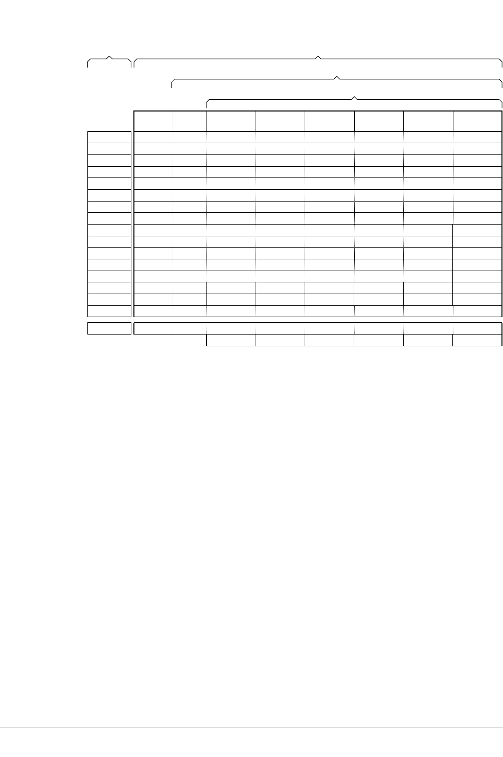
User
mode
System
mode
Supervisor
mode
Monitor
mode ‡
Abort
mode
Undefined
mode
IRQ
mode
FIQ
mode
R0_usr
R1_usr
R2_usr
R3_usr
R4_usr
R5_usr
R6_usr
R7_usr
R8_usr
R9_usr
R10_usr
R11_usr
R12_usr
SP_usr
LR_usr
PC
CPSRAPSR
SPSR_svc SPSR_mon ‡ SPSR_abt SPSR_und SPSR_irq SPSR_fiq
LR_svc LR_mon ‡ LR_abt LR_und LR_irq LR_fiq
SP_svc SP_mon ‡ SP_abt SP_und SP_irq SP_fiq
R8_fiq
R9_fiq
R10_fiq
R11_fiq
R12_fiqR12
SP
LR
PC
R11
R10
R9
R8
R7
R6
R5
R4
R3
R2
R1
R0
Exception modes
Privileged modes
System level views
Application
level view
‡ Monitor mode and the associated banked registers are implemented only as part of the Security Extensions
Figure 2-1 Organization of general-purpose registers and Program Status Registers
In ARMv6-M and ARMv-7M based processors, SP is an alias for the two banked stack pointer
registers:
• Main stack pointer register, which is only available in privileged software execution.
• Process stack pointer register.
Related concepts
2.9 General-purpose registers on page 2-44.
2.15 Program Counter on page 2-50.
2.16 Application Program Status Register on page 2-51.
2.19 Saved Program Status Registers on page 2-54.
2.18 Current Program Status Register on page 2-53.
2.4 Processor modes, and privileged and unprivileged software execution on page 2-38.
Related information
ARM Architecture Reference Manual.
2 Overview of the ARM Architecture
2.8 ARM registers
ARM DUI0473J Copyright © 2010-2013 ARM. All rights reserved. 2-43
Non-Confidential

2.9 General-purpose registers
There are restrictions on the use of SP and LR as general-purpose registers.
With the exception of ARMv6-M and ARMv7-M based processors, there are 30 (or 32 if Security
Extensions are implemented) general-purpose 32-bit registers, that include the banked SP and LR
registers. Fifteen general-purpose registers are visible at any one time, depending on the current
processor mode. These are R0-R12, SP, LR. The PC (R15) is not considered a general-purpose
register.
SP (or R13) is the stack pointer. The C and C++ compilers always use SP as the stack pointer. Use
of SP as a general purpose register is discouraged. In Thumb, SP is strictly defined as the stack
pointer. The instruction descriptions mention when SP and PC can be used.
In User mode, LR (or R14) is used as a link register to store the return address when a subroutine
call is made. It can also be used as a general-purpose register if the return address is stored on the
stack.
In the exception handling modes, LR holds the return address for the exception, or a subroutine
return address if subroutine calls are executed within an exception. LR can be used as a general-
purpose register if the return address is stored on the stack.
Note
When using the --use_frame_pointer option with armcc, do not use R11 as a general-
purpose register.
Related concepts
2.15 Program Counter on page 2-50.
2.10 Register accesses on page 2-45.
Related references
2.11 Predeclared core register names on page 2-46.
10.62 MRS (PSR to general-purpose register) on page 10-409.
10.65 MSR (general-purpose register to PSR) on page 10-413.
Related information
--use_frame_pointer.
2 Overview of the ARM Architecture
2.9 General-purpose registers
ARM DUI0473J Copyright © 2010-2013 ARM. All rights reserved. 2-44
Non-Confidential

2.10 Register accesses
16-bit Thumb instructions can access only a limited set of registers. There are also some
restrictions on the use of special-purpose registers by ARM and 32-bit Thumb instructions.
Most 16-bit Thumb instructions can only access R0 to R7. Only a small number of these
instructions can access R8-R12, SP, LR, and PC. Registers R0 to R7 are called Lo registers.
Registers R8-R12, SP, LR, and PC are called Hi registers.
All 32-bit Thumb instructions can access R0 to R12, and LR. However, apart from a few
designated stack manipulation instructions, most Thumb instructions cannot use SP. Except for a
few specific instructions where PC is useful, most Thumb instructions cannot use PC.
In ARM state, all instructions can access R0 to R12, SP, and LR, and most instructions can also
access PC (R15). However, the use of the SP in an ARM instruction, in any way that is not
possible in the corresponding Thumb instruction, is deprecated. Explicit use of the PC in an ARM
instruction is not usually useful, and except for specific instances that are useful, such use is
deprecated. Implicit use of the PC, for example in branch instructions or load (literal) instructions,
is never deprecated.
The MRS instructions can move the contents of a status register to a general-purpose register,
where they can be manipulated by normal data processing operations. You can use the MSR
instruction to move the contents of a general-purpose register to a status register.
Related concepts
2.9 General-purpose registers on page 2-44.
2.15 Program Counter on page 2-50.
2.16 Application Program Status Register on page 2-51.
2.18 Current Program Status Register on page 2-53.
2.19 Saved Program Status Registers on page 2-54.
4.19 The Read-Modify-Write operation on page 4-92.
Related references
2.11 Predeclared core register names on page 2-46.
10.62 MRS (PSR to general-purpose register) on page 10-409.
10.65 MSR (general-purpose register to PSR) on page 10-413.
2 Overview of the ARM Architecture
2.10 Register accesses
ARM DUI0473J Copyright © 2010-2013 ARM. All rights reserved. 2-45
Non-Confidential

2.11 Predeclared core register names
Many of the core register names have synonyms.
The following table shows the predeclared core registers:
Table 2-2 Predeclared core registers
Register names Meaning
r0-r15 and R0-R15 General purpose registers.
a1-a4 Argument, result or scratch registers. These are synonyms
for R0 to R3
v1-v8 Variable registers. These are synonyms for R4 to R11.
sb and SB Static base register. This is a synonym for R9.
ip and IP Intra procedure call scratch register. This is a synonym for
R12.
sp and SP Stack pointer. This is a synonym for R13.
lr and LR Link register. This is a synonym for R14.
pc and PC Program counter. This is a synonym for R15.
With the exception of a1-a4 and v1-v8, you can write the registers either in all upper case or all
lower case.
Related concepts
2.9 General-purpose registers on page 2-44.
2 Overview of the ARM Architecture
2.11 Predeclared core register names
ARM DUI0473J Copyright © 2010-2013 ARM. All rights reserved. 2-46
Non-Confidential

2.12 Predeclared extension register names
You can write the names of NEON and VFP registers either in upper case or lower case.
The following extension register names are predeclared:
Table 2-3 Predeclared extension registers
Register names Meaning
q0-q15 and Q0-Q15 NEON quadword registers
d0-d31 and D0-D31 NEON doubleword registers, VFP double-precision registers
s0-s31 and S0-S31 VFP single-precision registers
Related concepts
8.4 Extension register bank mapping on page 8-180.
2 Overview of the ARM Architecture
2.12 Predeclared extension register names
ARM DUI0473J Copyright © 2010-2013 ARM. All rights reserved. 2-47
Non-Confidential

2.13 Predeclared XScale register names
When assembling for a Marvell XScale processor, you can use some additional predeclared
register names.
These are as follows:
Table 2-4 Predeclared XScale registers
Register name Meaning
acc0-acc7 and ACC0-ACC7 XScale accumulator registers
The following register names are predeclared when assembling for a Marvell XScale processor
with Wireless MMX:
Table 2-5 Predeclared Wireless MMX registers
Register name Meaning
wR0-wR15, wr0-wr15, and WR0-WR15 Wireless SIMD data registers (coprocesssor 0).
wC0-wC15, wc0-wc15, and WC0-WC15 Usable aliases for coprocessor 1 registers. Use of these aliases is not
recommended.
wCID, wcid, and WCID Coprocessor ID register (coprocessor 1 register c0).
wCon, wcon, and WCON Control register (coprocessor 1 register c1).
wCSSF, wcssf, and WCSSF Saturation SIMD flags (coprocessor 1 register c2).
wCASF, wcasf, and WCASF Arithmetic SIMD flags (coprocessor 1 register c3).
wCGR0-wCGR3, wcgr0-wcgr3, and WCGR0-
WCGR3
General purpose registers (coprocessor 1 registers c8 - c11).
The predeclared XScale register names are case-sensitive and can be mixed case where this
matches exactly the Wireless MMX Technology specification.
Control registers, ID register, general-purpose registers wCGR0-wCGR3 and the SIMD flags map
onto coprocessor 1. Use the Wireless MMX Technology instructions TMCR and TMRC to read and
write to these registers. The coprocessor 1 registers c4-c7 and c12-c15 are reserved.
SIMD data registers (wR0 - wR15) map onto coprocessor 0 and hold 16x64-bit packed data. Use
the Wireless MMX Technology pseudo-instructions TMRRC and TMCRR to move data between
these registers and the ARM registers.
The assembler supports the WRN and WCN directives to specify your own register names.
Related references
13 Wireless MMX Technology Instructions on page 13-755.
2 Overview of the ARM Architecture
2.13 Predeclared XScale register names
ARM DUI0473J Copyright © 2010-2013 ARM. All rights reserved. 2-48
Non-Confidential

2.14 Predeclared coprocessor names
There are ranges of predeclared coprocessor names and coprocessor register names. All names are
case-sensitive.
Table 2-6 Predeclared coprocessor registers
Register name Meaning
p0-p15 Coprocessors 0-15
c0-c15 Coprocessor registers 0-15
Related references
10.26 CDP and CDP2 on page 10-349.
10.51 MCR and MCR2 on page 10-396.
10.60 MRC and MRC2 on page 10-407.
2 Overview of the ARM Architecture
2.14 Predeclared coprocessor names
ARM DUI0473J Copyright © 2010-2013 ARM. All rights reserved. 2-49
Non-Confidential

2.15 Program Counter
You can use the Program Counter explicitly, for example in some ARM data processing
instructions, and implicitly, for example in branch instructions.
The Program Counter (PC) is accessed as PC (or R15). It is incremented by the size of the
instruction executed (which is always four bytes in ARM state). Branch instructions load the
destination address into PC. You can also load the PC directly using data processing instructions.
For example, to branch to the address in a general purpose register, use:
MOV PC,R0
During execution, PC does not contain the address of the currently executing instruction. The
address of the currently executing instruction is typically PC–8 for ARM, or PC–4 for Thumb.
Note
ARM recommends you use the BX instruction to jump to an address or to return from a function,
rather than writing to the PC directly.
Related concepts
7.5 Register-relative and PC-relative expressions on page 7-149.
Related references
10.16 B on page 10-333.
10.21 BL on page 10-340.
10.22 BLX on page 10-342.
10.23 BX on page 10-344.
10.24 BXJ on page 10-346.
10.25 CBZ and CBNZ on page 10-348.
10.150 TBB and TBH on page 10-536.
2 Overview of the ARM Architecture
2.15 Program Counter
ARM DUI0473J Copyright © 2010-2013 ARM. All rights reserved. 2-50
Non-Confidential

2.16 Application Program Status Register
The Application Program Status Register (APSR) holds the program status flags that are
accessible in any processor mode.
It holds copies of the N, Z, C, and V condition flags. The processor uses them to determine
whether or not to execute conditional instructions.
On ARMv5TE, ARMv6 and later architectures, the APSR also holds the Q (saturation) flag.
On ARMv6 and later, the APSR also holds the GE (Greater than or Equal) flags. The GE flags can
be set by the parallel add and subtract instructions. They are used by the SEL instruction to
perform byte-based selection from two registers.
These flags are accessible in all modes, using the MSR and MRS instructions.
Related concepts
5.1 Conditional instructions on page 5-106.
5.4 Updates to the condition flags on page 5-109.
Related references
10.62 MRS (PSR to general-purpose register) on page 10-409.
10.65 MSR (general-purpose register to PSR) on page 10-413.
10.101 SEL on page 10-466.
2 Overview of the ARM Architecture
2.16 Application Program Status Register
ARM DUI0473J Copyright © 2010-2013 ARM. All rights reserved. 2-51
Non-Confidential

2.17 The Q flag
The Q flag indicates overflow or saturation. It is one of the program status flags held in the APSR.
In ARMv5TE, ARMv6 and later, the Q flag is set to 1 when saturation has occurred in saturating
arithmetic instructions, or when overflow has occurred in certain multiply instructions.
The Q flag is a sticky flag. Although the saturating and certain multiply instructions can set the
flag, they cannot clear it. You can execute a series of such instructions, and then test the flag to
find out whether saturation or overflow occurred at any point in the series, without having to
check the flag after each instruction.
To clear the Q flag, use an MSR instruction to read-modify-write the APSR:
MRS r5, APSR
BIC r5, r5, #(1<<27)
MSR APSR_nzcvq, r5
The state of the Q flag cannot be tested directly by the condition codes. To read the state of the Q
flag, use an MRS instruction.
MRS r6, APSR
TST r6, #(1<<27); Z is clear if Q flag was set
Related concepts
4.19 The Read-Modify-Write operation on page 4-92.
Related references
10.62 MRS (PSR to general-purpose register) on page 10-409.
10.65 MSR (general-purpose register to PSR) on page 10-413.
10.76 QADD on page 10-432.
10.123 SMULxy on page 10-491.
10.125 SMULWy on page 10-493.
2 Overview of the ARM Architecture
2.17 The Q flag
ARM DUI0473J Copyright © 2010-2013 ARM. All rights reserved. 2-52
Non-Confidential

2.18 Current Program Status Register
The Current Program Status Register (CPSR) holds the same program status flags as the APSR,
and some additional information.
The CPSR holds:
• The APSR flags.
• The processor mode.
• The interrupt disable flags.
• The instruction set state (ARM, Thumb, ThumbEE, or Jazelle).
• The endianness state (on ARMv4T and later).
• The execution state bits for the IT block (on ARMv6T2 and later).
The execution state bits control conditional execution in the IT block.
Only the APSR flags are accessible in all modes. ARM deprecates using an MSR instruction to
change the endianness bit (E) of the CPSR, in any mode. SETEND is the preferred instruction to
write to the E bit.
The execution state bits for the IT block (IT[1:0]), Jazelle bit (J), and Thumb bit (T) can be
accessed by MRS only in Debug state.
Related concepts
5.4 Updates to the condition flags on page 5-109.
2.19 Saved Program Status Registers on page 2-54.
Related references
10.38 IT on page 10-366.
10.62 MRS (PSR to general-purpose register) on page 10-409.
10.65 MSR (general-purpose register to PSR) on page 10-413.
10.102 SETEND on page 10-468.
2 Overview of the ARM Architecture
2.18 Current Program Status Register
ARM DUI0473J Copyright © 2010-2013 ARM. All rights reserved. 2-53
Non-Confidential

2.19 Saved Program Status Registers
A Saved Program Status Register (SPSR) stores the current value of the CPSR when an exception
is taken so that the CPSR can be restored after handling the exception.
Each exception handling mode can access its own SPSR. User mode and System mode do not
have an SPSR because they are not exception handling modes.
The execution state bits, including the endianness state and current instruction set state can be
accessed from the SPSR in any exception mode, using the MSR and MRS instruction. You cannot
access the SPSR using MSR or MRS in User or System mode.
Related concepts
2.18 Current Program Status Register on page 2-53.
Related information
Handling Processor Exceptions.
2 Overview of the ARM Architecture
2.19 Saved Program Status Registers
ARM DUI0473J Copyright © 2010-2013 ARM. All rights reserved. 2-54
Non-Confidential

2.20 ARM and Thumb instruction set overview
ARM and Thumb instructions can be grouped by functional area.
All ARM instructions are 32 bits long. Instructions are stored word-aligned, so the least
significant two bits of instruction addresses are always zero in ARM state.
Thumb and ThumbEE instructions are either 16 or 32 bits long. Instructions are stored half-word
aligned. Some instructions use the least significant bit of the address to determine whether the
code being branched to is Thumb code or ARM code.
Before the introduction of 32-bit Thumb instructions, the Thumb instruction set was limited to a
restricted subset of the functionality of the ARM instruction set. Almost all Thumb instructions
were 16-bit. Together, the 32-bit and 16-bit Thumb instructions provide functionality that is
almost identical to that of the ARM instruction set.
The following table describes some of the functional groupings of the available instructions:
Table 2-7 Instruction groups
Instruction Group Description
Branch and control These instructions do the following:
• Branch to subroutines.
• Branch backwards to form loops.
• Branch forward in conditional structures.
• Make following instructions conditional without branching.
• Change the processor between ARM state and Thumb state.
Data processing These instructions operate on the general-purpose registers. They can perform operations such as
addition, subtraction, or bitwise logic on the contents of two registers and place the result in a
third register. They can also operate on the value in a single register, or on a value in a register
and an immediate value supplied within the instruction.
Long multiply instructions give a 64-bit result in two registers.
Register load and
store
These instructions load or store the value of a single register from or to memory. They can load or
store a 32-bit word, a 16-bit halfword, or an 8-bit unsigned byte. Byte and halfword loads can
either be sign extended or zero extended to fill the 32-bit register.
A few instructions are also defined that can load or store 64-bit doubleword values into two 32-bit
registers.
Multiple register load
and store
These instructions load or store any subset of the general-purpose registers from or to memory.
Status register access These instructions move the contents of a status register to or from a general-purpose register.
Coprocessor These instructions support a general way to extend the ARM architecture. They also enable the
control of the CP15 System Control coprocessor registers.
Related concepts
4.13 Load and store multiple register instructions on page 4-83.
Related references
10 ARM and Thumb Instructions on page 10-296.
2 Overview of the ARM Architecture
2.20 ARM and Thumb instruction set overview
ARM DUI0473J Copyright © 2010-2013 ARM. All rights reserved. 2-55
Non-Confidential

2.21 Access to the inline barrel shifter
The ARM arithmetic logic unit has a 32-bit barrel shifter that is capable of shift and rotate
operations.
The second operand to many ARM and Thumb data-processing and single register data-transfer
instructions can be shifted, before the data-processing or data-transfer is executed, as part of the
instruction. This supports, but is not limited to:
• Scaled addressing.
• Multiplication by an immediate value.
• Constructing immediate values.
32-bit Thumb instructions give almost the same access to the barrel shifter as ARM instructions.
The 16-bit Thumb instructions only allow access to the barrel shifter using separate instructions.
Related concepts
4.3 Load 32-bit immediates into registers on page 4-68.
Related references
4.4 Load immediate values using MOV and MVN on page 4-69.
2 Overview of the ARM Architecture
2.21 Access to the inline barrel shifter
ARM DUI0473J Copyright © 2010-2013 ARM. All rights reserved. 2-56
Non-Confidential

Chapter 3
Structure of Assembly Language Modules
Describes the structure of assembly language source files.
It contains the following:
• 3.1 Syntax of source lines in assembly language on page 3-58.
• 3.2 Literals on page 3-60.
• 3.3 ELF sections and the AREA directive on page 3-61.
• 3.4 An example ARM assembly language module on page 3-62.
ARM DUI0473J Copyright © 2010-2013 ARM. All rights reserved. 3-57
Non-Confidential

3.1 Syntax of source lines in assembly language
The assembler parses and assembles assembly language to produce object code.
Syntax
Each line of assembly language source code has this general form:
{symbol} {instruction|directive|pseudo-instruction} {;comment}
All three sections of the source line are optional.
symbol is usually a label. In instructions and pseudo-instructions it is always a label. In some
directives it is a symbol for a variable or a constant. The description of the directive makes this
clear in each case.
symbol must begin in the first column. It cannot contain any white space character such as a
space or a tab unless it is enclosed by bars (|).
Labels are symbolic representations of addresses. You can use labels to mark specific addresses
that you want to refer to from other parts of the code. Numeric local labels are a subclass of labels
that begin with a number in the range 0-99. Unlike other labels, a numeric local label can be
defined many times. This makes them useful when generating labels with a macro.
Directives provide important information to the assembler that either affects the assembly process
or affects the final output image.
Instructions and pseudo-instructions make up the code a processor uses to perform tasks.
Note
Instructions, pseudo-instructions, and directives must be preceded by white space, such as a space
or a tab, irrespective of whether there is a preceding label or not.
Some directives do not allow the use of a label.
A comment is the final part of a source line. The first semicolon on a line marks the beginning of a
comment except where the semicolon appears inside a string literal. The end of the line is the end
of the comment. A comment alone is a valid line. The assembler ignores all comments. You can
use blank lines to make your code more readable.
Considerations when writing assembly language source code
You must write instruction mnemonics, pseudo-instructions, directives, and symbolic register
names (except a1-a4, v1-v8, and Wireless MMX registers) in either all uppercase or all
lowercase. You must not use mixed case. Labels and comments can be in uppercase, lowercase, or
mixed case.
AREA ARMex, CODE, READONLY
; Name this block of code ARMex
ENTRY ; Mark first instruction to execute
start
MOV r0, #10 ; Set up parameters
MOV r1, #3
ADD r0, r0, r1 ; r0 = r0 + r1
stop
MOV r0, #0x18 ; angel_SWIreason_ReportException
LDR r1, =0x20026 ; ADP_Stopped_ApplicationExit
SVC #0x123456 ; ARM semihosting (formerly SWI)
END ; Mark end of file
To make source files easier to read, you can split a long line of source into several lines by placing
a backslash character (\) at the end of the line. The backslash must not be followed by any other
3 Structure of Assembly Language Modules
3.1 Syntax of source lines in assembly language
ARM DUI0473J Copyright © 2010-2013 ARM. All rights reserved. 3-58
Non-Confidential

characters, including spaces and tabs. The assembler treats the backslash followed by end-of-line
sequence as white space. You can also use blank lines to make your code more readable.
Note
Do not use the backslash followed by end-of-line sequence within quoted strings.
The limit on the length of lines, including any extensions using backslashes, is 4095 characters.
Related concepts
7.6 Labels on page 7-150.
7.10 Numeric local labels on page 7-154.
7.13 String literals on page 7-157.
Related references
7.1 Symbol naming rules on page 7-145.
7.15 Syntax of numeric literals on page 7-159.
3.2 Literals on page 3-60.
3 Structure of Assembly Language Modules
3.1 Syntax of source lines in assembly language
ARM DUI0473J Copyright © 2010-2013 ARM. All rights reserved. 3-59
Non-Confidential

3.2 Literals
Assembly language source code can contain numeric, string, Boolean, and single character literals.
Literals can be expressed as:
• Decimal numbers, for example 123.
• Hexadecimal numbers, for example 0x7B.
• Numbers in any base from 2 to 9, for example 5_204 is a number in base 5.
• Floating point numbers, for example 123.4.
• Boolean values {TRUE} or {FALSE}.
• Single character values enclosed by single quotes, for example 'w'.
• Strings enclosed in double quotes, for example "This is a string".
Note
In most cases, a string containing a single character is accepted as a single character value. For
example ADD r0,r1,#"a" is accepted, but ADD r0,r1,#"ab" is faulted.
You can also use variables and names to represent literals.
Related references
3.1 Syntax of source lines in assembly language on page 3-58.
3 Structure of Assembly Language Modules
3.2 Literals
ARM DUI0473J Copyright © 2010-2013 ARM. All rights reserved. 3-60
Non-Confidential

3.3 ELF sections and the AREA directive
Object files produced by the assembler are divided into sections. In assembly source code, you use
the AREA directive to mark the start of a section.
ELF sections are independent, named, indivisible sequences of code or data. A single code section
is the minimum required to produce an application.
The output of an assembly or compilation can include:
• One or more code sections. These are usually read-only sections.
• One or more data sections. These are usually read-write sections. They might be zero
initialized (ZI).
The linker places each section in a program image according to section placement rules. Sections
that are adjacent in source files are not necessarily adjacent in the application image
Use the AREA directive to name the section and set its attributes. The attributes are placed after the
name, separated by commas.
You can choose any name for your sections. However, names starting with any non-alphabetic
character must be enclosed in bars, or an AREA name missing error is generated. For example,
|1_DataArea|.
The following example defines a single read-only section called ARMex that contains code:
AREA ARMex, CODE, READONLY ; Name this block of code ARMex
Related concepts
3.4 An example ARM assembly language module on page 3-62.
Related references
14.6 AREA on page 14-774.
Related information
Information about scatter files.
3 Structure of Assembly Language Modules
3.3 ELF sections and the AREA directive
ARM DUI0473J Copyright © 2010-2013 ARM. All rights reserved. 3-61
Non-Confidential

3.4 An example ARM assembly language module
An ARM assembly language module has several constituent parts.
These are:
• ELF sections (defined by the AREA directive).
• Application entry (defined by the ENTRY directive).
• Application execution.
• Application termination.
• Program end (defined by the END directive).
The following example defines a single section called ARMex that contains code and is marked as
being READONLY.
Constituents of an assembly language module
AREA ARMex, CODE, READONLY
; Name this block of code ARMex
ENTRY ; Mark first instruction to execute
start
MOV r0, #10 ; Set up parameters
MOV r1, #3
ADD r0, r0, r1 ; r0 = r0 + r1
stop
MOV r0, #0x18 ; angel_SWIreason_ReportException
LDR r1, =0x20026 ; ADP_Stopped_ApplicationExit
SVC #0x123456 ; ARM semihosting (formerly SWI)
END ; Mark end of file
Application entry
The ENTRY directive declares an entry point to the program. It marks the first instruction to be
executed. In applications using the C library, an entry point is also contained within the C library
initialization code. Initialization code and exception handlers also contain entry points.
Application execution
The application code begins executing at the label start, where it loads the decimal values 10
and 3 into registers R0 and R1. These registers are added together and the result placed in R0.
Application termination
After executing the main code, the application terminates by returning control to the debugger.
This is done using the ARM semihosting SVC (0x123456 by default), with the following
parameters:
• R0 equal to angel_SWIreason_ReportException (0x18).
• R1 equal to ADP_Stopped_ApplicationExit (0x20026).
Program end
The END directive instructs the assembler to stop processing this source file. Every assembly
language source module must finish with an END directive on a line by itself. Any lines following
the END directive are ignored by the assembler.
Related concepts
3.3 ELF sections and the AREA directive on page 3-61.
Related references
14.22 END on page 14-793.
14.23 ENTRY on page 14-794.
3 Structure of Assembly Language Modules
3.4 An example ARM assembly language module
ARM DUI0473J Copyright © 2010-2013 ARM. All rights reserved. 3-62
Non-Confidential


Chapter 4
Writing ARM Assembly Language
Describes the use of a few basic assembly language instructions and the use of macros.
It contains the following:
• 4.1 About the Unified Assembler Language on page 4-66.
• 4.2 Register usage in subroutine calls on page 4-67.
• 4.3 Load 32-bit immediates into registers on page 4-68.
• 4.4 Load immediate values using MOV and MVN on page 4-69.
• 4.5 Load 32-bit values to a register using MOV32 on page 4-72.
• 4.6 Load 32-bit immediate values to a register using LDR Rd, =const on page 4-73.
• 4.7 Literal pools on page 4-74.
• 4.8 Load addresses into registers on page 4-76.
• 4.9 Load addresses to a register using ADR on page 4-77.
• 4.10 Load addresses to a register using ADRL on page 4-79.
• 4.11 Load addresses to a register using LDR Rd, =label on page 4-80.
• 4.12 Other ways to load and store registers on page 4-82.
• 4.13 Load and store multiple register instructions on page 4-83.
• 4.14 Load and store multiple register instructions in ARM and Thumb on page 4-84.
• 4.15 Stack implementation using LDM and STM on page 4-86.
• 4.16 Stack operations for nested subroutines on page 4-88.
• 4.17 Block copy with LDM and STM on page 4-89.
• 4.18 Memory accesses on page 4-91.
• 4.19 The Read-Modify-Write operation on page 4-92.
• 4.20 Optional hash with immediate constants on page 4-93.
ARM DUI0473J Copyright © 2010-2013 ARM. All rights reserved. 4-64
Non-Confidential

• 4.21 About macros on page 4-94.
• 4.22 Test-and-branch macro example on page 4-95.
• 4.23 Unsigned integer division macro example on page 4-96.
• 4.24 Instruction and directive relocations on page 4-98.
• 4.25 Symbol versions on page 4-100.
• 4.26 Frame directives on page 4-101.
• 4.27 Exception tables and Unwind tables on page 4-102.
• 4.28 Assembly language changes after RVCT v2.1 on page 4-103.
4 Writing ARM Assembly Language
ARM DUI0473J Copyright © 2010-2013 ARM. All rights reserved. 4-65
Non-Confidential

4.1 About the Unified Assembler Language
Unified Assembler Language (UAL) is a common syntax for ARM and Thumb instructions.
UAL supersedes earlier versions of both the ARM and Thumb assembler languages.
Code written using UAL can be assembled for ARM or Thumb for any ARM processor. The
assembler faults the use of unavailable instructions.
RealView® Compilation Tools (RVCT) v2.1 and earlier can only assemble the pre-UAL syntax.
Later versions of RVCT and ARM Compiler toolchain can assemble code written in pre-UAL and
UAL syntax.
You can use directives or command-line options to instruct the assembler whether you are using
UAL or pre-UAL syntax. By default, the assembler expects source code to be written in UAL. If
you use any of the CODE32, ARM, THUMB, or THUMBX directives, or if you assemble with any of the
--32, --arm, --thumb, or --thumbx command-line options, the assembler accepts UAL
syntax. The assembler also accepts source code written in pre-UAL ARM assembly language
when you use the CODE32 or ARM directives.
The assembler accepts source code written in pre-UAL Thumb assembly language when you
assemble using the --16 command-line option, or you use the CODE16 directive in the source
code.
Note
The pre-UAL Thumb assembly language does not support 32-bit Thumb instructions.
4 Writing ARM Assembly Language
4.1 About the Unified Assembler Language
ARM DUI0473J Copyright © 2010-2013 ARM. All rights reserved. 4-66
Non-Confidential

4.2 Register usage in subroutine calls
You use branch instructions to call and return from subroutines. The Procedure Call Standard for
the ARM Architecture defines how to use registers in subroutine calls.
A subroutine is a block of code that performs a task based on some arguments and optionally
returns a result. By convention, you use registers R0 to R3 to pass arguments to subroutines, and
R0 to pass a result back to the callers. A subroutine that requires more than four inputs uses the
stack for the additional inputs.
To call subroutines, use a branch and link instruction. The syntax is:
BL destination
where destination is usually the label on the first instruction of the subroutine.
destination can also be a PC-relative expression.
The BL instruction:
• Places the return address in the link register.
• Sets the PC to the address of the subroutine.
After the subroutine code has executed you can use a BX LR instruction to return.
Note
Calls between separately assembled or compiled modules must comply with the restrictions and
conventions defined by the Procedure Call Standard for the ARM Architecture.
The following example shows a subroutine, doadd, that adds the values of two arguments and
returns a result in R0:
Add two arguments
AREA subrout, CODE, READONLY ; Name this block of code
ENTRY ; Mark first instruction to execute
start MOV r0, #10 ; Set up parameters
MOV r1, #3
BL doadd ; Call subroutine
stop MOV r0, #0x18 ; angel_SWIreason_ReportException
LDR r1, =0x20026 ; ADP_Stopped_ApplicationExit
SVC #0x123456 ; ARM semihosting (formerly SWI)
doadd ADD r0, r0, r1 ; Subroutine code
BX lr ; Return from subroutine
END ; Mark end of file
Related concepts
4.16 Stack operations for nested subroutines on page 4-88.
Related references
10.16 B on page 10-333.
Related information
Procedure Call Standard for the ARM Architecture.
4 Writing ARM Assembly Language
4.2 Register usage in subroutine calls
ARM DUI0473J Copyright © 2010-2013 ARM. All rights reserved. 4-67
Non-Confidential

4.3 Load 32-bit immediates into registers
To represent some 32-bit immediate values, you might have to use a sequence of instructions
rather than a single instruction.
ARM and Thumb instructions can only be 32 bits wide. You can use the MOV or MVN instruction to
load a register with an immediate value supported by the instruction set. Certain 32-bit values
cannot be represented as an immediate operand to a single 32-bit instruction. You can load these
values from memory in a single instruction.
In ARMv6T2 and later, you can load any 32-bit immediate value into a register with two
instructions, a MOV followed by a MOVT. Or, you can use a pseudo-instruction, MOV32, to construct
the instruction sequence for you.
You can also use the LDR pseudo-instruction to load immediate values into a register.
You can include many commonly-used immediate values directly as operands within data
processing instructions, without a separate load operation. The range of immediate values that you
can include as operands in 16-bit Thumb instructions is much smaller.
Related concepts
4.5 Load 32-bit values to a register using MOV32 on page 4-72.
4.6 Load 32-bit immediate values to a register using LDR Rd, =const on page 4-73.
8.7 Load values to VFP and NEON registers on page 8-184.
Related references
4.4 Load immediate values using MOV and MVN on page 4-69.
10.45 LDR pseudo-instruction on page 10-385.
4 Writing ARM Assembly Language
4.3 Load 32-bit immediates into registers
ARM DUI0473J Copyright © 2010-2013 ARM. All rights reserved. 4-68
Non-Confidential

4.4 Load immediate values using MOV and MVN
The MOV and MVN instructions can write a range of immediate values to a register.
In ARM state:
•MOV can load any 8-bit immediate value, giving a range of 0x0-0xFF (0-255).
It can also rotate these values by any even number.
These values are also available as immediate operands in many data processing operations,
without being loaded in a separate instruction.
•MVN can load the bitwise complements of these values. The numerical values are -(n+1),
where n is the value available in MOV.
• In ARMv6T2 and later, MOV can load any 16-bit number, giving a range of 0x0-0xFFFF
(0-65535).
The following table shows the range of 8-bit values that can be loaded in a single ARM MOV or
MVN instruction (for data processing operations). The value to load must be a multiple of the value
shown in the Step column.
Table 4-1 ARM state immediate values (8-bit)
Binary Decimal Step Hexadecimal MVN valueaNotes
000000000000000000000000abcdefgh 0-255 1 0-0xFF –1 to –256 -
0000000000000000000000abcdefgh00 0-1020 4 0-0x3FC –4 to –1024 -
00000000000000000000abcdefgh0000 0-4080 16 0-0xFF0 –16 to –4096 -
000000000000000000abcdefgh000000 0-16320 64 0-0x3FC0 –64 to –16384 -
... ... ... ... ... -
abcdefgh000000000000000000000000 0-255 x 224 224 0-0xFF000000 1-256 x –224 -
cdefgh000000000000000000000000ab (bit pattern) - - (bit pattern) See b in Note
efgh000000000000000000000000abcd (bit pattern) - - (bit pattern) See b in Note
gh000000000000000000000000abcdef (bit pattern) - - (bit pattern) See b in Note
The following table shows the range of 16-bit values that can be loaded in a single MOV ARM
instruction in ARMv6T2 and later:
Table 4-2 ARM state immediate values in MOV instructions
Binary Decimal Step Hexadecimal MVN value Notes
0000000000000000abcdefghijklmnop 0-65535 1 0-0xFFFF - See c in Note
Note
These notes give extra information on both tables.
a
The MVN values are only available directly as operands in MVN instructions.
b
These values are available in ARM state only. All the other values in this table are also
available in 32-bit Thumb instructions.
4 Writing ARM Assembly Language
4.4 Load immediate values using MOV and MVN
ARM DUI0473J Copyright © 2010-2013 ARM. All rights reserved. 4-69
Non-Confidential

c
These values are only available in ARMv6T2 and later. They are not available directly as
operands in other instructions.
In Thumb state in ARMv6T2 and later:
• The 32-bit MOV instruction can load:
— Any 8-bit immediate value, giving a range of 0x0-0xFF (0-255).
— Any 8-bit immediate value, shifted left by any number.
— Any 8-bit pattern duplicated in all four bytes of a register.
— Any 8-bit pattern duplicated in bytes 0 and 2, with bytes 1 and 3 set to 0.
— Any 8-bit pattern duplicated in bytes 1 and 3, with bytes 0 and 2 set to 0.
These values are also available as immediate operands in many data processing operations,
without being loaded in a separate instruction.
• The 32-bit MVN instruction can load the bitwise complements of these values. The numerical
values are -(n+1), where n is the value available in MOV.
• The 32-bit MOV instruction can load any 16-bit number, giving a range of 0x0-0xFFFF
(0-65535). These values are not available as immediate operands in data processing operations.
In architectures with Thumb, the 16-bit Thumb MOV instruction can load any immediate value in
the range 0-255.
The following table shows the range of values that can be loaded in a single 32-bit Thumb MOV or
MVN instruction (for data processing operations). The value to load must be a multiple of the value
shown in the Step column.
Table 4-3 32-bit Thumb immediate values
Binary Decimal Step Hexadecimal MVN valueaNotes
0000000000000
00000000000ab
cdefgh
0-255 1 0x0-0xFF –1 to –256 -
0000000000000
0000000000abc
defgh0
0-510 2 0x0-0x1FE –2 to –512 -
0000000000000
000000000abcd
efgh00
0-1020 4 0x0-0x3FC –4 to –1024 -
... ... ... ... ... -
0abcdefgh0000
0000000000000
000000
0-255 x 223 223 0x0-0x7F800000 1-256 x –223 -
abcdefgh00000
0000000000000
000000
0-255 x 224 224 0x0-0xFF000000 1-256 x –224 -
abcdefghabcde
fghabcdefghab
cdefgh
(bit pattern) - 0xXYXYXYXY 0xXYXYXYXY -
4 Writing ARM Assembly Language
4.4 Load immediate values using MOV and MVN
ARM DUI0473J Copyright © 2010-2013 ARM. All rights reserved. 4-70
Non-Confidential

Table 4-3 32-bit Thumb immediate values (continued)
Binary Decimal Step Hexadecimal MVN valueaNotes
00000000abcde
fgh00000000ab
cdefgh
(bit pattern) - 0x00XY00XY 0xFFXYFFXY -
abcdefgh00000
000abcdefgh00
000000
(bit pattern) - 0xXY00XY00 0xXYFFXYFF -
0000000000000
0000000abcdef
ghijkl
0-4095 1 0x0-0xFFF - See b in Note
The following table shows the range of 16-bit values that can be loaded by the MOV 32-bit Thumb
instruction:
Table 4-4 32-bit Thumb immediate values in MOV instructions
Binary Decimal Step Hexadecimal MVN value Notes
0000000000000000abcdefghijklmnop 0-65535 1 0x0-0xFFFF - See c in Note
Note
These notes give extra information on the tables.
a
The MVN values are only available directly as operands in MVN instructions.
b
These values are available directly as operands in ADD, SUB, and MOV instructions, but not
in MVN or any other data processing instructions.
c
These values are only available in MOV instructions.
In both ARM and Thumb, you do not have to decide whether to use MOV or MVN. The assembler
uses whichever is appropriate. This is useful if the value is an assembly-time variable.
If you write an instruction with an immediate value that is not available, the assembler reports the
error: Immediate n out of range for this operation.
Related concepts
4.3 Load 32-bit immediates into registers on page 4-68.
4 Writing ARM Assembly Language
4.4 Load immediate values using MOV and MVN
ARM DUI0473J Copyright © 2010-2013 ARM. All rights reserved. 4-71
Non-Confidential

4.5 Load 32-bit values to a register using MOV32
To load any 32-bit immediate value, a pair of MOV and MOVT instructions is equivalent to a MOV32
pseudo-instruction.
In ARMv6T2 and later, both ARM and Thumb instruction sets include:
• A MOV instruction that can load any value in the range 0x00000000 to 0x0000FFFF into a
register.
• A MOVT instruction that can load any value in the range 0x0000 to 0xFFFF into the most
significant half of a register, without altering the contents of the least significant half.
You can use these two instructions to construct any 32-bit immediate value in a register.
Alternatively, you can use the MOV32 pseudo-instruction. The assembler generates the MOV, MOVT
instruction pair for you.
You can also use the MOV32 instruction to load addresses into registers by using a label or any PC-
relative expression in place of an immediate value. The assembler puts a relocation directive into
the object file for the linker to resolve the address at link-time.
Related concepts
7.5 Register-relative and PC-relative expressions on page 7-149.
Related references
10.57 MOV32 pseudo-instruction on page 10-404.
4 Writing ARM Assembly Language
4.5 Load 32-bit values to a register using MOV32
ARM DUI0473J Copyright © 2010-2013 ARM. All rights reserved. 4-72
Non-Confidential

4.6 Load 32-bit immediate values to a register using LDR Rd, =const
The LDR Rd,=const pseudo-instruction generates the most efficient single instruction to load
any 32-bit number.
You can use this pseudo-instruction to generate constants that are out of range of the MOV and MVN
instructions.
The LDR pseudo-instruction generates the most efficient single instruction for the specified
immediate value:
• If the immediate value can be constructed with a single MOV or MVN instruction, the assembler
generates the appropriate instruction.
• If the immediate value cannot be constructed with a single MOV or MVN instruction, the
assembler:
— Places the value in a literal pool (a portion of memory embedded in the code to hold
constant values).
— Generates an LDR instruction with a PC-relative address that reads the constant from the
literal pool.
For example:
LDR rn, [pc, #offset to literal pool]
; load register n with one word
; from the address [pc + offset]
You must ensure that there is a literal pool within range of the LDR instruction generated by the
assembler.
Related concepts
4.7 Literal pools on page 4-74.
Related references
10.45 LDR pseudo-instruction on page 10-385.
4 Writing ARM Assembly Language
4.6 Load 32-bit immediate values to a register using LDR Rd, =const
ARM DUI0473J Copyright © 2010-2013 ARM. All rights reserved. 4-73
Non-Confidential

4.7 Literal pools
The assembler uses literal pools to store some constant data in code sections. You can use the
LTORG directive to ensure a literal pool is within range.
The assembler places a literal pool at the end of each section. The end of a section is defined either
by the END directive at the end of the assembly or by the AREA directive at the start of the
following section. The END directive at the end of an included file does not signal the end of a
section.
In large sections the default literal pool can be out of range of one or more LDR instructions. The
offset from the PC to the constant must be:
• Less than 4KB in ARM or Thumb code when the 32-bit LDR instruction is available, but can
be in either direction.
• Forward and less than 1KB when only the 16-bit Thumb LDR instruction is available.
When an LDR Rd,=const pseudo-instruction requires the immediate value to be placed in a
literal pool, the assembler:
• Checks if the value is available and addressable in any previous literal pools. If so, it addresses
the existing constant.
• Attempts to place the value in the next literal pool if it is not already available.
If the next literal pool is out of range, the assembler generates an error message. In this case you
must use the LTORG directive to place an additional literal pool in the code. Place the LTORG
directive after the failed LDR pseudo-instruction, and within the valid range for an LDR instruction.
You must place literal pools where the processor does not attempt to execute them as instructions.
Place them after unconditional branch instructions, or after the return instruction at the end of a
subroutine. The following example shows how this works.
The instructions listed as comments are the ARM instructions generated by the assembler.
Placing literal pools
AREA Loadcon, CODE, READONLY
ENTRY ; Mark first instruction to execute
start
BL func1 ; Branch to first subroutine
BL func2 ; Branch to second subroutine
stop
MOV r0, #0x18 ; angel_SWIreason_ReportException
LDR r1, =0x20026 ; ADP_Stopped_ApplicationExit
SVC #0x123456 ; ARM semihosting (formerly SWI)
func1
LDR r0, =42 ; => MOV R0, #42
LDR r1, =0x55555555 ; => LDR R1, [PC, #offset to
; Literal Pool 1]
LDR r2, =0xFFFFFFFF ; => MVN R2, #0
BX lr
LTORG ; Literal Pool 1 contains
; literal Ox55555555
func2
LDR r3, =0x55555555 ; => LDR R3, [PC, #offset to
; Literal Pool 1]
; LDR r4, =0x66666666 ; If this is uncommented it
; fails, because Literal Pool 2
; is out of reach
BX lr
LargeTable
SPACE 4200 ; Starting at the current location,
; clears a 4200 byte area of memory
; to zero
END ; Literal Pool 2 is inserted here,
; but is out of range of the LDR
; pseudo-instruction that needs it
4 Writing ARM Assembly Language
4.7 Literal pools
ARM DUI0473J Copyright © 2010-2013 ARM. All rights reserved. 4-74
Non-Confidential


4.8 Load addresses into registers
It is often necessary to load an address into a register. There are several ways to do this.
For example, you might have to load the address of a variable, a string literal, or the start location
of a jump table.
Addresses are normally expressed as offsets from a label, or from the current PC or other register.
You can load an address into a register either:
• Using the instruction ADR.
• Using the pseudo-instruction ADRL.
• Using the pseudo-instruction MOV32.
• From a literal pool using the pseudo-instruction LDR Rd,=Label.
Related concepts
4.9 Load addresses to a register using ADR on page 4-77.
4.10 Load addresses to a register using ADRL on page 4-79.
4.5 Load 32-bit values to a register using MOV32 on page 4-72.
4.11 Load addresses to a register using LDR Rd, =label on page 4-80.
4 Writing ARM Assembly Language
4.8 Load addresses into registers
ARM DUI0473J Copyright © 2010-2013 ARM. All rights reserved. 4-76
Non-Confidential

4.9 Load addresses to a register using ADR
The ADR instruction loads an address within a certain range, without performing a data load.
ADR accepts a PC-relative expression, that is, a label with an optional offset where the address of
the label is relative to the PC.
Note
The label used with ADR must be within the same code section. The assembler faults references to
labels that are out of range in the same section.
The available range of addresses for the ADR instruction depends on the instruction set and
encoding:
ARM
Any value that can be produced by rotating an 8-bit value right by any even number of
bits within a 32-bit word. The range is relative to the PC.
32-bit Thumb encoding
±4095 bytes to a byte, halfword, or word-aligned address.
16-bit Thumb encoding
0 to 1020 bytes. label must be word-aligned. You can use the ALIGN directive to ensure
this.
Example of a jump table implementation with ADR
This example shows ARM code that implements a jump table. Here, the ADR instruction loads the
address of the jump table.
AREA Jump, CODE, READONLY ; Name this block of code
ARM ; Following code is ARM code
num EQU 2 ; Number of entries in jump table
ENTRY ; Mark first instruction to
; execute
start ; First instruction to call
MOV r0, #0 ; Set up the three arguments
MOV r1, #3
MOV r2, #2
BL arithfunc ; Call the function
stop
MOV r0, #0x18 ; angel_SWIreason_ReportException
LDR r1, =0x20026 ; ADP_Stopped_ApplicationExit
SVC #0x123456 ; ARM semihosting (formerly SWI)
arithfunc ; Label the function
CMP r0, #num ; Treat function code as unsigned
; integer
BXHS lr ; If code is >= num then return
ADR r3, JumpTable ; Load address of jump table
LDR pc, [r3,r0,LSL#2] ; Jump to the appropriate routine
JumpTable
DCD DoAdd
DCD DoSub
DoAdd
ADD r0, r1, r2 ; Operation 0
BX lr ; Return
DoSub
SUB r0, r1, r2 ; Operation 1
BX lr ; Return
END ; Mark the end of this file
In this example, the function arithfunc takes three arguments and returns a result in R0. The
first argument determines the operation to be carried out on the second and third arguments:
argument1=0
Result = argument2 + argument3.
argument1=1
Result = argument2 – argument3.
4 Writing ARM Assembly Language
4.9 Load addresses to a register using ADR
ARM DUI0473J Copyright © 2010-2013 ARM. All rights reserved. 4-77
Non-Confidential

The jump table is implemented with the following instructions and assembler directives:
EQU
Is an assembler directive. You use it to give a value to a symbol. In this example, it
assigns the value 2 to num. When num is used elsewhere in the code, the value 2 is
substituted. Using EQU in this way is similar to using #define to define a constant in C.
DCD
Declares one or more words of store. In this example, each DCD stores the address of a
routine that handles a particular clause of the jump table.
LDR
The LDR PC,[R3,R0,LSL#2] instruction loads the address of the required clause of the
jump table into the PC. It:
• Multiplies the clause number in R0 by 4 to give a word offset.
• Adds the result to the address of the jump table.
• Loads the contents of the combined address into the PC.
Related concepts
4.11 Load addresses to a register using LDR Rd, =label on page 4-80.
4.10 Load addresses to a register using ADRL on page 4-79.
Related references
10.11 ADR (PC-relative) on page 10-323.
4 Writing ARM Assembly Language
4.9 Load addresses to a register using ADR
ARM DUI0473J Copyright © 2010-2013 ARM. All rights reserved. 4-78
Non-Confidential

4.10 Load addresses to a register using ADRL
The ADRL pseudo-instruction loads an address within a certain range, without performing a data
load. The range is wider than that of the ADR instruction.
ADRL accepts a PC-relative expression, that is, a label with an optional offset where the address of
the label is relative to the current PC.
Note
The label used with ADRL must be within the same code section. The assembler faults references
to labels that are out of range in the same section.
ADRL is not available in Thumb state on processors before ARMv6T2.
The assembler converts an ADRL rn,label pseudo-instruction by generating:
• Two data processing instructions that load the address, if it is in range.
• An error message if the address cannot be constructed in two instructions.
The available range depends on the instruction set and encoding.
ARM
Any value that can be generated by two ADD or two SUB instructions. That is, any value
that can be produced by the addition of two values, each of which is 8 bits rotated right
by any even number of bits within a 32-bit word. The range is relative to the PC.
32-bit Thumb encoding
±1MB to a byte, halfword, or word-aligned address.
16-bit Thumb encoding
ADRL is not available.
Related concepts
4.9 Load addresses to a register using ADR on page 4-77.
4.11 Load addresses to a register using LDR Rd, =label on page 4-80.
4 Writing ARM Assembly Language
4.10 Load addresses to a register using ADRL
ARM DUI0473J Copyright © 2010-2013 ARM. All rights reserved. 4-79
Non-Confidential

4.11 Load addresses to a register using LDR Rd, =label
The LDR Rd,=label pseudo-instruction places an address in a literal pool and then loads the
address into a register.
LDR Rd,=label can load any 32-bit numeric value into a register. It also accepts PC-relative
expressions such as labels, and labels with offsets.
The assembler converts an LDR R0, =label pseudo-instruction by:
• Placing the address of label in a literal pool (a portion of memory embedded in the code to
hold constant values).
• Generating a PC-relative LDR instruction that reads the address from the literal pool, for
example:
LDR rn [pc, #offset_to_literal_pool]
; load register n with one word
; from the address [pc + offset]
You must ensure that there is a literal pool within range.
Unlike the ADR and ADRL pseudo-instructions, you can use the LDR Rd,= pseudo-instruction with
labels that are outside the current section. The assembler places a relocation directive in the object
code when the source file is assembled. The relocation directive instructs the linker to resolve the
address at link time. The address remains valid wherever the linker places the section containing
the LDR and the literal pool.
The following example shows how this works.
The instructions listed in the comments are the ARM instructions generated by the assembler.
Loading using LDR Rd, =label
AREA LDRlabel, CODE, READONLY
ENTRY ; Mark first instruction to execute
start
BL func1 ; Branch to first subroutine
BL func2 ; Branch to second subroutine
stop
MOV r0, #0x18 ; angel_SWIreason_ReportException
LDR r1, =0x20026 ; ADP_Stopped_ApplicationExit
SVC #0x123456 ; ARM semihosting (formerly SWI)
func1
LDR r0, =start ; => LDR R0,[PC, #offset into Literal Pool 1]
LDR r1, =Darea + 12 ; => LDR R1,[PC, #offset into Literal Pool 1]
LDR r2, =Darea + 6000 ; => LDR R2,[PC, #offset into Literal Pool 1]
BX lr ; Return
LTORG ; Literal Pool 1
func2
LDR r3, =Darea + 6000 ; => LDR r3,[PC, #offset into Literal Pool 1]
; (sharing with previous literal)
; LDR r4, =Darea + 6004 ; If uncommented, produces an error because
; Literal Pool 2 is out of range.
BX lr ; Return
Darea SPACE 8000 ; Starting at the current location, clears
; a 8000 byte area of memory to zero.
END ; Literal Pool 2 is automatically inserted
; after the END directive.
; It is out of range of all the LDR
; instructions in this example.
The following example shows an ARM code routine that overwrites one string with another. It
uses the LDR pseudo-instruction to load the addresses of the two strings from a data section. The
following are particularly significant:
DCB
The DCB directive defines one or more bytes of store. In addition to integer values, DCB
accepts quoted strings. Each character of the string is placed in a consecutive byte.
4 Writing ARM Assembly Language
4.11 Load addresses to a register using LDR Rd, =label
ARM DUI0473J Copyright © 2010-2013 ARM. All rights reserved. 4-80
Non-Confidential

LDR, STR
The LDR and STR instructions use post-indexed addressing to update their address
registers. For example, the instruction:
LDRB r2,[r1],#1
loads R2 with the contents of the address pointed to by R1 and then increments R1 by 1.
String copy
AREA StrCopy, CODE, READONLY
ENTRY ; Mark first instruction to execute
start
LDR r1, =srcstr ; Pointer to first string
LDR r0, =dststr ; Pointer to second string
BL strcopy ; Call subroutine to do copy
stop
MOV r0, #0x18 ; angel_SWIreason_ReportException
LDR r1, =0x20026 ; ADP_Stopped_ApplicationExit
SVC #0x123456 ; ARM semihosting (formerly SWI)
strcopy
LDRB r2, [r1],#1 ; Load byte and update address
STRB r2, [r0],#1 ; Store byte and update address
CMP r2, #0 ; Check for zero terminator
BNE strcopy ; Keep going if not
MOV pc,lr ; Return
AREA Strings, DATA, READWRITE
srcstr DCB "First string - source",0
dststr DCB "Second string - destination",0
END
Related concepts
4.10 Load addresses to a register using ADRL on page 4-79.
4.6 Load 32-bit immediate values to a register using LDR Rd, =const on page 4-73.
Related references
10.45 LDR pseudo-instruction on page 10-385.
14.14 DCB on page 14-785.
4 Writing ARM Assembly Language
4.11 Load addresses to a register using LDR Rd, =label
ARM DUI0473J Copyright © 2010-2013 ARM. All rights reserved. 4-81
Non-Confidential

4.12 Other ways to load and store registers
You can load and store registers using LDR, STR and MOV (register) instructions.
You can load any 32-bit value from memory into a register with an LDR data load instruction. To
store registers into memory you can use the STR data store instruction.
You can use the MOV instruction to move any 32-bit data from one register to another.
Related concepts
4.13 Load and store multiple register instructions on page 4-83.
Related references
4.14 Load and store multiple register instructions in ARM and Thumb on page 4-84.
10.56 MOV on page 10-402.
4 Writing ARM Assembly Language
4.12 Other ways to load and store registers
ARM DUI0473J Copyright © 2010-2013 ARM. All rights reserved. 4-82
Non-Confidential

4.13 Load and store multiple register instructions
The ARM and Thumb instruction sets include instructions that load and store multiple registers.
These instructions can provide a more efficient way of transferring the contents of several
registers to and from memory than using single register loads and stores.
Multiple register transfer instructions are most often used for block copy and for stack operations
at subroutine entry and exit. The advantages of using a multiple register transfer instruction
instead of a series of single data transfer instructions include:
• Smaller code size.
• A single instruction fetch overhead, rather than many instruction fetches.
• On uncached ARM processors, the first word of data transferred by a load or store multiple is
always a nonsequential memory cycle, but all subsequent words transferred can be sequential
memory cycles. Sequential memory cycles are faster in most systems.
Note
The lowest numbered register is transferred to or from the lowest memory address accessed, and
the highest numbered register to or from the highest address accessed. The order of the registers in
the register list in the instructions makes no difference.
You can use the --diag_warning 1206 assembler command line option to check that registers
in register lists are specified in increasing order.
Related concepts
4.15 Stack implementation using LDM and STM on page 4-86.
4.16 Stack operations for nested subroutines on page 4-88.
4.17 Block copy with LDM and STM on page 4-89.
Related references
4.14 Load and store multiple register instructions in ARM and Thumb on page 4-84.
4 Writing ARM Assembly Language
4.13 Load and store multiple register instructions
ARM DUI0473J Copyright © 2010-2013 ARM. All rights reserved. 4-83
Non-Confidential

4.14 Load and store multiple register instructions in ARM and Thumb
Instructions are available in both the ARM and Thumb instruction sets to load and store multiple
registers.
They are:
LDM
Load Multiple registers.
STM
Store Multiple registers.
PUSH
Store multiple registers onto the stack and update the stack pointer.
POP
Load multiple registers off the stack, and update the stack pointer.
In LDM and STM instructions:
• The list of registers loaded or stored can include:
— In ARM instructions, any or all of R0-R12, SP, LR, and PC.
— In 32-bit Thumb instructions, any or all of R0-R12, and optionally LR or PC (LDM only)
with some restrictions.
— In 16-bit Thumb instructions, any or all of R0-R7.
• The address can be:
— Incremented after each transfer.
— Incremented before each transfer (ARM instructions only).
— Decremented after each transfer (ARM instructions only).
— Decremented before each transfer (not in 16-bit encoded Thumb instructions).
• The base register can be either:
— Updated to point to the next block of data in memory.
— Left as it was before the instruction.
When the base register is updated to point to the next block in memory, this is called writeback,
that is, the adjusted address is written back to the base register.
In PUSH and POP instructions:
• The stack pointer (SP) is the base register, and is always updated.
• The address is incremented after each transfer in POP instructions, and decremented before
each transfer in PUSH instructions.
• The list of registers loaded or stored can include:
— In ARM instructions, any or all of R0-R12, SP, LR, and PC.
— In 32-bit Thumb instructions, any or all of R0-R12, and optionally LR or PC (POP only)
with some restrictions.
— In 16-bit Thumb instructions, any or all of R0-R7, and optionally LR (PUSH only) or PC
(POP only).
Note
Use of SP in the list of registers in these ARM instructions is deprecated.
ARM STM and PUSH instructions that use PC in the list of registers, and ARM LDM and POP
instructions that use both PC and LR in the list of registers are deprecated.
4 Writing ARM Assembly Language
4.14 Load and store multiple register instructions in ARM and Thumb
ARM DUI0473J Copyright © 2010-2013 ARM. All rights reserved. 4-84
Non-Confidential

Related concepts
4.13 Load and store multiple register instructions on page 4-83.
Related references
About PUSH and POP instructions.
4 Writing ARM Assembly Language
4.14 Load and store multiple register instructions in ARM and Thumb
ARM DUI0473J Copyright © 2010-2013 ARM. All rights reserved. 4-85
Non-Confidential

4.15 Stack implementation using LDM and STM
You can use the LDM and STM instructions to implement pop and push operations respectively.
You use a suffix to indicate the stack type.
The load and store multiple instructions can update the base register. For stack operations, the
base register is usually the stack pointer, SP. This means that you can use these instructions to
implement push and pop operations for any number of registers in a single instruction.
The load and store multiple instructions can be used with several types of stack:
Descending or ascending
The stack grows downwards, starting with a high address and progressing to a lower one
(a descending stack), or upwards, starting from a low address and progressing to a higher
address (an ascending stack).
Full or empty
The stack pointer can either point to the last item in the stack (a full stack), or the next
free space on the stack (an empty stack).
To make it easier for the programmer, stack-oriented suffixes can be used instead of the increment
or decrement, and before or after suffixes. The following table shows the stack-oriented suffixes
and their equivalent addressing mode suffixes for load and store instructions:
Table 4-5 Stack-oriented suffixes and equivalent addressing mode suffixes
Stack-oriented suffix For store or push instructions For load or pop instructions
FD (Full Descending stack) DB (Decrement Before) IA (Increment After)
FA (Full Ascending stack) IB (Increment Before) DA (Decrement After)
ED (Empty Descending stack) DA (Decrement After) IB (Increment Before)
EA (Empty Ascending stack) IA (Increment After) DB (Decrement Before)
The following table shows the load and store multiple instructions with the stack-oriented suffixes
for the various stack types:
Table 4-6 Suffixes for load and store multiple instructions
Stack type Store Load
Full descending STMFD (STMDB, Decrement Before) LDMFD (LDM, increment after)
Full ascending STMFA (STMIB, Increment Before) LDMFA (LDMDA, Decrement After)
Empty descending STMED (STMDA, Decrement After) LDMED (LDMIB, Increment Before)
Empty ascending STMEA (STM, increment after) LDMEA (LDMDB, Decrement Before)
For example:
STMFD sp!, {r0-r5} ; Push onto a Full Descending Stack
LDMFD sp!, {r0-r5} ; Pop from a Full Descending Stack
Note
The Procedure Call Standard for the ARM Architecture (AAPCS), and the ARM and Thumb C
and C++ compilers always use a full descending stack.
4 Writing ARM Assembly Language
4.15 Stack implementation using LDM and STM
ARM DUI0473J Copyright © 2010-2013 ARM. All rights reserved. 4-86
Non-Confidential

The PUSH and POP instructions assume a full descending stack. They are the preferred synonyms
for STMDB and LDM with writeback.
Related concepts
4.13 Load and store multiple register instructions on page 4-83.
Related references
10.40 LDM on page 10-370.
Related information
Procedure Call Standard for the ARM Architecture.
4 Writing ARM Assembly Language
4.15 Stack implementation using LDM and STM
ARM DUI0473J Copyright © 2010-2013 ARM. All rights reserved. 4-87
Non-Confidential

4.16 Stack operations for nested subroutines
Stack operations can be very useful at subroutine entry and exit to avoid losing register contents if
other subroutines are called.
At the start of a subroutine, any working registers required can be stored on the stack, and at exit
they can be popped off again.
In addition, if the link register is pushed onto the stack at entry, additional subroutine calls can be
made safely without causing the return address to be lost. If you do this, you can also return from
a subroutine by popping the PC off the stack at exit, instead of popping the LR and then moving
that value into the PC. For example:
subroutine PUSH {r5-r7,lr} ; Push work registers and lr
; code
BL somewhere_else
; code
POP {r5-r7,pc} ; Pop work registers and pc
Note
Use this with care in mixed ARM and Thumb systems. In ARMv4T systems, you cannot change
state by popping directly into PC. In these cases you must pop the address into a temporary
register and use the BX instruction.
In ARMv5T and later, you can change state in this way.
Related concepts
4.2 Register usage in subroutine calls on page 4-67.
Related information
Procedure Call Standard for the ARM Architecture.
Interworking ARM and Thumb.
4 Writing ARM Assembly Language
4.16 Stack operations for nested subroutines
ARM DUI0473J Copyright © 2010-2013 ARM. All rights reserved. 4-88
Non-Confidential

4.17 Block copy with LDM and STM
You can sometimes make code more efficient by using LDM and STM instead of LDR and STR
instructions.
The following example is an ARM code routine that copies a set of words from a source location
to a destination a single word at a time:
Block copy without LDM and STM
AREA Word, CODE, READONLY ; name the block of code
num EQU 20 ; set number of words to be copied
ENTRY ; mark the first instruction called
start
LDR r0, =src ; r0 = pointer to source block
LDR r1, =dst ; r1 = pointer to destination block
MOV r2, #num ; r2 = number of words to copy
wordcopy
LDR r3, [r0], #4 ; load a word from the source and
STR r3, [r1], #4 ; store it to the destination
SUBS r2, r2, #1 ; decrement the counter
BNE wordcopy ; ... copy more
stop
MOV r0, #0x18 ; angel_SWIreason_ReportException
LDR r1, =0x20026 ; ADP_Stopped_ApplicationExit
SVC #0x123456 ; ARM semihosting (formerly SWI)
AREA BlockData, DATA, READWRITE
src DCD 1,2,3,4,5,6,7,8,1,2,3,4,5,6,7,8,1,2,3,4
dst DCD 0,0,0,0,0,0,0,0,0,0,0,0,0,0,0,0,0,0,0,0
END
You can make this module more efficient by using LDM and STM for as much of the copying as
possible. Eight is a sensible number of words to transfer at a time, given the number of registers
that the ARM has. You can find the number of eight-word multiples in the block to be copied (if
R2 = number of words to be copied) using:
MOVS r3, r2, LSR #3 ; number of eight word multiples
You can use this value to control the number of iterations through a loop that copies eight words
per iteration. When there are fewer than eight words left, you can find the number of words left
(assuming that R2 has not been corrupted) using:
ANDS r2, r2, #7
The following example lists the block copy module rewritten to use LDM and STM for copying:
Block copy using LDM and STM
AREA Block, CODE, READONLY ; name this block of code
num EQU 20 ; set number of words to be copied
ENTRY ; mark the first instruction called
start
LDR r0, =src ; r0 = pointer to source block
LDR r1, =dst ; r1 = pointer to destination block
MOV r2, #num ; r2 = number of words to copy
MOV sp, #0x400 ; Set up stack pointer (sp)
blockcopy
MOVS r3,r2, LSR #3 ; Number of eight word multiples
BEQ copywords ; Fewer than eight words to move?
PUSH {r4-r11} ; Save some working registers
octcopy
LDM r0!, {r4-r11} ; Load 8 words from the source
STM r1!, {r4-r11} ; and put them at the destination
SUBS r3, r3, #1 ; Decrement the counter
BNE octcopy ; ... copy more
POP {r4-r11} ; Don't require these now - restore
; originals
copywords
ANDS r2, r2, #7 ; Number of odd words to copy
BEQ stop ; No words left to copy?
4 Writing ARM Assembly Language
4.17 Block copy with LDM and STM
ARM DUI0473J Copyright © 2010-2013 ARM. All rights reserved. 4-89
Non-Confidential

wordcopy
LDR r3, [r0], #4 ; Load a word from the source and
STR r3, [r1], #4 ; store it to the destination
SUBS r2, r2, #1 ; Decrement the counter
BNE wordcopy ; ... copy more
stop
MOV r0, #0x18 ; angel_SWIreason_ReportException
LDR r1, =0x20026 ; ADP_Stopped_ApplicationExit
SVC #0x123456 ; ARM semihosting (formerly SWI)
AREA BlockData, DATA, READWRITE
src DCD 1,2,3,4,5,6,7,8,1,2,3,4,5,6,7,8,1,2,3,4
dst DCD 0,0,0,0,0,0,0,0,0,0,0,0,0,0,0,0,0,0,0,0
END
4 Writing ARM Assembly Language
4.17 Block copy with LDM and STM
ARM DUI0473J Copyright © 2010-2013 ARM. All rights reserved. 4-90
Non-Confidential

4.18 Memory accesses
Many load and store instructions support different addressing modes.
Offset addressing
The offset value is applied to an address obtained from the base register. The result is
used as the address for the memory access. The base register is unchanged. The assembly
language syntax for this mode is:
[Rn, offset]
Pre-indexed addressing
The offset value is applied to an address obtained from the base register. The result is
used as the address for the memory access, and written back into the base register. The
assembly language syntax for this mode is:
[Rn, offset]!
Post-indexed addressing
The address obtained from the base register is used, unchanged, as the address for the
memory access. The offset value is applied to the address, and written back into the base
register. The assembly language syntax for this mode is:
[Rn], offset
In each case, Rn is the base register and offset can be:
• An immediate constant.
• An index register, Rm.
• A shifted index register, such as Rm, LSL #shift.
Related concepts
6.18 Address alignment on page 6-141.
Related references
2.8 ARM registers on page 2-42.
4 Writing ARM Assembly Language
4.18 Memory accesses
ARM DUI0473J Copyright © 2010-2013 ARM. All rights reserved. 4-91
Non-Confidential

4.19 The Read-Modify-Write operation
The read-modify-write operation ensures that you modify only the specific bits in a system
register that you want to change.
Individual bits in a system register control different system functionality. Modifying the wrong
bits in a system register might cause your program to behave incorrectly.
The following example shows how to use the read-modify-write procedure to change some bits in
the NEON and VFP system register FPSCR, without affecting the other bits:
; copy FPSCR into the general-purpose r10
VMRS r10,FPSCR
; clear STRIDE bits[21:20] and LEN bits[18:16]
BIC r10,r10,#0x00370000
; set bits[17:16] (STRIDE =1 and LEN = 4)
ORR r10,r10,#0x00030000
; copy r10 back into FPSCR
VMSR FPSCR,r10
To read-modify-write a system register, the instruction sequence is:
1. The first instruction copies the value from the target system register to a temporary general-
purpose register.
2. The next one or more instructions modify the required bits in the general-purpose register.
This can be one or both of:
•BIC to clear to 0 only the bits that must be cleared.
•ORR to set to 1 only the bits that must be set.
3. The final instruction writes the value from the general-purpose register to the target system
register.
Related concepts
2.10 Register accesses on page 2-45.
2.17 The Q flag on page 2-52.
Related references
10.62 MRS (PSR to general-purpose register) on page 10-409.
10.65 MSR (general-purpose register to PSR) on page 10-413.
12.77 VMRS on page 12-678.
4 Writing ARM Assembly Language
4.19 The Read-Modify-Write operation
ARM DUI0473J Copyright © 2010-2013 ARM. All rights reserved. 4-92
Non-Confidential

4.20 Optional hash with immediate constants
You do not have to specify a hash before an immediate constant in any instruction syntax.
This applies to ARM, Thumb, Wireless MMX, NEON, and VFP instructions. For example, the
following are valid instructions:
BKPT 100
MOVT R1, 256
VCEQ.I8 Q1, Q2, 0
By default, the assembler warns if you do not specify a hash:
WARNING: A1865W: '#' not seen before constant expression.
This can be suppressed with --diag_suppress=1865.
If you use the assembler code with another assembler, you are advised to use the # before all
immediates. The disassembler always shows the # for clarity.
Related references
10 ARM and Thumb Instructions on page 10-296.
12 NEON and VFP Instructions on page 12-592.
4 Writing ARM Assembly Language
4.20 Optional hash with immediate constants
ARM DUI0473J Copyright © 2010-2013 ARM. All rights reserved. 4-93
Non-Confidential

4.21 About macros
A macro is a block of code with a name. You can use the name as a convenient alternative to
repeating the block of code.
A macro definition is enclosed within MACRO and MEND directives.
The main uses for a macro are:
• To make it easier to follow the logic of the source code by replacing a block of code with a
single meaningful name.
• To avoid repeating a block of code several times.
Related concepts
4.22 Test-and-branch macro example on page 4-95.
4.23 Unsigned integer division macro example on page 4-96.
Related references
14.50 MACRO and MEND on page 14-825.
4 Writing ARM Assembly Language
4.21 About macros
ARM DUI0473J Copyright © 2010-2013 ARM. All rights reserved. 4-94
Non-Confidential

4.22 Test-and-branch macro example
You can use a macro to perform a test-and-branch operation.
In ARM code in any processor and in Thumb code in processors before ARMv6T2, a test-and-
branch operation requires two instructions to implement.
You can define a macro such as this:
MACRO
$label TestAndBranch $dest, $reg, $cc
$label CMP $reg, #0
B$cc $dest
MEND
The line after the MACRO directive is the macro prototype statement. This defines the name
(TestAndBranch) you use to invoke the macro. It also defines parameters ($label, $dest,
$reg, and $cc). Unspecified parameters are substituted with an empty string. For this macro you
must give values for $dest, $reg and $cc to avoid syntax errors. The assembler substitutes the
values you give into the code.
This macro can be invoked as follows:
test TestAndBranch NonZero, r0, NE
...
...
NonZero
After substitution this becomes:
test CMP r0, #0
BNE NonZero
...
...
NonZero
Related concepts
4.21 About macros on page 4-94.
4.23 Unsigned integer division macro example on page 4-96.
7.10 Numeric local labels on page 7-154.
4 Writing ARM Assembly Language
4.22 Test-and-branch macro example
ARM DUI0473J Copyright © 2010-2013 ARM. All rights reserved. 4-95
Non-Confidential

4.23 Unsigned integer division macro example
You can use a macro to perform unsigned integer division.
The macro takes the following parameters:
$Bot
The register that holds the divisor.
$Top
The register that holds the dividend before the instructions are executed. After the
instructions are executed, it holds the remainder.
$Div
The register where the quotient of the division is placed. It can be NULL ("") if only the
remainder is required.
$Temp
A temporary register used during the calculation.
Unsigned integer division with a macro
MACRO
$Lab DivMod $Div,$Top,$Bot,$Temp
ASSERT $Top <> $Bot ; Produce an error message if the
ASSERT $Top <> $Temp ; registers supplied are
ASSERT $Bot <> $Temp ; not all different
IF "$Div" <> ""
ASSERT $Div <> $Top ; These three only matter if $Div
ASSERT $Div <> $Bot ; is not null ("")
ASSERT $Div <> $Temp ;
ENDIF
$Lab
MOV $Temp, $Bot ; Put divisor in $Temp
CMP $Temp, $Top, LSR #1 ; double it until
90 MOVLS $Temp, $Temp, LSL #1 ; 2 * $Temp > $Top
CMP $Temp, $Top, LSR #1
BLS %b90 ; The b means search backwards
IF "$Div" <> "" ; Omit next instruction if $Div
; is null
MOV $Div, #0 ; Initialize quotient
ENDIF
91 CMP $Top, $Temp ; Can we subtract $Temp?
SUBCS $Top, $Top,$Temp ; If we can, do so
IF "$Div" <> "" ; Omit next instruction if $Div
; is null
ADC $Div, $Div, $Div ; Double $Div
ENDIF
MOV $Temp, $Temp, LSR #1 ; Halve $Temp,
CMP $Temp, $Bot ; and loop until
BHS %b91 ; less than divisor
MEND
The macro checks that no two parameters use the same register. It also optimizes the code
produced if only the remainder is required.
To avoid multiple definitions of labels if DivMod is used more than once in the assembler source,
the macro uses numeric local labels (90, 91).
The following example shows the code that this macro produces if it is invoked as follows:
ratio DivMod R0,R5,R4,R2
Output from division macro
ASSERT r5 <> r4 ; Produce an error if the
ASSERT r5 <> r2 ; registers supplied are
ASSERT r4 <> r2 ; not all different
ASSERT r0 <> r5 ; These three only matter if $Div
ASSERT r0 <> r4 ; is not null ("")
ASSERT r0 <> r2 ;
ratio
4 Writing ARM Assembly Language
4.23 Unsigned integer division macro example
ARM DUI0473J Copyright © 2010-2013 ARM. All rights reserved. 4-96
Non-Confidential

MOV r2, r4 ; Put divisor in $Temp
CMP r2, r5, LSR #1 ; double it until
90 MOVLS r2, r2, LSL #1 ; 2 * r2 > r5
CMP r2, r5, LSR #1
BLS %b90 ; The b means search backwards
MOV r0, #0 ; Initialize quotient
91 CMP r5, r2 ; Can we subtract r2?
SUBCS r5, r5, r2 ; If we can, do so
ADC r0, r0, r0 ; Double r0
MOV r2, r2, LSR #1 ; Halve r2,
CMP r2, r4 ; and loop until
BHS %b91 ; less than divisor
Related concepts
4.21 About macros on page 4-94.
4.22 Test-and-branch macro example on page 4-95.
7.10 Numeric local labels on page 7-154.
4 Writing ARM Assembly Language
4.23 Unsigned integer division macro example
ARM DUI0473J Copyright © 2010-2013 ARM. All rights reserved. 4-97
Non-Confidential

4.24 Instruction and directive relocations
The assembler can embed relocation directives in object files to indicate labels with addresses that
are unknown at assembly time. The assembler can relocate several types of instruction.
A relocation is a directive embedded in the object file that enables source code to refer to a label
whose target address is unknown or cannot be calculated at assembly time. The assembler emits a
relocation in the object file, and the linker resolves this to the address where the target is placed.
The assembler relocates the data directives DCB, DCW, DCWU, DCD, and DCDU if their syntax
contains an external symbol, that is a symbol declared using IMPORT or EXTERN. This causes the
bottom 8, 16, or 32 bits of the address to be used at link-time.
The REQUIRE directive emits a relocation to signal to the linker that the target label must be
present if the current section is present.
The assembler is permitted to emit a relocation for these instructions:
LDR (PC-relative)
All ARM and Thumb instructions, except the Thumb doubleword instruction, can be
relocated.
PLD, PLDW, and PLI
All ARM and Thumb instructions can be relocated.
B, BL, and BLX
All ARM and Thumb instructions can be relocated.
CBZ and CBNZ
All Thumb instructions can be relocated but this is discouraged because of the limited
branch range of these instructions.
LDC and LDC2
Only ARM instructions can be relocated.
VLDR
Only ARM instructions can be relocated.
Wireless MMX load instructions
Only ARM word and doubleword load instructions can be relocated.
The assembler emits a relocation for these instructions if the label used meets any of the following
requirements, as appropriate for the instruction type:
• The label is WEAK.
• The label is not in the same AREA.
• The label is external to the object (IMPORT or EXTERN).
For B, BL, and BX instructions, the assembler emits a relocation also if:
• The label is a function.
• The label is exported using EXPORT or GLOBAL.
Note
You can use the RELOC directive to control the relocation at a finer level, but this requires
knowledge of the ABI.
Example
IMPORT sym ; sym is an external symbol
DCW sym ; Because DCW only outputs 16 bits, only the lower
; 16 bits of the address of sym are inserted at
; link-time.
4 Writing ARM Assembly Language
4.24 Instruction and directive relocations
ARM DUI0473J Copyright © 2010-2013 ARM. All rights reserved. 4-98
Non-Confidential

Related references
14.6 AREA on page 14-774.
14.25 EXPORT or GLOBAL on page 14-796.
14.44 IMPORT and EXTERN on page 14-818.
14.57 REQUIRE on page 14-836.
14.56 RELOC on page 14-835.
14.14 DCB on page 14-785.
14.15 DCD and DCDU on page 14-786.
14.21 DCW and DCWU on page 14-792.
10.42 LDR (PC-relative) on page 10-376.
10.11 ADR (PC-relative) on page 10-323.
10.73 PLD, PLDW, and PLI on page 10-427.
10.16 B on page 10-333.
10.25 CBZ and CBNZ on page 10-348.
10.39 LDC and LDC2 on page 10-368.
12.54 VLDR on page 12-655.
13.4 Wireless MMX load and store instructions on page 13-759.
Related information
ELF for the ARM Architecture.
4 Writing ARM Assembly Language
4.24 Instruction and directive relocations
ARM DUI0473J Copyright © 2010-2013 ARM. All rights reserved. 4-99
Non-Confidential

4.25 Symbol versions
The ARM linker conforms to the Base Platform ABI for the ARM Architecture (BPABI) and
supports the GNU-extended symbol versioning model.
To add a symbol version to an existing symbol, you must define a version symbol at the same
address. A version symbol is of the form:
•name@ver if ver is a non default version of name.
•name@@ver if ver is the default version of name.
The version symbols must be enclosed in vertical bars.
For example, to define a default version:
|my_versioned_symbol@@ver2| ; Default version
my_asm_function PROC
...
BX lr
ENDP
To define a non default version:
|my_versioned_symbol@ver1| ; Non default version
my_old_asm_function PROC
...
BX lr
ENDP
4 Writing ARM Assembly Language
4.25 Symbol versions
ARM DUI0473J Copyright © 2010-2013 ARM. All rights reserved. 4-100
Non-Confidential

4.26 Frame directives
Frame directives provide information in object files that enables debugging and profiling of
assembly language functions.
You must use frame directives to describe the way that your code uses the stack if you want to be
able to do either of the following:
• Debug your application using stack unwinding.
• Use either flat or call-graph profiling.
The assembler uses frame directives to insert DWARF debug frame information into the object
file in ELF format that it produces. This information is required by a debugger for stack
unwinding and for profiling.
Be aware of the following:
• Frame directives do not affect the code produced by the assembler.
• The assembler does not validate the information in frame directives against the instructions
emitted.
Related concepts
4.27 Exception tables and Unwind tables on page 4-102.
Related references
14.3 About frame directives on page 14-770.
Related information
Procedure Call Standard for the ARM Architecture.
4 Writing ARM Assembly Language
4.26 Frame directives
ARM DUI0473J Copyright © 2010-2013 ARM. All rights reserved. 4-101
Non-Confidential

4.27 Exception tables and Unwind tables
You use FRAME directives to enable the assembler to generate unwind tables.
Exception tables are necessary to handle exceptions thrown by functions in high-level languages
such as C++. Unwind tables contain debug frame information which is also necessary for the
handling of such exceptions. An exception can only propagate through a function with an unwind
table.
An assembly language function is code enclosed by either PROC and ENDP or FUNC and ENDFUNC
directives. Functions written in C++ have unwind information by default. However, for assembly
language functions that are called from C++ code, you must ensure that there are exception tables
and unwind tables to enable the exceptions to propagate through them.
An exception cannot propagate through a function with a nounwind table. The exception handling
runtime environment terminates the program if it encounters a nounwind table during exception
processing.
The assembler can generate nounwind table entries for all functions and non-functions. The
assembler can generate an unwind table for a function only if the function contains sufficient
FRAME directives to describe the use of the stack within the function. To be able to create an
unwind table for a function, each POP or PUSH instruction must be followed by a FRAME POP or
FRAME PUSH directive respectively. Functions must conform to the conditions set out in the
Exception Handling ABI for the ARM Architecture (EHABI), section 9.1 Constraints on Use. If
the assembler cannot generate an unwind table it generates a nounwind table.
Related concepts
4.26 Frame directives on page 4-101.
Related references
14.3 About frame directives on page 14-770.
9.31 --exceptions, --no_exceptions on page 9-250.
9.32 --exceptions_unwind, --no_exceptions_unwind on page 9-251.
14.36 FRAME UNWIND ON on page 14-808.
14.37 FRAME UNWIND OFF on page 14-809.
14.38 FUNCTION or PROC on page 14-810.
14.39 ENDFUNC or ENDP on page 14-812.
Related information
Exception Handling ABI for the ARM Architecture.
4 Writing ARM Assembly Language
4.27 Exception tables and Unwind tables
ARM DUI0473J Copyright © 2010-2013 ARM. All rights reserved. 4-102
Non-Confidential

4.28 Assembly language changes after RVCT v2.1
The assembler accepts ARM and Thumb instructions written in either UAL or pre-UAL syntax.
Some older versions of the assembler only accept pre-UAL syntax.
The assembly language accepted by the RVCT v2.1 assembler and earlier is called pre-UAL ARM
and Thumb. In RVCT 2.2 and later, the assembler accepts both the UAL and the pre-UAL ARM
and Thumb syntax. The assembler accepts the pre-UAL Thumb syntax only if it is preceded by a
CODE16 directive, or if the source file is assembled with the --16 command-line option.
For the convenience of programmers who are familiar with the ARM assembly language accepted
in RVCT v2.1 and earlier, the following table highlights the differences between the UAL and
pre-UAL ARM assembly language syntax:
Table 4-7 Changes from earlier ARM assembly language
Change Pre-UAL ARM syntax Preferred UAL syntax
The default addressing mode for LDM and STM is IA LDMIA, STMIA LDM, STM
You can use the PUSH and POP mnemonics for full, descending
stack operations in ARM in addition to Thumb. STMFD sp!, {reglist}
LDMFD sp!, {reglist}PUSH {reglist}
POP {reglist}
You can use the LSL, LSR, ASR, ROR, and RRX instruction
mnemonics for instructions with rotations and no other
operation, in ARM in addition to Thumb.
MOV Rd, Rn, LSL shift
MOV Rd, Rn, LSR shift
MOV Rd, Rn, ASR shift
MOV Rd, Rn, ROR shift
MOV Rd, Rn, RRX
LSL Rd, Rn, shift
LSR Rd, Rn, shift
ASR Rd, Rn, shift
ROR Rd, Rn, shift
RRX Rd, Rn
Use the label form for PC-relative addressing. Do not use the
offset form in new code. LDR Rd, [pc, #offset] LDR Rd, label
Specify both registers for doubleword memory accesses. You
must still obey rules about the register combinations you can
use.
LDRD Rd, addr_mode LDRD Rd, Rd2, addr_mode
{cond}, if used, is always the last element of all instructions. ADD{cond}S
LDR{cond}SB ADDS{cond}
LDRSB{cond}
In addition, some flexibility is permitted that was not permitted in previous assemblers as the
following table shows:
Table 4-8 Relaxation of requirements
Relaxation Permitted syntax Preferred syntax
If the destination register is the same as the first operand, you can use a two
register form of the instruction. ADD r1, r3 ADD r1, r1, r3
You can write source code for Thumb processors earlier than ARMv6T2 using UAL.
If you are writing Thumb code for a processor earlier than ARMv6T2, you must restrict yourself
to instructions that are available on the processor. The assembler generates error messages if you
attempt to use an instruction that is not available.
If you are writing Thumb code for an ARMv6T2 or later processor, you can minimize your code
size by using 16-bit instructions wherever possible.
4 Writing ARM Assembly Language
4.28 Assembly language changes after RVCT v2.1
ARM DUI0473J Copyright © 2010-2013 ARM. All rights reserved. 4-103
Non-Confidential

The following table shows the main differences between the UAL and the pre-UAL Thumb
assembly language:
Table 4-9 Differences between pre-UAL Thumb syntax and UAL syntax
Change Pre-UAL Thumb syntax UAL syntax
The default addressing mode for LDM
and STM is IA
LDMIA, STMIA LDM, STM
You must use the S postfix on
instructions that update the flags. This
change is essential to avoid conflict
with 32-bit Thumb instructions.
ADD r1, r2, r3
SUB r4, r5, #6
MOV r0, #1
LSR r1, r2, #1
ADDS r1, r2, r3
SUBS r4, r5, #6
MOVS r0, #1
LSRS r1, r2, #1
The preferred form for ALU
instructions specifies three registers,
even if the destination register is the
same as the first operand. However, the
UAL syntax allows the two register
syntax.
ADD r7, r8
SUB r1, #80 ADD r7, r7, r8
SUBS r1, r1, #80
If Rd and Rn are both Lo registers, MOV
Rd, Rn is disassembled as ADDS Rd,
Rn, #0.
MOV r2, r3
MOV r8, r9
CPY r0, r1
LSL r2, r3, #0
ADDS r2, r3, #0
MOV r8, r9
MOV r0, r1
MOVS r2, r3
NEG Rd, Rm is disassembled as RSBS
Rd, Rm, #0.
NEG Rd, Rm RSBS Rd, Rm, #0
When using the LDR Rd,=const literal
load pseudo-instruction, in pre-UAL
syntax, the generated instruction may
affect the condition code flags.
In UAL syntax, the generated
instruction sequence is guaranteed to
not affect the condition code flags.
LDR r0,=0
; generates the instruction:
MOVS r0,#0
LDR r0,=0
; generates the sequence:
LDR r0,{pc}+n
...
DCD 0
Related references
14.7 ARM, THUMB, THUMBX, CODE16, and CODE32 on page 14-778.
4 Writing ARM Assembly Language
4.28 Assembly language changes after RVCT v2.1
ARM DUI0473J Copyright © 2010-2013 ARM. All rights reserved. 4-104
Non-Confidential

Chapter 5
Condition Codes
Describes condition codes and the conditional execution of ARM and Thumb code.
It contains the following:
• 5.1 Conditional instructions on page 5-106.
• 5.2 Conditional execution in ARM state on page 5-107.
• 5.3 Conditional execution in Thumb state on page 5-108.
• 5.4 Updates to the condition flags on page 5-109.
• 5.5 Condition code suffixes on page 5-110.
• 5.6 Comparison of condition code meanings on page 5-111.
• 5.7 Benefits of using conditional execution on page 5-113.
• 5.8 Illustration of the benefits of using conditional instructions on page 5-114.
• 5.9 Optimization for execution speed on page 5-117.
ARM DUI0473J Copyright © 2010-2013 ARM. All rights reserved. 5-105
Non-Confidential

5.1 Conditional instructions
ARM and Thumb instructions can execute conditionally on the condition flags set by a previous
instruction.
The conditional instruction can occur either:
• Immediately after the instruction that updated the flags.
• After any number of intervening instructions that have not updated the flags.
The instructions that you can make conditional depends on whether the processor is in ARM state
or Thumb state.
To make an instruction conditional, you must add a condition code suffix to the instruction
mnemonic. The condition code suffix enables the processor to test a condition based on the flags.
If the condition test of a conditional instruction fails, the instruction:
• Does not execute.
• Does not write any value to its destination register.
• Does not affect any of the flags.
• Does not generate any exception.
Related concepts
5.4 Updates to the condition flags on page 5-109.
5.2 Conditional execution in ARM state on page 5-107.
5.3 Conditional execution in Thumb state on page 5-108.
Related references
5.5 Condition code suffixes on page 5-110.
5 Condition Codes
5.1 Conditional instructions
ARM DUI0473J Copyright © 2010-2013 ARM. All rights reserved. 5-106
Non-Confidential

5.2 Conditional execution in ARM state
To execute ARM instructions conditionally you can either append a two letter suffix to the
mnemonic, or you can use a conditional branch instruction.
Almost all ARM instructions can be executed conditionally on the value of the condition flags in
the APSR. You can either add a condition code suffix to the instruction or you can conditionally
skip over the instruction using a conditional branch instruction.
Using conditional branch instructions to control the flow of execution can be more efficient when
a series of instructions depend on the same condition.
Conditional instructions to control execution
; flags set by a previous instruction
LSLEQ r0, r0, #24
ADDEQ r0, r0, #2
;…
Conditional branch to control execution
; flags set by a previous instruction
BNE over
LSL r0, r0, #24
ADD r0, r0, #2
over
;…
Related concepts
5.3 Conditional execution in Thumb state on page 5-108.
5 Condition Codes
5.2 Conditional execution in ARM state
ARM DUI0473J Copyright © 2010-2013 ARM. All rights reserved. 5-107
Non-Confidential

5.3 Conditional execution in Thumb state
To execute Thumb instructions conditionally, you can either use an IT instruction, or a
conditional branch instruction.
In Thumb state on processors before ARMv6T2, the only mechanism for conditional execution is
a conditional branch. You can conditionally skip over the instruction using a conditional branch
instruction.
In Thumb state on ARMv6T2 or later processors, instructions can also be conditionally executed
by using any of the following:
•CBZ and CBNZ instructions.
• The IT (If-Then) instruction.
The Thumb CBZ (Conditional Branch on Zero) and CBNZ (Conditional Branch on Non-Zero)
instructions compare the value of a register against zero and branch on the result.
IT is a 16-bit instruction that enables almost all Thumb instructions to be conditionally executed,
based on the value of the condition flags and the condition code suffix specified. Each IT
instruction provides conditional execution for up to four following instructions.
Conditional instructions using IT block
; flags set by a previous instruction
ITT EQ
LSLEQ r0, r0, #24
ADDEQ r0, r0, #2
;…
Related concepts
5.2 Conditional execution in ARM state on page 5-107.
Related references
10.38 IT on page 10-366.
10.25 CBZ and CBNZ on page 10-348.
5 Condition Codes
5.3 Conditional execution in Thumb state
ARM DUI0473J Copyright © 2010-2013 ARM. All rights reserved. 5-108
Non-Confidential

5.4 Updates to the condition flags
Most ARM and Thumb data processing instructions only update the condition flags if you append
an S suffix to the mnemonic. These instructions can update all or a subset of the flags.
In ARM state, and in Thumb state on ARMv6T2 or later processors, most data processing
instructions have an option to update the condition flags in the Application Program Status
Register (APSR) according to the result of the operation. Instructions with the optional S suffix
update the flags. Conditional instructions that are not executed have no effect on the flags.
In Thumb state on processors before ARMv6T2, most data processing instructions update the
condition flags automatically according to the result of the operation. There is no option to leave
the flags unchanged and not update them. Other instructions cannot update the flags.
The instruction also determines the flags that get updated. Some instructions update all flags, and
some instructions only update a subset of the flags. If a flag is not updated, the original value is
preserved. The description of each ARM and Thumb instruction includes the effect it has on the
flags.
Note
Most instructions update the condition flags only if the S suffix is specified. The instructions CMP,
CMN, TEQ, and TST always update the flags.
The condition flags are held in the APSR. They are set or cleared as follows:
N
Set to 1 when the result of the operation is negative, cleared to 0 otherwise.
Z
Set to 1 when the result of the operation is zero, cleared to 0 otherwise.
C
Set to 1 when the operation results in a carry, or when a subtraction results in no borrow,
cleared to 0 otherwise.
V
Set to 1 when the operation causes overflow, cleared to 0 otherwise.
C is set in one of the following ways:
• For an addition, including the comparison instruction CMN, C is set to 1 if the addition
produced a carry (that is, an unsigned overflow), and to 0 otherwise.
• For a subtraction, including the comparison instruction CMP, C is set to 0 if the subtraction
produced a borrow (that is, an unsigned underflow), and to 1 otherwise.
• For non-addition/subtractions that incorporate a shift operation, C is set to the last bit shifted
out of the value by the shifter.
• For other non-addition/subtractions, C is normally left unchanged, but see the individual
instruction descriptions for any special cases.
Overflow occurs if the result of a signed add, subtract, or compare is greater than or equal to 231,
or less than –231.
Related concepts
5.1 Conditional instructions on page 5-106.
Related references
5.5 Condition code suffixes on page 5-110.
10 ARM and Thumb Instructions on page 10-296.
5 Condition Codes
5.4 Updates to the condition flags
ARM DUI0473J Copyright © 2010-2013 ARM. All rights reserved. 5-109
Non-Confidential

5.5 Condition code suffixes
Condition code suffixes define the conditions that must be met for the instruction to execute.
The following table shows the condition codes that you can use and the flag settings they depend
on:
Table 5-1 Condition code suffixes
Suffix Flags Meaning
EQ Z set Equal
NE Z clear Not equal
CS or HS C set Higher or same (unsigned >= )
CC or LO C clear Lower (unsigned < )
MI N set Negative
PL N clear Positive or zero
VS V set Overflow
VC V clear No overflow
HI C set and Z clear Higher (unsigned >)
LS C clear or Z set Lower or same (unsigned <=)
GE N and V the same Signed >=
LT N and V differ Signed <
GT Z clear, N and V the same Signed >
LE Z set, N and V differ Signed <=
AL Any Always. This suffix is normally omitted.
The optional condition code is shown in syntax descriptions as {cond}. This condition is encoded
in ARM instructions, and encoded in a preceding IT instruction for Thumb instructions. An
instruction with a condition code is only executed if the condition flags in the APSR meet the
specified condition.
In Thumb state on processors before ARMv6T2, the {cond} field is only permitted on certain
branch instructions because there is no IT instruction on these processors.
The following is an example of conditional execution:
ADD r0, r1, r2 ; r0 = r1 + r2, don't update flags
ADDS r0, r1, r2 ; r0 = r1 + r2, and update flags
ADDSCS r0, r1, r2 ; If C flag set then r0 = r1 + r2,
; and update flags
CMP r0, r1 ; update flags based on r0-r1.
Related concepts
5.1 Conditional instructions on page 5-106.
5.4 Updates to the condition flags on page 5-109.
Related references
10 ARM and Thumb Instructions on page 10-296.
5.6 Comparison of condition code meanings on page 5-111.
5 Condition Codes
5.5 Condition code suffixes
ARM DUI0473J Copyright © 2010-2013 ARM. All rights reserved. 5-110
Non-Confidential

5.6 Comparison of condition code meanings
The meaning of the condition code mnemonic suffixes depends on whether the condition flags in
the APSR were set by a floating-point operation or by an ARM data processing instruction.
This is because:
• Floating-point values are never unsigned, so the unsigned conditions are not required.
• Not-a-Number (NaN) values have no ordering relationship with numbers or with each other, so
additional conditions are required to account for unordered results.
The only VFP instruction that can update the condition flags is VCMP. Other VFP or NEON
instructions cannot modify the flags.
The VCMP instruction does not update the flags in the APSR directly, but updates a separate set of
flags in the FPSCR. To use these flags to control conditional instructions, including conditional
VFP instructions, you must first copy them into the APSR using a VMRS instruction:
VMRS APSR_nzcv, FPSCR
The meanings of the condition code mnemonic suffixes are shown in the following table:
Table 5-2 Condition codes
Suffix Meaning after ARM data processing instruction Meaning after VFP VCMP instruction
EQ Equal Equal
NE Not equal Not equal, or unordered
CS Carry set Greater than or equal, or unordered
HS Unsigned higher or same Greater than or equal, or unordered
CC Carry clear Less than
LO Unsigned lower Less than
MI Negative Less than
PL Positive or zero Greater than or equal, or unordered
VS Overflow Unordered (at least one NaN operand)
VC No overflow Not unordered
HI Unsigned higher Greater than, or unordered
LS Unsigned lower or same Less than or equal
GE Signed greater than or equal Greater than or equal
LT Signed less than Less than, or unordered
GT Signed greater than Greater than
LE Signed less than or equal Less than or equal, or unordered
AL Always (normally omitted) Always (normally omitted)
Related references
5.5 Condition code suffixes on page 5-110.
12.34 VCMP, VCMPE on page 12-632.
12.77 VMRS on page 12-678.
5 Condition Codes
5.6 Comparison of condition code meanings
ARM DUI0473J Copyright © 2010-2013 ARM. All rights reserved. 5-111
Non-Confidential


5.7 Benefits of using conditional execution
It can be more efficient to use conditional instructions rather than conditional branches.
You can use conditional execution of ARM instructions to reduce the number of branch
instructions in your code. This improves code density. The IT instruction in Thumb achieves a
similar improvement.
Branch instructions are also expensive in processor cycles. On ARM processors without branch
prediction hardware, it typically takes three processor cycles to refill the processor pipeline each
time a branch is taken.
Some ARM processors, for example the ARM Cortex®-A15 MPCore™ processor, have branch
prediction hardware. In systems using these processors, the pipeline only has to be flushed and
refilled when there is a misprediction.
Related concepts
5.8 Illustration of the benefits of using conditional instructions on page 5-114.
5 Condition Codes
5.7 Benefits of using conditional execution
ARM DUI0473J Copyright © 2010-2013 ARM. All rights reserved. 5-113
Non-Confidential

5.8 Illustration of the benefits of using conditional instructions
Using conditional instructions rather than conditional branches can save both code size and cycles.
This topic illustrates the difference between using branches and using conditional instructions. It
uses the Euclid algorithm for the Greatest Common Divisor (gcd) to demonstrate how conditional
instructions improve code size and speed.
In C the gcd algorithm can be expressed as:
int gcd(int a, int b)
{
while (a != b)
{
if (a > b)
a = a - b;
else
b = b - a;
}
return a;
}
The following examples show implementations of the gcd algorithm with and without conditional
instructions:
Note
The detailed analysis of execution speed only applies to an ARM7™ processor. The code density
calculations apply to all ARM processors.
Example of conditional execution using branches in ARM code
This is an ARM code implementation of the gcd algorithm using branches, without using any
other conditional instructions. Conditional execution is achieved by using conditional branches,
rather than individual conditional instructions:
gcd CMP r0, r1
BEQ end
BLT less
SUBS r0, r0, r1 ; could be SUB r0, r0, r1 for ARM
B gcd
less
SUBS r1, r1, r0 ; could be SUB r1, r1, r0 for ARM
B gcd
end
The code is seven instructions long because of the number of branches. Every time a branch is
taken, the processor must refill the pipeline and continue from the new location. The other
instructions and non-executed branches use a single cycle each.
The following table shows the number of cycles this implementation uses on an ARM7 processor
when R0 equals 1 and R1 equals 2:
Table 5-3 Conditional branches only
R0: a R1: b Instruction Cycles (ARM7)
1 2 CMP r0, r1 1
1 2 BEQ end 1 (not executed)
1 2 BLT less 3
1 2 SUB r1, r1, r0 1
1 2 B gcd 3
5 Condition Codes
5.8 Illustration of the benefits of using conditional instructions
ARM DUI0473J Copyright © 2010-2013 ARM. All rights reserved. 5-114
Non-Confidential

Table 5-3 Conditional branches only (continued)
R0: a R1: b Instruction Cycles (ARM7)
1 1 CMP r0, r1 1
1 1 BEQ end 3
Total = 13
Example of conditional execution using conditional instructions in ARM code
This is an ARM code implementation of the gcd algorithm using individual conditional
instructions in ARM code. The gcd algorithm only takes four instructions:
gcd
CMP r0, r1
SUBGT r0, r0, r1
SUBLE r1, r1, r0
BNE gcd
In addition to improving code size, in most cases this code executes faster than the version that
uses only branches.
The following table shows the number of cycles this implementation uses on an ARM7 processor
when R0 equals 1 and R1 equals 2:
Table 5-4 All instructions conditional
R0: a R1: b Instruction Cycles (ARM7)
1 2 CMP r0, r1 1
1 2 SUBGT r0,r0,r1 1 (not executed)
1 1 SUBLT r1,r1,r0 1
1 1 BNE gcd 3
1 1 CMP r0,r1 1
1 1 SUBGT r0,r0,r1 1 (not executed)
1 1 SUBLT r1,r1,r0 1 (not executed)
1 1 BNE gcd 1 (not executed)
Total = 10
Comparing this with the example that uses only branches:
• Replacing branches with conditional execution of all instructions saves three cycles.
• Where R0 equals R1, both implementations execute in the same number of cycles. For all
other cases, the implementation that uses conditional instructions executes in fewer cycles than
the implementation that uses branches only.
Example of conditional execution using conditional instructions in Thumb code
In ARMv6T2 and later architectures, you can use the IT instruction to write conditional
instructions in Thumb code. The Thumb code implementation of the gcd algorithm using
conditional instructions is very similar to the implementation in ARM code. The implementation
in Thumb code is:
gcd
CMP r0, r1
5 Condition Codes
5.8 Illustration of the benefits of using conditional instructions
ARM DUI0473J Copyright © 2010-2013 ARM. All rights reserved. 5-115
Non-Confidential

ITE GT
SUBGT r0, r0, r1
SUBLE r1, r1, r0
BNE gcd
This assembles equally well to ARM or Thumb code. The assembler checks the IT instructions,
but omits them on assembly to ARM code.
It requires one more instruction in Thumb code (the IT instruction) than in ARM code, but the
overall code size is 10 bytes in Thumb code compared with 16 bytes in ARM code.
Example of conditional execution code using branches in Thumb code
In architectures before ARMv6T2, there is no IT instruction and therefore Thumb instructions
cannot be executed conditionally except for the B branch instruction. The gcd algorithm must be
written with conditional branches and is very similar to the ARM code implementation using
branches, without conditional instructions.
The Thumb code implementation of the gcd algorithm without conditional instructions requires
seven instructions. The overall code size is 14 bytes. This is even less than the ARM
implementation that uses conditional instructions, which uses 16 bytes.
In addition, on a system using 16-bit memory, this Thumb implementation runs faster than both
ARM implementations because only one memory access is required for each 16-bit Thumb
instruction, whereas each 32-bit ARM instruction requires two fetches.
Related concepts
5.7 Benefits of using conditional execution on page 5-113.
5.9 Optimization for execution speed on page 5-117.
Related references
10.38 IT on page 10-366.
5.5 Condition code suffixes on page 5-110.
Related information
ARM Architecture Reference Manual.
5 Condition Codes
5.8 Illustration of the benefits of using conditional instructions
ARM DUI0473J Copyright © 2010-2013 ARM. All rights reserved. 5-116
Non-Confidential

5.9 Optimization for execution speed
To optimize code for execution speed you must have detailed knowledge of the instruction
timings, branch prediction logic, and cache behavior of your target system.
For more information, see the Technical Reference Manual for your processor.
Related information
ARM Architecture Reference Manual.
Further reading.
5 Condition Codes
5.9 Optimization for execution speed
ARM DUI0473J Copyright © 2010-2013 ARM. All rights reserved. 5-117
Non-Confidential

Chapter 6
Using the Assembler
Describes how to use the ARM assembler, armasm.
It contains the following:
• 6.1 Assembler command-line syntax on page 6-119.
• 6.2 Specify command-line options with an environment variable on page 6-120.
• 6.3 Overview of via files on page 6-121.
• 6.4 Via file syntax rules on page 6-122.
• 6.5 Using stdin to input source code to the assembler on page 6-123.
• 6.6 Built-in variables and constants on page 6-124.
• 6.7 Identifying versions of armasm in source code on page 6-129.
• 6.8 Diagnostic messages on page 6-130.
• 6.9 Interlocks diagnostics on page 6-131.
• 6.10 Automatic IT block generation on page 6-132.
• 6.11 Thumb branch target alignment on page 6-133.
• 6.12 Thumb code size diagnostics on page 6-134.
• 6.13 ARM and Thumb instruction portability diagnostics on page 6-135.
• 6.14 Instruction width on page 6-136.
• 6.15 Two pass assembler diagnostics on page 6-137.
• 6.16 Conditional assembly on page 6-138.
• 6.17 Using the C preprocessor on page 6-139.
• 6.18 Address alignment on page 6-141.
• 6.19 Instruction width selection in Thumb on page 6-142.
ARM DUI0473J Copyright © 2010-2013 ARM. All rights reserved. 6-118
Non-Confidential

6.1 Assembler command-line syntax
You can use a command line to invoke the assembler. You must specify an input source file and
you can specify various options.
The command for invoking the assembler is:
armasm {options} inputfile
where:
options
are commands that instruct the assembler how to assemble the inputfile. You can
invoke the assembler with any combination of options separated by spaces. You can
specify values for some options. To specify a value for an option, use either ‘=’
(option=value) or a space character (option value).
inputfile
is an assembly source file. It must contain UAL or pre-UAL ARM or Thumb assembly
language.
Note
The inline and embedded assemblers are part of the C and C++ compilers and do not use any
command-line syntax for invocation. However, to pass additional assembler options when the
compiler invokes armasm for embedded assembly, you can use the armcc –A option.
The assembler command line is case-insensitive, except in filenames and where specified. The
assembler uses the same command-line ordering rules as the compiler. This means that if the
command line contains options that conflict with each other, then the last option found always
takes precedence.
Related information
Order of compiler command-line options.
Compiler command-line options listed by group.
6 Using the Assembler
6.1 Assembler command-line syntax
ARM DUI0473J Copyright © 2010-2013 ARM. All rights reserved. 6-119
Non-Confidential

6.2 Specify command-line options with an environment variable
The ARMCC5_ASMOPT environment variable can hold command-line options for the assembler.
The syntax is identical to the command-line syntax. The assembler reads the value of
ARMCC5_ASMOPT and inserts it at the front of the command string. This means that options
specified in ARMCC5_ASMOPT can be overridden by arguments on the command line.
Related concepts
6.1 Assembler command-line syntax on page 6-119.
Related information
Toolchain environment variables.
6 Using the Assembler
6.2 Specify command-line options with an environment variable
ARM DUI0473J Copyright © 2010-2013 ARM. All rights reserved. 6-120
Non-Confidential

6.3 Overview of via files
Via files are plain text files that allow you to specify assembler command-line arguments and
options.
Typically, you use a via file to overcome the command-line length limitations. However, you
might want to create multiple via files that:
• Group similar arguments and options together.
• Contain different sets of arguments and options to be used in different scenarios.
Note
In general, you can use a via file to specify any command-line option to a tool, including --via.
This means that you can call multiple nested via files from within a via file.
Via file evaluation
When the assembler is invoked it:
1. Replaces the first specified --via via_file argument with the sequence of argument words
extracted from the via file, including recursively processing any nested --via commands in
the via file.
2. Processes any subsequent --via via_file arguments in the same way, in the order they are
presented.
That is, via files are processed in the order you specify them, and each via file is processed
completely including processing nested via files before processing the next via file.
6 Using the Assembler
6.3 Overview of via files
ARM DUI0473J Copyright © 2010-2013 ARM. All rights reserved. 6-121
Non-Confidential

6.4 Via file syntax rules
Via files must conform to some syntax rules.
• A via file is a text file containing a sequence of words. Each word in the text file is converted
into an argument string and passed to the tool.
• Words are separated by whitespace, or the end of a line, except in delimited strings, for
example:
--bigend --reduce_paths (two words)
--bigend--reduce_paths (one word)
• The end of a line is treated as whitespace, for example:
--bigend
--reduce_paths
This is equivalent to:
--bigend --reduce_paths
• Strings enclosed in quotation marks ("), or apostrophes (') are treated as a single word. Within
a quoted word, an apostrophe is treated as an ordinary character. Within an apostrophe
delimited word, a quotation mark is treated as an ordinary character.
Use quotation marks to delimit filenames or path names that contain spaces, for example:
--errors C:\My Project\errors.txt (three words)
--errors "C:\My Project\errors.txt" (two words)
Use apostrophes to delimit words that contain quotes, for example:
-DNAME='"ARM Compiler"' (one word)
• Characters enclosed in parentheses are treated as a single word, for example:
--option(x, y, z) (one word)
--option (x, y, z) (two words)
• Within quoted or apostrophe delimited strings, you can use a backslash (\) character to escape
the quote, apostrophe, and backslash characters.
• A word that occurs immediately next to a delimited word is treated as a single word, for
example:
--errors"C:\Project\errors.txt"
This is treated as the single word:
--errorsC:\Project\errors.txt
• Lines beginning with a semicolon (;) or a hash (#) character as the first nonwhitespace
character are comment lines. A semicolon or hash character that appears anywhere else in a
line is not treated as the start of a comment, for example:
-o objectname.axf ;this is not a comment
A comment ends at the end of a line, or at the end of the file. There are no multi-line
comments, and there are no part-line comments.
6 Using the Assembler
6.4 Via file syntax rules
ARM DUI0473J Copyright © 2010-2013 ARM. All rights reserved. 6-122
Non-Confidential

6.5 Using stdin to input source code to the assembler
You can use stdin to pipe output from another program into armasm or to input source code
directly on the command line. This is useful if you want to test a short piece of code without
having to create a file for it.
To use stdin to pipe output from another program into armasm, invoke the program and the
assembler using the pipe character (|). Use the minus character (-) as the source filename to
instruct the assembler to take input from stdin. You must specify the output filename using the -
o option. You can specify the command-line options you want to use. For example to pipe output
from fromelf:
fromelf --disassemble input.o | armasm -o output.o -
Note
The source code from stdin is stored in an internal cache that can hold up to 8 MB. You can
increase this cache size using the --maxcache command-line option.
To use stdin to input source code directly on the command line:
Procedure
1. Invoke the assembler with the command-line options you want to use. Use the minus character
(-) as the source filename to instruct the assembler to take input from stdin. You must
specify the output filename using the -o option. For example:
armasm --bigend -o output.o -
2. Enter your input. For example:
AREA ARMex, CODE, READONLY
; Name this block of code ARMex
ENTRY ; Mark first instruction to execute
start
MOV r0, #10 ; Set up parameters
MOV r1, #3
ADD r0, r0, r1 ; r0 = r0 + r1
stop
MOV r0, #0x18 ; angel_SWIreason_ReportException
LDR r1, =0x20026 ; ADP_Stopped_ApplicationExit
SVC #0x123456 ; ARM semihosting (formerly SWI)
END ; Mark end of file
3. Terminate your input by entering:
•Ctrl+Z then Return on Microsoft Windows systems.
•Ctrl+D on Unix-based operating systems.
Related concepts
6.1 Assembler command-line syntax on page 6-119.
Related references
9.48 --maxcache=n on page 9-268.
Related information
Using a text file to specify command-line options.
Compilation tools command-line option rules.
6 Using the Assembler
6.5 Using stdin to input source code to the assembler
ARM DUI0473J Copyright © 2010-2013 ARM. All rights reserved. 6-123
Non-Confidential

6.6 Built-in variables and constants
The assembler defines built-in variables that hold information about, for example, the state of the
assembler, the command-line options used, and the target architecture or processor.
The following table lists the built-in variables defined by the assembler:
Table 6-1 Built-in variables
{ARCHITECTURE} Holds the name of the selected ARM architecture.
{AREANAME} Holds the name of the current AREA.
{ARMASM_VERSION} Holds an integer that increases with each version of armasm. The format of
the version number is PVVbbbb where:
P
is the major version.
VV
is the minor version.
bbbb
is the build number.
|ads$version| Has the same value as {ARMASM_VERSION}.
{CODESIZE} Is a synonym for {CONFIG}.
{COMMANDLINE} Holds the contents of the command line.
{CONFIG} Has the value 32 if the assembler is assembling ARM code, or 16 if it is
assembling Thumb code.
{CPU} Holds the name of the selected processor. The default is "ARM7TDMI". If an
architecture was specified in the command-line --cpu option, {CPU} holds
the value "Generic ARM".
{ENDIAN} Has the value "big" if the assembler is in big-endian mode, or "little" if
it is in little-endian mode.
{FPIC} Has the Boolean value {True} if --apcs=/fpic is set. The default is
{False}.
{FPU} Holds the name of the selected FPU. The default is "SoftVFP".
{INPUTFILE} Holds the name of the current source file.
{INTER} Has the Boolean value True if --apcs=/inter is set. The default is
{False}.
{LINENUM} Holds an integer indicating the line number in the current source file.
{LINENUMUP} When used in a macro, holds an integer indicating the line number of the
current macro. The value is the same as {LINENUM} when used in a non-
macro context.
{LINENUMUPPER} When used in a macro, holds an integer indicating the line number of the top
macro. The value is the same as {LINENUM} when used in a non-macro
context.
6 Using the Assembler
6.6 Built-in variables and constants
ARM DUI0473J Copyright © 2010-2013 ARM. All rights reserved. 6-124
Non-Confidential

{OPT} Value of the currently-set listing option. You can use the OPT directive to
save the current listing option, force a change in it, or restore its original
value.
{PC} or .Address of current instruction.
{PCSTOREOFFSET} Is the offset between the address of the STR PC,[…] or STM Rb,{…, PC}
instruction and the value of PC stored out. This varies depending on the
processor or architecture specified.
{ROPI} Has the Boolean value {True} if --apcs=/ropi is set. The default is
{False}.
{RWPI} Has the Boolean value {True} if --apcs=/rwpi is set. The default is
{False}.
{VAR} or @Current value of the storage area location counter.
You can use built-in variables in expressions or conditions in assembly source code. For example:
IF {ARCHITECTURE} = "4T"
They cannot be set using the SETA, SETL, or SETS directives.
The built-in variable |ads$version| must be all in lowercase. The names of the other built-in
variables can be in uppercase, lowercase, or mixed, for example:
IF {CpU} = "Generic ARM"
Note
All built-in string variables contain case-sensitive values. Relational operations on these built-in
variables do not match with strings that contain an incorrect case. Use the command-line options
--cpu and --fpu to determine valid values for {CPU}, {ARCHITECTURE}, and {FPU}.
The assembler defines the built-in Boolean constants TRUE and FALSE.
Table 6-2 Built-in Boolean constants
{FALSE} Logical constant false.
{TRUE} Logical constant true.
The following table lists the target processor-related built-in variables that are predefined by the
assembler. Where the value field is empty, the symbol is a Boolean value and the meaning column
describes when its value is {TRUE}.
6 Using the Assembler
6.6 Built-in variables and constants
ARM DUI0473J Copyright © 2010-2013 ARM. All rights reserved. 6-125
Non-Confidential

Table 6-3 Predefined macros
Name Value Meaning
{TARGET_ARCH_ARM} num The number of the ARM base architecture of the target processor
irrespective of whether the assembler is assembling for ARM or
Thumb.
{TARGET_ARCH_THUMB} num The number of the Thumb base architecture of the target processor
irrespective of whether the assembler is assembling for ARM or
Thumb. The value is defined as zero if the target does not support
Thumb.
{TARGET_ARCH_XX}–XX represents the target architecture and its value depends on the
target processor. For example, if you specify the assembler option
--cpu=4T or --cpu=ARM7TDMI then {TARGET_ARCH_4T} is
defined.
{TARGET_FEATURE_EXTENSION_RE
GISTER_COUNT}
num The number of 64-bit extension registers available in NEON or
VFP.
{TARGET_FEATURE_CLZ} –If the target processor supports the CLZ instruction (that is,
ARMv5T and later except ARMv6-M).
{TARGET_FEATURE_DIVIDE} –If the target processor supports the hardware divide instructions
SDIV and UDIV in Thumb (that is, ARMv7-M or ARMv7-R).
{TARGET_FEATURE_DOUBLEWORD} –If the target processor supports the LDRD and STRD instructions
(that is, ARMv5TE and later except ARMv6-M).
{TARGET_FEATURE_DSPMUL} – If the DSP-enhanced multiplier (for example the SMLAxy
instruction) is available, for example in ARMv5TE.
{TARGET_FEATURE_MULTIPLY} –If the target processor supports the long multiply instructions
SMULL, SMLAL, UMULL, and UMLAL (that is, all architectures
except ARMv6-M).
{TARGET_FEATURE_MULTIPROCESS
ING}
–If assembling for a target processor with ARMv7 Multiprocessing
Extensions.
{TARGET_FEATURE_NEON} –If the target processor has NEON.
{TARGET_FEATURE_NEON_FP16} –If the target processor has NEON with half-precision floating-
point operations.
{TARGET_FEATURE_NEON_FP32} –If the target processor has NEON with single-precision floating-
point operations.
{TARGET_FEATURE_NEON_INTEGER
}
–If the target processor has NEON with integer operations.
{TARGET_FEATURE_UNALIGNED} –If the target processor has support for unaligned access (that is,
ARMv6 and later except ARMv6-M).
{TARGET_FPU_SOFTVFP} – If assembling with the option --fpu=softvfp.
6 Using the Assembler
6.6 Built-in variables and constants
ARM DUI0473J Copyright © 2010-2013 ARM. All rights reserved. 6-126
Non-Confidential

Table 6-3 Predefined macros (continued)
Name Value Meaning
{TARGET_FPU_SOFTVFP_VFP} – If assembling for a target processor with softvfp and VFP
hardware, for example --fpu=softvfp+vfpv3.
{TARGET_FPU_VFP} – If assembling for a target processor with VFP hardware, without
using softvfp, for example --fpu=vfpv3
{TARGET_FPU_VFPV2} – If assembling for a target processor with VFPv2.
{TARGET_FPU_VFPV3} – If assembling for a target processor with VFPv3.
{TARGET_PROFILE_A} – If assembling for a Cortex™-A profile processor, for example, if
you specify the assembler option --cpu=7-A.
{TARGET_PROFILE_M} –If assembling for a Cortex-M profile processor, for example, if
you specify the assembler option --cpu=7-M.
{TARGET_PROFILE_R} – If assembling for a Cortex-R profile processor, for example, if you
specify the assembler option --cpu=7-R.
The following table shows the possible values for {TARGET_ARCH_ARM} and
{TARGET_ARCH_THUMB}, and for XX in the TARGET_ARCH_XX built-in variables. It also shows
how these values relate to versions of the ARM architecture.
Table 6-4 {TARGET_ARCH_ARM} in relation to {TARGET_ARCH_THUMB}
ARM architecture {TARGET_ARCH_ARM} {TARGET_ARCH_THUMB} xx
v4 4 0 4
v4T 4 1 4T
v5T 5 2 5T
v5TE 5 2 5TE
v5TEJ 5 2 5TEJ
v6 6 3 6
v6K 6 3 6K
v6Z 6 3 6Z
v6T2 6 4 6T2
v6-M 0 3 6M
v6S-M 0 3 6SM
v7-A 7 4 7A
v7-R 7 4 7R
v7-M 0 4 7M
Related concepts
6.7 Identifying versions of armasm in source code on page 6-129.
6 Using the Assembler
6.6 Built-in variables and constants
ARM DUI0473J Copyright © 2010-2013 ARM. All rights reserved. 6-127
Non-Confidential


6.7 Identifying versions of armasm in source code
The assembler defines the built-in variable ARMASM_VERSION to hold the version number of the
assembler.
You can use it as follows:
IF ( {ARMASM_VERSION} / 1000000) >= 5
; using armasm in ARM Compiler 5 or above
ELSE
; using armasm in ARM Compiler 4.1 or earlier
ENDIF
The assembler also defines the built-in variable |ads$version| for legacy code. This variable
did not exist before ADS and RVCT. If you have to build versions of your code using legacy
development tools, you can test for the built-in variable |ads$version|. If this variable is not
defined, then the assembler is part of a legacy development toolchain. Use code similar to the
following:
IF :DEF: |ads$version|
; code for RealView or ADS
ELSE
; code for SDT (a legacy development toolchain)
ENDIF
Related references
6.6 Built-in variables and constants on page 6-124.
6 Using the Assembler
6.7 Identifying versions of armasm in source code
ARM DUI0473J Copyright © 2010-2013 ARM. All rights reserved. 6-129
Non-Confidential

6.8 Diagnostic messages
The assembler can provide extra error, warning, and remark diagnostic messages in addition to the
default ones.
By default, these additional diagnostic messages are not displayed. However, you can enable them
using the command-line options --diag_error, --diag_warning, and --diag_remark.
Related concepts
6.9 Interlocks diagnostics on page 6-131.
6.10 Automatic IT block generation on page 6-132.
6.11 Thumb branch target alignment on page 6-133.
6.12 Thumb code size diagnostics on page 6-134.
6.13 ARM and Thumb instruction portability diagnostics on page 6-135.
6.14 Instruction width on page 6-136.
6.15 Two pass assembler diagnostics on page 6-137.
Related references
9.20 --diag_error=tag[,tag,…] on page 9-239.
6 Using the Assembler
6.8 Diagnostic messages
ARM DUI0473J Copyright © 2010-2013 ARM. All rights reserved. 6-130
Non-Confidential

6.9 Interlocks diagnostics
The assembler can report warning messages about possible interlocks in your code caused by the
pipeline of the processor chosen by the --cpu option.
To do this, use the following command-line option when invoking the assembler:
armasm --diag_warning 1563
Note
The assembler does not have an accurate model of the target processor, so these messages are not
reliable when used with a multi-issue processor such as Cortex-A8.
Related concepts
6.8 Diagnostic messages on page 6-130.
6.10 Automatic IT block generation on page 6-132.
6.11 Thumb branch target alignment on page 6-133.
6.14 Instruction width on page 6-136.
Related references
9.24 --diag_warning=tag[,tag,…] on page 9-243.
6 Using the Assembler
6.9 Interlocks diagnostics
ARM DUI0473J Copyright © 2010-2013 ARM. All rights reserved. 6-131
Non-Confidential

6.10 Automatic IT block generation
The assembler can automatically insert an IT block for conditional instructions in Thumb code,
without requiring the use of explicit IT instructions.
If you write the following code:
AREA x, CODE
THUMB
MOVNE r0,r1
NOP
IT NE
MOVNE r0,r1
END
the assembler generates the following instructions:
IT NE
MOVNE r0,r1
NOP
IT NE
MOVNE r0,r1
You can receive warning messages about this automatic generation of IT blocks when assembling
Thumb code. To do this, use the following command-line option when invoking the assembler:
armasm --diag_warning 1763
Related concepts
6.8 Diagnostic messages on page 6-130.
Related references
9.24 --diag_warning=tag[,tag,…] on page 9-243.
6 Using the Assembler
6.10 Automatic IT block generation
ARM DUI0473J Copyright © 2010-2013 ARM. All rights reserved. 6-132
Non-Confidential

6.11 Thumb branch target alignment
The assembler can issue warnings about non word-aligned branch targets in Thumb code.
On some processors, non word-aligned Thumb instructions sometimes take one or more additional
cycles to execute in loops. This means that it can be an advantage to ensure that branch targets are
word-aligned. To ensure the assembler reports such warnings, use the following command-line
option when invoking the assembler:
armasm --diag_warning 1604
Related concepts
6.8 Diagnostic messages on page 6-130.
Related references
9.24 --diag_warning=tag[,tag,…] on page 9-243.
6 Using the Assembler
6.11 Thumb branch target alignment
ARM DUI0473J Copyright © 2010-2013 ARM. All rights reserved. 6-133
Non-Confidential

6.12 Thumb code size diagnostics
The assembler can issue a warning when it assembles a Thumb instruction to a 32-bit encoding
when it could have used a 16-bit encoding.
In Thumb code, some instructions, for example a branch or LDR (PC-relative), can be encoded as a
32-bit or 16-bit instruction. The assembler chooses the size of the encoded instruction.
To enable this warning, use the following command-line option when invoking the assembler:
armasm --diag_warning 1813
Related concepts
6.8 Diagnostic messages on page 6-130.
6.19 Instruction width selection in Thumb on page 6-142.
2.2 ARM, Thumb, and ThumbEE instruction sets on page 2-36.
Related references
9.24 --diag_warning=tag[,tag,…] on page 9-243.
6 Using the Assembler
6.12 Thumb code size diagnostics
ARM DUI0473J Copyright © 2010-2013 ARM. All rights reserved. 6-134
Non-Confidential

6.13 ARM and Thumb instruction portability diagnostics
The assembler can issue warnings about instructions that cannot assemble to both ARM and
Thumb code.
There are a few UAL instructions that can assemble as either ARM code or Thumb code, but not
both. You can identify these instructions in the source code using the following command-line
option when invoking the assembler:
armasm --diag_warning 1812
It warns for any instruction that cannot be assembled in the other instruction set. This is only a
hint, and other factors, like relocation availability or target distance might affect the accuracy of
the message.
Related concepts
6.8 Diagnostic messages on page 6-130.
2.2 ARM, Thumb, and ThumbEE instruction sets on page 2-36.
Related references
9.24 --diag_warning=tag[,tag,…] on page 9-243.
6 Using the Assembler
6.13 ARM and Thumb instruction portability diagnostics
ARM DUI0473J Copyright © 2010-2013 ARM. All rights reserved. 6-135
Non-Confidential

6.14 Instruction width
The assembler can issue a warning when it assembles a Thumb branch instruction to a 32-bit
encoding when it could have used a 16-bit encoding.
If you use the .W specifier, the instruction is encoded in 32 bits even if it can be encoded in 16
bits. You can use a diagnostic warning to detect when a branch instruction could have been
encoded in 16 bits, but has been encoded in 32 bits. To do this, use the following command-line
option when invoking the assembler:
armasm --diag_warning 1607
Note
This diagnostic does not produce a warning for relocated branch instructions, because the final
address is not known. The linker might even insert a veneer, if the branch is out of range for a 32-
bit instruction.
Related concepts
6.8 Diagnostic messages on page 6-130.
Related references
9.24 --diag_warning=tag[,tag,…] on page 9-243.
6 Using the Assembler
6.14 Instruction width
ARM DUI0473J Copyright © 2010-2013 ARM. All rights reserved. 6-136
Non-Confidential

6.15 Two pass assembler diagnostics
The assembler can issue a warning about code that might not be identical in both assembler
passes.
The ARM assembler is a two pass assembler and the input code that the assembler reads must be
identical in both passes. If a symbol is defined after the :DEF: test for that symbol, then the code
read in pass 1 might be different from the code read in pass 2. The assembler can warn in this
situation.
To do this, use the following command-line option when invoking the assembler:
armasm --diag_warning 1907
The following example shows that the symbol foo is defined after the :DEF: foo test.
Assembling this code with --diag_warning 1907 generates the message:
Warning A1907W: Test for this symbol has been seen and may cause failure in the second
pass.
Symbol test before symbol definition
AREA x,CODE
[ :DEF: foo
]
foo MOV r3, r4
END
Related concepts
1.3 How the assembler works on page 1-29.
6.8 Diagnostic messages on page 6-130.
6.10 Automatic IT block generation on page 6-132.
6.11 Thumb branch target alignment on page 6-133.
6.14 Instruction width on page 6-136.
Related references
9.24 --diag_warning=tag[,tag,…] on page 9-243.
6 Using the Assembler
6.15 Two pass assembler diagnostics
ARM DUI0473J Copyright © 2010-2013 ARM. All rights reserved. 6-137
Non-Confidential

6.16 Conditional assembly
Conditional assembly works differently from conditional compilation using the C preprocessor.
The C preprocessor performs textual transformations of macro identifiers into their definitions.
Transformation occurs at the point at which the identifier is used. The C preprocessor is controlled
by the following:
• Preprocessor directives embedded in the C source file, for example, #define.
• Compiler command-line options, for example -D and -U. These have the same effect as a
#define or #undef directive at the beginning of each source file.
For example, in the following code, the C preprocessor replaces y with x+1 at the point at which y
is used, and therefore example() returns 0:
#define x 1
#define y x+1
#define x 2
int example()
{
#if y == 2
return 1;
#else
return 0;
#endif
}
Conditional assembly is based on variables, and works on each line in turn. Unlike the C
preprocessor, the assembler evaluates expressions. Conditional assembly is controlled by the
following:
• Assembler directives that declare and set the value of variables, for example GBLx, LCLx and
SETx.
• Assembler directives that control the flow of the assembly, for example WHILE, IF and ELSE.
• Assembler directives that define macros, for example MACRO.
• The assembler command-line option --predefine, which pre-executes a GBLx and SETx
directive.
For example, in the following code, the assembler evaluates x+1 at the point at which the SETA
directive occurs, and therefore MOV sets r0 to 1:
GBLA x
GBLA y
x SETA 1
y SETA x+1
x SETA 2
AREA example, CODE
IF y == 2
MOV r0, #1
ELSE
MOV r0, #0
ENDIF
END
Related references
14.2 About assembly control directives on page 14-769.
9.58 --predefine "directive" on page 9-278.
Related information
-Dname[(parm-list)][=def] compiler option.
-Uname compiler option.
6 Using the Assembler
6.16 Conditional assembly
ARM DUI0473J Copyright © 2010-2013 ARM. All rights reserved. 6-138
Non-Confidential

6.17 Using the C preprocessor
The assembler can invoke the compiler to preprocess an assembly language source file before
assembling it. This allows you to use C preprocessor commands in assembly source code.
If you do this, you must use the --cpreproc command-line option when invoking the assembler.
This causes armasm to call armcc to preprocess the file before assembling it.
armasm looks for the armcc binary in the same directory as the armasm binary. If it does not find
the binary, it expects it to be on the PATH.
armasm passes certain options to armcc if present on the command line. These are shown in the
following table:
Table 6-5 Command-line options
--16 --arm_only --diag_error --diag_warning --li
--32 --bi --diag_remark --fpu --library_type
--apcs --cpu --diag_style --fpumode --thumb
--arm --device --diag_suppress -i --unaligned_access, --
no_unaligned_access
Some of the options that armasm passes to armcc are converted to the armcc equivalent
beforehand. These are shown in the following table:
Table 6-6 armcc equivalent command-line options
armasm armcc
--16 --thumb
--32 --arm
-i -I
To pass other simple compiler options, such as the preprocessor option -D, you must use the --
cpreproc_opts command-line option. armasm correctly interprets the preprocessed #line
commands. It can generate error messages and debug_line tables using the information in the
#line commands.
The following example shows the commands you write to preprocess and assemble a file,
source.s. The example also passes the compiler options to define a macro called RELEASE, and
to undefine a macro called ALPHA.
Preprocessing an assembly language source file
armasm --cpreproc --cpreproc_opts=-D,RELEASE,-U,ALPHA source.s
If you want to use complex preprocessor options, you must manually call armcc to preprocess the
file before calling armasm. The following example shows the commands you write to manually
preprocess and assemble a file, source.s. In this example, the preprocessor outputs a file called
preprocessed.s, and armasm assembles it.
6 Using the Assembler
6.17 Using the C preprocessor
ARM DUI0473J Copyright © 2010-2013 ARM. All rights reserved. 6-139
Non-Confidential

Preprocessing an assembly language source file manually
armcc -E source.s > preprocessed.s
armasm preprocessed.s
Related references
9.11 --cpreproc on page 9-227.
9.12 --cpreproc_opts=options on page 9-228.
Related information
Compiler command-line options listed by group.
6 Using the Assembler
6.17 Using the C preprocessor
ARM DUI0473J Copyright © 2010-2013 ARM. All rights reserved. 6-140
Non-Confidential

6.18 Address alignment
Some ARM architectures allow unaligned addresses in some load and store instructions. You can
enable or disable alignment checking using assembler command-line options.
For processors based on ARMv5 or earlier, or ARMv6-M, you must ensure that addresses for 4-
byte transfers are 4-byte word-aligned, and addresses for 2-byte transfers are 2-byte aligned. In
ARMv6 and later, except ARMv6-M, unaligned accesses are permitted for LDR, LDRH, STR,
STRH, LDRSH, LDRT, STRT, LDRSHT, LDRHT, STRHT, and TBH instructions, where the architecture
supports the instruction.
On some ARM processors, you can enable alignment checking. Non word-aligned 32-bit transfers
cause an alignment exception if alignment checking is enabled.
If all your accesses are aligned, you can use the --no_unaligned_access command-line
option, to avoid linking in any library functions that might have an unaligned option.
If a processor does not have alignment checking available and enabled:
• For STR, the specified address is rounded down to a multiple of four.
• For LDR:
1. The specified address is rounded down to a multiple of four.
2. Four bytes of data are loaded from the resulting address.
3. The loaded data is rotated right by one, two or three bytes according to bits [1:0] of the
address.
For a little-endian memory system, this causes the addressed byte to occupy the least
significant byte of the register.
For a big-endian memory system, it causes the addressed byte to occupy:
— Bits[31:24] if bit[0] of the address is 0.
— Bits[15:8] if bit[0] of the address is 1.
• For STM, LDM, STRD, and LDRD, in ARMv6 and earlier architectures, the specified address is
rounded down to a multiple of 4.
In ARMv7 some instructions fault regardless of alignment checking.
Related references
9.68 --unaligned_access, --no_unaligned_access on page 9-288.
6 Using the Assembler
6.18 Address alignment
ARM DUI0473J Copyright © 2010-2013 ARM. All rights reserved. 6-141
Non-Confidential

6.19 Instruction width selection in Thumb
If the assembler can select either a 16-bit or a 32-bit encoding for a Thumb instruction, in general
it selects the 16-bit encoding. You can override this by specifying a .W or .N mnemonic qualifier.
If you are writing Thumb code for ARMv6T2 or later processors, some instructions can have
either a 16-bit encoding or a 32-bit encoding.
If you do not specify the instruction size, by default:
• For forward reference LDR, ADR, and B instructions, the assembler always generates a 16-bit
instruction, even if that results in failure for a target that could be reached using a 32-bit
instruction.
• For external reference LDR and B instructions, the assembler always generates a 32-bit
instruction.
• In all other cases, the assembler generates the smallest size encoding that can be output.
If you want to override this behavior, you can use the .W or .N width specifier to ensure a
particular instruction size. The assembler faults if it cannot generate an instruction with the
specified width.
The .W specifier is ignored when assembling to ARM code, so you can safely use this specifier in
code that might assemble to either ARM or Thumb code. However, the .N specifier is faulted
when assembling to ARM code.
Related concepts
6.12 Thumb code size diagnostics on page 6-134.
10.2 Instruction width specifiers on page 10-309.
6 Using the Assembler
6.19 Instruction width selection in Thumb
ARM DUI0473J Copyright © 2010-2013 ARM. All rights reserved. 6-142
Non-Confidential

Chapter 7
Symbols, Literals, Expressions, and Operators
Describes how you can use symbols to represent variables, addresses and constants in code.
It also describes how you can combine these with operators to create numeric or string
expressions.
It contains the following:
• 7.1 Symbol naming rules on page 7-145.
• 7.2 Variables on page 7-146.
• 7.3 Numeric constants on page 7-147.
• 7.4 Assembly time substitution of variables on page 7-148.
• 7.5 Register-relative and PC-relative expressions on page 7-149.
• 7.6 Labels on page 7-150.
• 7.7 Labels for PC-relative addresses on page 7-151.
• 7.8 Labels for register-relative addresses on page 7-152.
• 7.9 Labels for absolute addresses on page 7-153.
• 7.10 Numeric local labels on page 7-154.
• 7.11 Syntax of numeric local labels on page 7-155.
• 7.12 String expressions on page 7-156.
• 7.13 String literals on page 7-157.
• 7.14 Numeric expressions on page 7-158.
• 7.15 Syntax of numeric literals on page 7-159.
• 7.16 Syntax of floating-point literals on page 7-160.
• 7.17 Logical expressions on page 7-161.
• 7.18 Logical literals on page 7-162.
ARM DUI0473J Copyright © 2010-2013 ARM. All rights reserved. 7-143
Non-Confidential

• 7.19 Unary operators on page 7-163.
• 7.20 Binary operators on page 7-165.
• 7.21 Multiplicative operators on page 7-166.
• 7.22 String manipulation operators on page 7-167.
• 7.23 Shift operators on page 7-168.
• 7.24 Addition, subtraction, and logical operators on page 7-169.
• 7.25 Relational operators on page 7-170.
• 7.26 Boolean operators on page 7-171.
• 7.27 Operator precedence on page 7-172.
• 7.28 Difference between operator precedence in assembly language and C on page 7-173.
7 Symbols, Literals, Expressions, and Operators
ARM DUI0473J Copyright © 2010-2013 ARM. All rights reserved. 7-144
Non-Confidential

7.1 Symbol naming rules
You must follow some rules when naming symbols in assembly language source code.
The following rules apply:
• Symbol names must be unique within their scope.
• You can use uppercase letters, lowercase letters, numeric characters, or the underscore
character in symbol names. Symbol names are case-sensitive, and all characters in the symbol
name are significant.
• Do not use numeric characters for the first character of symbol names, except in numeric local
labels.
• Symbols must not use the same name as built-in variable names or predefined symbol names.
• If you use the same name as an instruction mnemonic or directive, use double bars to delimit
the symbol name. For example:
||ASSERT||
The bars are not part of the symbol.
• You must not use the symbols |$a|, |$t|, |$t.x|, or |$d| as program labels. These are
mapping symbols that mark the beginning of ARM, Thumb, ThumbEE, and data within the
object file.
• Symbols beginning with the characters $v are mapping symbols that are related to VFP and
might be output when building for a target with VFP. ARM recommends you avoid using
symbols beginning with $v in your source code.
If you have to use a wider range of characters in symbols, for example, when working with
compilers, use single bars to delimit the symbol name. For example:
|.text|
The bars are not part of the symbol. You cannot use bars, semicolons, or newlines within the bars.
Related concepts
7.10 Numeric local labels on page 7-154.
Related references
2.11 Predeclared core register names on page 2-46.
2.12 Predeclared extension register names on page 2-47.
2.13 Predeclared XScale register names on page 2-48.
2.14 Predeclared coprocessor names on page 2-49.
6.6 Built-in variables and constants on page 6-124.
7 Symbols, Literals, Expressions, and Operators
7.1 Symbol naming rules
ARM DUI0473J Copyright © 2010-2013 ARM. All rights reserved. 7-145
Non-Confidential

7.2 Variables
You can declare numeric, logical, or string variables using assembler directives.
The value of a variable can be changed as assembly proceeds. Variables are local to the assembler.
This means that in the generated code or data, every instance of the variable has a fixed value.
The type of a variable cannot be changed. Variables are one of the following types:
• Numeric.
• Logical.
• String.
The range of possible values of a numeric variable is the same as the range of possible values of a
numeric constant or numeric expression.
The possible values of a logical variable are {TRUE} or {FALSE}.
The range of possible values of a string variable is the same as the range of values of a string
expression.
Use the GBLA, GBLL, GBLS, LCLA, LCLL, and LCLS directives to declare symbols representing
variables, and assign values to them using the SETA, SETL, and SETS directives.
Example
a SETA 100
L1 MOV R1, #(a*5) ; In the object file, this is MOV R1, #500
a SETA 200 ; Value of 'a' is 200 only after this point.
; The previous instruction is always MOV R1, #500
…
BNE L1 ; When the processor branches to L1, it executes
; MOV R1, #500
Related concepts
7.3 Numeric constants on page 7-147.
7.14 Numeric expressions on page 7-158.
7.12 String expressions on page 7-156.
7.17 Logical expressions on page 7-161.
Related references
14.41 GBLA, GBLL, and GBLS on page 14-814.
14.48 LCLA, LCLL, and LCLS on page 14-823.
14.62 SETA, SETL, and SETS on page 14-842.
7 Symbols, Literals, Expressions, and Operators
7.2 Variables
ARM DUI0473J Copyright © 2010-2013 ARM. All rights reserved. 7-146
Non-Confidential

7.3 Numeric constants
You can define 32-bit numeric constants using the EQU assembler directive.
Numeric constants are 32-bit integers. You can set them using unsigned numbers in the range 0 to
232–1, or signed numbers in the range –231 to 231 –1. However, the assembler makes no distinction
between –n and 232–n. Relational operators such as >= use the unsigned interpretation. This
means that 0 > –1 is {FALSE}.
Use the EQU directive to define constants. You cannot change the value of a numeric constant after
you define it. You can construct expressions by combining numeric constants and binary
operators.
Related concepts
7.14 Numeric expressions on page 7-158.
Related references
7.15 Syntax of numeric literals on page 7-159.
14.24 EQU on page 14-795.
7 Symbols, Literals, Expressions, and Operators
7.3 Numeric constants
ARM DUI0473J Copyright © 2010-2013 ARM. All rights reserved. 7-147
Non-Confidential

7.4 Assembly time substitution of variables
You can assign a string variable to all or part of a line of assembly language code. A string
variable can contain numeric and logical variables.
Use the variable with a $ prefix in the places where the value is to be substituted for the variable.
The dollar character instructs the assembler to substitute the string into the source code line before
checking the syntax of the line. The assembler faults if the substituted line is larger than the source
line limit.
Numeric and logical variables can also be substituted. The current value of the variable is
converted to a hexadecimal string (or T or F for logical variables) before substitution.
Use a dot to mark the end of the variable name if the following character would be permissible in
a symbol name. You must set the contents of the variable before you can use it.
If you require a $ that you do not want to be substituted, use $$. This is converted to a single $.
You can include a variable with a $ prefix in a string. Substitution occurs in the same way as
anywhere else.
Substitution does not occur within vertical bars, except that vertical bars within double quotes do
not affect substitution.
Example
; straightforward substitution
GBLS add4ff
;
add4ff SETS "ADD r4,r4,#0xFF" ; set up add4ff
$add4ff.00 ; invoke add4ff
; this produces
ADD r4,r4,#0xFF00
; elaborate substitution
GBLS s1
GBLS s2
GBLS fixup
GBLA count
;
count SETA 14
s1 SETS "a$$b$count" ; s1 now has value a$b0000000E
s2 SETS "abc"
fixup SETS "|xy$s2.z|" ; fixup now has value |xyabcz|
|C$$code| MOV r4,#16 ; but the label here is C$$code
Related references
3.1 Syntax of source lines in assembly language on page 3-58.
7.1 Symbol naming rules on page 7-145.
7 Symbols, Literals, Expressions, and Operators
7.4 Assembly time substitution of variables
ARM DUI0473J Copyright © 2010-2013 ARM. All rights reserved. 7-148
Non-Confidential

7.5 Register-relative and PC-relative expressions
The assembler supports PC-relative and register-relative expressions.
A register-relative expression evaluates to a named register combined with a numeric expression.
A PC-relative expression is written in source code as the PC or a label combined with a numeric
expression. It can also be expressed in the form [PC, #number]. It is represented in the
instruction as the PC value plus or minus a numeric offset. The assembler calculates the required
offset from the address of the current instruction to the label. If the offset is too big, the assembler
produces an error.
ARM recommends you write PC-relative expressions using labels rather than the PC because the
value of the PC depends on the instruction set.
Note
• In ARM state, the value of the PC is the address of the current instruction plus 8 bytes.
• In Thumb state:
— For B, BL, CBNZ, and CBZ instructions, the value of the PC is the address of the current
instruction plus 4 bytes.
— For all other instructions that use labels, the value of the PC is the address of the current
instruction plus 4 bytes, with bit[1] of the result cleared to 0 to make it word-aligned.
Example
LDR r4,=data+4*n ; n is an assembly-time variable
; code
MOV pc,lr
data DCD value_0
; n-1 DCD directives
DCD value_n ; data+4*n points here
; more DCD directives
Related concepts
7.6 Labels on page 7-150.
Related references
14.51 MAP on page 14-828.
7 Symbols, Literals, Expressions, and Operators
7.5 Register-relative and PC-relative expressions
ARM DUI0473J Copyright © 2010-2013 ARM. All rights reserved. 7-149
Non-Confidential

7.6 Labels
A label is a symbol that represents the memory address of an instruction or data.
The address can be PC-relative, register-relative, or absolute. Labels are local to the source file
unless you make them global using the EXPORT directive.
The address given by a label is calculated during assembly. The assembler calculates the address
of a label relative to the origin of the section where the label is defined. A reference to a label
within the same section can use the PC plus or minus an offset. This is called PC-relative
addressing.
Addresses of labels in other sections are calculated at link time, when the linker has allocated
specific locations in memory for each section.
Related concepts
7.7 Labels for PC-relative addresses on page 7-151.
7.8 Labels for register-relative addresses on page 7-152.
7.9 Labels for absolute addresses on page 7-153.
Related references
3.1 Syntax of source lines in assembly language on page 3-58.
14.25 EXPORT or GLOBAL on page 14-796.
7 Symbols, Literals, Expressions, and Operators
7.6 Labels
ARM DUI0473J Copyright © 2010-2013 ARM. All rights reserved. 7-150
Non-Confidential

7.7 Labels for PC-relative addresses
A label can represent the PC value plus or minus the offset from the PC to the label. You can use
labels on instructions and data definitions, and section names as PC-relative addresses.
Use these labels as targets for branch instructions, or to access small items of data embedded in
code sections. You can define PC-relative labels using a label on an instruction or on one of the
data definition directives.
You can also use the section name of an AREA directive as a label for PC-relative addresses. In
this case the label points to the first byte of the specified AREA. ARM does not recommend using
AREA names as branch targets because when branching from ARM to Thumb state or Thumb to
ARM state in this way, the processor does not change the state properly.
Related references
14.6 AREA on page 14-774.
14.14 DCB on page 14-785.
14.15 DCD and DCDU on page 14-786.
14.17 DCFD and DCFDU on page 14-788.
14.18 DCFS and DCFSU on page 14-789.
14.19 DCI on page 14-790.
14.20 DCQ and DCQU on page 14-791.
14.21 DCW and DCWU on page 14-792.
7 Symbols, Literals, Expressions, and Operators
7.7 Labels for PC-relative addresses
ARM DUI0473J Copyright © 2010-2013 ARM. All rights reserved. 7-151
Non-Confidential

7.8 Labels for register-relative addresses
A label can represent a named register plus a numeric value. You define these labels in a storage
map. They are most commonly used to access data in data sections.
You can use the EQU directive to define additional register-relative labels, based on labels defined
in storage maps.
Storage map definitions
MAP 0,r9
MAP 0xff,r9
Related references
14.16 DCDO on page 14-787.
14.24 EQU on page 14-795.
14.51 MAP on page 14-828.
14.63 SPACE or FILL on page 14-843.
7 Symbols, Literals, Expressions, and Operators
7.8 Labels for register-relative addresses
ARM DUI0473J Copyright © 2010-2013 ARM. All rights reserved. 7-152
Non-Confidential

7.9 Labels for absolute addresses
A label can represent the absolute address of code or data.
These labels are numeric constants in the range 0 to 232–1. They address the memory directly.
You can use labels to represent absolute addresses using the EQU directive. You can specify the
absolute address as ARM, Thumb, or data to ensure that the labels are used correctly when
referenced in code.
Defining labels for absolute address
abc EQU 2 ; assigns the value 2 to the symbol abc
xyz EQU label+8 ; assigns the address (label+8) to the
; symbol xyz
fiq EQU 0x1C, CODE32 ; assigns the absolute address 0x1C to
; the symbol fiq, and marks it as code
Related concepts
7.6 Labels on page 7-150.
7.7 Labels for PC-relative addresses on page 7-151.
7.8 Labels for register-relative addresses on page 7-152.
Related references
14.24 EQU on page 14-795.
7 Symbols, Literals, Expressions, and Operators
7.9 Labels for absolute addresses
ARM DUI0473J Copyright © 2010-2013 ARM. All rights reserved. 7-153
Non-Confidential

7.10 Numeric local labels
Numeric local labels are a type of label that you refer to by number rather than by name. They are
used in a similar way to PC-relative labels, but their scope is more limited.
A numeric local label is a number in the range 0-99, optionally followed by a name. Unlike other
labels, a numeric local label can be defined many times and the same number can be used for
more than one numeric local label in an area.
Numeric local labels do not appear in the object file. This means that, for example, a debugger
cannot set a breakpoint directly on a numeric local label, like it can for named local labels kept
using the KEEP directive.
A numeric local label can be used in place of symbol in source lines in an assembly language
module:
• On its own, that is, where there is no instruction or directive.
• On a line that contains an instruction.
• On a line that contains a code- or data-generating directive.
A numeric local label is generally used where you might use a PC-relative label.
Numeric local labels are typically used for loops and conditional code within a routine, or for
small subroutines that are only used locally. They are particularly useful when you are generating
labels in macros.
The scope of numeric local labels is limited by the AREA directive. Use the ROUT directive to limit
the scope of numeric local labels more tightly. A reference to a numeric local label refers to a
matching label within the same scope. If there is no matching label within the scope in either
direction, the assembler generates an error message and the assembly fails.
You can use the same number for more than one numeric local label even within the same scope.
By default, the assembler links a numeric local label reference to:
• The most recent numeric local label with the same number, if there is one within the scope.
• The next following numeric local label with the same number, if there is not a preceding one
within the scope.
Use the optional parameters to modify this search pattern if required.
Related concepts
7.6 Labels on page 7-150.
Related references
3.1 Syntax of source lines in assembly language on page 3-58.
7.11 Syntax of numeric local labels on page 7-155.
14.50 MACRO and MEND on page 14-825.
14.47 KEEP on page 14-822.
14.61 ROUT on page 14-841.
7 Symbols, Literals, Expressions, and Operators
7.10 Numeric local labels
ARM DUI0473J Copyright © 2010-2013 ARM. All rights reserved. 7-154
Non-Confidential

7.11 Syntax of numeric local labels
When referring to numeric local labels you can specify how the assembler should search for the
label.
Syntax
n{routname} ; a numeric local label
%{F|B}{A|T}n{routname} ; a reference to a numeric local label
where:
n
is the number of the numeric local label in the range 0-99.
routname
is the name of the current scope.
%
introduces the reference.
F
instructs the assembler to search forwards only.
B
instructs the assembler to search backwards only.
A
instructs the assembler to search all macro levels.
T
instructs the assembler to look at this macro level only.
Usage
If neither F nor B is specified, the assembler searches backwards first, then forwards.
If neither A nor T is specified, the assembler searches all macros from the current level to the top
level, but does not search lower level macros.
If routname is specified in either a label or a reference to a label, the assembler checks it against
the name of the nearest preceding ROUT directive. If it does not match, the assembler generates an
error message and the assembly fails.
Related concepts
7.10 Numeric local labels on page 7-154.
Related references
14.61 ROUT on page 14-841.
7 Symbols, Literals, Expressions, and Operators
7.11 Syntax of numeric local labels
ARM DUI0473J Copyright © 2010-2013 ARM. All rights reserved. 7-155
Non-Confidential

7.12 String expressions
String expressions consist of combinations of string literals, string variables, string manipulation
operators, and parentheses.
Characters that cannot be placed in string literals can be placed in string expressions using
the :CHR: unary operator. Any ASCII character from 0 to 255 is permitted.
The value of a string expression cannot exceed 5120 characters in length. It can be of zero length.
Example
improb SETS "literal":CC:(strvar2:LEFT:4)
; sets the variable improb to the value "literal"
; with the left-most four characters of the
; contents of string variable strvar2 appended
Related concepts
7.2 Variables on page 7-146.
7.13 String literals on page 7-157.
7.19 Unary operators on page 7-163.
Related references
7.22 String manipulation operators on page 7-167.
14.62 SETA, SETL, and SETS on page 14-842.
7 Symbols, Literals, Expressions, and Operators
7.12 String expressions
ARM DUI0473J Copyright © 2010-2013 ARM. All rights reserved. 7-156
Non-Confidential

7.13 String literals
String literals consist of a series of characters or spaces contained between double quote
characters.
The length of a string literal is restricted by the length of the input line.
To include a double quote character or a dollar character within the string literal, include the
character twice as a pair. For example, you must use $$ if you require a single $ in the string.
C string escape sequences are also enabled and can be used within the string, unless --no_esc is
specified.
Examples
abc SETS "this string contains only one "" double quote"
def SETS "this string contains only one $$ dollar symbol"
Related references
3.1 Syntax of source lines in assembly language on page 3-58.
9.51 --no_esc on page 9-271.
7 Symbols, Literals, Expressions, and Operators
7.13 String literals
ARM DUI0473J Copyright © 2010-2013 ARM. All rights reserved. 7-157
Non-Confidential

7.14 Numeric expressions
Numeric expressions consist of combinations of numeric constants, numeric variables, ordinary
numeric literals, binary operators, and parentheses.
Numeric expressions can contain register-relative or program-relative expressions if the overall
expression evaluates to a value that does not include a register or the PC.
Numeric expressions evaluate to 32-bit integers. You can interpret them as unsigned numbers in
the range 0 to 232–1, or signed numbers in the range –231 to 231–1. However, the assembler makes
no distinction between –n and 232–n. Relational operators such as >= use the unsigned
interpretation. This means that 0 > –1 is {FALSE}.
Example
a SETA 256*256 ; 256*256 is a numeric expression
MOV r1,#(a*22) ; (a*22) is a numeric expression
Related concepts
7.2 Variables on page 7-146.
7.3 Numeric constants on page 7-147.
7.20 Binary operators on page 7-165.
Related references
7.15 Syntax of numeric literals on page 7-159.
14.62 SETA, SETL, and SETS on page 14-842.
7 Symbols, Literals, Expressions, and Operators
7.14 Numeric expressions
ARM DUI0473J Copyright © 2010-2013 ARM. All rights reserved. 7-158
Non-Confidential

7.15 Syntax of numeric literals
Numeric literals consist of a sequence of characters, or a single character in quotes, evaluating to
an integer.
They can take any of the following forms:
•decimal-digits.
•hexadecimal-digits.
•&hexadecimal-digits.
•n_base-n-digits.
•'character'.
where:
decimal-digits
Is a sequence of characters using only the digits 0 to 9.
hexadecimal-digits
Is a sequence of characters using only the digits 0 to 9 and the letters A to F or a to f.
n_
Is a single digit between 2 and 9 inclusive, followed by an underscore character.
base-n-digits
Is a sequence of characters using only the digits 0 to (n –1)
character
Is any single character except a single quote. Use the standard C escape character (\') if
you require a single quote. The character must be enclosed within opening and closing
single quotes. In this case, the value of the numeric literal is the numeric code of the
character.
You must not use any other characters. The sequence of characters must evaluate to an integer in
the range 0 to 232–1 (except in DCQ and DCQU directives, where the range is 0 to 264–1).
Examples
a SETA 34906
addr DCD 0xA10E
LDR r4,=&1000000F
DCD 2_11001010
c3 SETA 8_74007
DCQ 0x0123456789abcdef
LDR r1,='A' ; pseudo-instruction loading 65 into r1
ADD r3,r2,#'\'' ; add 39 to contents of r2, result to r3
Related concepts
7.3 Numeric constants on page 7-147.
7 Symbols, Literals, Expressions, and Operators
7.15 Syntax of numeric literals
ARM DUI0473J Copyright © 2010-2013 ARM. All rights reserved. 7-159
Non-Confidential

7.16 Syntax of floating-point literals
Floating-point literals consist of a sequence of characters evaluating to a floating-point number.
They can take any of the following forms:
•{-}digitsE{-}digits.
•{-}{digits}.digits.
•{-}{digits}.digitsE{-}digits.
•0xhexdigits.
•&hexdigits.
•0f_hexdigits.
•0d_hexdigits.
where:
digits
Are sequences of characters using only the digits 0 to 9. You can write E in uppercase or
lowercase. These forms correspond to normal floating-point notation.
hexdigits
Are sequences of characters using only the digits 0 to 9 and the letters A to F or a to f.
These forms correspond to the internal representation of the numbers in the computer.
Use these forms to enter infinities and NaNs, or if you want to be sure of the exact bit
patterns you are using.
The 0x and & forms allow the floating-point bit pattern to be specified by any number of hex
digits.
The 0f_ form requires the floating-point bit pattern to be specified by exactly 8 hex digits.
The 0d_ form requires the floating-point bit pattern to be specified by exactly 16 hex digits.
The range for single-precision floating-point values is:
• Maximum 3.40282347e+38.
• Minimum 1.17549435e–38.
The range for double-precision floating-point values is:
• Maximum 1.79769313486231571e+308.
• Minimum 2.22507385850720138e–308.
Floating-point numbers are only available if your system has VFP, or NEON with floating-point.
Examples
DCFD 1E308,-4E-100
DCFS 1.0
DCFS 0.02
DCFD 3.725e15
DCFS 0x7FC00000 ; Quiet NaN
DCFD &FFF0000000000000 ; Minus infinity
Related concepts
7.3 Numeric constants on page 7-147.
Related references
7.15 Syntax of numeric literals on page 7-159.
7 Symbols, Literals, Expressions, and Operators
7.16 Syntax of floating-point literals
ARM DUI0473J Copyright © 2010-2013 ARM. All rights reserved. 7-160
Non-Confidential

7.17 Logical expressions
Logical expressions consist of combinations of logical literals ({TRUE} or {FALSE}), logical
variables, Boolean operators, relations, and parentheses.
Relations consist of combinations of variables, literals, constants, or expressions with appropriate
relational operators.
Related references
7.26 Boolean operators on page 7-171.
7.25 Relational operators on page 7-170.
7 Symbols, Literals, Expressions, and Operators
7.17 Logical expressions
ARM DUI0473J Copyright © 2010-2013 ARM. All rights reserved. 7-161
Non-Confidential

7.18 Logical literals
Logical or Boolean literals can have one of two values, {TRUE} or {FALSE}.
Related concepts
7.13 String literals on page 7-157.
Related references
7.15 Syntax of numeric literals on page 7-159.
7 Symbols, Literals, Expressions, and Operators
7.18 Logical literals
ARM DUI0473J Copyright © 2010-2013 ARM. All rights reserved. 7-162
Non-Confidential

7.19 Unary operators
Unary operators return a string, numeric, or logical value. They have higher precedence than other
operators and are evaluated first.
A unary operator precedes its operand. Adjacent operators are evaluated from right to left.
The following table lists the unary operators that return strings:
Table 7-1 Unary operators that return strings
Operator Usage Description
:CHR: :CHR:A Returns the character with ASCII code A.
:LOWERCASE: :LOWERCASE:string Returns the given string, with all uppercase characters converted to
lowercase.
:REVERSE_CC: :REVERSE_CC:cond_code Returns the inverse of the condition code in cond_code, or an error if
cond_code does not contain a valid condition code.
:STR: :STR:A Returns an 8-digit hexadecimal string corresponding to a numeric
expression, or the string "T" or "F" if used on a logical expression.
:UPPERCASE: :UPPERCASE:string Returns the given string, with all lowercase characters converted to
uppercase.
The following table lists the unary operators that return numeric values:
Table 7-2 Unary operators that return numeric or logical values
Operator Usage Description
? ?A Number of bytes of code generated by line defining symbol A.
+ and -+A
-A
Unary plus. Unary minus. + and – can act on numeric and PC-relative
expressions.
:BASE: :BASE:A If A is a PC-relative or register-relative expression, :BASE: returns
the number of its register component. :BASE: is most useful in
macros.
:CC_ENCODING: :CC_ENCODING:cond_code Returns the numeric value of the condition code in cond_code, or an
error if cond_code does not contain a valid condition code.
:DEF: :DEF:A {TRUE} if A is defined, otherwise {FALSE}.
:INDEX: :INDEX:A If A is a register-relative expression, :INDEX: returns the offset from
that base register. :INDEX: is most useful in macros.
:LEN: :LEN:A Length of string A.
:LNOT: :LNOT:A Logical complement of A.
7 Symbols, Literals, Expressions, and Operators
7.19 Unary operators
ARM DUI0473J Copyright © 2010-2013 ARM. All rights reserved. 7-163
Non-Confidential

Table 7-2 Unary operators that return numeric or logical values (continued)
Operator Usage Description
:NOT: :NOT:A Bitwise complement of A (~ is an alias, for example ~A).
:RCONST: :RCONST:Rn Number of register, 0-15 corresponding to R0-R15.
Related concepts
7.20 Binary operators on page 7-165.
7 Symbols, Literals, Expressions, and Operators
7.19 Unary operators
ARM DUI0473J Copyright © 2010-2013 ARM. All rights reserved. 7-164
Non-Confidential

7.20 Binary operators
You write binary operators between the pair of sub-expressions they operate on. They have lower
precedence than unary operators.
Note
The order of precedence is not the same as in C.
Related concepts
7.28 Difference between operator precedence in assembly language and C on page 7-173.
Related references
7.21 Multiplicative operators on page 7-166.
7.22 String manipulation operators on page 7-167.
7.23 Shift operators on page 7-168.
7.24 Addition, subtraction, and logical operators on page 7-169.
7.25 Relational operators on page 7-170.
7.26 Boolean operators on page 7-171.
7 Symbols, Literals, Expressions, and Operators
7.20 Binary operators
ARM DUI0473J Copyright © 2010-2013 ARM. All rights reserved. 7-165
Non-Confidential

7.21 Multiplicative operators
Multiplicative operators have the highest precedence of all binary operators. They act only on
numeric expressions.
The following table shows the multiplicative operators:
Table 7-3 Multiplicative operators
Operator Alias Usage Explanation
* A*B Multiply
/ A/B Divide
:MOD: %A:MOD:B A modulo B
You can use the :MOD: operator on PC-relative expressions to ensure code is aligned correctly.
These alignment checks have the form PC-relative:MOD:Constant. For example:
AREA x,CODE
ASSERT ({PC}:MOD:4) == 0
DCB 1
y DCB 2
ASSERT (y:MOD:4) == 1
ASSERT ({PC}:MOD:4) == 2
END
Related concepts
7.20 Binary operators on page 7-165.
7.5 Register-relative and PC-relative expressions on page 7-149.
7.14 Numeric expressions on page 7-158.
Related references
7.15 Syntax of numeric literals on page 7-159.
7 Symbols, Literals, Expressions, and Operators
7.21 Multiplicative operators
ARM DUI0473J Copyright © 2010-2013 ARM. All rights reserved. 7-166
Non-Confidential

7.22 String manipulation operators
You can use string manipulation operators to concatenate two strings, or to extract a substring.
The following table shows the string manipulation operators. In CC, both A and B must be strings.
In the slicing operators LEFT and RIGHT:
•A must be a string.
•B must be a numeric expression.
Table 7-4 String manipulation operators
Operator Usage Explanation
:CC: A:CC:B B concatenated onto the end of A
:LEFT: A:LEFT:B The left-most B characters of A
:RIGHT: A:RIGHT:B The right-most B characters of A
Related concepts
7.12 String expressions on page 7-156.
7.14 Numeric expressions on page 7-158.
7 Symbols, Literals, Expressions, and Operators
7.22 String manipulation operators
ARM DUI0473J Copyright © 2010-2013 ARM. All rights reserved. 7-167
Non-Confidential

7.23 Shift operators
Shift operators act on numeric expressions, by shifting or rotating the first operand by the amount
specified by the second.
The following table shows the shift operators:
Table 7-5 Shift operators
Operator Alias Usage Explanation
:ROL: A:ROL:B Rotate A left by B bits
:ROR: A:ROR:B Rotate A right by B bits
:SHL: << A:SHL:B Shift A left by B bits
:SHR: >> A:SHR:B Shift A right by B bits
Note
SHR is a logical shift and does not propagate the sign bit.
Related concepts
7.20 Binary operators on page 7-165.
7 Symbols, Literals, Expressions, and Operators
7.23 Shift operators
ARM DUI0473J Copyright © 2010-2013 ARM. All rights reserved. 7-168
Non-Confidential

7.24 Addition, subtraction, and logical operators
Addition, subtraction, and logical operators act on numeric expressions.
Logical operations are performed bitwise, that is, independently on each bit of the operands to
produce the result.
The following table shows the addition, subtraction, and logical operators:
Table 7-6 Addition, subtraction, and logical operators
Operator Alias Usage Explanation
+ A+B Add A to B
- A-B Subtract B from A
:AND: &A:AND:B Bitwise AND of A and B
:EOR: ^A:EOR:B Bitwise Exclusive OR of A and B
:OR: A:OR:B Bitwise OR of A and B
The use of | as an alias for :OR: is deprecated.
Related concepts
7.20 Binary operators on page 7-165.
7 Symbols, Literals, Expressions, and Operators
7.24 Addition, subtraction, and logical operators
ARM DUI0473J Copyright © 2010-2013 ARM. All rights reserved. 7-169
Non-Confidential

7.25 Relational operators
Relational operators act on two operands of the same type to produce a logical value.
The operands can be one of:
• Numeric.
• PC-relative.
• Register-relative.
• Strings.
Strings are sorted using ASCII ordering. String A is less than string B if it is a leading substring of
string B, or if the left-most character in which the two strings differ is less in string A than in string
B.
Arithmetic values are unsigned, so the value of 0>-1 is {FALSE}.
The following table shows the relational operators:
Table 7-7 Relational operators
Operator Alias Usage Explanation
=== A=B A equal to B
> A>B A greater than B
>= A>=B A greater than or equal to B
< A<B A less than B
<= A<=B A less than or equal to B
/= <> != A/=B A not equal to B
Related concepts
7.20 Binary operators on page 7-165.
7 Symbols, Literals, Expressions, and Operators
7.25 Relational operators
ARM DUI0473J Copyright © 2010-2013 ARM. All rights reserved. 7-170
Non-Confidential

7.26 Boolean operators
Boolean operators perform standard logical operations on their operands. They have the lowest
precedence of all operators.
In all three cases, both A and B must be expressions that evaluate to either {TRUE} or {FALSE}.
The following table shows the Boolean operators:
Table 7-8 Boolean operators
Operator Alias Usage Explanation
:LAND: && A:LAND:B Logical AND of A and B
:LEOR: A:LEOR:B Logical Exclusive OR of A and B
:LOR: || A:LOR:B Logical OR of A and B
Related concepts
7.20 Binary operators on page 7-165.
7 Symbols, Literals, Expressions, and Operators
7.26 Boolean operators
ARM DUI0473J Copyright © 2010-2013 ARM. All rights reserved. 7-171
Non-Confidential

7.27 Operator precedence
The assembler includes an extensive set of operators for use in expressions. It evaluates them
using a strict order of precedence.
Many of the operators resemble their counterparts in high-level languages such as C.
The assembler evaluates operators in the following order:
1. Expressions in parentheses are evaluated first.
2. Operators are applied in precedence order.
3. Adjacent unary operators are evaluated from right to left.
4. Binary operators of equal precedence are evaluated from left to right.
Related concepts
7.19 Unary operators on page 7-163.
7.20 Binary operators on page 7-165.
7.28 Difference between operator precedence in assembly language and C on page 7-173.
Related references
7.21 Multiplicative operators on page 7-166.
7.22 String manipulation operators on page 7-167.
7.23 Shift operators on page 7-168.
7.24 Addition, subtraction, and logical operators on page 7-169.
7.25 Relational operators on page 7-170.
7.26 Boolean operators on page 7-171.
7 Symbols, Literals, Expressions, and Operators
7.27 Operator precedence
ARM DUI0473J Copyright © 2010-2013 ARM. All rights reserved. 7-172
Non-Confidential

7.28 Difference between operator precedence in assembly language and C
The assembler does not follow exactly the same order of precedence when evaluating operators as
a C compiler.
For example, (1 + 2 :SHR: 3) evaluates as (1 + (2 :SHR: 3)) = 1 in assembly language.
The equivalent expression in C evaluates as ((1 + 2) >> 3) = 0.
ARM recommends you use brackets to make the precedence explicit.
If your code contains an expression that would parse differently in C, and you are not using the --
unsafe option, armasm gives a warning:
A1466W: Operator precedence means that expression would evaluate differently in C
The following table shows the order of precedence of operators in assembly language.
In this table:
• The highest precedence operators are at the top of the list.
• The highest precedence operators are evaluated first.
• Operators of equal precedence are evaluated from left to right.
Table 7-9 Operator precedence in ARM assembly language
assembly language precedence equivalent C operators
unary operators unary operators
* / :MOD:* / %
string manipulation n/a
:SHL: :SHR: :ROR: :ROL: << >>
+ - :AND: :OR: :EOR: + - & | ^
= > >= < <= /= <> == > >= < <= !=
:LAND: :LOR: :LEOR: && ||
The following table shows the order of precedence of operators in C.
In this table:
• The highest precedence operators are at the top of the list.
• The highest precedence operators are evaluated first.
• Operators of equal precedence are evaluated from left to right.
Table 7-10 Operator precedence in C
C precedence
unary operators
* / %
+ - (as binary operators)
<< >>
< <= > >=
== !=
7 Symbols, Literals, Expressions, and Operators
7.28 Difference between operator precedence in assembly language and C
ARM DUI0473J Copyright © 2010-2013 ARM. All rights reserved. 7-173
Non-Confidential

Table 7-10 Operator
precedence in
C (continued)
C precedence
&
^
|
&&
||
Related concepts
7.20 Binary operators on page 7-165.
Related references
7.27 Operator precedence on page 7-172.
7 Symbols, Literals, Expressions, and Operators
7.28 Difference between operator precedence in assembly language and C
ARM DUI0473J Copyright © 2010-2013 ARM. All rights reserved. 7-174
Non-Confidential

Chapter 8
NEON and VFP Programming
Describes the assembly programming of NEON and the VFP hardware.
It contains the following:
• 8.1 Architecture support for NEON and VFP on page 8-177.
• 8.2 Half-precision extension on page 8-178.
• 8.3 Fused Multiply-Add extension on page 8-179.
• 8.4 Extension register bank mapping on page 8-180.
• 8.5 NEON views of the register bank on page 8-182.
• 8.6 VFP views of the extension register bank on page 8-183.
• 8.7 Load values to VFP and NEON registers on page 8-184.
• 8.8 Conditional execution of NEON and VFP instructions on page 8-185.
• 8.9 Floating-point exceptions on page 8-186.
• 8.10 NEON and VFP data types on page 8-187.
• 8.11 NEON vectors on page 8-188.
• 8.12 Normal, long, wide, and narrow NEON operation on page 8-189.
• 8.13 Saturating NEON instructions on page 8-190.
• 8.14 NEON scalars on page 8-191.
• 8.15 Extended notation on page 8-192.
• 8.16 Polynomial arithmetic over {0,1} on page 8-193.
• 8.17 NEON and VFP system registers on page 8-194.
• 8.18 Flush-to-zero mode on page 8-195.
• 8.19 When to use flush-to-zero mode on page 8-196.
• 8.20 The effects of using flush-to-zero mode on page 8-197.
ARM DUI0473J Copyright © 2010-2013 ARM. All rights reserved. 8-175
Non-Confidential

• 8.21 Operations not affected by flush-to-zero mode on page 8-198.
• 8.22 VFP vector mode on page 8-199.
• 8.23 Vectors in the VFP extension register bank on page 8-200.
• 8.24 VFP vector wrap-around on page 8-202.
• 8.25 VFP vector stride on page 8-203.
• 8.26 Restriction on vector length on page 8-204.
• 8.27 Control of scalar, vector, and mixed operations on page 8-205.
• 8.28 Overview of VFP directives and vector notation on page 8-206.
• 8.29 Pre-UAL VFP syntax and mnemonics on page 8-207.
• 8.30 Vector notation on page 8-209.
• 8.31 VFPASSERT SCALAR on page 8-210.
• 8.32 VFPASSERT VECTOR on page 8-211.
8 NEON and VFP Programming
ARM DUI0473J Copyright © 2010-2013 ARM. All rights reserved. 8-176
Non-Confidential

8.1 Architecture support for NEON and VFP
NEON technology and VFP are optional extensions to the ARM architecture. There are versions
of both that provide additional instructions.
The NEON extension is optionally available only for the ARMv7-A and ARMv7-R architectures.
All NEON instructions, with the exception of half-precision and fused multiply-add instructions,
are available on systems that support NEON. Some of these instructions are also available on
systems that implement the VFP extension without NEON. These are called shared instructions.
Most VFP and the shared instructions are available in all versions of the VFP architecture. Where
this is not true, the descriptions of the instructions specify the applicable VFP architecture
versions.
VFPv3 has variants that do not support all VFPv3 registers and floating-point data types. VFPv3
with half-precision extension and fused multiply-add extension is called VFPv4. There is a single-
precision only version of VFPv4, called FPv4-SP.
For details of the implemented VFP architecture and variant, you must always refer to the
Technical Reference Manual for your processor. To get VFP, you must specify the FPU or have it
implicit in the CPU.
NEON and VFP instructions, including the half-precision and fused multiply-add instructions, are
treated as Undefined Instructions on systems that do not support the necessary architecture
extension. Even on systems that support NEON and VFP, the instructions are undefined if the
necessary coprocessors are not enabled in the Coprocessor Access Control Register (CP15
CPACR).
Related concepts
8.2 Half-precision extension on page 8-178.
8.3 Fused Multiply-Add extension on page 8-179.
8.22 VFP vector mode on page 8-199.
Related information
Floating-point support.
Further reading.
8 NEON and VFP Programming
8.1 Architecture support for NEON and VFP
ARM DUI0473J Copyright © 2010-2013 ARM. All rights reserved. 8-177
Non-Confidential

8.2 Half-precision extension
The Half-precision extension optionally extends the VFPv3 and the NEON architectures.
It provides VFP and NEON instructions that perform conversion between single-precision (32-bit)
and half-precision (16-bit) floating-point numbers.
The half-precision instructions are only available on NEON or VFP systems that implement the
half-precision extension. The VFP variants that implement the half-precision extension are
VFPv3-FP16, VFPv3-D16-FP16, and VFPv4.
Related concepts
8.1 Architecture support for NEON and VFP on page 8-177.
8 NEON and VFP Programming
8.2 Half-precision extension
ARM DUI0473J Copyright © 2010-2013 ARM. All rights reserved. 8-178
Non-Confidential

8.3 Fused Multiply-Add extension
The Fused Multiply-Add extension optionally extends the VFPv3 and the NEON architectures.
It provides VFP and NEON instructions that perform multiply and accumulate operations with a
single rounding step, so suffers from less loss of accuracy than performing a multiplication
followed by an add.
The fused multiply-add instructions are only available on NEON or VFP systems that implement
the fused multiply-add extension. The VFP system that implements the fused multiply-add
extension is VFPv4.
Related concepts
8.1 Architecture support for NEON and VFP on page 8-177.
8 NEON and VFP Programming
8.3 Fused Multiply-Add extension
ARM DUI0473J Copyright © 2010-2013 ARM. All rights reserved. 8-179
Non-Confidential

8.4 Extension register bank mapping
NEON technology and VFP use the same extension register bank, which is distinct from the ARM
register bank.
The extension register bank is a collection of registers which can be accessed as either 32-bit, 64-
bit, or 128-bit registers, depending on whether the instruction is NEON or VFP.
The following figure shows the three views of the extension register bank, and the overlap
between the different size registers. For example, the 128-bit register Q0 is an alias for two
consecutive 64-bit registers D0 and D1, and is also an alias for four consecutive 32-bit registers
S0, S1, S2, and S3. The 128-bit register Q8 is an alias for 2 consecutive 64-bit registers D16 and
D17 but does not have an alias using the 32-bit Sn registers.
Note
The following versions of VFP use sixteen double precision registers, D0-D15.
• VFPv2.
• VFPv3-D16.
• VFPv4-D16.
NEON technology uses thirty-two double precision registers, so if your processor has both NEON
and VFP, the VFP implementation must use thirty-two double precision registers.
The aliased views enable half-precision, single-precision, double-precision values, and NEON
vectors to coexist in different non-overlapped registers at the same time.
You can also use the same overlapped registers to store half-precision, single-precision, and
double-precision values, and NEON vectors at different times.
Do not attempt to use overlapped 32-bit and 64-bit, or 128-bit registers at the same time because it
creates meaningless results.
8 NEON and VFP Programming
8.4 Extension register bank mapping
ARM DUI0473J Copyright © 2010-2013 ARM. All rights reserved. 8-180
Non-Confidential
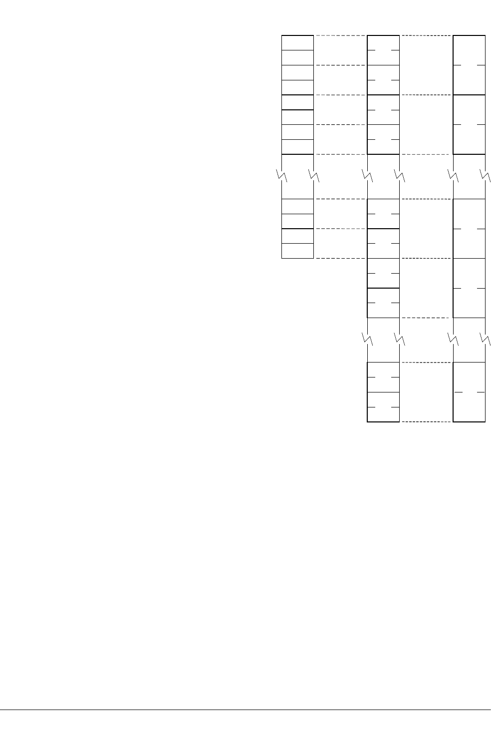
D0
D3
D31
D30
S0
S1
S2
S3
S4
S5
S28
S29
S6
S7
S30
S31
...
D1
D2
D14
D15
D16
D17
...
Q0
Q1
Q7
Q8
Q15
...
...
...
Figure 8-1 Extension register bank
The mapping between the registers is as follows:
•S<2n> maps to the least significant half of D<n>.
•S<2n+1> maps to the most significant half of D<n>.
•D<2n> maps to the least significant half of Q<n>.
•D<2n+1> maps to the most significant half of Q<n>.
For example, you can access the least significant half of the elements of a vector in Q6 by
referring to D12, and the most significant half of the elements by referring to D13.
Related concepts
8.5 NEON views of the register bank on page 8-182.
8.6 VFP views of the extension register bank on page 8-183.
8 NEON and VFP Programming
8.4 Extension register bank mapping
ARM DUI0473J Copyright © 2010-2013 ARM. All rights reserved. 8-181
Non-Confidential

8.5 NEON views of the register bank
NEON technology can view the extension register bank as sixteen 128-bit registers, or as thirty-
two 64-bit registers, or as a combination of registers from these views.
The 128-bit registers are Q0-Q15. The 64-bit registers are D0-D31.
NEON technology views each register as containing a vector of 1, 2, 4, 8, or 16 elements, all of
the same size and type. Individual elements can also be accessed as scalars.
In NEON technology, the 64-bit registers are called doubleword registers and the 128-bit registers
are called quadword registers.
Related concepts
8.4 Extension register bank mapping on page 8-180.
8.6 VFP views of the extension register bank on page 8-183.
8 NEON and VFP Programming
8.5 NEON views of the register bank
ARM DUI0473J Copyright © 2010-2013 ARM. All rights reserved. 8-182
Non-Confidential

8.6 VFP views of the extension register bank
VFP can view the extension register bank as thirty-two 32-bit registers, or as either sixteen or
thirty-two 64-bit registers, depending on the VFP version.
In VFPv3 and VFPv3-FP16, you can view the extension register bank as:
• Thirty-two 64-bit registers, D0-D31.
• Thirty-two 32-bit registers, S0-S31. Only half of the register bank is accessible in this view.
• A combination of registers from these views.
In VFPv2, VFPv3-D16, and VFPv3-D16-FP16, you can view the extension register bank as:
• Sixteen 64-bit registers, D0-D15.
• Thirty-two 32-bit registers, S0-S31.
• A combination of registers from these views.
In VFP, 64-bit registers are called double-precision registers and can contain double-precision
floating-point values. 32-bit registers are called single-precision registers and can contain either a
single-precision or two half-precision floating-point values.
Related concepts
8.4 Extension register bank mapping on page 8-180.
8.5 NEON views of the register bank on page 8-182.
8 NEON and VFP Programming
8.6 VFP views of the extension register bank
ARM DUI0473J Copyright © 2010-2013 ARM. All rights reserved. 8-183
Non-Confidential

8.7 Load values to VFP and NEON registers
There are different ways to load immediate values into NEON and VFP registers.
In NEON technology and in VFPv3 and later, the VMOV and VMVN instructions load a limited range
of floating-point immediate values.
The NEON VMOV and VMVN instructions can also load integer immediates.
You can load any 64-bit integer, single-precision, or double-precision floating-point value from a
literal pool, in a single instruction, using the VLDR pseudo-instruction.
Related references
12.56 VLDR pseudo-instruction on page 12-657.
12.68 VMOV (floating-point) on page 12-669.
12.69 VMOV (immediate) on page 12-670.
8 NEON and VFP Programming
8.7 Load values to VFP and NEON registers
ARM DUI0473J Copyright © 2010-2013 ARM. All rights reserved. 8-184
Non-Confidential

8.8 Conditional execution of NEON and VFP instructions
You can execute VFP instructions conditionally, in the same way as ARM and Thumb
instructions. Most NEON instructions always execute unconditionally.
In ARM state, you can use a condition code to control the execution of VFP instructions. The
instruction is executed conditionally, according to the status flags in the APSR, in exactly the
same way as almost all other ARM instructions.
In ARM state, except for the instructions that are common to both VFP and NEON, you cannot
use a condition code to control the execution of NEON instructions.
In Thumb state, you can use an IT instruction to set condition codes on up to four following
NEON or VFP instructions. However, ARM deprecates the use of any NEON instruction that does
not also exist in VFP, in an IT block.
Related references
5.6 Comparison of condition code meanings on page 5-111.
10.8 Condition codes on page 10-317.
8 NEON and VFP Programming
8.8 Conditional execution of NEON and VFP instructions
ARM DUI0473J Copyright © 2010-2013 ARM. All rights reserved. 8-185
Non-Confidential

8.9 Floating-point exceptions
The NEON and VFP extensions record floating-point exceptions in the FPSCR cumulative flags.
They record the following exceptions:
Invalid operation
The exception is caused if the result of an operation has no mathematical value or cannot
be represented.
Division by zero
The exception is caused if a divide operation has a zero divisor and a dividend that is not
zero, an infinity or a NaN.
Overflow
The exception is caused if the absolute value of the result of an operation, produced after
rounding, is greater than the maximum positive normalized number for the destination
precision.
Underflow
The exception is caused if the absolute value of the result of an operation, produced
before rounding, is less than the minimum positive normalized number for the destination
precision, and the rounded result is inexact.
Inexact
The exception is caused if the result of an operation is not equivalent to the value that
would be produced if the operation were performed with unbounded precision and
exponent range.
Input denormal
The exception is caused if a denormalized input operand is replaced in the computation
by a zero.
The descriptions of NEON and VFP instructions that can cause floating-point exceptions include a
subsection listing the exceptions. If there is no such subsection, that instruction cannot cause any
floating-point exception. See also the Technical Reference Manual for your processor.
Related concepts
8.18 Flush-to-zero mode on page 8-195.
Related references
12 NEON and VFP Instructions on page 12-592.
Related information
ARM Architecture Reference Manual.
Further reading.
8 NEON and VFP Programming
8.9 Floating-point exceptions
ARM DUI0473J Copyright © 2010-2013 ARM. All rights reserved. 8-186
Non-Confidential

8.10 NEON and VFP data types
Most NEON and VFP instructions use a data type specifier to define the size and type of data that
the instruction operates on.
Data type specifiers in NEON and VFP instructions usually consist of a letter indicating the type
of data, followed by a number indicating the width. They are separated from the instruction
mnemonic by a point.
The following table shows the data type specifiers available in NEON instructions:
Table 8-1 NEON data type specifiers
8-bit 16-bit 32-bit 64-bit
Unsigned integer U8 U16 U32 U64
Signed integer S8 S16 S32 S64
Integer of unspecified type I8 I16 I32 I64
Floating-point number not available F16 F32 (or F) not available
Polynomial over {0,1} P8 P16 not available not available
The following table shows the data type specifiers available in VFP instructions:
Table 8-2 VFP data type specifiers
16-bit 32-bit 64-bit
Unsigned integer U16 U32 not available
Signed integer S16 S32 not available
Floating-point number F16 F32 (or F)F64 (or D)
The data type of the second (or only) operand is specified in the instruction.
Note
• Most instructions have a restricted range of permitted data types. See the instruction pages for
details. However, the data type description is flexible:
— If the description specifies I, you can also use S or U data types.
— If only the data size is specified, you can specify a type (I, S, U, P or F).
— If no data type is specified, you can specify a data type.
• The F16 data type is only available on systems that implement the half-precision architecture
extension.
Related concepts
8.16 Polynomial arithmetic over {0,1} on page 8-193.
8 NEON and VFP Programming
8.10 NEON and VFP data types
ARM DUI0473J Copyright © 2010-2013 ARM. All rights reserved. 8-187
Non-Confidential

8.11 NEON vectors
NEON registers holding more than one element of the same size and type are called vectors.
NEON technology supports 64-bit doubleword vectors and 128-bit quadword vectors.
An operand in a NEON instruction can be a vector or a scalar.
The size of the elements in a NEON vector is defined by the data type specifier appended to the
instruction mnemonic.
Doubleword vectors can contain:
• Eight 8-bit elements.
• Four 16-bit elements.
• Two 32-bit elements.
• One 64-bit element.
Quadword vectors can contain:
• Sixteen 8-bit elements.
• Eight 16-bit elements.
• Four 32-bit elements.
• Two 64-bit elements.
Related concepts
8.14 NEON scalars on page 8-191.
8.4 Extension register bank mapping on page 8-180.
8.15 Extended notation on page 8-192.
8.10 NEON and VFP data types on page 8-187.
8.12 Normal, long, wide, and narrow NEON operation on page 8-189.
8 NEON and VFP Programming
8.11 NEON vectors
ARM DUI0473J Copyright © 2010-2013 ARM. All rights reserved. 8-188
Non-Confidential

8.12 Normal, long, wide, and narrow NEON operation
Many NEON data processing instructions are available in long, wide and narrow variants. In long,
wide, and narrow operation, the result vector is a different width from one or both operand
vectors.
Normal operation
The operands are either doubleword or quadword vectors. The result vector is the same
width, and usually the same type, as the operand vectors, for example:
VADD.I16 D0, D1, D2
You can specify that the operands and result of a normal instruction must all be
quadwords by appending a Q to the instruction mnemonic. If you do this, the assembler
produces an error if the operands or result are not quadwords.
Long operation
The operands are doubleword vectors and the result is a quadword vector. The elements
of the result are usually twice the width of the elements of the operands, and the same
type.
Long operation is specified using an L appended to the instruction mnemonic, for
example:
VADDL.S16 Q0, D2, D3
Wide operation
One operand vector is doubleword and the other is quadword. The result vector is
quadword. The elements of the result and the first operand are twice the width of the
elements of the second operand.
Wide operation is specified using a W appended to the instruction mnemonic, for example:
VADDW.S16 Q0, Q1, D4
Narrow operation
The operands are quadword vectors, and the result is a doubleword vector. The elements
of the result are half the width of the elements of the operands.
Narrow operation is specified using an N appended to the instruction mnemonic, for
example:
VADDHN.I16 D0, Q1, Q2
Related concepts
8.11 NEON vectors on page 8-188.
8 NEON and VFP Programming
8.12 Normal, long, wide, and narrow NEON operation
ARM DUI0473J Copyright © 2010-2013 ARM. All rights reserved. 8-189
Non-Confidential

8.13 Saturating NEON instructions
Saturating instructions saturate the result to the value of the upper limit or lower limit if the result
overflows or underflows.
Saturating instructions are specified using a Q prefix between the V and the instruction mnemonic.
The following table shows the ranges that NEON saturating instructions saturate to, where x is the
result of the operation:
Table 8-3 NEON saturation ranges
Data type Saturation range of x
S8 –27 <= x < 27
S16 –215 <= x < 215
S32 –231 <= x < 231
S64 –263 <= x < 263
U8 0 <= x < 28
U16 0 <= x < 216
U32 0 <= x < 232
U64 0 <= x < 264
Related references
10.7 Saturating instructions on page 10-316.
8 NEON and VFP Programming
8.13 Saturating NEON instructions
ARM DUI0473J Copyright © 2010-2013 ARM. All rights reserved. 8-190
Non-Confidential

8.14 NEON scalars
Some NEON instructions act on scalars in combination with vectors. NEON scalars can be 8-bit,
16-bit, 32-bit, or 64-bit.
The instruction syntax refers to the scalars using an index, x, into a doubleword vector, so that
Dm[x] is the xth element in vector Dm. Other than multiply instructions, instructions that access
scalars can access any element in the register bank.
Multiply instructions only allow 16-bit or 32-bit scalars, and can only access the first 32 scalars in
the register bank. That is, in multiply instructions:
• 16-bit scalars are restricted to registers D0-D7, with x in the range 0-3.
• 32-bit scalars are restricted to registers D0-D15, with x either 0 or 1.
Related concepts
8.11 NEON vectors on page 8-188.
8.4 Extension register bank mapping on page 8-180.
8 NEON and VFP Programming
8.14 NEON scalars
ARM DUI0473J Copyright © 2010-2013 ARM. All rights reserved. 8-191
Non-Confidential

8.15 Extended notation
The assembler supports an extension to the architectural NEON and VFP assembly syntax, called
extended notation. This allows you to define register names that include data type specifiers or
scalar indexes, for convenience.
If you use extended notation, you do not need to include the data type or scalar index information
in every instruction.
Register names can be any of the following:
Untyped
The register name specifies the register, but not what datatype it contains, nor any index
to a particular scalar within the register.
Untyped with scalar index
The register name specifies the register, but not what datatype it contains, It specifies an
index to a particular scalar within the register.
Typed
The register name specifies the register, and what datatype it contains, but not any index
to a particular scalar within the register.
Typed with scalar index
The register name specifies the register, what datatype it contains, and an index to a
particular scalar within the register.
Use the SN, DN, and QN directives to define names for typed and scalar registers.
Related concepts
8.11 NEON vectors on page 8-188.
8.10 NEON and VFP data types on page 8-187.
8.14 NEON scalars on page 8-191.
Related references
14.55 QN, DN, and SN on page 14-833.
8 NEON and VFP Programming
8.15 Extended notation
ARM DUI0473J Copyright © 2010-2013 ARM. All rights reserved. 8-192
Non-Confidential

8.16 Polynomial arithmetic over {0,1}
The coefficients 0 and 1 are manipulated using the rules of Boolean arithmetic.
The following rules apply:
• 0 + 0 = 1 + 1 = 0.
• 0 + 1 = 1 + 0 = 1.
• 0 * 0 = 0 * 1 = 1 * 0 = 0.
• 1 * 1 = 1.
That is, adding two polynomials over {0,1} is the same as a bitwise exclusive OR, and multiplying
two polynomials over {0,1} is the same as integer multiplication except that partial products are
exclusive-ORed instead of being added.
Related concepts
8.10 NEON and VFP data types on page 8-187.
8 NEON and VFP Programming
8.16 Polynomial arithmetic over {0,1}
ARM DUI0473J Copyright © 2010-2013 ARM. All rights reserved. 8-193
Non-Confidential

8.17 NEON and VFP system registers
NEON technology and VFP share the same set of system registers.
The following NEON and VFP system registers are accessible in all implementations of NEON
and VFP:
• FPSCR, the floating-point status and control register.
• FPEXC, the floating-point exception register.
• FPSID, the floating-point system ID register.
A particular implementation of NEON or VFP can have additional registers. For more
information, see the Technical Reference Manual for your processor.
Related concepts
4.19 The Read-Modify-Write operation on page 4-92.
Related information
ARM Architecture Reference Manual.
Further reading.
8 NEON and VFP Programming
8.17 NEON and VFP system registers
ARM DUI0473J Copyright © 2010-2013 ARM. All rights reserved. 8-194
Non-Confidential

8.18 Flush-to-zero mode
Flush-to-zero mode replaces denormalized numbers with zero. This does not comply with IEEE
754 arithmetic, but in some circumstances can improve performance considerably.
Some implementations of VFP use support code to handle denormalized numbers. The
performance of such systems, in calculations involving denormalized numbers, is much less than
it is in normal calculations.
NEON and VFPv3 flush-to-zero preserves the sign bit. VFPv2 flush-to-zero flushes to +0.
NEON always uses flush-to-zero mode.
Related concepts
8.20 The effects of using flush-to-zero mode on page 8-197.
Related references
8.19 When to use flush-to-zero mode on page 8-196.
8.21 Operations not affected by flush-to-zero mode on page 8-198.
8 NEON and VFP Programming
8.18 Flush-to-zero mode
ARM DUI0473J Copyright © 2010-2013 ARM. All rights reserved. 8-195
Non-Confidential

8.19 When to use flush-to-zero mode
You can change between flush-to-zero mode and normal mode, depending on the requirements of
different parts of your code.
You must select flush-to-zero mode if all the following are true:
• IEEE 754 compliance is not a requirement for your system.
• The algorithms you are using sometimes generate denormalized numbers.
• Your system uses support code to handle denormalized numbers.
• The algorithms you are using do not depend for their accuracy on the preservation of
denormalized numbers.
• The algorithms you are using do not generate frequent exceptions as a result of replacing
denormalized numbers with 0.
You select flush-to-zero mode by setting the FZ bit in the FPSCR to 1. You do this using the VMRS
and VMSR instructions.
Numbers already in registers are not affected by changing mode.
Related concepts
8.18 Flush-to-zero mode on page 8-195.
8.20 The effects of using flush-to-zero mode on page 8-197.
8 NEON and VFP Programming
8.19 When to use flush-to-zero mode
ARM DUI0473J Copyright © 2010-2013 ARM. All rights reserved. 8-196
Non-Confidential

8.20 The effects of using flush-to-zero mode
In flush-to-zero mode, denormalized inputs are treated as zero. Results that are too small to be
represented in a normalized number are replaced with zero.
With certain exceptions, flush-to-zero mode has the following effects on floating-point operations:
• A denormalized number is treated as 0 when used as an input to a floating-point operation. The
source register is not altered.
• If the result of a single-precision floating-point operation, before rounding, is in the range –2–
126 to +2–126, it is replaced by 0.
• If the result of a double-precision floating-point operation, before rounding, is in the range –2–
1022 to +2–1022, it is replaced by 0.
In flush-to-zero mode, an Input Denormal exception occurs whenever a denormalized number is
used as an operand. An Underflow exception occurs when a result is flushed-to-zero.
Related concepts
8.18 Flush-to-zero mode on page 8-195.
Related references
8.21 Operations not affected by flush-to-zero mode on page 8-198.
8 NEON and VFP Programming
8.20 The effects of using flush-to-zero mode
ARM DUI0473J Copyright © 2010-2013 ARM. All rights reserved. 8-197
Non-Confidential

8.21 Operations not affected by flush-to-zero mode
Some NEON and VFP instructions can be carried out on denormalized numbers even in flush-to-
zero mode, without flushing the results to zero.
These instructions are as follows:
• Copy, absolute value, and negate (VMOV, VMVN, V{Q}ABS, and V{Q}NEG).
• Duplicate (VDUP).
• Swap (VSWP).
• Load and store (VLDR and VSTR).
• Load multiple and store multiple (VLDM and VSTM).
• Transfer between extension registers and ARM general-purpose registers (VMOV).
Related concepts
8.18 Flush-to-zero mode on page 8-195.
8.20 The effects of using flush-to-zero mode on page 8-197.
Related references
12.8 VABS on page 12-606.
12.9 VABS (floating-point) on page 12-607.
12.43 VDUP on page 12-641.
12.53 VLDM on page 12-654.
12.54 VLDR on page 12-655.
12.70 VMOV (register) on page 12-671.
12.71 VMOV (between one ARM register and single precision VFP) on page 12-672.
12.72 VMOV (between two ARM registers and an extension register) on page 12-673.
12.73 VMOV (between an ARM register and a NEON scalar) on page 12-674.
12.145 VSWP on page 12-749.
8 NEON and VFP Programming
8.21 Operations not affected by flush-to-zero mode
ARM DUI0473J Copyright © 2010-2013 ARM. All rights reserved. 8-198
Non-Confidential

8.22 VFP vector mode
VFP vector mode allows you to use VFP instructions on vectors of floating-point numbers. ARM
deprecates VFP vector mode.
Usually the VFP core only works on a single register. However, many VFP arithmetic instructions
can also operate on vectors of up to eight single-precision or four double-precision numbers,
enabling Single Instruction Multiple Data (SIMD) vectorization.
In addition, the floating-point load and store instructions have multiple register forms, enabling
vectors to be transferred to and from memory easily.
Note
ARM deprecates the use of VFP vector mode.
Related concepts
8.1 Architecture support for NEON and VFP on page 8-177.
8.23 Vectors in the VFP extension register bank on page 8-200.
Related information
ARM Architecture Reference Manual.
8 NEON and VFP Programming
8.22 VFP vector mode
ARM DUI0473J Copyright © 2010-2013 ARM. All rights reserved. 8-199
Non-Confidential
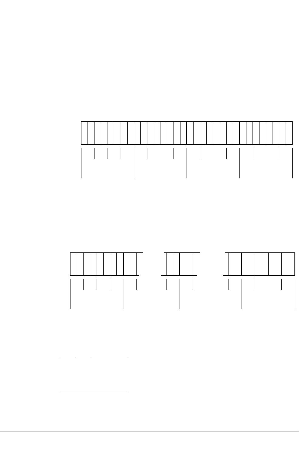
8.23 Vectors in the VFP extension register bank
In VFP vector mode, the VFP extension register bank can be viewed as a collection of smaller
banks. A vector consists of multiple registers from the same bank. Each of these smaller banks is
treated either as a bank of 8 single-precision registers or 4 double-precision registers.
In VFPv2, VFPv3-D16, and VFPv3-D16-FP16 the VFP extension register bank can be viewed as
a collection of:
• Four banks of single-precision registers, s0 to s7, s8 to s15, s16 to s23, and s24 to s31.
• Four banks of double-precision registers, d0 to d3, d4 to d7, d8 to d11, and d12 to d15.
• Any combination of single-precision and double-precision banks.
Bank 0 Bank 1 Bank 2 Bank 3
d0 d1 d3 d4 d7 d8 d11 d12 d15d2 ...... ...
s0s1 s7s8 s15s16 s23s24 s31s2s3s4s5s6 ... ... ...
Figure 8-2 VFPv2 register banks
In VFPv3 and VFPv3-FP16, the VFP extension register bank can be viewed as a collection of:
• Four banks of single-precision registers, s0 to s7, s8 to s15, s16 to s23, and s24 to s31.
• Eight banks of double-precision registers, d0 to d3, d4 to d7, d8 to d11, d12 to d15, d16 to d19,
d20 to d23, d24 to d27, and d28 to d31.
• Any combination of single-precision and double-precision banks.
Bank 0 Bank 1 Bank 3
d0 d1 d3 d4 d16 d27 d28d15d2 ...
s0s1 s7s8 s31s2s3s4s5s6
...
d31
Bank 7Bank 4 Bank 6
...
Figure 8-3 VFPv3 register banks
A vector, in a VFP instruction, can use up to eight single-precision registers, or four double-
precision registers, from the same bank. The number of registers used by a vector is controlled by
the LEN bits in the FPSCR.
Note
The value of the LEN bits is not a sufficient condition to perform vector operations using VFP.
Whether a VFP operation is scalar, vector or mixed depends on which bank the specified operand
and destination registers are in.
A vector can start from any register and wraps around to the beginning of the bank. The first
register used by an operand vector is the register that is specified as the operand in the individual
8 NEON and VFP Programming
8.23 Vectors in the VFP extension register bank
ARM DUI0473J Copyright © 2010-2013 ARM. All rights reserved. 8-200
Non-Confidential

VFP instructions. The first register used by the destination vector is the register that is specified as
the destination in the individual VFP instructions.
Related concepts
8.24 VFP vector wrap-around on page 8-202.
8.25 VFP vector stride on page 8-203.
8.26 Restriction on vector length on page 8-204.
8.27 Control of scalar, vector, and mixed operations on page 8-205.
Related information
ARM Architecture Reference Manual.
8 NEON and VFP Programming
8.23 Vectors in the VFP extension register bank
ARM DUI0473J Copyright © 2010-2013 ARM. All rights reserved. 8-201
Non-Confidential

8.24 VFP vector wrap-around
In VFP vector mode, if a vector extends beyond the end of a bank, it wraps around to the
beginning of the same bank.
For example:
• A vector of length 6 starting at s5 is {s5, s6, s7, s0, s1, s2}.
• A vector of length 3 starting at s15 is {s15, s8, s9}.
• A vector of length 4 starting at s22 is {s22, s23, s16, s17}.
• A vector of length 2 starting at d7 is {d7, d4}.
• A vector of length 3 starting at d10 is {d10, d11, d8}.
A vector cannot contain registers from more than one bank.
Related concepts
8.23 Vectors in the VFP extension register bank on page 8-200.
8.25 VFP vector stride on page 8-203.
8.26 Restriction on vector length on page 8-204.
Related information
ARM Architecture Reference Manual.
8 NEON and VFP Programming
8.24 VFP vector wrap-around
ARM DUI0473J Copyright © 2010-2013 ARM. All rights reserved. 8-202
Non-Confidential

8.25 VFP vector stride
In VFP vector mode, vectors can occupy consecutive or alternate registers. This is controlled by
the STRIDE bits in the FPSCR.
For example:
• A vector of length 3, stride 2, starting at s1, is {s1, s3, s5}.
• A vector of length 4, stride 2, starting at s6, is {s6, s0, s2, s4}.
• A vector of length 2, stride 2, starting at d1, is {d1, d3}.
• A vector of length 4, stride 1, starting at d0, is {d0, d1, d2, d3}.
Related concepts
8.23 Vectors in the VFP extension register bank on page 8-200.
8.24 VFP vector wrap-around on page 8-202.
8.26 Restriction on vector length on page 8-204.
Related information
ARM Architecture Reference Manual.
8 NEON and VFP Programming
8.25 VFP vector stride
ARM DUI0473J Copyright © 2010-2013 ARM. All rights reserved. 8-203
Non-Confidential

8.26 Restriction on vector length
In VFP vector mode, a vector cannot use the same register twice. This means that vector length is
restricted.
Enabling for vector wrap-around, you cannot have:
• A single-precision vector with length > 4 and stride = 2.
• A double-precision vector with length > 4 and stride = 1.
• A double-precision vector with length > 2 and stride = 2.
Related concepts
8.23 Vectors in the VFP extension register bank on page 8-200.
8.24 VFP vector wrap-around on page 8-202.
Related information
ARM Architecture Reference Manual.
8 NEON and VFP Programming
8.26 Restriction on vector length
ARM DUI0473J Copyright © 2010-2013 ARM. All rights reserved. 8-204
Non-Confidential

8.27 Control of scalar, vector, and mixed operations
Whether a VFP arithmetic instruction operates on scalars, vectors, or a mixture of both depends on
the LEN bits in the FPSCR and also on which register bank the destination and operand registers
are in.
Use the LEN bits in the FPSCR to control the length of vectors. When LEN is 1 all VFP operations
are scalar.
When LEN is greater than 1, the VFP operation can be scalar, vector or mixed. The behavior of
VFP arithmetic operations depends on which register bank the destination and operand registers
are in.
The first bank of registers, s0 to s7 or d0 to d3 and the fifth bank of registers d16 to d19 are scalar
banks. All other banks are vector banks. A vector operation or mixed operation is one where the
destination register is in one of the vector banks.
Given instructions of the following general forms:
Op Fd,Fn,Fm
Op Fd,Fm
where:
Op
is the VFP instruction.
Fd
is the destination register.
Fn
is an operand register.
Fm
is the only or second operand register.
the behavior of the operation is as follows:
• If Fd is in the first or fifth bank of registers then the operation is scalar.
• If Fm is in the first or fifth bank of registers, but Fd is not, then the operation is mixed.
• If neither Fd nor Fm are in the first or fifth bank of registers, the operation is vector.
In scalar operations, Op acts on the value in Fm, and the value in Fn if present. The result is placed
in Fd.
In vector operations, Op acts on the values in the vector starting at Fm, together with the values in
the vector starting at Fn if present. The results are placed in the vector starting at Fd.
In mixed operations, with a single operand, Op acts on the single value in Fm and LEN copies of
the result are placed in the vector starting at Fd.
In mixed operations, with two operands, Op acts on the single value in Fm, together with the values
in the vector starting at Fn. The results are placed in the vector starting at Fd.
Related concepts
8.23 Vectors in the VFP extension register bank on page 8-200.
8.24 VFP vector wrap-around on page 8-202.
8.25 VFP vector stride on page 8-203.
8.26 Restriction on vector length on page 8-204.
Related information
ARM Architecture Reference Manual.
8 NEON and VFP Programming
8.27 Control of scalar, vector, and mixed operations
ARM DUI0473J Copyright © 2010-2013 ARM. All rights reserved. 8-205
Non-Confidential

8.28 Overview of VFP directives and vector notation
To use vector notation, you must use pre-UAL syntax and mnemonics. You can use assembler
directives to check you are using the correct syntax.
This applies only to armasm. The inline assemblers in the C and C++ compilers do not accept
these directives or vector notation.
The use of VFP vector mode is deprecated, and vector notation is not supported in UAL. To use
vector notation, you must use the pre-UAL mnemonics. You can mix pre-UAL VFP mnemonics
and UAL VFP mnemonics.
You can make assertions about VFP vector lengths and strides in your code, and have them
checked by the assembler, by using the following directives:
•VFPASSERT SCALAR.
•VFPASSERT VECTOR.
If you use the VFPASSERT directives, you must specify vector details in all VFP data processing
instructions written using pre-UAL mnemonics. If you do not use the VFPASSERT directives you
must not use this notation.
Related concepts
8.29 Pre-UAL VFP syntax and mnemonics on page 8-207.
Related references
8.31 VFPASSERT SCALAR on page 8-210.
8.32 VFPASSERT VECTOR on page 8-211.
8.30 Vector notation on page 8-209.
8 NEON and VFP Programming
8.28 Overview of VFP directives and vector notation
ARM DUI0473J Copyright © 2010-2013 ARM. All rights reserved. 8-206
Non-Confidential

8.29 Pre-UAL VFP syntax and mnemonics
There are differences between pre-UAL and UAL syntax and mnemonics for VFP instructions.
Where UAL mnemonics use .F32 to specify single-precision data, pre-UAL mnemonics use S
appended to the instruction mnemonic. For example, VABS.F32 was FABSS.
Where UAL mnemonics use .F64 to specify double-precision data, pre-UAL mnemonics use D
appended to the instruction mnemonic. For example, VCMPE.F64 was FCMPED.
Pre-UAL VFP mnemonics
The following table shows the pre-UAL mnemonics of those instructions that are affected by VFP
vector mode. All other VFP instructions are always scalar regardless of the settings of LEN and
STRIDE.
Table 8-4 Pre-UAL VFP mnemonics
UAL mnemonic Equivalent pre-UAL mnemonic
VABS FABS
VADD FADD
VDIV FDIV
VMLA FMAC
VMLS FNMAC
VMOV (immediate) FCONST a
VMOV (register) FCPY
VMUL FMUL
VNEG FNEG
VNMLA FNMSC
VNMLS FMSC
VNMUL FNMUL
VSQRT FSQRT
VSUB FSUB
Immediate values in FCONST
The following table shows the floating-point values you can load using FCONST. Trailing zeroes
are omitted for clarity. The immediate value you must put in the FCONST instruction is the decimal
representation of the binary number abcdefgh, where:
a
is 0 for positive numbers, or 1 for negative numbers.
bcd
is shown in the column headings.
efgh
is shown in the row headings.
aThe immediate in VMOV (immediate) is the floating-point number you want to load. The immediate in FCONST is the
number encoded in the instruction to produce the floating-point number you want to load.
8 NEON and VFP Programming
8.29 Pre-UAL VFP syntax and mnemonics
ARM DUI0473J Copyright © 2010-2013 ARM. All rights reserved. 8-207
Non-Confidential

Alternatively, you can use 0x followed by the hexadecimal representation.
Table 8-5 Floating-point values for use with FCONST
bcd 000 001 010 011 100 101 110 111
efgh
0000 2.0 4.0 8.0 16.0 0.125 0.25 0.5 1.0
0001 2.125 4.25 8.5 17.0 0.1328125 0.265625 0.53125 1.0625
0010 2.25 4.5 9.0 18.0 0.140625 0.28125 0.5625 1.125
0011 2.375 4.75 9.5 19.0 0.1484375 0.296875 0.59375 1.1875
0100 2.5 5.0 10.0 20.0 0.15625 0.3125 0.625 1.25
0101 2.625 5.25 10.5 21.0 0.1640625 0.328125 0.65625 1.3125
0110 2.75 5.5 11.0 22.0 0.171875 0.34375 0.6875 1.375
0111 2.875 5.75 11.5 23.0 0.1796875 0.359375 0.71875 1.4375
1000 3.0 6.0 12.0 24.0 0.1875 0.375 0.75 1.5
1001 3.125 6.25 12.5 25.0 0.1953125 0.390625 0.78125 1.5625
1010 3.25 6.5 13.0 26.0 0.203125 0.40625 0.8125 1.625
1011 3.375 6.75 13.5 27.0 0.2109375 0.421875 0.84375 1.6875
1100 3.5 7.0 14.0 28.0 0.21875 0.4375 0.875 1.75
1101 3.625 7.25 14.5 29.0 0.2265625 0.453125 0.90625 1.8125
1110 3.75 7.5 15.0 30.0 0.234375 0.46875 0.9375 1.875
1111 3.875 7.75 15.5 31.0 0.2421875 0.484375 0.96875 1.9375
8 NEON and VFP Programming
8.29 Pre-UAL VFP syntax and mnemonics
ARM DUI0473J Copyright © 2010-2013 ARM. All rights reserved. 8-208
Non-Confidential

8.30 Vector notation
In vector notation, you specify vectors of VFP registers using angle brackets.
You specify scalar and vector registers in pre-UAL VFP data processing instructions as follows:
•sn is a single-precision scalar register n.
•sn<> is a single-precision vector whose length and stride are given by the current vector
length and stride, as defined by VFPASSERT VECTOR. The vector starts at register n.
•sn<L> is a single-precision vector of length L, stride 1. The vector starts at register n.
•sn<L:S> is a single-precision vector of length L, stride S. The vector starts at register n.
•dn is a double-precision scalar register n.
•dn<> is a double-precision vector whose length and stride are given by the current vector
length and stride, as defined by VFPASSERT VECTOR. The vector starts at register n.
•dn<L> is a double-precision vector of length L, stride 1. The vector starts at register n.
•dn<L:S> is a double-precision vector of length L, stride S. The vector starts at register n.
You can use this vector notation with names defined using the DN and SN directives.
You must not use this vector notation in the DN and SN directives themselves.
Related references
8.31 VFPASSERT SCALAR on page 8-210.
8.32 VFPASSERT VECTOR on page 8-211.
14.55 QN, DN, and SN on page 14-833.
8 NEON and VFP Programming
8.30 Vector notation
ARM DUI0473J Copyright © 2010-2013 ARM. All rights reserved. 8-209
Non-Confidential

8.31 VFPASSERT SCALAR
The VFPASSERT SCALAR directive informs the assembler that the following VFP instructions are
in scalar mode. This forces the instruction syntax to be scalar.
Syntax
VFPASSERT SCALAR
Usage
Use the VFPASSERT SCALAR directive to mark the end of any block of code where the VFP mode
is VECTOR.
Place the VFPASSERT SCALAR directive immediately after the instruction where the change
occurs. This is usually an FMXR instruction, but might be a BL instruction.
If a function expects VFP to be in vector mode on exit, place a VFPASSERT SCALAR directive
immediately after the last instruction. Such a function would not be AAPCS compliant.
Note
This directive does not generate any code. It is only an assertion by the programmer. The
assembler produces error messages if any such assertions are inconsistent with each other, or with
any vector notation in VFP data processing instructions.
The assembler faults vector notation in VFP data processing instructions following a VFPASSERT
SCALAR directive, even if the vector length is 1.
Example
VFPASSERT SCALAR ; scalar mode
faddd d4, d4, d0 ; okay
fadds s4<3>, s8<3>, s0 ; ERROR, vectors in scalar mode
fabss s24<1>, s28<1> ; ERROR, vectors in scalar mode
; (even though length==1)
Related references
8.30 Vector notation on page 8-209.
8.32 VFPASSERT VECTOR on page 8-211.
Related information
Procedure Call Standard for the ARM Architecture.
8 NEON and VFP Programming
8.31 VFPASSERT SCALAR
ARM DUI0473J Copyright © 2010-2013 ARM. All rights reserved. 8-210
Non-Confidential

8.32 VFPASSERT VECTOR
The VFPASSERT VECTOR directive informs the assembler that the following VFP instructions are
in vector mode. It can also specify the length and stride of the vectors.
Syntax
VFPASSERT VECTOR{<{n{:s}}>}
where:
n
is the vector length, 1-8.
s
is the vector stride, 1-2.
Usage
Use the VFPASSERT VECTOR directive to mark the start of a block of instructions where the VFP
mode is VECTOR, and to mark changes in the length or stride of vectors.
Place the VFPASSERT VECTOR directive immediately after the instruction where the change
occurs. This is usually an FMXR instruction, but might be a BL instruction.
If a function expects VFP to be in vector mode on entry, place a VFPASSERT VECTOR directive
immediately before the first instruction. Such a function would not be AAPCS compliant.
Note
This directive does not generate any code. It is only an assertion by the programmer. The
assembler produces error messages if any such assertions are inconsistent with each other, or with
any vector notation in VFP data processing instructions.
Example
VMRS r10,FPSCR ; UAL mnemonic - could be FMRX instead.
BIC r10,r10,#0x00370000
ORR r10,r10,#0x00020000 ; set length = 3, stride = 1
VMSR FPSCR,r10
VFPASSERT VECTOR ; assert vector mode, unspecified length
; and stride
faddd d4, d4, d0 ; ERROR, scalars in vector mode
fadds s16<3>, s8<3>, s0 ; okay
fabss s24<1>, s28<1> ; wrong length, but not faulted
; (unspecified)
VMRS r10,FPSCR
BIC r10,r10,#0x00370000
ORR r10,r10,#0x00030000 ; set length = 4, stride = 1
VMSR FPSCR,r10
VFPASSERT VECTOR<4> ; assert vector mode, length 4, stride 1
fadds s24<4>, s8<4>, s0 ; okay
fabss s24<2>, s24<2> ; ERROR, wrong length
VMRS r10,FPSCR
BIC r10,r10,#0x00370000
ORR r10,r10,#0x00130000 ; set length = 4, stride = 2
VMSR FPSCR,r10
VFPASSERT VECTOR<4:2> ; assert vector mode, length 4, stride 2
fadds s8<4>, s16<4>, s0 ; ERROR, wrong stride because omitting
; stride causes a default stride of 1.
fabss s16<4:2>, s28<4:2> ; okay
fadds s8<>, s16<>, s2 ; okay (s8 and s16 both have
; length 4 and stride 2. s2 is scalar.)
Related references
8.30 Vector notation on page 8-209.
8.31 VFPASSERT SCALAR on page 8-210.
8 NEON and VFP Programming
8.32 VFPASSERT VECTOR
ARM DUI0473J Copyright © 2010-2013 ARM. All rights reserved. 8-211
Non-Confidential


Chapter 9
Assembler Command-line Options
Describes the command-line options supported by the ARM assembler, armasm.
It contains the following:
• 9.1 --16 on page 9-216.
• 9.2 --32 on page 9-217.
• 9.3 --apcs=qualifier…qualifier on page 9-218.
• 9.4 --arm on page 9-220.
• 9.5 --arm_only on page 9-221.
• 9.6 --bi on page 9-222.
• 9.7 --bigend on page 9-223.
• 9.8 --brief_diagnostics, --no_brief_diagnostics on page 9-224.
• 9.9 --checkreglist on page 9-225.
• 9.10 --compatible=name on page 9-226.
• 9.11 --cpreproc on page 9-227.
• 9.12 --cpreproc_opts=options on page 9-228.
• 9.13 --cpu=list on page 9-229.
• 9.14 --cpu=name on page 9-230.
• 9.15 --debug on page 9-234.
• 9.16 --depend=dependfile on page 9-235.
• 9.17 --depend_format=string on page 9-236.
• 9.18 --device=list on page 9-237.
• 9.19 --device=name on page 9-238.
• 9.20 --diag_error=tag[,tag,…] on page 9-239.
ARM DUI0473J Copyright © 2010-2013 ARM. All rights reserved. 9-213
Non-Confidential

• 9.21 --diag_remark=tag[,tag,…] on page 9-240.
• 9.22 --diag_style={arm|ide|gnu} on page 9-241.
• 9.23 --diag_suppress=tag[,tag,…] on page 9-242.
• 9.24 --diag_warning=tag[,tag,…] on page 9-243.
• 9.25 --dllexport_all on page 9-244.
• 9.26 --dwarf2 on page 9-245.
• 9.27 --dwarf3 on page 9-246.
• 9.28 --errors=errorfile on page 9-247.
• 9.29 --execstack, --no_execstack on page 9-248.
• 9.30 --execute_only on page 9-249.
• 9.31 --exceptions, --no_exceptions on page 9-250.
• 9.32 --exceptions_unwind, --no_exceptions_unwind on page 9-251.
• 9.33 --fpmode=model on page 9-252.
• 9.34 --fpu=list on page 9-253.
• 9.35 --fpu=name on page 9-254.
• 9.36 -g on page 9-256.
• 9.37 --help on page 9-257.
• 9.38 -idir{,dir, …} on page 9-258.
• 9.39 --keep on page 9-259.
• 9.40 --length=n on page 9-260.
• 9.41 --li on page 9-261.
• 9.42 --library_type=lib on page 9-262.
• 9.43 --licretry on page 9-263.
• 9.44 --list=file on page 9-264.
• 9.45 --list= on page 9-265.
• 9.46 --littleend on page 9-266.
• 9.47 -m on page 9-267.
• 9.48 --maxcache=n on page 9-268.
• 9.49 --md on page 9-269.
• 9.50 --no_code_gen on page 9-270.
• 9.51 --no_esc on page 9-271.
• 9.52 --no_hide_all on page 9-272.
• 9.53 --no_regs on page 9-273.
• 9.54 --no_terse on page 9-274.
• 9.55 --no_warn on page 9-275.
• 9.56 -o filename on page 9-276.
• 9.57 --pd on page 9-277.
• 9.58 --predefine "directive" on page 9-278.
• 9.59 --reduce_paths, --no_reduce_paths on page 9-279.
• 9.60 --regnames=none on page 9-280.
• 9.61 --regnames=callstd on page 9-281.
• 9.62 --regnames=all on page 9-282.
• 9.63 --report-if-not-wysiwyg on page 9-283.
• 9.64 --show_cmdline on page 9-284.
• 9.65 --split_ldm on page 9-285.
• 9.66 --thumb on page 9-286.
• 9.67 --thumbx on page 9-287.
• 9.68 --unaligned_access, --no_unaligned_access on page 9-288.
• 9.69 --unsafe on page 9-289.
9 Assembler Command-line Options
ARM DUI0473J Copyright © 2010-2013 ARM. All rights reserved. 9-214
Non-Confidential

• 9.70 --untyped_local_labels on page 9-290.
• 9.71 --version_number on page 9-291.
• 9.72 --via=filename on page 9-292.
• 9.73 --vsn on page 9-293.
• 9.74 --width=n on page 9-294.
• 9.75 --xref on page 9-295.
9 Assembler Command-line Options
ARM DUI0473J Copyright © 2010-2013 ARM. All rights reserved. 9-215
Non-Confidential

9.1 --16
Instructs the assembler to interpret instructions as Thumb instructions using the pre-UAL Thumb
syntax.
This option is equivalent to a CODE16 directive at the head of the source file. Use the --thumb
option to specify Thumb instructions using the UAL syntax.
Related references
9.66 --thumb on page 9-286.
14.7 ARM, THUMB, THUMBX, CODE16, and CODE32 on page 14-778.
9 Assembler Command-line Options
9.1 --16
ARM DUI0473J Copyright © 2010-2013 ARM. All rights reserved. 9-216
Non-Confidential


9.3 --apcs=qualifier…qualifier
Controls interworking and position independence when generating code.
Syntax
--apcs=qualifier...qualifier
Where qualifier...qualifier denotes a list of qualifiers. There must be:
• At least one qualifier present.
• No spaces or commas separating individual qualifiers in the list.
Each instance of qualifier must be one of:
none
Specifies that the input file does not use AAPCS. AAPCS registers are not set up. Other
qualifiers are not permitted if you use none.
/interwork, /nointerwork
/interwork specifies that the code in the input file can interwork between ARM and
Thumb safely. The default is /nointerwork.
/inter, /nointer
Are synonyms for /interwork and /nointerwork.
/ropi, /noropi
/ropi specifies that the code in the input file is Read-Only Position-Independent
(ROPI). The default is /noropi.
/pic, /nopic
Are synonyms for /ropi and /noropi.
/rwpi, /norwpi
/rwpi specifies that the code in the input file is Read-Write Position-Independent
(RWPI). The default is /norwpi.
/pid, /nopid
Are synonyms for /rwpi and /norwpi.
/fpic, /nofpic
/fpic specifies that the code in the input file is read-only independent and references to
addresses are suitable for use in a Linux shared object. The default is /nofpic.
/hardfp, /softfp
Requests hardware or software floating-point linkage. This enables the procedure call
standard to be specified separately from the version of the floating-point hardware
available through the --fpu option. It is still possible to specify the procedure call
standard by using the --fpu option, but ARM recommends you use --apcs. If floating-
point support is not permitted (for example, because --fpu=none is specified, or
because of other means), then /hardfp and /softfp are ignored. If floating-point
support is permitted and the softfp calling convention is used (--fpu=softvfp or --
fpu=softvfp+vfp...), then /hardfp gives an error.
Usage
This option specifies whether you are using the Procedure Call Standard for the ARM
Architecture (AAPCS). It can also specify some attributes of code sections.
The AAPCS forms part of the Base Standard Application Binary Interface for the ARM
Architecture (BSABI) specification. By writing code that adheres to the AAPCS, you can ensure
that separately compiled and assembled modules can work together.
Note
AAPCS qualifiers do not affect the code produced by the assembler. They are an assertion by the
programmer that the code in the input file complies with a particular variant of AAPCS. They
9 Assembler Command-line Options
9.3 --apcs=qualifier…qualifier
ARM DUI0473J Copyright © 2010-2013 ARM. All rights reserved. 9-218
Non-Confidential

cause attributes to be set in the object file produced by the assembler. The linker uses these
attributes to check compatibility of files, and to select appropriate library variants.
Example
armasm --apcs=/inter/ropi inputfile.s
Related information
Procedure Call Standard for the ARM Architecture.
--apcs=qualifier...qualifier compiler option.
Interworking ARM and Thumb.
Application Binary Interface (ABI) for the ARM Architecture.
9 Assembler Command-line Options
9.3 --apcs=qualifier…qualifier
ARM DUI0473J Copyright © 2010-2013 ARM. All rights reserved. 9-219
Non-Confidential

9.4 --arm
Targets the ARM instruction set. The assembler is permitted to generate both ARM and Thumb
code, but recognizes that ARM code is preferred.
This option instructs the assembler to interpret instructions as ARM instructions. It does not,
however, guarantee ARM-only code in the object file. This is the default. Using this option is
equivalent to specifying the ARM or CODE32 directive at the start of the source file.
Related references
9.2 --32 on page 9-217.
9.5 --arm_only on page 9-221.
14.7 ARM, THUMB, THUMBX, CODE16, and CODE32 on page 14-778.
9 Assembler Command-line Options
9.4 --arm
ARM DUI0473J Copyright © 2010-2013 ARM. All rights reserved. 9-220
Non-Confidential

9.5 --arm_only
Enforces ARM-only code. The assembler behaves as if Thumb is absent from the target
architecture.
This option instructs the assembler to only generate ARM code. This is similar to --arm but also
has the property that the assembler does not permit the generation of any Thumb code.
Related references
9.4 --arm on page 9-220.
9 Assembler Command-line Options
9.5 --arm_only
ARM DUI0473J Copyright © 2010-2013 ARM. All rights reserved. 9-221
Non-Confidential


9.8 --brief_diagnostics, --no_brief_diagnostics
Enables and disables the output of brief diagnostic messages.
This option instructs the assembler whether to use a shorter form of the diagnostic output. In this
form, the original source line is not displayed and the error message text is not wrapped when it is
too long to fit on a single line. The default is --no_brief_diagnostics.
Related references
9.20 --diag_error=tag[,tag,…] on page 9-239.
9.24 --diag_warning=tag[,tag,…] on page 9-243.
9 Assembler Command-line Options
9.8 --brief_diagnostics, --no_brief_diagnostics
ARM DUI0473J Copyright © 2010-2013 ARM. All rights reserved. 9-224
Non-Confidential

9.9 --checkreglist
Instructs the assembler to check RLIST, LDM, and STM register lists to ensure that all registers are
provided in increasing register number order.
When this option is used, the assembler gives a warning if the registers are not listed in order.
This option is deprecated. Use --diag_warning 1206 instead.
Related references
9.24 --diag_warning=tag[,tag,…] on page 9-243.
9 Assembler Command-line Options
9.9 --checkreglist
ARM DUI0473J Copyright © 2010-2013 ARM. All rights reserved. 9-225
Non-Confidential

9.10 --compatible=name
Generates code that is compatible with multiple target architectures or processors.
Syntax
--compatible=name
Where name is the name of a target processor or architecture, or NONE.
Usage
When you specify a processor or architecture name using --compatible, valid values of name
for both the --cpu and --compatible options are restricted to those shown in the following
table and must not be from the same group:
Table 9-1 Compatible processor or architecture combinations
Group 1 ARM7TDMI, 4T
Group 2 Cortex-M0, Cortex-M1, Cortex-M3, Cortex-M4, 7-M, 6-M, 6S-M, SC300, SC000
Specify --compatible=NONE to turn off all previous instances of the option on the command
line.
Example
armasm --cpu=arm7tdmi --compatible=cortex-m3 inputfile.s
Related references
9.14 --cpu=name on page 9-230.
9 Assembler Command-line Options
9.10 --compatible=name
ARM DUI0473J Copyright © 2010-2013 ARM. All rights reserved. 9-226
Non-Confidential

9.11 --cpreproc
Instructs the assembler to call armcc to preprocess the input file before assembling it.
Related concepts
6.17 Using the C preprocessor on page 6-139.
Related references
9.12 --cpreproc_opts=options on page 9-228.
9 Assembler Command-line Options
9.11 --cpreproc
ARM DUI0473J Copyright © 2010-2013 ARM. All rights reserved. 9-227
Non-Confidential

9.12 --cpreproc_opts=options
Enables the assembler to pass options to the compiler when using the C preprocessor.
Syntax
--cpreproc_opts=options
Where options is a comma-separated list of options and their values.
Example
armasm --cpreproc --cpreproc_opts='-DDEBUG=1' inputfile.s
Related concepts
6.17 Using the C preprocessor on page 6-139.
Related references
9.11 --cpreproc on page 9-227.
9 Assembler Command-line Options
9.12 --cpreproc_opts=options
ARM DUI0473J Copyright © 2010-2013 ARM. All rights reserved. 9-228
Non-Confidential


9.14 --cpu=name
Enables code generation for the selected ARM processor or architecture.
Syntax
--cpu=name
Where name is the name of a processor or architecture:
• If name is the name of a processor, enter it as shown on ARM data sheets, for example,
ARM7TDMI, ARM1176JZ-S, MPCore.
• If name is the name of an architecture, it must belong to the list of architectures shown in the
following table.
Processor and architecture names are not case-sensitive.
Wildcard characters are not accepted.
Table 9-2 Supported ARM architectures
Architecture Description Example processors
4ARMv4 without Thumb SA-1100
4T ARMv4 with Thumb ARM7TDMI, ARM9TDMI,
ARM720T, ARM740T,
ARM920T, ARM922T,
ARM940T, SC100
5T ARMv5 with Thumb and interworking -
5TE ARMv5 with Thumb, interworking, DSP multiply, and double-
word instructions
ARM9E, ARM946E-S,
ARM966E-S
5TEJ ARMv5 with Thumb, interworking, DSP multiply, double-word
instructions, and Jazelle extensions
Note
armasm cannot generate Java bytecodes.
ARM926EJ-S, ARM1026EJ-S,
SC200
6ARMv6 with Thumb, interworking, DSP multiply, double-word
instructions, unaligned and mixed-endian support, Jazelle, and
media extensions
ARM1136J-S, ARM1136JF-S
6-M ARMv6 micro-controller profile with Thumb only, plus processor
state instructions
Cortex-M1 without OS
extensions, Cortex-M0, SC000,
Cortex-M0plus
6S-M ARMv6 micro-controller profile with Thumb only, plus processor
state instructions and OS extensions
Cortex-M1 with OS extensions
6K ARMv6 with SMP extensions MPCore
6T2 ARMv6 with Thumb (Thumb-2 technology) ARM1156T2-S, ARM1156T2F-S
6Z ARMv6 with Security Extensions ARM1176JZF-S, ARM1176JZ-S
7ARMv7 with Thumb (Thumb-2 technology) only, and without
hardware divide
-
9 Assembler Command-line Options
9.14 --cpu=name
ARM DUI0473J Copyright © 2010-2013 ARM. All rights reserved. 9-230
Non-Confidential

Table 9-2 Supported ARM architectures (continued)
Architecture Description Example processors
7-A ARMv7 application profile supporting virtual MMU-based
memory systems, with ARM, Thumb (Thumb-2 technology) and
ThumbEE, DSP support, and 32-bit SIMD support
Cortex-A5, Cortex-A7, Cortex-
A8, Cortex-A9, Cortex-A15
7-A.security Enables the use of the SMC instruction (formerly SMI) when
assembling for the v7-A architecture
Cortex-A5, Cortex-A7, Cortex-
A8, Cortex-A9, Cortex-A15
7-R ARMv7 real-time profile with ARM, Thumb (Thumb-2
technology), DSP support, and 32-bit SIMD support
Cortex-R4, Cortex-R4F, Cortex-
R7
7-M ARMv7 micro-controller profile with Thumb (Thumb-2
technology) only and hardware divide
Cortex-M3, SC300
7E-M ARMv7-M enhanced with DSP (saturating and 32-bit SIMD)
instructions
Cortex-M4
Note
• ARMv7 is not an actual ARM architecture. --cpu=7 denotes the features that are common to
the ARMv7-A, ARMv7-R, and ARMv7-M architectures. By definition, any given feature used
with --cpu=7 exists on the ARMv7-A, ARMv7-R, and ARMv7-M architectures.
•7-A.security is not an actual ARM architecture, but rather, refers to 7-A plus Security
Extensions.
Default
armasm assumes --cpu=ARM7TDMI if you do not specify a --cpu option.
To obtain a full list of architectures and processors, use the --cpu=list option.
Usage
The following general points apply to processor and architecture options:
Processors
• Selecting the processor selects the appropriate architecture, Floating-Point Unit
(FPU), and memory organization.
• The supported --cpu values include all current ARM product names or architecture
versions.
Other ARM architecture-based processors, such as the Marvell Feroceon and the
Marvell XScale, are also supported.
• If you specify a processor for the --cpu option, the generated code is optimized for
that processor. This enables the assembler to use specific coprocessors or instruction
scheduling for optimum performance.
Architectures
• If you specify an architecture name for the --cpu option, the generated code can run
on any processor supporting that architecture. For example, --cpu=5TE produces
code that can be used by the ARM926EJ-S® processor.
9 Assembler Command-line Options
9.14 --cpu=name
ARM DUI0473J Copyright © 2010-2013 ARM. All rights reserved. 9-231
Non-Confidential

FPU
• Some specifications of --cpu imply an --fpu selection.
For example, when building with the --arm option, --cpu=ARM1136JF-S implies
--fpu=vfpv2. Similarly, --cpu=Cortex-R4F implies --fpu=vfpv3_d16.
Note
Any explicit FPU, set with --fpu on the command line, overrides an implicit FPU.
• If no --fpu option is specified and no --cpu option is specified, --fpu=softvfp is
used.
ARM/Thumb
• Specifying a processor or architecture that supports Thumb instructions, such as --
cpu=ARM7TDMI, does not make the assembler generate Thumb code. It only enables
features of the processor to be used, such as long multiply. Use the --thumb option
to generate Thumb code, unless the processor is a Thumb-only processor, for example
Cortex-M4. In this case, --thumb is not required.
Note
Specifying the target processor or architecture might make the generated object code
incompatible with other ARM processors. For example, code generated for
architecture ARMv6 might not run on an ARM920T processor, if the generated object
code includes instructions specific to ARMv6. Therefore, you must choose the lowest
common denominator processor suited to your purpose.
• If you are building for mixed ARM/Thumb systems for processors that support
ARMv4T or ARMv5T, then you must specify the interworking option --apcs=/
interwork. By default, this is enabled for processors that support ARMv5T or
above.
• If you build for Thumb, that is with the --thumb option on the command line, the
assembler generates as much of the code as possible using the Thumb instruction set.
However, the assembler might generate ARM code for some parts of the compilation.
For example, if you are generating code for a 16-bit Thumb processor and using VFP,
any function containing floating-point operations is compiled for ARM.
• If the architecture only supports Thumb, you do not have to specify --thumb on the
command line. For example, if building for ARMv7-M with --cpu=7-M, you do not
have to specify --thumb on the command line, because ARMv7-M only supports
Thumb. Similarly, ARMv6-M and other Thumb-only architectures.
Restrictions
You cannot specify both a processor and an architecture on the same command-line.
Example
armasm --cpu=Cortex-M3 inputfile.s
Related references
9.10 --compatible=name on page 9-226.
9.13 --cpu=list on page 9-229.
9.69 --unsafe on page 9-289.
9 Assembler Command-line Options
9.14 --cpu=name
ARM DUI0473J Copyright © 2010-2013 ARM. All rights reserved. 9-232
Non-Confidential


9.15 --debug
Instructs the assembler to generate DWARF debug tables.
--debug is a synonym for -g. The default is DWARF 3.
Note
Local symbols are not preserved with --debug. You must specify --keep if you want to
preserve the local symbols to aid debugging.
Related references
9.26 --dwarf2 on page 9-245.
9.27 --dwarf3 on page 9-246.
9.36 -g on page 9-256.
9.39 --keep on page 9-259.
9 Assembler Command-line Options
9.15 --debug
ARM DUI0473J Copyright © 2010-2013 ARM. All rights reserved. 9-234
Non-Confidential

9.16 --depend=dependfile
Writes makefile dependency lines to a file.
Source file dependency lists are suitable for use with make utilities.
Related references
9.49 --md on page 9-269.
9.17 --depend_format=string on page 9-236.
9 Assembler Command-line Options
9.16 --depend=dependfile
ARM DUI0473J Copyright © 2010-2013 ARM. All rights reserved. 9-235
Non-Confidential

9.17 --depend_format=string
Specifies the format of output dependency files, for compatibility with some UNIX make
programs.
Syntax
--depend_format=string
Where string is one of:
unix
generates dependency file entries using UNIX-style path separators.
unix_escaped
is the same as unix, but escapes spaces with \.
unix_quoted
is the same as unix, but surrounds path names with double quotes.
Related references
9.16 --depend=dependfile on page 9-235.
9 Assembler Command-line Options
9.17 --depend_format=string
ARM DUI0473J Copyright © 2010-2013 ARM. All rights reserved. 9-236
Non-Confidential

9.18 --device=list
Lists the device names that are supported by the --device=name option.
Note
This option is deprecated.
Related references
9.19 --device=name on page 9-238.
9 Assembler Command-line Options
9.18 --device=list
ARM DUI0473J Copyright © 2010-2013 ARM. All rights reserved. 9-237
Non-Confidential

9.19 --device=name
Selects a specific microcontroller or System-on-Chip (SoC) device.
Note
This option is deprecated.
Related references
9.18 --device=list on page 9-237.
9.14 --cpu=name on page 9-230.
9 Assembler Command-line Options
9.19 --device=name
ARM DUI0473J Copyright © 2010-2013 ARM. All rights reserved. 9-238
Non-Confidential

9.20 --diag_error=tag[,tag,…]
Sets diagnostic messages that have a specific tag to Error severity.
Syntax
--diag_error=tag[,tag,…]
Where tag can be:
• A diagnostic message number to set to error severity.
•warning, to treat all warnings as errors.
Usage
Diagnostic messages output by the assembler can be identified by a tag in the form of
{prefix}number, where the prefix is A.
You can specify more than one tag with this option by separating each tag using a comma. You
can specify the optional assembler prefix A before the tag number. If any prefix other than A is
included, the message number is ignored.
The following table shows the meaning of the term severity used in the option descriptions:
Table 9-3 Severity of diagnostic messages
Severity Description
Error Errors indicate violations in the syntactic or semantic rules of assembly language. Assembly continues, but
object code is not generated.
Warning Warnings indicate unusual conditions in your code that might indicate a problem. Assembly continues, and
object code is generated unless any problems with an Error severity are detected.
Remark Remarks indicate common, but not recommended, use of assembly language. These diagnostics are not issued
by default. Assembly continues, and object code is generated unless any problems with an Error severity are
detected.
Related references
9.8 --brief_diagnostics, --no_brief_diagnostics on page 9-224.
9.24 --diag_warning=tag[,tag,…] on page 9-243.
9.21 --diag_remark=tag[,tag,…] on page 9-240.
9 Assembler Command-line Options
9.20 --diag_error=tag[,tag,…]
ARM DUI0473J Copyright © 2010-2013 ARM. All rights reserved. 9-239
Non-Confidential

9.21 --diag_remark=tag[,tag,…]
Sets diagnostic messages that have a specific tag to Remark severity.
Syntax
--diag_remark=tag[,tag,…]
Where tag is a comma-separated list of diagnostic message numbers.
Usage
Diagnostic messages output by the assembler can be identified by a tag in the form of
{prefix}number, where the prefix is A.
You can specify more than one tag with this option by separating each tag using a comma. You
can specify the optional assembler prefix A before the tag number. If any prefix other than A is
included, the message number is ignored.
Related references
9.20 --diag_error=tag[,tag,…] on page 9-239.
9.24 --diag_warning=tag[,tag,…] on page 9-243.
9 Assembler Command-line Options
9.21 --diag_remark=tag[,tag,…]
ARM DUI0473J Copyright © 2010-2013 ARM. All rights reserved. 9-240
Non-Confidential

9.22 --diag_style={arm|ide|gnu}
Specifies the display style for diagnostic messages.
Syntax
--diag_style=string
Where string is one of:
arm
Display messages using the ARM compiler style.
ide
Include the line number and character count for any line that is in error. These values are
displayed in parentheses.
gnu
Display messages in the format used by gcc.
Usage
--diag_style=gnu matches the format reported by the GNU Compiler, gcc.
--diag_style=ide matches the format reported by Microsoft Visual Studio.
Choosing the option --diag_style=ide implicitly selects the option --brief_diagnostics.
Explicitly selecting --no_brief_diagnostics on the command line overrides the selection of
--brief_diagnostics implied by --diag_style=ide.
Selecting either the option --diag_style=arm or the option --diag_style=gnu does not
imply any selection of --brief_diagnostics.
Default
The default is --diag_style=arm.
Related references
9.8 --brief_diagnostics, --no_brief_diagnostics on page 9-224.
9 Assembler Command-line Options
9.22 --diag_style={arm|ide|gnu}
ARM DUI0473J Copyright © 2010-2013 ARM. All rights reserved. 9-241
Non-Confidential

9.23 --diag_suppress=tag[,tag,…]
Suppresses diagnostic messages that have a specific tag.
Syntax
--diag_suppress=tag[,tag,…]
Where tag can be:
• A diagnostic message number to be suppressed.
•error, to suppress all errors that can be downgraded.
•warning, to suppress all warnings.
Diagnostic messages output by the assembler can be identified by a tag in the form of
{prefix}number, where the prefix is A.
You can specify more than one tag with this option by separating each tag using a comma.
Examples
For example, to suppress the warning messages that have numbers 1293 and 187, use the
following command:
armasm --diag_suppress=1293,187
You can specify the optional assembler prefix A before the tag number. For example:
armasm --diag_suppress=A1293,A187
If any prefix other than A is included, the message number is ignored. Diagnostic message tags
can be cut and pasted directly into a command line.
9 Assembler Command-line Options
9.23 --diag_suppress=tag[,tag,…]
ARM DUI0473J Copyright © 2010-2013 ARM. All rights reserved. 9-242
Non-Confidential

9.24 --diag_warning=tag[,tag,…]
Sets diagnostic messages that have a specific tag to Warning severity.
Syntax
--diag_warning=tag[,tag,…]
Where tag can be:
• A diagnostic message number to set to warning severity.
•error, to set all errors that can be downgraded to warnings.
Diagnostic messages output by the assembler can be identified by a tag in the form of
{prefix}number, where the prefix is A.
You can specify more than one tag with this option by separating each tag using a comma.You
can specify the optional assembler prefix A before the tag number. If any prefix other than A is
included, the message number is ignored.
Related references
9.20 --diag_error=tag[,tag,…] on page 9-239.
9.21 --diag_remark=tag[,tag,…] on page 9-240.
9 Assembler Command-line Options
9.24 --diag_warning=tag[,tag,…]
ARM DUI0473J Copyright © 2010-2013 ARM. All rights reserved. 9-243
Non-Confidential

9.25 --dllexport_all
Controls symbol visibility when building DLLs.
This option gives all exported global symbols STV_PROTECTED visibility in ELF rather than
STV_HIDDEN, unless overridden by source directives.
Related references
14.25 EXPORT or GLOBAL on page 14-796.
9 Assembler Command-line Options
9.25 --dllexport_all
ARM DUI0473J Copyright © 2010-2013 ARM. All rights reserved. 9-244
Non-Confidential

9.26 --dwarf2
Uses DWARF 2 debug table format.
This option can be used with --debug, to instruct the assembler to generate DWARF 2 debug
tables.
Related references
9.15 --debug on page 9-234.
9.27 --dwarf3 on page 9-246.
9 Assembler Command-line Options
9.26 --dwarf2
ARM DUI0473J Copyright © 2010-2013 ARM. All rights reserved. 9-245
Non-Confidential

9.27 --dwarf3
Uses DWARF 3 debug table format.
This option can be used with --debug, to instruct the assembler to generate DWARF 3 debug
tables. This is the default if --debug is specified.
Related references
9.15 --debug on page 9-234.
9.26 --dwarf2 on page 9-245.
9 Assembler Command-line Options
9.27 --dwarf3
ARM DUI0473J Copyright © 2010-2013 ARM. All rights reserved. 9-246
Non-Confidential

9.28 --errors=errorfile
Redirects the output of diagnostic messages from stderr to the specified errors file.
9 Assembler Command-line Options
9.28 --errors=errorfile
ARM DUI0473J Copyright © 2010-2013 ARM. All rights reserved. 9-247
Non-Confidential

9.29 --execstack, --no_execstack
Generates a .note.GNU-stack section marking the stack as either executable or non-executable.
You can also use the AREA directive to generate either an executable or non-
executable .note.GNU-stack section. The following code generates an
executable .note.GNU-stack section. Omitting the CODE attribute generates a non-
executable .note.GNU-stack section.
AREA |.note.GNU-stack|,ALIGN=0,READONLY,NOALLOC,CODE
In the absence of --execstack and --no_execstack, the .note.GNU-stack section is not
generated unless it is specified by the AREA directive.
If both the command-line option and source directive are used and are different, then the stack is
marked as executable.
Table 9-4 Specifying a command-line option and an AREA directive for GNU-stack sections
--execstack command-line option --no_execstack command-line
option
execstack AREA directive execstack execstack
no_execstack AREA directive execstack no_execstack
Related references
14.6 AREA on page 14-774.
9 Assembler Command-line Options
9.29 --execstack, --no_execstack
ARM DUI0473J Copyright © 2010-2013 ARM. All rights reserved. 9-248
Non-Confidential

9.30 --execute_only
Adds the EXECONLY AREA attribute to all code sections.
Usage
The EXECONLY AREA attribute causes the linker to treat the section as execute-only.
It is the user's responsibility to ensure that the code in the section is safe to run in execute-only
memory. For example:
• The code must not contain literal pools.
• The code must not attempt to load data from the same, or another, execute-only section.
Restrictions
This option is only supported for the following processors:
• Cortex-M3.
• Cortex-M4.
Related references
14.6 AREA on page 14-774.
Related information
Execute-only memory.
Building applications for execute-only memory.
9 Assembler Command-line Options
9.30 --execute_only
ARM DUI0473J Copyright © 2010-2013 ARM. All rights reserved. 9-249
Non-Confidential

9.31 --exceptions, --no_exceptions
Enables or disables exception handling.
These options instruct the assembler to switch on or off exception table generation for all
functions defined by FUNCTION (or PROC) and ENDFUNC (or ENDP) directives.
--no_exceptions causes no tables to be generated. It is the default.
Related references
9.32 --exceptions_unwind, --no_exceptions_unwind on page 9-251.
14.36 FRAME UNWIND ON on page 14-808.
14.37 FRAME UNWIND OFF on page 14-809.
14.38 FUNCTION or PROC on page 14-810.
14.39 ENDFUNC or ENDP on page 14-812.
9 Assembler Command-line Options
9.31 --exceptions, --no_exceptions
ARM DUI0473J Copyright © 2010-2013 ARM. All rights reserved. 9-250
Non-Confidential

9.32 --exceptions_unwind, --no_exceptions_unwind
Enables or disables function unwinding for exception-aware code. This option is only effective if
--exceptions is enabled.
The default is --exceptions_unwind.
For finer control, use the FRAME UNWIND ON and FRAME UNWIND OFF directives.
Related references
9.31 --exceptions, --no_exceptions on page 9-250.
14.36 FRAME UNWIND ON on page 14-808.
14.37 FRAME UNWIND OFF on page 14-809.
14.38 FUNCTION or PROC on page 14-810.
14.39 ENDFUNC or ENDP on page 14-812.
9 Assembler Command-line Options
9.32 --exceptions_unwind, --no_exceptions_unwind
ARM DUI0473J Copyright © 2010-2013 ARM. All rights reserved. 9-251
Non-Confidential

9.33 --fpmode=model
Specifies floating-point standard conformance and sets library attributes and floating-point
optimizations.
Syntax
--fpmode=model
Where model is one of:
none
Source code is not permitted to use any floating-point type or floating-point instruction.
This option overrides any explicit --fpu=name option.
ieee_full
All facilities, operations, and representations guaranteed by the IEEE standard are
available in single and double-precision. Modes of operation can be selected dynamically
at runtime.
ieee_fixed
IEEE standard with round-to-nearest and no inexact exceptions.
ieee_no_fenv
IEEE standard with round-to-nearest and no exceptions. This mode is compatible with the
Java floating-point arithmetic model.
std
IEEE finite values with denormals flushed to zero, round-to-nearest and no exceptions. It
is C and C++ compatible. This is the default option.
Finite values are as predicted by the IEEE standard. It is not guaranteed that NaNs and
infinities are produced in all circumstances defined by the IEEE model, or that when they
are produced, they have the same sign. Also, it is not guaranteed that the sign of zero is
that predicted by the IEEE model.
fast
Some value altering optimizations, where accuracy is sacrificed to fast execution. This is
not IEEE compatible, and is not standard C.
Note
This does not cause any changes to the code that you write.
Example
armasm --fpmode ieee_full inputfile.s
Related references
9.35 --fpu=name on page 9-254.
Related information
IEEE Standards Association.
9 Assembler Command-line Options
9.33 --fpmode=model
ARM DUI0473J Copyright © 2010-2013 ARM. All rights reserved. 9-252
Non-Confidential

9.34 --fpu=list
Lists the FPU architecture names that are supported by the --fpu=name option.
Examples
armasm --fpu=list
Related references
9.33 --fpmode=model on page 9-252.
9.35 --fpu=name on page 9-254.
9 Assembler Command-line Options
9.34 --fpu=list
ARM DUI0473J Copyright © 2010-2013 ARM. All rights reserved. 9-253
Non-Confidential

9.35 --fpu=name
Specifies the target FPU architecture.
Syntax
--fpu=name
Where name is one of:
none
Selects no floating-point option. No floating-point code is to be used. This produces an
error if your code contains floating-point instructions.
vfpv2
Selects a hardware floating-point unit conforming to architecture VFPv2.
vfpv3
Selects a hardware vector floating-point unit conforming to architecture VFPv3. VFPv3
is backwards compatible with VFPv2 except that VFPv3 cannot trap floating-point
exceptions.
vfpv3_fp16
Selects a hardware vector floating-point unit conforming to architecture VFPv3 that also
provides the half-precision extensions.
vfpv3_d16
Selects a hardware vector floating-point unit conforming to VFPv3-D16 architecture.
vfpv3_d16_fp16
Selects a hardware vector floating-point unit conforming to VFPv3-D16 architecture, that
also provides the half-precision extensions.
vfpv4
Selects a hardware floating-point unit conforming to the VFPv4 architecture.
vfpv4_d16
Selects a hardware floating-point unit conforming to the VFPv4-D16 architecture.
fpv4-sp
Selects a hardware floating-point unit conforming to the single precision variant of the
FPv4 architecture.
softvfp
Selects software floating-point support where floating-point operations are performed by
a floating-point library, fplib. This is the default if you do not specify a --fpu option,
or if you select a CPU that does not have an FPU.
softvfp+vfpv2
Selects a hardware floating-point unit conforming to VFPv2, with software floating-point
linkage. Select this option if you are interworking Thumb code with ARM code on a
system that implements a VFP unit.
softvfp+vfpv3
Selects a hardware vector floating-point unit conforming to VFPv3, with software
floating-point linkage. Select this option if you are interworking Thumb code with ARM
code on a system that implements a VFPv3 unit.
softvfp+vfpv3_fp16
Selects a hardware vector floating-point unit conforming to VFPv3-fp16, with software
floating-point linkage.
softvfp+vfpv3_d16
Selects a hardware vector floating-point unit conforming to VFPv3-D16, with software
floating-point linkage.
softvfp+vfpv3_d16_fp16
Selects a hardware vector floating-point unit conforming to VFPv3-D16-fp16, with
software floating-point linkage.
9 Assembler Command-line Options
9.35 --fpu=name
ARM DUI0473J Copyright © 2010-2013 ARM. All rights reserved. 9-254
Non-Confidential

softvfp+vfpv4
Selects a hardware floating-point unit conforming to FPv4, with software floating-point
linkage.
softvfp+vfpv4_d16
Selects a hardware floating-point unit conforming to VFPv4-D16, with software floating-
point linkage.
softvfp+fpv4-sp
Selects a hardware floating-point unit conforming to FPv4-SP, with software floating-
point linkage.
Usage
If you specify this option, it overrides any implicit FPU option that appears on the command line,
for example, where you use the --cpu option.
Any FPU explicitly selected using the --fpu option always overrides any FPU implicitly selected
using the --cpu option. For example, the option --cpu=ARM1136JF-S --fpu=softvfp
generates code that uses the software floating-point library fplib, even though the choice of CPU
implies the use of architecture VFPv2.
The assembler sets a build attribute corresponding to name in the object file. The linker
determines compatibility between object files, and selection of libraries, accordingly.
To control floating-point linkage without affecting the choice of FPU, you can use --apcs=/
softfp or --apcs=/hardfp.
To obtain a full list of FPU architectures use the --fpu=list option.
Restrictions
The assembler only permits hardware VFP architectures, such as --fpu=vfpv3 or --
fpu=softvfp+vfpv2, to be specified when MRRC and MCRR instructions are supported in the
processor instruction set. MRRC and MCRR instructions are not supported in 4, 4T, 5T and 6-M.
Therefore, the assembler does not allow the use of these CPU architectures with hardware VFP
architectures.
Other than this, the assembler does not check that --cpu and --fpu combinations are valid.
Beyond the scope of the assembler, additional architectural constraints apply. For example,
VFPv3 is not supported with architectures prior to ARMv7. Therefore, the combination of --fpu
and --cpu options permitted by the assembler does not necessarily translate to the actual device
in use.
NEON support is disabled for softvfp.
Default
The default target FPU architecture is derived from use of the --cpu option.
If the CPU specified with --cpu has a VFP coprocessor, the default target FPU architecture is the
VFP architecture for that CPU. For example, the option --cpu ARM1136JF-S implies the option
--fpu vfpv2. If a VFP coprocessor is present, VFP instructions are generated.
Related references
9.33 --fpmode=model on page 9-252.
9 Assembler Command-line Options
9.35 --fpu=name
ARM DUI0473J Copyright © 2010-2013 ARM. All rights reserved. 9-255
Non-Confidential


9.37 --help
Displays a summary of the main command-line options.
Default
This is the default if you specify armasm without any options or source files.
Related references
9.71 --version_number on page 9-291.
9.73 --vsn on page 9-293.
9 Assembler Command-line Options
9.37 --help
ARM DUI0473J Copyright © 2010-2013 ARM. All rights reserved. 9-257
Non-Confidential

9.38 -idir{,dir, …}
Adds directories to the source file include path.
Any directories added using this option have to be fully qualified.
Related references
14.42 GET or INCLUDE on page 14-815.
9 Assembler Command-line Options
9.38 -idir{,dir, …}
ARM DUI0473J Copyright © 2010-2013 ARM. All rights reserved. 9-258
Non-Confidential


9.42 --library_type=lib
Enables the selected library to be used at link time.
Syntax
--library_type=lib
Where lib is one of:
standardlib
Specifies that the full ARM runtime libraries are selected at link time. This is the default.
microlib
Specifies that the C micro-library (microlib) is selected at link time.
Note
This option can be used with the compiler, assembler, or linker when use of the libraries require
more specialized optimizations.
This option can be overridden at link time by providing it to the linker.
Related information
Building an application with microlib.
--library_type=lib compiler option.
9 Assembler Command-line Options
9.42 --library_type=lib
ARM DUI0473J Copyright © 2010-2013 ARM. All rights reserved. 9-262
Non-Confidential

9.43 --licretry
If you are using floating licenses, this option makes up to 10 attempts to obtain a license when you
invoke armasm.
Usage
Use this option if your builds are failing to obtain a license from your license server, and only
after you have ruled out any other problems with the network or the license server setup.
It is recommended that you place this option in the ARMCC5_ASMOPT environment variable. In this
way, you do not have to modify your build files.
Related information
Toolchain environment variables.
ARM DS-5 License Management Guide.
9 Assembler Command-line Options
9.43 --licretry
ARM DUI0473J Copyright © 2010-2013 ARM. All rights reserved. 9-263
Non-Confidential

9.44 --list=file
Instructs the assembler to output a detailed listing of the assembly language produced by the
assembler to a file.
If - is given as file, the listing is sent to stdout.
Use the following command-line options to control the behavior of --list:
•--no_terse.
•--width.
•--length.
•--xref.
Related references
9.54 --no_terse on page 9-274.
9.74 --width=n on page 9-294.
9.40 --length=n on page 9-260.
9.75 --xref on page 9-295.
14.54 OPT on page 14-831.
9 Assembler Command-line Options
9.44 --list=file
ARM DUI0473J Copyright © 2010-2013 ARM. All rights reserved. 9-264
Non-Confidential

9.45 --list=
Instructs the assembler to send the detailed assembly language listing to inputfile.lst.
Note
You can use --list without the equals sign and filename to send the output to inputfile.lst.
However, this syntax is deprecated and the assembler issues a warning. This syntax is to be
removed in a later release. Use --list= instead.
Related references
9.44 --list=file on page 9-264.
9 Assembler Command-line Options
9.45 --list=
ARM DUI0473J Copyright © 2010-2013 ARM. All rights reserved. 9-265
Non-Confidential


9.48 --maxcache=n
Sets the maximum source cache size in bytes.
The default is 8MB. armasm gives a warning if the size is less than 8MB.
9 Assembler Command-line Options
9.48 --maxcache=n
ARM DUI0473J Copyright © 2010-2013 ARM. All rights reserved. 9-268
Non-Confidential


9.50 --no_code_gen
Instructs the assembler to exit after pass 1, generating no object file. This option is useful if you
only want to check the syntax of the source code or directives.
9 Assembler Command-line Options
9.50 --no_code_gen
ARM DUI0473J Copyright © 2010-2013 ARM. All rights reserved. 9-270
Non-Confidential

9.51 --no_esc
Instructs the assembler to ignore C-style escaped special characters, such as \n and \t.
9 Assembler Command-line Options
9.51 --no_esc
ARM DUI0473J Copyright © 2010-2013 ARM. All rights reserved. 9-271
Non-Confidential

9.52 --no_hide_all
Gives all exported and imported global symbols STV_DEFAULT visibility in ELF rather than
STV_HIDDEN, unless overridden using source directives.
You can use the following directives to specify an attribute that overrides the implicit symbol
visibility:
•EXPORT.
•EXTERN.
•GLOBAL.
•IMPORT.
Related references
14.25 EXPORT or GLOBAL on page 14-796.
14.44 IMPORT and EXTERN on page 14-818.
9 Assembler Command-line Options
9.52 --no_hide_all
ARM DUI0473J Copyright © 2010-2013 ARM. All rights reserved. 9-272
Non-Confidential

9.53 --no_regs
Instructs the assembler not to predefine register names.
This option is deprecated. Use --regnames=none instead.
Related references
9.60 --regnames=none on page 9-280.
9 Assembler Command-line Options
9.53 --no_regs
ARM DUI0473J Copyright © 2010-2013 ARM. All rights reserved. 9-273
Non-Confidential

9.54 --no_terse
Instructs the assembler to show in the list file the lines of assembly code that it has skipped
because of conditional assembly.
If you do not specify this option, the assembler does not output the skipped assembly code to the
list file.
This option turns off the terse flag. By default the terse flag is on.
Related references
9.44 --list=file on page 9-264.
9 Assembler Command-line Options
9.54 --no_terse
ARM DUI0473J Copyright © 2010-2013 ARM. All rights reserved. 9-274
Non-Confidential


9.56 -o filename
Specifies the name of the output file.
If this option is not used, the assembler creates an object filename in the form
inputfilename.o. This option is case-sensitive.
9 Assembler Command-line Options
9.56 -o filename
ARM DUI0473J Copyright © 2010-2013 ARM. All rights reserved. 9-276
Non-Confidential


9.58 --predefine "directive"
Instructs the assembler to pre-execute one of the SETA, SETL, or SETS directives.
You must enclose directive in quotes, for example:
armasm --predefine "VariableName SETA 20" inputfile.s
The assembler also executes a corresponding GBLL, GBLS, or GBLA directive to define the variable
before setting its value.
The variable name is case-sensitive. The variables defined using the command line are global to
the assembler source files specified on the command line.
Considerations when using --predefine
Be aware of the following:
• The command-line interface of your system might require you to enter special character
combinations, such as \", to include strings in directive. Alternatively, you can use --via
file to include a --predefine argument. The command-line interface does not alter
arguments from --via files.
•--predefine is not equivalent to the compiler option -Dname. --predefine defines a
global variable whereas -Dname defines a macro that the C preprocessor expands.
Although you can use predefined global variables in combination with assembly control
directives, for example IF and ELSE to control conditional assembly, they are not intended to
provide the same functionality as the C preprocessor in the assembler. If you require this
functionality, ARM recommends you use the compiler to pre-process your assembly code.
Related concepts
6.16 Conditional assembly on page 6-138.
Related references
9.57 --pd on page 9-277.
14.41 GBLA, GBLL, and GBLS on page 14-814.
14.43 IF, ELSE, ENDIF, and ELIF on page 14-816.
14.62 SETA, SETL, and SETS on page 14-842.
9 Assembler Command-line Options
9.58 --predefine "directive"
ARM DUI0473J Copyright © 2010-2013 ARM. All rights reserved. 9-278
Non-Confidential

9.59 --reduce_paths, --no_reduce_paths
Enables or disables the elimination of redundant path name information in file paths.
Windows systems impose a 260 character limit on file paths. Where relative pathnames exist
whose absolute names expand to longer than 260 characters, you can use the --reduce_paths
option to reduce absolute pathname length by matching up directories with corresponding
instances of .. and eliminating the directory/.. sequences in pairs.
--no_reduce_paths is the default.
Note
ARM recommends that you avoid using long and deeply nested file paths, in preference to
minimizing path lengths using the --reduce_paths option.
Note
This option is valid for 32-bit Windows systems only.
Related information
--reduce_paths, --no_reduce_paths compiler option.
9 Assembler Command-line Options
9.59 --reduce_paths, --no_reduce_paths
ARM DUI0473J Copyright © 2010-2013 ARM. All rights reserved. 9-279
Non-Confidential

9.60 --regnames=none
Instructs the assembler not to predefine register names.
Related references
9.53 --no_regs on page 9-273.
9.61 --regnames=callstd on page 9-281.
9.62 --regnames=all on page 9-282.
2.11 Predeclared core register names on page 2-46.
2.12 Predeclared extension register names on page 2-47.
2.13 Predeclared XScale register names on page 2-48.
2.14 Predeclared coprocessor names on page 2-49.
9 Assembler Command-line Options
9.60 --regnames=none
ARM DUI0473J Copyright © 2010-2013 ARM. All rights reserved. 9-280
Non-Confidential

9.61 --regnames=callstd
Defines additional register names based on the AAPCS variant that you are using, as specified by
the --apcs option.
Related references
9.60 --regnames=none on page 9-280.
9.62 --regnames=all on page 9-282.
9.3 --apcs=qualifier…qualifier on page 9-218.
9 Assembler Command-line Options
9.61 --regnames=callstd
ARM DUI0473J Copyright © 2010-2013 ARM. All rights reserved. 9-281
Non-Confidential

9.62 --regnames=all
Defines all AAPCS registers regardless of the value of --apcs.
Related references
9.60 --regnames=none on page 9-280.
9.61 --regnames=callstd on page 9-281.
9.3 --apcs=qualifier…qualifier on page 9-218.
9 Assembler Command-line Options
9.62 --regnames=all
ARM DUI0473J Copyright © 2010-2013 ARM. All rights reserved. 9-282
Non-Confidential

9.63 --report-if-not-wysiwyg
Instructs the assembler to report when it outputs an encoding that was not directly requested in the
source code.
This can happen when the assembler:
• Uses a pseudo-instruction that is not available in other assemblers, for example MOV32.
• Outputs an encoding that does not directly match the instruction mnemonic, for example if the
assembler outputs the MVN encoding when assembling the MOV instruction.
• Inserts additional instructions where necessary for instruction syntax semantics, for example
the assembler can insert a missing IT instruction before a conditional Thumb instruction.
9 Assembler Command-line Options
9.63 --report-if-not-wysiwyg
ARM DUI0473J Copyright © 2010-2013 ARM. All rights reserved. 9-283
Non-Confidential

9.64 --show_cmdline
Outputs the command line used by the assembler.
Usage
Shows the command line after processing by the assembler, and can be useful to check:
• The command line a build system is using.
• How the assembler is interpreting the supplied command line, for example, the ordering of
command-line options.
The commands are shown normalized, and the contents of any via files are expanded.
The output is sent to the standard error stream (stderr).
Related references
9.72 --via=filename on page 9-292.
9 Assembler Command-line Options
9.64 --show_cmdline
ARM DUI0473J Copyright © 2010-2013 ARM. All rights reserved. 9-284
Non-Confidential

9.65 --split_ldm
Instructs the assembler to fault LDM and STM instructions with a large number of registers.
Note
This option is deprecated.
This option faults LDM instructions if the maximum number of registers transferred exceeds:
• Five, for LDMs that do not load the PC.
• Four, for LDMs that load the PC.
This option faults STM instructions if the maximum number of registers transferred exceeds 5.
Avoiding large multiple register transfers can reduce interrupt latency on ARM systems that:
• Do not have a cache or a write buffer (for example, a cacheless ARM7TDMI).
• Use zero wait-state, 32-bit memory.
Also, avoiding large multiple register transfers:
• Always increases code size.
• Has no significant benefit for cached systems or processors with a write buffer.
• Has no benefit for systems without zero wait-state memory, or for systems with slow
peripheral devices. Interrupt latency in such systems is determined by the number of cycles
required for the slowest memory or peripheral access. This is typically much greater than the
latency introduced by multiple register transfers.
Related references
10.40 LDM on page 10-370.
9 Assembler Command-line Options
9.65 --split_ldm
ARM DUI0473J Copyright © 2010-2013 ARM. All rights reserved. 9-285
Non-Confidential

9.66 --thumb
Targets the Thumb instruction set.
This option instructs the assembler to interpret instructions as Thumb instructions, using the UAL
syntax. This is equivalent to a THUMB directive at the start of the source file.
Related references
9.4 --arm on page 9-220.
14.7 ARM, THUMB, THUMBX, CODE16, and CODE32 on page 14-778.
9 Assembler Command-line Options
9.66 --thumb
ARM DUI0473J Copyright © 2010-2013 ARM. All rights reserved. 9-286
Non-Confidential

9.67 --thumbx
Targets the ThumbEE instruction set.
This option instructs the assembler to interpret instructions as ThumbEE instructions, using the
UAL syntax. This is equivalent to a THUMBX directive at the start of the source file.
Related references
14.7 ARM, THUMB, THUMBX, CODE16, and CODE32 on page 14-778.
9 Assembler Command-line Options
9.67 --thumbx
ARM DUI0473J Copyright © 2010-2013 ARM. All rights reserved. 9-287
Non-Confidential

9.68 --unaligned_access, --no_unaligned_access
Enables or disables unaligned accesses to data on ARM architecture-based processors.
These options instruct the assembler to set an attribute in the object file to enable or disable the
use of unaligned accesses.
9 Assembler Command-line Options
9.68 --unaligned_access, --no_unaligned_access
ARM DUI0473J Copyright © 2010-2013 ARM. All rights reserved. 9-288
Non-Confidential

9.69 --unsafe
Enables instructions for other architectures to be assembled without error.
It downgrades error messages to corresponding warning messages. It also suppresses warnings
about operator precedence.
Related concepts
7.20 Binary operators on page 7-165.
Related references
9.20 --diag_error=tag[,tag,…] on page 9-239.
9.24 --diag_warning=tag[,tag,…] on page 9-243.
9 Assembler Command-line Options
9.69 --unsafe
ARM DUI0473J Copyright © 2010-2013 ARM. All rights reserved. 9-289
Non-Confidential

9.70 --untyped_local_labels
Causes the assembler not to set the Thumb bit for the address of a numeric local label referenced
in an LDR pseudo instruction.
When this option is not used, if you reference a numeric local label in an LDR pseudo-instruction,
and the label is in Thumb code, then the assembler sets the Thumb bit (bit 0) of the address. You
can then use the address as the target for a BX or BLX instruction.
If you require the actual address of the numeric local label, without the Thumb bit set, then use
this option.
Note
When using this option, if you use the address in a branch (register) instruction, the assembler
treats it as an ARM code address, causing the branch to arrive in ARM state, meaning it would
interpret this code as ARM instructions.
Example
THUMB
...
1
...
LDR r0,=%B1 ; r0 contains the address of numeric local label "1".
; Thumb bit is not set if --untyped_local_labels was
; used.
...
Related concepts
7.10 Numeric local labels on page 7-154.
Related references
10.45 LDR pseudo-instruction on page 10-385.
10.16 B on page 10-333.
9 Assembler Command-line Options
9.70 --untyped_local_labels
ARM DUI0473J Copyright © 2010-2013 ARM. All rights reserved. 9-290
Non-Confidential

9.71 --version_number
Displays the version of armasm you are using.
Usage
The assembler displays the version number in the format nnnbbbb, where:
•nnn is the version number.
•bbbb is the build number.
Examples
Version 5.01 build 0019 is displayed as 5010019.
9 Assembler Command-line Options
9.71 --version_number
ARM DUI0473J Copyright © 2010-2013 ARM. All rights reserved. 9-291
Non-Confidential

9.72 --via=filename
Reads an additional list of input filenames and assembler options from filename.
Syntax
--via=filename
Where filename is the name of a via file containing options to be included on the command line.
Usage
You can enter multiple --via options on the assembler command line. The --via options can
also be included within a via file.
Related concepts
6.3 Overview of via files on page 6-121.
Related references
6.4 Via file syntax rules on page 6-122.
9 Assembler Command-line Options
9.72 --via=filename
ARM DUI0473J Copyright © 2010-2013 ARM. All rights reserved. 9-292
Non-Confidential

9.73 --vsn
Displays the version information and the license details.
Examples
Example output:
> armasm --vsn
Product: ARM Compiler N.nn
Component: ARM Compiler N.nn
Tool: armasm [build_number]
license_type
Software supplied by: ARM Limited
9 Assembler Command-line Options
9.73 --vsn
ARM DUI0473J Copyright © 2010-2013 ARM. All rights reserved. 9-293
Non-Confidential


9.75 --xref
Instructs the assembler to list cross-referencing information on symbols, including where they
were defined and where they were used, both inside and outside macros.
The default is off.
Related references
9.44 --list=file on page 9-264.
9 Assembler Command-line Options
9.75 --xref
ARM DUI0473J Copyright © 2010-2013 ARM. All rights reserved. 9-295
Non-Confidential

Chapter 10
ARM and Thumb Instructions
Describes the ARM and Thumb instructions supported by the ARM assembler, armasm.
Some instruction descriptions have an Architectures section. Instructions that do not have this
section are available in all versions of the ARM instruction set, and all versions of the Thumb
instruction set.
It contains the following:
• 10.1 ARM and Thumb instruction summary on page 10-301.
• 10.2 Instruction width specifiers on page 10-309.
• 10.3 Flexible second operand (Operand2) on page 10-310.
• 10.4 Syntax of Operand2 as a constant on page 10-311.
• 10.5 Syntax of Operand2 as a register with optional shift on page 10-312.
• 10.6 Shift operations on page 10-313.
• 10.7 Saturating instructions on page 10-316.
• 10.8 Condition codes on page 10-317.
• 10.9 ADC on page 10-318.
• 10.10 ADD on page 10-320.
• 10.11 ADR (PC-relative) on page 10-323.
• 10.12 ADR (register-relative) on page 10-325.
• 10.13 ADRL pseudo-instruction on page 10-327.
• 10.14 AND on page 10-329.
• 10.15 ASR on page 10-331.
• 10.16 B on page 10-333.
• 10.17 BFC on page 10-335.
ARM DUI0473J Copyright © 2010-2013 ARM. All rights reserved. 10-296
Non-Confidential

• 10.18 BFI on page 10-336.
• 10.19 BIC on page 10-337.
• 10.20 BKPT on page 10-339.
• 10.21 BL on page 10-340.
• 10.22 BLX on page 10-342.
• 10.23 BX on page 10-344.
• 10.24 BXJ on page 10-346.
• 10.25 CBZ and CBNZ on page 10-348.
• 10.26 CDP and CDP2 on page 10-349.
• 10.27 CLREX on page 10-350.
• 10.28 CLZ on page 10-351.
• 10.29 CMP and CMN on page 10-352.
• 10.30 CPS on page 10-354.
• 10.31 CPY pseudo-instruction on page 10-356.
• 10.32 DBG on page 10-357.
• 10.33 DMB on page 10-358.
• 10.34 DSB on page 10-360.
• 10.35 EOR on page 10-362.
• 10.36 ERET on page 10-364.
• 10.37 ISB on page 10-365.
• 10.38 IT on page 10-366.
• 10.39 LDC and LDC2 on page 10-368.
• 10.40 LDM on page 10-370.
• 10.41 LDR (immediate offset) on page 10-373.
• 10.42 LDR (PC-relative) on page 10-376.
• 10.43 LDR (register offset) on page 10-379.
• 10.44 LDR (register-relative) on page 10-382.
• 10.45 LDR pseudo-instruction on page 10-385.
• 10.46 LDR, unprivileged on page 10-387.
• 10.47 LDREX on page 10-389.
• 10.48 LSL on page 10-391.
• 10.49 LSR on page 10-393.
• 10.50 MAR on page 10-395.
• 10.51 MCR and MCR2 on page 10-396.
• 10.52 MCRR and MCRR2 on page 10-397.
• 10.53 MIA, MIAPH, and MIAxy on page 10-398.
• 10.54 MLA on page 10-400.
• 10.55 MLS on page 10-401.
• 10.56 MOV on page 10-402.
• 10.57 MOV32 pseudo-instruction on page 10-404.
• 10.58 MOVT on page 10-405.
• 10.59 MRA on page 10-406.
• 10.60 MRC and MRC2 on page 10-407.
• 10.61 MRRC and MRRC2 on page 10-408.
• 10.62 MRS (PSR to general-purpose register) on page 10-409.
• 10.63 MRS (system coprocessor register to ARM register) on page 10-411.
• 10.64 MSR (ARM register to system coprocessor register) on page 10-412.
• 10.65 MSR (general-purpose register to PSR) on page 10-413.
• 10.66 MUL on page 10-415.
10 ARM and Thumb Instructions
ARM DUI0473J Copyright © 2010-2013 ARM. All rights reserved. 10-297
Non-Confidential

• 10.67 MVN on page 10-417.
• 10.68 NEG pseudo-instruction on page 10-419.
• 10.69 NOP on page 10-420.
• 10.70 ORN (Thumb only) on page 10-421.
• 10.71 ORR on page 10-423.
• 10.72 PKHBT and PKHTB on page 10-425.
• 10.73 PLD, PLDW, and PLI on page 10-427.
• 10.74 POP on page 10-429.
• 10.75 PUSH on page 10-431.
• 10.76 QADD on page 10-432.
• 10.77 QADD8 on page 10-433.
• 10.78 QADD16 on page 10-434.
• 10.79 QASX on page 10-435.
• 10.80 QDADD on page 10-436.
• 10.81 QDSUB on page 10-437.
• 10.82 QSAX on page 10-438.
• 10.83 QSUB on page 10-439.
• 10.84 QSUB8 on page 10-440.
• 10.85 QSUB16 on page 10-441.
• 10.86 RBIT on page 10-442.
• 10.87 REV on page 10-443.
• 10.88 REV16 on page 10-444.
• 10.89 REVSH on page 10-445.
• 10.90 RFE on page 10-446.
• 10.91 ROR on page 10-448.
• 10.92 RRX on page 10-450.
• 10.93 RSB on page 10-452.
• 10.94 RSC on page 10-454.
• 10.95 SADD8 on page 10-456.
• 10.96 SADD16 on page 10-458.
• 10.97 SASX on page 10-460.
• 10.98 SBC on page 10-462.
• 10.99 SBFX on page 10-464.
• 10.100 SDIV on page 10-465.
• 10.101 SEL on page 10-466.
• 10.102 SETEND on page 10-468.
• 10.103 SEV on page 10-469.
• 10.104 SHADD8 on page 10-470.
• 10.105 SHADD16 on page 10-471.
• 10.106 SHASX on page 10-472.
• 10.107 SHSAX on page 10-473.
• 10.108 SHSUB8 on page 10-474.
• 10.109 SHSUB16 on page 10-475.
• 10.110 SMC on page 10-476.
• 10.111 SMLAxy on page 10-477.
• 10.112 SMLAD on page 10-479.
• 10.113 SMLAL on page 10-480.
• 10.114 SMLALD on page 10-481.
• 10.115 SMLALxy on page 10-482.
10 ARM and Thumb Instructions
ARM DUI0473J Copyright © 2010-2013 ARM. All rights reserved. 10-298
Non-Confidential

• 10.116 SMLAWy on page 10-484.
• 10.117 SMLSD on page 10-485.
• 10.118 SMLSLD on page 10-486.
• 10.119 SMMLA on page 10-487.
• 10.120 SMMLS on page 10-488.
• 10.121 SMMUL on page 10-489.
• 10.122 SMUAD on page 10-490.
• 10.123 SMULxy on page 10-491.
• 10.124 SMULL on page 10-492.
• 10.125 SMULWy on page 10-493.
• 10.126 SMUSD on page 10-494.
• 10.127 SRS on page 10-495.
• 10.128 SSAT on page 10-497.
• 10.129 SSAT16 on page 10-498.
• 10.130 SSAX on page 10-499.
• 10.131 SSUB8 on page 10-501.
• 10.132 SSUB16 on page 10-503.
• 10.133 STC and STC2 on page 10-505.
• 10.134 STM on page 10-507.
• 10.135 STR (immediate offset) on page 10-509.
• 10.136 STR (register offset) on page 10-512.
• 10.137 STR, unprivileged on page 10-515.
• 10.138 STREX on page 10-517.
• 10.139 SUB on page 10-519.
• 10.140 SUBS pc, lr on page 10-522.
• 10.141 SVC on page 10-524.
• 10.142 SWP and SWPB on page 10-525.
• 10.143 SXTAB on page 10-526.
• 10.144 SXTAB16 on page 10-527.
• 10.145 SXTAH on page 10-529.
• 10.146 SXTB on page 10-530.
• 10.147 SXTB16 on page 10-532.
• 10.148 SXTH on page 10-533.
• 10.149 SYS on page 10-535.
• 10.150 TBB and TBH on page 10-536.
• 10.151 TEQ on page 10-537.
• 10.152 TST on page 10-539.
• 10.153 UADD8 on page 10-541.
• 10.154 UADD16 on page 10-542.
• 10.155 UASX on page 10-543.
• 10.156 UBFX on page 10-545.
• 10.157 UDIV on page 10-546.
• 10.158 UHADD8 on page 10-547.
• 10.159 UHADD16 on page 10-548.
• 10.160 UHASX on page 10-549.
• 10.161 UHSAX on page 10-550.
• 10.162 UHSUB8 on page 10-551.
• 10.163 UHSUB16 on page 10-552.
• 10.164 UMAAL on page 10-553.
10 ARM and Thumb Instructions
ARM DUI0473J Copyright © 2010-2013 ARM. All rights reserved. 10-299
Non-Confidential

• 10.165 UMLAL on page 10-554.
• 10.166 UMULL on page 10-555.
• 10.167 UND pseudo-instruction on page 10-556.
• 10.168 UQADD8 on page 10-557.
• 10.169 UQADD16 on page 10-558.
• 10.170 UQASX on page 10-559.
• 10.171 UQSAX on page 10-560.
• 10.172 UQSUB8 on page 10-561.
• 10.173 UQSUB16 on page 10-562.
• 10.174 USAD8 on page 10-563.
• 10.175 USADA8 on page 10-564.
• 10.176 USAT on page 10-565.
• 10.177 USAT16 on page 10-566.
• 10.178 USAX on page 10-567.
• 10.179 USUB8 on page 10-569.
• 10.180 USUB16 on page 10-571.
• 10.181 UXTAB on page 10-573.
• 10.182 UXTAB16 on page 10-574.
• 10.183 UXTAH on page 10-576.
• 10.184 UXTB on page 10-577.
• 10.185 UXTB16 on page 10-579.
• 10.186 UXTH on page 10-580.
• 10.187 WFE on page 10-582.
• 10.188 WFI on page 10-583.
• 10.189 YIELD on page 10-584.
10 ARM and Thumb Instructions
ARM DUI0473J Copyright © 2010-2013 ARM. All rights reserved. 10-300
Non-Confidential

10.1 ARM and Thumb instruction summary
Different ARM architecture versions support different sets of ARM and Thumb instructions.
The following table gives a summary of the availability of ARM and Thumb instructions in
different versions of the ARM architecture:
Table 10-1 Summary of ARM and Thumb instructions
Mnemonic Brief description Arch.
ADC Add with Carry All
ADD Add All
ADR Load program or register-relative address (short range) All
ADRL pseudo-instruction Load program or register-relative address (medium range) x6M
AND Logical AND All
ASR Arithmetic Shift Right All
BBranch All
BFC Bit Field Clear T2
BFI Bit Field Insert T2
BIC Bit Clear All
BKPT Breakpoint 5
BL Branch with Link All
BLX Branch with Link, change instruction set T
BX Branch, change instruction set T
BXJ Branch, change to Jazelle J, x7M
CBZ, CBNZ Compare and Branch if {Non}Zero T2
CDP Coprocessor Data Processing operation x6M
CDP2 Coprocessor Data Processing operation 5, x6M
CLREX Clear Exclusive K, x6M
CLZ Count leading zeros 5, x6M
CMN, CMP Compare Negative, Compare All
CPS Change Processor State 6
CPY pseudo-instruction Copy 6
DBG Debug 7
DMB Data Memory Barrier 7, 6M
DSB Data Synchronization Barrier 7, 6M
EOR Exclusive OR All
ERET Exception Return 7VE
ISB Instruction Synchronization Barrier 7, 6M
10 ARM and Thumb Instructions
10.1 ARM and Thumb instruction summary
ARM DUI0473J Copyright © 2010-2013 ARM. All rights reserved. 10-301
Non-Confidential

Table 10-1 Summary of ARM and Thumb instructions (continued)
Mnemonic Brief description Arch.
IT If-Then T2
LDC Load Coprocessor x6M
LDC2 Load Coprocessor 5, x6M
LDM Load Multiple registers All
LDR Load Register with word All
LDR pseudo-instruction Load Register pseudo-instruction All
LDRB Load Register with byte All
LDRBT Load Register with byte, user mode x6M
LDRD Load Registers with two words 5E, x6M
LDREX Load Register Exclusive 6, x6M
LDREXB, LDREXH Load Register Exclusive Byte, Halfword K, x6M
LDREXD Load Register Exclusive Doubleword K, x7M
LDRH Load Register with halfword All
LDRHT Load Register with halfword, user mode T2
LDRSB Load Register with signed byte All
LDRSBT Load Register with signed byte, user mode T2
LDRSH Load Register with signed halfword All
LDRSHT Load Register with signed halfword, user mode T2
LDRT Load Register with word, user mode x6M
LSL Logical Shift Left All
LSR Logical Shift Right All
MAR Move from Registers to 40-bit Accumulator XScale
MCR Move from Register to Coprocessor x6M
MCR2 Move from Register to Coprocessor 5, x6M
MCRR Move from Registers to Coprocessor 5E, x6M
MCRR2 Move from Registers to Coprocessor 6, x6M
MIA, MIAPH, MIAxy Multiply with Internal 40-bit Accumulate XScale
MLA Multiply Accumulate x6M
MLS Multiply and Subtract T2
MOV Move All
MOVT Move Top T2
MOV32 pseudo-instruction Move 32-bit immediate to register T2
MRA Move from 40-bit Accumulator to Registers XScale
MRC Move from Coprocessor to Register x6M
10 ARM and Thumb Instructions
10.1 ARM and Thumb instruction summary
ARM DUI0473J Copyright © 2010-2013 ARM. All rights reserved. 10-302
Non-Confidential

Table 10-1 Summary of ARM and Thumb instructions (continued)
Mnemonic Brief description Arch.
MRC2 Move from Coprocessor to Register 5, x6M
MRRC Move from Coprocessor to Registers 5E, x6M
MRRC2 Move from Coprocessor to Registers 6, x6M
MRS Move from PSR to register All
MRS Move from system Coprocessor to Register 7A, 7R
MSR Move from register to PSR All
MSR Move from Register to system Coprocessor 7A, 7R
MUL Multiply All
MVN Move Not All
NEG pseudo-instruction Negate All
NOP No Operation All
ORN Logical OR NOT T2
ORR Logical OR All
PKHBT, PKHTB Pack Halfwords 6, 7EM
PLD Preload Data 5E, x6M
PLDW Preload Data with intent to Write 7MP
PLI Preload Instruction 7
POP POP registers from stack All
PUSH PUSH registers to stack All
QADD Signed saturating Add 5E, 7EM
QADD8 Signed saturating parallel byte-wise addition 6, 7EM
QADD16 Signed saturating parallel halfword-wise addition 6, 7EM
QASX Signed saturating parallel add and subtract halfwords with exchange 6, 7EM
QDADD Signed saturating Double and Add 5E, 7EM
QDSUB Signed saturating Double and Subtract 5E, 7EM
QSAX Signed saturating parallel subtract and add halfwords with exchange 6, 7EM
QSUB Signed saturating Subtract 5E, 7EM
QSUB8 Signed saturating parallel byte-wise subtraction 6, 7EM
QSUB16 Signed saturating parallel halfword-wise subtraction 6, 7EM
RBIT Reverse Bits T2
REV Reverse byte order in a word 6
REV16 Reverse byte order in two halfwords 6
REVSH Reverse byte order in a halfword and sign extend 6
RFE Return From Exception T2, x7M
10 ARM and Thumb Instructions
10.1 ARM and Thumb instruction summary
ARM DUI0473J Copyright © 2010-2013 ARM. All rights reserved. 10-303
Non-Confidential

Table 10-1 Summary of ARM and Thumb instructions (continued)
Mnemonic Brief description Arch.
ROR Rotate Right Register All
RRX Rotate Right with Extend x6M
RSB Reverse Subtract All
RSC Reverse Subtract with Carry x7M
SADD8 Signed parallel byte-wise addition 6, 7EM
SADD16 Signed parallel halfword-wise addition 6, 7EM
SASX Signed parallel add and subtract halfwords with exchange 6, 7EM
SBC Subtract with Carry All
SBFX Signed Bit Field eXtract T2
SDIV Signed divide 7M, 7R
SEL Select bytes according to APSR GE flags 6, 7EM
SETEND Set Endianness for memory accesses 6, x7M
SEV Set Event K, 6M
SHADD8 Signed halving parallel byte-wise addition 6, 7EM
SHADD16 Signed halving parallel halfword-wise addition 6, 7EM
SHASX Signed halving parallel add and subtract halfwords with exchange 6, 7EM
SHSAX Signed halving parallel subtract and add halfwords with exchange 6, 7EM
SHSUB8 Signed halving parallel byte-wise subtraction 6, 7EM
SHSUB16 Signed halving parallel halfword-wise subtraction 6, 7EM
SMC Secure Monitor Call Z
SMLAxy Signed Multiply with Accumulate (32 <= 16 x 16 + 32) 5E, 7EM
SMLAD Dual Signed Multiply Accumulate 6, 7EM
(32 <= 32 + 16 x 16 + 16 x 16)
SMLAL Signed Multiply Accumulate (64 <= 64 + 32 x 32) x6M
SMLALxy Signed Multiply Accumulate (64 <= 64 + 16 x 16) 5E, 7EM
SMLALD Dual Signed Multiply Accumulate Long 6, 7EM
(64 <= 64 + 16 x 16 + 16 x 16)
SMLAWy Signed Multiply with Accumulate (32 <= 32 x 16 + 32) 5E, 7EM
SMLSD Dual Signed Multiply Subtract Accumulate 6, 7EM
(32 <= 32 + 16 x 16 – 16 x 16)
SMLSLD Dual Signed Multiply Subtract Accumulate Long 6, 7EM
(64 <= 64 + 16 x 16 – 16 x 16)
SMMLA Signed top word Multiply with Accumulate (32 <= TopWord(32 x
32 + 32))
6, 7EM
10 ARM and Thumb Instructions
10.1 ARM and Thumb instruction summary
ARM DUI0473J Copyright © 2010-2013 ARM. All rights reserved. 10-304
Non-Confidential

Table 10-1 Summary of ARM and Thumb instructions (continued)
Mnemonic Brief description Arch.
SMMLS Signed top word Multiply with Subtract (32 <= TopWord(32 - 32 x
32))
6, 7EM
SMMUL Signed top word Multiply (32 <= TopWord(32 x 32)) 6, 7EM
SMUAD, SMUSD Dual Signed Multiply, and Add or Subtract products 6, 7EM
SMULxy Signed Multiply (32 <= 16 x 16) 5E, 7EM
SMULL Signed Multiply (64 <= 32 x 32) x6M
SMULWy Signed Multiply (32 <= 32 x 16) 5E, 7EM
SRS Store Return State T2, x7M
SSAT Signed Saturate 6, x6M
SSAT16 Signed Saturate, parallel halfwords 6, 7EM
SSAX Signed parallel subtract and add halfwords with exchange 6, 7EM
SSUB8 Signed parallel byte-wise subtraction 6, 7EM
SSUB16 Signed parallel halfword-wise subtraction 6, 7EM
STC Store Coprocessor x6M
STC2 Store Coprocessor 5, x6M
STM Store Multiple registers All
STR Store Register with word All
STRB Store Register with byte All
STRBT Store Register with byte, user mode x6M
STRD Store Registers with two words 5E, x6M
STREX Store Register Exclusive 6, x6M
STREXB, STREXH Store Register Exclusive Byte, Halfword K, x6M
STREXD Store Register Exclusive Doubleword K, x7M
STRH Store Register with halfword All
STRHT Store Register with halfword, user mode T2
STRT Store Register with word, user mode x6M
SUB Subtract All
SUBS pc, lr Exception return, no stack T2, x7M
SVC (formerly SWI) SuperVisor Call All
SWP, SWPB Swap registers and memory (ARM only) All,
x7M
SXTAB Sign extend Byte, with Addition 6, 7EM
SXTAB16 Sign extend two Bytes, with Addition 6, 7EM
SXTAH Sign extend Halfword, with Addition 6, 7EM
SXTB Sign extend Byte 6
10 ARM and Thumb Instructions
10.1 ARM and Thumb instruction summary
ARM DUI0473J Copyright © 2010-2013 ARM. All rights reserved. 10-305
Non-Confidential

Table 10-1 Summary of ARM and Thumb instructions (continued)
Mnemonic Brief description Arch.
SXTH Sign extend Halfword 6
SXTB16 Sign extend two Bytes 6, 7EM
SYS Execute system coprocessor instruction 7A, 7R
TBB, TBH Table Branch Byte, Halfword T2
TEQ Test Equivalence x6M
TST Test All
UADD8 Unsigned parallel byte-wise addition 6, 7EM
UADD16 Unsigned parallel halfword-wise addition
UASX Unsigned parallel add and subtract halfwords with exchange
UBFX Unsigned Bit Field eXtract T2
UDIV Unsigned divide 7M, 7R
UHADD8 Unsigned halving parallel byte-wise addition 6, 7EM
UHADD16 Unsigned halving parallel halfword-wise addition 6, 7EM
UHASX Unsigned halving parallel add and subtract halfwords with
exchange
6, 7EM
UHSAX Unsigned halving parallel subtract and add halfwords with
exchange
6, 7EM
UHSUB8 Unsigned halving parallel byte-wise subtraction 6, 7EM
UHSUB16 Unsigned halving parallel halfword-wise subtraction 6, 7EM
UMAAL Unsigned Multiply Accumulate Accumulate Long 6, 7EM
(64 <= 32 + 32 + 32 x 32)
UMLAL Unsigned Multiply Accumulate x6M
(64 <= 32 x 32 + 64), (64 <= 32 x 32)
UMULL Unsigned Multiply x6M
(64 <= 32 x 32 + 64), (64 <= 32 x 32)
UQADD8 Unsigned saturating parallel byte-wise addition 6, 7EM
UQADD16 Unsigned saturating parallel halfword-wise addition 6, 7EM
UQASX Unsigned saturating parallel add and subtract halfwords with
exchange
6, 7EM
UQSAX Unsigned saturating parallel subtract and add halfwords with
exchange
6, 7EM
UQSUB8 Unsigned saturating parallel byte-wise subtraction 6, 7EM
UQSUB16 Unsigned saturating parallel halfword-wise subtraction 6, 7EM
USAD8 Unsigned Sum of Absolute Differences 6, 7EM
USADA8 Accumulate Unsigned Sum of Absolute Differences 6, 7EM
10 ARM and Thumb Instructions
10.1 ARM and Thumb instruction summary
ARM DUI0473J Copyright © 2010-2013 ARM. All rights reserved. 10-306
Non-Confidential

Table 10-1 Summary of ARM and Thumb instructions (continued)
Mnemonic Brief description Arch.
USAT Unsigned Saturate 6, x6M
USAT16 Unsigned Saturate, parallel halfwords 6, 7EM
USAX Unsigned parallel subtract and add halfwords with exchange 6, 7EM
USUB8 Unsigned parallel byte-wise subtraction 6, 7EM
USUB16 Unsigned parallel halfword-wise subtraction 6, 7EM
UXTAB Zero extend Byte with Addition 6, 7EM
UXTAB16 Zero extend two bytes with Addition 6, 7EM
UXTAH Zero extend Halfword with Addition 6, 7EM
UXTB Zero extend Byte 6
UXTH Zero extend Halfword 6
UXTB16 Zero extend two bytes 6, 7EM
V* NEON and VFP instructions
WFE Wait For Event T2, 6M
WFI Wait For Interrupt T2, 6M
YIELD Yield T2, 6M
Entries in the Architecture column indicate that the instructions are available as follows:
All
All versions of the ARM architecture.
5
The ARMv5T*, ARMv6*, and ARMv7 architectures.
5E
The ARMv5TE, ARMv6*, and ARMv7 architectures.
6
The ARMv6* and ARMv7 architectures.
6M
The ARMv6-M and ARMv7 architectures.
x6M
Not available in the ARMv6-M architecture.
7
The ARMv7 architectures.
7M
The ARMv7-M architecture, including ARMv7E-M implementations.
x7M
Not available in the ARMv6-M or ARMv7-M architecture, or any ARMv7E-M
implementation.
7EM
ARMv7E-M implementations but not in the ARMv7-M or ARMv6-M architecture.
7R
The ARMv7-R architecture.
7MP
The ARMv7 architectures that implement the Multiprocessing Extensions.
7VE
The ARMv7 architectures that implement the Virtualization Extensions.
10 ARM and Thumb Instructions
10.1 ARM and Thumb instruction summary
ARM DUI0473J Copyright © 2010-2013 ARM. All rights reserved. 10-307
Non-Confidential

J
The ARMv5TEJ, ARMv6*, and ARMv7 architectures.
K
The ARMv6K, and ARMv7 architectures.
T
The ARMv4T, ARMv5T*, ARMv6*, and ARMv7 architectures.
T2
The ARMv6T2 and above architectures.
XScale
XScale versions of the ARM architecture.
Z
If Security Extensions are implemented.
10 ARM and Thumb Instructions
10.1 ARM and Thumb instruction summary
ARM DUI0473J Copyright © 2010-2013 ARM. All rights reserved. 10-308
Non-Confidential

10.2 Instruction width specifiers
The instruction width specifiers .W and .N control the size of Thumb instruction encodings for
ARMv6T2 or later.
In Thumb code (ARMv6T2 or later) the .W width specifier forces the assembler to generate a 32-
bit encoding, even if a 16-bit encoding is available. The .W specifier has no effect when
assembling to ARM code.
In Thumb code the .N width specifier forces the assembler to generate a 16-bit encoding. In this
case, if the instruction cannot be encoded in 16 bits or if .N is used in ARM code, the assembler
generates an error.
If you use an instruction width specifier, you must place it immediately after the instruction
mnemonic and any condition code, for example:
BCS.W label ; forces 32-bit instruction even for a short branch
B.N label ; faults if label out of range for 16-bit instruction
10 ARM and Thumb Instructions
10.2 Instruction width specifiers
ARM DUI0473J Copyright © 2010-2013 ARM. All rights reserved. 10-309
Non-Confidential

10.3 Flexible second operand (Operand2)
Many ARM and Thumb general data processing instructions have a flexible second operand.
This is shown as Operand2 in the descriptions of the syntax of each instruction.
Operand2 can be either of the following:
• A constant.
• A register with optional shift.
Related concepts
10.6 Shift operations on page 10-313.
Related references
10.4 Syntax of Operand2 as a constant on page 10-311.
10.5 Syntax of Operand2 as a register with optional shift on page 10-312.
10 ARM and Thumb Instructions
10.3 Flexible second operand (Operand2)
ARM DUI0473J Copyright © 2010-2013 ARM. All rights reserved. 10-310
Non-Confidential

10.4 Syntax of Operand2 as a constant
An Operand2 constant in an instruction has a limited range of values.
Syntax
#constant
where constant is an expression evaluating to a numeric value.
Usage
In ARM instructions, constant can have any value that can be produced by rotating an 8-bit
value right by any even number of bits within a 32-bit word.
In Thumb instructions, constant can be:
• Any constant that can be produced by shifting an 8-bit value left by any number of bits within
a 32-bit word.
• Any constant of the form 0x00XY00XY.
• Any constant of the form 0xXY00XY00.
• Any constant of the form 0xXYXYXYXY.
Note
In these constants, X and Y are hexadecimal digits.
In addition, in a small number of instructions, constant can take a wider range of values. These
are listed in the individual instruction descriptions.
When an Operand2 constant is used with the instructions MOVS, MVNS, ANDS, ORRS, ORNS, EORS,
BICS, TEQ or TST, the carry flag is updated to bit[31] of the constant, if the constant is greater
than 255 and can be produced by shifting an 8-bit value. These instructions do not affect the carry
flag if Operand2 is any other constant.
Instruction substitution
If the value of an Operand2 constant is not available, but its logical inverse or negation is
available, then the assembler produces an equivalent instruction and inverts or negates the
constant.
For example, an assembler might assemble the instruction CMP Rd, #0xFFFFFFFE as the
equivalent instruction CMN Rd, #0x2.
Be aware of this when comparing disassembly listings with source code.
You can use the --diag_warning 1645 assembler command line option to check when an
instruction substitution occurs.
Related concepts
10.6 Shift operations on page 10-313.
Related references
10.3 Flexible second operand (Operand2) on page 10-310.
10.5 Syntax of Operand2 as a register with optional shift on page 10-312.
10 ARM and Thumb Instructions
10.4 Syntax of Operand2 as a constant
ARM DUI0473J Copyright © 2010-2013 ARM. All rights reserved. 10-311
Non-Confidential

10.5 Syntax of Operand2 as a register with optional shift
When you use an Operand2 register in an instruction, you can optionally also specify a shift value.
Syntax
Rm {, shift}
where:
Rm
is the register holding the data for the second operand.
shift
is an optional constant or register-controlled shift to be applied to Rm. It can be one of:
ASR #n
arithmetic shift right n bits, 1 ≤ n ≤ 32.
LSL #n
logical shift left n bits, 1 ≤ n ≤ 31.
LSR #n
logical shift right n bits, 1 ≤ n ≤ 32.
ROR #n
rotate right n bits, 1 ≤ n ≤ 31.
RRX
rotate right one bit, with extend.
type Rs
register-controlled shift is available in ARM code only, where:
type
is one of ASR, LSL, LSR, ROR.
Rs
is a register supplying the shift amount, and only the least significant
byte is used.
-
if omitted, no shift occurs, equivalent to LSL #0.
Usage
If you omit the shift, or specify LSL #0, the instruction uses the value in Rm.
If you specify a shift, the shift is applied to the value in Rm, and the resulting 32-bit value is used
by the instruction. However, the contents of the register Rm remain unchanged. Specifying a
register with shift also updates the carry flag when used with certain instructions.
Related concepts
10.6 Shift operations on page 10-313.
Related references
10.3 Flexible second operand (Operand2) on page 10-310.
10.4 Syntax of Operand2 as a constant on page 10-311.
10 ARM and Thumb Instructions
10.5 Syntax of Operand2 as a register with optional shift
ARM DUI0473J Copyright © 2010-2013 ARM. All rights reserved. 10-312
Non-Confidential
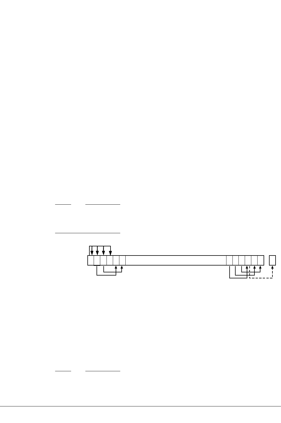
10.6 Shift operations
Register shift operations move the bits in a register left or right by a specified number of bits,
called the shift length.
Register shift can be performed:
• Directly by the instructions ASR, LSR, LSL, ROR, and RRX, and the result is written to a
destination register.
• During the calculation of Operand2 by the instructions that specify the second operand as a
register with shift. The result is used by the instruction.
The permitted shift lengths depend on the shift type and the instruction, see the individual
instruction description or the flexible second operand description. If the shift length is 0, no shift
occurs. Register shift operations update the carry flag except when the specified shift length is 0.
Arithmetic shift right (ASR)
Arithmetic shift right by n bits moves the left-hand 32-n bits of a register to the right by n places,
into the right-hand 32-n bits of the result. It copies the original bit[31] of the register into the left-
hand n bits of the result.
You can use the ASR #n operation to divide the value in the register Rm by 2n, with the result
being rounded towards negative-infinity.
When the instruction is ASRS or when ASR #n is used in Operand2 with the instructions MOVS,
MVNS, ANDS, ORRS, ORNS, EORS, BICS, TEQ or TST, the carry flag is updated to the last bit shifted
out, bit[n-1], of the register Rm.
Note
• If n is 32 or more, then all the bits in the result are set to the value of bit[31] of Rm.
• If n is 32 or more and the carry flag is updated, it is updated to the value of bit[31] of Rm.
31 1 0
Carry
Flag
...
2345
Figure 10-1 ASR #3
Logical shift right (LSR)
Logical shift right by n bits moves the left-hand 32-n bits of a register to the right by n places, into
the right-hand 32-n bits of the result. It sets the left-hand n bits of the result to 0.
You can use the LSR #n operation to divide the value in the register Rm by 2n, if the value is
regarded as an unsigned integer.
When the instruction is LSRS or when LSR #n is used in Operand2 with the instructions MOVS,
MVNS, ANDS, ORRS, ORNS, EORS, BICS, TEQ or TST, the carry flag is updated to the last bit shifted
out, bit[n-1], of the register Rm.
Note
• If n is 32 or more, then all the bits in the result are cleared to 0.
10 ARM and Thumb Instructions
10.6 Shift operations
ARM DUI0473J Copyright © 2010-2013 ARM. All rights reserved. 10-313
Non-Confidential
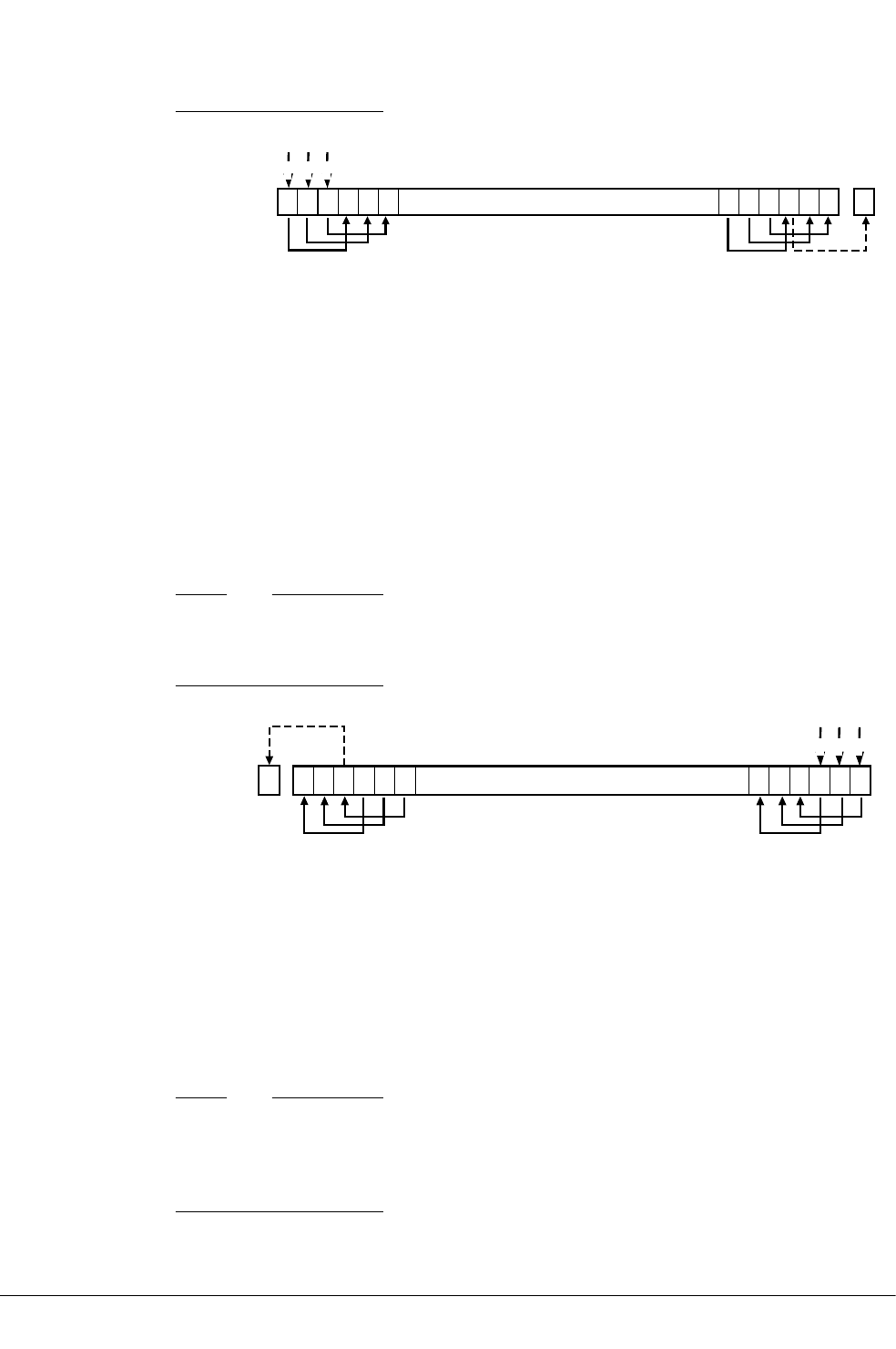
• If n is 33 or more and the carry flag is updated, it is updated to 0.
31 1 0
Carry
Flag
...
000
2345
Figure 10-2 LSR #3
Logical shift left (LSL)
Logical shift left by n bits moves the right-hand 32-n bits of a register to the left by n places, into
the left-hand 32-n bits of the result. It sets the right-hand n bits of the result to 0.
You can use the LSL #n operation to multiply the value in the register Rm by 2n, if the value is
regarded as an unsigned integer or a two’s complement signed integer. Overflow can occur
without warning.
When the instruction is LSLS or when LSL #n, with non-zero n, is used in Operand2 with the
instructions MOVS, MVNS, ANDS, ORRS, ORNS, EORS, BICS, TEQ or TST, the carry flag is updated
to the last bit shifted out, bit[32-n], of the register Rm. These instructions do not affect the carry
flag when used with LSL #0.
Note
• If n is 32 or more, then all the bits in the result are cleared to 0.
• If n is 33 or more and the carry flag is updated, it is updated to 0.
31 1 0
Carry
Flag ...
000
2345
Figure 10-3 LSL #3
Rotate right (ROR)
Rotate right by n bits moves the left-hand 32-n bits of a register to the right by n places, into the
right-hand 32-n bits of the result. It also moves the right-hand n bits of the register into the left-
hand n bits of the result.
When the instruction is RORS or when ROR #n is used in Operand2 with the instructions MOVS,
MVNS, ANDS, ORRS, ORNS, EORS, BICS, TEQ or TST, the carry flag is updated to the last bit
rotation, bit[n-1], of the register Rm.
Note
• If n is 32, then the value of the result is same as the value in Rm, and if the carry flag is
updated, it is updated to bit[31] of Rm.
•ROR with shift length, n, more than 32 is the same as ROR with shift length n-32.
10 ARM and Thumb Instructions
10.6 Shift operations
ARM DUI0473J Copyright © 2010-2013 ARM. All rights reserved. 10-314
Non-Confidential
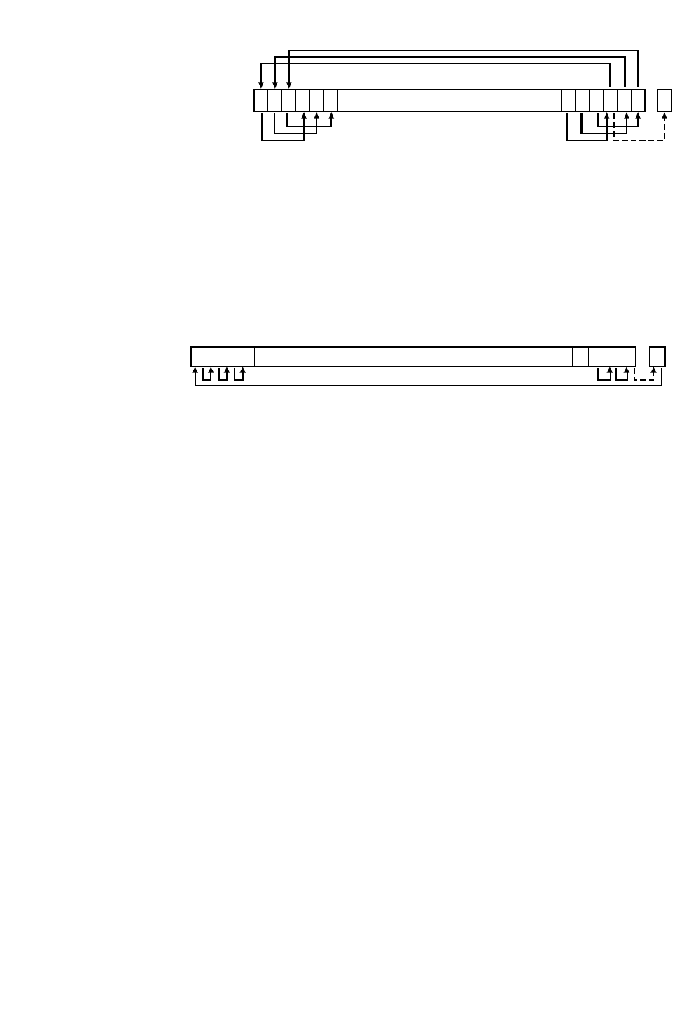
31 1 0
Carry
Flag
...
2345
Figure 10-4 ROR #3
Rotate right with extend (RRX)
Rotate right with extend moves the bits of a register to the right by one bit. It copies the carry flag
into bit[31] of the result.
When the instruction is RRXS or when RRX is used in Operand2 with the instructions MOVS,
MVNS, ANDS, ORRS, ORNS, EORS, BICS, TEQ or TST, the carry flag is updated to bit[0] of the
register Rm.
31 10
Carry
Flag
... ...
Figure 10-5 RRX
Related references
10.3 Flexible second operand (Operand2) on page 10-310.
10.4 Syntax of Operand2 as a constant on page 10-311.
10.5 Syntax of Operand2 as a register with optional shift on page 10-312.
10 ARM and Thumb Instructions
10.6 Shift operations
ARM DUI0473J Copyright © 2010-2013 ARM. All rights reserved. 10-315
Non-Confidential

10.7 Saturating instructions
Some ARM and Thumb instructions perform saturating arithmetic.
The saturating instructions are:
•QADD.
•QDADD.
•QDSUB.
•QSUB.
•SSAT.
•USAT.
Some of the parallel instructions are also saturating.
Saturating arithmetic
Saturation means that, for some value of 2n that depends on the instruction:
• For a signed saturating operation, if the full result would be less than –2n, the result returned is
–2n.
• For an unsigned saturating operation, if the full result would be negative, the result returned is
zero.
• If the full result would be greater than 2n – 1, the result returned is 2n – 1.
When any of these occurs, it is called saturation. Some instructions set the Q flag when saturation
occurs.
Note
Saturating instructions do not clear the Q flag when saturation does not occur. To clear the Q flag,
use an MSR instruction.
The Q flag can also be set by two other instructions, but these instructions do not saturate.
Related references
10.76 QADD on page 10-432.
10.83 QSUB on page 10-439.
10.80 QDADD on page 10-436.
10.81 QDSUB on page 10-437.
10.111 SMLAxy on page 10-477.
10.116 SMLAWy on page 10-484.
10.123 SMULxy on page 10-491.
10.125 SMULWy on page 10-493.
10.128 SSAT on page 10-497.
10.176 USAT on page 10-565.
10.65 MSR (general-purpose register to PSR) on page 10-413.
10 ARM and Thumb Instructions
10.7 Saturating instructions
ARM DUI0473J Copyright © 2010-2013 ARM. All rights reserved. 10-316
Non-Confidential

10.8 Condition codes
Instructions that can be conditional have an optional two character condition code suffix.
Condition codes are shown in syntax descriptions as {cond}. The following table shows the
condition codes that you can use:
Table 10-2 Condition code suffixes
Suffix Meaning
EQ Equal
NE Not equal
CS Carry set (identical to HS)
HS Unsigned higher or same (identical to CS)
CC Carry clear (identical to LO)
LO Unsigned lower (identical to CC)
MI Minus or negative result
PL Positive or zero result
VS Overflow
VC No overflow
HI Unsigned higher
LS Unsigned lower or same
GE Signed greater than or equal
LT Signed less than
GT Signed greater than
LE Signed less than or equal
AL Always (this is the default)
Note
The meanings of the condition codes depend on whether the condition flags were set by a VFP
instruction or by an ARM data processing instruction.
Related concepts
8.8 Conditional execution of NEON and VFP instructions on page 8-185.
Related references
5.6 Comparison of condition code meanings on page 5-111.
10.38 IT on page 10-366.
12.77 VMRS on page 12-678.
10 ARM and Thumb Instructions
10.8 Condition codes
ARM DUI0473J Copyright © 2010-2013 ARM. All rights reserved. 10-317
Non-Confidential

10.9 ADC
Add with Carry.
Syntax
ADC{S}{cond} {Rd}, Rn, Operand2
where:
S
is an optional suffix. If S is specified, the condition flags are updated on the result of the
operation.
cond
is an optional condition code.
Rd
is the destination register.
Rn
is the register holding the first operand.
Operand2
is a flexible second operand.
Usage
The ADC (Add with Carry) instruction adds the values in Rn and Operand2, together with the
carry flag.
You can use ADC to synthesize multiword arithmetic.
In certain circumstances, the assembler can substitute one instruction for another. Be aware of this
when reading disassembly listings.
Use of PC and SP in Thumb instructions
You cannot use PC (R15) for Rd, or any operand with the ADC command.
You cannot use SP (R13) for Rd, or any operand with the ADC command.
Use of PC and SP in ARM instructions
You cannot use PC for Rd or any operand in any data processing instruction that has a register-
controlled shift.
Use of PC for any operand, in instructions without register-controlled shift, is deprecated.
If you use PC (R15) as Rn or Operand2, the value used is the address of the instruction plus 8.
If you use PC as Rd:
• Execution branches to the address corresponding to the result.
• If you use the S suffix, see the SUBS pc,lr instruction.
Use of SP with the ADC ARM instruction is deprecated.
Note
The deprecation of SP and PC in ARM instructions is only in ARMv6T2 and above.
Condition flags
If S is specified, the ADC instruction updates the N, Z, C and V flags according to the result.
10 ARM and Thumb Instructions
10.9 ADC
ARM DUI0473J Copyright © 2010-2013 ARM. All rights reserved. 10-318
Non-Confidential

16-bit instructions
The following forms of this instruction are available in Thumb code, and are 16-bit instructions:
ADCS Rd, Rd, Rm
Rd and Rm must both be Lo registers. This form can only be used outside an IT block.
ADC{cond} Rd, Rd, Rm
Rd and Rm must both be Lo registers. This form can only be used inside an IT block.
Multiword arithmetic examples
These two instructions add a 64-bit integer contained in R2 and R3 to another 64-bit integer
contained in R0 and R1, and place the result in R4 and R5.
ADDS r4, r0, r2 ; adding the least significant words
ADC r5, r1, r3 ; adding the most significant words
Related references
10.3 Flexible second operand (Operand2) on page 10-310.
10.8 Condition codes on page 10-317.
Related information
Handling Processor Exceptions.
10 ARM and Thumb Instructions
10.9 ADC
ARM DUI0473J Copyright © 2010-2013 ARM. All rights reserved. 10-319
Non-Confidential

10.10 ADD
Add without Carry.
Syntax
ADD{S}{cond} {Rd}, Rn, Operand2
ADD{cond} {Rd}, Rn, #imm12 ; Thumb, 32-bit encoding only
where:
S
is an optional suffix. If S is specified, the condition flags are updated on the result of the
operation.
cond
is an optional condition code.
Rd
is the destination register.
Rn
is the register holding the first operand.
Operand2
is a flexible second operand.
imm12
is any value in the range 0-4095.
Operation
The ADD instruction adds the values in Rn and Operand2 or imm12.
In certain circumstances, the assembler can substitute one instruction for another. Be aware of this
when reading disassembly listings.
Use of PC and SP in Thumb instructions
Generally, you cannot use PC (R15) for Rd, or any operand.
The exceptions are:
• you can use PC for Rn in 32-bit encodings of Thumb ADD instructions, with a constant
Operand2 value in the range 0-4095, and no S suffix. These instructions are useful for
generating PC-relative addresses. Bit[1] of the PC value reads as 0 in this case, so that the base
address for the calculation is always word-aligned.
• you can use PC in 16-bit encodings of Thumb ADD{cond} Rd, Rd, Rm instructions, where
both registers cannot be PC. However, the following 16-bit Thumb instructions are deprecated
in ARMv6T2 and above:
— ADD{cond} PC, SP, PC.
— ADD{cond} SP, SP, PC.
Generally, you cannot use SP (R13) for Rd, or any operand. Except that:
• You can use SP for Rn in ADD instructions.
•ADD{cond} SP, SP, SP is permitted but is deprecated in ARMv6T2 and above.
•ADD{S}{cond} SP, SP, Rm{,shift} and SUB{S}{cond} SP, SP, Rm{,shift} are
permitted if shift is omitted or LSL #1, LSL #2, or LSL #3.
Use of PC and SP in ARM instructions
You cannot use PC for Rd or any operand in any data processing instruction that has a register-
controlled shift.
10 ARM and Thumb Instructions
10.10 ADD
ARM DUI0473J Copyright © 2010-2013 ARM. All rights reserved. 10-320
Non-Confidential

In ADD instructions without register-controlled shift, use of PC is deprecated except for the
following cases:
• Use of PC for Rd in instructions that do not add SP to a register.
• Use of PC for Rn and use of PC for Rm in instructions that add two registers other than SP.
• Use of PC for Rn in the instruction ADD{cond} Rd, Rn, #Constant.
If you use PC (R15) as Rn or Rm, the value used is the address of the instruction plus 8.
If you use PC as Rd:
• Execution branches to the address corresponding to the result.
• If you use the S suffix, see the SUBS pc,lr instruction.
You can use SP for Rn in ADD instructions, however, ADDS PC, SP, #Constant is deprecated.
You can use SP in ADD (register) if Rn is SP and shift is omitted or LSL #1, LSL #2, or LSL
#3.
Other uses of SP in these ARM instructions are deprecated.
Note
The deprecation of SP and PC in ARM instructions is only in ARMv6T2 and above.
Condition flags
If S is specified, these instructions update the N, Z, C and V flags according to the result.
16-bit instructions
The following forms of these instructions are available in Thumb code, and are 16-bit instructions:
ADDS Rd, Rn, #imm
imm range 0-7. Rd and Rn must both be Lo registers. This form can only be used outside
an IT block.
ADD{cond} Rd, Rn, #imm
imm range 0-7. Rd and Rn must both be Lo registers. This form can only be used inside an
IT block.
ADDS Rd, Rn, Rm
Rd, Rn and Rm must all be Lo registers. This form can only be used outside an IT block.
ADD{cond} Rd, Rn, Rm
Rd, Rn and Rm must all be Lo registers. This form can only be used inside an IT block.
ADD Rd, Rd, Rm
ARMv6 and earlier: either Rd or Rm, or both, must be a Hi register. ARMv6T2 and
above: this restriction does not apply.
ADDS Rd, Rd, #imm
imm range 0-255. Rd must be a Lo register. This form can only be used outside an IT
block.
ADD{cond} Rd, Rd, #imm
imm range 0-255. Rd must be a Lo register. This form can only be used inside an IT
block.
ADD SP, SP, #imm
imm range 0-508, word aligned.
ADD Rd, SP, #imm
imm range 0-1020, word aligned. Rd must be a Lo register.
ADD Rd, pc, #imm
imm range 0-1020, word aligned. Rd must be a Lo register. Bits[1:0] of the PC are read as
0 in this instruction.
10 ARM and Thumb Instructions
10.10 ADD
ARM DUI0473J Copyright © 2010-2013 ARM. All rights reserved. 10-321
Non-Confidential

Example
ADD r2, r1, r3
Multiword arithmetic example
These two instructions add a 64-bit integer contained in R2 and R3 to another 64-bit integer
contained in R0 and R1, and place the result in R4 and R5.
ADDS r4, r0, r2 ; adding the least significant words
ADC r5, r1, r3 ; adding the most significant words
Related references
10.3 Flexible second operand (Operand2) on page 10-310.
10.8 Condition codes on page 10-317.
10.140 SUBS pc, lr on page 10-522.
Related information
Handling Processor Exceptions.
10 ARM and Thumb Instructions
10.10 ADD
ARM DUI0473J Copyright © 2010-2013 ARM. All rights reserved. 10-322
Non-Confidential

10.11 ADR (PC-relative)
Generate a PC-relative address in the destination register, for a label in the current area.
Syntax
ADR{cond}{.W} Rd,label
where:
cond
is an optional condition code.
.W
is an optional instruction width specifier.
Rd
is the destination register to load.
label
is a PC-relative expression.
label must be within a limited distance of the current instruction.
Usage
ADR produces position-independent code, because the assembler generates an instruction that adds
or subtracts a value to the PC.
Use the ADRL pseudo-instruction to assemble a wider range of effective addresses.
label must evaluate to an address in the same assembler area as the ADR instruction.
If you use ADR to generate a target for a BX or BLX instruction, it is your responsibility to set the
Thumb bit (bit 0) of the address if the target contains Thumb instructions.
Offset range and architectures
The assembler calculates the offset from the PC for you. The assembler generates an error if
label is out of range.
The following table shows the possible offsets between the label and the current instruction:
10 ARM and Thumb Instructions
10.11 ADR (PC-relative)
ARM DUI0473J Copyright © 2010-2013 ARM. All rights reserved. 10-323
Non-Confidential

Table 10-3 PC-relative offsets
Instruction Offset range Architectures b
ARM ADR Any value that can be produced by
rotating an 8-bit value right by any
even number of bits within a 32-bit
word.
All
Thumb ADR, 32-bit encoding +/– 4095 T2
Thumb ADR, 16-bit encoding c0-1020 dT
ADR in Thumb
You can use the .W width specifier to force ADR to generate a 32-bit instruction in Thumb code.
ADR with .W always generates a 32-bit instruction, even if the address can be generated in a 16-bit
instruction.
For forward references, ADR without .W always generates a 16-bit instruction in Thumb code,
even if that results in failure for an address that could be generated in a 32-bit Thumb ADD
instruction.
Restrictions
In Thumb code, Rd cannot be PC or SP.
In ARM code, Rd can be PC or SP but use of SP is deprecated in ARMv6T2 and above.
Related concepts
4.9 Load addresses to a register using ADR on page 4-77.
7.5 Register-relative and PC-relative expressions on page 7-149.
Related references
10.4 Syntax of Operand2 as a constant on page 10-311.
10.13 ADRL pseudo-instruction on page 10-327.
14.6 AREA on page 14-774.
10.8 Condition codes on page 10-317.
bEntries in the Architectures column indicate that the instructions are available as follows:
All
All versions of the ARM architecture.
T2
The ARMv6T2 and above architectures.
T
The ARMv4T, ARMv5T*, ARMv6*, and ARMv7 architectures.
cRd must be in the range R0-R7.
dMust be a multiple of 4.
10 ARM and Thumb Instructions
10.11 ADR (PC-relative)
ARM DUI0473J Copyright © 2010-2013 ARM. All rights reserved. 10-324
Non-Confidential

10.12 ADR (register-relative)
Generate a register-relative address in the destination register, for a label defined in a storage map.
Syntax
ADR{cond}{.W} Rd,label
where:
cond
is an optional condition code.
.W
is an optional instruction width specifier.
Rd
is the destination register to load.
label
is a symbol defined by the FIELD directive. label specifies an offset from the base
register which is defined using the MAP directive.
label must be within a limited distance from the base register.
Usage
ADR generates code to easily access named fields inside a storage map.
Use the ADRL pseudo-instruction to assemble a wider range of effective addresses.
Restrictions
In Thumb code:
•Rd cannot be PC.
•Rd can be SP only if the base register is SP.
Offset range and architectures
The assembler calculates the offset from the base register for you. The assembler generates an
error if label is out of range.
The following table shows the possible offsets between the label and the current instruction:
10 ARM and Thumb Instructions
10.12 ADR (register-relative)
ARM DUI0473J Copyright © 2010-2013 ARM. All rights reserved. 10-325
Non-Confidential

Table 10-4 Register-relative offsets
Instruction Offset range Architectures e
ARM ADR Any value that can be produced by rotating an 8-bit value
right by any even number of bits within a 32-bit word.
All
Thumb ADR, 32-bit encoding +/– 4095 T2
Thumb ADR, 16-bit encoding, base register
is SP f
0-1020 gT
ADR in Thumb
You can use the .W width specifier to force ADR to generate a 32-bit instruction in Thumb code.
ADR with .W always generates a 32-bit instruction, even if the address can be generated in a 16-bit
instruction.
For forward references, ADR without .W, with base register SP, always generates a 16-bit
instruction in Thumb code, even if that results in failure for an address that could be generated in a
32-bit Thumb ADD instruction.
Related concepts
7.5 Register-relative and PC-relative expressions on page 7-149.
Related references
10.4 Syntax of Operand2 as a constant on page 10-311.
10.13 ADRL pseudo-instruction on page 10-327.
14.51 MAP on page 14-828.
14.40 FIELD on page 14-813.
10.8 Condition codes on page 10-317.
eEntries in the Architectures column indicate that the instructions are available as follows:
All
All versions of the ARM architecture.
T2
The ARMv6T2 and above architectures.
T
The ARMv4T, ARMv5T*, ARMv6*, and ARMv7 architectures.
fRd must be in the range R0-R7 or SP. If Rd is SP, the offset range is –508 to 508 and must be a multiple of 4
gMust be a multiple of 4.
10 ARM and Thumb Instructions
10.12 ADR (register-relative)
ARM DUI0473J Copyright © 2010-2013 ARM. All rights reserved. 10-326
Non-Confidential

10.13 ADRL pseudo-instruction
Load a PC-relative or register-relative address into a register.
Syntax
ADRL{cond} Rd,label
where:
cond
is an optional condition code.
Rd
is the register to load.
label
is a PC-relative or register-relative expression.
Usage
ADRL always assembles to two 32-bit instructions. Even if the address can be reached in a single
instruction, a second, redundant instruction is produced.
If the assembler cannot construct the address in two instructions, it generates an error message and
the assembly fails. You can use the LDR pseudo-instruction for loading a wider range of addresses.
ADRL is similar to the ADR instruction, except ADRL can load a wider range of addresses because it
generates two data processing instructions.
ADRL produces position-independent code, because the address is PC-relative or register-relative.
If label is PC-relative, it must evaluate to an address in the same assembler area as the ADRL
pseudo-instruction.
If you use ADRL to generate a target for a BX or BLX instruction, it is your responsibility to set the
Thumb bit (bit 0) of the address if the target contains Thumb instructions.
Architectures and range
The available range depends on the instruction set in use:
ARM
The range of the instruction is any value that can be generated by two ADD or two SUB
instructions. That is, any value that can be produced by the addition of two values, each
of which is 8 bits rotated right by any even number of bits within a 32-bit word.
Thumb, 32-bit encoding
±1MB bytes to a byte, halfword, or word-aligned address.
Thumb, 16-bit encoding
ADRL is not available.
The given range is relative to a point four bytes (in Thumb code) or two words (in ARM code)
after the address of the current instruction.
Note
When assembling Thumb instructions, ADRL is only available in ARMv6T2 and later.
Related concepts
7.5 Register-relative and PC-relative expressions on page 7-149.
4.3 Load 32-bit immediates into registers on page 4-68.
10 ARM and Thumb Instructions
10.13 ADRL pseudo-instruction
ARM DUI0473J Copyright © 2010-2013 ARM. All rights reserved. 10-327
Non-Confidential

Related references
10.4 Syntax of Operand2 as a constant on page 10-311.
10.45 LDR pseudo-instruction on page 10-385.
14.6 AREA on page 14-774.
10.10 ADD on page 10-320.
10.8 Condition codes on page 10-317.
Related information
ARM Architecture Reference Manual.
10 ARM and Thumb Instructions
10.13 ADRL pseudo-instruction
ARM DUI0473J Copyright © 2010-2013 ARM. All rights reserved. 10-328
Non-Confidential

10.14 AND
Logical AND.
Syntax
AND{S}{cond} Rd, Rn, Operand2
where:
S
is an optional suffix. If S is specified, the condition flags are updated on the result of the
operation.
cond
is an optional condition code.
Rd
is the destination register.
Rn
is the register holding the first operand.
Operand2
is a flexible second operand.
Operation
The AND instruction performs bitwise AND operations on the values in Rn and Operand2.
In certain circumstances, the assembler can substitute BIC for AND, or AND for BIC. Be aware of
this when reading disassembly listings.
Use of PC in Thumb instructions
You cannot use PC (R15) for Rd or any operand with the AND instruction.
Use of PC and SP in ARM instructions
You can use PC and SP with the AND ARM instruction but this is deprecated in ARMv6T2 and
above.
If you use PC as Rn, the value used is the address of the instruction plus 8.
If you use PC as Rd:
• Execution branches to the address corresponding to the result.
• If you use the S suffix, see the SUBS pc,lr instruction.
You cannot use PC for any operand in any data processing instruction that has a register-
controlled shift.
Condition flags
If S is specified, the AND instruction:
• Updates the N and Z flags according to the result.
• Can update the C flag during the calculation of Operand2.
• Does not affect the V flag.
16-bit instructions
The following forms of this instruction are available in Thumb code, and are 16-bit instructions:
ANDS Rd, Rd, Rm
Rd and Rm must both be Lo registers. This form can only be used outside an IT block.
10 ARM and Thumb Instructions
10.14 AND
ARM DUI0473J Copyright © 2010-2013 ARM. All rights reserved. 10-329
Non-Confidential

AND{cond} Rd, Rd, Rm
Rd and Rm must both be Lo registers. This form can only be used inside an IT block.
It does not matter if you specify AND{S} Rd, Rm, Rd. The instruction is the same.
Examples
AND r9,r2,#0xFF00
ANDS r9, r8, #0x19
Related references
10.3 Flexible second operand (Operand2) on page 10-310.
10.140 SUBS pc, lr on page 10-522.
10.8 Condition codes on page 10-317.
Related information
Handling Processor Exceptions.
10 ARM and Thumb Instructions
10.14 AND
ARM DUI0473J Copyright © 2010-2013 ARM. All rights reserved. 10-330
Non-Confidential

10.15 ASR
Arithmetic Shift Right. This instruction is a preferred synonym for MOV instructions with shifted
register operands.
Syntax
ASR{S}{cond} Rd, Rm, Rs
ASR{S}{cond} Rd, Rm, #sh
where:
S
is an optional suffix. If S is specified, the condition flags are updated on the result of the
operation.
Rd
is the destination register.
Rm
is the register holding the first operand. This operand is shifted right.
Rs
is a register holding a shift value to apply to the value in Rm. Only the least significant
byte is used.
sh
is a constant shift. The range of values permitted is 1-32.
Operation
ASR provides the signed value of the contents of a register divided by a power of two. It copies the
sign bit into vacated bit positions on the left.
Restrictions in Thumb code
Thumb instructions must not use PC or SP.
Use of SP and PC in ARM instructions
You can use SP in the ASR ARM instruction but this is deprecated in ARMv6T2 and above.
You cannot use PC in instructions with the ASR{S}{cond} Rd, Rm, Rs syntax. You can use
PC for Rd and Rm in the other syntax, but this is deprecated in ARMv6T2 and above.
If you use PC as Rm, the value used is the address of the instruction plus 8.
If you use PC as Rd:
• Execution branches to the address corresponding to the result.
• If you use the S suffix, the SPSR of the current mode is copied to the CPSR. You can use this
to return from exceptions.
Note
The ARM instruction ASRS{cond} pc,Rm,#sh always disassembles to the preferred form
MOVS{cond} pc,Rm{,shift}.
Caution
Do not use the S suffix when using PC as Rd in User mode or System mode. The assembler cannot
warn you about this because it has no information about what the processor mode is likely to be at
execution time.
10 ARM and Thumb Instructions
10.15 ASR
ARM DUI0473J Copyright © 2010-2013 ARM. All rights reserved. 10-331
Non-Confidential

You cannot use PC for Rd or any operand in the ASR instruction if it has a register-controlled
shift.
Condition flags
If S is specified, the ASR instruction updates the N and Z flags according to the result.
The C flag is unaffected if the shift value is 0. Otherwise, the C flag is updated to the last bit
shifted out.
16-bit instructions
The following forms of these instructions are available in Thumb code, and are 16-bit instructions:
ASRS Rd, Rm, #sh
Rd and Rm must both be Lo registers. This form can only be used outside an IT block.
ASR{cond} Rd, Rm, #sh
Rd and Rm must both be Lo registers. This form can only be used inside an IT block.
ASRS Rd, Rd, Rs
Rd and Rs must both be Lo registers. This form can only be used outside an IT block.
ASR{cond} Rd, Rd, Rs
Rd and Rs must both be Lo registers. This form can only be used inside an IT block.
Architectures
The ASR ARM instruction is available in all architectures.
The ASR 32-bit Thumb instruction is available in ARMv6T2 and above.
The ASR 16-bit Thumb instruction is available in ARMv4T and above.
Example
ASR r7, r8, r9
Related references
10.56 MOV on page 10-402.
10.8 Condition codes on page 10-317.
10 ARM and Thumb Instructions
10.15 ASR
ARM DUI0473J Copyright © 2010-2013 ARM. All rights reserved. 10-332
Non-Confidential

10.16 B
Branch.
Syntax
B{cond}{.W} label
where:
cond
is an optional condition code.
.W
is an optional instruction width specifier to force the use of a 32-bit B instruction in
Thumb.
label
is a PC-relative expression.
Operation
The B instruction causes a branch to label.
Instruction availability and branch ranges
The following table shows the B instructions that are available in ARM and Thumb state.
Instructions that are not shown in this table are not available. Notes in brackets show the first
architecture version where the instruction is available.
Table 10-5 B instruction availability and range
Instruction ARM Thumb, 16-bit encoding Thumb, 32-bit encoding
B label ±32MB (All) ±2KB (All T) ±16MB h(All T2)
B{cond}
label
±32MB (All) –252 to +258 (All T) ±1MB h(All T2)
Extending branch ranges
Machine-level B instructions have restricted ranges from the address of the current instruction.
However, you can use these instructions even if label is out of range. Often you do not know
where the linker places label. When necessary, the linker adds code to enable longer branches.
The added code is called a veneer.
B in Thumb
You can use the .W width specifier to force B to generate a 32-bit instruction in Thumb code.
B.W always generates a 32-bit instruction, even if the target could be reached using a 16-bit
instruction.
For forward references, B without .W always generates a 16-bit instruction in Thumb code, even if
that results in failure for a target that could be reached using a 32-bit Thumb instruction.
Condition flags
The B instruction does not change the flags.
hUse .W to instruct the assembler to use this 32-bit instruction.
10 ARM and Thumb Instructions
10.16 B
ARM DUI0473J Copyright © 2010-2013 ARM. All rights reserved. 10-333
Non-Confidential

Architectures
See the preceding table for details of availability of the B instruction in each architecture.
Example
B loopA
Related concepts
7.5 Register-relative and PC-relative expressions on page 7-149.
Related references
10.8 Condition codes on page 10-317.
Related information
Information about image structure and generation.
10 ARM and Thumb Instructions
10.16 B
ARM DUI0473J Copyright © 2010-2013 ARM. All rights reserved. 10-334
Non-Confidential

10.17 BFC
Bit Field Clear.
Syntax
BFC{cond} Rd, #lsb, #width
where:
cond
is an optional condition code.
Rd
is the destination register.
lsb
is the least significant bit that is to be cleared.
width
is the number of bits to be cleared. width must not be 0, and (width+lsb) must be less
than 32.
Operation
Clears adjacent bits in a register. width bits in Rd are cleared, starting at lsb. Other bits in Rd are
unchanged.
Register restrictions
You cannot use PC for any register.
You can use SP in the BFC ARM instruction but this is deprecated in ARMv6T2 and above. You
cannot use SP in the BFC Thumb instruction.
Condition flags
The BFC instruction does not change the flags.
Architectures
This ARM instruction is available in ARMv6T2 and above.
This 32-bit Thumb instruction is available in ARMv6T2 and above.
There is no 16-bit version of this instruction in Thumb.
Related references
10.8 Condition codes on page 10-317.
10 ARM and Thumb Instructions
10.17 BFC
ARM DUI0473J Copyright © 2010-2013 ARM. All rights reserved. 10-335
Non-Confidential

10.18 BFI
Bit Field Insert.
Syntax
BFI{cond} Rd, Rn, #lsb, #width
where:
cond
is an optional condition code.
Rd
is the destination register.
Rn
is the source register.
lsb
is the least significant bit that is to be copied.
width
is the number of bits to be copied. width must not be 0, and (width+lsb) must be less
than 32.
Operation
Inserts adjacent bits from one register into another. width bits in Rd, starting at lsb, are replaced
by width bits from Rn, starting at bit[0]. Other bits in Rd are unchanged.
Register restrictions
You cannot use PC for any register.
You can use SP in the BFI ARM instruction but this is deprecated in ARMv6T2 and above. You
cannot use SP in the BFI Thumb instruction.
Condition flags
The BFI instruction does not change the flags.
Architectures
This ARM instruction is available in ARMv6T2 and above.
This 32-bit Thumb instruction is available in ARMv6T2 and above.
There is no 16-bit version of this instruction in Thumb.
Related references
10.8 Condition codes on page 10-317.
10 ARM and Thumb Instructions
10.18 BFI
ARM DUI0473J Copyright © 2010-2013 ARM. All rights reserved. 10-336
Non-Confidential

10.19 BIC
Bit Clear.
Syntax
BIC{S}{cond} Rd, Rn, Operand2
where:
S
is an optional suffix. If S is specified, the condition flags are updated on the result of the
operation.
cond
is an optional condition code.
Rd
is the destination register.
Rn
is the register holding the first operand.
Operand2
is a flexible second operand.
Operation
The BIC (Bit Clear) instruction performs an AND operation on the bits in Rn with the
complements of the corresponding bits in the value of Operand2.
In certain circumstances, the assembler can substitute BIC for AND, or AND for BIC. Be aware of
this when reading disassembly listings.
Use of PC in Thumb instructions
You cannot use PC (R15) for Rd or any operand in a BIC instruction.
Use of PC and SP in ARM instructions
You can use PC and SP with the BIC instruction but they are deprecated in ARMv6T2 and above.
If you use PC as Rn, the value used is the address of the instruction plus 8.
If you use PC as Rd:
• Execution branches to the address corresponding to the result.
• If you use the S suffix, see the SUBS pc,lr instruction.
You cannot use PC for any operand in any data processing instruction that has a register-
controlled shift.
Condition flags
If S is specified, the BIC instruction:
• Updates the N and Z flags according to the result.
• Can update the C flag during the calculation of Operand2.
• Does not affect the V flag.
16-bit instructions
The following forms of the BIC instruction are available in Thumb code, and are 16-bit
instructions:
10 ARM and Thumb Instructions
10.19 BIC
ARM DUI0473J Copyright © 2010-2013 ARM. All rights reserved. 10-337
Non-Confidential

BICS Rd, Rd, Rm
Rd and Rm must both be Lo registers. This form can only be used outside an IT block.
BIC{cond} Rd, Rd, Rm
Rd and Rm must both be Lo registers. This form can only be used inside an IT block.
Example
BIC r0, r1, #0xab
Related references
10.3 Flexible second operand (Operand2) on page 10-310.
10.140 SUBS pc, lr on page 10-522.
10.8 Condition codes on page 10-317.
Related information
Handling Processor Exceptions.
10 ARM and Thumb Instructions
10.19 BIC
ARM DUI0473J Copyright © 2010-2013 ARM. All rights reserved. 10-338
Non-Confidential

10.20 BKPT
Breakpoint.
Syntax
BKPT #imm
where:
imm
is an expression evaluating to an integer in the range:
• 0-65535 (a 16-bit value) in an ARM instruction.
• 0-255 (an 8-bit value) in a 16-bit Thumb instruction.
Usage
The BKPT instruction causes the processor to enter Debug state. Debug tools can use this to
investigate system state when the instruction at a particular address is reached.
In both ARM state and Thumb state, imm is ignored by the ARM hardware. However, a debugger
can use it to store additional information about the breakpoint.
BKPT is an unconditional instruction. It must not have a condition code in ARM code. In Thumb
code, the BKPT instruction does not require a condition code suffix because BKPT always executes
irrespective of its condition code suffix.
Architectures
This ARM instruction is available in ARMv5T and above.
This 16-bit Thumb instruction is available in ARMv5T and above.
There is no 32-bit version of this instruction in Thumb.
10 ARM and Thumb Instructions
10.20 BKPT
ARM DUI0473J Copyright © 2010-2013 ARM. All rights reserved. 10-339
Non-Confidential

10.21 BL
Branch with Link.
Syntax
BL{cond}{.W} label
where:
cond
is an optional condition code. cond is not available on all forms of this instruction.
.W
is an optional instruction width specifier to force the use of a 32-bit BL instruction in
Thumb.
label
is a PC-relative expression.
Operation
The BL instruction causes a branch to label, and copies the address of the next instruction into
LR (R14, the link register).
Instruction availability and branch ranges
The following table shows the BL instructions that are available in ARM and Thumb state.
Instructions that are not shown in this table are not available. Notes in brackets show the first
architecture version where the instruction is available.
Table 10-6 BL instruction availability and range
Instruction ARM Thumb, 16-bit encoding Thumb, 32-bit encoding
BL label ±32MB (All) ±4MB i(All T) ±16MB (All T2)
BL{cond} label ±32MB (All) - - -
Extending branch ranges
Machine-level BL instructions have restricted ranges from the address of the current instruction.
However, you can use these instructions even if label is out of range. Often you do not know
where the linker places label. When necessary, the linker adds code to enable longer branches.
The added code is called a veneer.
Condition flags
The BL instruction does not change the flags.
Architectures
See the preceding table for details of availability of the BL instruction in each architecture.
Examples
BLE ng+8
BL subC
BLLT rtX
iBL label and BLX label are an instruction pair.
10 ARM and Thumb Instructions
10.21 BL
ARM DUI0473J Copyright © 2010-2013 ARM. All rights reserved. 10-340
Non-Confidential

Related concepts
7.5 Register-relative and PC-relative expressions on page 7-149.
Related references
10.8 Condition codes on page 10-317.
Related information
Information about image structure and generation.
10 ARM and Thumb Instructions
10.21 BL
ARM DUI0473J Copyright © 2010-2013 ARM. All rights reserved. 10-341
Non-Confidential

10.22 BLX
Branch with Link and exchange instruction set.
Syntax
BLX{cond}{.W} label
BLX{cond} Rm
where:
cond
is an optional condition code. cond is not available on all forms of this instruction.
.W
is an optional instruction width specifier to force the use of a 32-bit BLX instruction in
Thumb.
label
is a PC-relative expression.
Rm
is a register containing an address to branch to.
Operation
The BLX instruction causes a branch to label, or to the address contained in Rm. In addition:
• The BLX instruction copies the address of the next instruction into LR (R14, the link register).
• The BLX instruction can change the instruction set.
BLX label always changes the instruction set. It changes a processor in ARM state to Thumb
state, or a processor in Thumb state to ARM state.
BLX Rm derives the target instruction set from bit[0] of Rm:
— if bit[0] of Rm is 0, the processor changes to, or remains in, ARM state
— if bit[0] of Rm is 1, the processor changes to, or remains in, Thumb state.
Instruction availability and branch ranges
The following table shows the BLX instructions that are available in ARM and Thumb state.
Instructions that are not shown in this table are not available. Notes in brackets show the first
architecture version where the instruction is available.
Table 10-7 BLX instruction availability and range
Instruction ARM Thumb, 16-bit encoding Thumb, 32-bit encoding
BLX label ±32MB (5) ±4MB j(5T) ±16MB (All T2 except
ARMv7-M)
BLX Rm Available (5) Available (5T) Use 16-bit (All T2)
BLX{cond}
Rm
Available (5) - - -
jBLX label and BL label are an instruction pair.
10 ARM and Thumb Instructions
10.22 BLX
ARM DUI0473J Copyright © 2010-2013 ARM. All rights reserved. 10-342
Non-Confidential

BLX in ThumbEE
You can use the BLX instruction as a branch in ThumbEE code, but you cannot use it to change
state. You cannot use the BLX{cond} label form of this instruction in ThumbEE. In the register
form, bit[0] of Rm must be 1, and execution continues at the target address in ThumbEE state.
Register restrictions
You can use PC for Rm in the ARM BLX instruction, but this is deprecated in ARMv6T2 and
above. You cannot use PC in other ARM instructions.
You can use PC for Rm in the Thumb BLX instruction. You cannot use PC in other Thumb
instructions.
You can use SP for Rm in this ARM instruction but this is deprecated in ARMv6T2 and above.
You can use SP for Rm in the Thumb BLX instruction, but this is deprecated. You cannot use SP in
the other Thumb instructions.
Condition flags
This instruction does not change the flags.
Architectures
See the preceding table for details of availability of the BLX instruction in each architecture.
Related concepts
7.5 Register-relative and PC-relative expressions on page 7-149.
Related references
10.8 Condition codes on page 10-317.
Related information
Information about image structure and generation.
10 ARM and Thumb Instructions
10.22 BLX
ARM DUI0473J Copyright © 2010-2013 ARM. All rights reserved. 10-343
Non-Confidential

10.23 BX
Branch and exchange instruction set.
Syntax
BX{cond} Rm
where:
cond
is an optional condition code. cond is not available on all forms of this instruction.
Rm
is a register containing an address to branch to.
Operation
The BX instruction causes a branch to the address contained in Rm and exchanges the instruction
set, if required:
•BX Rm derives the target instruction set from bit[0] of Rm:
— If bit[0] of Rm is 0, the processor changes to, or remains in, ARM state.
— If bit[0] of Rm is 1, the processor changes to, or remains in, Thumb state.
Instruction availability and branch ranges
The following table shows the instructions that are available in ARM and Thumb state.
Instructions that are not shown in this table are not available. Notes in brackets show the first
architecture version where the instruction is available.
Table 10-8 BX instruction availability and range
Instruction ARM Thumb, 16-bit encoding Thumb, 32-bit encoding
BX Rm kAvailable (4T, 5) Available (All T) Use 16-bit (All T2)
BX{cond} Rm kAvailable (4T, 5) - - -
BX in ThumbEE
You can use the BX instruction as a branch in ThumbEE code, but you cannot use it to change
state. Bit[0] of Rm must be 1, and execution continues at the target address in ThumbEE state.
Register restrictions
You can use PC for Rm in the ARM BX instruction, but this is deprecated in ARMv6T2 and above.
You cannot use PC in other ARM instructions.
You can use PC for Rm in the Thumb BX instruction. You cannot use PC in other Thumb
instructions.
You can use SP for Rm in the ARM BX instruction but this is deprecated in ARMv6T2 and above.
You can use SP for Rm in the Thumb BX instruction, but this is deprecated.
Condition flags
The BX instruction does not change the flags.
kThe assembler accepts BX{cond} Rm for code assembled for ARMv4 and converts it to MOV{cond} PC, Rm at
link time, unless objects targeted for ARMv4T are present.
10 ARM and Thumb Instructions
10.23 BX
ARM DUI0473J Copyright © 2010-2013 ARM. All rights reserved. 10-344
Non-Confidential

Architectures
See the preceding table for details of availability of the BX instruction in each architecture.
Related concepts
7.5 Register-relative and PC-relative expressions on page 7-149.
Related references
10.8 Condition codes on page 10-317.
Related information
Information about image structure and generation.
10 ARM and Thumb Instructions
10.23 BX
ARM DUI0473J Copyright © 2010-2013 ARM. All rights reserved. 10-345
Non-Confidential

10.24 BXJ
Branch and change to Jazelle state.
Syntax
BXJ{cond} Rm
where:
cond
is an optional condition code. cond is not available on all forms of this instruction.
Rm
is a register containing an address to branch to.
Operation
The BXJ instruction causes a branch to the address contained in Rm and changes the instruction set
state to Jazelle.
Instruction availability and branch ranges
The following table shows the BXJ instructions that are available in ARM and Thumb state.
Instructions that are not shown in this table are not available. Notes in brackets show the first
architecture version where the instruction is available.
Table 10-9 BXJ instruction availability and range
Instruction ARM Thumb, 16-bit encoding Thumb, 32-bit encoding
BXJ Rm Available (5J, 6) - Available (All T2 except ARMv7-M)
BXJ{cond} Rm Available (5J, 6) - - -
BXJ in ThumbEE
You can use this instruction as a branch in ThumbEE code, but you cannot use it to change state.
Bit[0] of Rm must be 1, and execution continues at the target address in ThumbEE state.
Note
BXJ behaves like BX in ThumbEE.
Register restrictions
You can use SP for Rm in the BXJ ARM instruction but this is deprecated in ARMv6T2 and above.
You cannot use SP in the BXJ Thumb instruction.
Condition flags
The BXJ instruction does not change the flags.
Architectures
See the preceding table for details of availability of the BXJ instruction in each architecture.
Related concepts
7.5 Register-relative and PC-relative expressions on page 7-149.
10 ARM and Thumb Instructions
10.24 BXJ
ARM DUI0473J Copyright © 2010-2013 ARM. All rights reserved. 10-346
Non-Confidential


10.25 CBZ and CBNZ
Compare and Branch on Zero, Compare and Branch on Non-Zero.
Syntax
CBZ Rn, label
CBNZ Rn, label
where:
Rn
is the register holding the operand.
label
is the branch destination.
Usage
You can use the CBZ or CBNZ instructions to avoid changing the condition flags and to reduce the
number of instructions.
Except that it does not change the condition flags, CBZ Rn, label is equivalent to:
CMP Rn, #0
BEQ label
Except that it does not change the condition flags, CBNZ Rn, label is equivalent to:
CMP Rn, #0
BNE label
Restrictions
The branch destination must be within 4 to 130 bytes after the instruction and in the same
execution state.
These instructions must not be used inside an IT block.
Condition flags
These instructions do not change the flags.
Architectures
These 16-bit Thumb instructions are available in ARMv6T2 and above.
There are no ARM or 32-bit Thumb encodings of these instructions.
10 ARM and Thumb Instructions
10.25 CBZ and CBNZ
ARM DUI0473J Copyright © 2010-2013 ARM. All rights reserved. 10-348
Non-Confidential

10.26 CDP and CDP2
Coprocessor data operations.
Syntax
CDP{cond} coproc, #opcode1, CRd, CRn, CRm{, #opcode2}
CDP2{cond} coproc, #opcode1, CRd, CRn, CRm{, #opcode2}
where:
cond
is an optional condition code. In ARM code, cond is not permitted for CDP2.
coproc
is the name of the coprocessor the instruction is for. The standard name is pn, where n is
an integer in the range 0 to 15.
opcode1
is a 4-bit coprocessor-specific opcode.
opcode2
is an optional 3-bit coprocessor-specific opcode.
CRd, CRn, CRm
are coprocessor registers.
Usage
The use of these instructions depends on the coprocessor. See the coprocessor documentation for
details.
Architectures
The CDP ARM instruction is available in all versions of the ARM architecture.
The CDP2 ARM instruction is available in ARMv5T and above.
These 32-bit Thumb instructions are available in ARMv6T2 and above.
There are no 16-bit versions of these instructions in Thumb.
Related references
10.8 Condition codes on page 10-317.
10 ARM and Thumb Instructions
10.26 CDP and CDP2
ARM DUI0473J Copyright © 2010-2013 ARM. All rights reserved. 10-349
Non-Confidential

10.27 CLREX
Clear Exclusive.
Syntax
CLREX{cond}
where:
cond
is an optional condition code.
Note
cond is permitted only in Thumb code, using a preceding IT instruction. This is an
unconditional instruction in ARM.
Usage
Use the CLREX instruction to clear the local record of the executing processor that an address has
had a request for an exclusive access.
CLREX returns a closely-coupled exclusive access monitor to its open-access state. This removes
the requirement for a dummy store to memory.
It is implementation defined whether CLREX also clears the global record of the executing
processor that an address has had a request for an exclusive access.
Architectures
This ARM instruction is available in ARMv6K and above.
This 32-bit Thumb instruction is available in ARMv7 and above.
There is no 16-bit CLREX instruction in Thumb.
Related references
10.8 Condition codes on page 10-317.
Related information
ARM Architecture Reference Manual.
10 ARM and Thumb Instructions
10.27 CLREX
ARM DUI0473J Copyright © 2010-2013 ARM. All rights reserved. 10-350
Non-Confidential

10.28 CLZ
Count Leading Zeros.
Syntax
CLZ{cond} Rd, Rm
where:
cond
is an optional condition code.
Rd
is the destination register.
Rm
is the operand register.
Operation
The CLZ instruction counts the number of leading zeros in the value in Rm and returns the result in
Rd. The result value is 32 if no bits are set in the source register, and zero if bit 31 is set.
Register restrictions
You cannot use PC for any operand.
You can use SP in these ARM instructions but this is deprecated in ARMv6T2 and above.
You cannot use SP in Thumb instructions.
Condition flags
This instruction does not change the flags.
Architectures
This ARM instruction is available in ARMv5T and above.
This 32-bit Thumb instruction is available in ARMv6T2 and above.
There is no 16-bit version of this instruction in Thumb.
Examples
CLZ r4,r9
CLZNE r2,r3
Use the CLZ Thumb instruction followed by a left shift of Rm by the resulting Rd value to
normalize the value of register Rm. Use MOVS, rather than MOV, to flag the case where Rm is zero:
CLZ r5, r9
MOVS r9, r9, LSL r5
Related references
10.8 Condition codes on page 10-317.
10 ARM and Thumb Instructions
10.28 CLZ
ARM DUI0473J Copyright © 2010-2013 ARM. All rights reserved. 10-351
Non-Confidential

10.29 CMP and CMN
Compare and Compare Negative.
Syntax
CMP{cond} Rn, Operand2
CMN{cond} Rn, Operand2
where:
cond
is an optional condition code.
Rn
is the ARM register holding the first operand.
Operand2
is a flexible second operand.
Operation
These instructions compare the value in a register with Operand2. They update the condition
flags on the result, but do not place the result in any register.
The CMP instruction subtracts the value of Operand2 from the value in Rn. This is the same as a
SUBS instruction, except that the result is discarded.
The CMN instruction adds the value of Operand2 to the value in Rn. This is the same as an ADDS
instruction, except that the result is discarded.
In certain circumstances, the assembler can substitute CMN for CMP, or CMP for CMN. Be aware of
this when reading disassembly listings.
Use of PC in ARM and Thumb instructions
You cannot use PC for any operand in any data processing instruction that has a register-
controlled shift.
You can use PC (R15) in these ARM instructions without register controlled shift but this is
deprecated in ARMv6T2 and above.
If you use PC as Rn in ARM instructions, the value used is the address of the instruction plus 8.
You cannot use PC for any operand in these Thumb instructions.
Use of SP in ARM and Thumb instructions
You can use SP for Rn in ARM and Thumb instructions.
You can use SP for Rm in ARM instructions but this is deprecated in ARMv6T2 and above.
You can use SP for Rm in a 16-bit Thumb CMP Rn, Rm instruction but this is deprecated in
ARMv6T2 and above. Other uses of SP for Rm are not permitted in Thumb.
Condition flags
These instructions update the N, Z, C and V flags according to the result.
16-bit instructions
The following forms of these instructions are available in Thumb code, and are 16-bit instructions:
CMP Rn, Rm
Lo register restriction does not apply.
10 ARM and Thumb Instructions
10.29 CMP and CMN
ARM DUI0473J Copyright © 2010-2013 ARM. All rights reserved. 10-352
Non-Confidential

CMN Rn, Rm
Rn and Rm must both be Lo registers.
CMP Rn, #imm
Rn must be a Lo register. imm range 0-255.
Examples
CMP r2, r9
CMN r0, #6400
CMPGT sp, r7, LSL #2
Incorrect example
CMP r2, pc, ASR r0 ; PC not permitted with register-controlled
; shift.
Related references
10.3 Flexible second operand (Operand2) on page 10-310.
10.8 Condition codes on page 10-317.
10 ARM and Thumb Instructions
10.29 CMP and CMN
ARM DUI0473J Copyright © 2010-2013 ARM. All rights reserved. 10-353
Non-Confidential

10.30 CPS
Change Processor State.
Syntax
CPSeffect iflags{, #mode}
CPS #mode
where:
effect
is one of:
IE
Interrupt or abort enable.
ID
Interrupt or abort disable.
iflags
is a sequence of one or more of:
a
Enables or disables imprecise aborts.
i
Enables or disables IRQ interrupts.
f
Enables or disables FIQ interrupts.
mode
specifies the number of the mode to change to.
Usage
Changes one or more of the mode, A, I, and F bits in the CPSR, without changing the other CPSR
bits.
CPS is only permitted in privileged software execution, and has no effect in User mode.
CPS cannot be conditional, and is not permitted in an IT block.
Condition flags
This instruction does not change the condition flags.
16-bit instructions
The following forms of these instructions are available in Thumb code, and are 16-bit instructions:
•CPSIE iflags.
•CPSID iflags.
You cannot specify a mode change in a 16-bit Thumb instruction.
Architectures
This ARM instruction is available in ARMv6 and above.
This 32-bit Thumb instruction are available in ARMv6T2 and above.
This 16-bit Thumb instruction is available in T variants of ARMv6 and above.
10 ARM and Thumb Instructions
10.30 CPS
ARM DUI0473J Copyright © 2010-2013 ARM. All rights reserved. 10-354
Non-Confidential

Examples
CPSIE if ; Enable IRQ and FIQ interrupts.
CPSID A ; Disable imprecise aborts.
CPSID ai, #17 ; Disable imprecise aborts and interrupts, and enter
; FIQ mode.
CPS #16 ; Enter User mode.
10 ARM and Thumb Instructions
10.30 CPS
ARM DUI0473J Copyright © 2010-2013 ARM. All rights reserved. 10-355
Non-Confidential

10.31 CPY pseudo-instruction
Copy a value from one register to another.
Syntax
CPY{cond} Rd, Rm
where:
cond
is an optional condition code.
Rd
is the destination register.
Rm
is the register holding the value to be copied.
Operation
The CPY pseudo-instruction copies a value from one register to another, without changing the
condition flags.
CPY Rd, Rm assembles to MOV Rd, Rm.
Architectures
This pseudo-instruction is available in ARMv6 and above in ARM code and in T variants of
ARMv6 and above in Thumb code.
Register restrictions
Using SP or PC for both Rd and Rm is deprecated.
Condition flags
This instruction does not change the condition flags.
Related references
10.56 MOV on page 10-402.
10 ARM and Thumb Instructions
10.31 CPY pseudo-instruction
ARM DUI0473J Copyright © 2010-2013 ARM. All rights reserved. 10-356
Non-Confidential

10.32 DBG
Debug.
Syntax
DBG{cond} {option}
where:
cond
is an optional condition code.
option
is an optional limitation on the operation of the hint. The range is 0-15.
Usage
DBG is a hint instruction. It is optional whether it is implemented or not. If it is not implemented, it
behaves as a NOP. The assembler produces a diagnostic message if the instruction executes as NOP
on the target.
DBG executes as a NOP instruction in ARMv6K and ARMv6T2.
Debug hint provides a hint to a debugger and related tools. See your debugger and related tools
documentation to determine the use, if any, of this instruction.
Architectures
This ARM instruction is available in ARMv6K and above.
This 32-bit Thumb instruction is available in ARMv6T2 and above.
There is no 16-bit version of this instruction in Thumb.
Related references
10.69 NOP on page 10-420.
10.8 Condition codes on page 10-317.
10 ARM and Thumb Instructions
10.32 DBG
ARM DUI0473J Copyright © 2010-2013 ARM. All rights reserved. 10-357
Non-Confidential

10.33 DMB
Data Memory Barrier.
Syntax
DMB{cond} {option}
where:
cond
is an optional condition code.
Note
cond is permitted only in Thumb code. This is an unconditional instruction in ARM
code.
option
is an optional limitation on the operation of the hint. Permitted values are:
SY
Full system DMB operation. This is the default and can be omitted.
ST
DMB operation that waits only for stores to complete.
ISH
DMB operation only to the inner shareable domain.
ISHST
DMB operation that waits only for stores to complete, and only to the inner
shareable domain.
NSH
DMB operation only out to the point of unification.
NSHST
DMB operation that waits only for stores to complete and only out to the point of
unification.
OSH
DMB operation only to the outer shareable domain.
OSHST
DMB operation that waits only for stores to complete, and only to the outer
shareable domain.
Operation
Data Memory Barrier acts as a memory barrier. It ensures that all explicit memory accesses that
appear in program order before the DMB instruction are observed before any explicit memory
accesses that appear in program order after the DMB instruction. It does not affect the ordering of
any other instructions executing on the processor.
Alias
The following alternative values of option are supported, but ARM recommends that you do not
use them:
•SH is an alias for ISH.
•SHST is an alias for ISHST.
•UN is an alias for NSH.
•UNST is an alias for NSHST.
10 ARM and Thumb Instructions
10.33 DMB
ARM DUI0473J Copyright © 2010-2013 ARM. All rights reserved. 10-358
Non-Confidential

Architectures
This ARM and 32-bit Thumb instruction is available in ARMv7.
There is no 16-bit version of this instruction in Thumb.
Related references
10.8 Condition codes on page 10-317.
10 ARM and Thumb Instructions
10.33 DMB
ARM DUI0473J Copyright © 2010-2013 ARM. All rights reserved. 10-359
Non-Confidential

10.34 DSB
Data Synchronization Barrier.
Syntax
DSB{cond} {option}
where:
cond
is an optional condition code.
Note
cond is permitted only in Thumb code. This is an unconditional instruction in ARM.
option
is an optional limitation on the operation of the hint. Permitted values are:
SY
Full system DSB operation. This is the default and can be omitted.
ST
DSB operation that waits only for stores to complete.
ISH
DSB operation only to the inner shareable domain.
ISHST
DSB operation that waits only for stores to complete, and only to the inner
shareable domain.
NSH
DSB operation only out to the point of unification.
NSHST
DSB operation that waits only for stores to complete and only out to the point of
unification.
OSH
DSB operation only to the outer shareable domain.
OSHST
DSB operation that waits only for stores to complete, and only to the outer
shareable domain.
Operation
Data Synchronization Barrier acts as a special kind of memory barrier. No instruction in program
order after this instruction executes until this instruction completes. This instruction completes
when:
• All explicit memory accesses before this instruction complete.
• All Cache, Branch predictor and TLB maintenance operations before this instruction complete.
Alias
The following alternative values of option are supported for DSB, but ARM recommends that
you do not use them:
•SH is an alias for ISH.
•SHST is an alias for ISHST.
•UN is an alias for NSH.
•UNST is an alias for NSHST.
10 ARM and Thumb Instructions
10.34 DSB
ARM DUI0473J Copyright © 2010-2013 ARM. All rights reserved. 10-360
Non-Confidential

Architectures
This ARM and 32-bit Thumb instruction is available in ARMv7.
There is no 16-bit version of this instruction in Thumb.
Related references
10.8 Condition codes on page 10-317.
10 ARM and Thumb Instructions
10.34 DSB
ARM DUI0473J Copyright © 2010-2013 ARM. All rights reserved. 10-361
Non-Confidential

10.35 EOR
Logical Exclusive OR.
Syntax
EOR{S}{cond} Rd, Rn, Operand2
where:
S
is an optional suffix. If S is specified, the condition flags are updated on the result of the
operation.
cond
is an optional condition code.
Rd
is the destination register.
Rn
is the register holding the first operand.
Operand2
is a flexible second operand.
Operation
The EOR instruction performs bitwise Exclusive OR operations on the values in Rn and
Operand2.
Use of PC in Thumb instructions
You cannot use PC (R15) for Rd or any operand in an EOR instruction.
Use of PC and SP in ARM instructions
You can use PC and SP with the EOR instruction but they are deprecated in ARMv6T2 and above.
If you use PC as Rn, the value used is the address of the instruction plus 8.
If you use PC as Rd:
• Execution branches to the address corresponding to the result.
• If you use the S suffix, see the SUBS pc,lr instruction.
You cannot use PC for any operand in any data processing instruction that has a register-
controlled shift.
Condition flags
If S is specified, the EOR instruction:
• Updates the N and Z flags according to the result.
• Can update the C flag during the calculation of Operand2.
• Does not affect the V flag.
16-bit instructions
The following forms of the EOR instruction are available in Thumb code, and are 16-bit
instructions:
EORS Rd, Rd, Rm
Rd and Rm must both be Lo registers. This form can only be used outside an IT block.
EOR{cond} Rd, Rd, Rm
Rd and Rm must both be Lo registers. This form can only be used inside an IT block.
10 ARM and Thumb Instructions
10.35 EOR
ARM DUI0473J Copyright © 2010-2013 ARM. All rights reserved. 10-362
Non-Confidential

It does not matter if you specify EOR{S} Rd, Rm, Rd. The instruction is the same.
Examples
EORS r0,r0,r3,ROR r6
EORS r7, r11, #0x18181818
Incorrect example
EORS r0,pc,r3,ROR r6 ; PC not permitted with register
; controlled shift
Related references
10.3 Flexible second operand (Operand2) on page 10-310.
10.140 SUBS pc, lr on page 10-522.
10.8 Condition codes on page 10-317.
Related information
Handling Processor Exceptions.
10 ARM and Thumb Instructions
10.35 EOR
ARM DUI0473J Copyright © 2010-2013 ARM. All rights reserved. 10-363
Non-Confidential

10.36 ERET
Exception Return.
Syntax
ERET{cond}
where:
cond
is an optional condition code.
Usage
In a processor that implements the Virtualization Extensions, you can use ERET to perform a
return from an exception taken to Hyp mode.
Operation
When executed in Hyp mode, ERET loads the PC from ELR_hyp and loads the CPSR from
SPSR_hyp. When executed in any other mode, apart from User or System, it behaves as:
•MOVS PC, LR in the ARM instruction set.
•SUBS PC, LR, #0 in the Thumb instruction set.
Notes
You must not use ERET in ThumbEE state or in User or System mode. The assembler cannot
detect the use of ERET in User or System mode, but it can detect and diagnose it in ThumbEE
state.
ERET is the preferred synonym for SUBS PC, LR, #0 in the Thumb instruction set.
Architectures
This ARM instruction is available in ARMv7 architectures that include the Virtualization
Extensions.
This 32-bit Thumb instruction is available in ARMv7 architectures that include the Virtualization
Extensions.
There is no 16-bit version of this instruction in Thumb.
Related concepts
2.4 Processor modes, and privileged and unprivileged software execution on page 2-38.
Related references
10.56 MOV on page 10-402.
10.140 SUBS pc, lr on page 10-522.
10.8 Condition codes on page 10-317.
10 ARM and Thumb Instructions
10.36 ERET
ARM DUI0473J Copyright © 2010-2013 ARM. All rights reserved. 10-364
Non-Confidential

10.37 ISB
Instruction Synchronization Barrier.
Syntax
ISB{cond} {option}
where:
cond
is an optional condition code.
Note
cond is permitted only in Thumb code. This is an unconditional instruction in ARM.
option
is an optional limitation on the operation of the hint. The permitted value is:
SY
Full system ISB operation. This is the default, and can be omitted.
Operation
Instruction Synchronization Barrier flushes the pipeline in the processor, so that all instructions
following the ISB are fetched from cache or memory, after the instruction has been completed. It
ensures that the effects of context altering operations, such as changing the ASID, or completed
TLB maintenance operations, or branch predictor maintenance operations, in addition to all
changes to the CP15 registers, executed before the ISB instruction are visible to the instructions
fetched after the ISB.
In addition, the ISB instruction ensures that any branches that appear in program order after it are
always written into the branch prediction logic with the context that is visible after the ISB
instruction. This is required to ensure correct execution of the instruction stream.
Note
When the target architecture is ARMv7-M, you cannot use an ISB instruction in an IT block,
unless it is the last instruction in the block.
Architectures
This ARM and 32-bit Thumb instruction is available in ARMv7.
There is no 16-bit version of this instruction in Thumb.
Related references
10.8 Condition codes on page 10-317.
10 ARM and Thumb Instructions
10.37 ISB
ARM DUI0473J Copyright © 2010-2013 ARM. All rights reserved. 10-365
Non-Confidential

10.38 IT
If-Then.
Syntax
IT{x{y{z}}} {cond}
where:
x
specifies the condition switch for the second instruction in the IT block.
y
specifies the condition switch for the third instruction in the IT block.
z
specifies the condition switch for the fourth instruction in the IT block.
cond
specifies the condition for the first instruction in the IT block.
The condition switch for the second, third and fourth instruction in the IT block can be either:
T
Then. Applies the condition cond to the instruction.
E
Else. Applies the inverse condition of cond to the instruction.
Usage
The IT instruction makes up to four following instructions (the IT block) conditional. The
conditions can be all the same, or some of them can be the logical inverse of the others.
The instructions (including branches) in the IT block, except the BKPT instruction, must specify
the condition in the {cond} part of their syntax.
You are not required to write IT instructions in your code, because the assembler generates them
for you automatically according to the conditions specified on the following instructions.
However, if you do write IT instructions, the assembler validates the conditions specified in the
IT instructions against the conditions specified in the following instructions.
Writing the IT instructions ensures that you consider the placing of conditional instructions, and
the choice of conditions, in the design of your code.
When assembling to ARM code, the assembler performs the same checks, but does not generate
any IT instructions.
With the exception of CMP, CMN, and TST, the 16-bit instructions that normally affect the
condition flags, do not affect them when used inside an IT block.
A BKPT instruction in an IT block is always executed, so it does not require a condition in the
{cond} part of its syntax. The IT block continues from the next instruction.
Note
You can use an IT block for unconditional instructions by using the AL condition.
Conditional branches inside an IT block have a longer branch range than those outside the IT
block.
Restrictions
The following instructions are not permitted in an IT block:
10 ARM and Thumb Instructions
10.38 IT
ARM DUI0473J Copyright © 2010-2013 ARM. All rights reserved. 10-366
Non-Confidential

•IT.
•CBZ and CBNZ.
•TBB and TBH.
•CPS, CPSID and CPSIE.
•SETEND.
Other restrictions when using an IT block are:
• A branch or any instruction that modifies the PC is only permitted in an IT block if it is the last
instruction in the block.
• You cannot branch to any instruction in an IT block, unless when returning from an exception
handler.
• You cannot use any assembler directives in an IT block.
Note
The assembler shows a diagnostic message when any of these instructions are used in an IT block.
Condition flags
This instruction does not change the flags.
Exceptions
Exceptions can occur between an IT instruction and the corresponding IT block, or within an IT
block. This exception results in entry to the appropriate exception handler, with suitable return
information in LR and SPSR.
Instructions designed for use as exception returns can be used as normal to return from the
exception, and execution of the IT block resumes correctly. This is the only way that a PC-
modifying instruction can branch to an instruction in an IT block.
Architectures
This 16-bit Thumb instruction is available in ARMv6T2 and above.
In ARM code, IT is a pseudo-instruction that does not generate any code.
There is no 32-bit version of this instruction.
Examples
ITTE NE ; IT can be omitted
ANDNE r0,r0,r1 ; 16-bit AND, not ANDS
ADDSNE r2,r2,#1 ; 32-bit ADDS (16-bit ADDS does not set flags in
; IT block)
MOVEQ r2,r3 ; 16-bit MOV
ITT AL ; emit 2 non-flag setting 16-bit instructions
ADDAL r0,r0,r1 ; 16-bit ADD, not ADDS
SUBAL r2,r2,#1 ; 16-bit SUB, not SUB
ADD r0,r0,r1 ; expands into 32-bit ADD, and is not in IT block
ITT EQ
MOVEQ r0,r1
BEQ dloop ; branch at end of IT block is permitted
ITT EQ
MOVEQ r0,r1
BKPT #1 ; BKPT always executes
ADDEQ r0,r0,#1
Incorrect example
IT NE
ADD r0,r0,r1 ; syntax error: no condition code used in IT block
10 ARM and Thumb Instructions
10.38 IT
ARM DUI0473J Copyright © 2010-2013 ARM. All rights reserved. 10-367
Non-Confidential

10.39 LDC and LDC2
Transfer Data from memory to Coprocessor.
Syntax
op{L}{cond} coproc, CRd, [Rn]
op{L}{cond} coproc, CRd, [Rn, #{-}offset] ; offset addressing
op{L}{cond} coproc, CRd, [Rn, #{-}offset]! ; pre-index addressing
op{L}{cond} coproc, CRd, [Rn], #{-}offset ; post-index addressing
op{L}{cond} coproc, CRd, label
where:
op
is LDC or LDC2.
cond
is an optional condition code.
In ARM code, cond is not permitted for LDC2.
L
is an optional suffix specifying a long transfer.
coproc
is the name of the coprocessor the instruction is for. The standard name is pn, where n is
an integer in the range 0 to 15.
CRd
is the coprocessor register to load.
Rn
is the register on which the memory address is based. If PC is specified, the value used is
the address of the current instruction plus eight.
-
is an optional minus sign. If - is present, the offset is subtracted from Rn. Otherwise, the
offset is added to Rn.
offset
is an expression evaluating to a multiple of 4, in the range 0 to 1020.
!
is an optional suffix. If ! is present, the address including the offset is written back into
Rn.
label
is a word-aligned PC-relative expression.
label must be within 1020 bytes of the current instruction.
Usage
The use of these instructions depends on the coprocessor. See the coprocessor documentation for
details.
In ThumbEE, if the value in the base register is zero, execution branches to the NullCheck handler
at HandlerBase - 4.
Architectures
LDC is available in all versions of the ARM architecture.
LDC2 is available in ARMv5T and above.
10 ARM and Thumb Instructions
10.39 LDC and LDC2
ARM DUI0473J Copyright © 2010-2013 ARM. All rights reserved. 10-368
Non-Confidential

These 32-bit Thumb instructions are available in ARMv6T2 and above.
There are no 16-bit versions of these instructions in Thumb.
Register restrictions
You cannot use PC for Rn in the pre-index and post-index instructions. These are the forms that
write back to Rn.
Related concepts
7.5 Register-relative and PC-relative expressions on page 7-149.
Related references
10.8 Condition codes on page 10-317.
10 ARM and Thumb Instructions
10.39 LDC and LDC2
ARM DUI0473J Copyright © 2010-2013 ARM. All rights reserved. 10-369
Non-Confidential

10.40 LDM
Load Multiple registers.
Syntax
LDM{addr_mode}{cond} Rn{!}, reglist{^}
where:
addr_mode
is any one of the following:
IA
Increment address After each transfer. This is the default, and can be omitted.
IB
Increment address Before each transfer (ARM only).
DA
Decrement address After each transfer (ARM only).
DB
Decrement address Before each transfer.
You can also use the stack oriented addressing mode suffixes, for example, when
implementing stacks.
cond
is an optional condition code.
Rn
is the base register, the ARM register holding the initial address for the transfer. Rn must
not be PC.
!
is an optional suffix. If ! is present, the final address is written back into Rn.
reglist
is a list of one or more registers to be loaded, enclosed in braces. It can contain register
ranges. It must be comma separated if it contains more than one register or register range.
Any combination of registers R0 to R15 (PC) can be transferred in ARM state, but there
are some restrictions in Thumb state.
^
is an optional suffix, available in ARM state only. You must not use it in User mode or
System mode. It has the following purposes:
• If reglist contains the PC (R15), in addition to the normal multiple register
transfer, the SPSR is copied into the CPSR. This is for returning from exception
handlers. Use this only from exception modes.
• Otherwise, data is transferred into or out of the User mode registers instead of the
current mode registers.
Restrictions on reglist in 32-bit Thumb instructions
In 32-bit Thumb instructions:
• The SP cannot be in the list.
• The PC and LR cannot both be in the list.
• There must be two or more registers in the list.
If you write an LDM instruction with only one register in reglist, the assembler automatically
substitutes the equivalent LDR instruction. Be aware of this when comparing disassembly listings
with source code.
10 ARM and Thumb Instructions
10.40 LDM
ARM DUI0473J Copyright © 2010-2013 ARM. All rights reserved. 10-370
Non-Confidential

You can use the --diag_warning 1645 assembler command line option to check when an
instruction substitution occurs.
Restrictions on reglist in ARM instructions
ARM load instructions can have SP and PC in the reglist but these instructions that include SP
in the reglist or both PC and LR in the reglist are deprecated in ARMv6T2 and above.
16-bit instructions
16-bit versions of a subset of these instructions are available in Thumb code.
The following restrictions apply to the 16-bit instructions:
• All registers in reglist must be Lo registers.
•Rn must be a Lo register.
•addr_mode must be omitted (or IA), meaning increment address after each transfer.
• Writeback must be specified for LDM instructions where Rn is not in the reglist.
In addition, the PUSH and POP instructions are subsets of the STM and LDM instructions and can
therefore be expressed using the STM and LDM instructions. Some forms of PUSH and POP are also
16-bit instructions.
Note
These 16-bit instructions are not available in ThumbEE.
Loading to the PC
A load to the PC causes a branch to the instruction at the address loaded.
In ARMv4, bits[1:0] of the address loaded must be 0b00.
In ARMv5T and above:
• Bits[1:0] must not be 0b10.
• If bit[0] is 1, execution continues in Thumb state.
• If bit[0] is 0, execution continues in ARM state.
Loading or storing the base register, with writeback
In ARM or 16-bit Thumb instructions, if Rn is in reglist, and writeback is specified with the !
suffix:
• If the instruction is STM{addr_mode}{cond} and Rn is the lowest-numbered register in
reglist, the initial value of Rn is stored. These instructions are deprecated in ARMv6T2 and
above.
• Otherwise, the loaded or stored value of Rn cannot be relied on, so these instructions are not
permitted.
32-bit Thumb instructions are not permitted if Rn is in reglist, and writeback is specified with
the ! suffix.
Example
LDM r8,{r0,r2,r9} ; LDMIA is a synonym for LDM
10 ARM and Thumb Instructions
10.40 LDM
ARM DUI0473J Copyright © 2010-2013 ARM. All rights reserved. 10-371
Non-Confidential

Incorrect example
LDMDA r2, {} ; must be at least one register in list
Related concepts
4.15 Stack implementation using LDM and STM on page 4-86.
Related references
10.74 POP on page 10-429.
10.8 Condition codes on page 10-317.
10 ARM and Thumb Instructions
10.40 LDM
ARM DUI0473J Copyright © 2010-2013 ARM. All rights reserved. 10-372
Non-Confidential

10.41 LDR (immediate offset)
Load with immediate offset, pre-indexed immediate offset, or post-indexed immediate offset.
Syntax
LDR{type}{cond} Rt, [Rn {, #offset}] ; immediate offset
LDR{type}{cond} Rt, [Rn, #offset]! ; pre-indexed
LDR{type}{cond} Rt, [Rn], #offset ; post-indexed
LDRD{cond} Rt, Rt2, [Rn {, #offset}] ; immediate offset, doubleword
LDRD{cond} Rt, Rt2, [Rn, #offset]! ; pre-indexed, doubleword
LDRD{cond} Rt, Rt2, [Rn], #offset ; post-indexed, doubleword
where:
type
can be any one of:
B
unsigned Byte (Zero extend to 32 bits on loads.)
SB
signed Byte (LDR only. Sign extend to 32 bits.)
H
unsigned Halfword (Zero extend to 32 bits on loads.)
SH
signed Halfword (LDR only. Sign extend to 32 bits.)
-
omitted, for Word.
cond
is an optional condition code.
Rt
is the register to load.
Rn
is the register on which the memory address is based.
offset
is an offset. If offset is omitted, the address is the contents of Rn.
Rt2
is the additional register to load for doubleword operations.
Not all options are available in every instruction set and architecture.
Offset ranges and architectures
The following table shows the ranges of offsets and availability of these instructions:
Table 10-10 Offsets and architectures, LDR, word, halfword, and byte
Instruction Immediate offset Pre-indexed Post-indexed Arch. l
ARM, word or byte m–4095 to 4095 –4095 to 4095 –4095 to 4095 All
ARM, signed byte, halfword, or signed halfword –255 to 255 –255 to 255 –255 to 255 All
ARM, doubleword –255 to 255 –255 to 255 –255 to 255 5E
Thumb 32-bit encoding, word, halfword, signed
halfword, byte, or signed byte m–255 to 4095 –255 to 255 –255 to 255 T2
10 ARM and Thumb Instructions
10.41 LDR (immediate offset)
ARM DUI0473J Copyright © 2010-2013 ARM. All rights reserved. 10-373
Non-Confidential

Table 10-10 Offsets and architectures, LDR, word, halfword, and byte (continued)
Instruction Immediate offset Pre-indexed Post-indexed Arch. l
Thumb 32-bit encoding, doubleword –1020 to 1020 o–1020 to 1020 o–1020 to 1020 oT2
Thumb 16-bit encoding, word n0 to 124 oNot available Not available T
Thumb 16-bit encoding, unsigned halfword n0 to 62 pNot available Not available T
Thumb 16-bit encoding, unsigned byte n0 to 31 Not available Not available T
Thumb 16-bit encoding, word, Rn is SP q0 to 1020 oNot available Not available T
ThumbEE 16-bit encoding, word n–28 to 124 oNot available Not available EE
ThumbEE 16-bit encoding, word, Rn is R9 q0 to 252 oNot available Not available EE
ThumbEE 16-bit encoding, word, Rn is R10 q0 to 124 oNot available Not available EE
Register restrictions
Rn must be different from Rt in the pre-index and post-index forms.
Doubleword register restrictions
Rn must be different from Rt2 in the pre-index and post-index forms.
For Thumb instructions, you must not specify SP or PC for either Rt or Rt2.
For ARM instructions:
•Rt must be an even-numbered register.
•Rt must not be LR.
• ARM strongly recommends that you do not use R12 for Rt.
•Rt2 must be R(t + 1).
Use of PC
In ARM code you can use PC for Rt in LDR word instructions and PC for Rn in LDR instructions.
Other uses of PC are not permitted in these ARM instructions.
lEntries in the Architecture column indicate that the instructions are available as follows:
All
All versions of the ARM architecture.
5E
The ARMv5TE, ARMv6*, and ARMv7 architectures.
T2
The ARMv6T2 and above architectures.
T
The ARMv4T, ARMv5T*, ARMv6*, and ARMv7 architectures.
EE
ThumbEE variants of the ARM architecture.
mFor word loads, Rt can be the PC. A load to the PC causes a branch to the address loaded. In ARMv4, bits[1:0] of
the address loaded must be 0b00. In ARMv5T and above, bits[1:0] must not be 0b10, and if bit[0] is 1, execution
continues in Thumb state, otherwise execution continues in ARM state.
nRt and Rn must be in the range R0-R7.
oMust be divisible by 4.
pMust be divisible by 2.
qRt must be in the range R0-R7.
10 ARM and Thumb Instructions
10.41 LDR (immediate offset)
ARM DUI0473J Copyright © 2010-2013 ARM. All rights reserved. 10-374
Non-Confidential

In Thumb code you can use PC for Rt in LDR word instructions and PC for Rn in LDR instructions.
Other uses of PC in these Thumb instructions are not permitted.
Use of SP
You can use SP for Rn.
In ARM code, you can use SP for Rt in word instructions. You can use SP for Rt in non-word
instructions in ARM code but this is deprecated in ARMv6T2 and above.
In Thumb code, you can use SP for Rt in word instructions only. All other use of SP for Rt in
these instructions are not permitted in Thumb code.
Examples
LDR r8,[r10] ; loads R8 from the address in R10.
LDRNE r2,[r5,#960]! ; (conditionally) loads R2 from a word
; 960 bytes above the address in R5, and
; increments R5 by 960.
Related references
10.8 Condition codes on page 10-317.
10 ARM and Thumb Instructions
10.41 LDR (immediate offset)
ARM DUI0473J Copyright © 2010-2013 ARM. All rights reserved. 10-375
Non-Confidential

10.42 LDR (PC-relative)
Load register. The address is an offset from the PC.
Syntax
LDR{type}{cond}{.W} Rt, label
LDRD{cond} Rt, Rt2, label ; Doubleword
where:
type
can be any one of:
B
unsigned Byte (Zero extend to 32 bits on loads.)
SB
signed Byte (LDR only. Sign extend to 32 bits.)
H
unsigned Halfword (Zero extend to 32 bits on loads.)
SH
signed Halfword (LDR only. Sign extend to 32 bits.)
-
omitted, for Word.
cond
is an optional condition code.
.W
is an optional instruction width specifier.
Rt
is the register to load or store.
Rt2
is the second register to load or store.
label
is a PC-relative expression.
label must be within a limited distance of the current instruction.
Note
Equivalent syntaxes are available for the STR instruction in ARM code but they are deprecated in
ARMv6T2 and above.
Offset range and architectures
The assembler calculates the offset from the PC for you. The assembler generates an error if
label is out of range.
The following table shows the possible offsets between the label and the current instruction:
Table 10-11 PC-relative offsets
Instruction Offset range Architectures r
ARM LDR, LDRB, LDRSB, LDRH, LDRSH s+/– 4095 All
ARM LDRD +/– 255 5E
32-bit Thumb LDR, LDRB, LDRSB, LDRH, LDRSH s+/– 4095 T2
10 ARM and Thumb Instructions
10.42 LDR (PC-relative)
ARM DUI0473J Copyright © 2010-2013 ARM. All rights reserved. 10-376
Non-Confidential

Table 10-11 PC-relative offsets (continued)
Instruction Offset range Architectures r
32-bit Thumb LDRD +/– 1020 tT2
16-bit Thumb LDR u0-1020 tT
Note
In ARMv7-M, LDRD (PC-relative) instructions must be on a word-aligned address.
LDR (PC-relative) in Thumb
You can use the .W width specifier to force LDR to generate a 32-bit instruction in Thumb code.
LDR.W always generates a 32-bit instruction, even if the target could be reached using a 16-bit
LDR.
For forward references, LDR without .W always generates a 16-bit instruction in Thumb code,
even if that results in failure for a target that could be reached using a 32-bit Thumb LDR
instruction.
Doubleword register restrictions
For 32-bit Thumb instructions, you must not specify SP or PC for either Rt or Rt2.
For ARM instructions:
•Rt must be an even-numbered register.
•Rt must not be LR.
• ARM strongly recommends that you do not use R12 for Rt.
•Rt2 must be R(t + 1).
Use of SP
In ARM code, you can use SP for Rt in LDR word instructions. You can use SP for Rt in LDR
non-word ARM instructions but this is deprecated in ARMv6T2 and above.
In Thumb code, you can use SP for Rt in LDR word instructions only. All other uses of SP in these
instructions are not permitted in Thumb code.
Related concepts
7.5 Register-relative and PC-relative expressions on page 7-149.
rEntries in the Architectures column indicate that the instructions are available as follows:
All
All versions of the ARM architecture.
5E
The ARMv5TE, ARMv6*, and ARMv7 architectures.
T2
The ARMv6T2 and above architectures.
T
The ARMv4T, ARMv5T*, ARMv6*, and ARMv7 architectures.
sFor word loads, Rt can be the PC. A load to the PC causes a branch to the address loaded. In ARMv4, bits[1:0] of
the address loaded must be 0b00. In ARMv5T and above, bits[1:0] must not be 0b10, and if bit[0] is 1, execution
continues in Thumb state, otherwise execution continues in ARM state.
tMust be a multiple of 4.
uRt must be in the range R0-R7. There are no byte, halfword, or doubleword 16-bit instructions.
10 ARM and Thumb Instructions
10.42 LDR (PC-relative)
ARM DUI0473J Copyright © 2010-2013 ARM. All rights reserved. 10-377
Non-Confidential


10.43 LDR (register offset)
Load with register offset, pre-indexed register offset, or post-indexed register offset.
Syntax
LDR{type}{cond} Rt, [Rn, ±Rm {, shift}] ; register offset
LDR{type}{cond} Rt, [Rn, ±Rm {, shift}]! ; pre-indexed ; ARM only
LDR{type}{cond} Rt, [Rn], ±Rm {, shift} ; post-indexed ; ARM only
LDRD{cond} Rt, Rt2, [Rn, ±Rm] ; register offset, doubleword ; ARM only
LDRD{cond} Rt, Rt2, [Rn, ±Rm]! ; pre-indexed, doubleword ; ARM only
LDRD{cond} Rt, Rt2, [Rn], ±Rm ; post-indexed, doubleword ; ARM only
where:
type
can be any one of:
B
unsigned Byte (Zero extend to 32 bits on loads.)
SB
signed Byte (LDR only. Sign extend to 32 bits.)
H
unsigned Halfword (Zero extend to 32 bits on loads.)
SH
signed Halfword (LDR only. Sign extend to 32 bits.)
-
omitted, for Word.
cond
is an optional condition code.
Rt
is the register to load.
Rn
is the register on which the memory address is based.
Rm
is a register containing a value to be used as the offset. –Rm is not permitted in Thumb
code.
shift
is an optional shift.
Rt2
is the additional register to load for doubleword operations.
Not all options are available in every instruction set and architecture.
Offset register and shift options
The following table shows the ranges of offsets and availability of these instructions:
10 ARM and Thumb Instructions
10.43 LDR (register offset)
ARM DUI0473J Copyright © 2010-2013 ARM. All rights reserved. 10-379
Non-Confidential

Table 10-12 Options and architectures, LDR (register offsets)
Instruction +/–Rm vshift Arch. w
ARM, word or byte x+/–Rm LSL #0-31 LSR #1-32 All
ASR #1-32 ROR #1-31 RRX
ARM, signed byte, halfword, or signed halfword +/–Rm Not available All
ARM, doubleword +/–Rm Not available 5E
Thumb 32-bit encoding, word, halfword, signed halfword, byte, or
signed byte x+Rm LSL #0-3 T2
Thumb 16-bit encoding, all except doubleword y+Rm Not available T
ThumbEE 16-bit encoding, word x+Rm LSL #2 (required) EE
ThumbEE 16-bit encoding, halfword, signed halfword x+Rm LSL #1 (required) EE
ThumbEE 16-bit encoding, byte, signed byte x+Rm Not available EE
Register restrictions
In the pre-index and post-index forms:
•Rn must be different from Rt.
•Rn must be different from Rm in architectures before ARMv6.
Doubleword register restrictions
For ARM instructions:
•Rt must be an even-numbered register.
•Rt must not be LR.
• ARM strongly recommends that you do not use R12 for Rt.
•Rt2 must be R(t + 1).
•Rm must be different from Rt and Rt2 in LDRD instructions.
•Rn must be different from Rt2 in the pre-index and post-index forms.
vWhere +/–Rm is shown, you can use –Rm, +Rm, or Rm. Where +Rm is shown, you cannot use –Rm.
wEntries in the Architecture column indicate that the instructions are available as follows:
All
All versions of the ARM architecture.
5E
The ARMv5TE, ARMv6*, and ARMv7 architectures.
T2
The ARMv6T2 and above architectures.
T
The ARMv4T, ARMv5T*, ARMv6*, and ARMv7 architectures.
EE
ThumbEE variants of the ARM architecture.
xFor word loads, Rt can be the PC. A load to the PC causes a branch to the address loaded. In ARMv4, bits[1:0] of
the address loaded must be 0b00. In ARMv5T and above, bits[1:0] must not be 0b10, and if bit[0] is 1, execution
continues in Thumb state, otherwise execution continues in ARM state.
yRt, Rn, and Rm must all be in the range R0-R7.
10 ARM and Thumb Instructions
10.43 LDR (register offset)
ARM DUI0473J Copyright © 2010-2013 ARM. All rights reserved. 10-380
Non-Confidential

Use of PC
In ARM instructions you can use PC for Rt in LDR word instructions, and you can use PC for Rn
in LDR instructions with register offset syntax (that is the forms that do not writeback to the Rn).:
Other uses of PC are not permitted in ARM instructions.
In Thumb instructions you can use PC for Rt in LDR word instructions. Other uses of PC in these
Thumb instructions are not permitted.
Use of SP
You can use SP for Rn.
In ARM code, you can use SP for Rt in word instructions. You can use SP for Rt in non-word
ARM instructions but this is deprecated in ARMv6T2 and above.
You can use SP for Rm in ARM instructions but this is deprecated in ARMv6T2 and above.
In Thumb code, you can use SP for Rt in word instructions only. All other use of SP for Rt in
these instructions are not permitted in Thumb code.
Use of SP for Rm is not permitted in Thumb state.
Related references
10.8 Condition codes on page 10-317.
10 ARM and Thumb Instructions
10.43 LDR (register offset)
ARM DUI0473J Copyright © 2010-2013 ARM. All rights reserved. 10-381
Non-Confidential

10.44 LDR (register-relative)
Load register. The address is an offset from a base register.
Syntax
LDR{type}{cond}{.W} Rt, label
LDRD{cond} Rt, Rt2, label ; Doubleword
where:
type
can be any one of:
B
unsigned Byte (Zero extend to 32 bits on loads.)
SB
signed Byte (LDR only. Sign extend to 32 bits.)
H
unsigned Halfword (Zero extend to 32 bits on loads.)
SH
signed Halfword (LDR only. Sign extend to 32 bits.)
-
omitted, for Word.
cond
is an optional condition code.
.W
is an optional instruction width specifier.
Rt
is the register to load or store.
Rt2
is the second register to load or store.
label
is a symbol defined by the FIELD directive. label specifies an offset from the base
register which is defined using the MAP directive.
label must be within a limited distance of the value in the base register.
Offset range and architectures
The assembler calculates the offset from the base register for you. The assembler generates an
error if label is out of range.
The following table shows the possible offsets between the label and the current instruction:
Table 10-13 Register-relative offsets
Instruction Offset range Architectures z
ARM LDR, LDRB aa +/– 4095 All
ARM LDRSB, LDRH, LDRSH +/– 255 All
ARM LDRD +/– 255 5E
Thumb, 32-bit LDR, LDRB, LDRSB, LDRH, LDRSH aa –255 to 4095 T2
Thumb, 32-bit LDRD +/– 1020 ab T2
Thumb, 16-bit LDR ac 0 to 124 ab T
10 ARM and Thumb Instructions
10.44 LDR (register-relative)
ARM DUI0473J Copyright © 2010-2013 ARM. All rights reserved. 10-382
Non-Confidential

Table 10-13 Register-relative offsets (continued)
Instruction Offset range Architectures z
Thumb, 16-bit LDRH ac 0 to 62 ad T
Thumb, 16-bit LDRB ac 0 to 31 T
Thumb, 16-bit LDR, base register is SP ae 0 to 1020 ab T
ThumbEE, 16-bit LDR ac –28 to 124 ab EE
Thumb, 16-bit LDR, base register is R9 ae 0 to 252 ab EE
ThumbEE, 16-bit LDR, base register is R10 ae 0 to 124 ab EE
LDR (register-relative) in Thumb
You can use the .W width specifier to force LDR to generate a 32-bit instruction in Thumb code.
LDR.W always generates a 32-bit instruction, even if the target could be reached using a 16-bit
LDR.
For forward references, LDR without .W always generates a 16-bit instruction in Thumb code,
even if that results in failure for a target that could be reached using a 32-bit Thumb LDR
instruction.
Doubleword register restrictions
For 32-bit Thumb instructions, you must not specify SP or PC for either Rt or Rt2.
For ARM instructions:
•Rt must be an even-numbered register.
•Rt must not be LR.
• ARM strongly recommends that you do not use R12 for Rt.
•Rt2 must be R(t + 1).
Use of PC
You can use PC for Rt in word instructions. Other uses of PC are not permitted in these
instructions.
zEntries in the Architectures column indicate that the instructions are available as follows:
All
All versions of the ARM architecture.
5E
The ARMv5TE, ARMv6*, and ARMv7 architectures.
T2
The ARMv6T2 and above architectures.
T
The ARMv4T, ARMv5T*, ARMv6*, and ARMv7 architectures.
EE
ThumbEE variants of the ARM architecture.
aa For word loads, Rt can be the PC. A load to the PC causes a branch to the address loaded. In ARMv4, bits[1:0] of
the address loaded must be 0b00. In ARMv5T and above, bits[1:0] must not be 0b10, and if bit[0] is 1, execution
continues in Thumb state, otherwise execution continues in ARM state.
ab Must be a multiple of 4.
ac Rt and base register must be in the range R0-R7.
ad Must be a multiple of 2.
ae Rt must be in the range R0-R7.
10 ARM and Thumb Instructions
10.44 LDR (register-relative)
ARM DUI0473J Copyright © 2010-2013 ARM. All rights reserved. 10-383
Non-Confidential

Use of SP
In ARM code, you can use SP for Rt in word instructions. You can use SP for Rt in non-word
ARM instructions but this is deprecated in ARMv6T2 and above.
In Thumb code, you can use SP for Rt in word instructions only. All other use of SP for Rt in
these instructions are not permitted in Thumb code.
Related concepts
7.5 Register-relative and PC-relative expressions on page 7-149.
Related references
14.40 FIELD on page 14-813.
14.51 MAP on page 14-828.
10.8 Condition codes on page 10-317.
10 ARM and Thumb Instructions
10.44 LDR (register-relative)
ARM DUI0473J Copyright © 2010-2013 ARM. All rights reserved. 10-384
Non-Confidential

10.45 LDR pseudo-instruction
Load a register with either a 32-bit immediate value or an address.
Note
This describes the LDR pseudo-instruction only, and not the LDR instruction.
Syntax
LDR{cond}{.W} Rt, =expr
LDR{cond}{.W} Rt, =label_expr
where:
cond
is an optional condition code.
.W
is an optional instruction width specifier.
Rt
is the register to be loaded.
expr
evaluates to a numeric value.
label_expr
is a PC-relative or external expression of an address in the form of a label plus or minus a
numeric value.
Usage
When using the LDR pseudo-instruction:
• If the value of expr can be loaded with a valid MOV or MVN instruction, the assembler uses that
instruction.
• If a valid MOV or MVN instruction cannot be used, or if the label_expr syntax is used, the
assembler places the constant in a literal pool and generates a PC-relative LDR instruction that
reads the constant from the literal pool.
Note
— An address loaded in this way is fixed at link time, so the code is not position-independent.
— The address holding the constant remains valid regardless of where the linker places the
ELF section containing the LDR instruction.
The assembler places the value of label_expr in a literal pool and generates a PC-relative LDR
instruction that loads the value from the literal pool.
If label_expr is an external expression, or is not contained in the current section, the assembler
places a linker relocation directive in the object file. The linker generates the address at link time.
If label_expr is either a named or numeric local label, the assembler places a linker relocation
directive in the object file and generates a symbol for that local label. The address is generated at
link time. If the local label references Thumb code, the Thumb bit (bit 0) of the address is set.
The offset from the PC to the value in the literal pool must be less than ±4KB (in an ARM or 32-
bit Thumb encoding) or in the range 0 to +1KB (16-bit Thumb encoding). You are responsible for
ensuring that there is a literal pool within range.
10 ARM and Thumb Instructions
10.45 LDR pseudo-instruction
ARM DUI0473J Copyright © 2010-2013 ARM. All rights reserved. 10-385
Non-Confidential

If the label referenced is in Thumb code, the LDR pseudo-instruction sets the Thumb bit (bit 0) of
label_expr.
Note
In RealView Compilation Tools (RVCT) v2.2, the Thumb bit of the address was not set. If you
have code that relies on this behavior, use the command line option --untyped_local_labels
to force the assembler not to set the Thumb bit when referencing labels in Thumb code.
LDR in Thumb code
You can use the .W width specifier to force LDR to generate a 32-bit instruction in Thumb code on
ARMv6T2 and above processors. LDR.W always generates a 32-bit instruction, even if the
immediate value could be loaded in a 16-bit MOV, or there is a literal pool within reach of a 16-bit
PC-relative load.
If the value to be loaded is not known in the first pass of the assembler, LDR without .W generates
a 16-bit instruction in Thumb code, even if that results in a 16-bit PC-relative load for a value that
could be generated in a 32-bit MOV or MVN instruction. However, if the value is known in the first
pass, and it can be generated using a 32-bit MOV or MVN instruction, the MOV or MVN instruction is
used.
In UAL syntax, the LDR pseudo-instruction never generates a 16-bit flag-setting MOV instruction.
Use the --diag_warning 1727 assembler command line option to check when a 16-bit
instruction could have been used.
You can use the MOV32 pseudo-instruction for generating immediate values or addresses without
loading from a literal pool.
Examples
LDR r3,=0xff0 ; loads 0xff0 into R3
; => MOV.W r3,#0xff0
LDR r1,=0xfff ; loads 0xfff into R1
; => LDR r1,[pc,offset_to_litpool]
; ...
; litpool DCD 0xfff
LDR r2,=place ; loads the address of
; place into R2
; => LDR r2,[pc,offset_to_litpool]
; ...
; litpool DCD place
Related concepts
7.3 Numeric constants on page 7-147.
7.5 Register-relative and PC-relative expressions on page 7-149.
7.10 Numeric local labels on page 7-154.
4.3 Load 32-bit immediates into registers on page 4-68.
4.6 Load 32-bit immediate values to a register using LDR Rd, =const on page 4-73.
Related references
9.70 --untyped_local_labels on page 9-290.
10.57 MOV32 pseudo-instruction on page 10-404.
10.8 Condition codes on page 10-317.
14.49 LTORG on page 14-824.
10 ARM and Thumb Instructions
10.45 LDR pseudo-instruction
ARM DUI0473J Copyright © 2010-2013 ARM. All rights reserved. 10-386
Non-Confidential

10.46 LDR, unprivileged
Unprivileged load byte, halfword, or word.
Syntax
LDR{type}T{cond} Rt, [Rn {, #offset}] ; immediate offset (32-bit Thumb
encoding only)
LDR{type}T{cond} Rt, [Rn] {, #offset} ; post-indexed (ARM only)
LDR{type}T{cond} Rt, [Rn], ±Rm {, shift} ; post-indexed (register) (ARM
only)
where:
type
can be any one of:
B
unsigned Byte (Zero extend to 32 bits on loads.)
SB
signed Byte (Sign extend to 32 bits.)
H
unsigned Halfword (Zero extend to 32 bits on loads.)
SH
signed Halfword (Sign extend to 32 bits.)
-
omitted, for Word.
cond
is an optional condition code.
Rt
is the register to load.
Rn
is the register on which the memory address is based.
offset
is an offset. If offset is omitted, the address is the value in Rn.
Rm
is a register containing a value to be used as the offset. Rm must not be PC.
shift
is an optional shift.
Operation
When these instructions are executed by privileged software, they access memory with the same
restrictions as they would have if they were executed by unprivileged software.
When executed by unprivileged software these instructions behave in exactly the same way as the
corresponding load instruction, for example LDRSBT behaves in the same way as LDRSB.
Offset ranges and architectures
The following table shows the ranges of offsets and availability of these instructions.
10 ARM and Thumb Instructions
10.46 LDR, unprivileged
ARM DUI0473J Copyright © 2010-2013 ARM. All rights reserved. 10-387
Non-Confidential

Table 10-14 Offsets and architectures, LDR (User mode)
Instruction Immediate offset Post-indexed +/–Rm af shift Arch. ag
ARM, word or byte Not available –4095 to 4095 +/–Rm LSL #0-31 All
LSR #1-32
ASR #1-32
ROR #1-31
RRX
ARM, signed byte, halfword, or signed halfword Not available –255 to 255 +/–Rm Not available T2
Thumb, 32-bit encoding, word, halfword, signed
halfword, byte, or signed byte
0 to 255 Not available Not available T2
Related references
10.8 Condition codes on page 10-317.
af You can use –Rm, +Rm, or Rm.
ag Entries in the Architecture column indicate that the instructions are available as follows:
All
All versions of the ARM architecture.
T2
The ARMv6T2 and above architectures.
10 ARM and Thumb Instructions
10.46 LDR, unprivileged
ARM DUI0473J Copyright © 2010-2013 ARM. All rights reserved. 10-388
Non-Confidential

10.47 LDREX
Load Register Exclusive.
Syntax
LDREX{cond} Rt, [Rn {, #offset}]
LDREXB{cond} Rt, [Rn]
LDREXH{cond} Rt, [Rn]
LDREXD{cond} Rt, Rt2, [Rn]
where:
cond
is an optional condition code.
Rd
is the destination register for the returned status.
Rt
is the register to load.
Rt2
is the second register for doubleword loads.
Rn
is the register on which the memory address is based.
offset
is an optional offset applied to the value in Rn. offset is permitted only in 32-bit Thumb
instructions. If offset is omitted, an offset of zero is assumed.
Operation
LDREX loads data from memory.
• If the physical address has the Shared TLB attribute, LDREX tags the physical address as
exclusive access for the current processor, and clears any exclusive access tag for this
processor for any other physical address.
• Otherwise, it tags the fact that the executing processor has an outstanding tagged physical
address.
Restrictions
PC must not be used for any of Rd, Rt, Rt2, or Rn.
For ARM instructions:
• SP can be used but use of SP for any of Rd, Rt, or Rt2 is deprecated in ARMv6T2 and above.
• For LDREXD, Rt must be an even numbered register, and not LR.
•Rt2 must be R(t+1).
•offset is not permitted.
For Thumb instructions:
• SP can be used for Rn, but must not be used for any of Rd, Rt, or Rt2.
• For LDREXD, Rt and Rt2 must not be the same register.
• The value of offset can be any multiple of four in the range 0-1020.
Usage
Use LDREX and STREX to implement interprocess communication in multiple-processor and
shared-memory systems.
10 ARM and Thumb Instructions
10.47 LDREX
ARM DUI0473J Copyright © 2010-2013 ARM. All rights reserved. 10-389
Non-Confidential

For reasons of performance, keep the number of instructions between corresponding LDREX and
STREX instructions to a minimum.
Note
The address used in a STREX instruction must be the same as the address in the most recently
executed LDREX instruction.
Architectures
ARM LDREX and STREX are available in ARMv6 and above.
ARM LDREXB, LDREXH, LDREXD, STREXB, STREXD, and STREXH are available in ARMv6K and
above.
All these 32-bit Thumb instructions are available in ARMv6T2 and above, except that LDREXD
and STREXD are not available in the ARMv7-M architecture.
There are no 16-bit versions of these instructions.
Examples
MOV r1, #0x1 ; load the ‘lock taken’ value
try
LDREX r0, [LockAddr] ; load the lock value
CMP r0, #0 ; is the lock free?
STREXEQ r0, r1, [LockAddr] ; try and claim the lock
CMPEQ r0, #0 ; did this succeed?
BNE try ; no – try again
.... ; yes – we have the lock
Related references
10.8 Condition codes on page 10-317.
10 ARM and Thumb Instructions
10.47 LDREX
ARM DUI0473J Copyright © 2010-2013 ARM. All rights reserved. 10-390
Non-Confidential

10.48 LSL
Logical Shift Left. This instruction is a preferred synonym for MOV instructions with shifted
register operands.
Syntax
LSL{S}{cond} Rd, Rm, Rs
LSL{S}{cond} Rd, Rm, #sh
where:
S
is an optional suffix. If S is specified, the condition flags are updated on the result of the
operation.
Rd
is the destination register.
Rm
is the register holding the first operand. This operand is shifted right.
Rs
is a register holding a shift value to apply to the value in Rm. Only the least significant
byte is used.
sh
is a constant shift. The range of values permitted is 0-31.
Operation
LSL provides the value of a register multiplied by a power of two, inserting zeros into the vacated
bit positions.
Restrictions in Thumb code
Thumb instructions must not use PC or SP.
You cannot specify zero for the sh value in an LSL instruction in an IT block.
Use of SP and PC in ARM instructions
You can use SP in these ARM instructions but this is deprecated in ARMv6T2 and above.
You cannot use PC in instructions with the LSL{S}{cond} Rd, Rm, Rs syntax. You can use
PC for Rd and Rm in the other syntax, but this is deprecated in ARMv6T2 and above.
If you use PC as Rm, the value used is the address of the instruction plus 8.
If you use PC as Rd:
• Execution branches to the address corresponding to the result.
• If you use the S suffix, the SPSR of the current mode is copied to the CPSR. You can use this
to return from exceptions.
Note
The ARM instruction LSLS{cond} pc,Rm,#sh always disassembles to the preferred form
MOVS{cond} pc,Rm{,shift}.
10 ARM and Thumb Instructions
10.48 LSL
ARM DUI0473J Copyright © 2010-2013 ARM. All rights reserved. 10-391
Non-Confidential

Caution
Do not use the S suffix when using PC as Rd in User mode or System mode. The assembler cannot
warn you about this because it has no information about what the processor mode is likely to be at
execution time.
You cannot use PC for Rd or any operand in the LSL instruction if it has a register-controlled shift.
Condition flags
If S is specified, the LSL instruction updates the N and Z flags according to the result.
The C flag is unaffected if the shift value is 0. Otherwise, the C flag is updated to the last bit
shifted out.
16-bit instructions
The following forms of this instruction are available in Thumb code, and are 16-bit instructions:
LSLS Rd, Rm, #sh
Rd and Rm must both be Lo registers. This form can only be used outside an IT block.
LSL{cond} Rd, Rm, #sh
Rd and Rm must both be Lo registers. This form can only be used inside an IT block.
LSLS Rd, Rd, Rs
Rd and Rs must both be Lo registers. This form can only be used outside an IT block.
LSL{cond} Rd, Rd, Rs
Rd and Rs must both be Lo registers. This form can only be used inside an IT block.
Architectures
This ARM instruction is available in all architectures.
This 32-bit Thumb instruction is available in ARMv6T2 and above.
This 16-bit Thumb instruction is available in ARMv4T and above.
Example
LSLS r1, r2, r3
Related references
10.56 MOV on page 10-402.
10.8 Condition codes on page 10-317.
10 ARM and Thumb Instructions
10.48 LSL
ARM DUI0473J Copyright © 2010-2013 ARM. All rights reserved. 10-392
Non-Confidential

10.49 LSR
Logical Shift Right. This instruction is a preferred synonym for MOV instructions with shifted
register operands.
Syntax
LSR{S}{cond} Rd, Rm, Rs
LSR{S}{cond} Rd, Rm, #sh
where:
S
is an optional suffix. If S is specified, the condition flags are updated on the result of the
operation.
Rd
is the destination register.
Rm
is the register holding the first operand. This operand is shifted right.
Rs
is a register holding a shift value to apply to the value in Rm. Only the least significant
byte is used.
sh
is a constant shift. The range of values permitted is 1-32.
Operation
LSR provides the unsigned value of a register divided by a variable power of two, inserting zeros
into the vacated bit positions.
Restrictions in Thumb code
Thumb instructions must not use PC or SP.
Use of SP and PC in ARM instructions
You can use SP in these ARM instructions but they are deprecated in ARMv6T2 and above.
You cannot use PC in instructions with the LSR{S}{cond} Rd, Rm, Rs syntax. You can use
PC for Rd and Rm in the other syntax, but this is deprecated in ARMv6T2 and above.
If you use PC as Rm, the value used is the address of the instruction plus 8.
If you use PC as Rd:
• Execution branches to the address corresponding to the result.
• If you use the S suffix, the SPSR of the current mode is copied to the CPSR. You can use this
to return from exceptions.
Note
The ARM instruction LSRS{cond} pc,Rm,#sh always disassembles to the preferred form
MOVS{cond} pc,Rm{,shift}.
Caution
Do not use the S suffix when using PC as Rd in User mode or System mode. The assembler cannot
warn you about this because it has no information about what the processor mode is likely to be at
execution time.
10 ARM and Thumb Instructions
10.49 LSR
ARM DUI0473J Copyright © 2010-2013 ARM. All rights reserved. 10-393
Non-Confidential

You cannot use PC for Rd or any operand in the LSR instruction if it has a register-controlled shift.
Condition flags
If S is specified, the instruction updates the N and Z flags according to the result.
The C flag is unaffected if the shift value is 0. Otherwise, the C flag is updated to the last bit
shifted out.
16-bit instructions
The following forms of these instructions are available in Thumb code, and are 16-bit instructions:
LSRS Rd, Rm, #sh
Rd and Rm must both be Lo registers. This form can only be used outside an IT block.
LSR{cond} Rd, Rm, #sh
Rd and Rm must both be Lo registers. This form can only be used inside an IT block.
LSRS Rd, Rd, Rs
Rd and Rs must both be Lo registers. This form can only be used outside an IT block.
LSR{cond} Rd, Rd, Rs
Rd and Rs must both be Lo registers. This form can only be used inside an IT block.
Architectures
This ARM instruction is available in all architectures.
This 32-bit Thumb instruction is available in ARMv6T2 and above.
This 16-bit Thumb instruction is available in ARMv4T and above.
Example
LSR r4, r5, r6
Related references
10.56 MOV on page 10-402.
10.8 Condition codes on page 10-317.
10 ARM and Thumb Instructions
10.49 LSR
ARM DUI0473J Copyright © 2010-2013 ARM. All rights reserved. 10-394
Non-Confidential

10.50 MAR
Transfer between two general-purpose registers and a 40-bit internal accumulator.
Syntax
MAR{cond} Acc, RdLo, RdHi
where:
cond
is an optional condition code.
Acc
is the internal accumulator. The standard name is accx,where x is an integer in the range
0 to n. The value of n depends on the processor. It is 0 for current processors.
RdLo, RdHi
are general-purpose registers. RdLo and RdHi must not be the PC.
Operation
The MAR instruction copies the contents of RdLo to bits[31:0] of Acc, and the least significant byte
of RdHi to bits[39:32] of Acc.
Architectures
The MAR ARM coprocessor 0 instruction is only available in XScale processors.
There is no Thumb version of the MAR instruction.
Examples
MAR acc0, r0, r1
MARNE acc0, r9, r2
Related references
10.8 Condition codes on page 10-317.
10 ARM and Thumb Instructions
10.50 MAR
ARM DUI0473J Copyright © 2010-2013 ARM. All rights reserved. 10-395
Non-Confidential

10.51 MCR and MCR2
Move to Coprocessor from ARM Register. Depending on the coprocessor, you might be able to
specify various additional operations.
Syntax
MCR{cond} coproc, #opcode1, Rt, CRn, CRm{, #opcode2}
MCR2{cond} coproc, #opcode1, Rt, CRn, CRm{, #opcode2}
where:
cond
is an optional condition code. In ARM code, cond is not permitted for MCR2.
coproc
is the name of the coprocessor the instruction is for. The standard name is pn, where n is
an integer in the range 0 to 15.
opcode1
is a 3-bit coprocessor-specific opcode.
opcode2
is an optional 3-bit coprocessor-specific opcode.
Rt
is an ARM source register. Rt must not be PC.
CRn, CRm
are coprocessor registers.
Usage
The use of these instructions depends on the coprocessor. See the coprocessor documentation for
details.
Architectures
The MCR ARM instruction is available in all versions of the ARM architecture.
The MCR2 ARM instruction is available in ARMv5T and above.
These 32-bit Thumb instructions are available in ARMv6T2 and above.
There are no 16-bit versions of these instructions in Thumb.
Related references
10.8 Condition codes on page 10-317.
10 ARM and Thumb Instructions
10.51 MCR and MCR2
ARM DUI0473J Copyright © 2010-2013 ARM. All rights reserved. 10-396
Non-Confidential

10.52 MCRR and MCRR2
Move to Coprocessor from ARM Registers. Depending on the coprocessor, you might be able to
specify various additional operations.
Syntax
MCRR{cond} coproc, #opcode, Rt, Rt2, CRn
MCRR2{cond} coproc, #opcode, Rt, Rt2, CRn
where:
cond
is an optional condition code. In ARM code, cond is not permitted for MCRR2.
coproc
is the name of the coprocessor the instruction is for. The standard name is pn, where n is
an integer in the range 0 to 15.
opcode
is a 4-bit coprocessor-specific opcode.
Rt, Rt2
are ARM source registers. Rt and Rt2 must not be PC.
CRn
is a coprocessor register.
Usage
The use of these instructions depends on the coprocessor. See the coprocessor documentation for
details.
Architectures
The MCRR ARM instruction is available in ARMv6 and above, and E variants of ARMv5T.
The MCRR2 ARM instruction is available in ARMv6 and above.
These 32-bit Thumb instructions are available in ARMv6T2 and above.
There are no 16-bit versions of these instructions in Thumb.
Related references
10.8 Condition codes on page 10-317.
10 ARM and Thumb Instructions
10.52 MCRR and MCRR2
ARM DUI0473J Copyright © 2010-2013 ARM. All rights reserved. 10-397
Non-Confidential

10.53 MIA, MIAPH, and MIAxy
Multiply with Internal Accumulate, Multiply with Internal Accumulate, Packed Halfwords.
Syntax
MIA{cond} Acc, Rn, Rm
MIAPH{cond} Acc, Rn, Rm
MIA<x><y>{cond} Acc, Rn, Rm
where:
cond
is an optional condition code.
Acc
is the internal accumulator. The standard name is accx, where x is an integer in the range
0 to n. The value of n depends on the processor. It is 0 in current processors.
Rn, Rm
are the ARM registers holding the values to be multiplied.
Rn and Rm must not be PC.
<x><y>
is one of: BB, BT, TB, TT.
Operation
These instructions multiply either 16-bit or 32-bit signed integers, adding the result to a 40-bit
accumulator.
The MIA instruction multiplies the signed integers from Rn and Rm, and adds the result to the 40-
bit value in Acc.
The MIAPH instruction multiplies the signed integers from the bottom halves of Rn and Rm,
multiplies the signed integers from the upper halves of Rn and Rm, and adds the two 32-bit results
to the 40-bit value in Acc.
The MIAxy instruction multiplies the signed integer from the selected half of Rs by the signed
integer from the selected half of Rm, and adds the 32-bit result to the 40-bit value in Acc. <x> ==
B means use the bottom half (bits [15:0]) of Rn, <x> == T means use the top half (bits [31:16]) of
Rn. <y> == B means use the bottom half (bits [15:0]) of Rm, <y> == T means use the top half (bits
[31:16]) of Rm.
Condition flags
These instructions do not change the flags.
Note
These instructions cannot raise an exception. If overflow occurs on these instructions, the result
wraps round without any warning.
Architectures
These ARM coprocessor 0 instructions are only available in XScale processors.
There are no Thumb versions of these instructions.
10 ARM and Thumb Instructions
10.53 MIA, MIAPH, and MIAxy
ARM DUI0473J Copyright © 2010-2013 ARM. All rights reserved. 10-398
Non-Confidential

Examples
MIA acc0,r5,r0
MIALE acc0,r1,r9
MIAPH acc0,r0,r7
MIAPHNE acc0,r11,r10
MIABB acc0,r8,r9
MIABT acc0,r8,r8
MIATB acc0,r5,r3
MIATT acc0,r0,r6
MIABTGT acc0,r2,r5
Related references
10.8 Condition codes on page 10-317.
10 ARM and Thumb Instructions
10.53 MIA, MIAPH, and MIAxy
ARM DUI0473J Copyright © 2010-2013 ARM. All rights reserved. 10-399
Non-Confidential

10.54 MLA
Multiply-Accumulate with signed or unsigned 32-bit operands, giving the least significant 32 bits
of the result.
Syntax
MLA{S}{cond} Rd, Rn, Rm, Ra
where:
cond
is an optional condition code.
S
is an optional suffix. If S is specified, the condition flags are updated on the result of the
operation.
Rd
is the destination register.
Rn, Rm
are registers holding the values to be multiplied.
Ra
is a register holding the value to be added.
Operation
The MLA instruction multiplies the values from Rn and Rm, adds the value from Ra, and places the
least significant 32 bits of the result in Rd.
Register restrictions
Rn must be different from Rd in architectures before ARMv6.
You cannot use PC for any register.
You can use SP in ARM instructions but this is deprecated in ARMv6T2 and above. You cannot
use SP in Thumb instructions.
Condition flags
If S is specified, the MLA instruction:
• Updates the N and Z flags according to the result.
• Corrupts the C and V flag in ARMv4.
• Does not affect the C or V flag in ARMv5T and above.
Architectures
The MLA ARM instruction is available in all versions of the ARM architecture.
This 32-bit Thumb instruction is available in ARMv6T2 and above.
Example
MLA r10, r2, r1, r5
Related references
10.8 Condition codes on page 10-317.
10 ARM and Thumb Instructions
10.54 MLA
ARM DUI0473J Copyright © 2010-2013 ARM. All rights reserved. 10-400
Non-Confidential

10.55 MLS
Multiply-Subtract, with signed or unsigned 32-bit operands, giving the least significant 32 bits of
the result.
Syntax
MLS{cond} Rd, Rn, Rm, Ra
where:
cond
is an optional condition code.
S
is an optional suffix. If S is specified, the condition flags are updated on the result of the
operation.
Rd
is the destination register.
Rn, Rm
are registers holding the values to be multiplied.
Ra
is a register holding the value to be subtracted from.
Operation
The MLS instruction multiplies the values in Rn and Rm, subtracts the result from the value in Ra,
and places the least significant 32 bits of the final result in Rd.
Register restrictions
You cannot use PC for any register.
You can use SP in ARM instructions but this is deprecated in ARMv6T2 and above. You cannot
use SP in Thumb instructions.
Architectures
The MLS ARM instruction is available in ARMv6T2 and above.
This 32-bit Thumb instruction is available in ARMv6T2 and above.
Example
MLS r4, r5, r6, r7
Related references
10.8 Condition codes on page 10-317.
10 ARM and Thumb Instructions
10.55 MLS
ARM DUI0473J Copyright © 2010-2013 ARM. All rights reserved. 10-401
Non-Confidential

10.56 MOV
Move.
Syntax
MOV{S}{cond} Rd, Operand2
MOV{cond} Rd, #imm16
where:
S
is an optional suffix. If S is specified, the condition flags are updated on the result of the
operation.
cond
is an optional condition code.
Rd
is the destination register.
Operand2
is a flexible second operand.
imm16
is any value in the range 0-65535.
Operation
The MOV instruction copies the value of Operand2 into Rd.
In certain circumstances, the assembler can substitute MVN for MOV, or MOV for MVN. Be aware of
this when reading disassembly listings.
Use of PC and SP in 32-bit Thumb encodings
You cannot use PC (R15) for Rd, or in Operand2, in 32-bit Thumb MOV instructions. With the
following exceptions, you cannot use SP (R13) for Rd, or in Operand2:
•MOV{cond}.W Rd, SP, where Rd is not SP.
•MOV{cond}.W SP, Rm, where Rm is not SP.
Use of PC and SP in 16-bit Thumb encodings
You can use PC or SP in 16-bit Thumb MOV{cond} Rd, Rm instructions but these instructions in
which both Rd and Rm are SP or PC are deprecated in ARMv6T2 and above.
You cannot use PC or SP in any other MOV{S} 16-bit Thumb instructions.
Use of PC and SP in ARM MOV
You cannot use PC for Rd or any operand in any data processing instruction that has a register-
controlled shift.
In instructions without register-controlled shift, the use of PC is deprecated except for the
following cases:
•MOVS PC, LR.
•MOV PC, Rm when Rm is not PC or SP.
•MOV Rd, PC when Rd is not PC or SP.
You can use SP for Rd or Rm. But this is deprecated except for the following cases:
•MOV SP, Rm when Rm is not PC or SP.
•MOV Rd, SP when Rd is not PC or SP.
10 ARM and Thumb Instructions
10.56 MOV
ARM DUI0473J Copyright © 2010-2013 ARM. All rights reserved. 10-402
Non-Confidential

Note
• You cannot use PC for Rd in MOV Rd, #imm16 if the #imm16 value is not a permitted
Operand2 value. You can use PC in forms with Operand2 without register-controlled shift.
• The deprecation of PC and SP in ARM instructions only applies to ARMv6T2 and above.
If you use PC as Rm, the value used is the address of the instruction plus 8.
If you use PC as Rd:
• Execution branches to the address corresponding to the result.
• If you use the S suffix, see the SUBS pc,lr instruction.
Condition flags
If S is specified, the instruction:
• Updates the N and Z flags according to the result.
• Can update the C flag during the calculation of Operand2.
• Does not affect the V flag.
16-bit instructions
The following forms of this instruction are available in Thumb code, and are 16-bit instructions:
MOVS Rd, #imm
Rd must be a Lo register. imm range 0-255. This form can only be used outside an IT
block.
MOV{cond} Rd, #imm
Rd must be a Lo register. imm range 0-255. This form can only be used inside an IT
block.
MOVS Rd, Rm
Rd and Rm must both be Lo registers. This form can only be used outside an IT block.
MOV{cond} Rd, Rm
In architectures before ARMv6, either Rd or Rm, or both, must be a Hi register. In
ARMv6 and above, this restriction does not apply.
Architectures
The #imm16 form of the ARM instruction is available in ARMv6T2 and above. The other forms
of the ARM instruction are available in all versions of the ARM architecture.
This 32-bit Thumb instruction is available in ARMv6T2 and above.
This 16-bit Thumb instruction is available in all T variants of the ARM architecture.
Related references
10.3 Flexible second operand (Operand2) on page 10-310.
10.140 SUBS pc, lr on page 10-522.
10.8 Condition codes on page 10-317.
Related information
Handling Processor Exceptions.
10 ARM and Thumb Instructions
10.56 MOV
ARM DUI0473J Copyright © 2010-2013 ARM. All rights reserved. 10-403
Non-Confidential

10.57 MOV32 pseudo-instruction
Load a register with either a 32-bit immediate value or any address.
Syntax
MOV32{cond} Rd, expr
where:
cond
is an optional condition code.
Rd
is the register to be loaded. Rd must not be SP or PC.
expr
can be any one of the following:
symbol
A label in this or another program area.
#constant
Any 32-bit immediate value.
symbol + constant
A label plus a 32-bit immediate value.
Usage
MOV32 always generates two 32-bit instructions, a MOV, MOVT pair. This enables you to load any
32-bit immediate, or to access the whole 32-bit address space.
The main purposes of the MOV32 pseudo-instruction are:
• To generate literal constants when an immediate value cannot be generated in a single
instruction.
• To load a PC-relative or external address into a register. The address remains valid regardless
of where the linker places the ELF section containing the MOV32.
Note
An address loaded in this way is fixed at link time, so the code is not position-independent.
MOV32 sets the Thumb bit (bit 0) of the address if the label referenced is in Thumb code.
Architectures
This pseudo-instruction is available in ARMv6T2 and above in both ARM and Thumb.
Examples
MOV32 r3, #0xABCDEF12 ; loads 0xABCDEF12 into R3
MOV32 r1, Trigger+12 ; loads the address that is 12 bytes
; higher than the address Trigger into R1
Related references
10.8 Condition codes on page 10-317.
10 ARM and Thumb Instructions
10.57 MOV32 pseudo-instruction
ARM DUI0473J Copyright © 2010-2013 ARM. All rights reserved. 10-404
Non-Confidential

10.58 MOVT
Move Top.
Syntax
MOVT{cond} Rd, #imm16
where:
cond
is an optional condition code.
Rd
is the destination register.
imm16
is a 16-bit immediate value.
Usage
MOVT writes imm16 to Rd[31:16], without affecting Rd[15:0].
You can generate any 32-bit immediate with a MOV, MOVT instruction pair. The assembler
implements the MOV32 pseudo-instruction for convenient generation of this instruction pair.
Register restrictions
You cannot use PC in ARM or Thumb instructions.
You can use SP for Rd in ARM instructions but this is deprecated.
You cannot use SP in Thumb instructions.
Condition flags
This instruction does not change the flags.
Architectures
This ARM instruction is available in ARMv6T2 and above.
This 32-bit Thumb instruction is available in ARMv6T2 and above.
There is no 16-bit version of this instruction in Thumb.
Related references
10.57 MOV32 pseudo-instruction on page 10-404.
10.8 Condition codes on page 10-317.
10 ARM and Thumb Instructions
10.58 MOVT
ARM DUI0473J Copyright © 2010-2013 ARM. All rights reserved. 10-405
Non-Confidential

10.59 MRA
Transfer between two general-purpose registers and a 40-bit internal accumulator.
Syntax
MRA{cond} RdLo, RdHi, Acc
where:
cond
is an optional condition code.
Acc
is the internal accumulator. The standard name is accx,where x is an integer in the range
0 to n. The value of n depends on the processor. It is 0 for current processors.
RdLo, RdHi
are general-purpose registers. RdLo and RdHi must not be the PC, and they must be
different registers.
Operation
The MRA instruction:
• Copies bits[31:0] of Acc to RdLo.
• Copies bits[39:32] of Acc to RdHi bits[7:0].
• Sign extends the value by copying bit[39] of Acc to bits[31:8] of RdHi.
Architectures
The MRA ARM coprocessor 0 instruction is only available in XScale processors.
There is no Thumb version of the MRA instruction.
Examples
MRA r4, r5, acc0
MRAGT r4, r8, acc0
Related references
10.8 Condition codes on page 10-317.
10 ARM and Thumb Instructions
10.59 MRA
ARM DUI0473J Copyright © 2010-2013 ARM. All rights reserved. 10-406
Non-Confidential

10.60 MRC and MRC2
Move to ARM Register from Coprocessor. Depending on the coprocessor, you might be able to
specify various additional operations.
Syntax
MRC{cond} coproc, #opcode1, Rt, CRn, CRm{, #opcode2}
MRC2{cond} coproc, #opcode1, Rt, CRn, CRm{, #opcode2}
where:
cond
is an optional condition code. In ARM code, cond is not permitted for MRC2.
coproc
is the name of the coprocessor the instruction is for. The standard name is pn, where n is
an integer in the range 0 to 15.
opcode1
is a 3-bit coprocessor-specific opcode.
opcode2
is an optional 3-bit coprocessor-specific opcode.
Rt
is the ARM destination register. Rt must not be PC.
Rt can be APSR_nzcv. This means that the coprocessor executes an instruction that
changes the value of the condition flags in the APSR.
CRn, CRm
are coprocessor registers.
Usage
The use of these instructions depends on the coprocessor. See the coprocessor documentation for
details.
Architectures
The MRC ARM instruction is available in all versions of the ARM architecture.
The MRC2 ARM instruction is available in ARMv5T and above.
These 32-bit Thumb instructions are available in ARMv6T2 and above.
There are no 16-bit versions of these instructions in Thumb.
Related references
10.8 Condition codes on page 10-317.
10 ARM and Thumb Instructions
10.60 MRC and MRC2
ARM DUI0473J Copyright © 2010-2013 ARM. All rights reserved. 10-407
Non-Confidential

10.61 MRRC and MRRC2
Move to ARM Registers from Coprocessor. Depending on the coprocessor, you might be able to
specify various additional operations.
Syntax
MRRC{cond} coproc, #opcode, Rt, Rt2, CRm
MRRC2{cond} coproc, #opcode, Rt, Rt2, CRm
where:
cond
is an optional condition code. In ARM code, cond is not permitted for MRRC2.
coproc
is the name of the coprocessor the instruction is for. The standard name is pn, where n is
an integer in the range 0 to 15.
opcode
is a 4-bit coprocessor-specific opcode.
Rt, Rt2
are ARM destination registers. Rt and Rt2 must not be PC.
CRm
is a coprocessor register.
Usage
The use of these instructions depends on the coprocessor. See the coprocessor documentation for
details.
Architectures
The MRRC ARM instruction is available in ARMv6 and above, and E variants of ARMv5T.
The MRRC2 ARM instruction is available in ARMv6 and above.
These 32-bit Thumb instructions are available in ARMv6T2 and above.
There are no 16-bit versions of these instructions in Thumb.
Related references
10.8 Condition codes on page 10-317.
10 ARM and Thumb Instructions
10.61 MRRC and MRRC2
ARM DUI0473J Copyright © 2010-2013 ARM. All rights reserved. 10-408
Non-Confidential

10.62 MRS (PSR to general-purpose register)
Move the contents of a PSR to a general-purpose register.
Syntax
MRS{cond} Rd, psr
where:
cond
is an optional condition code.
Rd
is the destination register.
psr
is one of:
APSR
on any processor, in any mode.
CPSR
deprecated synonym for APSR and for use in Debug state, on any processor
except ARMv7-M and ARMv6-M.
SPSR
on any processor except ARMv7-M and ARMv6-M, in privileged software
execution only.
Mpsr
on ARMv7-M and ARMv6-M processors only.
Mpsr
can be any of: IPSR, EPSR, IEPSR, IAPSR, EAPSR, MSP, PSP, XPSR, PRIMASK,
BASEPRI, BASEPRI_MAX, FAULTMASK, or CONTROL.
Usage
Use MRS in combination with MSR as part of a read-modify-write sequence for updating a PSR, for
example to change processor mode, or to clear the Q flag.
In process swap code, the programmers’ model state of the process being swapped out must be
saved, including relevant PSR contents. Similarly, the state of the process being swapped in must
also be restored. These operations make use of MRS/store and load/MSR instruction sequences.
SPSR
You must not attempt to access the SPSR when the processor is in User or System mode. This is
your responsibility. The assembler cannot warn you about this, because it has no information
about the processor mode at execution time.
CPSR
ARM deprecates reading the CPSR endianness bit (E) with an MRS instruction.
The CPSR execution state bits, other than the E bit, can only be read when the processor is in
Debug state, halting debug-mode. Otherwise, the execution state bits in the CPSR read as zero.
The condition flags can be read in any mode on any processor. Use APSR if you are only
interested in accessing the condition flags in User mode.
Register restrictions
You cannot use PC for Rd in ARM instructions. You can use SP for Rd in ARM instructions but
this is deprecated in ARMv6T2 and above.
10 ARM and Thumb Instructions
10.62 MRS (PSR to general-purpose register)
ARM DUI0473J Copyright © 2010-2013 ARM. All rights reserved. 10-409
Non-Confidential

You cannot use PC or SP for Rd in Thumb instructions.
Condition flags
This instruction does not change the flags.
Architectures
This ARM instruction is available in all versions of the ARM architecture.
This 32-bit Thumb instruction is available in ARMv6T2 and above.
There is no 16-bit version of this instruction in Thumb.
Related concepts
2.18 Current Program Status Register on page 2-53.
Related references
10.63 MRS (system coprocessor register to ARM register) on page 10-411.
10.64 MSR (ARM register to system coprocessor register) on page 10-412.
10.65 MSR (general-purpose register to PSR) on page 10-413.
10.8 Condition codes on page 10-317.
10 ARM and Thumb Instructions
10.62 MRS (PSR to general-purpose register)
ARM DUI0473J Copyright © 2010-2013 ARM. All rights reserved. 10-410
Non-Confidential

10.63 MRS (system coprocessor register to ARM register)
Move to ARM register from system coprocessor register.
Syntax
MRS{cond} Rn, coproc_register
MRS{cond} APSR_nzcv, special_register
where:
cond
is an optional condition code.
coproc_register
is the name of the coprocessor register.
special_register
is the name of the coprocessor register that can be written to APSR_nzcv. This is only
possible for the coprocessor register DBGDSCRint.
Rn
is the ARM destination register. Rn must not be PC.
Usage
You can use this pseudo-instruction to read CP14 or CP15 coprocessor registers, with the
exception of write-only registers. A complete list of the applicable coprocessor register names is
in the ARMv7-AR Architecture Reference Manual. For example:
MRS R1, SCTLR ; writes the contents of the CP15 coprocessor
; register SCTLR into R1
Architectures
This pseudo-instruction is available in ARMv7-A and ARMv7-R in ARM and 32-bit Thumb code.
There is no 16-bit version of this pseudo-instruction in Thumb.
Related references
10.62 MRS (PSR to general-purpose register) on page 10-409.
10.64 MSR (ARM register to system coprocessor register) on page 10-412.
10.65 MSR (general-purpose register to PSR) on page 10-413.
10.8 Condition codes on page 10-317.
Related information
ARM Architecture Reference Manual.
10 ARM and Thumb Instructions
10.63 MRS (system coprocessor register to ARM register)
ARM DUI0473J Copyright © 2010-2013 ARM. All rights reserved. 10-411
Non-Confidential

10.64 MSR (ARM register to system coprocessor register)
Move to system coprocessor register from ARM register.
Syntax
MSR{cond} coproc_register, Rn
where:
cond
is an optional condition code.
coproc_register
is the name of the coprocessor register.
Rn
is the ARM source register. Rn must not be PC.
Usage
You can use this pseudo-instruction to write to any CP14 or CP15 coprocessor writable register. A
complete list of the applicable coprocessor register names is in the ARMv7-AR Architecture
Reference Manual. For example:
MSR SCTLR, R1 ; writes the contents of R1 into the CP15
; coprocessor register SCTLR
Architectures
This pseudo-instruction is available in ARMv7-A and ARMv7-R in ARM and 32-bit Thumb code.
There is no 16-bit version of this pseudo-instruction in Thumb.
Related references
10.62 MRS (PSR to general-purpose register) on page 10-409.
10.63 MRS (system coprocessor register to ARM register) on page 10-411.
10.65 MSR (general-purpose register to PSR) on page 10-413.
10.8 Condition codes on page 10-317.
10.149 SYS on page 10-535.
Related information
ARM Architecture Reference Manual.
10 ARM and Thumb Instructions
10.64 MSR (ARM register to system coprocessor register)
ARM DUI0473J Copyright © 2010-2013 ARM. All rights reserved. 10-412
Non-Confidential

10.65 MSR (general-purpose register to PSR)
Load an immediate value, or the contents of a general-purpose register, into the specified fields of
a Program Status Register (PSR).
Syntax
MSR{cond} APSR_flags, Rm
where:
cond
is an optional condition code.
flags
specifies the APSR flags to be moved. flags can be one or more of:
nzcvq
ALU flags field mask, PSR[31:27] (User mode)
g
SIMD GE flags field mask, PSR[19:16] (User mode).
Rm
is the source register. Rm must not be PC.
Syntax
You can also use the following syntax on architectures other than ARMv7-M and ARMv6-M:
MSR{cond} APSR_flags, #constant
MSR{cond} psr_fields, #constant
MSR{cond} psr_fields, Rm
where:
cond
is an optional condition code.
flags
specifies the APSR flags to be moved. flags can be one or more of:
nzcvq
ALU flags field mask, PSR[31:27] (User mode)
g
SIMD GE flags field mask, PSR[19:16] (User mode).
constant
is an expression evaluating to a numeric value. The value must correspond to an 8-bit
pattern rotated by an even number of bits within a 32-bit word. Not available in Thumb.
Rm
is the source register. Rm must not be PC.
psr
is one of:
CPSR
for use in Debug state, also deprecated synonym for APSR
SPSR
on any processor, in privileged software execution only.
fields
specifies the SPSR or CPSR fields to be moved. fields can be one or more of:
10 ARM and Thumb Instructions
10.65 MSR (general-purpose register to PSR)
ARM DUI0473J Copyright © 2010-2013 ARM. All rights reserved. 10-413
Non-Confidential

c
control field mask byte, PSR[7:0] (privileged software execution)
x
extension field mask byte, PSR[15:8] (privileged software execution)
s
status field mask byte, PSR[23:16] (privileged software execution)
f
flags field mask byte, PSR[31:24] (privileged software execution).
Syntax
You can also use the following syntax on ARMv7-M and ARMv6-M only:
MSR{cond} psr, Rm
where:
cond
is an optional condition code.
Rm
is the source register. Rm must not be PC.
psr
can be any of: APSR, IPSR, EPSR, IEPSR, IAPSR, EAPSR, XPSR, MSP, PSP, PRIMASK,
BASEPRI, BASEPRI_MAX, FAULTMASK, or CONTROL.
Usage
In User mode:
• Use APSR to access the condition flags, Q, or GE bits.
• Writes to unallocated, privileged or execution state bits in the CPSR are ignored. This ensures
that User mode programs cannot change to privileged software execution.
ARM deprecates using MSR to change the endianness bit (E) of the CPSR, in any mode.
You must not attempt to access the SPSR when the processor is in User or System mode.
Register restrictions
You cannot use PC in ARM instructions. You can use SP for Rm in ARM instructions but this is
deprecated in ARMv6T2 and above.
You cannot use PC or SP in Thumb instructions.
Condition flags
This instruction updates the flags explicitly if the APSR_nzcvq or CPSR_f field is specified.
Architectures
This ARM instruction is available in all versions of the ARM architecture.
This 32-bit Thumb instruction is available in ARMv6T2 and above.
There is no 16-bit version of this instruction in Thumb.
Related references
10.62 MRS (PSR to general-purpose register) on page 10-409.
10.63 MRS (system coprocessor register to ARM register) on page 10-411.
10.64 MSR (ARM register to system coprocessor register) on page 10-412.
10.8 Condition codes on page 10-317.
10 ARM and Thumb Instructions
10.65 MSR (general-purpose register to PSR)
ARM DUI0473J Copyright © 2010-2013 ARM. All rights reserved. 10-414
Non-Confidential

10.66 MUL
Multiply with signed or unsigned 32-bit operands, giving the least significant 32 bits of the result.
Syntax
MUL{S}{cond} {Rd}, Rn, Rm
where:
cond
is an optional condition code.
S
is an optional suffix. If S is specified, the condition flags are updated on the result of the
operation.
Rd
is the destination register.
Rn, Rm
are registers holding the values to be multiplied.
Operation
The MUL instruction multiplies the values from Rn and Rm, and places the least significant 32 bits
of the result in Rd.
Register restrictions
Rn must be different from Rd in architectures before ARMv6.
You cannot use PC for any register.
You can use SP in ARM instructions but this is deprecated in ARMv6T2 and above. You cannot
use SP in Thumb instructions.
Condition flags
If S is specified, the MUL instruction:
• Updates the N and Z flags according to the result.
• Corrupts the C and V flag in ARMv4.
• Does not affect the C or V flag in ARMv5T and above.
16-bit instructions
The following forms of the MUL instruction are available in Thumb code, and are 16-bit
instructions:
MULS Rd, Rn, Rd
Rd and Rn must both be Lo registers. This form can only be used outside an IT block.
MUL{cond} Rd, Rn, Rd
Rd and Rn must both be Lo registers. This form can only be used inside an IT block.
Architectures
This ARM instruction is available in all versions of the ARM architecture.
MUL is available in a 32-bit encoding in Thumb in ARMv6T2 and above. MULS is not available in
a 32-bit encoding in Thumb.
This 16-bit Thumb instruction is available in all T variants of the ARM architecture.
10 ARM and Thumb Instructions
10.66 MUL
ARM DUI0473J Copyright © 2010-2013 ARM. All rights reserved. 10-415
Non-Confidential


10.67 MVN
Move Not.
Syntax
MVN{S}{cond} Rd, Operand2
where:
S
is an optional suffix. If S is specified, the condition flags are updated on the result of the
operation.
cond
is an optional condition code.
Rd
is the destination register.
Operand2
is a flexible second operand.
Operation
The MVN instruction takes the value of Operand2, performs a bitwise logical NOT operation on
the value, and places the result into Rd.
In certain circumstances, the assembler can substitute MVN for MOV, or MOV for MVN. Be aware of
this when reading disassembly listings.
Use of PC and SP in 32-bit Thumb MVN
You cannot use PC (R15) for Rd, or in Operand2, in 32-bit Thumb MVN instructions. You cannot
use SP (R13) for Rd, or in Operand2.
Use of PC and SP in 16-bit Thumb instructions
You cannot use PC or SP in any MVN{S} 16-bit Thumb instructions.
Use of PC and SP in ARM MVN
You cannot use PC for Rd or any operand in any data processing instruction that has a register-
controlled shift.
In instructions without register-controlled shift, use of PC is deprecated.
You can use SP for Rd or Rm, but this is deprecated.
Note
• The deprecation of PC and SP in ARM instructions only applies to ARMv6T2 and above.
If you use PC as Rm, the value used is the address of the instruction plus 8.
If you use PC as Rd:
• Execution branches to the address corresponding to the result.
• If you use the S suffix, see the SUBS pc,lr instruction.
Condition flags
If S is specified, the instruction:
• Updates the N and Z flags according to the result.
10 ARM and Thumb Instructions
10.67 MVN
ARM DUI0473J Copyright © 2010-2013 ARM. All rights reserved. 10-417
Non-Confidential

• Can update the C flag during the calculation of Operand2.
• Does not affect the V flag.
16-bit instructions
The following forms of this instruction are available in Thumb code, and are 16-bit instructions:
MVNS Rd, Rm
Rd and Rm must both be Lo registers. This form can only be used outside an IT block.
MVN{cond} Rd, Rm
Rd and Rm must both be Lo registers. This form can only be used inside an IT block.
Architectures
This ARM instruction is available in all versions of the ARM architecture.
This 32-bit Thumb instruction is available in ARMv6T2 and above.
This 16-bit Thumb instruction is available in all T variants of the ARM architecture.
Example
MVNNE r11, #0xF000000B ; ARM only. This immediate value is not
; available in Thumb.
Incorrect example
MVN pc,r3,ASR r0 ; PC not permitted with
; register-controlled shift
Related references
10.3 Flexible second operand (Operand2) on page 10-310.
10.140 SUBS pc, lr on page 10-522.
10.8 Condition codes on page 10-317.
Related information
Handling Processor Exceptions.
10 ARM and Thumb Instructions
10.67 MVN
ARM DUI0473J Copyright © 2010-2013 ARM. All rights reserved. 10-418
Non-Confidential

10.68 NEG pseudo-instruction
Negate the value in a register.
Syntax
NEG{cond} Rd, Rm
where:
cond
is an optional condition code.
Rd
is the destination register.
Rm
is the register containing the value that is subtracted from zero.
Operation
The NEG pseudo-instruction negates the value in one register and stores the result in a second
register.
NEG{cond} Rd, Rm assembles to RSBS{cond} Rd, Rm, #0.
Architectures
The ARM encoding of this pseudo-instruction is available in all versions of the ARM architecture.
The 32-bit Thumb encoding of this pseudo-instruction is available in ARMv6T2 and later.
Register restrictions
In ARM instructions, using SP or PC for Rd or Rm is deprecated. In Thumb instructions, you
cannot use SP or PC for Rd or Rm.
Condition flags
This pseudo-instruction updates the condition flags, based on the result.
Related references
10.10 ADD on page 10-320.
10 ARM and Thumb Instructions
10.68 NEG pseudo-instruction
ARM DUI0473J Copyright © 2010-2013 ARM. All rights reserved. 10-419
Non-Confidential

10.69 NOP
No Operation.
Syntax
NOP{cond}
where:
cond
is an optional condition code.
Usage
NOP does nothing. If NOP is not implemented as a specific instruction on your target architecture,
the assembler treats it as a pseudo-instruction and generates an alternative instruction that does
nothing, such as MOV r0, r0 (ARM) or MOV r8, r8 (Thumb).
NOP is not necessarily a time-consuming NOP. The processor might remove it from the pipeline
before it reaches the execution stage.
You can use NOP for padding, for example to place the following instruction on a 64-bit boundary
in ARM, or a 32-bit boundary in Thumb.
Architectures
This ARM instruction is available in ARMv6K and above.
This 32-bit Thumb instruction is available in ARMv6T2 and above.
This 16-bit Thumb instruction is available in ARMv6T2 and above.
NOP is available on all other ARM and Thumb architectures as a pseudo-instruction.
Related references
10.8 Condition codes on page 10-317.
10 ARM and Thumb Instructions
10.69 NOP
ARM DUI0473J Copyright © 2010-2013 ARM. All rights reserved. 10-420
Non-Confidential

10.70 ORN (Thumb only)
Logical OR NOT.
Syntax
ORN{S}{cond} Rd, Rn, Operand2
where:
S
is an optional suffix. If S is specified, the condition flags are updated on the result of the
operation.
cond
is an optional condition code.
Rd
is the destination register.
Rn
is the register holding the first operand.
Operand2
is a flexible second operand.
Operation
The ORN Thumb instruction performs an OR operation on the bits in Rn with the complements of
the corresponding bits in the value of Operand2.
In certain circumstances, the assembler can substitute ORN for ORR, or ORR for ORN. Be aware of
this when reading disassembly listings.
Use of PC
You cannot use PC (R15) for Rd or any operand in the ORN instruction.
Condition flags
If S is specified, the ORN instruction:
• Updates the N and Z flags according to the result.
• Can update the C flag during the calculation of Operand2.
• Does not affect the V flag.
Examples
ORN r7, r11, lr, ROR #4
ORNS r7, r11, lr, ASR #32
Architectures
This 32-bit Thumb instruction is available in ARMv6T2 and above.
There is no ARM or 16-bit Thumb ORN instruction.
Related references
10.3 Flexible second operand (Operand2) on page 10-310.
10.140 SUBS pc, lr on page 10-522.
10.8 Condition codes on page 10-317.
10 ARM and Thumb Instructions
10.70 ORN (Thumb only)
ARM DUI0473J Copyright © 2010-2013 ARM. All rights reserved. 10-421
Non-Confidential


10.71 ORR
Logical OR.
Syntax
ORR{S}{cond} Rd, Rn, Operand2
where:
S
is an optional suffix. If S is specified, the condition flags are updated on the result of the
operation.
cond
is an optional condition code.
Rd
is the destination register.
Rn
is the register holding the first operand.
Operand2
is a flexible second operand.
Operation
The ORR instruction performs bitwise OR operations on the values in Rn and Operand2.
In certain circumstances, the assembler can substitute ORN for ORR, or ORR for ORN. Be aware of
this when reading disassembly listings.
Use of PC in 32-bit Thumb instructions
You cannot use PC (R15) for Rd or any operand with the ORR instruction.
Use of PC and SP in ARM instructions
You can use PC and SP with the ORR instruction but this is deprecated in ARMv6T2 and above.
If you use PC as Rn, the value used is the address of the instruction plus 8.
If you use PC as Rd:
• Execution branches to the address corresponding to the result.
• If you use the S suffix, see the SUBS pc,lr instruction.
You cannot use PC for any operand in any data processing instruction that has a register-
controlled shift.
Condition flags
If S is specified, the ORR instruction:
• Updates the N and Z flags according to the result.
• Can update the C flag during the calculation of Operand2.
• Does not affect the V flag.
16-bit instructions
The following forms of the ORR instruction are available in Thumb code, and are 16-bit
instructions:
ORRS Rd, Rd, Rm
Rd and Rm must both be Lo registers. This form can only be used outside an IT block.
10 ARM and Thumb Instructions
10.71 ORR
ARM DUI0473J Copyright © 2010-2013 ARM. All rights reserved. 10-423
Non-Confidential

ORR{cond} Rd, Rd, Rm
Rd and Rm must both be Lo registers. This form can only be used inside an IT block.
It does not matter if you specify ORR{S} Rd, Rm, Rd. The instruction is the same.
Example
ORREQ r2,r0,r5
Related references
10.3 Flexible second operand (Operand2) on page 10-310.
10.140 SUBS pc, lr on page 10-522.
10.8 Condition codes on page 10-317.
Related information
Handling Processor Exceptions.
10 ARM and Thumb Instructions
10.71 ORR
ARM DUI0473J Copyright © 2010-2013 ARM. All rights reserved. 10-424
Non-Confidential

10.72 PKHBT and PKHTB
Halfword Packing instructions that combine a halfword from one register with a halfword from
another register. One of the operands can be shifted before extraction of the halfword.
Syntax
PKHBT{cond} {Rd}, Rn, Rm{, LSL #leftshift}
PKHTB{cond} {Rd}, Rn, Rm{, ASR #rightshift}
where:
PKHBT
Combines bits[15:0] of Rn with bits[31:16] of the shifted value from Rm.
PKHTB
Combines bits[31:16] of Rn with bits[15:0] of the shifted value from Rm.
cond
is an optional condition code.
Rd
is the destination register.
Rn
is the register holding the first operand.
Rm
is the register holding the first operand.
leftshift
is in the range 0 to 31.
rightshift
is in the range 1 to 32.
Register restrictions
You cannot use PC for any register.
You can use SP in ARM instructions but this is deprecated in ARMv6T2 and above. You cannot
use SP in Thumb instructions.
Condition flags
These instructions do not change the flags.
Architectures
These ARM instructions are available in ARMv6 and above.
These 32-bit Thumb instructions are available in ARMv6T2 and above. For the ARMv7-M
architecture, they are only available in an ARMv7E-M implementation.
There are no 16-bit versions of these instructions in Thumb.
Examples
PKHBT r0, r3, r5 ; combine the bottom halfword of R3
; with the top halfword of R5
PKHBT r0, r3, r5, LSL #16 ; combine the bottom halfword of R3
; with the bottom halfword of R5
PKHTB r0, r3, r5, ASR #16 ; combine the top halfword of R3
; with the top halfword of R5
You can also scale the second operand by using different values of shift.
10 ARM and Thumb Instructions
10.72 PKHBT and PKHTB
ARM DUI0473J Copyright © 2010-2013 ARM. All rights reserved. 10-425
Non-Confidential


10.73 PLD, PLDW, and PLI
Preload Data and Preload Instruction allow the processor to signal the memory system that a data
or instruction load from an address is likely in the near future.
Syntax
PLtype{cond} [Rn {, #offset}]
PLtype{cond} [Rn, ±Rm {, shift}]
PLtype{cond} label
where:
type
can be one of:
D
Data address.
DW
Data address with intention to write.
I
Instruction address.
type cannot be DW if the syntax specifies label.
cond
is an optional condition code.
Note
cond is permitted only in Thumb code, using a preceding IT instruction. This is an
unconditional instruction in ARM code and you must not use cond.
Rn
is the register on which the memory address is based.
offset
is an immediate offset. If offset is omitted, the address is the value in Rn.
Rm
is a register containing a value to be used as the offset.
shift
is an optional shift.
label
is a PC-relative expression.
Range of offsets
The offset is applied to the value in Rn before the preload takes place. The result is used as the
memory address for the preload. The range of offsets permitted is:
• –4095 to +4095 for ARM instructions.
• –255 to +4095 for Thumb instructions, when Rn is not PC.
• –4095 to +4095 for Thumb instructions, when Rn is PC.
The assembler calculates the offset from the PC for you. The assembler generates an error if
label is out of range.
10 ARM and Thumb Instructions
10.73 PLD, PLDW, and PLI
ARM DUI0473J Copyright © 2010-2013 ARM. All rights reserved. 10-427
Non-Confidential

Register or shifted register offset
In ARM code, the value in Rm is added to or subtracted from the value in Rn. In Thumb code, the
value in Rm can only be added to the value in Rn. The result is used as the memory address for the
preload.
The range of shifts permitted is:
•LSL #0 to #3 for Thumb instructions.
• Any one of the following for ARM instructions:
— LSL #0 to #31.
— LSR #1 to #32.
— ASR #1 to #32.
— ROR #1 to #31.
— RRX.
Address alignment for preloads
No alignment checking is performed for preload instructions.
Register restrictions
Rm must not be PC. For Thumb instructions Rm must also not be SP.
Rn must not be PC for Thumb instructions of the syntax PLtype{cond} [Rn, ±Rm{,
#shift}].
Architectures
ARM PLD is available in ARMv5TE and above.
The 32-bit Thumb encoding of PLD is available in ARMv6T2 and above.
PLDW is available only in ARMv7 and above that implement the Multiprocessing Extensions.
PLI is available only in ARMv7 and above.
There are no 16-bit encodings of PLD, PLDW, or PLI in Thumb.
These are hint instructions, and their implementation is optional. If they are not implemented, they
execute as NOPs.
Related concepts
7.5 Register-relative and PC-relative expressions on page 7-149.
Related references
10.8 Condition codes on page 10-317.
10 ARM and Thumb Instructions
10.73 PLD, PLDW, and PLI
ARM DUI0473J Copyright © 2010-2013 ARM. All rights reserved. 10-428
Non-Confidential

10.74 POP
Pop registers off a full descending stack.
Syntax
POP{cond} reglist
where:
cond
is an optional condition code.
reglist
is a non-empty list of registers, enclosed in braces. It can contain register ranges. It must
be comma separated if it contains more than one register or register range.
Operation
POP is a synonym for LDMIA sp! reglist. POP is the preferred mnemonic.
Note
LDM and LDMFD are synonyms of LDMIA.
Registers are stored on the stack in numerical order, with the lowest numbered register at the
lowest address.
POP, with reglist including the PC
This instruction causes a branch to the address popped off the stack into the PC. This is usually a
return from a subroutine, where the LR was pushed onto the stack at the start of the subroutine.
In ARMv5T and above:
• Bits[1:0] must not be 0b10.
• If bit[0] is 1, execution continues in Thumb state.
• If bit[0] is 0, execution continues in ARM state.
In ARMv4, bits[1:0] of the address loaded must be 0b00.
Thumb instructions
A subset of these instructions are available in the Thumb instruction set.
The following restriction applies to the 16-bit POP instruction:
•reglist can only include the Lo registers and the PC.
The following restrictions apply to the 32-bit POP instruction:
•reglist must not include the SP.
•reglist can include either the LR or the PC, but not both.
Restrictions on reglist in ARM instructions
ARM POP instructions cannot have SP but can have PC in the reglist. These instructions that
include both PC and LR in the reglist are deprecated in ARMv6T2 and above.
Example
POP {r0,r10,pc} ; no 16-bit version available
10 ARM and Thumb Instructions
10.74 POP
ARM DUI0473J Copyright © 2010-2013 ARM. All rights reserved. 10-429
Non-Confidential


10.75 PUSH
Push registers onto a full descending stack.
Syntax
PUSH{cond} reglist
where:
cond
is an optional condition code.
reglist
is a non-empty list of registers, enclosed in braces. It can contain register ranges. It must
be comma separated if it contains more than one register or register range.
Operation
PUSH is a synonym for STMDB sp!, reglist. PUSH is the preferred mnemonic.
Note
STMFD is a synonym of STMDB.
Registers are stored on the stack in numerical order, with the lowest numbered register at the
lowest address.
Thumb instructions
The following restriction applies to the 16-bit PUSH instruction:
•reglist can only include the Lo registers and the LR.
The following restrictions apply to the 32-bit PUSH instruction:
•reglist must not include the SP.
•reglist must not include the PC.
Restrictions on reglist in ARM instructions
ARM PUSH instructions can have SP and PC in the reglist but these instructions that include
SP or PC in the reglist are deprecated in ARMv6T2 and above.
Examples
PUSH {r0,r4-r7}
PUSH {r2,lr}
Related references
10.40 LDM on page 10-370.
10.8 Condition codes on page 10-317.
10 ARM and Thumb Instructions
10.75 PUSH
ARM DUI0473J Copyright © 2010-2013 ARM. All rights reserved. 10-431
Non-Confidential

10.76 QADD
Signed saturating addition.
Syntax
QADD{cond} {Rd}, Rm, Rn
where:
cond
is an optional condition code.
Rd
is the destination register.
Rm, Rn
are the registers holding the operands.
Operation
The QADD instruction adds the values in Rm and Rn. It saturates the result to the signed range –231
≤ x ≤ 231–1.
Note
All values are treated as two’s complement signed integers by this instruction.
Register restrictions
You cannot use PC for any operand.
You can use SP in ARM instructions but this is deprecated in ARMv6T2 and above. You cannot
use SP in Thumb instructions.
Q flag
If saturation occurs, this instruction sets the Q flag. To read the state of the Q flag, use an MRS
instruction.
Architectures
This ARM instruction is available in ARMv6 and above, and E variants of ARMv5T.
This 32-bit Thumb instruction is available in ARMv6T2 and above. For the ARMv7-M
architecture, it is only available in an ARMv7E-M implementation.
There is no 16-bit version of this instruction in Thumb.
Example
QADD r0, r1, r9
Related concepts
2.17 The Q flag on page 2-52.
Related references
10.62 MRS (PSR to general-purpose register) on page 10-409.
10.8 Condition codes on page 10-317.
10 ARM and Thumb Instructions
10.76 QADD
ARM DUI0473J Copyright © 2010-2013 ARM. All rights reserved. 10-432
Non-Confidential

10.77 QADD8
Signed saturating parallel byte-wise addition.
Syntax
QADD8{cond} {Rd}, Rn, Rm
where:
cond
is an optional condition code.
Rd
is the destination register.
Rm, Rn
are the ARM registers holding the operands.
Operation
This instruction performs four signed integer additions on the corresponding bytes of the operands
and writes the results into the corresponding bytes of the destination. It saturates the results to the
signed range –27 ≤ x ≤ 27 –1. The Q flag is not affected even if this operation saturates.
Register restrictions
You cannot use PC for any register.
You can use SP in ARM instructions but this is deprecated in ARMv6T2 and above. You cannot
use SP in Thumb instructions.
Condition flags
This instruction does not affect the N, Z, C, V, Q, or GE flags.
Architectures
This ARM instruction is available in ARMv6 and above.
This 32-bit Thumb instruction is available in ARMv6T2 and above. For the ARMv7-M
architecture, it is only available in an ARMv7E-M implementation.
There is no 16-bit version of this instruction in Thumb.
Related concepts
2.17 The Q flag on page 2-52.
Related references
10.8 Condition codes on page 10-317.
10 ARM and Thumb Instructions
10.77 QADD8
ARM DUI0473J Copyright © 2010-2013 ARM. All rights reserved. 10-433
Non-Confidential

10.78 QADD16
Signed saturating parallel halfword-wise addition.
Syntax
QADD16{cond} {Rd}, Rn, Rm
where:
cond
is an optional condition code.
Rd
is the destination register.
Rm, Rn
are the ARM registers holding the operands.
Operation
This instruction performs two signed integer additions on the corresponding halfwords of the
operands and writes the results into the corresponding halfwords of the destination. It saturates the
results to the signed range –215 ≤ x ≤ 215 –1. The Q flag is not affected even if this operation
saturates.
Register restrictions
You cannot use PC for any register.
You can use SP in ARM instructions but this is deprecated in ARMv6T2 and above. You cannot
use SP in Thumb instructions.
Condition flags
This instruction does not affect the N, Z, C, V, Q, or GE flags.
Architectures
This ARM instruction is available in ARMv6 and above.
This 32-bit Thumb instruction is available in ARMv6T2 and above. For the ARMv7-M
architecture, it is only available in an ARMv7E-M implementation.
There is no 16-bit version of this instruction in Thumb.
Related concepts
2.17 The Q flag on page 2-52.
Related references
10.8 Condition codes on page 10-317.
10 ARM and Thumb Instructions
10.78 QADD16
ARM DUI0473J Copyright © 2010-2013 ARM. All rights reserved. 10-434
Non-Confidential

10.79 QASX
Signed saturating parallel add and subtract halfwords with exchange.
Syntax
QASX{cond} {Rd}, Rn, Rm
where:
cond
is an optional condition code.
Rd
is the destination register.
Rm, Rn
are the ARM registers holding the operands.
Operation
This instruction exchanges the two halfwords of the second operand, then performs an addition on
the two top halfwords of the operands and a subtraction on the bottom two halfwords. It writes the
results into the corresponding halfwords of the destination. It saturates the results to the signed
range –215 ≤ x ≤ 215 –1. The Q flag is not affected even if this operation saturates.
Register restrictions
You cannot use PC for any register.
You can use SP in ARM instructions but this is deprecated in ARMv6T2 and above. You cannot
use SP in Thumb instructions.
Condition flags
This instruction does not affect the N, Z, C, V, Q, or GE flags.
Architectures
This ARM instruction is available in ARMv6 and above.
This 32-bit Thumb instruction is available in ARMv6T2 and above. For the ARMv7-M
architecture, it is only available in an ARMv7E-M implementation.
There is no 16-bit version of this instruction in Thumb.
Related concepts
2.17 The Q flag on page 2-52.
Related references
10.8 Condition codes on page 10-317.
10 ARM and Thumb Instructions
10.79 QASX
ARM DUI0473J Copyright © 2010-2013 ARM. All rights reserved. 10-435
Non-Confidential

10.80 QDADD
Signed saturating Double and Add.
Syntax
QDADD{cond} {Rd}, Rm, Rn
where:
cond
is an optional condition code.
Rd
is the destination register.
Rm, Rn
are the registers holding the operands.
Operation
QDADD calculates SAT(Rm + SAT(Rn * 2)). It saturates the result to the signed range –231 ≤ x
≤ 231–1. Saturation can occur on the doubling operation, on the addition, or on both. If saturation
occurs on the doubling but not on the addition, the Q flag is set but the final result is unsaturated.
Note
All values are treated as two’s complement signed integers by this instruction.
Register restrictions
You cannot use PC for any operand.
You can use SP in ARM instructions but this is deprecated in ARMv6T2 and above. You cannot
use SP in Thumb instructions.
Q flag
If saturation occurs, this instruction sets the Q flag. To read the state of the Q flag, use an MRS
instruction.
Architectures
This ARM instruction is available in ARMv6 and above, and E variants of ARMv5T.
This 32-bit Thumb instruction is available in ARMv6T2 and above. For the ARMv7-M
architecture, it is only available in an ARMv7E-M implementation.
There is no 16-bit version of this instruction in Thumb.
Related concepts
2.17 The Q flag on page 2-52.
Related references
10.62 MRS (PSR to general-purpose register) on page 10-409.
10.8 Condition codes on page 10-317.
10 ARM and Thumb Instructions
10.80 QDADD
ARM DUI0473J Copyright © 2010-2013 ARM. All rights reserved. 10-436
Non-Confidential

10.81 QDSUB
Signed saturating Double and Subtract.
Syntax
QDSUB{cond} {Rd}, Rm, Rn
where:
cond
is an optional condition code.
Rd
is the destination register.
Rm, Rn
are the registers holding the operands.
Operation
QDSUB calculates SAT(Rm - SAT(Rn * 2)). It saturates the result to the signed range –231 ≤ x
≤ 231–1. Saturation can occur on the doubling operation, on the subtraction, or on both. If
saturation occurs on the doubling but not on the subtraction, the Q flag is set but the final result is
unsaturated.
Note
All values are treated as two’s complement signed integers by this instruction.
Register restrictions
You cannot use PC for any operand.
You can use SP in ARM instructions but this is deprecated in ARMv6T2 and above. You cannot
use SP in Thumb instructions.
Q flag
If saturation occurs, this instruction sets the Q flag. To read the state of the Q flag, use an MRS
instruction.
Architectures
This ARM instruction is available in ARMv6 and above, and E variants of ARMv5T.
This 32-bit Thumb instruction is available in ARMv6T2 and above. For the ARMv7-M
architecture, it are only available in an ARMv7E-M implementation.
There is no 16-bit version of this instruction in Thumb.
Example
QDSUBLT r9, r0, r1
Related concepts
2.17 The Q flag on page 2-52.
Related references
10.62 MRS (PSR to general-purpose register) on page 10-409.
10.8 Condition codes on page 10-317.
10 ARM and Thumb Instructions
10.81 QDSUB
ARM DUI0473J Copyright © 2010-2013 ARM. All rights reserved. 10-437
Non-Confidential

10.82 QSAX
Signed saturating parallel subtract and add halfwords with exchange.
Syntax
QSAX{cond} {Rd}, Rn, Rm
where:
cond
is an optional condition code.
Rd
is the destination register.
Rm, Rn
are the ARM registers holding the operands.
Operation
This instruction exchanges the two halfwords of the second operand, then performs a subtraction
on the two top halfwords of the operands and an addition on the bottom two halfwords. It writes
the results into the corresponding halfwords of the destination. It saturates the results to the signed
range –215 ≤ x ≤ 215 –1. The Q flag is not affected even if this operation saturates.
Register restrictions
You cannot use PC for any register.
You can use SP in ARM instructions but this is deprecated in ARMv6T2 and above. You cannot
use SP in Thumb instructions.
Condition flags
This instruction does not affect the N, Z, C, V, Q, or GE flags.
Architectures
This ARM instruction is available in ARMv6 and above.
This 32-bit Thumb instruction is available in ARMv6T2 and above. For the ARMv7-M
architecture, it is only available in an ARMv7E-M implementation.
There is no 16-bit version of this instruction in Thumb.
Related concepts
2.17 The Q flag on page 2-52.
Related references
10.8 Condition codes on page 10-317.
10 ARM and Thumb Instructions
10.82 QSAX
ARM DUI0473J Copyright © 2010-2013 ARM. All rights reserved. 10-438
Non-Confidential

10.83 QSUB
Signed saturating Subtract.
Syntax
QSUB{cond} {Rd}, Rm, Rn
where:
cond
is an optional condition code.
Rd
is the destination register.
Rm, Rn
are the registers holding the operands.
Operation
The QSUB instruction subtracts the value in Rn from the value in Rm. It saturates the result to the
signed range –231 ≤ x ≤ 231–1.
Note
All values are treated as two’s complement signed integers by this instruction.
Register restrictions
You cannot use PC for any operand.
You can use SP in ARM instructions but this is deprecated in ARMv6T2 and above. You cannot
use SP in Thumb instructions.
Q flag
If saturation occurs, this instruction sets the Q flag. To read the state of the Q flag, use an MRS
instruction.
Architectures
This ARM instruction is available in ARMv6 and above, and E variants of ARMv5T.
This 32-bit Thumb instruction is available in ARMv6T2 and above. For the ARMv7-M
architecture, it is only available in an ARMv7E-M implementation.
There is no 16-bit version of this instruction in Thumb.
Related concepts
2.17 The Q flag on page 2-52.
Related references
10.62 MRS (PSR to general-purpose register) on page 10-409.
10.8 Condition codes on page 10-317.
10 ARM and Thumb Instructions
10.83 QSUB
ARM DUI0473J Copyright © 2010-2013 ARM. All rights reserved. 10-439
Non-Confidential

10.84 QSUB8
Signed saturating parallel byte-wise subtraction.
Syntax
QSUB8{cond} {Rd}, Rn, Rm
where:
cond
is an optional condition code.
Rd
is the destination register.
Rm, Rn
are the ARM registers holding the operands.
Operation
This instruction subtracts each byte of the second operand from the corresponding byte of the first
operand and writes the results into the corresponding bytes of the destination. It saturates the
results to the signed range –27 ≤ x ≤ 27 –1. The Q flag is not affected even if this operation
saturates.
Register restrictions
You cannot use PC for any register.
You can use SP in ARM instructions but this is deprecated in ARMv6T2 and above. You cannot
use SP in Thumb instructions.
Condition flags
This instruction does not affect the N, Z, C, V, Q, or GE flags.
Architectures
This ARM instruction is available in ARMv6 and above.
This 32-bit Thumb instruction is available in ARMv6T2 and above. For the ARMv7-M
architecture, it is only available in an ARMv7E-M implementation.
There is no 16-bit version of this instruction in Thumb.
Related concepts
2.17 The Q flag on page 2-52.
Related references
10.8 Condition codes on page 10-317.
10 ARM and Thumb Instructions
10.84 QSUB8
ARM DUI0473J Copyright © 2010-2013 ARM. All rights reserved. 10-440
Non-Confidential

10.85 QSUB16
Signed saturating parallel halfword-wise subtraction.
Syntax
QSUB16{cond} {Rd}, Rn, Rm
where:
cond
is an optional condition code.
Rd
is the destination register.
Rm, Rn
are the ARM registers holding the operands.
Operation
This instruction subtracts each halfword of the second operand from the corresponding halfword
of the first operand and writes the results into the corresponding halfwords of the destination. It
saturates the results to the signed range –215 ≤ x ≤ 215 –1. The Q flag is not affected even if this
operation saturates.
Register restrictions
You cannot use PC for any register.
You can use SP in ARM instructions but this is deprecated in ARMv6T2 and above. You cannot
use SP in Thumb instructions.
Condition flags
This instruction does not affect the N, Z, C, V, Q, or GE flags.
Architectures
This ARM instruction is available in ARMv6 and above.
This 32-bit Thumb instruction is available in ARMv6T2 and above. For the ARMv7-M
architecture, it is only available in an ARMv7E-M implementation.
There is no 16-bit version of this instruction in Thumb.
Related concepts
2.17 The Q flag on page 2-52.
Related references
10.8 Condition codes on page 10-317.
10 ARM and Thumb Instructions
10.85 QSUB16
ARM DUI0473J Copyright © 2010-2013 ARM. All rights reserved. 10-441
Non-Confidential

10.86 RBIT
Reverse the bit order in a 32-bit word.
Syntax
RBIT{cond} Rd, Rn
where:
cond
is an optional condition code.
Rd
is the destination register.
Rn
is the register holding the operand.
Register restrictions
You cannot use PC for any register.
You can use SP in ARM instructions but this is deprecated in ARMv6T2 and above. You cannot
use SP in Thumb instructions.
Condition flags
This instruction does not change the flags.
Architectures
This ARM instruction is available in ARMv6T2 and above.
This 32-bit Thumb instruction is available in ARMv6T2 and above.
This 16-bit Thumb instruction is available in ARMv6 and above.
Example
RBIT r7, r8
Related references
10.8 Condition codes on page 10-317.
10 ARM and Thumb Instructions
10.86 RBIT
ARM DUI0473J Copyright © 2010-2013 ARM. All rights reserved. 10-442
Non-Confidential

10.87 REV
Reverse the byte order in a word.
Syntax
REV{cond} Rd, Rn
where:
cond
is an optional condition code.
Rd
is the destination register.
Rn
is the register holding the operand.
Usage
You can use this instruction to change endianness. REV converts 32-bit big-endian data into little-
endian data or 32-bit little-endian data into big-endian data.
Register restrictions
You cannot use PC for any register.
You can use SP in ARM instructions but this is deprecated in ARMv6T2 and above. You cannot
use SP in Thumb instructions.
Condition flags
This instruction does not change the flags.
16-bit instructions
The following form of this instruction is available in Thumb code, and is a 16-bit instruction:
REV Rd, Rm
Rd and Rm must both be Lo registers.
Architectures
This ARM instruction is available in ARMv6 and above.
This 32-bit Thumb instruction is available in ARMv6T2 and above.
This 16-bit Thumb instruction is available in ARMv6 and above.
Example
REV r3, r7
Related references
10.8 Condition codes on page 10-317.
10 ARM and Thumb Instructions
10.87 REV
ARM DUI0473J Copyright © 2010-2013 ARM. All rights reserved. 10-443
Non-Confidential

10.88 REV16
Reverse the byte order in each halfword independently.
Syntax
REV16{cond} Rd, Rn
where:
cond
is an optional condition code.
Rd
is the destination register.
Rn
is the register holding the operand.
Usage
You can use this instruction to change endianness. REV16 converts 16-bit big-endian data into
little-endian data or 16-bit little-endian data into big-endian data.
Register restrictions
You cannot use PC for any register.
You can use SP in ARM instructions but this is deprecated in ARMv6T2 and above. You cannot
use SP in Thumb instructions.
Condition flags
This instruction does not change the flags.
16-bit instructions
The following form of this instruction is available in Thumb code, and is a 16-bit instruction:
REV16 Rd, Rm
Rd and Rm must both be Lo registers.
Architectures
This ARM instruction is available in ARMv6 and above.
This 32-bit Thumb instruction is available in ARMv6T2 and above.
This 16-bit Thumb instruction is available in ARMv6 and above.
Example
REV16 r0, r0
Related references
10.8 Condition codes on page 10-317.
10 ARM and Thumb Instructions
10.88 REV16
ARM DUI0473J Copyright © 2010-2013 ARM. All rights reserved. 10-444
Non-Confidential

10.89 REVSH
Reverse the byte order in the bottom halfword, and sign extend to 32 bits.
Syntax
REVSH{cond} Rd, Rn
where:
cond
is an optional condition code.
Rd
is the destination register.
Rn
is the register holding the operand.
Usage
You can use this instruction to change endianness. REVSH converts either:
• 16-bit signed big-endian data into 32-bit signed little-endian data.
• 16-bit signed little-endian data into 32-bit signed big-endian data.
Register restrictions
You cannot use PC for any register.
You can use SP in ARM instructions but this is deprecated in ARMv6T2 and above. You cannot
use SP in Thumb instructions.
Condition flags
This instruction does not change the flags.
16-bit instructions
The following form of this instruction is available in Thumb code, and is a 16-bit instruction:
REVSH Rd, Rm
Rd and Rm must both be Lo registers.
Architectures
This ARM instruction is available in ARMv6 and above.
This 32-bit Thumb instruction is available in ARMv6T2 and above.
This 16-bit Thumb instruction is available in ARMv6 and above.
Example
REVSH r0, r5 ; Reverse Signed Halfword
Related references
10.8 Condition codes on page 10-317.
10 ARM and Thumb Instructions
10.89 REVSH
ARM DUI0473J Copyright © 2010-2013 ARM. All rights reserved. 10-445
Non-Confidential

10.90 RFE
Return From Exception.
Syntax
RFE{addr_mode}{cond} Rn{!}
where:
addr_mode
is any one of the following:
IA
Increment address After each transfer (Full Descending stack)
IB
Increment address Before each transfer (ARM only)
DA
Decrement address After each transfer (ARM only)
DB
Decrement address Before each transfer.
If addr_mode is omitted, it defaults to Increment After.
cond
is an optional condition code.
Note
cond is permitted only in Thumb code, using a preceding IT instruction. This is an
unconditional instruction in ARM code.
Rn
specifies the base register. Rn must not be PC.
!
is an optional suffix. If ! is present, the final address is written back into Rn.
Usage
You can use RFE to return from an exception if you previously saved the return state using the
SRS instruction. Rn is usually the SP where the return state information was saved.
Operation
Loads the PC and the CPSR from the address contained in Rn, and the following address.
Optionally updates Rn.
Notes
RFE writes an address to the PC. The alignment of this address must be correct for the instruction
set in use after the exception return:
• For a return to ARM, the address written to the PC must be word-aligned.
• For a return to Thumb, the address written to the PC must be halfword-aligned.
• For a return to Jazelle, there are no alignment restrictions on the address written to the PC.
No special precautions are required in software to follow these rules, if you use the instruction to
return after a valid exception entry mechanism.
Where addresses are not word-aligned, RFE ignores the least significant two bits of Rn.
10 ARM and Thumb Instructions
10.90 RFE
ARM DUI0473J Copyright © 2010-2013 ARM. All rights reserved. 10-446
Non-Confidential

The time order of the accesses to individual words of memory generated by RFE is not
architecturally defined. Do not use this instruction on memory-mapped I/O locations where access
order matters.
Do not use RFE in unprivileged software execution.
Do not use RFE in ThumbEE.
Architectures
This ARM instruction is available in ARMv6 and above.
This 32-bit Thumb instruction is available in ARMv6T2 and above, except the ARMv7-M
architecture.
There is no 16-bit version of this instruction.
Example
RFE sp!
Related concepts
2.4 Processor modes, and privileged and unprivileged software execution on page 2-38.
Related references
10.127 SRS on page 10-495.
10.8 Condition codes on page 10-317.
10 ARM and Thumb Instructions
10.90 RFE
ARM DUI0473J Copyright © 2010-2013 ARM. All rights reserved. 10-447
Non-Confidential

10.91 ROR
Rotate Right. This instruction is a preferred synonym for MOV instructions with shifted register
operands.
Syntax
ROR{S}{cond} Rd, Rm, Rs
ROR{S}{cond} Rd, Rm, #sh
where:
S
is an optional suffix. If S is specified, the condition flags are updated on the result of the
operation.
Rd
is the destination register.
Rm
is the register holding the first operand. This operand is shifted right.
Rs
is a register holding a shift value to apply to the value in Rm. Only the least significant
byte is used.
sh
is a constant shift. The range of values is 1-31.
Operation
ROR provides the value of the contents of a register rotated by a value. The bits that are rotated off
the right end are inserted into the vacated bit positions on the left.
Restrictions in Thumb code
Thumb instructions must not use PC or SP.
Use of SP and PC in ARM instructions
You can use SP in these ARM instructions but this is deprecated in ARMv6T2 and above.
You cannot use PC in instructions with the ROR{S}{cond} Rd, Rm, Rs syntax. You can use
PC for Rd and Rm in the other syntax, but this is deprecated in ARMv6T2 and above.
If you use PC as Rm, the value used is the address of the instruction plus 8.
If you use PC as Rd:
• Execution branches to the address corresponding to the result.
• If you use the S suffix, the SPSR of the current mode is copied to the CPSR. You can use this
to return from exceptions.
Note
The ARM instruction RORS{cond} pc,Rm,#sh always disassembles to the preferred form
MOVS{cond} pc,Rm{,shift}.
Caution
Do not use the S suffix when using PC as Rd in User mode or System mode. The assembler cannot
warn you about this because it has no information about what the processor mode is likely to be at
execution time.
10 ARM and Thumb Instructions
10.91 ROR
ARM DUI0473J Copyright © 2010-2013 ARM. All rights reserved. 10-448
Non-Confidential

You cannot use PC for Rd or any operand in this instruction if it has a register-controlled shift.
Condition flags
If S is specified, the instruction updates the N and Z flags according to the result.
The C flag is unaffected if the shift value is 0. Otherwise, the C flag is updated to the last bit
shifted out.
16-bit instructions
The following forms of this instruction are available in Thumb code, and are 16-bit instructions:
RORS Rd, Rd, Rs
Rd and Rs must both be Lo registers. This form can only be used outside an IT block.
ROR{cond} Rd, Rd, Rs
Rd and Rs must both be Lo registers. This form can only be used inside an IT block.
Architectures
This ARM instruction is available in all architectures.
This 32-bit Thumb instruction is available in ARMv6T2 and above.
This 16-bit Thumb instruction is available in ARMv4T and above.
Example
ROR r4, r5, r6
Related references
10.56 MOV on page 10-402.
10.8 Condition codes on page 10-317.
10 ARM and Thumb Instructions
10.91 ROR
ARM DUI0473J Copyright © 2010-2013 ARM. All rights reserved. 10-449
Non-Confidential

10.92 RRX
Rotate Right with Extend. This instruction is a preferred synonym for MOV instructions with
shifted register operands.
Syntax
RRX{S}{cond} Rd, Rm
where:
S
is an optional suffix. If S is specified, the condition flags are updated on the result of the
operation.
Rd
is the destination register.
Rm
is the register holding the first operand. This operand is shifted right.
Operation
RRX provides the value of the contents of a register shifted right one bit. The old carry flag is
shifted into bit[31]. If the S suffix is present, the old bit[0] is placed in the carry flag.
Restrictions in Thumb code
Thumb instructions must not use PC or SP.
Use of SP and PC in ARM instructions
You can use SP in this ARM instruction but this is deprecated in ARMv6T2 and above.
If you use PC as Rm, the value used is the address of the instruction plus 8.
If you use PC as Rd:
• Execution branches to the address corresponding to the result.
• If you use the S suffix, the SPSR of the current mode is copied to the CPSR. You can use this
to return from exceptions.
Note
The ARM instruction RRXS{cond} pc,Rm always disassembles to the preferred form
MOVS{cond} pc,Rm{,shift}.
Caution
Do not use the S suffix when using PC as Rd in User mode or System mode. The assembler cannot
warn you about this because it has no information about what the processor mode is likely to be at
execution time.
You cannot use PC for Rd or any operand in this instruction if it has a register-controlled shift.
Condition flags
If S is specified, the instruction updates the N and Z flags according to the result.
The C flag is unaffected if the shift value is 0. Otherwise, the C flag is updated to the last bit
shifted out.
10 ARM and Thumb Instructions
10.92 RRX
ARM DUI0473J Copyright © 2010-2013 ARM. All rights reserved. 10-450
Non-Confidential

Architectures
This ARM instruction is available in all architectures.
This 32-bit Thumb instruction is available in ARMv6T2 and above.
There is no 16-bit RRX instruction in Thumb.
Related references
10.56 MOV on page 10-402.
10.8 Condition codes on page 10-317.
10 ARM and Thumb Instructions
10.92 RRX
ARM DUI0473J Copyright © 2010-2013 ARM. All rights reserved. 10-451
Non-Confidential

10.93 RSB
Reverse Subtract without carry.
Syntax
RSB{S}{cond} {Rd}, Rn, Operand2
where:
S
is an optional suffix. If S is specified, the condition flags are updated on the result of the
operation.
cond
is an optional condition code.
Rd
is the destination register.
Rn
is the register holding the first operand.
Operand2
is a flexible second operand.
Operation
The RSB instruction subtracts the value in Rn from the value of Operand2. This is useful because
of the wide range of options for Operand2.
In certain circumstances, the assembler can substitute one instruction for another. Be aware of this
when reading disassembly listings.
Use of PC and SP in Thumb instructions
You cannot use PC (R15) for Rd or any operand.
You cannot use SP (R13) for Rd or any operand.
Use of PC and SP in ARM instructions
You cannot use PC for Rd or any operand in an RSB instruction that has a register-controlled shift.
Use of PC for any operand, in instructions without register-controlled shift, is deprecated.
If you use PC (R15) as Rn or Rm, the value used is the address of the instruction plus 8.
If you use PC as Rd:
• Execution branches to the address corresponding to the result.
• If you use the S suffix, see the SUBS pc,lr instruction.
Use of SP in RSB ARM instructions is deprecated.
Note
The deprecation of SP and PC in ARM instructions is only in ARMv6T2 and above.
Condition flags
If S is specified, the RSB instruction updates the N, Z, C and V flags according to the result.
16-bit instructions
The following forms of this instruction are available in Thumb code, and are 16-bit instructions:
10 ARM and Thumb Instructions
10.93 RSB
ARM DUI0473J Copyright © 2010-2013 ARM. All rights reserved. 10-452
Non-Confidential

RSBS Rd, Rn, #0
Rd and Rn must both be Lo registers. This form can only be used outside an IT block.
RSB{cond} Rd, Rn, #0
Rd and Rn must both be Lo registers. This form can only be used inside an IT block.
Example
RSB r4, r4, #1280 ; subtracts contents of R4 from 1280
Related references
10.3 Flexible second operand (Operand2) on page 10-310.
10.8 Condition codes on page 10-317.
Related information
Handling Processor Exceptions.
10 ARM and Thumb Instructions
10.93 RSB
ARM DUI0473J Copyright © 2010-2013 ARM. All rights reserved. 10-453
Non-Confidential

10.94 RSC
Reverse Subtract with Carry.
Syntax
RSC{S}{cond} {Rd}, Rn, Operand2
where:
S
is an optional suffix. If S is specified, the condition flags are updated on the result of the
operation.
cond
is an optional condition code.
Rd
is the destination register.
Rn
is the register holding the first operand.
Operand2
is a flexible second operand.
Usage
The RSC instruction subtracts the value in Rn from the value of Operand2. If the carry flag is
clear, the result is reduced by one.
You can use RSC to synthesize multiword arithmetic.
In certain circumstances, the assembler can substitute one instruction for another. Be aware of this
when reading disassembly listings.
Use of PC and SP in Thumb instructions
You cannot use PC (R15) for Rd, or any operand.
You cannot use SP (R13) for Rd, or any operand.
Use of PC and SP in ARM instructions
You cannot use PC for Rd or any operand in an RSC instruction that has a register-controlled shift.
Use of PC for any operand in RSC instructions without register-controlled shift, is deprecated.
If you use PC (R15) as Rn or Rm, the value used is the address of the instruction plus 8.
If you use PC as Rd:
• Execution branches to the address corresponding to the result.
• If you use the S suffix, see the SUBS pc,lr instruction.
Use of SP in RSC ARM instructions is deprecated.
Note
The deprecation of SP and PC in ARM instructions is only in ARMv6T2 and above.
Condition flags
If S is specified, the RSC instruction updates the N, Z, C and V flags according to the result.
10 ARM and Thumb Instructions
10.94 RSC
ARM DUI0473J Copyright © 2010-2013 ARM. All rights reserved. 10-454
Non-Confidential

Example
RSCSLE r0,r5,r0,LSL r4 ; conditional, flags set
Incorrect example
RSCSLE r0,pc,r0,LSL r4 ; PC not permitted with register
; controlled shift
Related references
10.3 Flexible second operand (Operand2) on page 10-310.
10.8 Condition codes on page 10-317.
Related information
Handling Processor Exceptions.
10 ARM and Thumb Instructions
10.94 RSC
ARM DUI0473J Copyright © 2010-2013 ARM. All rights reserved. 10-455
Non-Confidential

10.95 SADD8
Signed parallel byte-wise addition.
Syntax
SADD8{cond} {Rd}, Rn, Rm
where:
cond
is an optional condition code.
Rd
is the destination register.
Rm, Rn
are the ARM registers holding the operands.
Operation
This instruction performs four signed integer additions on the corresponding bytes of the operands
and writes the results into the corresponding bytes of the destination. The results are modulo 28. It
sets the APSR GE flags.
Register restrictions
You cannot use PC for any register.
You can use SP in ARM instructions but this is deprecated in ARMv6T2 and above. You cannot
use SP in Thumb instructions.
GE flags
This instruction does not affect the N, Z, C, V, or Q flags.
It sets the GE flags in the APSR as follows:
GE[0]
for bits[7:0] of the result.
GE[1]
for bits[15:8] of the result.
GE[2]
for bits[23:16] of the result.
GE[3]
for bits[31:24] of the result.
It sets a GE flag to 1 to indicate that the corresponding result is greater than or equal to zero. This
is equivalent to an ADDS instruction setting the N and V condition flags to the same value, so that
the GE condition passes.
You can use these flags to control a following SEL instruction.
Architectures
This ARM instruction is available in ARMv6 and above.
This 32-bit Thumb instruction is available in ARMv6T2 and above. For the ARMv7-M
architecture, it is only available in an ARMv7E-M implementation.
There is no 16-bit version of this instruction in Thumb.
10 ARM and Thumb Instructions
10.95 SADD8
ARM DUI0473J Copyright © 2010-2013 ARM. All rights reserved. 10-456
Non-Confidential


10.96 SADD16
Signed parallel halfword-wise addition.
Syntax
SADD16{cond} {Rd}, Rn, Rm
where:
cond
is an optional condition code.
Rd
is the destination register.
Rm, Rn
are the ARM registers holding the operands.
Operation
This instruction performs two signed integer additions on the corresponding halfwords of the
operands and writes the results into the corresponding halfwords of the destination. The results are
modulo 216. It sets the APSR GE flags.
Register restrictions
You cannot use PC for any register.
You can use SP in ARM instructions but this is deprecated in ARMv6T2 and above. You cannot
use SP in Thumb instructions.
GE flags
This instruction does not affect the N, Z, C, V, or Q flags.
It sets the GE flags in the APSR as follows:
GE[1:0]
for bits[15:0] of the result.
GE[3:2]
for bits[31:16] of the result.
It sets a pair of GE flags to 1 to indicate that the corresponding result is greater than or equal to
zero. This is equivalent to an ADDS instruction setting the N and V condition flags to the same
value, so that the GE condition passes.
You can use these flags to control a following SEL instruction.
Note
GE[1:0] are set or cleared together, and GE[3:2] are set or cleared together.
Architectures
This ARM instruction is available in ARMv6 and above.
This 32-bit Thumb instruction is available in ARMv6T2 and above. For the ARMv7-M
architecture, it is only available in an ARMv7E-M implementation.
There is no 16-bit version of this instruction in Thumb.
10 ARM and Thumb Instructions
10.96 SADD16
ARM DUI0473J Copyright © 2010-2013 ARM. All rights reserved. 10-458
Non-Confidential


10.97 SASX
Signed parallel add and subtract halfwords with exchange.
Syntax
SASX{cond} {Rd}, Rn, Rm
where:
cond
is an optional condition code.
Rd
is the destination register.
Rm, Rn
are the ARM registers holding the operands.
Operation
This instruction exchanges the two halfwords of the second operand, then performs an addition on
the two top halfwords of the operands and a subtraction on the bottom two halfwords. It writes the
results into the corresponding halfwords of the destination. The results are modulo 216. It sets the
APSR GE flags.
Register restrictions
You cannot use PC for any register.
You can use SP in ARM instructions but this is deprecated in ARMv6T2 and above. You cannot
use SP in Thumb instructions.
GE flags
This instruction does not affect the N, Z, C, V, or Q flags.
It sets the GE flags in the APSR as follows:
GE[1:0]
for bits[15:0] of the result.
GE[3:2]
for bits[31:16] of the result.
It sets a pair of GE flags to 1 to indicate that the corresponding result is greater than or equal to
zero. This is equivalent to an ADDS or SUBS instruction setting the N and V condition flags to the
same value, so that the GE condition passes.
You can use these flags to control a following SEL instruction.
Note
GE[1:0] are set or cleared together, and GE[3:2] are set or cleared together.
Architectures
This ARM instruction is available in ARMv6 and above.
This 32-bit Thumb instruction is available in ARMv6T2 and above. For the ARMv7-M
architecture, it is only available in an ARMv7E-M implementation.
There is no 16-bit version of this instruction in Thumb.
10 ARM and Thumb Instructions
10.97 SASX
ARM DUI0473J Copyright © 2010-2013 ARM. All rights reserved. 10-460
Non-Confidential


10.98 SBC
Subtract with Carry.
Syntax
SBC{S}{cond} {Rd}, Rn, Operand2
where:
S
is an optional suffix. If S is specified, the condition flags are updated on the result of the
operation.
cond
is an optional condition code.
Rd
is the destination register.
Rn
is the register holding the first operand.
Operand2
is a flexible second operand.
Usage
The SBC (Subtract with Carry) instruction subtracts the value of Operand2 from the value in Rn.
If the carry flag is clear, the result is reduced by one.
You can use SBC to synthesize multiword arithmetic.
In certain circumstances, the assembler can substitute one instruction for another. Be aware of this
when reading disassembly listings.
Use of PC and SP in Thumb instructions
You cannot use PC (R15) for Rd, or any operand.
You cannot use SP (R13) for Rd, or any operand.
Use of PC and SP in ARM instructions
You cannot use PC for Rd or any operand in an SBC instruction that has a register-controlled shift.
Use of PC for any operand in instructions without register-controlled shift, is deprecated.
If you use PC (R15) as Rn or Rm, the value used is the address of the instruction plus 8.
If you use PC as Rd:
• Execution branches to the address corresponding to the result.
• If you use the S suffix, see the SUBS pc,lr instruction.
Use of SP in SBC ARM instructions is deprecated.
Note
The deprecation of SP and PC in ARM instructions is only in ARMv6T2 and above.
Condition flags
If S is specified, the SBC instruction updates the N, Z, C and V flags according to the result.
10 ARM and Thumb Instructions
10.98 SBC
ARM DUI0473J Copyright © 2010-2013 ARM. All rights reserved. 10-462
Non-Confidential

16-bit instructions
The following forms of this instruction are available in Thumb code, and are 16-bit instructions:
SBCS Rd, Rd, Rm
Rd and Rm must both be Lo registers. This form can only be used outside an IT block.
SBC{cond} Rd, Rd, Rm
Rd and Rm must both be Lo registers. This form can only be used inside an IT block.
Multiword arithmetic examples
These instructions subtract one 96-bit integer contained in R9, R10, and R11 from another 96-bit
integer contained in R6, R7, and R8, and place the result in R3, R4, and R5:
SUBS r3, r6, r9
SBCS r4, r7, r10
SBC r5, r8, r11
For clarity, the above examples use consecutive registers for multiword values. There is no
requirement to do this. The following, for example, is perfectly valid:
SUBS r6, r6, r9
SBCS r9, r2, r1
SBC r2, r8, r11
Related references
10.3 Flexible second operand (Operand2) on page 10-310.
10.8 Condition codes on page 10-317.
Related information
Handling Processor Exceptions.
10 ARM and Thumb Instructions
10.98 SBC
ARM DUI0473J Copyright © 2010-2013 ARM. All rights reserved. 10-463
Non-Confidential

10.99 SBFX
Signed Bit Field Extract.
Syntax
SBFX{cond} Rd, Rn, #lsb, #width
where:
cond
is an optional condition code.
Rd
is the destination register.
Rn
is the source register.
lsb
is the bit number of the least significant bit in the bitfield, in the range 0 to 31.
width
is the width of the bitfield, in the range 1 to (32–lsb).
Operation
Copies adjacent bits from one register into the least significant bits of a second register, and sign
extends to 32 bits.
Register restrictions
You cannot use PC for any register.
You can use SP in the ARM instruction but this is deprecated in ARMv6T2 and above. You
cannot use SP in the Thumb instruction.
Condition flags
This instruction does not alter any flags.
Architectures
This ARM instruction is available in ARMv6T2 and above.
This 32-bit Thumb instruction is available in ARMv6T2 and above.
There is no 16-bit version of this instruction in Thumb.
Related references
10.8 Condition codes on page 10-317.
10 ARM and Thumb Instructions
10.99 SBFX
ARM DUI0473J Copyright © 2010-2013 ARM. All rights reserved. 10-464
Non-Confidential

10.100 SDIV
Signed Divide.
Syntax
SDIV{cond} {Rd}, Rn, Rm
where:
cond
is an optional condition code.
Rd
is the destination register.
Rn
is the register holding the value to be divided.
Rm
is a register holding the divisor.
Register restrictions
PC or SP cannot be used for Rd, Rn or Rm.
Architectures
This 32-bit Thumb instruction is available in ARMv7-R and ARMv7-M only.
There is no ARM or 16-bit Thumb SDIV instruction.
Related references
10.8 Condition codes on page 10-317.
10 ARM and Thumb Instructions
10.100 SDIV
ARM DUI0473J Copyright © 2010-2013 ARM. All rights reserved. 10-465
Non-Confidential

10.101 SEL
Select bytes from each operand according to the state of the APSR GE flags.
Syntax
SEL{cond} {Rd}, Rn, Rm
where:
cond
is an optional condition code.
Rd
is the destination register.
Rn
is the register holding the first operand.
Rm
is the register holding the second operand.
Operation
The SEL instruction selects bytes from Rn or Rm according to the APSR GE flags:
• If GE[0] is set, Rd[7:0] come from Rn[7:0], otherwise from Rm[7:0].
• If GE[1] is set, Rd[15:8] come from Rn[15:8], otherwise from Rm[15:8].
• If GE[2] is set, Rd[23:16] come from Rn[23:16], otherwise from Rm[23:16].
• If GE[3] is set, Rd[31:24] come from Rn[31:24], otherwise from Rm[31:24].
Usage
Use the SEL instruction after one of the signed parallel instructions. You can use this to select
maximum or minimum values in multiple byte or halfword data.
Register restrictions
You cannot use PC for any register.
You can use SP in ARM instructions but this is deprecated in ARMv6T2 and above. You cannot
use SP in Thumb instructions.
Condition flags
This instruction does not change the flags.
Architectures
This ARM instruction is available in ARMv6 and above.
This 32-bit Thumb instruction is available in ARMv6T2 and above. For the ARMv7-M
architecture, it is only available in an ARMv7E-M implementation.
There is no 16-bit version of this instruction in Thumb.
Examples
SEL r0, r4, r5
SELLT r4, r0, r4
10 ARM and Thumb Instructions
10.101 SEL
ARM DUI0473J Copyright © 2010-2013 ARM. All rights reserved. 10-466
Non-Confidential

The following instruction sequence sets each byte in R4 equal to the unsigned minimum of the
corresponding bytes of R1 and R2:
USUB8 r4, r1, r2
SEL r4, r2, r1
Related concepts
2.16 Application Program Status Register on page 2-51.
Related references
10.8 Condition codes on page 10-317.
10 ARM and Thumb Instructions
10.101 SEL
ARM DUI0473J Copyright © 2010-2013 ARM. All rights reserved. 10-467
Non-Confidential

10.102 SETEND
Set the endianness bit in the CPSR, without affecting any other bits in the CPSR.
Syntax
SETEND specifier
where:
specifier
is one of:
BE
Big-endian.
LE
Little-endian.
Usage
Use SETEND to access data of different endianness, for example, to access several big-endian
DMA-formatted data fields from an otherwise little-endian application.
SETEND cannot be conditional, and is not permitted in an IT block.
Architectures
This ARM instruction is available in ARMv6 and above.
This 16-bit Thumb instruction is available in T variants of ARMv6 and above, except the
ARMv6-M and ARMv7-M architectures.
There is no 32-bit version of this instruction in Thumb.
Example
SETEND BE ; Set the CPSR E bit for big-endian accesses
LDR r0, [r2, #header]
LDR r1, [r2, #CRC32]
SETEND le ; Set the CPSR E bit for little-endian accesses
; for the rest of the application
10 ARM and Thumb Instructions
10.102 SETEND
ARM DUI0473J Copyright © 2010-2013 ARM. All rights reserved. 10-468
Non-Confidential

10.103 SEV
Set Event.
Syntax
SEV{cond}
where:
cond
is an optional condition code.
Operation
This is a hint instruction. It is optional whether it is implemented or not. If it is not implemented, it
executes as a NOP. The assembler produces a diagnostic message if the instruction executes as a
NOP on the target.
SEV executes as a NOP instruction in ARMv6T2.
SEV causes an event to be signaled to all cores within a multiprocessor system. If SEV is
implemented, WFE must also be implemented.
Architectures
This ARM instruction is available in ARMv6K and above.
This 32-bit Thumb instruction is available in ARMv6T2 and above.
This 16-bit Thumb instruction is available in ARMv6T2 and above.
Related references
10.69 NOP on page 10-420.
10.8 Condition codes on page 10-317.
10 ARM and Thumb Instructions
10.103 SEV
ARM DUI0473J Copyright © 2010-2013 ARM. All rights reserved. 10-469
Non-Confidential

10.104 SHADD8
Signed halving parallel byte-wise addition.
Syntax
SHADD8{cond} {Rd}, Rn, Rm
where:
cond
is an optional condition code.
Rd
is the destination register.
Rm, Rn
are the ARM registers holding the operands.
Operation
This instruction performs four signed integer additions on the corresponding bytes of the
operands, halves the results, and writes the results into the corresponding bytes of the destination.
This cannot cause overflow.
Register restrictions
You cannot use PC for any register.
You can use SP in ARM instructions but this is deprecated in ARMv6T2 and above. You cannot
use SP in Thumb instructions.
Condition flags
This instruction does not affect the N, Z, C, V, Q, or GE flags.
Architectures
This ARM instruction is available in ARMv6 and above.
This 32-bit Thumb instruction is available in ARMv6T2 and above. For the ARMv7-M
architecture, it is only available in an ARMv7E-M implementation.
There is no 16-bit version of this instruction in Thumb.
Related references
10.8 Condition codes on page 10-317.
10 ARM and Thumb Instructions
10.104 SHADD8
ARM DUI0473J Copyright © 2010-2013 ARM. All rights reserved. 10-470
Non-Confidential

10.105 SHADD16
Signed halving parallel halfword-wise addition.
Syntax
SHADD16{cond} {Rd}, Rn, Rm
where:
cond
is an optional condition code.
Rd
is the destination register.
Rm, Rn
are the ARM registers holding the operands.
Operation
This instruction performs two signed integer additions on the corresponding halfwords of the
operands, halves the results, and writes the results into the corresponding halfwords of the
destination. This cannot cause overflow.
Register restrictions
You cannot use PC for any register.
You can use SP in ARM instructions but this is deprecated in ARMv6T2 and above. You cannot
use SP in Thumb instructions.
Condition flags
This instruction does not affect the N, Z, C, V, Q, or GE flags.
Architectures
This ARM instruction is available in ARMv6 and above.
This 32-bit Thumb instruction is available in ARMv6T2 and above. For the ARMv7-M
architecture, it is only available in an ARMv7E-M implementation.
There is no 16-bit version of this instruction in Thumb.
Related references
10.8 Condition codes on page 10-317.
10 ARM and Thumb Instructions
10.105 SHADD16
ARM DUI0473J Copyright © 2010-2013 ARM. All rights reserved. 10-471
Non-Confidential

10.106 SHASX
Signed halving parallel add and subtract halfwords with exchange.
Syntax
SHASX{cond} {Rd}, Rn, Rm
where:
cond
is an optional condition code.
Rd
is the destination register.
Rm, Rn
are the ARM registers holding the operands.
Operation
This instruction exchanges the two halfwords of the second operand, then performs an addition on
the two top halfwords of the operands and a subtraction on the bottom two halfwords. It halves the
results and writes them into the corresponding halfwords of the destination. This cannot cause
overflow.
Register restrictions
You cannot use PC for any register.
You can use SP in ARM instructions but this is deprecated in ARMv6T2 and above. You cannot
use SP in Thumb instructions.
Condition flags
This instruction does not affect the N, Z, C, V, Q, or GE flags.
Architectures
This ARM instruction is available in ARMv6 and above.
This 32-bit Thumb instruction is available in ARMv6T2 and above. For the ARMv7-M
architecture, it is only available in an ARMv7E-M implementation.
There is no 16-bit version of this instruction in Thumb.
Related references
10.8 Condition codes on page 10-317.
10 ARM and Thumb Instructions
10.106 SHASX
ARM DUI0473J Copyright © 2010-2013 ARM. All rights reserved. 10-472
Non-Confidential

10.107 SHSAX
Signed halving parallel subtract and add halfwords with exchange.
Syntax
SHSAX{cond} {Rd}, Rn, Rm
where:
cond
is an optional condition code.
Rd
is the destination register.
Rm, Rn
are the ARM registers holding the operands.
Operation
This instruction exchanges the two halfwords of the second operand, then performs a subtraction
on the two top halfwords of the operands and an addition on the bottom two halfwords. It halves
the results and writes them into the corresponding halfwords of the destination. This cannot cause
overflow.
Register restrictions
You cannot use PC for any register.
You can use SP in ARM instructions but this is deprecated in ARMv6T2 and above. You cannot
use SP in Thumb instructions.
Condition flags
This instruction does not affect the N, Z, C, V, Q, or GE flags.
Architectures
This ARM instruction is available in ARMv6 and above.
This 32-bit Thumb instruction is available in ARMv6T2 and above. For the ARMv7-M
architecture, it is only available in an ARMv7E-M implementation.
There is no 16-bit version of this instruction in Thumb.
Related references
10.8 Condition codes on page 10-317.
10 ARM and Thumb Instructions
10.107 SHSAX
ARM DUI0473J Copyright © 2010-2013 ARM. All rights reserved. 10-473
Non-Confidential

10.108 SHSUB8
Signed halving parallel byte-wise subtraction.
Syntax
SHSUB8{cond} {Rd}, Rn, Rm
where:
cond
is an optional condition code.
Rd
is the destination register.
Rm, Rn
are the ARM registers holding the operands.
Operation
This instruction subtracts each byte of the second operand from the corresponding byte of the first
operand, halves the results, and writes the results into the corresponding bytes of the destination.
This cannot cause overflow.
Register restrictions
You cannot use PC for any register.
You can use SP in ARM instructions but this is deprecated in ARMv6T2 and above. You cannot
use SP in Thumb instructions.
Condition flags
This instruction does not affect the N, Z, C, V, Q, or GE flags.
Architectures
This ARM instruction is available in ARMv6 and above.
This 32-bit Thumb instruction is available in ARMv6T2 and above. For the ARMv7-M
architecture, it is only available in an ARMv7E-M implementation.
There is no 16-bit version of this instruction in Thumb.
Related references
10.8 Condition codes on page 10-317.
10 ARM and Thumb Instructions
10.108 SHSUB8
ARM DUI0473J Copyright © 2010-2013 ARM. All rights reserved. 10-474
Non-Confidential

10.109 SHSUB16
Signed halving parallel halfword-wise subtraction.
Syntax
SHSUB16{cond} {Rd}, Rn, Rm
where:
cond
is an optional condition code.
Rd
is the destination register.
Rm, Rn
are the ARM registers holding the operands.
Operation
This instruction subtracts each halfword of the second operand from the corresponding halfword
of the first operand, halves the results, and writes the results into the corresponding halfwords of
the destination. This cannot cause overflow.
Register restrictions
You cannot use PC for any register.
You can use SP in ARM instructions but this is deprecated in ARMv6T2 and above. You cannot
use SP in Thumb instructions.
Condition flags
This instruction does not affect the N, Z, C, V, Q, or GE flags.
Architectures
This ARM instruction is available in ARMv6 and above.
This 32-bit Thumb instruction is available in ARMv6T2 and above. For the ARMv7-M
architecture, it is only available in an ARMv7E-M implementation.
There is no 16-bit version of this instruction in Thumb.
Related references
10.8 Condition codes on page 10-317.
10 ARM and Thumb Instructions
10.109 SHSUB16
ARM DUI0473J Copyright © 2010-2013 ARM. All rights reserved. 10-475
Non-Confidential

10.110 SMC
Secure Monitor Call.
Syntax
SMC{cond} #imm4
where:
cond
is an optional condition code.
imm4
is a 4-bit immediate value. This is ignored by the ARM processor, but can be used by the
SMC exception handler to determine what service is being requested.
Note
SMC was called SMI in earlier versions of the ARM assembly language. SMI instructions
disassemble to SMC, with a comment to say that this was formerly SMI.
Architectures
This ARM instruction is available in implementations of ARMv6 and above, if they have the
Security Extensions.
This 32-bit Thumb instruction is available in implementations of ARMv6T2 and above, if they
have the Security Extensions.
There is no 16-bit version of this instruction in Thumb.
Related references
10.8 Condition codes on page 10-317.
Related information
ARM Architecture Reference Manual.
10 ARM and Thumb Instructions
10.110 SMC
ARM DUI0473J Copyright © 2010-2013 ARM. All rights reserved. 10-476
Non-Confidential

10.111 SMLAxy
Signed Multiply Accumulate, with 16-bit operands and a 32-bit result and accumulator.
Syntax
SMLA<x><y>{cond} Rd, Rn, Rm, Ra
where:
<x>
is either B or T. B means use the bottom half (bits [15:0]) of Rn, T means use the top half
(bits [31:16]) of Rn.
<y>
is either B or T. B means use the bottom half (bits [15:0]) of Rm, T means use the top half
(bits [31:16]) of Rm.
cond
is an optional condition code.
Rd
is the destination register.
Rn, Rm
are the registers holding the values to be multiplied.
Ra
is the register holding the value to be added.
Operation
SMLAxy multiplies the 16-bit signed integers from the selected halves of Rn and Rm, adds the 32-
bit result to the 32-bit value in Ra, and places the result in Rd.
Register restrictions
You cannot use PC for any register.
You can use SP in ARM instructions but this is deprecated in ARMv6T2 and above. You cannot
use SP in Thumb instructions.
Condition flags
This instruction does not affect the N, Z, C, or V flags.
If overflow occurs in the accumulation, SMLAxy sets the Q flag. To read the state of the Q flag,
use an MRS instruction.
Note
SMLAxy never clears the Q flag. To clear the Q flag, use an MSR instruction.
Architectures
This ARM instruction is available in ARMv6 and above, and E variants of ARMv5T.
This 32-bit Thumb instruction is available in ARMv6T2 and above. For the ARMv7-M
architecture, it is only available in an ARMv7E-M implementation.
There is no 16-bit version of this instruction in Thumb.
10 ARM and Thumb Instructions
10.111 SMLAxy
ARM DUI0473J Copyright © 2010-2013 ARM. All rights reserved. 10-477
Non-Confidential

Examples
SMLABBNE r0, r2, r1, r10
SMLABT r0, r0, r3, r5
Related references
10.62 MRS (PSR to general-purpose register) on page 10-409.
10.65 MSR (general-purpose register to PSR) on page 10-413.
10.8 Condition codes on page 10-317.
10 ARM and Thumb Instructions
10.111 SMLAxy
ARM DUI0473J Copyright © 2010-2013 ARM. All rights reserved. 10-478
Non-Confidential

10.112 SMLAD
Dual 16-bit Signed Multiply with Addition of products and 32-bit accumulation.
Syntax
SMLAD{X}{cond} Rd, Rn, Rm, Ra
where:
cond
is an optional condition code.
X
is an optional parameter. If X is present, the most and least significant halfwords of the
second operand are exchanged before the multiplications occur.
Rd
is the destination register.
Rn, Rm
are the registers holding the operands.
Ra
is the register holding the accumulate operand.
Operation
SMLAD multiplies the bottom halfword of Rn with the bottom halfword of Rm, and the top halfword
of Rn with the top halfword of Rm. It then adds both products to the value in Ra and stores the sum
to Rd.
Register restrictions
You cannot use PC for any register.
You can use SP in ARM instructions but this is deprecated in ARMv6T2 and above. You cannot
use SP in Thumb instructions.
Condition flags
This instruction does not change the flags.
Architectures
This ARM instruction is available in ARMv6 and above.
This 32-bit Thumb instruction is available in ARMv6T2 and above. For the ARMv7-M
architecture, it is only available in an ARMv7E-M implementation.
There is no 16-bit version of this instruction in Thumb.
Example
SMLADLT r1, r2, r4, r1
Related references
10.8 Condition codes on page 10-317.
10 ARM and Thumb Instructions
10.112 SMLAD
ARM DUI0473J Copyright © 2010-2013 ARM. All rights reserved. 10-479
Non-Confidential

10.113 SMLAL
Signed Long Multiply, with optional Accumulate, with 32-bit operands, and 64-bit result and
accumulator.
Syntax
SMLAL{S}{cond} RdLo, RdHi, Rn, Rm
where:
S
is an optional suffix available in ARM state only. If S is specified, the condition flags are
updated on the result of the operation.
cond
is an optional condition code.
RdLo, RdHi
are the destination registers. They also hold the accumulating value. RdLo and RdHi must
be different registers
Rn, Rm
are ARM registers holding the operands.
Operation
The SMLAL instruction interprets the values from Rn and Rm as two’s complement signed integers.
It multiplies these integers, and adds the 64-bit result to the 64-bit signed integer contained in
RdHi and RdLo.
Register restrictions
Rn must be different from RdLo and RdHi in architectures before ARMv6.
You cannot use PC for any register.
You can use SP in ARM instructions but this is deprecated in ARMv6T2 and above. You cannot
use SP in Thumb instructions.
Condition flags
If S is specified, this instruction:
• Updates the N and Z flags according to the result.
• Does not affect the C or V flags.
Architectures
This ARM instruction is available in all versions of the ARM architecture.
This 32-bit Thumb instruction is available in ARMv6T2 and above.
There is no 16-bit version of this instruction in Thumb.
Related references
10.8 Condition codes on page 10-317.
10 ARM and Thumb Instructions
10.113 SMLAL
ARM DUI0473J Copyright © 2010-2013 ARM. All rights reserved. 10-480
Non-Confidential

10.114 SMLALD
Dual 16-bit Signed Multiply with Addition of products and 64-bit Accumulation.
Syntax
SMLALD{X}{cond} RdLo, RdHi, Rn, Rm
where:
X
is an optional parameter. If X is present, the most and least significant halfwords of the
second operand are exchanged before the multiplications occur.
cond
is an optional condition code.
RdLo, RdHi
are the destination registers for the 64-bit result. They also hold the 64-bit accumulate
operand. RdHi and RdLo must be different registers.
Rn, Rm
are the registers holding the operands.
Operation
SMLALD multiplies the bottom halfword of Rn with the bottom halfword of Rm, and the top
halfword of Rn with the top halfword of Rm. It then adds both products to the value in RdLo, RdHi
and stores the sum to RdLo, RdHi.
Register restrictions
You cannot use PC for any register.
You can use SP in ARM instructions but this is deprecated in ARMv6T2 and above. You cannot
use SP in Thumb instructions.
Condition flags
This instruction does not change the flags.
Architectures
This ARM instruction is available in ARMv6 and above.
This 32-bit Thumb instruction is available in ARMv6T2 and above. For the ARMv7-M
architecture, it is only available in an ARMv7E-M implementation.
There is no 16-bit version of this instruction in Thumb.
Example
SMLALD r10, r11, r5, r1
Related references
10.8 Condition codes on page 10-317.
10 ARM and Thumb Instructions
10.114 SMLALD
ARM DUI0473J Copyright © 2010-2013 ARM. All rights reserved. 10-481
Non-Confidential

10.115 SMLALxy
Signed Multiply-Accumulate with 16-bit operands and a 64-bit accumulator.
Syntax
SMLAL<x><y>{cond} RdLo, RdHi, Rn, Rm
where:
<x>
is either B or T. B means use the bottom half (bits [15:0]) of Rn, T means use the top half
(bits [31:16]) of Rn.
<y>
is either B or T. B means use the bottom half (bits [15:0]) of Rm, T means use the top half
(bits [31:16]) of Rm.
cond
is an optional condition code.
RdLo, RdHi
are the destination registers. They also hold the accumulate value. RdHi and RdLo must
be different registers.
Rn, Rm
are the registers holding the values to be multiplied.
Operation
SMLALxy multiplies the signed integer from the selected half of Rm by the signed integer from the
selected half of Rn, and adds the 32-bit result to the 64-bit value in RdHi and RdLo.
Register restrictions
You cannot use PC for any register.
You can use SP in ARM instructions but this is deprecated in ARMv6T2 and above. You cannot
use SP in Thumb instructions.
Condition flags
This instruction does not change the flags.
Note
SMLALxy cannot raise an exception. If overflow occurs on this instruction, the result wraps round
without any warning.
Architectures
This ARM instruction is available in ARMv6 and above, and E variants of ARMv5T.
This 32-bit Thumb instruction is available in ARMv6T2 and above. For the ARMv7-M
architecture, it is only available in an ARMv7E-M implementation.
There is no 16-bit version of this instruction in Thumb.
Examples
SMLALTB r2, r3, r7, r1
SMLALBTVS r0, r1, r9, r2
10 ARM and Thumb Instructions
10.115 SMLALxy
ARM DUI0473J Copyright © 2010-2013 ARM. All rights reserved. 10-482
Non-Confidential


10.116 SMLAWy
Signed Multiply-Accumulate Wide, with one 32-bit and one 16-bit operand, providing the top 32
bits of the result.
Syntax
SMLAW<y>{cond} Rd, Rn, Rm, Ra
where:
<y>
is either B or T. B means use the bottom half (bits [15:0]) of Rm, T means use the top half
(bits [31:16]) of Rm.
cond
is an optional condition code.
Rd
is the destination register.
Rn, Rm
are the registers holding the values to be multiplied.
Ra
is the register holding the value to be added.
Operation
SMLAWy multiplies the signed integer from the selected half of Rm by the signed integer from Rn,
adds the 32-bit result to the 32-bit value in Ra, and places the result in Rd.
Register restrictions
You cannot use PC for any register.
You can use SP in ARM instructions but this is deprecated in ARMv6T2 and above. You cannot
use SP in Thumb instructions.
Condition flags
This instruction does not affect the N, Z, C, or V flags.
If overflow occurs in the accumulation, SMLAWy sets the Q flag.
Architectures
This ARM instruction is available in ARMv6 and above, and E variants of ARMv5T.
This 32-bit Thumb instruction is available in ARMv6T2 and above. For the ARMv7-M
architecture, it is only available in an ARMv7E-M implementation.
There is no 16-bit version of this instruction in Thumb.
Related references
10.62 MRS (PSR to general-purpose register) on page 10-409.
10.8 Condition codes on page 10-317.
10 ARM and Thumb Instructions
10.116 SMLAWy
ARM DUI0473J Copyright © 2010-2013 ARM. All rights reserved. 10-484
Non-Confidential

10.117 SMLSD
Dual 16-bit Signed Multiply with Subtraction of products and 32-bit accumulation.
Syntax
SMLSD{X}{cond} Rd, Rn, Rm, Ra
where:
cond
is an optional condition code.
X
is an optional parameter. If X is present, the most and least significant halfwords of the
second operand are exchanged before the multiplications occur.
Rd
is the destination register.
Rn, Rm
are the registers holding the operands.
Ra
is the register holding the accumulate operand.
Operation
SMLSD multiplies the bottom halfword of Rn with the bottom halfword of Rm, and the top halfword
of Rn with the top halfword of Rm. It then subtracts the second product from the first, adds the
difference to the value in Ra, and stores the result to Rd.
Register restrictions
You cannot use PC for any register.
You can use SP in ARM instructions but this is deprecated in ARMv6T2 and above. You cannot
use SP in Thumb instructions.
Condition flags
This instruction does not change the flags.
Architectures
This ARM instruction is available in ARMv6 and above.
This 32-bit Thumb instruction is available in ARMv6T2 and above. For the ARMv7-M
architecture, this instruction is only available in an ARMv7E-M implementation.
There is no 16-bit version of this instruction in Thumb.
Examples
SMLSD r1, r2, r0, r7
SMLSDX r11, r10, r2, r3
Related references
10.8 Condition codes on page 10-317.
10 ARM and Thumb Instructions
10.117 SMLSD
ARM DUI0473J Copyright © 2010-2013 ARM. All rights reserved. 10-485
Non-Confidential

10.118 SMLSLD
Dual 16-bit Signed Multiply with Subtraction of products and 64-bit accumulation.
Syntax
SMLSD{X}{cond} RdLo, RdHi, Rn, Rm
where:
X
is an optional parameter. If X is present, the most and least significant halfwords of the
second operand are exchanged before the multiplications occur.
cond
is an optional condition code.
RdLo, RdHi
are the destination registers for the 64-bit result. They also hold the 64-bit accumulate
operand. RdHi and RdLo must be different registers.
Rn, Rm
are the registers holding the operands.
Operation
SMLSLD multiplies the bottom halfword of Rn with the bottom halfword of Rm, and the top
halfword of Rn with the top halfword of Rm. It then subtracts the second product from the first,
adds the difference to the value in RdLo, RdHi, and stores the result to RdLo, RdHi.
Register restrictions
You cannot use PC for any register.
You can use SP in ARM instructions but this is deprecated in ARMv6T2 and above. You cannot
use SP in Thumb instructions.
Condition flags
This instruction does not change the flags.
Architectures
This ARM instruction is available in ARMv6 and above.
This 32-bit Thumb instruction is available in ARMv6T2 and above. For the ARMv7-M
architecture, it is only available in an ARMv7E-M implementation.
There is no 16-bit version of this instruction in Thumb.
Example
SMLSLD r3, r0, r5, r1
Related references
10.8 Condition codes on page 10-317.
10 ARM and Thumb Instructions
10.118 SMLSLD
ARM DUI0473J Copyright © 2010-2013 ARM. All rights reserved. 10-486
Non-Confidential

10.119 SMMLA
Signed Most significant word Multiply with Accumulation.
Syntax
SMMLA{R}{cond} Rd, Rn, Rm, Ra
where:
R
is an optional parameter. If R is present, the result is rounded, otherwise it is truncated.
cond
is an optional condition code.
Rd
is the destination register.
Rn, Rm
are the registers holding the operands.
Ra
is a register holding the value to be added or subtracted from.
Operation
SMMLA multiplies the values from Rn and Rm, adds the value in Ra to the most significant 32 bits
of the product, and stores the result in Rd.
If the optional R parameter is specified, 0x80000000 is added before extracting the most
significant 32 bits. This has the effect of rounding the result.
Register restrictions
You cannot use PC for any register.
You can use SP in ARM instructions but this is deprecated in ARMv6T2 and above. You cannot
use SP in Thumb instructions.
Condition flags
This instruction does not change the flags.
Architectures
This ARM instruction is available in ARMv6 and above.
This 32-bit Thumb instruction is available in ARMv6T2 and above. For the ARMv7-M
architecture, it is only available in an ARMv7E-M implementation.
There is no 16-bit version of this instruction in Thumb.
Related references
10.8 Condition codes on page 10-317.
10 ARM and Thumb Instructions
10.119 SMMLA
ARM DUI0473J Copyright © 2010-2013 ARM. All rights reserved. 10-487
Non-Confidential

10.120 SMMLS
Signed Most significant word Multiply with Subtraction.
Syntax
SMMLS{R}{cond} Rd, Rn, Rm, Ra
where:
R
is an optional parameter. If R is present, the result is rounded, otherwise it is truncated.
cond
is an optional condition code.
Rd
is the destination register.
Rn, Rm
are the registers holding the operands.
Ra
is a register holding the value to be added or subtracted from.
Operation
SMMLS multiplies the values from Rn and Rm, subtracts the product from the value in Ra shifted
left by 32 bits, and stores the most significant 32 bits of the result in Rd.
If the optional R parameter is specified, 0x80000000 is added before extracting the most
significant 32 bits. This has the effect of rounding the result.
Register restrictions
You cannot use PC for any register.
You can use SP in ARM instructions but this is deprecated in ARMv6T2 and above. You cannot
use SP in Thumb instructions.
Condition flags
This instruction does not change the flags.
Architectures
This ARM instruction is available in ARMv6 and above.
This 32-bit Thumb instruction is available in ARMv6T2 and above. For the ARMv7-M
architecture, it is only available in an ARMv7E-M implementation.
There is no 16-bit version of this instruction in Thumb.
Related references
10.8 Condition codes on page 10-317.
10 ARM and Thumb Instructions
10.120 SMMLS
ARM DUI0473J Copyright © 2010-2013 ARM. All rights reserved. 10-488
Non-Confidential

10.121 SMMUL
Signed Most significant word Multiply.
Syntax
SMMUL{R}{cond} {Rd}, Rn, Rm
where:
R
is an optional parameter. If R is present, the result is rounded, otherwise it is truncated.
cond
is an optional condition code.
Rd
is the destination register.
Rn, Rm
are the registers holding the operands.
Ra
is a register holding the value to be added or subtracted from.
Operation
SMMUL multiplies the 32-bit values from Rn and Rm, and stores the most significant 32 bits of the
64-bit result to Rd.
If the optional R parameter is specified, 0x80000000 is added before extracting the most
significant 32 bits. This has the effect of rounding the result.
Register restrictions
You cannot use PC for any register.
You can use SP in ARM instructions but this is deprecated in ARMv6T2 and above. You cannot
use SP in Thumb instructions.
Condition flags
This instruction does not change the flags.
Architectures
This ARM instruction is available in ARMv6 and above.
This 32-bit Thumb instruction is available in ARMv6T2 and above. For the ARMv7-M
architecture, it is only available in an ARMv7E-M implementation.
There is no 16-bit version of this instruction in Thumb.
Examples
SMMULGE r6, r4, r3
SMMULR r2, r2, r2
Related references
10.8 Condition codes on page 10-317.
10 ARM and Thumb Instructions
10.121 SMMUL
ARM DUI0473J Copyright © 2010-2013 ARM. All rights reserved. 10-489
Non-Confidential

10.122 SMUAD
Dual 16-bit Signed Multiply with Addition of products, and optional exchange of operand halves.
Syntax
SMUAD{X}{cond} {Rd}, Rn, Rm
where:
X
is an optional parameter. If X is present, the most and least significant halfwords of the
second operand are exchanged before the multiplications occur.
cond
is an optional condition code.
Rd
is the destination register.
Rn, Rm
are the registers holding the operands.
Operation
SMUAD multiplies the bottom halfword of Rn with the bottom halfword of Rm, and the top halfword
of Rn with the top halfword of Rm. It then adds the products and stores the sum to Rd.
Register restrictions
You cannot use PC for any register.
You can use SP in ARM instructions but this is deprecated in ARMv6T2 and above. You cannot
use SP in Thumb instructions.
Q flag
The SMUAD instruction sets the Q flag if the addition overflows.
Architectures
This ARM instruction is available in ARMv6 and above.
This 32-bit Thumb instruction is available in ARMv6T2 and above. For the ARMv7-M
architecture, it is only available in an ARMv7E-M implementation.
There is no 16-bit version of this instruction in Thumb.
Examples
SMUAD r2, r3, r2
Related references
10.8 Condition codes on page 10-317.
10 ARM and Thumb Instructions
10.122 SMUAD
ARM DUI0473J Copyright © 2010-2013 ARM. All rights reserved. 10-490
Non-Confidential

10.123 SMULxy
Signed Multiply, with 16-bit operands and a 32-bit result and accumulator.
Syntax
SMUL<x><y>{cond} {Rd}, Rn, Rm
where:
<x>
is either B or T. B means use the bottom half (bits [15:0]) of Rn, T means use the top half
(bits [31:16]) of Rn.
<y>
is either B or T. B means use the bottom half (bits [15:0]) of Rm, T means use the top half
(bits [31:16]) of Rm.
cond
is an optional condition code.
Rd
is the destination register.
Rn, Rm
are the registers holding the values to be multiplied.
Ra
is the register holding the value to be added.
Operation
SMULxy multiplies the 16-bit signed integers from the selected halves of Rn and Rm, and places the
32-bit result in Rd.
Register restrictions
You cannot use PC for any register.
You can use SP in ARM instructions but this is deprecated in ARMv6T2 and above. You cannot
use SP in Thumb instructions.
Condition flags
These instructions do not affect the N, Z, C, or V flags.
Architectures
This ARM instruction is available in ARMv6 and above, and E variants of ARMv5T.
This 32-bit Thumb instruction is available in ARMv6T2 and above. For the ARMv7-M
architecture, it is only available in an ARMv7E-M implementation.
There is no 16-bit version of this instruction in Thumb.
Examples
SMULTBEQ r8, r7, r9
Related references
10.62 MRS (PSR to general-purpose register) on page 10-409.
10.65 MSR (general-purpose register to PSR) on page 10-413.
10.8 Condition codes on page 10-317.
10 ARM and Thumb Instructions
10.123 SMULxy
ARM DUI0473J Copyright © 2010-2013 ARM. All rights reserved. 10-491
Non-Confidential

10.124 SMULL
Signed Long Multiply, with 32-bit operands and 64-bit result.
Syntax
SMULL{S}{cond} RdLo, RdHi, Rn, Rm
where:
S
is an optional suffix available in ARM state only. If S is specified, the condition flags are
updated on the result of the operation.
cond
is an optional condition code.
RdLo, RdHi
are the destination registers. RdLo and RdHi must be different registers
Rn, Rm
are ARM registers holding the operands.
Operation
The SMULL instruction interprets the values from Rn and Rm as two’s complement signed integers.
It multiplies these integers and places the least significant 32 bits of the result in RdLo, and the
most significant 32 bits of the result in RdHi.
Register restrictions
Rn must be different from RdLo and RdHi in architectures before ARMv6.
You cannot use PC for any register.
You can use SP in ARM instructions but this is deprecated in ARMv6T2 and above. You cannot
use SP in Thumb instructions.
Condition flags
If S is specified, this instruction:
• Updates the N and Z flags according to the result.
• Does not affect the C or V flags.
Architectures
This ARM instruction is available in all versions of the ARM architecture.
This 32-bit Thumb instruction is available in ARMv6T2 and above.
There is no 16-bit version of this instruction in Thumb.
Related references
10.8 Condition codes on page 10-317.
10 ARM and Thumb Instructions
10.124 SMULL
ARM DUI0473J Copyright © 2010-2013 ARM. All rights reserved. 10-492
Non-Confidential

10.125 SMULWy
Signed Multiply Wide, with one 32-bit and one 16-bit operand, providing the top 32 bits of the
result.
Syntax
SMULW<y>{cond} {Rd}, Rn, Rm
where:
<y>
is either B or T. B means use the bottom half (bits [15:0]) of Rm, T means use the top half
(bits [31:16]) of Rm.
cond
is an optional condition code.
Rd
is the destination register.
Rn, Rm
are the registers holding the values to be multiplied.
Ra
is the register holding the value to be added.
Operation
SMULWy multiplies the signed integer from the selected half of Rm by the signed integer from Rn,
and places the upper 32-bits of the 48-bit result in Rd.
Register restrictions
You cannot use PC for any register.
You can use SP in ARM instructions but this is deprecated in ARMv6T2 and above. You cannot
use SP in Thumb instructions.
Condition flags
This instruction does not affect the N, Z, C, or V flags.
Architectures
This ARM instruction is available in ARMv6 and above, and E variants of ARMv5T.
This 32-bit Thumb instruction is available in ARMv6T2 and above. For the ARMv7-M
architecture, it is only available in an ARMv7E-M implementation.
There is no 16-bit version of this instruction in Thumb.
Related references
10.62 MRS (PSR to general-purpose register) on page 10-409.
10.8 Condition codes on page 10-317.
10 ARM and Thumb Instructions
10.125 SMULWy
ARM DUI0473J Copyright © 2010-2013 ARM. All rights reserved. 10-493
Non-Confidential

10.126 SMUSD
Dual 16-bit Signed Multiply with Subtraction of products, and optional exchange of operand
halves.
Syntax
SMUSD{X}{cond} {Rd}, Rn, Rm
where:
X
is an optional parameter. If X is present, the most and least significant halfwords of the
second operand are exchanged before the multiplications occur.
cond
is an optional condition code.
Rd
is the destination register.
Rn, Rm
are the registers holding the operands.
Operation
SMUSD multiplies the bottom halfword of Rn with the bottom halfword of Rm, and the top halfword
of Rn with the top halfword of Rm. It then subtracts the second product from the first, and stores
the difference to Rd.
Register restrictions
You cannot use PC for any register.
You can use SP in ARM instructions but this is deprecated in ARMv6T2 and above. You cannot
use SP in Thumb instructions.
Architectures
This ARM instruction is available in ARMv6 and above.
This 32-bit Thumb instruction is available in ARMv6T2 and above. For the ARMv7-M
architecture, it is only available in an ARMv7E-M implementation.
There is no 16-bit version of this instruction in Thumb.
Example
SMUSDXNE r0, r1, r2
Related references
10.8 Condition codes on page 10-317.
10 ARM and Thumb Instructions
10.126 SMUSD
ARM DUI0473J Copyright © 2010-2013 ARM. All rights reserved. 10-494
Non-Confidential

10.127 SRS
Store Return State onto a stack.
Syntax
SRS{addr_mode}{cond} sp{!}, #modenum
SRS{addr_mode}{cond} #modenum{!} ; This is pre-UAL syntax
where:
addr_mode
is any one of the following:
IA
Increment address After each transfer
IB
Increment address Before each transfer (ARM only)
DA
Decrement address After each transfer (ARM only)
DB
Decrement address Before each transfer (Full Descending stack).
If addr_mode is omitted, it defaults to Increment After. You can also use stack oriented
addressing mode suffixes, for example, when implementing stacks.
cond
is an optional condition code.
Note
cond is permitted only in Thumb code, using a preceding IT instruction. This is an
unconditional instruction in ARM.
!
is an optional suffix. If ! is present, the final address is written back into the SP of the
mode specified by modenum.
modenum
specifies the number of the mode whose banked SP is used as the base register. You must
use only the defined mode numbers.
Operation
SRS stores the LR and the SPSR of the current mode, at the address contained in SP of the mode
specified by modenum, and the following word respectively. Optionally updates SP of the mode
specified by modenum. This is compatible with the normal use of the STM instruction for stack
accesses.
Note
For full descending stack, you must use SRSFD or SRSDB.
Usage
You can use SRS to store return state for an exception handler on a different stack from the one
automatically selected.
10 ARM and Thumb Instructions
10.127 SRS
ARM DUI0473J Copyright © 2010-2013 ARM. All rights reserved. 10-495
Non-Confidential

Notes
Where addresses are not word-aligned, SRS ignores the least significant two bits of the specified
address.
The time order of the accesses to individual words of memory generated by SRS is not
architecturally defined. Do not use this instruction on memory-mapped I/O locations where access
order matters.
Do not use SRS in User and System modes because these modes do not have a SPSR.
Do not use SRS in ThumbEE.
SRS is not permitted in a non-secure state if modenum specifies monitor mode.
Architectures
This ARM instruction is available in ARMv6 and above.
This 32-bit Thumb instruction is available in ARMv6T2 and above, except the ARMv7-M
architecture.
There is no 16-bit version of this instruction.
Example
R13_usr EQU 16
SRSFD sp,#R13_usr
Related concepts
4.15 Stack implementation using LDM and STM on page 4-86.
2.4 Processor modes, and privileged and unprivileged software execution on page 2-38.
Related references
10.40 LDM on page 10-370.
10.8 Condition codes on page 10-317.
10 ARM and Thumb Instructions
10.127 SRS
ARM DUI0473J Copyright © 2010-2013 ARM. All rights reserved. 10-496
Non-Confidential

10.128 SSAT
Signed Saturate to any bit position, with optional shift before saturating.
Syntax
SSAT{cond} Rd, #sat, Rm{, shift}
where:
cond
is an optional condition code.
Rd
is the destination register.
sat
specifies the bit position to saturate to, in the range 1 to 32.
Rm
is the register containing the operand.
shift
is an optional shift. It must be one of the following:
ASR #n
where n is in the range 1-32 (ARM) or 1-31 (Thumb)
LSL #n
where n is in the range 0-31.
Operation
The SSAT instruction applies the specified shift, then saturates a signed value to the signed range –
2sat–1 ≤ x ≤ 2sat–1 –1.
Register restrictions
You cannot use PC for any register.
You can use SP in ARM instructions but this is deprecated in ARMv6T2 and above. You cannot
use SP in Thumb instructions.
Q flag
If saturation occurs, this instruction sets the Q flag. To read the state of the Q flag, use an MRS
instruction.
Architectures
This ARM instruction is available in ARMv6 and above.
This 32-bit Thumb instruction is available in ARMv6T2 and above.
There is no 16-bit version of this instruction in Thumb.
Example
SSAT r7, #16, r7, LSL #4
Related references
10.129 SSAT16 on page 10-498.
10.62 MRS (PSR to general-purpose register) on page 10-409.
10.8 Condition codes on page 10-317.
10 ARM and Thumb Instructions
10.128 SSAT
ARM DUI0473J Copyright © 2010-2013 ARM. All rights reserved. 10-497
Non-Confidential

10.129 SSAT16
Parallel halfword Saturate.
Syntax
SSAT16{cond} Rd, #sat, Rn
where:
cond
is an optional condition code.
Rd
is the destination register.
sat
specifies the bit position to saturate to, in the range 1 to 16.
Rn
is the register holding the operand.
Operation
Halfword-wise signed saturation to any bit position.
The SSAT16 instruction saturates each signed halfword to the signed range –2sat–1 ≤ x ≤ 2sat–1 –1.
Register restrictions
You cannot use PC for any register.
You can use SP in ARM instructions but this is deprecated in ARMv6T2 and above. You cannot
use SP in Thumb instructions.
Q flag
If saturation occurs on either halfword, this instruction sets the Q flag. To read the state of the Q
flag, use an MRS instruction.
Architectures
This ARM instruction is available in ARMv6 and above.
This 32-bit Thumb instruction is available in ARMv6T2 and above. For the ARMv7-M
architecture, it is only available in an ARMv7E-M implementation.
There is no 16-bit version of this instruction in Thumb.
Example
SSAT16 r7, #12, r7
Incorrect example
SSAT16 r1, #16, r2, LSL #4 ; shifts not permitted with halfword
; saturations
Related references
10.62 MRS (PSR to general-purpose register) on page 10-409.
10.8 Condition codes on page 10-317.
10 ARM and Thumb Instructions
10.129 SSAT16
ARM DUI0473J Copyright © 2010-2013 ARM. All rights reserved. 10-498
Non-Confidential

10.130 SSAX
Signed parallel subtract and add halfwords with exchange.
Syntax
SSAX{cond} {Rd}, Rn, Rm
where:
cond
is an optional condition code.
Rd
is the destination register.
Rm, Rn
are the ARM registers holding the operands.
Operation
This instruction exchanges the two halfwords of the second operand, then performs a subtraction
on the two top halfwords of the operands and an addition on the bottom two halfwords. It writes
the results into the corresponding halfwords of the destination. The results are modulo 216. It sets
the APSR GE flags.
Register restrictions
You cannot use PC for any register.
You can use SP in ARM instructions but this is deprecated in ARMv6T2 and above. You cannot
use SP in Thumb instructions.
GE flags
This instruction does not affect the N, Z, C, V, or Q flags.
It sets the GE flags in the APSR as follows:
GE[1:0]
for bits[15:0] of the result.
GE[3:2]
for bits[31:16] of the result.
It sets a pair of GE flags to 1 to indicate that the corresponding result is greater than or equal to
zero. This is equivalent to an ADDS or SUBS instruction setting the N and V condition flags to the
same value, so that the GE condition passes.
You can use these flags to control a following SEL instruction.
Note
GE[1:0] are set or cleared together, and GE[3:2] are set or cleared together.
Architectures
This ARM instruction is available in ARMv6 and above.
This 32-bit Thumb instruction is available in ARMv6T2 and above. For the ARMv7-M
architecture, it is only available in an ARMv7E-M implementation.
There is no 16-bit version of this instruction in Thumb.
10 ARM and Thumb Instructions
10.130 SSAX
ARM DUI0473J Copyright © 2010-2013 ARM. All rights reserved. 10-499
Non-Confidential


10.131 SSUB8
Signed parallel byte-wise subtraction.
Syntax
SSUB8{cond} {Rd}, Rn, Rm
where:
cond
is an optional condition code.
Rd
is the destination register.
Rm, Rn
are the ARM registers holding the operands.
Operation
This instruction subtracts each byte of the second operand from the corresponding byte of the first
operand and writes the results into the corresponding bytes of the destination. The results are
modulo 28. It sets the APSR GE flags.
Register restrictions
You cannot use PC for any register.
You can use SP in ARM instructions but this is deprecated in ARMv6T2 and above. You cannot
use SP in Thumb instructions.
GE flags
This instruction does not affect the N, Z, C, V, or Q flags.
It sets the GE flags in the APSR as follows:
GE[0]
for bits[7:0] of the result.
GE[1]
for bits[15:8] of the result.
GE[2]
for bits[23:16] of the result.
GE[3]
for bits[31:24] of the result.
It sets a GE flag to 1 to indicate that the corresponding result is greater than or equal to zero. This
is equivalent to a SUBS instruction setting the N and V condition flags to the same value, so that
the GE condition passes.
You can use these flags to control a following SEL instruction.
Architectures
This ARM instruction is available in ARMv6 and above.
This 32-bit Thumb instruction is available in ARMv6T2 and above. For the ARMv7-M
architecture, it is only available in an ARMv7E-M implementation.
There is no 16-bit version of this instruction in Thumb.
10 ARM and Thumb Instructions
10.131 SSUB8
ARM DUI0473J Copyright © 2010-2013 ARM. All rights reserved. 10-501
Non-Confidential


10.132 SSUB16
Signed parallel halfword-wise subtraction.
Syntax
SSUB16{cond} {Rd}, Rn, Rm
where:
cond
is an optional condition code.
Rd
is the destination register.
Rm, Rn
are the ARM registers holding the operands.
Operation
This instruction subtracts each halfword of the second operand from the corresponding halfword
of the first operand and writes the results into the corresponding halfwords of the destination. The
results are modulo 216. It sets the APSR GE flags.
Register restrictions
You cannot use PC for any register.
You can use SP in ARM instructions but this is deprecated in ARMv6T2 and above. You cannot
use SP in Thumb instructions.
GE flags
This instruction does not affect the N, Z, C, V, or Q flags.
It sets the GE flags in the APSR as follows:
GE[1:0]
for bits[15:0] of the result.
GE[3:2]
for bits[31:16] of the result.
It sets a pair of GE flags to 1 to indicate that the corresponding result is greater than or equal to
zero. This is equivalent to a SUBS instruction setting the N and V condition flags to the same
value, so that the GE condition passes.
You can use these flags to control a following SEL instruction.
Note
GE[1:0] are set or cleared together, and GE[3:2] are set or cleared together.
Architectures
This ARM instruction is available in ARMv6 and above.
This 32-bit Thumb instruction is available in ARMv6T2 and above. For the ARMv7-M
architecture, it is only available in an ARMv7E-M implementation.
There is no 16-bit version of this instruction in Thumb.
10 ARM and Thumb Instructions
10.132 SSUB16
ARM DUI0473J Copyright © 2010-2013 ARM. All rights reserved. 10-503
Non-Confidential


10.133 STC and STC2
Transfer Data between memory and Coprocessor.
Syntax
op{L}{cond} coproc, CRd, [Rn]
op{L}{cond} coproc, CRd, [Rn, #{-}offset] ; offset addressing
op{L}{cond} coproc, CRd, [Rn, #{-}offset]! ; pre-index addressing
op{L}{cond} coproc, CRd, [Rn], #{-}offset ; post-index addressing
op{L}{cond} coproc, CRd, label
where:
op
is one of STC or STC2.
cond
is an optional condition code.
In ARM code, cond is not permitted for STC2.
L
is an optional suffix specifying a long transfer.
coproc
is the name of the coprocessor the instruction is for. The standard name is pn, where n is
an integer in the range 0 to 15.
CRd
is the coprocessor register to store.
Rn
is the register on which the memory address is based. If PC is specified, the value used is
the address of the current instruction plus eight.
-
is an optional minus sign. If - is present, the offset is subtracted from Rn. Otherwise, the
offset is added to Rn.
offset
is an expression evaluating to a multiple of 4, in the range 0 to 1020.
!
is an optional suffix. If ! is present, the address including the offset is written back into
Rn.
label
is a word-aligned PC-relative expression.
label must be within 1020 bytes of the current instruction.
Usage
The use of these instructions depends on the coprocessor. See the coprocessor documentation for
details.
In ThumbEE, if the value in the base register is zero, execution branches to the NullCheck handler
at HandlerBase - 4.
Architectures
STC is available in all versions of the ARM architecture.
STC2 is available in ARMv5T and above.
10 ARM and Thumb Instructions
10.133 STC and STC2
ARM DUI0473J Copyright © 2010-2013 ARM. All rights reserved. 10-505
Non-Confidential

These 32-bit Thumb instructions are available in ARMv6T2 and above.
There are no 16-bit versions of these instructions in Thumb.
Register restrictions
You cannot use PC for Rn in the pre-index and post-index instructions. These are the forms that
write back to Rn.
You cannot use PC for Rn in Thumb STC and STC2 instructions.
ARM STC and STC2 instructions that use the label syntax, or where Rn is PC, are deprecated in
ARMv6T2 and above.
Related concepts
7.5 Register-relative and PC-relative expressions on page 7-149.
Related references
10.8 Condition codes on page 10-317.
10 ARM and Thumb Instructions
10.133 STC and STC2
ARM DUI0473J Copyright © 2010-2013 ARM. All rights reserved. 10-506
Non-Confidential

10.134 STM
Store Multiple registers.
Syntax
STM{addr_mode}{cond} Rn{!}, reglist{^}
where:
addr_mode
is any one of the following:
IA
Increment address After each transfer. This is the default, and can be omitted.
IB
Increment address Before each transfer (ARM only).
DA
Decrement address After each transfer (ARM only).
DB
Decrement address Before each transfer.
You can also use the stack-oriented addressing mode suffixes, for example when
implementing stacks.
cond
is an optional condition code.
Rn
is the base register, the ARM register holding the initial address for the transfer. Rn must
not be PC.
!
is an optional suffix. If ! is present, the final address is written back into Rn.
reglist
is a list of one or more registers to be stored, enclosed in braces. It can contain register
ranges. It must be comma-separated if it contains more than one register or register range.
Any combination of registers R0 to R15 (PC) can be transferred in ARM state, but there
are some restrictions in Thumb state.
^
is an optional suffix, available in ARM state only. You must not use it in User mode or
System mode. Data is transferred into or out of the User mode registers instead of the
current mode registers.
Restrictions on reglist in 32-bit Thumb instructions
In 32-bit Thumb instructions:
• The SP cannot be in the list.
• The PC cannot be in the list.
• There must be two or more registers in the list.
If you write an STM instruction with only one register in reglist, the assembler automatically
substitutes the equivalent STR instruction. Be aware of this when comparing disassembly listings
with source code.
You can use the --diag_warning 1645 assembler command-line option to check when an
instruction substitution occurs.
10 ARM and Thumb Instructions
10.134 STM
ARM DUI0473J Copyright © 2010-2013 ARM. All rights reserved. 10-507
Non-Confidential

Restrictions on reglist in ARM instructions
ARM store instructions can have SP and PC in the reglist but these instructions that include SP
or PC in the reglist are deprecated in ARMv6T2 and above.
16-bit instruction
A 16-bit version of this instruction is available in Thumb code.
The following restrictions apply to the 16-bit instruction:
• All registers in reglist must be Lo registers.
•Rn must be a Lo register.
•addr_mode must be omitted (or IA), meaning increment address after each transfer.
• Writeback must be specified for STM instructions.
Note
16-bit Thumb STM instructions with writeback that specify Rn as the lowest register in the
reglist are deprecated in ARMv6T2 and above.
In addition, the PUSH and POP instructions are subsets of the STM and LDM instructions and can
therefore be expressed using the STM and LDM instructions. Some forms of PUSH and POP are also
16-bit instructions.
Note
This 16-bit instruction is not available in ThumbEE.
Storing the base register, with writeback
In ARM or 16-bit Thumb instructions, if Rn is in reglist, and writeback is specified with the !
suffix:
• If the instruction is STM{addr_mode}{cond} and Rn is the lowest-numbered register in
reglist, the initial value of Rn is stored. These instructions are deprecated in ARMv6T2 and
above.
• Otherwise, the stored value of Rn cannot be relied on, so these instructions are not permitted.
32-bit Thumb instructions are not permitted if Rn is in reglist, and writeback is specified with
the ! suffix.
Example
STMDB r1!,{r3-r6,r11,r12}
Incorrect example
STM r5!,{r5,r4,r9} ; value stored for R5 unknown
Related concepts
4.15 Stack implementation using LDM and STM on page 4-86.
Related references
10.74 POP on page 10-429.
10.8 Condition codes on page 10-317.
10 ARM and Thumb Instructions
10.134 STM
ARM DUI0473J Copyright © 2010-2013 ARM. All rights reserved. 10-508
Non-Confidential

10.135 STR (immediate offset)
Store with immediate offset, pre-indexed immediate offset, or post-indexed immediate offset.
Syntax
STR{type}{cond} Rt, [Rn {, #offset}] ; immediate offset
STR{type}{cond} Rt, [Rn, #offset]! ; pre-indexed
STR{type}{cond} Rt, [Rn], #offset ; post-indexed
STRD{cond} Rt, Rt2, [Rn {, #offset}] ; immediate offset, doubleword
STRD{cond} Rt, Rt2, [Rn, #offset]! ; pre-indexed, doubleword
STRD{cond} Rt, Rt2, [Rn], #offset ; post-indexed, doubleword
where:
type
can be any one of:
B
unsigned Byte (Zero extend to 32 bits on loads.)
SB
signed Byte (LDR only. Sign extend to 32 bits.)
H
unsigned Halfword (Zero extend to 32 bits on loads.)
SH
signed Halfword (LDR only. Sign extend to 32 bits.)
-
omitted, for Word.
cond
is an optional condition code.
Rt
is the register to store.
Rn
is the register on which the memory address is based.
offset
is an offset. If offset is omitted, the address is the contents of Rn.
Rt2
is the additional register to store for doubleword operations.
Not all options are available in every instruction set and architecture.
Offset ranges and architectures
The following table shows the ranges of offsets and availability of this instruction:
Table 10-15 Offsets and architectures, STR, word, halfword, and byte
Instruction Immediate offset Pre-indexed Post-indexed Arch. ah
ARM, word or byte –4095 to 4095 –4095 to 4095 –4095 to 4095 All
ARM, signed byte, halfword, or signed halfword –255 to 255 –255 to 255 –255 to 255 All
ARM, doubleword –255 to 255 –255 to 255 –255 to 255 5E
Thumb 32-bit encoding, word, halfword, signed
halfword, byte, or signed byte
–255 to 4095 –255 to 255 –255 to 255 T2
10 ARM and Thumb Instructions
10.135 STR (immediate offset)
ARM DUI0473J Copyright © 2010-2013 ARM. All rights reserved. 10-509
Non-Confidential

Table 10-15 Offsets and architectures, STR, word, halfword, and byte (continued)
Instruction Immediate offset Pre-indexed Post-indexed Arch. ah
Thumb 32-bit encoding, doubleword –1020 to 1020 aj –1020 to 1020 aj –1020 to 1020 aj T2
Thumb 16-bit encoding, word ai 0 to 124 aj Not available Not available T
Thumb 16-bit encoding, unsigned halfword ai 0 to 62 ak Not available Not available T
Thumb 16-bit encoding, unsigned byte ai 0 to 31 Not available Not available T
Thumb 16-bit encoding, word, Rn is SP al 0 to 1020 aj Not available Not available T
ThumbEE 16-bit encoding, word ai –28 to 124 aj Not available Not available EE
ThumbEE 16-bit encoding, word, Rn is R9 al 0 to 252 aj Not available Not available EE
ThumbEE 16-bit encoding, word, Rn is R10 al 0 to 124 aj Not available Not available EE
Register restrictions
Rn must be different from Rt in the pre-index and post-index forms.
Doubleword register restrictions
Rn must be different from Rt2 in the pre-index and post-index forms.
For Thumb instructions, you must not specify SP or PC for either Rt or Rt2.
For ARM instructions:
•Rt must be an even-numbered register.
•Rt must not be LR.
• ARM strongly recommends that you do not use R12 for Rt.
•Rt2 must be R(t + 1).
Use of PC
In ARM instructions you can use PC for Rt in STR word instructions and PC for Rn in STR
instructions with immediate offset syntax (that is the forms that do not writeback to the Rn).
However, this is deprecated in ARMv6T2 and above.
Other uses of PC are not permitted in these ARM instructions.
In Thumb code, using PC in STR instructions is not permitted.
ah Entries in the Architecture column indicate that the instructions are available as follows:
All
All versions of the ARM architecture.
5E
The ARMv5TE, ARMv6*, and ARMv7 architectures.
T2
The ARMv6T2 and above architectures.
T
The ARMv4T, ARMv5T*, ARMv6*, and ARMv7 architectures.
EE
ThumbEE variants of the ARM architecture.
ai Rt and Rn must be in the range R0-R7.
aj Must be divisible by 4.
ak Must be divisible by 2.
al Rt must be in the range R0-R7.
10 ARM and Thumb Instructions
10.135 STR (immediate offset)
ARM DUI0473J Copyright © 2010-2013 ARM. All rights reserved. 10-510
Non-Confidential

Use of SP
You can use SP for Rn.
In ARM code, you can use SP for Rt in word instructions. You can use SP for Rt in non-word
instructions in ARM code but this is deprecated in ARMv6T2 and above.
In Thumb code, you can use SP for Rt in word instructions only. All other use of SP for Rt in this
instruction is not permitted in Thumb code.
Example
STR r2,[r9,#consta-struc] ; consta-struc is an expression
; evaluating to a constant in
; the range 0-4095.
Related references
10.8 Condition codes on page 10-317.
10 ARM and Thumb Instructions
10.135 STR (immediate offset)
ARM DUI0473J Copyright © 2010-2013 ARM. All rights reserved. 10-511
Non-Confidential

10.136 STR (register offset)
Store with register offset, pre-indexed register offset, or post-indexed register offset.
Syntax
STR{type}{cond} Rt, [Rn, ±Rm {, shift}] ; register offset
STR{type}{cond} Rt, [Rn, ±Rm {, shift}]! ; pre-indexed ; ARM only
STR{type}{cond} Rt, [Rn], ±Rm {, shift} ; post-indexed ; ARM only
STRD{cond} Rt, Rt2, [Rn, ±Rm] ; register offset, doubleword ; ARM only
STRD{cond} Rt, Rt2, [Rn, ±Rm]! ; pre-indexed, doubleword ; ARM only
STRD{cond} Rt, Rt2, [Rn], ±Rm ; post-indexed, doubleword ; ARM only
where:
type
can be any one of:
B
unsigned Byte (Zero extend to 32 bits on loads.)
SB
signed Byte (LDR only. Sign extend to 32 bits.)
H
unsigned Halfword (Zero extend to 32 bits on loads.)
SH
signed Halfword (LDR only. Sign extend to 32 bits.)
-
omitted, for Word.
cond
is an optional condition code.
Rt
is the register to store.
Rn
is the register on which the memory address is based.
Rm
is a register containing a value to be used as the offset. –Rm is not permitted in Thumb
code.
shift
is an optional shift.
Rt2
is the additional register to store for doubleword operations.
Not all options are available in every instruction set and architecture.
Offset register and shift options
The following table shows the ranges of offsets and availability of this instruction:
10 ARM and Thumb Instructions
10.136 STR (register offset)
ARM DUI0473J Copyright © 2010-2013 ARM. All rights reserved. 10-512
Non-Confidential

Table 10-16 Options and architectures, STR (register offsets)
Instruction +/–Rm am shift Arch. an
ARM, word or byte +/–Rm LSL #0-31 LSR #1-32 All
ASR #1-32 ROR #1-31 RRX
ARM, signed byte, halfword, or signed halfword +/–Rm Not available All
ARM, doubleword +/–Rm Not available 5E
Thumb 32-bit encoding, word, halfword, signed halfword, byte, or
signed byte
+Rm LSL #0-3 T2
Thumb 16-bit encoding, all except doubleword ao +Rm Not available T
ThumbEE 16-bit encoding, word +Rm LSL #2 (required) EE
ThumbEE 16-bit encoding, halfword, signed halfword +Rm LSL #1 (required) EE
ThumbEE 16-bit encoding, byte, signed byte +Rm Not available EE
Register restrictions
In the pre-index and post-index forms:
•Rn must be different from Rt.
•Rn must be different from Rm in architectures before ARMv6.
Doubleword register restrictions
For ARM instructions:
•Rt must be an even-numbered register.
•Rt must not be LR.
• ARM strongly recommends that you do not use R12 for Rt.
•Rt2 must be R(t + 1).
•Rn must be different from Rt2 in the pre-index and post-index forms.
Use of PC
In ARM instructions you can use PC for Rt in STR word instructions, and you can use PC for Rn
in STR instructions with register offset syntax (that is, the forms that do not writeback to the Rn).
However, this is deprecated in ARMv6T2 and above.
Other uses of PC are not permitted in ARM instructions.
am Where +/–Rm is shown, you can use –Rm, +Rm, or Rm. Where +Rm is shown, you cannot use –Rm.
an Entries in the Architecture column indicate that the instructions are available as follows:
All
All versions of the ARM architecture.
5E
The ARMv5TE, ARMv6*, and ARMv7 architectures.
T2
The ARMv6T2 and above architectures.
T
The ARMv4T, ARMv5T*, ARMv6*, and ARMv7 architectures.
EE
ThumbEE variants of the ARM architecture.
ao Rt, Rn, and Rm must all be in the range R0-R7.
10 ARM and Thumb Instructions
10.136 STR (register offset)
ARM DUI0473J Copyright © 2010-2013 ARM. All rights reserved. 10-513
Non-Confidential

Use of PC in STR Thumb instructions is not permitted.
Use of SP
You can use SP for Rn.
In ARM code, you can use SP for Rt in word instructions. You can use SP for Rt in non-word
ARM instructions but this is deprecated in ARMv6T2 and above.
You can use SP for Rm in ARM instructions but this is deprecated in ARMv6T2 and above.
In Thumb code, you can use SP for Rt in word instructions only. All other use of SP for Rt in this
instruction is not permitted in Thumb code.
Use of SP for Rm is not permitted in Thumb state.
Related references
10.8 Condition codes on page 10-317.
10 ARM and Thumb Instructions
10.136 STR (register offset)
ARM DUI0473J Copyright © 2010-2013 ARM. All rights reserved. 10-514
Non-Confidential

10.137 STR, unprivileged
Unprivileged Store, byte, halfword, or word.
Syntax
STR{type}T{cond} Rt, [Rn {, #offset}] ; immediate offset (Thumb, 32-bit
encoding only)
STR{type}T{cond} Rt, [Rn] {, #offset} ; post-indexed (ARM only)
STR{type}T{cond} Rt, [Rn], ±Rm {, shift} ; post-indexed (register) (ARM
only)
where:
type
can be any one of:
B
unsigned Byte (Zero extend to 32 bits on loads.)
SB
signed Byte (LDR only. Sign extend to 32 bits.)
H
unsigned Halfword (Zero extend to 32 bits on loads.)
SH
signed Halfword (LDR only. Sign extend to 32 bits.)
-
omitted, for Word.
cond
is an optional condition code.
Rt
is the register to load or store.
Rn
is the register on which the memory address is based.
offset
is an offset. If offset is omitted, the address is the value in Rn.
Rm
is a register containing a value to be used as the offset. Rm must not be PC.
shift
is an optional shift.
Operation
When these instructions are executed by privileged software, they access memory with the same
restrictions as they would have if they were executed by unprivileged software.
When executed by unprivileged software, these instructions behave in exactly the same way as the
corresponding store instruction, for example STRSBT behaves in the same way as STRSB.
Offset ranges and architectures
The following table shows the ranges of offsets and availability of this instruction:
10 ARM and Thumb Instructions
10.137 STR, unprivileged
ARM DUI0473J Copyright © 2010-2013 ARM. All rights reserved. 10-515
Non-Confidential

Table 10-17 Offsets and architectures, STR (User mode)
Instruction Immediate offset Post-indexed +/–Rm ap shift Arch. aq
ARM, word or byte Not available –4095 to 4095 +/–Rm LSL #0-31 All
LSR #1-32
ASR #1-32
ROR #1-31
RRX
ARM, signed byte, halfword, or signed halfword Not available –255 to 255 +/–Rm Not available T2
Thumb 32-bit encoding, word, halfword, signed
halfword, byte, or signed byte
0 to 255 Not available Not available T2
Related references
10.8 Condition codes on page 10-317.
ap You can use –Rm, +Rm, or Rm.
aq Entries in the Architecture column indicate that the instructions are available as follows:
All
All versions of the ARM architecture.
T2
The ARMv6T2 and above architectures.
10 ARM and Thumb Instructions
10.137 STR, unprivileged
ARM DUI0473J Copyright © 2010-2013 ARM. All rights reserved. 10-516
Non-Confidential

10.138 STREX
Store Register Exclusive.
Syntax
STREX{cond} Rd, Rt, [Rn {, #offset}]
STREXB{cond} Rd, Rt, [Rn]
STREXH{cond} Rd, Rt, [Rn]
STREXD{cond} Rd, Rt, Rt2, [Rn]
where:
cond
is an optional condition code.
Rd
is the destination register for the returned status.
Rt
is the register to store.
Rt2
is the second register for doubleword stores.
Rn
is the register on which the memory address is based.
offset
is an optional offset applied to the value in Rn. offset is permitted only in Thumb
instructions. If offset is omitted, an offset of 0 is assumed.
Operation
STREX performs a conditional store to memory. The conditions are as follows:
• If the physical address does not have the Shared TLB attribute, and the executing processor
has an outstanding tagged physical address, the store takes place, the tag is cleared, and the
value 0 is returned in Rd.
• If the physical address does not have the Shared TLB attribute, and the executing processor
does not have an outstanding tagged physical address, the store does not take place, and the
value 1 is returned in Rd.
• If the physical address has the Shared TLB attribute, and the physical address is tagged as
exclusive access for the executing processor, the store takes place, the tag is cleared, and the
value 0 is returned in Rd.
• If the physical address has the Shared TLB attribute, and the physical address is not tagged as
exclusive access for the executing processor, the store does not take place, and the value 1 is
returned in Rd.
Restrictions
PC must not be used for any of Rd, Rt, Rt2, or Rn.
For STREX, Rd must not be the same register as Rt, Rt2, or Rn.
For ARM instructions:
• SP can be used but use of SP for any of Rd, Rt, or Rt2 is deprecated in ARMv6T2 and above.
• For STREXD, Rt must be an even numbered register, and not LR.
•Rt2 must be R(t+1).
•offset is not permitted.
10 ARM and Thumb Instructions
10.138 STREX
ARM DUI0473J Copyright © 2010-2013 ARM. All rights reserved. 10-517
Non-Confidential

For Thumb instructions:
• SP can be used for Rn, but must not be used for any of Rd, Rt, or Rt2.
• The value of offset can be any multiple of four in the range 0-1020.
Usage
Use LDREX and STREX to implement interprocess communication in multiple-processor and
shared-memory systems.
For reasons of performance, keep the number of instructions between corresponding LDREX and
STREX instructions to a minimum.
Note
The address used in a STREX instruction must be the same as the address in the most recently
executed LDREX instruction.
Architectures
ARM STREX is available in ARMv6 and above.
ARM STREXB, STREXD, and STREXH are available in ARMv6K and above.
All these 32-bit Thumb instructions are available in ARMv6T2 and above, except that STREXD is
not available in the ARMv7-M architecture.
There are no 16-bit versions of these instructions.
Examples
MOV r1, #0x1 ; load the ‘lock taken’ value
try
LDREX r0, [LockAddr] ; load the lock value
CMP r0, #0 ; is the lock free?
STREXEQ r0, r1, [LockAddr] ; try and claim the lock
CMPEQ r0, #0 ; did this succeed?
BNE try ; no – try again
.... ; yes – we have the lock
Related references
10.8 Condition codes on page 10-317.
10 ARM and Thumb Instructions
10.138 STREX
ARM DUI0473J Copyright © 2010-2013 ARM. All rights reserved. 10-518
Non-Confidential

10.139 SUB
Subtract without carry.
Syntax
SUB{S}{cond} {Rd}, Rn, Operand2
SUB{cond} {Rd}, Rn, #imm12 ; Thumb, 32-bit encoding only
where:
S
is an optional suffix. If S is specified, the condition flags are updated on the result of the
operation.
cond
is an optional condition code.
Rd
is the destination register.
Rn
is the register holding the first operand.
Operand2
is a flexible second operand.
imm12
is any value in the range 0-4095.
Operation
The SUB instruction subtracts the value of Operand2 or imm12 from the value in Rn.
In certain circumstances, the assembler can substitute one instruction for another. Be aware of this
when reading disassembly listings.
Use of PC and SP in Thumb instructions
In general, you cannot use PC (R15) for Rd, or any operand. The exception is you can use PC for
Rn in 32-bit Thumb SUB instructions, with a constant Operand2 value in the range 0-4095, and
no S suffix. These instructions are useful for generating PC-relative addresses. Bit[1] of the PC
value reads as 0 in this case, so that the base address for the calculation is always word-aligned.
Generally, you cannot use SP (R13) for Rd, or any operand, except that you can use SP for Rn.
Use of PC and SP in ARM instructions
You cannot use PC for Rd or any operand in a SUB instruction that has a register-controlled shift.
In SUB instructions without register-controlled shift, use of PC is deprecated except for the
following cases:
• Use of PC for Rd.
• Use of PC for Rn in the instruction SUB{cond} Rd, Rn, #Constant.
If you use PC (R15) as Rn or Rm, the value used is the address of the instruction plus 8.
If you use PC as Rd:
• Execution branches to the address corresponding to the result.
• If you use the S suffix, see the SUBS pc,lr instruction.
You can use SP for Rn in SUB instructions, however, SUBS PC, SP, #Constant is deprecated.
10 ARM and Thumb Instructions
10.139 SUB
ARM DUI0473J Copyright © 2010-2013 ARM. All rights reserved. 10-519
Non-Confidential

You can use SP in SUB (register) if Rn is SP and shift is omitted or LSL #1, LSL #2, or LSL
#3.
Other uses of SP in ARM SUB instructions are deprecated.
Note
The deprecation of SP and PC in ARM instructions is only in ARMv6T2 and above.
Condition flags
If S is specified, the SUB instruction updates the N, Z, C and V flags according to the result.
16-bit instructions
The following forms of this instruction are available in Thumb code, and are 16-bit instructions:
SUBS Rd, Rn, Rm
Rd, Rn and Rm must all be Lo registers. This form can only be used outside an IT block.
SUB{cond} Rd, Rn, Rm
Rd, Rn and Rm must all be Lo registers. This form can only be used inside an IT block.
SUBS Rd, Rn, #imm
imm range 0-7. Rd and Rn must both be Lo registers. This form can only be used outside
an IT block.
SUB{cond} Rd, Rn, #imm
imm range 0-7. Rd and Rn must both be Lo registers. This form can only be used inside an
IT block.
SUBS Rd, Rd, #imm
imm range 0-255. Rd must be a Lo register. This form can only be used outside an IT
block.
SUB{cond} Rd, Rd, #imm
imm range 0-255. Rd must be a Lo register. This form can only be used inside an IT
block.
SUB{cond} SP, SP, #imm
imm range 0-508, word aligned.
Example
SUBS r8, r6, #240 ; sets the flags based on the result
Multiword arithmetic examples
These instructions subtract one 96-bit integer contained in R9, R10, and R11 from another 96-bit
integer contained in R6, R7, and R8, and place the result in R3, R4, and R5:
SUBS r3, r6, r9
SBCS r4, r7, r10
SBC r5, r8, r11
For clarity, the above examples use consecutive registers for multiword values. There is no
requirement to do this. The following, for example, is perfectly valid:
SUBS r6, r6, r9
SBCS r9, r2, r1
SBC r2, r8, r11
10 ARM and Thumb Instructions
10.139 SUB
ARM DUI0473J Copyright © 2010-2013 ARM. All rights reserved. 10-520
Non-Confidential

Related references
10.3 Flexible second operand (Operand2) on page 10-310.
10.140 SUBS pc, lr on page 10-522.
10.8 Condition codes on page 10-317.
Related information
Handling Processor Exceptions.
10 ARM and Thumb Instructions
10.139 SUB
ARM DUI0473J Copyright © 2010-2013 ARM. All rights reserved. 10-521
Non-Confidential

10.140 SUBS pc, lr
Exception return, without popping anything from the stack.
Syntax
SUBS{cond} pc, lr, #imm ; ARM and Thumb code
MOVS{cond} pc, lr ; ARM and Thumb code
op1S{cond} pc, Rn, #imm ; ARM code only and is deprecated
op1S{cond} pc, Rn, Rm {, shift} ; ARM code only and is deprecated
op2S{cond} pc, #imm ; ARM code only and is deprecated
op2S{cond} pc, Rm {, shift} ; ARM code only and is deprecated
where:
op1
is one of ADC, ADD, AND, BIC, EOR, ORN, ORR, RSB, RSC, SBC, and SUB.
op2
is one of MOV and MVN.
cond
is an optional condition code.
imm
is an immediate value. In Thumb code, it is limited to the range 0-255. In ARM code, it is
a flexible second operand.
Rn
is the first operand register. ARM deprecates the use of any register except LR.
Rm
is the optionally shifted second or only operand register.
shift
is an optional condition code.
Usage
SUBS pc, lr, #imm subtracts a value from the link register and loads the PC with the result,
then copies the SPSR to the CPSR.
You can use SUBS pc, lr, #imm to return from an exception if there is no return state on the
stack. The value of #imm depends on the exception to return from.
Notes
SUBS pc, lr, #imm writes an address to the PC. The alignment of this address must be correct
for the instruction set in use after the exception return:
• For a return to ARM, the address written to the PC must be word-aligned.
• For a return to Thumb, the address written to the PC must be halfword-aligned.
• For a return to Jazelle, there are no alignment restrictions on the address written to the PC.
No special precautions are required in software to follow these rules, if you use the instruction to
return after a valid exception entry mechanism.
In Thumb, only SUBS{cond} pc, lr, #imm is a valid instruction. MOVS pc, lr is a
synonym of SUBS pc, lr, #0. Other instructions are undefined.
In ARM, only SUBS{cond} pc, lr, #imm and MOVS{cond} pc, lr are valid instructions.
Other instructions are deprecated in ARMv6T2 and above.
10 ARM and Thumb Instructions
10.140 SUBS pc, lr
ARM DUI0473J Copyright © 2010-2013 ARM. All rights reserved. 10-522
Non-Confidential

Caution
Do not use these instructions in User mode or System mode. The assembler cannot warn you
about this.
Architectures
This ARM instruction is available in all versions of the ARM architecture.
This 32-bit Thumb instruction is available in ARMv6T2 and above, except the ARMv7-M
architecture.
There is no 16-bit version of this instruction in Thumb.
Related references
10.14 AND on page 10-329.
10.56 MOV on page 10-402.
10.3 Flexible second operand (Operand2) on page 10-310.
10.10 ADD on page 10-320.
10.8 Condition codes on page 10-317.
10 ARM and Thumb Instructions
10.140 SUBS pc, lr
ARM DUI0473J Copyright © 2010-2013 ARM. All rights reserved. 10-523
Non-Confidential

10.141 SVC
SuperVisor Call.
Syntax
SVC{cond} #imm
where:
cond
is an optional condition code.
imm
is an expression evaluating to an integer in the range:
• 0 to 224–1 (a 24-bit value) in an ARM instruction.
• 0-255 (an 8-bit value) in a Thumb instruction.
Operation
The SVC instruction causes an exception. This means that the processor mode changes to
Supervisor, the CPSR is saved to the Supervisor mode SPSR, and execution branches to the SVC
vector.
imm is ignored by the processor. However, it can be retrieved by the exception handler to
determine what service is being requested.
Note
SVC was called SWI in earlier versions of the ARM assembly language. SWI instructions
disassemble to SVC, with a comment to say that this was formerly SWI.
Condition flags
This instruction does not change the flags.
Architectures
This ARM instruction is available in all versions of the ARM architecture.
This 16-bit Thumb instruction is available in all T variants of the ARM architecture.
There is no 32-bit version of this instruction in Thumb.
Related references
10.8 Condition codes on page 10-317.
Related information
Handling Processor Exceptions.
10 ARM and Thumb Instructions
10.141 SVC
ARM DUI0473J Copyright © 2010-2013 ARM. All rights reserved. 10-524
Non-Confidential

10.142 SWP and SWPB
Swap data between registers and memory.
Syntax
SWP{B}{cond} Rt, Rt2, [Rn]
where:
cond
is an optional condition code.
B
is an optional suffix. If B is present, a byte is swapped. Otherwise, a 32-bit word is
swapped.
Rt
is the destination register. Rt must not be PC.
Rt2
is the source register. Rt2 can be the same register as Rt. Rt2 must not be PC.
Rn
contains the address in memory. Rn must be a different register from both Rt and Rt2.
Rn must not be PC.
Usage
You can use SWP and SWPB to implement semaphores:
• Data from memory is loaded into Rt.
• The contents of Rt2 are saved to memory.
• If Rt2 is the same register as Rt, the contents of the register are swapped with the contents of
the memory location.
Note
The use of SWP and SWPB is deprecated in ARMv6 and above. You can use LDREX and STREX
instructions to implement more sophisticated semaphores in ARMv6 and above.
Architectures
These ARM instructions are available in all versions of the ARM architecture.
There are no Thumb SWP or SWPB instructions.
Related references
10.47 LDREX on page 10-389.
10.8 Condition codes on page 10-317.
10 ARM and Thumb Instructions
10.142 SWP and SWPB
ARM DUI0473J Copyright © 2010-2013 ARM. All rights reserved. 10-525
Non-Confidential

10.143 SXTAB
Sign extend Byte with Add, to extend an 8-bit value to a 32-bit value.
Syntax
SXTAB{cond} {Rd}, Rn, Rm {,rotation}
where:
cond
is an optional condition code.
Rd
is the destination register.
Rn
is the register holding the number to add.
Rm
is the register holding the value to extend.
rotation
is one of:
ROR #8
Value from Rm is rotated right 8 bits.
ROR #16
Value from Rm is rotated right 16 bits.
ROR #24
Value from Rm is rotated right 24 bits.
If rotation is omitted, no rotation is performed.
Operation
This instruction does the following:
1. Rotate the value from Rm right by 0, 8, 16 or 24 bits.
2. Extract bits[7:0] from the value obtained.
3. Sign extend to 32 bits.
4. Add the value from Rn.
Register restrictions
You cannot use PC for any register.
You can use SP in ARM instructions but this is deprecated in ARMv6T2 and above. You cannot
use SP in Thumb instructions.
Condition flags
This instruction does not change the flags.
Architectures
This ARM instruction is available in ARMv6 and above.
This 32-bit Thumb instruction is available in ARMv6T2 and above. For the ARMv7-M
architecture, it is only available in an ARMv7E-M implementation.
There is no 16-bit version of this instruction in Thumb.
Related references
10.8 Condition codes on page 10-317.
10 ARM and Thumb Instructions
10.143 SXTAB
ARM DUI0473J Copyright © 2010-2013 ARM. All rights reserved. 10-526
Non-Confidential

10.144 SXTAB16
Sign extend two Bytes with Add, to extend two 8-bit values to two 16-bit values.
Syntax
SXTAB16{cond} {Rd}, Rn, Rm {,rotation}
where:
cond
is an optional condition code.
Rd
is the destination register.
Rn
is the register holding the number to add.
Rm
is the register holding the value to extend.
rotation
is one of:
ROR #8
Value from Rm is rotated right 8 bits.
ROR #16
Value from Rm is rotated right 16 bits.
ROR #24
Value from Rm is rotated right 24 bits.
If rotation is omitted, no rotation is performed.
Operation
This instruction does the following:
1. Rotate the value from Rm right by 0, 8, 16 or 24 bits.
2. Extract bits[23:16] and bits[7:0] from the value obtained.
3. Sign extend to 16 bits.
4. Add them to bits[31:16] and bits[15:0] respectively of Rn to form bits[31:16] and bits[15:0] of
the result.
Register restrictions
You cannot use PC for any register.
You can use SP in ARM instructions but this is deprecated in ARMv6T2 and above. You cannot
use SP in Thumb instructions.
Condition flags
This instruction does not change the flags.
Architectures
This ARM instruction is available in ARMv6 and above.
This 32-bit Thumb instruction is available in ARMv6T2 and above. For the ARMv7-M
architecture, it is only available in an ARMv7E-M implementation.
There is no 16-bit version of this instruction in Thumb.
10 ARM and Thumb Instructions
10.144 SXTAB16
ARM DUI0473J Copyright © 2010-2013 ARM. All rights reserved. 10-527
Non-Confidential


10.145 SXTAH
Sign extend Halfword with Add, to extend a 16-bit value to a 32-bit value.
Syntax
SXTAH{cond} {Rd}, Rn, Rm {,rotation}
where:
cond
is an optional condition code.
Rd
is the destination register.
Rn
is the register holding the number to add.
Rm
is the register holding the value to extend.
rotation
is one of:
ROR #8
Value from Rm is rotated right 8 bits.
ROR #16
Value from Rm is rotated right 16 bits.
ROR #24
Value from Rm is rotated right 24 bits.
If rotation is omitted, no rotation is performed.
Operation
This instruction does the following:
1. Rotate the value from Rm right by 0, 8, 16 or 24 bits.
2. Extract bits[15:0] from the value obtained.
3. Sign extend to 32 bits.
4. Add the value from Rn.
Register restrictions
You cannot use PC for any register.
You can use SP in ARM instructions but this is deprecated in ARMv6T2 and above. You cannot
use SP in Thumb instructions.
Condition flags
This instruction does not change the flags.
Architectures
This ARM instruction is available in ARMv6 and above.
This 32-bit Thumb instruction is available in ARMv6T2 and above. For the ARMv7-M
architecture, it is only available in an ARMv7E-M implementation.
There is no 16-bit version of this instruction in Thumb.
Related references
10.8 Condition codes on page 10-317.
10 ARM and Thumb Instructions
10.145 SXTAH
ARM DUI0473J Copyright © 2010-2013 ARM. All rights reserved. 10-529
Non-Confidential

10.146 SXTB
Sign extend Byte, to extend an 8-bit value to a 32-bit value.
Syntax
SXTB{cond} {Rd}, Rm {,rotation}
where:
cond
is an optional condition code.
Rd
is the destination register.
Rm
is the register holding the value to extend.
rotation
is one of:
ROR #8
Value from Rm is rotated right 8 bits.
ROR #16
Value from Rm is rotated right 16 bits.
ROR #24
Value from Rm is rotated right 24 bits.
If rotation is omitted, no rotation is performed.
Operation
This instruction does the following:
1. Rotates the value from Rm right by 0, 8, 16 or 24 bits.
2. Extracts bits[7:0] from the value obtained.
3. Sign extends to 32 bits.
Register restrictions
You cannot use PC for any register.
You can use SP in ARM instructions but this is deprecated in ARMv6T2 and above. You cannot
use SP in Thumb instructions.
Condition flags
This instruction does not change the flags.
16-bit instructions
The following form of this instruction is available in Thumb code, and is a 16-bit instruction:
SXTB Rd, Rm
Rd and Rm must both be Lo registers.
Architectures
This ARM instruction is available in ARMv6 and above.
This 32-bit Thumb instruction is available in ARMv6T2 and above. For the ARMv7-M
architecture, it is only available in an ARMv7E-M implementation.
This 16-bit Thumb instruction is available in ARMv6 and above.
10 ARM and Thumb Instructions
10.146 SXTB
ARM DUI0473J Copyright © 2010-2013 ARM. All rights reserved. 10-530
Non-Confidential


10.147 SXTB16
Sign extend two bytes.
Syntax
SXTB16{cond} {Rd}, Rm {,rotation}
where:
cond
is an optional condition code.
Rd
is the destination register.
Rm
is the register holding the value to extend.
rotation
is one of:
ROR #8
Value from Rm is rotated right 8 bits.
ROR #16
Value from Rm is rotated right 16 bits.
ROR #24
Value from Rm is rotated right 24 bits.
If rotation is omitted, no rotation is performed.
Operation
SXTB16 extends two 8-bit values to two 16-bit values. It does this by:
1. Rotating the value from Rm right by 0, 8, 16 or 24 bits.
2. Extracting bits[23:16] and bits[7:0] from the value obtained.
3. Sign extending to 16 bits each.
Register restrictions
You cannot use PC for any register.
You can use SP in ARM instructions but this is deprecated in ARMv6T2 and above. You cannot
use SP in Thumb instructions.
Condition flags
This instruction does not change the flags.
Architectures
This ARM instruction is available in ARMv6 and above.
This 32-bit Thumb instruction is available in ARMv6T2 and above. For the ARMv7-M
architecture, it is only available in an ARMv7E-M implementation.
There is no 16-bit version of this instruction in Thumb.
Related references
10.8 Condition codes on page 10-317.
10 ARM and Thumb Instructions
10.147 SXTB16
ARM DUI0473J Copyright © 2010-2013 ARM. All rights reserved. 10-532
Non-Confidential

10.148 SXTH
Sign extend Halfword.
Syntax
SXTH{cond} {Rd}, Rm {,rotation}
where:
cond
is an optional condition code.
Rd
is the destination register.
Rm
is the register holding the value to extend.
rotation
is one of:
ROR #8
Value from Rm is rotated right 8 bits.
ROR #16
Value from Rm is rotated right 16 bits.
ROR #24
Value from Rm is rotated right 24 bits.
If rotation is omitted, no rotation is performed.
Operation
SXTH extends a 16-bit value to a 32-bit value. It does this by:
1. Rotating the value from Rm right by 0, 8, 16 or 24 bits.
2. Extracting bits[15:0] from the value obtained.
3. Sign extending to 32 bits.
Register restrictions
You cannot use PC for any register.
You can use SP in ARM instructions but this is deprecated in ARMv6T2 and above. You cannot
use SP in Thumb instructions.
Condition flags
This instruction does not change the flags.
16-bit instructions
The following form of this instruction is available in Thumb code, and is a 16-bit instruction:
SXTH Rd, Rm
Rd and Rm must both be Lo registers.
Architectures
This ARM instruction is available in ARMv6 and above.
This 32-bit Thumb instruction is available in ARMv6T2 and above. For the ARMv7-M
architecture, it is only available in an ARMv7E-M implementation.
This 16-bit Thumb instruction is available in ARMv6 and above.
10 ARM and Thumb Instructions
10.148 SXTH
ARM DUI0473J Copyright © 2010-2013 ARM. All rights reserved. 10-533
Non-Confidential


10.149 SYS
Execute system coprocessor instruction.
Syntax
SYS{cond} instruction{, Rn}
where:
cond
is an optional condition code.
instruction
is the coprocessor instruction to execute.
Rn
is an operand to the instruction. For instructions that take an argument, Rn is compulsory.
For instructions that do not take an argument, Rn is optional and if it is not specified, R0
is used. Rn must not be PC.
Usage
You can use this instruction to execute special coprocessor instructions such as cache, branch
predictor, and TLB operations. The instructions operate by writing to special write-only
coprocessor registers. The instruction names are the same as the write-only coprocessor register
names and are listed in the ARMv7-AR Architecture Reference Manual. For example:
SYS ICIALLUIS ; invalidates all instruction caches Inner Shareable
; to Point of Unification and also flushes branch
; target cache.
Architectures
The SYS ARM instruction is available in ARMv7-A and ARMv7-R.
The SYS 32-bit Thumb instruction is available in ARMv7-A and ARMv7-R.
There is no 16-bit version of this instruction in Thumb.
Related references
10.8 Condition codes on page 10-317.
10 ARM and Thumb Instructions
10.149 SYS
ARM DUI0473J Copyright © 2010-2013 ARM. All rights reserved. 10-535
Non-Confidential

10.150 TBB and TBH
Table Branch Byte and Table Branch Halfword.
Syntax
TBB [Rn, Rm]
TBH [Rn, Rm, LSL #1]
where:
Rn
is the base register. This contains the address of the table of branch lengths. Rn must not
be SP.
If PC is specified for Rn, the value used is the address of the instruction plus 4.
Rm
is the index register. This contains an index into the table.
Rm must not be PC or SP.
Operation
These instructions cause a PC-relative forward branch using a table of single byte offsets (TBB) or
halfword offsets (TBH). Rn provides a pointer to the table, and Rm supplies an index into the table.
The branch length is twice the value of the byte (TBB) or the halfword (TBH) returned from the
table. The target of the branch table must be in the same execution state.
Notes
In ThumbEE, if the value in the base register is zero, execution branches to the NullCheck handler
at HandlerBase - 4.
Architectures
These 32-bit Thumb instructions are available in ARMv6T2 and above.
There are no versions of these instructions in ARM or in 16-bit Thumb encodings.
10 ARM and Thumb Instructions
10.150 TBB and TBH
ARM DUI0473J Copyright © 2010-2013 ARM. All rights reserved. 10-536
Non-Confidential

10.151 TEQ
Test Equivalence.
Syntax
TEQ{cond} Rn, Operand2
where:
cond
is an optional condition code.
Rn
is the ARM register holding the first operand.
Operand2
is a flexible second operand.
Usage
This instruction tests the value in a register against Operand2. It updates the condition flags on
the result, but does not place the result in any register.
The TEQ instruction performs a bitwise Exclusive OR operation on the value in Rn and the value
of Operand2. This is the same as an EORS instruction, except that the result is discarded.
Use the TEQ instruction to test if two values are equal, without affecting the V or C flags (as CMP
does).
TEQ is also useful for testing the sign of a value. After the comparison, the N flag is the logical
Exclusive OR of the sign bits of the two operands.
Register restrictions
In this Thumb instruction, you cannot use SP or PC for Rn or Operand2.
In this ARM instruction, use of SP or PC is deprecated in ARMv6T2 and above.
For ARM instructions:
• If you use PC (R15) as Rn, the value used is the address of the instruction plus 8.
• You cannot use PC for any operand in any data processing instruction that has a register-
controlled shift.
Condition flags
This instruction:
• Updates the N and Z flags according to the result.
• Can update the C flag during the calculation of Operand2.
• Does not affect the V flag.
Architectures
This ARM instruction is available in all architectures that support the ARM instruction set.
The TEQ Thumb instruction is available in ARMv6T2 and above.
Example
TEQEQ r10, r9
10 ARM and Thumb Instructions
10.151 TEQ
ARM DUI0473J Copyright © 2010-2013 ARM. All rights reserved. 10-537
Non-Confidential

Incorrect example
TEQ pc, r1, ROR r0 ; PC not permitted with register
; controlled shift
Related references
10.3 Flexible second operand (Operand2) on page 10-310.
10.8 Condition codes on page 10-317.
10 ARM and Thumb Instructions
10.151 TEQ
ARM DUI0473J Copyright © 2010-2013 ARM. All rights reserved. 10-538
Non-Confidential

10.152 TST
Test bits.
Syntax
TST{cond} Rn, Operand2
where:
cond
is an optional condition code.
Rn
is the ARM register holding the first operand.
Operand2
is a flexible second operand.
Operation
This instruction tests the value in a register against Operand2. It updates the condition flags on
the result, but does not place the result in any register.
The TST instruction performs a bitwise AND operation on the value in Rn and the value of
Operand2. This is the same as an ANDS instruction, except that the result is discarded.
Register restrictions
In this Thumb instruction, you cannot use SP or PC for Rn or Operand2.
In this ARM instruction, use of SP or PC is deprecated in ARMv6T2 and above.
For ARM instructions:
• If you use PC (R15) as Rn, the value used is the address of the instruction plus 8.
• You cannot use PC for any operand in any data processing instruction that has a register-
controlled shift.
Condition flags
This instruction:
• Updates the N and Z flags according to the result.
• Can update the C flag during the calculation of Operand2.
• Does not affect the V flag.
16-bit instructions
The following form of the TST instruction is available in Thumb code, and is a 16-bit instruction:
TST Rn, Rm
Rn and Rm must both be Lo registers.
Architectures
This ARM instruction is available in all architectures that support the ARM instruction set.
The TST Thumb instruction is available in all architectures that support the Thumb instruction set.
Examples
TST r0, #0x3F8
TSTNE r1, r5, ASR r1
10 ARM and Thumb Instructions
10.152 TST
ARM DUI0473J Copyright © 2010-2013 ARM. All rights reserved. 10-539
Non-Confidential


10.153 UADD8
Unsigned parallel byte-wise addition.
Syntax
UADD8{cond} {Rd}, Rn, Rm
where:
cond
is an optional condition code.
Rd
is the destination register.
Rm, Rn
are the ARM registers holding the operands.
Operation
This instruction performs four unsigned integer additions on the corresponding bytes of the
operands and writes the results into the corresponding bytes of the destination. The results are
modulo 28. It sets the APSR GE flags.
Register restrictions
You cannot use PC for any register.
You can use SP in ARM instructions but this is deprecated in ARMv6T2 and above. You cannot
use SP in Thumb instructions.
GE flags
This instruction does not affect the N, Z, C, V, or Q flags.
It sets the GE flags in the APSR as follows:
GE[0]
for bits[7:0] of the result.
GE[1]
for bits[15:8] of the result.
GE[2]
for bits[23:16] of the result.
GE[3]
for bits[31:24] of the result.
It sets a GE flag to 1 to indicate that the corresponding result overflowed, generating a carry. This
is equivalent to an ADDS instruction setting the C condition flag to 1.
You can use these flags to control a following SEL instruction.
Architectures
This ARM instruction is available in ARMv6 and above.
This 32-bit Thumb instruction is available in ARMv6T2 and above. For the ARMv7-M
architecture, it is only available in an ARMv7E-M implementation.
There is no 16-bit version of this instruction in Thumb.
Related references
10.101 SEL on page 10-466.
10.8 Condition codes on page 10-317.
10 ARM and Thumb Instructions
10.153 UADD8
ARM DUI0473J Copyright © 2010-2013 ARM. All rights reserved. 10-541
Non-Confidential

10.154 UADD16
Unsigned parallel halfword-wise addition.
Syntax
UADD16{cond} {Rd}, Rn, Rm
where:
cond
is an optional condition code.
Rd
is the destination register.
Rm, Rn
are the ARM registers holding the operands.
Operation
This instruction performs two unsigned integer additions on the corresponding halfwords of the
operands and writes the results into the corresponding halfwords of the destination. The results are
modulo 216. It sets the APSR GE flags.
Register restrictions
You cannot use PC for any register.
You can use SP in ARM instructions but this is deprecated in ARMv6T2 and above. You cannot
use SP in Thumb instructions.
GE flags
This instruction does not affect the N, Z, C, V, or Q flags.
It sets the GE flags in the APSR as follows:
GE[1:0]
for bits[15:0] of the result.
GE[3:2]
for bits[31:16] of the result.
It sets a pair of GE flags to 1 to indicate that the corresponding result overflowed, generating a
carry. This is equivalent to an ADDS instruction setting the C condition flag to 1.
You can use these flags to control a following SEL instruction.
Note
GE[1:0] are set or cleared together, and GE[3:2] are set or cleared together.
Architectures
This ARM instruction is available in ARMv6 and above.
This 32-bit Thumb instruction is available in ARMv6T2 and above. For the ARMv7-M
architecture, it is only available in an ARMv7E-M implementation.
There is no 16-bit version of this instruction in Thumb.
Related references
10.101 SEL on page 10-466.
10.8 Condition codes on page 10-317.
10 ARM and Thumb Instructions
10.154 UADD16
ARM DUI0473J Copyright © 2010-2013 ARM. All rights reserved. 10-542
Non-Confidential

10.155 UASX
Unsigned parallel add and subtract halfwords with exchange.
Syntax
UASX{cond} {Rd}, Rn, Rm
where:
cond
is an optional condition code.
Rd
is the destination register.
Rm, Rn
are the ARM registers holding the operands.
Operation
This instruction exchanges the two halfwords of the second operand, then performs an addition on
the two top halfwords of the operands and a subtraction on the bottom two halfwords. It writes the
results into the corresponding halfwords of the destination. The results are modulo 216. It sets the
APSR GE flags.
Register restrictions
You cannot use PC for any register.
You can use SP in ARM instructions but this is deprecated in ARMv6T2 and above. You cannot
use SP in Thumb instructions.
GE flags
This instruction does not affect the N, Z, C, V, or Q flags.
It sets the GE flags in the APSR as follows:
GE[1:0]
for bits[15:0] of the result.
GE[3:2]
for bits[31:16] of the result.
It sets GE[1:0] to 1 to indicate that the subtraction gave a result greater than or equal to zero,
meaning a borrow did not occur. This is equivalent to a SUBS instruction setting the C condition
flag to 1.
It sets GE[3:2] to 1 to indicate that the addition overflowed, generating a carry. This is equivalent
to an ADDS instruction setting the C condition flag to 1.
You can use these flags to control a following SEL instruction.
Note
GE[1:0] are set or cleared together, and GE[3:2] are set or cleared together.
Architectures
This ARM instruction is available in ARMv6 and above.
This 32-bit Thumb instruction is available in ARMv6T2 and above. For the ARMv7-M
architecture, it is only available in an ARMv7E-M implementation.
There is no 16-bit version of this instruction in Thumb.
10 ARM and Thumb Instructions
10.155 UASX
ARM DUI0473J Copyright © 2010-2013 ARM. All rights reserved. 10-543
Non-Confidential


10.156 UBFX
Unsigned Bit Field Extract.
Syntax
UBFX{cond} Rd, Rn, #lsb, #width
where:
cond
is an optional condition code.
Rd
is the destination register.
Rn
is the source register.
lsb
is the bit number of the least significant bit in the bitfield, in the range 0 to 31.
width
is the width of the bitfield, in the range 1 to (32–lsb).
Operation
Copies adjacent bits from one register into the least significant bits of a second register, and zero
extends to 32 bits.
Register restrictions
You cannot use PC for any register.
You can use SP in the ARM instruction but this is deprecated in ARMv6T2 and above. You
cannot use SP in the Thumb instruction.
Condition flags
This instruction does not alter any flags.
Architectures
This ARM instruction is available in ARMv6T2 and above.
This 32-bit Thumb instruction is available in ARMv6T2 and above.
There is no 16-bit version of this instruction in Thumb.
Related references
10.8 Condition codes on page 10-317.
10 ARM and Thumb Instructions
10.156 UBFX
ARM DUI0473J Copyright © 2010-2013 ARM. All rights reserved. 10-545
Non-Confidential

10.157 UDIV
Unsigned Divide.
Syntax
UDIV{cond} {Rd}, Rn, Rm
where:
cond
is an optional condition code.
Rd
is the destination register.
Rn
is the register holding the value to be divided.
Rm
is a register holding the divisor.
Register restrictions
PC or SP cannot be used for Rd, Rn, or Rm.
Architectures
This 32-bit Thumb instruction is available in ARMv7-R and ARMv7-M only.
There are no ARM or 16-bit Thumb encodings of UDIV.
Related references
10.8 Condition codes on page 10-317.
10 ARM and Thumb Instructions
10.157 UDIV
ARM DUI0473J Copyright © 2010-2013 ARM. All rights reserved. 10-546
Non-Confidential

10.158 UHADD8
Unsigned halving parallel byte-wise addition.
Syntax
UHADD8{cond} {Rd}, Rn, Rm
where:
cond
is an optional condition code.
Rd
is the destination register.
Rm, Rn
are the ARM registers holding the operands.
Operation
This instruction performs four unsigned integer additions on the corresponding bytes of the
operands, halves the results, and writes the results into the corresponding bytes of the destination.
This cannot cause overflow.
Register restrictions
You cannot use PC for any register.
You can use SP in ARM instructions but this is deprecated in ARMv6T2 and above. You cannot
use SP in Thumb instructions.
Condition flags
This instruction does not affect the N, Z, C, V, Q, or GE flags.
Architectures
This ARM instruction is available in ARMv6 and above.
This 32-bit Thumb instruction is available in ARMv6T2 and above. For the ARMv7-M
architecture, it is only available in an ARMv7E-M implementation.
There is no 16-bit version of this instruction in Thumb.
Related references
10.8 Condition codes on page 10-317.
10 ARM and Thumb Instructions
10.158 UHADD8
ARM DUI0473J Copyright © 2010-2013 ARM. All rights reserved. 10-547
Non-Confidential

10.159 UHADD16
Unsigned halving parallel halfword-wise addition.
Syntax
UHADD16{cond} {Rd}, Rn, Rm
where:
cond
is an optional condition code.
Rd
is the destination register.
Rm, Rn
are the ARM registers holding the operands.
Operation
This instruction performs two unsigned integer additions on the corresponding halfwords of the
operands, halves the results, and writes the results into the corresponding halfwords of the
destination. This cannot cause overflow.
Register restrictions
You cannot use PC for any register.
You can use SP in ARM instructions but this is deprecated in ARMv6T2 and above. You cannot
use SP in Thumb instructions.
Condition flags
This instruction does not affect the N, Z, C, V, Q, or GE flags.
Architectures
This ARM instruction is available in ARMv6 and above.
This 32-bit Thumb instruction is available in ARMv6T2 and above. For the ARMv7-M
architecture, it is only available in an ARMv7E-M implementation.
There is no 16-bit version of this instruction in Thumb.
Related references
10.8 Condition codes on page 10-317.
10 ARM and Thumb Instructions
10.159 UHADD16
ARM DUI0473J Copyright © 2010-2013 ARM. All rights reserved. 10-548
Non-Confidential

10.160 UHASX
Unsigned halving parallel add and subtract halfwords with exchange.
Syntax
UHASX{cond} {Rd}, Rn, Rm
where:
cond
is an optional condition code.
Rd
is the destination register.
Rm, Rn
are the ARM registers holding the operands.
Operation
This instruction exchanges the two halfwords of the second operand, then performs an addition on
the two top halfwords of the operands and a subtraction on the bottom two halfwords. It halves the
results and writes them into the corresponding halfwords of the destination. This cannot cause
overflow.
Register restrictions
You cannot use PC for any register.
You can use SP in ARM instructions but this is deprecated in ARMv6T2 and above. You cannot
use SP in Thumb instructions.
Condition flags
This instruction does not affect the N, Z, C, V, Q, or GE flags.
Architectures
This ARM instruction is available in ARMv6 and above.
This 32-bit Thumb instruction is available in ARMv6T2 and above. For the ARMv7-M
architecture, it is only available in an ARMv7E-M implementation.
There is no 16-bit version of this instruction in Thumb.
Related references
10.8 Condition codes on page 10-317.
10 ARM and Thumb Instructions
10.160 UHASX
ARM DUI0473J Copyright © 2010-2013 ARM. All rights reserved. 10-549
Non-Confidential

10.161 UHSAX
Unsigned halving parallel subtract and add halfwords with exchange.
Syntax
UHSAX{cond} {Rd}, Rn, Rm
where:
cond
is an optional condition code.
Rd
is the destination register.
Rm, Rn
are the ARM registers holding the operands.
Operation
This instruction exchanges the two halfwords of the second operand, then performs a subtraction
on the two top halfwords of the operands and an addition on the bottom two halfwords. It halves
the results and writes them into the corresponding halfwords of the destination. This cannot cause
overflow.
Register restrictions
You cannot use PC for any register.
You can use SP in ARM instructions but this is deprecated in ARMv6T2 and above. You cannot
use SP in Thumb instructions.
Condition flags
This instruction does not affect the N, Z, C, V, Q, or GE flags.
Architectures
This ARM instruction is available in ARMv6 and above.
This 32-bit Thumb instruction is available in ARMv6T2 and above. For the ARMv7-M
architecture, it is only available in an ARMv7E-M implementation.
There is no 16-bit version of this instruction in Thumb.
Related references
10.8 Condition codes on page 10-317.
10 ARM and Thumb Instructions
10.161 UHSAX
ARM DUI0473J Copyright © 2010-2013 ARM. All rights reserved. 10-550
Non-Confidential

10.162 UHSUB8
Unsigned halving parallel byte-wise subtraction.
Syntax
UHSUB8{cond} {Rd}, Rn, Rm
where:
cond
is an optional condition code.
Rd
is the destination register.
Rm, Rn
are the ARM registers holding the operands.
Operation
This instruction subtracts each byte of the second operand from the corresponding byte of the first
operand, halves the results, and writes the results into the corresponding bytes of the destination.
This cannot cause overflow.
Register restrictions
You cannot use PC for any register.
You can use SP in ARM instructions but this is deprecated in ARMv6T2 and above. You cannot
use SP in Thumb instructions.
Condition flags
This instruction does not affect the N, Z, C, V, Q, or GE flags.
Architectures
This ARM instruction is available in ARMv6 and above.
This 32-bit Thumb instruction is available in ARMv6T2 and above. For the ARMv7-M
architecture, it is only available in an ARMv7E-M implementation.
There is no 16-bit version of this instruction in Thumb.
Related references
10.8 Condition codes on page 10-317.
10 ARM and Thumb Instructions
10.162 UHSUB8
ARM DUI0473J Copyright © 2010-2013 ARM. All rights reserved. 10-551
Non-Confidential

10.163 UHSUB16
Unsigned halving parallel halfword-wise subtraction.
Syntax
UHSUB16{cond} {Rd}, Rn, Rm
where:
cond
is an optional condition code.
Rd
is the destination register.
Rm, Rn
are the ARM registers holding the operands.
Operation
This instruction subtracts each halfword of the second operand from the corresponding halfword
of the first operand, halves the results, and writes the results into the corresponding halfwords of
the destination. This cannot cause overflow.
Register restrictions
You cannot use PC for any register.
You can use SP in ARM instructions but this is deprecated in ARMv6T2 and above. You cannot
use SP in Thumb instructions.
Condition flags
This instruction does not affect the N, Z, C, V, Q, or GE flags.
Architectures
This ARM instruction is available in ARMv6 and above.
This 32-bit Thumb instruction is available in ARMv6T2 and above. For the ARMv7-M
architecture, it is only available in an ARMv7E-M implementation.
There is no 16-bit version of this instruction in Thumb.
Related references
10.8 Condition codes on page 10-317.
10 ARM and Thumb Instructions
10.163 UHSUB16
ARM DUI0473J Copyright © 2010-2013 ARM. All rights reserved. 10-552
Non-Confidential

10.164 UMAAL
Unsigned Multiply Accumulate Accumulate Long.
Syntax
UMAAL{cond} RdLo, RdHi, Rn, Rm
where:
cond
is an optional condition code.
RdLo, RdHi
are the destination registers for the 64-bit result. They also hold the two 32-bit
accumulate operands. RdLo and RdHi must be different registers.
Rn, Rm
are the registers holding the multiply operands.
Operation
The UMAAL instruction multiplies the 32-bit values in Rn and Rm, adds the two 32-bit values in
RdHi and RdLo, and stores the 64-bit result to RdLo, RdHi.
Register restrictions
You cannot use PC for any register.
You can use SP in ARM instructions but this is deprecated in ARMv6T2 and above. You cannot
use SP in Thumb instructions.
Condition flags
This instruction does not change the flags.
Architectures
This ARM instruction is available in ARMv6 and above.
This 32-bit Thumb instruction is available in ARMv6T2 and above. For the ARMv7-M
architecture, it is only available in an ARMv7E-M implementation.
There is no 16-bit version of this instruction in Thumb.
Examples
UMAAL r8, r9, r2, r3
UMAALGE r2, r0, r5, r3
Related references
10.8 Condition codes on page 10-317.
10 ARM and Thumb Instructions
10.164 UMAAL
ARM DUI0473J Copyright © 2010-2013 ARM. All rights reserved. 10-553
Non-Confidential

10.165 UMLAL
Unsigned Long Multiply, with optional Accumulate, with 32-bit operands and 64-bit result and
accumulator.
Syntax
UMLAL{S}{cond} RdLo, RdHi, Rn, Rm
where:
S
is an optional suffix available in ARM state only. If S is specified, the condition flags are
updated based on the result of the operation.
cond
is an optional condition code.
RdLo, RdHi
are the destination registers. They also hold the accumulating value. RdLo and RdHi must
be different registers.
Rn, Rm
are ARM registers holding the operands.
Operation
The UMLAL instruction interprets the values from Rn and Rm as unsigned integers. It multiplies
these integers, and adds the 64-bit result to the 64-bit unsigned integer contained in RdHi and
RdLo.
Register restrictions
Rn must be different from RdLo and RdHi in architectures before ARMv6.
You cannot use PC for any register.
You can use SP in ARM instructions but this is deprecated in ARMv6T2 and above. You cannot
use SP in Thumb instructions.
Condition flags
If S is specified, this instruction:
• Updates the N and Z flags according to the result.
• Does not affect the C or V flags.
Architectures
This ARM instruction is available in all versions of the ARM architecture.
This 32-bit Thumb instruction is available in ARMv6T2 and above.
There is no 16-bit version of this instruction in Thumb.
Example
UMLALS r4, r5, r3, r8
Related references
10.8 Condition codes on page 10-317.
10 ARM and Thumb Instructions
10.165 UMLAL
ARM DUI0473J Copyright © 2010-2013 ARM. All rights reserved. 10-554
Non-Confidential

10.166 UMULL
Unsigned Long Multiply, with 32-bit operands, and 64-bit result.
Syntax
UMULL{S}{cond} RdLo, RdHi, Rn, Rm
where:
S
is an optional suffix available in ARM state only. If S is specified, the condition flags are
updated based on the result of the operation.
cond
is an optional condition code.
RdLo, RdHi
are the destination registers. RdLo and RdHi must be different registers.
Rn, Rm
are ARM registers holding the operands.
Operation
The UMULL instruction interprets the values from Rn and Rm as unsigned integers. It multiplies
these integers and places the least significant 32 bits of the result in RdLo, and the most significant
32 bits of the result in RdHi.
Register restrictions
Rn must be different from RdLo and RdHi in architectures before ARMv6.
You cannot use PC for any register.
You can use SP in ARM instructions but this is deprecated in ARMv6T2 and above. You cannot
use SP in Thumb instructions.
Condition flags
If S is specified, this instruction:
• Updates the N and Z flags according to the result.
• Does not affect the C or V flags.
Architectures
This ARM instruction is available in all versions of the ARM architecture.
This 32-bit Thumb instruction is available in ARMv6T2 and above.
There is no 16-bit version of this instruction in Thumb.
Example
UMULL r0, r4, r5, r6
Related references
10.8 Condition codes on page 10-317.
10 ARM and Thumb Instructions
10.166 UMULL
ARM DUI0473J Copyright © 2010-2013 ARM. All rights reserved. 10-555
Non-Confidential

10.167 UND pseudo-instruction
Generate an architecturally undefined instruction.
Syntax
UND{cond}{.W} {#expr}
where:
cond
is an optional condition code.
.W
is an optional instruction width specifier.
expr
evaluates to a numeric value. The following table shows the range and encoding of expr
in the instruction, where Y shows the locations of the bits that encode for expr and V is
the 4 bits that encode for the condition code.
If expr is omitted, the value 0 is used.
Table 10-18 Range and encoding of expr
Instruction Encoding Number of bits for expr Range
ARM 0xV7FYYYFY 16 0-65535
Thumb 32-bit encoding 0xF7FYAYFY 12 0-4095
Thumb16-bit encoding 0xDEYY 8 0-255
Usage
An attempt to execute an undefined instruction causes the Undefined instruction exception.
Architecturally undefined instructions are expected to remain undefined.
UND in Thumb code
You can use the .W width specifier to force UND to generate a 32-bit instruction in Thumb code on
ARMv6T2 and above processors. UND.W always generates a 32-bit instruction, even if expr is in
the range 0-255.
Disassembly
The encodings that this pseudo-instruction produces disassemble to DCI.
Related references
10.8 Condition codes on page 10-317.
10 ARM and Thumb Instructions
10.167 UND pseudo-instruction
ARM DUI0473J Copyright © 2010-2013 ARM. All rights reserved. 10-556
Non-Confidential

10.168 UQADD8
Unsigned saturating parallel byte-wise addition.
Syntax
UQADD8{cond} {Rd}, Rn, Rm
where:
cond
is an optional condition code.
Rd
is the destination register.
Rm, Rn
are the ARM registers holding the operands.
Operation
This instruction performs four unsigned integer additions on the corresponding bytes of the
operands and writes the results into the corresponding bytes of the destination. It saturates the
results to the unsigned range 0 ≤ x ≤ 28 –1. The Q flag is not affected even if this operation
saturates.
Register restrictions
You cannot use PC for any register.
You can use SP in ARM instructions but this is deprecated in ARMv6T2 and above. You cannot
use SP in Thumb instructions.
Condition flags
This instruction does not affect the N, Z, C, V, Q, or GE flags.
Architectures
This ARM instruction is available in ARMv6 and above.
This 32-bit Thumb instruction is available in ARMv6T2 and above. For the ARMv7-M
architecture, it is only available in an ARMv7E-M implementation.
There is no 16-bit version of this instruction in Thumb.
Related references
10.8 Condition codes on page 10-317.
10 ARM and Thumb Instructions
10.168 UQADD8
ARM DUI0473J Copyright © 2010-2013 ARM. All rights reserved. 10-557
Non-Confidential

10.169 UQADD16
Unsigned saturating parallel halfword-wise addition.
Syntax
UQADD16{cond} {Rd}, Rn, Rm
where:
cond
is an optional condition code.
Rd
is the destination register.
Rm, Rn
are the ARM registers holding the operands.
Operation
This instruction performs two unsigned integer additions on the corresponding halfwords of the
operands and writes the results into the corresponding halfwords of the destination. It saturates the
results to the unsigned range 0 ≤ x ≤ 216 –1. The Q flag is not affected even if this operation
saturates.
Register restrictions
You cannot use PC for any register.
You can use SP in ARM instructions but this is deprecated in ARMv6T2 and above. You cannot
use SP in Thumb instructions.
Condition flags
This instruction does not affect the N, Z, C, V, Q, or GE flags.
Architectures
This ARM instruction is available in ARMv6 and above.
This 32-bit Thumb instruction is available in ARMv6T2 and above. For the ARMv7-M
architecture, it is only available in an ARMv7E-M implementation.
There is no 16-bit version of this instruction in Thumb.
Related references
10.8 Condition codes on page 10-317.
10 ARM and Thumb Instructions
10.169 UQADD16
ARM DUI0473J Copyright © 2010-2013 ARM. All rights reserved. 10-558
Non-Confidential

10.170 UQASX
Unsigned saturating parallel add and subtract halfwords with exchange.
Syntax
UQASX{cond} {Rd}, Rn, Rm
where:
cond
is an optional condition code.
Rd
is the destination register.
Rm, Rn
are the ARM registers holding the operands.
Operation
This instruction exchanges the two halfwords of the second operand, then performs an addition on
the two top halfwords of the operands and a subtraction on the bottom two halfwords. It writes the
results into the corresponding halfwords of the destination. It saturates the results to the unsigned
range 0 ≤ x ≤ 216 –1. The Q flag is not affected even if this operation saturates.
Register restrictions
You cannot use PC for any register.
You can use SP in ARM instructions but this is deprecated in ARMv6T2 and above. You cannot
use SP in Thumb instructions.
Condition flags
This instruction does not affect the N, Z, C, V, Q, or GE flags.
Architectures
This ARM instruction is available in ARMv6 and above.
This 32-bit Thumb instruction is available in ARMv6T2 and above. For the ARMv7-M
architecture, it is only available in an ARMv7E-M implementation.
There is no 16-bit version of this instruction in Thumb.
Related references
10.8 Condition codes on page 10-317.
10 ARM and Thumb Instructions
10.170 UQASX
ARM DUI0473J Copyright © 2010-2013 ARM. All rights reserved. 10-559
Non-Confidential

10.171 UQSAX
Unsigned saturating parallel subtract and add halfwords with exchange.
Syntax
UQSAX{cond} {Rd}, Rn, Rm
where:
cond
is an optional condition code.
Rd
is the destination register.
Rm, Rn
are the ARM registers holding the operands.
Operation
This instruction exchanges the two halfwords of the second operand, then performs a subtraction
on the two top halfwords of the operands and an addition on the bottom two halfwords. It writes
the results into the corresponding halfwords of the destination. It saturates the results to the
unsigned range 0 ≤ x ≤ 216 –1. The Q flag is not affected even if this operation saturates.
Register restrictions
You cannot use PC for any register.
You can use SP in ARM instructions but this is deprecated in ARMv6T2 and above. You cannot
use SP in Thumb instructions.
Condition flags
This instruction does not affect the N, Z, C, V, Q, or GE flags.
Architectures
This ARM instruction is available in ARMv6 and above.
This 32-bit Thumb instruction is available in ARMv6T2 and above. For the ARMv7-M
architecture, it is only available in an ARMv7E-M implementation.
There is no 16-bit version of this instruction in Thumb.
Related references
10.8 Condition codes on page 10-317.
10 ARM and Thumb Instructions
10.171 UQSAX
ARM DUI0473J Copyright © 2010-2013 ARM. All rights reserved. 10-560
Non-Confidential

10.172 UQSUB8
Unsigned saturating parallel byte-wise subtraction.
Syntax
UQSUB8{cond} {Rd}, Rn, Rm
where:
cond
is an optional condition code.
Rd
is the destination register.
Rm, Rn
are the ARM registers holding the operands.
Operation
This instruction subtracts each byte of the second operand from the corresponding byte of the first
operand and writes the results into the corresponding bytes of the destination. It saturates the
results to the unsigned range 0 ≤ x ≤ 28 –1. The Q flag is not affected even if this operation
saturates.
Register restrictions
You cannot use PC for any register.
You can use SP in ARM instructions but this is deprecated in ARMv6T2 and above. You cannot
use SP in Thumb instructions.
Condition flags
This instruction does not affect the N, Z, C, V, Q, or GE flags.
Architectures
This ARM instruction is available in ARMv6 and above.
This 32-bit Thumb instruction is available in ARMv6T2 and above. For the ARMv7-M
architecture, it is only available in an ARMv7E-M implementation.
There is no 16-bit version of this instruction in Thumb.
Related references
10.8 Condition codes on page 10-317.
10 ARM and Thumb Instructions
10.172 UQSUB8
ARM DUI0473J Copyright © 2010-2013 ARM. All rights reserved. 10-561
Non-Confidential

10.173 UQSUB16
Unsigned saturating parallel halfword-wise subtraction.
Syntax
UQSUB16{cond} {Rd}, Rn, Rm
where:
cond
is an optional condition code.
Rd
is the destination register.
Rm, Rn
are the ARM registers holding the operands.
Operation
This instruction subtracts each halfword of the second operand from the corresponding halfword
of the first operand and writes the results into the corresponding halfwords of the destination. It
saturates the results to the unsigned range 0 ≤ x ≤ 216 –1. The Q flag is not affected even if this
operation saturates.
Register restrictions
You cannot use PC for any register.
You can use SP in ARM instructions but this is deprecated in ARMv6T2 and above. You cannot
use SP in Thumb instructions.
Condition flags
This instruction does not affect the N, Z, C, V, Q, or GE flags.
Architectures
This ARM instruction is available in ARMv6 and above.
This 32-bit Thumb instruction is available in ARMv6T2 and above. For the ARMv7-M
architecture, it is only available in an ARMv7E-M implementation.
There is no 16-bit version of this instruction in Thumb.
Related references
10.8 Condition codes on page 10-317.
10 ARM and Thumb Instructions
10.173 UQSUB16
ARM DUI0473J Copyright © 2010-2013 ARM. All rights reserved. 10-562
Non-Confidential

10.174 USAD8
Unsigned Sum of Absolute Differences.
Syntax
USAD8{cond} {Rd}, Rn, Rm
where:
cond
is an optional condition code.
Rd
is the destination register.
Rn
is the register holding the first operand.
Rm
is the register holding the second operand.
Operation
The USAD8 instruction finds the four differences between the unsigned values in corresponding
bytes of Rn and Rm. It adds the absolute values of the four differences, and saves the result to Rd.
Register restrictions
You cannot use PC for any register.
You can use SP in ARM instructions but this is deprecated in ARMv6T2 and above. You cannot
use SP in Thumb instructions.
Condition flags
This instruction does not alter any flags.
Architectures
This ARM instruction is available in ARMv6 and above.
This 32-bit Thumb instruction is available in ARMv6T2 and above. For the ARMv7-M
architecture, it is only available in an ARMv7E-M implementation.
There is no 16-bit version of this instruction in Thumb.
Example
USAD8 r2, r4, r6
Related references
10.8 Condition codes on page 10-317.
10 ARM and Thumb Instructions
10.174 USAD8
ARM DUI0473J Copyright © 2010-2013 ARM. All rights reserved. 10-563
Non-Confidential

10.175 USADA8
Unsigned Sum of Absolute Differences and Accumulate.
Syntax
USADA8{cond} Rd, Rn, Rm, Ra
where:
cond
is an optional condition code.
Rd
is the destination register.
Rn
is the register holding the first operand.
Rm
is the register holding the second operand.
Ra
is the register holding the accumulate operand.
Operation
The USADA8 instruction adds the absolute values of the four differences to the value in Ra, and
saves the result to Rd.
Register restrictions
You cannot use PC for any register.
You can use SP in ARM instructions but this is deprecated in ARMv6T2 and above. You cannot
use SP in Thumb instructions.
Condition flags
This instruction does not alter any flags.
Architectures
This ARM instruction is available in ARMv6 and above.
This 32-bit Thumb instruction is available in ARMv6T2 and above. For the ARMv7-M
architecture, it is only available in an ARMv7E-M implementation.
There is no 16-bit version of this instruction in Thumb.
Examples
USADA8 r0, r3, r5, r2
USADA8VS r0, r4, r0, r1
Incorrect examples
USADA8 r2, r4, r6 ; USADA8 requires four registers
USADA16 r0, r4, r0, r1 ; no such instruction
Related references
10.8 Condition codes on page 10-317.
10 ARM and Thumb Instructions
10.175 USADA8
ARM DUI0473J Copyright © 2010-2013 ARM. All rights reserved. 10-564
Non-Confidential

10.176 USAT
Unsigned Saturate to any bit position, with optional shift before saturating.
Syntax
USAT{cond} Rd, #sat, Rm{, shift}
where:
cond
is an optional condition code.
Rd
is the destination register.
sat
specifies the bit position to saturate to, in the range 0 to 31.
Rm
is the register containing the operand.
shift
is an optional shift. It must be one of the following:
ASR #n
where n is in the range 1-32 (ARM) or 1-31 (Thumb).
LSL #n
where n is in the range 0-31.
Operation
The USAT instruction applies the specified shift to a signed value, then saturates to the unsigned
range 0 ≤ x ≤ 2sat – 1.
Register restrictions
You cannot use PC for any register.
You can use SP in ARM instructions but this is deprecated in ARMv6T2 and above. You cannot
use SP in Thumb instructions.
Q flag
If saturation occurs, this instruction sets the Q flag. To read the state of the Q flag, use an MRS
instruction.
Architectures
This ARM instruction is available in ARMv6 and above.
This 32-bit Thumb instruction is available in ARMv6T2 and above.
There is no 16-bit version of this instruction in Thumb.
Example
USATNE r0, #7, r5
Related references
10.129 SSAT16 on page 10-498.
10.62 MRS (PSR to general-purpose register) on page 10-409.
10.8 Condition codes on page 10-317.
10 ARM and Thumb Instructions
10.176 USAT
ARM DUI0473J Copyright © 2010-2013 ARM. All rights reserved. 10-565
Non-Confidential

10.177 USAT16
Parallel halfword Saturate.
Syntax
USAT16{cond} Rd, #sat, Rn
where:
cond
is an optional condition code.
Rd
is the destination register.
sat
specifies the bit position to saturate to, in the range 0 to 15.
Rn
is the register holding the operand.
Operation
Halfword-wise unsigned saturation to any bit position.
The USAT16 instruction saturates each signed halfword to the unsigned range 0 ≤ x ≤ 2sat –1.
Register restrictions
You cannot use PC for any register.
You can use SP in ARM instructions but this is deprecated in ARMv6T2 and above. You cannot
use SP in Thumb instructions.
Q flag
If saturation occurs on either halfword, this instruction sets the Q flag. To read the state of the Q
flag, use an MRS instruction.
Architectures
This ARM instruction is available in ARMv6 and above.
This 32-bit Thumb instruction is available in ARMv6T2 and above. For the ARMv7-M
architecture, it is only available in an ARMv7E-M implementation.
There is no 16-bit version of this instruction in Thumb.
Example
USAT16 r0, #7, r5
Related references
10.62 MRS (PSR to general-purpose register) on page 10-409.
10.8 Condition codes on page 10-317.
10 ARM and Thumb Instructions
10.177 USAT16
ARM DUI0473J Copyright © 2010-2013 ARM. All rights reserved. 10-566
Non-Confidential

10.178 USAX
Unsigned parallel subtract and add halfwords with exchange.
Syntax
USAX{cond} {Rd}, Rn, Rm
where:
cond
is an optional condition code.
Rd
is the destination register.
Rm, Rn
are the ARM registers holding the operands.
Operation
This instruction exchanges the two halfwords of the second operand, then performs a subtraction
on the two top halfwords of the operands and an addition on the bottom two halfwords. It writes
the results into the corresponding halfwords of the destination. The results are modulo 216. It sets
the APSR GE flags.
Register restrictions
You cannot use PC for any register.
You can use SP in ARM instructions but this is deprecated in ARMv6T2 and above. You cannot
use SP in Thumb instructions.
GE flags
This instruction does not affect the N, Z, C, V, or Q flags.
It sets the GE flags in the APSR as follows:
GE[1:0]
for bits[15:0] of the result.
GE[3:2]
for bits[31:16] of the result.
It sets GE[1:0] to 1 to indicate that the addition overflowed, generating a carry. This is equivalent
to an ADDS instruction setting the C condition flag to 1.
It sets GE[3:2] to 1 to indicate that the subtraction gave a result greater than or equal to zero,
meaning a borrow did not occur. This is equivalent to a SUBS instruction setting the C condition
flag to 1.
You can use these flags to control a following SEL instruction.
Note
GE[1:0] are set or cleared together, and GE[3:2] are set or cleared together.
Architectures
This ARM instruction is available in ARMv6 and above.
This 32-bit Thumb instruction is available in ARMv6T2 and above. For the ARMv7-M
architecture, it is only available in an ARMv7E-M implementation.
There is no 16-bit version of this instruction in Thumb.
10 ARM and Thumb Instructions
10.178 USAX
ARM DUI0473J Copyright © 2010-2013 ARM. All rights reserved. 10-567
Non-Confidential


10.179 USUB8
Unsigned parallel byte-wise subtraction.
Syntax
USUB8{cond} {Rd}, Rn, Rm
where:
cond
is an optional condition code.
Rd
is the destination register.
Rm, Rn
are the ARM registers holding the operands.
Operation
This instruction subtracts each byte of the second operand from the corresponding byte of the first
operand and writes the results into the corresponding bytes of the destination. The results are
modulo 28. It sets the APSR GE flags.
Register restrictions
You cannot use PC for any register.
You can use SP in ARM instructions but this is deprecated in ARMv6T2 and above. You cannot
use SP in Thumb instructions.
GE flags
This instruction does not affect the N, Z, C, V, or Q flags.
It sets the GE flags in the APSR as follows:
GE[0]
for bits[7:0] of the result.
GE[1]
for bits[15:8] of the result.
GE[2]
for bits[23:16] of the result.
GE[3]
for bits[31:24] of the result.
It sets a GE flag to 1 to indicate that the corresponding result is greater than or equal to zero,
meaning a borrow did not occur. This is equivalent to a SUBS instruction setting the C condition
flag to 1.
You can use these flags to control a following SEL instruction.
Architectures
This ARM instruction is available in ARMv6 and above.
This 32-bit Thumb instruction is available in ARMv6T2 and above. For the ARMv7-M
architecture, it is only available in an ARMv7E-M implementation.
There is no 16-bit version of this instruction in Thumb.
10 ARM and Thumb Instructions
10.179 USUB8
ARM DUI0473J Copyright © 2010-2013 ARM. All rights reserved. 10-569
Non-Confidential


10.180 USUB16
Unsigned parallel halfword-wise subtraction.
Syntax
USUB16{cond} {Rd}, Rn, Rm
where:
cond
is an optional condition code.
Rd
is the destination register.
Rm, Rn
are the ARM registers holding the operands.
Operation
This instruction subtracts each halfword of the second operand from the corresponding halfword
of the first operand and writes the results into the corresponding halfwords of the destination. The
results are modulo 216. It sets the APSR GE flags.
Register restrictions
You cannot use PC for any register.
You can use SP in ARM instructions but this is deprecated in ARMv6T2 and above. You cannot
use SP in Thumb instructions.
Condition flags
This instruction does not affect the N, Z, C, V, or Q flags.
It sets the GE flags in the APSR as follows:
GE[1:0]
for bits[15:0] of the result.
GE[3:2]
for bits[31:16] of the result.
It sets a pair of GE flags to 1 to indicate that the corresponding result is greater than or equal to
zero, meaning a borrow did not occur. This is equivalent to a SUBS instruction setting the C
condition flag to 1.
You can use these flags to control a following SEL instruction.
Note
GE[1:0] are set or cleared together, and GE[3:2] are set or cleared together.
Architectures
This ARM instruction is available in ARMv6 and above.
This 32-bit Thumb instruction is available in ARMv6T2 and above. For the ARMv7-M
architecture, it is only available in an ARMv7E-M implementation.
There is no 16-bit version of this instruction in Thumb.
10 ARM and Thumb Instructions
10.180 USUB16
ARM DUI0473J Copyright © 2010-2013 ARM. All rights reserved. 10-571
Non-Confidential


10.181 UXTAB
Zero extend Byte and Add.
Syntax
UXTAB{cond} {Rd}, Rn, Rm {,rotation}
where:
cond
is an optional condition code.
Rd
is the destination register.
Rn
is the register holding the number to add.
Rm
is the register holding the value to extend.
rotation
is one of:
ROR #8
Value from Rm is rotated right 8 bits.
ROR #16
Value from Rm is rotated right 16 bits.
ROR #24
Value from Rm is rotated right 24 bits.
If rotation is omitted, no rotation is performed.
Operation
UXTAB extends an 8-bit value to a 32-bit value. It does this by:
1. Rotating the value from Rm right by 0, 8, 16 or 24 bits.
2. Extracting bits[7:0] from the value obtained.
3. Zero extending to 32 bits.
4. Adding the value from Rn.
Register restrictions
You cannot use PC for any register.
You can use SP in ARM instructions but this is deprecated in ARMv6T2 and above. You cannot
use SP in Thumb instructions.
Condition flags
This instruction does not change the flags.
Architectures
This ARM instruction is available in ARMv6 and above.
This 32-bit Thumb instruction is available in ARMv6T2 and above. For the ARMv7-M
architecture, it are only available in an ARMv7E-M implementation.
There is no 16-bit version of this instruction in Thumb.
Related references
10.8 Condition codes on page 10-317.
10 ARM and Thumb Instructions
10.181 UXTAB
ARM DUI0473J Copyright © 2010-2013 ARM. All rights reserved. 10-573
Non-Confidential

10.182 UXTAB16
Zero extend two Bytes and Add.
Syntax
UXTAB16{cond} {Rd}, Rn, Rm {,rotation}
where:
cond
is an optional condition code.
Rd
is the destination register.
Rn
is the register holding the number to add.
Rm
is the register holding the value to extend.
rotation
is one of:
ROR #8
Value from Rm is rotated right 8 bits.
ROR #16
Value from Rm is rotated right 16 bits.
ROR #24
Value from Rm is rotated right 24 bits.
If rotation is omitted, no rotation is performed.
Operation
UXTAB16 extends two 8-bit values to two 16-bit values. It does this by:
1. Rotating the value from Rm right by 0, 8, 16 or 24 bits.
2. Extracting bits[23:16] and bits[7:0] from the value obtained.
3. Zero extending them to 16 bits.
4. Adding them to bits[31:16] and bits[15:0] respectively of Rn to form bits[31:16] and bits[15:0]
of the result.
Register restrictions
You cannot use PC for any register.
You can use SP in ARM instructions but this is deprecated in ARMv6T2 and above. You cannot
use SP in Thumb instructions.
Condition flags
This instruction does not change the flags.
Architectures
This ARM instruction is available in ARMv6 and above.
This 32-bit Thumb instruction is available in ARMv6T2 and above. For the ARMv7-M
architecture, it is only available in an ARMv7E-M implementation.
There is no 16-bit version of this instruction in Thumb.
10 ARM and Thumb Instructions
10.182 UXTAB16
ARM DUI0473J Copyright © 2010-2013 ARM. All rights reserved. 10-574
Non-Confidential


10.183 UXTAH
Zero extend Halfword and Add.
Syntax
UXTAH{cond} {Rd}, Rn, Rm {,rotation}
where:
cond
is an optional condition code.
Rd
is the destination register.
Rn
is the register holding the number to add.
Rm
is the register holding the value to extend.
rotation
is one of:
ROR #8
Value from Rm is rotated right 8 bits.
ROR #16
Value from Rm is rotated right 16 bits.
ROR #24
Value from Rm is rotated right 24 bits.
If rotation is omitted, no rotation is performed.
Operation
UXTAH extends a 16-bit value to a 32-bit value. It does this by:
1. Rotating the value from Rm right by 0, 8, 16 or 24 bits.
2. Extracting bits[15:0] from the value obtained.
3. Zero extending to 32 bits.
4. Adding the value from Rn.
Register restrictions
You cannot use PC for any register.
You can use SP in ARM instructions but this is deprecated in ARMv6T2 and above. You cannot
use SP in Thumb instructions.
Condition flags
This instruction does not change the flags.
Architectures
This ARM instruction is available in ARMv6 and above.
This 32-bit Thumb instruction is available in ARMv6T2 and above. For the ARMv7-M
architecture, it is only available in an ARMv7E-M implementation.
There is no 16-bit version of this instruction in Thumb.
Related references
10.8 Condition codes on page 10-317.
10 ARM and Thumb Instructions
10.183 UXTAH
ARM DUI0473J Copyright © 2010-2013 ARM. All rights reserved. 10-576
Non-Confidential

10.184 UXTB
Zero extend Byte.
Syntax
UXTB{cond} {Rd}, Rm {,rotation}
where:
cond
is an optional condition code.
Rd
is the destination register.
Rm
is the register holding the value to extend.
rotation
is one of:
ROR #8
Value from Rm is rotated right 8 bits.
ROR #16
Value from Rm is rotated right 16 bits.
ROR #24
Value from Rm is rotated right 24 bits.
If rotation is omitted, no rotation is performed.
Operation
UXTB extends an 8-bit value to a 32-bit value. It does this by:
1. Rotating the value from Rm right by 0, 8, 16, or 24 bits.
2. Extracting bits[7:0] from the value obtained.
3. Zero extending to 32 bits.
Register restrictions
You cannot use PC for any register.
You can use SP in ARM instructions but this is deprecated in ARMv6T2 and above. You cannot
use SP in Thumb instructions.
Condition flags
This instruction does not change the flags.
16-bit instruction
The following form of this instruction is available in Thumb code, and is a 16-bit instruction:
UXTB Rd, Rm
Rd and Rm must both be Lo registers.
Architectures
This ARM instruction is available in ARMv6 and above.
This 32-bit Thumb instruction is available in ARMv6T2 and above. For the ARMv7-M
architecture, it is only available in an ARMv7E-M implementation.
This 16-bit Thumb instruction is available in ARMv6 and above.
10 ARM and Thumb Instructions
10.184 UXTB
ARM DUI0473J Copyright © 2010-2013 ARM. All rights reserved. 10-577
Non-Confidential


10.185 UXTB16
Zero extend two Bytes.
Syntax
UXTB16{cond} {Rd}, Rm {,rotation}
where:
cond
is an optional condition code.
Rd
is the destination register.
Rm
is the register holding the value to extend.
rotation
is one of:
ROR #8
Value from Rm is rotated right 8 bits.
ROR #16
Value from Rm is rotated right 16 bits.
ROR #24
Value from Rm is rotated right 24 bits.
If rotation is omitted, no rotation is performed.
Operation
UXTB16 extends two 8-bit values to two 16-bit values. It does this by:
1. Rotating the value from Rm right by 0, 8, 16 or 24 bits.
2. Extracting bits[23:16] and bits[7:0] from the value obtained.
3. Zero extending each to 16 bits.
Register restrictions
You cannot use PC for any register.
You can use SP in ARM instructions but this is deprecated in ARMv6T2 and above. You cannot
use SP in Thumb instructions.
Condition flags
This instruction does not change the flags.
Architectures
This ARM instruction is available in ARMv6 and above.
This 32-bit Thumb instruction is available in ARMv6T2 and above. For the ARMv7-M
architecture, it is only available in an ARMv7E-M implementation.
There is no 16-bit version of this instruction in Thumb.
Related references
10.8 Condition codes on page 10-317.
10 ARM and Thumb Instructions
10.185 UXTB16
ARM DUI0473J Copyright © 2010-2013 ARM. All rights reserved. 10-579
Non-Confidential

10.186 UXTH
Zero extend Halfword.
Syntax
UXTH{cond} {Rd}, Rm {,rotation}
where:
cond
is an optional condition code.
Rd
is the destination register.
Rm
is the register holding the value to extend.
rotation
is one of:
ROR #8
Value from Rm is rotated right 8 bits.
ROR #16
Value from Rm is rotated right 16 bits.
ROR #24
Value from Rm is rotated right 24 bits.
If rotation is omitted, no rotation is performed.
Operation
UXTH extends a 16-bit value to a 32-bit value. It does this by:
1. Rotating the value from Rm right by 0, 8, 16, or 24 bits.
2. Extracting bits[15:0] from the value obtained.
3. Zero extending to 32 bits.
Register restrictions
You cannot use PC for any register.
You can use SP in ARM instructions but this is deprecated in ARMv6T2 and above. You cannot
use SP in Thumb instructions.
Condition flags
This instruction does not change the flags.
16-bit instructions
The following form of this instruction is available in Thumb code, and is a 16-bit instruction:
UXTH Rd, Rm
Rd and Rm must both be Lo registers.
Architectures
This ARM instruction is available in ARMv6 and above.
This 32-bit Thumb instruction is available in ARMv6T2 and above. For the ARMv7-M
architecture, it is only available in an ARMv7E-M implementation.
This 16-bit Thumb instruction is available in ARMv6 and above.
10 ARM and Thumb Instructions
10.186 UXTH
ARM DUI0473J Copyright © 2010-2013 ARM. All rights reserved. 10-580
Non-Confidential


10.187 WFE
Wait For Event.
Syntax
WFE{cond}
where:
cond
is an optional condition code.
Operation
This is a hint instruction. It is optional whether this instruction is implemented or not. If this
instruction is not implemented, it executes as a NOP. The assembler produces a diagnostic message
if the instruction executes as a NOP on the target.
WFE executes as a NOP instruction in ARMv6T2.
If the Event Register is not set, WFE suspends execution until one of the following events occurs:
• An IRQ interrupt, unless masked by the CPSR I-bit.
• An FIQ interrupt, unless masked by the CPSR F-bit.
• An Imprecise Data abort, unless masked by the CPSR A-bit.
• A Debug Entry request, if Debug is enabled.
• An Event signaled by another processor using the SEV instruction.
If the Event Register is set, WFE clears it and returns immediately.
If WFE is implemented, SEV must also be implemented.
Architectures
This ARM instruction is available in ARMv6K and above.
This 32-bit Thumb instruction is available in ARMv6T2 and above.
This 16-bit Thumb instruction is available in ARMv6T2 and above.
Related references
10.69 NOP on page 10-420.
10.8 Condition codes on page 10-317.
10 ARM and Thumb Instructions
10.187 WFE
ARM DUI0473J Copyright © 2010-2013 ARM. All rights reserved. 10-582
Non-Confidential

10.188 WFI
Wait for Interrupt.
Syntax
WFI{cond}
where:
cond
is an optional condition code.
Operation
This is a hint instruction. It is optional whether this instruction is implemented or not. If this
instruction is not implemented, it executes as a NOP. The assembler produces a diagnostic message
if the instruction executes as a NOP on the target.
WFI executes as a NOP instruction in ARMv6T2.
WFI suspends execution until one of the following events occurs:
• An IRQ interrupt, regardless of the CPSR I-bit.
• An FIQ interrupt, regardless of the CPSR F-bit.
• An Imprecise Data abort, unless masked by the CPSR A-bit.
• A Debug Entry request, regardless of whether Debug is enabled.
Architectures
This ARM instruction is available in ARMv6K and above.
This 32-bit Thumb instruction is available in ARMv6T2 and above.
This 16-bit Thumb instruction is available in ARMv6T2 and above.
Related references
10.69 NOP on page 10-420.
10.8 Condition codes on page 10-317.
10 ARM and Thumb Instructions
10.188 WFI
ARM DUI0473J Copyright © 2010-2013 ARM. All rights reserved. 10-583
Non-Confidential

10.189 YIELD
Yield.
Syntax
YIELD{cond}
where:
cond
is an optional condition code.
Operation
This is a hint instruction. It is optional whether this instruction is implemented or not. If this
instruction is not implemented, it executes as a NOP. The assembler produces a diagnostic message
if the instruction executes as a NOP on the target.
YIELD executes as a NOP instruction in ARMv6T2.
YIELD indicates to the hardware that the current thread is performing a task, for example a
spinlock, that can be swapped out. Hardware can use this hint to suspend and resume threads in a
multithreading system.
Architectures
This ARM instruction is available in ARMv6K and above.
This 32-bit Thumb instruction is available in ARMv6T2 and above.
This 16-bit Thumb instruction is available in ARMv6T2 and above.
Related references
10.69 NOP on page 10-420.
10.8 Condition codes on page 10-317.
10 ARM and Thumb Instructions
10.189 YIELD
ARM DUI0473J Copyright © 2010-2013 ARM. All rights reserved. 10-584
Non-Confidential

Chapter 11
ThumbEE Instructions
Describes the ThumbEE instructions supported by the ARM assembler, armasm.
Note
ARM deprecates the use of ThumbEE instructions.
It contains the following:
• 11.1 ThumbEE instruction differences on page 11-586.
• 11.2 Instruction summary on page 11-588.
• 11.3 CHKA on page 11-589.
• 11.4 ENTERX and LEAVEX on page 11-590.
• 11.5 HB, HBL, HBLP, and HBP on page 11-591.
ARM DUI0473J Copyright © 2010-2013 ARM. All rights reserved. 11-585
Non-Confidential

11.1 ThumbEE instruction differences
In general, ThumbEE instructions are identical to Thumb instructions. However some ThumbEE
instructions differ from their Thumb counterparts.
BLX
You can use the BLX instruction as a branch in ThumbEE code, but you cannot use it to change
instruction set state. You cannot use the BLX{cond} label form of this instruction in
ThumbEE. In the register form, bit[0] of Rm must be 1, and execution continues at the target
address in ThumbEE state.
BX, BXJ
You can use the BX and BXJ instructions as branches in ThumbEE code, but you cannot use them
to change instruction set state. Bit[0] of Rm must be 1, and execution continues at the target
address in ThumbEE state.
ERET
You cannot use ERET in ThumbEE state.
LDC, LDC2, STC, STC2, TBB, TBH
In ThumbEE, if the value in the base register is zero, execution branches to the NullCheck handler
at HandlerBase - 4.
LDM, STM
16-bit versions of a subset of the LDM and STM instructions are available in Thumb code. These
16-bit instructions are not available in ThumbEE.
LDR, STR (immediate offset)
The following table shows the ranges of offsets and availability of these instructions in ThumbEE:
Table 11-1 ThumbEE LDR/STR (immediate offset) offsets and availability
Instruction Immediate offset Pre-indexed Post-indexed
16-bit ThumbEE, word ar –28 to 124 as Not available Not available
16-bit ThumbEE, word, Rn is R9 at 0 to 252 as Not available Not available
16-bit ThumbEE, word, Rn is R10 at 0 to 124 as Not available Not available
LDR, STR (register offset)
The following table shows the ranges of offsets and availability of these instructions in ThumbEE:
ar Rt and Rn must be in the range R0-R7.
as Must be divisible by 4.
at Rt must be in the range R0-R7.
11 ThumbEE Instructions
11.1 ThumbEE instruction differences
ARM DUI0473J Copyright © 2010-2013 ARM. All rights reserved. 11-586
Non-Confidential

Table 11-2 ThumbEE LDR/STR (register offset) offsets and availability
Instruction +/–Rm au shift
16-bit ThumbEE, word av +Rm LSL #2 (required)
16-bit ThumbEE, halfword, signed
halfword av +Rm LSL #1 (required)
16-bit ThumbEE, byte, signed byte av +Rm Not available
LDR (register-relative)
The following table shows the possible offsets between the label and the current instruction in
ThumbEE:
Table 11-3 ThumbEE LDR (register-relative) offsets
Instruction Offset range
16-bit ThumbEE LDR aw –28 to 124 ax
16-bit ThumbEE LDR, base register is R9 ay 0 to 252 ax
16-bit ThumbEE LDR, base register is R10 ay 0 to 124 ax
RFE, SRS
Do not use these instructions in ThumbEE.
au Where +Rm is shown, you cannot use –Rm.
av For word loads, Rt can be the PC. A load to the PC causes a branch to the address loaded. In ARMv4, bits[1:0] of
the address loaded must be 0b00. In ARMv5T and above, bits[1:0] must not be 0b10, and if bit[0] is 1, execution
continues in Thumb state, otherwise execution continues in ARM state.
aw Rt and base register must be in the range R0-R7.
ax Must be a multiple of 4.
ay Rt must be in the range R0-R7.
11 ThumbEE Instructions
11.1 ThumbEE instruction differences
ARM DUI0473J Copyright © 2010-2013 ARM. All rights reserved. 11-587
Non-Confidential

11.2 Instruction summary
The ThumbEE instruction set is based on the Thumb instruction set, with some changes and
additional instructions to make it a better target for dynamically generated code.
The following table shows the additional ThumbEE instructions. Apart from ENTERX and
LEAVEX, these instructions are only accepted when the assembler has been switched into
ThumbEE state using the --thumbx command-line option or the THUMBX directive.
Table 11-4 Additional ThumbEE instructions
Mnemonic Brief description
CHKA Check array
ENTERX, LEAVEX Change state to or from ThumbEE
HB, HBL, HBLP, HBP Handler Branch, branches to a specified handler
Note
Unless stated otherwise, ThumbEE instructions are identical to Thumb instructions.
Related references
10.1 ARM and Thumb instruction summary on page 10-301.
11.3 CHKA on page 11-589.
11.4 ENTERX and LEAVEX on page 11-590.
11.5 HB, HBL, HBLP, and HBP on page 11-591.
11 ThumbEE Instructions
11.2 Instruction summary
ARM DUI0473J Copyright © 2010-2013 ARM. All rights reserved. 11-588
Non-Confidential

11.3 CHKA
Check Array.
Syntax
CHKA Rn, Rm
where:
Rn
contains the array size. Rn must not be PC.
Rm
contains the array index. Rn must not be PC or SP.
Operation
CHKA compares the unsigned values in two registers.
If the value in the first register is lower than, or the same as, the second, it copies the PC to the
LR, and causes a branch to the IndexCheck handler.
Architectures
This instruction is not available in ARM or Thumb state.
This 16-bit ThumbEE instruction is only available in ARMv7, with ThumbEE support.
11 ThumbEE Instructions
11.3 CHKA
ARM DUI0473J Copyright © 2010-2013 ARM. All rights reserved. 11-589
Non-Confidential

11.4 ENTERX and LEAVEX
Switch between Thumb state and ThumbEE state.
Syntax
ENTERX
LEAVEX
Usage
ENTERX causes a change from Thumb state to ThumbEE state, or has no effect in ThumbEE state.
LEAVEX causes a change from ThumbEE state to Thumb state, or has no effect in Thumb state.
Do not use ENTERX or LEAVEX in an IT block.
Architectures
These instructions are not available in the ARM instruction set.
These 32-bit Thumb and ThumbEE instructions are available in ARMv7, with ThumbEE support.
There are no 16-bit versions of these instructions.
Related information
ARM Architecture Reference Manual.
11 ThumbEE Instructions
11.4 ENTERX and LEAVEX
ARM DUI0473J Copyright © 2010-2013 ARM. All rights reserved. 11-590
Non-Confidential

11.5 HB, HBL, HBLP, and HBP
Handler Branch, branches to a specified handler.
Syntax
HB{L} #HandlerID
HB{L}P #imm, #HandlerID
where:
L
is an optional suffix. If L is present, the instruction saves a return address in the LR.
P
is an optional suffix. If P is present, the instruction passes the value of imm to the handler
in R8.
imm
is an immediate value. If L is present, imm must be in the range 0-31, otherwise imm must
be in the range 0-7.
HandlerID
is the index number of the handler to be called. If P is present, HandlerID must be in the
range 0-31, otherwise HandlerID must be in the range 0-255.
Operation
This instruction can optionally store a return address to the LR, pass a parameter to the handler, or
both.
Architectures
These instructions are not available in ARM or Thumb state.
These 16-bit ThumbEE instructions are only available in ThumbEE state, in ARMv7 with
ThumbEE support.
11 ThumbEE Instructions
11.5 HB, HBL, HBLP, and HBP
ARM DUI0473J Copyright © 2010-2013 ARM. All rights reserved. 11-591
Non-Confidential

Chapter 12
NEON and VFP Instructions
Describes the assembly programming of NEON and the VFP hardware.
It contains the following:
• 12.1 Summary of NEON instructions on page 12-596.
• 12.2 Summary of shared NEON and VFP instructions on page 12-600.
• 12.3 Summary of VFP instructions on page 12-601.
• 12.4 Interleaving provided by load and store element and structure instructions on page 12-
602.
• 12.5 Alignment restrictions in load and store element and structure instructions on page 12-
603.
• 12.6 VABA and VABAL on page 12-604.
• 12.7 VABD and VABDL on page 12-605.
• 12.8 VABS on page 12-606.
• 12.9 VABS (floating-point) on page 12-607.
• 12.10 VACLE, VACLT, VACGE and VACGT on page 12-608.
• 12.11 VADD (floating-point) on page 12-609.
• 12.12 VADD on page 12-610.
• 12.13 VADDHN on page 12-611.
• 12.14 VADDL and VADDW on page 12-612.
• 12.15 VAND (immediate) on page 12-613.
• 12.16 VAND (register) on page 12-614.
• 12.17 VBIC (immediate) on page 12-615.
• 12.18 VBIC (register) on page 12-616.
• 12.19 VBIF on page 12-617.
ARM DUI0473J Copyright © 2010-2013 ARM. All rights reserved. 12-592
Non-Confidential

• 12.20 VBIT on page 12-618.
• 12.21 VBSL on page 12-619.
• 12.22 VCEQ (immediate #0) on page 12-620.
• 12.23 VCEQ (register) on page 12-621.
• 12.24 VCGE (immediate #0) on page 12-622.
• 12.25 VCGE (register) on page 12-623.
• 12.26 VCGT (immediate #0) on page 12-624.
• 12.27 VCGT (register) on page 12-625.
• 12.28 VCLE (immediate #0) on page 12-626.
• 12.29 VCLE (register) on page 12-627.
• 12.30 VCLS on page 12-628.
• 12.31 VCLT (immediate #0) on page 12-629.
• 12.32 VCLT (register) on page 12-630.
• 12.33 VCLZ on page 12-631.
• 12.34 VCMP, VCMPE on page 12-632.
• 12.35 VCNT on page 12-633.
• 12.36 VCVT (between fixed-point or integer, and floating-point) on page 12-634.
• 12.37 VCVT (between half-precision and single-precision floating-point) on page 12-635.
• 12.38 VCVT (between single-precision and double-precision) on page 12-636.
• 12.39 VCVT (between floating-point and integer) on page 12-637.
• 12.40 VCVT (between floating-point and fixed-point) on page 12-638.
• 12.41 VCVTB, VCVTT (half-precision extension) on page 12-639.
• 12.42 VDIV on page 12-640.
• 12.43 VDUP on page 12-641.
• 12.44 VEOR on page 12-642.
• 12.45 VEXT on page 12-643.
• 12.46 VFMA, VFMS on page 12-644.
• 12.47 VFMA, VFMS, VFNMA, VFNMS on page 12-645.
• 12.48 VHADD on page 12-646.
• 12.49 VHSUB on page 12-647.
• 12.50 VLDn (single n-element structure to one lane) on page 12-648.
• 12.51 VLDn (single n-element structure to all lanes) on page 12-650.
• 12.52 VLDn (multiple n-element structures) on page 12-652.
• 12.53 VLDM on page 12-654.
• 12.54 VLDR on page 12-655.
• 12.55 VLDR (post-increment and pre-decrement) on page 12-656.
• 12.56 VLDR pseudo-instruction on page 12-657.
• 12.57 VMAX and VMIN on page 12-658.
• 12.58 VMLA on page 12-659.
• 12.59 VMLA (by scalar) on page 12-660.
• 12.60 VMLA (floating-point) on page 12-661.
• 12.61 VMLAL (by scalar) on page 12-662.
• 12.62 VMLAL on page 12-663.
• 12.63 VMLS (by scalar) on page 12-664.
• 12.64 VMLS on page 12-665.
• 12.65 VMLS (floating-point) on page 12-666.
• 12.66 VMLSL on page 12-667.
• 12.67 VMLSL (by scalar) on page 12-668.
• 12.68 VMOV (floating-point) on page 12-669.
12 NEON and VFP Instructions
ARM DUI0473J Copyright © 2010-2013 ARM. All rights reserved. 12-593
Non-Confidential

• 12.69 VMOV (immediate) on page 12-670.
• 12.70 VMOV (register) on page 12-671.
• 12.71 VMOV (between one ARM register and single precision VFP) on page 12-672.
• 12.72 VMOV (between two ARM registers and an extension register) on page 12-673.
• 12.73 VMOV (between an ARM register and a NEON scalar) on page 12-674.
• 12.74 VMOVL on page 12-675.
• 12.75 VMOVN on page 12-676.
• 12.76 VMOV2 on page 12-677.
• 12.77 VMRS on page 12-678.
• 12.78 VMSR on page 12-679.
• 12.79 VMUL on page 12-680.
• 12.80 VMUL (floating-point) on page 12-681.
• 12.81 VMUL (by scalar) on page 12-682.
• 12.82 VMULL on page 12-683.
• 12.83 VMULL (by scalar) on page 12-684.
• 12.84 VMVN (register) on page 12-685.
• 12.85 VMVN (immediate) on page 12-686.
• 12.86 VNEG (floating-point) on page 12-687.
• 12.87 VNEG on page 12-688.
• 12.88 VNMLA (floating-point) on page 12-689.
• 12.89 VNMLS (floating-point) on page 12-690.
• 12.90 VNMUL (floating-point) on page 12-691.
• 12.91 VORN (register) on page 12-692.
• 12.92 VORN (immediate) on page 12-693.
• 12.93 VORR (register) on page 12-694.
• 12.94 VORR (immediate) on page 12-695.
• 12.95 VPADAL on page 12-696.
• 12.96 VPADD on page 12-697.
• 12.97 VPADDL on page 12-698.
• 12.98 VPMAX and VPMIN on page 12-699.
• 12.99 VPOP on page 12-700.
• 12.100 VPUSH on page 12-701.
• 12.101 VQABS on page 12-702.
• 12.102 VQADD on page 12-703.
• 12.103 VQDMLAL and VQDMLSL (by vector or by scalar) on page 12-704.
• 12.104 VQDMULH (by vector or by scalar) on page 12-705.
• 12.105 VQDMULL (by vector or by scalar) on page 12-706.
• 12.106 VQMOVN and VQMOVUN on page 12-707.
• 12.107 VQNEG on page 12-708.
• 12.108 VQRDMULH (by vector or by scalar) on page 12-709.
• 12.109 VQRSHL (by signed variable) on page 12-710.
• 12.110 VQRSHRN and VQRSHRUN (by immediate) on page 12-711.
• 12.111 VQSHL (by signed variable) on page 12-712.
• 12.112 VQSHL and VQSHLU (by immediate) on page 12-713.
• 12.113 VQSHRN and VQSHRUN (by immediate) on page 12-714.
• 12.114 VQSUB on page 12-715.
• 12.115 VRADDHN on page 12-716.
• 12.116 VRECPE on page 12-717.
• 12.117 VRECPS on page 12-718.
12 NEON and VFP Instructions
ARM DUI0473J Copyright © 2010-2013 ARM. All rights reserved. 12-594
Non-Confidential

• 12.118 VREV16, VREV32, and VREV64 on page 12-719.
• 12.119 VRHADD on page 12-720.
• 12.120 VRSHL (by signed variable) on page 12-721.
• 12.121 VRSHR (by immediate) on page 12-722.
• 12.122 VRSHRN (by immediate) on page 12-723.
• 12.123 VRSQRTE on page 12-724.
• 12.124 VRSQRTS on page 12-725.
• 12.125 VRSRA (by immediate) on page 12-726.
• 12.126 VRSUBHN on page 12-727.
• 12.127 VSHL (by immediate) on page 12-728.
• 12.128 VSHL (by signed variable) on page 12-730.
• 12.129 VSHLL (by immediate) on page 12-731.
• 12.130 VSHR (by immediate) on page 12-732.
• 12.131 VSHRN (by immediate) on page 12-733.
• 12.132 VSLI on page 12-734.
• 12.133 VSQRT on page 12-735.
• 12.134 VSRA (by immediate) on page 12-736.
• 12.135 VSRI on page 12-737.
• 12.136 VSTM on page 12-738.
• 12.137 VSTn (multiple n-element structures) on page 12-739.
• 12.138 VSTn (single n-element structure to one lane) on page 12-741.
• 12.139 VSTR on page 12-743.
• 12.140 VSTR (post-increment and pre-decrement) on page 12-744.
• 12.141 VSUB (floating-point) on page 12-745.
• 12.142 VSUB on page 12-746.
• 12.143 VSUBHN on page 12-747.
• 12.144 VSUBL and VSUBW on page 12-748.
• 12.145 VSWP on page 12-749.
• 12.146 VTBL and VTBX on page 12-750.
• 12.147 VTRN on page 12-751.
• 12.148 VTST on page 12-752.
• 12.149 VUZP on page 12-753.
• 12.150 VZIP on page 12-754.
12 NEON and VFP Instructions
ARM DUI0473J Copyright © 2010-2013 ARM. All rights reserved. 12-595
Non-Confidential

12.1 Summary of NEON instructions
Most NEON instructions are not available in VFP.
The following table shows a summary of the NEON instructions that are not available in VFP:
Table 12-1 Summary of NEON instructions
Mnemonic Brief description
VABA, VABL Absolute difference and Accumulate, Absolute difference and Accumulate Long
VABD, VABDL Absolute difference, Absolute difference Long
VABS Absolute value
VACGE, VACGT Absolute Compare Greater than or Equal, Greater Than
VACLE, VACLT Absolute Compare Less than or Equal, Less Than (pseudo-instructions)
VADD Add
VADDHN Add, select High half
VADDL, VADDW Add Long, Add Wide
VAND Bitwise AND
VAND Bitwise AND (pseudo-instruction)
VBIC Bitwise Bit Clear (register)
VBIC Bitwise Bit Clear (immediate)
VBIF Bitwise Insert if False
VBIT Bitwise Insert if True
VBSL Bitwise Select
VCEQ Compare Equal (immediate, #0)
VCEQ Compare Equal (register)
VCGE Compare Greater than or Equal (immediate, #0)
VCGE Compare Greater than or Equal (register)
VCGT Compare Greater Than (immediate, #0)
VCGT Compare Greater Than (register)
VCLE Compare Less than or Equal (immediate, #0)
VCLE Compare Less than or Equal (register)
VCLS Count Leading Sign bits
VCNT Count set bits
VCLT Compare Less Than (immediate, #0)
VCLT Compare Less Than (register)
VCLZ Count Leading Zeros
VCVT Convert fixed-point or integer to floating point, floating-point to integer or fixed-point
VCVT Convert between half-precision and single-precision floating-point numbers
12 NEON and VFP Instructions
12.1 Summary of NEON instructions
ARM DUI0473J Copyright © 2010-2013 ARM. All rights reserved. 12-596
Non-Confidential

Table 12-1 Summary of NEON instructions (continued)
Mnemonic Brief description
VDUP Duplicate scalar to all lanes of vector
VEOR Bitwise Exclusive OR
VEXT Extract
VFMA, VFMS Fused Multiply Accumulate, Fused Multiply Subtract (vector)
VHADD Halving Add
VHSUB Halving Subtract
VLDnLoad (single n-element structure to one lane)
VLDnLoad (single n-element structure to all lanes)
VLDnLoad (multiple n-element structures)
VMAX, VMIN Maximum, Minimum
VMLA Multiply Accumulate (by scalar)
VMLA Multiply Accumulate (vector)
VMLAL Multiply Accumulate Long (by scalar)
VMLAL Multiply Accumulate Long (vector)
VMLS Multiply Subtract (by scalar)
VMLS Multiply Subtract (vector)
VMLSL Multiply Subtract Long (by scalar)
VMLSL Multiply Subtract Long (vector)
VMOV Move (immediate)
VMOV Move (register)
VMOVL Move Long (register)
VMOVN Move Narrow (register)
VMUL Multiply (vector)
VMUL Multiply (by scalar)
VMULL Multiply Long (vector)
VMULL Multiply Long (by scalar)
VMVN Move Negative (immediate)
VMVN Move Negative (register)
VNEG Negate
VORN Bitwise OR NOT
VORN Bitwise OR NOT (pseudo-instruction)
VORR Bitwise OR (register)
VORR Bitwise OR (immediate)
VPADAL Pairwise Add and Accumulate Long
12 NEON and VFP Instructions
12.1 Summary of NEON instructions
ARM DUI0473J Copyright © 2010-2013 ARM. All rights reserved. 12-597
Non-Confidential

Table 12-1 Summary of NEON instructions (continued)
Mnemonic Brief description
VPADD Pairwise Add
VPADDL Pairwise Add Long
VPMAX, VPMIN Pairwise Maximum, Pairwise Minimum
VQABS Absolute value, saturate
VQADD Add, saturate
VQDMLAL, VQDMLSL Saturating Doubling Multiply Accumulate, and Multiply Subtract
VQDMULH Saturating Doubling Multiply returning High half
VQDMULL Saturating Doubling Multiply
VQMOV{U}N Saturating Move and Narrow (register)
VQNEG Negate, saturate
VQRDMULH Saturating Doubling Multiply returning High half
VQRSHL Shift Left, Round, saturate (by signed variable)
VQRSHR{U}N Shift Right, Round, saturate (by immediate)
VQSHL Shift Left, saturate (by signed variable)
VQSHL{U} Shift Left, saturate (by immediate)
VQSHR{U}N Shift Right, Narrow, saturate (by immediate)
VQSUB Subtract, saturate
VRADDHN Add, select High half, Round
VRECPE Reciprocal Estimate
VRECPS Reciprocal Step
VREV16, VREV32, VREV64 Reverse elements within halfwords, words, doublewords
VRHADD Halving Add, Round
VRSHL Shift Left and Round (by signed variable)
VRSHR Shift Right and Round (by immediate)
VRSHRN Shift Right, Round, Narrow (by immediate)
VRSQRTE Reciprocal Square Root Estimate
VRSQRTS Reciprocal Square Root Step
VRSRA Shift Right, Round, and Accumulate (by immediate)
VRSUBHN Subtract, select High half, Round
VSHL Shift Left (by immediate)
VSHL Shift Left (by signed variable)
VSHLL Shift Left Long (by immediate)
VSHR Shift Right (by immediate)
12 NEON and VFP Instructions
12.1 Summary of NEON instructions
ARM DUI0473J Copyright © 2010-2013 ARM. All rights reserved. 12-598
Non-Confidential

Table 12-1 Summary of NEON instructions (continued)
Mnemonic Brief description
VSHRN Shift Right, Narrow (by immediate)
VSLI Shift Left and Insert
VSRA Shift Right, Accumulate (by immediate)
VSRI Shift Right and Insert
VSTnStore (multiple n-element structures)
VSTnStore (single n-element structure to one lane)
VSUB Subtract
VSUBHN Subtract, select High half
VSUBL, VSUBW Subtract Long, Subtract Wide
VSWP Swap vectors
VTBL, VTBX Vector table look-up
VTRN Vector transpose
VTST Test bits
VUZP Vector de-interleave
VZIP Vector interleave
12 NEON and VFP Instructions
12.1 Summary of NEON instructions
ARM DUI0473J Copyright © 2010-2013 ARM. All rights reserved. 12-599
Non-Confidential

12.2 Summary of shared NEON and VFP instructions
Some instructions are common to NEON and VFP.
The following table shows a summary of the common instructions:
Table 12-2 Summary of shared NEON and VFP instructions
Mnemonic Brief description Op. Arch.
VLDM Load multiple - All
VLDR Load (see also VLDR pseudo-instruction) Scalar All
Load (post-increment and pre-decrement) Scalar All
VMOV Transfer from one ARM register to half of a doubleword register Scalar All
Transfer from two ARM registers to a doubleword register Scalar VFPv2
Transfer from half of a doubleword register to ARM register Scalar All
Transfer from a doubleword register to two ARM registers Scalar VFPv2
Transfer from single-precision to ARM register Scalar All
Transfer from ARM register to single-precision Scalar All
VMRS Transfer from NEON and VFP system register to ARM register - All
VMSR Transfer from ARM register to NEON and VFP system register - All
VPOP Pop VFP or NEON registers from full-descending stack - All
VPUSH Push VFP or NEON registers to full-descending stack - All
VSTM Store multiple - All
VSTR Store Scalar All
Store (post-increment and pre-decrement) Scalar All
12 NEON and VFP Instructions
12.2 Summary of shared NEON and VFP instructions
ARM DUI0473J Copyright © 2010-2013 ARM. All rights reserved. 12-600
Non-Confidential

12.3 Summary of VFP instructions
Most VFP instructions are not available in NEON. Not all of these instructions are available in all
VFP versions.
The following table shows a summary of the VFP instructions that are not available in NEON:
Table 12-3 Summary of VFP instructions
Mnemonic Brief description Arch.
VABS Absolute value All
VADD Add All
VCMP, VCMPE Compare All
VCVT Convert between single-precision and double-precision All
Convert between floating-point and integer All
Convert between floating-point and fixed-point VFPv3
VCVTB, VCVTT Convert between half-precision and single-precision floating-point Half- precision
VDIV Divide All
VFMA, VFMS Fused multiply accumulate, Fused multiply subtract VFPv4
VFNMA, VFNMS Fused multiply accumulate with negation, Fused multiply subtract with negation VFPv4
VMLA Multiply accumulate All
VMLS Multiply subtract All
VMOV Insert floating-point immediate in single-precision or double-precision register VFPv3
VMUL Multiply All
VNEG Negate All
VNMLA Negated multiply accumulate All
VNMLS Negated multiply subtract All
VNMUL Negated multiply All
VSQRT Square Root All
VSUB Subtract All
12 NEON and VFP Instructions
12.3 Summary of VFP instructions
ARM DUI0473J Copyright © 2010-2013 ARM. All rights reserved. 12-601
Non-Confidential
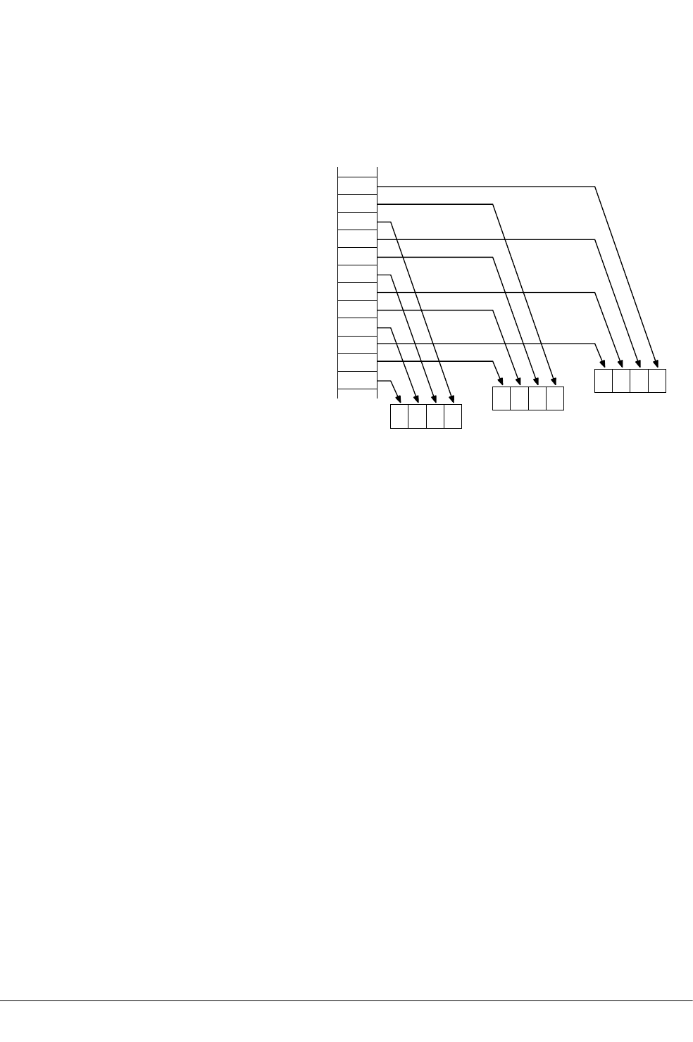
12.4 Interleaving provided by load and store element and structure instructions
Many instructions in this group provide interleaving when structures are stored to memory, and
de-interleaving when structures are loaded from memory.
The following figure shows an example of de-interleaving. Interleaving is the inverse process.
Z
3D2
A[3].x
A[3].y
A[3].z
Z
2Z
1Z
0
A[2].x
A[2].y
A[2].z
A[1].x
A[1].y
A[1].z
A[0].x
A[0].y
A[0].z
Y
3D1Y
2Y
1Y
0
X
3D0X
2X
1X
0
Figure 12-1 De-interleaving an array of 3-element structures
Related concepts
12.5 Alignment restrictions in load and store element and structure instructions on page 12-603.
Related references
12.50 VLDn (single n-element structure to one lane) on page 12-648.
12.51 VLDn (single n-element structure to all lanes) on page 12-650.
12.52 VLDn (multiple n-element structures) on page 12-652.
Related information
ARM Architecture Reference Manual.
12 NEON and VFP Instructions
12.4 Interleaving provided by load and store element and structure instructions
ARM DUI0473J Copyright © 2010-2013 ARM. All rights reserved. 12-602
Non-Confidential

12.5 Alignment restrictions in load and store element and structure instructions
Many of these instructions allow you to specify memory alignment restrictions.
When the alignment is not specified in the instruction, the alignment restriction is controlled by
the A bit (SCTLR bit[1]):
• If the A bit is 0, there are no alignment restrictions (except for strongly-ordered or device
memory, where accesses must be element-aligned).
• If the A bit is 1, accesses must be element-aligned.
If an address is not correctly aligned, an alignment fault occurs.
Related concepts
12.4 Interleaving provided by load and store element and structure instructions on page 12-602.
Related references
12.50 VLDn (single n-element structure to one lane) on page 12-648.
12.51 VLDn (single n-element structure to all lanes) on page 12-650.
12.52 VLDn (multiple n-element structures) on page 12-652.
Related information
ARM Architecture Reference Manual.
12 NEON and VFP Instructions
12.5 Alignment restrictions in load and store element and structure instructions
ARM DUI0473J Copyright © 2010-2013 ARM. All rights reserved. 12-603
Non-Confidential

12.6 VABA and VABAL
Vector Absolute Difference and Accumulate.
Syntax
VABA{cond}.datatype {Qd}, Qn, Qm
VABA{cond}.datatype {Dd}, Dn, Dm
VABAL{cond}.datatype Qd, Dn, Dm
where:
cond
is an optional condition code.
datatype
must be one of S8, S16, S32, U8, U16, or U32.
Qd, Qn, Qm
are the destination vector, the first operand vector, and the second operand vector, for a
quadword operation.
Dd, Dn, Dm
are the destination vector, the first operand vector, and the second operand vector, for a
doubleword operation.
Qd, Dn, Dm
are the destination vector, the first operand vector, and the second operand vector, for a
long operation.
Operation
VABA subtracts the elements of one vector from the corresponding elements of another vector, and
accumulates the absolute values of the results into the elements of the destination vector.
VABAL is the long version of the VABA instruction.
Related concepts
8.10 NEON and VFP data types on page 8-187.
Related references
10.8 Condition codes on page 10-317.
12 NEON and VFP Instructions
12.6 VABA and VABAL
ARM DUI0473J Copyright © 2010-2013 ARM. All rights reserved. 12-604
Non-Confidential

12.7 VABD and VABDL
Vector Absolute Difference.
Syntax
VABD{cond}.datatype {Qd}, Qn, Qm
VABD{cond}.datatype {Dd}, Dn, Dm
VABDL{cond}.datatype Qd, Dn, Dm
where:
cond
is an optional condition code.
datatype
must be one of:
•S8, S16, S32, U8, U16, or U32 for VABDL.
•S8, S16, S32, U8, U16, U32 or F32 for VABD.
Qd, Qn, Qm
are the destination vector, the first operand vector, and the second operand vector, for a
quadword operation.
Dd, Dn, Dm
are the destination vector, the first operand vector, and the second operand vector, for a
doubleword operation.
Qd, Dn, Dm
are the destination vector, the first operand vector, and the second operand vector, for a
long operation.
Operation
VABD subtracts the elements of one vector from the corresponding elements of another vector, and
places the absolute values of the results into the elements of the destination vector.
VABDL is the long version of the VABD instruction.
Related concepts
8.10 NEON and VFP data types on page 8-187.
Related references
10.8 Condition codes on page 10-317.
12 NEON and VFP Instructions
12.7 VABD and VABDL
ARM DUI0473J Copyright © 2010-2013 ARM. All rights reserved. 12-605
Non-Confidential

12.8 VABS
Vector Absolute
Syntax
VABS{cond}.datatype Qd, Qm
VABS{cond}.datatype Dd, Dm
where:
cond
is an optional condition code.
datatype
must be one of S8, S16, S32, or F32.
Qd, Qm
are the destination vector and the operand vector, for a quadword operation.
Dd, Dm
are the destination vector and the operand vector, for a doubleword operation.
Operation
VABS takes the absolute value of each element in a vector, and places the results in a second
vector. (The floating-point version only clears the sign bit.)
Related concepts
8.10 NEON and VFP data types on page 8-187.
Related references
12.101 VQABS on page 12-702.
10.8 Condition codes on page 10-317.
12 NEON and VFP Instructions
12.8 VABS
ARM DUI0473J Copyright © 2010-2013 ARM. All rights reserved. 12-606
Non-Confidential

12.9 VABS (floating-point)
Floating-point absolute value.
Syntax
VABS{cond}.F32 Sd, Sm
VABS{cond}.F64 Dd, Dm
where:
cond
is an optional condition code.
Sd, Sm
are the single-precision registers for the result and operand.
Dd, Dm
are the double-precision registers for the result and operand.
Operation
The VABS instruction takes the contents of Sm or Dm, clears the sign bit, and places the result in Sd
or Dd. This gives the absolute value.
If the operand is a NaN, the sign bit is determined as above, but no exception is produced.
Floating-point exceptions
VABS instructions do not produce any exceptions.
Related references
10.8 Condition codes on page 10-317.
12 NEON and VFP Instructions
12.9 VABS (floating-point)
ARM DUI0473J Copyright © 2010-2013 ARM. All rights reserved. 12-607
Non-Confidential

12.10 VACLE, VACLT, VACGE and VACGT
Vector Absolute Compare.
Syntax
VACop{cond}.F32 {Qd}, Qn, Qm
VACop{cond}.F32 {Dd}, Dn, Dm
where:
op
must be one of:
GE
Absolute Greater than or Equal.
GT
Absolute Greater Than.
LE
Absolute Less than or Equal.
LT
Absolute Less Than.
cond
is an optional condition code.
Qd, Qn, Qm
specifies the destination register, the first operand register, and the second operand
register, for a quadword operation.
Dd, Dn, Dm
specifies the destination register, the first operand register, and the second operand
register, for a doubleword operation.
The result datatype is I32.
Operation
These instructions take the absolute value of each element in a vector, and compare it with the
absolute value of the corresponding element of a second vector. If the condition is true, the
corresponding element in the destination vector is set to all ones. Otherwise, it is set to all zeros.
Note
On disassembly, the VACLE and VACLT pseudo-instructions are disassembled to the corresponding
VACGE and VACGT instructions, with the operands reversed.
Related references
10.8 Condition codes on page 10-317.
12 NEON and VFP Instructions
12.10 VACLE, VACLT, VACGE and VACGT
ARM DUI0473J Copyright © 2010-2013 ARM. All rights reserved. 12-608
Non-Confidential

12.11 VADD (floating-point)
Floating-point add.
Syntax
VADD{cond}.F32 {Sd}, Sn, Sm
VADD{cond}.F64 {Dd}, Dn, Dm
where:
cond
is an optional condition code.
Sd, Sn, Sm
are the single-precision registers for the result and operands.
Dd, Dn, Dm
are the double-precision registers for the result and operands.
Operation
The VADD instruction adds the values in the operand registers and places the result in the
destination register.
Floating-point exceptions
The VADD instruction can produce Invalid Operation, Overflow, or Inexact exceptions.
Related references
10.8 Condition codes on page 10-317.
12 NEON and VFP Instructions
12.11 VADD (floating-point)
ARM DUI0473J Copyright © 2010-2013 ARM. All rights reserved. 12-609
Non-Confidential

12.12 VADD
Vector Add.
Syntax
VADD{cond}.datatype {Qd}, Qn, Qm
VADD{cond}.datatype {Dd}, Dn, Dm
where:
cond
is an optional condition code.
datatype
must be one of I8, I16, I32, I64, or F32
Qd, Qn, Qm
are the destination vector, the first operand vector, and the second operand vector, for a
quadword operation.
Dd, Dn, Dm
are the destination vector, the first operand vector, and the second operand vector, for a
doubleword operation.
Operation
VADD adds corresponding elements in two vectors, and places the results in the destination vector.
Related concepts
8.10 NEON and VFP data types on page 8-187.
Related references
12.14 VADDL and VADDW on page 12-612.
12.102 VQADD on page 12-703.
10.8 Condition codes on page 10-317.
12 NEON and VFP Instructions
12.12 VADD
ARM DUI0473J Copyright © 2010-2013 ARM. All rights reserved. 12-610
Non-Confidential

12.13 VADDHN
Vector Add and Narrow, selecting High half.
Syntax
VADDHN{cond}.datatype Dd, Qn, Qm
where:
cond
is an optional condition code.
datatype
must be one of I16, I32, or I64.
Dd, Qn, Qm
are the destination vector, the first operand vector, and the second operand vector.
Operation
VADDHN adds corresponding elements in two vectors, selects the most significant halves of the
results, and places the final results in the destination vector. Results are truncated.
Related concepts
8.10 NEON and VFP data types on page 8-187.
Related references
12.115 VRADDHN on page 12-716.
10.8 Condition codes on page 10-317.
12 NEON and VFP Instructions
12.13 VADDHN
ARM DUI0473J Copyright © 2010-2013 ARM. All rights reserved. 12-611
Non-Confidential

12.14 VADDL and VADDW
Vector Add Long, Vector Add Wide.
Syntax
VADDL{cond}.datatype Qd, Dn, Dm ; Long operation
VADDW{cond}.datatype {Qd,} Qn, Dm ; Wide operation
where:
cond
is an optional condition code.
datatype
must be one of S8, S16, S32, U8, U16, or U32.
Qd, Dn, Dm
are the destination vector, the first operand vector, and the second operand vector, for a
long operation.
Qd, Qn, Dm
are the destination vector, the first operand vector, and the second operand vector, for a
wide operation.
Operation
VADDL adds corresponding elements in two doubleword vectors, and places the results in the
destination quadword vector.
VADDW adds corresponding elements in one quadword and one doubleword vector, and places the
results in the destination quadword vector.
Related concepts
8.10 NEON and VFP data types on page 8-187.
Related references
12.12 VADD on page 12-610.
10.8 Condition codes on page 10-317.
12 NEON and VFP Instructions
12.14 VADDL and VADDW
ARM DUI0473J Copyright © 2010-2013 ARM. All rights reserved. 12-612
Non-Confidential

12.15 VAND (immediate)
Vector bitwise AND immediate pseudo-instruction.
Syntax
VAND{cond}.datatype Qd, #imm
VAND{cond}.datatype Dd, #imm
where:
cond
is an optional condition code.
datatype
must be either I8, I16, I32, or I64.
Qd or Dd
is the NEON register for the result.
imm
is the immediate value.
Operation
VAND takes each element of the destination vector, performs a bitwise AND with an immediate
value, and returns the result into the destination vector.
Note
On disassembly, this pseudo-instruction is disassembled to a corresponding VBIC instruction, with
the complementary immediate value.
Immediate values
If datatype is I16, the immediate value must have one of the following forms:
•0xFFXY.
•0xXYFF.
If datatype is I32, the immediate value must have one of the following forms:
•0xFFFFFFXY.
•0xFFFFXYFF.
•0xFFXYFFFF.
•0xXYFFFFFF.
Related concepts
8.10 NEON and VFP data types on page 8-187.
Related references
12.17 VBIC (immediate) on page 12-615.
10.8 Condition codes on page 10-317.
12 NEON and VFP Instructions
12.15 VAND (immediate)
ARM DUI0473J Copyright © 2010-2013 ARM. All rights reserved. 12-613
Non-Confidential

12.16 VAND (register)
Vector bitwise AND.
Syntax
VAND{cond}{.datatype} {Qd}, Qn, Qm
VAND{cond}{.datatype} {Dd}, Dn, Dm
where:
cond
is an optional condition code.
datatype
is an optional data type. The assembler ignores datatype.
Qd, Qn, Qm
specifies the destination register, the first operand register, and the second operand
register, for a quadword operation.
Dd, Dn, Dm
specifies the destination register, the first operand register, and the second operand
register, for a doubleword operation.
Operation
VAND performs a bitwise logical AND between two registers, and places the result in the
destination register.
Related references
10.8 Condition codes on page 10-317.
12 NEON and VFP Instructions
12.16 VAND (register)
ARM DUI0473J Copyright © 2010-2013 ARM. All rights reserved. 12-614
Non-Confidential

12.17 VBIC (immediate)
Vector Bit Clear immediate.
Syntax
VBIC{cond}.datatype Qd, #imm
VBIC{cond}.datatype Dd, #imm
where:
cond
is an optional condition code.
datatype
must be either I8, I16, I32, or I64.
Qd or Dd
is the NEON register for the source and result.
imm
is the immediate value.
Operation
VBIC takes each element of the destination vector, performs a bitwise AND complement with an
immediate value, and returns the result in the destination vector.
Immediate values
You can either specify imm as a pattern which the assembler repeats to fill the destination register,
or you can directly specify the immediate value (that conforms to the pattern) in full. The pattern
for imm depends on datatype as shown in the following table:
Table 12-4 Patterns for immediate value in VBIC (immediate)
I16 I32
0x00XY 0x000000XY
0xXY00 0x0000XY00
0x00XY0000
0xXY000000
If you use the I8 or I64 datatypes, the assembler converts it to either the I16 or I32 instruction
to match the pattern of imm. If the immediate value does not match any of the patterns in the
preceding table, the assembler generates an error.
Related concepts
8.10 NEON and VFP data types on page 8-187.
Related references
12.15 VAND (immediate) on page 12-613.
10.8 Condition codes on page 10-317.
12 NEON and VFP Instructions
12.17 VBIC (immediate)
ARM DUI0473J Copyright © 2010-2013 ARM. All rights reserved. 12-615
Non-Confidential

12.18 VBIC (register)
Vector Bit Clear.
Syntax
VBIC{cond}{.datatype} {Qd}, Qn, Qm
VBIC{cond}{.datatype} {Dd}, Dn, Dm
where:
cond
is an optional condition code.
datatype
is an optional data type. The assembler ignores datatype.
Qd, Qn, Qm
specifies the destination register, the first operand register, and the second operand
register, for a quadword operation.
Dd, Dn, Dm
specifies the destination register, the first operand register, and the second operand
register, for a doubleword operation.
Operation
VBIC performs a bitwise logical AND complement between two registers, and places the results in
the destination register.
Related references
10.8 Condition codes on page 10-317.
12 NEON and VFP Instructions
12.18 VBIC (register)
ARM DUI0473J Copyright © 2010-2013 ARM. All rights reserved. 12-616
Non-Confidential

12.19 VBIF
Vector Bitwise Insert if False.
Syntax
VBIF{cond}{.datatype} {Qd}, Qn, Qm
VBIF{cond}{.datatype} {Dd}, Dn, Dm
where:
cond
is an optional condition code.
datatype
is an optional datatype. The assembler ignores datatype.
Qd, Qn, Qm
specifies the destination register, the first operand register, and the second operand
register, for a quadword operation.
Dd, Dn, Dm
specifies the destination register, the first operand register, and the second operand
register, for a doubleword operation.
Operation
VBIF inserts each bit from the first operand into the destination if the corresponding bit of the
second operand is 0, otherwise it leaves the destination bit unchanged.
Related references
10.8 Condition codes on page 10-317.
12 NEON and VFP Instructions
12.19 VBIF
ARM DUI0473J Copyright © 2010-2013 ARM. All rights reserved. 12-617
Non-Confidential

12.20 VBIT
Vector Bitwise Insert if True.
Syntax
VBIT{cond}{.datatype} {Qd}, Qn, Qm
VBIT{cond}{.datatype} {Dd}, Dn, Dm
where:
cond
is an optional condition code.
datatype
is an optional datatype. The assembler ignores datatype.
Qd, Qn, Qm
specifies the destination register, the first operand register, and the second operand
register, for a quadword operation.
Dd, Dn, Dm
specifies the destination register, the first operand register, and the second operand
register, for a doubleword operation.
Operation
VBIT inserts each bit from the first operand into the destination if the corresponding bit of the
second operand is 1, otherwise it leaves the destination bit unchanged.
Related references
10.8 Condition codes on page 10-317.
12 NEON and VFP Instructions
12.20 VBIT
ARM DUI0473J Copyright © 2010-2013 ARM. All rights reserved. 12-618
Non-Confidential

12.21 VBSL
Vector Bitwise Select.
Syntax
VBSL{cond}{.datatype} {Qd}, Qn, Qm
VBSL{cond}{.datatype} {Dd}, Dn, Dm
where:
cond
is an optional condition code.
datatype
is an optional datatype. The assembler ignores datatype.
Qd, Qn, Qm
specifies the destination register, the first operand register, and the second operand
register, for a quadword operation.
Dd, Dn, Dm
specifies the destination register, the first operand register, and the second operand
register, for a doubleword operation.
Operation
VBSL selects each bit for the destination from the first operand if the corresponding bit of the
destination is 1, or from the second operand if the corresponding bit of the destination is 0.
Related references
10.8 Condition codes on page 10-317.
12 NEON and VFP Instructions
12.21 VBSL
ARM DUI0473J Copyright © 2010-2013 ARM. All rights reserved. 12-619
Non-Confidential

12.22 VCEQ (immediate #0)
Vector Compare Equal to zero.
Syntax
VCEQ{cond}.datatype {Qd}, Qn, #0
VCEQ{cond}.datatype {Dd}, Dn, #0
where:
cond
is an optional condition code.
datatype
must be one of I8, I16, I32, or F32.
The result datatype is:
•I32 for operand datatypes I32 or F32.
•I16 for operand datatype I16.
•I8 for operand datatype I8.
Qd, Qn, Qm
specifies the destination register and the operand register, for a quadword operation.
Dd, Dn, Dm
specifies the destination register and the operand register, for a doubleword operation.
#0
specifies a comparison with zero.
Operation
VCEQ takes the value of each element in a vector, and compares it with zero. If the condition is
true, the corresponding element in the destination vector is set to all ones. Otherwise, it is set to all
zeros.
Related concepts
8.10 NEON and VFP data types on page 8-187.
Related references
10.8 Condition codes on page 10-317.
12 NEON and VFP Instructions
12.22 VCEQ (immediate #0)
ARM DUI0473J Copyright © 2010-2013 ARM. All rights reserved. 12-620
Non-Confidential

12.23 VCEQ (register)
Vector Compare Equal.
Syntax
VCEQ{cond}.datatype {Qd}, Qn, Qm
VCEQ{cond}.datatype {Dd}, Dn, Dm
where:
cond
is an optional condition code.
datatype
must be one of I8, I16, I32, or F32.
The result datatype is:
•I32 for operand datatypes I32 or F32.
•I16 for operand datatype I16.
•I8 for operand datatype I8.
Qd, Qn, Qm
specifies the destination register, the first operand register, and the second operand
register, for a quadword operation.
Dd, Dn, Dm
specifies the destination register, the first operand register, and the second operand
register, for a doubleword operation.
Operation
VCEQ takes the value of each element in a vector, and compares it with the value of the
corresponding element of a second vector. If the condition is true, the corresponding element in
the destination vector is set to all ones. Otherwise, it is set to all zeros.
Related concepts
8.10 NEON and VFP data types on page 8-187.
Related references
12.29 VCLE (register) on page 12-627.
12.32 VCLT (register) on page 12-630.
10.8 Condition codes on page 10-317.
12 NEON and VFP Instructions
12.23 VCEQ (register)
ARM DUI0473J Copyright © 2010-2013 ARM. All rights reserved. 12-621
Non-Confidential

12.24 VCGE (immediate #0)
Vector Compare Greater than or Equal to zero.
Syntax
VCGE{cond}.datatype {Qd}, Qn, #0
VCGE{cond}.datatype {Dd}, Dn, #0
where:
cond
is an optional condition code.
datatype
must be one of S8, S16, S32, or F32.
The result datatype is:
•I32 for operand datatypes S32 or F32.
•I16 for operand datatype S16.
•I8 for operand datatype S8.
Qd, Qn, Qm
specifies the destination register and the operand register, for a quadword operation.
Dd, Dn, Dm
specifies the destination register and the operand register, for a doubleword operation.
#0
specifies a comparison with zero.
Operation
VCGE takes the value of each element in a vector, and compares it with zero. If the condition is
true, the corresponding element in the destination vector is set to all ones. Otherwise, it is set to all
zeros.
Related concepts
8.10 NEON and VFP data types on page 8-187.
Related references
12.29 VCLE (register) on page 12-627.
12.32 VCLT (register) on page 12-630.
10.8 Condition codes on page 10-317.
12 NEON and VFP Instructions
12.24 VCGE (immediate #0)
ARM DUI0473J Copyright © 2010-2013 ARM. All rights reserved. 12-622
Non-Confidential

12.25 VCGE (register)
Vector Compare Greater than or Equal.
Syntax
VCGE{cond}.datatype {Qd}, Qn, Qm
VCGE{cond}.datatype {Dd}, Dn, Dm
where:
cond
is an optional condition code.
datatype
must be one of S8, S16, S32, U8, U16, U32, or F32.
The result datatype is:
•I32 for operand datatypes S32, U32, or F32.
•I16 for operand datatypes S16 or U16.
•I8 for operand datatypes S8 or U8.
Qd, Qn, Qm
specifies the destination register, the first operand register, and the second operand
register, for a quadword operation.
Dd, Dn, Dm
specifies the destination register, the first operand register, and the second operand
register, for a doubleword operation.
Operation
VCGE takes the value of each element in a vector, and compares it with the value of the
corresponding element of a second vector. If the condition is true, the corresponding element in
the destination vector is set to all ones. Otherwise, it is set to all zeros.
Related concepts
8.10 NEON and VFP data types on page 8-187.
Related references
12.29 VCLE (register) on page 12-627.
12.32 VCLT (register) on page 12-630.
10.8 Condition codes on page 10-317.
12 NEON and VFP Instructions
12.25 VCGE (register)
ARM DUI0473J Copyright © 2010-2013 ARM. All rights reserved. 12-623
Non-Confidential

12.26 VCGT (immediate #0)
Vector Compare Greater Than zero.
Syntax
VCGT{cond}.datatype {Qd}, Qn, #0
VCGT{cond}.datatype {Dd}, Dn, #0
where:
cond
is an optional condition code.
datatype
must be one of S8, S16, S32, or F32.
The result datatype is:
•I32 for operand datatypes S32 or F32.
•I16 for operand datatype S16.
•I8 for operand datatype S8.
Qd, Qn, Qm
specifies the destination register and the operand register, for a quadword operation.
Dd, Dn, Dm
specifies the destination register and the operand register, for a doubleword operation.
Operation
VCGT takes the value of each element in a vector, and compares it with zero. If the condition is
true, the corresponding element in the destination vector is set to all ones. Otherwise, it is set to all
zeros.
Related concepts
8.10 NEON and VFP data types on page 8-187.
Related references
12.29 VCLE (register) on page 12-627.
12.32 VCLT (register) on page 12-630.
10.8 Condition codes on page 10-317.
12 NEON and VFP Instructions
12.26 VCGT (immediate #0)
ARM DUI0473J Copyright © 2010-2013 ARM. All rights reserved. 12-624
Non-Confidential

12.27 VCGT (register)
Vector Compare Greater Than.
Syntax
VCGT{cond}.datatype {Qd}, Qn, Qm
VCGT{cond}.datatype {Dd}, Dn, Dm
where:
cond
is an optional condition code.
datatype
must be one of S8, S16, S32, U8, U16, U32, or F32.
The result datatype is:
•I32 for operand datatypes S32, U32, or F32.
•I16 for operand datatypes S16 or U16.
•I8 for operand datatypes S8 or U8.
Qd, Qn, Qm
specifies the destination register, the first operand register, and the second operand
register, for a quadword operation.
Dd, Dn, Dm
specifies the destination register, the first operand register, and the second operand
register, for a doubleword operation.
Operation
VCGT takes the value of each element in a vector, and compares it with the value of the
corresponding element of a second vector. If the condition is true, the corresponding element in
the destination vector is set to all ones. Otherwise, it is set to all zeros.
Related concepts
8.10 NEON and VFP data types on page 8-187.
Related references
12.29 VCLE (register) on page 12-627.
12.32 VCLT (register) on page 12-630.
10.8 Condition codes on page 10-317.
12 NEON and VFP Instructions
12.27 VCGT (register)
ARM DUI0473J Copyright © 2010-2013 ARM. All rights reserved. 12-625
Non-Confidential

12.28 VCLE (immediate #0)
Vector Compare Less than or Equal to zero.
Syntax
VCLE{cond}.datatype {Qd}, Qn, #0
VCLE{cond}.datatype {Dd}, Dn, #0
where:
cond
is an optional condition code.
datatype
must be one of S8, S16, S32, or F32.
The result datatype is:
•I32 for operand datatypes S32 or F32.
•I16 for operand datatype S16.
•I8 for operand datatype S8.
Qd, Qn, Qm
specifies the destination register and the operand register, for a quadword operation.
Dd, Dn, Dm
specifies the destination register and the operand register, for a doubleword operation.
#0
specifies a comparison with zero.
Operation
VCLE takes the value of each element in a vector, and compares it with zero. If the condition is
true, the corresponding element in the destination vector is set to all ones. Otherwise, it is set to all
zeros.
Related concepts
8.10 NEON and VFP data types on page 8-187.
Related references
12.29 VCLE (register) on page 12-627.
12.32 VCLT (register) on page 12-630.
10.8 Condition codes on page 10-317.
12 NEON and VFP Instructions
12.28 VCLE (immediate #0)
ARM DUI0473J Copyright © 2010-2013 ARM. All rights reserved. 12-626
Non-Confidential

12.29 VCLE (register)
Vector Compare Less than or Equal pseudo-instruction.
Syntax
VCLE{cond}.datatype {Qd}, Qn, Qm
VCLE{cond}.datatype {Dd}, Dn, Dm
where:
cond
is an optional condition code.
datatype
must be one of S8, S16, S32, U8, U16, U32, or F32.
The result datatype is:
•I32 for operand datatypes S32, U32, or F32.
•I16 for operand datatypes S16 or U16.
•I8 for operand datatypes S8 or U8.
Qd, Qn, Qm
specifies the destination register, the first operand register, and the second operand
register, for a quadword operation.
Dd, Dn, Dm
specifies the destination register, the first operand register, and the second operand
register, for a doubleword operation.
Operation
VCLE takes the value of each element in a vector, and compares it with the value of the
corresponding element of a second vector. If the condition is true, the corresponding element in
the destination vector is set to all ones. Otherwise, it is set to all zeros.
On disassembly, this pseudo-instruction is disassembled to the corresponding VCGE instruction,
with the operands reversed.
Related concepts
8.10 NEON and VFP data types on page 8-187.
Related references
10.8 Condition codes on page 10-317.
12 NEON and VFP Instructions
12.29 VCLE (register)
ARM DUI0473J Copyright © 2010-2013 ARM. All rights reserved. 12-627
Non-Confidential

12.30 VCLS
Vector Count Leading Sign bits.
Syntax
VCLS{cond}.datatype Qd, Qm
VCLS{cond}.datatype Dd, Dm
where:
cond
is an optional condition code.
datatype
must be one of S8, S16, or S32.
Qd, Qm
are the destination vector and the operand vector, for a quadword operation.
Dd, Dm
are the destination vector and the operand vector, for a doubleword operation.
Operation
VCLS counts the number of consecutive bits following the topmost bit, that are the same as the
topmost bit, in each element in a vector, and places the results in a second vector.
Related concepts
8.10 NEON and VFP data types on page 8-187.
Related references
10.8 Condition codes on page 10-317.
12 NEON and VFP Instructions
12.30 VCLS
ARM DUI0473J Copyright © 2010-2013 ARM. All rights reserved. 12-628
Non-Confidential

12.31 VCLT (immediate #0)
Vector Compare Less Than zero.
Syntax
VCLT{cond}.datatype {Qd}, Qn, #0
VCLT{cond}.datatype {Dd}, Dn, #0
where:
cond
is an optional condition code.
datatype
must be one of S8, S16, S32, or F32.
The result datatype is:
•I32 for operand datatypes S32 or F32.
•I16 for operand datatype S16.
•I8 for operand datatype S8.
Qd, Qn, Qm
specifies the destination register and the operand register, for a quadword operation.
Dd, Dn, Dm
specifies the destination register and the operand register, for a doubleword operation.
#0
specifies a comparison with zero.
Operation
VCLT takes the value of each element in a vector, and compares it with zero. If the condition is
true, the corresponding element in the destination vector is set to all ones. Otherwise, it is set to all
zeros.
Related concepts
8.10 NEON and VFP data types on page 8-187.
Related references
10.8 Condition codes on page 10-317.
12 NEON and VFP Instructions
12.31 VCLT (immediate #0)
ARM DUI0473J Copyright © 2010-2013 ARM. All rights reserved. 12-629
Non-Confidential

12.32 VCLT (register)
Vector Compare Less Than.
Syntax
VCLT{cond}.datatype {Qd}, Qn, Qm
VCLT{cond}.datatype {Dd}, Dn, Dm
where:
cond
is an optional condition code.
datatype
must be one of S8, S16, S32, U8, U16, U32, or F32.
The result datatype is:
•I32 for operand datatypes S32, U32, or F32.
•I16 for operand datatypes S16 or U16.
•I8 for operand datatypes S8 or U8.
Qd, Qn, Qm
specifies the destination register, the first operand register, and the second operand
register, for a quadword operation.
Dd, Dn, Dm
specifies the destination register, the first operand register, and the second operand
register, for a doubleword operation.
Operation
VCLT takes the value of each element in a vector, and compares it with the value of the
corresponding element of a second vector. If the condition is true, the corresponding element in
the destination vector is set to all ones. Otherwise, it is set to all zeros.
Note
On disassembly, this pseudo-instruction is disassembled to the corresponding VCGT instruction,
with the operands reversed.
Related concepts
8.10 NEON and VFP data types on page 8-187.
Related references
10.8 Condition codes on page 10-317.
12 NEON and VFP Instructions
12.32 VCLT (register)
ARM DUI0473J Copyright © 2010-2013 ARM. All rights reserved. 12-630
Non-Confidential

12.33 VCLZ
Vector Count Leading Zeros.
Syntax
VCLZ{cond}.datatype Qd, Qm
VCLZ{cond}.datatype Dd, Dm
where:
cond
is an optional condition code.
datatype
must be one of I8, I16, or I32.
Qd, Qm
are the destination vector and the operand vector, for a quadword operation.
Dd, Dm
are the destination vector and the operand vector, for a doubleword operation.
Operation
VCLZ counts the number of consecutive zeros, starting from the top bit, in each element in a
vector, and places the results in a second vector.
Related concepts
8.10 NEON and VFP data types on page 8-187.
Related references
10.8 Condition codes on page 10-317.
12 NEON and VFP Instructions
12.33 VCLZ
ARM DUI0473J Copyright © 2010-2013 ARM. All rights reserved. 12-631
Non-Confidential

12.34 VCMP, VCMPE
Floating-point compare.
Syntax
VCMP{E}{cond}.F32 Sd, Sm
VCMP{E}{cond}.F32 Sd, #0
VCMP{E}{cond}.F64 Dd, Dm
VCMP{E}{cond}.F64 Dd, #0
where:
E
if present, indicates that the instruction raises an Invalid Operation exception if either
operand is a quiet or signaling NaN. Otherwise, it raises the exception only if either
operand is a signaling NaN.
cond
is an optional condition code.
Sd, Sm
are the single-precision registers holding the operands.
Dd, Dm
are the double-precision registers holding the operands.
Operation
The VCMP{E} instruction subtracts the value in the second operand register (or 0 if the second
operand is #0) from the value in the first operand register, and sets the VFP condition flags based
on the result.
VCMP and VCMPE are always scalar.
Floating-point exceptions
VCMP{E} instructions can produce Invalid Operation exceptions.
Related references
10.8 Condition codes on page 10-317.
12 NEON and VFP Instructions
12.34 VCMP, VCMPE
ARM DUI0473J Copyright © 2010-2013 ARM. All rights reserved. 12-632
Non-Confidential

12.35 VCNT
Vector Count set bits.
Syntax
VCNT{cond}.datatype Qd, Qm
VCNT{cond}.datatype Dd, Dm
where:
cond
is an optional condition code.
datatype
must be I8.
Qd, Qm
are the destination vector and the operand vector, for a quadword operation.
Dd, Dm
are the destination vector and the operand vector, for a doubleword operation.
Operation
VCNT counts the number of bits that are one in each element in a vector, and places the results in a
second vector.
Related concepts
8.10 NEON and VFP data types on page 8-187.
Related references
10.8 Condition codes on page 10-317.
12 NEON and VFP Instructions
12.35 VCNT
ARM DUI0473J Copyright © 2010-2013 ARM. All rights reserved. 12-633
Non-Confidential

12.36 VCVT (between fixed-point or integer, and floating-point)
Vector Convert.
Syntax
VCVT{cond}.type Qd, Qm {, #fbits}
VCVT{cond}.type Dd, Dm {, #fbits}
where:
cond
is an optional condition code.
type
specifies the data types for the elements of the vectors. It must be one of:
S32.F32
Floating-point to signed integer or fixed-point.
U32.F32
Floating-point to unsigned integer or fixed-point.
F32.S32
Signed integer or fixed-point to floating-point.
F32.U32
Unsigned integer or fixed-point to floating-point.
Qd, Qm
specifies the destination vector and the operand vector, for a quadword operation.
Dd, Dm
specifies the destination vector and the operand vector, for a doubleword operation.
fbits
if present, specifies the number of fraction bits in the fixed point number. Otherwise, the
conversion is between floating-point and integer. fbits must lie in the range 0-32. If
fbits is omitted, the number of fraction bits is 0.
Operation
VCVT converts each element in a vector in one of the following ways, and places the results in the
destination vector:
• From floating-point to integer.
• From integer to floating-point.
• From floating-point to fixed-point.
• From fixed-point to floating-point.
Rounding
Integer or fixed-point to floating-point conversions use round to nearest.
Floating-point to integer or fixed-point conversions use round towards zero.
Related references
10.8 Condition codes on page 10-317.
12 NEON and VFP Instructions
12.36 VCVT (between fixed-point or integer, and floating-point)
ARM DUI0473J Copyright © 2010-2013 ARM. All rights reserved. 12-634
Non-Confidential

12.37 VCVT (between half-precision and single-precision floating-point)
Vector Convert.
Syntax
VCVT{cond}.F32.F16 Qd, Dm
VCVT{cond}.F16.F32 Dd, Qm
where:
cond
is an optional condition code.
Qd, Dm
specifies the destination vector for the single-precision results and the half-precision
operand vector.
Dd, Qm
specifies the destination vector for half-precision results and the single-precision operand
vector.
Operation
VCVT with half-precision extension, converts each element in a vector in one of the following
ways, and places the results in the destination vector:
• From half-precision floating-point to single-precision floating-point (F32.F16).
• From single-precision floating-point to half-precision floating-point (F16.F32).
Architectures
This instruction is only available in NEON systems with the half-precision extension.
Related references
10.8 Condition codes on page 10-317.
12 NEON and VFP Instructions
12.37 VCVT (between half-precision and single-precision floating-point)
ARM DUI0473J Copyright © 2010-2013 ARM. All rights reserved. 12-635
Non-Confidential

12.38 VCVT (between single-precision and double-precision)
Convert between single-precision and double-precision numbers.
Syntax
VCVT{cond}.F64.F32 Dd, Sm
VCVT{cond}.F32.F64 Sd, Dm
where:
cond
is an optional condition code.
Dd
is a double-precision register for the result.
Sm
is a single-precision register holding the operand.
Sd
is a single-precision register for the result.
Dm
is a double-precision register holding the operand.
Operation
These instructions convert the single-precision value in Sm to double-precision, placing the result
in Dd, or the double-precision value in Dm to single-precision, placing the result in Sd.
These instructions are always scalar.
Floating-point exceptions
These instructions can produce Invalid Operation, Input Denormal, Overflow, Underflow, or
Inexact exceptions.
Related references
10.8 Condition codes on page 10-317.
12 NEON and VFP Instructions
12.38 VCVT (between single-precision and double-precision)
ARM DUI0473J Copyright © 2010-2013 ARM. All rights reserved. 12-636
Non-Confidential

12.39 VCVT (between floating-point and integer)
Convert between floating-point numbers and integers.
Syntax
VCVT{R}{cond}.type.F64 Sd, Dm
VCVT{R}{cond}.type.F32 Sd, Sm
VCVT{cond}.F64.type Dd, Sm
VCVT{cond}.F32.type Sd, Sm
where:
R
makes the operation use the rounding mode specified by the FPSCR. Otherwise, the
operation rounds towards zero.
cond
is an optional condition code.
type
can be either U32 (unsigned 32-bit integer) or S32 (signed 32-bit integer).
Sd
is a single-precision register for the result.
Dd
is a double-precision register for the result.
Sm
is a single-precision register holding the operand.
Dm
is a double-precision register holding the operand.
Operation
The first two forms of this instruction convert from floating-point to integer.
The third and fourth forms convert from integer to floating-point.
VCVT is always scalar.
Floating-point exceptions
These instructions can produce Input Denormal, Invalid Operation, or Inexact exceptions.
Related references
10.8 Condition codes on page 10-317.
12 NEON and VFP Instructions
12.39 VCVT (between floating-point and integer)
ARM DUI0473J Copyright © 2010-2013 ARM. All rights reserved. 12-637
Non-Confidential

12.40 VCVT (between floating-point and fixed-point)
Convert between floating-point and fixed-point numbers.
Syntax
VCVT{cond}.type.F64 Dd, Dd, #fbits
VCVT{cond}.type.F32 Sd, Sd, #fbits
VCVT{cond}.F64.type Dd, Dd, #fbits
VCVT{cond}.F32.type Sd, Sd, #fbits
where:
cond
is an optional condition code.
type
can be any one of:
S16
16-bit signed fixed-point number.
U16
16-bit unsigned fixed-point number.
S32
32-bit signed fixed-point number.
U32
32-bit unsigned fixed-point number.
Sd
is a single-precision register for the operand and result.
Dd
is a double-precision register for the operand and result.
fbits
is the number of fraction bits in the fixed-point number, in the range 0-16 if type is S16
or U16, or in the range 1-32 if type is S32 or U32.
Operation
The first two forms of this instruction convert from floating-point to fixed-point.
The third and fourth forms convert from fixed-point to floating-point.
In all cases the fixed-point number is contained in the least significant 16 or 32 bits of the register.
VCVT is always scalar.
Floating-point exceptions
These instructions can produce Input Denormal, Invalid Operation, or Inexact exceptions.
Related references
10.8 Condition codes on page 10-317.
12 NEON and VFP Instructions
12.40 VCVT (between floating-point and fixed-point)
ARM DUI0473J Copyright © 2010-2013 ARM. All rights reserved. 12-638
Non-Confidential

12.41 VCVTB, VCVTT (half-precision extension)
Convert between half-precision and single-precision floating-point numbers.
Syntax
VCVTB{cond}.type Sd, Sm
VCVTT{cond}.type Sd, Sm
where:
cond
is an optional condition code.
type
can be any one of:
F32.F16
Convert from half-precision to single-precision.
F16.F32
Convert from single-precision to half-precision.
Sd
is a single word register for the result.
Sm
is a single word register for the operand.
Operation
VCVTB uses the bottom half (bits[15:0]) of the single word register to obtain or store the half-
precision value
VCVTT uses the top half (bits[31:16]) of the single word register to obtain or store the half-
precision value.
VCVTB and VCVTT are always scalar.
Architectures
The instructions are only available in VFPv3 systems with the half-precision extension, and
VFPv4.
Floating-point exceptions
These instructions can produce Input Denormal, Invalid Operation, Overflow, Underflow, or
Inexact exceptions.
Related references
10.8 Condition codes on page 10-317.
12 NEON and VFP Instructions
12.41 VCVTB, VCVTT (half-precision extension)
ARM DUI0473J Copyright © 2010-2013 ARM. All rights reserved. 12-639
Non-Confidential

12.42 VDIV
Floating-point divide.
Syntax
VDIV{cond}.F32 {Sd}, Sn, Sm
VDIV{cond}.F64 {Dd}, Dn, Dm
where:
cond
is an optional condition code.
Sd, Sn, Sm
are the single-precision registers for the result and operands.
Dd, Dn, Dm
are the double-precision registers for the result and operands.
Operation
The VDIV instruction divides the value in the first operand register by the value in the second
operand register, and places the result in the destination register.
Floating-point exceptions
VDIV operations can produce Division by Zero, Invalid Operation, Overflow, Underflow, or
Inexact exceptions.
Related references
10.8 Condition codes on page 10-317.
12 NEON and VFP Instructions
12.42 VDIV
ARM DUI0473J Copyright © 2010-2013 ARM. All rights reserved. 12-640
Non-Confidential

12.43 VDUP
Vector Duplicate.
Syntax
VDUP{cond}.size Qd, Dm[x]
VDUP{cond}.size Dd, Dm[x]
VDUP{cond}.size Qd, Rm
VDUP{cond}.size Dd, Rm
where:
cond
is an optional condition code.
size
must be 8, 16, or 32.
Qd
specifies the destination register for a quadword operation.
Dd
specifies the destination register for a doubleword operation.
Dm[x]
specifies the NEON scalar.
Rm
specifies the ARM register. Rm must not be PC.
Operation
VDUP duplicates a scalar into every element of the destination vector. The source can be a NEON
scalar or an ARM register.
Related references
10.8 Condition codes on page 10-317.
12 NEON and VFP Instructions
12.43 VDUP
ARM DUI0473J Copyright © 2010-2013 ARM. All rights reserved. 12-641
Non-Confidential

12.44 VEOR
Vector Bitwise Exclusive OR.
Syntax
VEOR{cond}{.datatype} {Qd}, Qn, Qm
VEOR{cond}{.datatype} {Dd}, Dn, Dm
where:
cond
is an optional condition code.
datatype
is an optional data type. The assembler ignores datatype.
Qd, Qn, Qm
specifies the destination register, the first operand register, and the second operand
register, for a quadword operation.
Dd, Dn, Dm
specifies the destination register, the first operand register, and the second operand
register, for a doubleword operation.
Operation
VEOR performs a logical exclusive OR between two registers, and places the result in the
destination register.
Related references
10.8 Condition codes on page 10-317.
12 NEON and VFP Instructions
12.44 VEOR
ARM DUI0473J Copyright © 2010-2013 ARM. All rights reserved. 12-642
Non-Confidential
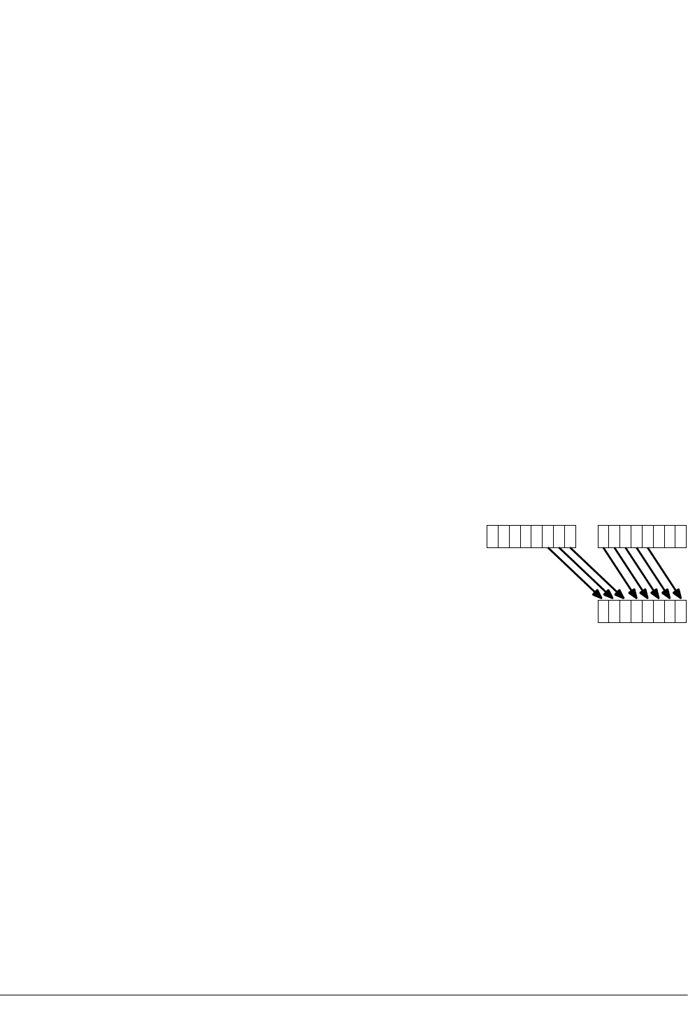
12.45 VEXT
Vector Extract.
Syntax
VEXT{cond}.8 {Qd}, Qn, Qm, #imm
VEXT{cond}.8 {Dd}, Dn, Dm, #imm
where:
cond
is an optional condition code.
Qd, Qn, Qm
specifies the destination register, the first operand register, and the second operand
register, for a quadword operation.
Dd, Dn, Dm
specifies the destination register, the first operand register, and the second operand
register, for a doubleword operation.
imm
is the number of 8-bit elements to extract from the bottom of the second operand vector,
in the range 0-7 for doubleword operations, or 0-15 for quadword operations.
Operation
VEXT extracts 8-bit elements from the bottom end of the second operand vector and the top end of
the first, concatenates them, and places the result in the destination vector. See the following
figure for an example:
Vd
VnVm
0123456701234567
Figure 12-2 Operation of doubleword VEXT for imm = 3
VEXT pseudo-instruction
You can specify a datatype of 16, 32, or 64 instead of 8. In this case, #imm refers to halfwords,
words, or doublewords instead of referring to bytes, and the permitted ranges are correspondingly
reduced.
Related references
10.8 Condition codes on page 10-317.
12 NEON and VFP Instructions
12.45 VEXT
ARM DUI0473J Copyright © 2010-2013 ARM. All rights reserved. 12-643
Non-Confidential

12.46 VFMA, VFMS
Vector Fused Multiply Accumulate, Vector Fused Multiply Subtract.
Syntax
Vop{cond}.F32 {Qd}, Qn, Qm
Vop{cond}.F32 {Dd}, Dn, Dm
where:
op
is one of FMA or FMS.
cond
is an optional condition code.
Dd, Dn, Dm
are the destination and operand vectors for doubleword operation.
Qd, Qn, Qm
are the destination and operand vectors for quadword operation.
Operation
VFMA multiplies corresponding elements in the two operand vectors, and accumulates the results
into the elements of the destination vector. The result of the multiply is not rounded before the
accumulation.
VFMS multiplies corresponding elements in the two operand vectors, then subtracts the products
from the corresponding elements of the destination vector, and places the final results in the
destination vector. The result of the multiply is not rounded before the subtraction.
Related references
12.79 VMUL on page 12-680.
10.8 Condition codes on page 10-317.
12 NEON and VFP Instructions
12.46 VFMA, VFMS
ARM DUI0473J Copyright © 2010-2013 ARM. All rights reserved. 12-644
Non-Confidential

12.47 VFMA, VFMS, VFNMA, VFNMS
Fused floating-point multiply accumulate and fused floating-point multiply subtract, with optional
negation.
Syntax
VF{N}op{cond}.F64 {Dd}, Dn, Dm
VF{N}op{cond}.F32 {Sd}, Sn, Sm
where:
op
is one of MA or MS.
N
negates the final result.
cond
is an optional condition code.
Sd, Sn, Sm
are the single-precision registers for the result and operands.
Dd, Dn, Dm
are the double-precision registers for the result and operands.
Qd, Qn, Qm
are the double-precision registers for the result and operands.
Operation
VFMA multiplies the values in the operand registers, adds the value in the destination register, and
places the final result in the destination register. The result of the multiply is not rounded before
the accumulation.
VFMS multiplies the values in the operand registers, subtracts the product from the value in the
destination register, and places the final result in the destination register. The result of the multiply
is not rounded before the subtraction.
In each case, the final result is negated if the N option is used.
These instructions are always scalar.
Floating-point exceptions
These instructions can produce Input Denormal, Invalid Operation, Overflow, Underflow, or
Inexact exceptions.
Related references
12.80 VMUL (floating-point) on page 12-681.
10.8 Condition codes on page 10-317.
12 NEON and VFP Instructions
12.47 VFMA, VFMS, VFNMA, VFNMS
ARM DUI0473J Copyright © 2010-2013 ARM. All rights reserved. 12-645
Non-Confidential

12.48 VHADD
Vector Halving Add.
Syntax
VHADD{cond}.datatype {Qd}, Qn, Qm
VHADD{cond}.datatype {Dd}, Dn, Dm
where:
cond
is an optional condition code.
datatype
must be one of S8, S16, S32, U8, U16, or U32.
Qd, Qn, Qm
are the destination vector, the first operand vector, and the second operand vector, for a
quadword operation.
Dd, Dn, Dm
are the destination vector, the first operand vector, and the second operand vector, for a
doubleword operation.
Operation
VHADD adds corresponding elements in two vectors, shifts each result right one bit, and places the
results in the destination vector. Results are truncated.
Related concepts
8.10 NEON and VFP data types on page 8-187.
Related references
10.8 Condition codes on page 10-317.
12 NEON and VFP Instructions
12.48 VHADD
ARM DUI0473J Copyright © 2010-2013 ARM. All rights reserved. 12-646
Non-Confidential

12.49 VHSUB
Vector Halving Subtract.
Syntax
VHSUB{cond}.datatype {Qd}, Qn, Qm
VHSUB{cond}.datatype {Dd}, Dn, Dm
where:
cond
is an optional condition code.
datatype
must be one of S8, S16, S32, U8, U16, or U32.
Qd, Qn, Qm
are the destination vector, the first operand vector, and the second operand vector, for a
quadword operation.
Dd, Dn, Dm
are the destination vector, the first operand vector, and the second operand vector, for a
doubleword operation.
Operation
VHSUB subtracts the elements of one vector from the corresponding elements of another vector,
shifts each result right one bit, and places the results in the destination vector. Results are always
truncated.
Related concepts
8.10 NEON and VFP data types on page 8-187.
Related references
10.8 Condition codes on page 10-317.
12 NEON and VFP Instructions
12.49 VHSUB
ARM DUI0473J Copyright © 2010-2013 ARM. All rights reserved. 12-647
Non-Confidential

12.50 VLDn (single n-element structure to one lane)
Vector Load single n-element structure to one lane.
Syntax
VLDn{cond}.datatype list, [Rn{@align}]{!}
VLDn{cond}.datatype list, [Rn{@align}], Rm
where:
n
must be one of 1, 2, 3, or 4.
cond
is an optional condition code.
datatype
see the following table.
list
specifies the NEON register list. See the following table for options.
Rn
is the ARM register containing the base address. Rn cannot be PC.
align
specifies an optional alignment. See the following table for options.
!
if ! is present, Rn is updated to (Rn + the number of bytes transferred by the instruction).
The update occurs after all the loads have taken place.
Rm
is an ARM register containing an offset from the base address. If Rm is present, the
instruction updates Rn to (Rn + Rm) after using the address to access memory. Rm cannot
be SP or PC.
Operation
VLDn loads one n-element structure from memory into one or more NEON registers. Elements of
the register that are not loaded are unaltered.
Table 12-5 Permitted combinations of parameters for VLDn (single n-element structure to
one lane)
n datatype list az align ba alignment
1 8 {Dd[x]} - Standard only
16 {Dd[x]} @16 2-byte
32 {Dd[x]} @32 4-byte
28 {Dd[x], D(d+1)[x]} @16 2-byte
16 {Dd[x], D(d+1)[x]} @32 4-byte
{Dd[x], D(d+2)[x]} @32 4-byte
32 {Dd[x], D(d+1)[x]} @64 8-byte
{Dd[x], D(d+2)[x]} @64 8-byte
az Every register in the list must be in the range D0-D31.
ba align can be omitted. In this case, standard alignment rules apply.
12 NEON and VFP Instructions
12.50 VLDn (single n-element structure to one lane)
ARM DUI0473J Copyright © 2010-2013 ARM. All rights reserved. 12-648
Non-Confidential

Table 12-5 Permitted combinations of parameters for VLDn (single n-element structure to one
lane) (continued)
n datatype list az align ba alignment
38 {Dd[x], D(d+1)[x], D(d+2)[x]} - Standard only
16 or 32 {Dd[x], D(d+1)[x], D(d+2)[x]} - Standard only
{Dd[x], D(d+2)[x], D(d+4)[x]} - Standard only
48 {Dd[x], D(d+1)[x], D(d+2)[x], D(d+3)[x]} @32 4-byte
16 {Dd[x], D(d+1)[x], D(d+2)[x], D(d+3)[x]} @64 8-byte
{Dd[x], D(d+2)[x], D(d+4)[x], D(d+6)[x]} @64 8-byte
32 {Dd[x], D(d+1)[x], D(d+2)[x], D(d+3)[x]} @64 or @128 8-byte or 16-byte
{Dd[x], D(d+2)[x], D(d+4)[x], D(d+6)[x]} @64 or @128 8-byte or 16-byte
Related concepts
12.4 Interleaving provided by load and store element and structure instructions on page 12-602.
12.5 Alignment restrictions in load and store element and structure instructions on page 12-603.
Related references
12.51 VLDn (single n-element structure to all lanes) on page 12-650.
12.52 VLDn (multiple n-element structures) on page 12-652.
10.8 Condition codes on page 10-317.
12 NEON and VFP Instructions
12.50 VLDn (single n-element structure to one lane)
ARM DUI0473J Copyright © 2010-2013 ARM. All rights reserved. 12-649
Non-Confidential

12.51 VLDn (single n-element structure to all lanes)
Vector Load single n-element structure to all lanes.
Syntax
VLDn{cond}.datatype list, [Rn{@align}]{!}
VLDn{cond}.datatype list, [Rn{@align}], Rm
where:
n
must be one of 1, 2, 3, or 4.
cond
is an optional condition code.
datatype
see the following table.
list
specifies the NEON register list. See the following table for options.
Rn
is the ARM register containing the base address. Rn cannot be PC.
align
specifies an optional alignment. See the following table for options.
!
if ! is present, Rn is updated to (Rn + the number of bytes transferred by the instruction).
The update occurs after all the loads have taken place.
Rm
is an ARM register containing an offset from the base address. If Rm is present, the
instruction updates Rn to (Rn + Rm) after using the address to access memory. Rm cannot
be SP or PC.
Operation
VLDn loads multiple copies of one n-element structure from memory into one or more NEON
registers.
Table 12-6 Permitted combinations of parameters for VLDn (single n-element structure to
all lanes)
n datatype list bb align bc alignment
1 8 {Dd[]} - Standard only
{Dd[],D(d+1)[]} - Standard only
16 {Dd[]} @16 2-byte
{Dd[],D(d+1)[]} @16 2-byte
32 {Dd[]} @32 4-byte
{Dd[],D(d+1)[]} @32 4-byte
28 {Dd[], D(d+1)[]} @8 byte
{Dd[], D(d+2)[]} @8 byte
bb Every register in the list must be in the range D0-D31.
bc align can be omitted. In this case, standard alignment rules apply.
12 NEON and VFP Instructions
12.51 VLDn (single n-element structure to all lanes)
ARM DUI0473J Copyright © 2010-2013 ARM. All rights reserved. 12-650
Non-Confidential

Table 12-6 Permitted combinations of parameters for VLDn (single n-element structure to all
lanes) (continued)
n datatype list bb align bc alignment
16 {Dd[], D(d+1)[]} @16 2-byte
{Dd[], D(d+2)[]} @16 2-byte
32 {Dd[], D(d+1)[]} @32 4-byte
{Dd[], D(d+2)[]} @32 4-byte
38, 16, or 32 {Dd[], D(d+1)[], D(d+2)[]} - Standard only
{Dd[], D(d+2)[], D(d+4)[]} - Standard only
48 {Dd[], D(d+1)[], D(d+2)[], D(d+3)[]} @32 4-byte
{Dd[], D(d+2)[], D(d+4)[], D(d+6)[]} @32 4-byte
16 {Dd[], D(d+1)[], D(d+2)[], D(d+3)[]} @64 8-byte
{Dd[], D(d+2)[], D(d+4)[], D(d+6)[]} @64 8-byte
32 {Dd[], D(d+1)[], D(d+2)[], D(d+3)[]} @64 or @128 8-byte or 16-byte
{Dd[], D(d+2)[], D(d+4)[], D(d+6)[]} @64 or @128 8-byte or 16-byte
Related concepts
12.4 Interleaving provided by load and store element and structure instructions on page 12-602.
12.5 Alignment restrictions in load and store element and structure instructions on page 12-603.
Related references
12.50 VLDn (single n-element structure to one lane) on page 12-648.
12.52 VLDn (multiple n-element structures) on page 12-652.
10.8 Condition codes on page 10-317.
12 NEON and VFP Instructions
12.51 VLDn (single n-element structure to all lanes)
ARM DUI0473J Copyright © 2010-2013 ARM. All rights reserved. 12-651
Non-Confidential

12.52 VLDn (multiple n-element structures)
Vector Load multiple n-element structures.
Syntax
VLDn{cond}.datatype list, [Rn{@align}]{!}
VLDn{cond}.datatype list, [Rn{@align}], Rm
where:
n
must be one of 1, 2, 3, or 4.
cond
is an optional condition code.
datatype
see the following table for options.
list
specifies the NEON register list. See the following table for options.
Rn
is the ARM register containing the base address. Rn cannot be PC.
align
specifies an optional alignment. See the following table for options.
!
if ! is present, Rn is updated to (Rn + the number of bytes transferred by the instruction).
The update occurs after all the loads have taken place.
Rm
is an ARM register containing an offset from the base address. If Rm is present, the
instruction updates Rn to (Rn + Rm) after using the address to access memory. Rm cannot
be SP or PC.
Operation
VLDn loads multiple n-element structures from memory into one or more NEON registers, with
de-interleaving (unless n == 1). Every element of each register is loaded.
Table 12-7 Permitted combinations of parameters for VLDn (multiple n-element structures)
n datatype list bd align be alignment
1 8, 16, 32, or 64 {Dd} @64 8-byte
{Dd, D(d+1)} @64 or @128 8-byte or 16-byte
{Dd, D(d+1), D(d+2)} @64 8-byte
{Dd, D(d+1), D(d+2), D(d+3)} @64, @128, or @256 8-byte, 16-byte, or 32-byte
28, 16, or 32 {Dd, D(d+1)} @64, @128 8-byte or 16-byte
{Dd, D(d+2)} @64, @128 8-byte or 16-byte
{Dd, D(d+1), D(d+2), D(d+3)} @64, @128, or @256 8-byte, 16-byte, or 32-byte
38, 16, or 32 {Dd, D(d+1), D(d+2)} @64 8-byte
{Dd, D(d+2), D(d+4)} @64 8-byte
bd Every register in the list must be in the range D0-D31.
be align can be omitted. In this case, standard alignment rules apply.
12 NEON and VFP Instructions
12.52 VLDn (multiple n-element structures)
ARM DUI0473J Copyright © 2010-2013 ARM. All rights reserved. 12-652
Non-Confidential

Table 12-7 Permitted combinations of parameters for VLDn (multiple n-element structures) (continued)
n datatype list bd align be alignment
48, 16, or 32 {Dd, D(d+1), D(d+2), D(d+3)} @64, @128, or @256 8-byte, 16-byte, or 32-byte
{Dd, D(d+2), D(d+4), D(d+6)} @64, @128, or @256 8-byte, 16-byte, or 32-byte
Related concepts
12.4 Interleaving provided by load and store element and structure instructions on page 12-602.
12.5 Alignment restrictions in load and store element and structure instructions on page 12-603.
Related references
12.50 VLDn (single n-element structure to one lane) on page 12-648.
12.51 VLDn (single n-element structure to all lanes) on page 12-650.
10.8 Condition codes on page 10-317.
12 NEON and VFP Instructions
12.52 VLDn (multiple n-element structures)
ARM DUI0473J Copyright © 2010-2013 ARM. All rights reserved. 12-653
Non-Confidential

12.53 VLDM
Extension register load multiple.
Syntax
VLDMmode{cond} Rn{!}, Registers
where:
mode
must be one of:
IA
meaning Increment address After each transfer. IA is the default, and can be
omitted.
DB
meaning Decrement address Before each transfer.
EA
meaning Empty Ascending stack operation. This is the same as DB for loads.
FD
meaning Full Descending stack operation. This is the same as IA for loads.
cond
is an optional condition code.
Rn
is the ARM register holding the base address for the transfer.
!
is optional. ! specifies that the updated base address must be written back to Rn. If ! is
not specified, mode must be IA.
Registers
is a list of consecutive extension registers enclosed in braces, { and }. The list can be
comma-separated, or in range format. There must be at least one register in the list.
You can specify S, D, or Q registers, but they must not be mixed. The number of registers
must not exceed 16 D registers, or 8 Q registers. If Q registers are specified, on
disassembly they are shown as D registers.
Note
VPOP Registers is equivalent to VLDM sp!, Registers.
You can use either form of this instruction. They both disassemble to VPOP.
Related concepts
4.15 Stack implementation using LDM and STM on page 4-86.
Related references
10.8 Condition codes on page 10-317.
12 NEON and VFP Instructions
12.53 VLDM
ARM DUI0473J Copyright © 2010-2013 ARM. All rights reserved. 12-654
Non-Confidential

12.54 VLDR
Extension register load.
Syntax
VLDR{cond}{.size} Fd, [Rn{, #offset}]
VLDR{cond}{.size} Fd, label
where:
cond
is an optional condition code.
size
is an optional data size specifier. Must be 32 if Fd is an S register, or 64 otherwise.
Fd
is the extension register to be loaded. For a NEON instruction, it must be a D register. For
a VFP instruction, it can be either a D or S register.
Rn
is the ARM register holding the base address for the transfer.
offset
is an optional numeric expression. It must evaluate to a numeric value at assembly time.
The value must be a multiple of 4, and lie in the range –1020 to +1020. The value is
added to the base address to form the address used for the transfer.
label
is a PC-relative expression.
label must be aligned on a word boundary within ±1KB of the current instruction.
Operation
The VLDR instruction loads an extension register from memory.
One word is transferred if Fd is an S register (VFP only). Two words are transferred otherwise.
There is also a VLDR pseudo-instruction.
Related concepts
7.5 Register-relative and PC-relative expressions on page 7-149.
Related references
12.56 VLDR pseudo-instruction on page 12-657.
10.8 Condition codes on page 10-317.
12 NEON and VFP Instructions
12.54 VLDR
ARM DUI0473J Copyright © 2010-2013 ARM. All rights reserved. 12-655
Non-Confidential

12.55 VLDR (post-increment and pre-decrement)
Pseudo-instruction that loads extension registers, with post-increment and pre-decrement forms.
Note
There are also VLDR and VSTR instructions without post-increment and pre-decrement.
Syntax
VLDR{cond}{.size} Fd, [Rn], #offset ; post-increment
VLDR{cond}{.size} Fd, [Rn, #-offset]! ; pre-decrement
where:
cond
is an optional condition code.
size
is an optional data size specifier. Must be 32 if Fd is an S register, or 64 if Fd is a D
register.
Fd
is the extension register to load. For a NEON instruction, it must be a doubleword (Dd)
register. For a VFP instruction, it can be either a double precision (Dd) or a single
precision (Sd) register.
Rn
is the ARM register holding the base address for the transfer.
offset
is a numeric expression that must evaluate to a numeric value at assembly time. The
value must be 4 if Fd is an S register, or 8 if Fd is a D register.
Operation
The post-increment instruction increments the base address in the register by the offset value, after
the transfer. The pre-decrement instruction decrements the base address in the register by the
offset value, and then performs the transfer using the new address in the register. This pseudo-
instruction assembles to a VLDM instruction.
Related references
12.53 VLDM on page 12-654.
12.54 VLDR on page 12-655.
10.8 Condition codes on page 10-317.
12 NEON and VFP Instructions
12.55 VLDR (post-increment and pre-decrement)
ARM DUI0473J Copyright © 2010-2013 ARM. All rights reserved. 12-656
Non-Confidential

12.56 VLDR pseudo-instruction
Pseudo-instruction that loads a constant value into every element of a 64-bit NEON vector, or into
a VFP single-precision or double-precision register.
Note
This section describes the VLDR pseudo-instruction only.
Syntax
VLDR{cond}.datatype Dd,=constant
VLDR{cond}.datatype Sd,=constant
where:
datatype
must be one of:
In
NEON only.
Sn
NEON only.
Un
NEON only.
F32
NEON or VFP.
F64
VFP only.
n
must be one of 8, 16, 32, or 64.
cond
is an optional condition code.
Dd or Sd
is the extension register to be loaded.
constant
is an immediate value of the appropriate type for datatype.
Operation
If an instruction (for example, VMOV) is available that can generate the constant directly into the
register, the assembler uses it. Otherwise, the assembler generates a doubleword literal pool entry
containing the constant and loads the constant using a VLDR instruction.
Related concepts
8.10 NEON and VFP data types on page 8-187.
Related references
12.54 VLDR on page 12-655.
10.8 Condition codes on page 10-317.
12 NEON and VFP Instructions
12.56 VLDR pseudo-instruction
ARM DUI0473J Copyright © 2010-2013 ARM. All rights reserved. 12-657
Non-Confidential

12.57 VMAX and VMIN
Vector Maximum, Vector Minimum.
Syntax
Vop{cond}.datatype Qd, Qn, Qm
Vop{cond}.datatype Dd, Dn, Dm
where:
op
must be either MAX or MIN.
cond
is an optional condition code.
datatype
must be one of S8, S16, S32, U8, U16, U32, or F32.
Qd, Qn, Qm
are the destination vector, the first operand vector, and the second operand vector, for a
quadword operation.
Dd, Dn, Dm
are the destination vector, the first operand vector, and the second operand vector, for a
doubleword operation.
Operation
VMAX compares corresponding elements in two vectors, and copies the larger of each pair into the
corresponding element in the destination vector.
VMIN compares corresponding elements in two vectors, and copies the smaller of each pair into
the corresponding element in the destination vector.
Floating-point maximum and minimum
max(+0.0, –0.0) = +0.0.
min(+0.0, –0.0) = –0.0
If any input is a NaN, the corresponding result element is the default NaN.
Related concepts
8.10 NEON and VFP data types on page 8-187.
Related references
12.96 VPADD on page 12-697.
10.8 Condition codes on page 10-317.
12 NEON and VFP Instructions
12.57 VMAX and VMIN
ARM DUI0473J Copyright © 2010-2013 ARM. All rights reserved. 12-658
Non-Confidential

12.58 VMLA
Vector Multiply Accumulate.
Syntax
VMLA{cond}.datatype {Qd}, Qn, Qm
VMLA{cond}.datatype {Dd}, Dn, Dm
where:
cond
is an optional condition code.
datatype
must be one of I8, I16, I32, or F32.
Qd, Qn, Qm
are the destination vector, the first operand vector, and the second operand vector, for a
quadword operation.
Dd, Dn, Dm
are the destination vector, the first operand vector, and the second operand vector, for a
doubleword operation.
Operation
VMLA multiplies corresponding elements in two vectors, and accumulates the results into the
elements of the destination vector.
Related concepts
8.16 Polynomial arithmetic over {0,1} on page 8-193.
8.10 NEON and VFP data types on page 8-187.
Related references
10.8 Condition codes on page 10-317.
12 NEON and VFP Instructions
12.58 VMLA
ARM DUI0473J Copyright © 2010-2013 ARM. All rights reserved. 12-659
Non-Confidential

12.59 VMLA (by scalar)
Vector Multiply by scalar and Accumulate.
Syntax
VMLA{cond}.datatype {Qd}, Qn, Dm[x]
VMLA{cond}.datatype {Dd}, Dn, Dm[x]
where:
cond
is an optional condition code.
datatype
must be one of I16, I32, or F32.
Qd, Qn
are the destination vector and the first operand vector, for a quadword operation.
Dd, Dn
are the destination vector and the first operand vector, for a doubleword operation.
Dm[x]
is the scalar holding the second operand.
Operation
VMLA multiplies each element in a vector by a scalar, and accumulates the results into the
corresponding elements of the destination vector.
Related concepts
8.10 NEON and VFP data types on page 8-187.
Related references
10.8 Condition codes on page 10-317.
12 NEON and VFP Instructions
12.59 VMLA (by scalar)
ARM DUI0473J Copyright © 2010-2013 ARM. All rights reserved. 12-660
Non-Confidential

12.60 VMLA (floating-point)
Floating-point multiply accumulate.
Syntax
VMLA{cond}.F32 Sd, Sn, Sm
VMLA{cond}.F64 Dd, Dn, Dm
where:
cond
is an optional condition code.
Sd, Sn, Sm
are the single-precision registers for the result and operands.
Dd, Dn, Dm
are the double-precision registers for the result and operands.
Operation
The VMLA instruction multiplies the values in the operand registers, adds the value in the
destination register, and places the final result in the destination register.
Floating-point exceptions
This instruction can produce Invalid Operation, Overflow, Underflow, Inexact, or Input Denormal
exceptions.
Related references
10.8 Condition codes on page 10-317.
12 NEON and VFP Instructions
12.60 VMLA (floating-point)
ARM DUI0473J Copyright © 2010-2013 ARM. All rights reserved. 12-661
Non-Confidential

12.61 VMLAL (by scalar)
Vector Multiply by scalar and Accumulate Long.
Syntax
VMLAL{cond}.datatype Qd, Dn, Dm[x]
where:
cond
is an optional condition code.
datatype
must be one of S16, S32, U16, or U32
Qd, Dn
are the destination vector and the first operand vector, for a long operation.
Dm[x]
is the scalar holding the second operand.
Operation
VMLAL multiplies each element in a vector by a scalar, and accumulates the results into the
corresponding elements of the destination vector.
Related concepts
8.10 NEON and VFP data types on page 8-187.
Related references
10.8 Condition codes on page 10-317.
12 NEON and VFP Instructions
12.61 VMLAL (by scalar)
ARM DUI0473J Copyright © 2010-2013 ARM. All rights reserved. 12-662
Non-Confidential

12.62 VMLAL
Vector Multiply Accumulate Long.
Syntax
VMLAL{cond}.datatype Qd, Dn, Dm
where:
cond
is an optional condition code.
datatype
must be one of S8, S16, S32,U8, U16, or U32.
Qd, Dn, Dm
are the destination vector, the first operand vector, and the second operand vector, for a
long operation.
Operation
VMLAL multiplies corresponding elements in two vectors, and accumulates the results into the
elements of the destination vector.
Related concepts
8.16 Polynomial arithmetic over {0,1} on page 8-193.
8.10 NEON and VFP data types on page 8-187.
Related references
10.8 Condition codes on page 10-317.
12 NEON and VFP Instructions
12.62 VMLAL
ARM DUI0473J Copyright © 2010-2013 ARM. All rights reserved. 12-663
Non-Confidential

12.63 VMLS (by scalar)
Vector Multiply by scalar and Subtract.
Syntax
VMLS{cond}.datatype {Qd}, Qn, Dm[x]
VMLS{cond}.datatype {Dd}, Dn, Dm[x]
where:
cond
is an optional condition code.
datatype
must be one of I16, I32, or F32.
Qd, Qn
are the destination vector and the first operand vector, for a quadword operation.
Dd, Dn
are the destination vector and the first operand vector, for a doubleword operation.
Dm[x]
is the scalar holding the second operand.
Operation
VMLS multiplies each element in a vector by a scalar, subtracts the results from the corresponding
elements of the destination vector, and places the final results in the destination vector.
Related concepts
8.10 NEON and VFP data types on page 8-187.
Related references
10.8 Condition codes on page 10-317.
12 NEON and VFP Instructions
12.63 VMLS (by scalar)
ARM DUI0473J Copyright © 2010-2013 ARM. All rights reserved. 12-664
Non-Confidential

12.64 VMLS
Vector Multiply Subtract.
Syntax
VMLS{cond}.datatype {Qd}, Qn, Qm
VMLS{cond}.datatype {Dd}, Dn, Dm
where:
cond
is an optional condition code.
datatype
must be one of I8, I16, I32, F32.
Qd, Qn, Qm
are the destination vector, the first operand vector, and the second operand vector, for a
quadword operation.
Dd, Dn, Dm
are the destination vector, the first operand vector, and the second operand vector, for a
doubleword operation.
Operation
VMLS multiplies corresponding elements in two vectors, subtracts the results from corresponding
elements of the destination vector, and places the final results in the destination vector.
Related concepts
8.16 Polynomial arithmetic over {0,1} on page 8-193.
8.10 NEON and VFP data types on page 8-187.
Related references
10.8 Condition codes on page 10-317.
12 NEON and VFP Instructions
12.64 VMLS
ARM DUI0473J Copyright © 2010-2013 ARM. All rights reserved. 12-665
Non-Confidential

12.65 VMLS (floating-point)
Floating-point multiply subtract.
Syntax
VMLS{cond}.F32 Sd, Sn, Sm
VMLS{cond}.F64 Dd, Dn, Dm
where:
cond
is an optional condition code.
Sd, Sn, Sm
are the single-precision registers for the result and operands.
Dd, Dn, Dm
are the double-precision registers for the result and operands.
Operation
The VMLS instruction multiplies the values in the operand registers, subtracts the result from the
value in the destination register, and places the final result in the destination register.
Floating-point exceptions
This instruction can produce Invalid Operation, Overflow, Underflow, Inexact, or Input Denormal
exceptions.
Related references
10.8 Condition codes on page 10-317.
12 NEON and VFP Instructions
12.65 VMLS (floating-point)
ARM DUI0473J Copyright © 2010-2013 ARM. All rights reserved. 12-666
Non-Confidential

12.66 VMLSL
Vector Multiply Subtract Long.
Syntax
VMLSL{cond}.datatype Qd, Dn, Dm
where:
cond
is an optional condition code.
datatype
must be one of S8, S16, S32, U8, U16, or U32.
Qd, Dn, Dm
are the destination vector, the first operand vector, and the second operand vector, for a
long operation.
Operation
VMLSL multiplies corresponding elements in two vectors, subtracts the results from corresponding
elements of the destination vector, and places the final results in the destination vector.
Related concepts
8.16 Polynomial arithmetic over {0,1} on page 8-193.
8.10 NEON and VFP data types on page 8-187.
Related references
10.8 Condition codes on page 10-317.
12 NEON and VFP Instructions
12.66 VMLSL
ARM DUI0473J Copyright © 2010-2013 ARM. All rights reserved. 12-667
Non-Confidential

12.67 VMLSL (by scalar)
Vector Multiply by scalar and Subtract Long.
Syntax
VMLSL{cond}.datatype Qd, Dn, Dm[x]
where:
cond
is an optional condition code.
datatype
must be one of S16, S32, U16, or U32.
Qd, Dn
are the destination vector and the first operand vector, for a long operation.
Dm[x]
is the scalar holding the second operand.
Operation
VMLSL multiplies each element in a vector by a scalar, subtracts the results from the corresponding
elements of the destination vector, and places the final results in the destination vector.
Related concepts
8.10 NEON and VFP data types on page 8-187.
Related references
10.8 Condition codes on page 10-317.
12 NEON and VFP Instructions
12.67 VMLSL (by scalar)
ARM DUI0473J Copyright © 2010-2013 ARM. All rights reserved. 12-668
Non-Confidential

12.68 VMOV (floating-point)
Insert a floating-point immediate value into a single-precision or double-precision register, or
copy one register into another register. This instruction is always scalar.
Syntax
VMOV{cond}.F32 Sd, #imm
VMOV{cond}.F64 Dd, #imm
VMOV{cond}.F32 Sd, Sm
VMOV{cond}.F64 Dd, Dm
where:
cond
is an optional condition code.
Sd
is the single-precision destination register.
Dd
is the double-precision destination register.
imm
is the floating-point immediate value.
Sm
is the single-precision source register.
Dm
is the double-precision source register.
Immediate values
Any number that can be expressed as +/–n * 2–r,where n and r are integers, 16 <= n <= 31, 0 <= r
<= 7.
Architectures
The instructions that copy immediate constants are available in VFPv3 and above.
The instructions that copy from registers are available in all VFP systems.
Related references
10.8 Condition codes on page 10-317.
12 NEON and VFP Instructions
12.68 VMOV (floating-point)
ARM DUI0473J Copyright © 2010-2013 ARM. All rights reserved. 12-669
Non-Confidential

12.69 VMOV (immediate)
Vector Move.
Syntax
VMOV{cond}.datatype Qd, #imm
VMOV{cond}.datatype Dd, #imm
where:
cond
is an optional condition code.
datatype
must be one of I8, I16, I32, I64, or F32.
Qd or Dd
is the NEON register for the result.
imm
is an immediate value of the type specified by datatype. This is replicated to fill the
destination register.
Operation
VMOV replicates an immediate value in every element of the destination register.
Table 12-8 Available immediate values in VMOV (immediate)
datatype VMOV
I8 0xXY
I16 0x00XY, 0xXY00
I32 0x000000XY, 0x0000XY00, 0x00XY0000, 0xXY000000
0x0000XYFF, 0x00XYFFFF
I64 byte masks, 0xGGHHJJKKLLMMNNPP bf
F32 floating-point numbers bg
Related concepts
8.10 NEON and VFP data types on page 8-187.
Related references
10.8 Condition codes on page 10-317.
bf Each of 0xGG, 0xHH, 0xJJ, 0xKK, 0xLL, 0xMM, 0xNN, and 0xPP must be either 0x00 or 0xFF.
bg Any number that can be expressed as +/–n * 2–r, where n and r are integers, 16 <= n <= 31, 0 <= r <= 7.
12 NEON and VFP Instructions
12.69 VMOV (immediate)
ARM DUI0473J Copyright © 2010-2013 ARM. All rights reserved. 12-670
Non-Confidential

12.70 VMOV (register)
Vector Move.
Syntax
VMOV{cond}{.datatype} Qd, Qm
VMOV{cond}{.datatype} Dd, Dm
where:
cond
is an optional condition code.
datatype
is an optional datatype. The assembler ignores datatype.
Qd, Qm
specifies the destination vector and the source vector, for a quadword operation.
Dd, Dm
specifies the destination vector and the source vector, for a doubleword operation.
Operation
VMOV copies the contents of the source register into the destination register.
Related references
10.8 Condition codes on page 10-317.
12 NEON and VFP Instructions
12.70 VMOV (register)
ARM DUI0473J Copyright © 2010-2013 ARM. All rights reserved. 12-671
Non-Confidential

12.71 VMOV (between one ARM register and single precision VFP)
Transfer contents between a single-precision floating-point register and an ARM register.
Syntax
VMOV{cond} Rd, Sn
VMOV{cond} Sn, Rd
where:
cond
is an optional condition code.
Sn
is the VFP single-precision register.
Rd
is the ARM register. Rd must not be PC.
Operation
VMOV Rd, Sn transfers the contents of Sn into Rd.
VMOV Sn, Rd transfers the contents of Rd into Sn.
Related references
10.8 Condition codes on page 10-317.
12 NEON and VFP Instructions
12.71 VMOV (between one ARM register and single precision VFP)
ARM DUI0473J Copyright © 2010-2013 ARM. All rights reserved. 12-672
Non-Confidential

12.72 VMOV (between two ARM registers and an extension register)
Transfer contents between two ARM registers and a 64-bit extension register, or two consecutive
32-bit VFP registers.
Syntax
VMOV{cond} Dm, Rd, Rn
VMOV{cond} Rd, Rn, Dm
VMOV{cond} Sm, Sm1, Rd, Rn
VMOV{cond} Rd, Rn, Sm, Sm1
where:
cond
is an optional condition code.
Dm
is a 64-bit extension register.
Sm
is a VFP 32-bit register.
Sm1
is the next consecutive VFP 32-bit register after Sm.
Rd, Rn
are the ARM registers. Rd and Rn must not be PC.
Operation
VMOV Dm, Rd, Rn transfers the contents of Rd into the low half of Dm, and the contents of Rn
into the high half of Dm.
VMOV Rd, Rn, Dm transfers the contents of the low half of Dm into Rd, and the contents of the
high half of Dm into Rn.
VMOV Rd, Rn, Sm, Sm1 transfers the contents of Sm into Rd, and the contents of Sm1 into Rn.
VMOV Sm, Sm1, Rd, Rn transfers the contents of Rd into Sm, and the contents of Rn into Sm1.
Architectures
The 64-bit instructions are available in:
• NEON.
• VFPv2 and above.
The 2 x 32-bit instructions are available in VFPv2 and above.
Related references
10.8 Condition codes on page 10-317.
12 NEON and VFP Instructions
12.72 VMOV (between two ARM registers and an extension register)
ARM DUI0473J Copyright © 2010-2013 ARM. All rights reserved. 12-673
Non-Confidential

12.73 VMOV (between an ARM register and a NEON scalar)
Transfer contents between an ARM register and a NEON scalar.
Syntax
VMOV{cond}{.size} Dn[x], Rd
VMOV{cond}{.datatype} Rd, Dn[x]
where:
cond
is an optional condition code.
size
the data size. Can be 8, 16, or 32. If omitted, size is 32. For VFP instructions, size
must be 32 or omitted.
datatype
the data type. Can be U8, S8, U16, S16, or 32. If omitted, datatype is 32. For VFP
instructions, datatype must be 32 or omitted.
Dn[x]
is the NEON scalar.
Rd
is the ARM register. Rd must not be PC.
Operation
VMOV Dn[x], Rd transfers the contents of the least significant byte, halfword, or word of Rd into
Dn[x].
VMOV Rd, Dn[x] transfers the contents of Dn[x] into the least significant byte, halfword, or
word of Rd. The remaining bits of Rd are either zero or sign extended.
Related concepts
8.14 NEON scalars on page 8-191.
8.10 NEON and VFP data types on page 8-187.
Related references
10.8 Condition codes on page 10-317.
12 NEON and VFP Instructions
12.73 VMOV (between an ARM register and a NEON scalar)
ARM DUI0473J Copyright © 2010-2013 ARM. All rights reserved. 12-674
Non-Confidential

12.74 VMOVL
Vector Move Long.
Syntax
VMOVL{cond}.datatype Qd, Dm
where:
cond
is an optional condition code.
datatype
must be one of S8, S16, S32, U8, U16, or U32.
Qd, Dm
specifies the destination vector and the operand vector.
Operation
VMOVL takes each element in a doubleword vector, sign or zero extends them to twice their
original length, and places the results in a quadword vector.
Related concepts
8.10 NEON and VFP data types on page 8-187.
Related references
10.8 Condition codes on page 10-317.
12 NEON and VFP Instructions
12.74 VMOVL
ARM DUI0473J Copyright © 2010-2013 ARM. All rights reserved. 12-675
Non-Confidential

12.75 VMOVN
Vector Move and Narrow.
Syntax
VMOVN{cond}.datatype Dd, Qm
where:
cond
is an optional condition code.
datatype
must be one of I16, I32, or I64.
Dd, Qm
specifies the destination vector and the operand vector.
Operation
VMOVN copies the least significant half of each element of a quadword vector into the
corresponding elements of a doubleword vector.
Related concepts
8.10 NEON and VFP data types on page 8-187.
Related references
10.8 Condition codes on page 10-317.
12 NEON and VFP Instructions
12.75 VMOVN
ARM DUI0473J Copyright © 2010-2013 ARM. All rights reserved. 12-676
Non-Confidential

12.76 VMOV2
Pseudo-instruction that generates an immediate value and places it in every element of a NEON
vector, without loading a value from a literal pool.
Syntax
VMOV2{cond}.datatype Qd, #constant
VMOV2{cond}.datatype Dd, #constant
where:
datatype
must be one of:
•I8, I16, I32, or I64.
•S8, S16, S32, or S64.
•U8, U16, U32, or U64.
•F32.
cond
is an optional condition code.
Qd or Dd
is the extension register to be loaded.
constant
is an immediate value of the appropriate type for datatype.
Operation
VMOV2 can generate any 16-bit immediate value, and a restricted range of 32-bit and 64-bit
immediate values.
VMOV2 is a pseudo-instruction that always assembles to exactly two instructions. It typically
assembles to a VMOV or VMVN instruction, followed by a VBIC or VORR instruction.
Related concepts
8.10 NEON and VFP data types on page 8-187.
Related references
12.69 VMOV (immediate) on page 12-670.
12.17 VBIC (immediate) on page 12-615.
10.8 Condition codes on page 10-317.
12 NEON and VFP Instructions
12.76 VMOV2
ARM DUI0473J Copyright © 2010-2013 ARM. All rights reserved. 12-677
Non-Confidential

12.77 VMRS
Transfer the contents of a NEON and VFP system register to an ARM register.
Syntax
VMRS{cond} Rd, extsysreg
where:
cond
is an optional condition code.
extsysreg
is the NEON and VFP system register, usually FPSCR, FPSID, or FPEXC.
Rd
is the ARM register. Rd must not be PC.
It can be APSR_nzcv, if extsysreg is FPSCR. In this case, the floating-point status
flags are transferred into the corresponding flags in the ARM APSR.
Operation
The VMRS instruction transfers the contents of extsysreg into Rd.
Note
This instruction stalls the processor until all current NEON or VFP operations complete.
Examples
VMRS r2,FPCID
VMRS APSR_nzcv, FPSCR ; transfer FP status register to ARM APSR
Related references
8.17 NEON and VFP system registers on page 8-194.
10.8 Condition codes on page 10-317.
12 NEON and VFP Instructions
12.77 VMRS
ARM DUI0473J Copyright © 2010-2013 ARM. All rights reserved. 12-678
Non-Confidential

12.78 VMSR
Transfer the contents of an ARM register to a NEON and VFP system register.
Syntax
VMSR{cond} extsysreg, Rd
where:
cond
is an optional condition code.
extsysreg
is the NEON and VFP system register, usually FPSCR, FPSID, or FPEXC.
Rd
is the ARM register. Rd must not be PC.
Operation
The VMSR instruction transfers the contents of Rd into extsysreg.
Note
This instruction stalls the processor until all current NEON or VFP operations complete.
Example
VMSR FPSCR, r4
Related references
8.17 NEON and VFP system registers on page 8-194.
10.8 Condition codes on page 10-317.
12 NEON and VFP Instructions
12.78 VMSR
ARM DUI0473J Copyright © 2010-2013 ARM. All rights reserved. 12-679
Non-Confidential

12.79 VMUL
Vector Multiply.
Syntax
VMUL{cond}.datatype {Qd}, Qn, Qm
VMUL{cond}.datatype {Dd}, Dn, Dm
where:
cond
is an optional condition code.
datatype
must be one of I8, I16, I32, F32, or P8.
Qd, Qn, Qm
are the destination vector, the first operand vector, and the second operand vector, for a
quadword operation.
Dd, Dn, Dm
are the destination vector, the first operand vector, and the second operand vector, for a
doubleword operation.
Operation
VMUL multiplies corresponding elements in two vectors, and places the results in the destination
vector.
Related concepts
8.16 Polynomial arithmetic over {0,1} on page 8-193.
8.10 NEON and VFP data types on page 8-187.
Related references
10.8 Condition codes on page 10-317.
12 NEON and VFP Instructions
12.79 VMUL
ARM DUI0473J Copyright © 2010-2013 ARM. All rights reserved. 12-680
Non-Confidential

12.80 VMUL (floating-point)
Floating-point multiply.
Syntax
VMUL{cond}.F32 {Sd,} Sn, Sm
VMUL{cond}.F64 {Dd,} Dn, Dm
where:
cond
is an optional condition code.
Sd, Sn, Sm
are the single-precision registers for the result and operands.
Dd, Dn, Dm
are the double-precision registers for the result and operands.
Operation
The VMUL operation multiplies the values in the operand registers and places the result in the
destination register.
Floating-point exceptions
This instruction can produce Invalid Operation, Overflow, Underflow, Inexact, or Input Denormal
exceptions.
Related references
10.8 Condition codes on page 10-317.
12 NEON and VFP Instructions
12.80 VMUL (floating-point)
ARM DUI0473J Copyright © 2010-2013 ARM. All rights reserved. 12-681
Non-Confidential

12.81 VMUL (by scalar)
Vector Multiply by scalar.
Syntax
VMUL{cond}.datatype {Qd}, Qn, Dm[x]
VMUL{cond}.datatype {Dd}, Dn, Dm[x]
where:
cond
is an optional condition code.
datatype
must be one of I16, I32, or F32.
Qd, Qn
are the destination vector and the first operand vector, for a quadword operation.
Dd, Dn
are the destination vector and the first operand vector, for a doubleword operation.
Dm[x]
is the scalar holding the second operand.
Operation
VMUL multiplies each element in a vector by a scalar, and places the results in the destination
vector.
Related concepts
8.10 NEON and VFP data types on page 8-187.
Related references
10.8 Condition codes on page 10-317.
12 NEON and VFP Instructions
12.81 VMUL (by scalar)
ARM DUI0473J Copyright © 2010-2013 ARM. All rights reserved. 12-682
Non-Confidential

12.82 VMULL
Vector Multiply Long
Syntax
VMULL{cond}.datatype Qd, Dn, Dm
where:
cond
is an optional condition code.
datatype
must be one of U8, U16, U32, S8, S16, S32, or P8.
Qd, Dn, Dm
are the destination vector, the first operand vector, and the second operand vector, for a
long operation.
Operation
VMULL multiplies corresponding elements in two vectors, and places the results in the destination
vector.
Related concepts
8.16 Polynomial arithmetic over {0,1} on page 8-193.
8.10 NEON and VFP data types on page 8-187.
Related references
10.8 Condition codes on page 10-317.
12 NEON and VFP Instructions
12.82 VMULL
ARM DUI0473J Copyright © 2010-2013 ARM. All rights reserved. 12-683
Non-Confidential

12.83 VMULL (by scalar)
Vector Multiply Long by scalar
Syntax
VMULL{cond}.datatype Qd, Dn, Dm[x]
where:
cond
is an optional condition code.
datatype
must be one of S16, S32, U16, or U32.
Qd, Dn
are the destination vector and the first operand vector, for a long operation.
Dm[x]
is the scalar holding the second operand.
Operation
VMULL multiplies each element in a vector by a scalar, and places the results in the destination
vector.
Related concepts
8.10 NEON and VFP data types on page 8-187.
Related references
10.8 Condition codes on page 10-317.
12 NEON and VFP Instructions
12.83 VMULL (by scalar)
ARM DUI0473J Copyright © 2010-2013 ARM. All rights reserved. 12-684
Non-Confidential

12.84 VMVN (register)
Vector Move NOT (register).
Syntax
VMVN{cond}{.datatype} Qd, Qm
VMVN{cond}{.datatype} Dd, Dm
where:
cond
is an optional condition code.
datatype
is an optional datatype. The assembler ignores datatype.
Qd, Qm
specifies the destination vector and the source vector, for a quadword operation.
Dd, Dm
specifies the destination vector and the source vector, for a doubleword operation.
Operation
VMVN inverts the value of each bit from the source register and places the results into the
destination register.
Related references
10.8 Condition codes on page 10-317.
12 NEON and VFP Instructions
12.84 VMVN (register)
ARM DUI0473J Copyright © 2010-2013 ARM. All rights reserved. 12-685
Non-Confidential

12.85 VMVN (immediate)
Vector Move NOT (immediate).
Syntax
VMVN{cond}.datatype Qd, #imm
VMVN{cond}.datatype Dd, #imm
where:
cond
is an optional condition code.
datatype
must be one of I8, I16, I32, I64, or F32.
Qd or Dd
is the NEON register for the result.
imm
is an immediate value of the type specified by datatype. This is replicated to fill the
destination register.
Operation
VMVN inverts the value of each bit from an immediate value and places the results into each
element in the destination register.
Table 12-9 Available immediate values in VMVN (immediate)
datatype VMVN
I8 -
I16 0xFFXY, 0xXYFF
I32 0xFFFFFFXY, 0xFFFFXYFF, 0xFFXYFFFF, 0xXYFFFFFF
0xFFFFXY00, 0xFFXY0000
I64 -
F32 -
Related concepts
8.10 NEON and VFP data types on page 8-187.
Related references
10.8 Condition codes on page 10-317.
12 NEON and VFP Instructions
12.85 VMVN (immediate)
ARM DUI0473J Copyright © 2010-2013 ARM. All rights reserved. 12-686
Non-Confidential

12.86 VNEG (floating-point)
Floating-point negate.
Syntax
VNEG{cond}.F32 Sd, Sm
VNEG{cond}.F64 Dd, Dm
where:
cond
is an optional condition code.
Sd, Sm
are the single-precision registers for the result and operand.
Dd, Dm
are the double-precision registers for the result and operand.
Operation
The VNEG instruction takes the contents of Sm or Dm, changes the sign bit, and places the result in
Sd or Dd. This gives the negation of the value.
If the operand is a NaN, the sign bit is determined as above, but no exception is produced.
Floating-point exceptions
VNEG instructions do not produce any exceptions.
Related references
10.8 Condition codes on page 10-317.
12 NEON and VFP Instructions
12.86 VNEG (floating-point)
ARM DUI0473J Copyright © 2010-2013 ARM. All rights reserved. 12-687
Non-Confidential

12.87 VNEG
Vector Negate.
Syntax
VNEG{cond}.datatype Qd, Qm
VNEG{cond}.datatype Dd, Dm
where:
cond
is an optional condition code.
datatype
must be one of S8, S16, S32, or F32.
Qd, Qm
are the destination vector and the operand vector, for a quadword operation.
Dd, Dm
are the destination vector and the operand vector, for a doubleword operation.
Operation
VNEG negates each element in a vector, and places the results in a second vector. (The floating-
point version only inverts the sign bit.)
Related concepts
8.10 NEON and VFP data types on page 8-187.
Related references
12.86 VNEG (floating-point) on page 12-687.
10.8 Condition codes on page 10-317.
12 NEON and VFP Instructions
12.87 VNEG
ARM DUI0473J Copyright © 2010-2013 ARM. All rights reserved. 12-688
Non-Confidential

12.88 VNMLA (floating-point)
Floating-point multiply accumulate with negation.
Syntax
VNMLA{cond}.F32 Sd, Sn, Sm
VNMLA{cond}.F64 Dd, Dn, Dm
where:
cond
is an optional condition code.
Sd, Sn, Sm
are the single-precision registers for the result and operands.
Dd, Dn, Dm
are the double-precision registers for the result and operands.
Operation
The VNMLA instruction multiplies the values in the operand registers, adds the value to the
destination register, and places the negated final result in the destination register.
Floating-point exceptions
This instruction can produce Invalid Operation, Overflow, Underflow, Inexact, or Input Denormal
exceptions.
Related references
10.8 Condition codes on page 10-317.
12 NEON and VFP Instructions
12.88 VNMLA (floating-point)
ARM DUI0473J Copyright © 2010-2013 ARM. All rights reserved. 12-689
Non-Confidential

12.89 VNMLS (floating-point)
Floating-point multiply subtract with negation.
Syntax
VNMLS{cond}.F32 Sd, Sn, Sm
VNMLS{cond}.F64 Dd, Dn, Dm
where:
cond
is an optional condition code.
Sd, Sn, Sm
are the single-precision registers for the result and operands.
Dd, Dn, Dm
are the double-precision registers for the result and operands.
Operation
The VNMLS instruction multiplies the values in the operand registers, subtracts the result from the
value in the destination register, and places the negated final result in the destination register.
Floating-point exceptions
This instruction can produce Invalid Operation, Overflow, Underflow, Inexact, or Input Denormal
exceptions.
Related references
10.8 Condition codes on page 10-317.
12 NEON and VFP Instructions
12.89 VNMLS (floating-point)
ARM DUI0473J Copyright © 2010-2013 ARM. All rights reserved. 12-690
Non-Confidential

12.90 VNMUL (floating-point)
Floating-point multiply with negation.
Syntax
VNMUL{cond}.F32 {Sd,} Sn, Sm
VNMUL{cond}.F64 {Dd,} Dn, Dm
where:
cond
is an optional condition code.
Sd, Sn, Sm
are the single-precision registers for the result and operands.
Dd, Dn, Dm
are the double-precision registers for the result and operands.
Operation
The VNMUL instruction multiplies the values in the operand registers and places the negated result
in the destination register.
Floating-point exceptions
This instruction can produce Invalid Operation, Overflow, Underflow, Inexact, or Input Denormal
exceptions.
Related references
10.8 Condition codes on page 10-317.
12 NEON and VFP Instructions
12.90 VNMUL (floating-point)
ARM DUI0473J Copyright © 2010-2013 ARM. All rights reserved. 12-691
Non-Confidential

12.91 VORN (register)
Vector bitwise OR NOT (register).
Syntax
VORN{cond}{.datatype} {Qd}, Qn, Qm
VORN{cond}{.datatype} {Dd}, Dn, Dm
where:
cond
is an optional condition code.
datatype
is an optional data type. The assembler ignores datatype.
Qd, Qn, Qm
specifies the destination register, the first operand register, and the second operand
register, for a quadword operation.
Dd, Dn, Dm
specifies the destination register, the first operand register, and the second operand
register, for a doubleword operation.
Operation
VORN performs a bitwise logical OR complement between two registers, and places the results in
the destination register.
Related references
10.8 Condition codes on page 10-317.
12 NEON and VFP Instructions
12.91 VORN (register)
ARM DUI0473J Copyright © 2010-2013 ARM. All rights reserved. 12-692
Non-Confidential

12.92 VORN (immediate)
Vector bitwise OR NOT (immediate) pseudo-instruction.
Syntax
VORN{cond}.datatype Qd, #imm
VORN{cond}.datatype Dd, #imm
where:
cond
is an optional condition code.
datatype
must be either I8, I16, I32, or I64.
Qd or Dd
is the NEON register for the result.
imm
is the immediate value.
Operation
VORN takes each element of the destination vector, performs a bitwise OR complement with an
immediate value, and returns the result in the destination vector.
Note
On disassembly, this pseudo-instruction is disassembled to a corresponding VORR instruction, with
a complementary immediate value.
Immediate values
If datatype is I16, the immediate value must have one of the following forms:
•0xFFXY.
•0xXYFF.
If datatype is I32, the immediate value must have one of the following forms:
•0xFFFFFFXY.
•0xFFFFXYFF.
•0xFFXYFFFF.
•0xXYFFFFFF.
Related concepts
8.10 NEON and VFP data types on page 8-187.
Related references
12.17 VBIC (immediate) on page 12-615.
10.8 Condition codes on page 10-317.
12 NEON and VFP Instructions
12.92 VORN (immediate)
ARM DUI0473J Copyright © 2010-2013 ARM. All rights reserved. 12-693
Non-Confidential

12.93 VORR (register)
Vector bitwise OR (register).
Syntax
VORR{cond}{.datatype} {Qd}, Qn, Qm
VORR{cond}{.datatype} {Dd}, Dn, Dm
where:
cond
is an optional condition code.
datatype
is an optional data type. The assembler ignores datatype.
Qd, Qn, Qm
specifies the destination register, the first operand register, and the second operand
register, for a quadword operation.
Dd, Dn, Dm
specifies the destination register, the first operand register, and the second operand
register, for a doubleword operation.
Note
VORR with the same register for both operands is a VMOV instruction. You can use VORR in this
way, but disassembly of the resulting code produces the VMOV syntax.
Operation
VORR performs a bitwise logical OR between two registers, and places the result in the destination
register.
Related references
12.70 VMOV (register) on page 12-671.
10.8 Condition codes on page 10-317.
12 NEON and VFP Instructions
12.93 VORR (register)
ARM DUI0473J Copyright © 2010-2013 ARM. All rights reserved. 12-694
Non-Confidential

12.94 VORR (immediate)
Vector bitwise OR immediate.
Syntax
VORR{cond}.datatype Qd, #imm
VORR{cond}.datatype Dd, #imm
where:
cond
is an optional condition code.
datatype
must be either I8, I16, I32, or I64.
Qd or Dd
is the NEON register for the source and result.
imm
is the immediate value.
Operation
VORR takes each element of the destination vector, performs a bitwise logical OR with an
immediate value, and places the result in the destination vector.
Immediate values
You can either specify imm as a pattern which the assembler repeats to fill the destination register,
or you can directly specify the immediate value (that conforms to the pattern) in full. The pattern
for imm depends on the datatype, as shown in the following table:
Table 12-10 Patterns for immediate value in VORR (immediate)
I16 I32
0x00XY 0x000000XY
0xXY00 0x0000XY00
0x00XY0000
0xXY000000
If you use the I8 or I64 datatypes, the assembler converts it to either the I16 or I32 instruction
to match the pattern of imm. If the immediate value does not match any of the patterns in the
preceding table, the assembler generates an error.
Related concepts
8.10 NEON and VFP data types on page 8-187.
Related references
12.15 VAND (immediate) on page 12-613.
10.8 Condition codes on page 10-317.
12 NEON and VFP Instructions
12.94 VORR (immediate)
ARM DUI0473J Copyright © 2010-2013 ARM. All rights reserved. 12-695
Non-Confidential
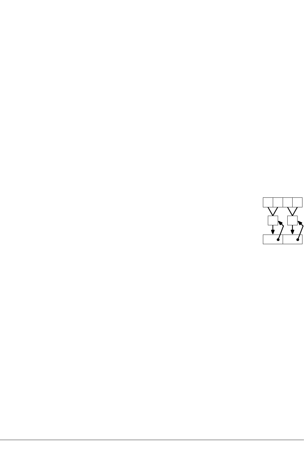
12.95 VPADAL
Vector Pairwise Add and Accumulate Long.
Syntax
VPADAL{cond}.datatype Qd, Qm
VPADAL{cond}.datatype Dd, Dm
where:
cond
is an optional condition code.
datatype
must be one of S8, S16, S32, U8, U16, or U32.
Qd, Qm
are the destination vector and the operand vector, for a quadword instruction.
Dd, Dm
are the destination vector and the operand vector, for a doubleword instruction.
Operation
VPADAL adds adjacent pairs of elements of a vector, and accumulates the absolute values of the
results into the elements of the destination vector.
Dd
Dm
+ +
Figure 12-3 Example of operation of VPADAL (in this case for data type I16)
Related concepts
8.10 NEON and VFP data types on page 8-187.
Related references
10.8 Condition codes on page 10-317.
12 NEON and VFP Instructions
12.95 VPADAL
ARM DUI0473J Copyright © 2010-2013 ARM. All rights reserved. 12-696
Non-Confidential
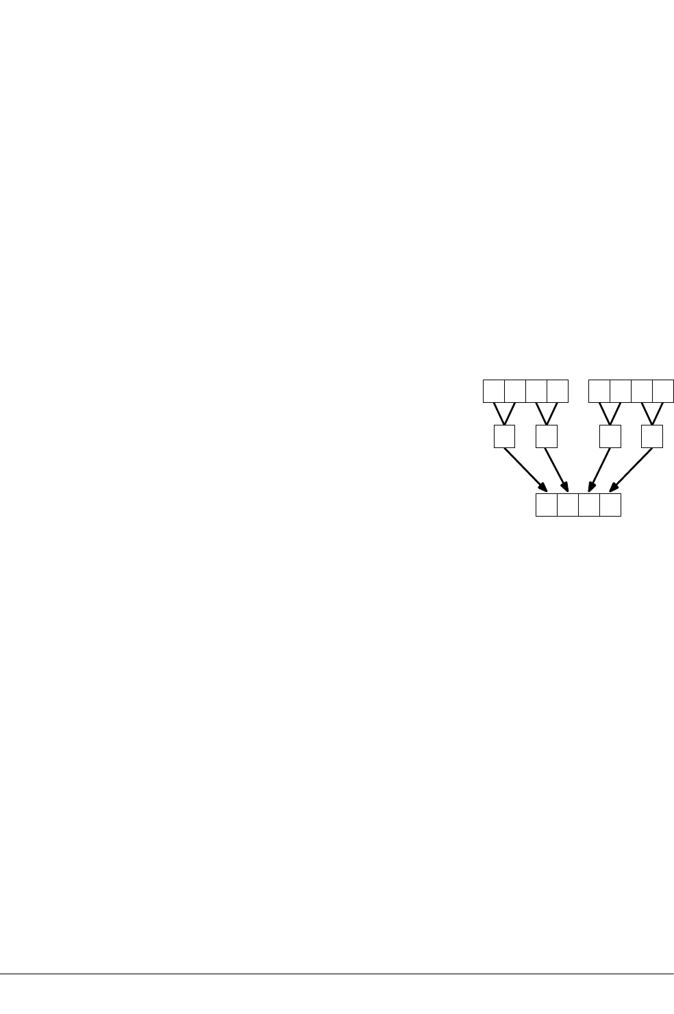
12.96 VPADD
Vector Pairwise Add.
Syntax
VPADD{cond}.datatype {Dd}, Dn, Dm
where:
cond
is an optional condition code.
datatype
must be one of I8, I16, I32, or F32.
Dd, Dn, Dm
are the destination vector, the first operand vector, and the second operand vector.
Operation
VPADD adds adjacent pairs of elements of two vectors, and places the results in the destination
vector.
Dd
DnDm
+ + ++
Figure 12-4 Example of operation of VPADD (in this case, for data type I16)
Related concepts
8.10 NEON and VFP data types on page 8-187.
Related references
10.8 Condition codes on page 10-317.
12 NEON and VFP Instructions
12.96 VPADD
ARM DUI0473J Copyright © 2010-2013 ARM. All rights reserved. 12-697
Non-Confidential
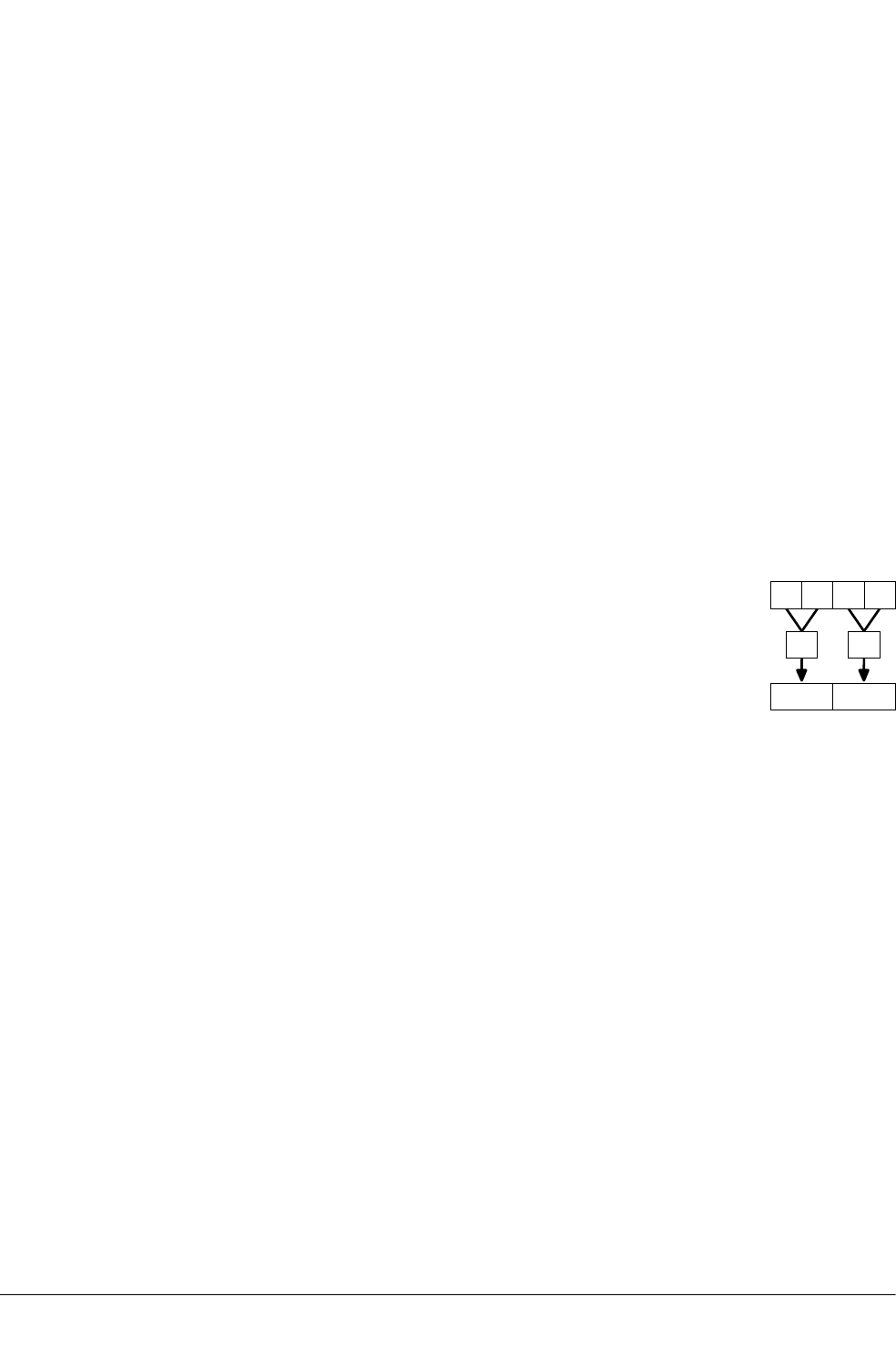
12.97 VPADDL
Vector Pairwise Add Long.
Syntax
VPADDL{cond}.datatype Qd, Qm
VPADDL{cond}.datatype Dd, Dm
where:
cond
is an optional condition code.
datatype
must be one of S8, S16, S32, U8, U16, or U32.
Qd, Qm
are the destination vector and the operand vector, for a quadword instruction.
Dd, Dm
are the destination vector and the operand vector, for a doubleword instruction.
Operation
VPADDL adds adjacent pairs of elements of a vector, sign or zero extends the results to twice their
original width, and places the final results in the destination vector.
Dd
Dm
+ +
Figure 12-5 Example of operation of doubleword VPADDL (in this case, for data type S16)
Related concepts
8.10 NEON and VFP data types on page 8-187.
Related references
10.8 Condition codes on page 10-317.
12 NEON and VFP Instructions
12.97 VPADDL
ARM DUI0473J Copyright © 2010-2013 ARM. All rights reserved. 12-698
Non-Confidential

12.98 VPMAX and VPMIN
Vector Pairwise Maximum, Vector Pairwise Minimum.
Syntax
VPop{cond}.datatype Dd, Dn, Dm
where:
op
must be either MAX or MIN.
cond
is an optional condition code.
datatype
must be one of S8, S16, S32, U8, U16, U32, or F32.
Dd, Dn, Dm
are the destination doubleword vector, the first operand doubleword vector, and the
second operand doubleword vector.
Operation
VPMAX compares adjacent pairs of elements in two vectors, and copies the larger of each pair into
the corresponding element in the destination vector. Operands and results must be doubleword
vectors.
VPMIN compares adjacent pairs of elements in two vectors, and copies the smaller of each pair
into the corresponding element in the destination vector. Operands and results must be
doubleword vectors.
Floating-point maximum and minimum
max(+0.0, –0.0) = +0.0.
min(+0.0, –0.0) = –0.0
If any input is a NaN, the corresponding result element is the default NaN.
Related concepts
8.10 NEON and VFP data types on page 8-187.
Related references
12.96 VPADD on page 12-697.
10.8 Condition codes on page 10-317.
12 NEON and VFP Instructions
12.98 VPMAX and VPMIN
ARM DUI0473J Copyright © 2010-2013 ARM. All rights reserved. 12-699
Non-Confidential

12.99 VPOP
Pop extension registers from the stack.
Syntax
VPOP{cond} Registers
where:
cond
is an optional condition code.
Registers
is a list of consecutive extension registers enclosed in braces, { and }. The list can be
comma-separated, or in range format. There must be at least one register in the list.
You can specify S, D, or Q registers, but they must not be mixed. The number of registers
must not exceed 16 D registers, or 8 Q registers. If Q registers are specified, on
disassembly they are shown as D registers.
Note
VPOP Registers is equivalent to VLDM sp!, Registers.
You can use either form of this instruction. They both disassemble to VPOP.
Related concepts
4.15 Stack implementation using LDM and STM on page 4-86.
Related references
10.8 Condition codes on page 10-317.
12 NEON and VFP Instructions
12.99 VPOP
ARM DUI0473J Copyright © 2010-2013 ARM. All rights reserved. 12-700
Non-Confidential

12.100 VPUSH
Push extension registers onto the stack.
Syntax
VPUSH{cond} Registers
where:
cond
is an optional condition code.
Registers
is a list of consecutive extension registers enclosed in braces, { and }. The list can be
comma-separated, or in range format. There must be at least one register in the list.
You can specify S, D, or Q registers, but they must not be mixed. The number of registers
must not exceed 16 D registers, or 8 Q registers. If Q registers are specified, on
disassembly they are shown as D registers.
Note
VPUSH Registers is equivalent to VSTMDB sp!, Registers.
You can use either form of this instruction. They both disassemble to VPUSH.
Related concepts
4.15 Stack implementation using LDM and STM on page 4-86.
Related references
10.8 Condition codes on page 10-317.
12 NEON and VFP Instructions
12.100 VPUSH
ARM DUI0473J Copyright © 2010-2013 ARM. All rights reserved. 12-701
Non-Confidential

12.101 VQABS
Vector Saturating Absolute.
Syntax
VQABS{cond}.datatype Qd, Qm
VQABS{cond}.datatype Dd, Dm
where:
cond
is an optional condition code.
datatype
must be one of S8, S16, or S32.
Qd, Qm
are the destination vector and the operand vector, for a quadword operation.
Dd, Dm
are the destination vector and the operand vector, for a doubleword operation.
Operation
VQABS takes the absolute value of each element in a vector, and places the results in a second
vector.
The sticky QC flag (FPSCR bit[27]) is set if saturation occurs.
Related concepts
8.10 NEON and VFP data types on page 8-187.
Related references
10.8 Condition codes on page 10-317.
12 NEON and VFP Instructions
12.101 VQABS
ARM DUI0473J Copyright © 2010-2013 ARM. All rights reserved. 12-702
Non-Confidential

12.102 VQADD
Vector Saturating Add.
Syntax
VQADD{cond}.datatype {Qd}, Qn, Qm
VQADD{cond}.datatype {Dd}, Dn, Dm
where:
cond
is an optional condition code.
datatype
must be one of S8, S16, S32, S64, U8, U16, U32, or U64.
Qd, Qn, Qm
are the destination vector, the first operand vector, and the second operand vector, for a
quadword operation.
Dd, Dn, Dm
are the destination vector, the first operand vector, and the second operand vector, for a
doubleword operation.
Operation
VQADD adds corresponding elements in two vectors, and places the results in the destination
vector.
The sticky QC flag (FPSCR bit[27]) is set if saturation occurs.
Related concepts
8.10 NEON and VFP data types on page 8-187.
Related references
10.8 Condition codes on page 10-317.
12 NEON and VFP Instructions
12.102 VQADD
ARM DUI0473J Copyright © 2010-2013 ARM. All rights reserved. 12-703
Non-Confidential

12.103 VQDMLAL and VQDMLSL (by vector or by scalar)
Vector Saturating Doubling Multiply Accumulate Long, Vector Saturating Doubling Multiply
Subtract Long.
Syntax
VQDopL{cond}.datatype Qd, Dn, Dm
VQDopL{cond}.datatype Qd, Dn, Dm[x]
where:
op
must be one of:
MLA
Multiply Accumulate.
MLS
Multiply Subtract.
cond
is an optional condition code.
datatype
must be either S16 or S32.
Qd, Dn
are the destination vector and the first operand vector.
Dm
is the vector holding the second operand, for a by vector operation.
Dm[x]
is the scalar holding the second operand, for a by scalar operation.
Operation
These instructions multiply their operands and double the results. VQDMLAL adds the results to the
values in the destination register. VQDMLSL subtracts the results from the values in the destination
register.
If any of the results overflow, they are saturated. The sticky QC flag (FPSCR bit[27]) is set if
saturation occurs.
Related concepts
8.10 NEON and VFP data types on page 8-187.
Related references
10.8 Condition codes on page 10-317.
12 NEON and VFP Instructions
12.103 VQDMLAL and VQDMLSL (by vector or by scalar)
ARM DUI0473J Copyright © 2010-2013 ARM. All rights reserved. 12-704
Non-Confidential

12.104 VQDMULH (by vector or by scalar)
Vector Saturating Doubling Multiply Returning High Half.
Syntax
VQDMULH{cond}.datatype {Qd}, Qn, Qm
VQDMULH{cond}.datatype {Dd}, Dn, Dm
VQDMULH{cond}.datatype {Qd}, Qn, Dm[x]
VQDMULH{cond}.datatype {Dd}, Dn, Dm[x]
where:
cond
is an optional condition code.
datatype
must be either S16 or S32.
Qd, Qn
are the destination vector and the first operand vector, for a quadword operation.
Dd, Dn
are the destination vector and the first operand vector, for a doubleword operation.
Qm or Dm
is the vector holding the second operand, for a by vector operation.
Dm[x]
is the scalar holding the second operand, for a by scalar operation.
Operation
VQDMULH multiplies corresponding elements in two vectors, doubles the results, and places the
most significant half of the final results in the destination vector.
The second operand can be a scalar instead of a vector.
If any of the results overflow, they are saturated. The sticky QC flag (FPSCR bit[27]) is set if
saturation occurs. Each result is truncated.
Related concepts
8.10 NEON and VFP data types on page 8-187.
Related references
10.8 Condition codes on page 10-317.
12 NEON and VFP Instructions
12.104 VQDMULH (by vector or by scalar)
ARM DUI0473J Copyright © 2010-2013 ARM. All rights reserved. 12-705
Non-Confidential

12.105 VQDMULL (by vector or by scalar)
Vector Saturating Doubling Multiply Long.
Syntax
VQDMULL{cond}.datatype Qd, Dn, Dm
VQDMULL{cond}.datatype Qd, Dn, Dm[x]
where:
cond
is an optional condition code.
datatype
must be either S16 or S32.
Qd, Dn
are the destination vector and the first operand vector.
Dm
is the vector holding the second operand, for a by vector operation.
Dm[x]
is the scalar holding the second operand, for a by scalar operation.
Operation
VQDMULL multiplies corresponding elements in two vectors, doubles the results and places the
results in the destination register.
The second operand can be a scalar instead of a vector.
If any of the results overflow, they are saturated. The sticky QC flag (FPSCR bit[27]) is set if
saturation occurs.
Related concepts
8.10 NEON and VFP data types on page 8-187.
Related references
10.8 Condition codes on page 10-317.
12 NEON and VFP Instructions
12.105 VQDMULL (by vector or by scalar)
ARM DUI0473J Copyright © 2010-2013 ARM. All rights reserved. 12-706
Non-Confidential

12.106 VQMOVN and VQMOVUN
Vector Saturating Move and Narrow.
Syntax
VQMOVN{cond}.datatype Dd, Qm
VQMOVUN{cond}.datatype Dd, Qm
where:
cond
is an optional condition code.
datatype
must be one of:
S16, S32, S64
for VQMOVN or VQMOVUN.
U16, U32, U64
for VQMOVN.
Dd, Qm
specifies the destination vector and the operand vector.
Operation
VQMOVN copies each element of the operand vector to the corresponding element of the destination
vector. The result element is half the width of the operand element, and values are saturated to the
result width. The results are the same type as the operands.
VQMOVUN copies each element of the operand vector to the corresponding element of the
destination vector. The result element is half the width of the operand element, and values are
saturated to the result width. The elements in the operand are signed and the elements in the result
are unsigned.
Related concepts
8.10 NEON and VFP data types on page 8-187.
Related references
10.8 Condition codes on page 10-317.
12 NEON and VFP Instructions
12.106 VQMOVN and VQMOVUN
ARM DUI0473J Copyright © 2010-2013 ARM. All rights reserved. 12-707
Non-Confidential

12.107 VQNEG
Vector Saturating Negate.
Syntax
VQNEG{cond}.datatype Qd, Qm
VQNEG{cond}.datatype Dd, Dm
where:
cond
is an optional condition code.
datatype
must be one of S8, S16, or S32.
Qd, Qm
are the destination vector and the operand vector, for a quadword operation.
Dd, Dm
are the destination vector and the operand vector, for a doubleword operation.
Operation
VQNEG negates each element in a vector, and places the results in a second vector.
The sticky QC flag (FPSCR bit[27]) is set if saturation occurs.
Related concepts
8.10 NEON and VFP data types on page 8-187.
Related references
10.8 Condition codes on page 10-317.
12 NEON and VFP Instructions
12.107 VQNEG
ARM DUI0473J Copyright © 2010-2013 ARM. All rights reserved. 12-708
Non-Confidential

12.108 VQRDMULH (by vector or by scalar)
Vector Saturating Rounding Doubling Multiply Returning High Half.
Syntax
VQRDMULH{cond}.datatype {Qd}, Qn, Qm
VQRDMULH{cond}.datatype {Dd}, Dn, Dm
VQRDMULH{cond}.datatype {Qd}, Qn, Dm[x]
VQRDMULH{cond}.datatype {Dd}, Dn, Dm[x]
where:
cond
is an optional condition code.
datatype
must be either S16 or S32.
Qd, Qn
are the destination vector and the first operand vector, for a quadword operation.
Dd, Dn
are the destination vector and the first operand vector, for a doubleword operation.
Qm or Dm
is the vector holding the second operand, for a by vector operation.
Dm[x]
is the scalar holding the second operand, for a by scalar operation.
Operation
VQRDMULH multiplies corresponding elements in two vectors, doubles the results, and places the
most significant half of the final results in the destination vector.
The second operand can be a scalar instead of a vector.
If any of the results overflow, they are saturated. The sticky QC flag (FPSCR bit[27]) is set if
saturation occurs. Each result is rounded.
Related concepts
8.10 NEON and VFP data types on page 8-187.
Related references
10.8 Condition codes on page 10-317.
12 NEON and VFP Instructions
12.108 VQRDMULH (by vector or by scalar)
ARM DUI0473J Copyright © 2010-2013 ARM. All rights reserved. 12-709
Non-Confidential

12.109 VQRSHL (by signed variable)
Vector Saturating Rounding Shift Left by signed variable.
Syntax
VQRSHL{cond}.datatype {Qd}, Qm, Qn
VQRSHL{cond}.datatype {Dd}, Dm, Dn
where:
cond
is an optional condition code.
datatype
must be one of S8, S16, S32, S64, U8, U16, U32, or U64.
Qd, Qm, Qn
are the destination vector, the first operand vector, and the second operand vector, for a
quadword operation.
Dd, Dm, Dn
are the destination vector, the first operand vector, and the second operand vector, for a
doubleword operation.
Operation
VQRSHL takes each element in a vector, shifts them by a value from the least significant byte of
the corresponding element of a second vector, and places the results in the destination vector. If
the shift value is positive, the operation is a left shift. Otherwise, it is a rounding right shift.
The sticky QC flag (FPSCR bit[27]) is set if saturation occurs.
Related concepts
8.10 NEON and VFP data types on page 8-187.
Related references
10.8 Condition codes on page 10-317.
12 NEON and VFP Instructions
12.109 VQRSHL (by signed variable)
ARM DUI0473J Copyright © 2010-2013 ARM. All rights reserved. 12-710
Non-Confidential

12.110 VQRSHRN and VQRSHRUN (by immediate)
Vector Saturating Shift Right, Narrow, by immediate value, with Rounding.
Syntax
VQRSHR{U}N{cond}.datatype Dd, Qm, #imm
where:
U
if present, indicates that the results are unsigned, although the operands are signed.
Otherwise, the results are the same type as the operands.
cond
is an optional condition code.
datatype
must be one of:
I16, I32, I64
for VQRSHRN or VQRSHRUN. Only a #0 immediate is permitted with these
datatypes.
S16, S32, S64
for VQRSHRN or VQRSHRUN.
U16, U32, U64
for VQRSHRN only.
Dd, Qm
are the destination vector and the operand vector.
imm
is the immediate value specifying the size of the shift, in the range 0 to (size(datatype)
– 1). The ranges are shown in the following table:
Table 12-11 Available immediate ranges in VQRSHRN and VQRSHRUN (by
immediate)
datatype imm range
S16 or U16 0 to 8
S32 or U32 0 to 16
S64 or U64 0 to 32
Operation
VQRSHR{U}N takes each element in a quadword vector of integers, right shifts them by an
immediate value, and places the results in a doubleword vector.
The sticky QC flag (FPSCR bit[27]) is set if saturation occurs.
Results are rounded.
Related concepts
8.10 NEON and VFP data types on page 8-187.
Related references
10.8 Condition codes on page 10-317.
12 NEON and VFP Instructions
12.110 VQRSHRN and VQRSHRUN (by immediate)
ARM DUI0473J Copyright © 2010-2013 ARM. All rights reserved. 12-711
Non-Confidential

12.111 VQSHL (by signed variable)
Vector Saturating Shift Left by signed variable.
Syntax
VQSHL{cond}.datatype {Qd}, Qm, Qn
VQSHL{cond}.datatype {Dd}, Dm, Dn
where:
cond
is an optional condition code.
datatype
must be one of S8, S16, S32, S64, U8, U16, U32, or U64.
Qd, Qm, Qn
are the destination vector, the first operand vector, and the second operand vector, for a
quadword operation.
Dd, Dm, Dn
are the destination vector, the first operand vector, and the second operand vector, for a
doubleword operation.
Operation
VQSHL takes each element in a vector, shifts them by a value from the least significant byte of the
corresponding element of a second vector, and places the results in the destination vector. If the
shift value is positive, the operation is a left shift. Otherwise, it is a truncating right shift.
The sticky QC flag (FPSCR bit[27]) is set if saturation occurs.
Related concepts
8.10 NEON and VFP data types on page 8-187.
Related references
10.8 Condition codes on page 10-317.
12 NEON and VFP Instructions
12.111 VQSHL (by signed variable)
ARM DUI0473J Copyright © 2010-2013 ARM. All rights reserved. 12-712
Non-Confidential

12.112 VQSHL and VQSHLU (by immediate)
Vector Saturating Shift Left.
Syntax
VQSHL{U}{cond}.datatype {Qd}, Qm, #imm
VQSHL{U}{cond}.datatype {Dd}, Dm, #imm
where:
U
only permitted if Q is also present. Indicates that the results are unsigned even though the
operands are signed.
cond
is an optional condition code.
datatype
must be one of :
S8, S16, S32, S64
for VQSHL or VQSHLU.
U8, U16, U32, U64
for VQSHL only.
Qd, Qm
are the destination and operand vectors, for a quadword operation.
Dd, Dm
are the destination and operand vectors, for a doubleword operation.
imm
is the immediate value specifying the size of the shift, in the range 0 to (size(datatype)
– 1). The ranges are shown in the following table:
Table 12-12 Available immediate ranges in VQSHL and VQSHLU (by immediate)
datatype imm range
S8 or U8 0 to 7
S16 or U16 0 to 15
S32 or U32 0 to 31
S64 or U64 0 to 63
Operation
VQSHL and VQSHLU instructions take each element in a vector of integers, left shift them by an
immediate value, and place the results in the destination vector.
The sticky QC flag (FPSCR bit[27]) is set if saturation occurs.
Related concepts
8.10 NEON and VFP data types on page 8-187.
Related references
10.8 Condition codes on page 10-317.
12 NEON and VFP Instructions
12.112 VQSHL and VQSHLU (by immediate)
ARM DUI0473J Copyright © 2010-2013 ARM. All rights reserved. 12-713
Non-Confidential

12.113 VQSHRN and VQSHRUN (by immediate)
Vector Saturating Shift Right, Narrow, by immediate value.
Syntax
VQSHR{U}N{cond}.datatype Dd, Qm, #imm
where:
U
if present, indicates that the results are unsigned, although the operands are signed.
Otherwise, the results are the same type as the operands.
cond
is an optional condition code.
datatype
must be one of:
I16, I32, I64
for VQSHRN or VQSHRUN. Only a #0 immediate is permitted with these datatypes.
S16, S32, S64
for VQSHRN or VQSHRUN.
U16, U32, U64
for VQSHRN only.
Dd, Qm
are the destination vector and the operand vector.
imm
is the immediate value specifying the size of the shift. The ranges are shown in the
following table:
Table 12-13 Available immediate ranges in VQSHRN and VQSHRUN (by immediate)
datatype imm range
S16 or U16 0 to 8
S32 or U32 0 to 16
S64 or U64 0 to 32
Operation
VQSHR{U}N takes each element in a quadword vector of integers, right shifts them by an
immediate value, and places the results in a doubleword vector.
The sticky QC flag (FPSCR bit[27]) is set if saturation occurs.
Results are truncated.
Related concepts
8.10 NEON and VFP data types on page 8-187.
Related references
10.8 Condition codes on page 10-317.
12 NEON and VFP Instructions
12.113 VQSHRN and VQSHRUN (by immediate)
ARM DUI0473J Copyright © 2010-2013 ARM. All rights reserved. 12-714
Non-Confidential

12.114 VQSUB
Vector Saturating Subtract.
Syntax
VQSUB{cond}.datatype {Qd}, Qn, Qm
VQSUB{cond}.datatype {Dd}, Dn, Dm
where:
cond
is an optional condition code.
datatype
must be one of S8, S16, S32, S64, U8, U16, U32, or U64.
Qd, Qn, Qm
are the destination vector, the first operand vector, and the second operand vector, for a
quadword operation.
Dd, Dn, Dm
are the destination vector, the first operand vector, and the second operand vector, for a
doubleword operation.
Operation
VQSUB subtracts the elements of one vector from the corresponding elements of another vector,
and places the results in the destination vector.
The sticky QC flag (FPSCR bit[27]) is set if saturation occurs.
Related concepts
8.10 NEON and VFP data types on page 8-187.
Related references
10.8 Condition codes on page 10-317.
12 NEON and VFP Instructions
12.114 VQSUB
ARM DUI0473J Copyright © 2010-2013 ARM. All rights reserved. 12-715
Non-Confidential

12.115 VRADDHN
Vector Rounding Add and Narrow, selecting High half.
Syntax
VRADDHN{cond}.datatype Dd, Qn, Qm
where:
cond
is an optional condition code.
datatype
must be one of I16, I32, or I64.
Dd, Qn, Qm
are the destination vector, the first operand vector, and the second operand vector.
Operation
VRADDHN adds corresponding elements in two quadword vectors, selects the most significant
halves of the results, and places the final results in the destination doubleword vector. Results are
rounded.
Related concepts
8.10 NEON and VFP data types on page 8-187.
Related references
10.8 Condition codes on page 10-317.
12 NEON and VFP Instructions
12.115 VRADDHN
ARM DUI0473J Copyright © 2010-2013 ARM. All rights reserved. 12-716
Non-Confidential

12.116 VRECPE
Vector Reciprocal Estimate.
Syntax
VRECPE{cond}.datatype Qd, Qm
VRECPE{cond}.datatype Dd, Dm
where:
cond
is an optional condition code.
datatype
must be either U32 or F32.
Qd, Qm
are the destination vector and the operand vector, for a quadword operation.
Dd, Dm
are the destination vector and the operand vector, for a doubleword operation.
Operation
VRECPE finds an approximate reciprocal of each element in a vector, and places the results in a
second vector.
Results for out-of-range inputs
The following table shows the results where input values are out of range:
Table 12-14 Results for out-of-range inputs in VRECPE
Operand element Result element
Integer <= 0x7FFFFFFF 0xFFFFFFFF
Floating-point NaN Default NaN
Negative 0, Negative Denormal Negative Infinity bh
Positive 0, Positive Denormal Positive Infinity bh
Positive infinity Positive 0
Negative infinity Negative 0
Related concepts
8.10 NEON and VFP data types on page 8-187.
Related references
10.8 Condition codes on page 10-317.
bh The Division by Zero exception bit in the FPSCR (FPSCR[1]) is set
12 NEON and VFP Instructions
12.116 VRECPE
ARM DUI0473J Copyright © 2010-2013 ARM. All rights reserved. 12-717
Non-Confidential

12.117 VRECPS
Vector Reciprocal Step.
Syntax
VRECPS{cond}.F32 {Qd}, Qn, Qm
VRECPS{cond}.F32 {Dd}, Dn, Dm
where:
cond
is an optional condition code.
Qd, Qn, Qm
are the destination vector, the first operand vector, and the second operand vector, for a
quadword operation.
Dd, Dn, Dm
are the destination vector, the first operand vector, and the second operand vector, for a
doubleword operation.
Operation
VRECPS multiplies the elements of one vector by the corresponding elements of another vector,
subtracts each of the results from 2, and places the final results into the elements of the destination
vector.
The Newton-Raphson iteration:
xn+1 = xn (2-dxn)
converges to (1/d) if x0 is the result of VRECPE applied to d.
Results for out-of-range inputs
The following table shows the results where input values are out of range:
Table 12-15 Results for out-of-range inputs in VRECPS
1st operand element 2nd operand element Result element
NaN - Default NaN
- NaN Default NaN
+/– 0.0 or denormal +/– infinity 2.0
+/– infinity +/– 0.0 or denormal 2.0
Related references
10.8 Condition codes on page 10-317.
12 NEON and VFP Instructions
12.117 VRECPS
ARM DUI0473J Copyright © 2010-2013 ARM. All rights reserved. 12-718
Non-Confidential

12.118 VREV16, VREV32, and VREV64
Vector Reverse within halfwords, words, or doublewords.
Syntax
VREVn{cond}.size Qd, Qm
VREVn{cond}.size Dd, Dm
where:
n
must be one of 16, 32, or 64.
cond
is an optional condition code.
size
must be one of 8, 16, or 32, and must be less than n.
Qd, Qm
specifies the destination vector and the operand vector, for a quadword operation.
Dd, Dm
specifies the destination vector and the operand vector, for a doubleword operation.
Operation
VREV16 reverses the order of 8-bit elements within each halfword of the vector, and places the
result in the corresponding destination vector.
VREV32 reverses the order of 8-bit or 16-bit elements within each word of the vector, and places
the result in the corresponding destination vector.
VREV64 reverses the order of 8-bit, 16-bit, or 32-bit elements within each doubleword of the
vector, and places the result in the corresponding destination vector.
Related references
10.8 Condition codes on page 10-317.
12 NEON and VFP Instructions
12.118 VREV16, VREV32, and VREV64
ARM DUI0473J Copyright © 2010-2013 ARM. All rights reserved. 12-719
Non-Confidential

12.119 VRHADD
Vector Rounding Halving Add.
Syntax
VRHADD{cond}.datatype {Qd}, Qn, Qm
VRHADD{cond}.datatype {Dd}, Dn, Dm
where:
cond
is an optional condition code.
datatype
must be one of S8, S16, S32, U8, U16, or U32.
Qd, Qn, Qm
are the destination vector, the first operand vector, and the second operand vector, for a
quadword operation.
Dd, Dn, Dm
are the destination vector, the first operand vector, and the second operand vector, for a
doubleword operation.
Operation
VRHADD adds corresponding elements in two vectors, shifts each result right one bit, and places
the results in the destination vector. Results are rounded.
Related concepts
8.10 NEON and VFP data types on page 8-187.
Related references
10.8 Condition codes on page 10-317.
12 NEON and VFP Instructions
12.119 VRHADD
ARM DUI0473J Copyright © 2010-2013 ARM. All rights reserved. 12-720
Non-Confidential

12.120 VRSHL (by signed variable)
Vector Rounding Shift Left by signed variable.
Syntax
VRSHL{cond}.datatype {Qd}, Qm, Qn
VRSHL{cond}.datatype {Dd}, Dm, Dn
where:
cond
is an optional condition code.
datatype
must be one of S8, S16, S32, S64, U8, U16, U32, or U64.
Qd, Qm, Qn
are the destination vector, the first operand vector, and the second operand vector, for a
quadword operation.
Dd, Dm, Dn
are the destination vector, the first operand vector, and the second operand vector, for a
doubleword operation.
Operation
VRSHL takes each element in a vector, shifts them by a value from the least significant byte of the
corresponding element of a second vector, and places the results in the destination vector. If the
shift value is positive, the operation is a left shift. Otherwise, it is a rounding right shift.
Related concepts
8.10 NEON and VFP data types on page 8-187.
Related references
10.8 Condition codes on page 10-317.
12 NEON and VFP Instructions
12.120 VRSHL (by signed variable)
ARM DUI0473J Copyright © 2010-2013 ARM. All rights reserved. 12-721
Non-Confidential

12.121 VRSHR (by immediate)
Vector Rounding Shift Right by immediate value.
Syntax
VRSHR{cond}.datatype {Qd}, Qm, #imm
VRSHR{cond}.datatype {Dd}, Dm, #imm
where:
cond
is an optional condition code.
datatype
must be one of S8, S16, S32, S64, U8, U16, U32, or U64.
Qd, Qm
are the destination vector and the operand vector, for a quadword operation.
Dd, Dm
are the destination vector and the operand vector, for a doubleword operation.
imm
is the immediate value specifying the size of the shift, in the range 0 to
(size(datatype)). The ranges are shown in the following table:
Table 12-16 Available immediate ranges in VRSHR (by immediate)
datatype imm range
S8 or U8 0 to 8
S16 or U16 0 to 16
S32 or U32 0 to 32
S64 or U64 0 to 64
VRSHR with an immediate value of zero is a pseudo-instruction for VMOV.
Operation
VRSHR takes each element in a vector, right shifts them by an immediate value, and places the
results in the destination vector. The results are rounded.
Related concepts
8.10 NEON and VFP data types on page 8-187.
Related references
12.70 VMOV (register) on page 12-671.
10.8 Condition codes on page 10-317.
12 NEON and VFP Instructions
12.121 VRSHR (by immediate)
ARM DUI0473J Copyright © 2010-2013 ARM. All rights reserved. 12-722
Non-Confidential

12.122 VRSHRN (by immediate)
Vector Rounding Shift Right, Narrow, by immediate value.
Syntax
VRSHRN{cond}.datatype Dd, Qm, #imm
where:
cond
is an optional condition code.
datatype
must be one of I16, I32, or I64.
Dd, Qm
are the destination vector and the operand vector.
imm
is the immediate value specifying the size of the shift, in the range 0 to
(size(datatype)/2). The ranges are shown in the following table:
Table 12-17 Available immediate ranges in VRSHRN (by immediate)
datatype imm range
I16 0 to 8
I32 0 to 16
I64 0 to 32
VRSHRN with an immediate value of zero is a pseudo-instruction for VMOVN.
Operation
VRSHRN takes each element in a quadword vector, right shifts them by an immediate value, and
places the results in a doubleword vector. The results are rounded.
Related concepts
8.10 NEON and VFP data types on page 8-187.
Related references
12.75 VMOVN on page 12-676.
10.8 Condition codes on page 10-317.
12 NEON and VFP Instructions
12.122 VRSHRN (by immediate)
ARM DUI0473J Copyright © 2010-2013 ARM. All rights reserved. 12-723
Non-Confidential

12.123 VRSQRTE
Vector Reciprocal Square Root Estimate.
Syntax
VRSQRTE{cond}.datatype Qd, Qm
VRSQRTE{cond}.datatype Dd, Dm
where:
cond
is an optional condition code.
datatype
must be either U32 or F32.
Qd, Qm
are the destination vector and the operand vector, for a quadword operation.
Dd, Dm
are the destination vector and the operand vector, for a doubleword operation.
Operation
VRSQRTE finds an approximate reciprocal square root of each element in a vector, and places the
results in a second vector.
Results for out-of-range inputs
The following table shows the results where input values are out of range:
Table 12-18 Results for out-of-range inputs in VRSQRTE
Operand element Result element
Integer <= 0x3FFFFFFF 0xFFFFFFFF
Floating-point NaN, Negative Normal, Negative
Infinity
Default NaN
Negative 0, Negative Denormal Negative Infinity bi
Positive 0, Positive Denormal Positive Infinity bi
Positive infinity Positive 0
Negative 0
Related concepts
8.10 NEON and VFP data types on page 8-187.
Related references
10.8 Condition codes on page 10-317.
bi The Division by Zero exception bit in the FPSCR (FPSCR[1]) is set
12 NEON and VFP Instructions
12.123 VRSQRTE
ARM DUI0473J Copyright © 2010-2013 ARM. All rights reserved. 12-724
Non-Confidential

12.124 VRSQRTS
Vector Reciprocal Square Root Step.
Syntax
VRSQRTS{cond}.F32 {Qd}, Qn, Qm
VRSQRTS{cond}.F32 {Dd}, Dn, Dm
where:
cond
is an optional condition code.
Qd, Qn, Qm
are the destination vector, the first operand vector, and the second operand vector, for a
quadword operation.
Dd, Dn, Dm
are the destination vector, the first operand vector, and the second operand vector, for a
doubleword operation.
Operation
VRSQRTS multiplies the elements of one vector by the corresponding elements of another vector,
subtracts each of the results from three, divides these results by two, and places the final results
into the elements of the destination vector.
The Newton-Raphson iteration:
xn+1 = xn (3-dxn2)/2
converges to (1/√d) if x0 is the result of VRSQRTE applied to d.
Results for out-of-range inputs
The following table shows the results where input values are out of range:
Table 12-19 Results for out-of-range inputs in VRSQRTS
1st operand element 2nd operand element Result element
NaN - Default NaN
- NaN Default NaN
+/– 0.0 or denormal +/– infinity 1.5
+/– infinity +/– 0.0 or denormal 1.5
Related references
10.8 Condition codes on page 10-317.
12 NEON and VFP Instructions
12.124 VRSQRTS
ARM DUI0473J Copyright © 2010-2013 ARM. All rights reserved. 12-725
Non-Confidential

12.125 VRSRA (by immediate)
Vector Rounding Shift Right by immediate value and Accumulate.
Syntax
VRSRA{cond}.datatype {Qd}, Qm, #imm
VRSRA{cond}.datatype {Dd}, Dm, #imm
where:
cond
is an optional condition code.
datatype
must be one of S8, S16, S32, S64, U8, U16, U32, or U64.
Qd, Qm
are the destination vector and the operand vector, for a quadword operation.
Dd, Dm
are the destination vector and the operand vector, for a doubleword operation.
imm
is the immediate value specifying the size of the shift, in the range 1 to
(size(datatype)). The ranges are shown in the following table:
Table 12-20 Available immediate ranges in VRSRA (by immediate)
datatype imm range
S8 or U8 1 to 8
S16 or U16 1 to 16
S32 or U32 1 to 32
S64 or U64 1 to 64
Operation
VRSRA takes each element in a vector, right shifts them by an immediate value, and accumulates
the results into the destination vector. The results are rounded.
Related concepts
8.10 NEON and VFP data types on page 8-187.
Related references
10.8 Condition codes on page 10-317.
12 NEON and VFP Instructions
12.125 VRSRA (by immediate)
ARM DUI0473J Copyright © 2010-2013 ARM. All rights reserved. 12-726
Non-Confidential

12.126 VRSUBHN
Vector Rounding Subtract and Narrow, selecting High half.
Syntax
VRSUBHN{cond}.datatype Dd, Qn, Qm
where:
cond
is an optional condition code.
datatype
must be one of I16, I32, or I64.
Dd, Qn, Qm
are the destination vector, the first operand vector, and the second operand vector.
Operation
VRSUBHN subtracts the elements of one quadword vector from the corresponding elements of
another quadword vector, selects the most significant halves of the results, and places the final
results in the destination doubleword vector. Results are rounded.
Related concepts
8.10 NEON and VFP data types on page 8-187.
Related references
10.8 Condition codes on page 10-317.
12 NEON and VFP Instructions
12.126 VRSUBHN
ARM DUI0473J Copyright © 2010-2013 ARM. All rights reserved. 12-727
Non-Confidential

12.127 VSHL (by immediate)
Vector Shift Left by immediate.
Syntax
VSHL{cond}.datatype {Qd}, Qm, #imm
VSHL{cond}.datatype {Dd}, Dm, #imm
where:
cond
is an optional condition code.
datatype
must be one of I8, I16, I32, or I64.
Qd, Qm
are the destination and operand vectors, for a quadword operation.
Dd, Dm
are the destination and operand vectors, for a doubleword operation.
imm
is the immediate value specifying the size of the shift. The ranges are shown in the
following table:
Table 12-21 Available immediate ranges in VSHL (by immediate)
datatype imm range
I8 0 to 7
I16 0 to 15
I32 0 to 31
I64 0 to 63
Operation
VSHL takes each element in a vector of integers, left shifts them by an immediate value, and places
the results in the destination vector.
Bits shifted out of the left of each element are lost.
The following figure shows the operation of VSHL with two elements and a shift value of one. The
least significant bit in each element in the destination vector is set to zero.
Qd
Qm
Element 0
0
Element 1
0
... ...
Figure 12-6 Operation of quadword VSHL.64 Qd, Qm, #1
Related concepts
8.10 NEON and VFP data types on page 8-187.
12 NEON and VFP Instructions
12.127 VSHL (by immediate)
ARM DUI0473J Copyright © 2010-2013 ARM. All rights reserved. 12-728
Non-Confidential


12.128 VSHL (by signed variable)
Vector Shift Left by signed variable.
Syntax
VSHL{cond}.datatype {Qd}, Qm, Qn
VSHL{cond}.datatype {Dd}, Dm, Dn
where:
cond
is an optional condition code.
datatype
must be one of S8, S16, S32, S64, U8, U16, U32, or U64.
Qd, Qm, Qn
are the destination vector, the first operand vector, and the second operand vector, for a
quadword operation.
Dd, Dm, Dn
are the destination vector, the first operand vector, and the second operand vector, for a
doubleword operation.
Operation
VSHL takes each element in a vector, shifts them by the value from the least significant byte of the
corresponding element of a second vector, and places the results in the destination vector. If the
shift value is positive, the operation is a left shift. Otherwise, it is a truncating right shift.
Related concepts
8.10 NEON and VFP data types on page 8-187.
Related references
10.8 Condition codes on page 10-317.
12 NEON and VFP Instructions
12.128 VSHL (by signed variable)
ARM DUI0473J Copyright © 2010-2013 ARM. All rights reserved. 12-730
Non-Confidential

12.129 VSHLL (by immediate)
Vector Shift Left Long.
Syntax
VSHLL{cond}.datatype Qd, Dm, #imm
where:
cond
is an optional condition code.
datatype
must be one of S8, S16, S32, U8, U16, or U32.
Qd, Dm
are the destination and operand vectors, for a long operation.
imm
is the immediate value specifying the size of the shift. The ranges are shown in the
following table:
Table 12-22 Available immediate ranges in VSHLL (by immediate)
datatype imm range
S8 or U8 1 to 8
S16 or U16 1 to 16
S32 or U32 1 to 32
0 is permitted, but the resulting code disassembles to VMOVL.
Operation
VSHLL takes each element in a vector of integers, left shifts them by an immediate value, and
places the results in the destination vector. Values are sign or zero extended.
Related concepts
8.10 NEON and VFP data types on page 8-187.
Related references
10.8 Condition codes on page 10-317.
12 NEON and VFP Instructions
12.129 VSHLL (by immediate)
ARM DUI0473J Copyright © 2010-2013 ARM. All rights reserved. 12-731
Non-Confidential

12.130 VSHR (by immediate)
Vector Shift Right by immediate value.
Syntax
VSHR{cond}.datatype {Qd}, Qm, #imm
VSHR{cond}.datatype {Dd}, Dm, #imm
where:
cond
is an optional condition code.
datatype
must be one of S8, S16, S32, S64, U8, U16, U32, or U64.
Qd, Qm
are the destination vector and the operand vector, for a quadword operation.
Dd, Dm
are the destination vector and the operand vector, for a doubleword operation.
imm
is the immediate value specifying the size of the shift. The ranges are shown in the
following table:
Table 12-23 Available immediate ranges in VSHR (by immediate)
datatype imm range
S8 or U8 0 to 8
S16 or U16 0 to 16
S32 or U32 0 to 32
S64 or U64 0 to 64
VSHR with an immediate value of zero is a pseudo-instruction for VMOV.
Operation
VSHR takes each element in a vector, right shifts them by an immediate value, and places the
results in the destination vector. The results are truncated.
Related concepts
8.10 NEON and VFP data types on page 8-187.
Related references
12.70 VMOV (register) on page 12-671.
10.8 Condition codes on page 10-317.
12 NEON and VFP Instructions
12.130 VSHR (by immediate)
ARM DUI0473J Copyright © 2010-2013 ARM. All rights reserved. 12-732
Non-Confidential

12.131 VSHRN (by immediate)
Vector Shift Right, Narrow, by immediate value.
Syntax
VSHRN{cond}.datatype Dd, Qm, #imm
where:
cond
is an optional condition code.
datatype
must be one of I16, I32, or I64.
Dd, Qm
are the destination vector and the operand vector.
imm
is the immediate value specifying the size of the shift. The ranges are shown in the
following table:
Table 12-24 Available immediate ranges in VSHRN (by immediate)
datatype imm range
I16 0 to 8
I32 0 to 16
I64 0 to 32
VSHRN with an immediate value of zero is a pseudo-instruction for VMOVN.
Operation
VSHRN takes each element in a quadword vector, right shifts them by an immediate value, and
places the results in a doubleword vector. The results are truncated.
Related concepts
8.10 NEON and VFP data types on page 8-187.
Related references
12.75 VMOVN on page 12-676.
10.8 Condition codes on page 10-317.
12 NEON and VFP Instructions
12.131 VSHRN (by immediate)
ARM DUI0473J Copyright © 2010-2013 ARM. All rights reserved. 12-733
Non-Confidential
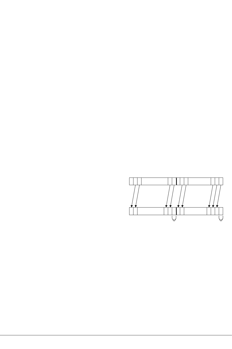
12.132 VSLI
Vector Shift Left and Insert.
Syntax
VSLI{cond}.size {Qd}, Qm, #imm
VSLI{cond}.size {Dd}, Dm, #imm
where:
cond
is an optional condition code.
size
must be one of 8, 16, 32, or 64.
Qd, Qm
are the destination vector and the operand vector, for a quadword operation.
Dd, Dm
are the destination vector and the operand vector, for a doubleword operation.
imm
is the immediate value specifying the size of the shift, in the range 0 to (size – 1).
Operation
VSLI takes each element in a vector, left shifts them by an immediate value, and inserts the results
in the destination vector. Bits shifted out of the left of each element are lost. The following figure
shows the operation of VSLI with two elements and a shift value of one. The least significant bit
in each element in the destination vector is unchanged.
Qd
Qm
Element 0
Element 1
... ...
Unchanged
bit
Unchanged
bit
Figure 12-7 Operation of quadword VSLI.64 Qd, Qm, #1
Related references
10.8 Condition codes on page 10-317.
12 NEON and VFP Instructions
12.132 VSLI
ARM DUI0473J Copyright © 2010-2013 ARM. All rights reserved. 12-734
Non-Confidential

12.133 VSQRT
Floating-point square root.
Syntax
VSQRT{cond}.F32 Sd, Sm
VSQRT{cond}.F64 Dd, Dm
where:
cond
is an optional condition code.
Sd, Sm
are the single-precision registers for the result and operand.
Dd, Dm
are the double-precision registers for the result and operand.
Operation
The VSQRT instruction takes the square root of the contents of Sm or Dm, and places the result in
Sd or Dd.
Floating-point exceptions
VSQRT instructions can produce Invalid Operation or Inexact exceptions.
Related references
10.8 Condition codes on page 10-317.
12 NEON and VFP Instructions
12.133 VSQRT
ARM DUI0473J Copyright © 2010-2013 ARM. All rights reserved. 12-735
Non-Confidential

12.134 VSRA (by immediate)
Vector Shift Right by immediate value and Accumulate.
Syntax
VSRA{cond}.datatype {Qd}, Qm, #imm
VSRA{cond}.datatype {Dd}, Dm, #imm
where:
cond
is an optional condition code.
datatype
must be one of S8, S16, S32, S64, U8, U16, U32, or U64.
Qd, Qm
are the destination vector and the operand vector, for a quadword operation.
Dd, Dm
are the destination vector and the operand vector, for a doubleword operation.
imm
is the immediate value specifying the size of the shift. The ranges are shown in the
following table:
Table 12-25 Available immediate ranges in VSRA (by immediate)
datatype imm range
S8 or U8 1 to 8
S16 or U16 1 to 16
S32 or U32 1 to 32
S64 or U64 1 to 64
Operation
VSRA takes each element in a vector, right shifts them by an immediate value, and accumulates the
results into the destination vector. The results are truncated.
Related concepts
8.10 NEON and VFP data types on page 8-187.
Related references
10.8 Condition codes on page 10-317.
12 NEON and VFP Instructions
12.134 VSRA (by immediate)
ARM DUI0473J Copyright © 2010-2013 ARM. All rights reserved. 12-736
Non-Confidential
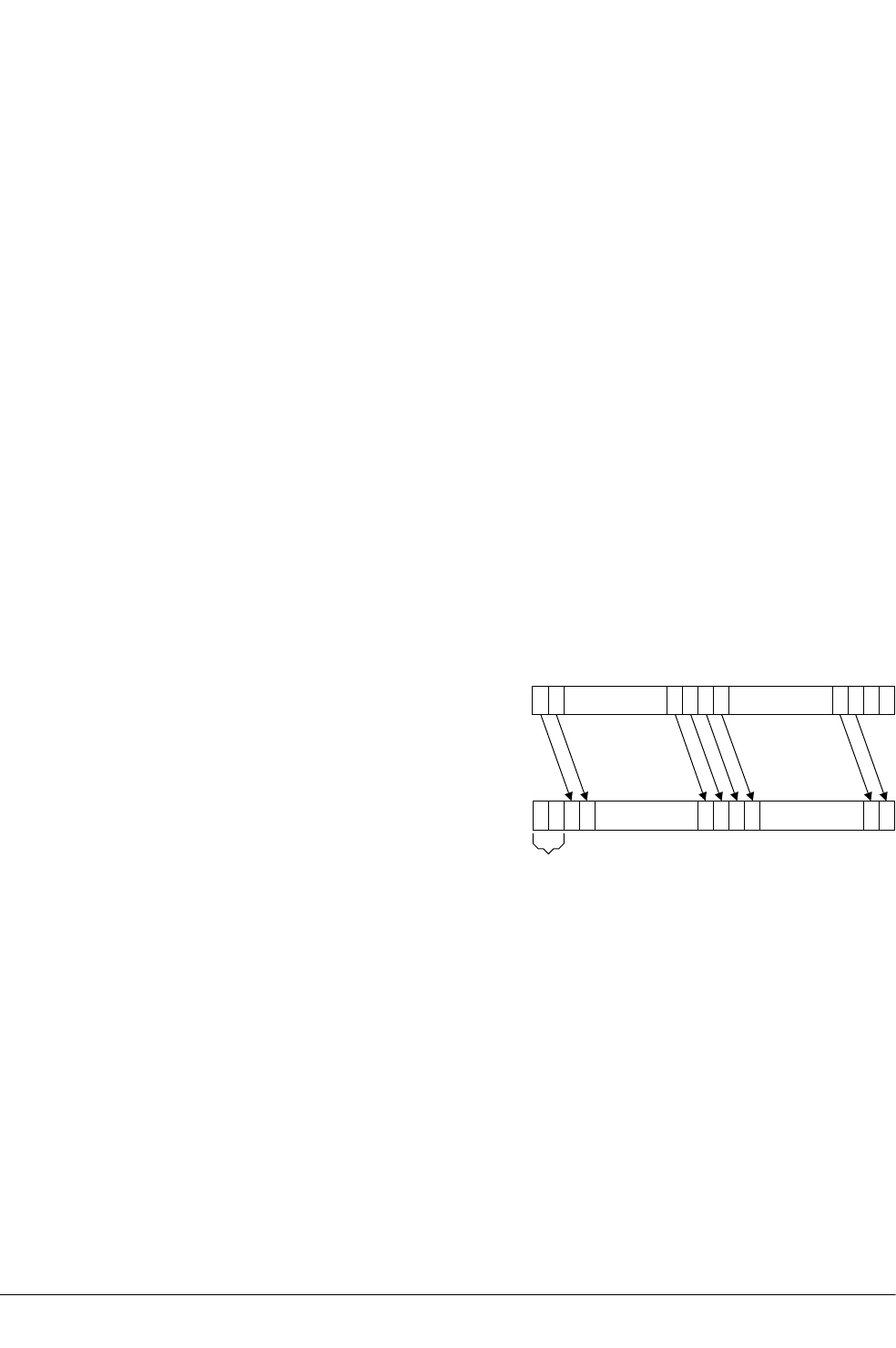
12.135 VSRI
Vector Shift Right and Insert.
Syntax
VSRI{cond}.size {Qd}, Qm, #imm
VSRI{cond}.size {Dd}, Dm, #imm
where:
cond
is an optional condition code.
size
must be one of 8, 16, 32, or 64.
Qd, Qm
are the destination vector and the operand vector, for a quadword operation.
Dd, Dm
are the destination vector and the operand vector, for a doubleword operation.
imm
is the immediate value specifying the size of the shift, in the range 1 to size.
Operation
VSRI takes each element in a vector, right shifts them by an immediate value, and inserts the
results in the destination vector. Bits shifted out of the right of each element are lost. The
following figure shows the operation of VSRI with a single element and a shift value of two. The
two most significant bits in the destination vector are unchanged.
Dd
Dm
Element 0
... ...
Unchanged
bits
Figure 12-8 Operation of doubleword VSRI.64 Dd, Dm, #2
Related references
10.8 Condition codes on page 10-317.
12 NEON and VFP Instructions
12.135 VSRI
ARM DUI0473J Copyright © 2010-2013 ARM. All rights reserved. 12-737
Non-Confidential

12.136 VSTM
Extension register store multiple.
Syntax
VSTMmode{cond} Rn{!}, Registers
where:
mode
must be one of:
IA
meaning Increment address After each transfer. IA is the default, and can be
omitted.
DB
meaning Decrement address Before each transfer.
EA
meaning Empty Ascending stack operation. This is the same as IA for stores.
FD
meaning Full Descending stack operation. This is the same as DB for stores.
cond
is an optional condition code.
Rn
is the ARM register holding the base address for the transfer.
!
is optional. ! specifies that the updated base address must be written back to Rn. If ! is
not specified, mode must be IA.
Registers
is a list of consecutive extension registers enclosed in braces, { and }. The list can be
comma-separated, or in range format. There must be at least one register in the list.
You can specify S, D, or Q registers, but they must not be mixed. The number of registers
must not exceed 16 D registers, or 8 Q registers. If Q registers are specified, on
disassembly they are shown as D registers.
Note
VPUSH Registers is equivalent to VSTMDB sp!, Registers.
You can use either form of this instruction. They both disassemble to VPUSH.
Related concepts
4.15 Stack implementation using LDM and STM on page 4-86.
Related references
10.8 Condition codes on page 10-317.
12 NEON and VFP Instructions
12.136 VSTM
ARM DUI0473J Copyright © 2010-2013 ARM. All rights reserved. 12-738
Non-Confidential

12.137 VSTn (multiple n-element structures)
Vector Store multiple n-element structures.
Syntax
VSTn{cond}.datatype list, [Rn{@align}]{!}
VSTn{cond}.datatype list, [Rn{@align}], Rm
where:
n
must be one of 1, 2, 3, or 4.
cond
is an optional condition code.
datatype
see the following table for options.
list
specifies the NEON register list. See the following table for options.
Rn
is the ARM register containing the base address. Rn cannot be PC.
align
specifies an optional alignment. See the following table for options.
!
if ! is present, Rn is updated to (Rn + the number of bytes transferred by the instruction).
The update occurs after all the stores have taken place.
Rm
is an ARM register containing an offset from the base address. If Rm is present, the
instruction updates Rn to (Rn + Rm) after using the address to access memory. Rm cannot
be SP or PC.
Operation
VSTn stores multiple n-element structures to memory from one or more NEON registers, with
interleaving (unless n == 1). Every element of each register is stored.
Table 12-26 Permitted combinations of parameters for VSTn (multiple n-element structures)
n datatype list bj align bk alignment
1 8, 16, 32, or 64 {Dd} @64 8-byte
{Dd, D(d+1)} @64 or @128 8-byte or 16-byte
{Dd, D(d+1), D(d+2)} @64 8-byte
{Dd, D(d+1), D(d+2), D(d+3)} @64, @128, or @256 8-byte, 16-byte, or 32-byte
28, 16, or 32 {Dd, D(d+1)} @64, @128 8-byte or 16-byte
{Dd, D(d+2)} @64, @128 8-byte or 16-byte
{Dd, D(d+1), D(d+2), D(d+3)} @64, @128, or @256 8-byte, 16-byte, or 32-byte
38, 16, or 32 {Dd, D(d+1), D(d+2)} @64 8-byte
{Dd, D(d+2), D(d+4)} @64 8-byte
bj Every register in the list must be in the range D0-D31.
bk align can be omitted. In this case, standard alignment rules apply.
12 NEON and VFP Instructions
12.137 VSTn (multiple n-element structures)
ARM DUI0473J Copyright © 2010-2013 ARM. All rights reserved. 12-739
Non-Confidential

Table 12-26 Permitted combinations of parameters for VSTn (multiple n-element
structures) (continued)
n datatype list bj align bk alignment
48, 16, or 32 {Dd, D(d+1), D(d+2), D(d+3)} @64, @128, or @256 8-byte, 16-byte, or 32-byte
{Dd, D(d+2), D(d+4), D(d+6)} @64, @128, or @256 8-byte, 16-byte, or 32-byte
Related concepts
12.4 Interleaving provided by load and store element and structure instructions on page 12-602.
12.5 Alignment restrictions in load and store element and structure instructions on page 12-603.
Related references
12.50 VLDn (single n-element structure to one lane) on page 12-648.
12.51 VLDn (single n-element structure to all lanes) on page 12-650.
10.8 Condition codes on page 10-317.
12 NEON and VFP Instructions
12.137 VSTn (multiple n-element structures)
ARM DUI0473J Copyright © 2010-2013 ARM. All rights reserved. 12-740
Non-Confidential

12.138 VSTn (single n-element structure to one lane)
Vector Store single n-element structure to one lane.
Syntax
VSTn{cond}.datatype list, [Rn{@align}]{!}
VSTn{cond}.datatype list, [Rn{@align}], Rm
where:
n
must be one of 1, 2, 3, or 4.
cond
is an optional condition code.
datatype
see the following table.
list
specifies the NEON register list. See the following table for options.
Rn
is the ARM register containing the base address. Rn cannot be PC.
align
specifies an optional alignment. See the following table for options.
!
if ! is present, Rn is updated to (Rn + the number of bytes transferred by the instruction).
The update occurs after all the stores have taken place.
Rm
is an ARM register containing an offset from the base address. If Rm is present, the
instruction updates Rn to (Rn + Rm) after using the address to access memory. Rm cannot
be SP or PC.
Operation
VSTn stores one n-element structure into memory from one or more NEON registers.
Table 12-27 Permitted combinations of parameters for VSTn (single n-element structure to
one lane)
n datatype list bl align bm alignment
1 8 {Dd[x]} - Standard only
16 {Dd[x]} @16 2-byte
32 {Dd[x]} @32 4-byte
28 {Dd[x], D(d+1)[x]} @16 2-byte
16 {Dd[x], D(d+1)[x]} @32 4-byte
{Dd[x], D(d+2)[x]} @32 4-byte
32 {Dd[x], D(d+1)[x]} @64 8-byte
{Dd[x], D(d+2)[x]} @64 8-byte
38 {Dd[x], D(d+1)[x], D(d+2)[x]} - Standard only
bl Every register in the list must be in the range D0-D31.
bm align can be omitted. In this case, standard alignment rules apply.
12 NEON and VFP Instructions
12.138 VSTn (single n-element structure to one lane)
ARM DUI0473J Copyright © 2010-2013 ARM. All rights reserved. 12-741
Non-Confidential

Table 12-27 Permitted combinations of parameters for VSTn (single n-element structure to one
lane) (continued)
n datatype list bl align bm alignment
16 or 32 {Dd[x], D(d+1)[x], D(d+2)[x]} - Standard only
{Dd[x], D(d+2)[x], D(d+4)[x]} - Standard only
48 {Dd[x], D(d+1)[x], D(d+2)[x], D(d+3)[x]} @32 4-byte
16 {Dd[x], D(d+1)[x], D(d+2)[x], D(d+3)[x]} @64 8-byte
{Dd[x], D(d+2)[x], D(d+4)[x], D(d+6)[x]} @64 8-byte
32 {Dd[x], D(d+1)[x], D(d+2)[x], D(d+3)[x]} @64 or @128 8-byte or 16-byte
{Dd[x], D(d+2)[x], D(d+4)[x], D(d+6)[x]} @64 or @128 8-byte or 16-byte
Related concepts
12.4 Interleaving provided by load and store element and structure instructions on page 12-602.
12.5 Alignment restrictions in load and store element and structure instructions on page 12-603.
Related references
12.51 VLDn (single n-element structure to all lanes) on page 12-650.
12.52 VLDn (multiple n-element structures) on page 12-652.
10.8 Condition codes on page 10-317.
12 NEON and VFP Instructions
12.138 VSTn (single n-element structure to one lane)
ARM DUI0473J Copyright © 2010-2013 ARM. All rights reserved. 12-742
Non-Confidential

12.139 VSTR
Extension register store.
Syntax
VSTR{cond}{.size} Fd, [Rn{, #offset}]
VSTR{cond}{.size} Fd, label
where:
cond
is an optional condition code.
size
is an optional data size specifier. Must be 32 if Fd is an S register, or 64 otherwise.
Fd
is the extension register to be saved. For a NEON instruction, it must be a D register. For
a VFP instruction, it can be either a D or S register.
Rn
is the ARM register holding the base address for the transfer.
offset
is an optional numeric expression. It must evaluate to a numeric value at assembly time.
The value must be a multiple of 4, and lie in the range –1020 to +1020. The value is
added to the base address to form the address used for the transfer.
label
is a PC-relative expression.
label must be aligned on a word boundary within ±1KB of the current instruction.
Operation
The VSTR instruction saves the contents of an extension register to memory.
One word is transferred if Fd is an S register (VFP only). Two words are transferred otherwise.
Related concepts
7.5 Register-relative and PC-relative expressions on page 7-149.
Related references
12.56 VLDR pseudo-instruction on page 12-657.
10.8 Condition codes on page 10-317.
12 NEON and VFP Instructions
12.139 VSTR
ARM DUI0473J Copyright © 2010-2013 ARM. All rights reserved. 12-743
Non-Confidential

12.140 VSTR (post-increment and pre-decrement)
Pseudo-instruction that stores extension registers with post-increment and pre-decrement forms.
Note
There are also VLDR and VSTR instructions without post-increment and pre-decrement.
Syntax
VSTR{cond}{.size} Fd, [Rn], #offset ; post-increment
VSTR{cond}{.size} Fd, [Rn, #-offset]! ; pre-decrement
where:
cond
is an optional condition code.
size
is an optional data size specifier. Must be 32 if Fd is an S register, or 64 if Fd is a D
register.
Fd
is the extension register to be saved. For a NEON instruction, it must be a doubleword
(Dd) register. For a VFP instruction, it can be either a double precision (Dd) or a single
precision (Sd) register.
Rn
is the ARM register holding the base address for the transfer.
offset
is a numeric expression that must evaluate to a numeric value at assembly time. The
value must be 4 if Fd is an S register, or 8 if Fd is a D register.
Operation
The post-increment instruction increments the base address in the register by the offset value, after
the transfer. The pre-decrement instruction decrements the base address in the register by the
offset value, and then performs the transfer using the new address in the register. This pseudo-
instruction assembles to a VSTM instruction.
Related references
12.139 VSTR on page 12-743.
12.136 VSTM on page 12-738.
10.8 Condition codes on page 10-317.
12 NEON and VFP Instructions
12.140 VSTR (post-increment and pre-decrement)
ARM DUI0473J Copyright © 2010-2013 ARM. All rights reserved. 12-744
Non-Confidential

12.141 VSUB (floating-point)
Floating-point subtract.
Syntax
VSUB{cond}.F32 {Sd}, Sn, Sm
VSUB{cond}.F64 {Dd}, Dn, Dm
where:
cond
is an optional condition code.
Sd, Sn, Sm
are the single-precision registers for the result and operands.
Dd, Dn, Dm
are the double-precision registers for the result and operands.
Operation
The VSUB instruction subtracts the value in the second operand register from the value in the first
operand register, and places the result in the destination register.
Floating-point exceptions
The VSUB instruction can produce Invalid Operation, Overflow, or Inexact exceptions.
Related references
10.8 Condition codes on page 10-317.
12 NEON and VFP Instructions
12.141 VSUB (floating-point)
ARM DUI0473J Copyright © 2010-2013 ARM. All rights reserved. 12-745
Non-Confidential

12.142 VSUB
Vector Subtract.
Syntax
VSUB{cond}.datatype {Qd}, Qn, Qm
VSUB{cond}.datatype {Dd}, Dn, Dm
where:
cond
is an optional condition code.
datatype
must be one of I8, I16, I32, I64, or F32.
Qd, Qn, Qm
are the destination vector, the first operand vector, and the second operand vector, for a
quadword operation.
Operation
VSUB subtracts the elements of one vector from the corresponding elements of another vector, and
places the results in the destination vector.
Related concepts
8.10 NEON and VFP data types on page 8-187.
Related references
10.8 Condition codes on page 10-317.
12 NEON and VFP Instructions
12.142 VSUB
ARM DUI0473J Copyright © 2010-2013 ARM. All rights reserved. 12-746
Non-Confidential

12.143 VSUBHN
Vector Subtract and Narrow, selecting High half.
Syntax
VSUBHN{cond}.datatype Dd, Qn, Qm
where:
cond
is an optional condition code.
datatype
must be one of I16, I32, or I64.
Dd, Qn, Qm
are the destination vector, the first operand vector, and the second operand vector.
Operation
VSUBHN subtracts the elements of one quadword vector from the corresponding elements of
another quadword vector, selects the most significant halves of the results, and places the final
results in the destination doubleword vector. Results are truncated.
Related concepts
8.10 NEON and VFP data types on page 8-187.
Related references
10.8 Condition codes on page 10-317.
12 NEON and VFP Instructions
12.143 VSUBHN
ARM DUI0473J Copyright © 2010-2013 ARM. All rights reserved. 12-747
Non-Confidential

12.144 VSUBL and VSUBW
Vector Subtract Long, Vector Subtract Wide.
Syntax
VSUBL{cond}.datatype Qd, Dn, Dm ; Long operation
VSUBW{cond}.datatype {Qd}, Qn, Dm ; Wide operation
where:
cond
is an optional condition code.
datatype
must be one of S8, S16, S32, U8, U16, or U32.
Qd, Dn, Dm
are the destination vector, the first operand vector, and the second operand vector, for a
long operation.
Qd, Qn, Dm
are the destination vector, the first operand vector, and the second operand vector, for a
wide operation.
Operation
VSUBL subtracts the elements of one doubleword vector from the corresponding elements of
another doubleword vector, and places the results in the destination quadword vector.
VSUBW subtracts the elements of a doubleword vector from the corresponding elements of a
quadword vector, and places the results in the destination quadword vector.
Related concepts
8.10 NEON and VFP data types on page 8-187.
Related references
10.8 Condition codes on page 10-317.
12 NEON and VFP Instructions
12.144 VSUBL and VSUBW
ARM DUI0473J Copyright © 2010-2013 ARM. All rights reserved. 12-748
Non-Confidential

12.145 VSWP
Vector Swap.
Syntax
VSWP{cond}{.datatype} Qd, Qm
VSWP{cond}{.datatype} Dd, Dm
where:
cond
is an optional condition code.
datatype
is an optional datatype. The assembler ignores datatype.
Qd, Qm
specifies the vectors for a quadword operation.
Dd, Dm
specifies the vectors for a doubleword operation.
Operation
VSWP exchanges the contents of two vectors. The vectors can be either doubleword or quadword.
There is no distinction between data types.
Related references
10.8 Condition codes on page 10-317.
12 NEON and VFP Instructions
12.145 VSWP
ARM DUI0473J Copyright © 2010-2013 ARM. All rights reserved. 12-749
Non-Confidential

12.146 VTBL and VTBX
Vector Table Lookup, Vector Table Extension.
Syntax
Vop{cond}.8 Dd, list, Dm
where:
op
must be either TBL or TBX.
cond
is an optional condition code.
Dd
specifies the destination vector.
list
Specifies the vectors containing the table. It must be one of:
•{Dn}.
•{Dn,D(n+1)}.
•{Dn,D(n+1),D(n+2)}.
•{Dn,D(n+1),D(n+2),D(n+3)}.
•{Qn,Q(n+1)}.
All the registers in list must be in the range D0-D31 or Q0-Q15 and must not wrap
around the end of the register bank. For example {D31,D0,D1} is not permitted. If list
contains Q registers, they disassemble to the equivalent D registers.
Dm
specifies the index vector.
Operation
VTBL uses byte indexes in a control vector to look up byte values in a table and generate a new
vector. Indexes out of range return zero.
VTBX works in the same way, except that indexes out of range leave the destination element
unchanged.
Related references
10.8 Condition codes on page 10-317.
12 NEON and VFP Instructions
12.146 VTBL and VTBX
ARM DUI0473J Copyright © 2010-2013 ARM. All rights reserved. 12-750
Non-Confidential
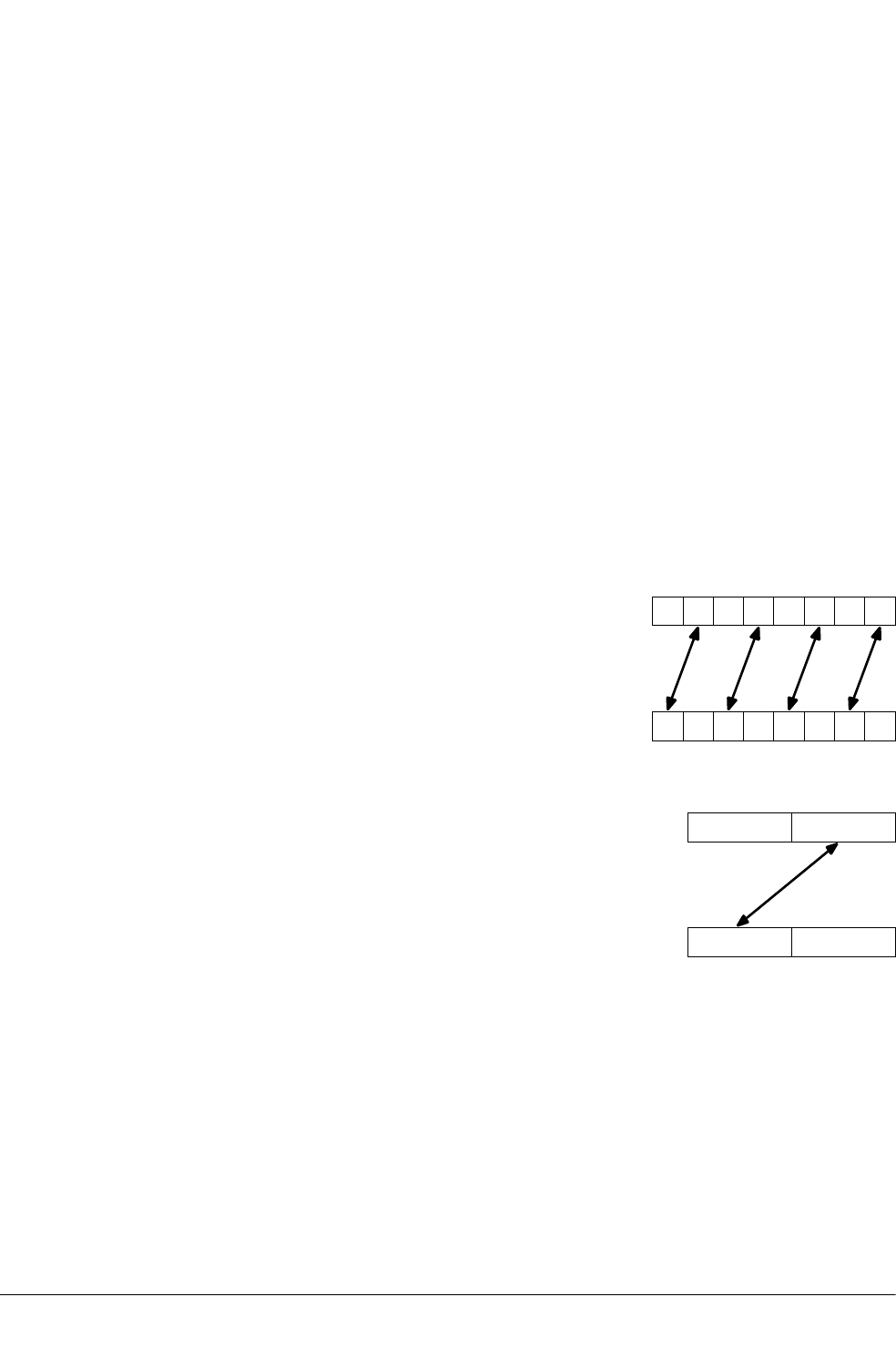
12.147 VTRN
Vector Transpose.
Syntax
VTRN{cond}.size Qd, Qm
VTRN{cond}.size Dd, Dm
where:
cond
is an optional condition code.
size
must be one of 8, 16, or 32.
Qd, Qm
specifies the vectors, for a quadword operation.
Dd, Dm
specifies the vectors, for a doubleword operation.
Operation
VTRN treats the elements of its operand vectors as elements of 2 x 2 matrices, and transposes the
matrices. The following figures show examples of the operation of VTRN:
Dd
Dm
017 6 5 4 3 2
Figure 12-9 Operation of doubleword VTRN.8
Dd
Dm
01
Figure 12-10 Operation of doubleword VTRN.32
Related references
10.8 Condition codes on page 10-317.
12 NEON and VFP Instructions
12.147 VTRN
ARM DUI0473J Copyright © 2010-2013 ARM. All rights reserved. 12-751
Non-Confidential

12.148 VTST
Vector Test bits.
Syntax
VTST{cond}.size {Qd}, Qn, Qm
VTST{cond}.size {Dd}, Dn, Dm
where:
cond
is an optional condition code.
size
must be one of 8, 16, or 32.
Qd, Qn, Qm
specifies the destination register, the first operand register, and the second operand
register, for a quadword operation.
Dd, Dn, Dm
specifies the destination register, the first operand register, and the second operand
register, for a doubleword operation.
Operation
VTST takes each element in a vector, and bitwise logical ANDs them with the corresponding
element of a second vector. If the result is not zero, the corresponding element in the destination
vector is set to all ones. Otherwise, it is set to all zeros.
Related references
10.8 Condition codes on page 10-317.
12 NEON and VFP Instructions
12.148 VTST
ARM DUI0473J Copyright © 2010-2013 ARM. All rights reserved. 12-752
Non-Confidential

12.149 VUZP
Vector Unzip.
Syntax
VUZP{cond}.size Qd, Qm
VUZP{cond}.size Dd, Dm
where:
cond
is an optional condition code.
size
must be one of 8, 16, or 32.
Qd, Qm
specifies the vectors, for a quadword operation.
Dd, Dm
specifies the vectors, for a doubleword operation.
Note
The following are all the same instruction:
•VZIP.32 Dd, Dm.
•VUZP.32 Dd, Dm.
•VTRN.32 Dd, Dm.
The instruction is disassembled as VTRN.32 Dd, Dm.
Operation
VUZP de-interleaves the elements of two vectors.
De-interleaving is the inverse process of interleaving.
Table 12-28 Operation of doubleword VUZP.8
Register state before operation Register state after operation
Dd A7A6A5A4A3A2A1A0B6B4B2B0A6A4A2A0
Dm B7B6B5B4B3B2B1B0B7B5B3B1A7A5A3A1
Table 12-29 Operation of quadword VUZP.32
Register state before operation Register state after operation
Qd A3A2A1A0B2B0A2A0
Qm B3B2B1B0B3B1A3A1
Related concepts
12.4 Interleaving provided by load and store element and structure instructions on page 12-602.
Related references
12.147 VTRN on page 12-751.
10.8 Condition codes on page 10-317.
12 NEON and VFP Instructions
12.149 VUZP
ARM DUI0473J Copyright © 2010-2013 ARM. All rights reserved. 12-753
Non-Confidential

12.150 VZIP
Vector Zip.
Syntax
VZIP{cond}.size Qd, Qm
VZIP{cond}.size Dd, Dm
where:
cond
is an optional condition code.
size
must be one of 8, 16, or 32.
Qd, Qm
specifies the vectors, for a quadword operation.
Dd, Dm
specifies the vectors, for a doubleword operation.
Note
The following are all the same instruction:
•VZIP.32 Dd, Dm.
•VUZP.32 Dd, Dm.
•VTRN.32 Dd, Dm.
The instruction is disassembled as VTRN.32 Dd, Dm.
Operation
VZIP interleaves the elements of two vectors.
Table 12-30 Operation of doubleword VZIP.8
Register state before operation Register state after operation
Dd A7A6A5A4A3A2A1A0B3A3B2A2B1A1B0A0
Dm B7B6B5B4B3B2B1B0B7A7B6A6B5A5B4A4
Table 12-31 Operation of quadword VZIP.32
Register state before operation Register state after operation
Qd A3A2A1A0B1A1B0A0
Qm B3B2B1B0B3A3B2A2
Related concepts
12.4 Interleaving provided by load and store element and structure instructions on page 12-602.
Related references
12.147 VTRN on page 12-751.
10.8 Condition codes on page 10-317.
12 NEON and VFP Instructions
12.150 VZIP
ARM DUI0473J Copyright © 2010-2013 ARM. All rights reserved. 12-754
Non-Confidential

Chapter 13
Wireless MMX Technology Instructions
Describes the support for Wireless MMX Technology instructions.
It contains the following:
• 13.1 About Wireless MMX Technology instructions on page 13-756.
• 13.2 WRN and WCN directives to support Wireless MMX Technology on page 13-757.
• 13.3 Frame directives and Wireless MMX Technology on page 13-758.
• 13.4 Wireless MMX load and store instructions on page 13-759.
• 13.5 Wireless MMX Technology and XScale instructions on page 13-761.
• 13.6 Wireless MMX instructions on page 13-762.
• 13.7 Wireless MMX pseudo-instructions on page 13-765.
ARM DUI0473J Copyright © 2010-2013 ARM. All rights reserved. 13-755
Non-Confidential

13.1 About Wireless MMX Technology instructions
Marvell Wireless MMX Technology is a set of Single Instruction Multiple Data (SIMD)
instructions available on selected XScale processors that improve the performance of some
multimedia applications.
Wireless MMX Technology uses 64-bit registers to enable it to operate on multiple data elements
in a packed format.
The assembler supports Marvell Wireless MMX Technology instructions to assemble code to run
on the PXA270 processor. This processor implements the ARMv5TE architecture, with MMX
extensions. Wireless MMX Technology uses ARM coprocessors 0 and 1 to support its instruction
set and data types. ARM Compiler toolchain supports Wireless MMX Technology Control and
Single Instruction Multiple Data (SIMD) Data registers, and include new directives for Wireless
MMX Technology development. There is also enhanced support for load and store instructions.
When using the assembler, be aware that:
• Wireless MMX Technology instructions are only assembled if you specify the supported
processor (armasm --device PXA270).
• The PXA270 processor supports code written in ARM or Thumb only.
• Most Wireless MMX Technology instructions can be executed conditionally, depending on the
state of the ARM flags. The Wireless MMX Technology condition codes are identical to the
ARM condition codes.
Wireless MMX 2 Technology is an upgraded version of Wireless MMX Technology.
This documentation contains information on the Wireless MMX Technology support provided by
the assembler in the ARM Compiler toolchain. It does not provide a detailed description of the
Wireless MMX Technology. Wireless MMX Technology Developer Guide contains information
about the programmers’ model and a full description of the Wireless MMX Technology
instruction set.
Related concepts
13.3 Frame directives and Wireless MMX Technology on page 13-758.
13.5 Wireless MMX Technology and XScale instructions on page 13-761.
Related references
13.2 WRN and WCN directives to support Wireless MMX Technology on page 13-757.
13.4 Wireless MMX load and store instructions on page 13-759.
Related information
Further reading.
13 Wireless MMX Technology Instructions
13.1 About Wireless MMX Technology instructions
ARM DUI0473J Copyright © 2010-2013 ARM. All rights reserved. 13-756
Non-Confidential

13.2 WRN and WCN directives to support Wireless MMX Technology
The assembler supports directives that define names for Wireless MMX Technology registers.
The following directives are available to support Wireless MMX Technology:
WCN
Defines a name for a specified Control register, for example:
speed WCN wcgr0 ; defines speed as a symbol for control reg 0
WRN
Defines a name for a specified SIMD Data register, for example:
rate WRN wr6 ; defines rate as a symbol for data reg 6
Avoid conflicting uses of the same register under different names. Do not use any of the
predefined register and coprocessor names.
Related concepts
13.1 About Wireless MMX Technology instructions on page 13-756.
13 Wireless MMX Technology Instructions
13.2 WRN and WCN directives to support Wireless MMX Technology
ARM DUI0473J Copyright © 2010-2013 ARM. All rights reserved. 13-757
Non-Confidential

13.3 Frame directives and Wireless MMX Technology
Wireless MMX Technology registers can be used with FRAME directives in the same way as ARM
registers to add debug information into your object files.
Be aware of the following restrictions:
• A warning is given if you try to push Wireless MMX Technology registers wR0 - wR9 or
wCGR0 - wCGR3 onto the stack.
• Wireless MMX Technology registers cannot be used as address offsets.
Related concepts
13.1 About Wireless MMX Technology instructions on page 13-756.
13 Wireless MMX Technology Instructions
13.3 Frame directives and Wireless MMX Technology
ARM DUI0473J Copyright © 2010-2013 ARM. All rights reserved. 13-758
Non-Confidential

13.4 Wireless MMX load and store instructions
Load and store a byte, halfword, word, or doubleword to and from Wireless MMX coprocessor
registers.
Syntax
op<type>{cond} wRd, [Rn, #{-}offset]{!}
op<type>{cond} wRd, [Rn] {, #{-}offset}
opW{cond} wRd, label
opW wCd, [Rn, #{-}offset]{!}
opW wCd, [Rn] {, #{-}offset}
opD {cond} wRd,label
opD wRd, [Rn, {-}Rm {, LSL #imm4}]{!} ; MMX2 only
opD wRd, [Rn], {-}Rm {, LSL #imm4} ; MMX2 only
where:
op
can be either:
WLDR
Load Wireless MMX Register.
WSTR
Store Wireless MMX Register.
<type>
can be any one of:
B
Byte.
H
Halfword.
W
Word.
D
Doubleword.
cond
is an optional condition code.
wRd
is the Wireless MMX SIMD data register to load or save.
wCd
is the Wireless MMX Status and Control register to load or save.
Rn
is the register on which the memory address is based.
offset
is an immediate offset. If offset is omitted, the instruction is a zero offset instruction.
!
is an optional suffix. If ! is present, the instruction is a pre-indexed instruction.
label
is a PC-relative expression.
label must be within ± 1020 bytes of the current instruction.
13 Wireless MMX Technology Instructions
13.4 Wireless MMX load and store instructions
ARM DUI0473J Copyright © 2010-2013 ARM. All rights reserved. 13-759
Non-Confidential

Rm
is a register containing a value to be used as the offset. Rm must not be PC.
imm4
contains the number of bits to shift Rm left, in the range 0-15.
Loading constants into SIMD registers
The assembler also supports the WLDRW and WLDRD literal load pseudo-instructions, for example:
WLDRW wr0, =0x114
Be aware that:
• The assembler cannot load byte and halfword literals. These produce a downgradable error. If
downgraded, the instruction is converted to a WLDRW and a 32-bit literal is generated. This is
the same as a byte literal load, but uses a 32-bit word instead.
• If the literal to be loaded is zero, and the destination is a SIMD Data register, the assembler
converts the instruction to a WZERO.
• Doubleword loads must be 8-byte aligned.
Related concepts
13.1 About Wireless MMX Technology instructions on page 13-756.
13 Wireless MMX Technology Instructions
13.4 Wireless MMX load and store instructions
ARM DUI0473J Copyright © 2010-2013 ARM. All rights reserved. 13-760
Non-Confidential

13.5 Wireless MMX Technology and XScale instructions
Wireless MMX Technology instructions overlap with XScale instructions. To avoid conflicts, the
assembler has some restrictions.
The following restrictions apply:
• You cannot mix the XScale instructions with Wireless MMX Technology instructions in the
same assembly.
• Wireless MMX Technology TMIA instructions have a MIA mnemonic that overlaps with the
XScale MIA instructions. Be aware that:
— MIA acc0, Rm, Rs is accepted in XScale, but faulted in Wireless MMX Technology.
— MIA wR0, Rm, Rs and TMIA wR0, Rm, Rs are accepted in Wireless MMX
Technology.
— TMIA acc0, Rm, Rs is faulted in XScale (XScale has no TMIA instruction).
Related concepts
7.5 Register-relative and PC-relative expressions on page 7-149.
Related references
2.13 Predeclared XScale register names on page 2-48.
10.53 MIA, MIAPH, and MIAxy on page 10-398.
10.50 MAR on page 10-395.
14.3 About frame directives on page 14-770.
14.29 FRAME PUSH on page 14-801.
14.27 FRAME ADDRESS on page 14-799.
14.32 FRAME RETURN ADDRESS on page 14-804.
10.8 Condition codes on page 10-317.
13 Wireless MMX Technology Instructions
13.5 Wireless MMX Technology and XScale instructions
ARM DUI0473J Copyright © 2010-2013 ARM. All rights reserved. 13-761
Non-Confidential

13.6 Wireless MMX instructions
Wireless MMX technology provides an instruction set that operates on ARM and Wireless MMX
technology registers.
The following table gives a list of the Wireless MMX Technology instruction set. The instructions
are described in Wireless MMX Technology Developer Guide. Wireless MMX Technology
registers are indicated by wRn, wRd, and ARM registers are shown as Rn, Rd.
Table 13-1 Wireless MMX Technology instructions
Mnemonic Example
TANDC
TANDCB r15
TBCST
TBCSTB wr15, r1
TEXTRC
TEXTRCB r15, #0
TEXTRM
TEXTRMUBCS r3, wr7, #7
TINSR
TINSRB wr6, r11, #0
TMIA, TMIAPH, TMIAxy
TMIANE wr1, r2, r3
TMIAPH wr4, r5, r6
TMIABB wr4, r5, r6
MIAPHNE wr4, r5, r6
TMOVMSK
TMOVMSKBNE r14, wr15
TORC
TORCB r15
WACC
WACCBGE wr1, wr2
WADD
WADDBGE wr1, wr2, wr13
WALIGNI, WALIGNR
WALIGNI wr7, wr6, wr5,#3
WALIGNR0 wr4, wr8, wr12
WAND, WANDN
WAND wr1, wr2, wr3
WANDN wr5, wr5, wr9
13 Wireless MMX Technology Instructions
13.6 Wireless MMX instructions
ARM DUI0473J Copyright © 2010-2013 ARM. All rights reserved. 13-762
Non-Confidential

Table 13-1 Wireless MMX Technology
instructions (continued)
Mnemonic Example
WAVG2
WAVG2B wr3, wr6, wr9
WAVG2BR wr4, wr7, wr10
WCMPEQ
WCMPEQB wr0, wr4, wr2
WCMPGT
WCMPGTUB wr0, wr4, wr2
WLDR
WLDRB wr1, [r2, #0]
WMAC
WMACU wr3, wr4, wr5
WMADD
WMADDU wr3, wr4, wr5
WMAX, WMIN
WMAXUB wr0, wr4, wr2
WMINSB wr0, wr4, wr2
WMUL
WMULUL wr4, wr2, wr3
WOR
WOR wr3, wr1, wr4
WPACK
WPACKHUS wr2, wr7, wr1
WROR
WRORH wr3, wr1, wr4
WSAD
WSADB wr3, wr5, wr8
WSHUFH
WSHUFH wr8, wr15, #17
WSLL, WSRL
WSLLH wr3, wr1, wr4
WSRLHG wr3, wr1, wcgr0
WSRA
WSRAH wr3, wr1, wr4
WSRAHG wr3, wr1, wcgr0
13 Wireless MMX Technology Instructions
13.6 Wireless MMX instructions
ARM DUI0473J Copyright © 2010-2013 ARM. All rights reserved. 13-763
Non-Confidential

Table 13-1 Wireless MMX Technology
instructions (continued)
Mnemonic Example
WSTR
WSTRB wr1, [r2, #0]
WSTRW wc1, [r2, #0]
WSUB
WSUBBGE wr1, wr2, wr13
WUNPCKEH, WUNPCKEL
WUNPCKEHUB wr0, wr4
WUNPCKELSB wr0, wr4
WUNPCKIH, WUNPCKIL
WUNPCKIHB wr0, wr4, wr2
WUNPCKILH wr1, wr5, wr3
WXOR
WXOR wr3, wr1, wr4
Related concepts
13.1 About Wireless MMX Technology instructions on page 13-756.
Related references
13.7 Wireless MMX pseudo-instructions on page 13-765.
Related information
Further reading.
13 Wireless MMX Technology Instructions
13.6 Wireless MMX instructions
ARM DUI0473J Copyright © 2010-2013 ARM. All rights reserved. 13-764
Non-Confidential

13.7 Wireless MMX pseudo-instructions
Wireless MMX technology provides a set of pseudo-instructions that operate on ARM and
Wireless MMX technology registers.
The following table gives an overview of the Wireless MMX Technology pseudo-instructions.
These instructions are described in the Wireless MMX Technology Developer Guide.
Table 13-2 Wireless MMX Technology pseudo-instructions
Mnemonic Brief description Example
TMCR Moves the contents of source register, Rn, to Control register, wCn. Maps onto the
ARM MCR coprocessor instruction. TMCR wc1, r10
TMCRR Moves the contents of two source registers, RnLo and RnHi, to destination
register, wRd. Do not use R15 for either RnLo or RnHi. Maps onto the ARM
MCRR coprocessor instruction.
TMCRR wr4, r5, r6
TMRC Moves the contents of Control register, wCn, to destination register, Rd. Do not
use R15 for Rd. Maps onto the ARM MRC coprocessor instruction. TMRC r1, wc2
TMRRC Moves the contents of source register, wRn, to two destination registers, RdLo and
RdHi. Do not use R15 for either destination register. RdLo and RdHi must be
distinct registers. Maps onto the ARM MRRC coprocessor instruction.
TMRRC r1, r0, wr2
WMOV Moves the contents of source register, wRn, to destination register, wRd. This
instruction is a form of WOR.WMOV wr1, wr8
WZERO Zeros destination register, wRd. This instruction is a form of WANDN.
WZERO wr1
Related references
10.51 MCR and MCR2 on page 10-396.
10.52 MCRR and MCRR2 on page 10-397.
10.60 MRC and MRC2 on page 10-407.
10.61 MRRC and MRRC2 on page 10-408.
13.6 Wireless MMX instructions on page 13-762.
13 Wireless MMX Technology Instructions
13.7 Wireless MMX pseudo-instructions
ARM DUI0473J Copyright © 2010-2013 ARM. All rights reserved. 13-765
Non-Confidential

Chapter 14
Directives Reference
Describes the directives that are provided by the ARM assembler, armasm.
Note
None of these directives are available in the inline assemblers in the ARM C and C++ compilers.
It contains the following:
• 14.1 Alphabetical list of directives on page 14-768.
• 14.2 About assembly control directives on page 14-769.
• 14.3 About frame directives on page 14-770.
• 14.4 ALIAS on page 14-771.
• 14.5 ALIGN on page 14-772.
• 14.6 AREA on page 14-774.
• 14.7 ARM, THUMB, THUMBX, CODE16, and CODE32 on page 14-778.
• 14.8 ASSERT on page 14-779.
• 14.9 ATTR on page 14-780.
• 14.10 CN on page 14-781.
• 14.11 COMMON on page 14-782.
• 14.12 CP on page 14-783.
• 14.13 DATA on page 14-784.
• 14.14 DCB on page 14-785.
• 14.15 DCD and DCDU on page 14-786.
• 14.16 DCDO on page 14-787.
• 14.17 DCFD and DCFDU on page 14-788.
ARM DUI0473J Copyright © 2010-2013 ARM. All rights reserved. 14-766
Non-Confidential

• 14.18 DCFS and DCFSU on page 14-789.
• 14.19 DCI on page 14-790.
• 14.20 DCQ and DCQU on page 14-791.
• 14.21 DCW and DCWU on page 14-792.
• 14.22 END on page 14-793.
• 14.23 ENTRY on page 14-794.
• 14.24 EQU on page 14-795.
• 14.25 EXPORT or GLOBAL on page 14-796.
• 14.26 EXPORTAS on page 14-798.
• 14.27 FRAME ADDRESS on page 14-799.
• 14.28 FRAME POP on page 14-800.
• 14.29 FRAME PUSH on page 14-801.
• 14.30 FRAME REGISTER on page 14-802.
• 14.31 FRAME RESTORE on page 14-803.
• 14.32 FRAME RETURN ADDRESS on page 14-804.
• 14.33 FRAME SAVE on page 14-805.
• 14.34 FRAME STATE REMEMBER on page 14-806.
• 14.35 FRAME STATE RESTORE on page 14-807.
• 14.36 FRAME UNWIND ON on page 14-808.
• 14.37 FRAME UNWIND OFF on page 14-809.
• 14.38 FUNCTION or PROC on page 14-810.
• 14.39 ENDFUNC or ENDP on page 14-812.
• 14.40 FIELD on page 14-813.
• 14.41 GBLA, GBLL, and GBLS on page 14-814.
• 14.42 GET or INCLUDE on page 14-815.
• 14.43 IF, ELSE, ENDIF, and ELIF on page 14-816.
• 14.44 IMPORT and EXTERN on page 14-818.
• 14.45 INCBIN on page 14-820.
• 14.46 INFO on page 14-821.
• 14.47 KEEP on page 14-822.
• 14.48 LCLA, LCLL, and LCLS on page 14-823.
• 14.49 LTORG on page 14-824.
• 14.50 MACRO and MEND on page 14-825.
• 14.51 MAP on page 14-828.
• 14.52 MEXIT on page 14-829.
• 14.53 NOFP on page 14-830.
• 14.54 OPT on page 14-831.
• 14.55 QN, DN, and SN on page 14-833.
• 14.56 RELOC on page 14-835.
• 14.57 REQUIRE on page 14-836.
• 14.58 REQUIRE8 and PRESERVE8 on page 14-837.
• 14.59 RLIST on page 14-839.
• 14.60 RN on page 14-840.
• 14.61 ROUT on page 14-841.
• 14.62 SETA, SETL, and SETS on page 14-842.
• 14.63 SPACE or FILL on page 14-843.
• 14.64 TTL and SUBT on page 14-844.
• 14.65 WHILE and WEND on page 14-845.
14 Directives Reference
ARM DUI0473J Copyright © 2010-2013 ARM. All rights reserved. 14-767
Non-Confidential

14.1 Alphabetical list of directives
The ARM assembler, armasm, provides various directives.
The following table lists all the directives:
Table 14-1 List of directives
Directive Directive Directive
ALIAS EQU LTORG
ALIGN EXPORT or GLOBAL MACRO and MEND
ARM and CODE32 EXPORTAS MAP
AREA EXTERN MEND see MACRO
ASSERT FIELD MEXIT
ATTR FRAME ADDRESS NOFP
CN FRAME POP OPT
CODE16 FRAME PUSH PRESERVE8 see REQUIRE8
COMMON FRAME REGISTER PROC see FUNCTION
CP FRAME RESTORE QN
DATA FRAME SAVE RELOC
DCB FRAME STATE REMEMBER REQUIRE
DCD and DCDU FRAME STATE RESTORE REQUIRE8 and PRESERVE8
DCDO FRAME UNWIND ON or OFF RLIST
DCFD and DCFDU FUNCTION or PROC RN
DCFS and DCFSU GBLA, GBLL, and GBLS ROUT
DCI GET or INCLUDE SETA, SETL, and SETS
DCQ and DCQU GLOBAL see EXPORT SN
DCW and DCWU IF, ELSE, ENDIF, and ELIF SPACE or FILL
DN IMPORT SUBT
ELIF, ELSE see IF INCBIN THUMB
END INCLUDE see GET THUMBX
ENDFUNC or ENDP INFO TTL
ENDIF see IF KEEP WHILE and WEND
ENTRY LCLA, LCLL, and LCLS
14 Directives Reference
14.1 Alphabetical list of directives
ARM DUI0473J Copyright © 2010-2013 ARM. All rights reserved. 14-768
Non-Confidential

14.2 About assembly control directives
Some assembler directives control conditional assembly, looping, inclusions, and macros.
These directives are as follows:
•MACRO and MEND.
•MEXIT.
•IF, ELSE, ENDIF, and ELIF.
•WHILE and WEND.
Nesting directives
The following structures can be nested to a total depth of 256:
•MACRO definitions.
•WHILE...WEND loops.
•IF...ELSE...ENDIF conditional structures.
•INCLUDE file inclusions.
The limit applies to all structures taken together, regardless of how they are nested. The limit is
not 256 of each type of structure.
Related references
14.50 MACRO and MEND on page 14-825.
14.52 MEXIT on page 14-829.
14.43 IF, ELSE, ENDIF, and ELIF on page 14-816.
14.65 WHILE and WEND on page 14-845.
14 Directives Reference
14.2 About assembly control directives
ARM DUI0473J Copyright © 2010-2013 ARM. All rights reserved. 14-769
Non-Confidential

14.3 About frame directives
Frame directives enable debugging and profiling of assembly language functions. They also
enable the stack usage of functions to be calculated.
Correct use of these directives:
• Enables the armlink --callgraph option to calculate stack usage of assembler functions.
The following are the rules that determine stack usage:
— If a function is not marked with PROC or ENDP, stack usage is unknown.
— If a function is marked with PROC or ENDP but with no FRAME PUSH or FRAME POP, stack
usage is assumed to be zero. This means that there is no requirement to manually add
FRAME PUSH 0 or FRAME POP 0.
— If a function is marked with PROC or ENDP and with FRAME PUSH n or FRAME POP n,
stack usage is assumed to be n bytes.
• Helps you to avoid errors in function construction, particularly when you are modifying
existing code.
• Enables the assembler to alert you to errors in function construction.
• Enables backtracing of function calls during debugging.
• Enables the debugger to profile assembler functions.
If you require profiling of assembler functions, but do not want frame description directives for
other purposes:
• You must use the FUNCTION and ENDFUNC, or PROC and ENDP, directives.
• You can omit the other FRAME directives.
• You only have to use the FUNCTION and ENDFUNC directives for the functions you want to
profile.
In DWARF, the canonical frame address is an address on the stack specifying where the call
frame of an interrupted function is located.
Related references
14.27 FRAME ADDRESS on page 14-799.
14.28 FRAME POP on page 14-800.
14.29 FRAME PUSH on page 14-801.
14.30 FRAME REGISTER on page 14-802.
14.31 FRAME RESTORE on page 14-803.
14.32 FRAME RETURN ADDRESS on page 14-804.
14.33 FRAME SAVE on page 14-805.
14.34 FRAME STATE REMEMBER on page 14-806.
14.35 FRAME STATE RESTORE on page 14-807.
14.36 FRAME UNWIND ON on page 14-808.
14.37 FRAME UNWIND OFF on page 14-809.
14.38 FUNCTION or PROC on page 14-810.
14.39 ENDFUNC or ENDP on page 14-812.
14 Directives Reference
14.3 About frame directives
ARM DUI0473J Copyright © 2010-2013 ARM. All rights reserved. 14-770
Non-Confidential

14.4 ALIAS
The ALIAS directive creates an alias for a symbol.
Syntax
ALIAS name, aliasname
where:
name
is the name of the symbol to create an alias for
aliasname
is the name of the alias to be created.
Usage
The symbol name must already be defined in the source file before creating an alias for it.
Properties of name set by the EXPORT directive are not inherited by aliasname, so you must use
EXPORT on aliasname if you want to make the alias available outside the current source file.
Apart from the properties set by the EXPORT directive, name and aliasname are identical.
Example
baz
bar PROC
BX lr
ENDP
ALIAS bar,foo ; foo is an alias for bar
EXPORT bar
EXPORT foo ; foo and bar have identical properties
; because foo was created using ALIAS
EXPORT baz ; baz and bar are not identical
; because the size field of baz is not set
Incorrect example
EXPORT bar
IMPORT car
ALIAS bar,foo ; ERROR - bar is not defined yet
ALIAS car,boo ; ERROR - car is external
bar PROC
BX lr
ENDP
Related references
14.25 EXPORT or GLOBAL on page 14-796.
14 Directives Reference
14.4 ALIAS
ARM DUI0473J Copyright © 2010-2013 ARM. All rights reserved. 14-771
Non-Confidential

14.5 ALIGN
The ALIGN directive aligns the current location to a specified boundary by padding with zeros or
NOP instructions.
Syntax
ALIGN {expr{,offset{,pad{,padsize}}}}
where:
expr
is a numeric expression evaluating to any power of 2 from 20 to 231
offset
can be any numeric expression
pad
can be any numeric expression
padsize
can be 1, 2 or 4.
Operation
The current location is aligned to the next lowest address of the form:
offset + n * expr
n is any integer which the assembler selects to minimise padding.
If expr is not specified, ALIGN sets the current location to the next word (four byte) boundary.
The unused space between the previous and the new current location are filled with:
• Copies of pad, if pad is specified.
•NOP instructions, if all the following conditions are satisfied:
— pad is not specified.
— The ALIGN directive follows ARM or Thumb instructions.
— The current section has the CODEALIGN attribute set on the AREA directive.
• Zeros otherwise.
pad is treated as a byte, halfword, or word, according to the value of padsize. If padsize is not
specified, pad defaults to bytes in data sections, halfwords in Thumb code, or words in ARM
code.
Usage
Use ALIGN to ensure that your data and code is aligned to appropriate boundaries. This is
typically required in the following circumstances:
• The ADR Thumb pseudo-instruction can only load addresses that are word aligned, but a label
within Thumb code might not be word aligned. Use ALIGN 4 to ensure four-byte alignment of
an address within Thumb code.
• Use ALIGN to take advantage of caches on some ARM processors. For example, the
ARM940T has a cache with 16-byte lines. Use ALIGN 16 to align function entries on 16-byte
boundaries and maximize the efficiency of the cache.
•LDRD and STRD doubleword data transfers must be eight-byte aligned. Use ALIGN 8 before
memory allocation directives such as DCQ if the data is to be accessed using LDRD or STRD.
• A label on a line by itself can be arbitrarily aligned. Following ARM code is word-aligned
(Thumb code is halfword aligned). The label therefore does not address the code correctly. Use
ALIGN 4 (or ALIGN 2 for Thumb) before the label.
14 Directives Reference
14.5 ALIGN
ARM DUI0473J Copyright © 2010-2013 ARM. All rights reserved. 14-772
Non-Confidential

Alignment is relative to the start of the ELF section where the routine is located. The section must
be aligned to the same, or coarser, boundaries. The ALIGN attribute on the AREA directive is
specified differently.
Examples
AREA cacheable, CODE, ALIGN=3
rout1 ; code ; aligned on 8-byte boundary
; code
MOV pc,lr ; aligned only on 4-byte boundary
ALIGN 8 ; now aligned on 8-byte boundary
rout2 ; code
In the following example, the ALIGN directive tells the assembler that the next instruction is word
aligned and offset by 3 bytes. The 3 byte offset is counted from the previous word aligned address,
resulting in the second DCB placed in the last byte of the same word and 2 bytes of padding are to
be added.
AREA OffsetExample, CODE
DCB 1 ; This example places the two bytes in the first
ALIGN 4,3 ; and fourth bytes of the same word.
DCB 1 ; The second DCB is offset by 3 bytes from the
; first DCB.
In the following example, the ALIGN directive tells the assembler that the next instruction is word
aligned and offset by 2 bytes. Here, the 2 byte offset is counted from the next word aligned
address, so the value n is set to 1 (n=0 clashes with the third DCB). This time three bytes of
padding are to be added.
AREA OffsetExample1, CODE
DCB 1 ; In this example, n cannot be 0 because it
DCB 1 ; clashes with the 3rd DCB. The assembler
DCB 1 ; sets n to 1.
ALIGN 4,2 ; The next instruction is word aligned and
DCB 2 ; offset by 2.
In the following example, the DCB directive makes the PC misaligned. The ALIGN directive
ensures that the label subroutine1 and the following instruction are word aligned.
AREA Example, CODE, READONLY
start LDR r6,=label1
; code
MOV pc,lr
label1 DCB 1 ; PC now misaligned
ALIGN ; ensures that subroutine1 addresses
subroutine1 ; the following instruction.
MOV r5,#0x5
Related references
14.6 AREA on page 14-774.
14 Directives Reference
14.5 ALIGN
ARM DUI0473J Copyright © 2010-2013 ARM. All rights reserved. 14-773
Non-Confidential

14.6 AREA
The AREA directive instructs the assembler to assemble a new code or data section.
Sections are independent, named, indivisible chunks of code or data that are manipulated by the
linker.
Syntax
AREA sectionname{,attr}{,attr}...
where:
sectionname
is the name to give to the section.
You can choose any name for your sections. However, names starting with a non-
alphabetic character must be enclosed in bars or a missing section name error is
generated. For example, |1_DataArea|.
Certain names are conventional. For example, |.text| is used for code sections
produced by the C compiler, or for code sections otherwise associated with the C library.
attr
are one or more comma-delimited section attributes. Valid attributes are:
ALIGN=expression
By default, ELF sections are aligned on a four-byte boundary. expression can
have any integer value from 0 to 31. The section is aligned on a 2expression-byte
boundary. For example, if expression is 10, the section is aligned on a 1KB
boundary.
This is not the same as the way that the ALIGN directive is specified.
Note
Do not use ALIGN=0 or ALIGN=1 for ARM code sections.
Do not use ALIGN=0 for Thumb code sections.
ASSOC=section
section specifies an associated ELF section. sectionname must be included
in any link that includes section
CODE
Contains machine instructions. READONLY is the default.
CODEALIGN
Causes the assembler to insert NOP instructions when the ALIGN directive is used
after ARM or Thumb instructions within the section, unless the ALIGN directive
specifies a different padding. CODEALIGN is the default for execute-only
sections.
COMDEF
Is a common section definition. This ELF section can contain code or data. It
must be identical to any other section of the same name in other source files.
Identical ELF sections with the same name are overlaid in the same section of
memory by the linker. If any are different, the linker generates a warning and
does not overlay the sections.
14 Directives Reference
14.6 AREA
ARM DUI0473J Copyright © 2010-2013 ARM. All rights reserved. 14-774
Non-Confidential

COMGROUP=symbol_name
Is the signature that makes the AREA part of the named ELF section group. See
the GROUP=symbol_name for more information. The COMGROUP attribute
marks the ELF section group with the GRP_COMDAT flag.
COMMON
Is a common data section. You must not define any code or data in it. It is
initialized to zeros by the linker. All common sections with the same name are
overlaid in the same section of memory by the linker. They do not all have to be
the same size. The linker allocates as much space as is required by the largest
common section of each name.
DATA
Contains data, not instructions. READWRITE is the default.
EXECONLY
Indicates that the section is execute-only. Execute-only sections must also have
the CODE attribute, and must not have any of the following attributes:
•READONLY.
•READWRITE.
•DATA.
•ZEROALIGN.
The assembler faults if any of the following occur in an execute-only section:
• Explicit data definitions, for example DCD and DCB.
• Implicit data definitions, for example LDR r0, =0xaabbccdd.
• Literal pool directives, for example LTORG, if there is literal data to be
emitted.
•INCBIN or SPACE directives.
•ALIGN directives, if the required alignment cannot be accomplished by
padding with NOP instructions. The assembler implicitly applies the
CODEALIGN attribute to sections with the EXECONLY attribute.
FINI_ARRAY
Sets the ELF type of the current area to SHT_FINI_ARRAY.
GROUP=symbol_name
Is the signature that makes the AREA part of the named ELF section group. It
must be defined by the source file, or a file included by the source file. All
AREAS with the same symbol_name signature are part of the same group.
Sections within a group are kept or discarded together.
INIT_ARRAY
Sets the ELF type of the current area to SHT_INIT_ARRAY.
LINKORDER=section
Specifies a relative location for the current section in the image. It ensures that
the order of all the sections with the LINKORDER attribute, with respect to each
other, is the same as the order of the corresponding named sections in the
image.
MERGE=n
Indicates that the linker can merge the current section with other sections with
the MERGE=n attribute. n is the size of the elements in the section, for example
n is 1 for characters. You must not assume that the section is merged, because
the attribute does not force the linker to merge the sections.
NOALLOC
Indicates that no memory on the target system is allocated to this area.
14 Directives Reference
14.6 AREA
ARM DUI0473J Copyright © 2010-2013 ARM. All rights reserved. 14-775
Non-Confidential

NOINIT
Indicates that the data section is uninitialized, or initialized to zero. It contains
only space reservation directives SPACE or DCB, DCD, DCDU, DCQ, DCQU, DCW, or
DCWU with initialized values of zero. You can decide at link time whether an area
is uninitialized or zero initialized.
PREINIT_ARRAY
Sets the ELF type of the current area to SHT_PREINIT_ARRAY.
READONLY
Indicates that this section must not be written to. This is the default for Code
areas.
READWRITE
Indicates that this section can be read from and written to. This is the default for
Data areas.
SECFLAGS=n
Adds one or more ELF flags, denoted by n, to the current section.
SECTYPE=n
Sets the ELF type of the current section to n.
STRINGS
Adds the SHF_STRINGS flag to the current section. To use the STRINGS
attribute, you must also use the MERGE=1 attribute. The contents of the section
must be strings that are nul-terminated using the DCB directive.
ZEROALIGN
Causes the assembler to insert zeros when the ALIGN directive is used after
ARM or Thumb instructions within the section, unless the ALIGN directive
specifies a different padding. ZEROALIGN is the default for sections that are not
execute-only.
Usage
Use the AREA directive to subdivide your source file into ELF sections. You can use the same
name in more than one AREA directive. All areas with the same name are placed in the same ELF
section. Only the attributes of the first AREA directive of a particular name are applied.
In general, ARM recommends that you use separate ELF sections for code and data. However,
you can put data in code sections. Large programs can usually be conveniently divided into
several code sections. Large independent data sets are also usually best placed in separate sections.
The scope of numeric local labels is defined by AREA directives, optionally subdivided by ROUT
directives.
There must be at least one AREA directive for an assembly.
Note
The assembler emits R_ARM_TARGET1 relocations for the DCD and DCDU directives if the directive
uses PC-relative expressions and is in any of the PREINIT_ARRAY, FINI_ARRAY, or
INIT_ARRAY ELF sections. You can override the relocation using the RELOC directive after each
DCD or DCDU directive. If this relocation is used, read-write sections might become read-only
sections at link time if the platform ABI permits this.
Example
The following example defines a read-only code section named Example:
AREA Example,CODE,READONLY ; An example code section.
; code
14 Directives Reference
14.6 AREA
ARM DUI0473J Copyright © 2010-2013 ARM. All rights reserved. 14-776
Non-Confidential

Related concepts
3.3 ELF sections and the AREA directive on page 3-61.
Related references
14.5 ALIGN on page 14-772.
14.56 RELOC on page 14-835.
14.15 DCD and DCDU on page 14-786.
Related information
Execute-only memory.
Building applications for execute-only memory.
Information about image structure and generation.
14 Directives Reference
14.6 AREA
ARM DUI0473J Copyright © 2010-2013 ARM. All rights reserved. 14-777
Non-Confidential

14.7 ARM, THUMB, THUMBX, CODE16, and CODE32
The ARM, THUMB, THUMBX, CODE16, and CODE32 directives instruct the assembler how to interpret
subsequent instructions.
The ARM directive and the CODE32 directive are synonyms. They instruct the assembler to
interpret subsequent instructions as ARM instructions, using either the UAL or the pre-UAL ARM
assembler language syntax.
The THUMB directive instructs the assembler to interpret subsequent instructions as Thumb
instructions, using the UAL syntax.
The THUMBX directive instructs the assembler to interpret subsequent instructions as ThumbEE
instructions, using the UAL syntax.
The CODE16 directive instructs the assembler to interpret subsequent instructions as Thumb
instructions, using the pre-UAL assembly language syntax.
If necessary, these directives also insert up to three bytes of padding to align to the next word
boundary for ARM, or up to one byte of padding to align to the next halfword boundary for
Thumb or ThumbEE.
Syntax
ARM
THUMB
THUMBX
CODE16
CODE32
Usage
In files that contain code using different instruction sets:
•ARM must precede any ARM code. CODE32 is a synonym for ARM.
•THUMB must precede Thumb code written in UAL syntax.
•THUMBX must precede ThumbEE code written in UAL syntax.
•CODE16 must precede Thumb code written in pre-UAL syntax.
These directives do not assemble to any instructions. They also do not change the state. They only
instruct the assembler to assemble ARM, Thumb, or ThumbEE instructions as appropriate, and
insert padding if necessary.
Example
This example shows how you can use ARM and THUMB directives to switch state and assemble both
ARM and Thumb instructions in a single area.
AREA ToThumb, CODE, READONLY ; Name this block of code
ENTRY ; Mark first instruction to execute
ARM ; Subsequent instructions are ARM
start
ADR r0, into_thumb + 1 ; Processor starts in ARM state
BX r0 ; Inline switch to Thumb state
THUMB ; Subsequent instructions are Thumb
into_thumb
MOVS r0, #10 ; New-style Thumb instructions
14 Directives Reference
14.7 ARM, THUMB, THUMBX, CODE16, and CODE32
ARM DUI0473J Copyright © 2010-2013 ARM. All rights reserved. 14-778
Non-Confidential

14.8 ASSERT
The ASSERT directive generates an error message during assembly if a given assertion is false.
Syntax
ASSERT logical-expression
where:
logical-expression
is an assertion that can evaluate to either {TRUE} or {FALSE}.
Usage
Use ASSERT to ensure that any necessary condition is met during assembly.
If the assertion is false an error message is generated and assembly fails.
Example
ASSERT label1 <= label2 ; Tests if the address
; represented by label1
; is <= the address
; represented by label2.
Related references
14.46 INFO on page 14-821.
14 Directives Reference
14.8 ASSERT
ARM DUI0473J Copyright © 2010-2013 ARM. All rights reserved. 14-779
Non-Confidential

14.9 ATTR
The ATTR set directives set values for the ABI build attributes. The ATTR scope directives specify
the scope for which the set value applies to.
Syntax
ATTR FILESCOPE
ATTR SCOPE name
ATTR settype tagid, value
where:
name
is a section name or symbol name.
settype
can be any of:
•SETVALUE.
•SETSTRING.
•SETCOMPATIBLEWITHVALUE.
•SETCOMPATIBLEWITHSTRING.
tagid
is an attribute tag name (or its numerical value) defined in the ABI for the ARM
Architecture.
value
depends on settype:
• is a 32-bit integer value when settype is SETVALUE or
SETCOMPATIBLEWITHVALUE.
• is a nul-terminated string when settype is SETSTRING or
SETCOMPATIBLEWITHSTRING.
Usage
The ATTR set directives following the ATTR FILESCOPE directive apply to the entire object file.
The ATTR set directives following the ATTR SCOPE name directive apply only to the named
section or symbol.
For tags that expect an integer, you must use SETVALUE or SETCOMPATIBLEWITHVALUE. For
tags that expect a string, you must use SETSTRING or SETCOMPATIBLEWITHSTRING.
Use SETCOMPATIBLEWITHVALUE and SETCOMPATIBLEWITHSTRING to set tag values which the
object file is also compatible with.
Examples
ATTR SETSTRING Tag_CPU_raw_name, "Cortex-A8"
ATTR SETVALUE Tag_VFP_arch, 3 ; VFPv3 instructions permitted.
ATTR SETVALUE 10, 3 ; 10 is the numerical value of
; Tag_VFP_arch.
Related information
Addenda to, and Errata in, the ABI for the ARM Architecture.
14 Directives Reference
14.9 ATTR
ARM DUI0473J Copyright © 2010-2013 ARM. All rights reserved. 14-780
Non-Confidential

14.10 CN
The CN directive defines a name for a coprocessor register.
Syntax
name CN expr
where:
name
is the name to be defined for the coprocessor register. name cannot be the same as any of
the predefined names.
expr
evaluates to a coprocessor register number from 0 to 15.
Usage
Use CN to allocate convenient names to registers, to help you remember what you use each
register for.
Note
Avoid conflicting uses of the same register under different names.
The names c0 to c15 are predefined.
Example
power CN 6 ; defines power as a symbol for
; coprocessor register 6
Related references
2.11 Predeclared core register names on page 2-46.
2.12 Predeclared extension register names on page 2-47.
2.13 Predeclared XScale register names on page 2-48.
14 Directives Reference
14.10 CN
ARM DUI0473J Copyright © 2010-2013 ARM. All rights reserved. 14-781
Non-Confidential

14.11 COMMON
The COMMON directive allocates a block of memory of the defined size, at the specified symbol.
You specify how the memory is aligned. If alignment is omitted, the default alignment is 4. If size
is omitted, the default size is 0.
You can access this memory as you would any other memory, but no space is allocated in object
files.
Syntax
COMMON symbol{,size{,alignment}} {[attr]}
where:
symbol
is the symbol name. The symbol name is case-sensitive.
size
is the number of bytes to reserve.
alignment
is the alignment.
attr
can be any one of:
DYNAMIC
sets the ELF symbol visibility to STV_DEFAULT.
PROTECTED
sets the ELF symbol visibility to STV_PROTECTED.
HIDDEN
sets the ELF symbol visibility to STV_HIDDEN.
INTERNAL
sets the ELF symbol visibility to STV_INTERNAL.
Usage
The linker allocates the required space as zero initialized memory during the link stage. You
cannot define, IMPORT or EXTERN a symbol that has already been created by the COMMON
directive. In the same way, if a symbol has already been defined or used with the IMPORT or
EXTERN directive, you cannot use the same symbol for the COMMON directive.
Example
LDR r0, =xyz
COMMON xyz,255,4 ; defines 255 bytes of ZI store, word-aligned
Incorrect examples
COMMON foo,4,4
COMMON bar,4,4
foo DCD 0 ; cannot define label with same name as COMMON
IMPORT bar ; cannot import label with same name as COMMON
14 Directives Reference
14.11 COMMON
ARM DUI0473J Copyright © 2010-2013 ARM. All rights reserved. 14-782
Non-Confidential

14.12 CP
The CP directive defines a name for a specified coprocessor.
The coprocessor number must be within the range 0 to 15.
Syntax
name CP expr
where:
name
is the name to be assigned to the coprocessor. name cannot be the same as any of the
predefined names.
expr
evaluates to a coprocessor number from 0 to 15.
Usage
Use CP to allocate convenient names to coprocessors, to help you to remember what you use each
one for.
Note
Avoid conflicting uses of the same coprocessor under different names.
The names p0 to p15 are predefined for coprocessors 0 to 15.
Example
dmu CP 6 ; defines dmu as a symbol for
; coprocessor 6
Related references
2.11 Predeclared core register names on page 2-46.
2.12 Predeclared extension register names on page 2-47.
2.13 Predeclared XScale register names on page 2-48.
14 Directives Reference
14.12 CP
ARM DUI0473J Copyright © 2010-2013 ARM. All rights reserved. 14-783
Non-Confidential

14.13 DATA
The DATA directive is no longer required. It is ignored by the assembler.
14 Directives Reference
14.13 DATA
ARM DUI0473J Copyright © 2010-2013 ARM. All rights reserved. 14-784
Non-Confidential

14.14 DCB
The DCB directive allocates one or more bytes of memory, and defines the initial runtime contents
of the memory.
= is a synonym for DCB.
Syntax
{label} DCB expr{,expr}...
where:
expr
is either:
• A numeric expression that evaluates to an integer in the range –128 to 255.
• A quoted string. The characters of the string are loaded into consecutive bytes of
store.
Usage
If DCB is followed by an instruction, use an ALIGN directive to ensure that the instruction is
aligned.
Example
Unlike C strings, ARM assembler strings are not nul-terminated. You can construct a nul-
terminated C string using DCB as follows:
C_string DCB "C_string",0
Related concepts
7.14 Numeric expressions on page 7-158.
Related references
14.15 DCD and DCDU on page 14-786.
14.20 DCQ and DCQU on page 14-791.
14.21 DCW and DCWU on page 14-792.
14.63 SPACE or FILL on page 14-843.
14.5 ALIGN on page 14-772.
14 Directives Reference
14.14 DCB
ARM DUI0473J Copyright © 2010-2013 ARM. All rights reserved. 14-785
Non-Confidential

14.15 DCD and DCDU
The DCD directive allocates one or more words of memory, aligned on four-byte boundaries, and
defines the initial runtime contents of the memory. DCDU is the same, except that the memory
alignment is arbitrary.
& is a synonym for DCD.
Syntax
{label} DCD{U} expr{,expr}
where:
expr
is either:
• A numeric expression.
• A PC-relative expression.
Usage
DCD inserts up to three bytes of padding before the first defined word, if necessary, to achieve
four-byte alignment.
Use DCDU if you do not require alignment.
Examples
data1 DCD 1,5,20 ; Defines 3 words containing
; decimal values 1, 5, and 20
data2 DCD mem06 + 4 ; Defines 1 word containing 4 +
; the address of the label mem06
AREA MyData, DATA, READWRITE
DCB 255 ; Now misaligned ...
data3 DCDU 1,5,20 ; Defines 3 words containing
; 1, 5 and 20, not word aligned
Related concepts
7.14 Numeric expressions on page 7-158.
Related references
14.14 DCB on page 14-785.
14.20 DCQ and DCQU on page 14-791.
14.21 DCW and DCWU on page 14-792.
14.63 SPACE or FILL on page 14-843.
14.19 DCI on page 14-790.
14 Directives Reference
14.15 DCD and DCDU
ARM DUI0473J Copyright © 2010-2013 ARM. All rights reserved. 14-786
Non-Confidential

14.16 DCDO
The DCDO directive allocates one or more words of memory, aligned on four-byte boundaries, and
defines the initial runtime contents of the memory as an offset from the static base register, sb
(R9).
Syntax
{label} DCDO expr{,expr}...
where:
expr
is a register-relative expression or label. The base register must be sb.
Usage
Use DCDO to allocate space in memory for static base register relative relocatable addresses.
Example
IMPORT externsym
DCDO externsym ; 32-bit word relocated by offset of
; externsym from base of SB section.
14 Directives Reference
14.16 DCDO
ARM DUI0473J Copyright © 2010-2013 ARM. All rights reserved. 14-787
Non-Confidential

14.17 DCFD and DCFDU
The DCFD directive allocates memory for word-aligned double-precision floating-point numbers,
and defines the initial runtime contents of the memory. DCFDU is the same, except that the
memory alignment is arbitrary.
Double-precision numbers occupy two words and must be word aligned to be used in arithmetic
operations.
Syntax
{label} DCFD{U} fpliteral{,fpliteral}...
where:
fpliteral
is a double-precision floating-point literal.
Usage
The assembler inserts up to three bytes of padding before the first defined number, if necessary, to
achieve four-byte alignment.
Use DCFDU if you do not require alignment.
The word order used when converting fpliteral to internal form is controlled by the floating-
point architecture selected. You cannot use DCFD or DCFDU if you select the --fpu none option.
The range for double-precision numbers is:
• Maximum 1.79769313486231571e+308.
• Minimum 2.22507385850720138e–308.
Examples
DCFD 1E308,-4E-100
DCFDU 10000,-.1,3.1E26
Related references
14.18 DCFS and DCFSU on page 14-789.
7.16 Syntax of floating-point literals on page 7-160.
14 Directives Reference
14.17 DCFD and DCFDU
ARM DUI0473J Copyright © 2010-2013 ARM. All rights reserved. 14-788
Non-Confidential

14.18 DCFS and DCFSU
The DCFS directive allocates memory for word-aligned single-precision floating-point numbers,
and defines the initial runtime contents of the memory. DCFSU is the same, except that the
memory alignment is arbitrary.
Single-precision numbers occupy one word and must be word aligned to be used in arithmetic
operations.
Syntax
{label} DCFS{U} fpliteral{,fpliteral}...
where:
fpliteral
is a single-precision floating-point literal.
Usage
DCFS inserts up to three bytes of padding before the first defined number, if necessary to achieve
four-byte alignment.
Use DCFSU if you do not require alignment.
The range for single-precision values is:
• Maximum 3.40282347e+38.
• Minimum 1.17549435e–38.
Examples
DCFS 1E3,-4E-9
DCFSU 1.0,-.1,3.1E6
Related references
14.17 DCFD and DCFDU on page 14-788.
7.16 Syntax of floating-point literals on page 7-160.
14 Directives Reference
14.18 DCFS and DCFSU
ARM DUI0473J Copyright © 2010-2013 ARM. All rights reserved. 14-789
Non-Confidential

14.19 DCI
The DCI directive allocates two or four-byte aligned memory and defines the initial runtime
contents of the memory.
In ARM code, it allocates one or more words of memory, aligned on four-byte boundaries.
In Thumb code, it allocates one or more halfwords of memory, aligned on two-byte boundaries.
Syntax
{label} DCI{.W} expr{,expr}
where:
expr
is a numeric expression.
.W
if present, indicates that four bytes must be inserted in Thumb code.
Usage
The DCI directive is very like the DCD or DCW directives, but the location is marked as code
instead of data. Use DCI when writing macros for new instructions not supported by the version of
the assembler you are using.
In ARM code, DCI inserts up to three bytes of padding before the first defined word, if necessary,
to achieve four-byte alignment. In Thumb code, DCI inserts an initial byte of padding, if
necessary, to achieve two-byte alignment.
You can use DCI to insert a bit pattern into the instruction stream. For example, use:
DCI 0x46c0
to insert the Thumb operation MOV r8,r8.
Example macro
MACRO ; this macro translates newinstr Rd,Rm
; to the appropriate machine code
newinst $Rd,$Rm
DCI 0xe16f0f10 :OR: ($Rd:SHL:12) :OR: $Rm
MEND
32-bit Thumb example
DCI.W 0xf3af8000 ; inserts 32-bit NOP, 2-byte aligned.
Related concepts
7.14 Numeric expressions on page 7-158.
Related references
14.15 DCD and DCDU on page 14-786.
14.21 DCW and DCWU on page 14-792.
14 Directives Reference
14.19 DCI
ARM DUI0473J Copyright © 2010-2013 ARM. All rights reserved. 14-790
Non-Confidential

14.20 DCQ and DCQU
The DCQ directive allocates one or more eight-byte blocks of memory, aligned on four-byte
boundaries, and defines the initial runtime contents of the memory. DCQU is the same, except that
the memory alignment is arbitrary.
Syntax
{label} DCQ{U} {-}literal{,{-}literal}...
where:
literal
is a 64-bit numeric literal.
The range of numbers permitted is 0 to 264–1.
In addition to the characters normally permitted in a numeric literal, you can prefix
literal with a minus sign. In this case, the range of numbers permitted is –263 to –1.
The result of specifying -n is the same as the result of specifying 264–n.
Usage
DCQ inserts up to three bytes of padding before the first defined eight-byte block, if necessary, to
achieve four-byte alignment.
Use DCQU if you do not require alignment.
Example
AREA MiscData, DATA, READWRITE
data DCQ -225,2_101 ; 2_101 means binary 101.
Incorrect example
number EQU 2
DCQU number ; DCQ and DCQU only accept literals not
; expressions.
Related concepts
7.14 Numeric expressions on page 7-158.
Related references
14.14 DCB on page 14-785.
14.15 DCD and DCDU on page 14-786.
14.21 DCW and DCWU on page 14-792.
14.63 SPACE or FILL on page 14-843.
14 Directives Reference
14.20 DCQ and DCQU
ARM DUI0473J Copyright © 2010-2013 ARM. All rights reserved. 14-791
Non-Confidential

14.21 DCW and DCWU
The DCW directive allocates one or more halfwords of memory, aligned on two-byte boundaries,
and defines the initial runtime contents of the memory. DCWU is the same, except that the memory
alignment is arbitrary.
Syntax
{label} DCW{U} expr{,expr}...
where:
expr
is a numeric expression that evaluates to an integer in the range –32768 to 65535.
Usage
DCW inserts a byte of padding before the first defined halfword if necessary to achieve two-byte
alignment.
Use DCWU if you do not require alignment.
Examples
data DCW -225,2*number ; number must already be defined
DCWU number+4
Related concepts
7.14 Numeric expressions on page 7-158.
Related references
14.14 DCB on page 14-785.
14.15 DCD and DCDU on page 14-786.
14.20 DCQ and DCQU on page 14-791.
14.63 SPACE or FILL on page 14-843.
14 Directives Reference
14.21 DCW and DCWU
ARM DUI0473J Copyright © 2010-2013 ARM. All rights reserved. 14-792
Non-Confidential

14.22 END
The END directive informs the assembler that it has reached the end of a source file.
Syntax
END
Usage
Every assembly language source file must end with END on a line by itself.
If the source file has been included in a parent file by a GET directive, the assembler returns to the
parent file and continues assembly at the first line following the GET directive.
If END is reached in the top-level source file during the first pass without any errors, the second
pass begins.
If END is reached in the top-level source file during the second pass, the assembler finishes the
assembly and writes the appropriate output.
Related references
14.42 GET or INCLUDE on page 14-815.
14 Directives Reference
14.22 END
ARM DUI0473J Copyright © 2010-2013 ARM. All rights reserved. 14-793
Non-Confidential

14.23 ENTRY
The ENTRY directive declares an entry point to a program.
Syntax
ENTRY
Usage
A program must have an entry point. You can specify an entry point in the following ways:
• Using the ENTRY directive in assembly language source code.
• Providing a main() function in C or C++ source code.
• Using the armlink --entry command-line option.
You can declare more than one entry point in a program, although a source file cannot contain
more than one ENTRY directive. For example, a program could contain multiple assembly
language source files, each with an ENTRY directive. Or it could contain a C or C++ file with a
main() function and one or more assembly source files with an ENTRY directive.
If the program contains multiple entry points, then you must select one of them. You do this by
exporting the symbol for the ENTRY directive that you want to use as the entry point, then using
the armlink --entry option to select the exported symbol.
Example
AREA ARMex, CODE, READONLY
ENTRY ; Entry point for the application.
EXPORT ep1 ; Export the symbol so the linker can find it
ep1 ; in the object file.
; code
END
When you invoke armlink, if other entry points are declared in the program, then you must
specify --entry=ep1, to select ep1.
14 Directives Reference
14.23 ENTRY
ARM DUI0473J Copyright © 2010-2013 ARM. All rights reserved. 14-794
Non-Confidential

14.24 EQU
The EQU directive gives a symbolic name to a numeric constant, a register-relative value or a PC-
relative value.
* is a synonym for EQU.
Syntax
name EQU expr{, type}
where:
name
is the symbolic name to assign to the value.
expr
is a register-relative address, a PC-relative address, an absolute address, or a 32-bit
integer constant.
type
is optional. type can be any one of:
•ARM.
•THUMB.
•CODE32.
•CODE16.
•DATA.
You can use type only if expr is an absolute address. If name is exported, the name
entry in the symbol table in the object file is marked as ARM, THUMB, CODE32, CODE16,
or DATA, according to type. This can be used by the linker.
Usage
Use EQU to define constants. This is similar to the use of #define to define a constant in C.
Examples
abc EQU 2 ; Assigns the value 2 to the symbol abc.
xyz EQU label+8 ; Assigns the address (label+8) to the
; symbol xyz.
fiq EQU 0x1C, CODE32 ; Assigns the absolute address 0x1C to
; the symbol fiq, and marks it as code.
Related references
14.47 KEEP on page 14-822.
14.25 EXPORT or GLOBAL on page 14-796.
14 Directives Reference
14.24 EQU
ARM DUI0473J Copyright © 2010-2013 ARM. All rights reserved. 14-795
Non-Confidential

14.25 EXPORT or GLOBAL
The EXPORT directive declares a symbol that can be used by the linker to resolve symbol
references in separate object and library files. GLOBAL is a synonym for EXPORT.
Syntax
EXPORT {[WEAK]}
EXPORT symbol {[SIZE=n]}
EXPORT symbol {[type{,set}]}
EXPORT symbol [attr{,type{,set}}{,SIZE=n}]
EXPORT symbol [WEAK {,attr}{,type{,set}}{,SIZE=n}]
where:
symbol
is the symbol name to export. The symbol name is case-sensitive. If symbol is omitted,
all symbols are exported.
WEAK
symbol is only imported into other sources if no other source exports an alternative
symbol. If [WEAK] is used without symbol, all exported symbols are weak.
attr
can be any one of:
DYNAMIC
sets the ELF symbol visibility to STV_DEFAULT.
PROTECTED
sets the ELF symbol visibility to STV_PROTECTED.
HIDDEN
sets the ELF symbol visibility to STV_HIDDEN.
INTERNAL
sets the ELF symbol visibility to STV_INTERNAL.
type
specifies the symbol type:
DATA
symbol is treated as data when the source is assembled and linked.
CODE
symbol is treated as code when the source is assembled and linked.
ELFTYPE=n
symbol is treated as a particular ELF symbol, as specified by the value of n,
where n can be any number from 0 to 15.
If unspecified, the assembler determines the most appropriate type. Usually the
assembler determines the correct type so you are not required to specify the type.
set
specifies the instruction set:
ARM
symbol is treated as an ARM symbol.
THUMB
symbol is treated as a Thumb symbol.
If unspecified, the assembler determines the most appropriate set.
14 Directives Reference
14.25 EXPORT or GLOBAL
ARM DUI0473J Copyright © 2010-2013 ARM. All rights reserved. 14-796
Non-Confidential

n
specifies the size and can be any 32-bit value. If the SIZE attribute is not specified, the
assembler calculates the size:
• For PROC and FUNCTION symbols, the size is set to the size of the code until its ENDP
or ENDFUNC.
• For other symbols, the size is the size of instruction or data on the same source line. If
there is no instruction or data, the size is zero.
Usage
Use EXPORT to give code in other files access to symbols in the current file.
Use the [WEAK] attribute to inform the linker that a different instance of symbol takes
precedence over this one, if a different one is available from another source. You can use the
[WEAK] attribute with any of the symbol visibility attributes.
Example
AREA Example,CODE,READONLY
EXPORT DoAdd ; Export the function name
; to be used by external
; modules.
DoAdd ADD r0,r0,r1
Symbol visibility can be overridden for duplicate exports. In the following example, the last
EXPORT takes precedence for both binding and visibility:
EXPORT SymA[WEAK] ; Export as weak-hidden
EXPORT SymA[DYNAMIC] ; SymA becomes non-weak dynamic.
The following examples show the use of the SIZE attribute:
EXPORT symA [SIZE=4]
EXPORT symA [DATA, SIZE=4]
Related references
14.44 IMPORT and EXTERN on page 14-818.
Related information
ELF for the ARM Architecture.
14 Directives Reference
14.25 EXPORT or GLOBAL
ARM DUI0473J Copyright © 2010-2013 ARM. All rights reserved. 14-797
Non-Confidential

14.26 EXPORTAS
The EXPORTAS directive enables you to export a symbol from the object file, corresponding to a
different symbol in the source file.
Syntax
EXPORTAS symbol1, symbol2
where:
symbol1
is the symbol name in the source file. symbol1 must have been defined already. It can be
any symbol, including an area name, a label, or a constant.
symbol2
is the symbol name you want to appear in the object file.
The symbol names are case-sensitive.
Usage
Use EXPORTAS to change a symbol in the object file without having to change every instance in
the source file.
Examples
AREA data1, DATA ; Starts a new area data1.
AREA data2, DATA ; Starts a new area data2.
EXPORTAS data2, data1 ; The section symbol referred to as data2
; appears in the object file string table
one EQU 2 ; as data1.
EXPORTAS one, two
EXPORT one ; The symbol 'two' appears in the object
; file's symbol table with the value 2.
Related references
14.25 EXPORT or GLOBAL on page 14-796.
14 Directives Reference
14.26 EXPORTAS
ARM DUI0473J Copyright © 2010-2013 ARM. All rights reserved. 14-798
Non-Confidential

14.27 FRAME ADDRESS
The FRAME ADDRESS directive describes how to calculate the canonical frame address for
following instructions.
You can only use it in functions with FUNCTION and ENDFUNC or PROC and ENDP directives.
Syntax
FRAME ADDRESS reg[,offset]
where:
reg
is the register on which the canonical frame address is to be based. This is SP unless the
function uses a separate frame pointer.
offset
is the offset of the canonical frame address from reg. If offset is zero, you can omit it.
Usage
Use FRAME ADDRESS if your code alters which register the canonical frame address is based on,
or if it changes the offset of the canonical frame address from the register. You must use FRAME
ADDRESS immediately after the instruction that changes the calculation of the canonical frame
address.
Note
If your code uses a single instruction to save registers and alter the stack pointer, you can use
FRAME PUSH instead of using both FRAME ADDRESS and FRAME SAVE.
If your code uses a single instruction to load registers and alter the stack pointer, you can use
FRAME POP instead of using both FRAME ADDRESS and FRAME RESTORE.
Example
_fn FUNCTION ; CFA (Canonical Frame Address) is value
; of SP on entry to function
PUSH {r4,fp,ip,lr,pc}
FRAME PUSH {r4,fp,ip,lr,pc}
SUB sp,sp,#4 ; CFA offset now changed
FRAME ADDRESS sp,24 ; - so we correct it
ADD fp,sp,#20
FRAME ADDRESS fp,4 ; New base register
; code using fp to base call-frame on, instead of SP
Related references
14.28 FRAME POP on page 14-800.
14.29 FRAME PUSH on page 14-801.
14 Directives Reference
14.27 FRAME ADDRESS
ARM DUI0473J Copyright © 2010-2013 ARM. All rights reserved. 14-799
Non-Confidential

14.28 FRAME POP
The FRAME POP directive informs the assembler when the callee reloads registers.
You can only use it within functions with FUNCTION and ENDFUNC or PROC and ENDP directives.
You do not have to do this after the last instruction in a function.
Syntax
There are the following alternative syntaxes for FRAME POP:
FRAME POP {reglist}
FRAME POP {reglist},n
FRAME POP n
where:
reglist
is a list of registers restored to the values they had on entry to the function. There must be
at least one register in the list.
n
is the number of bytes that the stack pointer moves.
Usage
FRAME POP is equivalent to a FRAME ADDRESS and a FRAME RESTORE directive. You can use it
when a single instruction loads registers and alters the stack pointer.
You must use FRAME POP immediately after the instruction it refers to.
If n is not specified or is zero, the assembler calculates the new offset for the canonical frame
address from {reglist}. It assumes that:
• Each ARM register popped occupies four bytes on the stack.
• Each VFP single-precision register popped occupies four bytes on the stack, plus an extra four-
byte word for each list.
• Each VFP double-precision register popped occupies eight bytes on the stack, plus an extra
four-byte word for each list.
Related references
14.27 FRAME ADDRESS on page 14-799.
14.31 FRAME RESTORE on page 14-803.
14 Directives Reference
14.28 FRAME POP
ARM DUI0473J Copyright © 2010-2013 ARM. All rights reserved. 14-800
Non-Confidential

14.29 FRAME PUSH
The FRAME PUSH directive informs the assembler when the callee saves registers, normally at
function entry.
You can only use it within functions with FUNCTION and ENDFUNC or PROC and ENDP directives.
Syntax
There are the following alternative syntaxes for FRAME PUSH:
FRAME PUSH {reglist}
FRAME PUSH {reglist},n
FRAME PUSH n
where:
reglist
is a list of registers stored consecutively below the canonical frame address. There must
be at least one register in the list.
n
is the number of bytes that the stack pointer moves.
Usage
FRAME PUSH is equivalent to a FRAME ADDRESS and a FRAME SAVE directive. You can use it
when a single instruction saves registers and alters the stack pointer.
You must use FRAME PUSH immediately after the instruction it refers to.
If n is not specified or is zero, the assembler calculates the new offset for the canonical frame
address from {reglist}. It assumes that:
• Each ARM register pushed occupies four bytes on the stack.
• Each VFP single-precision register pushed occupies four bytes on the stack, plus an extra four-
byte word for each list.
• Each VFP double-precision register popped occupies eight bytes on the stack, plus an extra
four-byte word for each list.
Example
p PROC ; Canonical frame address is SP + 0
EXPORT p
PUSH {r4-r6,lr}
; SP has moved relative to the canonical frame address,
; and registers R4, R5, R6 and LR are now on the stack
FRAME PUSH {r4-r6,lr}
; Equivalent to:
; FRAME ADDRESS sp,16 ; 16 bytes in {R4-R6,LR}
; FRAME SAVE {r4-r6,lr},-16
Related references
14.27 FRAME ADDRESS on page 14-799.
14.33 FRAME SAVE on page 14-805.
14 Directives Reference
14.29 FRAME PUSH
ARM DUI0473J Copyright © 2010-2013 ARM. All rights reserved. 14-801
Non-Confidential

14.30 FRAME REGISTER
The FRAME REGISTER directive maintains a record of the locations of function arguments held in
registers.
You can only use it within functions with FUNCTION and ENDFUNC or PROC and ENDP directives.
Syntax
FRAME REGISTER reg1, reg2
where:
reg1
is the register that held the argument on entry to the function.
reg2
is the register in which the value is preserved.
Usage
Use the FRAME REGISTER directive when you use a register to preserve an argument that was
held in a different register on entry to a function.
14 Directives Reference
14.30 FRAME REGISTER
ARM DUI0473J Copyright © 2010-2013 ARM. All rights reserved. 14-802
Non-Confidential

14.31 FRAME RESTORE
The FRAME RESTORE directive informs the assembler that the contents of specified registers have
been restored to the values they had on entry to the function.
You can only use it within functions with FUNCTION and ENDFUNC or PROC and ENDP directives.
Syntax
FRAME RESTORE {reglist}
where:
reglist
is a list of registers whose contents have been restored. There must be at least one register
in the list.
Usage
Use FRAME RESTORE immediately after the callee reloads registers from the stack. You do not
have to do this after the last instruction in a function.
reglist can contain integer registers or floating-point registers, but not both.
Note
If your code uses a single instruction to load registers and alter the stack pointer, you can use
FRAME POP instead of using both FRAME RESTORE and FRAME ADDRESS.
Related references
14.28 FRAME POP on page 14-800.
14 Directives Reference
14.31 FRAME RESTORE
ARM DUI0473J Copyright © 2010-2013 ARM. All rights reserved. 14-803
Non-Confidential

14.32 FRAME RETURN ADDRESS
The FRAME RETURN ADDRESS directive provides for functions that use a register other than LR
for their return address.
You can only use it within functions with FUNCTION and ENDFUNC or PROC and ENDP directives.
Note
Any function that uses a register other than LR for its return address is not AAPCS compliant.
Such a function must not be exported.
Syntax
FRAME RETURN ADDRESS reg
where:
reg
is the register used for the return address.
Usage
Use the FRAME RETURN ADDRESS directive in any function that does not use LR for its return
address. Otherwise, a debugger cannot backtrace through the function.
Use FRAME RETURN ADDRESS immediately after the FUNCTION or PROC directive that
introduces the function.
14 Directives Reference
14.32 FRAME RETURN ADDRESS
ARM DUI0473J Copyright © 2010-2013 ARM. All rights reserved. 14-804
Non-Confidential

14.33 FRAME SAVE
The FRAME SAVE directive describes the location of saved register contents relative to the
canonical frame address.
You can only use it within functions with FUNCTION and ENDFUNC or PROC and ENDP directives.
Syntax
FRAME SAVE {reglist}, offset
where:
reglist
is a list of registers stored consecutively starting at offset from the canonical frame
address. There must be at least one register in the list.
Usage
Use FRAME SAVE immediately after the callee stores registers onto the stack.
reglist can include registers which are not required for backtracing. The assembler determines
which registers it requires to record in the DWARF call frame information.
Note
If your code uses a single instruction to save registers and alter the stack pointer, you can use
FRAME PUSH instead of using both FRAME SAVE and FRAME ADDRESS.
Related references
14.29 FRAME PUSH on page 14-801.
14 Directives Reference
14.33 FRAME SAVE
ARM DUI0473J Copyright © 2010-2013 ARM. All rights reserved. 14-805
Non-Confidential

14.34 FRAME STATE REMEMBER
The FRAME STATE REMEMBER directive saves the current information on how to calculate the
canonical frame address and locations of saved register values.
You can only use it within functions with FUNCTION and ENDFUNC or PROC and ENDP directives.
Syntax
FRAME STATE REMEMBER
Usage
During an inline exit sequence the information about calculation of canonical frame address and
locations of saved register values can change. After the exit sequence another branch can continue
using the same information as before. Use FRAME STATE REMEMBER to preserve this
information, and FRAME STATE RESTORE to restore it.
These directives can be nested. Each FRAME STATE RESTORE directive must have a
corresponding FRAME STATE REMEMBER directive.
Example
; function code
FRAME STATE REMEMBER
; save frame state before in-line exit sequence
POP {r4-r6,pc}
; do not have to FRAME POP here, as control has
; transferred out of the function
FRAME STATE RESTORE
; end of exit sequence, so restore state
exitB ; code for exitB
POP {r4-r6,pc}
ENDP
Related references
14.35 FRAME STATE RESTORE on page 14-807.
14.38 FUNCTION or PROC on page 14-810.
14 Directives Reference
14.34 FRAME STATE REMEMBER
ARM DUI0473J Copyright © 2010-2013 ARM. All rights reserved. 14-806
Non-Confidential

14.35 FRAME STATE RESTORE
The FRAME STATE RESTORE directive restores information about how to calculate the canonical
frame address and locations of saved register values.
You can only use it within functions with FUNCTION and ENDFUNC or PROC and ENDP directives.
Syntax
FRAME STATE RESTORE
Related references
14.34 FRAME STATE REMEMBER on page 14-806.
14.38 FUNCTION or PROC on page 14-810.
14 Directives Reference
14.35 FRAME STATE RESTORE
ARM DUI0473J Copyright © 2010-2013 ARM. All rights reserved. 14-807
Non-Confidential

14.36 FRAME UNWIND ON
The FRAME UNWIND ON directive instructs the assembler to produce unwind tables for this and
subsequent functions.
Syntax
FRAME UNWIND ON
Usage
You can use this directive outside functions. In this case, the assembler produces unwind tables
for all following functions until it reaches a FRAME UNWIND OFF directive.
Note
A FRAME UNWIND directive is not sufficient to turn on exception table generation. Furthermore a
FRAME UNWIND directive, without other FRAME directives, is not sufficient information for the
assembler to generate the unwind information.
Related references
9.31 --exceptions, --no_exceptions on page 9-250.
9.32 --exceptions_unwind, --no_exceptions_unwind on page 9-251.
14 Directives Reference
14.36 FRAME UNWIND ON
ARM DUI0473J Copyright © 2010-2013 ARM. All rights reserved. 14-808
Non-Confidential

14.37 FRAME UNWIND OFF
The FRAME UNWIND OFF directive instructs the assembler to produce no unwind tables for this
and subsequent functions.
Syntax
FRAME UNWIND OFF
Usage
You can use this directive outside functions. In this case, the assembler produces no unwind tables
for all following functions until it reaches a FRAME UNWIND ON directive.
Related references
9.31 --exceptions, --no_exceptions on page 9-250.
9.32 --exceptions_unwind, --no_exceptions_unwind on page 9-251.
14 Directives Reference
14.37 FRAME UNWIND OFF
ARM DUI0473J Copyright © 2010-2013 ARM. All rights reserved. 14-809
Non-Confidential

14.38 FUNCTION or PROC
The FUNCTION directive marks the start of a function. PROC is a synonym for FUNCTION.
Syntax
label FUNCTION [{reglist1} [, {reglist2}]]
where:
reglist1
is an optional list of callee-saved ARM registers. If reglist1 is not present, and your
debugger checks register usage, it assumes that the AAPCS is in use. If you use empty
brackets, this informs the debugger that all ARM registers are caller-saved.
reglist2
is an optional list of callee-saved VFP registers. If you use empty brackets, this informs
the debugger that all VFP registers are caller-saved.
Usage
Use FUNCTION to mark the start of functions. The assembler uses FUNCTION to identify the start
of a function when producing DWARF call frame information for ELF.
FUNCTION sets the canonical frame address to be R13 (SP), and the frame state stack to be empty.
Each FUNCTION directive must have a matching ENDFUNC directive. You must not nest
FUNCTION and ENDFUNC pairs, and they must not contain PROC or ENDP directives.
You can use the optional reglist parameters to inform the debugger about an alternative
procedure call standard, if you are using your own. Not all debuggers support this feature. See
your debugger documentation for details.
If you specify an empty reglist, using {}, this indicates that all registers for the function are
caller-saved. Typically you do this when writing a reset vector where the values in all registers are
unknown on execution. This avoids problems in a debugger if it tries to construct a backtrace from
the values in the registers.
Note
FUNCTION does not automatically cause alignment to a word boundary (or halfword boundary for
Thumb). Use ALIGN if necessary to ensure alignment, otherwise the call frame might not point to
the start of the function.
Examples
ALIGN ; Ensures alignment.
dadd FUNCTION ; Without the ALIGN directive, this might not be
EXPORT dadd ; word-aligned.
PUSH {r4-r6,lr} ; This line automatically word-aligned.
FRAME PUSH {r4-r6,lr}
; subroutine body
POP {r4-r6,pc}
ENDFUNC
func6 PROC {r4-r8,r12},{D1-D3} ; Non-AAPCS-conforming function.
...
ENDP
func7 FUNCTION {} ; Another non-AAPCS-conforming function.
...
ENDFUNC
Related references
14.35 FRAME STATE RESTORE on page 14-807.
14 Directives Reference
14.38 FUNCTION or PROC
ARM DUI0473J Copyright © 2010-2013 ARM. All rights reserved. 14-810
Non-Confidential


14.39 ENDFUNC or ENDP
The ENDFUNC directive marks the end of an AAPCS-conforming function. ENDP is a synonym for
ENDFUNC.
Related references
14.38 FUNCTION or PROC on page 14-810.
14 Directives Reference
14.39 ENDFUNC or ENDP
ARM DUI0473J Copyright © 2010-2013 ARM. All rights reserved. 14-812
Non-Confidential

14.40 FIELD
The FIELD directive describes space within a storage map that has been defined using the MAP
directive.
# is a synonym for FIELD.
Syntax
{label} FIELD expr
where:
label
is an optional label. If specified, label is assigned the value of the storage location
counter, {VAR}. The storage location counter is then incremented by the value of expr.
expr
is an expression that evaluates to the number of bytes to increment the storage counter.
Usage
If a storage map is set by a MAP directive that specifies a base-register, the base register is
implicit in all labels defined by following FIELD directives, until the next MAP directive. These
register-relative labels can be quoted in load and store instructions.
Examples
The following example shows how register-relative labels are defined using the MAP and FIELD
directives:
MAP 0,r9 ; set {VAR} to the address stored in R9
FIELD 4 ; increment {VAR} by 4 bytes
Lab FIELD 4 ; set Lab to the address [R9 + 4]
; and then increment {VAR} by 4 bytes
LDR r0,Lab ; equivalent to LDR r0,[r9,#4]
When using the MAP and FIELD directives, you must ensure that the values are consistent in both
passes. The following example shows a use of MAP and FIELD that causes inconsistent values for
the symbol x. In the first pass sym is not defined, so x is at 0x04+R9. In the second pass, sym is
defined, so x is at 0x00+R0. This example results in an assembly error.
MAP 0, r0
if :LNOT: :DEF: sym
MAP 0, r9
FIELD 4 ; x is at 0x04+R9 in first pass
ENDIF
x FIELD 4 ; x is at 0x00+R0 in second pass
sym LDR r0, x ; inconsistent values for x results in assembly error
Related concepts
1.3 How the assembler works on page 1-29.
Related references
14.51 MAP on page 14-828.
1.4 Directives that can be omitted in pass 2 of the assembler on page 1-31.
14 Directives Reference
14.40 FIELD
ARM DUI0473J Copyright © 2010-2013 ARM. All rights reserved. 14-813
Non-Confidential

14.41 GBLA, GBLL, and GBLS
The GBLA, GBLL, and GBLS directives declare and initialize global variables.
The GBLA directive declares a global arithmetic variable, and initializes its value to 0.
The GBLL directive declares a global logical variable, and initializes its value to {FALSE}.
The GBLS directive declares a global string variable and initializes its value to a null string, "".
Syntax
<gblx> variable
where:
<gblx>
is one of GBLA, GBLL, or GBLS.
variable
is the name of the variable. variable must be unique among symbols within a source
file.
Usage
Using one of these directives for a variable that is already defined re-initializes the variable.
The scope of the variable is limited to the source file that contains it.
Set the value of the variable with a SETA, SETL, or SETS directive.
Global variables can also be set with the --predefine assembler command-line option.
Examples
The following example declares a variable objectsize, sets the value of objectsize to 0xFF,
and then uses it later in a SPACE directive:
GBLA objectsize ; declare the variable name
objectsize SETA 0xFF ; set its value
.
. ; other code
.
SPACE objectsize ; quote the variable
The following example shows how to declare and set a variable when you invoke armasm. Use
this when you want to set the value of a variable at assembly time. --pd is a synonym for --
predefine.
armasm --predefine "objectsize SETA 0xFF" sourcefile -o objectfile
Related references
14.48 LCLA, LCLL, and LCLS on page 14-823.
14.62 SETA, SETL, and SETS on page 14-842.
9.58 --predefine "directive" on page 9-278.
14 Directives Reference
14.41 GBLA, GBLL, and GBLS
ARM DUI0473J Copyright © 2010-2013 ARM. All rights reserved. 14-814
Non-Confidential

14.42 GET or INCLUDE
The GET directive includes a file within the file being assembled. INCLUDE is a synonym for GET.
The included file is assembled at the location of the GET directive.
Syntax
GET filename
where:
filename
is the name of the file to be included in the assembly. The assembler accepts pathnames
in either UNIX or MS-DOS format.
Usage
GET is useful for including macro definitions, EQUs, and storage maps in an assembly. When
assembly of the included file is complete, assembly continues at the line following the GET
directive.
By default the assembler searches the current place for included files. The current place is the
directory where the calling file is located. Use the -i assembler command line option to add
directories to the search path. File names and directory names containing spaces must not be
enclosed in double quotes ( " " ).
The included file can contain additional GET directives to include other files.
If the included file is in a different directory from the current place, this becomes the current place
until the end of the included file. The previous current place is then restored.
You cannot use GET to include object files.
Examples
AREA Example, CODE, READONLY
GET file1.s ; includes file1 if it exists
; in the current place.
GET c:\project\file2.s ; includes file2
GET c:\Program files\file3.s ; space is permitted
Related references
14.45 INCBIN on page 14-820.
14.2 About assembly control directives on page 14-769.
14 Directives Reference
14.42 GET or INCLUDE
ARM DUI0473J Copyright © 2010-2013 ARM. All rights reserved. 14-815
Non-Confidential

14.43 IF, ELSE, ENDIF, and ELIF
The IF, ELSE, ENDIF, and ELIF directives allow you to conditionally assemble sequences of
instructions and directives.
Syntax
IF logical-expression
…;code
{ELSE
…;code}
ENDIF
where:
logical-expression
is an expression that evaluates to either {TRUE} or {FALSE}.
Usage
Use IF with ENDIF, and optionally with ELSE, for sequences of instructions or directives that are
only to be assembled or acted on under a specified condition.
IF...ENDIF conditions can be nested.
The IF directive introduces a condition that controls whether to assemble a sequence of
instructions and directives. [ is a synonym for IF.
The ELSE directive marks the beginning of a sequence of instructions or directives that you want
to be assembled if the preceding condition fails. | is a synonym for ELSE.
The ENDIF directive marks the end of a sequence of instructions or directives that you want to be
conditionally assembled. ] is a synonym for ENDIF.
The ELIF directive creates a structure equivalent to ELSE IF, without the requirement for nesting
or repeating the condition.
Using ELIF
Without using ELIF, you can construct a nested set of conditional instructions like this:
IF logical-expression
instructions
ELSE
IF logical-expression2
instructions
ELSE
IF logical-expression3
instructions
ENDIF
ENDIF
ENDIF
A nested structure like this can be nested up to 256 levels deep.
You can write the same structure more simply using ELIF:
IF logical-expression
instructions
ELIF logical-expression2
instructions
ELIF logical-expression3
instructions
ENDIF
14 Directives Reference
14.43 IF, ELSE, ENDIF, and ELIF
ARM DUI0473J Copyright © 2010-2013 ARM. All rights reserved. 14-816
Non-Confidential

This structure only adds one to the current nesting depth, for the IF...ENDIF pair.
Examples
The following example assembles the first set of instructions if NEWVERSION is defined, or the
alternative set otherwise:
Assembly conditional on a variable being defined
IF :DEF:NEWVERSION
; first set of instructions or directives
ELSE
; alternative set of instructions or directives
ENDIF
Invoking armasm as follows defines NEWVERSION, so the first set of instructions and directives
are assembled:
armasm --predefine "NEWVERSION SETL {TRUE}" test.s
Invoking armasm as follows leaves NEWVERSION undefined, so the second set of instructions and
directives are assembled:
armasm test.s
The following example assembles the first set of instructions if NEWVERSION has the value
{TRUE}, or the alternative set otherwise:
Assembly conditional on a variable value
IF NEWVERSION = {TRUE}
; first set of instructions or directives
ELSE
; alternative set of instructions or directives
ENDIF
Invoking armasm as follows causes the first set of instructions and directives to be assembled:
armasm --predefine "NEWVERSION SETL {TRUE}" test.s
Invoking armasm as follows causes the second set of instructions and directives to be assembled:
armasm --predefine "NEWVERSION SETL {FALSE}" test.s
Related references
7.25 Relational operators on page 7-170.
14.2 About assembly control directives on page 14-769.
14 Directives Reference
14.43 IF, ELSE, ENDIF, and ELIF
ARM DUI0473J Copyright © 2010-2013 ARM. All rights reserved. 14-817
Non-Confidential

14.44 IMPORT and EXTERN
The IMPORT and EXTERN directives provide the assembler with a name that is not defined in the
current assembly.
Syntax
directive symbol {[SIZE=n]}
directive symbol {[type]}
directive symbol [attr{,type}{,SIZE=n}]
directive symbol[WEAK {,attr}{,type}{,SIZE=n}]
where:
directive
can be either:
IMPORT
imports the symbol unconditionally.
EXTERN
imports the symbol only if it is referred to in the current assembly.
symbol
is a symbol name defined in a separately assembled source file, object file, or library. The
symbol name is case-sensitive.
WEAK
prevents the linker generating an error message if the symbol is not defined elsewhere. It
also prevents the linker searching libraries that are not already included.
attr
can be any one of:
DYNAMIC
sets the ELF symbol visibility to STV_DEFAULT.
PROTECTED
sets the ELF symbol visibility to STV_PROTECTED.
HIDDEN
sets the ELF symbol visibility to STV_HIDDEN.
INTERNAL
sets the ELF symbol visibility to STV_INTERNAL.
type
specifies the symbol type:
DATA
symbol is treated as data when the source is assembled and linked.
CODE
symbol is treated as code when the source is assembled and linked.
ELFTYPE=n
symbol is treated as a particular ELF symbol, as specified by the value of n,
where n can be any number from 0 to 15.
If unspecified, the linker determines the most appropriate type.
14 Directives Reference
14.44 IMPORT and EXTERN
ARM DUI0473J Copyright © 2010-2013 ARM. All rights reserved. 14-818
Non-Confidential

n
specifies the size and can be any 32-bit value. If the SIZE attribute is not specified, the
assembler calculates the size:
• For PROC and FUNCTION symbols, the size is set to the size of the code until its ENDP
or ENDFUNC.
• For other symbols, the size is the size of instruction or data on the same source line. If
there is no instruction or data, the size is zero.
Usage
The name is resolved at link time to a symbol defined in a separate object file. The symbol is
treated as a program address. If [WEAK] is not specified, the linker generates an error if no
corresponding symbol is found at link time.
If [WEAK] is specified and no corresponding symbol is found at link time:
• If the reference is the destination of a B or BL instruction, the value of the symbol is taken as
the address of the following instruction. This makes the B or BL instruction effectively a NOP.
• Otherwise, the value of the symbol is taken as zero.
Example
The example tests to see if the C++ library has been linked, and branches conditionally on the
result.
AREA Example, CODE, READONLY
EXTERN __CPP_INITIALIZE[WEAK] ; If C++ library linked, gets the
; address of __CPP_INITIALIZE
; function.
LDR r0,=__CPP_INITIALIZE ; If not linked, address is zeroed.
CMP r0,#0 ; Test if zero.
BEQ nocplusplus ; Branch on the result.
The following examples show the use of the SIZE attribute:
EXTERN symA [SIZE=4]
EXTERN symA [DATA, SIZE=4]
Related references
14.25 EXPORT or GLOBAL on page 14-796.
Related information
ELF for the ARM Architecture.
14 Directives Reference
14.44 IMPORT and EXTERN
ARM DUI0473J Copyright © 2010-2013 ARM. All rights reserved. 14-819
Non-Confidential

14.45 INCBIN
The INCBIN directive includes a file within the file being assembled. The file is included as it is,
without being assembled.
Syntax
INCBIN filename
where:
filename
is the name of the file to be included in the assembly. The assembler accepts pathnames
in either UNIX or MS-DOS format.
Usage
You can use INCBIN to include executable files, literals, or any arbitrary data. The contents of the
file are added to the current ELF section, byte for byte, without being interpreted in any way.
Assembly continues at the line following the INCBIN directive.
By default, the assembler searches the current place for included files. The current place is the
directory where the calling file is located. Use the -i assembler command line option to add
directories to the search path. File names and directory names containing spaces must not be
enclosed in double quotes ( " " ).
Example
AREA Example, CODE, READONLY
INCBIN file1.dat ; Includes file1, if it
; exists in the
; current place.
INCBIN c:\project\file2.txt ; Includes file2.
14 Directives Reference
14.45 INCBIN
ARM DUI0473J Copyright © 2010-2013 ARM. All rights reserved. 14-820
Non-Confidential

14.46 INFO
The INFO directive supports diagnostic generation on either pass of the assembly.
! is very similar to INFO, but has less detailed reporting.
Syntax
INFO numeric-expression, string-expression{, severity}
where:
numeric-expression
is a numeric expression that is evaluated during assembly. If the expression evaluates to
zero:
• No action is taken during pass one.
•string-expression is printed as a warning during pass two if severity is 1.
•string-expression is printed as a message during pass two if severity is 0 or
not specified.
If the expression does not evaluate to zero:
•string-expression is printed as an error message and the assembly fails
irrespective of whether severity is specified or not (non-zero values for severity
are reserved in this case).
string-expression
is an expression that evaluates to a string.
severity
is an optional number that controls the severity of the message. Its value can be either 0
or 1. All other values are reserved.
Usage
INFO provides a flexible means of creating custom error messages.
Examples
INFO 0, "Version 1.0"
IF endofdata <= label1
INFO 4, "Data overrun at label1"
ENDIF
Related concepts
7.12 String expressions on page 7-156.
7.14 Numeric expressions on page 7-158.
Related references
14.8 ASSERT on page 14-779.
14 Directives Reference
14.46 INFO
ARM DUI0473J Copyright © 2010-2013 ARM. All rights reserved. 14-821
Non-Confidential

14.47 KEEP
The KEEP directive instructs the assembler to retain named local labels in the symbol table in the
object file.
Syntax
KEEP {label}
where:
label
is the name of the local label to keep. If label is not specified, all named local labels are
kept except register-relative labels.
Usage
By default, the only labels that the assembler describes in its output object file are:
• Exported labels.
• Labels that are relocated against.
Use KEEP to preserve local labels. This can help when debugging. Kept labels appear in the ARM
debuggers and in linker map files.
KEEP cannot preserve register-relative labels or numeric local labels.
Example
label ADC r2,r3,r4
KEEP label ; makes label available to debuggers
ADD r2,r2,r5
Related concepts
7.10 Numeric local labels on page 7-154.
Related references
14.51 MAP on page 14-828.
14 Directives Reference
14.47 KEEP
ARM DUI0473J Copyright © 2010-2013 ARM. All rights reserved. 14-822
Non-Confidential

14.48 LCLA, LCLL, and LCLS
The LCLA, LCLL, and LCLS directives declare and initialize local variables.
The LCLA directive declares a local arithmetic variable, and initializes its value to 0.
The LCLL directive declares a local logical variable, and initializes its value to {FALSE}.
The LCLS directive declares a local string variable, and initializes its value to a null string, "".
Syntax
<lclx> variable
where:
<lclx>
is one of LCLA, LCLL, or LCLS.
variable
is the name of the variable. variable must be unique within the macro that contains it.
Usage
Using one of these directives for a variable that is already defined re-initializes the variable.
The scope of the variable is limited to a particular instantiation of the macro that contains it.
Set the value of the variable with a SETA, SETL, or SETS directive.
Example
MACRO ; Declare a macro
$label message $a ; Macro prototype line
LCLS err ; Declare local string
; variable err.
err SETS "error no: " ; Set value of err
$label ; code
INFO 0, "err":CC::STR:$a ; Use string
MEND
Related references
14.41 GBLA, GBLL, and GBLS on page 14-814.
14.62 SETA, SETL, and SETS on page 14-842.
14.50 MACRO and MEND on page 14-825.
14 Directives Reference
14.48 LCLA, LCLL, and LCLS
ARM DUI0473J Copyright © 2010-2013 ARM. All rights reserved. 14-823
Non-Confidential

14.49 LTORG
The LTORG directive instructs the assembler to assemble the current literal pool immediately.
Syntax
LTORG
Usage
The assembler assembles the current literal pool at the end of every code section. The end of a
code section is determined by the AREA directive at the beginning of the following section, or the
end of the assembly.
These default literal pools can sometimes be out of range of some LDR, VLDR, and WLDR pseudo-
instructions. Use LTORG to ensure that a literal pool is assembled within range.
Large programs can require several literal pools. Place LTORG directives after unconditional
branches or subroutine return instructions so that the processor does not attempt to execute the
constants as instructions.
The assembler word-aligns data in literal pools.
Example
AREA Example, CODE, READONLY
start BL func1
func1 ; function body
; code
LDR r1,=0x55555555
; => LDR R1, [pc, #offset to Literal Pool 1]
; code
MOV pc,lr ; end function
LTORG ; Literal Pool 1 contains literal
; &55555555.
data SPACE 4200 ; Clears 4200 bytes of memory,
; starting at current location.
END ; Default literal pool is empty.
Related references
10.45 LDR pseudo-instruction on page 10-385.
12.56 VLDR pseudo-instruction on page 12-657.
13.4 Wireless MMX load and store instructions on page 13-759.
14 Directives Reference
14.49 LTORG
ARM DUI0473J Copyright © 2010-2013 ARM. All rights reserved. 14-824
Non-Confidential

14.50 MACRO and MEND
The MACRO directive marks the start of the definition of a macro. Macro expansion terminates at
the MEND directive.
Syntax
These two directives define a macro. The syntax is:
MACRO
{$label} macroname{$cond} {$parameter{,$parameter}...}
; code
MEND
where:
$label
is a parameter that is substituted with a symbol given when the macro is invoked. The
symbol is usually a label.
macroname
is the name of the macro. It must not begin with an instruction or directive name.
$cond
is a special parameter designed to contain a condition code. Values other than valid
condition codes are permitted.
$parameter
is a parameter that is substituted when the macro is invoked. A default value for a
parameter can be set using this format:
$parameter="default value"
Double quotes must be used if there are any spaces within, or at either end of, the default
value.
Usage
If you start any WHILE...WEND loops or IF...ENDIF conditions within a macro, they must be
closed before the MEND directive is reached. You can use MEXIT to enable an early exit from a
macro, for example, from within a loop.
Within the macro body, parameters such as $label, $parameter or $cond can be used in the
same way as other variables. They are given new values each time the macro is invoked.
Parameters must begin with $ to distinguish them from ordinary symbols. Any number of
parameters can be used.
$label is optional. It is useful if the macro defines internal labels. It is treated as a parameter to
the macro. It does not necessarily represent the first instruction in the macro expansion. The macro
defines the locations of any labels.
Use | as the argument to use the default value of a parameter. An empty string is used if the
argument is omitted.
In a macro that uses several internal labels, it is useful to define each internal label as the base
label with a different suffix.
Use a dot between a parameter and following text, or a following parameter, if a space is not
required in the expansion. Do not use a dot between preceding text and a parameter.
You can use the $cond parameter for condition codes. Use the unary operator :REVERSE_CC: to
find the inverse condition code, and :CC_ENCODING: to find the 4-bit encoding of the condition
code.
14 Directives Reference
14.50 MACRO and MEND
ARM DUI0473J Copyright © 2010-2013 ARM. All rights reserved. 14-825
Non-Confidential

Macros define the scope of local variables.
Macros can be nested.
Examples
; macro definition
MACRO ; start macro definition
$label xmac $p1,$p2
; code
$label.loop1 ; code
; code
BGE $label.loop1
$label.loop2 ; code
BL $p1
BGT $label.loop2
; code
ADR $p2
; code
MEND ; end macro definition
; macro invocation
abc xmac subr1,de ; invoke macro
; code ; this is what is
abcloop1 ; code ; is produced when
; code ; the xmac macro is
BGE abcloop1 ; expanded
abcloop2 ; code
BL subr1
BGT abcloop2
; code
ADR de
; code
Using a macro to produce assembly-time diagnostics:
MACRO ; Macro definition
diagnose $param1="default" ; This macro produces
INFO 0,"$param1" ; assembly-time diagnostics
MEND ; (on second assembly pass)
; macro expansion
diagnose ; Prints blank line at assembly-time
diagnose "hello" ; Prints "hello" at assembly-time
diagnose | ; Prints "default" at assembly-time
Note
When variables are also being passed in as arguments, use of | might leave some variables
unsubstituted. To work around this, define the | in a LCLS or GBLS variable and pass this variable
as an argument instead of |. For example:
MACRO ; Macro definition
m2 $a,$b=r1,$c ; The default value for $b is r1
add $a,$b,$c ; The macro adds $b and $c and puts
; result in $a.
MEND ; Macro end
MACRO ; Macro definition
m1 $a,$b ; This macro adds $b to r1 and puts
; result in $a.
LCLS def ; Declare a local string variable for |
def SETS "|" ; Define |
m2 $a,$def,$b ; Invoke macro m2 with $def instead of |
; to use the default value for the second
; argument.
MEND ; Macro end
Conditional macro example
AREA codx, CODE, READONLY
; macro definition
14 Directives Reference
14.50 MACRO and MEND
ARM DUI0473J Copyright © 2010-2013 ARM. All rights reserved. 14-826
Non-Confidential

MACRO
Return$cond
[ {ARCHITECTURE} <> "4"
BX$cond lr
|
MOV$cond pc,lr
]
MEND
; macro invocation
fun PROC
CMP r0,#0
MOVEQ r0,#1
ReturnEQ
MOV r0,#0
Return
ENDP
END
Related concepts
4.21 About macros on page 4-94.
7.4 Assembly time substitution of variables on page 7-148.
Related references
14.52 MEXIT on page 14-829.
14.41 GBLA, GBLL, and GBLS on page 14-814.
14.48 LCLA, LCLL, and LCLS on page 14-823.
14 Directives Reference
14.50 MACRO and MEND
ARM DUI0473J Copyright © 2010-2013 ARM. All rights reserved. 14-827
Non-Confidential

14.51 MAP
The MAP directive sets the origin of a storage map to a specified address.
The storage-map location counter, {VAR}, is set to the same address. ^ is a synonym for MAP.
Syntax
MAP expr{,base-register}
where:
expr
is a numeric or PC-relative expression:
• If base-register is not specified, expr evaluates to the address where the storage
map starts. The storage map location counter is set to this address.
• If expr is PC-relative, you must have defined the label before you use it in the map.
The map requires the definition of the label during the first pass of the assembler.
base-register
specifies a register. If base-register is specified, the address where the storage map
starts is the sum of expr, and the value in base-register at runtime.
Usage
Use the MAP directive in combination with the FIELD directive to describe a storage map.
Specify base-register to define register-relative labels. The base register becomes implicit in
all labels defined by following FIELD directives, until the next MAP directive. The register-relative
labels can be used in load and store instructions.
The MAP directive can be used any number of times to define multiple storage maps.
The {VAR} counter is set to zero before the first MAP directive is used.
Examples
MAP 0,r9
MAP 0xff,r9
Related concepts
1.3 How the assembler works on page 1-29.
Related references
14.40 FIELD on page 14-813.
1.4 Directives that can be omitted in pass 2 of the assembler on page 1-31.
14 Directives Reference
14.51 MAP
ARM DUI0473J Copyright © 2010-2013 ARM. All rights reserved. 14-828
Non-Confidential

14.52 MEXIT
The MEXIT directive exits a macro definition before the end.
Usage
Use MEXIT when you require an exit from within the body of a macro. Any unclosed
WHILE...WEND loops or IF...ENDIF conditions within the body of the macro are closed by the
assembler before the macro is exited.
Example
MACRO
$abc example abc $param1,$param2
; code
WHILE condition1
; code
IF condition2
; code
MEXIT
ELSE
; code
ENDIF
WEND
; code
MEND
Related references
14.50 MACRO and MEND on page 14-825.
14 Directives Reference
14.52 MEXIT
ARM DUI0473J Copyright © 2010-2013 ARM. All rights reserved. 14-829
Non-Confidential

14.53 NOFP
The NOFP directive ensures that there are no floating-point instructions in an assembly language
source file.
Syntax
NOFP
Usage
Use NOFP to ensure that no floating-point instructions are used in situations where there is no
support for floating-point instructions either in software or in target hardware.
If a floating-point instruction occurs after the NOFP directive, an Unknown opcode error is
generated and the assembly fails.
If a NOFP directive occurs after a floating-point instruction, the assembler generates the error:
Too late to ban floating point instructions
and the assembly fails.
14 Directives Reference
14.53 NOFP
ARM DUI0473J Copyright © 2010-2013 ARM. All rights reserved. 14-830
Non-Confidential

14.54 OPT
The OPT directive sets listing options from within the source code.
Syntax
OPT n
where:
n
is the OPT directive setting. The following table lists the valid settings:
Table 14-2 OPT directive settings
OPT n Effect
1 Turns on normal listing.
2 Turns off normal listing.
4 Page throw. Issues an immediate form feed and starts a new page.
8 Resets the line number counter to zero.
16 Turns on listing for SET, GBL and LCL directives.
32 Turns off listing for SET, GBL and LCL directives.
64 Turns on listing of macro expansions.
128 Turns off listing of macro expansions.
256 Turns on listing of macro invocations.
512 Turns off listing of macro invocations.
1024 Turns on the first pass listing.
2048 Turns off the first pass listing.
4096 Turns on listing of conditional directives.
8192 Turns off listing of conditional directives.
16384 Turns on listing of MEND directives.
32768 Turns off listing of MEND directives.
Usage
Specify the --list= assembler option to turn on listing.
By default the --list= option produces a normal listing that includes variable declarations,
macro expansions, call-conditioned directives, and MEND directives. The listing is produced on the
second pass only. Use the OPT directive to modify the default listing options from within your
code.
14 Directives Reference
14.54 OPT
ARM DUI0473J Copyright © 2010-2013 ARM. All rights reserved. 14-831
Non-Confidential

You can use OPT to format code listings. For example, you can specify a new page before
functions and sections.
Example
AREA Example, CODE, READONLY
start ; code
; code
BL func1
; code
OPT 4 ; places a page break before func1
func1 ; code
Related references
9.44 --list=file on page 9-264.
14 Directives Reference
14.54 OPT
ARM DUI0473J Copyright © 2010-2013 ARM. All rights reserved. 14-832
Non-Confidential

14.55 QN, DN, and SN
The QN, DN, and SN directives define names for NEON and VFP registers.
The QN directive defines a name for a specified 128-bit extension register.
The DN directive defines a name for a specified 64-bit extension register.
The SN directive defines a name for a specified single-precision VFP register.
Syntax
name directive expr{.type}{[x]}
where:
directive
is QN, DN, or SN.
name
is the name to be assigned to the extension register. name cannot be the same as any of
the predefined names.
expr
Can be:
• An expression that evaluates to a number in the range:
— 0-15 if you are using DN in VFPv2 or QN in NEON.
— 0-31 otherwise.
• A predefined register name, or a register name that has already been defined in a
previous directive.
type
is any NEON or VFP datatype.
[x]
is only available for NEON code. [x] is a scalar index into a register.
type and [x] are Extended notation.
Usage
Use QN, DN, or SN to allocate convenient names to extension registers, to help you to remember
what you use each one for.
Note
Avoid conflicting uses of the same register under different names.
You cannot specify a vector length in a DN or SN directive.
Examples
energy DN 6 ; defines energy as a symbol for
; VFP double-precision register 6
mass SN 16 ; defines mass as a symbol for
; VFP single-precision register 16
Extended notation examples
varA DN d1.U16
varB DN d2.U16
varC DN d3.U16
VADD varA,varB,varC ; VADD.U16 d1,d2,d3
14 Directives Reference
14.55 QN, DN, and SN
ARM DUI0473J Copyright © 2010-2013 ARM. All rights reserved. 14-833
Non-Confidential

index DN d4.U16[0]
result QN q5.I32
VMULL result,varA,index ; VMULL.U16 q5,d1,d4[0]
Related concepts
8.10 NEON and VFP data types on page 8-187.
8.28 Overview of VFP directives and vector notation on page 8-206.
8.15 Extended notation on page 8-192.
Related references
2.11 Predeclared core register names on page 2-46.
2.12 Predeclared extension register names on page 2-47.
2.13 Predeclared XScale register names on page 2-48.
2.14 Predeclared coprocessor names on page 2-49.
14 Directives Reference
14.55 QN, DN, and SN
ARM DUI0473J Copyright © 2010-2013 ARM. All rights reserved. 14-834
Non-Confidential

14.56 RELOC
The RELOC directive explicitly encodes an ELF relocation in an object file.
Syntax
RELOC n, symbol
RELOC n
where:
n
must be an integer in the range 0 to 255 or one of the relocation names defined in the
Application Binary Interface for the ARM Architecture.
symbol
can be any PC-relative label.
Usage
Use RELOC n, symbol to create a relocation with respect to the address labeled by symbol.
If used immediately after an ARM or Thumb instruction, RELOC results in a relocation at that
instruction. If used immediately after a DCB, DCW, or DCD, or any other data generating directive,
RELOC results in a relocation at the start of the data. Any addend to be applied must be encoded in
the instruction or in the data.
If the assembler has already emitted a relocation at that place, the relocation is updated with the
details in the RELOC directive, for example:
DCD sym2 ; R_ARM_ABS32 to sym32
RELOC 55 ; ... makes it R_ARM_ABS32_NOI
RELOC is faulted in all other cases, for example, after any non-data generating directive, LTORG,
ALIGN, or as the first thing in an AREA.
Use RELOC n to create a relocation with respect to the anonymous symbol, that is, symbol 0 of the
symbol table. If you use RELOC n without a preceding assembler generated relocation, the
relocation is with respect to the anonymous symbol.
Examples
IMPORT impsym
LDR r0,[pc,#-8]
RELOC 4, impsym
DCD 0
RELOC 2, sym
DCD 0,1,2,3,4 ; the final word is relocated
RELOC 38,sym2 ; R_ARM_TARGET1
DCD impsym
RELOC R_ARM_TARGET1 ; relocation code 38
Related information
Application Binary Interface for the ARM Architecture.
14 Directives Reference
14.56 RELOC
ARM DUI0473J Copyright © 2010-2013 ARM. All rights reserved. 14-835
Non-Confidential

14.57 REQUIRE
The REQUIRE directive specifies a dependency between sections.
Syntax
REQUIRE label
where:
label
is the name of the required label.
Usage
Use REQUIRE to ensure that a related section is included, even if it is not directly called. If the
section containing the REQUIRE directive is included in a link, the linker also includes the section
containing the definition of the specified label.
14 Directives Reference
14.57 REQUIRE
ARM DUI0473J Copyright © 2010-2013 ARM. All rights reserved. 14-836
Non-Confidential

14.58 REQUIRE8 and PRESERVE8
The REQUIRE8 and PRESERVE8 directives specify that the current file requires or preserves eight-
byte alignment of the stack.
The REQUIRE8 directive sets the REQ8 build attribute to inform the linker.
The PRESERVE8 directive sets the PRES8 build attribute to inform the linker.
The linker checks that any code that requires eight-byte alignment of the stack is only called,
directly or indirectly, by code that preserves eight-byte alignment of the stack.
Syntax
REQUIRE8 {bool}
PRESERVE8 {bool}
where:
bool
is an optional Boolean constant, either {TRUE} or {FALSE}.
Usage
Where required, if your code preserves eight-byte alignment of the stack, use PRESERVE8 to set
the PRES8 build attribute on your file. If your code does not preserve eight-byte alignment of the
stack, use PRESERVE8 {FALSE} to ensure that the PRES8 build attribute is not set. If there are
multiple REQUIRE8 or PRESERVE8 directives in a file, the assembler uses the value of the last
directive.
Note
If you omit both PRESERVE8 and PRESERVE8 {FALSE}, the assembler decides whether to set
the PRES8 build attribute or not, by examining instructions that modify the SP. ARM
recommends that you specify PRESERVE8 explicitly.
You can enable a warning with:
armasm --diag_warning 1546
This gives you warnings like:
"test.s", line 37: Warning: A1546W: Stack pointer update potentially
breaks 8 byte stack alignment
37 00000044 STMFD sp!,{r2,r3,lr}
Examples
REQUIRE8
REQUIRE8 {TRUE} ; equivalent to REQUIRE8
REQUIRE8 {FALSE} ; equivalent to absence of REQUIRE8
PRESERVE8 {TRUE} ; equivalent to PRESERVE8
PRESERVE8 {FALSE} ; NOT exactly equivalent to absence of PRESERVE8
Related references
9.24 --diag_warning=tag[,tag,…] on page 9-243.
14 Directives Reference
14.58 REQUIRE8 and PRESERVE8
ARM DUI0473J Copyright © 2010-2013 ARM. All rights reserved. 14-837
Non-Confidential


14.59 RLIST
The RLIST (register list) directive gives a name to a set of general-purpose registers.
Syntax
name RLIST {list-of-registers}
where:
name
is the name to be given to the set of registers. name cannot be the same as any of the
predefined names.
list-of-registers
is a comma-delimited list of register names and register ranges. The register list must be
enclosed in braces.
Usage
Use RLIST to give a name to a set of registers to be transferred by the LDM or STM instructions.
LDM and STM always put the lowest physical register numbers at the lowest address in memory,
regardless of the order they are supplied to the LDM or STM instruction. If you have defined your
own symbolic register names it can be less apparent that a register list is not in increasing register
order.
Use the --diag_warning 1206 assembler option to ensure that the registers in a register list are
supplied in increasing register order. If registers are not supplied in increasing register order, a
warning is issued.
Example
Context RLIST {r0-r6,r8,r10-r12,pc}
Related references
2.11 Predeclared core register names on page 2-46.
2.12 Predeclared extension register names on page 2-47.
2.13 Predeclared XScale register names on page 2-48.
2.14 Predeclared coprocessor names on page 2-49.
14 Directives Reference
14.59 RLIST
ARM DUI0473J Copyright © 2010-2013 ARM. All rights reserved. 14-839
Non-Confidential

14.60 RN
The RN directive defines a name for a specified register.
Syntax
name RN expr
where:
name
is the name to be assigned to the register. name cannot be the same as any of the
predefined names.
expr
evaluates to a register number from 0 to 15.
Usage
Use RN to allocate convenient names to registers, to help you to remember what you use each
register for. Be careful to avoid conflicting uses of the same register under different names.
Examples
regname RN 11 ; defines regname for register 11
sqr4 RN r6 ; defines sqr4 for register 6
Related references
2.11 Predeclared core register names on page 2-46.
2.12 Predeclared extension register names on page 2-47.
2.13 Predeclared XScale register names on page 2-48.
2.14 Predeclared coprocessor names on page 2-49.
14 Directives Reference
14.60 RN
ARM DUI0473J Copyright © 2010-2013 ARM. All rights reserved. 14-840
Non-Confidential

14.61 ROUT
The ROUT directive marks the boundaries of the scope of numeric local labels.
Syntax
{name} ROUT
where:
name
is the name to be assigned to the scope.
Usage
Use the ROUT directive to limit the scope of numeric local labels. This makes it easier for you to
avoid referring to a wrong label by accident. The scope of numeric local labels is the whole area if
there are no ROUT directives in it.
Use the name option to ensure that each reference is to the correct numeric local label. If the name
of a label or a reference to a label does not match the preceding ROUT directive, the assembler
generates an error message and the assembly fails.
Example
; code
routineA ROUT ; ROUT is not necessarily a routine
; code
3routineA ; code ; this label is checked
; code
BEQ %4routineA ; this reference is checked
; code
BGE %3 ; refers to 3 above, but not checked
; code
4routineA ; code ; this label is checked
; code
otherstuff ROUT ; start of next scope
Related concepts
7.10 Numeric local labels on page 7-154.
Related references
14.6 AREA on page 14-774.
14 Directives Reference
14.61 ROUT
ARM DUI0473J Copyright © 2010-2013 ARM. All rights reserved. 14-841
Non-Confidential

14.62 SETA, SETL, and SETS
The SETA, SETL, and SETS directives set the value of a local or global variable.
The SETA directive sets the value of a local or global arithmetic variable.
The SETL directive sets the value of a local or global logical variable.
The SETS directive sets the value of a local or global string variable.
Syntax
variable <setx> expr
where:
<setx>
is one of SETA, SETL, or SETS.
variable
is the name of a variable declared by a GBLA, GBLL, GBLS, LCLA, LCLL, or LCLS
directive.
expr
is an expression that is:
• numeric, for SETA
• logical, for SETL
• string, for SETS.
Usage
You must declare variable using a global or local declaration directive before using one of
these directives.
You can also predefine variable names on the command line.
Examples
GBLA VersionNumber
VersionNumber SETA 21
GBLL Debug
Debug SETL {TRUE}
GBLS VersionString
VersionString SETS "Version 1.0"
Related concepts
7.12 String expressions on page 7-156.
7.14 Numeric expressions on page 7-158.
7.17 Logical expressions on page 7-161.
Related references
14.41 GBLA, GBLL, and GBLS on page 14-814.
14.48 LCLA, LCLL, and LCLS on page 14-823.
9.58 --predefine "directive" on page 9-278.
14 Directives Reference
14.62 SETA, SETL, and SETS
ARM DUI0473J Copyright © 2010-2013 ARM. All rights reserved. 14-842
Non-Confidential

14.63 SPACE or FILL
The SPACE directive reserves a zeroed block of memory. The FILL directive reserves a block of
memory to fill with the given value.
% is a synonym for SPACE.
Syntax
{label} SPACE expr
{label} FILL expr{,value{,valuesize}}
where:
label
is an optional label.
expr
evaluates to the number of bytes to fill or zero.
value
evaluates to the value to fill the reserved bytes with. value is optional and if omitted, it
is 0. value must be 0 in a NOINIT area.
valuesize
is the size, in bytes, of value. It can be any of 1, 2, or 4. valuesize is optional and if
omitted, it is 1.
Usage
Use the ALIGN directive to align any code following a SPACE or FILL directive.
Example
AREA MyData, DATA, READWRITE
data1 SPACE 255 ; defines 255 bytes of zeroed store
data2 FILL 50,0xAB,1 ; defines 50 bytes containing 0xAB
Related concepts
7.14 Numeric expressions on page 7-158.
Related references
14.14 DCB on page 14-785.
14.15 DCD and DCDU on page 14-786.
14.20 DCQ and DCQU on page 14-791.
14.21 DCW and DCWU on page 14-792.
14.5 ALIGN on page 14-772.
14 Directives Reference
14.63 SPACE or FILL
ARM DUI0473J Copyright © 2010-2013 ARM. All rights reserved. 14-843
Non-Confidential

14.64 TTL and SUBT
The TTL directive inserts a title at the start of each page of a listing file. The SUBT directive places
a subtitle on the pages of a listing file.
The title is printed on each page until a new TTL directive is issued.
The subtitle is printed on each page until a new SUBT directive is issued.
Syntax
TTL title
SUBT subtitle
where:
title
is the title.
subtitle
is the subtitle.
Usage
Use the TTL directive to place a title at the top of the pages of a listing file. If you want the title to
appear on the first page, the TTL directive must be on the first line of the source file.
Use additional TTL directives to change the title. Each new TTL directive takes effect from the top
of the next page.
Use SUBT to place a subtitle at the top of the pages of a listing file. Subtitles appear in the line
below the titles. If you want the subtitle to appear on the first page, the SUBT directive must be on
the first line of the source file.
Use additional SUBT directives to change subtitles. Each new SUBT directive takes effect from the
top of the next page.
Examples
TTL First Title ; places a title on the first
; and subsequent pages of a
; listing file.
SUBT First Subtitle ; places a subtitle on the
; second and subsequent pages
; of a listing file.
14 Directives Reference
14.64 TTL and SUBT
ARM DUI0473J Copyright © 2010-2013 ARM. All rights reserved. 14-844
Non-Confidential

14.65 WHILE and WEND
The WHILE directive starts a sequence of instructions or directives that are to be assembled
repeatedly. The sequence is terminated with a WEND directive.
Syntax
WHILE logical-expression
code
WEND
where:
logical-expression
is an expression that can evaluate to either {TRUE} or {FALSE}.
Usage
Use the WHILE directive, together with the WEND directive, to assemble a sequence of instructions
a number of times. The number of repetitions can be zero.
You can use IF...ENDIF conditions within WHILE...WEND loops.
WHILE...WEND loops can be nested.
Example
GBLA count ; declare local variable
count SETA 1 ; you are not restricted to
WHILE count <= 4 ; such simple conditions
count SETA count+1 ; In this case,
; code ; this code is
; code ; repeated four times
WEND
Related concepts
7.17 Logical expressions on page 7-161.
Related references
14.2 About assembly control directives on page 14-769.
14 Directives Reference
14.65 WHILE and WEND
ARM DUI0473J Copyright © 2010-2013 ARM. All rights reserved. 14-845
Non-Confidential


A.1 Revisions for armasm User Guide
The following technical changes have been made to the armasm User Guide.
Table A-1 Differences between issue I and issue J
Change Topics affected
Added the chapters from the Assembler Reference into the
armasm User Guide. The Assembler Reference is no longer
being provided as a separate document.
• 9 Assembler Command-line Options on page 9-213
• 10 ARM and Thumb Instructions on page 10-296
• 11 ThumbEE Instructions on page 11-585
• 12 NEON and VFP Instructions on page 12-592
• 13 Wireless MMX Technology Instructions on page
13-755
• 14 Directives Reference on page 14-766
Added the --execute_only command-line option. 9.30 --execute_only on page 9-249
Added the EXECONLY and ZEROALIGN AREA attributes, and
mentioned that CODEALIGN is the default for execute-only
sections.
14.6 AREA on page 14-774
Changed references to the assembler environment variable
from ARMCCn_ASMOPT to ARMCC5_ASMOPT.
• 6.2 Specify command-line options with an
environment variable on page 6-120
• 9.43 --licretry on page 9-263
--cpu and --fpu options are fully documented • 9.14 --cpu=name on page 9-230
• 9.35 --fpu=name on page 9-254
Added topics on via file syntax. • 6.3 Overview of via files on page 6-121
• 6.4 Via file syntax rules on page 6-122
Removed the topics --project, --no_project, --
reinitialize_workdir, and --workdir.• 9 Assembler Command-line Options on page 9-213
Mentioned a difference in behavior between pre-UAL Thumb
syntax and UAL syntax for the LDR Rd,= const literal load
pseudo-instruction.
• 4.28 Assembly language changes after RVCT v2.1
on page 4-103
A Assembler Document Revisions
A.1 Revisions for armasm User Guide
ARM DUI0473J Copyright © 2010-2013 ARM. All rights reserved. Appx-A-847
Non-Confidential

Table A-2 Differences between issue H and issue I
Change Topics affected
Where appropriate, changed the term local label to either
numeric local label or named local label.• 3.1 Syntax of source lines in assembly language on page
3-58
• 7.1 Symbol naming rules on page 7-145
• 7.10 Numeric local labels on page 7-154
• 7.11 Syntax of numeric local labels on page 7-155
• 14.47 KEEP on page 14-822
• 14.61 ROUT on page 14-841
• 9.39 --keep on page 9-259
• 9.70 --untyped_local_labels on page 9-290
• 10.45 LDR pseudo-instruction on page 10-385
Replaced or removed the term UNPREDICTABLE. Various instructions
Clarified how the carry flag is set.
Where appropriate, changed the terminology that implied
that 16-bit Thumb and 32-bit Thumb are separate
instruction sets.
Various topics
Where appropriate, changed the term processor state to
instruction set state.• 2.3 Changing between ARM, Thumb, and ThumbEE state
on page 2-37
• 2.18 Current Program Status Register on page 2-53
• 2.19 Saved Program Status Registers on page 2-54
• 10.24 BXJ on page 10-346
Clarified the difference between changing the assembler
mode and changing the instruction set state.
2.3 Changing between ARM, Thumb, and ThumbEE state on
page 2-37
Mentioned that DMB, DSB and ISB cannot be conditional
in ARM code.
• 10.33 DMB on page 10-358
• 10.34 DSB on page 10-360
• 10.37 ISB on page 10-365
Corrected the available immediate ranges for
VQ{R}SHR{U}N and mentioned the I16, I32, and I64
datatypes.
• 12.110 VQRSHRN and VQRSHRUN (by immediate) on
page 12-711
• 12.113 VQSHRN and VQSHRUN (by immediate) on page
12-714
Mentioned that VFP vector mode and mixed mode are
deprecated, for the following VFP instructions: VABS,
VADD, VDIV, VMLA, VMLS, VMUL, VNEG, VNMLA, VNMLS,
VNMUL, VSQRT, and VSUB.
8 NEON and VFP Programming on page 8-175
Described the E suffix for the VCMP instruction. 12.34 VCMP, VCMPE on page 12-632
A Assembler Document Revisions
A.1 Revisions for armasm User Guide
ARM DUI0473J Copyright © 2010-2013 ARM. All rights reserved. Appx-A-848
Non-Confidential

Table A-2 Differences between issue H and issue I (continued)
Change Topics affected
Added the non flag-setting forms to the lists of 16-bit
Thumb instructions, for the following instructions: ADC,
ADD, AND, ASR, BIC, EOR, LSL, LSR, MOV, MUL, ORR,
ROR, RSB, SBC, and SUB. Also mentioned that the
corresponding flag-setting forms can only be used
outside IT blocks.
10 ARM and Thumb Instructions on page 10-296
Corrected the examples given for the DCQ and DCQU
directives.
14.20 DCQ and DCQU on page 14-791
Table A-3 Differences between issue G and issue H
Change Topics affected
Added a topic about conditional assembly. 6.16 Conditional assembly on page 6-138
Clarified the difference between the --predefine
assembler option and the -Dname compiler option.
9.58 --predefine "directive" on page 9-278
Mentioned behaviour when using PC or SP with the
MRS or MSR instructions. • 10.62 MRS (PSR to general-purpose register) on page 10-409
• 10.65 MSR (general-purpose register to PSR) on page 10-413
Added a note about using the ISB instruction in an
IT block on ARMv7-M.
10.37 ISB on page 10-365
Separated the V{R}SHR, V{R}SHRN and V{R}SRA
instruction descriptions and changed the descriptions
of the valid immediate ranges.
• 12.130 VSHR (by immediate) on page 12-732
• 12.131 VSHRN (by immediate) on page 12-733
• 12.134 VSRA (by immediate) on page 12-736
• 12.121 VRSHR (by immediate) on page 12-722
• 12.122 VRSHRN (by immediate) on page 12-723
• 12.125 VRSRA (by immediate) on page 12-726
Changed the terminology used for ARM architecture
versions and added explanatory table footnotes. • 10.11 ADR (PC-relative) on page 10-323
• 10.12 ADR (register-relative) on page 10-325
• 10.41 LDR (immediate offset) on page 10-373
• 10.136 STR (register offset) on page 10-512
• 10.46 LDR, unprivileged on page 10-387
• 10.42 LDR (PC-relative) on page 10-376
• 10.44 LDR (register-relative) on page 10-382
Added the CPY and NEG pseudo-instructions. • 10.31 CPY pseudo-instruction on page 10-356
• 10.68 NEG pseudo-instruction on page 10-419
Expanded the Usage and Example sections for the
ENTRY directive.
14.23 ENTRY on page 14-794
A Assembler Document Revisions
A.1 Revisions for armasm User Guide
ARM DUI0473J Copyright © 2010-2013 ARM. All rights reserved. Appx-A-849
Non-Confidential

Table A-4 Differences between issue F and issue G
Change Topics affected
Changed the ordering of some operands from vector, scalar,
vector to vector, vector, scalar, in the examples of VFP arithmetic
instructions.
• 8.31 VFPASSERT SCALAR on page 8-210
• 8.32 VFPASSERT VECTOR on page 8-211
Where appropriate:
• Mentioned Thumb-2 technology.
• Changed 32-bit Thumb to Thumb-2 technology.
• 2.2 ARM, Thumb, and ThumbEE instruction sets
on page 2-36
• 2.20 ARM and Thumb instruction set overview
on page 2-55
Updated the description of --untyped_local_labels. 9.70 --untyped_local_labels on page 9-290
Added the ERET instruction. 10.36 ERET on page 10-364
Mentioned that the MVN instruction exists in a 16-bit Thumb
encoding.
10.67 MVN on page 10-417
Added a figure showing the operation of VSHL and updated the
figures for VSLI and VSRI.• 12.127 VSHL (by immediate) on page 12-728
• 12.132 VSLI on page 12-734
• 12.135 VSRI on page 12-737
Added links to the NEON and VFP data types topic from the
associated NEON and VFP instructions.
Various NEON and VFP instructions
Mentioned that the FUNCTION directive can accept an empty
reglist.
14.38 FUNCTION or PROC on page 14-810
Table A-5 Differences between issue E and issue F
Change Topics affected
Clarified the range of addresses accessible to the ADR instruction and the
ADRL pseudo-instruction in ARM state. •
• 10.13 ADRL pseudo-instruction on page
10-327
Where appropriate:
• Changed Thumb-2 to 32-bit Thumb.
• Changed Thumb-2EE to ThumbEE.
Various topics
Changed the minor version component of the built-in variable
ARMASM_VERSION from one to two digits.
6.6 Built-in variables and constants on page
6-124
Changed the minor version component of the integer reported by the --
version_number option from one to two digits.
9.71 --version_number on page 9-291
Modified the description of --vsn. 9.73 --vsn on page 9-293
Added a note that the --device option is deprecated. • 9.18 --device=list on page 9-237
• 9.19 --device=name on page 9-238
A Assembler Document Revisions
A.1 Revisions for armasm User Guide
ARM DUI0473J Copyright © 2010-2013 ARM. All rights reserved. Appx-A-850
Non-Confidential

Table A-5 Differences between issue E and issue F (continued)
Change Topics affected
Modified the description of --licretry. 9.43 --licretry on page 9-263
Mentioned a restriction on using LSL in an IT block with a zero value
for sh. 10.48 LSL on page 10-391
Table A-6 Differences between issue D and issue E
Change Topics affected
Added SC300 and SC000 to table of --compatible options. 9.10 --compatible=name on page 9-226
Table A-7 Differences between issue C and issue D
Change Topics affected
Added note about --use_frame_pointer. 2.9 General-purpose registers on page 2-44
Changed ARMCC41* environment variables to ARMCCnn*.
Added a link to the topic Toolchain environment variables.
6.2 Specify command-line options with an environment
variable on page 6-120
Added a topic on directives that can be omitted in pass 2 and
added a link to this topic from How the assembler works.
1.4 Directives that can be omitted in pass 2 of the
assembler on page 1-31
Added that all instructions must appear in both passes. 1.3 How the assembler works on page 1-29
In the summary table, changed instruction mnemonics from:
•VQRSHR to VQRSHR{U}N.
•VQSHR to VQSHR{U}N.
•VRSUBH to VRSUBHN.
•VSUBH to VSUBHN.
•VRADDH to VRADDHN.
12.1 Summary of NEON instructions on page 12-596
Added GBLA count to the example. 14.65 WHILE and WEND on page 14-845
Changed FPv4_SP to FPv4-SP. 9.35 --fpu=name on page 9-254
Made changes to ALinknames for MRS, MSR, SEV, SYS, and
NOP instructions.
• 10.64 MSR (ARM register to system coprocessor
register) on page 10-412
• 10.63 MRS (system coprocessor register to ARM
register) on page 10-411
• 10.149 SYS on page 10-535
• 10.103 SEV on page 10-469
• 10.69 NOP on page 10-420
A Assembler Document Revisions
A.1 Revisions for armasm User Guide
ARM DUI0473J Copyright © 2010-2013 ARM. All rights reserved. Appx-A-851
Non-Confidential

Table A-8 Differences between issue B and issue C
Change Topics affected
Added topic on 2 pass assembler diagnostics. 6.15 Two pass assembler diagnostics on page 6-137
Added topic on How the assembler works. 1.3 How the assembler works on page 1-29
Changed the restrictions to say that Rt must be even-
numbered only in LDREXD and STREXD instructions.
• 10.47 LDREX on page 10-389
• 10.138 STREX on page 10-517
Mentioned the additional cases where SP and PC are
deprecated.
• 10.47 LDREX on page 10-389
• 10.10 ADD on page 10-320
• 10.56 MOV on page 10-402
• 10.39 LDC and LDC2 on page 10-368
Mentioned that deprecation of SP and PC is only in
ARMv6T2 and above.
Various instructions
Added example of inconsistent use of MAP and FIELD
directives. 14.40 FIELD on page 14-813
Changed --cpu PXA270 to --device PXA270. 13.1 About Wireless MMX Technology instructions on page
13-756
Table A-9 Differences between issue A and issue B
Change Topics affected
Split the General-purpose registers topic into two. The second
topic is called Register accesses.
• 2.9 General-purpose registers on page 2-44
• 2.10 Register accesses on page 2-45
Mentioned that PC is not considered to be a general-purpose
register and that the instruction topics describe when SP and PC
can be used.
2.9 General-purpose registers on page 2-44
Mentioned that the use of PC in reglist in 32-bit Thumb
instructions is for LDM and POP only.
• 10.40 LDM on page 10-370
• 10.134 STM on page 10-507
• 10.75 PUSH on page 10-431
• 10.74 POP on page 10-429
Added a note that ARM instructions are deprecated if reglist
contains SP or PC (STM and PUSH), or both PC and LR (LDM and
POP).
• 10.40 LDM on page 10-370
• 10.134 STM on page 10-507
• 10.75 PUSH on page 10-431
• 10.74 POP on page 10-429
Added a topic on Instruction and directive relocations. 4.24 Instruction and directive relocations on page
4-98
Added a topic on Thumb code size diagnostics. 6.12 Thumb code size diagnostics on page 6-134
A Assembler Document Revisions
A.1 Revisions for armasm User Guide
ARM DUI0473J Copyright © 2010-2013 ARM. All rights reserved. Appx-A-852
Non-Confidential

Table A-9 Differences between issue A and issue B (continued)
Change Topics affected
Added a topic on ARM and Thumb instruction portability
diagnostics.
6.13 ARM and Thumb instruction portability
diagnostics on page 6-135
Added a link to Thumb code size diagnostics. 6.19 Instruction width selection in Thumb on page
6-142
Added that symbols beginning with $v must be avoided. 7.1 Symbol naming rules on page 7-145
Removed | as an alias for :OR: 7.24 Addition, subtraction, and logical operators on
page 7-169
Clarified that NEON is optionally available on ARMv7-A and
ARMv7-R but not on ARMv7E-M. Clarified that ARMv7E-M
adds only the VFP single-precision floating-point instructions.
8.1 Architecture support for NEON and VFP on
page 8-177
Added a new topic on how to input assembly code using stdin. 6.5 Using stdin to input source code to the
assembler on page 6-123
Added the options --execstack and --no_execstack. 9.29 --execstack, --no_execstack on page 9-248
Updated the description of --cpu=name. 9.14 --cpu=name on page 9-230
Added the option --fpmode=none. 9.33 --fpmode=model on page 9-252
Updated the description of --show_cmdline. 9.64 --show_cmdline on page 9-284
Updated the instruction summary table and footnotes with
ARMv7E-M.
10.1 ARM and Thumb instruction summary on page
10-301
Replaced "profile" with "architecture" when referring to ARMv6-
M, ARMv7-M, ARMv7-R, and ARMv7-A in the instruction
summary table and in the architecture sections of the instruction
descriptions.
10.1 ARM and Thumb instruction summary on page
10-301
Mentioned register-controlled shift in the description of
Operand2.
10.5 Syntax of Operand2 as a register with optional
shift on page 10-312
Added register restrictions to ADR (PC-relative). 10.11 ADR (PC-relative) on page 10-323
Added register restrictions and deprecation information in LDR
and STR (immediate offset).
• 10.41 LDR (immediate offset) on page 10-373
• 10.135 STR (immediate offset) on page 10-509
Identified the ARM only instruction syntaxes in LDR and STR
(register offset).
• 10.43 LDR (register offset) on page 10-379
• 10.136 STR (register offset) on page 10-512
Added register restrictions and deprecation information, use of
SP, and use of PC in LDR and STR (register offset).
• 10.43 LDR (register offset) on page 10-379
• 10.136 STR (register offset) on page 10-512
Noted that PC-relative STR is available but deprecated. 10.42 LDR (PC-relative) on page 10-376
A Assembler Document Revisions
A.1 Revisions for armasm User Guide
ARM DUI0473J Copyright © 2010-2013 ARM. All rights reserved. Appx-A-853
Non-Confidential

Table A-9 Differences between issue A and issue B (continued)
Change Topics affected
Added information about deprecation and use of SP in LDR (PC-
relative).
10.42 LDR (PC-relative) on page 10-376
In Restrictions on reglist in ARM instructions, added that reglist
containing both PC and LR in ARM LDM is deprecated.
10.40 LDM on page 10-370
Added Restrictions of reglist in ARM instructions. 10.74 POP on page 10-429
Added register restriction for Rn and moved the statement "Rm
must not be PC" to this section.
10.73 PLD, PLDW, and PLI on page 10-427
Added restrictions on reglist in LDM and STM. • 10.40 LDM on page 10-370
• 10.134 STM on page 10-507
Added the statement "must not be PC" for each of the registers in
the syntax.
10.142 SWP and SWPB on page 10-525
Mentioned SUBS pc, lr in Use of PC and SP in ARM
instructions.
10.10 ADD on page 10-320
Removed the caution against the use of the S suffix when using
PC as Rd in User or System mode.
10.10 ADD on page 10-320
Mentioned the deprecated instructions that use PC. 10.10 ADD on page 10-320
Added more syntaxes that are only present in ARM code and
described the additional items in the syntax.
10.140 SUBS pc, lr on page 10-522
Documented the valid forms of the SUBS instruction in ARM and
Thumb, and added the caution to not use these instructions in
User or System mode.
10.140 SUBS pc, lr on page 10-522
Mentioned SUBS pc, lr in Use of PC and SP in ARM
instructions.
10.14 AND on page 10-329
Removed the caution against the use of the S suffix when using
PC as Rd in User or System mode.
10.14 AND on page 10-329
Added Register restrictions section to say Rn cannot be PC in
instructions that write back to Rn.
10.39 LDC and LDC2 on page 10-368
Mentioned that Rt cannot be PC. 10.51 MCR and MCR2 on page 10-396
Mentioned that Rm cannot be PC. 10.65 MSR (general-purpose register to PSR) on
page 10-413
Mentioned SUBS pc, lr in Use of PC and SP in ARM MOV. 10.56 MOV on page 10-402
A Assembler Document Revisions
A.1 Revisions for armasm User Guide
ARM DUI0473J Copyright © 2010-2013 ARM. All rights reserved. Appx-A-854
Non-Confidential

Table A-9 Differences between issue A and issue B (continued)
Change Topics affected
Removed the caution against the use of the S suffix when using
PC as Rd in User or System mode.
10.56 MOV on page 10-402
Mentioned the deprecated instructions that use PC. 10.56 MOV on page 10-402
Mentioned that SP is not permitted in Thumb TST and TEQ
instructions, and is deprecated in ARM TST and TEQ instructions.
• 10.152 TST on page 10-539
• 10.151 TEQ on page 10-537
Added that SEL is available in ARMv7E-M. 10.101 SEL on page 10-466
Added that Rn must be different from Rd in MUL and MLA before
ARMv6.
• 10.66 MUL on page 10-415
• 10.54 MLA on page 10-400
Added that Rn must be different from RdLo and RdHi before
ARMv6.
10.166 UMULL on page 10-555
Added that the Thumb instructions are available in ARMv7E-M. • 10.123 SMULxy on page 10-491
• 10.125 SMULWy on page 10-493
• 10.115 SMLALxy on page 10-482
• 10.122 SMUAD on page 10-490
• 10.121 SMMUL on page 10-489
• 10.112 SMLAD on page 10-479
• 10.114 SMLALD on page 10-481
• 10.164 UMAAL on page 10-553
• 10.76 QADD on page 10-432
• 10.174 USAD8 on page 10-563
• 10.129 SSAT16 on page 10-498
• 10.146 SXTB on page 10-530
• 10.72 PKHBT and PKHTB on page 10-425
DBG is available in ARMv6K and above in ARM, and in
ARMv6T2 and above in Thumb. Also mentioned that DBG
executes as NOP in ARMv6K and ARMv6T2.
10.32 DBG on page 10-357
Added figures for the operation of VSLI and VSRI. • 12.132 VSLI on page 12-734
• 12.135 VSRI on page 12-737
Added tables showing the register state before and after operation
of VUZP and VZIP.
• 12.149 VUZP on page 12-753
• 12.150 VZIP on page 12-754
Added that n can be a defined relocation name and added a
related example in the examples section.
14.56 RELOC on page 14-835
Added a note for a macro workaround when using |. 14.50 MACRO and MEND on page 14-825
Clarified the message to say that error generation is during
assembly rather than second pass of the assembly.
14.8 ASSERT on page 14-779
A Assembler Document Revisions
A.1 Revisions for armasm User Guide
ARM DUI0473J Copyright © 2010-2013 ARM. All rights reserved. Appx-A-855
Non-Confidential

Table A-9 Differences between issue A and issue B (continued)
Change Topics affected
Added the ALIAS directive. 14.4 ALIAS on page 14-771
Clarified that n is any integer, and described the examples in the
examples sections.
14.5 ALIGN on page 14-772
Clarified the description of COMGROUP and GROUP. 14.6 AREA on page 14-774
Added note about R_ARM_TARGET1. 14.6 AREA on page 14-774
Added link to 8 Byte Stack Alignment. 14.58 REQUIRE8 and PRESERVE8 on page 14-837
Added /hardfp and /softfp values to the --apcs option and
added a link to the --apcs compiler option.
9.3 --apcs=qualifier…qualifier on page 9-218
A Assembler Document Revisions
A.1 Revisions for armasm User Guide
ARM DUI0473J Copyright © 2010-2013 ARM. All rights reserved. Appx-A-856
Non-Confidential
