DVW 970/970P DIGITAL BETACAM 970
User Manual: DIGITAL BETACAM DVW-970
Open the PDF directly: View PDF ![]() .
.
Page Count: 160 [warning: Documents this large are best viewed by clicking the View PDF Link!]
- Table of Contents
- Chapter 1 Overview
- Chapter 2 Locations and Functions of Parts and Controls
- Chapter 3 Recording and Playback
- 3-1 About Cassette
- 3-2 Recording
- 3-2-1 Basic Procedures
- 3-2-2 Continuous Recording
- 3-2-3 Recording Essence Marks
- 3-2-4 Starting a Shoot with a Few Seconds of Pre-Stored Picture Data (Picture Cache Function: with CBK- MB01)
- 3-2-5 Shooting Picture at Intervals (Interval Rec Function: with CBK- MB01)
- 3-2-6 Continuous Recording on Previous Cut
- 3-2-7 Searching for the Last Recorded Portion and Turning in Recording Pause Mode (End Search Function)
- 3-3 Checking Recording and Playback
- 3-4 Freezing a Picture During Playback
- 3-5 Setting the Stand-by off Timer During Rec- Pause
- Chapter 4 Adjustments and Settings for Recording
- Chapter 5 Menu Displays and Detailed Settings
- 5-1 Menu Organization and Operation
- 5-2 Status Display on the Viewfinder Screen
- 5-2-1 Layout of the Status Display on the Viewfinder Screen
- 5-2-2 Selecting the Display Items
- 5-2-3 Display Modes and Setting Change Confirmation/Adjustment Progress Messages
- 5-2-4 Setting the Marker Display
- 5-2-5 Setting the Viewfinder
- 5-2-6 Recording Shot Data Superimposed on the Color Bars
- 5-2-7 Setting the Shot ID
- 5-2-8 Displaying the Status Confirmation Windows
- 5-2-9 Confirming the Image of the Return Video Signal in the Viewfinder
- 5-3 Adjustments and Settings from Menus
- 5-3-1 Setting Gain Values for the GAIN Selector Positions
- 5-3-2 Selecting the Output Signals
- 5-3-3 Setting the Color Temperature Manually
- 5-3-4 Specifying an Offset for the Auto White Balance Setting
- 5-3-5 Assigning Functions to Assignable Switches
- 5-3-6 Setting the Date/Time of the Internal Clock
- 5-3-7 Selecting the Lens File
- 5-3-8 Selecting the Aspect Ratio
- 5-3-9 Setting the CCD Scan Mode
- 5-3-10 Using UMID Data
- 5-4 Resetting USER Menu Settings to the Standard Settings
- Chapter 6 Saving and Loading User Setting Data
- Chapter 7 Setting Up the Camcorder
- 7-1 Power Supply
- 7-2 Adjusting the Viewfinder
- 7-3 Mounting the Lens
- 7-4 Adjusting the Flange Focal Length
- 7-5 Audio Input System
- 7-6 Tripod Mounting
- 7-7 Attaching/Detaching the Shoulder Strap
- 7-8 Adjusting the Shoulder Pad Position
- 7-9 Putting on the Rain Cover (Not Supplied)
- 7-10 Connecting the Remote Control Unit
- Chapter 8 Maintenance
- Appendixes

DIGITAL CAMCORDER
DVW-970/970P
OPERATION MANUAL [English]
1st Edition (Revised 2)
TM
2
To reduce the risk of fire or electric shock,
do not expose this apparatus to rain or
moisture.
To avoid electrical shock, do not open the
cabinet. Refer servicing to qualified
personnel only.
For the customers in the USA
This equipment has been tested and found to comply with the
limits for a Class B digital device, pursuant to Part 15 of the
FCC Rules. These limits are designed to provide reasonable
protection against harmful interference in a residential
installation. This equipment generates, uses, and can radiate
radio frequency energy and, if not installed and used in
accordance with the instructions, may cause harmful
interference to radio communications. However, there is no
guarantee that interference will not occur in a particular
installation. If this equipment does cause harmful interference
to radio or television reception, which can be determined by
turning the equipment off and on, the user is encouraged to try
to correct the interference by one or more of the following
measures:
—Reorient or relocate the receiving antenna.
—Increase the separation between the equipment and
receiver.
—Connect the equipment into an outlet on a circuit different
from that to which the receiver is connected.
—Consult the dealer or an experienced radio/TV technician
for help.
You are cautioned that any changes or modifications not
expressly approved in this manual could void your authority to
operate this equipment.
All interface cables used to connect peripherals must be
shielded in order to comply with the limits for a digital device
pursuant to Subpart B of Part 15 of FCC Rules.
For the customers in the USA and Canada
RECYCLING LITHIUM-ION BATTERIES
Lithium-Ion batteries are recyclable.
You can help preserve our environment by returning your used
rechargeable batteries to the collection and recycling location
nearest you.
For more information regarding recycling of rechargeable
batteries, call toll free 1-800-822-8837, or visit
http://www.rbrc.org/
Caution: Do not handle damaged or leaking lithium-ion
batteries.
For the State of California, USA only
Perchlorate Material - special handling may apply, See
www.dtsc.ca.gov/hazardouswaste/perchlorate
Perchlorate Material : Lithium battery contains perchlorate.
For the customers in Europe
This product with the CE marking complies with the EMC
Directive (89/336/EEC) issued by the Commission of the
European Community.
Compliance with this directive implies conformity to the
following European standards:
• EN55103-1: Electromagnetic Interference (Emission)
• EN55103-2: Electromagnetic Susceptibility (Immunity)
This product is intended for use in the following
Electromagnetic Environment(s):
E1 (residential), E2 (commercial and light industrial), E3
(urban outdoors) and E4 (controlled EMC environment, ex. TV
studio).
Voor de Klanten in Nederland
• Gooi de batterij niet weg maar lever deze in als klein
chemisch afval (KCA).
• Dit apparaat bevat een vast ingebouwde batterij die niet
vervangen hoeft te worden tijdens de levensduur van het
apparaat.
• Raadpleeg uw leverancier indien de batterij toch vervangen
moet worden. De batterij mag alleen vervangen worden door
vakbekwaam servicepersoneel.
• Lever het apparaat aan het einde van de levensduur in voor
recycling, de batterij zal dan op correcte wijze verwerkt
worden.
For the customers in Taiwan only
WARNING

3
Table of Contents
Table of Contents
Chapter 1 Overview
1-1 Features............................................................................8
1-1-1 Camera Features................................................................8
1-1-2 VTR Features ....................................................................9
1-1-3 Other Features ...................................................................9
1-2 Example of System Configuration ...............................11
1-3 Precautions ....................................................................12
Chapter 2 Locations and Functions of Parts and Controls
2-1 Power Supply.................................................................13
2-2 Accessory Attachments................................................14
2-3 Audio Functions ............................................................15
2-4 Shooting and Recording/Playback Functions ............18
2-5 Menu Operating Section ...............................................23
2-6 Time Code System.........................................................25
2-7 Warnings and Indications .............................................27
2-8 Warnings and Indications on the Display Panel.........28
2-9 Indicators in the Viewfinder..........................................30
Chapter 3 Recording and Playback
3-1 About Cassette ..............................................................31
3-1-1 Loading and Unloading a Cassette..................................31
3-1-2 Preventing Accidental Erasure........................................32
3-2 Recording .......................................................................33
3-2-1 Basic Procedures .............................................................33
3-2-2 Continuous Recording.....................................................34
3-2-3 Recording Essence Marks ...............................................35
3-2-4 Starting a Shoot with a Few Seconds of Pre-Stored Picture
Data (Picture Cache Function: with CBK-MB01)..........38
3-2-5 Shooting Picture at Intervals (Interval Rec Function: with
CBK-MB01) ...................................................................40
3-2-6 Continuous Recording on Previous Cut..........................47
3-2-7 Searching for the Last Recorded Portion and Turning in
Recording Pause Mode (End Search Function) ..............48
3-3 Checking Recording and Playback..............................49

4Table of Contents
3-3-1 Checking the Last Two Seconds of the Recording —
Recording Review ..........................................................49
3-3-2 Checking the Recording on the Color Video Monitor —
Playback in Color ...........................................................49
3-4 Freezing a Picture During Playback............................ 50
3-5 Setting the Stand-by off Timer During Rec-Pause..... 51
Chapter 4 Adjustments and Settings for Recording
4-1 Adjusting the Black Balance and the White Balance 52
4-1-1 Adjusting the Black Balance...........................................52
4-1-2 Adjusting the White Balance ..........................................53
4-2 Setting the Electronic Shutter ..................................... 55
4-2-1 Shutter Modes .................................................................55
4-2-2 Selecting the Shutter Mode and Shutter Speed...............56
4-3 Changing the Reference Value for Automatic Iris Ad-
justment......................................................................... 59
4-4 Adjusting the Audio Level............................................ 61
4-4-1 Manually Adjusting the Audio Input Level of the AUDIO
IN CH1/CH2 Connectors................................................61
4-4-2 Manually Adjusting the Audio Level of the Front
Microphone.....................................................................62
4-4-3 Input level of audio channels CH-3 and CH-4 ...............63
4-5 Setting the Time Data ................................................... 63
4-5-1 Setting the Time Code ....................................................63
4-5-2 Saving the Actual Time in the Time Code .....................64
4-5-3 Setting the User Bits .......................................................64
4-5-4 Synchronizing the Time Code ........................................65
Chapter 5 Menu Displays and Detailed Settings
5-1 Menu Organization and Operation .............................. 67
5-1-1 Menu Organization .........................................................67
5-1-2 Basic Menu Operations...................................................68
5-1-3 Editing the USER Menu .................................................70
5-2 Status Display on the Viewfinder Screen ................... 74
5-2-1 Layout of the Status Display on the Viewfinder Screen.74
5-2-2 Selecting the Display Items ............................................76
5-2-3 Display Modes and Setting Change Confirmation/
Adjustment Progress Messages ......................................77
5-2-4 Setting the Marker Display .............................................78
5-2-5 Setting the Viewfinder ....................................................78

5
Table of Contents
5-2-6 Recording Shot Data Superimposed on the Color Bars ..79
5-2-7 Setting the Shot ID..........................................................80
5-2-8 Displaying the Status Confirmation Windows................81
5-2-9 Confirming the Image of the Return Video Signal in the
Viewfinder ......................................................................83
5-3 Adjustments and Settings from Menus .......................84
5-3-1 Setting Gain Values for the GAIN Selector Positions ....84
5-3-2 Selecting the Output Signals ...........................................85
5-3-3 Setting the Color Temperature Manually........................85
5-3-4 Specifying an Offset for the Auto White Balance
Setting .............................................................................86
5-3-5 Assigning Functions to Assignable Switches .................87
5-3-6 Setting the Date/Time of the Internal Clock ...................89
5-3-7 Selecting the Lens File ....................................................90
5-3-8 Selecting the Aspect Ratio ..............................................90
5-3-9 Setting the CCD Scan Mode ...........................................91
5-3-10 Using UMID Data .........................................................93
5-4 Resetting USER Menu Settings to the Standard Set-
tings ................................................................................96
Chapter 6 Saving and Loading User Setting Data
6-1 Saving and Loading User Files ....................................97
6-1-1 Handling the “Memory Stick” ........................................97
6-1-2 Saving USER Menu Data (User File) to the “Memory
Stick”...............................................................................98
6-1-3 Loading Saved Data from a “Memory Stick” ...............100
6-2 Saving and Loading Scene Files................................101
6-2-1 Saving a Scene File .......................................................101
6-2-2 Loading a Scene File.....................................................103
6-2-3 Resetting the Settings of the Camcorder to the Standard
Settings Saved in the Reference File ............................105
6-3 Jumping to a File-Related Menu Page When Inserting a
“Memory Stick”............................................................105
Chapter 7 Setting Up the Camcorder
7-1 Power Supply...............................................................107
7-1-1 Using a Battery Pack.....................................................107
7-1-2 Avoiding Breaks in Operation Due to an Exhausted
Battery...........................................................................107
7-1-3 Using an AC Adaptor....................................................108

6Table of Contents
7-1-4 Using the Anton Bauer Ultralight System ....................108
7-2 Adjusting the Viewfinder............................................ 109
7-2-1 Adjusting the Viewfinder Position ...............................109
7-2-2 Adjusting the Viewfinder Focus and Screen ................109
7-2-3 Detaching the Viewfinder .............................................110
7-2-4 Detaching the Eyepiece ................................................110
7-3 Mounting the Lens ...................................................... 111
7-4 Adjusting the Flange Focal Length ........................... 112
7-5 Audio Input System .................................................... 112
7-5-1 Using the Supplied Microphone ...................................112
7-5-2 Using an External Microphone .....................................113
7-5-3 Attaching a UHF Portable Tuner (for a UHF Wireless
Microphone System).....................................................114
7-5-4 Connecting Line Input Audio Equipment.....................116
7-6 Tripod Mounting.......................................................... 116
7-7 Attaching/Detaching the Shoulder Strap.................. 117
7-8 Adjusting the Shoulder Pad Position........................ 118
7-9 Putting on the Rain Cover (Not Supplied) ................ 118
7-10 Connecting the Remote Control Unit...................... 119
Chapter 8 Maintenance
8-1 Testing the Camcorder Before Shooting.................. 121
8-1-1 Preparations for Testing................................................121
8-1-2 Testing the Camera .......................................................121
8-1-3 Testing the VTR............................................................123
8-2 Maintenance ................................................................ 125
8-2-1 Cleaning the Video Heads ............................................125
8-2-2 Cleaning the Viewfinder ...............................................125
8-3 Operation Warnings.................................................... 126
Appendixes
Specifications..................................................................... 128
General ....................................................................................128
Video Camera Section .............................................................128
VTR Section ............................................................................129
Recommended Additional Equipment ....................................129
Menu List ............................................................................ 131
OPERATION Menu ................................................................131
PAINT Menu ...........................................................................137
MAINTENANCE Menu .........................................................142

7
Table of Contents
FILE Menu...............................................................................151
DIAGNOSIS Menu..................................................................153
About a “Memory Stick” ....................................................154
Index ....................................................................................156

8Features
Chapter 1 Overview
Chapter 1
Overview
1-1 Features
The DVW-970/970P1) is a camcorder, in which a color
video camera using 2/3-inch high-definition CCDs of a
16:9 aspect ratio and a recorder of the Digital BETACAM
format are combined integrally. The camera’s CCDs have
approximately 1,000,000 picture elements (pixels) (the
number of effective pixels: approximately 500,000).
Its high imaging quality is established by the combination
of Power HAD2) EX CCDs and advanced digital signal
processing technologies. In addition to resistance to
vibration, dust, and moisture of the Betacam-series
camcorders, this unit has various functions that make it
ideal as a tool for ENG3) and EFP4).
1) The DVW-970 is for the NTSC broadcast system. The DVW-970P is for
the PAL broadcast system. The description given in this manual applies to
both models, any differences being clearly noted in the text.
2) Abbreviation of “Power Hole-Accumulated Diode.” “Power HAD” is a
registered trademark of Sony Corporation.
3) ENG: Electronic News Gathering
4) EFP: Electronic Field Production
1-1-1 Camera Features
2/3-inch Power HAD EX CCDs
The high sensitivity, low smear 2/3-inch Power HAD EX
CCDs provide high image quality which is at the top of its
class.
• The unit is switchable between a 16:9 aspect ratio wide
image and 4:3 standard aspect ratio.
• You can select an interlaced scan mode or progressive
scan mode (30 fps (frames per second)1) for the DVW-
970, 25 fps for the DVW-970P).
• With the optional CBK-FC01 Pull Down Board
installed, a 24 fps2) progressive scan video can be
recorded subjected to pull-down (24P mode), providing
imaging quality close to that of film (DVW-970 only).
1) More precisely, 29.97 fps
2) More precisely, 23.98 fps
Camera signal processing for high quality
video
• The 14-bit A/D converter provides stable high-quality
images and reliability.
• The high-performance electronic shutter allows you to
select extended clear scan mode (ECS1)) and high
vertical resolution mode (EVS2)), to obtain clear, high-
quality video.
1) ECS: Extended Clear Scan
2) EVS: Super Enhanced Vertical Definition System
Shooting functions to cope with different
shooting conditions
• A slow shutter function (up to 1/2 second) is provided as
a standard feature. This allows noiseless shooting under
very poor lighting conditions and a variety of expressive
possibilities, such as shots of moving subjects which are
smoothed out by afterimages.
• Owing to the scene file function, you can easily recall
sets of adjustment values from the built-in memory, to
match the particular lighting conditions.
•The ATW
1) function provides automatic white balance
adjustment in response to changing lighting conditions.
• The TruEyeTM 2) process yields distortion-free video,
even with high intensity colors.
• The TURBO GAIN button enables an instantaneous
boost of the video gain to the maximum 48 dB.
1) ATW: Auto Tracing White balance
2) TruEye: “TruEye” is a registered trademark of Sony Corporation.
Wide range of menu settings
The menus provide the following operations, among
others:
• Status display, message, and marker display settings
• Camera adjustment settings
• Switch function assignment
• “Memory Stick” operations
You can also assign any settings to the USER menu, to
create customized menus.

9
Features
Chapter 1 Overview
Saving and recalling settings in a “Memory
Stick”
Using an optional “Memory Stick” 1), you can save menu
settings for particular shooting conditions, for recall as
required.
1) “Memory Stick” is a trademark of Sony Corporation.
High-functionality viewfinder
The 2-inch monochrome viewfinder allows accurate
focusing.
The switch settings, automatic black balance and white
balance items, status, warnings and so on appear on the
viewfinder screen.
Remote control connectors
By connecting an optional RM-B150/B750 or similar
remote control unit, you can control the camera settings of
this unit externally.
1-1-2 VTR Features
Digital BETACAM format
• Use of the Digital BETACAM format provides superior
S/N, frequency range, waveform characteristics, and
reproducibility of details for high quality video and
audio.
• A long recording time of approximately 40 minutes for
the DVW-970 and 48 minutes for the DVW-970P is
achieved.
Metadata for easier and more comfortable
operation
It is possible to record recording-start markers and good-
shot markers on the tape while shooting, and search
automatically for required cuts when editing.
Time Code operations inevitable in
broadcasting
•LTC
1) and VITC2) recording and LTC playback can be
performed.
• The built-in time code generator can be synchronized
with an external generator.
• A lithium battery is the back-up power supply for the
built-in time code generator enabling the time code to be
held for approximately 5 years without being charged
(with the camcorder power supply).
• The time code can be displayed in the LCD window
screen even when the power is off. The automatic power
shut-off function allows you to set the time when the
time code display disappears.
1) LTC: Longitudinal Time Code
2) VITC: Vertical Interval Time Code
Audio functions
• A slot-in UHF portable tuner WRR-855A/855B (not
supplied) can be attached.
• Four channels of 20-bit digital audio can be recorded, as
well as four channels of 16-bit digital audio.
• When an audio cable is connected to the AUDIO IN CH-
1/CH-2 connectors (XLR 3-pin), the audio signals input
to the XLR 3-pin connectors are recorded regardless of
the AUDIO IN switch setting. This function is called the
XLR connection automatic detection function.
• The AUDIO OUT connector (XLR 5-pin) allows the
camcorder to output signals as stereo audio.
Other VTR functions
• Recording continuity from the very next frame is
ensured.
• It is possible to automatically rewind and review the last
2 seconds of the recording on the tape for a quick check
immediately after shooting.
• A 4-times-normal speed search function provides quick
positioning of the tape.
• The camcorder searches for the most recently recorded
cut and records the new cut over it. This function is
called the RE-TAKE function.
• The camcorder searches for the point most recently
recorded on the tape and automatically switches to
paused recording mode (REC pause). This function is
called the End Search function.
1-1-3 Other Features
Proper balancing design
A new shoulder-pad system that enables position
adjustment in the front-to-rear direction with no need to
use a tool ensures proper balance when using the unit.
Instant operation assignable switches
Function-assignable switches are provided on the side
panel. Assigning the functions most useful to you, by
selecting them on the menu pages, will create a smooth
shooting environment.
Function extension interface and optional
boards
• An extension connector can be attached to the battery
attachment on the rear panel, to allow various camera
adapters to be fitted.
• Use of the following optional boards permits you to
expand the functions.

10 Features
Chapter 1 Overview
CBK-MB01 Picture Cache Board:
Installing the board allows the camcorder to record up to
several seconds of the picture before the REC button is
pressed (Picture Cache Function) and to shoot pictures at
intervals (Interval Rec).
CBK-FC01 Pull Down (24P) Board (for the DVW-
970 only):
With the board installed, a 24 fps progressive scan video
can be recorded subjected to 2-3 pull-down.
CBK-SD01 SDI Output Board:
Installing the board enables SDI signal output from the
VIDEO OUT connectors.
11
Example of System Configuration
Chapter 1 Overview
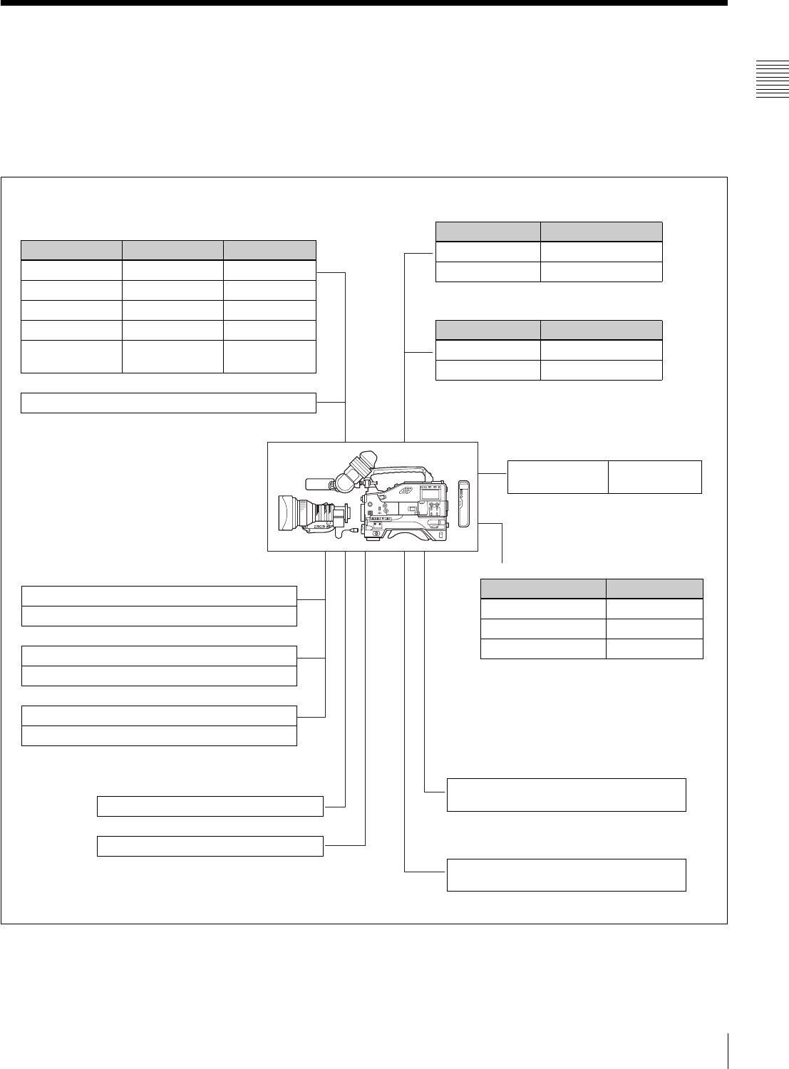
1-2 Example of System Configuration
The diagram below shows a typical configuration of the
camcorder for ENG and EFP.
For more information about the fittings, connections, or
use of additional equipment and accessories, see “Chapter
7 Setting Up the Camcorder” as well as the operation
manuals for the connected equipment.
Control signals
RM-B150/B750 Remote Control Unit
“Memory Stick” (see page 130) Video output
Video monitor for color image check during
shooting
Extension board
1) For the DVW-970 only
Product Model name
Pull Down (24P) Board CBK-FC01 1)
SDI Output Board CBK-SD01
Picture Cache Board CBK-MB01
Viewfinder-related equipment
Name / Purpose Magnification Part No.
Fog-proof filter — 1-547-341-11
Lens assembly –2.8 D to +2.0 D A-8262-537-A
Lens assembly –3.6 D to –0.8 D A-8262-538-A
Lens assembly –3.6 D to +0.4 D A-8267-737-A
Lens assembly
(3 × magnification)
–2.4 D to +0.5 D A-8314-798-A
BKW-401 Viewfinder Rotation Bracket
AC power supply
Battery
Product Model name
AC Adaptor AC-550/550CE
AC Adaptor AC-DN10
Product Model name
Battery Charger BC-M150/M50
Battery Pack BP-GL65/GL95/L60S
Audio input signals
External microphone ECM-672 or similar microphone
CAC-12 Microphone Holder
Analog audio equipment
CCXA-53 audio cable
WRR-860/862 UHF Portable Tuner
WRR-855-series UHF Synthesized Tuner Unit
Audio output
XLR 5-pin connector for stereo microphone
(service part)
Wireless video/audio transmission
Wireless Camera
Transmitter
WLL-CA50

12 Precautions
Chapter 1 Overview
1-3 Precautions
Use and Storage
Do not subject the unit to severe shocks
The internal mechanism may be damaged or the body
warped.
After use
Always turn off the power.
Before storing the unit for a long period
Remove the battery pack.
Use and storage locations
Store in a level, ventilated place. Avoid using or storing the
unit in the following places.
• Places subject to temperature extremes
• Very damp places
• Places subject to severe vibration
• Near strong magnetic fields
• In direct sunlight or close to heaters for extended periods
To prevent electromagnetic interference from
portable communications devices
The use of portable telephones and other communications
devices near this unit can result in malfunctions and
interference with audio and video signals.
It is recommended that the portable communications
devices near this unit be powered off.
Note on laser beams
Laser beams may damage the CCDs. If you shoot a scene
that includes a laser beam, be careful not to let the laser
beam be directed into the lens of the camera.
Use at a high temperature
If the unit is used at a high temperature, white flecks may
appear on the screen.
13
Chapter 2 Locations and Functions of Parts and Controls
Chapter
Power Supply
2
Locations and Functions
of Parts and Controls
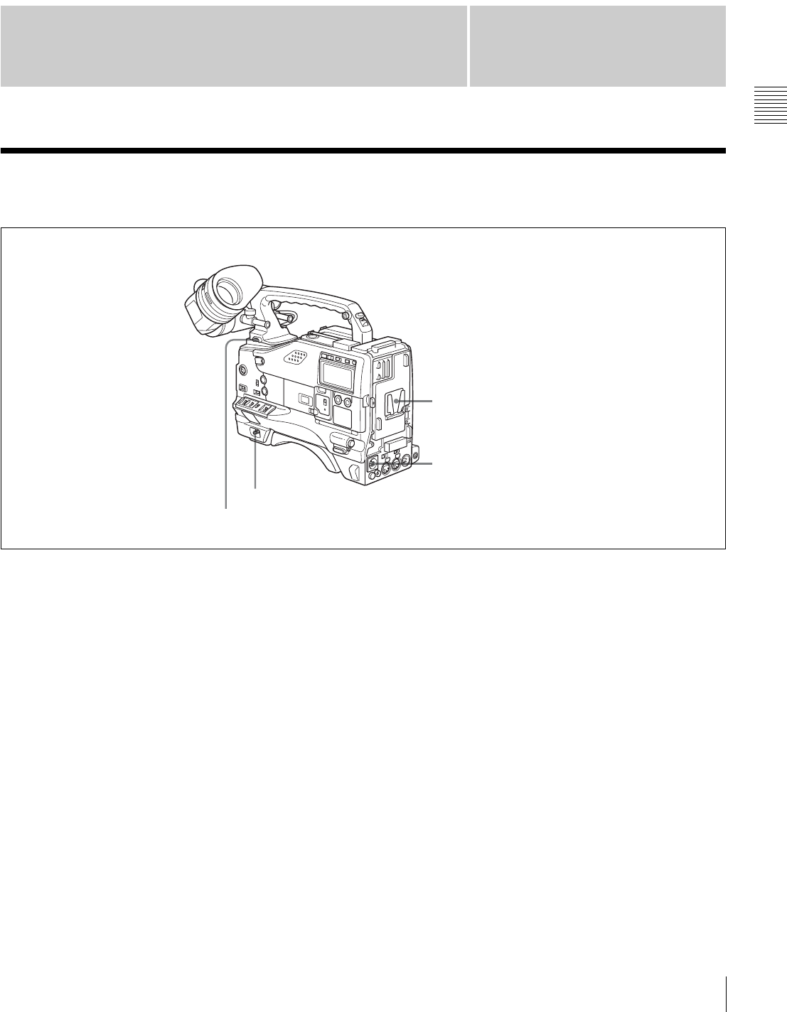
2-1 Power Supply
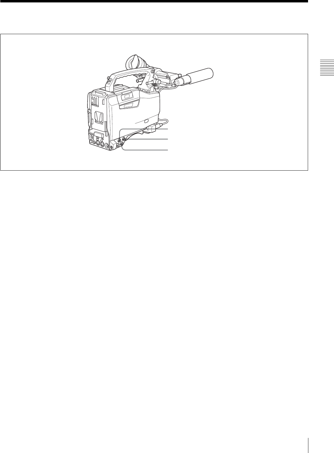
aBattery attachment
Attach a battery pack, BP-GL65, BP-GL95, or BP-L60S.
Furthermore, by attaching an AC-DN10 AC Adaptor, you
can operate the camcorder from AC power.
bDC IN connector (XLR type, 4-pin, male)
To operate the camcorder using an AC power supply,
connect an AC-550/550CE AC Adaptor with the DC
output cable supplied with the adaptor.
To use an external battery, connect its DC output cable to
the DC IN connector.
cPOWER switch
This switch turns the main power supply on and off.
dLIGHT switch
This determines how a video light connected to the LIGHT
connector is turned on and off.
AUTO: When the switch on the video light is in the on
position, putting the camcorder in recording mode
turns the video light on automatically. When using the
auto interval recording mode, the video light is
automatically turned on immediately before recording
starts.
MANUAL: You can turn the video light on or off
manually, using its own switch.
cPOWER switch
dLIGHT switch
bDC IN connector
aBattery attachment
14 Accessory Attachments
Chapter 2 Locations and Functions of Parts and Controls
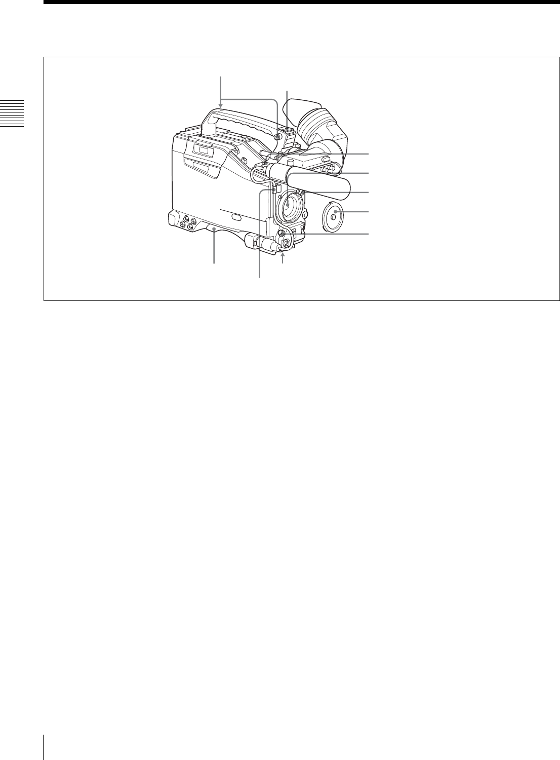
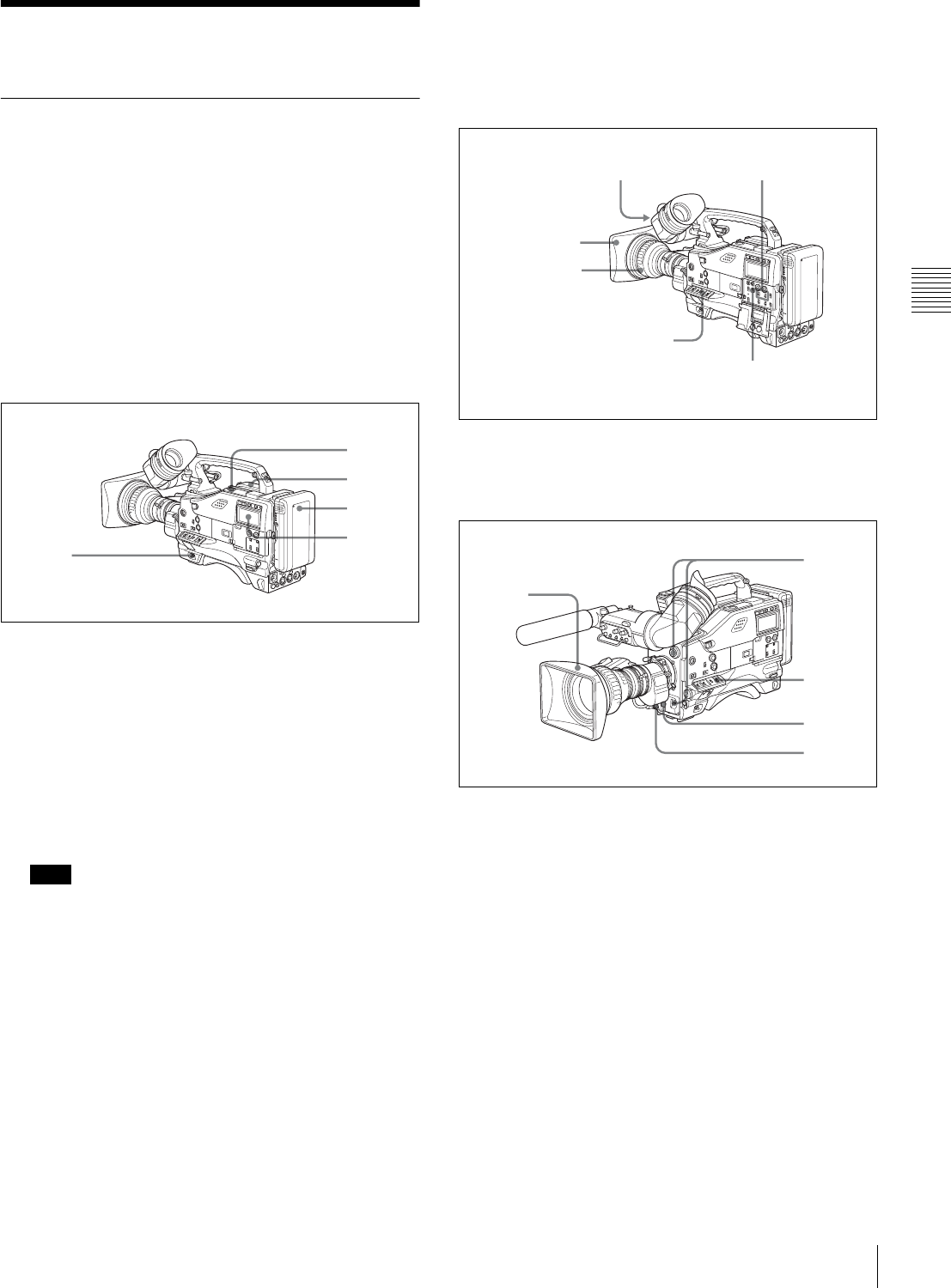
2-2 Accessory Attachments
aShoulder strap posts
Attach the supplied shoulder strap to these posts.
For details, see “7-7 Attaching/Detaching the Shoulder
Strap” on page 117.
bLight shoe
Attach an optional accessory such as a video light to this
shoe.
cLIGHT connector (2-pin, female)
Connect the cable of an Anton Bauer Ultralight System
attached to the light shoe. The system operates with lights
powered by 12 V, with a maximum power consumption of
50 W.
dLens mount (special bayonet mount)
Use this for mounting the lens.
eLens locking lever
After inserting the lens in the lens mount, rotate the lens
mount ring with this lever to lock the lens in position.
fLens mount cap
Remove this cap by pushing up the lens locking lever.
When no lens is mounted, keep this cap fitted for
protection from dust.
gLENS connector (12-pin)
Fit the lens cable to this connector. Contact your Sony
representative for more information about the lens you can
use.
hTripod mount
When using the camcorder on a tripod, attach the tripod
adaptor (optional).
iShoulder pad
You can move the shoulder pad forwards or backwards by
raising up the shoulder pad locking lever. Do this to ensure
the best balance when shooting with the camcorder on
your shoulder.
For details, see “7-8 Adjusting the Shoulder Pad Position”
on page 118.
cLIGHT connector
dLens mount
bLight shoe
aShoulder strap posts
eLens locking lever
fLens mount cap
gLENS connector
hTripod mountiShoulder pad
Lens cable clamp
15
Audio Functions
Chapter 2 Locations and Functions of Parts and Controls
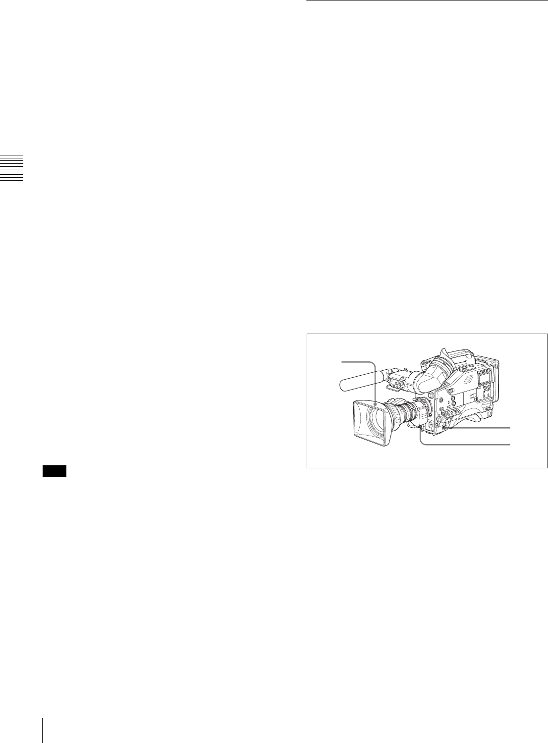
2-3 Audio Functions
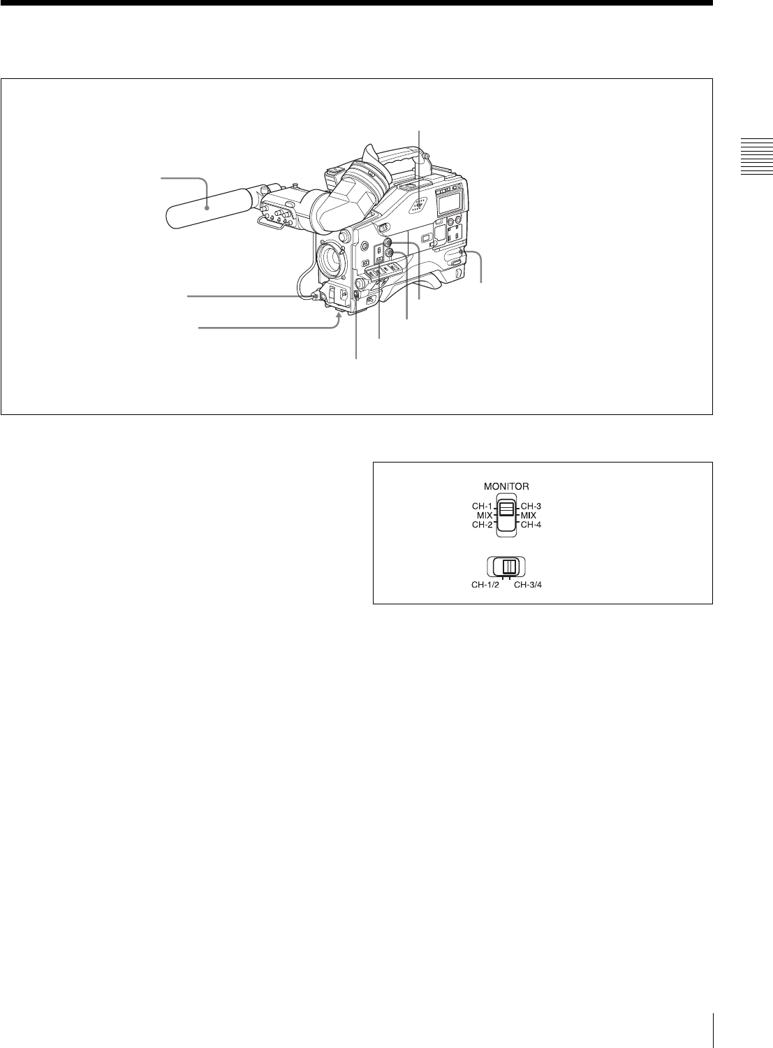
Audio functions (1)
aMicrophone
This is a super-cardioid directional monaural microphone
with an external power supply (+48 V) system.
bMIC IN (microphone input) connector (XLR type,
3-pin, female)
Connect the supplied microphone to this connector. A
microphone other than the supplied one may also be
connected as long as it can operate with the power (+48 V)
supplied from this connector.
By fitting a 5-pin connector (service part number: A-1053-
453-A), you can also use a stereo microphone.
cMIC (microphone) LEVEL control
This control adjusts the audio level of the microphone
connected to the MIC IN connector.
dEARPHONE jacks (minijacks)
You can monitor the E-E sound 1) during recording and
playback sound during playback. Plugging an earphone
into the jack automatically cuts off the built-in speaker.
When an alarm is indicated, you can hear the alarm sound
through the earphone.
1) E-E: Abbreviation of “Electric-to-Electric.” In E-E mode, video and audio
signals input to the camcorder are output after passing through internal
electric circuits only. This can be used to check input signals.
eMONITOR switch and CH-1/2 / CH-3/4 switch
These switches together determine the channel selection
for audio monitor output.
MONITOR switch and CH-1/2 / CH-3/4 switch
CH-1/2 / CH-3/4 switch:
This determines the pair of audio channels selected with
the MONITOR switch.
CH-1/2 position: channels 1 and 2
CH-3/4 position: channels 3 and 4
The signals output from the AUDIO OUT connector and
EARPHONE jacks and the audio level meter in the display
window also depend on the setting of this switch.
MONITOR switch:
This selects the audio monitor channels output to the
earphone or speaker, depending on the setting of the CH-
1/2 / CH-3/4 switch.
cMIC LEVEL control
gALARM volume control
bMIC IN connector
aMicrophone
fMONITOR volume control
eMONITOR switch and CH-1/2 / CH-3/4 switch
hBuilt-in speaker
dEARPHONE jack (front)
dEARPHONE jack (rear)
MONITOR switch
CH-1/2 / CH-3/4 switch
16 Audio Functions
Chapter 2 Locations and Functions of Parts and Controls
fMONITOR volume control
This control adjusts the speaker or earphone volume for
sounds other than the alarm sound. At the minimum
position, no sound can be heard.
gALARM volume control
This control adjusts the speaker or earphone alarm volume.
At the minimum position, no sound can be heard.
ALARM volume control
hBuilt-in speaker
The speaker can be used to monitor E-E sound during
recording, and playback sound during playback. The
speaker also sounds alarms to reinforce visual warnings.
If you connect an earphone to the EARPHONE jack, the
speaker is automatically muted.
See “8-3 Operation Warnings” on page 126 for
information about alarms.
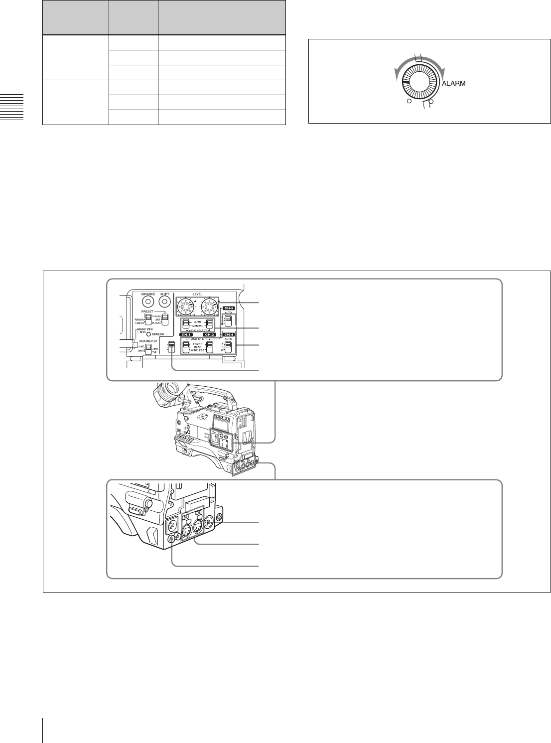
Audio functions (2)
iLEVEL (CH-1/CH-2) (audio channel-1 and
channel-2 recording level) controls
These controls adjust the audio levels of channels 1 and 2
when the AUDIO SELECT switches are set to MANUAL.
jAUDIO SELECT CH-1/CH-2 (audio channel-1 and
channel-2 adjustment method selection) switches
These switches select the audio level adjustment method
for each of audio channels 1 and 2.
AUTO: Select this setting for automatic adjustment.
MANUAL: Select this setting for manual adjustment.
CH-1/2/CH-3/4
switch
position
MONITOR
switch
position
Audio output
CH-1/2 CH-1 Audio channel 1
MIX Mix sound of channels 1 and 2
CH-2 Audio channel 2
CH-3/4 CH-3 Audio channel 3
MIX Mix sound of channels 3 and 4
CH-4 Audio channel 4
Minimum Maximum
CUE IN
CH-1
MIX
CH-2
iLEVEL (CH-1/CH-2) controls
kAUDIO IN CH-1/CH-2/CH-3/CH-4 switches
jAUDIO SELECT CH-1/CH-2 switches
mAUDIO OUT connector
oDC OUT 12V connector
nAUDIO IN CH1/CH2 connectors
and LINE/MIC/+48V ON switches
lCUE IN switch

17
Audio Functions
Chapter 2 Locations and Functions of Parts and Controls
kAUDIO IN CH-1/CH-2/CH-3/CH-4 (audio input
selection) switches
CH-1/CH-2 switches
These switches select the audio input signals to be
recorded on audio channels 1 and 2.
FRONT: The input signal source is the microphone
connected to the MIC IN connector.
REAR: The input signal source is the audio equipment
connected to the AUDIO IN CH1/CH2 connectors.
WIRELESS: The input signal source is a WRR-855A/
855B UHF Synthesized Tuner Unit (option).
CH-3/CH-4 switches
These switches select the audio input signals to be
recorded on audio channels 3 and 4.
F (front): The input signal source is the microphone
connected to the MIC IN connector.
R (rear): The input signal source is the audio equipment
connected to the AUDIO IN CH1/CH2 connectors.
W (wireless): The input signal source is a WRR-855A/
855B UHF Synthesized Tuner Unit (not supplied).
lCUE IN (cue track input) switch
This switch selects the input signal to be recorded on the
cue track.
CH-1: Signal selected by the AUDIO IN CH-1 switch
MIX: Mixed signals selected by the AUDIO IN CH-1 and
CH-2 switches
CH-2: Signal selected by the AUDIO IN CH-2 switch
mAUDIO OUT (audio output) connector (XLR type,
5-pin, male)
This connector outputs the audio signals recorded on audio
channels 1 and 2 or audio channels 3 and 4.
The MONITOR CH-1/2 / CH-3/4 switches allow you to
select the audio signal to be monitored.
nAUDIO IN CH1/CH2 (audio channel-1 and
channel-2 input) connectors (XLR type, 3-pin, female)
and LINE/MIC/+48 V ON (line input/microphone
input/external power supply +48V ON) switches
These are audio input connectors for channels 1 and 2 to
which you can connect audio equipment or a microphone.
The LINE/MIC/+48V ON switches select the audio source
of the audio input signals connected to each of these
connectors.
LINE: Line input audio equipment
MIC: Microphone with an internal power supply
+48V ON: Microphone with an external power supply
system
oDC OUT 12 V (DC power output) connector (4-pin,
female)
This connector supplies power for a WRR-860A/862A/
862B UHF Portable Tuner (option). Do not connect any
equipment other than the UHF portable tuner.
18 Shooting and Recording/Playback Functions
Chapter 2 Locations and Functions of Parts and Controls
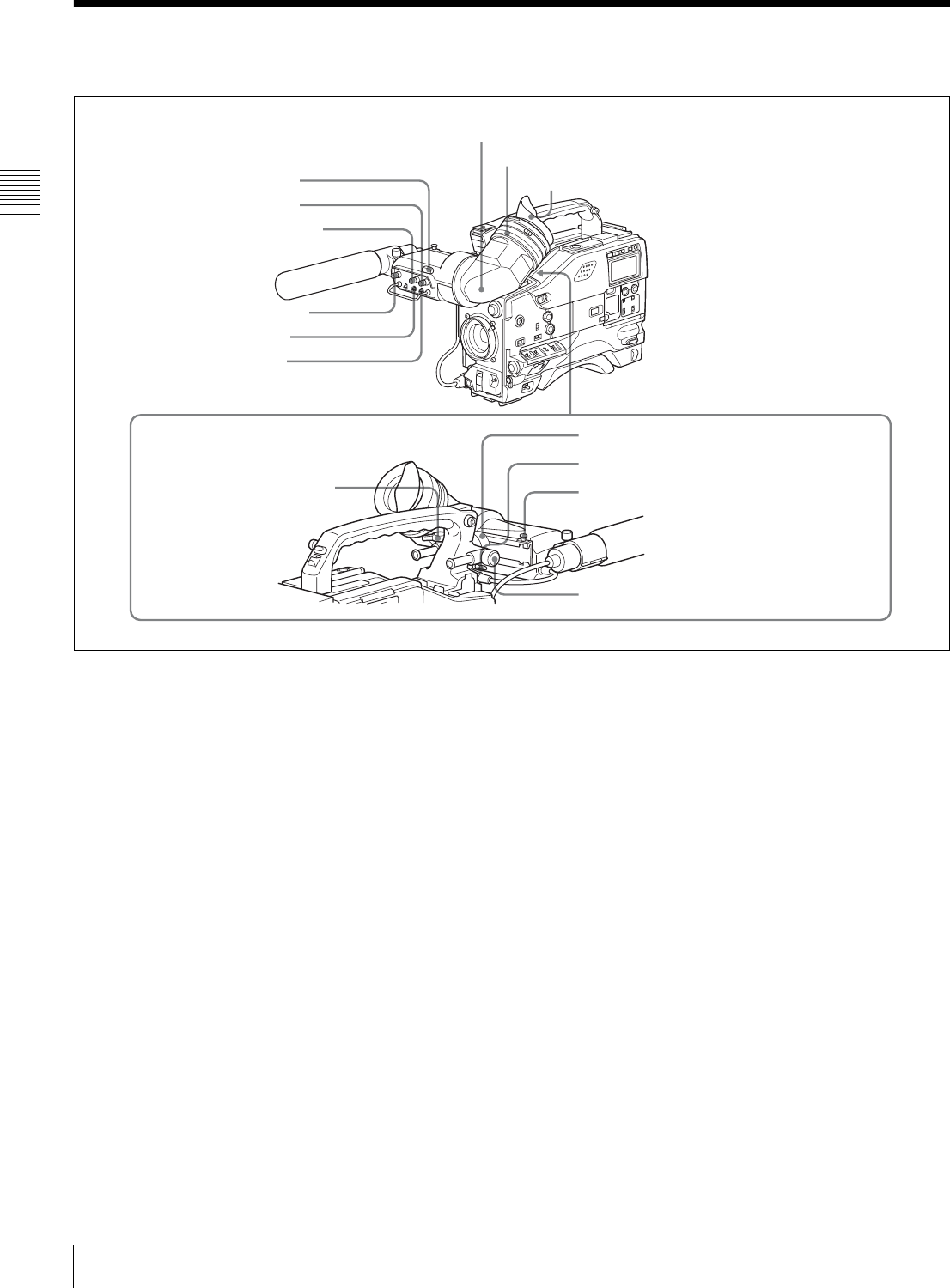
2-4 Shooting and Recording/Playback Functions
Shooting and recording/playback functions (1)
aTALLY indicator
Setting the TALLY switch to HIGH or LOW enables this
indicator. The indicator lights during recording on the
VTR. Like the REC indicator in the viewfinder, it flashes
to indicate a problem. You can set the indicator brightness
with the TALLY switch.
bBRIGHT (brightness) control
This control adjusts the picture brightness on the
viewfinder screen. It has no effect on the camera output
signal.
cCONTRAST control
This control adjusts the picture contrast on the viewfinder
screen. It has no effect on the camera output signal.
dPEAKING control
This control adjusts the sharpness of the picture on the
viewfinder screen to make focusing easier. It has no effect
on the camera output signal.
eZEBRA switch
This switch controls the zebra pattern1) on the viewfinder
screen.
ON: The zebra pattern is displayed and stays.
OFF: No zebra pattern is displayed.
MOMENT: The zebra pattern is displayed and stays for 5
to 6 seconds.
The zebra pattern is factory set to indicate picture areas
where the video level is approximately 70%.You can use
the setup menu to change the setting so that areas where
the video level is 100% and above are also displayed at the
same time.
1) The zebra pattern aids in manual iris adjustment by indicating areas of the
picture where the video level is approximately 70% and 100% and above.
For information about how to change the zebra pattern
setting in the setup menu, see “5-2-5 Setting the
Viewfinder” on page 78.
fTAL LY switch
This switch controls the TALLY indicator, setting its
brightness (HIGH or LOW) or turning it off.
HIGH: The TALLY indicator brightness is high.
OFF: The TALLY indicator is disabled.
LOW: The TALLY indicator brightness is low.
gViewfinder
hDiopter adjustment ring
aTALLY indicator Eyecup
bBRIGHT control
cCONTRAST control
dPEAKING control
eZEBRA switch
fTALLY switch
iViewfinder front-rear
positioning lever
jViewfinder left-right positioning ring
kCamera operator tally indicator
lViewfinder stopper
mLOCK knob
19
Shooting and Recording/Playback Functions
Chapter 2 Locations and Functions of Parts and Controls
gViewfinder
The viewfinder lets you view the image in black and white
while shooting, recording or playing back. It also displays
various warnings and messages related to the settings or
operating conditions of the camcorder, a zebra pattern,
safety zone marker 1), and center marker 2).
1) The safety zone marker is a rectangle indicating the effective picture area.
2) The center marker indicates the center of the picture with a crosshair.
For details, see “5-2-4 Setting the Marker Display” on
page 78.
hDiopter adjustment ring
Use this ring to adjust the viewfinder image for your
vision.
iViewfinder front-rear positioning lever
To adjust the viewfinder position in the front-rear
direction, loosen this lever and the LOCK knob. After
adjustment, retighten this lever and the LOCK knob.
jViewfinder left-right positioning ring
Loosen this ring to move the viewfinder sideways.
kCamera operator tally indicator
This indicator lights while the camcorder is recording.
Slide the window open when you shoot with your eye away
from the viewfinder. This indicator flashes when the
battery level is running low or the disc is almost full.
lViewfinder stopper
Pull up this stopper to detach the viewfinder from the
camera.
mLOCK knob
To adjust the viewfinder position in the front-rear
direction, loosen this knob and the viewfinder front-rear
positioning lever. After adjustment, retighten this knob and
the viewfinder front-rear positioning lever.
Shooting and recording/playback functions (2)
nFILTER selector
Use this selector to select the most appropriate filter to
match the light source illuminating the subject.
When this selector is used with the display mode set to 3,
the new setting appears on the viewfinder screen for about
3 seconds. (e.g.: ND: 1, CC: B)
The relationships between the selector settings and filter
selections as well as examples of filters for different
shooting conditions are as follows:
1) A type of special effect filter, which generates a cross of light on a
highlighted portion.
nFILTER selector
oASSIGN 1/2 switches
pSHUTTER selector
qAUTO W/B BAL switch
tWHITE BAL switch
sOUTPUT/DCC selector
rGAIN selector
uTURBO GAIN button
FILTER selector (outer knob) setting CC filter selection
ACross filter 1)
B 3200K
C 4300K
D 6300K
FILTER selector (inner knob) setting ND filter selection
1 Clear
21/4 ND
31/16 ND
41/64 ND
20 Shooting and Recording/Playback Functions
Chapter 2 Locations and Functions of Parts and Controls
oASSIGN 1/2 switches
You can assign the desired functions to each of the
ASSIGN 1 switch (push button) and ASSIGN 2 switch
(sliding) on the FUNCTION 1 page of the USER menu.
For details, see “5-3-5 Assigning Functions to Assignable
Switches” on page 87.
pSHUTTER selector
Set this selector to ON to use the electronic shutter. Push it
down to SELECT to switch the shutter speed or mode
setting within the range previously set with the setup
menu.
When this selector is operated, the new setting appears on
the setting change/adjustment progress message display
area for about 3 seconds.
For details about the shutter speed and mode settings, see
“4-2 Setting the Electronic Shutter” on page 55.
qAUTO W/B BAL (automatic white/black balance
adjustment) switch
This switch activates the white balance and black balance
automatic adjustment functions.
WHT: Automatic adjustment of the white balance. If the
WHITE BAL switch is set to A or B, the white balance
setting is stored in the corresponding memory. The
memory stores a separate white balance setting for each
filter setting.
BLK: Automatic adjustment of the black set and black
balance.
rGAIN selector
This selector switches the gain of the video amplifier to
match the lighting conditions during shooting. The gains
corresponding to the L, M, and H settings can be selected
from the setup menu. The factory settings are L = 0 dB, M
= 9 dB, and H = 18 dB.
When this selector is adjusted, the new setting appears on
the setting change/adjustment progress message display
area of the viewfinder screen for about 3 seconds.
For details about setting the gain values, see “5-3-1
Setting Gain Values for the GAIN Selector Positions” on
page 84.
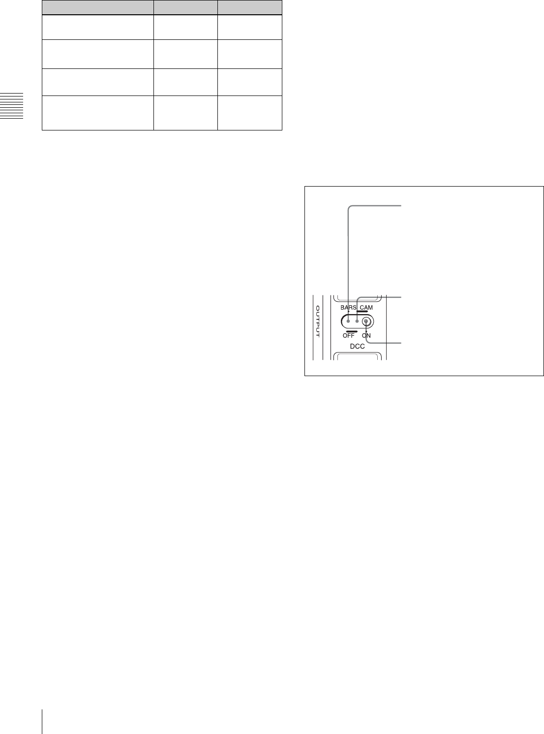
sOUTPUT/DCC (output signal/dynamic contrast
control) selector
This selector switches the video signal that is output to the
VTR, viewfinder, and video monitor, between the
following two.
BARS: Outputs the color bar signal.
CAM: Outputs the video signal from the camera. When
this is selected, you can switch DCC1) on and off with
this selector.
1) DCC (Dynamic Contrast Control)
Against a very bright background with the iris opening adjusted to the
subject, objects in the background will be lost in the glare. The DCC
function will suppress the high intensity and restore much of the lost detail
and is particularly effective in the following cases.
•Shooting people in the shade on a sunny day
•Shooting a subject indoors, against a background through a window
•Any high contrast scene
OUTPUT/DCC selector
tWHITE BAL (white balance memory) switch
This switch controls the white balance setting.
PRST (preset): Adjusts the color temperature
corresponding to the position of the FILTER selector.
Use the PRST setting when you have no time to adjust
the white balance.
A or B: When the AUTO W/B BAL switch is pushed to
WHT, the white balance is automatically adjusted
according to the current position of the FILTER
selector, and the adjusted value is stored in either
memory A or memory B. (There are two memories for
each filter, allowing a total of eight adjustments to be
stored.) When this switch is set to A or B, the
camcorder automatically adjusts itself to the stored
value corresponding to the current settings of this
switch and the FILTER selector.
You can use the AUTO W/B BAL switch even when
AT W 1) is in use.
1) ATW (Auto Tracing White Balance)
The white balance of the picture being shot is adjusted automatically for
varying lighting conditions.
Shooting condition CC filter ND filter
Sunrise and sunset; inside
studio
B (3200K) 1 (clear)
Clear skies C (4300K) or
D (6300K) 2 (1/4 ND) or
3 (1/16 ND)
Cloudy or raining D (6300K) 1 (clear) or
2 (1/4 ND)
Very bright conditions such
as snow, at high altitudes,
or at the seashore
C (4300K) or
D (6300K) 3 (1/16 ND) or
4 (1/64 ND)
BARS, DCC OFF
A color bar signal is output and the
DCC circuit does not operate. For
example, use the setting for the
following purposes.
• Adjusting the video monitor
• Recording the color bar signal
CAM, DCC OFF
The video signal from the camera is
output, and the DCC circuit does not
operate.
CAM, DCC ON
The video signal from the camera is
output, and the DCC circuit operates.
21
Shooting and Recording/Playback Functions
Chapter 2 Locations and Functions of Parts and Controls
B (ATW): When this switch is set to B and on the
FUNCTION 2 page of the OPERATION menu,
“WHITE B CH” is set to “ATW”, ATW is activated.
When this switch is adjusted, the new setting appears on
the setting change/adjustment progress message display
area of the viewfinder screen for about 3 seconds.
You can assign the ATW ON/OFF function to the ASSIGN
1 switch (push button) on the FUNCTION 1 page of the
USER menu.
For details, see “5-3-5 Assigning Functions to Assignable
Switches” on page 87.
uTURBO GAIN button
When shooting under extremely poor lighting conditions,
press the button once to boost the video gain to the value
preset on the GAIN SW page of the USER menu (up to 48
dB). To stop boosting the gain, press the button once more.
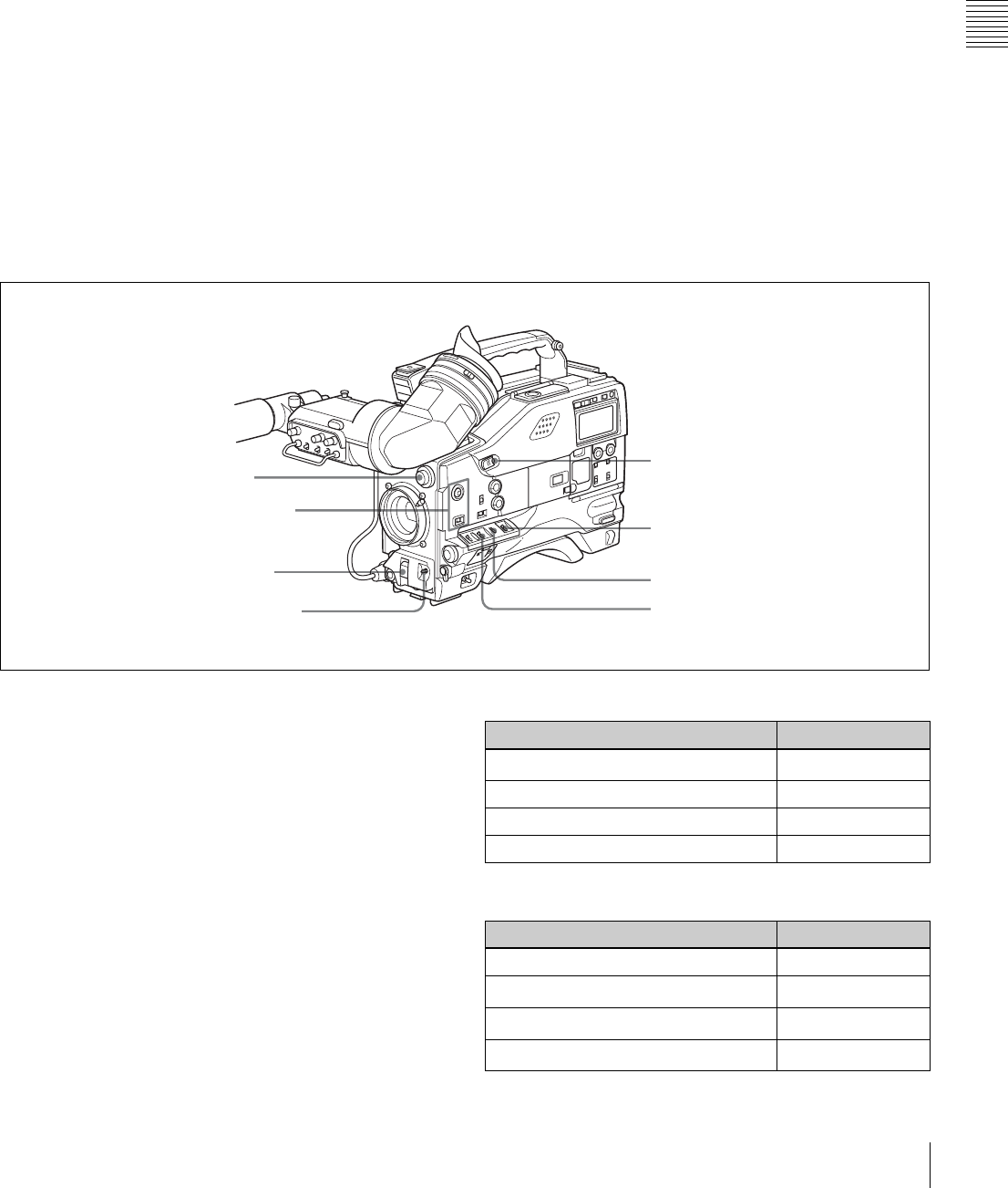
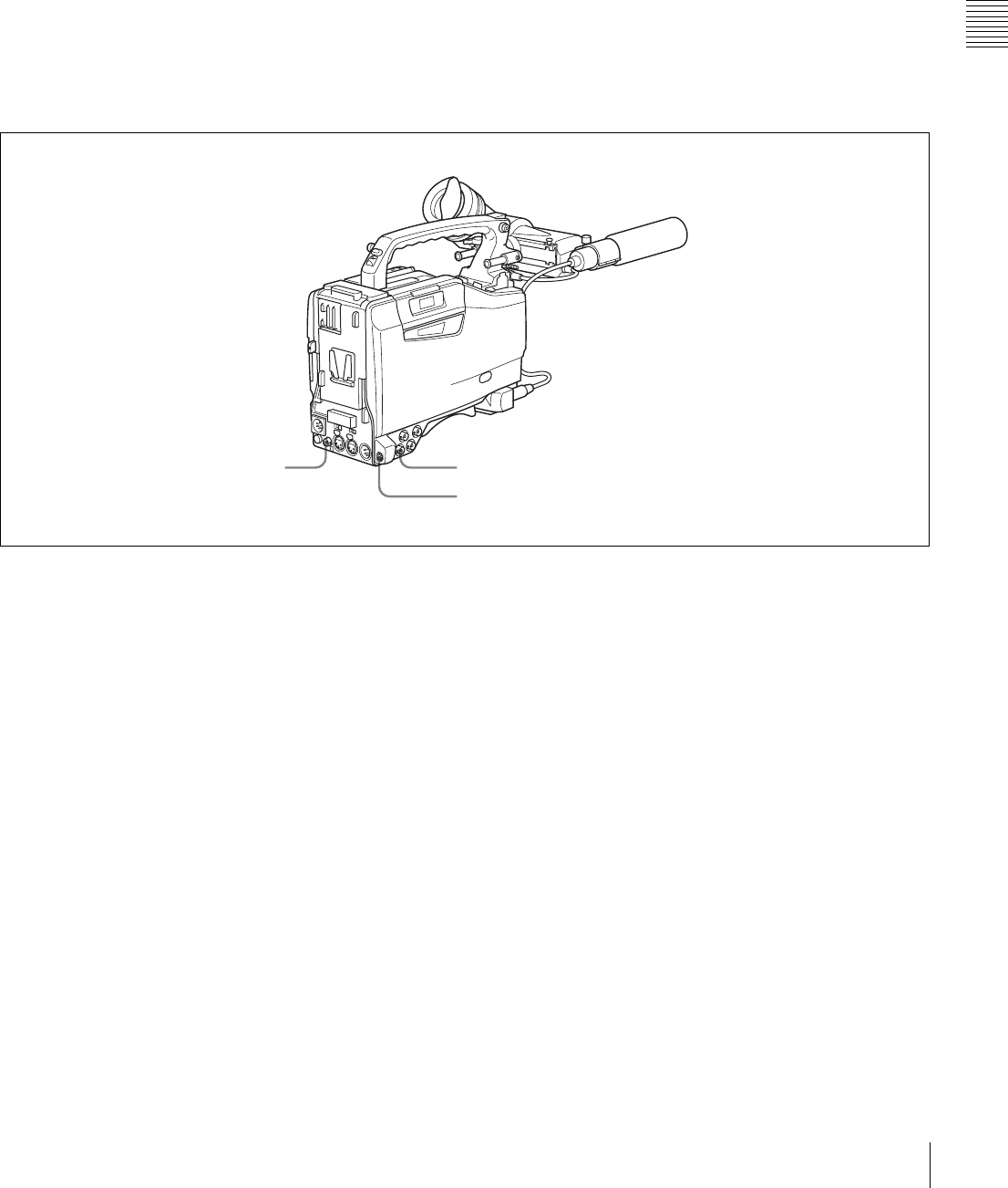
Shooting and recording/playback functions (3)
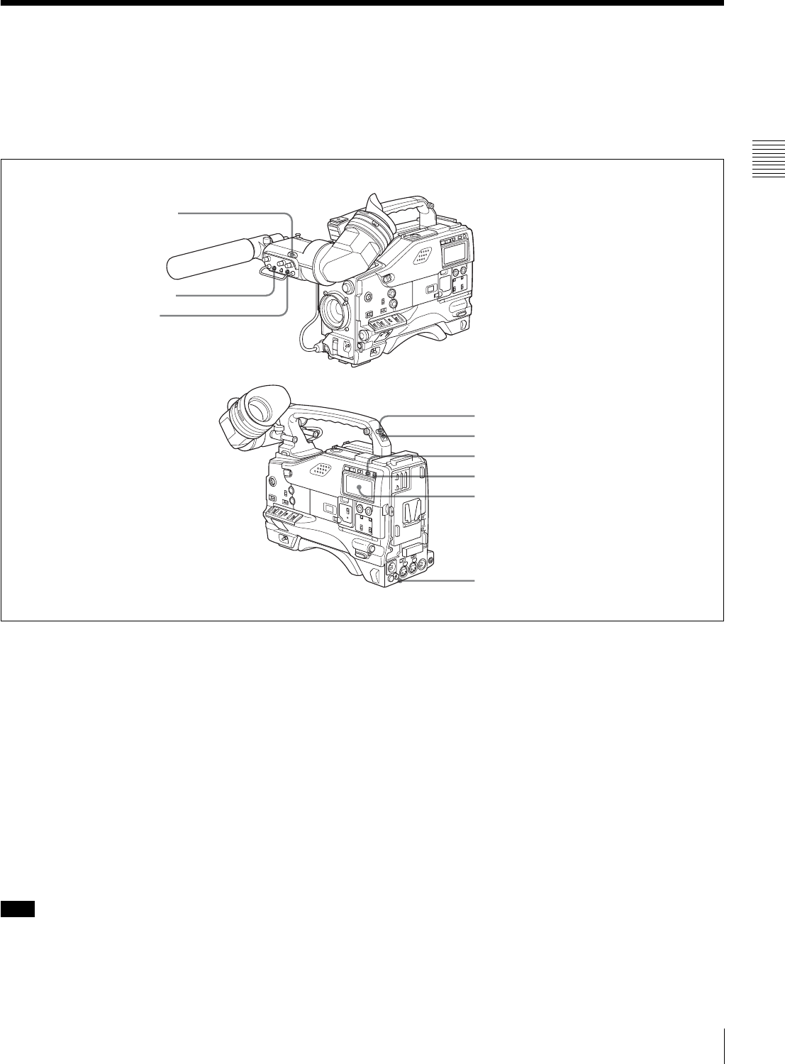
vVIDEO OUT connector (BNC type)
This connector outputs a composite video signal (standard
level, 75-ohm terminated) for a video monitor. With a
video monitor connected to this connector, you can
monitor the picture being shot by the camera or the picture
played back by the VTR. To choose between the composite
video signal output and SDI signal output, use the menu.
When synchronizing the time code of an external VTR
with that of the camcorder, connect this connector to the
GENLOCK IN connector of the external VTR.
By installing the CBK-SD01 extension board (not
supplied), you can output an SDI signal (supporting
embedded audio and the EDH function) from this
connector.
For details on how to select the output signal, see “5-3-2
Selecting the Output Signals” on page 85.
wTEST OUT connector (BNC type)
This connector outputs the video signal (standard level, 75-
ohm terminated) for a video monitor. The output signal can
be selected from composite or RGB. The factory setting is
composite, and the setting returns to composite whenever
the unit is powered on.
Depending on menu settings, menus, time code, and shot
data can be superimposed on the image on the monitor.
For details on how to select the test output signal, refer to
the Maintenance Manual.
xREMOTE connector (8-pin)
Connect the RM-B150/B750 Remote Control Unit, which
makes it possible to control the VTR and camera remotely.
vVIDEO OUT connector wTEST OUT connector
xREMOTE connector
22 Shooting and Recording/Playback Functions
Chapter 2 Locations and Functions of Parts and Controls
Shooting and recording/playback functions (4)
yVTR START button
Press this button to start recording. Press it again to stop
recording. The effect is exactly the same as that of the VTR
button on the lens.
When the REC SWITCH function is assigned to the
ASSIGN 1 switch (push button), you can use the switch as
the REC START button.
zVTR SAVE/STBY (standby) switch
This switch controls the VTR power mode during pauses
in recording.
SAVE: Power saving mode. When you press the VTR
START button, there is a short delay before recording
starts, but power consumption in this mode is less than
in standby mode, so that battery life is extended. When
the switch is set to SAVE, the SAVE indicator in the
viewfinder lights.
STBY: Standby mode. Recording starts as soon as you
press the REC START button.
• Avoid allowing the camcorder to remain in STBY
(standby) mode for a long time.
• Even if the switch is set to the STBY position, the
camcorder can automatically turn to power saving mode
if the tape does not run for a certain period. In such a
case, the VTR SAVE indicator in the viewfinder lights.
This function is effective when a setting other than OFF
is selected for the STBY OFF TIMER item on the VTR
MODE page of the MAINTENANCE menu. The STBY
OFF TIMER item also allows you to select the length of
time until the camcorder turns to power saving mode.
For detailed information, see “3-5 Setting the Stand-by off
Timer During Rec-Pause” on page 51.
wj EJECT button
Press this button to eject or load a cassette.
wk REW (rewind) button and indicator
Press this button to rewind the tape. The indicator lights
during rewinding.
wl F FWD (fast forward) button and indicator
Press this button to fast forward the tape. The indicator
lights during fast forward.
e; PLAY button and indicator
Press this button to view the recorded picture in the
viewfinder or on the color video monitor. The indicator
lights during playback.
The 4 times normal speed search function is provided to
make it far quicker to find a desired location of the tape.
Press the REW button or F FWD button during playback
to view the 4 times normal speed search picture.
ea STOP button
Press this button to stop the tape.
yVTR START button
zVTR SAVE/STBY connector
wj EJECT button
wk REW button and indicator
wl F FWD button and indicator
e; PLAY button and indicator
ea STOP button
Notes
23
Menu Operating Section
Chapter 2 Locations and Functions of Parts and Controls
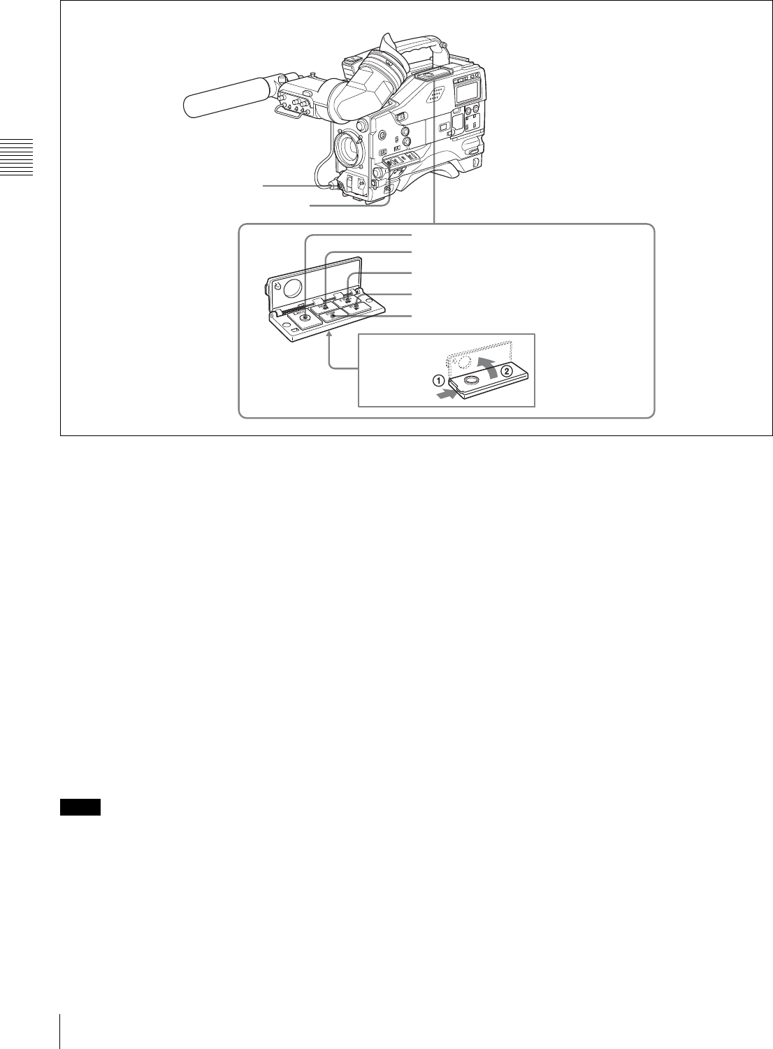
2-5 Menu Operating Section
Menu operation section
a“Memory Stick” compartment
Open the cover of the “Memory Stick” compartment by
pressing the MEMORY STICK OPEN button and insert
the “Memory Stick.”
To remove, press the eject button.
During data writing/loading to/from the “Memory Stick,”
the ACCESS indicator lights or flashes.
For details, see “6-1-1 Handling the “Memory Stick”” on
page 97.
bMENU knob
Use this knob to change the page selection or a setting
within the menu.
Press: If you press this knob when the arrow (b) is placed
at the page title on the menu, the arrow changes to a
question mark (?) and you can change the page by
turning this knob.
When the arrow mark is placed at a position other than
the page title, you can change the setting of the current
item by pressing and turning this knob.
Turn: Turn this knob to change the page or change item
settings.
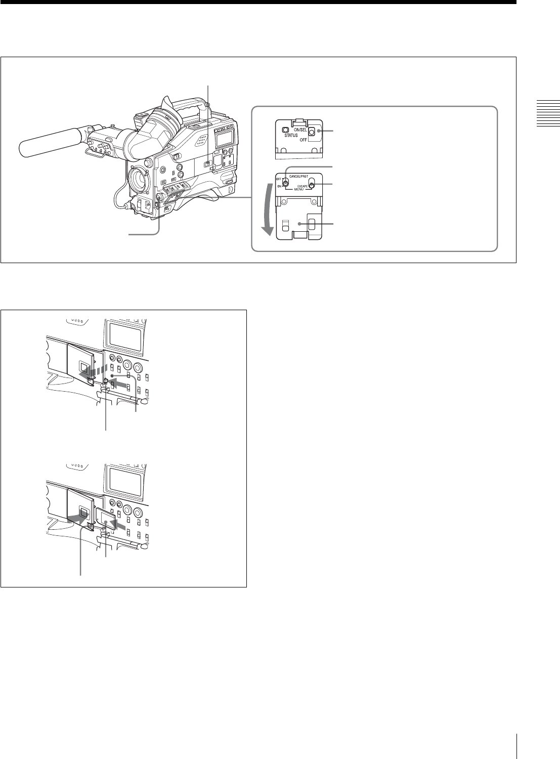
cSTATUS ON/SEL / OFF (menu display on/page
selection/display off) switch
To enable this switch, set the MENU ON/OFF switch to
OFF.
Closing the cover automatically sets the MENU ON/OFF
switch to OFF.
ON/SEL: Each time this switch is pushed upward, a
window to confirm the menu settings and status of the
camcorder appears on the viewfinder screen. The
window consists of three pages, which are switched
each time the switch is pushed upward. Each page is
displayed for about 10 seconds.
OFF: To clear the page immediately after display, push
this switch down to the OFF position.
You can select the pages to be displayed on the menu.
For details, see “5-2-8 Displaying the Status Confirmation
Windows” on page 81.
dMENU ON/OFF switch
To use this switch, open the cover.
eCANCEL/PRST / ESCAPE switch
bMENU knob
cSTATUS ON/SEL / OFF switch
dMENU ON/OFF switch
a“Memory Stick” compartment
Cover
ACCESS indicator
MEMORY STICK OPEN button
Eject button
“Memory Stick”
f

24 Menu Operating Section
Chapter 2 Locations and Functions of Parts and Controls
This switch is used to display the menu on the viewfinder
screen or the test signal screen.
Closing the cover automatically sets this switch to OFF.
ON: Displays the menu on the viewfinder screen or the test
signal screen, at the last accessed page. When the menu
is used for the first time, the first page is displayed.
OFF: Removes the menu from the viewfinder screen or the
test signal screen.
eCANCEL/PRST (preset) / ESCAPE switch
To enable this switch, set the MENU ON/OFF switch to
ON.
Closing the cover automatically sets the MENU ON/OFF
switch to OFF.
CANCEL/PRST: Pushing this switch up to this position
displays the message to confirm whether the previous
settings are cancelled or settings are reset to their initial
values, depending on the menu operating condition.
Pushing this switch up to this position again cancels the
previous settings or resets the settings to their initial
values.
ESCAPE: Use this switch when the menu page, which has
a hierarchical structure, is opened. Each time the switch
is pushed to this position, the page returns to one stage
higher in the hierarchy.
25
Time Code System
Chapter 2 Locations and Functions of Parts and Controls
2-6 Time Code System
Time code functions (1)
aGENLOCK IN connector (BNC type)
• This connector accepts a reference signal when the
camera is to be genlocked or when the time code is to be
synchronized with external equipment. Use the items GL
H PHASE, GL SC PHASE and GL SC 0/180 SEL on the
GENLOCK page of the MAINTENANCE menu to
adjust the genlock H-phase (phase of horizontal sync
signal) and the sub-carrier phase.
• This connector also accepts a return video signal.
You can display the return video signal in the viewfinder
screen while holding the RET button down with
“RETURN VIDEO” set to “ON” on the GENLOCK
page of the OPERATION menu.
bTC IN (time code input) connector (BNC type)
To synchronize the time code of this unit to an external
time code, input the reference time code to this connector.
cTC OUT (time code output) connector (BNC type)
To synchronize the time code of an external VTR to that of
the camcorder, connect this connector to the reference time
code input connector of the external VTR.
cTC OUT connector
aGENLOCK IN connector
bTC IN connector
26 Time Code System
Chapter 2 Locations and Functions of Parts and Controls
Time code functions (2)
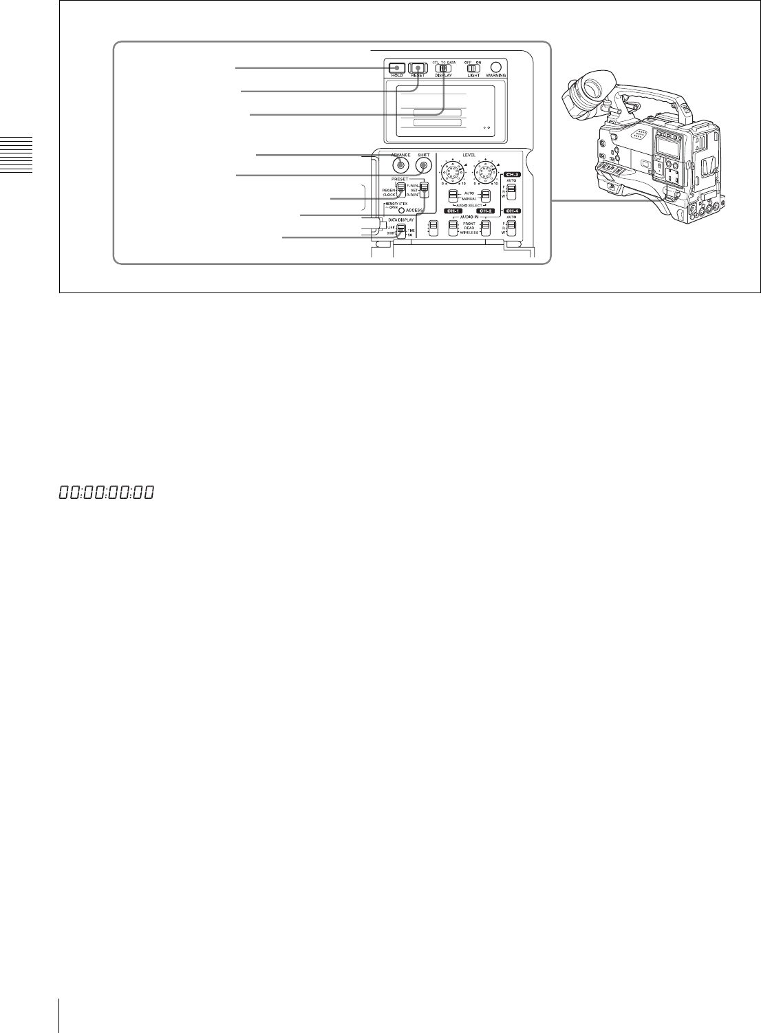
dHOLD (display hold) button
Pressing this button instantly freezes the time data
displayed in the counter display section. (The time code
generator continues running.) Pressing this button again
releases the hold. You can use this button, for example, to
determine the exact time of a particular shot.
When the HOLD button is activated, the time data is
displayed in the following format:
For details of the counter display, see “2-8 Warnings and
Indications on the Display Panel” on page 28.
eRESET button
Pressing this button resets the time data displayed on the
counter display section to “00:00:00:00” or the user bit
data to “00000000.”
fDISPLAY (LCD display) switch
CTL: Control signal
TC: Time code
DATA: The item selected by the DATA DISPLAY switch.
For details, see “Time code display” on page 29.
gADVANCE button
For setting the time code, user bits, or real time, each press
of this button increments the flashing digit selected by the
SHIFT button.
hSHIFT button
For setting the time code, user bits, or real time, this button
selects the digit to be changed. The selected digit flashes.
iPRESET/REGEN (regeneration)/CLOCK switch
This switch selects whether to set a new time code or to
follow the already recorded time code.
PRESET: Records time code with a preset initial value.
REGEN: Records time code continuous with the existing
time code recorded on the tape. Regardless of the
setting of the F-RUN/SET/R-RUN switch, the
camcorder operates in R-RUN mode.
CLOCK: Records time code synchronized to the internal
clock. Regardless of the setting of the F-RUN/SET/R-
RUN switch, the camcorder operates in F-RUN mode.
For more information, see “To make the time code
consecutive” on page 64.
jF-RUN/SET/R-RUN (free run/set/recording run)
switch
This switch selects the operating mode for the internal time
code generator.
F-RUN: Time code keeps advancing, regardless of the
operating state of the VTR. Use this setting when
aligning the time code with real time or when
synchronizing the time code with an external time
code.
SET: Set the switch to this position to set the time code or
user bits.
R-RUN: The time code value advances only during
recording. Use this setting to have a consecutive time
code on the tape.
For details, see “4-5-1 Setting the Time Code” on page 63
and “4-5-3 Setting the User Bits” on page 64.
kDATA DISPLAY switch
U-BIT: To display the user bit value
SHOT-TIME: To display the date and time from the shot
data
SHOT-NO: Not used
CUE IN
CH-1
MIX
CH-2
dHOLD button
eRESET button
fDISPLAY switch
gADVANCE button
kDATA DISPLAY switch
hSHIFT button
iPRESET/REGEN/CLOCK switch
jF-RUN/SET/R-RUN switch
27
Warnings and Indications
Chapter 2 Locations and Functions of Parts and Controls
2-7 Warnings and Indications
Besides the viewfinder, speaker and earphones, the
indicators and displays described in this section also
provide you with information such as the operating state of
the camcorder and warnings.
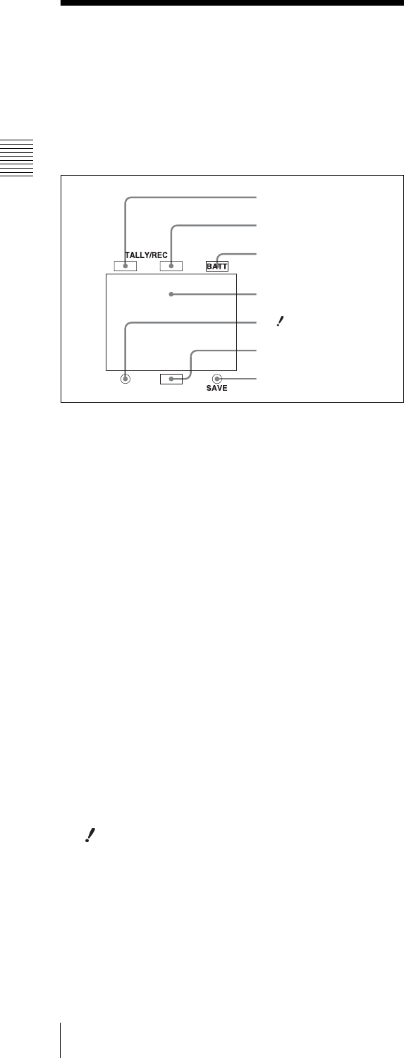
Warning and indication functions
aTALLY indicator
Setting the TALLY switch on the viewfinder to HIGH or
LOW enables this indicator. It lights when the VTR starts
recording. Like the REC indicator in the viewfinder, it also
flashes to provide warnings. The brightness of this
indicator when it is lit can be switched with the TALLY
switch.
bDISPLAY switch
This switches the indications on the viewfinder screen on
or off.
ON: The indications appear on the viewfinder screen.
OFF: The indications do not appear on the viewfinder
screen.
Setting the MENU ON/OFF switch to ON displays the
menu on the viewfinder screen even if the DISPLAY
switch is set to OFF.
cTALLY s witch
This switch controls the TALLY indicator as follows:
HIGH: The TALLY indicator brightness is high.
OFF: The TALLY indicator is disabled.
LOW: The TALLY indicator brightness is low.
dBACK TALLY indicator
When the BACK TALLY switch is set to ON, this indicator
has the same function as the TALLY indicator.
eBACK TALLY switch
This switch enables or disables the BACK TALLY and
REAR TALLY indicators.
ON: The BACK TALLY and REAR TALLY indicators are
enabled.
OFF: The BACK TALLY and REAR TALLY indicators
are disabled.
fLIGHT switch
This switch turns on/off the display panel light.
aTALLY indicator
bDISPLAY switch
cTALLY switch
dBACK TALLY indicator
eBACK TALLY switch
iREAR TALLY indicator
hDisplay panel
gWARNING indicator
fLIGHT switch
Note
28 Warnings and Indications on the Display Panel
Chapter 2 Locations and Functions of Parts and Controls
gWA R N I N G in d i c at o r
This indicator lights up or flashes when there is a fault in
the VTR.
For details, see “8-3 Operation Warnings” on page 126.
hDisplay panel
This displays VTR-related warnings, battery status, tape
status, audio levels, time data, and so on.
For details, see “2-8 Warnings and Indications on the
Display Panel” on page 28.
iREAR TALLY indicator
When the BACK TALLY switch is set to ON, this indicator
has the same function as the TALLY indicator.
2-8 Warnings and
Indications on the Display
Panel
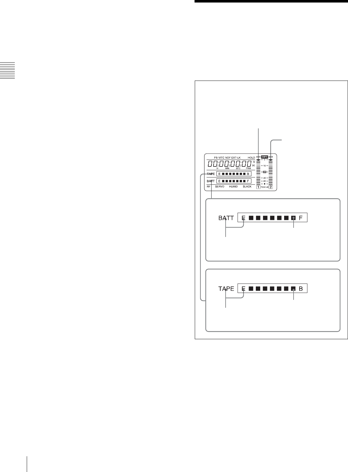
Tape status, battery status and audio level
Tape status, battery status, and level indicators
Close to end: “TAPE” flashes.
End (tape must be replaced): “TAPE”
and “E” flash.
Audio channel level meter:
When the CH-1/2 / CH-3/4 switch is set
to CH-1/2, the audio channel level 1 is
displayed.
When the CH-1/2 / CH-3/4 switch is set
to CH-3/4, the audio channel level 3 is
displayed.
Audio channel level meter:
When the CH-1/2 / CH-3/4
switch is set to CH-1/2, the
audio channel level 2 is
displayed.
When the CH-1/2 / CH-3/4
switch is set to CH-3/4, the
audio channel level 4 is
displayed.
Nearly dead: “BATT” flashes.
Dead battery (battery must be charged):
“BATT” and “E” flash.
Full (at beginning)
Fully charged
Battery status indicator
Tape status indicator
29
Warnings and Indications on the Display Panel
Chapter 2 Locations and Functions of Parts and Controls
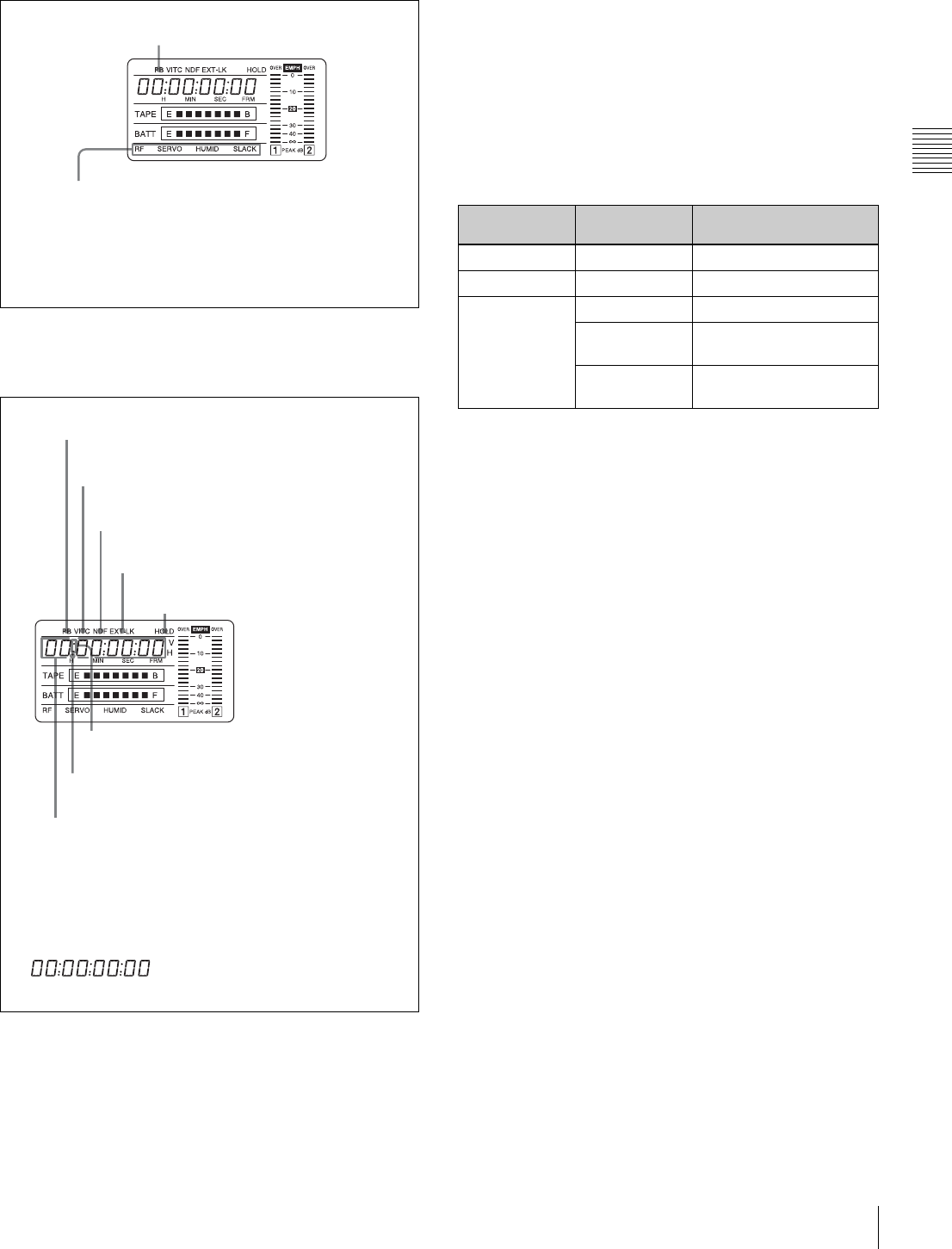
VTR operation status and status indicators
VTR operation and status indicators
Time code display
Time code display
Relationships between the DISPLAY switch and
DATA DISPLAY switch settings and the time
counter displays
Except during setting of the time code, the time counter
display is determined by the position of the DISPLAY
switch and DATA DISPLAY switch.
For details of setting the time code menu operation, see “4-
5-1 Setting the Time Code” on page 63.
Warning indication
RF: Lights if the recording heads are clogged.
SERVO: Lights if the servo motor fails.
HUMID: Lights if condensation is on the drum.
SLACK: Lights if the tape is not winding properly.
For details, see “8-3 Operation Warnings” on page 126.
Lights during playback
Lights when the time code generator
is on hold.
Lights in playback mode.
Lights when VITC is selected for the time code.
Lights in non-drop frame mode. (DVW-970 only)
Lights when the camcorder is synchronized
with an external time code.
Lights when the time code, CTL or
real time is displayed.
1) When the HOLD button is pressed to hold the time code value,
the time code is displayed in the format shown below. When the
HOLD button is pressed again to release the hold, the time code
is displayed in the normal format.
Lights when the HOLD button is pressed.1)
Time counter display: Shows the time code,
CTL, user bit data, and real time.
Switch settings related to time code and displayed
information
DISPLAY
switch position
DATA DISPLAY
switch position
Displayed information
CTL Any position CTL
TC Any position Time code
DATA U-BIT User bits
SHOT-TIME Data and time from shot
data
SHOT-NO Not used (currently zero
is displayed.)
30 Indicators in the Viewfinder
Chapter 2 Locations and Functions of Parts and Controls
2-9 Indicators in the
Viewfinder
Several indicators are provided above and below the
viewfinder screen to indicate the current state and
adjustments of the camera.
Indicators on the viewfinder
aTALLY (green tally) indicator
This indicator lights when the camcorder is in Picture
Cache mode. Also, this indicator lights when a green tally
signal is received from the camera control unit.
It flashes in Interval Rec mode.
bREC (recording, red tally) indicator
This indicator lights red when recording starts and remains
lit during recording. It also lights when a red tally signal is
received from the camera control unit and flashes to give a
warning.
For details, see “8-3 Operation Warnings” on page 126.
cBATT (battery) indicator
This indicator starts flashing when the battery connected to
the camcorder is nearly exhausted, and stays lit when the
battery is completely exhausted.
The battery power level at which the indicator starts
flashing can be set on the BATTERY page of the
MAINTENANCE menu.
For details, refer to the Maintenance Manual.
d (warning) indicator
This indicator lights when any of the following conditions
occurs with the corresponding item set to ON on the “!”
LED page of the USER menu.
• The gain is set to other than 0 dB.
• The SHUTTER selector is set to ON.
• The WHITE BAL switch is set to PRST.
•ATW is enabled.
• The lens extender is used.
• The FILTER selector is set to other than ND:1/CC:B.
• The reference value of auto iris override is not the
standard value.
eSpare indicator
This is a spare indicator. Setting the REC TALLY item to
“BOTH” on the FUNCTION 3 page of the
MAINTENANCE menu makes it possible to use this as a
REC indicator.
fSAVE indicator
This indicator lights when the VTR SAVE/STBY switch is
set to SAVE, putting the VTR into power save mode.
aTALLY indicator
bREC indicator
cBATT indicator
d indicator
eSpare indicator
fSAVE indicator
Viewfinder screen
31
Chapter 3 Recording and Playback
Chapter
About Cassette
3
Recording and Playback
3-1 About Cassette
This section describes the procedure for loading and
unloading a cassette.
See Specifications “VTR Section” on page 129 for
information about the cassettes you can use in the
camcorder.
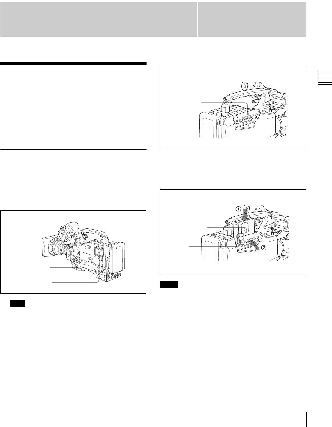
3-1-1 Loading and Unloading a
Cassette
Loading a cassette
1
Turn on the POWER switch.
If the interior of the VTR section is damp, the HUMID
indicator will light. If this happens, wait until the
indicator goes off before going on to step 2.
2
Press the EJECT button.
The cassette compartment lid will open.
3
Check that there is no slack in the tape. Then slide in
the cassette until it clicks into position and close the
cassette lid completely by pressing near the engraved
PUSH.
• To insert the tape correctly, make sure to stand the grip
of the camcorder.
• When inserting the tape, be careful that you don’t hit the
tape against the tape holder.
Note
POWER switch
HUMID indicator Notes
Cassette
compartment lid
Insert the cassette.
Window outwards
Push and close the lid.
Cassette
holder
32 About Cassette
Chapter 3 Recording and Playback
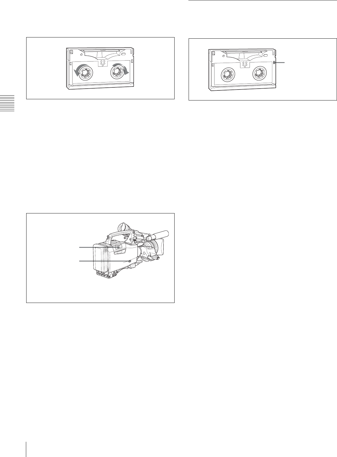
Checking the tape for slack
Pressing in the reels lightly, turn them gently with your
fingers in the directions shown below. If the reels will not
move, there is no slack.
Checking the tape for slack
Unloading a cassette
With the power supply on, press the EJECT button to open
the cassette compartment lid. Then take out the cassette. If
you are not going to insert another cassette, close the
cassette lid.
It is possible to take out the cassette and close the cassette
compartment lid unless the battery voltage drops below
about 10.5 V. Do not repeat this unloading operation.
Unloading a cassette manually
If the battery voltage drops below about 10.5 V, take out
the cassette manually as illustrated below.
Unloading a cassette manually
You need not return the screw to its original position after
taking out the cassette. Although the cassette compartment
lid is not locked, turning on the power makes the cassette
lid operable again.
3-1-2 Preventing Accidental Erasure
The following procedure prevents cassettes from being
recorded inadvertently.
Preventing accidental erasure
1Turn the power off.
2Open this rubber cover.
3Pushing on the screw
inside with a screwdriver,
turn the screw clockwise
until the cassette lid
opens.
Cassette
compartment lid
Push the plug in.
To reuse the cassette,
return the plug to its
original position.
33
Recording
Chapter 3 Recording and Playback
3-2 Recording
3-2-1 Basic Procedures
This section describes the basic procedures for shooting
and recording.
Before a shooting session, ensure that the camcorder is
functioning properly.
For details, see “8-1 Testing the Camcorder Before
Shooting” on page 121.
From turning on the camcorder to loading
a cassette
Proceed as follows:
Basic procedure for shooting: from power supply
to cassette loading
1
Attach a fully charged battery pack.
For details, see “7-1 Power Supply” on page 107.
2
Set the POWER switch to ON. Check that the HUMID
indicator does not appear and that the battery power
level is sufficient.
If HUMID indicator appears, wait until it disappears.
After turning off the power, check whether the drum is
dry (even if the HUMID indicator is off) when the
turning on the power again.
3
Check that there are no obstructions near the cassette
lid. Then press the EJECT button to open the cassette
lid.
4
After checking the points below, load the cassette and
close the cassette lid.
• The cassette is not write-protected.
• There is no slack in the tape.
From adjusting the black balance and
white balance to stopping recording
After turning on the power and loading a cassette, set the
switches and selectors as shown below and begin
operation.
Switch and selector settings before shooting
Shooting
Proceed as follows:
Basic procedure for shooting: from adjusting the black
balance and white balance to stopping recording
1
Push the AUTO W/B BAL switch to BLK to adjust the
black balance.
For details of black balance adjustment, see “4-1-1
Adjusting the Black Balance” on page 52.
2
Select the CC filter and ND filter to match the lighting
conditions, and adjust the white balance.
When the white balance settings are already in
memory
Set the WHITE BAL switch to A or B.
When the white balance setting is not in memory
and you do not have enough time to adjust the white
balance
Set the WHITE BAL switch to PRST.
Note
2
4
3
1
2
DISPLAY: ON
AUDIO SELECT
CH-1/CH-2: AUTO
Iris: AUTO
Zoom: AUTO
OUTPUT/DCC: CAM, DCC ON
F-RUN/SET/R-RUN:
F-RUN or R-RUN
(set as needed)
3,5
4
1,2
5,6
2
34 Recording
Chapter 3 Recording and Playback
This automatically adjusts the white balance as
follows, depending on the setting of the FILTER knob.
B: 3200K
C: 4300K
D: 6300K
For details, see “4-1-2 Adjusting the White Balance”
on page 53.
3
Aim the camera at the subject and adjust the focus and
zoom.
4
If necessary, set the electronic shutter for an
appropriate mode and speed.
For details, see “4-2 Setting the Electronic Shutter” on
page 55.
5
To start recording, press the VTR START button or the
VTR button on the lens.
If the recording start/stop function is assigned to the
ASSIGN 1 switch, this switch functions as VTR
START button.
For details, see “5-3-5 Assigning Functions to
Assignable Switches” on page 87.
During recording, the REC indicator lights in the
viewfinder. Perform zooming and focus control, if
necessary.
6
To stop recording, press the VTR START button or the
VTR button on the lens again.
The REC indicator in the viewfinder goes off.
Cassette control buttons
During recording, the cassette control buttons (EJECT,
REW, F FWD, PLAY, STOP) have no effect.
When crash-recording without doing continuous recording
on a recorded tape, or when recording with the RE-TAKE
function, the timecode recorded previously may be
displayed for a few seconds when playing back the first
part of the cut.
3-2-2 Continuous Recording
If the camcorder is in the recording pause mode, simply
pressing the VTR START button on the camcorder or the
VTR button on the lens continues recording exactly from
the next frame.
In other cases, you first need to position the tape at an
appropriate point.
When the camcorder is in Recording
Pause mode
Pressing the VTR START button on the camcorder or the
VTR button on the lens continues recording at exactly the
next frame. However, the time taken before recording
starts depends on the setting of the VTR SAVE/STBY
switch.
• If the VTR SAVE/STBY switch is in the SAVE position,
it takes about 4 seconds before recording starts.
• If the VTR SAVE/STBY switch is in the STBY position,
recording starts immediately. However, just after the
switch position is changed from SAVE to STBY, it takes
about 4 seconds before recording starts.
If you turn off the power during a recording
pause
Continuous recording after turning off the power
during a recording pause
1
Turn on the power again.
2
Press the RET button on the lens.
If an analog composite signal is input to the
GENLOCK IN connector, make sure that RETURN
VIDEO is set to OFF on the GENLOCK page of the
MAINTENANCE menu.
The camcorder positions the tape at the appropriate
point. Note, however, that this function works only for
continuously recorded material or consecutively
joined segments totaling at least 3 seconds in length.
3
Press the VTR START button on the camcorder or the
VTR button on the lens to start recording.
Note
2
3
1
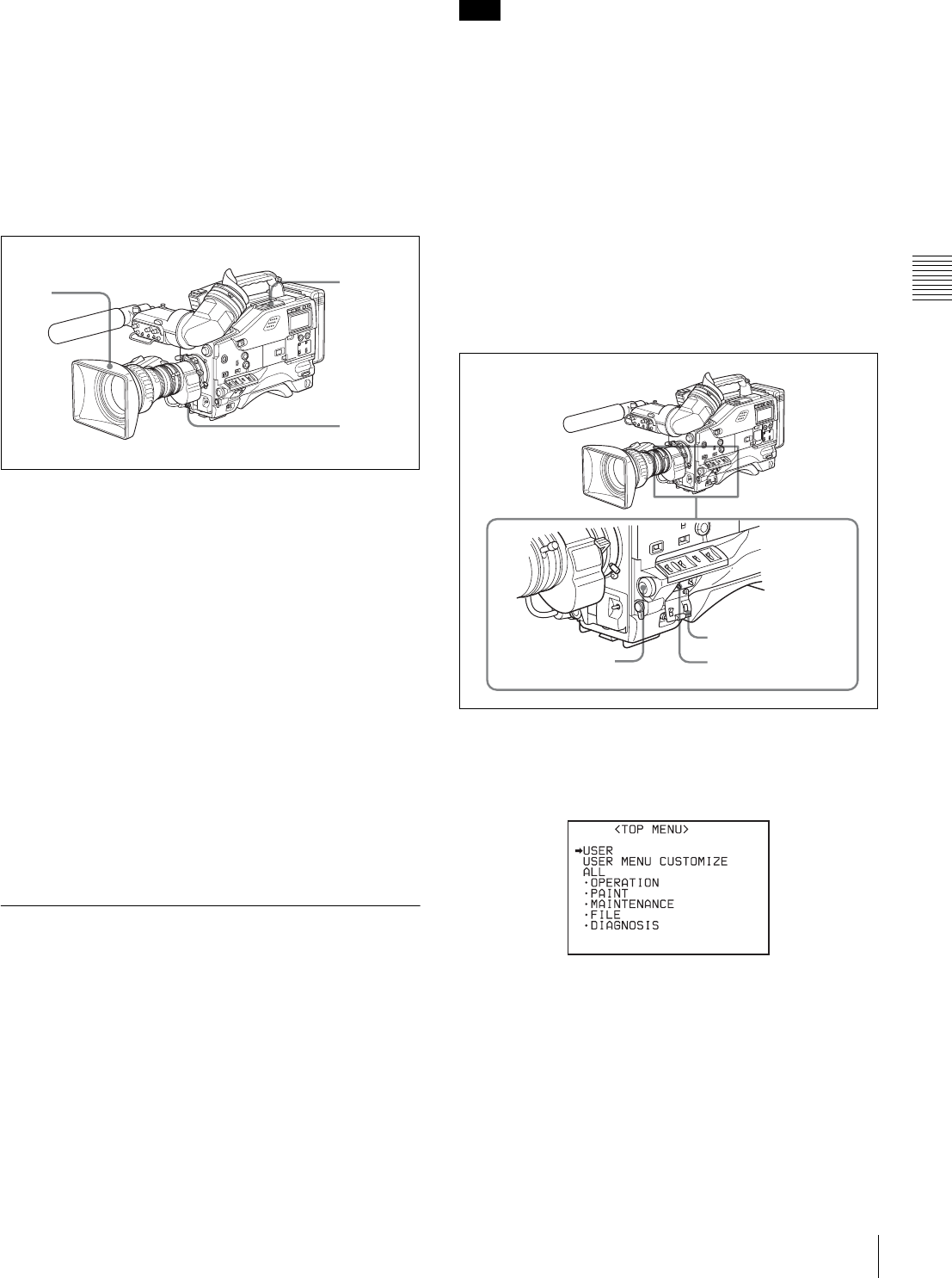
35
Recording
Chapter 3 Recording and Playback
Continuous recording in other cases
After rewinding or fast forward, after removing the
cassette, or on a tape that has been partially recorded, you
can obtain a continuous recording by following the
procedure below.
The End Search function also allows you to continue
recording on the partially recorded tape.
For details, see “3-2-7 Searching for the Last Recorded
Portion and Turning in Recording Pause Mode (End
Search Function)” on page 48.
Continuous recording after rewinding or fast forward,
after removing the cassette,
or on a tape that has been partly recorded
1
Looking in the viewfinder, press the PLAY button to
start playback.
2
Press the STOP button at the desired point to begin
recording. To continue from the end of recording
already on the tape, press the STOP button
immediately after the end of the previous recording
(within 0.5 seconds).
3
Press the RET button.
The tape will rewind and will be positioned at the
desired point to continue recording.
4
Press the VTR START button on the camcorder or the
VTR button on the lens to start recording.
3-2-3 Recording Essence Marks
Various essence marks, such as shot marks, can be
recorded on tape. Recording essence marks for scenes
containing important images and sounds enables quick
access to the marked points. This increases editing
efficiency.
There are essence marks that are automatically recorded by
starting recording or firing the flash and those you can
manually record when necessary.
For good shot marks (shot mark 1 and shot mark 2) and
recording start mark among available essence marks, you
can select recording in the LTC-UBIT area and/or
recording in the system area as required to maintain
compatibility with conventional systems.
Settings for recording essence marks to
the system area
Settings on the ESSENCE MARK and ESSENCE
MARK2 pages of the MAINTENANCE menu determine
which essence marks are to be recorded on the system area
of tape.
Follow the procedures below:
1
Set the MENU ON/OFF switch to ON while pushing
the MENU knob.
The TOP menu appears.
2
Turn the MENU knob to move the b mark to
MAINTENANCE.
3
Push the MENU knob.
When the MAINTENANCE menu is first used, the
CONTENTS page appears.
Or if you have used the MAINTENANCE menu
already, the page that was on the screen when the last
menu operation ended appears.
4
31,2
Note
MENU knob MENU ON/OFF switch
Cover
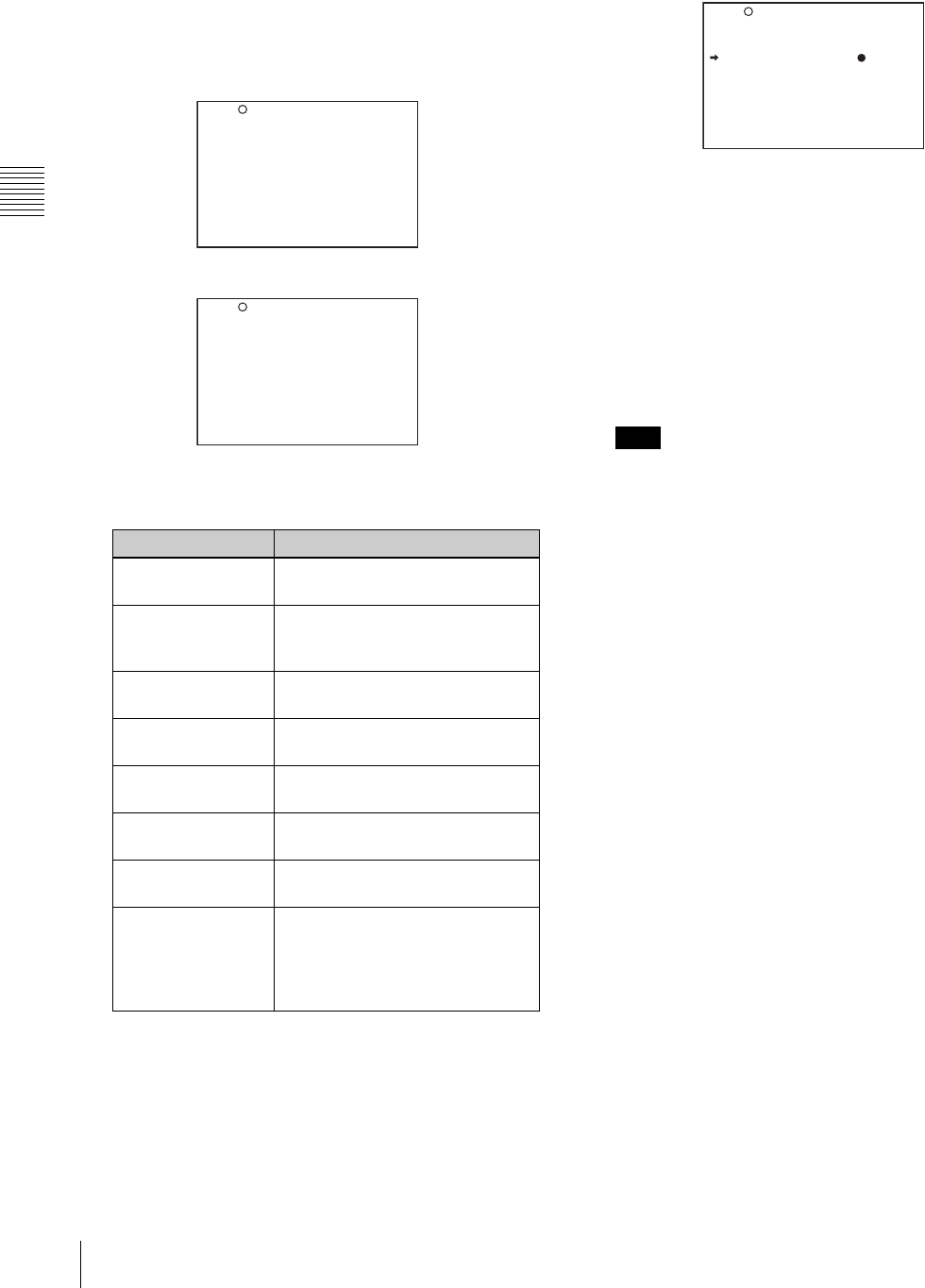
36 Recording
Chapter 3 Recording and Playback
4
When the CONTENTS page is displayed, turn the
MENU knob to move the b mark to ESSENCE
MARK then push the MENU knob.
When any page of the MAINTENANCE menu is
displayed, turn the MENU knob until the ESSENCE
MARK or ESSENCE MARK2 page appears, then
push the MENU knob.
ESSENCE MARK page
ESSENCE MARK2 page
The following items on these pages are for setting the
corresponding essence marks:
You can check whether any of the essence marks that
are automatically recorded (OVER AUDIO LIMIT,
GAIN CHG MARK, FILTER CHG MARK,
SHUTTER CHG MARK, WHITE CHG MARK,
FLASH MARK) has been recorded, by setting the
display for recorded essence marks ON.
For details on the display setting, see “5-2 Status
Display on the Viewfinder Screen” (page 74).
5
Turn the MENU knob to move the b mark to the item
to be set.
6
Push the MENU knob.
The b mark to the left of the item changes to the z
mark, and the z mark to the left of the setting changes
to the ? mark.
7
Turn the MENU knob clockwise or counter clockwise
until the desired setting appears.
To record the mark on tape, select ON.
To not record the mark, select OFF.
Whether or not to record good shot marks (shot mark
1 and shot mark 2) and recording start mark in the
system area is determined by the ON/OFF settings of
the corresponding items regardless of the LTC UB-
MARKER setting on the ESSENCE MARK page.
8
Push the MENU knob.
9
Perform settings for the remaining marks, repeating
steps 5 to 8.
10
When you set FLASH MARK to ON, select the
threshold value (1 to 20) of the luminance level change
for recording the mark.
11
Set the MENU ON/OFF switch to OFF to end the
menu operation.
Settings for recording good shot marks
and recording start mark to the LTC-UBIT
area
Good shot marks (shot mark 1 and shot mark 2) and
recording start mark can also be recorded to the LTC-UBIT
area of tape.
Follow the procedures below:
Mark Condition
REC START MARK To be recorded when recording
starts.
SHOT MARK 1/2 To be recorded when the RET
button on the lens is manually
operated.
OVER AUDIO
LIMIT
To be recorded when the audio
level exceeds 0 dBFS.
GAIN CHG MARK To be recorded when the gain
value changes.
FILTER CHG
MARK
To be recorded when the filter is
changed.
SHUTTER CHG
MARK
To be recorded when the shutter
speed changes.
WHITE CHG
MARK
To be recorded when the white
balance changes.
FLASH MARK To be recorded when the
luminance suddenly changes,
such as when the flash is
exposed or the unit is moved
indoors from outdoors.
LTC UB-MARKER : SET
REC START MARK : OFF
SHOTMARK 1 : OFF
SHOTMARK 2 : OFF
SHOT TIME DISP : MD:HM
?M10 ESSENCE MARK
OVER AUDIO LIMIT: ON
GAIN CHG MARK : ON
FILTER CHG MARK : ON
SHUTTER CHG MARK: ON
WHITE CHG MARK : ON
FLASH MARK : ON
FLASH MARK LEVEL: 10
E.MARK SD LINE : 17
?M11 ESSENCE MARK2
Note
LTC UB-MARKER : SET
REC START MARK : OFF
SHOTMARK 1 : OFF
SHOTMARK 2 : OFF
SHOT TIME DISP : MD:HM
M10 ESSENCE MARK
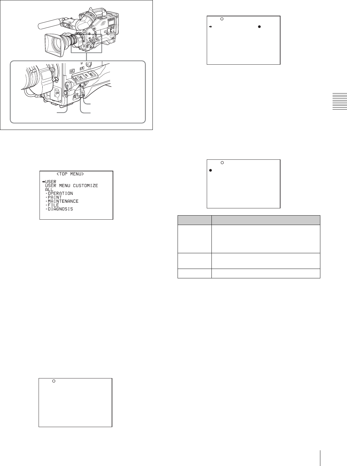
37
Recording
Chapter 3 Recording and Playback
1
Set the MENU ON/OFF switch to ON while pushing
the MENU knob.
The TOP menu appears.
2
Turn the MENU knob to move the b mark to
MAINTENANCE.
3
Push the MENU knob.
When the MAINTENANCE menu is first used, the
CONTENTS page appears.
Or if you have used the MAINTENANCE menu
already, the page that was on the screen when the last
menu operation ended appears.
4
When the CONTENTS page is displayed, turn the
MENU knob to move the b mark to ESSENCE
MARK then push the MENU knob.
When any page of the MAINTENANCE menu is
displayed, turn the MENU knob until the ESSENCE
MARK page appears, then push the MENU knob.
ESSENCE MARK page
5
Turn the MENU knob to move the b mark to LTC UB-
MARKER.
6
Push the MENU knob.
The b mark to the left of LTC UB-MARKER changes
to the z mark, and the z mark to the left of the setting
changes to the ? mark.
7
Turn the MENU knob clockwise or counterclockwise
until the desired setting appears.
The setting changes in the order of SET y ALL y
OFF.
If you select SET, go to step 8.
If you select ALL or OFF, go to step 9.
8
Set the mark(s) to be recorded to ON.
1Turn the MENU knob to move the b mark to the
mark to be set.
2Turn the MENU knob clockwise or
counterclockwise until the desired setting appears.
To record the mark on the tape, select ON.
To not record the mark, select OFF.
3Perform settings for the remaining marks,
repeating steps 1 and 2.
9
Set the MENU ON/OFF switch to OFF to end the
menu operation.
MENU knob MENU ON/OFF switch
Cover
LTC UB-MARKER : SET
REC START MARK : OFF
SHOTMARK 1 : OFF
SHOTMARK 2 : OFF
SHOT TIME DISP : MD:HM
?M10 ESSENCE MARK
Item Contents
SET Determines whether to record REC
START MARK, SHOT MARK 1, and
SHOT MARK 2 in accordance with the
ON/OFF setting fot that item.
ALL Records all of REC START MARK, SHOT
MARK 1, and SHOT MARK 2.
OFF Does not record any marks.
LTC UB-MARKER : SET
REC START MARK : OFF
SHOTMARK 1 : OFF
SHOTMARK 2 : OFF
SHOT TIME DISP : MD:HM
M10 ESSENCE MARK
LTC UB-MARKER :? SET
REC START MARK : OFF
SHOTMARK 1 : OFF
SHOTMARK 2 : OFF
SHOT TIME DISP : MD:HM
M10 ESSENCE MARK

38 Recording
Chapter 3 Recording and Playback
Shot mark recording
When SHOT MARK 1 and SHOT MARK 2 are set to ON
on the ESSENCE MARK page, good shot marks (shot
mark 1 and shot mark 2) are recorded when you press the
RET button of the lens. (If LTC UP-MARKER is set to
OFF, the marks are recorded only in the system area. If
LTC UP-MARKER is set to ALL, the marks are recorded
in the LTC UBIT area even when SHOT MARK 1 and
SHOT MARK 2 are set to OFF.)
To record a shot mark 1: Press the RET button on the lens
once.
On the viewfinder screen, z and the time code of the
marked point are displayed for about 3 seconds.
To record a shot mark 2: Press the RET button on the lens
twice.
On the viewfinder screen, X and the time code of the
marked point are displayed for about 3 seconds.
For detailed information on shot mark operations, refer to
the manual supplied with your VTR.
When you perform the setting to confirm the image of the
return video signal in the viewfinder (see page 83), shot
mark 1 and shot mark 2 cannot be recorded by operating
the RET button of the lens.
Recording start mark recording
When REC START MARK set to ON on the ESSENCE
MARK page, a recording start mark is recorded at the
beginning of recording. (If LTC UP-MARKER is set to
OFF, the mark is recorded only in the system area. If LTC
UP-MARKER is set to ALL, the mark is recorded in the
LTC UBIT area even when REC START MARK is set to
OFF.)
For detailed information on recording start mark
operations, refer to the manual supplied with your VTR.
3-2-4 Starting a Shoot with a Few
Seconds of Pre-Stored Picture Data
(Picture Cache Function: with CBK-
MB01)
By installing the optional CBK-MB01 extension board in
the camcorder, the camcorder is able to constantly store a
few seconds (up to 8 seconds) worth of the most current
picture and sound data in the boards memory.
Thus, when you press the VTR START button or the VTR
button on the lens, the recording starts with the data stored
a few seconds before.
Setting the Picture Cache time/Picture
Cache mode
To record in Picture Cache mode, you need to turn on
Picture Cache mode and set the picture data storage time
(Picture Cache time) using the USER menu.
The Picture Cache time and VTR SAVE/STBY switch
settings determine the number of seconds of picture data
that will be stored in memory and recorded when you press
the VTR START button or VTR button on the lens.
The following table shows the approximate number of
seconds worth of picture data (counting back from the time
you begin recording) that will be recorded from memory.
However, when changing from SAVE to STBY, or under
the special situations explained in the notes on this page,
the actual amount of data recorded may be shorter.
• After selecting the Picture Cache mode, immediately
changing the Picture Cache time or performing playback
or recording review, the picture data stored in memory
before this operation are made to be unrecordable. This
means that when you press the VTR START button or
VTR button on the lens, the previously stored picture
data will not be recorded.
• During playback or recording review, the picture data is
not stored in the MSDW-903s memory. Picture data
corresponding to the duration of playback or recording
review will not be in memory and will not be recorded to
tape.
Setting procedure
To turn Picture Cache mode on, proceed as follows:
Note
Picture Cache time setting and recording start point
Picture Cache
time
Recording start point
VTR STBY mode VTR SAVE mode
8 (seconds) About 8 seconds
before
About 4 seconds
before
6 (seconds) About 6 seconds
before
About 4 seconds
before
5 (seconds) About 5 seconds
before
About 4 seconds
before
4 (seconds) About 4 seconds
before
About 4 seconds
before
3 (seconds) About 3 seconds
before
About 3 seconds
before
2 (seconds) About 2 seconds
before
About 2 seconds
before
1 (seconds) About 1 seconds
before
About 1 seconds
before
0 (seconds) About 0 seconds
before
About 0 seconds
before
Notes
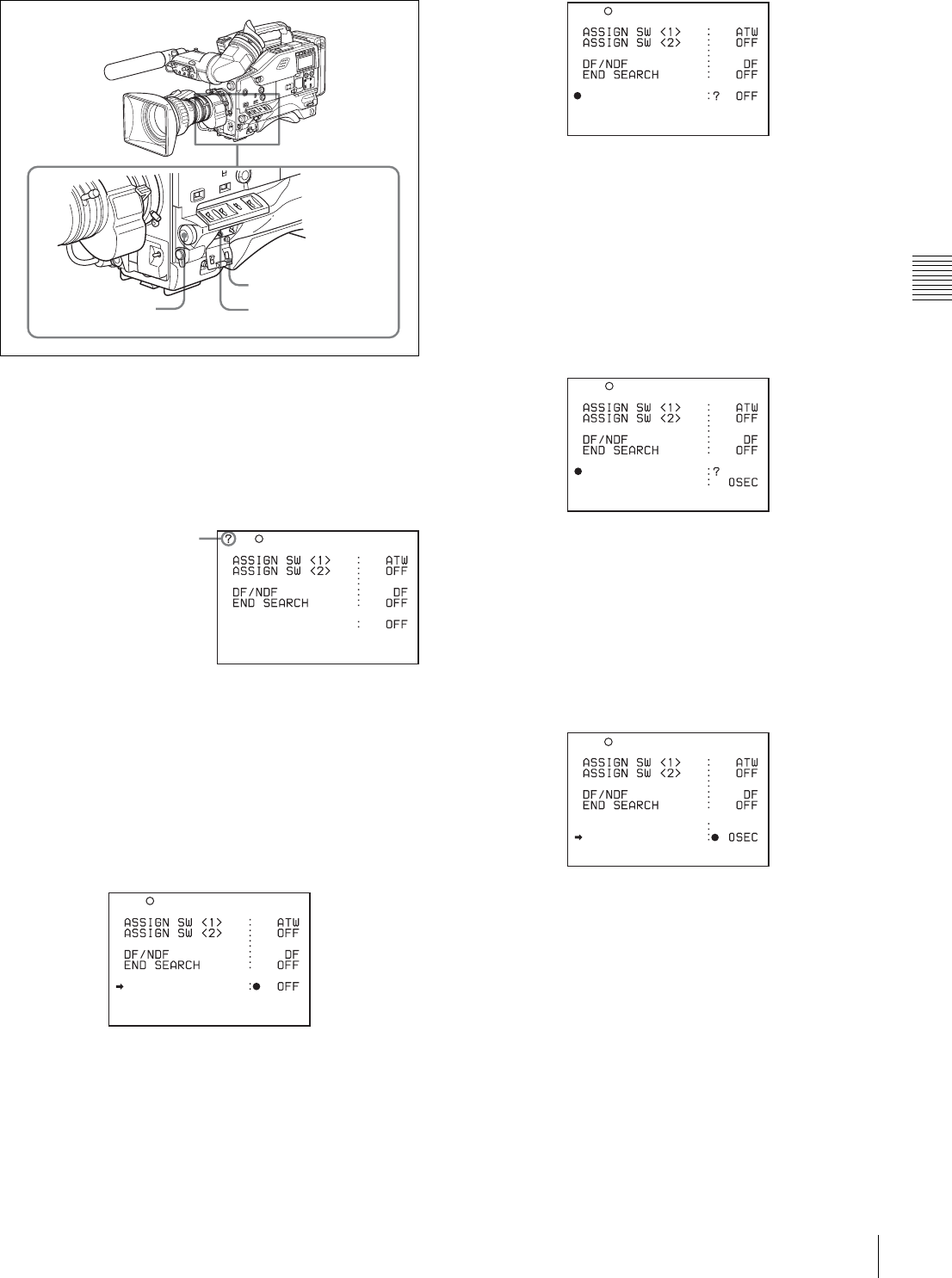
39
Recording
Chapter 3 Recording and Playback
1
Set the MENU ON/OFF switch to ON.
The last accessed menu page appears on the
viewfinder screen.
2
Turn the MENU knob until the FUNCTION 1 page
appears.
3
Press the MENU knob.
A b mark appears on the left of the currently selected
item and a z mark appears on the left of the setting.
4
Turn the MENU knob to move the b mark to
“CACHE/INTVAL REC.”
5
Press the MENU knob.
The b mark on the left of “CACHE/INTVAL REC”
changes to a z mark and the z mark on the left of the
setting changes to a ? mark.
6
Turn the MENU knob until “CACHE” appears.
As you turn the MENU knob, the setting changes in
the following sequence: OFF y CACHE y A. INT
y M. INT.
When “CACHE” appears, the camcorder is in Picture
Cache mode, where picture, sound, and time code are
constantly saved in memory. The TALLY indicator
(green) in the viewfinder is on while picture data is
being stored in memory.
7
Press the MENU knob.
The z mark on the left of “CACHE/INTVAL REC”
changes to a b mark and the ? mark on the left of the
setting changes to a z mark. In this case, you can
select another item.
8
Turn the MENU knob to move the b mark to “CACHE
REC TIME.”
9
Press the MENU knob.
The b mark on the left of “CACHE REC TIME”
changes to a z mark and the z mark on the left of the
setting changes to a ? mark.
10
Turn the MENU knob until the desired Picture Cache
time appears.
As you turn the MENU knob, the Picture Cache time
changes in the following sequence: 0SEC y 1SEC
y 2SEC y 3SEC y 4SEC y 5SECy
6SECy 8SEC.
MENU knob MENU ON/OFF switch
Cover
U03 FUNCTION1
CACHE/INTVAL REC
TURBO SW TURBO
When the question mark
appears at the left corner of
the title page, you can
switch the pages.
Turn the MENU knob
clockwise or
counterclockwise to display
the desired page. The DF/
NDF item on the
FUNCTION 1 page appears
only for the DVW-970.
CACHE/INTVAL REC
TURBO SW TURBO
U03 FUNCTION1
CACHE/INTVAL REC
TURBO SW TURBO
U03 FUNCTION1
CACHE/INTVAL REC
CACHE REC TIME
TURBO SW TURBO
CACHE
U03 FUNCTION1
CACHE/INTVAL REC
CACHE REC TIME
CACHE
TURBO SW TURBO
U03 FUNCTION1

40 Recording
Chapter 3 Recording and Playback
11
Press the MENU knob.
The z mark on the left of “CACHE REC TIME”
changes to a b mark and the ? mark changes to a z
mark.
12
To end the menu operation, set the MENU ON/OFF
switch to OFF.
The menu disappears, and the display indicating the
current status of the camcorder appears along the top
and bottom of the viewfinder screen.
Settings made in Picture Cache mode are maintained until
changed.
You can turn Picture Cache mode on and off by assigning
the Picture Cache ON/OFF function to one of the
assignable switches (ASSIGN 1/2 and TURBO GAIN),
and pressing the switch.
For detailed information on the assignable switches, see
“5-3-5 Assigning Functions to Assignable Switches” on
page 87.
Camcorder operations in Picture Cache mode
The recording procedure in Picture Cache time is basically
the same as that for normal recording. However, note the
following differences.
• When you record in Picture Cache mode, the picture you
shoot is recorded to tape after the Picture Cache time
elapses. For this reason, the tape does not stop
immediately when you press the VTR START button.
After the VTR START button is pressed, all tape
operation buttons (EJECT, REW, F FWD, PLAY, and
STOP) stop functioning until the Picture Cache time has
elapsed. During this time, if you press the VTR START
button or the VTR button on the lens, recording starts
again as if there were no pause in recording.
• The time the tape stops after the VTR START button is
pressed equals the Picture Cache time set. However, if
you start recording within the set Picture Cache time
immediately after selecting the Picture Cache mode,
changing the Picture Cache time or performing playback
or recording review, the picture data for the duration of
the Picture Cache time will not be stored in memory.
Thus, the time the tape stops after the STOP button is
pressed becomes shorter than the Picture Cache time.
• The time code stops advancing while time data is being
set (when the F-RUN/SET/R-RUN switch is set to SET).
For this reason, if you start recording immediately after
switching to F-RUN or R-RUN (i.e., to a position other
than SET), you may overwrite a portion of the previously
recorded time code.
• Positions of essence marks, such as shot marks, may be
shifted depending on the Picture Cache time setting.
• Menu operation for the Picture Cache time setting is
disabled during recording. To change the setting, once
stop the recording by pressing the VTR START button or
the VTR button on the lens.
When power is lost during recording
• When the power is turned off during recording, the
camera will switch off by itself after the tape has run for
a few seconds.
• If you remove the battery, pull out the DC cable, or cut
power to the AC adaptor during recording, actual
recording of picture data ends the instant the tape is
stopped. However, a certain amount of recorded picture
data, equal to that recorded during the Picture Cache
time, will be lost, because it has not yet been recorded on
the tape before the tape stops. For this reason, make sure
you do not change the battery while recording.
When the tape runs out during recording
Please note that if the tape runs out and the camcorder
stops during recording, a certain amount of recorded
picture data, equal to that recorded during the Picture
Cache time, will be lost, because it has not yet been
recorded on the tape.
3-2-5 Shooting Picture at Intervals
(Interval Rec Function: with CBK-
MB01)
Inserting an optional CBK-MB01 extension board in the
camcorder enables the camcorder to record pictures at
various intervals. There are two kinds of Interval Rec
mode:
Auto Interval Rec
In Auto Interval Rec mode, pictures are automatically shot
a frame at a time at the specified interval and stored in
memory. To use this function you must set the total time
for shooting (TAKE TOTAL TIME) and the length of time
for recording on the tape (REC TIME).
Manual Interval Rec
There are two modes of Manual Interval Rec:
• Single Trigger mode
Setting the number of frames to be recorded at one
shooting (NUMBER OF FRAME) enables the
camcorder to record the number of frames preset each
time the VTR START button or the VTR button on the
lens is pressed.
• Continuous Trigger mode
Pictures are automatically shot by preset frames at preset
intervals by pressing the VTR START button or the VTR
button on the lens.
In Auto Interval Rec and Continuous Trigger mode of
Manual Interval Rec, by setting the PRE-LIGHTING
function to ON, the light connected to the LIGHT
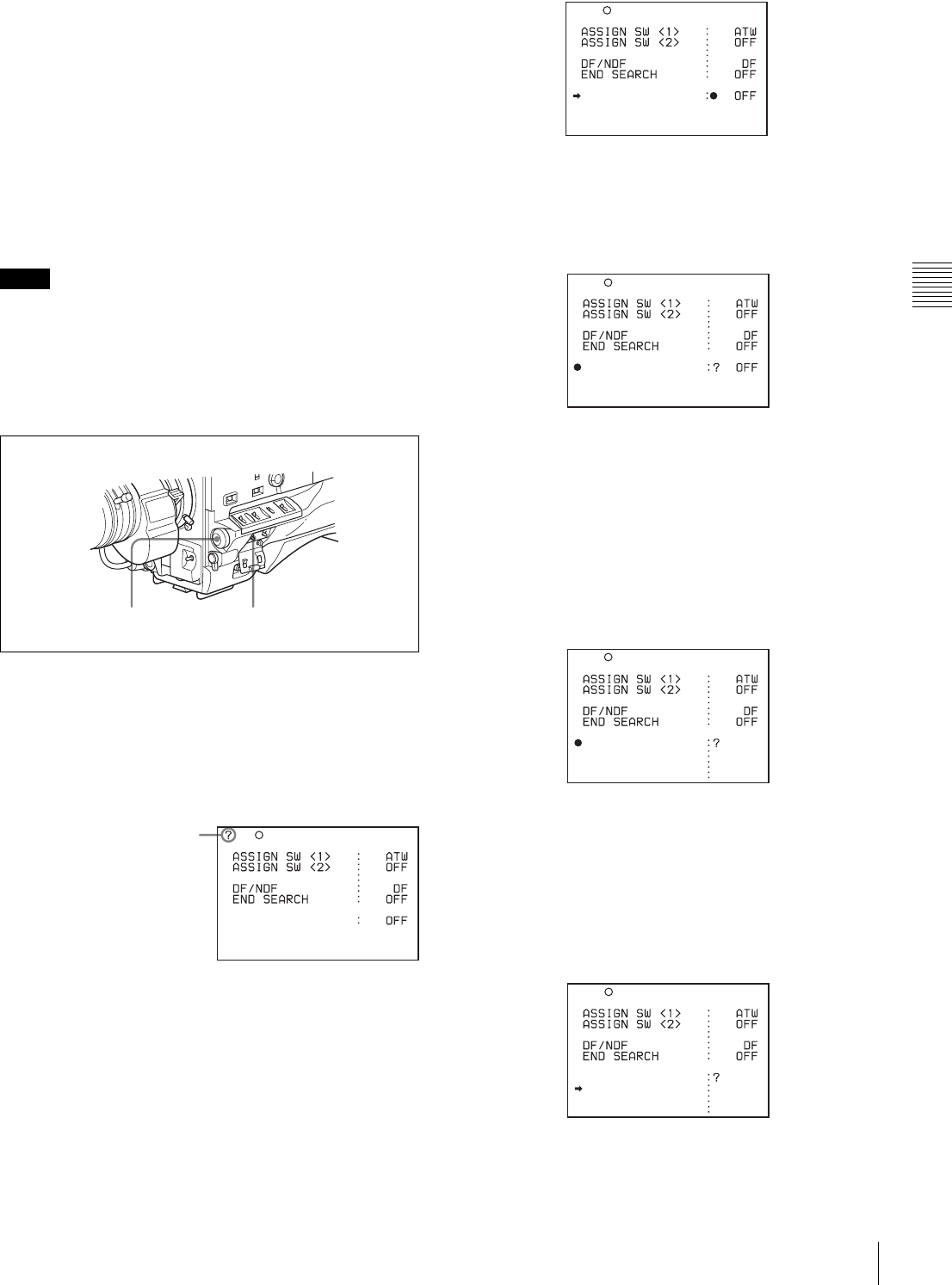
41
Recording
Chapter 3 Recording and Playback
connector automatically turns on before recording starts.
This allows you to record pictures under stable light and
color temperature conditions.
Auto Interval Rec mode settings
To make settings before shooting
To record in Auto Interval Rec mode, you need to turn on
Auto Interval Rec and set the total time from start to finish
of shooting (TAKE TOTAL TIME) and the length of time
for recording on the tape (REC TIME), using the USER
menu.
• To make settings for Auto Interval Rec mode, set “TAKE
TOTAL TIME” first, then “REC TIME.”
• To turn on the light automatically before recording starts,
set the LIGHT switch to AUTO.
To turn on Auto Interval Rec mode, proceed as follows:
1
Set the MENU ON/OFF switch to ON.
The last accessed menu page appears on the
viewfinder screen.
2
Turn the MENU knob until the FUNCTION 1 page
appears.
3
Press the MENU knob.
A b mark appears on the left of the currently selected
item and a z mark appears on the left of the setting.
4
Turn the MENU knob to move the b mark to
“CACHE/INTVAL REC.”
5
Press the MENU knob.
The b mark on the left of “CACHE/INTVAL REC”
changes to a z mark and the z mark on the left of the
setting changes to a ? mark.
6
Turn the MENU knob until A. INT appears.
As you turn the MENU knob, the setting changes in
the following sequence: OFF y CACHE y A. INT
y M. INT.
When A. INT appears, the camcorder is in Auto
Interval Rec mode. The TALLY indicator (green) in
the viewfinder flashes (one flash/second) while the
camcorder is in this mode. Also, TAKE TOTAL
TIME, REC TIME and PRE-LIGHTING appear.
7
Press the MENU knob.
The z mark on the left of “CACHE/INTVAL REC”
changes to a b mark and the ? mark of the setting
changes to a z mark.
8
Turn the MENU knob to move the b mark to “TAKE
TOTAL TIME.”
9
Press the MENU knob.
Notes
MENU knob MENU ON/OFF switch
U03 FUNCTION1
CACHE/INTVAL REC
TURBO SW TURBO
When the question mark
appears at the left corner of
the title page, you can
switch the pages.
Turn the MENU knob
clockwise or
counterclockwise to display
the desired page. The DF/
NDF item on the
FUNCTION 1 page appears
only for the DVW-970.
CACHE/INTVAL REC
TURBO SW TURBO
U03 FUNCTION1
CACHE/INTVAL REC
TURBO SW TURBO
U03 FUNCTION1
CACHE/INTVAL REC
TAKE TOTAL TIME
REC TIME
PRE-LIGHTING
A.INT
5M
5SEC
OFF
TURBO SW TURBO
U03 FUNCTION1
CACHE/INTVAL REC
TAKE TOTAL TIME
REC TIME
PRE-LIGHTING
A.INT
5M
5SEC
OFF
TURBO SW TURBO
U03 FUNCTION1
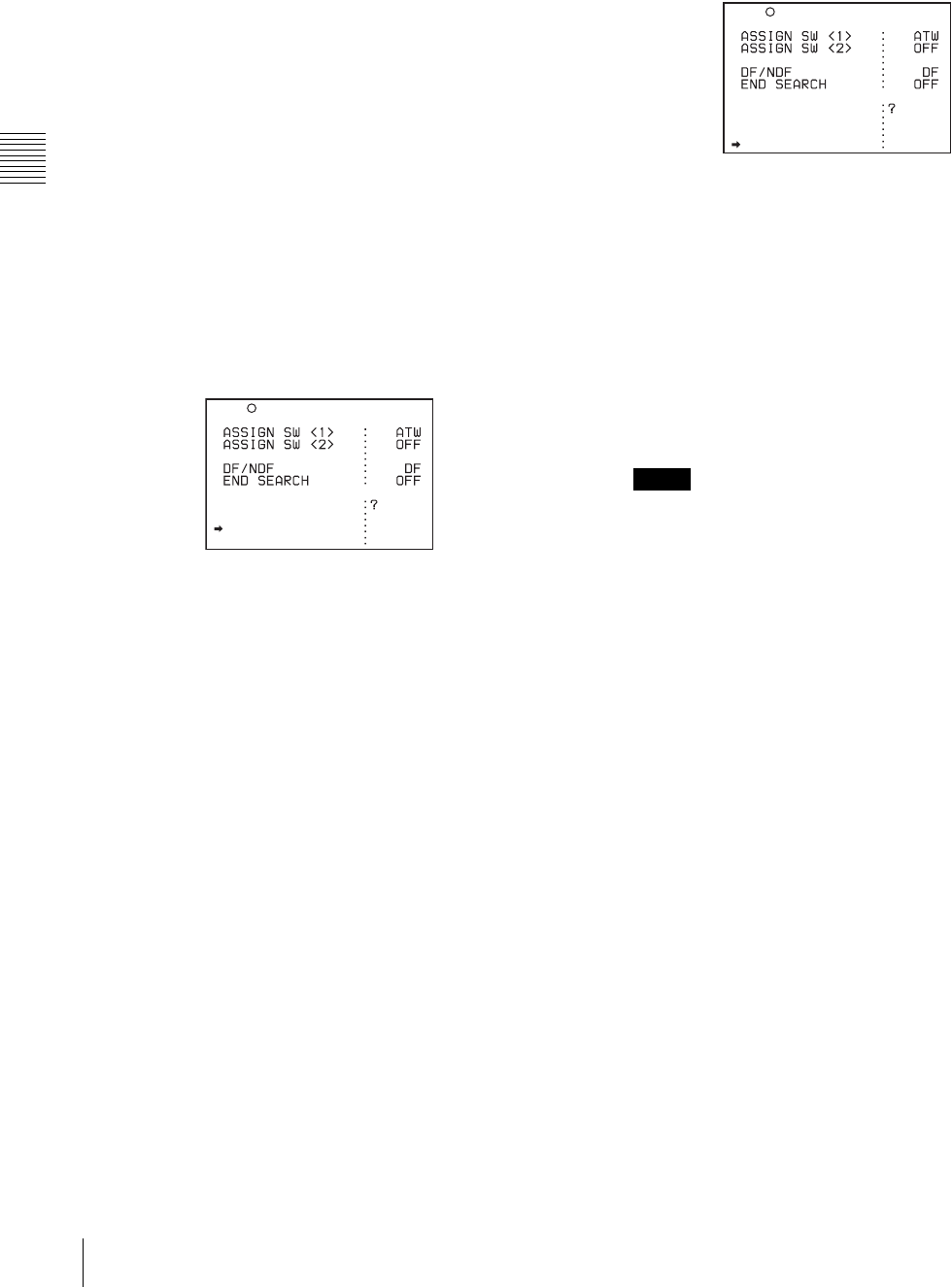
42 Recording
Chapter 3 Recording and Playback
The b mark on the left of “TAKE TOTAL TIME”
changes to a z mark and the z mark on the left of the
setting changes to a ? mark.
10
Turn the MENU knob until the desired setting of
“TAKE TOTAL TIME” appears.
As you turn the MENU knob, the setting of TAKE
TOTAL TIME changes in the following sequence:
5M y 10M y 15M y 20M y 30M y 40M
y 50M y 1H y 2H y 3H y 4H y 5H y
7H y 10H y 15H y 20H y 30H y 40H y
50H y 70H y 100H.
Here M means minutes (5M is 5 minutes) and H means
hours (1H is one hour).
11
Press the MENU knob.
The z mark on the left of “TAKE TOTAL TIME”
changes to a b mark and the ? mark changes to a z
mark.
12
Turn the MENU knob to move the b mark to “REC
TIME.”
13
Press the MENU knob.
The b mark on the left of “REC TIME” returns to a z
mark and the z mark of the setting returns to a ? mark.
14
Turn the MENU knob until the desired time to be
recorded on the tape appears.
As you turn the MENU knob, the setting of REC
TIME changes in the following sequence:
5SEC y 10SEC y 15SEC y 20SEC y 30SEC
y 40SEC y 50SEC y 1MIN y 2MIN y
.......38MIN y 39MIN y 40MIN.
Here SEC means seconds (5SEC is 5 seconds) and
MIN means minutes (1MIN is one minute).
You cannot set a REC TIME that is more than one
thirtieth of TAKE TOTAL TIME.
For example: When TAKE TOTAL TIME is set to 1H,
the maximum value of REC TIME is 2 MIN. (60
minutes divided by 30 gives 2 minutes.)
The time setting displayed when you turn the MENU
knob changes within the available setting times.
Be sure to set REC TIME after setting TAKE TOTAL
TIME.
15
Press the MENU knob.
The z mark on the left of “REC TIME” returns to a b
mark and the ? mark returns to a z mark.
16
Turn the MENU knob to move the b mark to “PRE-
LIGHTING.”
17
Press the MENU knob.
The b mark on the left of “PRE-LIGHTING” changes
to a z mark and the z mark on the left of the setting
changes to a ? mark.
18
Turn the MENU knob until the desired time to turn on
the light before starting to record appears.
As you turn the MENU knob, the PRE-LIGHTING
time changes in the following sequence: OFF y
2SEC y 5SEC y 10SEC.
• Set the LIGHT switch on the camcorder to AUTO to
turn on the light before recording.
The light switch must also be set to ON. With these
settings, the light turns on and off automatically.
(However, the light remains on continuously if the
off time is less than 5 seconds.)
• When the LIGHT switch is set to MANUAL and the
light switch is set to ON, the light remains on
continuously.
19
Press the MENU knob.
The z mark on the left of “PRE-LIGHTING” returns
to a b mark and the ? mark returns to a z mark.
20
To end the menu operation, set the MENU ON/OFF
switch to OFF.
The menu disappears from the viewfinder screen and the
message AUTO INTERVAL **M**S indicating Auto
Interval Rec mode appears along the bottom of the
viewfinder.
**M**S indicates the shooting interval. For example,
when TAKE TOTAL TIME is set to 1H and REC TIME is
set to 30 SEC, the message AUTO INTERVAL 00M04S
appears. The shooting interval is 4 seconds.
The display indicating the current status of the camcorder
appears along the top and bottom of the viewfinder.
CACHE/INTVAL REC
TAKE TOTAL TIME
REC TIME
PRE-LIGHTING
A.INT
5M
5SEC
OFF
TURBO SW TURBO
U03 FUNCTION1
Notes
CACHE/INTVAL REC
TAKE TOTAL TIME
REC TIME
PRE-LIGHTING
A.INT
5M
5SEC
OFF
TURBO SW TURBO
U03 FUNCTION1
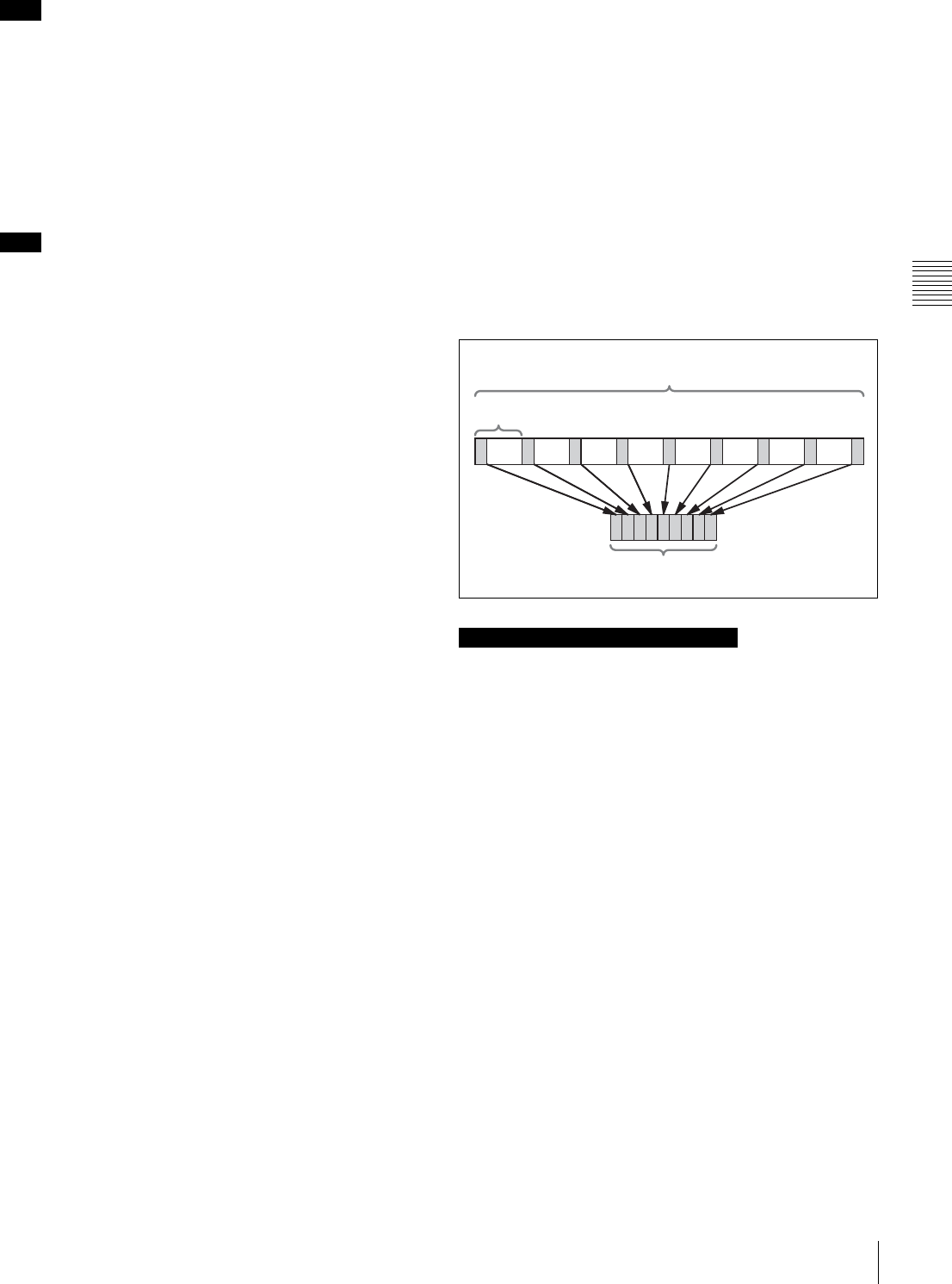
43
Recording
Chapter 3 Recording and Playback
The settings for Auto Interval Rec mode are maintained
until changed. However, if you switch off the camcorder
power, Auto Interval Rec mode is cleared except for the
TAKE TOTAL TIME, REC TIME and PRE-LIGHTING
settings. To use the Auto Interval Rec function again after
switching on the power, perform steps 1 to 6.
Recording in Auto Interval Rec mode
Proceed as follows:
When you use cassettes on which nothing is recorded, such
as brand new cassettes, be sure to record color bars for
more than 2 seconds at the beginning of a cassette.
1
After performing the basic procedures for shooting
and recording, following the instructions in “3-2-1
Basic Procedures” (page 33), secure the camcorder so
that it will not move.
2
Press the VTR START button on the camcorder or the
VTR button on the lens.
The camcorder starts recording in Auto Interval Rec
mode. When you use the PRE-LIGHTING function,
recording starts after the light is switched on.
The actual recording to disc begins when the
camcorder has saved about five seconds of video in
memory, so disc access is intermittent.
While recording in Auto Interval Rec mode, the
TALLY indicator (green) in the viewfinder flashes (4
flashes/second) and the message “AUTO INTERVAL
**M**S” flashes on the viewfinder screen.
When the camcorder is capturing the picture in
memory, the REC indicator in the viewfinder lights.
After the length of time for recording on the tape (REC
TIME) has elapsed, the camcorder automatically stops
recording.
To continue auto interval recording
Press the VTR START button on the camcorder or the
VTR button on the lens again.
The camcorder starts recording in Auto Interval Rec mode
again.
To interrupt auto interval recording
Press the VTR START button or the VTR button on the
lens. The camcorder stops recording.
However, the tape may run for recording picture data
already stored in memory.
To end auto interval recording
You can exit Auto Interval Rec mode using the following
two methods:
• Set the POWER switch to OFF.
• Set CACHE/INTVAL REC to OFF on the FUNCTION
1 page.
Time required for shooting and time required for
recording on the tape
Auto Interval Rec mode is effective for shooting objects
that move very slowly. To use this function, you need to set
the total time for shooting (TAKE TOTAL TIME) and the
length of time for recording on the tape (REC TIME).
The time required for shooting is the time required to
capture the very slowly moving subject, and the camcorder
must be arranged so that during this time the subject is
always in the frame.
The tape recording time indicates the running time of the
completed recording. The camcorder calculates the time-
lapse interval from these two times.
Note the following points.
Time code
In Auto Interval Rec mode, the internal time code
generator runs in R-RUN mode regardless of how the F-
RUN/SET/R-RUN switch is set.
The actual time of the shooting is saved in the user bits.
When you need to set the internal clock, use the TIME
DATE page of the DIAGNOSIS menu.
For details, see “5-3-6 Setting the Date/Time of the
Internal Clock” on page 89.
Audio
Audio signals are not recorded in Auto Interval Rec mode.
Cassette control buttons
While recording in Auto Interval Rec mode, you cannot
use the cassette control buttons (EJECT, REW, F FWD,
PLAY and STOP). To use these buttons, stop recording by
pressing the VTR START button or the VTR button on the
lens.
Menu operation
While recording in Auto Interval Rec mode, you cannot
change the settings of CACHE/INTVAL REC, TAKE
Note
Note
Notes on Auto Interval Rec operation
Total time for shooting (TAKE TOTAL TIME)
Shooting interval
Time for recording on the tape (REC TIME)

44 Recording
Chapter 3 Recording and Playback
TOTAL TIME and REC TIME. To change the settings,
stop recording by pressing the VTR START button or the
VTR button on the lens.
When the camcorder power is switched off during
recording in Auto Interval Rec mode
• When you set the POWER switch to OFF, the camcorder
will switch off by itself after the tape has run for a few
seconds to record the picture data stored in memory.
• If you remove the battery, unplug the DC cable, or cut
power to the AC adaptor during auto interval recording,
picture data stored before recording stops (a maximum
of 5 seconds) may be lost. Take care when changing the
battery.
When tape runs out during auto interval recording
Note that picture data (a maximum of 5 seconds) shot and
stored before the tape stops is not recorded if the tape runs
out and the camcorder stops.
Manual Interval Rec mode
Manual Interval Rec has the following two modes.
Single Trigger mode: Each time the VTR START button
or VTR button on the lens is pressed, the camcorder
captures to memory a single shot consisting of the
specified number of video frames.
Continuous Trigger mode: Once the VTR START button
or VTR button on the lens is pressed, the camcorder
captures consecutive shots to memory at the specified
interval, with each shot consisting of the specified
number of video frames.
Setting Single Trigger mode of Manual
Interval Rec
Proceed as follows:
1
Carry out steps 1 to 5 of the procedure “To make
settings before shooting” (page 41), to select CACHE/
INTVAL REC on the FUNCTION 1 page.
2
Turn the MENU knob until “M. INT” appears.
As you turn the MENU knob, the setting changes in
the following sequence: OFF y CACHE y A. INT
y M. INT.
When M. INT appears, the camcorder is in Manual
Interval Rec mode and the TALLY indicator (green) in
the viewfinder flashes. “NUMBER OF FRAME,”
“TRIGGER INTERVAL” and “PRE-LIGHTING”
appear.
3
Press the MENU knob.
The z mark on the left of “CACHE/INTVAL REC”
changes to a b mark and the ? mark on the left of the
setting changes to a z mark.
4
Turn the MENU knob to move the b mark to
“NUMBER OF FRAME.”
5
Press the MENU knob.
The b mark on the left of “NUMBER OF FRAME”
changes to a z mark, and the z mark on the left of the
setting changes to a ? mark.
6
Turn the MENU knob until the desired number of
frames to be recorded in each shot appears.
As you turn the MENU knob, the number changes in
the following sequence: 1 y 2 y 4 y 8.
7
Press the MENU knob.
The z mark on the left of “NUMBER OF FRAME”
returns to a b mark and the ? mark on the left of the
setting returns to a z mark.
8
Turn the MENU knob to move the b mark to
“TRIGGER INTERVAL.”
9
Press the MENU knob.
The b mark on the left of “TRIGGER INTERVAL”
changes to a z mark and the z mark on the left of the
setting changes to a ? mark.
10
Turn the MENU knob to display M.
ASSIGN SW <1> : ATW
ASSIGN SW <2> : OFF
TURBO SW : TURBO
DF/NDF : DF
END SEARCH : OFF
CACHE/INTVAL REC:? M.INT
NUMBER OF FRAME : 1
TRIGGER INTERVAL: 5MIN
PRE-LIGHTING : OFF
U03 FUNCTION1
U03 FUNCTION1
ASSIGN SW <1> : ATW
ASSIGN SW <2> : OFF
TURBO SW : TURBO
DF/NDF : DF
END SEARCH : OFF
CACHE/INTVAL REC: M.INT
NUMBER OF FRAME : 1
TRIGGER INTERVAL: 5MIN
PRE-LIGHTING : OFF
U03 FUNCTION1
ASSIGN SW <1> : ATW
ASSIGN SW <2> : OFF
TURBO SW : TURBO
DF/NDF : DF
END SEARCH : OFF
CACHE/INTVAL REC: M.INT
NUMBER OF FRAME : 1
TRIGGER INTERVAL: 5MIN
PRE-LIGHTING : OFF

45
Recording
Chapter 3 Recording and Playback
If you turn the MENU knob clockwise or
counterclockwise, the number changes in the
following sequence: M y 1SEC y 2SEC........12H
y 24H.
When M appears, the TALLY indicator (green) flashes
(2 flashes/second) and PRE-LIGHTING disappears.
11
Press the MENU knob.
The z mark on the left of “TRIGGER INTERVAL”
returns to a b mark and the ? mark on the left of the
setting returns to a z mark.
12
To end the menu operation, set the MENU ON/OFF
switch to OFF.
The menu disappears from the viewfinder screen and
the message MANU INTERVAL *FRAME, indicating
the single trigger mode of the Manual Interval Rec
mode, appears along the bottom of the viewfinder.
*FRAME indicates the number of frames set in step 6.
The display indicating the current status of the
camcorder appears along the top and bottom of the
viewfinder.
The settings for Single Trigger mode of Manual Interval
Rec are maintained until changed. However, if you switch
the camcorder power off, all Manual Interval Rec mode
settings are cleared except for the NUMBER OF FRAME
setting and the single trigger mode selection. To use Single
Trigger mode of the Manual Interval Rec function again
after switching on the power, perform steps 1 and 2.
Recording in Single Trigger mode of
Manual Interval Rec
Follow the procedure below to shoot a picture in Single
Trigger mode of Manual Interval Rec.
When you use cassettes on which nothing is recorded, such
as brand new cassettes, be sure to record color bars for
more than 2 seconds at the beginning of a cassette.
1
After performing the basic procedure for shooting and
recording following the instructions in “3-2-1 Basic
Procedures” on page 33, secure the camcorder so that
it will not move.
2
Push the VTR START button on the camcorder or the
VTR button on the lens.
The camcorder starts recording in Single Trigger mode
of Manual Interval Rec. The TALLY indicator (green)
in the viewfinder flashes (2 flashes/second) and the
message MANU INTERVAL *FRAME flashes on the
viewfinder screen.
Each time you press the VTR START button or the
VTR button, the camcorder captures and stores the
picture data of the preset number of frames. The REC
indicator in the viewfinder is on while the camcorder
is capturing the picture in the memory. The camcorder
stores picture data (about 5 seconds worth) in memory,
and then actually records the stored picture data on the
tape. The tape runs intermittently.
To stop recording in Single Trigger mode
You can stop recording in Single Trigger mode of Manual
Rec Interval using the following two methods. However,
the tape may continue to run to record the picture data
stored in the memory at the instant the tape stopped.
• Press the EJECT button.
• Set the POWER switch to OFF.
Setting Continuous Trigger mode of
Manual Interval Rec
1
Follow the procedure in steps 1 to 9 in “Setting Single
Trigger mode of Manual Interval Rec” on page 44.
2
Turn the MENU knob clockwise or counterclockwise
to display the desired trigger interval.
If you turn the MENU knob clockwise or
counterclockwise, the number changes in the
following sequence: M y 1SEC y 2SEC y
3SEC y 4SEC y 5SEC y 6SEC y 7SEC y
8SEC y 9SEC y 10SEC y 15SEC y 20SEC
y 30SEC y 40SEC y 50SEC y 1MIN y
2MIN y 3MIN y 4MIN y 5MIN y 6MIN y
7MIN y 8MIN y 9MIN y 10MIN y 15MIN
y 20MIN y 30MIN y 40MIN y 50MIN y
1H y 2H y 3H y 4H y 6H y 12H y 24H.
When a trigger interval time other than M is displayed,
the camcorder is in Continuous Trigger mode of
Manual Interval Rec. The TALLY indicator (green)
flashes (1 flash/second).
Note
Note
ASSIGN SW <1> : ATW
ASSIGN SW <2> : OFF
TURBO SW : TURBO
DF/NDF : DF
END SEARCH : OFF
CACHE/INTVAL REC: M.INT
NUMBER OF FRAME : 1
TRIGGER INTERVAL:? M
PRE-LIGHTING : OFF
U03 FUNCTION1
ASSIGN SW <1> : ATW
ASSIGN SW <2> : OFF
TURBO SW : TURBO
DF/NDF : DF
END SEARCH : OFF
CACHE/INTVAL REC: M.INT
NUMBER OF FRAME : 1
TRIGGER INTERVAL:? 1SEC
PRE-LIGHTING : OFF
U03 FUNCTION1

46 Recording
Chapter 3 Recording and Playback
3
Push the MENU knob.
The ? mark on the left of setting returns to a z mark,
and the z mark on the left of “TRIGGER
INTERVAL” returns to an b mark.
4
Turn the MENU knob to move the b mark to PRE-
LIGHTING.
5
Push the MENU knob.
The b mark on the left of “PRE-LIGHTING” changes
to a z mark, and the z mark on the left of the setting
changes to a ? mark.
6
Turn the MENU knob clockwise or counterclockwise
until the desired time interval at which to turn on the
light before recording starts appears.
If you turn the MENU knob clockwise or
counterclockwise, the PRE-LIGHTING time changes
in the following sequence: OFF y 2SEC y 5SEC
y 10SEC.
• To turn on the light automatically before recording
starts by setting the PRE-LIGHTING item to ON, be
sure to set the LIGHT switch to AUTO. Also, set the
switch of the light connected to the LIGHT
connector to ON.
The light automatically turns on and off in
Continuous Trigger mode of Manual Interval Rec.
However, if the duration the light should be off is
less than 5 seconds, the light is on continuously.
• When the LIGHT switch is set to MANUAL and the
switch of the light is set to ON, the light is always on.
7
Push the MENU knob.
The ? mark on the left of setting returns to a z mark
and the z mark on the left of PRE-LIGHTING returns
to an b mark.
8
To end the menu operation, set the MENU ON/OFF
switch to OFF or close the cover of the menu operating
section.
The menu disappears from the viewfinder screen and
the message INTERVAL *SEC *FRAME, indicating
Continuous Trigger mode of Manual Interval Rec,
appears along the bottom of the viewfinder.
*SEC indicates the trigger interval preset and
*FRAME indicates the number of frames preset.
The display indicating the current status of the
camcorder appears along the top and bottom of the
viewfinder.
The settings for Continuous Trigger mode of Manual
Interval Rec are maintained until changed. However, if you
switch the camcorder power off, all Manual Interval Rec
mode settings are cleared except for the NUMBER OF
FRAME, TRIGGER INTERVAL, and PRE-LIGHTING
settings. To use Continuous Trigger mode of Manual
Interval Rec again after switching on the power, perform
steps 1 and 2 in “Setting Single Trigger mode of Manual
Interval Rec” on page 44.
Recording in Continuous Trigger mode of
Manual Interval Rec
Follow the procedure below to shoot pictures in
Continuous Trigger mode of Manual Interval Rec.
When you use cassettes on which nothing is recorded, such
as brand new cassettes, be sure to record color bars for
more than 2 seconds at the beginning of a cassette.
1
After performing the basic procedures for shooting
and recording following the instructions in “3-2-1
Basic Procedures” on page 33, secure the camcorder
so that it will not move.
2
Push the VTR START button on the camcorder or the
VTR button on the lens.
The camcorder starts recording in Continuous Trigger
mode of Manual Interval Rec, and the flashing cycle of
the TALLY indicator (green) changes from 1 flash/
second to 4 flashes/second, and the message
INTERVAL *SEC *FRAME flashes on the viewfinder
screen.
When you use the PRE-LIGHTING function, the light
turns on when you press the VTR START button. After
the preset PRE-LIGHTING time has elapsed, the
camcorder captures the picture in the memory. The
camcorder stores picture data (about 5 seconds worth)
in memory, and then actually records the stored picture
data on the tape. Thus, the tape runs intermittently. The
REC indicator in the viewfinder is on while the
camcorder is capturing the picture in the memory.
To stop recording in Continuous Trigger mode of
Manual Interval Rec
You can stop recording in Continuous Trigger mode of
Manual Interval Rec using the following two methods.
However, the tape may continue to run to record the picture
data stored in the memory at the instant the tape stopped.
Notes
ASSIGN SW <1> : ATW
ASSIGN SW <2> : OFF
TURBO SW : TURBO
DF/NDF : DF
END SEARCH : OFF
CACHE/INTVAL REC: M.INT
NUMBER OF FRAME : 1
TRIGGER INTERVAL: 1SEC
PRE-LIGHTING : OFF
U03 FUNCTION1
Note
Note
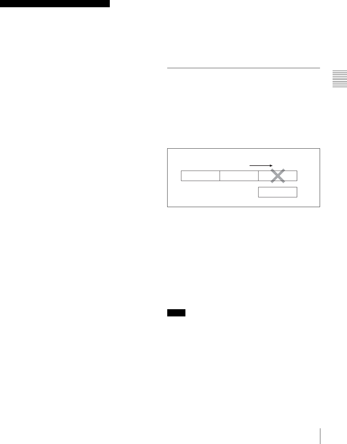
47
Recording
Chapter 3 Recording and Playback
• Press the VTR START button or the VTR button on the
lens.
• Set the POWER switch to OFF.
Take note of the following points which are common to
Single Trigger mode and Continuous Trigger mode.
Differences are clearly noted, if any.
Time code
In Manual Interval Rec mode, the internal time code
generator runs in R-RUN mode regardless of how the F-
RUN/SET/R-RUN switch is set. Also, in Continuous
Trigger mode of Manual Interval Rec, the actual time of
the shooting is saved in the user bits.
Audio
Audio signals are not recorded in Manual Interval Rec
mode.
Cassette control buttons
While recording in Single Trigger mode of Manual
Interval Rec (the green TALLY indicator in the viewfinder
flashes (2 flashes/second)), you cannot use the cassette
control buttons (REW, F FWD, PLAY and STOP). Note
that the camcorder stops recording in the single trigger
mode of the Manual Interval Rec mode if you press the
EJECT button.
While recording in Continuous Trigger mode of Manual
Interval Rec (the TALLY indicator (green) flashes (4
flashes/second)), you cannot use the cassette control
buttons (EJECT, REW, F FWD, PLAY and STOP). To stop
recording, press the VTR START button or the VTR button
on the lens. However, the tape may run to record the
picture data stored in the memory before stopping the
manual interval recording.
Menu operation
In Single Trigger mode of Manual Interval Rec, you cannot
change the settings of “CACHE/INTVAL REC” and
“NUMBER OF FRAME” on the FUNCTION 1 page after
the camcorder starts recording. To change the settings, stop
recording by pressing the EJECT button or setting the
POWER switch to OFF.
While recording in Continuous Trigger mode of Manual
Interval Rec, you cannot change the settings of CACHE/
INTVAL REC, NUMBER OF FRAME and TRIGGER
INTERVAL on the FUNCTION 1 page. To change these
settings, stop recording by pressing the VTR START
button or the VTR button on the lens or by setting the
POWER switch to OFF.
When the camcorder power is switched off during
recording in Manual Interval Rec mode
• When you set the POWER switch to OFF, the camcorder
will switch off by itself after disc access has continued
for a few seconds to record the picture data stored in
memory.
• If you remove the battery, unplug the DC cable, or cut the
power to the AC adaptor during manual interval
recording, picture data stored before recording stops (a
maximum of 10 seconds) may be lost. Take care when
changing the battery.
When tape runs out during recording in Manual
Interval Rec mode
Note that picture data (a maximum of 5 seconds) at the
instant the tape stopped is not recorded if the tape runs out
and the camcorder stops.
3-2-6 Continuous Recording on
Previous Cut
By assigning the RE-TAKE function to the ASSIGN 1
switch, you can use the ASSIGN 1 switch to position the
tape at the most recent cut, clear it and record the new cut.
For detailed information, see “5-3-5 Assigning Functions
to Assignable Switches” on page 87.
Example: After recording cut 3, clearing cut 3
and recording cut 4 after cut 2
Continuous recording the new cut after the
cut before the most recent cut
In the above example, with the camcorder in the recording
pause mode after recording the cut 3, press the RET switch
on the lens while holding the ASSIGN 1 switch down.
The camcorder automatically positions the tape at the end
point of cut 2 and turns in the recording pause mode.
Record cut 4.
Cut 4 is recorded after cut 2.
• When pictures consisting of cuts recorded using the RE-
TAKE function are played back on a VTR for
professional use, the CHANNEL CONDITION
indicator, which indicates the condition of the played
back signal of the VTR, may be lit in yellow, noise may
be added to the cue audio for the first 2 or 3 seconds, or
the previously recorded timecode may be displayed for a
few seconds. To avoid this, it is recommended that you
make the first part of the cut (in the above example, cut
4) about 3 seconds longer.
Notes on Manual Interval Rec operation
Notes
Tape running direction
Cut 1 Cut 2 Cut 3
Cut 4

48 Recording
Chapter 3 Recording and Playback
• In the following cases, the RE-TAKE function is not
accepted. The message “INVALID OPERATION!” is
displayed on the viewfinder screen for three seconds.
1.When only one cut has been recorded
2.When the length of the recorded cuts is less than three
seconds
3.When Picture Cache is ON
The RE-TAKE function is also not accepted after
recording stops until the recording pause operation is
completed (about 1 second). The message “INVALID
OPERATION!” is displayed. In this case, the RE-
TAKE function will be accepted when you perform the
RE-TAKE operation again after the message
disappears.
3-2-7 Searching for the Last
Recorded Portion and Turning in
Recording Pause Mode (End Search
Function)
The End Search function allows the camcorder to search
for the end of the recording on the tape after the recorded
portion is rewound and played back.
To use this function, set the END SEARCH function to ON
on the FUNCTION 1 page of the USER menu.
For detailed information on menu operation, see “5-1-2
Basic Menu Operations” on page 68.
END SEARCH function
Searching for the end of the recording and
turning in recording pause mode
To start the recording again after rewinding the recorded
tape, playing it back and stopping the camcorder, follow
the procedure.
Press the RET button on the lens.
The tape automatically runs and stops at the end of the
recording. The camcorder is in recording pause mode.
When the STOP KEY FREEZE function is set to become
active on the VTR MODE page of the MAINTENANCE
menu, the picture is frozen once you push the STOP button
during playback. To activate the end search function, push
the STOP button again to stop the camcorder and then
press the RET button on the lens.
Note
The current tape position
Searching for the end of the
recorded portion and turning
in recording pause mode
Blank portion
Recorded portion
Tape running direction
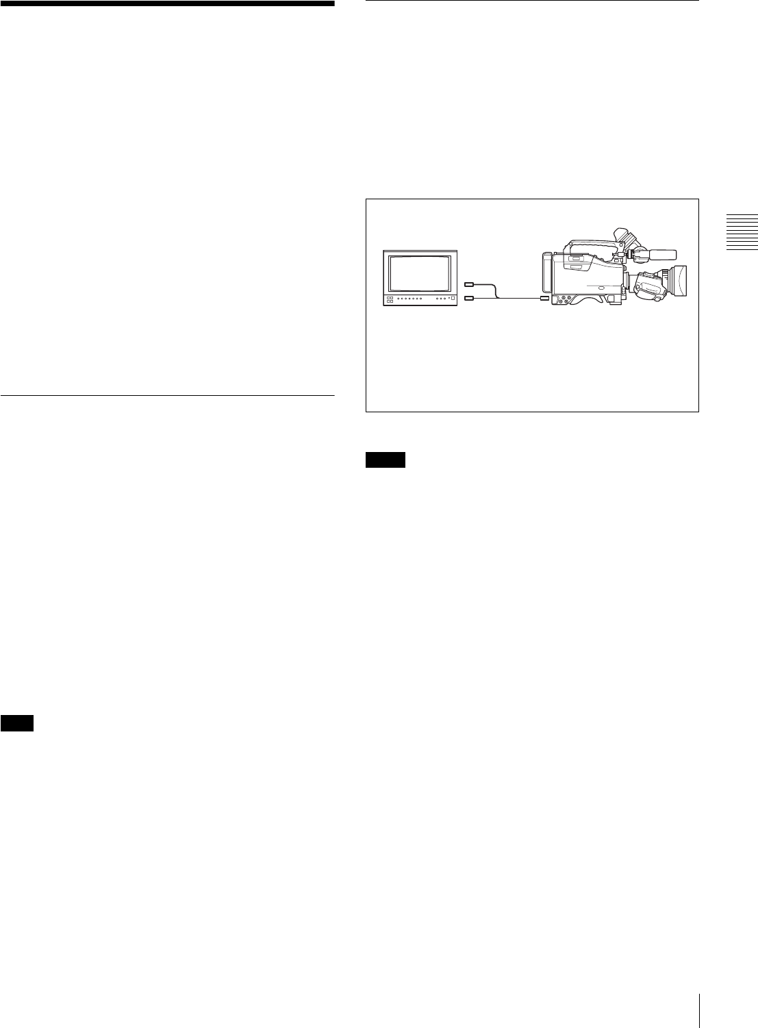
49
Checking Recording and Playback
Chapter 3 Recording and Playback
3-3 Checking Recording
and Playback
By pressing the PLAY button, you can review any length
of recording in the viewfinder in black and white. There
are two other ways to review the recording.
•Recording review: You can view the last 2 seconds of
the recording in the viewfinder in black and white.
•Color playback: You can see the recording in color on
a color video monitor without the need for any external
adaptor.
You may also view the picture during searching by
rewinding or fast forwarding by pressing the PLAY +
REW button or PLAY + F FWD button.
See “2-3 Audio Functions” on page 15 for information
about the switches and controls used to select the audio
output signal and to adjust the audio level.
3-3-1 Checking the Last Two
Seconds of the Recording —
Recording Review
If you press the RET button on the lens while recording is
paused, the last two seconds of the recording is played
back on the viewfinder screen and the color LCD. Use this
function to check whether recording went smoothly. If you
hold the RET button down longer, at most 10 seconds of
the tape is rewound and played back. After playback, the
camcorder is ready to start recording again.
By assigning the LENS RET function to the ASSIGN 1
switch, you can use the ASSIGN 1 switch in the same way
as the RET button on the lens.
For details, see “5-3-5 Assigning Functions to Assignable
Switches” on page 87.
The recording review functions only works if the recording
you have made is at least 3 seconds long.
3-3-2 Checking the Recording on
the Color Video Monitor — Playback
in Color
Connect a color video monitor to the VIDEO OUT
connector of the camcorder. By pressing the PLAY button,
you can view the recorded picture.
When the optional CBK-SD01 SDI Output Board is
installed, you can connect a color video monitor provided
with an SDI IN connector.
Color playback
• You can select either VBS or SDI as the output signal of
the VIDEO OUT connector when the CBK-SD01 is
installed.
• When the CBK-SD01 is not installed, the OUTPUT
page is not displayed. The output is fixed to VBS.
For details, see “5-3-2 Selecting the Output Signals” on
page 85.
Note
Notes
DVW-970/970PColor Video monitor
VIDEO IN
connector 1)
SDI IN connector 2) VIDEO OUT connector
1) When VBS is selected as the output signal of the VIDEO
OUT connector.
2) When SDI is selected as the output signal of the VIDEO
OUT connector (only when the CBK-SD01 is installed).
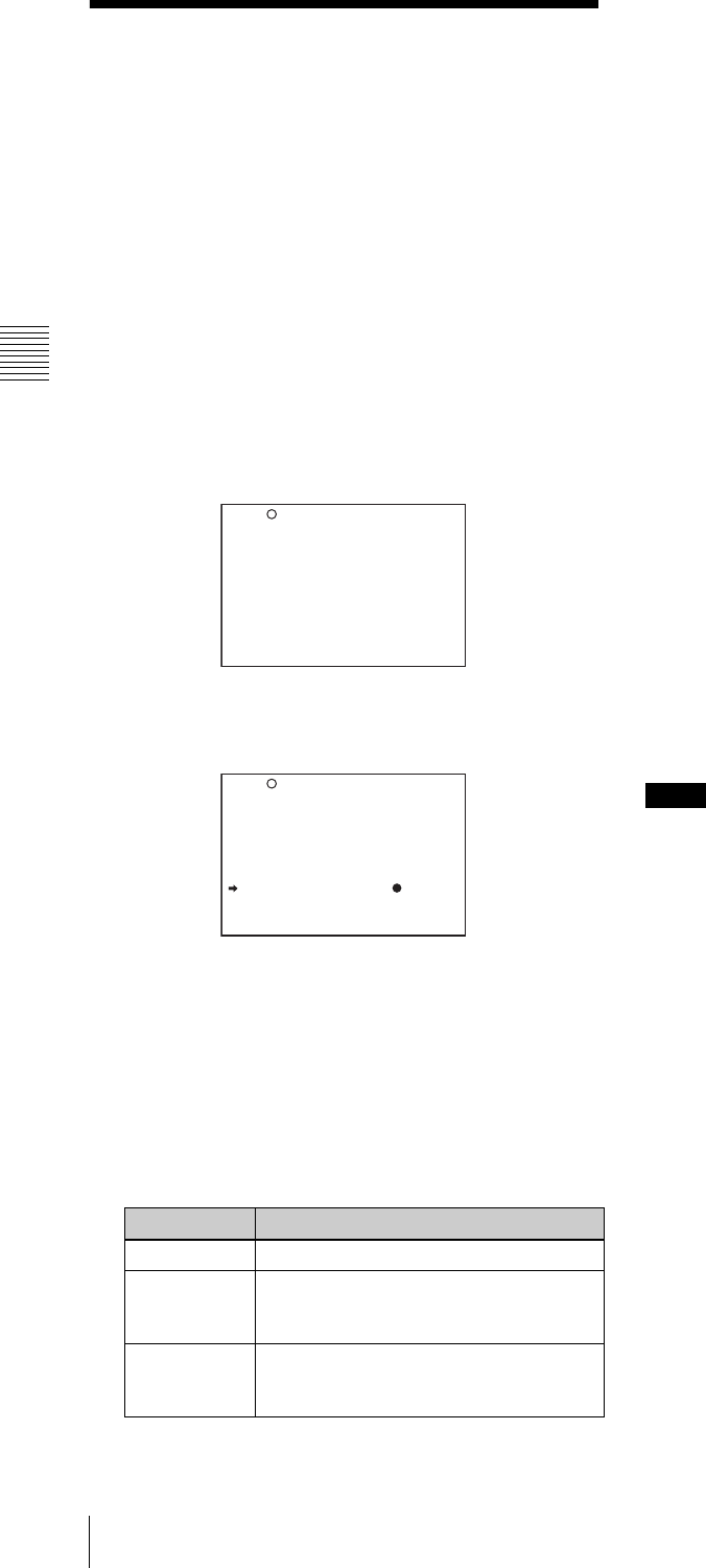
50 Freezing a Picture During Playback
Chapter 3 Recording and Playback
3-4 Freezing a Picture
During Playback
Pressing the STOP button during playback stops playback
and freezes the picture.
The VTR MODE page of the MAINTENANCE menu
allows you to set the freeze-frame mode where you can
view the frozen picture during playback.
Performing the settings required for
freezing the picture
1
Follow steps 1 to 4 in “Settings for recording essence
marks to the system area” (page 35) to display the
VTR MODE page of the MAINTENANCE menu.
2
Turn the MENU knob to move the b mark to STOP
KEY FREEZE, then push the MENU knob.
The b mark on the left of STOP KEY FREEZE
changes to a z mark, and the z mark on the left of the
setting changes to a ? mark.
3
Turn the MENU knob clockwise or counterclockwise
until the desired freeze mode appears.
The freeze mode changes in the following sequence:
OFF y FRAME y FIELD
4
Push the MENU knob.
The ? mark on the left of the setting returns to a z
mark, and the z mark on the left of STOP KEY
FREEZE returns to an b mark.
5
To end menu operation, set the MENU ON/OFF
switch to OFF.
Viewing frozen pictures
1
Push the PLAY button to start playback.
2
Push the STOP button at the instant when you want to
freeze the picture.
The tape stops running and the picture is frozen.
The time code is displayed in the counter display and
the PLAY indicator flashes (one flash/second).
Changing to another mode
To cancel the freeze-frame mode for viewing the frozen
picture and change to another mode, proceed as follows:
To restart playback: Push the PLAY button.
To view the pictures shot by the camcorder: Push the
STOP button.
To rewind the tape: Push the REW button.
To fast forward the tape: Push the F FWD button.
To eject the tape: Push the EJECT button.
• In the freeze-frame mode, you cannot start recording
pictures on the tape. To start recording the shot pictures
again, push the STOP button to finish playback and then
push the VTR START button.
• When changing to the recording pause mode from the
freeze-frame mode by using the end-search function or
positioning function for continuous recording, push the
STOP button first, and then push the RET button.
When remotely controlling the camcorder from
an RM-B150/B750 remote control unit (not
supplied)
You can perform the same operation from an RM-B150/
B750.
Setting Contents
OFF Deactivates the freeze function.
FRAME Freezes pictures in frame mode. This
mode is effective for freezing pictures of
objects that are not moving.
FIELD Freezes pictures in field mode. This
mode is effective for freezing moving
pictures.
REC TALLY BLINK : ON
REC START BEEP : OFF
LCD DISPLAY HOLD: TIMER
LCD HOLD TIMER : 1H
REC VIDEO RATE : 50M
STBY OFF TIMER : 60MIN
STOP KEY FREEZE : OFF
?M08 VTR MODE
REC TALLY BLINK : ON
REC START BEEP : OFF
LCD DISPLAY HOLD: TIMER
LCD HOLD TIMER : 1H
REC VIDEO RATE : 50M
STBY OFF TIMER : 60MIN
STOP KEY FREEZE : OFF
M08 VTR MODE Notes

51
Setting the Stand-by off Timer During Rec-Pause
Chapter 3 Recording and Playback
3-5 Setting the Stand-by
off Timer During Rec-
Pause
The VTR SAVE/STBY switch allows you to control the
VTR power mode during pauses in recording (rec-pause)
or when stopped.
However, even in the standby mode (with the VTR SAVE/
STBY switch set to STBY), you can set the VTR in such a
way that the mode is automatically switched from the
standby mode to save mode when the tape does not run for
a preset time, using the VTR MODE page of the
MAINTENANCE menu.
1
Follow steps 1 to 4 in “Settings for recording essence
marks to the system area” (page 35) to display the
VTR MODE page of the MAINTENANCE menu.
2
Turn the MENU knob to move the b mark to STBY
OFF TIMER, then push the MENU knob.
The b mark on the left of “STBY OFF TIMER”
changes to a z mark, and the z mark on the left of the
setting changes to a ? mark.
3
Turn the MENU knob clockwise or counterclockwise
until the desired STBY OFF TIMER appears.
If you turn the MENU knob clockwise or
counterclockwise, STBY OFF TIMER changes in the
following sequence: 60MIN y 30MIN y 10MIN
y 5MIN y OFF.
In order not to enter in the VTR SAVE mode, select
OFF.
To enter the VTR SAVE mode, select the desired time.
4
Press the MENU knob.
The z mark on the left of “STBY OFF TIMER”
returns to an b mark, and the ? mark to the left of the
setting returns to the z mark.
5
To end menu operations, set the MENU ON/OFF
switch to OFF.
REC TALLY BLINK : ON
REC START BEEP : OFF
LCD DISPLAY HOLD: TIMER
LCD HOLD TIMER : 1H
REC VIDEO RATE : 50M
STBY OFF TIMER : 60MIN
STOP KEY FREEZE : OFF
M08 VTR MODE
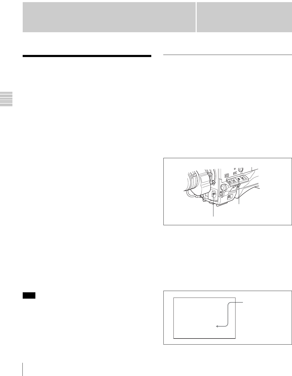
52 Adjusting the Black Balance and the White Balance
Chapter 4 Adjustments and Settings for Recording
Chapter 4
Adjustments and
Settings for Recording
4-1 Adjusting the Black
Balance and the White
Balance
To ensure excellent image quality when using this
camcorder, conditions may require that both the black
balance and the white balance be adjusted.
Black balance adjustment
The black balance will require adjustment in the following
cases.
• When the camcorder is used for the first time
• When the camcorder has not been used for a long time
• When the camcorder is used under conditions in which
the surrounding temperature has changed greatly
• When the GAIN selector (L/M/H) values have been
changed by using the USER menu
It is not usually necessary to adjust the black balance when
using the camcorder after it has been off.
White balance adjustment
Always readjust the white balance when the lighting
conditions change.
Viewfinder screen displays
If the black balance or white balance adjustment is started,
messages that report on the progress and results are
displayed on the viewfinder screen when the VF DISP
MODE item is set to “2” or “3” on the VF DISP 1 page of
the USER menu.
Black balance and white balance adjustment values that
are automatically set by the camcorder and the various
settings are stored in the camcorder memory and retained
even when the power is turned off.
4-1-1 Adjusting the Black Balance
To automatically adjust the black balance
In automatic black balance mode, adjustments are
performed in the following order: clamp level, black set,
and black balance. Manual black balance adjustment can
be selected from the setup menu.
Note that the automatic black balance adjustment includes
a function to correct for white flecks caused in the CCDs
by cosmic rays, in addition to the normal black balance
operation.
To adjust the black balance, proceed as follows:
1
Set the OUTPUT/DCC switch to CAM.
2
Push the AUTO W/B BAL switch to BLK and release
the switch.
The switch returns to the center position, and the
adjustment is executed.
During adjustment, the following message is displayed
on the viewfinder screen.
Note
AUTO W/B BAL switch
OUTPUT/DCC switch
ABB:EXECUTING
-BLACK SET-
The messages change
in the following
sequence:
-BLACK SET- t
-BLACK BALANCE-
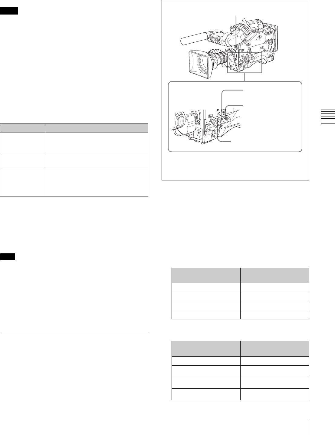
53
Adjusting the Black Balance and the White Balance
Chapter 4 Adjustments and Settings for Recording
The black balance adjustment ends in a few seconds
with the message “ABB:OK” and the adjustment value
is automatically stored in memory.
• During the black balance adjustment, the iris is
automatically closed.
• During the black balance adjustment, the gain selection
circuit is automatically activated so you may see
flickering on the viewfinder screen, but this is not a fault.
If automatic black balance adjustment
cannot be made
If the black balance adjustment cannot be completed
normally, an error message will appear for about 3 seconds
on the viewfinder screen (in display mode 2 or 3).
Possible messages are listed below.
If any of the above error messages is displayed, retry the
black balance adjustment.
Keep pushing the AUTO W/B BAL to BLK until
“-BLACK SET-” appears after “-BLACK BALANCE-”
appears. If the error message occurs again, contact your
Sony service representative.
If the lens cable is not firmly connected to the LENS
connector, it may not be possible to adjust the lens iris. If
this happens, the black balance will be incorrect.
Black balance memory
Values stored in memory are held until the black balance is
next adjusted.
4-1-2 Adjusting the White Balance
To automatically adjust the white balance
When you make automatic white balance adjustment, the
adjustment value obtained is saved in memory.
Proceed as follows:
1
Set the switches and selectors as shown in the figure
below.
If the setting of the GAIN selector or WHITE BAL
switch is changed, a message reporting the new setting
position appears for about 3 seconds in the setting
change and adjustment progress message display area
of the viewfinder screen.
2
Set the FILTER selector to suit the lighting conditions
as follows:
Notes
Black balance adjustment error messages
Error message Meaning
ABB : NG
IRIS NOT
CLOSED
The lens iris did not close; adjustment
was impossible.
ABB : NG
TIME LIMIT
Adjustment could not be completed
within the standard number of attempts.
ABB : NG
R (or G or B) :
OVERFLOW
The difference between the reference
value and the current value is so great
that it exceeds the range. Adjustment
was impossible.
Note FILTER selector (outer knob) setting and CC-filter
selection
FILTER selector (outer
knob) setting
CC filter
A Cross filter
B 3200K
C 4300K
D 6300K
FILTER selector (inner knob) setting and ND-filter
selection
FILTER selector
(inner knob) setting
ND filter
1Clear
21/4 ND
31/16 ND
41/64 ND
1) White balance setting values are stored in memory B only
when the WHITE SWITCH <B> item is set to “MEM” on
the FUNCTION 2 page of the OPERATION menu.
FILTER selector (step 2)
GAIN selector: Set as low as
possible.
OUTPUT/DCC switch:
CAM
WHITE BAL switch:
A or B 1)
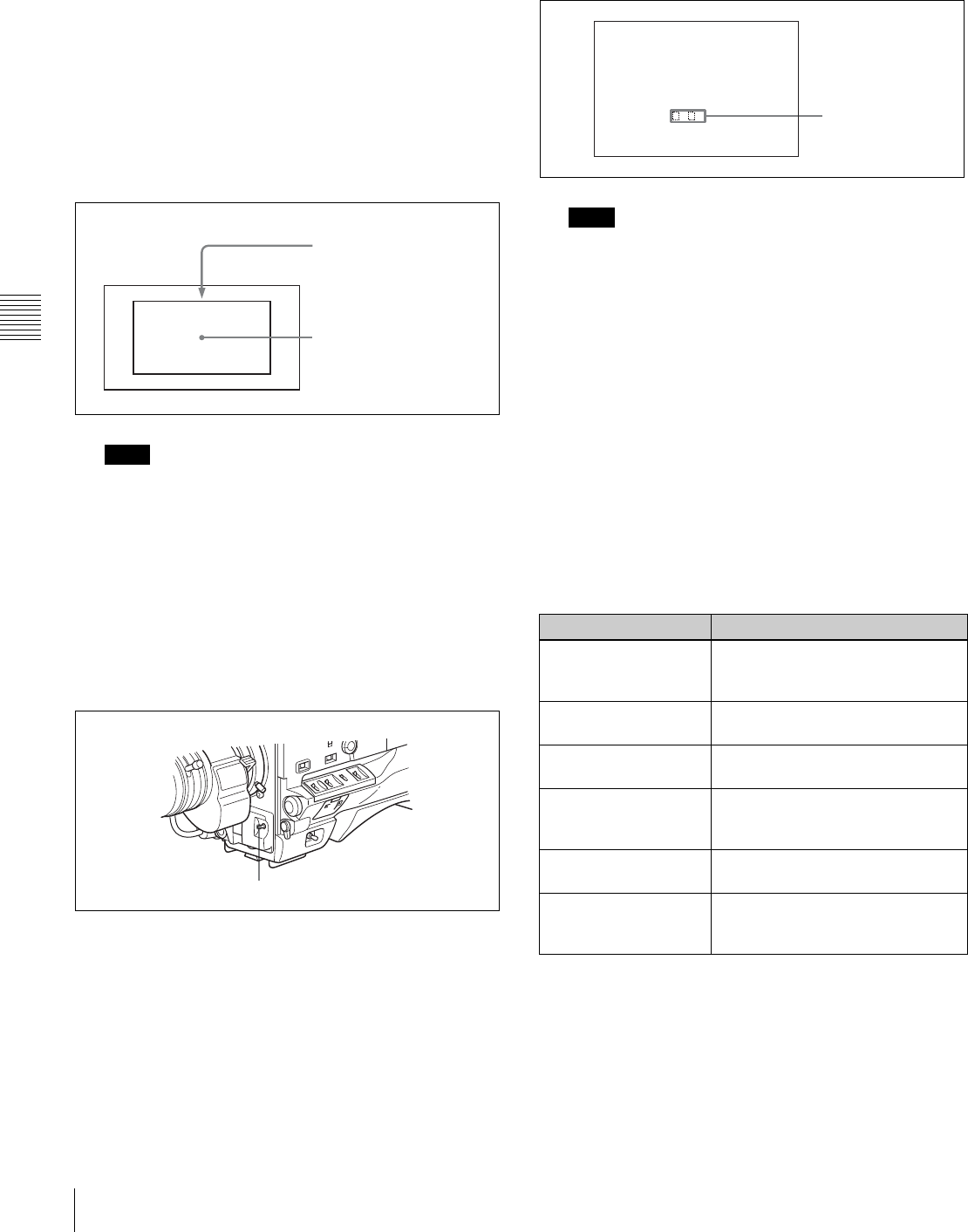
54 Adjusting the Black Balance and the White Balance
Chapter 4 Adjustments and Settings for Recording
If the setting of the FILTER selector is changed, a
message reporting the setting appears for about 3
seconds in the setting change and adjustment progress
message display area of the viewfinder screen (in
display mode 3).
3
Place a white test card under the same lighting
conditions as for the subject to be shot and zoom up to
it.
Alternatively, any white object such as a cloth or a wall
can be used.
The absolute minimum white area is as follows:
Make sure there are not bright spots in the rectangle.
4
Adjust the lens iris.
Manually adjusted lens: set the iris to an appropriate
setting.
Lens with automatic iris: set the automatic/manual
switch on the lens to automatic.
5
Push the AUTO W/B BAL switch to WHT and then
release the switch.
The switch returns to the center position, and the
adjustment is executed.
During adjustment, the message “AWB :
EXECUTING” is displayed on the viewfinder screen
(in display mode 2 or 3).
The white balance adjustment ends in about one
second with the message shown in the following
figure, and the adjustment setting is automatically
stored in the memory (A or B) that was selected in step
1.
If the camera has a zoom lens with an automatic iris,
the iris may hunt 1) during the adjustment. To prevent
this, adjust the iris gain knob (indicated as IG, IS, or S)
on the lens.
1)Hunting
Repeated brightening and darkening of the image, resulting from
repeated response to automatic iris control.
For details, refer to the lens operation manual.
If the automatic white balance adjustment
cannot be made
If the white balance adjustment cannot be completed
normally, an error message will appear for about 3 seconds
on the viewfinder screen (in display mode 2 or 3).
Possible messages are listed below.
If any of the above error messages is displayed, retry the
white balance adjustment. If the error message occurs
again, contact your Sony service representative.
Note
Rectangle centered on
the screen. The lengths of
the sides are 70% of the
length and width of the
screen.
The white object must be
within the rectangle and
have an area of at least
10% of the screen.
AUTO W/B BAL switch
Note
White balance adjustment error messages
Error message Meaning
AWB : NG
LOW LEVEL
The white video level is too low.
Either open the lens iris or increase
the gain.
AWB : NG
COLOR TEMP HIGH
The color temperature is too high.
Select a suitable filter setting.
AWB : NG
COLOR TEMP LOW
The color temperature is too low.
Select a suitable filter setting.
AWB : NG
TIME LIMIT
Adjustment could not be completed
within the standard number of
attempts.
AWB : NG
POOR WHITE AREA
The white area could not be
checked.
AWB : NG
OVER LEVEL
The white video level is too high.
Either stop down the lens iris or
change the ND filter.
AWB:OK
. K
Approximate color
temperature of the
subject

55
Setting the Electronic Shutter
Chapter 4 Adjustments and Settings for Recording
If you have no time to adjust the white
balance
Set the WHITE BAL switch to PRST.
The white balance is automatically set as follows,
depending on the FILTER selector setting.
B: 3200K
C: 4300K
D: 6300K
For details about setting the white balance manually, see
“To automatically adjust the white balance” on page 53.
White balance memory
Values stored in memory are held until the white balance is
next adjusted.
There are two sets of white balance memories, A and B,
and adjustments for each of the filters can be automatically
stored in the memory corresponding to the setting (A or B)
of the WHITE BAL switch. The camcorder has four built-
in filters, so a total of eight (4 × 2) adjustments can be
stored. The number of memories allocated to each of A and
B can be limited to one by setting the WHT FILTER INH.
item to “ON” on the FUNCTION 3 page of the
MAINTENANCE menu. In this case, the memory contents
are not linked to the filter settings.
If the WHITE BAL switch is set to B, and on the
FUNCTION 2 page of the OPERATION menu, the
WHITE SWITCH <B> item is set to “ATW,” the ATW
(Auto Tracing White) function is activated to
automatically adjust the white balance of the picture being
shot for varying lighting conditions.
4-2 Setting the Electronic
Shutter
This section describes the shutter modes that can be used
with the electronic shutter of the camcorder, and describes
the procedure for selecting the shutter speed and shutter
mode.
4-2-1 Shutter Modes
The shutter modes that can be used with the electronic
shutter and the shutter speeds that can be selected are
shown below.
Standard mode
Use this mode for shooting fast-moving subjects with little
blurring.
ECS (Extended Clear Scan) mode
Use this mode for obtaining images with no horizontal
bands of noise when shooting subjects such as monitor
screens.
SLS (slow speed shutter) mode
The SLS mode can only be selected when the CCD scan
mode is set to “I (interlace scan).”
Use this mode For shooting subjects in low level lighting
conditions.
You can select the shutter speed from among 1 (1/30 sec
for the DVW-970, 1/25 sec for the DVW-970P) to 8, 16
CCD scan mode Shutter speed (sec.)
I DVW-970 1/100, 1/125, 1/250, 1/500, 1/1000,
1/2000
DVW-970P 1/60, 1/125, 1/250, 1/500, 1/1000,
1/2000
PsF DVW-970 1/40, 1/60, 1/120, 1/125, 1/250,
1/500, 1/1000, 1/2000
DVW-970P 1/33, 1/50, 1/100, 1/125, 1/250,
1/500, 1/1000, 1/2000
24P (DVW-970 only) 1/32, 1/48, 1/96, 1/125, 1/250,
1/500, 1/1000, 1/2000
CCD scan mode Shutter speed
I DVW-970 60.00 to 6000 Hz
DVW-970P 50.00 to 6000 Hz
PsF DVW-970 30.00 to 7000 Hz
DVW-970P 25.00 to 6000 Hz
24P (DVW-970 only) 24.00 to 5000 Hz
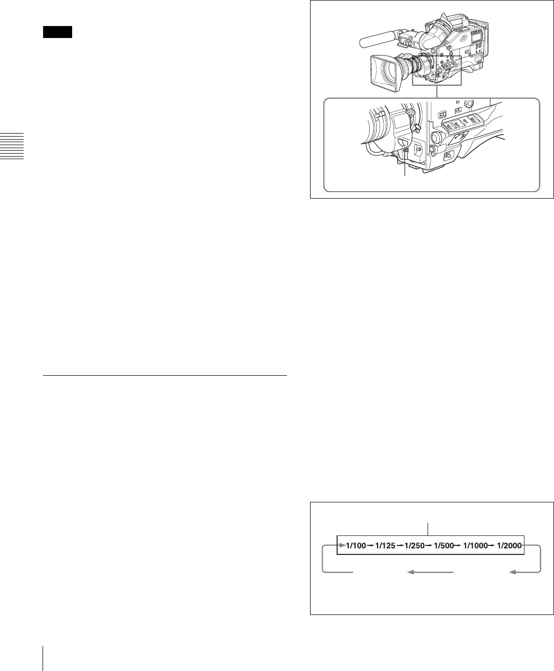
56 Setting the Electronic Shutter
Chapter 4 Adjustments and Settings for Recording
frames (1/2 sec for the DVW-970, 2/3 sec for the DVW-
970P).
EVS (Enhanced Vertical definition System) mode
This mode is used to improved vertical resolution.
However, the sensitivity and dynamic range are reduced.
The shutter speed is set to the same value as that currently
selected in Standard or ECS mode.
• Whatever the operating mode of the electronic shutter,
the sensitivity of the CCD decreases with increasing
shutter speed.
• When the automatic iris is used, the iris opens wider as
the shutter speed increases, thus reducing the depth of
field.
• Under artificial light, particularly fluorescent or mercury
lamps, the light intensity may appear to be constant, but
the red, green, and blue intensities are actually changing
in synchronization with the frequency of the power
supply causing flicker. Using an electronic shutter under
such lighting could make the flicker even worse. Color
flicker is particularly likely to happen when the power
supply frequency is 60 Hz (with the DVW-970) or 50 Hz
(with the DVW-970P). However, if the power frequency
is 50 Hz (with the DVW-970) or 60 Hz (with the DVW-
970P), setting the shutter speed to 1/100 or 1/60 can
reduce this flicker.
• When a bright object is shot in EVS mode or ECS mode
in such a manner that it fills the screen, the upper edge of
the picture may have poor quality because of an inherent
characteristic of CCDs. Before using EVS mode or ECS
mode, check the shooting conditions.
You can turn on or off the EVS mode on the SW STATUS
page of the PAINT menu.
4-2-2 Selecting the Shutter Mode
and Shutter Speed
Use the SHUTTER selector to select a shutter mode or a
standard-mode shutter speed. To set the shutter speed in
ECS or SLS mode, with the SHUTTER selector set to ON
and the ECS or SLS mode selected, use the MENU knob
for adjustment.
You can use the SHT ENABLE page of the OPERATION
menu to narrow the range of choice in advance, or to select
in advance whether or not you use ECS/SLS.
Setting the shutter mode and the shutter
speed in standard mode
Once the shutter speed is selected, it is retained even when
the camcorder power is turned off.
1
Follow the procedure described in “5-2-2 Selecting the
Display Items” (page 76) to set the VF DISPLAY
MODE item to “2” or “3” on the VF DISP 1 page of
the USER menu.
2
Push the SHUTTER selector from ON to SEL.
The current shutter setting indication appears for about
3 seconds in the setting change and adjustment
progress message display area of the viewfinder
screen.
Examples: “: SS : 1/250,” “: ECS : 60.00 Hz”
3
Before the shutter setting indication disappears, push
the SHUTTER selector down to SELECT again and
repeat this until the desired mode or speed appears.
Pushing the SHUTTER selector down to SELECT
repeatedly allows you to cycle through the settings of
mode and speed preselected on the SHT ENABLE
page of the OPERATION menu.
Note that all modes and all standard-mode speeds
listed in the table on the previous page are preselected
using the SHT ENABLE page of the OPERATION
menu.
By factory default, all available shutter modes and
shutter speeds are displayed in the sequence shown in
the following figure. (You can use the SHT ENABLE
page of the OPERATION menu to make a setting so
that only the desired (or most frequently used) modes
and speeds are displayed.)
Notes
SHUTTER selector
Standard mode
ECS mode
1/100: for the DVW-970
1/60: for the DVW-970P
SLS mode
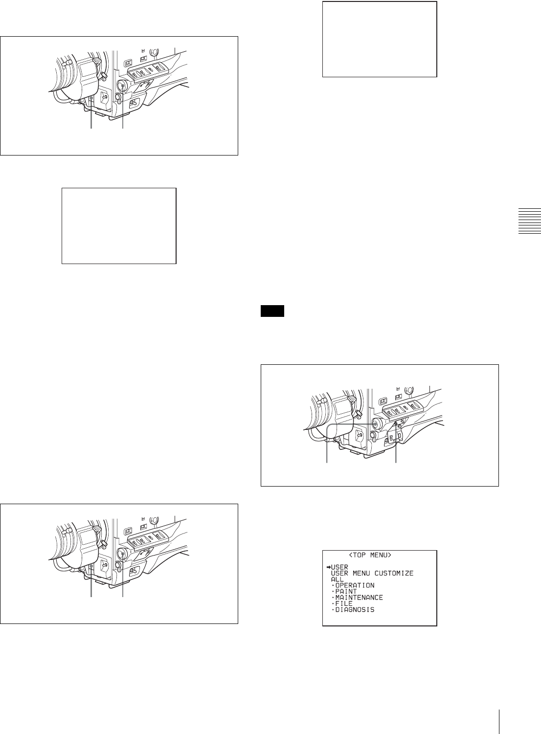
57
Setting the Electronic Shutter
Chapter 4 Adjustments and Settings for Recording
Setting the shutter speed in ECS mode
Proceed as follows:
1
Set the shutter speed mode to ECS.
Example of view finder screen display
for ECS setting operation
2
Turn the MENU knob counterclockwise as seen from
the front of the camera to increase the value, or
clockwise to decrease the value, until the desired
frequency appears.
The frequency range can be changed between 60.1 and
7000 Hz (DVW-970) or between 50.2 and 9000 Hz
(DVW-970P).
When the RM-B150/B750 Remote Control Unit is
connected
You can set the shutter speed of ECS with the rotary
encoder of the RM-B150/B750.
Setting the shutter speed in SLS mode
Proceed as follows:
1
Set the shutter speed mode to SLS.
Example of view finder screen display
for SLS setting operation
2
Turn the MENU knob until the desired number of
frames appears.
The number of frames can be set to values in the range
1 to 8, and 16 (1 frame nearly equals to 1/30 second
(DVW-970) or 1/25 second (DVW-970P)).
Changing the range of choice of shutter
mode and speed settings
You can reduce the time required to select the shutter mode
and speed by narrowing the choice of settings in advance.
This can be done by using the SHT ENABLE page of the
OPERATION menu.
Proceed as follows:
The settings selected on the SHT ENABLE page of the
OPERATION menu become invalid when the RM-B150/
B750 Remote Control Unit is connected to the camcorder.
1
Set the MENU ON/OFF switch to ON while holding
down the MENU knob.
The TOP menu appears.
2
Turn the MENU knob to move the b mark to
OPERATION.
12
ECS:60.00Hz
12
Note
SLS: 1/30 : 1FRAME
MENU knob MENU ON/OFF switch

58 Setting the Electronic Shutter
Chapter 4 Adjustments and Settings for Recording
3
Press the MENU knob.
If this is the first time the OPERATION menu has been
displayed, the CONTENTS page of the OPERATION
menu appears.
If the menu has been used before, the last accessed
page appears.
4
If the CONTENTS page is displayed, turn the MENU
knob to move the b mark to “SHT ENABLE,” then
press the MENU knob to display the SHT ENABLE
page.
If a different page is displayed, turn the MENU knob
until the SHT ENABLE page appears, then press the
MENU knob to select the page.
SHT ENABLE page
(This menu display is for the DVW-970. For the DVW-
970P, “SHUTTER 1/60” is displayed instead of
“SHUTTER 1/100.”)
5
Turn the MENU knob to move the b mark to the
shutter mode or shutter speed you want, then press the
MENU knob.
The b mark on the left of the selected item changes to
a z mark and the z mark on the left of the setting
changes to a ? mark.
6
Turn the MENU knob until “ON” appears, then press
the MENU knob.
The z mark on the left of the selected item returns to
a b mark and the ? mark on the left of the setting
returns to a z mark.
To set another mode or speed, return to step 5.
Note that only the shutter speeds set to “ON” can be
selected with the SHUTTER selector.
7
To end the menu operation, set the MENU ON/OFF
switch to OFF.
The menu disappears from the viewfinder screen and
the display indicating the current status of the
camcorder appears along the top and bottom of the
viewfinder screen.
When you set “SHT DISP MODE” to “DEG” on the
FUNCTION 4 page, the shutter speed indications in
seconds (e.g. 1/100) can be changed to degrees (360 is
equivalent to shutter OFF).
Note
17 SHT ENABLE
SHUTTER SLS : ON
SHUTTER ECS : ON
SHUTTER 1/100 : ON
SHUTTER 1/125 : ON
SHUTTER 1/250 : ON
SHUTTER 1/500 : ON
SHUTTER 1/1000 : ON
SHUTTER 1/2000 : ON
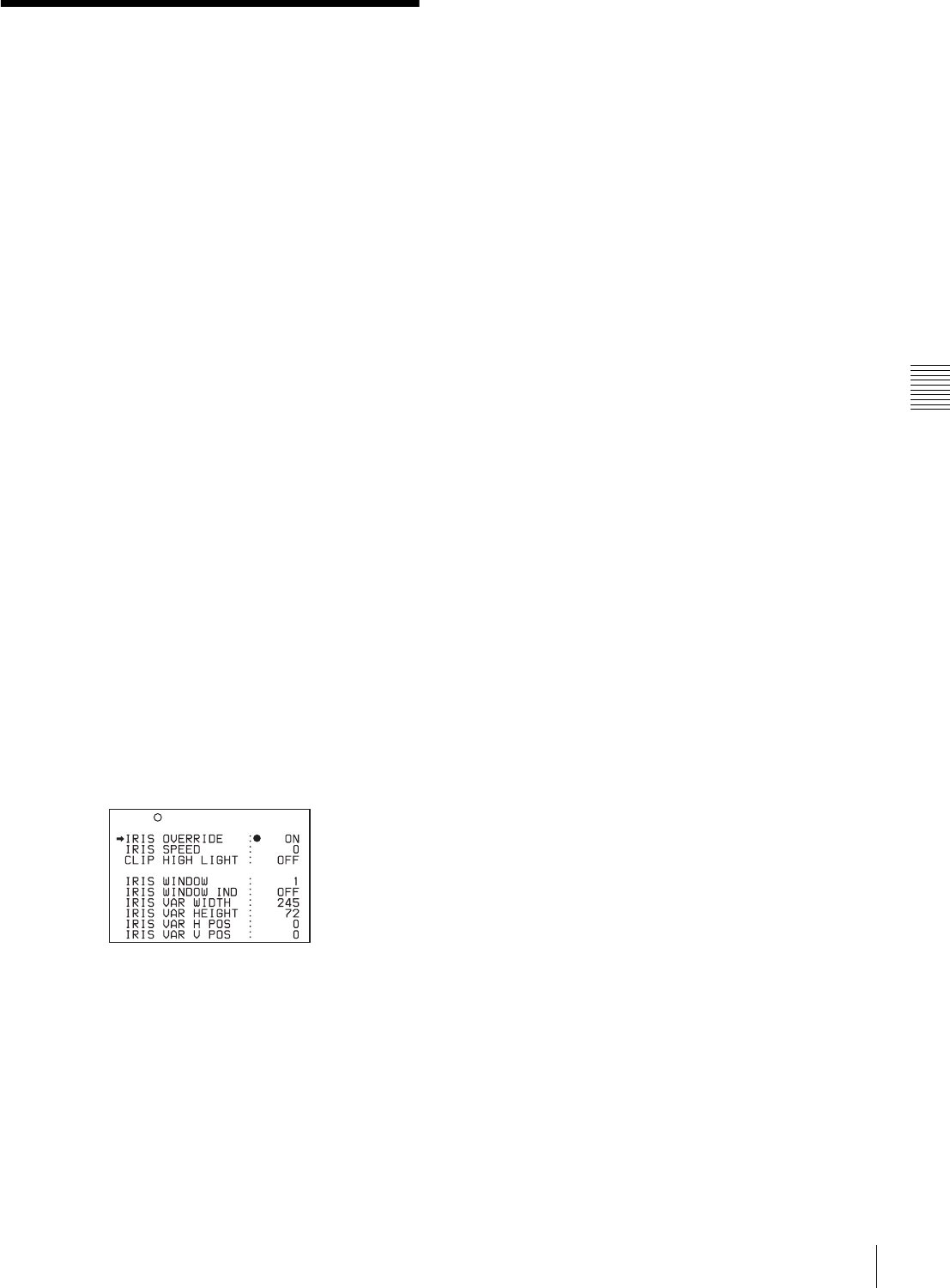
59
Changing the Reference Value for Automatic Iris Adjustment
Chapter 4 Adjustments and Settings for Recording
4-3 Changing the
Reference Value for
Automatic Iris
Adjustment
The reference value for automatic iris adjustment can be
changed to aid the shooting of clear pictures of back-lit
subjects, or to prevent blown-out highlights. The reference
value for the lens iris can be set within the following range
with respect to the standard value.
• 0.5: about 0.5 stop further open
• 1: about 1 stop further open
• –0.5: about 0.5 stop further closed
• –1: about 1 stop further closed
Changing the reference value
Proceed as follows:
1
Set the MENU ON/OFF switch to ON.
If this is the first time the USER menu has been
displayed, the CONTENTS page of the USER menu
appears. If the menu has been used before, the last
accessed page appears.
2
If the CONTENTS page is displayed, turn the MENU
knob to move the b mark to AUTO IRIS, then press
the MENU knob to display the AUTO IRIS page.
If a different page is displayed, turn the MENU knob
until the AUTO IRIS page appears, then press the
MENU knob to select the page.
AUTO IRIS page
3
Turn the MENU knob to move the b mark to “IRIS
OVERRIDE,” then press the MENU knob.
The b mark on the left of the selected item changes to
a z mark and the z mark on the left of the setting
changes to a ? mark.
4
Turn the MENU knob until “ON” appears, then press
the MENU knob.
The z mark on the left of the selected item returns to
a b mark and the ? mark on the left of the setting
returns to a z mark.
The IRIS OVERRIDE item is set to “ON” (factory
setting: OFF).
5
Set the MENU ON/OFF switch to OFF.
The AUTO IRIS page disappears from the viewfinder
screen.
6
Turn the MENU knob to change the reference value.
The changed reference value is retained until the
power of the camcorder is turned off.
Even if the reference value is changed, it reverts to the
standard value every time the power is turned on.
To open the iris by 0.5 stop:
Turn the MENU knob counterclockwise as seen from
the front of the camera.
One bar (s) appears in the upper part to the left of the
F number in the iris indication.
To open the iris by 1 stop:
Turn the MENU knob counterclockwise as seen from
the front of the camera.
Two bars (ss) appear in the upper part to the left of
the F number in the iris indication.
To stop down the iris by 0.5 stop:
Turn the MENU knob clockwise as seen from the front
of the camera.
One bar (s) appears in the lower part to the left of the
F number in the iris indication.
To stop down the iris by 1 stop:
Turn the MENU knob further clockwise as seen from
the front of the camera.
Two bars (ss) appear in the lower part to the left of
the F number in the iris indication.
U10 AUTO IRIS
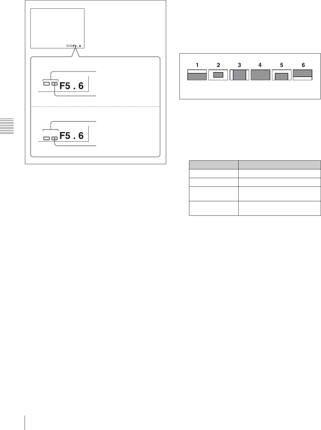
60 Changing the Reference Value for Automatic Iris Adjustment
Chapter 4 Adjustments and Settings for Recording
Adjusting the reference value for automatic iris adjustment
When the RM-B150/B750 Remote Control Unit is
connected
The IRIS control knob of the RM-B150/B750 can be used
for lens iris setting. In this case, the bar display (s) does
not appear.
Selecting the automatic iris window
Proceed as follows:
1
Follow the procedure of steps 1 and 2 described in the
previous item “Changing the reference value” (page
59) to display the AUTO IRIS page.
2
Turn the MENU knob to move the b mark to “IRIS
WINDOW IND,” then press the MENU knob.
The b mark on the left of “IRIS WINDOW IND”
changes to a z mark, and the z mark on the left of the
setting changes to a ? mark.
3
Turn the MENU knob until “ON” appears, then press
the MENU knob.
The z mark returns to a b mark, and the ? mark
returns to a z mark.
The currently selected auto iris window appears on the
screen.
If it is not necessary to display the auto iris window on
the screen, set to “OFF.”
4
Turn the MENU knob to move the b mark to “IRIS
WINDOW,” then press the MENU knob.
The b mark changes to a z mark, and the z mark
changes to a ? mark.
5
Turn the MENU knob until the desired auto iris
window appears, then press the MENU knob.
Auto iris window
The z mark on returns to a b mark and the ? mark
returns to a z mark.
If you select “VARIABLE,” the following items
become effective and you can set the window of the
desired size. Set each item to the desired size.
6
Set the MENU ON/OFF switch to OFF or close the
cover of the menu operating section.
The menu disappears from the viewfinder screen and
the display indicating the current status of the
camcorder appears along the top and bottom of the
screen.
To counter problems with very bright
highlights
If the subject is too bright, the iris may close too much,
leaving the overall image dark, or the highlights may be
blown out. In such cases, setting the highlight clip function
on reduces the luminance range, avoiding problems from
the automatic iris correction.
In the AUTO IRIS page of the USER menu, set the CLIP
HIGH LIGHT item to “ON.”
Opening the lens iris
Iris opened by 1 stop
(two bars)
Iris opened by 0.5 stop
(one bar)
Stopping down the lens iris
Iris stopped down by 1 stop
(two bars)
Iris stopped down by 0.5 stop
(one bar)
Item Setting
IRIS VAR WIDTH The width of the window
IRIS VAR HEIGHT The height of the window
IRIS VAR H POS. The position of the window in the
horizontal direction
IRIS VAR V POS. The position of the window in the
vertical direction.
The shaded parts indicate the area
where light detection occurs.
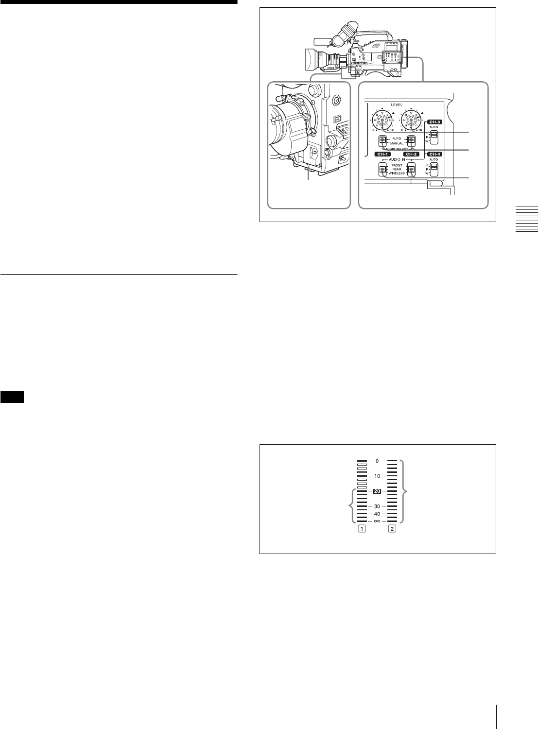
61
Adjusting the Audio Level
Chapter 4 Adjustments and Settings for Recording
4-4 Adjusting the Audio
Level
Setting the AUDIO SELECT CH-1/CH-2 switches to
AUTO automatically adjusts the input levels of the audio
signal to be recorded in audio channels 1 and 2. You can
also adjust the audio level manually.
For the audio level of the signal to be recorded in
audio channels 3 and 4
The input levels of audio channels CH-3 and CH-4 are
automatically adjusted or fixed.
When the CH-1/2 / CH-3/4 switch is set to CH-3/4, the
audio channel level meters display the level of the audio
signals recorded in audio channels CH-3 and CH-4. You
can select the audio input signals to be recorded for audio
channel CH-3 and 4 by using the AUDIO IN CH-3/CH-4
switches.
4-4-1 Manually Adjusting the Audio
Input Level of the AUDIO IN CH1/CH2
Connectors
Follow the procedure described below to adjust the audio
levels of the audio input from the AUDIO IN CH1/CH2
connectors, which are to be recorded in audio channels
CH-1 and CH-2.
When 1 and 2 are not displayed under the audio channel
level meters, the CH-1/2/ CH-3/4 switch is set to the CH-
3/4 position. Set this switch to CH-1/2.
At the factory setting, the XLR connection automatic
detection mode of the AUDIO IN CH1/CH2 connectors is
set to OFF. If the setting has been changed to ON, start the
operation from step 2.
Start the operation from step 1 with the XLR connection
automatic detection mode set to OFF.
You can set the XLR connection automatic detection mode
on the AUDIO-1 page of the MAINTENANCE menu.
Manual adjustment of the audio levels
of AUDIO IN CH1/CH2
1
To adjust the signal input to the AUDIO IN CH1 or
AUDIO IN CH2 connector, set the AUDIO IN CH-1 or
AUDIO IN CH-2 switch to REAR.
To adjust both input signals, set both switches to
REAR.
2
Set the AUDIO SELECT switch(es) corresponding to
the channel(s) selected in step 1 to MANUAL.
3
With the LEVEL control for the channel selected in
step 1, adjust so that the audio level meter shows up to
–20 dB for a normal input volume.
The second bar from the top may turn on occasionally,
but do not allow the top bar (0 dB) to go on. If it goes
on, the audio level is too high.
Using the LEVEL controls
You can select the audio level controls to be used to adjust
the level of the audio signals input to the AUDIO IN CH1/
CH2 connectors on the AUDIO-3 page of the
MAINTENANCE menu.
Note
1
2
3
MIC LEVEL control
All bars go on.
These bars go on.
Normal input level Excessive input level
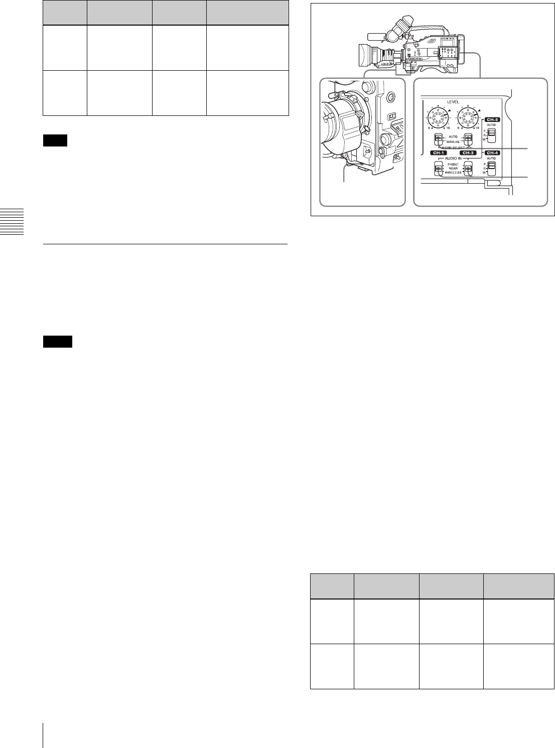
62 Adjusting the Audio Level
Chapter 4 Adjustments and Settings for Recording
When you have operation of the LEVEL (CH-1/CH-2)
controls and MIC LEVEL control linked together, if the
MIC LEVEL control is set to 0, the audio signals on
channels 1 and 2 cannot be recorded. Check the position of
the MIC LEVEL control before adjusting the LEVEL
(CH-1/CH-2) controls.
4-4-2 Manually Adjusting the Audio
Level of the Front Microphone
You can adjust the audio level input from the front
microphone connected to the MIC IN connector, which is
to be recorded on audio channels 1 and 2.
•When [1] and [2] are not displayed under the audio
channel level meters, the CH-1/2 / CH-3/4 switch is set
to the CH-3/4 position. Set this switch to CH-1/2.
• If the XLR connection automatic detection mode is on,
when the cables are connected to the AUDIO IN CH1/
CH2 connectors, the camcorder detects the connection to
the AUDIO IN CH1/CH2 connectors. Thus, the AUDIO
IN switches are internally reset to REAR and the audio
signals input to the AUDIO IN CH1/CH2 connectors are
automatically selected.
Before adjusting the audio level of the front microphone,
confirm that no cables are connected to the AUDIO IN
CH1/CH2 connectors. Alternatively, set the REAR XLR
AUTO item to “OFF” on the AUDIO-1 page of the
MAINTENANCE menu.
To adjust the audio level of the front microphone, proceed
as follows:
Manual adjustment of the audio levels
of the front microphone
1
Set either or both of the AUDIO IN switch(es) to
FRONT as follows:
When using the front microphone input for both
channels 1 and 2: Set both AUDIO IN switches to
FRONT.
When using the front microphone input for either
channel 1 or 2: Set the AUDIO IN switch for the
desired channel to FRONT.
2
Set the AUDIO SELECT switch(es) for the desired
channel(s) selected in step 1 to MANUAL.
3
Turn the MIC LEVEL control, and adjust so that the
audio level meter shows up to –20 dB for a normal
input volume.
• The 9 bars from the bottom among 17 bars go on
with the normal input volume.
• The second top bar may turn on occasionally, but do
not allow the top bar to go on. If it goes on, the audio
level is too high.
Using the LEVEL controls
You can select the audio level controls to be used to adjust
the level of the front microphone on the AUDIO-3 page of
the MAINTENANCE menu.
At the factory
setting
Example 1 Example 2
Audio
level to
CH-1
LEVEL (CH-1)
control
MIC LEVEL
control
The MIC LEVEL
control is linked
with LEVEL (CH-1)
control.
Audio
level to
CH-2
LEVEL (CH-2)
control
MIC LEVEL
control
The MIC LEVEL
control is linked
with LEVEL (CH-2)
control.
Note
Notes
At the factory
setting
Example 1 Example 2
Audio
level to
CH-1
MIC LEVEL
control
LEVEL (CH-1)
control
The MIC LEVEL
control is linked
with LEVEL
(CH-1) control.
Audio
level to
CH-2
MIC LEVEL
control
LEVEL (CH-2)
control
The MIC LEVEL
control is linked
with LEVEL
(CH-2) control.
1
2
3
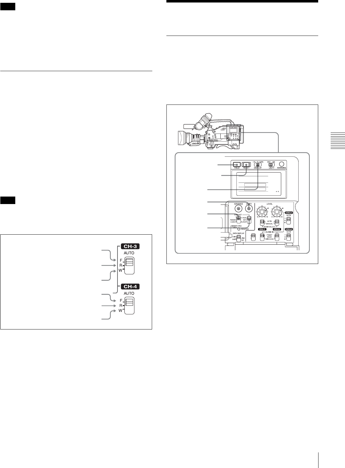
63
Setting the Time Data
Chapter 4 Adjustments and Settings for Recording
When you have operation of the MIC LEVEL control and
LEVEL (CH-1/CH-2) controls linked together, if the
LEVEL (CH-1/CH-2) controls are set to 0, the audio
signals on channels 1 and 2 cannot be recorded. Check the
position of the LEVEL (CH-1/CH-2) controls before
adjusting the MIC LEVEL control.
4-4-3 Input level of audio channels
CH-3 and CH-4
The levels of the audio signals recorded in audio channels
CH-3 and CH-4 are automatically adjusted or fixed. You
cannot adjust them manually.
You can select the audio signal to be recorded in audio
channels CH-3 and CH-4 using the AUDIO IN CH-3 and
CH-4 switches.
To adjust the audio recording level
Set AU CH34 AGC MODE on the AUDIO-2 page of the
MAINTENANCE menu as follows:
For automatic adjustment: Set to STREO or MONO.
To fix the level: Set to OFF.
The XLR connector automatic detection function does not
affect audio signals recorded on audio channels CH-3 and
CH-4.
Audio signals to be recorded on audio channels 3 and 4
4-5 Setting the Time Data
4-5-1 Setting the Time Code
The time code setting range is from 00 : 00 : 00 : 00 to 23
: 59 : 59 : 29 (hours : minutes : seconds : frames) for the
DVW-970, and from 00 : 00 : 00 : 00 to 23 : 59 : 59 : 24 for
the DVW-970P.
To set the time code, proceed as follows:
Setting the time code
1
Set the DISPLAY switch to TC.
2
Set the PRESET/REGEN/CLOCK switch to PRESET.
3
Set the F-RUN/SET/R-RUN switch to SET.
The first (leftmost) digit of time code flashes.
4
Using the SHIFT and ADVANCE buttons, set the time
code.
SHIFT: Selects a digit to set. Each time you press the
button, the flashing digit moves one column to the
right.
Pressing this button while holding down the HOLD
button moves the flashing digit one to the left.
ADVANCE: Increments the value of the flashing
digit.
Pressing this button while holding down the HOLD
button decrements the flashing digit.
Note
Note
F: The audio signal from the front
microphone is recorded.
F: Same as with the CH-3 switch.
R: The audio signal input to the AUDIO
IN CH1 connector is recorded.
W: The audio signal of the wireless
microphone is recorded.
R: The audio signal input to the AUDIO
IN CH2 connector is recorded.
W: Same as with the CH-3 switch.
1
4
2
3,5 CUE IN
CH-1
MIX
CH-2
RESET button
HOLD button
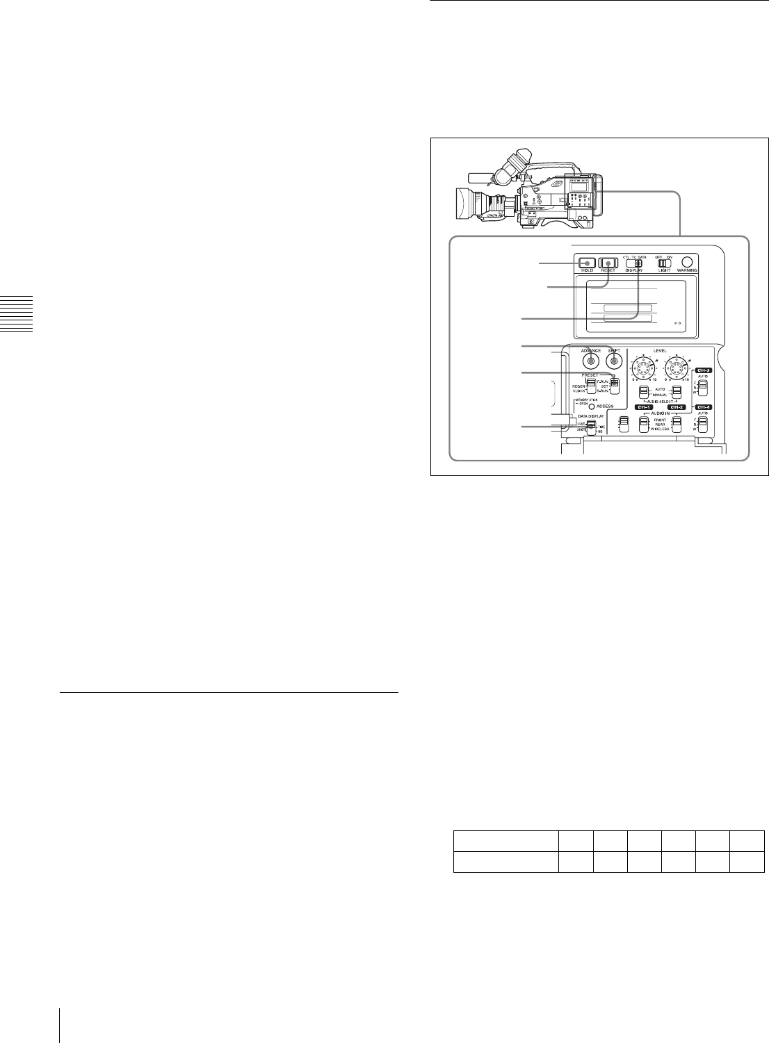
64 Setting the Time Data
Chapter 4 Adjustments and Settings for Recording
To reset the time code value to 00:00:00:00
Press the RESET button.
5
Set the F-RUN/SET/R-RUN switch to F-RUN or R-
RUN.
F-RUN: Free run. The time code generator keeps
running.
R-RUN: Recording run. The time code generator runs
only while recording.
To set the drop frame mode/non-drop frame mode
(only for the DVW-970)
You can select the drop frame (DF) mode or non-drop
frame (NDF) mode on the FUNCTION 1 page of the
USER menu or OPERATION menu or on the TIMECODE
page of the MAINTENANCE menu.
To make the time code consecutive
When the F-RUN/SET/R-RUN switch is set to R-RUN,
recording a number of scenes on the tape normally
produces consecutive time code. However, once you
remove the tape and record on another tape, the time code
will no longer be contiguous when you use again the
original tape for recording. In this case, to make the time
code consecutive, proceed as follows:
1
Set the PRESET/REGEN/CLOCK switch to REGEN.
2
Use the PLAY buttons to play back.
3
Watching the playback, find the point of the previous
recording on the tape from which you wish to continue
recording, and press the STOP button.
4
Press the RET button on the lens.
This reads the previous recording and synchronizes the
internal time code generator, thus allowing the new
time code recorded to follow on consecutively.
4-5-2 Saving the Actual Time in the
Time Code
Setting the PRESET/REGEN/CLOCK switch to CLOCK
saves the actual time in the time code.
When it is necessary to set the actual time, use the TIME/
DATE page of the DIAGNOSIS menu.
For details, see “5-3-6 Setting the Date/Time of the
Internal Clock” on page 89.
4-5-3 Setting the User Bits
By setting the user bits (up to 8 hexadecimal digits), you
can record user information such as the date, time, or scene
number on the time code track.
To set the user bits, proceed as follows:
Setting the user bits
1
Set the DISPLAY switch to DATA.
2
Set the F-RUN/SET/R-RUN switch to SET.
3
Set the DATA DISPLAY switch to U-BIT.
4
Set the user bits by using the SHIFT and ADVANCE
buttons.
SHIFT: Selects a digit to set. Each time you press the
button, the flashing digit moves one column to the
right. Pressing this button while holding down the
HOLD button moves the flashing digit one to the
left.
ADVANCE: Increments the value of the flashing
digit. Pressing this button while holding down the
HOLD button decrements the flashing digit.
Hexadecimal digits A to F are displayed as follows:
To reset the user bit data to 00:00:00:00
Press the RESET button.
Hexadecimal A B C D E F
Display AbCdEF
1
4
2,5
3
CUE IN
CH-1
MIX
CH-2
RESET button
HOLD button
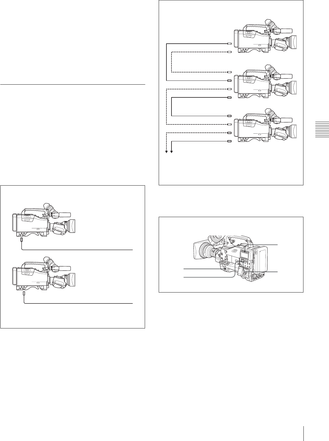
65
Setting the Time Data
Chapter 4 Adjustments and Settings for Recording
5
Set the F-RUN/SET/R-RUN switch to F-RUN or R-
RUN, corresponding to the desired operating mode for
the time code generator.
The set user bit data will be recorded for both LTC and
VITC.
To store the user bit setting in memory
The user bit setting (apart from the real time) is
automatically retained in memory even when the power is
turned off.
4-5-4 Synchronizing the Time Code
You can synchronize the internal time code generator of
this camcorder with an external generator for the
regeneration of an external time code. You can also
synchronize the time code generators of other camcorders/
VTRs with the internal generator of this camcorder.
Connections for time code
synchronization
Connect both the reference video signal and the external
time code as illustrated below.
Procedure for time code synchronization
To synchronize the time code, proceed as follows:
Synchronizing the time code
1
Turn on the POWER switch.
2
Set the PRESET/REGEN/CLOCK switch to PRESET.
3
Set the F-RUN/SET/R-RUN switch to F-RUN.
4
Set the DISPLAY switch to TC.
5
Supply a time code signal and a reference video signal
complying with the SMPTE (for the DVW-970) or
EBU (for the DVW-970P) standard and in proper
phase relationship, to the TC IN connector and to the
GENLOCK IN connector, respectively.
Example 1: Synchronizing with an external time code
1) Set GENLOCK to ON on the GENLOCK page of the
MAINTENANCE menu, if GENLOCK is set to OFF.
GENLOCK IN 1) Reference video signal
TC IN External time code
Example 2: Interconnecting a number of camcorders
for time code synchronization
1) Set GENLOCK to ON on the GENLOCK page of the
MAINTENANCE menu, if GENLOCK is set to OFF.
TEST OUT
To another camcorder to be synchronized
TC OUT
Reference camcorder
TC IN
GENLOCK IN 1)
TC OUT
TEST OUT
GENLOCK IN 1)
TC IN
TC OUT
TEST OUT
1
2
4
3

66 Setting the Time Data
Chapter 4 Adjustments and Settings for Recording
This operation synchronizes the internal time code
generator with the external time code. After about 10
seconds, you can disconnect the external time code
without losing the synchronization. However, there
will be noise on the recorded image if you connect or
disconnect the time code signal during recording.
• When you finish the above procedure, the internal time
code is immediately synchronized with the external time
code and the counter display will show the value of the
external time code. However, wait for a few seconds
until the sync generator stabilizes before recording.
• If the frequency of the reference video signal is not the
same as the frame frequency of the camcorder, the
camera cannot be correctly genlocked. In such a case, the
internal time code is not correctly synchronized with the
external time code.
• When the GENLOCK ON/OFF item is set to “OFF” on
the GENLOCK page of the MAINTENANCE menu, the
time code cannot be synchronized with the reference
video signal. In this case, set the GENLOCK item to
“ON” on the GENLOCK page of the MAINTENANCE
menu.
User bit settings during time code
synchronization
When the time code is synchronized, only the time data is
synchronized with the external time code value. Therefore,
the user bits can have their own settings for each
camcorder.
To synchronize the user bits with external user bit data, set
the EXT-LK UBIT item on the TIME CODE page of the
MAINTENANCE menu to “EXT.”
To release the time code synchronization
First disconnect the external time code, then set the F-
RUN/SET/R-RUN switch to R-RUN.
To change the power supply from the battery
pack to an external power supply during time
code synchronization
To maintain a continuous power supply, connect the
external power supply to the DC IN connector before
removing the battery pack. You may lose time code
synchronization if you remove the battery pack first.
Camera synchronization during time code
synchronization
During time code synchronization, the camera is
genlocked to the reference video signal input from the
GENLOCK IN connector.
Notes
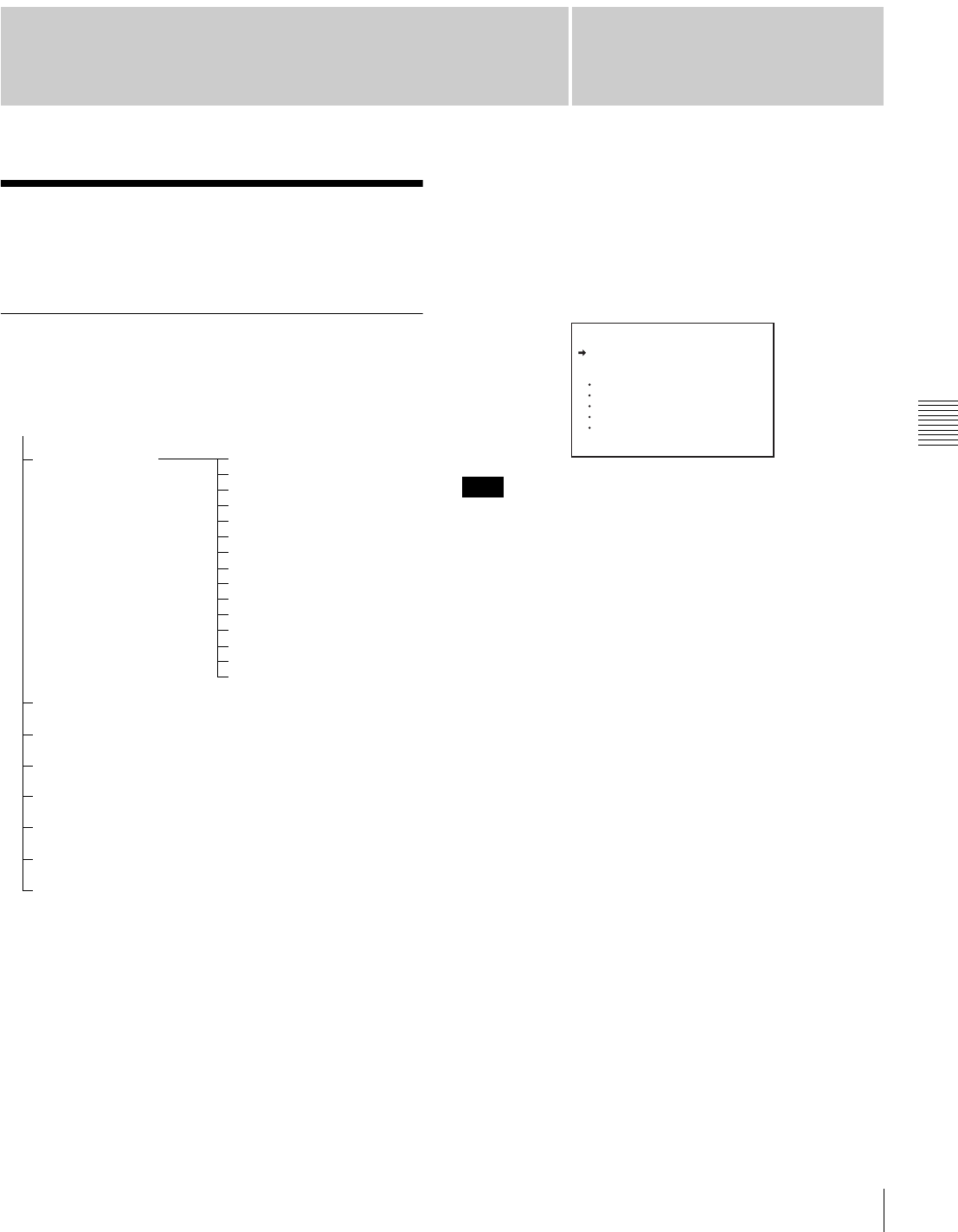
67
Chapter 5 Menu Displays and Detailed Settings
Chapter
Menu Organization and Operation
5
Menu Displays and
Detailed Settings
5-1 Menu Organization
and Operation
5-1-1 Menu Organization
The following shows the organization of menus that you
can use to make various settings and adjustments.
1) In this manual, the USER menu consisting of items and pages registered at
the factory is used. You use the USER MENU CUSTOMIZE menu to add
or delete pages according to how the camcorder is being used.
2) This menu appears only when the CBK-SD01 is installed.
For details, see “5-1-3 Editing the USER Menu” on page
70.
TOP menu
The menus of the camcorder are composed of submenus
classified into categories according to the frequency of use,
purpose of use and so on. The TOP menu allows you to
select the desired submenus.
To display the TOP menu screen
While holding down the MENU knob, set the MENU ON/
OFF switch from the OFF position to the ON position.
Depending on the internal switch settings, display of the
TOP menu may be disabled.
For details, ask your Sony service representative.
Submenus selected in the TOP menu
These are the following menus.
• USER menu
This menu includes monitor output settings, viewfinder
settings, and commonly used functions. This menu is
normally displayed when the MENU ON/OFF switch is
changed to ON.
• USER MENU CUSTOMIZE menu
This menu allows you to add pages to or delete pages from
the USER menu to suit your needs.
• ALL menu
This menu contains all items of the OPERATION menu,
PAINT menu, MAINTENANCE menu, FILE menu and
DIAGNOSIS menu.
• OPERATION menu
This menu contains items for changing settings according
to conditions related to the subject when the camcorder is
being operated.
TOP menu
USER submenu 1) OUTPUT page 2)
TEST OUT page
FUNCTION 1 page
VF DISP 1 page
VF DISP 2 page
! LED page
MARKER 1 page
GAIN SW page
VF SETTING page
AUTO IRIS page
SHOT ID page
SHOT DISP page
SET STATUS page
LENS FILE page
USER FILE page
USER MENU CUSTOMIZE submenu
ALL submenu
• OPERATION submenu
• PAINT submenu
• MAINTENANCE submenu
• FILE submenu
• DIAGNOSIS submenu
Just as with the USER
submenu, each submenu
is composed of pages. On
these pages you can
make various settings
and adjustments. Some
pages have a window for
more settings. This
manual refers to these
submenus as the menu.
Note
<TOP MENU>
USER
USER MENU CUSTOMIZE
ALL
OPERATION
PAINT
MAINTENANCE
FILE
DIAGNOSIS
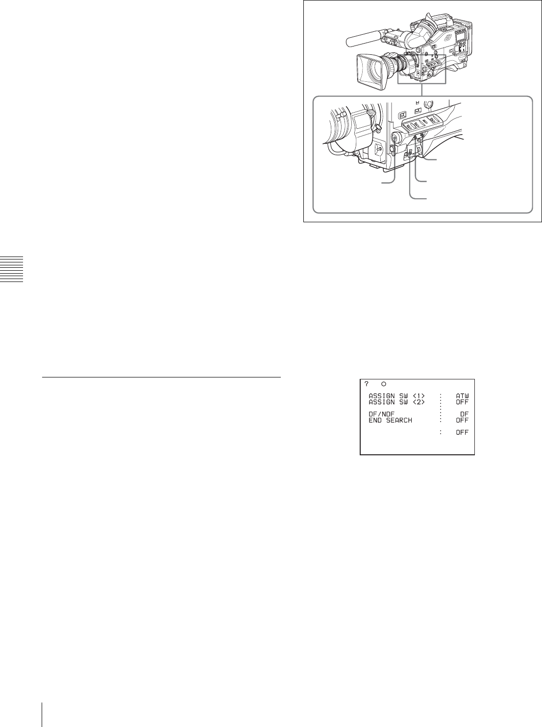
68 Menu Organization and Operation
Chapter 5 Menu Displays and Detailed Settings
• PAINT menu
This menu contains items for making detailed image
adjustments while using a waveform monitor to monitor
the waveforms output by the camera. Support of a video
engineer is usually required to use this menu. Although
you can also use an external remote control panel or master
setup unit to set the items on this menu, this menu is
effective when using the camcorder by itself outdoors.
• MAINTENANCE menu
This menu contains items for performing camera
maintenance operations, such as changing the system or
using infrequently used “paint” items.
• FILE menu
This menu is for performing file operations, such as
writing the reference file.
• DIAGNOSIS menu
This menu enables you to confirm the VTR status or
identify a failed circuit board.
Returning to the TOP menu from other
menus
There are two methods.
• Align the b mark with “TOP” at the top right of the
menu page, and press the MENU knob.
• Push the CANCEL/PRST / ESCAPE switch down to the
ESCAPE position repeatedly until the TOP menu
appears.
5-1-2 Basic Menu Operations
When you open the cover of the menu operating section,
the MENU ON/OFF switch appears. If the MENU ON/
OFF switch is set to ON, the menu is displayed on the
viewfinder screen. Closing the cover automatically sets the
MENU ON/OFF switch to OFF.
Controls used for the basic use of the menu operations
This section explains operations on the USER menu. But
the operations are the same as those on menus other than
the USER menu. Also, if the optional extension boards are
not installed in your camcorder, some items on the USER
menu pages are not displayed.
Proceed as follows:
1
Switch the MENU ON/OFF switch from OFF to ON.
A USER menu page normally appears.
(For the DVW-970P, the DF/NDF item is not included.)
If the USER menu has been used before, the last
accessed page appears. In this case, go to step 2.
If this is the first time the USER menu has been
displayed, the CONTENTS page of the USER menu
appears. In this case, follow the procedure below.
1Turn the MENU knob to move the b mark to the
desired page number.
CANCEL/PRST/
ESCAPE switch
MENU ON/OFF switch
MENU knob
Cover of the menu
operating section
U03 FUNCTION1
CACHE/INTVAL REC
TURBO SW TURBO
Example:
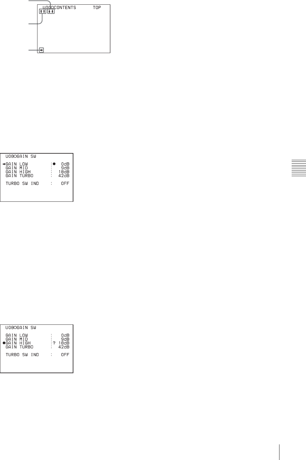
69
Menu Organization and Operation
Chapter 5 Menu Displays and Detailed Settings
2Press the MENU knob.
The selected page is displayed.
Go to step 4.
2
Turn the MENU knob until the desired page appears.
3
Press the MENU knob.
A b mark appears on the left of the item currently
selected on the page.
4
Turn the move MENU knob to move the b mark to the
desired item.
• Turning the MENU knob counterclockwise as seen
from the front of the camera moves the b mark up
continuously.
• Turning the MENU knob clockwise as seen from the
front of the camera moves the b mark down
continuously.
5
Press the MENU knob.
The b mark on the left of the selected item changes to
a z mark, and the z mark on the left of the setting
changes to a ? mark.
6
Turn the MENU knob to change the setting.
To increase a setting value
Turn the MENU knob counterclockwise as seen from
the front of the camera.
To decrease a setting value
Turn the MENU knob clockwise as seen from the front
of the camera.
As turning the MENU knob, the setting increases or
decreases one step by one step.
If you turn the knob quickly, the numeric value
changes rapidly. If you turn it slowly, you can make
minute adjustments.
To toggle a setting on or off
Turn the MENU knob clockwise or counterclockwise.
Each turning operation of the knob toggles the ON and
OFF settings.
To cancel the setting/to reset the setting to the initial
setting
You can cancel the setting and reset it to its initial value
(one set at the factory, or preset value) by pushing the
CANCEL/PRST / ESCAPE switch to CANCEL/
PRST before pushing the MENU knob in step 7.
When the CANCEL/PRST / ESCAPE switch is set to
CANCEL/PRST, the message CANCEL? appears. To
cancel the previous setting, push the CANCEL/PRST/
ESCAPE switch to CANCEL/PRST again.
To reset the setting to the initial value, push the
CANCEL/PRST/ESCAPE switch to CANCEL/PRST
a third time. The message PRESET? appears. To reset
to the initial setting, push the CANCEL/PRST/
ESCAPE switch to CANCEL/PRST once more.
The action of the CANCEL/PRST function differs for
some setting items. Some items are only affected by
PRST. Check the setting procedure for each item for
more information.
To interrupt changing the settings
By setting the MENU ON/OFF switch to OFF, the
menu disappears from the screen. By setting the
MENU ON/OFF switch to ON again, the values that
were displayed when you interrupted the setting
operations will reappear so you can continue making
settings.
7
Press the MENU knob.
The z mark returns to a b mark, and the ? mark
returns to a z mark. The setting is confirmed.
8
To continue setting other items in the same page,
repeat steps from 4 to 7.
To move to another page
Proceed as follows:
1
Turn the MENU knob to move the b mark to the page
number, then press the MENU knob.
If the b mark is placed at a position other than the page
01.OUTPUT
02.TEST OUT
03.FUNCTION1
04.VF DISP 1
05.VF DISP 2
06.`!'LED
07.MARKER
08.GAIN SW
09.VF SETTING
10.AUTO IRIS
This indicates that the
menu screen can be
scrolled downwards.
b mark
This indicates that the
menu screen can be
scrolled upwards.

70 Menu Organization and Operation
Chapter 5 Menu Displays and Detailed Settings
number, push the CANCEL/PRST / ESCAPE switch
to ESCAPE.
A ? mark appears in front of the page number. The
camcorder is now in page selecting mode.
2
Turn the MENU knob until the desired page appears.
3
Press the MENU knob when the desired page appears.
To end menu operations
You can end menu operations using the following two
methods:
• Turn the MENU ON/OFF switch to OFF.
• Close the cover of the menu operating section. When you
close the cover, the MENU ON/OFF switch is set to OFF
automatically.
The menu disappears from the viewfinder screen, and the
display indicating the current status of the camcorder
appears along the top and bottom of the screen (when the
viewfinder DISPLAY switch is set to ON or the VF DISP
item on the VF DISP 1 page of the USER menu is set to
“ON”).
For details of the viewfinder display, see “5-2-2 Selecting
the Display Items” on page 76.
5-1-3 Editing the USER Menu
The USER MENU CUSTOMIZE menu allows you to
configure a USER menu that consists only of pages and
items that you need by adding, deleting or replacing the
pages.
Adding a new page
The USER MENU CUSTOMIZE menu allows you to add
a new page to the USER menu.
While the EDIT page contains factory-preset items, the
USER 1 EDIT to USER 19 EDIT pages and the ASSIGN
SEL EDIT page are all blank in their initial state. You can
register up to 10 items, including blank lines, on each of
these pages.
To add a new page, proceed as follows:
1
While holding down the MENU knob, move the
MENU ON/OFF switch from the OFF position to the
ON position.
The TOP menu appears.
2
Turn the MENU knob to move the b mark to “USER
MENU CUSTOMIZE,” then press the MENU knob.
If this is the first time the USER MENU CUSTOMIZE
menu has been displayed, the CONTENTS page of the
menu appears.
If the USER MENU CUSTOMIZE menu has been
used before, the last accessed page appears.
3
If the CONTENTS page is displayed, turn the MENU
knob to move the b mark to one of USER 1 EDIT to
USER 19 EDIT and ASSIGN SEL EDIT, then press
the MENU knob to display the page.
If a different page is displayed, turn the MENU knob
until the desired page appears, then press the MENU
knob to select the page.
Example: When you select the USER 2 EDIT page
4
Move the b mark to the item to be added (this
operation is unnecessary, if no item exists on the page
as shown in the figure for step 3), then press the
MENU knob.
The EDIT FUNCTION display appears.
5
Move the b mark to “INSERT,” and press the MENU
knob.
The page for the last added item appears.
6
Add the items.
E00 CONTENTS
01.EDIT PAGE
02.USER 1 EDIT
03.USER 2 EDIT
04.USER 3 EDIT
05.USER 4 EDIT
06.USER 5 EDIT
07.USER 6 EDIT
08.USER 7 EDIT
09.USER 8 EDIT
10.USER 9 EDIT
TOP
E02 USER 2 EDIT TOP
EDIT FUNCTION
INSERT
MOVE
DELETE
BLANK
ESC
P25 BLACK/FLARE
MASTER BLACK : 0
R BLACK : 0
B BLACK : 0
MASTER FLARE : 0
R FLARE : 0
G FLARE : 0
B FLARE : 0
FLARE : ON
TEST OUT SELECT : ENC
ESC

71
Menu Organization and Operation
Chapter 5 Menu Displays and Detailed Settings
1Turn the MENU knob until the page that has the
desired items appears, then press the MENU knob.
2Turn the MENU knob to move the b mark to the
desired item, then press the MENU knob.
The USER 2 EDIT page appears again, displaying the
newly added item.
7
Add the remaining items by repeating steps 4 to 6.
You can add up to 10 items on one page.
To delete items from a page by using the
CANCEL/PRST / ESCAPE switch
You can delete items from any of the USER 1 EDIT to
USER 19 EDIT pages.
Proceed as follows:
1
Turn the MENU knob to move the b mark to the item
to be deleted.
2
Push the CANCEL/PRST / ESCAPE switch to
CANCEL/PRST.
The message “PRESET DATA OK?” appears.
3
Push the CANCEL/PRST / ESCAPE switch to
CANCEL/PRST again.
The item is deleted.
To delete items from a page by using the menu
Proceed as follows:
1
Move the b mark to the item to be deleted, and press
the MENU knob.
The EDIT FUNCTION page appears.
2
Select “DELETE,” and press the MENU knob.
The previously displayed page appears again, and the
message “DELETE OK? YES b NO” appears at the
upper right.
3
To delete, turn the MENU knob to move the b mark to
“YES,” and press the MENU knob.
To change the order of the items on a page
Proceed as follows:
1
Turn the MENU knob to move the b mark to the item
to be replaced, then press the MENU knob.
The EDIT FUNCTION page appears.
2
Select MOVE, then press the MENU knob.
The previously displayed page appears again.
3
Turn the MENU knob to move the b mark to the
position where you want to move the item, then press
the MENU knob.
The item selected in step 1 moves to the position that
you selected in step 3.
In the above example, “MASTER BLACK” is moved
to the top and the other items are moved down one line.
To insert a blank line
You can insert a blank line above the selected item.
Proceed as follows:
1
Turn the MENU knob to move the b mark to the item
above which you want to insert a blank line.
The EDIT FUNCTION page appears.
2
Select “BLANK,” and press the MENU knob.
The previously displayed page appears again, and a
blank line is inserted above the specified item.
You cannot insert a blank line on a page where 10 items
have already been registered.
Adding/deleting/replacing pages
You can add a new page to the USER menu, delete a page
from the USER menu or replace pages, using the EDIT
PAGE of the USER MENU CUSTOMIZE menu.
To add a page
Proceed as follows:
1
While holding down the MENU knob, move the
MENU ON/OFF switch from the OFF position to the
ON position.
The TOP menu appears.
2
Turn the MENU knob to move the b mark to “USER
MENU CUSTOMIZE,” then press the MENU knob.
If this is the first time the USER MENU CUSTOMIZE
menu has been displayed, the CONTENTS page of the
menu appears. If the menu has been used before, the
last accessed page appears.
Note
E02 USER 1 EDIT
WHITE<B>CH : AWB
TEST OUT MENU : OFF
OFFSET WHITE <A>: OFF
WARM COOL <A>: 3200
COLOR FINE <A>: 0
MASTER BLACK : 0
TOP
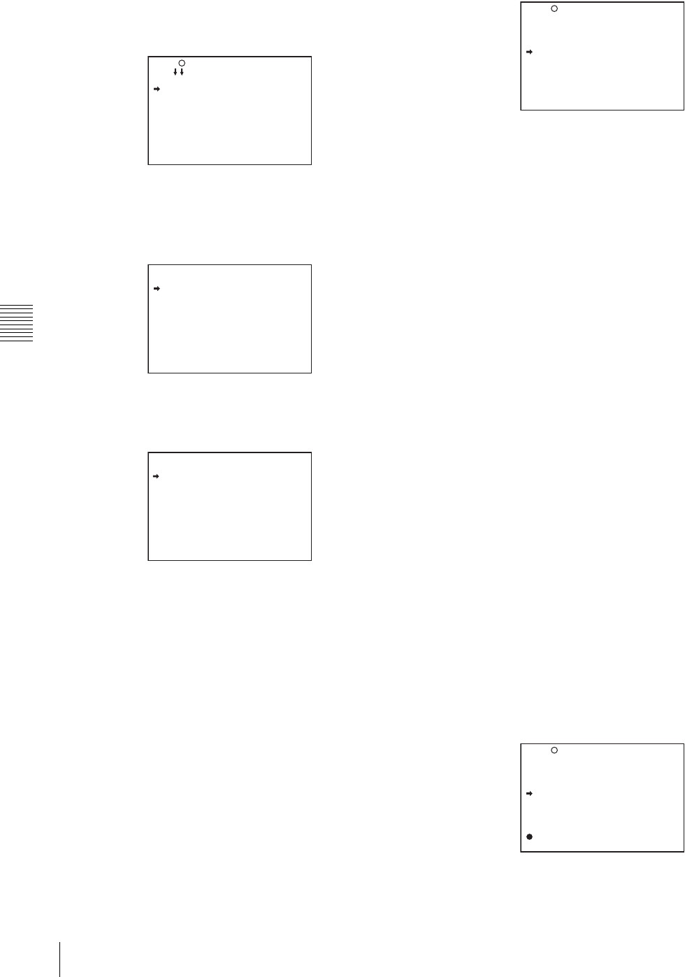
72 Menu Organization and Operation
Chapter 5 Menu Displays and Detailed Settings
3
If the CONTENTS page is displayed, turn the MENU
knob to move the b mark to “EDIT PAGE,” then press
the MENU knob to display the EDIT PAGE screen.
If a different page is displayed, turn the MENU knob
until the EDIT PAGE screen appears, then press the
MENU knob to select the page.
EDIT PAGE
4
Turn the MENU knob to move the b mark to where
you want to add the page, then press the MENU knob.
The EDIT FUNCTION display appears.
5
Select INSERT, and press the MENU knob.
The selection screen appears.
6
Turn the MENU knob to move the b mark to the
desired page, then press the MENU knob.
This adds the number and name of the selected page
above the item selected in step 4.
To cancel adding a page
Before pressing the MENU knob in step 6, turn the MENU
knob to move the b mark to “ESC” at the top right of the
screen, then press the MENU knob.
The EDIT PAGE screen appears again.
To delete a page by using the CANCEL/PRST /
ESCAPE switch
Proceed as follows:
1
Open the EDIT PAGE and turn the MENU knob to
move the b mark to the page to be deleted.
2
Push the CANCEL/PRST / ESCAPE switch to
CANCEL/PRST.
The message “DELETE PAGE OK?” appears.
3
Push the CANCEL/PRST / ESCAPE switch to
CANCEL/PRST again.
In the above example, the VF DISP 1 page is deleted.
To delete a page by using the menu
Proceed as follows:
1
On the EDIT PAGE screen of the USER MENU
CUSTOMIZE menu, move the b mark to the page to
be deleted, and press the MENU knob.
The EDIT FUNCTION page appears.
2
Select DELETE, and press the MENU knob.
The previously displayed page appears again, and the
message “DELETE OK?” appears at the upper right.
3
To delete, turn the menu knob to move the b mark to
“YES,” and press the MENU knob.
To change the order of pages
Proceed as follows:
1
Display the EDIT PAGE screen of the USER MENU
CUSTOMIZE menu. Turn the MENU knob to move
the b mark to the page that you want to move.
The EDIT FUNCTION page appears.
2
Select MOVE, then press the MENU knob.
The EDIT PAGE screen appears again.
3
Turn MENU knob to move the b mark to the position
to where you want to move the page selected in step 1.
4
Press the MENU knob.
E01 EDIT PAGE
01.OUTPUT
02.TEST OUT
03.FUNCTION 1
04.VF DISP 1
05.VF DISP 2
06.'!'LED
07.MARKER 1
08.GAIN SW
09.VF SETTING
10.AUTO IRIS
TOP
EDIT FUNCTION
INSERT
MOVE
DELETE
BLANK
ESC
CONTENTS
01.USER PAGE 1
02.USER PAGE 2
03.USER PAGE 3
04.USER PAGE 4
05.USER PAGE 5
06.USER PAGE 6
07.USER PAGE 7
08.USER PAGE 8
09.USER PAGE 9
ESC
E01 EDIT PAGE
DELETE PAGE OK ?
01.OUTPUT
02.TEST OUT
03.FUNCTION 1
04.VF DISP 1
05.VF DISP 2
06.'!'LED
07.MARKER 1
08.GAIN SW
09.VF SETTING
10.AUTO IRIS
E01 EDIT PAGE
PUSH TO PAGE INSERT
01.OUTPUT
02.TEST OUT
03.FUNCTION 1
04.VF DISP 1
05.'!'LED
06.MARKER 1
07.GAIN SW
08.VF SETTING
09.AUTO IRIS

73
Menu Organization and Operation
Chapter 5 Menu Displays and Detailed Settings
The page selected in step 1 is moved to the position
selected in step 3.
In the above example, “AUTO IRIS” moves to the “04”
position and the “VF DISP 1” and following items
move down one line.
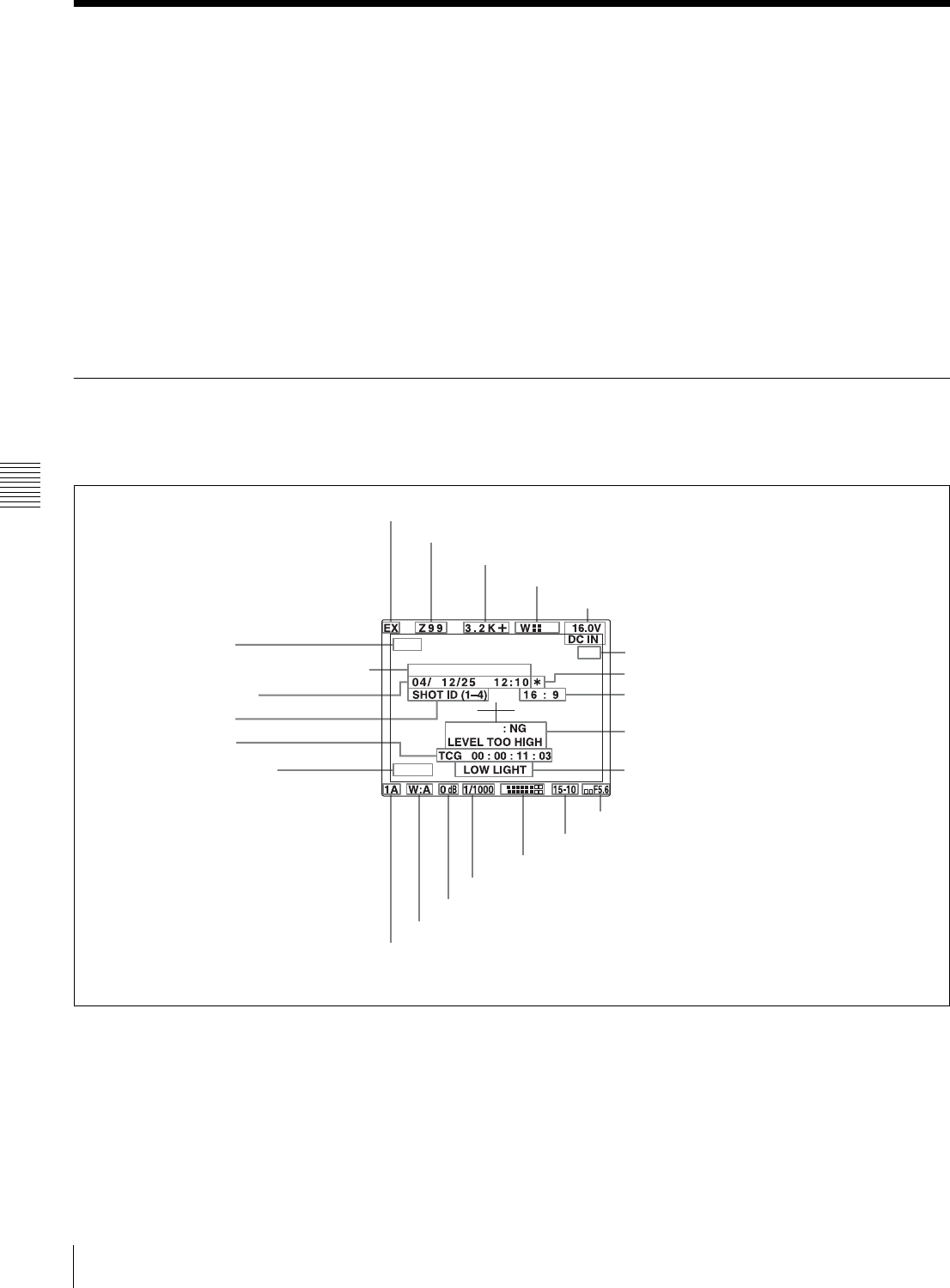
74 Status Display on the Viewfinder Screen
Chapter 5 Menu Displays and Detailed Settings
5-2 Status Display on the Viewfinder Screen
The viewfinder screen displays not only the video picture
but also characters and messages indicating the camcorder
settings and operating status, a center marker, a safety zone
marker, etc.
When the MENU ON/OFF switch is set to OFF and the
DISPLAY switch is set to ON, the items for which an
“ON” setting was made in the VF DISP1 page of the USER
menu or with related switches are displayed at the top and
bottom of the screen. The messages that give details of the
settings and adjustment progress and results can also be
made to appear for about 3 seconds while settings are
being changed, during adjustment, and after adjustment.
For information about the display item selection, see “5-2-
2 Selecting the Display Items” on page 76.
For information about setting change and adjustment
progress messages, see “5-2-3 Display Modes and Setting
Change Confirmation/Adjustment Progress Messages” on
page 77.
For information about marker display, see “5-2-4 Setting
the Marker Display” on page 78.
5-2-1 Layout of the Status Display on the Viewfinder Screen
All items that can be displayed on the viewfinder screen
are shown below.
Status display on the viewfinder
aExtender
“EX” is displayed when a lens extender is used.
bZoom position
This indicator appears only when you use a lens that has a
zoom position display function. It indicates the
approximate position of the variator 1) of the zoom lens,
between wide angle and telephoto.
1) Variator
A group of lenses that are moved to adjust the focal length.
DVW-970
D5600
EM
16:9
1
2
AWB
7, 8, w;, wa and ws appear only when color bars are displayed.
aExtender
bZoom position
cColor temperature
dUHF wireless microphone reception level
eDC IN / battery voltage or remaining capacity
g* indicator
h16:9 mode recording indicator
iSetting change and adjustment progress
message display area
jOperation/error message display area
kIris setting/auto iris override
lRemaining tape
mAudio level
nShutter speed
oGain
pWhite balance memory
qFilter
rD5600 indication
sTime code
tID number
uDate and time
vModel name and serial number
w16:9 mode fEssence mark indication

75
Status Display on the Viewfinder Screen
Chapter 5 Menu Displays and Detailed Settings
cColor temperature
This indicates the currently selected color temperature.
dUHF wireless microphone reception level
This indicates reception level of the wireless microphone
when the UHF wireless microphone is attached, using four
x which appear at the right of “W.” When four x are lit,
the receiving condition is good.
eDC IN / battery voltage or remaining capacity
This shows the battery voltage or remaining capacity of an
internal battery pack.
When the power is supplied from an AC adaptor connected
to the DC IN connector, “DC IN” appears.
When the DISP BATT REMAIN item is set to “INT” on
the VF DISP 2 page of the USER menu, the battery voltage
is not indicated. However, when the Anton Bauer
intelligent battery system or the BP-GL65/GL95/L60S
battery pack is used, the remaining battery capacity is
automatically detected and indicated as a percentage even
when the DISP BATT REMAIN item is set to “OFF.” The
indicated value changes in steps of 10%.
• Until the remaining battery capacity is reduced to 40%,
the indications MAX, 90%, 80%...40% are displayed for
3 seconds in the viewfinder each time the remaining
battery capacity reduces by 10%.
• When the remaining battery capacity is less than 40%,
the indication is displayed all the time.
• When the remaining battery capacity is less than 10%1),
the indication flashes. When the remaining battery
capacity is reduced further, the LOW indication flashes.
1) This value can be set to either 10% or 20% on the FUNCTION 2 page of
the OPERATION menu.
fEssence mark indication
This appears when an essence mark has been recorded.
g* indicator
This flashes when the color bars are displayed and is
recorded together with the color bars.
h16:9 mode recording indicator
This indicates recording in the 16:9 mode. This indicator is
recorded together with the color bars.
iSetting change and adjustment progress message
display area
For details, see “5-2-3 Display Modes and Setting Change
Confirmation/Adjustment Progress Messages” on page 77.
jOperation/error message display area
For details, see “Operation/error messages” on page 127.
kIris setting/auto iris override
This indicates the f-stop (iris setting) of the lens.
Also, the auto iris override is displayed using bars which
appear in the upper and lower parts to the left of the F
number respectively.
For details, see “Changing the Reference Value for
Automatic Iris Adjustment” on page 59.
lRemaining tape
This indicator indicates the remaining tape recording time
(in minutes) of the VTR.
mAudio level
These indicate the level of audio channel 1 and channel 2.
The peak indication of the VTR level meter is related as
follows to the audio level when an 1-kHz sine wave is
input.
nShutter speed
This indicates the shutter speed or the shutter mode.
However, if the SHUTTER selector is set to OFF, nothing
is displayed.
1/100 (DVW-970) or 1/60 (DVW-970P), 1/125, 1/250,
1/500, 1/1000, 1/2000: Shutter speed (in seconds) in
standard mode
ECS: ECS mode
EVS: EVS mode
1F to 8F, 16F: Number of frames in SLS mode
oGain
This indicates the gain of the video amplifier, as set by the
GAIN selector.
pWhite balance memory
This indicates the currently selected white balance
automatic adjustment memory.
A: Displayed when the WHITE BAL switch is set to A.
B: Displayed when the WHITE BAL switch is set to B.
Examples of remaining disc recording time indication
Indication Remaining disc recording time
F – 30 Full to 30 minutes
30 – 25 30 to 25 minutes
25 – 20 25 to 20 minutes
20 – 15 20 to 15 minutes
15 – 10 15 to 10 minutes
10 – 5 10 to 5 minutes
5 – 0 5 to 2 minutes
5 – 0 (flashing) 2 to 0 minute
1
2
Audio channel 1
level indicator
Audio channel 2
level indicator
VTR level meter
indicator
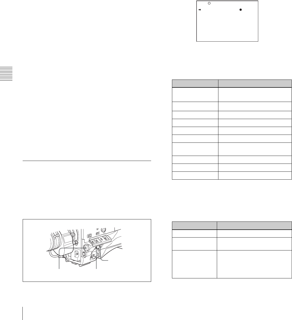
76 Status Display on the Viewfinder Screen
Chapter 5 Menu Displays and Detailed Settings
P: Displayed when the WHITE BAL switch is set to PRST
or when the preset button on the RM-B150/B750 has
been pushed.
T: Displayed when ATW is being used.
qFilter
This indicates the currently selected filter types.
rD5600 indication
This appears when the electric 5600K color temperature
filter function has been activated on the FUNCTION 2
page of the MAINTENANCE menu.
sTime code
This indicates the time code, user bits or other information
selected by the DISPLAY switch and DATA DISPLAY
switch settings.
For more information, see “Relationships between the
DISPLAY switch and DATA DISPLAY switch settings and
the time counter displays” on page 29.
tID number
This indicates the ID number selected from ID 1 to ID 4.
The ID number is recorded together with the color bars.
uDate and time
This indicates the date and time of recording, which are
recorded together with the color bars.
vModel name and serial number
This indicates the model name and serial number of the
camcorder, which are recorded together with the color
bars.
w16:9 mode
This indicates the 16:9 mode.
5-2-2 Selecting the Display Items
To select the items to be displayed on the viewfinder screen
from the VF DISP 1 and VF DISP 2 pages of the USER
menu, turn on or off the indication next to each item.
To select the items to be displayed on the viewfinder
screen, proceed as follows:
1
Set the MENU ON/OFF switch to ON.
The last accessed menu page appears on the
viewfinder screen.
2
Turn the MENU knob until the VF DISP 1 or VF DISP
2 page appears, and press the MENU knob to select the
page.
The current setting is displayed on the right of each
item.
VF DISP 1 page
You can select the following items to be displayed on
the screen on the VF DISP 1 or VF DISP 2 page.
VF DISP 1 page
1) The viewfinder display can be also turned on or off by using the
DISPLAY switch on the viewfinder.
2) For detailed information on the display mode, see “5-2-3 Display
Modes and Setting Change Confirmation/Adjustment Progress
Messages” on page 77.
VF DISP 2 page
CANCEL/PRST /
ESCAPE switch
MENU ON/OFF switchMENU knob
Item Description
VF DISP Turning on or off the viewfinder
display 1)
VF DISP MODE Selecting the display mode 2)
DISP EXTENDER Extender indicator
DISP FILTER Types of the ND and CC filters
DISP WHITE White balance memory indicator
DISP GAIN Gain indicator
DISP SHUTTER Shutter speed and ECS mode
indicator
DISP AUDIO Audio level indicator
DISP TAPE Remaining tape indicator
DISP IRIS Iris opening indicator
Item Description
DISP ZOOM Zoom position indicator
DISP COLOR
TEMP.
Displays the color temperature.
DISP BATT
REMAIN1)
Displays the battery voltage/
remaining capacity of an internal
battery pack or an external battery
connected to the DC IN
connector.
U04 VF DISP 1
VF DISP : ON
VF DISP MODE : 3
DISP EXTENDER : ON
DISP FILTER : ON
DISP WHITE : ON
DISP GAIN : ON
DISP SHUTTER : ON
DISP AUDIO : ON
DISP TAPE : ON
DISP IRIS : ON

77
Status Display on the Viewfinder Screen
Chapter 5 Menu Displays and Detailed Settings
1) When an Anton Bauer Intelligent Battery System or the BP-GL65/
GL95/L60S battery pack is used, the setting of this item determines
the display as follows:
INT: The remaining battery capacity is shown as a percentage when
there is a change, and when the capacity is low.
AUTO: The remaining battery capacity is shown as a percentage,
except that when this is impossible the battery voltage appears.
VOLT: The battery voltage is shown.
3
Turn the MENU knob to move the b mark to the item
you want to set, and press the MENU knob.
The b mark on the left of the selected item changes to
a z mark, and the z mark on the left of the setting
changes to a ? mark.
4
Turn the MENU knob to select whether the selected
item should appear in the viewfinder display (the
“ON” setting), or not appear (the “OFF” setting), and
press the MENU knob.
The z mark returns to a b mark, and the ? mark
returns to a z mark.
Note that pressing the CANCEL/PRST / ESCAPE
switch to CANCEL/PRST on this page has no effect.
5
To set another item to “ON” or “OFF,” repeat steps 3
and 4.
6
To end the menu operation, set the MENU ON/OFF
switch to OFF or close the cover of the menu operating
section.
The menu disappears from the viewfinder screen, and
the display indicating the current status of the
camcorder appears along the top and bottom of the
screen.
5-2-3 Display Modes and Setting
Change Confirmation/Adjustment
Progress Messages
You can limit or suppress the messages that give details of
setting changes and adjustment progress and results by
setting a display mode.
The conditions under which messages are displayed and
their correspondence with the display mode are as follows:
1) This is also displayed for about 3 seconds when the SHUTTER selector is
set to ON.
2) For details, see “4-1 Adjusting the Black Balance and the White Balance”
on page 52.
Changing the display mode
The currently set display mode appears on the VF DISP 1
page of the USER menu. To change it, proceed as follows:
1
Follow steps 1 and 2 in “5-2-2 Selecting the Display
Items” (page 76), until the VF DISP 1 page of the
USER menu appears on the screen.
DISP DC IN Displayed when the power is
supplied from an external battery
connected to the DC IN
connector.
DISP 16:9/4:3 ID Displays the 16:9/4:3 mode
indicator.
DISP WRR RF LVL Displays the reception level of the
wireless microphone.
DISP E. MARK IND Displayed when an essence mark
has been recorded.
DISP TIME CODE Displays the time code.
DISP VIDEO RATE Displays the recording video
signal rate.
Item Description
Setting change confirmation/adjustment progress messages
and display modes
Y: Message is displayed.
N: Message is not displayed.
Message
display
condition
Message Display
mode setting
1 2 3
When the filter
selection has
been changed
ND : n, CC : m
(where n = 1, 2, 3, 4,
m = A, B, C, D)
NNY
When the gain
setting has been
changed
GAIN : n (where n =
–3 dB, 0 dB, 3 dB, 6 dB,
9 dB,12 dB, 18 dB, 24 dB,
30 dB, 36 dB, 42 dB,
48 dB)
NNY
When the
setting of the
WHITE BAL
switch has been
changed
WHITE : n
(where n = A CH, B CH,
PRESET)
or ATW : RUN
NNY
When the
OUTPUT/DCC
selector has
been set to DCC
ON or OFF
DCC : ON (or OFF) N Y Y
When the
shutter speed
and mode
setting has been
changed 1)
SS : 1/100 (DVW-970) or
1/60 (DVW-970P)
(or 1/125, 1/250, 1/500,
1/1000, 1/2000, ECS,
SLS)
NYY
When the black
or white balance
has been
adjusted 2)
E.g. AWB : OK N Y Y
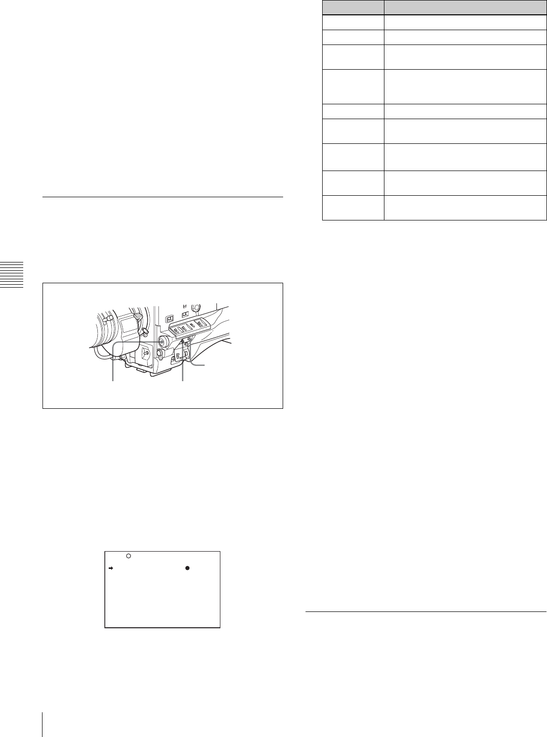
78 Status Display on the Viewfinder Screen
Chapter 5 Menu Displays and Detailed Settings
2
Turn the MENU knob to move the b mark to “VF
DISPLAY MODE,” and press the MENU knob.
The b mark on the left of “VF DISPLAY MODE”
changes to a z mark, and the z mark on the left of the
setting changes to a ? mark.
3
Turn the MENU knob until the desired display mode
appears, and press the MENU knob.
The z mark returns to a b mark, and the ? mark
returns to a z mark.
4
To end the menu operation, set the MENU ON/OFF
switch to OFF or close the cover of the menu operating
section.
5-2-4 Setting the Marker Display
Use the MARKER 1 page of the USER menu to switch the
display of the center and safety zone markers on or off and
to select whether the area indicated by the safety zone
marker is 80%, 90% or 100% of the screen area.
1
Set the MENU ON/OFF switch to ON.
The last accessed menu page appears on the
viewfinder screen.
2
Turn the MENU knob until the MARKER 1 page
appears, and press the MENU knob to select the page.
The current setting of each item appears on the right of
the item.
MARKER 1 page
You can set the following items on the MARKER 1
page.
1) The ASPECT MASK item is for processing the signal to be output to
the viewfinder. When R, G, or B is selected for the TEST OUT
SELECT item from the menu, the same video signal is output to the
viewfinder and the TEST OUT connector. Thus, when the ASPECT
MASK item is set to “ON” with R/G/B selected, the masked video
signal is output to the TEST OUT connector.
3
Perform the settings for each item.
1Turn the MENU knob to move the b mark to the
item you want to set, and press MENU knob.
The b mark on the left of the selected item changes
to the z mark, and the z mark on the left of the
setting changes to a ? mark.
2Turn the MENU knob to change the setting, and
press the MENU knob.
The z mark on the left of the selected item returns
to a b mark, and the ? mark on the left of the setting
returns to a z mark.
4
To continue setting other items, repeat step 3.
5
To end the menu operation, set the MENU ON/OFF
switch to OFF or close the cover of the menu operating
section.
The menu disappears from the viewfinder screen, and
the display indicating the current status of the
camcorder appears along the top and bottom of the
screen.
5-2-5 Setting the Viewfinder
Use the VF SETTING page of the USER menu to select
items related to the viewfinder.
CANCEL/PRST /
ESCAPE switch
MENU knob MENU ON/OFF switch
U07 MARKER 1
MARKER : OFF
CENTER : OFF
SAFETY ZONE : OFF
SAFETY AREA : 90%
ASPECT : OFF
ASPECT SELECT : 4:3
ASPECT MASK : OFF
ASPECT MASK LVL : 1/4
100% MARKER : OFF
TOP
Item Description
MARKER Not to display all markers, set to OFF.
CENTER To display the center marker, set to ON.
SAFETY
ZONE
To display the safety zone, set to ON.
SAFETY
AREA
To select the safety zone range (80%,
90%, 92.5% or 95%), when SAFETY
ZONE is set to ON.
ASPECT To display the aspect marker, set to ON.
ASPECT
SELECT
To select the type (4:3, 13:9, 14:9) of
the aspect marker.
ASPECT
MASK1)
To make the areas out of the selected
aspect marker dimmer, set to ON.
ASPECT
MASK LVL
To set the mask level (1/2, 1/4 or 1/8),
when the ASPECT MASK is set to ON.
100%
MARKER
To display the effective pixel area, set to
ON.
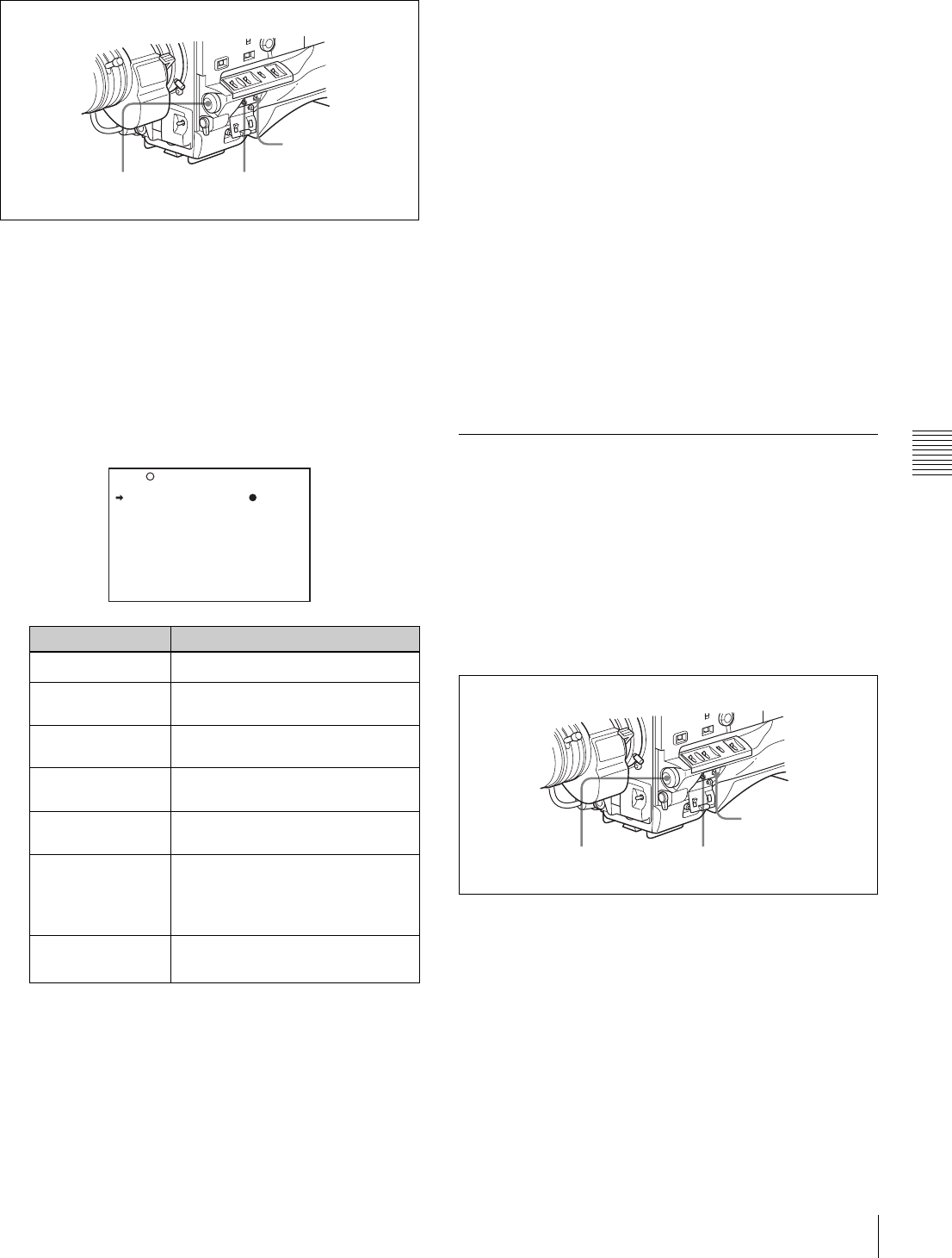
79
Status Display on the Viewfinder Screen
Chapter 5 Menu Displays and Detailed Settings
Proceed as follows:
1
Set the MENU ON/OFF switch to ON.
The last accessed menu page appears on the
viewfinder screen.
2
Turn the MENU knob until the VF SETTING page
appears, and press the MENU knob to select the page
The current setting of each item appears on the right of
the item.
VF SETTING page
1) When you use the viewfinder which is not equipped with the ZEBRA
switch, turns the display on or off using this item. When you use the
viewfinder with the ZEBRA switch, the most recent operation of the
ZEBRA switch and this menu operation is effective.
2) The sharpness setting at the viewfinder does not affect the recorded
image.
3) When the VF ASPECT item is set to “AUTO,” this is linked to the
16:9/4:3 selection on the FORMAT page.
3
Turn the MENU knob to move the b mark to the item
you want to set, and press the MENU knob.
The b mark on the left of the selected item changes to
a z mark, and the z mark on the left of the setting
changes to a ? mark.
4
Turn the MENU knob to change the setting, and press
the MENU knob.
The z mark returns to a b mark, and the ? mark
returns to a z mark.
5
To continue setting other items, repeat steps 3 and 4.
6
To end the menu operation, set the MENU ON/OFF
switch to OFF or close the cover of the menu operating
section.
The menu disappears from the screen, and the display
indicating the current status of the camcorder appears
along the top and bottom of the screen.
5-2-6 Recording Shot Data
Superimposed on the Color Bars
In the SHOT DISP page of the USER menu, you can select
which shot data is recorded superimposed on the color
bars. You can also select which of the shot IDs (1 to 4) set
in the SHOT DATA page is recorded superimposed on the
picture.
Proceed as follows:
1
Set the MENU ON/OFF switch to ON.
The last accessed menu page appears on the
viewfinder screen.
2
Turn the MENU knob until the SHOT DISP page
appears, and press the MENU knob to select the page.
The current setting of each item appears on the right of
the item.
Item Description
ZEBRA Turns the zebra display on or off. 1)
ZEBRA SELECT Selects ZEBRA 1, ZEBRA 2 or
BOTH.
ZEBRA 1 DET. LVL Adjusts the level of the zebra 1
(factory setting: 70%) display.
ZEBRA 1 APT. LVL Adjusts the aperture level of the
zebra 1 display (1 to 10 to 20).
ZEBRA 2 DET. LVL Adjusts the level of the zebra 2
(factory setting: 100%) display.
VF DETAIL LEVEL Adjusts the sharpness of the
viewfinder. 2)
Turns the VF detail function on or
off and adjusts the level.
VF ASPECT Selects the viewfinder aspect ratio
(AUTO/16:9). 3)
CANCEL/PRST /
ESCAPE switch
MENU knob MENU ON/OFF switch
U09 VF SETTING
ZEBRA : OFF
ZEBRA SELECT : 1
ZEBRA1 DET.LEVEL: 70%
ZEBRA1 APT.LEVEL: 10%
ZEBRA2 DET.LEVEL: 100%
VF DETAIL LEVEL : OFF
VF ASPECT : AUTO
CANCEL/PRST/
ESCAPE switch
MENU knob MENU ON/OFF switch
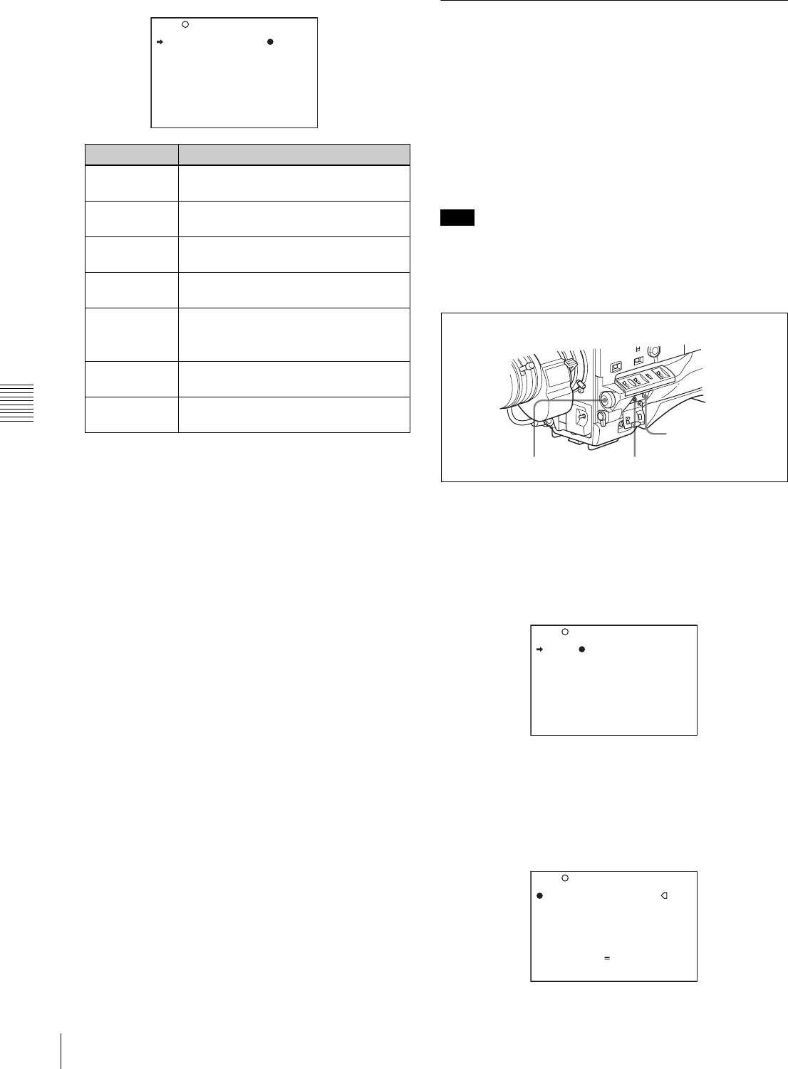
80 Status Display on the Viewfinder Screen
Chapter 5 Menu Displays and Detailed Settings
SHOT DISP page
1) To carry out superimposed recording, select the SHOT ID number (1
to 4). Not to carry out superimposed recording, select “OFF.”
3
Turn the MENU knob to move the b mark to the item
you want to set, and press MENU knob.
The b mark on the left of the selected item changes to
a z mark, and the z mark on the left of the setting
changes to a ? mark.
4
Turn the MENU knob to select whether or not to
record the selected item superimposed on the color
bars, and press the MENU knob.
The z mark on returns to a b mark, and the ? mark
returns to a z mark.
5
To continue setting other items, repeat steps 3 and 4.
6
To end the menu operation, set the MENU ON/OFF
switch to OFF or close the cover of the menu operating
section.
Carrying out superimposed recording
To actually record the items selected for superimposed
recording on the SHOT DISP page, set the OUTPUT/DCC
switch to BARS, DCC OFF.
The items selected for superimposed recording appear on
the screen and are recorded superimposed on the color
bars.
5-2-7 Setting the Shot ID
On the SHOT ID page of the USER menu, you can set a
shot ID of up to 12 alphanumeric characters, spaces, and
symbols.
When the OUTPUT/DCC switch is set to BARS, DCC
OFF, this shot ID is output with the color bar signal. The
shot ID comprises ID1 to ID4, and the setting can be
changed using the SHOT DISP page of the USER menu.
You can select the SHOT ID to be recorded superimposed
on the color bars on the SHOT DISP page.
When the menu is displayed, the shot ID is not displayed
even if the color bar signal is output.
To set the shot ID, proceed as follows:
1
Set the MENU ON/OFF switch to ON.
The last accessed menu page appears on the screen.
2
Turn the MENU knob until the SHOT ID page
appears, and press the MENU knob to select the page.
SHOT ID page
3
Turn the MENU knob to move the b mark to the ID
(one of ID-1 to ID-4) you want to set, and press the
MENU knob.
A x mark appears over the first character position in
the string, and characters can now be input.
Item Description
SHOT DATE Selects whether or not the shot date is
superimposed (ON or OFF).
SHOT TIME Selects whether or not shot time is
superimposed (ON or OFF).
SHOT MODEL
NAME
Selects whether or not the model name
is superimposed (ON or OFF).
SHOT SERIAL
NO
Selects whether or not the serial
number is superimposed (ON or OFF).
SHOT ID SEL Selects whether or not the shot ID set
on the SHOT ID 1) page is
superimposed (1 to 4 or OFF).
SHOT 16:9 ID Selects whether or not the 16:9 mode
indicator is superimposed (ON or OFF).
SHOT BLINK
CHARA
Selects whether or not the blinking * is
superimposed (ON or OFF).
SHOT DATE : OFF
SHOT TIME : OFF
SHOT MODEL NAME : OFF
SHOT SERIAL NO : OFF
SHOT ID SEL : OFF
SHOT 16:9 ID : OFF
SHOT BLINK CHARA: OFF
U12 SHOT DISP
Note
CANCEL/PRST /
ESCAPE switch
MENU knob MENU ON/OFF switch
U11 SHOT ID
ID-1 :
ssssssssssss
ID-2 :
ssssssssssss
ID-3 :
ssssssssssss
ID-4 :
ssssssssssss
TOP
ID-1 :?
x
ID-2 :
ssssssssssss
ID-3 :
ssssssssssss
ID-4 :
ssssssssssss
!#$%&'()*+,-./012345678
9:;<=>?@ABCDEFGHIJKLMNOP
QRSTUVWXYZ[Y]abcdefghijk
lmnopqrstuvwxyz~
INS DEL RET ESC END
U11 SHOT ID TOP
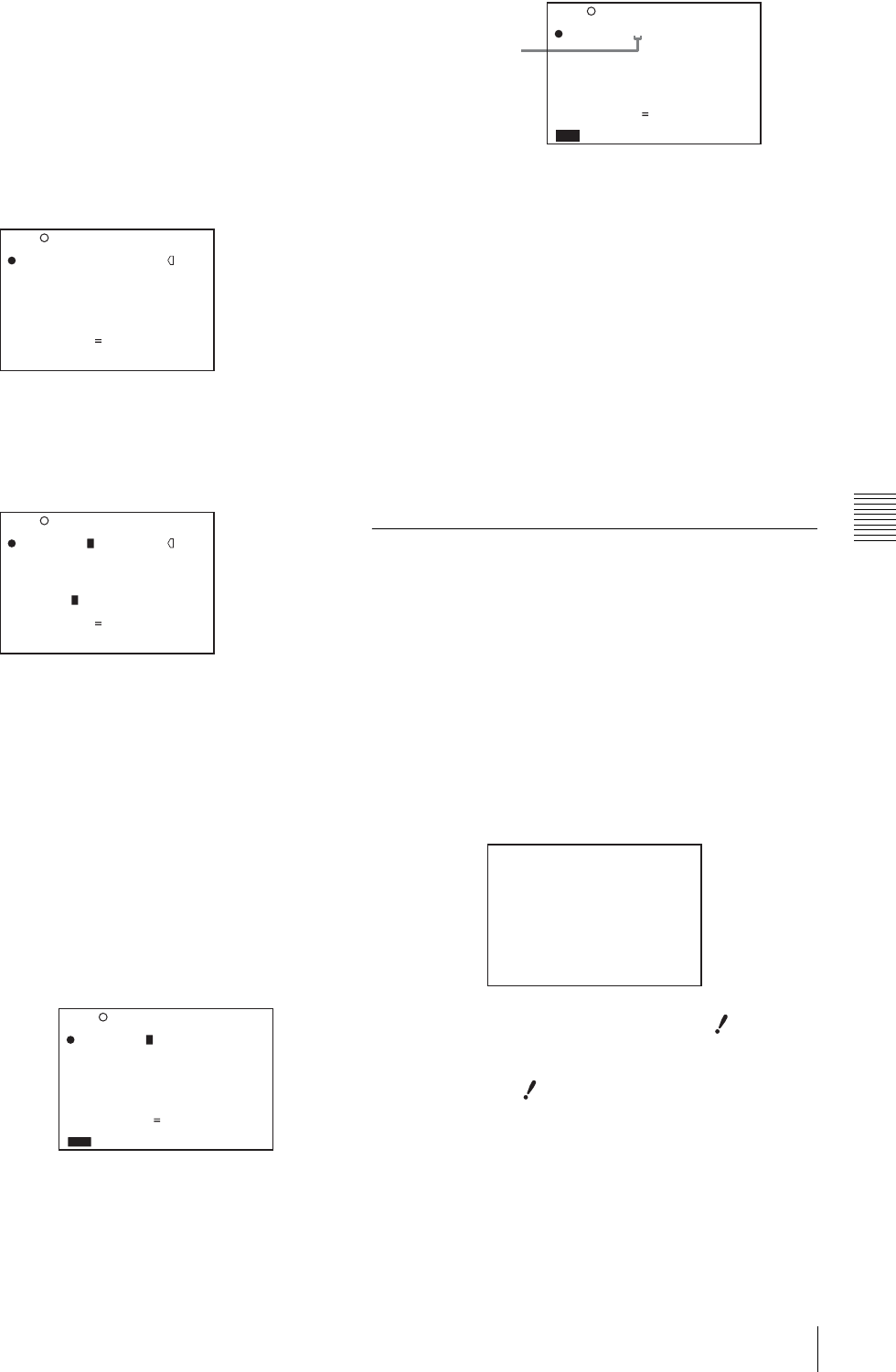
81
Status Display on the Viewfinder Screen
Chapter 5 Menu Displays and Detailed Settings
4
Enter or change the shot ID.
When you are entering the whole shot ID, go to step
2.
1Turn the MENU knob to move the x mark to the
character which you want to change, then press the
MENU knob.
A character table appears.
2Turn the MENU knob until the x mark moves to
the character position that you want to select, then
press the MENU knob.
5
Repeat step 4 for each of the remaining characters.
6
When the input is complete, turn the MENU knob to
move the x mark over “END,” then press the MENU
knob.
This ends the input, and returns to the original SHOT
ID page.
To insert a space
Proceed as follows:
1
In step 4 above, move the x mark over “INS,” and
press the MENU knob.
2
Move the x mark over “RET,” then press the MENU
knob.
To delete a character
In step 4 of the procedure for setting the shot ID, move the
x mark over “DEL,” and press the MENU knob.
This deletes the character under the x mark in the shot ID
row.
To cancel deleting the character, move the x mark over
“RET,” and press the MENU knob.
To cancel entering or changing shot ID
Before executing step 6 of the procedure for setting the
shot ID, move the b mark to “ESC” at the top right of the
screen, then press the MENU knob or push the CANCEL/
PRST / ESCAPE switch down to ESCAPE.
This cancels all changes, and returns to the SHOT ID page.
5-2-8 Displaying the Status
Confirmation Windows
You can confirm the settings or status of the camcorder on
the screen by displaying the following three windows.
• ABNORMAL <!> window
• FUNCTION window
• AUDIO STATUS window
Indications on the windows
ABNORMAL <!> window
This window allows you to confirm why the (warning)
indicator lights.
You can use the '!' LED page of the USER menu to set
whether or not the (warning) indicator lights.
U11 SHOT ID
ID-1 :?
x
ID-2 :
ssssssssssss
ID-3 :
ssssssssssss
ID-4 :
ssssssssssss
!#$%&'()*+,-./012345678
9:;<=>?@ABCDEFGHIJKLMNOP
QRSTUVWXYZ[Y]abcdefghijk
lmnopqrstuvwxyz~
INS DEL RET ESC END
TOP
ID-1 :? +
ID-2 :
ssssssssssss
ID-3 :
ssssssssssss
ID-4 :
ssssssssssss
!#$%&'()*+,-./012345678
9:;<=>?@ABCDEFGHIJKLMNOP
QRSTUVWXYZ[Y]abcdefghijk
lmnopqrstuvwxyz~
INS DEL RET ESC END
U11 SHOT ID TOP
Example: To input “+”
U11 SHOT ID
ID-1 : CM015
ID-2 :
ssssssssssss
ID-3 :
ssssssssssss
ID-4 :
ssssssssssss
!#$%&'()*+,-./012345678
9:;<=>?@ABCDEFGHIJKLMNOP
QRSTUVWXYZ[Y]abcdefghijk
lmnopqrstuvwxyz~
INS DEL RET ESC END
TOP
Move the x mark
over “INS.”
U11 SHOT ID
ID-1 : CM 015
ID-2 :
ssssssssssss
ID-3 :
ssssssssssss
ID-4 :
ssssssssssss
!#$%&'()*+,-./012345678
9:;<=>?@ABCDEFGHIJKLMNOP
QRSTUVWXYZ[Y]abcdefghijk
lmnopqrstuvwxyz~
INS DEL RET ESC END
TOP
Space inserted
ABNORMAL<!>
xxxxxxxxxxxxxxxxxxxxxxxxx
!GAIN : ON 3dB
!SHUTTER : ON OFF
WHT PRESET : ON WB
ATW RUN : ON OFF
EXTENDER : ON OFF
!FILTER : OFF 1B
OVERRIDE : ON O
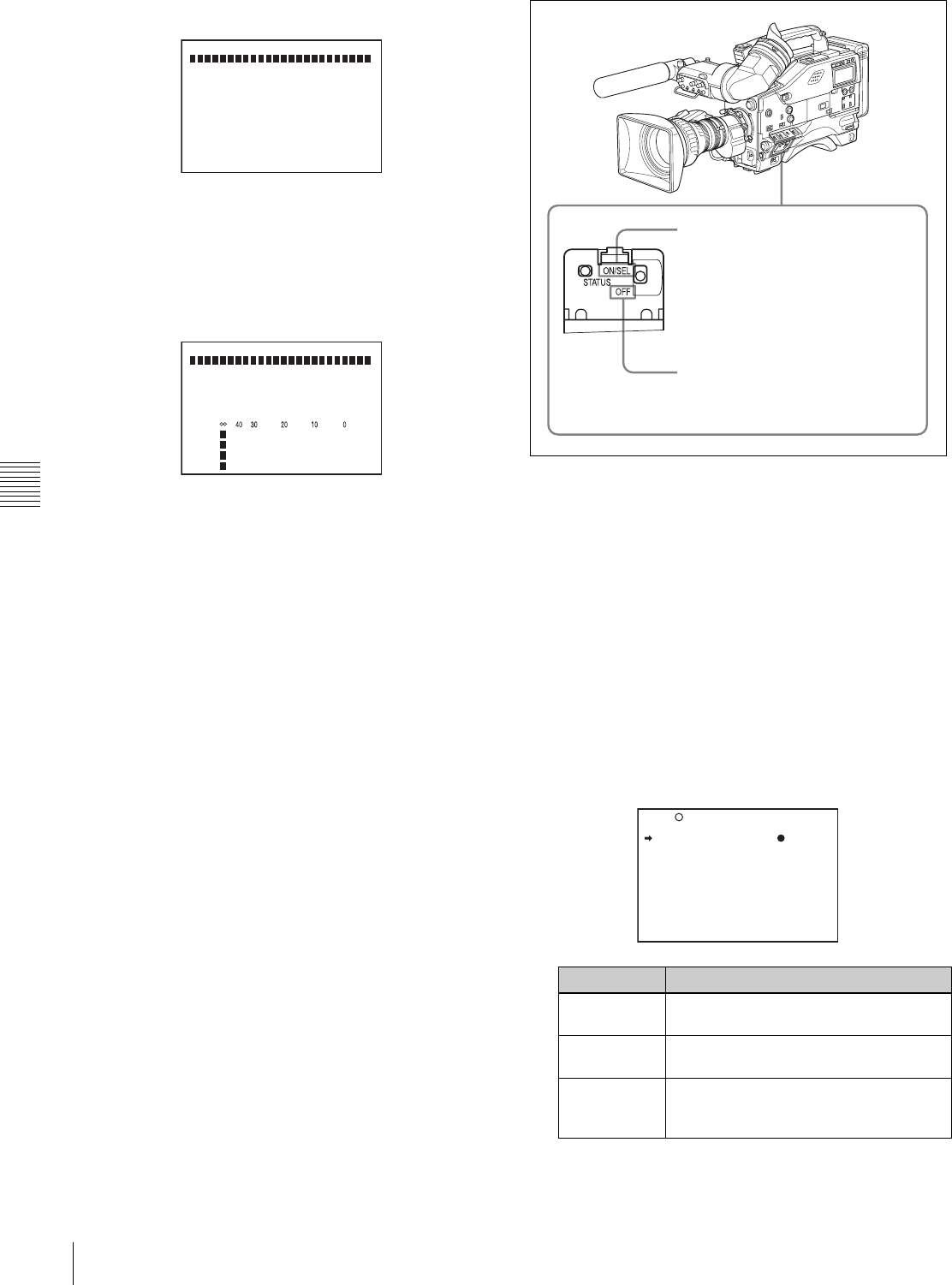
82 Status Display on the Viewfinder Screen
Chapter 5 Menu Displays and Detailed Settings
FUNCTION window
This window allows you to confirm the assigned function
of the ASSIGN 1/2 switches, ON/OFF of the Picture
Cache function, and ON/OFF of the output of the VIDEO
OUT connector.
AUDIO STATUS window
This window allows you to confirm the following items
related to audio.
• DF/NDF setting (only for the DVW-970)
• Type of input signal to audio channels 1 to 4
• Input level of audio channels 1 to 4
You can use the SET STATUS page of the USER menu to
set whether or not the status confirmation windows are
displayed.
Displaying the status confirmation
windows
You can use the CANCEL/PRST / ESCAPE switch as the
STATUS ON/SEL / OFF switch when the MENU ON/OFF
switch is set to OFF (when the cover of the menu operating
section is closed, OFF is automatically selected).
Disabling display of the status
confirmation windows
Proceed as follows:
1
Set the MENU ON/OFF switch to ON.
The last accessed menu page appears on the
viewfinder screen.
2
Turn the MENU knob until the SET STATUS page
appears, and press the MENU knob to select the page.
The current setting of each item appears on the right of
the item.
SET STATUS page
FUNCTION
FORMAT: I
ASSIGN<1> ATW <2> OFF
<T>TURBO
ZEBRA :OFF SELECT: 1
DET 70% APT: 10%
DET2 100%
P.CACHE : OFF: 0SEC
- Actual State ---------
REAR BNC:OFF
AUDIO STATUS
DF
CH1:FRONT CH3:WIRELES
CH2:REAR CH4:WIRELES
CH1:
CH2:
CH3:
CH4:
Item Description
STATUS
ABNORMAL
Selects whether or not the ABNORMAL
window is displayed (ON or OFF).
STATUS
FUNCTION
Selects whether or not the FUNCTION
window is displayed (ON or OFF).
STATUS
AUDIO
Selects whether or not the STATUS
AUDIO window is displayed (ON or
OFF).
By pushing the STATUS ON/SEL / OFF
switch up to ON/SEL, the confirmation
window appears.
Each time you push this switch up to
ON/SEL, the window switches. After 10
seconds, the window disappears
automatically.
To make the window disappear
promptly after displaying the window,
push this switch down to OFF.
U13 SET STATUS
STATUS ABNORMAL : ON
STATUS FUNCTION : ON
STATUS AUDIO : ON

83
Status Display on the Viewfinder Screen
Chapter 5 Menu Displays and Detailed Settings
3
Turn the MENU knob to move the b mark to the item
you want to set, and press MENU knob.
The b mark on the left of the selected item changes to
a z mark, and the z mark on the left of the setting
changes to a ? mark.
4
Turn the MENU knob to select whether or not to
display the selected window, then press the MENU
knob.
The z mark returns to a b mark, and the ? mark
returns to a z mark.
5
To continue setting other windows, repeat steps 3 and
4.
6
To end the menu operation, set the MENU ON/OFF
switch to OFF or close the cover of the menu operating
section.
5-2-9 Confirming the Image of the
Return Video Signal in the
Viewfinder
You can set whether or not to see the image of the return
video signal in the viewfinder, using the GENLOCK page
of the MAINTENANCE menu.
Proceed as follows:
1
Set the MENU ON/OFF switch to ON while holding
down the MENU knob.
The TOP menu appears.
2
Turn the MENU knob to move the b mark to
“MAINTENANCE,” then press the MENU knob.
If this is the first time the MAINTENANCE menu has
been displayed, the CONTENTS page of the
MAINTENANCE menu appears.
If the menu has been used before, the last accessed
page appears.
3
If the CONTENTS page is displayed, turn the MENU
knob to move the b mark to “GENLOCK,” then press
the MENU knob to display the GENLOCK page.
If a different page is displayed, turn the MENU knob
until the GENLOCK page appears, then press the
MENU knob to select the page.
The current setting of each item appears on the right of
the item.
GENLOCK page
4
Carry out setting operations as follows:
1Turn the MENU knob to move the b mark to
“GENLOCK,” and press the MENU knob.
The b mark on the left of “GENLOCK” changes to
a z mark, and the z mark on the left of the
GENLOCK setting changes to a ? mark.
2Turn the MENU knob until “OFF” appears, then
press the MENU knob.
The z mark returns to a b mark, and the ? mark
returns to a z mark, and the setting is executed.
3Turn the MENU knob to move the b mark to
“RETURN VIDEO,” and press the MENU knob.
The b mark changes to a z mark, and the z mark
changes to a ? mark.
4Turn the MENU knob until “ON” appears, then
press the MENU knob.
The z mark returns to a b mark, and the ? mark
returns to a z mark, and the setting is executed.
5
To end the menu operation, set the MENU ON/OFF
switch to OFF or close the cover of the menu operating
section.
To see the image of the return video signal on the
viewfinder screen
Hold down the RET switch on the lens. The image of the
return video signal input to the GENLOCK IN connector
is displayed on the viewfinder screen while you are
holding down the RET switch.
When the return video function is assigned to the ASSIGN
1 switch, you can see the image of the return video signal
on the viewfinder screen while you are holding down the
ASSIGN 1 switch even if the RETURN VIDEO item is set
to “OFF” on the GENLOCK page of the
MAINTENANCE menu.
When no signal is input to the GENLOCK IN connector,
the image is not changed even if you hold down the RET
switch on the lens.
Note
M16 GENLOCK
GENLOCK : ON
RETURN VIDEO : OFF
GL H PHASE : 0
GL SC PHASE : 0
GL SC 0/180 SEL : 180
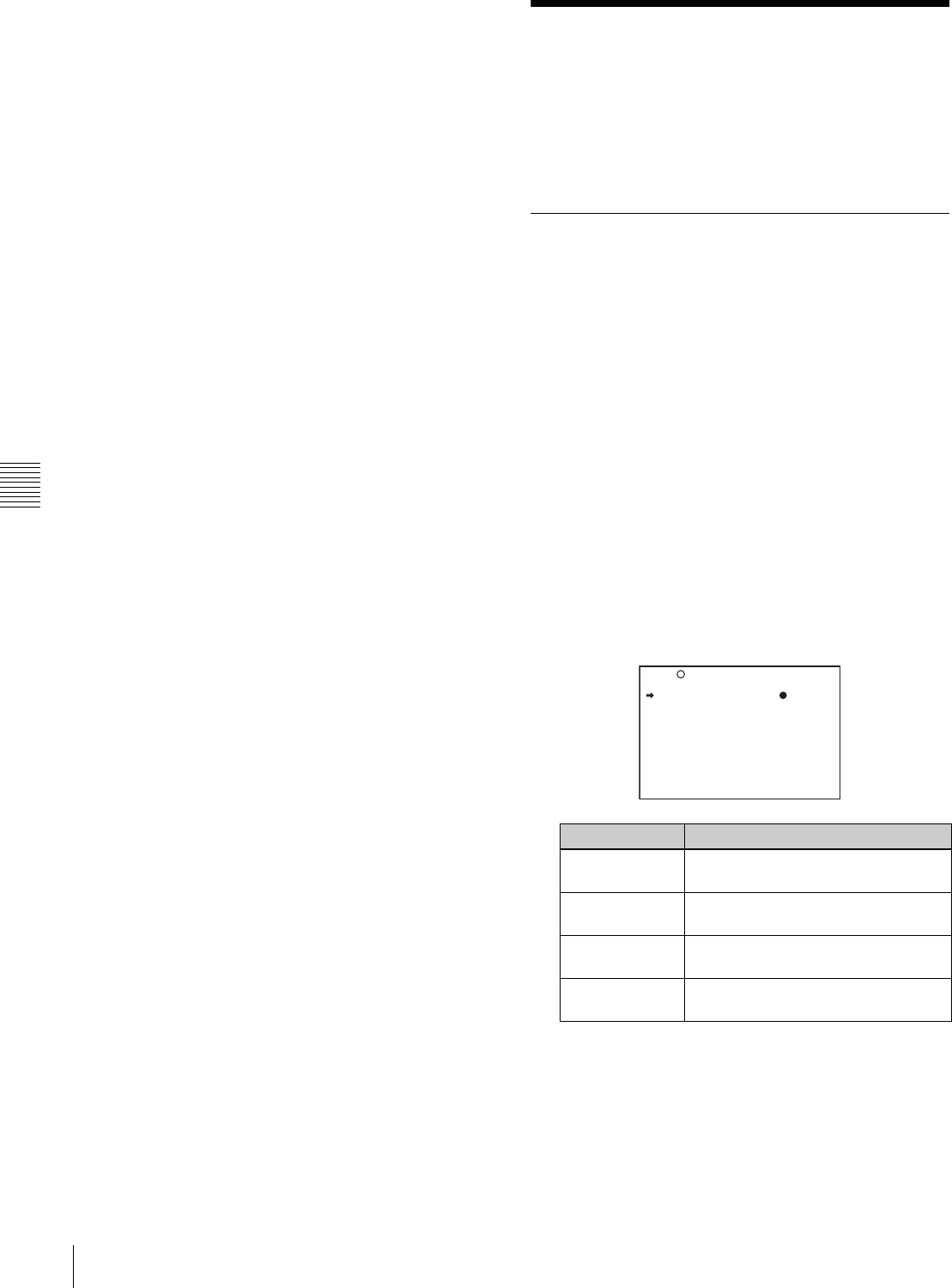
84 Adjustments and Settings from Menus
Chapter 5 Menu Displays and Detailed Settings
However, the image is switched while you are holding
down the ASSIGN 1 switch to which the return video
function is assigned, even if no signal is input to the
GENLOCK IN connector.
5-3 Adjustments and
Settings from Menus
The camcorder provides menus for adjustments and
settings.
5-3-1 Setting Gain Values for the
GAIN Selector Positions
Before using the camcorder, use the GAIN SW page of the
USER menu to set the gains corresponding to the L, M,
and H positions of the GAIN selector, which switches the
gain of the video amplifier.
To set the gain values, proceed as follows:
1
Set the MENU ON/OFF switch to ON.
The last accessed menu page appears on the
viewfinder screen.
2
Turn the MENU knob until the GAIN SW page
appears, then press the MENU knob to select the page.
The current setting of each item appears on the right of
the item.
GAIN SW page
Item Description
GAIN LOW Sets the gain value corresponding to
the L position of the GAIN selector.
GAIN MID Sets the gain value corresponding to
the M position of the GAIN selector.
GAIN HIGH Sets the gain value corresponding to
the H position of the GAIN selector.
GAIN TURBO Sets the gain value corresponding to
TURBO GAIN button selection.
U08 GAIN SW
GAIN LOW : 0db
GAIN MID : 9db
GAIN HIGH : 18db
GAIN TURBO : 42db
TURBO SW IND : OFF
TOP

85
Adjustments and Settings from Menus
Chapter 5 Menu Displays and Detailed Settings
3
Turn the MENU knob to move the b mark to the item
you want to set, and press MENU knob.
The b mark on the left of the selected item changes to
a z mark, and the z mark on the left of the setting
changes to a ? mark.
4
Turn the MENU knob to change the setting, and press
the MENU knob.
The z mark on the left of the selected item returns to
a b mark, and the ? mark on the left of the setting
returns to a z mark.
Any of –3, 0, 3, 6, 9, 12, 18, 24, 30, 36, 42 or 48 dB
can be set for each of the L, M, and H positions, in any
sequence.
For TURBO, any of –3, 0, 3, 6, 9, 12, 18, 24, 30, 36,
42 or 48 dB can be selected.
To change the gain corresponding to another switch
position, return to step 3.
5
To end the menu operation, set the MENU ON/OFF
switch to OFF or close the cover of the menu operating
section.
The menu display disappears, and the current status of
the camcorder is shown along the top and bottom of
the viewfinder screen.
5-3-2 Selecting the Output Signals
When the optional CBK-SD01 extension board is
installed, you can select the type of video signals (VBS/
SDI) from the VIDEO OUT SEL connector on the
OUTPUT page of the USER menu.
Proceed as follows:
1
Set the MENU ON/OFF switch to ON.
The last accessed menu page appears on the
viewfinder screen.
2
Turn the MENU knob until the OUTPUT page
appears, then press the MENU knob to select the page.
OUTPUT page
3
Turn the MENU knob to move the b mark to “REAR
BNC OUT SEL,” and press the MENU knob.
The b mark on the left of “REAR BNC OUT SEL”
changes to a z mark, and the z mark on the left of the
setting changes to a ? mark.
4
Turn the MENU knob to change the desired setting,
and press the MENU knob.
The z mark returns to a b mark, and the ? mark on the
left of the setting returns to a z mark.
5
To end the menu operation, set the MENU ON/OFF
switch to OFF or close the cover of the menu operating
section.
5-3-3 Setting the Color Temperature
Manually
You can adjust the value of the white balance manually by
setting the color temperature.
Proceed as follows:
1
Holding down the MENU knob, move the MENU ON/
OFF switch to ON.
The TOP menu appears.
2
Turn the MENU knob to move the b mark to “PAINT,”
and press the MENU knob.
TURBO SW IND OFF: When you operate the GAIN
selector after pressing the TURBO
GAIN button once, the video gain is
changed according to the GAIN
selector operation.
ON: When the video gain is boosted
to the video gain to the value preset
by pressing the TURBO GAIN
button once, the video gain is not
changed even if you operate the
GAIN selector, until you press the
TURBO GAIN button once more.
Item Description
Item Description
REAR BNC OUT
SEL
Selects the type of the video signal to
be output from the VIDEO OUT
connector.
SDI: Outputs the SDI signal. When SDI
is selected, connect the VIDEO OUT
connector to the SDI IN connector of
the video monitor.
VBS: Outputs the analog composite
video signal. When VBS is selected,
connector the VIDEO OUT connector
to the VIDEO IN connector of the
video monitor.
U01 OUTPUT
REAR BNC OUT SEL: VBS
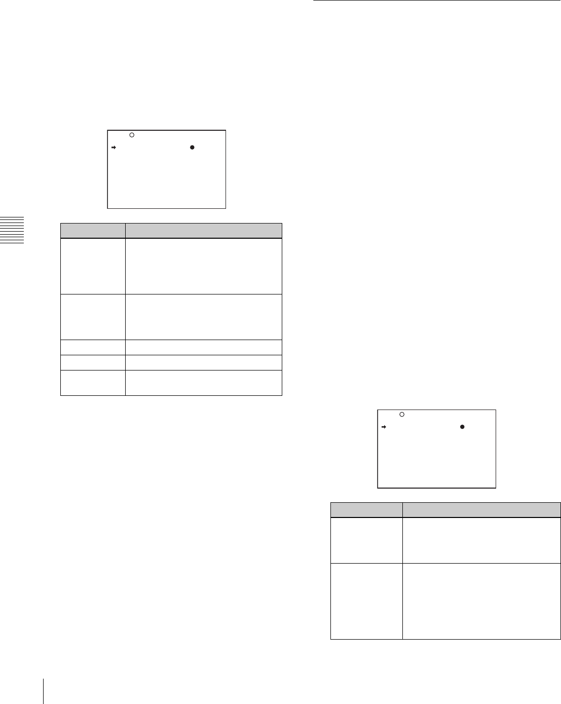
86 Adjustments and Settings from Menus
Chapter 5 Menu Displays and Detailed Settings
If this is the first time the PAINT menu has been
displayed, the CONTENTS page appears.
If the menu has been used before, the last accessed
page appears.
3
If the CONTENTS page is displayed, turn the MENU
knob to move the b mark to “WHITE,” and press the
MENU knob to display the WHITE page.
If a different page is displayed, turn the MENU knob
until the WHITE page appears, and press the MENU
knob to select the page.
The current setting of each item appears on the right of
the item.
WHITE page
The above table shows the adjustment of the white
balance of channel A.
Items followed by “<B>” are used to adjust the white
balance of channel B.
4
Turn the MENU knob to move the b mark to the item
you want to set, and press MENU knob.
The b mark on the left of the selected item changes to
a z mark, and the z mark on the left of the setting
changes to a ? mark.
5
Turn the MENU knob to change the setting, and press
the MENU knob.
The z mark returns to a b mark, and the ? mark
returns to a z mark.
To set other items, go back to step 3.
6
To end the menu operation, set the MENU ON/OFF
switch to OFF or close the cover of the menu operating
section.
5-3-4 Specifying an Offset for the
Auto White Balance Setting
By setting an offset for the value of auto white balance, you
can make the picture warmer or colder.
The OFFSET WHT page of the OPERATION menu
allows you to do this setting.
Proceed as follows:
1
Holding down the MENU knob, move the MENU ON/
OFF switch from OFF to ON.
The TOP menu appears.
2
Turn the MENU knob to move the b mark to
“OPERATION,” and press the MENU knob.
If this is the first time the OPERATION menu has been
displayed, the CONTENTS page appears. If the menu
has been used before, the last accessed page appears.
3
If the CONTENTS page is displayed, turn the MENU
knob to move the b mark to “OFFSET WHITE,” and
press the MENU knob to display the OFFSET WHT
page.
If a different page is displayed, turn the MENU knob
until the OFFSET WHT page appears, and press the
MENU knob to select the page.
The current settings of each item appears on the right
of the item.
OFFSET WHT page
Item Description
COLOR
TEMP <A>
Sets the color temperature for the
desired value. Adjust the value while
looking at the real image because
error tends to be bigger for
adjustment of high color temperature.
COLOR FINE
<A>
Adjusts the value more precisely
when the color temperature
adjustment through COLOR TEMP is
not satisfactory.
R GAIN <A> Only the value of R GAIN is changed.
B GAIN <A> Only the value of B GAIN is changed.
D5600K Sets the color temperature to
approximately 5600K.
P02 WHITE
COLOR TEMP <A>: 3200
COLOR FINE <A>: 0
R GAIN <A>: 0
B GAIN <A>: 0
D5600K <A>: OFF
COLOR TEMP <B>: 3200
COLOR FINE <B>: 0
R GAIN <B>: 0
B GAIN <B>: 0
D5600K : OFF
Item Description
OFFSET
WHITE <A>
Turns the setting of the offset for
channel A ON or OFF. ON: Adds the
offset adjusted on this page to the
white balance.
WARM-COOL
<A>
When OFFSET WHITE <A> is ON,
sets the offset for the white balance of
channel A, using the color
temperature. Adjust the value while
looking at the real image because
error tends to be bigger for
adjustment of high color temperature.
16 OFFSET WHT
OFFSET WHITE <A>: OFF
WARM COOL <A>: 3200
COLOR FINE <A>: 0
OFFSET WHITE <B>: OFF
WARM COOL <B>: 3200
COLOR FINE <B>: 0
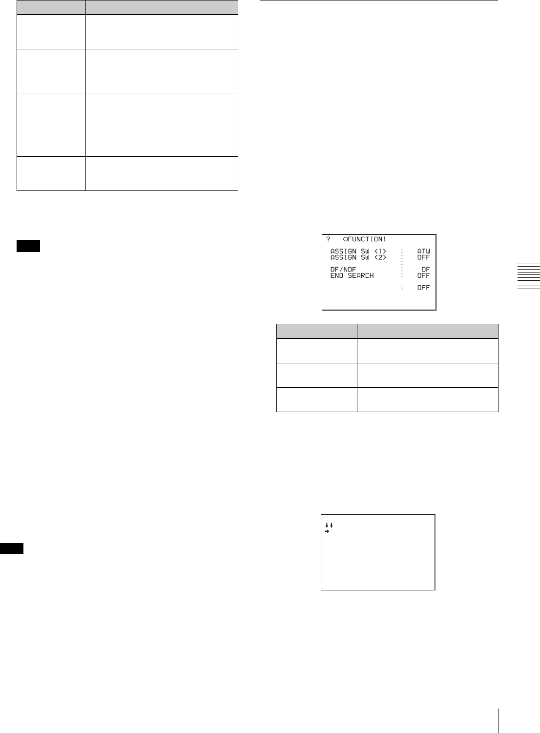
87
Adjustments and Settings from Menus
Chapter 5 Menu Displays and Detailed Settings
4
Set the WHITE BAL switch to the position
corresponding to the desired channel (A or B).
If the WHITE BAL switch is not set to A or B when
you operate the camcorder, the adjustment value will
not be reflected in the output signal.
5
Turn the MENU knob to move the b mark to the item
you want to set, and press MENU knob.
The b mark on the left of the selected item changes to
a z mark, and the z mark on the left of the setting
changes to a ? mark.
6
Turn the MENU knob to change the setting, and press
the MENU knob.
The z mark returns to a b mark, and the ? mark
returns to a z mark.
To set other items, go back to step 3.
To set the other white balance channel, go back to step
2.
7
To end the menu operation, set the MENU ON/OFF
switch to OFF or close the cover of the menu operating
section.
When using the OFFSET WHITE function, “+” is
displayed as the WARM color temperature indication and
“-” is displayed as the COOL temperature indication in the
viewfinder.
5-3-5 Assigning Functions to
Assignable Switches
You can assign the desired function to the ASSIGN 1/2
switches and the TURBO GAIN button.
Proceed as follows:
1
Set the MENU ON/OFF switch to ON.
The last accessed menu page appears on the
viewfinder screen.
2
Turn the MENU knob until the FUNCTION 1 page
appears, then press the MENU knob to select to page.
The current settings of each item appears on the right
of the item.
FUNCTION 1 page
3
Turn the MENU knob to move the b mark to the item
corresponding to the switch to which you want to
assign the function, and press the MENU knob.
The corresponding ASSIGN SEL window appears.
ASSIGN <1> SEL window
COLOR FINE
<A>
Adjusts the value more precisely if the
adjustment by WARM-COOL <A> is
not satisfactory.
OFFSET
WHITE <B>
Turns the setting of the offset for
channel B ON or OFF. ON: Adds the
offset adjusted on this page to the
white balance.
WARM-COOL
<B>
Sets the offset for the white balance
of channel B, using the color
temperature. Adjust the value while
looking at the real image because
error tends to be bigger for
adjustment of high color temperature.
COLOR FINE
<B>
Adjusts the value more precisely if the
adjustment by WARM-COOL <B> is
not satisfactory.
Note
Note
Item Description
Item Description
ASSIGN SW <1> Assigns the function to ASSIGN 1
(push-type) switch.
ASSIGN SW <2> Assigns the function to ASSIGN 2
(slide-type) switch.
TURBO SW Assigns the function to the TURBO
GAIN button.
CACHE/INTVAL REC
TURBO SW TURBO
U03
ASSIGN <1> SEL ESC
OFF
PICTURE CACHE ON/OFF
TEST OUT CHARACTER
MARKER
RE-TAKE
ATW
RETURN VIDEO
LENS RET
REC SWITCH
TURBO SWITCH
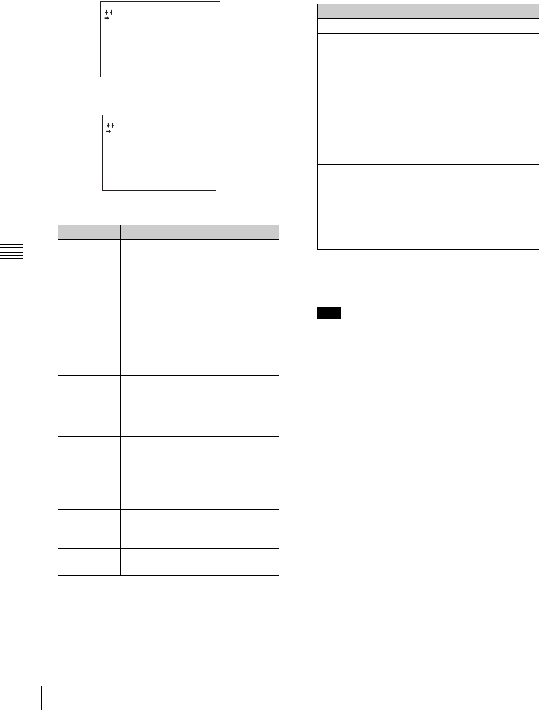
88 Adjustments and Settings from Menus
Chapter 5 Menu Displays and Detailed Settings
ASSIGN <2> SEL window
TURBO SW SEL window
1) This does not appear if the CBK-MB01 is not installed.
2) Even when the MARKER item is set to “OFF” on the MARKER
page of the USER menu, the ASSIGN 1 switch (or TURBO GAIN
button) allows you to display or not to display all markers.
3) Even if the RETURN VIDEO item is set to “OFF” on the GENLOCK
page of the MAINTENANCE menu, you can use this switch to
display the image of the return video signal on the viewfinder.
4) This does not appear if nothing is assigned in the Assign menu.
1) This does not appear if the CBK-MB01 is not installed.
2) Even when the MARKER item is set to “OFF” on the MARKER
page of the USER menu, the ASSIGN 2 switch allows you to display
or not to display all markers.
3) This does not appear if nothing is assigned in the Assign menu.
For functions that are assigned to the ASSIGN 2
(slide-type) switch, you cannot change those settings
using other menus. The function assigned to ASSIGN
2 switch takes precedence over the menu setting.
4
Turn the MENU knob to move the b mark to the item
you want to set, and press MENU knob.
The b mark changes to a z mark, and the z mark by
the setting changes to a ? mark.
5
Turn the MENU knob to switch to the desired setting,
and press the MENU knob.
The z mark returns to a b mark, and the ? mark
returns to a z mark, confirming the setting.
6
To continue with other settings, repeat steps 3 and 4.
To return to the previous page
Turn the MENU knob to move the b mark to “ESC” at the
right top of the window and press the MENU knob.
Alternatively, push the CANCEL/PRST / ESCAPE switch
down to the ESCAPE side.
To end the menu operation
Set the MENU ON/OFF switch to OFF or close the cover
of the menu operating section.
Functions to be assigned to the ASSIGN 1 (push-type)
switch and TURBO GAIN button
Function Description
OFF Disables the switch.
PICTURE
CACHE
ON/OFF 1)
Assigns Picture Cache mode ON/OFF
function.
TEST OUT
CHARACTER
Assigns the function to switch whether
or not text is superimposed on the
video signal to be output from the TEST
OUT connector.
MARKER Assigns the ON/OFF function to display
all markers.2)
RE-TAKE Assigns the RE-TAKE function.
ATW Assigns the ON/OFF function of auto-
tracing white balance.
RETURN
VIDEO
Assigns the ON/OFF function to display
the image of the return video signal on
the viewfinder.3)
LENS RET Assigns the same function as that of
the RET switch on the lens.
REC SWITCH Assigns the VTR S/S (start/stop)
function.
TURBO
SWITCH
Assigns the TURBO GAIN function.
ZEBRA Assigns the zebra pattern display
function.
D5600 Applies an electrical 5600K filter.
UA01 to
UA10 4)
Assigns the items assigned in the
ASSIGN SEL menu.
ASSIGN <2> SEL ESC
OFF
PICTURE CACHE ON/OFF
TEST OUT CHARACTER
MARKER
ZEBRA
D5600
EXT REC CONTROL
TURBO SW SEL ESC
OFF
PICTURE CACHE ON/OFF
TEST OUT CHARACTER
MARKER
RE-TAKE
ATW
RETURN VIDEO
LENS RET
REC SWITCH
TURBO SWITCH
Functions to be assigned to
the ASSIGN 2 (slide-type) switch
Function Content
OFF Disables the switch.
PICTURE
CACHE
ON/OFF 1)
Assigns Picture Cache mode ON/OFF
function.
TEST OUT
CHARACTER
Assigns the function to switch whether
or not the characters are mixed to the
video signal to be output from the TEST
OUT connector.
MARKER Assigns the ON/OFF function to display
all markers.2)
ZEBRA Assigns the zebra pattern display
function.
D5600 Applies an electrical 5600K filter.
EXT REC
CONTROL
Selects whether or not recording
control of external devices connected
through the CCZ connector (26-pin) of
a CA-702 is possible.
UA01 to
UA10 3)
Assigns the items assigned in the
ASSIGN SEL menu.
Note
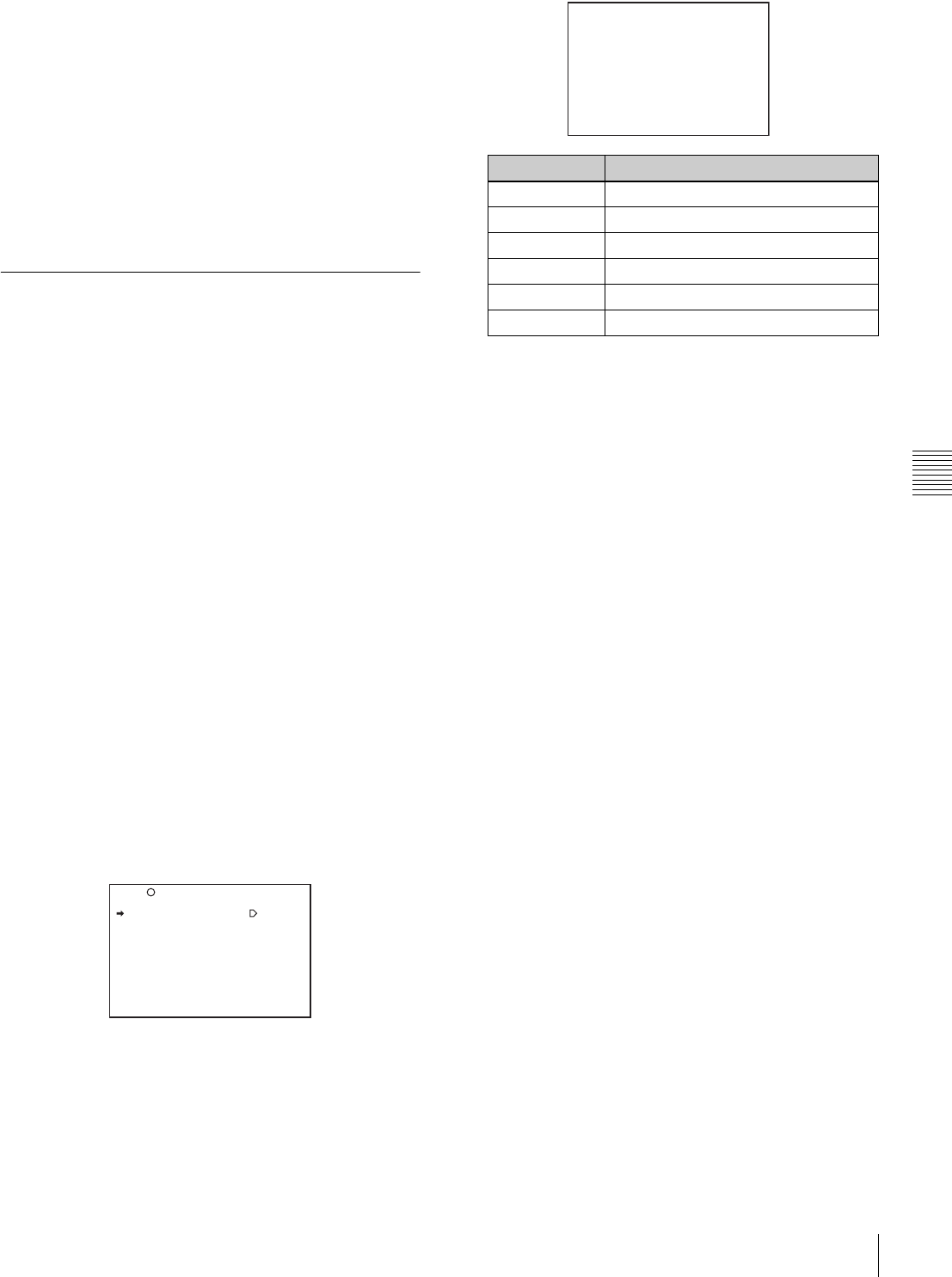
89
Adjustments and Settings from Menus
Chapter 5 Menu Displays and Detailed Settings
Operation of the assignable switches when UA01
to UA10 are assigned
When an on/off switchable function (or menu item) is
assigned to one of the assignable switches, each time the
switch is pressed toggles the function on or off.
When another type of menu item is assigned, pressing the
switch displays the item and its setting value on the
viewfinder screen.
You can then change the setting by pressing and turning the
MENU knob.
The viewfinder screen display disappears approximately 3
seconds after the last operation.
5-3-6 Setting the Date/Time of the
Internal Clock
You can set or change the date and time of the internal
clock. The date and time set are reflected in the time code.
Proceed as follows:
1
Holding down the MENU knob, move the MENU ON/
OFF switch to ON.
The TOP menu appears.
2
Turn the MENU knob to move the b mark to
“DIAGNOSIS,” and press the MENU knob.
If this is the first time the DIAGNOSIS menu has been
displayed, the CONTENTS page appears. If the menu
has been used before, the last accessed page appears.
3
If the CONTENTS page is displayed, turn the MENU
knob to move the b mark to “TIME/DATE,” and press
the MENU knob to display the TIME/DATE page.
If a different page is displayed, turn the MENU knob
until the TIME/DATE page appears, then press the
MENU knob to select the page.
The b mark is displayed at “ADJUST.”
TIME/DATE page
4
Press the MENU knob.
The TIME ADJUST setting window appears.
5
Turn the MENU knob to move the b mark to the item
you want to set, and press MENU knob.
The b mark on the left of the selected item changes to
a z mark, and the z mark on the left of the setting
changes to a ? mark.
6
Turn the MENU knob to display the desired value, and
press the MENU knob.
The z mark returns to a b mark, and the ? mark
returns to a z mark.
7
To continue the remaining settings, repeat steps 5 and
6.
8
When you finish settings, turn the MENU knob to
move the b mark to “OK,” then press the MENU knob.
The internal clock is set with the date and time set in
steps 5 to 7. The TIME/DATE page of the
DIAGNOSIS menu appears again. The time set on the
TIME ADJUST setting window is displayed.
To cancel the setting
Before executing step 8, move the b mark to “ESC” at the
top right of the window and press the MENU knob.
Alternatively, push the CANCEL/PRST / ESCAPE switch
down to the ESCAPE side.
All settings or changes are discarded and the TIME/DATE
page of the DIAGNOSIS menu appears.
D02 TIME/DATE
ADJUST : EXEC
HOUR : 12
MIN : 55
SEC : 58
YEAR : 00
MONTH : 07
DAY : 31
Item Description
HOUR Sets the hour value.
MIN Sets the minutes value.
SEC Sets the seconds value.
YEAR Sets the year.
MONTH Sets the month.
DAY Sets the day.
TIME ADJUST ESC
HOUR : 12
MIN : 55
SEC : 58
YEAR : 00
MONTH : 07
DAY : 31
OK
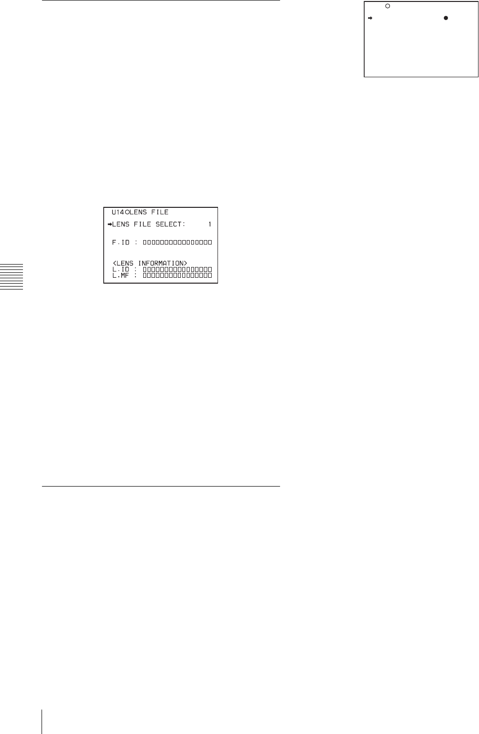
90 Adjustments and Settings from Menus
Chapter 5 Menu Displays and Detailed Settings
5-3-7 Selecting the Lens File
The LENS FILE page of the USER menu allows you to
change the lens file according to the lens in use.
Proceed as follows:
1
Set the MENU ON/OFF switch to ON.
The last accessed menu page appears on the
viewfinder screen.
2
Turn the MENU knob until the LENS FILE page
appears, then press the MENU knob to select the page.
The LENS FILE page shows the lens name and the f-
stop (iris setting) of the lens file currently selected.
3
Turn the MENU knob to move the b mark to LENS
FILE SELECT, and press the MENU knob.
The b mark changes to a z mark, and the z mark
changes to a ? mark.
4
Turn the MENU knob until the lens file No. in use
appears, then press the MENU knob.
The z mark returns to a b mark, and the ? mark
returns to a z mark.
5
To end the menu operation, set the MENU ON/OFF
switch to OFF or close the cover of the menu operating
section.
5-3-8 Selecting the Aspect Ratio
The FORMAT page of the OPERATION menu allows you
to select the aspect ratio of the video output signal.
Proceed as follows:
1
Follow the procedure of steps 1 to 3 described in
“5-3-4 Specifying an Offset for the Auto White
Balance Setting” on page 86 to display the FORMAT
page of the OPERATION menu.
(“UC/J SELECT” is displayed only for the DVW-970.)
2
Turn the MENU knob to move the b mark to “16:9/4:3
SELECT,” and press MENU knob.
The b mark on the left of the selected item changes to
a z mark, and the z mark on the left of the setting
changes to a ? mark.
3
Turn the MENU knob to display the desired aspect
ratio, and press the MENU knob.
The z mark returns to a b mark, and the ? mark
returns to a z mark.
4
To end the menu operation, set the MENU ON/OFF
switch to OFF or close the cover of the menu operating
section.
To display the aspect ratio of 16:9/4:3 on the
viewfinder screen
By setting the “DISP 16:9/4:3 ID” item on the VF DISP 2
page of the USER menu to “ON,” “16:9” or “4:3” appears
on the viewfinder screen according to the setting on the
FORMAT page.
For details, see “5-2-2 Selecting the Display Items” on
page 76.
To display “16:9” in color bars
By setting the “SHOT 16:9 ID” on the SHOT DISP page
of the USER menu to ON, you can record a “16:9” mode
indicator superimposed on the color bars.
For details, see “5-2-6 Recording Shot Data Superimposed
on the Color Bars” on page 79.
19 FORMAT
16:9/4:3 SELECT : 16:9
SCAN MODE : I
UC/J SELECT : UC
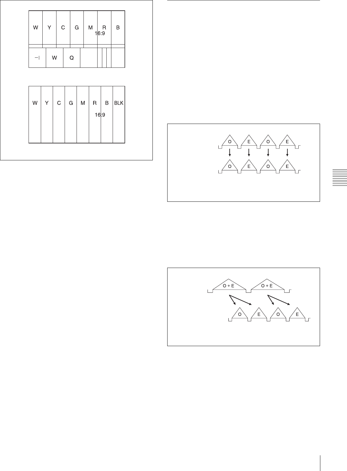
91
Adjustments and Settings from Menus
Chapter 5 Menu Displays and Detailed Settings
16:9 mode indicator on the color bar display
5-3-9 Setting the CCD Scan Mode
Since the camcorder has CCDs that use an “all pixels read-
out method,” a progressive scan mode is also available in
addition to the conventional interlace scan mode.
You can select either of the following modes using the
FORMAT page of the OPERATION menu.
• I (interlace scan) mode
• PsF (progressive scan) mode
Installing the CBK-FC01 allows you to select the 24P
mode (DVW-970 only).
Each mode is described below using timing charts.
I (interlace scan) mode
Interlace scan mode timing chart
The video signal of an odd scanning line and that of an
even scanning line are output from the CCD alternately.
Thus, the timing of the odd-field video signal and even-
field video signal are different.
PsF (progressive scan) mode
Progressive scan mode timing chart
The video signal of an odd scanning line and that of an
even scanning line are output from the CCD at the same
time. Then they are sent to the memory and separated into
odd-field and even-field scanning lines. Thus the timing of
an odd-field video signal and an even-field video signal are
the same.
Color bars (SMPTE type)
Color bars (EBU type) CCD output
Video output signal
O: Odd
E: Even
CCD output
Video output signal
O: Odd
E: Even
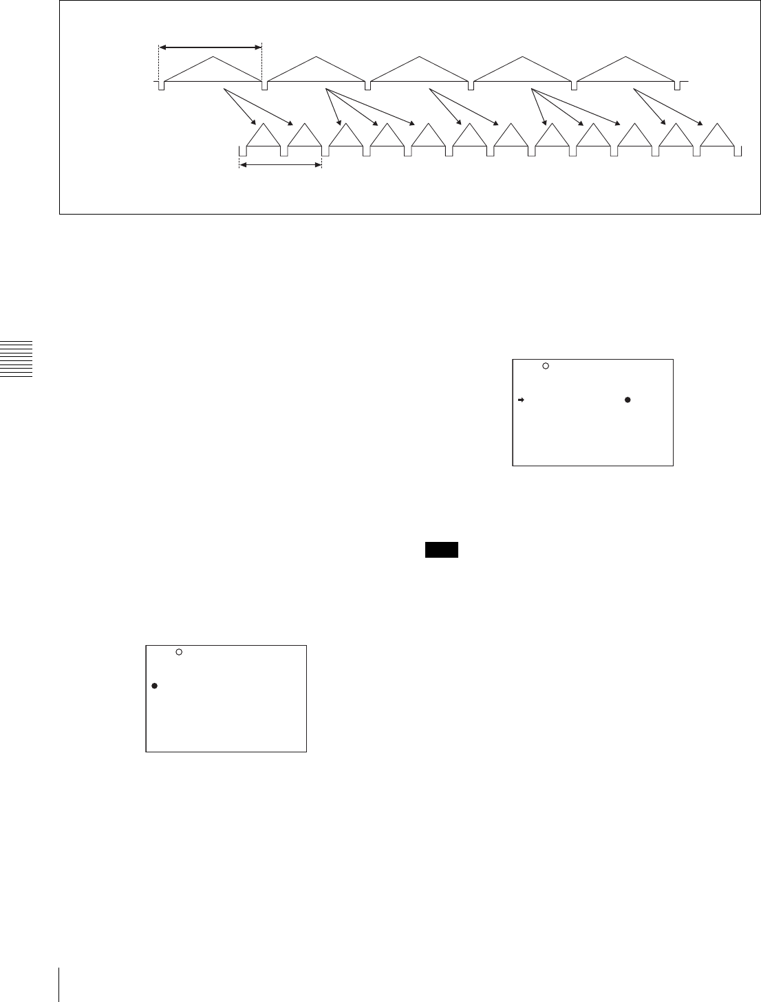
92 Adjustments and Settings from Menus
Chapter 5 Menu Displays and Detailed Settings
24P (pull-down) mode (DVW-970 with CBK-FC01 only)
24P mode timing chart
After reading from the CCDs in 24P mode (23.98 frames
per second), a pull-down conversion is carried out to the 30
frames (29.97 frames per second) of the normal
progressive scan mode.
Setting the CCD scan mode to the progressive scan mode
The scan mode of the camcorder has been set to the
interlace scan mode at the factory. The FORMAT page of
the OPERATION menu allows you to change the CCD
scan mode to the progressive scan mode or 24P mode
(DVW-970 with CBK-FC01 only).
1
Follow the procedures given in steps 1 to 3 described
in “5-3-4 Specifying an Offset for the Auto White
Balance Setting” on page 86, to display the FORMAT
page of the OPERATION menu.
2
Turn the MENU knob to move the b mark to “SCAN
MODE,” and press the MENU knob.
The b mark on the left of “SCAN MODE” changes to
a z mark, and the z mark on the left of the setting
changes to a ? mark.
(“UC/J SELECT” is displayed only for the DVW-970.)
3
Turn the MENU knob to display “PsF” or “24P,” and
press the MENU knob.
The z mark changes to a b mark, and the ? mark
changes to a z mark.
4
To end the menu operation, set the MENU ON/OFF
switch to OFF.
When the CBK-FC01 is connected, “V LPF (24P/30P)
OFF/ON” is displayed under “SCAN MODE” on the
menu. With this function set to “ON,” flicker in the vertical
direction of horizontal/slanted lines in PsF/24P mode will
be decreased (default is “ON”).
AO
A(O+E) B(O+E) C(O+E) D(O+E) A(O+E)
AE BO BE BO CE CO DE DO DE AO AE
CCD output
Video output signal
O: Odd
E: Even
23.98 frames per second
29.97 frames per second
19 FORMAT
16:9/4:3 SELECT : 16:9
SCAN MODE :? I
UC/J SELECT : UC
Note
19 FORMAT
16:9/4:3 SELECT : 16:9
SCAN MODE : PsF
UC/J SELECT : UC
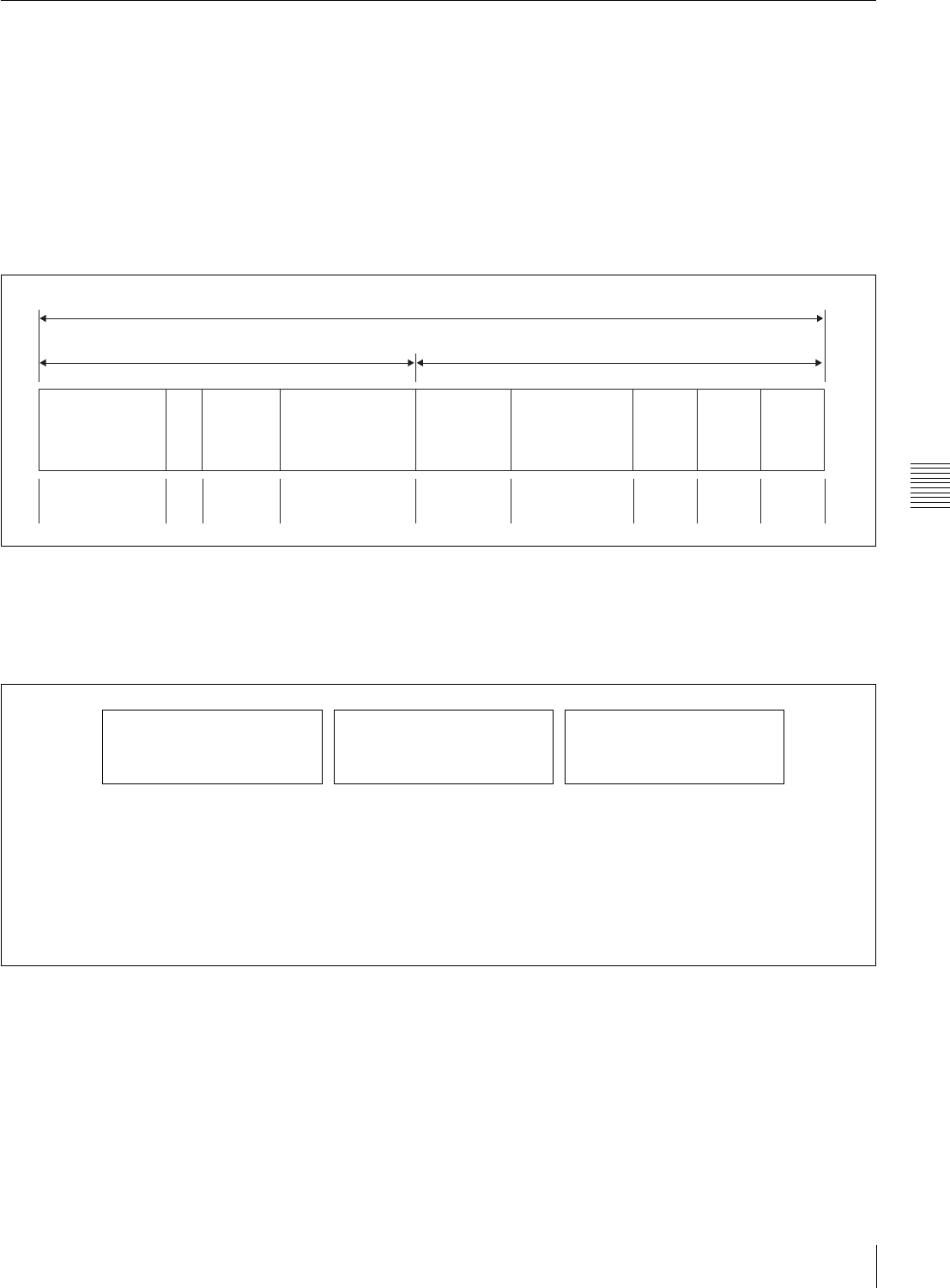
93
Adjustments and Settings from Menus
Chapter 5 Menu Displays and Detailed Settings
5-3-10 Usin
g
UMID Data
To perform operations from interviewing to editing
effectively and to detect audio-visual materials easily
when reusing them, metadata that provides additional
information is recorded along with audio-visual data on a
tape. As one of application of metadata, the UMID
(Unique Material Identifier) is internationally
standardized.
What is a UMID?
The UMID (Unique Material Identifier) is a unique
identifier for audio-visual material defined by the
SMPTE330M-2003 standard.
The UMID may be used either as the 32-byte Basic UMID
or as the Extended UMID, which includes an additional 32
bytes of Source Pack to make a total 64 bytes.
For details, refer to SMPTE 330M.
Globally unique ID is automatically recorded every
shooting.
The Extended UMID is metadata that provides additional
information such as location, time/date, company and so
on.
The UMID is applied as follows:
Using the Extended UMID
You have to enter a country code, organization code and
user code. Set the country code referring to the ISO-3166
table, and set the organization code and user code
independently.
For details, see “UMID menu setup” on page 94.
Functions of UMID data
The UMID data enables the following:
• Add a globally unique ID to every shot of audio-visual
material. The unique ID is used to detect the material
source and to link it with the original source material.
• Distinguishing between original material and copied
material. 00 is added to the Instance Number for original
material.
Extended UMID (64 bytes)
Basic UMID (32 bytes) Source Pack (32 bytes)
Universal label L Inst. No. Material Number Time/Date Spatial
Co-ordinates Country Org User
12 bytes 1 3 bytes 16 bytes 8 bytes 12 bytes 4 bytes 4 bytes 4 bytes
Instance No.
Material No.
ID generated when shooting
Same as the above
Source Pack
Shooting information (when,
where and who)
Same as the above
Original material: 00 00 00
Copied material:
generation number (1 byte) +
random number (2 bytes)
M
Distinguishing between the
original material and copied
material
M
Material source ID/detecting
material
M
Metadata pack that identifies the
source of material unit by
defining the when, where and
who of the material unit with
which it is associated.
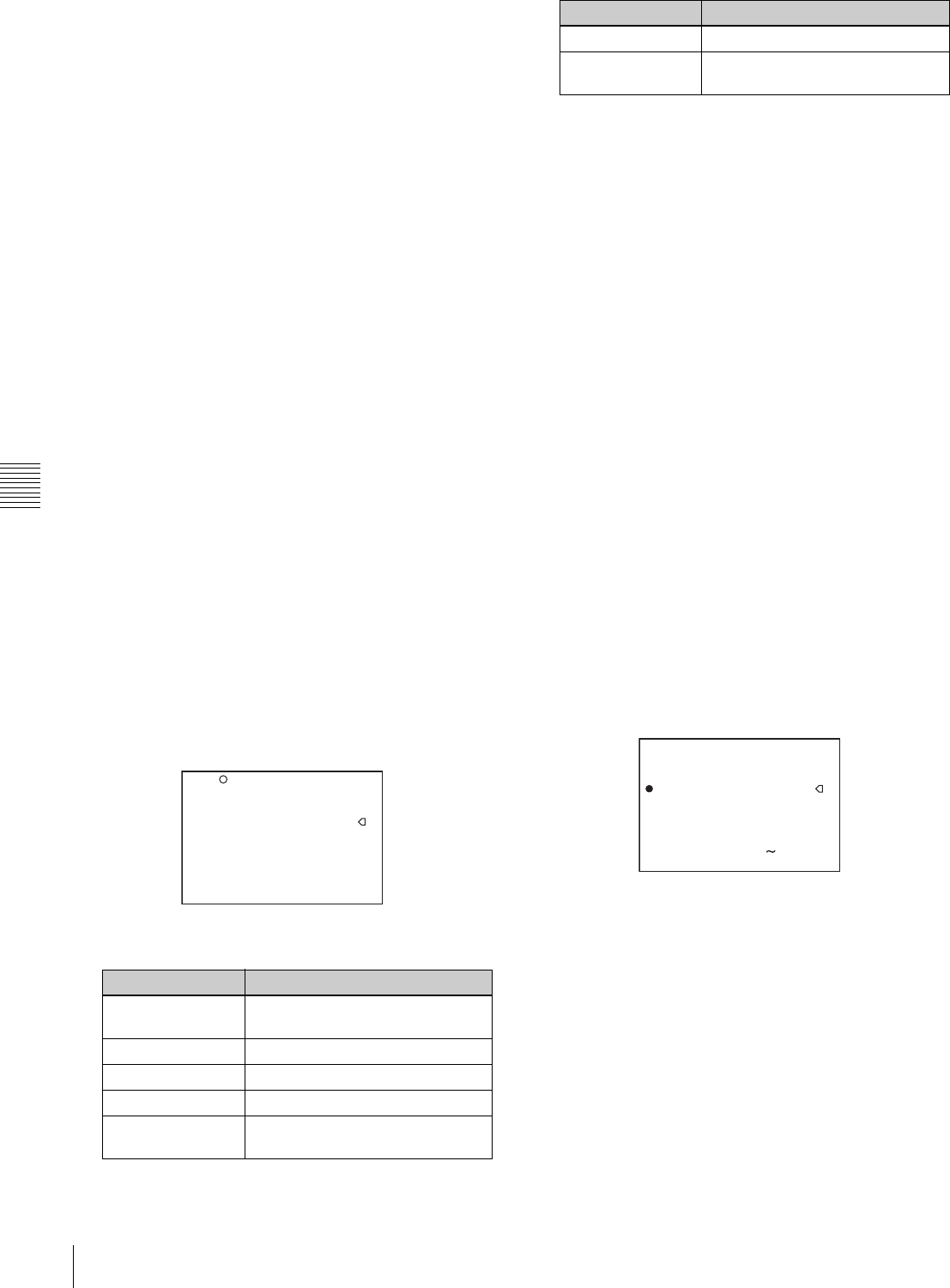
94 Adjustments and Settings from Menus
Chapter 5 Menu Displays and Detailed Settings
• Recording based on the UTC. The UTC is used when
recording the UMID. This enables uniform control of
source material recorded all over the world based on the
universal time code.
• Calculating the date difference among source materials.
The source material is recorded based on the MJD
(Modified Julian Date), which enables easy calculation
of date difference among source materials.
UMID menu setup
The UMID SET page of the OPERATION menu allows
you to make settings for UMID data.
Proceed as follows:
1
Holding down the MENU knob, set the MENU ON/
OFF switch from OFF to ON.
The TOP menu appears.
2
Turn the MENU knob to move the b mark to
“OPERATION,” and press the MENU knob.
If this is the first time the OPERATION menu has been
displayed, the CONTENTS page appears.
If the menu has been used before, the last accessed
page appears.
3
If the CONTENTS page is displayed, turn the MENU
knob to move the b mark to “UMID SET,” and press
the MENU knob.
If a different page is displayed, turn the MENU knob
until the UMID SET page appears, then press the
MENU knob.
The current settings appear on the right side of each
item.
UMID SET page
Proceed as follows:
4
Turn the MENU knob to move the b mark to the item
you want to set, and press the MENU knob.
The b mark to the left of the selected item changes to
a z mark, and the z mark to the left of the setting
changes to a ? mark.
5
Turn the MENU knob to change the setting of the
selected item or to display the desired value, and press
the MENU knob.
The z mark returns to a b mark, and the ? mark
returns to a z mark.
6
To end the menu operation, set the MENU ON/OFF
switch to OFF.
Additional information on the UMID SET
menu items
EX-OWNERSHIP REC
Specify whether to record the user data.
ON: The user data (COUNTRY CODE,
ORGANIZATION, and USER CODE) are recorded on
the tape.
OFF: The user data are not recorded.
COUNTRY CODE
When you select this item, the character table appears.
Enter an abbreviated alphanumeric string (4-byte
alphanumeric strings) according to the values defined in
ISO 3166-1.
There are about 240 country codes.
Find your own country code on the following home page.
Refer to ISO-3166-1:
http://www.din.de/gremien/nas/nabd/iso3166ma/codlstp1/
en_listp1.html
When the country code is less than 4 bytes, the active part
of the code will occupy the first part of the 4-bytes and the
remainder must be filled with the space character (20h).
Item Contents
EX-OWNERSHIP
REC
Specifies whether to record the
user data.
COUNTRY CODE Sets the country code.
ORGANIZATION Sets the organization code.
USER CODE Sets the user code.
INSTANCE NO. Specifies how to generate the
instance number.
?20 UMID SET
EX-OWNERSHIP REC: OFF
COUNTRY CODE :
sss
ORGANIZATION :
sssss
USER CODE :
sssss
INSTANCE NO : RND
TIME ZONE : 00 : +00:00
MACHINE :
sssssssssssss
TIME ZONE Sets the time difference from UTC.
MACHINE Displays the machine-specific
number.
Item Contents
20 UMID SET TOP
EX-OWNERSHIP REC: OFF
COUNTRY CODE :
sss
ORGANIZATION :
sssss
USER CODE :
sssss
INSTANCE NO : RND
-0123456789ABCDEFGHIJKL
MNOPQRSTUVWXYZabcdefghij
klmnopqrstuvwxyz
INS DEL RET ESC END

95
Adjustments and Settings from Menus
Chapter 5 Menu Displays and Detailed Settings
Example: In the case of Japan
For Japan, if the country code is JP, it is 2 bytes, if JPN, it
is 3 bytes.
Thus, enter the following:
JP_ _
or
JPN _
where _ represents a space.
ORGANIZATION (organization code)
When you select this item, the character table appears.
(Refer to COUNTRY CODE above.)
Enter an abbreviated 4-byte alphanumeric string for the
organization code.
There are no problems in recording or playing back audio-
video signals, if ORGANIZATION is not set.
Organization codes must be acquired by applying to the
SMPTE registration office. When no organization code has
been acquired, it is forbidden to enter an arbitrary string.
As a rule, the code “00” must be entered. Freelance
operators who do not belong to an origination should enter
“~.”
USER CODE
When you select this item, the USER CODE window
appears.
(Refer to the COUNTRY CODE window above.)
Enter the 4-byte alphanumeric strings for user
identification.
The user code is registered with each organization locally.
It is usually not centrally registered.
When the user code is less than 4 bytes, enter the user code
from the beginning of the 4 bytes and enter the space
character (20h) in the remaining strings.
This user code is determined by the organization. The
methods used depend on the organization.
User bits cannot be entered when no organization code has
been entered.
INSTANCE NO.
Select the method for generating the numbers to be used to
identify the original video images.
RND: Random
GEN: Generation (number of times of copy)
Ask the system administrator for selection.
TIME ZONE
When you select this item, the TIME ZONE window
appears.
The UTC is calculated based on the local time, using the
time zone. If the time zone is not set, the UTC is not
recorded correctly.
Set the time difference from UTC. When setting the
summer time or daylight savings time, change the code to
one which will advance the time by 1 hour.
When you change the time zone, adjust the built-in clock
to local time and turn the power of the camcorder off and
then the power on again.
MACHINE
An identification number specific to the machine is
displayed. This number cannot be set or modified by users.
Note
Note
Note
TIME ZONE ESC
00.UTC GREENWICH
01.UTC-01:00 AZORES
02.UTC-02:00 M-ATRANTIC
03.UTC-03:00 ARZENTINE
04.UTC-04:00 HALIFAX
05.UTC-05:00 NEW YORK
06.UTC-06:00 CHICAGO
07.UTC-07:00 DENVER
08.UTC-08:00 LOSANGELES
09.UTC-09:00 ALASKA

96 Resetting USER Menu Settings to the Standard Settings
Chapter 5 Menu Displays and Detailed Settings
5-4 Resetting USER
Menu Settings to the
Standard Settings
You can return all settings in the USER menu to the
standard settings.
Proceed as follows:
1
Set the MENU ON/OFF switch to ON.
The last accessed menu appears on the screen.
2
Turn the MENU knob until the USER FILE page
appears, and press the MENU knob.
USER FILE page
3
Turn the MENU knob to move the b mark to “USER
PRESET,” and press the MENU knob.
The message “PRESET OK? YES b NO” appears.
4
Turn the MENU knob to move the b mark to “YES,”
and press the MENU knob.
The settings for all items in the USER menu are reset
to the standard settings.
F01 USER FILE
USER FILE LOAD : EXEC
USER FILE SAVE : EXEC
F.ID :
sssssssssssssssss
USER PRESET : EXEC
F01 USER FILE
PRESET OK? YES NO
USER FILE LOAD : EXEC
USER FILE SAVE : EXEC
F.ID :
sssssssssssssssss
USER PRESET : EXEC
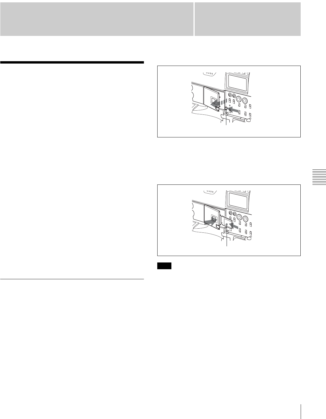
97
Chapter 6 Saving and Loading User Setting Data
Chapter
Saving and Loading User Files
6
Saving and Loading User
Setting Data
6-1 Saving and Loading
User Files
The camcorder is equipped with a “Memory Stick” drive,
which enables you to save user files, scene files, lens files,
reference files and “ALL” files. You can load these files
from the “Memory Stick” for immediate recall of a
particular setting configuration.
When a menu page is displayed, you can set up the
camcorder so that inserting a “Memory Stick”
automatically jumps to the appropriate file-related menu
page.
For details about scene files, see “6-2 Saving and Loading
Scene Files” on page 101.
For details of the function for jumping to the appropriate
file-related menu page, see “6-3 Jumping to a File-Related
Menu Page When Inserting a “Memory Stick”” on page
105.
“Memory Sticks” usable with this camcorder
With this camcorder, you can use “Memory Sticks” whose
capacity does not exceed 128 MB.
For details, see “Memory Stick” in “Specifications” on
page 130.
6-1-1 Handling the “Memory Stick”
The “Memory Stick” can be inserted to or removed from
the camcorder with the power turned on or off.
Inserting the “Memory Stick”
Proceed as follows:
1
Push the MEMORY STICK OPEN button.
The cover of the “Memory Stick” compartment opens.
2
Hold the “Memory Stick” with the notch facing
downward and the label side facing toward you, and
insert the “Memory Stick” into the “Memory Stick”
insertion slot until it clicks into place. Then, close the
cover.
If it does not fit into the slot properly or if there is some
resistance when you insert it, the “Memory Stick” may be
turned around or upside down. Do not force the “Memory
Stick” into the slot. Confirm the direction of the notch and
arrow on the “Memory Stick” before inserting the
“Memory Stick,” and then try inserting it again.
Removing the “Memory Stick”
Press the MEMORY STICK OPEN button to open the
cover of the “Memory Stick” compartment.
Push the eject button after confirming that the ACCESS
indicator is not lit. The “Memory Stick” pops out.
Note
MEMORY STICK OPEN button
Label side of “Memory Stick”
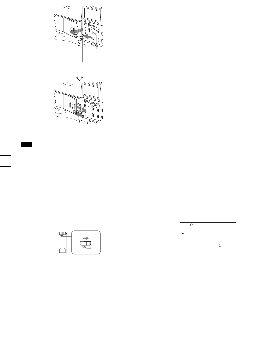
98 Saving and Loading User Files
Chapter 6 Saving and Loading User Setting Data
Do not remove the “Memory Stick” while the ACCESS
indicator is lit. You may lose data, or damage the “Memory
Stick.”
Protecting saved data
To prevent accidental erasure of important setup data, use
the LOCK switch on the “Memory Stick.”
Slide the switch right to the write protect position. The
message “MEMORY STICK LOCKED” is displayed. It is
now impossible to write or delete data on the “Memory
Stick.”
LOCK switch on the “Memory Stick”
Notes on using and storing the “Memory
Stick”
• Avoid touching the connector of the “Memory Stick” or
contacting it with a metal object.
• When attaching a label to the “Memory Stick,” use only
the label supplied for the “Memory Stick.”
• Do not drop, bend, or submit the “Memory Stick” to
external shock.
• Do not disassemble or modify the “Memory Stick.”
• Avoid getting liquids on the “Memory Stick.”
• Avoid using or storing the “Memory Stick” in a location
subject to:
—extremely high temperature such as the hot inside of a
car or the outdoors exposed to a burning sun, or a
place near a heater
—direct sunlight
—high humidity
—excessive dust
• When storing and carrying the “Memory Stick,” keep it
in its original case to ensure protection of important data.
• When carrying the camcorder with the “Memory Stick”
inserted, close the cover of the menu operating section.
• Avoid removing the “Memory Stick” from the insertion
slot while the access indicator is lit.
• Do not format the “Memory Stick” using a PC.
• Formatting of “Memory Sticks” can be performed on the
MEMORY STICK page of the FILE menu.
6-1-2 Saving USER Menu Data (User
File) to the “Memory Stick”
You can save USER menu settings held in the camcorder
as user files in the “Memory Stick.”
You can save up to 100 user files in the “Memory Stick.”
Insert the “Memory Stick,” then proceed as follows:
1
Set the MENU ON/OFF switch to ON.
The last accessed menu page appears on the
viewfinder screen.
2
Turn the MENU knob until the USER FILE page
appears, then press the MENU knob to select the page.
Alternately, select “USER FILE” on the CONTENTS
page.
USER FILE page
If you want to set a file ID for the data to be saved
Set the file ID before going to step 3.
For details on setting the file ID, see “Setting the file
ID” on page 99.
3
Turn the MENU knob to move the b mark to USER
FILE SAVE, and press the MENU knob.
The P00 USER SAVE page appears.
Note
MEMORY STICK OPEN button
Check that the ACCESS
indicator is not lit.
Eject button
F01 USER FILE
USER FILE LOAD : EXEC
USER FILE SAVE : EXEC
F.ID :
sssssssssssssssss
USER PRESET : EXEC

99
Saving and Loading User Files
Chapter 6 Saving and Loading User Setting Data
When a ? appears on the left of “P00” at the top left of
the page, you can change the page. Up to 20 pages,
from P00 to P19, can be used to save user files in the
“Memory Stick.” Each page can hold up to 5 files.
4
Turn the MENU knob until the page which contains
the desired file number appears, and press the MENU
knob.
5
Turn the MENU knob to move the b mark to the
desired file number, and press the MENU knob.
The message “SAVE OK? YES b NO” appears.
6
To carry out the save, move the b mark to “YES” and
press the MENU knob.
To cancel, press the MENU knob leaving the b mark
pointing to “NO.”
The ACCESS indicator lights.
When the saving is completed, the message
“COMPLETE” appears and the ACCESS indicator
goes off.
If no “Memory Stick” has been inserted, the message
“NO MEMORY STICK” will appear. Insert a
“Memory Stick.”
If you select a file number where data has already
been saved
The message “OVERWRITE OK? YES b NO”
appears. In this case, the b mark appears on the left of
“NO,” which is flashing.
• To stop overwriting, press the MENU knob.
• To overwrite, move the b mark to “YES” and press
the MENU knob.
You can select the information displayed on each
USER SAVE or USER LOAD page by changing the
DISPLAY MODE setting.
For details, see “Selecting the display contents” on
page 100.
7
To end the menu operation, set the MENU ON/OFF
switch to OFF or close the cover of the menu operating
section.
The menu disappears from the viewfinder screen, and
the display indicating the current status of the
camcorder appears along the top and bottom of the
screen.
USER menu settings to be saved in the “Memory
Stick”
Settings for items on all pages of the USER menu are saved
in the “Memory Stick” as a user file. However, you can
select the items which are not to be saved in the “Memory
Stick.”
Use the items LOAD CUSTOM DATA, LOAD OUT OF
USER, BEFORE FILE PAGE and USER LOAD WHITE
on the USER FILE2 page of the FILE menu.
If data cannot be saved
If one of the following error messages appears during or
after the save operation, then the data was not saved.
Setting the file ID
Before data is saved to a “Memory Stick,” it is useful to set
a file ID for the “Memory Stick” to identify it.
When data is saved to a “Memory Stick,” the file ID is
saved to the “Memory Stick” together with the data.
Set the file ID before saving data in the “Memory Stick.”
Otherwise, the file ID is not saved with the other data.
Proceed as follows:
?P00 USER SAVE
DISPLAY MODE : ALL
001.NEW FILE
002.NEW FILE
003.NEW FILE
004.NEW FILE
005.NEW FILE
ESC
P00 USER SAVE
DISPLAY MODE : ALL
001.NEW FILE
002.NEW FILE
003.NEW FILE
004.NEW FILE
005.NEW FILE
ESC
P00 USER SAVE
SAVE OK? YES NO
DISPLAY MODE : ALL
001.NEW FILE
002.NEW FILE
003.NEW FILE
004.NEW FILE
005.NEW FILE
ESC
When a file number is
shown as “NEW FILE,”
this means that the file is
empty. When data is
stored in a file number,
the file name appears.
Data save error messages
Error message Cause Action
NO MEMORY
STICK (flashing)
No “Memory
Stick” is inserted.
Insert or reinsert the
“Memory Stick.”
MEMORY STICK
LOCKED
The LOCK
switch on the
“Memory Stick”
is set to the write
protect position.
Set the LOCK switch
to the write enable
position.
MEMORY STICK
ERROR
(flashing)
Circuit or
“Memory Stick”
fault.
Check the circuitry, or
replace the “Memory
Stick”.
Note
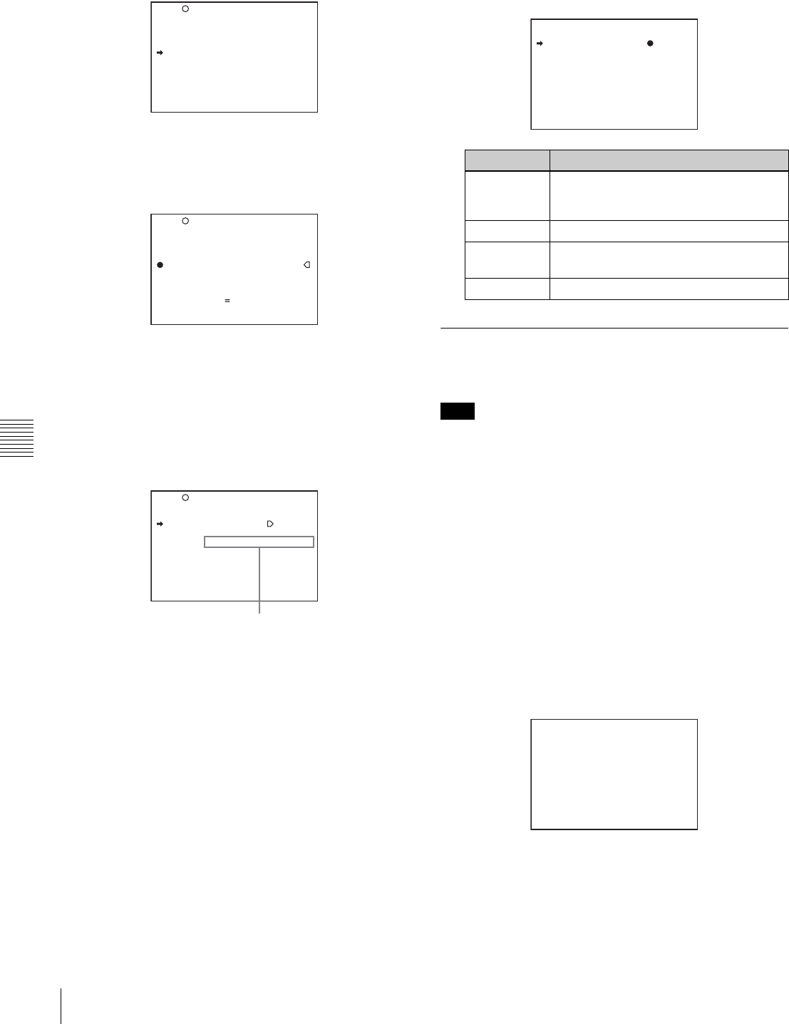
100 Saving and Loading User Files
Chapter 6 Saving and Loading User Setting Data
1
On the USER FILE page, turn the MENU knob to
move the b mark to “F. ID.”
2
Press the MENU knob.
A character table appears, allowing you to select
characters you want to enter.
3
Follow the procedure of steps 4 and 5 described in “5-
2-7 Setting the Shot ID” (page 80) to enter the file ID.
4
When you finish entering the file ID, turn the MENU
knob to move the x mark to “END,” then press the
MENU knob.
The entered file ID is now displayed.
After setting the file ID, carry out the procedure from
step 3 in “6-1-2 Saving USER Menu Data (User File)
to the “Memory Stick”” (page 98).
The set file ID is saved in the “Memory Stick” with the
data.
Selecting the display contents
You can select the contents of the file to be displayed on
the USER SAVE page and USER LOAD page.
Proceed as follows:
1
Turn the MENU knob to move the b mark to
“DISPLAY MODE,” and press the MENU knob.
2
Turn the MENU knob to move the b mark until the
desired type of the display contents (see the following
table) appears, then press the MENU knob.
6-1-3 Loading Saved Data from a
“Memory Stick”
The data loaded from the “Memory Stick” overwrites the
data saved in the camcorder.
Proceed as follows:
1
Set the MENU ON/OFF switch to ON.
The last accessed menu page appears on the screen.
2
Turn the MENU knob until the USER FILE page
appears, then press the MENU knob. Alternatively,
select “USER FILE” on the CONTENTS page.
3
Turn the MENU knob to move the b mark to “USER
FILE LOAD,” and press the MENU knob.
The P00 USER LOAD page appears.
4
Turn the MENU knob until the page which contains
the desired file number appears, then press the MENU
knob.
F01 USER FILE
USER FILE LOAD : EXEC
USER FILE SAVE : EXEC
F.ID :
sssssssssssssssss
USER PRESET : EXEC
TOP
F01 USER FILE
USER FILE LOAD : EXEC
USER FILE SAVE : EXEC
F.ID :?
x
!#$%&'()*+,-./012345678
9:;<=>?@ABCDEFGHIJKLMNOP
QRSTUVWXYZ[Y]abcdefghijk
lmnopqrstuvwxyz~
INS DEL RET ESC END
TOP
F01 USER FILE
USER FILE LOAD : EXEC
USER FILE SAVE : EXEC
F.ID :
sssssssssssssssss
USER PRESET : EXEC
TOP
File ID set in step 3
Display type Description
ALL File ID (10 characters) and date ((month/
day/year) for the DVW-970 and (day/
month/year) for the DVW-970P))
F.ID File ID (16 characters)
DATE Saved date (year/month/day/hours/
minutes/seconds)
MODEL Information on the model
Note
P00 USER LOAD
DISPLAY MODE : F.ID
001.USER1
002.USER2
003.NO FILE
004.USER4
005.USER5
ESC
?P00 USER LOAD
DISPLAY MODE : ALL
001.USER1 JAN/01/04
002.USER2 JAN/15/04
003.NO FILE
004.USER4 FEB/05/04
005.USER5 FEB/20/04
ESC

101
Saving and Loading Scene Files
Chapter 6 Saving and Loading User Setting Data
5
Turn the MENU knob to move the b mark to the
desired file number to be loaded, and press the MENU
knob.
The message “LOAD OK? YES b NO” appears.
6
To carry out the load, move the b mark to “YES” and
press the MENU knob.
To cancel, press the MENU knob leaving the b mark
pointing to “NO.”
The ACCESS indicator lights.
When the load is completed, the message
“COMPLETE” appears and the ACCESS indicator
goes off.
The USER FILE page appears again.
7
To end the menu operation, set the MENU ON/OFF
switch to OFF or close the cover of the menu operating
section.
If data cannot be loaded
If one of the following error messages appears during or
after the load operation, then the data was not loaded.
6-2 Saving and Loading
Scene Files
You can save various settings for shooting a particular
scene as a scene file. Loading the scene file, you can
quickly recreate setup conditions suitable for the scene.
You can save up to five scene files in the camcorder
memory and up to 100 scene files in a “Memory Stick.”
You can also load data from the “Memory Stick” into the
camcorder memory.
Data that can be saved in a scene file
You can save the following data in a scene file:
• Values adjusted using the PAINT menu (except the items
that return to the default values when power is on, such
as TEST OUT SELECT)
• Shutter speed settings made in the standard mode and
ECS mode
The white balance data can be loaded only when the
SCENE WHITE DATA setting on the REFERENCE page
of the FILE menu is ON.
6-2-1 Saving a Scene File
Proceed as follows to save a scene file in the camcorder
memory or the “Memory Stick.”
To save a scene file in the “Memory Stick,” insert the
“Memory Stick” before starting the operation.
1
In the TOP menu, select the FILE menu.
2
Turn the MENU knob until the SCENE FILE page
appears, then press the MENU knob to select the page.
Alternatively, select “SCENE FILE” on the
CONTENTS page to display the SCENE FILE page.
SCENE FILE page
If you want to set a file ID for the data to be saved
Set the file ID before going to step 3.
For details on setting the file ID, see “Setting the file
ID” on page 103.
Data load error messages
Error message Cause Action
NO MEMORY
STICK (flashing)
No “Memory
Stick” is inserted.
Insert or reinsert the
“Memory Stick.”
MEMORY STICK
ERROR
(flashing)
Circuit or
“Memory Stick”
fault.
Recheck, and
consult your Sony
representative.
OTHER
MODEL’S FILE
(flashing)
The “Memory
Stick” contains
data that cannot
be loaded into this
camcorder.
Do not try to load
data saved from
another camcorder.
P00 USER LOAD
DISPLAY MODE : ALL
001.USER1 JAN/01/04
002.USER2 JAN/15/04
003.NO FILE
004.USER4 FEB/05/04
005.USER5 FEB/20/04
ESC
P00 USER LOAD
LOAD OK? YES NO
DISPLAY MODE : ALL
001.USER1 JAN/01/04
002.USER2 JAN/15/04
003.NO FILE
004.USER4 FEB/05/04
005.USER5 FEB/20/04
ESC
F04 SCENE FILE
s
1 :STANDARD
s
2 :STANDARD
s
3 :STANDARD
s
4 :STANDARD
s
5 :STANDARD
s
STANDARD
SCENE RECALL : EXEC
SCENE STORE : EXEC
F.ID:
TOP

102 Saving and Loading Scene Files
Chapter 6 Saving and Loading User Setting Data
3
Turn the MENU knob to move the b mark to “SCENE
STORE,” and press the MENU knob.
The SCENE STORE page appears.
4
Select the desired file number.
When no “Memory Stick” has been inserted
Turn the MENU knob to move the b mark to the
desired file number, and press the MENU knob.
When the save is completed, the SCENE FILE page
appears again.
When you select a file number where data has
already been saved
The message “OVERWRITE OK? YES b NO”
appears. In this case, the b mark is placed on the left
of “NO.”
• To stop overwriting, press the MENU knob.
• To overwrite, move the b mark to “YES” and press
the MENU knob.
When a “Memory Stick” has been inserted
You can use up to 20 pages, from P01 to P20, to save
scene files in the “Memory Stick.” Each page can hold
up to 5 files.
To select a file, proceed as follows:
1Turn the MENU knob until the page which
contains the desired file number appears, then press
the MENU knob.
2Turn the MENU knob to move the b mark to the
desired file number, and press the MENU knob.
The message “STORE OK? YES b NO” appears.
3To carry out the storing, move the b mark to
“YES” and press the MENU knob.
To cancel, press the MENU knob leaving the b
mark pointing to “NO.”
You can select the contents of the user file to be
displayed on the page.
For details, see “Selecting the display contents” on
page 103.
5
To end the menu operation, set the MENU ON/OFF
switch to OFF or close the cover of the menu operating
section.
To return to the SCENE FILE page
After the message “COMPLETE” is displayed, move
the b mark to “ESC” at the top right of the page by
turning the MENU knob, then press the MENU knob.
White balance setting data to be saved in the
scene file
The white balance setting data selected when you save the
scene file is saved. For example, when the WHITE BAL
switch is set to A, the adjusted values in memory A are
saved in the scene file, and when the WHITE BAL switch
is set to PRST, the preset value is saved.
Saving scene files from the camcorder
memory to the “Memory Stick”
You can save five scene files from the camcorder to the
“Memory Stick” in a single operation.
Proceed as follows:
1
After displaying the SCENE FILE page (page 101)
turn the MENU knob to move the b mark to “SCENE
STORE,” then press the MENU knob.
One of the SCENE STORE pages appears.
2
Turn the MENU knob until the desired SCENE
STORE page appears, then press the MENU knob.
F04 SCENE FILE
s
1 :STANDARD
s
2 :STANDARD
s
3 :STANDARD
s
4 :STANDARD
s
5 :STANDARD
s
STANDARD
SCENE RECALL : EXEC
SCENE STORE : EXEC
F.ID:
TOP
?P00 SCENE STORE
DISPLAY MODE : ALL
MEM-01:STANDARD
MEM-02:STANDARD
MEM-03:STANDARD
MEM-04:STANDARD
MEM-05:STANDARD
ESC
P01 SCENE STORE
DISPLAY MODE : ALL
001.SCENE1 FEB/05/02
002.STANDARD
003.STANDARD
004.STANDARD
005.STANDARD
***.5FILE SAVE MEM1-5
ESC
P01 SCENE STORE
STORE OK? YES NO
DISPLAY MODE : ALL
001.SCENE1 FEB/05/02
002.STANDARD
003.STANDARD
004.STANDARD
005.STANDARD
***.5FILE SAVE MEM1-5
ESC
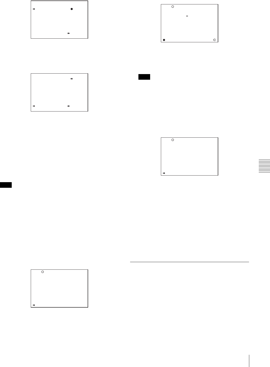
103
Saving and Loading Scene Files
Chapter 6 Saving and Loading User Setting Data
3
Turn the MENU knob to move the b mark to “5FILE
SAVE B MEM1-5,” and press the MENU knob.
The message “SAVE OK? YES b NO” appears.
4
To carry out the save, move the b mark to “YES” and
press the MENU knob.
To cancel, press the MENU knob leaving the b mark
pointing to “NO.”
When the save is completed, the message
“COMPLETE” appears.
5
To end the menu operation, set the MENU ON/OFF
switch to OFF.
If files have been saved in the page selected in step 2, those
files are replaced with files loaded from the camcorder
memory. For example, files from 001 to 005 are replaced.
Setting the file ID
Before the data is saved as a scene file, it is useful to set a
file ID to identify it. The set file ID is saved together with
the data.
To set the file ID, proceed as follows:
1
On the SCENE FILE page, turn the MENU knob to
move the b mark to “F. ID.”
2
Press the MENU knob.
A character table appears, allowing you to select
characters you want to enter.
3
Carry out the operations for steps 4 and 5 described in
5-2-7 “Setting the Shot ID” (page 80) to enter the file
ID.
Set the file ID before saving the scene file in the
“Memory Stick” or the camcorder memory.
Otherwise, the file ID is not saved with the other data.
4
When you finish entering the file ID, turn the MENU
knob to move the x mark to “END,” then press the
MENU knob.
The SCENE FILE page appears again.
Carry out the procedure from step 3 in 6-2-1 “Saving
a Scene File” (page 101).
The set file ID is saved together with the data.
Selecting the display contents
You can select the items of file information to be displayed
on the SCENE STORE pages (P01 to P20) or the SCENE
RECALL pages (P01 to P20) used for saving data to or
loading data from a “Memory Stick.”
For details, see “Selecting the display contents” on page
100.
6-2-2 Loading a Scene File
Proceed as follows:
1
In the TOP menu, select the FILE menu.
2
Turn the MENU knob until the SCENE FILE page
appears, then press the MENU knob to select the page.
Alternatively, on the CONTENTS page select
“SCENE FILE,” and press the MENU knob to display
the SCENE FILE page.
Note
P01 SCENE STORE
DISPLAY MODE : ALL
001.SCENE1 FEB/05/02
002.SCENE2 FEB/06/02
003.NO FILE
004.SCENE4 FEB/08/02
005.SCENE5 FEB/08/02
***.5FILE SAVE MEM1-5
ESC
P01 SCENE STORE
SAVE OK? YES NO
DISPLAY MODE : ALL
001.SCENE1
002.SCENE2
003.NO FILE
004.SCENE4
005.SCENE5
***.5FILE SAVE MEM1-5
ESC
F04 SCENE FILE
s
1 :STANDARD
s
2 :STANDARD
s
3 :STANDARD
s
4 :STANDARD
s
5 :STANDARD
s
STANDARD
SCENE RECALL : EXEC
SCENE STORE : EXEC
F.ID:
TOP
Note
F04 SCENE FILE
!#$%&'()*+,-./012345678
9:;<=>?@ABCDEFGHIJKLMNOP
QRSTUVWXYZ[Y]abcdefghijk
lmnopqrstuvwxyz~
INS DEL RET ESC END
s
STANDARD
SCENE RECALL : EXEC
SCENE STORE : EXEC
F.ID:
x
TOP
F04 SCENE FILE
s
1 :STANDARD
s
2 :STANDARD
s
3 :STANDARD
s
4 :STANDARD
s
5 :STANDARD
s
STANDARD
SCENE RECALL : EXEC
SCENE STORE : EXEC
F.ID: SCENE21
TOP
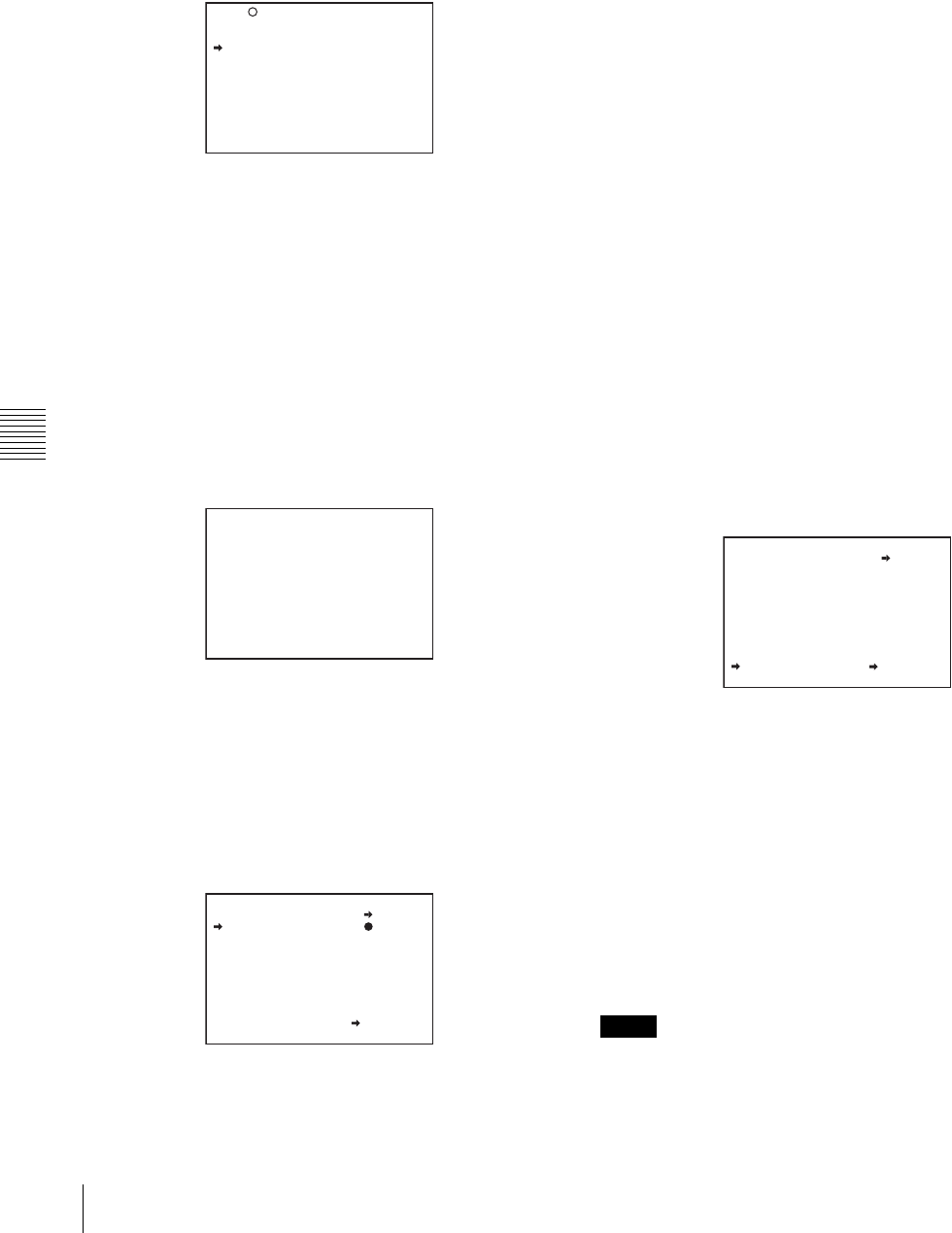
104 Saving and Loading Scene Files
Chapter 6 Saving and Loading User Setting Data
3
Load a scene file.
To load a scene file stored in the camcorder
Turn the MENU knob to move the b mark to the
desired file number, and press the MENU knob.
The s which is displayed on the left of the file number
changes to x.
The camcorder is set up according to the loaded scene
file.
To cancel the selected scene file
Move the b mark to x, and press the MENU knob. x
changes to s.
The camcorder returns to the settings before selecting
this scene file.
To load a scene file saved in the “Memory Stick”
Proceed as follows:
1Turn the MENU knob to move the b mark to
“SCENE RECALL,” and press the MENU knob.
The P00 SCENE RECALL page appears.
2Turn the MENU knob until the page which
contains the desired file number appears, then press
the MENU knob.
3Turn the MENU knob to move the b mark to the
desired file number, and press the MENU knob.
The message “RECALL OK? YES bNO” appears.
4
To carry out the recall, move the b mark to “YES” and
press the MENU knob.
To cancel, press the MENU knob leaving the b mark
pointing to “NO.”
When the loading is completed, the message
“COMPLETE” appears. The camcorder is set up
according to the loaded scene file.
If no file is present with a particular file number, this is
shown as “NO FILE.”
5
To end the menu operation, set the MENU ON/OFF
switch to OFF.
Loading scene files from a “Memory Stick”
into the camcorder memory
You can load up to five scene files stored in the “Memory
Stick” into the camcorder memory in a single operation.
1
After displaying the SCENE FILE page (page 101),
turn the MENU knob to move the b mark to “SCENE
RECALL,” and press the MENU knob.
A SCENE RECALL page appears.
2
Turn the MENU knob until the SCENE RECALL page
which contains the desired scene files appears, then
press the MENU knob.
3
Turn the MENU knob to move the b mark to “5FILE
LOAD b MEM 1-5,” and press the MENU knob.
The message “RECALL OK? YES bNO” appears.
4
To carry out the recall, move the b mark to “YES” and
press the MENU knob.
To cancel, press the MENU knob leaving the b mark
pointing to “NO.”
When loading is complete, the message
“COMPLETE” appears and the ACCESS indicator
goes off.
5
To end the menu operation, set the MENU ON/OFF
switch to OFF or close the cover of the menu operating
section.
• The scene files loaded from the “Memory Stick”
overwrite data saved in the camcorder memory.
F04 SCENE FILE
s
1 :SCENE 25
x
2 :SCENE 26
s
3 :SCENE 27
s
4 :SCENE 28
s
5 :NO FILE
s
STANDARD
SCENE RECALL : EXEC
SCENE STORE : EXEC
F.ID: SCENE21
TOP
?P00 SCENE RECALL
DISPLAY MODE : F.ID
MEM<1>:STANDARD
MEM<2>:STANDARD
MEM<3>:STANDARD
MEM<4>:STANDARD
MEM<5>:NO FILE
ESC
P01 SCENE RECALL
RECALL OK? YES NO
DISPLAY MODE : ALL
001.SCENE1
002.SCENE2
003.NO FILE
004.SCENE4
005.SCENE5
***.5FILE LOAD MEM1-5
ESC
Notes
P01 SCENE RECALL
RECALL OK? YES NO
DISPLAY MODE : ALL
001.SCENE1
002.SCENE2
003.NO FILE
004.SCENE4
005.SCENE5
***.5FILE LOAD MEM1-5
ESC
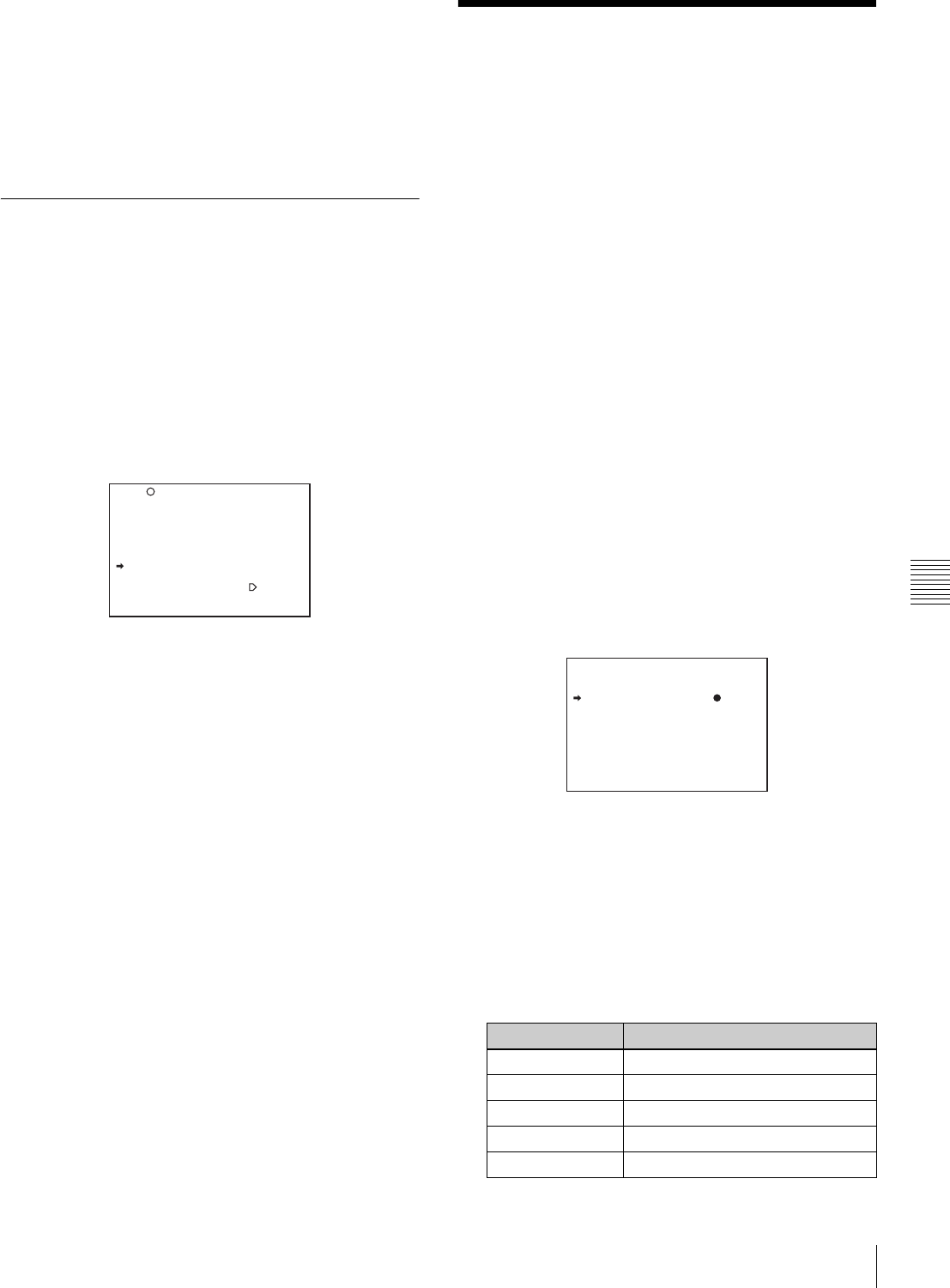
105
Jumping to a File-Related Menu Page When Inserting a “Memory Stick”
Chapter 6 Saving and Loading User Setting Data
• To load the scene file saved in the camcorder memory
when the “Memory Stick” is inserted, return to the P00
SCENE RECALL page and load the desired scene file in
the camcorder memory.
• When there is no file to be loaded (shown as “NO
FILE”), an existing file of the same number is
unaffected. In the example shown in step 3, MEM(3) is
not overwritten.
6-2-3 Resetting the Settings of the
Camcorder to the Standard Settings
Saved in the Reference File
You can reset the settings of the camcorder to the settings
saved in the reference file (standard settings).
For details about the items in the reference file, refer to the
Maintenance Manual.
On the SCENE FILE page, turn the MENU knob to move
the b mark to “STANDARD,” and press the MENU knob.
The s displayed on the left of STANDARD changes to x.
When x changes to s, the settings of the camcorder are
reset to the settings saved in the reference file.
If you press the MENU knob again while x is displayed,
the operation is cancelled and the camcorder returns to the
settings before STANDARD was selected.
6-3 Jumping to a File-
Related Menu Page When
Inserting a “Memory
Stick”
A “Memory Stick” enables you to save user files, scene
files, lens files, reference files and “ALL” files. The
camcorder menu system allows you to make a setting so
that when a “Memory Stick” holding these files is inserted
while in menu operating mode, a menu page relating to the
desired file is automatically displayed on the screen. Thus
you can proceed to file operation quickly. This is very
convenient especially when you manage data files using
“Memory Sticks.”
The page to be displayed can be selected on the MEMORY
STICK page of the FILE menu.
To make this setting, proceed as follows:
1
In the TOP menu, select the FILE menu.
2
Turn the MENU knob until the MEMORY STICK
page of the FILE menu appears, then press the MENU
knob to select the page. Alternatively, on the
CONTENTS page select MEMORY STICK.
MEMORY STICK page
3
Turn the MENU knob to move the b mark to “M.S. IN
> JUMP TO,” and press the MENU knob.
The b mark on the left of “M.S. IN > JUMP TO”
changes to a z mark, and the z mark on the left of the
setting changes to a ? mark.
4
Turn the MENU knob to select the desired setting
(target FILE menu page).
F04 SCENE FILE
s
1 :SCENE 25
s
2 :SCENE 26
s
3 :SCENE 27
s
4 :SCENE 28
s
5 :NO FILE
x
STANDARD
SCENE RECALL : EXEC
SCENE STORE : EXEC
F.ID: SCENE21
TOP
Setting Description
OFF Disables this function.
USER Jumps to the USER FILE page.
ALL Jumps to the ALL FILE page.
SCENE Jumps to the SCENE FILE page.
LENS Jumps to the LENS FILE 1 page.
F09 MEMORY STICK
M.S. FORMAT : EXEC
M.S. IN > JUMP TO: OFF

106 Jumping to a File-Related Menu Page When Inserting a “Memory Stick”
Chapter 6 Saving and Loading User Setting Data
5
Press the MENU knob to confirm the selection.
The z mark returns to a b mark, and the ? mark
returns to a z mark.
In the following cases, jumping to the target page is
impossible.
• When the power is turned on after you insert a “Memory
Stick.”
• When OFF is selected for the M.S. IN > JUMP TO item.
• When any of the following menu pages is already
displayed.
—A file-related page such as the USER FILE page of
the FILE menu
—MEMORY STICK, ALL FILE, SCENE FILE, LENS
FILE, REFERENCE FILE or ROM VERSION page
REFER Jumps to the REFERENCE page.
USER 1 Jumps to the USER 1 page.
Notes
Setting Description
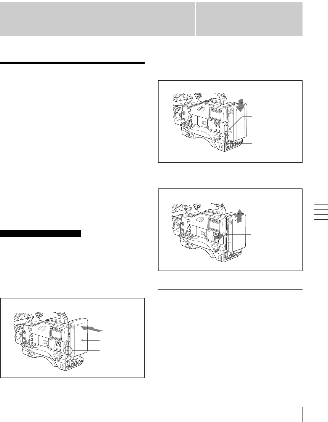
107
Chapter 7 Setting Up the Camcorder
Chapter
Power Supply
7
Setting Up the
Camcorder
7-1 Power Supply
The following power supplies can be used with the
camcorder.
• BP-GL65/GL95/L60S Lithium-ion battery pack
• AC power using the AC-550/550CE or AC-DN10 AC
adaptor
7-1-1 Using a Battery Pack
When a BP-GL95 battery pack is used, the camcorder will
operate continuously for about 180 minutes. When a BP-
GL65 is used, the camcorder will operate continuously for
about 120 minutes.
Before use, charge the battery pack with a BC-M50/M150
Battery Charger. It takes about 145 minutes to charge one
BP-GL95.
For details, refer to the battery charger operation manual.
A warm battery pack may not be able to be fully recharged.
Attaching the battery pack
1
Press the battery pack against the back of the
camcorder, aligning the line on the side of the battery
pack with the matching line on the camcorder.
2
Slide the battery pack down until its “LOCK” arrow
points at the matching line on the camcorder.
Detaching the battery pack
Detaching the battery pack
7-1-2 Avoiding Breaks in Operation
Due to an Exhausted Battery
If you use both an internal battery pack (attached to the
camcorder) and an external battery (connected to the DC
IN connector) at the same time, you can avoid breaks in
operation due to dead batteries.
When the external battery begins to fail and an
internal battery pack is also used
Remove the DC output cable from the DC IN connector.
The power source will switch to the internal battery pack.
Note on using the battery pack
Back of camcorder
Battery pack
Align these lines.
“LOCK” arrow
Matching line on
the camcorder
Holding the button
in, pull the battery
pack up.
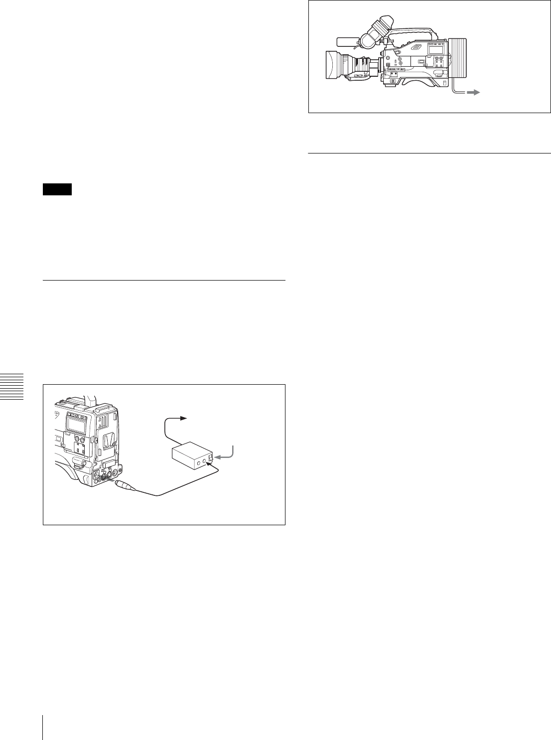
108 Power Supply
Chapter 7 Setting Up the Camcorder
When the external battery begins to fail and an
internal battery pack is not used
First load the camcorder with a fully charged internal
battery pack, then remove the DC output cable of the
external battery from the DC IN connector. The power
source will switch to the internal battery pack. To use an
external battery again, connect a fully charged external
battery to the DC IN connector before unloading the
internal battery pack. The power source will switch to the
external battery.
Continuous operation when operating with only
an internal battery pack
First, connect a fully charged external battery to the DC IN
connector, then change the internal battery.
• When an internal battery pack is loaded and an external
battery is connected to the DC IN connector, the external
battery is always used as the power source.
• There may be some noise on the video signal at the
instant the power sources are switched.
7-1-3 Using an AC Adaptor
Using the AC-550/550CE AC adaptor
Connect the camcorder to the AC power supply through
the AC-550/550CE AC Adaptor as shown in the following
figure, and turn the POWER switch of the AC-550/550CE
on.
Using an AC adaptor
Using the AC-DN10 AC adaptor
Mount the AC-DN10 on the camcorder in the same way as
a battery pack, then connect to the AC power supply. The
AC-DN10 can supply up to 100 W of power.
Connecting to an AC power source
using the AC-DN10 AC Adaptor
7-1-4 Using the Anton Bauer
Ultralight System
By fitting the camcorder with the Anton Bauer Ultralight
system, and setting the LIGHT switch to AUTO, you can
switch the light on and off automatically as you start and
stop VTR operation. This system operates with lights
powered by 12 V, with a maximum power consumption of
50 W.
Notes
to an AC power source
Power switch on
AC Adaptor
AC-550/
550CE
DC OUT
DC IN
DC output cable (supplied with
the AC-550/550CE)
to an AC power
source
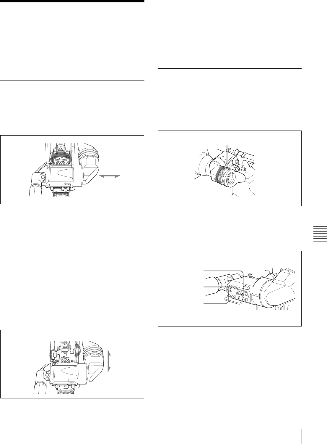
109
Adjusting the Viewfinder
Chapter 7 Setting Up the Camcorder
7-2 Adjusting the
Viewfinder
For maximum viewing convenience, you can adjust the
viewfinder position in the left-right and backward-forward
directions.
7-2-1 Adjusting the Viewfinder
Position
Adjusting the position to the left or right
Proceed as follows:
Adjusting the position to the left or right
1
Loosen the viewfinder left-right positioning ring.
2
Slide the viewfinder to the s convenient position.
3
Tighten the viewfinder left-right positioning ring.
To store the camcorder in the carrying case
Always store the camcorder with the viewfinder moved
fully in the direction opposite to the barrel and the
viewfinder left-right positioning ring tightened.
Adjusting the position backward or
forward
Proceed as follows:
Adjusting the position backward or forward
1
Loosen the viewfinder front-rear positioning lever and
the LOCK knob.
2
Slide the viewfinder longitudinally to the most
convenient position.
3
Tighten the viewfinder front-rear positioning lever and
the LOCK knob.
7-2-2 Adjusting the Viewfinder
Focus and Screen
Adjusting the viewfinder focus
Turn the diopter adjustment ring until the viewfinder
image is sharpest.
Adjusting the viewfinder focus
Adjusting the viewfinder screen
Adjust the brightness, contrast, and peaking of the
viewfinder screen with the controls shown below:
Adjusting the viewfinder screen
2
31
2
3
1
1
Diopter adjustment ring
BRIGHT control
CONTRAST control
PEAKING control
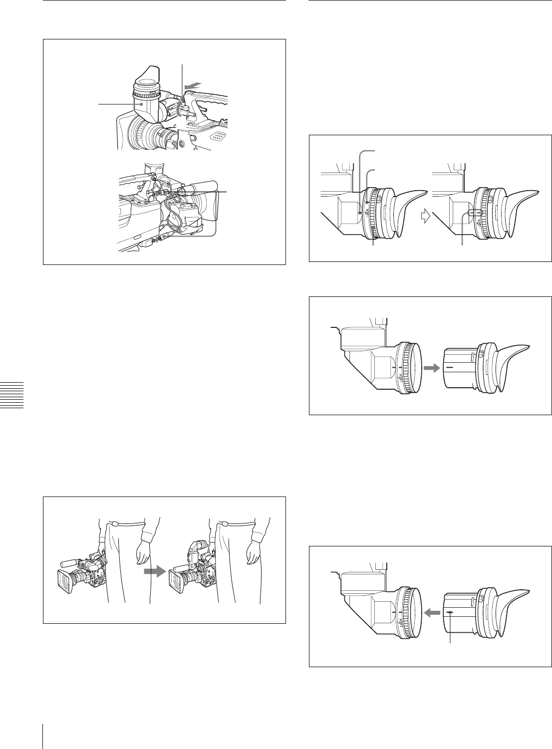
110 Adjusting the Viewfinder
Chapter 7 Setting Up the Camcorder
7-2-3 Detaching the Viewfinder
Detaching the viewfinder
1
Point the viewfinder barrel up or down.
2
Loosen the viewfinder left-right positioning ring.
3
Holding the viewfinder stopper up, slide the
viewfinder in the direction indicated by the arrow and
detach it.
4
Remove the viewfinder cable and microphone cable
from the clamps and disconnect them.
Using the viewfinder rotation bracket
By fitting a BKW-401 Viewfinder Rotation Bracket (not
supplied), you can rotate the viewfinder out of the way so
that your right leg does not hit the viewfinder while you are
carrying the camcorder.
Using the BKW-401 Viewfinder Rotation Bracket
For more information, refer to the BKW-401 manual.
7-2-4 Detaching the Eyepiece
Removing the eyepiece gives a clearer view of the screen
from further away. It is also easy to remove dust from the
viewfinder screen and mirror when the eyepiece is
detached.
1
Turn the eyepiece locking ring fully counterclockwise,
to align the red marks on the locking ring and the
viewfinder barrel.
2
Detach the eyepiece.
Reattaching the eyepiece
1
Align the red marks on the eyepiece locking ring and
the viewfinder barrel.
2
Align the red mark on the end of the eyepiece end with
the red marks on the eyepiece locking ring and the
viewfinder barrel. Then insert the eyepiece into the
viewfinder barrel.
1
3
4
2
Viewfinder stopper
Red mark
Locking ring Line up the red marks.
Red mark
Red mark on the end of the eyepiece
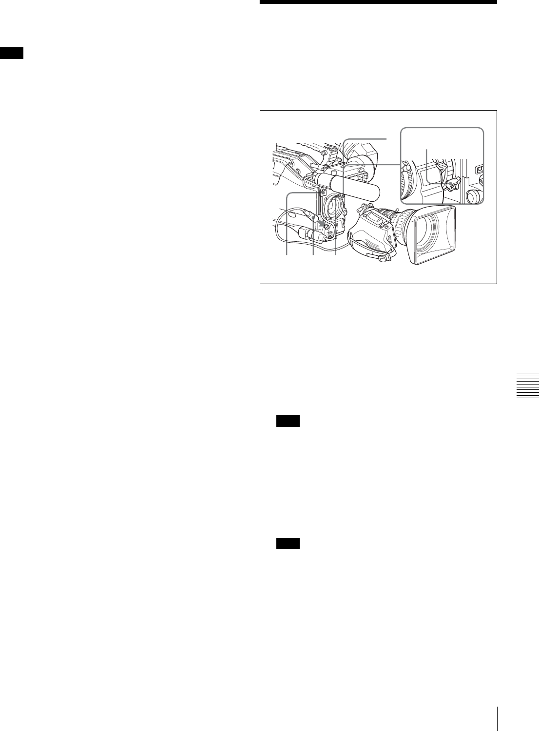
111
Mounting the Lens
Chapter 7 Setting Up the Camcorder
3
Turn the eyepiece locking ring clockwise until its
“LOCK” arrow points at the red mark on the
viewfinder barrel.
When the eyecup is worn out, replace it with a new one
(service part number 3-723-079-03).
7-3 Mounting the Lens
To mount the lens, proceed as follows:
For information about using the lens, refer to the lens
manual.
Mounting the lens
1
Push the lens locking lever upward and remove the
lens mount cap from the lens mount.
2
Align the center slot in the lens mount with the center
pin on the lens and insert the lens into the mount.
3
Holding the lens in place, push the lens locking lever
downward to mount the lens.
If the lens is not firmly locked, it may come off while
the camcorder is being used. This could cause a serious
accident. Make sure the lens is firmly locked. It is
recommended that the lens mount securing rubber
(supplied) be put on the lens-locking lever as
illustrated above.
4
Connect the lens cable to the LENS connector.
Connecting a cable to the LENS connector while in
powered status may cause a malfunction or damage the
unit. Turn off the power before you make a connection
with the LENS connector.
5
Secure the lens cable with the cable clamps.
Note
Note
Note
245
31 Lens mount
securing rubber
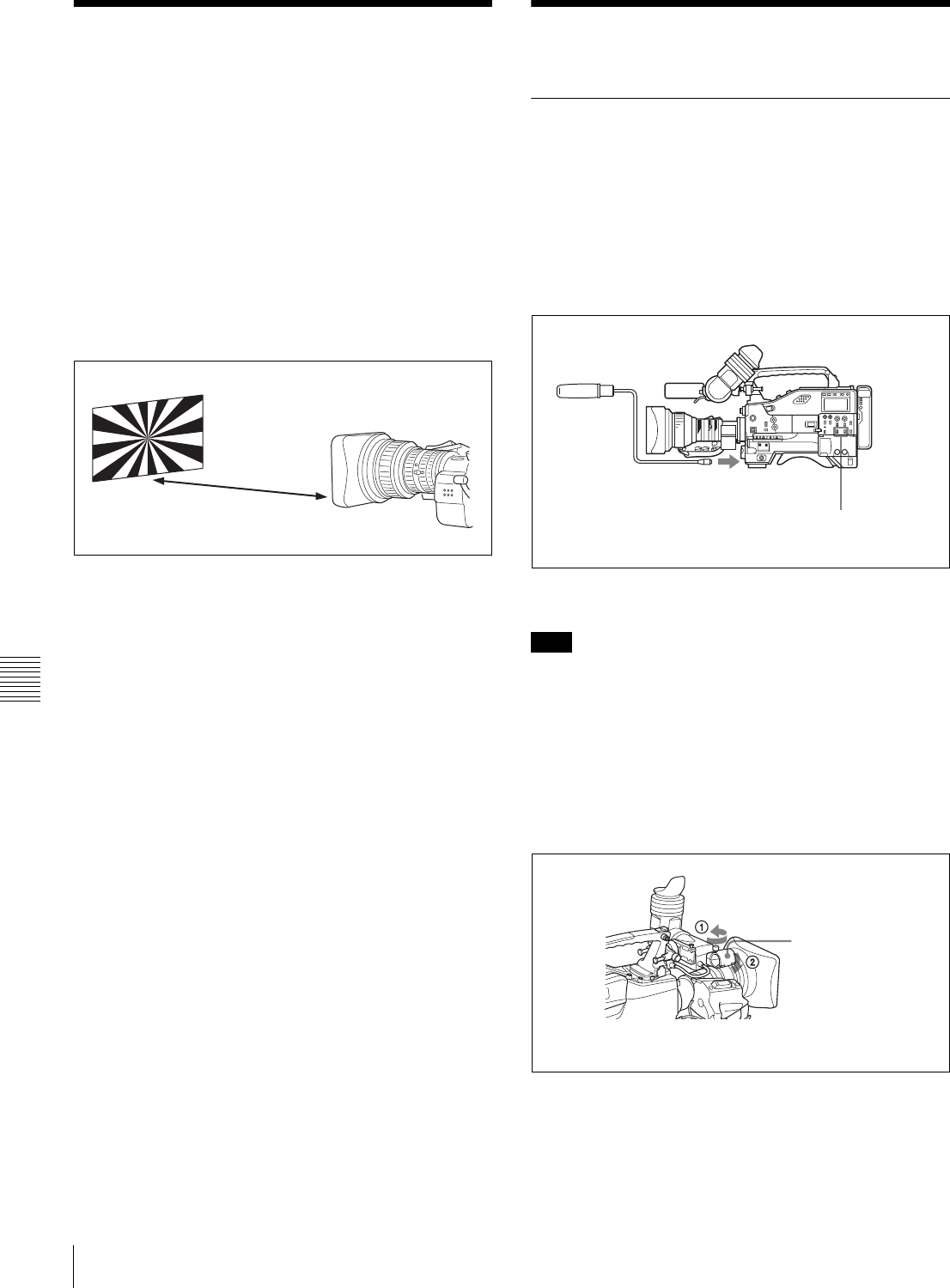
112 Adjusting the Flange Focal Length / Audio Input System
Chapter 7 Setting Up the Camcorder
7-4 Adjusting the Flange
Focal Length
If the lens does not stay in focus properly as you zoom
from telephoto to wide angle, adjust the flange focal length
(the distance from the plane of the lens mounting flange to
the imaging plane). Make this adjustment after mounting
or changing the lens.
Adjusting the flange focal length
The position of the controls for adjusting the flange focal
length vary somewhat from lens to lens. Check the
identification of the various controls in the lens manual.
Adjusting the flange focal length
1
Set the iris to manual.
2
Open the iris. Place the flange focal length adjustment
chart about 3 m (10 ft) away from the camera, lit well
enough to provide a satisfactory video output level.
3
Loosen the fixing screws on the F.f or F.B ring (flange
focal length adjustment ring).
4
Use manual or power zoom to set the lens to telephoto.
5
Point the camera at the chart by turning the focus ring
and focus on it.
6
Set the zoom ring to wide angle.
7
Turn the F.f or F.B ring until the chart is in focus, being
careful not to disturb the focus ring.
8
Repeat steps 4 to 7 until the chart stays in focus all the
way from wide angle to telephoto.
9
Tighten the F.f or F.B ring fixing screws.
7-5 Audio Input System
7-5-1 Using the Supplied
Microphone
You can use the supplied microphone either detached from
or attached to the camcorder.
Using the microphone detached from the
camcorder
Using the supplied microphone detached
from the camcorder
When using the supplied microphone with an extension
cable, always use an external power supply type cable.
Using the microphone attached to the
camcorder
1
Loosen the screw and open the microphone holder
clamp.
About 3 m (10 ft)
Note
Connect to the MIC IN
connector.
Set the AUDIO IN switch for
the desired audio recording
channel to FRONT.
Clamp of the
Microphone holder
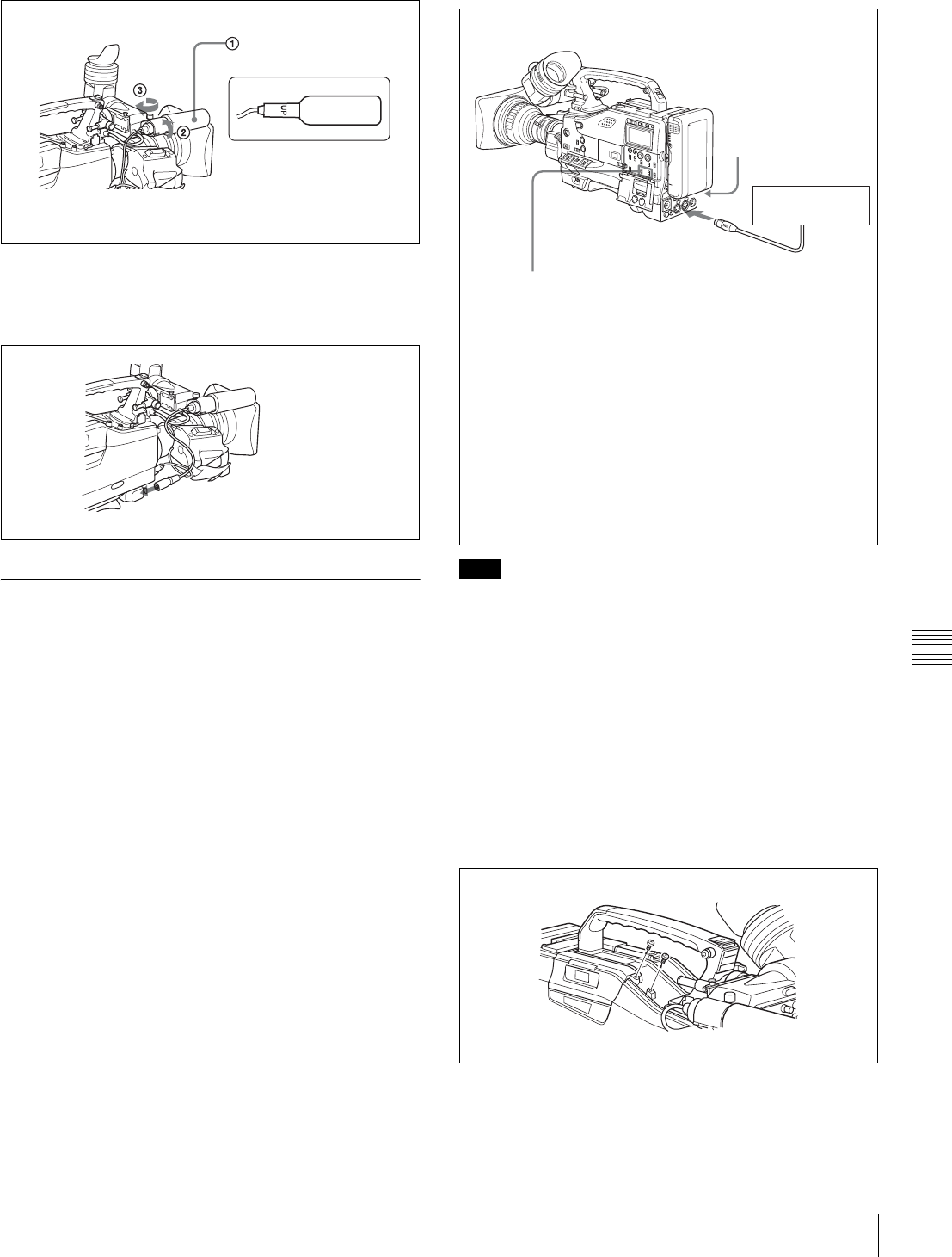
113
Audio Input System
Chapter 7 Setting Up the Camcorder
2
Place the microphone in the microphone holder.
3
Plug the microphone cable into the MIC IN connector,
then set the AUDIO IN switch for the desired
recording channel to FRONT.
7-5-2 Using an External Microphone
You can connect up to two external microphones using the
AUDIO IN CH1 and CH2 connectors.
When using a condenser microphone that requires external
power (phantom power), set the LINE/MIC/+48 V ON
switch to +48 V ON.
If the microphone being used does not require external
power (dynamic microphone), set the LINE/MIC/+48 V
ON switch to MIC.
Using a detached external microphone
In order for the AUDIO IN CH1 and CH2 connectors on
the camcorder to be able to provide a phantom 48 V power
supply, female XLR connectors (3-pin) are fitted. If the
microphone cable has a female connector, use an adaptor.
Using an external microphone attached to
the camcorder
You can attach an external microphone to the camcorder
using the optional CAC-12 microphone holder.
1
Remove the fixing screws for external microphone
holder.
2
Attach the CAC-12 Microphone Holder.
Place the microphone in
the holder so that “UP” is
at the top.
Tighten the screw.
Close the microphone holder.
Connect to the MIC IN connector.
Note
External
microphone
AUDIO IN CH-1/CH-2 switches:
When the audio cable is connected to either
the AUDIO IN CH1 or CH2 connector with the
XLR connection automatic detection function
set to ON on the AUDIO-1 page of the
MAINTENANCE menu, the signal input to the
AUDIO IN CH1 or CH2 connector is
automatically selected as the signal to be
recorded. This is true regardless of the
AUDIO IN CH-1/CH-2 switch settings. (This
is called XLR connection automatic detection
function.)
When the XLR connection automatic
detection function is set to OFF (factory
setting), set the AUDIO IN CH-1/CH-2 switch
corresponding to the channel to which the
microphone is connected to REAR.
LINE/MIC/+48 V ON
switch:
Set the LINE/MIC/+48 V
ON switch to +48 V ON if
you use an external
power supply type
microphone. Otherwise,
set the switch to MIC.
AUDIO IN for
CH-1 or CH-2
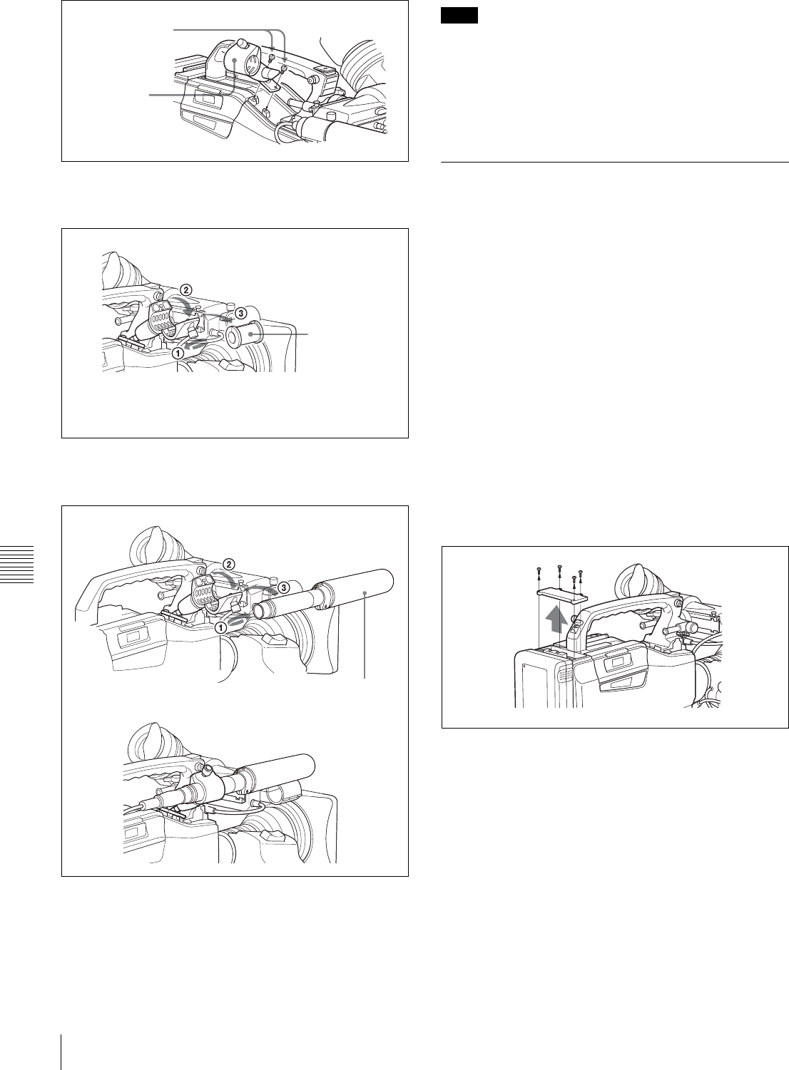
114 Audio Input System
Chapter 7 Setting Up the Camcorder
3
Open the CAC-12 and remove the microphone
adaptor.
4
Place an ECM-672 electret condenser microphone in
the CAC-12.
5
Connect the microphone cable to the AUDIO IN CH1
or AUDIO IN CH2 connector.
Set the LINE/MIC/+48 V ON switch to +48 V ON if
you use an external power supply type microphone.
Otherwise, set the switch to MIC.
When you detach the CAC-12 Microphone Holder once
you have attached to the camcorder, be careful not to lose
the two screws fixing the CAC-12. After detaching the
CAC-12, be sure to put the two screws back into their
original places (see the figure illustrating the step 1
operation).
7-5-3 Attaching a UHF Portable
Tuner (for a UHF Wireless
Microphone System)
To use a Sony UHF wireless microphone system, fit one of
the following UHF portable tuners.
• WRR-855A/855B UHF Synthesized Tuner Unit
• WRR-860/862 UHF Portable Tuner.
For each of these UHF portable tuners, use the following
attachment procedure.
For details, refer to the UHF portable turner manual.
Fitting the WRR-855A/855B
You can use the WRR-855A/855B UHF Synthesized
Tuner Unit simply by inserting it into the slot in the
camcorder, and fastening the fixing screws.
1
Undo the four fixing screws holding the cover of the
slot, and remove the cover.
2
Insert the WRR-855A/855B, and fasten the four fixing
screws.
Screws removed
in step 1
CAC-12
Open the CAC-12.
Microphone
adaptor 1)
Loosen the screw.
1) Attach the microphone adaptor when using a small-
diameter external microphone.
Close the CAC-12.
Tighten the screw. ECM-672 or similar
microphone
f
Note
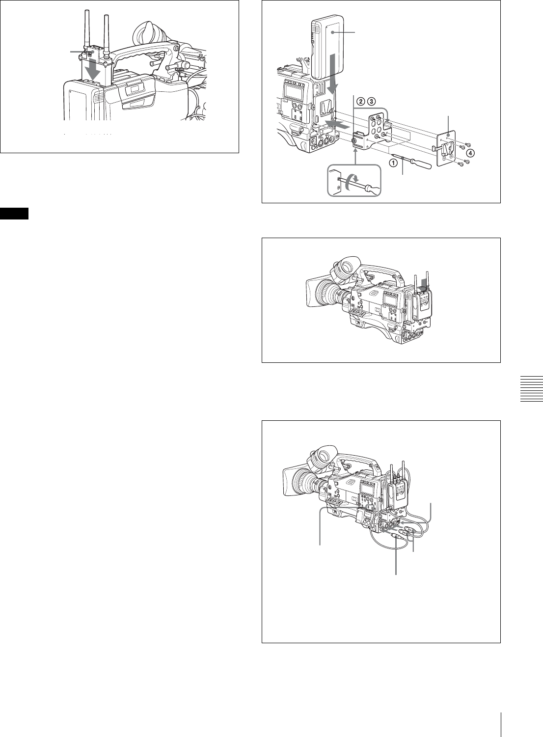
115
Audio Input System
Chapter 7 Setting Up the Camcorder
For the operation of the WRR-855A/855B, refer to the
manual supplied with the WRR-855A/855B.
• When the XLR connection automatic detection function
is on, even if the AUDIO IN CH-1 or CH-2 switch is set
to WIRELESS, the signal input to the AUDIO IN CH1
or CH2 connector is automatically selected when an
audio cable is connected to the AUDIO IN CH1 or CH2
connector. In such a case, set REAR XLR AUTO to OFF
on the AUDIO-1 page of the MAINTENANCE menu.
• The audio signals to be recorded on audio channels 3 and
4 depend on the settings of the AUDIO IN CH-3/CH-4
switches without being affected by the XLR connection
automatic detection function.
Fitting the WRR-862 (with a battery pack)
1
(1) Attach the WRR tuner fitting (not supplied, service
part number: A-8278-057-A) to the back of the
camcorder.
1Use a Phillips-type screwdriver to tighten the
four screws placed in the tuner fitting. For three
of these screws, insert the screwdriver through
the corresponding hole and tighten the screw.
2Loosen the adjustment screws.
3Adjust the tuner fitting position for a battery
pack to be attached, and tighten the adjustment
screws to fix its position.
4Attach the mount plate supplied with the WRR-
862.
(2) Attach the battery pack.
For details about attaching the battery pack, see “7-1-
1 Using a Battery Pack” on page 107.
2
Mount the tuner on the WRR tuner fitting.
3
Connect the tuner power cord to the DC OUT
connector of the camcorder, and the audio output cable
to the AUDIO IN CH1 or CH2 connector.
Notes
WRR-855A/855B
Set the AUDIO IN switch to WIRELESS.
Back of camcorder
Battery Pack
Adjustment screws
Mount plate (supplied
with WRR-862)
Screwdriver
WRR-862
LINE/MIC/+48 V ON
switch:
Set the LINE/MIC/
+48 V ON switch for
the channel to which
the audio out cable is
attached to MIC.
AUDIO IN CH-1/CH-2 switches:
When the XLR connection
automatic detection function is
set to OFF on the AUDIO-1 page
of the MAINTENANCE menu,
set the AUDIO IN CH-1 or CH-2
switch for the channel to which
the audio output cable is
connected to REAR.
to AUDIO IN CH1 or
CH2 connector
to DC OUT connector
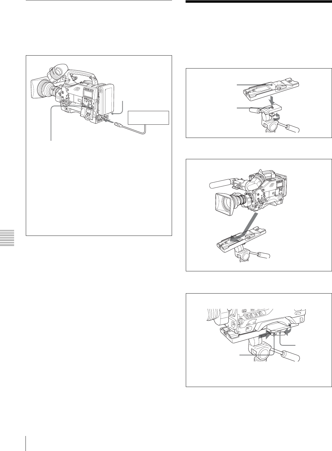
116 Tripod Mounting
Chapter 7 Setting Up the Camcorder
7-5-4 Connecting Line Input Audio
Equipment
Connect the audio output connector of the audio
equipment that supplies the line input signal to the AUDIO
IN CH1 or CH2 connector.
7-6 Tripod Mounting
You can easily mount and dismount the camcorder on a
tripod by using the VCT-14 tripod adaptor (not supplied).
1
Attach the tripod adaptor to the tripod.
2
Mount the camcorder on the tripod adaptor.
Removing the camcorder from the tripod adaptor
Removing the camcorder from the tripod adapter
Audio equipment
AUDIO IN CH-1/CH-2 switches:
When the audio cable is connected to either
the AUDIO IN CH1 or CH2 connector with
REAR XLR AUTO set to ON on the AUDIO-1
page of the MAINTENANCE menu, the signal
input to the AUDIO IN CH1 or CH2 connector
is automatically selected as the signal to be
recorded. This is true regardless of the
AUDIO IN CH-1/CH-2 switch settings. (This is
called XLR connection automatic detection
function.)
When the XLR connection automatic
detection function is set to OFF (factory
setting), set the AUDIO IN CH-1 or CH-2
switch corresponding to the channel to which
the audio equipment is connected to REAR.
LINE/MIC/+48 V ON
switch:
Set the LINE/MIC/+48 V
ON switch for the
channel to which the
audio out cable is
attached to LINE.
AUDIO IN for
CH-1 or CH-2
Tripod adaptor
Camera mount
Slide the camcorder
forward along the groove in
the adaptor until it clicks.
While pressing the red button against
the lever, move the lever in the direction
indicated by the arrow.
Red button
Lever
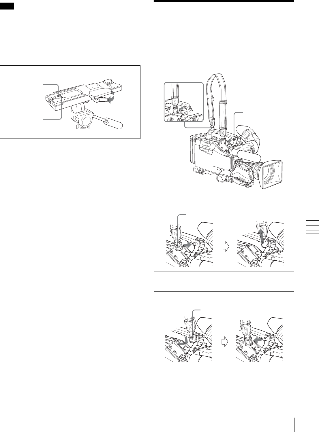
117
Attaching/Detaching the Shoulder Strap
Chapter 7 Setting Up the Camcorder
The tripod adaptor pin may remain in the engaged position
even after the camcorder is removed. If this happens, press
the red button against the lever a second time and move the
lever as shown below until the pin returns to the stowed
position. If the pin remains in the engaged position, you
will not be able to mount the camcorder on the tripod
adaptor.
If the pin remains in the engaged position
7-7 Attaching/Detaching
the Shoulder Strap
Attaching the shoulder strap
Attach the supplied shoulder strap as shown below:
Removing the shoulder strap
Note
Stowed position
Pin
Shoulder strap post
Clip
Pull up the strap to lock
the fitting.
Press here and pull in
the direction shown by
the arrow to release.
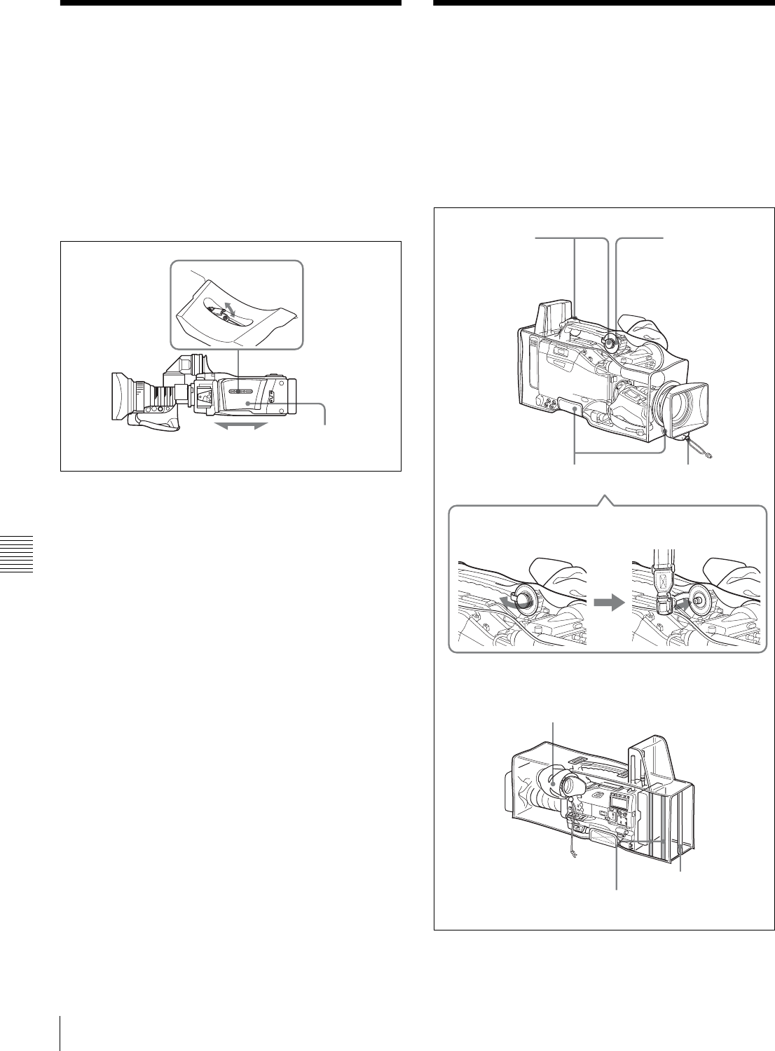
118 Adjusting the Shoulder Pad Position / Putting on the Rain Cover (Not Supplied)
Chapter 7 Setting Up the Camcorder
7-8 Adjusting the
Shoulder Pad Position
You can shift the shoulder pad from its center position
(factory setting) backward by up to 10 mm (3/8 inch) or
forward by up to 25 mm (1 inch). This adjustment helps
you get the best balance for shooting with the camcorder
on your shoulder.
Proceed as follows:
Adjusting the shoulder pad position
1
Raise the lever in the center of the shoulder pad to
unlock the shoulder pad.
2
Slide the shoulder pad backward or forward until it is
in the most convenient position.
3
Bring down the lever to lock the shoulder pad in the
selected position.
7-9 Putting on the Rain
Cover (Not Supplied)
Attach the rain cover (part number 3-191-064-02) as
illustrated below. You can insert and remove cassette tapes,
operate various switches and controls, and mount the
camcorder on the tripod adaptor with the rain cover
attached.
1,3
2Shoulder pad
Bottom
When a shoulder
belt is not used,
cover the holes
on the rain cover
with caps.
When you use a
shoulder strap,
use these holes.
For details, see
the following
diagram.
Rear
Front
Velcro tape Drawstring
Pass the shoulder strap post clearly through this hole
on the rain cover.
Insert the viewfinder barrel here with the
eyecup out and fasten the drawstring around
the eyecup.
Drawstring
Velcro tape
Velcro tape
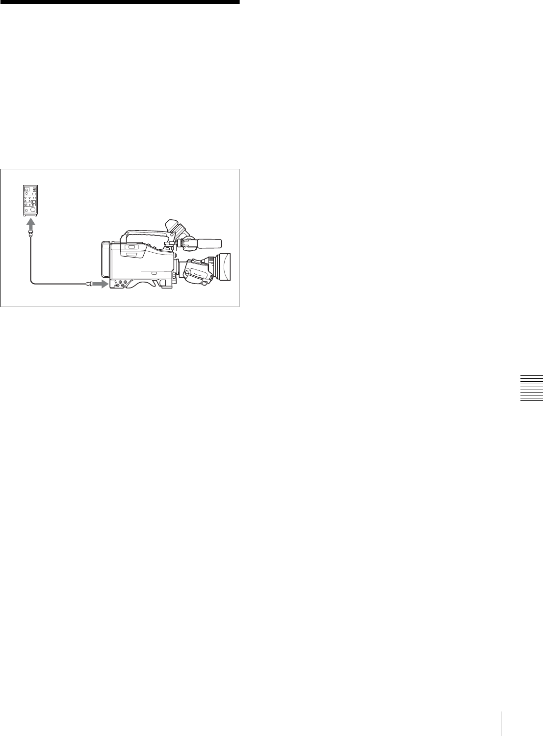
119
Connecting the Remote Control Unit
Chapter 7 Setting Up the Camcorder
7-10 Connecting the
Remote Control Unit
Connecting the RM-B150/B750 Remote Control Unit
(optional) enables remote control of the principal camera
functions.
Connecting the remote control unit to the REMOTE
connector (8-pin) automatically puts the camcorder into
remote control mode. If you disconnect the remote control
unit, the remote control mode is cancelled.
Camcorder switch functions when the
remote control unit is connected
The following switches on the camcorder do not function.
• GAIN selector
• OUTPUT/DCC switch
• WHITE BAL switch
• AUTO W/B BAL switch
• SHUTTER selector
• TURBO GAIN button (ASSIGN 1 switch to which the
TURBO GAIN function is assigned)
• VTR START button (VTR button on the lens and the
ASSIGN 1 or the TURBO GAIN switch to which the
VTR START/STOP function is assigned) (When the RM
REC START item on the FUNCTION 3 page of the
MAINTENANCE menu is set to RM.)
For details of the function of the VTR START button, see
the item “Function of the VTR START button when the
remote control unit is connected” on this page.
Paint adjustment when the remote control
unit is connected
If RM COMMON MEMORY is set to OFF on the
FUNCTION 3 page of the MAINTENANCE menu.
The settings of the paint adjustment that were in effect the
last time the remote control unit was used are recalled.
Function of the VTR START button when
the remote control unit is connected
You can select the function of the VTR START button on
the camcorder when the remote control unit is connected,
using the RM REC START item on the FUNCTION 3
page of the MAINTENANCE menu.
To disable the camcorder VTR START button and
the lens VTR button
On the FUNCTION 3 page of the MAINTENANCE menu,
set RM REC START to “RM.”
If the same function as that of the VTR START button is
assigned to the ASSIGN 1 switch or the TURBO GAIN
button, this setting also disables these controls.
To enable the camcorder VTR START button and
the lens VTR button
On the FUNCTION 3 page of the MAINTENANCE menu,
set RM REC START to “CAM” or “PARA.”
If the same function as that of the VTR START button is
assigned to the ASSIGN 1 switch or the TURBO GAIN
button, this setting also enables these controls.
When the monitor is connected to the
remote control unit
The MONITOR connector (BNC type) of the RM-B150/
B750 outputs the same signal as that from the TEST OUT
connector on the camcorder.
Use the black cable supplied with the RM-B150/B750 to
connect the monitor to the MONITOR connector on the
RM-B150/B750.
When the remote control unit is
disconnected from the camcorder
The camcorder settings return to the settings in effect
before the remote control unit was connected.
By making a menu setting, the setting of the paint
adjustment made with the remote control unit can be
retained even after the remote control unit is removed from
the camcorder.
For details, see “Structure of the paint adjustment data”
below.
Structure of the paint adjustment data
The non-volatile memory of the camcorder used for
storing paint adjustment data consists of two regions as
shown below: one is the “independent data region” that is
used when a remote control unit is not connected, and the
other is the “remote control data region” that is used when
a remote control unit is connected. Paint adjustment data is
automatically selected and output to the hardware of the
camcorder depending on whether or not a remote control
unit, such as the RM-B150, is connected.
RM-B150/B750
REMOTE
connector
Remote control cable

120 Connecting the Remote Control Unit
Chapter 7 Setting Up the Camcorder
Thus, when a remote control unit is connected to the
camcorder, the effective data region is switched to the
“remote control data region” and the settings of the paint
adjustment that were in effect last time the remote control
unit was used are recalled.
Settings of the absolute value volume 1) and absolute value
switches 2) are overwritten by those on the remote control
unit after the remote control unit is connected.
When the remote control unit is removed from the
camcorder, the “independent data region” becomes
effective. Thus the camcorder will return to the settings
that were in effect before the remote control unit was
connected.
1) Absolute value volume
The data corresponding to the rotation degree (position) of the volume
knob is output. The data corresponding to the rotation amount (change) is
called the relative value volume.
2) Absolute value switch
Toggle switches or slide switches (except the temporary switches) (or
controls) whose positions must coincide with their functions are called
absolute value switches.
To use settings of the paint adjustment data
stored in the “independent data region” even
when you disconnect a remote control unit
Set RM COMMON MEMORY to ON on the FUNCTION
3 page of the MAINTENANCE menu.
In this case, the settings stored in the “independent data
region” will be renewed according to the change of settings
in the “remote control data region.” Thus, the settings of
the paint data made with the remote control unit can be
retained even if the remote control unit is removed.
However, if the switch position on the remote control unit
differs from the one on the camcorder, the switch position
on the camcorder takes precedence over that on the remote
control unit.
For details on menu operations, see “5-1-2 Basic Menu
Operations” on page 68.
To keep the video quality before a remote control
unit is connected
Set RM COMMON MEMORY to ON on the FUNCTION
3 menu of the MAINTENANCE menu, and set all the
volume on the remote control unit to the relative value
mode. After making these settings, connect the remote
control unit.
For details, refer to the operation manual supplied with the
remote control unit.
Non-volatile memory
Independent data
region
MASTER BLACK
MASTER GAMMA
KNEE POINT
DETAIL LEVEL
R/B GAIN
R/B BLACK
Remote control data
region
MASTER BLACK
MASTER GAMMA
KNEE POINT
DETAIL LEVEL
R/B GAIN
R/B BLACK
Setup
menu of the
camcorder
RM-B150
Hardware of
the camera
RM-B150
connected
RM-B150 not
connected
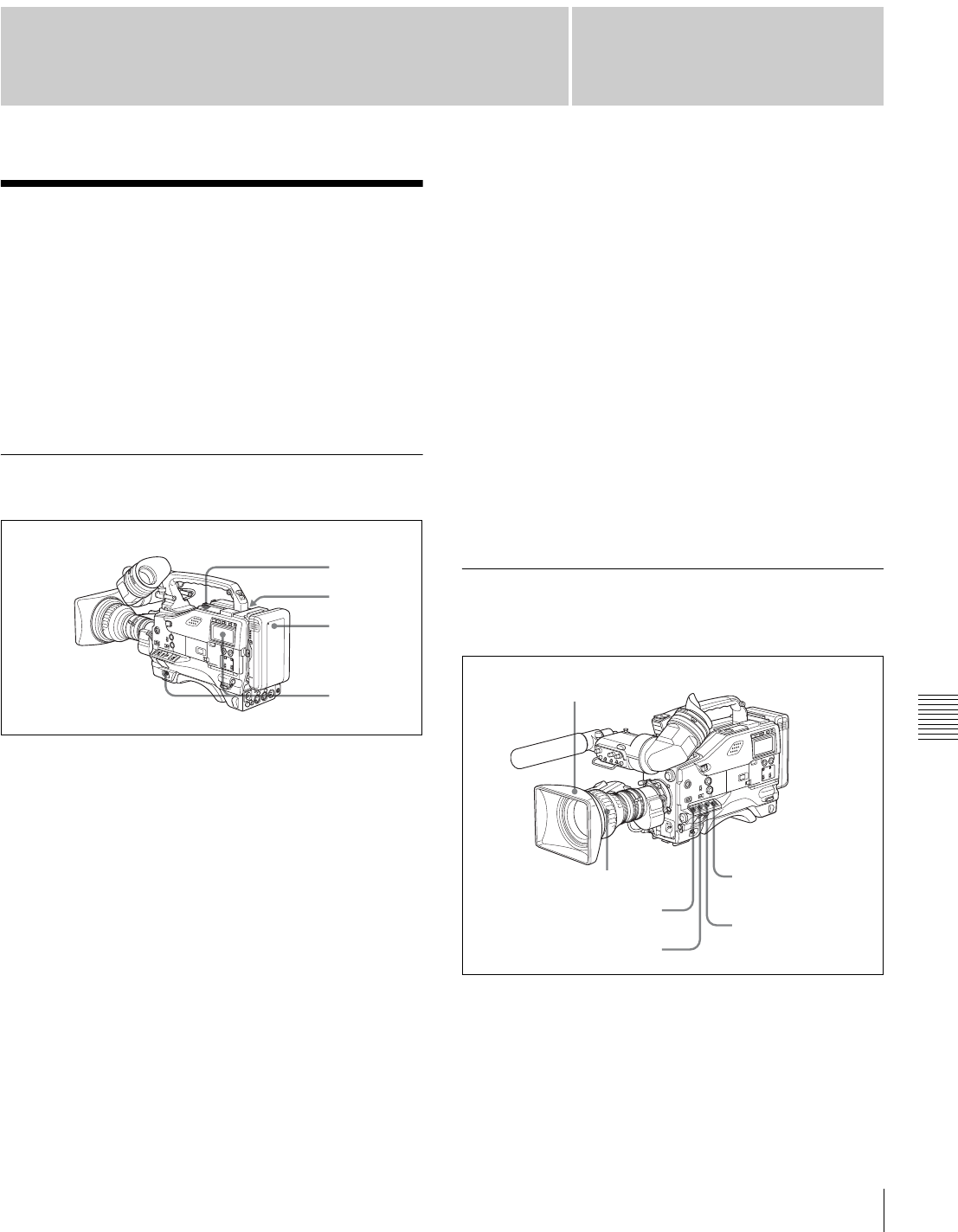
121
Chapter 8 Maintenance
Chapter
Testing the Camcorder Before Shooting
8
Maintenance
8-1 Testing the
Camcorder Before
Shooting
Check the functions of the camcorder before setting out for
a shooting session, preferably by operating the camcorder
together with a color video monitor.
8-1-1 Preparations for Testing
1
Attach a fully charged battery pack.
2
Set the POWER switch to ON and check that the
HUMID indicator does not appear and that the battery
power level is sufficient.
If the HUMID indicator appears, wait until it
disappears.
3
Check that there are no obstructions near the cassette
lid, and then press the EJECT button to open the
cassette lid.
4
After checking the points below, load the cassette and
close the cassette lid.
• The cassette is not write-protected.
• There is no slack in the tape.
• Condensation does not form in the tape.
Condensation
If you move the camcorder from a very cold place to a
warm place, or use it in a damp location, condensation may
form on the head drum. Then, if the camcorder is operated
in this state, the tape may adhere to the drum and cause a
failure or even permanent damage. Do the following to
prevent this from happening.
• When moving the camcorder from a cold place to a
warm place, be sure no cassette is loaded in the
camcorder.
• Whenever you turn on the power, check that the HUMID
indicator does not appear. If it appears, wait until it
disappears before loading a cassette.
For more information, see “3-1-1 Loading and Unloading
a Cassette” on page 31 and “8-3 Operation Warnings” on
page 126.
8-1-2 Testing the Camera
Set the switches and selectors as follows:
Testing the viewfinder
Proceed as follows:
1
Adjust the position of the viewfinder.
1
2
3
4
OUTPUT/DCC: BARS
Iris: Automatic
Zoom: SERVO/MAN
VTR SAVE/STBY: SAVE
WHITE BAL: A or B
GAIN: Set as low as possible.

122 Testing the Camcorder Before Shooting
Chapter 8 Maintenance
2
Check that the color bars are displayed on the
viewfinder screen, and adjust the BRIGHT,
CONTRAST, and PEAKING controls to give the best
color bar display.
3
Check each of the following operations.
• The menu is displayed on the viewfinder screen.
• Turn the MENU knob and check that the menu page
changes to the next page.
• Press the MENU knob and check that settings of
each item of the selected page are displayed.
• Turn the MENU knob and check that the b mark
moves within the page.
• Press the MENU knob and check that the b mark
placed before the item changes to a z mark and the
z mark placed before the setting of the item changes
to a ? mark.
• Turn the MENU knob and check that the setting of
the selected item changes.
4
Set the OUTPUT/DCC switch to CAM, and change
the inner FILTER (ND filter) selector position in the
sequence of 1, 2, 3 and 4, and the outer FILTER (CC
filter) selector position in the sequence B, C, D, A and
B.
Check that the FILTER indicator on the viewfinder
screen displays the correct numbers.
5
Carry out of the following operations, and check that
that the indicator lights if the corresponding item
has been turned on on the '!' LED page of the USER
menu.
• Set the gain to anything but 0 dB by using the GAIN
selector and the GAIN SW page of the OPERATION
menu.
• Set the SHUTTER selector to ON.
• Set the WHITE BAL switch to PRST.
• Use the lens extender.
• Set the inner FILTER (ND filter) selector to anything
but 1.
• Set the outer FILTER (CC filter) selector to anything
but B.
• Set the iris override to a value other than 0.
6
Move the SHUTTER selector from ON to SEL
repeatedly, and check that the shutter setting changes
on the viewfinder screen.
7
Pointing the camera at a suitable subject, focus the
camera and check the picture on the viewfinder screen.
8
Set both of the AUDIO IN switches to FRONT, and
check that when sound is input to a microphone
connected to the MIC IN connector on the front of the
camcorder, the audio level indicators appear on the
viewfinder screen.
9
Check that setting the ZEBRA switch to ON and OFF
makes the zebra pattern appear and disappear on the
viewfinder screen.
The results of checking in steps 3 to 9 may not be as
expected, depending on the settings relating to the
viewfinder display function. In this case, set the desired
items on the VF DISP 1 and VF DISP 2 pages of the USER
menu.
For details, see “5-2-2 Selecting the Display Items” on
page 76.
Testing the iris and zoom functions
1
Set the zoom to automatic zoom mode and check that
the power zoom operates correctly.
2
Set the zoom to manual zoom mode and check the
zoom functions manually.
3
Set the iris switch on the lens to AUTO and point the
camera at objects of different brightness. Check that
the automatic iris adjustment operates correctly.
4
Set the iris switch on the lens to MANUAL and check
that turning the iris ring manually adjusts the iris
correctly.
5
Set the iris switch on the lens back to AUTO and check
the following points when the GAIN selector is moved
from L to M to H.
• For objects of the same brightness, the iris is
adjusted to correspond to the change in setting.
• The gain indicator on the viewfinder screen changes
to correspond to the change in setting.
6
If an extender mechanism is incorporated in your lens,
put the extender lever of the lens into the 2x position
and check the following points.
• The indication “EX” appears at the top left on the
viewfinder screen.
• The auto iris functions correctly.
Note

123
Testing the Camcorder Before Shooting
Chapter 8 Maintenance
8-1-3 Testing the VTR
Perform tests (1) to (7) consecutively.
(1) Testing the tape transport functions
1
Set the VTR SAVE/STBY switch to VTR SAVE and
check that the SAVE indicator in the viewfinder goes
on.
2
Set the VTR SAVE/STBY switch to STBY and check
that the VTR SAVE indicator in the viewfinder goes
off.
3
Set the F-RUN/SET/R-RUN to R-RUN.
4
Set the DISPLAY switch to CTL.
5
Press the VTR START button and check the following
points.
• The tape reels are turning.
• The counter indication is changing.
• The REC indicator in the viewfinder is on.
• The RF and SERVO indicators on the display panel
are off.
6
Press the VTR START button again and check that the
tape stops and that the REC indicator in the viewfinder
goes off.
7
Repeat the checks of steps 5 and 6, this time using the
VTR button on the lens.
8
Press the RESET button and check that the indication
in the counter display is “00:00:00:00.”
9
Turn on the LIGHT switch and check that the display
panel is illuminated.
10
Hold down the REW button to rewind the tape for a
while, then press the PLAY button. Check that the
rewind and playback functions operate normally.
11
Press the STOP button and press the F FWD button.
Check that the fast forward function operates
normally.
(2) Testing the automatic audio level
adjusting functions
1
Set the AUDIO IN CH-1 and CH-2 switches to
FRONT.
2
Set the AUDIO SELECT CH-1/CH-2 switches to
AUTO.
3
Set the CH-1/2 / CH-3/4 switch to CH-1/2.
4
Aim the microphone connected to the MIC IN
connector at a suitable sound source. Check that the
level indications for channels 1 and 2 correspond to the
sound level, respectively.
5
Set the AUDIO IN CH-3 and CH-4 switches to F.
6
Set the CH-1/2 / CH-3/4 switch to CH-3/4.
7
Aim the microphone connected to the MIC IN
connector at a suitable sound source. Check that the
level indications for both channels 3 and 4 correspond
to the sound level.
8
Be sure to reset the CH-1/2 / CH-3/4 switch to CH-1/2
after checking the channels 3 and 4.
(3) Testing the manual audio level
adjusting functions
1
Set the AUDIO IN CH-1 and CH-2 switches to
FRONT.
2
Set the AUDIO SELECT CH-1 and CH-2 switches to
MANUAL.
3
Turn the MIC LEVEL control. Check that the channel-
1 and -2 audio level meter in the display panel show
more and more segments as you turn the control
counterclockwise as seen from the front of the
camcorder.
(4) Testing the earphone and speaker
1
Turn the MONITOR volume control and check that the
speaker volume changes accordingly.
2
Connect an earphone to the front or rear EARPHONE
jack.
Check that the speaker sound is cut off and that you
can hear the sound from the microphone in the
earphone.
3
Turn the MONITOR volume control and check that the
earphone volume changes accordingly.
4
Connect the earphone to the other EARPHONE jack.
Check the earphone as in step 3.
(5) Testing external microphones.
1
Connect external microphones to the AUDIO IN CH1/
CH2 connectors.

124 Testing the Camcorder Before Shooting
Chapter 8 Maintenance
2
Set the LINE/MIC/+48V ON switches as follows:
• If the connected microphone is of the internal power
supply type, set the switch to MIC.
• If the connected microphone is of the external power
supply type, set the switch to +48V ON.
3
Set the AUDIO IN switches to REAR.
4
Aim the microphones at a sound source.
5
Check that the audio level meter in the display panel
and the audio level indicators in the viewfinder reflect
the changing sound level.
(6) Checking the XLR connection
automatic detection function
Before starting to check, remove the front microphone
connected to the MIC IN connector if it is connected.
1
Perform the operations of steps 1 and 2 explained in
(5) “Testing external microphones.”
2
Set the AUDIO IN CH1 and CH2 switches to FRONT.
3
Perform the operations of steps 4 and 5 explained in
(5) “Testing external microphones.”
When performing the operation of step 5 in (5) Testing
external microphones, if the audio level meters in the
display panel and audio level indicators in the
viewfinder reflect the changing sound level, the
function of the XLR connection automatic detection
works correctly.
If it does not reflect the changing sound level, the
function of the XLR connection automatic detection
function is off. Set REAR XLR AUTO to “ON” on the
AUDIO-1 page of the MAINTENANCE menu.
If it does not reflect even after making this setting, the
XLR connection automatic detection function does not
work correctly.
(7) Checking the user bit and time code
functions
1
Set the user bits as required.
For the operation, see “4-5-3 Setting the User Bits” on
page 64.
2
Set the time code.
For the operation, see “4-5-1 Setting the Time Code”
on page 63.
3
Set the F-RUN/SET/R-RUN switch to R-RUN.
4
Press the VTR START button, and check that
recording starts and that the counter indication
changes.
5
Press the VTR START button again, and check that the
tape stops and that the counter indication also stops
changing.
6
Set the F-RUN/SET/R-RUN switch to F-RUN, and
check that the counter indication changes regardless of
whether the tape is running.
7
Set the DISPLAY switch to DATA and the DATA
switch to U-BIT, and check that the user bit data that
was set is displayed.
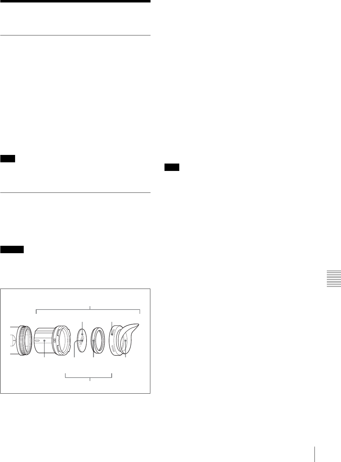
125
Maintenance
Chapter 8 Maintenance
8-2 Maintenance
8-2-1 Cleaning the Video Heads
To clean the video heads, use a Sony BCT-HD12CL
Cleaning Cassette. Follow the instructions given with the
cleaning cassette, as incorrect or excessive use could
damage the video heads.
To clean the heads, perform the following:
Load the cleaning cassette according to the procedure
described in “Loading a cassette” (page 31).
The tape runs automatically in PLAY mode for about 5
seconds to clean the head.
After the tape runs, the cleaning cassette is automatically
ejected.
Do not run the cleaning cassette 5 or more times
consecutively.
8-2-2 Cleaning the Viewfinder
Use a dust blower to clean the CRT screen and mirror
inside the viewfinder barrel.
Clean the lens and protecting filter with a commercially
available lens cleaner.
Never use organic solvents such as thinner.
Disassembling the eyepiece for cleaning
1
Detach the eyepiece from the viewfinder barrel.
For the detaching procedure, see “7-2-4 Detaching the
Eyepiece” on page 110.
2
Remove the eyecup from the eyecup holder.
3
Remove the protecting filter, together with the packing
ring, from inside the eyecup holder.
4
Detach the protecting filter from the packing ring.
Fog-proof filter
Depending on the temperature and humidity, the protecting
filter may mist because of vapor or your breath. To ensure
that the viewfinder is always clear, replace the protecting
filter with a fog-proof filter (Part No. 1-547-341-11, not
supplied).
Fitting the fog-proof filter
Replace the protecting filter on the packing ring with the
fog-proof filter.
Be sure to correctly assemble the fog-proof filter, the
packing ring, and the eyecup so that the reassembled
eyepiece is waterproof.
When cleaning the fog-proof filter, wipe it very gently with
a soft cloth to avoid damaging the anti-fogging coating.
Note
Caution
1
3
42
Viewfinder
barrel
Eyecup
holder
Protecting
filter
Packing
ring
Eyecup
Note
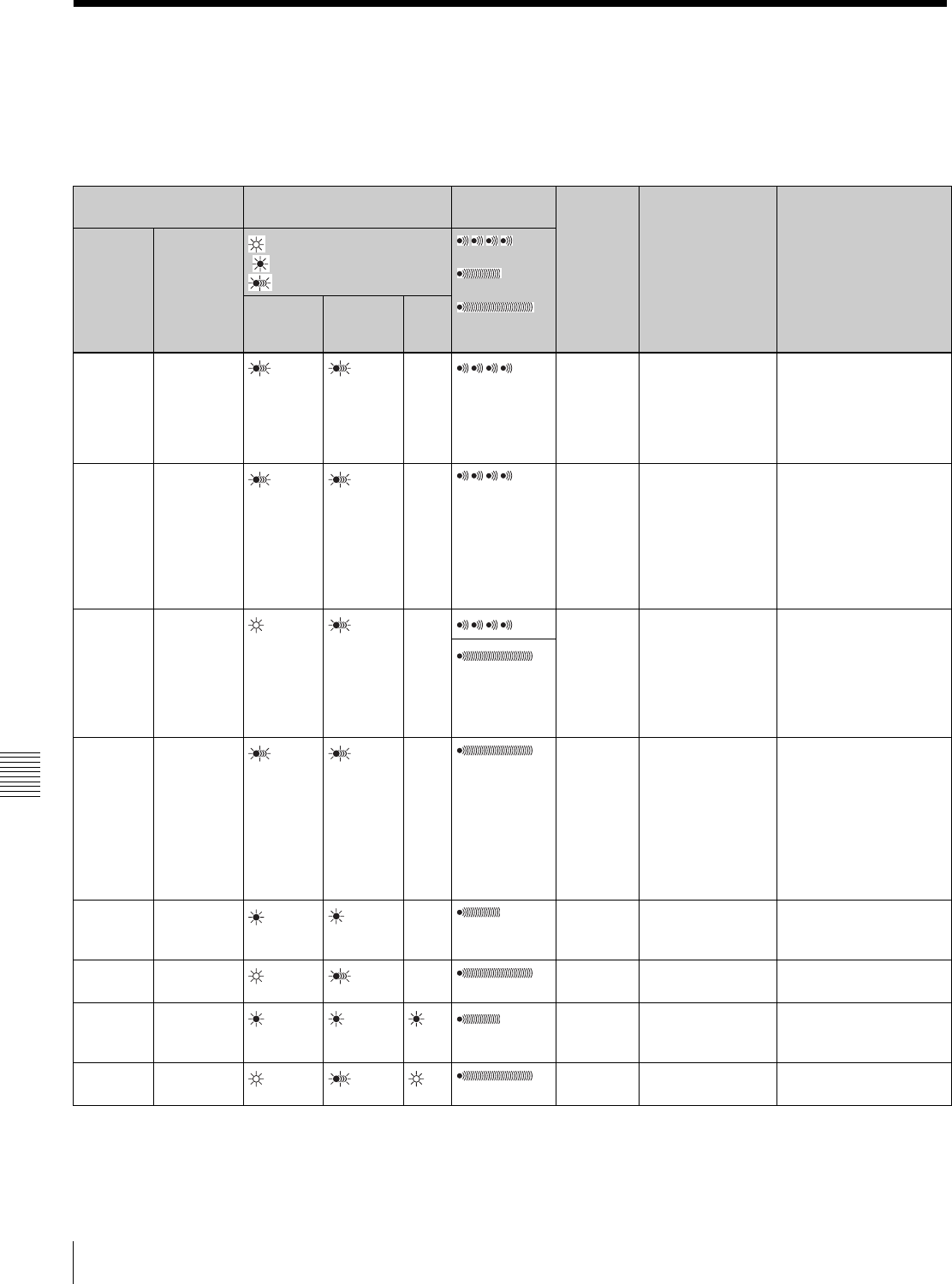
126 Operation Warnings
Chapter 8 Maintenance
8-3 Operation Warnings
When a problem occurs at power on or during operation, a
warning is given by the relevant indicators in the display
panel, in the viewfinder and on the camcorder body. The
speaker and earphone also give audible warnings.
1) During recording
2) During playback, fast forward, or stop
3) Additionally “5-0” appears for the tape remaining indication.
4) During recording or in stop mode
5) The VTR once stops recording in auto interval recording mode.
Operation warnings
Display panel Indicators in viewfinder Warning
sounds
Problem VTR operation Action to take
Warning/
Battery
status
indication
Status
(Flashing/
Lit)
: Lit
: 1 flash/s
: 4 flashes/s
:
4 beeps/s
:
1 beep/s
:
Continuous
beep
WARNING
REC/tally BATT
RF Lit
1)
–
1)
Video
head gap
clogged or
problem in
recording
circuit
After clogged head
is detected,
recording continues
but may be
substandard.
Clean the head. If
recording is still
substandard, turn off the
power, and consult your
Sony service
representative
SERVO Lit – Servo lock
lost
Recording
continuous but may
be substandard.
Turn off the power and
contact your Sony
service representative.
(This indication may be
given momentarily when
the tape starts moving,
but this does not indicate
a problem.)
HUMID! Lit –
1)
Condensa-
tion on the
optical
pickup.
Recording
continues but stops
if the tape sticks to
the head drum.
Playback, fast
forward, and rewind
do not operate.
Stop the tape, and wait
until the HUMID indicator
disappears.
2)
SLACK Lit – The tape
cannot be
wound
properly.
VTR stops. An error
code appears in the
time code display
section of the
display panel. Look
up the error code in
the Maintenance
Manual.
Remove the cassette by
the method described in
the Maintenance Manual.
Close the cassette lid
without loading a
cassette, turn off the
power, and consult your
Sony service
representative.
TA P E Flashing
4) 1)
Near the
end of
tape
Operation
continues.
Be prepared to change
the cassette.
TAPE and
E
Flashing End of
tape
Recording stops. Change the cassette.
BATT Flashing
4)
Battery
almost
exhausted.
Operation
continues.
5)
Change the battery.
BATT and
E
Flashing Battery
exhausted.
Operation stops. Change the battery.
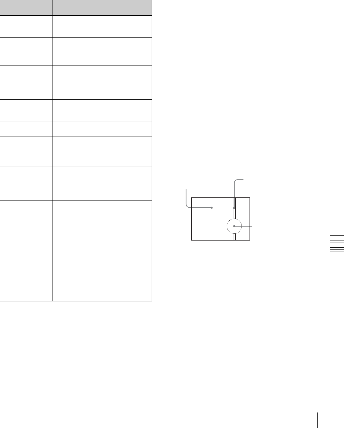
127
Operation Warnings
Chapter 8 Maintenance
Operation/error messages
An operation or error message is displayed in the
operation/error message display area (see page 74) in the
viewfinder.
1) In this case, position the tape at the point where you want to start the
recording manually.
2) To replace the backup battery, contact your nearest Sony dealer.
Phenomena specific to CCD image
sensors
The following phenomena that may appear in images are
specific to CCD (Charge Coupled Device) image sensors.
They do not indicate malfunctions.
White flecks
Although the CCD image sensors are produced with high-
precision technologies, fine white flecks may be generated
on the screen in rare cases, caused by cosmic rays, etc.
This is related to the principle of CCD image sensors and
is not a malfunction.
The white flecks especially tend to be seen in the following
cases:
• when operating at a high environmental temperature
• when you have raised the master gain (sensitivity)
• when operating in Slow-Shutter mode
This product has a compensation function and the problem
may be alleviated by automatic black balance adjustment
(see page 52).
Vertical smear
When an extremely bright object, such as a strong spotlight
or flashlight, is being shot, vertical tails may be produced
on the screen, or the image may be distorted.
Aliasing
When fine patterns, stripes, or lines are shot, they may
appear jagged or flicker.
Operation/error
message
Meaning
AUTO INTERVAL
**M**S
Indicates the camera is in the Auto
Interval Rec mode. **M**S indicates
the shooting interval.
MANU INTERVAL
*FRAME
Indicates the camera is in the single
shot mode of the Manual Interval Rec
mode. *FRAME indicates the number
of frames.
INTERVAL **S(M/
H)*FRAME
Indicates the camera is in the
consecutive mode of the Manual
Interval Rec mode. **S(M/H) indicates
the trigger interval and *FRAME
indicates the number of frames.
LOW LIGHT Appears, if set to ON on the menu, to
indicate the subject illumination is
inadequate.
TAPE REC INH. Appears when recording on a write-
protected cassette.
Retake Search
Failed
Appears when the camcorder fails to
position the tape at recording starting
point when recording using the RE-
TAKE function.1)
Humid Disturbed
INT REC
Appears when there are portions
where recording has failed due to
condensation while shooting pictures
at intervals (using the interval rec
function).
INVALID
OPERATION
Appears when:
• there is only one recorded cut when
recording using the RE-TAKE
function.
• the recorded cuts are less than 3
sec. when recording using the RE-
TAKE function.
• the RE-TAKE function was denied
for some reason, e.g. as Picture
Cache was on.
• when you execute the RE-TAKE
operation before the recording
pause operation has completed.
ON-BOARD
BATTERY EMPTY
Appears when the backup battery for
the internal clock has been used up.2)
Vertical tails shown on the
image.
Monitor screen
Bright object (e.g. strong
spotlight, strong reflected
light, flashlight, the sun)
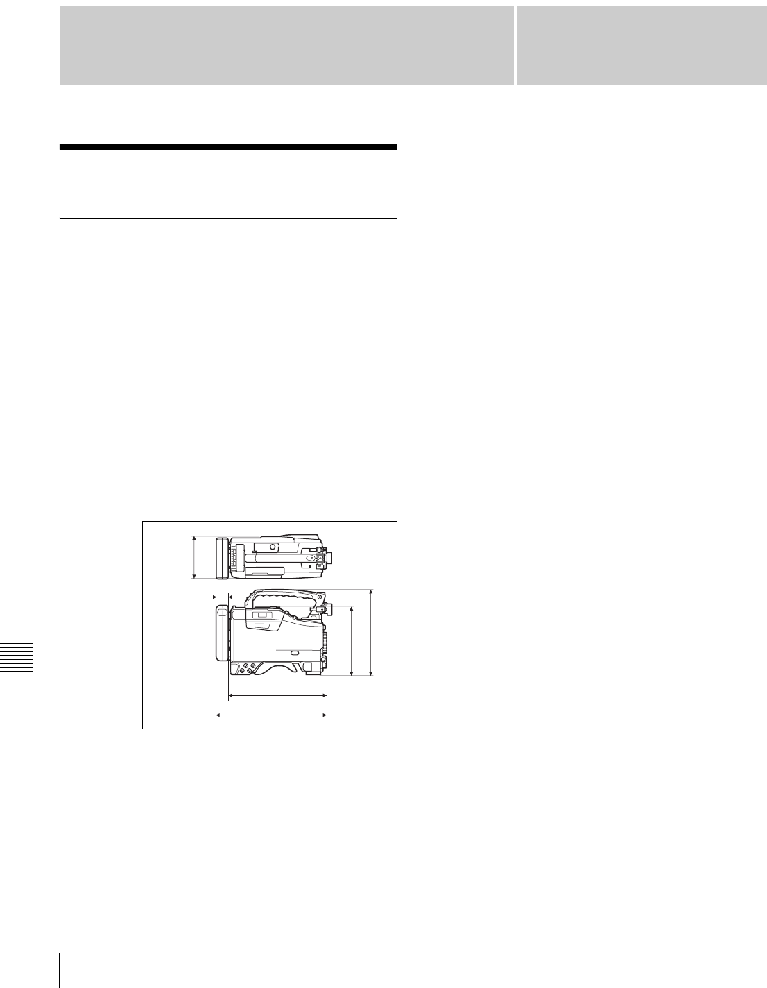
128 Specifications
Appendixes
Appendixes
Specifications
General
Power voltage 12 V DC +5.0/–1.0 V
Power consumption
Approx. 29 W (with 12 V DC supply,
when recording)
Operating temperature
0°C to +40°C (32°F to 104°F)
Operating humidity
25% to 85% (relative humidity)
Storage temperature
–20°C to +60°C (–4°F to +140°F)
Mass Approx. 5.4 kg (12 lb 2 oz) (with
microphone, viewfinder, BCT-D40
cassette and BP-GL95 Battery Pack)
Dimensions in mm (inches)
Supplied accessories
Shoulder strap (1)
Microphone (super cardioid directional,
external power supply type) (1)
Lens mount securing rubber (1)
Operation guide
Japanese version (1) (DVW-970 only)
Operation manual
English version (1)
CD-ROM manual (1)
Video Camera Section
General
Imager 2/3-inch type CCD with 1,000,000
pixels
Effective picture elements
980 (H) × 988 (V) with DVW-970
980 (H) × 1164 (V) with DVW-970P
Imager Configuration
RGB 3 CCDs
Spectral system F1.4 prism system (with quartz filter)
Built-in filters CC filter
A: Cross filter
B: 3200K
C: 4300K
D: 6300K
ND filter
1: Clear
2: 1/4 ND
3: 1/16 ND
4: 1/64 ND
Lens mount Special bayonet mount
Sensitivity F11 standard (89.9% reflection chart,
2000 lx)
Minimum illumination
0.008 1x (at F1.4, +48 dB gain, 16-
frame slow shutter)
Video S/N ratio 65 dB (Y typical) (for the DVW-970)
63 dB (Y typical) (for the DVW-970P)
Modulation (at screen center)
4:3 mode: 55%
16:9 mode: 70%
Registration 0.05% or less for entire screen area
(excluding distortion due to lens)
Geometric distortion
None identified (excluding distortion
due to lens)
Smear –145 dB (Y-typical)
345 (13
5
/
8
)
308 (12
1
/
4
)
37 (1
1
/
2
)
206 (8
1
/
4
)
269 (10
5
/
8
)
127 (5)

129
Specifications
Appendixes
Viewfinder
CRT 2-inch monochrome, quick start type
Horizontal resolution
4:3 mode: 600 TV lines (at screen
center)
16:9 mode: 450 TV lines (at screen
center)
VTR Section
General
Usable cassette tapes
BCT-D6/D12/D22/D32/D40 1/2-inch
Digital BETACAM cassette tapes
Tape speed Approx. 96.7 mm/s (at 30 frames) (for
the DVW-970)
Approx. 80.6 mm/s (at 25 frames) (for
the DVW-970P)
Record/playback time
40 minutes (using BCT-D40 video
cassette) (DVW-970)
48 minutes (using BCT-D40 video
cassette) (DVW-970P)
Fast forward time
Approx. 5 minutes (using BCT-D40
video cassette)
Rewind time Approx. 5 minutes (using BCT-D40
video cassette)
Continuous recording time
Approx. 170 minutes (using BP-GL95
Battery Pack)
Approx. 110 minutes (using BP-GL65
Battery Pack)
Digital video
Sampling frequency
Y: 13.5 MHz
R–Y/B–Y: 6.75 MHz
Quantization 10 bits/sample
Compression Coefficient recording system
Channel coding S-NRZI PR-IV
Error correction Reed-Solomon code
Audio (with standard playback machine)
Frequency response
20 Hz to 20 kHz +0.5/–0.8 dB
Dynamic range 85 dB min. (emphasis ON)
Distortion (THD) 0.08% max.
Cross talk –70 dB max.
Wow and flutter Below measurable limit
Input/output connectors
Signal inputs
AUDIO IN CH1/CH2
XLR type, 3-pin, female
–60 dBu/–50 dBu/–40 dBu/+4 dBu
(0 dBu = 0.775 Vrms.)
MIC IN XLR type, 3-pin, female –60 dBu/–50
dBu/–40 dBu
GENLOCK IN BNC type
1.0 Vp-p, 75 Ω, unbalanced
TC IN BNC type
0.5 V to 18 Vp-p, 10 k Ω
Signal outputs
TEST OUT BNC type
1.0 Vp-p, 75 Ω, unbalanced
VIDEO OUT BNC type, 75 Ω, unbalanced
VBS OUT: 1.0 Vp-p
SDI OUT: 0.8 Vp-p (only when the
CBK-SD01 is installed)
AUDIO OUT XLR type, 5-pin, male, 0 dBm
TC OUT BNC type, 1.0 Vp-p, 75 Ω
EARPHONE minijack
8 Ω, –∞ to –18 dBs variable
Others
DC IN XLR type, 4-pin, male, 11 to 17 V DC
DC OUT 4-pin, 11 to 17 V DC, maximum rated
current 0.1 A
LENS 12-pin
REMOTE 8-pin
Recommended Additional
Equipment
Power supply and related equipment
BP-GL65/GL95/L60S Battery Pack
BC-M50/M150 Battery Charger
AC-550/550CE AC Adaptor
AC-DN10 AC Adaptor
MPEG IMX cassette tapes
BCT-D6/D12/D22/D32/D40
Viewfinder and related equipment
BKW-401 Viewfinder Rotation Bracket
Fog-proof filter (Part No. 1-547-341-11)
Lens assembly (farsighted) (Part No. A-8262-537-A)
Lens assembly (low magnification) (Part No. A-8262-538-
A)
Lens assembly (standard magnification with special
compensation for aberrations) (Part No. A-8267-737-A)

130 Specifications
Appendixes
Optical attachments
ND filter (1/8 ND) (Part No. 3-174-685-01)
ND filter (1/32 ND) (Part No. 3-174-683-01)
Consult your Sony representative for more information
about these filters.
Equipment for remote control
RM-B150/B750 Remote Control Unit
Wireless video/audio transmission
WLL-CA50 Wireless Camera Transmitter
“Memory Stick”
MSH-32 (32 MB)
MSH-64 (64 MB)
MSH-128 (128 MB)
Audio equipment
ECM-672 Microphone
CAC-12 Microphone Holder
CCXA-53 Audio Cable (for converting 5-pin connector to
two 3-pin connectors)
WRR-855A/855B UHF Synthesized Tuner Unit
WRR-860/862 UHF Portable Tuner
WRT-850/860 UHF Transmitter
WRR Tuner Fitting (service part number: A-8278-057-A)
For Audio equipment described above, confirm whether
the connector is male or female and the number of pins on
the connector.
The audio input connectors of the camcorder are female
and 3-pin and the audio output connectors are male and 5-
pin. A converting adaptor may be required depending on
the audio equipment to be connected to the camcorder.
Extension boards
CBK-FC01 Pull Down (24P) Board (for the DVW-970
only)
CBK-SD01 SDI Output Board
CBK-MB01 Picture Cache Board
Equipment for maintenance and easier
handling
BCT-HD12CL Cleaning Cassette
LC-DN7 Hard Carrying Case
LC-DS300SFT Soft Carrying Case
Tripod Adaptor VCT-14
Rain cover (Part No. 3-191-064-02)
Maintenance Manual
Design and specifications are subject to change without
notice.
Notes
•Always make a test recording, and verify that it was
recorded successfully.
SONY WILL NOT BE LIABLE FOR DAMAGES
OF ANY KIND INCLUDING, BUT NOT LIMITED
TO, COMPENSATION OR REIMBURSEMENT
ON ACCOUNT OF FAILURE OF THIS UNIT OR
ITS RECORDING MEDIA, EXTERNAL
STORAGE SYSTEMS OR ANY OTHER MEDIA
OR STORAGE SYSTEMS TO RECORD
CONTENT OF ANY TYPE.
•Always verify that the unit is operating properly
before use. SONY WILL NOT BE LIABLE FOR
DAMAGES OF ANY KIND INCLUDING, BUT
NOT LIMITED TO, COMPENSATION OR
REIMBURSEMENT ON ACCOUNT OF THE LOSS
OF PRESENT OR PROSPECTIVE PROFITS DUE
TO FAILURE OF THIS UNIT, EITHER DURING
THE WARRANTY PERIOD OR AFTER
EXPIRATION OF THE WARRANTY, OR FOR
ANY OTHER REASON WHATSOEVER.

131
Specifications
Appendixes
Menu List
This section briefly explains menus that the camcorder
provides for adjustments and settings using tables.
For the menu organization and the USER menu, see
Chapter 5.
OPERATION Menu
The following table lists and describes the items in the
OPERATION menu. Some pages of the OPERATION
menu have been registered in the USER menu at the
factory. These pages are indicated by a circle (a) in the
USER menu column. The USER MENU CUSTOMIZE
menu allows you to add and delete pages in the USER
menu to suit your requirements.
When the setting range in the Settings column is
surrounded by parentheses ( ), the setup value is a relative
value. The setting range shown on the menu screen may
differ from what is shown in the manual.
USER
menu
No. Page Item Settings Default Description
a01 OUTPUT REAR BNC OUT SEL VBS/SDI VBS See “5-3-2 Selecting the
Output Signals” on page 85.
a02 TEST OUT TEST OUT MARKER OFF/ON OFF Selects whether or not the
marker signal is mixed to the
output signal from the TEST
OUT connector.
TEST OUT VFDISP OFF/ON OFF Selects whether or not the VF
DISP display signal is mixed
to the output signal from the
TEST OUT connector.
TEST OUT MENU OFF/ON OFF Selects whether or not the
MENU display signal is mixed
to the output signal from the
TEST OUT connector.
TEST OUT ZEBRA OFF/ON OFF Selects whether or not the
ZEBRA display signal is
mixed to the output signal
from the TEST OUT
connector.
TEST OUT TC OFF/ON OFF Selects whether or not a time
code signal is mixed to the
output signal from the TEST
OUT connector.
TEST OUT SELECT ENC/R/G/B ENC Selects the output signal of
TEST OUT.

132 Specifications
Appendixes
a03 FUNCTION 1 ASSIGN SW <1> OFF/CACHE/
CHARA/MARKR/
RTAKE/ATW/RET.V/
RET/REC/TURBO/
D5600/ZEBRA etc.
AT W See “5-3-5 Assigning
Functions to Assignable
Switches” on page 87.
ASSIGN SW <2> OFF/CACHE/
CHARA/MARKR/
EXT. V/ZEBRA/5600
etc.
OFF
TURBO SW OFF/CACHE/
CHARA/MARKR/
RTAKE/ATW/RET.V/
RET/REC/TURBO/
D5600/ZEBRA etc.
TURBO
DF/NDF
(DVW-970 only)
DF/NDF DF Switches between drop frame
(DF) mode and non-drop
frame (NDF) mode.
END SEARCH ON/OFF OFF Turns the END SEARCH
function on/off.
CACHE/INTVAL REC OFF/CACHE/A.INT/
M.INT
OFF See “3-2-4 Starting a Shoot
with a Few Seconds of Pre-
Stored Picture Data (Picture
Cache Function: with CBK-
MB01)” on page 38.
(CACHE)
CACHE REC TIME
0/1/2/3/4/5/6/8 SEC 0 SEC
(A.INT)
TAKE TOTAL TIME
5/10/15/20/30/40/50
MIN,
1/2/3/4/5/7/10/15/20/
30/40/50/70/100 H
5 MIN See “3-2-5 Shooting Picture
at Intervals (Interval Rec
Function: with CBK-MB01)”
on page 40.
(A.INT)
REC TIME
5/10/15/20/30/40/50
SEC, 1 to 40 MIN
5 SEC
(M.INT except TRIGGER
INTERVAL=M)
PRE-LIGHTING
OFF/2SEC/5SEC/
10SEC
OFF
(M.INT)
NUMBER OF FRAME
1/2/4/8 1
(M.INT)
TRIGGER INTERVAL
M, 1 to 10/15/20/30/
40/50 SEC,
1 to 10/15/20/30/40/
50 MIN,
1/2/3/4/6/12/24 H
M
USER
menu
No. Page Item Settings Default Description
133
Specifications
Appendixes
04 FUNCTION 2 D5600 OFF/ON OFF Turns on and off the function
which electrically applies a
5600K color temperature
filter.
WIDE AWB OFF/ON ON Turns on and off the function
which widens the range
adjustable by Auto White
Balance.
WHITE SWITCH <B> MEM/ATW MEM Sets the function of the
WHITE BAL B switch.
SHOCKLESS WHITE OFF/1/2/3 1 Changes the white gain
smoothly when operating the
WHITE BAL switch.
ATW SPEED 1 to 5 4 Changes the speed of the
Auto Tracing White operation.
LOW LIGHT OFF/ON OFF Turns the warning display on/
off when the video average
level is less than the preset
value.
LOW LIGHT LEVEL (–99 to +99) 0 Sets the level at which the
LOW LIGHT function
becomes effective.
VF BATT WARNING 10/20% 10% Sets the threshold value of
remaining battery capacity to
make the remaining capacity
indication flash.
a05 VF DISP 1 VF DISP OFF/ON OFF See “5-2-2 Selecting the
Display Items” on page 76.
VF DISP MODE 1/2/3 3
DISP EXTENDER OFF/ON ON
DISP FILTER OFF/ON ON
DISP WHITE OFF/ON ON
DISP GAIN OFF/ON ON
DISP SHUTTER OFF/ON ON
DISP AUDIO OFF/ON ON
DISP TAPE OFF/ON ON
DISP IRIS OFF/ON ON
a06 VF DISP 2 DISP ZOOM OFF/ON ON See “5-2-2 Selecting the
Display Items” on page 76.
DISP COLOR TEMP OFF/ON OFF
DISP BATT REMAIN INT/VOLT/AUTO INT
DISP DC IN OFF/ON OFF
DISP 16:9/4:3 ID OFF/ON OFF
DISP WRR RF LVL OFF/ON OFF
DISP E. MARK IND OFF/ON OFF
DISP TIME CODE OFF/ON OFF
USER
menu
No. Page Item Settings Default Description

134 Specifications
Appendixes
a07 '!'LED GAIN <!> OFF/ON ON See “2-9 Indicators in the
Viewfinder” on page 30.
SHUTTER <!> OFF/ON ON
WHT PRESET<!> OFF/ON ON
ATW RUN <!> OFF/ON ON
EXTENDER <!> OFF/ON ON
FILTER <!> OFF/ON OFF
OVERRIDE <!> OFF/ON ON
a08 MARKER 1 MARKER OFF/ON OFF See “5-2-4 Setting the Marker
Display” on page 78.
CENTER OFF/ON OFF
SAFETY ZONE OFF/ON OFF
SAFETY AREA 80/90/92/95% 90%
ASPECT OFF/ON OFF
ASPECT SELECT 14:9/13:9/4:3 4:3
ASPECT MASK (4:3) OFF/ON OFF
ASPECT MASK LVL 1/2, 1/4, 1/8 1/4
100% MARKER OFF/ON OFF
09 MARKER 2 USER BOX OFF/ON OFF Turns the box cursor on/off.
USER BOX WIDTH 1 to 465 245 Adjusts the width (from the
center to right or left side) of
the box cursor.
USER BOX HEIGHT 1 to 120 (DVW-970) 72 Adjusts the height (from the
center to top or bottom) of the
box cursor.
1 to 142 (DVW-970P) 85
USER BOX H POS. –461 to +461 0 Adjusts the H position of the
center.
USER BOX V POS. –118 to +118
(DVW-970)
0 Adjusts the V position of the
center.
–141 to +140
(DVW-970P)
CENTER H POS. –48 to +47 0 Adjusts the H position of the
center marker.
CENTER V POS. –15 to +14 0 Adjusts the V position of the
center marker.
a10 GAIN SW GAIN LOW –3/0/3/6/9/12/18/24/
30/36/42/48
0See “5-3-1 Setting Gain
Values for the GAIN Selector
Positions” on page 84.
GAIN MID 9
GAIN HIGH 18
GAIN TURBO 42
TURBO SW IND OFF/ON OFF
a11 VF SETTING ZEBRA OFF/ON OFF See “5-2-5 Setting the
Viewfinder” on page 78.
ZEBRA SELECT 1/2/BOTH 1
ZEBRA1 DET.LEVEL 20 to 107 70%
ZEBRA1 APT.LEVEL 1 to 20 10%
ZEBRA2 DET.LEVEL 52 to 109 100%
VF DTL LEVEL (–99 to +99) 0
VF ASPECT AUTO/16:9 AUTO
USER
menu
No. Page Item Settings Default Description

135
Specifications
Appendixes
a12 AUTO IRIS IRIS OVERRIDE OFF/ON OFF See “4-3 Changing the
Reference Value for
Automatic Iris Adjustment” on
page 59.
IRIS SPEED (–99 to +99) 0
CLIP HIGH LIGHT OFF/ON OFF
IRIS WINDOW 1/2/3/4/5/6/VAR 1
IRIS WINDOW IND. OFF/ON OFF
IRIS VAR WIDTH 20 to 465 245
IRIS VAR HEIGHT 17 to 120 (DVW-970) 72
20 to 142
(DVW-970P)
85
IRIS VAR H POS. –447 to +446 0
IRIS VAR V POS. –104 to +104
(DVW-970)
0
–124 to +123
(DVW-970P)
a13 SHOT ID ID-1 12 characters — See “5-2-7 Setting the Shot
ID” on page 80.
ID-2
ID-3
ID-4
a14 SHOT DISP SHOT DATE OFF/ON OFF See “5-2-6 Recording Shot
Data Superimposed on the
Color Bars” on page 79.
SHOT TIME OFF/ON OFF
SHOT MODEL NAME OFF/ON OFF
SHOT SERIAL NO OFF/ON OFF
SHOT ID SEL OFF/ID-1/ID-2/ID-3/
ID-4
OFF
SHOT 16:9 ID OFF/ON OFF
SHOT BLINK CHARA OFF/ON OFF
a15 SET STATUS STATUS ABNORMAL OFF/ON ON See “5-2-8 Displaying the
Status Confirmation
Windows” on page 81.
STATUS FUNCTION OFF/ON ON
STATUS AUDIO OFF/ON ON
16 OFFSET
WHT
OFFSET WHITE <A> OFF/ON OFF See “5-3-4 Specifying an
Offset for the Auto White
Balance Setting” on page 86.
WARM COOL <A> Display color
temperature
3200
COLOR FINE <A> (–99 to +99) 0
OFFSET WHITE <B> OFF/ON OFF
WARM COOL <B> Display color
temperature
3200
COLOR FINE <B> (–99 to +99) 0
USER
menu
No. Page Item Settings Default Description

136 Specifications
Appendixes
17 SHT ENABLE SHUTTER SLS OFF/ON ON See “4-2 Setting the
Electronic Shutter” on page
55.
The items which can be set
differ depending on the CCD
scan mode setting (see page
91).
SHUTTER ECS OFF/ON ON
SHUTTER 1/32 OFF/ON ON
SHUTTER 1/33 OFF/ON ON
SHUTTER 1/40 OFF/ON ON
SHUTTER 1/48 OFF/ON ON
SHUTTER 1/50 OFF/ON ON
SHUTTER 1/60 OFF/ON ON
SHUTTER 1/96 OFF/ON ON
SHUTTER 1/100 OFF/ON ON
SHUTTER 1/120 OFF/ON ON
SHUTTER 1/125 OFF/ON ON
SHUTTER 1/250 OFF/ON ON
SHUTTER 1/500 OFF/ON ON
SHUTTER 1/1000 OFF/ON ON
SHUTTER 1/2000 OFF/ON ON
a18 LENS FILE LENS FILE SELECT 1 to 17* 1 See “5-3-7 Selecting the Lens
File” on page 90.
*: “17” can be selected only
when a lens having serial
transmission ability is
mounted.
F.ID (Display only) —
L. ID (Display only) — To show the lens-specific ID
(when a serial lens is
connected).
L. MF (Display only) — To show the name of the lens
manufacturer (when a serial
lens is connected).
19 FORMAT 16:9/4:3 SELECT 16:9/4:3 16:9 See “5-3-8 Selecting the
Aspect Ratio” on page 90.
SCAN MODE I/PsF/24P
(24P is selectable
only when CBK-
FC01 is connected.)
ISee “5-3-9 Setting the CCD
Scan Mode” on page 91.
V LPF (24P/30P)
(only when CBK-FC01 is
connected)
OFF/ON ON See “5-3-9 Setting the CCD
Scan Mode” on page 91.
UC/J SELECT
(DVW-970 only)
UC/J UC Selects the signal format.
20 UMID SET EX-OWNERSHIP REC OFF/ON OFF See “5-3-10 Using UMID
Data” on page 93.
COUNTRY CODE 4-byte alphanumeric
strings
—
ORGANIZATION 4-byte alphanumeric
strings
—
USER CODE 4-byte alphanumeric
strings
—
INSTANCE NO RND/GEN RND
TIME ZONE : 00 00 to 25,1A to 1F, 2A
to 2F, 32, 3A to 3F
00
MACHINE n—
USER
menu
No. Page Item Settings Default Description
137
Specifications
Appendixes
PAINT Menu
The following table lists and describes the items in the
PAINT menu.
When the setting range in the Settings column is
surrounded by parentheses ( ), the setup value is a relative
value. The setting range shown on the menu screen may
differ from what is shown in the manual.
No. Page Item Settings Default Description
P01 SW STATUS GAMMA OFF/ON ON Turns the gamma correction on/off.
CHROMA OFF/ON ON Turns the chroma of the composite signal on/
off.
MATRIX OFF/ON ON Turns the linear matrix correction on/off.
KNEE OFF/ON ON Turns the knee correction on/off.
WHITE CLIP OFF/ON ON Turns the white clipping correction on/off.
DETAIL OFF/ON ON Turns the detail signal on/off.
APERTURE
OFF/ON ON Turns the aperture function on/off.
FLARE ON/OFF ON Turns the flare function on/off.
EVS OFF/ON OFF Turns the EVS shutter on/off.
TEST SAW OFF/REC/SAW OFF Selects the test signal.
P02 WHITE COLOR TEMP <A> Display color
temperature
3200 Sets the color temperature of WHITE A.
COLOR FINE <A>
(–99 to +99)
0 Adjusts the value more precisely when the
color temperature adjustment through
COLOR TEMP is not satisfactory.
R GAIN <A>
(–99 to +99)
0 Only the value of R GAIN is changed.
B GAIN <A>
(–99 to +99)
0 Only the value of B GAIN is changed.
D5600K <A> OFF/ON OFF Turns the WHITE A electronic 5600K filter on/
off.
COLOR TEMP <B> Display color
temperature
3200 Sets the color temperature of WHITE B.
COLOR FINE <B>
(–99 to +99)
0 Adjusts the value more precisely when the
color temperature adjustment through
COLOR TEMP is not satisfactory.
R GAIN <B>
(–99 to +99)
0 Only the value of R GAIN is changed.
B GAIN <B>
(–99 to +99)
0 Only the value of B GAIN is changed.
D5600K <B> OFF/ON OFF Turns the WHITE B electronic 5600K filter on/
off.
P03 BLACK/FLARE MASTER BLACK
(–99 to +99)
0 Adjusts the master black level.
R BLACK
(–99 to +99)
0 Adjusts the R black level.
B BLACK
(–99 to +99)
0 Adjusts the B black level.
MASTER FLARE
(–99 to +99)
0 Adjusts the flare level of the master.
R FLARE
(–99 to +99)
0 Adjusts the R flare level.
G FLARE
(–99 to +99)
0 Adjusts the G flare level.
B FLARE
(–99 to +99)
0 Adjusts the B flare level.
FLARE OFF/ON ON Turns the flare correction circuit on/off.
TEST OUT SELECT ENC/R/G/B ENC Selects the output signal of TEST OUT
connector.

138 Specifications
Appendixes
P04 GAMMA GAMMA OFF/ON ON Turns the gamma correction function on/off.
STEP GAMMA 0.35 to 0.90 0.45 Sets the master gamma correction curve in
steps.
MASTER GAMMA
(–99 to +99)
0 Sets the master gamma correction curve.
R GAMMA
(–99 to +99)
0 Sets the R gamma correction curve.
G GAMMA
(–99 to +99)
0 Sets the G gamma correction curve.
B GAMMA
(–99 to +99)
0 Sets the B gamma correction curve.
TEST OUT SELECT ENC/R/G/B ENC Selects the output signal of TEST OUT
connector.
GAMMA SELECT STD/FILM STD Selects the gamma table.
GAM SEL (STD) 1 to 6 3 Selects the gamma table of STD.
GAM SEL (FILM) 1 to 5 1 Selects the gamma table of FILM.
P05 BLACK GAMMA BLACK GAMMA OFF/ON OFF Turns the black gamma correction on/off.
BLACK GAM RANGE LOW/L.MID/
H.MID/HIGH
HIGH Sets the range affected by black gamma.
MASTER BLK
GAMMA
(–99 to +99)
0 Adjusts the master black gamma.
R BLACK GAMMA
(–99 to +99)
0 Sets the correction curve of the R black
gamma.
G BLACK GAMMA
(–99 to +99)
0 Sets the correction curve of the G black
gamma.
B BLACK GAMMA
(–99 to +99)
0 Sets the correction curve of the B black
gamma.
TEST OUT SELECT ENC/R/G/B ENC Selects the output signal of TEST OUT
connector.
P06 KNEE KNEE OFF/ON ON Turns the knee correction circuit on/off.
KNEE POINT 50 to 109% 85.0 Sets the knee point level.
KNEE SLOPE
(–99 to +99)
0 Set the knee slope level.
KNEE SATURATION OFF/ON ON Turns the knee saturation function on/off.
KNEE SAT LEVEL
(–99 to +99)
0 Sets the knee saturation level.
WHITE CLIP OFF/ON ON Turns the white clipping function on/off.
WHITE CLIP LEVEL 100.0 to 109.5% 109.0
(DVW-
970)/
105.0
(DVW-
970P)
Adjusts the white clipping level.
P07 DETAIL 1 DETAIL OFF/ON ON Sets the detail correction function on/off.
APERTURE OFF/ON ON Turns the aperture correction function on/off.
DETAIL LEVEL
(–99 to +99)
0 Sets the general level of the detail signal.
APERTURE LVL
(–99 to +99)
0 Sets the aperture level.
DTL H/V RATIO
(–99 to +99)
0 Sets the level of the V detail signal.
CRISPENING
(–99 to +99)
0 Sets the crispening level.
LEVEL DEPEND OFF/ON ON Turns the level depend function on/off.
LEVEL DEPEND LVL
(–99 to +99)
0 Sets the level of the level depend.
DETAIL FREQUENCY
(–99 to +99)
0 Sets the frequency of the H detail signal.
No. Page Item Settings Default Description

139
Specifications
Appendixes
P08 DETAIL 2 KNEE APERTURE OFF/ON OFF Turns the knee aperture function on/off.
KNEE APT LVL
(–99 to +99)
0 Sets the knee aperture level.
DETAIL COMB (–99 to 0) 0 Sets the level at which the comb filter
becomes effective.
CROSS COLOR ON/OFF OFF Turns the cross color component on/off.
CROSS COLOR LVL 0
to 99
43 Sets the suppression level of the cross color.
DETAIL LIMIT
(–99 to +99)
0 Sets the both detail black and white limiters.
DTL WHT LIMIT
(–99 to +99)
0 Sets the detail white limiter.
DTL BLK LIMIT
(–99 to +99)
0 Sets the detail black limiter.
DTL V-BLK LMT
(–99 to +99)
0 Sets the V detail black limiter.
P09 DETAIL 3 FINE DTL OFF/ON OFF Turns the fine detail function on/off.
FINE DTL LVL
(–99 to +99)
0 Sets the level at which the fine detail function
becomes effective.
V DTL CREATION
NAM/G/R+G/Y R+G Selects the source signal of the V DTL signal.
H/V CONTROL MODE H/V / V V Select the operation mode of DETAIL H/V
RATIO on the DETAIL 1 page. (H/V: H and V
both enabled, V: V DTL only enabled)
P10 SKIN DETAIL SKIN DETAIL ALL OFF/ON OFF Turns on all of 1, 2 and 3 of the color detail
function.
SKIN DETECT Moves to color
detection page.
EXEC Executes the color detail function.
SKIN AREA IND OFF/ON OFF Turns the zebra indication on/off in the area of
the currently selected type of the color detail
function.
SKIN DTL SELECT 1/2/3 1 Selects the channels to be displayed on the
menu.
SKIN DETAIL OFF/ON ON Turns the color detail function on/off for the
selected channels.
SKIN DETAIL LVL
(–99 to +99)
0 Sets the level of the color detail signal.
SKIN DTL SAT
(–99 to +99)
0 Adjusts the saturation level of the hue
possessed by the color detail function.
SKIN DTL HUE (0 to 359) 0 Adjusts the center phase of the hue
possessed by the color detail function.
SKIN DTL WIDTH (0 to 359) 40 Adjusts the width of the hue possessed by the
color detail function.
No. Page Item Settings Default Description

140 Specifications
Appendixes
P11 MTX LINEAR MATRIX OFF/ON ON Turns the linear matrix correction and user-
set matrix correction functions on/off.
MATRIX (USER) OFF/ON OFF Turns the user-set matrix correction function
on/off.
MATRIX (PRESET) OFF/ON ON Turns the preset matrix correction function
on/off.
MATRIX R-G
(–99 to +99)
0 Sets the arbitrary R-G user-set matrix
coefficients.
MATRIX R-B
(–99 to +99)
0 Sets the arbitrary R-B user-set matrix
coefficients.
MATRIX G-R
(–99 to +99)
0 Sets the arbitrary G-R user-set matrix
coefficients.
MATRIX G-B
(–99 to +99)
0 Sets the arbitrary G-B user-set matrix
coefficients.
MATRIX B-R
(–99 to +99)
0 Sets the arbitrary B-R user-set matrix
coefficients.
MATRIX B-G
(–99 to +99)
0 Sets the arbitrary B-G user-set matrix
coefficients.
P12 MTX MULTI MATRIX OFF/ON ON Turns the linear matrix correction and multi
matrix correction functions on/off.
MATRIX (MULTI) OFF/ON OFF Turns the multi matrix correction function on/
off.
MATRIX AREA IND OFF/ON OFF Turns the zebra indication on/off in the area
corresponding to the currently selected
setting.
MATRIX COLOR DET Moves to color
detection page.
EXEC Detects color.
MTX (MULTI) AXIS B/B+/MG–/MG/
MG+/R/R+/YL–/
YL/YL+/G–/G/
G+/CY/CY+/B–
B Selects the axis for which the multi matrix
correction function can be changed.
MTX (MULTI) HUE (–99 to +99) 0 Adjusts the color phase affected by the multi
matrix correction function in every sixteen-
axis mode.
MTX (MULTI) SAT (–99 to +99) 0 Adjusts the saturation level affected by the
multi matrix correction function in every
sixteen-axis mode.
P13
V MODULATION
V MOD OFF/ON ON Turns the V modulation function on/off.
MASTER VMOD (–99 to +99) 0 Turns the master V modulation function on/
off.
R VMOD (–99 to +99) 0 Turns the R V modulation function on/off.
G VMOD (–99 to +99) 0 Turns the G V modulation function on/off.
B VMOD (–99 to +99) 0 Turns the B V modulation function on/off.
TEST OUT SELECT ENC/R/G/B ENC Selects the output signal of TEST OUT.
No. Page Item Settings Default Description
141
Specifications
Appendixes
P14 LOW KEY SAT. LOW KEY SAT OFF/ON OFF Turns the low key saturation function on/off.
L.KEY SAT LEVEL (–99 to +99) 0 Sets the saturation level of the low luminance
part.
L.KEY SAT RANGE LOW/L.MID/
H.MID/HIGH
HIGH Sets the luminance level at which the low key
saturation function becomes effective.
Y BLACK GAMMA OFF/ON OFF Turns the Y black gamma function on/off.
Y BLK GAM LEVEL (–99 to +99) 0 Sets the gamma curve in the low luminance
part.
Y BLK GAM RANGE LOW/L.MID/
H.MID/HIGH
HIGH Sets the luminance level at which the Y black
gamma becomes effective.
P15 SCENE FILE 1 — — Recalls the scene file saved in the memory of
the camcorder.
2——
3——
4——
5——
STANDARD — — Clears all current detail-adjusted settings and
switch settings and returns the settings to the
standard settings saved in the reference file.
SCENE RECALL — — Recalls the scene file from the memory of the
camcorder or the “Memory Stick.”
SCENE STORE — — Stores the scene file in the memory of the
camcorder or the “Memory Stick.”
F.ID 16 characters — Sets the File ID.
No. Page Item Settings Default Description

142 Specifications
Appendixes
MAINTENANCE Menu
The following table lists and describes the items in the
MAINTENANCE menu.
When the setting range in the Settings column is
surrounded by parentheses ( ), the setup value is a relative
value. The setting range shown on the menu screen may
differ from what is shown in the manual.
No. Page Item Settings Default Description
M01 WHT SHADING WHT SHAD CH
SEL
R/G/B/TEST R Selects the channel adjusted by this menu. If
TEST is selected, the setting is the same as
the setting of TEST OUT SELECT.
TEST OUT SELECT ENC/R/G/B ENC Selects the signal output to the TEST OUT
connector.
R/G/B WHT H SAW (–99 to +99) 0 Adjusts the H Saw white shading
compensation.
R/G/B WHT H PARA (–99 to +99) 0 Adjusts the H Parabola white shading
compensation.
R/G/B WHT V SAW (–99 to +99) 0 Adjusts the V Saw white shading
compensation.
R/G/B WHT V PARA (–99 to +99) 0 Adjusts the V Parabola white shading
compensation.
WHITE SAW/PARA OFF/ON ON Turns white shading Saw and Parabola
compensation on and off.
M02 BLK SHADING BLK SHAD CH SEL R/G/B/TEST R Selects the channel adjusted by this menu. If
TEST is selected, the setting is the same as
the setting of TEST OUT SELECT.
TEST OUT SELECT ENC/R/G/B ENC Selects the signal output to the TEST OUT
connector.
R/G/B BLK H SAW (–99 to +99) 0 For the H Saw black shading compensation
R/G/B BLK H PARA (–99 to +99) 0 For the H Parabola black shading
compensation
R/G/B BLK V SAW (–99 to +99) 0 For the V Saw black shading compensation
R/G/B BLK V PARA (–99 to +99) 0 For the V Parabola black shading
compensation
BLACK SAW/PARA OFF/ON ON Turns black shading Saw and Parabola
compensation on and off.
MASTER BLACK (–99 to +99) 0 Adjusts the master black level.
MASTER
GAIN(TMP)
–3/0/3/6/9/12/18/
24/30/36/42/48 dB
0 dB Temporarily adjusts the master gain value.
M03 LEVEL ADJ ENC VIDEO LEVEL (–99 to +99) 0 Adjusts the encoder video level.
RGB LEVEL (–99 to +99) 0 Adjusts the R/G/B video level.
TEST OUT SELECT ENC/R/G/B ENC Selects the signal output to the TEST OUT
connector.
H BLANKING
WIDTH
(–99 to +99) 0 Adjusts the H blanking width.

143
Specifications
Appendixes
M04 BATTERY BEFORE END 1 5/10/15 to 95/100%
(in 5% steps)
5% Used when a Sony-made battery pack, such
as BP-GL65/GL95, is used. Set the voltage
warning level just before the battery ends.
END 1 0/1/2/3/4/5% 0% Used when a Sony-made battery pack, such
as BP-GL65/GL95, is used. Set the voltage
level at which the battery ends and the
camcorder stops operation, just before the
battery ends.
BEFORE END 2 11.0 to 17.0 V
(in 0.1 V steps)
11.3 Used when a Sony-made battery pack, such
as BP-L60S, is used. Set the voltage warning
level just before the battery ends.
END 2 10.5 to 11.5 V
(in 0.1 V steps)
11.0 Used when a Sony-made battery pack, such
as BP-L60S, is used. Set the voltage level at
which the battery ends and the camcorder
stops operation, just before the battery ends.
BEFORE END 3 11.0 to 17.0 V
(in 0.1 V steps)
11.8 Used when a battery pack other than a Sony-
made one or an external power connected to
the DC IN connector is used. Set the voltage
warning level just before the battery ends.
END 3 10.5 to 14.0 V
(in 0.1 V steps)
11.0 Used when a battery pack other than a Sony-
made one or an external power connected to
the DC IN connector is used. Set the voltage
level at which the battery ends and the
camcorder stops operation, just before the
battery ends.
BATT REMAIN
DISP
1/2/3 1 1: Standard mode
2: LCD remaining indication mode: One x on
the LCD indicates 10% for a battery
classified in <Others..., EXT DC> type.
3: ANTON mode: Remaining detection of the
ANTON type is made even for a battery
classified in <SONY> type.
M05 AUDIO-1 AUDIO OUT (F/R) CUE/EE EE Selects the audio output signal during FF/
REW.
CUE: cue audio signal
EE: Input signal
REC AUDIO OUT EE/SAVE EE Selects the audio output signal during
recording.
EE: Input signal
SAVE: Not to outputl
CA-701 AUDIO IN ENABL/DSABL ENABL When a CA-701 camera adaptor is
connected, select whether or not to enable
input of audio channels 3 and 4 from the
camera adaptor.
ENABL: Camera adaptor can be used.
DSABL: Camera adaptor cannot be used.
AUDIO CH3/4
MODE
CH1/2/SW SW Selects the sources to be recorded to
channels CH-3/4.
CH1/2: Same sources as CH-1/2.
SW: Signals selected by the AUDIO IN CH-3/
CH-4 switches.
REAR XLR AUTO OFF/ON OFF Turns the XLR connection automatic
detection on/off .
FRONT MIC REF –60 dB/–50 dB/–40
dB
–60 dB Sets the reference level of the front
microphone.
REAR MIC REF –60 dB/–50 dB/–40
dB
–60 dB Sets the reference level when the AUDIO IN
CH1 or CH2 connector is set to MIC.
No. Page Item Settings Default Description

144 Specifications
Appendixes
M06 AUDIO-2 AU REC EMPHASIS OFF/ON OFF Turns the emphasis function on/off.
CUE REC OFF/ON ON Turns cue audio recording on/off.
AU REF LEVEL –20 dB/–18 dB/–16
dB
–20 dB Sets the output level of the 1 kHz test signal.
AU REF OUT 0 dB/+4 dB/–3 dB 0 dB Sets the output reference level.
AU CH12 AGC
MODE
MONO/STREO MONO Selects automatic adjustment mode of the
input levels of analog audio signals to be
recorded on channels 1 and 2; MONO (to
independently adjust channel 1 and 2) or
STREO (stereo mode).
AU CH34 AGC
MODE
OFF/MONO/
STREO
MONO Selects automatic adjustment mode of the
input levels of analog audio signals to be
recorded on channels 1 and 2; MONO (to
independently adjust channel 1 and 2),
STREO (stereo mode), or OFF.
AU AGC SPEC –6/–9/–12/–15/–17
dB
–6 dB Sets the AGC characteristics (saturation
level).
AU LIMITER MODE OFF/–6/–9/–12/
–15/–17 dB
OFF Sets the limiter characteristics (saturation
level) for high-level input signals in manual
adjustment of the audio input level.
AU OUT LIMITER OFF/ON ON Turns the audio output limiter on/off.
No. Page Item Settings Default Description

145
Specifications
Appendixes
M07 AUDIO-3 AU SG (1kHz) ON/OFF/AUTO OFF Sets whether to output a 1 kHz test tone
during the Color Bar mode or not.
ON: a 1 kHz test tone is output during the
Color Bar mode.
OFF: a 1 kHz test tone is not output during
the Color Bar mode.
AUTO: a 1 kHz test tone is output only when
the CH 1 AUDIO SELECT switch on the
inside panel is in the AUTO position.
MIC CH1 LEVEL SIDE1/FRONT/
F+S1
FRONT When recording the front microphone sound
on CH 1, select which control is to be used for
the level adjustment.
SIDE 1: Adjust it with the LEVEL control (left
side) on the side panel.
FRONT: Adjust it with the MIC LEVEL control
on the front panel.
F + S1: It can be adjusted using either the
LEVEL control (left side) or the MIC
LEVEL control. (The two controls are
linked to each other.)
MIC CH2 LEVEL SIDE2/FRONT/
F+S2
FRONT When recording the front microphone sound
on CH 2, select which control is to be used for
the level adjustment.
SIDE 2: Adjust it with the LEVEL control (right
side) on the side panel.
FRONT: Adjust it with the MIC LEVEL control
on the front panel.
F + S2: It can be adjusted using either the
LEVEL control (right side) or the MIC
LEVEL control. (The two controls are
linked to each other.)
REAR1/WRR
LEVEL
SIDE1/FRONT/
F+S1
SIDE 1 Selects any of these controls to adjust the
audio level of the equipment that is connected
to the wireless microphone and whatever is
connected to the AUDIO IN CH1 connector
on the rear panel.
SIDE 1: Adjust it with the LEVEL control (left
side) on the side panel.
FRONT: Adjust it with the MIC LEVEL control
on the front panel.
F + S1: It can be adjusted using either the
LEVEL control (left side) or the MIC
LEVEL control. (The two controls are
linked to each other.)
REAR2/WRR
LEVEL
SIDE2/FRONT/
F+S2
SIDE 2 Selects any of these controls to adjust the
audio level of the equipment that is connected
to the wireless microphone and whatever is
connected to the AUDIO IN CH2 connector
on the rear panel.
SIDE 2: Adjust it with the LEVEL control (right
side) on the side panel.
FRONT: Adjust it with the MIC LEVEL control
on the front panel.
F + S2: It can be adjusted using either the
LEVEL control (right side) or the MIC
LEVEL control. (The two controls are
linked to each other.)
No. Page Item Settings Default Description

146 Specifications
Appendixes
M08 TIMECODE TC OUT AUTO/GENE AUTO Selects the time code signal output.
AUTO: Outputs the time code generator
output during recording and outputs the
time code reader output during playback.
GENE: Outputs the time code generator
output during recording and playback.
DF/NDF
(DVW-970 only)
DF/NDF DF Sets DF or NDF mode.
DF: Drop frame mode
NDF: Non-drop frame mode
EXT-LK UBIT INT/EXT INT Sets whether the LTC UBIT setup value locks
to an INT or an EXT source when the time
code is locked to an external source.
INT: Internal lock
EXT: External lock
LTC UBIT FIX/TIME FIX Sets the data to be recorded in UBIT of LTC.
FIX: Records the data that is set by the user.
TIME: Records the present time.
VITC UBIT FIX/TIME FIX Sets the data to be recorded in UBIT of VITC.
FIX: Records the data that is set by the user.
TIME: Records the present time.
WATCH AUTO ADJ OFF/ON ON Turns the automatic time correction function
of the built-in clock on/off . With ON, the time
of the built-in clock matches with the time
data of the user bits of an external time code.
UBIT GROUP ID 000/101 000 Selects the UBIT GROUP ID.
VITC INS LINE 1 12 to 19 H
(DVW-970)
16H Selects the line into which VITC is to be
inserted.
9 to 22 H
(DVW-970P)
19H
VITC INS LINE 2 12 to 19 H
(DVW-970)
18H Selects the line into which VITC is to be
inserted.
9 to 22 H
(DVW-970P)
21H
M09 VTR MODE REC TALLY BLINK OFF/ON ON Turns the tally illumination control on/off in the
event of BATTERY BEFORE END/DISC
BEFORE END.
REC START BEEP OFF/ON OFF Turns on/off the alarm sound at REC START/
STOP.
LCD DISPLAY
HOLD
TIMER/OFF/CONT TIMER Sets the time code (TC) display after power-
off as follows.
TIMER: The TC display turns off after the
elapse of the time set by the LCD HOLD
TIMER below.
OFF: Not displayed.
CONT: Displayed.
LCD HOLD TIMER 1H/3H/8H 1H Sets the duration of time after which the TC
display is to be turned off after power-off,
when LCD DISPLAY HOLD is set to TIMER
(H: hours).
VIDEO OUT (F/R) EE/PB EE Selects the video output signal during FF/
REW.
EE: Input signal
PB: Playback signal
STBY OFF TIMER OFF/5MIN/10MIN/
30MIN/60MIN
60MIN Sets the length of time for the stand-by off
timer.
STOP KEY FREEZE OFF/FRAME/
FIELD
OFF Selects the freeze function.
No. Page Item Settings Default Description
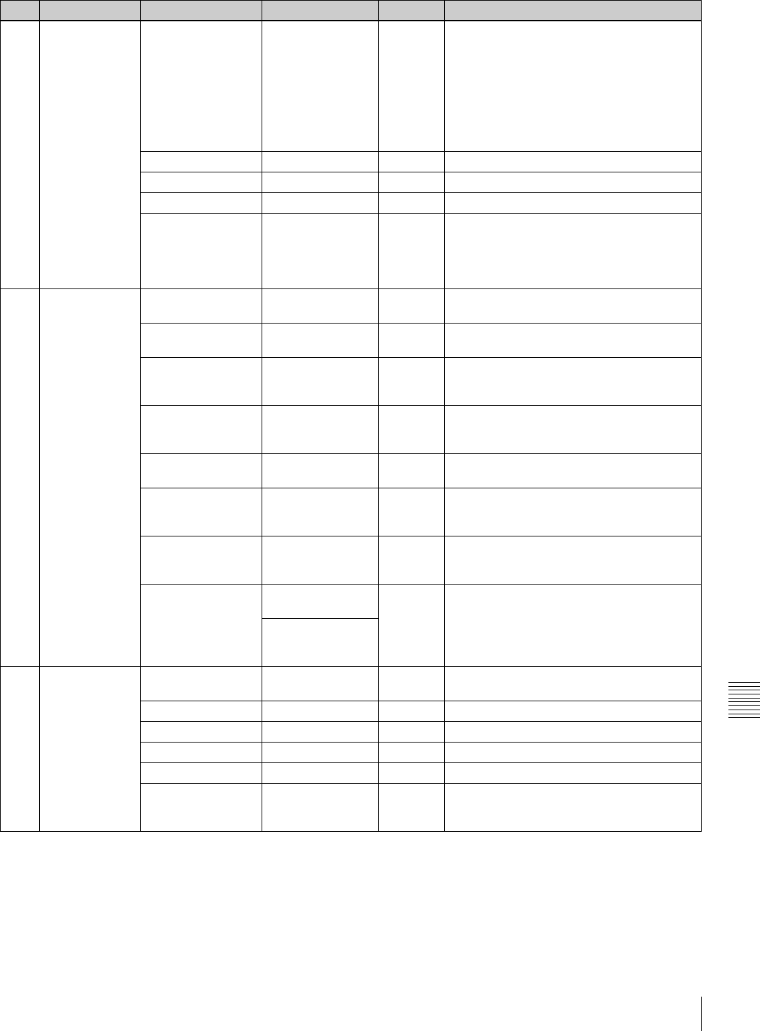
147
Specifications
Appendixes
M10 ESSENCE
MARK
LTC UB-MARKER SET/ALL/OFF SET Sets whether to write the markers in UBIT of
LTC or not.
SET: To independently select the ON/OFF
setting of the following items, REC START
MARK, SHOT MARK 1, and SHOT MARK
2
ALL: To write REC START MARK, SHOT
MARK 1, and SHOT MARK 2 all.
OFF: None are written.
REC START MARK OFF/ON OFF Turns REC START MARK on/off.
SHOT MARK 1 OFF/ON OFF Turns SHOT MARK 1 on/off.
SHOT MARK 2 OFF/ON OFF Turns SHOT MARK 2 on/off.
SHOT TIME DISP MD:HM/DM:HM/
D:HMS
MD:HM Selects the format of the time to be displayed
on the LCD.
MD:HM: Month, day, hour, minute
DM:HM: Day, month, hour, minute
D:HMS: Day, hour, minute, second
M11 ESSENCE
MARK2
OVER AUDIO LIMIT OFF/ON ON Turns the function to write a mark when the
audio level exceeds 0 dB in recording on/off.
GAIN CHG MARK OFF/ON ON Turns the function to write a mark when the
gain is changed in recording on/off.
FILTER CHG MARK OFF/ON ON Turns the function to write a mark when the
ND filter or CC filter is changed in recording
on/off.
SHUTTER CHG
MARK
OFF/ON ON Turns the function to write a mark when the
shutter speed or shutter mode is changed in
recording on/off.
WHITE CHG MARK OFF/ON ON Turns the function to write a mark when the
white balance is changed in recording on/off.
FLASH MARK OFF/ON ON Turns the function to write a mark when an
extreme luminunce change occurs in
recording on/off.
FLASH MARK
LEVEL
1 to 20 10 Sets the threshold of the lluminance change
to permit a mark to be written for FLASH
MARK.
E. MARK SD LINE 12/13/15/16/17/18/
19 (DVW-970)
17 Specifies the essence mark output SDI VANC
LINE number to be recorded on the tape.
9/10/12/13/14/15/
16/17/18 (DVW-
970P)
M12 PRESET WHT COLOR TEMP <P> Display color
temperature.
3200 White balance preset value
COLOR FINE <P> (–99 to +99) 0 —
R GAIN <P> (–99 to +99) 0 R gain preset value
B GAIN <P> (–99 to +99) 0 B gain preset value
D5600K <P> OFF/ON OFF Turns the electric 5600K filter on/off.
AWB ENABLE <P> OFF/ON OFF Turns the function which automatically
acquires the preset value for automatic white
balance adjustment on/off.
No. Page Item Settings Default Description

148 Specifications
Appendixes
M13 DCC ADJUST DCC FUNCTION
SEL
DCC/ADP.K/FIX DCC Selects the function assigned to the DCC
switch.
ADP.K is Adaptive knee and FIX is fixed knee.
DCC D RANGE 400/450/500/550/
600%
600% Sets the timing range when the DCC switch is
set to the ON position.
DCC POINT (–99 to +99) 0 For the DCC minimum knee point adjustment
DCC GAIN (–99 to +99) 0 For the gain adjustment to DCC detected
value
DCC DELAY TIME (–99 to +99) 0 Adjusts the DCC reaction speed.
M14 AUTO IRIS 2 IRIS WINDOW 1/2/3/4/5/6/VAR 1 Selects the auto iris detection window. VAR is
variable.
IRIS WINDOW IND OFF/ON OFF Turns on and off the function which displays a
frame marker for the auto iris detection
window.
IRIS LEVEL (–99 to +99) 0 Adjusts the level of the auto iris target value
IRIS APL RATIO (–99 to +99) 0 Adjusts the mix ratio of auto iris detection
peak value and average value.
IRIS VAR WIDTH 20 to 465 245 Sets the width and height of detection frame
when the auto iris detection window is set to
VAR.
IRIS VAR HEIGHT 17 to 120
(DVW-970)
72 Sets the height of detection frame when the
auto iris detection window is set to VAR.
20 to 142
(DVW-970P)
85
IRIS VAR H POS. –447 to +446 0 Sets the horizontal position of detection frame
when the auto iris detection window is set to
VAR.
IRIS VAR V POS. –104 to +104
(DVW-970)
0 Sets the vertical position of detection frame
when the auto iris detection window is set to
VAR.
–124 to +123
(DVW-970P)
0
IRIS SPEED (–99 to +99) 0 Adjusts the auto iris operation speed.
CLIP HIGH LIGHT OFF/ON OFF Turns on and off the function which, during
auto iris adjustment, ignores very bright areas
by dulling the reaction to high luminescence.
No. Page Item Settings Default Description

149
Specifications
Appendixes
M15 FUNCTION 3 WHT FILTER INH OFF/ON OFF Turns on and off the function which inhibits
independent white memory for each filter
position.
COLOR BAR SEL SMPTE/EBU/SNG SMPTE
(DVW-
970)
Selects the color bar type.
EBU
(DVW-
970P)
REC TALLY UPPER/BOTH UPPER Selects whether to light the upper tally
indicator only, or both upper and lower tally
indicators.
COLOR VF INPUT COMP/VBS/BOTH COMP For video input selection when a color
viewfinder is used
USER & ALL ONLY OFF/ON OFF Selects whether to show only USER, USER
MENU CUSTOMIZE, and ALL menus in the
top menu.
RM COMMON
MEMORY
OFF/ON OFF Selects whether or not to share settings for
when an RM remote control unit is connected
and when the unit is used alone.
RM REC START RM/CAM/PARA RM Selects which VTR START/STOP buttons (on
the RM, camera, or both) are enabled when
an RM-series remote control unit is
connected.
REC INH. WITH
CCU
OFF/ON ON Selects whether to disable recording
operations when a CCU is connected. A
large viewfinder cannot be used with the OFF
setting.
EXT VTR REC CTL OFF/ON OFF Selects whether to synchronize recording
with an external VTR via a CCZ cable when
the CA-702 is connected.
M16 FUNCTION 4 SET DISP MODE SEC/DEG SEC Selects whether to display the shutter speed
in seconds or degrees.
AWB FIXED AREA OFF/ON OFF Selects whether or not to perform AWB for all
pixels in the rectangular area of 25% by 25%.
M17 GENLOCK GENLOCK OFF/ON ON Turns genlock on and off.
RETURN VIDEO OFF/ON OFF Turns return video on and off.
GL H PHASE (–99 to +99) 0 Adjusts the genlock H phase.
GL SC PHASE (–99 to +99) 0 Adjusts the genlock subcarrier phase.
GL SC 0/180 SEL 0/180 180 For coarse adjustment of the genlock
subcarrier phase.
M18 ND COMP ND OFFSET
ADJUST
OFF/ON — Turns on and off the mode which sets ND
(neutral density) filter color compensation
values.
CLEAR ND
OFFSET
— EXEC Clears ND filter color compensation values.
M19 AUTO SHADING AUTO BLK
SHADING
EXEC EXEC Executes the auto black shooting function.
RESET BLK SHD EXEC EXEC Clears black shooting compensation values.
TEST OUT SELECT ENC/R/G/B ENC Selects the signal output to the TEST OUT
connector.
MASTER GAIN
(TMP)
–3/0/3/6/9/12/18/
24/30/36/42/48 dB
0 dB Temporarily sets the master gain value.
No. Page Item Settings Default Description

150 Specifications
Appendixes
M20 VANC RX UMID LINE 0, 12, 13, 15 to 19
(DVW-970)
0 Selects the line on which the UMID is to be
recorded.
0, 9, 10, 12 to 18
(DVW-970P)
No. Page Item Settings Default Description
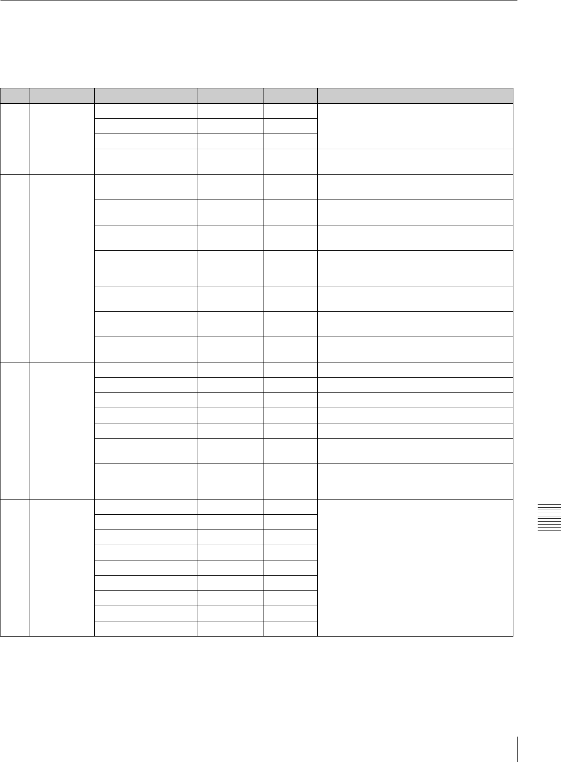
151
Specifications
Appendixes
FILE Menu
The following table lists and describes the items in the
FILE menu.
When the setting range in the Settings column is
surrounded by parentheses ( ), the setup value is a relative
value. The setting range shown on the menu screen may
differ from what is shown in the manual.
No. Page Item Settings Default Description
F01 USER FILE USER FILE LOAD — EXEC See “6-1 Saving and Loading User Files” on
page 97.
USER FILE SAVE — EXEC
F. ID 16 characters —
USER PRESET — EXEC See “5-4 Resetting USER Menu Settings to the
Standard Settings” on page 96.
F02 USER FILE2 STORE USR PRESET — EXEC Sets the pages registered in the USER menu
to the standard setting.
CLEAR USR PRESET — EXEC Clears the standard setting of pages registered
in the USER menu.
CUSTOMIZE RESET — EXEC Returns the setting of the pages registered in
the USER menu to the factory default state.
LOAD CUSTOM DATA OFF/ON OFF Selects whether to read the USER MENU
CUSTOMIZE settings to be loaded by USER
FILE LOAD.
LOAD OUT OF USER OFF/ON OFF Selects whether to read pages not registered
by USER FILE LOAD.
BEFORE FILE PAGE OFF/ON OFF Selects whether to read data after USER FILE
pages by USER FILE LOAD.
USER LOAD WHITE OFF/ON OFF Selects whether to read white balance data by
USER FILE LOAD.
F03 ALL FILE ALL FILE LOAD — EXEC Loads ALL file.
ALL FILE SAVE — EXEC Saves ALL file.
F. ID 16 characters — To name ALL file.
ALL PRESET — EXEC Returns items in the ALL file to preset values.
STORE ALL PRESET — EXEC Sets the preset values of items in the ALL file.
CLEAR ALL PRESET — EXEC Clears the preset values of items in the ALL
file.
3SEC CLR PRESET OFF/ON OFF Turns on and off the function to clear the
standard setting when the MENU knob is kept
pressed for 3 seconds.
F04 SCENE FILE 1 — — See “6-2 Saving and Loading Scene Files” on
page 101.
2——
3——
4——
5——
STANDARD — —
SCENE RECALL — EXEC
SCENE STORE — EXEC
F. ID 16 characters —

152 Specifications
Appendixes
F05 REFERENCE REFERENCE STORE — EXEC Saves the reference file in internal memory.
REFERENCE CLEAR — EXEC Clears the reference file.
REFERENCE LOAD — EXEC Loads the reference file.
REFERENCE SAVE — EXEC Saves the reference file to “Memory Stick.”
F. ID 16 characters — To name the reference file.
SCENE WHITE DATA OFF/ON OFF See “White balance setting data to be saved in
the scene file” on page 102.
F06 LENS FILE 1 LENS FILE RECALL — EXEC Loads lens files.
LENS FILE STORE — EXEC Saves lens files.
F. ID 16 characters — To name lens files.
LENS NO OFFSET — EXEC To clear lens files.
SOURCE MEMORY — MEMORY1 Number of selected lens file
IRIS GAIN (–99 to +99) 0 Iris gain value of lens file
LENS AUTO RECALL OFF/ON ON Turns the automatic recall function for serial
lens.
L. ID (Display only) — To show the lens-specific ID (when a serial
lens is connected).
L. MF (Display only) — To show the name of the lens manufacturer
(when a serial lens is connected).
F07 LENS FILE 2 LENS M VMOD (–99 to +99) 0 For the lens file V Saw shading
LENS CENTER H –48 to +47 0 For the horizontal position compensation of
lens file center marker
LENS CENTER V –15 to +14 0 For the vertical position compensation of lens
file center marker
TEST OUT SELECT ENC/R/G/B ENC Selects signal output to TEST OUT connector.
LENS R FLARE (–99 to +99) 0 Adjusts the lens file flare (R).
LENS G FLARE (–99 to +99) 0 Adjusts the lens file flare (G).
LENS B FLARE (–99 to +99) 0 Adjusts the lens file flare (B).
LENS W-R OFST (–99 to +99) 0 Adjusts the R compensation value for white.
LENS W-B OFST (–99 to +99) 0 Adjusts the B compensation value for white.
F08 LENS FILE 3 SHADING CH SEL R/G/B/TEST R Selects the channel adjusted by this menu. If
TEST is selected, the setting is the same as
the setting of TEST OUT SELECT.
TEST OUT SELECT ENC/R/G/B ENC Selects the signal output to the TEST OUT
connector.
LENS R/G/B H SAW (–99 to +99) 0 For the H Saw white shading compensation
LENS R/G/B H PARA (–99 to +99) 0 For the H Parabola white shading
compensation
LENS R/G/B V SAW (–99 to +99) 0 For the V Saw white shading compensation
LENS R/G/B V PARA (–99 to +99) 0 For the V Parabola white shading
compensation
F09 MEMORY
STICK
M.S. FORMAT — EXEC Formats a “Memory Stick.”
M.S. IN > JUMP TO OFF/USER/
ALL/SCENE/
LENS/REFER/
USER1
OFF See “6-3 Jumping to a File-Related Menu Page
When Inserting a “Memory Stick”” on page
105.
No. Page Item Settings Default Description
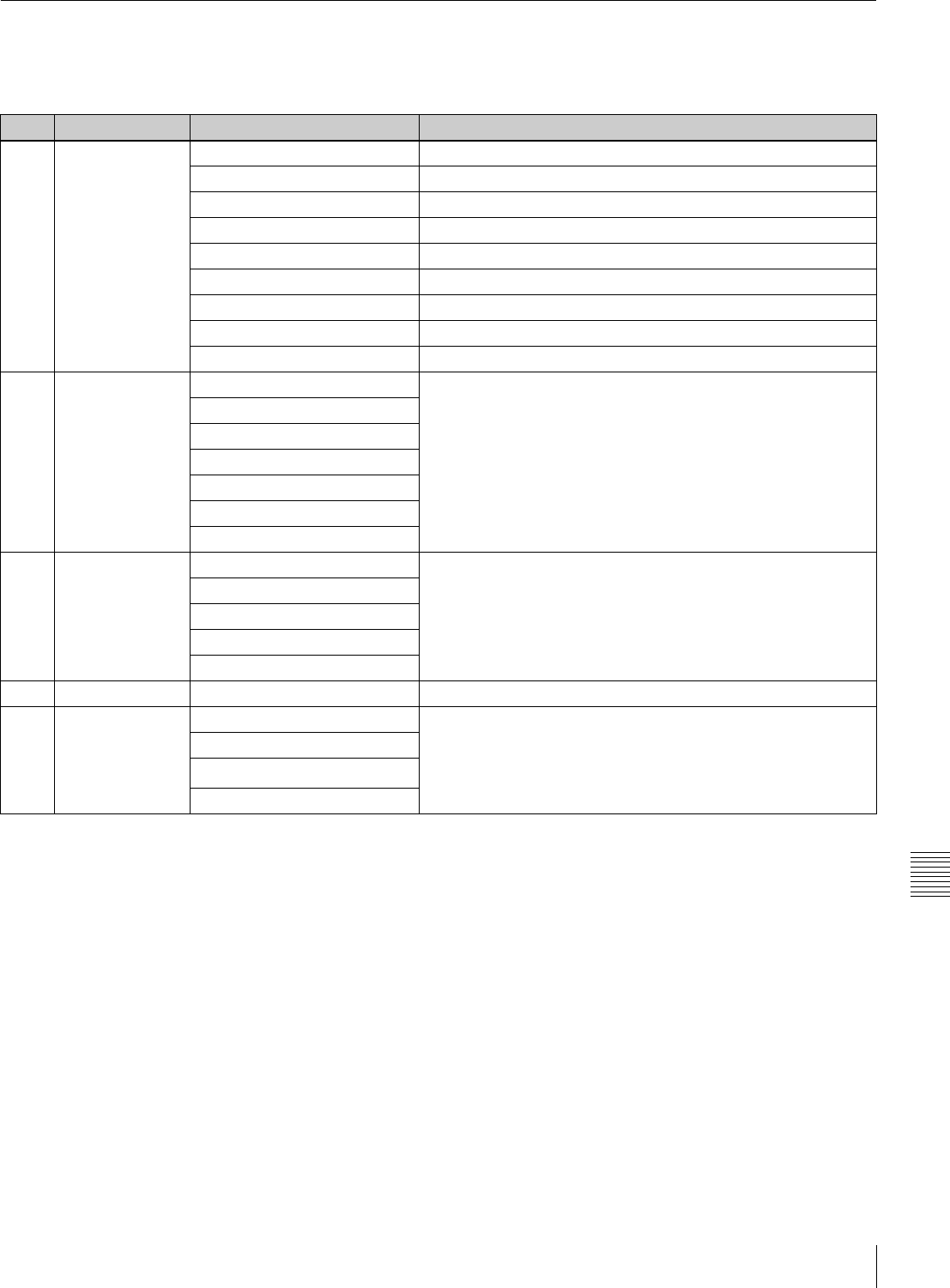
153
Specifications
Appendixes
DIAGNOSIS Menu
The following table lists and describes the items in the
DIAGNOSIS menu.
1) DVW-970 only
No. Page Item Description
D01 HOURS METER RESET METER Resets the resettable meters (-2).
DRUM RUNNING Displays the total time the drum has rotated.
TAPE RUNNING Displays the accumlated time the tape has run.
OPERATION Display the time that the unit has been powered.
THREADING Displays the number of time of tape threading.
DRUM RUNNING-2 Displays the total time the drum has rotated (reset possible).
TAPE RUNNING-2 Displays the accumlated time the tape has run (reset possible).
OPERATION-2 Display the time that the unit has been powered (reset possible).
THREADING-2 Displays the number of time of tape threading (reset possible).
D02 TIME/DATE ADJUST See “5-3-6 Setting the Date/Time of the Internal Clock” on page
89.
HOUR
MIN
SEC
YEAR
MONTH
DAY
D03 ROM VERSION AT: Ver. X.XX Displays ROM version.
SS: Ver. X.XX
FP: Ver X.XX
EQ: Ver X.XX
AU DISP: Ver X.XX
D04 DEV STATUS I/O EEPROM LSI FRAM SCI Displays the self diagnosis.
D05 OPTION BOARD SDI OUTPUT Displays installed options.
COMPOSITE VIDEO INPUT
PULL DOWN (24P) 1)
PICTURE CACHE

154 About a “Memory Stick”
Appendixes
About a “Memory Stick”
What is “Memory Stick”?
“Memory Stick” is a new compact, portable and versatile
IC (Integrated Circuit) recording medium with a data
capacity that exceeds a floppy disk. “Memory Stick” is
specially designed for exchanging and sharing digital data
among “Memory Stick” compatible products. Because it is
removable, “Memory Stick” can also be used for external
data storage.
“Memory Stick” is available in two sizes: standard size and
compact “Memory Stick Duo” size. Once attached to a
“Memory Stick Duo” adapter, “Memory Stick Duo” turns
to the same size as standard “Memory Stick” and thus can
be used with products compliant with standard “Memory
Stick”.”
Types of “Memory Stick”
“Memory Stick” is available in the following four types to
meet various requirements in functions.
“Memory Stick-R”
Stored data are not overwritten. You can write data to
“Memory Stick-R” with “Memory Stick-R” compatible
products only. Copyright protected data that requires
MagicGate copyright protection technology cannot be
written to “Memory Stick-R.”
“Memory Stick”
Stores any type of data except copyright-protected data
that requires the MagicGate copyright protection
technology.
“MagicGate Memory Stick”
Equipped with the MagicGate copyright protection
technology.
“Memory Stick-ROM”
Stores pre-recorded, read-only data. You cannot record on
“Memory Stick-ROM” or erase the pre-recorded data.
Available types of “Memory Stick”
You can use a “Memory Stick” or a “MagicGate Memory
Stick” with your product.
You can not use a “Memory Stick Duo” with your product.
Note on data read/write speed
Data read/write speed may vary depending on the
combination of the “Memory Stick” and “Memory Stick”
compliant product you use.
What is MagicGate ?
MagicGate is copyright protection technology that uses
encryption technology.
Before using a “Memory Stick”
• When you set the “Memory Stick” erasure prevention
switch to “LOCK,” data cannot be recorded, edited, or
erased.
• Data may be damaged if:
—You remove the “Memory Stick” or turn off the unit
while it is reading or writing data.
—You use the “Memory Stick” in a location subject to
the effects of static electricity or electric noise.
• We recommend that you make a backup copy of
important data that you record on the “Memory Stick”.
• Do not attach anything other than the supplied label to
the “Memory Stick” labeling position.
• Attach the label so that it does not stick out beyond the
labeling position.
• Carry and store the “Memory Stick” in its case.
• Do not touch the connector of the “Memory Stick” with
anything, including your finger or metallic objects.
• Do not strike, bend, or drop the “Memory Stick”.
• Do not disassemble or modify the “Memory Stick”.
• Do not allow the “Memory Stick” to get wet.
• Do not use or store the “Memory Stick” in a location that
is:
—Extremely hot, such as in a car parked in the sun
—Under direct sunlight
—Very humid or subject to corrosive substances
ACCESS Indicator
If the access indicator is turned on or is flashing, data is
being read from or written to the “Memory Stick”. At this
time, do not shake the computer or product or subject them
to shock. Do not turn off the power of the computer and
product or remove the “Memory Stick”. This may damage
the data.
Note
Notes
Terminal
Write-protect tab
Labelling position
155
About a “Memory Stick”
Appendixes
Precautions
• To prevent data loss, make backups of data frequently. In
no event will Sony be liable for any loss of data.
• Unauthorized recording may be contrary to the
provisions of copyright law. When you use a “Memory
Stick” that has been pre-recorded, be sure that the
material has been recorded in accordance with copyright
and other applicable laws.
• The “Memory Stick” application software may be
modified or changed by Sony without prior notice.
• Note that there are certain restrictions on recording stage
performances and other entertainment events, even if
they are recorded for personal use only.
• “Memory Stick”, and “MagicGate Memory
Stick” are trademarks of Sony Corporation.
• “Memory Stick Duo” and are
trademarks of Sony Corporation.
• “Memory Stick PRO” and are
trademarks of Sony Corporation.
• “MagicGate” and are trademarks
of Sony Corporation.

156 Index
Index
Index
Symbols
'!'LED 134
Numerics
24P mode 92
A
ABNORMAL window 81
AC adaptor 108
AC-550/550CE 108
ACCESS indicator 23
Accessory Attachments 14
accidental erasure 32
AC-DN10 108
actual time in the time code 64
ADVANCE button 26
ALARM volume control 16
Aliasing 127
ALL FILE 151
ALL menu 67
Anton Bauer Ultralight System 108
aspect ratio 90
ASSIGN 1/2 switches 20
ASSIGN SEL window 87
Assignable Switches 87
ATW 55, 133
Audio channel level meter 28
Audio Functions 15
AUDIO IN CH1/CH2 connectors 17
AUDIO IN CH-1/CH-2/CH-3/CH-4
switches 17
audio level 61
AUDIO OUT connector 17
AUDIO SELECT CH-1/CH-2 switches
16
AUDIO STATUS window 82
AUDIO-1 143
AUDIO-2 144
AUDIO-3 145
Auto Interval Rec mode 41
AUTO IRIS 135
AUTO IRIS 2 148
AUTO IRIS page 59
AUTO SHADING 149
Auto Tracing White 55, 133
AUTO W/B BAL switch 20
automatic black balance adjustment 52
automatic iris adjustment 59
automatic iris window 60
automatic white balance adjustment
53
B
BACK TALLY indicator 27
BACK TALLY switch 27
BATT indicator 30
BATTERY 143
Battery attachment 13
battery pack 107
Battery status indicator 28
BKW-401 110
black balance 52
BLACK GAMMA 138
BLACK/FLARE 137
BLK SHADING 142
BP-GL65/GL95/L60S 107
BRIGHT control 18
Built-in speaker 16
C
Camera operator tally indicator 19
CANCEL/PRST / ESCAPE switch 24
cassette
loading 31
unloading 32
CBK-MB01 40
CBK-SD01 49
CC filter 53
CCD image sensors 127
CH-1/2 / CH-3/4 switch 15
Cleaning
video heads 125
viewfinder 125
color temperature 85
Condensation 121
continues recording 34
Continuous Trigger mode 44
CONTRAST control 18
CUE IN switch 17
D
DATA DISPLAY switch 26
Date/Time of the Internal Clock 89
DC IN connector 13
DC OUT 12 V connector 17
DCC ADJUST 148
DETAIL 1 138
DETAIL 2 139
DETAIL 3 139
DEV STATUS 153
DIAGNOSIS menu 68
diopter adjustment 109
Diopter adjustment ring 19
display mode 77
Display panel 28
DISPLAY switch 26, 27
drop frame mode 64
E
EARPHONE jacks 15
ECS (Extended Clear Scan) mode 55
EJECT button 22
Eject button 23
End Search function 48
error messages 127
ESSENCE MARK 147
ESSENCE MARK page 36, 37
ESSENCE MARK2 147
ESSENCE MARK2 page 36
essence marks 35
EVS (Enhanced Vertical definition
System) mode 56
external microphone 113
Eyepiece 110
disassembling 125
F
F FWD button and indicator 22
FILE menu 68
FILTER selector 19
flange focal length 112
Fog-proof filter 125
FORMAT 136
FORMAT page 90
freeze-frame mode 50
F-RUN/SET/R-RUN switch 26
FUNCTION 149
FUNCTION 1 132
FUNCTION 1 page 87
FUNCTION 2 133
FUNCTION 3 149
FUNCTION 4 149
FUNCTION window 82
G
Gain 84
GAIN selector 20
GAIN SW 134
GAIN SW page 84
GAMMA 138
GENLOCK 149
GENLOCK IN connector 25
GENLOCK page 83
good shot marks 35, 38
H
HOLD button 26
HOURS METER 153
I
I mode 91
Interlace scan mode 91

157
Index
Index
Interval Rec Function 40
K
KNEE 138
L
Lens
mounting 111
LENS connector 14
LENS FILE 136
lens file 90
LENS FILE 1 152
LENS FILE 2 152
LENS FILE 3 152
LENS FILE page 90
Lens locking lever 14
Lens mount 14
Lens mount cap 14
LEVEL (CH-1/CH-2) controls 16
LEVEL ADJ 142
LIGHT connector 14
Light shoe 14
LIGHT switch 13, 27
LINE/MIC/+48 V ON switches 17
LOCK knob 19
LOW KEY SAT. 141
M
MAINTENANCE menu 68
Manual Interval Rec mode 44
MARKER 1 134
MARKER 1 page 78
MARKER 2 134
Marker Display 78
MEMORY STICK 152
Memory Stick compartment 23
MEMORY STICK OPEN button 23
MEMORY STICK page 105
MENU knob 23
MENU ON/OFF switch 23
Menu Organization 67
MIC IN connector 15
MIC LEVEL control 15
Microphone 15
MONITOR switch 15
MONITOR volume control 16
MTX LINEAR 140
MTX MULTI 140
N
ND COMP 149
ND filter 53
non-drop frame mode 64
O
OFFSET WHT 135
OFFSET WHT page 86
OPERATION menu 67
operation messages 127
Operation warnings 126
OPTION BOARD 153
OUTPUT 131
OUTPUT page 85
Output Signals 85
OUTPUT/DCC selector 20
P
PAINT menu 68
PEAKING control 18
Picture Cache Function 38
Picture Cache mode 38
Picture Cache time 38
PLAY button and indicator 22
Playback in Color 49
Power Supply 13
POWER switch 13
PRESET WHT 147
PRESET/REGEN/CLOCK switch 26
Progressive scan mode 91
PsF mode 91
Pull down mode 92
R
Rain Cover 118
REAR TALLY indicator 28
REC indicator 30
Recording Review 49
recording start mark 35, 38
REFERENCE 152
reference file 105
REMOTE connector 21
RESET button 26
RE-TAKE function 47
return video signal 83
REW button and indicator 22
ROM VERSION 153
S
SAVE indicator 30
SCENE FILE 141, 151
scene file 101
loading 103
saving 101
SCENE FILE page 101
SET STATUS 135
SET STATUS page 82
SHIFT button 26
SHOT DISP 135
SHOT DISP page 79
SHOT ID 135
shot ID 80
SHOT ID page 80
shot marks 35
Shoulder pad 14
shoulder pad 118
shoulder strap 117
Shoulder strap posts 14
SHT ENABLE 136
SHT ENABLE page 58
SHUTTER selector 20
Single Trigger mode 44
SKIN DETAIL 139
SLS (slow speed shutter) mode 55
Spare indicator 30
Stand-by off Timer 51
Status Confirmation Windows 81
STATUS ON/SEL / OFF switch 23
STOP button 22
Supplied accessories 128
supplied microphone 112
SW STATUS 137
System configuration 11
T
TALLY indicator 18, 27, 30
TALLY switch 18, 27
Tape status indicator 28
TC IN connector 25
TC OUT connector 25
TEST OUT 131
TEST OUT connector 21
Time code display 29
time code setting 63
time code synchronization 65
TIME/DATE 153
TIME/DATE page 89
TIMECODE 146
TOP menu 67
tripod 116
tripod adaptor 116
Tripod mount 14
TURBO GAIN button 21
TURBO SW SEL window 88
U
UHF portable tuners 114
UMID SET 136
UMID SET page 94
user bits 64
USER FILE 151
User File 98
USER FILE2 151
USER menu 67
USER MENU CUSTOMIZE menu 67

158 Index
Index
V
V MODULATION 140
VANC RX 150
Vertical smear 127
VF DISP 1 133
VF DISP 1 page 76
VF DISP 2 133
VF DISP 2 page 76
VF SETTING 134
VF SETTING page 79
VIDEO OUT connector 21
Viewfinder 19
detaching 110
Viewfinder front-rear positioning lever
19
Viewfinder left-right positioning ring
19
viewfinder position 109
Viewfinder Rotation Bracket 110
Viewfinder stopper 19
VTR MODE 146
VTR operation status and status
indicators 29
VTR SAVE/STBY switch 22
VTR START button 22
W
Warning (!) indicator 30
WARNING indicator 28
WHITE 137
WHITE BAL switch 20
white balance 53
White flecks 127
WHITE page 86
WHT SHADING 142
WRR-855A/855B 114
WRR-860/862 114
X
XLR connection automatic detection
113, 116
Z
ZEBRA switch 18
The material contained in this manual consists of information
that is the property of Sony Corporation and is intended solely
for use by the purchasers of the equipment described in this
manual.
Sony Corporation expressly prohibits the duplication of any
portion of this manual or the use thereof for any purpose other
than the operation or maintenance of the equipment described
in this manual without the express written permission of Sony
Corporation.

Sony Corporation
DVW-970/970P
(SY)
3-869-915-03(1) © 2005
