Radio Shack Hardware Manual DWP 510 Operation 1984 Tandy Text
User Manual: manual pdf -FilePursuit
Open the PDF directly: View PDF ![]() .
.
Page Count: 52

TDCfiA
1Ku OU
DWP-
Catalog Number 26-1270


&.-#;.
TERMS AND CONDITIONS OF SALE AND LICENSE OF RADIO SHACK COMPUTER EQUIPMENT AND SOFTWARE
PURCHASED FROM ARADIO SHACK COMPANY-OWNED COMPUTER CENTER. RETAIL STORE OR FROM A
RADIO SHACK FRANCHISEE OR DEALER AT ITS AUTHORIZED LOCATION
LIMITED WARRANTY
I. CUSTOMER OBLIGATIONS
ACUSTOMER assumes lull responsibility that this Radio Shack computer hardware purchased (the Equipment"), and any copies of Radio
Shack software included with the Equipment or licensed separately (the "Software") meets the specifications, capacity, capabilities,
versatility, and other requirements of CUSTOMER.
B. CUSTOMER assumes full responsibility for the condition and effectiveness of the operating environment in which the Equipment and Software
are to function, and for its installation.
II. RADIO SHACK LIMITED WARRANTIES AND CONDITIONS OF SALE
AFor aperiod of ninety (90) calendar days from the date of the Radio Shack sales document received upon purchase of the Equipment. RADIO
SHACK warrants to the onqinal CUSTOMER that the Equipment and the medium upon which the Software is stored is free from manufacturing
defects THIS WARRANTY IS ONLY APPLICABLE TO PURCHASES OF RADIO SHACK EQUIPMENT BY THE ORIGINAL CUSTOMER FROM
RADIO SHACK COMPANY-OWNED COMPUTER CENTERS. RETAIL STORES AND FROM RADIO SHACK FRANCHISEES AND DEALERS AT ITS
AUTHORIZED LOCATION The warranty is void if the Equipment's case or cabinet has been opened, or if the Equipment or Software has been
subiected to improper or abnormal use. If amanufacturing defect is discovered during the stated warranty period, the defective Equipment
must be returned to aRadio Shack Computer Center, aRadio Shack retail store, participating Radio Shack franchisee or Radio Shack dealer
for repair along with acopy of the sales document or lease agreement. The original CUSTOMER'S sole and exclusive remedy in the event of
adefect is limited to the correction of the defect by repair, replacement, or refund of the purchase price, at RADIO SHACK'S election and sole
expense. RADIO SHACK has no obligation to replace or repair expendable items.
8RADIO SHACK makes no warranty as to the design, capability, capacity, or suitability for use of the Software, except as provided in this
paragraph Software is licensed on an "AS IS" basis, without warranty. The original CUSTOMER'S exclusive remedy, in the event of a
Software manufacturing defect, is its repair or replacement within thirty (30) calendar days of the date of the Radio Shack sales document
received upon license of the Software. The defective Software shall be returned to a Radio Shack Computer Center, aRadio Shack retail store,
participating Radio Shack franchisee or Radio Shack dealer along with the sales document.
C. Except as provided herein no employee, agent, franchisee, dealer or other person is authorized to give any warranties of any nature on behalt
DExcept as provided herein. RADIO SHACK MAKES NO WARRANTIES, INCLUDING WARRANTIES OF MERCHANTABILITY OR FITNESS FOR A
PARTICULAR PURPOSE. ,tnllCTnMCD
E. Some states do not allow limitations on how long an implied warranty lasts, so the above limitation(s) may not apply to LUblUMtK.
III. LIMITATION OF LIABILITY
AEXCEPT AS PROVIDED HEREIN, RADIO SHACK SHALL HAVE NO LIABILITY OR RESPONSIBILITY TO CUSTOMER OR ANY OTHER PERSON
OR ENTITY WITH RESPECT TO ANY LIABILITY. LOSS OR DAMAGE CAUSED OR ALLEGED TO BE CAUSED DIRECTLY OR INDIRECTLY BY'
"EQUIPMENT" OR "SOFTWARE" SOLD LEASED. LICENSED OR FURNISHED BY RADIO SHACK, INCLUDING, BUT NOT LIMITED TO. ANY
INTERRUPTION OF SERVICE LOSS OF BUSINESS OR ANTICIPATORY PROFITS OR CONSEQUENTIAL DAMAGES RESULTING FROM THE
USE OR OPERATION OF THE '"EQUIPMENT" OR "SOFTWARE" IN NO EVENT SHALL RADIO SHACK BE LIABLE FOR LOSS OF PROFITS. OR
ANY INDIRECT SPECIAL OR CONSEQUENTIAL DAMAGES ARISING OUT OF ANY BREACH OF THIS WARRANTY OR IN ANY MANNER
ARISING OUT OF OR CONNECTED WITH THE SALE. LEASE, LICENSE. USE OR ANTICIPATED USE OF THE "EQUIPMENT" OR "SOFTWARE
NOTWITHSTANDING THE ABOVE LIMITATIONS AND WARRANTIES. RADIO SHACK'S LIABILITY HEREUNDER FOR DAMAGES INCURRED BY
CUSTOMER OR OTHERS SHALL NOT EXCEED THE AMOUNT PAID BY CUSTOMER FOR THE PARTICULAR "EQUIPMENT" OR "SOFTWARE"
INVOLVED
.
r„_. „
BRADIO SHACK shall not be liable for any damages caused by delay in delivering or furnishing Equipment and/or Software.
CNo action arising out of any claimed breach of this Warranty or transactions under this Warranty may be brought more than two (2) years
after the cause of action has accrued or more than four (4) years after the date of the Radio Shack sales document for the Equipment or
Software, whichever first occurs. ,...,, ,,,„„
,
D. Some states do not allow the limitation or exclusion of incidental or consequential damages, so the above limitation(s) or exclusion(s) may
not apply to CUSTOMER.
IV. RADIO SHACK SOFTWARE LICENSE
RADIO SHACK grants to CUSTOMER anon-exclusive, paid-up license to use the RADIO SHACK Software on one computer, subiect to the following
AExcept as otherwise provided in this Software License, applicable copyright laws shall apply to the Software. „,,„„,,„.„ .4 , ,.,, f
B. Title to the medium on which the Software is recorded (cassette and/or diskette) or stored (ROM) is transferred to CUSTOMER, but not title to
C. CUSTOMER may use Software on one host computer and access that Software through one or more terminals if the Software permits this
DCUSTOMER shall not use, make, manufacture, or reproduce copies of Software except for use on one computer and as is specifically
provided in this Software License. Customer is expressly prohibited from disassembling the Software.
ECUSTOMER is permitted to make additional copies of the Software only for backup or archival purposes or if additional copies are required in
the operation of one computer with the Software, but only to the extent the Software allows abackup copy to be made. However, tor
TRSDOS Software, CUSTOMER is permitted to make alimited number of additional copies for CUSTOMER Sown use
FCUSTOMER may resell or distribute unmodified copies of the Software provided CUSTOMER has purchased one copy of the Software tor each
one sold or distributed. The provisions of this Software License shall also be applicable to third parties receiving copies of the Software from
CUSTOMER.
G. All copyright notices shall be retained on all copies of the Software.
V. APPLICABILITY OF WARRANTY
AThe terms and conditions of this Warranty are applicable as between RADIO SHACK and CUSTOMER to either asale of the Equipment and/or
Software License to CUSTOMER or to atransaction whereby RADIO SHACK sells or conveys such Equipment to athird party for lease to
B. The limitations of liability and Warranty provisions herein shall inure to the benefit of RADIO SHACK, the author, owner and/or licensor of the
Software and any manufacturer of the Equipment sold by-RADIO SHACK.
...''':.<
%J5S»
11
w£*353
IW^Wi
Ws ftHRNHB mm
m&u®i
The FCC Wants You to Know . .
.
This equipment generates and uses radio frequency energy. If not installed and used prop-
erly, that is, in strict accordance with the manufacturer's instructions, it may cause interfer-
ence to radio and television reception.
It has been type tested and found to comply with the limits for aClass Bcomputing
device in accordance with the specifications in Subpart Jof Part 15 of FCC Rules, which are
designed to provide reasonable protection against such interference in aresidential instal-
lation. However, there is no guarantee that interference will not occur in aparticular
installation.
If this equipment does cause interference to radio or television reception, which can be
determined by turning the equipment off and on, the user is encouraged to try to correct the
interference by one or more of the following measures:
•Reorient the receiving antenna
•Relocate the computer with respect to the receiver
•Move the computer away from the receiver
•Plug the computer into adifferent outlet so that computer and receiver are on different
branch circuits.
If necessary, you should consult the dealer or an experienced radio/television technician for
additional suggestions. You may find the following booklet prepared by the Federal Com-
munications Commission helpful: How to Identify and Resolve Radio-TV Interference
Problems.
This booklet is available from the US Government Printing Office, Washington DC
20402, Stock No. 004-000-00345-4.
Warning
This equipment has been certified to comply with the limits for aClass Bcomputing device,
pursuant to Subpart Jof Part 15 of FCC Rules. Only peripherals (computer input/output
devices, terminals, printers, etc.) certified to comply with the Class Blimits may be attached
to this computer. Operation with non-certified peripherals is likely to result in interference to
radio and TV reception.
DWP-510 Operation Manual:
Copyright© 1984 Tandy Corporation,
Fort Worth, Texas 76102, U.S.A.
All rights reserved.
Reproduction or use, without express written permission from
Tandy Corporation and/or its licensor, of any portion of this
manual is prohibited. While reasonable efforts have been ta-
ken in the preparation of this manual to assure its accuracy,
Tandy Corporation assumes no liability resulting from any
errors or omissions in this manual, or from the use of the in-
formation contained herein.
Contents
Introduction i
1/Description of the DWP-510 3
Front View 4
Inside View 5
Rear View 6
2/Setting Up the DWP-510 7
Print Wheel Installation/Removal 7
Ribbon Cartridge Installation/Removal 8
Paper Loading 9
Connecting the DWP-510 to aPower Source 10
Connecting the DWP-510 to aTRS-80 10
3/Using the DWP-510 13
Setting the Pitch Switch 13
Setting the New Line Switch 13
Control Codes and the DWP-510 13
External Program Mode 16
Special Functions I8
4/Care and Maintenance 19
Troubleshooting 19
5/Specifications 21
Appendix A/ ASCII Chracter Codes 23
Appendix B/ Interface Description 27
Appendix C/ Print Samples 29
Appendix D/ Schematic Diagrams 33

Introduction
Congratulations for selecting the TRS-80 DWP-510. We think it's one of the best medium-cost, high-quality
printers available for microcomputers and it should provide you with years of reliable service.
With asimple change of print wheels, the DWP-5 10 can provide print-outs in avariety of font styles.
Other special features of the DWP-510 include:
®Selectable print pitch (characters per inch). The pitch can be specified via the DWP-510 front panel switches
or, for maximum flexibility, via program control.
•Tractor Feed (optional/extra) paper handling for fanfold paper, or Friction Feed (standard) paper handling for
single-sheet or fanfold paper.
®ASelf-Test feature that lets you see if the Printer is operating properly before you begin printing.
•An Out-of-Ribbon Sensor that automatically stops printing when the ribbon runs out.
•Special Line Feeds (1/48", Reverse, etc.) for special printing applications.
and much more!
This manual will:
®Describe the DWP-5 10 to you.
®Show you how to set it up.
•Describe how to use the Printer in avariety of printing applications.
-1-

-2-

1/ Description of the DWP-510
When you unpack the DWP-5 10, be sure the package contains a:
®DWP-510
•Power Cord
®Print Wheel
•Ribbon Cartridge
Be sure to unpack the cushions found on the inside of the Printer. You'll have to grasp the front cover with both
hands and gently lift it up to gain access to the inside of the Printer.
It's important to become familiar with the Printer before you begin using it. Study the following section carefully
before setting up and using the DWP-5 10.
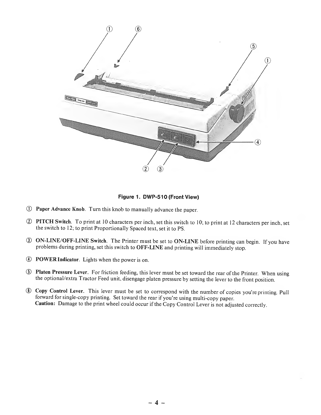
Figure 1. DWP-510 (Front View)
©Paper Advance Knob. Turn this knob to manually advance the paper.
©PITCH Switch. To print at 10 characters per inch, set this switch to 10; to print at 12 characters per inch, set
the switch to 12; to print Proportionally Spaced text, set it to PS.
©ON-LINE/OFF-LINE Switch. The Printer must be set to ON-LINE before printing can begin. If you have
problems during printing, set this switch to OFF-LINE and printing will immediately stop.
©POWER Indicator. Lights when the power is on.
©Platen Pressure Lever. For friction feeding, this lever must be set toward the rear of the Printer. When using
the optional/extra Tractor Feed unit, disengage platen pressure by setting the lever to the front position.
©Copy Control Lever. This lever must be set to correspond with the number of copies you're printing. Pull
forward for single-copy printing. Set toward the rear if you're using multi-copy paper.
Caution: Damage to the print wheel could occur if the Copy Control Lever is not adjusted correctly.
-4-

©
Figure 2. DWP-510 (Inside View)
©Front Cover. Always use both hands when lifting this cover. Note that the cover must be closed before print-
ing will occur.
®Platen.
(D Paper Bail. For the best printing results, the bail should always be against the paper.
©Carriage. This mechanism holds the ribbon cartridge and the print wheel. Always remove the ribbon car-
tridge before tilting the carriage back to get to the print wheel. To tilt the carriage back, grasp the two green
handles closest to the paper and pull up and towards you. Do not move the carriage back and forth manually
when the power is ON.
5-
inia esii
J a I'
^':.,- \J
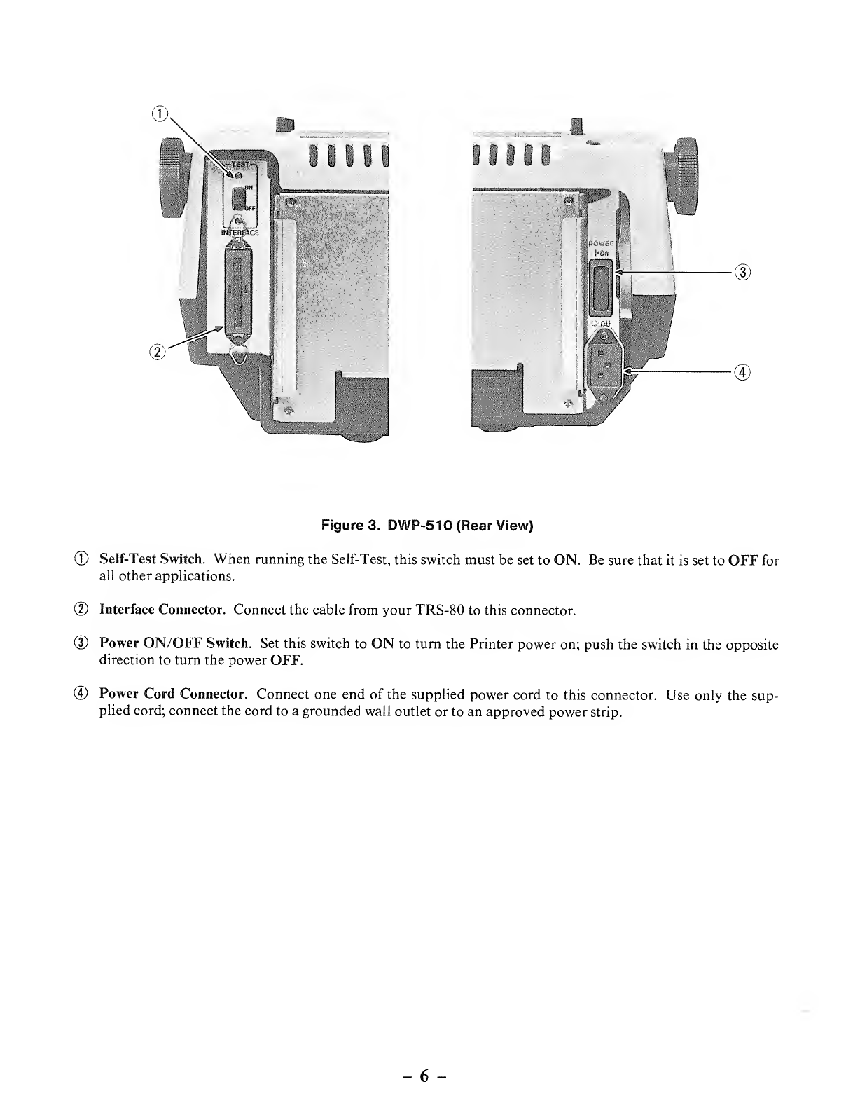
Figure 3. DWP-510 (Rear View)
©Self-Test Switch. When running the Self-Test, this switch must be set to ON. Be sure that it is set to OFF for
all other applications.
(D Interface Connector. Connect the cable from your TRS-80 to this connector.
(D Power ON/OFF Switch. Set this switch to ON to turn the Printer power on; push the switch in the opposite
direction to turn the power OFF.
©Power Cord Connector. Connect one end of the supplied power cord to this connector. Use only the sup-
plied cord; connect the cord to agrounded wall outlet or to an approved power strip.
-6
2/ Setting Up the
When setting up the DWP-510, always be sure you pick alevel, sturdy location with plenty of room for easy
paper flow.
Print Wheel Installation/Removal
The DWP-510 package includes aCourier 10 print wheel which you will need to install before printing. Radio
Shack carries anumber of different print wheels for printing different font styles. These include:
•Courier (10 pitch) (26-1430)
•Prestige Elite (12pitch) (26-1431)
•Madeleine (Proportional Space) (26-1432)
®Cubic (Proportional Space) (26-1433)
•Tile Italic (12 pitch) (26-1434)
®OCR-B (26-1435)
•Letter Gothic (12 pitch) (26-1436)
•Cubic 15 (26-1438)
•Bold Proportional Space (26-1439)
•Scientific A/N (26-1486)
•Pica (10 pitch) (26-1290)
•Narrator (26- 1291)
•OCR-A (26-1292)
•Elite (12 pitch) (26-1293)
If these font styles don't fit your immediate printing needs, be sure to check with your local Radio Shack Com-
puter Center or store since we are continually making more font styles available.
7-

To Install the Print Wheel:
1. Remove the ribbon cartridge from the carriage by gently lifting the ribbon cartridge straight up.
2. Grasp the two green handles (which are closest to the platen) between your thumb and forefinger and gently tilt
the carriage toward you.
3. Hold the print wheel by the green hub. When the print wheel is properly installed, the hub will be toward the
paper.
4. Position the red dot (on the back of the print wheel, opposite the hub) so that it corresponds to and fits into the
open notch on the carriage. (Match the red on both the hub and the notch.)
5. Push down on the hub until the wheel clicks into place. The green hub should be all the way down.
6. Grasp the two green handles (which are closest to the platen) between your thumb and forefinger and gently tilt
the carriage away from you; firmly press the carriage down into its original position.
7. Replace or reinstall the ribbon cartridge.
To Remove the Print Wheel:
1. Remove the ribbon cartridge.
2. Tilt the carriage back as described above.
3. Grasp the green hub of the print wheel and pull up. For easier removal, gently twist the wheel back and forth
while pulling it up.
Ribbon Cartridge Installation/Removal
Radio Shack carries two ribbon cartridges for the DWP-510— ahigh-quality carbon ribbon (26-1419) and along
life nylon ribbon (26-1449). No matter which ribbon you choose, you'll find that they're both easy to install and
remove.
Note: When the carbon ribbon (26-1419) runs out, the printer detects the end of the ribbon and stops printing.
The nylon ribbon (26-1449) is an endless loop, so this will not happen.
To Install aRibbon Cartridge:
1
.
Before installing the cartridge, remove all slack in the ribbon by turning the green knob on the cartridge in the
direction indicated by the arrow (clockwise).
2. Position the cartridge so that the ribbon slides into position between the print wheel and the plastic card guide;
the tabs on the cartridge should line up with the green claws on the carriage.
3. Press down on the cartridge and snap it into place.
4. Turn the ribbon feed knob 1/4 to 1/2 turn clockwise until the cartridge locks down.
To Remove aRibbon Cartridge:
1
.
Gently press the green carriage claws away from the cartridge tabs.
2. Lift up on the cartridge. Be careful not to catch the ribbon on the print wheel.

Paper Loading
You can use either fanfold computer paper or single-sheet typewriter paper with the DWP-510.
If you're using fanfold paper, you'll find it most efficient to use the optional/extra DWP-510 Bidirectional Trac-
tor Feed unit (26-1447).
Friction Feed Paper Loading
1
.
Gently pull the paper bail away from the platen.
2. Set the platen pressure lever toward the rear side of the Printer (pressure ON).
3. Insert the paper behind the platen and turn the platen manually(turn the paper advance knob) so that the paper
advances past the card guide.
4. Set the platen pressure lever toward the front of the Printer (pressure OFF) so that the paper can move freely
back and forth.
5. Align and position the paper at the left margin.
6. Hold the paper in position and move the platen pressure lever back toward the rear side of the Printer (pres-
sure ON). The paper will no longer move freely.
7. Lower the paper bail so that it is against the paper.
8. Position the paper manually to the first line of printing by turning the paper advance knob.
Note: Be sure the Copy Control Lever is set to 1unless you're using multiple form paper. If the Printer runs out of
paper, no out of paper signal will be sent to the computer; the Printer will continue printing on the platen.
If this happens, immediately turn the ON-LINE/OFF-LINE switch to OFF-LINE; after loading more pa-
per, return this switch to ON-LINE.
-9-
Connecting the DWP-510 to aPower Source
Always be sure the DWP-510 is connected to a grounded wall outlet or grounded approved power strip, such as
Radio Shack's Plug-In Power Strip (6 1-26 19) or the Automatic Power Controller, Model SW-30 1(26- 1429).
Always use the supplied cord when connecting the DWP-5 1to apower source.
1. Plug the female end of the cord into the connector on the rear side of the Printer.
2. Connect the other end of the cord into an approved power source.
Connecting the DWP-510 to aXMS-80
The DWP-510 can be used with any TRS-80 Computer or Data Terminal that has parallel interface capabilities.
This includes the:
•Model I
•Model II
•Model III
•Model 4
•Model 12
•Model 16
•Model 100
•Model 2000
•DT-1 Data Terminal
However, before connecting the Printer to the TRS-80, be sure you have the correct cable. Table 1summarizes
the appropriate Radio Shack cables; Table 2briefly describes the location points on the TRS-80s.
10
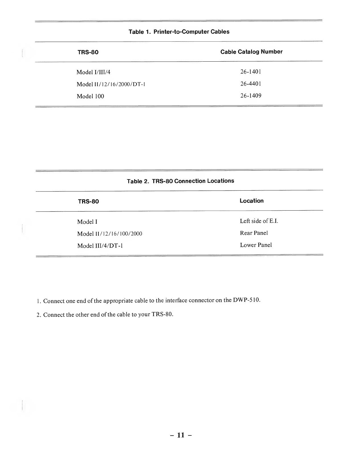
Table 1. Printer-to-Computer Cables
TRS-80 Cable Catalog Number
Model I/III/4 26-1401
Model 1I/12/16/2000/DT-I 26-4401
Model 100 26-1409
Table 2. TRS-80 Connection Locations
TRS-80 Location
Model ILeft side of E.I.
Model 11/12/ 16/ 100/2000 Rear Panel
Model III/4/DT-
1
Lower Panel
1. Connect one end of the appropriate cable to the interface connector on theDWP-510.
2. Connect the other end of the cable to your TRS-80.
-11

-12 -

3/ Using the DWP-510
Before using the DWP-5 10, you should perform the Self-Test to ensure that the Printer is operating properly.
Before running the Self-Test, however, you should load wide paper (15") into the Printer because Self-Test per-
forms printing across the full length of the platen. To run the Self-Test;
1
.
Set the Printer power ON/OFF switch to ON.
2. Set the ON-LINE/OFF-LINE switch to OFF-LINE.
3. Set the TEST switch to ON.
To end the Self-Test, set the TEST switch to OFF.
Setting the Pitch Switch
Be sure to set the PITCH switch (on the front panel) to the position that corresponds with the print wheel you are
using. If you are using aCourier 10 print wheel, for example, set the Switch to 10; if you're using aMadeleine
Proportional Space wheel, set the switch to PS.
Do not accidentally bump the PITCH switch during printing. Unless you change the pitch via software, the cur-
rent switch setting remains in effect. (Once you change the pitch via software, you must turn the Printer power
OFF to use the front panel switch.)
Setting the New Line Switch
Inside the front panel (right side of the frame) is aswitch to select Carriage Return with Line Feed or Carriage Re-
turn only when the Printer receives code 13, the Carriage Return code (see next section ).
Normally, you'll leave this switch in the CR+LF position. For some applications (like when you are using the
Printer with an IBM PC), set it to CR ONLY
You can also select CR +LF or CR only via software (27 21/27 22 code sequence). However, once you change
this function via software, you must turn the Printer power OFF to use this switch.
Control Codes and the DWP-510
Before using the DWP-5 10, consider how the TRS-80 communicates with the Printer.
All information is sent to the Printer as numbers between and 255 decimal (00-FF for you hexadecimal fans).
The printer interprets these numbers according to the American Standard Code for Information Interchange,
commonly referred to as the ASCII code. (See Appendix Afor alist of ASCII codes.) Most numbers (or codes)
are printed as letters, numbers, or symbols. However, the numbers 0-31, as well as some special sequences of
code numbers, are used to control various functions of the Printer. These Control Codes allow you to control line
feeds, backspacing, underlining, etc.
13 -
Sending Control Codes from BASIC
Some Printer functions are activated by asingle code, but many require asequence of two or more codes. Most
multiple-code sequences begin with decimal 27 (referred to as the ESCape code). The ESC code notifies the
Printer that aspecial sequence is on its way. The next code(s) sent determines which Printer function is selected.
In BASIC, use CHR$ ()to send these codes to the Printer.
For instance, set up the DWP-510 as described earlier and enter BASIC in the normal way. Then type the fol-
lowing short program:
10 LPRINT CHR$(15); "UNDERLINE" CHR$(14); "NO UNDERLINE"
and RUN it.
Roll the paper forward and look at the results. The word UNDERLINE was underlined and the words NO
UNDERLINE were not underlined. Why? The codes CHR$(15) and CHR$(14) are the guilty parties. Take a
quick look at Table 3. This chart shows the various code sequences understood by the DWP-5 10.
-14 -
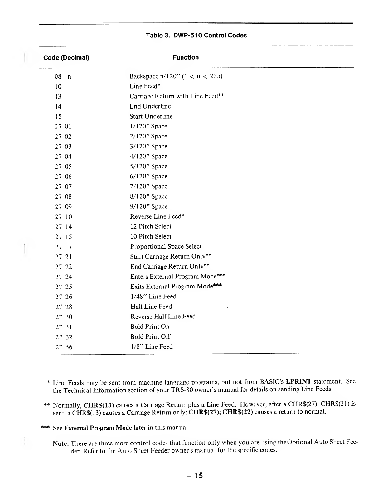
Table 3. DWP-5 10 Control Codes
Code (Decimal) Function
08 n
10
13
14
15
27 01
27 02
27 03
27 04
27 05
27 06
27 07
27 08
27 09
27 10
27 14
27 15
27 17
27 21
27 22
27 24
27 25
27 26
27 28
27 30
27 31
27 32
27 56
Backspace n/ 120" (1 <n<255)
Line Feed*
Carriage Return with Line Feed**
End Underline
Start Underline
1/120" Space
2/120" Space
3/120" Space
4/120" Space
5/120" Space
6/120" Space
7/120" Space
8/120" Space
9/120" Space
Reverse Line Feed*
12 Pitch Select
10 Pitch Select
Proportional Space Select
Start Carriage Return Only**
End Carriage Return Only**
Enters External Program Mode***
Exits External Program Mode***
1/48" Line Feed
Half Line Feed
Reverse Half Line Feed
Bold Print On
Bold Print Off
1/8" Line Feed
*Line Feeds may be sent from machine-language programs, but not from BASIC'S LPRINT statement. See
the Technical Information section of your TRS-80 owner's manual for details on sending Line Feeds.
** Normally, CHR$(13) causes aCarriage Return plus aLine Feed. However, after aCHR$(27); CHR$(21) is
sent, aCHR$(13) causes aCarriage Return only; CHR$(27); CHR$(22) causes areturn to normal.
*** See External Program Mode later in this manual.
Note: There are three more control codes that function only when you are using theOptional Auto Sheet Fee-
der. Refer to the Auto Sheet Feeder owner's manual for the specific codes.
-15 -
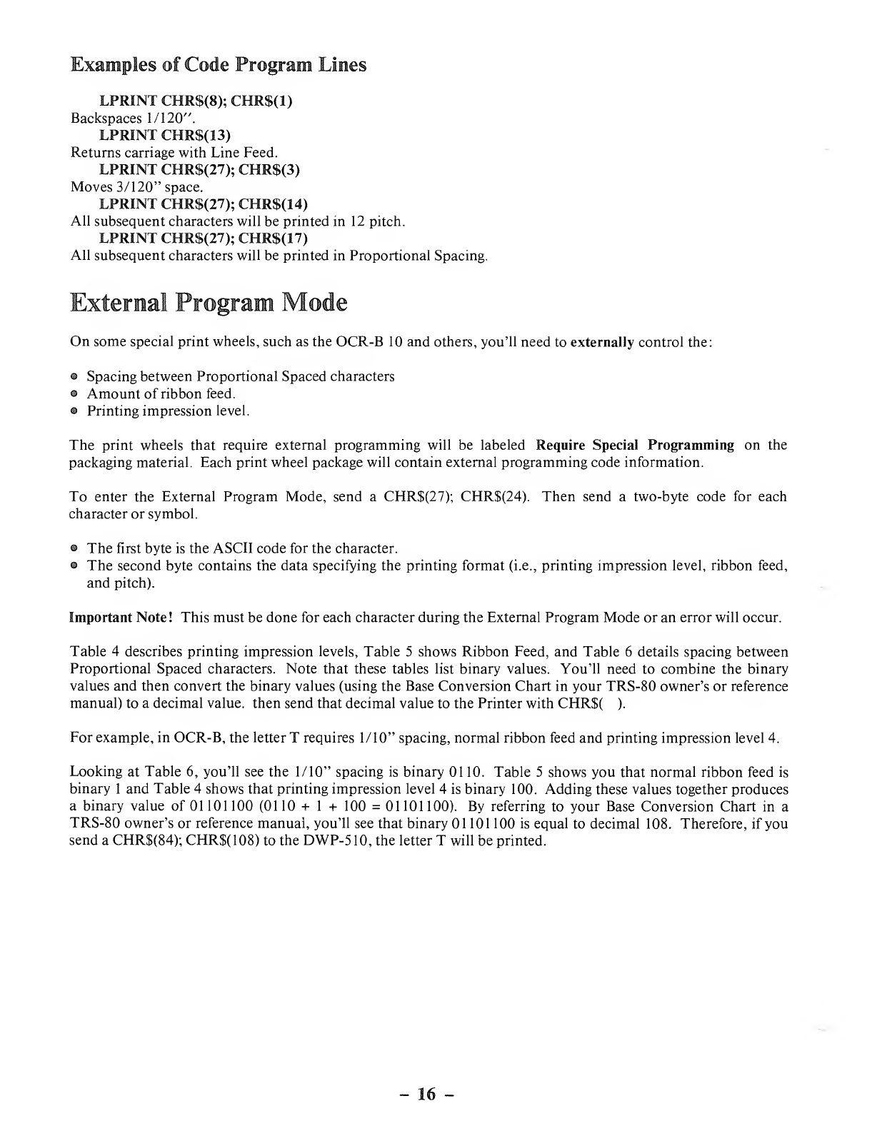
Examples of Code Program Lines
LPRINT CHR$(8); CHR$(1)
Backspaces 1/120".
LPRINT CHR$(13)
Returns carriage with Line Feed.
LPRINT CHR$(27); CHR$(3)
Moves 3/120" space.
LPRINT CHR$(27); CHR$(14)
All subsequent characters will be printed in 12 pitch.
LPRINT CHR$(27); CHR$(17)
All subsequent characters will be printed in Proportional Spacing.
External Program Mode
On some special print wheels, such as the OCR-B 10 and others, you'll need to externally control the:
•Spacing between Proportional Spaced characters
•Amount of ribbon feed.
•Printing impression level.
The print wheels that require external programming will be labeled Require Special Programming on the
packaging material. Each print wheel package will contain external programming code information.
To enter the External Program Mode, send aCHR$(27); CHR$(24). Then send atwo-byte code for each
character or symbol.
•The first byte is the ASCII code for the character.
•The second byte contains the data specifying the printing format (i.e., printing impression level, ribbon feed,
and pitch).
Important Note! This must be done for each character during the External Program Mode or an error will occur.
Table 4describes printing impression levels, Table 5shows Ribbon Feed, and Table 6details spacing between
Proportional Spaced characters. Note that these tables list binary values. You'll need to combine the binary
values and then convert the binary values (using the Base Conversion Chart in your TRS-80 owner's or reference
manual) to adecimal value, then send that decimal value to the Printer with CHR$( ).
For example, in OCR-B, the letter Trequires 1/10" spacing, normal ribbon feed and printing impression level 4.
Looking at Table 6, you'll see the 1/10" spacing is binary 0110. Table 5shows you that normal ribbon feed is
binary 1and Table 4shows that printing impression level 4is binary 100. Adding these values together produces
abinary value of 01 101 100 (01 10 +1+100 =01 101 100). By referring to your Base Conversion Chart in a
TRS-80 owner's or reference manual, you'll see that binary 01 101 100 is equal to decimal 108. Therefore, if you
send aCHR$(84); CHR$(108) to the DWP-510, the letter Twill be printed.
-16 -

D8 D7 D6 D5
PS unit set (Available
in PS mode only)
D4
RF
set
D3 D2 Dl
Unit amount (A/60") D8 D7 D6 D5
(print without
Carriage movement)
11
21
311
41
51 1
611
711 1
8
91
10 1
11 11
12 1
13 11
14 1 1
15 11 1
Hammer set
Hammer impression
level D3 D2 Dl
11
21
31 1
41
511
611
(no hammer action) 111
Table 4
Ribbon Feed
amount D4
Normal 1
Long
Table 5
Table 6
Example
10 LPRINT CHR$(27); CHR$(24) 'ENTERS EXTERNAL PROGRAM
20 LPRINT CHR$(84); CHR$(108); 'PRINT T
30 LPRINT CHR$(97); CHR$(107); 'PRINT a
40 LPRINT CHR$(110); CHR$(107); 'PRINT n
50 LPRINT CHR$(100); CHR$(108); 'PRINT d
60 LPRINT CHR$(121); CHR$(107); 'PRINT y
17 -
Special Functions
When using the DWP-5 10, you should be aware that there are special functions available.
Auto NL (New Line)
In some cases, the DWP-5 10 will automatically execute aNew Line function (Carriage Return and Line Feed).
These cases include:
•When the DWP-5 10 is set to 10 pitch and the carriage is in the 136th column position.
•When the DWP-510 is set to 12 pitch and the carriage is in the 163rd column position.
•When the DWP-5 10 is set to Proportional Spacing and the carriage moves to within 8units (8/60") of the right
margin.
REMEMBER! The New Line switch can be set to select either Carriage Return with Line Feed or Carriage Re-
turn only. Usually it is set to CR+NL. (when you are using the DWP-510 with an IBM PC, set this switch to CR
ONLY.) Refer to Setting the New Line Switch.
Optimizer
For more efficient printing, the DWP-510 stores certain codes when they are received within 10 milliseconds of
each other. These codes include:
•Space
®Backspace
•Line Feed (including New Line)
•Reverse Line Feed
•Half Line Feed
•Half Reverse Line Feed
These codes are stored until either the character codes or function codes are sent within intervals of 10 msec or
more. When either of these situations occurs, the stored codes are executed one at atime. For example, when 10
Line Feed codes. are entered with less than 10 msec intervals, the DWP-510 will automatically feed 10 lines at
once.
-18 -
4/ Care and Maintenance
Only the parts marked with green require any normal handling/adjustment. Any other maintenance should be
performed only by aqualified service technician.
Of course, you can and should perform standard cleaning procedures —just as you would with any office type-
writer. Clean the platen, print wheel and other parts with standard typewriter cleaning fluids (use asoft, lint-free
cloth).
Some do's and don'ts to assure maximum performance and reliability from your Printer:
DO DON'T
Plug power cord into 3-wire grounded outlet. Operate Printer in environments of high dust or dirt
content, high temperature or humidity.
Position the Printer on afirm, clean, flat surface.
Place any objects on any part of the Printer (if anything
Use only alint- free cloth to clean the Printer case. falls inside the Printer, turn Printer power off and
Mild detergent solution can be used sparingly. carefully remove the object).
Ensure that all covers are closed and secured before Use alcohol, solvents or harsh cleaning agents on any
operating. part of the Printer.
Turn off power before making any adjustment. Operate Printer without paper (if paper is less than
15" wide take care not to print lines too long for the
paper).
Troubleshooting
If the Printer fails to operate properly, try to solve the problem as follows:
1
.
Power lamp does not turn on :
ACheck to see that the AC cord is plugged securely into an appropriate power source.
2. No communication with the TRS-80 :
ACheck to see if the interface cable is properly connected.
BCheck to see if the ON-LINE/OFF-LINE switch is ON-LINE.
3. Printer will not print
:
AEnsure that the cover is securely closed.
BCheck and change the ribbon, if necessary.
CPerform the Self-Test! operation to ensure that the Printer is internally capable of printing (see page 13).
DEnsure that the print wheel is locked into position.
ECheck to see if anything has fallen into the mechanism that is physically obstructing the carriage move-
ment.
-19

-20 -
5/ Specifications
Printing Speed 43 characters per second
Carriage Return Speed 300 ms per 13.6 inches
Line Feed Speed 4inches per second
Printing Pitch 1/10 inch, 1/12 inch, Proportional spacing
Line Feed Pitch 1/6 inch, 1/12 inch
Font 124 character positions on Double Daisy Print Wheel
Wheel Courier 10 (Catalog Number 26-1430)
Prestige Elite (Catalog Number 26-1431)
Madeleine P.S. (Catalog Number 26-1432)
Cubic P.S. (Catalog Number 26-1433)
Tile Italic (Catalog Number 26-1434)
OCR-B (Catalog Number 26-1435)
Letter Gothic 12 (Catalog Number 26-1436)
Cubic 15 (Catalog Number 26-1438)
Bold P.S. (Catalog Number 26- 1439)
Scientific A/N (Catalog Number 26-1486)
Pica 10 (Catalog Number 26-1290)
Narrator (Catalog Number 26-129 1)
OCR-A (Catalog Number 26-1292)
Elite 12 (Catalog Number 26-1293)
Characters per Line 136 characters in 10 pitch mode
163 characters in 12 pitch mode
Print Wheel Life 40 million characters
Ribbon Life Nominal 270,000 characters; may vary according to the text printed
(Multistrike carbon ribbon)
Nominal 1,600,000 characters (Fabric ribbon)
Interfaces
Data 8parallel data and 1strobe
Code Modified ASCII
Temperature Ranges
Operating 41 to 95°F(5 to 35°C)
Storage -40 to 149°F (-40 to 65°C)
Relative Humidity
Operating 20 -90% RH (No condensation)
Storage 5-95% RH (No condensation)
Paper Weight Total weight: 26 pound/ft2max. (127.9 grams/m2 max.)
One ply: 8pound/ft2max. (40 grams/m2 max.)
Size Width: 16. 54 inches max. (420 mm max.)
Length: 3.33 inches min. (84.7 mm min.)
Ribbon Multi-strike, carbon ribbon (Catalog Number 26-1419)
Fabric ribbon (Catalog Number 26-1449)
Size 8.05" x24.6" x15.55"
204.5 mm x625 mm x395 mm (HWD)
Power Requirements 120 VAC, 50/60 Hz, 135 Wtypical
Optional bidirectional tractor is available (Catalog Number 26-1447).
-21 -
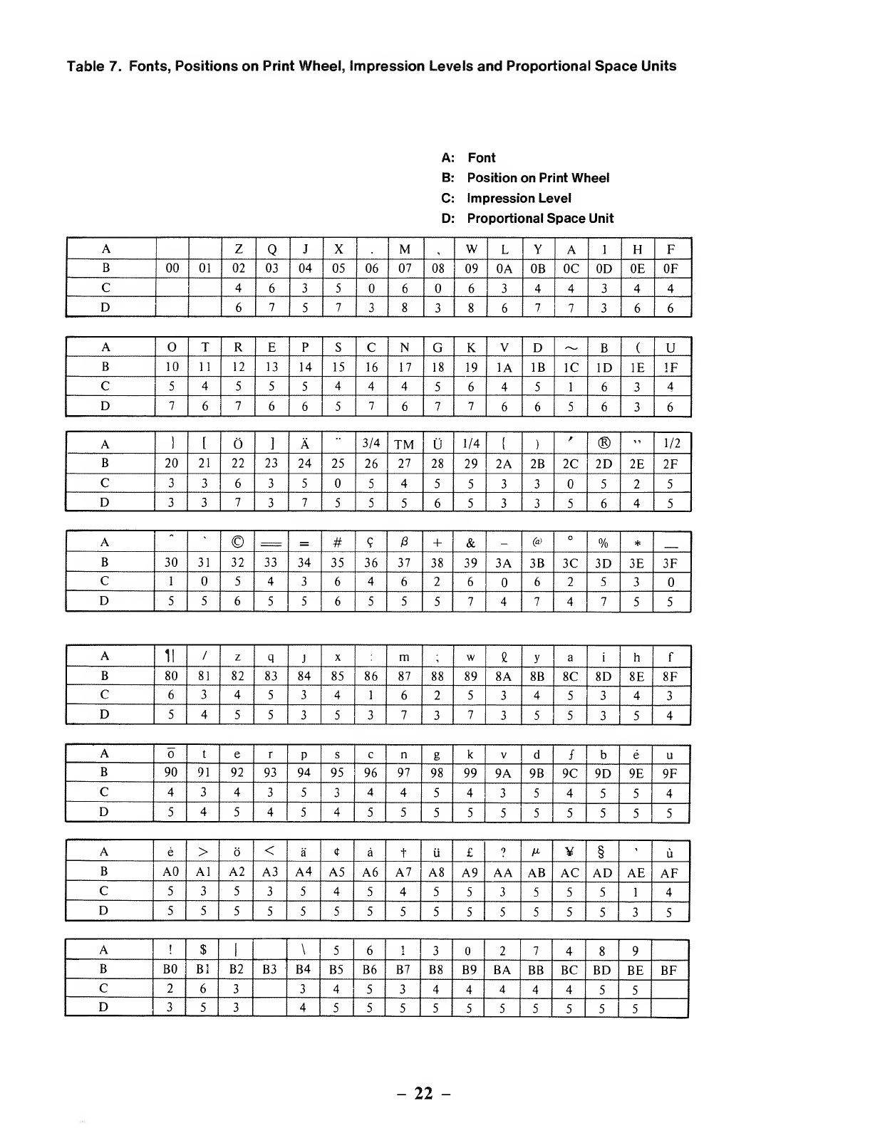
Table 7. Fonts, Positions on Print Wheel, impression Levels and Proportional Space Units
Font
Position on Print Wheel
Impression Level
Proportional Space Unit
AZQJXM,WLYAIHF
B00 01 02 03 04 05 06 07 08 09 0A 0B OC 0D 0E OF
C463566 3 44344
D67573838677366
ATREPSCNGKVD~B(U
B10 11 12 13 14 15 16 17 18 19 1A IB 1C ID IE IF
C5455544456451634
D7676657677665636
A1[O]A3/4 TM 1/4 S)
r®"1/2
B20 21 22 23 24 25 26 27 28 29 2A 2B 2C 2D 2E 2F
C33635545533 525
D3373755565335645
A"©=#9+&-(a) O%*
B30 31 32 33 34 35 36 37 38 39 3A 3B 3C 3D 3E 3F
C1543646 2 662 5 3
D5565 5 6555747 4 755
A11 /zqJXmiweyaihf
B80 81 82 83 84 85 86 87 88 89 8A 8B 8C 8D 8E 8F
C6345341625345343
D54553 5 3 7 37355354
AterPscngkVdfb e u
B90 91 92 93 94 95 96 97 98 99 9A 9B 9C 9D 9E 9F
C4343 5 34454354554
D545454555555555 5
Ae>6<a<r atii £9M¥§'u
BA0 Al A2 A3 A4 A5 A6 A7 A8 A9 AA AB AC AD AE AF
C5353545455355514
D5555 5 55555 5 55535
AI$|\56132 7 48 9
BB0 Bl B2 B3 B4 B5 B6 B7 B8 B9 BA BB BC BD BE BF
C263345 3 4444 4 55
D35 3 4555555 5 55 5
-22 -

Appendix A/ ASCII Character Codes
Printable Characters
The DWP-5 10 can produce all Modified ASCII characters. Here's what they look like:
Code Char. Code Char. Code Char. Code Char.
Dec. Hex Oct. Dec. Hex Oct. Dec. Hex Oct. Dec. Hex Oct.
32 20 040 SP 64 40 100 @96 60 140 -128 80 200 a
33 21 041 165 41 101 A97 61 141 a156 9C 234 9
34 22 042 •• 66 42 102 B98 62 142 b163 A3 243 £
35 23 043 #67 43 103 C99 63 143 c165 A5 245 M
36 24 044 $68 44 104 D100 64 144 d166 A6 246 °
37 25 045 %69 45 105 E101 65 145 e167 A7 247 -
38 26 046 &70 46 106 F102 66 146 f168 A8 250 t
39 27 047 '71 47 107 G103 67 147 g169 A9 251 TM
40 28 050 (72 48 110 H104 68 150 h170 AA 252 ®
41 29 051 )73 49 111 1105 69 151 i171 AB 253 ©
42 2A 052 *74 4A 112 J106 6A 152 J172 AC 254 1/4
43 2B 053 +75 4B 113 K107 6B 153 k173 AD 255 3/4
44 2C 054 ,76 4C 114 L108 6C 154 1174 AE 256 1/2
45 2D 055 -77 4D 115 M109 6D 155 m175 AF 257 f
46 2E 056 78 4E 116 N110 6E 156 n187 BB 273 e
47 2F 057 /79 4F 117 O111 6F 157 188 BC 274 u
48 30 060 80 50 120 P112 70 160 P189 BD 275 A
49 31 061 181 51 121 Q113 71 161 q190 BE 276
50 32 062 282 52 122 R114 72 162 r191 BF 277 /
51 33 063 383 53 123 S 115 73 163 s192 CO 300 1
52 34 064 484 54 124 T116 74 164 t204 CC 314 ¥
53 35 065 585 55 125 U117 75 165 u219 DB 333 A
54 36 066 686 56 126 V118 76 166 V220 DC 334
55 37 067 787 57 127 W119 77 167 w221 DD 335
56 38 070 888 58 130 X120 78 170 X222 DE 336 «
57 39 071 989 59 131 Y121 79 171 y223 DF 337 —
58 3A 072 90 5A 132 Z122 7A 172 z251 FB 373 a
59 3B 073 91 5B 133 [123 7B 173 I252 FC 374 6
60 3C 074 <92 5C 134 \124 7C 174 1253 FD 375 ii
61 3D 075 =93 5D 135 1125 7D 175 I254 FE 376
62 3E 076 >94 5E 136 /\ 126 7E 176 ~
63 3F 077 995 5F 137 127 7F 177 (Blank)
-23 -

Proportional Character Set Units Per Column
3UNITS 4UNITS 5UNITS 6UNITS 7UNITS 8UNITS
-46/2E "-34/22 J-74/4A V-118/76 Z-90/5A Q-81/51 M-77/4D
-44/2C --45/2D S-83/53 d-100/64 L-76/4C X-88/58 W-87/57
I-73/49 -166/A6 ~-126/7E /-191/BF H-72/48 Y-89/59
(-40/28 /-47/2F -190/BE b-98/62 F-70/46 A-65/41
1-125/7D f-102/66 3/4 -173/AD e-187/BB T-84/54 -79/4F
[-91/5B t-116/74 TM -169/A9 u-117/75 E-69/45 R-82/52
]-93/5D r-114/72 1/4 -172/AC e-189/BD P-80/50 C-67/43
[-123/7B s-115/73 '
-167/A7 >-62/3E N-78/4E G-71/47
)-41/29 \-92/5C 1/2 -174/AE 6-252/FC V-86/56 K-75/4B
j-106/6A -94/5E <-60/3C D-68/44 -220/DC
:-58/3A *
-96/60 a-251/FB B-66/42 A-219/DB
;-59/3B -223/DF <r -222/DE U-85/55 &-38/26
1-108/6C =-61/3D a-128/80 U-221/DD @-64/40
i-105/69 9-156/9C +-168/A8 ®-170/AA %-37/25
-39/27 -254/FE u-253/FD ©-171/AB m-109/6D
!-33/21 +-43/2B £-163/A3 #-35/23 w-119/77
1-124/7C *
H
z
q
X
y
a
h
e
P
c
n
g
k
-42/2A
-95/5F
-175/AF
-122/7A
-113/71
-120/78
-121/79
-97/61
-104/68
-111/6F
-101/65
-112/70
-99/63
-110/6E
-103/67
-107/6B
§
u
$
5
6
1
3
2
7
4
8
9
-63/3F
-165/A5
-204/CC
-192/CO
-188/BC
-36/24
-53/35
-54/36
-49/31
-51/33
-48/30
-50/32
-55/37
-52/34
-56/38
-57/39
Note: Codes are in Decimal and Hexadecimal (Dec/Hex).
-24 -
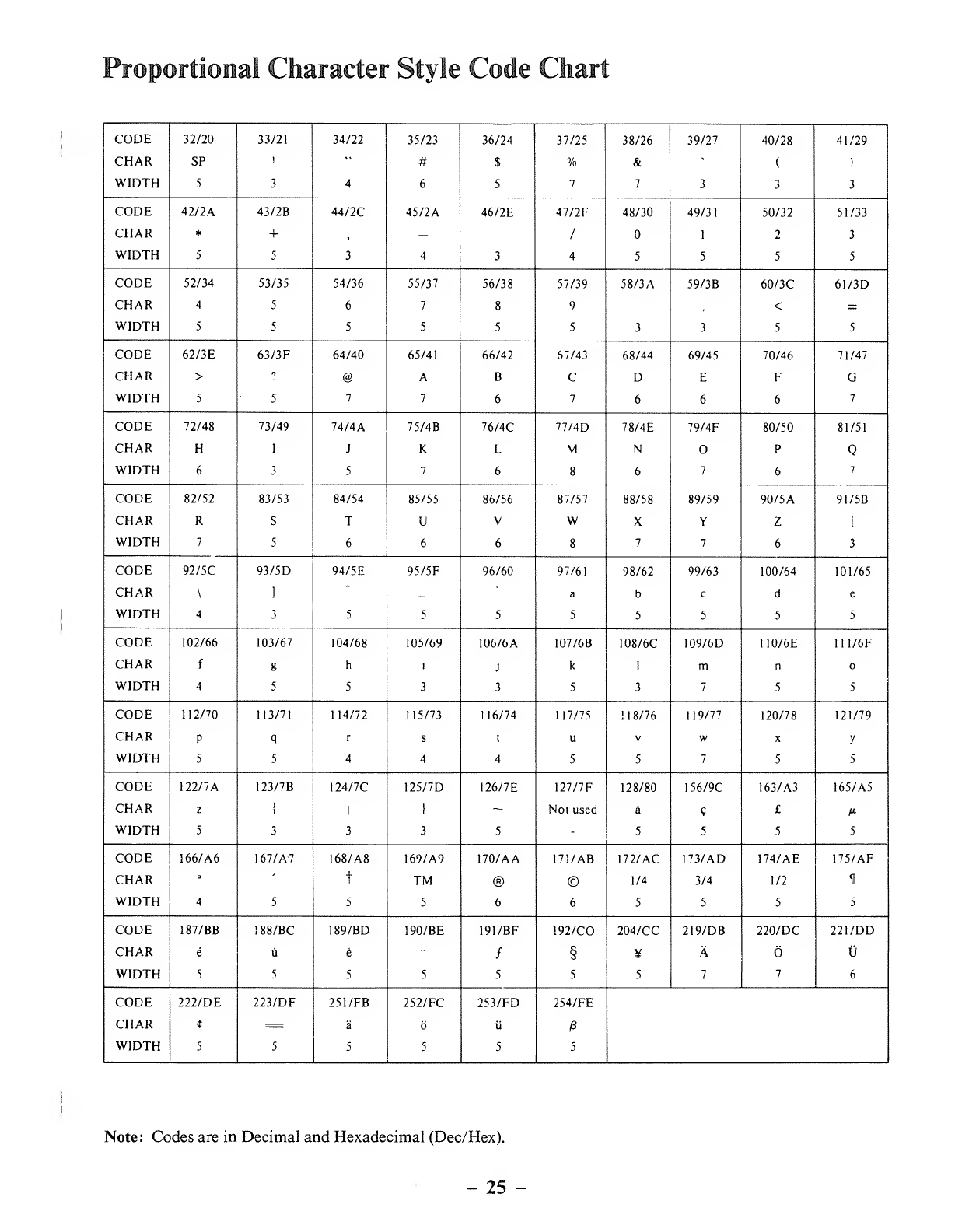
Proportional Character Style Code Chart
CODE 32/20 33/21 34/22 35/23 36/24 37/25 38/26 39/27 40/28 41/29
CHAR SP i"#$%&<
()
WIDTH 5346577333
CODE 42/2A 43/2B 44/2C 45/2A 46/2E 47/2F 48/30 49/31 50/32 51/33
CHAR *+,—/12 3
WIDTH 5534345555
CODE 52/34 53/35 54/36 55/37 56/38 57/39 58/3A 59/3B 60/3C 61/3D
CHAR 456789", <=
WIDTH 55 5 5 553355
CODE 62/3E 63/3F 64/40 65/41 66/42 67/43 68/44 69/45 70/46 71/47
CHAR >f> @ABC D EFG
WIDTH 5577676667
CODE 72/48 73/49 74/4A 75/4B 76/4C 77/4D 78/4E 79/4F 80/50 81/51
CHAR HIJKLMNOP
WIDTH 6357686767
CODE 82/52 83/53 84/54 85/55 86/56 87/57 88/58 89/59 90/ 5A91/5B
CHAR RSTUVWX Y Z [
WIDTH 7566687763
CODE 92/5C 93/5D 94/5E 95/5F 96/60 97/61 98/62 99/63 100/64 101/65
CHAR \]
"
abcde
WIDTH 43 5 5555 5 5 5
CODE 102/66 103/67 104/68 105/69 106/6
A
107/6B 108/6C 109/6D 110/6E 111/6F
CHAR fgh!Jk1mn
WIDTH 455 3 3 5 3 75 5
CODE 112/70 113/71 114/72 115/73 116/74 117/75 ! 1 8/76 119/77 120/78 121/79
CHAR PqrsluVwXy
WIDTH 5544455755
CODE 122/7A 123/7B 124/7C 125/7D 126/7E 127/7F 128/80 156/9C 163/A3 165/A5
CHAR zi
i1I~Not used a?£M
WIDTH 53335-5 5 55
CODE 166/A6 167/A-7 168/A8 169/A9 170/AA 171/AB 172/AC 173/AD 174/AE 175/AF
CHAR °'
iTM ® © 1/4 3/4 1/2 11
WIDTH 4555665555
CODE 187/BB 188/BC 189/BD 190/BE 191/BF 192/CO 204/CC 219/DB 220/DC 221/DD
CHAR eue/§¥A
WIDTH 5 5 5 5 5 5 577 6
CODE 222/DE 223/DF 251/FB 252/FC 253/FD 254/FE
CHAR t=aUP
WIDTH 5 5 5 5 5 5
Note: Codes are in Decimal and Hexadecimal (Dec/Hex).
-25 -

-26 -

Appendix B/ Interface Description
Interface Input Signal
Input Signal System Diagram
>
DATA 1
TRS-
DATA 2
DATA 3
DATA 4-80
PRINTER DATA 5
DATA 6
DATA 7
DATA 8
STROBE
'Ground not shown.
Description of Each Input Signal
(1) DATA Lines (DATA 1-DATA 8)
These DATA lines provide 8input signals for actuating the Printer. The Printer will ignore any invalid code
applied.
(2) STROBE
Asampling signal for the DATA lines which provide instruction signals for actuating the Printer.
Acontrol signal generated by the computer which latches data into the Printer.
Output Signal
Output Signal System Diagram
BUSY
OUT OF PAPER
PRINTER BUSY TRS-80
ACK
FAULT
Ground not shown.
-27 -
Description of Each Output Signal
•BUSY
Busy condition:
1
)
Data is in buffer
2) Initial state
3) Off-line mode
4) Error state
5) Ribbon fault state
6) Cover open state
Ready condition:
1) Condition other than one of those listed in 1through 6above
2) Cover closed state
•OUT OF PAPER
No function. This line is always a"0" signal.
BUSY
This signal is the logical inverse of BUSY.
•ACK
This signal indicates the Printer has accepted data from CPU.
•FAULT
This signal indicates the Printer is in an error state, ribbon fault state, cover open state or off-line state.
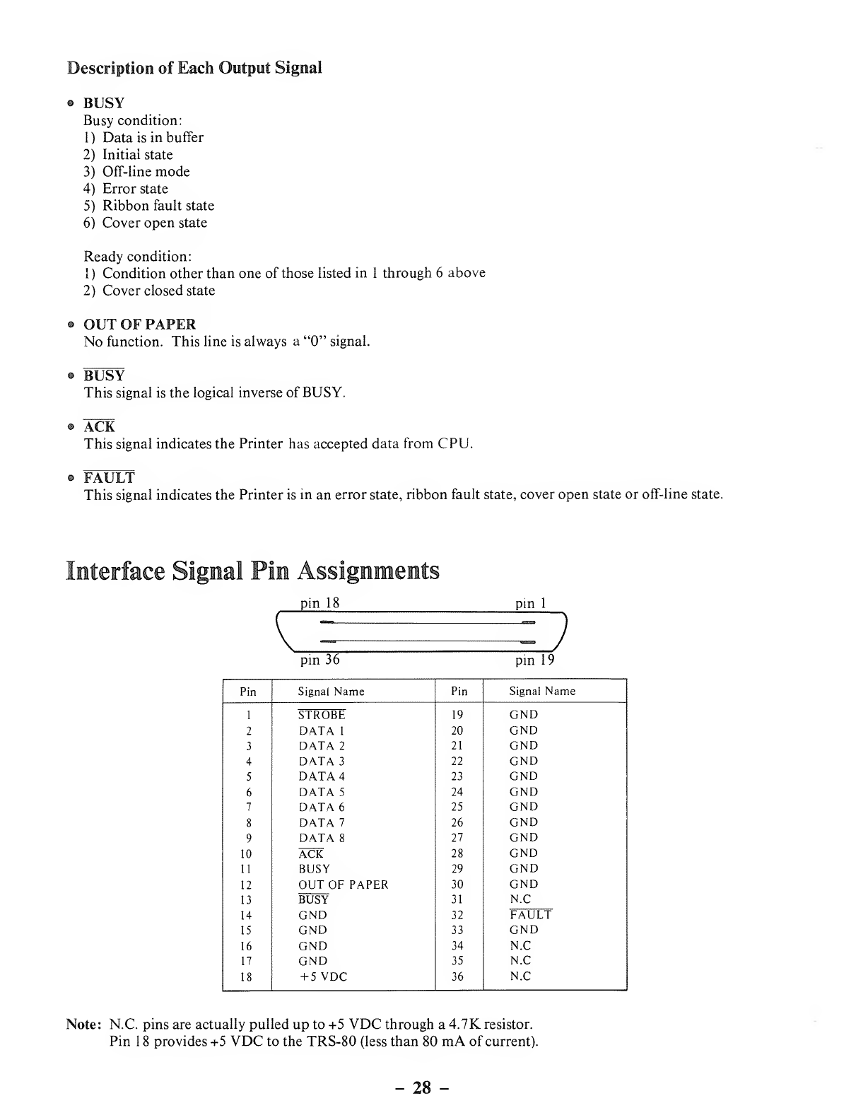
terface Signal Pin Assignments
pin 18
pin 36
pin 1
pin 19
Pin Signal Name Pin Signal Name
119 GND
STROBE
2DATA 120 GND
3DATA 221 GND
4DATA 322 GND
5DATA 423 GND
6DATA 524 GND
7DATA 625 GND
8DATA 726 GND
9DATA 827 GND
10 ACK 28 GND
11 BUSY 29 GND
12 OUT OF PAPER 30 GND
13
14
BUSY
GND
31
32
N.C
FAULT
15 GND 33 GND
16 GND 34 N.C
17 GND 35 N.C
18 +5VDC 36 N.C
Note: N.C. pins are actually pulled up to +5 VDC through a4.7K resistor.
Pin 18 provides +5 VDC to the TRS-80 (less than 80 mA of current).
-28 -
Appendex C/ Print Samples
Courier (10 pitch)
ABCDEFGHIJKLMNOPQRSTUVWXYZ
abcdef ghi jklmnopqrstuvwxyz
0123456789"[| IM J'®]i"
feed'ata iit£n¥§$0AU
!%.(){}*+-=, ;:/\<>? f~13g&§
Cubic (Proportional Space)
ABCDEFGHIJKLMNOPQRSTUVWXYZ
abcdefghijklmnopqrstuvwxyz
0123456789"[t'Hi'®]i"
/eeoa^a ut£u.¥§$OAU
!%.(){}*+-=, ;:/\<>?jrSc&i
°#|©'~iT
Prestige Elite (12 pitch)
ABCDEFGHIJKLMNOPQRSTUVWXYZ
abcdef ghi jklmnopqrstuvwxyz
0123456789"[f mi'®H"
/eeoaca UT£u¥§$0AU-
!%.(){}*+-=, ;:/\<>?JTBc&@
Tile Italic (12 pitch)
ABCDEFGHIJKLMNOPQRSTUVWXYZ
abcdef ghi jklmn op qrst uvwxyz
0123456789"[i mi'®]i'
feeoata 0t£^Y§$0nU
!%.( ){}*+-=, ;:/\<>? 1[~(3c&@
°#| ©' ~u'
Madeleine (Proportional Space) OCR-B
ABCDEFGHI3KLMNOPQRSTUVWXYZ
abcdefghijklmnopqrstuvwxyz
0123456789"[| mr®]i"
/eeoaCa utLM¥§$OAU
!%.()0*+-=,;:/\<>?_H~Bc&@
°#|©'~uN_
ABCDEFGHIJKLMNOPQRSTUVWXYZ
abcdefghi jkLmnopqrstuvwxyz
0123456789" '§¥i-n£
!"#$%&'()=" |
•<:_ +*><>?-" \ac
;:],. /aijIJeeBRo'd
g/EauU£NuaA<*a i
External Program Mode (EPM) required
-29 -
Letter Gothic (1 2pitch)
ABCDEFGHIJKLMNOPQRSTUVWXYZ
abcdefghi jklmnopqrstuvwxyz
0123456789""[rr®]i"
feeoaia Utfn¥§$DAU
!%.(){}*+-=, ;:/\<>? Oc&(a
Scientific A/N
ABCDEFGHIJKLMNOPQRSTUVWXYZ
abcdefghi jklmnopqrstuvwxyz
0123456789 0123 "56789
a8Y<SeriA. y£iTpaTa)A9Q
!%'(){}*+-=,. :A<>? |~f-+»a:
/AZrhJrJ
EPM required
Cubic 15
ABCDEFGHIJKLMNOPQRSTUVWXYZ
abcdefghi jklmnopqrstuvwxyz
Ul23456789"[2™£ '®]J»
/f§e6a0a ut£|i¥§$a A'U
{%.(){}* +-=, ;:/\<>?_1l~Bg&a
Pica (10 pitch)
ABCDEFGHIJKLMNOPQRSTUVWXYZ
abcdefghi jklmnopqrstuvwxyz
0123456789"[£™io®]£»
fee'atka ut£|i¥§$GH(j
!*.(){}*+-=, ;:/\<>? 1f~B&@
°#l©'~iTg
Bold Proportional Space Narrator
ABCDEFGHIJKLMNOPQRSTUVWXYZ
abcdefghijklmnopqrstuvwxyz
0123456789"[| mi'®B"
fe&oMh ut£u¥§$OSU
!%.(){}*+-=,;:/\<>?_1f-Bc&@
°#|©'~if
ABCDEFGHIJKLMNOPQRSTUVWXYZ
ABCDEFGHIJKLMNOPQRSTUVWXYZ
012345678r[i m*d®H"
ftE'Uh ut£u¥§$DAU
!S. (){}*+—, ;:/\<>? 1f~6&@
-30 -
OCR-A Elite (12 pitch)
abcdefghijklunoporstuvuxyz
abcdefghijklmnopqrstuvwxyz
QlSa^bTflT.E—.n-OiT"
..0' . . .f.£• ¥I=?'o"a'Ci.
!"/..() {}* +-= -ii :/\<>f_ ||H&a
*#.«' A.-V0
ABCDEFGHIJKLMNOPQRSTUVWXYZ
abcdefghijklmnopqrstuvwxyz
0123456789"[?™i6®]i"
/ee'atfa ut£|i¥§$dHU
!*. (){}•+-=, ;:/\<>? 11
°# |Oi-r,- <?_
EPM required
-31 -

-32 -
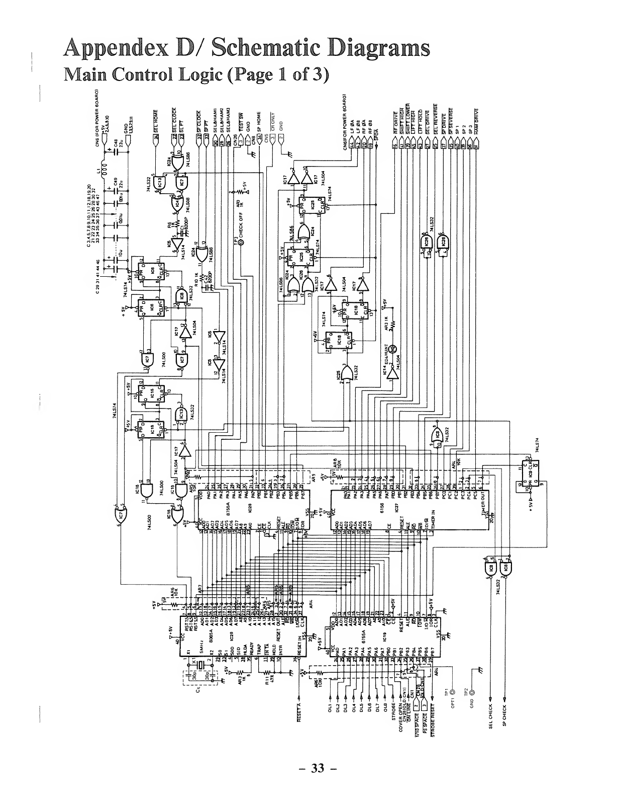
ppendex D/ Schematic Diaj
ain Control Logic (Page 1of 3)
[rams
-33 -
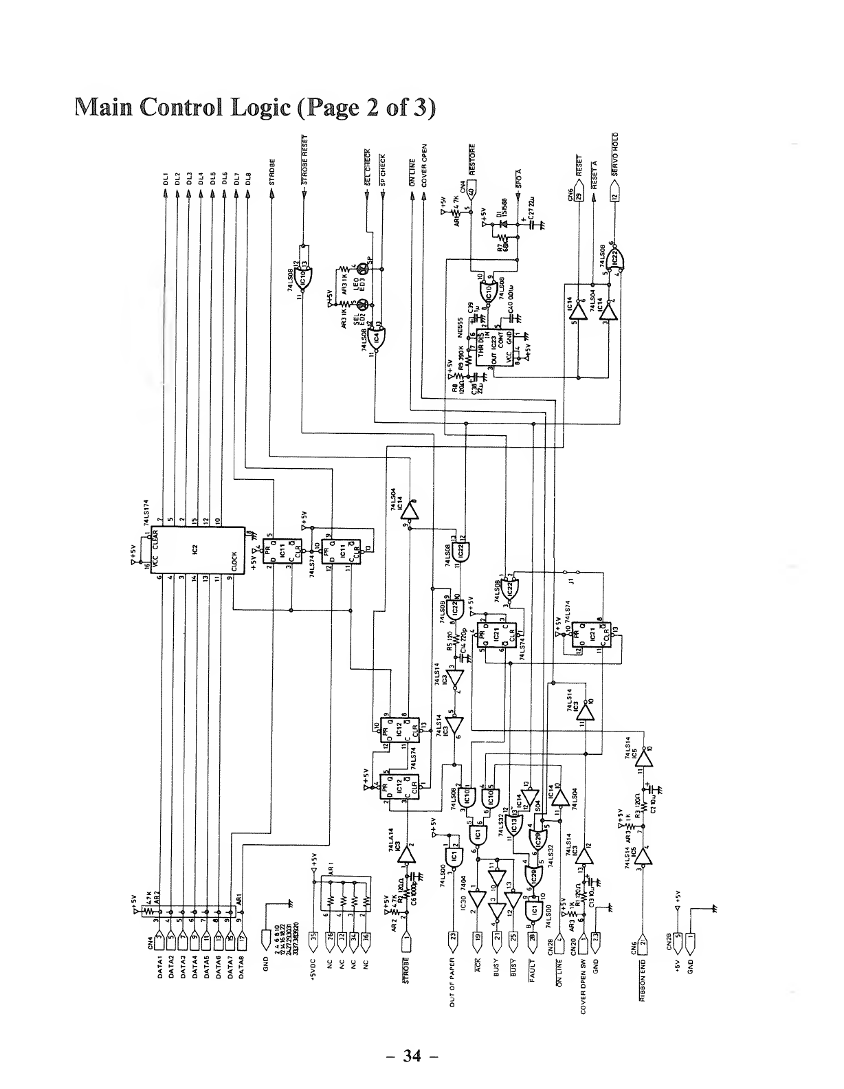
Main Control Logic (Page 2of 3)
OODQOQao
I4A A ,i
rl
ii
Ciaiii
IA
>|w^r
o_o
Lasi G?^
3/T
ikdk
<<<<<<<<
t-l-i-l-S-HHI-
<<<<<<<<
QQOOQQDQ
=66666666 OH fl WW 6613 66 816 th
ozzzz
-34
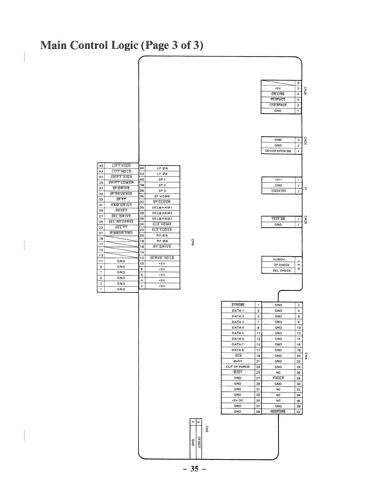
Main Control Logic (Page 3of 3)
45 LIFT HIGH 44 LF 0A
43 42 LF 0B
41 40 SP 1
39 38 SP 2
37 36 SP 3
35 SP REVERSE 34 SP HOME
33 SPTT 32 SP CLOCK
31 30 SEL&HAM1
29 RESET 28 SEL&HAM2
27 SEL DRIVE 26 SEL&HAM3
25 SEL REVERSE 74 SLE HOME
23 SEL PT 22 SLE CLOCK
21 RIBBON END 20 RF BA
19 ~~~~ _____ 18 RF 0B
17 "
16 RF DRIVE
15 "—_14
13 "____ 12 SERVO HOLD
11 GND 10 *5V
9GND 8+5V
7GND 65V
5GND 45V
3GND 2+5V
1GND
'__ 6
+5V 5
On LINE 4
PS SPACE 3
1lid SPACE 2
GND 1
GND 3
GND 2
COVER OPEN SW 1
OPT1 1
GND 2
3
CHECK OFF
TEST SW 3
GND 2
HUNCH
D
SP CHECK
SEL CHECK
K> »
O
z
n
o"*
STROBE 1GND 2
DATA 13GND 4
DATA 25GND 6
DATA 37GND 8
DATA 49GND 10
DATA 511 GND 12
DATA 613 GND 14
DATA? 15 GND 16
DATA 817 GND 18
ACK 19 GND 20
BUSY 21 GND 22
OUT OF PAPER 23 GND 24
BUSY 25 NC 26
GND 27 FAULT 28
GND 29 GND 30
GND 31 NC 32
GND 33 NC 34
5VDC 35 NC 36
GND 37 GND 38
GND 39 RESTORE 40
-35 -
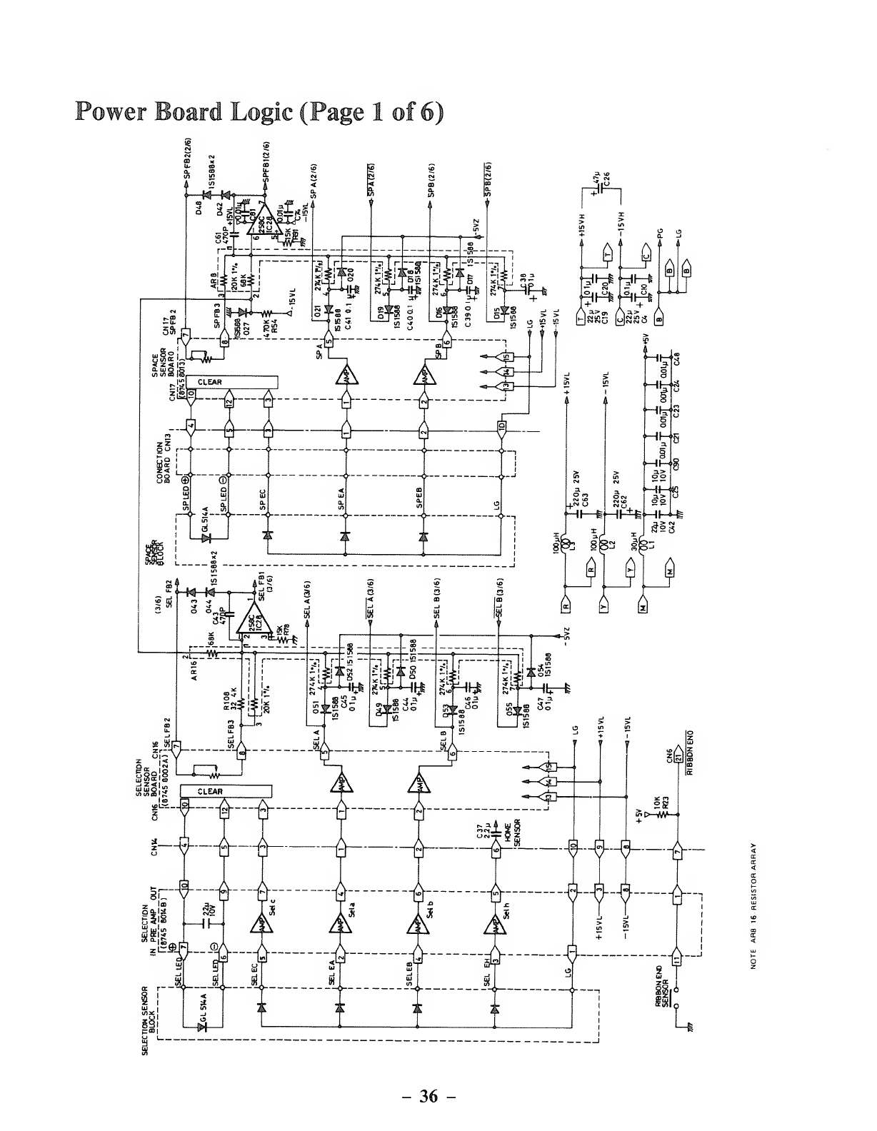
Power Board Logic (Page 1of 6)
-36 -
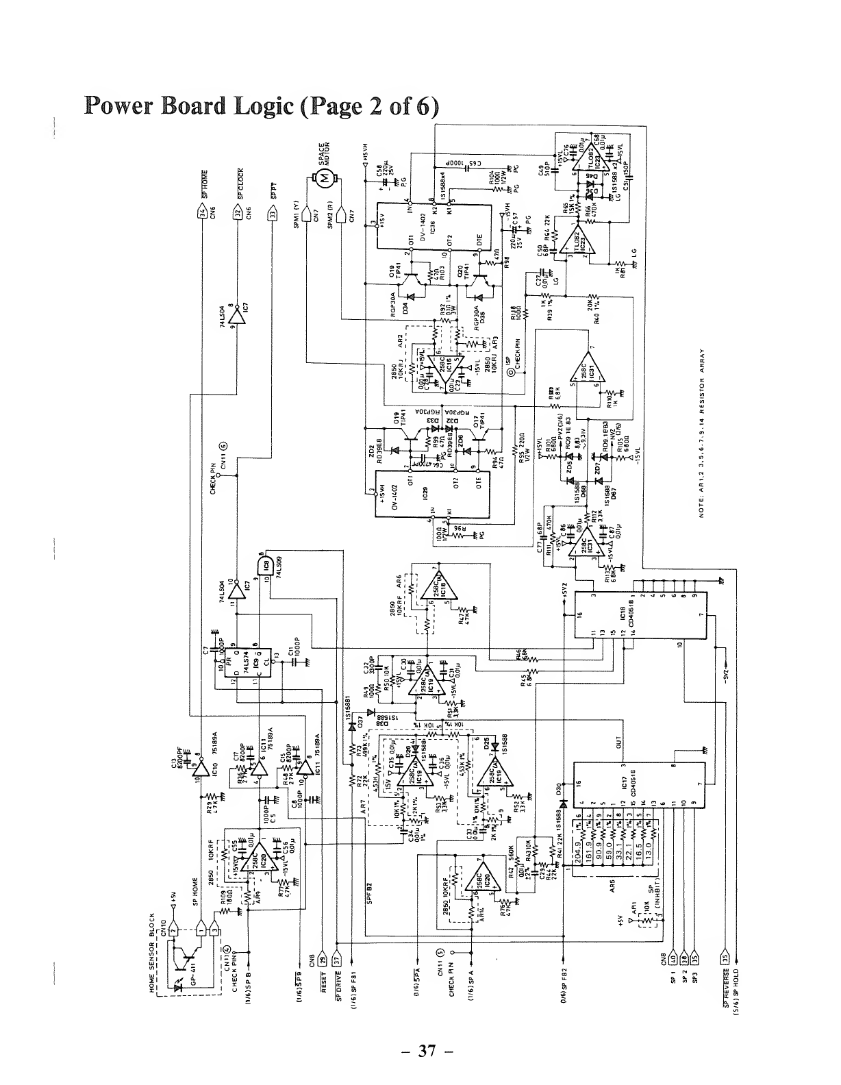
Power Board Logic (Page 2 of 6)
$1 A
IAS
©
IAB
£ 3 Si
|f 4a=11; -II .i
EC -J
Ml KSSi
=dM ^1
37
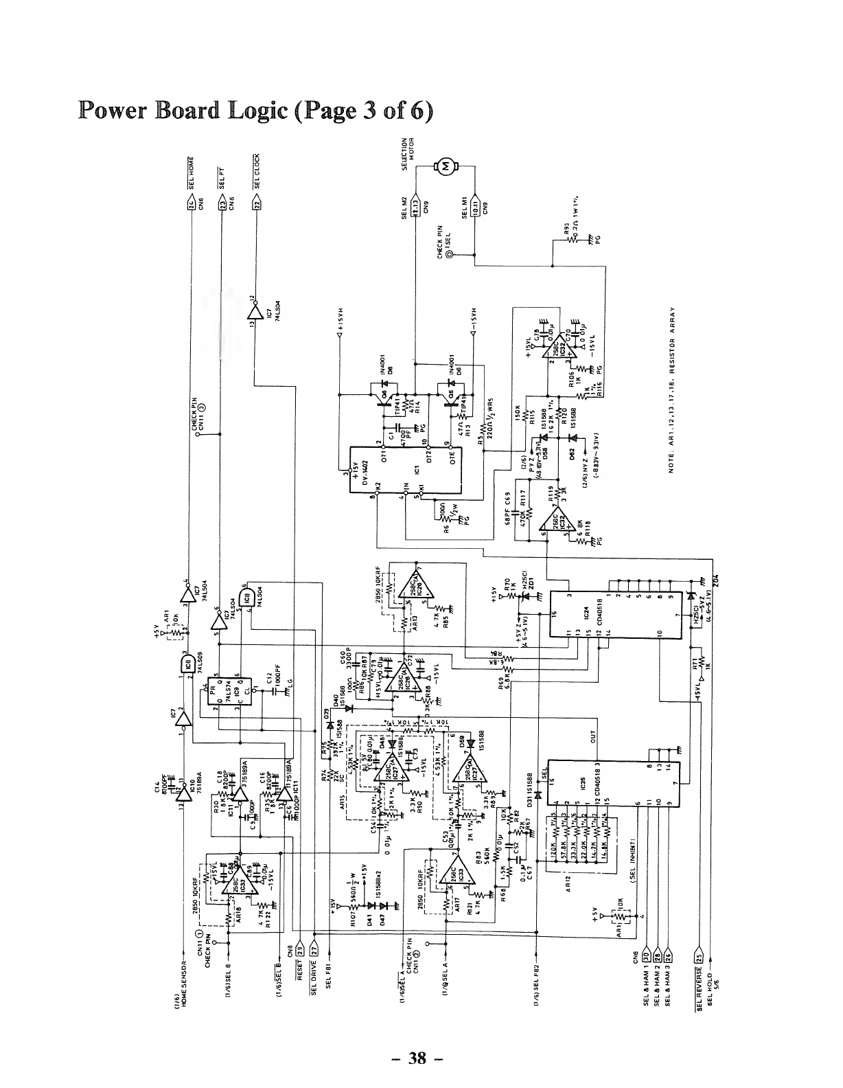
Power Board Logic (Page 3of 6)
r<I>n
$1 &! $
As!
;i
r—*~l»
-38 -
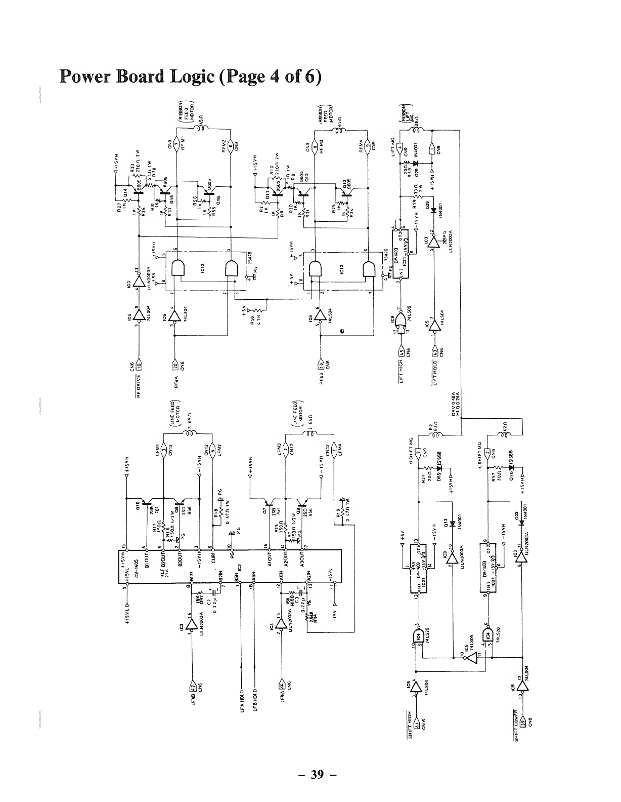
Power Board Logic (Page 4of 6)
-39 -
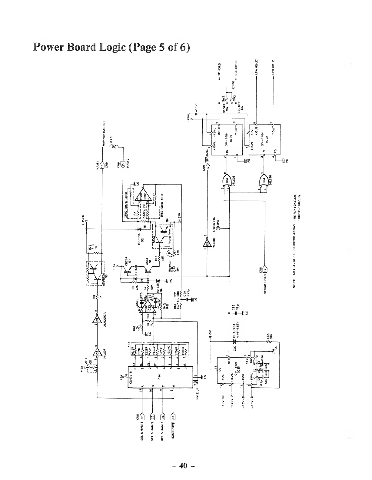
Power Board Logic (Page 5 of 6)
m&& Q
40 -
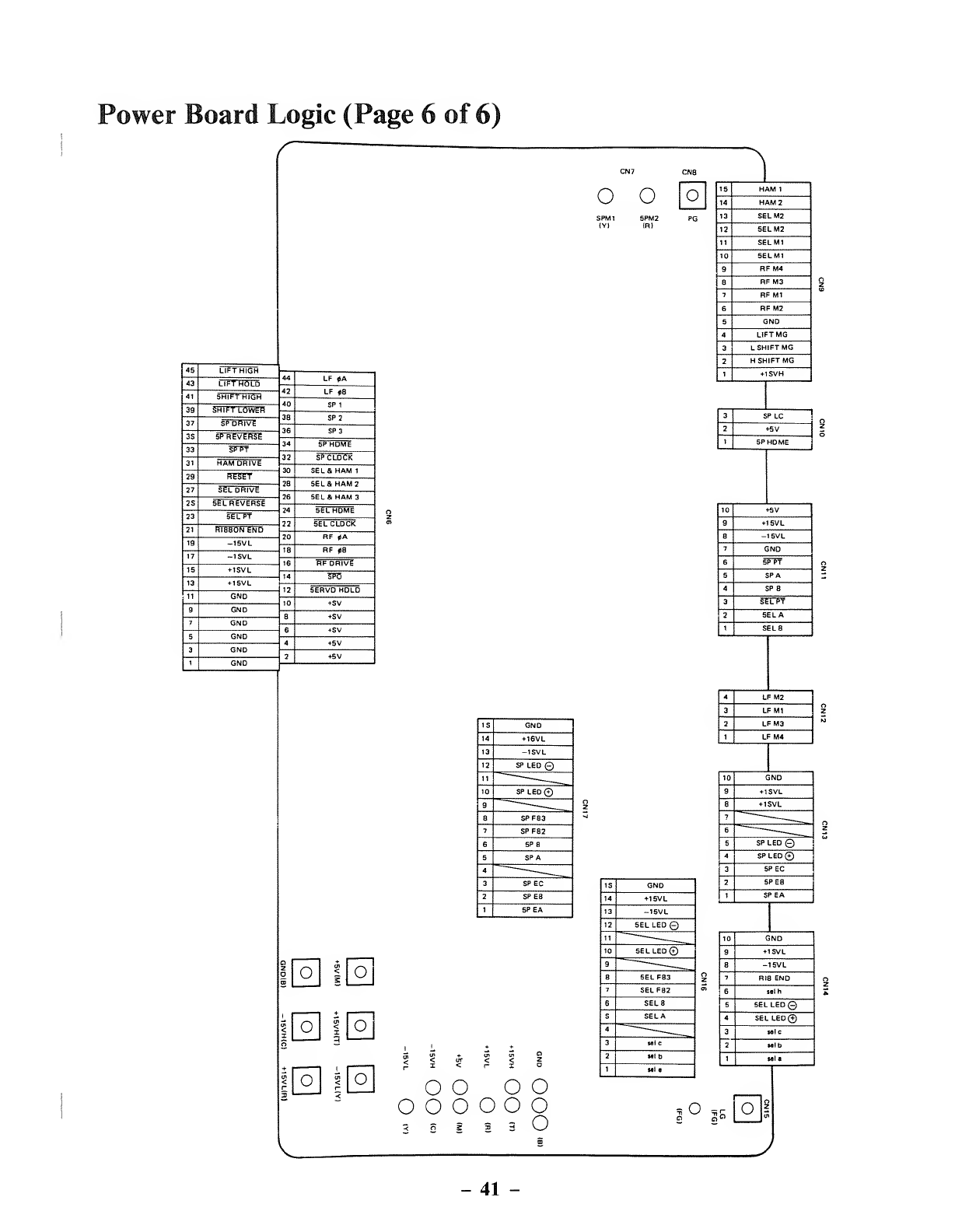
Power Board Logic (Page 6of 6)
LIFT HOLD
SP REVERSE
HAM DRIVE
SEL DRIVE
SEL REVERSE
ooo
SEL 8. HAM 2
SEL Si HAM 3
SERVO HOLD
o<
3o
oen
<
Io
o<o
15 GND
14 +16VL
13 -15VL
12 SP LED ©
11 _____
10 SP LED Q
9_____
8SPFB3
7SPFB2
6SPB
5SPA
4—____
3SPEC
2SPEB
1SPEA
oooo
o o ooo o
<ss33V_J
15 GND
14 +15VL
13 -15V L
12 SEL LED ©
11 ______
10 SEL LED©
9~"——_
8SELFB3
7SELFB2
6SELB
5SELA
4""-""-
_____
3Mic
2Mib
1wta
o
__1
15 HAM 1
14 HAM 2
13 SELM2
12 SELM2
11 SELM1
10 SELM1
9RF M4
8RFM3
7RFM1
6RFM2
5GND
4LIFTMG
3LSHIFT MG
2HSHIFT MG
1+15VH
3SPLC
2+5V
1SP HOME
10 +5V
9+15VL
8-15VL
7GND
6SP FT
5SPA
4SP B
3SELPT
2SELA
1SELB
4LFM2
3LFM1
2LFM3
1LFM4
10 GND
9+15VL
8+15VL
7~
_____
6-——__
5SP LED ©
4SPLED©
3SPEC
2SPEB
1SPEA
10 GND
9+15VL
8-15V L
7RIB END
6lelh
5SEL LED©
4SEL LED©
3
2
Ml C
Mlb
1Ml a
r
aOl
41 -
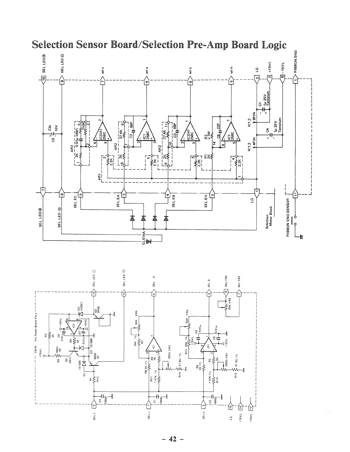
Selection Sensor Board/Selection Pre-Amp Board Logic
©
oO
D
___R...R-K-A-
1
42
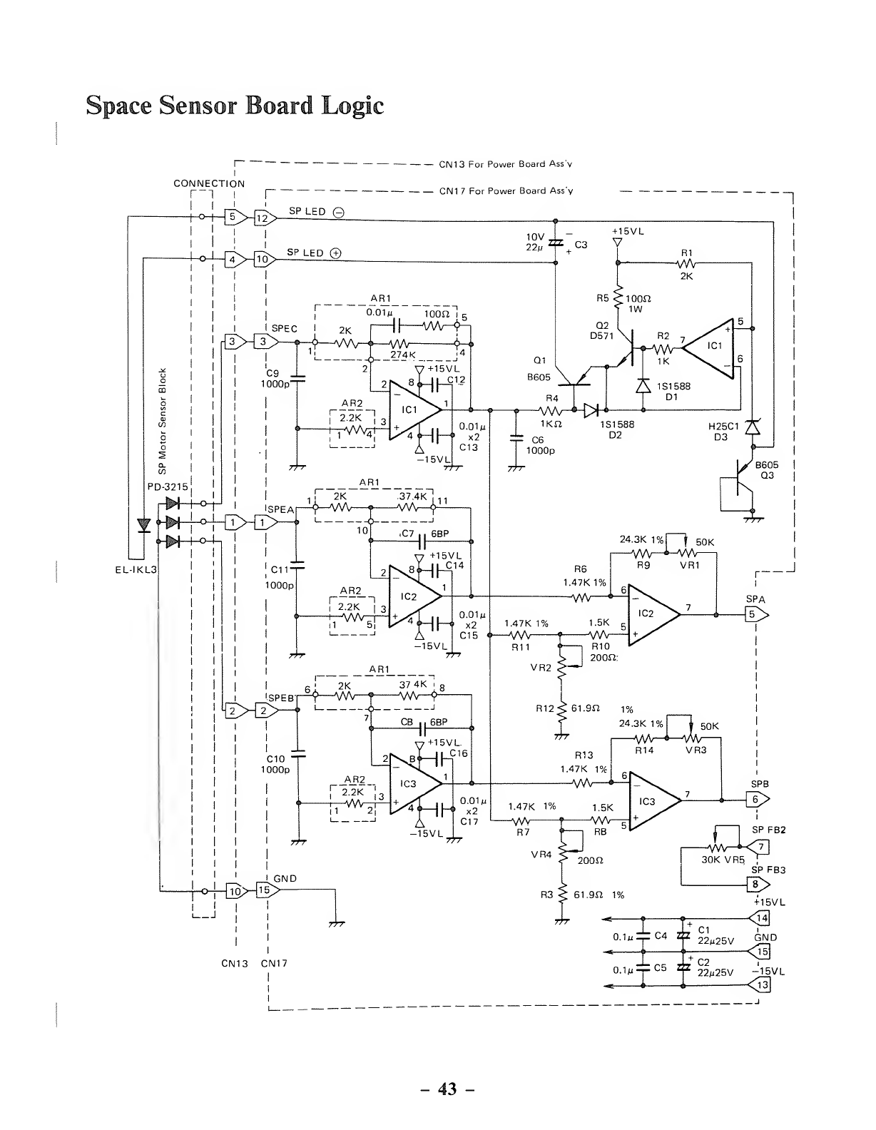
Space Sensor Board Logic
CONNECTION
'^4^HT2> SPLE °e
CN13 For Power Board Ass'v
q|\j-j 7por power Board Ass'v
EL-IKL3
-43 -
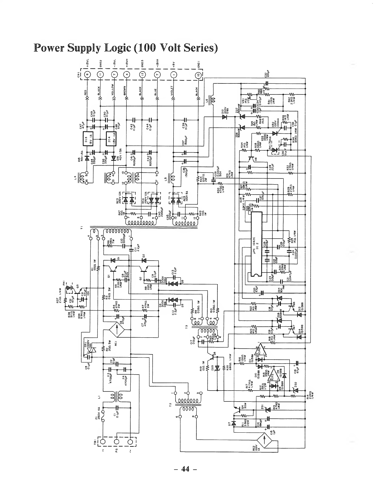
Power Supply Logic (100 Volt Series)
iLS)_§_2J2_f,
_5__(2__5l
44 -

SERVICE POLICY
Radio Shack's nationwide network of service facilities provides quick, conve-
nient, and reliable repair services for all of its computer products, in most
instances. Warranty service will be performed in accordance with Radio
Shack's Limited Warranty. Non-warranty service will be provided at reasonable
parts and labor costs.
Because of the sensitivity of computer equipment, and the problems which can
result from improper servicing, the following limitations also apply to the
services offered by Radio- Shack:
1
.
If any of the warranty seals on any Radio Shack computer products are
broken, Radio Shack reserves the right to refuse to service the equipment or
to void any remaining warranty on the equipment.
2. If any Radio Shack computer equipment has been modified so that it is not
within manufacturer's specifications, including, but not limited to, the in-
stallation of any non-Radio Shack parts, components, or replacement
boards, then Radio Shack reserves the right to refuse to service the equip-
ment, void any remaining warranty, remove and replace any non-Radio
Shack part found in the equipment, and perform whatever modifications are
necessary to return the equipment to original factory manufacturer's speci-
fications.
3. The cost for the labor and parts required to return the Radio Shack com-
puter equipment to original manufacturer's specifications will be charged to
the customer in addition to the normal repair charge.
RADIO SHACK, ADIVISION OF TANDY CORPORATION
U.S.A.: FORT WORTH, TEXAS 76102
CANADA: BARRIE, ONTARIO L4M 4W5
TANDY CORPORATION
AUSTRALIA BELGIUM U. K.
91 KURRAJONG AVENUE PARC INOUSTRIEL DE NANINNE BILSTON ROAD WEDNESBURY
MOUNT DRUITT, N.S.W, 2770 5140 NANINNE WEST MIDLANDS WS10 7JN
Printed in Japan
5A4 87469903
