RS 232 Interfacing DX1208 Control Protocol V1002
User Manual:
Open the PDF directly: View PDF ![]() .
.
Page Count: 49

http://www.eaw.com
RS-232 Control Protocol
(EAWC DX1208)
Rev 1.002 – 31 August 2009

LOUD Technologies, Inc. 11/19/2009
2
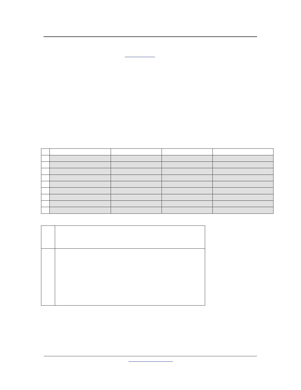
Revision History
Revision
Date
Description
1.002
08/31/09
Removed (the previous) Appendix F and edited the ‘Handshaking’
section to reflect the fact that message forwarding has been
disabled. Stateless controllers which poll are assumed.
1.001
08/13/09
Changed ‘library’ to ‘preset’ for clarity and simplicity.
Added Preset Load example.
1.000
08/11/09
Initial import from (EAWC DX Family) Bucket Net Spec.
Removed non-RS-232 related messages.
Added RS-232 interfacing-specific sections.

LOUD Technologies, Inc. 11/19/2009
3
Table of Contents
REVISION HISTORY ................................................................................................................................. 2
TABLE OF CONTENTS ............................................................................................................................. 3
OVERVIEW ................................................................................................................................................. 5
RS-232 ........................................................................................................................................................... 5
HANDSHAKING ......................................................................................................................................... 6
BUCKET NET PROTOCOL ...................................................................................................................... 7
MESSAGE FORMAT ...................................................................................................................................... 7
HEADER FORMAT ........................................................................................................................................ 8
DATA FORMAT ............................................................................................................................................ 8
BUCKET NET MESSAGES ....................................................................................................................... 9
PING (0X00) ...............................................................................................................................................10
STATUS QUERY (0X01) ..............................................................................................................................10
MEMORY READ (0X05) ..............................................................................................................................10
ASSIGN DEVICE INSTANCE (0X06) .............................................................................................................11
WHO IS OUT THERE (0X08) ........................................................................................................................11
ASSIGN DEVICE LABEL (0X0F) ..................................................................................................................12
PING RESPONSE (0X30) ..............................................................................................................................12
STATUS QUERY RESPONSE (0X31) .............................................................................................................13
Hardware Information ...........................................................................................................................13
Device Dependent Information..........................................................................................................13
DX Family Device Dependent Information ...................................................................................13
Boot Status .............................................................................................................................................14
Code Execution Error ............................................................................................................................15
Hardware Serial Number ......................................................................................................................17
Communication Status ...........................................................................................................................17
Firmware Version ..................................................................................................................................17
Operational Status .................................................................................................................................18
Debug Log Address ...............................................................................................................................18
Current Time .........................................................................................................................................19
IP Address .............................................................................................................................................19
MEMORY READ RESPONSE (0X35) .............................................................................................................20
WHO IS OUT THERE RESPONSE (0X38) ......................................................................................................20
METERS (0X51) ..........................................................................................................................................21
FAT CHANNEL METERS (0X52) ..................................................................................................................22
PARAMETER EDIT (0X54) ...........................................................................................................................24
Parameter IDs .......................................................................................................................................26
DATA REQUEST (0X5B)..............................................................................................................................27
Meters ....................................................................................................................................................27
Fat Channel Meters ...............................................................................................................................28
Parameter Edit ......................................................................................................................................29
IDENTIFY DEVICE (0X5C) ...........................................................................................................................30
PRESET INFO (0X71) ...................................................................................................................................30
PRESET INFO RESPONSE (0X72) ..................................................................................................................31
PRESET STORE (0X73) ................................................................................................................................31
PRESET LOAD (0X74) .................................................................................................................................31
PRESET CLEAR (0X75)................................................................................................................................32
APPENDIX A – DEVICE FAMILY ..........................................................................................................33

LOUD Technologies, Inc. 11/19/2009
4
APPENDIX B – DEVICE INSTANCE ......................................................................................................33
APPENDIX C – CHANNEL/TYPE IDS ...................................................................................................33
APPENDIX D – EFFECT AND PARAMETER IDS ...............................................................................34
EFFECT IDS ................................................................................................................................................34
PARAMETER IDS (BY EFFECT) ....................................................................................................................34
1 - FADER EFFECT ......................................................................................................................................34
2 - MUTE EFFECT........................................................................................................................................34
4 - SETUP EFFECT .......................................................................................................................................34
5 - EQ EFFECT ............................................................................................................................................35
6 - FILTER EFFECT ......................................................................................................................................35
7 - COMPRESSOR EFFECT ............................................................................................................................36
8 - GATE EFFECT ........................................................................................................................................36
11 - DUCKER EFFECT ..................................................................................................................................36
12 - DELAY EFFECT ....................................................................................................................................36
17 - SOLO EFFECT.......................................................................................................................................36
25 - MATRIX LEVEL EFFECT .......................................................................................................................37
50 - UNIVERSAL REMOTE EFFECT ..............................................................................................................37
51 - LOGIC INPUT EFFECT ...........................................................................................................................37
53 - LOGIC OUTPUT EFFECT .......................................................................................................................38
69 - MATRIX ENABLE EFFECT ....................................................................................................................38
101 - LABEL EFFECT...................................................................................................................................38
224 - AUTOMIX EFFECT ..............................................................................................................................38
240 - GLOBAL EFFECT ................................................................................................................................39
243 - DUMMY EFFECT ................................................................................................................................39
APPENDIX E – DX FAMILY CONFIGURATION FILES ....................................................................40
APPENDIX F – EXAMPLES .....................................................................................................................42
1 - PING ......................................................................................................................................................42
2 - IDENTIFY DEVICE ..................................................................................................................................43
3 - STATUS QUERY: HARDWARE INFORMATION ........................................................................................43
4 - DATA REQUEST: METERS .....................................................................................................................44
5 - METERS .................................................................................................................................................45
6 - DATA REQUEST: PARAMETER EDIT ......................................................................................................46
7 - PARAMETER EDIT ..................................................................................................................................47
8 - PRESET LOAD ........................................................................................................................................49

LOUD Technologies, Inc. 11/19/2009
http://www.eaw.com
5
Overview
This document is intended for use in interfacing remote controller hardware with EAWC DX
Family installed sound mixers via the rear RS-232 port. It specifies the details of the physical
interface, the interface protocol (Bucket Net), and the hierarchy of device parameters, as well as
presenting some specific examples of ‘finished’ RS-232 control messages.
The bulk of this document is comprised of reduced specification for the Bucket Net protocol,
tailored to be specific to the needs of RS-232 controller interfacing. DX Family Devices ‘speak’
Bucket Net over RS-232, USB, and Ethernet. The DX Navigator software GUI for use with DX
Family devices can communicate (using Bucket Net) across any (or all) of these communications
channels. RS-232 controllers can similarly interface using Bucket Net messaging.
This document is intended to be generic to the entire DX Family of devices. Interface designers
will need to consult the (parameter) Configuration File specific to the DX Family member their
particular controller is intended to connect to in order to access the specific parameter lists for
that device.
RS-232
DX Family devices utilize a standard RS-232 interface, running at 115200 baud, with 8 data bits,
no parity bit, 1 stop bit, and no flow control.
Bucket Net messages are composed of 32-bit words. Those words should be broken down into 4
8-bit words for transmission over RS-232 and sent least significant byte (LSB) first.

LOUD Technologies, Inc. 11/19/2009
http://www.eaw.com
6
Handshaking
DX Family devices do not use flow control to regulate RS-232 communications; there is no
hardware handshaking. Additionally, Bucket Net does not specify any particular software
handshaking protocol. It is up to developers to insure that they:
Provide adequate time for each message to be handled and for any responses to be
generated,
Handle those responses,
Maintain synchronization of parameter data between the controller and device.
There are a number of factors which complicate this task:
Some Bucket Net messages generate responses, but many do not generate any
acknowledgement at all.
Some Bucket Net messages can generate multiple responses, and the number of
responses, while consistent for any specific message, may be unpredictable until the first
time the message is sent.
There is no easy way in Bucket Net to ‘get’ a parameter value in order to verify a ‘set’.
Note that all messages received on a particular communications channel are serialized by the DX
Family device. No valid message directed at the device is dropped, and each message must be
handled in sequence before the next can be handled.
Specific suggestions for dealing with the points above:
‘Throttling’ parameter changes so that, for instance, slider pulls, don’t generate edits
more often than the human eye and/or ear can perceive them (a few Hz), should allow
plenty of time for the device to keep up.
Waiting for all expected responses to arrive (with a timeout on the order of hundreds of
milliseconds) and checking for errors (comm status, code execution, and/or event log) if
any is not received. (Although note that errors from all communications interfaces are
handled by the same registers.)
Sending simple messages which generate a response (e.g. Ping, Status Query) can be
used to verify that preceding messages have been received and handled. (Though
watch out for invalid or misdirected messages, which will be ignored.)
The ‘scratch’ buffer can be used to buffer presets (or potentially other specifically edited
parameters) without changing device state.
The ‘Dummy’ effect of the Global Type is specifically reserved for host use; its 32
unsigned long global parameters are never touched by the DX Family device, and can be
used to ‘mark’ progress, flag the end of multiple responses, etc.

LOUD Technologies, Inc. 11/19/2009
http://www.eaw.com
7
Bucket Net Protocol
Bucket Net is an extensible messaging protocol intended primarily for use as a control protocol
for digital audio devices. It is intended to be independent of any particular communications
method, processor, or memory device.
Message Format
Bucket Net messages consist of a series of 32-bit words; they are of variable length. Each
message has a 3 word header segment. Messages may or may not have an additional, message
specific, data segment. The data segment, if present, will have a maximum length of 255 32-bit
words, for a maximum message length of 258 words.
In order to be properly handled, messages should be 32-bit aligned with respect to memory. All
messages should consist of an integral number of 32-bit words; pad bytes should be postpended
as necessary to satisfy this requirement. Unused bytes and pad bytes should be filled with the
hexadecimal value 0xFF. (WARNING: While the value 0xFF is specified by the current and
previous versions of the Bucket Net Specification, many Bucket Net implementations seem to
expect a fill value of 0x00!)
LOUD Technologies, Inc. 11/19/2009
http://www.eaw.com
8
Header Format
A Bucket Net message header consists of 3 words, divided into 9 fields (some multibyte):
LSB MSB
0
1
2
3
0
SYNC
LENGTH
DESTINST
DESTFAM
1
MSGID LO
MSGID HI
SRCINST
SRCFAM
2
MSGCHKSUM LO
MSGCHKSUM HI
HDRCHKSUM LO
HDRCHKSUM HI
3
(DATA BYTE 0)
(DATA BYTE 1)
(…)
…
= header segment
= data segment
SYNC – The byte 0xA5 is used to signify the start of a Bucket Net message.
LENGTH – The length (in 32-bit words) of the data segment.
DESTINST – The 8-bit instance designation of destination device.
DESTFAM – The 8-bit family designation of the destination device.
MSGID – The 16-bit message specific message identifier (ID).
SRCINST – The 8-bit instance designation of the source device.
SRCFAM – The 8-bit family designation of the source device.
MSGCHKSUM – The 16-bit message checksum. This checksum is computed by taking the 1’s
complement of the sum of the bytes in the data segment. (And so has the value 0xFFFF if
‘LENGTH’ is 0.)
HDRCHCKSUM – The 16-bit header checksum. This checksum is computed by taking the 1’s
complement of the sum of the other 10 bytes in the header segment (including the message
checksum).
Note that while the family designation of a particular host or device is fixed, the instance
designation may be initialized to 0xFE (BUCKETNET_DEVICE_UNINITIALIZED) and assigned
during communications set up.
Note further that the value 0xFF (BUCKETNET_DEVICE_GLOBAL) is generally reserved for
broadcast use, and thus should not be assigned to a particular instance (or family). All devices
should handle a broadcast message.
Data Format
Whether a particular message has a data segment, and, if so, the contents of that segment, are
message ID dependent. Details of specific message IDs and their respective data segments’
formats are presented in the next section. Note the general caution (see ‘Message Format’) that
all messages must consist of an integral number of 32-bits words, with pad bytes inserted as
necessary.
W
O
R
D
LOUD Technologies, Inc. 11/19/2009
http://www.eaw.com
9
Bucket Net Messages
A number of Bucket Net messages (message IDs) have been defined:
Message
ID
Description
Ping
0x00
Query the device for its firmware version information.
Status Query
0x01
Query the device for specific status information.
Memory Read
0x05
Read 32-bit data from memory.
Assign Device Instance
0x06
Assign a device instance number.
Who Is Out There
0x08
Query the device for its serial number.
Assign Device Label
0x0F
Assign a device (ASCII) label.
Ping Response
0x30
*
Requested firmware version info.
Status Query Response
0x31
*
Requested status info.
Memory Read Response
0x35
*
Requested 32-bit data from memory.
Who Is Out There
Response
0x38
*
Requested serial number.
Meters
0x51
*
Requested meter values.
Fat Channel Meters
0x52
*
Requested ‘fat channel’ meter values.
Parameter Edit
0x54
Sets the specified parameter(s).
Data Request
0x5B
Request (to set locally) a specified type of data from the
(remote) device (e.g. meters, parameter values).
Identify Device
0x5C
Override the front panel LEDs for device ID purposes.
Preset Info
0x71
Request information about a preset.
Preset Info Response
0x72
*
Requested preset info.
Preset Store
0x73
Store the current state to a preset.
Preset Load
0x74
Load the current state from a preset.
Preset Clear
0x75
Clear a preset..
* DX Family devices generate, but do not handle, this message ID.
LOUD Technologies, Inc. 11/19/2009
http://www.eaw.com
10
Ping (0x00)
Correctly addressed devices should respond with a Ping Response message.
Ping messages have no data segment.
Status Query (0x01)
Correctly addressed devices should respond with a Status Query Response message.
Status Query messages have an optional (16-bit) data segment. If no data segment is present,
the default status code for the device should be handled. (DX Family default: 0x00.):
LSB MSB
0
1
2
3
3
STATUS_CODE_LO
STATUS_CODE_HI
Status Codes
0x0000
Hardware Information
0x0004
Boot Status
0x0005
Code Execution Error
0x0007
Hardware Serial Number
0x0009
Communication Status
0x000B
Firmware Version
0x000D
Operational Status
0x0011
Debug Log Address
0x0013
Current Time
0x0015
IP Address
Memory Read (0x05)
Correctly addressed devices should respond with a Memory Read Response message.
Memory Read messages have a 2 word data segment consisting of a control code and the
address of the read (byte addressing is assumed):
LSB MSB
0
1
2
3
3
CONTROL_CODE_LO
…
…
CONTROL_CODE_HI
4
ADDRESS_LO
…
…
ADDRESS_HI
While the control codes are technically the same as those used in Memory Write messages, only
the data length field (least significant byte) is applicable to reads.
LOUD Technologies, Inc. 11/19/2009
http://www.eaw.com
11
Assign Device Instance (0x06)
Assign Device Instance messages have a 3 word data segment:
LSB MSB
0
1
2
3
3
DESTINST
DESTFAM
4
SERIAL_1
SERIAL_2
SERIAL_3
SERIAL_4
5
SERIAL_5
SERIAL_6
SERIAL_7
SERIAL_8
If the 64-bit serial number contained in the second and third data words matches the device serial
number, or if the serial number 0xFFFFFFFFFFFFFFFF is specified, then the device should
update its device family and instance values to match the 8-bit values specified in the first data
word (unless the specified value is 0xFF, in which case that field should not be changed).
Example: The device instance value 0xFE indicates that the device instance is uninitialized. In
order to reset a device to uninitialized state, a data segment of 0xFE, 0xFF, fill, fill, 0xFFFFFFFF,
0xFFFFFFFF should be sent, overwriting the instance to 0xFE, but not changing the family, of
any receiving device.
Who Is Out There (0x08)
Correctly addressed devices should respond with a Who Is Out There Response message.
Who Is Out There messages have no data segment.
LOUD Technologies, Inc. 11/19/2009
http://www.eaw.com
12
Assign Device Label (0x0F)
Assign Device Label messages have an 8 word data segment, consisting of a single, NULL
terminated, ASCII character string to be used as a device name or label:
LSB MSB
0
1
2
3
3
LABEL_1
LABEL_2
LABEL_3
LABEL_4
4
LABEL_5
LABEL_6
LABEL_7
LABEL_8
5
LABEL_9
LABEL_10
LABEL_11
LABEL_12
6
LABEL_13
LABEL_14
LABEL_15
LABEL_16
7
LABEL_17
LABEL_18
LABEL_19
LABEL_20
8
LABEL_21
LABEL_22
LABEL_23
LABEL_24
9
LABEL_25
LABEL_26
LABEL_27
LABEL_28
10
LABEL_29
LABEL_30
LABEL_31
LABEL_32
Ping Response (0x30)
Generated in response to a Ping message. The data segment of a Ping Response consists of
one word:
LSB MSB
0
1
2
3
3
OS_BUILDNUMBER
OS_BUILDTYPE
OS_VERSION_LO
OS_VERSION_HI
OS Build Type
Release Type (bits 0-3)
0x00 = Release
0x01 = Development
0x02 = Alpha
0x03 = Beta
OS Type (bits 4-7)
0x00 = Boot
0x10 = BIST
0x20 = OS
0x30 = Production Test
LOUD Technologies, Inc. 11/19/2009
http://www.eaw.com
13
Status Query Response (0x31)
Generated in response to a Status Query message. The data segment of a Status Query
Response depends on the status code passed in the original message. The first word of the data
segment always echoes this (16-bit) code back; further words are filled based on the code itself:
LSB MSB
0
1
2
3
3
STATUS_CODE_LO
STATUS_CODE_HI
4
DATA…
A table of status codes is listed under the Status Query message.
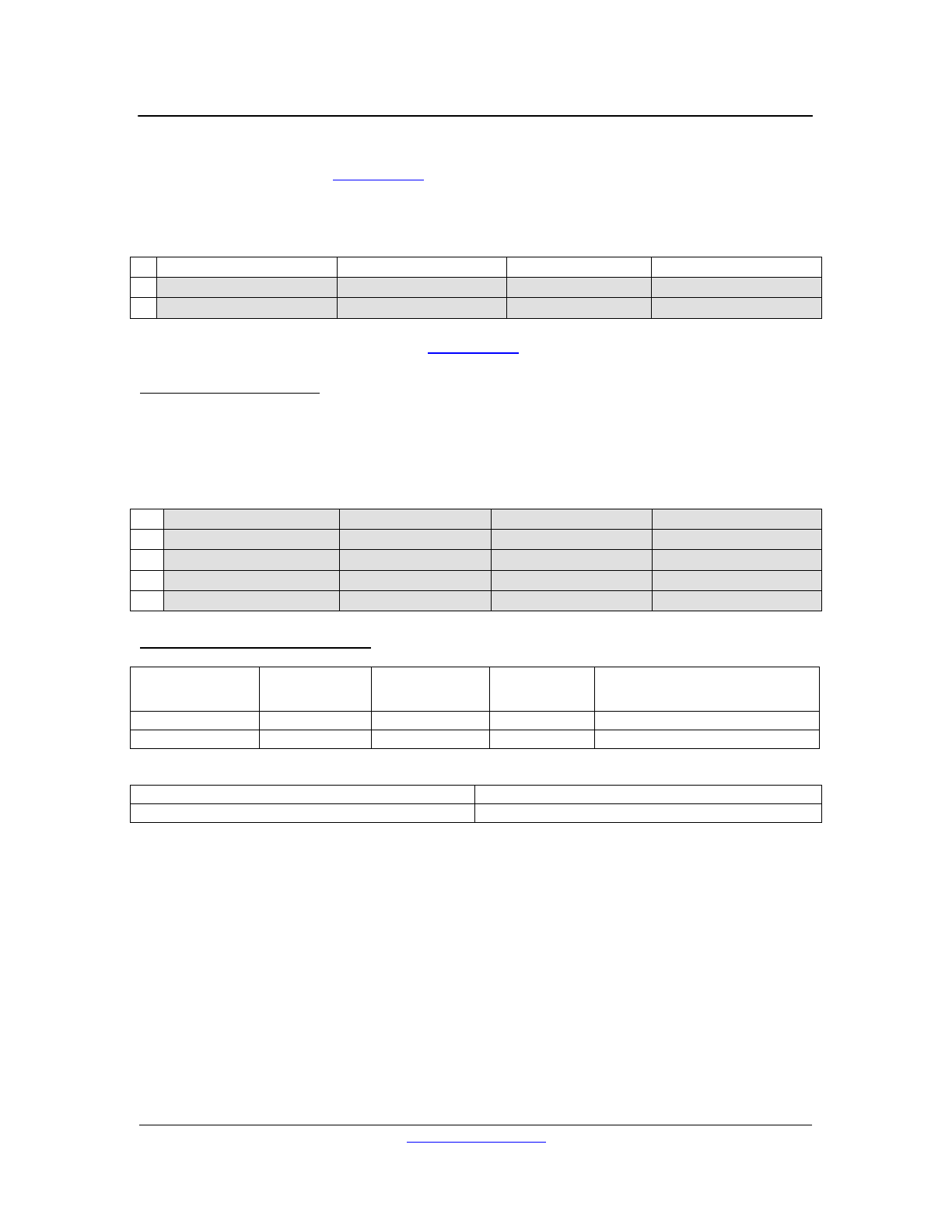
Hardware Information
The status code specific data of an SQ: Hardware Information response consists of at least 3
data words, possibly more. The required 3 words encode details of the hardware and software
model and version numbers. Any further data words are device dependent:
LSB MSB
3
Status_Code = 0
4
OS_BUILDNUMBER
OS_BUILDTYPE
OS_VERSION_LO
OS_VERSION_HI
5
MANUFACTID_LO
…
…
MANUFACTID_HI
6
DEVICEMEM_LO
DEVICEMEM_HI
DEVICEFAM_LO
DEVICEFAM_HI
7
Device dependent…
Device Dependent Information
Model
Manufacturer
ID
Device Family
Family
Member
Information Description
DX1208
0x00000066
0x0002
0x0000
Device Label
DX200
0x00000066
0x0002
0x0001
Device Label
DX Family Device Dependent Information
Description
Device Label (ASCII)
32 bytes of ASCII character data
LOUD Technologies, Inc. 11/19/2009
http://www.eaw.com
14
Boot Status
The status code specific data of an SQ: Boot Status response consists of 2 data words. The first
concatenates the 16-bit boot status with the 16-bit boot time (see Assign Boot Time). The second
indicates the address (in FLASH) of the boot code:
LSB MSB
3
Status_Code = 4
4
BOOT_STATUS_LO
BOOT_STATUS_HI
BOOT_TIME_LO
BOOT_TIME_HI
5
BOOT_ADDR_LO
…
…
BOOT_ADDR_HI
Boot Status
0
Boot OK
0x8000
Boot Held Off By Command
0x8001
Boot Held Off By Key
0x8FFF
Boot Held Off By Failure
Boot Address
-1
Address Absent
-2
Address Corrupt
other
Boot Address

LOUD Technologies, Inc. 11/19/2009
http://www.eaw.com
15
Code Execution Error
The status code specific data of an SQ: Code Execution response consists a single data word, a
(device specific) code representing the most recent error generated by the device:
LSB MSB
3
Status_Code = 5
4
ERROR_CODE_LO
…
…
ERROR_CODE_HI
Note that reading the error code also clears the error register.
Error Code
-9
No Error – TCP Connection Refused
-8
No Error – Excess Remotes Ignored
-7
No Error – Preset Load
-6
No Error – Preset Clear
-5
No Error – Preset Store
-4
No Error – Logout
-3
No Error – Login
-2
No Error – Power On
-1
No Error – Reply In Place
0
No Error
1
Unknown Error
2
Out of Memory
3
VDK – Out of Threads
4
Login Disabled
5
Bad Password
6
Insufficient Permission
7
Session Timed Out
8
Bucket Overflow
9
Bucket Timeout
10
BucketNet Error
11
BucketNet – Unimplemented Message
12
BucketNet – Unimplemented Option
13
BucketNet – Unimplemented Status Code
14
BucketNet – Unimplemented Request ID
15
BucketNet – Payload Size Mismatch
16
BucketNet – Payload Underflow
17
BucketNet – Payload Overflow
18
BucketNet – Bad Address
19
BucketNet – Bad Data
20
BucketNet – Bad Flags
21
BucketNet – Bad Format
22
BucketNet – Bad Type
23
BucketNet – Bad Instance
24
BucketNet – Bad Effect
25
BucketNet – Bad Parameter
26
BucketNet – Bad Source
27
BucketNet – Bad Destination
28
BucketNet – Checksum Mismatch
29
BucketNet – Multiblock Format Required

LOUD Technologies, Inc. 11/19/2009
http://www.eaw.com
16
30
FishNet Error
31
FishNet – Unimplemented Message
32
FishNet – Bad Sync
33
FishNet – Bad Source
34
FishNet – Bad Destination
35
FishNet – Bad Length
36
FishNet – Bad ID
37
FishNet – Checksum Mismatch
38
FishNet – NACK Received
39
FishNet – ERROR Received
40
FLASH Erase Error
41
FLASH Write Error
42
FLASH Read Error
43
Invalid FLASH Image
44
SDRAM Error
45
ADI – System Services Init Failure
46
ADI – ISR Init Failure
47
Ethernet Error
48
Ethernet – UDP Error
49
Ethernet – TCP Error
50
Remote Not Responding
51
Remote Dropped
52
RS-485 Transmit Error
53
RS-485 Receive Error
54
RTC Not Ready Error
55
SHARC Not Ready Error
56
SHARC Error
57
S/PDIF Error
58
Transmit Failure
59
UART Error
60
UART RX FIFO Overflow
61
USB RX FIFO Overflow
LOUD Technologies, Inc. 11/19/2009
http://www.eaw.com
17
Hardware Serial Number
The status code specific data of an SQ: Hardware Serial Number response consists of 2 data
words, consisting of the 64-bit device serial number:
LSB MSB
3
Status_Code = 7
4
SERIAL_1
SERIAL_2
SERIAL_3
SERIAL_4
5
SERIAL_5
SERIAL_6
SERIAL_7
SERIAL_8
Communication Status
The status code specific data of an SQ: Communication Status response consists of a single
data word encoding the current status of communications:
LSB MSB
3
Status_Code = 9
4
COMM_STATUS
Note that reading the communications status also clears any communications error.
Communications Status
Bit
Description*
0
General Error
1
Buffer Overrun Error
2
Checksum Failure
*A ‘1’ in the appropriate bit means the error has occurred; ‘0’ means no error.
Firmware Version
The status code specific data of an SQ: Firmware Version response is of variable length,
depending on the status of the various processors running in the DX Family device:
LSB MSB
3
Status_Code = 11
4
OS_BUILDNUMBER
OS_BUILDTYPE
OS_VERSION_LO
OS_VERSION_HI
5
OS_BUILDNUMBER
OS_BUILDTYPE
OS_VERSION_LO
OS_VERSION_HI
If the device is in boot, only one additional word will be generated, encoding the Blackfin boot
firmware version number.
If the device is not in boot (in its ‘OS’), and the DSP is not ready (due to error), then only one
additional word will be generated, encoding the Blackfin OS firmware version.
If the device is not in boot, and the DSP is ready, then two additional words will be generated,
encoding first the Blackfin OS firmware version, and then the SHARC DSP firmware version.
LOUD Technologies, Inc. 11/19/2009
http://www.eaw.com
18
Operational Status
The status code specific data of an SQ: Operational Status response consists of a single data
word which encodes the operational status of the SHARC DSP:
LSB MSB
3
Status_Code = 13
4
OPS_STATUS_LO
…
…
OPS_STATUS_HI
Note that the response to this status code is extremely device specific.
SHARC DSP Operational Status Bits
0-1
Ready (10 = ready)
2
DXLink Valid (1 = valid)
3
DXLink Locked (1 = locked)
4
Audio Locked (1 = locked)
5
S/PDIF Reset Request (0 = stop, 1 = run)
6-30
Reserved
31
Error (1 = error)
Debug Log Address
The status code specific data of an SQ: Debug Log Address response consists of 4 data words,
in 2 pairs of 2 words. Each pair communicates the base address and length in bytes of one page
of the Event (Debug) Log in FLASH:
LSB MSB
3
Status_Code = 17
4
LOG0_ADDR_LO
…
…
LOG0_ADDR_HI
5
LOG0_BYTES_LO
…
…
LOG0_BYTES_HI
6
LOG1_ADDR_LO
…
…
LOG1_ADDR_HI
7
LOG1_BYTES_LO
…
…
LOG1_BYTES_HI
The DX Family Event Log is used in a ping-pong fashion: once one page fills, the other is erased
and begins to fill, so that there is always one full page of events in the history (once any page has
filled). Each ‘line’ of the Event Log represents a single system event:
Event Line Format
(32-bit) Word
Description
0
Timestamp (see Status Query: Current Time)
1
Firmware Version (see Status Query: Firmware Version)
2
Event Code (see Status Query: Code Execution Error)
3
Event Modifier (Event Code specific)
4-15
Event Desription (48 character NULL-terminated ASCII string)
Uninitialized (erased) FLASH bytes read as 0xFF. Note that the value 0xFFFFFFFF is not a valid
Blackfin RTC timestamp.
LOUD Technologies, Inc. 11/19/2009
http://www.eaw.com
19
Current Time
The status code specific data of an SQ: Current Time response consists of 2 data words; non-DX
Family devices may use 3, depending on the value of the first word.
LSB MSB
3
Status Code = 19
4
FLAG_1
5
TIME_LO (0-31)
…
…
TIME_HI (0-31)
(if 64-bit time)
6
TIME_LO (32-63)
…
…
TIME_HI (32-63)
Flag Bits
Bits
0
0 = Below 50kHz (Time Format = 32-bit)
1 = Above 50kHz (Time Format = 64-bit)
1-7
Reserved (set to 0)
DX Family devices use the Blackfin RTC time format:
Blackfin RTC Time Format Bits
0-5
Seconds (0-59)
6-11
Minutes (0-59)
12-16
Hours (0-23)
17-31
Days (0-32767)
NOTE: DX Family device times typically represent elapsed time since unit ‘birth’, counting up
from 0. They are not set to reflect the accurate time of day.
IP Address
The status code specific data of an SQ: IP Address response consists of a single data word, the
current IP address for the device in 32-bit unsigned integer (network) format:
LSB MSB
3
Status Code = 21
4
IP_ADDR_LO
…
…
IP_ADDR_HI
Note that reading the IP address of a device which is using dynamic addressing will refresh the
dynamic IP address (update the global parameter to match the current system address).
LOUD Technologies, Inc. 11/19/2009
http://www.eaw.com
20
Memory Read Response (0x35)
Generated in response to a Memory Read message. The data segment of a Memory Read
Response consists of one or more words:
LSB MSB
0
1
2
3
3
ADDRESS_LO
…
…
ADDRESS_HI
4
DATA_LO
…
…
DATA_HI
…
MORE DATA…
The address field should correspond to the address in the originating Memory Read. The count
of (32-bit) data words should correspond to the length specified in the control codes.
NOTE: Memory Reads have limited utility with respect to the DX Family. They are used primarily
to access the Event Log (see Status Query: Debug Log Address). Most system data and
parameters are ‘read’ using either specific Status Query messages or via Data Request
messages.
Who Is Out There Response (0x38)
Generated in response to a Who Is Out There message. The data segment of a Who Is Out
There Response consists of 2 words which can be concatenated to form the 64-bit device serial
number:
LSB MSB
0
1
2
3
3
SERIAL_1
SERIAL_2
SERIAL_3
SERIAL_4
4
SERIAL_5
SERIAL_6
SERIAL_7
SERIAL_8
LOUD Technologies, Inc. 11/19/2009
http://www.eaw.com
21
Meters (0x51)
(Usually) generated in response to a Data Request message. The data segment of a Meter
message consists of one or more blocks, each of which in turn consists of at least 2 words.
The first word concatenates the 8-bit Meter Type, the 8-bit Meter Flags, and the 8-bit Instance
and Type IDs indicating the channel type and number of the first meter value. All subsequent
words in the block of data will contain meter values in the format indicated by the flags, beginning
with the indicated device Type and Instance and incrementing the instance by one for each new
value:
LSB MSB
0
1
2
3
3
METER_TYPE
METER_FLAGS
PARMID_INST
PARMID_TYPE
4
METER_VALUE_LO
…
…
METER_VALUE_HI
5
METER_VALUE_LO
…
…
METER_VALUE_HI
…
MORE VALUES…
…
METER_TYPE
METER_FLAGS
PARMID_INST
PARMID_TYPE
…
METER_VALUE_LO
…
…
METER_VALUE_HI
…
MORE VALUES…
Meter Type Bits
0-3
Meter Placement
0000 = Pre-DSP (Channel Input)
0001 = Post-DSP (Channel Output)
4-6
Meter Type
000 = Peak
7
Reserved (= 0)
Meter Flag Bits
0-2
Meter Data Format
000 = 8-bit signed
001 = 16-bit signed (8.8)
010 = 32-bit float (IEEE float)
3-7
Meter Words
This field indicates the number of 32-bit words of meter values in
this block. Each word may contain multiple values, depending on
the format specified (e.g. up to 4 in the case of an 8-bit format).
A value of zero in this field indicates that meter values for all
instances of the specified PARMID_TYPE are being supplied.
Otherwise the first value begins from the instance specified by
PARMID_INST.
Example: If PARMID_INST is 0x09, the Meter Data Format
requested is an 8-bit format, and Meter Words is 2, then this block
of the Meter message contains meter data for channels 9 to 16 of
this type.
LOUD Technologies, Inc. 11/19/2009
http://www.eaw.com
22
Fat Channel Meters (0x52)
(Usually) generated in response to a Data Request message. ‘Fat Channel’ meters are the
meters associated with effects (such as gates, automixers, etc.), as opposed to (plain) meters,
which are associated with types (channels). The data segment of a Fat Channel Meter message
consists of one or more blocks, each of which in turn consists of at least 3 words.
The first word concatenates the 8-bit Meter Flags, and the 8-bit Instance, Effect, and Type IDs
indicating the channel type and number, as well as the effect, of the first meter value. The
second word indicates the particular Meter ID (of the specified effect) of the meter values. All
subsequent words in the block of data will contain meter values in the format indicated by the
flags, beginning with the indicated device Type, Effect, Meter ID, and Instance and incrementing
the instance by one for each new value
If Meter ID is wild (0xFF), all Meter IDs of the effect are contained in the message, incrementing
from lowest to highest per value. If values for more than one Instance are also required, then all
meter IDs for the first instance are sent before the first meter ID of the second instance:
LSB MSB
0
1
2
3
3
METER_FLAGS
PARMID_INST
PARMID_EFFECT
PARMID_TYPE
4
METERID_LO
…
…
METERID_HI
5
METER_VALUE_LO
…
…
METER_VALUE_HI
6
METER_VALUE_LO
…
…
METER_VALUE_HI
…
MORE VALUES…
…
METER_FLAGS
PARMID_INST
PARMID_EFFECT
PARMID_TYPE
…
METERID_LO
…
…
METERID_HI
..
METER_VALUE_LO
…
…
METER_VALUE_HI
…
MORE VALUES…
Meter Flag Bits
0-2
Meter Data Format
000 = 8-bit signed
001 = 16-bit signed (8.8)
010 = 32-bit float (IEEE float)
3-7
Meter Words
This field indicates the number of 32-bit words of meter values in
this block. Each word may contain multiple values, depending on
the format specified (e.g. up to 4 in the case of an 8-bit format).
A value of zero in this field indicates that meter values for all
instances of the specified PARMID_TYPE are being supplied.
Otherwise the first value begins from the instance specified by
PARMID_INST.
LOUD Technologies, Inc. 11/19/2009
http://www.eaw.com
23
Example:
Data Request
0x000009a5,
0x0000005b, // data request
0x00000000, // checksum (gets calculated when sent)
BNMESSAGE_ID_FATCHANMETERS, // Fat Meter request
// Type ID Effect Channel Format Meters
// Request ALL Analog Input Comp Input Meters in 32 bit float format
(TYPEID_ANALOG_INPUT << 24)+(EFFECTID_COMP<<16)+ (0xFF<<8)+ 0x02, 1,
// Request ALL Analog Input Gate Input Meters in 32 bit float format
(TYPEID_ANALOG_INPUT << 24)+ (EFFECTID_GATE<<16)+(0xFF<<8)+ 0x02, 3;
// Request Analog Input Channel 13 Comp Input Meter in 32 bit float format
(TYPEID_ANALOG_INPUT << 24)+(EFFECTID_COMP<<16)+ (0x0D<<8)+ 0x0A, 1;
// Request Analog Input Channel 13-24 Comp Input Meter in 32 bit float format
(TYPEID_ANALOG_INPUT << 24)+(EFFECTID_COMP<<16)+ (0x0D<<8)+ 0x02, 1;
Fat Channel Meters
0x000045A5, 0xFFFF0052, 0x????????
0x0107FFC2, 0x00000001
0xC2B164ED, 0xC2B36C43, 0xC2B3FF1E, 0xC2B4953B, 0xC2B29F2C, 0xC2B33307,
0xC2B6057B, 0xC2B64B0C, 0xC2B3D613, 0xC2B52BED, 0xC2B14BD4, 0xC2B2C7A0,
0xC2B42D05, 0xC2B65D94, 0xC2B47779, 0xC2B5C2E7, 0xC3107E90, 0xC3107E90,
0xC3107E90, 0xC3107E90, 0xC2B38563, 0xC2B5AC61, 0xC2B38771, 0xC2B172A5,
0x0108FFC2, 0x00000003,
0xC2B164ED, 0xC2B36C43, 0xC2B3FF1E, 0xC2B4953B, 0xC2B29F2C, 0xC2B33307,
0xC2B6057B, 0xC2B64B0C, 0xC2B3D613, 0xC2B52BED, 0xC2B14BD4, 0xC2B2C7A0,
0xC2B42D05, 0xC2B65D94, 0xC2B47779, 0xC2B5C2E7, 0xC3107E90, 0xC3107E90,
0xC3107E90, 0xC3107E90, 0xC2B38563, 0xC2B5AC61, 0xC2B38771, 0xC2B172A5,
0x01070D0A, 0x00000001,
0xC2B42D05,
0x01070D62, 0x00000001,
0xC2B42D05, 0xC2B65D94, 0xC2B47779, 0xC2B5C2E7, 0xC3107E90, 0xC3107E90,
0xC3107E90, 0xC3107E90, 0xC2B38563, 0xC2B5AC61, 0xC2B38771, 0xC2B172A5;

LOUD Technologies, Inc. 11/19/2009
http://www.eaw.com
24
Parameter Edit (0x54)
Parameter Edit messages may be generated in response to a Data Request message; they are
also commonly generated directly in response to user input. The data segment of a Parameter
Edit message consists of one or more blocks, each of which in turn consists of at least 3 words.
The first 32-bit data word consist of numerous Flags describing the format of the message and its
contents; depending on these flags the content of subsequent fields may change.
The second 32-bit data word specifies the precise (first) parameter to be edited, using a semi-
hierarchical taxonomy common to all Bucket Net parameters (see below).
Subsequent data words depend heavily on the particular Flags. The example below shows the
typical format of DX Family Parameter Edits, with one parameter value per word, beginning with
the parameter specified in the second word of the block and incrementing thereafter either by
instance or parameter according to the Flags; there are two blocks of edits:
LSB MSB
0
1
2
3
3
FLAGS1
FLAGS2
FLAGS3
FLAGS4
4
PARMID_PARAM
PARMID_INST
PARMID_EFFECT
PARMID_TYPE
5
VALUE1_LO
…
…
VALUE1_HI
6
VALUE2_LO
…
…
VALUE2_HI
…
…
X-1
VALUEN_LO
…
…
VALUEN_HI
X
FLAGS1
FLAGS2
FLAGS3
FLAGS4
X+1
PARMID_NUMBER
PARMID_INST
PARMID_EFFECT
PARMID_TYPE
X+2
VALUE1_LO
…
…
VALUE1_HI
X+3
VALUE2_LO
…
…
VALUE2_HI
…
…
X+M
VALUEN_LO
…
…
VALUEN_HI

LOUD Technologies, Inc. 11/19/2009
http://www.eaw.com
25
FLAGS1 Bits – General Flags
0
Autoincrement Enable
0 = Disabled (Single Parameter Edit)
1 = Enabled (see Autoincrement Type)
1
Reserved (= 0)
2-3
Reserved (= 00)
4
Autoincrement Type
0 = Increment Parameter Number
1 = Increment Instance Number
5-6
Reserved (= 00)
7
Reserved (= 0)
FLAGS2 Bits – Data Format
0
Reserved (= 0)
1-5
Data Element Format
00000 = unsigned long (32-bit)
00001 = signed long (32-bit)
00010 = unsigned short (16-bit)
00011 = signed short (16-bit)
00100 = unsigned char (8-bit)
00101 = signed char (8-bit)
00110 = float (32-bit IEEE float)
00111 = double (64-bit IEEE double precision)
01000 = double long (64-bit signed integer)
01001 = fractional data type (16.16)
01001-11111 = Reserved
6-7
Reserved (= 00)
FLAGS3 Bits – Target Buffer
0
Target Buffer (to Edit)
0 = Edit Buffer
1 = Scratch Buffer
1-5
Reserved (ignored)
6-7
Reserved (= 00)
FLAGS4 – Block Length
0
Block continues to the end of the message.
1-255
Block Words - This field indicates the number of 32-bit words of parameters
in this block. Each word may contain multiple values, depending on the
format specified (e.g. up to 4 in the case of an 8-bit format).

LOUD Technologies, Inc. 11/19/2009
http://www.eaw.com
26
Parameter IDs
Parameters in Bucket Net are specified using four values:
TYPE
The ‘type’ or ‘channel’, e.g. Analog Input, Global, or Logic Output, etc.
EFFECT
E.g. Compressor, Gate, EQ, Fader, Logic Input, Label, Global, Mute, etc.
INSTANCE
‘Types’ are grouped into multiple instances, e.g. Analog Outputs 1-8; this is
the particular instance number. Note that ‘Global’ types have 0 instances.
PARAMETER
(NUMBER)
These are the specific parameters of a particular effect, e.g. Gate Attack,
Fader Level, Mute Enable, Global Default Preset, etc.
The current state of all parameters is maintained in volatile memory (RAM); this memory buffer is
referred to as the ‘edit’ buffer. Edits to the edit buffer have an immediate effect on device state.
A mirror buffer of the same size is also maintained; this ‘scratch’ buffer can be used to buffer
presets or individual parameter data without affecting the current state.
Examples:
Parameter Edit (Single Block)
0x00000aa5,
0x00000054, // parameter edit
0x00000000, // checksum (gets calculated when sent)
0x00000c01, // format flag (auto increment – parameter, 32 bit float)
0x01080201, // starting PID (analog input, gate effect, channel 2, parameter 1)
0x3f800000, // value of PID 0x01080201
0x430177f8, // value of PID 0x01080202
0x00000000, // value of PID 0x01080203
0x42480000, // value of PID 0x01080204
0xc2700000, // value of PID 0x01080205
0x3f800000, // value of PID 0x01080206
0x00000000, // value of PID 0x01080207
0x00000000 // value of PID 0x01080208
Parameter Edit (Multiple Block)
0x000007a5,
0x00000054, // parameter edit
0x00000000, // checksum (gets calculated when sent)
0x06000a11, // format flag (auto increment – instance, 8 bit char)
0x01010101, // starting PID (analog input, fader, channel 1, parameter 1)
0x05ff0ef8, // values of PID 0x01010101 (value of f8) to 0x01010401 (value of 05)
0x0000fff3, // values of PID 0x01010501 (value of f3) to 0x01010601 (value of ff)
0x01000000, // format flag (auto increment off, ulong 32 bits)
0x01050107, // starting PID (analog input, eq, channel 1, band 2 enable)
0x00000001, // value of PID 0x01050107
LOUD Technologies, Inc. 11/19/2009
http://www.eaw.com
27
Data Request (0x5B)
Correctly addressed devices should respond with the specified message type.
Data Request messages have at least 1 word in their data segment. This first word consists of
an 8-bit Data Request ID describing the type of data requested; the other 24 bits of the first word,
and all subsequent words in the data segment, depend on the data type requested:
LSB MSB
0
1
2
3
3
DATAREQ_ID
(FLAGS1)
(FLAGS2)
(FLAGS3)
4
DATA…
Data Request Types
Request Type
DATAREQ_ID
FLAGS1
Meters
0x51 (81)
N/A
Fat Channel Meters
0x52 (82)
N/A
Parameter Edit
0x54 (84)
Source/Destination Buffer
Meters
The Data Request Type specific data of an DR: Meters consists of 1 data word per request; each
request word should generate a new block in the Meters message response. (WARNING:
Requesting more meter data than can be fit into the payload of a single Meters message is
invalid!)
Each data word is formatted exactly as the first data word of a Meters message, except that
PARMID_INST is allowed to be wild (0xFF), requesting all instances of the specified type, and
Meter Flag Bits 3-7 are modified to accommodate wildcarding:
LSB MSB
4
METER_TYPE
METER_FLAGS
PARMID_INST
PARMID_TYPE
5
METER_TYPE
METER_FLAGS
PARMID_INST
PARMID_TYPE
…
MORE REQS…
Meter Flag Bits
3-7
Meter Words
If PARMID_INST is wild (0xFF) this field is omitted (set to zero);
meter data for all instances of the specified type should be
returned.
Otherwise, this field indicates the number of 32-bit words of meter
values in this block, as usual. Each word may contain multiple
values, depending on the format specified (e.g. up to 4 in the case
of an 8-bit format).
LOUD Technologies, Inc. 11/19/2009
http://www.eaw.com
28
Fat Channel Meters
The Data Request Type specific data of an DR: Fat Channel Meters consists of 2 data words per
request; each request word should generate a new block in the Fat Channel Meters message
response. (WARNING: Requesting more fat channel meter data than can be fit into the payload
of a single Fat Channel Meters message is invalid!)
Each request is formatted exactly as the first two data words of a Fat Channel Meters message,
except that PARMID_INST is allowed to be wild (0xFF), requesting all instances of the specified
type, and Meter Flag Bits 3-7 are modified to accommodate wildcarding. (Meter ID is allowed to
be wild (0xFF) as usual.):
LSB MSB
3
METER_FLAGS
PARMID_INST
PARMID_EFFECT
PARMID_TYPE
4
METERID_LO
…
…
METERID_HI
5
METER_FLAGS
PARMID_INST
PARMID_EFFECT
PARMID_TYPE
6
METERID_LO
…
…
METERID_HI
…
MORE REQS…
Meter Flag Bits
3-7
Meter Words
If PARMID_INST is wild (0xFF) this field is omitted (set to zero);
meter data for all instances of the specified type should be
returned.
Otherwise, this field indicates the number of 32-bit words of meter
values in this block, as usual. Each word may contain multiple
values, depending on the format specified (e.g. up to 4 in the case
of an 8-bit format).
LOUD Technologies, Inc. 11/19/2009
http://www.eaw.com
29
Parameter Edit
The Data Request Type specific data of an DR: Parameter Edit consists of 1 data word; only one
request is allowed per DR: Parameter Edit. Note, however, that a single Data Request of this
type may generate multiple Parameter Edit messages in response, not just one; it is up to the
recipient to decide how to package up the data requested.
It should be stressed that the response to a DR: Parameter Edit is a Parameter Edit. The
FLAGS1 field of the Data Request is used to specify the target buffer both for reading the
parameter data on the recipient side and for editing on the requesting side. Requesting to Edit
the edit buffer is effectively the same as a ‘Request to Set’, in that it destructively overwrites the
current parameter value on the requesting side. Requesting to Edit the scratch buffer, however,
can be used to emulate a ‘Get’; the received parameters can be compared to local parameters
without altering current state. (Of course the difficulty in this case is getting the desired state into
the scratch buffer.):
FLAGS1 - Source/Destination Buffer
0
Edit Buffer
1
Scratch Buffer
2-255
Reserved
The request is formatted exactly as the second data words of a Parameter Edit message, except
that each 8-bit field is allowed to be wild (0xFF), with results as tabulated below:
LSB MSB
3
PARMID_PARAM
PARMID_INST
PARMID_EFFECT
PARMID_TYPE
Wildcard Effects
Parameter ID Field
Effect
TYPE
Edits all parameters of the device. (WARNING: This will include any
‘dummy’ global effect used for handshaking!)
EFFECT
Edits all parameters of the specified type.
INSTANCE &
PARAMETER
Edits all parameters of the specified effect.
INSTANCE
Edits all instances of the specified effect parameter.
PARAMETER
Edits all parameters of the specified effect instance.
NOTE: Only the ‘most significant’ wildcard will be applied, except in the case of both Instance
and Parameter wildcarding.
LOUD Technologies, Inc. 11/19/2009
http://www.eaw.com
30
Identify Device (0x5C)
Identify Device messages have a 1 word data segment, indicating the desired response of the
front panel I/O LEDs:
LSB MSB
0
1
2
3
3
LED_CMD_LO
…
…
LED_CMD_HI
LED Command
-1 (= 0xFFFFFFFF)
Turn LEDs On (random pattern)
0
Turn LEDs Off
1 – 4294967294 (= N)
Turn LEDs On (random pattern) for N ms, then Turn LEDs Off
Preset Info (0x71)
Correctly addressed devices should respond with a Preset Info Response message.
Preset Info messages have a 1 word data segment. The low 16-bits specify the (Data) Index of
the preset to be searched. The 8-bit Library Type field specifies the type of state buffer, which is
fixed to ‘preset’ for DX Family devices. The remaining 8-bit field is used to specify the source or
destination buffer for Preset Load and Store operations; it is ignored for purposes of the Info
message:
LSB MSB
0
1
2
3
3
DATA_INDEX_LO
DATA_INDEX_HI
LIBRARY_TYPE
SRC_DEST_BUF
DX Family preset indices begin at 0; preset numbers (in DX Navigator) begin at 1. To convert
from index to number, simply add 1 (or subtract 1 if going from number to index).
Library Type
1
Preset
non-1
Reserved
Source/Destination Buffer
0
Edit Buffer
1
Scratch Buffer
2-255
Reserved
NOTE: Current device state is referred to as the ‘edit’ buffer. Loading to the ‘edit’ buffer changes
device state. The ‘scratch’ buffer can be loaded to with affecting device state.
LOUD Technologies, Inc. 11/19/2009
http://www.eaw.com
31
Preset Info Response (0x72)
Generated in response to a Preset Info message. The data segment of a Preset Info Response
consists of 10 words. The first word copies the data segment of the originating Info message
The second indicates the initialization status of the specified preset. The remaining 8 words
contain a single, NULL terminated, ASCII character string (of up to 32 characters) reflecting the
preset’s name or label (which should be NULL if the buffer is uninitialized):
LSB MSB
0
1
2
3
3
DATA_INDEX_LO
DATA_INDEX_HI
LIBRARY_TYPE
SRC_DEST_BUF
4
INIT_STATUS
5
LABEL_1
LABEL_2
LABEL_3
LABEL_4
6
LABEL_5
LABEL_6
LABEL_7
LABEL_8
7
LABEL_9
LABEL_10
LABEL_11
LABEL_12
8
LABEL_13
LABEL_14
LABEL_15
LABEL_16
9
LABEL_17
LABEL_18
LABEL_19
LABEL_20
10
LABEL_21
LABEL_22
LABEL_23
LABEL_24
11
LABEL_25
LABEL_26
LABEL_27
LABEL_28
12
LABEL_29
LABEL_30
LABEL_31
LABEL_32
Initialization Status
0
Buffer Uninitialized
non-1
Buffer Initialized
Preset Store (0x73)
Preset Store messages have a 1 word data segment. The low 16-bits specify the (Data) Index of
the (destination) preset to be written to. The 8-bit Library Type field specifies the type of state
buffer. The 8-bit Source Buffer field is used to specify the source buffer to be read from:
LSB MSB
0
1
2
3
3
DATA_INDEX_LO
DATA_INDEX_HI
LIBRARY_TYPE
SRC_BUFFER
(See the Preset Info message for further detail.)
Preset Load (0x74)
Preset Load messages have a 1 word data segment. The low 16-bits specify the (Data) Index of
the (source) preset to be read from. The 8-bit Library Type field specifies the type of state buffer.
The 8-bit Destination Buffer field is used to specify the destination buffer to be written to:
LSB MSB
0
1
2
3
3
DATA_INDEX_LO
DATA_INDEX_HI
LIBRARY_TYPE
DEST_BUFFER
(See the Preset Info message for further detail.)
LOUD Technologies, Inc. 11/19/2009
http://www.eaw.com
32
Preset Clear (0x75)
Preset Clear messages have a 1 word data segment. The low 16-bits specify the (Data) Index of
the (destination) preset to be cleared. The 8-bit Library Type field specifies the type of state
buffer. The remaining 8-bit field is used to specify the source or destination buffer for Preset
Load and Store operations; it is ignored for purposes of the Clear message:
LSB MSB
0
1
2
3
3
DATA_INDEX_LO
DATA_INDEX_HI
LIBRARY_TYPE
SRC_DEST_BUF
(See the Preset Info message for further detail.)
LOUD Technologies, Inc. 11/19/2009
http://www.eaw.com
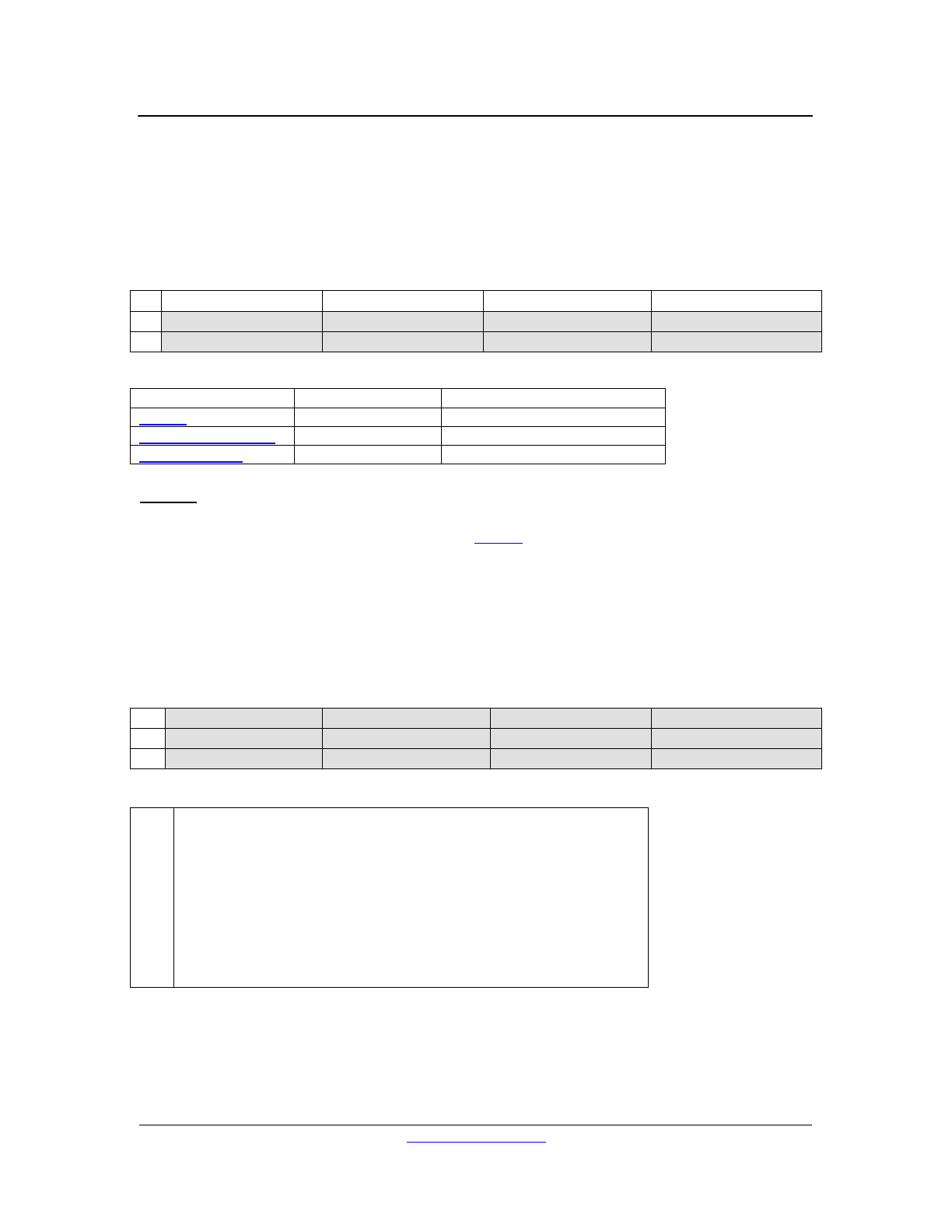
33
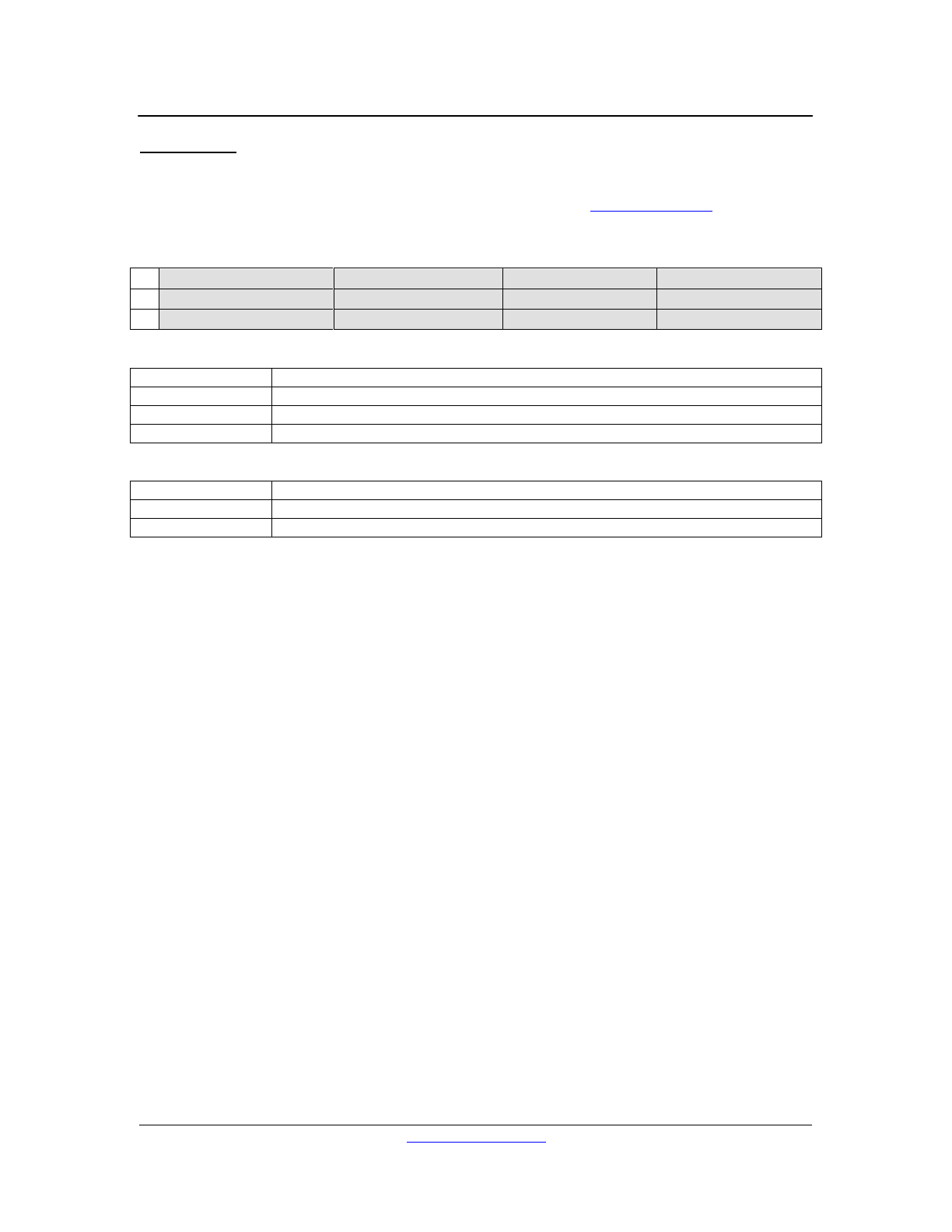
Appendix A – Device Family
Device ID
Description
0xFF
Global Device Family
0x00
PC Host
0x07
Processor (inc. DX Family)
Appendix B – Device Instance
Device ID
Description
0xFF
Global Device (Broadcast)
0xFE
Uninitialized Device (Default)
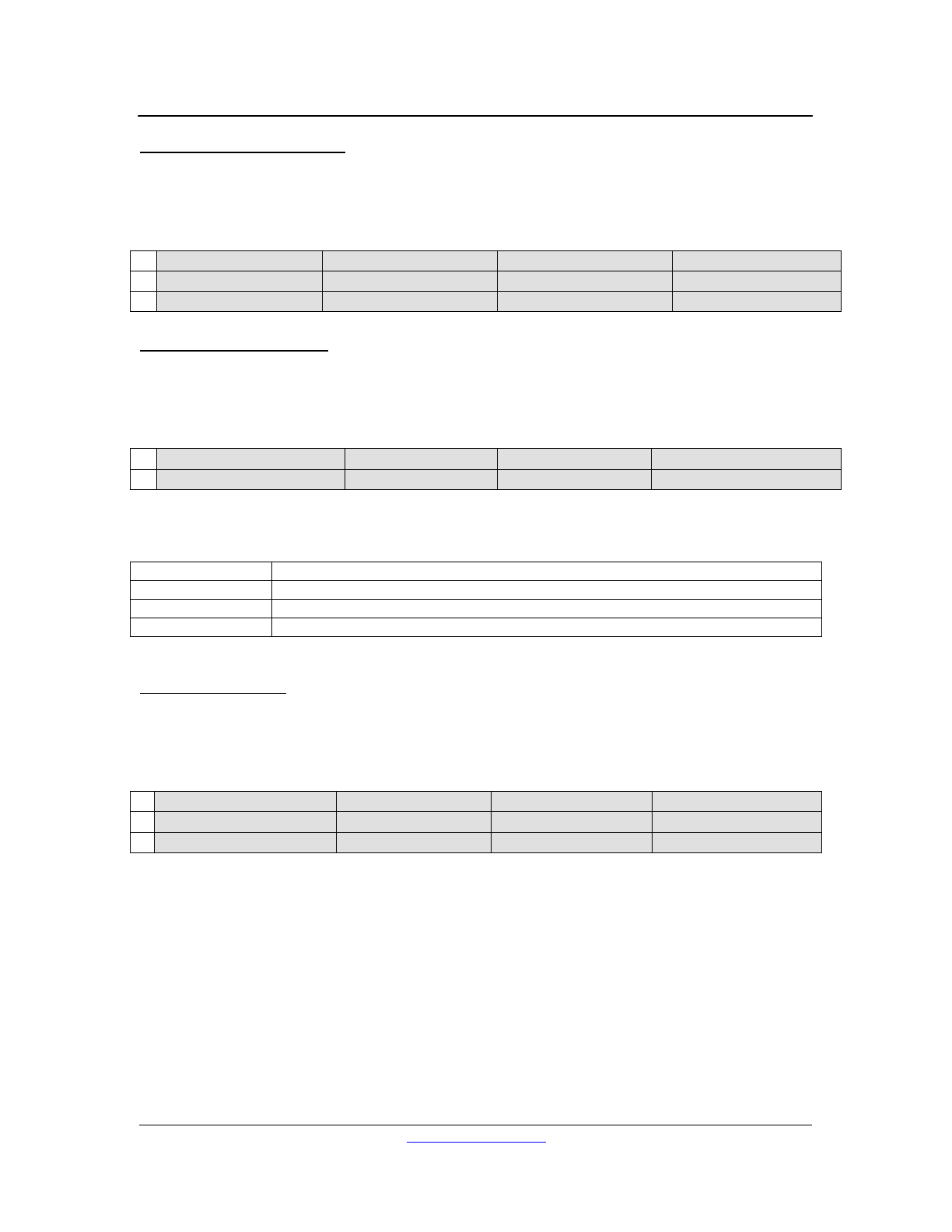
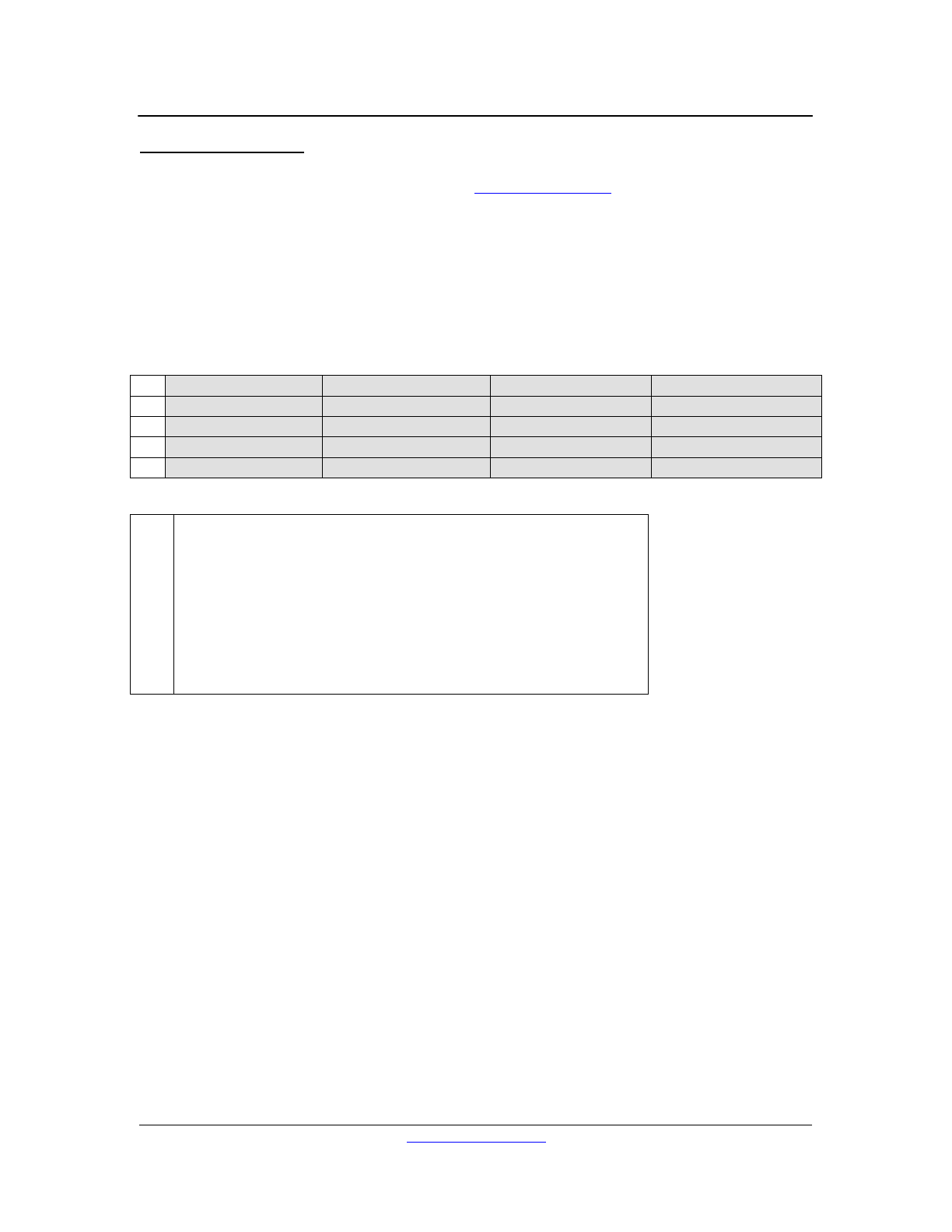
Appendix C – Channel/Type IDs
Note also that while most channels can have one or more ‘instances’ (e.g. 8 analog inputs or 4
digital inputs), global ‘types’ have zero instances by convention.
Channel/Type ID
Description
1
Analog Input
2
Digital Input
3
Analog Output
50
Remote
51
Logic Input
53
Logic Output
225
DXLink Input
227
DXLink Output
240
Global
LOUD Technologies, Inc. 11/19/2009
http://www.eaw.com
34
Appendix D – Effect and Parameter IDs
Note that not all types (or channels) support all effects.
Effect IDs
Effect ID
Name
Comments
1
Fader
2
Mute
4
Setup
Mic Pre
5
EQ
Parametric EQ
6
Filter
High- or Lowpass Filter
7
Compressor
Alternatively a Limiter or an AGC
8
Gate
Alternatively an Expander
11
Ducker
12
Delay
17
Solo
25
Matrix Level
50
Universal Remote
51
Logic Input
53
Logic Output
69
Matrix Enable
101
Label
224
Automix
240
Global
(‘Global’ effect - zero instances)
243
Dummy
Host scratchpad (‘Global’ effect - zero instances)
Parameter IDs (by Effect)
1 - Fader Effect
Parameter #
Description
1
Fader Level
2 - Mute Effect
Parameter #
Description
1
Mute Enable
4 - Setup Effect
Parameter #
Description
1
Setup Enable
2
Analog Trim (0, 20, 40, 50, 60 dB)
3
Phantom Power

LOUD Technologies, Inc. 11/19/2009
http://www.eaw.com
35
5 - EQ Effect
Parameter #
Description
1
EQ Enable (all bands)
2
EQ Band 1 Enable
3
EQ Band 1 Frequency
4
EQ Band 1 Q
5
EQ Band 1 Gain
6
EQ Band 1 Type (see below)
7
EQ Band 2 Enable
8
EQ Band 2 Frequency
9
EQ Band 2 Q
10
EQ Band 2 Gain
11
EQ Band 2 Type
12...16
EQ Band 3 Enable, Frequency, Q, Gain, Type
17...21
EQ Band 4 Enable, Frequency, Q, Gain, Type
22...26
EQ Band 5 Enable, Frequency, Q, Gain, Type
27...31
EQ Band 6 Enable, Frequency, Q, Gain, Type
32...36
EQ Band 7 Enable, Frequency, Q, Gain, Type
37...41
EQ Band 8 Enable, Frequency, Q, Gain, Type
EQ Filter Types
0
Low Pass (2nd order Butterworth)
1
High Pass (2nd order Butterworth)
2
Band Pass (a.k.a. Parametric)
3
Low Shelf (2nd order)
4
High Shelf (2nd order)
5
Low Shelf (1st order)
6
High Shelf (1st order)
6 - Filter Effect
Parameter #
Description
1
Filter Enable (all bands) (constant)
2
Highpass Filter Enable
3
Highpass Filter Frequency
4
Highpass Filter Type (see below)
5
Highpass Filter Slope (6, 12, 18, or 24 dB)
6
Lowpass Filter Enable
7
Lowpass Filter Frequency
8
Lowpass Filter Type
9
Lowpass Filter Slope (6, 12, 18, or 24 dB)
HPF & LPF Filter Types
0
Butterworth
1
Linkwitz-Riley
2
Bessel
LOUD Technologies, Inc. 11/19/2009
http://www.eaw.com
36
7 - Compressor Effect
Parameter #
Description
1
Compressor Enable
2
Gain (Makeup)
3
Attack
4
Release
5
Threshold
6
Ratio
7
Knee (constant)
8
Knee Enable (constant)
9
Stereo Link Enable (constant)
10
AGC Enable
11
AGC Threshold
12
AGC Target
8 - Gate Effect
Parameter #
Description
1
Gate Enable
2
Attack
3
Hold
4
Release
5
Threshold
6
(Expander) Ratio (constant)
7
(Gate) Range
8
Mode (Gate -> 0 or Expander -> 1) (constant)
9
Stereo Link Enable (constant)
11 - Ducker Effect
NOTE: See also the Global effect for more ducker parameters.
Parameter #
Description
1
Ducker Enable
2
Priority
3
Level Detect
12 - Delay Effect
Parameter #
Description
1
Delay Enable
2
Delay Time
17 - Solo Effect
Parameter #
Description
1
Solo Assign

LOUD Technologies, Inc. 11/19/2009
http://www.eaw.com
37
25 - Matrix Level Effect
Parameter #
Description
1
Matrix Level Out
2
Matrix Level In 1
3
Matrix Level In 2
…
…
29
Matrix Level In 28
50 - Universal Remote Effect
Parameter #
Description
1
Initialized
2
Present (read only)
3
Enable
4
ID
5
Type
6
I/O 1 LED State (read only)
7
I/O 1 Action
8
I/O 1 Event
9
I/O 1 Select
10
I/O 2 LED State (read only)
11
I/O 2 Action
12
I/O 2 Event
13
I/O 2 Select
14
I/O 3 LED State (read only)
15
I/O 3 Action
16
I/O 3 Event
17
I/O 3 Select
18
I/O 4 LED State (read only)
19
I/O 4 Action
20
I/O 4 Event
21
I/O 4 Select
51 - Logic Input Effect
Parameter #
Description
1
Logic In Enable
2
State (read only)
3
Action
4
Active
5
Event
6
Select

LOUD Technologies, Inc. 11/19/2009
http://www.eaw.com
38
53 - Logic Output Effect
Parameter #
Description
1
Logic Out Enable
2
State (read only)
3
Active
4
Event
5
Select
69 - Matrix Enable Effect
Parameter #
Description
1
Matrix Enable Out
2
Matrix Enable In 1
3
Matrix Enable In 2
…
…
29
Matrix Enable In 28
101 - Label Effect
Parameter #
Description
1
Characters 0-3
2
Characters 4-7
3
Characters 8-11
4
Characters 12-15
5
Characters 16-19
6
Characters 20-23
7
Characters 24-27
8
Characters 28-31
224 - Automix Effect
Parameter #
Description
1
Automix Enable
2
Response
3
Ratio
4
Assign In 1
5
Assign In 2
…
…
31
Assign In 28
LOUD Technologies, Inc. 11/19/2009
http://www.eaw.com
39
240 - Global Effect
NOTE: Global parameters are very device specific!
Parameter #
Description
1
Ducker Attack
2
Ducker Release
3
Ducker Threshold
4
Ducker Hold
5
Ducker Priority 1 Enable
6
Ducker Priority 1 Depth
7
Ducker Priority 2 Enable
8
Ducker Priority 2 Depth
9
Ducker Priority 3 Enable
10
Ducker Priority 3 Depth
11
Ducker Priority 4 Enable
12
Ducker Priority 4 Depth
13
Global Initialized (system maintained)
14
Preset Initialized (system maintained)
15
Default Preset
16
Login Enable
17
Admin Password Characters 0-3 (write only)
18
Admin Password Characters 4-7 (write only)
19
Admin Password Characters 8-11 (write only)
20
Admin Password Characters 12-15 (write only)
21
User Password Characters 0-3 (write only)
22
User Password Characters 4-7 (write only)
23
User Password Characters 8-11 (write only)
24
User Password Characters 12-15 (write only)
25
Static IP Enable
26
Static IP Address
27
Static IP Subnet Mask
28
Static IP Subnet Gateway
29
DXLink Master
30
DXLink Valid (read only)
31
DXLink Locked (read only)
32
Audio Locked (read only)
33
SHARC Ready (read only)
34
SHARC Error (read only)
35
Dynamic IP Address (read only)
243 - Dummy Effect
Parameter #
Description
1
Dummy 1
2
Dummy 2
…
…
32
Dummy 32

LOUD Technologies, Inc. 11/19/2009
http://www.eaw.com
40
Appendix E – DX Family Configuration Files
Each DX Family member (DX1208, DX200) has its own device-specific Configuration
spreadsheet. This spreadsheet enumerates all device parameters in tabular format along with
important statistics pertaining to each parameter and to various parameter groupings. This
section is intended as a ‘key’ to deciphering a DX Family Configuration file.
There is a single identifying label at the beginning of a DX Family Configuration, listing the device
type and the date of the last file update. The rest of the file consists of a table of parameter
information, with one parameter per row. There are twelve columns per row; most parameters
have values in only a subset of the columns, as the file is laid out in a hierarchical format, per the
Bucket Net Parameter ID hierarchy (see Parameter IDs).
Column Heading
Description
TYPE
Type IDs for each device Type (or channel).
INSTANCES
The number of instances of the specified Type.
(‘Global’ effects have 0 instances by convention.)
TAPS
The number of meter placements available for the specified Type.
(See Meters.)
EFFECT
Effect IDs for each Effect of the specified Type.
Note the same effect can be used on multiple Types.
WORDS
This data is relevant for DSP interfacing only – it has no effect on external
communications.
FAT
The number of fat channel meter IDs available for the specified Effect.
(See Fat Channel Meters.)
For most effects there are two meter IDs – one for the input signal level and
the other for output signal level. However, the Automix effect takes input
signals from each input channel, and it thus has many more IDs.
PARAMETER
Parameter IDs (or numbers) for each Parameter of the specified Effect.
All Parameter ID values start at 1 and increment by 1 per parameter.
SEGMENT
The memory segment in which the value of the specified parameter is stored.
(See below.)
FORMAT
The native format of the specified parameter.
This is generally either Boolean, unsigned long integer, or 32-bit floating
point, as DX Family device processors are 32-bit processors. (Note that 32-
bit Boolean values are representing using 32-bit unsigned long integers, so
there are really only two formats.)
MIN
The minimum value of the specified parameter.
INIT
The initial (or default) value of the specified parameter.
MAX
The maximum value of the specified parameter.
*All IDs are represented by #defined labels (which decode to the integral values specified in
Appendices C & D) for readability.
The first line of the parameter information specifies a type, its first effect, and the effect’s first
parameter. Subsequent lines step through the rest of the effect parameters, one per line (with no
gaps – constant parameters are used as placeholders for consecutive parameters which are not
implemented or not user configurable on a particular device), until all effect parameters are
specified. The next effect begins the next line, continuing until all effects of the type have been
specified. The next type then begins the next line, until all types are specified and all device
parameters have been accounted for. Note that while the effects and types need not be specified
in any particular order, there can only be one occurrence of a particular type per device and only
one occurrence of an effect per type.

LOUD Technologies, Inc. 11/19/2009
http://www.eaw.com
41
Memory Segments
SEGMENT
Access
Description
0
constant
Constant or unused (placeholder) parameters.
Edits to these parameters will be ignored; requests will return their
default value.
1
read-only
Read only system state – not backed up to FLASH.
Edits to these parameters will be ignored; requests will return their
current value.
NOTE: Read-only parameters are generally allowed to change
without notice – they must be polled or requested in order to
maintain synchronization.
2
write-only
Write only password data.
Edits to these parameters will succeed; requests, however, will
ALWAYS return their default value, even if they have been changed.
NOTE: All write-only parameters are also global.
3
global
Read- and writeable global control parameters.
Edits to these parameters will affect the current system state, are
immediately backed up to FLASH, and persist across power cycles.
4
preset
Read- and writeable preset specific parameters.
Edits to these parameters will affect the current system state; unless
the system state is backed up to FLASH using a Preset Store
message the edits will not survive a power cycle.
For user editable parameters (segments 2-4), the last four columns of the parameter information
describe the format and limits of the parameter value. Attempts to set a parameter value to below
its minimum or above its maximum will fail, causing the entire Parameter Edit message containing
the change to be invalidated, and generating an error (see Status Query: Debug Log Address).
Note that issuing a Preset Load specifying an uninitialized preset will effectively reset current
device state to the default values of all (non-global) parameters.
Finally, while the format column specifies the ‘native’ format of each parameter, some format
conversion is built in to Bucket Net messaging. In particular, 32-bit floating format is commonly
used as a sort of ‘interchange’ format for the purpose of generating autoincrement parameter
Parameter Edit messages (possibly is response to a Data Request). When an entire effect
instance is being specified using a single autoincrement parameter message, and the formats of
the effect parameters are not all the same, it is expedient to avoid the use of multiblock edits by
simply converting all the non-floating point parameter values (which are unsigned long integers
on DX Family devices) into 32-bit floating point values. (WARNING: This conversion is not
always possible without loss of precision or distortion of the parameter value!) DX Family devices
may generate such Parameter Edit messages in response to Data Requests; DX Family
Parameter Edit handlers will attempt to ‘deconvert’ received floating-point formatted data into its
native format.

LOUD Technologies, Inc. 11/19/2009
http://www.eaw.com
42
Appendix F – Examples
This section is intended to navigate the reader step by step through the process of creating
hexadecimal strings suitable for use in RS-232 interfacing for several basic messages.
1 - Ping
Ping messages have no data segment, so creating one involves only filling in the proper header
fields:
Header Field
Value
SYNC
0xA5
LENGTH
0x00 (no data segment)
DESTINST
A
The instance designation of the destination, if known and/or assigned.
0xFF will here will ‘broadcast’ to all instances; 0xFE will specify all
uninitialized instances. It is typical to use Assign Device Instance to set
the instance number of an uninitialized device instance.
DESTFAM
0x07 (DX Family)
MSGID (16-bit)
0x0000 (Ping message ID)
SRCINST
0x01 (or whatever instance you’d like to be)
SRCFAM
0x00 (PC Host – We’re pretending to be a PC!)
MSGCHKSUM (16-bit)
0xFFFF (1’s complement of 0x0000, as there is no data segment)
HDRCHKSUM (16-bit)
B
This will depend on the value of A, and is computed by taking the 1’s
complement of the sum of the (other) header bytes: 0xA5 + 0x00 + A +
0x07 + 0x00 + 0x00 + 0x01 + 0x00 + 0xFF + 0xFF.
Thus, the finished Ping message, transmitted left to right, is:
0xA5, 0x00, A, 0x07, 0x00, 0x00, 0x01, 0x00, 0xFF, 0xFF, B (lo), B (hi)
A DX Family device receiving this message should reply with a Ping Response message.
LOUD Technologies, Inc. 11/19/2009
http://www.eaw.com
43
2 - Identify Device
Identify Device messages do not generate a response; they do, on the other hand, generate
visual feedback from the front panel of the connected device. The header of an Identify Device
message is composed as shown for the Ping message, with two important differences: message
ID and (data segment) length:
Header Field
Value
LENGTH
0x01
MSGID (16-bit)
0x005C (Identify Device message ID)
MSGCHKSUM (16-bit)
C
This will depend on the value of the bytes in the data segment.
HDRCHKSUM (16-bit)
B
This will depend on the values of A and C, and is computed by taking
the 1’s complement of the sum of the (other) header bytes: 0xA5 +
0x00 + A + 0x07 + 0x00 + 0x5C + 0x01 + 0x00 + C (lo) + C (hi).
Identify Device messages have a single data word, specifying the time (in ms) to take control of
the front panel LEDs. For purposes of this example, let’s choose 3000 ms (0xBB8), yielding the
following message string:
0xA5, 0x01, A, 0x07, 0x5C, 0x00, 0x01, 0x00, C (lo), C (hi), B (lo), B (hi),
0xB8, 0x0B, 0x00, 0x00
3 - Status Query: Hardware Information
Status Query messages are used to ascertain all sorts of (non-parameter) system state. There
are numerous status codes which can be sent; the response to each code depends on the code
itself. The most basic Status Query it the default query, requesting Hardware Information:
Header Field
Value
LENGTH
0x01
MSGID (16-bit)
0x0001 (Status Query message ID)
Status Queries have an optional data word. If no data segment is present, the default code is
assumed. While the default code is Hardware Information, this example will specify the code
explicitly anyway, in order to show the ‘full’ format. The code for Hardware Information is 0x0000:
0xA5, 0x01, A, 0x07, 0x01, 0x00, 0x01, 0x00, C (lo), C (hi), B (lo), B (hi),
0x00, 0x00, 0x00 or 0xFF, 0x00 or 0xFF
Status codes are 16-bit, but all data segments must be 32-bit aligned. Thus the last two data
bytes, should, technically, be ‘fill’ bytes (0xFF). Some Bucket Net capable systems do not appear
to be able to handle fill bytes correctly; DX Family devices should. A Status Query Response
should be generated in reply to this message.

LOUD Technologies, Inc. 11/19/2009
http://www.eaw.com
44
4 - Data Request: Meters
Data Request messages come in several flavors: Meters, Fat Channel Meters, and Parameter
Edit. As Device Requests are heavily used in interfacing with DX Family devices, examples of
both meter and parameter requests are given.
Meters requests should generate Meters messages in response. Each data word of a Data
Request: Meters will add one block to the response. Let’s create a request for all analog and
digital input meter data at the inputs, plus the meters for analog outputs 3 & 4 (at the outputs);
this request requires three data words (in addition to the word specifying the type of Data
Request):
Header Field
Value
LENGTH
0x04
MSGID (16-bit)
0x005B (Data Request message ID)
Data
Byte
Name
Value
0
Data Request ID
0x51 (Meters)
1
N/A
0x00 or 0xFF
2
N/A
0x00 or 0xFF
3
N/A
0x00 or 0xFF
4
Meter Type
0x00 (pre-DSP, peak)
5
Meter Flags
0x02 (32-bit floating point – native meter format for DX Family)
6
Instance ID
0xFF (all)
7
Type ID
0x01 (Analog Input)
8
Meter Type
0x00 (pre-DSP, peak)
9
Meter Flags
0x02 (32-bit floating point – native meter format for DX Family)
10
Instance ID
0xFF (all)
11
Type ID
0x02 (Digital Input)
12
Meter Type
0x01 (post-DSP, peak)
13
Meter Flags
0x12 (32-bit floating point – native meter format for DX Family 0x02
OR’d with two meter words only 0x10)
14
Instance ID
0x03 (beginning with instance 3)
15
Type ID
0x03 (Analog Output)
Here’s the resulting message string:
0xA5, 0x04, A, 0x07, 0x5B, 0x00, 0x01, 0x00, C (lo), C (hi), B (lo), B (hi),
0x51, 0x00 or 0xFF, 0x00 or 0xFF, 0x00 or 0xFF,
0x00, 0x02, 0xFF, 0x01,
0x00, 0x02, 0xFF, 0x02,
0x01, 0x12, 0x03, 0x03
The response message will be examined in the next example.

LOUD Technologies, Inc. 11/19/2009
http://www.eaw.com
45
5 - Meters
Meters messages are not usually generated, as it is not possible to write audio levels directly.
However, it is quite common to request meter data, and thus important to be able to parse and
handle Meters messages.
In the previous example we created a Data Request for all analog and digital input meter data (at
the inputs), plus the meter data for (just) analog outputs 3 & 4 (at the outputs). After sending that
message, a response like this should be received (suppressing the ‘0x’ prefixes indicating
hexadecimal to save space, and using a fixed font for alignment):
HEADER: A5 11 01 00 51 00 FE 07 98 D8 82 FC
BLOCK1: 00 42 01 01
56 13 A5 C2 08 6F AA C2 59 9B A8 C2 AB CF A2 C2
30 A8 60 C0 5A B3 A5 C2 6C 51 A9 C2 69 79 A6 C2
BLOCK2: 00 22 01 02
E3 E9 F6 C2 E3 E9 F6 C2 E3 E9 F6 C2 E3 E9 F6 C2
BLOCK3: 01 12 03 03
E3 E9 F6 C2 E3 E9 F6 C2
The first line of the message is its header. Of note: The length of the data segment is 17 words,
and this is a Meters message (ID 0x51). (Note also that the sender’s device instance is
uninitialized – 0xFE.)
The data segment of the message consists of three blocks, each beginning with a data word
describing the meter values that follow. The data values themselves are in 32-bit floating point
format, and, if decoded, show that not much is plugged in to the inputs of this device (just analog
input 5); the output is also in digital silence. As expected, we see blocks of 8 values (analog
inputs), 4 values (digital inputs), and 2 values (analog outputs 3 & 4).
Decoding the block headers:
Block 1
Value
Description
Meter Type
0x00
pre-DSP, peak
Meter Flags
0x42
32-bit floating point (0x02) OR’d with 8 words (0x40)
Instance ID
0x01
Beginning with the first instance…
Type ID
0x01
Analog Input
Block 2
Value
Description
Meter Type
0x00
pre-DSP, peak
Meter Flags
0x22
32-bit floating point (0x02) OR’d with 4 words (0x20)
Instance ID
0x01
Beginning with the first instance…
Type ID
0x02
Digital Input
Block 3
Value
Description
Meter Type
0x01
post-DSP, peak
Meter Flags
0x12
32-bit floating point (0x02) OR’d with 2 words (0x10)
Instance ID
0x03
Beginning with the third instance…
Type ID
0x03
Analog Output

LOUD Technologies, Inc. 11/19/2009
http://www.eaw.com
46
6 - Data Request: Parameter Edit
Having generated a meter request in a previous example, now let’s generate a Data Request for
parameter data, namely all the parameters of the Gate effect on Analog Input 5:
Header Field
Value
LENGTH
0x02
MSGID (16-bit)
0x005B (Data Request message ID)
Data
Byte
Name
Value
0
Data Request ID
0x54 (Parameter Edit)
1
Flags 1
0x00 (edit buffer)
2
N/A
0x00 or 0xFF
3
N/A
0x00 or 0xFF
4
Parameter ID
0xFF (all)
5
Instance ID
0x05 (instance 5)
6
Effect ID
0x08 (Gate)
7
Type ID
0x01 (Analog Input)
Here’s the resulting message string:
0xA5, 0x02, A, 0x07, 0x5B, 0x00, 0x01, 0x00, C (lo), C (hi), B (lo), B (hi),
0x5C, 0x00, 0x00 or 0xFF, 0x00 or 0xFF,
0xFF, 0x05, 0x08, 0x01
The Parameter Edit message received in response will be examined in the next example.

LOUD Technologies, Inc. 11/19/2009
http://www.eaw.com
47
7 - Parameter Edit
In this example we will both examine the result of the Data Request: Parameter Edit from the
previous example and generate a separate Parameter Edit message.
In the previous example, we requested all of the parameter data for the Gate effect on Analog
Input 5. The following message was received in reply:
HEADER: A5 0B 01 00 54 00 FE 07 10 FB EA FC
FLAGS: 01 0C 00 09
IDS: 01 05 08 01
VALUES: 00 00 00 00 00 00 A0 41 00 00 48 43 00 00 48 43
00 00 20 C2 00 00 80 3F 00 00 70 C2 00 00 00 00
00 00 00 00
The first line of the message is its header. Of note: The length of the data segment is 11 words,
and this is a Parameter Edit message (ID 0x54). (Note also that the sender’s device instance is
uninitialized – 0xFE.)
Next, the flags:
Flag
Value
Description
General Flags
0x01
Autoincrement (Parameter)
Data Format
0x0C
32-bit floating point
Target Buffer
0x00
Edit Buffer (current state)
Block Length
0x09
9 words
Finally, the Parameter IDs specify the first parameter in the of the data values – parameter 1
(0x01) of instance 5 (0x05) of effect 8 (Gate) of type 1 (Analog Input). Each parameter value
after the first increments the parameter number, per the flags.
The remaining data words are the values of the Gate parameters, from 1 to 9, in floating point
format.
Two things about this message require special note:
Firstly, it is an edit message, and, while we may have requested it, there is no way to tell this
particular Parameter Edit from another which the DX Family device may have generated in
response to some other (remote) edit. This is not a ‘get’; it is a ‘request to set’.
Secondly, the format, as specified in the flags, of ALL of the parameter data in the message is 32-
bit floating point. Assuming that the connected device is a DX1208, and examining the DX1208
Configuration file, we can see the formats of the Gate parameters. Parameters 1 (Enable), 8
(Mode), and 9 (Stereo Link Enable) are not natively floating point! The DX1208 has converted
these values from integer format to floating point format in order to avoid using a multiblock
Parameter Edit (or multiple edits) in response to the original Data Request. The local receiver will
need to either handle these values as floating point, or to ‘deconvert’ them back to their native
format(s).
LOUD Technologies, Inc. 11/19/2009
http://www.eaw.com
48
Next, let’s create a Parameter Edit to a single, global parameter. Let’s enable static IP
addressing:
Header Field
Value
LENGTH
0x03
MSGID (16-bit)
0x0054 (Parameter Edit message ID)
Data
Byte
Name
Value
0
General Flags
0x00 (Autoincrement Disabled)
1
Data Format
0x00 (unsigned long integer)
2
Target Buffer
0x00 (Edit Buffer)
3
Block Length
0x00 (block extends to the end of the message)
4
Parameter ID
0x19 (Static IP Enable)
5
Instance ID
0x00 (‘Global’ Type – no instances)
6
Effect ID
0xF0 (Global)
7
Type ID
0xF0 (Global)
We’re turning on static addressing, so we’ll need to change the (Boolean) value from 0x00000000
to 0x00000001.
Here’s the resulting message string:
0xA5, 0x03, A, 0x07, 0x54, 0x00, 0x01, 0x00, C (lo), C (hi), B (lo), B (hi),
0x00, 0x00, 0x00, 0x00,
0x19, 0x00, 0xF0, 0xF0,
0x01, 0x00, 0x00, 0x00
There is no response to this edit. (Nothing happened? You must be logged in to use a
Parameter Edit over communications channels other than RS-232. Are you using RS-232?)
LOUD Technologies, Inc. 11/19/2009
http://www.eaw.com
49
8 - Preset Load
Once a connection is established, the majority of controller/device messaging is likely to consist
of just a few message IDs: Data Requests, Parameter Edits, possibly Meters and/or Fat Channel
Meters, and Preset Loads. This example shows how to create the last of these ‘basic’ messages:
a Preset Load message.
Preset Load messages have a single data word, which specifies both the preset index to load and
the buffer to be loaded. RS-232 controllers are unlikely to want to use the ‘scratch’ buffer, which
is mostly used for transferring data in and out of the device; in general they want to change
device state by loading to the ‘edit’ buffer. For this example, let’s instruct the device to load its
current state from preset number 5:
Data
Byte
Name
Value
0
Preset Index (lo)
0x04 (Preset Index = Preset Number – 1)
1
Preset Index (hi)
0x00 (always, as no DX Family device has this many presets)
2
Library Type
0x01 (always – this just means ‘preset’)
3
Destination Buffer
0x00 (Edit Buffer – Change current device state!)
As with all preset related messaging, see the Preset Info message for further details of the data
segment fields.
The resulting message string:
0xA5, 0x01, A, 0x07, 0x74, 0x00, 0x01, 0x00, C (lo), C (hi), B (lo), B (hi),
0x04, 0x00, 0x01, 0x00
Preset Load messages do not generate a response.
