Dart+Linear+Actuator+pulley+swap+instructions
User Manual:
Open the PDF directly: View PDF ![]() .
.
Page Count: 6
Dart Linear Actuator
Ratio/Pulley Change Instructions
DART Linear Actuators come standard with a 2.50:1 ratio pulley set consisting of a 12 tooth drive pulley
mounted to the motor and a 30 tooth driven pulley mounted to the lead screw. Both a 2.00:1 and 1.00:1
ratio pulley set are available and come with a 24 tooth or 12 tooth pulley, respectively, as well as
appropriately sized timing belt. These ratios are accomplished by replacing the 30 tooth driven pulley
mounted to the lead screw. Other ratios are possible by changing the drive pulley with any of these
pulleys as shaft and key sizes are identical.
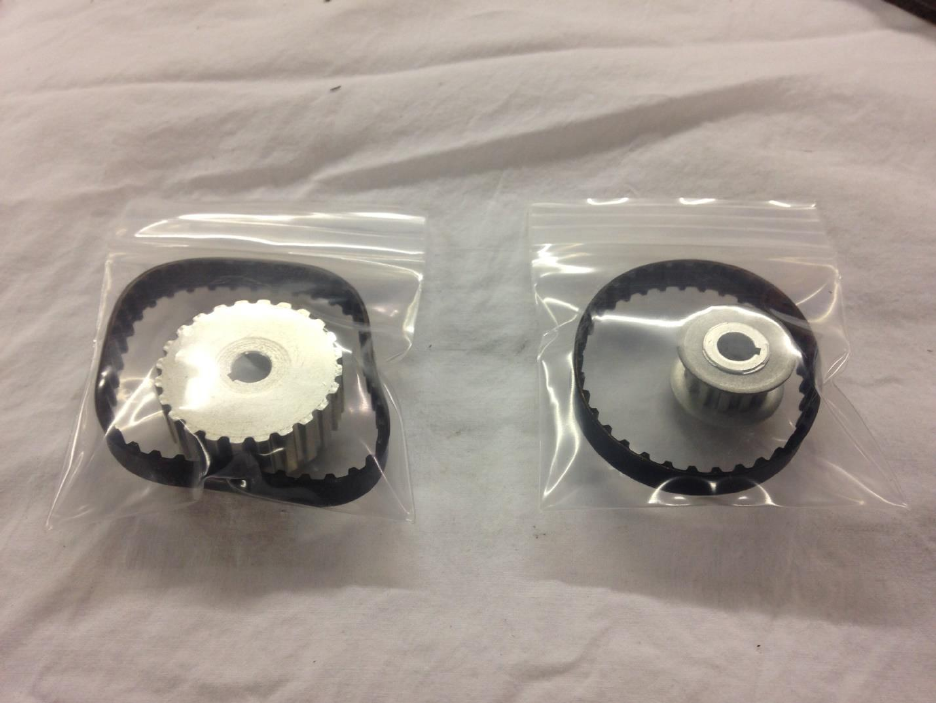
To change ratios the drive enclosure portion of the actuator must be taken apart, to do this you will
need the following tools: #2 Philips screw driver, 5/16” box wrench or socket, 1/2” box wrench or
socket, 5/32” Allen wrench. 2.00:1 and 1.00:1 ratio pulley and belt kits shown below from left to right
respectively.
1. Begin by removing drive enclosure top and sides by removing the 6 #8 Phillips screws passing
through the top and side plates.
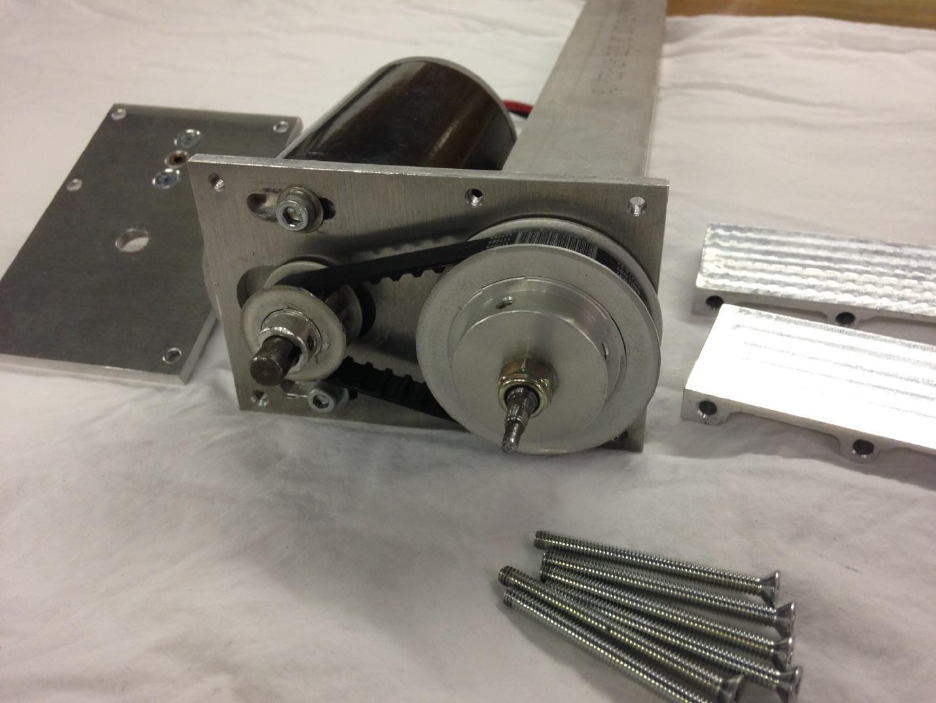
2. Loosen, but do not remove, the two #10 socket head cap screws securing the motor to the
motor plate. Slide the motor toward the actuator housing such that the belt can be removed.
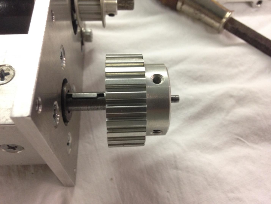
3. Remove the 5/16-24 Nylock nut securing the driven 30 tooth pulley to the lead screw. Using 2
flat blade screw drivers, carefully pry the pulley off the lead screw shaft as shown. Be careful not
to lose the 2mmx10mm machine key captured between the pulley and shaft. Do not remove the
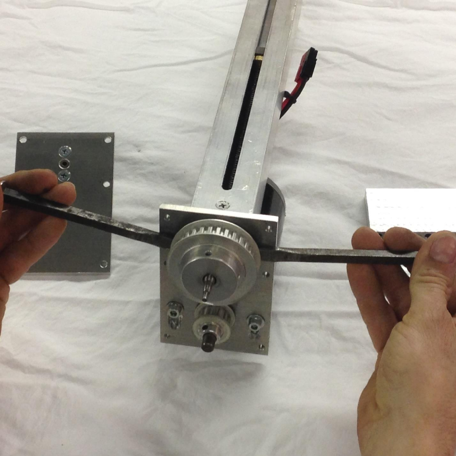
race spacer located under the pulley, this will support the new pulley as it did the original.
4. Place the 2mmx10mm machine key back in the keyway in the lead screw shaft if dislodged
during step 3. Place the pulley from your desired pulley/belt kit onto the lead screw shaft. Take
care to align the keyway in the pulley with the key placed in the lead screw shaft keyway. If the
pulley does not slide all the way to down to the race spacer by hand it can be tapped into place
using a socket placed over the end of the lead screw shaft and a hammer. Be sure the actuator is
standing on end when this is performed to avoid driving the lead screw shaft out of the bearing
block.
5. Replace the 5/16-24 Nylock nut that was removed in step 3. Torque till snug or 35 inch pounds
holding the pulley to keep the lead screw shaft from rotating.
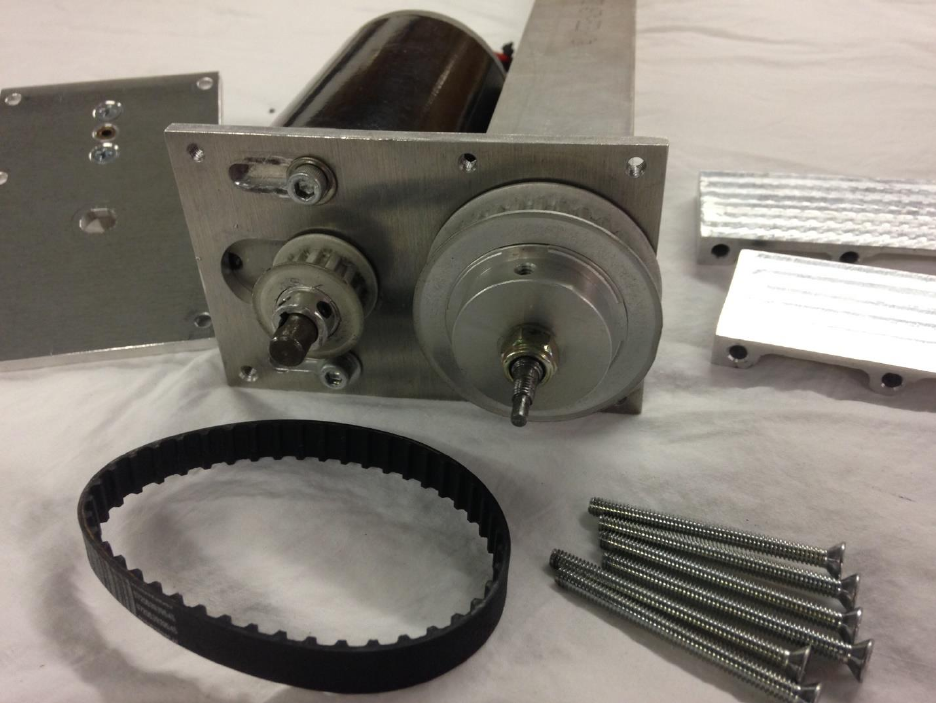
6. Place the new timing belt, included with the pulley kit, over the drive and driven pulley. Slide the
motor in its screw slots to tension the belt. Tighten the two 10-32 motor screws to hold the
motor in position and timing belt at tension. Belt tension is correct when moderate pressure
from one finger deflects one belt span about 1/8”. No prying or levers should be necessary to
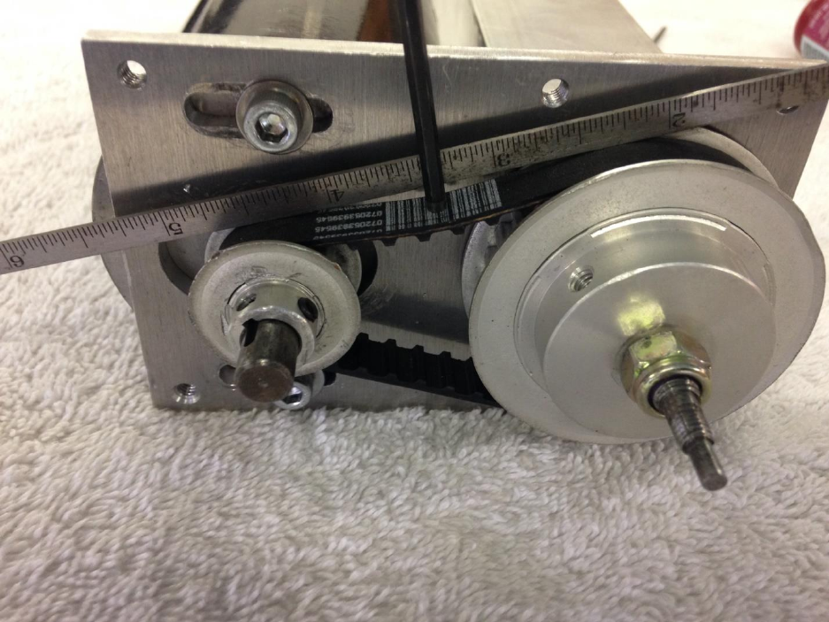
achieve sufficient belt tension. Motor screws should be tightened to 30 Inch pounds.
7. Replace the top and side plates of the drive enclosure using the 6 #8 screws removed in step 1.
Start all 6 scews then tighten in two steps criscross pattern. Pulley swap is complete.
