Data Centre Handbook
User Manual:
Open the PDF directly: View PDF ![]() .
.
Page Count: 23
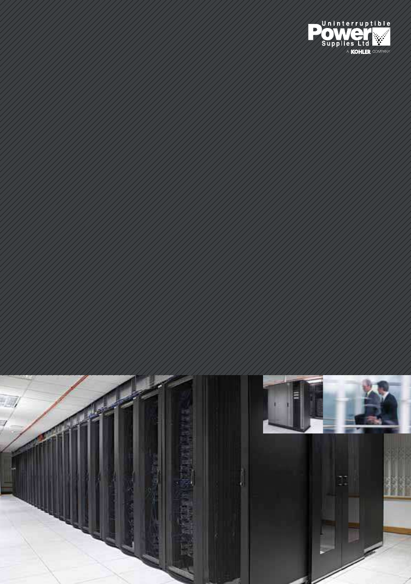
The UPS
data centre
handbook
The essential guide to making
informed decisions around
UPS data centre systems

Highly efficient & reliable
UPS systems for the data
centre industry
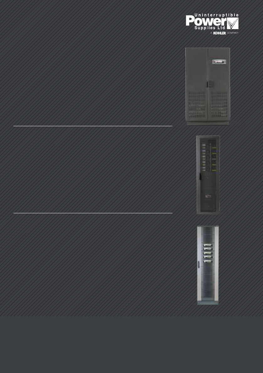
PowerWAVE 6000 –
Transformerless UPS
technology for best-in-class
performance up to 5 MVA
PowerWAVE 8000DPA –
Modular, three-phase UPS
providing power protection
up to 200 kVA
PowerWAVE 9000DPA –
Three-phase, modular UPS
with a high operating
efficiency of up to 96%
Low total cost of ownership
Whether you’re supporting a localised IT facility or an enterprise level
data centre with over 500 servers, operating a UPS system contributes
significantly to capital and operating expenditure. So, although the UPSs
critical role demands investment in the most advanced, reliable solutions,
maximising efficiency and lowering total cost of ownership is also
essential; a small change can have a big impact on the bottom line.
UPSLs PowerWAVE range, including the 6000, 8000DPA and 9000DPA,
provides a complete offering of highly-efficient solutions for data centres of
all sizes. The range’s class-leading efficiency levels, available over a wide
load spectrum, combine with near-unity power factors to ensure operating
costs are minimised, while available scalability options reduces upfront
capital expenditure.
Find out which is right for your operation today.
2 The UPS data centre handbook www.upspower.co.uk www.upspower.co.uk The UPS data centre handbook 3
Contact us to calculate
your TCO today
01256 386700
sales@upspower.co.uk
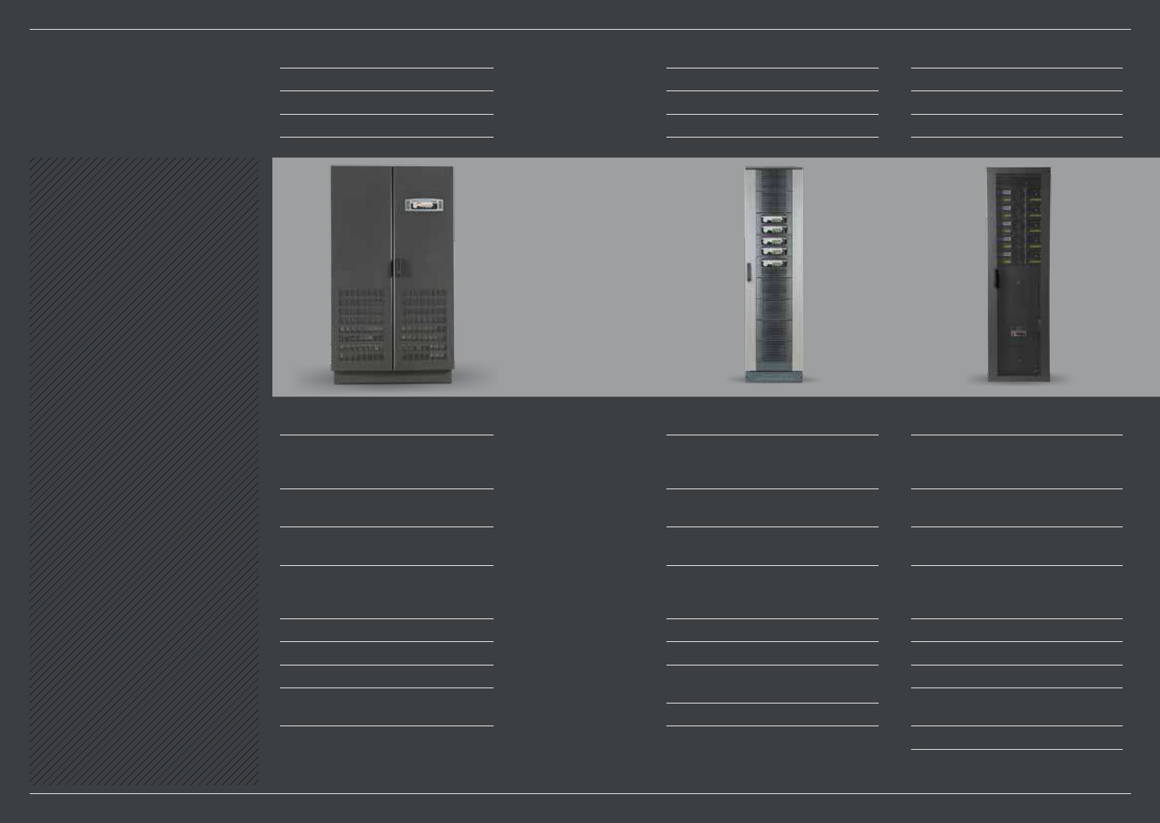
Enterprise data centre
>5,000 sq ft
>500 servers
UPS size=>750kVA
PowerWAVE 6000
High operating efficiency regardless
of loading:
n Up to 96% for 25–100% loads.
Near unity input power factor:
n 99% at 100% load.
Reduced installation and
upgrading costs.
Reduced system running costs:
£19,225* cost saving over five years
per 1% efficiency improvement.
Reduced air conditioning costs:
Less heat loss.
Low carbon footprint.
60–500kVA ‘building blocks’ scalable
to 5MVA.
* 500kVA @ 100% load / 95% efficiency
Mid-tier data centre
<5,000 sq ft
101–500 servers
UPS size=101kVA–750kVA
PowerWAVE 9000DPA
High operating efficiency regardless
of loading:
n Up to 96% for 25–100% loads.
Near unity input power factor:
n 99% at 100% load.
Reduced installation and
upgrading costs.
Reduced system running costs:
£9,520* cost saving over five years
per 1% efficiency improvement.
Reduced air conditioning costs.
Low carbon footprint.
10–250kVA capacity in 10, 20, 30, 40 or
50kVA modular steps.
N+1 Redundancy (up to 200 kVA N+1).
* 250kVA @ 100% load / 95.5% efficiency
Localised data centre
<1,000 sq ft
25–100 servers
UPS size=25kVA–100kVA
PowerWAVE 8000DPA(ST)
High operating efficiency regardless
of loading:
n Up to 95.5% for 25–100% loads.
Near unity input power factor:
n 99% at 100% load.
Reduced installation and
upgrading costs.
Reduced system running costs:
£4,570* cost saving over five years
per 1% efficiency improvement.
Reduced air conditioning costs:
Less heat loss.
Low carbon footprint.
10-200 kVA capacity in 10 kVA and
20 kVA modular steps.
N+1 Redundancy (up to 180 kVA N+1).
* 120kVA @ 100% load / 95.5% efficiency
4 The UPS data centre handbook www.upspower.co.uk www.upspower.co.uk The UPS data centre handbook 5

Contents
Summary of
survey findings
Introduction
85
A review of
data centre tier
classifications
22
The impact of
UPS technology
on the design
of green data
centres
10
The importance
of a reliable
Service Partner
in data centre
UPS systems
28
The upside and
downside of Dual
bus power
14
The application
of ‘economy-
mode’ in ICT
UPS systems
34
6 The UPS data centre handbook www.upspower.co.uk www.upspower.co.uk The UPS data centre handbook 7

Introduction
We trust that this Handbook will become a valuable asset and
reference for owners, operators and designers. In a complex
field with many variables, it focuses on the efficiency and
reliability issues that matter most today to anyone planning
a data centre UPS installation or upgrade.
UPS systems have become absolutely indispensible
to every data centre though choosing the right product,
configuring and installing it correctly is far from easy as
operators face conflicting pressures. The availability of clean,
uninterrupted power has become business-critical and now
has to be combined with maximum possible efficiency. Not
only are electricity costs steadily rising, but also data centres
must demonstrate effective Green policies to comply with
existing and potential legislation, and preserve their reputation
with customers, shareholders and employees.
Fortunately, balanced solutions are possible through
improved UPS technologies and topologies, ICT equipment
and, sometimes, utility mains power. This handbook explains
the issues, interactions and solutions. It discusses how UPS
“This Handbook focuses on
the efficiency and reliability
issues that matter most
today to anyone planning
a UPS installation or
upgrade.”
www.upspower.co.uk The UPS data centre handbook 9

efficiency for all load levels is improved by transformerless
design, and how both capex and opex can be minimised
through modular design and right sizing. It also covers
the increasingly popular question of ‘Eco mode’ operation.
This mode, when first introduced by UPSL was not widely
favoured. It is now commonly used as modern ICT equipment
has better blackout ride-through capabilities, while many
utilities now offer better voltage and frequency stability.
Availability is also discussed in terms of MTBF and Mean
Down Time (MDT), and the importance of a reliable
service partner in maximising MTBF whilst minimising
MDT is explained.
The Handbook also discusses industry views and
standards on UPS efficiency and availability, particularly
by examining Power Usage Efficiency (PUE) and data
centre tier classifications. PUE has become the driving
force behind improving data centre efficiency, and as cooling
systems have become more efficient, attention is turning to
the UPS contribution. Tier classifications, sponsored by the
Uptime Institute for nearly 20 years, describe facilities from an
availability standpoint. The Handbook shows how dual-cord
and N+1 redundancy UPS configurations can be used to
change tier level and dramatically improve availability.
The UPS data centre handbook 11
10 The UPS data centre handbook www.upspower.co.uk
70
75%
of respondents are already
investigating product efficiency
as a way to control/reduce
operating costs
92%
of respondents agree that
maintenance and call out
services are as important
as the hardware itself. 65%
of those questioned are
concerned that increasing
environmental legislation
is a major concern to
their business.
of those questioned
agreed with the
statement ‘Rising power
costs are a major
concern for my
business’.
of those who completed the
survey have a carbon reduction
policy in place.
Product efficiency
Maintenance
Carbon footprint Power costs
Legislation
of respondents believe that
the reliability of power in the UK
is going to be come a major
concern within the next 10 years.
believe the most
important factor to a
potential buyer when
selecting an OEM
is ‘a reputation for
quality and reliability’.
%
of respondents believe that
maximum reliability is the
number one product feature
they look for.
When considering reducing power consumption, what is
the primary driver for change within your organisation?
% %
Reducing their carbon footprint
62
Reducing operating costs
Reliability
Operations
Power Buying
Summary of
survey findings
Each year Uninterruptible Power Supplies Limited, a Kohler company, commissions a
national survey of IT professionals across the United Kingdom, allowing it to keep pace
with current thinking, trends and attitudes regarding UPS equipment, power consumption
and energy efficiency. Here you will find a snapshot of the key findings:
12 The UPS data centre handbook www.upspower.co.uk www.upspower.co.uk The UPS data centre handbook 13

“Topology has also
changed, with double-
conversion being enhanced
with eco-mode and modular
designs enabling higher
load power factors.”
The impact of UPS
technology on the design
of ‘green’ data centres
Power Usage Effectiveness (PUE) has become the driving
force behind the improvement in energy efficiency of data
centre M&E infrastructures and an integral part in the pursuit
of the ‘green’ data centre. PUE can be defined as a measure
of how efficiently power is used within a data centre. It is
measured by a ratio of total amount of power used, to the
amount of power delivered to computing equipment.
PUE = Total facility power / IT equipment power
For many years, UPS efficiency has been gradually improving
but it has been the mechanical cooling systems that have
attracted the most attention regarding energy-overhead
reduction. As the cooling systems have themselves improved,
in some cases drastically, the focus has now returned to the
power system. This white-paper reviews the historical case,
where design PUEs of >2.0 were not uncommon, and looks
at the possibilities provided by scalable high-efficiency UPS
products, and the maximum impact that the UPS can make
to the PUE as it progresses below 1.4.
UPS in historical PUE context
Although the PUE metric is a relatively recent innovation
(by The Green Grid), the principle of working out what
capacity utility was required for a given ICT load in a data
centre has always been one of the first tasks of the designer.
Indeed, as PUE is an annualised energy metric and not a
peak-power metric, that calculation still has to be done as
the ‘peak’ dictates the size of the utility and the emergency
generation system.
If we consider a typical early-90s data centre with a
critical load of around 1MVA, (the kW load was hardly ever
considered in those days as the load power factor was
not unity and harmonic currents dominated), it had an
N+1 UPS of probably 3x500kVA with an efficiency of 88%
and a compressor-based mechanical cooling system that
maintained tight temperature and humidity environment. The
chilled water was supplied at 6ºC and the air supplied into the
under-floor plenum was around 15ºC. No ‘free cooling’ coils
were ever considered (or available in standard equipment) and
variable speed pumps and fans were still on the application
horizon. Humidification and de-hum consumed energy and
even the lighting was high in proportion to the load as the
power density was 350-500W/m≤ from mainly main-frame
hardware. The overall impact of this infrastructure was a
system where the utility load was constant (non-seasonal)
and the fully loaded ‘PUE’ (if that had been innovated) was in
the order of 2.5. However, the partial load performance was
very poor – with monolithic plant (no scalability planned) and
no variable speed drives – with the result that the majority of
facilities ran at a PUE equivalent of 3.5. Hence, even at partial
load, the UPS system only contributed about 0.15 to the
PUE with the mechanical cooling load dominating the power
demand. Energy was cheap and the load was sacrosanct and
so very few people, if any, worried too much about the energy
costs of data centres.
The development of UPS efficiency
The efficiency improvement of UPS has followed a
combination of component innovation, such as thyristors
being replaced by transistors in inverters (and, much later,
rectifiers), which enabled the removal of passive filters and
transformers. Topology has also changed, with double-
conversion being enhanced with eco-mode and modular
designs enabling higher load power factors.
“For many years, UPS
efficiency has been
gradually improving, but it
has been the mechanical
cooling systems that have
attracted the most attention
for energy overhead
reduction.”
14 The UPS data centre handbook www.upspower.co.uk www.upspower.co.uk The UPS data centre handbook 15

In the early 90s a large UPS module would have an
input transformer, 12-pulse thyristor rectifier, passive 11th
harmonic input filter, DC capacitors, 6-step thyristor inverter
with isolating transformer and output filter network, which
all resulted in a maximum efficiency at full load of 87%.
Compare that today with a transformer-less IGBT/IGBT
rectifier/boost-stage/inverter model which can offer 96% in
double-conversion mode and, if the user enables it, eco-mode
operation providing up to 99%.
It is worthy of note that any system requiring an annual
shutdown of four hours for maintenance can only achieve an
availability of 99.95% (MTBF=8,760h and MDT=4h).
So, a high availability can be achieved by either a long
MTBF or a short MDT but the MDT should (but usually does
not) include the ICT system re-start time.
The introduction of ‘free-cooling’ economisers and, more
recently, the relaxation of the thermal envelope (temperature
and humidity) by ASHRAE have led the cooling system power
to be drastically reduced. Strict air-management, ensuring that
no cooled air bypasses the load, has been established as best-
practice and this has been enhanced for partial load conditions
by the widespread use of variable speed drives for fans and
pumps. Full-load cooling coefficient of performance (CoP) has
improved from 1.0 (where to move 1kW of heat from within the
critical space to the external ambient takes a further 1kW of
power in the cooling system) to better than 0.1 (1kW of cooling
system power to remove 10kW of waste heat from the load).
To compliment this contribution to a target PUE of 1.2
or better the UPS is required to offer 0.05 and the other
consumers (internal & external lighting, NOC, controls and
security etc) a further 0.05. It can be seen that getting to an
annualised PUE of c1.15 requires extremely efficient systems
but a full load UPS efficiency of >95% is essential. Partial-load
performance must also be excellent, through technology
(e.g. with >94% efficiency at 30–40% load) or ‘right-sizing’
to keep the UPS load >70%, including the option of using
modular UPS topology as described later.
Tier classification and impact on PUE
With the exceptions of the largest search engines and social
media network data centres partial-load is a common feature
of data centre operations. Newly constructed ‘enterprise’
class facilities can start life carrying loads as low as 15% and
take 4–6 years to reach higher than 65%. They often never
exceed 80% load and, as we have already seen, partial load
is a barrier to high efficiency in data centre systems. For
single-bus ICT systems (Tier I-III), with N+1 redundancy, this
can be mitigated by scalable systems (where modules can be
disabled to keep the load factor high (e.g. 5x500kW for a 2MW
system load) or modular systems (see over).
For dual bus (Tier I-IV) scalable (and modular) UPS
architecture can help raise the efficiency of each bus but the
load is never likely to exceed 40% per bus, and very often will
be less than 20%. Hence the UPS contribution to the PUE will
be higher than an N+1 singlebus system unless more radical
measures are taken – such as using an eco-mode feature in
one or both buses. In the case of ecomode enablement the
usual penalty from highly partial load in dual bus systems can
be entirely overcome.
Modular UPS topology
For small and medium systems the advent of modular
systems (where rackable modules are contained within a
single infrastructure cabinet) has made the ‘right-sizing’ of
UPS to a given load easier than ever before. Expansion of
capacity is a simple matter of adding a further module and
contraction is a simple matter of turning off modules in turn.
The initial frame must, of course, be sized for the ultimate
load. The selection of the module rating should be influenced
by the load steps anticipated and the ultimate load. Hence a
100kW ultimate load may be suitable for 10kW modules and a
1MW ultimate load suitable for 200kW. Above 1MW it is usual
to engineer a multi-module scalable solution (e.g. of 500kW
modules) and provision the switchgear infrastructure for the
ultimate configuration, but not necessarily installing all UPS
modules on ‘day-1’.
The aim is simply to allow the UPS to be loaded to 70–80%
at any given load – where the UPS will be able to provide its
highest efficiency rating.
The future
ICT loads need an effective UPS system for continuous
operation as much today as they ever have and those UPSs
have to provide operational efficiencies of >95% (even at
partial loads) to produce the level of infrastructure energy
efficiency (PUE) expected by endusers and future carbon-
reporting and possible legislation.
As energy costs rise and the reliability of eco-mode UPS
operation is proven in mature grids the UPS of the future is
likely to operate at c99% efficiency for >90% of the year. This
level of performance in conjunction with the most advanced
cooling systems (such as adiabatic indirect cooling with
air:air heat exchangers with CoP of 0.025) and LED motion-
controlled lighting will permit the typical PUE to be <1.10
across all of Europe.
16 The UPS data centre handbook www.upspower.co.uk www.upspower.co.uk The UPS data centre handbook 17
Highly efficient & reliable
UPS systems from
Uninterruptible Power
Supplies Ltd.
Find out which is right
for your operation.
Call 01256 386700
or email
sales@upspower.co.uk

“To move from Tier I to
Tier IV clearly increases
the potential availability
in terms of both planned
outage for maintenance
and unplanned outage
by failure.”
The upside and downside
of dual bus power
Introduction
Data centre facilities provide high-fidelity power to the critical
load by the provision of Uninterruptible Power Supply systems
in various levels of redundant architectures that are well
described in the foundation work of The Uptime Institute in the
USA. When the founders of The Uptime Institute introduced
their data centre tier classifications in the early 90s they built
on their own innovation of dual-corded ICT loads. Prior to
that time ICT loads, such as enterprise servers, were single-
corded devices and there were only two possible levels of
provision in the power domain – firstly without redundant
components, which often needed a load shutdown to
carry out maintenance and where a single failure resulted in
downtime, and the second with redundant elements which
gave some opportunities for concurrent maintenance and a
degree of fault tolerance. The best example is the UPS system –
Tier I having a single module and Tier II having a redundant
system with N+1 architecture.
With the advent of the dual-corded loads, the opportunity
for concurrent maintenance expanded when Tier III introduced
the principle of an active path (containing an N+1 system) to
one cord and a separate passive path that brought power
(from the utility or generator if required) to the other cord.
For the ultimate reliability and resilience Tier IV brought
active/active to the two load cords – with an N+1 redundant
power system in each path, 2(N+1), that provided both
concurrent maintenance and fault tolerance to the single
major failure event.
It is interesting to note that once you assume that the most
basic power system (Tier I) comprises a single UPS and single
generator, there are only four possible power architectures
to support dual corded loads. Therefore it should not be
surprising to see that many ‘design’ authorities followed in
the steps of TUI and perpetuated the four tier levels, e.g.
TIA942, BICSI and the soon to be released EN50600. In the
20 years since the original tier classifications were innovated
only one change has been seen – the reduction from 2(N+1)
to 2N in Tier IV, although this has only been well described
by the originators, TUI, and not followed by such standards
as TIA942.
So what are the upsides and downsides of dual bus?
Upsides of dual bus topology
To move from Tier I to Tier IV clearly increases the potential
availability in terms of both planned outage for maintenance
and unplanned outage by failure, and the major step occurs
between Tier II and Tier III as dual-corded loads offer the
opportunity to utilise a dual bus power architecture. However
the term ‘availability’ is often misunderstood, misused and
sometimes abused deliberately for marketing purposes. At
the heart of this ‘problem’ are the original percentages that
TUI published in their original white paper: For each tier they
gave an availability percentage and expressed it as ‘X minutes
downtime per year’, e.g. Tier I offered 99.67% with 28.8
hours/year downtime compared to Tier IV, 99.99% with 53
minutes/year downtime. It should be obvious to all that one
failure per year would be unacceptable for any system (I or IV)
and the amount of downtime hardly matters when it may take
the average integrated ICT load several hours to re-engage
with the mission critical function after a loss in power.
Clearly the benefit of moving up the tier layers is to extend
the Mean Time Between Failure (MTBF) although if single-
corded loads exist in the dual bus architecture then they
should be protected by point-of-use (usually rack-mounted)
static-transfer switches.
“Clearly the benefit of
moving up the tier layers is
to extend the Mean Time
Between Failure (MTBF).”
18 The UPS data centre handbook www.upspower.co.uk www.upspower.co.uk The UPS data centre handbook 19

After that (single) failure the recovery time (Mean Down
Time) needs to be short as possible as, interestingly, to give
an availability figure you need to know both the MTBF and the
MDT, as follows;
MTBF
Availability = (MTBF+MDT) x100%
It is worthy of note that any system requiring an annual
shutdown of 4h for maintenance can only achieve an
availability of 99.95% (MTBF=8,760h and MDT=4h). So a high
availability can be achieved by either a long MTBF or a short
MDT but the MDT should (but usually does not) include the
ICT system re-start time.
Having pointed out the weakness in the term ‘availability’
and accepting that MDT will always be several hours, we can
better express the upside of climbing up the tier layers as a
relative MTBF of the alternative power system architecture.
Figure 1 tabulates the relative MTBF of the architectures
from N to 2(N+1) for a change in ‘N’. In this case the MTBF
describes the voltage supplied by the UPS system inside the
latest version of the ITIC/CBEMA voltage tolerance curve,
and ignores the MTBF of the downstream power distribution
systems. In the case of the dual bus active/active the MTBF
represents the event of concurrent failure of both buses.
Figure1: Relative UPS MTBF, CapEx & availability
Availability calculated with a single UPS module
MTBF=100,000 and MDT=8h
Where N= Where N=2
Architecture N=1 N=2 N=3 CapEx MTBF (y) Availability (%)
N 1 0.9 0.8 1 10 99.991112%
N+1 10 9 8 1.8 103 99.999111%
2N 800 700 600 2.3 7,991 99.999989%
2(N+1) 1000 900 800 3.6 10,274 99.999991%
So it can be seen that the MTBF of dual bus systems is
dramatically enhanced over the MTBF of a single module.
We can see in the last three columns a typical high power data
centre (where N=2) the availability based on one failure event
with a Mean Down Time of 8 hours – a 4h response on site
followed by a 4h repair or an 8h reboot time after a momentary
failure in voltage lasting longer than 20ms.
However there is an additional advantage of any dual bus
system over a single bus system:
Depending upon which analyses of data centre failure you
choose to read, you will learn that 35–70% of all data centre
failures are down to human error and most of those take place
in the electrical infrastructure. The advantage of dual bus, be
that 2N or 2(N+1), is that simultaneous human errors (i.e. one
human error in each system at the same moment) is virtually
impossible. The obvious cause of downtime in single bus
systems is inadvertent operation of the EPO and that just
can’t happen in two separate rooms. So, the chances of
human error are substantially reduced in dual bus systems.
It is worth noting that many data centre designs that are
not Tier IV per se, incorporate 2N power to enable ease of
management and maintenance without shutdown or risk.
These are often referred to as Tier III+, although TUI do not
support, in any fashion, the concept of intermediate steps in
the tier classification hierarchy.
Historical downsides of dual bus topology
To counteract the clear advantages of dual bus there have
been penalties. Of course, if the business model of the
organisation requiring the data centre is centred only on
ultra-high availability and high fault tolerance, these
‘downsides’ are the acceptable cost of doing business.
The most obvious penalty may be the initial capital
investment in the extra redundant components, although the
relative costs are outweighed by the huge increase in relative
availability as indicated in the above table.
Additional plant-room space to house the transformers,
generators, UPS, switchgear in segregated spaces and
delivery paths, complete with environmental control, fire
detection and suppression, lighting and security all add
to the initial investment. Having said that, the facility costs
represent less than 25% of the data centre 10-year Total Cost
of Ownership but the cost of power, the next downside of dual
bus architecture to be considered, is the largest element in the
TCO – in some data centre business models as much as 50%.
If we consider the original 2(N+1) architecture at partial
load, we will be able to see why the change to 2N came about
as concerns about energy efficiency grew, even in the USA.
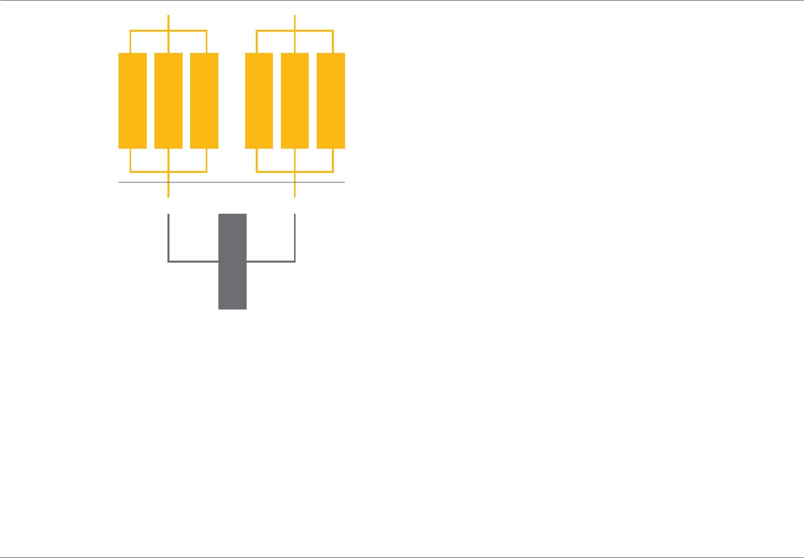
Figure 2 shows the configuration of 2(N+1) when N=2.
20 The UPS data centre handbook www.upspower.co.uk www.upspower.co.uk The UPS data centre handbook 21
Let us now consider how an ‘average’ enterprise data centre
facility load develops over time:
n The critical load often starts off below 20%.
n It may climb to c40% after 2–3 years.
n Reaches a plateaux of <80% after 5 years.
n The critical load never reaches 100%.
If we consider the 2(N+1) UPS system in Figure 2 the
module load in normal operation against these indicative
20%/40%/80% load stages we can show that it is
3.3%/6.7%/13.3% respectively.
In other words, the UPS modules work at very light loads for
the vast majority of their service life. Turning one module ‘off’ in
each system to improve the load factor is only possible when
the load is below 50%, and this improves the early years to 5%
load per module at 20% facility load and 10% load per module at
40% facility load – still very low.
It was very probably this low load problem that pushed the
change to 2N, removing the (double) redundant module on each
side and relying on each system to be 100% redundant for the
other. However, we need to view this against the efficiency of a
typical North American legacy UPS: A typical large UPS in the
USA was thyristor based, 460V input, 208V output with input,
output and bypass transformers, often with a 6-pulse rectifier
without a harmonic filter up to 600kVA. The efficiency at full load
was c91% but the partial load efficiency was poor. On Figure 3 is
shown (in red) a typical efficiency curve from c2005. To consider
the impact of installing this type of UPS in 2(N+1) architecture
we need to consider the efficiency in the sub-10% load range of
around 50%. If we add a dual bus cooling system at similar low
load it is easy to see that an operational PUE (rather than design
PUE) of >3 was very easy to achieve.
Pressures on operational costs (power and maintenance),
and the realisation that a double redundant system gave little
increased resilience for dual corded loads, resulted in Tier IV
being downgraded to 2N from 2(N+1).
Dual bus also can have an unfortunate side-effect outside of
the UPS loading – that of under-utilised plant. This led to many
forms of distributed redundancy architectures with ‘swing’
transformers or generators and often utilising static-transfer
switches. These solutions saved capital expenditure but at
the risk of increasing complexity that sometimes led to lower
reliability and the introduction of increased opportunities for
human error.
One inadvertent consequence of following TUI and TIA942
recommendations for 15 minutes of battery autonomy per
module in Tier IV systems, was that battery autonomy is not
linear with load, and the effect of very light load on the dual
bus system is to produce battery autonomies in the region of
3 hours. With power densities in the critical space gradually
increasing, any extended UPS autonomy is not usable unless
the cooling system is also continuous – since the load will shut-
down on thermal-alarm before the power is shut-off.
Overcoming the problem – the modern solution for
the legacy
There is no doubt that the extended MTBF and lower risk of
human error that dual bus architecture offers with dualcorded
loads, is as attractive now as it always was, if not more so.
However it is now possible to mitigate, if not avoid altogether,
the problems associated with partial load by utilising state-
of-the-art UPS technology and designing the system in a
scalable, modular, topology. Designing a data centre with
dual bus power and N+1 cooling, both with concurrent
maintenance capability, is generally referred to as Tier III+,
despite TUI objections.
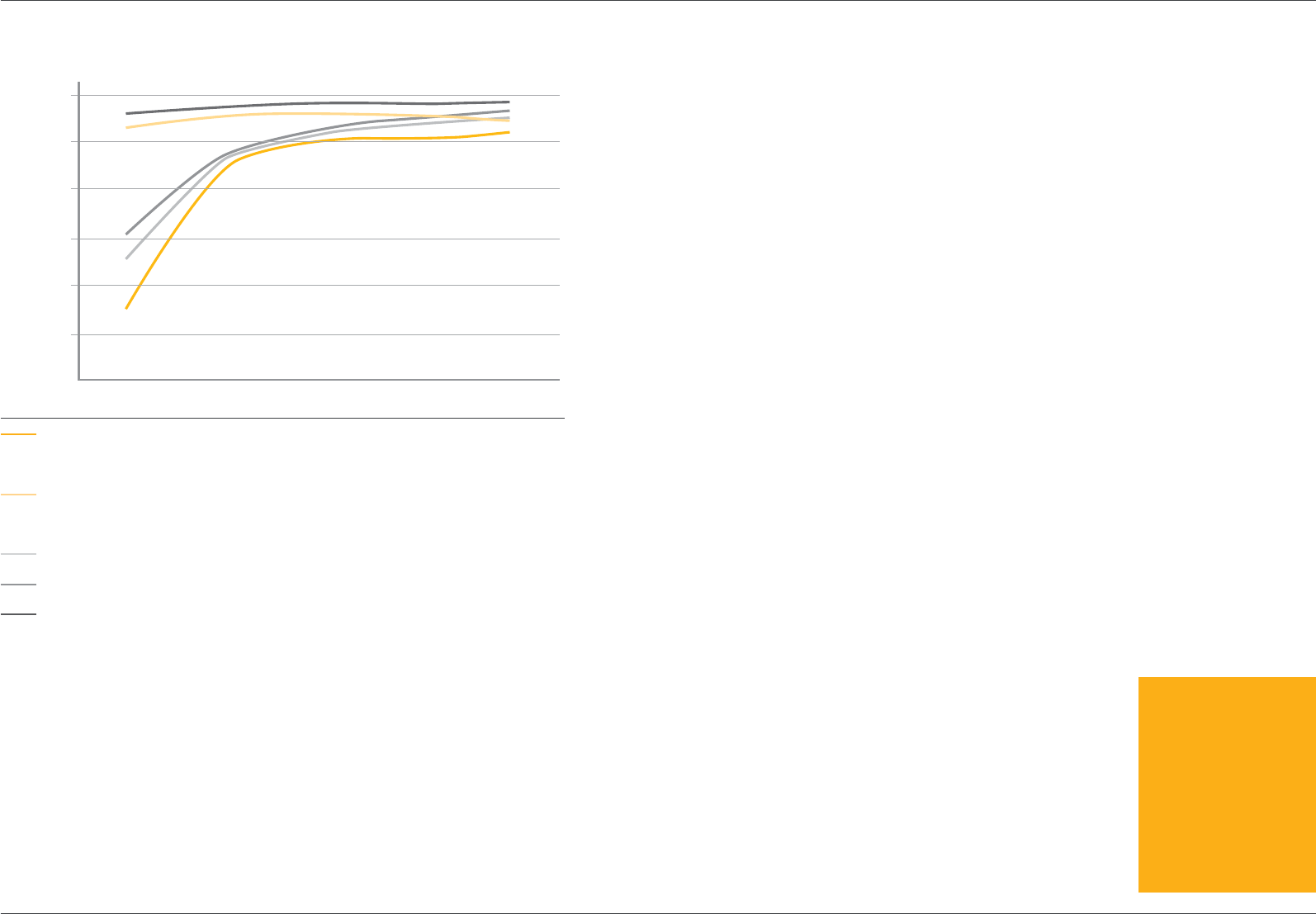
In Figure 3 we can see the dramatic improvement in
efficiency, at all loads, between a legacy North American
machine and an IGBT/IGBT transformer-free design.
A B
Figure 2:
2(N+1) when N=2
Dual bus for dual-cord loads
Load = 1MW
N=2
2x 3x500 kW UPS modules
22 The UPS data centre handbook www.upspower.co.uk www.upspower.co.uk The UPS data centre handbook 23
In the same way that modern European UPS designs have
dramatically improved in recent years, the change in part-load
efficiency of static-UPS has also overtaken that of rotary-UPS
in all its variants, so, for completeness, also included in Fig.3 is
the curve for a typical hybrid-rotary UPS and a typical DRUPS.
The modern solution to this legacy problem is straightforward:
n Use high-efficiency IGBT/IGBT transformer-free UPS that
has high partial load efficiency.
n Apply it in a scalable way that suits the anticipated initial
load and anticipated load growth profile – with the aim of
maintaining as high a system load as is possible by turning
‘off’ any over-redundant capacity.
n In one (or even both) bus turn ‘on’ the UPS’s eco-mode
capability and virtually halve the system losses (ability to start
the UPS inverter in static bypass if mode conditions dictate).
n Try to restrict the installed battery capacity on each module
to under 10 minutes.
For most large systems this strategy could result in an overall
system efficiency of over 95% rather than 50% – a small price
to pay for such high availability?
UPS Efficiency
Percentage Load
15%
40
50
60
70
80
90
100
25% 50% 75% 100%
Figure 3: Comparative UPS Efficiency
460V/208V legacy UPS system
with transformer plus PUD
transformer for 120V load.
400V/400V IGBT/IGBT
transformer-free UPS with 230V
load.
Hybrid-Rotary UPS with battery.
Diesel Rotary UPS with battery.
Eco-Mode static-UPS.
Highly efficient & reliable
UPS systems from
Uninterruptible Power
Supplies Ltd.
Find out which is right
for your operation.
Call 01256 386700
or email
sales@upspower.co.uk
24 The UPS data centre handbook www.upspower.co.uk www.upspower.co.uk The UPS data centre handbook 25

1 The Uptime Institute, Building 100,
2904 Rodeo Park Drive East,
Santa Fe, NM 87505, USA.
www.uptimeinstitute.org
2 Industry Standard Tier
Classifications Define Site
Infrastructure Performance; Turner,
Seader & Brill, © 2001–2005 The
Uptime Institute, Inc
3 TIA, Standards and Technology
Department, 2500 Wilson
Boulevard, Arlington, VA 22201,
USA. www.tiaonline.org
4 BICSI, (Building Industry
Consulting Service International
Inc) 8610 Hidden River Parkway,
Tampa, FL 33637. www.bicsi.org
5 CENELEC, European Committee
for Electrotechnical Standardization
is responsible for standardization
in the electrotechnical engineering
field. CENELEC prepares voluntary
standards, which help facilitate
trade between countries, create
new markets, cut compliance costs
and support the development of
a Single European Market. www.
cenelec.eu
A review of data centre
tier classifications
Information technology clients expect an
availability of 99.999%, ‘Five-Nines’
The substantial investment that a business makes to achieve
Five-Nines in its computer hardware and software platforms is
unlikely to be sufficient unless matched by a site mechanical
and electrical infrastructure that can support their availability
goals. Data centre’s are classified by their availability which
comes down to their capability to achieve concurrent
maintenance and fault tolerance but their overall site ‘Tier’
rating is dependent upon all aspects of the site infrastructure
and will be the lowest of the individual sub system ratings
covering such aspects as power, cooling and connectivity etc.
It is important to be aware that operational issues (how the
site is operated once constructed) also plays a significant role
in what site availability is actually achieved. All too often it is
assumed that installing a UPS is the end of any problems but,
if the overall design, installation and ongoing service support is
handled badly it could just be the beginning of the problems.
For example, it is vital to ensure that the Mean-Time-To-Repair
(MTTR) of the system is kept to a minimum if the highest
overall availability is to be achieved. Nowhere is this more
important than in the design of data centres. Each business
has a unique availability target driving the site infrastructure tier
level requirement.
After careful alignment of IT availability objectives with
site infrastructure performance expectations, an informed
client may select a site infrastructure based on one of the
tier classifications. Data centre owners/operators have the
responsibility to determine what level of functionality and
resilience is appropriate or required for their sites. As such,
it is a business decision to determine the tier classification
necessary to support site availability objectives. Part of this
decision is to balance the IT operational practices with the
facility practices that support the IT infrastructure but once
selected the desired tier should be uniformly implemented
across all systems.
The benchmark tier standards
The Uptime Institute1 has, for nearly 20 years, sponsored
research and practical studies into data centre design,
operation and resultant resilience and developed a tier
classification to describe and differentiate facilities from
an availability standpoint. A white paper2 from the Institute
(authors of which include the originator of dual power supplies
in IT equipment and the tier system itself) is the basis of this
review of the facility and operational concepts. The Uptime
classification system describes four levels of availability for the
overall site, from the basic Tier I to the ultra-available Tier IV.
A later addition to TUI is a data centre ‘standard’ in ANSI/
TIA-942-2005 Telecommunications Infrastructure Standard
for Data Centers, issued by Telecommunications Industry
Association3. This follows the same Tier I-IV format and draws
heavily on The Uptime Institute publications but extends the
detail, especially in connectivity, and is more proscriptive.
It is entirely a USA centric ANSI specification, but can be
used as a very useful guide outside of the reach of ANSI.
One point worth noting is that TIA-942 was specifically
written for telecom related data centre environments of a
power density up to 2.7kW/m2.
Another US-centric design guide was published by
BICSI4 which introduced a ‘fifth’ tier but this was Tier ‘0’ and
described a data centre without UPS or generator support
that most observers would not classify as a data centre in the
first place.
CENELEC5 is preparing a new European Standard, EN
50600, for data centre infrastructure which will also be based
on four levels (classes rather than tiers) of availability.
“It is a business decision
to determine the tier
classification necessary
to support site availability
objectives.”
“Each business has a unique
availability target driving the
site infrastructure tier level
requirement.”
26 The UPS data centre handbook www.upspower.co.uk www.upspower.co.uk The UPS data centre handbook 27

Why only four levels?
It was the founders of The Uptime Institute that innovated
the concept of the ‘dual-cord’ IT load and then went on
to produce a classification system to take advantage of
that feature. Prior to the dual-cord load there was only two
options for feeding the power to a load: With a single-bus
power system that comprised a unitary string of conditioning
components that needed to be shut down for maintenance
and should a single failure occur, disconnect the load. An
improvement on this was to introduce redundancy in the
components (e.g. N+1) that gave protection from a single
failure and a degree of concurrent maintenance. Although not
described as such at the time these two options covered Tier
I and Tier II.
Adding the second power-cord to the load introduced the
concept of the dual bus power system, with an ‘active path’
including the redundant components of Tier II and a ‘passive
path’ enabling a wrap-around power connection, for truly
concurrent maintenance operations. This describes Tier III.
Tier IV, with a physically segregated ‘active-path/active-
path’ topology comprised of two independent Tier II systems,
was a very short step to very high availability, concurrent
maintenance and near total fault tolerance. It is hard, if not
impossible, to describe a ‘fifth’ tier unless the load was triple-
corded, with only one out of three cords needing power for
100% compute operation.
Tier I Tier II Tier III Tier IV
Number of delivery paths Only 1 Only 1 1 Active
1 Passive
2 Active
Redundancy N N+1 N+1 S+S or
2(N+1)
Compartmentalisation No No No Yes
Concurrently Maintainable No No Yes Yes
Fault Tolerant to Worst Event None None None Yes
Getting to Five-Nines?
Concurrent maintenance and fault tolerance is the key to
the tiers and the table (above) shows the progressive level
of redundancy and resilience required and how it might be
achieved. This table refers to each of several key systems that
are identified by TUI as critical to the operation of a specific
data centre. For a facility to achieve a tier classification it must
achieve the benchmark in all the criteria and critical power is
just one of those (sixteen) criteria.
Tier Site A% Nines MDT h/5y
I 99.670% 2 144.54
II 99.750% 2 109.50
III 99.980% 3 8.76
IV 99.990% 4 4.38
Availability – a measure of ‘goodness’?
To achieve a high-percentage availability is simple – achieve
a long MTBF (Mean Time Between Failure) and a very short
MTTR (Mean Time to Repair), the calculation simply being:
MTBF
Availability = MTBF+MTTR) x100%
TUI has assigned a target availability (A%) to each of the
tiers (table above) and sensibly recommend to measure the
downtime (MDT) over at least a five-year period, rather than
over just one year.
It will be immediately apparent to the reader that to
achieve a defined overall site availability then each of the
sixteen sub-systems must achieve much higher performance
(e.g. A% raised to the power of sixteen). For the ultimate
Tier IV site this means that every sub-system (e.g. power
at the load terminals) has to achieve 99.9994% – the magic
Five-Nines.
The importance of a short MTTR
Clearly a wide range of ‘answers’ can be generated by varying
combinations of MTBF and MTTR (see right) but the reality is
that only an emergency service back-up that can minimize
travel time to site, have comprehensive spare-parts availability
and excel in first-time fix rate will achieve the sort of MTTR’s
needed to push the availability to the required level for the
higher tiers. Indeed it is quite easy to demonstrate that Tier III
cannot tolerate travel times of more than 4 hours to site if the
system is to achieve the desired availability performance –
even with MTBF’s in the 200–400,000h range.
This conclusion highlights the need for 24x7 remote
monitoring, diagnostics and tele-assisted service via data-
connectivity and a first-class service support organization.
28 The UPS data centre handbook www.upspower.co.uk www.upspower.co.uk The UPS data centre handbook 29
Higher tier power systems don’t come cheap
Comparing systems is rather complicated when taking into
account the type of load (single-corded or dual-corded) and
the scale of the system with its redundancy plan. In the strict
definitions Tier III & IV are only intended for dual-cord loads
without Static Transfer Switches (STS). However at the most
fundamental level we can take Tier I as the base cost and
MTBF (=1) and make relative comparisons:
Tier Load Concurrent A% MTBF COST
I Single No 99.98333% 1 1
II Single Limited 99.98547% 1 1.6
II Dual Partial 99.99965% 45 1.8
III Dual Yes 99.99983% 45 2.2
IV Dual Yes 99.99999% 2,450 3.0
Partial load problems with legacy UPS systems in
Tier IV architecture
Legacy UPS, particularly large monolithic systems, suffered
from very low efficiency at partial load. When this characteristic
was overlaid with a Tier IV dual bus 2(N+1) architecture
and the usual partial load of data centres the result can
be a load per UPS module of lower than 5%. Under these
circumstances it was only to be expected that very poor
power system efficiency was a result.
Four developments have mitigated the traditional downside
of Tier IV:
n The Uptime Institute ‘reduced’ the requirements of Tier IV
from the double-redundant 2(N+1) to 2N (where each system
is 100% redundant for the other) and raised the UPS module
load by several percentage points.
n Modern IGBT/IGBT transformer-free UPS technology has
raised the efficiency bar considerably – with over 96% in
double-conversion, even at 50% load.
n Modular UPS architecture has introduced the huge
opportunity to keep the load per module high and thereby
minimize the UPS power losses.
n Eco-mode technology options in UPS have enabled
efficiency of >98% even at 10% load – especially useful in one
of the two power-buses even when the end-user may have
reservations about eco-mode operation for all the load.
With modern technology the load can be provided with dual
bus power from high-efficiency double-conversion without any
of the traditional penalties of low efficiency.
The upside of dual bus (Tier IV) power systems
In addition to the clear advantage of several magnitudes of
increased statistical availability, Tier IV power has the potential
to raise the actual system performance if implemented
correctly: With most reports agreeing that 60–70% of all
failures in the data centre attributable to human error any
feature that protects against human intervention has the
capacity to remove instantaneous failures and including
inadvertent EPO activation.
Conclusions
Whatever tier classification is chosen, 24x7 remote
diagnostics, tele-maintenance, spare-parts access and
sub-4 hour emergency repair performance achievement
are essential to meet the Tier III and IV availability targets.
The first-time fix rate will dictate the site availability.
Tier IV, for dual-corded loads is, by more than 1000x, the
most resilient power architecture possible. The traditional
drawbacks have been the high CapEx (typically a 35–40%
premium over Tier III), higher OpEx with partial load
inefficiencies and under-utilized plant that can be regarded as
wasteful of resources, However if the client needed a specific
classification (e.g. Tier IV for a given business case) then there
was little choice but to follow TUI. For the future in Europe
the new standard, EN50600, will offer a locally applicable
Availability Class.
With modern UPS technology, modular architecture
and, optionally, eco-mode operation, all the efficiency
disadvantages of Tier IV are removed.
Availability: MTBF Vs
MTTR
Availability
MTTR (hours) MTBF (hours)
40,000
1
99.9700%
99.9750%
99.9800%
99.9850%
99.9900%
99.9950%
100.0000%
2
3
4
5
6
7
8
120,000
100,000
80,000
60,000
Highly efficient & reliable
UPS systems from
Uninterruptible Power
Supplies Ltd.
Find out which is right
for your operation.
Call 01256 386700
or email
sales@upspower.co.uk
30 The UPS data centre handbook www.upspower.co.uk www.upspower.co.uk The UPS data centre handbook 31

1 As defined by any of The
Uptime Institute, TIA942,
BICSI or the future EN50600
The importance of a
reliable Service Partner in
data centre UPS systems
Executive Summary
Data centres are at the heart of the Digital Economy and the
ICT loads housed within them rely on UPS systems to provide
continuous service for the operator. However to achieve the
levels of availability in a data centre power system requires
not only a reliable and resilient UPS but also a rigorous and
well executed planned maintenance programme, on-site
or fast access to critical spares inventory and a rapid and
high quality intervention service to cover emergencies. This
white paper compares the required restoration time (the
combination of response, travel and repair hours) with the
data centre operators’ expectations from their design tier
classification1, from the most basic to the highest availability
required and the role of modular UPS in the power availability
strategy is reviewed. The conclusions drawn include the
recommendation that there is no substitute for an authorised
Service Partner with experienced and factory trained field
technicians with direct and fast access to engineering support
and spare-parts.
Planned maintenance versus emergency intervention
Data centres are continuously manned with facilities staff who
oversee the mechanical and electrical services so, in theory at
least, there are opportunities for those staff to carry out some,
but probably not all, of the routine planned maintenance
tasks if (and only if) the power system topology incorporates
sufficient ‘concurrent maintenance’ capability. Those tasks
include downloading the event-logs, set-point monitoring,
filter changes, visual inspection of all connections, general
cleaning and battery cleaning/torque setting. If the concurrent
maintenance capability is dependent upon manual switching
of complete systems (including the UPS for example) then the
correct levels of system training and familiarity exercises must
be regularly carried out. Those non-routine PM work items,
probably not suitable for on-site supervisory staff to undertake,
include the following tasks:
n Battery load bank and cell impedance measurements
(annual, rising to bi-annual).
n DC capacitor changes.
n AC capacitor changes (7–9 year intervals) Swap DC with
AC on these two lines to swap. AC 8 years, DC 10 years.
The problem with these non-routine PM tasks and all UPS
failure interventions are that they are very infrequent. In the
cases of emergency interventions (actual failure of one or
more UPS functions) they are so infrequent as to be virtually
impossible to cover properly, especially 24/7 multi-shift, by
using on-site staff.
The level of documentation and constant training
requirements does not make commercial sense when
compared to an external Service Contract which provides
both capable and well-experienced technicians arriving within
a short-time on site. Natural wastage and turnover in onsite
personnel presents a huge training issue, associated with high
costs. The core skills required to rapidly fault-find and repair a
failure in a UPS system that will usually never experience more
than one such requirement in a 10 year operational period
is what a client can expect from external technicians that do
nothing else on a day-today basis within a large installed base.
“There is no substitute
for an authorised Service
Partner with experienced
and factory trained field
technicians with direct and
fast access to engineering
support and spare-parts.”
32 The UPS data centre handbook www.upspower.co.uk www.upspower.co.uk The UPS data centre handbook 33

Factory upgrades
The OEM will be the only centralised repository for field
operation and failure statistics of their particular UPS models
and where these have an effect upon performance and
reliability the end-user will benefit greatly from the continuous
improvement processes that the OEM undertakes. Of course,
equipment upgrades that involve life safety will, no doubt, be
initiated by the OEM (assuming that the full traceability path
of the equipment is intact) but only by contracting with the
OEM or their authorised service agent in some form can the
end-user participate in performance related upgrades. There
are generally no processes or mechanisms by which a third-
party maintenance organisation can keep up-to-date with
such initiatives.
Emergency intervention
When emergencies arise, as they surely will during the
anticipated 12–15 years service life of most UPS systems, the
resolution will require being speedy and permanent. In UPS
terms (because a ‘power failure’ at the load can involve the
electrical cabling and switchgear infrastructure that connects
the UPS rather than the UPS itself) the failure can be described
in only four ways:
In a single-bus UPS system where a loss of redundancy
(e.g. when one module trips off-line) and there is no impact
upon the critical load: In this case the response to the failure
can be handled with a degree of calm investigation of the root
cause. If the fault has been caused by operator error then it
can usually be rectified by on-site operation staff but where the
cause cannot be identified then a qualified service technician
will be required in a matter of within 24 hours unless a service
contract is not in place.
In a single-bus system where the entire UPS system
(redundant or not) trips off-line and successfully transfers
the load to the utility supply: In this case the failure has not
impacted the load immediately but it is at immediate risk from
utility-borne interference. A manual transfer to emergency
generator supply, with controlled load and restart shutdown,
would usually be recommended although this brings additional
risk from operator error and it has to have been previously
established that the generator can support the ICT load
without the UPS in circuit.
In mature urban grids the MTBF (mean time between
failure) of the utility voltage outside of the CBEMA PQ voltage
immunity curve (embodied in IEEE466 & 1100, also known as
the ITIC Curve) is in the order of 250h but a ‘deviation’ from
the CBEMA allowable region could occur almost immediately,
or not occur for several tens of days depending upon
transmission arrangements for the location, neighbourhood
power consumers and climatic season.
Getting the UPS rapidly back on-line is of paramount
importance and the rapid intervention of an expert service
technician will be vital – usually with a response time of less
than 4 hours. To achieve that level of availability a service
contract must be in place.
In a single-bus system where the entire UPS trips off-line
and does not (for whatever reason) transfer the critical load
to the utility supply and the load is disconnected: A loss of
data centre load is a traumatic event in any business and the
operators ability to get the UPS bypass connected, probably
including a manual starting of the emergency generator
system, will not reduce the impact of the failure but only speed
up the process of recovery. All of the above comments apply
and a service engineer is required in almost every case to
diagnose, repair and reinstate the UPS system.
In a dual bus UPS system where one system is negatively
impacted but the load remains protected either by being
dual-corded or being protected by point-of-use static
transfer switches: This is where the extra investment in a
dual bus power system is rewarded and the provisioned fault
tolerance fully utilised. Clearly the failure in one of the two
buses needs to be addressed quickly but the chances of load
impact in the intervening period are negligible, if not almost
zero. This failure mode is probably the only data centre power
event where an immediate service intervention is not required,
albeit still being a desirable target.
It is important to note that the ‘failures’ we are referring
usually exclude human error but often the human error
produces exactly one of the four main scenarios listed above
and the required response is the same. Many reports have
been published that put the incidence of human operator
error causing a load-loss in a data centre as high as 70% –
so we are here talking about the UPS ‘share’ of the remaining
30%. Perhaps as low as 5% of the total failures for the power
system and <2% for the UPS system in isolation.
When considering the support requirements (as laid out in
the preceding section on Planned Maintenance) it should be
clear that an external service contract that is provisioned with
trained and experienced staff is essential for high-availability
data centre operations. Taking a statistical approach to the
problem we can easily demonstrate that, for a single-bus UPS
system, the typical system availability target of 99.997%
2 Computer Business
Equipment Manufacturers
Association
34 The UPS data centre handbook www.upspower.co.uk www.upspower.co.uk The UPS data centre handbook 35

(e.g. a Tier III facility with 6 (Power, Cooling, Connectivity, EPO,
Fire & Security) dependent sub-systems) would permit a single
downtime event of just 8.76 hours in a five-year operational
window. This would include a 4h ‘time-to-arrival-on-site’ and
4.76h for the fault to be rectified.
Modular UPS topology
In small and medium sized single-bus data centre power
systems (for example up to c1MW, N+1) the application of
modular UPS can reduce the downtime of any individual
module drastically, even where the services of an external
on-call service technician are employed. If the on-site
staff have the spare (pre-commissioned) UPS module
and have had the training for a module-swap-out then
the downtime can be limited to less than one hour under
most circumstances.
The failed module then has to be repaired in the same
manner, but in a more relaxed and potentially error-reduced
environment. If the end-user carries redundant spare modules
then the failed unit can be returned to the authorised OEM
repair organisation for inspection, report, repair, load testing
and return – rather than repaired on site. Such a repair
service should be part of a formal support package to include
engineering support etc.
Remote monitoring connection
For many years the opportunity for remote monitoring of UPS
systems has been available but the take-up of such services
has been somewhat limited. There is little doubt that a monthly
check on set-points and generation of a health-check report
aids both the user and the service organisation, regardless of
the service arrangements.
Spare parts availability
Access to spare-parts is essential for high availability but those
spare-parts have to be of the correct generation, complete
with any upgrades, 100% compatible with the installed
machine and fully pre-tested. Only the OEM can guarantee
the compatibility and provide local inventory that reflects
the installed base. This inventory must support the installed
machine for at least 15 years and be accessible within 4 hours.
A rigorously maintained ‘crash-kit’ system available to the
technician engineer on a 24/7 basis for each UPS product, is
an essential part of a comprehensive service support contract.
Conclusions
The availability of power for continuous digital services from
data centres is an essential part of the modern economy
and at the heart of the data centre power system is the UPS.
To provide the highest possible availability incorporating
routine maintenance, upgrades and emergency intervention
it is recommended that the OEM is contracted as a
comprehensive service partner.
“The availability of power for
continuous digital services
from data centres is an
essential part of the modern
economy and at the heart
of the data centre power
system is the UPS.”
Highly efficient & reliable
UPS systems from
Uninterruptible Power
Supplies Ltd.
Find out which is right
for your operation.
Call 01256 386700
or email
sales@upspower.co.uk
36 The UPS data centre handbook www.upspower.co.uk www.upspower.co.uk The UPS data centre handbook 37

The application of
‘economy-mode’ in
ICT UPS systems
Executive Summary
In the pursuit of higher energy efficiency, particularly in the
rapid growth sector of data centres and ICT microprocessor
loads, the utilisation of high-efficiency, or ‘eco-mode’, UPS
is a growing topic for debate. The fundamental question
surrounds the risks, perceived or real, of continuous voltage
supply compared to the rewards of lower electricity bills.
This white paper explores the advantages to be gained from
enabling an eco-mode feature together with reviewing the
application risks.
Historical context
In historical terms, UPSL was one of the very first companies
to introduce an ‘eco-mode’ feature in an UPS system back
in the early 90s as well as innovating the first three-phase
transformer-less UPS on the market. In those days the
market’s appetite for such a radical feature was small – with
a background of lower power costs, higher UPS costs than
today and lower ride-through capabilities of ICT loads. After
the UPSL innovation, many OEMs have introduced eco-mode
for static UPS in one form or another.
What is eco-mode?
There is no official technical definition of what ‘high efficiency’
or ‘economy’ mode is but as most UPS are used to protect
microprocessor based ICT equipment, it is reasonable to
assume that a UPS with eco-mode enabled will provide
the critical load with sufficient voltage fidelity to avoid load
disruption. This means providing continuous operation within
the voltage limits set down by the ITIC/CBEMA Power Quality
curve such that the supply voltage is never zero for longer
than 20ms. Many examples of critical load can withstand
(e.g. ride-through without disruption to service) much longer
breaks in voltage, especially when at partial load and dual-
corded but in certain circumstances, especially when the ICT
equipment is single-corded and fully configured such that
the on-board power-supply is close to full load, a maximum
of 10ms is considered safer. By coincidence the pre-1997
CBEMA Curve specified a maximum of 10ms.
All static UPS that have a static-switch automatic bypass
can be equipped with an eco-mode functionality, since the
load is run on the bypass instead of the inverter – exactly the
opposite of normal operation where the bypass is waiting
to accept the load if the UPS fails or the ‘bypass’ button is
activated. The standard static-switch fitted in a UPS can
sense and operate in c4ms.
In this way, eco-mode operation can be described as
a power system that operates in a high-efficiency state
(c98–99%) when the mains power is suitable for the critical
load, but is ready to supply the load from the inverter within
c4ms of any mains power deviation. In operation, eco-mode
is best described as simply ‘off-line’, with the inverter running
at no-load and the bypass static-switch ready and controlled
to transfer the critical load to the inverter if the mains supply
deviates from the ITIC/CBEMA limits. Thus, with eco-mode
enabled, the load is normally fed by the mains and only reverts
to the UPS when the mains power quality deviates, thus
saving energy on UPS losses. Eco-mode generally offers an
operating efficiency of 98–99%.
It is worth noting that some vendors prefer not to admit that
eco-mode operation is off-line operation – rather suggesting
that it is some form of line-interactive mode and energy is
saved in partially shutting down unused elements like the
cooling fans and rectifier.
“The fundamental
question surrounds the
risks, perceived or real, of
continuous voltage supply
compared to the rewards of
lower electricity bills.”
38 The UPS data centre handbook www.upspower.co.uk www.upspower.co.uk The UPS data centre handbook 39

Advantages of eco-mode
When emergencies arise, as they surely will during the anticipated
12–15 years service life of most UPS systems, the resolution will
require being speedy and permanent. In UPS terms (because a
‘power failure’ at the load can involve the electrical cabling and
switchgear infrastructure that connects the UPS rather than the
UPS itself) the failure can be described in only four ways:
1. Higher efficiency, lower losses, leading to a lower TCO
and improved data centre PUE.
n With the advent of ultra-high efficiency double-conversion
UPS (e.g. 96.5% at 50% load) the delta between normal
and eco-mode operation has narrowed to c2.5% at typical
loads. However with power costs at GB£0.09/kWh (and set
to rise 15%/year for at least the next 5 years) even that small
difference can produce a saving of £20,000 per MW of IT load
per year.
n The effect on a facilities PUE can be 0.025 which could be a
significant improvement if the data centre PUE is below 1.20.
n If increased risk to the load is feared (see next section) then
energy saving opportunities can still exist in dual bus power
systems – where one bus can be run in double-conversion
(e.g. at 95–96% efficiency) and the other bus run in eco-mode
(e.g. at c98% efficiency).
2. Lower cooling requirements, adding to the energy
savings, equivalent to around 60,000kWh per MW of UPS
load per year.
3. Avoidance of frequency sensitive line-interactive
operation to achieve high-efficiency.
4. Full series-on-line double-conversion protection is
available when needed, including for when on diesel
generator operation.
Issues for consideration
As with all engineering solutions there are issues to be
considered and the enablement of eco-mode operation raises
the following:
Mains power quality
When the control system detects a mains deviation the eco-
mode operation is disabled and the UPS returns to on-line
duty. This remains the case until the mains power has been
stable for an adjustable period, usually 30–60 minutes. This
prevents the UPS from hunting between modes in times of
mains instability, such as bad weather. In grids like the UK,
where deviations from the ITIC/CBEMA Curve occur with an
MTBF of c250h intervals and last (MTTR) for c3 seconds the
eco-mode function will be enabled for 99.6% of the year. In
areas of poor power quality eco-mode is not suitable.
Transient Voltage Surge Suppression
Although it is always recommended to install a graded SPD/
TVSS surge-suppression system from the incoming mains
right down to the critical PDU, extra care should be taken
when eco-mode enablement is anticipated. In this way the
ICT will be protected from transient over-voltages (spikes)
entering the facility from the public network.
Leading power factor ICT loads
The modern trend of ICT loads is to draw current at a leading
Power Factor. It is to be ensured in the control system that
eco-mode is disabled whenever emergency generators are
feeding the system, due to their inability to export kVAR and
feed leading power factor loads with a stable voltage.
Non-linear ICT loads and current harmonics
The modern trend of ICT loads that are not fully loaded or that
are dual-corded is for the load current to be relatively high in
harmonic current. Total Harmonic Current Distortion (THCD)
as high as 35% is possible. In normal mode the UPS will shield
the incoming mains supply system from these load harmonics,
but with eco-mode enabled, these harmonics will be present
upstream of the UPS and will have to be dealt with by the
mains transformer and wiring system. An up-rated Neutral
conductor may be required.
Conclusions
High-efficiency, economy or eco-mode operation of modern
on-line UPS can provide considerable energy savings, whilst
providing double-conversion protection when needed and
avoiding having line-interactive partial protection just to save
energy. It can be used to great advantage in dual bus power
systems.
The perception of ‘off-line’ operation, and any risk
associated with it, must be fully weighed against the energy
savings. As energy costs rise and pressure increases on
carbon emissions, the advantages of eco-mode may come
to overwhelm the perceived disadvantages.
If eco-mode enablement is planned then the whole
system design must take into account the possible impacts –
albeit no more so than a normal-mode UPS in bypass for
maintenance purposes.
“If eco-mode enablement
is planned then the whole
system design must take
into account the possible
impacts.”
Highly efficient & reliable
UPS systems from
Uninterruptible Power
Supplies Ltd.
Find out which is right
for your operation.
Call 01256 386700
or email
sales@upspower.co.uk
40 The UPS data centre handbook www.upspower.co.uk www.upspower.co.uk The UPS data centre handbook 41

Uninterruptible Power Supplies Ltd
Woodgate
Bartley Wood Business Park
Hook
Hampshire
RG27 9XA
01256 386700
sales@upspower.co.uk
www.upspower.co.uk
UPS716-01-00 Data Centre Handbook 08.02.2013
PowerWAVE 6000 –
Transformerless UPS technology for
best-in-class performance up to 5 MVA
PowerWAVE 8000DPA –
Modular, three-phase UPS providing power
protection up to 200 kVA
PowerWAVE 9000DPA –
Three-phase, modular UPS with a high operating
efficiency of up to 96%
