00 Table Of Contents Delta_IA MDS_VFD CT2000_UM_EN_20120524 Delta IA MDS VFD CT2000 UM EN 20120524
User Manual: Delta_IA-MDS_VFD-CT2000_UM_EN_20120524
Open the PDF directly: View PDF ![]() .
.
Page Count: 486 [warning: Documents this large are best viewed by clicking the View PDF Link!]

CT2000 Series User Manual
IABU Headquarters
Delta Electronics, Inc.
Taoyuan Technology Center
No.18, Xinglong Rd., Taoyuan City,
Taoyuan County 33068, Taiwan
TEL: 886-3-362-6301 / FAX: 886-3-371-6301
Asia
Delta Electronics (Jiangsu) Ltd.
Wujiang Plant 3
1688 Jiangxing East Road,
Wujiang Economic Development Zone
Wujiang City, Jiang Su Province,
People's Republic of China (Post code: 215200)
TEL: 86-512-6340-3008 / FAX: 86-769-6340-7290
Delta Greentech (China) Co., Ltd.
238 Min-Xia Road, Pudong District,
ShangHai, P.R.C.
Post code : 201209
TEL: 86-21-58635678 / FAX: 86-21-58630003
Delta Electronics (Japan), Inc.
Tokyo Office
2-1-14 Minato-ku Shibadaimon,
Tokyo 105-0012, Japan
TEL: 81-3-5733-1111 / FAX: 81-3-5733-1211
Delta Electronics (Korea), Inc.
1511, Byucksan Digital Valley 6-cha, Gasan-dong,
Geumcheon-gu, Seoul, Korea, 153-704
TEL: 82-2-515-5303 / FAX: 82-2-515-5302
Delta Electronics Int’l (S) Pte Ltd
4 Kaki Bukit Ave 1, #05-05, Singapore 417939
TEL: 65-6747-5155 / FAX: 65-6744-9228
Delta Electronics (India) Pvt. Ltd.
Plot No 43 Sector 35, HSIIDC
Gurgaon, PIN 122001, Haryana, India
TEL : 91-124-4874900 / FAX : 91-124-4874945
Americas
Delta Products Corporation (USA)
Raleigh Office
P.O. Box 12173,5101 Davis Drive,
Research Triangle Park, NC 27709, U.S.A.
TEL: 1-919-767-3800 / FAX: 1-919-767-8080
Delta Greentech (Brasil) S.A
Sao Paulo Office
Rua Itapeva, 26 - 3° andar Edificio Itapeva One-Bela Vista
01332-000-São P a u l o -SP-Brazil
TEL: +55 11 3568-3855 / FAX: +55 11 3568-3865
Europe
Deltronics (The Netherlands) B.V.
Eindhoven Office
De Witbogt 15, 5652 AG Eindhoven, The Netherlands
TEL: 31-40-2592850 / FAX: 31-40-2592851
*We reserve the right to change the information in this catalogue without prior notice.
Delta
Intelligent Drive for Textile
CT2000 Series User Manual
C T E 0
5012611200
2012-05

PLEASE READ PRIOR TO INSTALLATION FOR SAFETY.
DANGER
; AC input power must be disconnected before any wiring to the AC motor drive
is made.
; Even if the power has been turned off, a charge may still remain in the DC-link
capacitors with hazardous voltages before the POWER LED is OFF. Please do
not touch the internal circuit and components.
; There are highly sensitive MOS components on the printed circuit boards.
These components are especially sensitive to static electricity. Please do not
touch these components or the circuit boards before taking anti-static
measures. Never reassemble internal components or wiring.
; Ground the AC motor drive using the ground terminal. The grounding method
must comply with the laws of the country where the AC motor drive is to be
installed.
; DO NOT install the AC motor drive in a place subjected to high temperature,
direct sunlight and inflammables.
CAUTION
; Never connect the AC motor drive output terminals U/T1, V/T2 and W/T3
directly to the AC mains circuit power supply.
; Only qualified persons are allowed to install, wire and maintain the AC motor
drives.
; Even if the 3-phase AC motor is stop, a charge may still remain in the main
circuit terminals of the AC motor drive with hazardous voltages.
; If the AC motor drive is stored in no charge condition for more than 3
months, the ambient temperature should not be higher than 30 °C.
Storage longer than one year is not recommended, it could result in the
degradation of the electrolytic capacitors.
NOTE
The content of this manual may be revised without prior notice. Please consult our distributors or download the most
updated version at http://www.delta.com.tw/industrialautomation

Table of Contents
CHAPTER 1 INTRODUCTION .................................................................................................... 1-1
CHAPTER 2 INSTALLATION ....................................................................................................2-1
CHAPTER 3 UNPACKING .......................................................................................................... 3-1
CHAPTER 4 WIRING .................................................................................................................. 4-1
CHAPTER 5 MAIN CIRCUIT TERMINALS ................................................................................ 5-1
CHPATER 6 CONTROL TERMINALS......................................................................................... 6-1
CHAPTER 7 OPTIONAL ACCESSORIES................................................................................ 7-1
CHAPTER 8 OPTION CARDS .................................................................................................... 8-1
CHAPTER 9 SPECIFICATION .................................................................................................... 9-1
CHAPTER 10 DIGITAL KEYPAD .............................................................................................. 10-1
CHAPTER 11 SUMMARPY OF PARAMETERS........................................................................ 11-1
CHPAPTER 12 DESCRIPTION OF PARAMETER SETTINGS.................................................. 12-1
CHAPTER 13 WARNING CODES............................................................................................. 13-1
CHAPTER 14 FAULT CODES AND DESCRIPTIONS............................................................... 14-1
CHAPTER 15 CANOPEN OVERVIEW...................................................................................... 15-1
CHAPTER 16 PLC FUNCTION ................................................................................................. 16-1
CHAPTER 17 HOW TO SELECT THE RIGHT AC MOTOR DIRVE ..........................................17-1
CHAPTER 18 SUGGESTIONS AND ERROR CORRECTIONS FOR STANDARD AC MOTOR
DRIVES ..................................................................................................................................... 18-1
Application Control BD V1.01;
Keypad V1.02;
Chapter 1 Introduction|CT2000 Series
1-1
Chapter 1 Introduction
Receiving and Inspection
After receiving the AC motor drive, please check for the following:
1. Please inspect the unit after unpacking to assure it was not damaged during shipment. Make sure
that the part number printed on the package corresponds with the part number indicated on the
nameplate.
2. Make sure that the voltage for the wiring lie within the range as indicated on the nameplate. Please
install the AC motor drive according to this manual.
3. Before applying the power, please make sure that all the devices, including power, motor, control
board and digital keypad, are connected correctly.
4. When wiring the AC motor drive, please make sure that the wiring of input terminals “R/L1, S/L2,
T/L3” and output terminals”U/T1, V/T2, W/T3” are correct to prevent drive damage.
5. When power is applied, select the language and set parameter groups via the digital keypad
(KPC-CC01). When executes trial run, please begin with a low speed and then gradually increases
the speed untill the desired speed is reached.
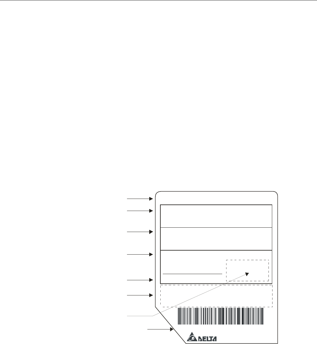
Nameplate Information
MODEL VFD110CT43F21A3:
INPUT :
Light Duty: 3PH 380-480V 50/60Hz 25A
Heavy Duty: 3PH 380-480V 50/60Hz 19A
OUTPUT :
Duty: 3PH 380-480V 22.5A 18KVA 15HP
Heavy Duty: 3PH 380-480V 17A 14KVA 15HP
Light
FREQUENCY RANGE :
Duty: 0-600Hz
Heavy Duty: 0-300Hz
Light
Version:VX.XX
110T3EFJT1360001
DALTA ELECTRONICS. INC.
MADE IN xxxxxxxx
AC Drive Model
Input Voltage Current
/
Output Voltage Current
/
Frequency Range
Firmware Version
Certifications
Enclosure type (IPXX)
Serial Number
Chapter 1 Introduction|CT2000 Series
1-2
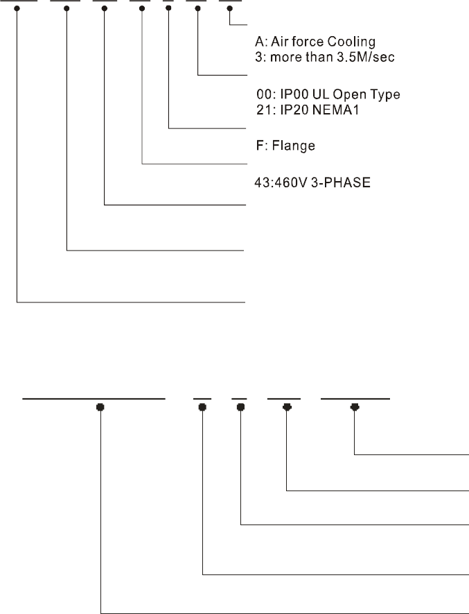
Model Name
VFD 110 CT 43 F 21 A
3
110:15HP(11kW)~ 900:125HP(90kW)
CT2000 Series
(Air velocity @fc=2kHz)
Cooling method
Protection Mode
Installation Method
Input Voltage
Applicable motor capcity
Series name (Variable Frequency Drive)
(For more information please read the user manual)
,
Intelligent Field-oriented Vector Control Drive for Textile Industry
Serial Number
110T3EFJ T 1 36 000
1
460V 3-PHASE 15HP(11kW)
Production number
Production week
Production year
Production factory
Model numbe
r
T: Tauyuan W: Wujian
S: Shanghai
Chapter 1 Introduction|CT2000 Series
1-3
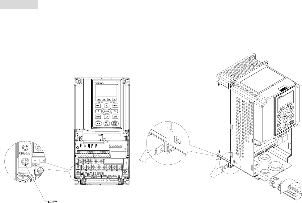
RFI Jumper
RFI Jumper: The AC motor drive may emit the electrical noise. The RFI jumper is used to suppress the
interference (Radio Frequency Interference) on the power line.
Frame B~C Screw Torque: 8~10kg-cm(6.9-8.7 lb -in.)
Loosen the screws and remove the MOV-PLATE. Fasten the screws back to the original position after
MOV-PLATE is removed.
Chapter 1 Introduction|CT2000 Series
1-4
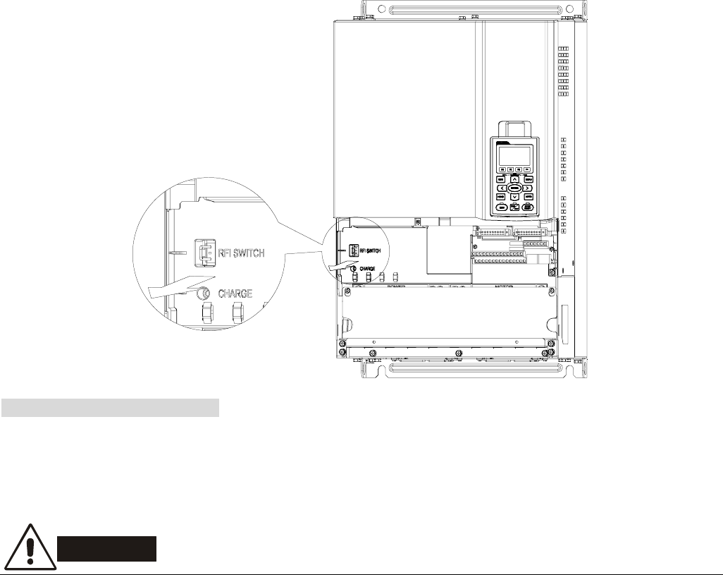
Frame D~H
Remove the MOV-PLATE by hands, no screws need to be loosen.
Main power isolated from earth:
If the AC motor drive is supplied from an isolated power (IT power), the RFI jumper must be cut off. Then
the RFI capacities (filter capacitors) will be disconnected from ground to prevent circuit damage
(according to IEC 61800-3) and reduce earth leakage current.
CAUTION!
1. When power is applied to the AC motor drive, do not cut off the RFI jumper.
2. Make sure main power is switched off before cutting the RFI jumper.
3. The gap discharge may occur when the transient voltage is higher than 1,000V. Besides,
electro-magnetic compatibility of the AC motor drives will be lower after cutting the RFI jumper.
4. Do NOT cut the RFI jumper when main power is connected to earth.
5. The RFI jumper cannot be cut when Hi-pot tests are performed. The mains power and motor must be
separated if high voltage test is performed and the leakage currents are too high.
6. To prevent drive damage, the RFI jumper connected to ground shall be cut off if the AC motor drive is
installed on an ungrounded power system or a high resistance-grounded (over 30 ohms) power
system or a corner grounded TN system.
Chapter 1 Introduction|CT2000 Series
1-5
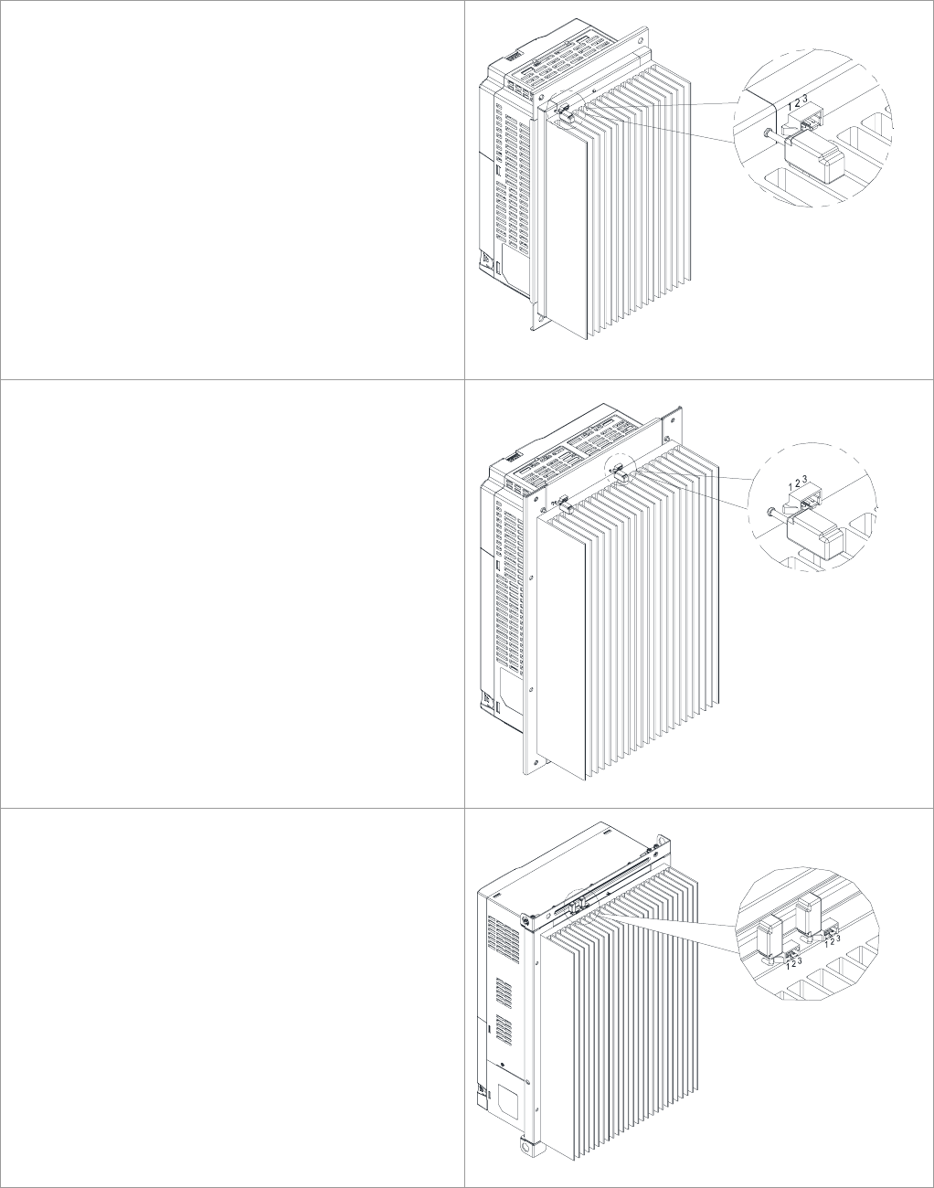
Fan Extension Slot
Bcakup one or two empty DC power plugs for users to intall cooling fans when necessary.
Frame B
Electrical Specification
24Vdc, 0.51A(Max. Current)
Cooling Fan's Adaptor: JWT A2007 Series
PIN Definition
PIN 1: -
PIN 2: Reserved
PIN 3: +
Frame C
Electrical Specification
24Vdc, 0.75A(Single set’s Max. Current )
Cooling Fan's Adaptor: JWT A2007 Series
PIN Definition
PIN 1: -
PIN 2: Reserved
PIN 3: +
Frame D
Electrical Specification
24Vdc,1A(Single set’s Max. Current)
Cooling Fan's Adaptor: JWT A2007 Series
A
2007T0P-00(gilding),applicable: 26~28AWG。
PIN Definition
PIN 1: -
PIN 2: Reserved
PIN 3: +
Chapter 1 Introduction|CT2000 Series
1-6
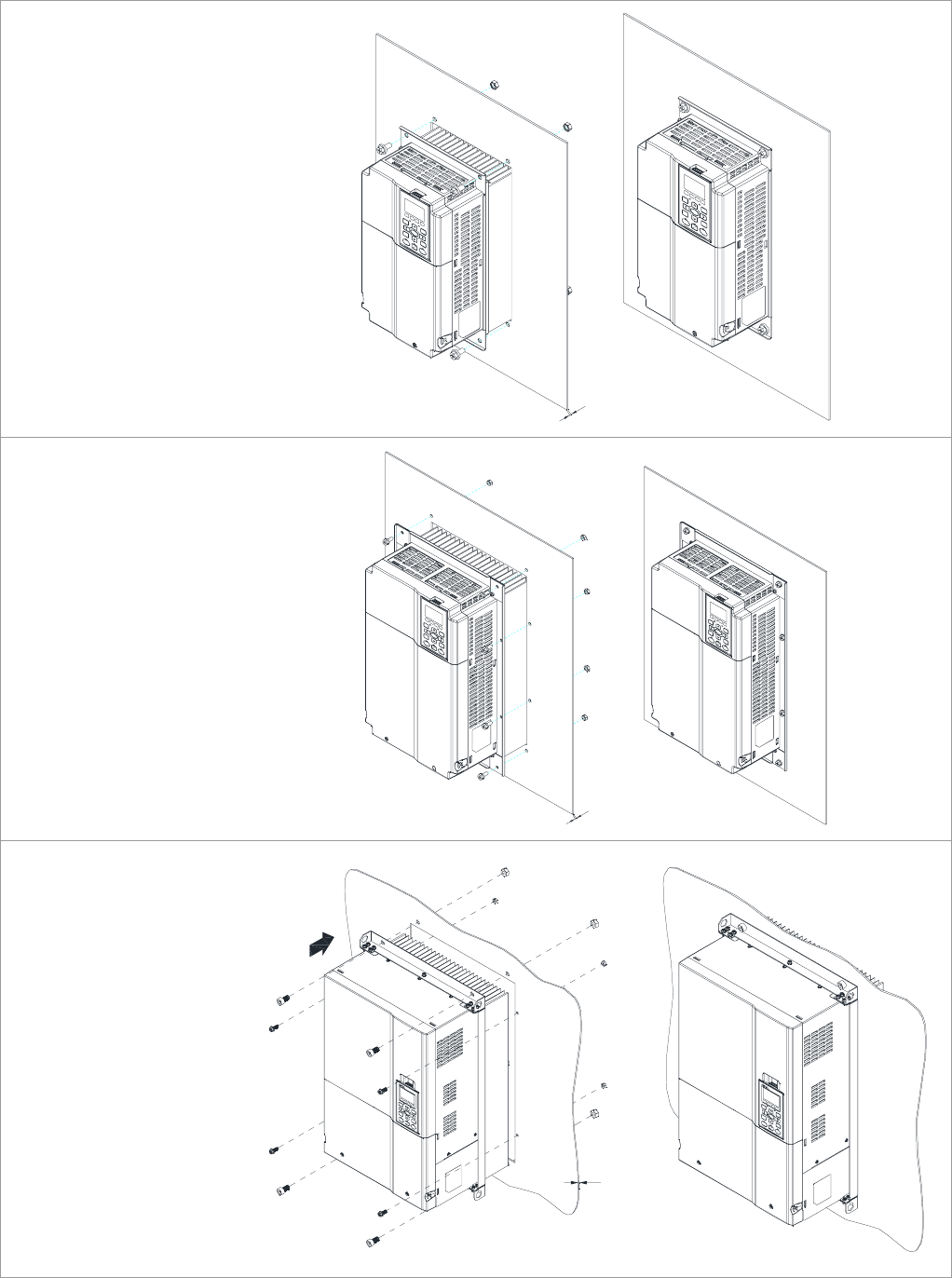
Flange Mounting Kit
Frame B
Screw Torque:
40kg-cm(34.7 lb-in.)
t
Frame C
Screw Torque:
40kg-cm(34.7 lb-in.)
t
Frame D
M6 Screw Torque:
40kg-cm(34.7 lb-in.)
M10 Screw Torque:
200 kg-cm(173.4 lb-in.)
t
Chapter 1 Introduction|CT2000 Series
1-7
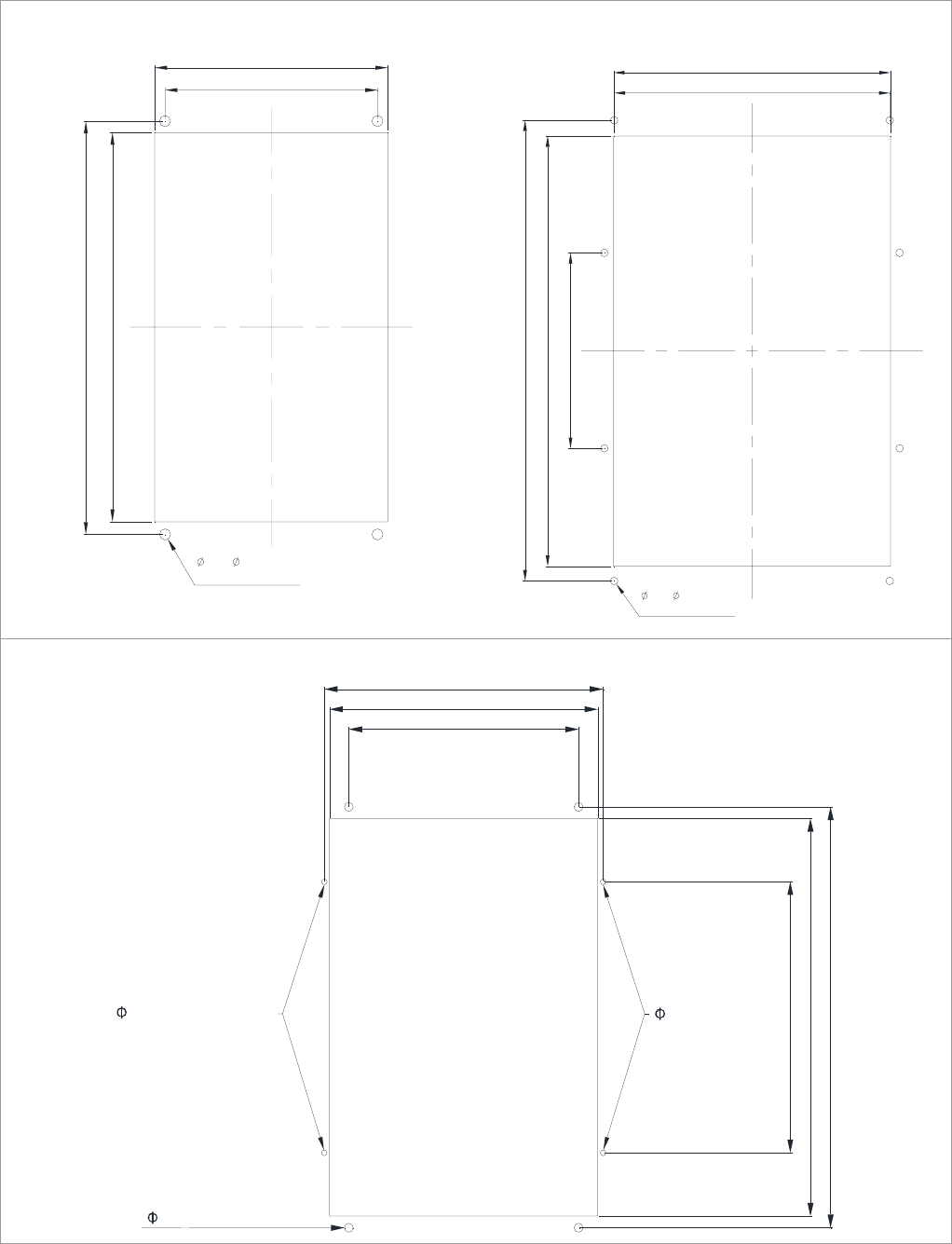
Cutout Dimensions
Frame B
173.0 [6.81]
190.0 [7.48]
317.0 [12.48]
336.8 [13.26]
9.0 [ 0.35] (4X)
or M8* P1.25
Frame C
254.0 [10.00]
255.0 [10.04]
180.0 [7.09]
396.0 [15.59]
424.0 [16.69]
7.0 [ 0.28] (8X)
or M6* P1.0
Frame D
285 [11.22]
346
[13
.
62]
333 [13.11]
525 [20.67]
338 [13.31]
496 [19.53]
11 [0.43] or M10 (4X)
7 [0.28 ]
7 [0.28 ] or M6 (2X)
or M6 (2X)
Chapter 1 Introduction|CT2000 Series
1-8
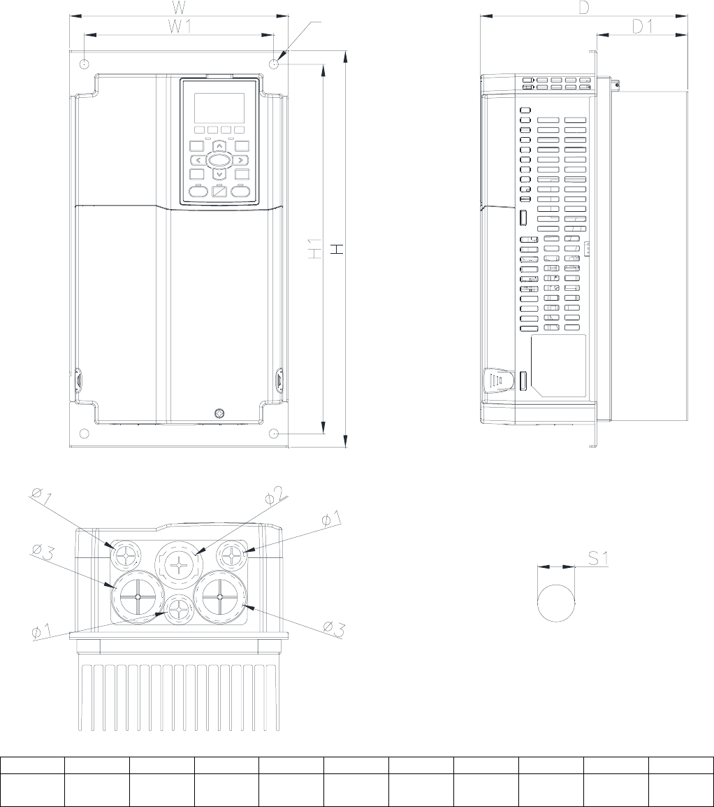
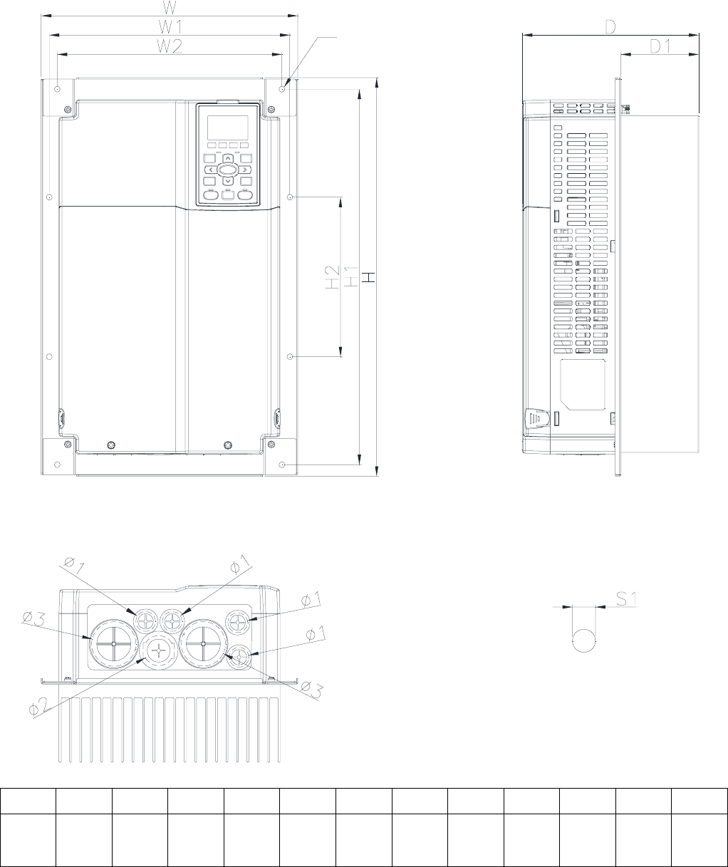
Dimensions
Frame B
VFD110CT43F21A3; VFD150CT43F21A3; VFD185CT43F21A3;
Detail A (Mounting Hole)
See Detail A
Unit: mm [inch]
Frame W H D W1 H1 D1 S1 Φ1 Φ2 Φ3
B1 200.0
[7.87]
361.8
[14.24]
189.4
[7.46]
173.0
[6.81]
336.8
[13.26]
83.2
[3.28]
8.5
[0.33]
22.2
[0.87]
34.0
[1.34]
43.8
[1.72]
Chapter 1 Introduction|CT2000 Series
1-9
Frame C
VFD220CT43F21A3; VFD300CT43F21A3; VFD370CT43F21A7;
Detail A (Mounting Hole)
See Detail A
Unit: mm [inch]
Frame W H D W1 W2 H1 H2 D1 S1 Φ1 Φ2 Φ3
C1 290.0
[11.42]
450.0
[17.72]
199.5
[7.86]
272.0
[10.71]
254.0
[10.00]
424.0
[16.69]
180.0
[7.09]
88.2
[3.47]
6.5
[0.26]
22.2
[0.87]
34.0
[1.34]
50.0
[1.97]
Chapter 1 Introduction|CT2000 Series
1-10
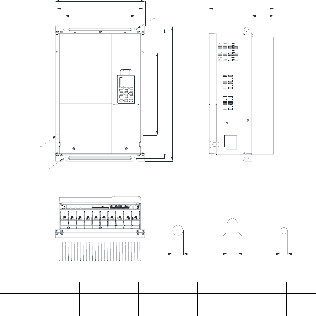
Frame D
VFD450CT43F00A3; VFD550CT43F00A4; VFD750CT43F00A6; VFD900CT43F00A8;
H
H1
H2
W
W2
W1
SEE DETAIL B
SEE DETAIL A
SEE DETAIL C
S1
S1
DETAIL A
(MOUNTING HOLE)
DETAIL B
(MOUNTING HOLE)
S2
DETAIL C
(MOUNTING HOLE)
D1
D
Unit: mm[inch]
Frame W H D W1 W2 H1 H2 D1 S1 S2
D 365.2
[13.38]
550.0
[21.65]
262.8
[10.35]
346.0
[13.62]
285.0
[11.22]
525.0
[20.67]
338.0
[13.31]
90.0
[3.54]
11.0
[0.43]
7.0
[0.28]
Chapter 1 Introduction|CT2000 Series
1-11
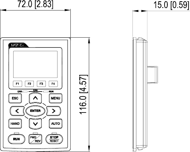
Digital Keypad
KPC-CC01
Unit: mm[inch]
Chapter 2 Installation|CT2000 Series
2-1
Chapter 2 Installation
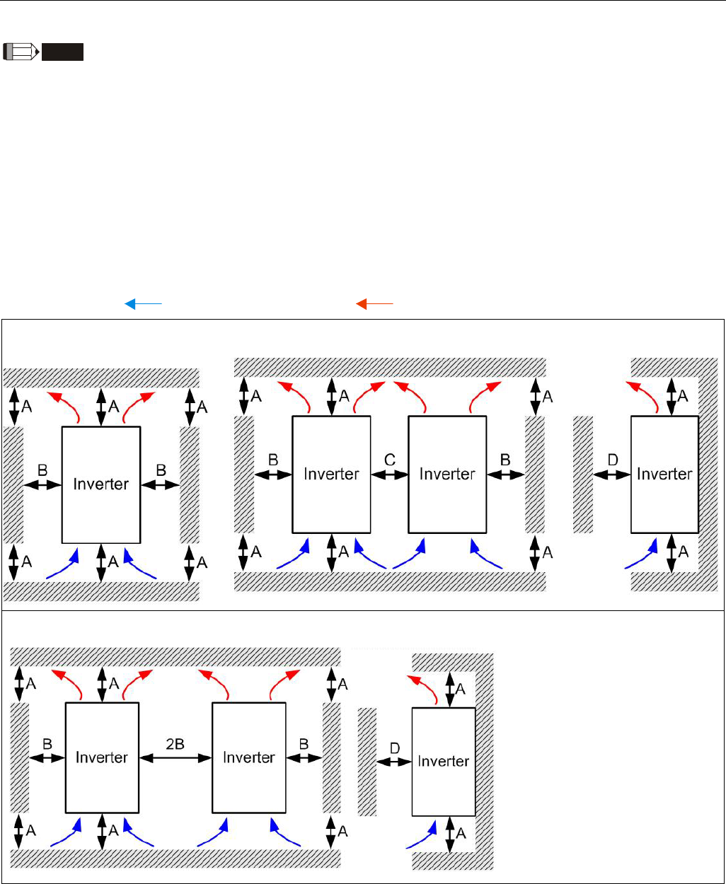
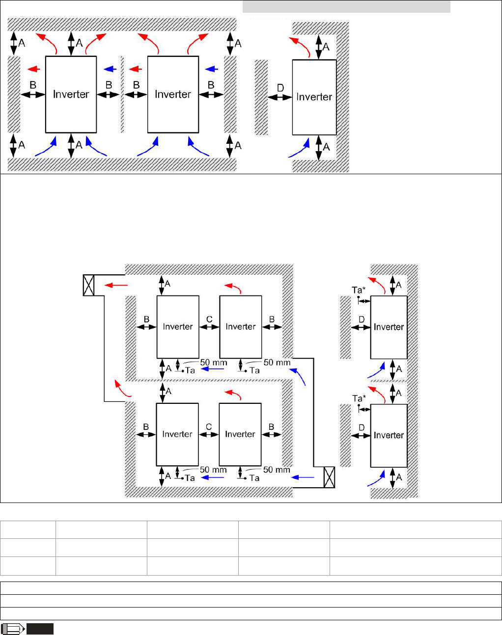
Minimum Mounting Clearance and Installation
NOTE
; Prevent fiber particles, scraps of paper, shredded wood saw dust, metal particles, etc. from
adhereing to the heat sink
; Install the AC motor drive in a metal cabinet. When installing one drive below another one,
use a metal separation between the AC motor drives to prevent mutual heating and to
prevent the risk of fire accident.
; Install the AC motor drive in Pollution Degree 2 environments only: normallyl only
nonconductive pollution occurs and temporary conductivity caused by condensation is
expected.
The appearances shown in the following figures are for reference only.
Airflow direction: (Blue arrow) inflow (Red arrow) outflow
Single drive installation
(Frame B-D)
Side-by-side installation (Frame B-D)
Multiple drives, side-by-side installation (Frame B,C,)
Chapter 2 Installation|CT2000 Series
2-2
Multiple drives, side-by-side installation (Frame D) Install metal separation between the drives.
Multiple drives side-by-side installation and in rows (Frame B,C )
When installing one AC motor drive below another one (top-bottom installation), use a metal separation
between the drives to prevent mutual heating. The temperature measured at the fan’s inflow side must be
lower than the temperature measured at the operation side. If the fan’s inflow temperature is higher, use
a thicker or larger size of metal seperature. Operation temperature is the temperature measured at 50mm
away from the fan’s inflow side. (As shown in the figure below)
Minimum mounting clearance
Frame A (mm) B (mm) C (mm) D (mm)
B~C 60 30 10 0
D 100 50 - 0
Frame B VFD110CT43F21A3; VFD150CT43F21A3; VFD185CT43F21A3;
Frame C VFD220CT43F21A3; VFD300CT43F21A3; VFD370CT43F21A7;
Frame D VFD450CT43F00A3; VFD550CT43F00A4; VFD750CT43F00A6; VFD900CT43F00A8;
NOTE
1. The minimum mounting clearances stated in the table above applies to AC motor drives frame A to D. A drive
fails to follow the minimum mounting clearances may cause the fan to malfunction and heat dissipation problem.
Chapter 2 Installation|CT2000 Series
2-3
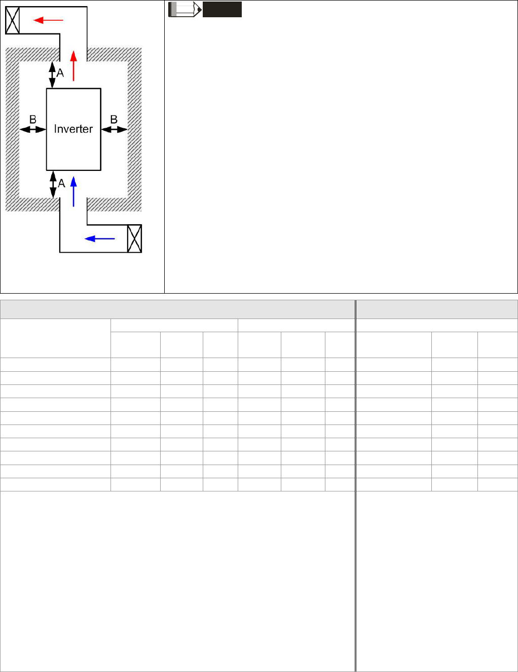
NOTE
※ The mounting clearances stated in the figure is for installing the drive in an
open area. To install the drive in a confined space (such as cabinet or
electric box), please follow the following three rules: (1) Keep the minimum
mounting clearances. (2) Install a ventilation equipment or an air
conditioner to keep surrounding temperature lower than operation
temperature. (3) Refer to parameter setting and set up Pr. 00-16, Pr.00-17,
and Pr. 06-55.
※ The following table shows the heat dissipation and the required air
volume when installing a single drive in a confined space. When
installing multiple drives, the required air volume shall be multiplied
by the number the drives.
※ Refer to the chart (Air flow rate for cooling) for ventilation equipment
design and selection.
※ Refer to the chart (Power dissipation) for air conditioner design and
selection.
Air flow rate for cooling Power Dissipation
Flow Rate (cfm) Flow Rate (m3/hr) Power Dissipation
Model No. External Internal Total External Internal Total Loss External
(Heat sink) Internal Total
VFD110CT43F21A3 - 14 - - 24 - 275 164 439
VFD150CT43F21A3 - 14 - - 24 - 370 194 564
VFD185CT43F21A3 - 14 - - 24 - 459 192 651
VFD220CT43F21A3 - 21 - - 36 - 455 358 813
VFD300CT43F21A3 - 21 - - 36 - 609 363 972
VFD370CT43F21A7 - 21 - - 36 - 845 405 1250
VFD450CT43F00A3 - 30 - - 51 - 1056 459 1515
VFD550CT43F00A4 - 30 - - 51 - 1163 669 1832
VFD750CT43F00A6 - 30 - - 51 - 1639 657 2296
VFD900CT43F00A8 - 30 - - 51 - 1787 955 2742
※ The required airflow shown in chart is for installing single drive in a
confined space.
※ When installing the multiple drives, the required air volume should
be the required air volume for single drive X the number of the
drives.
※ The heat dissipation shown
in the chart is for installing
single drive in a confined
space.
※ When installing the multiple
drives, volume of heat
dissipation should be the
heat dissipated for single
drive X the number of the
drives.
※ Heat dissipation for each
model is calculated by rated
voltage, current and default
carrier.
Chapter 2 Installation|CT2000 Series
2-4
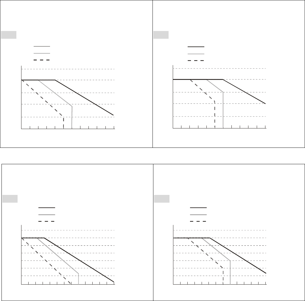
Derating Curve Diagram of Normal Duty (Pr.00-16=0)
Set Pr.06-55 = 1
Set Pr.06-55 = 0 or 2
(40℃:UL type1 or open type_size by size)
460V
100
110
90
80
70
60
4 5 6 7 8 9 101112131415
Fc (kHz)
R
atio(
%
)
VFD110~185CT43FxxAx
VFD220~750CT43
VFD900CT43 FxxAx
FxxAx
Set Pr.06-55 = 0 or 2
(30℃: UL type1 or open type_size by size)
460V
100
110
90
80
70
60
4 5 6 7 8 9 10 11 12 13 14 15
Fc (kHz)
R
atio(
%
)
VFD110~185CT43FxxAx
VFD220~750CT43
VFD900CT43 FxxAx
FxxAx
Derating Curve Diagram of Heavy Duty (Pr.00-16=1)
Set Pr.06-55 = 1
Set Pr.06-55 = 0 or 2
(40℃: UL type1 or open type_size by size)
460V
100
110
90
80
70
50
2 5 6 7 8 9 10 11 12 13 14 15
Fc (kHz)
R
atio(
%
)
60
40
4
3
VFD110~185CT43FxxAx
VFD220~750CT43
VFD900CT43 FxxAx
FxxAx
Set Pr.06-55 = 0 or 2
(30℃: UL type1 or open type_size by size)
460V
100
110
90
80
70
50
2 5 6 7 8 9 10 11 12 13 14 15
Fc (kHz)
R
atio(
%
)
60
40
4
3
VFD110~185CT43FxxAx
VFD220~750CT43
VFD900CT43 FxxAx
FxxAx
Chapter 3 Unpacking|C2000 Series
3-1
Chapter 3 Unpacking
The AC motor drive should be kept in the shipping carton or crate before installation. In order to retain the
warranty coverage, the AC motor drive should be stored properly when it is not to be used for an
extended period of time.
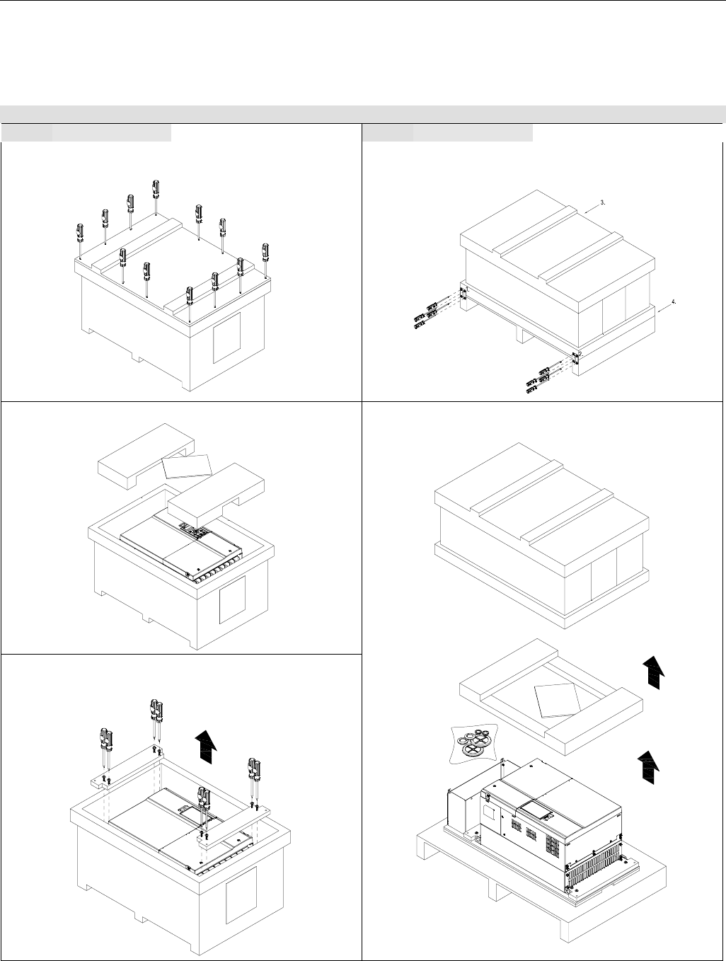
The AC motor drive is packed in the crate. Follows the following step for unpack:
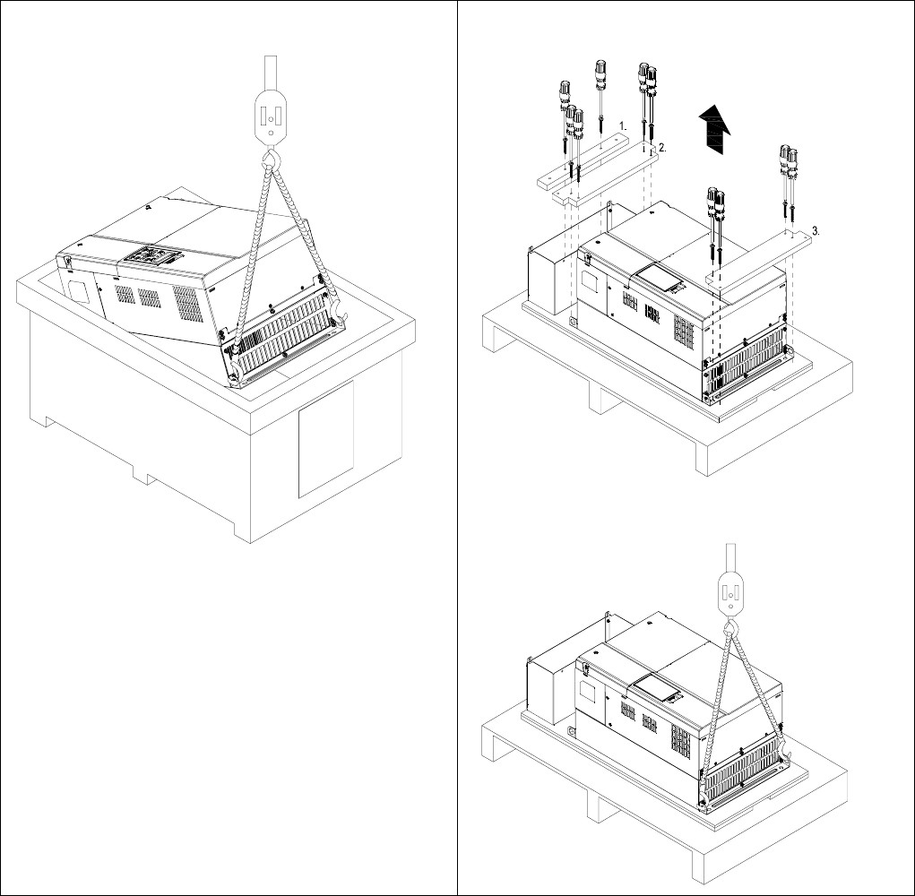
Frame D
Crate 1 (VFDXXXCXXA) Crate 2 (VFDXXXCXXE)
Loosen the 12 cover screws to open the crate.
Loosen the 4 screws on the iron plates. There are 4
iron plates and in total of 16 screws.
Remove the EPEs and manual.
Loosen the 8 screws that fastened on the pallet
and remove the wooden plate.
Remove the crate cover, EPEs, rubber and
manual.
Chapter 3 Unpacking|C2000 Series
3-2
Lift the drive by hooking the lifting hole. It is now
ready for installation.
Loosen the 10 screws on the pallet, remove the
wooden plate.
Lift the drive by hooking the lifting hole. It is now
ready for installation.
Chapter 3 Unpacking|C2000 Series
3-3
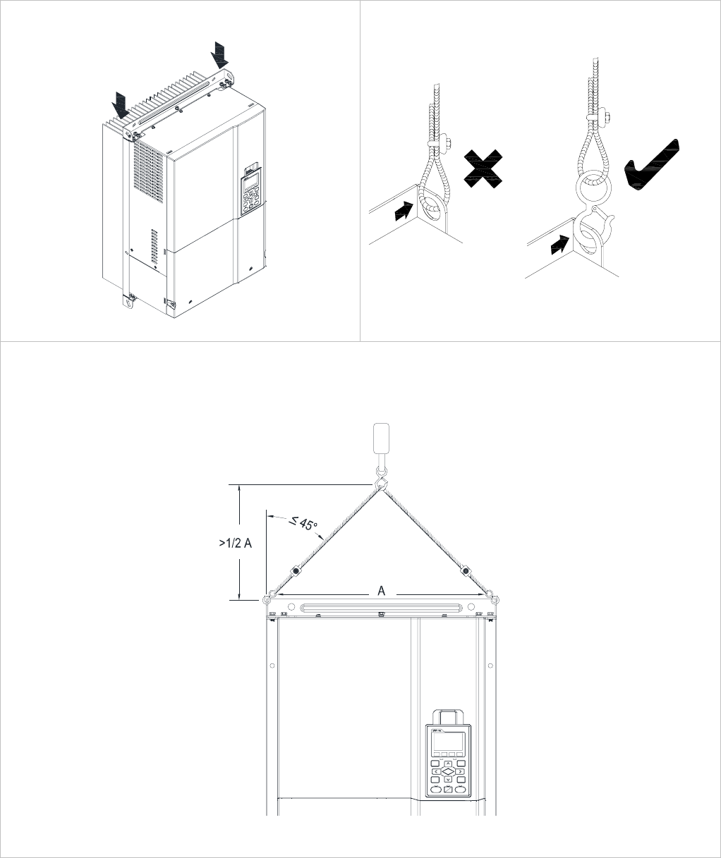
The Lifting Hook
The arrows indicate the location of the lifting holes o
f
frame D, as shown in figure below:
Figure 1
Ensure the lifting hook properly goes through the
lifting hole, as shown in the following diagram.
(Applicable to Frame D)
Ensure the angle between the lifting holes and the lifting device is within the specification, as shown in the
following figure.
A
pplicable to Frame D
(VFD450CT43F00A3; VFD550CT43F00A4; VFD750CT43F00A6; VFD900CT43F00A8;)
Weight: 37.6kg (82.9lbs.)±0.5%

Chapter 4 Wiring|CT2000 Series
4-1
Chapter 4 Wiring
After removing the front cover, examine if the power and control terminals are clearly noted. Please read
following precautions before wiring.
; Make sure that power is only applied to the R/L1, S/L2, T/L3 terminals. Failure to comply may result
in damage to the equipments. The voltage and current should lie within the range as indicated on
the nameplate (Chapter 1-1).
; All the units must be grounded directly to a common ground terminal to prevent lightning strike or
electric shock.
; Please make sure to fasten the screw of the main circuit terminals to prevent sparks which is made
by the loose screws due to vibration
DANGER
; It is crucial to turn off the AC motor drive power before any wiring installation are
made. A charge may still remain in the DC bus capacitors with hazardous voltages
even if the power has been turned off therefore it is suggested for users to measure
the remaining voltage before wiring. For your personnel saftery, please do not
perform any wiring before the voltage drops to a safe level < 25 Vdc. Wiring
installation with remaninig voltage condition may caus sparks and short circuit.
; Only qualified personnel familiar with AC motor drives is allowed to perform
installation, wiring and commissioning. Make sure the power is turned off before
wiring to prevent electric shock.
; When wiring, please choose the wires with specification that complys with local
regulation for your personnel safety.
; Check following items after finishing the wiring:
1. Are all connections correct?
2. Any loosen wires?
3. Any short-circuits between the terminals or to ground?
Chapter 4 Wiring|CT2000 Series
4-2
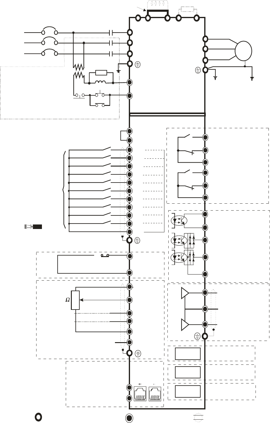
Wiring Diagram for Frame B~C
* It provides 3-phase power Brake resistor
(optional)
DC choke
(optional)
R(L1)
S(L2)
T(L3)
R(L1)
S(L2)
T(L3)
U(T1)
V(T2)
W(T3)
IM
3~
+2 B1 B2+1
-
Jumper
Fuse/NFB(No Fuse Breaker)
Motor
SA
OFF ON
MC
MC
It is recommended to install a
protective circuit at RB-RC
to protect it from system
damage.
RB 1
RC 1
When fault occurs, the
contact will switch ON to shut
the power and protect the power system.
250Vac/5A (N.O.)
250Vac/3A (N.C.)
NOTE
AFM1
ACM
IO extension card
Option
Slot 1
RA1
RB1
RC1
AVI
ACM
+10V
5K
3
2
1
0~10V/ 0~20mA
ACI
AUI
4~20mA/0~10V
-10~+10V
-10V
+10V/20mA
-10V/20mA
MO2
MCM
FWD
REV
MI1
MI3
MI4
MI5
MI6
MI7
DCM
MI2
MI8
Option
Slot 3
Option
Slot 2
DFM
MO1
COM
AFM2
RA2
RB2
RC2
DCM
+24V
81
Modbus RS-485
CAN BUS
81
SG+
SG-
Pin 1~2, 7, 8: reserved
Pin 3, 6:GND
Pin 4:SG-
Pin 5:SG+
30Vdc/5A (N.O.)
30Vdc/3A (N.C.)
250Vac/1.2A (N.C.)
Estimate at COS (0.4)
250Vac/2A (N.O.)
Estimate at COS (0.4)
Analog Signal common
Analog Signal Common
* Do NOT apply the mains voltage directly
to above terminals.
* MI8 can input pulses 100kHz
FWD/STOP
REV/STOP
Multi-step 1
Multi-step 2
Multi-step 3
Multi-step 4
Digital Signal Common
N/A
Factory setting: NPN (SINK) Mode
Please refer to
Figure 1 for wiring
of NPN mode and
PNP mode.
Factory
setting
Power removal safety function for
EN954-1 and IEC/EN61508
SCM
S1
Digital Signal Common
Analog Multi-function
Output Terminal
0~10VDC/-10~+10V
Analog Multi-function
Out put Terminal
0~10VDC/4~20mA
Multi-function
output terminals
PG extension card
IO&RELAY
extension card
N/A
N/A
N/A
Multi-function output
frequency terminals
30V30mA 100kHz
Multi-function output
frequency terminals
48V/50mA
Multi-function output
frequency terminals
48V/50mA
Multi-function
Photocoupler Output
Main circuit (power) terminals Control terminals Shielded leads & Cable
Chapter 4 Wiring|CT2000 Series
4-3
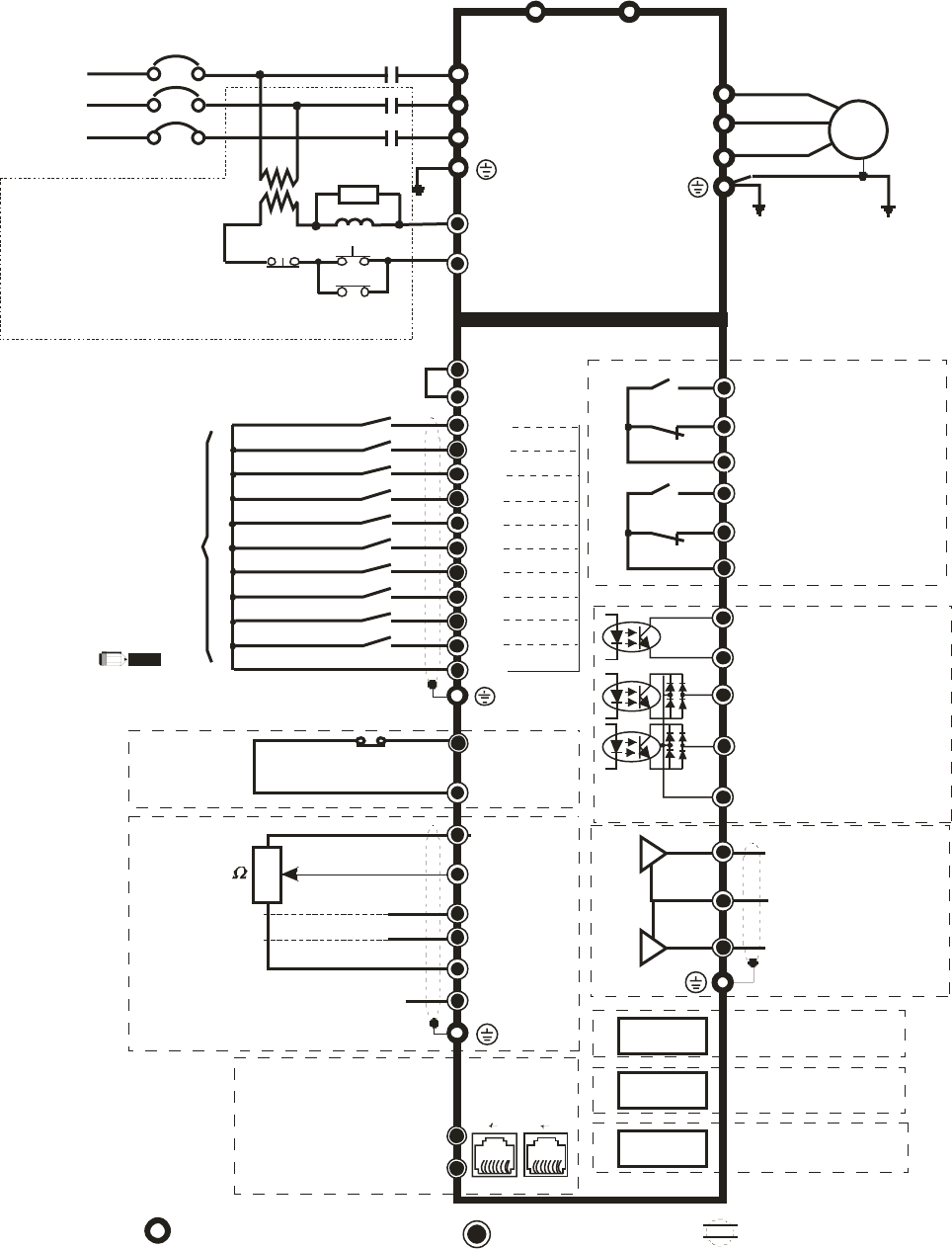
Wiring Diagram for Frame D
* It provides 3-phase power
R(L1)
S(L2)
T(L3)
R(L1)
S(L2)
T(L3)
U(T1)
V(T2)
W(T3)
IM
3~
Fuse/NFB(No Fuse Breaker)
Motor
SA
OFF ON
MC
MC
RB 1
RC 1
250Vac/5A (N.O.)
250Vac/3A (N.C.)
NOTE
AFM1
ACM
IO extension card
Option
Slot 1
RA1
RB1
RC1
AVI
ACM
+10V
5K
3
2
1
0~10V/ 0~20mA
ACI
AUI
4~20mA/0~10V
-10~+10V
-10V
+10V/20mA
-10V/20mA
MO2
MCM
FWD
REV
MI1
MI3
MI4
MI5
MI6
MI7
DCM
MI2
MI8
Option
Slot 3
Option
Slot 2
DFM
MO1
COM
AFM2
RA2
RB2
RC2
DCM
+24V
81
Modbus RS-485
CAN BUS
81
SG+
SG-
Pin 1~2 , 7, 8 : re se rve d
Pin 3, 6 :GND
Pin 4:SG-
Pin 5:SG+
30Vdc/5A (N.O.)
30Vdc/3A (N.C.)
250Vac/1.2A (N .C.)
Estim ate at C OS (0.4)
250Vac/2A (N.O.)
Estimate at COS (0.4)
A
nalog Signal commo
n
Analog Signal Common
* Do NOT apply the mains voltage directly
to above terminals.
* MI8 can input 100kHz pulses
FWD/STOP
REV/STOP
Multi-step 1
Multi-step 2
Multi-step 3
Multi-step 4
Digital Signal Common
N/A
Factory setting: NPN (SINK) Mode
Please refer to
Figure 1 for wiring
of NPN mode and
PNP mode.
Factory
setting
power removal safety function
for EN954-1 and IEC/EN61508
SCM
S1
Digital Signal Common
Analog Multi-function
Output Terminal
0~10VDC/-10~+10V
Analog Multi-function
Output Terminal
0~10VDC/4~20mA
Main circuit (power) terminals Control terminals Shielded leads & Cable
Multi-function
output terminals
PG extension card
IO&RELAY
extension card
N/A
N/A
N/A
Multi-function output
frequency terminals
30V30mA 100kHz
Multi-function output
frequency terminals
48V/50mA
Multi-function output
frequency terminals
48V/50mA
Multi-function
Photocoupler Output
-/DC-
+/DC+
It is recommended to install a
protective circuit at RB-RC
to protect it from system
damage.
When fault occurs, the
contact will switch ON to shut
the power and protect the power system.
Chapter 4 Wiring|CT2000 Series
4-4
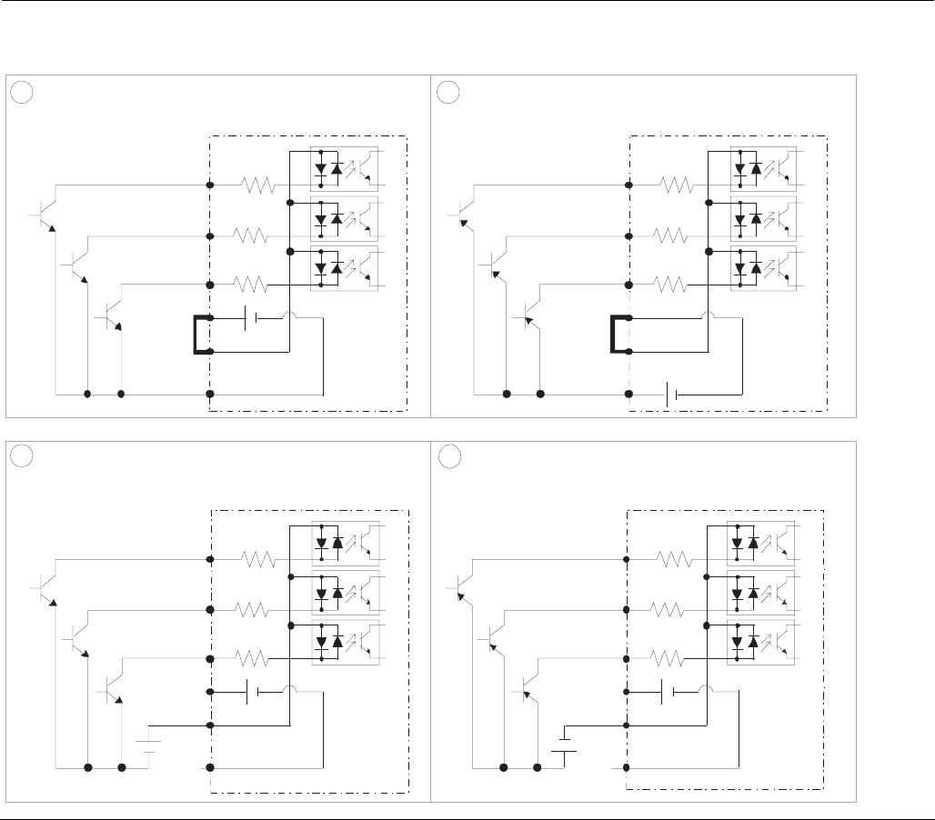
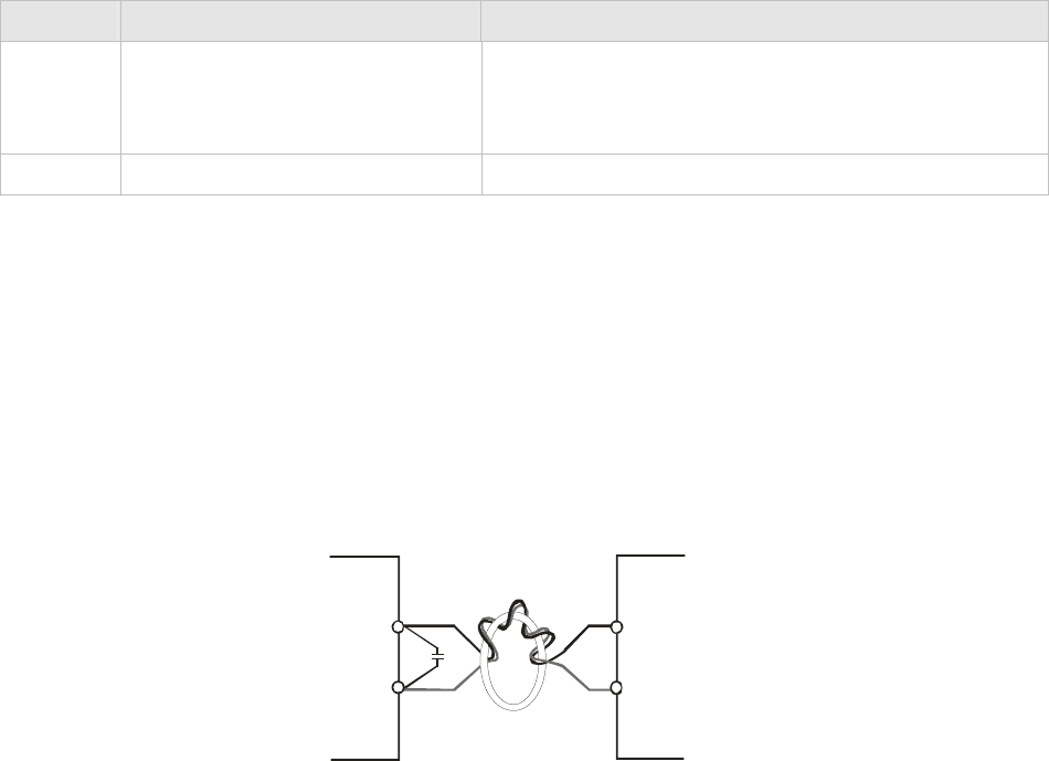
Figure 1
SINK(NPN)/SOURCE(PNP)Mode
12
DCM
MI1
+2 4V
MI2
MI8
~
COM
DCM
MI1
+2 4V
MI2
MI8
~
COM
Sink Mode Source Mode
with internal power (+24VDC) with internal power (+24VDC)
internal circuit internal circuit
34
DCM
MI1
+24V
MI2
MI8
~
COM
DCM
MI1
+24V
MI2
MI8
~
COM
Sink Mode Source Mode
with external power with external power
internal circuit
internal circuit
external power +24V external power +24V

Chapter 5 Main Circuit Terminals|CT2000 Series
5-1
Chapter 5 Main Circuit Terminals
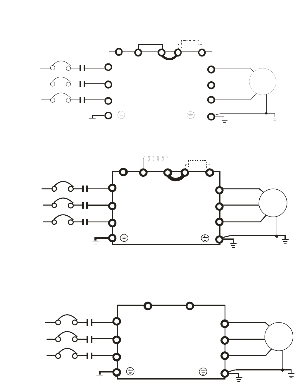
Main Circuit Diagram 1
* Provide 3-phase input power
Fuse/NFB(No Fuse Breaker)
R(L1)
S(L2)
T(L3)
R(L1)
S(L2)
T(L3)
Motor
U(T1)
V(T2)
W(T3)
IM
3~
+2
Jumper
Brake resistor
(optional)
B1 B2
+1
-
For frame B~C
* Provide 3-phase input power
Fuse/NFB(No Fuse Breaker)
R(L1)
S(L2)
T(L3)
R(L1)
S(L2)
T(L3)
Motor
U(T1)
V(T2)
W(T3)
IM
3~
+2
Jumper
Brake resistor
(optional)
DC choke
(optional)
B1 B2
+1
-
For frame B~C
Main Circuit Diagram 2
* Provide 3-phase input power
Fuse/NFB(No Fuse Breaker)
R(L1)
S(L2)
T(L3)
R(L1)
S(L2)
T(L3)
Motor
U(T1)
V(T2)
W(T3)
IM
3~
+1/DC+ -/DC-
For frame D0~D

Chapter 5 Main Circuit Terminals|CT2000 Series
5-2
Terminals Descriptions
R/L1, S/L2, T/L3 AC line input terminals 3-phase
U/T1, V/T2, W/T3 AC drive output terminals for connecting 3-phase induction motor
+1, +2
Applicable to frame B~C
Connections for DC reactor to improve the power factor. It needs to remove the
jumper for installation.
+1/DC+, -/DC-
Connections for brake unit (VFDB series)
( (for 460V models: 30kW, built≦-in brake unit)
Common DC Bus
B1, B2 Connections for brake resistor (optional)
Earth connection, please comply with local regulations.
Main power terminals
; Do not connect 3-phase model to one-phase power. R/L1, S/L2 and T/L3
has no phase-sequence requirement, it can be used upon random
selection.
; It is recommend to add a magnetic contactor (MC) to the power input
wiring to cut off power quickly and reduce malfunction when activating
the protection function of the AC motor drive. Both ends of the MC
should have an R-C surge absorber.
; Fasten the screws in the main circuit terminal to prevent sparks condition
made by the loose screws due to vibration.
; Please use voltage and current within the specification.
; When using a general GFCI (Ground Fault Circuit Interrupter), select a
current sensor with sensitivity of 200mA or above and not less than
0.1-second operation time to avoid nuisance tripping.
; Please use the shield wire or tube for the power wiring and ground the
two ends of the shield wire or tube.
; Do NOT run/stop AC motor drives by turning the power ON/OFF.
Run/stop AC motor drives by RUN/STOP command via control terminals
or keypad. If you still need to run/stop AC motor drives by turning power
ON/OFF, it is recommended to do so only ONCE per hour.
Output terminals for main circuit
; When it needs to install the filter at the output side of terminals U/T1,
V/T2, W/T3 on the AC motor drive. Please use inductance filter. Do not
use phase-compensation capacitors or L-C (Inductance-Capacitance) or
R-C (Resistance-Capacitance), unless approved by Delta.
; DO NOT connect phase-compensation capacitors or surge absorbers at
the output terminals of AC motor drives.
; Use well-insulated motor, suitable for inverter operation.
Terminals for connecting DC reactor, external brake resistor, external

Chapter 5 Main Circuit Terminals|CT2000 Series
5-3
brake resistor and DC circuit
; This is the terminals used to connect the DC reactor to improve the
power factor. For the factory setting, it connects the short-circuit object.
Please remove this short-circuit object before connecting to the DC
reactor.
+1 +
2
DC reactor (optional)
; When the AC Motor Drive is connected directly to a large-capacity power
transformer (600kVA or above) or when a phase lead capacitor is
switched, excess peak currents may occur in the power input circuit due
to the load changes and the converter section may be damaged. To
avoid this, it is recommend to use a serial connected AC input
reactor(6%) at the AC Motor Drive mains input side to reduce the current
and improve the input power efficiency.
; Connect a brake resistor or brake unit in applications with frequent
deceleration ramps, short deceleration time, too low brake torque or
requiring increased brake torque.
B1
B2
BR
+
-
VFDB
Brake resistor
(optional)
Brake resistor
(optional)
Brake unit
(optional)
; The external brake resistor should connect to the terminals (B1, B2) of
AC motor drives.
; For those models without built-in brake resistor, please connect external
brake unit and brake resistor (both of them are optional) to increase
brake torque.
; When the terminals +1, +2 and - are not used, please leave the terminals
open.
; DO NOT connect [+1, -], [+2, -], [+1/DC+, -/DC-] or brake resistor directly
to prevent drive damage.
; DC+ and DC- are connected by common DC bus, please refer to
Chapter 5-1(Main Circuit Terminal) for the wiring terminal specification
and the wire gauge information.
; Please refer to the VFDB manual for more information on wire gauge
when installing the brake unit.

Chapter 5 Main Circuit Terminals|CT2000 Series
5-4
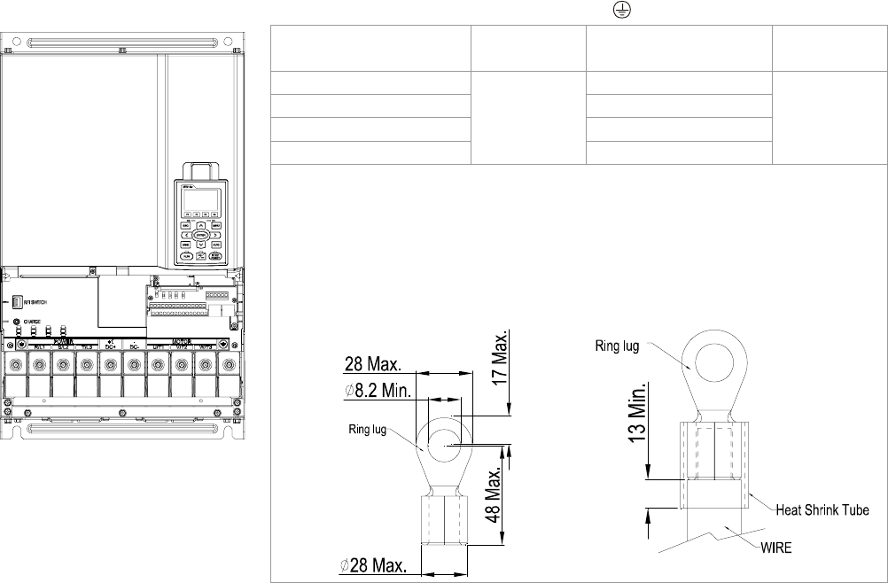
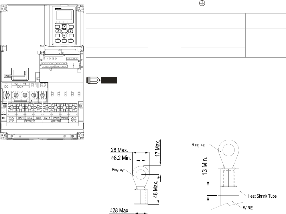
5-1 Main Circuit Terminals
Frame B
Main circuit terminals:
R/L1, S/L2, T/L3, U/T1, V/T2, W/T3, , B1, B2, +1, +2, -
Models Max. Wire
Gauge Min. Wire Gauge Torque
(±10%)
VFD110CT43F21A3; 8 AWG (8.4mm2)
VFD150CT43F21A3; 6 AWG (13.3mm2)
VFD185CT43F21A3;
4 AWG
(21.2mm2)4 AWG (21.2mm2)
M5
35kg-cm
(30.4 lb-in.)
(3.434Nm)
UL installations must use 600V, 75℃ or 90℃ wire. Use copper wire
only.
NOTE
Terminal D+ [+2 & +1]: Torque: 45 kg-cm [39.0lb-in.] (4.415Nm) (±10%)
1. VFD110C23A must use 600V, 90℃ wire when surrounding
temperature exceeds 45℃.
2. Figure 1 shows the terminal specification.
3. Figure 2 shows the specification of insulated heat shrink tubing that
comply with UL (600V, YDPU2).
Figure 1
Figure 2

Chapter 5 Main Circuit Terminals|CT2000 Series
5-5
Frame C
Main circuit terminals:
R/L1, S/L2, T/L3, U/T1, V/T2, W/T3, , B1, B2, +1, +2, -
Models Max. Wire
Gauge Min. Wire Gauge Torque
(±10%)
VFD220CT43F21A3; 4 AWG (21.2mm2)
VFD300CT43F21A3; 2 AWG (33.6mm2)
VFD370CT43F21A7;
1/0 AWG
(53.5mm2)1/0 AWG (53.5mm2)
M8
80kg-cm
(69.4 lb-in.)
(7.85Nm)
UL installations must use 600V, 75℃ or 90℃ wire. Use copper wire
only.
NOTE
Terminal D+ [+2 & +1]: Torque: 90 kg-cm [78.2lb-in.] (8.83Nm) (±10%)
1. VFD220C23A must use 600V, 90℃ wire when surrounding
temperature exceeds 40℃.
2. Figure 1 shows the terminal specification.
3. Figure 2 shows the specification of insulated heat shrink tubing that
comply with UL (600V, YDPU2).
Figure 1
Figure 2
Chapter 5 Main Circuit Terminals|CT2000 Series
5-6
Frame D
Main circuit terminals:
R/L1, S/L2, T/L3, U/T1, V/T2, W/T3, , +1/DC+, -/DC-
Models Max. Wire
Gauge Min. Wire Gauge Torque
(±10%)
VFD450CT43F00A3; 2/0 AWG (67.4mm2)
VFD550CT43F00A4; 3/0 AWG (85mm2)
VFD750CT43F00A6; 250MCM (127mm2)
VFD900CT43F00A8;
300MCM
(152mm2)
300MCM (152mm2)
M8
200kg-cm
(173 lb-in.)
(19.62Nm)
1. UL installations must use 600V, 75oC or 90 oC wires. Use copper
wire only.
2. Figure 1 shows the terminal specification.
3. Figure 2 shows the specification of insulated heat shrink tubing
that comply with UL (600V, YDPU2).
Figure 1
Figure 2
Chapter 5 Main Circuit Terminals|CT2000 Series
5-1
Chapter 5 Main Circuit Terminals
Main Circuit Diagram 1
* Provide 3-phase input power
Fuse/NFB(No Fuse Breaker)
R(L1)
S(L2)
T(L3)
R(L1)
S(L2)
T(L3)
Motor
U(T1)
V(T2)
W(T3)
IM
3~
+2
Jumper
Brake resistor
(optional)
B1 B2
+1
-
For frame B~C
* Provide 3-phase input power
Fuse/NFB(No Fuse Breaker)
R(L1)
S(L2)
T(L3)
R(L1)
S(L2)
T(L3)
Motor
U(T1)
V(T2)
W(T3)
IM
3~
+2
Jumper
Brake resistor
(optional)
DC choke
(optional)
B1 B2
+1
-
For frame B~C
Main Circuit Diagram 2
* Provide 3-phase input power
Fuse/NFB(No Fuse Breaker)
R(L1)
S(L2)
T(L3)
R(L1)
S(L2)
T(L3)
Motor
U(T1)
V(T2)
W(T3)
IM
3~
+1/DC+ -/DC-
For frame D0~D

Chapter 5 Main Circuit Terminals|CT2000 Series
5-2
Terminals Descriptions
R/L1, S/L2, T/L3 AC line input terminals 3-phase
U/T1, V/T2, W/T3 AC drive output terminals for connecting 3-phase induction motor
+1, +2
Applicable to frame B~C
Connections for DC reactor to improve the power factor. It needs to remove the
jumper for installation.
+1/DC+, -/DC-
Connections for brake unit (VFDB series)
( (for 460V models: 30kW, built≦-in brake unit)
Common DC Bus
B1, B2 Connections for brake resistor (optional)
Earth connection, please comply with local regulations.
Main power terminals
; Do not connect 3-phase model to one-phase power. R/L1, S/L2 and T/L3
has no phase-sequence requirement, it can be used upon random
selection.
; It is recommend to add a magnetic contactor (MC) to the power input
wiring to cut off power quickly and reduce malfunction when activating
the protection function of the AC motor drive. Both ends of the MC
should have an R-C surge absorber.
; Fasten the screws in the main circuit terminal to prevent sparks condition
made by the loose screws due to vibration.
; Please use voltage and current within the specification.
; When using a general GFCI (Ground Fault Circuit Interrupter), select a
current sensor with sensitivity of 200mA or above and not less than
0.1-second operation time to avoid nuisance tripping.
; Please use the shield wire or tube for the power wiring and ground the
two ends of the shield wire or tube.
; Do NOT run/stop AC motor drives by turning the power ON/OFF.
Run/stop AC motor drives by RUN/STOP command via control terminals
or keypad. If you still need to run/stop AC motor drives by turning power
ON/OFF, it is recommended to do so only ONCE per hour.
Output terminals for main circuit
; When it needs to install the filter at the output side of terminals U/T1,
V/T2, W/T3 on the AC motor drive. Please use inductance filter. Do not
use phase-compensation capacitors or L-C (Inductance-Capacitance) or
R-C (Resistance-Capacitance), unless approved by Delta.
; DO NOT connect phase-compensation capacitors or surge absorbers at
the output terminals of AC motor drives.
; Use well-insulated motor, suitable for inverter operation.
Terminals for connecting DC reactor, external brake resistor, external

Chapter 5 Main Circuit Terminals|CT2000 Series
5-3
brake resistor and DC circuit
; This is the terminals used to connect the DC reactor to improve the
power factor. For the factory setting, it connects the short-circuit object.
Please remove this short-circuit object before connecting to the DC
reactor.
+1 +
2
DC reactor (optional)
; When the AC Motor Drive is connected directly to a large-capacity power
transformer (600kVA or above) or when a phase lead capacitor is
switched, excess peak currents may occur in the power input circuit due
to the load changes and the converter section may be damaged. To
avoid this, it is recommend to use a serial connected AC input
reactor(6%) at the AC Motor Drive mains input side to reduce the current
and improve the input power efficiency.
; Connect a brake resistor or brake unit in applications with frequent
deceleration ramps, short deceleration time, too low brake torque or
requiring increased brake torque.
B1
B2
BR
+
-
VFDB
Brake resistor
(optional)
Brake resistor
(optional)
Brake unit
(optional)
; The external brake resistor should connect to the terminals (B1, B2) of
AC motor drives.
; For those models without built-in brake resistor, please connect external
brake unit and brake resistor (both of them are optional) to increase
brake torque.
; When the terminals +1, +2 and - are not used, please leave the terminals
open.
; DO NOT connect [+1, -], [+2, -], [+1/DC+, -/DC-] or brake resistor directly
to prevent drive damage.
; DC+ and DC- are connected by common DC bus, please refer to
Chapter 5-1(Main Circuit Terminal) for the wiring terminal specification
and the wire gauge information.
; Please refer to the VFDB manual for more information on wire gauge
when installing the brake unit.
Chapter 5 Main Circuit Terminals|CT2000 Series
5-4
5-1 Main Circuit Terminals
Frame B
Main circuit terminals:
R/L1, S/L2, T/L3, U/T1, V/T2, W/T3, , B1, B2, +1, +2, -
Models Max. Wire
Gauge Min. Wire Gauge Torque
(±10%)
VFD110CT43F21A3; 8 AWG (8.4mm2)
VFD150CT43F21A3; 6 AWG (13.3mm2)
VFD185CT43F21A3;
4 AWG
(21.2mm2)4 AWG (21.2mm2)
M5
35kg-cm
(30.4 lb-in.)
(3.434Nm)
UL installations must use 600V, 75℃ or 90℃ wire. Use copper wire
only.
NOTE
Terminal D+ [+2 & +1]: Torque: 45 kg-cm [39.0lb-in.] (4.415Nm) (±10%)
1. VFD110C23A must use 600V, 90℃ wire when surrounding
temperature exceeds 45℃.
2. Figure 1 shows the terminal specification.
3. Figure 2 shows the specification of insulated heat shrink tubing that
comply with UL (600V, YDPU2).
Figure 1
Figure 2
Chapter 5 Main Circuit Terminals|CT2000 Series
5-5
Frame C
Main circuit terminals:
R/L1, S/L2, T/L3, U/T1, V/T2, W/T3, , B1, B2, +1, +2, -
Models Max. Wire
Gauge Min. Wire Gauge Torque
(±10%)
VFD220CT43F21A3; 4 AWG (21.2mm2)
VFD300CT43F21A3; 2 AWG (33.6mm2)
VFD370CT43F21A7;
1/0 AWG
(53.5mm2)1/0 AWG (53.5mm2)
M8
80kg-cm
(69.4 lb-in.)
(7.85Nm)
UL installations must use 600V, 75℃ or 90℃ wire. Use copper wire
only.
NOTE
Terminal D+ [+2 & +1]: Torque: 90 kg-cm [78.2lb-in.] (8.83Nm) (±10%)
1. VFD220C23A must use 600V, 90℃ wire when surrounding
temperature exceeds 40℃.
2. Figure 1 shows the terminal specification.
3. Figure 2 shows the specification of insulated heat shrink tubing that
comply with UL (600V, YDPU2).
Figure 1
Figure 2

Chapter 5 Main Circuit Terminals|CT2000 Series
5-6
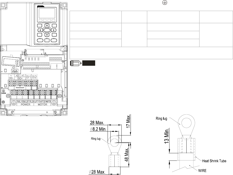
Frame D
Main circuit terminals:
R/L1, S/L2, T/L3, U/T1, V/T2, W/T3, , +1/DC+, -/DC-
Models Max. Wire
Gauge Min. Wire Gauge Torque
(±10%)
VFD450CT43F00A3; 2/0 AWG (67.4mm2)
VFD550CT43F00A4; 3/0 AWG (85mm2)
VFD750CT43F00A6; 250MCM (127mm2)
VFD900CT43F00A8;
300MCM
(152mm2)
300MCM (152mm2)
M8
200kg-cm
(173 lb-in.)
(19.62Nm)
1. UL installations must use 600V, 75oC or 90 oC wires. Use copper
wire only.
2. Figure 1 shows the terminal specification.
3. Figure 2 shows the specification of insulated heat shrink tubing
that comply with UL (600V, YDPU2).
Figure 1
Figure 2
Chapter 6 Control Terminals|CT2000 Series
6-1
Chapter 6 Control Terminals
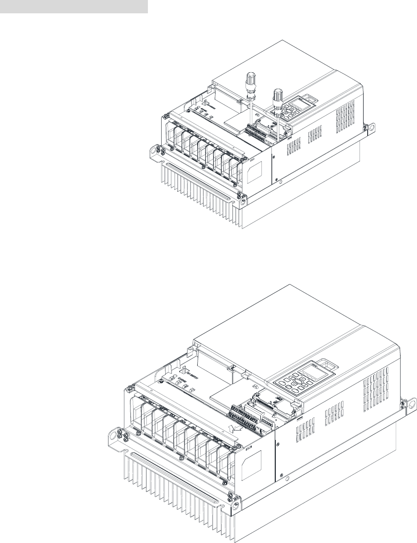
Please remove the top cover before wiring the multi-function input and output terminals,
The drive appearances shown in the figures are for reference only, a real drive may look different.
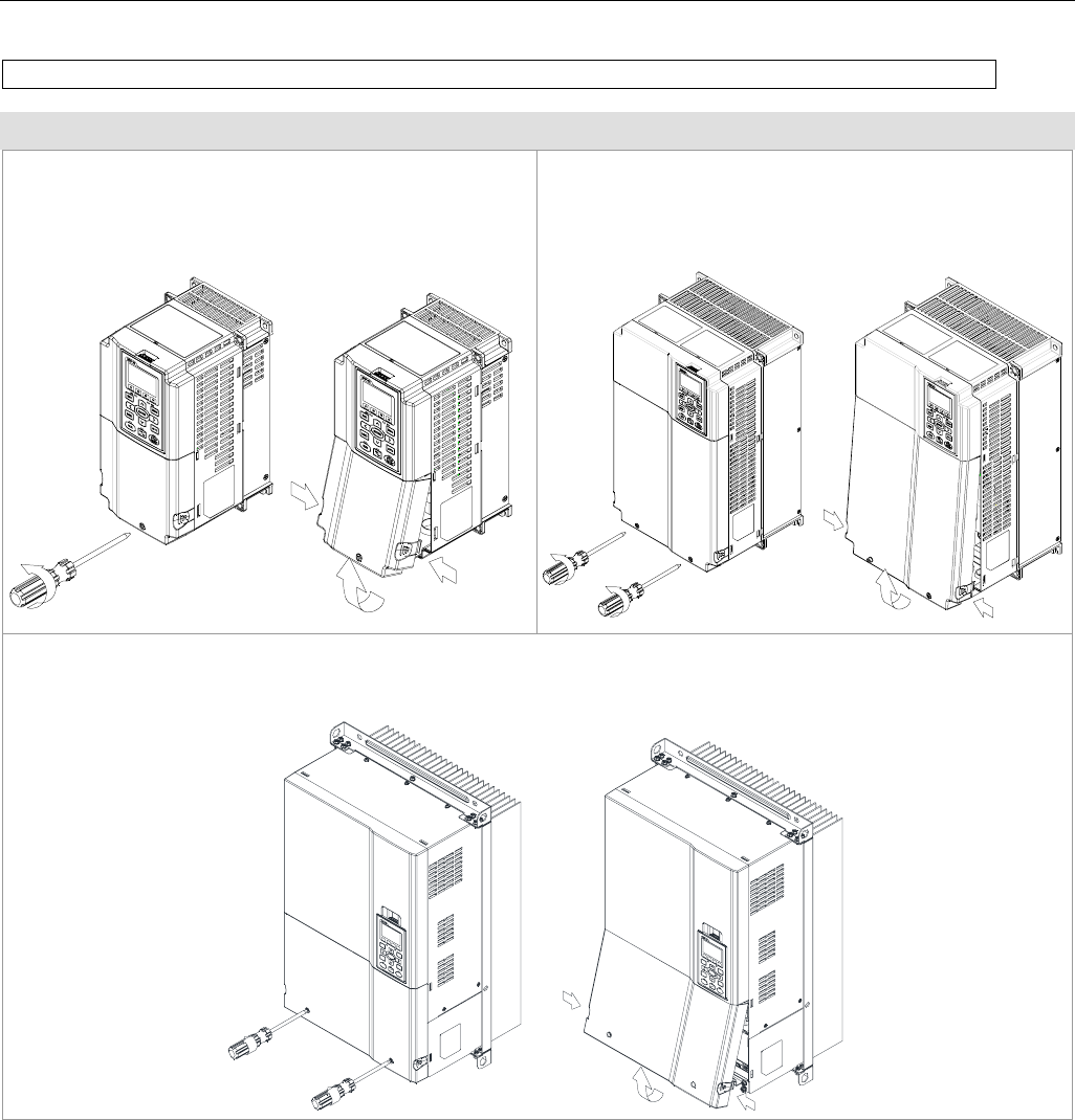
Remove the cover for wiring. Frame A~H
Frame B
Loosen the screws and press the tabs on both sides
to remove the cover.
Screw torque: 12~15Kg-cm [10.4~13lb-in.]
Frame C
Loosen the screws and press the tabs on both sides
to remove the cover.
Screw torque: 12~15Kg-cm [10.4~13lb-in.]
Frame D
Loosen the screws and press the tabs on both sides to remove the cover.
Screw torque: 12~15Kg-cm [10.4~13lb-in.]
Chapter 6 Control Terminals|C2000 Series
6-2
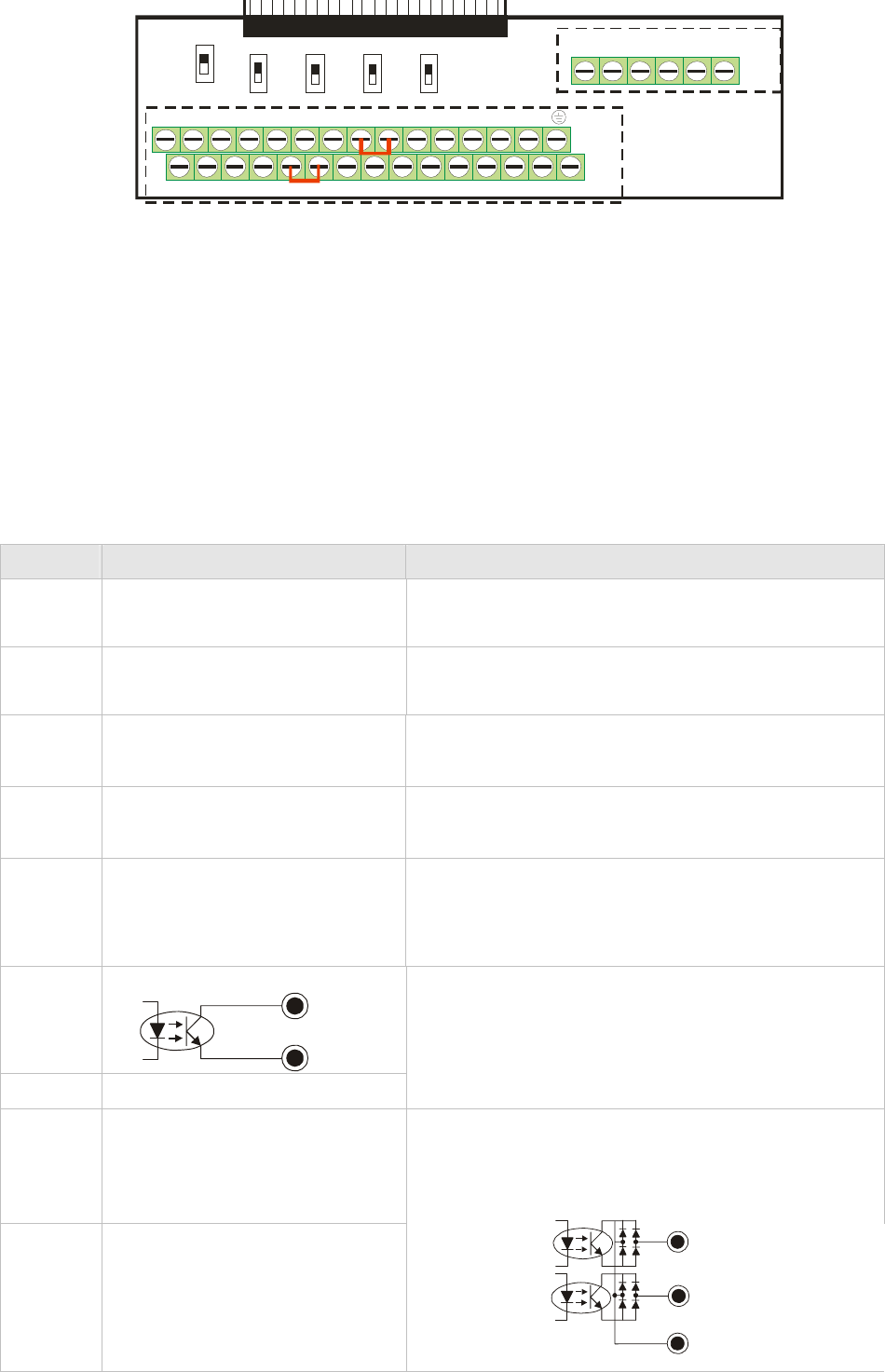
MI1+24VCOM FWD
MO1 MI5
MI3
ACI
+10V AVI
AFM1 MO2 MCM MI7
MI4DCM REV MI2S1 MI8MI6ACM-10V AUI
AFM2 SCM DFM SG-SG+
RA 2RC2 RB2 RB1RC1 RA1
0-10V
-10-10V
0-10V 0-10V
0-10V
0-20mA 0-20mA
0-20mA Open
120
AFM1 AFM2 AVI ACI 485
Removable Terminal Block
Specifications of Control Terminal
Wire Gauge: 26~16AWG(0.1281-1.318mm2),
Torque: (A) 5kg-cm [4.31Ib-in.] (0.49Nm) (As shown in figure above)
(B) 8kg-cm [6.94Ib-in.] (0.78Nm) (As shown in figure above)
Wiring precautions:
Reserves 5mm and properly install the wire into the terminal; fasten the installation by a
slotted screwdriver. If the wire is stripped, sort the wire before install into the terminal.
Flathead screwdriver: blade width 3.5mm, tip thickness 0.6mm
In the figure above, the factory setting for S1-SCM is short circuit. The factory setting for
+24V-COM is short circuit and SINK mode (NPN); please refer to Chapter 4 Wiring for more
detail.
Terminals Terminal Function Factory Setting (NPN mode)
+24V Digital control signal common
(Source)
+24V±5% 200mA
COM Digital control signal common
(Sink)
Common for multi-function input terminals
FWD Forward-Stop command FWD-DCM:
ONÎ forward running
OFFÎ deceleration to stop
REV Reverse-Stop command
REV-DCM:
ONÎ reverse running
OFFÎ deceleration to stop
MI1
~
MI8
Multi-function input 1~8
Refer to parameters 02-01~02-08 to program the
multi-function inputs MI1~MI8.
ON: the activation current is 6.5mA 11Vdc≧
OFF: leakage current tolerance is 10μA 11Vdc ≦
DFM
Digital frequency meter
DFM
DCM
DCM Digital frequency signal common
Regard the pulse voltage as the output monitor
signal
Duty-cycle: 50%
Min. load impedance: 1kΩ/100pf
Max. current: 30mA
Max. voltage: 30Vdc
MO1 Multi-function Output 1
(photocoupler)
MO2 Multi-function Output 2
(photocoupler)
The AC motor drive releases various monitor
signals, such as drive in operation, frequency
attained and overload indication, via transistor (open
collector).
MO2
MCM
MO1
Chapter 6 Control Terminals|CT2000 Series
6-3
Terminals Terminal Function Factory Setting (NPN mode)
MCM Multi-function Output Common Max 48Vdc 50mA
RA1 Multi-function relay output 1
(N.O.) a
RB1 Multi-function relay output 1
(N.C.) b
RC1 Multi-function relay common
RA2 Multi-function relay output 2
(N.O.) a
RB2 Multi-function relay output 2
(N.C.) b
RC2 Multi-function relay common
Resistive Load:
5A(N.O.)/3A(N.C.) 250VAC
5A(N.O.)/3A(N.C.) 30VDC
Inductive Load (COS 0.4):
2.0A(N.O.)/1.2A(N.C.) 250VAC
2.0A(N.O.)/1.2A(N.C.) 30VDC
It is used to output each monitor signal, such as
drive is in operation, frequency attained or overload
indication.
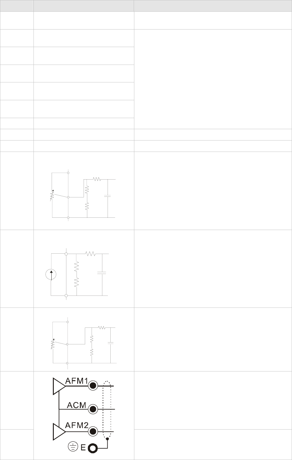
+10V Potentiometer power supply Analog frequency setting: +10Vdc 20mA
-10V Potentiometer power supply Analog frequency setting: -10Vdc 20mA
AVI
Analog voltage input
ACM
AVI
+10V AVI circuit
internal circuit
Impedance: 20kΩ
Range: 4 ~ 20mA/0~10V =0~Max. Output
Frequency (Pr.01-00)
AVI switch, factory setting is 0~10V
ACI
Analog current input
A
CM
A
CI ACI circuit
internal circuit
Impedance: 250Ω
Range: 4 ~ 20mA/0~10V= 0 ~ Max. Output
Frequency (Pr.01-00)
ACI Switch, factory setting is 4~20mA
AUI
Auxiliary analog voltage input
ACM
AUI
+10
~
-10V
AUI circuit
internal circuit
Impedance: 20kΩ
Range: -10~+10VDC=0 ~ Max. Output
Frequency(Pr.01-00)
AFM1
0~10V impedance 100kΩ (voltage output)
-10~10V impedance 100kΩ (voltage output)
Output current: 2mA max
Resolution: 0~10V corresponds to Max. operation
frequency
Range: 0~10V Æ -10~+10V
AFM Switch, factory setting is 0~10V
AFM2
0~10V impedance 100kΩ (voltage output)
0~20mA impedance100Ω (current output)
Output current: 20mA max
Chapter 6 Control Terminals|C2000 Series
6-4
Terminals Terminal Function Factory Setting (NPN mode)
Resolution: 0~10V corresponds to Max. operation
frequency
Range: 0~10V Æ 4~20mA
AFM Switch, factory setting is 0~10V
ACM Analog Signal Common Common for analog terminals
NOTE: Wire size of analog control signals: 18 AWG (0.75 mm2) with shielded wire
Analog input terminals (AVI, ACI, AUI, ACM)
; Analog input signals are easily affected by external noise. Use shielded wiring and keep it as
short as possible (<20m) with proper grounding. If the noise is inductive, connecting the shield to
terminal ACM can bring improvement.
; If the analog input signals are affected by noise from the AC motor drive, please connect a
capacitor and ferrite core as indicated in the following diagram.
C
AVI/ACI/AUI
ACM
ferrite core
Wind each wires 3 times or more around the core
Digital inputs (FWD, REV, MI1~MI8, COM)
; When using contacts or switches to control the digital inputs, please use high quality
components to avoid contact bounce.
Transistor outputs (MO1, MO2, MCM)
; Make sure to connect the digital outputs to the right polarity.
; When connecting a relay to the digital outputs connect a surge absorber across the coil and
check the polarity.
Chapter 6 Control Terminals|CT2000 Series
6-5
Remove the Terminal Block
1. Loosen the screws by screwdriver. (As shown in figure below).
2. Remove the control board by pulling it out for a distance 6~8 cm (as 1 in the figure) then lift the control
board upward(as 2 in the figure).

Chapter 7 Optional Accessories|CT2000 Series
7-1
Chapter 7 Optional Accessories
The optional accessories listed in this chapter are available upon request. Installing additional
accessories to your drive would substantially improves the drive’s performance. Please select an
applicable accessory according to your need or contact the local distributor for suggestion.
• All Brake Resistors and Brake Units Used in AC Motor Drives
• Non-fuse Circuit Breaker
• Fuse (Specification Chart)
• AC Reactor
• Zero Phase Reactor
• DC Reactor
• EMI Filter
• Digital Keypad
• Panel Mounting
• Fan Kit
• USB/RS-485 Communication Interface IFD6530
Chapter 7 Optional Accessories |CT2000 Series
7-2
All Brake Resistors and Brake Units Used in AC Motor Drives
460V
Applicable
Motor *1 125%Braking Torque 10%ED *2 Max. Brake Torque
Brake
Unit
HP kW
Braking
Torque
(kg-m) *4VFDB
*3Braking Resistor series for
each Brake Unit
Resistor
value spec.
for each AC
motor Drive
Total
Braking
Currnet (A)
Min.
Resistor
Value (Ω)
Max. Total
Braking
Current (A)
Peak
Power
(kW)
15 11 7.5 - BR1K5W043*1 1500W43Ω17.6 42.2 18 13.7
20 15 10.2 - BR1K0W016*2 2 series 2000W32Ω24 26.2 29 22.0
25 18 12.2 - BR1K0W016*2 2 series 2000W32Ω24 23.0 33 25.1
30 22 14.9 - BR1K5W013*2 2 series 3000W26Ω29 23.0 33 25.1
40 30 20.3 - BR1K0W016*4 2 parallel,
2 series 4000W16Ω47.5 14.1 54 41.0
50 40 25.1 4045*1 BR1K2W015*4 2 parallel,
2 series 4800W15Ω50 12.7 60 45.6
60 45 30.5 4045*1 BR1K5W013*4 2 parallel,
2 series 6000W13Ω59 12.7 60 45.6
75 55 37.2 4030*2
BR1K0W5P1*4 4 parallel 8000W10.2Ω76 9.5 80 60.8
100 75 50.8 4045*2
BR1K2W015*4 2 parallel,
2 series 9600W7.5Ω100 6.3 120 91.2
125 90 60.9 4045*2 BR1K5W013*4 2 parallel,
2 series 12000W6.5Ω117 6.3 120 91.2
*1 Calculation for 125% brake toque: (kw)*125%*0.8; where 0.8 is motor efficiency.
Because there is a resistor limit of power consumption, the longest operation time for 10%ED is 10sec (on: 10sec/ off:
90sec).
*2 Please refer to the Brake Performance Curve for “Operation Duration & ED” vs. “Braking Current”.
*3 For heat dissipation, a resistor of 400W or lower should be fixed to the frame and maintain the surface temperature below
50℃; a resistor of 1000W and above should maintain the surface temperature below 350 .℃
*4
Please refer to VFDB series Braking Module Instruction for more detail on braking resistor.
NOTE
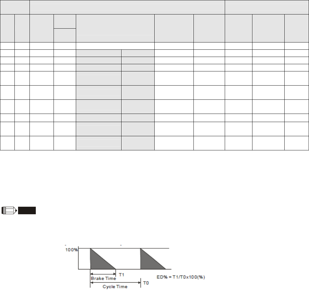
1. Definition for Brake Usage ED%
Explanation: The definition of the brake usage ED (%) is for assurance of enough time for the brake unit and brake resistor
to dissipate away heat generated by braking. When the brake resistor heats up, the resistance would increase with
temperature, and brake torque would decrease accordingly. Recommended cycle time is one minute.
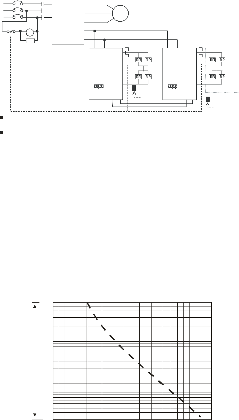
For safety concern, install an overload relay (O.L) between the brake unit and the brake resistor in conjunction with the
magnetic contactor (MC) prior to the drive for abnormal protection. The purpose of installing the thermal overload relay is to
protect the brake resistor from damage due to frequent brake, or due to brake unit keeping operating resulted from unusual
high input voltage. Under such circumstance, just turn off the power to prevent damaging the brake resistor.
Chapter 7 Optional Accessories|CT2000 Series
7-3
MC
MOTOR
O.L.
SA
R/L1
S/L2
T/L3
NFB
MC
IM
Thermal relay
or Temperature Switch
Trip Contact
Va rist o r
Temperature
switch
VFD
U/T1
V/T2
W/T3
+(P)
- (N)
R/L1
S/L2
T/L3
VFDB
XXXX
B1
+
(P)
Thermal relay
Brake unit
-
(N)
MASTER
M1 M2
O.L. Brake
Resistor
B2
VFDB
XXXX
B1
+
(P)
Brake unit
-
(N)
MASTER
M1 M2
B2
Thermal relay
O.L.
Brake
Resistor
22
Parallel Serie/
Temperature switch
。
When AC Drive is equipped with a DC reactor, please read user manual to know t
h
wiring method of input circuit of brake unit +(P).
Do Not connect input circuit -(N) to the neutral point of the power system.
2. If damage to the drive or other equipment is due to the fact that the brake resistors and brake modules in use are not
provided by Delta, the warranty will be void.
3. Take into consideration the safety of the environment when installing the brake resistors. If the minimum resistance value is
to be utilized, consult local dealers for the calculation of Watt figures.
4. When using more than 2 brake units, equivalent resistor value of parallel brake unit can’t be less than the value in the
column “Minimum Equivalent Resistor Value for Each AC Drive” (the right-most column in the table). Please read the wiring
information in the user manual of brake unit thoroughly prior to operation
5. This chart is for normal usage; if the AC motor drive is applied for frequent braking, it is suggested to enlarge 2~3 times of
the Watts.
6. Thermal Relay:
Thermal relay selection is basing on its overload capability. A standard braking capacity for C2000 is 10%ED (Tripping
time=10s). The figure below is an example of 406V, 110kw AC motor drive. It requires the thermal relay to take 260%
overload capacity in 10s (Host starting) and the braking current is 126A. In this case, user should select a rated 50A
thermal relay. The property of each thermal relay may vary among different manufacturer, please carefully read
specification.
60
40
30
20
10
T
r
i
p
p
i
n
g
t
im
e
8
3
2
4
6
1
0.8
0.6
0.4
0.30.8 1 1.5 23456810 1579
Multiple of current setting xln (A)
Second

Chapter 7 Optional Accessories |CT2000 Series
7-4
Non-fuse Circuit Breaker
Comply with UL standard: Per UL 508, paragraph 45.8.4, part a,
The rated current of the breaker shall be 2~4 times of the maximum rated input current of
AC motor drive.
3-phase 460V
Model Recommended
non-fuse breaker (A)
VFD110CT43F21A3; 50
VFD150CT43F21A3; 60
VFD185CT43F21A3; 75
VFD220CT43F21A3; 100
VFD300CT43F21A3; 125
VFD370CT43F21A7; 150
VFD450CT43F00A3; 175
VFD550CT43F00A4; 250
VFD750CT43F00A6; 300
VFD900CT43F00A8; 300
Fuse Specification Chart
Use only the fuses comply with UL certificated.
Use only the fuses comply with local regulations.
Input Current I(A) Line Fuse
460VModel Heavy Duty Normal Duty I (A) Bussmann P/N
VFD110CT43F21A3; 17 22.5 50 JJS-50
VFD150CT43F21A3; 23 30 125 JJS-125
VFD185CT43F21A3; 30 36 75 JJS-75
VFD220CT43F21A3; 36 45 100 JJS-100
VFD300CT43F21A3; 43 56 200 JJS-200
VFD370CT43F21A7; 57 72 150 JJS-150
VFD450CT43F00A3; 69 91 175 JJS-175
VFD550CT43F00A4; 86 110 250 JJS-250
VFD750CT43F00A6; 105 144 300 JJS-300
VFD900CT43F00A8; 143 180 300 JJS-300
Chapter 7 Optional Accessories|CT2000 Series
7-5
AC Reactor
When the AC Motor Drive is connected directly to a large-capacity power transformer
(600kVA or above) or when a phase lead capacitor is switched, excess peak currents may
occur in the power input circuit due to the load changes and the converter section may be
damaged. To avoid this, it is recommend to use a serial connected AC input reactor(6%) at
the AC Motor Drive mains input side to reduce the current and improve the input power
efficiency.
460V, 50/60Hz, 3-phase
Inductance(mh)
kW HP Rated Amps of AC
Reactor Max. continuous
Amps 3% impedance 5% impedance
11 15 25 37.5 1.2 2
15 20 35 52.5 0.8 1.2
18.5 25 45 67.5 0.7 1.2
22 30 45 67.5 0.7 1.2
30 40 80 120 0.4 0.7
37 50 80 120 0.4 0.7
45 60 100 150 0.3 0.45
55 75 130 195 0.2 0.3
75 100 160 240 0.15 0.23
90 125 200 300 0.110 0.185
Applications for AC Reactor
Connected in input circuit
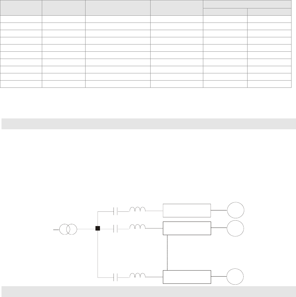
Application 1
When more than one AC motor drive is connected to the same mains power, and one of
them is ON during operation.
Problem: When applying power to one of the AC motor drive, the charge current of the
capacitors may cause voltage dip. The AC motor drive may be damaged when
over current occurs during operation.
Correct wiring:
M1
M2
Mn
reactor
AC motor drive
AC motor drive
AC motor drive
motor
motor
motor
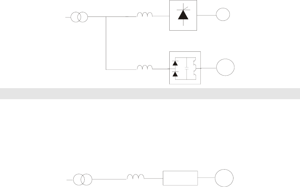
Application 2
Silicon rectifier and AC motor drive are connected to the same power.
Problem: Switching spikes will be generated when the silicon rectifier switches ON/OFF.
These spikes may damage the mains circuit.
Chapter 7 Optional Accessories |CT2000 Series
7-6
Correct wiring:
DC
power reactor
reactor
AC motor drive
motor
silicon rectifier
Application 3
When the power supply capacity exceeds 10 times of the inverter capacity.
Problem: When the mains power capacity is too large, line impedance will be small and the
charge current will be too high. This may damage AC motor drive due to higher
rectifier temperature.
Correct wiring
large-capacity
power reactor
small-capacity
AC motor drive
motor
Chapter 7 Optional Accessories|CT2000 Series
7-7
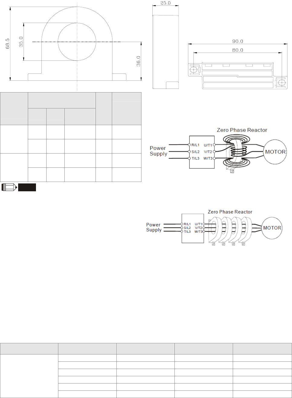
Zero Phase Reactors
RF220X00A UNIT: mm (inch)
Recommended
Wire Size (mm2)
Cable
type
(Note) AWG mm2 Nominal
(mm2)
Qty. Wiring
Method
≤10 ≤5.3 ≤5.5 1
Diagram
A
Single-
core
≤2 ≤33.6 ≤38 4
Diagram
B
≤12 ≤3.3 ≤3.5 1
Diagram
A
Three-
core ≤1 ≤42.4 ≤50 4
Diagram
B
Diagram A
Wind each wire around the core for 4 times. The reactor
must be placed at the AC motor drive output side as
close as possible.
NOTE
600V insulated cable wire
1. The table above gives approximate wire size for
the zero phase reactors but the selection is
ultimately governed by the type and the
diameter of the cable, i.e. the cable diameter
must small enough to go through the center of
the zero phase reactor.
2. When wiring, do not goes through the earth
core. It only needs to pass through the motor
cable or the power cable.
3. When a long motor cable for output is used, a
zero phase reactor may be necessary to reduce
the radiated emission.
Diagram B
Put the wires/cables through the middle of the 4 cores
that lines in parallel.
DC Reactor
460V DC Choke
Input Voltage kW HP DC Amps Inductance (mh)
11 15 38 1.62
15 20 52 1.2
18.5 25 60 1.05
22 30 70 0.89
30 40 93 0.67
460Vac
50/60Hz
3-Phase
37 50 110 0.56

Chapter 7 Optional Accessories |CT2000 Series
7-8
EMI Filter
Model Applicable
EMI Filter Reference Website
VFD110CT43F21A3;
VFD150CT43F21A3;
KMF350A
http://www.dem-uk.com/roxburgh/products/industrial_emc_filters/three_phase_indus
trial_mains_filters_high_performance/
KMF350A Three Phase Industrial Mains Filters - High Performance 50 Amps
VFD185CT43F21A3;
VFD220CT43F21A3;
VFD300CT43F21A3; KMF370A
http://www.dem-uk.com/roxburgh/products/industrial_emc_filters/three_phase_indus
trial_mains_filters_high_performance/
KMF370A Three Phase Industrial Mains Filters - High Performance 70 Amps
VFD370CT43F21A7;
VFD450CT43F00A3;
VFD550CT43F00A4;
VFD750CT43F00A6; MIF3150
http://www.dem-uk.com/roxburgh/products/industrial_emc_filters/three_phase_indus
trial_multi_stage_drive_filters/
MIF3150 Three Phase Industrial Multi Stage Drive Filters - Very High Performance
150 Amps
VFD900CT43F00A8; MIF3400B
http://www.dem-uk.com/roxburgh/products/industrial_emc_filters/three_phase_indus
trial_multi_stage_drive_filters/
MIF3400B Three Phase Industrial Multi Stage Drive Filters - Very High Performance
400 Amps
EMI Filter Installation
All electrical equipment, including AC motor drives, will generate high-frequency/low-frequency noise and will
interfere with peripheral equipment by radiation or conduction when in operation. By using an EMI filter with correct
installation, much interference can be eliminated. It is recommended to use DELTA EMI filter to have the best
interference elimination performance.
We assure that it can comply with following rules when AC motor drive and EMI filter are installed and wired
according to user manual:
EN61000-6-4
EN61800-3: 1996
EN55011 (1991) Class A Group 1 (1st Environment, restricted distribution)
General precaution
1. EMI filter and AC motor drive should be installed on the same metal plate.
2. Please install AC motor drive on footprint EMI filter or install EMI filter as close as possible to the AC motor drive.
3. Please wire as short as possible.
4. Metal plate should be grounded.
5. The cover of EMI filter and AC motor drive or grounding should be fixed on the metal plate and the contact area
should be as large as possible.
Choose suitable motor cable and precautions
Improper installation and choice of motor cable will affect the performance of EMI filter. Be sure to observe the
following precautions when selecting motor cable.
1. Use the cable with shielding (double shielding is the best).
2. The shielding on both ends of the motor cable should be grounded with the minimum length and maximum
contact area.
3. Remove any paint on metal saddle for good ground contact with the plate and shielding.
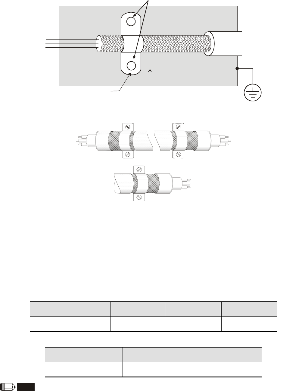
Chapter 7 Optional Accessories|CT2000 Series
7-9
Remove any paint on metal saddle for good ground contact with
the plate and shielding.
saddle the plate with grounding
Figure 1
Saddle on both ends
Saddle on one end
Figure 2
The length of motor cable
When motor is driven by an AC motor drive of PWM type, the motor terminals will experience surge voltages easily
due to components conversion of AC motor drive and cable capacitance. When the motor cable is very long
(especially for the 460V series), surge voltages may reduce insulation quality. To prevent this situation, please
follow the rules below:
Use a motor with enhanced insulation.
Connect an output reactor (optional) to the output terminals of the AC motor drive
The length of the cable between AC motor drive and motor should be as short as possible (10 to 20 m or less)
For models 7.5hp and above:
Insulation level of motor 1000V 1300V 1600V
460VAC input voltage 66 ft (20m) 328 ft (100m) 1312 ft (400m)
For models 5hp and less:
Insulation level of motor 1000V 1300V 1600V
460VAC input voltage 66 ft (20m) 165 ft (50m) 165 ft (50m)
NOTE
Never connect phase lead capacitors or surge absorbers to the output terminals of the AC motor drive.

Chapter 7 Optional Accessories |CT2000 Series
7-10
If the length is too long, the stray capacitance between cables will increase and may cause leakage current. It
will activate the protection of over current, increase leakage current or not insure the correction of current
display. The worst case is that AC motor drive may damage.
If more than one motor is connected to the AC motor drive, the total wiring length is the sum of the wiring
length from AC motor drive to each motor.
For the 460V series AC motor drive, when an overload relay is installed between the drive and the motor to
protect motor over heating, the connecting cable must be shorter than 50m. However, an overload relay
malfunction may still occur. To prevent the malfunction, install an output reactor (optional) to the drive or lower
the carrier frequency setting (Pr.00-17).
NOTE
When a thermal O/L relay protected by motor is used between AC motor drive and motor, it may malfunction
(especially for 460V series), even if the length of motor cable is only 165 ft (50m) or less. To prevent it, please use
AC reactor and/or lower the carrier frequency (Pr. 00-17 PWM carrier frequency).
Chapter 7 Optional Accessories|CT2000 Series
7-11
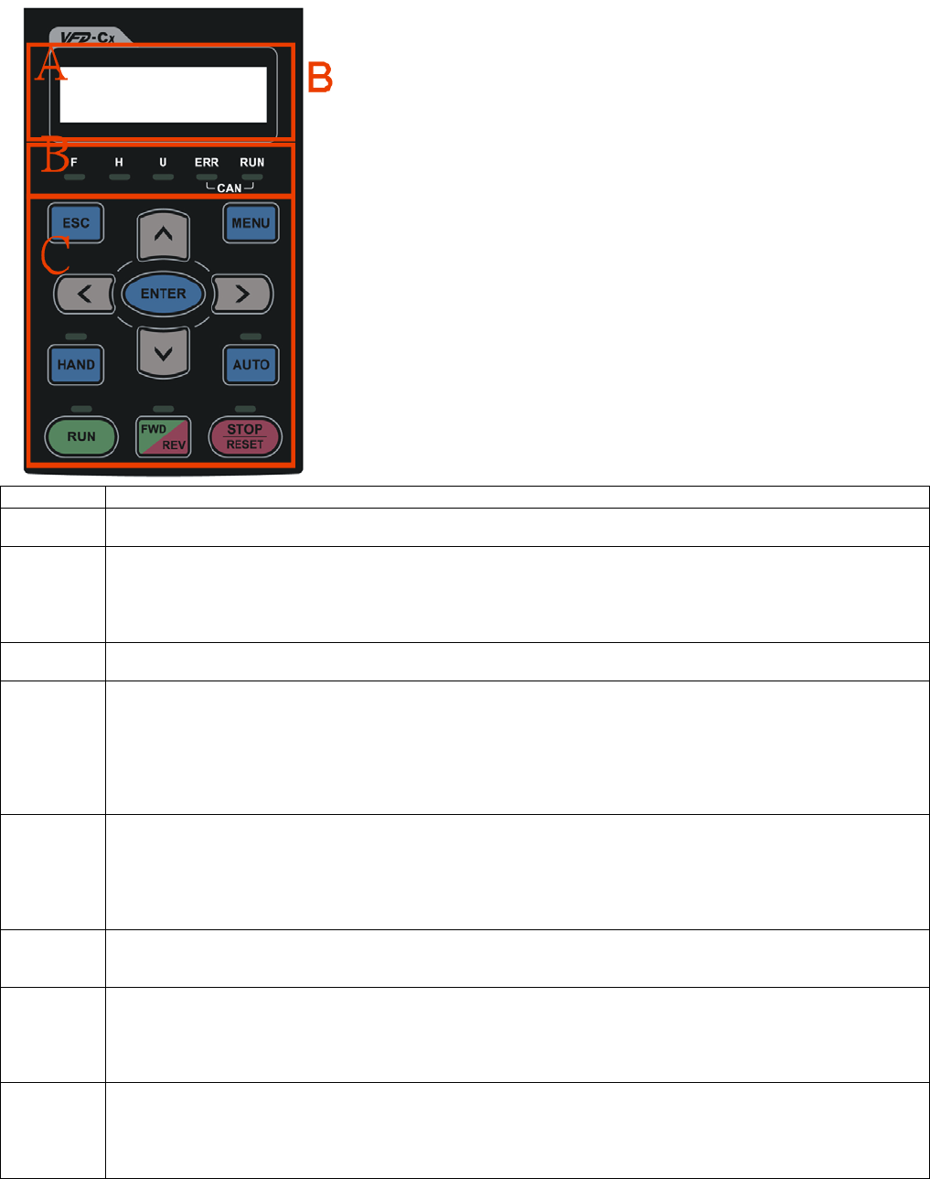
Digital Keypad
KPC-CE01
F: Frequency Command
H: Output Frequency
U: User Defined Units
ERR: CAN Error Indicator
RUN: CAN Run Indicator
: Status Indicator
A
: LED Disp lay
Display frequency, current, voltage and error etc.
C
: Function
(Refer to the chart follows for detail description)
Key Description
ESC ESC Key
Press ESC key to return to the previous page. It also functions as a return to last category key in the sub-menu.
MENU Menu Key
Press MENU key under any condition will return to the main MENU.
Menu content:
1. Parameter Detail
2. Copy Parameter
3. Keypad locked
4. PLC Function
ENTER ENTER Key
Press ENTER and go to the next level. If it is the last level then press ENTER to execute the command.
HAND HAND ON Key
1. HAND key will operates according to the parameter settings when the source of HAND master frequency
command and the source of HAND operation command is properly set,. The factory setting of the source
command for frequency and operation are from the digital keypad .
2. Press HAND key in stop status, the drive setting switches to the parametr setting of H
A
ND. Press HAND key
in during operation, the drive will come to stop then switches to the parameter setting of HAND.
3. When process complete: H/A LED ON.
AUTO Auto Operation Key
1. AUTO function executes according to the parameter settings of the source of AUTO frequency and AUTO
operation. The factory setting is the external terminal (source of operation is 4-20mA).
2. Press the ATUO key in stop status, the drivel switches to auto-setting. Press the auto key during operation
statu, the drivel will come to stop and switch to auto-setting.
3. When process complete: H/A LED is OFF
FWD/REV Operation Direction Key
1. FWD/REV key controls the operation direction but will NOT activate the drive. FWD: forward, REV: reverse.
2. The drive operates in the direction as shown by the LED light.
RUN Start Key
1. It is only valid when the source of operation command is from the keypad.
2. Press the RUN key, the drive will according to the start-up setting and the RUN LED will be ON.
3. RUN key can be pressed for many times when the drive is in stop status.
4. “HAND” mode is enabled only when the source of operation command is by keypad.
STOP Stop Key.
1. STOP key has the highest priority in command.
2. Press STOP key, the drive will come to stop under any condition.
3. The RESET key can be used to reset the drive when faults occur. If the RESET key is not responding, check
MENU Æ Fault Records and checck the most recent fault.
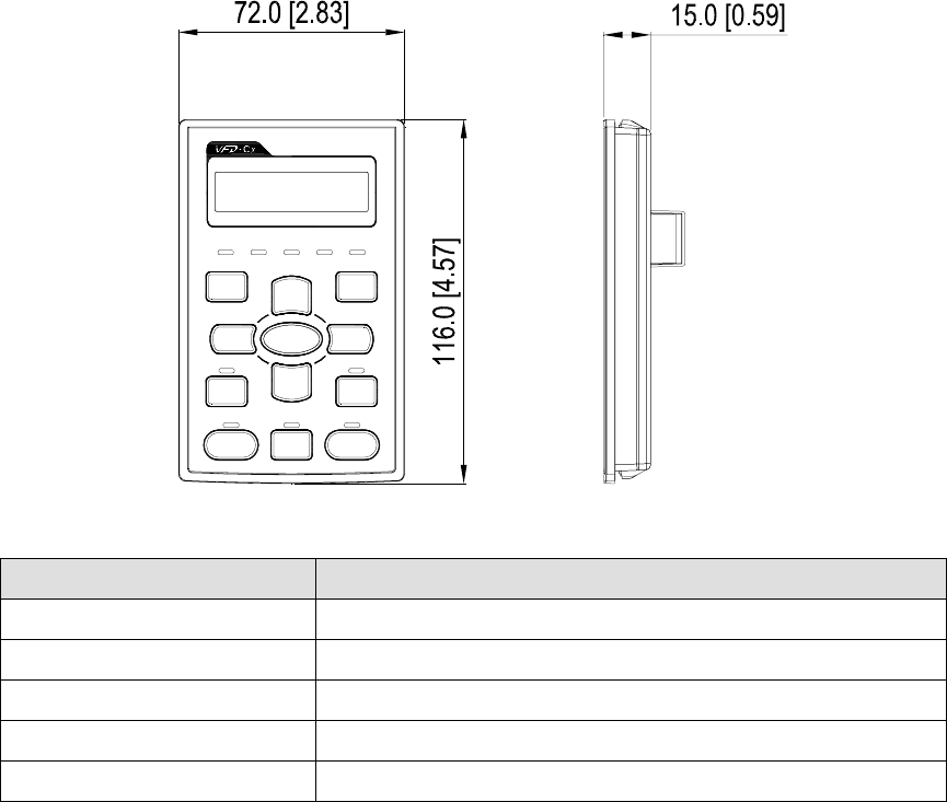
Chapter 7 Optional Accessories |CT2000 Series
7-12
Dimension
RJ45 Extension Lead for Digital Keypad
Part # Description
CBC-K3FT 3 feet RJ45 extension lead (approximately 0.9m)
CBC-K5FT 5 feet RJ45 extension lead (approximately 1.5 m)
CBC-K7FT 7 feet RJ45 extension lead (approximately 2.1 m)
CBC-K10FT 10 feet RJ45 extension lead (approximately 3 m)
CBC-K16FT 16 feet RJ45 extension lead (approximately 4.9 m)
Chapter 7 Optional Accessories|CT2000 Series
7-13
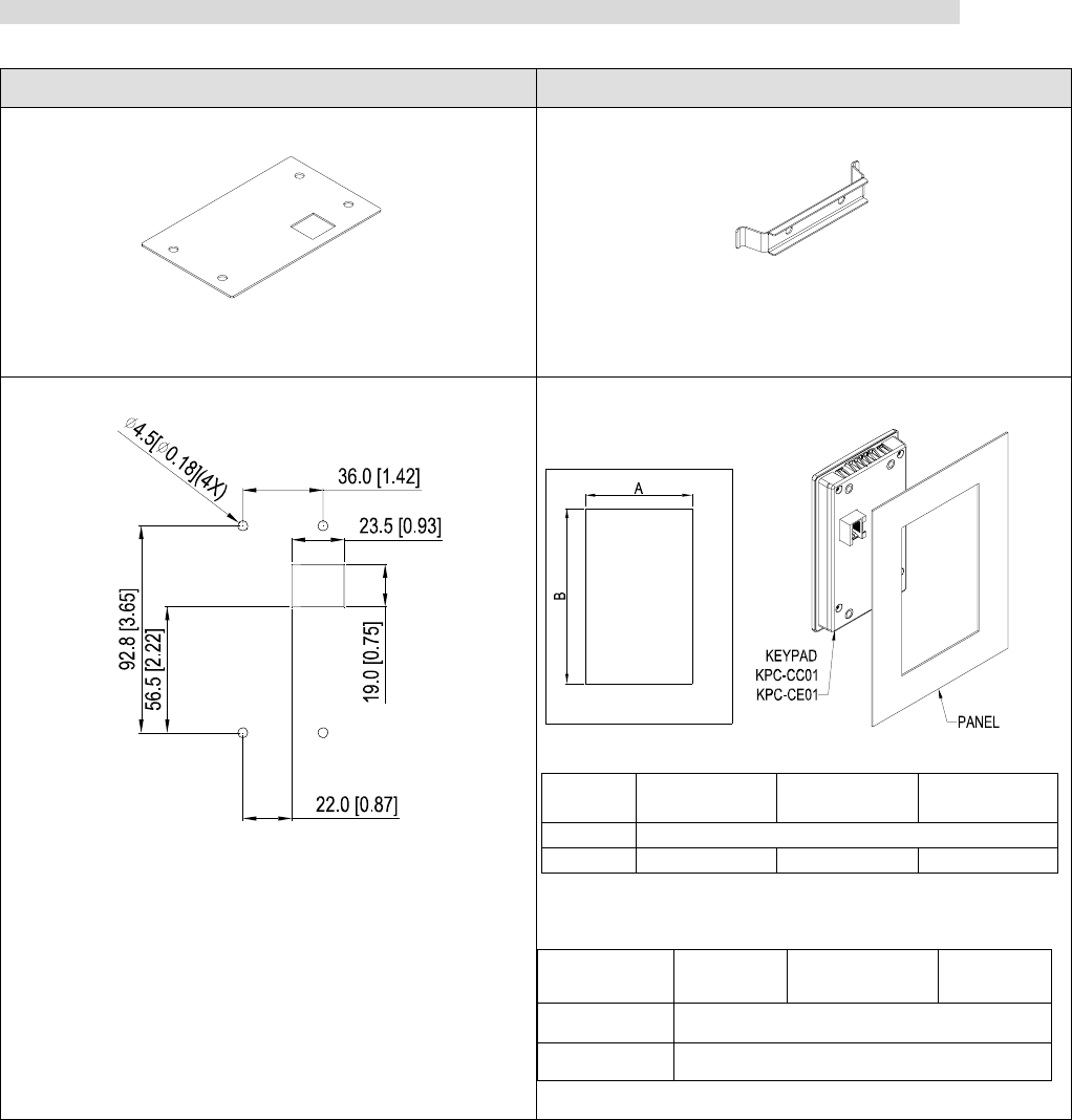
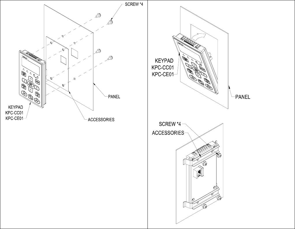
Panel Mounting (MKC-KPPK)
For MKC-KPPK model, user can choose wall mounting or embedded mounting, protection level is IP56.
Applicable to the digital keypads (KPC-CC01 & KPC-CE01).
Wall Mounting Embedded Mounting
accessories*1
Screw *4 ~M4*p 0.7 *L8mm
Torque: 10-12kg-cm (8.7-10.4lb-in.)
accessories*2
Screw *4 ~M4*p 0.7 *L8mm
Torque: 10-12kg-cm (8.7-10.4lb-in.)
Panel cutout dimension Unit: mm [inch]
Panel cutout dimension Unit: mm [inch]
Normal cutout dimension
Panel
thickness 1.2mm 1.6mm 2.0mm
A 66.4 [2.614]
B 110.2 [4.339] 111.3 [4.382] 112.5 [4.429]
*Deviation: ±0.15mm /±0.0059inch
Cutout dimension (Waterproof level: IP56)
Panel
thickness 1.2mm 1.6mm 2.0mm
A 66.4 [2.614]
B 110.8 [4.362]
*Deviation: ±0.15mm /±0.0059inch
Chapter 7 Optional Accessories |CT2000 Series
7-14
Chapter 7 Optional Accessories|CT2000 Series
7-15
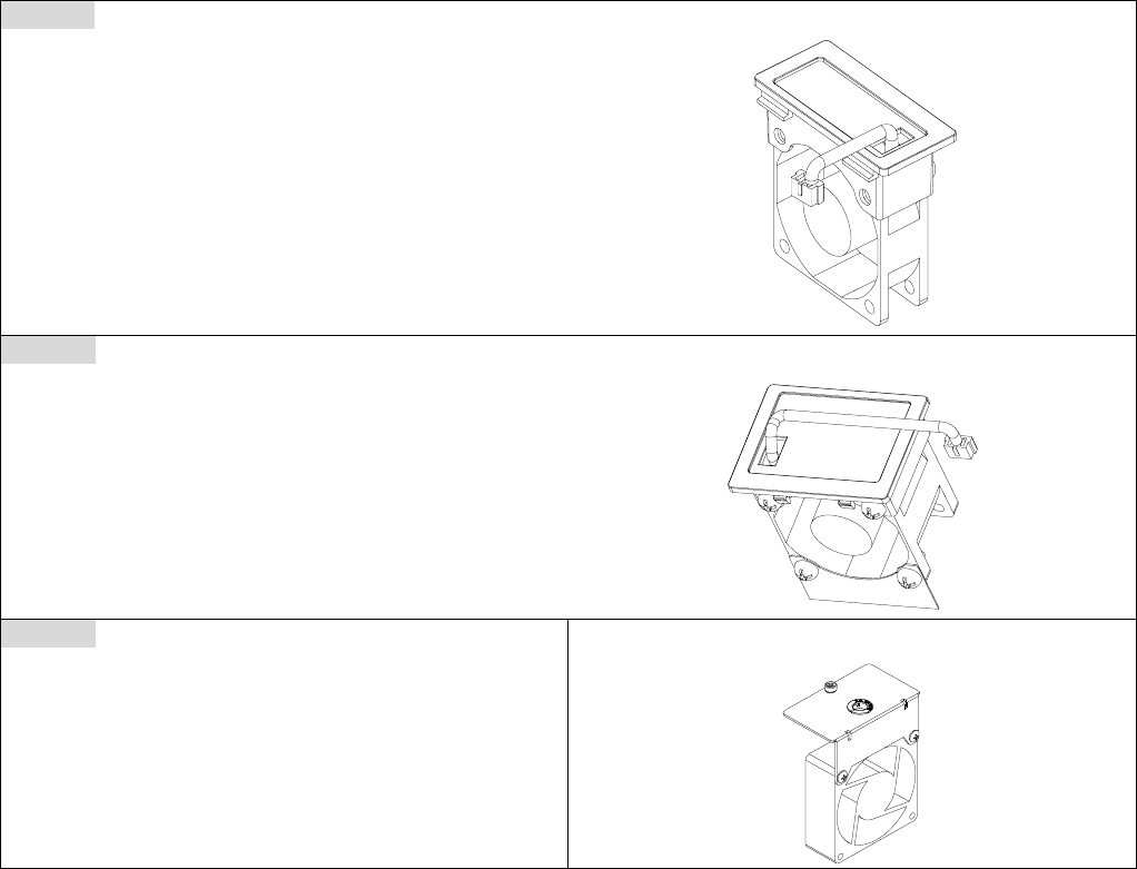
Fan Kit
Frames of the fan kit
Frame B
A
pplicable Model
VFD110CT43F21A3;
VFD150CT43F21A3;
VFD185CT43F21A3;
Model 『MKC-BFKB』
Frame C
A
pplicable Model
VFD220CT43F21A3;
VFD300CT43F21A3;
VFD370CT43F21A7;
Model 『MKC-CFKB2』
Frame D
A
pplicable Model
VFD450CT43F00A3;
VFD550CT43F00A4;
VFD750CT43F00A6;
VFD900CT43F00A8;
Model 『MKC-DFKB』
Chapter 7 Optional Accessories |CT2000 Series
7-16
Fan Removal
Frame B&C
Applicable model
VFD110CT43F21A3;VFD150CT43F21A3; VFD185CT43F21A3; VFD220CT43F21A3;
VFD300CT43F21A3; VFD370CT43F21A7;
Disconnect the power terminal by slotted screwdriver to remove the fan cover.
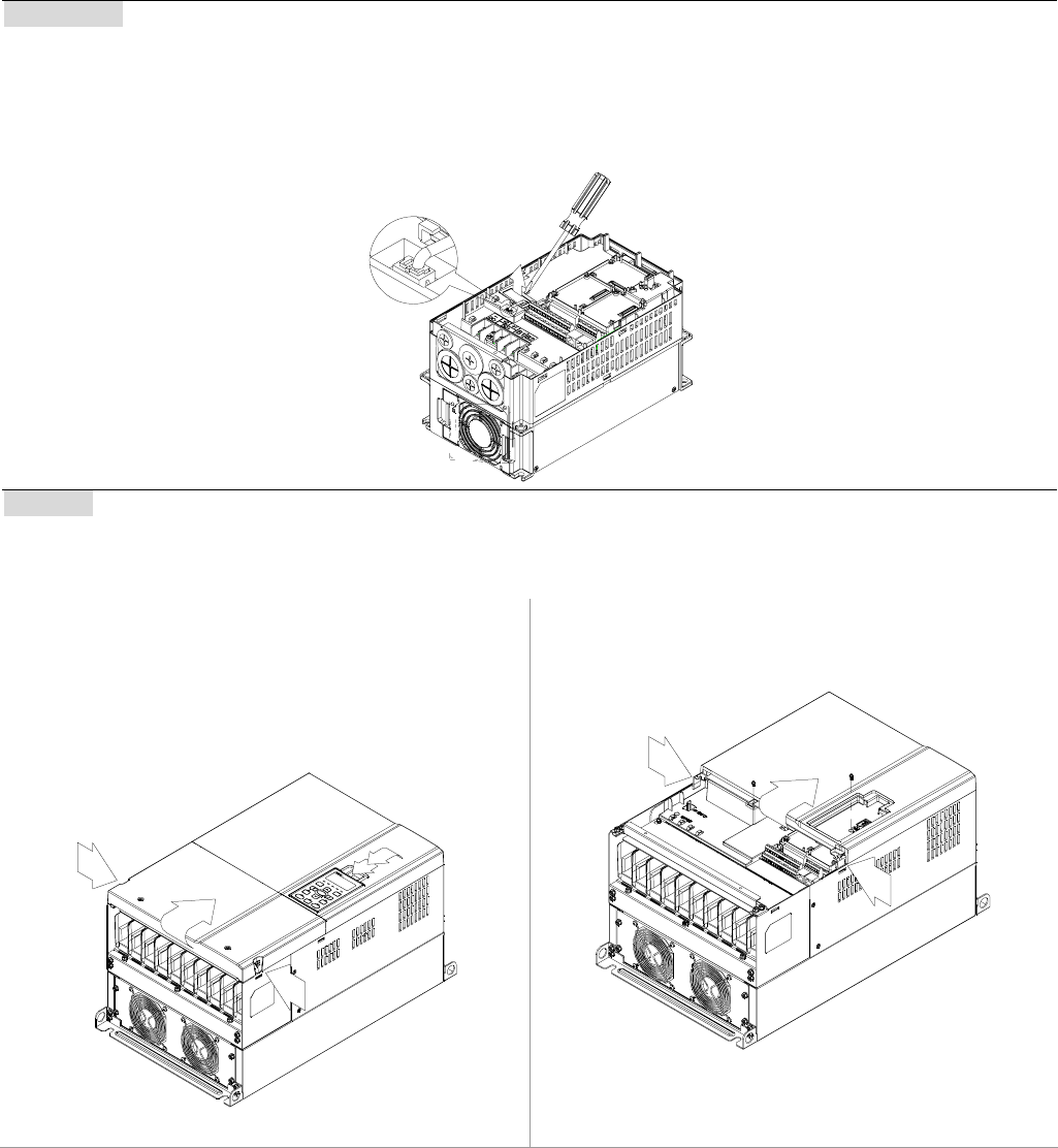
Frame D
Applicable model
VFD450CT43F00A3; VFD550CT43F00A4; VFD750CT43F00A6; VFD900CT43F00A8;
1. (Figure 1) Loosen screw 1 and screw 2, press
the on the right and the left to remove the cover,
follow the direction the arrows indicate. Press on
top of digital keypad KPC-CE01 to properly
remove the keypad. Screw torque: 10~12kg-cm
(8.6~10.4in-lbf).
1
2
Figure 1
2. (Figure 2) Loosen screw 3 and screw 4, press
the tab on the right and the left to remove the
cover. Screw torque: 6~8kg-cm (5.2~6.9in-lbf).
34
Figure 2
Chapter 7 Optional Accessories|CT2000 Series
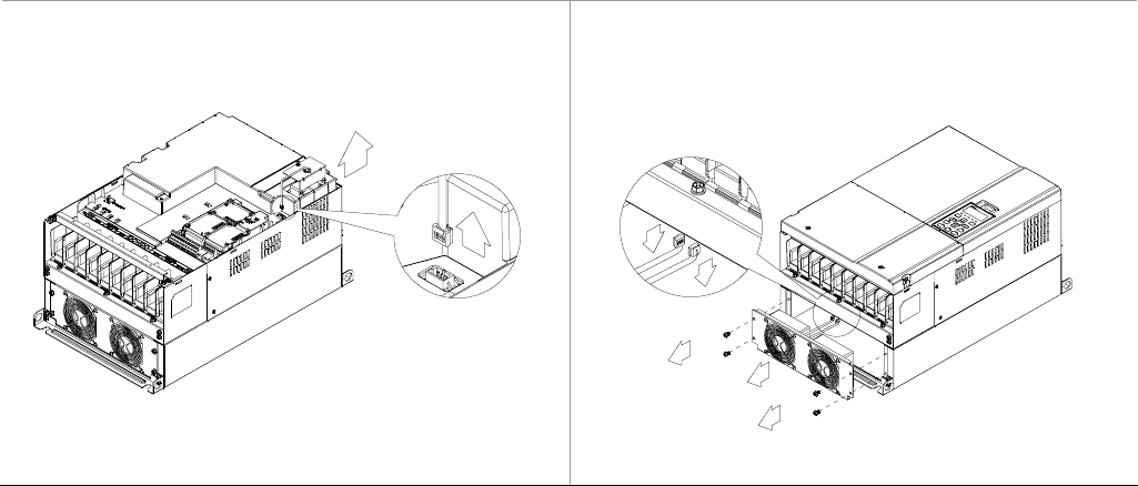
7-17
3. (Figure 3) Loosen screw 5 and disconnect the
fan power. Screw torque: 10~12kg-cm
(8.6~10.4in-lbf).
5
Figure 3
4. (Figure 4) Loosen the screws. Screw torque:
24~26kg-cm (20.8~25.6in-lbf).
5. Disconnect fan power and pull out the fan. (As
shown in the larger picture)
1
2
3
4
Figure 4
Chapter 7 Optional Accessories |CT2000 Series
7-18
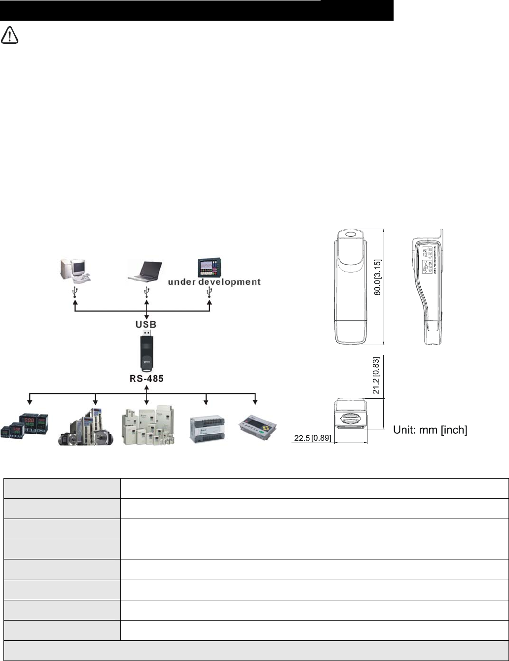
USB/RS-485 Communication Interface IFD6530
Warning
3 Please thoroughly read this instruction sheet before installation and putting it into use.
3 The content of this instruction sheet and the driver file may be revised without prior notice. Please
consult our distributors or download the most updated instruction/driver version at
http://www.delta.com.tw/product/em/control/cm/control_cm_main.asp
1. Introduction
IFD6530 is a convenient RS-485-to-USB converter, which does not require external power-supply and complex
setting process. It supports baud rate from 75 to 115.2kbps and auto switching direction of data transmission. In
addition, it adopts RJ-45 in RS-485 connector for users to wire conveniently. And its tiny dimension, handy use of
plug-and-play and hot-swap provide more conveniences for connecting all DELTA IABU products to your PC.
Applicable Models: All DELTA IABU products.
(Application & Dimension)
2. Specifications
Power supply No external power is needed
Power consumption 1.5W
Isolated voltage 2,500VDC
Baud rate 75, 150, 300, 600, 1,200, 2,400, 4,800, 9,600, 19,200, 38,400, 57,600, 115,200 bps
RS-485 connector RJ-45
USB connector A type (plug)
Compatibility Full compliance with USB V2.0 specification
Max. cable length RS-485 Communication Port: 100 m
Support RS-485 half-duplex transmission
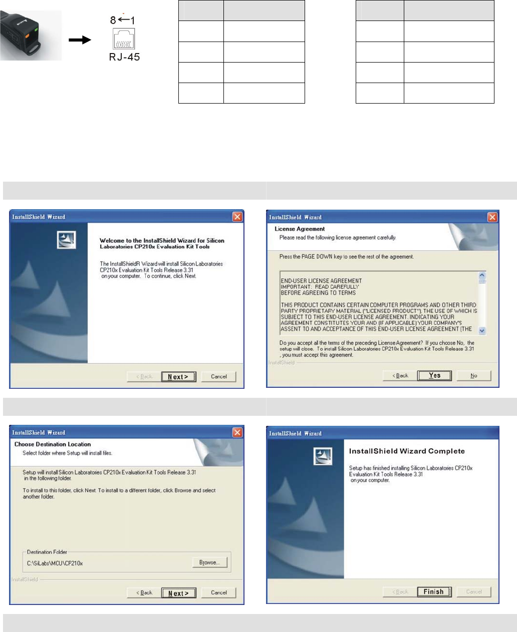
Chapter 7 Optional Accessories|CT2000 Series
7-19
RJ-45
PIN Description PIN Description
1 Reserved 5 SG+
2 Reserved 6 GND
3 GND 7 Reserved
4 SG- 8 +9V
3. Preparations before Driver Installation
Please extract the driver file (IFD6530_Drivers.exe) by following steps. You could find driver file
(IFD6530_Drivers.exe) in the CD supplied with IFD6530.
Note: DO NOT connect IFD6530 to PC before extracting the driver file.
STEP 1 STEP 2
STEP 3 STEP 4
STEP 5
You should have a folder marked SiLabs under drive C. c:\ SiLabs
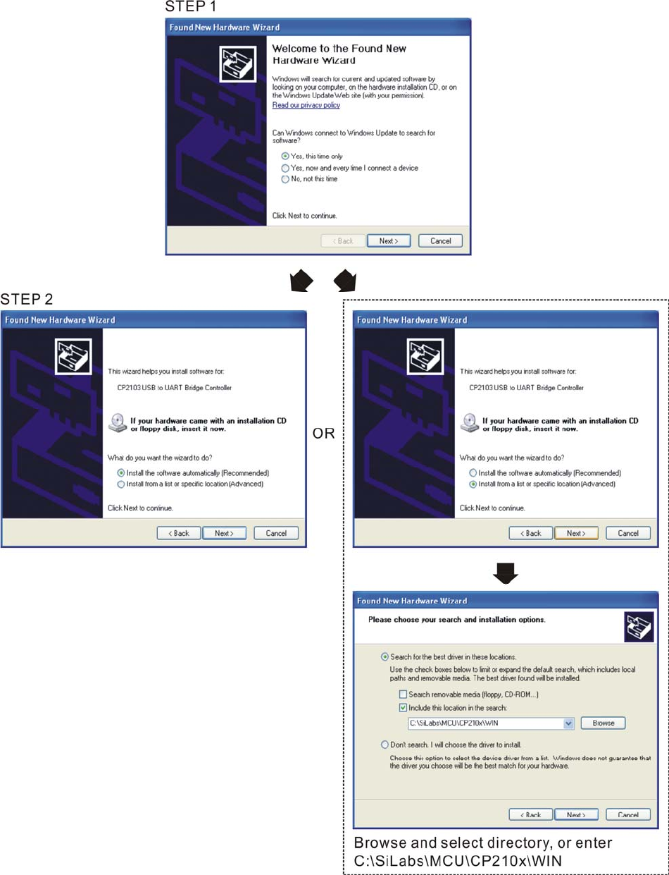
Chapter 7 Optional Accessories |CT2000 Series
7-20
4. Driver Installation
After connecting IFD6530 to PC, please install driver by following steps.
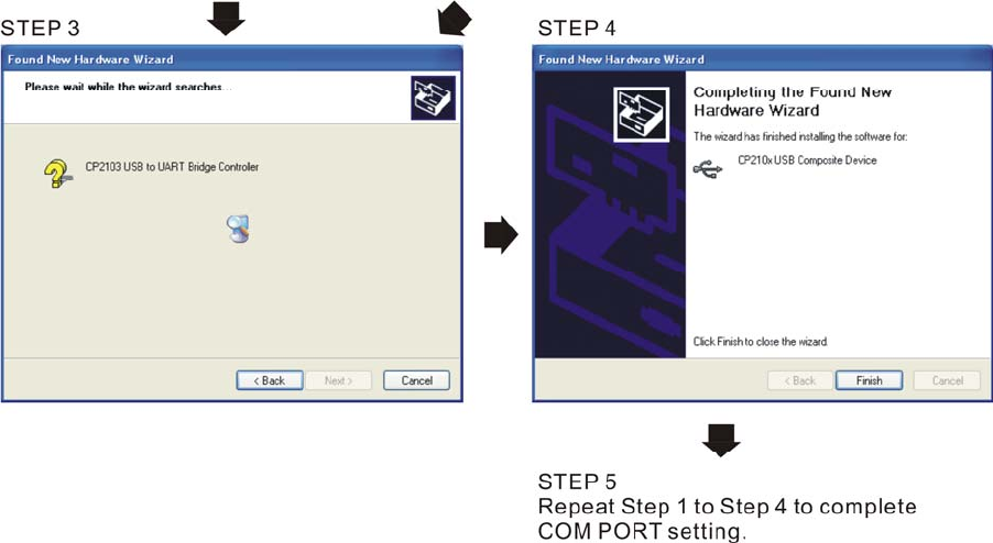
Chapter 7 Optional Accessories|CT2000 Series
7-21
5. LED Display
1. Steady Green LED ON: power is ON.
2. Blinking orange LED: data is transmitting.
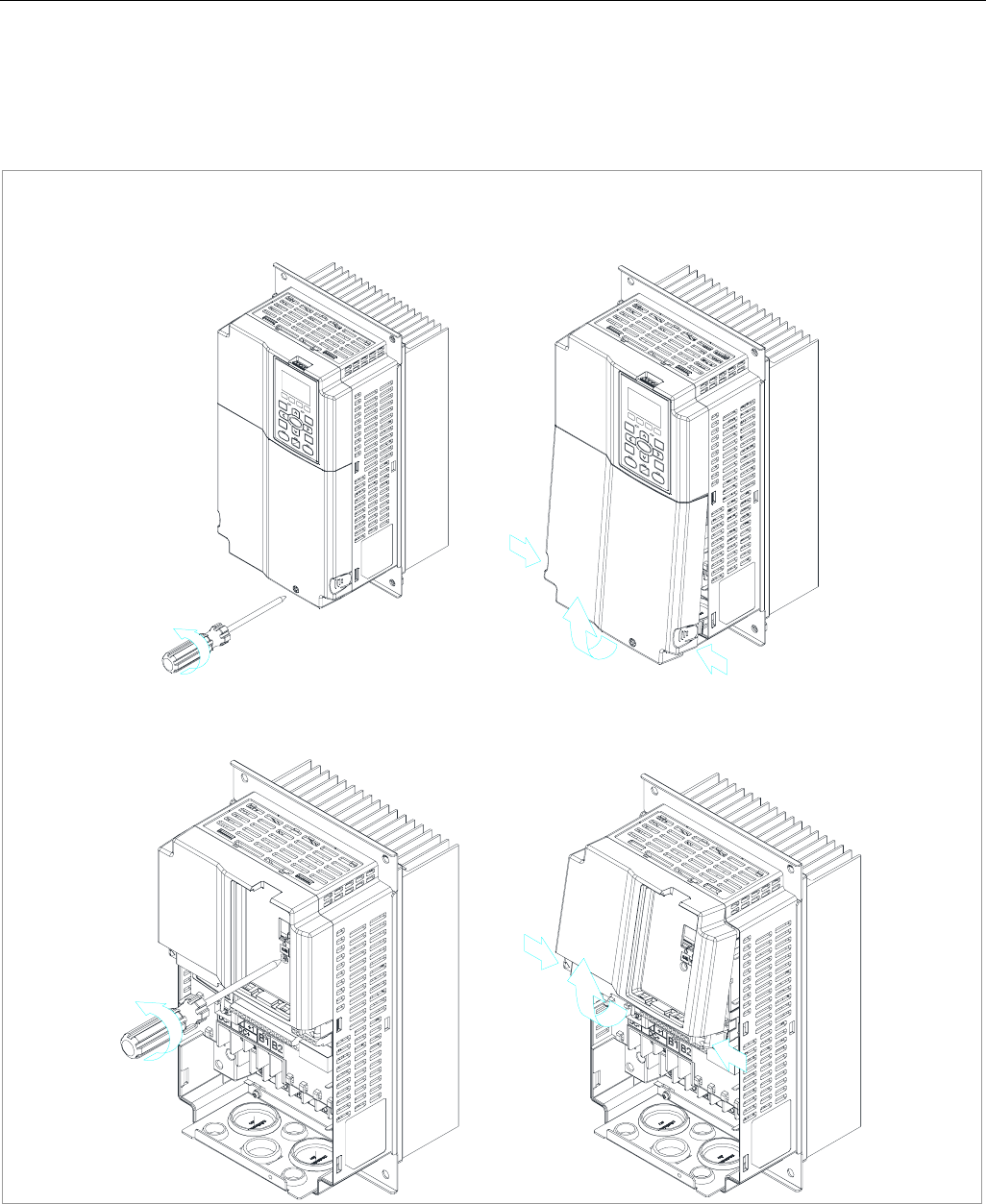
Chapter 8 Optional Cards |CT2000 Series
8-1
Chapter 8 Option Cards
Please select applicable option cards for your drive or contact local distributor for suggestion.
To prevent drive damage during installation, please removes the digital keypad and the cover before
wiring. Refer to the following instruction.
Removed key cover
Frame B&C
Screw Torque: 12~15Kg-cm [10.4~13lb-in.]
A
fter loosing screws, press the snap locks on the both side and rotate to pull it out.
Screw Torque: 6~8Kg-cm [5.2~6.9lb-in.]
A
fter loosing screws, press the snap locks on the both side and rotate to pull it out.
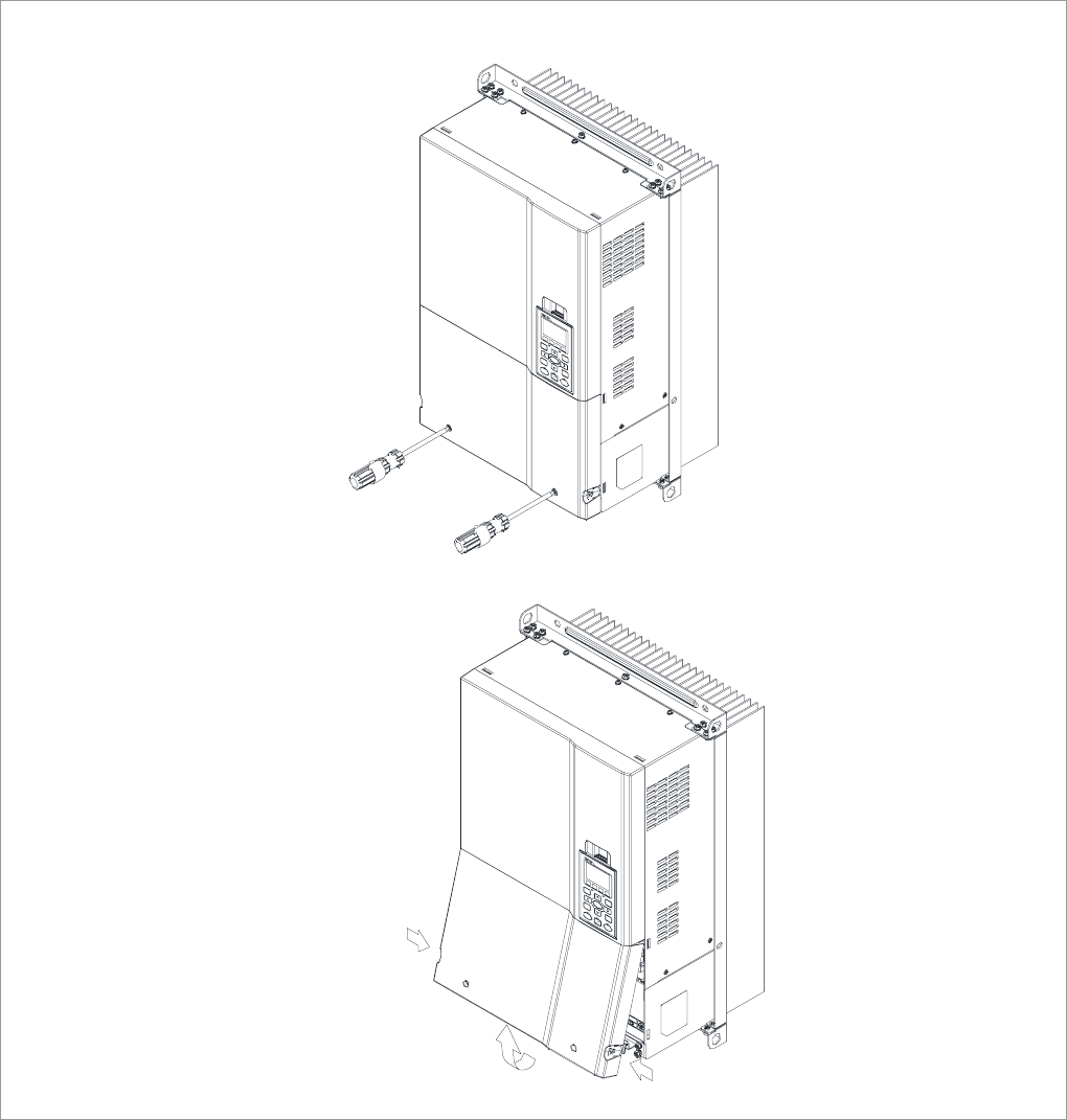
Chapter 8 Optional Cards |CT2000 Series
8-2
Frame D
(1) Screw Torque: 10~12Kg-cm [8.7~10.4lb-in.]
(2) After loosing screws, press the snap locks on the both side and rotate to pull it out.
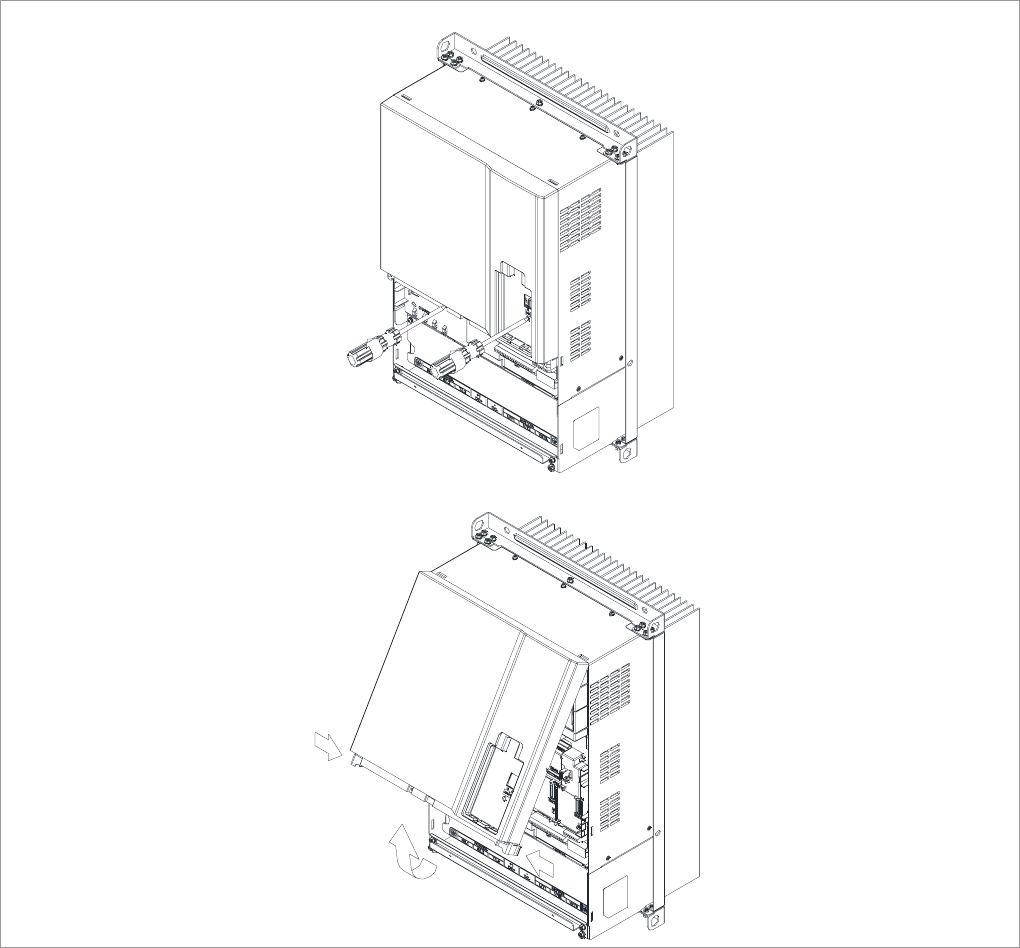
Chapter 8 Optional Cards |CT2000 Series
8-3
(3) Screw Torque: 6~8Kg-cm [5.2~6.9lb-in.]
(4) After loosing screws, press the snap locks on the both side and rotate to pull it out.
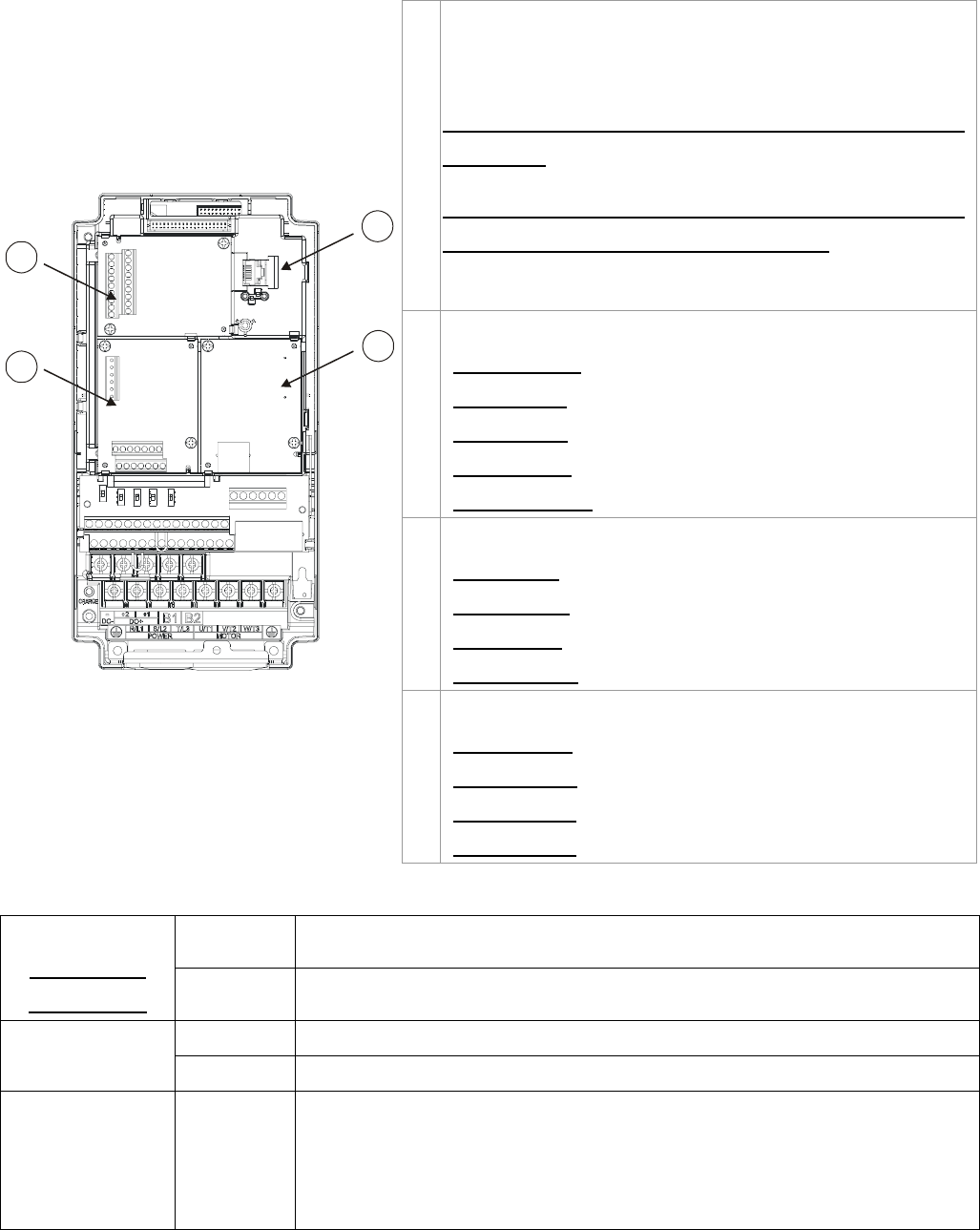
Chapter 8 Optional Cards |CT2000 Series
8-4
1
2
3
4
Slot 1Slot 2
Slot 3
1RJ45 (Socket) for digital keypad
KPC-CC01; KPC-CE01
Please refer to CH10 Digital Keypad for more details on
KPC-CE01.
Please refer to CH10 Digital Keypad for more details on
optional accessory RJ45 extension cable.
2 Communication extension card (Slot 1)
CMC-MOD01;
CMC-PD01;
CMC-DN01;
CMC-EIP01;
EMC-COP01;
3 I/O & Relay extension card (Slot 3)
EMC-D42A;
EMC-D611A;
EMC-R6AA;
EMC-BPS01;
4 PG Card (Slot 2)
EMC-PG01L;
EMC-PG01O;
EMC-PG01U;
EMC-PG01R;
Screws Speciation for option card terminals:
Wire gauge 24~12AWG(0.205~3.31mm2)
EMC-D42A
EMC-D611A
EMC-BPS01 Torque 4Kg-cm [3.47Ib-in]
Wire gauge 24~16AWG(0.205~1.31mm2)
EMC-R6AA Torque 6Kg-cm [5.21Ib-in]
EMC-PG01L
EMC-PG01O
EMC-PG01R
EMC-PG01U
Wire gauge
Torque
30~16AWG(0.0509~1.31mm2)
2Kg-cm [1.74Ib-in]

Chapter 8 Optional Cards |CT2000 Series
8-5
EMC-D42A
Terminals Descriptions
COM
Common for Multi-function input terminals
Select SINK(NPN)/SOURCE(PNP)in J1 jumper / external power
supply
MI10~ MI13
Refer to parameters 02-26~02-29 to program the multi-function
inputs MI10~MI13.
Internal power is applied from terminal E24: +24Vdc±5% 200mA,
5W
External power +24VDC: max. voltage 30VDC, min. voltage
19VDC, 30W
ON: the activation current is 6.5mA
OFF: leakage current tolerance is 10μA
MO10~MO11
Multi-function output terminals (photocoupler)
Duty-cycle: 50%
Max. output frequency: 100Hz
Max. current: 50mA
Max. voltage: 48Vdc
I/O Extension
Card
MXM
Common for multi-function output terminals MO10,
MO11(photocoupler)
Max 48VDC 50mA
EMC-D611A
Terminals Descriptions
AC AC power Common for multi-function input terminal (Neutral)
I/O Extension
Card MI10~ MI15
Refer to Pr. 02.26~ Pr. 02.31 for multi-function input selection
Input voltage: 100~130VAC
Input frequency: 57~63Hz
Input impedance: 27Kohm
Terminal response time:
ON: 10ms
OFF: 20ms
EMC-R6AA
Terminals Descriptions
Relay Extension
Card R10A~R15A
R10C~R15C
Refer to Pr. 02.36~ Pr. 02.41 for multi-function input selection
Resistive load:
5A(N.O.)/3A 250VAC
5A(N.O.)/3A 30VDC
Inductive load (COS 0.4)
2.0A(N.O.)/1.2A 250VAC
2.0A(N.O.)/1.2A 30VDC
It is used to output each monitor signal, such as drive is in
operation, frequency attained or overload indication.

Chapter 8 Optional Cards |CT2000 Series
8-6
EMC-BPS01
Terminals Descriptions
External Power
Supply 24V
GND
Input power: 24V±5%
Maximum input current:0.5A
Note:
1) Do not connect control terminal +24V (Digital control signal common:
SOURCE) directly to the EMC-BPS01input terminal 24V.
2) Do not connect control terminal GND directly to the EMC-BPS01 input
termina GND.
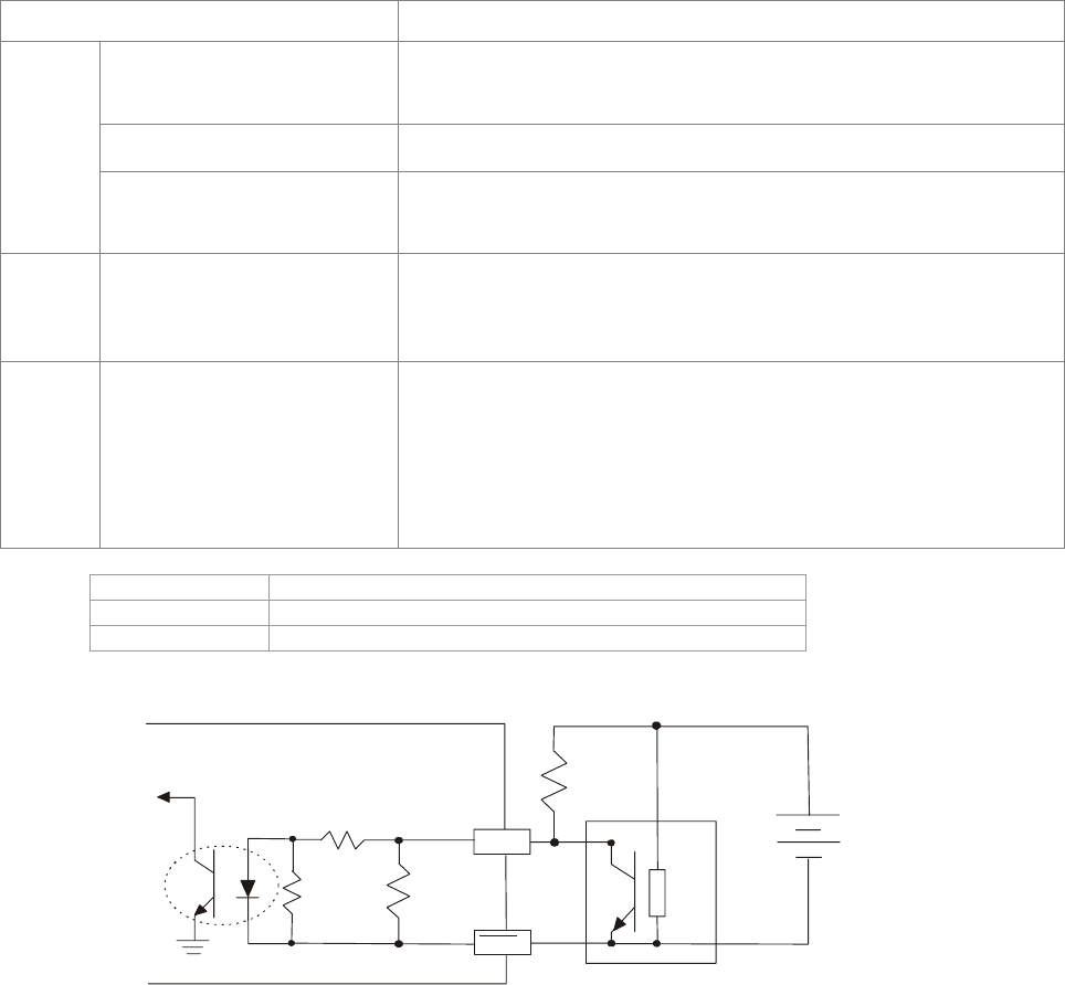
Chapter 8 Optional Cards |CT2000 Series
8-7
EMC-PG01L
Terminal description
Set by Pr.10-00~10-02
Terminals Descriptions
VP
Output voltage for power: +5V/+12V±5% (use FSW3 to
switch +5V/+12V)
Max. output current: 200mA
DCM Common for power and signal
PG1
A1, /A1, B1, /B1, Z1, /Z1
Encoder input signal (Line Driver)
It can be 1-phase or 2-phase input.
Max. output frequency: 300kP/sec
PG2 A2, /A2,
B2, /B2
Pulse Input signal (Line Driver or Open Collector)
Open Collector input voltage: +5~+24V (Note1)
It can be 1-phase or 2-phase input.
Max. output frequency: 300kP/sec.
PG OUT
AO, /AO,
BO, /BO,
ZO, /ZO,
SG,
PG Card Output signals. It has division frequency function:
1~255 times
Max. output voltage for Line driver: 5VDC
Max. output current: 50mA
Max. output frequency: 300kP/sec
SG is the GND of PG card. It is also the GND of position machine or
PLC to make the ouput signal to be the common pivot point.
Note 1: Open Collector application, input current 5~15mA to each set then each set needs one pull-up resistor.
5V Recommanded pull-up resistor: above100~220Ω, 1/2W
12V Recommanded pull-up resistor: above 510~1.35kΩ, 1/2W
24V Recommanded pull-up resistor, above1.8k~3.3kΩ, 1/2W
PG2 Wiring Diagram
AB2
AB2
Ext Pull
high RES
Ext Power
(5-24V)
Ext Ground
4.7k
Ω
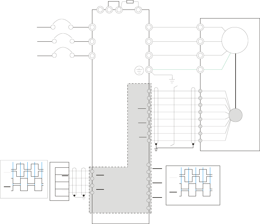
Chapter 8 Optional Cards |CT2000 Series
8-8
Wiring Diagram
; Please use a shielded cable to prevent interference. Do not run control wires parallel to any high voltage
AC power line (200 V and above).
; Recommended wire size 0.21 to 0.81mm2 (AWG24 to AWG18).
; Cable length: Less than 100m
R/L1
S/L2
T/L3
NFB
R
S
T
+1 +2/B1 B2
U/T1
V/T2
W/T3
M
3~
-U
W
V
VP
DCM
A1
A1
B1
B1
Z1
Z1
PG
A2
A2
B2
B2
Line driver
EH-PLC
Y0
Y0
Y1
Y1
Y0
Y0
Y1
Y1
AO
AO
BO
BO
ZO
ZO
EMC-PG01L
AO
AO
BO
BO
Phase difference90
o
SG
Jumper
No-Fuse Breaker
Braking resistor (optional)
Motor
Reflective Encoders
Phase difference90
o
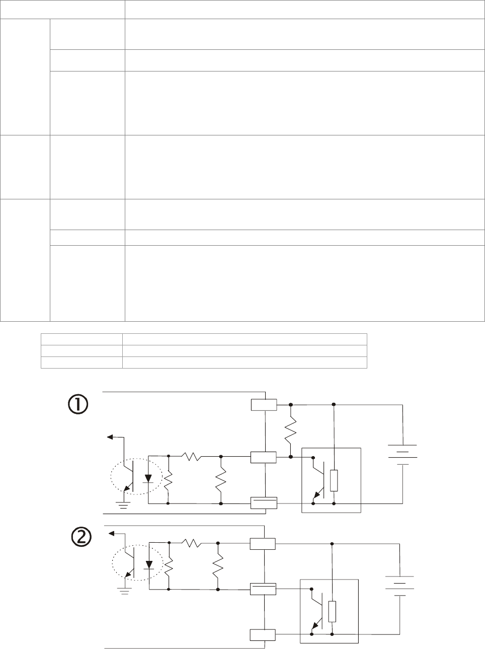
Chapter 8 Optional Cards |CT2000 Series
8-9
EMC-PG01O
Terminal descriptions
Set by Pr.10-00~10-02
Terminals Descriptions
VP Output voltage for power: +5V/+12V±5% (use FSW3 to switch +5V/+12V)
Max. output current: 200mA
DCM Common for power and signal
PG1
A1, /A1, B1,
/B1, Z1, /Z1
Encoder Input signal (Line Driver or Open Collector)
Open Collector Input Voltage: +5V/+12V
It can be 1-phase or 2-phase input.
Max. output frequency: 300kP/sec
PG2 A2, /A2,
B2, /B2
Pulse Input Signal (Line Driver or Open Collector)
Open Collector Input Voltage: +5~+24V
It can be 1-phase or 2-phase input.
Max. output frequency: 300kP/sec.
V+, V+ Needs external power source for PG OUT circuit.
Input voltage of power:+12V ~ +24V
V- Input voltage for the negative side
PG OUT
A/O, B/O, Z/O
PG Card Output signals has division frequency function: 1~255 times.
On the open collector’s output signal, add a high-pull resistor on the external
power V+ ~ V- (e.g. power of PLC) to prevent the interference of the receiving
signal. Max. 。[Three pull-up resistor are included in the package (1.8kW/1W)]
Max. output frequency: 300KP/Sec
Note 1: Open Collector application, input current 5~15mA to each set then each set needs one pull-up resistor.
5V Recommanded pull-up resistor: above100~220Ω, 1/2W
12V Recommanded pull-up resistor: above 510~1.35kΩ, 1/2W
24V Recommanded pull-up resistor, above1.8k~3.3kΩ, 1/2W
PG1 Wiring Diagram
ABZ1
ABZ1
V
p
DCM
Vp
Ext Pull
high RES
4.7k
Ω
ABZ1
ABZ1
V
p
DCM
DCM
4.7k
Ω
When wiring in this way, if there a signal on EMC-PG01's
A1, B1 and Z1,LED lights is OFF.
if A1, B1 and Z1 have no signals, LED lights is ON.
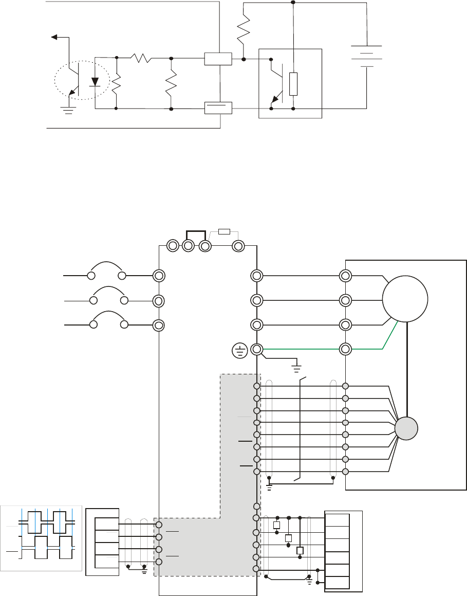
Chapter 8 Optional Cards |CT2000 Series
8-10
PG2 Wiring Diagram
AB2
AB2
Ext Pull
high RES
Ext Power
(5-24V)
Ext Ground
4.7k
Ω
Wiring Diagram
; Please use a shielded cable to prevent interference. Do not run control wires parallel to any high voltage
AC power line (200 V and above).
; Recommended wire size 0.21 to 0.81mm2 (AWG24 to AWG18).
; Cable length: Less than 100m
R/L1
S/L2
T/L3
NFB
R
S
T
+1 +2/B1 B2
U/T1
V/T2
W/T3
M
3~
-U
W
V
VP
DCM
A1
A1
B1
B1
Z1
Z1
PG
A2
A2
B2
B2
EMC-PG01O
Line driver/
Open Collector
EH-PLC
Y0
Y0
Y1
Y1
Y0
Y0
Y1
Y1
V+
A/O
B/O
Z/O
V+
V-
EH-PLC
+24V
X1
X2
S/S
24G
X0
R
R
R
Jumper
No-Fuse Breaker
Braking resistor (optional)
Motor
Reflective Encoders
Phase difference90
o
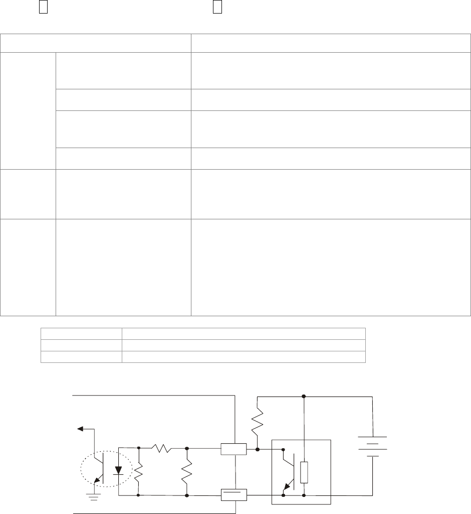
Chapter 8 Optional Cards |CT2000 Series
8-11
EMC-PG01U
FJMP1 S: Standard UVW Output Encoder; D: Delta Encoder
Set by Pr.10-00~10-02
Terminals Descriptions
VP
Output voltage for power: +5V/+12V±5% (use FSW3 to
switch +5V/+12V)
Max. output current: 200mA
DCM Common for power and signal
A1, /A1, B1, /B1, Z1, /Z1
Encoder input signal (Line Driver)
It can be 1-phase or 2-phase input.
Max. output frequency: 300kP/sec
PG1
U1, /U1, V1, /V1, W1, /W1 Encoder input signal
PG2 A2, /A2,
B2, /B2
Pulse Input signal (Line Driver or Open Collector)
Open Collector Input Voltage: +5~+24V (Note1)
It can be 1-phase or 2-phase input.
Max. output frequency: 300kP/sec.
PG OUT AO, /AO, BO, /BO, ZO,
/ZO, SG
PG Card Output signals.
It has division frequency function: 1~255 times
Max. output voltage for Line driver: 5Vdc
Max. output current: 50mA
Max. output frequency: 300kP/sec
SG is the GND of PG card. It is also the GND of position
machine or PLC to make the ouput signal to be the common
pivot point.
Note 1: Open Collector application, input current 5~15mA to each set then each set needs one pull-up resistor.
5V Recommanded pull-up resistor: above100~220Ω, 1/2W
12V Recommanded pull-up resistor: above 510~1.35kΩ, 1/2W
24V Recommanded pull-up resistor, above1.8k~3.3kΩ, 1/2W
PG2 Wiring Diagram
AB2
AB2
Ext Pull
high RES
Ext Power
(5-24V)
Ext Ground
4.7k
Ω
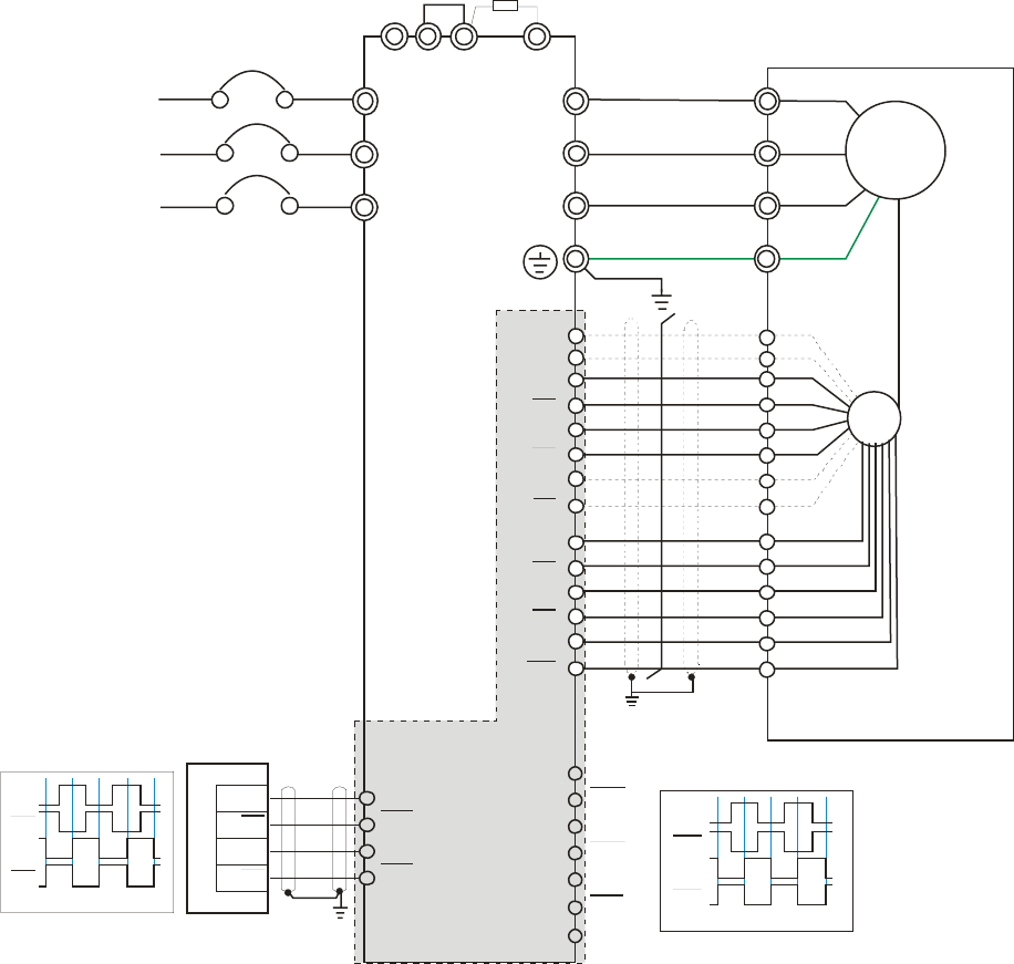
Chapter 8 Optional Cards |CT2000 Series
8-12
Wiring Diagram
; Please use a shielded cable to prevent interference. Do not run control wires parallel to any high voltage
AC power line (200 V and above).
; Recommended wire size 0.21 to 0.81mm2 (AWG24 to AWG18).
; Cable length: Less than 100m
R/L1
S/L2
T/L3
NFB
R
S
T
+1 +2/B1 B2
U/T1
V/T2
W/T3
M
3~
-U
W
V
EMC-PG01U
AO
AO
BO
BO
ZO
ZO
VP
DCM
A1
A1
B1
B1
Z1
Z1
PG
U1
U1
V1
V1
W1
W1
A2
A2
B2
B2
EH-PLC
Y0
Y0
Y1
Y1
Y0
Y0
Y1
Y1
SG
AO
AO
BO
BO
Line driver
Jumper
No-Fuse Breaker
Braking resistor (optional)
Motor
Encoder
Phase difference90
o
Phase difference90
o
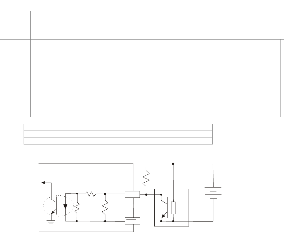
Chapter 8 Optional Cards |CT2000 Series
8-13
EMC-PG01R
Terminal Descriptions
Set by Pr.10-00~10-02
Terminals Descriptions
R1- R2 Resolver Output Power
7Vrms, 10kHz
PG1
S1,S2, S3, S4, Resolver Input Signal
3.5±0.175Vrms, 10kHz
PG2 A2, /A2,
B2, /B2
Pulse Input signal (Line Driver or Open Collector)
Open Collector Input Voltage: +5~+24V (Note1)
It can be 1-phase or 2-phase input.
Max. output frequency: 300kP/sec.
PG OUT
AO, /AO,
BO, /BO,
ZO, /ZO,
SG,
PG Card Output signals. It has division frequency function: 1~255
times
Max. output voltage for Line driver: 5VDC
Max. output current: 50mA
Max. output frequency: 300kP/sec
SG is the GND of PG card. It is also the GND of position machine or PLC to
make the ouput signal to be the common pivot point.
Note 1: Open Collector application, input current 5~15mA to each set then each set needs one pull-up resistor.
5V Recommanded pull-up resistor: above100~220Ω, 1/2W
12V Recommanded pull-up resistor: above 510~1.35kΩ, 1/2W
24V Recommanded pull-up resistor, above1.8k~3.3kΩ, 1/2W
PG2 Wiring Diagram
AB2
AB2
Ext Pull
high RES
Ext Power
(5-24V)
Ext Ground
4.7k
Ω
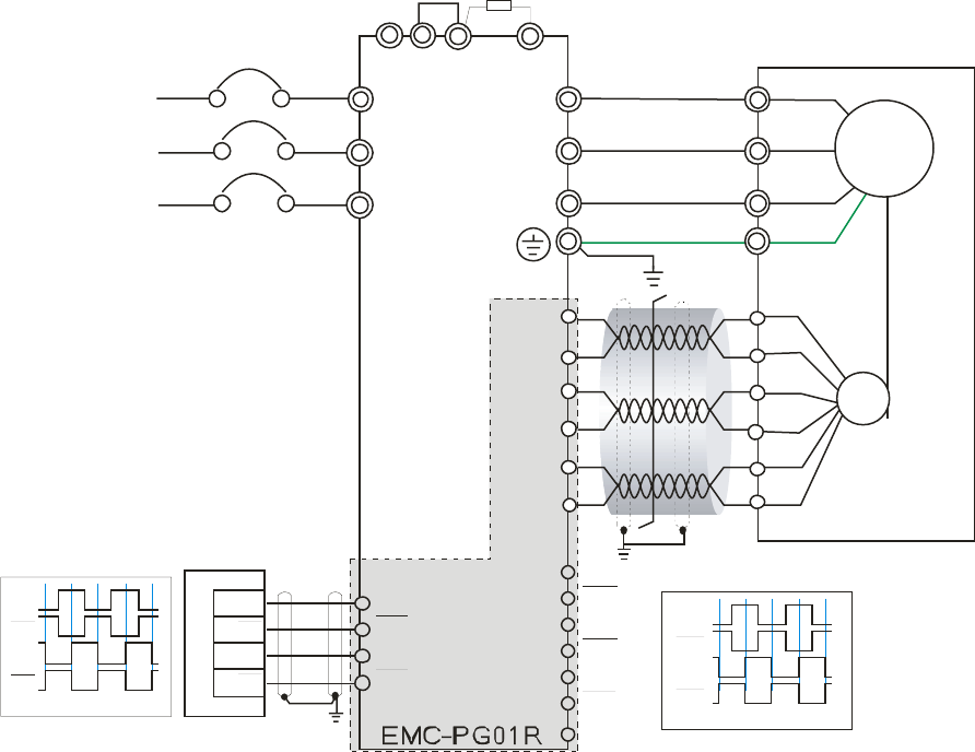
Chapter 8 Optional Cards |CT2000 Series
8-14
Wiring Diagram
; Please use a shielded cable to prevent interference. Do not run control wires parallel to any high voltage
AC power line (200 V and above).
; Recommended wire size 0.21 to 0.81mm2 (AWG24 to AWG18).
; Cable length: Less than 100m
R/L1
S/L2
T/L3
NFB
R
S
T
+1 +2/B1 B2
U/T1
V/T2
W/T3
M
3~
-U
W
V
AO
AO
BO
BO
ZO
ZO
PG
A2
A2
B2
B2
EH-PLC
Y0
Y0
Y1
Y1
Y0
Y0
Y1
Y1
Resolver
R1
R2
S2
S4
S1
S3
SG
AO
AO
BO
BO
Jumper
No-Fuse Breaker
Braking resistor (optional)
Motor
Encoder
Phase difference90o
Phase difference90o
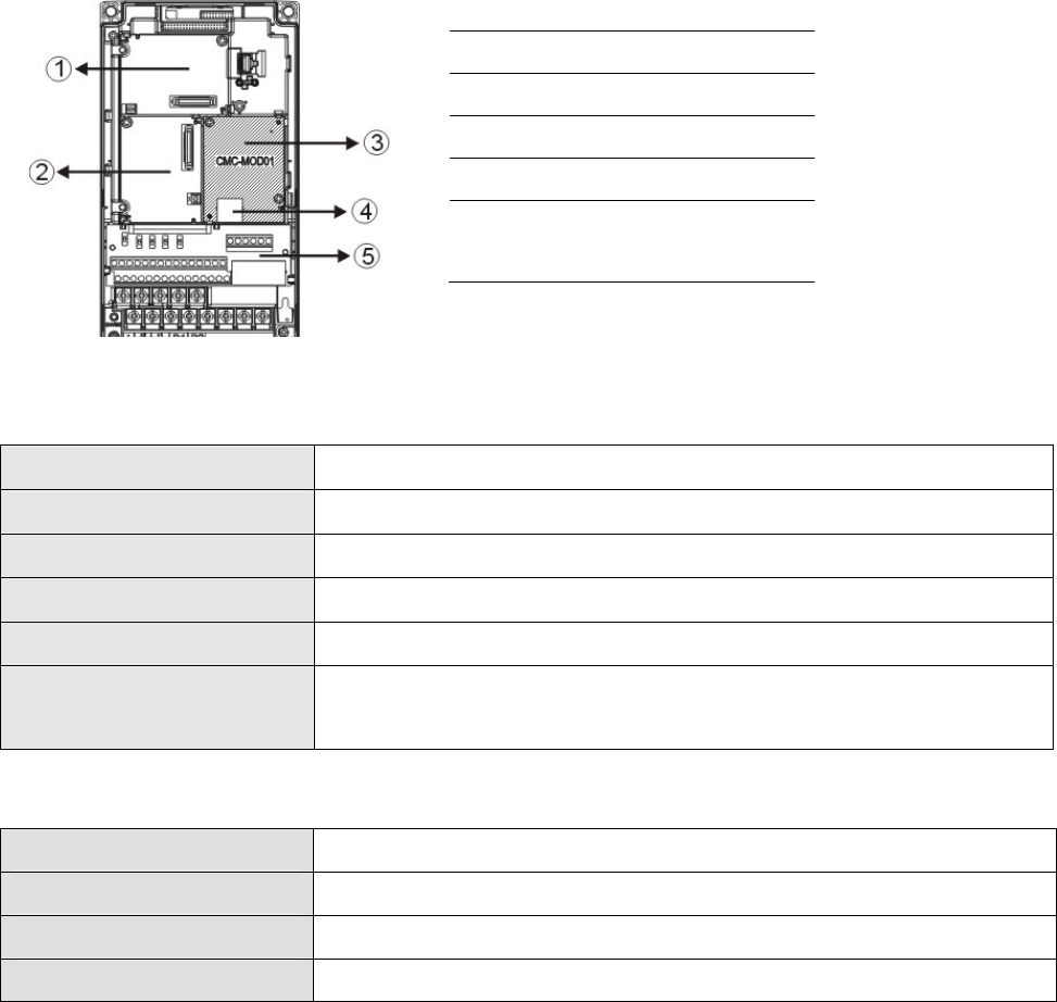
Chapter 8 Optional Cards |CT2000 Series
8-15
CMC-MOD01
Features
1. Supports Modbus TCP protocol
2. MDI/MDI-X auto-detect
3. Baud rate: 10/100Mbps auto-detect
4. E-mail alarm
5. AC motor drive keypad/Ethernet configuration
6. Virtual serial port.
Product File
1I/O CARD & Relay Card
2PG Card
3Comm. Card
4RJ-45 connection port
5Removable control circuit
terminal
Specifications
Network Interface
Interface RJ-45 with Auto MDI/MDIX
Number of ports 1 Port
Transmission method IEEE 802.3, IEEE 802.3u
Transmission cable Category 5e shielding 100M
Transmission speed 10/100 Mbps Auto-Detect
Network protocol ICMP, IP, TCP, UDP, DHCP, HTTP, SMTP, MODBUS OVER TCP/IP,
Delta Configuration
Electrical Specification
Power supply voltage 5VDC (supply by the AC motor drive)
Insulation voltage 2KV
Power consumption 0.8W
Weight 25g
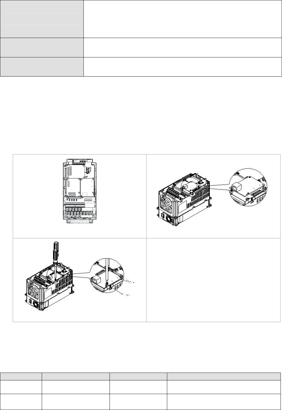
Chapter 8 Optional Cards |CT2000 Series
8-16
Environment
Noise immunity
ESD (IEC 61800-5-1, IEC 61000-4-2)
EFT (IEC 61800-5-1, IEC 61000-4-4)
Surge Test (IEC 61800-5-1, IEC 61000-4-5)
Conducted Susceptibility Test (IEC 61800-5-1, IEC 61000-4-6)
Operation/storage Operation: -10°C ~ 50°C (temperature), 90% (humidity)
Storage: -25°C ~ 70°C (temperature), 95% (humidity)
Vibration/shock immunity International standard: IEC 61800-5-1, IEC 60068-2-6/IEC
61800-5-1, IEC 60068-2-27
Install CMC-MOD01 to VFD-C2000
1. Switch off the power supply of VFD-C2000.
2. Open the front cover of VFD-C2000.
3. Place the insulation spacer into the positioning pin at Slot 1 (shown in Figure 3), and aim the
two holes on the PCB at the positioning pin. Press the pin to clip the holes with the PCB (shown
in Figure 4).
4. Screw up at torque 6 ~ 8 kg-cm (5.21 ~ 6.94 in-lbs) after the PCB is clipped with the holes
(shown in Figure 5).
Slot 1Slot 2
Slot 3
[Figure 3]
[Figure 4]
[Figure 5]
Communication Parameters for VFD-C2000 Connected to Ethernet
When VFD-C2000 is link to Ethernet, please set up the communication parameters base on the table
below. Ethernet master will be able to read/write the frequency word and control word of VFD-C2000
after communication parameters setup.
Parameter Function Set value (Dec) Explanation
P00-20 Source of frequency
command setting 8 The frequency command is controlled by
communication card.
P00-21 Source of operation
command setting 5 The operation command is controlled by
communication card.
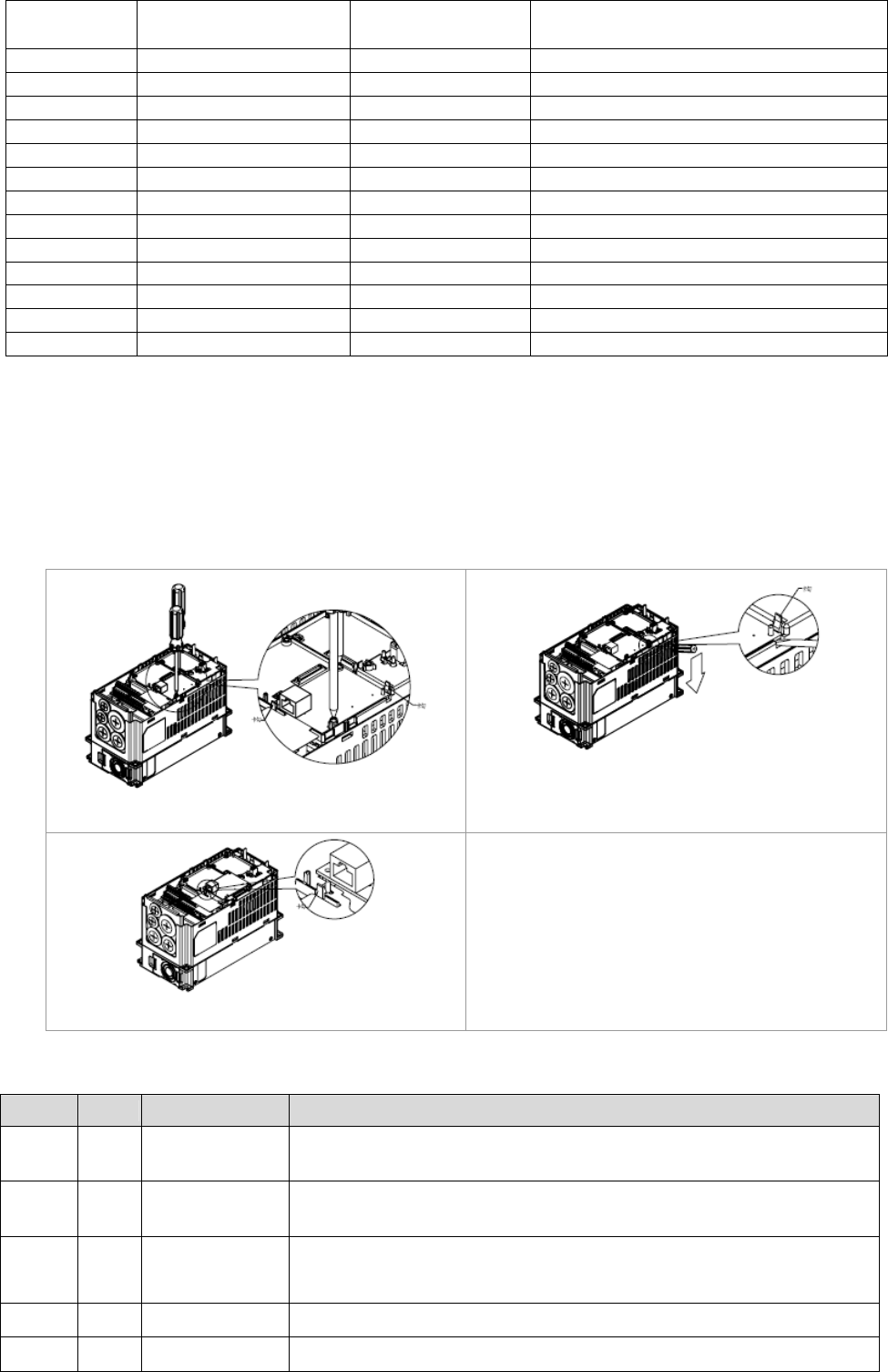
Chapter 8 Optional Cards |CT2000 Series
8-17
P09-30 Decoding method for
communication 0 Decoding method for Delta AC motor
drive
P09-75 IP setting 0 Static IP(0) / Dynamic distribution IP(1)
P09-76 IP address -1 192 IP address 192.168.1.5
P09-77 IP address -2 168 IP address 192.168.1.5
P09-78 IP address -3 1 IP address 192.168.1.5
P09-79 IP address -4 5 IP address 192.168.1.5
P09-80 Netmask -1 255 Netmask 255.255.255.0
P09-81 Netmask -2 255 Netmask 255.255.255.0
P09-82 Netmask -3 255 Netmask 255.255.255.0
P09-83 Netmask -4 0 Netmask 255.255.255.0
P09-84 Default gateway -1 192 Default gateway 192.168.1.1
P09-85 Default gateway -2 168 Default gateway 192.168.1.1
P09-86 Default gateway -3 1 Default gateway 192.168.1.1
P09-87 Default gateway -4 1 Default gateway 192.168.1.1
Disconnecting CMC- MOD01 from VFD-C2000
1. Switch off the power supply of VFD-C2000.
2. Remove the two screws (shown in Figure 6).
3. Twist opens the card clip and inserts the slot type screwdriver to the hollow to prize the PCB off
the card clip (shown in Figure 7).
4. Twist opens the other card clip to remove the PCB (shown in Figure 8).
[Figure 6]
[Figure 7]
[Figure 8]
Basic Registers
BR# R/W Content Explanation
#0 R
Model name Set up by the system; read only. The model code of
CMC-MOD01=H’0203
#1 R
Firmware
version
Displaying the current firmware version in hex, e.g. H’0100 indicates the
firmware version V1.00.
#2 R
Release date of
the version
Displaying the data in decimal form. 10,000s digit and 1,000s digit are for
“month”; 100s digit and 10s digit are for “day”.
For 1 digit: 0 = morning; 1 = afternoon.
#11 R/W Modbus Timeout Pre-defined setting: 500 (ms)
#13 R/W Keep Alive Time Pre-defined setting: 30 (s)

Chapter 8 Optional Cards |CT2000 Series
8-18
LED Indicator & Troubleshooting
LED Indicators
LED Status Indication How to correct it?
On Power supply in normal status --
POWER Green
Off No power supply Check the power supply
On Network connection in normal status --
Flashes Network in operation --
LINK Green
Off Network not connected Check if the network cable is
connected
Troubleshooting
Abnormality Cause How to correct it?
AC motor drive not powered Check if AC motor drive is powered, and if the
power supply is normal.
POWER LED off CMC-MOD01 not connected
to AC motor drive
Make sure CMC-MOD01 is connected to AC motor
drive.
CMC-MOD01 not connected
to network
Make sure the network cable is correctly connected
to network.
LINK LED off Poor contact to RJ-45
connector
Make sure RJ-45 connector is connected to
Ethernet port.
CMC-MOD01 not connected
to network Make sure CMC-MOD01 is connected to network.
No module found PC and CMC-MOD01 in
different networks and
blocked by network firewall.
Search by IP or set up relevant settings by AC
motor drive keypad.
CMC-MOD01 not connected
to network
Make sure CMC-MOD01 is connected to the
network.
Incorrect communication
setting in DCISoft
Make sure the communication setting in DCISoft is
set to Ethernet.
Fail to open
CMC-MOD01
setup page PC and CMC-MOD01 in
different networks and
blocked by network firewall.
Conduct the setup by AC motor drive keypad.
Able to open
CMC-MOD01
setup page but fail
to utilize webpage
monitoring
Incorrect network setting in
CMC-MOD01
Check if the network setting for CMC-MOD01 is
correct. For the Intranet setting in your company,
please consult your IT staff. For the Internet setting
in your home, please refer to the network setting
instruction provided by your ISP.
Incorrect network setting in
CMC-MOD01
Check if the network setting for CMC-MOD01 is
correct.
Fail to send e-mail
Incorrect mail server setting Please confirm the IP address for SMTP-Server.
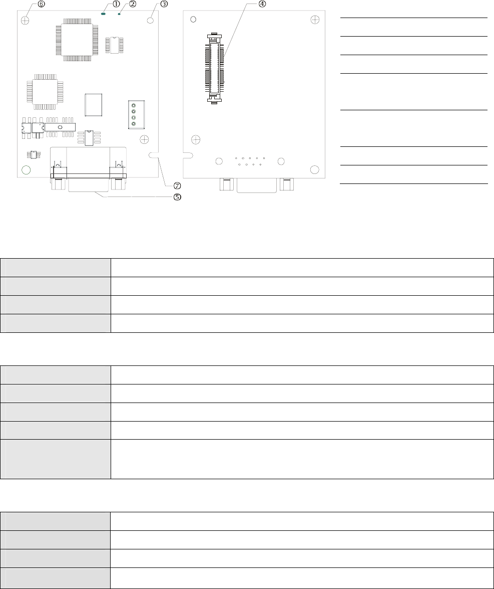
Chapter 8 Optional Cards |CT2000 Series
8-19
CMC-PD01
Features
1. Supports PZD control data exchange.
2. Supports PKW polling AC motor drive parameters.
3. Supports user diagnosis function.
4. Auto-detects baud rates; supports Max. 12Mbps.
Product Profile
1. NET indicator
2. POWER indicator
3. Positioning hole
4. AC motor drive connection
port
5. PROFIBUS DP connection
port
6. Screw fixing hole
7. Fool-proof groove
Specifications
PROFIBUS DP Connector
Interface DB9 connector
Transmission method High-speed RS-485
Transmission cable Shielded twisted pair cable
Electrical isolation 500VDC
Communication
Message type Cyclic data exchange
Module name CMC-PD01
GSD document DELA08DB.GSD
Company ID 08DB (HEX)
Serial transmission
speed supported
(auto-detection)
9.6kbps; 19.2kbps; 93.75kbps; 187.5kbps; 125kbps; 250kbps; 500kbps; 1.5Mbps;
3Mbps; 6Mbps; 12Mbps (bit per second)
Electrical Specification
Power supply 5VDC (supplied by AC motor drive)
Insulation voltage 500VDC
Power consumption 1W
Weight 28g
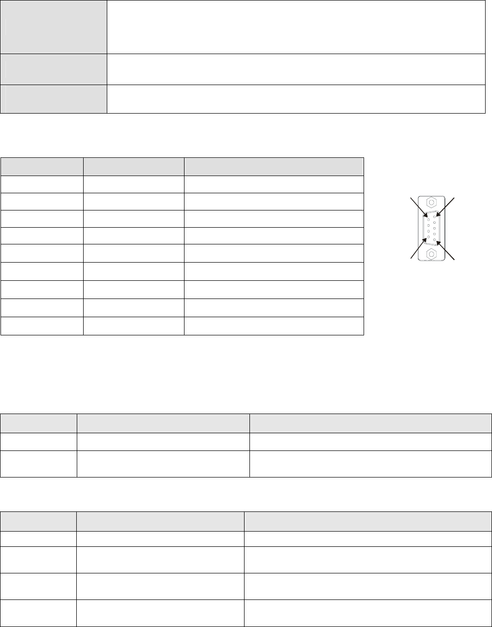
Chapter 8 Optional Cards |CT2000 Series
8-20
Environment
Noise immunity
ESD(IEC 61800-5-1,IEC 6100-4-2)
EFT(IEC 61800-5-1,IEC 6100-4-4)
Surge Teat(IEC 61800-5-1,IEC 6100-4-5)
Conducted Susceptibility Test(IEC 61800-5-1,IEC 6100-4-6)
Operation /storage Operation: -10ºC ~ 50ºC (temperature), 90% (humidity)
Storage: -25ºC ~ 70ºC (temperature), 95% (humidity)
Shock / vibration
resistance
International standards: IEC61131-2, IEC68-2-6 (TEST Fc)/IEC61131-2 & IEC
68-2-27 (TEST Ea)
Installation
PROFIBUS DP Connector
PIN PIN name Definition
1 - Not defined
2 - Not defined
3 Rxd/Txd-P Sending/receiving data P(B)
4 - Not defined
5 DGND Data reference ground
6 VP Power voltage – positive
7 - Not defined
16
5
9
8 Rxd/Txd-N Sending/receiving data N(A)
9 - Not defined
LED Indicator & Troubleshooting
There are 2 LED indicators on CMC-PD01. POWER LED displays the status of the working power.
NET LED displays the connection status of the communication.
POWER LED
LED status Indication How to correct it?
Green light on Power supply in normal status. --
Off No power Check if the connection between CMC-PD01 and AC
motor drive is normal.
NET LED
LED status Indication How to correct it?
Green light on Normal status --
Red light on CMC-PD01 is not connected to
PROFIBUS DP bus. Connect CMC-PD01 to PROFIBUS DP bus.
Red light
flashes
Invalid PROFIBUS communication
address
Set the PROFIBUS address of CMC-PD01 between 1 ~
125 (decimal)
Orange light
flashes
CMC-PD01 fails to communication
with AC motor drive.
Switch off the power and check whether CMC-PD01 is
correctly and normally connected to AC motor drive.
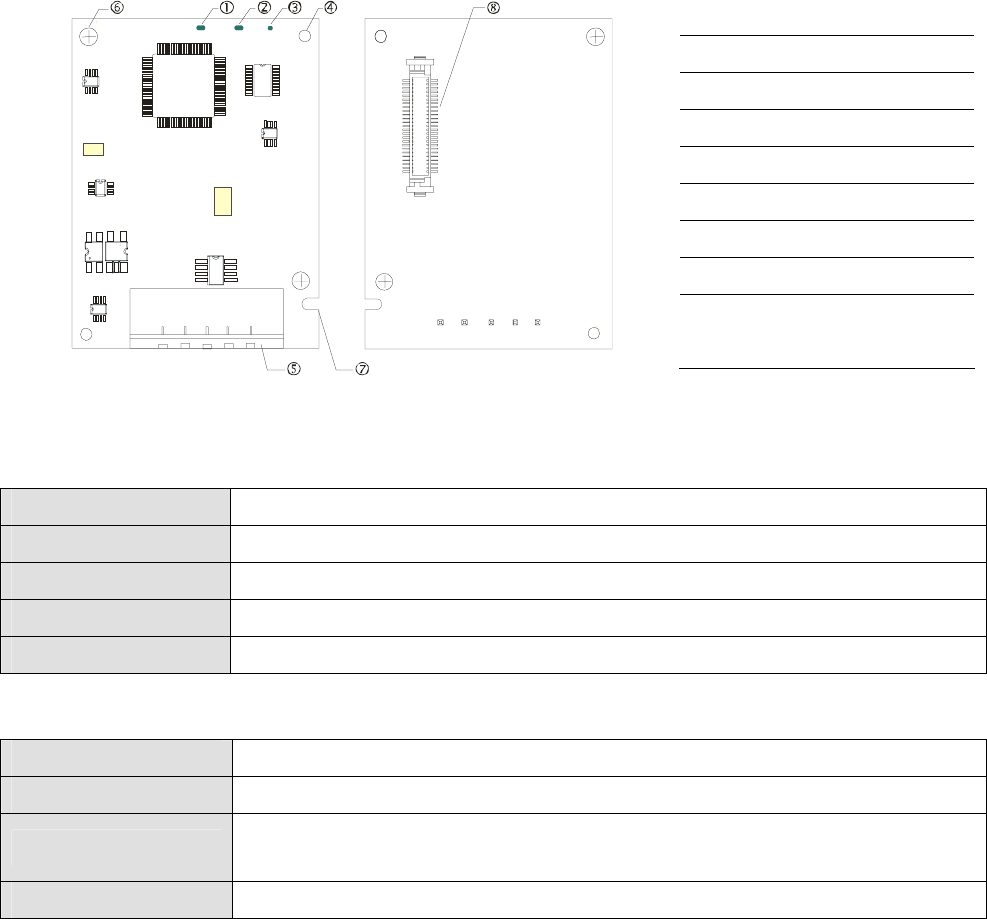
Chapter 8 Optional Cards |CT2000 Series
8-21
CMC-DN01
Functions
1. Based on the high-speed communication interface of Delta HSSP protocol, able to conduct
immediate control to AC motor drive.
2. Supports Group 2 only connection and polling I/O data exchange.
3. For I/O mapping, supports Max. 32 words of input and 32 words of output.
4. Supports EDS file configuration in DeviceNet configuration software.
5. Supports all baud rates on DeviceNet bus: 125kbps, 250kbps, 500kbps and extendable serial
transmission speed mode.
6. Node address and serial transmission speed can be set up on AC motor drive.
7. Power supplied from AC motor drive.
Product Profile
1. NS indicator
2. MS indicator
3. POWER indicator
4. Positioning hole
5. DeviceNet connection port
6. Screw fixing hole
7. Fool-proof groove
8. AC motor drive connection
port
Specifications
DeviceNet Connector
Interface 5-PIN open removable connector. Of 5.08mm PIN interval
Transmission
th d
CAN
Transmission cable Shielded twisted pair cable (with 2 power cables)
Transmission speed 125kbps, 250kbps, 500kbps and extendable serial transmission speed
d
Network protocol DeviceNet protocol
AC Motor Drive Connection Port
Interface 50 PIN communication terminal
Transmission method SPI communication
Terminal function 1. Communicating with AC motor drive
2. Transmitting power supply from AC motor drive
Communication
tl
Delta HSSP protocol
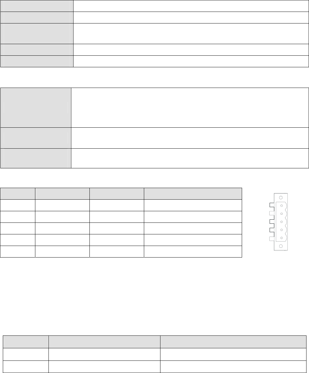
Chapter 8 Optional Cards |CT2000 Series
8-22
Electrical Specification
Power supply voltage 5VDC (supplied by AC motor drive)
Insulation voltage 500VDC
Communication wire
power consumption 0.85W
Power consumption 1W
Weight 23g
Environment
Noise immunity
ESD (IEC 61800-5-1,IEC 6100-4-2)
EFT (IEC 61800-5-1,IEC 6100-4-4)
Surge Teat(IEC 61800-5-1,IEC 6100-4-5)
Conducted Susceptibility Test (IEC 61800-5-1,IEC 6100-4-6)
Operation /storage Operation: -10ºC ~ 50ºC (temperature), 90% (humidity)
Storage: -25ºC ~ 70ºC (temperature), 95% (humidity)
Shock / vibration
resistance
International standards: IEC61131-2, IEC68-2-6 (TEST Fc)/IEC61131-2 &
IEC 68-2-27 (TEST Ea)
DeviceNet Connector
PIN Signal Color Definition
1 V+ Red DC24V
2 H White Signal+
3 S - Earth
4 L Blue Signal-
5 V- Black 0V
5
4
3
2
1
LED Indicator & Troubleshooting
There are 3 LED indicators on CMC-DN01. POWER LED displays the status of power supply. MS
LED and NS LED are dual-color LED, displaying the connection status of the communication and
error messages.
POWER LED
LED status Indication How to correct it?
On Power supply in abnormal status. Check the power supply of CMC-DN01.
Off Power supply in normal status --

Chapter 8 Optional Cards |CT2000 Series
8-23
NS LED
LED status Indication How to correct it?
Off No power supply or CMC-DN01 has
not completed MAC ID test yet.
1. Check the power of CMC-DN01 and see if the
connection is normal.
2. Make sure at least one or more nodes are on the
bus.
3. Check if the serial transmission speed of
CMC-DN01 is the same as that of other nodes.
Green light
flashes
CMC-DN01 is on-line but has not
established connection to the master.
1. Configure CMC-DN01 to the scan list of the
master.
2. Re-download the configured data to the master.
Green light on CMC-DN01 is on-line and is normally
connected to the master --
Red light
flashes
CMC-DN01 is on-line, but I/O
connection is timed-out.
1. Check if the network connection is normal.
2. Check if the master operates normally.
Red light on
1. The communication is down.
2. MAC ID test failure.
3. No network power supply.
4. CMC-DN01 is off-line.
1. Make sure all the MAC IDs on the network are
not repeated.
2. Check if the network installation is normal.
3. Check if the baud rate of CMC-DN01 is
consistent with that of other nodes.
4. Check if the node address of CMC-DN01 is
illegal.
5. Check if the network power supply is normal.
MS LED
LED status Indication How to correct it?
Off No power supply or being off-line Check the power supply of CMC-DN01 and see of
the connection is normal.
Green light
flashes Waiting for I/O data Switch the master PLC to RUN status
Green light on I/O data are normal --
Red light
flashes Mapping error 1. Reconfigure CMC-DN01
2. Re-power AC motor drive
Red light on Hardware error 1. See the error code displayed on AC motor drive.
2. Send back to the factory for repair if necessary.
Orange light
flashes
CMC-DN01 is establishing connection
with AC motor drive.
If the flashing lasts for a long time, check if
CMC-DN01 and AC motor drive are correctly
installed and normally connected to each other.
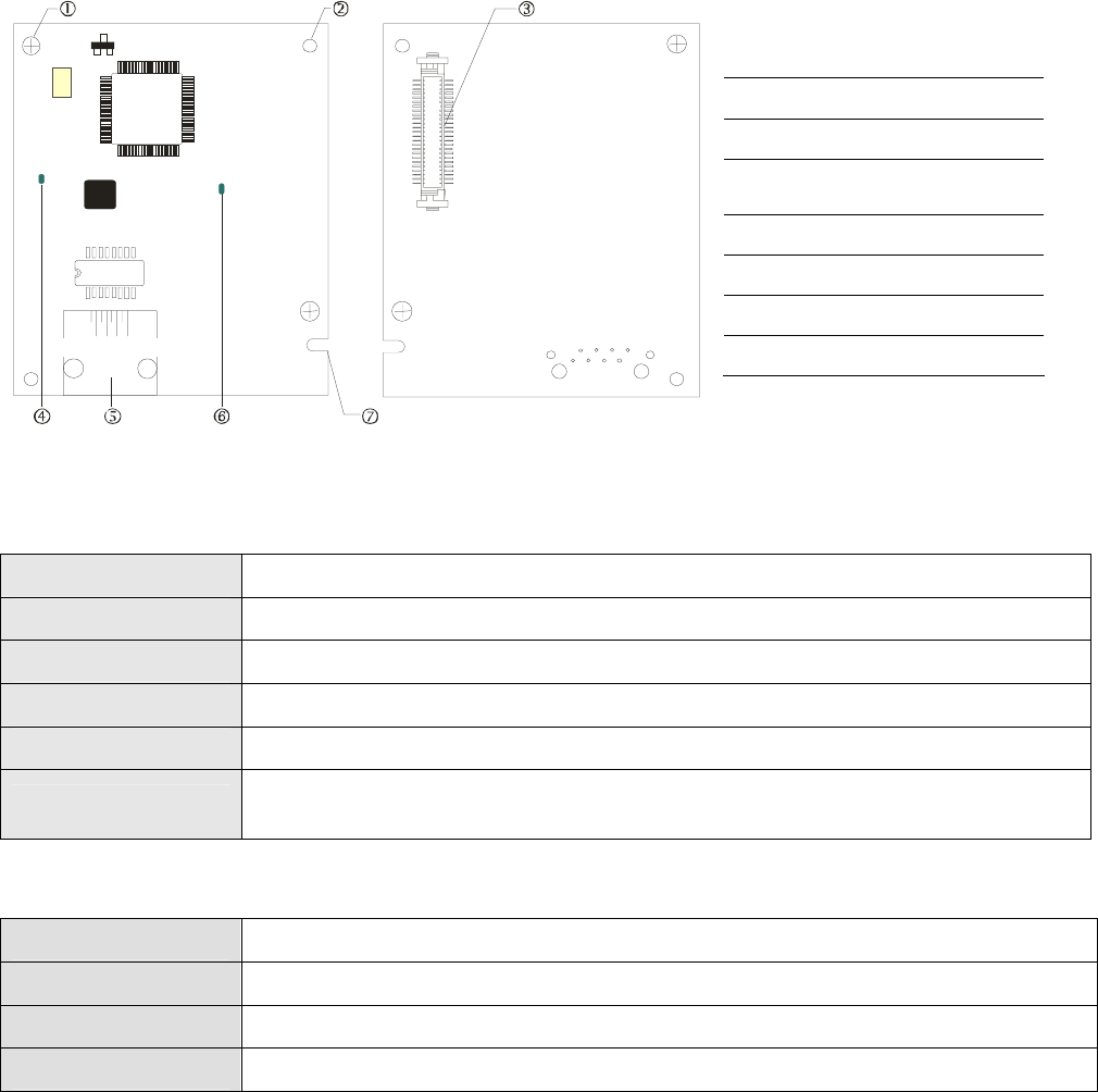
Chapter 8 Optional Cards |CT2000 Series
8-24
CMC-EIP01
Features
1. Supports Modbus TCP and Ethernet/IP protocol
2. MDI/MDI-X auto-detect
3. Baud rate: 10/100Mbps auto-detect
4. AC motor drive keypad/Ethernet configuration
5. Virtual serial port
Product Profile
[Figure1]
1. Screw fixing hole
2. Positioning hole
3. AC motor drive connection
port
4. LINK indicator
5. RJ-45 connection port
6. POWER indicator
7. Fool-proof groove
Specifications
Network Interface
Interface RJ-45 with Auto MDI/MDIX
Number of ports 1 Port
Transmission method IEEE 802.3, IEEE 802.3u
Transmission cable Category 5e shielding 100M
Transmission speed 10/100 Mbps Auto-Detect
Network protocol ICMP, IP, TCP, UDP, DHCP, HTTP, SMTP, MODBUS OVER TCP/IP, EtherNet/IP, Delta
Configuration
Electrical Specification
Weight 25g
Insulation voltage 500VDC
Power consumption 0.8W
Power supply voltage 5VDC
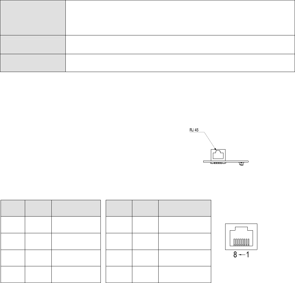
Chapter 8 Optional Cards |CT2000 Series
8-25
Environment
Noise immunity
ESD (IEC 61800-5-1,IEC 61000-4-2)
EFT (IEC 61800-5-1,IEC 61000-4-4)
Surge Test (IEC 61800-5-1,IEC 61000-4-5)
Conducted Susceptibility Test (IEC 61800-5-1,IEC 61000-4-6)
Operation/storage Operation: -10°C ~ 50°C (temperature), 90% (humidity)
Storage: -25°C ~ 70°C (temperature), 95% (humidity)
Vibration/shock
immunity International standard: IEC 61800-5-1, IEC 60068-2-6/IEC 61800-5-1, IEC 60068-2-27
Installation
Connecting CMC-EIP01 to Network
1. Turn off the power of AC motor drive.
2. Open the cover of AC motor drive.
3. Connect CAT-5e network cable to RJ-45 port on
CMC-EIP01 (See Figure 2).
[Figure 2]
RJ-45 PIN Definition
PIN Signal Definition PIN Signal Definition
1 Tx+
Positive pole for
data transmission 5 -- N/C
2 Tx-
Negative pole for
data transmission 6 Rx-
Negative pole for
data receiving
3 Rx+
Positive pole for
data receiving 7 -- N/C
4 -- N/C 8 -- N/C
Connecting CMC-EIP01 to VFD-C2000
1. Switch off the power of AC motor drive.
2. Open the front cover of AC motor drive.
3. Place the insulation spacer into the positioning pin at Slot 1 (shown in Figure 3), and aim the
two holes on the PCB at the positioning pin. Press the pin to clip the holes with the PCB (see
Figure 4).
4. Screw up at torque 6 ~ 8 kg-cm (5.21 ~ 6.94 in-lbs) after the PCB is clipped with the holes (see
Figure 5).
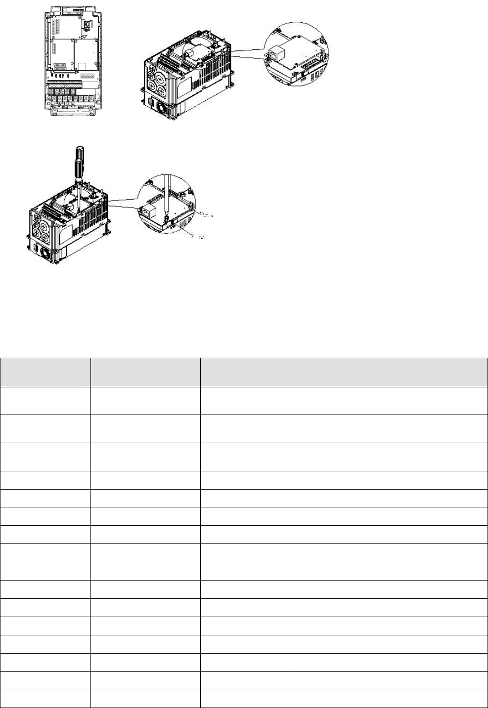
Chapter 8 Optional Cards |CT2000 Series
8-26
Slot 1Slot 2
Slot 3
[Figure 3] [Figure 4]
[Figure 5]
Communication Parameters for VFD-C2000 Connected to Ethernet
When VFD-C2000 is connected to Ethernet network, please set up the communication parameters
for it according to the table below. The Ethernet master is only able to read/write the frequency word
and control word of VFD-C2000 after the communication parameters are set.
Parameter
(Dec) Function Set value (Dec) Explanation
P00-20 Source of frequency
command setting 8 The frequency command is controlled by
communication card.
P00-21 Source of operation
command setting 5 The operation command is controlled by
communication card.
P09-30 Decoding method for
communication 0 The decoding method for Delta AC motor
drive
P09-75 IP setting 0 Static IP(0) / Dynamic distribution IP(1)
P09-76 IP address -1 192 IP address 192.168.1.5
P09-77 IP address -2 168 IP address 192.168.1.5
P09-78 IP address -3 1 IP address 192.168.1.5
P09-79 IP address -4 5 IP address 192.168.1.5
P09-80 Netmask -1 255 Netmask 255.255.255.0
P09-81 Netmask -2 255 Netmask 255.255.255.0
P09-82 Netmask -3 255 Netmask 255.255.255.0
P09-83 Netmask -4 0 Netmask 255.255.255.0
P09-84 Default gateway -1 192 Default gateway 192.168.1.1
P09-85 Default gateway -2 168 Default gateway 192.168.1.1
P09-86 Default gateway -3 1 Default gateway 192.168.1.1
P09-87 Default gateway -4 1 Default gateway 192.168.1.1
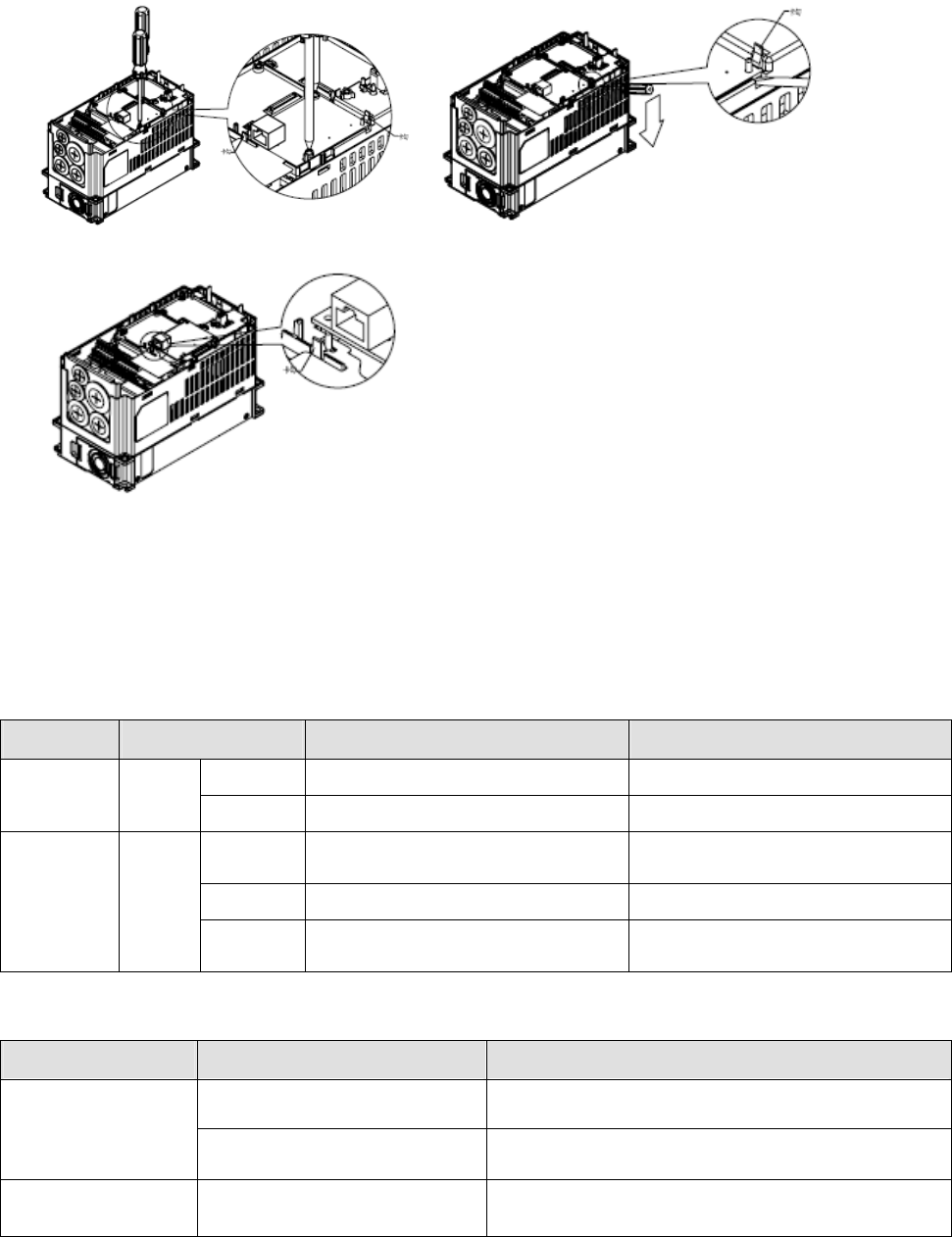
Chapter 8 Optional Cards |CT2000 Series
8-27
Disconnecting CMC- EIP01 from VFD-C2000
1. Switch off the power supply of VFD-C2000.
2. Remove the two screws (see Figure 6).
3. Twist opens the card clip and inserts the slot type screwdriver to the hollow to prize the PCB off the
card clip (see Figure 7).
4. Twist opens the other card clip to remove the PCB (see Figure 8).
[Figure 6] [Figure 7]
[Figure 8]
LED Indicator & Troubleshooting
There are 2 LED indicators on CMC-EIP01. The POWER LED displays the status of power supply,
and the LINK LED displays the connection status of the communication.
LED Indicators
LED Status Indication How to correct it?
On Power supply in normal status --
POWER Green
Off No power supply Check the power supply.
On Network connection in normal
status --
Flashes Network in operation --
LINK Green
Off Network not connected Check if the network cable is
connected.
Troubleshooting
Abnormality Cause How to correct it?
AC motor drive not powered Check if AC motor drive is powered, and if the
power supply is normal.
POWER LED off CMC-EIP01 not connected to
AC motor drive
Make sure CMC-EIP01 is connected to AC motor
drive.
LINK LED off CMC-EIP01 not connected to
network
Make sure the network cable is correctly connected
to network.

Chapter 8 Optional Cards |CT2000 Series
8-28
Abnormality Cause How to correct it?
Poor contact to RJ-45
connector
Make sure RJ-45 connector is connected to
Ethernet port.
CMC-EIP01 not connected to
network Make sure CMC-EIP01 is connected to network.
No communication
card found PC and CMC-EIP01 in
different networks and blocked
by network firewall.
Search by IP or set up relevant settings by AC
motor drive keypad.
CMC-EIP01 not connected to
network
Make sure CMC-EIP01 is connected to the
network.
Incorrect communication
setting in DCISoft
Make sure the communication setting in DCISoft is
set to Ethernet.
Fail to open
CMC-EIP01 setup
page PC and CMC-EIP01 in
different networks and blocked
by network firewall.
Conduct the setup by AC motor drive keypad.
Able to open
CMC-EIP01 setup
page but fail to
utilize webpage
monitoring
Incorrect network setting in
CMC-EIP01
Check if the network setting for CMC-EIP01 is
correct. For the Intranet setting in your company,
please consult your IT staff. For the Internet setting
in your home, please refer to the network setting
instruction provided by your ISP.
Incorrect network setting in
CMC-EIP01
Check if the network setting for CMC-EIP01 is
correct.
Fail to send e-mail
Incorrect mail server setting Please confirm the IP address for SMTP-Server.
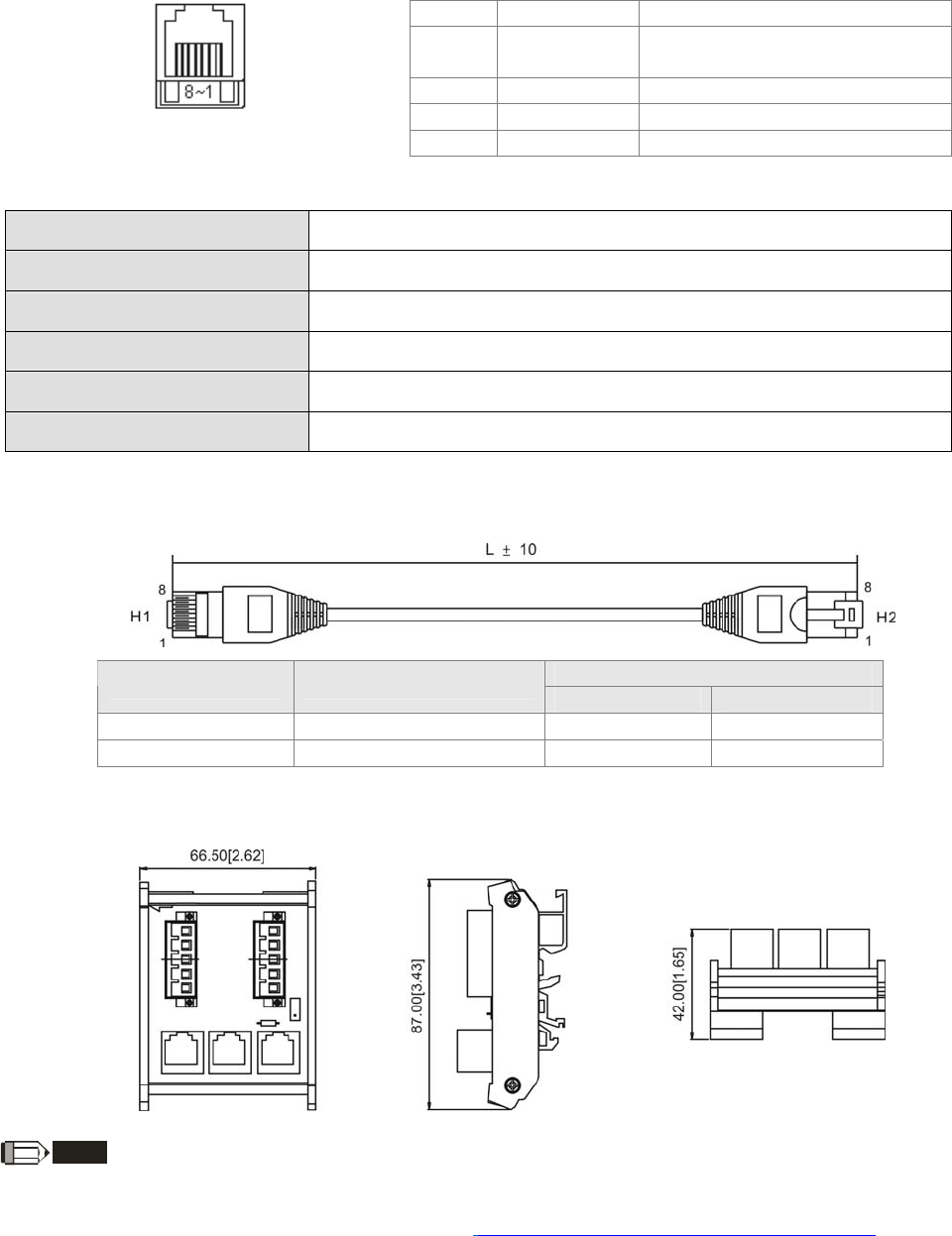
Chapter 8 Optional Cards |CT2000 Series
8-29
EMC-COP01
Built-in EMC-COP01 card are available in VFDXXXC23E/VFDXXXC43E series.
RJ-45 Pin definition
Pin Pin name Definition
1 CAN_H CAN_H bus line (dominant
high)
2 CAN_L CAN_L bus line (dominant low)
3 CAN_GND Ground/0V/V-
RS485 socket 7 CAN_GND Ground/0V/V-
Specifications
Interface RJ-45
Number of ports 1 Port
Transmission method CAN
Transmission cable CAN standard cable
Transmission speed 1M 500k 250k 125k 100k 50k
Communication protocol CANopen
CANopen Communication Cable
Model: TAP-CB03, TAP-CB04
L
Title Part No. mm inch
1 TAP-CB03
500 ± 10 19 ± 0.4
2 TAP-CB04
1000± 10 39 ± 0.4
CANopen Dimension
Model: TAP-CN03
NOTE
For more information on CANopen, please refer to Chapter 15 CANopen Overview or CANopen user
manual can also be downloaded on Delta website: http://www.delta.com.tw/industrialautomation/.

Chapter 9 Specifications CT2000 Series
9-1
Chapter 9 Specification
460V Series
Frame Size B C D
Model VFD_ _ _CT43F_ _A_; 110 150 185 220 300 370 450 550 750 900
Max. Applicable Motor Output (kW) 11 15 18.5 22 30 37 45 55 75 90
Max. Applicable Motor Output (hp) 15 20 25 30 40 50 60 75 100 125
Rated Output Capacity (kVA) 14 18 24 29 34 45 55 69 84 114
Rated Output Current (A) 17 23 30 36 43 57 69 86 105 143
HEAVY
DUTY
Carrier Frequency (kHz) 2~6kHz
Rate Output Capacity (kVA) 18 24 29 36 45 57 73 88 115 143
Rated Output Current (A) 22.5 30 36 45 56 72 91 110 144 180
Output Rating
LIGHT DUTY
Carrier Frequency (kHz) 2~15kHz 2~10kHz
2~9kHz
Input Current (A) Heavy Duty 19 25 33 38 45 60 70 96 108 149
Input Current (A) Light Duty 25 33 40 50 62 79 91 110 144 180
Rated Voltage/Frequency 3-Phase AC 380V~480V ( -15%~+10%), 50/60Hz
Operating Voltage Range 323~528Vac
Input Rating
Frequency Tolerance 47~63Hz
Cooling method Natural cooling
Braking Chopper Frame B to C (built-in); Frame D (optional)
DC reactor Frame B to C (optional); Frame D (built-in)
EMI Filter optional
General Specifications
Control Method 1: V/F, 2: SVC, 3: VF+PG, 4: FOC+PG, 5: TQC+PG,
Starting Torque Reach up to 150% or above at 0.5Hz.
Under FOC+PG mode, starting torque can reach 150% at 0Hz.
V/F Curve 4 point adjustable V/F curve and square curve
Speed Response Ability 5Hz (vector control can reach up to 40Hz)
Torque Limit Max. 200% torque current
Torque Accuracy 5%
Max. Output Frequency
(Hz) Light duty: 0.01~600.00Hz; Heavy duty: 0.00 ~ 300.00 Hz
Frequency Output
Accuracy Digital command:0.01%, -10℃~+40℃, Analog command: 0.1%, 2510℃
Output Frequency
Resolution Digital command: 0.01Hz, Analog command: 0.03 X max. output frequency/60 Hz (11 bit)
Control Characteristics
Overload Tolerance Light duty: rated output current is 120% for 60 seconds
Heavy duty: rated output current is 150% for 60 seconds, 180% for 3 seconds.
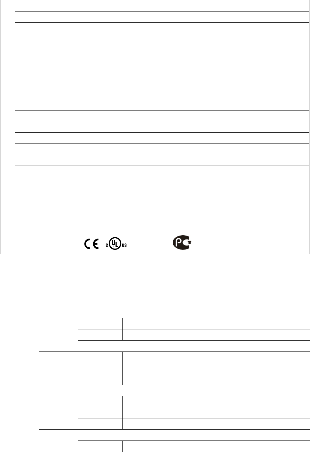
Chapter 9 Specifications CT2000 Series
9-2
Frequency Setting Signal +10V~-10, 0~+10V, 4~20mA, 0~20mA, Pulse input
Accel./decel. Time 0.00~600.00/0.0~6000.0 seconds
Main control function
Torque control, Droop control, Speed/torque control switching, Feed forward control,
Zero-servo control, Momentary power loss ride thru, Speed search, Over-torque detection,
Torque limit, 17-step speed (max), Accel/decel time switch, S-curve accel/decel, 3-wire
sequence, Auto-Tuning (rotational, stationary), Dwell, Slip compensation, Torque
compensation, JOG frequency, Frequency upper/lower limit settings, DC injection braking at
start/stop, High slip braking, PID control (with sleep function),Energy saving control,
MODOBUS communication (RS-485 RJ45, max. 115.2 kbps), Fault restart, Parameter copy
Motor Protection Electronic thermal relay protection
Over-current Protection Over-current protection for 220% rated current
current clamp『Light duty: 130~140%』;『Heavy duty: 180~185%』
Over-voltage Protection 460: drive will stop when DC-BUS voltage exceeds 820V
Over-temperature
Protection Built-in temperature sensor
Stall Prevention Stall prevention during acceleration, deceleration and running independently
Restart After
Instantaneous Power
Failure
Parameter setting up to 20 seconds
Protection Characteristics
Grounding Leakage
Current Protection Leakage current is higher than 50% of rated current of the AC motor drive
Certifications , , GB/T12668-2, (certification in progress)
Environment for Operation, Storage and Transportation
DO NOT expose the AC motor drive in the bad environment, such as dust, direct sunlight, corrosive/inflammable gasses,
humidity, liquid and vibration environment. The salt in the air must be less than 0.01mg/cm2 every year.
Installation
location
IEC60364-1/IEC60664-1 Pollution degree 2, Indoor use only
Storage -25 oC ~ +70 oC
Transportation -25 oC ~ +70 oC
Surrounding
Temperature Only allowed at non-condensation, non-frozen, non-conductive pollution environment.
Operation Max. 90%
Storage/
Transportation
Max. 95%
Rated Humidity
Only allowed at non-condensation, non-frozen, non-conductive pollution environment.
Operation/
Storage
86 to 106 kPa
Air Pressure
Transportation 70 to 106 kPa
IEC721-3-3
Environment
Pollution Level
Operation Class 3C2; Class 3S2
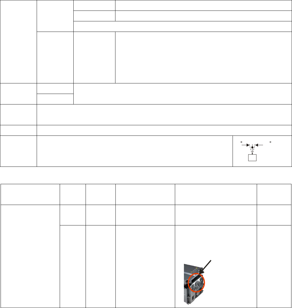
Chapter 9 Specifications CT2000 Series
9-3
Storage Class 2C2; Class 2S2
Transportation Class 1C2; Class 1S2
Only allowed at non-condensation, non-frozen, non-conductive pollution environment.
Altitude Operation
If AC motor drive is installed at altitude 0~1000m, follow normal operation
restriction. If it is install at altitude 1000~3000m, decrease 2% of rated current
or lower 0.5℃ of temperature for every 100m increase in altitude. Maximum
altitude for Corner Grounded is 2000m.
Storage
Package Drop Transportation ISTA procedure 1A(according to weight) IEC60068-2-31
Vibration 1.0mm, peak to peak value range from 2Hz to 13.2 Hz; 0.7G~1.0G range from 13.2Hz to 55Hz; 1.0G range
from 55Hz to 512 Hz. Comply with IEC 60068-2-6
Impact IEC/EN 60068-2-27
Operation
Position Max. allowed offset angle 10o (under normal installation position)
10 10
Specification for Operation Temperature and Protection Level
Model Frame Top cover Conduit Box Protection Level Operation
Temperature
B, C Top cover
Removed Standard conduit box IP20/UL Open Type -10~50℃;
VFDxxxCT43F_ _A_
D N/A No conduit box
IP00
IP20/UL Open Type
Only the circled area
is IP00, other are IP20
-10~40℃
(At heat sink’s
side)
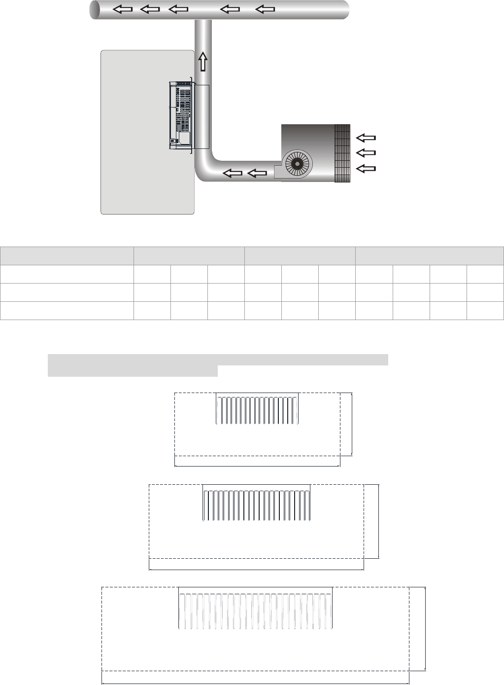
Chapter 9 Specifications CT2000 Series
9-4
Heat Dissipation System Diagram
A
ir
exhaust
system
Electric
Control
Case
Motor
Drive
Cooling
Fan
Temperature of air hose
≤
40 C
º
See page 2 3 for Air flow rate for cooling
-
Dust
Collector
Air Velocity Specification at Heat Dissipation Channel
Frame B C D
Model VFD_ _ _CT43F_ _A_; 110 150 185 220 300 370 450 550 750 900
A
ir Velocity @fc=2kHz (M/sec) 3.5 3.5 3.5 3.5 3.5 7 3.5 4.5 6 8.5
A
ir Velocity @ default fc (M/sec) 3.5 6.5 8.5 3.5 7 9.5 5.5 6 8.5 9.5
Definition of Air Velocity: When the dissipation channels are at bypass condition, the air speed that equally flows
5cm in front of the heatsink. As shown in the Figure 1 below, dotted lines are required size in mm to
calculate the minimum air velocity (table above) to cool down the heat.
The closer the size of the heat dissipation channel to the size of the heatsink,
the better the result of heat dissipation.
Frame B
370.0
140.0
Frame C
180.0
500.0
Frame D
180.0
660.0
Figure 1
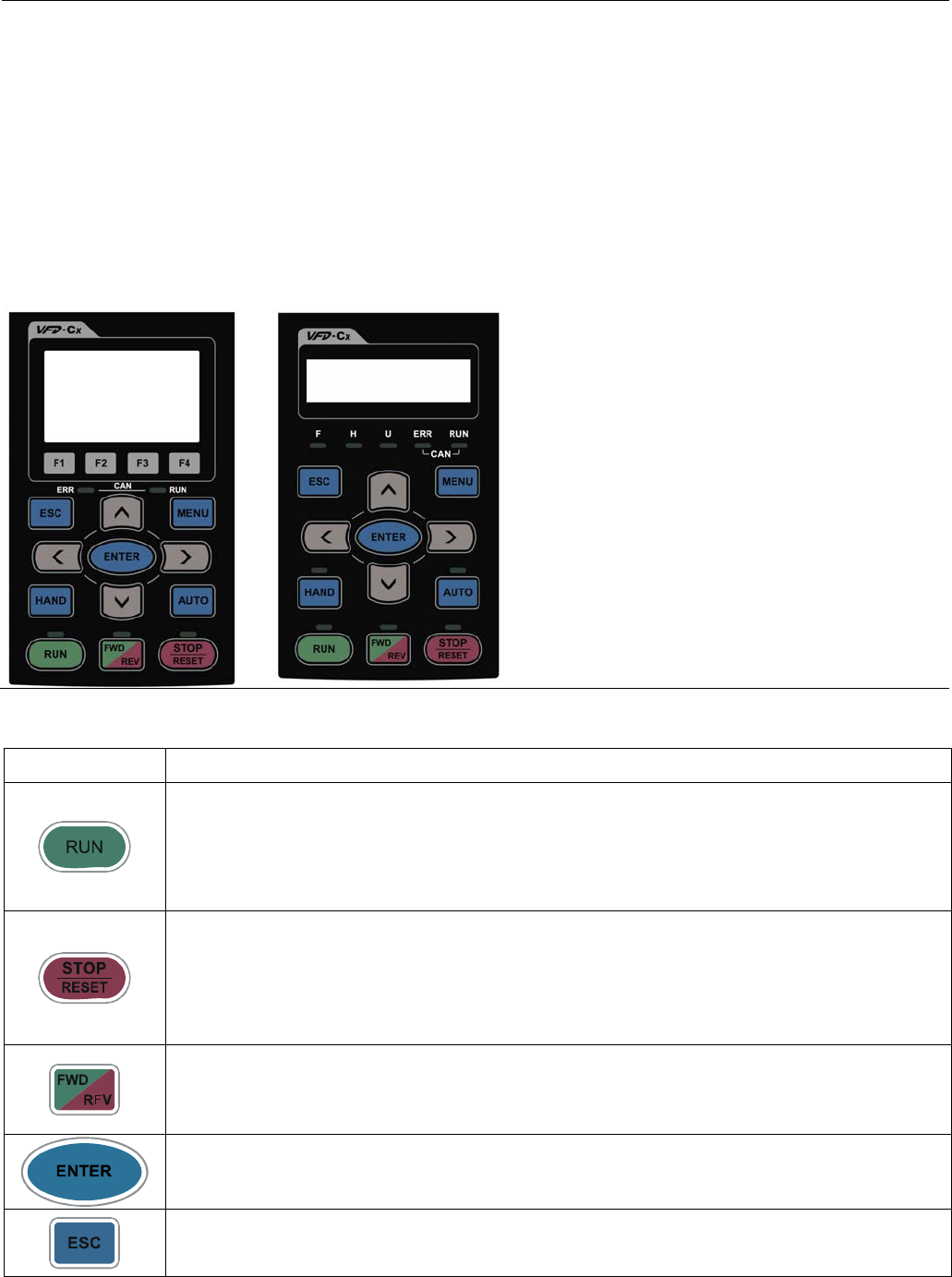
Chapter 10 Digital Keypad|CT2000 Series
10-1
Chapter 10 Digital Keypad
10-1 Descriptions of Digital Keypad
10-2 Function of Digital Keypad KPC-CC01
10-3 TPEditor Installation Instruction
10-4 Fault Code Description of Digital Keypad KPC-CC01
10-1 Descriptions of Digital Keypad
KPC-CC01
KPC-CE01(Option)
Communication Interface
RJ-45 (socket)、RS-485 interface;
Installation Method
Embedded type and can be put flat on the surface
of the control box. The front cover is water proof.
Descriptions of Keypad Functions
Key Descriptions
Start Operation Key
1. It is only valid when the source of operation command is from the keypad.
2. It can operate the AC motor drive by the function setting and the RUN LED will be ON.
3. It can be pressed again and again at stop process.
4. When enabling “HAND” mode, it is only valid when the source of operation command is
from the keypad.
Stop Command Key. This key has the highest processing priority in any situation.
1. When it receives STOP command, no matter the AC motor drive is in operation or stop
status, the AC motor drive needs to execute “STOP” command.
2. The RESET key can be used to reset the drive after the fault occurs. For those faults that
can’t be reset by the RESET key, see the fault records after pressing MENU key for
details.
Operation Direction Key
1. This key is only control the operation direction NOT for activate the drive. FWD: forward,
REV: reverse.
2. Refer to the LED descriptions for more details.
ENTER Key
Press ENTER and go to the next level. If it is the last level then press ENTER to execute the command.
ESC Key
ESC key function is to leave current menu and return to the last menu. It is also functioned as a
return key in the sub-menu.
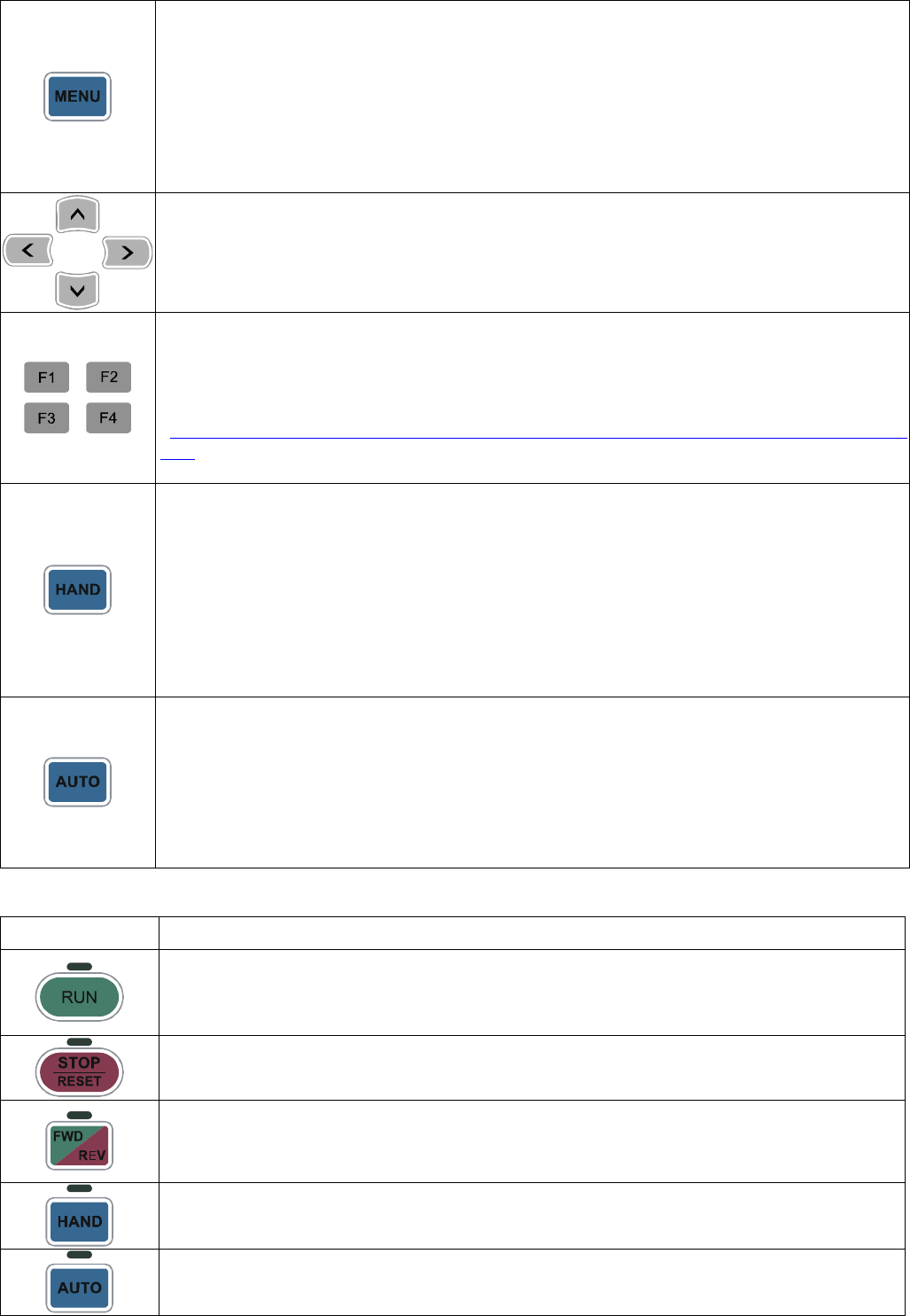
Chapter 10 Digital Keypad|CT2000 Series
10-2
Press menu to return to main menu.
Menu content:
KPC-CE01 does not support function 5 ~13.
1. Detail Parameter
2. Copy Parameter
3. Keypad Locked
4. PLC Function
5. Copy PLC
6. Fault Record
7. Quick/Simple Setup
8. Display Setup
9. Time Setup
10. Language Setup
11. Startup Menu
12. Main Page
13. PC Link
Direction: Left/Right/Up/Down
1. In the numeric value setting mode, it is used to move the cursor and change the numeric
value.
2. In the menu/text selection mode, it is used for item selection.
Function Key
1. It has the factory setting function and the function can be set by the user. The present
factory setting: F1 is JOG function.
2. Other functions must be defined by TPEditor first. TPEditor software V1.30.6 is available
for download at:
http://www.delta.com.tw/ch/product/em/download/download_main.asp?act=3&pid=1&cid=1&tp
id=3
3. Installation Instruction for TPEditor is on page 10-15 of this chapter.
HAND ON Key
1. This key is executed by the parameter settings of the source of Hand frequency and hand
operation. The factory settings of both source of Hand frequency and hand operation are
the digital keypad.
2. Press HAND ON key at stop status, the setting will switch to hand frequency source and
hand operation source. Press HAND ON key at operation status, it stops the AC motor
drive first (display AHSP warning), and switch to hand frequency source and hand
operation source.
3. Successful mode switching for KPC-CE01, “H/A” LED will be on; for KPC-CC01, it will
display HAND mode/ AUTO mode on the screen.
1. This key is executed by the parameter settings of the source of AUTO frequency and
AUTO operation. The factory setting is the external terminal (source of operation is
4-20mA).
2. Press Auto key at stop status, the setting will switch to hand frequency source and hand
operation source. Press Auto key at operation status, it stops the AC motor drive first
(display AHSP warning), and switch to hand frequency source and hand operation source.
3. Successful mode switching for KPC-CE01, “H/A” LED will be off; for KPC-CC01, it will
display HAND mode/ AUTO mode on the screen
Descriptions of LED Functions
LED Descriptions
Steady ON: operation indicator of the AC motor drive, including DC brake, zero speed,
standby, restart after fault and speed search.
Blinking: drive is decelerating to stop or in the status of base block.
Steady OFF: drive doesn’t execute the operation command
Steady ON: stop indicator of the AC motor drive.
Blinking: drive is in the standby status.
Steady OFF: drive doesn’t execute “STOP” command.
Operation Direction LED
1. Green light is on, the drive is running forward.
2. Red light is on, the drive is running backward.
3. Twinkling light: the drive is changing direction.
(Only KPC-CE01 support this function)
Setting can be done during operation.
HAND LED: When HAND LED is on (HAND mode); when HAND LED is off (AUTO mode).
(Only KPC-CE01Support this function )
Setting can be done during operation.
AUTO LED: when AUTO LED is on (AUTO mode); when AUTO LED is off (HAND mode).
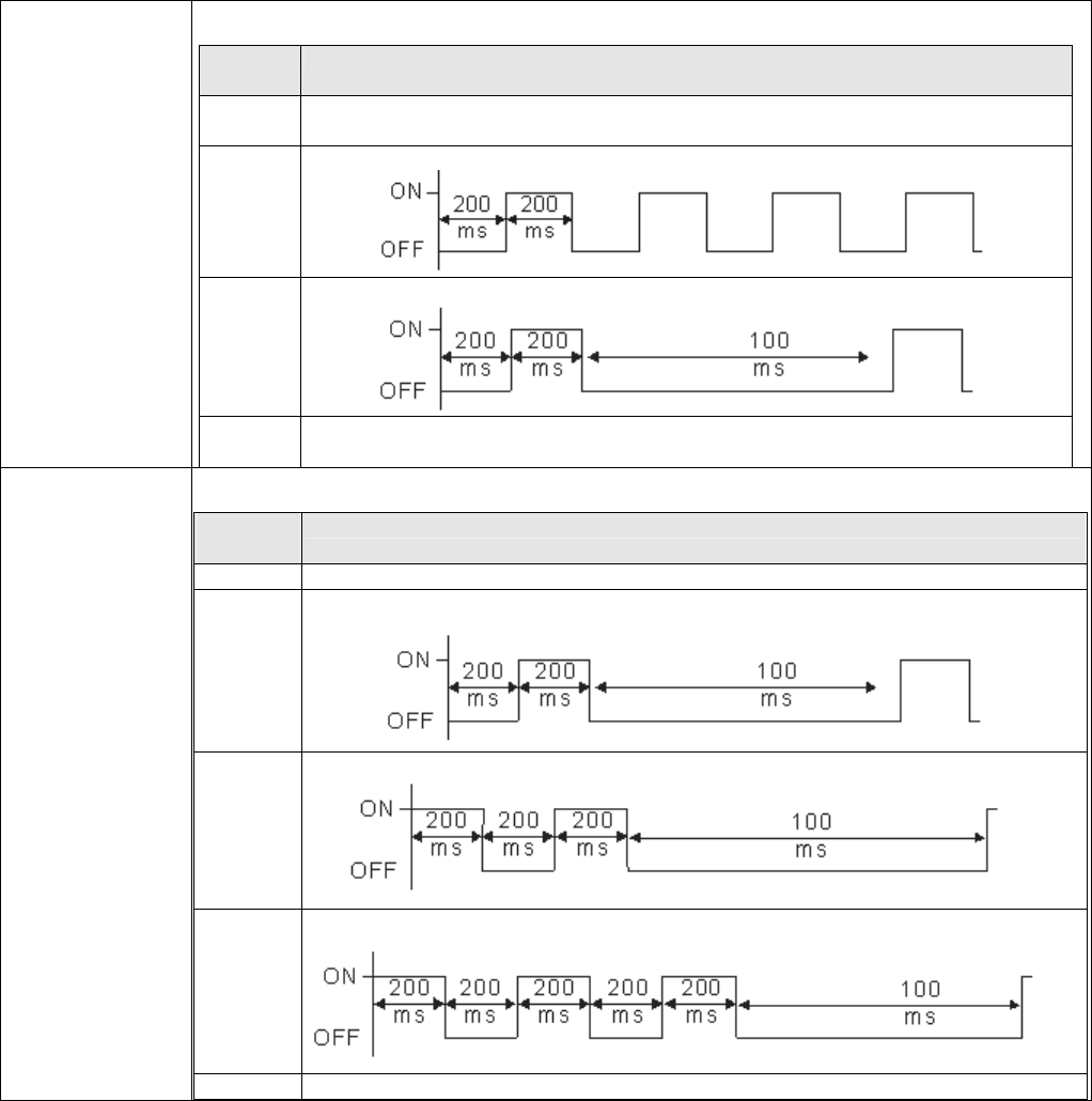
Chapter 10 Digital Keypad|CT2000 Series
10-3
CANopen ~”RUN”
RUN LED:
LED
status Condition/State
OFF CANopen at initial No LED
Blinking CANopen at pre-operation
Single
flash CANopen at stopped
ON CANopen at operation status No LED
CANopen ~”ERR”
ERR LED:
LED
status Condition/ State
OFF No Error
Single
flash One message fail
Double
flash Guarding fail or heartbeat fail
Triple
flash SYNC fail
ON Bus off
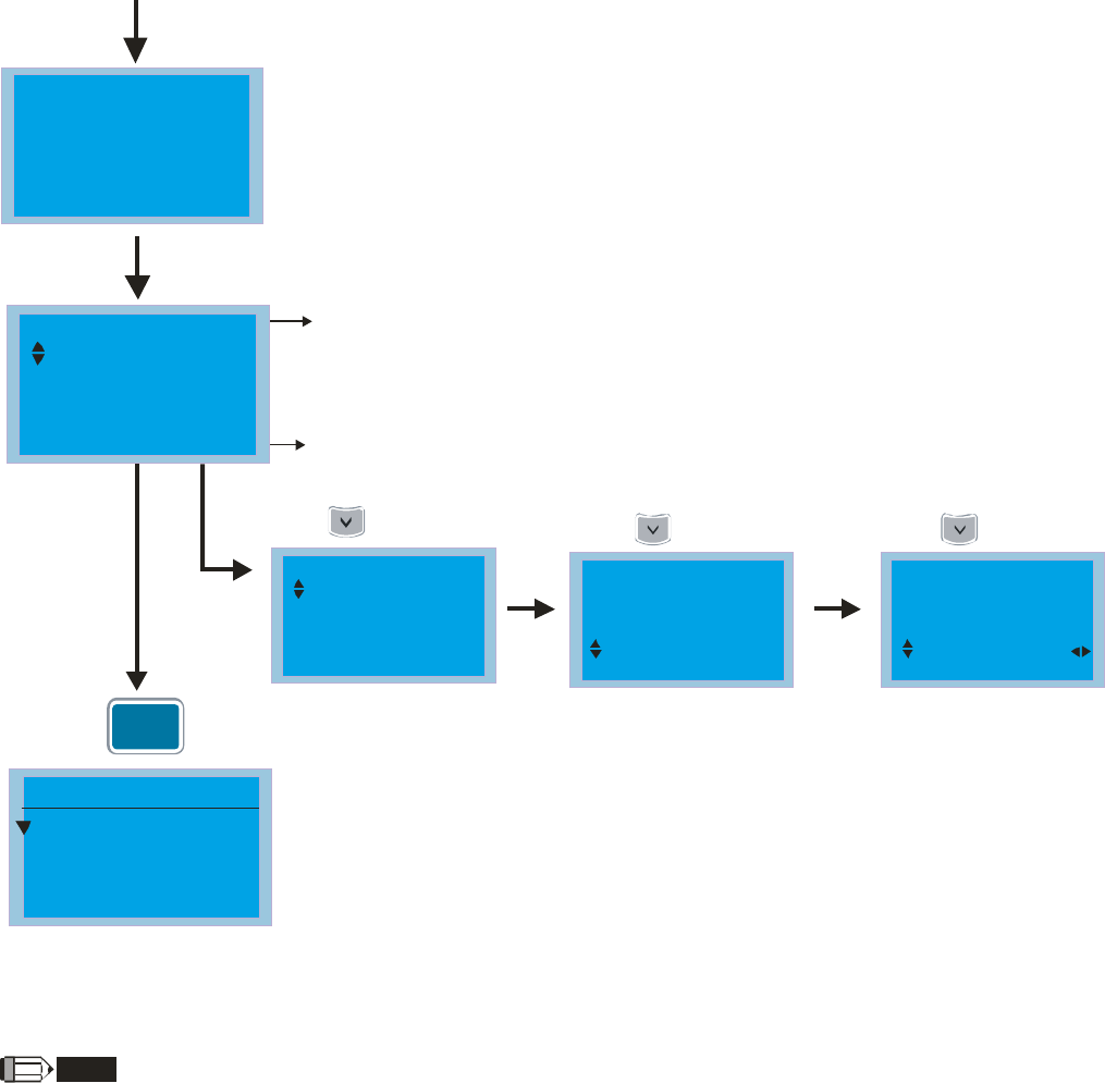
Chapter 10 Digital Keypad|CT2000 Series
10-4
10-2 Function of Digital Keypad KPC-CC01
POWER ON
1)The default Start-up page is Delta Logo.(Default 1and 2)
2) User can customize their start-up page through the edited function.
(Need to purchase the optional accessories)
Start-up
After main menu is selected, the start-up page will display in
the format user defined. The page shown on the left is display
as Delta default setting.
The button line of LCD displays time and JOG.
The top line of LCD displays the status of drive.
11. Start-up
12. Main page
5. Copy PLC
6. Fault Record
7. Quick/Simple Setup
8. Display Setup
9. Time Setup
10. Language Setup
1.Detail Parameter
2.Copy Parameter
3.Keypad Locked
MENU
MENU
Detail Parameter
2.Copy Parameter
3.Keypad Locked
4.PLC Function
1.
Skip to main page
afer 3sec.
MENU
Press
Item 1~4 are the
common items for
KPC-CC01 &KPC-CE01
Press once Press again Press again
AUTO
JOG 14 35:36:
F 60.00Hz
H 0.00Hz
A 0.00
AUTO
JOG 14 35:36:
F 60.00Hz
H 0.00Hz
A 0.00
AUTO
JOG 14 35:36:
F 60.00Hz
H 0.00Hz
A 0.00
AUTO
JOG 14 35:36:
H 0.00Hz
A 0.00
A 0.00 Amp
NOTE
1. Startup page can only display pictures, no flash.
2. When Power ON, it will display startup page then the main page. The main page displays Delta’s default setting F/H/A/U,
the display order can be set by Pr.00.03 (Startup display). When the selected item is U page, use left key and right key to
switch between the items, the display order of U page is set by Pr.00.04 (User display).
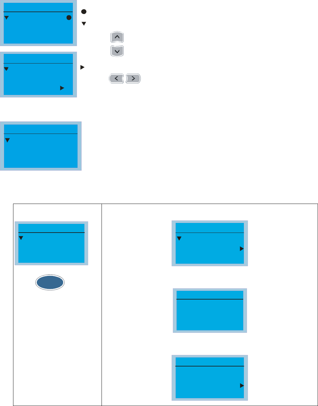
Chapter 10 Digital Keypad|CT2000 Series
10-5
Display Icon
00:System Pr
01:Basic
02:DI/DO
Pr
Pr
Pr setup
1.Default 1
2.Default 2
3.User define
Start-up
: present setting
Press for more options.
: roll down the page for more options
: show complete sentence
Press for complete information
Display item
5. Copy PLC
6. Fault Record
7. Quick/Simple Setup
8. Display Setup
9. Time Setup
10. Language Setup
13. PC Link
11. Start-up
12. Main page
1.Detail Parameter
2.Copy Parameter
3.Keypad Locked
MENU
MENU
Detail Parameter
2.Copy Parameter
3.Keypad Locked
4.PLC Function
1.
Item 1~4 are the common items for
KPC-CC01 &KPC-CE01
1. Detail Parameter
00:System Pr
01:Basic Pr
02:DI/DO Pr
Pr setup
ENTER
Press
to select.
00 System Pr Content
01 ID code
02 Rated curre
03 Pr reset
00- System Pr
00-08 Password Set
00-08
0000
Password set
0000~9999 MY MODE
01-00 The maximum output freq.
01-00 Hz
600.00
Max. output freq.
0.00~600.00 MY MODE
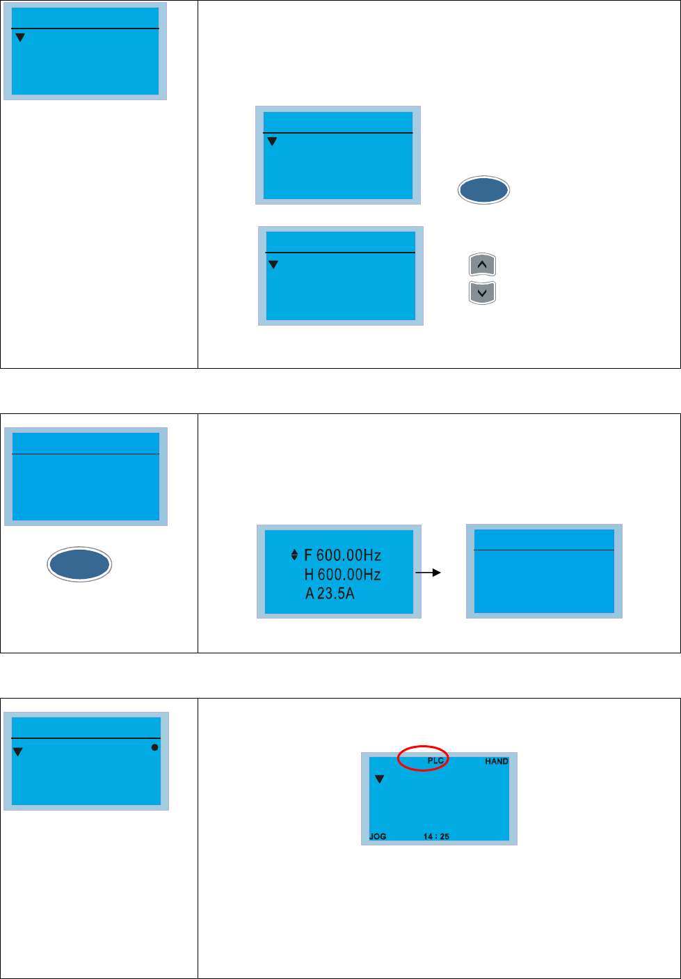
Chapter 10 Digital Keypad|CT2000 Series
10-6
2. Copy Parameter
1.
2.
3.
Copy pr
Copy parameters (Pr)
1. 4 sets of parameters duplication.
2. When the setting is complete, the date will be written to the copy
parameters (Pr) page.
1.2009/05/04
2.
3.
Copy pr
Press ENTER
1.SAVE
2.LOAD
File 1
Press
After selecting save and pressing "ENTER", the parameter
setting will be saved in the keypad.
to save or load
3. Keypad locked
Keypad locked
Press "ENTER"
to lock
Press to lock
ENTER
Keypad Locked
This function is used to lock the keypad. The main page would not display
“keypad locked” when the keypad is locked, however it will display the
message”please press ESC and then ENTER to unlock the keypad” when any
key is pressed.
HAND
JOG 14 35:56
:
Keypad locked
Press "ESC" for
3 seconds to unlock
Press any key.
4. PLC Function
1.Disable
2.PLC Run
3.PLC Stop
PLC
PLC function
1. Disable
2. PLC run
3. PLC stop
When activate and stop PLC function, the PLC status will be displayed on
main page of Delta default setting.
F
H
A
600.00Hz
23.5A
600.00Hz
The PLC function of KPC-CE01 can only displays:
1. PLC0
2. PLC1
3. PLC2
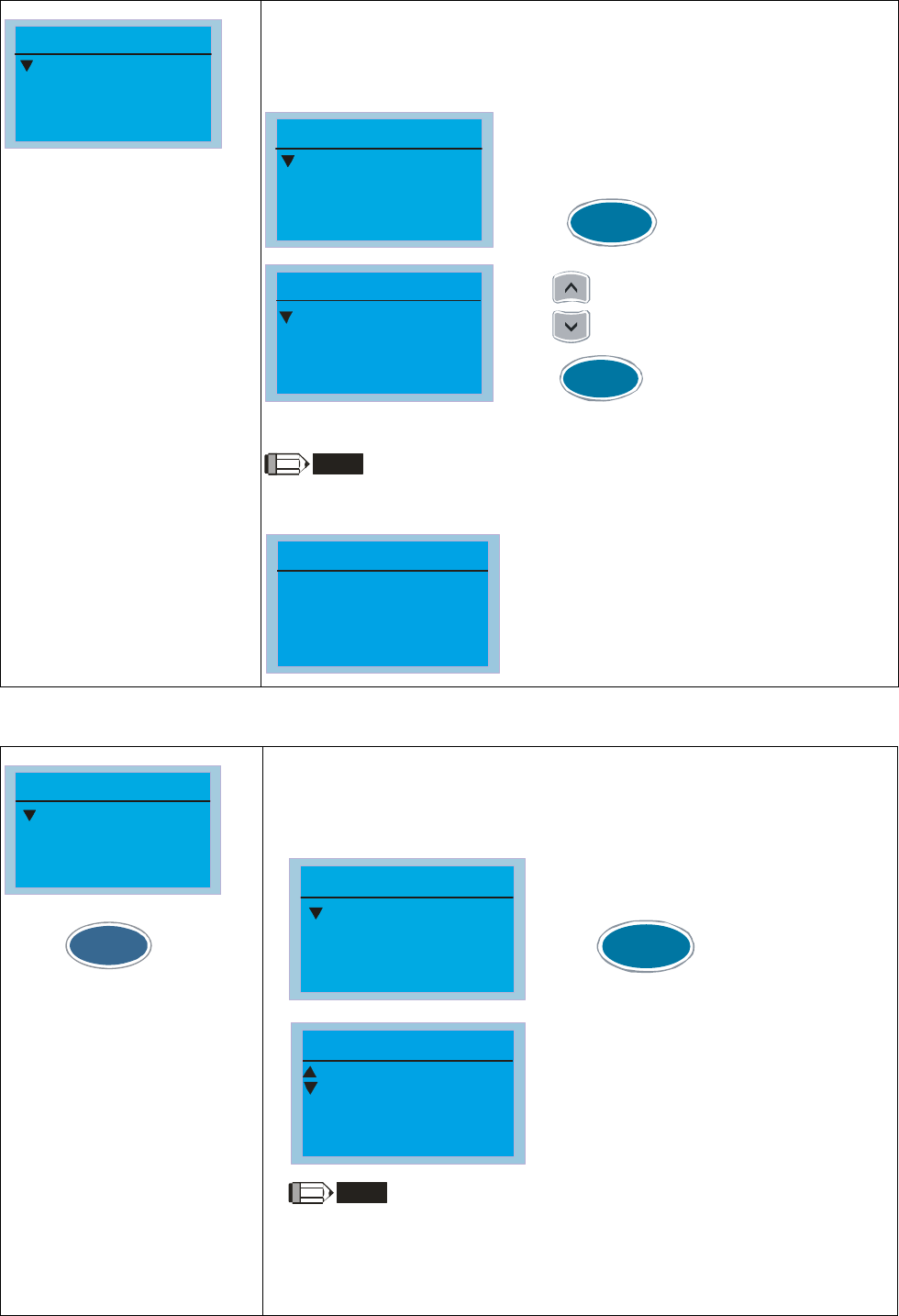
Chapter 10 Digital Keypad|CT2000 Series
10-7
5. Copy PLC
1.
2.
3.
Copy PLC
Copy PLC
1. Duplicate 4 sets of parameters.
2. When the setting is complete, the date will be written to the Copy
PLC page.
1.2010/03/14
2.
3.
Copy PLC
Press to setting menu.
ENTER
1. Save to the drive
2. Save to the
digital display
File 1
Press to select where to save the file
If select save to the drive and press enter, the file will be saved to the drive.
Press execute filesaving process.
ENTER
NOTE
If password protection for WPLSoft editor was set, it is required to enter the
password before the file can successfully be saved onto the digital display.
Password
File 1
Input Times
0000
0
6. Fault record
1:GFF
2:ocA
3:oH
Fault record
ENTER
Press
to select.
KPC-CE01 does not support
this function.
Fault Record
It can accumulate 6 sets of recent fault records.
The first fault code displays in the record is the latest fault. Select the fault
code for details on time, date, frequency, current, voltage and DC BUS Volt..
1:GFF
2:ocA
3:oH
Fault record
ENTER
Press to view the
current and voltage of the fault
Time: 19:47:00
Frequency: 0.00
Current: 0.00
2: ocA
NOTE
Fault actions of AC motor drive are record and save to KPC-CC01. When
KPC-CC01 is removed and apply to another AC motor drive, the previous
fault records will not be deleted. The new fault records of the present AC
motor drive will accumulate to KPC-CC01.
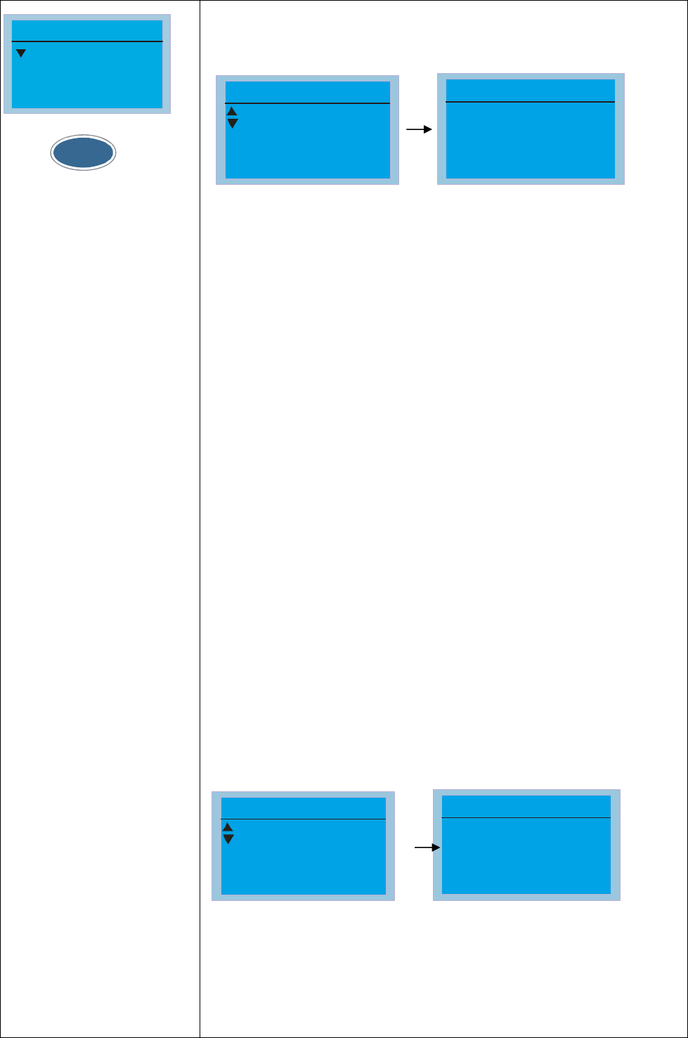
Chapter 10 Digital Keypad|CT2000 Series
10-8
7. Quick/Simple Setting
1: V/F mode
2: VFPG mode
3: SVC mode
Quick setting
ENTER
Press
to select.
Quick Setting:
1. VF Mode
2. VFPG Mode
3. SVC Mode
4. FOCPG Mode
5. TQCPG Mode
6. My Mode
Quick Setting:
1. V/F Mode
01: Password Input (Decode)
01. Password Input
02. Password Setting
03. Control Mode
V/F mode P00-07
0
Password Input
00-07
0~ 65535
Items
1. Parameter Protection Password Input (P00-07)
2. Parameter Protection Password Setting (P00-08)
3. Control Mode (P00-10)
4. Control of Speed Mode (P00-11)
5. Load Selection (P00-16)
6. Carrier Frequency (P00-17)
7. Source of the Master Frequency Command (AUTO) (P00-20)
8. Source of the Operation Command (AUTO) (P00-21)
9. Stop Method (P00-22)
10. Digital Keypad STOP function (P00-32)
11. Max. Operation Frequency (P01-00)
12. Base Frequency of Motor 1 (P01-01)
13. Max. Output Voltage Setting of Motor 1 (P01-02)
14. Mid-point Frequency 1 of Motor 1 (P01-03)
15. Mid-point Voltage 1 of Motor 1 (P01-04)
16. Mid-point Frequency 2 of Motor 1 (P01-05)
17. Mid-point Voltage 2 of Motor 1 (P01-06)
18. Min. Output Frequency of Motor 1 (P01-07)
19. Min. Output Voltage of Motor 1 (P01-08)
20. Output Frequency Upper Limit (P01-10)
21. Output Frequency Lower Limit (P01-11)
22. Accel. Time 1 (P01-12)
23. Decel Time 1 (P01-13)
24. Over-voltage Stall Prevention (P06-01)
25. Derating Protection (P06-55)
26. Software Brake Level (P07-00)
27. Speed Search during Start-up (P07-12)
28. Emergency Stop (EF) & Force to Stop Selection (P07-20)
29. Filter Time of Torque Command (P07-24)
30. Filter Time of Slip Compensation (P07-25)
31. Torque Compensation Gain (P07-26)
32. Slip Compensation Gain (P07-27)
2. VFPG Mode
01: Password Input (Decode)
01. Password Input
02. Password Setting
03. Control Mode
V/F mode P00-07
0
Password Input
00-07
0~ 65535
Items
1. Parameter Protection Password Input (P00-07)
2. Parameter Protection Password Setting (P00-08)
3. Control Mode (P00-10)
4. Control of Speed Mode (P00-11)
5. Load Selection (P00-16)
6. Source of the Master Frequency Command (AUTO) (P00-20)
7. Source of the Operation Command (AUTO) (P00-21)
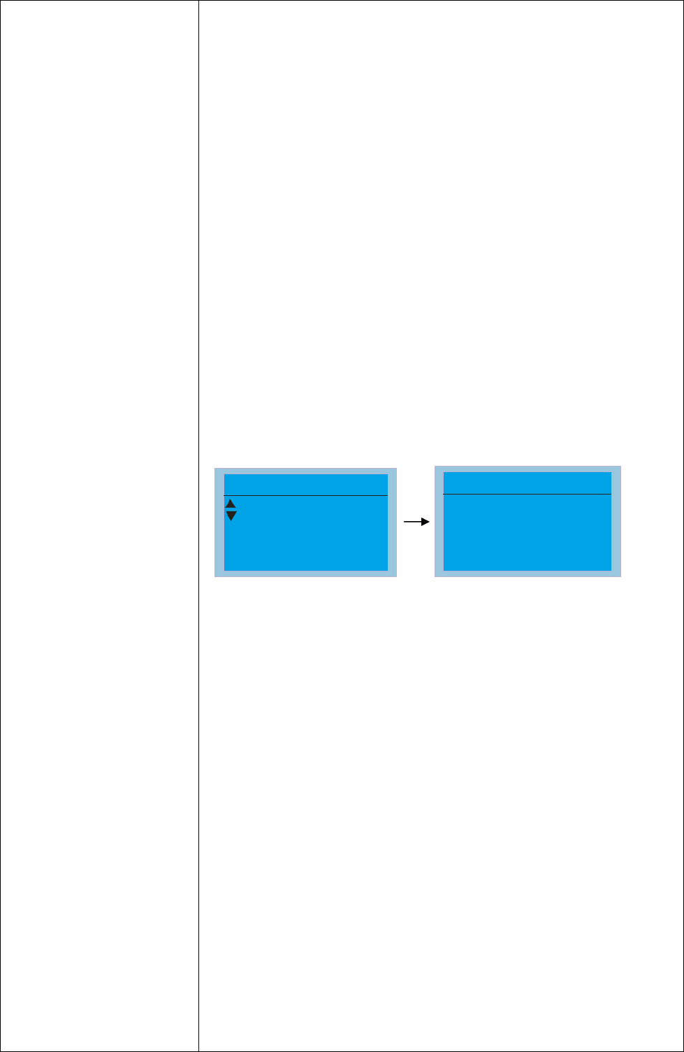
Chapter 10 Digital Keypad|CT2000 Series
10-9
8. Stop Method (P00-22)
9. Digital Keypad STOP function (P00-32)
10. Max. Operation Frequency (P01-00)
11. Base Frequency of Motor 1 (P01-01)
12. Max. Output Voltage Setting of Motor 1 (P01-02)
13. Min. Output Frequency of Motor 1 (P01-07)
14. Min. Output Voltage of Motor 1 (P01-08)
15. Output Frequency Upper Limit (P01-10)
16. Output Frequency Lower Limit (P01-11)
17. Accel. Time 1 (P01-12)
18. Decel Time 1 (P01-13)
19. Over-voltage Stall Prevention (P06-01)
20. Software Brake Level (P07-00)
21. Filter Time of Torque Command (P07-24)
22. Filter Time of Slip Compensation (P07-25)
23. Slip Compensation Gain (P07-27)
24. Encoder Type Selection (P10-00)
25. Encoder Pulse (P10-01)
26. Encoder Input Type Setting (P10-02)
27. ASR Control ( P) 1 (P11-06)
28. ASR Control (I) 1 (P11-07)
29. ASR Control ( P) 2 (P11-08)
30. ASR Control (I) 2 (P11-09)
31. P Gain of Zero Speed (P11-10)
32. I Gain of Zero Speed (P11-11)
3. SVCPG Mode
01: Password Input (Decode)
01. Password Input
02. Password Setting
03. Control Mode
V/F mode P00-07
0
Password Input
00-07
0~ 65535
Items
1. Parameter Protection Password Input (P00-07)
2. Parameter Protection Password Setting (P00-08)
3. Control Mode (P00-10)
4. Control of Speed Mode (P00-11)
5. Load Selection (P00-16)
6. Carrier Frequency (P00-17)
7. Source of the Master Frequency Command (AUTO) (P00-20)
8. Source of the Operation Command (AUTO) (P00-21)
9. Stop Method (P00-22)
10. Digital Keypad STOP function (P00-32)
11. Max. Operation Frequency (P01-00)
12. Base Frequency of Motor 1 (P01-01)
13. Max. Output Voltage Setting of Motor 1 (P01-02)
14. Min. Output Frequency of Motor 1 (P01-07)
15. Min. Output Voltage of Motor 1 (P01-08)
16. Output Frequency Upper Limit (P01-10)
17. Output Frequency Lower Limit (P01-11)
18. Accel. Time 1 (P01-12)
19. Decel Time 1 (P01-13)
20. Full-load Current of Induction Motor 1 (P05-01)
21. Rated Power of Induction Motor 1 (P05-02)
22. Rated Speed of Induction Motor 1 (P05-03)
23. Pole Number of Induction Motor 1 (P05-04)
24. No-load Current of Induction Motor 1 (P05-05)
25. Over-voltage Stall Prevention (P06-01)
26. Over-current Stall Prevention during Acceleration (P06-03)
27. Derating Protection (P06-55)
28. Software Brake Level (P07-00)

Chapter 10 Digital Keypad|CT2000 Series
10-10
29. Emergency Stop (EF) & Force to Stop Selection (P07-20)
30. Filter Time of Torque Command (P07-24)
31. Filter Time of Slip Compensation (P07-25)
32. Slip Compensation Gain (P07-27)
4. FOCPG Mode
01: Password Input (Decode)
01. Password Input
02. Password Setting
03. Control Mode
V/F mode P00-07
0
Password Input
00-07
0~ 65535
Items
1. Parameter Protection Password Input (P00-07)
2. Parameter Protection Password Setting (P00-08)
3. Control Mode (P00-10)
4. Control of Speed Mode (P00-11)
5. Source of the Master Frequency Command (AUTO)
(P00-20)
6. Source of the Operation Command (AUTO) (P00-21)
7. Stop Method (P00-22)
8. Max. Operation Frequency (P01-00)
9. Base Frequency of Motor 1 (P01-01)
10. Max. Output Voltage Setting of Motor 1 (P01-02)
11. Output Frequency Upper Limit (P01-10)
12. Output Frequency Lower Limit (P01-11)
13. Accel. Time 1 (P01-12)
14. Decel Time 1 (P01-13)
15. Full-load Current of Induction Motor 1 (P05-01)
16. Rated Power of Induction Motor 1 (P05-02)
17. Rated Speed of Induction Motor 1 (P05-03)
18. Pole Number of Induction Motor 1 (P05-04)
19. No-load Current of Induction Motor 1 (P05-05)
20. Over-voltage Stall Prevention (P06-01)
21. Over-current Stall Prevention during Acceleration (P06-03)
22. Derating Protection (P06-55)
23. Software Brake Level (P07-00)
24. Emergency Stop (EF) & Force to Stop Selection (P07-20)
25. Encoder Type Selection (P10-00)
26. Encoder Pulse (P10-01)
27. Encoder Input Type Setting (P10-02)
28. System Control (P11-00)
29. Per Unit of System Inertia (P11-01)
30. ASR1 Low-speed Bandwidth (P11-03)
31. ASR2 High-speed Bandwidth (P11-04)
32. Zero-speed Bandwidth (P11-05)
5. TQCPG Mode
01: Password Input (Decode)
01. Password Input
(Decode)
02. Password Setting
03. Control Mode
V/F mode P00-07
0
Password Input
00-07
0~ 65535
Items
1. Password Input (Decode) (P00-07)
2. Password Setting (P00-08)
3. Control Mode (P00-10)
4. Control of Speed Mode (P00-11)
5. Source of the Master Frequency Command (P00-20)

Chapter 10 Digital Keypad|CT2000 Series
10-11
6. Source of the Operation Command (P00-21)
7. Max. Operation Frequency (P01-00)
8. Base Frequency of Motor 1 (P01-01)
9. Max. Output Voltage Setting of Motor 1 (P01-02)
10. Full-load Current of Induction Motor 1 (P05-01)
11. Rated Power of Induction Motor 1 (P05-02)
12. Rated Speed of Induction Motor 1 (P05-03)
13. Pole Number of Induction Motor 1 (P05-04)
14. No-load Current of Induction Motor 1 (P05-05)
15. Over-voltage Stall Prevention (P06-01)
16. Software Brake Level (P07-00)
17. Encoder Type Selection (P10-00)
18. Encoder Pulse (P10-01)
19. Encoder Input Type Setting (P10-02)
20. System Control (P11-00)
21. Per Unit of System Inertia (P11-01)
22. ASR1 Low-speed Bandwidth (P11-03)
23. ASR2 High-speed Bandwidth (P11-04)
24. Zero-speed Bandwidth (P11-05)
25. Max. Torque Command (P11-27)
26. Source of Torque Offset (P11-28)
27. Torque Offset Setting (P11-29)
28. Source of Torque Command (P11-33)
29. Torque Command (P11-34)
30. Speed Limit Selection (P11-36)
31. Forward Speed Limit (torque mode) (P11-37)
32. Reverse Speed Limit (torque mode) (P11-38)
6.My Mode
01:
02:
03:
My mode
Click F4 in parameter setting
page, the parameter will save
to My Mode. To delete or
correct the parameter, enter
this parameter and click the
“DEL” on the bottom right
corner.
My mode:
It can save 01~32 sets of
parameters (Pr).
1
05-02
motor current
05-02 Amps
0.00~600.00
MY MODE
Press F4 and save to my mode.
2
01: motor current
02:
03:
My mode
The parameter (Pr) will be displayed
in My mode if it is properly saved.
To correct or to delete this Pr. clicks
DEL.
05-02
motor current
05-02 Amps
0.00~ 600.00 DEL
Press F4 to delete this Pr. setting
in My Mode.
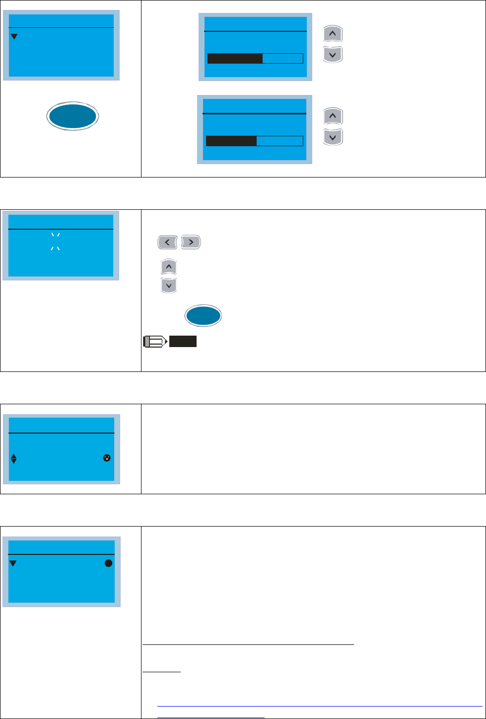
Chapter 10 Digital Keypad|CT2000 Series
10-12
8. Display setup
1.Contrast Ad
2.BKLT time
Disp setup
Press to
enter the setting menu.
ENTER
1. Contrast Adjustment
Contrast adjust
6
Adjust setting value
0
10
2. Back-lighted Time
BKLT Time Min
5
Adjust setting value
0
10
9. Time setting
Time setup
2009/01/01
_
_ : _ _ :_ _
Enter time setu
p
p
a
g
e
,
"9" will continue to blink
move to left / right
increase / decrease the value
ENTER
Press
to confirm.
NOTE
When the digital keypad is removed, the time setting will be in standby
status for 7 days. After this period, the time needs to be reset.
10. Language setup
1:English
2:
3:
繁體中文
簡體中文
Language
Language selection.
11. Startup Page Setting
1.Default 1
2.Default 2
3.User define
Start-up
1. Default picture 1
DELTA LOGO
2. Default picture 2
DELTA Text
3. User defined: optional accessory is require (TPEditor & USB/RS-485
Communication Interface-IFD6530)
Install an editing accessory would allow users to design their own start-up
page.If editor accessory is not installed, “user defined” option will dispay a
blank page.
USB/RS-485 Communication Interface-IFD6530
Please refer to Chapter 07 Optional Acessories for more detail.
TPEditor
TPEditor Installation Instruction is on page 10-15 and TPEditor V1.03.6 is
available for download at:
http://www.delta.com.tw/ch/product/em/download/download_main.asp?act
=3&pid=1&cid=1&tpid=3

Chapter 10 Digital Keypad|CT2000 Series
10-13
12. Main page
1.Default
2.User define
Main Page
ENTER
Press
to select.
1. Default page
Default picture and editable picture are available upon selection.
F
H
A
60.00Hz
0.00
0.00Hz
F 600.00Hz >>> H >>> A >>> U (circulate)
2. User defined: optional accessory is require (TPEditor & USB/RS-485
Communication Interface-IFD6530)
Install an editing accessory would allow users to design their own start-up
page.If editor accessory is not installed, “user defined” option will dispay a
blank page.
USB/RS-485 Communication Interface-IFD6530
Please refer to Chapter 07 Optional Acessories for more detail.
TPEditor
TPEditor Installation Instruction is on page 10-15 and TPEditor V1.30.6 is
available for download at:
http://www.delta.com.tw/ch/product/em/download/download_main.asp?act
=3&pid=1&cid=1&tpid=3
13. PC Link
PC Link
Press "ENTER"
to link
Select 1 and press ENTER
PC Link
Waiting
28%
Select 2 and press ENTER
The function of PC Link is to establish a connection with computer to
download the page for user defined editing. After enter to PC Link page,
check if the connection of KPC-CC01 and computer is successfully establish,
then press enter to go to next page and wait for communication response.
1. If the connection failed, the screen will show “Time Out”.
PC Link
Time Out
Press "ESC"back
to MENU
2. If the connection succeeds, the screen page will show “Downloading”.
When the download is done, it returns to MENU page.
PC Link
Downloading
28%
3. In order to set the start-up page and main page in the format user
defined, user must check the user define option for start-up page and
main page. If the user define page for editing has not yet downloaded to
KPC-CC01, the start-up page and main page will display as blank.

Chapter 10 Digital Keypad|CT2000 Series
10-14
Other display
When fault occur, the menu will display:
ocA
Oc at accel
Fault
CE01
Comm. Error 1
Warning
1. Press ENTER and start RESET. If still no response, please contact local distributor or return to the factory. To
view the fault DC BUS voltage, output current and output voltage, press “MENU”Æ“Fault Record”.
2. Press ENTER again, if the screen returns to main page, the fault is clear.
3. When fault or warning message appears, backlight LED will blinks until the fault or the warning is cleared.
Optional accessory: RJ45 Extension Lead for Digital Keypad
Part No. Description
CBC-K3FT RJ45 extension lead, 3 feet (approximately 0.9m)
CBC-K5FT RJ45 extension lead, 5 feet (approximately 1.5 m)
CBC-K7FT RJ45 extension lead, 7 feet (approximately 2.1 m)
CBC-K10FT RJ45 extension lead, 10 feet (approximately 3 m)
CBC-K16FT RJ45 extension lead, 16 feet (approximately 4.9 m)
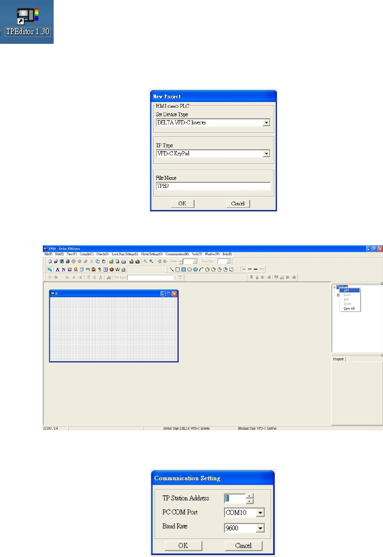
Chapter 10 Digital Keypad|CT2000 Series
10-15
10-3 TPEditor Installation Instruction
1) TPEditor: Setup & Basic Functions
1. Run TPEditor version 1.30
2. Go to File(F)ÆClick on New. The Window below will pop up. At the device type, click on the drop down
menu and choose DELTA VFD-C Inverter. At the TP type, click on the drop down menu and choose VFD-C
KeyPad. As for File Name, enter TPE0. Now click on OK.
3. You are now at the designing page. Go to Edit (E)ÆClick on Add a New Page (A) or go to the TP page on
the upper right side, right click once on TP page and choose Add to increase one more page for editing. The
current firmware of Keypad is version1.00 and can support up to 4 pages.
4. Download setting, Go to Tool ÆCommunication settings (C) to set up the PC Com Port and Baud Rate. The
supporting speeds of Baud rate are 9600bps, 19200bps and 38400bps. The default setting of TP address is
1, please do not modify.
2) Edit Startup Page
1. Click once on the Boot Page on the right hand side of your computer screen or click on View (V) Æclick on
Boot Page (B). Then a blank Boot Page window will pop up. Use the circled items to design your Startup page.
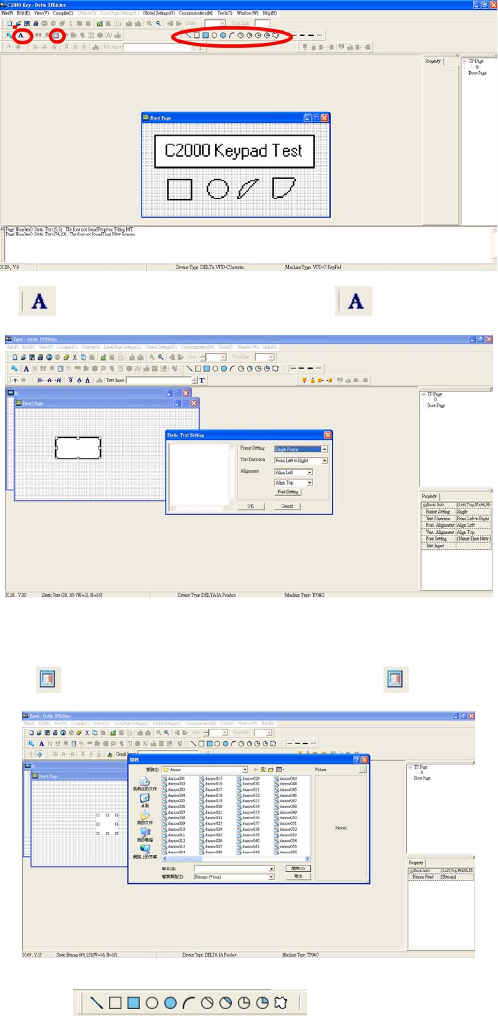
Chapter 10 Digital Keypad|CT2000 Series
10-16
2. Static Text . Open a blank page, click once on this button , and then double click on that blank
page. The following windows will pop up.
On the right hand side of the Static Text Setting, you can adjust the frame setting, the text direction, the
alignment and the font setting. Once you finish all the adjustments that you need.
You can continue to input your text in the blank space of Static Text Setting window. When you finish
inputting your text, click on OK to continue your next step or click cancel to abort the current step.
3. Static Bitmap ÆOpen a blank page, then click once on this button and then double click on that
blank page. The following window will pop up.
Please note that Static Bitmap setting support only images in BMP format. Now choose a image that you
need and click open, then that image will appear in the Static Bitmap window.
4. Geometric Bitmap Æ As shown in the picture on the left side, there
are 11 kinds of geometric bitmap to choose. Open a new blank page then click once on a geometric bitmap
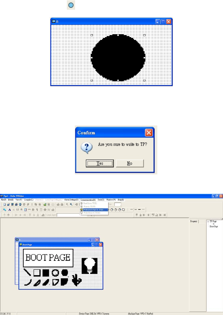
Chapter 10 Digital Keypad|CT2000 Series
10-17
icon that you need. Then drag that icon and enlarge it to the size that you need on that blank page. For
example, if you drag this icon to a blank page, you will see the following window.
5. Download---Take the image below as an example. The sentence “Boot page” is static text, the 11 images
below are geometric bitmaps. The image on the right hand side is a Static Bitmap. To upload a start up
page, double click to activate “Boot page. Make sure that you have followed the instruction on page 3 to
choose the right com port. Then go to “Communication (M)” ÆClick on “Write Boot Page TP (B).” When
you see the pop up message below
Go to the C2000 Keypad, press Menu then keep on pressing the Upward key until you see “PC Link,” then
press ENTER once, when you see “Press Enter to PC Link” on the keypad, press the ENTER again. Then
click the YES button to begin the upload.
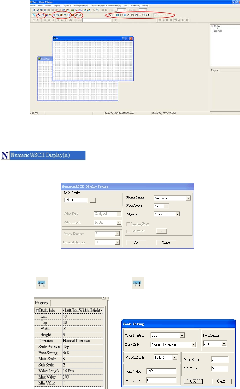
Chapter 10 Digital Keypad|CT2000 Series
10-18
3) Edit Main Page
1. Click on a page under the TP Page to edit or go to View Æ click on Boot Page to begin to edit main page.
The objects available for you to use are in the red circles below.
From left to right: Static Text, ASCII Display, Static Bitmap, Scale, Bar Graph, Button, Clock Display, Units,
Numeric Input, 11 geometric bitmaps and different width of lines. The application of Static Text, Static
Bitmap, and geometric bitmap is the same as the editing startup page.
2. Numeric/ASCII Display A): Go to Objects (O)ÆClick once on the Numeric/ASCII Display(A)
ÆDrag to enlarge to reach the size that you need to add objects in the
screen where you want to create an object ÆDouble click on the object to set up Related Devices, Frame
Setting , Fonts and Alignment.
Related Device: Choose the VFD Communication Port that you need, if you want to read output
frequency (H), set the VFD Communication Port to $2202. For other values, please refer to ACMD
ModBus Comm Address List.
3. Scale Setting : On the Tool Bar, click on this for Scale Setting. You can also edit Scale Setting in
the Property Window on the right hand side of your computer screen.
a. Scale Position: Click on the drop down list to choose which position that you need to place a scale.
b. Scale Side: Click on the drop down list to choose if you want to number your scale from smaller
number to bigger number or from big to small. Click OK to accept this setting or click Cancel to
abort.
c. Font Setting: Click on the drop down list to choose the Font setting that you need then click OK to
accept the setting or click Cancel to abort.
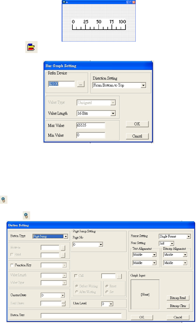
Chapter 10 Digital Keypad|CT2000 Series
10-19
d. Value Length: Click on the drop down to choose 16bits or 32 bits. Then click OK to accept the
setting or click Cancel to abort.
e. Main Scale & Sub Scale: In order to divide the whole scale into equal parts, key in the numbers of
your choices for main scale and sub scale.
f. Maximum value & Minimum Value are the numbers on the two ends of a scale. They can be
negative numbers but the input numbers are limited by value.
g. Follow the Scale setting mentioned above; you will have a scale as shown below.
4. Bar Graph setting :
a. Related Device: Choose the VFD Communication Port that you need.
b. Direction Setting: Click on the drop down menu to choose one of the following directions: From
Bottom to Top, From Top to Bottom, From Left to Right or From Right to Left.
c. Maximum Value & Minimum Value: They define the range covered by the maximum value and
minimum value. If a value is smaller than or equal to the minimum value, then the bar graph will be
blank. If a value is bigger or equal to the maximum value, then the bar graph will be full. If a value is
between minimum and maximum value, then the bar graph will be filled proportionally.
5. Button : Currently this function only allows the Keypad to switch pages, other functions are not yet
available. Text input function and Image inserted functions are not yet supported.
Double click on to open set up window.
a. <Button Type> allows you set up buttons’ functions. But Page Jump is the only supported function
currently.
b. Page Jump setting: After you choose the Page Jump function in the drop down list, you will see this
Page Jump Setting Menu
c. <Function Key> allows you to assign functions to the following keys on the KPC-CC01 keypad: F1,
F2, F3, F4, Up, Down, Left and Right. Please note that the Up and Down keys are locked by
TPEditor. These two keys cannot be programmed. If you want to program Up and Down keys, go to
ToolÆFunction Key Settings (F)ÆRe-Define Up/Down Key(R).
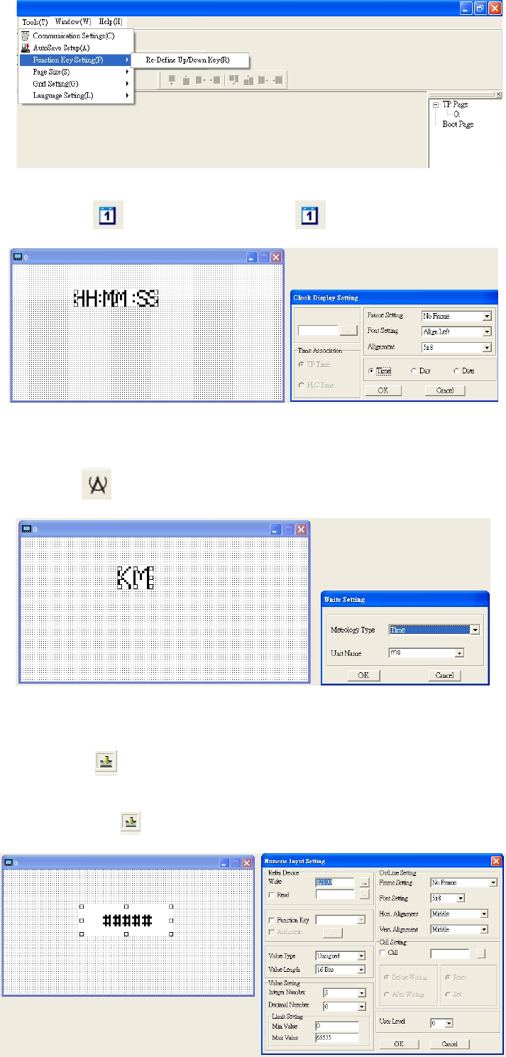
Chapter 10 Digital Keypad|CT2000 Series
10-20
d. There are no supported functions other than the setting mentioned above.
6. Clock Display Setting : Click once on this button .
Open a new file and click once in that window, you will see the following
In the clock display setting, you can choose to display Time, Day or Date on the Keypad. To adjust time,
go to #9 on the Keypad’s menu. You can also adjust Frame Setting, Font Setting and Alignment.
7. Unit Measurement : Click once on this Button:
Open a new file and double click on that window, you will see the following
Choose from the drop down list the Metrology and the Unity Name that you need.
As for Metrology, you have the following choices Length, Square Measure, Volume/Solid Measure,
Weight, Speed, Time and Temperature. The unit name changes automatically when you change
metrology type.
8. Numeric Input Setting :
This menu allows you to provide parameters or communication ports and to input numbers.
Click once on this button .
Open a new file and double click on that window, you will see the following:
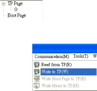
Chapter 10 Digital Keypad|CT2000 Series
10-21
a. Related Device: There are two blank spaces to fill in, one is <Write> and another one is <Read>.
Input the numbers that you want to display and the corresponding numbers of a parameter and that
of a communication port. For example, input 012C to Read and Write Parameter P01-44.
b. OutLine Setting: The Frame setting, Font setting, Vertical Alignment and Horizontal Alignment are
the same as mentioned before. Click on the drop down menu and choose the setting that you need.
c. Function key: The setting here allows you to program keys on the keypad. Press the key on the
menu then the corresponding key on the keypad will start to blink, then press Enter to confirm the
setting.
d. Value Type & Value Length: These two factors influence the range of the Minimum and Maximum
Value of the Limit Setting. Please note that the corresponding supporting values for C2000 have to
be 16bits. The 32bits values are not supported.
e. Value Setting: This part is set automatically by the keypad itself.
f. Limit Setting: Input the range the security setting here.
g. For example, if you set Function Key as F1, Minimum Value as 0 and Maximum Value ias 4, then
press F1 on Keypad Then you can press Up and Down key on the keypad to increase or decrease
the value. Press Enter Key on the keypad to confirm your setting. You can also go to parameter
table 01-44 to verify if your input correctly the value.
9. Download TP Page : Press Up or Down key on the keypad until you reach #13 PC
Link.
Then press Enter on the keypad and you will see the word “Waiting” on keypad’s screen. Now choose a
page that you have created then go to Communication (M)ÆWrite to TP(W) to start downloading the
page to the keypad
.
When you see the word Completed on the keypad’s screen, that means the download is done.
Then you can press ESC on the keypad to go back to the menu of the keypad.

Chapter 10 Digital Keypad|CT2000 Series
10-22
10-4 Digital Keypad KPC-CC01 Fault Codes and Descriptions
Following fault codes and description are for digital keypad KPC-CC01 with version V1.01 and version
higher.
LCM Display Description
FrEr
kpdFlash Read Er
Fault
Keypad flash memory read error
FSEr
kpdFlash Save Er
Fault
Keypad flash memory save error
FPEr
kpdFlash Pr Er
Fault
Keypad flash memory parameter error
VFDr
Read VFD Info Er
Fault
Keypad flash memory when read AC drive data error
LCM Display Description
CE01
Comm Command Er
Warning
Modbus function code error
CE02
Comm Address Er
Warning
Modbus data address error
CE03
Comm Data Error
Warning
Modbus data value error
CE04
Comm Slave Error
Warning
Modbus slave drive error
CE10
KpdComm Time Out
Warning
Modbus transmission time-Out
TPNO
TP No Object
Warning
Object not supported by TP Editor

Chapter 10 Digital Keypad|CT2000 Series
10-23
Fault Descriptoin of File Copy and Setting Errors
LCM Display Description
Err
Read Only
File 1
Parameter and rile are read only
Err
Write Fail
File 1
Fail to write parameter and file
Err
VFD Running
File 1
AC drive is in operating status
Err
Pr Lock
File 1
AC drive parameter is locked
Err
Pr Changing
File 1
AC drive parameter changing
Err
Fault Code
File 1
Fault code
Err
Warning Code
File 1
Warning code
Err
Type Dismatch
File 1
File type dismatch
Err
Password Lock
File 1
File is locked with password
Err
Version Fail
File 1
File version dismatch
Err
VFD Time Out
File 1
AC drive copy function time-out
Err
Keypad Issue
File 1
Other keypad error

Chapter 10 Digital Keypad|CT2000 Series
10-24
LCM Display Description
Err
VFD Issue
File 1
Other AC drive error

Chapter 11 Summary of Parameter Settings|C2000 Series
11-1
Chapter 11 Summary of Parameter Settings
This chapter provides summary of parameter settings for user to gather the parameter setting ranges,
factory settings and set parameters. The parameters can be set, changed and reset by the digital keypad.
NOTE
1) : the parameter can be set during operation
2) For more detail on parameters, please refer to Ch12 Description of Parameter Settings.
00 Drive Parameters
NOTE
IM: Induction Motor; PM: Permanent Magnet Motor
Pr. Explanation Settings Factory
Setting
00-00
Identity Code of the AC Motor Drive
4: 230V, 1HP
5: 460 V, 1HP
6: 230V,2HP
7: 460 V, 2HP
8: 230V, 3HP
9: 460 V, 3HP
10: 230V, 5HP
11: 460 V, 5HP
12: 230V, 7.5HP
13: 460 V, 7.5HP
14: 230V, 10HP
15: 460V, 10HP
16: 230V, 15HP
17: 460V, 15HP
18: 230V, 20HP
19: 460V, 20HP
20: 230V, 25HP
21: 460V, 25HP
22: 230V, 30HP
23: 460V, 30HP
24: 230V, 40HP
25: 460V, 40HP
26: 230V, 50HP
27: 460V, 50HP
28: 230V, 60HP
29: 460V, 60HP
30: 230V, 75HP
31: 460V, 75HP
32: 230V, 100HP
33: 460V, 100HP
34: 230V, 125HP
35: 460V, 125HP
37: 460V, 150HP
39: 460V, 175HP
41: 460V, 215HP
43: 460V, 250HP
45: 460V, 300HP
47: 460V, 375HP
49: 460V, 425HP
51: 460V, 475HP
93: 460V, 5HP(4kW)
Read
only
00-01 Display AC Motor Drive Rated
Current Display by models
Read
only

Chapter 11 Summary of Parameter Settings|C2000 Series
11-2
Pr. Explanation Settings Factory
Setting
00-02 Parameter Reset
0: No function
1: Read only
5: Reset KWH display to 0
6: Reset PLC (including CANopen Master Index)
7: Reset CANopen Index (Slave)
8: keypad lock
9: All parameters are reset to factory settings(base
frequency is 50Hz)
10: All parameters are reset to factory settings
(base frequency is 60Hz)
0
00-03 Start-up Display Selection
0: F (frequency command)
1: H (output frequency)
2: U (multi-function display, see Pr.00-04)
3: A (output current)
0
00-04 Content of Multi-function Display
0: Display output current (A)
1: Display counter value (c)
2: Display actual output frequency (H.)
3: Display DC-BUS voltage (v)
4: Display output voltage (E)
5: Display output power angle (n)
6: Display output power in kW (P)
7: Display actual motor speed rpm (r)
8: Display estimate output torque % (t)
9: Display PG feedback (G) (refer to
Pr.10-00,10-01)
10: Display PID feedback in % (b)
11: Display AVI in % (1.)
12: Display ACI in % (2.)
13: Display AUI in % (3.)
14: Display the temperature of IGBT in oC (i.)
15: Display the temperature of capacitance in oC
(c.)
16: The status of digital input (ON/OFF) (i)
17: The status of digital output (ON/OFF) (o)
18: Multi-step speed (S)
19: The corresponding CPU pin status of digital
input (d.)
20: The corresponding CPU pin status of digital
output (0.)
21: Actual motor position (PG1 of PG card) (P.)
22: Pulse input frequency (PG2 of PG card) (S.)
23: Pulse input position (PG2 of PG card) (q.)
24: Position command tracing error (E.)
25: Overload count (0.00~100.00%) (h.)
26: Ground Fault GFF (Unit :%)(G.)
27: DC Bus voltage ripple (Unit: Vdc) (r.)
28: Display PLC data D1043 (C)
29: Display PM motor pole section (EMC-PG01U
application) (4.)
30: Display output of user defined (U)
31: Display Pr.00-05 user Gain(K)
32: Number of actual motor revolution during
operation (PG card plug in and Z phase signal
input) (Z.)
33: Motor actual position during operation (when
PG card is connected)(q)
34: Operation speed of fan(%) (F.)
35: Control Mode display: 0= Speed control mode
(SPD), 1= torque control mode (TQR) (t.)
36: Present operating carrier frequency of drive
3

Chapter 11 Summary of Parameter Settings|C2000 Series
11-3
Pr. Explanation Settings Factory
Setting
(Hz) (J.)
37: Reserved
38: Display drive status (6.)
39: Display estimated output torque, postitive and
negative, using Nt-m as unit (t 0.0: postitive
torque; -0.0: negative torque (C.)
00-05 Coefficient Gain in Actual Output
Frequency 0~160.00 0
00-06 Software Version Read-only #.#
00-07 Parameter Protection Password
Input
0~65535
0~3: the times of password attempts
0
00-08 Parameter Protection Password
Setting
0 ~ 65535
0: No password protection / password is entered
correctly (Pr00-07)
1: Parameter is locked
0
00-09 Reserved
00-10 Control Mode
0: Speed mode
1: Point-to-Point position control
2: Torque mode
3: Home mode
0
00-11 Control of Speed Mode
0: VF (IM V/f control)
1: VFPG (IM V/f control+ Encoder)
2: SVC(IM Sensorless vector control)
3: FOCPG (IM FOC vector control+ encoder)
4: FOCPG(PM FOC vector control + Encoder)
5: FOC Sensorless (IM field oriented sensorless
vector control)
6: PM Sensorless (PM field oriented sensorless
vector control)
0
00-12 Point-to-Point Position mode 0: Relative position
1: Absolute position
00-13 Torque Mode Control
0: TQCPG(IM Torque control + Encoder)
1: TQCPG (PM Torque control + Encoder)
2: TQC Sensorless (IM Sensorless torque control)
0
00-14 Reserved
00-15 Reserved
00-16 Load Selection 0: Normal load
1: Heavy load
0
Normal load
230V 460V Carrier Frequency
1-15HP 1-20HP 2~15KHz
20-50HP 25-75HP 2~10KHz
60-125HP 100-475HP 2~09KHz
8
6
4
00-17 Carrier Frequency
Heavy load
230V 460V Carrier Frequency
1-15HP 1-20HP 2~15KHz
20-50HP 25-75HP 2~10KHz
60-125HP 100-475HP 2~09KHz
2
00-18 Reserved
00-19 PLC Command Mask
Bit 0: Control command by PLC force control
Bit 1: Frequency command by PLC force control
Bit 2: Position command by PLC force control
Bit 3: Torque command by PLC force control
Read
only
00-20 Source of Master Frequency
Command(AUTO)
0: Digital keypad
1: RS-485 serial communication
2: External analog input (Pr.03-00)
0

Chapter 11 Summary of Parameter Settings|C2000 Series
11-4
Pr. Explanation Settings Factory
Setting
3: External UP/DOWN terminal
4: Pulse input without direction command (Pr.10-16
without direction)
5: Pulse input with direction command (Pr.10-16)
6: CANopen communication card
7: Reserved
8: Communication card (no CANopen card)
00-21 Source of the Operation Command
(AUTO)
0: Digital keypad
1: External terminals. Keypad STOP disabled.
2: RS-485 serial communication. Keypad STOP
disabled.
3: CANopen communication card
4: Reserved
5: Communication card (no CANopen card)
0
00-22 Stop Method 0: Ramp to stop
1: Coast to stop
0
00-23 Control of Motor Direction
0: Enable forward/reverse
1: Reverse disable
2: Forward disable
0
00-24 Memory of Frequency Command Read only Read
only
00-25 User Defined Characteristics
Bit 0~3: user define on decimal place
0000b: no decimal place
0001b: one decimal place
0010b: two decimal place
0011b: three decimal place
Bit 4~15: user define on unit
000xh: Hz
001xh: rpm
002xh: %
003xh: kg
0
00-26 Max. User Defined Value
0: Disable
0~65535 (when Pr.00-25 set to no decimal place)
0.0~6553.5 (when Pr.00-25 set to 1 decimal place)
0.0~655.35 (when Pr.00-25 set to 2 decimal place)
0.0~65.535 (when Pr.00-25 set to 3 decimal place)
0
00-27 User Defined Value Read only Read
Only
00-28 Reserved
00-29 LOCAL/REMOTE Selection
0: Standard HOA function
1: Switching Local/Remote, the drive stops
2: Swithcing Local/Remote, the drive runs as the
REMOTE setting for frequency and operation
status
3: Swithcing Local/Remote, the drive runs as the
LOCAL setting for frequency and operation status
4: Swithcing Local/Remote, the drive runs as
LOCAL setting when switch to Local and runs as
REMOTE setting when switch to Remote for
frequency and operation status.
0
00-30 Source of the Master Frequency
Command(HAND)
0: Digital keypad
1: RS-485 serial communication
2: External analog input (Pr.03-00)
3: External UP/DOWN terminal
4: Pulse input without direction command (Pr.10-16
without direction)
5: Pulse input with direction command (Pr.10-16)
6: CANopen communication card
7: Reserved
8: Communication card (no CANopen card)
0
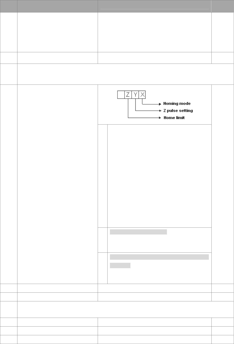
Chapter 11 Summary of Parameter Settings|C2000 Series
11-5
Pr. Explanation Settings Factory
Setting
00-31 Source of the Operation Command
(HAND)
0: Digital keypad
1: External terminals. Keypad STOP disabled.
2: RS-485 serial communication. Keypad STOP
disabled.
3: CANopen communication card
4: Reserved
5: Communication card (not include CANopen card)
0
00-32 Digital Keypad STOP Function 0: STOP key disable
1: STOP key enable 0
00-33
~
00-39
Reserved
X
Note: Forward run = closckwise (CW)
Reverse run = counterclockwise (CCW)
0: Forward run to home. Set PL forward limit as
check point.
1: Reverse run (CCW) to home. Set NL reverse
limit (CCWL) as check point.
2: Forward run to home. Set ORG : OFF→ON
as check point.
3: Reverse to home. Set ORG : OFF→ON as
check point.
4: Forward run and search for Z-pulse as check
point.
5: Forward run and search for Z-pulse as check
point.
6: Forward run to home. Set ORG: ON→OFF
as check point.
7: Reverse run to home. Set ORG : ON→OFF
as check point.
8: Define current position as home.
Y
Set X to 0, 1, 2, 3, 6, 7 first.
0: reverse run to Z pulse
1: continue forward run to Z pulse
2: Ignore Z pulse
00-40 Homing mode
Z
When home limit is reached, set X to 2, 3, 4, 5,
6, 7 first.
0: display the error
1: reverse the direction
0000
00-41 Homing by frequency 1 0.00~600.00Hz 8.00
00-42 Homing by frequency 2 0.00~600.00Hz 2.00
00-43
~
00-47
Reserved
00-48 Display Filter Time (Current) 0.001~65.535 sec 0.100
00-49 Display Filter Time (Keypad) 0.001~65.535 sec 0.100
00-50 Software Version (date) Read only #####

Chapter 11 Summary of Parameter Settings|C2000 Series
11-6
01 Basic Parameters
Pr. Explanation Settings Factory
Setting
01-00 Max. Operation Frequency
50.00~600.00Hz 60.00/
50.00
01-01 Output Frequency of Motor 1
0.00~600.00Hz
60.00/
50.00
01-02 Output Voltage of Motor 1
230V: 0.0V~255.0V
460V: 0.0V~510.0V
200.0
400.0
01-03 Mid-point Frequency 1 of Motor 1
0.00~600.00Hz
3.00
01-04 Mid-point Voltage 1 of Motor 1
230V: 0.0V~240.0V
460V: 0.0V~480.0V
11.0
22.0
01-05 Mid-point Frequency 2 of Motor 1
0.00~600.00Hz
0.50
01-06 Mid-point Voltage 2 of Motor 1
230V: 0.0V~240.0V
460V: 0.0V~480.0V
2.0
4.0
01-07 Min. Output Frequency of Motor 1
0.00~600.00Hz
0.00
01-08 Min. Output Voltage of Motor 1
230V: 0.0V~240.0V
460V: 0.0V~480.0V
0.0
0.0
01-09 Start-Up Frequency
0.00~600.00Hz
0.50
01-10 Output Frequency Upper Limit
0.00~600.00Hz
600.00
01-11 Output Frequency Lower Limit
0.00~600.00Hz
0
01-12 Accel. Time 1
Pr.01-45=0: 0.00~600.00 second
Pr.01-45=1: 0.00~6000.0 second
AC drive with power greater than 30HP: 60.00/60.0
10.00
10.0
01-13 Decel Time 1
Pr.01-45=0: 0.00~600.00 second
Pr.01-45=1: 0.00~6000.0 second
AC drive with power greater than 30HP: 60.00/60.0
10.00
10.0
01-14 Accel Time 2
Pr.01-45=0: 0.00~600.00 second
Pr.01-45=1: 0.00~6000.0 second
AC drive with power greater than 30HP: 60.00/60.0
10.00
10.0
01-15 Decel Time 2
Pr.01-45=0: 0.00~600.00 second
Pr.01-45=1: 0.00~6000.0 second
AC drive with power greater than 30HP: 60.00/60.0
10.00
10.0
01-16 Accel Time 3
Pr.01-45=0: 0.00~600.00 second
Pr.01-45=1: 0.00~6000.0 second
AC drive with power greater than 30HP: 60.00/60.0
10.00
10.0
01-17 Decel Time 3
Pr.01-45=0: 0.00~600.00 second
Pr.01-45=1: 0.00~6000.0 second
AC drive with power greater than 30HP: 60.00/60.0
10.00
10.0
01-18 Accel Time 4
Pr.01-45=0: 0.00~600.00 second
Pr.01-45=1: 0.00~6000.0 second
AC drive with power greater than 30HP: 60.00/60.0
10.00
10.0
01-19 Decel Time 4
Pr.01-45=0: 0.00~600.00 second
Pr.01-45=1: 0.00~6000.0 second
AC drive with power greater than 30HP: 60.00/60.0
10.00
10.0
01-20 JOG Acceleration Time
Pr.01-45=0: 0.00~600.00 second
Pr.01-45=1: 0.00~6000.0 second
AC drive with power greater than 30HP: 60.00/60.0
10.00
10.0
01-21 JOG Deceleration Time
Pr.01-45=0: 0.00~600.00 second 10.00
10.0

Chapter 11 Summary of Parameter Settings|C2000 Series
11-7
Pr. Explanation Settings Factory
Setting
Pr.01-45=1: 0.00~6000.0 second
AC drive with power greater than 30HP: 60.00/60.0
01-22 JOG Frequency
0.00~600.00Hz
6.00
01-23 1st/4th Accel/decel Frequency
0.00~600.00Hz
0.00
01-24 S-curve Acceleration Begin Time 1
Pr.01-45=0: 0.00~25.00 second
Pr.01-45=1: 0.0~250.0 second
0.20
0.2
01-25 S-curve Acceleration Arrival Time 2
Pr.01-45=0: 0.00~25.00 second
Pr.01-45=1: 0.0~250.0 second
0.20
0.2
01-26 S-curve Deceleration Begin Time 1
Pr.01-45=0: 0.00~25.00 second
Pr.01-45=1: 0.0~250.0 second
0.20
0.2
01-27 S-curve Deceleration Arrival Time 2
Pr.01-45=0: 0.00~25.00 second
Pr.01-45=1: 0.0~250.0 second
0.20
0.2
01-28 Skip Frequency 1 (upper limit)
0.00~600.00Hz
0.00
01-29 Skip Frequency 1 (lower limit)
0.00~600.00Hz
0.00
01-30 Skip Frequency 2 (upper limit)
0.00~600.00Hz
0.00
01-31 Skip Frequency 2 (lower limit)
0.00~600.00Hz
0.00
01-32 Skip Frequency 3 (upper limit)
0.00~600.00Hz
0.00
01-33 Skip Frequency 3 (lower limit)
0.00~600.00Hz
0.00
01-34 Zero-speed Mode
0: Output waiting
1: Zero-speed operation
2: Fmin (Refer to Pr.01-07, 01-41)
0
01-35 Output Frequency of Motor 2
0.00~600.00Hz
60.00/
50.00
01-36 Output Voltage of Motor 2
230V: 0.0V~255.0V
460V: 0.0V~510.0V
200.0
400.0
01-37 Mid-point Frequency 1 of Motor 2
0.00~600.00Hz
3.00
01-38 Mid-point Voltage 1 of Motor 2
230V: 0.0V~240.0V
460V: 0.0V~480.0V
11.0
22.0
01-39 Mid-point Frequency 2 of Motor 2
0.00~600.00Hz
0.50
01-40 Mid-point Voltage 2 of Motor 2
230V: 0.0V~240.0V
460V: 0.0V~480.0V
2.0
4.0
01-41 Min. Output Frequency of Motor 2
0.00~600.00Hz
0.00
01-42 Min. Output Voltage of Motor 2
230V: 0.0V~240.0V
460V: 0.0V~480.0V
0.0
0.0
01-43 V/f Curve Selection
0: V/f curve determined by Pr.01-00~01-08
1: Curve to the power of 1.5
2: Curve to the power of 2
0
01-44 Optimal Acceleration/Deceleration
Setting
0: Linear accel. /decel.
1: Auto accel.; linear decel.
2: Linear accel.; auto decel.
3: Auto accel./decel.
4: Linear, stall prevention by auto accel./decel. (limit
by Pr.01-12~01-21)
0
01-45 Time Unit for Accel. /Decel. and S
Curve
0: Unit: 0.01 sec
1: Unit: 0.1sec
0
01-46 CANopen Quick Stop Time Pr. 01-45=0: 0.00~600.00 sec
Pr. 01-45=1: 0.0~6000.0 sec
1.00

Chapter 11 Summary of Parameter Settings|C2000 Series
11-8
02 Digital Input/Output Parameters
Pr. Explanation Settings Factory
Setting
02-00 2-wire/3-wire Operation Control
0: 2-wire mode, power on for operation control
1: 2-wire mode 2, power on for operation control
2: 3-wire, power on for operation control
0
02-01 Multi-function Input Command 1
(MI1) 0: No function 1
02-02 Multi-function Input Command 2
(MI2)
1: Multi-step speed command 1/multi-step position
command 1 2
02-03 Multi-function Input Command 3
(MI3)
2: Multi-step speed command 2/multi-step position
command 2 3
02-04 Multi-function Input Command 4
(MI4)
3: Multi-step speed command 3/multi-step position
command 3 4
02-05 Multi-function Input Command 5
(MI5)
4: Multi-step speed command 4/multi-step position
command 4 0
02-06 Multi-function Input Command 6
(MI6) 5: Reset 0
02-07 Multi-function Input Command 7
(MI7) 6: JOG command(By KPC-CC01 or external control)0
02-08 Multi-function Input Command 8
(MI8) 7: Acceleration/deceleration speed inhibit 0
02-26 Input terminal of I/O
extension card (MI10) 8: The 1st, 2nd acceleration/deceleration time selection 0
02-27 Input terminal of I/O extension
card (MI11) 9: The 3rd, 4th acceleration/deceleration time selection 0
02-28 Input terminal of I/O extension
card (MI12) 10: EF Input (Pr.07-20) 0
02-29 Input terminal of I/O extension
card (MI13) 11: B.B input from external (Base Block) 0
02-30 Input terminal of I/O extension
card (MI14) 12: Output stop 0
02-31 13: Cancel the setting of optimal accel. /decel. time 0
14: Switch between motor 1 and motor 2
15: Operation speed command from AVI
Input terminal of I/O extension
card (MI15)
16: Operation speed command from ACI
17: Operation speed command from AUI
18: Emergency stop (Pr.07-20)
19: Digital up command
20: Digital down command
21: PID function disabled
22: Clear counter
23: Input the counter value (MI6)
24: FWD JOG command
25: REV JOG command
26: TQC/FOCmodel selection
27: ASR1/ASR2 selection
28: Emergency stop (EF1)
29: Signal confirmation for Y-connection
30: Signal confirmation for Δ-connection
31: High torque bias (Pr.11-30)
32: Middle torque bias (Pr.11-31)
33: Low torque bias (Pr.11-32)
34: Switch between multi-step position and
multi-speed control
35: Enable single point position control
36: Enable multi-step position learning function (valid
at stop)
37: Full position control pulse command input enable
38: Disable EEPROM write function

Chapter 11 Summary of Parameter Settings|C2000 Series
11-9
Pr. Explanation Settings Factory
Setting
39: Torque command direction
40: Force coast to stop
41: HAND switch
42: AUTO switch
43: Enable resolution selection (Pr.02-48)
44: Reversed direction homing
45: Forward direction homing
46: Homing (ORG)
47: Homing function enable
48: Mechanical gear ratio switch
49: Drive enable
50: Master dEb action input
51: Selection for PLC mode bit0
52: Selection for PLC mode bit1
53: Trigger CANopen quick stop
54~55: Reserve
56: Local/Remote Selection
57~70: Reserve
02-09 UP/DOWN key mode
0: up/down by the accel. /decel. time
1: up/down constant speed (Pr.02-10)
0
02-10
Constant speed. The Accel.
/Decel. Speed of the UP/DOWN
Key
0.01~1.00Hz/ms 0.01
02-11 Digital Input Response Time
0.000~30.000 second 0.005
02-12 Digital Input Mode Selection
0000h~FFFFh (0: N.O.; 1: N.C.) 0000
02-13 Multi-function Output 1 RY1 0: No function 11
02-14 Multi-function Output 2 RY2 1: Operation Indication 1
02-16 Multi-function Output 3 (MO1) 2: Operation speed attained 0
02-17 Multi-function Output 4 (MO2) 3: Desired frequency attained 1 (Pr.02-22) 0
02-36 Output terminal of the I/O
extension card (MO10) 4: Desired frequency attained 2 (Pr.02-24) 0
02-37 Output Terminal of I/O Extension
Card (MO11) 5: Zero speed (Frequency command) 0
02-38 Output Terminal of I/O Extension
Card (MO12) 6: Zero speed, include STOP(Frequency command) 0
02-39 Output Terminal of I/O Extension
Card (MO13) 7: Over torque 1(Pr.06-06~06-08) 0
02-40 Output Terminal of I/O Extension
Card (MO14) 8: Over torque 2(Pr.06-09~06-11) 0
02-41 Output Terminal of I/O Extension
Card (MO15) 9: Drive is ready 0
02-42 Output Terminal of I/O Extension
Card (MO16) 10: Low voltage warning(LV)(Pr.06-00) 0
02-43 Output Terminal of I/O Extension
Card (MO17) 11: Malfunction indication 0
02-44 Output Terminal of I/O Extension
Card (MO18) 12: Mechanical brake release(Pr.02-32) 0
02-45 Output Terminal of I/O Extension
Card (MO19) 13: Overheat warning (Pr.06-15) 0
02-46 Output Terminal of I/O Extension
Card (MO20) 14: Software brake signal indication(Pr.07-00) 0
15: PID feedback error
16: Slip error (oSL)
17: Terminal count value attained, does not return to 0
(Pr.02-20)

Chapter 11 Summary of Parameter Settings|C2000 Series
11-10
Pr. Explanation Settings Factory
Setting
18: Preliminary count value attained, returns to 0
(Pr.02-19)
19: Base Block
20: Warning output
21: Over voltage warning
22: Over-current stall prevention warning
23: Over-voltage stall prevention warning
24: Operation mode indication
25: Forward command
26: Reverse command
27: Output when current >= Pr.02-33 (>= 02-33)
28: Output when current <=Pr.02-33(<= 02-33)
29: Output when frequency >= Pr.02-34 (>= 02-34)
30: Output when frequency <= Pr.02-34 (<= 02-34)
31: Y-connection for the motor coil
32: △-connection for the motor coil
33: Zero speed (actual output frequency)
34: Zero speed include stop(actual output frequency)
35: Error output selection 1(Pr.06-23)
36: Error output selection 2(Pr.06-24)
37: Error output selection 3(Pr.06-25)
38: Error output selection 4(Pr.06-26)
39: Position attained (Pr.10-19)
40: Speed attained (including Stop)
41: Multi-position attained
42: Crane function
43: Actual motor speed slower than Pr.02-47
44: Low current output (use with Pr.06-71~06-73)
45: UVW Output Electromagnetic valve Switch
46: Master dEb warning output
47: Closed brake output
48: Reserved
49: Homing action complete
50: Output for CANopen control
51: Output for communication card
52: Output for RS485
53~62: Reserved
02-18 Multi-function output direction
0000h~FFFFh (0: N.O.; 1: N.C.) 0000
02-19 Terminal counting value attained
(returns to 0) 0~65500 0
02-20 Preliminary counting value
attained (not return to 0) 0~65500 0
02-21 Digital Output Gain (DFM)
1~166 1
02-22 Desired Frequency Attained 1
0.00~600.00Hz 60.00/
50.00
02-23 The Width of the Desired
Frequency Attained 1
0.00~600.00Hz 2.00
02-24 Desired Frequency Attained 2
0.00~600.00Hz 60.00/
50.00
02-25 The Width of the Desired
Frequency Attained 2
0.00~600.00Hz 2.00
02-32 Brake Delay Time
0.000~65.000 sec. 0.000
02-33 Output Current Level Setting for
Multi-function External Terminals
0~100% 0
02-34
Output frequency setting
for multi-function output
terminal
0.00~600.00Hz(Motor speed when using PG Card)0.00
02-35 External Operation Control
Selection after Reset and
0: Disable 0

Chapter 11 Summary of Parameter Settings|C2000 Series
11-11
Pr. Explanation Settings Factory
Setting
Activate 1: Drive runs if run command exists after reset
02-47 Zero-speed Level of Motor
0~65535 rpm 0
02-48 Max. Frequency of Resolution
Switch
0.01~600.00Hz 60.00
02-49 Switch the delay time of Max.
output frequency
0.000~65.000 sec. 0.000
02-50 Status of Multi-function Input
Terminal Monitor the status of multi-function input terminals Read
only
02-51 Status of Multi-function Output
Terminal Monitor the status of multi-function output terminals
Read
only
02-52 Display External Output terminal
occupied by PLC Monitor the status of PLC input terminals
Read
only
02-53 Display Analog Input Terminal
occupied by PLC Monitor the status of PLC output terminals
Read
only
02-54
Display the Frequency
Command Executed by External
Terminal
Read only Read
only
02-55 Reserved
02-56 Reserved
02-57
Multi-function output terminal:
Function 42: Brake Current
Checking Point
0~150% 0
02-58
Multi-function output terminal:
Function 42: Brake Frequency
Checking Point
0.00~655.35Hz 0.00

Chapter 11 Summary of Parameter Settings|C2000 Series
11-12
03 Analog Input/Output Parameters
Pr. Explanation Settings Factory
Setting
03-00 Analog Input Selection (AVI) 0: No function 1
03-01 Analog Input Selection (ACI) 1: Frequency command (torque limit under torque
control mode) 0
03-02 Analog Input Selection (AUI) 2: Torque command (torque limit under speed mode) 0
3: Torque compensation command
4: PID target value
5: PID feedback signal
6: PTC thermistor input value
7: Positive torque limit
8: Negative torque limit
9: Regenerative torque limit
10: Positive/negative torque limit
11: PT100 thermistor input value
12~17: Reserved
03-03 Analog Input Bias (AVI)
-100.0~100.0%
0
03-04 Analog Input Bias (ACI)
-100.0~100.0%
0
03-05 Analog Positive Voltage Input
Bias (AUI)
-100.0~100.0%
0
03-06 Reserved
03-07 Positive/negative Bias Mode
(AVI)
03-08 Positive/negative Bias Mode
(ACI)
03-09 Positive/negative Bias Mode
(AUI)
0: No bias
1: Lower than or equal to bias
2: Greater than or equal to bias
3: The absolute value of the bias voltage while serving
as the center
4: Serve bias as the center
0
03-10 Analog Frequency Command
for Reverse Run
0: Negative frequency is not valid. Forward and
reverse run is controlled by digital keypad or
external terminal.
1: Neagtive frequency is valid. Positive frequency =
forward run; negative frequency = reverse run.
Direction can not be switched by digital keypad or
external teriminal control.
0
03-11 Analog Input Gain (AVI)
-500.0~500.0%
100.0
03-12 Analog Input Gain (ACI)
-500.0~500.0%
100.0
03-13 Analog Positive Input Gain (AUI)
-500.0~500.0%
100.0
03-14 Analog Negative Input Gain
(AUI)
-500.0~500.0%
100.0
03-15 Analog Input Filter Time (AVI)
0.00~20.00 sec.
0.01
03-16 Analog Input Filter Time (ACI)
0.00~20.00 sec.
0.01
03-17 Analog Input Filter Time (AUI)
0.00~20.00 sec.
0.01
03-18 Addition Function of the Analog
Input
0: Disable (AVI, ACI, AUI)
1: Enable
0
03-19 ACI Signal Loss
0: Disable
1: Continue operation at the last frequency
2: Decelerate to 0Hz
3: Stop immediately and display ACE
0

Chapter 11 Summary of Parameter Settings|C2000 Series
11-13
Pr. Explanation Settings Factory
Setting
03-20 Multi-function Output 1 (AFM1) 0: Output frequency (Hz) 0
03-23 Multi-function Output 2 (AFM2) 1: Frequency command (Hz) 0
2: Motor speed (Hz)
3: Output current (rms)
4: Output voltage
5: DC Bus voltage
6: Power factor
7: Power
8: Output torque
9: AVI
10: ACI
11: AUI
12: Iq current
13: Iq feedback value
14: Id current
15: Id feedback value
16: Vq-axis voltage
17: Vd-axis voltage
18: Torque command
19: PG2 frequency command
20: CANopen analog output
21: RS485 analog output
22: Communication card analog output
23: Constant voltage/current output
03-21 Gain of Analog Output 1 (AFM1)
0~500.0%
100.0
03-22 Analog Output 1 when in REV
Direction (AFM1)
0: Absolute output voltage
1: Reverse output 0V; Positive output 0-10V
2: Reverse output 5-0V; Positive output 5-10V
0
03-24 Gain of Analog Output 2 (AFM2)
0~500.0%
100.0
03-25 Analog Output 2 when in REV
Direction (AFM2)
0: Absolute output voltage
1: Output 0V in REV direction; output 0-10V in FWD
direction
2: Output 5-0V in REV direction; output 5-10V in FWD
direction
0
03-26 Reserved
03-27 AFM2 Output Bias -100.00~100.00% 0.00
03-28 AVI Selection
0: 0-10V
1: 0-20mA
2: 4-20mA
0
03-29 ACI Selection
0: 4-20mA
1: 0-10V
2: 0-20mA
0
03-30 Status of PLC Output Terminal Monitor the status of PLC output terminals
Read
only
03-31 AFM2 0-20mA Output Selection 0: 0-20mA Output
1: 4-20mA Output 0
03-32 AFM1 DC output setting level 0.00~100.00% 0.00
03-33 AFM2 DC Output Setting Level 0.00~100.00% 0.00
03-34
~
03-49
Reserve
03-50 Analog Input Curve Selection
0: Regular Curve
1: 3 point curve of AVI
2: 3 point curve of ACI
0

Chapter 11 Summary of Parameter Settings|C2000 Series
11-14
Pr. Explanation Settings Factory
Setting
3: 3 point curve of AVI & ACI
4: 3 point curve of AUI
5: 3 point curve of AVI & AUI
6: 3 point curve of ACI & AUI
7: 3 point curve of AVI & ACI & AUI
03-51 AVI Low Point Pr.03-28=0, 0.00~10.00V
Pr.03-28≠0, 0.00~20.00mA 0.00
03-52 AVI Proportional Low Point 0.00~100.00% 0.00
03-53 AVI Mid Point Pr.03-28=0, 0.00~10.00V
Pr.03-28≠0, 0.00~20.00mA 5.00
03-54 AVI Proportional Mid Point 0.00~100.00% 50.00
03-55 AVI High Point Pr.03-28=0, 0.00~10.00V
Pr.03-28≠0, 0.00~20.00mA 10.00
03-56 AVI Proportional High Point 0.00~100.00% 100.00
03-57 ACI Low Point Pr.03-29=1, 0.00~10.00V
Pr.03-29≠1, 0.00~20.00mA 4.00
03-58 ACI Proportional Low Point 0.00~100.00% 0.00
03-59 ACI Mid Point Pr.03-29=1, 0.00~10.00V
Pr.03-29≠1, 0.00~20.00mA 12.00
03-60 ACI Proportional Mid Point 0.00~100.00% 50.00
03-61 ACI High Point Pr.03-29=1, 0.00~10.00V
Pr.03-29≠1, 0.00~20.00mA 20.00
03-62 ACI Proportional High Point 0.00~100.00% 100.00
03-63 Positive AUI Voltage Low Point 0.00~10.00V 0.00
03-64 Positive AUI Voltage
Proportional Low Point 0.00~100.00% 0.00
03-65 Positive AUI Voltage Mid Point 0.00~10.00V 5.00
03-66 Positive AUI Voltage
Proportional Mid Point 0.00~100.00% 50.00
03-67 Positive AUI Voltage High Point 0.00~10.00V 10.00
03-68 Positive AUI Voltage
Proportional High Point 0.00~100.00% 100.00
03-69 Negative AUI Voltage Low Point 0.00~ -10.00V 0.00
03-70 Negative AUI Voltage
Proportional Low Point 0.00~ -100.00% 0.00
03-71 Negative AUI Voltage Mid Point 0.00~ -10.00V -5.00
03-72 Negative AUI Voltage
Proportional Mid Point 0.00~ -100.00% -50.00
03-73 Negative AUI Voltage High Point 0.00~ -10.00V -10.00
03-74 Negative AUI Voltage
Proportional High Point 0.00~ -100.00% -100.00

Chapter 11 Summary of Parameter Settings|C2000 Series
11-15
04 Multi-step Speed Parameters
Pr. Explanation Settings Factory
Setting
04-00 1st Step Speed Frequency
0.00~600.00Hz
0
04-01 2nd Step Speed Frequency
0.00~600.00Hz
0
04-02 3rd Step Speed Frequency
0.00~600.00Hz
0
04-03 4th Step Speed Frequency
0.00~600.00Hz
0
04-04 5th Step Speed Frequency
0.00~600.00Hz
0
04-05 6th Step Speed Frequency
0.00~600.00Hz
0
04-06 7th Step Speed Frequency
0.00~600.00Hz
0
04-07 8th Step Speed Frequency
0.00~600.00Hz
0
04-08 9th Step Speed Frequency
0.00~600.00Hz
0
04-09 10th Step Speed Frequency
0.00~600.00Hz
0
04-10 11th Step Speed Frequency
0.00~600.00Hz
0
04-11 12th Step Speed Frequency
0.00~600.00Hz
0
04-12 13th Step Speed Frequency
0.00~600.00Hz
0
04-13 14th Step Speed Frequency
0.00~600.00Hz
0
04-14 15th Step Speed Frequency
0.00~600.00Hz
0
04-15 Position command 1 (revolution) -30000~30000 0
04-16 Position command 1 (pulse) -32767~32767 0
04-17 Position command 2 (revolution) -30000~30000 0
04-18 Position command 2 (pulse) -32767~32767 0
04-19 Position command 3 (revolution) -30000~30000 0
04-20 Position command 3 (pulse) -32767~32767 0
04-21 Position command 4 (revolution) -30000~30000 0
04-22 Position command 4 (pulse) -32767~32767 0
04-23 Position command 5 (revolution) -30000~30000 0
04-24 Position command 5 (pulse) -32767~32767 0
04-25 Position command 6 (revolution) -30000~30000 0
04-26 Position command 6 (pulse) -32767~32767 0
04-27 Position command 7 (revolution) -30000~30000 0
04-28 Position command 7 (pulse) -32767~32767 0
04-29 Position command 8 (revolution) -30000~30000 0
04-30 Position command 8 (pulse) -32767~32767 0
04-31 Position command 9 (revolution) -30000~30000 0
04-32 Position command 9 (pulse) -32767~32767 0
04-33 Position command 10
(revolution)
-30000~30000 0
04-34 Position command 10 (pulse) -32767~32767 0
04-35 Position command 11
(revolution)
-30000~30000 0
04-36 Position command 11 (pulse) -32767~32767 0

Chapter 11 Summary of Parameter Settings|C2000 Series
11-16
Pr. Explanation Settings Factory
Setting
04-37 Position command 12
(revolution)
-30000~30000 0
04-38 Position command 12 (pulse) -32767~32767 0
04-39 Position command 13
(revolution)
-30000~30000 0
04-40 Position command 13 (pulse) -32767~32767 0
04-41 Position command 14
(revolution)
-30000~30000 0
04-42 Position command 14 (pulse) -32767~32767 0
04-43 Position command 15
(revolution)
-30000~30000 0
04-44 Position command 15 (pulse) -32767~32767 0

Chapter 11 Summary of Parameter Settings|C2000 Series
11-17
05 Motor Parameters
Pr. Explanation Settings Factory
Setting
05-00 Motor Auto Tuning
0: No function
1: Rolling test for induction motor(IM) (Rs, Rr, Lm, Lx,
no-load current)
2: Static test for induction motor(IM)
3: No function
4: Rolling test for PM motor magnetic pole
5: Rolling test for PM motor
6: Rolling test for IM motor flux curve
12: FOC Sensorless inertia estimation
13: High frequency and blocked rotor test for PM motor
0
05-01 Full-load Current of Induction
Motor 1(A) 10~120% of drive’s rated current #.##
05-02 Rated Power of Induction Motor
1(kW)
0~655.35kW
#.##
05-03 Rated Speed of Induction Motor
1 (rpm)
0~65535
1710(60Hz 4poles) ; 1410(50Hz 4 poles)
1710
05-04 Pole Number of Induction Motor
1
2~20
4
05-05 No-load Current of Induction
Motor 1 (A)
0~ Pr.05-01 factory setting #.##
05-06 Stator Resistance (Rs) of
Induction Motor 1
0~65.535Ω
#.###
05-07 Rotor Resistance (Rr) of
Induction Motor 1
0~65.535Ω
#.###
05-08 Magnetizing Inductance (Lm) of
Induction Motor 1
0~6553.5mH
#.#
05-09 Stator Inductance (Lx) of
Induction Motor 1
0~6553.5mH
#.#
05-10
~
05-12
Reserved
05-13 Full-load Current of Induction
Motor 2 (A)
10~120%
#.##
05-14 Rated Power of Induction Motor
2 (kW)
0~655.35kW
#.##
05-15 Rated Speed of Induction Motor
2 (rpm)
0~65535
1710(60Hz 4 poles) ; 1410(50Hz 4 poles)
1710
05-16 Pole Number of Induction Motor
2
2~20
4
05-17 No-load Current of Induction
Motor 2 (A)
0~ Pr.05-01 factory setting
#.##
05-18 Stator Resistance (Rs) of
Induction Motor 2
0~65.535Ω
#.###
05-19 Rotor Resistance (Rr) of
Induction Motor 2
0~65.535Ω
#.###
05-20 Magnetizing Inductance (Lm) of
Induction Motor 2
0~6553.5mH
#.#
05-21 Stator Inductance (Lx) of
Induction Motor 2
0~6553.5mH
#.#
05-22 Induction Motor 1/ 2 Selection
1: motor 1
2: motor 2
1
05-23
Frequency for
Y-connection/△-connection
Switch of Induction Motor
0.00~600.00Hz
60.00
05-24 Y-connection/△-connection
Switch of Induction Motor
0: Disable
1: Enable
0

Chapter 11 Summary of Parameter Settings|C2000 Series
11-18
Pr. Explanation Settings Factory
Setting
05-25
Delay Time for
Y-connection/△-connection
Switch of Induction Motor
0.000~60.000 sec.
0.200
05-26 Accumulative Watt-second of
Motor in Low Word (W-sec) Read only #.#
05-27 Accumulative Watt-second of
Motor in High Word (W-sec) Read only #.#
05-28 Accumulative Watt-hour of Motor
(W-Hour) Read only #.#
05-29 Accumulative Watt-hour of Motor
in Low Word (KW-Hour) Read only #.#
05-30 Accumulative Watt-hour of Motor
in High Word (KW-Hour) Read only #.#
05-31 Accumulative Motor Operation
Time (Min)
00~1439
0
05-32 Accumulative Motor Operation
Time (day)
00~65535
0
05-33 Induction Motor and Permanent
Magnet Motor Selection
0: Induction Motor
1: Permanent Magnet Motor 0
05-34 Full-load current of Permanent
Magnet Motor
0.00~655.35Amps 0.00
05-35 Rated Power of Permanent
Magnet Motor
0.00~655.35kW 0.00
05-36 Rated speed of Permanent
Magnet Motor
0~65535rpm 2000
05-37 Pole number of Permanent
Magnet Motor
0~65535 10
05-38 Inertia of Permanent Magnet
Motor
0.0~6553.5 kg.cm2 0.0
05-39 Stator Resistance of PM Motor 0.000~65.535Ω 0.000
05-40 Permanent Magnet Motor Ld 0.00~655.35mH 0.000
05-41 Permanent Magnet Motor Lq 0.00~655.35mH 0.000
05-42 PG Offset angle of PM Motor 0.0~360.0° 0.0
05-43 Ke parameter of PM Motor 0~65535 (Unit: V/1000rpm) 0

Chapter 11 Summary of Parameter Settings|C2000 Series
11-19
06 Protection Parameters
Pr. Explanation Settings Factory
Setting
06-00 Low Voltage Level
230V:
Frame A to D: 150.0~220.0Vdc
Frame E and frames above E: 190.0~220.0V
460V:
Frame A to D: 300.0~440.0Vdc
Frame E and frames above E: 380.0~440.0V
180.0
200.0
360.0
400.0
06-01 Over-voltage Stall Prevention
0: Disabled
230V: 0.0~450.0Vdc
460V: 0.0~900.0Vdc
380.0
760.0
06-02 Selection for Over-voltage Stall
Prevention
0: Traditional over-voltage stall prevention
1: Smart over-voltage prevention 0
06-03 Over-current Stall Prevention
during Acceleration
Normal Load: 0~160%(100%: drive’s rated current)
Heavy Load: 0~180%(100%: drive’s rated current)
120
150
06-04 Over-current Stall Prevention
during Operation
Normal Load: 0~160%(100%: drive’s rated current)
Heavy Load: 0~180%(100%: drive’s rated current)
120
150
06-05
Accel. /Decel. Time Selection of
Stall Prevention at Constant
Speed
0: by current accel/decel time
1: by the 1st accel/decel time
2: by the 2nd accel/decel time
3: by the 3rd accel/decel time
4: by the 4th accel/decel time
5: by auto accel/decel
0
06-06 Over-torque Detection Selection
(OT1)
0: No function
1: Over-torque detection during constant speed
operation, continue to operate after detection
2: Over-torque detection during constant speed
operation, stop operation after detection
3: Over-torque detection during operation, continue to
operate after detection
4: Over-torque detection during operation, stop
operation after detection
0
06-07 Over-torque Detection Level
(OT1)
10~250% (100%: drive’s rated current)
120
06-08 Over-torque Detection Time
(OT1)
0.0~60.0 sec.
0.1
06-09 Over-torque Detection Selection
(OT2)
0: No function
1: Over-torque detection during constant speed
operation, continue to operate after detection
2: Over-torque detection during constant speed
operation, stop operation after detection
3: Over-torque detection during operation, continue to
operation after detection
4: Over-torque detection during operation, stop
operation after detection
0
06-10 Over-torque Detection Level
(OT2) 10~250% (100%: drive’s rated current)
120
06-11 Over-torque Detection Time
(OT2)
0.0~60.0 sec.
0.1
06-12 Current Limit 0~250% (100%: drive’s rated current) 150
06-13 Electronic Thermal Relay
Selection (Motor 1)
0: Inverter motor
1: Standard motor
2: Disable
2
06-14 Electronic Thermal Characteristic
for Motor 1
30.0~600.0 sec.
60.0
06-15 Heat Sink Over-heat (OH)
Warning 0.0~110.0℃ 85.0

Chapter 11 Summary of Parameter Settings|C2000 Series
11-20
Pr. Explanation Settings Factory
Setting
06-16 Stall Prevention Limit Level 0~100% (Pr.06-03, Pr.06-04) 50
06-17 Present Fault Record 0: No fault record 0
06-18 Second Most Recent Fault
Record 1: Over-current during acceleration (ocA) 0
06-19 Third Most Recent Fault Record 2: Over-current during deceleration (ocd) 0
06-20 Fourth Most Recent Fault Record 3: Over-current during constant speed(ocn) 0
06-21 Fifth Most Recent Fault Record 4: Ground fault (GFF) 0
06-22 Sixth Most Recent Fault Record 5: IGBT short-circuit (occ) 0
6: Over-current at stop (ocS)
7: Over-voltage during acceleration (ovA)
8: Over-voltage during deceleration (ovd)
9: Over-voltage during constant speed (ovn)
10: Over-voltage at stop (ovS)
11: Low-voltage during acceleration (LvA)
12: Low-voltage during deceleration (Lvd)
13: Low-voltage during constant speed (Lvn)
14: Stop mid-low voltage (LvS)
15: Phase loss protection (OrP)
16: IGBT over-heat (oH1)
17: Capacitance over-heat (oH2)
18: tH1o (TH1 open: IGBT over-heat
protection error)
19: tH2o (TH2 open: capacitance over-heat
protection error)
20: Reserved
21: Drive over-load (oL)
22: Electronics thermal relay 1 (EoL1)
23: Electronics thermal relay 2 (EoL2)
24: Motor overheat (oH3) (PTC)
25: Reserved
26: Over-torque 1 (ot1)
27: Over-torque 2 (ot2)
28: Low current (uC)
29: Home limit error (LMIT)
30: Memory write-in error (cF1)
31: Memory read-out error (cF2)
32: Reserved
33: U-phase current detection error (cd1)
34: V-phase current detection error (cd2)
35: W-phase current detection error (cd3)
36: Clamp current detection error (Hd0)
37: Over-current detection error (Hd1)
38: Over-voltage detection error (Hd2)
39: Ground current detection error (Hd3)
40: Auto tuning error (AUE)
41: PID feedback loss (AFE)
42: PG feedback error (PGF1)
43: PG feedback loss (PGF2)
44: PG feedback stall (PGF3)
45: PG slip error (PGF4)
46: PG ref loss (PGr1)
47: PG ref loss (PGr2)
48: Analog current input loss (ACE)
49: External fault input (EF)
50: Emergency stop (EF1)
51: External Base Block (bb)
52: Password error (PcodE)

Chapter 11 Summary of Parameter Settings|C2000 Series
11-21
Pr. Explanation Settings Factory
Setting
53: Reserved
54: Communication error (CE1)
55: Communication error (CE2)
56: Communication error (CE3)
57: Communication error (CE4)
58: Communication Time-out (CE10)
59: PU Time-out (CP10)
60: Brake transistor error (bF)
61: Y-connection/△-connection switch error (ydc)
62: Decel. Energy Backup Error (dEb)
63: Slip error (oSL)
64: Electromagnet switch error (ryF)
65 : PG Card Error (PGF5)
66-72: Reserved
73: External safety gate S1
74~78: Reserved
79: U phase over current (Uocc)
80: V phase over current (Vocc)
81: W phase over current (Wocc)
82: U phase output phase loss (OPHL)
83: V phase output phase loss (OPHL)
84: W phase output phase loss (OPHL)
85~100: Reserved
101: CANopen software disconnect1 (CGdE)
102: CAN open software disconnect2 (CHbE)
103: CANopen synchronous error (CSYE)
104: CANopen hardware disconnect (CbFE)
105: CANopen index setting error (CIdE)
106: CANopen slave station number setting error
(CAdE)
107: CANopen index setting exceed limit (CFrE)
111: Internal communication overtime error(InrCOM)
06-23 Fault Output Option 1
0~65535(refer to bit table for fault code)
0
06-24 Fault Output Option 2
0~65535(refer to bit table for fault code)
0
06-25 Fault Output Option 3
0~65535(refer to bit table for fault code)
0
06-26 Fault Output Option 4
0~65535(refer to bit table for fault code)
0
06-27 Electronic Thermal Relay
Selection 2 (Motor 2)
0: Inverter motor
1: Standard motor
2: Disable
2
06-28 Electronic Thermal
Characteristic for Motor 2
30.0~600.0 sec
60.0
06-29 PTC Detection Selection
0: Warn and keep operation
1: Warn and ramp to stop
2: Warn and coast to stop
3: No warning
0
06-30 PTC Level
0.0~100.0%
50.0
06-31 Frequency Command for
Malfunction
0.00~655.35 Hz
Read
only
06-32 Output Frequency at Malfunction
0.00~655.35 Hz
Read
only
06-33 Output Voltage at Malfunction
0.0~6553.5 V
Read
only
06-34 DC Voltage at Malfunction
0.0~6553.5 V
Read
only
06-35 Output Current at Malfunction
0.00~655.35 Amp
Read
only

Chapter 11 Summary of Parameter Settings|C2000 Series
11-22
Pr. Explanation Settings Factory
Setting
06-36 IGBT Temperature at Malfunction
0.0~6553.5 ℃
Read
only
06-37 Capacitance Temperature at
Malfunction
0.0~6553.5 ℃
Read
only
06-38 Motor Speed in rpm at
Malfunction
0~65535
Read
only
06-39 Torque Command at Malfunction
0~65535
Read
only
06-40 Status of Multi-function Input
Terminal at Malfunction 0000h~FFFFh
Read
only
06-41 Status of Multi-function Output
Terminal at Malfunction 0000h~FFFFh
Read
only
06-42 Drive Status at Malfunction 0000h~FFFFh
Read
only
06-43 Reserved
06-44 Reserved
06-45 Treatment to Output Phase Loss
Detection (OPHL)
0: Warn and keep operation
1: Warn and ramp to stop
2: Warn and coast to stop
3: No warning
3
06-46 Deceleration Time of Output
Phase Loss 0.000~65.535 sec 0.500
06-47 Current Bandwidth 0.00~655.35% 1.00
06-48 DC Brake Time of Output Phase
Loss 0.000~65.535sec 0.100
06-49 Reserved
06-50 Time for Input Phase Loss
Detection
0.00~600.00 sec.
0.20
06-51 Reserved
06-52 Ripple of Input Phase Loss
230V model: 0.0~160.0 Vdc
460V model: 0.0~320.0 Vdc
30.0
/60.0
06-53 Treatment for the detected Input
Phase Loss (OrP)
0: warn and ramp to stop
1: warn and coast to stop
0
06-54 Reserved
06-55 Derating Protection
0: constant rated current and limit carrier wave by
load current and temperature
1: constant carrier frequency and limit load current
by setting carrier wave
2: constant rated current(same as setting 0), but
close current limit
0
06-56 PT100 Detected Level 1 0.000~10.000V 5.000
06-57 PT100 Detected Level 2 0.000~10.000V 7.000
06-58 PT100 Level 1 Frequency
Protect 0.00~600.00Hz 0.00
06-59 Reserved
06-60 Software Detection GFF Current
Level 0.0~6553.5 % 60.0
06-61 Software Detection GFF Filter
Time 0.0~6553.5 % 0.10
06-62 Disable Level of dEb 230V series: 0.0~220.0 Vdc
460V series: 0.0~440.0 Vdc
180.0
/360.0
06-63 Fault Record 1 (Min) 0~64799 min Read
only

Chapter 11 Summary of Parameter Settings|C2000 Series
11-23
Pr. Explanation Settings Factory
Setting
06-64 Fault Record 2 (Min) 0~64799 min Read
only
06-65 Fault Record 3 (Min) 0~64799 min Read
only
06-66 Fault Record 4 (Min) 0~64799 min Read
only
06-67 Fault Record 5 (Min) 0~64799 min Read
only
06-68 Fault Record 6 (Min) 0~64799 min Read
only
06-69 Time interval between errors
occur (day) Read only Read
only
06-70 Time interval between errors
occur (minute) Read only Read
only
06-71 Low Current Setting Level 0.0 ~ 6553.5 % 0.0
06-72 Low Current Detection Time 0.00 ~ 655.35sec 0.00
06-73 Treatment for low current
0 : No function
1 : Warn and coast to stop
2 : Warn and ramp to stop by 2nd deceleration time
3 : Warn and operation continue
0

Chapter 11 Summary of Parameter Settings|C2000 Series
11-24
07 Special Parameters
Pr. Explanation Settings Factory
Setting
07-00 Software Brake Level
230V: 350.0~450.0Vdc
460V: 700.0~900.0Vdc
380.0
760.0
07-01 DC Brake Current Level
0~100%
0
07-02 DC Brake Time at Start-up
0.0~60.0 sec.
0.0
07-03 DC Brake Time at Stop
0.0~60.0 sec.
0.0
07-04 Startup Frequency for DC Brake
0.00~600.00Hz
0.00
07-05 Maximum Power Loss Duration 1~200% 100
07-06 Restart after Momentary Power
Loss
0: Stop operation
1: Speed search for last frequency command
2: Speed search for minimum output frequency
0
07-07 Maximum Power Loss Duration
0.1~20.0 sec.
2.0
07-08 Base Block Time 0.1~5.0 sec.
0.5
07-09 Current Limit for Speed Search
20~200%
50
07-10 Treatment to Reboots After Fault
0: Stop operation
1: Speed search starts with current speed
2: Speed search starts with minimum output frequency
0
07-11 Auto Restart After Fault
0~10
0
07-12 Speed Search during Start-up
0: Disable
1: Speed search for maximum output frequency
2: Speed search for start-up motor frequency
3: Speed search for minimum output frequency
0
07-13 Decel. Time to Momentary
Power Loss
0: Disable
1: 1st decel. time
2: 2nd decel. time
3: 3rd decel. time
4: 4th decel. time
5: current decel. time
6: Auto decel. time
0
07-14 DEB Return Time
0.0~25.0sec
0.0
07-15 Dwell Time at Accel.
0.00 ~ 600.00sec
0.00
07-16 Dwell Frequency at Accel.
0.00 ~ 600.00Hz
0.00
07-17 Dwell Time at Decel.
0.00 ~ 600.00sec
0.00
07-18 Dwell Frequency at Decel.
0.00 ~ 600.00Hz
0.00
07-19 Fan Cooling Control
0: Fan always ON
1: 1 minute after the AC motor drive stops, fan will be
OFF
2: When the AC motor drive runs, the fan is ON. When
the AC motor drive stops, the fan is OFF
3: Fan turns ON when preliminary heat sink
temperature (around 60oC) is attained.
4: Fan always OFF
0
07-20 Emergency Stop (EF) & Force to
Stop Selection
0: Coast stop
1: By deceleration Time 1
2: By deceleration Time 2
3: By deceleration Time 3
4: By deceleration Time 4
5: System Deceleration
6: Automatic Deceleration
0

Chapter 11 Summary of Parameter Settings|C2000 Series
11-25
Pr. Explanation Settings Factory
Setting
07-21 Auto Energy-saving Operation
0: Disable
1: Enable
0
07-22 Energy-saving Gain
10~1000%
100
07-23 Auto Voltage Regulation(AVR)
Function
0: Enable AVR
1: Disable AVR
2: Disable AVR during deceleration
0
07-24 Filter Time of Torque Command
(V/F and SVC control mode)
0.001~10.000 sec
0.020
07-25
Filter Time of Slip
Compensation (V/F and SVC
control mode)
0.001~10.000 sec
0.100
07-26 Torque Compensation Gain (V/F
and SVC control mode)
0~10
0
07-27 Slip Compensation Gain (V/F
and SVC control mode)
0.00~10.00
0.00
07-28 Reserved
07-29 Slip Deviation Level
0.0~100.0%
0
07-30 Detection Time of Slip Deviation
0.0~10.0 sec
1.0
07-31 Over Slip Treatment
0: Warn and keep operation
1: Warn and ramp to stop
2: Warn and coast to stop
3: No warning
0
07-32 Motor Hunting Gain
0~10000
1000
07-33 Auto Reset Time for Restart
after Fault
0.0~6000.0 sec
60.0

Chapter 11 Summary of Parameter Settings|C2000 Series
11-26
08 High-function PID Parameters
Pr. Explanation Settings Factory
Setting
08-00 Input Terminal for PID Feedback
0: No function
1: Negative PID feedback: input from external terminal
AVI (Pr.03-00)
2: Negative PID feedback from PG card (Pr.10-15, skip
direction)
3: Negative PID feedback from PG card (Pr.10-15)
4: Positive PID feedback from external terminal AVI
(Pr.03-00)
5: Positive PID feedback from PG card (Pr.10-15, skip
direction)
6: Positive PID feedback from PG card (Pr.10-15)
7: Negative PID feeback from communication protocol
8: Positive PID feedback from communication protocol
0
08-01 Proportional Gain (P)
0.0~500.0%
80.0
08-02 Integral Time (I)
0.00~100.00sec
1.00
08-03 Derivative Control (D)
0.00~1.00sec
0.00
08-04 Upper Limit of Integral Control
0.0~100.0%
100.0
08-05 PID Output Frequency Limit
0.0~110.0%
100.0
08-06 PID feedback value by
communication protocol 0.00~200.00% 0.00
08-07 PID Delay Time
0.0~2.5 秒 0.0
08-08 Feedback Signal Detection Time
0.0~3600.0sec
0.0
08-09 Feedback Signal Fault
Treatment
0: Warn and keep operation
1: Warn and ramp to stop
2: Warn and coast to stop
3: Warn and operate at last frequency
0
08-10 Sleep Frequency
0.00 ~ 600.00Hz
0.00
08-11 Wake-up Frequency
0.00 ~ 600.00Hz
0.00
08-12 Sleep Time
0.0 ~ 6000.0sec
0.0
08-13 PID Deviation Level
1.0 ~ 50.0%
10.0
08-14 PID Deviation Time
0.1~300.0sec
5.0
08-15 Filter Time for PID Feedback
0.1~300.0sec
5.0
08-16 PID Compensation Selection
0: Parameter setting
1: Reserve
0
08-17 PID Compensation -100.0~+100.0% 0
08-18 Setting of Sleep Mode Function 0: Follow PID output command
1: Follow PID feedback signal 0
08-19 Wake-up Integral Limit 0.0~200.0% 50.0
08-20 PID Mode Selection 0: Serial connection
1: Parallel connection 0
08-21 Enable PID to Change
Operation Direction
0: Operation direction can be changed
1: Operation direction can not be changed
0

Chapter 11 Summary of Parameter Settings|C2000 Series
11-27
09 Communication Parameters
Pr. Explanation Settings Factory
Setting
09-00 COM1 Communication Address
1~254
1
09-01 COM1 Transmission Speed
4.8~115.2Kbps
9.6
09-02 COM1 Transmission Fault
Treatment
0: Warn and continue operation
1: Warn and ramp to stop
2: Warn and coast to stop
3: No warning and continue operation
3
09-03 COM1 Time-out Detection
0.0~100.0 sec.
0.0
09-04 COM1 Communication Protocol
1: 7N2 (ASCII)
2: 7E1 (ASCII)
3: 7O1 (ASCII)
4: 7E2 (ASCII)
5: 7O2 (ASCII)
6: 8N1 (ASCII)
7: 8N2 (ASCII)
8: 8E1 (ASCII)
9: 8O1 (ASCII)
10: 8E2 (ASCII)
11: 8O2 (ASCII)
12: 8N1 (RTU)
13: 8N2 (RTU)
14: 8E1 (RTU)
15: 8O1 (RTU)
16: 8E2 (RTU)
17: 8O2 (RTU)
1
09-05
~
09-08
Reserved
09-09 Response Delay Time 0.0~200.0ms 2.0
09-10 Main Frequency of the
Communication 0.00~600.00Hz 60.00
09-11 Block Transfer 1 0~65535 0
09-12 Block Transfer 2 0~65535 0
09-13 Block Transfer 3 0~65535 0
09-14 Block Transfer 4 0~65535 0
09-15 Block Transfer 5 0~65535 0
09-16 Block Transfer 6 0~65535 0
09-17 Block Transfer 7 0~65535 0
09-18 Block Transfer 8 0~65535 0
09-19 Block Transfer 9 0~65535 0
09-20 Block Transfer 10 0~65535 0
09-21 Block Transfer 11 0~65535 0
09-22 Block Transfer 12 0~65535 0
09-23 Block Transfer 13 0~65535 0
09-24 Block Transfer 14 0~65535 0
09-25 Block Transfer 15 0~65535 0
09-26 Block Transfer 16 0~65535 0

Chapter 11 Summary of Parameter Settings|C2000 Series
11-28
Pr. Explanation Settings Factory
Setting
09-27
~
09-29
Reserved
09-30 Communication Decoding
Method
0: Decoding Method 1
1: Decoding Methond 2 1
09-31 Internal Communication
Protocol
0: Modbus 485
-1: Internal Communication Slave 1
-2: Internal Communication Slave 2
-3: Internal Communication Slave 3
-4: Internal Communication Slave 4
-5: Internal Communication Slave 5
-6: Internal Communication Slave 6
-7: Internal Communication Slave 7
-8: Internal Communication Slave 8
-9: Reserve
-10: Internal Communication Master
-11: Reserve
-12: Internal PLC Control
0
09-32
~
09-34
Reserve
09-35 PLC Address
1~254
2
09-36 CANopen Slave Address
0: Disable
1~127
0
09-37 CANopen Speed
0: 1M
1: 500k
2: 250k
3: 125k
4: 100k (Delta only)
5: 50k
0
09-38 CANopen Frequency Gain
1.00 ~ 2.00
1.00
09-39 CANopen Warning Record
bit 0: CANopen Guarding Time out
bit 1: CANopen Heartbeat Time out
bit 2: CANopen SYNC Time out
bit 3: CANopen SDO Time out
bit 4: CANopen SDO buffer overflow
bit 5: Can Bus Off
bit 6: Error protocol of CANopen
0
09-40 CANopen Decoding Method 0: Delta defined decoding method
1: CANopen DS402 Standard
1
09-41 CANopen Communication
Status
0: Node Reset State
1: Com Reset State
2: Boot up State
3: Pre Operation State
4: Operation State
5: Stop State
Read
Only
09-42 CANopen Control Status
0: Not ready for use state
1: Inhibit start state
2: Ready to switch on state
3: Switched on state
4: Enable operation state
7: Quick Stop Active state
13: Err Reaction Activation state
14: Error state
Read
Only
09-43 Reset CANopen Index
bit0: reset address 20XX to 0.
bit1: reset address 264X to 0
bit2: reset address 26AX to 0
bit3: reset address 60XX to 0
65535

Chapter 11 Summary of Parameter Settings|C2000 Series
11-29
Pr. Explanation Settings Factory
Setting
09-44 Reserved
09-45 CANopen Master Function
0: Disable
1: Enable
0
09-46 CANopen Master Address
1~127
100
09-47
~
09-59
Reserved
09-60 Identifications for
Communication Card
0: No communication card
1: DeviceNet Slave
2: Profibus-DP Slave
3: CANopen Slave/Master
4: Modbus-TCP Slave
5: Ethernet/IP Slave
6~8: Reserved
##
09-61 Firmware Version of
Communication Card
Read only
##
09-62 Product Code Read only
##
09-63 Error Code
Read only
##
09-64
~
09-69
Reserved
09-70 Address of Communication Card
DeviceNet: 0-63
Profibus-DP: 1-125
1
09-71 Setting of DeviceNet Speed
Standard DeviceNet:
0: 125Kbps
1: 250Kbps
2: 500Kbps
3: 1Mbps (Delta Only)
Non standard DeviceNet: (Delta Only)
0: 10Kbps
1: 20Kbps
2: 50Kbps
3: 100Kbps
4: 125Kbps
5: 250Kbps
6: 500Kbps
7: 800Kbps
8: 1Mbps
2
09-72 Other Setting of DeviceNet
Speed
0: Disable
In this mode, baud rate can only be 0,1,2,3 in
standard DeviceNet speed
1: Enable
In this mode, the baud rate of DeviceNet can be
same as CANopen (0-8).
0
09-73 Reserved
09-74 Reserved
09-75 IP Configuration of the
Communication Card
0: Static IP
1: Dynamic IP (DHCP) 0
09-76 IP Address 1 of the
Communication Card 0~255 0
09-77 IP Address 2 of the
Communication Card 0~255 0
09-78 IP Address 3 of the
Communication Card 0~255 0
09-79 IP Address 4 of the
Communication Card 0~255 0

Chapter 11 Summary of Parameter Settings|C2000 Series
11-30
Pr. Explanation Settings Factory
Setting
09-80 Address Mask 1 of the
Communication Card 0~255
0
09-81 Address Mask 2 of the
Communication Card 0~255 0
09-82 Address Mask 3 of the
Communication Card 0~255 0
09-83 Address Mask 4 of the
Communication Card 0~255 0
09-84 Getway Address 1 of the
Communication Card 0~255 0
09-85 Getway Address 2 of the
Communication Card 0~255 0
09-86 Getway Address 3 of the
Communication Card 0~255 0
09-87 Getway Address 4 of the
Communication Card 0~255 0
09-88 Password for Communication
Card (Low word) 0~255 0
09-89 Password for Communication
Card (High word) 0~255 0
09-90 Reset Communication Card 0: No function
1: Reset, return to factory setting 0
09-91 Additional Setting for
Communication Card
Bit0: Enable IP filter
Bit1: Enable to write internet parameters (1bit).
Bit 1: Enable to write internet parameters (1bit). This bit
will change to disable when it finishes saving the
internet parameter updates.
Bit 2: Enable login password (1bit). This bit will be
changed to disable when it finishes saving the
internet parameter updates.
0
09-92 Status of Communication Card
Bit 0: password enable
When the communication card is set with
password, this bit is enabled. When the password
is clear, this bit is disabled.
0

Chapter 11 Summary of Parameter Settings|C2000 Series
11-31
10 Speed Feedback Control Parameters
NOTE
IM: Induction Motor; PM: Permanent Magnet Motor
Pr. Explanation Settings Factory
Setting
10-00 Encoder Type Selection
0: Disable
1: ABZ
2: ABZ (Delta Encoder for PM motor)
3: Resolver 1x (Standard encoder for PM motor)
4: ABZ/UVW (Standard encoder for PM motor)
0
10-01 Encoder Pulse 1~20000 600
10-02 Encoder Input Type Setting
0: Disable
1: Phase A leads in a forward run command and phase
B leads in a reverse run command
2: Phase B leads in a forward run command and phase
A leads in a reverse run command
3: Phase A is a pulse input and phase B is a direction
input. (low input=reverse direction, high input=forward
direction)
4: Phase A is a pulse input and phase B is a direction
input. (low input=forward direction, high input=reverse
direction)
5: Single-phase input
0
10-03 Output Setting for Frequency
Division (denominator) 1~255 1
10-04 Electrical Gear at Load Side A1 1~65535 100
10-05 Electrical Gear at Motor Side B1 1~65535 100
10-06 Electrical Gear at Load Side A2 1~65535 100
10-07 Electrical Gear at Motor Side B2 1~65535 100
10-08 Treatment for Encoder
Feedback Fault
0: Warn and keep operation
1: Warn and ramp to stop
2: Warn and coast to stop
2
10-09 Detection Time of Encoder
Feedback Fault
0.0~10.0sec
0: No function 1.0
10-10 Encoder Stall Level 0~120%
0: No function 115
10-11 Detection Time of Encoder Stall 0.0 ~ 2.0sec 0.1
10-12 Treatment for Encoder Stall
0: Warn and keep operation
1: Warn and ramp to stop
2: Warn and coast to stop
2
10-13 Encoder Slip Range 0~50% (0: disable) 50
10-14 Detection Time of Encoder Slip 0.0~10.0sec 0.5
10-15 Treatment for Encoder Stall and
Slip Error
0: Warn and keep operation
1: Warn and ramp to stop
2: Warn and coast to stop
2
10-16 Pulse Input Type Setting
0: Disable
1: Phase A leads in a forward run command and phase
B leads in a reverse run command
2: Phase B leads in a forward run command and phase
A leads in a reverse run command
3: Phase A is a pulse input and phase B is a direction
input. (L=reverse direction, H=forward direction).
4: Phase A is a pulse input and phase B is a direction
input. (L=forward direction, H=reverse direction).
0
10-17 Electrical Gear A 1~65535 100
10-18 Electrical Gear B 1~65535 100
10-19 Positioning for Encoder Position 0~65535pulse 0

Chapter 11 Summary of Parameter Settings|C2000 Series
11-32
Pr. Explanation Settings Factory
Setting
10-20 Range for Encoder Position
Attained 0~65535pulse 10
10-21 Filter Time (PG2) 0~65.535 sec 0.100
10-22 Speed Mode (PG2) 0: Electronic Frequency
1: Mechanical Frequency (base on pole pair) 0
10-23 Reserved
10-24 FOC&TQC Function Control 0~65535 0
10-25 FOC Bandwidth of
Speed Observer 1.0~100.0Hz 40.0
10-26 FOC Minimum Stator Frequency 0.0~2.0%fN 2.0
10-27 FOC Low-pass Filter Time
Constant 1~1000ms 50
10-28 FOC Excitation Current Rise
Time 33~100%Tr 100
10-29 Top Limit of Frequency Deviation 0.00~100.00Hz 20.00
10-30 Resolver Pole Pair 1~50 1
10-31 I/F Mode, current command 0~150%Irated (Rated current % of the drive) 40
10-32 PM Sensorless Obeserver
Bandwith for High Speed Zone 0.00~600.00Hz 5.00
10-33 Reserved
10-34 PM Sensorless Observer
Low-pass Filter Gain 0.00~655.35 Hz 1.00
10-35 Reserved
10-36 Reserved
10-37 PM Sensorless Control Word 0000~FFFFh 0000
10-38 Reserved
10-39 Frequency when switch from I/F
Mode to PM sensorless mode. 0.00~600.00Hz 20.00
10-40
Frequency when switch from PM
sensorless observer mode to
V/F mode.
0.00~600.00Hz 20.00
10-41 I/F mode, low pass-filter time 0.0~6.0sec 0.2
10-42 Initial Angle Detection Time 0~20ms 5

Chapter 11 Summary of Parameter Settings|C2000 Series
11-33
11 Advanced Parameters
NOTE
IM: Induction Motor; PM: Permanent Magnet Motor
Pr. Explanation Settings Factory
Setting
11-00 System Control
bit 0: Auto tuning for ASR and APR
bit 1: Inertia estimate (only for FOCPG mode)
bit 2: Zero servo
bit 3: Dead Time compensation closed
Bit 7: Selection to save or not save the freqeuncy
Bit 8: Maximum speed of point to point position control
0
11-01 Per Unit of System Inertia
1~65535(256=1PU)
400
11-02 ASR1/ASR2 Switch
Frequency
5.00~600.00Hz
7.00
11-03 ASR1 Low-speed Bandwidth 1~40Hz (IM)/ 1~100Hz (PM) 10
11-04 ASR2 High-speed Bandwidth 1~40Hz (IM)/ 1~100Hz (PM) 10
11-05 Zero-speed Bandwidth 1~40Hz (IM)/ 1~100Hz (PM) 10
11-06 ASR Control ( P) 1 0~40Hz (IM)/ 1~100Hz (PM) 10
11-07 ASR Control (I) 1
0.000~10.000 sec
0.100
11-08 ASR Control ( P) 2
0~40Hz (IM)/ 0~100Hz (PM)
10
11-09 ASR Control (I) 2
0.000~10.000 sec
0.100
11-10 P Gain of Zero Speed
0~40Hz (IM)/ 0~100Hz (PM)
10
11-11 I Gain of Zero Speed
0.000~10.000 sec
0.100
11-12 Gain for ASR Speed Feed
Forward
0~100%
0
11-13 PDFF Gain
0~200%
30
11-14 Low-pass Filter Time of ASR
Output
0.000~0.350 sec
0.008
11-15 Notch Filter Depth
0~20db
0
11-16 Notch Filter Frequency
0.00~200.00Hz
0.0
11-17 Forward Motor Torque Limit
0~500%
200
11-18 Forward Regenerative Torque
Limit
0~500%
200
11-19 Reverse Motor Torque Limit
0~500%
200
11-20 Reverse Regenerative Torque
Limit
0~500%
200
11-21 Gain Value of Flux Weakening
Curve for Motor 1
0~200%
90
11-22 Gain Value of Flux Weakening
Curve for Motor 2
0~200%
90
11-23 Speed Response of Flux
Weakening Area
0~150%
65
11-24 APR Gain
0.00~40.00Hz (IM)/ 0~100.00Hz (PM)
10.00
11-25 Gain Value of APR Feed
Forward
0~100
30
11-26 APR Curve Time
0.00~655.35 sec
3.00
11-27 Max. Torque Command
0~500%
100
11-28 Source of Torque Offset
0: No function
1: Analog signal input (Pr.03-00)
2: RS485 communication (Pr.11-29)
3: Control by external terminal (Pr.11-30~11-32)
0

Chapter 11 Summary of Parameter Settings|C2000 Series
11-34
Pr. Explanation Settings Factory
Setting
11-29 Torque Offset Setting
0~100%
0.0
11-30 High Torque Offset
0~100%
30.0
11-31 Middle Torque Offset
0~100%
20.0
11-32 Low Torque Offset
0~100%
10.0
11-33 Source of Torque Command
0: Digital keypad
1: RS-485 communication (Pr.11-34)
2: Analog input (Pr.03-00)
3: CANopen
4: Reserved
5: Communication extension card
0
11-34 Torque Command
-100.0~+100.0% (Pr.11-27*11-34)
0
11-35 Filter Time of Torque
Command
0.000~1.000sec
0.000
11-36 Speed Limit Selection
0: Set by Pr.11-37 (Forward speed limit) and Pr.11-38
(Reverse speed limit)
1: Set by Pr.11-37,11-38 and Pr.00-20 (Source of
Master Frequency Command)
2: Set by Pr.00-20 (Source of Master Frequency
Command).
0
11-37 Forward Speed Limit (torque
mode)
0~120%
10
11-38 Reverse Speed Limit (torque
mode)
0~120%
10
11-39 Zero Torque Command Mode
0: Torque mode
1: Speed mode
0
11-40 Command Source of
Point-to-Point Position Control
0: External terminal
1: Reserved
2: RS485
3: CAN
4: PLC
5: Communication card
0
11-41 Reserved
11-42 System Control Flags 0000~FFFFh 0000
11-43 Max. Frequency of Point-
to-Point Position Control 0.00~327.67Hz 10.00
11-44 Accel. Time of Point-to Point
Position Control 0.00~655.35 sec 1.00
11-45 Decel. Time of Point-to Point
Position Control 0.00~655.35 sec 3.00
Chapter 12 Description of Parameter Settings|C2000 Series
12-1
Chapter 12 Description of Parameter Settings
00 Drive Parameters This parameter can be set during operation.
Identity Code of the AC Motor Drive
Factory Setting: #.#
Settings Read Only
Display AC Motor Drive Rated Current
Factory Setting: #.#
Settings Read Only
Pr. 00-00 displays the identity code of the AC motor drive. Using the following table to check if
Pr.00-01 setting is the rated current of the AC motor drive. Pr.00-01 corresponds to the identity
code Pr.00-01.
The factory setting is the rated current for normal duty. Please set Pr.00-16 to 1 to display the rated
current for the heavy duty.
230V Series
Frame A B C
kW 0.75 1.5 2.2 3.7 5.5 7.5 11 15 18.5 22
HP 1.0 2.0 3.0 5.0 7.5 10 15 20 25 30
Pr.00-00 4 6 8 10 12 14 16 18 20 22
Rated Current for
Heavy Duty (A) 4.8 7.1 10 16 24 31 47 62 71 86
Rated Current for
Normal Duty (A) 5 8 11 17 25 33 49 65 75 90
Frame D E F
kW 30 37 45 50 75 90
HP 40 50 60 75 100 125
Pr.00-00 24 26 28 30 32 34
Rated Current for
Heavy Duty (A) 114 139 171 204 242 329
Rated Current for
Normal Duty (A) 120 146 180 215 255 346
460V Series
Frame A B C
kW 0.75 1.5 2.2 3.7 4.0 5.5 7. 5 11 15 18.5 22 30
HP 1 2 3 5 5 7.5 10 15 20 25 30 40
Pr.00-00 5 7 9 11 93 13 15 17 19 21 23 25
Rated Current for
Heavy Duty (A) 2.9 3.8 5.7 8.1 9.5 11 17 23 30 36 43 57
Rated Current for
Normal Duty (A) 3.0 4.0 6.0 9.0 10.5 12 18 24 32 38 45 60
Frame D E F G H
kW 37 45 55 75 90 110 132 160 185 220 280 315 355
HP 50 60 75 100 125 150 175 215 250 300 375 425 475
Pr.00-00 27 29 31 33 35 37 39 41 43 45 47 49 51
Rated Current for
Heavy Duty (A) 69 86 105 143 171 209 247 295 352 437 523 585 649
Rated Current for
Normal Duty (A) 73 91 110 150 180 220 260 310 370 460 550 616 683

Chapter 12 Description of Parameter Settings|C2000 Series
12-2
Parameter Reset
Factory Setting: 0
Settings 0: No Function
1: Write protection for parameters
5: Reset KWH display to 0
6: Reset PLC (including CANopen Master Index)
7: Reset CANopen Index (Slave)
8: keypad lock
9: All parameters are reset to factory settings(base frequency is 50Hz)
10: All parameters are reset to factory settings (base frequency is 60Hz)
When it is set to 1, all parameters are read only except Pr.00-02~00-08 and it can be used with
password setting for password protection. It needs to set Pr.00-02 to 0 before changing other
parameter settings.
When it is set to 9 or 10: all parameters are reset to factory settings. If password is set in Pr.00-08,
input the password set in Pr.00-07 to reset to factory settings.
When it is set to 5, KWH display value can be reset to 0 even when the drive is operating. Pr.
05-26, 05-27, 05-28, 05-29, 05-30 reset to 0.
When it is set to 6: clear internal PLC program (includes the related settings of PLC internal
CANopen master)
When it is set to 7: reset the related settings of CANopen slave.
Start-up Display Selection
Factory setting: 0
Settings 0: Display the frequency command (F)
1: Display the actual output frequency (H)
2: Display User define (U)
3: Output current ( A)
This parameter determines the start-up display page after power is applied to the drive. User
defined choice display according to the setting in Pr.00-04.
Content of Multi-function Display
Factory setting: 3
Settings 0: Display output current (A)
1: Display counter value (c)
2: Display actual output frequency (H.)
3: Display DC-BUS voltage (v)
4: Display output voltage (E)
5: Display output power angle (n)
6: Display output power in kW (P)
7: Display actual motor speed rpm (r = 00: positive speed; -00 negative
speed)
Chapter 12 Description of Parameter Settings|C2000 Series
12-3
8: Display estimate output torque % (t = 00: positive torque; -00 negative
torque) (t)
9: Display PG feedback (G) (refer to Note 1)
10: Display PID feedback in % (b)
11: Display AVI in % (1.), 0~10V/4-20mA/0-20mA corresponds to 0~100%
(Refer to Note 2)
12: Display ACI in % (2.), 4~20mA/0~10V/0-20mA corresponds to
0~100%(Refer to Note 2)
13: Display AUI in % (3.), -10V~10V corresponds to -100~100%(Refer to
Note 2)
14: Display the temperature of IGBT in oC (i.)
15: Display the temperature of capacitance in oC (c.)
16: The status of digital input (ON/OFF) refer to Pr.02-12 (i) (Refer to
Note3)
17: Display digital output status ON/OFF (Pr.02-18) (o) (refer to NOTE 4)
18: Display the multi-step speed that is executing (S)
19: The corresponding CPU pin status of digital input (d) (refer to NOTE 3)
20: The corresponding CPU pin status of digital output (0.) (refer to NOTE
4)
21: Actual motor position (PG1 of PG card). When the motor direction
changes or the drive stops, the counter will start from 0 (display value
restarts counting from 0) (Max. 65535) (P.)
22: Pulse input frequency (PG2 of PG card) (S.)
23: Pulse input position (PG2 of PG card) (max. 65535) (q.)
24: Position command tracing error (E.)
25: Overload counting (0.00~100.00%) (o.) (Refer to Note 6)
26: GFF Ground Fault (Unit :%)(G.)
27:DC Bus voltage ripple (Unit: Vdc)(r.)
28: Display PLC register D1043 data (C) display in hexadecimal
29: Display PM motor pole section (EMC-PG01U application) (4.)
30 : Display output of user defined (U)
31 : H page x 00-05 Display user Gain(K)
32: Number of actual motor revolution during operation (PG card plug in
and Z phase signal input) (Z.)
33: Motor actual position during operation (when PG card is connected)(q)
34: Operation speed of fan(%) (F.)
35: Control Mode display: 0= Speed control mode (SPD), 1= torque control
mode (TQR) (t.)
36: Present operating carrier frequency of drive (Hz) (J.)
37: Reserved
38: Display drive status (6.) (Refer to Note 7)
Chapter 12 Description of Parameter Settings|C2000 Series
12-4
39: Display estimated output torque, positive and negative, using Nt-m as
unit (t 0.0: positive; -0.0 negative torque(C.)
NOTE
1. When Pr.10-01 is set to 1000 and Pr.10-02 is set to 1/2, the display range for PG feedback will be from
0 to 4000.
When Pr.10-01 is set to 1000 and Pr.10-02 is set to 3/4/5, the display range for PG feedback will be
from 0 to 1000.
Home position: If it has Z phase, Z phase will be regarded as home position. Otherwise, home position
will be the encoder start up position.
2. It can display negative values when setting analog input bias (Pr.03-03~03-10).
Example: assume that AVI input voltage is 0V, Pr.03-03 is 10.0% and Pr.03-07 is 4 (Serve bias as the
center).
3. Example: If REV, MI1 and MI6 are ON, the following table shows the status of the terminals.
0: OFF, 1: ON
Terminal MI15 MI14 MI13 MI12 MI11 MI10 MI8 MI7 MI6 MI5 MI4 MI3 MI2 MI1 REV FWD
Status 0 0 0 0 0 0 0010000
1 1 0
MI10~MI15 are the terminals for extension cards (Pr.02-26~02-31).
If REV, MI1 and MI6 are ON, the value is 0000 0000 1000 0110 in binary and 0086h in HEX. When
Pr.00-04 is set to “16” or “19”, it will display “0086h” with LED U is ON on the keypad KPC-CE01. The
setting 16 is the status of digital input by Pr.02-12 setting and the setting 19 is the corresponding CPU
pin status of digital input, the FWD/REV action and the three-wire MI are not controlled by Pr.02-12.
User can set to 16 to monitor digital input status and then set to 19 to check if the wire is normal.
4. Assume that RY1: Pr.02-13 is set to 9 (Drive ready). After applying the power to the AC motor drive, if
there is no other abnormal status, the contact will be ON. The display status will be shown as follows.
N.O. switch status:
Terminal Reserved Reserved Reserved MO2 MO1 Reserved RY2 RY1
Status 0 0 00 0 0000000 0 0 0 0 1
At the meanwhile, if Pr.00-04 is set to 17 or 20, it will display in hexadecimal “0001h” with LED U is ON
on the keypad. The setting 17 is the status of digital output by Pr.02-18 setting and the setting 20 is the
corresponding CPU pin status of digital output. User can set 17 to monitor the digital output status and
then set to 20 to check if the wire is normal.
5. Setting 8: 100% means the motor rated torque. Motor rated torque = (motor rated power x60/2π)/motor
rated speed
6. If Pr.00-04 = 25, when display value reaches 100.00%, the drive will show “oL” as an overload warning.
7. If Pr.00-04 = 38,
Bit 0: The drive is running forward.
Bit 1: The drive is running backward.
Bit 2: The drive is ready.
Bit 3: Errors occurred on the drive.
Bit 4: The drive is running.
Bit 5: Warnings on the drive.
Coefficient Gain in Actual Output Frequency
Factory Setting: 0
Settings 0~160.00
This parameter is to set coefficient gain in actual output frequency. Set Pr.00-04= 31 to display the
calculation result on the screen (calculation = output frequency * Pr.00-05).
Chapter 12 Description of Parameter Settings|C2000 Series
12-5
Software Version
Factory Setting: #.#
Settings Read only
Parameter Protection Password Input
Factory Setting: 0
Settings 1~9998, 10000~65535
Display 0~3 (the times of password attempts)
This parameter allows user to enter their password (which is set in Pr.00-08) to unlock the
parameter protection and to make changes to the parameter.
Pr.00-07 and Pr.00-08 are used to prevent the personal misoperation.
When the user have forgotten the password, clear the setting by input 9999 and press ENTER key,
then input 9999 again and press Enter within 10 seconds. After decoding, all the settings will
return to factory setting.
Parameter Protection Password Setting
Factory Setting: 0
Settings 1~9998, 10000~65535
0: No password protection / password is entered correctly (Pr00-07)
1: Password has been set
To set a password to protect your parameter settings.If the display shows 0, no password is set
nor password has been correctly entered in Pr.00-07. All parameters can then be changed,
including Pr.00-08. The first time you can set a password directly. After successful setting of
password the display will show 1. Be sure to write down the password for later use. To cancel the
parameter lock, set the parameter to 0 after inputting correct password into Pr. 00-07.
How to retrieve parameter protection after decoding by Pr.00-07:
Method 1: Re-enter the password to Pr.00-08 (input the password once).
Method 2: After reboots, password function will be recovered.
Method 3: Input any value into Pr.00-07 (Do not enter the password).
.
Password Decode Flow Chart
Password Setting Password Forgotten
Enter 9999 and press ENTER,
then enter 9999 again within 10
seconds
and press ENTER.
Then all pa ra meters will reset
to factory settings.
Displays 01 after
correct password is
entered to Pr.00-08.
3 chances of password input:
Incorrect password 1:
displays "02"
Incorrect password 3: "Pcode"(blinking)
displays "01"
Incorrect password 2:
Keypad will be locked after 3 wrong attempted
passwords. To re-activate the keypad, please
reboot the drive and input the correct
password.
Password Incorrect
00-07
00-08 00-07
Chapter 12 Description of Parameter Settings|C2000 Series
12-6
00-08
00-07
Decode Flow Chart
Password Set
Password Input
Pr.00-08=0 Yes
No
Shut down th drive
and re-apply power
Re-apply power.
(The password is still valid)
Reserved
Control Mode
Factory Setting: 0
Settings 0: Speed mode
1: Point-to-Point position control
2: Torque mode
3: Home mode
This parameter determines the control mode of C2000 series AC motor drive.
Control of Speed Mode
Factory Setting: 0
Settings 0: VF (IM V/f control)
1: VFPG (IM V/f control+ Encoder)
2: SVC(IM sensorless vector control)
3: FOCPG (IM FOC vector control+ encoder)
4: FOCPG(PM FOC vector control + Encoder)
5: FOC Sensorless (IM field oriented sensorless vector control)
6 : PM Sensorless (PM field oriented sensorless vector control)
This parameter determines the control method of the AC motor drive:
0: (IM V/f control): user can design proportion of V/f as required and can control multiple motors
simultaneously.
1: (IM V/f control + Encoder): user can use optional PG card with encoder for the closed-loop
speed control.
2: (IM Sensorless vector control): get the optimal control by the auto-tuning of motor
parameters.
3: (IM FOC vector control+ encoder): besides torque increases, the speed control will be more
accurate (1:1000).
4: (PM FOC vector control + Encoder): besides torque increases, the speed control will be
more accurate (1:1000).
5: FOC Sensorless: IM field oriented sensorless vector control
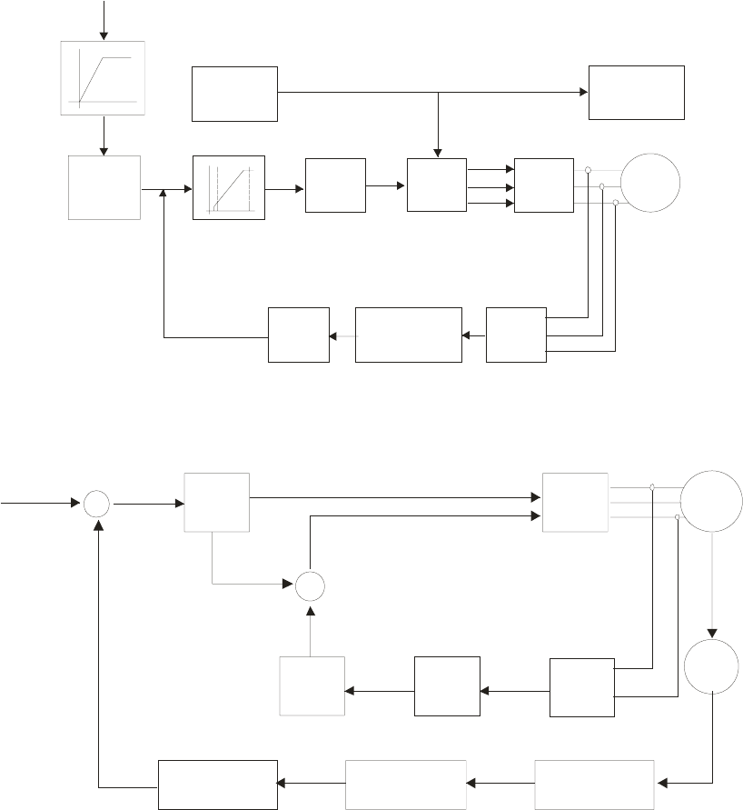
Chapter 12 Description of Parameter Settings|C2000 Series
12-7
6: PM Sensorless (PM field oriented sensorless vector control)
When setting Pr.00-11 to 0, the V/F control diagram is shown as follows.
Fcmd
Pr00-20
2/3
e->s
AVR
07-23
3/2
s->e
IGBT
PWM
01-00
01-01
01-02
05-01
05-02
05-03
05-04
DC BUS
V/F
table
Voltage
Detect
Protection
accel/decel time
DC BUS Voltage
Current Detection
01-00,01-01
01-02,01-03
01-04,01-05
01-06,01-07
01-08
Top Limit F:01-10
Lower Limit F:01-11
Torque
Compensate
07-26
Filter
Time
07-24
Vcmd
M
When setting Pr.00-11 to 1, the V/F control + encoder diagram is shown as follows.
Irms
M
IGBT
PWM
V/F
table
07-26
Filter
Time
07-24
Fcmd
EN
Vol tage
cmd
Power
Factor
X
+
Filter Time
Frequency
Inaccuracy
Vol tage
Command
+
Fcmd
00-20
Frequency
Inaccuracy
Current
Detect
Voltage Compensate
Slip
comp.
Real Speed
Real Speed
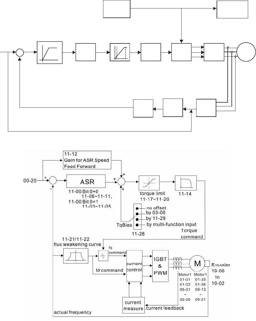
Chapter 12 Description of Parameter Settings|C2000 Series
12-8
When setting Pr.00-11 to 2, the sensorless vector control diagram is shown as follows.
Fcmd
Pr00-20 2/3
e->s
AVR
07-23
3/2
s->e
M
IGBT
PWM
01-00
01-01
01-02
05-01
05-02
05-03
05-04
DC BU
S
V/F
table
Voltage
Detection Protection
Accel/decel
time
DC BUS Voltage
Current
Detection
01-00,01-01
01-02,01-03
01-04,01-05
01-06,01-07
01-08
Top limit F:01-10
Lower limit F:01-11
Slip
Compensate
07-27
Filter
Time
07-25
Fcmd
When setting Pr.00-11 to 3, the FOCPG control diagram is shown as follows.
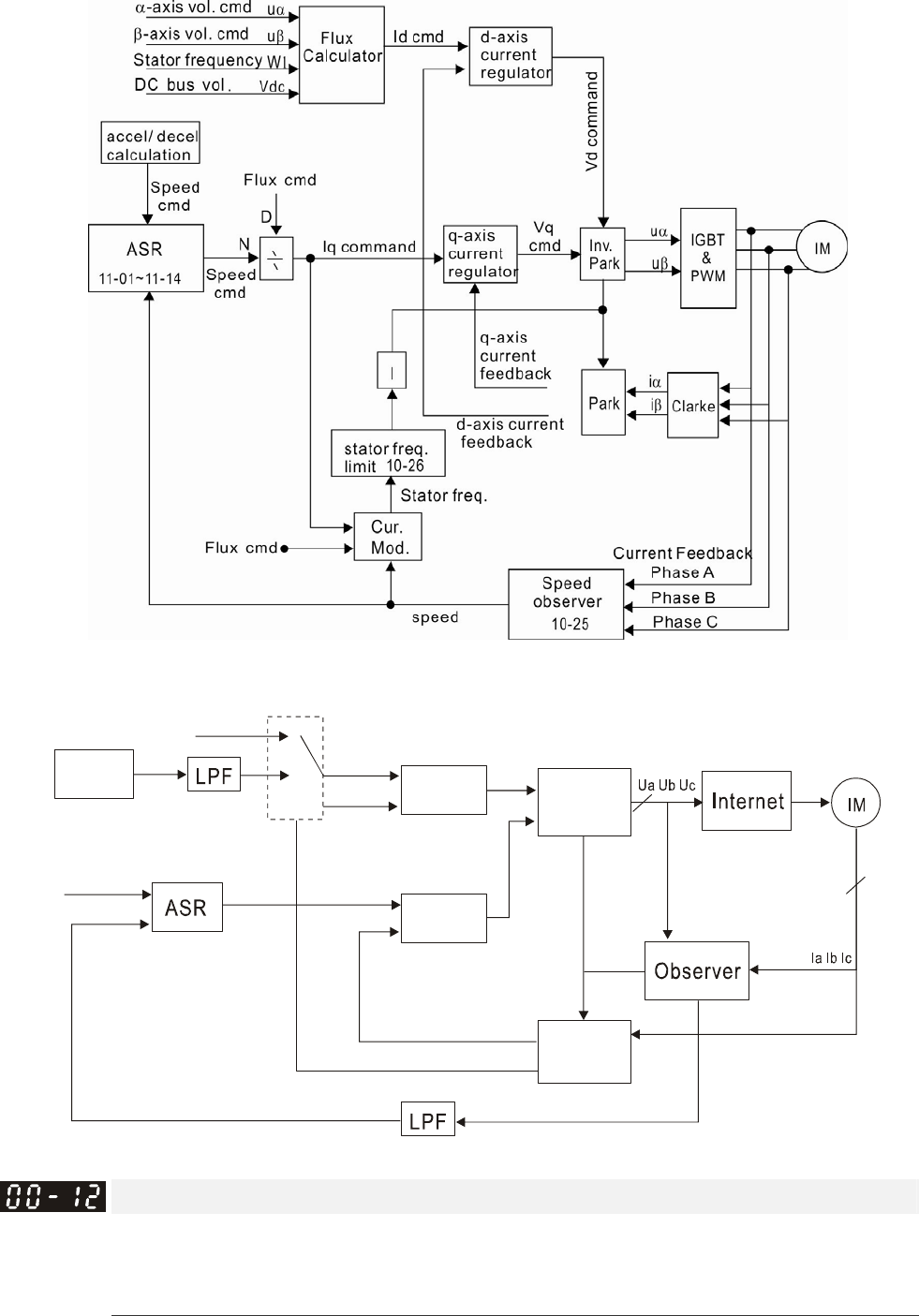
Chapter 12 Description of Parameter Settings|C2000 Series
12-9
When setting Pr.00-11 to 5, FOC sensorless control diagram is shown as follows.
When setting Pr.00-11 to 6, PM FOC sensorless control diagram is shown as follows:
AMR
Id
command
ACRd
Id
feedback
dq2abc
ACRq
Wr_cmd Iq
command
Iq feedback
Wr_est
dq2abc
θ
_
est
07-01
10 39
-
10-35
11-01~11-05
10-34
10-31~10-33
10-36
Point to Point Position control
Factory Settings: 0
Settings: 0: Incremental Type
1: Absolute Type
Pr. 00-12 = 0 is incremental type P2P; Pr.00-12 = 1 is absolute type P2P
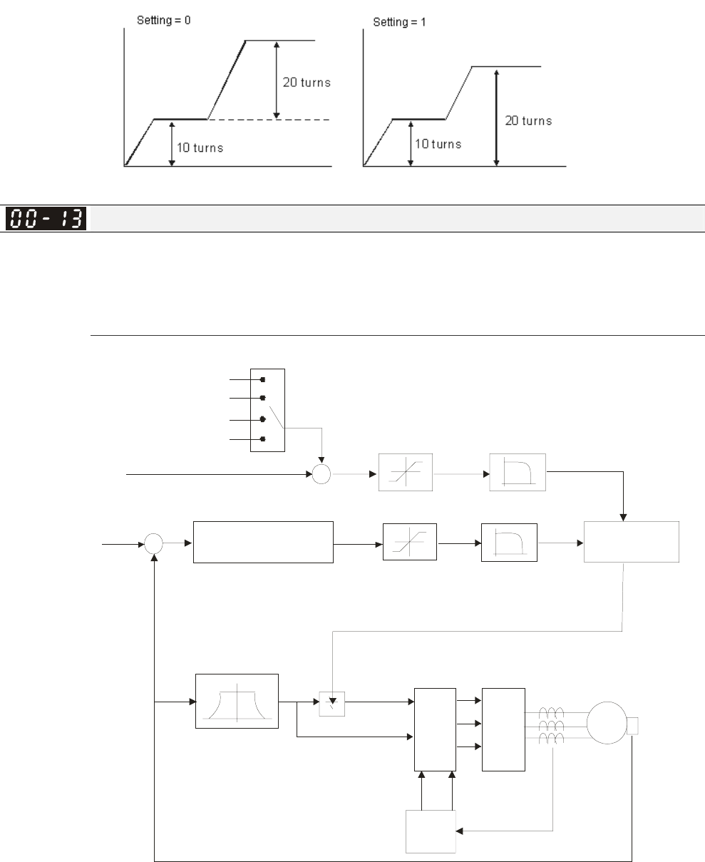
Chapter 12 Description of Parameter Settings|C2000 Series
12-10
Control of Torque Mode
Factory Setting: 0
Settings 0: TQCPG(IM Torque control + Encoder)
1: TQCPG (PM Torque control + Encoder)
2: TQC Sensorless (IM Sensorless torque control)
TQCPG control diagram is shown in the following:
11-14
IGBT
&
PWM
M
+
-
+
06-12 11-35
+
ASR
11-00 B it 0=0
11-00 B it 0=1
11-06~11-11
11-03~11-05
11-21/11-22
10-00
~
10-02
Encoder
Motor 1
01-01
01-02
05-01
~
05-09
Motor1
01-35
01-36
05-13
~
05-21
no offset
by Pr.03-00
actual frequency Current feedback
Current
control
Cur re nt
measure
flux weakening curve
lq
command
ld command
by Pr.11-29
by multi-function input
Torque command
11-34
11-36 or 00-20
Speed limit or command
Torque limit
11-17~11-20
speed/torque
mode switch
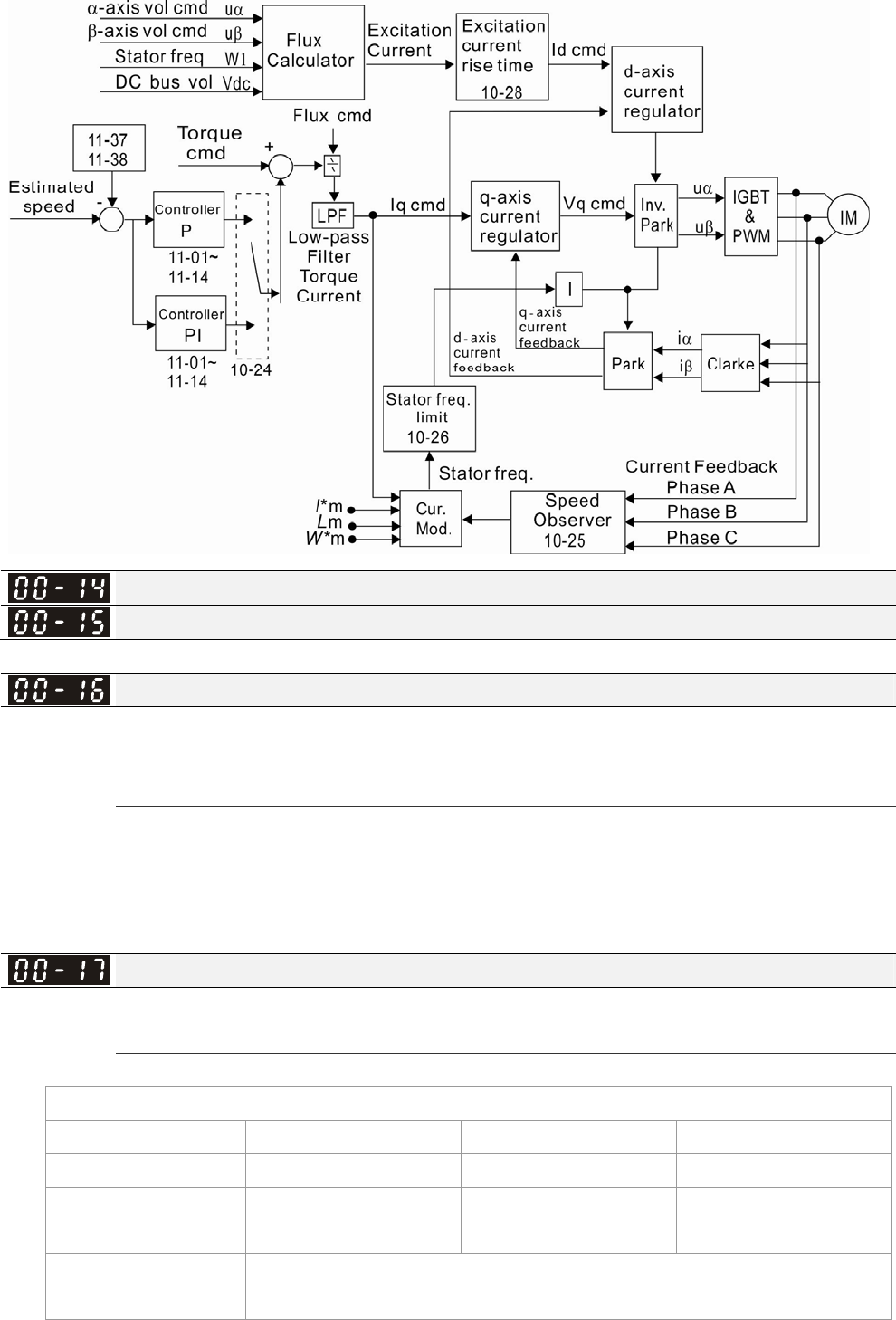
Chapter 12 Description of Parameter Settings|C2000 Series
12-11
TQC Sensorless control diagram is shown in the following:
Reserved
Reserved
Load Selection
Factory Setting: 0
Settings 0: Normal load
1: Heavy load
Normal duty: over load, rated output current 160% in 3 second. Please refer to Pr.00-17 for the
setting of carrier wave. Refer to chapter specifications or Pr.00-01 for the rated current.
Heavy duty: over load, rated output current 180% in 3 second. Please refer to Pr.00-17 for the
setting of carrier wave. Refer to chapter specifications or Pr.00-01 for the rated current.
Carrier Frequency
Factory setting: Table below
Settings 2~15kHz
This parameter determinates the PWM carrier frequency of the AC motor drive.
230V Series
Models 1-15HP [0.75-11kW] 20-50HP [15-37kW] 60-125HP [45-90kW]
Setting Range 02~15kHz 02~10kHz 02~09kHz
Normal Duty Factory
Setting
8kHz 6kHz 4kHz
Heavy Duty Factory
Setting
2kHz
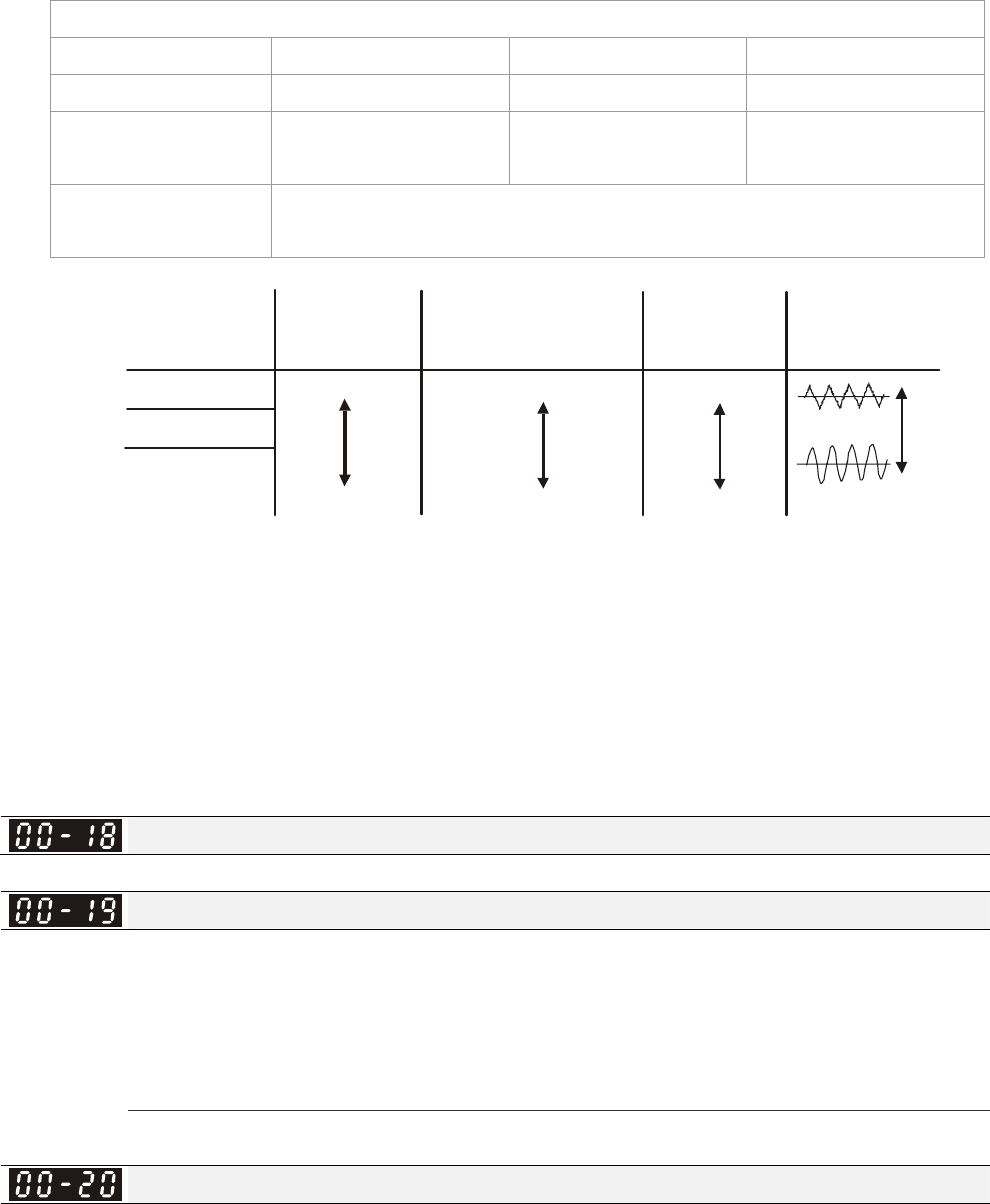
Chapter 12 Description of Parameter Settings|C2000 Series
12-12
460V Series
Models 1-20HP [0.75-15kW] 25-75HP [18.5-55kW] 100-475HP [75-355kW]
Setting Range 02~15kHz 02~10kHz 02~09kHz
Normal Duty Factory
Setting
8kHz 6kHz 4kHz
Heavy Duty Factory
Setting
2kHz
1kHz
8kHz
15kHz
Carrier
Frequency
Acoustic
Noise
Electromagnetic
Noise or Leakage
Current
Heat
Dissipation
Current
Wave
Significant
Minimal
Minimal Minimal
Significant Significant
From the table, we see that the PWM carrier frequency has a significant influence on the
electromagnetic noise, AC motor drive heat dissipation, and motor acoustic noise. Therefore, if the
surrounding noise is greater than the motor noise, lower the carrier frequency is good to reduce the
temperature rise. Although it is quiet operation in the higher carrier frequency, the entire wiring and
interference resistance should be considerate.
When the carrier frequency is higher than the factory setting, it needs to protect by decreasing the
carrier frequency. See Pr.06-55 for the related setting and details.
Reserved
PLC Command Mask
Factory Setting: Read Only
Settings Bit 0: Control command by PLC force control
Bit 1: Frequency command by PLC force control
Bit 2: Position command by PLC force control
Bit 3: Torque command by PLC force control
This parameter determines if frequency command or control command is occupied by PLC
Source of the Master Frequency Command(AUTO)
Factory Setting: 0
Settings 0: Digital keypad
1: RS-485 serial communication
2: External analog input (Pr.03-00)
3: External UP/DOWN terminal
4: Pulse input without direction command (Pr.10-16 without direction)
5: Pulse input with direction command (Pr.10-16)
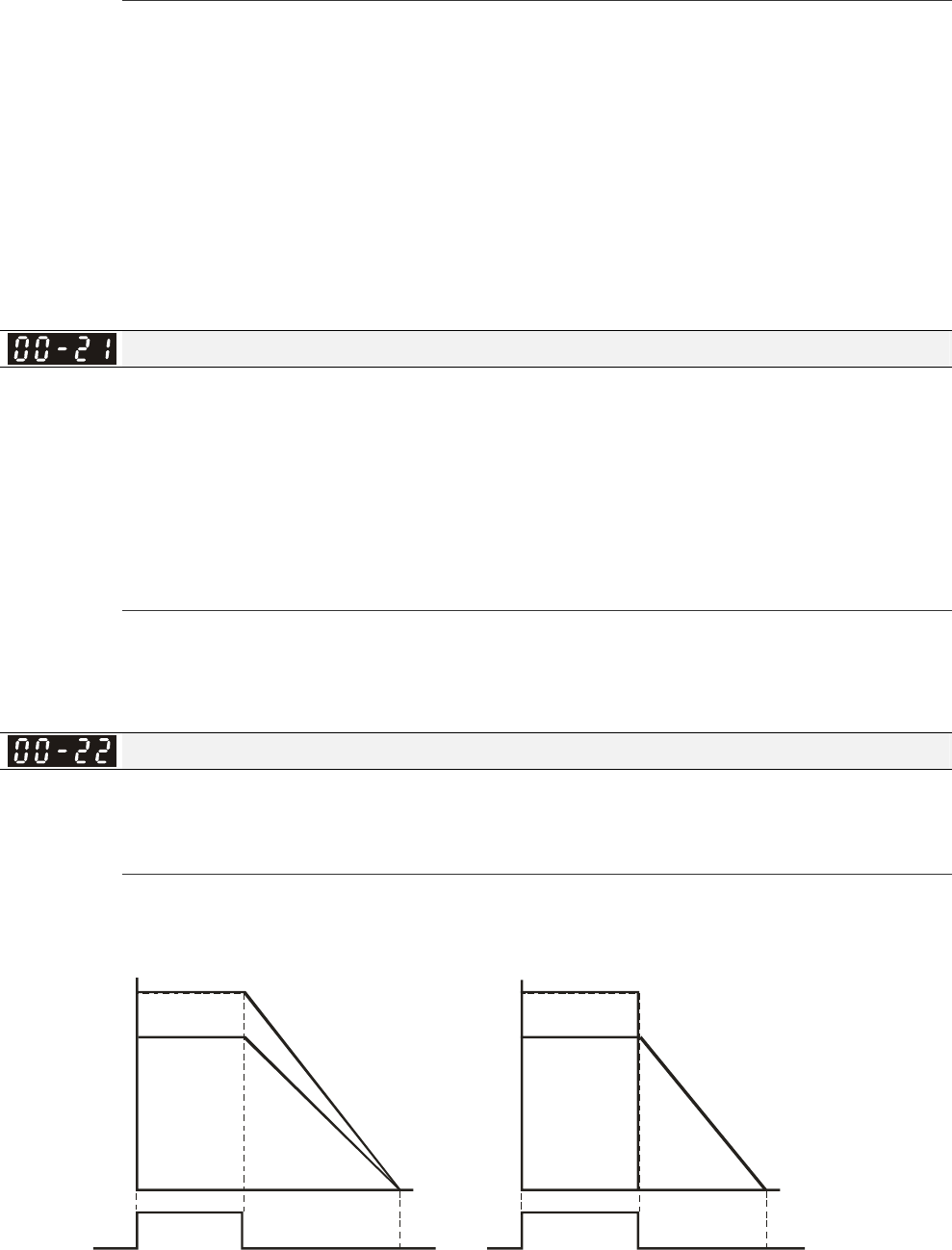
Chapter 12 Description of Parameter Settings|C2000 Series
12-13
6: CANopen communication card
7: Reserved
8: Communication card (no CANopen card)
It is used to set the source of the master frequency in AUTO mode.
Pr.00-20 and 00-21 are for the settings of frequency source and operation source in AUTO mode.
Pr.00-30 and 00-31 are for the settings of frequency source and operation source in HAND mode.
The AUTO/HAND mode can be switched by the keypad KPC-CC01 or multi-function input terminal
(MI).
The factory setting of frequency source or operation source is for AUTO mode. It will return to
AUTO mode whenever power on again after power off. If there is multi-function input terminal used
to switch AUTO/HAND mode. The highest priority is the mutli-function input terminal. When the
external terminal is OFF, the drive won’t receive any operation signal and can’t execute JOG.
Source of the Operation Command (AUTO)
Factory Setting: 0
Settings 0: Digital keypad
1: External terminals. Keypad STOP disabled.
2: RS-485 serial communication. Keypad STOP disabled.
3: CANopen card
4: Reserved
5: Communication card (not includes CANopen card)
It is used to set the source of the operation frequency in AUTO mode.
When the operation command is controlled by the keypad KPC-CC01, keys RUN, STOP and JOG
(F1) are valid.
Stop Method
Factory Setting: 0
Settings 0: Ramp to stop
1:Coast to stop
The parameter determines how the motor is stopped when the AC motor drive receives a valid stop
command.
Ramp to Stop and Coast to Stop
Operation
Co mmand
Motor
Rotation
Speed
Oper ation
Command
Frequency
Time
Time
Stops according to
deceleration time
Free running
to stop
Output
Frequenc y
RUN STOP RUN STOP
Motor
Rotation
Speed
Frequenc
y
Output
Frequenc y

Chapter 12 Description of Parameter Settings|C2000 Series
12-14
Ramp to stop: the AC motor drive decelerates from the setting of deceleration time to 0 or
minimum output frequency (Pr. 01-09) and then stop (by Pr.01-07).
Coast to stop: the AC motor drive stops the output instantly upon a STOP command and the
motor free runs until it comes to a complete standstill.
(1) It is recommended to use “ramp to stop” for safety of personnel or to prevent material from
being wasted in applications where the motor has to stop after the drive is stopped. The
deceleration time has to be set accordingly.
(2) If the motor free running is allowed or the load inertia is large, it is recommended to select
“coast to stop”. For example, blowers, punching machines and pumps
The stop method of the torque control is also set by Pr.00-22.
Control of Motor Direction
Factory Setting: 0
Settings 0: Enable forward/ reverse
1: Disable reverse
2: Disable forward
This parameter enables the AC motor drives to run in the forward/reverse Direction. It may be used
to prevent a motor from running in a direction that would consequently injure the user or damage
the equipment.
Memory of Frequency Command
Factory Setting: Read Only
Settings Read only
If keypad is the source of frequency command, when Lv or Fault occurs the present frequency
command will be saved in this parameter.
User Defined Characteristics
Factory Setting: 0
Settings Bit 0~3: user define on decimal place
0000b: no decimal place
0001b: one decimal place
0010b: two decimal place
0011b: three decimal place
Bit 4~15: user define on unit
000xh: Hz
001xh: rpm
002xh: %
003xh: kg
Bit 0~3: F & H page unit and Pr.00-26 decimal display is supported up to 3 decimal places.
Bit 4~15: F & H page unit and Pr.00-26 unit display is supported up to 4 types of unit display.
Max. User Defined Value
Factory Setting: 0
Settings 0: Disable
0~65535 (when Pr.00-25 set to no decimal place)

Chapter 12 Description of Parameter Settings|C2000 Series
12-15
0.0~6553.5 (when Pr.00-25 set to 1 decimal place)
0.0~655.35 (when Pr.00-25 set to 2 decimal place)
0.0~65.535 (when Pr.00-25 set to 3 decimal place)
User define is enabled when Pr.00-26 is not 0. The setting of Pr.00-26 corresponds to Pr.01.00
(Max. output frequency of the drive).
Example: User define: 100.0%, Pr.01.00 = 60.00Hz
Pr.00.25 setting is 0021h; Pr.0026 setting is 100.0%
NOTE
The drive will display as Pr.00-25 setting when Pr.00-25 is properly set and Pr.00-26 is not 0.
User Defined Value
Factory Setting: Read only
Settings Read only
Pr.00-27 will show user defined value when Pr.00-26 is not set to 0.
User defined function is valid when Pr.00-20 is set to digital keypad control or RS-285
communication input control.
Reserved
LOCAL/REMOTE Selection
Factory Setting: 0
Settings 0: Standard HOA function
1: Switching Local/Remote, the drive stops
2: Swithcing Local/Remote, the drive runs as the REMOTE setting for
frequency and operation status
3: Swithcing Local/Remote, the drive runs as the LOCAL setting for frequency
and operation status
4: Swithcing Local/Remote, the drive runs as LOCAL setting when switch to
Local and runs as REMOTE setting when switch to Remote for frequency
and operation status.
The factory setting of Pr.00-29 is 0 (standard Hand-Off-Auto function). The AUTO frequency and
source of operation can be set by Pr.00-20 and Pr.00-21, and the HAND frequency and source of
operation can be set by Pr.00-30 and Pr.00-31. AUTO/HAND mode can be selected or switched by
using digital keypad(KPC-CC01) or setting multi-function input terminal MI= 41, 42.
When external terminal MI is set to 41 and 42 (AUTO/HAND mode), the settings Pr.00-29=1,2,3,4
will be disabled. The external terminal has the highest priority among all command, Pr.00-29 will
always function as Pr.00-29=0, standard HOA mode.
When Pr.00-29 is not set to 0, Local/Remote function is enabled, the top right corner of digital
keypad (KPC-CC01) will display “LOC” or “REM” (the display is available when KPC-CC01 is
installed with firmware version higher than version 1.021). The LOCAL frequency and source of
operation can be set by Pr.00-20 and Pr.00-21, and the REMOTE frequency and source of
operation can be set by Pr.00-30 and Pr.00-31. Local/Remote function can be selected or switched
by using digital keypad(KPC-CC01) or setting external terminal MI=56. The AUTO key of the digital
keypad now controls for the REMOTE function and HAND key now controls for the LOCAL
function.
When MI is set to 56 for LOC/REM selection, if Pr.00-29 is set to 0, then the external terminal is

Chapter 12 Description of Parameter Settings|C2000 Series
12-16
disabled.
When MI is set to 56 for LOC/REM selection, if Pr.00-29 is not set to 0, the external terminal has
the highest priority of command and the ATUO/HAND keys will be disabled.
Source of the Master Frequency Command(HAND)
Factory Setting: 0
Settings 0: Digital keypad
1: RS-485 serial communication
2: External analog input (Pr.03-00)
3: External UP/DOWN terminal
4: Pulse input without direction command (Pr.10-16 without direction)
5: Pulse input with direction command (Pr.10-16)
6: CANopen communication card
7: Reserved
8: Communication card (no CANopen card)
It is used to set the source of the master frequency in HAND mode.
Source of the Operation Command (HAND)
Factory Setting: 0
Settings 0: Digital keypad
1: External terminals. Keypad STOP disabled.
2: RS-485 serial communication. Keypad STOP disabled.
3: CANopen communication card
4: Reserved
5: Communication card (not include CANopen card
It is used to set the source of the operation frequency in HAND mode.
Pr.00-20 and 00-21 are for the settings of frequency source and operation source in AUTO mode.
Pr.00-30 and 00-31 are for the settings of frequency source and operation source in HAND mode.
The AUTO/HAND mode can be switched by the keypad KPC-CC01 or multi-function input terminal
(MI).
The factory setting of frequency source or operation source is for AUTO mode. It will return to
AUTO mode whenever power on again after power off. If there is multi-function input terminal used
to switch AUTO/HAND mode. The highest priority is the multi-function input terminal. When the
external terminal is OFF, the drive won’t receive any operation signal and can’t execute JOG.
Digital Keypad STOP Function
Factory Setting: 0
Settings 0: STOP key disable
1: STOP key enable
~
Reserved
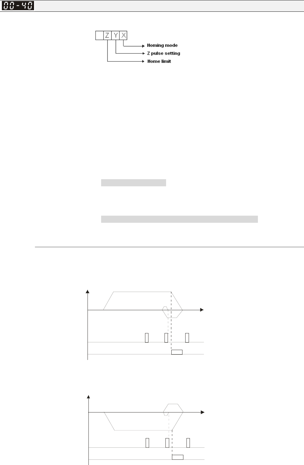
Chapter 12 Description of Parameter Settings|C2000 Series
12-17
Homing mode
Factory Setting: 0000h
Settings:
Note: Forward run = closckwise (CW)
Reverse run = counterclockwise (CCW)
X 0: Forward run to home. Set PL forward limit as check point.
1: Reverse run (CCW) to home. Set NL reverse limit (CCWL) as check
point.
2: Forward run to home. Set ORG : OFF→ON as check point.
3: Reverse to home. Set ORG : OFF→ON as check point.
4: Forward run and search for Z-pulse as check point.
5: Forward run and search for Z-pulse as check point.
6: Forward run to home. Set ORG: ON→OFF as check point.
7: Reverse run to home. Set ORG : ON→OFF as check point.
8: Define current position as home.
Y Set X to 0, 1, 2, 3, 6, 7 .
0: reverse run to Z pulse
1: continue forward run to Z pulse
2: Ignore Z pulse
Z When home limit is reached, set X to 2, 3, 4, 5, 6, 7 first.
0: display error
1: reverse the direction
Homing action is control by Pr. 00-40, 00-41, 00-42 and 02-01~02-08.
1. When Y=0, X=0 or Y=0, X=2
Z p ulse
CCWL/ORGP
Spee
d
Position
2. When Y=0, X=1 or Y=0, X=3
Z pulse
CWL/ORGP
Spee
d
Position
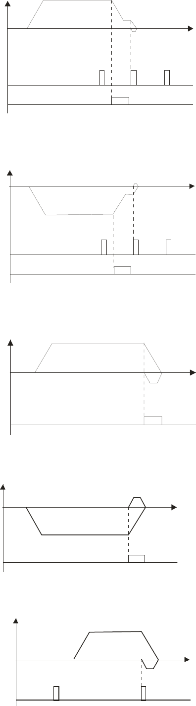
Chapter 12 Description of Parameter Settings|C2000 Series
12-18
3. When Y=1, X=2
Z p ulse
ORGP
Spee
d
Position
4. When Y=1, X=3
Z pulse
ORGP
Spee
d
Position
5. When Y=2, X=2
ORGP
Spee
d
Position
6. When Y=2, X=3
ORGP
Speed
Position
7. When Y=2, X=4
Zpulse
Speed
Position
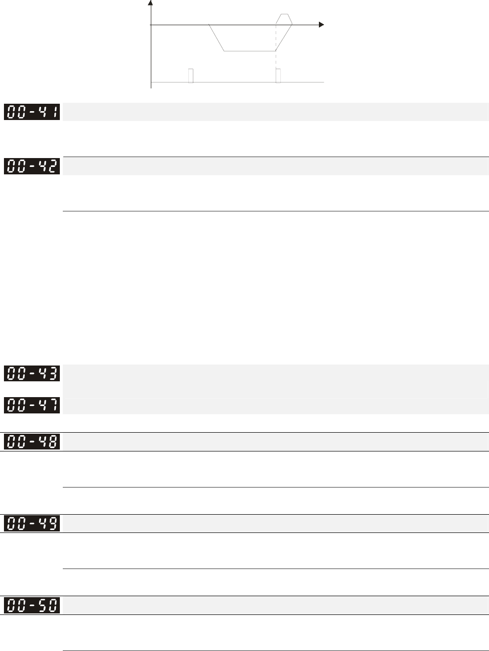
Chapter 12 Description of Parameter Settings|C2000 Series
12-19
8. When Y=2, X=5
Zpulse
Spee
d
Position
Homing by Frequency 1
Factory Setting: 8.00
Settings 0.00~600.00Hz
Homing by Frequency 2
Factory Setting: 2.00
Settings 0.00~600.00Hz
Control by Multi-funcion Input Terminal Pr. 02-01~02-08 (44~47).
44: Reverse direction homing
45: Forward direction homing
46: Homing (ORG)
47: Homing function enable
If the drive is not control by CAN or PLC, set Pr.00-10 =1 (Contorl mode = P2P position control)
and set exterminal output terminal to 47 (homing function enable) for homing.
When Pr.00-10 is set to 3, after homing is complete, user must set control mode setting Pr.00-10
to 1 in order to perform P2P position control.
~
Reserved
Display Filter Time (Current)
Factory Settings: 0.100
Settings: 0.001~65.535 sec
Set this parameter to minimize the current fluctuation displayed by digital keypad.
Display Filter Time (Keypad)
Factory Settings: 0.100
Settings: 0.001~65.535 sec
Set this parameter to minimize the display value fluctuation displayed by digital keypad.
Software Version (date)
Factory Settings: ####
Settings: Read only
This parameter displays the drive’s software version by date.
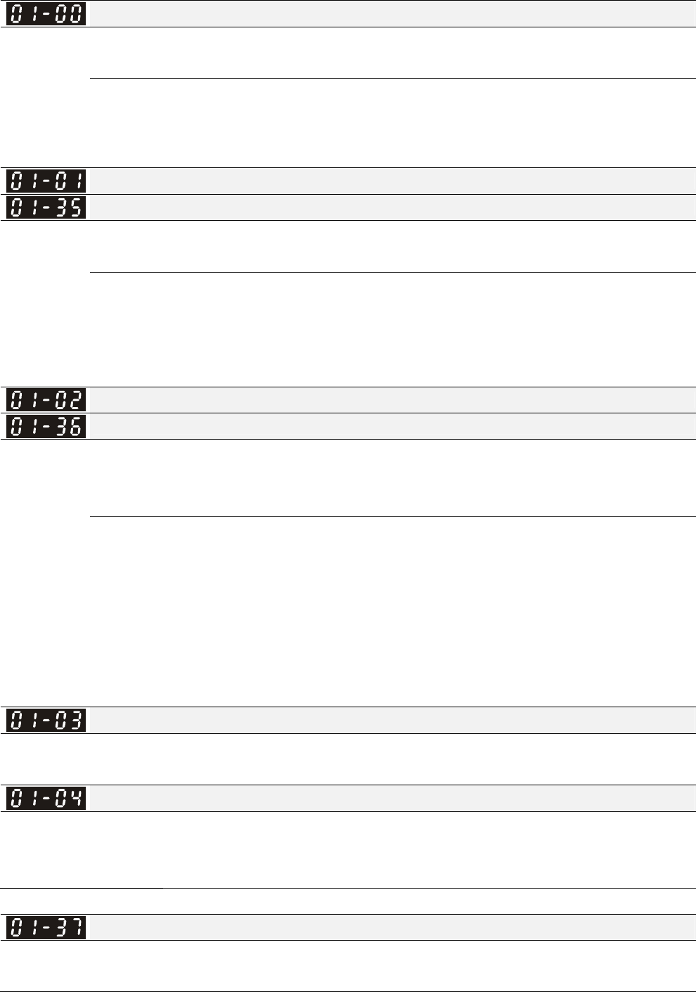
Chapter 12 Description of Parameter Settings|C2000 Series
12-20
Group 1 Basic Parameters This parameter can be set during operation.
Maximum Output Frequency
Factory Setting: 60.00/50.00
Settings 50.00~600.00Hz
This parameter determines the AC motor drive’s Maximum Output Frequency. All the AC motor
drive frequency command sources (analog inputs 0 to +10V, 4 to 20mA, 0 to 20mAand ±10V) are
scaled to correspond to the output frequency range.
Output Frequency of Motor 1(base frequency and motor rated frequency)
Output Frequency of Motor 2(base frequency and motor rated frequency)
Factory Setting: 60.00/50.00
Settings 0.00~600.00Hz
This value should be set according to the rated frequency of the motor as indicated on the motor
nameplate. If the motor is 60Hz, the setting should be 60Hz. If the motor is 50Hz, it should be set
to 50Hz.
Pr.01-35 is used for the application occasion that uses double base motor.
Output Voltage of Motor 1(base frequency and motor rated frequency)
Output Voltage of Motor 2(base frequency and motor rated frequency)
Factory Setting: 200.0/400.0
Settings 230V series: 0.0~255.0V
460V series: 0.0~510.0V
This value should be set according to the rated voltage of the motor as indicated on the motor
nameplate. If the motor is 220V, the setting should be 220.0. If the motor is 200V, it should be set to
200.0.
There are many motor types in the market and the power system for each country is also difference.
The economic and convenience method to solve this problem is to install the AC motor drive. There
is no problem to use with the different voltage and frequency and also can amplify the original
characteristic and life of the motor.
Mid-point Frequency 1 of Motor 1
Factory Setting: 3.00
Settings 0.00~600.00Hz
Mid-point Voltage 1 of Motor 1
Factory Setting: 11.0/22.0
Settings 230V series: 0.0~240.0V
460V series: 0.0~480.0V
Mid-point Frequency 1 of Motor 2
Factory Setting: 3.00
Settings 0.00~600.00Hz

Chapter 12 Description of Parameter Settings|C2000 Series
12-21
Mid-point Voltage 1 of Motor 2
Factory Setting: 11.0/22.0
Settings 230V series: 0.0~240.0V
460V series: 0.0~480.0V
Mid-point Frequency 2 of Motor 1
Factory Setting: 0.50
Settings 0.00~600.00Hz
Mid-point Voltage 2 of Motor 1
Factory Setting: 2.0/4.0
Settings 230V series: 0.0~240.0V
460V series: 0.0~480.0V
Mid-point Frequency 2 of Motor 2
Factory Setting: 0.50
Settings 0.00~600.00Hz
Mid-point Voltage 2 of Motor 2
Factory Setting: 2.0/4.0
Settings 230V series: 0.0~240.0V
460V series: 0.0~480.0V
Min. Output Frequency of Motor 1
Factory Setting: 0.00
Settings 0.00~600.00Hz
Min. Output Voltage of Motor 1
Factory Setting: 0.0/0.0
Settings 230V series: 0.0~240.0V
460V series: 0.0~480.0V
Min. Output Frequency of Motor 2
Factory Setting: 0.00
Settings 0.00~600.00Hz
Min. Output Voltage of Motor 2
Factory Setting: 0.0/0.0
Settings 230V series: 0.0~240.0V
460V series: 0.0~480.0V
V/f curve setting is usually set by the motor’s allowable loading characteristics. Pay special
attention to the motor’s heat dissipation, dynamic balance, and bearing lubricity, if the loading
characteristics exceed the loading limit of the motor.
There is no limit for the voltage setting, but a high voltage at low frequency may cause motor
damage, overheat, and stall prevention or over-current protection. Therefore, please use the low
voltage at the low frequency to prevent motor damage.
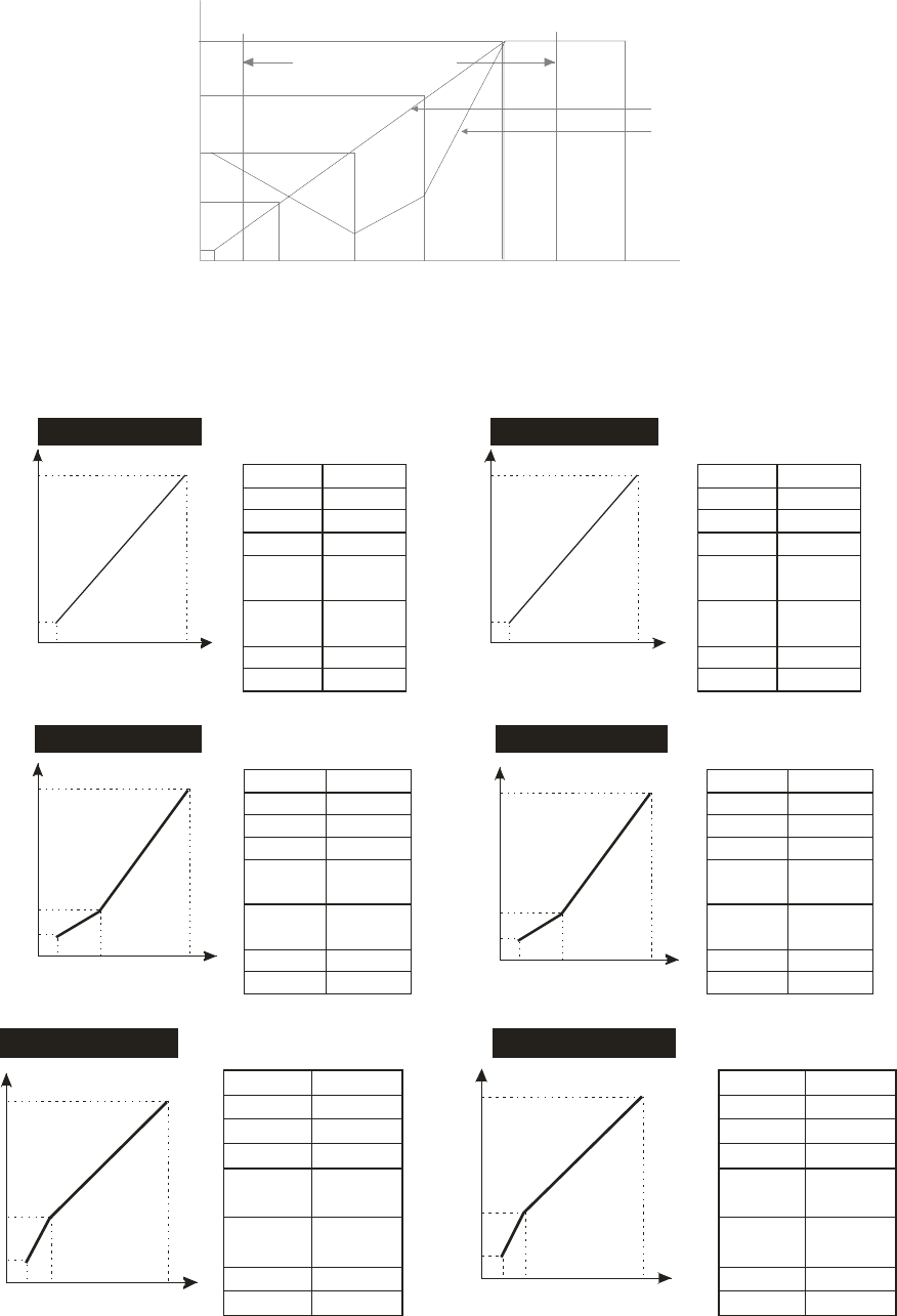
Chapter 12 Description of Parameter Settings|C2000 Series
12-22
Pr.01-35 to Pr.01-42 is the V/f curve for the motor 2. When multi-function input terminals
Pr.02-01~02-08 and Pr.02-26 ~Pr.02-31 are set to 14 and enabled, the AC motor drive will act as
the 2nd V/f curve.
The V/f curve for the motor 1 is shown as follows. The V/f curve for the motor 2 can be deduced
from it.
01-05 01-03 01-01
01-06
01-04
01-02
01-00
01-07
01-08 01-09
01-11 01-10
1st Output
Voltage Setting Output Frequency Lower Limit
Frequency output
ranges limitation
Regular V/f Curve
Special V/f Curve
Voltag
e
4th Freq. Start Freq.
3rd Freq.
2nd Freq.1st Freq. Maximum Output
Frequency
V/f Curve
2nd Output
Voltage Setting
3rd Output
Voltage Setting
4th Output
Voltage Setting
Output Frequency
Upper Limit
Frequency
Common settings of V/f curve:
(1) General purpose
VV
FF
220
220
10
10
1.31.5 50.0
60.0
60.001-00
01-01
01-02
01-03
01-05
01-04
01-06
01-07
01-08
60.0
220.0
1.50
10.0
1.50
10.0
50.001-00
01-01
01-02
01-03
01-05
01-04
01-06
01-07
01-08
50.0
220.0
1.30
10.0
1.30
10.0
Motor spec. 60Hz Motor spec. 50Hz
Pr. Setting Pr. Setting
(2) Fan and hydraulic machinery
60.001-00
01-01
01-02
01-03
01-05
01-04
01-06
01-07
01-08
60.0
220.0
30.0
50.0
1.50
10.0
50.001-00
01-01
01-02
01-03
01-05
01-04
01-06
01-07
01-08
50.0
220.0
25.0
50.0
1.30
10.0
Motor spec. 60Hz Motor spec. 50Hz
Pr. Setting Pr. Setting
V
F
220
10
1.5 60.0
50
30
V
F
220
10
1.3 50.0
50
25
(3) High starting torque
60.001-00
01-01
01-02
01-03
01-05
01-04
01-06
01-07
01-08
60.0
220.0
3.00
23.0
1.50
18.0
50.001-00
01-01
01-02
01-03
01-05
01-04
01-06
01-07
01-08
50.0
220.0
2.20
23.0
1.30
14.0
Motor spec. 60Hz Motor spec. 50Hz
Pr. Setting Pr. Setting
V
F
220
18
1.5 60.0
23
3
V
F
220
14
1.3 50.0
23
2.2
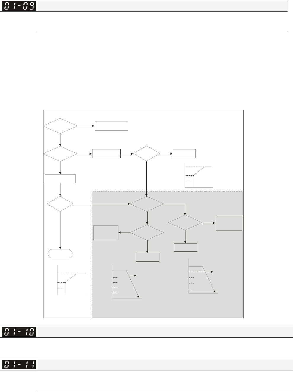
Chapter 12 Description of Parameter Settings|C2000 Series
12-23
Start-Up Frequency
Factory Setting: 0.50
Settings 0.0~600.00Hz
When start frequency is higher than the min. output frequency, drives’ output will be from start
frequency to the setting frequency. Please refer to the following diagram for details.
Fcmd=frequency command,
Fstart=start frequency (Pr.01-09),
fstart=actual start frequency of drive,
Fmin=4th output frequency setting (Pr.01-07/Pr.01-41),
Flow=output frequency lower limit (Pr.01-11)
Fcmd>Fmin
Fstart>Fmin
NO
YES
YES
fstart=Fstart
NO
fstart=Fmin
Flow=0
Flow=0
YES
H=Fcmd
YES
H=Fcmd
NO
Fcmd>Flow
YES
Fcmd>Fmin
YES
H=Fcmd
NO
NO
Fcmd<Fmin
NO
H=Flow
YES
NO
Fcmd
Fmin
Fstart
Fcmd
Fmin
Fstart
Fcmd1>Flow &
Fcmd1>Fmin
Fmin
Flow
Fcmd2>Flow &
Fcmd2<Fmin
Flow>Fcmd1
>Fmin
Fmin
Flow
Fmin>Fcmd2
60Hz 60Hz
Hz
Time
Hz
Time
Time
Time
Hz
Hz
Fcmd1
Fcmd2
H=Flow
Fcmd1
Fcmd2
H=Fcmd1
by Pr.01- 34
by
Pr.01-34
by
Pr.01-34
by Pr.01-34
by Pr.01-34
operation after
start-up
Output Frequency Upper Limit
Factory Setting: 600.00
Settings 0.0~600.00Hz
Output Frequency Lower Limit
Factory Setting: 0.00
Settings 0.0~600.00Hz
The upper/lower output frequency setting is used to limit the actual output frequency. If the
frequency setting is higher than the upper limit, it will run with the upper limit frequency. If output
frequency lower than output frequency lower limit and frequency setting is higher than min.
frequency, it will run with lower limit frequency. The upper limit frequency should be set to be higher
than the lower limit frequency.
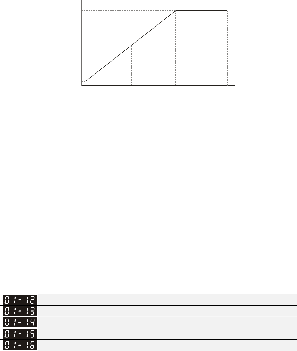
Chapter 12 Description of Parameter Settings|C2000 Series
12-24
Pr.01-10 setting must be ≥ Pr.01-11 setting. Pr.01-00 setting is regarded as 100.0%.
Output frequency upper limit = (Pr.01-00
×
Pr.01-10) /100
This setting will limit the max. Output frequency of drive. If frequency setting is higher than Pr.01-10,
the output frequency will be limited by Pr.01-10 setting.
When the drive starts the function of slip compensation (Pr.07-27) or PID feedback control, drive
output frequency may exceed frequency command but still be limited by this setting.
Related parameters: Pr.01-00 Max. Operation Frequency and Pr.01-11 Output Frequency Lower
Limit
01.05 01.03 01.01
01.06
01.04
01.02
01.00
Vo l ta g e
Frequency
Motor rated voltage
(Vbase)
Mid-point voltage
(Vmid)
Min. output voltage
setting (Vmin) Min. output
frequency
(Fmin)
Mid-point
frequency
(Fmid)
Motor rated
frequency
(Fbase)
Max. operation
frequency
This setting will limit the min. output frequency of drive. When drive frequency command or
feedback control frequency is lower than this setting, drive output frequency will limit by the lower
limit of frequency.
When the drive starts, it will operate from min. output frequency (Pr.01-05) and accelerate to the
setting frequency. It won’t limit by this parameter setting.
The setting of output frequency upper/lower limit is used to prevent personal misoperation,
overheat due to too low operation frequency or damage due to too high speed.
If the output frequency upper limit setting is 50Hz and frequency setting is 60Hz, max. output
frequency will be 50Hz.
If the output frequency lower limit setting is 10Hz and min. operation frequency setting (Pr.01-05) is
1.5Hz, it will operate by 10Hz when the frequency command is greater than Pr.01-05 and less than
10Hz. If the frequency command is less than Pr.01-05, the drive will be in ready status and no
output.
If the frequency output upper limit is 60Hz and frequency setting is also 60Hz, it won’t exceed 60Hz
even after slip compensation. If the output frequency needs to exceed 60Hz, it can increase output
frequency upper limit or max. operation frequency.
Accel. Time 1
Decel. Time 1
Accel. Time 2
Decel. Time 2
Accel. Time 3
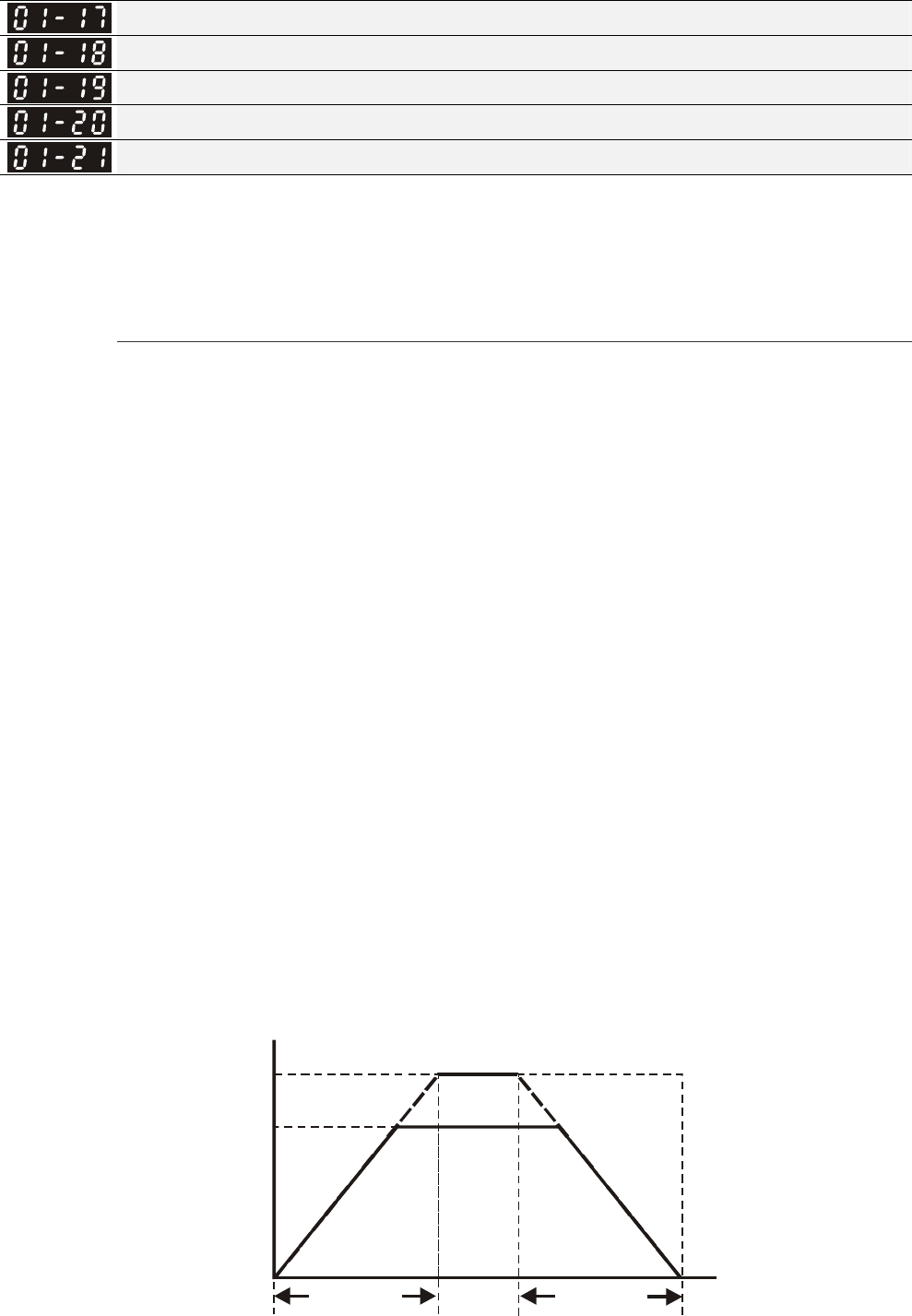
Chapter 12 Description of Parameter Settings|C2000 Series
12-25
Decel. Time 3
Accel. Time 4
Decel. Time 4
JOG Acceleration Time
JOG Deceleration Time
Factory Setting: 10.00/10.0
Factory Setting for AC drive with power
greater than 30HP: 60.00/60.0
Settings Pr.01-45=0: 0.00~600.00 seconds
Pr.01-45=1: 0.00~6000.00 seconds
The Acceleration Time is used to determine the time required for the AC motor drive to ramp from
0Hz to Maximum Output Frequency (Pr.01-00).
The Deceleration Time is used to determine the time require for the AC motor drive to decelerate
from the Maximum Output Frequency (Pr.01-00) down to 0Hz.
The Acceleration/Deceleration Time is invalid when using Pr.01-44 Optimal
Acceleration/Deceleration Setting.
The Acceleration/Deceleration Time 1, 2, 3, 4 are selected according to the Multi-function Input
Terminals settings. The factory settings are Accel./Decel. time 1.
When enabling torque limits and stalls prevention function, actual accel./decel. time will be longer
than the above action time.
Please note that it may trigger the protection function (Pr.06-03 Over-current Stall Prevention
during Acceleration or Pr.06-01 Over-voltage Stall Prevention) when the setting of accel./decel.
time is too short.
Please note that it may cause motor damage or drive protection enabled due to over current during
acceleration when the setting of acceleration time is too short.
Please note that it may cause motor damage or drive protection enabled due to over current during
deceleration or over-voltage when the setting of deceleration time is too short.
It can use suitable brake resistor (see Chapter 06 Accessories) to decelerate in a short time and
prevent over-voltage.
When enabling Pr.01-24~Pr.01-27, the actual accel./decel. time will be longer than the setting.
01-00
01-13,15,17,19,21
01-12,14,16,18,20
Frequency
Time
Max. Output
Frequency
Frequency
Setting
accel. time decel. time
Accel./Decel. Time
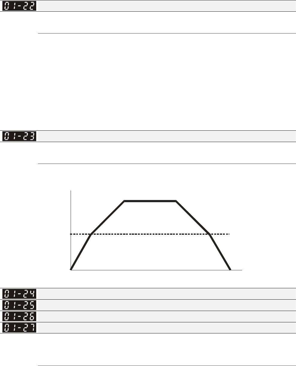
Chapter 12 Description of Parameter Settings|C2000 Series
12-26
JOG Frequency
Factory Setting: 6.00
Settings 0.00~600.00Hz
Both external terminal JOG and key “F1” on the keypad KPC-CC01 can be used. When the jog
command is ON, the AC motor drive will accelerate from 0Hz to jog frequency (Pr.01-22). When the
jog command is OFF, the AC motor drive will decelerate from Jog Frequency to zero. The Jog
Accel./Decel. time (Pr.01-20, Pr.01-21) is the time that accelerates from 0.0Hz to Pr.01-22 JOG
Frequency.
The JOG command can’t be executed when the AC motor drive is running. In the same way, when
the JOG command is executing, other operation commands are invalid except forward/reverse
commands and STOP key on the digital keypad.
It does not support JOG function in the optional keypad KPC-CE01.
1st/4th Accel./decel. Frequency
Factory Setting: 0.00
Settings 0.00~600.00Hz
The transition from acceleration/deceleration time 1 to acceleration/deceleration time 4, may also
be enabled by the external terminals. The external terminal has priority over Pr. 01-23.
Freque nc
y
Ti me
01-23
4th Acceleration
Time
4th Deceleration
Time
1st Acce ler ati on
Time
1st Deceleration
Time
1st/4th Acceleration/Deceleration Frequency Switching
S-curve Acceleration Begin Time 1
S-curve Acceleration Arrival Time 2
S-curve Deceleration Begin Time 1
S-curve Deceleration Arrival Time 2
Factory Setting: 0.20/0.2
Settings Pr.01-45=0: 0.00~25.00 seconds
Pr.01-45=1: 0.00~250.0 seconds
It is used to give the smoothest transition between speed changes. The accel./decel. curve can
adjust the S-curve of the accel./decel. When it is enabled, the drive will have different accel./decel.
curve by the accel./decel. time.
The S-curve function is disabled when accel./decel. time is set to 0.
When Pr.01-12, 01-14, 01-16, 01-18 ≥ Pr.01-24 and Pr.01-25,
The Actual Accel. Time = Pr.01-12, 01-14, 01-16, 01-18 + (Pr.01-24 + Pr.01-25)/2
When Pr.01-13, 01-15, 01-17, 01-19 ≥ Pr.01-26 and Pr.01-27,
The Actual Decel. Time = Pr.01-13, 01-15, 01-17, 01-19 + (Pr.01-26 + Pr.01-27)/2

Chapter 12 Description of Parameter Settings|C2000 Series
12-27
01-24
01-25 01-26
01-27
Frequency
Time
Skip Frequency 1 (upper limit)
Skip Frequency 1 (lower limit)
Skip Frequency 2 (upper limit)
Skip Frequency 2 (lower limit)
Skip Frequency 3 (upper limit)
Skip Frequency 3 (lower limit)
Factory Setting: 0.00
Settings 0.00~600.00Hz
These parameters are used to set the skip frequency of the AC drive. But the frequency output is
continuous. There is no limit for the setting of these six parameters and can be used as required.
The skip frequencies are useful when a motor has vibration at a specific frequency bandwidth. By
skipping this frequency, the vibration will be avoided. It offers 3 zones for use.
These parameters are used to set the skip frequency of the AC drive. But the frequency output is
continuous. The limit of these six parameters is 01-28≥01-29≥01-30≥01-31≥01-32≥01-33. This
function will be invalid when setting to 0.0.
The setting of frequency command (F) can be set within the range of skip frequencies. In this
moment, the output frequency (H) will be limited by these settings.
When accelerating/decelerating, the output frequency will still pass the range of skip frequencies.
0
01-28
01-29
01-30
01-31
01-32
01-33
Internal
frequency
command
Frequency setting command
rising frequency
fa ll in g fr eq ue ncy
Zero-speed Mode
Factory Setting: 0
Settings 0: Output waiting
1: Zero-speed operation
2: Fmin (Refer to Pr.01-07, 01-41)

Chapter 12 Description of Parameter Settings|C2000 Series
12-28
When the frequency is less than Fmin (Pr.01-07 or Pr.01-41), it will operate by this parameter.
When it is set to 0, the AC motor drive will be in waiting mode without voltage output from terminals
U/V/W.
When setting 1, it will execute DC brake by Vmin(Pr.01-08 and Pr.01-42) in V/f, VFPG and SVC
modes. It executes zero-speed operation in VFPG and FOCPG mode.
When it is set to 2, the AC motor drive will run by Fmin (Pr.01-07, Pr.01-41) and Vmin (Pr.01-08,
Pr.01-42) in V/f, VFPG, SVC and FOCPG modes.
In V/f, VFPG and SVC modes
fmin
01-07
fou
t
0Hz
01-34=0 01-34=2
01-34=1
0Hz
stop output
0Hz operation
(DC brake)
stop waiting for output
In FOCPG mode, when Pr.01-34 is set to 2, it will act according Pr.01-34 setting.
fmin
01-07
fout
01-34=0 01-34=2
01-34=1
frequency command frequency command
V/f Curve Selection
Factory Setting: 0
Settings 0: V/f curve determined by group 01
1: 1.5 power curve
2: Square curve
When setting to 0, refer to Pr.01-01~01-08 for motor 1 V/f curve. For motor 2, please refer to
Pr.01-35~01-42.
When setting to 1 or 2, 2nd and 3rd voltage frequency setting are invalid.
If motor load is variable torque load (torque is in direct proportion to speed, such as the load of fan
or pump), it can decrease input voltage to reduce flux loss and iron loss of the motor at low speed
with low load torque to raise the entire efficiency.
When setting higher power V/f curve, it is lower torque at low frequency and is not suitable for rapid
acceleration/deceleration. It is recommended Not to use this parameter for the rapid
acceleration/deceleration.
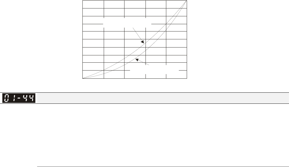
Chapter 12 Description of Parameter Settings|C2000 Series
12-29
020 4
0
6
0
80 100
100
90
80
70
60
50
40
30
20
10
01-02
Voltage %
1.5 power curve
Square curve 01-01
Frequency%
Optimal Acceleration/Deceleration Setting
Factory Setting: 0
Settings 0: Linear accel./decel.
1: Auto accel., linear decel.
2: Linear accel., auto decel.
3: Auto accel./decel. (auto calculate the accel./decel. time by actual load)
4: Stall prevention by auto accel./decel. (limited by 01-12 to 01-21)
Pr.01-44 is used to reduce the drive’s vibration during load starts and stops. Also it will speed up to
the setting frequency with the fastest and smoothest start-up current when it detects small torque.
At deceleration, it will auto stop the drive with the fastest and the smoothest deceleration time when
the regenerated voltage of the load is detected.
Setting 0 Linear accel./decel.: it will accelerate/decelerate according to the setting of
Pr.01-12~01-19.
Setting to Auto accel./decel.: it can reduce the mechanical vibration and prevent the complicated
auto-tuning processes. It won’t stall during acceleration and no need to use brake resistor. In
addition, it can improve the operation efficiency and save energy.
Setting 3 Auto accel./decel. (auto calculate the accel./decel. time by actual load): it can auto detect
the load torque and accelerate from the fastest acceleration time and smoothest start current to the
setting frequency. In the deceleration, it can auto detect the load re-generation and stop the motor
smoothly with the fastest decel. time.
Setting 4 Stall prevention by auto accel./decel. (limited by 01-12 to 01-21): if the
acceleration/deceleration is in the reasonable range, it will accelerate/decelerate by
Pr.01-12~01-19. If the accel./decel. time is too short, the actual accel./decel. time is greater than
the setting of accel./decel. time.
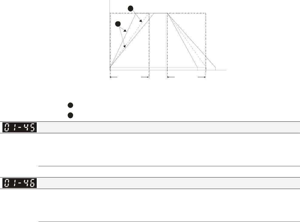
Chapter 12 Description of Parameter Settings|C2000 Series
12-30
1
2
01-00
01-12 01-14
01-16 01-18 01-13 01-15
01-17 01-19
1
2
When Pr.01-44 is set to 0.
Frequency
Max.
Frequency
01-07
Min.
Frequency accel. time Time
decel. time
Accel./Decel. Time
When Pr.01-44 is set to 3.
Time Unit for Acceleration/Deceleration and S Curve
Factory Setting: 0
Settings 0: Unit 0.01 sec
1: Unit 0.1 sec
Time for CANopen Quick Stop
Factory Setting: 1.00
Settings Pr. 01-45=0: 0.00~600.00 sec
Pr. 01-45=1: 0.0~6000.0 sec
It is used to set the time that decelerates from the max. operation frequency (Pr.01-00) to 0.00Hz in
CANopen control
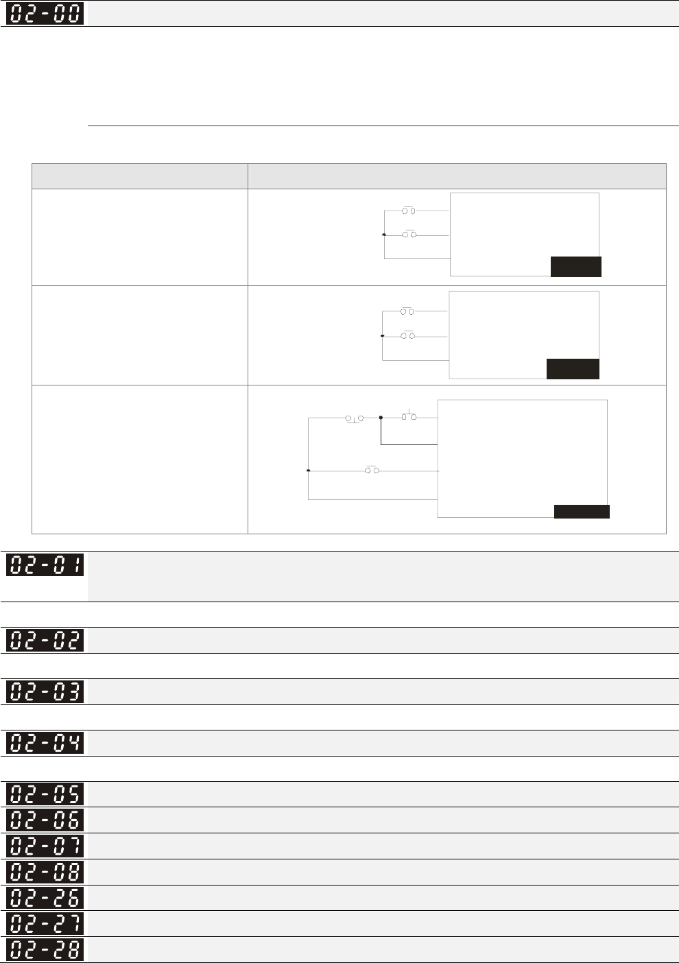
Chapter 12 Description of Parameter Settings|C2000 Series
12-31
02 Digital Input/Output Parameter This parameter can be set during operation.
2-wire/3-wire Operation Control
Factory Setting: 0
Settings 0: 2 wire mode 1
1: 2 wire mode 2
2: 3 wire mode
It is used to set the operation control method:
Pr.02-00 Control Circuits of the External Terminal
0
2-wire mode 1
FWD/STOP
REV/STOP
FW D: (" O PE N" :STO P )
("CL OSE":FWD)
REV:("OPEN": ST OP)
("C LOSE": REV)
VFD-C
DCM
FWD/ STOP
REV/STOP
1
2-wire mode 2
RUN/STOP
REV/FWD
FWD:("OPEN":STOP)
("CLOSE":RUN)
REV:("OPEN": FWD)
("CLOSE": REV)
VFD-C
DCM
RUN /STOP
FWD/ REV
3
3-wire operation control
FWD "CLOSE":RUN
MI1 "OPEN":STOP
REV/FWD "OPEN": FWD
"CLOSE": REV
VFD-C
DC M
STOP
REV/F WD
RUN
Multi-function Input Command 1 (MI1) (MI1= STOP command when in 3-wire operation
control)
Factory Setting: 1
Multi-function Input Command 2 (MI2)
Factory Setting: 2
Multi-function Input Command 3 (MI3)
Factory Setting: 3
Multi-function Input Command 4 (MI4)
Factory Setting: 4
Multi-function Input Command 5 (MI5)
Multi-function Input Command 6 (MI6)
Multi-function Input Command 7 (MI7)
Multi-function Input Command 8 (MI8)
Input terminal of I/O extension card (MI10)
Input terminal of I/O extension card (MI11)
Input terminal of I/O extension card (MI12)

Chapter 12 Description of Parameter Settings|C2000 Series
12-32
Input terminal of I/O extension card (MI13)
Input terminal of I/O extension card (MI14)
Input terminal of I/O extension card (MI15)
Factory Setting: 0
Settings
0: no function
1: multi-step speed command 1/multi-step position command 1
2: multi-step speed command 2/multi-step position command 2
3: multi-step speed command 3/multi-step position command 3
4: multi-step speed command 4/multi-step position command 4
5: Reset
6: JOG command(By KPC-CC01 or external control)
7: acceleration/deceleration speed not allow
8: the 1st, 2nd acceleration/deceleration time selection
9: the 3rd, 4th acceleration/deceleration time selection
10: EF Input (Pr.07-20)
11: B.B input from external (Base Block)
12: Output stop
13: cancel the setting of the optimal acceleration/deceleration time
14: switch between motor 1 and motor 2
15: operation speed command from AVI
16: operation speed command from ACI
17: operation speed command from AUI
18: Emergency stop (Pr.07-20)
19: Digital up command
20: Digital down command
21: PID function disabled
22: Clear counter
23: Input the counter value (MI6)
24: FWD JOG command
25: REV JOG command
26: FOCG/TQC model selection
27: ASR1/ASR2 selection
28: Emergency stop (EF1)
29: Signal confirmation for Y-connection
30: Signal confirmation for Δ-connection
31: High torque bias (Pr.11-30)
32: Middle torque bias (Pr.11-31)
33: Low torque bias (Pr.11-32)
34: Switch between multi-step position and multi-speed control
35: Enable position control
36: Enable multi-step position learning function (valid at stop)
37: Enable pulse position input command
38: Disable write EEPROM function
39: Torque command direction
40: Force coast to stop
41: HAND switch
42: AUTO switch
43: Enable resolution selection (Pr.02-48)
44: Reverse direction homing
45: Forward direction homing
46: Homing ORG
47: Homing function enable
48: Mechanical gear ratio switch
49: Drive enable
50: Master dEb action input
51: Selection for PLC mode bit0
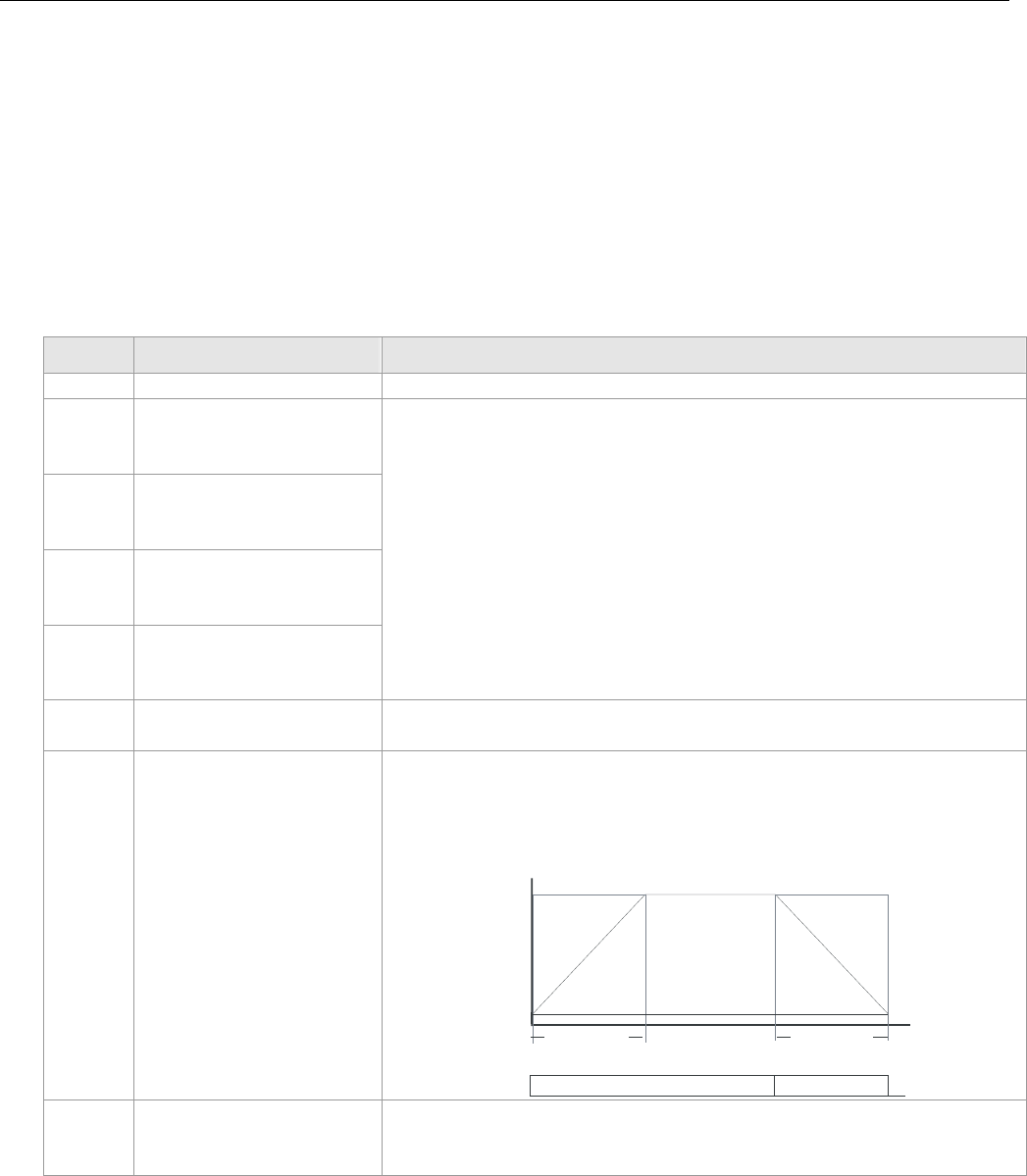
Chapter 12 Description of Parameter Settings|C2000 Series
12-33
52: Selection for PLC mode bit1
53: Trigger CANopen quick stop
54~55: Reserve
56: Local/Remote Selection
57~70: Reserve
This parameter selects the functions for each multi-function terminal.
The terminals of Pr.02-26~Pr.02-29 are virtual and set as MI10~MI13 when using with optional card
EMC-D42A. Pr.02-30~02-31 are virtual terminals.
When being used as a virtual terminal, it needs to change the status (0/1: ON/OFF) of bit 8-15 of
Pr.02-12 by digital keypad KPC-CC01 or communication.
If Pr.02-00 is set to 3-wire operation control. Terminal MI1 is for STOP contact. Therefore, MI1 is
not allowed for any other operation.
Summary of function settings (Take the normally open contact for example, ON: contact is closed,
OFF: contact is open)
Settings Functions Descriptions
0 No Function
1
Multi-step speed
command 1/multi-step
position command 1
2
Multi-step speed
command 2/ multi-step
position command 2
3
Multi-step speed
command 3/ multi-step
position command 3
4
Multi-step speed
command 4/ multi-step
position command 4
15 step speeds could be conducted through the digital status of the
4 terminals, and 16 in total if the master speed is included. (Refer to
Parameter set 4)
5 Reset After the error of the drive is eliminated, use this terminal to reset
the drive.
6 JOG Command
Before executing this function, it needs to wait for the drive stop
completely. During running, it can change the operation direction
and STOP key on the keypad is valid. Once the external terminal
receives OFF command, the motor will stop by the JOG
deceleration time. Refer to Pr.01-20~01-22 for details.
01-20
01 -2 1
ON OFF
MIx-GND
01-22
JOG fr eq ue ncy
01-07
Mi n. o utp ut fr eq ue ncy
of motor 1
JOG accel. time JOG decel. time
7 Acceleration/deceleration
Speed Inhibit
When this function is enabled, acceleration and deceleration is
stopped. After this function is disabled, the AC motor drive starts
to accel./decel. from the inhibit point.
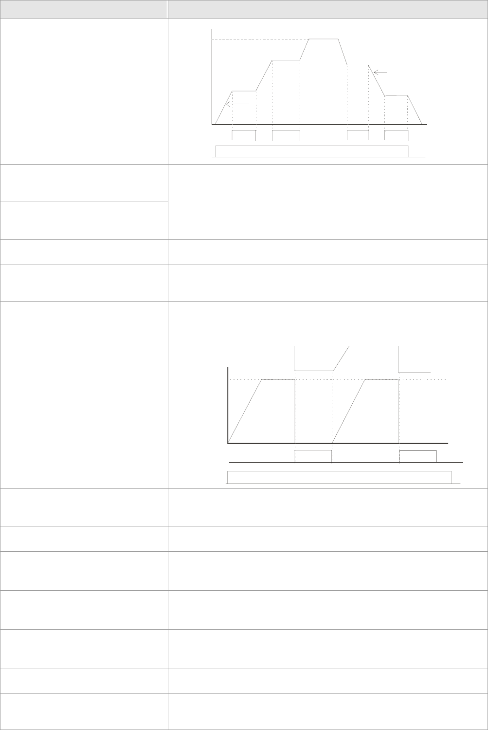
Chapter 12 Description of Parameter Settings|C2000 Series
12-34
Settings Functions Descriptions
ON ON ON ON
ON OFF
MIx-GND
Fr equency
Operation
command
Time
Setting
freq uency
A c tua l o pe ra tio n f r eq ue nc y
Actual operation
fr eq uency
Accel. inhibit
area
Accel. inhibit
area Decel. inhibit
area
Decel. inhibit
area
8
The 1st, 2nd acceleration
or deceleration time
selection
9
The 3rd, 4th acceleration
or deceleration time
selection
The acceleration/deceleration time of the drive could be selected
from this function or the digital status of the terminals; there are 4
acceleration/deceleration speeds in total for selection.
10 EF Input (EF: External
fault)
External fault input terminal. It will decelerate by Pr.07-20 setting (it
will have fault record when external fault occurs)
11 External B.B. Input (Base
Block)
When this contact is ON, output of the drive will be cut off
immediately, and the motor will be free run and display B.B. signal.
Refer to Pr.07-08 for details.
12 Output Stop
If this contact is ON, output of the drive will be cut off immediately,
and the motor will then be free run. And once it is turned to OFF,
the drive will accelerate to the setting frequency.
ON
MI -GNDxON
OFF
ON
Voltag
e
Freq uency
Time
Operation
command
Setting
fr equency
13 Cancel the setting of the
optimal accel./decel. time
Before using this function, Pr.01-44 should be set to 01/02/03/04
first. When this function is enabled, OFF is for auto mode and ON
is for linear accel./decel.
14 Switch between drive
settings 1 and 2
When the contact is ON: use motor 2 parameters. OFF: use
motor 1 parameters.
15 Operation speed
command form AVI
When the contact is ON, the source of the frequency will force to be
AVI. (If the operation speed commands are set to AVI, ACI and AUI
at the same time. The priority is AVI>ACI>AUI)
16 Operation speed
command form ACI
When the contact is ON, the source of the frequency will force to be
ACI. (If the operation speed commands are set to AVI, ACI and AUI
at the same time. The priority is AVI>ACI>AUI)
17 Operation speed
command form AUI
When this function is enabled, the source of the frequency will
force to be AUI. (If the operation speed commands are set to AVI,
ACI and AUI at the same time. The priority is AVI>ACI>AUI)
18 Emergency Stop (07-20)
When the contact is ON, the drive will ramp to stop by Pr.07-20
setting.
19 Digital Up command When the contact is ON, the frequency will be increased and
decreased. If this function is constantly ON, the frequency will be
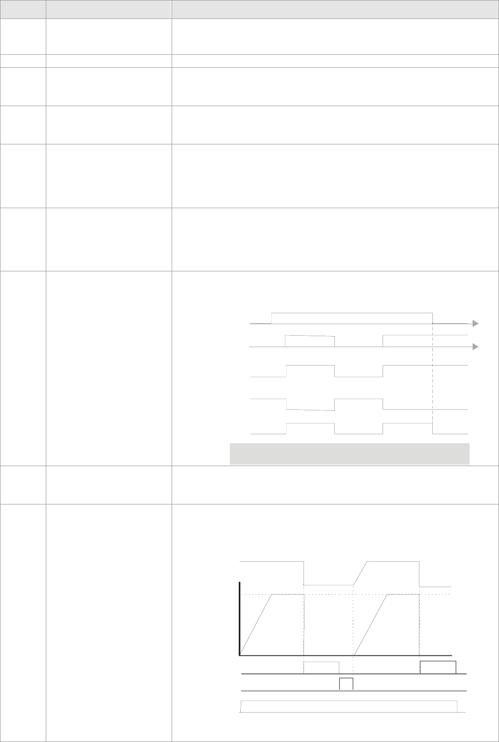
Chapter 12 Description of Parameter Settings|C2000 Series
12-35
Settings Functions Descriptions
20 Digital Down command
increased/decreased by Pr.02-09/Pr.02-10.
21 PID function disabled When the contact is ON, the PID function is disabled.
22 Clear counter
When the contact is ON, it will clear current counter value and
display “0”. Only when this function is disabled, it will keep counting
upward.
23
Input the counter value
(multi-function input
command 6)
The counter value will increase 1 once the contact is ON. It needs
to be used with Pr.02-19.
24 FWD JOG command
When the contact is ON, the drive will execute forward Jog
command.
When execute JOG command under torque mode, the drive will
automatically switch to speed mode; after JOG command is done,
the drive will return to torque mode.
25 REV JOG command
When the contact is ON the drive will execute reverse Jog
command.
When execute JOG command under torque mode, the drive will
automatically switch to speed mode; after JOG command is done,
the drive will return to torque mode.
26 FOCPG/TQCPG mode
selection
When the contact is ON: TQCPG mode.
When the contact is OFF: FOCPG mode.
RU N STOP
ON OFF
OFF ON
RU N/ST OP
co mmand
sp eed
command
speed limit speed limit sp eed
command
torque
command
torque
command
torque
limit
torque
limit
sp eed
co ntrol
sp eed
co ntrol
torque
control
torque
control
sp eed
co ntrol
(decel. t o stop )
contro l
mode
03 -0 0~ 02= 2
(AVI/AUI/ACI i s
tor que co mman d)
03 -0 0~ 02= 1
(AVI/AUI/ACI i s
fr eq uen cy co mman d)
Mul t i- f unc ti on i np ut
terminal is set to 26
(t o rqu e/spe ed
mode switch )
Sw itch timing for t orq ue/speed control
(00- 10=0/4 , mu lt i-fu nct ion inpu t t erminal is set to 2 6)
27 ASR1/ASR2 selection
When the contact is ON: speed will be adjusted by ASR 2 setting.
OFF: speed will be adjusted by ASR 1 setting. Refer to Pr.11-02 for
details.
28 Emergency stop (EF1)
When the contact is ON, the drive will execute emergency stop and
display EF1 on the keypad. The motor won’t run and be in the free
run until the fault is cleared after pressing RESET” (EF: External
Fault)
ON
MI -GNDxON
OFF
ON
Reset ON OFF
Voltag
e
Fr eq ue ncy
Setting
fr eq ue ncy
Time
Operation
command
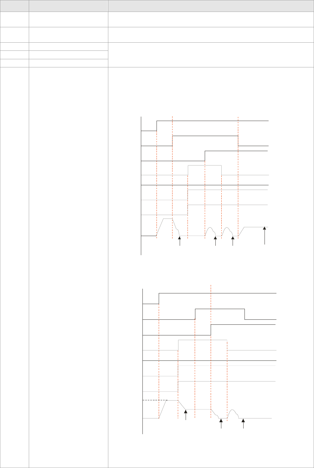
Chapter 12 Description of Parameter Settings|C2000 Series
12-36
Settings Functions Descriptions
29 Signal confirmation for
Y-connection When is the contact is ON, the drive will operate by 1st V/f.
30 Signal confirmation for
Δ-connection When the contact is ON, the drive will operate by 2nd V/f.
31 High torque bias
32 Middle torque bias
33 Low torque bias
Refer to Pr.11-30~11-32 for details.
34
Switch between
multi-step position and
multi-speed control
When the contact is ON, the corresponding 15-step speed for the
multi-function inputs 1-4 will be 15 positions. (Refer to Pr.04-16 to
Pr.04-44)
Run
1
0
1
1
1
0
1
1
0
0
1
1
0
0
1
1
04-40 04-38 04-11
MI=d35
MI=d34
MI=d1
MI=d2
MI=d3
MI=d4
speed mode speed mode
position mode
10-19
position
(Home)
multi-
position
1
3
multi-
position
12
12th step
speed
frequency
output
frequency
MI=4
Run
1
0
1
1
1
0
1
1
1
0
1
1
0
0
1
1
04-12
04-40 04-38
MI=d34
MI=d35
MI=d1
MI=d2
MI=d3
speed mode position mode
13th step
speed
frequency
multi-
position
13
multi-
position
12
Master
frequency
Output
frequency
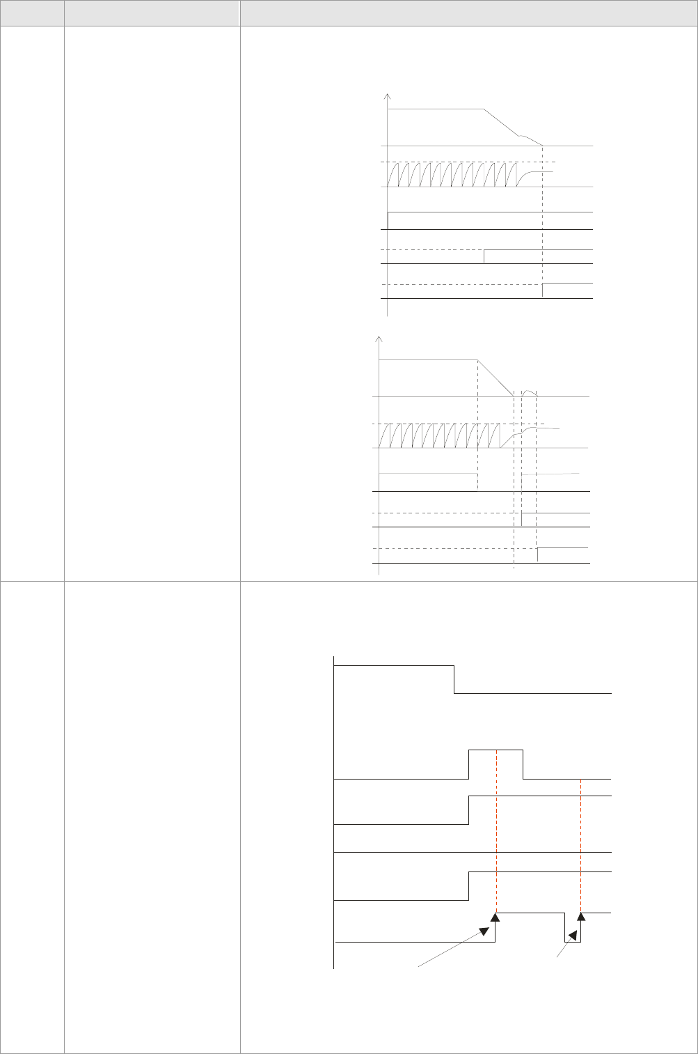
Chapter 12 Description of Parameter Settings|C2000 Series
12-37
Settings Functions Descriptions
35 Enable single-point
position control
When the contact is ON, the AC motor drive will execute internal
single-point position control according to the setting in Pr.10-19.
This function is valid in FOCPG mode only.
Output
frequency
PG
feedback
10-01
10-02
RUN
MI=d35
MO=d39
10-19
Time
Output
fr equency
PG
feed back
10-01
10-02
RUN
MI=d35
MO=d39
10-19
RUN RUN
Time
36
Enable multi-step
position learning function
(valid at stop)
When the contact is ON/OFF, the drive will base the multi-function
inputs 1-4 ON/OFF status to find the corresponding multi-step
positions and write current motor position into such corresponding
multi-step position.
MI=d1
Run/Stop
1
1
1010 =10
2
corresponds to
Pr.04-34
11
00
000
11 1
1011 =11
2
corresponds
to Pr.04-36
MI=d2
MI=d3
MI=d4
MI=d36
Writing the motor position
into the Pr.04-3
6
Writing the motor position
into the Pr.04-34
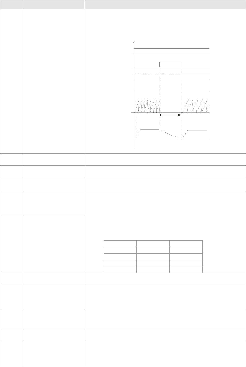
Chapter 12 Description of Parameter Settings|C2000 Series
12-38
Settings Functions Descriptions
37
Full position control
pulse command input
enable
When Pr.00-20 is set to 4 or 5 and this contact is ON, the input
pulse of PG card is position command. When using this function, it
is recommended to set Pr.11-25 to 0.
Example: please refer to the following diagram when using this
faction with MI=d35 return to home position,.
RUN
MI=d35
MO=d39
MI=d37
pulse
command
internal
positioning
output
frequency Time
38 Disable EEPROM write
function When this contact is ON, write to EEPROM is disabled.
39 Torque command
direction
For torque control (Pr.00-10=2), when torque command is AVI or
ACI, the contact is ON and it is negative torque.
40 Force coast to stop When this contact is ON during the operation, the drive will free run
to stop.
41 HAND switch
42 AUTO switch
1. When MI is switched to off status, it executes a STOP
command. , If MI is switched to off during operation, the drive
will also stop.
2. Using keypad KPC-CC01 to switch between HAND/AUTO,
the drive will stop first then switch to the HAND or AUTO status.
3. On the digital keypad KPC-CC01, it will display current drive
status (HAND/OFF/AUTO).
Bit 1 Bit 0
OFF 0 0
AUTO 0 1
HAND 1 0
OFF 1 1
43 Enable resolution
selection Refer to Pr.02-48 for details.
44 Reverse direction
homing
Signal input for reverse direction limit switch. When this terminal is
ON, the drive will react to the setting in Pr.00-40, 00-41, 00-42
accordingly to execute homing in a reverse direction (counter
clockwise).
45 Forward direction homing
Signal input for forward direction limit switch. When this terminal is
ON, the drive will react to the setting in Pr.00-40, 00-41, 00-42
accordingly to execute homing in a forward direction (clockwise).
46 Homing ORG ORG point input. When this terminal is ON, the drive will refer to the
setting in Pr.00-40, 00-41, 00-42 accordingly to execute homing.
47 Homing function enable
Pr.00-10 = 3 (homing mode), if the external terminal MIx=47 is
OFF, the drive will ignore the home command and execute Point to
Point position control.
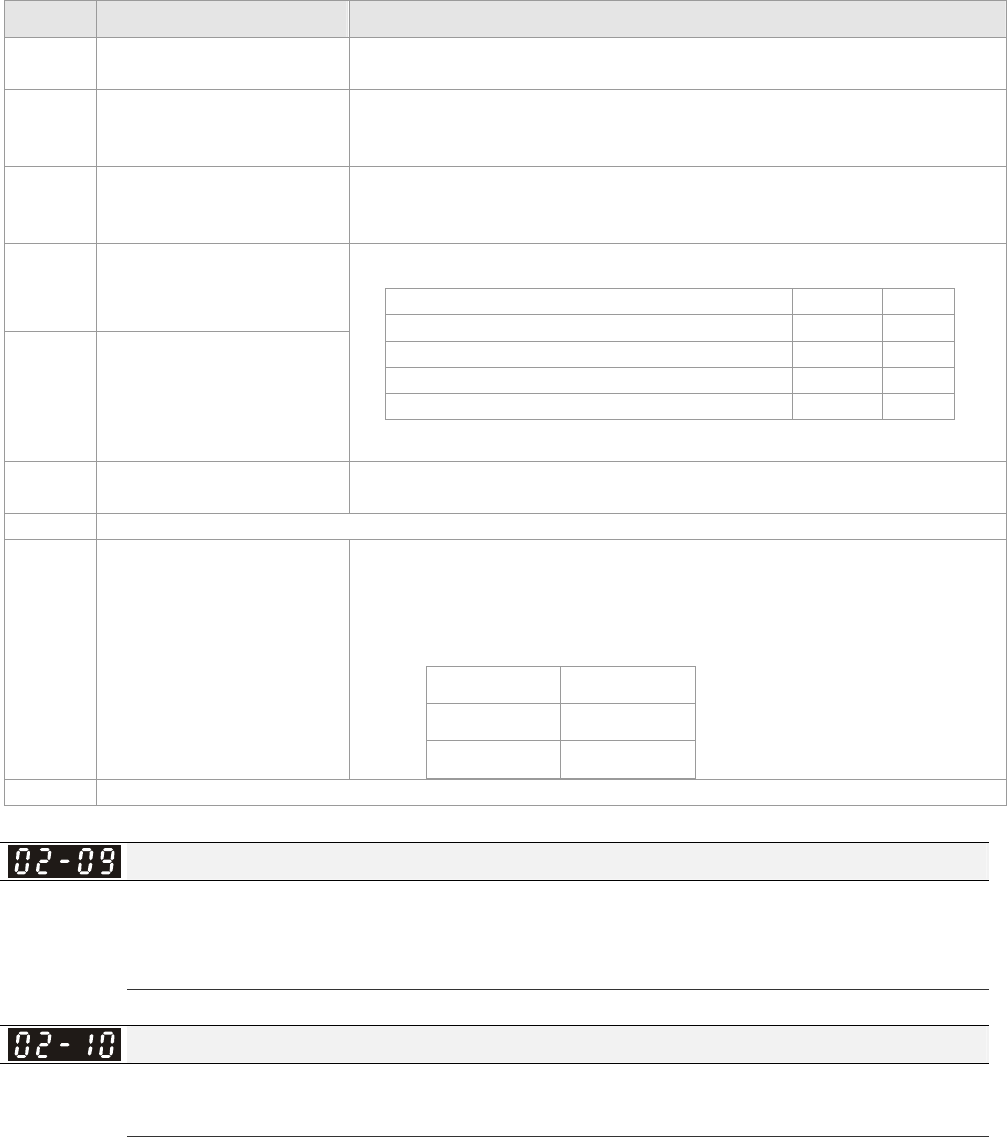
Chapter 12 Description of Parameter Settings|C2000 Series
12-39
Settings Functions Descriptions
48 Mechanical gear ratio
switch
When this contact is ON, the mechanical gear ratio switch will be
the second group A2/B2 (refer to Pr.10-08 and Pr.10-09).
49 Drive enable
When drive=enable, RUN command is valid.
When drive= disable, RUN command is invalid.
When drive is in operation, motor coast to stop.
50 Master dEb action input
Input the message setting in this parameter when dEb occurs to
Master. This will ensure dEb also occurs to Slave, then Master and
Slave will stop simultaneously.
51 Selection for PLC mode
bit0
52 Selection for PLC mode
bit1
PLC status Bit 1 Bit 0
Disable PLC function (PLC 0) 0 0
Trigger PLC to operation (PLC 1) 0 1
Trigger PLC to stop (PLC 2) 1 0
No function 1 1
53 Enable CANopen quick
stop
When this function is enabled under CANopen control, it will
change to quick stop. Refer to Chapter 15 for more details.
54~55 Reserved
56 LOCAL/REMOTE Selection
Use Pr.00-29 to select for LOCAL/REMOTE mode(refer to
Pr.00-29)
When Pr.00-29 is not set to 0, on the digital keypad KPC-CC01 it
will display LOC/REM status. (It will display on the KPC-CC01 if the
firmware version is above version 1.021).
Bit 0
REM 0
LOC 1
57~70 Reserved
UP/DOWN Key Mode
Factory Setting: 0
Settings 0: Up/down by the accel/decel time
1: Up/down constant speed (Pr.02-10)
Constant speed. The Accel. /Decel. Speed of the UP/DOWN Key
Factory Setting: 0.01
Settings 0.01~1.00Hz/ms
These settings are used when multi-function input terminals are set to 19/20. Refer to Pr.02-09 and
02-10 for the frequency up/down command.
Pr.02-09 set to 0: it will increase/decrease frequency command (F) by the external terminal
UP/DOWN key as shown in the following diagram. In this mode, it also can be controlled by
UP/DOWN key on the digital keypad.
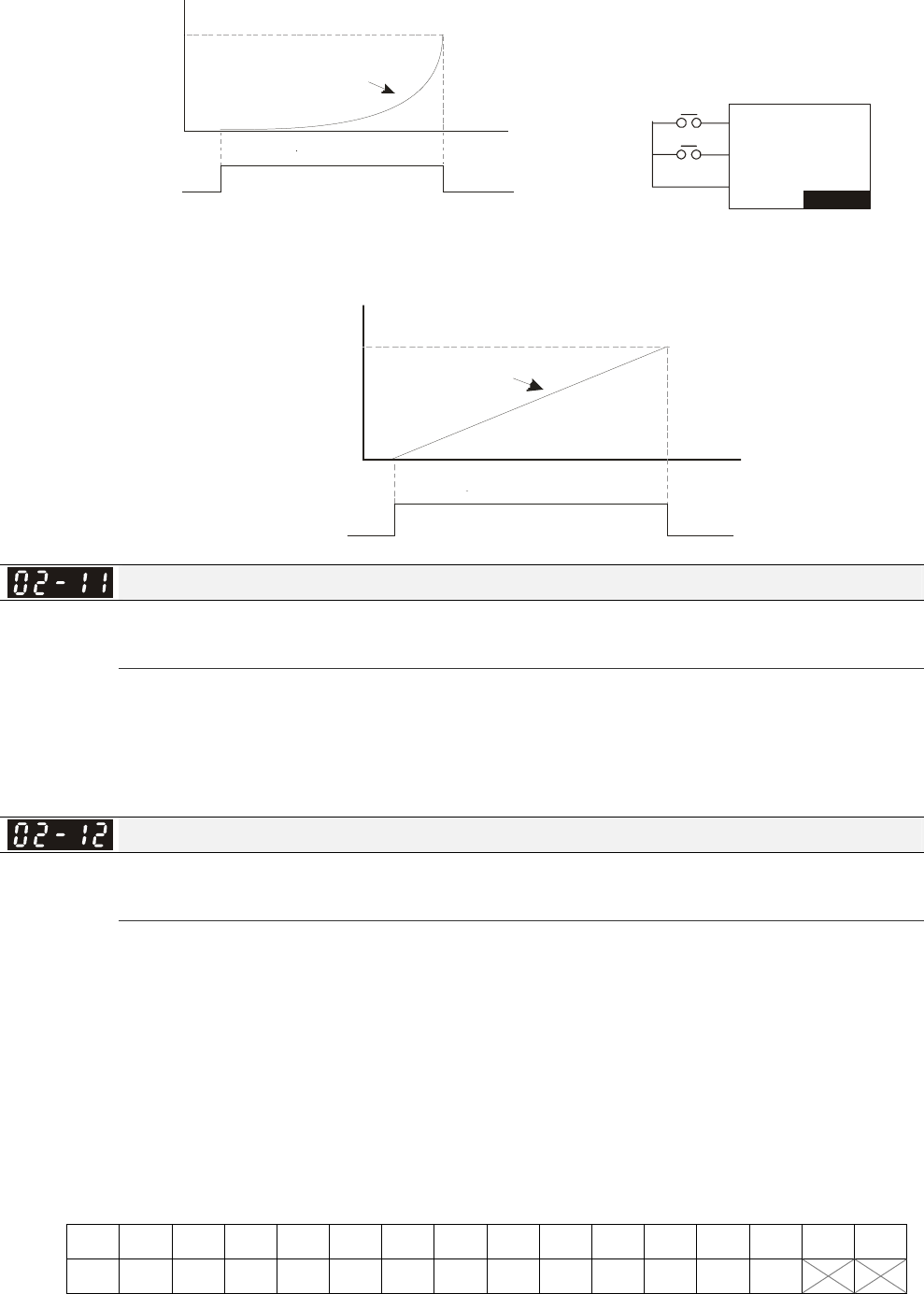
Chapter 12 Description of Parameter Settings|C2000 Series
12-40
OFF
ON
Time
Frequency
Frequency command
External terminal
UP key
DCM
DOWN
UP
VFD-C
Ml1~15
Ml1~15
Pr.02-09 set to 1: it will increase/decrease frequency command (F) by the setting of
acceleration/deceleration (Pr.01-12~01-19) and only be valid during operation.
OFF
ON
Fr eq ue nc
y
Fr eq ue ncy
command
Time
Mu lti-function
input terminal
10 Frequency
incr eased comma nd
Increased by acceleration time
Digital Input Response Time
Factory Setting: 0.005
Settings 0.000~30.000 sec
This parameter is used to set the response time of digital input terminals FWD, REV and MI1~MI8.
It is used for digital input terminal signal delay and confirmation. The delay time is confirmation
time to prevent some uncertain interference that would cause error in the input of the digital
terminals. Under this condition, confirmation for this parameter would improve effectively, but the
response time will be somewhat delayed.
Digital Input Operation Direction
Factory Setting: 0000
Settings 0000h~FFFFh(0:N.O. ; 1:N.C.)
The setting of this parameter is In hexadecimal.
This parameter is used to set the input signal level and it won’t be affected by the SINK/SOURCE
status.
Bit0 is for FWD terminal, bit1 is for REV terminal and bit2 to bit15 is for MI1 to MI14.
User can change terminal status by communicating.
For example, MI1 is set to 1 (multi-step speed command 1), MI2 is set to 2 (multi-step speed
command 2). Then the forward + 2nd step speed command=1001(binary)=9 (Decimal). Only need
to set Pr.02-12=9 by communication and it can forward with 2nd step speed. It doesn’t need to wire
any multi-function terminal.
Bit15 bit14 bit13 bit12 bit11 bit10 bit9 bit8 bit7 bit6 bit5 bit4 bit3 bit2 bit1 bit0
MI14 MI13 MI12 MI11 MI10 MI9 MI8 MI7 MI6 MI5 MI4 MI3 MI2 MI1
Chapter 12 Description of Parameter Settings|C2000 Series
12-41
Multi-function Output 1 (Relay1)
Factory Setting: 11
Multi-function Output 2 (Relay2)
Factory Setting: 1
Multi-function Output 3 (MO1)
Multi-function Output 4 (MO2)
Output terminal of I/O extension card (MO10)
Output terminal of I/O extension card (MO11)
Output terminal of I/O extension card (MO12)
Output terminal of I/O extension card (MO13)
Output terminal of I/O extension card (MO14)
Output terminal of I/O extension card (MO15)
Output terminal of I/O extension card (MO16)
Output terminal of I/O extension card (MO17)
Output terminal of I/O extension card (MO18)
Output terminal of I/O extension card (MO19)
Output terminal of the I/O extension card (MO20)
Factory Setting: 0
Settings
0: No function
1: Operation Indication
2: Operation speed attained
3: Desired frequency attained 1 (Pr.02-22)
4: Desired frequency attained 2 (Pr.02-24)
5: Zero speed (Frequency command)
6: Zero speed, include STOP(Frequency command)
7: Over torque 1(Pr.06-06~06-08)
8: Over torque 2(Pr.06-09~06-11)
9: Drive is ready
10: Low voltage warning(LV)(Pr.06-00)
11: Malfunction indication
12: Mechanical brake release(Pr.02-32)
13: Overheat warning (Pr.06-15)
14: Software brake signal indication(Pr.07-00)
15: PID feedback error
16: Slip error (oSL)
17: Terminal count value attained (Pr.02-20; not return to 0)
18: Preliminary count value attained (Pr.02-19; returns to 0)
19: Base Block
20: Warning output
21: Over voltage warning

Chapter 12 Description of Parameter Settings|C2000 Series
12-42
22: Over-current stall prevention warning
23: Over-voltage stall prevention warning
24: Operation mode indication
25: Forward command
26: Reverse command
27: Output when current >= Pr.02-33 (>= 02-33)
28: Output when current <=Pr.02-33 (<= 02-33)
29: Output when frequency >= Pr.02-34 (>= 02-34)
30: Output when frequency <= Pr.02-34 (<= 02-34)
31: Y-connection for the motor coil
32: △-connection for the motor coil
33: Zero speed (actual output frequency)
34: Zero speed include stop(actual output frequency)
35: Error output selection 1(Pr.06-23)
36: Error output selection 2(Pr.06-24)
37: Error output selection 3(Pr.06-25)
38: Error output selection 4(Pr.06-26)
39: Position attained (Pr.10-19)
40: Speed attained (including Stop)
41: Multi-position attained
42: Crane function
43: Actual motor speed slower than Pr.02-47
44: Low current output (Pr.06-71 to Pr.06-73)
45: UVW Output Electromagnetic valve On/Off Switch
46: Master dEb action output
47: Closed brake output
48: Reserved
49: Homing action complete
50: Output for CANopen control
51: Output for communication card
52: Output for RS485
53~62: Reserved
This parameter is used for setting the function of multi-function terminals.
Pr.02-36~Pr.02-41 requires additional extension cards to display the parameters, the choices of
optional cards are EMC-D42A and EMC-R6AA.
The optional card EMC-D42A provides 2 output terminals and can be used with Pr.02-36~02-37.
The optional card EMC-R6AA provides 6 output terminals and can be used with Pr.02-36~02-41.
Summary of function settings (Take the normally open contact for example, ON: contact is closed,
OFF: contact is open)

Chapter 12 Description of Parameter Settings|C2000 Series
12-43
Settings Functions Descriptions
0 No Function
1 Operation Indication Active when the drive is not at STOP.
2 Master Frequency
Attained
Active when the AC motor drive reaches the output frequency
setting.
3 Desired Frequency
Attained 1 (Pr.02-22) Active when the desired frequency (Pr.02-22) is attained.
4 Desired Frequency
Attained 2 (Pr.02-24) Active when the desired frequency (Pr.02-24) is attained.
5 Zero Speed (frequency
command)
Active when frequency command =0. (the drive should be at RUN
mode)
6 Zero Speed with Stop
(frequency command) Active when frequency command =0 or stop.
7 Over Torque 1
Active when detecting over-torque. Refer to Pr.06-07 (over-torque
detection level-OT1) and Pr.06-08 (over-torque detection
time-OT1). Refer to Pr.06-06~06-08.
8 Over Torque 2
Active when detecting over-torque. Refer to Pr.06-10 (over-torque
detection level-OT2) and Pr.06-11 (over-torque detection
time-OT2). Refer to Pr.06-09~06-11.
9 Drive Ready Active when the drive is ON and no abnormality detected.
10 Low voltage warn (Lv) Active when the DC Bus voltage is too low. (refer to Pr.06-00 low
voltage level)
11 Malfunction Indication Active when fault occurs (except Lv stop).
12 Mechanical Brake
Release (Pr.02-32)
When drive runs after Pr.02-32, it will be ON. This function should
be used with DC brake and it is recommended to use
contact ”b”(N.C).
13 Overheat Active when IGBT or heat sink overheats to prevent OH turn off
the drive. (refer to Pr.06-15)
14 Software Brake Signal
Indication Active when the soft brake function is ON. (refer to Pr.07-00)
15 PID Feedback Error Active when the feedback signal is abnormal.
16 Slip Error (oSL) Active when the slip error is detected.
17
Terminal Count Value
Attained (Pr.02-20; not
return to 0)
Active when the counter reaches Terminal Counter Value
(Pr.02-19). This contact won’t active when Pr.02-20>Pr.02-19.
18
Preliminary Counter
Value Attained
(Pr.02-19; returns to 0)
Active when the counter reaches Preliminary Counter Value
(Pr.02-19).
19 External Base Block
input (B.B.)
Active when the output of the AC motor drive is shut off during
base block.
20 Warning Output Active when the warning is detected.
21 Over-voltage Warning Active when the over-voltage is detected.
22 Over-current Stall
Prevention Warning Active when the over-current stall prevention is detected.
23 Over-voltage Stall
prevention Warning Active when the over-voltage stall prevention is detected.
24 Operation Mode
Indication
Active when the operation command is controlled by external
terminal. (Pr.00-20≠0)
25 Forward Command Active when the operation direction is forward.
26 Reverse Command Active when the operation direction is reverse.
27 Output when Current >=
Pr.02-33 Active when current is >= Pr.02-33.
28 Output when Current <=
Pr.02-33 Active when current is <= Pr.02-33
29 Output when frequency
>= Pr.02-34 Active when frequency is >= Pr.02-34.
30 Output when Frequency
<= Pr.02-34 Active when frequency is <= Pr.02-34.
31 Y-connection for the
Motor Coil
Active when PR.05-24 is less than Pr.05-23 and time is more than
Pr.05-25.

Chapter 12 Description of Parameter Settings|C2000 Series
12-44
Settings Functions Descriptions
32 -connection for the
Motor Coil
Active when PR.05-24 is higher than Pr.05-23 and time is more
than Pr.05-25.
33 Zero Speed (actual
output frequency)
Active when the actual output frequency is 0. (the drive should be
at RUN mode)
34 Zero Speed with Stop
(actual output frequency) Active when the actual output frequency is 0 or Stop.
35 Error Output Selection 1
(Pr.06-23) Active when Pr.06-23 is ON.
36 Error Output Selection 2
(Pr.06-24) Active when Pr.06-24 is ON.
37 Error Output Selection 3
(Pr.06-25) Active when Pr.06-25 is ON.
38 Error Output Selection 4
(Pr.06-26) Active when Pr.06-26 is ON.
39 Position Attained
(Pr.10-19) Active when the PG position control point reaches Pr.10-19.
40 Speed Attained
(including zero speed)
Active when the output frequency reaches frequency setting or
stop.
41 Multi-position Attained
User can set any three multi-function input terminals to 41. The
current position action status of these three terminals will be
outputted. Example: if setting Pr.02-36~02-38 to 41 and only the
multi-position of the second point has been done. Therefore,
current status is RA (ON), RA (OFF) and MO1 (OFF). In this way,
their status is 010. Bit0 is RA and so on.
MO2
Pr.02-17=41
MO1
Pr.02-16=41
RY2
Pr.02-14=41
RY1
Pr.02-13=41
Pr.04-16 0 0 0 1
Pr.04-18 0 0 1 0
Pr.04-20 0 0 1 1
Pr.04-22 0 1 0 0
Pr.04-24 0 1 0 1
Pr.04-26 0 1 1 0
Pr.04-28 0 1 1 1
Pr.04-30 1 0 0 0
Pr.04-32 1 0 0 1
Pr.04-34 1 0 1 0
Pr.04-36 1 0 1 1
Pr.04-38 1 1 0 0
Pr.04-40 1 1 0 1
Pr.04-42 1 1 1 0
Pr.04-44 1 1 1 1
42 Crane Function
This function should be used with Pr.02-32, Pr.02-33, Pr.02-34,
Pr.02-57 and Pr.02-58.
Active when setting Pr.07-16=Pr.02-34 and Fcmd > Pr.02-34 and
output current > Pr.02-33 and Time > Pr.02-32.
The example of the crane application is in the following for your
reference.
43 Motor Zero-speed
Output (Pr.02-47) Active when motor actual speed is less than Pr.02-47.
44 Low Current Output This function needs to be used with Pr.06-71 ~ Pr.06-73
45
UVW Phase Magnet
Contractor ON/ OFF
Switch
1. Under FOCPG control mode, set MI=49 (drive enable) and
MO=45 (electromagnetic contractor On/Off swictch), then the
magnetic contractor will follow the drive status to be On or Off.
2. For brake control, set MO=12 (mechanical brake release),
Pr.02-31=T1 sec (mechanical brake delay time); then
enable/disable DC braking by set 07-01 (DC brake current) to any
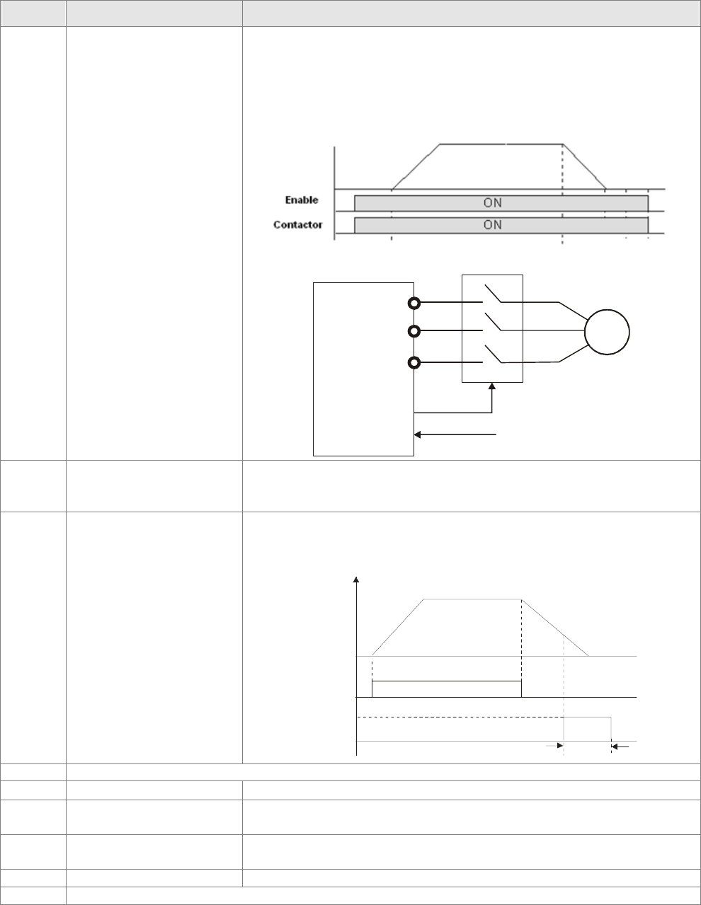
Chapter 12 Description of Parameter Settings|C2000 Series
12-45
Settings Functions Descriptions
level except 0 and set Pr.07-02 = T2 (DC brake time at start up)
and Pr.07-03 = T2 (DC brake current at stop). It is recommend to
set T2 >T1 and try to activate brake control during zero-speed
status.
Motor
U(T1)
V(T2)
W(T3)
IM
3~
MC
MOx=45
MIx=49
AC Driver
46 Master dEb signal output
When dEb arise at Master, MO will send a dEb signal to Slave. Then
Slave will follow Master’s command and decelerate to stop
simultaneously.
47 Brake Release at Stop
When drive stops, the corresponding multi-function terminal will
be ON if the frequency is less than Pr.02-34. After it is ON, it will
be OFF when brake delay time exceeds Pr.02-32.
Multi-function
Output
MO=d47
Output Frequenc
y
02-32
RUN RUN
Time
Output Frequency
< Pr.02-34
48 Reserved
49 Homing Action Complete Output when homing action complete.
50 Output for CANopen
control For CANopen communication output
51 Output for
communication card
For communication output of communication cards
(CMC-MOD01, CMC-EIP01, CMC-PN01 and CMC-DN01)
52 Output for RS-485 For RS-485 output
53~62 Reserved
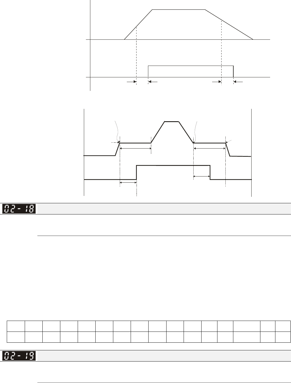
Chapter 12 Description of Parameter Settings|C2000 Series
12-46
Example: Crane Application
02-3202-32
Outpu
t
Frequency
Freq. Command>02-34
& output current >02-33
Freq. command<02-58
or output current <02-57
multi-function output
MO=42 (Active when
Fcom>=02-34, output
current>02-33 and time
>02-32)
It is recommended to be used with Dwell function as shown in the following:
Multi-function output
MO= 42
( Activate when
Fcmd >= 02-34
output current > 02-33
Time > 02-32)
07-16 Dwell
Freq.
at Accel. 07-15
Dwell Time at Accel.
Output Freq.
02-32
Brake Delay Time
Set 07-16=02-34and
output current >02-33
07-17
Dwell Time atDecel.
Set 07-18=02-34 and
output current <02-57
07-18 Dwell Freq.
at Decel.
02-32
Brake Delay Time
Multi-function Output Direction
Factory Setting: 0000
Settings 0000h~FFFFh(0:N.O. ; 1:N.C.)
The setting of this parameter is in hexadecimal.
This parameter is set via bit setting. If a bit is 1, the corresponding output acts in the opposite way.
Example:
If Pr02-13=1 and Pr02-18=0, Relay 1 is ON when the drive runs and is open when the drive is
stopped.
If Pr02-13=1 and Pr02-18=1, Relay 1 is open when the drive runs and is closed when the drive is
stopped.
Bit setting
bit15 bit14 bit13 bit12 bit11 bit10 bit9 bit8 bit7 bit6 bit5 bit4 bit3 bit2 bit1 bit0
MO20 MO19 MO18 MO17 MO16 MO15 MO14 MO13 MO12 MO11 MO10 MO2 MO1 Reserved RY2 RY1
Terminal Counting Value Attained (return to 0)
Factory Setting: 0
Settings 0~65535
The counter trigger can be set by the multi-function terminal MI6 (set Pr.02-06 to 23). Upon
completion of counting, the specified output terminal will be activated (Pr.02-13~02-14, Pr.02-36,
02-37 is set to 18). Pr.02-19 can’t be set to 0.
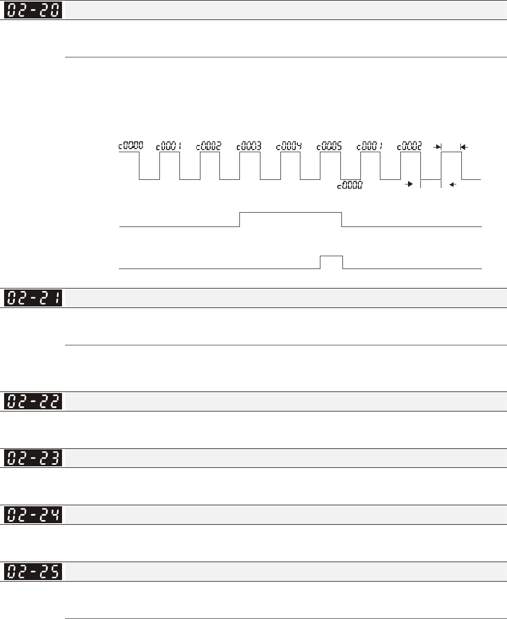
Chapter 12 Description of Parameter Settings|C2000 Series
12-47
When the display shows c5555, the drive has counted 5,555 times. If display shows c5555•, it
means that real counter value is between 55,550 to 55,559.
Preliminary Counting Value Attained (not return to 0)
Factory Setting: 0
Settings 0~65535
When the counter value counts from 1 and reaches this value, the corresponding multi-function
output terminal will be activated, provided one of Pr. 02-13, 02-14, 02-36, 02-37 set to 17
(Preliminary Count Value Setting). This parameter can be used for the end of the counting to make
the drive runs from the low speed to stop.
1.0msec
TRG
[00-04=01]
02-14=17
02-19=5
02-20=3
[02-06=23]
Display value
Counter Trigger
(output signal)
Preliminary Counter Value
RY 1 P r.02-13=17
Terminal Counter Value
RY 2 P r.02-14=18
Th e width of tr ig ge r signal
02-13, 02-14, 02-36, 02-37
1.0msec
Digital Output Gain(DFM)
Factory Setting: 1
Settings 1~166
It is used to set the signal for the digital output terminals (DFM-DCM) and digital frequency output
(pulse X work period=50%). Output pulse per second = output frequency X Pr.02-21.
Desired Frequency Attained 1
Factory Setting: 60.00/50.00
Settings 0.00~600.00Hz
The Width of the Desired Frequency Attained 1
Factory Setting: 2.00
Settings 0.00~600.00Hz
Desired Frequency Attained 2
Factory Setting: 60.00/50.00
Settings 0.00~600.00Hz
The Width of the Desired Frequency Attained 2
Factory Setting: 2.00
Settings 0.00~600.00Hz
Once output frequency reaches desired frequency and the corresponding multi-function output
terminal is set to 3 or 4 (Pr.02-13, 02-14, 02-36, and 02-37), this multi-function output terminal will
be ON.
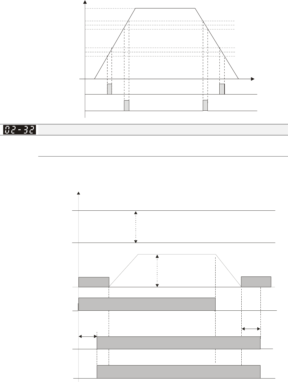
Chapter 12 Description of Parameter Settings|C2000 Series
12-48
02-13,02-14,
02-36,02-37,
Fcmd=60Hz
02-22=10Hz
02-23=2Hz
02-24=40Hz
02-25=2Hz
H
38Hz
40Hz
42Hz
10Hz
12Hz
8Hz
T
=3
02-13,02-14,
02-36,02-37, =4
Brake Delay Time
Factory Setting: 0.000
Settings 0.000~65.000 sec
When the AC motor drive runs after Pr.02-32 delay time, the corresponding multi-function output
terminal (12: mechanical brake release) will be ON. It is recommended to use this function with DC
brake.
RUN STOP
A
B=A
Multi-function output
(mechanical brake release)
Pr.02-11 to 02-14=d12
Output
frequency
DC brake
07-02
DC brake
time during
start-up
07-03
DC brake
time during
stopping
Mechanical brake
02-32 brake delay time
bounce time of mechanical brake
RUN/STOP
braked release
frequency
command
braked
DC brake
Time
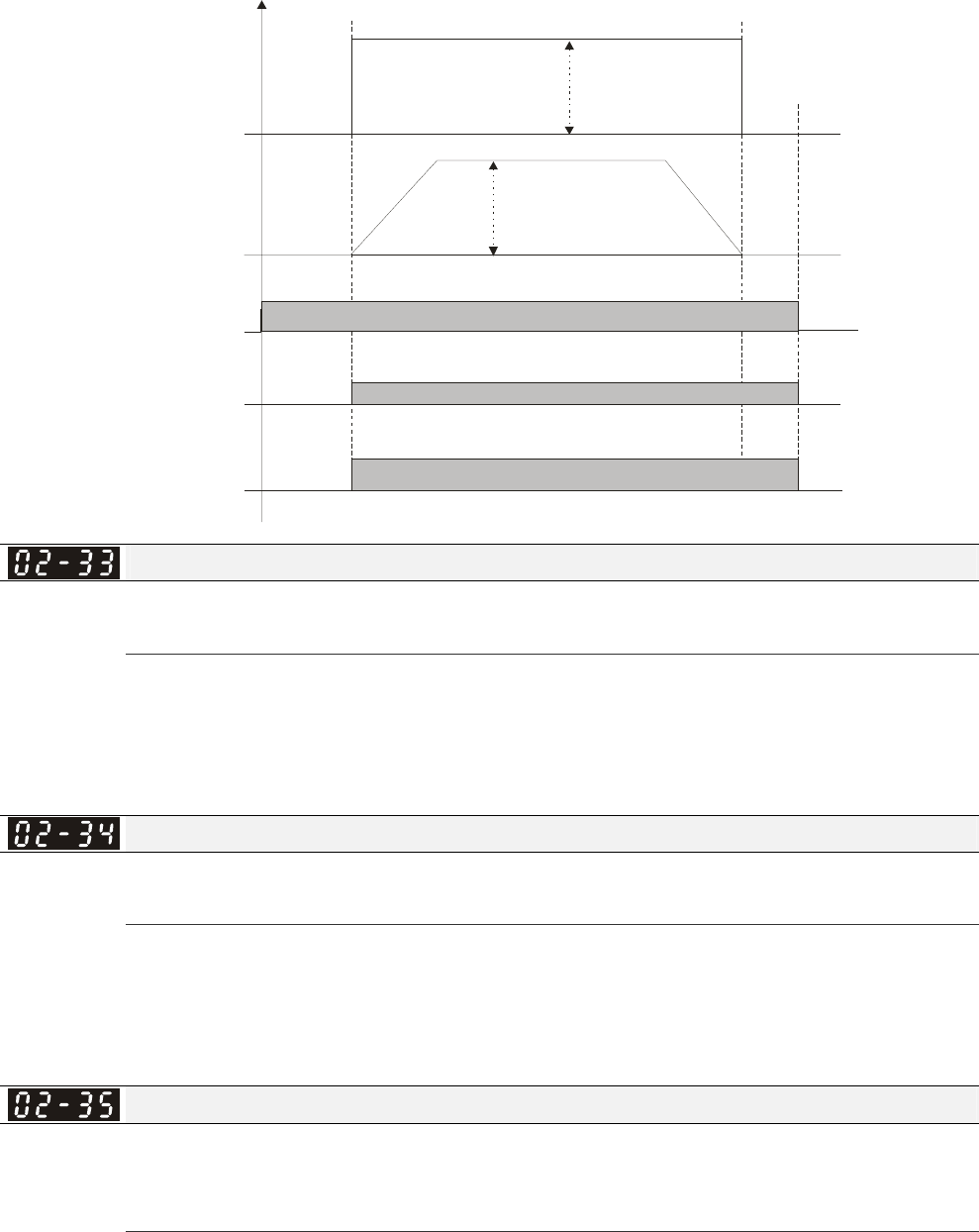
Chapter 12 Description of Parameter Settings|C2000 Series
12-49
If this parameter is used without DC brake, it will be invalid. Refer to the following operation timing.
Multi-function output
(mechanical brake
release)
Pr.02-11 to 02-14=d12
RUN STOP
A
B=A
zero
speed
zero
speed
Time
frequency
command
output
frequency
RUN/STOP
mechanical brake brake brake
release
Output Current Level Setting for Multi-function Output Terminals
Factory Setting: 0
Settings 0~100%
When output current is higher or equal to Pr.02-33, it will activate multi-function output terminal
(Pr.02-13, 02-14, 02-16, and 02-17 is set to 27).
When output current is lower or equal to Pr.02-33, it will activate multi-function output terminal
(Pr.02-13, 02-14, 02-16, and 02-17 is set to 28).
Output Boundary for Multi-function Output Terminals
Factory Setting: 0.00
Settings 0.00~600.00Hz
When output frequency is higher or equal to Pr.02-34, it will activate the multi-function terminal
(Pr.02-13, 02-14, 02-16, 02-17 is set to 29).
When output frequency is lower or equal to Pr.02-34, it will activate the multi-function terminal
(Pr.02-13, 02-14, 02-16, 02-17 is set to 30).
External Operation Control Selection after Reset and Activate
Factory Setting: 0
Settings 0: Disable
1: Drive runs if the run command still exists after reset or re-boots.
Setting 1:
Status 1: After the drive is powered on and the external terminal for RUN keeps ON, the drive will
run.
Status 2: After clearing fault once a fault is detected and the external terminal for RUN keeps ON,
the drive can run after pressing RESET key.

Chapter 12 Description of Parameter Settings|C2000 Series
12-50
Zero-speed Level of Motor
Factory Setting: 0
Settings 0~65535 rpm
This parameter should be used with the multi-function output terminals (set to 43). It needs to be
used with PG cared and motor with encoder feedback.
This parameter is used to set the level of motor zero-speed. When the actual speed is lower than
this setting, the corresponding multi-function output terminal 43 will be ON as shown as follows.
02-47
MO=d43
actual motor
speed
Time
Max. Frequency of Resolution Switch
Factory Setting: 60.00
Settings 0.01~600.00Hz
Switch the delay time of Max. output frequency
Factory Setting: 0.000
Settings 0.000~65.000 sec
It is used to improve the unstable speed or unstable position due to the insufficient of analog
resolution. It needs to be used with external terminal (set to 43). After setting this parameter, it
needs to adjust the analog output resolution of controller simultaneously by this setting.
A
UI +10V
AU I 0V
AUI -10V
0Hz
ON
Accel./Decel. time
01-12~01-19
Frequency
command
Output
frequency
F or war d r unn i ng Reverse running
Max. output frequency
01-00
Max. output frequency
01-00
Resolution
switch
MI=43
Delay time for max.
frequency switch
10-24
Resolution switch
frequency
10-25
Resolution switch
frequency
10-25 Delay time for max .
frequency switch
10-24
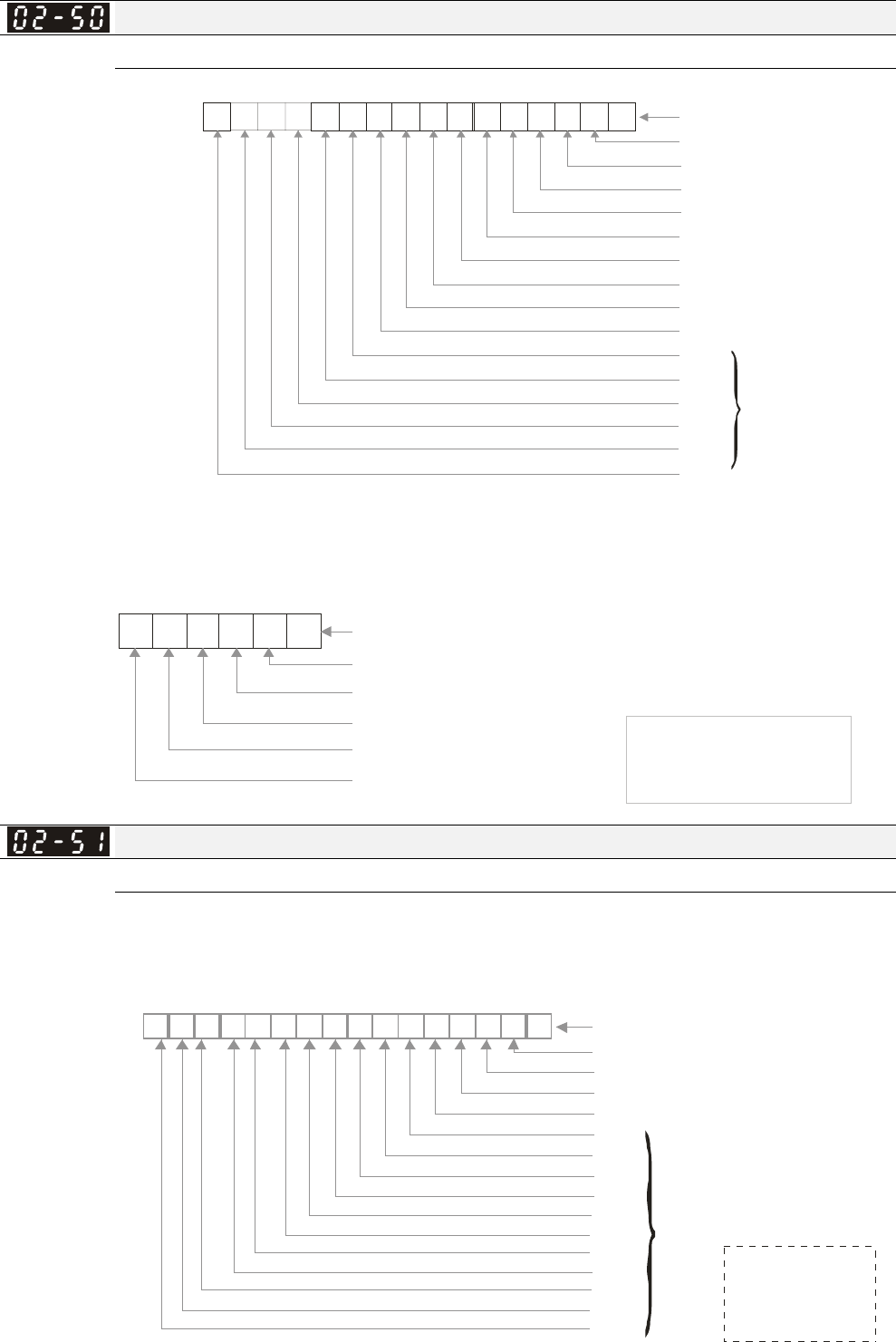
Chapter 12 Description of Parameter Settings|C2000 Series
12-51
Display the Status of Multi-function Input Terminal
Factory Setting: Read only
123450
FWD
REV
MI1
MI2
MI3
MI4
MI5
MI6
MI7
MI8
MI10
MI11
MI12
MI13
MI14
MI15
7891011 6
2 2 2 2 2 2 2 2 2 2 2 2 2 2 2 2
15 14 1 3 12 11 10 9 8 7 6 5 4 3 2 1 0
12131415
Weights
Bit
0=On
1=Off
For
option
card
For Example:
If Pr.02-50 displays 0034h (Hex), i.e. the value is 52, and 110100 (binary). It means MI1, MI3 and
MI4 are active.
MI1
MI2
MI3
MI4
MI5
MI6
2222 2
2
5 4 3 2 1 0
0101
10
Settings
= bit5x2 +bit4x2 +bit2x2
542
= 1x2+1x2+1x2
54 2
=32+16+4 =52
2 =322 =16 2 =8 2 =4
2 =2 2 =1
54 3 2
10
0=ON
1=OFF
Weights
Bit
NOTE
Status of Multi-function Output Terminal
Factory Setting: Read only
For Example:
If Pr.02-51 displays 000Bh (Hex), i.e. the value is 11, and 1011 (binary). It means RY1, RY2 and
MO1 are ON.
Relay 1
MO1
MO2
MO10
MO11
MO12
MO13
MO14
2 =128 2 =64
2 =32 2 =16 2 =8
2 =4 2 =2 2 =1
76
543
210
Relay 2
MO15
MO16
MO17
MO18
MO19
MO20
103254769811 1013 1215 14
2 2 2 2 2 2 2 2 2 2 2 2 2 2 2 2
1 5 1 4 1 3 1 2 1 1 1 0 9 8 7 6 5 4 3 2 1 0
Weights
Bit
0=ON
1=OFF
Reserved
For
option
card
NOTE
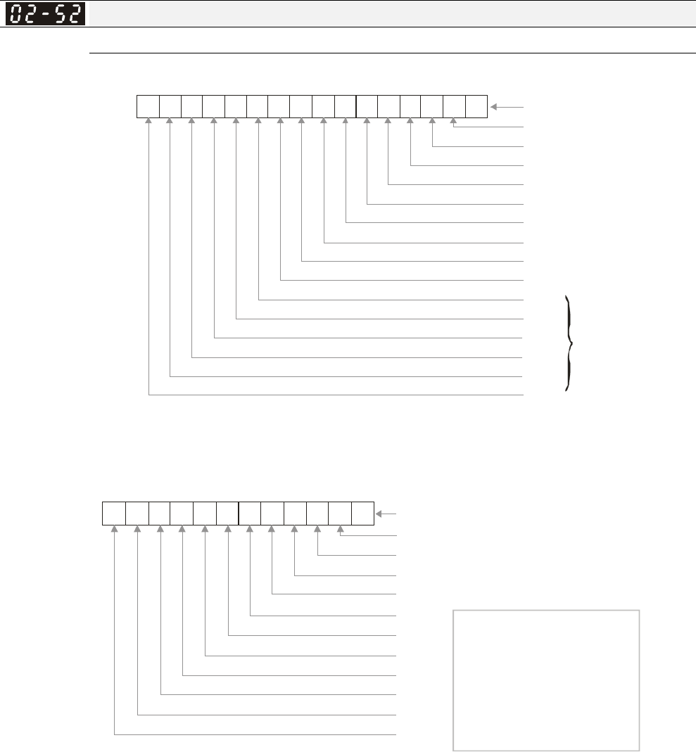
Chapter 12 Description of Parameter Settings|C2000 Series
12-52
Display External Output terminal occupied by PLC
Factory Setting: Read only
P.02-52 shows the external multi-function input terminal that used by PLC.
12
3
4
50
FWD
REV
MI1
MI2
MI3
MI4
MI5
MI6
MI7
MI8
MI10
MI11
MI12
MI13
MI14
MI1
5
78
9
10
11 6
2 2 2 2 2 2 2 2 2 2 2 2 2 2 2 2
1 5 1 4 1 3 1 2 1 1 1 0 9 8 7 6 5 4 3 2 1 0
12
13
1415
Weights
Bit
0=ON
1=OFF
For option
card
For Example:
When Pr.02-52 displays 0034h(hex) and switching to 110100 (binary), it means MI1, MI3 and MI4
are used by PLC.
MI1
MI2
MI3
MI4
MI5
MI6
MI7
MI8
MI10
MI11
MI12
MI13
2 2222 222 222 2
11 10 9 8 7 6 5 4 3 2 1 0
01
0
1
10
00
0000
= bit5x2 +bit4x2 +bit2x2
542
= 1x2 +1x2 +1x2
54 2
=32+16+4 =52
NOTE
2 =1638 4 2 =8192 2 =409 6
2 =2048 2 =1024 2 =512
2 =2 56 2 =1 2 8 2 = 64
2 =3 22 = 16 2 =8 2 =4
2 =2 2 =1
14 13 12
11 10 9
876
54 3 2
10
Weight
s
Bit
0: not used by PLC
1: used by PLC
Displays
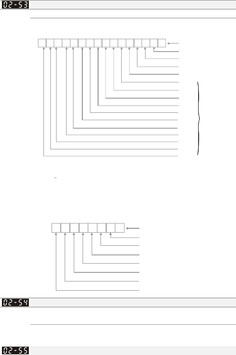
Chapter 12 Description of Parameter Settings|C2000 Series
12-53
Display Analog Input Terminal occupied by PLC
Factory Setting: Read only
P.02-53 shows the external multi-function output terminal that used by PLC.
Relay 1
MO1
10
32
54
76
MO2
MO10
MO11
MO12
MO13
MO14
NOTE
2 =128 2 =64
2 =32 2 =16 2 =8
2 =4 2 =2 2 =1
76
53
210
Relay 2
98
11 10
13 12
15 14
2 2 2 2 2 2 2 2 2 2 2 2 2 2 2 2
15 14 13 1 2 1 1 10 9 8 7 6 5 4 3 2 1 0
MO15
MO16
MO17
MO18
MO19
MO20
Weights
Bit
0=ON
1=OFF
Reserved
For option
card
For Example:
If the value of Pr.02-53 displays 0003h (Hex), it means RY1and RY2 are used by PLC.
Relay 1
MO1
11000000
MO2
MO3
MO4
MO5
22222222
7 6 5 4 3 2 1 0
Display value
3=2+1
=1x2 +1x2
=bi t 1x2 +b i t 0 x 2
10
10
Relay 2
Weights
Bit
0=NOT used by PL
C
1=Used by PLC
Reserved
Display the Frequency Command Executed by External Terminal
Factory Setting: Read only
Settings Read only
When the source of frequency command comes from the external terminal, if Lv or Fault occurs at
this time, the frequency command of the external terminal will be saved in this parameter.
Reserved

Chapter 12 Description of Parameter Settings|C2000 Series
12-54
Reserved
Multi-function output terminal: Function 42: Brake Current Checking Point
Factory setting: 0
Settings 0~150%
Multi-function output terminal: Function 42: Brake Frequency Checking Point
Factory setting:0.00
Settings 0.00~655.35Hz
Pr02-32, Pr02-33, Pr02-34, Pr02-57 and Pr02-58 can be applied on setting up cranes. (Choose
crane action #42 to set up multi-functional output Pr02-13, Pr02-14, Pr02-16, and Pr02-17)
When output current of a drive is higher than the the setting of Pr02-33 Pivot Point of the Current
(>=02-33) and when output frequency is higher than the the setting of Pr02-34 Pivot Point of the
Frequency (>= 02-34), choose #42 to set up Multi-functional output Pr02-13, Pr02-14, Pr02-16
and Pr002-17 after the delay time set at Pr402-32.
When the Pivot Point of the Current 's setting 02-57≠0 and when the output current of the drive is
lower than the setting of Pr02-57 (<02-57), or when the output frequency is lower than the setting
of Pr02-58 (<02-58), the disable the setting #42 of the multi-functional output Pr02-13, Pr02-14,
Pr02-16, Pr02-17
When Pr02-57 = 0, the output current is lower than setting of Pr02-33 Pivot Point of the
Current(<02-33) or when output frequency is lower than the setting of Pr02-58(<02-58), disable
the setting of #42 of the multi-functional output Pr02-13, Pr02-14, Pr02-16, Pr02-17.
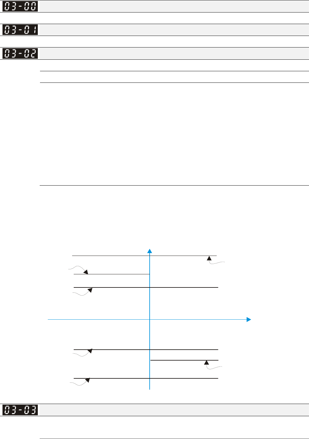
Chapter 12 Description of Parameter Settings|C2000 Series
12-55
03 Analog Input/Output Parameter This parameter can be set during operation.
Analog Input Selection (AVI)
Factory Setting: 1
Analog Input Selection (ACI)
Factory Setting: 0
Analog Input Selection (AUI)
Factory Setting: 0
Settings
0: No function
1: Frequency command (torque limit under torque control mode)
2: Torque command (torque limit under speed mode)
3: Torque compensation command
4: PID target value
5: PID feedback signal
6: PTC thermistor input value
7: Positive torque limit
8: Negative torque limit
9: Regenerative torque limit
10: Positive/negative torque limit
11: PT100 thermistor input value
12~17: Reserved
When it is frequency command or TQC speed limit, the corresponding value for 0~±10V/4~20mA is
0 – max. output frequency(Pr.01-00)
When it is torque command or torque limit, the corresponding value for 0~±10V/4~20mA is 0 – max.
output torque (Pr.11-27).
When it is torque compensation, the corresponding value for 0~±10V/4~20mA is 0 – rated torque.
Positive torque
Reverse
03-00~02=7
Positive torque limit
03-00~02=8
Negative torque limit
03-00~02=9
Regenerative
torque limit
03-00~02=10
Positive/negative torque limit
Negative Torque
Forward
03-00~02=10
Positive/negative torque limit 03-00~02=9
Regenerative
torque limit
Analog Input Bias (AVI)
Factory Setting: 0
Settings -100.0~100.0%
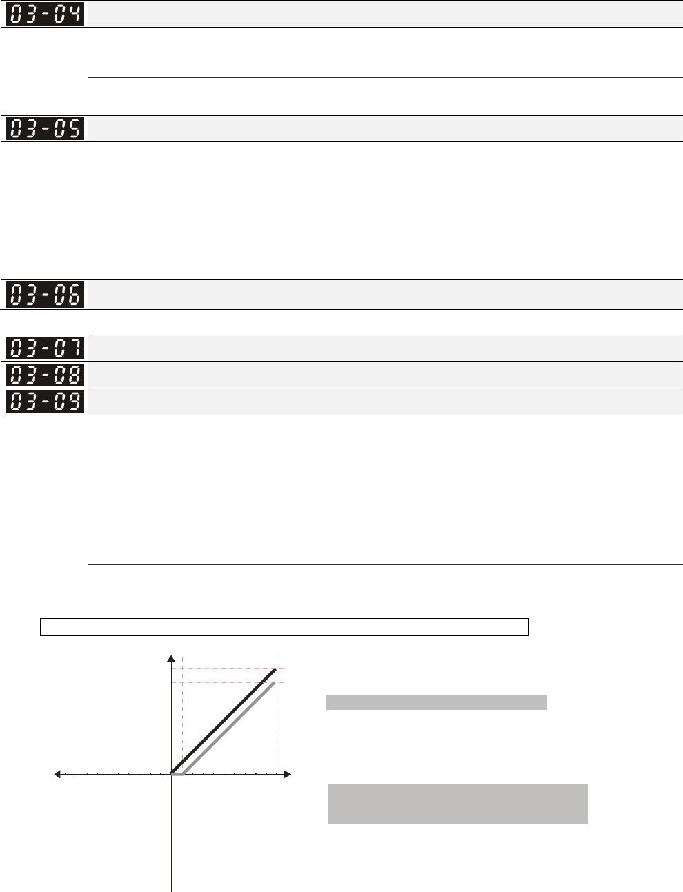
Chapter 12 Description of Parameter Settings|C2000 Series
12-56
It is used to set the corresponding AVI voltage of the external analog input 0.
Analog Input Bias (ACI)
Factory Setting: 0
Settings -100.0~100.0%
It is used to set the corresponding ACI voltage of the external analog input 0.
Analog Voltage Input Bias (AUI)
Factory Setting: 0
Settings -100.0~100.0%
It is used to set the corresponding AUI voltage of the external analog input 0.
The relation between external input voltage/current and setting frequency: 0~10V (4-20mA)
corresponds to 0-60Hz.
Reserved
Positive/negative Bias Mode (AVI)
Positive/negative Bias Mode (ACI)
Positive/negative Bias Mode (AUI)
Factory Setting: 0
Settings 0: Zero bias
1: Lower than or equal to bias
2: Greater than or equal to bias
3: The absolute value of the bias voltage while serving as the center
4: Serve bias as the center
In a noisy environment, it is advantageous to use negative bias to provide a noise margin. It is
recommended NOT to use less than 1V to set the operation frequency.
In the diagram below: Black color line: Frequency. Gray color line: Voltage
1051234 6789
V
60Hz
54Hz
10 6 12345798
-V
Frequenc
y
Pr.03-07~03-09 (Positive/Negative Bias Mode)
Pr.03-10 (Analog Frequency Command for Reverse Run)
Pr.03-11 Analog Input Gain (AVI)= 100%
Pr.03-03=10%
0: Negative frequency is not valid.
Forward and reverse run is controlled
by digital keypad or external terminal.
1: Neagtive frequency is valid. Positive
frequency = forward run; negative
frequency = reverse run. Direction
can not be switched by digital keypad or
external teriminal control.
0: No bias
1:
2: Greater than or equal to bias
3: The absolute value of the bias voltage
while serving as the center
4: Serve bias as the center
Lower than or equal to bias
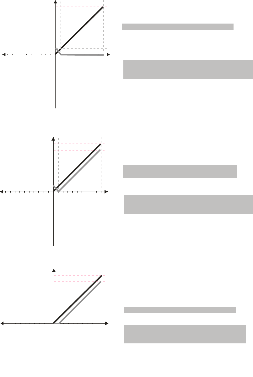
Chapter 12 Description of Parameter Settings|C2000 Series
12-57
1051234 6789
V
60Hz
10 6 12345798
-V
6Hz
Frequency
Pr.03-07~03-09 (Positive/Negative Bias Mode)
Pr.03-10 (Analog Frequency Command for Reverse Run)
Pr.03-11Analog Input Gain (AVI)=100%
Pr.03-03=10%
0: Negative frequency is not valid.
Forward and reverse run is controlled
by digital keypad or external terminal.
1: Neagtive frequency is valid. Positive
frequency = forward run; negative
frequency = reverse run. Direction
can not be switched by digital keypad or
external teriminal control.
0: No bias
1:
2: Greater than or equal to bias
3: The absolute value of the bias voltage
while serving as the center
4: Serve bias as the center
Lower than or equal to bias
1051234 6789
V
60Hz
54Hz
10 6 12345798
-V
6Hz
Frequency
Pr.03-07~03-09 (Positive/Negative Bias Mode)
Pr.03-10 (Analog Frequency Command for Reverse Run)
Pr.03-11 Analog Input Gain (AVI) = 100%
Pr.03-03=10%
0: Negative frequency is not valid.
Forward and reverse run is controlled
by digital keypad or external terminal.
1: Neagtive frequency is valid. Positive
frequency = forward run; negative
frequency = reverse run. Direction
can not be switched by digital keypad or
external teriminal control.
0: No bias
1:
2: Greater than or equal to bias
3: The absolute value of the bias voltage
while serving as the center
4: Serve bias as the center
Lower than or equal to bias
1051234 6789
V
60Hz
54Hz
10 6 12345798
-V
Frequency
Pr.03-07~03-09 (Positive/Negative Bias Mode)
Pr.03-10 (Analog Frequency Command for Reverse Run)
Pr.03-11 Analog Input Gain (AVI) = 100%
Pr.03-03=10%
0: Negative frequency is not valid.
Forward and reverse run is controlled
by digital keypad or external terminal.
1: Neagtive frequency is valid. Positive
frequency = forward run; negative
frequency = reverse run. Direction
can not be switched by digital keypad or
external teriminal control.
0: No bias
1:
2: Greater than or equal to bias
3: The absolute value of the bias voltage
while serving as the center
4: Serve bias as the center
Lower than or equal to bias
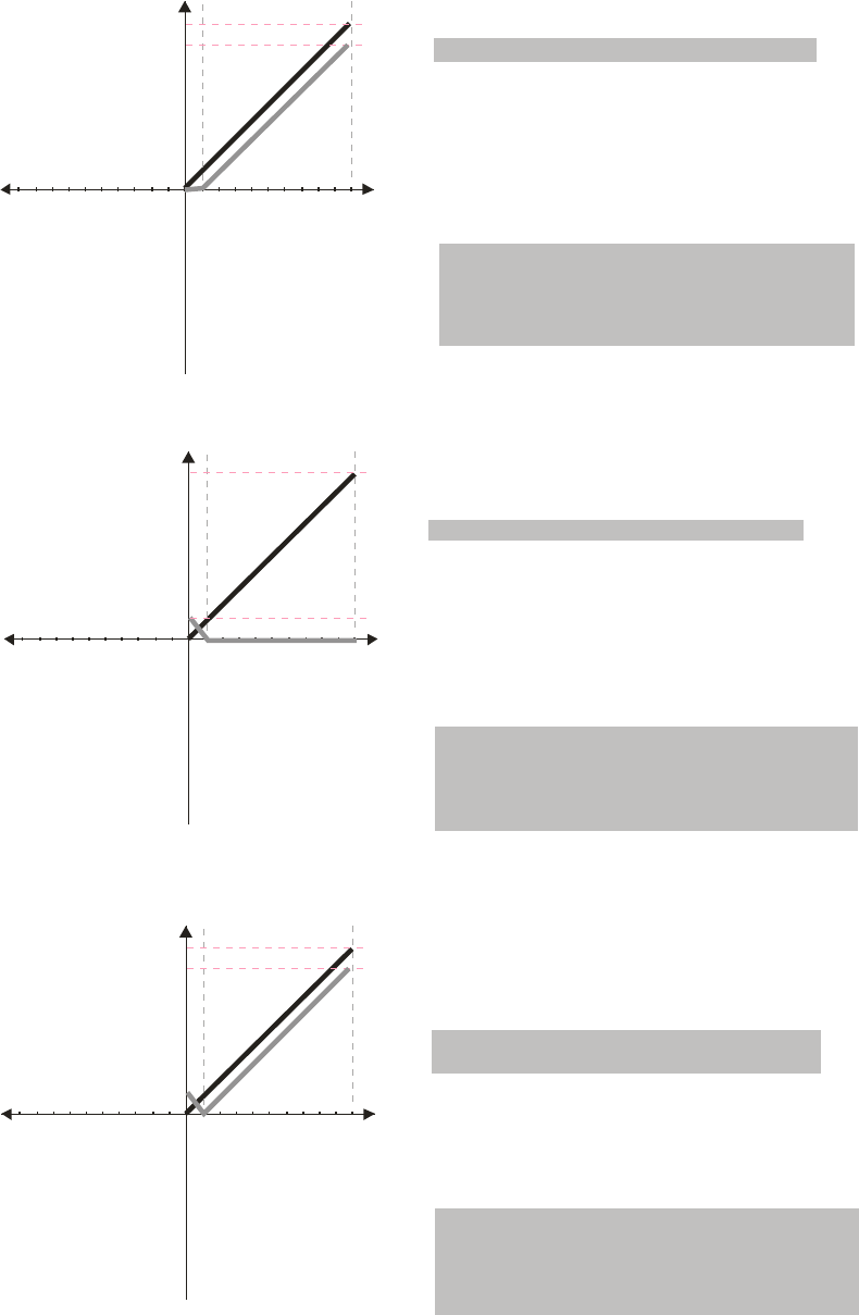
Chapter 12 Description of Parameter Settings|C2000 Series
12-58
1051234 6789
V
60Hz
54Hz
10 6 12345798
-V
Frequency Pr.03-07~03-09 (Positive/Negative Bias Mode)
Pr.03-10 (Analog Frequency Command for Reverse Run)
Pr.03-11 Analog Input Gain (AVI)= 100%
Pr.03-03=10%
0: Negative frequency is not valid.
Forward and reverse run is controlled
by digital keypad or external terminal.
1: Neagtive frequency is valid. Positive
frequency = forward run; negative
frequency = reverse run. Direction
can not be switched by digital keypad or
external teriminal control.
0: No bias
1:
2: Greater than or equal to bias
3: The absolute value of the bias voltage
while serving as the center
4: Serve bias as the center
Lower than or equal to bias
1051234 6789
V
60Hz
10 6 12345798
-V
6Hz
Frequency
Pr.03-07~03-09 (Positive/Negative Bias Mode)
Pr.03-10 (Analog Frequency Command for Reverse Run)
Pr.03-11Analog Input Gain (AVI)= 100%
Pr.03-03=10%
0: Negative frequency is not valid.
Forward and reverse run is controlled
by digital keypad or external terminal.
1: Neagtive frequency is valid. Positive
frequency = forward run; negative
frequency = reverse run. Direction
can not be switched by digital keypad or
external teriminal control.
0: No bias
1:
2: Greater than or equal to bias
3: The absolute value of the bias voltage
while serving as the center
4: Serve bias as the center
Lower than or equal to bias
1051234 6789
V
60Hz
54Hz
10 6 12345798
-V
6Hz
Pr.03-07~03-09 (Positive/Negative Bias Mode)
Pr.03-10 (Analog Frequency Command for Reverse Run)
Pr.03-11 Analog Input Gain (AVI) = 100%
Pr.03-03=10%
0: Negative frequency is not valid.
Forward and reverse run is controlled
by digital keypad or external terminal.
1: Neagtive frequency is valid. Positive
frequency = forward run; negative
frequency = reverse run. Direction
can not be switched by digital keypad or
external teriminal control.
0: No bias
1:
2: Greater than or equal to bias
3: The absolute value of the bias voltage
while serving as the center
4: Serve bias as the center
Lower than or equal to bias
Frequency
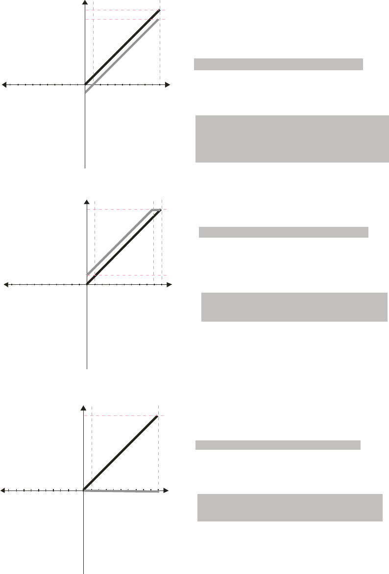
Chapter 12 Description of Parameter Settings|C2000 Series
12-59
10
5
1234 6789
V
60Hz
54Hz
-V
-6Hz
Frequency
Pr.03-07~03-09 (Positive/Negative Bias Mode)
Pr.03-10 (Analog Frequency Command for Reverse Run)
Pr.03-11 Analog Input Gain (AVI) = 100%
Pr.03-03=10%
0: Negative frequency is not valid.
Forward and reverse run is controlled
by digital keypad or external terminal.
1: Neagtive frequency is valid. Positive
frequency = forward run; negative
frequency = reverse run. Direction
can not be switched by digital keypad or
external teriminal control.
0: No bias
1:
2: Greater than or equal to bias
3: The absolute value of the bias voltage
while serving as the center
4: Serve bias as the center
Lower than or equal to bias
1051234 6789
V
60Hz
10 6 12345798
-V
6Hz
Frequency
Pr.03-07~03-09 (Positive/Negative Bias Mode)
Pr.03-10 (Analog Frequency Command for Reverse Run)
Pr.03-11 Analog Input Gain (AVI)= 100%
Pr.03-03=-10%
0: Negative frequency is not valid.
Forward and reverse run is controlled
by digital keypad or external terminal.
1: Neagtive frequency is valid. Positive
frequency = forward run; negative
frequency = reverse run. Direction
can not be switched by digital keypad or
external teriminal control.
0: No bias
1:
2: Greater than or equal to bias
3: The absolute value of the bias voltage
while serving as the center
4: Serve bias as the center
Lower than or equal to bias
1051234 6789
V
60Hz
10 6 12345798
-V
Frequency
Pr.03-07~03-09 (Positive/Negative Bias Mode)
Pr.03-10 (Analog Frequency Command for Reverse Run)
Pr.03-11 Analog Input Gain (AVI)= 100%
Pr.03-03=-10%
0: Negative frequency is not valid.
Forward and reverse run is controlled
by digital keypad or external terminal.
1: Neagtive frequency is valid. Positive
frequency = forward run; negative
frequency = reverse run. Direction
can not be switched by digital keypad or
external teriminal control.
0: No bias
1:
2: Greater than or equal to bias
3: The absolute value of the bias voltage
while serving as the center
4: Serve bias as the center
Lower than or equal to bias
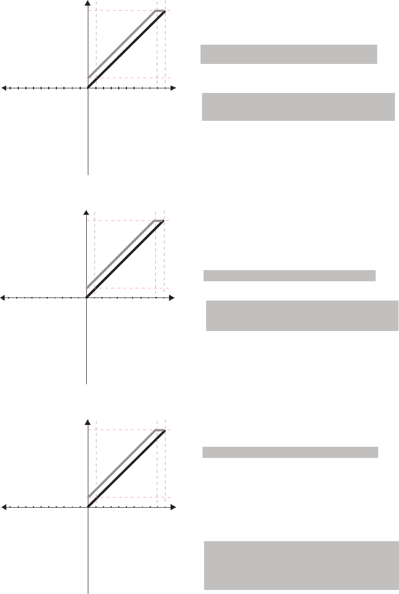
Chapter 12 Description of Parameter Settings|C2000 Series
12-60
1051234 6789
V
60Hz
10 6 12345798
-V
6Hz
Frequency
Pr.03-07~03-09 (Positive/Negative Bias Mode)
Pr.03-10 (Analog Frequency Command for Reverse Run)
Pr.03-11 Analog Input Gain (AVI) = 100%
Pr.03-03=-10%
0: Negative frequency is not valid.
Forward and reverse run is controlled
by digital keypad or external terminal.
1: Neagtive frequency is valid. Positive
frequency = forward run; negative
frequency = reverse run. Direction
can not be switched by digital keypad or
external teriminal control.
0: No bias
1:
2: Greater than or equal to bias
3: The absolute value of the bias voltage
w hile serving as the center
4: Serve bias as the center
Lower than or equal to bias
10
5
1234 6789
V
60Hz
10 6 1234
5
798
-V
6Hz
Frequency
Pr.03-07~03-09 (Positive/Negative Bias Mode)
Pr.03-10 (Analog Frequency Command for Reverse Run)
Pr.03-11 Analog Input Gain (AVI) = 100%
Pr.03-03=-10%
0: Negative frequency is not valid.
Forward and reverse run is controlled
by digital keypad or external terminal.
1: Neagtive frequency is valid. Positive
frequency = forward run; negative
frequency = reverse run. Direction
can not be switched by digital keypad or
external teriminal control.
0: No bias
1:
2: Greater than or equal to bias
3: The absolute value of the bias voltage
while serving as the center
4: Serve bias as the center
Lower than or equal to bias
1051234 6789
V
60Hz
10 6 12345798
-V
6Hz
Frequency
Pr.03-07~03-09 (Positive/Negative Bias Mode)
Pr.03-10 (Analog Frequency Command for Reverse Run)
Pr.03-11 Analog Input Gain (AVI)= 100%
Pr.03-03=-10%
0: Negative frequency is not valid.
Forward and reverse run is controlled
by digital keypad or external terminal.
1: Neagtive frequency is valid. Positive
frequency = forward run; negative
frequency = reverse run. Direction
can not be switched by digital keypad or
external teriminal control.
0: No bias
1:
2: Greater than or equal to bias
3: The absolute value of the bias voltage
while serving as the center
4: Serve bias as the center
Lower than or equal to bias
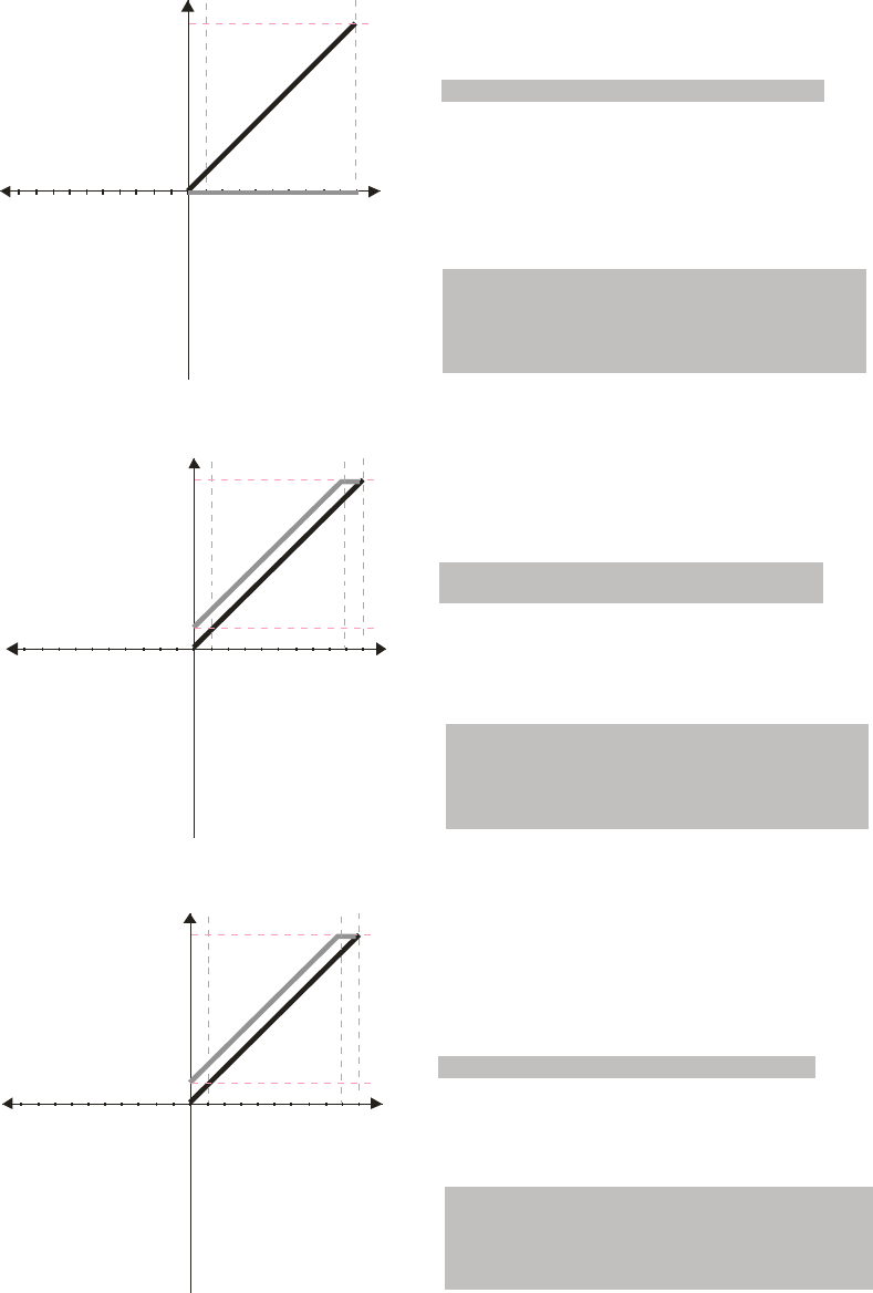
Chapter 12 Description of Parameter Settings|C2000 Series
12-61
1051234 6789
V
60Hz
10 6 12345798
-V
Frequency
Pr.03-07~03-09 (Positive/Negative Bias Mode)
Pr.03-10 (Analog Frequency Command for Reverse Run)
Pr.03-11 Analog Input Gain (AVI)= 100%
Pr.03-03=-10%
0: Negative frequency is not valid.
Forward and reverse run is controlled
by digital keypad or external terminal.
1: Neagtive frequency is valid. Positive
frequency = forward run; negative
frequency = reverse run. Direction
can not be switched by digital keypad or
external teriminal control.
0: No bias
1:
2: Greater than or equal to bias
3: The absolute value of the bias voltage
while serving as the center
4: Serve bias as the center
Lower than or equal to bias
1051234 6789
V
60Hz
10 6 12345798
-V
6Hz
Frequency
Pr.03-07~03-09 (Positive/Negative Bias Mode)
Pr.03-10 (Analog Frequency Command for Reverse Run)
Pr.03-11 Analog Input Gain (AVI) = 100%
Pr.03-03=-10%
0: Negative frequency is not valid.
Forward and reverse run is controlled
by digital keypad or external terminal.
1: Neagtive frequency is valid. Positive
frequency = forward run; negative
frequency = reverse run. Direction
can not be switched by digital keypad or
external teriminal control.
0: No bias
1:
2: Greater than or equal to bias
3: The absolute value of the bias voltage
while serving as the center
4: Serve bias as the center
Lower than or equal to bias
1051234 6789
V
60Hz
10 6 12345798
-V
6Hz
Frequency
Pr.03-07~03-09 (Positive/Negative Bias Mode)
Pr.03-10 (Analog Frequency Command for Reverse Run)
Pr.03-11 Analog Input Gain (AVI) = 100%
Pr.03-03=-10%
0: Negative frequency is not valid.
Forward and reverse run is controlled
by digital keypad or external terminal.
1: Neagtive frequency is valid. Positive
frequency = forward run; negative
frequency = reverse run. Direction
can not be switched by digital keypad or
external teriminal control.
0: No bias
1:
2: Greater than or equal to bias
3: The absolute value of the bias voltage
while serving as the center
4: Serve bias as the center
Lower than or equal to bias
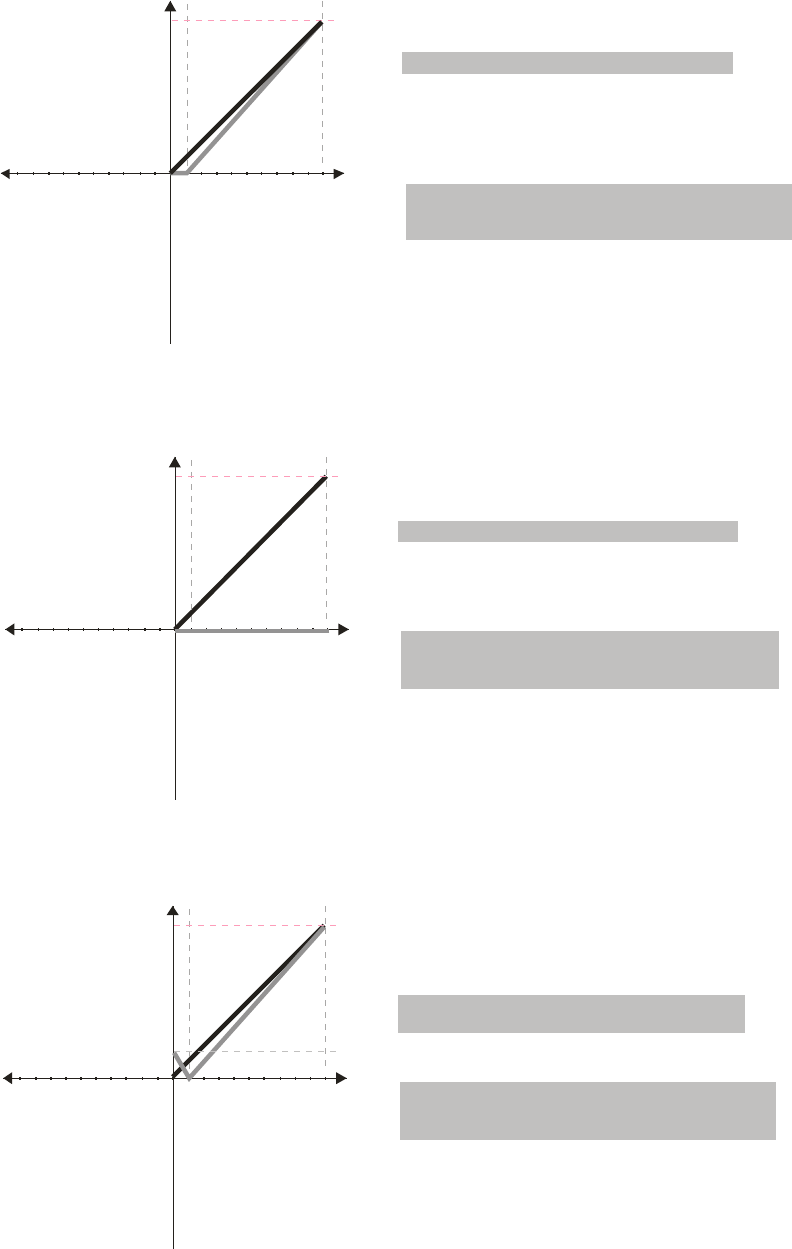
Chapter 12 Description of Parameter Settings|C2000 Series
12-62
1051234 6789
V
60Hz
10 6 12345798
-V
Frequency
Pr.03-07~03-09 (Positive/Negative Bias Mode)
Pr.03-10 (Analog Frequency Command for Reverse Run)
Pr.03 -11 11 .1%Analog Input Gain (AVI)= 1
Pr.03-03=-10%
0: Negative frequency is not valid.
Forward and reverse run is controlled
by digital keypad or external terminal.
1: Neagtive frequency is valid. Positive
frequency = forward run; negative
frequency = reverse run. Direction
can not be switched by digital keypad or
external teriminal control.
0: No bias
1:
2: Greater than or equal to bias
3: The absolute value of the bias voltage
while serving as the center
4: Serve bias as the center
Lower than or equal to bias
10/9=111.1%
1051234 6789
V
60Hz
10 6 12345798
-V
Pr.03-07~03-09 (Positive/Negative Bias Mode)
Pr.03-10 (Analog Frequency Command for Reverse Run)
Pr.03-11Analog Input Gain (AVI)=111.1%
Pr.03-03=10%
0: Negative frequency is not valid.
Forward and reverse run is controlled
by digital keypad or external terminal.
1: Neagtive frequency is valid. Positive
frequency = forward run; negative
frequency = reverse run. Direction
can not be switched by digital keypad or
external teriminal control.
0: No bias
1:
2: Greater than or equal to bias
3: The absolute value of the bias voltage
while serving as the center
4: Serve bias as the center
Lower than or equal to bias
10/9 =111.1
%
Frequency
1051234 6789
V
60Hz
10 6 12345798
-V
6.66Hz
Pr.03-07~03-09 (Positive/Negative Bias Mode)
Pr.03-10 (Analog Frequency Command for Reverse Run)
Pr.03-11 Analog Input Gain (AVI) = 111.1%
Pr.03-03=10%
0: Negative frequency is not valid.
Forward and reverse run is controlled
by digital keypad or external terminal.
1: Neagtive frequency is valid. Positive
frequency = forward run; negative
frequency = reverse run. Direction
can not be switched by digital keypad or
external teriminal control.
0: No bias
1:
2: Greater than or equal to bias
3: The absolute value of the bias voltage
while serving as the center
4: Serve bias as the center
Lower than or equal to bias
10/9 =111.1%
Frequency
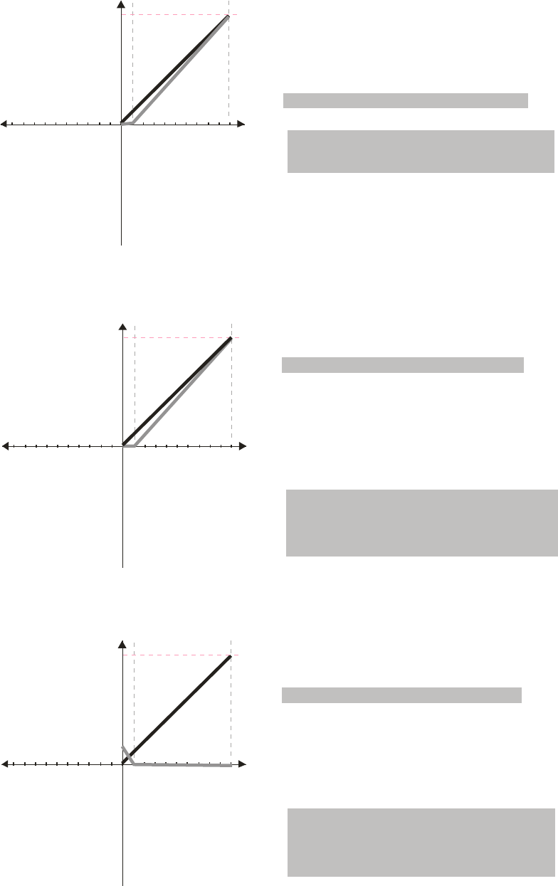
Chapter 12 Description of Parameter Settings|C2000 Series
12-63
1051234 6789
V
60Hz
10 6 12345798
-V
Frequency
Pr.03-07~03-09 (Positive/Negative Bias Mode)
Pr.03-10 (Analog Frequency Command for Reverse Run)
Pr.03-11 Analog Input Gain (AVI) = 111.1%
Pr.03-03=10%
0: Negative frequency is not valid.
Forward and reverse run is controlled
by digital keypad or external terminal.
1: Neagtive frequency is valid. Positive
frequency = forward run; negative
frequency = reverse run. Direction
can not be switched by digital keypad or
external teriminal control.
0: No bias
1:
2: Greater than or equal to bias
3: The absolute value of the bias voltage
while serving as the center
4: Serve bias as the center
Lower than or equal to bias
10/9 =111.1%
1051234 6789
V
60Hz
10 6 12345798
-V
Pr.03-07~03-09 (Positive/Negative Bias Mode)
Pr.03-10 (Analog Frequency Command for Reverse Run)
Pr03-11 Analog Input Gain (AVI) = 111.1%
Pr.03-03=10%
0: Negative frequency is not valid.
Forward and reverse run is controlled
by digital keypad or external terminal.
1: Neagtive frequency is valid. Positive
frequency = forward run; negative
frequency = reverse run. Direction
can not be switched by digital keypad or
external teriminal control.
0: No bias
1:
2: Greater than or equal to bias
3: The absolute value of the bias voltage
while serving as the center
4: Serve bias as the center
Lower than or equal to bias
10/9 =111.1%
Frequency
1051234 6789
V
60Hz
10 6 12345798
-V
6.66Hz
Pr.03-07~03-09 (Positive/Negative Bias Mode)
Pr.03-10 (Analog Frequency Command for Reverse Run)
Pr03-11Analog Input Gain (AVI) = 111.1%
Pr.03-03=10%
0: Negative frequency is not valid.
Forward and reverse run is controlled
by digital keypad or external terminal.
1: Neagtive frequency is valid. Positive
frequency = forward run; negative
frequency = reverse run. Direction
can not be switched by digital keypad or
external teriminal control.
0: No bias
1:
2: Greater than or equal to bias
3: The absolute value of the bias voltage
while serving as the center
4: Serve bias as the center
Lower than or equal to bias
10/9 =111.1%
Frequency
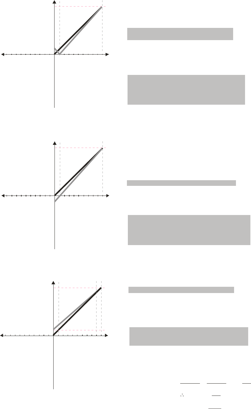
Chapter 12 Description of Parameter Settings|C2000 Series
12-64
1051234 6789
V
60Hz
10 6 12345798
-V
6.66Hz
Pr.03-07~03-09 (Positive/Negative Bias Mode)
Pr.03-10 (Analog Frequency Command for Reverse Run)
Pr03-11 Analog Input Gain (AVI) = 111.1%
Pr.03-03=10%
0: Negative frequency is not valid.
Forward and reverse run is controlled
by digital keypad or external terminal.
1: Neagtive frequency is valid. Positive
frequency = forward run; negative
frequency = reverse run. Direction
can not be switched by digital keypad or
external teriminal control.
0: No bias
1:
2: Greater than or equal to bias
3: The absolute value of the bias voltage
while serving as the center
4: Serve bias as the center
Lower than or equal to bias
10/9 =111.1%
Frequency
1051234 6789
V
60Hz
-V
-6.66Hz
Pr.03-07~03-09 (Positive/Negative Bias Mode)
Pr.03-10 (Analog Frequency Command for Reverse Run)
Pr03-11 Analog Input Gain (AVI) = 100%
Pr.03-03=10%
0: Negative frequency is not valid.
Forward and reverse run is controlled
by digital keypad or external terminal.
1: Neagtive frequency is valid. Positive
frequency = forward run; negative
frequency = reverse run. Direction
can not be switched by digital keypad or
external teriminal control.
0: No bias
1:
2: Greater than or equal to bias
3: The absolute value of the bias voltage
w hile serving as the center
4: Serve bias as the center
Lower than or equal to bias
10/9 =111.1%
Frequency
1051234 6789
V
60Hz
10 6 12345798
-V
6Hz
Frequency Pr.03-07~03-09 (Positive/Negative Bias Mode)
Pr.03-10 (Analog Frequency Command for Reverse Run)
0: Negative frequency is not valid.
Forward and reverse run is controlled
by digital keypad or external terminal.
1: Neagtive frequency is valid. Positive
frequency = forward run; negative
frequency = reverse run. Direction
can not be switched by digital keypad or
external teriminal control.
0: No bias
1:
2: Greater than or equal to bias
3: The absolute value of the bias voltage
while serving as the center
4: Serve bias as the center
Lower than or equal to bias
Pr.03-11 100%=×=90.0%
10V
11.1V
60-6Hz
10V
6-0Hz
XV
=XV= 10
9=1 . 1 1 V
Pr.03-03 100=×%
1.11
10
Calculate the gain:
Calculate the bias:
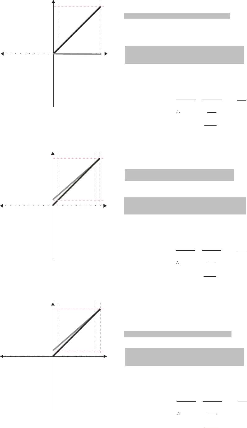
Chapter 12 Description of Parameter Settings|C2000 Series
12-65
10
5
1234 6789
V
60Hz
10 6 1234
5
798
-V
Pr.03-07~03-09 (Positive/Negative Bias Mode)
Pr.03-10 (Analog Frequency Command for Reverse Run)
0: Negative frequency is not valid.
Forward and reverse run is controlled
by digital keypad or external terminal.
1: Neagtive frequency is valid. Positive
frequency = forward run; negative
frequency = reverse run. Direction
can not be switched by digital keypad or
external teriminal control.
0: No bias
1:
2: Greater than or equal to bias
3: The absolute value of the bias voltage
while serving as the center
4: Serve bias as the center
Lower than or equal to bias
Pr.03-11 100%=×=90.0%
10V
11.1V
60-6Hz
10V
6-0Hz
XV
=XV= 10
9=1 . 11 V
Pr.03-03 100=×%
1.11
10
Calculate the gain:
Calculate the bias:
Frequency
1051234 6789
V
60Hz
10 6 12345798
-V
6Hz
Pr.03-07~03-09 (Positive/Negative Bias Mode)
Pr.03-10 (Analog Frequency Command for Reverse Run)
0: Negative frequency is not valid.
Forward and reverse run is controlled
by digital keypad or external terminal.
1: Neagtive frequency is valid. Positive
frequency = forward run; negative
frequency = reverse run. Direction
can not be switched by digital keypad or
external teriminal control.
0: No bias
1:
2: Greater than or equal to bias
3: The absolute value of the bias voltage
w hile serving as the center
4: Serve bias as the center
Lower than or equal to bias
Pr.03-11 100%=×=90.0%
10V
11.1V
60-6Hz
10V
6-0Hz
XV
=XV= 10
9=1 . 1 1 V
Pr.03-03 100=×%
1.11
10
Calculate the gain:
Calculate the bias:
Frequency
1051234 6789
V
60Hz
10 6 12345798
-V
6Hz
Pr.03-07~03-09 (Positive/Negative Bias Mode)
Pr.03-10 (Analog Frequency Command for Reverse Run)
0: Negative frequency is not valid.
Forward and reverse run is controlled
by digital keypad or external terminal.
1: Neagtive frequency is valid. Positive
frequency = forward run; negative
frequency = reverse run. Direction
can not be switched by digital keypad or
external teriminal control.
0: No bias
1:
2: Greater than or equal to bias
3: The absolute value of the bias voltage
while serving as the center
4: Serve bias as the center
Lower than or equal to bias
Pr.03-11 100%=×=90.0%
10V
11.1V
60-6Hz
10V
6-0Hz
XV
=XV= 10
9=1 . 1 1 V
Pr.03-03 100=×%
1.11
10
Calculate the gain:
Calculate the bias:
Frequency
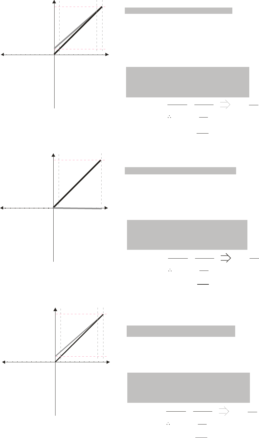
Chapter 12 Description of Parameter Settings|C2000 Series
12-66
1051234 6789
V
60Hz
10 6 12345798
-V
6Hz
Pr.03-07~03-09 (Positive/Negative Bias Mode)
Pr.03-10 (Analog Frequency Command for Reverse Run)
0: Negative frequency is not valid.
Forward and reverse run is controlled
by digital keypad or external terminal.
1: Neagtive frequency is valid. Positive
frequency = forward run; negative
frequency = reverse run. Direction
can not be switched by digital keypad or
external teriminal control.
0: No bias
1:
2: Greater than or equal to bias
3: The absolute value of the bias voltage
w hile serving as the center
4: Serve bias as the center
Lower than or equal to bias
Pr.03-11 100%=× =90.0%
10V
11.1V
60-6Hz
10V
6-0Hz
XV
=XV= 10
9=1 .1 1 V
Pr.03-03 100=× %
1.11
10
C a l cul ate the gai n:
Calculate the bias:
Frequency
1051234 6789 V
60Hz
10 6 12345798
-V
Pr.03-07~03-09 (Positive/Negative Bias Mode)
Pr.03-10 (Analog Frequency Command for Reverse Run)
0: Negative frequency is not valid.
Forward and reverse run is controlled
by digital keypad or external terminal.
1: Neagtive frequency is valid. Positive
frequency = forward run; negative
frequency = reverse run. Direction
can not be switched by digital keypad or
external teriminal control.
0: No bias
1:
2: Greater than or equal to bias
3: The absolute value of the bias voltage
while serving as the center
4: Serve bias as the center
Lower than or equal to bias
Pr.03-11 100%=× =90.0%
10V
11.1V
60-6Hz
10V
6-0Hz
XV
=XV= 10
9=1 .1 1 V
Pr.03-03 100=× %
1.11
10
Calculate the gain:
Calculate the bias:
Frequency
1051234 6789
V
60Hz
10 6 12345798
-V
6Hz
Pr.03-07~03-09 (Positive/Negative Bias Mode)
Pr.03-10 (Analog Frequency Command for Reverse Run)
0: Negative frequency is not valid.
Forward and reverse run is controlled
by digital keypad or external terminal.
1: Neagtive frequency is valid. Positive
frequency = forward run; negative
frequency = reverse run. Direction
can not be switched by digital keypad or
external teriminal control.
0: No bias
1:
2: Greater than or equal to bias
3: The absolute value of the bias voltage
w hile serving as the cent er
4: Serve bias as the center
Lower than or equal to bias
Frequency
Pr.03-11 100%=× =90.0%
10V
11.1V
60-6Hz
10V
6-0Hz
XV
=XV= 10
9=1 . 11 V
Pr.03-03 100=× %
1.11
10
Calculate the gain:
Calculate the bias:
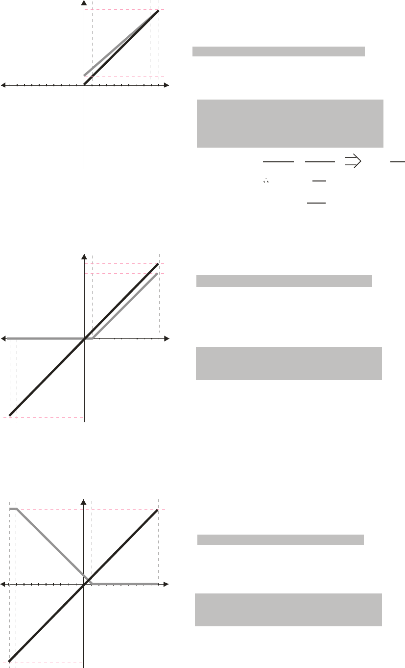
Chapter 12 Description of Parameter Settings|C2000 Series
12-67
1051234 6789 V
60Hz
10 6 12345798
-V
6Hz
Pr.03-07~03-09 (Positive/Negative Bias Mode)
Pr.03-10 (Analog Frequency Command for Reverse Run)
0: Negative frequency is not valid.
Forward and reverse run is controlled
by digital keypad or external terminal.
1: Neagtive frequency is valid. Positive
frequency = forward run; negative
frequency = reverse run. Direction
can not be switched by digital keypad or
external teriminal control.
0: No bias
1:
2: Greater than or equal to bias
3: The absolute value of the bias voltage
w hile serving as the cent er
4: Serve bias as the center
Lower than or equal to bias
Frequency
10V
11.1V
Pr.03-11 100%=× =90.0%
60-6Hz
10V
6-0Hz
XV
=XV= 10
9=1 . 1 1 V
Pr.03-03 100=× %
1.11
10
Calculate the gain:
Calculate the bias:
10
5
1234 6789
V
60Hz
54Hz
10 6 12345798
-V
60Hz
Frequency
Pr.03-07~03-09 (Positive/Negative Bias Mode)
Pr.03-10 (Analog Frequency Command for Reverse Run)
0: Negative frequency is not valid.
Forward and reverse run is controlled
by digital keypad or external terminal.
1: Neagtive frequency is valid. Positive
frequency = forward run; negative
frequency = reverse run. Direction
can not be switched by digital keypad or
external teriminal control.
0: No bias
1: Lower than or equal to bias
2: Greater than or equal to bias
3: The absolute value of the bias voltage
while serving as the center
4: Serve bias as the center
Pr.03-05 Analog Positive Voltage Input Bias (AUI) = 10%
Pr.03-14 Analog Negative Input Gain (AUI)= 100%
Pr.00-13 Analog Positive Input Gain (AUI)= 100%
Pr.00-21=0 (Dgital keypad control and d run in FWD direction)
1051234 6789 V
60Hz
10 6 12345798
-V
60Hz
Pr.03-07~03-09 (Positive/Negative Bias Mode)
Pr.03-10 (Analog Frequency Command for Reverse Run)
0: Negative frequency is not valid.
Forward and reverse run is controlled
by digital keypad or external terminal.
1: Neagtive frequency is valid. Positive
frequency = forward run; negative
frequency = reverse run. Direction
can not be sw itched by digital keypad or
external teriminal control.
0: No bias
1: Lower than or equal to bias
2: Greater than or equal to bias
3: The absolute value of the bias voltage
while serving as the center
4: Serve bias as the center
Frequency
Pr.03-14 Analog Negative Input Gain (AUI)= 100%
Pr.00-13 Analog Positive Input Gain (AUI)= 100%
Pr.03-05 Analog Positive Voltage Input Bias (AUI) = 10%
Pr.00-21=0 (Dgital keypad control and d run in FWD direction)
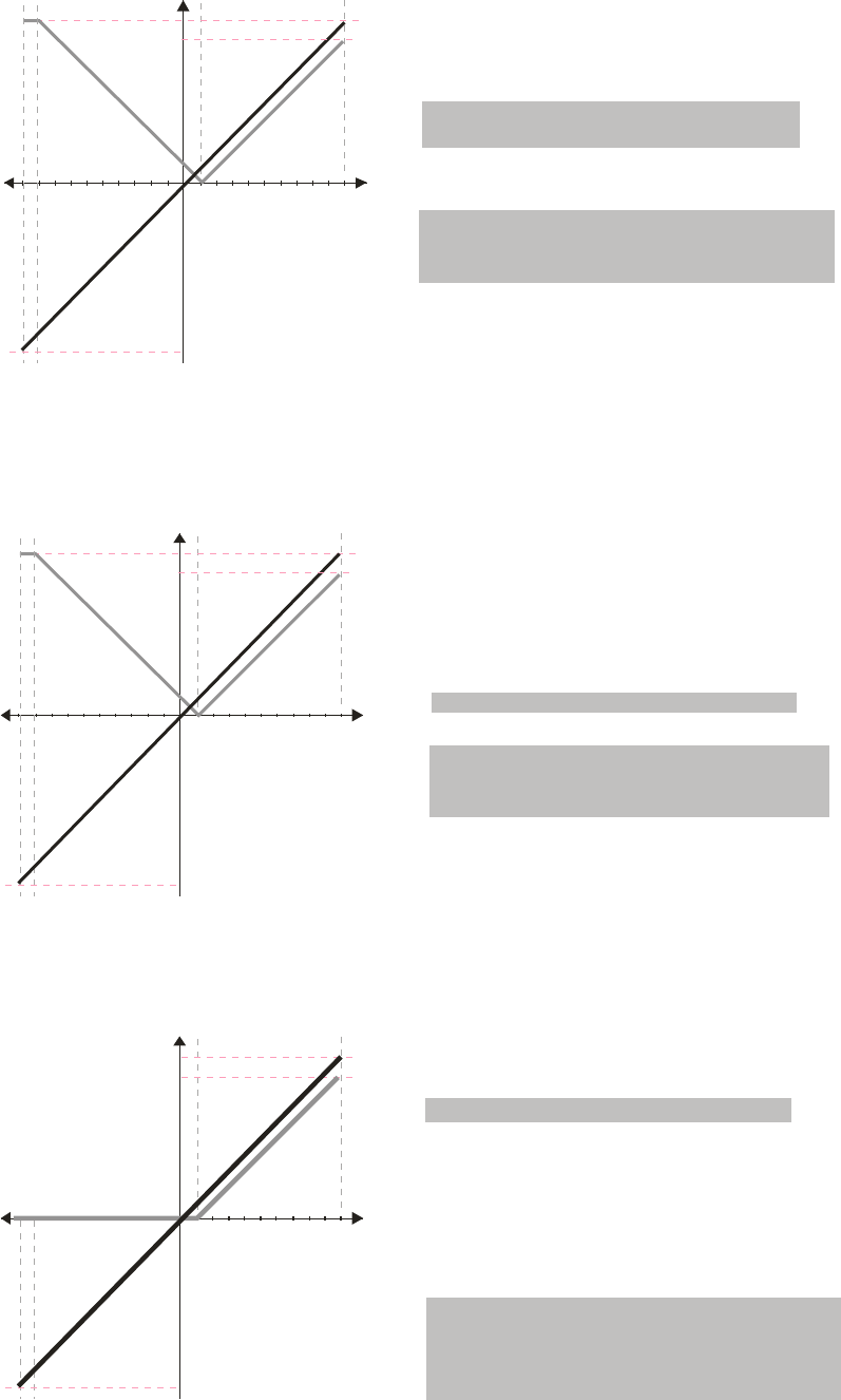
Chapter 12 Description of Parameter Settings|C2000 Series
12-68
1051234 6789
V
60Hz
10 6 12345798
-V
60Hz
54Hz
Pr.03-07~03-09 (Positive/Negative Bias Mode)
Pr.03-10 (Analog Frequency Command for Reverse Run)
0: Negative frequency is not valid.
Forward and reverse run is controlled
by digital keypad or external terminal.
1: Neagtive frequency is valid. Positive
frequency = forward run; negative
frequency = reverse run. Direction
can not be switched by digital keypad or
external teriminal control.
0: No bias
1: Lower than or equal to bias
2: Greater than or equal to bias
3: The absolute value of the bias voltage
while serving as the center
4: Serve bias as the center
Frequency Pr.03-05 Analog Positive Voltage Input Bias (AUI) = 10%
Pr.03-14 Analog Negative Input Gain (AUI)= 100%
Pr.00-13 Analog Positive Input Gain (AUI)= 100%
Pr.00-21=0 (Dgital keypad control and d run in FWD direction)
1051234 6789
V
60Hz
54Hz
10 6 12345798
-V
60Hz
Frequency
Pr.03-07~03-09 (Positive/Negative Bias Mode)
Pr.03-10 (Analog Frequency Command for Reverse Run)
0: Negative frequency is not valid.
Forward and reverse run is controlled
by digital keypad or external terminal.
1: Neagtive frequency is valid. Positive
frequency = forward run; negative
frequency = reverse run. Direction
can not be switched by digital keypad or
external teriminal control.
0: No bias
1:
2: Greater than or equal to bias
3: The absolute value of the bias voltage
while serving as the center
4: Serve bias as the center
Lower than or equal to bias
Pr.03-14 Analog Negative Input Gain (AUI)= 100%
Pr.00-13 Analog Positive Input Gain (AUI)= 100%
Pr.03-05 Analog Positive Voltage Input Bias (AUI) = 10%
Pr.00-21=0 (Digital keypad control and run in FWD direction )
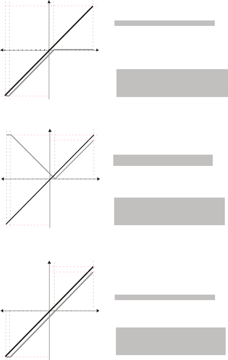
Chapter 12 Description of Parameter Settings|C2000 Series
12-69
1051234 6789
V
60Hz
10 6 12345798
-V
60Hz
Frequency
Pr.03-07~03-09 (Positive/Negative Bias Mode)
Pr.03-10 (Analog Frequency Command for Reverse Run)
0: Negative frequency is not valid.
Forward and reverse run is controlled
by digital keypad or external terminal.
1: Neagtive frequency is valid. Positive
frequency = forward run; negative
frequency = reverse run. Direction
can not be switched by digital keypad or
external teriminal control.
0: No bias
1:
2: Greater than or equal to bias
3: The absolute value of the bias voltage
while serving as the center
4: Serve bias as the center
Lower than or equal to bias
Pr.03-05 Analog Positive Voltage Input Bias (AUI) = 10%
Pr.03-14 Analog Negative Input Gain (AUI)= 100%
Pr.00-13 Analog Positive Input Gain (AUI)= 100%
Pr.00-21=0 (Digital keypad control and run in FWD direction)
1051234 6789
V
60Hz
10 6 12345798
-V
60Hz
54Hz
Pr.03-07~03-09 (Positive/Negative Bias Mode)
Pr.03-10 (Analog Frequency Command for Reverse Run)
0: Negative frequency is not valid.
Forward and reverse run is controlled
by digital keypad or external terminal.
1: Neagtive frequency is valid. Positive
frequency = forward run; negative
frequency = reverse run. Direction
can not be switched by digital keypad or
external teriminal control.
0: No bias
1:
2: Greater than or equal to bias
3: The absolute value of the bias voltage
while serving as the center
4: Serve bias as the center
Lower than or equal to bias
Frequency Pr.03-05 Analog Positive Voltage Input Bias (AUI) = 10%
Pr.03-14 Analog Negative Input Gain (AUI)= 100%
Pr.00-13 Analog Positive Input Gain (AUI)= 100%
Pr.00-21=0 (Digital keypad control and run in FWD direction)
105
1234 6789
V
60Hz
10 6 12345798
-V
60Hz
54Hz
Pr.03-07~03-09 (Positive/Negative Bias Mode)
Pr.03-10 (Analog Frequency Command for Reverse Run)
0: Negative frequency is not valid.
Forward and reverse run is controlled
by digital keypad or external terminal.
1: Neagtive frequency is valid. Positive
frequency = forward run; negative
frequency = reverse run. Direction
can not be switched by digital keypad or
external teriminal control.
0: No bias
1:
2: Greater than or equal to bias
3: The absolute value of the bias voltage
while serving as the center
4: Serve bias as the center
Lower than or equal to bias
Frequency
Pr.00-21=0 (Digital keypad control and run in FWD direction)
Pr.03-05 Analog Positive Voltage Input Bias (AUI) = 10%
Pr.03-14 Analog Negative Input Gain (AUI)= 100%
Pr.00-13 Analog Positive Input Gain (AUI)= 100%
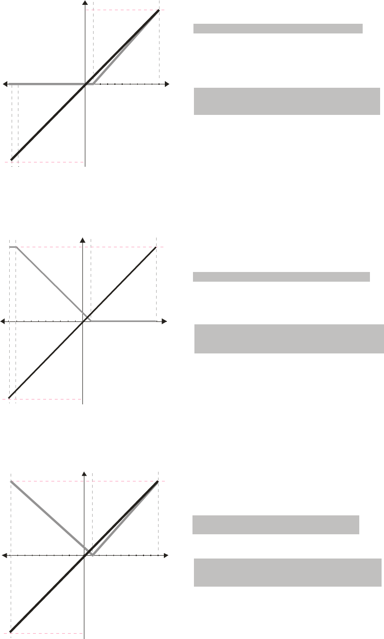
Chapter 12 Description of Parameter Settings|C2000 Series
12-70
1051234 6789
V
60Hz
10 6 12345798
-V
60Hz
Frequency
Pr.03-07~03-09 (Positive/Negative Bias Mode)
Pr.03-10 (Analog Frequency Command for Reverse Run)
0: Negative frequency is not valid.
Forward and reverse run is controlled
by digital keypad or external terminal.
1: Neagtive frequency is valid. Positive
frequency = forward run; negative
frequency = reverse run. Direction
can not be switched by digital keypad or
external teriminal control.
0: No bias
1:
2: Greater than or equal to bias
3: The absolute value of the bias voltage
while serving as the center
4: Serve bias as the center
Lower than or equal to bias
Pr.03-05 Analog Positive Voltage Input Bias (AUI) = 10%
Pr.00-21=0 )(Digital keypad control and run in FWD direction
(10/9) *100% = 111.1%
Pr.00-14 Analog Negative Input Gain (AUI) = 100%
Pr.00-13 Analog Positive Input Gain (AUI)= 111.1%
1051234 6789
V
60Hz
10 6 12345798
-V
60Hz
Pr.03-07~03-09 (Positive/Negative Bias Mode)
Pr.03-10 (Analog Frequency Command for Reverse Run)
0: Negative frequency is not valid.
Forward and reverse run is controlled
by digital keypad or external terminal.
1: Neagtive frequency is valid. Positive
frequency = forward run; negative
frequency = reverse run. Direction
can not be switched by digital keypad or
external teriminal control.
0: No bias
1:
2: Greater than or equal to bias
3: The absolute value of the bias voltage
w hile serving as the cent er
4: Serve bias as the center
Lower than or equal to bias
Frequency
Pr.03-05 Analog Positive Voltage Input Bias (AUI) = 10%
Pr.00-21=0 )(Digital keypad control and run in FWD direction
(10/9) *100% = 111.1%
Pr.00-14 Analog Negative Input Gain (AUI) = 100%
Pr.00-13 Analog Positive Input Gain (AUI)= 111.1%
1051234 6789
V
60Hz
10 6 12345798
-V
60Hz
Pr.03-07~03-09 (Positive/Negative Bias Mode)
Pr.03-10 (Analog Frequency Command for Reverse Run)
0: Negative frequency is not valid.
Forward and reverse run is controlled
by digital keypad or external terminal.
1: Neagtive frequency is valid. Positive
frequency = forward run; negative
frequency = reverse run. Direction
can not be switched by digital keypad or
external teriminal control.
0: No bias
1:
2: Greater than or equal to bias
3: The absolute value of the bias voltage
while serving as the center
4: Serve bias as the center
Lower than or equal to bias
Frequency
Pr.03-05 Analog Positive Voltage Input Bias (AUI) = 10%
Pr.00-21=0 )(Digital keypad control and run in FWD direction
(10/9) *100% = 111.1%
Pr.00-14 Analog Negative Input Gain (AUI) = 100%
Pr.00-13 Analog Positive Input Gain (AUI)= 111.1%
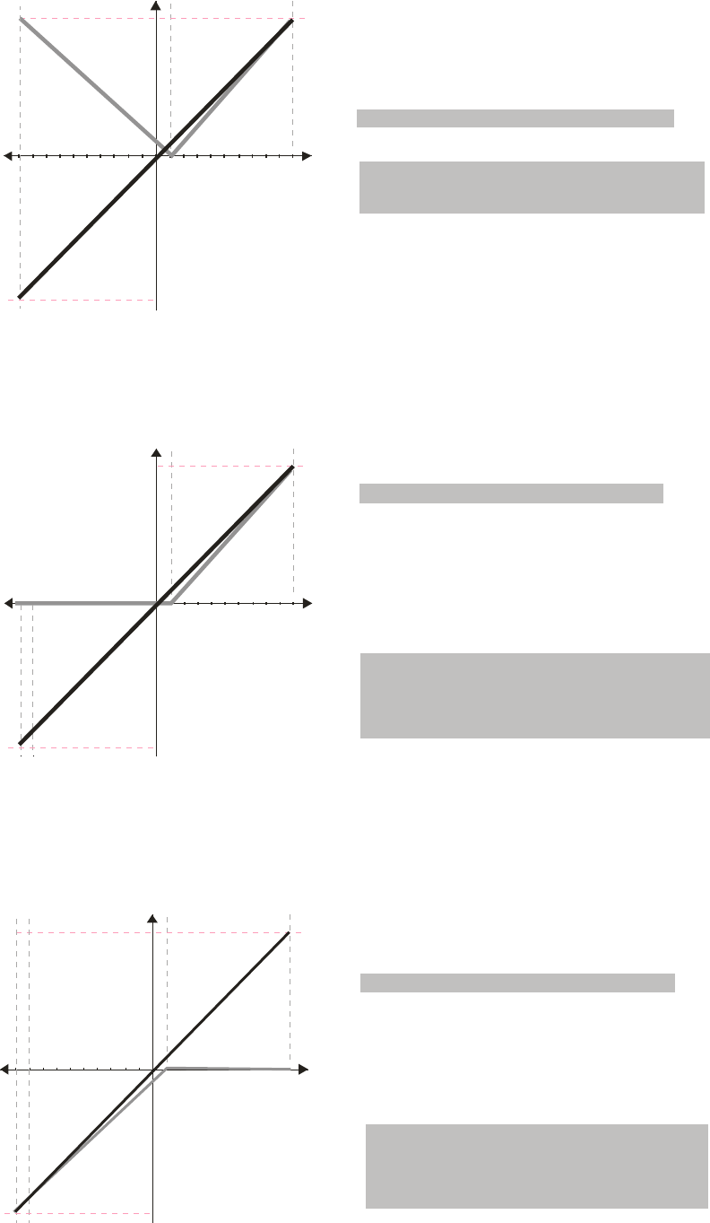
Chapter 12 Description of Parameter Settings|C2000 Series
12-71
1051234 6789
V
60Hz
10 6 12345798
-V
60Hz
Pr.03-07~03-09 (Positive/Negative Bias Mode)
Pr.03-10 (Analog Frequency Command for Reverse Run)
0: Negative frequency is not valid.
Forward and reverse run is controlled
by digital keypad or external terminal.
1: Neagtive frequency is valid. Positive
frequency = forward run; negative
frequency = reverse run. Direction
can not be switched by digital keypad or
external teriminal control.
0: No bias
1:
2: Greater than or equal to bias
3: The absolute value of the bias voltage
while serving as the cent er
4: Serve bias as the center
Lower than or equal to bias
Pr.00-21=0 )(Digital keypad control and run in FWD direction
Frequency Pr.03-05 Analog Positive Voltage Input Bias (AUI) = 10%
(10/9) *100% = 111.1%
Pr.00-14 Analog Negative Input Gain (AUI) = 100%
Pr.00-13 Analog Positive Input Gain (AUI)= 111.1%
1051234 6789
V
60Hz
10 6 12345798
-V
60Hz
Frequency
Pr.03-07~03-09 (Positive/Negative Bias Mode)
Pr.03-10 (Analog Frequency Command for Reverse Run)
0: Negative frequency is not valid.
Forward and reverse run is controlled
by digital keypad or external terminal.
1: Neagtive frequency is valid. Positive
frequency = forward run; negative
frequency = reverse run. Direction
can not be switched by digital keypad or
external teriminal control.
0: No bias
1:
2: Greater than or equal to bias
3: The absolute value of the bias voltage
while serving as the center
4: Serve bias as the center
Lower than or equal to bias
Pr.03-05 Analog Positive Voltage Input Bias (AUI) = 10%
Pr.00-21=0 igital keypad control and run in FWD direction)(D
(10/9) *100% = 111.1%
Pr.00-14 Analog Negative Input Gain (AUI) = 90.9%
Pr.00-13 Analog Positive Input Gain (AUI)= 111.1%
(10/11) *100% = 90.9%
1051234 6789
V
60Hz
10 6 12345798
-V
60Hz
Pr.03-07~03-09 (Positive/Negative Bias Mode)
Pr.03-10 (Analog Frequency Command for Reverse Run)
0: Negative frequency is not valid.
Forward and reverse run is controlled
by digital keypad or external terminal.
1: Neagtive frequency is valid. Positive
frequency = forward run; negative
frequency = reverse run. Direction
can not be switched by digital keypad or
external teriminal control.
0: No bias
1:
2: Greater than or equal to bias
3: The absolute value of the bias voltage
while serving as the center
4: Serve bias as the center
Lower than or equal to bias
Frequency Pr.03-05 Analog Positive Voltage Input Bias (AUI) = 10%
Pr.00-21=0 igital keypad control and run in FWD direction)(D
(10/9) *100% = 111.1%
Pr.00-14 Analog Negative Input Gain (AUI) = 90.9%
Pr.00-13 Analog Positive Input Gain (AUI)= 111.1%
(10/11) *100% = 90.9%
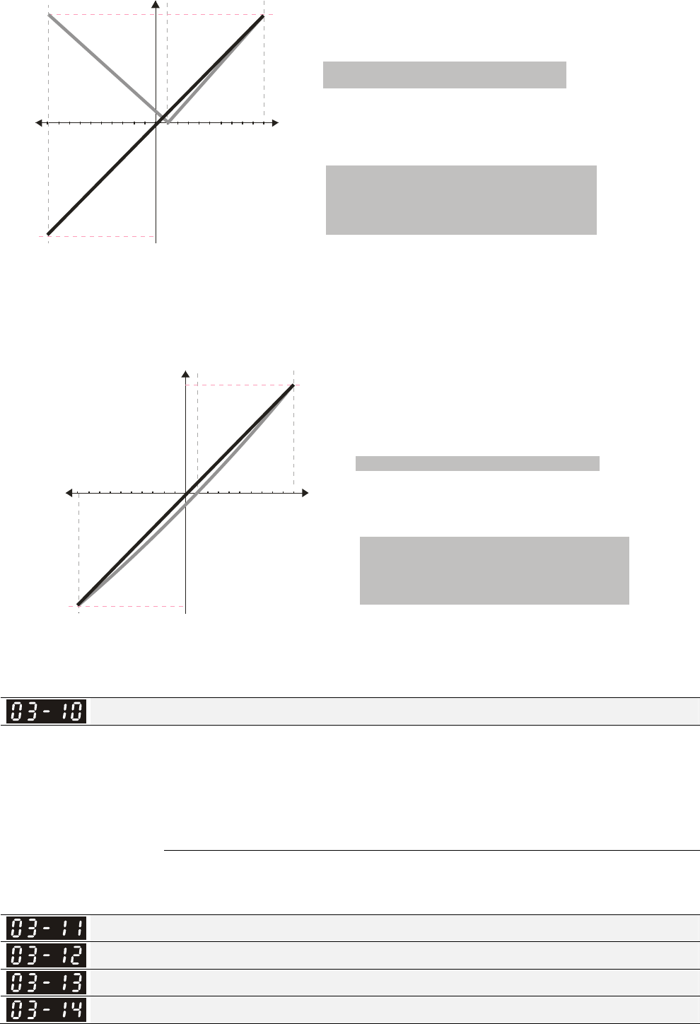
Chapter 12 Description of Parameter Settings|C2000 Series
12-72
1051234 6789 V
60Hz
10 6 12345798
-V
60Hz
Pr.03-07~03-09 (Positive/Negative Bias Mode)
Pr.03-10 (Analog Frequency Command for Reverse Run)
0: Negative frequency is not valid.
Forward and reverse run is controlled
by digital keypad or external terminal.
1: Neagtive frequency is valid. Positive
frequency = forward run; negative
frequency = reverse run. Direction
can not be switched by digital keypad or
external teriminal control.
0: No bias
1:
2: Greater than or equal to bias
3: The absolute value of the bias voltage
while serving as the center
4: Serve bias as the center
Lower than or equal to bias
Frequency Pr.03-05 Analog Positive Voltage Input Bias (AUI) = 10%
Pr.00-21=0 igital keypad control and run in FWD direction)(D
(10/9) *100% = 111.1%
Pr.00-14 Analog Negative Input Gain (AUI) = 90.9%
Pr.00-13 Analog Positive Input Gain (AUI)= 111.1%
(10/11) *100% = 90.9%
1051234 6789
V
60Hz
10 6 12345798
-V
60Hz
Pr.03-07~03-09 (Positive/Negative Bias Mode)
Pr.03-10 (Analog Frequency Command for Reverse Run)
0: Negative frequency is not valid.
Forward and reverse run is controlled
by digital keypad or external terminal.
1: Neagtive frequency is valid. Positive
frequency = forward run; negative
frequency = reverse run. Direction
can not be switched by digital keypad or
external teriminal control.
0: No bias
1:
2: Greater than or equal to bias
3: The absolute value of the bias voltage
w hile serving as the cent er
4: Serve bias as the center
Lower than or equal to bias
Frequency Pr.03-05 Analog Positive Voltage Input Bias (AUI) = 10%
Pr.00-21=0 igital keypad control and run in FWD direction)(D
(10/9) *100% = 111.1%
Pr.00-14 Analog Negative Input Gain (AUI) = 90.9%
Pr.00-13 Analog Positive Input Gain (AUI)= 111.1%
(10/11) *100% = 90.9%
Analog Frequency Command for Reverse Run
Factory Setting: 0
Settings 0: Negative frequency is not valid. Forward and reverse run is controlled by digital
keypad or external terminal.
1: Neagtive frequency is valid. Positive frequency = forward run; negative frequency =
reverse run. Run direction can not be switched by digital keypad or the external
teriminal control.
Parameter 03-10 is used to enable reverse run command when a negative frequency (negative
bias and gain) is input to AVI or ACI anaglog signal input.
Analog Input Gain (AVI)
Analog Input Gain (ACI)
Analog Positive Input Gain (AUI)
Analog Negative Input Gain (AUI)
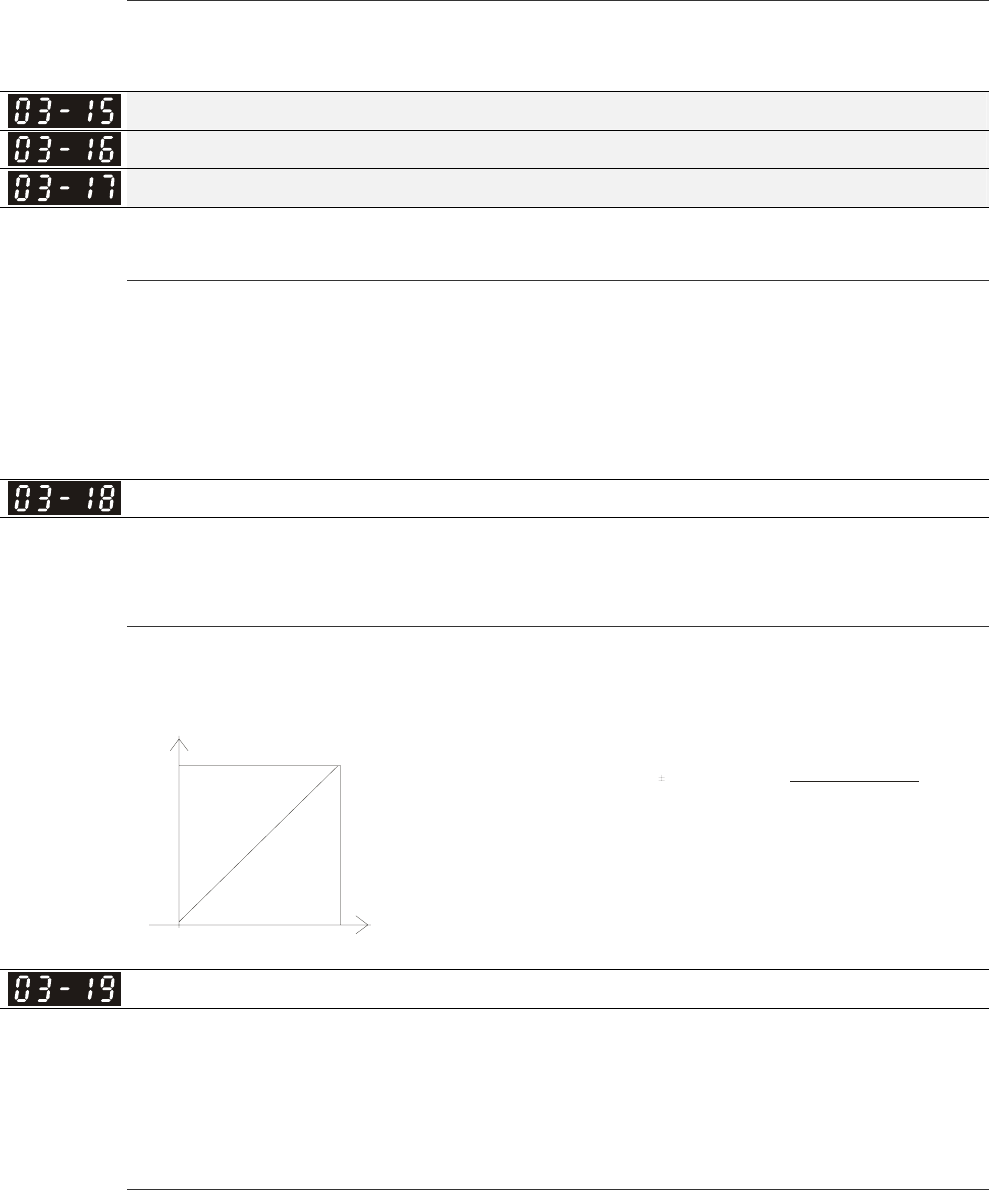
Chapter 12 Description of Parameter Settings|C2000 Series
12-73
Factory Setting: 100.0
Settings -500.0~500.0%
Parameters 03-03 to 03-14 are used when the source of frequency command is the analog
voltage/current signal.
Analog Input Filter Time (AVI)
Analog Input Filter Time (ACI)
Analog Input Filter Time (AUI)
Factory Setting: 0.01
Settings 0.00~20.00 sec
These input delays can be used to filter noisy analog signal.
When the setting of the time constant is too large, the control will be stable but the control response
will be slow. When the setting of time constant is too small, the control response will be faster but
the control may be unstable. To find the optimal setting, please adjust the setting according to the
control stable or response status.
Addition Function of the Analog Input
Factory Setting: 0
Settings 0: Disable (AVI, ACI, AUI)
1: Enable
When Pr.03-18 is set to 0 and the analog input setting is the same, the priority for AVI, ACI and AUI
are AVI>ACI>AUI.
Fco mmand= [(ay bias)*gain]* Fmax(01-00)
10V or 16mA
ay : 10 or 16mA
bias : Pr.03-03,Pr. 03-04, Pr.0 3-05
gain : Pr.03 -11 , Pr.03-12, Pr. 03-13, Pr.0 3-14
Frequ enc
y
Voltage
Fcomma nd: the co rresponding
frequen cy for 10V or 20mA
Treatment to 4-20mA Analog Input Signal Loss
Factory Setting: 0
Settings 0: Disable
1: Continue operation at the last frequency
2: Decelerate to stop
3: Stop immediately and display ACE
This parameter determines the behavior when 4~20mA signal is loss, when AVIc(Pr.03-28=2) or
ACIc (03-29=0).
When Pr.03-28 is not set to 2, it means the voltage input to AVI terminal is 0-10V or 0-20mA. At this
moment, Pr.03-19 will be invalid.
When Pr.03-29 is set to 1, it means the voltage input to ACI terminal is for 0-10V. At this moment,
Pr.03-19 will be invalid.
When setting is 1 or 2, it will display warning code “AnL” on the keypad. It will be blinking until the
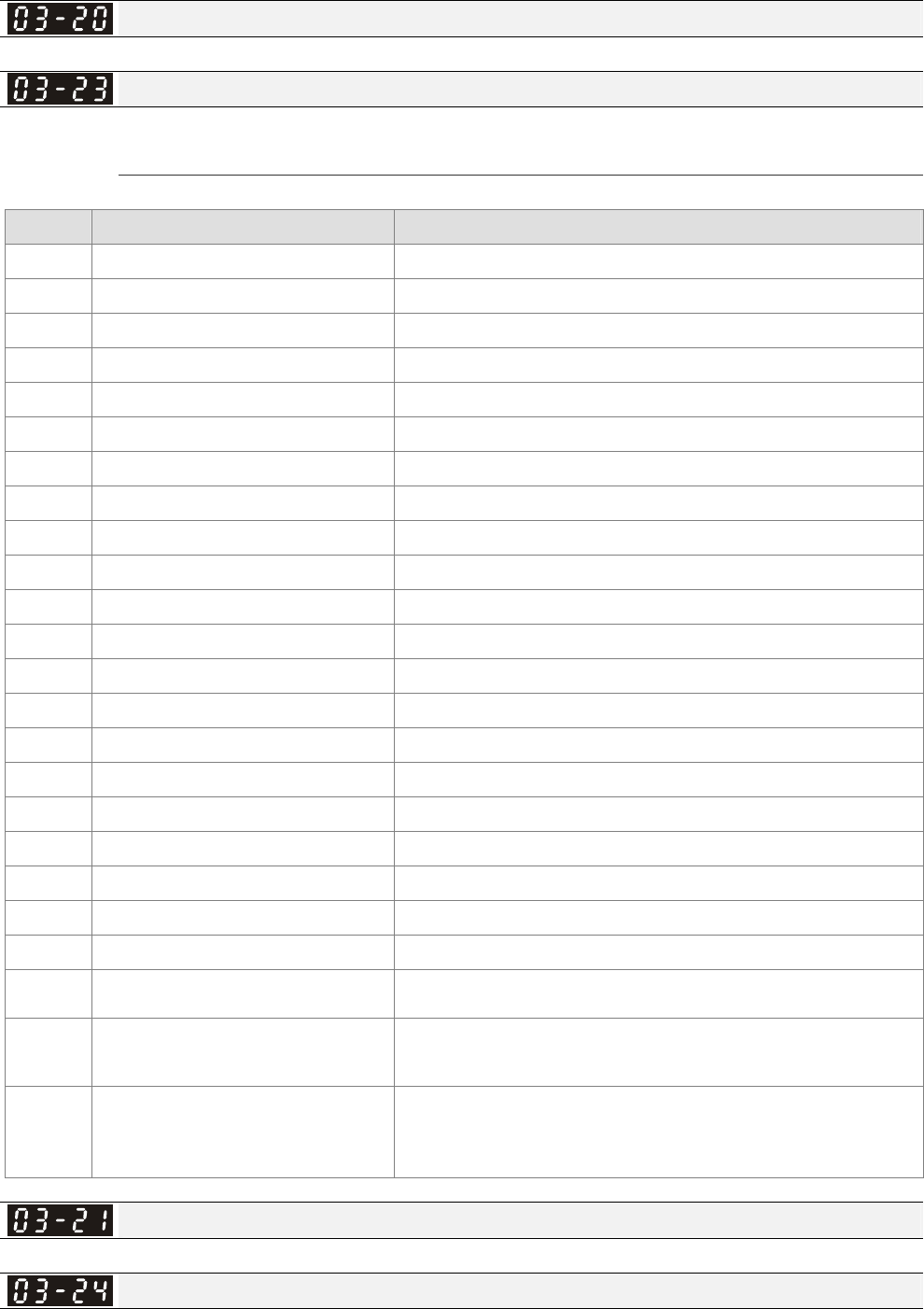
Chapter 12 Description of Parameter Settings|C2000 Series
12-74
loss of the ACI signal is recovered or drive is stop.
Multi-function Output 1 (AFM1)
Factory Setting: 0
Multi-function Output 2 (AFM2)
Factory Setting: 0
Settings 0~23
Function Chart
Settings Functions Descriptions
0 Output frequency (Hz) Max. frequency Pr.01-00 is regarded as 100%.
1 Frequency command (Hz) Max. frequency Pr.01-00 is regarded as 100%.
2 Motor speed (Hz) 600Hz is regarded as 100%
3 Output current (rms) (2.5 X rated current) is regarded as 100%
4 Output voltage (2 X rated voltage) is regarded as 100%
5 DC Bus Voltage 450V (900V)=100%
6 Power factor -1.000~1.000=100%
7 Power Rated power is regarded as 100%
8 Output torque Full-load torque is regarded as 100%
9 AVI 0~10V=0~100%
10 ACI 0~20mA=0~100%
11 AUI -10~10V=0~100%
12 q-axis current (Iq) (2.5 X rated current) is regarded as 100%
13 q-axis feedback value (Iq) (2.5 X rated current) is regarded as 100%
14 d-axis current (Id) (2.5 X rated current) is regarded as 100%
15 d-axis feedback value (Id) (2.5 X rated current) is regarded as 100%
16 q-axis voltage (Vq) 250V (500V) =100%
17 d-axis voltage(Vd) 250V (500V) =100%
18 Torque command Rated torque is regarded as 100%
19 PG2 frequency command Max. frequency Pr.01-00 is regarded as 100%.
20 Output for CANopen control For CANopen analog output
21 RS485 analog output For communication output (CMC-MOD01, CMC-EIP01,
CMC-PN01, CMC-DN01)
22 Analog output for
communication card
For communication output (CMC-MOD01, CMC-EIP01,
CMC-PN01, CMC-DN01)
23 Constant voltage/current output
Pr.03-32 and Pr.03-33 controls voltage/current output
level
0~100% of Pr.03-32 corresponds to 0~10V of AFM1.
Gain of Analog Output 1 (AFM1)
Factory Setting: 100.0
Gain of Analog Output 2 (AFM2)
Factory Setting: 100.0
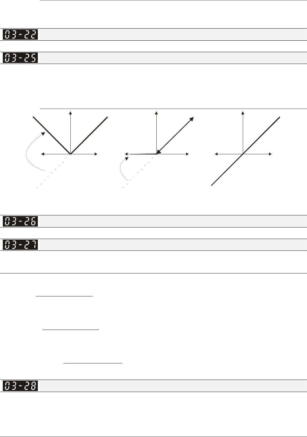
Chapter 12 Description of Parameter Settings|C2000 Series
12-75
Settings 0~500.0%
It is used to adjust the analog voltage level (Pr.03-20) that terminal AFM outputs.
This parameter is set the corresponding voltage of the analog output 0.
Analog Output 1 when in REV Direction (AFM1)
Factory Setting: 0
Analog Output 2 when in REV Direction (AFM2)
Factory Setting: 0
Settings 0: Absolute value in REV direction
1: Output 0V in REV direction; output 0-10V in FWD direction
2: Output 5-0V in REV direction; output 5-10V in FWD direction
03-18
03-21
03-24
03-22=0
03-25=0
03-22=1
03-25=1
10V(20mA)
03-22=2
03-25=2
5V
(12mA)
10V(20mA)
0V
(0mA)
10V(20mA)
0V
(0mA)
Frequency Frequency
Selections for the analog output direction
Reserved
AFM2 Output Bias
Factory Setting: 0.00
Settings -100.00~100.00%
Example 1, AFM2 0-10V is set output frequency, the output equation is
27-03 10V 24-03 )
00-01
FrequencyOutput
(10V ×+××
Example 2, AFM2 0-20mA is set output frequency, the output equation is
27-0320mA 24-03 )
00-01
FrequencyOutput
(20mA ×+××
Example 3, AFM2 4-20mA is set output frequency, the output equation is
27-0316mA 24-03 )
00-01
FrequencyOutput
(16mA4mA ×+××+
AVI Selection
Factory Setting: 0
Settings 0: 0-10V
1: 0-20mA
2: 4-20mA
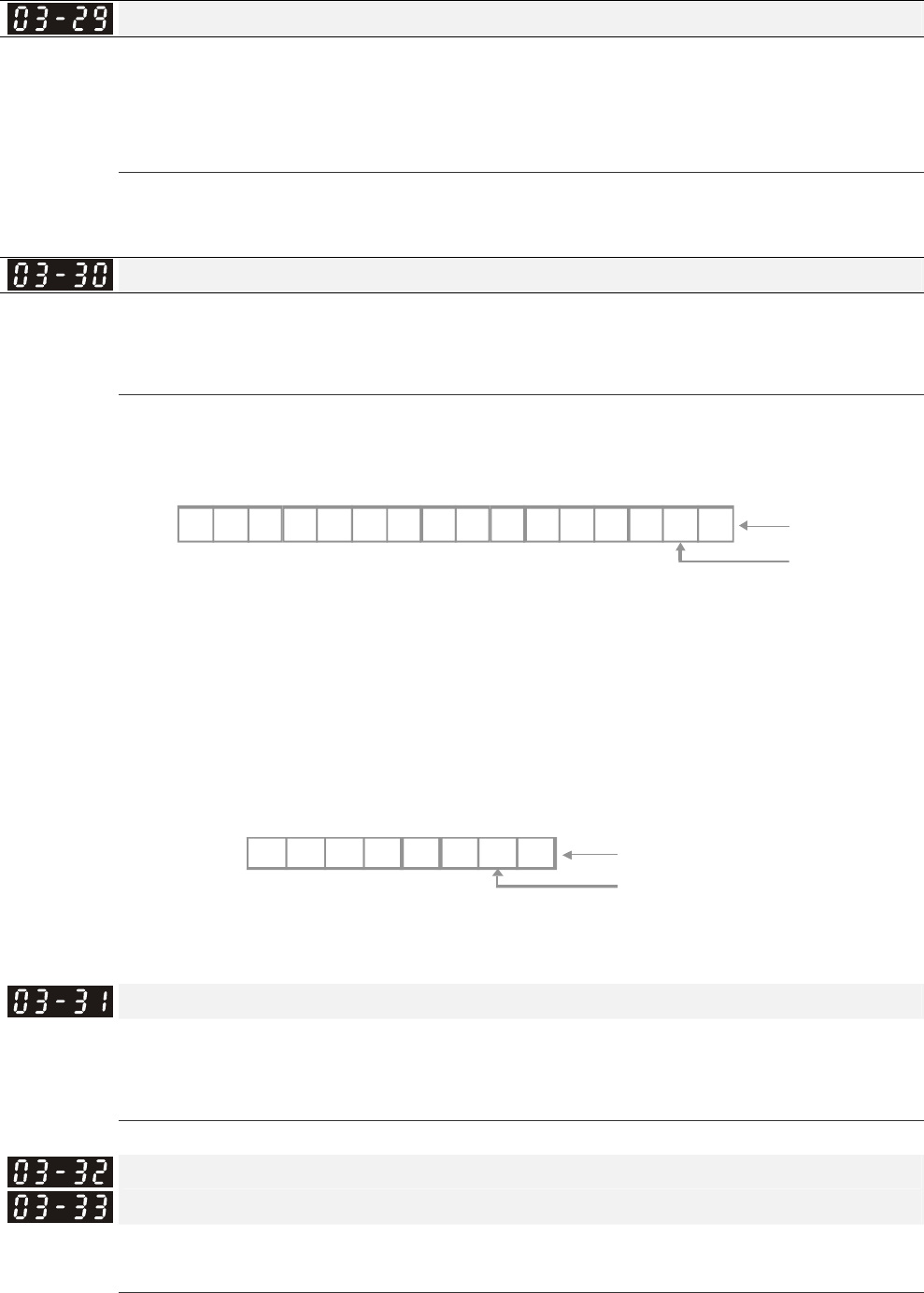
Chapter 12 Description of Parameter Settings|C2000 Series
12-76
ACI Selection
Factory Setting: 0
Settings 0: 4-20mA
1: 0-10V
2: 0-20mA
When changing the input mode, please check if the switch of external terminal (SW3, SW4)
corresponds to the setting of Pr.03-28~03-29.
Status of PLC Output Terminal
Factory Setting: ##
Settings 0~65535
Monitor the status of PLC analog output terminals
P.03-30 shows the external multi-function output terminal that used by PLC.
AFM 1
10325476
NOTE
2 = 1 28 2 =6 4
2 = 3 2 2
4
= 1 6 2 = 8
2 = 4 2 = 2 2 =
1
76
53
210
AFM 2
9811 1013 1215 14
2 2 2 2 2 2 2 2 2 2 2 2 2 2 2 2
15 14 13 1 2 11 10 9 8 7 6 5 4 3 2 1 0
Weights
Bit
0=O
N
1=OFF
For Example:
If the value of Pr.02-30 displays 0002h(Hex), it means AFM1and AFM2 are used by PLC.
Bit AFM 1
10000000
22222222
7 6 5 4 3 2 1 0
Display value
2=1x2 +0x2
=bi t 1x2 +bi t 0 x2
10
10
AFM 2
Weights
0=Not used by PLC
1=Used by PLC
AFM2 0-20mA Output Selection
Factory Setting: 0
Settings 0: 0-20mA output
1: 4-20mA output
AFM1 DC output setting level
AFM2 DC Output Setting Level
Factory Setting: 0.00
Settings 0.00~100.00%

Chapter 12 Description of Parameter Settings|C2000 Series
12-77
~
Reserve
Analog Input Curve Selection
Factory Setting: 0
Settings 0: Regular Curve
1: 3 point curve of AVI
2: 3 point curve of ACI
3: 3 point curve of AVI & ACI
4: 3 point curve of AUI
5: 3 point curve of AVI & AUI
6: 3 point curve of ACI & AUI
7: 3 point curve of AVI & ACI & AUI
AVI Low Point
Factory Setting: 0.00
Settings 03-28=0, 0.00~10.00V
03-28≠0, 0.00~20.00mA
AVI Proportional Low Point
Factory Setting: 0.00
Settings 0.00~100.00%
AVI Mid Point
Factory Setting: 5.00
Settings 03-28=0, 0.00~10.00V
03-28≠0, 0.00~20.00mA
AVI Proportional Mid Point
Factory Setting: 50.00
Settings 0.00~100.00%
AVI High Point
Factory Setting: 10.00
Settings 03-28=0, 0.00~10.00V
03-28≠0, 0.00~20.00mA
AVI Proportional High Point
Factory Setting: 100.00
Settings 0.00~100.00%
When Pr.03-28 = 0, AVI setting is 0-10V and the unit is in voltage (V).
When Pr.03-28 ≠ 0, AVI setting is 0-20mA or 4-20mA and the unit is in current (mA).
When setting anaolog input AVI to frequency command, it 100% corresponds to Fmax (Pr.01-00
Max. operation frequency).
Three of the AVI points can be set according to user’s demand on voltage(current) and proportion,

Chapter 12 Description of Parameter Settings|C2000 Series
12-78
there is no setting limit for ACI points.
ACI Low Point
Factory Setting: 4.00
Settings Pr.03-29=1, 0.00~10.00V
Pr.03-29≠1, 0.00~20.00mA
ACI Proportional Low Point
Factory Setting: 0.00
Settings 0.00~100.00%
ACI Mid Point
Factory Setting: 12.00
Settings 03-29=1, 0.00~10.00V
03-29≠1, 0.00~20.00mA
ACI Proportional Mid Point
Factory Setting: 50.00
Settings 0.00~100.00%
ACI High Point
Factory Setting: 20.00
Settings 03-29=1, 0.00~10.00V
03-29≠1, 0.00~20.00mA
ACI Proportional High Point
Factory Setting: 100.00
Settings 0.00~100.00%
When Pr.03-29=1, ACI setting is 0-10V and the unit is in voltage (V).
When Pr.03-29≠1, ACI setting is 0-20mA or 4-20mA and the unit is in current (mA).
When setting anaolog input ACI to frequency command, it 100% corresponds to Fmax (Pr.01-00
Max. operation frequency).
Three of the ACI points can be set according to user’s demand on voltage(current) and proportion,
there is no setting limit for ACI points.
Positive AUI Voltage Low Point
Factory Setting: 0.00
Settings 0.00~10.00V
Positive AUI Voltage Proportional Low Point
Factory Setting: 0.00
Settings 0.00~100.00%
Positive AUI Voltage Mid Point
Factory Setting: 5.00
Settings 0.00~10.00V
Positive AUI Voltage Proportional Mid Point
Factory Setting: 50.00
Settings 0.00~100.00%

Chapter 12 Description of Parameter Settings|C2000 Series
12-79
Positive AUI Voltage High Point
Factory Setting: 10.00
Settings 0.00~10.00V
Positive AUI Voltage Proportional High Point
Factory Setting: 100.00
Settings 0.00~100.00%
When setting positive voltage AUI to frequency command, it 100% corresponds to Fmax (Pr.01-00
Max. operation frequency) and the motor runs in forward direction.
Three of the positive voltage AUI points can be set according to user’s demand on voltage and
proportion, there is no setting limit for AUI points.
Negative AUI Voltage Low Point
Factory Setting: 0.00
Settings 0.00~-10.00V
Negative AUI Voltage Proportional Low Point
Factory Setting: 0.00
Settings 0.00~-100.00%
Negative AUI Voltage Mid Point
Factory Setting: -5.00
Settings 0.00~-10.00V
Negative AUI Voltage Proportional Mid Point
Factory Setting: -50.00
Settings 0.00~-100.00%
Negative AUI Voltage High Point
Factory Setting: -10.00
Settings 0.00~-10.00V
Negative AUI Voltage Proportional High Point
Factory Setting: -100.00
Settings 0.00~-100.00%
When setting negative voltage AUI to frequency command, it 100% corresponds to Fmax (Pr.01-00
Max. operation frequency) and the motor runs in reverse direction.
Three of the negative voltage AUI points can be set according to user’s demand on voltage and
proportion, there is no setting limit for AUI points.

Chapter 12 Description of Parameter Settings|C2000 Series
12-80
04 Multi-Step Speed Parameters This parameter can be set during operation.
1st Step Speed Frequency
2nd Step Speed Frequency
3rd Step Speed Frequency
4th Step Speed Frequency
5th Step Speed Frequency
6th Step Speed Frequency
7th Step Speed Frequency
8th Step Speed Frequency
9th Step Speed Frequency
10th Step Speed Frequency
11th Step Speed Frequency
12th Step Speed Frequency
13th Step Speed Frequency
14th Step Speed Frequency
15th Step Speed Frequency
Factory Setting: 0.00
Settings 0.00~600.00Hz
The Multi-function Input Terminals (refer to setting 1~4 of Pr.02-01~02-08 and 02-26~02-31) are
used to select one of the AC motor drive Multi-step speeds(max. 15 speeds). The speeds
(frequencies) are determined by Pr.04-00 to 04-14 as shown in the following.
The run/stop command can be controlled by the external terminal/digital keypad/communication via
Pr.00-21.
Each one of multi-step speeds can be set within 0.0~600.0Hz during operation.
Explanation for the timing diagram for multi-step speeds and external terminals
The Related parameter settings are:
1. Pr.04-00~04-14: setting multi-step speeds (to set the frequency of each step speed)
2. Pr.02-01~02-08, 02-26~02-31: setting multi-function input terminals (multi-step speed 1~4)
Related parameters: 01-22 JOG Frequency, 02-01 Multi-function Input Command 1 (MI1),
02-02 Multi-function Input Command 2 (MI2), 02-03 Multi-function Input Command 3 (MI3),
02-04 Multi-function Input Command 4 (MI4)
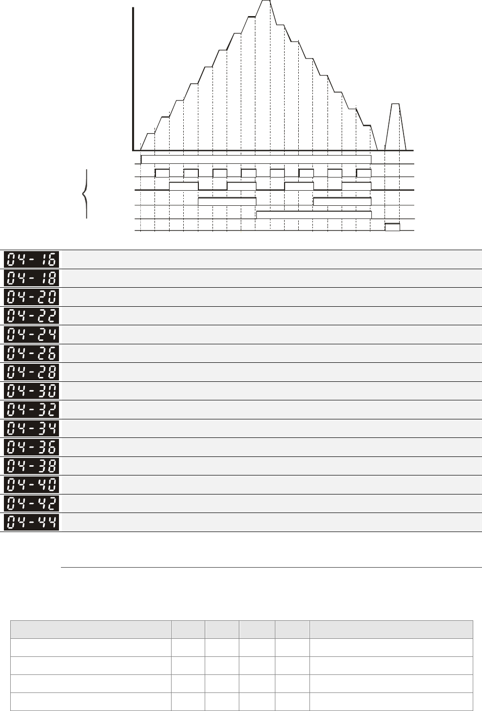
Chapter 12 Description of Parameter Settings|C2000 Series
12-81
ON ON ON ON ON ON ON ON
ONONONON
ON
ON
ON
ON
ON
04-00
04-01
04-02
04-03
04-04
04-05
04-06
04-07
04-08
04-09
04-10
04-11
04-12
04-13
04-14
01-22
OFF
OFF
OFF
OFF
OFF
123456 7 8 9 10 11 12 13 14 15
Multi-function
terminals
MI1~MI4
02-01~02-08
Frequency
Master Speed
JOG Freq.
2nd speed
1st speed
Jog Freq.
Multi-speed via External Terminals
Run/Sto p
PU/external terminals
/communication
3rd speed
4th speed
Position command 1 (pulse)
Position command 2 (pulse)
Position command 3 (pulse)
Position command 4 (pulse)
Position command 5 (pulse)
Position command 6 (pulse)
Position command 7 (pulse)
Position command 8 (pulse)
Position command 9 (pulse)
Position command 10 (pulse)
Position command 11 (pulse)
Position command 12 (pulse)
Position command 13 (pulse)
Position command 14 (pulse)
Position command 15 (pulse)
Factory Setting: 0
Settings -32767~32767
Please refer to Pr.02-01~02-08 (Multi-function Input Command) for description on setting 34
(Switch between multi-step position and multi-speed control) and setting 36 (Enable multi-step
position learning function).
Multi-step position corresponding MI4 MI3 MI2 MI1 Multi-step speed corresponding
10-19 0 0 0 0 Positioning for Encoder Position
04-16 Position command 1 (pulse) 0 0 0 1 04-00 1st step speed frequency
04-18 Position command 1 (pulse) 0 0 1 0 04-01 2nd step speed frequency
04-20 Position command 1 (pulse) 0 0 1 1 04-02 3rd step speed frequency
Chapter 12 Description of Parameter Settings|C2000 Series
12-82
04-22 Position command 1 (pulse) 0 1 0 0 04-03 4th step speed frequency
04-24 Position command 1 (pulse) 0 1 0 1 04-04 5th step speed frequency
04-26 Position command 1 (pulse) 0 1 1 0 04-05 6th step speed frequency
04-28 Position command 1 (pulse) 0 1 1 1 04-06 7th step speed frequency
04-30 Position command 1 (pulse) 1 0 0 0 04-07 8th step speed frequency
04-32 Position command 1 (pulse) 1 0 0 1 04-08 9th step speed frequency
04-34 Position command 1 (pulse) 1 0 1 0 04-09 10th step speed frequency
04-36 Position command 1 (pulse) 1 0 1 1 04-10 11th step speed frequency
04-38 Position command 1 (pulse) 1 1 0 0 04-11 12th step speed frequency
04-40 Position command 1 (pulse) 1 1 0 1 04-12 13th step speed frequency
04-42 Position command 1 (pulse) 1 1 1 0 04-13 14th step speed frequency
04-44 Position command 1 (pulse) 1 1 1 1 04-14 15th step speed frequency
Position command 1 (revolution)
Position command 2 (revolution)
Position command 3 (revolution)
Position command 4 (revolution)
Position command 5 (revolution)
Position command 6 (revolution)
Position command 7 (revolution)
Position command 8 (revolution)
Position command 9 (revolution)
Position command 10 (revolution)
Position command 11 (revolution)
Position command 12 (revolution)
Position command 13 (revolution)
Position command 14 (revolution)
Position command 15 (revolution)
To switch the target position of the external terminal, set external terminal parameters to
Pr.02-01=1, Pr.02-02=2, Pr.02-03=3, Pr.02-04= 4 by selecting the P2P target position via multi-step
speed.
Setting: Target Position = 04-15 × (10-01*4) + 04-16
Multi-step
Speed Status Target Position of P2P Maximum Speed of P2P
0000 0 11-00 bit8=0 11-00 bit8=1
0001 Position 1 04-15 04-16 11-43 04-00
0010 Position 2 04-17 04-18 04-01
0011 Position 3 04-19 04-20 04-02
0100 Position 4 04-21 04-22 04-03
0101 Position 5 04-23 04-24 04-04
0110 Position 6 04-25 04-26 04-05
0111 Position 7 04-27 04-28 04-06
1000 Position 8 04-29 04-30 11-43 04-07

Chapter 12 Description of Parameter Settings|C2000 Series
12-83
Multi-step
Speed Status Target Position of P2P Maximum Speed of P2P
1001 Position 9 04-31 04-32 04-08
1010 Position 10 04-33 04-34 04-09
1011 Position 11 04-35 04-36 04-10
1100 Position 12 04-37 04-38 04-11
1101 Position 13 04-39 04-40 04-12
1110 Position 14 04-41 04-42 04-13
1111 Position 15 04-43 04-44 04-14
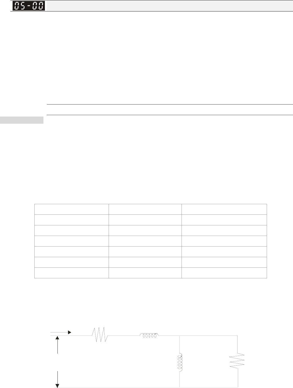
Chapter 12 Description of Parameter Settings|C2000 Series
12-84
05 Motor Parameters This parameter can be set during operation.
Motor Auto Tuning
Factory Setting: 0
Settings 0: No function
1: Rolling test for induction motor (Rs, Rr, Lm, Lx, no-load current)
2: Rolling test for induction motor
3: No function
4: Rolling test for PM motor magnetic pole
5: Rolling test for PM motor
6: Rolling test for IM motor flux curve
12: FOC Sensorless inertia estimation
13: High frequency and blocked rotor test for PM motor parameter
Induction Motor
Press 【Run】to beging auto tuning. The measured value will be written into motor 1 (Pr.05-05
~05-09, Rs, Rr, Lm, Lx, no-load current) and motor 2 (Pr.05-17 to Pr.05-21) automatically.
To begin AUTO-Tuning in rolling test:
1. Make sure that all the parameters are set to factory settings and the motor wiring is correct.
2. Make sure the motor has no-load before executing auto-tuning and the shaft is not connected
to any belt or gear motor. It is recommended to set to 2 if the motor can’t separate from the
load.
3.
Motor 1 Parameter Motor 2 Parameter
Motor Rated Frequency 01-01 01-35
Motor Rated Voltage 01-02 01-36
Motor Full-load Current 05-01 05-13
Motor Rated Power 05-02 05-14
Motor Rated Speed 05-03 05-15
Motor Pole Numbers 05-04 05-16
4. Set Pr.05-00=1 and press【Run】, the drive will begin auto-tuning. Please be aware of the
motor that it starts spinning as【Run】 is pressed.
5. When auto-tuning is completed, please check if the measured values are written into motor 1
(Pr.05-05 ~05-09) and motor 2 (Pr.05-17 ~05-21) automatically.
6. Mechanical equivalent circuit
V
S
IRs
Rr
Lx
Lm
Pr.0 5- 06
Pr.0 5- 18
Pr.05-09
Pr.05-21
Pr.0 5- 08
Pr.0 5- 20
Pr.05-07
Pr.05-19
※ If Pr.05-00 is set to 2 (static test), user needs to input the no-load current value of motor
into Pr.05-05 for motor 1/Pr.05-17 for motor 2.

Chapter 12 Description of Parameter Settings|C2000 Series
12-85
Set Pr.05-00=6 to begin rolling test for IM motor flux curve. This function is available
when the drive is in FOC/TQC Sensorless control. User may begin auto-tuning after
setting up the motor information.
; Set up Pr.01-01, 01-02, 05-01~05-04 according to the motor nameplate information。
; Set Pr.05-00=6 and press【Run】, make sure no loading is applied to the motor
before setting Pr.05-00 to 6 and before performing auto-tuning.
When Pr.05-00=12, the drive begins FOC Sensorless inertia estimation for IM motor. This
function is available when the drive is in FOC/TQC Sensorless control. User may begin
auto-tuning after setting up the motor information.
; Note: Make sure the motor parameters (no-load current, Rs, Rr, Lm and Lx) of the
drive are set before performing Pr.05-00=12 (auto-tuningfor FOC Sensorless interia
estimation for IM motor).
1. Set Pr.00-10=2 (torque mode)
2. Set Pr. 00-13=2 (TQCPG, Open-loop torque mode)
3. Set Pr. 05-00=12 and press【Run】to begin FOC Sensorless inertia measure
4. When the process of inertia estimation is completed, check Pr.11-01 (unit: PU Q8) and
see if the measured value is acceptable.
Set up Sensorless FOC Mode
1. Set Pr.00-10 = 0 (speed mode)
2. Set Pr.00-11 = 5 (FOC sensorless mode)
3. Set bit0 of Pr.11-00 to 1 (use ASR gain function to automatically adjust the ASR
bandwidth in Pr.11-03,11-04,11-05)
NOTE
; In torque/vector control mode, it is not recommended to have motors run in parallel.
; It is not recommended to use torque/vector control mode if motor rated power exceeds
the rated power of the AC motor drive.
; When auto-tuning 2 motors, it needs to set multi-function input terminals (setting 14) or
change Pr.05-22 for motor 1/motor 2 selection.
; The no-load current is usually 20~50% X rated current.
; The rated speed can not be greater than or equal to 120f/p (f = rated frequency
Pr.01-01/01-35; P: number of motor poles Pr.05-04/05-16).
Permanent Magnet Motor (PM)
Set Pr.05-00= 5 or 13 and press 【Run】 to begin auto tuning for PM motor. The
measured values will be written into Pr.05-39(Rs), Pr.05-40 & 41(Ld & Lq) and
Pr.05-43(PM motor's Ke parameter).
To begin AUTO-Tuning for PM motor in rolling test:
1. Make sure all the parameters are reset to factory setting and the motor wiring installtion is

Chapter 12 Description of Parameter Settings|C2000 Series
12-86
correct.
2. For PM motor, set Pr.05-33=1 and complete the following settings according to your motor
specifications, Pr.05-34 rated current, Pr.05-35 rated power, Pr.05-36 rated speed and Pr.
05-37 pole number. The acceleration time and deceleration time should be set according to
your motor capacity.
3. Set Pr.05-00 to 5 and press 【Run】 to begin auto tuning for PM motor. Please be aware of
the motor that it starts spinning as【Run】 is pressed.
4. When auto-tuning is completed, please check if the measured values are written into
Pr.05-39~05-41 and Pr.05-43 automatically.
Set Pr.05-00=4 and press【Run】to begin auto-tuning for PM motor PG offset angle. The
measured value will be written into Pr.05-42 automatically.
; Note 1: When execute auto-tuning for PM motor PG origin, please make sure the
encoder setting are correct (Pr.10-00, 10-01, 10-02), otherwise the PG origin measure
error and motor stall may occur.
; Note 2: If PM motor runs in an opposite direction of the drive’s command, switch any
two of the UVW cable and re-connect, then execute PG origin search again. It is crucial
to execute auto-tuning after the switch otherwise PG origin measure error and motor
stall may occur.
Auto-tuning process for measuring PG offset angle of PM motor:
1. Set Pr.05-00=5 and press RUN, or manually input the values into Pr. 01-01, 05-34~-541 and
Pr.05-43.
2. It is strongly suggested to remove the motor and unload before beings auto-tuning.
3. Set Pr.05-00=4 and press【Run】 to begin auto-tuning. Please be aware of the motor that it
starts spinning as 【Run】is pressed.
4. When auto-tuning is completed, please check if the PG offset angle is written into Pr.05-42
automatically.
NOTE
When auto-tuning for PM motor is completed and the control mode setting is done, it is
recommend to turn the drive’s power off and restart again to ensure the drive operates according
to the motor parameter settings.
Full-load Current of Induction Motor 1(A)
Unit: Amper
Factory Setting: #.##
Settings 10 to 120% of drive’s rated current
This value should be set according to the rated frequency of the motor as indicated on the motor
nameplate. The factory setting is 90% X rated current.
Example: The rated current for 7.5HP (5.5kW) is 25 and factory setting is 22.5A. The range for
setting will be 10~30A.(25*40%=10A and 25*120%=30A)
Chapter 12 Description of Parameter Settings|C2000 Series
12-87
Rated Power of Induction Motor 1(kW)
Factory Setting: #.##
Settings 0~655.35 kW
It is used to set rated power of the motor 1. The factory setting is the power of the drive.
Rated Speed of Induction Motor 1 (rpm)
Factory Setting:
1710(60Hz 4 poles)
1410(50Hz 4 poles)
Settings 0~65535
It is used to set the rated speed of the motor and need to set according to the value indicated on
the motor nameplate.
Pole Number of Induction Motor 1
Factory Setting: 4
Settings 2~20
It is used to set the number of motor poles (must be an even number).
No-load Current of Induction Motor 1 (A)
Unit: Amper
Factory Setting: #.##
Settings 0 to the factory setting in Pr.05-01
The factory setting is 40% X rated current.
Stator Resistance(Rs) of Induction Motor 1
Rotor Resistance(Rr) of Induction Motor 1
Factory Setting: #.###
Settings 0~65.535Ω
Magnetizing Inductance(Lm) of Induction Motor 1
Stator inductance(Lx) of Induction Motor 1
Factory Setting: #.#
Settings 0~6553.5mH
~
Reserved
Full-load Current of Induction Motor 2(A)
Unit: Amper
Factory Setting:#.##
Settings 10~120%
This value should be set according to the rated frequency of the motor as indicated on the motor
Chapter 12 Description of Parameter Settings|C2000 Series
12-88
nameplate. The factory setting is 90% X rated current.
Example: The rated current for 7.5HP (5.5kW) is 25A and factory setting is 22.5A. The range for
setting will be 10~30A.(25*40%=10A and 25*120%=30A)
Rated Power of Induction Motor 2 (kW)
Factory Setting: #.##
Settings 0~655.35 kW
It is used to set rated power of the motor 2. The factory setting is the power of the drive.
Rated Speed of Induction Motor 2 (rpm)
Factory Setting: 1710
Settings 0~65535
It is used to set the rated speed of the motor and need to set according to the value indicated on
the motor nameplate.
Pole Number of Induction Motor 2
Factory Setting: 4
Settings 2~20
It is used to set the number of motor poles (must be an even number).
No-load Current of Induction Motor 2 (A)
Unit: Amper
Factory Setting: #.##
Settings 0 to the factory setting in Pr.05-01
The factory setting is 40% X rated current.
Stator Resistance (Rs) of Induction Motor 2
Rotor Resistance (Rr) of Induction Motor 2
Factory Setting: #.###
Settings 0~65.535Ω
Magnetizing Inductance (Lm) of Induction Motor 2
Stator Inductance (Lx) of Induction Motor 2
Factory Setting: #.#
Settings 0~6553.5 mH
Induction Motor 1/ 2 Selection
Factory Setting: 1
Settings 1: Motor 1
2: Motor 2
It is used to set the motor that driven by the AC motor drive.
Frequency for Y-connection/△-connection Switch of Induction Motor
Factory Setting: 60.00
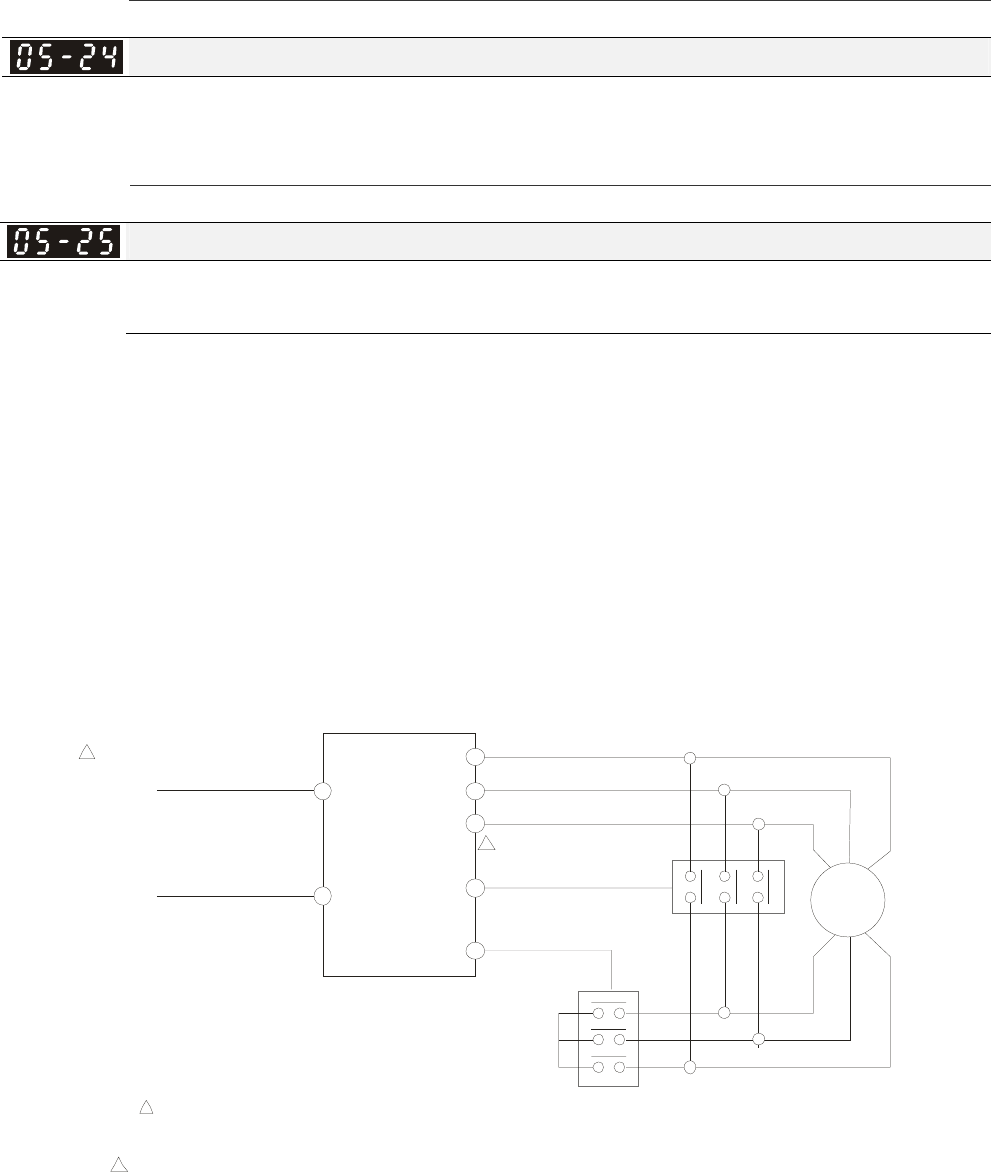
Chapter 12 Description of Parameter Settings|C2000 Series
12-89
Settings 0.00~600.00Hz
Y-connection/△-connection Switch of Induction Motor IM
Factory Setting: 0
Settings 0: Disable
1: Enable
Delay Time for Y-connection/△-connection Switch of Induction Motor
Factory Setting: 0.200
Settings 0.000~60.000 sec
P.05-23 and Pr.05-25 are applied in the wide range motors and the motor coil will execute the
switch of Y-connection/Δ-connection as required. (The wide range motors has relation with the
motor design. In general, it has higher torque at low speed and Y-connection and it has higher
speed at high speed and connection.
Pr.05-24 is used to enable/disable Y-connection/Δ-connection Switch.
When Pr.05-24 is set to 1, the drive will select by Pr.05-23 setting and current motor frequency to
switch motor to Y-connection or Δ-connection. At the same time, it will also affect motor
parameters.
Pr.05-25 is used to set the switch delay time of Y-connection/Δ-connection.
When output frequency reaches Y-connection/Δ-connection switch frequency, drive will delay by
Pr.05-25 before multi-function output terminals are active.
Pr.02-01~08=29
Pr.02-11~14=31
Y- connection switch: can be used for wide range motor
Y -connection for low speed: higher torque can be used for rigid tapping
-connection for high speed: higher torque can be used for high-speed drilling
Pr.02-01~08=30
-connection is finished
Y-connection is finished Pr.02-13~14=32
-connection control
Y-connection control
U
V
W
MI1
MI2 RA
MRA
IM
WV U
XY Z
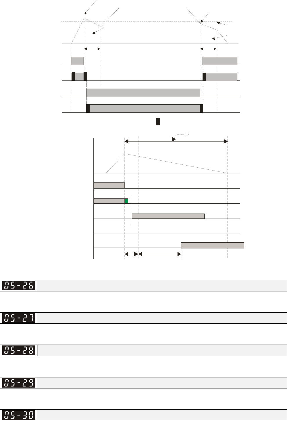
Chapter 12 Description of Parameter Settings|C2000 Series
12-90
Pr.05-23
Y- sw it ch
frequency
△
Y-connection output
Y-conenction
confirmation input
△-connection output
Pr.02-13~14=32
△-connection
confirmation input
Pr.02-13~14=30
ON ON
Pr.02-13~14=31
ON
Pr.02-13~14=29
ON
ON
ON
If switch point is 60Hz
,
the accel. switch point is 62Hz
Motor speed/
frequency
Bandwidth is 2Hz
:
mechanical bounce time
Decel. switch point is 58Hz
In this area, motor is in free
run status. AC motor drive
sto ps out put ti ng. Motor speed will
decrease
by load inertia.
Pr. 05-25 Delay Time for Y-c onnection
/D -connection(Min. is 0.2 seconds)
Y-connection output
Pr.02-13~14=31
Y-connection
confirmation input
Pr.02-01~08=29
△-connection output
Pr.02-13~14=32
△-connection
confirmation input
Pr.02-01~08=30
ON
ON
ON
ON
2 seconds
Y- switch error
frequency
△
free run statu
s
output
frequency
delay time
Pr.05-25
Accumulative Watt Per Second of Motor in Low Word (W-sec)
Factory Setting: 0.0
Settings Read only
Accumulative Watt Per Second of Motor in High Word (W-sec)
Factory Setting: 0.0
Settings Read only
Accumulative Watt-hour of Motor (W-Hour)
Factory Setting: 0.0
Settings Read only
Accumulative Watt-hour of Motor in Low Word (KW-Hour)
Factory Setting: 0.0
Settings Read only
Accumulative Watt-hour of Motor in High Word (KW-Hour)
Factory Setting: 0.0
Chapter 12 Description of Parameter Settings|C2000 Series
12-91
Settings Read only
Pr.05-26~05-29 records the amount of power consumed by motors. The accumulation begins
when the drive is activated and record is saved when the drive stops or turns OFF. The amount of
consumed watts will continue to accumulate when the drive activate again. To clear the
accumulation, set Pr.00-02 to 5 then the accumulation record will return to 0.
Accumulative Motor Operation Time (Min)
Factory Setting: 0
Settings 00~1439
Accumulative Motor Operation Time (day)
Factory Setting: 0
Settings 00~65535
Pr. 05-31 and Pr.05-32 are used to record the motor operation time. To clear the operation time, set
Pr.05-31 and Pr.05-32 to 00. Operation time shorter than 60 seconds will not be recorded.
Induction Motor (IM) and Permanent Magnet Motor Selection
Factory Setting: 0
Settings 0: Induction Motor
1: Permanent Magnet Motor
Full-load current of Permanent Magnet Motor
Factory Setting: 0.00
Settings 0.00~655.35 Amps
Rated Power of Permanent Magnet Motor
Factory Setting: 0.00
Settings 0.00~655.35 kW
Rated speed of Permanent Magnet Motor
Factory Setting: 2000
Settings 0~65535 rpm
Pole number of Permanent Magnet Motor
Factory Setting: 10
Settings 0~65535
Inertia of Permanent Magnet Motor
Factory Setting: 0.0
Settings 0.0~6553.5 kg.cm2 (0.0001kg.m2)
This parameter setting is defined in kg-cm2 . If this measure is not familiar to you, please refer to
the chart below. (Delta’s motor inertia chart is for reference purpose only.)
Chapter 12 Description of Parameter Settings|C2000 Series
12-92
Delta Motor (Low inertia model)
Rated Power(kW) 0.1 0.2 0.4 0.4 0.75 1 2
Rotor inertia (kg.m^2) 3.70E-06 1.77E-05 2.77E-05 6.80E-05 1.13E-04 2.65E-04 4.45E-04
Delta Motor (Mid to High Inertia model)
Rated Power(kW) 0.5 1 1.5 2 2 0.3 0.6 0.9
Rotor inertia (kg.m^2) 8.17E-04 8.41E-04 1.12E-03 1.46E-03 3.47E-03 8.17E-04 8.41E-04 1.12E-03
※ For more information on motor inertia value, please refer to Pr.11-01.
Stator Resistance of PM Motor
Factory Setting: 0.000
Settings 0.000~65.535Ω
Permanent Magnet Motor Ld
Factory Setting: 0.00
Settings 0.00~655.35 mH
Permanent Magnet Motor Lq
Factory Setting: 0.00
Settings 0.00~655.35 mH
PG Offset angle of PM Motor
Factory Setting: 0
Settings 0.0~360.0°
When Pr.05-00 is set to 4, the drive will detect offset angle and write into Pr.05-42.
Ke parameter of PM Motor
Unit: V/1000rpm
Factory Setting: 0
Settings 0~65535
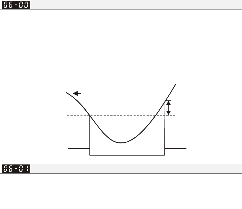
Chapter 12 Description of Parameter Settings|C2000 Series
12-93
06 Protection Parameters This parameter can be set during operation.
Low Voltage Level
Factory Setting:
Settings 230V Series:
Frame A to D: 150.o~ 220.0 Vdc
Frame E and frames above E: 190.0~220.0V
180.0
200.0
Frame A to D:
460V Series: 300.0~440.0V
Frame E and frames above E: 380.0~440.0V
360.0
400.0
It is used to set the Lv level. When the drive is in the low voltage, it will stop output and free to stop.
LV
Pr. 06-00
30V(60V)
input voltage
Over-voltage Stall Prevention
Factory Setting: 380.0/760.0
Settings 230V Series: 0.0~450.0V
460V Series:0.0~900.0V
0: Disabled
When Pr.06-01 is set to 0.0, the over-voltage stall prevention function is disabled.
During deceleration, the DC bus voltage may exceed its Maximum Allowable Value due to motor
regeneration. When this function is enabled, the AC motor drive will not decelerate further and
keep the output frequency constant until the voltage drops below the preset value again.
This function is used for the occasion that the load inertia is unsure. When it stops in the normal
load, the over-voltage won’t occur during deceleration and fulfill the setting of deceleration time.
Sometimes, it may not stop due to over-voltage during decelerating to stop when increasing the
load regenerative inertia. At this moment, the AC drive will auto add the deceleration time until drive
stop.
When the over-voltage stall prevention is enabled, drive deceleration time will be larger than the
setting.
When there is any problem as using deceleration time, refer to the following items to solve it.
1. Add the suitable deceleration time.
2. Add brake resistor (refer to appendix B-1 for details) to consume the electrical energy that
regenerated from the motor with heat type.
Related parameters: Pr.01-13, 01-15, 01-17, 01-19 (settings of decel. time 1~4), Pr.02-13~02-14
(Multi-function Output 1 RY1, RY2), Pr. 02-16~02-17 Multi-function Output (MO1, 2)
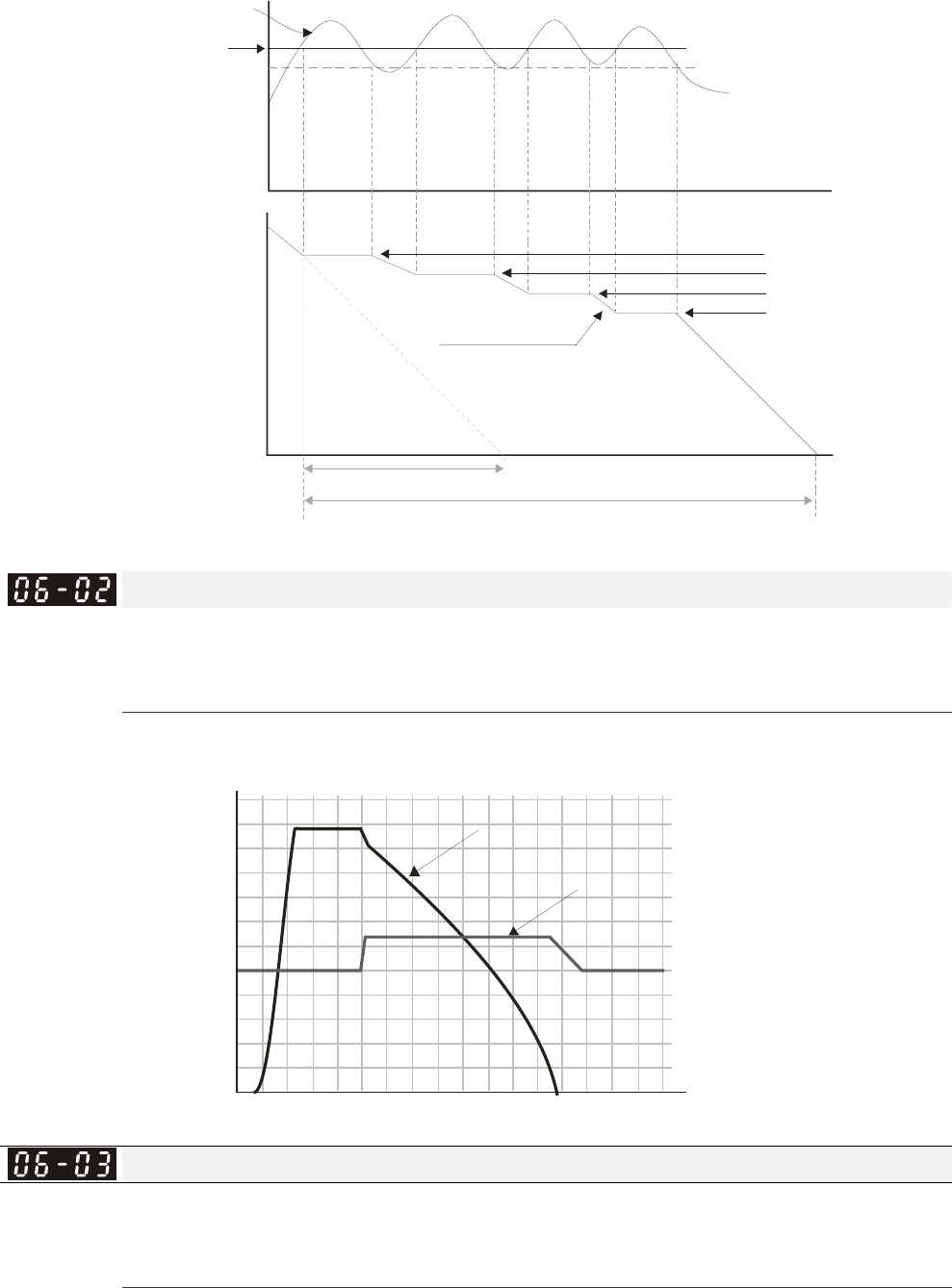
Chapter 12 Description of Parameter Settings|C2000 Series
12-94
Output
frequency
Deceleration characteristic
when Over-Voltage Stall
Prevention enabled
Frequency Held
previous deceleration time
Time
Time
High-voltage
at DC side
Over-voltage
detection
level
required time for decelerating to 0Hz when over-voltage
stall prevention is enabled.
Selectionfor Over-voltage Stall Prevention
Factory Setting: 0
Settings 0: Traditional over-voltage stall prevention
1: Smart over-voltage prevention
When Pr.06-02 is set to 1, the drive will maintain DCbus voltage when decelerating and prevent
OV.
Output Frequency
DCBUS Volta ge
310Vdc
370Vdc
Time
230V Serie
s
60Hz
0
Over-current Stall Prevention during Acceleration
Settings Normal duty: 0~160% (100%: drive’s rated current) Factory Setting: 120
Heavy duty: 0~180% (100%: drive’s rated current) Factory Setting: 150
If the motor load is too large or drive acceleration time is too short, the AC drive output current may
increase abruptly during acceleration and it may cause motor damage or trigger protection
functions (OL or OC). This parameter is used to prevent this situation.
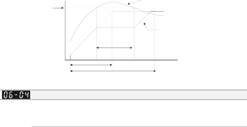
Chapter 12 Description of Parameter Settings|C2000 Series
12-95
During acceleration, the AC drive output current may increase abruptly and exceed the value
specified by Pr.06-03 due to rapid acceleration or excessive load on the motor. When this function
is enabled, the AC drive will stop accelerating and keep the output frequency constant until the
current drops below the maximum value.
When the over-current stall prevention is enabled, drive deceleration time will be larger than the
setting.
When the Over-Current Stall Prevention occurs due to too small motor capacity or in the factory
setting, please decrease Pr.06-03 setting.
When there is any problem by using acceleration time, refer to the following items to solve it.
Related parameters: Pr.01-12, 01-14, 01-16, 01-18 (settings of accel. time 1~4), Pr.01-44
1. dd the suitable acceleration time.
2. Setting Pr.01-44 Optimal Acceleration/Deceleration Setting to 1, 3 or 4 (auto accel.)
Optimal Acceleration/Deceleration Setting, Pr.02-13~02-14 (Multi-function Output 1 RY1, RY2), Pr.
02-16~02-17 Multi-function Output (MO1, 2)
06-03
Over-Current
Detection
Level
Over-Current Stall prevention during
Acceleration,frequency held
actual acceleration time when over-current stall
prevention is enabled
Output current
Setting frequency
Output frequency
Time
Original setting of acceleration time
Over-current Stall Prevention during Operation
Settings Normal duty: 0~160% (100%: drive’s rated current) Factory Setting: 120
Heavy duty: 0~180% (100%: drive’s rated current) Factory Setting: 150
It is a protection for drive to auto decrease output frequency when the motor is over-load abruptly
during motor constant operation.
If the output current exceeds the setting specified in Pr.06-04 when the drive is operating, the drive
will decrease its output frequency (according to Pr.06-05) to prevent the motor stall. If the output
current is lower than the setting specified in Pr.06-04, the drive will accelerate (according to
Pr.06-05) again to catch up with the set frequency command value.
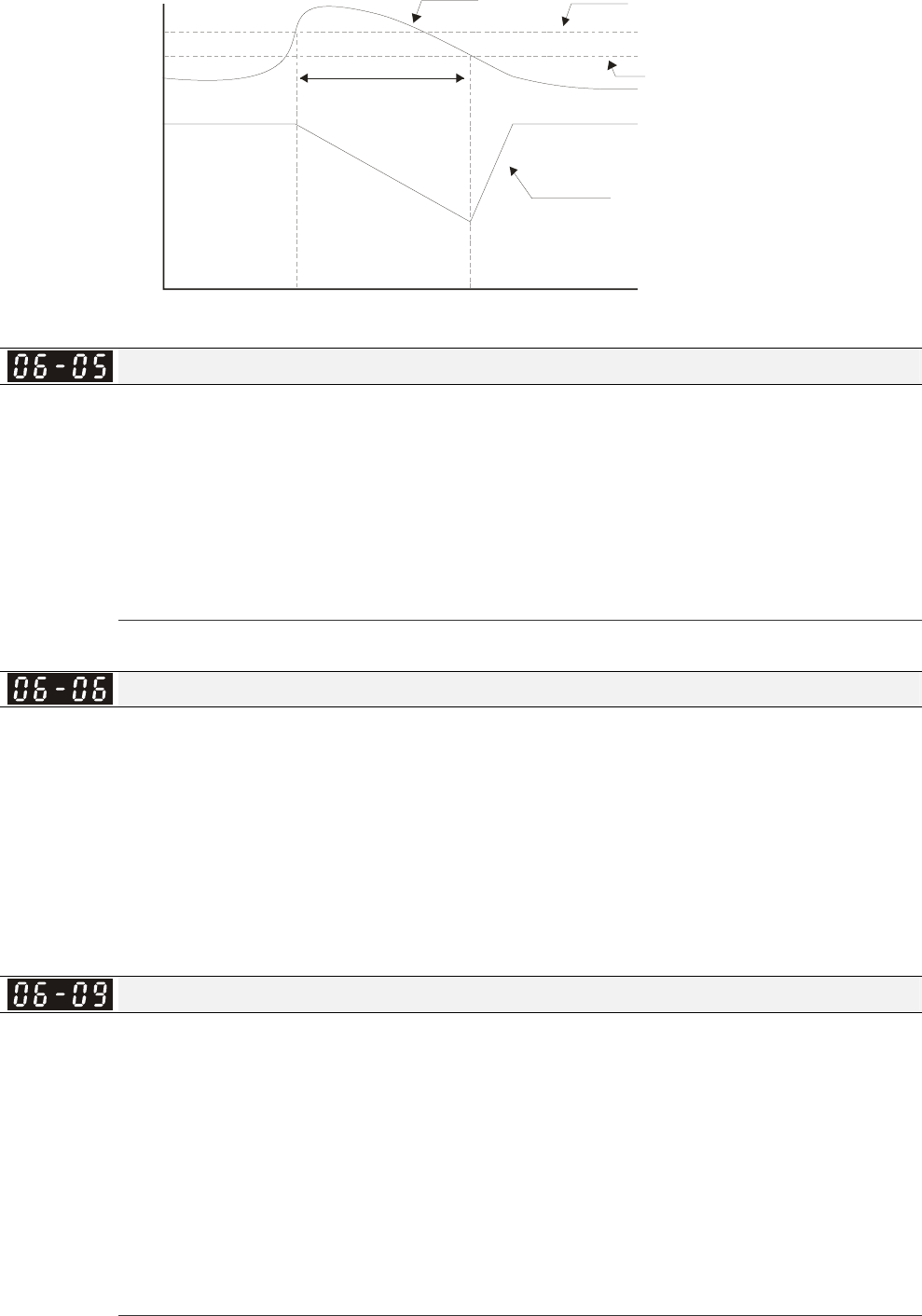
Chapter 12 Description of Parameter Settings|C2000 Series
12-96
Over-Current
Detection Level
06-04
Output
Frequency
Ov er-Curr ent Stall P revention
during Operation, output
frequency decreases
over-current stall prevention during operation
Time
Current Pr . 06-04 s etting
Pr . 06-04 s etting-
rated dr ive c urrent X 5%
Decreases by
deceleration time
Accel./Decel. Time Selection of Stall Prevention at Constant Speed
Factory Setting: 0
Settings 0: by current accel/decel time
1: by the 1st accel/decel time
2: by the 2nd accel/decel time
3: by the 3rd accel/decel time
4: by the 4th accel/decel time
5: by auto accel/decel
It is used to set the accel./decel. time selection when stall prevention occurs at constant speed.
Over-torque Detection Selection (OT1)
Factory Setting: 0
Settings 0: Disable
1: Over-torque detection during constant speed operation, continue to
operate after detection
2: Over-torque detection during constant speed operation, stop operation
after detection
3: Over-torque detection during operation, continue to operate after detection
4: Over-torque detection during operation, stop operation after detection
Over-torque Detection Selection (OT2)
Factory Setting: 0
Settings 0: Disable
1: Over-torque detection during constant speed operation, continue to
operate after detection
2: Over-torque detection during constant speed operation, stop operation
after detection
3: Over-torque detection during operation, continue to operation after
detection
4: Over-torque detection during operation, stop operation after detection
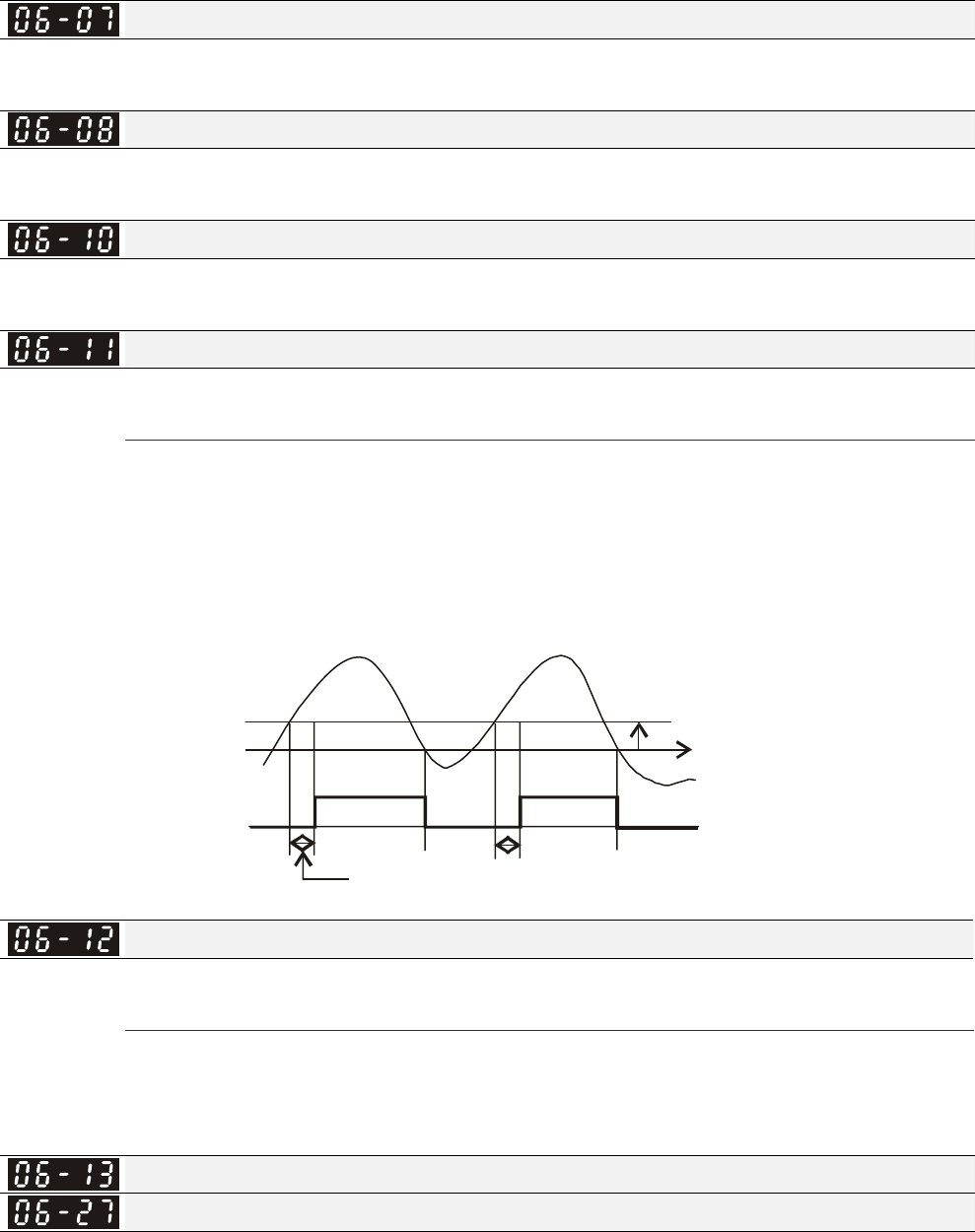
Chapter 12 Description of Parameter Settings|C2000 Series
12-97
When Pr.06-06 and Pr.06-09 are set to 1 or 3, it will display a warning message and won’t have an
abnormal record.
When Pr.06-06 and Pr.06-09 are set to 2 or 4, it will display a warning message and will have an
abnormal record.
Over-torque Detection Level (OT1)
Factory Setting: 120
Settings 10 to 250% (100%: drive’s rated current)
Over-torque Detection Level (OT1)
Factory Setting: 0.1
Settings 0.0~60.0 sec
Over-torque Detection Level (OT2)
Factory Setting: 120
Settings 10 to 250% (100%: drive’s rated current)
Over-torque Detection Time (OT2)
Factory Setting: 0.1
Settings 0.0~60.0 sec
Over torque detection is determine by the following method: if the output current exceeds the
over-torque detection level (Pr.06-07, factory setting: 150%) and also exceeds Pr.06-08
Over-Torque Detection Time, the fault code “ot1/ot2” will appear. If a Multi-Functional Output
Terminal is to over-torque detection (setting 7 or 8), the output is on. Please refer to
Pr.02-13~02-14 for details.
5%
Pr.06-07,
Pr.06-10
Pr.06-08, 06-11
current
Current Limit
Factory Setting: 170
Settings 0~250% (100%: drive’s rated current)
Pr.06-12 sets the maximum output current of the drive. Pr.06-12 and Pr.11-17 ~ Pr.11-20 are used
to set the drive’s output current limit. When the drive is in VF, SVC or VFPG control mode, output
frequency will decreases as the output current reaches current limit. It is a current stall prevention.
Electronic Thermal Relay Selection (Motor 1)
Electronic Thermal Relay Selection (Motor 2)
Factory Setting: 2
Settings 0: Inverter motor
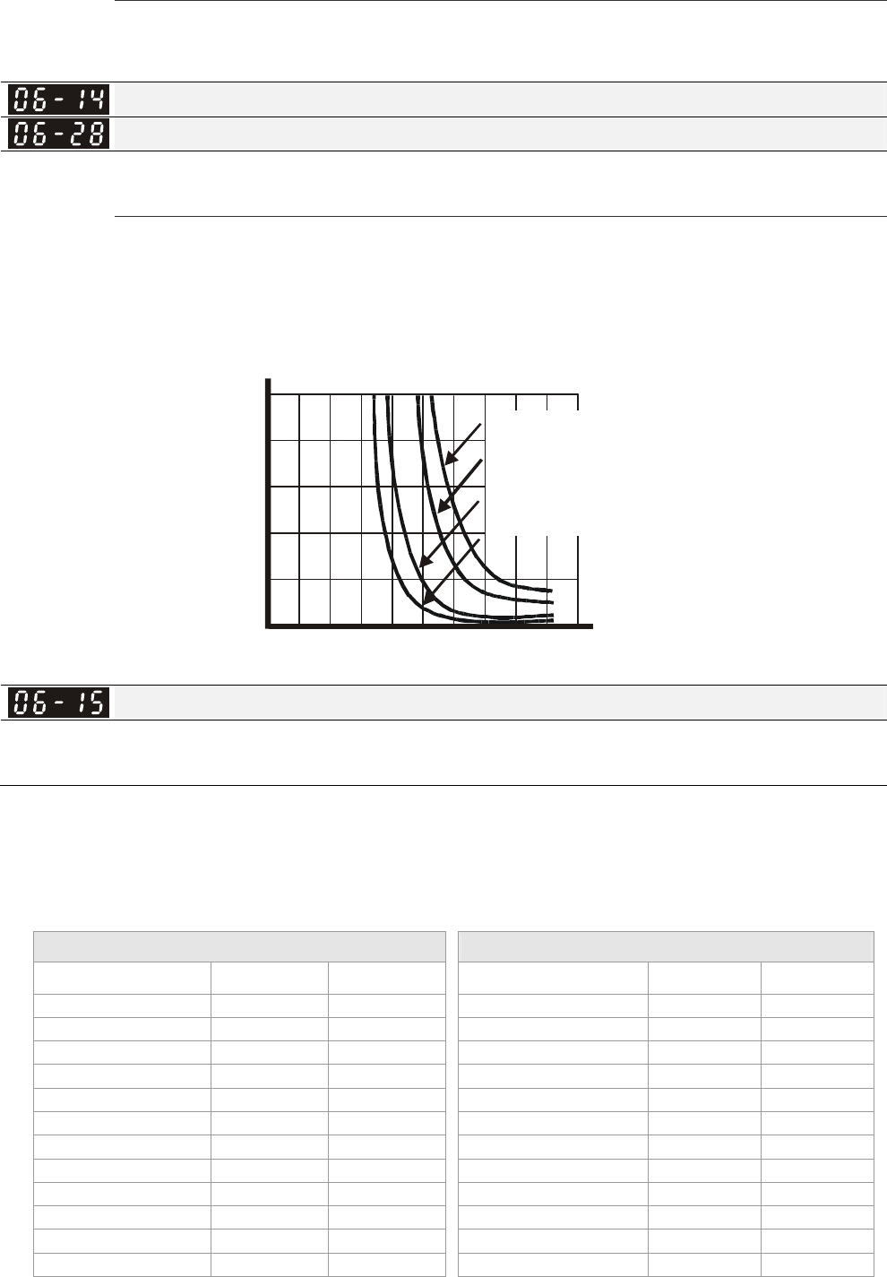
Chapter 12 Description of Parameter Settings|C2000 Series
12-98
1: Standard motor
2: Disable
It is used to prevent self-cooled motor overheats under low speed. User can use electronic thermal
relay to limit driver’s output power.
Electronic Thermal Characteristic for Motor 1
Electronic Thermal Characteristic for Motor 2
Factory Setting: 60.0
Settings 30.0~600.0 sec
The parameter is set by the 150% of motor rated current and the setting of Pr.06-14 and Pr.06-28 to
prevent the motor damaged from overheating. When it reaches the setting, it will display
“EoL1/EoL2” and the motor will be in free running.
1
2
3
4
5
0 20 40 60 80100120140160180200
Operation
time(min)
Load
factor (%)
60Hz or more
50Hz
10Hz
5Hz
Heat Sink Over-heat (OH) Warning
Factory Setting: 85.0
Settings 0.0~110.0℃
Pr.06-15 sets the heatsink temperature level of the drive. The drive will output an overheating
warning when the temperature exceeds the setting of Pr.06-15. If the setting of Pr.06-15 is higher
than the default setting of the drive, the drive will use the default setting level for warning output.
Capacitor (CAP) overheating level is set by the drive’s default setting, it can not be adjusted.
Over-heating Level (℃) Over-heating Level (℃)
Model IGBT OH1 CAP OH 2 Model IGBT OH1 CAP OH 2
VFD007C23A/E 100 90 VFD055C43A/E 100 95
VFD015C23A/E 100 90 VFD075C43A/E 95 75
VFD022C23A/E 100 90 VFD110C43A/E 95 75
VFD037C23A/E 100 95 VFD150C43A/E 95 75
VFD055C23A/E 100 75 VFD185C43A/E 95 80
VFD075C23A/E 100 75 VFD220C43A/E 95 80
VFD110C23A/E 100 75 VFD300C43A/E 100 80
VFD150C23A/E 95 70 VFD370C43A/E 95 60
VFD185C23A/E 95 70 VFD450C43A/E 95 60
VFD220C23A/E 95 70 VFD550C43A/E 100 60
VFD300C23A/E 95 60 VFD750C43A/E 100 60
VFD370C23A/E 95 60 VFD900C43A/E 100 60
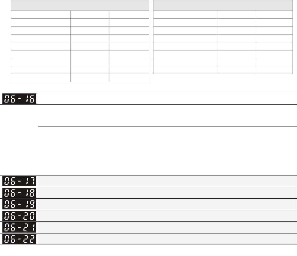
Chapter 12 Description of Parameter Settings|C2000 Series
12-99
Over-heating Level (℃) Over-heating Level (℃)
VFD450C23A/E 100 60 VFD1100C43A/E 100 60
VFD550C23A/E 100 60 VFD1320C43A/E 100 60
VFD750C23A/E 100 60 VFD1600C43A/E 100 60
VFD900C23A/E 100 60 VFD1850C43A/E 100 65
VFD007C43A/E 100 90
VFD2200C43A/E 100 65
VFD015C43A/E 100 90
VFD2800C43A/E 100 65
VFD022C43A/E 100 95
VFD3150C43A/E 100 65
VFD037C43A/E 100 100
VFD3550C43A/E 100 65
VFD040C43A/E 100 95
Stall Prevention Limit Level
Factory Setting: 50
Settings 0~100% (Refer to Pr.06-03, Pr.06-04)
When operation frequency is larger than Pr.01-01; e.g. Pr06-03=150%, Pr. 06-04=100% and Pr.
06-16=80%:
Calculate the Stall Prevention Level during acceleration: Pr.06-03 * Pr.06-16=150x80%=120%.
Calculate the Stall Prevention Level at constant speed: Pr.06-04 * Pr.06-16=100x80%=80%.
Present Fault Record
Second Most Recent Fault Record
Third Most Recent Fault Record
Fourth Most Recent Fault Record
Fifth Most Recent Fault Record
Sixth Most Recent Fault Record
Settings
0: No fault record
1: Over-current during acceleration (ocA)
2: Over-current during deceleration (ocd)
3: Over-current during constant speed(ocn)
4: Ground fault (GFF)
5: IGBT short-circuit (occ)
6: Over-current at stop (ocS)
7: Over-voltage during acceleration (ovA)
8: Over-voltage during deceleration (ovd)
9: Over-voltage during constant speed (ovn)
10: Over-voltage at stop (ovS)
11: Low-voltage during acceleration (LvA)
12: Low-voltage during deceleration (Lvd)
13: Low-voltage during constant speed (Lvn)
14: Stop mid-low voltage (LvS)
15: Phase loss protection (OrP)
16: IGBT over-heat (oH1)
17: Capacitance over-heat (oH2) (for 40hp above)
Chapter 12 Description of Parameter Settings|C2000 Series
12-100
18: tH1o (TH1 open: IGBT over-heat
protection error)
19: tH2o (TH2 open: capacitance over-heat
protection error)
20: Reserved
21: Drive over-load (oL)
22: Electronics thermal relay 1 (EoL1)
23: Electronics thermal relay 2 (EoL2)
24: Motor PTC overheat (oH3) (PTC)
25: Reserved
26: Over-torque 1 (ot1)
27: Over-torque 2 (ot2)
28: Low current (uC)
29: Home limit error (LMIT)
30: Memory write-in error (cF1)
31: Memory read-out error (cF2)
32: Reserved
33: U-phase current detection error (cd1)
34: V-phase current detection error (cd2)
35: W-phase current detection error (cd3)
36: Clamp current detection error (Hd0)
37: Over-current detection error (Hd1)
38: Over-voltage detection error (Hd2)
39: occ IGBT short circuit detection error (Hd3)
40: Auto tuning error (AUE)
41: PID feedback loss (AFE)
42: PG feedback error (PGF1)
43: PG feedback loss (PGF2)
44: PG feedback stall (PGF3)
45: PG slip error (PGF4)
46: PG ref loss (PGr1)
47: PG ref loss (PGr2)
48: Analog current input loss (ACE)
49: External fault input (EF)
50: Emergency stop (EF1)
51: External Base Block (bb)
52: Password error (PcodE)
53: Reserved
54: Communication error (CE1)
55: Communication error (CE2)
56: Communication error (CE3)
57: Communication error (CE4)

Chapter 12 Description of Parameter Settings|C2000 Series
12-101
58: Communication Time-out (CE10)
59: PU Time-out (CP10)
60: Brake transistor error (bF)
61: Y-connection/△-connection switch error (ydc)
62: Decel. Energy Backup Error (dEb)
63: Slip error (oSL)
64: Electromagnet switch error (ryF)
65 : PG Card Error (PGF5)
66-72: Reserved
73: External safety gate S1
74~78: Reserved
79: Uocc U phase over current (Detection begins as RUN is pressed,
software protection)
80: Vocc V phase over current (Detection begins as RUN is pressed,
software protection)
81: Wocc W phase over current (Detection begins as RUN is pressed,
software protection)
82: OPHL U phase output phase loss
83: OPHL Vphase output phase loss
84: OPHL Wphase output phase loss
85~100: Reserved
101: CGdE CANopen software disconnect1
102: CHbE CANopen software disconnect2
103: CSYE CANopen synchronous error
104: CbFE CANopen hardware disconnect
105: CIdE CANopen index setting error
106: CAdE CANopen slave station number setting error
107: CFrE CANopen index setting exceed limit
108~110: Reserved
111: InrCOM Internal communication overtime error
When the fault occurs and force stopping, it will record in this parameter.
At stop with low voltage Lv (LvS warn, no record). During operation with mid-low voltage Lv (LvA,
Lvd, Lvn error, will record).
Setting 62: when dEb function is enabled, the drive will execute dEb and record to the Pr.06-17 to
Pr.06-22 simultaneously.
Fault Output Option 1
Fault Output Option 2
Fault Output Option 3
Fault Output Option 4
Factory Setting: 0
Settings 0 to 65535 sec (refer to bit table for fault code)
These parameters can be used with multi-function output (set to 35-38) for the specific

Chapter 12 Description of Parameter Settings|C2000 Series
12-102
requirement. When the fault occurs, the corresponding terminals will be activated (It needs
to convert binary value to decimal value to fill in Pr.06-23 to Pr.06-26).
Bit0 Bit1 Bit2 Bit3 Bit4 Bit5 Bit6
Fault Code current Volt. OL SYS FBK EXI CE
0: No fault
1: Over-current during acceleration (ocA) ●
2: Over-current during deceleration (ocd) ●
3: Over-current during constant speed(ocn) ●
4: Ground fault (GFF) ●
5: IGBT short-circuit (occ) ●
6: Over-current at stop (ocS) ●
7: Over-voltage during acceleration (ovA) ●
8: Over-voltage during deceleration (ovd) ●
9: Over-voltage during constant speed (ovn) ●
10: Over-voltage at stop (ovS) ●
11: Low-voltage during acceleration (LvA) ●
12: Low-voltage during deceleration (Lvd) ●
13: Low-voltage during constant speed (Lvn) ●
14: Stop mid-low voltage (LvS ) ●
15: Phase loss protection (OrP) ●
16: IGBT over-heat (oH1) ●
17: Capacitance over-heat (oH2) ●
18: tH1o (TH1 open) ●
19: tH2o (TH2 open) ●
20: Reserved
21: Drive over-load (oL) ●
22: Electronics thermal relay 1 (EoL1) ●
23: Electronics thermal relay 2 (EoL2) ●
24: Motor PTC overheat (oH3) (PTC) ●
25: Reserved
26: Over-torque 1 (ot1) ●
27: Over-torque 2 (ot2) ●
28: Low current (uC) ●
29: Home limit error (LMIT) ●
30: Memory write-in error (cF1) ●
31: Memory read-out error (cF2) ●
32: Reserved
33: U-phase current detection error (cd1) ●
34: V-phase current detection error (cd2) ●
35: W-phase current detection error (cd3) ●

Chapter 12 Description of Parameter Settings|C2000 Series
12-103
Bit0 Bit1 Bit2 Bit3 Bit4 Bit5 Bit6
Fault Code current Volt. OL SYS FBK EXI CE
36: Clamp current detection error (Hd0) ●
37: Over-current detection error (Hd1) ●
38: Over-voltage detection error (Hd2) ●
39: occ IGBT short circuit detection error (Hd3) ●
40: Auto tuning error (AUE) ●
41: PID feedback loss (AFE) ●
42: PG feedback error (PGF1) ●
43: PG feedback loss (PGF2) ●
44: PG feedback stall (PGF3) ●
45: PG slip error (PGF4) ●
46: PG ref loss (PGr1) ●
47: PG ref loss (PGr2) ●
48: Analog current input loss (ACE) ●
49: External fault input (EF) ●
50: Emergency stop (EF1) ●
51: External Base Block (bb) ●
52: Password error (PcodE) ●
53: Reserved
54: Communication error (CE1) ●
55: Communication error (CE2) ●
56: Communication error (CE3) ●
57: Communication error (CE4) ●
58: Communication Time-out (CE10) ●
59: PU Time-out (CP10) ●
60: Brake transistor error (bF) ●
61: Y-connection/△-connection switch error
(ydc)
●
62: Decel. Energy Backup Error (dEb) ●
63: Slip error (oSL) ●
64: Electromagnet switch error (ryF) ●
65 : PG Card Error (PGF5) ●
66-72: Reserved
73: External safety gate S1 ●
74~78: Reserved
79: U phase over current (Uocc) ●
80: V phase over current (Vocc) ●
81: W phase over current (Wocc) ●
82: OPHL U phase output phase loss ●
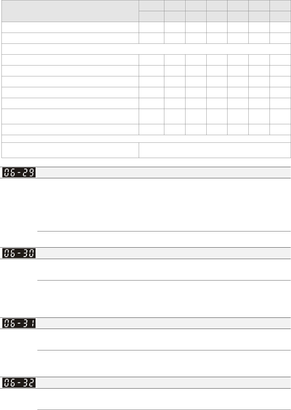
Chapter 12 Description of Parameter Settings|C2000 Series
12-104
Bit0 Bit1 Bit2 Bit3 Bit4 Bit5 Bit6
Fault Code current Volt. OL SYS FBK EXI CE
83: OPHL Vphase output phase loss ●
84: OPHL Wphase output phase loss ●
85~100: Reserved
101: CGdE CANopen software disconnect1 ●
102: CHbE CANopen software disconnect2 ●
103: CSYE CANopen synchronous error ●
104: CbFE CANopen hardware disconnect ●
105: CIdE CANopen index setting error ●
106: CAdE CANopen slave station number
setting error ●
107: CFrE CANopen index setting exceed limit ●
108~110: Reserved
111: InrCOM Internal communication overtime
error ●
PTC (Positive Temperature Coefficient) Detection Selection
Factory Setting: 0
Settings 0: Warn and keep operating
1: Warn and ramp to stop
2: Warn and coast to stop
3: No warning
Pr.06-29 setting defines how the will drive operate after PTC detection.
PTC Level
Factory Setting: 50.0
Settings 0.0~100.0%
It needs to set AVI/ACI/AUI analog input function Pr.03-00~03-02 to 6 (P.T.C. thermistor input
value).
It is used to set the PTC level, and the corresponding value for 100% is max. analog input value.
Frequency Command for Malfunction
Factory Setting: Read only
Settings 0.00~655.35Hz
When malfunction occurs, use can check the frequency command. If it happens again, it will
overwrite the previous record.
Output Frequency at Malfunction
Factory Setting: Read only
Settings 0.00~655.35Hz
When malfunction occurs, use can check the current frequency command. If it happens
again, it will overwrite the previous record.

Chapter 12 Description of Parameter Settings|C2000 Series
12-105
Output Voltage at Malfunction
Factory Setting: Read only
Settings 0.0~6553.5V
When malfunction occurs, user can check current output voltage. If it happens again, it will
overwrite the previous record.
DC Voltage at Malfunction
Factory Setting: Read only
Settings 0.0~6553.5V
When malfunction occurs, user can check the current DC voltage. If it happens again, it will
overwrite the previous record.
Output Current at Malfunction
Factory Setting: Read only
Settings 0.00~655.35Amp
When malfunction occurs, user can check the current output current. If it happens again, it will
overwrite the previous record.
IGBT Temperature at Malfunction
Factory Setting: Read only
Settings 0.0~6553.5℃
When malfunction occurs, user can check the current IGBT temperature. If it happens again, it will
overwrite the previous record.
Capacitance Temperature at Malfunction
Factory Setting: Read only
Settings 0.0~6553.5℃
When malfunction occurs, user can check the current capacitance temperature. If it happens again,
it will overwrite the previous record.
Motor Speed in rpm at Malfunction
Factory Setting: Read only
Settings 0.0~6553.5℃
When malfunction occurs, user can check the current motor speed in rpm. If it happens again, it will
overwrite the previous record.
Torque Command at Malfunction
Factory Setting: Read only
Settings 0~65535
When malfunction occurs, user can check the current torque command. If it happens again, it will
overwrite the previous record.
Status of Multi-function Input Terminal at Malfunction
Factory Setting: Read only
Chapter 12 Description of Parameter Settings|C2000 Series
12-106
Settings 0000h~FFFFh
Status of Multi-function Output Terminal at Malfunction
Factory Setting: Read only
Settings 0000h~FFFFh
When malfunction occurs, user can check the status of multi-function input/output terminals. If it
happens again, it will overwrite the previous record.
Drive Status at Malfunction
Factory Setting: Read only
Settings 0000H~FFFFh
When malfunction occurs, please check the drive status (communication address 2119H). If
malfunction happens again, the previous record will be overwritten by this parameter.
Reserved
Reserved
Treatment to Output Phase Loss Detection (OPHL)
Factory Setting: 3
Settings 0: Warn and keep operating
1: Warn and ramp to stop
2: Warn and coast to stop
3: No warning
Pr.06-45 defines how the drive will operates when output phase loss occur.
Deceleration Time of Output Phase Loss
Factory Setting:0.500
Settings 0.000~65.535 sec
Current Bandwidth
Factory Setting:1.00
Settings 0.00~655.35%
DC Brake Time of Output Phase Loss
Factory Setting:0.000
Settings 0.000~65.535 sec
Reserved
Time for Input Phase Loss Detection
Factory Setting:0.20
Settings 0.00~600.00 sec
Reserved

Chapter 12 Description of Parameter Settings|C2000 Series
12-107
Ripple of Input Phase Loss
Factory Setting:30.0 / 60.0
Settings 230V Series: 0.0~160.0 Vdc
460V Series: 0.0~320.0 Vdc
Treatment for the detected Input Phase Loss (OrP)
Factory Setting: 0
Settings 0: warn, ramp to stop
1: warn, coast to stop
Over ripple protection
Reserved
Derating Protection
Factory Setting: 0
Settings 0: constant rated current and limit carrier wave by load current and
temperature
1: constant carrier frequency and limit load current by setting carrier wave
2: constant rated current(same as setting 0), but close current limit
Setting 0:
When the rated current is constant, carrier frequency (Fc) outputted by PWM will auto decrease
according to surrounding temperature, overload output current and time. If overload situation is
not frequent and only cares the carrier frequency operated with the rated current for a long time
and carrier wave changes during short overload, it is recommended to set to 0.
Refer to the following diagram for the level of carrier frequency. Take VFD007C43A in normal duty
as example, surrounding temperature 50oC with independent installation and UL open-type.
When the carrier frequency is set to 15kHz, it corresponds to 72% rated output current. When it
outputs higher than the value, it will auto decrease the carrier frequency. If the output is 83% rated
current and the carrier frequency will decrease to 12kHz. In addition, it will also decrease the
carrier frequency when overload. When the carrier frequency is 15kHz and the current is
120%*72%=86% for a minute, the carrier frequency will decrease to the factory setting.
Setting 1:
It is used for the fixed carrier frequency and prevents the carrier wave changes and motor noise
caused by the surrounding temperature and frequent overload.
Refer to the following for the derating level of rated current. Take VFD007C43A in normal duty as
example, when the carrier frequency keeps in 15kHz and the rated current is decreased to 72%, it
will have OL protection when the current is 120%*72%=86% for a minute. Therefore, it needs to
operate by the curve to keep the carrier frequency.
Setting 2:
It sets the protection method and action to 0 and disables the current limit for the Ratio*160% of
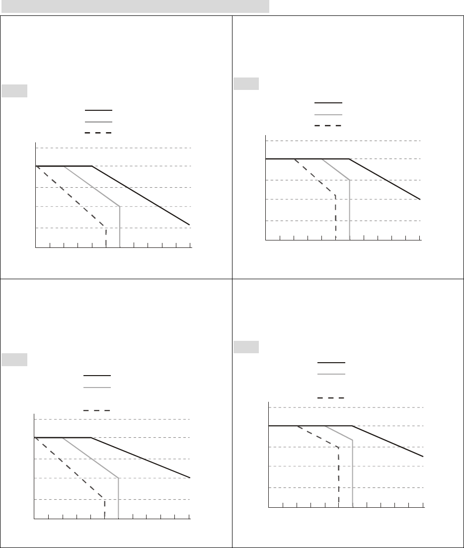
Chapter 12 Description of Parameter Settings|C2000 Series
12-108
output current in the normal duty and Ratio*180% of output current in the heavy duty. The
advantage is that it can provide higher output current when the setting is higher than the factory
setting of carrier frequency. The disadvantage is that it decreases carrier wave easily when
overload.
Derating curve diagram in the normal duty (Pr.00-16=0)
Pr.06-55=1
Pr.06-55=0 or 2
(50℃: UL open-type)
(40℃:UL type1 or open type_size by
size)
460V
100
110
90
80
70
60
4 5 6 7 8 9 10 11 12 13 14 15
Fc (kHz)
R
atio(
%
)
VFD007~150C43A/E
VFD185~550C43A/E
VFD750~3550C43A/E
Pr.06-55=0 or 2
(40℃: UL open-type)
(30℃: UL type1 or open type_size by
size)
460V
100
110
90
80
70
60
456789101112131415
Fc (kHz)
R
atio(
%
)
VFD007~150C43A/E
VFD185~550C43A/E
VFD750~3550C43A/E
Setting=1
Setting=0 or 2
(50℃: UL open-type)
(40℃:UL type1 or open type_size by
size)
230V
100
110
90
80
70
60
4 5 6 7 8 9 10 11 12 13 14 15
Fc (kHz)
R
atio(
%
)
VFD007~110C23A
VFD150~370C23A;
VFD300~370C23E
VFD450~900C23A/E
Setting=0 or 2
(40℃: UL open-type)
(30℃: UL type1 or open type_size by
size)
230V
100
110
90
80
70
60
4 5 6 7 8 9 10 11 12 13 14 15
Fc (kHz)
R
atio(
%
)
VFD007~110C23A
VFD150~370C23A;
VFD300~370C23E
VFD450~900C23A/E
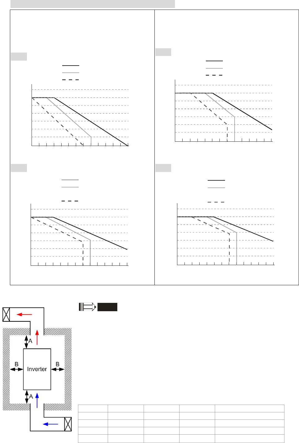
Chapter 12 Description of Parameter Settings|C2000 Series
12-109
Derating curve diagram in the heavy duty (Pr.00-16=1)
Pr.06-55=1
Pr.06-55=0 or 2
(50℃: UL open-type)
(40℃: UL type1 or open type_size by
size)
460V
100
110
90
80
70
50
2 5 6 7 8 9 10 11 12 13 14 15
Fc (kHz)
R
atio(
%
)
VFD007~150C43A/E
VFD185~550C43A/E
VFD750~3550C43A/E
60
40
4
3
Pr.06-55=0 or 2
(40℃: UL open-type)
(30℃: UL type1 or open type_size by
size)
460V
100
110
90
80
70
50
2 5 6 7 8 9 10 11 12 13 14 15
Fc (kHz)
R
atio(
%
)
VFD007~150C43A/E
VFD185~550C43A/E
VFD750~3550C43A/E
60
40
4
3
230V
100
110
90
80
70
50
2 56789101112131415
Fc (kHz)
R
atio(
%
)
VFD007~110C23A
VFD150~370C23A;
VFD300~370C23E
VFD450~900C23A/E
60
40
4
3
230V
100
110
90
80
70
50
2 56789101112131415
Fc (kHz)
R
atio(
%
)
VFD007~110C23A
VFD150~370C23A;
VFD300~370C23E
VFD450~900C23A/E
60
40
4
3
It should be used with Pr. 00-16 and Pr.00-17 for setting.
NOTE
※ The mounting clearances stated in the figure is for installing the drive in an
open area. To install the drive in a confined space (such as cabinet or electric
box), please follow the following three rules: (1) Keep the minimum mounting
clearances. (2) Install a ventilation equipment or an air conditioner to keep
surrounding temperature lower than operation temperature. (3) Refer to
parameter setting and set up Pr. 00-16, Pr.00-17, and Pr. 06-55.
※ The following table shows heat dissipation and the required air volume when
installing a single drive in a confined space. When installing multiple drives,
the required air volume shall be multiplied by the number the drives.
※ Refer to the chart (Air flow rate for cooling) for ventilation equipment design
and selection.
※ Refer to the chart (Power dissipation) for air conditioner design and selection.
Minimum mounting clearances:
Frame A (mm) B (mm) C (mm) D (mm)
A~C 60 30 10 0
D~F 100 50 - 0
G 200 100 - 0
H 350 0 0
200 (100, Ta=40℃)

Chapter 12 Description of Parameter Settings|C2000 Series
12-110
Air flow rate for cooling Power dissipation of AC motor
drive
Flow Rate (cfm) Flow Rate (m3/hr) Power Dissipation
Model No. External Internal Total External Internal Total Loss External
(Heat sink) Internal Total
VFD007C23A - - - - - - 33 27 61
VFD015C23A 14 - 14 24 - 24 56 31 88
VFD022C23A 14 - 14 24 - 24 79 36 115
VFD037C23A 10 - 10 17 - 17 113 46 159
VFD055C23A 40 14 54 68 24 92 197 67 264
VFD075C23A 66 14 80 112 24 136 249 86 335
VFD110C23A 58 14 73 99 24 124 409 121 529
VFD150C23A 166 12 178 282 20 302 455 161 616
VFD185C23A 166 12 178 282 20 302 549 184 733
VFD220C23A 146 12 158 248 20 268 649 216 865
VFD300C23A/E 179 30 209 304 51 355 913 186 1099
VFD370C23A/E 179 30 209 304 51 355 1091 220 1311
VFD450C23A/E 228 73 301 387 124 511 1251 267 1518
VFD550C23A/E 228 73 301 387 124 511 1401 308 1709
VFD750C23A/E 246 73 319 418 124 542 1770 369 2139
VFD900C23A/E 224 112 336 381 190 571 2304 484 2788
VFD007C43A/E - - - - - - 33 25 59
VFD015C43A/E - - - - - - 45 29 74
VFD022C43A/E 14 - 14 24 - 24 71 33 104
VFD037C43A/E 10 - 10 17 - 17 103 38 141
VFD040C43A/E 10 - 10 17 - 17 116 42 158
VFD055C43A/E 10 - 10 17 - 17 134 46 180
VFD075C43A/E 40 14 54 68 24 92 216 76 292
VFD110C43A/E 66 14 80 112 24 136 287 93 380
VFD150C43A/E 58 14 73 99 24 124 396 122 518
VFD185C43A/E 99 21 120 168 36 204 369 138 507
VFD220C43A/E 99 21 120 168 36 204 476 158 635
VFD300C43A/E 126 21 147 214 36 250 655 211 866
VFD370C43A/E 179 30 209 304 51 355 809 184 993
VFD450C43A/E 179 30 209 304 51 355 929 218 1147
VFD550C43A/E 179 30 209 304 51 355 1156 257 1413
VFD750C43A/E 186 30 216 316 51 367 1408 334 1742
VFD900C43A/E 257 73 330 437 124 561 1693 399 2092
VFD1100C43A/E 223 73 296 379 124 503 2107 491 2599
VFD1320C43A/E 224 112 336 381 190 571 2502 579 3081
VFD1600C43A/E 289 112 401 491 190 681 3096 687 3783
VFD1850C43A/E 454 771 4589
VFD2200C43A/E 454 771 5772
VFD2800C43A/E 769 1307 6381
VFD3150C43A/E 769 1307 7156
VFD3550C43A/E
769
1307
8007
※ The required airflow shown in chart is for installing one drive in confined space.
※ When installing the multiple drives, the required air volume should be the
required air volume for single drive X the number of the drives.
※ The heat dissipation shown in
the chart is for installing single
drive in a confined space.
※ When installing multiple drives,
volume of heat dissipation
should be the heat dissipated fo
r
single drive X the number of the
drives.
※ Heat dissipation for each model
is calculated by rated voltage,
current and default carrier.
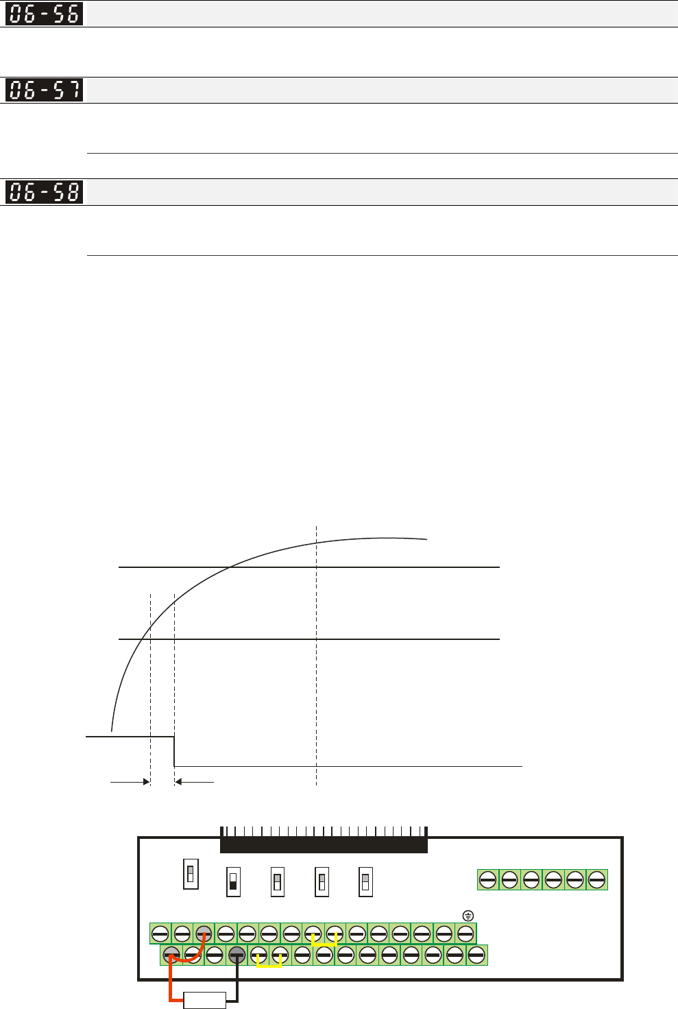
Chapter 12 Description of Parameter Settings|C2000 Series
12-111
PT100 Detection Level 1
Factory Setting:5.000
Settings 0.000~10.000V
PT100 Detection Level 2
Factory Setting: 7.000
Settings 0.000~10.000V
PT100 Level 1 Frequency Protection
Factory Setting: 0.00
Settings 0.00~600.00 Hz
PT100 operation
(1) Use AVI, AUI or ACI(set to 0-10V) for analog voltage input and select PT100 mode.
(2) Choose one of the anolog voltage input type: (a)AVI (Pr.03-00=11), (b) AUI (Pr.03-02=11), or
(c) ACI (Pr.03-01=11 and Pr.03-29=1).
(3) When using ACI as analog voltage input, set Pr.03-01=11 and Pr.03-29=1. Then switch SW2
to 0-10V on the I/O control terminal block.
(4) Set Pr.03-23=23 and AFM2 to constant current output. Switch AFM2 (SW2) to 0-20mA on the
I/O control terminal block and set constanst current output to 9mA by setting Pr.03-33=45.
The AFM2 constant output current is 20mA * 45% = 9mA.
(5) Pr.03-33 is for adjusting the constant voltage or constang current of AFM2, the setting range
is 0~100.00%.
(6) There are two types of action level for PT100. The diagram of PT protecting action is shown
as below:
Level 2 06-57=
Setting range 0.000 10.000V
Factory setting: 7.000V
: ~
Level 1 06-56=
Setting range: 0.000 10.000V
Factory setting: 5.000V
~
Frequency
Command
When voltage of PT100 reaches level 1,
the frequency command goes back to Pr.06-58.
the drive passed the delay time set at Pr06-59 ,
When voltage of PT100 reaches level 2, the drive activate
protecting action by following the setting of Pr.06-29.
Delay time
Pr.06 59-
(7) PT100 wiring diagram:
MI1+24V COM FWD
MO1 MI5
MI3
ACI+10V AVI
AFM1 MO2 MCM MI7
MI4DCM REV MI2S1 MI8MI6ACM-10V AUIAFM2 SCM DFM SG-SG+
RA2RC2 RB2 RB1RC1 RA1
0-10V
-10-10V
0-10V 0-10V
0-10V0-20mA 0-20mA
0-20mA Open
120
AFM1 AFM2 AVI ACI 485
Removable Terminal Block
PT100
Figure 1
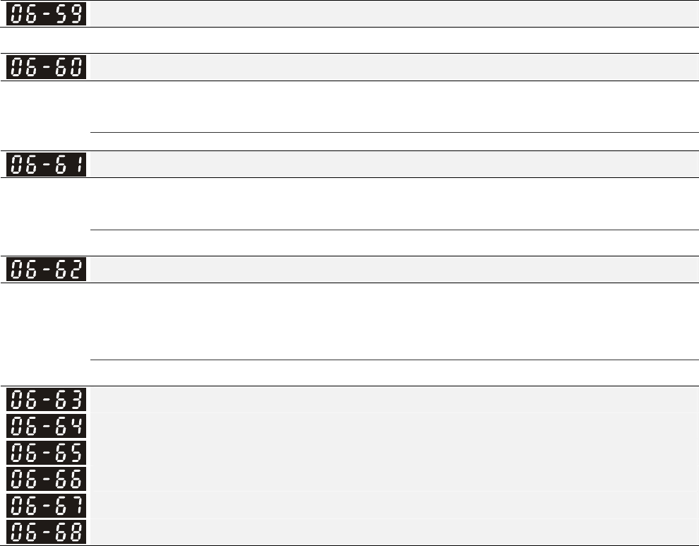
Chapter 12 Description of Parameter Settings|C2000 Series
12-112
When Pr.06-58=0.00Hz, PT100 function is disabled.
Example:
A PT100 is installed to the drive. If motor temperature reache 135℃ (275°F) or higher, the drive will
decrease motor frequency to the setting of Pr.06-58. Motor will operate at this frequency (Pr.06-58)
till the motor temperature decreases to 135℃(275°F) or lower. If motor temperature raise beyong
150℃(302°F), the motor will decelerate to stop and outputs an ‘OH3’ warning.
Set up process:
1. Switch AFM2 (SW2) to 0-20mA on the I/O control terminal block. (Refer to Figure 1, PT100 wiring
diagram)
2. Wiring (Refer to Figure 1, PT100 wiring diagram):
Connect external terminal AFM2 to (+)
Connect external terminal ACM to (-)
Connect external terminals AFM2 and AVI to short-circuit
3. Set Pr.03-00=11 or Pr.03-23=23 or Pr.03-33=45%(9mA)
4. Refer to RTD temperature and resistance comparison table
Temperature=135 , current=151.71℃Ω; Inputut current: 9mA, Voltage: approximately: 1.37Vdc
Temperature=150 , current=157.33℃Ω; Input current:9mA, Voltage: approximately: 1.42Vdc
5. Set Pr.06=56=1.37 and Pr.06-58=10Hz. When RTD temperature increases to 135 or higher, ℃
the drive will decelerate to the selected frequency. When Pr.06-58=0, the drive will not run.
6. Set Pr.06-57=1.42 and Pr.06-29=1 (warning and decelerate to stop). When RTD temperature
increases to 150℃ or higher, the drive will decelerate to stop and outputs an ‘OH3’ warning.
Reserved
Software Detection GFF Current Level
Factory Setting: 60.0
Settings 0.0~6553.5 %
Software Detection GFF Filter Time
Factory Setting: 0.10
Settings 0.0~6553.5 %
Disable Level of dab
Factory Setting: 180.0/360.0
Settings 230V series: 0.0~220.0 Vic
460V series: 0.0~440.0 Vic
Fault Record 1 (min)
Fault Record 2 (min)
Fault Record 3 (min)
Fault Record 4 (min)
Fault Record 5 (min)
Fault Record 6 (min)
Chapter 12 Description of Parameter Settings|C2000 Series
12-113
Factory Setting: Read only
Settings 0~64799 min
Pr.06-63 to Pr.06-68 are used to record the operation time for 6 malfunctions and it can also check
if there is any wrong with the drive according to the internal time.
When the malfunction occurs during operation, it records fault in Pr.06-17~06-22 and operation
time is recorded in Pr.06-63~06-68.
For example: When the first fault ovA occurs after operation 3000 min., second fault ovd occurs at
3482 min., third fault ovA occurs at 4051 min., fourth fault ocA at 5003 min., fifth fault ocA at 5824
min., sixth fault ocd occurs at 6402 min. and seven fault ocS at 6951 min..
It’ll be recorded as the following table:
It will be recorded as the following table:
First fault Pr.06-17 ovA Pr.06-63 3000 ovA occurs at the 3000 min
after operating.
Second fault Pr.06-17 ovd Pr.06-63 3482 3482-3000=482 min
ovd occurs at 482 min after
last fault (ovA)
Pr.06-18 ovA Pr.06-64 3000
Third fault Pr.06-17 ovA Pr.06-63 4051 4051-3482=569 min
ovA occurs at 569 min after
last fault (ovd)
Pr.06-18 ovd Pr.06-64 3482
Pr.06-19 ovA Pr.06-65 3000
Seven fault Pr.06-17 ocS Pr.06-63 12 (12-5824)+64800=58988 min
ocS occurs at 58988 min after
last fault (ocA)
Pr.06-18 ocA Pr.06-64 5824
Pr.06-19 ocA Pr.06-65 5003
Pr.06-20 ovA Pr.06-66 4051
Pr.06-21 ovd Pr.06-67 3482
Pr.06-22 ovA Pr.06-68 3000
Time interval between errors occur (day)
Factory Setting: Read only
Settings Read only
Time interval between errors occur (minute)
Factory Setting: Read only
Settings Read only
Low Current Setting Level
Factory Setting: 0.0

Chapter 12 Description of Parameter Settings|C2000 Series
12-114
Settings 0.0 ~ 6553.5 %
Low Current Detection Time
Factory Setting: 0.00
Settings 0.00 ~ 655.35 sec
Treatment for low current
Factory Setting: 0
Settings 0 : No function
1 : warn and coast to stop
2 : warn and ramp to stop by 2nd deceleration time
3 : warn and operation continue
The drive will operate as the setting of Pr.06-73 when output current is lower than the setting of
Pr.06-71 and when low current continues for a period longer than the setting of Pr.06-72. This
parameter can also be used with external multi-function output terminal 44 (MO44) for low current
output.

Chapter 12 Description of Parameter Settings|C2000 Series
12-115
07 Special Parameters This parameter can be set during operation.
Software Brake Level
Factory Setting: 380.0/760.0
Settings 230V series: 350.0~450.0Vdc
460V series: 700.0~900.0Vdc
This parameter sets the DC-bus voltage at which the brake chopper is activated. Users can choose
the suitable brake resistor to have the best deceleration. Refer to Chapter 7 Accessories for the
information of the brake resistor.
It is only valid for the models below 30kW of 460 series and 22kW of 230 series.
DC Brake Current Level
Factory Setting: 0
Settings 0~100%
This parameter sets the level of DC Brake Current output to the motor during start-up and stopping.
When setting DC Brake Current, the Rated Current is regarded as 100%. It is recommended to
start with a low DC Brake Current Level and then increase until proper holding torque has been
attained.
When it is in FOCPG/TQCPG mode, DC brake is zero-speed operation. It can enable DC brake
function by setting to any value.
DC Brake Time at Start-up
Factory Setting: 0.0
Settings 0.00~60.0 sec
The motor may be in the rotation status due to external force or itself inertia. If the drive is used with
the motor at this moment, it may cause motor damage or drive protection due to over current. This
parameter can be used to output DC current before motor operation to stop the motor and get a
stable start. This parameter determines the duration of the DC Brake current after a RUN command.
When it is set to 0.0, it is invalid.
DC Brake Time at Stop
Factory Setting: 0.00
Settings 0.00~60.00 sec
The motor may be in the rotation status after drive stop outputting due to external force or itself
inertia and can’t stop accurately. This parameter can output DC current to force the motor drive
stop after drive stops to make sure that the motor is stop.
This parameter determines the duration of the DC Brake current during stopping. To DC brake at
stop, this function will be valid when Pr.00-22 is set to 0 or 2. When setting to 0.0, it is invalid.
Related parameters: Pr.00-22 Stop Method, Pr.07-04 Start-point for DC Brake
Start-Point for DC Brake
Factory Setting: 0.00
Settings 0.00~600.00Hz
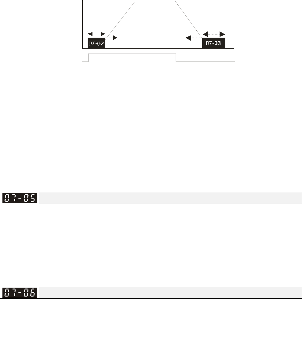
Chapter 12 Description of Parameter Settings|C2000 Series
12-116
This parameter determines the frequency when DC Brake will begin during deceleration. When
this setting is less than start frequency (Pr.01-09), the start-point for DC brake will start from the
min. frequency.
ON OFF
01-09
07-04
Output frequen c
y
Run /Stop Ti me
DC Brake Time
DC Br ak Time
during St opping
Minimum
out put
frequen cy
Start-point for
DC brake
time during
stopping
DC Brake at Start-up is used for loads that may move before the AC drive starts, such as fans and
pumps. Under such circumstances, DC Brake can be used to hold the load in position before
setting it in motion.
DC Brake at stop is used to shorten the stopping time and also to hold a stopped load in position,
such as crane or cutting machine.
Voltage Incrasing Gain
Factory Setting: 100
Settings 1~200%
When the user is using speed tracking, adjut Pr07-05 to slow down the increasing of voltage if
there are errors such as oL or ocv. Then the speed tracking time will be longer and the Pr07-09
Pivot Point of the Speed Tracking of the Current 20~200%, factory setting 50. If the pivot point of
the user is higher than the Pr06-03 pivot point of the oc stall, then the drive will choose the pivot
point of Pr06-03 as the highest pivot point of the speed tracking.
Restart after Momentary Power Loss
Factory Setting: 0
Settings 0: Stop operation
1: Speed search for last frequency command
2: Speed search for the minimum output frequency
This parameter determines the operation mode when the AC motor drive restarts from a
momentary power loss.
The power connected to the drive may power off momentarily due to many reasons. This function
allows the drive to keep outputting after power is on again after power off and won’t cause drive
stops.
Setting 1: Operation continues after momentary power loss, speed search starts with the Master
Frequency reference value after drive output frequency and motor rotator speed is synchronous.
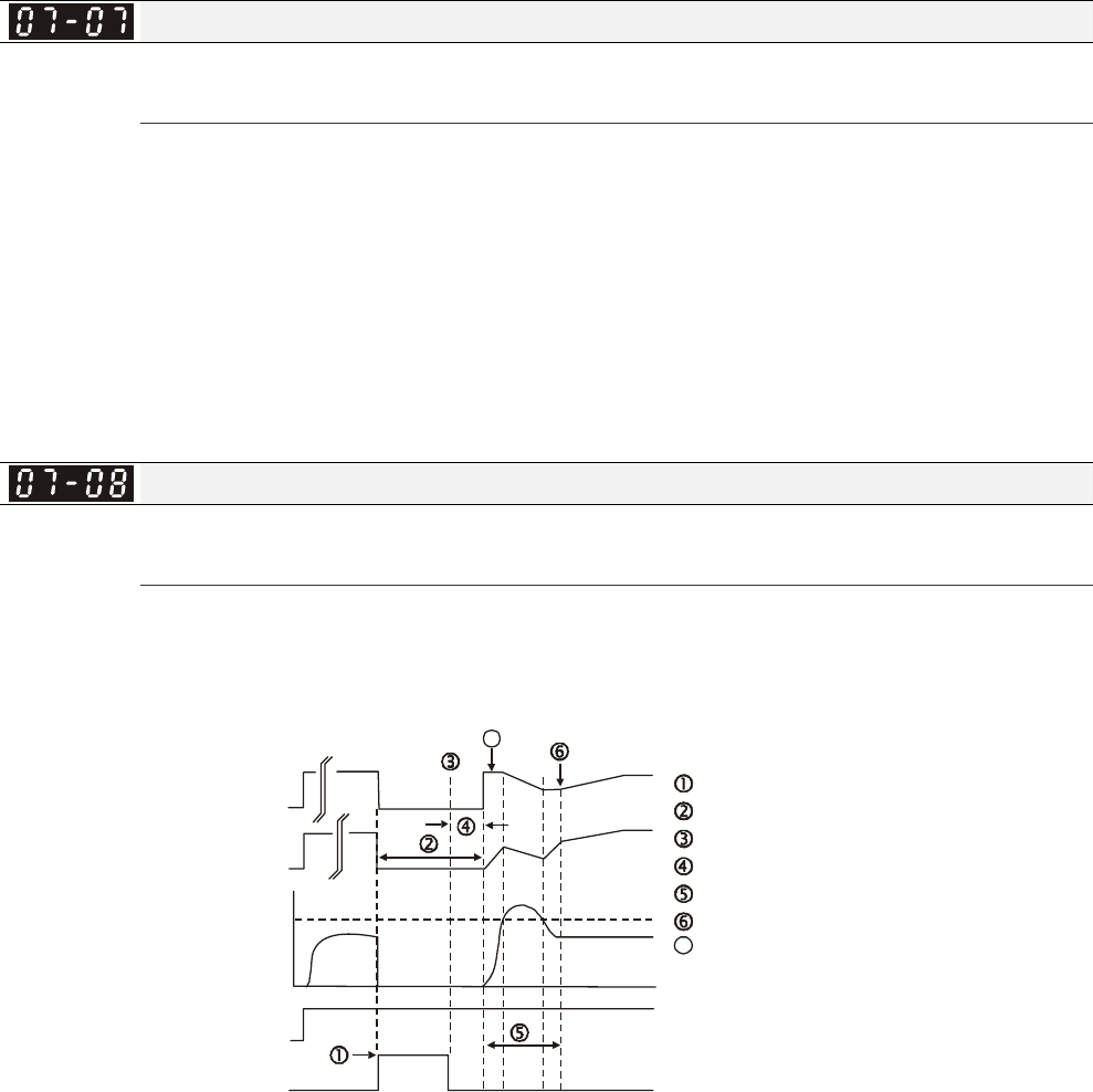
Chapter 12 Description of Parameter Settings|C2000 Series
12-117
The motor has the characteristics of big inertia and small obstruction. For example, in the
equipment with big inertia wheel, it doesn’t need to wait to execute operation command until
wheel is complete stop after re-start to save time.
Setting 2: Operation continues after momentary power loss, speed search starts with the master
frequency after drive output frequency and motor rotator speed is synchronous. The motor has
the characteristics of small inertia and bigger obstruction.
In PG control mode, the AC motor drive will execute the speed search function automatically by
the PG speed when this setting isn’t set to 0.
Maximum Power Loss Duration
Factory Setting: 2.0
Settings 0.1~20.0 sec
If the duration of a power loss is less than this parameter setting, the AC motor drive will resume
operation. If it exceeds the Maximum Allowable Power Loss Time, the AC motor drive output is
then turned off (coast stop).
The selected operation after power loss in Pr.07-06 is only executed when the maximum
allowable power loss time is ≤5 seconds and the AC motor drive displays “LU”.
But if the AC motor drive is powered off due to overload, even if the maximum allowable power
loss time is ≤5 seconds, the operation mode as set in Pr.07-06 is not executed. In that case it
starts up normally.
Base block Time
Factory Setting: 0.5
Settings 0.1~5.0 sec
When momentary power loss is detected, the AC drive will block its output and then wait for a
specified period of time (determined by Pr.07-08, called Base-Block Time) before resuming
operation. This parameter should be set at a value to ensure that any residual regeneration
voltage from the motor on the output has disappeared before the drive is activated again.
B.B.
A
Output frequency(H)
Output voltage(V)
Output current
07-09
Current Limit for
Speed Search
FWD Run
Time
B.B. Search with last output frequency downward timing chart
Input B.B. signal
Stop output voltage
Disable B.B. signal
Waiting time Pr.07-08
Speed search
Synchronization speed detection
7
7
Frequency command before B.B.
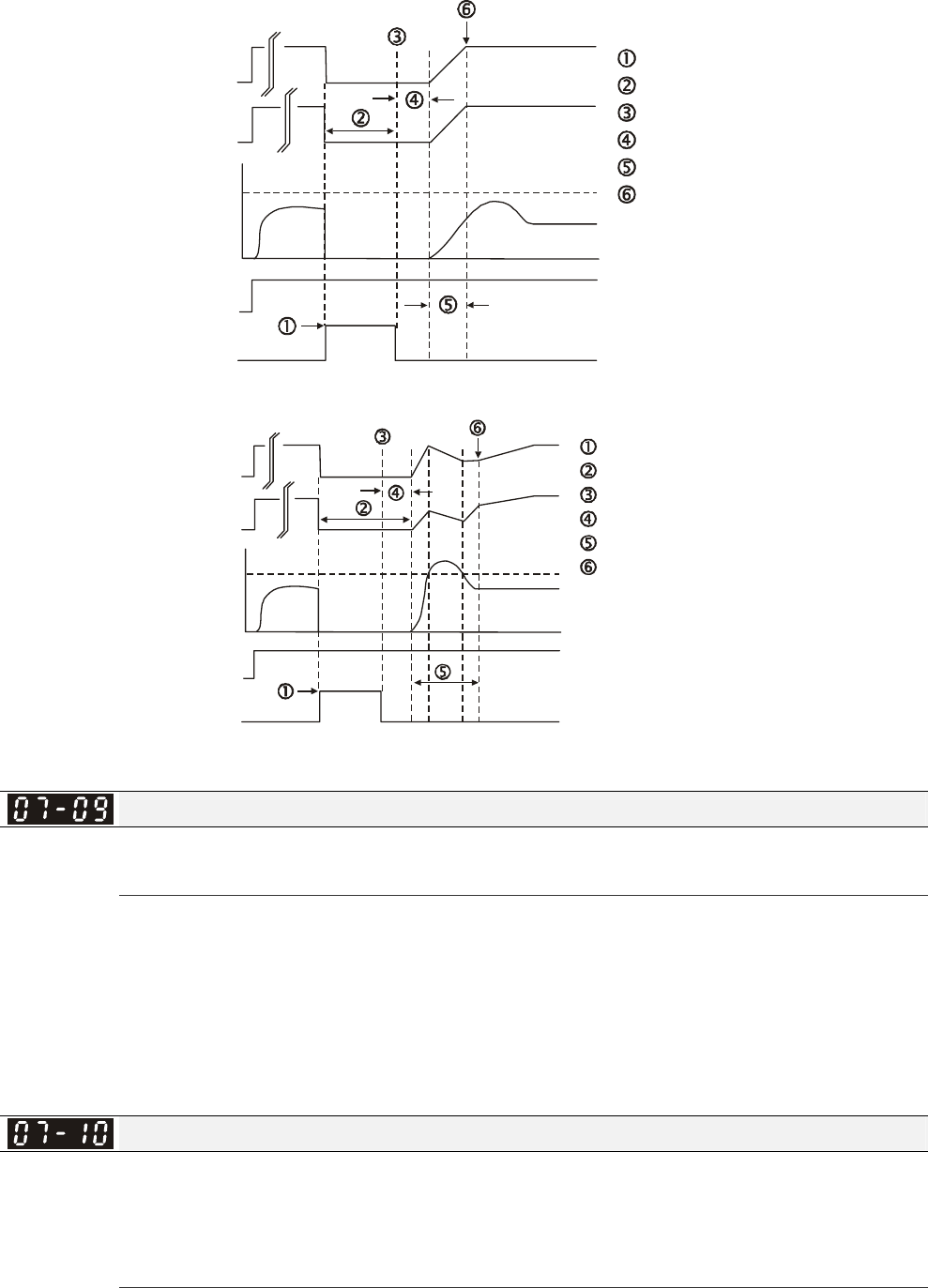
Chapter 12 Description of Parameter Settings|C2000 Series
12-118
Time
B.B.
output current A
Input B.B. signal
Stop output voltage
Disable B.B. signal
Waiting time 08.07
Speed Search
Synchronization speed detection
Output frequency
(H)
07-09 Current Limit
for Speed Search Speed
FWD Run
B.B. Search with minimum output frequency upward timing chart
Output voltage
(V)
B.B. Search with minimum output frequency upward timing chart
Output frequency(H)
Output voltage(V)
Output current
06-03
Over-Current Stall
Prevention
during Accel.
FWD Run
Time
Input B.B. signal
Stop voltage output
Disable B.B. signal
Waiting time Pr.07-08
Speed search
Synchronization speed detection
B.B.
A
Current Limit for Speed Search
Factory Setting: 50
Settings 20~200%
Following a momentary power loss, the AC motor drive will start its speed search operation only if
the output current is greater than the value set by Pr.07-09.
When executing speed search, the V/f curve is operated by group 1 setting. The maximum current
for the optimum accel./decel. and start speed search is set by Pr.07-09.
The speed search level will affect the synchronous time. It will get the synchronization faster when
this parameter is set to larger value. But too large value may active overload protection.
Treatment to Reboots After Fault
Factory Setting: 0
Settings 0: Stop operation
1: Speed search starts with current speed
2: Speed search starts with minimum output frequency
In PG control mode, the AC motor drive will execute the speed search function automatically by
the PG speed when this setting isn’t set to 0.

Chapter 12 Description of Parameter Settings|C2000 Series
12-119
Fault includes: bb,oc,ov,occ etc. To restart after oc, ov, occ, Pr.07-11 can not be set to 0.
Auto Restart After Fault
Factory Setting: 0
Settings 0~10
After fault (oc, ov, ov),occurs the AC motor drive can be reset/restarted automatically up to 10
times.
Setting this parameter to 0 will disable the reset/restart operation after any fault has occurred.
When enabled, the AC motor drive will restart with speed search, which starts at the frequency
before the fault.
If the drive execute reset/restart after fault more than the numbers of time set in Pr.07-11 and the
limit is reached within the time period in Pr.07-33, the drive will stop execute reset/restart after
fault function. User will be need to input RESET manually for the drive to continue operation.
Speed Search during Start-up
Factory Setting: 0
Settings 0: Disable
1: Speed search from maximum output frequency
2: Speed search from start-up motor frequency
3: Speed search from minimum output frequency
This parameter is used for starting and stopping a motor with a high inertia. A motor with high
inertia will take 2-5 minutes or longer to stop completely. By setting this parameter, the user does
not need to wait for the motor to come to a complete stop before restarting the AC motor drive. If a
PG card and encoder is used on the drive and motor, then the speed search will start from the
speed that is detected by the encoder and accelerate quickly to the commanded frequency. The
output current is set by the Pr.07-09.
In PG control mode, the AC motor drive will execute the speed search function automatically by
the PG speed when this setting isn’t set to 0.
Decel. Time at Momentary Power Loss (dEb function)
Factory Setting: 0
Settings 0: Disable
1: 1st decel. time
2: 2nd decel. time
3: 3rd decel. time
4: 4th decel. time
5: Current decel. time
6: Auto decel. time
This parameter is used for the decel. time selection for momentary power loss.
dEb Return Time
Factory Setting: 0.0
Settings 0.0~25.0 sec
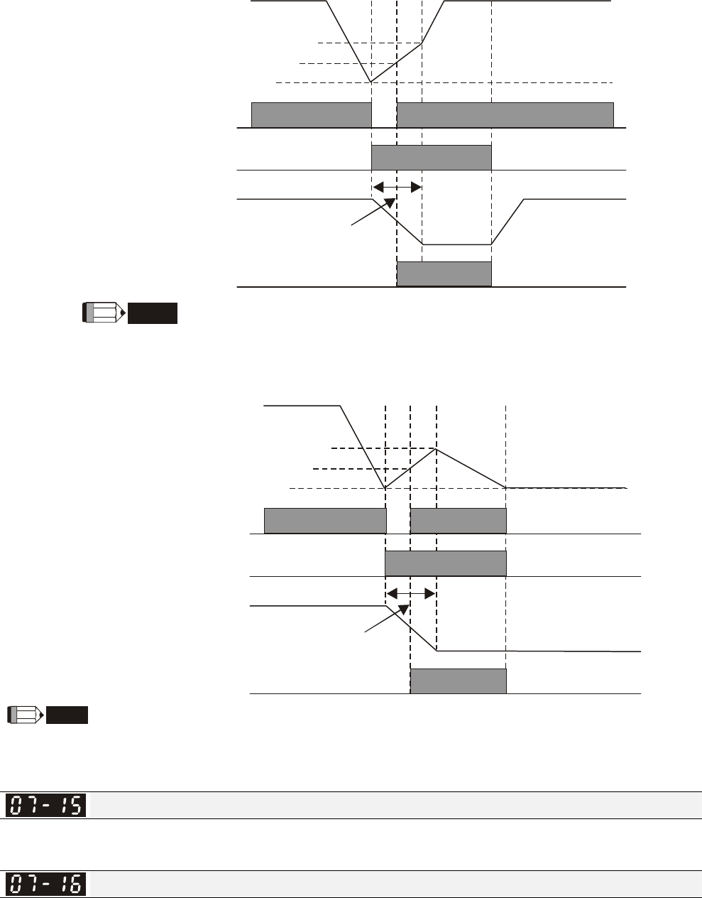
Chapter 12 Description of Parameter Settings|C2000 Series
12-120
function is the AC motor drive decelerates to stop after momentary power loss. When the
momentary power loss occurs, this function can be used for the motor to decelerate to 0 speed with
deceleration stop method. When the power is on again, motor will run again after DEB return time.
(has applied on high-speed spindle)
Status 1: Insufficient power supply due to momentary power-loss/unstable power (due to low
voltage)/sudden heavy-load
07-14
NOTE
DC BUS voltage
it doesn't need
multi-function terminals
The level for DEB return time
(Lv=+30V+58V)
Lv level
Soft start relay at
power side
Output frequency
DEB return time
Pr.07-13 Decel. time selection for
momentary power loss
DEB function is activated
The level for soft start relay to be ON
(Lv+30)
When Pr.07-14 is set to 0, the AC motor drive will be stopped and won't re-start
at the power-on again.
Status 2: unexpected power off, such as momentary power loss
DC BUS voltage
The level for DEB return time
(Lv=+30V+58V)
Lv level
Soft start relay at
power side
Output frequency
DEB return time
Pr.07-13 Decel. time selection for
momentary power loss
DEB function is activated
The level for soft start relay to be ON
(Lv+30)
07-14
NOTE
For example, in textile machinery, you will hope that all the machines can be decelerated to stop to prevent broken stitching
when power loss. In this case, the host controller will send a message to the AC motor drive to use dEb function with
deceleration time via EF.
Dwell Time at Accel.
Factory Setting: 0.00
Settings 0.00~600.00 sec
Dwell Frequency at Accel.
Factory Setting: 0.00
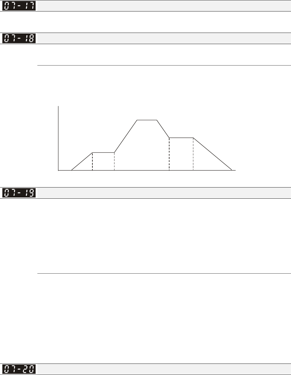
Chapter 12 Description of Parameter Settings|C2000 Series
12-121
Settings 0.00~600.00Hz
Dwell Time at Decel.
Factory Setting: 0.00
Settings 0.00~600.00 sec
Dwell Frequency at Decel.
Factory Setting: 0.00
Settings 0.00~600.00 Hz
In the heavy load situation, Dwell can make stable output frequency temporarily, such as crane or
elevator.
Pr.07-15 to Pr.07-18 is for heavy load to prevent OV or OC occurs.
Frequency
Time
Dwell at accel./decel.
07-16
Dwell
Frequency
at Accel. 07-15
Dwell Time
at Accel.
07-17
Dwell Time
at Decel.
07-18
Dwell
Frequency
at Decel.
Fan Cooling Control
Factory Setting: 0
Settings 0: Fan always ON
1: 1 minute after the AC motor drive stops, fan will be OFF
2: When the AC motor drive runs, the fan is ON. When the AC motor drive
stops, the fan is OFF
3: Fan turns ON when preliminary heat sink temperature (around 60oC) is
attained.
4: Fan always OFF
This parameter is used for the fan control.
Setting 0: Fan will be ON as the drive’s power is turned ON.
Setting 1: 1 minute after AC motor drive stops, fan will be OFF
Setting 2: AC motor drive runs and fan will be ON. AC motor drive stops and fan will be OFF.
Setting 3: Fan run according to IGBT and capacitance temperature. Fan will be ON when
preliminary capacitance temperature is higher than 60oC. Fan will be OFF, when capacitance
temperature is lower than 40oC.
Setting 4: Fan is always OFF
Emergency Stop (EF) & Force Stop
Factory Setting: 0
Settings 0: Coast to stop
1: Stop by 1st deceleration time
2: Stop by 2nd deceleration time
3: Stop by 3rd deceleration time
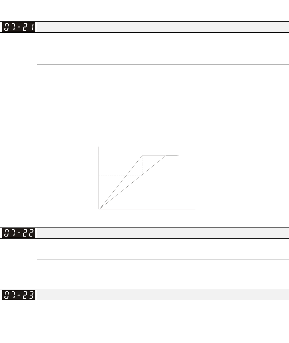
Chapter 12 Description of Parameter Settings|C2000 Series
12-122
4: Stop by 4th deceleration time
5: System Deceleration
6: Automatic Deceleration
Pr.07-20 determines AC motor drive stop method. When the multi-function input terminal is set to
10 or 18 and is activated, the drive will stop according to the setting in Pr.07-20.
Auto Energy-saving Operation
Factory Setting: 0
Settings 0: Disable
1: Enable
When Pr.07-21 is set to 1, the acceleration and deceleration will operate with full voltage. During
constant speed operation, it will auto calculate the best voltage value by the load power for the
load. This function is not suitable for the ever-changing load or near full-load during operation.
When the output frequency is constant, i.e. constant operation, the output voltage will auto
decrease by the load reduction. Therefore, the drive will operate with min. power, multiplication of
voltage and current.
75%
100 %
Output
voltage
Frequency
Auto energy-saving
save up to 25%
output voltage
Energy-saving Gain
Factory Setting: 100
Settings 10~1000%
When Pr.00-19 is set to 1, this parameter can be used to adjust the gain of energy-saving. The
factory setting is 100%. If the result is not good, it can adjust by decreasing the setting. If the
motor oscillates, it should increase the setting.
Auto Voltage Regulation(AVR) Function
Factory Setting: 0
Settings 0: Enable AVR
1: Disable AVR
2: Disable AVR during deceleration
The rated voltage of the motor is usually 220V/200VAC 60Hz/50Hz and the input voltage of the
AC motor drive may vary between 180V to 264 VAC 50Hz/60Hz. Therefore, when the AC motor
drive is used without AVR function, the output voltage will be the same as the input voltage. When
the motor runs at voltages exceeding the rated voltage with 12% - 20%, its lifetime will be shorter
and it can be damaged due to higher temperature, failing insulation and unstable torque output.
AVR function automatically regulates the AC motor drive output voltage to the motor rated voltage.

Chapter 12 Description of Parameter Settings|C2000 Series
12-123
For instance, if V/f curve is set at 200 VAC/50Hz and the input voltage is at 200V to 264VAC, then
the motor Output Voltage will automatically be reduced to a maximum of 200VAC/50Hz. If the
input voltage is at 180V to 200VAC, output voltage to motor and input power will be in direct
proportion.
Setting 0: when AVR function is enabled, the drive will calculate the output voltage by actual
DC-bus voltage. The output voltage won’t be changed by DC bus voltage.
Setting 1: when AVR function is disabled, the drive will calculate the output voltage by DC-bus
voltage. The output voltage will be changed by DC bus voltage. It may cause insufficient/over
current.
Setting 2: the drive will disable the AVR during deceleration, such as operated from high speed to
low speed.
When the motor ramps to stop, the deceleration time is longer. When setting this parameter to 2
with auto acceleration/deceleration, the deceleration will be quicker.
When it is in FOCPG or TQCPG, it is recommended to set to 0 (enable AVR).
Filter Time of Torque Command (V/F and SVC control mode)
Factory Setting: 0.020
Settings 0.001~10.000 sec
When the setting is too long, the control will be stable but the control response will be delay. When
the setting is too short, the response will be quickly but the control may be unstable. User can
adjust the setting by the control and response situation.
Filter Time of Slip Compensation (V/F and SVC control mode)
Factory Setting: 0.100
Settings 0.001~10.000 sec
It can set Pr.05-22 and 05-23 to change the response time of compensation.
If Pr.05-22 and 05-23 are set to 10seconds, the response time of compensation is the slowest. But
the system may be unstable when the setting is too short.
Torque Compensation Gain (V/F and SVC control mode)
Factory Setting: 0
Settings 0~10
When the motor load is large, a part of drive output voltage is absorbed by the resistor of stator
winding and causes insufficient voltage at motor induction and result in over output current and
insufficient output torque. It can auto adjust output voltage by the load and keep the air gap
magnetic fields stable to get the optimal operation.
In the V/F control, the voltage will be decreased in direct proportion when the frequency is
decreased. It’ll cause decrease torque at low speed due to small AC resistor and the same DC
resistor. Therefore, Auto torque compensation function will increase the output voltage in the low
frequency to get higher start torque.
When Pr.07-26 is set to large, it may cause motor overflux and result in too large output current,
motor overheat or triggers protection function.
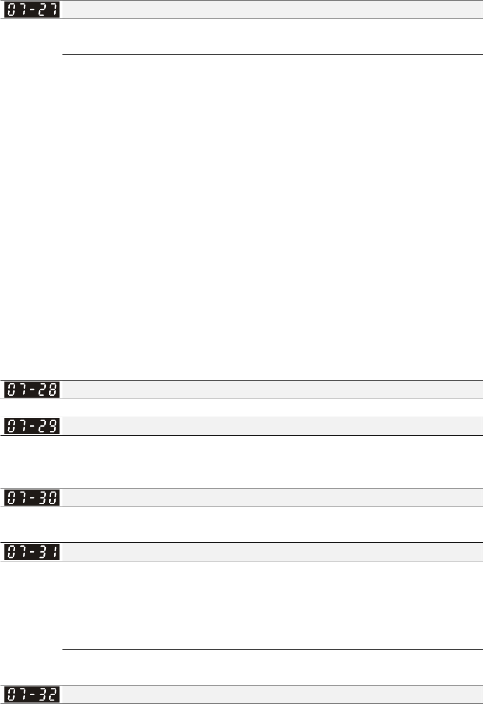
Chapter 12 Description of Parameter Settings|C2000 Series
12-124
Slip Compensation Gain (V/F and SVC control mode)
Factory Setting: 0.00
Settings 0.00~10.00
The induction motor needs the constant slip to produce magnetic torque. It can be ignore in the
higher motor speed, such as rated speed or 2-3% slip.
In the operation with variable frequency, the slip and the synchronous frequency will be in reverse
proportion to produce the same magnetic torque. That is the slip will be larger with the reduction
of synchronous frequency. The motor may stop when the synchronous frequency is decreased to
a specific value. Therefore, the slip serious affects the accuracy of motor speed at low speed.
In another situation, when the drive uses with induction motor, the slip will be increased by the
increasing load. It also affects the accuracy of motor speed.
This parameter can be used to set compensation frequency and reduce the slip to close the
synchronous speed when the motor runs in the rated current to raise the drive accuracy. When
the drive output current is larger than Pr.05-05 No-load Current of Induction Motor 1 (A), the drive
will compensation the frequency by this parameter.
When the control method (Pr.00-11) is changed from V/f mode to vector mode, this parameter will
auto be set to 1.00. Otherwise, it will be set to 0.00. Please do the compensation of slip after
overload and acceleration. The compensation value should be increased from small to large
gradually. That is to add the output frequency with motor rated slip X Pr.07-27 Slip Compensation
Gain when the motor is rated load. If the actual speed ratio is slow than expectation, please
increase the setting. Otherwise, decrease the setting.
Reserved
Slip Deviation Level
Factory Setting: 0
Settings 0~100.0%
0: No detection
Detection Time of Slip Deviation
Factory Setting:1.0
Settings 0.0~10.0 sec
Over Slip Treatment
Factory Setting:0
Settings 0: Warn and keep operation
1: Warn and ramp to stop
2: Warn and coast to stop
3: No warning
Pr.07-29 to Pr.07-31 are used to set allowable slip level/time and over slip treatment when the
drive is running.
Motor Hunting Gain
Factory Setting:1000
Settings 0~10000

Chapter 12 Description of Parameter Settings|C2000 Series
12-125
0: Disable
The motor will have current wave motion in some specific area. It can improve this situation by
setting this parameter. (When it is high frequency or run with PG, it can be set to 0. when the
current wave motion happens in the low frequency, please increase Pr.05-29.)
Recovery Time to Pr.07-11 (# of automatic reboots after fault)
Factory Setting:60.0
Settings 00~6000.0 sec
When a reset/restart after fault occurs, the drive will regards Pr.07-33 as a time boundary and
beging counting the numbers of faults occur within this time period. Within the period, if numbers
of faults occurred did not exceed the setting in Pr.07-11, the counting will be cleared and starts
from 0 when next fault occurs. However, if the numbers of faults occurred within this time period
have exceed the setting in Pr.07-11, user will need to press RESET key manually for the drive to
operate again.
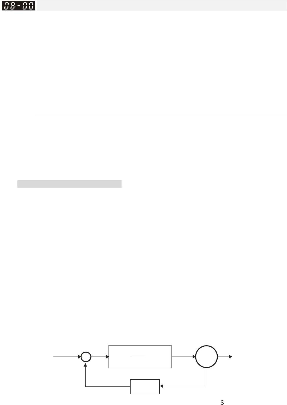
Chapter 12 Description of Parameter Settings|C2000 Series
12-126
08 High-function PID Parameters This parameter can be set during operation.
Input Terminal for PID Feedback
Factory Setting:0
Settings 0: No function
1: Negative PID feedback: input from external terminal AVI (Pr.03-00)
2: Negative PID feedback from PG card (Pr.10-15, skip direction)
3: Negative PID feedback from PG card (Pr.10-15)
4: Positive PID feedback from external terminal AVI (Pr.03-00)
5: Positive PID feedback from PG card (Pr.10-15, skip direction)
6: Positive PID feedback from PG card (Pr.10-15)
7: Negative PID feeback from communication protocol
8: Positive PID feedback from communication protocol
Negative feedback means: +target value – feedback. It is used for the detection value will be
increased by increasing the output frequency.
Positive feedback means: -target value + feedback. It is used for the detection value will be
decreased by increasing the output frequency.
When Pr08-00≠7 neither ≠8, input value is disabled. The value of the setting remain the same
after the derive is off.
Common applications for PID control
; Flow control: A flow sensor is used to feedback the flow data and performs accurate flow
control.
; Pressure control: A pressure sensor is used to feedback the pressure data and performs
precise pressure control.
; Air volume control: An air volume sensor is used to feedback the air volume data to have
excellent air volume regulation.
; Temperature control: A thermocouple or thermistor is used to feedback temperature data for
comfortable temperature control.
; Speed control: A speed sensor or encoder is used to feedback motor shaft speed or input
another machines speed as a target value for closed loop speed control of master-slave
operation. Pr.10.00 sets the PID set point source (target value).
; PID control operates with the feedback signal as set by Pr.10.01 either 0~+10V voltage or
4-20mA current.
PID control loop:
¨
S)T
ST
1
(1K
d
i
p×+
×
+IM
¿¥
+
-
Setpoint
drive execute PID control output value
feedback signal sensor
p
K: Proportional gain(P)
i
T: Integral time(I)
d
T: Derivative control(D) : Operator
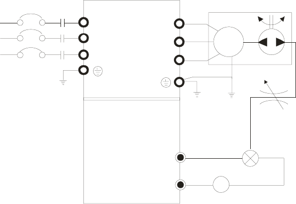
Chapter 12 Description of Parameter Settings|C2000 Series
12-127
Concept of PID control
1. Proportional gain(P):
the output is proportional to input. With only proportional gain control, there will always be
a steady-state error.
2. Integral time(I):
the controller output is proportional to the integral of the controller input. To eliminate the
steady-state error, an “integral part” needs to be added to the controller. The integral time
decides the relation between integral part and error. The integral part will be increased by
time even if the error is small. It gradually increases the controller output to eliminate the
error until it is 0. In this way a system can be stable without steady-state error by proportional
gain control and integral time control.
3. Differential control(D):
the controller output is proportional to the differential of the controller input. During
elimination of the error, oscillation or instability may occur. The differential control can be
used to suppress these effects by acting before the error. That is, when the error is near 0,
the differential control should be 0. Proportional gain(P) + differential control(D) can be used
to improve the system state during PID adjustment.
When PID control is used in a constant pressure pump feedback application:
Set the application’s constant pressure value (bar) to be the set point of PID control. The pressure
sensor will send the actual value as PID feedback value. After comparing the PID set point and
PID feedback, there will be an error. Thus, the PID controller needs to calculate the output by
using proportional gain(P), integral time(I) and differential time(D) to control the pump. It controls
the drive to have different pump speed and achieves constant pressure control by using a 4-20mA
signal corresponding to 0-10 bar as feedback to the drive.
pressure
sensor
throttle
R(L1)
S(L2)
T(L3)
R(L1)
S(L2)
T(L3)
U(T1)
V(T2)
W(T3)
IM
3~
ACM
ACI/AVI
-+
DC
(4-20mA/0-10V)
water pump
Feedback 4-20mA
corresponds
0-10bar
analog signal common
no fuse breaker
(NFB)
1. Pr.00-04 is set to 10 (Display PID analog feedback signal value (b) (%))
2. Pr.01-12 Acceleration Time will be set as required
3. Pr.01-13 Deceleration Time will be set as required
4. Pr.00-21=0 to operate from the digital keypad
5. Pr.00-20=0, the set point is controlled by the digital keypad
6. Pr.08-00=1 (Negative PID feedback from analog input)
7. ACI analog input Pr. 03-01 set to 5, PID feedback signal.

Chapter 12 Description of Parameter Settings|C2000 Series
12-128
8. Pr.08-01-08-03 will be set as required
8.1 If there is no vibration in the system, increase Pr.08-01(Proportional Gain (P))
8.2 If there is no vibration in the system, reduce Pr.08-02(Integral Time (I))
8.3 If there is no vibration in the system, increase Pr.08-03(Differential Time(D))
Refer to Pr.08-00 to 08-21 for PID parameters settings.
Proportional Gain (P)
Factory Setting:80.0
Settings 0.0~500.0%
It is used to eliminate the system error. It is usually used to decrease the error and get the faster
response speed. But if setting too large value in Pr.08-01, it may cause the system oscillation and
instability.
If the other two gains (I and D) are set to zero, proportional control is the only one effective.
Integral Time (I)
Factory Setting:1.00
Settings 0.00~100.00 sec
0.00: Disable
The integral controller is used to eliminate the error during stable system. The integral control
doesn’t stop working until error is 0. The integral is acted by the integral time. The smaller integral
time is set, the stronger integral action will be. It is helpful to reduce overshoot and oscillation to
make a stable system. At this moment, the decreasing error will be slow. The integral control is
often used with other two controls to become PI controller or PID controller.
This parameter is used to set the integral time of I controller. When the integral time is long, it will
have small gain of I controller, the slower response and bad external control. When the integral
time is short, it will have large gain of I controller, the faster response and rapid external control.
When the integral time is too small, it may cause system oscillation.
If the integral time is set as 0.00, Pr.08-02 will be disabled.
Derivative Control (D)
Factory Setting:0.00
Settings 0.00~1.00 sec
The differential controller is used to show the change of system error and it is helpful to preview
the change of error. So the differential controller can be used to eliminate the error to improve
system state. With the suitable differential time, it can reduce overshoot and shorten adjustment
time. However, the differential operation will increase the noise interference. Please note that
too large differential will cause big noise interference. Besides, the differential shows the change
and the output of the differential will be 0 when there is no change. Therefore, the differential
control can’t be used independently. It needs to be used with other two controllers to make a PD
controller or PID controller.
This parameter can be used to set the gain of D controller to decide the response of error change.
The suitable differential time can reduce the overshoot of P and I controller to decrease the
oscillation and have a stable system. But too long differential time may cause system oscillation.
The differential controller acts for the change of error and can’t reduce the interference. It is not
Chapter 12 Description of Parameter Settings|C2000 Series
12-129
recommended to use this function in the serious interference.
Upper limit of Integral Control
Factory Setting:100.0
Settings 0.0~100.0%
This parameter defines an upper bound or limit for the integral gain (I) and therefore limits the
Master Frequency. The formula is: Integral upper bound = Maximum Output Frequency (Pr.01-00)
x (Pr.08-04 %).
Too large integral value will make the slow response due to sudden load change. In this way, it
may cause motor stall or machine damage.
PID Output Frequency Limit
Factory Setting:100.0
Settings 0.0~110.0%
This parameter defines the percentage of output frequency limit during the PID control. The formula
is Output Frequency Limit = Maximum Output Frequency (Pr.01-00) X Pr.08-05 %.
PID feedback value by communication protocol
Factory Setting: 0.00
Settings 0.00~200.00%
PID Delay Time
Factory Setting: 0.0
Settings 0.0~35.0 sec
PID Mode Selection
Factory Setting: 0
Settings 0: Serial connection
1: Parallel connection
Pr.08-07 determines the primary low pass filter time when in PID control. Setting a large time
constant may slow down the response rate of drive.
Output frequency of PID control will filter by primary low pass function. This function could filtering
a mix frequencies. A long primary low pass time means filter degree is high and vice versa.
Inappropriate setting of delay time may cause system error.
PI Control: controlled by the P action only, and thus, the deviation cannot be eliminated entirely. To
eliminate residual deviations, the P + I control will generally be utilized. And when the PI control is
utilized, it could eliminate the deviation incurred by the targeted value changes and the constant
external interferences. However, if the I action is excessively powerful, it will delay the responding
toward the swift variation. The P action could be used solely on the loading system that
possesses the integral components.
PD Control: when deviation occurred, the system will immediately generate some operation load
that is greater than the load generated single handedly by the D action to restrain the increment of
the deviation. If the deviation is small, the effectiveness of the P action will be decreasing as well.
The control objects include occasions with integral component loads, which are controlled by the
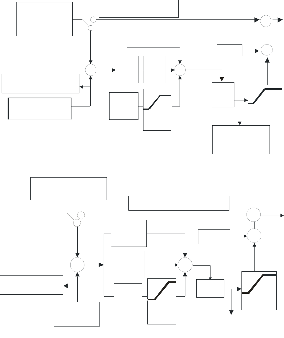
Chapter 12 Description of Parameter Settings|C2000 Series
12-130
P action only, and sometimes, if the integral component is functioning, the whole system will be
vibrating. On such occasions, in order to make the P action’s vibration subsiding and the system
stabilizing, the PD control could be utilized. In other words, this control is good for use with
loadings of no brake functions over the processes.
PID Control: Utilize the I action to eliminate the deviation and the D action to restrain the vibration,
thereafter, combine with the P action to construct the PID control. Use of the PID method could
obtain a control process with no deviations, high accuracies and a stable system.
Serial connection
Input Selection
of the PID Fee dback
PID Cancelled
PID Freq.
out put
command
limit
08-09
Treatment of the
Feedback Signal Fau lt
Int egral Time
Proportion
ga in
00-04=10 display o f t he
PID feed back
Differential
Time
00-20:KPC-CC01/
RS485
03-00~0 2:
UP/D own
ke y PG
08-00=0
or 02-01~ 06=21(pid off)
08-00:AVI/ACI
AUI /PG
P
08-01
D
08-03
I
08-02 08-04
08-07
If Hz>08 -05
time exce eds 08-08
08-05
Frequ ency
command
+
-+
+
Inp ut Selection of the
PID Targe ted Value
1
2
08-06
PID offset
Display of th e PID fee dback
uppe r limit
for
Int egral
PID
Delay
Time
+
Parallel connection
Input Selection
of the PID Feed back
PID Cancelled
08-09
Treatment of the Feedback Signal Fault
00-04=10 display of the
PID feedback
08-00=0
o r 02 -01~06 =21 (p id off)
08-00:AVI/ACI
AUI/PG
If Hz>08-05, time exceeds 08-08
Fr eq ue ncy
command
PID offset
Display of the PID feedback PID Delay
Time
08-07
08-05
+
-+
+
2
08-04
I
P
08-01
1
08-06
+
D
08-03
In put Se le ctio n o f the
PID Targeted Value
00-20:KPC-CC01/RS485
03-00~02:
UP/Down key PG
08-02
Integral Time
Differential
Time
Proportion gain
upper limit
for
Integral
PID Freq.
output
command limit
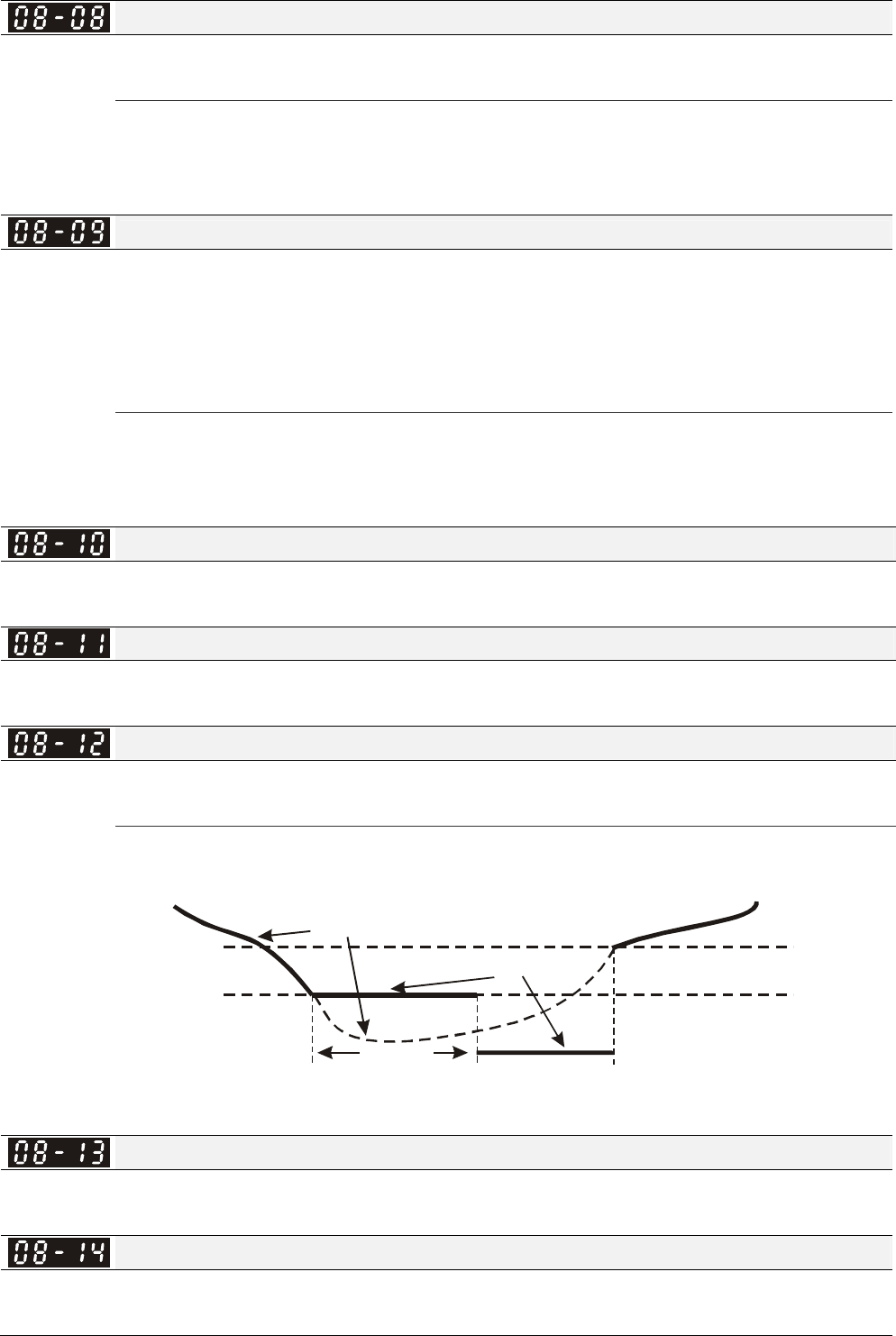
Chapter 12 Description of Parameter Settings|C2000 Series
12-131
Feedback Signal Detection Time
Factory Setting: 0.0
Settings 0.0~3600.0 sec
Pr.08-08 is valid only if the feedback signal is ACI.
This parameter sets the detection time of abnormal PID derative. If detection time is set to 0.0,
detection function is disabled.
Feedback Signal Fault Treatment
Factory Setting: 0
Settings 0: Warn and keep operation
1: Warn and ramp to stop
2: Warn and coast to stop
3: Warn and operate at last frequency
This parameter is valid only when the feedback signal is ACI.
AC motor drive acts when the feedback signals (analog PID feedback or PG (encoder) feedback)
are abnormal.
Sleep Frequency
Factory Setting: 0.00
Settings 0.00~600.00Hz
Wake-up Frequency
Factory Setting: 0.00
Settings 0.00~600.00Hz
Sleep Time
Factory Setting: 0.0
Settings 0.00~6000.0 sec
If the command frequency falls below the sleep frequency, for the specified time in Pr. 08-12, then
the drive will shut off the output and wait until the command frequency rises above Pr.08-11.
08-11
08-10
08-12
0Hz
Sleep Function
Frequency command
actual output frequency
sleep time
Wake-up frequency
Sleep frequency
PID Deviation Level
Factory Setting: 10.0
Settings 1.0~50.0%
PID Deviation Time
Factory Setting: 5.0
Settings 0.1~300.0 sec

Chapter 12 Description of Parameter Settings|C2000 Series
12-132
Filter Time for PID Feedback
Factory Setting: 5.0
Settings 0.1~300.0 sec
When the PID control function is normal, it should calculate within a period of time and close to the
setpoint value.
Refer to the PID control diagram for details. When executing PID feedback control, if |PID
reference target value – detection value| > Pr.08-13 PID Deviation Level and exceeds Pr.08-14
setting, the PID control fault occurs. The treatment will be done as Pr.08-09 setting.
PID Compensation Selection
Factory Setting: 0
Settings 0: Parameter setting
1: Analog input
PID Compensation
Factory Setting: 0
Settings -100.0~+100.0%
Setting of Sleep Mode Function
Factory Setting: 0
Settings 0: Follow PID output command
1: Follow PID feedback signal
Wake-up Integral Limit
Factory Setting: 50.0
Settings 0.0~200.0%
Enable PID to Change the Operation Direction
Factory Setting: 0
Settings 0: Disable change of direction
1: Enable change of direction
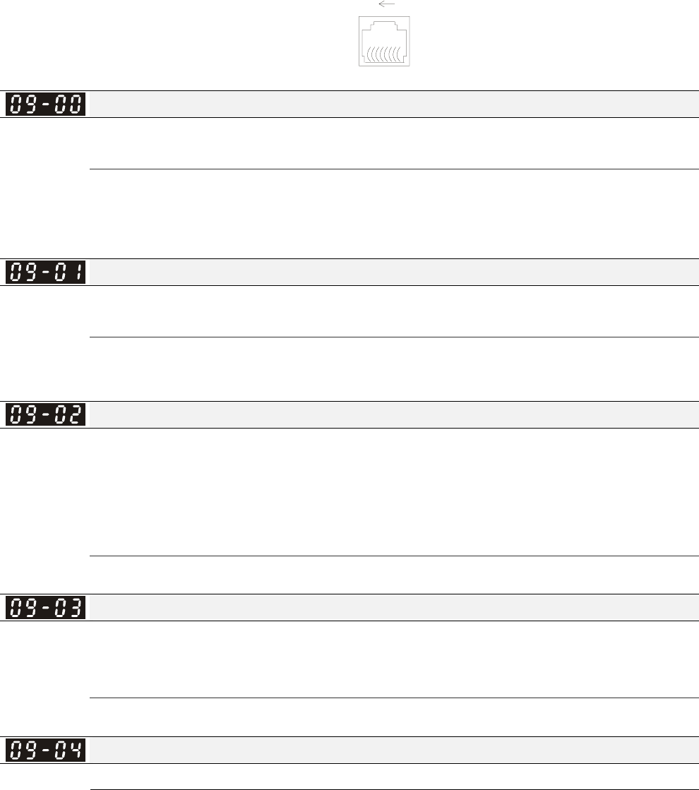
Chapter 12 Description of Parameter Settings|C2000 Series
12-133
09 Communication Parameters The parameter can be set during the operation.
Pin 1~2,7,8: Reserved
Pin 3, 6: GND
Pin 4: SG-
Pin 5: SG+
RS-485
81
Modbus RS-485
When using communication devices,
connects AC drive with PC by using
Delta IFD6530 or IFD6500.
COM1 Communication Address
Factory Setting: 1
Settings 1~254
If the AC motor drive is controlled by RS-485 serial communication, the communication address
for this drive must be set via this parameter. And the communication address for each AC motor
drive must be different and unique.
COM1 Transmission Speed
Factory Setting: 9.6
Settings 4.8~115.2 Kbps
This parameter is used to set the transmission speed between the RS485 master (PLC, PC, etc.)
and AC motor drive.
COM1 Transmission Fault Treatment
Factory Setting: 3
Settings 0: Warn and keep operation
1: Warn and ramp to stop
2: Warn and coast to stop
3: No warning and continue operation
This parameter is set to how to react if transmission errors occur.
COM1 Time-out Detection
Factory Setting: 0.0
Settings 0.0~100.0 sec
0.0: Disable
It is used to set the transmission time between communication and keypad.
COM1 Communication Protocol
Factory Setting: 1
Settings 1: 7, N, 2 for ASCII
2: 7, E, 1 for ASCII
3: 7, O, 1 for ASCII
4: 7, E, 2 for ASCII
5: 7, O, 2 for ASCII
6: 8, N, 1 for ASCII
7: 8, N, 2 for ASCII
8: 8, E, 1 for ASCII
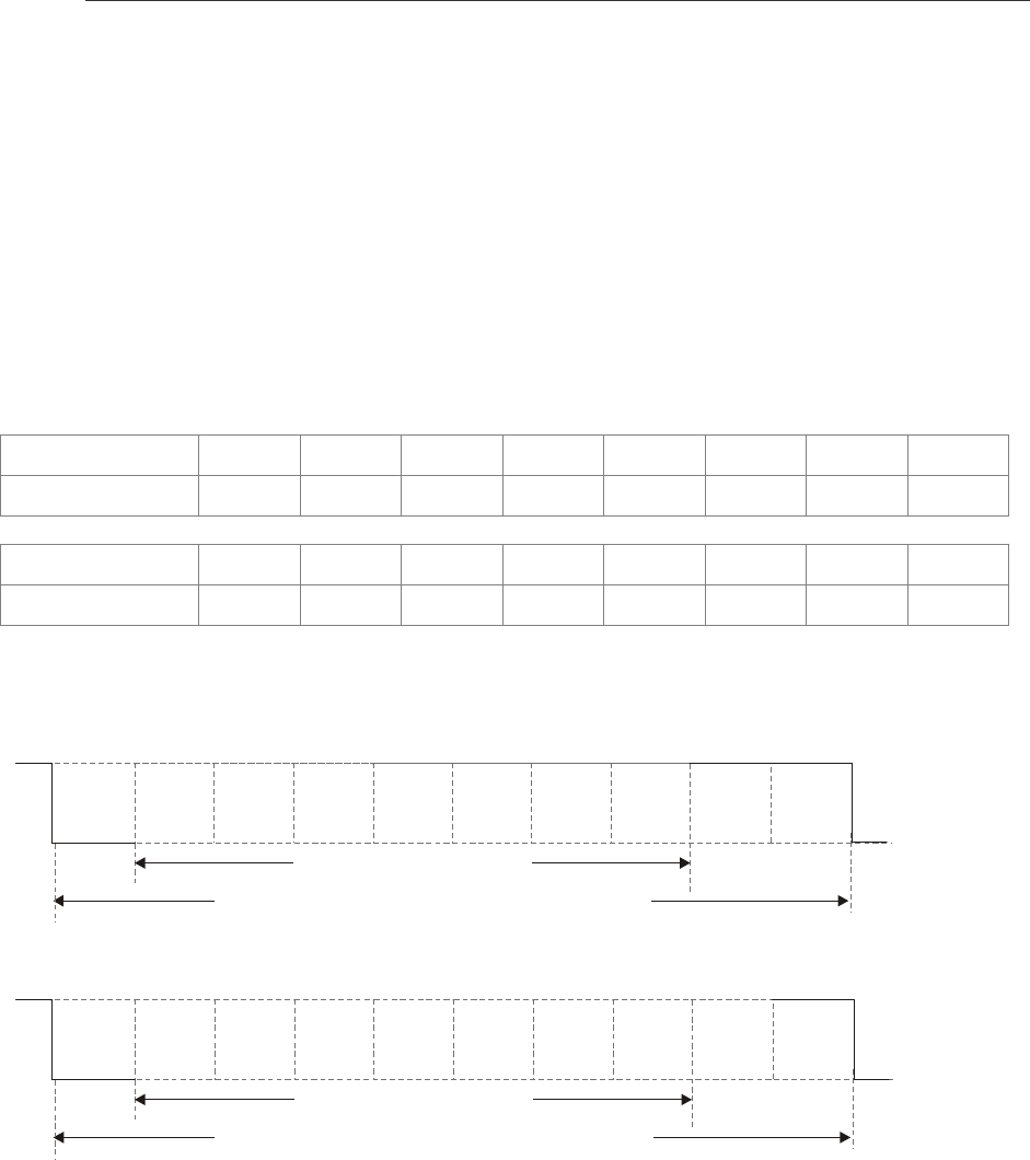
Chapter 12 Description of Parameter Settings|C2000 Series
12-134
9: 8, O, 1 for ASCII
10: 8, E, 2 for ASCII
11: 8, O, 2 for ASCII
12: 8, N, 1 for RTU
13: 8, N, 2 for RTU
14: 8, E, 1 for RTU
15: 8, O, 1 for RTU
16: 8, E, 2 for RTU
17: 8, O, 2 for RTU
Control by PC or PLC (Computer Link)
A VFD-C2000 can be set up to communicate on Modbus networks using one of the following
modes: ASCII (American Standard Code for Information Interchange) or RTU (Remote Terminal
Unit).Users can select the desired mode along with the RS-485 serial port communication
protocol in Pr.09-00.
MODBUS ASCII(American Standard Code for Information Interchange): Each byte data is the
combination of two ASCII characters. For example, a 1-byte data: 64 Hex, shown as ‘64’ in ASCII,
consists of ‘6’ (36Hex) and ‘4’ (34Hex).
1. Code Description
Communication protocol is in hexadecimal, ASCII: ”0”, “9”, “A”, “F”, every 16 hexadecimal
represent ASCII code. For example:
Character ‘0’ ‘1’ ‘2’ ‘3’ ‘4’ ‘5’ ‘6’ ‘7’
ASCII code 30H 31H 32H 33H 34H 35H 36H 37H
Character ‘8’ ‘9’ ‘A’ ‘B’ ‘C’ ‘D’ ‘E’ ‘F’
ASCII code 38H 39H 41H 42H 43H 44H 45H 46H
Data Format
10-bit character frame (For ASCII):
(7, N , 2)
Start
bit 0123456 Stop
bit
7-data bits
10-bits character frame
Stop
bit
(7 , E , 1)
Even
parity
Start
bit 0123456 Stop
bit
7-data bits
10-bits character frame
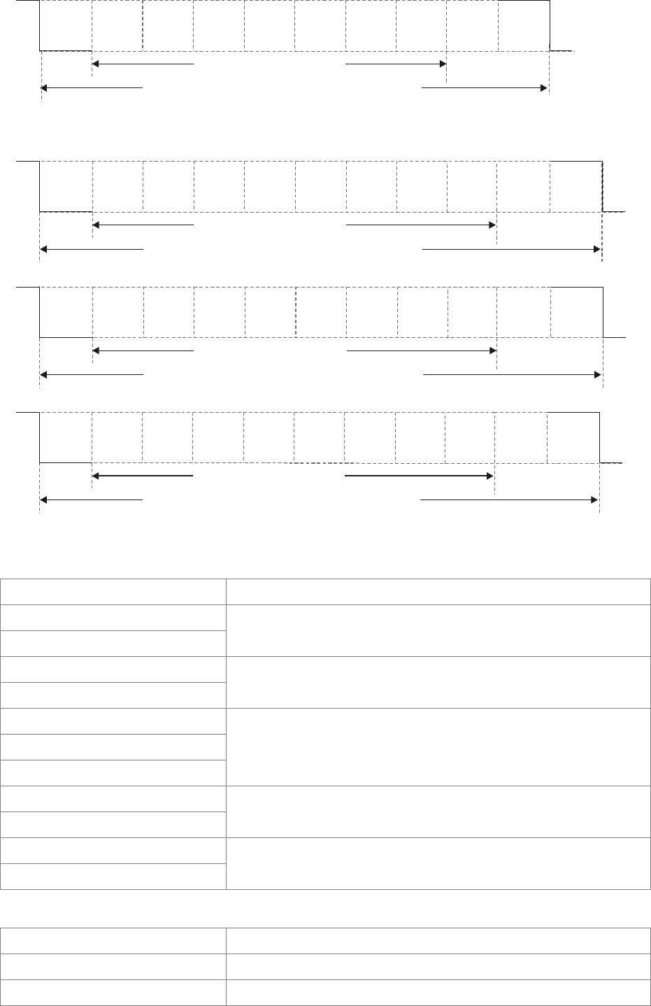
Chapter 12 Description of Parameter Settings|C2000 Series
12-135
(7 , O , 1)
Odd
parity
Start
bit 0123456Stop
bit
7-data bits
10-bits character frame
11-bit character frame (For RTU):
(8 , N , 2)
Start
bit 012 3456 Stop
bit
8-data bits
11-bits character frame
Stop
bit
7
(8 , E , 1)
Start
bit 012 3456 Stop
bit
8-data bits
11-bits character frame
7Even
parity
(8 , O , 1)
Start
bit 0123456 Stop
bit
8-data bits
11-bits character frame
7Odd
parity
2. Communication Protocol
Communication Data Frame: ASCII mode
STX Start character = ‘:’ (3AH)
Address Hi
Address Lo
Communication address:
8-bit address consists of 2 ASCII codes
Function Hi
Function Lo
Command code:
8-bit command consists of 2 ASCII codes
DATA (n-1)
…….
DATA 0
Contents of data:
Nx8-bit data consist of 2n ASCII codes
n<=16, maximum of 32 ASCII codes
LRC CHK Hi
LRC CHK Lo
LRC check sum:
8-bit check sum consists of 2 ASCII codes
END Hi
END Lo
End characters:
END1= CR (0DH), END0= LF(0AH)
Communication Data Frame: RTU mode
START A silent interval of more than 10 ms
Address Communication address: 8-bit address
Function Command code: 8-bit command

Chapter 12 Description of Parameter Settings|C2000 Series
12-136
DATA (n-1)
…….
DATA 0
Contents of data:
n×8-bit data, n<=16
CRC CHK Low
CRC CHK High
CRC check sum:
16-bit check sum consists of 2 8-bit characters
END A silent interval of more than 10 ms
Address (Communication Address)
Valid communication addresses are in the range of 0 to 254. A communication address equal to 0,
means broadcast to all AC drives (AMD). In this case, the AMD will not reply any message to the
master device.
00H: broadcast to all AC drives
01H: AC drive of address 01
0FH: AC drive of address 15
10H: AC drive of address 16
:
FEH: AC drive of address 254
Function (Function code) and DATA (data characters)
The format of data characters depends on the function code.
03H: read data from register
06H: write single register
Example: reading continuous 2 data from register address 2102H, AMD address is 01H.
ASCII mode:
Command Message: Response Message
STX ‘:’ STX ‘:’
‘0’ ‘0’
Address ‘1’ Address ‘1’
‘0’ ‘0’
Function ‘3’ Function ‘3’
‘2’ ‘0’
‘1’
Number of data
(count by byte) ‘4’
‘0’ ‘1’
Starting address
‘2’ ‘7’
‘0’ ‘7’
‘0’
Content of starting
address 2102H
‘0’
‘0’ ‘0’
Number of data
(count by word)
‘2’ ‘0’
‘D’ ‘0’
LRC Check ‘7’
Content of address 2103H
‘0’
CR ‘7’
END LF LRC Check ‘1’
CR
END LF
RTU mode:
Command Message: Response Message
Address 01H Address 01H
Function 03H Function 03H
21H
Starting data address 02H
Number of data
(count by byte) 04H
00H 17H Number of data
(count by world) 02H
Content of data
address 2102H 70H

Chapter 12 Description of Parameter Settings|C2000 Series
12-137
CRC CHK Low 6FH 00H
CRC CHK High F7H
Content of data
address 2103H 00H
CRC CHK Low FEH
CRC CHK High 5CH
06H: single write, write single data to register.
Example: writing data 6000(1770H) to register 0100H. AMD address is 01H.
ASCII mode:
Command Message: Response Message
STX ‘:’ STX ‘:’
‘0’ ‘0’
Address ‘1’ Address ‘1’
‘0’ ‘0’
Function ‘6’ Function ‘6’
‘0’ ‘0’
‘1’ ‘1’
‘0’ ‘0’
Data address
‘0’
Data address
‘0’
‘1’ ‘1’
‘7’ ‘7’
‘7’ ‘7’
Data content
‘0’
Data content
‘0’
‘7’ ‘7’
LRC Check ‘1’ LRC Check ‘1’
CR CR
END LF END LF
RTU mode:
Command Message: Response Message
Address 01H Address 01H
Function 06H Function 06H
01H 01H
Data address 00H Data address 00H
17H 17H
Data content 70H Data content 70H
86H 86H CRC CHK Low
CRC CHK High 22H
CRC CHK Low
CRC CHK High 22H
10H: write multiple registers (write multiple data to registers)
Example: Set the multi-step speed,
Pr.04-00=50.00 (1388H), Pr.04-01=40.00 (0FA0H). AC drive address is 01H.
ASCII Mode
Command Message: Response Message
STX ‘:’ STX ‘:’
‘0’ ‘0’ ADR 1
ADR 0 ‘1’
ADR 1
ADR 0 ‘1’
CMD 1 ‘1’ CMD 1 ‘1’
CMD 0 ‘0’ CMD 0 ‘0’
‘0’ ‘0’
‘5’ ‘5’
‘0’ ‘0’
Starting data address
‘0’
Starting data address
‘0’
‘0’ ‘0’
‘0’ ‘0’
‘0’ ‘0’
Number of data
(count by word)
‘2’
Number of data
(count by word)
‘2’

Chapter 12 Description of Parameter Settings|C2000 Series
12-138
‘0’ ‘E’ Number of data
(count by byte) ‘4’ LRC Check ‘8’
‘1’ CR
‘3’ END LF
‘8’
The first data content
‘8’
‘0’
‘F’
‘A’
The second data content
‘0’
‘9’
LRC Check ‘A’
CR
END LF
RTU mode:
Command Message: Response Message
ADR 01H ADR 01H
CMD 10H CMD 1 10H
05H 05H
Starting data address 00H Starting data address 00H
00H 00H Number of data
(count by word) 02H
Number of data
(count by word) 02H
Number of data
(count by byte)
04 CRC Check Low 41H
13H CRC Check High 04H
The first data content 88H
0FH The second data content
A0H
CRC Check Low ‘9’
CRC Check High ‘A’
Check sum
ASCII mode:
LRC (Longitudinal Redundancy Check) is calculated by summing up, module 256, and the values
of the bytes from ADR1 to last data character then calculating the hexadecimal representation of the
2’s-complement negation of the sum.
For example,
01H+03H+21H+02H+00H+02H=29H, the 2’s-complement negation of 29H is D7H.
RTU mode:
CRC (Cyclical Redundancy Check) is calculated by the following steps:
Step 1:
Load a 16-bit register (called CRC register) with FFFFH.
Step 2:
Exclusive OR the first 8-bit byte of the command message with the low order byte of the 16-bit CRC
register, putting the result in the CRC register.
Step 3:
Examine the LSB of CRC register.
Step 4:
Chapter 12 Description of Parameter Settings|C2000 Series
12-139
If the LSB of CRC register is 0, shift the CRC register one bit to the right with MSB zero filling, then
repeat step 3. If the LSB of CRC register is 1, shift the CRC register one bit to the right with MSB
zero filling, Exclusive OR the CRC register with the polynomial value A001H, then repeat step 3.
Step 5:
Repeat step 3 and 4 until eight shifts have been performed. When this is done, a complete 8-bit
byte will have been processed.
Step 6:
Repeat step 2 to 5 for the next 8-bit byte of the command message. Continue doing this until all
bytes have been processed. The final contents of the CRC register are the CRC value. When
transmitting the CRC value in the message, the upper and lower bytes of the CRC value must be
swapped, i.e. the lower order byte will be transmitted first.
The following is an example of CRC generation using C language. The function takes two
arguments:
Unsigned char* data Å a pointer to the message buffer
Unsigned char length Å the quantity of bytes in the message buffer
The function returns the CRC value as a type of unsigned integer.
Unsigned int crc_chk(unsigned char* data, unsigned char length)
{
int j;
unsigned int reg_crc=0Xffff;
while(length--){
reg_crc ^= *data++;
for(j=0;j<8;j++){
if(reg_crc & 0x01){ /* LSB(b0)=1 */
reg_crc=(reg_crc>>1) ^ 0Xa001;
}else{
reg_crc=reg_crc >>1;
}
}
}
return reg_crc; // return register CRC

Chapter 12 Description of Parameter Settings|C2000 Series
12-140
3. Address list
Content Address Function
AC drive Parameters GGnnH GG means parameter group, nn means parameter number, for
example, the address of Pr 4-01 is 0401H.
Command
Write only 2000H Bit 0-3
0: No function
1: Stop
2: Run
3: Jog + Run
Bit 4-5
00B: No function
01B: FWD
10B: REV
11B: Change direction
Bit 6-7
00B: 1st accel/decel
01B: 2nd accel/decel
10B: 3rd accel/decel
11B: 4th accel/decel
Bit 8-11 000B: master speed
0001B: 1st accel/decel.
0010B: 2nd accel/decel
0011B: 3rd accel/decel
0100B: 4th accel/decel
0101B: 5th accel/decel
0110B: 6th accel/decel
0111B: 7th accel/decel
1000B: 8th accel/decel
1001B: 9th accel/decel
1010B: 10th accel/decel
1011B: 11th accel/decel
1100B: 12th accel/decel
1101B: 13th accel/decel
1110B: 14th accel/decel
1111B: 15th accel/decel
Bit 12 1: enable bit06-11 function
Bit 13~14 00B: No function
01B: operated by digital keypad
10B: operated by Pr.00-21 setting
11B: change operation source
Bit 15 Reserved
2001H Frequency command
Bit 0 1: EF (external fault) on
Bit 1 1: Reset
Bit 2 1: B.B. ON
Command
Write only
2002H
Bit 3-15 Reserved
Status monitor
Read only 2100H Error code: refer to Pr.06-17 to Pr.06-22
2101H Bit0
Bit1
AC Drive Operation Status
00b: Drive stops
01b: Drive decelerating
10b: Drive standby
11b: Drive operating
Bit2 1: JOG Command
Bit3
Bit4
Operation Direction
00b: FWD run
01b: from REV run to FWD run
10b: REV run
11b: from FWD run to REV run
Bit8 1: Master frequency controlled by communication
interface

Chapter 12 Description of Parameter Settings|C2000 Series
12-141
Content Address Function
Bit9 1: Master frequency controlled by analog signal
Bit10 1: Operation command controlled by
communication interface
Bit11 1: Parameter locked
Bit12 1: Enable to copy parameters from keypad
Bit13~15 Reserved
2102H Frequency command (F)
2103H Output frequency (H)
2104H Output current (AXX.X.X)
2105H DC-BUS Voltage (UXXX.X)
2106H Output voltage (EXXX.X)
2107H Current step number of Multi-Step Speed Operation
2108H Reserved
2109H Counter value
201AH Power Factor Angle (XXX.X)
201BH Output Torque (%)
201CH Actual motor speed (rpm)
201DH Number of PG feed back pulses
201EH Number of PG2 pulse commands
201FH Power output (X.XXX)
2116H Multi-function display (Pr.00-04)
211BH Max. opeartion frequency (Pr.01-00) or Max. user defined value
(Pr.00-26)
2200H Display output current (A)
2201H Display counter value of TRG terminal (c)
2202H Display actual output frequency (H)
2203H Display DC-BUS voltage (u)
2204H Display output voltage of U, V, W (E)
2205H Display output power angle of U, V, W (n)
2206H Display actual motor speed kW of U, V, W (P)
2207H Display motor speed in rpm estimated by the drive or encoder
feedback (r00: positive speed, -00: negative speed)
2208H Display positive/negative output torque in %, estimated by the
drive (t0.0: positive torque, -0.0: negative torque)
2209H Display PG feedback (as NOTE 1)
220AH Display PID feedback value after enabling PID function in % (b)
220BH Display signal of AVI analog input terminal, 0-10V corresponds
to 0-100% (1.) (as NOTE 2)
220CH Display signal of ACI analog input terminal, 4-V20mA/0-10V
corresponds to 0-100% (2.) (as NOTE 2)
220DH Display signal of AUI analog input terminal, -10V~10V
corresponds to -100~100% (3.) (as NOTE 2)
220EH Display the IGBT temperature of drive power module in oC (c.)
220FH Display the temperature of capacitance in oC (i.)
2210H The status of digital input (ON/OFF), refer to Pr.02-12 (as
NOTE 3)
2211H The status of digital output (ON/OFF), refer to Pr.02-18 (as
NOTE 4)
2212H Display the multi-step speed that is executing (S)
2213H The corresponding CPU pin status of digital input (d.) (as NOTE
3)
2214H The corresponding CPU pin status of digital output (O.) (as
NOTE 4)
2215H Number of actual motor revolution (PG1 of PG card) (P.) it will
start from 9 when the actual operation direction is changed or
keypad display at stop is 0. Max. is 65535 (P.)
2216H Pulse input frequency (PG2 of PG card)(S.)

Chapter 12 Description of Parameter Settings|C2000 Series
12-142
Content Address Function
2217H Pulse input position (PG card PG2), maximum setting is 65535.
2218H Position command tracing error (P.)
2219H Display times of counter overload (0.00~100.00%)
221AH Display GFF in % (G.)
221BH Display DCbus voltage ripples (Unit: Vdc) (r.)
221CH Display PLC register D1043 data (C)
221DH Display Pole of Permanent Magnet Motor
221EH User page displays the value in physical measure
221FH Output Value of Pr.00-05
2220H Number of motor tunrns when drive operates
2221H Opeartion position of motor
2222H Fan speed of the drive
2223H Control mode of the drive 0: speed mode 1: torque mode
2224H Carrier frequency of the drive
4. Exception response:
The AC motor drive is expected to return a normal response after receiving command messages
from the master device. The following depicts the conditions when no normal response is replied to
the master device.
The AC motor drive does not receive the messages due to a communication error; thus, the AC
motor drive has no response. The master device will eventually process a timeout condition.
The AC motor drive receives the messages without a communication error, but cannot handle them.
An exception response will be returned to the master device and an error message “CExx” will be
displayed on the keypad of AC motor drive. The xx of “CExx” is a decimal code equal to the
exception code that is described below.
In the exception response, the most significant bit of the original command code is set to 1, and an
exception code which explains the condition that caused the exception is returned.
Example: ASCII mode: RTU mode:
STX ‘:’ Address 01H
‘0’ Function 86H
Address ‘1’ Exception code 02H
‘8’ CRC CHK Low C3H
Function ‘6’ CRC CHK High A1H
‘0’
Exception code ‘2’
‘7’
LRC CHK ‘7’
CR
END LF
The explanation of exception codes:
Exception
code Explanation
1 Illegal data value:
The data value received in the command message is not available for the AC drive.
2
Illegal data address:
The data address received in the command message is not available for the AC
motor drive.
3 Parameters are locked: parameters can’t be changed
4 Parameters can’t be changed during operation
10 Communication time-out.
Chapter 12 Description of Parameter Settings|C2000 Series
12-143
~
Reserved
Response Delay Time
Factory Setting: 2.0
Settings 0.0~200.0ms
This parameter is the response delay time after AC drive receives communication command as
shown in the following.
PC or PLC command
Handling time
of the AC drive Response Delay Time
Pr.09-09
Response Message
of the AC Drive
RS-485 BUS
Main Frequency of the Communication
Factory Setting: 60.00
Settings 0.00~600.00Hz
When Pr.00-20 is set to 1 (RS485 communication). The AC motor drive will save the last
frequency command into Pr.09-10 when abnormal turn-off or momentary power loss. After reboots
the power, it will regards the frequency set in Pr.09-10 if no new frequency command is inputted.
Block Transfer 1
Block Transfer 2
Block Transfer 3
Block Transfer 4
Block Transfer 5
Block Transfer 6
Block Transfer 7
Block Transfer 8
Block Transfer 9
Block Transfer 10
Block Transfer 11
Block Transfer 12
Block Transfer 13
Block Transfer 14
Block Transfer 15
Block Transfer 16
Factory Setting: 0
Settings 0~65535
There is a group of block transfer parameter available in the AC motor drive (Pr.09-11 to Pr.09-20).
User can use them (Pr.09-11 to Pr.09-20) to save those parameters that you want to read.
Chapter 12 Description of Parameter Settings|C2000 Series
12-144
~
Reserved
Communication Decoding Method
Factory Setting: 1
Settings 0: Decoding Method 1
1: Decoding Method 2
Decoding Method 1 Decoding Method 2
Digital Keypd Digital keypad controls the drive action regardless decoding method 1 or 2.
External
Terminal
External terminal controls the drive action regardless decoding method 1 or 2.
RS-485 Refer to address: 2000h~20FFh Refer to address: 6000h ~ 60FFh
CANopen Refer to index: 2020-01h~2020-FFh Refer to index:2060-01h ~ 2060-FFh
Communication
Card
Refer to address: 2000h ~ 20FFh Refer to address: 6000h ~ 60FFh
Source of
Operation
Control
PLC PLC commands the drive action regardless decoding method 1 or 2.
Internal Communication Protocol
Factory Setting: 0
Settings 0: Modbus 485
-1: Internal Communication Slave 1
-2: Internal Communication Slave 2
-3: Internal Communication Slave 3
-4: Internal Communication Slave 4
-5: Internal Communication Slave 5
-6: Internal Communication Slave 6
-7: Internal Communication Slave 7
-8: Internal Communication Slave 8
-9: Reserve
-10: Internal Communication Master
-11: Reserve
-12: Internal PLC Control
~
Reserved
PLC Address
Factory Setting: 2
Chapter 12 Description of Parameter Settings|C2000 Series
12-145
Settings 1~254
CANopen Slave Address
Factory Setting: 0
Settings 0: Disable
1~127
CANopen Speed
Factory Setting: 0
Settings 0: 1M
1: 500k
2: 250k
3: 125k
4: 100k (Delta only)
5: 50k
CANopen Frequency Gain
Factory Setting: 1.00
Settings 1.00~2.00
CANopen Warning Record
Factory Setting: 0
Settings bit 0: CANopen Guarding Time out
bit 1: CANopen Heartbeat Time out
bit 2: CANopen SYNC Time out
bit 3: CANopen SDO Time out
bit 4: CANopen SDO buffer overflow
bit 5: Can Bus Off
bit 6: Error protocol of CANOPEN
CANopen Decoding Method
Factory Setting: 1
Settings 0: Delta defined decoding method
1: CANopen Standard DS402 protocol
CANopen Status
Factory Setting: 0
Settings 0: Node Reset State
1: Com Reset State
2: Boot up State
3: Pre Operation State
4: Operation State
Chapter 12 Description of Parameter Settings|C2000 Series
12-146
5: Stop State
CANopen Control Status
Factory Setting: Read Only
Settings 0: Not ready for use state
1: Inhibit start state
2: Ready to switch on state
3: Switched on state
4: Enable operation state
7: Quick stop active state
13: Err reaction activation state
14: Error state
Reset CANopen Index
Factory Setting: 65535
Settings: bit0: reset address 20XX to 0.
bit1: reset address 264X to 0
bit2: reset address 26AX to 0
bit3: reset address 60XX to 0
Reserved
CANopen Master Function
Factory Setting: 0
Settings 0: Disable
1: Enable
CANopen Master Address
Factory Setting: 100
Settings 1~127
~
Reserved
Identifications for Communication Card
Factory Setting: ##
Settings 0: No communication card
1: DeviceNet Slave
2: Profibus-DP Slave
3: CANopen Slave/Master

Chapter 12 Description of Parameter Settings|C2000 Series
12-147
4: Modbus-TCP Slave
5: EtherNet/IP Slave
6~8: Reserved
Firmware Version of Communication Card
Factory Setting: ##
Settings Read only
Product Code
Factory Setting: ##
Settings Read only
Error Code
Factory Setting: ##
Settings Read only
~
Reserved
Address of Communication Card
Factory Setting: 1
Settings DeviceNet: 0-63
Profibus-DP: 1-125
Setting of DeviceNet Speed (according to Pr.09-72)
Factory Setting: 2
Settings Standard DeviceNet:
0: 125Kbps
1: 250Kbps
2: 500Kbps
3: 1Mbps (Delta only)
Non standard DeviceNet: (Delta only)
0: 10Kbps
1: 20Kbps
2: 50Kbps
3: 100Kbps
4: 125Kbps
5: 250Kbps
6: 500Kbps
7: 800Kbps
Chapter 12 Description of Parameter Settings|C2000 Series
12-148
8: 1Mbps
Other Setting of DeviceNet Speed
Factory Setting: 0
Settings 0: Disable
1: Enable
It needs to use with Pr.09-71.
Setting 0: the baud rate can only be set to 0, 1, 2 or 3.
Setting 1: setting of DeviceNet baud rate can be the same as CANopen (setting 0-8).
Reserved
Reserved
IP Configuration of the Communication Card
Factory Setting: 0
Settings 0: Static IP
1: DynamicIP (DHCP)
Setting 0: it needs to set IP address manually.
Setting 1: IP address will be auto set by host controller.
IP Address 1 of the Communication Card
IP Address 2 of the Communication Card
IP Address 3 of the Communication Card
IP Address 4 of the Communication Card
Factory Setting: 0
Settings 0~255
Address Mask 1 of the Communication Card
Address Mask 2 of the Communication Card
Address Mask 3 of the Communication Card
Address Mask 4 of the Communication Card
Factory Setting: 0
Settings 0~255
Getway Address 1 of the Communication Card
Getway Address 2 of the Communication Card
Getway Address 3 of the Communication Card
Getway Address 4 of the Communication Card
Factory Setting: 0
Settings 0~255
Chapter 12 Description of Parameter Settings|C2000 Series
12-149
Password for Communication Card (Low word)
Password for Communication Card (High word)
Factory Setting: 0
Settings 0~255
Reset Communication Card
Factory Setting: 0
Settings 0: Disable
1: Reset, return to factory setting
Additional Setting for Communication Card
Factory Setting: 1
Settings Bit 0: Enable IP Filter
Bit 1: Internet parameters enable(1bit)
Enable to write internet parameters (1bit). This bit will change to disable
when it finishes saving the update of internet parameters.
Bit 2: Login password enable(1bit)
Enable login password (1bit). This bit will be changed to disable when it
finishes saving the update of internet parameters.
Status of Communication Card
Factory Setting: 0
Settings Bit 0: password enable
When the communication card is set with password, this bit is enabled.
When the password is clear, this bit is disabled.
Chapter 12 Description of Parameter Settings|C2000 Series
12-150
10 PID Control This parameter can be set during operation.
In this parameter group, ASR is the abbreviation for Adjust Speed Regulator and PG is the
abbreviation for Pulse Generator.
Encoder Type Selection
Factory Setting: 0
Settings 0: Disable
1: ABZ
2: ABZ (Delta encoder for PM motor)
3: Resolver (Standard encoder for PM motor)
4: ABZ/UVW (Standard encoder for PM motor)
For PG extension card EMC-PG01L and EMC-PG01O, set Pr.10-00=1. These extension cards
are for IM motor only.
For EMC-PG01U, when setting Pr.10-00=2 (Delta encoder) make sure SW1 is switched to D
(Delta type). If the setting for Pr.10-00, 10-01 and 10-02 has changed, please turn off the drive’s
power and reboots to prevent PM motor stall. This mode is suggested for PM motor.
For EMC-PG01R, when setting Pr.10-00=3 please also input 1024 ppr.
For EMC-PG01U, when setting Pr.10-00=4 (Standard ABZ/UVW Encoder) make sure SW1 is
switched to S (Standard Type). This mode is applicable for both IM and PM motor.
Encoder Pulse
Factory Setting: 600
Settings 1~20000
A Pulse Generator (PG) or encoder is used as a sensor that provides a feedback signal of the
motor speed. This parameter defines the number of pulses for each cycle of the PG control, i.e.
the number of pulses for a cycle of A phase/B phase.
This setting is also the encoder resolution. With the higher resolution, the speed control will be
more accurate.
An errotic input to Pr.10-00 may result drive over current, motor stall, PM motor magnetic pole
origin detection error. If Pr.10-00 setting has changed, please trace the magnetic pole again, set
Pr.05-00=4 (static test for PM motor magnetic pole and PG origin again).
Encoder Input Type Setting
Factory Setting: 0
Settings 0: Disable
1: Phase A leads in a forward run command and phase B leads in a reverse
run command
A
B
FWD REV
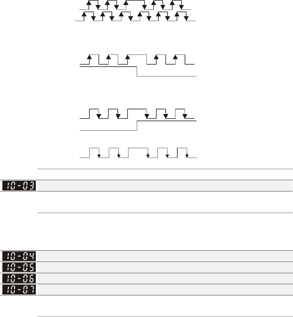
Chapter 12 Description of Parameter Settings|C2000 Series
12-151
2: Phase B leads in a forward run command and phase A leads in a reverse
run command
A
B
FWD REV
3: Phase A is a pulse input and phase B is a direction input. (L =reverse
direction, H=forward direction)
A
B
FWD REV
4: Phase A is a pulse input and phase B is a direction input. (L=forward
direction, H=reverse direction)
A
B
FWD REV
5: Single-phase input
A
Output Setting for Frequency Division (denominator)
Factory Setting: 1
Settings 1~255
This parameter is used to set the denominator for frequency division (for PG card EMC-PG01L or
EMC-PG01O). For example, when it is set to 2 with feedback 1024ppr, PG output will be
1024/2=512ppr.
Electrical Gear at Load Side A1
Electrical Gear at Motor Side B1
Electrical Gear at Load Side A2
Electrical Gear at Motor Side B2
Factory Setting: 100
Settings 1~65535
Parameters 10-04 to 10-07 can be used with the multi-function input terminal (set to 48) to switch
to Pr.10-04~10-05 or Pr.10-06~10-07 as shown as follows
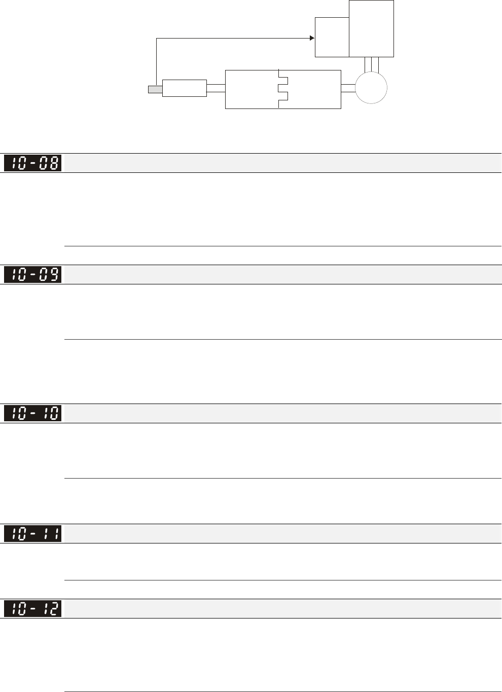
Chapter 12 Description of Parameter Settings|C2000 Series
12-152
ON =A2:B2
OFF=A1:B1
MI=48
Driver
PG
card
Motor
Gear
B1 or B2
Gear
A1 or A2
gear ratio
load
encoder is used
at load side
Treatment for Encoder Feedback Fault
Factory Setting: 2
Settings 0: Warn and keep operating
1: Warn and RAMP to stop
2: Warn and COAST to stop
Detection Time of Encoder Feedback Fault
Factory Setting: 1.0
Settings 0.0~10.0 sec
0: No function
When encoder loss, encoder signal error, pulse signal setting error or signal error, if time exceeds
the detection time for encoder feedback fault (Pr.10-09), the encoder signal error will occur. Refer
to the Pr.10-08 for encoder feedback fault treatment.
Encoder Stall Level
Factory Setting: 115
Settings 0~120%
0: No function
This parameter determines the maximum encoder feedback signal allowed before a fault occurs.
(Max. output frequency Pr.01-00 =100%)
Detection Time of Encoder Stall
Factory Setting: 0.1
Settings 0.0~2.0 sec
Treatment for Encoder Stall
Factory Setting: 2
Settings 0: Warn and keep operation
1: Warn and ramp to stop
2: Warn and coast to stop
When the motor frequency exceeds Pr.10-10 setting and detection time exceeds Pr.10-11, it will
operate as Pr.10-12 setting.
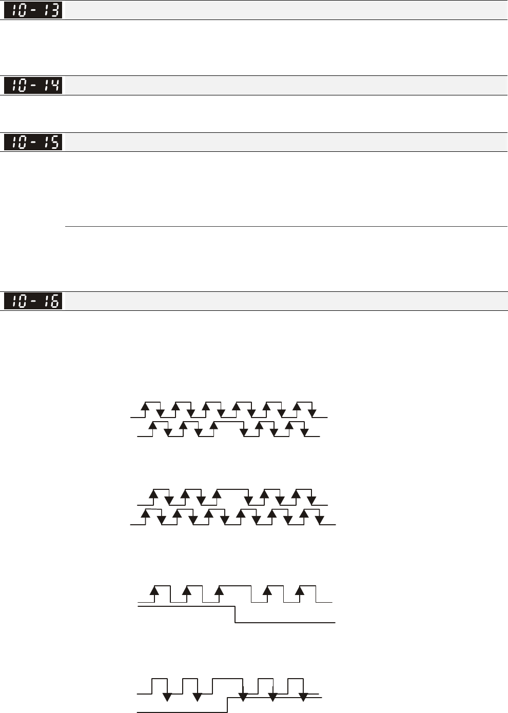
Chapter 12 Description of Parameter Settings|C2000 Series
12-153
Encoder Slip Range
Factory Setting: 50
Settings 0~50%
0: Disable
Detection Time of Encoder Slip
Factory Setting: 0.5
Settings 0.0~10.0 sec
Treatment for Encoder Stall and Slip Error
Factory Setting: 2
Settings 0: Warn and keep operation
1: Warn and ramp to stop
2: Warn and coast to stop
When the value of (rotation speed – motor frequency) exceeds Pr.10-13 setting, detection time
exceeds Pr.10-14; it will start to accumulate time. If detection time exceeds Pr.10-14, the encoder
feedback signal error will occur. Refer to Pr.10-15 encoder stall and slip error treatment.
Pulse Input Type Setting (PG card: PG2)
Factory Setting: 0
Settings 0: Disable
1: Phase A leads in a forward run command and phase B leads in a reverse
run command
A
B
FWD REV
2: Phase B leads in a forward run command and phase A leads in a reverse
run command
A
B
FWD REV
3: Phase A is a pulse input and phase B is a direction input. (L=reverse
direction, H=forward direction)
A
B
FWD REV
4: Phase A is a pulse input and phase B is a direction input. (L=forward
direction, H=reverse direction)
A
B
FWD REV
When this setting is different from Pr.10-01 setting and the source of the frequency command is
pulse input (Pr.00-20 is set to 4 or 5), it may have 4 times frequency problem.
Example: Assume that Pr.10-01=1024, Pr.10-02=1, Pr.10-16=3, Pr.00-20=5, MI=37 and ON, it
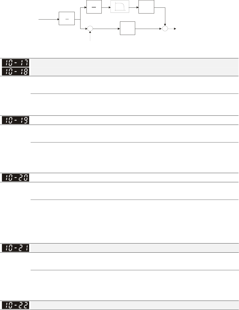
Chapter 12 Description of Parameter Settings|C2000 Series
12-154
needs 4096 pulses to rotate the motor a revolution.
Assume that Pr.10-01=1024, Pr.10-02=1, Pr.10-16=1, Pr.00-20=5, MI=37 and ON, it needs 1024
pulses to rotate the motor a revolution.
Position control diagram
d
dt kd
kp
+
-
11-00 bi t 0=0
11-24
11-00 bi t 0=1
11-0
5
11-2510-21
+
+
10-17
10-18
A
B
Position
command
Electrical
gear
Position
feedback
Speed
command
Electrical Gear A
Electrical Gear B
Factory Setting: 100
Settings 1~65535
Rotation speed = pulse frequency/encoder pulse (Pr.10-00) * PG Electrical Gear A / PG Electrical
Gear B.
Positioning for Encoder Position
Factory Setting: 0
Settings 0~65535 pulse
This parameter determines the internal position in the position mode.
It needs to be used with multi-function input terminal setting =35 (enable position control).
When it is set to 0, it is the Z-phase position of encoder.
Range for Encoder Position Attained
Factory Setting: 10
Settings 0~65535 pulse
This parameter determines the range for internal positioning position attained.
For example:
When the position is set by Pr.10-19 Positioning for Encoder Position and Pr.10-20 is set to 1000, it
reaches the position if the position is within 990-1010 after finishing the positioning.
Filter Time (PG2)
Factory Setting: 0.100
Settings 0.000~65.535 sec
When Pr.00-20 is set to 5 and multi-function input terminal is set to 37 (OFF), the pulse command
will be regarded as frequency command. This parameter can be used to suppress the jump of
speed command.
Speed Mode (PG2)
Factory Setting: 0
Settings 0: Electronic Frequency
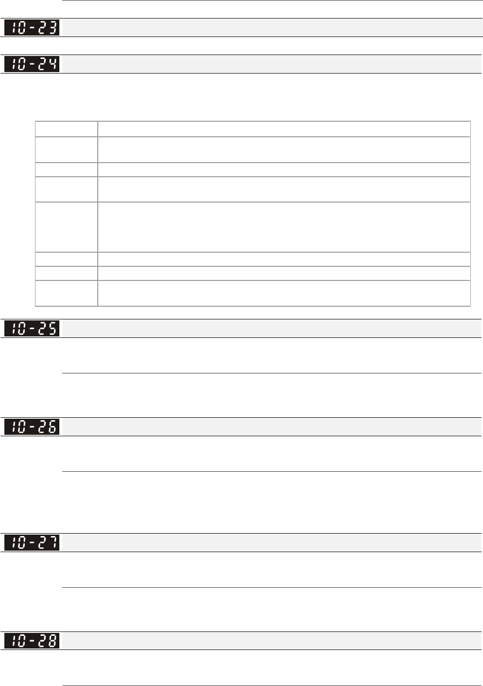
Chapter 12 Description of Parameter Settings|C2000 Series
12-155
1: Mechanical Frequency (base on pole pair)
Reserved
FOC&TQC Function Control
Factory Setting: 0
Settings 0~65535
Bit# Description
0 ASR control at sensorless torque
0:use PI as ASR; 1:use P as ASR
1~10 NA
11 Activate DC braking when executing zero torque command
0:ON , 1:OFF
12 FOC Sensorless mode, cross zero means speed goes from negative to
positive or positive to negative (forward to reverse direction or reverse to
forward direction). 0: determine by stator frequency , 1: determine by speed
command
13 NA
14 NA
15 Direction control at open loop status
0: Switch ON direction control 1: Switch OFF direction control
FOC Bandwidth of Speed Observer
Factory Setting:40.0
Settings 20.0~100.0Hz
Setting speed observer to higher bandwidth could shorten the speed response time but will create
greater noise interference during the speed observation. .
FOC Minimum Stator Frequency
Factory Setting:2.0
Settings 0.0~10.0%fN
This parameter is used to set the minimum level of stator frequency at operation status. This
setting ensures the stability and accuracy of observer and avoid interferences from voltage,
current and motor parameter.
FOC Low-pass Filter Time Constant
Factory Setting:50
Settings 1~1000ms
This parameter sets the low-pass filter time constant of a flux observer at start up. If the motor can
not be activated during the high-speed operation, please lower the setting in this parameter.
FOC Gain of Excitation Current Rise Time
Factory Setting:100
Settings 33~100% Tr (Tr: rotor time constant)
This parameter sets the drive’s excitation current rise time when activates at senslorless torque
mode. When the drive’s activation time is too long at torque mode, please adjust this parameter to
Chapter 12 Description of Parameter Settings|C2000 Series
12-156
a shorter time constant.
Top Limit of Frequency Deviation
Factory Setting: 20.00
Settings 0.00~100.00Hz
Pr.10-29 is for setting the maximum of frequency deviation.
Resolver Pole Pair
Factory Setting: 1
Settings 1~50
To use Pr.10-30 function, user must set Pr.10-00=3(Resolver Encoder) first.
Reserved
Reserved
Reserved
Reserved
I/F Mode, current command
Factory Setting: 40
Settings 0~150%Irated (
Rated current % of the drive)
PM Sensorless Obeserver Bandwith for High Speed Zone
Factory Setting: 5.00
Settings 0.00~600.00Hz
PM Sensorless Observer Low-pass Filter Gain
Factory Setting: 1.00
Settings 0.00~655.35Hz
PM Sensorless Control Word
Factory Setting: 0000
Settings 0000~FFFFh
Bit No. Function Description
0 Reserved
1 Reserved
2 Choose a control mode to
statrt.
0 :Start by IF mode
1: Start by VF mode
3 Choose a mode to stop . 0 :Stop by IF mode
1 :Stop by VF mode
4 Reserved
5 Choose a control mode to stop 0 : When lower than Pr10-40, coast to stop
If lower than Pr10-40, decelerate to stop by VF mode.
6 Reserved
7 Reserved
Frequency Point when switch from I/F mode to PM Sensorless mode

Chapter 12 Description of Parameter Settings|C2000 Series
12-157
Factory Setting: 20.00
Settings 0.00~600.00Hz
Frequency Point when switch from PM Sensorless Observation mde to I/F mode
Factory Setting: 20.00
Settings 0.00~600.00Hz
I/F mode, low pass-filter time
Factory Setting: 0.2
Settings 0.0~6.0 sec
Initial Angle Detection Time
Factory Setting: 5
Settings 0~20 ms
PM Sensorless Adjustment Procedure
1. When using high frequency standstill VFD parameter tuning, use VFD software v1.45 to
monitor adjustment procedure. To download VFD Sotware v1.45. go to:
http://www.delta.com.tw/product/em/drive/ac_motor/download/software/VFDSoft%20v1.45.zip
2. Testing PM High Frequency Standstill VFD (calculation of Rs, Ld, Lg)
Procedures:
A. Set control mode as VF mode (Pr00-10=0, Pr00-11=0
B. Output Frequency of Motor 1 (Pr01-01)
C. Output Voltage of Motor 1 (Pr01-02)
D. Induction Motor and Permanent Magnet Motor Selection (Pr05-33=1)
E. Full-load current of Permanent Magnet Motor(Pr05-34
F. Set Moto Auto Tuning Pr 05-00 =13; High frequency and blocked rotor test for PM motor. Then
run the drive.
3. Set control mode as PM sensorless Mode (Parameters 00-10=0, 00-11=6)
4. Set VFD Prameters
; Pr05-35 Rated Power of Permanent Magnet Motor
; Pr05-36 Rated speed of Permanent Magnet Motor
; Pr05-37 Pole number of Permanent Magnet Motor
; Pr05-38 Inertia of Permanent Magnet Motor
5. 設定 ASR 參數 Set ASR Parameters
; Pr11-00 bit0=1: Auto tuning for ASR and APR
; Pr11-02:ASR1/ASR2 Switch Frequency, it is recommended to set Pr10-39 higher than
10Hz.
; Pr11-03: ASR1 Low-speed Bandwidth and Pr11-03, ASR2 High-speed Bandwidth. Do not set
Low-speed Bandwith too high to avoid dissipation of the estimator.
6. Set speed estimator and speed control’s parameter.
; Pr10-39 Frequency when switch from I/F Mode to PM sensorless mode.
; Pr10-32 PM Sensorless Obeserver Bandwith for High Speed Zone
7. Zero-load test
; Refer to switch point prodcedure of I/F and FOC as shown in the image below.
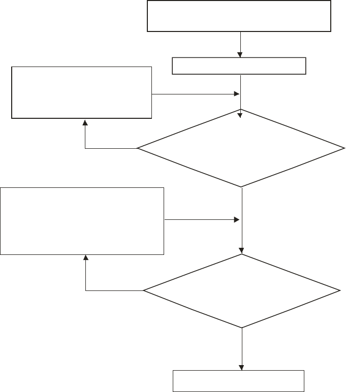
Chapter 12 Description of Parameter Settings|C2000 Series
12-158
Set frequency command
(Higher than switching command)
Perform RUN command
Yes
NO
Yes
NO
Big variation of current or
OC while switching
Lower Per Unit of System
Inertia (Pr.11-01)/
Lower ASR1 Low-speed
Bandwidth (Pr.11-03)
Can the drive run
normally until switching
to higher frequency?
Big variation of output
frequency or dissipation Observe output current
fequency via
commnucation intrefac
e
/
Increase load and Test
Observe output current
fequency via
commnucation intreface
/
Procedure for switching between I
F mode and FOC mode
/
When running at high
frequency, is the frequency
stable?
IncreasePM Sensorless
Observer Bandwidth for
High Speed Zone (Pr.10-32)/
Decrease Per Unit of
System Inertia (Pr.11-01)
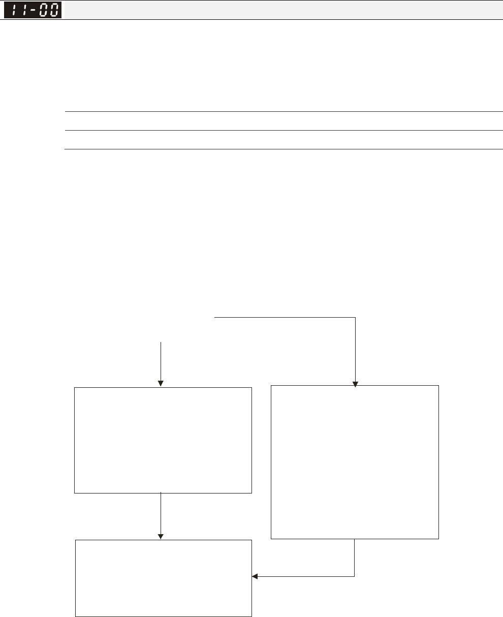
Chapter 12 Description of Parameter Settings|C2000 Series
12-159
11 Advanced Parameters This parameter can be set during operation.
In this parameter group, ASR is the abbreviation for Adjust Speed Regulator
System Control
Factory Setting: 0
Settings 0: Auto tuning for ASR and APR
1: Inertia estimate (only in FOCPG mode)
2: Zero servo
3: Dead time compensation closed
7: Selection to save or not save the freqeuncy
8: Maximum speed of point to point position control
Bit 0=0: Pr.11-06 to 11-11 will be valid and Pr.11-03~11-05 are invalid.
Bit 0=1: system will generate an ASR setting. At this moment, Pr.11-06~11-11 will be invalid and
Pr.11-03~11-05 are valid.
Bit 1=0: no function.
Bit 1=1: Inertia estimate function is enabled. (Bit 1 setting would not activate the estimation
process, please set Pr.05-00=12 to begin FOC/TQC Sensorless inertia estimating)
Bit 2=0: no function.
Bit 2=1: when frequency command is less than Fmin (Pr.01-07), it will use zero servo function.
YES
NO
Estimate inertia value
Setting auto gain adjustment
Pr.11-00=1
Adjust Pr.11-03, 11-04 and 11-05
separately by speed response
Adjust by requirement
Pr.11-13 (PDFF function)
Adjust by requirement
Pr.11-02
(ASR1/ASR2 switch frequency)
Adjust by requirement
Pr.11-17~20 (torque limit)
Adjust gain value by manual
Pr.11-00=0 (factory setting)
Adjust Pr.11-06, 11-07, 11-08,
11-09, 11-10 and 11-11
separately by speed response
Adjust by requirement
Pr.11-14 (for general,
no need to adjust)
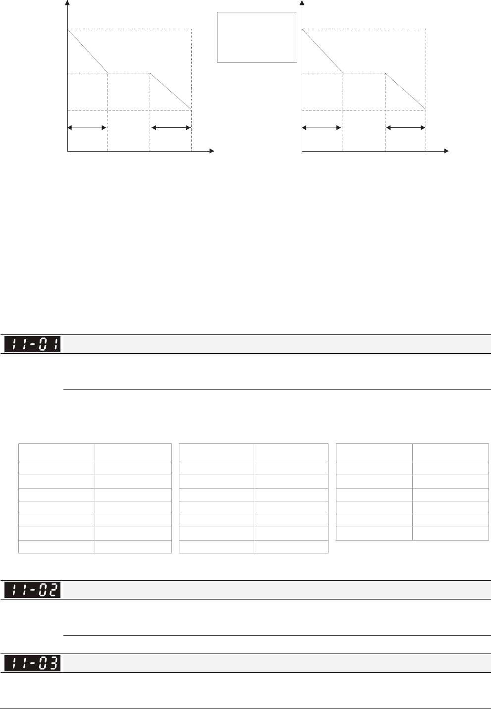
Chapter 12 Description of Parameter Settings|C2000 Series
12-160
PI adjustment-manual gain PI adjustment-auto gain
1. Pr. 11-01 value
2. set Pr.11-00 to bit 0=1
Pr.11-05
use to adjust the
strength of zero-
servo lock
P
I
Hz
11-10
11-11
11-08
11-09
11-06
11-07
0Hz 11-02
5Hz 5Hz
P
I
Hz
11-05
11-04
0Hz
5Hz 5Hz
11-02
Bit 7=0: frequency is saved before power turns off. When power turns on again, the display
frequency will be the memorized frequency.
Bit 7=1: frequency is not saved before power turns off. When power turns ON again, the display
frequency will be 0.00Hz.
Bit 8=0: maximum speed for point-to-point position control is control by the setting of Pr.11-43.
Bit 8=1: maximum speed for point-to-point position control is control by the multi-step speed
setting of the external terminal device. When multi-step speed of the external device is set to 0,
the maximum operation speed will bet the setting of Pr.11-43.
Per Unit of System Inertia
Factory Setting: 400
Settings 1~65535(256=1PU)
To get the system inertia from Pr.11-01, user needs to set Pr.11-00 to bit1=1 and execute
continuous forward/reverse running.
Unit of induction motor system inertia is 0.001kg-m^2:
Power Setting Power Setting Power Setting
1HP 2.3 20HP 95.3 100HP 1056.5
2HP 4.3 25HP 142.8 125HP 1275.3
3HP 8.3 30HP 176.5 150HP 1900.0
5HP 14.8 40HP 202.5 175HP 2150.0
7.5HP 26.0 50HP 355.5 215HP 2800.0
10HP 35.8 60HP 410.8 300HP 3550.0
15HP 74.3 75HP 494.8
The base value for induction motor system inertia is set by Pr.05-38 and the unit is in 0.001kg-m^2.
ASR1/ASR2 Switch Frequency
Factory Setting: 7.00
Settings 5.00~600.00Hz
ASR1 Low-speed Bandwidth
Factory Setting: 10
Settings 1~40Hz (IM)/ 1~100Hz (PM)
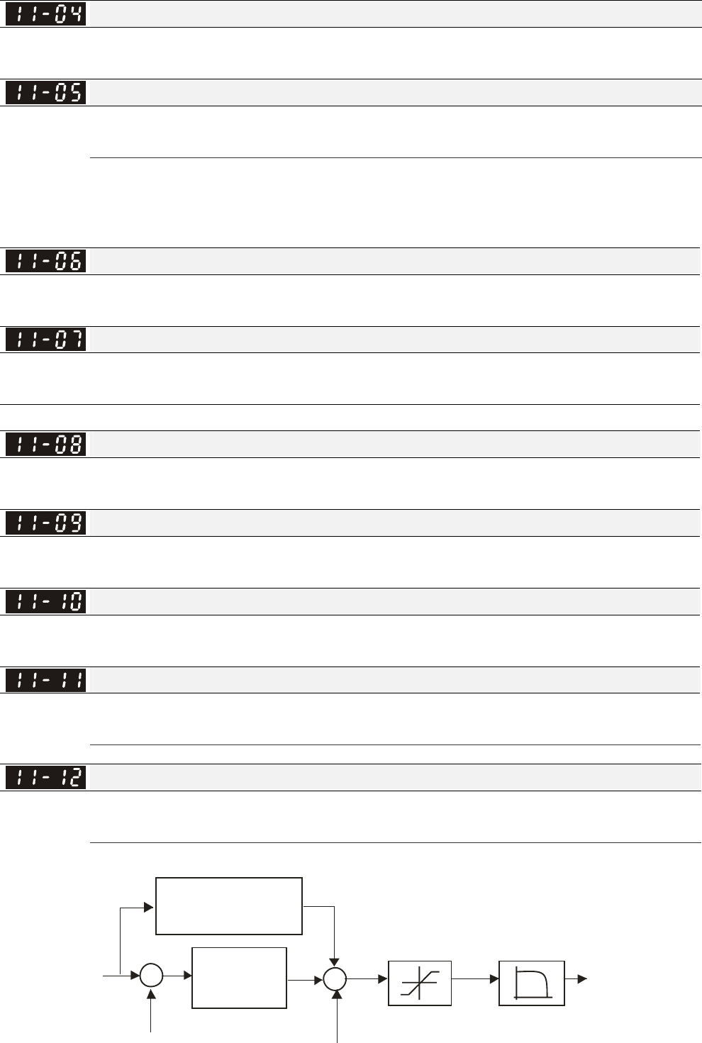
Chapter 12 Description of Parameter Settings|C2000 Series
12-161
ASR2 High-speed Bandwidth
Factory Setting: 10
Settings 1~40Hz (IM)/ 1~100Hz (PM)
Zero-speed Bandwidth
Factory Setting: 10
Settings 1~40Hz (IM)/ 1~100Hz (PM)
After estimating inertia and set Pr.11-00 to bit 0=1 (auto tuning), user can adjust parameters
Pr.11-03, 11-04 and 11-05 separately by speed response. The larger number you set, the faster
response you will get. Pr.11-02 is the switch frequency for low-speed/high-speed bandwidth.
ASR (Auto Speed Regulation) control (P) 1
Factory Setting: 10
Settings 0~40 Hz (IM)/ 1~100Hz (PM)
ASR (Auto Speed Regulation) control (I) 1
Factory Setting: 0.100
Settings 0.000~10.000 sec
ASR (Auto Speed Regulation) control (PI) 2
Factory Setting: 10
Settings 0~40 Hz (IM)/ 0~100Hz (PM)
ASR (Auto Speed Regulation) control (I) 2
Factory Setting: 0.100
Settings 0.000~10.000 sec
ASR(Auto Speed Regulation) Control (P) of Zero Speed
Factory Setting: 10
Settings 0~40 Hz (IM)/ 0~100Hz (PM)
ASR(Auto Speed Regulation) Control (I) of Zero Speed
Factory Setting: 0.100
Settings 0.000~10.000 sec
Gain for ASR Speed Feed Forward
Factory Setting: 0
Settings 0~100%
This parameter is used to improve speed response.
ASR
11- 1 4
00-20
++
+
11- 17~11- 20
-
+
Tq Bias
Speed feedback
Torque limit
To r q u e
command
11- 1 2
Gain for ASR
speed feed forward
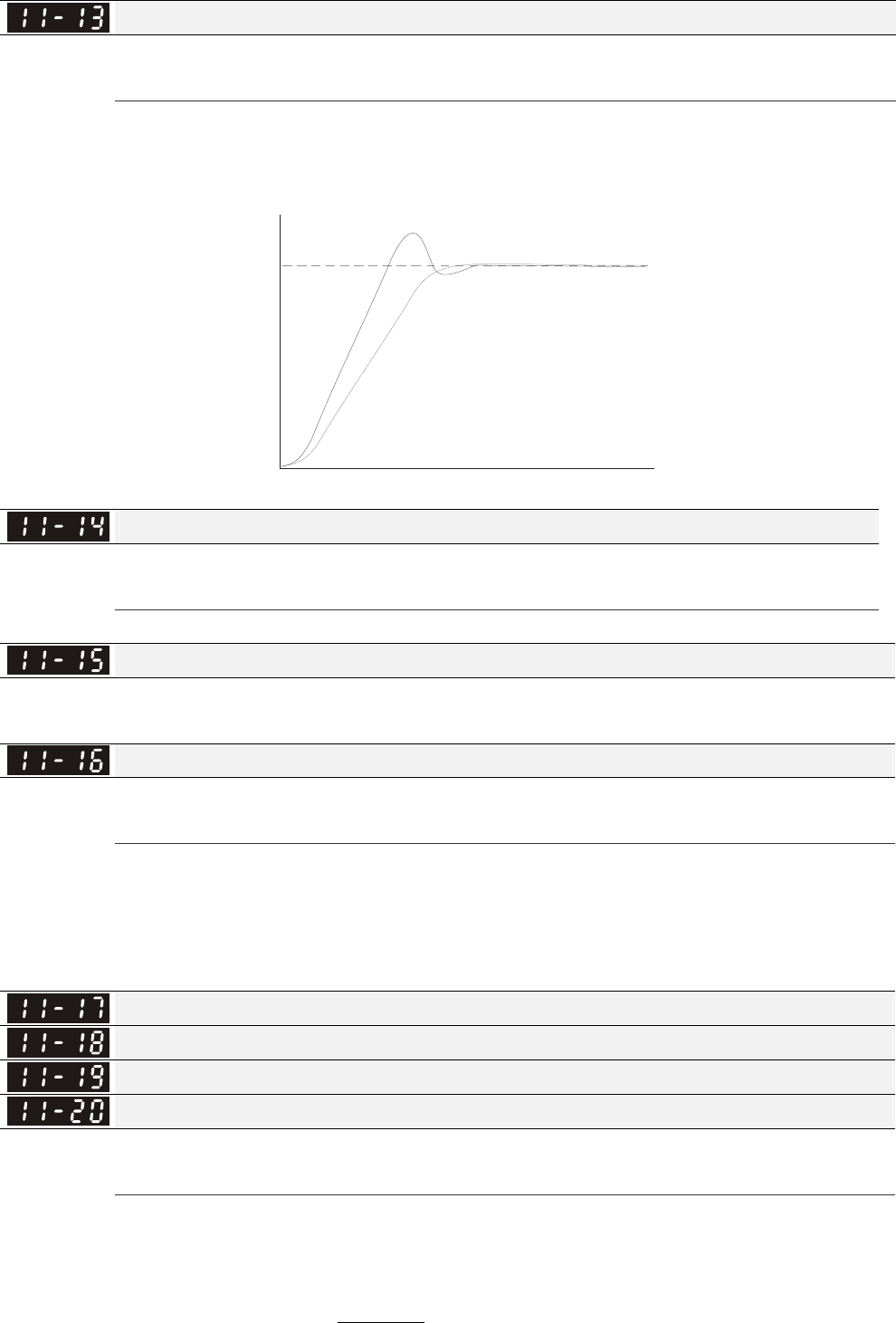
Chapter 12 Description of Parameter Settings|C2000 Series
12-162
PDFF Gain Value
Factory Setting: 30
Settings 0~200%
After finishing estimating and set Pr.11-00 to bit 0=1 (auto tuning), using Pr.11-13 to reduce
overshoot. Please adjust PDFF gain value by actual situation.
This parameter will be invalid when Pr.05-24 is set to 1.
PI PDFF
Tim
e
frequenc
y
Low-pass Filter Time of ASR Output
Factory Setting: 0.008
Settings 0.000~0.350 sec
It is used to set the filter time of ASR command.
Notch Filter Depth
Factory Setting: 0
Settings 0~20db
Notch Filter Frequency
Factory Setting: 0.00
Settings 0.00~200.00Hz
This parameter is used to set resonance frequency of mechanical system. It can be used to
suppress the resonance of mechanical system.
The larger number you set Pr.11-15, the better suppression resonance function you will get.
The notch filter frequency is the resonance of mechanical frequency.
Forward Motor Torque Limit
Forward Regenerative Torque Limit
Reverse Motor Torque Limit
Reverse Regenerative Torque Limit
Factory Setting: 500
Settings 0~500%
The motor rated torque is 100%. The settings for Pr.11-17 to Pr.11-20 will compare with
Pr.03-00=7, 8, 9, 10. The minimum of the comparison result will be torque limit.
Calculation equation for motor rated torque:
Motor rated torque= )/(
)(
).( srad
WP
MNT
ω
=
; P(W) value= Pr.05-02;
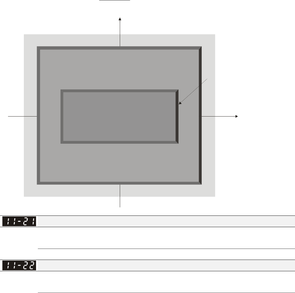
Chapter 12 Description of Parameter Settings|C2000 Series
12-163
ω(rad/s) value= Pr.05-03。srad
RPM /
60
2=
×
π
Positive
torque
Negative
torque
speed
06-12 current limit 06-12 current limit
06-12 current limit 06-12 current limit
Reverse motor mode Forward motor mo de
Forward motor mode
Reverse motor mode
The level of torque limit will be
the min. va lue of following thre e values
External analog terminals
Pr.03-00~02
7: positive torque limit
10: positive/negative torque limit
9: regenerative torque limit
External analog terminals
Pr.03-00~02
7: po sitive torque limit
10: positive/ne gative torque limit
External analog termin als
Pr.03-00~03-02
8: nega tive torque limit
10: positive/negative torque limit
External analog terminals
Pr.03-00~03-02
8: negative torque limit
10: positive/negative torque limit
Pr.11-19
Reverse regenerative
torque limit
Pr.11-17
Forward motor
torque limit
Pr.11-18
Forward regenera tive
torque limit
Pr.11-20
Reverse motor
torque limit
Quadrant I
Quadrant II
Quadrant III Quadrant IV
speed
Gain Value of Flux Weakening Curve for Motor 1
Factory Setting: 90
Settings 0~200%
Gain Value of Flux Weakening Curve for Motor 2
Factory Setting: 90
Settings 0~200%
Pr.11-21 and 11-22 are used to adjust the output voltage of flux weakening curve.
For the spindle application, the adjustment method is
1. It is used to adjust the output voltage when exceeding rated frequency.
2. Monitor the output voltage
3. Adjust Pr.11-21 (motor 1) or Pr.11-22 (motor 2) setting to make the output voltage reach motor
rated voltage.
4. The larger number it is set, the larger output voltage you will get.
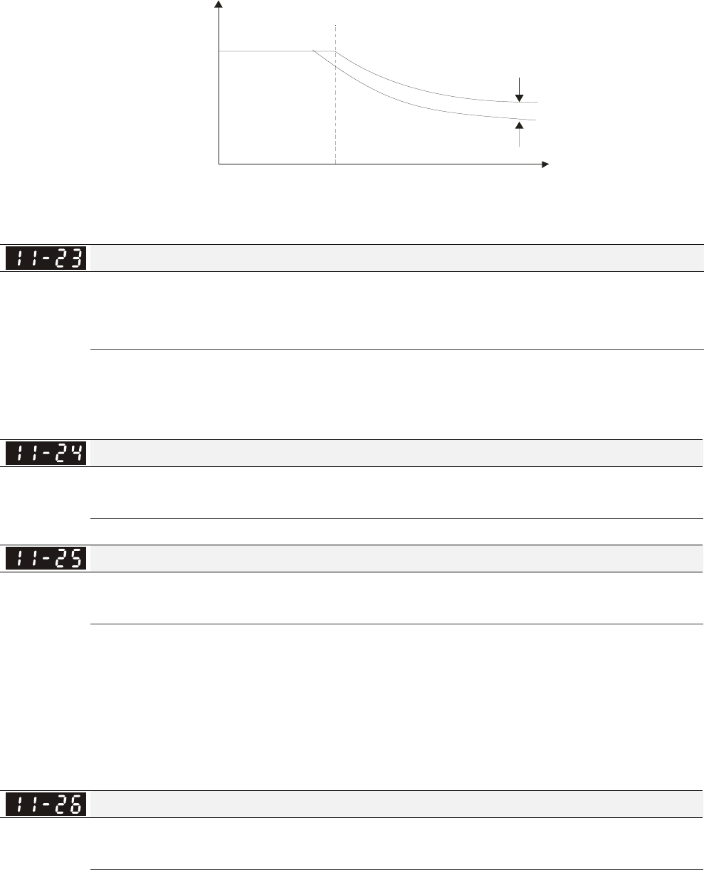
Chapter 12 Description of Parameter Settings|C2000 Series
12-164
01-01
or
01-35
11-21
or
11-22
100%
90%
output torque
Flux weakening curve
frequency
Speed Response of Flux Weakening Area
Factory Setting: 65
Settings 0: Disable
0~150%
It is used to control the speed in the flux weakening area. The larger value is set in Pr.11-23, the
faster acceleration/deceleration will generate. In general, it is not necessary to adjust this
parameter.
APR Gain
Factory Setting: 10.00
Settings 0.00~40.00 (IM)/ 0~100.00Hz (PM)
Kip gain of internal position is determined by Pr.11-05.
Gain Value of APR Feed Forward
Factory Setting: 30
Settings 0~100
For the position control, if it set a larger value in Pr.11-25, it can shorten the pulse differential and
speed up the position response. But it may overshoot.
When the multi-function input terminal is set to 37(ON), this parameter can be set as required. If
this parameter is set to a non zero value and adjust Pr.10-21 (PG2 Filter Time) to reduce the
position overshoot and pulse differential. If it is set to 0, it won’t have overshoot problem in
position control but the pulse differential is decided by Pr.11-05 (KP gain).
APR Curve Time
Factory Setting: 3.00
Settings 0.00~655.35 sec
It is valid when the multi-function input terminal is set to 35(ON). The larger it is set, the longer the
position time will be.
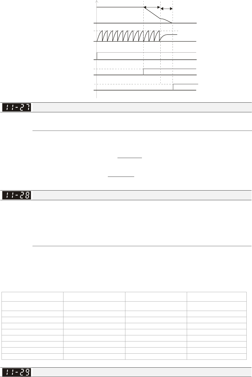
Chapter 12 Description of Parameter Settings|C2000 Series
12-165
Output
Frequency
PG Feedback
10-00
10-01
RUN
MI=d35
MO=d39
10-19
Time
11-4511-46
Max. Torque Command
Factory Setting: 100
Settings 0~500%
The upper limit of torque command is 100%.
Calculation equation for motor rated torque:
motor rated torque: )/(
)(
).( srad
WP
MNT
ω
=; P(W) value= Pr.05-02;
ω(rad/s) value= Pr.05-03。srad
RPM /
60
2=
×
π
Source of Torque Offset
Factory Setting: 0
Settings 0: Disable
1: Analog input (Pr.03-00)
2: Torque offset setting (Pr.11-29)
3: Control by external terminal (by Pr.11-30 to Pr.11-32)
This parameter is the source of torque offset.
When it is set to 3, source of torque offset would determine Pr.11-30 to Pr.11-32 by
When it is set to 3, the source of torque offset will regard Pr.11-30~11-32 by the multi-function
input terminals (MI) setting (31, 32 or 33).
N.O. switch status: ON= contact closed, OFF= contact open
Pr. 11-32 Pr. 11-31 Pr. 11-30
MI=33(High) MI=32(Mid) MI=31(Low) Torque Offset
OFF OFF OFF None
OFF OFF ON 11-30
OFF ON OFF 11-31
OFF ON ON 11-30+11-31
ON OFF OFF 11-32
ON OFF ON 11-30+11-32
ON ON OFF 11-31+11-32
ON ON ON 11-30+11-31+11-32
Torque Offset Setting
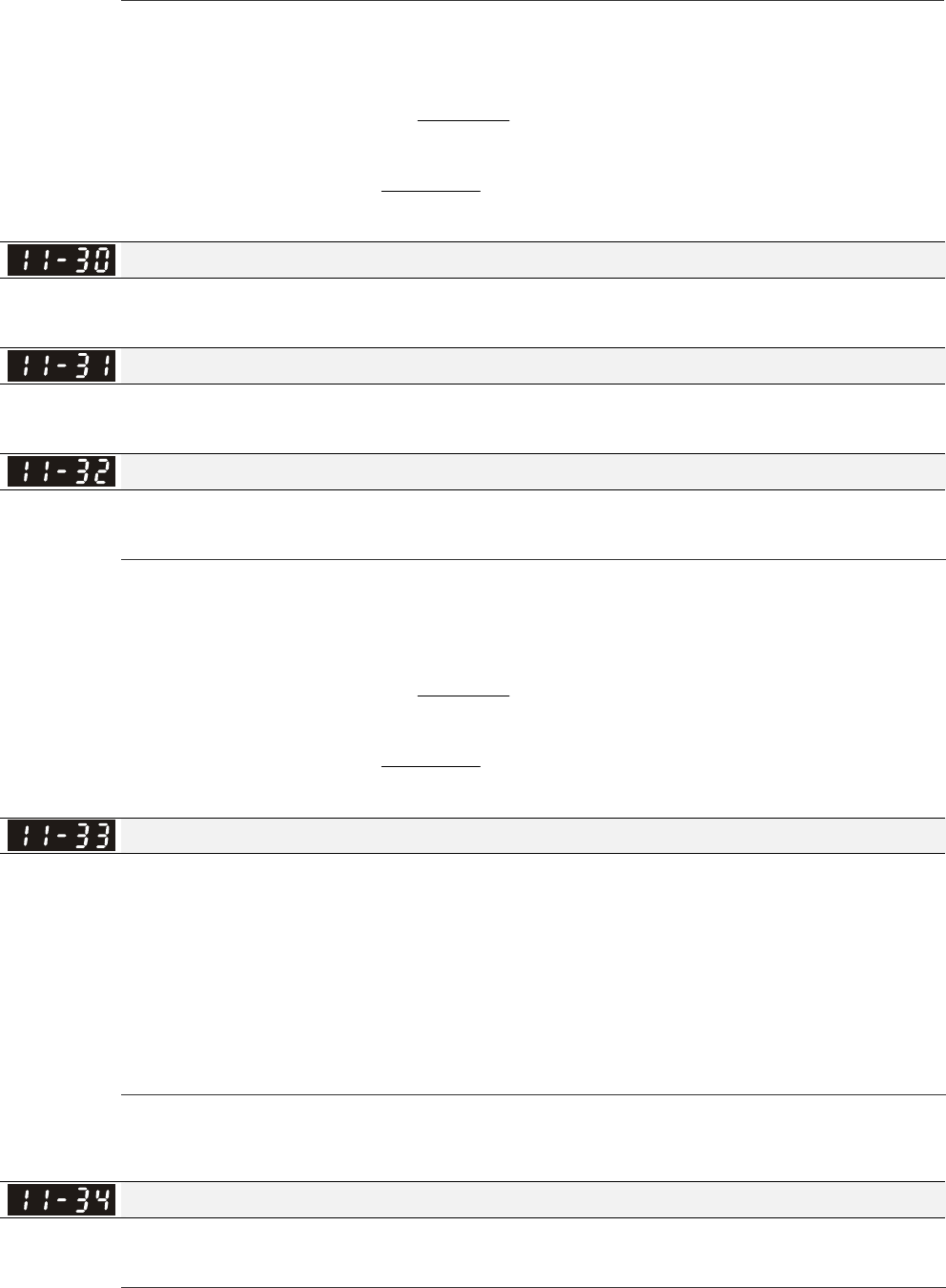
Chapter 12 Description of Parameter Settings|C2000 Series
12-166
Factory Setting: 0.0
Settings 0.0~100.0%
This parameter is torque offset. The motor rated torque is 100%.
Calculation equation for motor rated torque:
motor rated torque: )/(
)(
).( srad
WP
MNT
ω
=; P(W) value= Pr.05-02;
ω(rad/s) value= Pr.05-03。srad
RPM /
60
2=
×
π
High Torque Offset
Factory Setting: 30.0
Settings 0.0~100.0%
Middle Torque Offset
Factory Setting: 20.0
Settings 0.0~100.0%
Low Torque Offset
Factory Setting: 10.0
Settings 0.0~100.0%
When it is set to 3, the source of torque offset will regard Pr.11-30, Pr.11-31 and Pr.11-32 by the
multi-function input terminals setting (31, 32 or 33). The motor rated torque is 100%.
Calculation equation for motor rated torque:
motor rated torque: )/(
)(
).( srad
WP
MNT
ω
=; P(W) value= Pr.05-02;
ω(rad/s) value= Pr.05-03。srad
RPM /
60
2=
×
π
Source of Torque Command
Factory Setting: 0
Settings 0: Digital Keypad (Pr.11-34)
1: RS485 serial communication
2: Analog signal (Pr.03-00)
3: CANopen
4: Reserved
5: Communication card
When Pr.11-33 is set to 0, torque command can be set in Pr.11-34.
When Pr.11-33 is set to 1 or 2, Pr.11-34 would only display the torque command
Torque Command
Factory Setting: 0.0
Settings -100.0~100.0%(Pr.11-27=100%)
This parameter is for the torque command. When Pr.11-27 is set to 250% and Pr.11-34 is set to
100%, actual torque command=250X100%=250% motor rated torque.
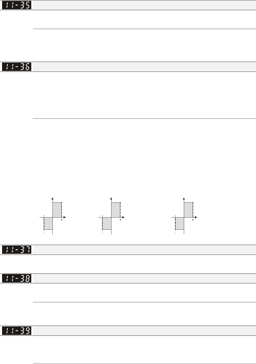
Chapter 12 Description of Parameter Settings|C2000 Series
12-167
The drive will save the setting to the record before power turns off.
Low-pass Filter Time of Torque Command
Factory Setting: 0.000
Settings 0.000~1.000 sec
When the setting is too long, the control will be stable but the control response will be delay. When
the setting is too short, the response will be quickly but the control maybe unstable. User can
adjust the setting by the control and response situation.
Speed Limit Selection
Factory Setting: 0
Settings 0: Set by Pr.11-37 (Forward speed limit) and Pr.11-38 (Reverse speed limit)
1: Set by Pr.11-37,11-38 and Pr.00-20 (Source of Master Frequency
Command)
2: Set by Pr.00-20 (Source of Master Frequency Command).
Speed limit function: in TQCPG, when the motor speed is accelerated to speed limit value
(Pr.11-36, 11-37 and 11-38), it will switch to speed control mode to stop acceleration.
When the torque is positive direction, speed limit is positive direction. When the torque is negative
direction, speed limit is negative direction.
to rque
Pr.11-36=0
running
direction are
limited by Pr.11-37
and Pr.11-38.
Forward/reverse
Pr.11-36=1
Whe n it is forward runn in g,
running direction is limited
by Pr.00-20
reverse runnin g direction
is limited by Pr.11-38.
Pr.11-36=1
Whe n it is reverse runn in g,
running direction is limited
by Pr.11-37
reverse running direction
is limited by Pr.00-20.
00-20
00-20
11-38
11-37
11-38
11-37
torque torque
motor
speed
motor
speed
motor
speed
Forward Speed Limit (torque mode)
Factory Setting: 10
Settings 0~120%
Reverse Speed Limit (torque mode)
Factory Setting: 10
Settings 0~120%
These parameters are used in the torque mode to limit the running direction and opposite
direction. (Pr.01-00 max. output frequency=100%)
Zero Torque Command Mode
Factory Setting: 0
Settings 0: Torque mode
1: Speed mode
This parameter defines the torque command mode at 0% of torque output. When Pr.11-39 is set
Chapter 12 Description of Parameter Settings|C2000 Series
12-168
as 0 (the torque mode), if torque command is 0%, the motor will produce excitation current but no
torque current. When Pr.11-39 is set as 1 (the speed mode), if torque command is 0%, the AC
motor drive can still produce torque current through speed controller to prevent motor race and
the drive will also atomatically adjust the speed to 0 when the speed command is not equal to 0.
Command Source of Point-to-Point Position Control
Factory Settings:0
Settings 0: External terminal
1: Reserved
2: RS485
3: CAN
4: PLC
5: Communication card
Reserved
系統控制旗標
Factory Settings: 0000
Settings 0000~FFFFh
Bit No. Function Description
0
A
t torque mode, selection between
speed control and current control.
0:Speed control at torque mode, the largest current
limit is the torque command.
1: Speed control at torque mode, P06-12 the largest
current limit is Pr06-12
1 FWD/REV direction control 0: FWD/REV cannot be controlled by 02-12 bit 0 & 1
1: FWD/REV can be controlled by 02-12 bit 0&1
2 Fuzzy PID selection control 0: Fuzzy PID enabled
1: Fuzzy PID disabled
3~15 Reserved
Max. Frequency of Point- to-Point Position Control
Factory Settings:10.00
Settings 0.00~327.67Hz
Accel. Time of Point-to Point Position Control
Factory Settings:1.00
Settings 0.00~655.35sec
Decel. Time of Point-to Point Position Control
Factory Settings:3.00
Settings 0.00~655.35sec
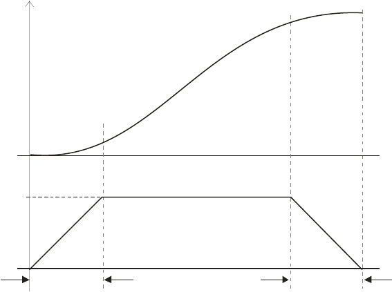
Chapter 12 Description of Parameter Settings|C2000 Series
12-169
Max. Frequency
11-43
11-44 11-45
Position
Speed
Accel. time Decel. time

Chapter 13 Warning Codes|CT2000 Series
13-1
Chapter 13Warning Codes
CE01
Comm. Error 1
Warning
Abbreviate error code
The code is displayed as shown on KPC-CE01.
Display error signal
Display error description
Display on LCM Keypad Descriptions
CE01
Comm. Error 1
Warning
Modbus function code error
CE02
Comm. Error 2
Warning
Address of Modbus data is error
CE03
Comm. Error 3
Warning
Modbus data error
CE04
Comm. Error 4
Warning
Modbus communication error
CE10
Comm. Error 10
Warning
Modbus transmission time-out
CP10
Keypad time out
Warning
Keypad transmission time-out
SE1
Save Error 1
Warning
Keypad COPY error 1
SE2
Save Error 2
Warning
Keypad COPY error 2
SE3
Copy Model Err 3
Warning
Keypad COPY error 3

Chapter 13 Warning Codes|CT2000 Series
13-2
Display on LCM Keypad Descriptions
oH1
Over heat 1 warn
Warning
IGBT over-heating warning
oH2
Over heat 2 warn
Warning
Capacity over-heating warning
PID
PID FBK Error
Warning
PID feedback error
ANL
A
nalog loss
Warning
ACI signal error
When Pr03-19 is set to 1 and 2.
uC
Under Current
Warning
Low current
AUE
A
uto-tune error
Warning
Auto tuning error
PGFB
PG FBK Warn
Warning
PG feedback error
PGL
PG Loss Warn
Warning
PG feedback loss
oSPD
Over Speed Warn
Warning
Over-speed warning
DAvE
Deviation Warn
Warning
Over speed deviation warning
PHL
Phase Loss
Warning
Phase loss
ot1
Over Torque 1
Warning
Over torque 1

Chapter 13 Warning Codes|CT2000 Series
13-3
Display on LCM Keypad Descriptions
ot2
Over Torque 2
Warning
Over torque 2
oH3
Motor Over Heat
Warning
Motor over-heating
oSL
Over Slip Warn
Warning
Over slip
tUn
A
uto tuning
Warning
Auto tuning processing
CGdn
Guarding T-out
Warning
CAN guarding time-out 1
CHbn
Heartbeat T-out
Warning
CAN heartbeat time-out 2
CSYn
SYNC T-out
Warning
CAN synchrony time-out
CbFn
Can Bus Off
Warning
CAN bus off
CSdn
SDO T-out
Warning
CAN SDO transmission time-out
CSbn
Buf Overflow
Warning
CAN SDO received register overflow
Cbtn
Boot up fault
Warning
CAN boot up error
CPtn
Error Protocol
Warning
CAN format error

Chapter 13 Warning Codes|CT2000 Series
13-4
Display on LCM Keypad Descriptions
CIdn
Warning
CAN/S Idx exceed
CAN index error
CAdn
Warning
CAN/S Addres set
CAN station address error
CFrn
Warning
CAN/S FRAM fail
CAN memory error
PLod
Opposite Defect
Warning
PLC download error
PLSv
Save mem defect
Warning
Save error of PLC download
PLdA
Data defect
Warning
Data error during PLC operation
PLFn
Function defect
Warning
Function code of PLC download error
PLor
Buf overflow
Warning
PLC register overflow
PLFF
Function defect
Warning
Function code of PLC operation error
PLSn
Check sum error
Warning
PLC checksum error
PLEd
No end command
Warning
PLC end command is missing
PLCr
PLC MCR error
Warning
PLC MCR command error

Chapter 13 Warning Codes|CT2000 Series
13-5
Display on LCM Keypad Descriptions
PLdF
Download fail
Warning
PLC download fail
PLSF
Scane time fail
Warning
PLC scan time exceed
PCGd
Warning
CAN/M Guard err
CAN Master guarding error
PCbF
Warning
CAN/M bus off
CAN Master bus off
PCnL
Warning
CAN/M Node Lack
CAN Master node error
PCCt
Warning
CAN/M cycle time-out
PCSF
Warning
CAN/M SDO over
CAN/M SDOover
PCSd
Warning
CAN/M Sdo Tout
CAN/M SDO time-out
PCAd
Warning
CAN/M Addres set
CAN/M station address error
ECid
ExCom ID failed
Warning
Duplicate MAC ID error
Node address setting error

Chapter 13 Warning Codes|CT2000 Series
13-6
Display on LCM Keypad Descriptions
ECLv
ExCom pwr loss
Warning
Low voltage of communication card
ECtt
ExCom Test Mode
Warning
Communication card in test mode
ECbF
ExCom Bus off
Warning
DeviceNet bus-off
ECnP
ExCom No power
Warning
DeviceNet no power
ECFF
ExCom Facty def
Warning
Factory default setting error
ECiF
ExCom Inner err
Warning
Serious internal error
ECio
ExCom IONet brk
Warning
IO connection break off
ECPP
ExCom Pr data
Warning
Profibus parameter data error
ECPi
ExCom Conf data
Warning
Profibus configuration data error
ECEF
ExCom Link fail
Warning
Ethernet Link fail
ECto
ExCom Inr T-out
Warning
Communication time-out for communication card and drive
ECCS
ExCom Inr CRC
Warning
Check sum error for Communication card and drive

Chapter 13 Warning Codes|CT2000 Series
13-7
Display on LCM Keypad Descriptions
ECrF
ExCom Rtn def
Warning
Communication card returns to default setting
ECo0
ExCom MTCP over
Warning
Modbus TCP exceed maximum communication value
ECo1
ExCom EIP over
Warning
EtherNet/IP exceed maximum communication value
ECiP
ExCom IP fail
Warning
IP fail
EC3F
ExCom Mail fail
Warning
Mail fail
Ecby
ExCom Busy
Warning
Communication card busy
Plra
RTC Adjust
Warning
Adjust RTC

Chapter 14 Fault Codes and Descriptions |CT2000 Series
14-1
Chapter 14 Fault Codes and Descriptions
CE01
Comm. Error 1
Warning
Abbreviate error code
The code is displayed as shown on KPC-CE01.
Display error signal
Display error description
Fault Name Fault Descriptions Corrective Actions
ocA
Oc at accel
Fault
Over-current during
acceleration
(Output current exceeds
triple rated current during
acceleration.)
1. Short-circuit at motor output: Check for possible
poor insulation at the output.
2. Acceleration Time too short: Increase the
Acceleration Time.
3. AC motor drive output power is too small:
Replace the AC motor drive with the next higher
power model.
ocd
Oc at decel
Fault
Over-current during
deceleration
(Output current exceeds
triple rated current during
deceleration.)
1. Short-circuit at motor output: Check for possible
poor insulation at the output.
2. Deceleration Time too short: Increase the
Deceleration Time.
3. AC motor drive output power is too small:
Replace the AC motor drive with the next higher
power model.
ocn
Oc at normal SPD
Fault
Over-current during
steady state operation
(Output current exceeds
triple rated current during
constant speed.)
1. Short-circuit at motor output: Check for possible
poor insulation at the output.
2. Sudden increase in motor loading: Check for
possible motor stall.
3. AC motor drive output power is too small:
Replace the AC motor drive with the next higher
power model.
ocS
Oc at stop
Fault
Hardware failure in
current detection Return to the factory
GFF
Ground fault
Fault
Ground fault
When (one of) the output terminal(s) is grounded,
short circuit current is more than 50% of AC motor
drive rated current, the AC motor drive power
module may be damaged.
NOTE: The short circuit protection is provided for
AC motor drive protection, not for protecting the
user.
1. Check the wiring connections between the AC
motor drive and motor for possible short circuits,
also to ground.
2. Check whether the IGBT power module is
damaged.
3. Check for possible poor insulation at the output.

Chapter 14 Fault Codes and Descriptions |CT2000 Series
14-2
Fault Name Fault Descriptions Corrective Actions
occ
Short Circuit
Fault
Short-circuit is detected
between upper bridge
and lower bridge of the
IGBT module
Return to the factory
ovA
Ov at accel
Fault
DC BUS over-voltage
during acceleration
(230V: DC 450V; 460V:
DC 900V)
1. Check if the input voltage falls within the rated
AC motor drive input voltage range.
2. Check for possible voltage transients.
3. If DC BUS over-voltage due to regenerative
voltage, please increase the Deceleration Time
or add an optional brake resistor.
ovd
Ov at decel
Fault
DC BUS over-voltage
during deceleration
(230V: DC 450V; 460V:
DC 900V)
1. Check if the input voltage falls within the rated
AC motor drive input voltage range.
2. Check for possible voltage transients.
3. If DC BUS over-voltage due to regenerative
voltage, please increase the Deceleration Time
or add an optional brake resistor.
ovn
Ov at normal SPD
Fault
DC BUS over-voltage at
constant speed (230V: DC
450V; 460V: DC 900V)
1. Check if the input voltage falls within the rated
AC motor drive input voltage range.
2. Check for possible voltage transients.
3. If DC BUS over-voltage due to regenerative
voltage, please increase the Deceleration Time
or add an optional brake resistor.
ovS
Ov at stop
Fault
Hardware failure in
voltage detection
0. Check if the input voltage falls within the rated
AC motor drive input voltage range.
0. Check for possible voltage transients.
LvA
Lv at accel
Fault
DC BUS voltage is less
than Pr.06-00 during
acceleration
1. Check if the input voltage is normal
2. Check for possible sudden load
Lvd
Lv at decel
Fault
DC BUS voltage is less
than Pr.06-00 during
deceleration
1. Check if the input voltage is normal
2. Check for possible sudden load
Lvn
Lv at normal SPD
Fault
DC BUS voltage is less
than Pr.06-00 in constant
speed
1. Check if the input voltage is normal
2. Check for possible sudden load
LvS
Lv at stop
Fault
DC BUS voltage is less
than Pr.06-00 at stop
1. Check if the input voltage is normal
2. Check for possible sudden load

Chapter 14 Fault Codes and Descriptions |CT2000 Series
14-3
Fault Name Fault Descriptions Corrective Actions
OrP
Phase lacked
Fault
Phase Loss
Check Power Source Input if all 3 input phases are
connected without loose contacts.
For models 40hp and above, please check if the fuse
for the AC input circuit is blown.
oH1
IGBT over heat
Fault
IGBT overheating
IGBT temperature
exceeds protection level
1. Ensure that the ambient temperature falls within
the specified temperature range.
2. Make sure that the ventilation holes are not
obstructed.
3. Remove any foreign objects from the heatsinks
and check for possible dirty heat sink fins.
4. Check the fan and clean it.
5. Provide enough spacing for adequate
ventilation.
oH2
Heat Sink oH
Fault
Heatsink overheating
Capacitance temperature
exceeds cause heatsink
overheating.
0. Ensure that the ambient temperature falls within
the specified temperature range.
0. Make sure heat sink is not obstructed. Check if
the fan is operating
0. Check if there is enough ventilation clearance
for AC motor drive.
oH3
Motor over heat
Fault
Motor overheating
The AC motor drive
detecting internal
temperature exceeds the
setting of Pr.06-30 (PTC
level)
0. Make sure that the motor is not obstructed.
0. Ensure that the ambient temperature falls within
the specified temperature range.
0. Take the next higher power AC motor drive
model.
tH1o
Thermo 1 open
Fault
IGBT Hardware Error Return to the factory
tH2o
Thermo 2 open
Fault
Capacitor Hardware Error Return to the factory
oL
Over load
Fault
Overload
The AC motor drive detects
excessive drive output
current.
0. Check if the motor is overloaded.
0. Take the next higher power AC motor drive
model.
EoL1
Thermal relay 1
Fault
Electronics thermal relay 1
protection
3. Check the setting of electronics thermal relay
(Pr.06-14)
Take the next higher power AC motor drive model

Chapter 14 Fault Codes and Descriptions |CT2000 Series
14-4
Fault Name Fault Descriptions Corrective Actions
EoL2
Thermal relay 2
Fault
Electronics thermal relay
2 protection
1. Check the setting of electronics thermal relay
(Pr.06-28)
1. Take the next higher power AC motor drive
model
ot1
Over torque 1
Fault
ot2
Over torque 2
Fault
These two fault codes
will be displayed when
output current exceeds
the over-torque detection
level (Pr.06-07 or
Pr.06-10) and exceeds
over-torque detection
(Pr.06-08 or Pr.06-11)
and it is set to 2 or 4 in
Pr.06-06 or Pr.06-09.
0. Check whether the motor is overloaded.
0. Check whether motor rated current setting
(Pr.05-01) is suitable
1. Take the next higher power AC motor drive
model.
uC
Under torque
Fault
Low current detection Check Pr.06-71, Pr.06-72, Pr.06-73.
LMIT
Limit Error
Fault
Limit error
cF1
EEPROM write err
Fault
Internal EEPROM can
not be programmed.
2. Press “RESET” key to the factory setting
2. Return to the factory.
cF2
EEPROM read err
Fault
Internal EEPROM can
not be read.
2. Press “RESET” key to the factory setting
2. Return to the factory.
cd1
Ias sensor err
Fault
U-phase error Reboots the power. If fault code is still displayed on the
keypad please return to the factory
cd2
Ibs sensor err
Fault
V-phase error Reboots the power. If fault code is still displayed on the
keypad please return to the factory
cd3
Ics sensor err
Fault
W-phase error Reboots the power. If fault code is still displayed on the
keypad please return to the factory

Chapter 14 Fault Codes and Descriptions |CT2000 Series
14-5
Fault Name Fault Descriptions Corrective Actions
Hd0
cc HW error
Fault
CC (current clamp) Reboots the power. If fault code is still displayed on the
keypad please return to the factory
Hd1
Oc HW error
Fault
OC hardware error Reboots the power. If fault code is still displayed on the
keypad please return to the factory
Hd2
Ov HW error
Fault
OV hardware error Reboots the power. If fault code is still displayed on the
keypad please return to the factory
Hd3
occ HW error
Fault
Occ hardware error Reboots the power. If fault code is still displayed on the
keypad please return to the factory
AUE
A
uto tuning err
Fault
Auto tuning error 0. Check cabling between drive and motor
0. Try again.
AFE
PID Fbk error
Fault
PID loss (ACI) 0. Check the wiring of the PID feedback
0. Check the PID parameters settings
PGF1
PG Fbk error
Fault
PG feedback error
Check if encoder parameter setting is accurate when
it is PG feedback control.
PGF2
PG Fbk loss
Fault
PG feedback loss Check the wiring of the PG feedback
PGF3
PG Fbk over SPD
Fault
PG feedback stall
0. Check the wiring of the PG feedback
0. Check if the setting of PI gain and deceleration is
suitable
0. Return to the factory
PGF4
PG Fbk deviate
Fault
PG slip error
0. Check the wiring of the PG feedback
0. Check if the setting of PI gain and deceleration
is suitable
0. Return to the factory

Chapter 14 Fault Codes and Descriptions |CT2000 Series
14-6
Fault Name Fault Descriptions Corrective Actions
PGr1
PG Ref error
Fault
Pulse input error 0. Check the pulse wiring
0. Return to the factory
PGr2
PG Ref loss
Fault
Pulse input loss 2. Check the pulse wiring
2. Return to the factory
ACE
ACI loss
Fault
ACI loss 0. Check the ACI wiring
0. Check if the ACI signal is less than 4mA
EF
External fault
Fault
External Fault
0. Input EF (N.O.) on external terminal is closed to
GND. Output U, V, W will be turned off.
0. Give RESET command after fault has been
cleared.
EF1
Emergency stop
Fault
Emergency stop
2. When the multi-function input terminals MI1 to
MI6 are set to emergency stop, the AC motor
drive stops output U, V, W and the motor coasts
to stop.
2. Press RESET after fault has been cleared.
bb
Base block
Fault
External Base Block
0. When the external input terminal (B.B) is active,
the AC motor drive output will be turned off.
0. Deactivate the external input terminal (B.B) to
operate the AC motor drive again.
Pcod
Password error
Fault
Password is locked.
Keypad will be locked. Turn the power ON after
power OFF to re-enter the correct password. See
Pr.00-07 and 00-08.
CE1
PC err command
Fault
Illegal function code Check if the function code is correct (function code
must be 03, 06, 10, 63)
CE2
PC err address
Fault
Illegal data address (00H
to 254H) Check if the communication address is correct
CE3
PC err data
Fault
Illegal data value Check if the data value exceeds max./min. value

Chapter 14 Fault Codes and Descriptions |CT2000 Series
14-7
Fault Name Fault Descriptions Corrective Actions
CE4
PC slave fault
Fault
Data is written to read-only
address Check if the communication address is correct
CE10
PC time out
Fault
Modbus transmission time-out
CP10
PU time out
Fault
Keypad transmission time-out
bF
Braking fault
Fault
Brake resistor fault If the fault code is still displayed on the keypad after
pressing “RESET” key, please return to the factory.
ydc
Y-delta connect
Fault
Y-connection/Δ-connecti
on switch error
0. Check the wiring of the
Y-connection/Δ-connection
0. Check the parameters settings
dEb
Dec. Energy back
Fault
When Pr.07-13 is not set
to 0 and momentary
power off or power cut, it
will display dEb during
accel./decel. stop.
3. Set Pr.07-13 to 0
3. Check if input power is stable
oSL
Over slip error
Fault
It will be displayed when
slip exceeds Pr.05-26
setting and time exceeds
Pr.05-27 setting.
0. Check if motor parameter is correct (please
decrease the load if overload
0. Check the settings of Pr.05-26 and Pr.05-27
S1
S1-emergy stop
Fault
Emergency stop for external safety
Uoc
U phase oc
Fault
Phase U short circuit
Voc
V phase oc
Fault
Phase V short circuit

Chapter 14 Fault Codes and Descriptions |CT2000 Series
14-8
Fault Name Fault Descriptions Corrective Actions
Woc
W phase oc
Fault
W phase short circuit
ryF
MC Fault
Fault
Electric valve switch
error when executing
Soft Start.
(This warning is for frame
E and higher frame of AC
drives)
Do not disconnect RST when drive is still operating.
PGF5
PG HW Error
Fault
Hardware error of PG
Card
Check if PG Card is insert to the right slot and
parameter settings for encoder are accurate.
OPHL
U phase lacked
Fault
Output phase loss (Phase U)
OPHL
V phase lacked
Fault
Output phase loss (Phase V)
OPHL
W phase lacked
Fault
Output phase loss (Phase W)
TRAP
CPU Trap Error
Fault
CPU trap error
CGdE
Guarding T-out
Fault
CANopen guarding error
CHbE
Heartbeat T-out
Fault
CANopen heartbeat error
CSYE
SYNC T-out
Fault
CANopen synchronous error

Chapter 14 Fault Codes and Descriptions |CT2000 Series
14-9
Fault Name Fault Descriptions Corrective Actions
CbFE
Can bus off
Fault
CANopen bus off error
CIdE
Can bus Index Err
Fault
CANopen index error
CAdE
Can bus Add. Err
Fault
CANopen station address error
CFrE
Can bus off
Fault
CANopen memory error
ictE
InrCom Time Out
Fault
Internal communication time-out

Chapter 15 CANopen Overview |CT2000 Series
15-1
Chapter 15 CANopen Overview
Newest version is available at http://www.delta.com.tw/industrialautomation/
15.1 CANopen Overview
15.2 Wiring for CANopen
15.3 How to control by CANopen
15.3.1 CANopen Control Mode Selection
15.3.2 Delta Defined Control Mode (There are two modes available)
15.3.3 DS402 Standard Control Mode
15.3.4 Remarks to Control Modes
15.4 CANopen Supporting Index
15.5 CANopen Fault Code
15.6 CANopen LED Function
The built-in CANopen function is a kind of remote control. Master can control the AC motor drive by using CANopen
protocol. CANopen is a CAN-based higher layer protocol. It provides standardized communication objects, including
real-time data (Process Data Objects, PDO), configuration data (Service Data Objects, SDO), and special functions
(Time Stamp, Sync message, and Emergency message). And it also has network management data, including
Boot-up message, NMT message, and Error Control message. Refer to CiA website http://www.can-cia.org/ for
details. The content of this instruction sheet may be revised without prior notice. Please consult our distributors or
download the most updated version at http://www.delta.com.tw/industrialautomation
Delta CANopen supporting functions:
Support CAN2.0A Protocol;
Support CANopen DS301 V4.02;
Support DSP-402 V2.0.
Delta CANopen supporting services:
PDO (Process Data Objects): PDO1~ PDO2
SDO (Service Data Object):
Initiate SDO Download;
Initiate SDO Upload;
Abort SDO;
SDO message can be used to configure the slave node and access the Object Dictionary in every node.
SOP (Special Object Protocol):
Support default COB-ID in Predefined Master/Slave Connection Set in DS301 V4.02;
Support SYNC service;
Support Emergency service.
NMT (Network Management):
Support NMT module control;
Support NMT Error control;
Support Boot-up.
Delta CANopen not supporting service:
Time Stamp service
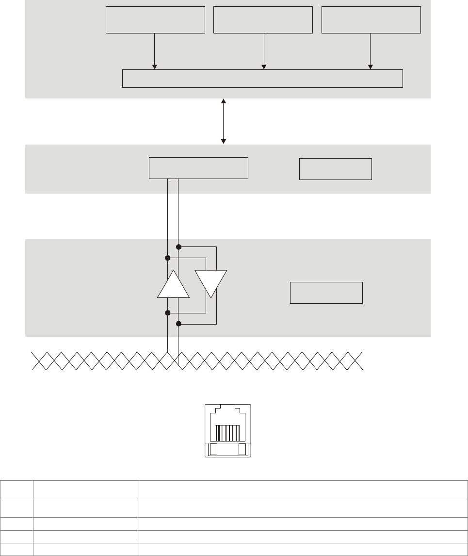
Chapter 15 CANopen Overview |CT2000 Series
15-2
15.1 CANopen Overview
CANopen Protocol
CANopen is a CAN-based higher layer protocol, and was designed for motion-oriented machine
control networks, such as handling systems. Version 4 of CANopen (CiA DS301) is standardized as
EN50325-4. The CANopen specifications cover application layer and communication profile (CiA
DS301), as well as a framework for programmable devices (CiA 302), recommendations for cables
and connectors (CiA 303-1) and SI units and prefix representations (CiA 303-2).
Device Profile CiA
DSP-401
Device Profile CiA
DSP-404
Device Profile CiA
DSP-XXX
OSI Layer 7
Application Communication Profile CiA DS-301
CAN Controller CAN 2.0A
OSI Layer 2
Data Link Layer
ISO 11898
OSI Layer 1
Physical Layer
+-
+-
CAN bus
RJ-45 Pin Definition
8~1
plug
PIN Signal Description
1 CAN_H CAN_H bus line (dominant high)
2 CAN_L CAN_L bus line (dominant low)
3 CAN_GND Ground / 0V /V-
7 CAN_GND Ground / 0V /V-

Chapter 15 CANopen Overview |CT2000 Series
15-3
Pre-Defined Connection Set
To reduce configuration effort for simple networks, CANopen define a mandatory default identifier
allocation scheme. The 11-bit identifier structure in predefined connection is set as follows:
COB Identifier (CAN Identifier)
10 9 8 7 6 5 4 3 2 1 0
Function Code Node Number
Object Function Code Node Number COB-ID Object Dictionary Index
Broadcast messages
NMT 0000 - 0 -
SYNC 0001 - 80H 1005H, 1006H, 1007H
TIME STAMP 0010 - 100H 1012H, 1013H
Point-to-point messages
Emergency 0001 1-127 81H-FFH 1014H, 1015H
TPDO1 0011 1-127 181H-1FFH 1800H
RPDO1 0100 1-127 201H-27FH 1400H
TPDO2 0101 1-127 281H-2FFH 1801H
RPDO2 0110 1-127 301H-37FH 1401H
TPDO3 0111 1-127 381H-3FFH 1802H
RPDO3 1000 1-127 401H-47FH 1402H
TPDO4 1001 1-127 481H-4FFH 1803H
RPDO4 1010 1-127 501H-57FH 1403H
Default SDO (tx) 1011 1-127 581H-5FFH 1200H
Default SDO (rx) 1100 1-127 601H-67FH 1200H
NMT Error Control 1110 1-127 701H-77FH 1016H, 1017H
CANopen Communication Protocol
It has services as follows:
NMT (Network Management Object)
SDO (Service Data Objects)
PDO (Process Data Object)
EMCY (Emergency Object)
NMT (Network Management Object)
The Network Management (NMT) follows a Master/Slave structure for executing NMT service. Only
one NMT master is in a network, and other nodes are regarded as slaves. All CANopen nodes have
a present NMT state, and NMT master can control the state of the slave nodes. The state diagram
of a node is shown as follows:
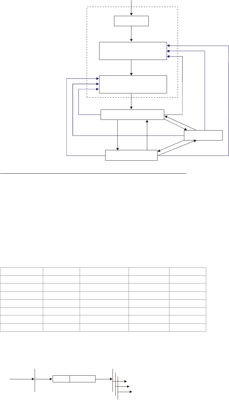
Chapter 15 CANopen Overview |CT2000 Series
15-4
Reset Communication
Initializing
Reset Application
Pre-Operation ABCD
Stopped AB
Operation ABCD
(1)
(15)
(16)
(2)F
(14)
(13)
(12)
(3) (4)
(11)
(10)
(9)
(7)
(5)
(6) (8)
(1) After power is applied, it is auto in initialization state
(2) Enter pre-operational state automatically
(3) (6) Start remote node
(4) (7) Enter pre-operational state
(5) (8) Stop remote node
(9) (10) (11) Reset node
(12) (13) (14) Reset communication
(15) Enter reset application state automatically
(16) Enter reset communication state automatically
A: NMT
B: Node Guard
C: SDO
D: Emergency
E: PDO
F: Boot-up
Initializing Pre-Operational Operational Stopped
PDO ○
SDO ○ ○
SYNC ○ ○
Time Stamp ○ ○
EMCY ○ ○
Boot-up ○
NMT ○ ○ ○
NMT Protocol is shown as follows:
CS
Value Definition
1 Start
2 Stop
128 Enter Pre-Operational
129 Reset Node
NMT Master
Request
request
CS Node-ID
COB-ID=0
Start Remote Node NMT Slave(s)
Indication
byte 0 byte 1
Indication
Indication
Indication(s)
130 Reset Communication

Chapter 15 CANopen Overview |CT2000 Series
15-5
SDO (Service Data Objects)
SDO is used to access the Object Dictionary in every CANopen node by Client/Server model. One
SDO has two COB-ID (request SDO and response SDO) to upload or download data between two
nodes. No data limit for SDOs to transfer data. But it needs to transfer by segment when data
exceeds 4 bytes with an end signal in the last segment.
The Object Dictionary (OD) is a group of objects in CANopen node. Every node has an OD in the
system, and OD contains all parameters describing the device and its network behavior. The access
path of OD is the index and sub-index, each object has a unique index in OD, and has sub-index if
necessary. The request and response frame structure of SDO communication is shown as follows:
PDO (Process Data Object)
PDO communication can be described by the producer/consumer model. Each node of the network
will listen to the messages of the transmission node and distinguish if the message has to be
processed or not after receiving the message. PDO can be transmitted from one device to one
another device or to many other devices. Every PDO has two PDO services: a TxPDO and a
RxPDO. PDOs are transmitted in a non-confirmed mode.
PDO Transmission type is defined in the PDO communication parameter index (1400h for the 1st
RxPDO or 1800h for the 1st TxPDO), and all transmission types are listed in the following table:
PDO
Type Number Cyclic Acyclic Synchronous Asynchronous RTR only
0 ○ ○
1-240 ○ ○
241-251 Reserved
252 ○ ○
253 ○ ○
254 ○
255 ○
Type number 1-240 indicates the number of SYNC message between two PDO transmissions.
Type number 252 indicates the data is updated (but not sent) immediately after receiving SYNC.
Type number 253 indicates the data is updated immediately after receiving RTR.
Type number 254: Delta CANopen doesn’t support this transmission format.
Type number 255 indicates the data is asynchronous transmission.
Data 0 Data 1 Data 2 Data 3 Data 4 Data 5 Data 6 Data 7
7 6 5 4 3 2 1 0 Index Index Index Data Data Data Data
Type
command L H Sub LL LH HL HH
Client 0 0 1 - N E S Initiate
Domain
Download
Server 0 1 1 - ----
Client 0 1 0 - - - - - Initiate
Domain
Upload
Server 0 1 0 - N E S
Client 1 0 0 - - - - - Abort Domain
Transfer Server 1 0 0 - - - - -
N: Bytes not use
E: normal(0)/expedited(1)
S: size indicated
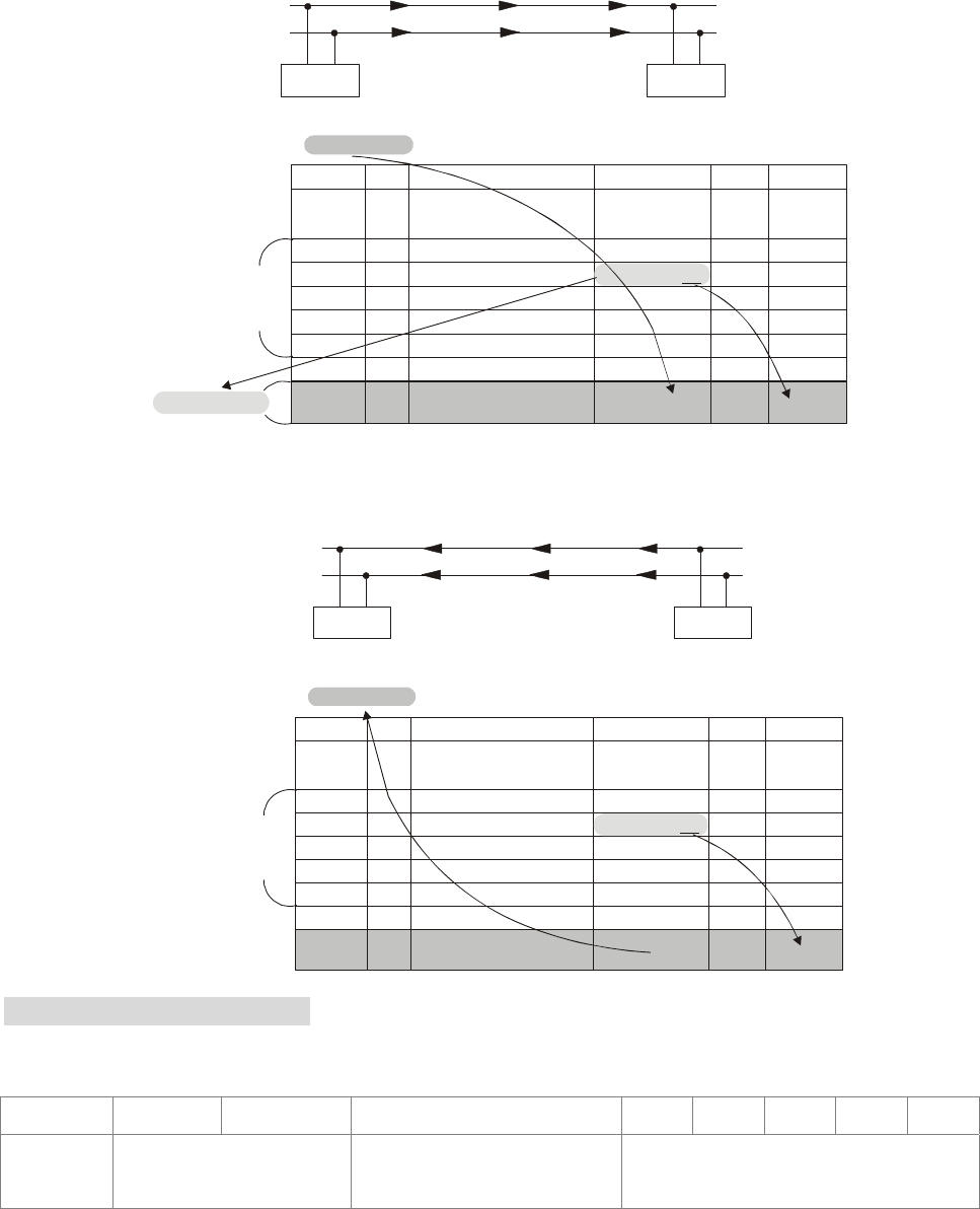
Chapter 15 CANopen Overview |CT2000 Series
15-6
All PDO transmission data must be mapped to index via Object Dictionary.
Example:
Master transmits data to SlavePDO
PDO1
CAN(H)
CAN(L)
Master Slave
PDO1 data value Data 0, Data 1, Data 2, Data 3, Data 4, Data 5, Data 6, Data 7,
0x11, 0x22, 0x33, 0x44, 0x55, 0x66, 0x77, 0x88,
Index Sub Definition Val ue R/W Size
1. Mapped Object
0. Number
2. Mapped Object
3. Mapped Object
4. Mapped Object
0
1
2
3
4
0x1600
0x1600
0x1600
0x1600
0x1600
R/W
R/W
R/W
R/W
R/W
1
0
0
0
U8
U32
U32
U32
U32
0x6040 0. Control word0R/W U16
PDO1 Map
0x60400010
(2 Bytes)
0x60400010 0x2211
Slave returns message to Master
PDO1
CAN(H)
CAN(L)
Master Slave
PDO1 data value Data 0, Data 1, Data 2, Data 3, Data 4, Data 5, Data 6, Data 7,
0xF3, 0x00,
Index Sub Definition Value R/W Size
1. Mapped Object
0. Number
2. Mapped Object
3. Mapped Object
4. Mapped Object
0
1
2
3
4
0x1A00
0x1A00
0x1A00
0x1A00
0x1A00
R/W
R/W
R/W
R/W
R/W
1
0
0
0
U8
U32
U32
U32
U32
0x6041 Status Word0R/W U16
PDO1 Map
0x60410010
0xF3
EMCY (Emergency Object)
Emergency objects are triggered when hardware failure occurs for a warning interrupt. The data
format of a emergency object is a 8 bytes data as shown in the following:
Byte 0 1 2 3 4 5 6 7
Content Emergency Error Code Error register
(Object 1001H) Manufacturer specific Error Field
Please refer to Chapter 5 CANopen error codes for emergency definition of C2000.
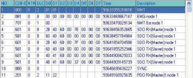
Chapter 15 CANopen Overview |CT2000 Series
15-7
Example:
Master send NM message to slave 1 for RESET request.
Slave 1 responds no error
Slave 1 responds a boot up message
Master enter Index6040 = 7EH in slave 1
Slave 1 responds OK
Master enter Index6040= 7FH in slave 1
Slave 1 responds OK
Master enter value for Index6041 to slave 1
Slave 1 responds 0640H
Master enter SYNC
Master enter PD01=2211H to slave 1
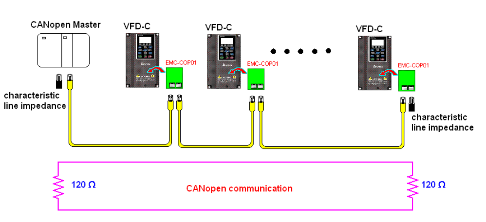
Chapter 15 CANopen Overview |CT2000 Series
15-8
15.2 Wiring for CANopen
An external adapter card: EMC-COP01 is used for CANopen wiring; establish CANopen to VFD
C2000 connection. The link is enabled by using RJ45 cable. The two farthest ends must be
terminated with 120Ω terminating resistors.
Chapter 15 CANopen Overview |CT2000 Series
15-9
15.3 How to Control by CANopen
15.3.1 CANopen Control Mode Selection
There are two control modes for CANopen; Pr.09.40 set to 1 is the factory setting mode DS402
standard and Pr.09.40 set to 0 is Delta’s standard setting mode.
15.3.2 Delta Defined Control Mode
There are two control modes.
1. Wiring for hardware (refer to chapter 15-2 Wiring for CANopen)
2. Operation source setting: set Pr.00-21 to 3 for CANopen communication card control.
3. Frequency source setting: set Pr.00.20 to 6 (CANopen setting. If torque control or position
control is required, set Pr.0.02 to 2. Also set Pr.09.30 to 1(default setting) to allow new address
60XX to function, the old address 20XX can not support the control function for position and
torque.
4. Source of torque setting is set by Pr.11-33.
5. CANopen station setting: set Pr.09-36 (Range of setting is 1~127. When Pr.09-36=0, CANopen
slave function is disabled. ) (Note: If error occurred (CAdE or CANopen memory error) as station
setting is completed, press Pr.00-02=7 for reset.)
6. CANopen baud rate setting: set Pr.09.37 (CANopen Baud Rate: 1M(0), 500K(1), 250K(2),
125K(3), 100K(4) and 50K(5))
7. CANopen decode method setting: set Pr.09.40 to 0 (Delta decoding method). It provides two
decoding method by using Pr.09-30 and the default setting of the drive is in decoding method 2
(Pr.09-30=1).
8. Decoding method 1. In index 2020.01 enter 0002H for motor run; 0001H for motor stop. In index
2020.02 enter 1000, frequency will be 10.00Hz. Refer to Index 2020 and 2021 for more detail.
9. Decoding method 2. In index 2060.01 enter 0080H for motor switch on; enter 0x81 for motor run
to the target frequency. Various control mode options are available in Pr.00-40, select your
control mode.
15.3.3 DS402 Standard Control Mode
To control the AC motor drive by CANopen, please set the parameters by the following steps:
1. Wiring for hardware (refer to Chapter 2 Wiring for CANopen)
2. Operation source setting: set Pr.00.21 to 3 (CANopen communication. Keypad STOP/RESET
disabled.)
3. Frequency source setting: set Pr.02.00 to 6 for CANopen communication card control. For
CANopen to do torque control, set Pr.11-33 to 3; to do position control, set Pr.11-40 to 3. Also
set Pr.09-30 to 1 (decoding method 2), use new address 60XX to control torque and position.
The old address 20XX does not support torque and position control.
4. Source of torque setting is set by Pr.11-33.
5. CANopen station setting: set Pr.09-36 (Range of setting is 1~127. When Pr.09-36=0, CANopen
slave function is disabled. ) (Note: If error occurred (CAdE or CANopen memory error) as station

Chapter 15 CANopen Overview |CT2000 Series
15-10
setting is completed, press Pr.00-02=7 for reset.)
6. CANopen baud rate setting: set Pr.09.37 (CANBUS Baud Rate: 1M(0), 500K(1), 250K(2),
125K(3), 100K(4) and50K(5))
7. Set multiple input functions to Quick Stop (it can also be enable or disable, default setting is
disable). If it is necessary to enable the function, set MI terminal to 53 in one of the following
parameter: Pr.02.01 ~Pr.02.08 or Pr.02.26 ~ Pr.02.31. (Note: This function is available in DS402
only.)
8. Switch to C2000 operation mode via the NMT string; control word 0x6040 (bit 0, bit 1, bit 2, bit 3
and bit 7) and status word 0x6041.
For example:
1. If the multi-function input terminal MI set Quick Stop to disable, enable the responsive
terminal of such MI terminal.
2. Set index 6040H to 7EH.
3. Set index 6040H to 7FH, the drive is now in operation mode.
4. Set index 6042H to 1500 (rpm), the default setting for pole is 4 (50Hz). Set the pole in
Pr.05.04 (Motor1) and Pr.05.16 (Motor 2).
Calculation for motor speed: p
120
fn ×= where
Example 1: set motor running in forward direction, f = 30Hz, P = 4.
(120*30)/4 = 900rpm
Example 2: set motor running in reverse direction, f = 20Hz, P = 6.
(120*15)/6 = 300rpm; 300rpm = 0x012C
Also,
Bit15 defines the positive and negative sign.
i.e. Index 6042 = -300 = ( 300’ + 1) = 012CH’ + 1 = FED3H +1 = FED4H
Switching mode:
n = ramp per minute (rpm/min);
P = poles
f = frequency (Hz)
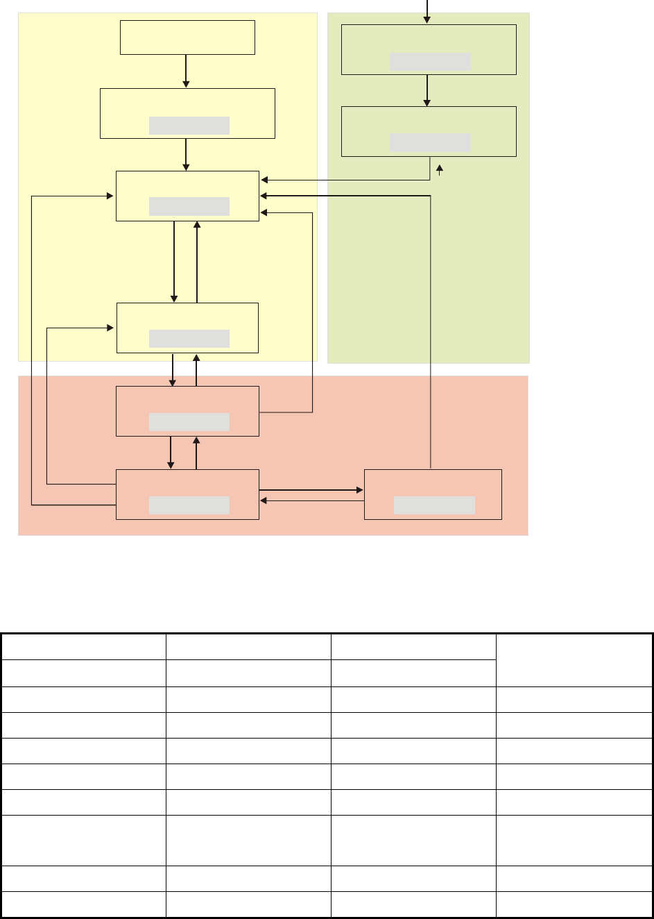
Chapter 15 CANopen Overview |CT2000 Series
15-11
Start
Not Ready to Switch On
X0XX0000
Switch On Disable
X1XX0000
Ready to Switch On
X01X0001
Switch On
X01X0011
Operation Enable
X01X0111
0XXXX110
and
Disable QStop=1
0XXXX111
0XXX1111
0XXXXX0X
or
0XXXX01X
or
Disable QStop=0
0XXXX110
0XXX0110
0XXX1111
0XXXXX0X
Quick Stop Active
X00X0111
0XXX1111
and
QStop=1Disable
0XXXX01X
or
QStop=0Disable
Fault Reaction Active
X0XX1111
Fault
X0XX1000
0XXXXX0X
or
Fout=0
XXXXXXX
Power
Disable
Fault
Power
Enable
0XXXXX0X
or
0XXXX01X
or
Disable QStop=0
< Status Switching Graph>
9. The operation of AC motor drive in DS402 standard is controlled by the Control Word 0x6040
(bit4~bit6), as shown in the following chart:
bit 6 bit 5 bit 4
ramp function reference ramp function disable ramp function enable
Outcome
0 0 0 STOP
1 0 0 STOP
0 1 0 STOP
1 1 0 STOP
0 0 1 STOP
1 0 1
LOCK
(at present frequency)
0 1 1 STOP
1 1 1 RUN
10. Follow the same steps, refer to status switching process for status word 0x6041(bit 0 to bit 6), bit
7= warn, bit 9 = 1 (permanently), bit 10= target frequency reached, bit 11= output exceeds
maximum frequency.

Chapter 15 CANopen Overview |CT2000 Series
15-12
15.3.4 Remarks to Control Modes
C2000 series offers 3 control modes for CANopen. Please refer to the following definitions for the
index setting of each control modes:
When CANopen is set in different control mode, the Index Setting is different:
DS402 Decoding Method 1 Decoding Method 2
Pr.09-40=1 Pr.09-40=0 and 09-30=0 Pr.09-40=0 and 09-30=1
Index Sub Index Sub Index Sub
2020h 01h
Control Command 6040h 00h 2020h 03h 2060h 01h
Speed Command 6042h 00h 2020h 02h 2060h 03h
Position Command 607Ah 00h No control 2060h 05h
Torque Command 6071h 00h No control 2060h 07h
Control modes have no influence to CANopen, Index setting has no function.
DS402 Decoding Method 1 Decoding Method 2
Pr.09-40=1 Pr.09-40=0 and Pr.09-30=0 Pr.09-40=0 and Pr.09-30=1
Index Sub Index Sub Index Sub
Treatment to
Signal Loss 6007h 00h
Decelerate by maximum
speed
Decelerate by maximum
speed
Acceleration Time 604Fh 00h 604Fh 00h 604Fh 00h
Deceleration Time 6050h 00h 6050h 00h 6050h 00h
Quick Stop 6051h 00h Disable Disable
Switching Mode 6060h 00h 6060h 00h 6060h 00h
Max. Torque 6072h 00h Disable Disable
When the drive is in Demo mode, Index can be read when setting to either DS402 mode, Decoding
method 1 or Decoding method 2.

Chapter 15 CANopen Overview |CT2000 Series
15-13
15.4 CANopen Supporting Index
Basic Index Support by C2000:
Index Sub Definition Factory Setting R/W Size Note
1000H 0 Device type 00010192H R U32
1001H 0 Error register 0R U8
1005H 0 COB-ID SYNC message 80H R U32
1006H 0 Communication cycle period 0RW U32
Unit: us
The setting value should be in a
multiple of 500us (integer)
within the range 500us to 16ms
1008H 0 Manufacturer device name 0R U32
1009H 0
Manufacturer hardware
version 0R U32
100AH 0
Manufacturer software
version 0R U32
100CH 0 Guarding time 0RW U16 Unit: ms
100DH 0 Guarding factor 0RW U8
0 Store Parameter 2R U8
1 Save all parameters 0RW U32
1010H
2 Save communication
parameter 1RW U32
0 Restore Parameter 2R U8
1 Restore all parameters 0RW U32
1011H
2 Restore communication
parameter 1RW U32
1014H 0 COB-ID emergency 0000080H+Node-I
DR U32
1015H 0 Inhibit time EMCY 0RW U16
Unit:100us
The setting value should be in a
multiple of 10 (integer)
0 Consumer heartbeat time 1R U8
1016H
1 Consumer 1 0RW U32
Unit: 1ms
Disable Guarding time to
function properly
1017H 0 Producer heartbeat time 0RW U16
Unit: 1ms
Disable Guarding time to
function properly
0 Number 0R U8
1 Vender ID 000001DDH R U32
2 Product code 2A00+machine
code R U32
1018H
3 Revision 00010000H R U32
0 Server SDO Parameter 2R U8
1 COB-ID Client -> Server 0000600H+Node-I
DR U32
1200H
2 COB-ID Client <- Server 0000580H+Node-I
DR U32
1400H 0 Number 2R U8

Chapter 15 CANopen Overview |CT2000 Series
15-14
Index Sub Definition Factory Setting R/W Size Note
1 COB-ID used by PDO 00000200H+Node-
ID RW U32
00:Acyclic& Synchronous
01~240:Cyclic & Synchronous
2 Transmission Type 5RW U8
255:Asynchronous
0 Number 2R U8
1 COB-ID used by PDO 80000300H+Node-
ID RW U32
00: Acyclic & Synchronous
01~240:Cyclic & Synchronous
1401H
2 Transmission Type 5RW U8
255:Asynchronous
0 Number 2R U8
1 COB-ID used by PDO 80000400H+Node-
ID RW U32
00: Acyclic & Synchronous
01~240:Cyclic & Synchronous
1402H
2 Transmission Type 5RW U8
255:Asynchronous
0 Number 2R U8
1 COB-ID used by PDO 80000500H+Node-
ID RW U32
00: Acyclic & Synchronous
01~240:Cyclic & Synchronous
1403H
2 Transmission Type 5H RW U8
255:Asynchronous
0 Number 2RW U8
1 1.Mapped Object 60400010H RW U32
2 2.Mapped Object 60420010H RW U32
3 3.Mapped Object 0RW U32
1600H
4 4.Mapped Object 0RW U32
0 Number 3RW U8
1 1.Mapped Object 20264110H RW U32
2 2.Mapped Object 2026A110H RW U32
3 3.Mapped Object 2026A210H RW U32
1601H
4 4.Mapped Object 0RW U32
0 Number 3RW U8
1 1.Mapped Object 60400010H RW U32
2 2.Mapped Object 607A0020H RW U32
3 3.Mapped Object 60600008H RW U32
1602H
4 4.Mapped Object 0RW U32
0 Number 3RW U8
1 1.Mapped Object 60400010H RW U32
2 2.Mapped Object 60710010H RW U32
3 3.Mapped Object 60600008H RW U32
1603H
4 4.Mapped Object 0RW U32

Chapter 15 CANopen Overview |CT2000 Series
15-15
Index Sub Definition Factory Setting R/W Size Note
0 Number 5R U8
1 COB-ID used by PDO 00000180H+Node-
ID RW U32
00: Acyclic & Synchronous
01~240:Cyclic & Synchronous
2 Transmission Type 5RW U8
255:Asynchronous
3 Inhibit time 0RW U16
Unit: 100us
The setting value should be in a
multiple of 10 (integer)
4 CMS-Priority Group 3RW U8
1800H
5 Event timer 0RW U16 Unit: 1ms
0 Number 5R U8
1 COB-ID used by PDO 80000280H+Node-
ID RW U32
00: Acyclic & Synchronous
01~240:Cyclic & Synchronous
2 Transmission Type 5RW U8
255:Asynchronous
3 Inhibit time 0RW U16
Unit: 100us
The setting value should be in a
multiple of 10 (integer)
4 CMS-Priority Group 3RW U8
1801H
5 Event timer 0RW U16 Unit: 1ms
0 Number 5R U8
1 COB-ID used by PDO 80000380H+Node-
ID RW U32
00: Acyclic & Synchronous
01~240:Cyclic & Synchronous
2 Transmission Type 5RW U8
255:Asynchronous
3 Inhibit time 0RW U16
Unit: 100us
The setting value should be in a
multiple of 10 (integer)
4 CMS-Priority Group 3RW U8
1802H
5 Event timer 0RW U16 Unit: 1ms
0 Number 5R U8
1 COB-ID used by PDO 80000480H+Node-
ID RW U32
00: Acyclic & Synchronous
01~240:Cyclic & Synchronous
2 Transmission Type 5RW U8
255:Asynchronous
3 Inhibit time 0RW U16
Unit: 100us
The setting value should be in a
multiple of 10 (integer)
4 CMS-Priority Group 3RW U8
1803H
5 Event timer 0RW U16 Unit: 1ms
0 Number 2RW U8
1 1.Mapped Object 60410010H RW U32
1A00H
2 2.Mapped Object 60430010H RW U32

Chapter 15 CANopen Overview |CT2000 Series
15-16
Index Sub Definition Factory Setting R/W Size Note
3 3.Mapped Object 0RW U32
4 4.Mapped Object 0RW U32
0 Number 4RW U8
1 1.Mapped Object 20260110H RW U32
2 2.Mapped Object 20266110H RW U32
3 3.Mapped Object 20266210H RW U32
1A01H
4 4.Mapped Object 20266310H RW U32
0 Number 3RW U8
1 1.Mapped Object 60410010H RW U32
2 2.Mapped Object 60640020H RW U32
3 3.Mapped Object 60610008H RW U32
1A02H
4 4.Mapped Object 0RW U32
0 Number 3RW U8
1 1.Mapped Object 60410010H RW U32
2 2.Mapped Object 60770010H RW U32
3 3.Mapped Object 60610008H RW U32
1A03H
4 4.Mapped Object 0RW U32
C2000 Index:
Parameter index corresponds to each other as following:
Index sub-Index
2000H + Group member+1
For example:
Pr.10.15 (Encoder Slip Error Treatment)
Group member
10(0 AH) - 15(0FH)
Index = 2000H + 0AH = 200A
Sub Index = 0FH + 1H = 10H
C2000 Control Index:
Delta Standard Mode (Old definition)
Index Sub Definition Factory
Setting R/W Size Note
0 Number 3 R U8
00B:disable
01B:stop
10B:disable
Bit 0~1
11B: JOG Enable
Bit2~3 Reserved
00B:disable
2020H
1 Control word 0 RW U16
Bit4~5
01B: Direction forward

Chapter 15 CANopen Overview |CT2000 Series
15-17
Index Sub Definition Factory
Setting R/W Size Note
10B: Reverse
11B: Switch Direction
00B: 1st step
acceleration/deceleration
Bit6~7
01B: 2nd step
acceleration/deceleration
Bit8~15 Reserved
2 vl target velocity(Hz) 0 RW U16
Bit0 1: E.F. ON
Bit1 1: Reset
3 Other trigger 0 RW U16
Bit2~15 Reserved
0 Number DH R U8 2021H
1 Error code 0 R U16
2021H 2 AC motor drive status 0 R U16 Bit 0~1 00B: stop
01B: decelerate to stop
10B: waiting for operation
command
11B: in operation
Bit 2 1: JOG command
Bit 3~4 00B: forward running
01B: switch from reverse
running to forward running
10B: switch from forward
running to reverse running
11B: reverse running
Bit 5~7 reserved
Bit 8 1: master frequency command
controlled by communication
interface
Bit 9 1: master frequency command
controlled by analog signal
input
Bit 10 1: operation command
controlled by communication
interface
Bit
11~15 Reserved
3 Frequency command(F)0 R U16
4 Output frequency(H) 0 R U16
5 Output current(AXX.X) 0 R U16
6 Reserved 0 R U16
7 Reserved 0 R U16
8 Reserved 0 R U16
9 Display output current(A)0 R U16
A Display counter value(c)0 R U16
B Display actual output
frequency (H) 0 R U16
C Display DC-BUS voltage (u) 0 R U16
D Display output voltage (E) 0 R U16
E Display output power angle
(n) 0 R U16
F Display output power in kW
(P) 0 R U16
10
Display actual motor speed
in rpm (r)
0 R U16
0 Number R U8
1 Display output current 0 R U16
2022H
2 Display counter value 0 R U16

Chapter 15 CANopen Overview |CT2000 Series
15-18
Index Sub Definition Factory
Setting R/W Size Note
3 Display actual output
frequency 0 R U16
4 Display DC-BUS voltage 0 R U16
5 Display output voltage 0 R U16
6 Display output power angle 0 R U16
7 Display output power in kW 0 R U16
8 Display actual motor speed
rpm 0 R U16
9 Display estimate output
torque % 0 R U16
A Display PG feedback (G) 0 R U16
B Display PID feedback in % 0 R U8
C Display AVI in %, 0~10V is
set as 0~100% 0 R U16
D
Display ACI in %,
4~20mA/0~10V are set as
0~100%
0 R U16
E Display AUI in %, -10V~10V
is set as -100~100% 0 R U16
F Display the temperature of
IGBT in ℃ 0 R U16
10 Display the temperature of
capacitance in ℃ 0 R U16
11 The status of digital input
(ON/OFF), refer to Pr.02-10 0 R U16
12 The status of digital output
(ON/OFF), refer to Pr.02-15 0 R U16
13 Display Multi-step speed 0 R U16
14 The corresponding CPU pin
status of digital input 0 R U16
15 The corresponding CPU pin
status of digital output 0 R U16
16
Actual motor position (PG1
of PG card). When the
motor direction changes or
the drive stops, the counter
will start from 0 (display
value restarts counting from
0) (Max. 65535)
0 R U16
17 Pulse input frequency (PG2
of PG card) 0 R U16
18 Pulse input position (PG2 of
PG card) (max. 65535) 0 R U16
19 Display position command
tracing error 0 R U16
1A Overload counting 0 R U16
1B GFF Ground Fault (Unit :%) 0 R U16
1C Reserve 0 R U16
1D Display PLC data D1043 0 R U16
1E Display PM motor magnetic
pole zone 0 R U16
1F Display output of user
defined 0 R U16
20 Display Pr.00-05 output
value 0 R U16
21 Number of motor revolution 0 R U16
22 Motor position 0 R U16
2022H
23 Operation speed of fan 0 R U16

Chapter 15 CANopen Overview |CT2000 Series
15-19
Index Sub Definition Factory
Setting R/W Size Note
24
Control Mode display: 0=
Speed control mode (SPD),
1= torque control mode
0 R U16
25 Present operating carrier
frequency of drive 0 R U16
Descriptions
Index sub R/W Size
bit Definition Priority
Speed Mode Position Mode Home Mode Torque Mode
00h R U8
0 Ack 4
0:fcmd =0
1:fcmd =
Fset(Fpid)
Pulse 1:
Position control
Pulse 1: Return
to home
1 Dir 4
0: FWD run
command
1: REV run
command
2
3 Halt
0: drive run till
target speed is
attained
1: drive stop by
declaration
setting
4 Hold
0: drive run till
target speed is
attained
1: frequency
stop at current
frequency
5 JOG
0:JOG OFF
Pulse 1:JOG
RUN
6 QStop Quick Stop
7 Power 0:Power OFF
1:Power ON
0:Power OFF
1:Power ON
0:Power OFF
1:Power ON
0:Power OFF
1:Power ON
11~8 Cmd
SW
Multi-step
frequency
switching
Multi-step
position
switching
13~12 Acc/Dec
SW
00b: 1st step
accel/decel time
01b: 2nd step
accel/decel time
10b: 3rd step
accel/decel time
11b 4th step
accel/decel time
14
0: Multi-step
command and
accel/decel time
switching is
disabled
1: Multi-step
command and
accel/decel time
switching is
enabled
0: Multi-step
command and
accel/decel time
switching is
disabled
1: Multi-step
command and
accel/decel time
switching is
enabled
01h RW U16
15 Pulse 1: Fault
code cleared
Pulse 1: Fault
code cleared
Pulse 1: Fault
code cleared
Pulse 1: Fault
code cleared
02h RW U16
2060h
03h RW U16 Speed command

Chapter 15 CANopen Overview |CT2000 Series
15-20
Descriptions
Index sub R/W Size
bit Definition Priority
Speed Mode Position Mode Home Mode Torque Mode
(unsigned
decimal)
04h RW U16
05h RW S32 Position
command
06h RW
07h RW U16
Torque
command
(signed
decimal)
08h RW U16
Speed limit
(unsigned
decimal)
0 Arrive Frequency
attained
Position
attained
Homing
complete Torque attained
1 Dir
0: Motor FWD
run
1: Motor REV run
0: Motor FWD
run
1: Motor REV
run
0: Motor FWD
run
1: Motor REV run
0: Motor FWD
run
1: Motor REV
run
2 Warn Warning Warning Warning Warning
3 Error Error detected Error detected Error detected Error detected
4
5 JOG JOG JOG JOG JOG
6 QStop Quick stop Quick stop Quick stop Quick stop
7 Power On Switch ON Switch ON Switch ON Switch ON
01h R U16
15~8
02h R
03h R U16 Actual output
frequency
Actual output
frequency
Actual output
frequency
Actual output
frequency
04h R
05h R S32 Actual position
(absolute)
Actual position
(absolute)
Actual position
(absolute)
Actual position
(absolute)
06h R
2061h
07h R S16 Actual torque Actual torque Actual torque Actual torque
DS402 Standard
Index Sub Definition Factory
Setting R/W Size Unit PDO
Map Mode Note
0: No action
2: Disable Voltage,
6007h 0 Abort connection option code 2 RW S16 Yes
3: quick stop
603Fh 0 Error code 0 R0 U16 Yes
6040h 0 Control word 0 RW U16 Yes
6041h 0 Status word 0 R0 U16 Yes
6042h 0 vl target velocity 0 RW S16 rpm Yes vl
6043h 0 vl velocity demand 0 RO S16 rpm Yes vl
6044h 0 vl control effort 0 RO S16 rpm Yes vl
604Fh 0 vl ramp function time 10000 RW U32 1ms Yes vl
6050h 0 vl slow down time 10000 RW U32 1ms Yes vl
6051h 0 vl quick stop time 1000 RW U32 1ms Yes vl
Unit must be: 100ms, and
check if the setting is set to
0.
0 : disable drive function
1 :slow down on slow down
ramp
605Ah 0 Quick stop option code 2 RW S16 No
2: slow down on quick stop
ramp

Chapter 15 CANopen Overview |CT2000 Series
15-21
Index Sub Definition Factory
Setting R/W Size Unit PDO
Map Mode Note
5 slow down on slow down
ramp and stay in QUICK
STOP
6 slow down on quick stop
ramp and stay in QUICK
STOP
605Ch 0
Disable operation option
code 1 RW S16 No
0: Disable drive function
1: Slow down with slow
down ramp; disable of the
drive function
6060h 0 Mode of operation 2 RW S8 Yes
1: Profile Position Mode
2: Velocity Mode
4: Torque Profile Mode
6: Homing Mode
6061h 0
Mode of operation display 2 RO S8 Yes Same as above
6064h 0
pp Position actual value 0 RO S32 Yes pp
6071h 0
tq Target torque 0 RW S16 0.1
%Yes tq Valid unit: 1%
6072h 0
tq Max torque 150 RW U16 0.1
%No tq Valid unit: 1%
6075h 0
tq Motor rated current 0 RO U32 mA No tq
6077h 0
tq torque actual value 0 RO S16 0.1
%Yes tq
6078h 0
tq current actual value 0 RO S16 0.1
%Yes tq
6079h 0
tq DC link circuit voltage 0 RO U32 mV Yes tq
607Ah 0
pp Target position 0 RW S32 1 Yes pp
Remote I/O
Index Sub Definition Factory
Setting R/W
Size
Note
0h Number DFh R U8
Bit 0 FWD
Bit 1 REV
Bit 2 MI1
Bit 3 MI2
Bit 4 MI3
Bit 5 MI4
Bit 6 MI5
Bit 7 MI6
Bit 8 MI7
Bit 9 MI8
Bit 10 MI9 (Extension card)
Bit 11 MI10 (Extension card)
Bit 12 MI12 (Extension card)
Bit 13 MI13 (Extension card)
Bit 14 MI14 (Extension card)
1h MI Status 0x00 R U16
Bit 15 MI15 (Extension card)
2h~40h Reserved 0x00 R U16
Bit 0 RY1
Bit 1 RY2
Bit 2
2026H
41h MO Control 0x00 RW
U16
Bit 3 MO1

Chapter 15 CANopen Overview |CT2000 Series
15-22
Index Sub Definition Factory
Setting R/W
Size
Note
Bit 4 MO2
Bit 5 MO3 (Extension card)
Bit 6 MO4 (Extension card)
Bit 7 MO5 (Extension card)
Bit 8 MO6 (Extension card)
Bit 9 MO7 (Extension card)
Bit 10 MO8 (Extension card)
Bit 11
Bit 12
Bit 13
Bit 14
Bit 15
42h~60h Reserved 0x00 R U16
61h AVI 0x00 R U16
0.0 ~100.0%
62h ACI 0x00 R U16
0.0 ~100.0%
63h AUI 0x00 R S16
-100.0 ~100.0%
64h~A0h Reserved 0x00 R U16
A1h AFM1 0x00 RW
U16
0.0 ~100.0%
A2h AFM2 0x00 RW
U16
0.0 ~100.0%
A3h~DFh Reserved 0x00 R U16
Note: For using Remote I/O, user must set MO or AO as CANopen control first. For example, if wish to control
MO2, user must set Pr.02-17=50; if wish to control AO, user must set Pr.03-23=20.

Chapter 15 CANopen Overview |CT2000 Series
15-23
15.5 CANopen Fault Code
Display Fault code Description CANopen
fault code
CANopen
fault
register
(bit 0~7)
ocA
Oc at accel
Fault
0001H Over-current during acceleration 2213 H 1
ocd
Oc at decel
0002H Over-current during deceleration 2213 H 1
ocn
Oc at normal SPD
Fault
0003H Over-current during steady status
operation 2214H 1
GFF
Ground fault
Fault
0004H
Ground fault. When (one of) the output
terminal(s) is grounded, short
circuit current is more than 50% of AC
motor drive rated current.
NOTE: The short circuit protection is
provided for AC motor drive
Protection, not for protection of the user.
2240H 1
occ
Short Circuit
Fault
0005H
Short-circuit is detected between upper
bridge and lower bridge of the
IGBT module.
2250H 1
ocS
Oc at stop
Fault
0006H Over-current at stop. Hardware failure in
current detection 2314H 1
ovA
Ov at accel
0007H Over-current during acceleration.
Hardware failure in current detection 3210H 2
ovd
Ov at decel
Fault
0008H Over-current during deceleration.
Hardware failure in current detection. 3210H 2
ovn
Ov at normal SPD
Fault
0009H
Over-current during steady speed.
Hardware failure in current detection.
230V: 450Vdc; 460V: 900Vdc
3210H 2

Chapter 15 CANopen Overview |CT2000 Series
15-24
Display Fault code Description CANopen
fault code
CANopen
fault
register
(bit 0~7)
ovS
Ov at stop
Fault
000AH
Over-voltage at stop. Hardware failure in
current detection
3210H 2
LvA
Lv at accel
Fault
000BH DC BUS voltage is less than Pr.06.00
during acceleration. 3220H 2
Lvd
Lv at decel
Fault
000VH DC BUS voltage is less than Pr.06.00
during deceleration. 3220H 2
Lvn
Lv at normal SPD
Fault
000DH DC BUS voltage is less than Pr.06.00 in
constant speed. 3220H 2
LvS
Lv at stop
Fault
000EH
DC BUS voltage is less than Pr.06-00 at
stop
3220H 2
OrP
Phase Lacked
Fault
000FH Phase Loss Protection 3130H 2
oH1
IGBT over heat
Fault
0010H
IGBT overheat
IGBT temperature exceeds protection
level.
1~15HP: 90℃
20~100HP: 100℃
4310H 3
oH2
Hear Sink oH
Fault
0011H
Heatsink overheat
Heat sink temperature exceeds 90oC
4310H 3
tH1o
Thermo 1 open
Fault
0012H
Temperature detection circuit error
(IGBT)
IGBT NTC
FF00H 3
tH2o
Thermo 2 open
Fault
0013H
Temperature detection circuit error
(capacity module)
CAP NTC
FF01H 3

Chapter 15 CANopen Overview |CT2000 Series
15-25
Display Fault code Description CANopen
fault code
CANopen
fault
register
(bit 0~7)
PWR
Power RST OFF
Fault
0014H Power RST off FF02H 2
oL
Inverter oL
Fault
0015H
Overload. The AC motor drive detects
excessive drive output current.
NOTE: The AC motor drive can
withstand up to 150% of the rated current
for a maximum of 60 seconds.
2310H 1
EoL2
Thermal relay 2
Fault
EoL1
Thermal relay 1
Fault
0016H Electronics thermal relay 1 protection
2310H 1
EoL2
Thermal relay 2
Fault
0017H Electronics thermal relay 2 protection
2310H 1
EoL2
Thermal relay 2
Fault
oH3
Motor over heat
Fault
0018H
Motor overheating
The AC motor drive detects that the
internal temperature exceeds
Pr.06-30 (PTC level)
FF20H 1
EoL2
Thermal relay 2
Fault
ot1
Over torque 1
Fault
001AH 8311H 3
EoL2
Thermal relay 2
Fault
ot2
Over torque 2
Fault
001BH
These two fault codes will be displayed
when output current exceeds
the over-torque detection level (Pr.06.07
or Pr.06.10) and exceeds
over-torque detection(Pr.06.08 or
Pr.06.11) and it is set 2 or 4 in
Pr.06-06 or Pr.06-09.
8311H 3
EoL2
Thermal relay 2
Fault
uC
Under torque 1
Fault
001CH Low current 8321H 1
EoL2
Thermal relay 2
Fault
LMIT
Limit Error
Fault
001DH Limit error 7320H 1
EoL2
Thermal relay 2
Fault
cF1
EEPROM write Err
Fault
001EH
Internal EEPROM can not be
programmed.
5530H 5

Chapter 15 CANopen Overview |CT2000 Series
15-26
Display Fault code Description CANopen
fault code
CANopen
fault
register
(bit 0~7)
EoL2
Thermal relay 2
Fault
cF2
EEPROM read Err
Fault
001FH Internal EEPROM can not be read. 5530H 5
EoL2
Thermal relay 2
Fault
cd1
Ias sensor Err
Fault
0021H U-phase error FF04H 1
EoL2
Thermal relay 2
Fault
cd2
Ibs sensor Err
Fault
0022H V-phase error FF05H 1
EoL2
Thermal relay 2
Fault
cd3
Ics sensor Err
Fault
0023H W-phase error FF06H 1
EoL2
Thermal relay 2
Fault
Hd0
cc HW Error
Fault
0024H cc (current clamp) hardware error FF07H 5
EoL2
Thermal relay 2
Fault
Hd1
oc HW Error
Fault
0025H oc hardware error FF08H 5
EoL2
Thermal relay 2
Fault
Hd2
ov HW Error
Fault
0026H ov hardware error FF09H 5
EoL2
Thermal relay 2
Fault
Hd3
GFF HW Error
Fault
0027H GFF hardware error FF0AH 5
EoL2
Thermal relay 2
Fault
AUE
Auto tuning Err
Fault
0028H Auto tuning error
FF21H 1
EoL2
Thermal relay 2
Fault
AFE
PID Fbk Error
Fault
0029H PID loss (ACI)
FF22H 7
EoL2
Thermal relay 2
Fault
PGF1
PG Fbk Error
Fault
002AH PG feedback error
7301H 7

Chapter 15 CANopen Overview |CT2000 Series
15-27
Display Fault code Description CANopen
fault code
CANopen
fault
register
(bit 0~7)
EoL2
Thermal relay 2
Fault
PGF2
PG Fbk Loss
Fault
002BH PG feedback loss
7301H 7
EoL2
Thermal relay 2
Fault
PGF3
PG Fbk Over SPD
Fault
002BH PG feedback stall
7301H 7
EoL2
Thermal relay 2
Fault
PGF4
PG Fbk deviate
Fault
002CH PG slip error
7301H 7
EoL2
Thermal relay 2
Fault
PGr1
PG ref Error
Fault
002DH Pulse input error
FF23H 7
EoL2
Thermal relay 2
Fault
PGr2
PG ref loss
Fault
002FH Pulse input loss
FF24H 7
EoL2
Thermal relay 2
Fault
ACE
ACI loss
Fault
0030H ACI loss
FF25H 1
EoL2
Thermal relay 2
Fault
EF
External Fault
Fault
0031H
External Fault
When input EF (N.O.) on external
terminal is closed to GND, AC motor
drive stops output U, V, and W.
9000H 5
EoL2
Thermal relay 2
Fault
EF1
Emergency stop
Fault
0032H
Emergency stop
When the multi-function input terminals
MI1 to MI6 are set to
emergency stop, the AC motor drive
stops output U, V, W and
the motor coasts to stop
9000H 5
EoL2
Thermal relay 2
Fault
bb
Base block
Fault
0033H
External Base Block
When the external input terminals MI1 to
MI16 are set as bb and active, the AC
motor drive output will be turned off
9000H 5

Chapter 15 CANopen Overview |CT2000 Series
15-28
Display Fault code Description CANopen
fault code
CANopen
fault
register
(bit 0~7)
EoL2
Thermal relay 2
Fault
Pcod
Password Error
Fault
0034H
Password will be locked if three fault
passwords are entered
FF26H 5
EoL2
Thermal relay 2
Fault
ccod
SW code Error
Fault
0035H Software error
6100H 5
EoL2
Thermal relay 2
Fault
cE1
Modbus CMD err
Fault
0036H Illegal function code
7500H 4
Thermal relay 2
Fault
cE2
Modbus ADDR err
Fault
0037H Illegal data address (00H to 254H) 7500H 4
Thermal relay 2
Fault
cE3
Modbus DATA err
Fault
0038H Illegal data value
7500H 4
Thermal relay 2
Fault
cE4
Modbus slave FLT
Fault
0039H Data is written to read-only address
7500H 4
Thermal relay 2
Fault
cE10
Modbus time out
Fault
003AH Modbus transmission timeout.
7500H 5
Thermal relay 2
Fault
cP10
Keypad time out
Fault
003BH Keypad transmission timeout.
7500H 4
Thermal relay 2
Fault
bF
Braking fault
Fault
003CH Brake resistor fault
7110H 4
Thermal relay 2
Fault
ydc
Y-delta connect
Fault
003DH Motor Y-Δ switch error 3330H 2
Thermal relay 2
Fault
dEb
Dec. Energy back
Fault
003EH Energy regeneration when decelerating FF27H 2

Chapter 15 CANopen Overview |CT2000 Series
15-29
Display Fault code Description CANopen
fault code
CANopen
fault
register
(bit 0~7)
Thermal relay 2
Fault
oSL
Over slip Error
Fault
003FH
Overslip error. Slip exceeds Pr.05.26
limit and slip duration exceeds Pr.05.27
setting.
FF28H 7
Thermal relay 2
Fault
ryF
MC Fault
Fault
0040H Electromagnet switch error 7110H 5
Thermal relay 2
Fault
PGF5
PG HW Error
Fault
0041H PG Card Error FF29H 5
Thermal relay 2
Fault
S1
S1-Emergy stop
Fault
0049H External emergency stop
FF2AH 5
Thermal relay 2
Fault
Uocc
U phase short
Fault
004FH U phase short circuit FF2BH 1
Thermal relay 2
Fault
Vocc
V phase short
Fault
0050H V phase short circuit FF2CH 1
Thermal relay 2
Fault
Wocc
W phase short
Fault
0051H W phase short circuit FF2DH 1
Thermal relay 2
Fault
OPHL
U phase lacked
Fault
0052H U phase output phase loss 2331H 2
Thermal relay 2
Fault
OPHL
U phase lacked
Fault
0053H V phase output phase loss 2332H 2
Thermal relay 2
Fault
OPHL
U phase lacked
Fault
0054H W phase output phase loss 2333H 2
Thermal relay 2
Fault
FStP
Force Stop
Fault
005AH Force to stop FF2EH

Chapter 15 CANopen Overview |CT2000 Series
15-30
Display Fault code Description CANopen
fault code
CANopen
fault
register
(bit 0~7)
Thermal relay 2
Fault
TRAP
CPU Trap Error
Fault
0063H CPU command error 6000H 7
Thermal relay 2
Fault
CGdE
Guarding T-out
Fault
0065H Guarding time-out 1 8130H 4
Thermal relay 2
Fault
CHbE
Heartbeat T-out
Fault
0066H Heartbeat time-out 8130H 4
Thermal relay 2
Fault
CSyE
SYNC T-out
Fault
0067H CAN synchrony error 8700H 4
Thermal relay 2
Fault
CbFE
CAN/S bus off
Fault
0068H CAN bus off
8140H 4
Thermal relay 2
Fault
CIdE
Fault
0069H Can index exceed
8110H 4
Thermal relay 2
Fault
CAdE
Fault
006AH CAN address error
0x8100 4
Thermal relay 2
Fault
CFdE
Fault
006BH
CAN frame fail
0x8100 4
Thermal relay 2
Fault
ictE
Fault
006FH Internal communication signal fail 0x7500 0x4
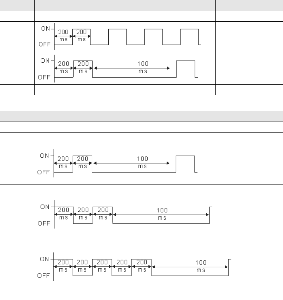
Chapter 15 CANopen Overview |CT2000 Series
15-31
15.6 CANopen LED Function
There are two CANopen flash signs: RUN and ERR.
RUN LED:
LED status Condition CANopen State
OFF Initial
Blinking
Pre-Operation
Single flash
Stopped
ON Operation
ERR LED:
LED status Condition/ State
OFF No Error
Single
flash
One Message fail
Double
flash
Guarding fail or heartbeat fail
Triple flash SYNC fail
ON Bus off

Chapter 16 PLC Function |CT2000 Series
16-1
Chapter 16 PLC Function
16.1 PLC Overview
16.2 Precautions for Using PLC
16.3 Start-up
16.4 PLC Ladder Diagram
16.5 PLC Devices
16.6 Commands
16.7 Error Code and Troubleshoot
16.8 CANopen Master Application
16.9 Descriptions of PLC Modes and Controls (Speed, Torque,
Homing and Position)
16.10 Internal Communication for Master Control
16.11 Counting Function via MI8

Chapter 16 PLC Function |CT2000 Series
16-2
16.1 PLC Overview
16.1.1 Introduction
The built in PLC function in CT2000 allows following commands: WPLSoft, basic commands and
application commands; the operation methods are the same as Delta DVPPLC series. Other than
that, CANopen master provides 8 stations for synchronous control and 126 asynchronous controls.
NOTE
In CT2000, CANopen master synchronous control complies with DS402 standard and supports homing mode, speed mode,
torque mode and point to point control mode; CANopen slave supports two control modes, speed mode and torque mode.
16.1.2 Ladder Diagram Editor – WPLSoft
WPLSoft is a program editor of Delta DVP-PLC series and CT2000 series for WINDOWS. Besides
general PLC program planning and general WINDOWS editing functions, such as cut, paste, copy,
multi-windows, WPLSoft also provides various Chinese/English comment editing and other special
functions (e.g. register editing, settings, the data readout, the file saving, and contacts monitor and
set, etc.).
Following is the system requirement for WPLSoft:
Item System Requirement
Operation System Windows 95/98/2000/NT/ME/XP
CPU Pentium 90 and above
Memory 16MB and above (32MB and above is recommended)
Hard Disk Capacity: 50MB and above
CD-ROM (for installing WPLSoft)
Monitor Resolution: 640×480, 16 colors and above,
It is recommended to set display setting of Windows to 800×600.
Mouse General mouse or the device compatible with Windows
Printer Printer with Windows driver
RS-232 port At least one of COM1 to COM8 can be connected to PLC
Applicable Models All Delta DVP-PLC series and CT2000 series
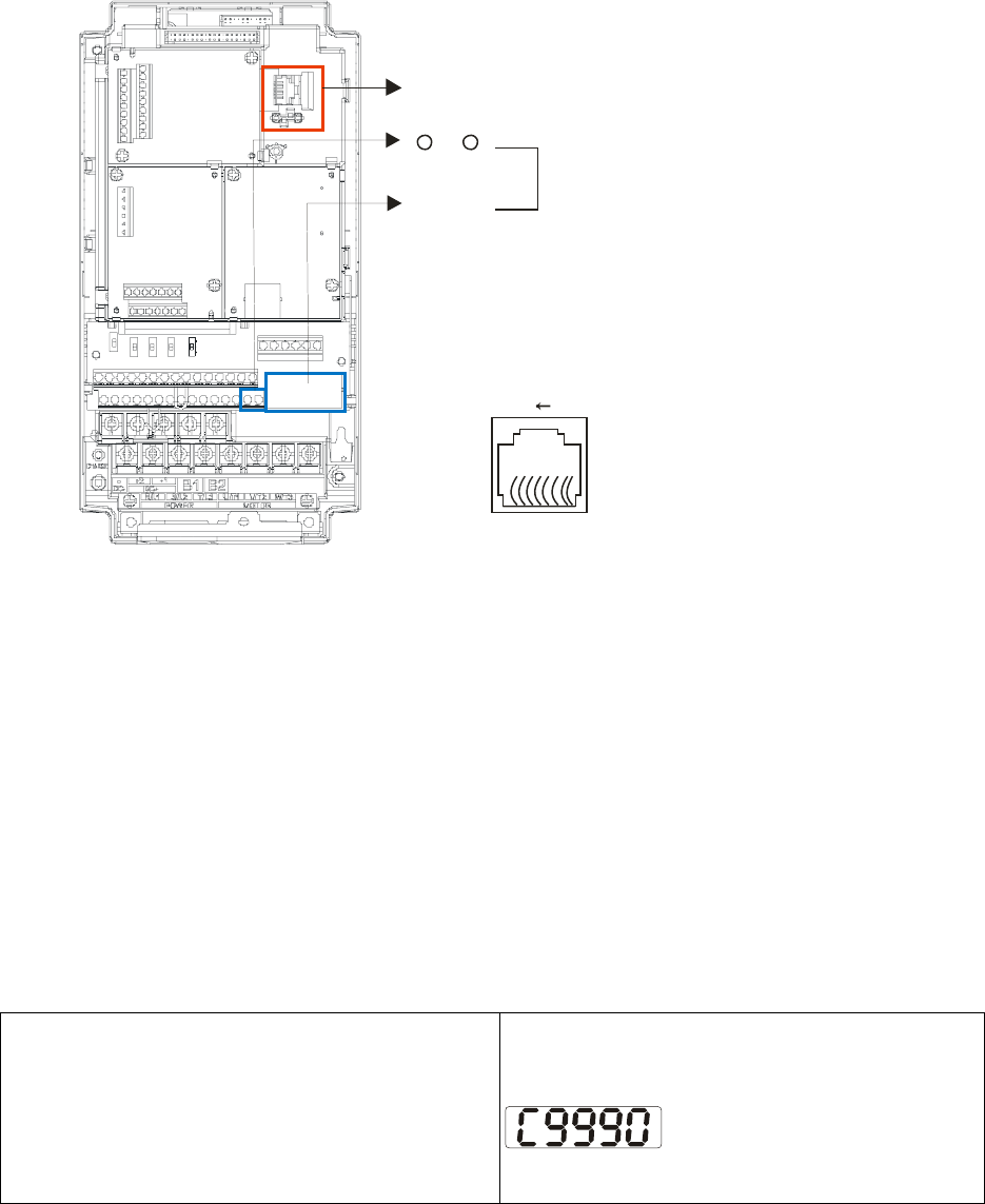
Chapter 16 PLC Function |CT2000 Series
16-3
16-2 Precautions for Using PLC Functions
1. Default setting of PLC communication protocol is 7,N,2 ,9600, station number 2. User can
change PLC station using Pr.09-35 but station address must be different to the AC motor drive’s
station address(Pr.09-00).
2. CT2000 series offers 2 communication ports for PLC program upload and download. Refer to
the figure follows for port location. The communication protocol of Channel 1 is always
19200,8,N,2。
Channel 1
Channel 2
SG-
SG+
RS-485
81
Modbus RS-485
Pin 1~2, 7, 8:
Pin 3, 6:GND
Pin 4:SG-
Pin 5:SG+
Reserved
3. Host controller can read/write data from/to both the AC motor drive and the internal PLC
program by setting the drive and internal PLC program to two different station numbers. For
example, if user wants to set AC motor drive as station 1 and PLC as station 2, please write
following setting to the host controller:
When setting 01(Station) 03(Read) 0400(Address) 0001(1 data), the host controller can read the
Pr.04-00 from the AC motor drive.
When setting 02(Station) 03(Read) 0400(Address) 0001(1 data), host controller will read X0
data from the internal PLC program.
4. The internal PLC program will stop operation when upload/download programs.
5. When using WPR command to write parameters, parameters can be changed for a maximum of
109 times. It is crucial not to exceed this limit to prevent occurrence of serious error.
6. When Pr.00-04 is set to 28, D1043 value of PLC register will be displayed on the digital keypad:
Digital Keypad KPC-CC01
Display range: 0~65535
Digital Keypad KPC-CE01
Display range: 0~9999
Display for values exceed 9999

Chapter 16 PLC Function |CT2000 Series
16-4
H 0.00Hz
A 0.00Hz
C _ _ _ _ _
7. When PLC is in PLC Run or PLC Stop mode, Pr.00-02 (settings 9 and 10) are disabled.
8. When Pr.00-02 is set to 6, PLC function settings will return to factory settings.
9. When the Input Terminal X of PLC is programmed, the corresponding MI will be disabled (no
function).
10. When AC motor drive operation status is controlled by PLC function, the setting of Pr.00-21 has
no function and the drive is fully under the control of PLC function.
11. When PLC function is programmed with FREQ command, AC motor drive frequency is now
under PLC function control. The setting of Pr.00-20 and Hand ON/OFF are disabled and has no
control over AC motor drive frequency.
12. When PLC is programmed with TORQ command, AC motor drive torque is now under PLC
function control. The setting of Pr.11-33 and Hand ON/OFF function are disabled and has no
control over AC motor drive torque.
13. When PLC is programmed with POS command, AC motor drive position is now under PLC
function control. The setting of Pr.11-40 and Hand ON/OFF function are disabled and has no
control over AC motor drive position.
14. If the Stop function of digital keypad is enabled when AC motor drive frequency is under PLC
function control, the AC motor drive will trigger FStP error and AC motor drive will stop
operation.
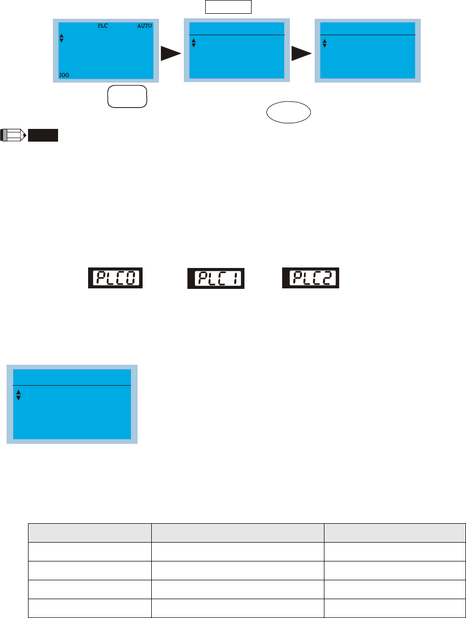
Chapter 16 PLC Function |CT2000 Series
16-5
16.3 Start-up
16.3.1 The Steps for PLC Execution
Please operate PLC functions by following the steps indicate below:
1. Press menu key on KPC-CC01 Æ select 3: PLC Æ ENTER.
F 60.00Hz
H 0.00Hz
A 0.00Hz
MENU
1.Pr Setup
2.Copy Pr
3.PLC
PLC
1.Disable
2.PLC Run
3.PLC Stop
Select 3.PLC
ENTER
MENU
Press
Press
NOTE
When using KPC-CE01 series digital keypad, switch the mode to PLC2 for program download/upload:
A. Press MODE key and select ‘PLC’.
B. Press ‘UP’ key and look for ‘PLC2’ then press ‘ENTER’.
C. If succeed, display ‘END’ for one to two seconds and return to ‘PLC2’ page.
The PLC warning that is displayed before program downloaded to CT2000 can be ignored, please continue the
operation.
Disable Run PLC PLC Stop
iACdi
2. Connection: Connect RJ-45 of AC motor drive to the computer by using RS485.
3. Run the program.
PLC
1.Disable
2.PLC Run
3.PLC Stop
PLC function, select function 2 (PLC Run).
1: Disable (PLC0)
2: PLC Run (PLC1)
3: PLC Stop (PLC2)
Optional accessories: Digital keypad KPC-CE01, display
PLC function as shown in the ( ).
When external input terminals (MI1~MI8) are set to PLC Mode select bit0 (51) or PLC Mode
select bit1 (52), it will force to switch to PLC mode regardless the terminal is ON or OFF.
Meanwhile, switching via keypad is disabled. Please refer to the chart below:
PLC Mode PLC Mode select bit1(52) PLC Mode select bit0 (51)
Disable (PLC 0) OFF OFF
PLC Run (PLC 1) OFF ON
PLC Stop (PLC 2) ON OFF
Previous state ON ON
When KPC-CE01 execute PLC function:
1. When switching the page from PLC to PLC1, it will execute PLC. The motion of PLC
(Execute/Stop) is controlled by WPL editor.

Chapter 16 PLC Function |CT2000 Series
16-6
2. When switching the page from PLC to PLC2, it will stop PLC. Again the motion of PLC
(Execute/Stop) is controlled by WPL editor.
3. The control of external terminals follows the same method.
NOTE
When input/output terminals (FWD REV MI1~MI8 MI10~15, Relay1, Relay2 RY10~RY15, MO1~MO2 MO10~MO11,)
are used in PLC program, they cannot be used in other places. Fro example, when PLC program (PLC1 or PLC2) is
activated, such as when it controls Y0, the corresponding output terminals Relay (RA/RB/RC) will be used. At this
moment, Pr.03.00 setting will be invalid since the terminal has been used by PLC. Refer to Pr.02-52, 02-53, 03-30 to
check which DI DO AO are occupied by PLC.
16.2.2 I/O Device Reference Table
Input device:
Device X0 X1 X2 X3 X4 X5 X6 X7 X10 X11 X12 X13 X14 X15 X16 X17
1 FWD REV MI1 MI2 MI3 MI4 MI5 MI6 MI7 MI8
2 MI10 MI11 MI12 MI13 MI14 MI15
3 MI10 MI11 MI12 MI13
1: I/O extension card
2: I/O extension card EMC-D611A (D1022=4)
3: I/O extension card EMC-D42A (D1022=5)
Output device:
Device Y0 Y1 Y2 Y3 Y4 Y5 Y6 Y7 Y10 Y11 Y12 Y13 Y14 Y15 Y16 Y17
1 RY
1 RY2 MO1 MO2
2 MO10 MO11
3 RY10 RY11 RY12 RY13 RY14 RY15
1: I/O extension card
2: I/O extension card EMC-D42A (D1022=5)
3: I/O extension card EMC-R6AA (D1022=6)
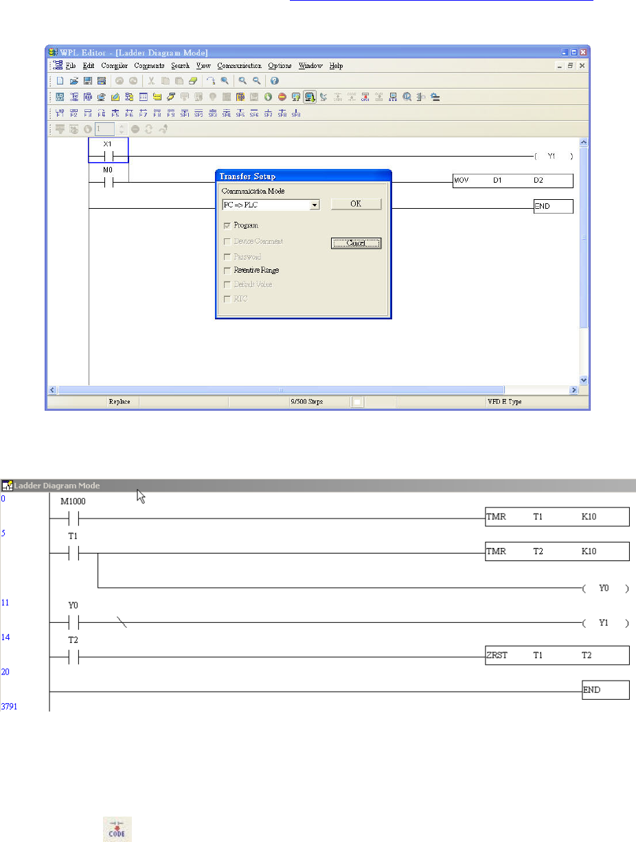
Chapter 16 PLC Function |CT2000 Series
16-7
16.2.3 WPLSoft Installation
Download PLC program toCT2000: Refer to D.3 to D.7 for program coding and download the
editor (WPLSoft V2.09) at DELTA website http://www.delta.com.tw/industrialautomation/
16.2.4 Program Input
16.2.5 Program Download
Please download the program by following steps:
Step 1. Press button for compiler after inputting program in WPLSoft.
Step 2. After compiler is finished, choose the item “Write to PLC” in the communication items.
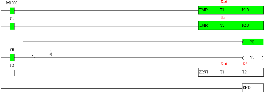
Chapter 16 PLC Function |CT2000 Series
16-8
After finishing Step 2, the program will be downloaded from WPLSoft to the AC motor drive by the
communication format.
16.2.6 Program Monitor
If you execute “start monitor” in the communication item during executing PLC, the ladder
diagram will be shown as follows.
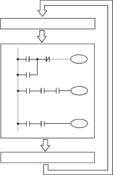
Chapter 16 PLC Function |CT2000 Series
16-9
16.3 Ladder Diagram
16.3.1 Program Scan Chart of the PLC Ladder Diagram
Calculate the result by
ladder diagram
algorithm (it doesn’t
sent to the outer output
point but the inner
equipment will output
immediately.)
Y0
X0 X1
Y0
Start
M100 X3
Y1
X10
:
:
X100 M505
Y126
End
Send the result to the output point
Read input state from outside
Repeats the
execution in
cycle.
16.3.2 Ladder Diagram
Ladder diagram is a diagram language that applied on the automatic control and it is also a
diagram that made up of the symbols of electric control circuit. PLC procedures are finished after
ladder diagram editor edits the ladder diagram. It is easy to understand the control flow that
indicated with diagram and also accept by technical staff of electric control circuit. Many basic
symbols and motions of ladder diagram are the same as mechanical and electrical equipments of
traditional automatic power panel, such as button, switch, relay, timer, counter and etc.
The kinds and amounts of PLC internal equipment will be different with brands. Although internal
equipment has the name of traditional electric control circuit, such as relay, coil and contact. It
doesn’t have the real components in it. In PLC, it just has a basic unit of internal memory. If this bit
is 1, it means the coil is ON and if this bit is 0, it means the coil is OFF. You should read the
corresponding value of that bit when using contact (Normally Open, NO or contact a). Otherwise,
you should read the opposite sate of corresponding value of that bit when using contact (Normally
Closed, NC or contact b). Many relays will need many bits, such as 8-bits makes up a byte. 2
bytes can make up a word. 2 words make up double word. When using many relays to do
calculation, such as add/subtraction or shift, you could use byte, word or double word.
Furthermore, the two equipments, timer and counter, in PLC not only have coil but also value of
counting time and times.

Chapter 16 PLC Function |CT2000 Series
16-10
In conclusion, each internal storage unit occupies fixed storage unit. When using these
equipments, the corresponding content will be read by bit, byte or word.
Brief introduction to the internal devices of PLC:
Internal Device Function
Input Relay
Input relay is the basic storage unit of internal memory that corresponds to
external input point (it is the terminal that used to connect to external input switch
and receive external input signal). Input signal from external will decide it to
display 0 or 1. You couldn’t change the state of input relay by program design or
forced ON/OFF via WPLSoft. The contacts (contact a, b) can be used unlimitedly.
If there is no input signal, the corresponding input relay could be empty and can’t
be used with other functions.
; Equipment indication method: X0, X1…X7, X10, X11… The symbol of
equipment is X and numbering in octal.
Output Relay
Output relay is the basic storage unit of internal memory that corresponds to
external output point (it is used to connect to external load). It can be driven by
input relay contact, the contact of other internal equipment and itself contact. It
uses a normally open contact to connect to external load and other contacts can
be used unlimitedly as input contacts. It doesn’t have the corresponding output
relay, if need, it can be used as internal relay.
; Equipment indication: Y0, Y1…Y7, Y10, Y11… The symbol of equipment is
Y and numbering in octal.
Internal Relay
The internal relay doesn’t connect directly to outside. It is an auxiliary relay in
PLC. Its function is the same as the auxiliary relay in electric control circuit. Each
auxiliary relay has the corresponding basic unit. It can be driven by the contact of
input relay, output relay or other internal equipment. Its contacts can be used
unlimitedly. Internal auxiliary relay can’t output directly, it should output with
output point.
; Equipment indication: M0, M1…M799. The symbol of equipment is M and
numbering in decimal system.
Counter
Counter is used to count. It needs to set counter before using counter (i.e. the
pulse of counter). There are coil, contacts and storage unit of counter in counter.
When coil is from OFF to ON, that means input a pulse in counter and the counter
should add 1. There are 16-bit, 32-bit and high-speed counter for user to use.
; Equipment indication: C0, C1… C79. The symbol of equipment is C and
numbering in decimal system.
Timer
Timer is used to control time. There are coil, contact and timer storage. When coil
is ON, its contact will act (contact a is close, contact b is open) when attaining
desired time. The time value of timer is set by settings and each timer has its
regular period. User sets the timer value and each timer has its timing period.
Once the coil is OFF, the contact won’t act (contact a is open and contact b is
close) and the timer will be set to zero.
; Equipment indication: T0, T1…T159. The symbol of equipment is T and
numbering in decimal system. The different number range corresponds with
the different timing period.
Data register PLC needs to handle data and operation when controlling each order, timer value
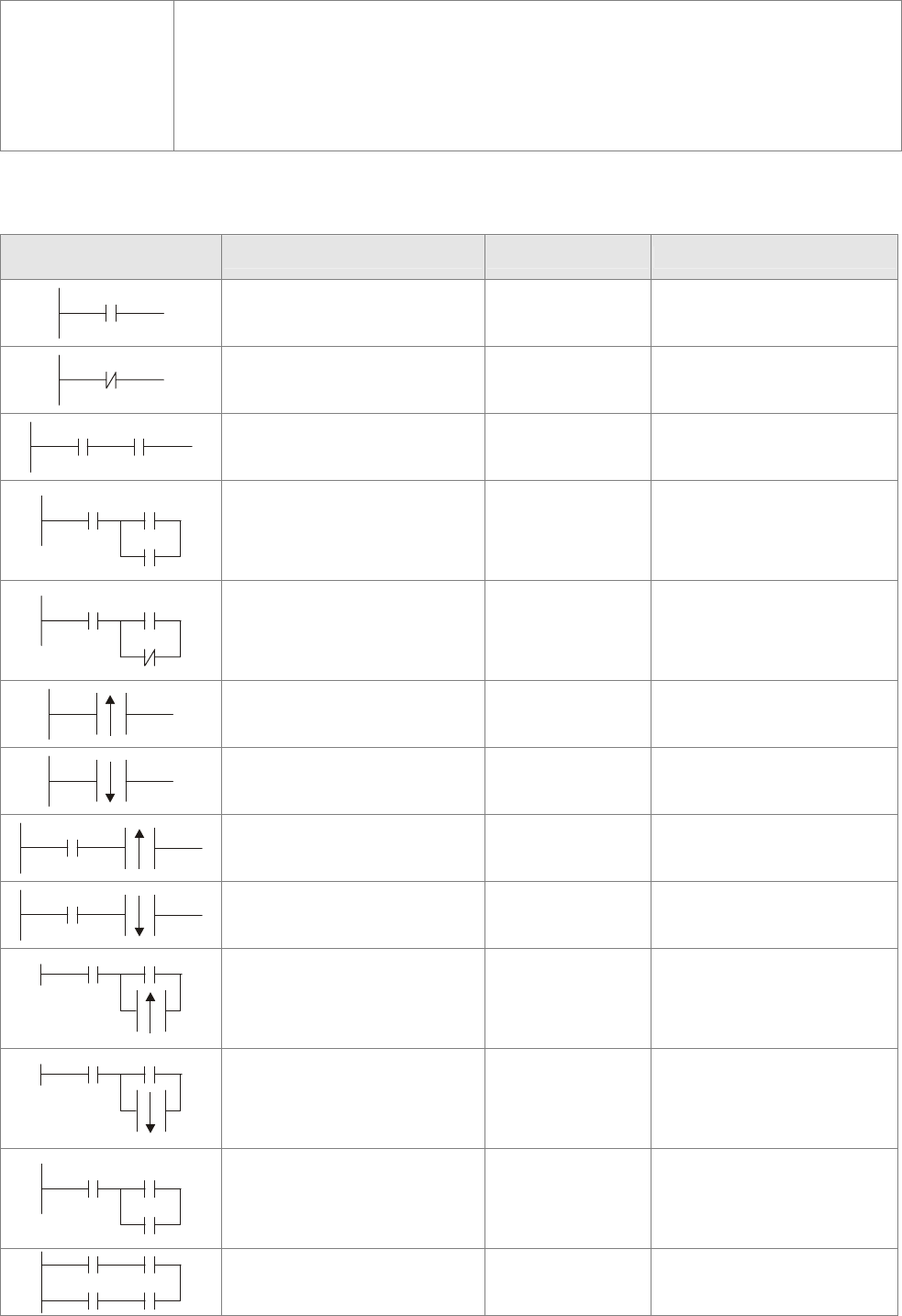
Chapter 16 PLC Function |CT2000 Series
16-11
and counter value. The data register is used to store data or parameters. It stores
16-bit binary number, i.e. a word, in each register. It uses two continuous number
of data register to store double words.
; Equipment indication: D0, D1,…,D399. The symbol of equipment is D and
numbering in decimal system.
The structure of ladder diagram and information:
Ladder Diagram
Structure Explanation Command Device
Normally open, contact a LD X, Y, M, T, C
Normally closed, contact b LDI X, Y, M, T, C
Serial normally open AND X, Y, M, T, C
Parallel normally open OR X, Y, M, T, C
Parallel normally closed ORI X, Y, M, T, C
Rising-edge trigger switch LDP X, Y, M, T, C
Falling-edge trigger switch LDF X, Y, M, T, C
Rising-edge trigger in serial ANDP X, Y, M, T, C
Falling-edge trigger in
serial ANDF X, Y, M, T, C
Rising-edge trigger in
parallel ORP X, Y, M, T, C
Falling-edge trigger in
parallel ORF X, Y, M, T, C
Block in serial ANB none
Block in parallel ORB none
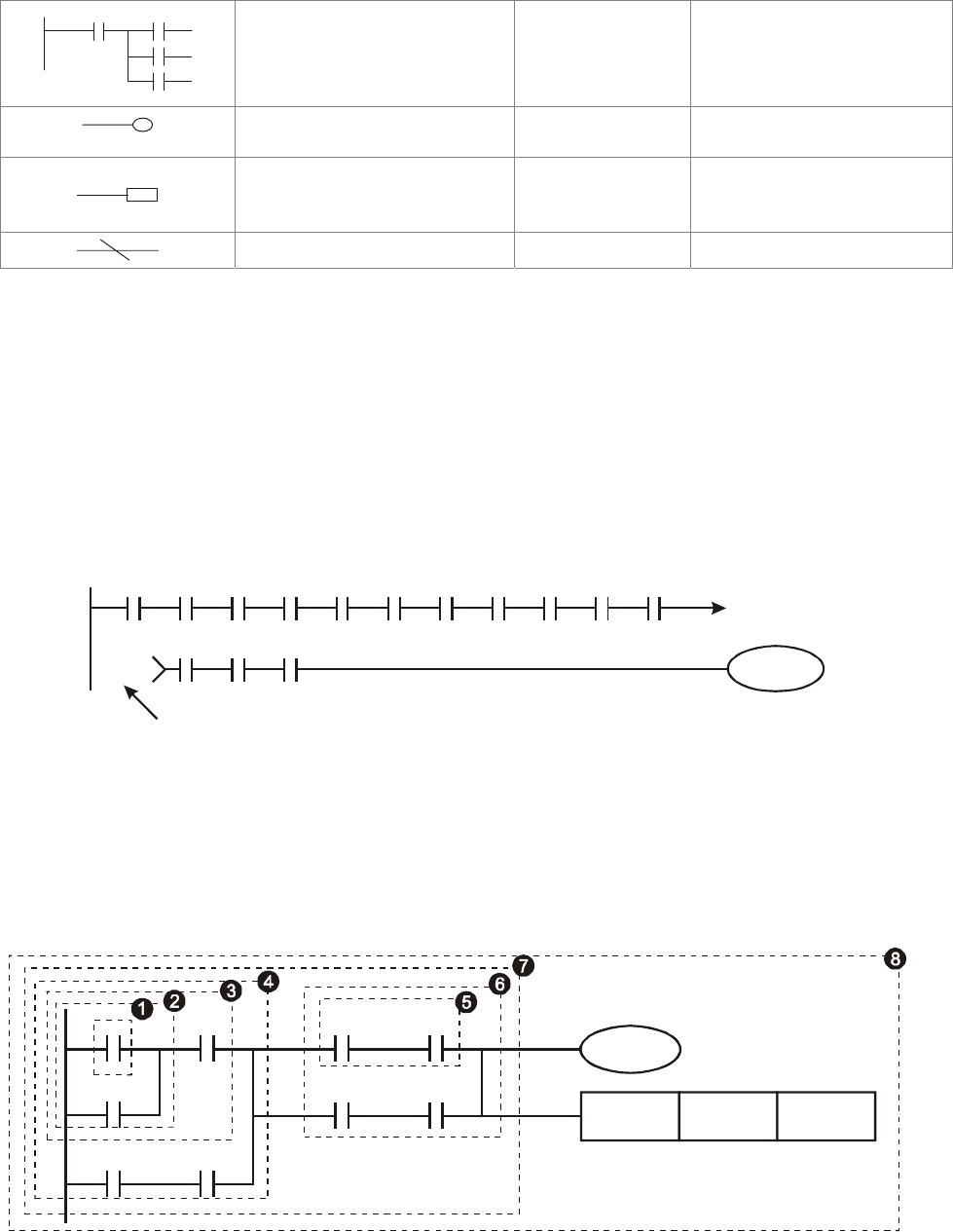
Chapter 16 PLC Function |CT2000 Series
16-12
Multiple output
MPS
MRD
MPP
none
Output command of coil
drive OUT Y, M
Basic command,
Application command
Basic command/
Application
command
Inverse logic INV none
16.3.3 The Edition of PLC Ladder Diagram
The program edited method is from left power line to right power line. (The right power line will be
omitted during the edited of WPLSoft.) After editing a row, go to editing the next row. The
maximum contacts in a row are 11 contacts. If you need more than 11 contacts, you could have
the new row and start with continuous line to continue more input devices. The continuous
number will be produced automatically and the same input point can be used repeatedly. The
drawing is shown as follows.
X0 X1 X2 X3 X4 X5
Y0
X11 X12 X13
X6 X7 X10 C0 C1
00000
00000
Row Number
The operation of ladder diagram is to scan from left upper corner to right lower corner. The output
handling, including the operation frame of coil and application command, at the most right side in
ladder diagram.
Take the following diagram for example; we analyze the process step by step. The number at the
right corner is the explanation order.
X0 X1 Y1 X4
M0
X3 M1
T0 M3
Y1
TMR T0 K10
The explanation of command order:
1 LD X0
2 OR M0
3 AND X1
4 LD X3
AND M1
ORB
5 LD Y1
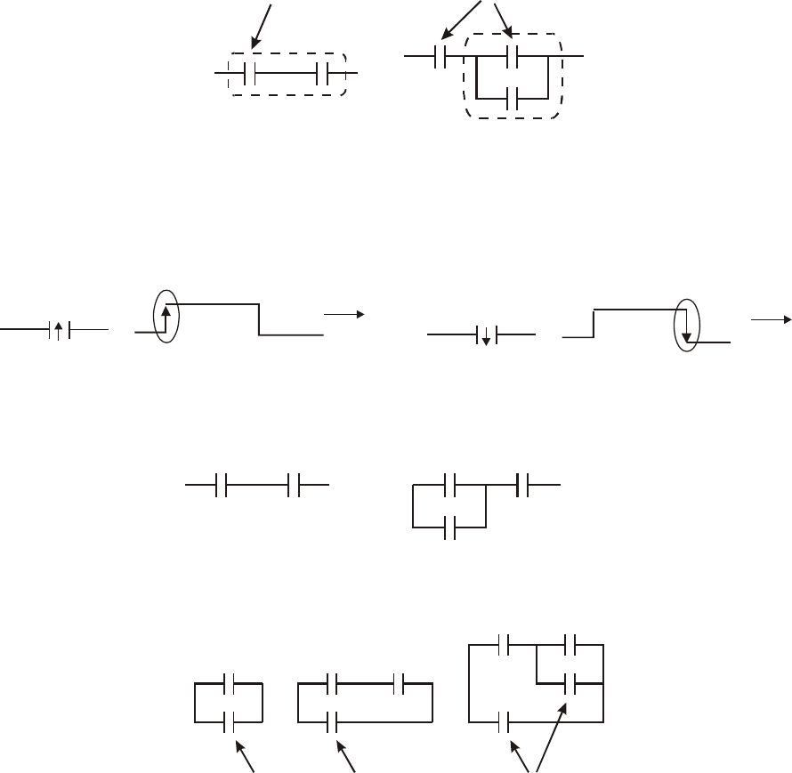
Chapter 16 PLC Function |CT2000 Series
16-13
AND X4
The explanation of command order:
6 LD T0
AND M3
ORB
7 ANB
8 OUT Y1
TMR T0 K10
The detail explanation of basic structure of ladder diagram
1. LD (LDI) command: give the command LD or LDI in the start of a block.
AND Block OR Block
LD command LD command
The structures of command LDP and LDF are similar to the command LD. The difference is that
command LDP and LDF will act in the rising-edge or falling-edge when contact is ON as shown in
the following.
X0
OFF ON OFF
Time
Falling-edge
X0
OFF ON OFF
Time
Rising-edge
2. AND (ANI) command: single device connects to a device or a block in series.
A
ND command
A
ND command
The structures of ANDP and ANDF are the same but the action is in rising-edge or falling-edge.
3. OR (ORI) command: single device connects to a device or a block.
OR command OR command OR command
The structures of ORP and ORF are the same but the action is in rising-edge or falling-edge.
4. ANB command: a block connects to a device or a block in series.
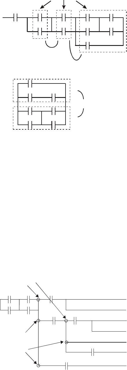
Chapter 16 PLC Function |CT2000 Series
16-14
A
NB command
5. ORB command: a block connects to a device or a block in parallel.
ORB command
If there are several blocks when operate ANB or ORB, they should be combined to blocks or
network from up to down or from left to right.
6. MPS, MRD, MPP commands: Divergent memory of multi-output. It can produce many various
outputs.
7. The command MPS is the start of divergent point. The divergent point means the connection place
between horizontal line and vertical line. We should determine to have contact memory command
or not according to the contacts status in the same vertical line. Basically, each contact could have
memory command but in some places of ladder diagram conversion will be omitted due to the
PLC operation convenience and capacity limit. MPS command can be used for 8 continuous times
and you can recognize this command by the symbol “┬”.
8. MRD command is used to read memory of divergent point. Because the logical status is the same
in the same horizontal line, it needs to read the status of original contact to keep on analyzing
other ladder diagram. You can recognize the command MRD by the symbol “├”.
9. MPP command is used to read the start status of the top level and pop it out from stack. Because
it is the last item of the horizontal line, it means the status of this horizontal line is ending.
()
()
()
()
()
()
()
MPS
MPP
MRD
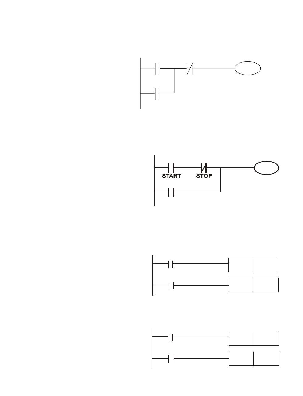
Chapter 16 PLC Function |CT2000 Series
16-15
16.3.4 The Example for Designing Basic Program
Start, Stop and Latching
In the same occasions, it needs transient close button and transient open button to be start and stop
switch. Therefore, if you want to keep the action, you should design latching circuit. There are
several latching circuits in the following:
Example 1: the latching circuit for priority of stop
When start normally open contact X1=On,
stop normally contact X2=Off, and Y1=On
are set at the same time, if X2=On, the coil
Y1 will stop acting. Therefore, it calls
priority of stop.
Y1 X2
X1
START
STOP
Y1
Example 2: the latching circuit for priority of start
When start normally open contact X1=On,
stop normally contact X2=Off and Y1=On
(coil Y1 will be active and latching) are valid
at the same time, if X2=On, coil Y1 will be
active due to latched contact. Therefore, it
calls priority of start.
X2
Y1
X1
Y1
Example 3: the latching circuit of SET and RST commands
SET Y1
RST Y1
X1
X2
Top priority of stop
The figure at the right side is latching circuit
that made up of RST and SET command.
It is top priority of stop when RST command
is set behind SET command. When
executing PLC from up to down, The coil Y1
is ON and coil Y1 will be OFF when X1 and
X2 act at the same time, therefore it calls
priority of stop.
It is top priority of start when SET command
is set after RST command. When X1 and
X2 act at the same time, Y1 is ON so it calls
top priority of start.
SET
Y1
RST
Y1
X2
X1
Top priority of start
The common control circuit
Example 4: condition control
X1 and X3 can start/stop Y1 separately, X2 and X4 can start/stop Y2 separately and they are all self
latched circuit. Y1 is an element for Y2 to do AND function due to the normally open contact
connects to Y2 in series. Therefore, Y1 is the input of Y2 and Y2 is also the input of Y1.
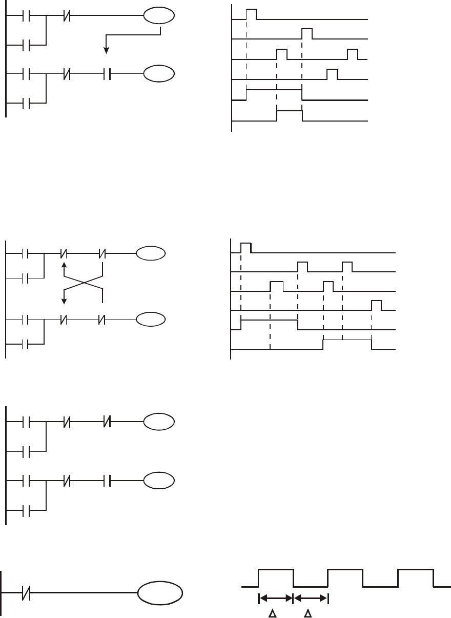
Chapter 16 PLC Function |CT2000 Series
16-16
X3
Y1
X1
Y1
X4
Y2
X2
Y2
Y1
X1
X3
X2
X4
Y1
Y2
Example 5: Interlock control
The figure above is the circuit of interlock control. Y1 and Y2 will act according to the start
contact X1 and X2. Y1 and Y2 will act not at the same time, once one of them acts and the other
won’t act. (This is called interlock.) Even if X1 and X2 are valid at the same time, Y1 and Y2
won’t act at the same time due to up-to-down scan of ladder diagram. For this ladder diagram,
Y1 has higher priority than Y2.
X3
Y1
X1
Y1
X4
Y2
X2
Y2
Y1
Y2
X1
X3
X2
X4
Y1
Y2
Example 6: Sequential Control
X3
Y1
X1
Y1
X4
Y2
X2
Y2
Y1
Y2
If add normally close contact Y2 into Y1 circuit to
be an input for Y1 to do AND function. (as shown in
the left side) Y1 is an input of Y2 and Y2 can stop
Y1 after acting. In this way, Y1 and Y2 can execute
in sequential.
Example 7: Oscillating Circuit
The period of oscillating circuit is ΔT+ΔT
Y1
Y1
Y1
T T
The figure above is a very simple ladder step diagram. When starting to scan Y1 normally close
contact, Y1 normally close contact is close due to the coil Y1 is OFF. Then it will scan Y1 and the
coil Y1 will be ON and output 1. In the next scan period to scan normally close contact Y1, Y1
normally close contact will be open due to Y1 is ON. Finally, coil Y1 will be OFF. The result of
repeated scan, coil Y will output the vibrating pulse with cycle time ΔT (On) +ΔT (Off).
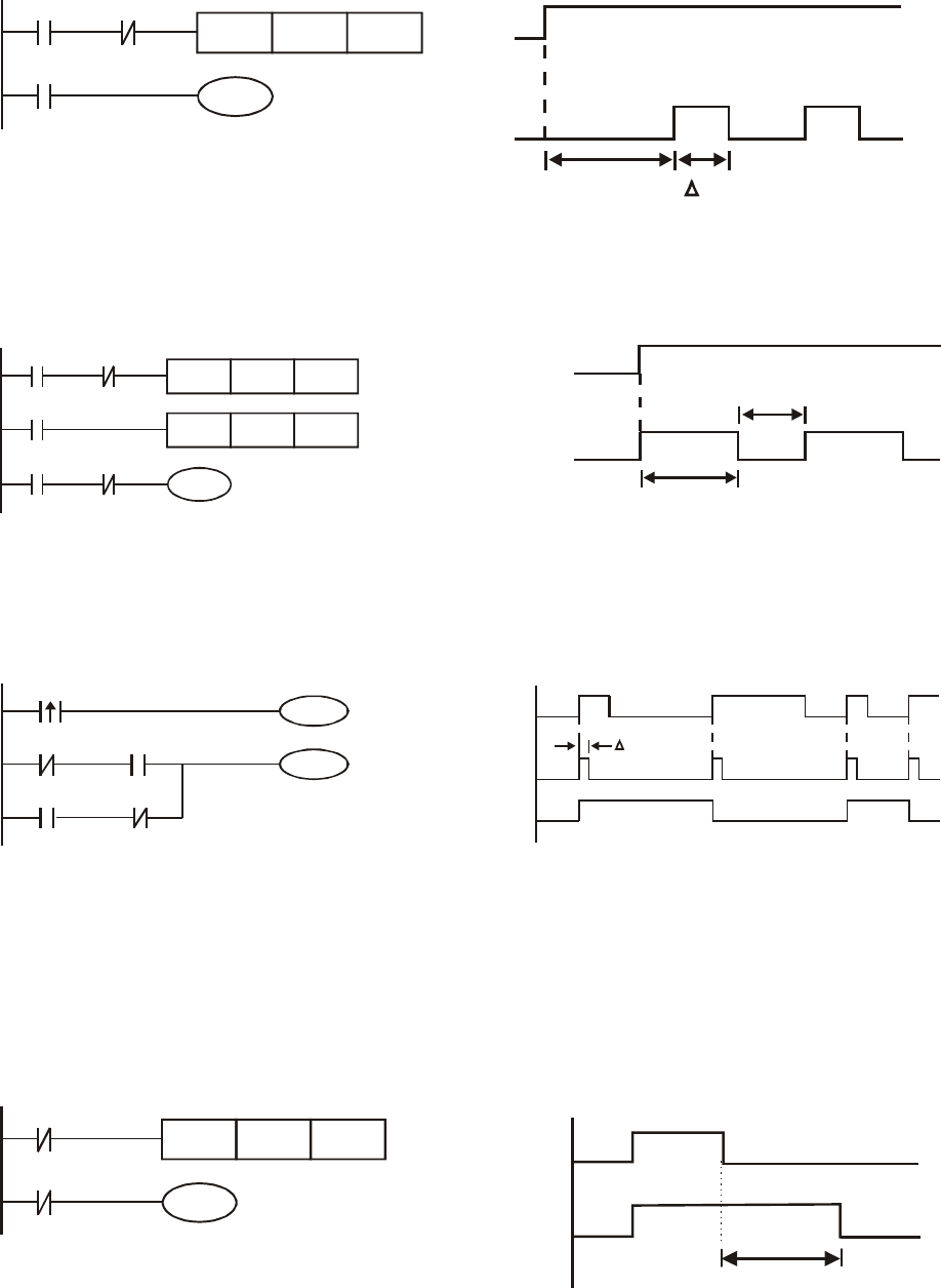
Chapter 16 PLC Function |CT2000 Series
16-17
The vibrating circuitry of cycle time ΔT (On) +ΔT (Off):
T0
X0
TMR
Y1
Y1
T0
Kn
Y1
TTn
X0
The figure above uses timer T0 to control coil Y1 to be ON. After Y1 is ON, timer T0 will be
closed at the next scan period and output Y1. The oscillating circuit will be shown as above. (n is
the setting of timer and it is decimal number. T is the base of timer. (clock period))
Example 8: Blinking Circuit
T2TMR Kn2
T1
X0
TMR
Y1
T2
T1
Kn1
X0 T1
Y1
T
n1
X0
Tn2
*
*
The figure above is common used oscillating circuit for indication light blinks or buzzer alarms. It
uses two timers to control On/OFF time of Y1 coil. If figure, n1 and n2 are timer setting of T1 and T2.
T is the base of timer (clock period)
Example 9: Triggered Circuit
Y1
M0
X0
Y1
Y1
M0
M0
X0
M0
Y1
T
In figure above, the rising-edge differential command of X0 will make coil M0 to have a single
pulse of ΔT (a scan time). Y1 will be ON during this scan time. In the next scan time, coil M0 will be
OFF, normally close M0 and normally close Y1 are all closed. However, coil Y1 will keep on being
ON and it will make coil Y1 to be OFF once a rising-edge comes after input X0 and coil M0 is ON
for a scan time. The timing chart is as shown above. This circuit usually executes alternate two
actions with an input. From above timing: when input X0 is a square wave of a period T, output coil
Y1 is square wave of a period 2T.
Example 10: Delay Circuit
T10
X0
TMR
Y1
T10
K1000
TB = 0.1 sec
X0
Y1
100 seconds
When input X0 is ON, output coil Y1 will be ON at the same time due to the corresponding
normally close contact OFF makes timer T10 to be OFF. Output coil Y1 will be OFF after delaying
100 seconds (K1000*0.1 seconds =100 seconds) once input X0 is OFF and T10 is ON. Please
refer to timing chart above.
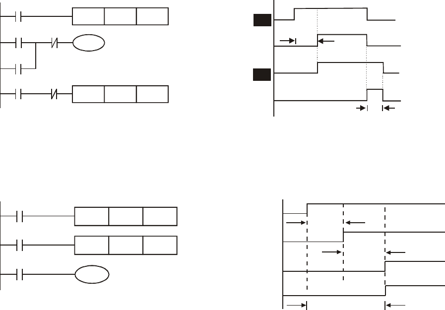
Chapter 16 PLC Function |CT2000 Series
16-18
Example 11: Output delay circuit, in the following example, the circuit is made up of two
timers.
No matter input X0 is ON or OFF, output Y4 will be delay.
T5
T5
TMR
Y4
T6
X0
K50
Y4
T6
Y4
TMR
X0
K30
X0
T5
Y0
T6
5 seconds
3 seconds
Example12: Extend Timer Circuit
In this circuit, the total delay time from input X0 is close and output Y1 is ON= (n1+n2)* T. where T is
clock period. Timer: T11, T12; Timer cycle: T.
T12TMR Kn2
T11
X0
TMR
Y1
T11
Kn1
T12
X0
Y1
T11
T12
n1*
n2*
T
T
(
n1+n2
)
*T

Chapter 16 PLC Function |CT2000 Series
16-19
16.4 PLC Devices Function
Items Specifications Remarks
Control Method Stored program, cyclic scan
system
I/O Processing Method Batch processing (when END
instruction is executed)
I/O refresh instruction is
available
Execution Speed Basic commands (minimum 0.24
us)
Application commands (1 ~
dozens us)
Program Language Instruction, Ladder Logic, SFC
Program Capacity 1000 STEPS
Commands 80 commands 30 basic commands
50 application commands
Input/Output Contact Input (X): 10, output (Y): 4
Device Item Range Function
X External Input Relay X0~X17, 16 points,
octal number system
Correspond to external
input point
Y External Output Relay Y0~Y17, 16 points,
octal number system
Total is
32
points Correspond to external
output point
For general M0~M799, 800 points
M Auxiliary For special M1000~M1079, 80
points
Total is
192
points
Contacts can switch to
On/Off in program
T Timer 100ms timer T0~T159, 160 points
Total is
16
points
When the timer
indicated by TMR
command attains the
setting, the T contact
with the same number
will be On.
Relay bit mode
C Counter 16-bit count up
for general C0~C79, 80 points
Total is
80
points
When the counter
indicated by CNT
command attains the
setting, the C contact
with the same number
will be On.
T Present value of timer T0~T15, 160 points
When timer attains, the
contact of timer will be
On.
C Present value of counter C0~C79, 16-bit counter, 80
points
When timer attains, the
contact of timer will be
On.
For latched D0~D399, 400 points
For general D1000~D1099, 100
points
Register WORD data
D Data
register
For special D2000~D2799, 800
points
Total is
1300
points
It can be memory area
for storing data.
K Decimal K-32,768 ~ K32,767 (16-bit operation)
Constant
H Hexadecimal H0000 ~ HFFFF (16-bit operation)
Communication port (program read/write) RS485 (slave)
Analog input/output Built-in 2 analog inputs and 1 analog output
Function extension module (optional) EMC-D42A; EMC-R6AA; EMCD611A
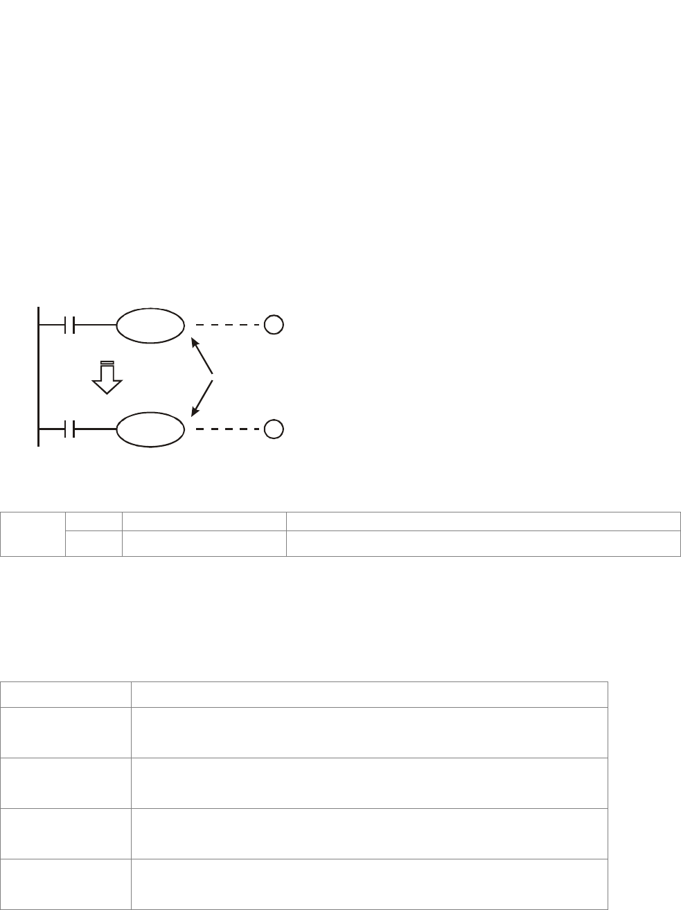
Chapter 16 PLC Function |CT2000 Series
16-20
16.4.1 Devices Functions
The Function of Input/output Contacts
The function of input contact X: input contact X reads input signal and enter PLC by connecting with
input equipment. It is unlimited usage times for contact A or contact B of each input contact X in
program. The On/Off of input contact X can be changed with the On/Off of input equipment but can’t
be changed by using peripheral equipment (WPLSoft).
The Function of Output Contact Y
The mission of output contact Y is to drive the load that connects to output contact Y by sending
On/Off signal. There are two kinds of output contact: one is relay and the other is transistor. It is
unlimited usage times for A or B contact of each output contact Y in program. But there is number for
output coil Y and it is recommended to use one time in program. Otherwise, the output result will be
decided by the circuit of last output Y with PLC program scan method.
X0
X10
Y0
Y0
1
2
Y0 is repeated
The output of Y0 will be decided by
circuit ○
2, i.e. decided by On/Off of
X10.
Value, Constant [K] / [H]
K Decimal K-32,768 ~ K32,767 (16-bit operation)
Constant H Hexadecimal H0000 ~ HFFFF (16-bit operation)
There are five value types for DVP-PLC to use by the different control destination. The following is
the explanation of value types.
Binary Number (BIN)
It uses binary system for the PLC internal operation or storage. The relative information of binary
system is in the following.
Bit Bit is the basic unit of binary system, the status are 1 or 0.
Nibble It is made up of continuous 4 bits, such as b3~b0. It can be used to
represent number 0~9 of decimal or 0~F of hexadecimal.
Byte It is made up of continuous 2 nibbles, i.e. 8 bits, b7~b0. It can used to
represent 00~FF of hexadecimal system.
Word It is made up of continuous 2 bytes, i.e. 16-bit, b15~b0. It can used to
represent 0000~FFFF of hexadecimal system.
Double Word It is made up of continuous 2 words, i.e. 32-bit, b31~b0. It can used to
represent 00000000~FFFFFFFF of hexadecimal system.
The relations among bit, nibble, byte, word, and double word of binary number are shown as follows.

Chapter 16 PLC Function |CT2000 Series
16-21
NB0NB1NB2NB3NB4NB5NB6NB7
BY3 BY2 BY1 BY0
W1
DW
W0
Double Word
Word
Byte
Nibble
Bit
¾ Octal Number (OCT)
The numbers of external input and output terminal of DVP-PLC use octal number.
Example:
External input: X0~X7, X10~X17… (device number)
External output: Y0~Y7, Y10~Y17… (device number)
¾ Decimal Number, DEC
The suitable time for decimal number to be used in DVP-PLC system.
; To be the setting value of timer T or counter C, such as TMR C0 K50. (K constant)
; To be the device number of M, T, C and D. For example: M10, T30. (device number)
; To be operand in application command, such as MOV K123 D0. (K constant)
¾ Binary Code Decimal (BCD)
It shows a decimal number by a unit number or four bits so continuous 16-bit can use to represent the
four numbers of decimal number. BCD code is usually used to read the input value of DIP switch or
output value to 7-segment display to be display.
¾ Hexadecimal Number (HEX)
The suitable time for hexadecimal number to be used in DVP-PLC system.
; To be operand in application command. For example: MOV H1A2B D0. (constant H)
¾ Constant K:
In PLC, it is usually have K before constant to mean decimal number. For example, K100 means 100
in decimal number.
Exception: The value that is made up of K and bit equipment X, Y, M, S will be bit, byte, word or
double word. For example, K2Y10, K4M100. K1 means a 4-bit data and K2~K4 can be 8, 12
and 16-bit data separately.
¾ Constant H:
In PLC, it is usually have H before constant to mean hexadecimal number. For example, H100
means 100 in hexadecimal number.
The Function of Auxiliary Relay
There are output coil and A, B contacts in auxiliary relay M and output relay Y. It is unlimited usage
times in program. User can control loop by using auxiliary relay, but can’t drive external load directly.
There are two types divided by its characteristics.

Chapter 16 PLC Function |CT2000 Series
16-22
1. Auxiliary relay for general : It will reset to Off when power loss during running. Its
state will be Off when power on after power loss.
2. Auxiliary relay for special : Each special auxiliary relay has its special function.
Please don’t use undefined auxiliary relay.
The Function of Timer
The unit of timer is 1ms, 10ms and 100ms. The count method is count up. The output coil will be On
when the present value of timer equals to the settings. The setting is K in decimal number. Data
register D can be also used as settings.
• The real setting time of timer = unit of timer * settings
The Features and Functions of Counter
Item 16-bit counters 32-bit counters
Type General General High speed
Count direction Count up Count up/down
Settings 0~32,767 -2,147,483,648~+2,147,483,647
Designate for
constant Constant K or data register D Constant K or data register D (2 for designated)
Present value
change
Counter will stop when attaining
settings
Counter will keep on counting when attaining
settings
Output contact
When count attains the settings
value, contact will be On and
latched.
When count up attains settings, contact will be
On and latched.
When count down attains settings, contact will
reset to Off.
Reset action The present value will reset to 0 when RST command is executed and contact will
reset to Off.
Present register 16-bit 32-bit
Contact action After scanning, act together.
After scanning, act together.
Act immediately when count attains. It has no
relation with scan period.
Functions:
When pulse input signal of counter is from Off to On, the present value of counter equals to settings
and output coil is On. Settings are decimal system and data register D can also be used as settings.
16-bit counters C0~C79:
; Setting range of 16-bit counter is K0~K32, 767. (K0 is the same as K1. output contact will be
On immediately at the first count.
; General counter will be clear when PLC is power loss. If counter is latched, it will remember the
value before power loss and keep on counting when power on after power loss.
; If using MOV command, WPLSoft to send a value, which is large than setting to C0, register, at
the next time that X1 is from Off to On, C0 counter contact will be On and present value will be
set to the same as settings.
; The setting of counter can use constant K or register D (not includes special data register
D1000~D1044) to be indirect setting.
; If using constant K to be setting, it can only be positive number but if setting is data register D, it
can be positive/negative number. The next number that counter counts up from 32,767 is
-32,768.
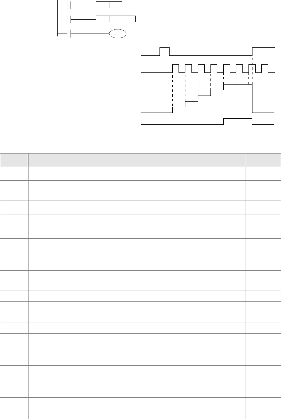
Chapter 16 PLC Function |CT2000 Series
16-23
Example:
LD X0
RST C0
LD X1
CNT C0 K5
LD C0
OUT Y0
X0
Y0
CNT C0 K5
X1
RST C0
C0
1. When X0=On, RST command is executed,
C0 reset to 0 and output contact reset to
Off.
2. When X1 is from Off to On, counter will
count up (add 1).
3. When counter C0 attains settings K5, C0
contact is On and C0 = setting =K5. C0
won’t accept X1 trigger signal and C0
remains K5.
X0
X1
0
1
2
3
4
5
0
Contacts Y0, C0
C0
present
value
settings
16.4.2 Special Auxiliary Relays
Special
M Function Read(R)/
Write(W)
M1000 Normally open contact (a contact). This contact is On when running and it is On when
the status is set to RUN. Read only
M1001 Normally closed contact (b contact). This contact is Off when running and it is Off
when the status is set to RUN.
Read only
M1002 On only for 1 scan after RUN. Initial pulse is contact a. It will get positive pulse in the
RUN moment. Pulse width=scan period. Read only
M1003 Off only for 1 scan after RUN. Initial pulse is contact a. It will get negative pulse in
the RUN moment. Pulse width=scan period. Read only
M1004 Reserved -
M1005 Fault indication of the AC motor drives Read only
M1006 Output frequency is 0, M1006 On Read only
M1007 Operation direction of AC motor drives (FWD: M1007 Off, REV: M1007On) Read only
M1008
~
M1010
Reserved -
M1011 10ms clock pulse, 5ms On/5ms Off Read only
M1012 100ms clock pulse, 50ms On / 50ms Off Read only
M1013 1s clock pulse, 0.5s On / 0.5s Off Read only
M1014 1min clock pulse, 30s On / 30s Off Read only
M1015 Frequency attained, M1015=On Read only
M1016 Parameter read/write error, M1016=On Read only
M1017 Succeed to write parameter, M1017 =On Read only
M1018 Reserved
M1019 Reserved
M1020 Zero flag Read only
M1021 Borrow flag Read only
M1022 Carry flag Read only

Chapter 16 PLC Function |CT2000 Series
16-24
Special
M Function Read(R)/
Write(W)
M1023 Divisor is 0 Read only
M1024 Reserved -
M1025 RUN(ON) / STOP(OFF) the AC motor drive Read/Write
M1026 The operation direction of the AC motor drive (FWD: OFF, REV: ON) Read/Write
M1027 AC motor drive reset Read/Write
M1028 Reserved
M1029 Reserved
M1030 Reserved
M1031 Reserved
M1032 Reserved
M1033 Reserved
M1034 Enable CANopen real time control Read/Write
M1035
~
M1039
Reserved -
M1040 Power On Read/Write
M1041 Reserved -
M1042 Quick stop Read/Write
M1043 Reserved -
M1044 Halt Read/Write
M1045
~
M1047
Reserved -
M1048 New position Read/Write
M1049~
M1051 Reserved
M1052 Freuqency Lock Read/Write
M1053
~
M1054
Reserved -
M1055 Home Read/Write
M1056 Power on ready Read only
M1057 Reserved -
M1058 On quick stopping Read only
M1059 CANopen master setting complete Read only
M1060 Initializing CANopen slave Read only
M1061 Initialize CANopen slave failed Read only
M1062 Reserved -
M1063 Target torque attained Read only
M1064 Target position attained Read only
M1065 Set pos ack Read only
M1066 Read/ Write CANopen data complete Read only
M1067 Read/ Write CANopen data suceed Read only

Chapter 16 PLC Function |CT2000 Series
16-25
Special
M Function Read(R)/
Write(W)
M1068
~
M1079
Reserved -
M1070 Homing complete Read only
M1071 Home error Read only
M1072
~
M1079
Reserved
16.4.3 Special Registers
Special D Function Read(R)/
Write(W)
D1000 Reserved -
D1001 PLC firmware version Read only
D1002 Program capacity Read only
D1003 Checksum Read only
D1004
~
D1009
Reserved -
D1010 Present scan time (Unit: 0.1ms) Read only
D1011 Minimum scan time (Unit: 0.1ms) Read only
D1012 Maximum scan time (Unit: 0.1ms) Read only
D1013
~
D1019
Reserved -
D1020 Output frequency (0.000~600.00Hz) Read only
D1021 Output current (####.#A) Read only
D1022
The ID of the extension card:
0: no card
1: Relay Card( 6 out )
2: I/O Card ( 4 in 2 out )
3~7: Reserved
Read only
D1023
The ID of the extension card:
0: no card
1: DeviceNet Slave
2: Profibus-DP Slave
3: CANopen Slave
4: Modbus-TCP Slave
5: EtherNet/IP Slave
6~8: Reserved
Read only
D1024
~
D1026
Reserved -
D1027 Frequency command of the PID control Read only
D1028 The responsive value of AUI AVI (analog voltage input) (0.00~100.00%) Read only
D1029 The responsive value of AUI ACI (analog current input) (0.0~100.00%) Read only
D1030 The corresponding value for AUI (-100.0~100.00%) Read only
D1031 Reserved -

Chapter 16 PLC Function |CT2000 Series
16-26
Special D Function Read(R)/
Write(W)
~
D1035
D1036 AC motor drive error code Read only
D1037 AC motor drive output frequency Read only
D1038 DC Bus voltage Read only
D1039 Output voltage Read only
D1040 Analog output value AFM1 (-100.00~100.00%) Read/Write
D1041
~
D1042
Reserved -
D1043 User defined (When Pr.00.04 is set to 28, the register data will be
displayed as C xxx) Read/Write
D1044 Reserved -
D1045 Analog output value AFM2 (-100.00~100.00%) Read/Write
D1046
~
D1049
Reserved -
D1050
Actual mode
0: Velocity mode
1: Position mode
2: Torque mode
3: Homing mode
Read only
+D1051
~
D1052
Reserved -
D1053 Actual torque Read only
D1054 Present count value of MI8(L word)
D1055 Present count value of MI8 (H word)
D1056
~
D1059
Reserved Read only
D1060
Mode setting
0: Speed Mode
1: Position Mode
2: Torque Mode
3: Homing Mode
Read/Write
D1061
~
D1069
Reserved Read/Write
D1100 Tartget frequency Read only
D1101 Target frequency (operating) Read only
D1102 Reference frequency Read only
D1103 Target position L Read only
D1104 Target position H Read only
D1105 Target torque Read only
D1106 - -
D1107 - -
D1108 - -
D1109 Random value Read only
D1110 Number of internal communication nodes RW
D1111 - -
D1112 - -
D1113 - -

Chapter 16 PLC Function |CT2000 Series
16-27
Special D Function Read(R)/
Write(W)
D1114 - -
D1115 Synchronous time cycle of internal communication Read only
D1116 Internal communication node error Read only
D1117 Corresponding on-line bit of internal communication node Read only
D1118 - -
D1119 Random value Read only
D1120 Control command of internal communication node 0 Read/Write
D1121 Mode of internal communication node 0 Read/Write
D1122 Reference command L of internal communication node 0 Read/Write
D1123 Referenc command H of internal communication node 0 Read/Write
D1124 - -
D1125 - -
D1126 Status of internal communication node 0 Read only
D1127 Reference status L of internal communication node 0 Read only
D1128 Reference status H of internal communication node 0 Read only
D1129 - -
D1130 Control command of internal communication node 1 Read/Write
D1131 Mode of internal communication node 1 Read/Write
D1132 Reference command L of internal communication node 1 Read/Write
D1133 Referenc command H of internal communication node 1 Read/Write
D1134 - -
D1135 - -
D1136 Status of internal communication node 1 Read only
D1137 Reference status L of internal communication node 1 Read only
D1138 Reference status H of internal communication node 1 Read only
D1139 - -
D1140 Control command of internal communication node 2 Read/Write
D1141 Mode of internal communication node 2 Read/Write
D1142 Reference command L of internal communication node 2 Read/Write
D1143 Referenc command H of internal communication node 2 Read/Write
D1144 - -
D1145 - -
D1146 Status of internal communication node 2 Read only
D1147 Reference status L of internal communication node 2 Read only
D1148 Reference status H of internal communication node 2 Read only
D1149 - -
D1150 Control command of internal communication node 3 Read/Write
D1151 Mode of internal communication node 3 Read/Write
D1152 Reference command L of internal communication node 3 Read/Write
D1153 Referenc command H of internal communication node 3 Read/Write
D1154 - -
D1155 - -
D1156 Status of internal communication node 3 Read only
D1157 Reference status L of internal communication node 3 Read only
D1158 Reference status H of internal communication node 3 Read only
D1159 - -
D1160 Control command of internal communication node 4 Read/Write
D1161 Mode of internal communication node 4 Read/Write
D1162 Reference command L of internal communication node 4 Read/Write
D1163 Referenc command H of internal communication node 4 Read/Write
D1164 - -
D1165 - -
D1166 Status of internal communication node 4 Read only
D1167 Reference status L of internal communication node 4 Read only

Chapter 16 PLC Function |CT2000 Series
16-28
Special D Function Read(R)/
Write(W)
D1168 Reference status H of internal communication node 4 Read only
D1169 - -
D1170 Control command of internal communication node 5 Read/Write
D1171 Mode of internal communication node 5 Read/Write
D1172 Reference command L of internal communication node 5 Read/Write
D1173 Referenc command H of internal communication node 5 Read/Write
D1174 - -
D1175 - -
D1176 Status of internal communication node 5 Read only
D1177 Reference status L of internal communication node 5 Read only
D1178 Reference status H of internal communication node 5 Read only
D1179 - -
D1180 Control command of internal communication node 6 Read/Write
D1181 Mode of internal communication node 6 Read/Write
D1182 Reference command L of internal communication node 6 Read/Write
D1183 Referenc command H of internal communication node 6 Read/Write
D1184 - -
D1185 - -
D1186 Status of internal communication node 6 Read only
D1187 Reference status L of internal communication node 6 Read only
D1188 Reference status H of internal communication node 6 Read only
D1189 - -
D1190 Control command of internal communication node 7 Read/Write
D1191 Mode of internal communication node 7 Read/Write
D1192 Reference command L of internal communication node 7 Read/Write
D1193 Referenc command H of internal communication node 7 Read/Write
D1194 - -
D1195 - -
D1196 Status of internal communication node 7 Read only
D1197 Reference status L of internal communication node 7 Read only
D1198 Reference status H of internal communication node 7 Read only
D1199 - Read only
CANopen Master Special D (Special D can be written only when PLC is at STOP)
Special D Function PDO
Map
Power
Failure
Memory
Factory
Setting R/W
D1070 The station which completed CANopen
initialization (bit0=Machine code0 …….) NO NO 0 R
D1071 The station which error occurs during CANopen
initialization (bit0=Machine code0 …….) NO NO 0 R
D1072 Reserved - - -
D1073 CANopen station cut off (bit0=Machine
code0 …….) NO NO R
D1074
Error code of master error
0: no error
1: slave setting error
2: synchronous cycle setting error (the setting is
too low)
NO NO 0 R
D1075 Reserved - - -
D1076 SDO fault (main index value) NO NO R
D1077 SDO fault (sub-index value) NO NO R

Chapter 16 PLC Function |CT2000 Series
16-29
Special D Function PDO
Map
Power
Failure
Memory
Factory
Setting R/W
D1078 SDO fault (error code L) NO NO R
D1079 SDO fault (error code H) NO NO R
D1080 Reserved - - -
D1081 Reserved NO NO R
D1082 Reserved NO NO R
D1083 Reserved NO NO R
D1084 Reserved NO NO R
D1085 Reserved NO NO R
D1086 Reserved NO NO R
D1087
~
D1089
Reserved - - -
D1090 Synchronous cycle setting NO YES 4 RW
D1091 The station for initialization during initializing
process. NO YES FFFFH RW
D1092 Delay time before initializing NO YES 0 RW
D1093 Break off detection time NO YES 1000ms RW
D1094 Times of Break off detection NO YES 3 RW
D1095
~
D1096
Reserved - - -
D1097 Type of P to P send (PDO)
Setting range: 1~240 NO YES 1 RW
D1098 Type of P to P received (PDO)
Setting range: 1~240 NO YES 1 RW
D1099 Delay time of initialization complete
Setting range: 1~60000 sec. NO YES 15 sec RW
CT2000 supports up to 8 CANopen protocol slaves; each slave occupies 100 of special D
register and is numbered in 1~8. There are in total of 8 stations.
Slave No. Slave No. 1 D2000
D2001
~
D2099
Station number
Factory code(L)
~
Mapping address 4 (H)of receiving station
Slave No. 2 D2100
D2101
~
D2199
Station number
Factory code(L)
~
Mapping address 4(H) of receiving station
4
Slave No. 3 D2200
D2201
~
D2299
Station number
Factory code(L)
~
Mapping address 4(H) of receiving station

Chapter 16 PLC Function |CT2000 Series
16-30
Slave No. 0~7
Special D Function PDO
Map Save Pre-defined
setting R/W
D2000+100*
n
Station number of slave No. n
Setting range: 0~127
0: CANopen disable
NO 0 RW
D2001+100*
n
The category of slave No. n
192H: AC motor drive/ AC servo motor and drive
191H: remote I/O module
NO 0 R
D2002+100*
n Factory code (L) of slave No. n NO 0 R
D2003+100*
n Factory code (H) of slave No. n NO 0 R
D2004+100*
n Factory product code (L) of slave No. n NO 0 R
D2005+100*
n Factory product code (H) of slave No. n NO 0 R
Basic definition
Slave No. 0~7
PDO
Special D Function PDO
Map Save Pre-defined
setting
CAN
Index 1 2 3 4 R/W
D2006+100*n Treatment for slave No. n
communication disconnect YES 0 6007H-001
0H ● ● ● RW
D2007+100*n Error code of slave No. n YES 0 603FH-001
0H ● ● ● R
D2008+100*n Control word of slave No. n YES 0 6040H-001
0H RW
D2009+100*n Status word of slave No. n YES 0 6041H-001
0H R
D2010+100*n Control mode of slave No. n YES 2 6060H-000
8H RW
D2011+100*n Actual mode of slave No. n YES 2 6061H-000
8H R
4
Ø
Slave No. 8 D2700
D2701
~
D2799
Station number
Factory code(L)
~
Mapping address 4(H)of receiving station
4

Chapter 16 PLC Function |CT2000 Series
16-31
Speed Control
Slave No. 0~7
PDO
Special D Function PDO
Map Save Pre-define
d Setting
CAN
Index 1 2 3 4 R/W
D2012+100*n Target speed of slave No. n YES 0 6042H-001
0H ● RW
D2013+100*n Actual speed of slave No. n YES 0 6043H-001
0H ● R
D2014+100*n Speed deviation of slave No.
n YES 0 6044H-001
0H R
D2015+100*n Accel. Time of slave No. n YES 1000 604FH-002
0H R
D2016+100*n Decel. Time of slave No. n YES 1000 6050H-002
0H RW
Torque control
Slave No. 0~7
PDO
Special D Function PDO
Map Save Pre-defined
Setting
CAN
Index 1 2 3 4 R/W
D2017+100*n Target torque of slave No. n YES 0 6071H-001
0H ●RW
D2018+100*n Actual torque of slave No. n YES 0 6077H-001
0H ●R
D2019+100*n Actual current of slave No. n YES 0 6078H-001
0H R
Position control
Slave No. 0~7
PDO
Special D Function PDO
Map Save Pre-defined
Setting
CAN
Index 1 2 3 4 R/W
D2020+100*n Target position(L) of slave
No. n YES 0 RW
D2021+100*n Target position(H) of slave
No. n YES 0
607AH-002
0H ●
RW
D2022+100*n Actual position(L) of slave
No. n YES 0 R
D2023+100*n Actual position(H) of slave
No. n YES 0
6064H-002
0H ●
R
D2024+100*n Speed diagram(L) of slave
No. n YES 10000 RW
D2025+100*n Speed diagram (H) of slave
No. n YES 0
6081H-002
0H RW

Chapter 16 PLC Function |CT2000 Series
16-32
20XXH address corresponds to MI MO AI AO.
Slave No. n=0~7
PDO
Special D Function PDO
Map Save Pre-defined
Setting
CAN
Index 1 2 3 4 R/W
D2026+100*n MI status of slave No. n YES 0 2026H-011
0H ●RW
D2027+100*n MO setting of slave No. n YES 0 2026H-411
0H ●RW
D2028+100*n AI1 status of slave No. n YES 0 2026H-611
0H ●RW
D2029+100*n AI2 status of slave No. n YES 0 2026H-621
0H ●RW
D2030+100*n AI3 status of slave No. n YES 0 2026H-631
0H ●RW
D2031+100*n AO1 status of slave No. n YES 0 2026H-A11
0H ●RW
D2032+100*n AO2 status of slave No. n YES 0 2026H-A2
10H ●RW
D2033+100*n AO3 status of slave No. n YES 0 2026H-A3
10H ●RW
Special D Function PDO
Map Save Pre-defined
Setting R/W
D2034+100*n Transmission setting of slave No. n NO YES 000AH RW
D2035+100*n The mapping address 1(L) for slave No. n
transmitting station 1 NO YES 0010H RW
D2036+100*n The mapping address 1(H) for slave No.n
transmitting station 1 NO YES 6040H RW
D2037+100*n The mapping address 2(L) for slave No. n
transmitting station 1 NO YES 0010H RW
D2038+100*n
The mapping address 2(H) for slave No.n
transmitting station 1 NO YES 6042H RW
D2039+100*n The mapping address 3(L) for slave No. n
transmitting station 1 NO YES 0 RW
D2040+100*n The mapping address 3(H) for slave No.n
transmitting station 1 NO YES 0 RW
D2041+100*n The mapping address 4(L) for slave No. n
transmitting station 1 NO YES 0 RW
D2042+100*n The mapping address 4(H) for slave No.n
transmitting station 1 NO YES 0 RW
D2043+100*n The mapping address 1(L) for slave No. n
transmitting station 2 NO YES 0110H RW
D2044+100*n The mapping address 1(H) for slave No.n
transmitting station 2 NO YES 2026H RW
D2045+100*n The mapping address 2(L) for slave No. n
transmitting station 2 NO YES 6110H RW

Chapter 16 PLC Function |CT2000 Series
16-33
Special D Function PDO
Map Save Pre-defined
Setting R/W
D2046+100*n The mapping address 2(H) for slave No.n
transmitting station 2 NO YES 2026H RW
D2047+100*n The mapping address 3(L) for slave No. n
transmitting station 2 NO YES 6210H RW
D2048+100*n
The mapping address 3(H) for slave No.n
transmitting station 2 NO YES 2026H RW
D2049+100*n The mapping address 4(L) for slave No. n
transmitting station 2 NO YES 6310H RW
D2050+100*n The mapping address 4(H) for slave No.n
transmitting station 2 NO YES 2026H RW
D2051+100*n The mapping address 1(L) for slave No. n
transmitting station 3 NO YES 0010H RW
D2052+100*n The mapping address 1(H) for slave No.n
transmitting station 3 NO YES 6040H RW
D2053+100*n The mapping address 2(L) for slave No. n
transmitting station 3 NO YES 0020H RW
D2054+100*n The mapping address 2(H) for slave No.n
transmitting station 3 NO YES 607AH RW
D2055+100*n The mapping address 3(L) for slave No. n
transmitting station 3 NO YES 0 RW
D2056+100*n The mapping address 3(H) for slave No.n
transmitting station 3 NO YES 0 RW
D2057+100*n The mapping address 4(L) for slave No. n
transmitting station 3 NO YES 0 RW
D2058+100*n
The mapping address 4(H) for slave No.n
transmitting station 3 NO YES 0 RW
D2059+100*n The mapping address 1(L) for slave No. n
transmitting station 4 NO YES 0010H RW
D2060+100*n The mapping address 1(H) for slave No.n
transmitting station 4 NO YES 6040H RW
D2061+100*n The mapping address 2(L) for slave No. n
transmitting station 4 NO YES 0010H RW
D2062+100*n The mapping address 2(H) for slave No.n
transmitting station 4 NO YES 6071H RW
D2063+100*n The mapping address 3(L) for slave No. n
transmitting station 4 NO YES 0 RW
D2064+100*n The mapping address 3(H) for slave No.n
transmitting station 4 NO YES 0 RW
D2065+100*n The mapping address 4(L) for slave No. n
transmitting station 4 NO YES 0 RW
D2066+100*n The mapping address 4(H) for slave No.n
transmitting station 4 NO YES 0 RW
D2067+100*n Receiving setting of slave No. n NO YES 0000H RW
D2068+100*n The mapping address 1(L) for slave No. n
receiving station 1 NO YES 0010H RW
D2069+100*n The mapping address 1(H) for slave No.n
receiving station 1 NO YES 6041H RW
D2070+100*n The mapping address 2(L) for slave No. n
receiving station 1 NO YES 0010H RW

Chapter 16 PLC Function |CT2000 Series
16-34
Special D Function PDO
Map Save Pre-defined
Setting R/W
D2071+100*n The mapping address 2(H) for slave No.n
receiving station 1 NO YES 6043H RW
D2072+100*n The mapping address 3(L) for slave No. n
receiving station 1 NO YES 0 RW
D2073+100*n The mapping address 3(H) for slave No.n
receiving station 1 NO YES 0 RW
D2074+100*n The mapping address 4(L) for slave No. n
receiving station 1 NO YES 0 RW
D2075+100*n The mapping address 4(H) for slave No.n
receiving station 1 NO YES 0 RW
D2076+100*n The mapping address 1(L) for slave No. n
receiving station 2 NO YES 4110H RW
D2077+100*n The mapping address 1(H) for slave No.n
receiving station 2 NO YES 2026H RW
D2078+100*n The mapping address 2(L) for slave No. n
receiving station 2 NO YES A110H RW
D2079+100*n The mapping address 2(H) for slave No.n
receiving station 2 NO YES 2026H RW
D2080+100*n The mapping address 3(L) for slave No. n
receiving station 2 NO YES A210H RW
D2081+100*n The mapping address 3(H) for slave No.n
receiving station 2 NO YES 2026H RW
D2082+100*n The mapping address 4(L) for slave No. n
receiving station 2 NO YES A310H RW
D2083+100*n The mapping address 4(H) for slave No.n
receiving station 2 NO YES 2026H RW
D2084+100*n The mapping address 1(L) for slave No. n
receiving station 3 NO YES 0010H RW
D2085+100*n The mapping address 1(H) for slave No.n
receiving station 3 NO YES 6041H RW
D2086+100*n The mapping address 2(L) for slave No. n
receiving station 3 NO YES 0020H RW
D2087+100*n The mapping address 2(H) for slave No.n
receiving station 3 NO YES 6064H RW
D2088+100*n The mapping address 3(L) for slave No. n
receiving station 3 NO YES 0 RW
D2089+100*n The mapping address 3(H) for slave No.n
receiving station 3 NO YES 0 RW
D2090+100*n The mapping address 4(L) for slave No. n
receiving station 3 NO YES 0 RW
D2091+100*n The mapping address 4(H) for slave No.n
receiving station 3 NO YES 0 RW
D2092+100*n The mapping address 1(L) for slave No. n
receiving station 4 NO YES 0010H RW
D2093+100*n The mapping address 1(H) for slave No.n
receiving station 4 NO YES 6041H RW
D2094+100*n The mapping address 2(L) for slave No. n
receiving station 4 NO YES 0010H RW
D2095+100*n The mapping address 2(H) for slave No.n
receiving station 4 NO YES 6077H RW

Chapter 16 PLC Function |CT2000 Series
16-35
Special D Function PDO
Map Save Pre-defined
Setting R/W
D2096+100*n The mapping address 3(L) for slave No. n
receiving station 4 NO YES 0 RW
D2097+100*n The mapping address 3(H) for slave No.n
receiving station 4 NO YES 0 RW
D2098+100*n The mapping address 4(L) for slave No. n
receiving station 4 NO YES 0 RW
D2099+100*n The mapping address 4(H) for slave No.n
receiving station 4 NO YES 0 RW
16.4.4 Communication Address for PLC Devices
Device Range Type Address (Hex)
X 00~17 (Octal) bit 0400~040F
Y 00~17 (Octal) bit 0500~050F
T 00~159 bit/word 0600~069F
M 000~799 bit 0800~0B1F
M 1000~1079 bit 0BE8~0C37
C 0~79 bit/word 0E00~0E47
D 00~399 word 1000~118F
D 1000~1099 word 13E8~144B
D 2000~2799 word 17D0~1AEF
Function Code
Function Code Description Supported Devices
01 Read coil status Y, M , T, C
02 Read input status X,Y,M,T,C
03 Read one data T,C,D
05 Force changing one coil status Y, M , T, C
06 Write in one data T,C,D
0F Force changing multiple coil
status Y, M, T, C
10 Write in multiple data T,C,D
Only when PLC is at Stop status, PLC data can be read/write via communication device. When PLC
is at Run status, the communication address should be the mapping address, e.g. for Pr.04-00 it
maps to 0400H.
NOTE
When PLC function is activated, CT2000 can Read/Write the PLC and drive’s parameter by different addresses
(pre-defined station number for the AC motor drive is 1, for PLC station number is 2)

Chapter 16 PLC Function |CT2000 Series
16-36
16.5 Commands
16.5.1 Basic Commands
Commands
Commands Function Operands
LD Load contact A X, Y, M, T, C
LDI Load contact B X, Y, M, T, C
AND Series connection with A contact X, Y, M, T, C
ANI Series connection with B contact X, Y, M, T, C
OR Parallel connection with A contact X, Y, M, T, C
ORI Parallel connection with B contact X, Y, M, T, C
ANB Series connects the circuit block --
ORB Parallel connects the circuit block --
MPS Save the operation result --
MRD Read the operation result (the pointer is
not moving) --
MPP Read the result --
Output Command
Commands Function Operands
OUT Drive coil Y, M
SET Action latched (ON) Y, M
RST Clear the contacts or the registers Y, M, T, C, D
Timer and Counter
Commands Function Operands
TMR 16-bit timer T-K or T-D
CNT 16-bit counter C-K or C-D(16 bit)
Main Control Command
Commands Function Operands
MC Connect the common series connection
contacts N0~N7
MCR Disconnect the common series connection
contacts N0~N7
Rising-edge/falling-edge Detection Commands of Contact
Commands Function Operands
LDP Rising-edge detection operation starts X, Y, M, T, C
LDF Falling-edge detection operation starts X, Y, M, T, C
ANDP Rising-edge detection series connection X, Y, M, T, C
ANDF Falling-edge detection series connection X, Y, M, T, C
ORP Rising-edge detection parallel connection X, Y, M, T, C
ORF Falling-edge detection parallel connection X, Y, M, T, C
Rising-edge/falling-edge Output Commands
Commands Function Operands
PLS Rising-edge output Y, M
PLF Falling-edge output Y, M
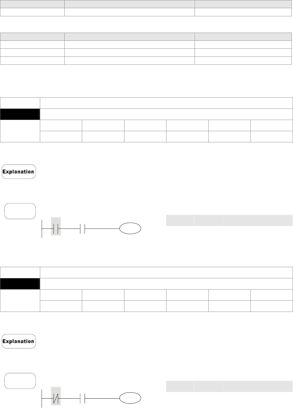
Chapter 16 PLC Function |CT2000 Series
16-37
End Command
Commands Function Operands
END Program end --
Other Command
Commands Function Operands
NOP No function --
INV Inverse operation result --
P Indicator P
16.5.2 Explanation for the Command
Mnemonic Function
LD Load A contact
X0~X17 Y0~Y17 M0~M799 T0~159 C0~C79 D0~D399
Operand 9 9 9 9 9 -
L The LD command is used on the A contact that has its start from the left BUS or
the A contact that is the start of a contact circuit. Function of the command is to
save present contents, and at the same time, save the acquired contact status
into the accumulative register.
Command code Operation
LD X0 Load contact A of X0
AND X1
Connect to contact A of
X1 in series
Example
Ladder diagram
X0 X1
Y1
OUT Y1 Drive Y1 coil
Mnemonic Function
LDI Load B contact
X0~X17 Y0~Y17 M0~M799 T0~159 C0~C79 D0~D399
Operand 9 9 9 9 9 -
The LDI command is used on the B contact that has its start from the left BUS or
the B contact that is the start of a contact circuit. Function of the command is to
save present contents, and at the same time, save the acquired contact status
into the accumulative register.
Command code: Operation:
LDI X0 Load contact B of X0
AND X1 Connect to contact A of
X1 in series
Example
Ladder diagram:
X0 X1
Y1
OUT Y1 Drive Y1 coil
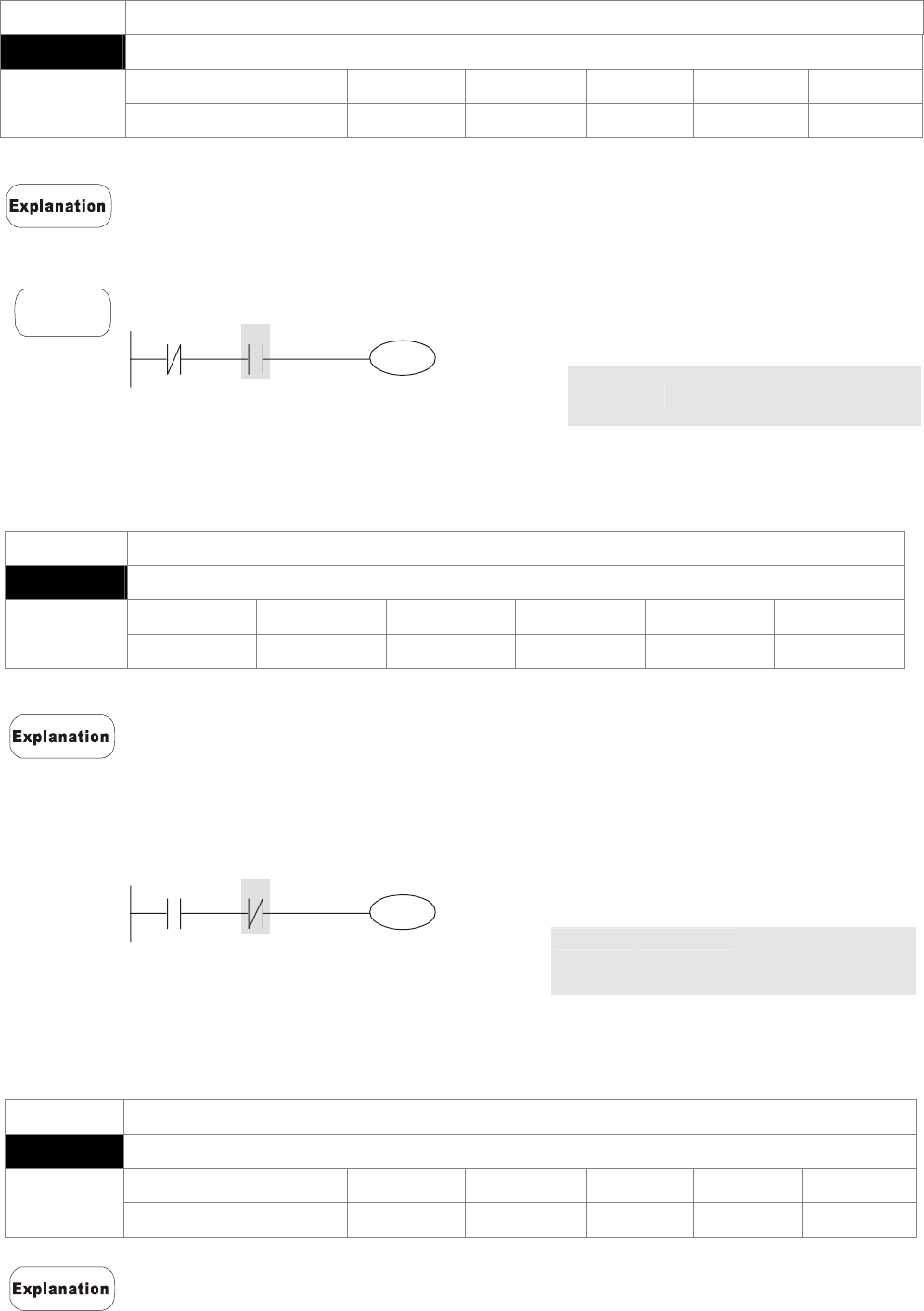
Chapter 16 PLC Function |CT2000 Series
16-38
Mnemonic Function
AND Series connection- A contact
X0~X17 Y0~Y17 M0~M799 T0~159 C0~C79 D0~D399
Operand 9 9 9 9 9 -
The AND command is used in the series connection of A contact. The function of the
command is to readout the status of present specific series connection contacts first,
and then to perform the “AND” calculation with the logic calculation result before the
contacts, thereafter, saving the result into the accumulative register.
Command code: Operation:
LDI X1
Load contact B of
X1
AND X0 Connect to contact
A of X0 in series
Example
Ladder diagram:
X1 X0
Y1
OUT Y1
Drive Y1 coil
Mnemonic Function
ANI Series connection- B contact
X0~X17 Y0~Y17 M0~M799 T0~159 C0~C79 D0~D399
Operand 9 9 9 9 9 -
The ANI command is used in the series connection of B contact. The function of the
command is to readout the status of present specific series connection contacts first,
and then to perform the “AND” calculation with the logic calculation result before the
contacts, thereafter, saving the result into the accumulative register.
Command code: Operation:
LD X1 Load contact A of
X1
ANI X0 Connect to contact
B of X0 in series
Example
Ladder diagram:
X0
X1
Y1
OUT Y1 Drive Y1 coil
Mnemonic Function
OR Parallel connection- A contact
X0~X17 Y0~Y17 M0~M799 T0~159 C0~C79 D0~D399
Operand 9 9 9 9 9 -
The OR command is used in the parallel connection of A contact. The function of the
command is to readout the status of present specific series connection contacts, and
then to perform the “OR” calculations with the logic calculation result before the
contacts, thereafter, saving the result into the accumulative register.
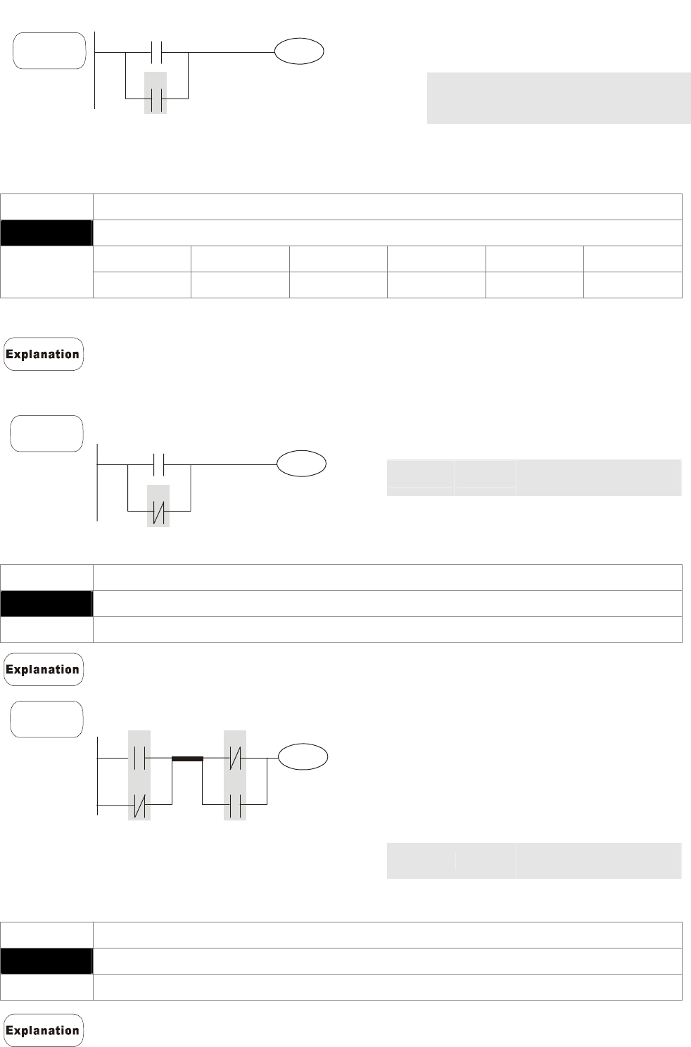
Chapter 16 PLC Function |CT2000 Series
16-39
Command code: Operation:
LD X0
Load contact A of
X0
OR X1 Connect to contact
A of X1 in parallel
OUT Y1
Drive Y1 coil
Example
Ladder diagram:
X0
X1
Y1
Mnemonic Function
ORI Parallel connection- B contact
X0~X17 Y0~Y17 M0~M799 T0~159 C0~C79 D0~D399
Operand 9 9 9 9 9 -
The ORI command is used in the parallel connection of B contact. The function of the
command is to readout the status of present specific series connection contacts, and
then to perform the “OR” calculations with the logic calculation result before the
contacts, thereafter, saving the result into the accumulative register.
Command code: Operation:
LD X0
Load contact A of X0
ORI X1 Connect to contact B of
X1 in parallel
OUT Y1
Drive Y1 coil
Example
Ladder diagram:
X0
X1
Y1
Mnemonic Function
ANB Series connection (Multiple Circuits)
Operand None
To perform the “ANB” calculation between the previous reserved logic results and
contents of the accumulative register.
Command code: Operation:
LD X0 Load contact A of X0
ORI X2
Connect to contact B of
X2 in parallel
LDI X1
Load contact B of X1
OR X3
Connect to contact A of
X3 in parallel
ANB Connect circuit block in
series
Example
Ladder diagram:
X1
X3
Y1
X0
X2
ANB
Block A Block B
OUT Y1
Drive Y1 coil
Mnemonic Function
ORB Parallel connection (Multiple circuits)
Operand None
ORB is to perform the “OR” calculation between the previous reserved logic results
and contents of the accumulative register.
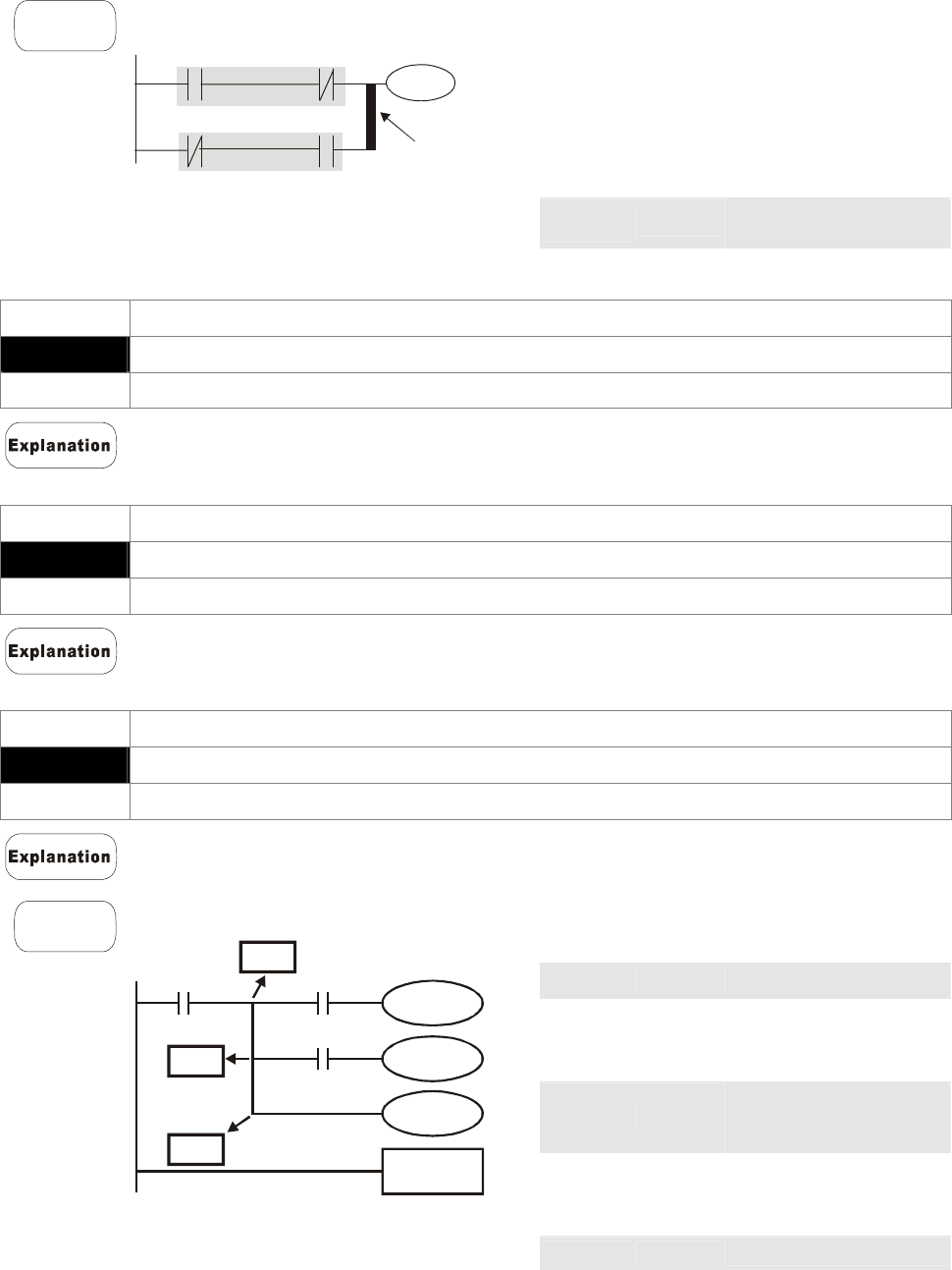
Chapter 16 PLC Function |CT2000 Series
16-40
Command code: Operation:
LD X0 Load contact A of X0
ANI X1
Connect to contact B of
X1 in series
LDI X2
Load contact B of X2
AND X3
Connect to contact A of
X3 in series
ORB Connect circuit block in
parallel
Example
Ladder diagram:
X1
X3
Y1
X0
X2
ORB
Block A
Block B
OUT Y1 Drive Y1 coil
Mnemonic Function
MPS Store the current result of the internal PLC operations
Operand None
To save contents of the accumulative register into the operation result. (the result
operation pointer pluses 1)
Mnemonic Function
MRD Reads the current result of the internal PLC operations
Operand None
Reading content of the operation result to the accumulative register. (the pointer of
operation result doesn’t move)
Mnemonic Function
MPP Reads the current result of the internal PLC operations
Operand None
Reading content of the operation result to the accumulative register. (the stack pointer
will decrease 1)
Command code: Operation:
LD X0
Load contact A of X0
MPS Save in stack
AND X1
Connect to contact A of
X1 in series
OUT Y1
Drive Y1 coil
MRD
Read from the stack
(without moving
pointer)
AND X2
Connect to contact A of
X2 in series
OUT M0
Drive M0 coil
MPP Read from the stack
OUT Y2
Drive Y2 coil
Example
Ladder diagram:
X0
Y1
X1
M0
X2
Y2
END
MPP
MRD
MPS
END
End program
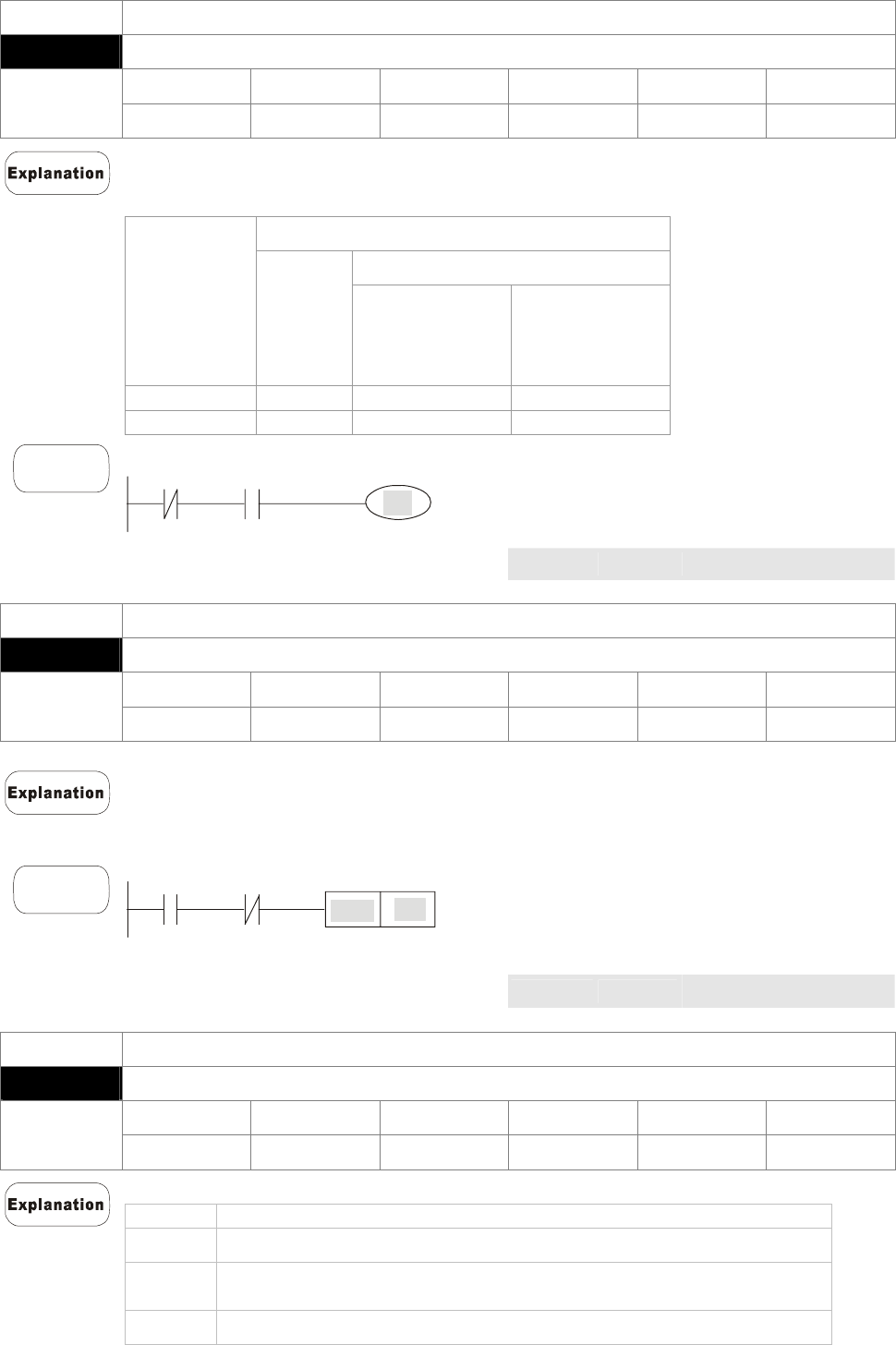
Chapter 16 PLC Function |CT2000 Series
16-41
Mnemonic Function
OUT Output coil
X0~X17 Y0~Y17 M0~M799 T0~159 C0~C79 D0~D399
Operand - 9 9 - - -
Output the logic calculation result before the OUT command to specific device.
Motion of coil contact:
OUT command
Contact
Operation
result Coil A contact
(normally open)
B contact
(normally
closed)
FALSE Off Non-continuity Continuity
TRUE On Continuity Non-continuity
Command code: Operation:
LD X0 Load contact B of X0
AND X1
Connect to contact A of
X1 in series
Example
Ladder diagram:
X0 X
1
Y1
OUT Y1 Drive Y1 coil
Mnemonic Function
SET Latch (ON)
X0~X17 Y0~Y17 M0~M799 T0~159 C0~C79 D0~D399
Operand - 9 9 - - -
When the SET command is driven, its specific device is set to be “ON,” which will
keep “ON” whether the SET command is still driven. You can use the RST command
to set the device to “OFF”.
Command code: Operation:
LD X0 Load contact A of X0
AN Y0
Connect to contact B of
Y0 in series
Example
Ladder diagram:
Y0
X0
Y1
SET
SET Y1 Y1 latch (ON)
Mnemonic Function
RST Clear the contacts or the registers
X0~X17 Y0~Y17 M0~M799 T0~159 C0~C79 D0~D399
Operand - 9 9 9 9 9
When the RST command is driven, motion of its specific device is as follows:
Device Status
Y, M Coil and contact will be set to “OFF”.
T, C Present values of the timer or counter will be set to 0, and the coil
and contact will be set to “OFF.”
D The content value will be set to 0.
When the RST command is not driven, motion of its specific device is unchanged.
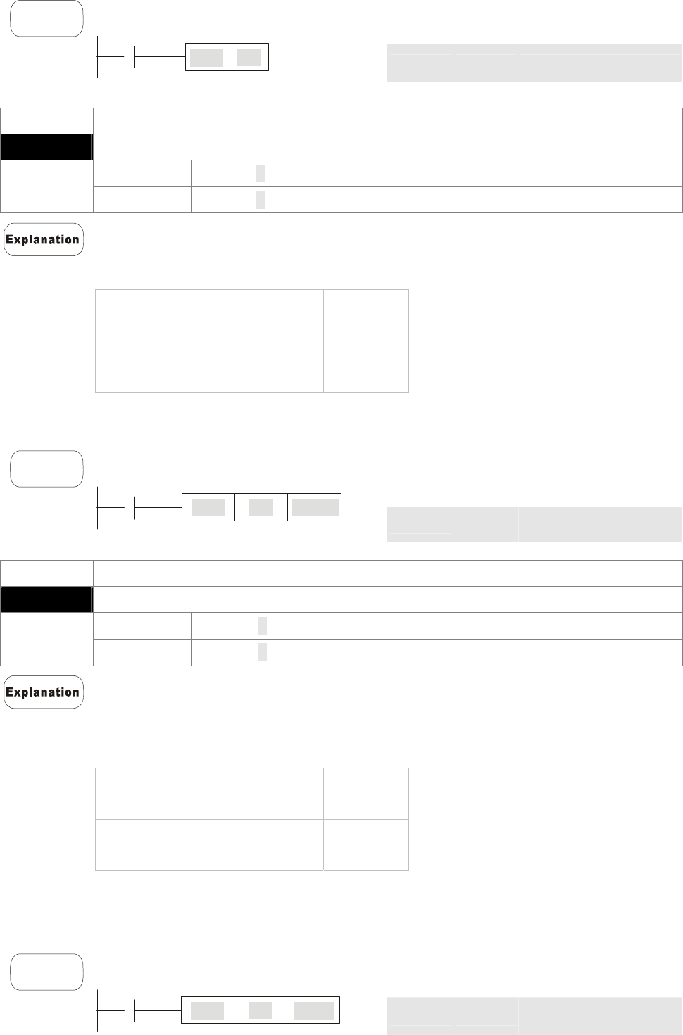
Chapter 16 PLC Function |CT2000 Series
16-42
Command code: Operation:
LD X0 Load contact A of X0
Example
Ladder diagram
X0
Y5
RST
RST Y5 Clear contact Y5
Mnemonic Function
TMR 16-bit timer
T-K T0~T159, K0~K32,767
Operand T-D T0~T159, D0~D399
When TMR command is executed, the specific coil of timer is ON and timer will start to
count. When the setting value of timer is attained (counting value >= setting value),
the contact will be as following
NO(Normally Open) contact Open
collector
NC(Normally Closed) contact Close
collector
When the RST command is not driven, motion of its specific device remains
unchanged.
Command code: Operation:
LD X0 Load contact A of X0
Example
Ladder Diagram:
X0
T5
TMR K1000
TMR T5
K1000
Setting of T5 counter
is K1000.
Mnemonic Function
CNT Clear contact or register
C-K C0~C79, K0~K32,767
Operand C-D C0~C79, D0~D399
When the CNT command is executed from OFFÆON, which means that the counter
coil is driven, and 1 should thus be added to the counter’s value; when the counter
achieved specific set value (value of counter = the setting value), motion of the
contact is as follows:
NO(Normally Open) contact Open
collector
NC(Normally Close) contact Close
collector
If there is counting pulse input after counting is attained, the contacts and the counting
values will be unchanged. To re-count or to conduct the CLEAR motion, please use
the RST command.
Command code: Operation
LD X0 Load contact A of
Example
Ladder diagram:
X0
C2
CNT K100
CNT C2 K100 Setting of C2 counter is
K100.
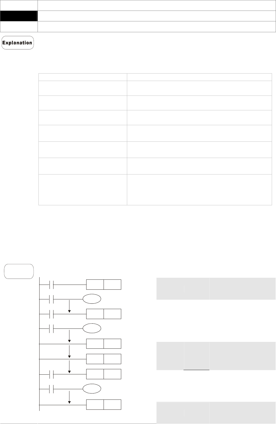
Chapter 16 PLC Function |CT2000 Series
16-43
Mnemonic Function
MC/MCR Master control Start/Reset
Operand N0~N7
1. MC is the main-control start command. When the MC command is executed, the
execution of commands between MC and MCR will not be interrupted. When MC
command is OFF, the motion of the commands that between MC and MCR is
described as follows:
Command Description
Timer The counting value is set back to zero, the coil and
the contact are both turned OFF
Accumulative timer The coil is OFF, and the timer value and the
contact stay at their present condition
Subroutine timer The counting value is back to zero. Both coil and
contact are turned OFF.
Counter The coil is OFF, and the counting value and the
contact stay at their present condition
Coils driven up by the OUT
command All turned OFF
Devices driven up by the SET
and RST commands Stay at present condition
Application commands
All of them are not acted , but the nest loop
FOR-NEXT command will still be executed for
times defined by users even though the MC-MCR
commands is OFF.
2. MCR is the main-control ending command that is placed at the end of the
main-control program and there should not be any contact commands prior to the
MCR command.
3. Commands of the MC-MCR main-control program support the nest program
structure, with 8 layers as its greatest. Please use the commands in order from N0~
N7, and refer to the following:
Command code: Operation:
LD X0 Load A contact of X0
MC N0 Enable N0 common
series connection
contact
LD X1 Load A contact of X1
OUT Y0 Drive Y0 coil
:
LD X2
Load A contact of X2
MC N1 Enable N1 common
series connection
contact
LD X3
Load A contact of X3
OUT Y1
Drive Y1 coil
:
Example
Ladder Diagram:
X0
MC N0
X1
Y0
X2
MC N1
X3
Y1
MCR N1
MCR N0
X10
MC N0
X11
Y10
MCR N0
MCR N1 Disable N1 common
series connection
contact
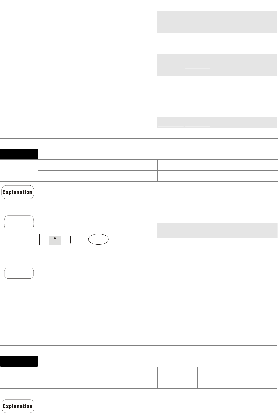
Chapter 16 PLC Function |CT2000 Series
16-44
:
MCR N0 Disable N0 common
series connection
contact
:
LD X10
Load A contact of X10
MC N0 Enable N0 common
series connection
contact
LD X11
Load A contact of X0
OUT Y10
Enable N0 common
series connection
contact
:
Load A contact of X1
MCR N0 Drive Y0 coil
Mnemonic Function
LDP Rising-edge detection operation
X0~X17 Y0~Y17 M0~M799 T0~159 C0~C79 D0~D399
Operand 9 9 9 9 9 -
Usage of the LDP command is the same as the LD command, but the motion is
different. It is used to reserve present contents and at the same time, saving the
detection status of the acquired contact rising-edge into the accumulative register.
Command code: Operation:
LDP X0 Start X0 rising-edge
detection
AND X1 Series connection A
contact of X1
Example
Ladder diagram:
X1
Y1
X0
OUT Y1
Drive Y1 coil
Remarks
Please refer to the specification of each model series for the applicable range of
operands.
If rising-edge status is ON when PLC power is off, then the rising-edge status will be
TRUE when PLC power is on.
Mnemonic Function
LDF Falling-edge detection operation
X0~X17 Y0~Y17 M0~M799 T0~159 C0~C79 D0~D399
Operand 9 9 9 9 9 -
Usage of the LDF command is the same as the LD command, but the motion is different. It is
used to reserve present contents and at the same time, saving the detection status of the
acquired contact falling-edge into the accumulative register.
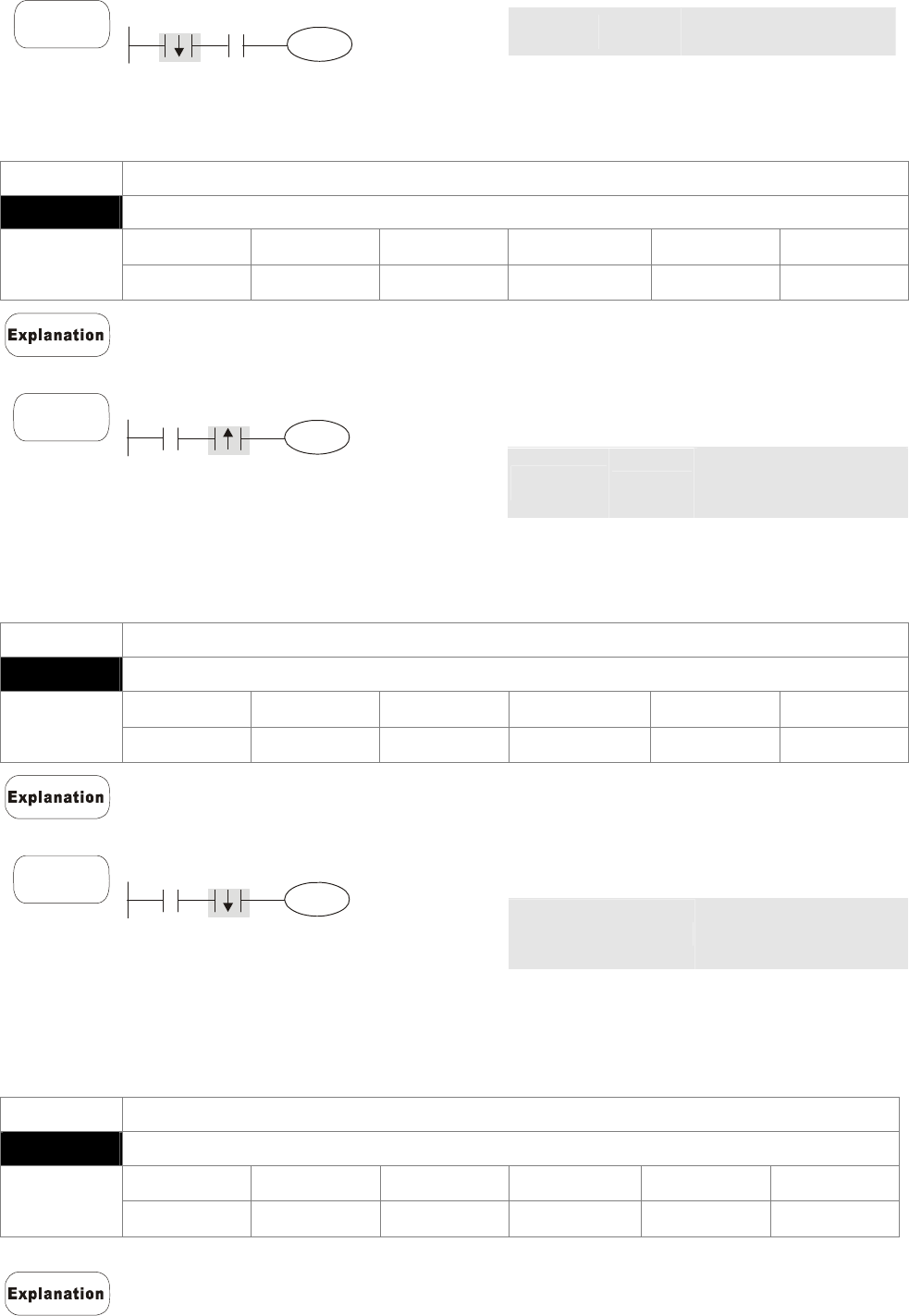
Chapter 16 PLC Function |CT2000 Series
16-45
Command code: Operation:
LDF X0 Start X0 falling-edge
detection
AND X1 Series connection A
contact of X1
Example
Ladder diagram:
X1
Y1
X0
OUT Y1
Drive Y1 coil
Mnemonic Function
ANDP Rising-edge series connection
X0~X17 Y0~Y17 M0~M799 T0~159 C0~C79 D0~D399
Operand 9 9 9 9 9 -
ANDP command is used in the series connection of the contacts’ rising-edge detection.
Command code: Operation:
LD X0
Load A contact of X0
ANDP X1 X1 rising-edge
detection in series
connection
Example
Ladder diagram:
X1
Y1
X0
OUT Y1
Drive Y1 coil
Mnemonic Function
ANDF Falling-edge series connection
X0~X17 Y0~Y17 M0~M799 T0~159 C0~C79 D0~D399
Operand 9 9 9 9 9 -
ANDF command is used in the series connection of the contacts’ falling-edge detection.
Command code: Operation:
LD X0
Load A contact of X0
ANDF X1 X1 falling-edge
detection in series
connection
Example
Ladder diagram:
X1
Y1
X0
OUT Y1
Drive Y1 coil
Mnemonic Function
ORP Rising-edge parallel connection
X0~X17 Y0~Y17 M0~M799 T0~159 C0~C79 D0~D399
Operand 9 9 9 9 9 -
The ORP commands are used in the parallel connection of the contact’s
rising-edge detection.
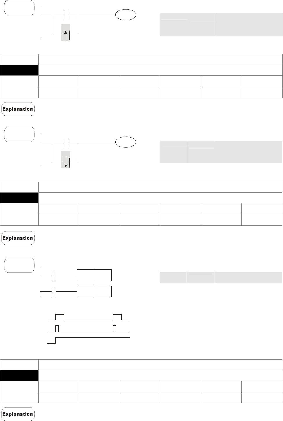
Chapter 16 PLC Function |CT2000 Series
16-46
Command code: Operation:
LD X0 Load A contact of X0
ORP X1 X1 rising-edge
detection in parallel
connection
Example
Ladder diagram:
X0
X1
Y1
OUT Y1 Drive Y1 coil
Mnemonic Function
ORF Falling-edge parallel connection
X0~X17 Y0~Y17 M0~M799 T0~159 C0~C79 D0~D399
Operand 9 9 9 9 9 -
The ORP commands are used in the parallel connection of the contact’s falling-edge
detection.
Command code: Operation:
LD X0 Load A contact of X0
ORF X1 X1 falling-edge
detection in parallel
connection
Example
Ladder diagram:
X0
X1
Y1
OUT Y1
Drive Y1 coil
Mnemonic Function
PLS Rising-edge output
X0~X17 Y0~Y17 M0~M799 T0~159 C0~C79 D0~D399
Operand - 9 9 - - -
When X0=OFF→ON (rising-edge trigger), PLS command will be executed and M0 will
send the pulse of one time which the length is the time needed for one scan cycle.
Command code: Operation:
LD X0 Load A contact of X0
PLS M0 M0 rising-edge output
LD M0
Load the contact A of
M0
SET Y0
Y0 latched (ON)
Example
Ladder diagram:
X0
M0
PLS
M0
Y0
SET
Timing diagram:
X0
M0
Y0
Time for one scan cycle
Mnemonic Function
PLF Falling-edge output
X0~X17 Y0~Y17 M0~M799 T0~159 C0~C79 D0~D399
Operand - 9 9 - - -
When X0= ON→OFF (falling-edge trigger), PLF command will be executed and M0
will send the pulse of one time which the length is the time for scan one time.
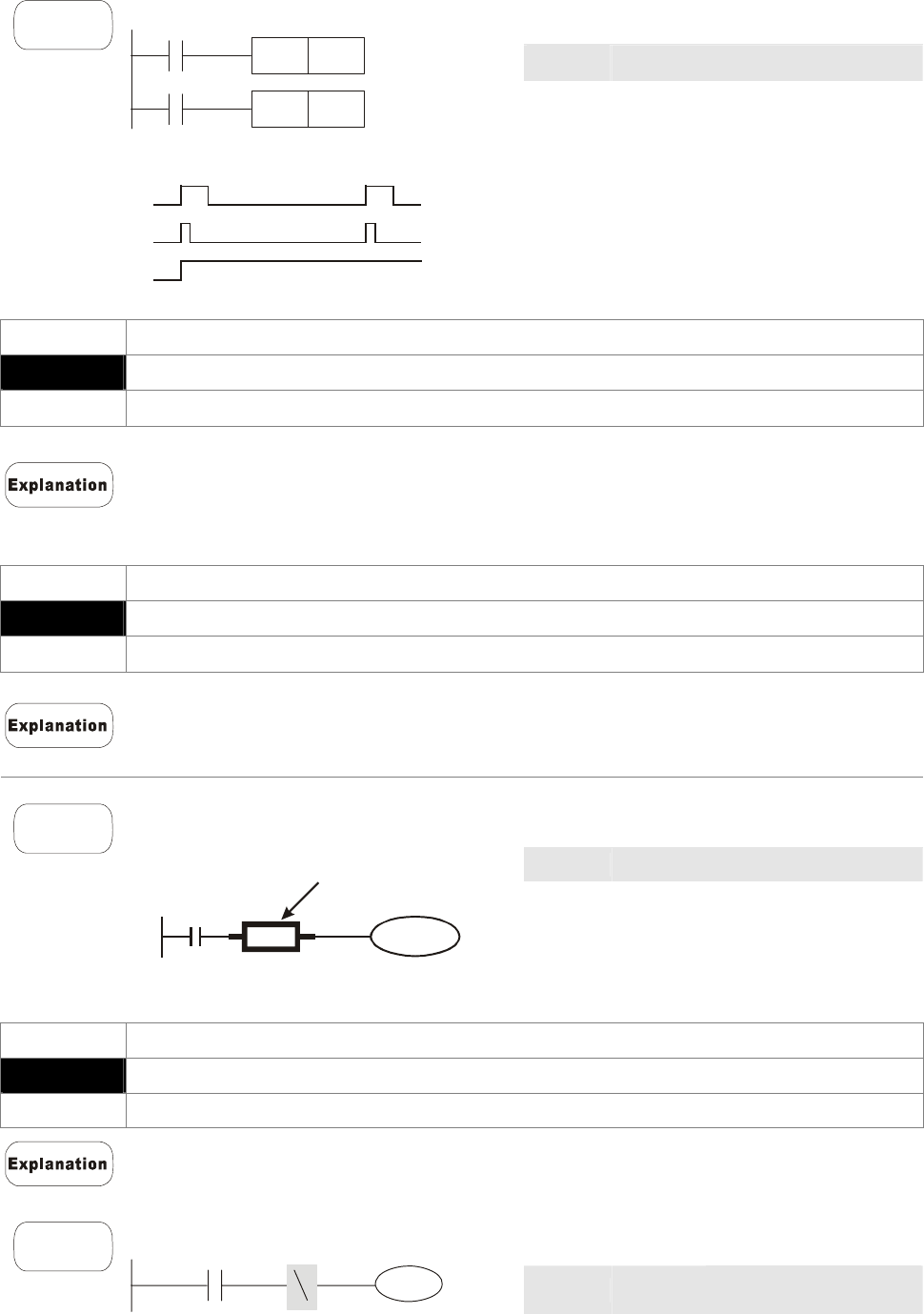
Chapter 16 PLC Function |CT2000 Series
16-47
Command code: Operation:
LD X0 Load contact A of X0
PLF M0 M0 falling-edge output
LD M0
Load contact A of M0
SET Y0 Y0 latched (ON)
Example
Ladder diagram:
X0
M0
PLS
M0
Y0
SET
Timing Diagram:
X0
M0
Y0
Time for one scan cycle
Mnemonic Function
END Program End
Operand None
It needs to add the END command at the end of ladder diagram program or
command program. PLC will scan from address o to END command, after the
execution it will return to address 0 and scan again.
Mnemonic Function
NOP No action
Operand None
NOP command does no operation in the program; the result of executing this
command will remain the logic operation. Use NOP command if user wants to delete
certain command without changing the length of the program.
Command code: Operation:
LD X0
Load contact B of X0
NOP No function
OUT Y1
Drive Y1 coil
Example
Ladder diagram:
X0
Y1
NOP
NOP command will be simplified and not
displayed when the ladder diagram is
displayed.
Mnemonic Function
INV Inverse operation result
Operand None
The operation result (before executing INV command) will be saved inversely into
cumulative register.
Command code: Operation:
LD X0 Load contact A of X0
INV Operation result
inversed
Example
Ladder diagram:
X0
Y1
OUT Y1 Drive Y1 coil
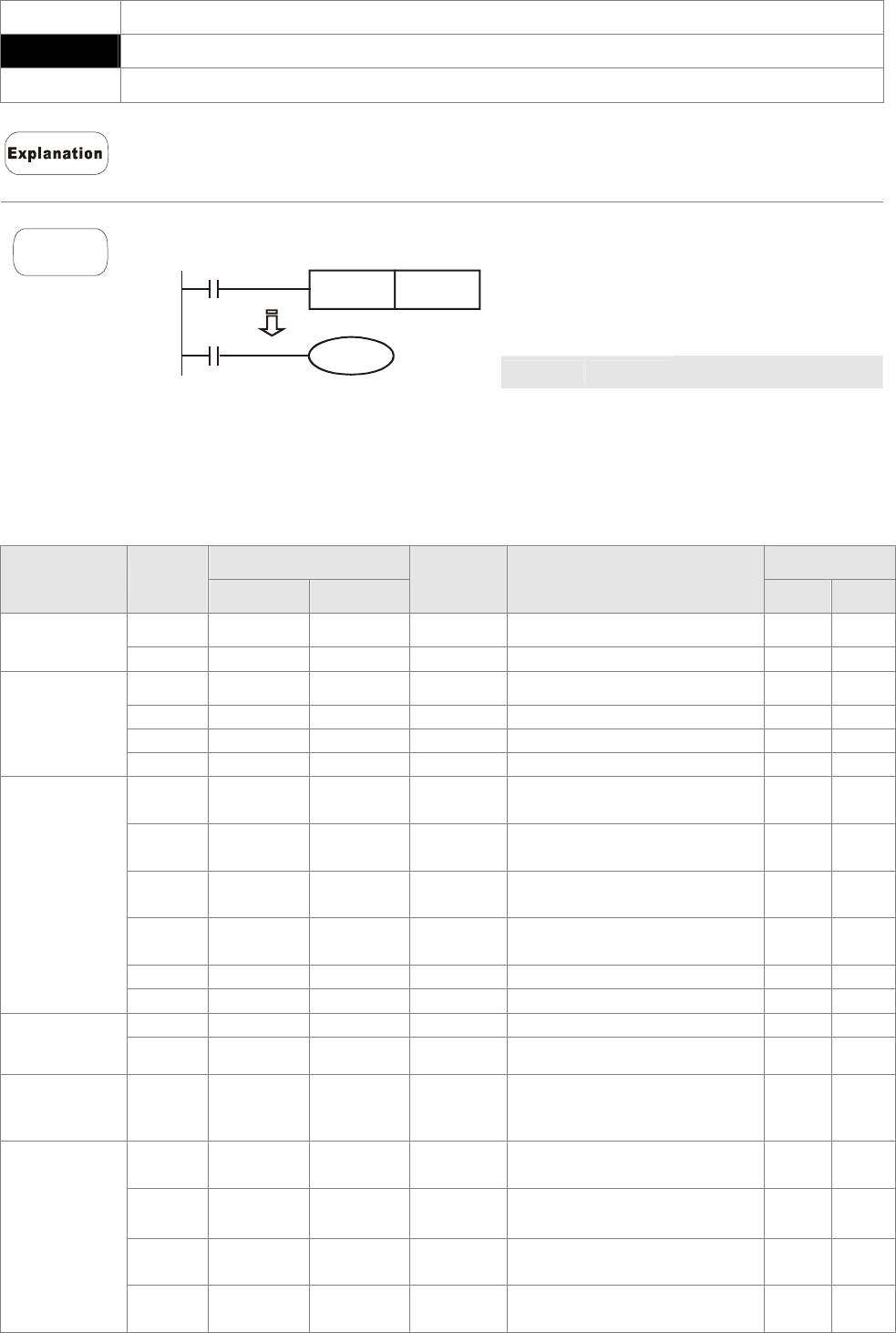
Chapter 16 PLC Function |CT2000 Series
16-48
Mnemonic Function
P Indicator
Operand P0~P255
Indicator P allows API 00 CJ command and API 01 CALL command to skip from 0.
Though it is not necessary to start from number 0, same number can not be used
twice or serious error would occur.
Command code: Operation:
LD X0
Load contact A of X0
CJ P10
Skip command CJ to
P10
:
P10 Indicator P10
Example
Ladder diagram:
X0
Y1
CJ P10
X1
P10
LD X1 Load contact A of X1
OUT Y1 Drive Y1 coil
16.5.3 Description of the Application Commands
Mnemonic Codes STEPS
API 16-bit 32-bit
P
Command Function 16bit 32bit
01 CALL - 9 CALL subroutine 3 -
Loop control 06 FEND - - The end of main program 1 -
10 CMP – 9 Compare 7 13
11 ZCP – 9 Zone compare 9 17
12 MOV – 9 Data Move 5 9
Transmission
Comparison
15 BMOV – 9 Block move 7 –
20 ADD – 9 Perform the addition of BIN
data 7 13
21 SUB – 9 Perform the subtraction of
BIN data 7 13
22 MUL – 9 Perform the multiplication
of BIN data 7 13
23 DIV – 9 Perform the division of BIN
data 7 13
24 INC – 9 Perform the addition of 1 3 5
Four
Fundamental
Operations of
Arithmetic
25 DEC – 9 Perform the subtraction of 1 3 5
30 ROR – 9 Rotate to the right 5 –
Rotation and
Displacement 31 ROL – 9 Rotate to the left 5 –
Data
Processing 40 ZRST – 9 Zero Reset 5 -
215 LD& DLD& -
Contact Logical Operation
LD# 5 9
216 LD| DLD| -
Contact type logic
operation LD# 5 9
217 LD^ DLD^ -
Contact Logical Operation
LD# 5 9
Contact type
logic
operation
218 AND& DAND& - Contact Logical Operation
AND# 5 9

Chapter 16 PLC Function |CT2000 Series
16-49
Mnemonic Codes STEPS
API 16-bit 32-bit
P
Command Function 16bit 32bit
219 ANDl DANDl - Contact Logical Operation
AND# 5 9
220 AND^ DAND^ - Contact Logical Operation
AND# 5 9
221 OR& DOR& - Contact Logical Operation
OR# 5 9
222 OR| DOR| -
Contact Logical Operation
OR# 5 9
223 OR^ DOR^ -
Contact Logical Operation
OR# 5 9
224 LD= DLD= - Load Compare LD※ 5 9
225 LD> DLD> - Load Compare LD※ 5 9
226 LD< DLD< - Load Compare LD※ 5 9
228 LD<> DLD<> - Load Compare LD※ 5 9
229 LD<= DLD<= - Load Compare LD※ 5 9
230 LD>= DLD>= - Load Compare LD※ 5 9
232 AND= DAND=- AND Compare※ 5 9
233 AND> DAND>- AND Compare※ 5 9
234 AND< DAND<- AND Compare※ 5 9
236 AND<> DAND<
> - AND Compare※ 5 9
237 AND<= DAND<
= - AND Compare※ 5 9
238 AND>= DAND>
= - AND Compare※ 5 9
240 OR= DOR=- OR compare ※ 5 9
241 OR> DOR>- OR compare ※ 5 9
242 OR< DOR<- OR compare ※ 5 9
244 OR<> DOR<> - OR compare ※ 5 9
245 OR<= DOR<= - OR compare ※ 5 9
Contact Type
Comparison
246 OR>= DOR>= - OR compare ※ 5 9
139 RPR – 9 Read the parameters 5 –
140 WPR – 9 Write the parameters 5 –
141 FPID – 9 Drive PID control 9 –
142 FREQ – 9 Control the drive frequency 7 –
261 CANRX – 9 Read CANopen Slave data 9 -
263 TORQ – 9 Set target torque 5 -
264 CANTX – 9 Write CANopen Slave data 9 -
Special
command for
AC motor
drive
265 CANFLS – 9 Update the mapping
special D of CANopen 3 -

Chapter 16 PLC Function |CT2000 Series
16-50
16.5.4 Explanation for the Application Commands
API
01
CALL P
S
Call Subroutine
Bit Devices Word Devices
X Y M K H KnX KnY KnM T C D
Operands:
S: Operand S can designate P.
Operand S of CT2000 series can designate
P0~P63.
16-bit command (3 STEPS)
CALL CALLP
32-bit command
- - - -
Flag signal: None
Explanation
1. S: The pointer of call subroutine.
2. Edit the subroutine designated by the pointer after FEND instruction.
3. If only CALL instruction is in use, it can call subroutines of the same pointer
number with no limit of times.
4. Subroutine can be nested for 5 levels including the initial CALL instruction. (If
entering the sixth level, the subroutine won’t be executed.)
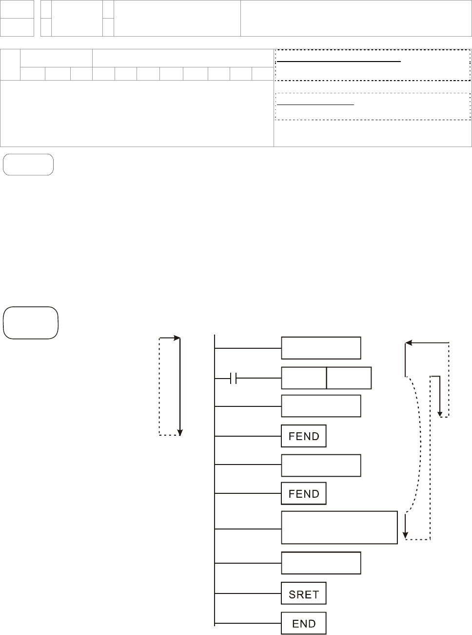
Chapter 16 PLC Function |CT2000 Series
16-51
API
06
FEND - The end of the main program (First End)
Bit Devices Word Devices
X Y M K H KnX KnY KnM T C D
Operands:
No operand
No contact to drive the instruction is required.
16-bit command (1 STEP)
FEND - -
32-bit command
- - - -
Flag signal: None
Explanation
1. This instruction denotes the end of the main program. It has the same function
as that of END instruction when being executed by PLC.
2. CALL must be written after FEND instruction and add SRET instruction in the
end of its subroutine. Interruption program has to be written after FEND
instruction and IRET must be added in the end of the service program.
3. If several FEND instructions are in use, place the subroutine and interruption
service programs between the final FEND and END instruction.
4. After CALL instruction is executed, executing FEND before SRET will result in
errors in the program.
CALL
Command
X1
CALL P63
P63 CALL
When X1=ON,
operation
procedure
Main Program
Main Program
Main Program
Main Program
When X1=OFF,
operation
procedure
Sub command
program
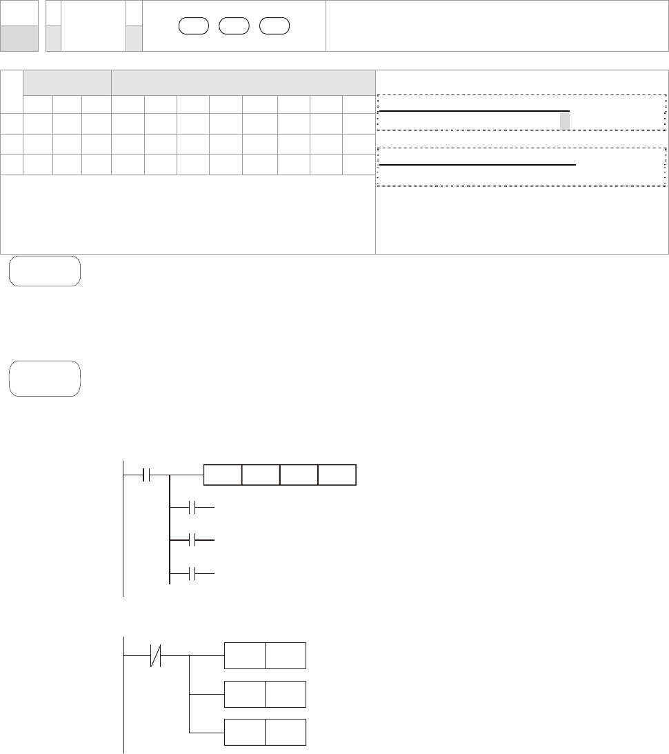
Chapter 16 PLC Function |CT2000 Series
16-52
API
10
D CMP P
S1 S2 D
Compare
Bit Devices Word Devices
X Y M K H KnX KnY KnM T C D
S1
* * * * * * * *
S2
* * * * * * * *
D * *
Operand
Operand D occupies 3 consecutive devices.
16-bit command ( 7 STEPS)
CMP CMPP
32bits command (13 STEPS)
- - - -
Flag signal: None
Explanation
1. S1: value comparsion 1, S2: value comparison 2 , D: result comparison
2. The contents in S1 and S2 are compared and result is stored in D.
3. The two comparison values are compared algebraically and the two values
are signed binary values. When b15 = 1 in 16-bit instruction, the comparison
will regard the value as negative binary values.
Example
1. Designate device Y0, and operand D automatically occupies Y0, Y1, and Y2.
2. When X10 = On, CMP instruction will be executed and one of Y0, Y1, and Y2
will be On. When X10 = Off, CMP instruction will not be executed and Y0,
Y1, and Y2 remain their status before X10 = Off.
3. If the user need to obtain a comparison result with ≥ ≤, and ≠, make a series
parallel connection between Y0 ~ Y2.
X10
Y0
Y1
Y2
CMP K10 D10 Y0
If K10>D10, Y0 = On
If K10=D10, Y1 = On
If K10<D10, Y2= On
4. To clear the comparison result, use RST or ZRST instruction.
X10
M0
RST
M1
RST
M2
RST
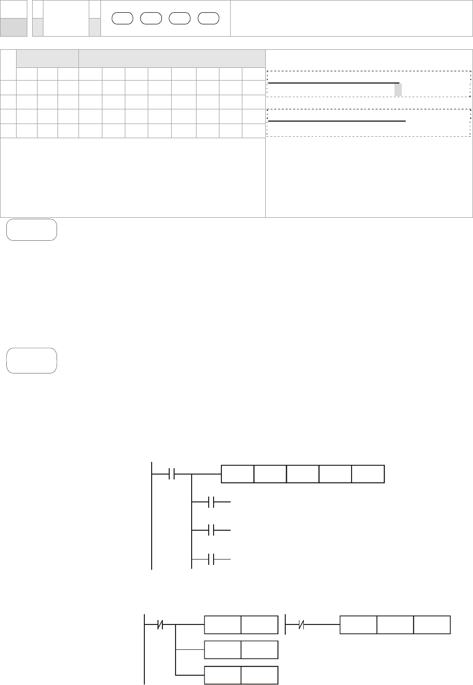
Chapter 16 PLC Function |CT2000 Series
16-53
API
11
D ZCP P
S1 S2 S D
Zone Compare
Bit Devices Word Devices
X Y M K H KnX KnY KnM T C D
S1
* * * * * * * *
S2
* * * * * * * *
S
* * * * * * * *
D * *
Operands:
S1: Lower bound of zone comparison S2: Upper
bound of zone comparison S: Comparison value
D: Comparison result
16-bit command (9 STEPS)
ZCP ZCPP
32-bit command (17 STEPS)
- - - -
Flag signal: none
Explanation
1. S1: Lower bound of zone comparison S2: Upper bound of zone
comparison S: Comparison value D: Comparison result
2. S is compared with its S1 S2 and the result is stored in D.
3. When
S1 > S2, the instruction performs comparison by using S1 as the
lower/upper bound.
4. The two comparison values are compared algebraically and the two
values are signed binary values. When b15 = 1 in 16-bit instruction or
b31 = 1 in 32-bit instruction, the comparison will regard the value as
negative binary values.
Example
1. Designate device M0, and operand D automatically occupies M0, M1 and
M2.
2. When X0 = On, ZCP instruction will be executed and one of M0, M1, and
M2 will be On. When X10 = Off, ZCP instruction will not be executed and
M0, M1, and M2 remain their status before X0 = Off.
3. If the user need to obtain a comparison result with ≥ ≤, and ≠, make a
series parallel connection between Y0 ~ Y2.
X0
M0
M1
M2
ZCP
If C10 < K10, M0 = On
If K10 < C10 < K100, M1 = On
If C10 > K100, M2 = On
X0
K10 C10 M0K100
==
4. To clear the comparison result, use RST or ZRST instruction.
X0
RST M0
RST
RST
M1
M2
X0
ZRST M0 M2
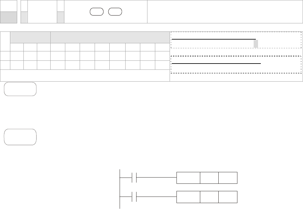
Chapter 16 PLC Function |CT2000 Series
16-54
API
12
D MOV P
S D
Moving the data
Bit Devices Word Devices
X Y M K H KnX KnY KnM T C D
S
* * * * * * * *
D
* * * * *
Operand: None
16-bit command (5 STEPS)
MOV MOVP
32-bit command (9 STEPS)
- - - -
Flag signal: None
Explanation
1. S: Source of data D: Destination of data
2. When this instruction is executed, the content of S will be moved directly
to D. When this instruction is not executed, the content of D remains
unchanged.
Example
1. When X0 = Off, the content in D10 will remain unchanged. If X0 = On, the
value K10 will be moved to D10 data register.
2. When X1 = Off, the content in D10 will remain unchanged. If X1 = On, the
present value T0 will be moved to D10 data register.
X0
K10MOV D0
X1
T0MOV D10
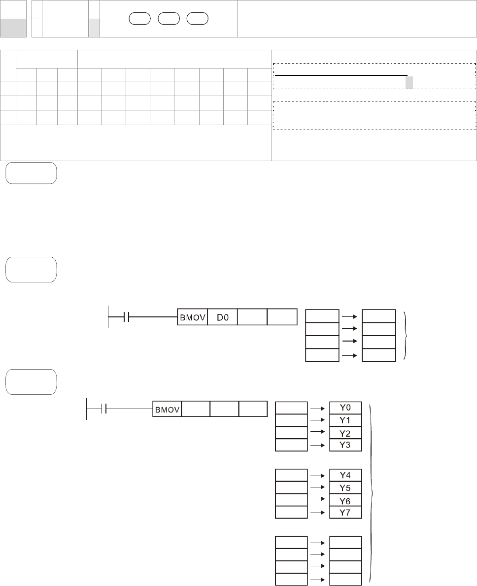
Chapter 16 PLC Function |CT2000 Series
16-55
API
15
BMOV P
S D n
Block Move
Bit Devices Word Devices
X Y M K H KnX KnY KnM T C D
S
* * * * * *
D
* * * * *
n
* *
Operand:
Range of n =1~512
16-bit command (7 STEPS)
BMOV BMOVP
32-bit command
- - - -
Flag signal: None
Explanation
1. S: Start of source devices D: Start of destination devices n: Number of data to
be moved
2. The contents in n registers starting from the device designated by S will be
moved to n registers starting from the device designated by D. If n exceeds the
actual number of available source devices, only the devices that fall within the
valid range will be used.
Example
1
When X10 = On, the contents in registers D0 ~ D3 will be moved to the 4 registers D20
~ D23.
X10
D20 K4 D0
D1
D2
D3
D20
D21
D22
D23
n=4
Example
2
Assume the bit devices KnX, KnY, KnM and KnS are designated for moving, the
number of digits of S and D has to be the same, i.e. their n has to be the same.
M1000
D0 D20 K4 M0
M1
M2
M3
M4
M5
M6
M7
M8
M9
M10
n=3
M11
Y10
Y11
Y12
Y13
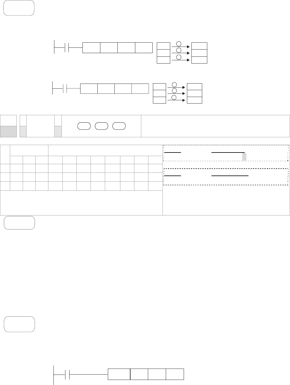
Chapter 16 PLC Function |CT2000 Series
16-56
Example
3
To avoid coincidence of the device numbers to be moved designated by the two
operands and cause confusion, please be aware of the arrangement on the
designated device numbers.
When S > D, the BMOV command is processed in the order as 1→2→3
X10
D20
BMOV
D19 K3 D20
D21
D22
D19
D20
D21
1
2
3
When S < D, the BMOV command is processed in the order as 3→2→1
D10
D11
D12
D11
D12
D13
1
2
3
X1
1
D10
BMOV
D11 K3
API
20
D ADD P
S1 S2 D
BIN Addition
Bit Devices Word Devices
X Y M K H KnX KnY KnM T C D
S1
* * * * * * * *
S2
* * * * * * * *
D
* * * * *
Operands: None
16-bit command (7 STEPS)
ADD ADDP
32-bit command (13 STEPS)
- - - -
Flag signal: M1020 Zero flag
M1021 Borrow flag
M1022 Carry flag
Explanation
1. S1: Summand S2: Addend D: Sum
2. This instruction adds S1 and S2 in BIN format and store the result in D.
3. The highest bit is symbolic bit 0 (+) and 1 (-), which is suitable for algebraic
addition, e.g. 3 + (-9) = -6.
4. Flag changes in binary addition
16-bit command:
A. If the operation result = 0, zero flag M1020 = On.
B. If the operation result < -32,768, borrow flag M1021 = On.
C. If the operation result > 32,767, carry flag M1022 = On.
Example
16-bit command:
When X0 = On, the content in D0 will plus the content in D10 and the sum will be
stored in D20.
X0
D0 D10 D20
ADD
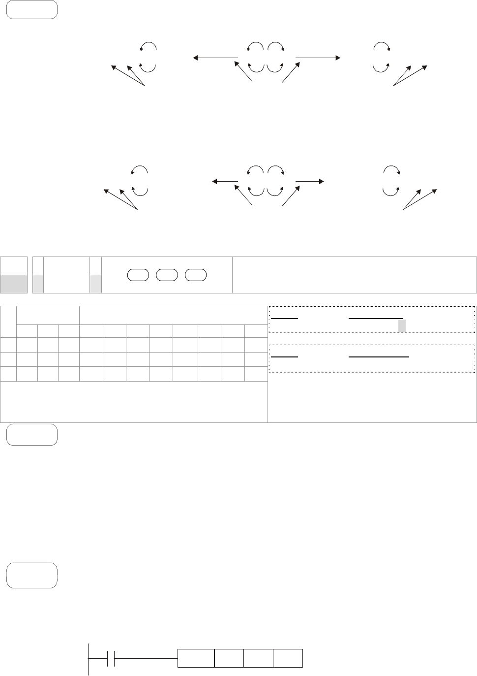
Chapter 16 PLC Function |CT2000 Series
16-57
Remarks
Flags and the positive/negative sign of the values:
-2, -1, 0 -32,768 -1, 0 1 32,767 0 1 2
-2, -1, 0 -2,147,483,648
-1, 0 1
2,147,483,647 0 1 2
16 bit: Zero flag Zero flag Zero flag
Borrow flag The highest bit
of the data
= 1 (negative)
32 bit: Zero flag Zero flag Zero flag
The highest bit
of the data
= 0 (positive)
Carry flag
Borrow flag Carry flag
The highest bit
of the data
= 1 (negative)
The highest bit
of the data
= 0 (positive)
API
21
D SUB P
S1 S2 D
Subtraction
Bit Devices Word Devices
X Y M K H KnX KnY KnM T C D
S1
* * * * * * * *
S2
* * * * * * * *
D
* * * * *
Operands: None
16-bit command (7 STEPS)
SUB SUBP
32-bit command (13 STEPS)
- - - -
Flag signal: M1020 Zero flag
M1021 Borrow flag
M1022 Carry flag
Explanation
1. S1: Minuend S2: Subtrahend D: Remainder
2. This instruction subtracts S1 and S2 in BIN format and stores the result in D.
3. The highest bit is symbolic bit 0 (+) and 1 (-), which is suitable for algebraic
subtraction.
4. Flag changes in binary subtraction
In 16-bit instruction:
If the operation result = 0, zero flag M1020 = On.
If the operation result < -32,768, borrow flag M1021 = On.
If the operation result > 32,767, carry flag M1022 = On.
Example
In 16-bit BIN subtraction:
When X0 = On, the content in D0 will minus the content in D10 and the remainder will
be stored in D20.
X0
D0 D10 D20
SUB
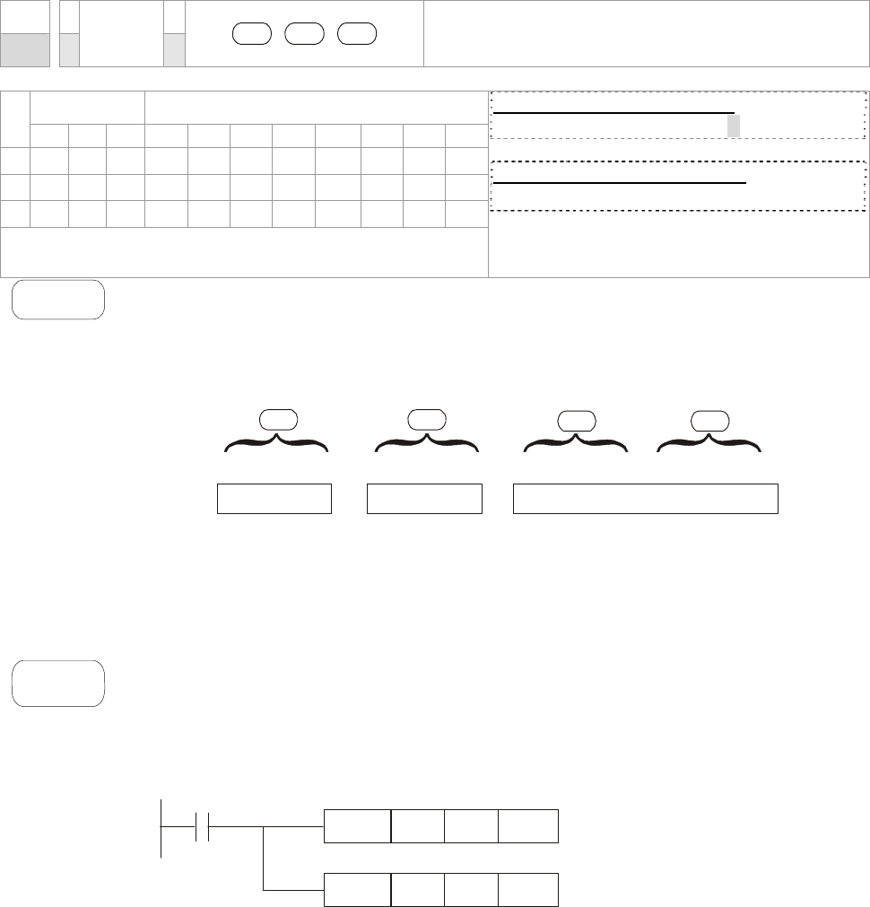
Chapter 16 PLC Function |CT2000 Series
16-58
API
22
D MUL P
S1 S2 D
BIN Multiplication
Bit Devices Word Devices
X Y M K H KnX KnY KnM T C D
S1
* * * * * * * *
S2
* * * * * * * *
D
* * * * *
Operands:
In 16-bit instruction, D occupies 2 consecutive devices.
16-bit command (7 STEPS)
MUL MULP
32-bit command (13 STEPS)
- - - -
Flag signal: None
Explanation
1. S1: Multiplicand S2: Multiplication D: Product
2. This instruction multiplies S1 by S2 in BIN format and stores the result in D.
Be careful with the positive/negative signs of S1, S2 and D when doing 16-bit
and 32-bit operations.
16-bit command:
S1 D
b15..........b0
X
b15..........b0
S2
=
b31..........b16b15..............b0
D+1
b15 is a symbol bit b15 is a symbol bit b31 is a symbol bit (b15 of D+1)
Symbol bit = 0 refers to a positive value.
Symbol bit = 1 refers to a negative value.
When D serves as a bit device, it can designate K1 ~ K4 and construct a 16-bit result,
occupying consecutive 2 groups of 16-bit data.
Example
The 16-bit D0 is multiplied by the 16-bit D10 and brings forth a 32-bit product. The
higher 16-bit are stored in D21 and the lower 16-bit are stored in D20. On/Off of the
most left bit indicates the positive/negative status of the result value.
X0
D0 D10 D20
MUL
D0 D10 K8M0
MUL
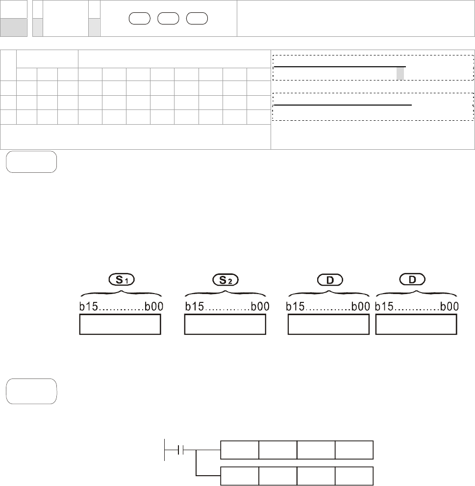
Chapter 16 PLC Function |CT2000 Series
16-59
API
23
D DIV P
S1 S2 D
BIN Division
Bit Devices Word Devices
X Y M K H KnX KnY KnM T C D
S1
* * * * * * * *
S2
* * * * * * * *
D
* * * * *
Operands:
In 16-bit instruction, D occupies 2 consecutive devices.
16-bit command (7 STEPS)
DIV DIVP
32-bit command (13 STEPS)
- - - -
Flag signal: none`
Explanation
1. S1: Dividend S2: Divisor D: Quotient and remainder
2. This instruction divides S1 and S2 in BIN format and stores the result in D. Be
careful with the positive/negative signs of S1, S2 and D when doing 16-bit and
32-bit operations.
16-bit instruction:
+1
=
/
Quotient Remainder
If D is the bit device, it allocates K1~K14 to 16-bit and occupies 2 continuous sets
of quotient and remainder.
Example
When X0 = On, D0 will be divided by D10; the quotient will be stored in D20 and
remainder in D21. On/Off of the highest bit indicates the positive/negative value of the
result.
X0
DIV D0 D10 D20
D0 D10 K4Y0
DIV
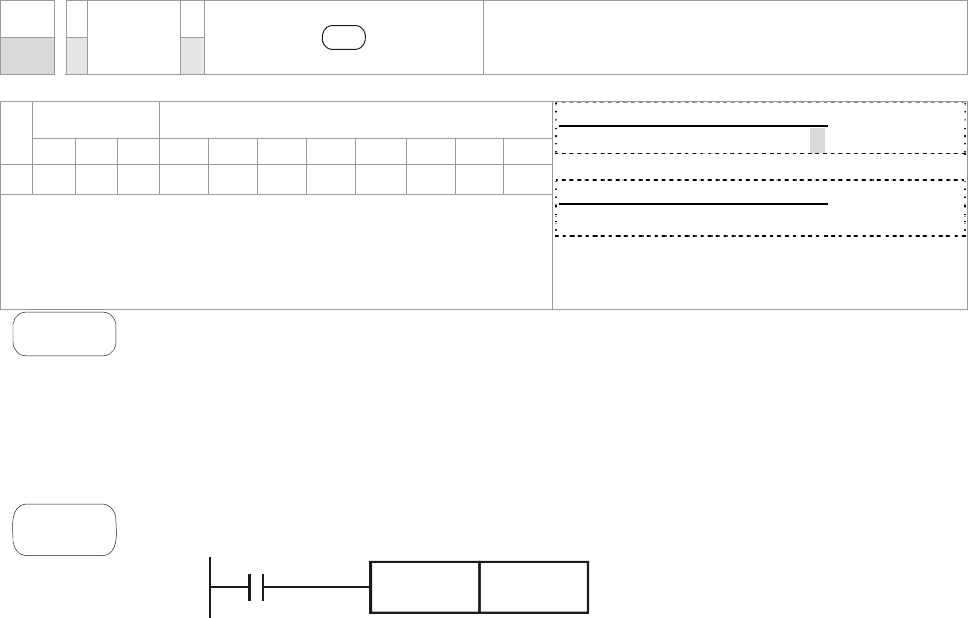
Chapter 16 PLC Function |CT2000 Series
16-60
API
24
D INC P
D
Increment: BIN plus 1
Bit Devices Word Devices
X Y M K H KnX KnY KnM T C D
D
* * * * *
Operands: none
16-bit command (3 STEPS)
INC INCP
32-bit command (5 STEPS)
- - - -
Flag signal: none
Explanation
1. D: Destination device
2. If the instruction is not a pulse execution one, the content in the
designated device D will plus “1” in every scan period whenever the
instruction is executed.
3. This instruction adopts pulse execution instructions (INCP).
4. In 16-bit operation, 32,767 pluses 1 and obtains -32,768. In 32-bit
operation, 2,147,483,647 pluses 1 and obtains -2,147,483,648.
Example
When X0 goes from Off to On, the content in D0 pluses 1 automatically.
X0
INCP D0
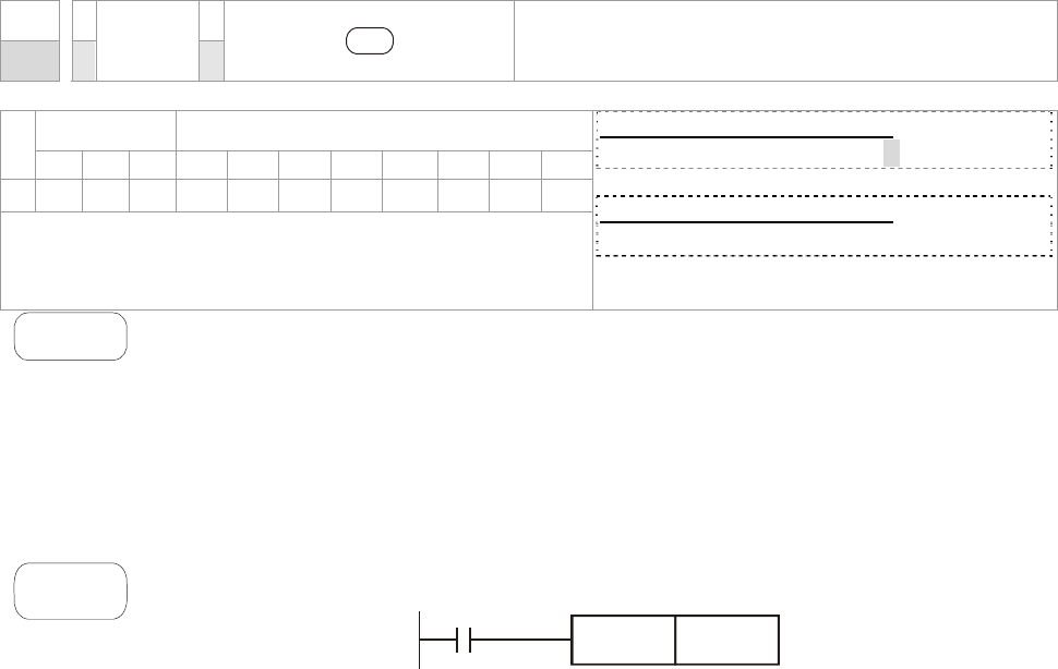
Chapter 16 PLC Function |CT2000 Series
16-61
API
25
D DEC P
D
Decrement: BIN minus 1
Bit Devices Word Devices
X Y M K H KnX KnY KnM T C D
D
* * * * *
Operands: none
16-bit command (3 STEPS)
DEC DECP
32-bit command (5 STEPS)
- - - -
Flag signal: none
Explanation
D: Destination
1. If the command is not a pulse execution type, the content in the designated
device D will minus “1” in every scan period whenever the instruction is
executed.
2. This instruction adopts pulse execution instructions (DECP).
3. In 16-bit operation, -32,768 minuses 1 and obtains 32,767. In 32-bit operation,
-2,147,483,648 minuses 1 and obtains 2,147,483,647.
Example
When X0 goes from Off to On, the content in D0 minuses 1 automatically.
X0
DECP D0
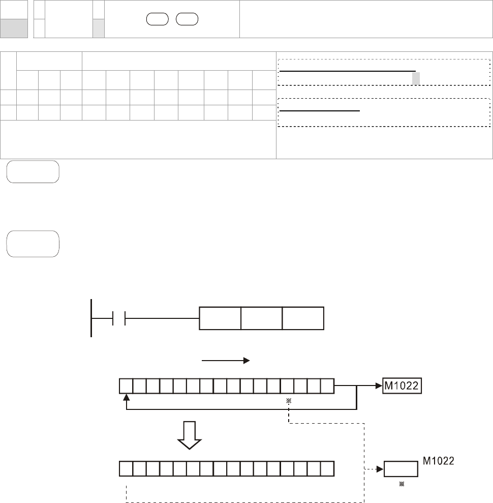
Chapter 16 PLC Function |CT2000 Series
16-62
API
30
ROR P
D n
Rotate to the Right
Bit Devices Word Devices
X Y M K H KnX KnY KnM T C D
D
* * * * *
n
* *
Operands:
D: if in KnY and KnM, only K4 (16-bit) is valid
n: n=K1~K16 (16-bit)
16 bit command (5 STEPS)
ROR RORP
32-bit command
- - - -
Flag signal: M1022 Carry flag
Explanation
1. D: Device to be rotated n: Number of bits to be rotated in 1 rotation
2. This instruction rotates the device content designated by D to the right for
n bits.
3. This instruction adopts pulse execution instructions (RORP).
Example
When X0 goes from Off to On, the 16-bit (4 bits as a group) in D10 will rotate to
the right, as shown in the figure below. The bit marked with will be sent to carry ※
flag M1022.
011 10 101 0 0111 001
010111001111001 0 0
upper bit lower bit
upper bit lower bit
*
X0
RORP D10 K4
Rotate to the right
16 bits
Carry
flag
Carry
flag
After one rotation
to the right
D10
D10
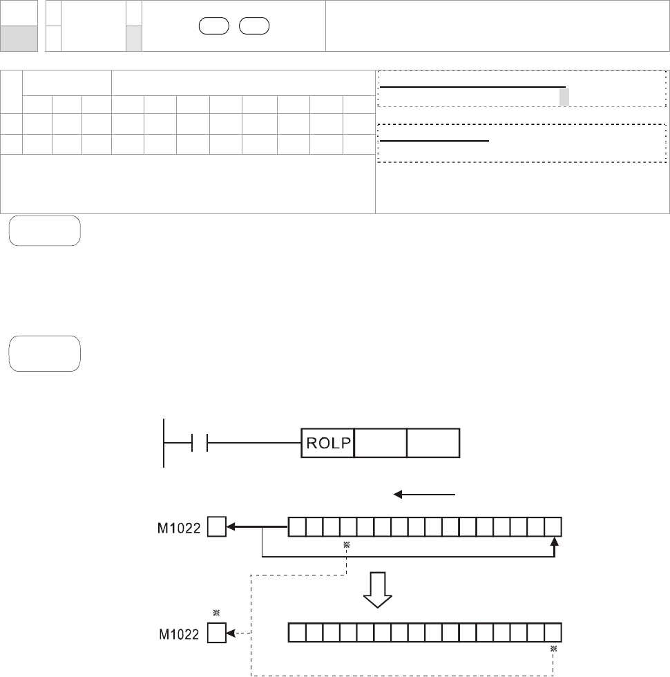
Chapter 16 PLC Function |CT2000 Series
16-63
API
31
ROL P
D n
Rotate to the Left
Bit Devices Word Devices
X Y M K H KnX KnY KnM T C D
D
* * * * *
n
* *
Operands:
D: if in KnY and KnM, only K4 (16-bit) is valid
n: n=K1~K16 (16-bit)
16-bit command (5 STEPS)
ROL ROLP
32-bit command
- - - -
Flag signal: M1022 Carry flag
Explanation
1. D: Device to be rotated; n: Number of bits to be rotated in 1 rotation
2. This instruction rotates the device content designated by D to the left for
n bits.
3. This instruction adopts pulse execution instructions (ROLP).
Example
When X0 goes from Off to On, the 16-bit (4 bits as a group) in D10 will rotate to
the left, as shown in the figure below. The bit marked with will be sent to carry ※
flag M1022.
X0
D10 K4
11111100 00011 000
11000001100110111
16 bits
Rotate to the left
After one rotation
to the left
Carry
flag
Carry
flag
D10
D10
upper bit
upper bit lower bit
lower bit
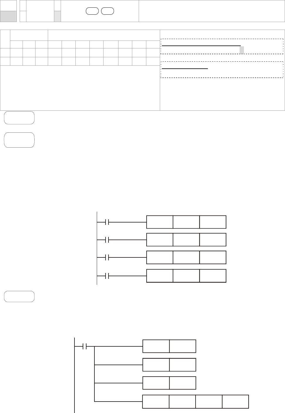
Chapter 16 PLC Function |CT2000 Series
16-64
API
40
ZRST P
D1 D2
Zero Reset
Bit Devices Word Devices
X Y M K H KnX KnY KnM T C D
D1 * *
* * *
D2 * *
* * *
Operands:
No of D1 operand. ≦No. of D2 operand
D1 and D2 must select same device type
Please refer to the specification of each model series
for applicable range of the device.
16-bit command (5 STEPS)
ZRST ZRSTP
32-bit command
- - - -
Flag signal: none
Explanation
D1: Start device of the range to be reset D2: End device of the range to be reset
When D1 > D2, only operands designated by D2 will be reset.
Example
1. When X0 = On, auxiliary relays M300 ~ M399 will be reset to Off.
2. When X1 = On, 16 counters C0 ~ C127 will all be reset (writing in 0; contact
and coil being reset to Off).
3. When X10 = On, timers T0 ~ T127 will all be reset (writing in 0; contact and coil
being reset to Off).
4. When X3 = On, data registers D0 ~ D100 will be reset to 0.
ZRST M300 M399
ZRST C0 C127
ZRST T0 T127
ZRST D0 D100
X0
X1
X10
X3
Remarks
1. Devices, e.g. bit devices Y, M, S and Word Devices T, C, D, can use RST
instruction.
2. API 16 FMOV instruction is also to send K0 to Word Devices T, C, D or bit
registers KnY, KnM, KnS for reset.
RST M0
X0
RST T0
RST Y0
FMOV K0 D10 K5
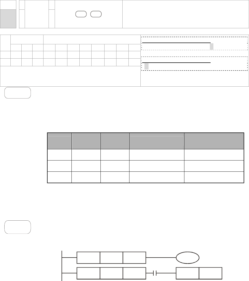
Chapter 16 PLC Function |CT2000 Series
16-65
API
215~
217 D LD#
S1 S2
Contact Logical Operation LD#
Bit Devices Word Devices
X Y M K H KnX KnY KnM T C D
S1
* * * * * * * *
S2
* * * * * * * *
Operands: #: &, |, ^
Please refer to the specifications of each model for the
range of operands.
16-bit command (5 STEPS)
LD# ZRSTP
32-bit command (9 STEPS)
DLD# - - -
Flag signal: none
Explanation
1. S1: Data source device 1 S2: Data source device 2
2. This instruction compares the content in S1 and S2. If the result is not “0”, the
continuity of the instruction is enabled. If the result is “0”, the continuity of the
instruction is disabled.
3. LD# (#: &, |, ^) instruction is used for direct connection with BUS.
API No. 16 -bit
instruction
32 -bit
instruction Continuity condition No-continuity
condition
215 LD& DLD& S1 &S2
≠
0 S1 & S2
=
0
216 LD| DLD| S1 |S2
≠
0 S1 | S2
=
0
217 LD^ DLD^ S1 ^S2
≠
0 S1 ^ S2
=
0
4. &: Logical “AND” operation
5. |: Logical “OR” operation
6. ^: Logical “XOR” operation
Example
1. When the result of logical AND operation of C0 and C10 ≠ 0, Y10 = On.
2. When the result of logical OR operation of D200 and D300 ≠ 0 and X1 = On,
Y11 = On will be retained.
LD C0 C10
LD D200 D300 SET
X1
&
IY11
Y10
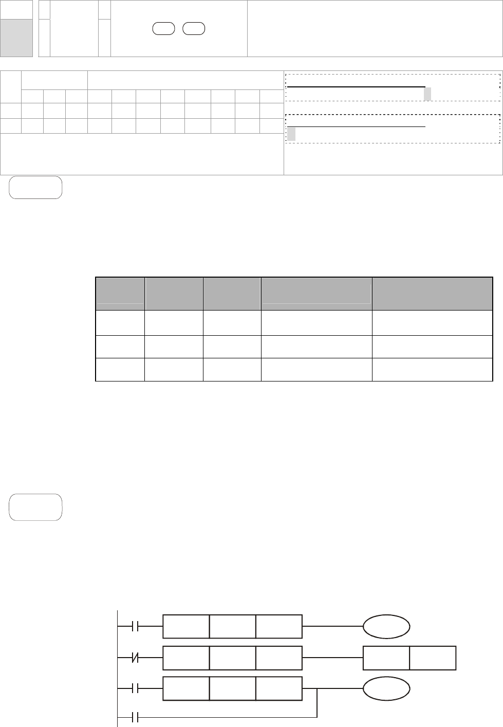
Chapter 16 PLC Function |CT2000 Series
16-66
API
218~
220 D AND#
S1 S2
Contact Logical Operation AND#
Bit Devices Word Devices
X Y M K H KnX KnY KnM T C D
S1
* * * * * * * *
S2
* * * * * * * *
Operands: #: &, |, ^
Please refer to the specifications of each model for the
range of operands.
16-bit command (5 STEPS)
AND# ZRSTP
32-bit command (9 STEPS)
DAND# - - -
Flag signal: none
Explanation
1. S1: Data source device 1 S2: Data source device 2
2. This instruction compares the content in S1 and S2. If the result is not “0”, the
continuity of the instruction is enabled. If the result is “0”, the continuity of the
instruction is disabled.
3. AND# (#: &, |, ^) is an operation instruction used on series contacts.
API No. 16 -bit
instruction
32 -bit
instruction Continuity condition No-continuity
condition
218 AND& DAND& S1 &S2
≠
0 S1 & S2
=
0
219 AND| DAND| S1 |S2
≠
0 S1 | S2
=
0
220 AND^ DAND^ S1 ^S2
≠
0 S1 ^ S2
=
0
4. &: Logical “AND” operation
5. |: Logical “OR” operation
6. ^: Logical “XOR” operation
Example
1. When X0 = On and the result of logical AND operation of C0 and C10 ≠ 0, Y10 =
On.
2. When X1 = Off and the result of logical OR operation of D10 and D0 ≠ 0 and X1 =
On, Y11 = On will be retained.
3. When X2 = On and the result of logical XOR operation of 32-bit register D200
(D201) and 32-bit register D100 (D101) ≠ 0 or M3 = On, M50 = On.
M3
DAND D200 D100 M50
AND C0 C10
AND D10 D0 SET
&
^
IY11
Y10
X0
X1
X2
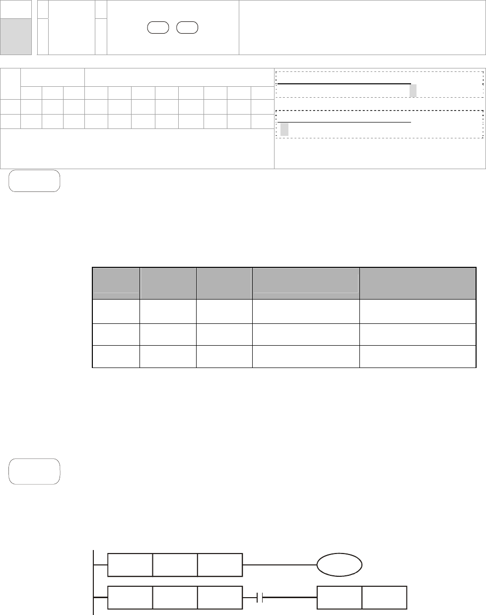
Chapter 16 PLC Function |CT2000 Series
16-67
API
221~
223 D OR#
S1 S2
Contact Logical operation OR#
Bit Devices Word Devices
X Y M K H KnX KnY KnM T C D
S1
* * * * * * * *
S2
* * * * * * * *
Operand: #: &, |, ^
Please refer to the specifications of each model for the
range of operands.
16-bit command (5 STEPS)
OR# ZRSTP
32-bit command (9 STEPS)
DOR# - - -
Flag signal: none
Explanation
1. S1: Data source device 1 S2: Data source device 2
2. This instruction compares the content in S1 and S2. If the result is not “0”, the
continuity of the instruction is enabled. If the result is “0”, the continuity of the
instruction is disabled.
3. OR# (#: &, |, ^) is an operation instruction used on parallel contacts.
API No. 16 -bit
instruction
32 -bit
instruction Continuity condition No-continuity
condition
221 OR& DOR& S1 &S2
≠
0 S1 & S2
=
0
222 OR| DOR| S1 |S2
≠
0 S1 | S2
=
0
223 OR^ DOR^ S1 ^S2
≠
0 S1 ^ S2
=
0
4. &: Logical “AND” operation
5. |: Logical “OR” operation
6. ^: Logical “XOR” operation
Example
When X1 = On and the result of logical AND operation of C0 and C10 ≠ 0, Y10 = On.
1. M60 will be On, if X2 and M30 are On with one of the following two conditions: 1.
The OR operation result of 32-bit register D10 (D11) and 32-bit register D20(D21)
does not equal to 0. 2. The XOR operation result of 32-bit counter C235 and
32bits register D200 (D201) does not equal 0.
LD= K200 C10 Y10
LD> D200 K-30
X1
SET Y11
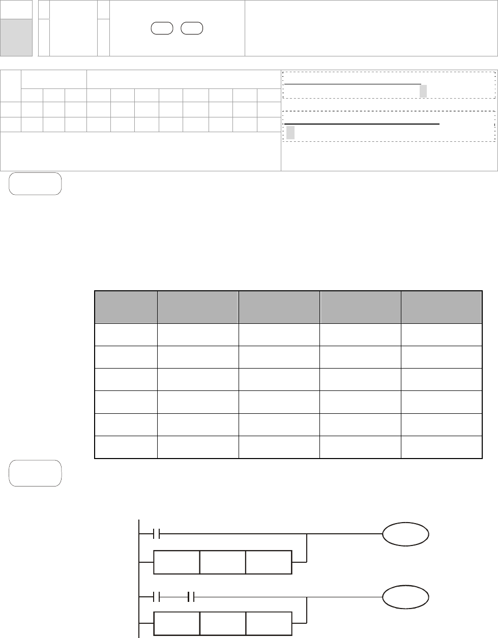
Chapter 16 PLC Function |CT2000 Series
16-68
API
224~
230 D LD※
S1 S2
Load Compare※
Bit Devices Word Devices
X Y M K H KnX KnY KnM T C D
S1
* * * * * * * *
S2
* * * * * * * *
Operands: ※: =, >, <, <>,≦,≧
Please refer to the specifications of each model for the
range of operands.
16-bit command (5 STEPS)
LD※ ZRSTP
32 位bits command (9 STEPS)
DLD※- - -
Flag signal: none
Explanation
1. S1: Data source device 1 S2: Data source device 2
2. This instruction compares the content in S1 and S2. Take API224 (LD=) for
example, if the result is “=”, the continuity of the instruction is enabled. If the
result is “≠”, the continuity of the instruction is disabled.
3. LD (※:※ =, >, <, <>, ≤, ≥) instruction is used for direct connection with BUS.
API No. 16 -bit
instruction
32 -bit
instruction
Continuity
condition
No-continuity
condition
224 LD= DLD= S1 = S2 S1 ≠ S2
225 LD> DLD> S1 > S2 S1 ≦S2
226 LD< DLD< S1 < S2 S1 ≧S2
228 LD<> DLD<> S1 ≠ S2 S1 = S2
229 LD<= DLD<= S1 ≦S2 S1 > S2
230 LD>= DLD>= S1 ≧S2 S1 < S2
Example
1. When the content in C10 = K200, Y10 = On.
2. When the content in D200 > K-30 and X1 = On, Y11= On will be retained.
OR C0 C10
DOR D10 D20
&
I
Y0
X2
X1
M30
M60
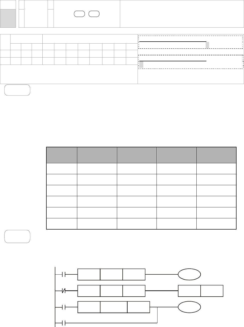
Chapter 16 PLC Function |CT2000 Series
16-69
API
232~
238 D AND※
S1 S2
AND Compare※
Bit Devices Word Devices
X Y M K H KnX KnY KnM T C D
S1
* * * * * * * *
S2
* * * * * * * *
Operands: ※: =, >, <, <>,≦,≧
Please refer to the specifications of each model for the
range of operands.
16-bit command (5 STEPS)
AND※ ZRSTP
32-bit command (9 STEPS)
DAND※- - -
Flag signal: none
Explanation
1. S1: Data source device 1 S2: Data source device 2
2. This instruction compares the content in S
1 and S2. Take API232 (AND=) for
example, if the result is “=”, the continuity of the instruction is enabled. If the result
is “≠”, the continuity of the instruction is disabled.
3. AND (※:※ =, >, <, <>, ≤, ≥) is a comparison instruction is used on series
contacts
API No. 16 –bit
instruction
32 –bit
instruction
Continuity
condition
No-continuity
condition
232 AND= DAND= S1 = S2 S1 ≠ S2
233 AND> DAND> S1 > S2 S1 ≦S2
234 AND< DAND< S1 < S2 S1 ≧S2
236 AND<> DAND<> S1 ≠ S2 S1 = S2
237 AND<= DAND<= S1 ≦S2 S1 > S2
238 AND>= DAND>= S1 ≧S2 S1 < S2
Example
1. When X0 = On and the content in C10 = K200, Y10 = On.
2. When X1 = Off and the content in D0 ≠ K-10, Y11= On will be retained.
3. When X2 = On and the content in 32-bit register D0 (D11) < 678,493 or M3 =
On, M50 = On.
AND= K200 C10
DAND> K678493 D10
M3
Y10
AND<> K-10 D0 SET Y11
M50
X2
X1
X0
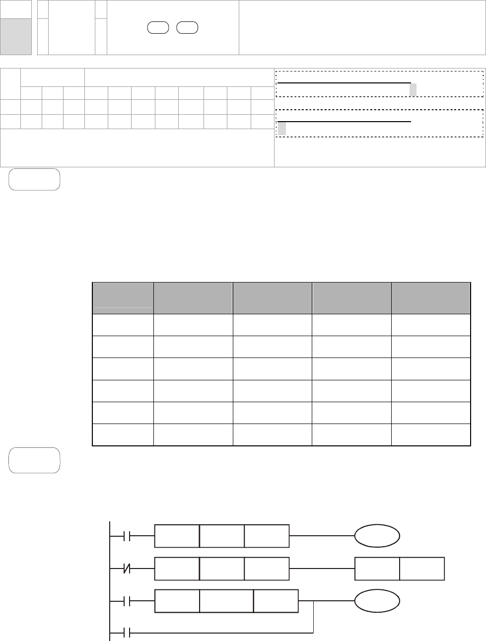
Chapter 16 PLC Function |CT2000 Series
16-70
API
240~
246 D OR※
S1 S2
OR Compare※
Bit Devices Word Devices
X Y M K H KnX KnY KnM T C D
S1
* * * * * * * *
S2
* * * * * * * *
Operands: ※: =, >, <, <>,≦,≧
Please refer to the specifications of each model for the
range of operands.
16-bit command (5 STEPS)
OR※ ZRSTP
32-bit command (9 STEPS)
DOR※- - -
Flag signal: none
Explanation
1. S1: Data source device 1 S2: Data source device 2
2. This instruction compares the content in S1 and S2. Take API240 (OR=) for
example, if the result is “=”, the continuity of the instruction is enabled. If the
result is “≠”, the continuity of the instruction is disabled.
3. OR (※:※ =, >, <, <>, ≤, ≥) is an comparison instruction used on parallel
contacts.
API No. 16 -bit
instruction
32 -bit
instruction
Continuity
condition
No-continuity
condition
232 AND= DAND= S1 = S2 S1 ≠ S2
233 AND> DAND> S1 > S2 S1 ≦S2
234 AND< DAND< S1 < S2 S1 ≧S2
236 AND<> DAND<> S1 ≠ S2 S1 = S2
237 AND<= DAND<= S1 ≦S2 S1 > S2
238 AND>= DAND>= S1 ≧S2 S1 < S2
Example
1. When X1 = On and the present value of C10 = K200, Y0 = On.
2. When X1 = Off and the content in D0 ≠ K-10, Y11= On will be retained.
3. M50 will be On when X2=On and the content of 32-bit register D0(D11) <678,493
or M3= On.
AND= K200 C10
DAND> K678493 D10
M3
Y10
AND<> K-10 D0 SET Y11
M50
X2
X1
X0
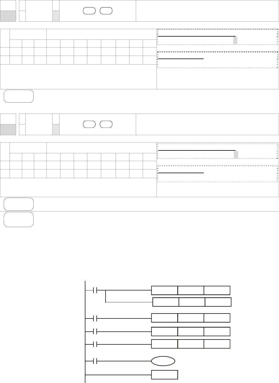
Chapter 16 PLC Function |CT2000 Series
16-71
16.5.5 Description to drive’s special commands
API
139 RPR P
S1 S2
Read the AC motor drive’s parameters
Bit Devices Word Devices
X Y M K H KnX KnY KnM T C D
S1
* *
*
S2
*
Operands: none
16-bit command (5 STEPS)
RPR RPRP
32-bit command
- - - -
Flag signal: none
Explanation
S1: Data address for reading S2: The register that saves the read data
API
140 WPR P
S1 S2
Write the AC motor drive’s parameters
Bit Devices Word Devices
X Y M K H KnX KnY KnM T C D
S1
* *
*
S2
* *
*
Operands: None
16-bit command (5 STEPS)
WPR WPRP
32-bit command
- - - -
Flag signal: none
Explanation
S1: The data for writing. S2: The parameters address for the write data.
Example
1. It will read the data in parameter H2100 of the CT2000 and write into D0; H2101
is read and write into D1.
2. When M0=On, data in D10 will be written into Pr. H2001 of CT2000.
3. When M1=ON, data in H2 will be written into Pr. H2001 of CT2000, which is to
activate the AC motor drive.
4. When M2=ON, data in H1 will be written into H2000 of CT2000, which is to stop
the AC motor drive.
5. When data writing successfully, M1017 will be on.
END
M1000
RPR H2100 D0
RPR H2101 D1
WPR
WPRP
WPRP
D10
H2
H1 H2000
H2001
H2000
Y0
M1017
M1
M2
M0
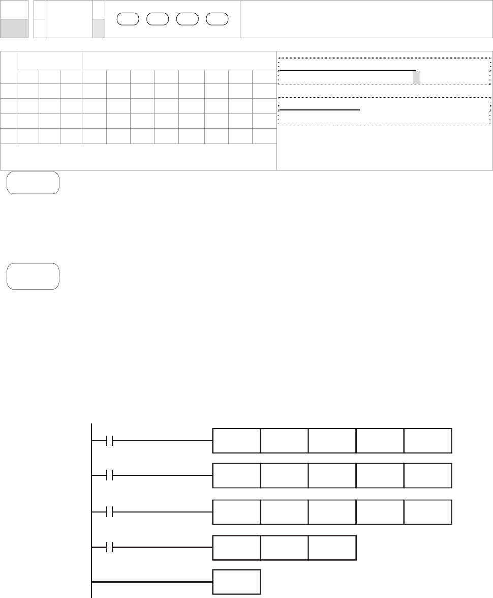
Chapter 16 PLC Function |CT2000 Series
16-72
API
141 FPID P
S1 S2 S3 S4
PID control for the AC motor drive
Bit Devices Word Devices
X Y M K H KnX KnY KnM T C D
S1
* *
*
S2
* *
*
S3
* *
*
S4
* *
*
Operands: None
16-bit command (9 STEPS)
FPID FPIDP
32-bit command
- - - -
Flag signal: None
Explanation
1. S1: PID Set Point Selection, S
2: Proportional Gain P, S3: Integral Time I, S4:
Derivative control D
2. This command FPID can control the PID parameters of the AC motor drive
directly, including Pr.08.00 PID set point selection, Pr.08.01 Proportional gain
(P), Pr.08.02 Integral time (I) and Pr.08.03 Derivative control (D)
Example
1. Assume that when M0=ON, S1 is set to 0 (PID function is disabled), S2=0, S3 =1
(unit: 0.01 seconds) and S4=1 (unit: 0.01 seconds).
2. Assume that when M1=ON, S1 is set to 0 (PID function is disabled), S2=1 (unit:
0.01), S3 =0 and S4=0.
3. Assume that when M2=ON, S1 is set to 1(frequency is inputted by digital
keypad), S2=1 (unit: 0.01), S3 =0 and S4=0.
4. D1027: frequency command after PID calculation.
END
H0
M2
M1
M0
M1000
H1
H0
H0
H1
H1
H1 H1
H0 H0
H0 H0
FPID
MOV D1027 D1
FPID
FPID
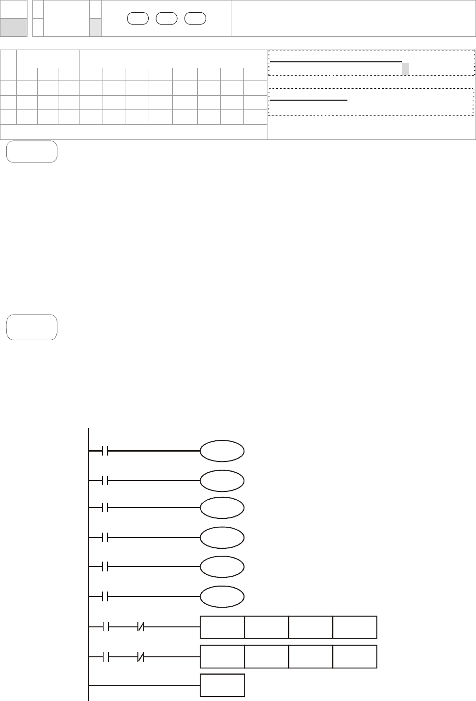
Chapter 16 PLC Function |CT2000 Series
16-73
API
142 FREQ P
S1 S2 S3
Operation control of the AC motor drive
Bit Devices Word Devices
X Y M K H KnX KnY KnM T C D
S1
* *
*
S2
* *
*
S3
* *
*
Operands: None
16-bit command (7 STEPS)
FREQ FREQP
32-bit command
- - - -
Flag signal: M1028
Explanation
1. S1: frequency command, S2: acceleration time, S3: deceleration time
2. This command FREQ can control frequency command, acceleration time and
deceleration time of the AC motor drive. Special register control is shown as
following:
M1025: controls RUN (On)/STOP (Off) of the drive. (Run is valid when Servo
On (M1040 On).)
M1026: Operation directions FWD (On)/REV (Off) of the drive.
M1040: controls Servo On (On)/ Servo Off (Off).
M1042: enable quick stop(ON)/ disable quick stop(Off)
M1044: enable Stop (On)/ disable stop(Off)
M1052: frequency locked (On)/ disable frequency locked(Off)
Example
1. M1025: controls RUN (On)/STOP (Off) of the drive. M1026: operation direction
FWD (On)/REV (Off) of the drive. M1015: frequency attained.
2. When M10=ON, setting frequency command of the AC motor drive to
K300(3.00Hz) and acceleration/deceleration time is 0.
3. When M11=ON, setting frequency command of the AC motor drive to
K3000(30.00Hz), acceleration time is 50 and deceleration time is 60.
END
M13
M1044
M14
M1052
FREQP K300 K0 K0
FREQ K3000 K50 K60
M11
M10
M10M11
M1000
M1040
M12
M1042
M1000
M1025
M11
M1026
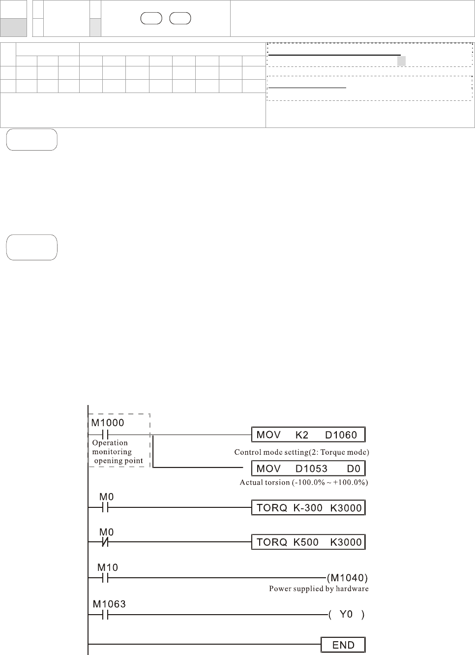
Chapter 16 PLC Function |CT2000 Series
16-74
API
263 TORQ P
S1 S2
Torque Control of AC Motor Drive
Bit Devices Word Devices
X Y M K H KnX KnY KnM T C D
S1
* *
*
S2
* *
*
Operands: None
16-bit command (7 STEPS)
TORQ TORQ P
32-bit command
- - - -
Flag signal: M1063
Explanation
1. S1: torque command (display in signed decimal with one decimal place)
S2: speed limit
2. This command can control torque command and speed limi. Special register
control is shown as following:
M1040: controls Servo On(On)/ Servo Off(Off). Torque output and speed limit
are defined by the setting of TORQ command when TORQ command is set
when Servo is ON.
Example
1. M1040: control Servo On(On)/ Servo Off(Off). M1063: target torque attained.
D1060: control mode setting. D1053: actual torque.
2. When M0=Off, setting torque command of the AC motor drive to K+300(+30.0%)
and speed limit to 3000(30Hz).
3. When M0=On, setting torque command of AC motor drive to K-300(-30.0%) and
speed limit to 3000(30Hz)。
4. When M10=On, AC motor drive begins to execute torque command.
5. When target torque is attained, M1063 will switch ON and flag signal will be
blinking.
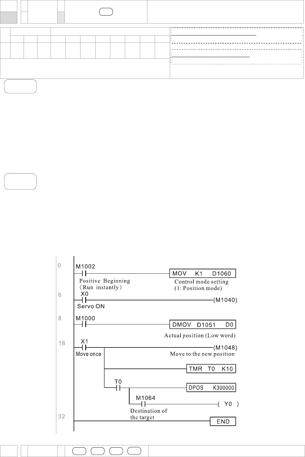
Chapter 16 PLC Function |CT2000 Series
16-75
API
262 DPOS P
S1
Point to Point Position Control of AC Motor Drive
Bit Devices Word Devices
X Y M K H KnX KnY KnM T C D
S1
* *
*
Operands: None
16-bit command (7 STEPS)
- - - -
32-bit command (5 steps)
DPOS DPOSP
Flag signal: M1064, M1070
Explanation
S1: target position (signed decimal)
This DPOS command can control the motor position of AC motor drive. Special
register control is shown as following:
M1040: controls Servo On(On)/ Servo Off(Off). M1055: searching origin point.
M1048: operate to the new position point. In the condition D1060 = 1 (control
mode is set to position mode), M1040=1 (Servo ON), and DPOS command is
given; when M1048 is set from OFF to ON the AC motor drive will operate till the
new position point.
Example
1. M1040: controls Servo On(On)/ Servo Off(Off). M1064: target position attained.
D1060: control mode setting. D1051(L) and D1052(H): actual position point.
2. When X0=On, setting M1040 to ON (Servo On).
3. When X1=On, setting DPOS position command to +300000. It will delay for 1
second then set M1048 to ON (operate to the new position). Please observe if the
D1051 value changes. When position is attained, M1064 will set to ON and Y0
will output an ON signal.
API CANRX
S1 S2 S3 D
Read CANopen slave data
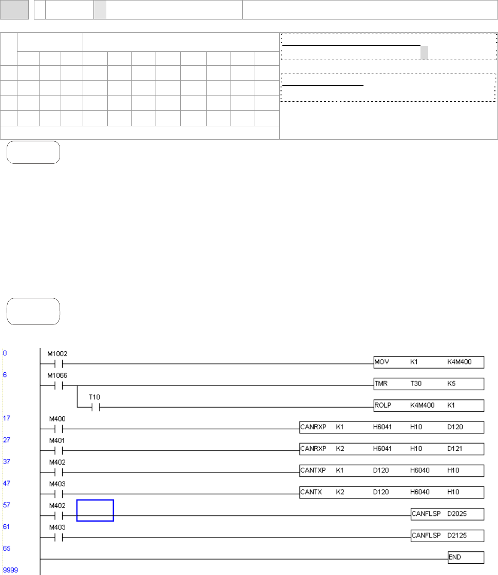
Chapter 16 PLC Function |CT2000 Series
16-76
261 P
Bit Devices Word Devices
X Y M K H KnX KnY KnM T C D
S1
* *
S2
* *
S3
* *
D
* * *
Operand: none
16-bit command (7 STEPS)
FREQ FREQP
32-bit command
- - - -
Flag signal: M1028
Explanation
1. S1: Slave station number, S
2: main index, S3: sub-index + bit length, D: save
address
2. Command CANRX can read the corresponding slave. Index. When executing this
command, it will send SDO message to the slave. At this time, M1066 and M1067
are 0 but when reading is complete M1066 will set to 1. If the slave replied an
accurate response, the value will be written to the designated register and M1067
is now set to 1. However, if the slave replied an inaccurate response, this error
message will be recorded in D1076~D1079.
Example
M1002: touch once to activate PLC and change K4M400=K1. After the change,
different message will be displayed when M1066 is set to 1.

Chapter 16 PLC Function |CT2000 Series
16-77
API
264 CANTX P
S1 S2 S3 S4
Write CANopen slave data
Bit Devices Word Devices
X Y M K H KnX KnY KnM T C D
S1
* *
S2
* *
* * *
S3
* *
S4
* *
Operands: None
16-bit command (7 STEPS)
FREQ FREQP
32-bit command
- - - -
Flag signal: M1028
Explanation
1. S1: slave station number, S2: the address to write, S3: main index, S4: sub-index+
bit length.
2. Command CANTX can read the corresponding index of the slave. When
executing this command, it will send SDO message to the slave. At this time,
M1066 and M1067 are 0 but when reading is complete M1066 will set to 1. If the
slave replied an accurate response, the value will be written to the designated
register and M1067 is now set to 1. However, if the slave replied an inaccurate
response, this error message will be recorded in D1076~D1079.

Chapter 16 PLC Function |CT2000 Series
16-78
API
265 CANFLS P
D
Update the mapping special D of CANopen
Bit Devices Word Devices
X Y M K H KnX KnY KnM T C D
D
* *
Operands: None
16-bit command (7 STEPS)
FREQ FREQP
32-bit command
- - - -
Flag signal: M1028
Explanation
1. D: the special D for update.
2. CANFLS can update the Special D command. When it executes in read only
mode, it sends equivalent message as CANRX to the slave and saves the slave
response to this particular Special D. When it executes in read/write mode, it
sends equivalent message as CANTX to the slave and saves this special D
value to the corresponding slave.
3. M1066 and M1067 are both 0. When reading is complete, M1066 will be 1 and
this value will write to the designated register if the slave replies an accurate
response. When slave replies a fault response then M1067 will be 0 and this
error message will be recorded to D1076~D1079.

Chapter 16 PLC Function |CT2000 Series
16-79
16.6 Error and Troubleshoot
Fault ID Fault Descript Corrective Action
PLiC 48 Internal communication signal off Check if shielded wire is properly inserted
to communication port COM1.
PLod 50 Data write error Check if there is error in the program and
download the program again.
PLSv 51 Data write error when executing Re-apply the power and download the
program again.
PLdA 52 Program upload error Upload again. If error occurs continuously,
please return to the factory.
PLFn 53
Command error when download
program
Check if there is error in the program and
download the program again.
PLor 54
Program capacity exceeds memory
capacity
Re-apply the power and download the
program again.
PLFF 55
Command error when executing Check if there is error in the program and
download the program again.
PLSn 56
Check sum error Check if there is error in the program and
download the program again.
PLEd 57
There is no “END” command in the
program
Check if there is error in the program and
download the program again.
PLCr 58
The command MC is continuous
used more than 9 times
Check if there is error in the program and
download the program again.
PLdF 59
Download program error Check if there is error in the program and
download the program again.
PLSF 60
PLC scan time over-time Check if the program code is inaccurately
written and download the program again.

Chapter 16 PLC Function |CT2000 Series
16-80
16.7 CANopen Master Application
Simple control of multiple-axes for certain application can be done by CT2000 if the device supports
CANopen protocol. One of the CT2000 could acts as Master to perform simple synchronous control,
e.g. position, speed, zero return, and torque control. The setup can be done in 7 steps:
Step 1: Activate CANopen Master
1. Set Pr.09-45 to 1. (To activate Master function, turn off the power after setting and reboot.
The digital keypadKPC-CC01 status will display “CAN Master”.)
2. Set Pr.00-02 to 6 for PLC reset. (Note: This action will erase the program and PLC register
and will be set to factory setting.)
3. Turn off the power and reboot.
4. Set PLC control to”PLC Stop mode” by digital keypad KPC-CC01. (If the digital keypad is
KPC-CE01 series, set PLC control to”PLC 2”. If the drive just came out of the factory, since
PLC program is not yet installed, the digital keypad will show PLFF warning code.)
Step 2: Configuration of the Special D in Master
Each slave occupies 100 of Special D space and is numbered 1 to 8. There are in total of 8
stations. Please refer to 4-3 Special Register in this chapter for Special D register definition.
Slave No. Slave No. 1 D2000
D2001
~
D2099
Station number
Factory code(L)
~
The mapping address 4(H) of receiving
station 4
Slave No. 2 D2100
D2101
~
D2199
Station number
Factory code(L)
~
The mapping address 4 (H)of receiving
station 4
Slave No. 3 D2200
D2201
~
D2299
Station number
Factory code(L)
~
The mapping address 4 (H)of receiving
station 4
Slave No. 8 D2700
D2701
~
D2799
Station number
Factory code(L)
~
The mapping address 4(H) of receiving
station 4
1. When communication cable 485 is connected, set PLC status to “stop” by WPL soft. (If PLC
had already switched to “PLC Stop” mode then PLC status should be “stop” already.)
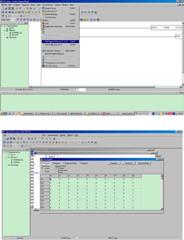
Chapter 16 PLC Function |CT2000 Series
16-81
2. To control the slave address and corresponding station. For example, control 2 stations of
the slave (max. 8 stations synchronous control), if the station number is 21 and 22, set
D2000 and D2100 to 20 and 21 and then set D2200, D2300, D2400, D2500, D2600 and
D2700 to 0. The setting can be done via PLC software editor WPL, follow the steps shown:
Open WPL Editor > communication> Edit Register Memory(T C D)
When the “Register” window appears, click “Transmit”.
When transmission window appear, select “read” and input the range D2000~D2799
then press enter. The value in D2000~D2799 will be read. If communication failed,
check the communication format (pre-defined PLC station is 2, 9600, 7N2, ASCII).
Insert the slave station for control. Set D2000 and D2100 to 20 and 21 then set D2200,
D2300, D2400, D2500, D2600 and D2700 to 0.
Click”Transmit” again. When transmission window appears, input the range
D2000~D2799 and enter. The value in D2000~D2799 will be write (If communication
error occur and display failed, it means PLC is not in “stop” status. The value can only

Chapter 16 PLC Function |CT2000 Series
16-82
be write in “stop” status, pleas switch PLC to “stop”.)
Another method is by setting D1091. Set the corresponding bit of the excluding slave
to 0 (slave station range from No.1~8). For example, if the user wants to exclude slave
No. 2, 6 and 7, please set D1091 = 003B by following steps: WPL Editor >
communication> Edit Register Memory(T C D)
3. Setup the communication setting. If following conditions apply to you then no additional
setting needs to be done:
; If the only control in this application is the speed mode of AC motor drive. (For
other control such as position and torque control, D2000~D2799 should be set. Please
refer to synchronous control on position, torque and zero return for more set up detail.
To perform synchronous control on position for the slave, please enable the
corresponding function PDO 3. (P to P function is not yet supported by CT2000.)
To activate PDO 3 TX (Master sending command to Slave), please set up bit
8~11 of the PLC address D2034+n*100. This special D register is defined as
below:
PDO4 PDO3 PDO2 PDO1
Torque Position Remote I/O Speed
Bit 15 14 ~ 12 11 10 ~ 8 7 6 ~ 4 3 2 ~ 0
Definition En Number En Number En Number En Number
The pre-defined setting of PDO 3 TX has corresponded to CANopen control word
“Index 6040”and CANopen target position” Index 607A”. If position control is the
only control in this application then simply set Special D register value to 0x0A00.
To activate PDO 3 RX (Slave response with the status to Master), please set up
bit 8~11 of the PLC address D2067+n*100. This special D register is defined as
below:
PDO4 PDO3 PDO2 PDO1
Torque Position Remote I/O Speed
Bit 15 14 ~ 12 11 10 ~ 8 7 6 ~ 4 3 2 ~ 0
Definition En Number En Number En Number En Number
The pre-defined setting of PDO 3 TX has corresponded to CANopen control word
“Index 6041”and CANopen actual position” Index 6064”. If position control is the
only control in this application then simply set Special D register value to 0x0A00.
In same theory, to perform torque control, please enable the mapping function
PDO4.
; The speed for 1 corresponding cycle is 8ms. (When shorten the cycle time to < 8ms,
make sure the time is enough for the data to be transmitted.
User should calculate the corresponding PDO quantity before setting the cycle. The
PDO quantity should not be greater than the N. The quantity can be calculated by the
following formula.
N = (1 cycle (ms) * rate (kbs) )/250

Chapter 16 PLC Function |CT2000 Series
16-83
Example: 1 cycle is 2ms, speed= 1000k, max PDO value is 2*1000/250 = 8. If user
wants to set the cycle time to 2ms, turns off 4 of the C type AC motor drive slave
stations must be turned off (since the pre-defined setting is 8 slaves, half of the
slave station would be 4). The slave station can be turned off by setting the
D2000+n*100 of the unused slaves to 0.
; Number of control station ≤ 8.
Controlling 8 slave stations at once can only be done by asynchronous control where
to Read/Write the slave is done by CANRX and CANTX command. This is similar to
the Read/Write action of Modbus protocol.
; The slave complies with DS402 standard.
; Does not control Slave IO terminal.
; If above conditions do not apply, please set up the slave corresponding addresses
manually by open WPL editor > communication> Edit Register Memory (T C D).
Step 3: Set up Master station number and communication speed.
; Set up the station number for the Master (the default setting of Pr.09-46=100). Do not
to set the same station number as the Slave.
; Set up CANopen communication parameter Pr.09-37. It does not matter if the drive is
defined as a Master or a Slave, communication speed is set by Pr.09-37 in both case.
Step 4: Coding
Real-time corresponding action: the data can be Read/Write directly to the corresponding
special “D” register.
Non Real-time corresponding action:
Read: Reading is made by CANRX command. When reading process is complete,
M1066=1. If reading succeeded, M1067 =1; if reading failed, M1067= 0.
Write: Writing is made by CANTX command. When writing process is complete, M1066
=1. If writing succeeded, M1067=1; if reading failed, M1067 =0.
Update: Updating the data is made by CANFLS command. (If special D register is defined
as RW type, Master will write the value into the slave. If special D register is
defined as RO type, then the data in the Slave will be read and write into the
Master.) When updating process is complete, M1066 will be 1. If updating
succeeded, M1067=1; if updating failed, M1067=0.
NOTE
When executing CANRX, CANTX and CANFLS commands, the device will wait till M1066 is
completed before the next CANRX, CANT or CANFLS begins. When the commands
completed, download the program to the drive. (Note: The factory setting of PLC
communication protocol is ASCII 7N2 9600 and station number is 2. Please change WPL
Editor setting at Setting> Communication Setting)
Step 5: Setting the Slave station number, communication speed, operation
source and command source
CANopen communication is supported by Delta CT2000 series and EC series AC motor drive.
The corresponding slave and CANopen speed are shown as below:

Chapter 16 PLC Function |CT2000 Series
16-84
The only servo motor and drive that supports CANopen communication interface is A2 series.
The corresponding slave station number and communication speed are shown as below:
Corresponding
Parameter of Drive
A2
Value Definition
Slave address 03-00 1~127 CANopen communication
address
R= 0 125K
R= 1 250K
R= 2 500K
R= 3 750K
CANopen speed bit8~11 of Pr.03-01
XRXX
R= 4 1M
Control/Command
Source 01-01 B
Step 6: Hardware connection
The terminating resistor must be installed at the two farthest ends as shown in the figure
below:
Corresponding
Parameter of Drive
CT2000 E-C
Value Definition
0 Disable CANopen Hardware Interface Slave
address 09-36 09-20
1~127 CANopen communication address
0 1M
1 500K
2 250K
3 125K
4 100K
CANopen
speed 09-37 09-21
5 50K
00-21 3 Source of
operation
command 02-01 5
00-20 6 Source of
frequency
command 02-00 5
Torque
command 11-34 3
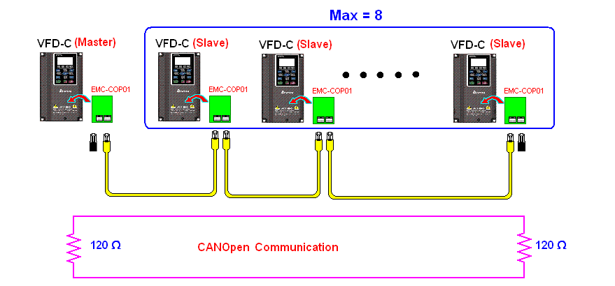
Chapter 16 PLC Function |CT2000 Series
16-85
Step 7: Activate PLC Control Function
Download the program after coding is complete and switch PLC mode to Run status. Then
reboots the power for Slave and Master. Please refer to CANMaster Test 1 vs. 2 driver.dvp.
Example:
CT2000 AC motor drive (1 master vs. 2 slave control)
Step 1: Activate CANopen Master
; Set Pr.09-45 to 1. (To activate Master function, turn off the power after setting and
reboot. The digital keypadKPC-CC01 status will display “CAN Master”.)
; Set Pr.00-02 to 6 for PLC reset. (Note: This action will erase the program and PLC
register and will be set to factory setting.)
; Turn off the power and reboot.
; Set PLC control to”PLC Stop mode” by digital keypad KPC-CC01. (If the digital
keypad is KPC-CE01 series, set PLC control to”PLC 2”. If the drive just came out of
the factory, since PLC program is not yet installed, the digital keypad will show PLFF
warning code.)
Step 2: Configuration of the Special D in Master
; Open WPL editor
; Set PLC mode to PLC Stop (PLC2) via the keypad
; WPL editor read D1070~D1099 and D2000~D2799
; Set D2000=10 and D2100=11
; Set D2100, 2200, 2300 2400 2500 2600 2700=0
; Download D2000~D2799 setting
Step 3: Set up Master station number and communication speed
; Set up the station number for the Master (the default setting of Pr.09-46=100). Do not
to set the same station number as the Slave.
; Set up CANopen communication speed to 1 M (parameter Pr.09-37= 0). It does not
matter if the drive is defined as a Master or a Slave, communication speed is set by
Pr.09-37 in both case.
Characteristic
line impedance Characteristic
line impedance
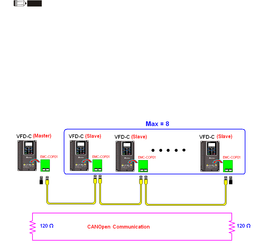
Chapter 16 PLC Function |CT2000 Series
16-86
Step 4: Coding
Real-time corresponding action: the data can be Read/Write directly to the corresponding
special “D” register.
Non Real-time corresponding action:
Read: Reading is made by CANRX command. When reading process is complete,
M1066=1. If reading succeeded, M1067 =1; if reading failed, M1067= 0.
Write: Writing is made by CANTX command. When writing process is complete, M1066
=1. If writing succeeded, M1067=1; if reading failed, M1067 =0.
Update: Updating the data is made by CANFLS command. (If special D register is defined
as RW type, Master will write the value into the slave. If special D register is
defined as RO type, then the data in the Slave will be read and write into the
Master.) When updating process is complete, M1066 will be 1. If updating
succeeded, M1067=1; if updating failed, M1067=0.
NOTE
When executing CANRX, CANTX and CANFLS commands, the device will wait till M1066 is completed before
the next CANRX, CANT or CANFLS begins. When the commands completed, download the program to the
drive. (Note: The factory setting of PLC communication protocol is ASCII 7N2 9600 and station number is 2.
Please change WPL setting at setting> communication setting)
Step 5: Set Slave station number and communication speed.
Slave No.1: Pr.09-37 = 0(speed 1M), Pr.09-36=10 (station number 10)
Slave No.2: Pr. 09-37 = 0(speed 1M), Pr.09-36=10 (station number 11)
Step 6: Hardware connection
The terminating resistor must be installed at the two farthest ends as shown in the figure
below:
Step 7: Activate PLC Control Function
Download the program after coding is complete and switch PLC mode to Run status. Then
reboots the power for Slave and Master. Please refer to CAN Master Test 1 vs. 2 driver.dvp.
Characteristic
line impedance Characteristic
line impedance

Chapter 16 PLC Function |CT2000 Series
16-87
16-9 Descriptions of PLC Control Modes
(Speed, Torque, Homing and Position Modes)
When the AC motor drive is in FOC vector control, it can perform torque mode, position mode and
speed mode. However, auto-tuning of motor must be done first for these modes to function.
There are two types of motors, Induction Motor (IM) and Permanent Magnetic Motor (PM). After
auto-tuning process, IM motor is ready for AC motor drive to control. For PM motor, user must
complete PG offset angle process after auto-tuning. Please refer to Pr.12-58 and Pr.05-00 for more
detail.
※ Set up Delta ECMA series PM motor by enter motor parameters, follow the motor parameters
shown in Delta Servo Motor Catalogue. It is not required to execute auto-tuning for using Delta
ECMA series PM motors.
Setting and Description for Other Control Modes:
Speed Control:
The corresponding registers for Speed Mode are listed in the chart below:
Special M Control Settings
Special M Descriptions R/W
M1025 AC motor drive operation status: (0) Stop (1) Start up (must also set M1040 =1) RW
M1026 AC motor drive opeartion direction: (0) FWD (1) REV RW
M1040 Power ON RW
M1042 Quick stop RW
M1044 Halt RW
M1052 Frequency lock RW
Special M Status
Special M Descriptions R/W
M1015 Target frequency attained RO
M1056 Power ON ready RO
M1058 Quick decelerating to stop RO
Special D Control Settings
Special D Descriptions R/W
D1060 Mode setting (speed mode = 0) RW
Speical D Status
Special D Descriptions R/W
D1037 Output frequency of AC motor drive command (0.00~600.00) RO
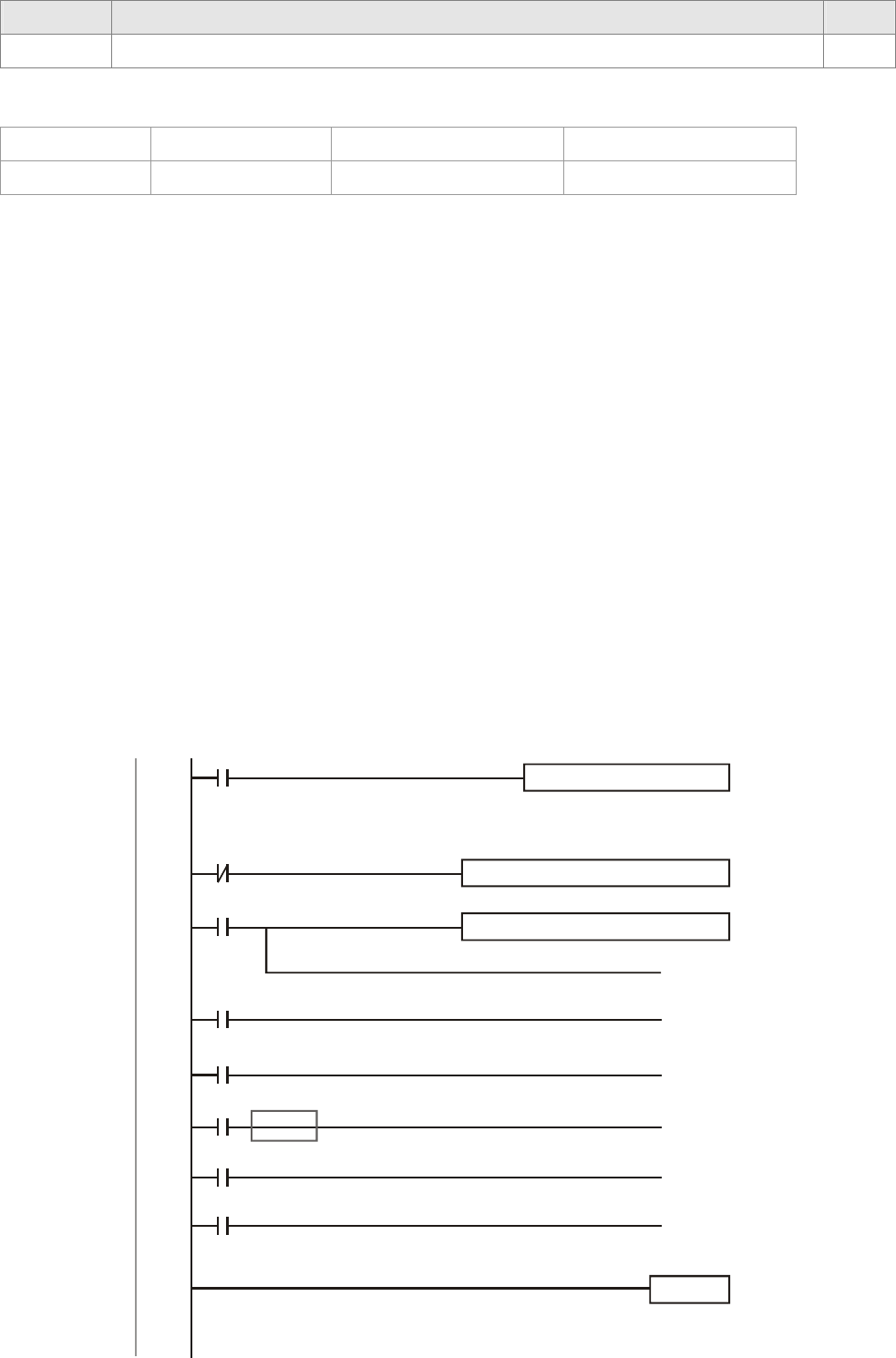
Chapter 16 PLC Function |CT2000 Series
16-88
Special D Descriptions R/W
D1050 Actual mode (0:Speed, 1: Position, 2: Torque, 3: Homing) RO
Control command for Speed Mode:
FREQ(P) S1 S2 S3
Target speed 1st step accel. time 1st step decel. time
Example of Speed Control Mode:
If the drive is in FOC control mode, please auto-tuning the motor before setting PLC control mode to
speed control.
1. When setting D1060 = 0, AC motor drive is in speed mode (default setting).
2. Write FREQ command to PLC program to control AC motor drive's frequency and accel./decel.
time.
3. When setting M1040 = 1, AC motor drive power turns ON but frequency remains 0.
4. When setting M1025 = 1, AC motor drive begins to operate till the FREQ frequency is attained
and will accel./decel. according to the setting of FREQ.
5. Use M1052 to lock present operation frequency.
6. Use M1044 to hault the drive and decelerate by the decleration setting.
7. Use M1042 to quick stopping the drive. The drive will declerate by it's maximum deceleration
speed and it is the speed that would not trigger a fault alarm. However if loading is too large, a
fault alarm may still occur.
8. Priority of the control command is: M1040(Power ON) > M1042(Quick Stop) >M1044(Halt)
>M1052(LOCK)
X0
M1002
MOV K0 D1060
END
Position
Beginning
X1
(M1040)
6
0
14
23
33
FREQ K100 K200
K3500
X0
FREQ K40 K50
K4500
X2
(M1025)
Power supply by hardware
(M1026)
AC Driver operating direction FWD (OFF)
AC Driver RUN(ON)STOP (OFF)
X3
(M1044)
Pause
X4
(M1052)
Frequency locked
X5
(M1042)
Park instantly
25
27
29
31
9999
RUN Instantly
:
Control Setting
0Speed

Chapter 16 PLC Function |CT2000 Series
16-89
Torque Control:
The corresponding registers for Torque Mode are listed in the chart below:
Special M Control Setting
Special M Description R/W
M1040 Power ON RW
Special M Status
Special M Description R/W
M1056 Power ON ready RO
M1063 Target torque attained RO
Special D Conrol Setting
Special D Description R/W
D1060 Mode setting (Torque mode=2) RW
Special D Status
Special D Description R/W
D1050 Actual mode (0:Speed, 1: Position, 2: Torque, 3: Homing) RO
D1053 Actual torque RO
Control command for Torque Mode:
TORQ(P) S1 S2
Target torque (signed decimal) Frequency limit
Example of Torque Control Mode:
Before setting PLC program to torque control mode, maker sure the torque parameter settings of
the AC motor drive are completed.
1. When setting D1060 = 2, AC motor drive is in torque mode.
2. Write TORQ command to PLC program for torque and speed limit control.
3. When setting M1040 = 1, AC motor drive power turns ON and operate till target torque or
speed limit is attained. Actual torque value can be read in D1053.
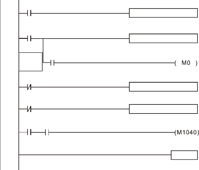
Chapter 16 PLC Function |CT2000 Series
16-90
M1000
M1002
MOV K2 D1060
Set control mode (0:V)
END
ON only for 1scan a
X1
6
0
13
X1
Ready
M0 X4
19
25
28
9999
TMR T0 K30
Power on delay
T0
Normally open contact
Power on delay
TORQ K100 K1000
TORQ K-200 K1000
Power on
Set Torque
Set Torque
Ready

Chapter 16 PLC Function |CT2000 Series
16-91
Homing/Position Control:
The corresponding registers for Homing/Position Mode are listed in the chart below:
Special M Control Setting
Special M Description R/W
M1040 Power ON RW
M1048 Run till the new position is attained. For M1048 to function, also need to set
control mode to position mode (D1060=1) and set M1040 = 1. RW
M1055 Home action begins. For 1055 to function, also need to set control mode to
position mode (D1060=3) and set M1040=1. RW
Special M Status
Special M Description R/W
M1064 Target position attained RO
M1070 Homing completed RO
M1071 Homing error RO
Special D Control Setting
Special D Description R/W
D1060 Mode selection (1: Position, 3: Homing) RW
Special D Status
Special D Description R/W
D1050 Actual mode (0:Speed, 1: Position, 2: Torque, 3: Homing) RO
D1051 Actual position (Low word) RO
D1052 Actual position (High word)
※ Read both D1051 and D1052 for actual position. The display value is in signed decimal.
Control Command for Position Mode:
DPOS(P) S1
Target position (signed decimal)
Example of Homing and Position Mode:
Before setting PLC program to homing mode or position mode, maker sure the motor parameter
settings of the AC motor drive are completed.
1. Set Pr.00-40 to homing mode and set up corresponding limit sensor and origin point by MI
(MI=44 is for reverse run limit, MI=45 is for forward run limit and MI=46 is for homing to origin
point). CT2000 series AC motor drive only supports Z phase homing to origin point, please
choose an Encoder with Z phase.
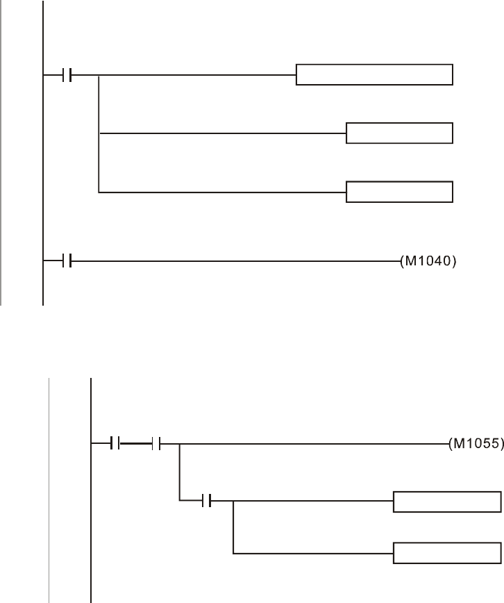
Chapter 16 PLC Function |CT2000 Series
16-92
2. When setting D1060 = 3, AC motor drive is in homing mode.
3. When setting M1040 = 1, AC motor drive power turns ON.
4. When setting M1055=1, AC motor drive search for origin point.
5. When homing is complete, M1070 will be ON. Then set D1060=1 to switch control mode to
position mode. (Ensure M1040 should not be turned OFF to avoid inaccurate origin point.)
6. Write DPOS command to PLC program for setting AC motor drive’s target position. Use
Pr.00-12 for the absolute or relative position selection.
7. Set M1048 to Pulse ON for one time and needs to be longer than 1ms, then AC motor drive
will begin to operate till the target position is attained (only when M1040=1). Present motor
position can be read from D1051 and D1052.
Step 1 ~ 7 can be categorized into three parts, please refer to the following example:
Part I: Set control mode to Homing Mode (D1060=3) and turn AC motor drive power ON by trigger
X2.
M1002
MOV K3 D1060
Set control mode (0:V)
ON only for 1scan a
0
10 X2
SET M100
Home mode
Power on
Initial condition
Servo on req
RST M101
P2P mode
Part II (Homing action): Begins homing mode by trigger X3. The drive will switch to position mode
automatically when homing is complete.
12
M1070
M100 X3
Home mode
RST M100
Home
mode Home
req
Home
finish
Home
RST M100
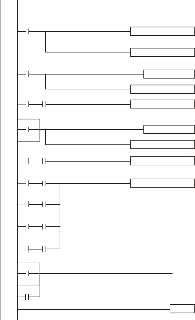
Chapter 16 PLC Function |CT2000 Series
16-93
Part III (Point to Point Position Control): Switch control mode to Position Mode (D1060=1) and
motor will be running forward and reverse between the position setting(+300000 ~ -300000 ).
M202
M101
MOV K1 D1060
Set control mode (0:V)
END
P2P mode
33
20
43 M201 M1064
49
59
81
Ack
P2P mode
MOV K1 K4M200
+300000
M200
DPOS K300000
TMR T100 K10
+300000
TMR T101 K10
Target Position atta
-400000
DPOS K300000
TMR T102 K10
M203
M1064
Ack
TMR T103 K10
Target Position atta
M200 T100
ROLP K4M200 K1
+300000
+300000
M200 T100
+300000
M200 T100
+300000
M200 T100
+300000
M202
Ack
Ack
(M1048)
84
65
※ If user’s application does not require homing action, you may skip Part I and Part II and go to the
next step. In this example, turn AC motor drive power ON by trigger X2 and set M1002 to
position mode, then the PLC program will be in position mode when drive power turns ON.
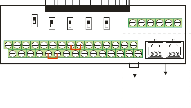
Chapter 16 PLC Function |CT2000 Series
16-94
16-10 Internal Communication for Master
Control
The ‘Internal Communication’ function is designed and developed for the applications where
CANopen communication is not applicable or accessable. It replaces CANopen by RS485 and
provides real-time transmission as CANopen communication. This communication protocol is
available for CT2000 series and CT2000 series AC motor drives only and the way it functions is
similar to Master/Slave control. A master drive could control a maximum of 8 slaves and the
master/slave setting process is very simple.
Slave Drives Settings:
1. Set Pr.09-31= -1~-8, the drive is able to control 8 nodes.
2. Set Pr.00-21=1, set source of control to RS485.
3. Select for what RS485 should control: Pr.00-21=2 (Speed command) or Pr.11-33 = 1 (Torque
command) or Pr.11-40=2 (Position command).
4. Once completed, the slave setting is done. It is not required to turn on PLC functions.
Master Drives Settings:
1. Set Pr.09-31= -10 and set PLC to Enable.
Connection for Hardware:
Establish Master drive and Slave drives connections by using RS485 cable. The CT2000 series AC
motor drive is designed with 2 types of RS485 ports, as shown in the figure following:
(Refer to Chapter 06 Control Terminal for more about wiring terminals)
SG-SG+
Modbus RS-485
81 81
Pin 1~2, 7~8:
Pin 3, 6:GND
Pin 4:SG-
Pin 5:SG+
Reserved
Removable Terminal Block
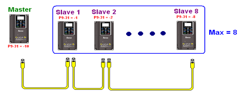
Chapter 16 PLC Function |CT2000 Series
16-95

Chapter 16 PLC Function |CT2000 Series
16-96
PLC Programming for Master Drive Control
1. In PLC program, D1110 is used for assigning the slave drive user wishes to control. The range
setting for D1110 is 1~8 (if D1110 is set to 0 slave 8 is assigned).
2. Once the Slave drive is assigned, set M1035=1 for the Master to control the Slave.
3. Write control command to the corresponding Slave address then Master is able to control the
Slave drive.
The corresponding registers for Internal Communication are listed in the chart below:
Special M Control Setting
Special M Description R/W
M1035 Enable internal communication control RW
Special D Control Setting
Special D Description R/W
D1110 Number of internal communication nodes(1~8) RW
Description
Special D
Definition bit Priority Speed Mode Position Mode Torque Mode Homing Mode
R/W
0 4
Command
Enable - -
Return to
Origin Point
1 4 Reverse
Command Switch - -
2 4 - - - -
3 3
Momentary
Stop
Momentary
Stop - -
4 4
Frequency
Locked - -
Momentary
Stop
5 4 JOG - - -
6 2 Quick Stop Quick Stop Quick Stop Quick Stop
7 1 Servo ON Servo ON Servo ON Servo ON
11~8 4
Switch
Multi-step
Speed
Switch
Multi-step
Speed
- -
13~12 4
Switch
Deceleration
Time
- - -
14 4 Enable Bit
13 ~ 8
Enable Bit
13 ~ 8 - -
D1120 + 10*N
Contorl Command for
Internal Communication
Node N
15 4 Clear Fault
Code
Clear Fault
Code
Clear Fault
Code
Clear Fault
Code
RW
D1121 + 10*N Contorl Mode for Internal
Communication Node N 0 1 2 3
RW
D1122 + 10*N
Reference Command L of
Internal Communication
Node N
Speed
Command
(unsigned
decimal)
Position
Command
(signed
decimal)
Torque
Command
(signed
decimal)
- RW
D1123 + 10*N
Reference Command H of
Internal Communication
Node N
- Speed Limit -
RW
※ N = 0 ~ 7
Special D Status
Special D Description R/W
D1115 Synchronous time cycle of internal communication(ms) RO
D1116 Internal communication node error (bit0= Slave 1, bit1= Slave 2, …, bit7= Slave
8) RO
D1117 Corresponding on-line bit of internal communication node (bit0= Slave 1, bit1= RO
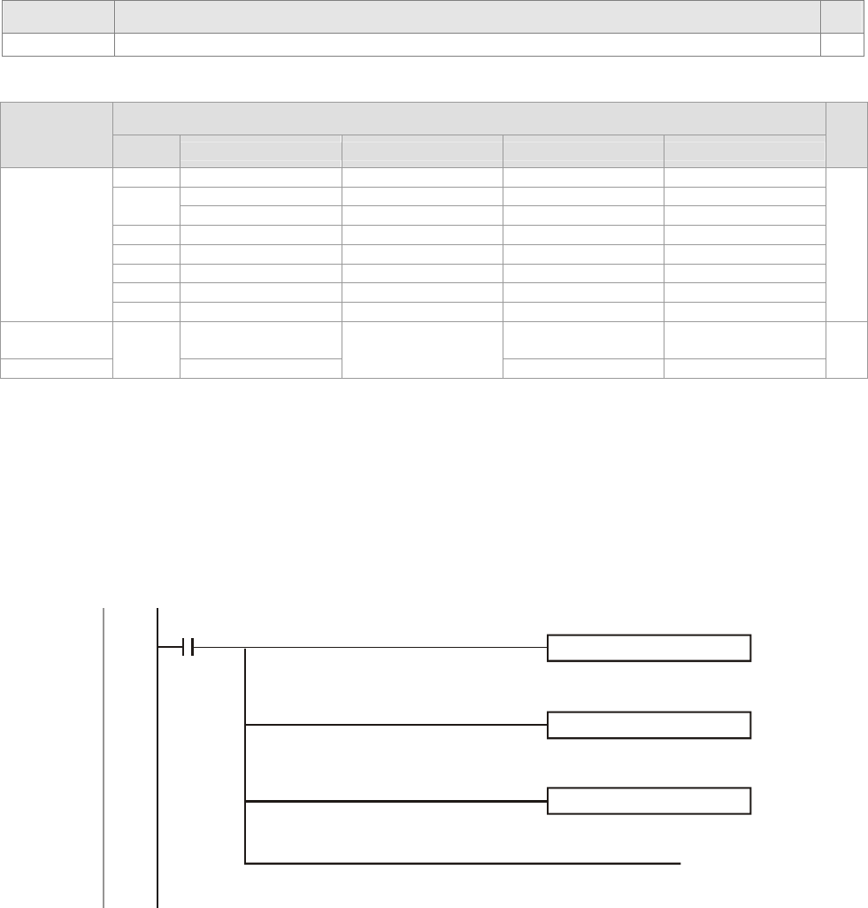
Chapter 16 PLC Function |CT2000 Series
16-97
Special D Description R/W
Slave 2, …, bit7= Slave 8)
Description
Special D Definition bit Definition bit Definition
R/W
bit
0 Frequency Attained Position Attained Torque Attained Homing Completed
Forward Run Forward Run Forward Run Forward Run
1 Reverse Run Reverse Run Reverse Run Reverse Run
2 Warning Warning Warning Warning
3 Error Error Error Error
5 JOG
6 Quick Stop Quick Stop Quick Stop Quick Stop
D1126 + 10*N
7 SERVO ON SERVO ON SERVO ON SERVO ON
RO
D1127 + 10*N Actual Frequency Actual Torque
(signed decimal) -
D1128 + 10*N
-
Actual Position
(signed decimal) - -
RO
※ N = 0 ~ 7
Example: The PLC programming diagram below shows how to use ‘Internal Communication’ to
control the frequency of Slave 1 and switches between 30.00Hz and 60.00 Hz.
Diagram 1: Detects Slave drive on-line status and check if error occurs. Then set internal
communication node 0 to the control command user wishes to control.
0M1000
MOV K1M700
D1117
Node 0 online
MOV K4M250
D1126
Node 0 arrive
MOV
Node 0 ack
(M1035)
K4M200 D1120
operation Monitoring
opening Point (a)
Internal node
Line correspondence
Internal node
Status of 0
Internal node 0
Enable internal communication control
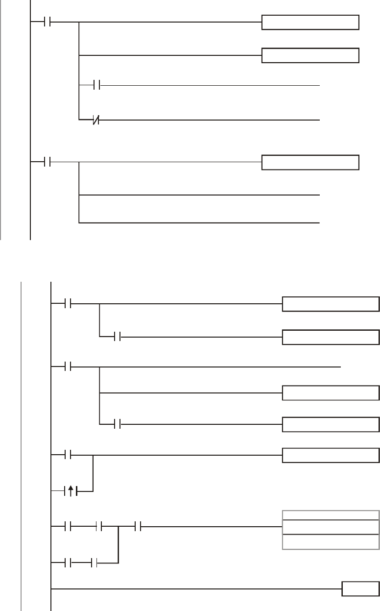
Chapter 16 PLC Function |CT2000 Series
16-98
Diagram 2: When Slave 1 on-line status is detected, it will delay for 3 seconds before control
command is enabled.
17 M700
MOVP D1121
K0
Node 0 online
TMR K30
T0
Enable Control Delay
( M100 )
Enable Control
( M215 )
Reset
Enable Control Delay
Enable Control Delay
T0
T0
M100
MOVP D1121
K0
( M207 )
Node 0 Servo On
( M200 )
Node 0 Ack
Enable Control
33
Internal node control mode
Internal node control mode
Diagram 3: Commanding Slave 1 to forward run in 30.00Hz for 1 second and reverse run in 60.00Hz
for 1 second and repeats frequency switching.
41 M300
MOV D1122
K3000
TMR K10
T10
Node 0 arrive
+30.00Hz
52 M301
MOV D1122K6000
-60.00Hz
( M200 )
Rev
TMR K10
T11
M250
M250
Node 0 arrive
64 M302
MOV K1M300
K1
Enable control
+30.00Hz
Repeat
M100
73 M300
ROLP K1
K4M300
Enable control
+30.00Hz
M301
T10 M100
T11
-60.00Hz
+30.00Hz
END
84
Reference command of Internal Node 0
Reference command of Internal Node 0
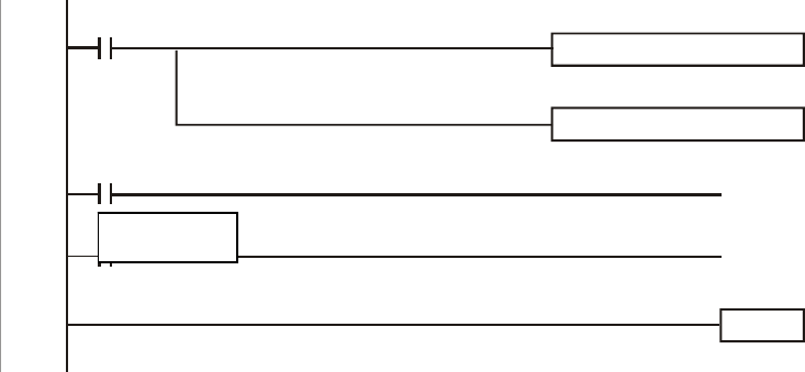
Chapter 16 PLC Function |CT2000 Series
16-99
16-11 Counting Function via MI8
The Multi-function Input Terminal (MI8) can be used for single direction Pulse counting and provides
a maximum speed of 100K. To initiate MI8 for counting, simply set M1038 to ON and the count value
will be saved to D1054 and D1055 in 32bit signed decimal. When M1039 is ON, counting value will
reset to 0.
0M1000
MOV D0
D1054
MI8 current calculating value
MOV D1
D1055
M0
(M1038)
MI8
M0
(M1039)
RESET MI8
END
11
13
15
Operation Monitoring
Opening Point (a)
MI8 current calculating value
Start counting
calculated value
※ WhenPLC program M1038 and M1039 uses MI8 for counting function, the previous AC
motor drive setting of MI8 is disabled and have no function.
改M1

Chapter 17 How to Select the Right AC Motor Drive|CT2000 Series
17-1
Chapter 17 How to Select the Right
AC Motor Drive
17-1 Capacity formula
17-2 General Precautions
17-3 How to choose a suitable motor
The choice of the right AC motor drive for the application is very important and has great influence on its
lifetime. If the capacity of AC motor drive is too large, it cannot offer complete protection to the motor and
motor maybe damaged. If the capacity of AC motor drive is too small, it cannot offer the required
performance and the AC motor drive maybe damaged due to overloading.
But by simply selecting the AC motor drive of the same capacity as the motor, user application
requirements cannot be met completely. Therefore, a designer should consider all the conditions,
including load type, load speed, load characteristic, operation method, rated output, rated speed, power
and the change of load capacity. The following table lists the factors you need to consider, depending on
your requirements.
Related Specification
Item Speed and torque
characteristics Time
ratings Overload
capacity Starting
torque
Load type
Friction load and weight
load
Liquid (viscous) load
Inertia load
Load with power
transmission
● ●
Load speed and
torque
characteristics
Constant torque
Constant output
Decreasing torque
Decreasing output
● ●
Load
characteristics
Constant load
Shock load
Repetitive load
High starting torque
Low starting torque
● ● ● ●
Continuous operation, Short-time operation
Long-time operation at medium/low speeds ● ●
Maximum output current (instantaneous)
Constant output current (continuous) ● ●
Maximum frequency, Base frequency ●
Power supply transformer capacity or
percentage impedance
Voltage fluctuations and unbalance
Number of phases, single phase protection
Frequency
● ●
Mechanical friction, losses in wiring ● ●
Duty cycle modification ●

Chapter 17 How to Select the Right AC Motor Drive|CT2000 Series
17-2
17-1 Capacity Formulas
1. When one AC motor drive operates one motor
The starting capacity should be less than 1.5x rated capacity of AC motor drive
The starting capacity=
)(_____5.1
375cos973
2kVAdrivemotorACofcapacitythe
t
NGD
T
Nk
A
L×≤
⎟
⎟
⎠
⎞
⎜
⎜
⎝
⎛×+
××
×
ϕη
2. When one AC motor drive operates more than one motor
2.1 The starting capacity should be less than the rated capacity of AC motor drive
Acceleration time 60 seconds≦
The starting capacity=
()
[]
()
)(_____5.11
cos 111 kVAdrivemotorACofcapacitythek
n
n
Pknn
Nk sCss
T
s
T×≤+=+
×
×
⎥
⎥
⎥
⎦
⎤
⎢
⎢
⎢
⎣
⎡
−−
ϕη
Acceleration time 60 seconds≧
The starting capacity=
()
[]
()
)(_____1
cos 111 kVAdrivemotorACofcapacitythek
n
n
Pknn
Nk sCss
T
s
T≤+=+
×
×
⎥
⎥
⎥
⎦
⎤
⎢
⎢
⎢
⎣
⎡
−−
ϕη
2.2 The current should be less than the rated current of AC motor drive(A)
Acceleration time 60 seconds≦
)(______5.111 AdrivemotorACofcurrentratedthek
n
n
In SM T
S
T×≤++ ⎥
⎦
⎤
⎢
⎣
⎡⎟
⎠
⎞
⎜
⎝
⎛−
Acceleration time 60 seconds≧
)(______11 AdrivemotorACofcurrentratedthek
n
n
In SM T
S
T≤++ ⎥
⎦
⎤
⎢
⎣
⎡⎟
⎠
⎞
⎜
⎝
⎛−

Chapter 17 How to Select the Right AC Motor Drive|CT2000 Series
17-3
2.3 When it is running continuously
The requirement of load capacity should be less than the capacity of AC motor drive(kVA)
The requirement of load capacity=
)(_____
cos kVAdrivemotorACofcapacitythe
Pk M≤
×
×
ϕη
The motor capacity should be less than the capacity of AC motor drive
)(_____103 3kVAdrivemotorACofcapacitytheIVk MM ≤×××× −
The current should be less than the rated current of AC motor drive(A)
)(______ AdrivemotorACofcurrentratedtheIk M≤×
Symbol explanation
M
P
: Motor shaft output for load (kW)
η : Motor efficiency (normally, approx. 0.85)
ϕ
cos : Motor power factor (normally, approx. 0.75)
MV : Motor rated voltage(V)
M
I
: Motor rated current(A), for commercial power
k : Correction factor calculated from current distortion factor (1.05-1.1, depending on PWM
method)
1CP : Continuous motor capacity (kVA)
Sk : Starting current/rated current of motor
Tn : Number of motors in parallel
Sn : Number of simultaneously started motors
2
GD : Total inertia (GD2) calculated back to motor shaft (kg m2)
L
T
: Load torque
A
t
: Motor acceleration time
N : Motor speed
Chapter 17 How to Select the Right AC Motor Drive|CT2000 Series
17-4
17-2 General Precaution
Selection Note
1. When the AC Motor Drive is connected directly to a large-capacity power transformer (600kVA or
above) or when a phase lead capacitor is switched, excess peak currents may occur in the power
input circuit and the converter section may be damaged. To avoid this, use an AC input reactor
(optional) before AC Motor Drive mains input to reduce the current and improve the input power
efficiency.
2. When a special motor is used or more than one motor is driven in parallel with a single AC Motor
Drive, select the AC Motor Drive current ≥1.25x(Sum of the motor rated currents).
3. The starting and accel./decel. characteristics of a motor are limited by the rated current and the
overload protection of the AC Motor Drive. Compared to running the motor D.O.L. (Direct On-Line),
a lower starting torque output with AC Motor Drive can be expected. If higher starting torque is
required (such as for elevators, mixers, tooling machines, etc.) use an AC Motor Drive of higher
capacity or increase the capacities for both the motor and the AC Motor Drive.
4. When an error occurs on the drive, a protective circuit will be activated and the AC Motor Drive
output is turned off. Then the motor will coast to stop. For an emergency stop, an external
mechanical brake is needed to quickly stop the motor.
Parameter Settings Note
1. The AC Motor Drive can be driven at an output frequency up to 400Hz (less for some models) with
the digital keypad. Setting errors may create a dangerous situation. For safety, the use of the
upper limit frequency function is strongly recommended.
2. High DC brake operating voltages and long operation time (at low frequencies) may cause
overheating of the motor. In that case, forced external motor cooling is recommended.
3. Motor accel./decel. time is determined by motor rated torque, load torque, and load inertia.
4. If the stall prevention function is activated, the accel./decel. time is automatically extended to a
length that the AC Motor Drive can handle. If the motor needs to decelerate within a certain time
with high load inertia that can’t be handled by the AC Motor Drive in the required time, either use
an external brake resistor and/or brake unit, depending on the model, (to shorten deceleration
time only) or increase the capacity for both the motor and the AC Motor Drive.
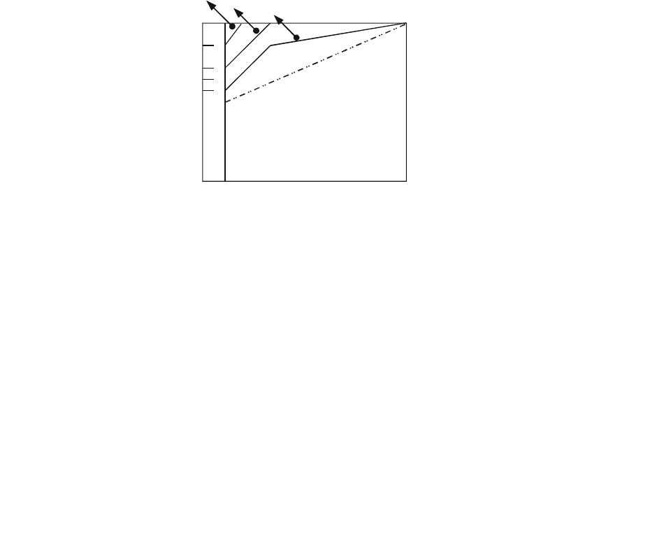
Chapter 17 How to Select the Right AC Motor Drive|CT2000 Series
17-5
17-3 How to Choose a Suitable Motor
Standard motor
When using the AC Motor Drive to operate a standard 3-phase induction motor, take the following
precautions:
1. The energy loss is greater than for an inverter duty motor.
2. Avoid running motor at low speed for a long time. Under this condition, the motor temperature may
rise above the motor rating due to limited airflow produced by the motor’s fan. Consider external
forced motor cooling.
3. When the standard motor operates at low speed for long time, the output load must be decreased.
4. The load tolerance of a standard motor is as follows:
3 6 20 60
100
82
70
60
50
0
60%
40%
25%
torque(%)
continuous
Frequency (Hz)
Load duty-cycle
5. If 100% continuous torque is required at low speed, it may be necessary to use a special inverter
duty motor.
6. Motor dynamic balance and rotor endurance should be considered once the operating speed
exceeds the rated speed (60Hz) of a standard motor.
7. Motor torque characteristics vary when an AC Motor Drive instead of commercial power supply
drives the motor. Check the load torque characteristics of the machine to be connected.
8. Because of the high carrier frequency PWM control of the VFD series, pay attention to the
following motor vibration problems:
Resonant mechanical vibration: anti-vibration (damping) rubbers should be used to mount
equipment that runs at varying speed.
Motor imbalance: special care is required for operation at 50 or 60 Hz and higher
frequency.
To avoid resonances, use the Skip frequencies.
9. The motor fan will be very noisy when the motor speed exceeds 50 or 60Hz.
Special motors:
1. Pole-changing (Dahlander) motor:
The rated current is differs from that of a standard motor. Please check before operation and
select the capacity of the AC motor drive carefully. When changing the pole number the motor
needs to be stopped first. If over current occurs during operation or regenerative voltage is too
high, please let the motor free run to stop (coast).
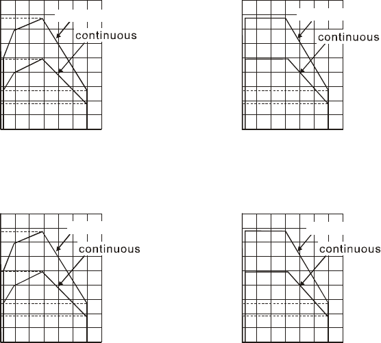
Chapter 17 How to Select the Right AC Motor Drive|CT2000 Series
17-6
2. Submersible motor:
The rated current is higher than that of a standard motor. Please check before operation and
choose the capacity of the AC motor drive carefully. With long motor cable between AC motor
drive and motor, available motor torque is reduced.
3. Explosion-proof (Ex) motor:
Needs to be installed in a safe place and the wiring should comply with the (Ex) requirements.
Delta AC Motor Drives are not suitable for (Ex) areas with special precautions.
4. Gear reduction motor:
The lubricating method of reduction gearbox and speed range for continuous operation will be
different and depending on brand. The lubricating function for operating long time at low speed
and for high-speed operation needs to be considered carefully.
5. Synchronous motor:
The rated current and starting current are higher than for standard motors. Please check before
operation and choose the capacity of the AC motor drive carefully. When the AC motor drive
operates more than one motor, please pay attention to starting and changing the motor.
Power Transmission Mechanism
Pay attention to reduced lubrication when operating gear reduction motors, gearboxes, belts and
chains, etc. over longer periods at low speeds. At high speeds of 50/60Hz and above, lifetime
reducing noises and vibrations may occur.
Motor torque
The torque characteristics of a motor operated by an AC motor drive and commercial mains power
are different.
Below you’ll find the torque-speed characteristics of a standard motor (4-pole, 15kW):
AC motor drive Motor
180
155
140
100
80
55
38
0320 60 120
60 seconds
Base freq.: 60Hz
V/F for 220V/60Hz
180
155
100
55
38
0320 60 120
torque (%)
Frequency (Hz) Frequency (Hz)
60 seconds
60 seconds
torque (%)
Base freq.: 60Hz
V/F for 220V/60Hz
130
140
100
85
45
35
0320 50 120
180
150
100
45
35
050 120
68 80
torque (%)
torque (
%
)
60 seconds 60 seconds
Frequency (Hz)
Frequency (Hz) 320
Base freq.: 50Hz
V/F for 220V/50Hz
Base freq.: 50Hz
V/F for 220V/50Hz

Chapter 18 Suggestions and Error Corrections for Standard AC Motor Drives |CT2000 Series
18-1
Chapter 18 Suggestions and Error
Corrections for Standard AC Motor Drives
18-1 Maintenance and Inspections
18-2 Greasy Dirt Problem
18-3 Fiber Dust Problem
18-4 Erosion Problem
18-5 Industrial Dust Problem
18-6 Wiring and Installation Problem
18-7 Multi-function Input/Output Terminals Problem
The AC motor drive has a comprehensive fault diagnostic system that includes several different alarms
and fault messages. Once a fault is detected, the corresponding protective functions will be activated.
The following faults are displayed as shown on the AC motor drive digital keypad display. The six most
recent faults can be read from the digital keypad or communication.
The AC motor drive is made up by numerous components, such as electronic components, including IC,
resistor, capacity, transistor, and cooling fan, relay, etc. These components can’t be used permanently.
They have limited-life even under normal operation. Preventive maintenance is required to operate this
AC motor drive in its optimal condition, and to ensure a long life.
Check your AC motor drive regularly to ensure there are no abnormalities during operation and follows
the precautions:
; Wait 5 seconds after a fault has been cleared before performing reset via keypad of
input terminal.
; When the power is off after 5 minutes for ≦ 22kW models and 10 minutes for ≧
30kW models, please confirm that the capacitors have fully discharged by
measuring the voltage between + and -. The voltage between + and - should be less
than 25VDC.
; Only qualified personnel can install, wire and maintain drives. Please take off any
metal objects, such as watches and rings, before operation. And only insulated tools
are allowed.
; Never reassemble internal components or wiring.
; Make sure that installation environment comply with regulations without abnormal
noise, vibration and smell.

Chapter 18 Suggestions and Error Corrections for Standard AC Motor Drives |CT2000 Series
18-2
18-1 Maintenance and Inspections
Before the check-up, always turn off the AC input power and remove the cover. Wait at least 10
minutes after all display lamps have gone out, and then confirm that the capacitors have fully
discharged by measuring the voltage between DC+ and DC-. The voltage between DC+ and
DC-should be less than 25VDC.
Ambient environment
Maintenance
Period
Check Items Methods and Criterion
Daily Half
Year One
Year
Check the ambient temperature, humidity,
vibration and see if there are any dust, gas,
oil or water drops
Visual inspection and
measurement with equipment
with standard specification
○
If there are any dangerous objects Visual inspection ○
Voltage
Maintenance
Period
Check Items Methods and Criterion
Daily Half
Year One
Year
Check if the voltage of main circuit and
control circuit is correct
Measure with multimeter with
standard specification
○
Digital Keypad Display
Maintenance
Period
Check Items Methods and Criterion
Daily Half
Year One
Year
Is the display clear for reading Visual inspection ○
Any missing characters Visual inspection ○
Mechanical parts
Maintenance
Period
Check Items Methods and Criterion
Daily Half
Year One
Year
If there is any abnormal sound or vibration Visual and aural inspection ○
If there are any loose screws Tighten the screws ○
If any part is deformed or damaged Visual inspection ○
If there is any color change by overheating Visual inspection ○
If there is any dust or dirt Visual inspection ○

Chapter 18 Suggestions and Error Corrections for Standard AC Motor Drives |CT2000 Series
18-3
Main circuit
Maintenance
Period
Check Items Methods and Criterion
Daily Half
Year One
Year
If there are any loose or missing screws Tighten or replace the screw ○
If machine or insulator is deformed, cracked,
damaged or with color change due to
overheating or ageing
Visual inspection
NOTE: Please ignore the
color change of copper
plate
○
If there is any dust or dirt Visual inspection ○
Terminals and wiring of main circuit
Maintenance
Period
Check Items Methods and Criterion
Daily Half
Year One
Year
If the terminal or the plate is color change or
deformation due to overheat Visual inspection ○
If the insulator of wiring is damaged or color
change Visual inspection ○
If there is any damage Visual inspection ○
DC capacity of main circuit
Maintenance
Period
Check Items Methods and Criterion
Daily Half
Year One
Year
If there is any leak of liquid, color change,
crack or deformation Visual inspection ○
If the safety valve is not removed? If valve is
inflated? Visual inspection ○
Measure static capacity when required ○
Resistor of main circuit
Maintenance
Period
Check Items Methods and Criterion
Daily Half
Year One
Year
If there is any peculiar smell or insulator
cracks due to overheat Visual inspection, smell ○
If there is any disconnection Visual inspection ○
If connection is damaged? Measure with multimeter with
standard specification
○

Chapter 18 Suggestions and Error Corrections for Standard AC Motor Drives |CT2000 Series
18-4
Transformer and reactor of main circuit
Maintenance
Period
Check Items Methods and Criterion
Daily Half
Year One
Year
If there is any abnormal vibration or peculiar
smell
Visual, aural inspection and
smell ○
Magnetic contactor and relay of main circuit
Maintenance
Period
Check Items Methods and Criterion
Daily Half
Year One
Year
If there are any loose screws Visual and aural inspection ○
If the contact works correctly Visual inspection ○
Printed circuit board and connector of main circuit
Maintenance
Period
Check Items Methods and Criterion
Daily Half
Year One
Year
If there are any loose screws and connectors
Tighten the screws and
press the connectors firmly
in place.
○
If there is any peculiar smell and color change Visual and smell inspection ○
If there is any crack, damage, deformation or
corrosion Visual inspection ○
If there is any liquid is leaked or deformation in
capacity Visual inspection ○
Cooling fan of cooling system
Maintenance
Period
Check Items Methods and Criterion
Daily Half
Year One
Year
If there is any abnormal sound or vibration
Visual, aural inspection and
turn the fan with hand (turn
off the power before
operation) to see if it rotates
smoothly
○
If there is any loose screw Tighten the screw ○
If there is any color change due to overheat Change fan ○

Chapter 18 Suggestions and Error Corrections for Standard AC Motor Drives |CT2000 Series
18-5
Ventilation channel of cooling system
Maintenance
Period
Check Items Methods and Criterion
Daily Half
Year One
Year
If there is any obstruction in the heat sink, air
intake or air outlet Visual inspection ○
NOTE
Please use the neutral cloth for clean and use dust cleaner to remove dust when necessary.
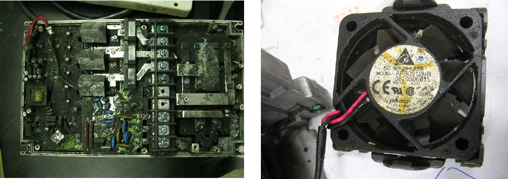
Chapter 18 Suggestions and Error Corrections for Standard AC Motor Drives |CT2000 Series
18-6
18-2 Greasy Dirt Problem
Serious greasy dirt problems generally occur in processing industries such as machine tools,
punching machines and so on. Please be aware of the possible damages that greasy oil may cause
to your drive:
1. Electronic components that silt up with greasy oil may cause the drive to burn out or even
explode.
2. Most greasy dirt contains corrosive substances that may damage the drive.
Solution:
Install the AC motor drive in a standard cabinet to keep it away from dirt. Clean and remove greasy
dirt regularly to prevent damage of the drive.
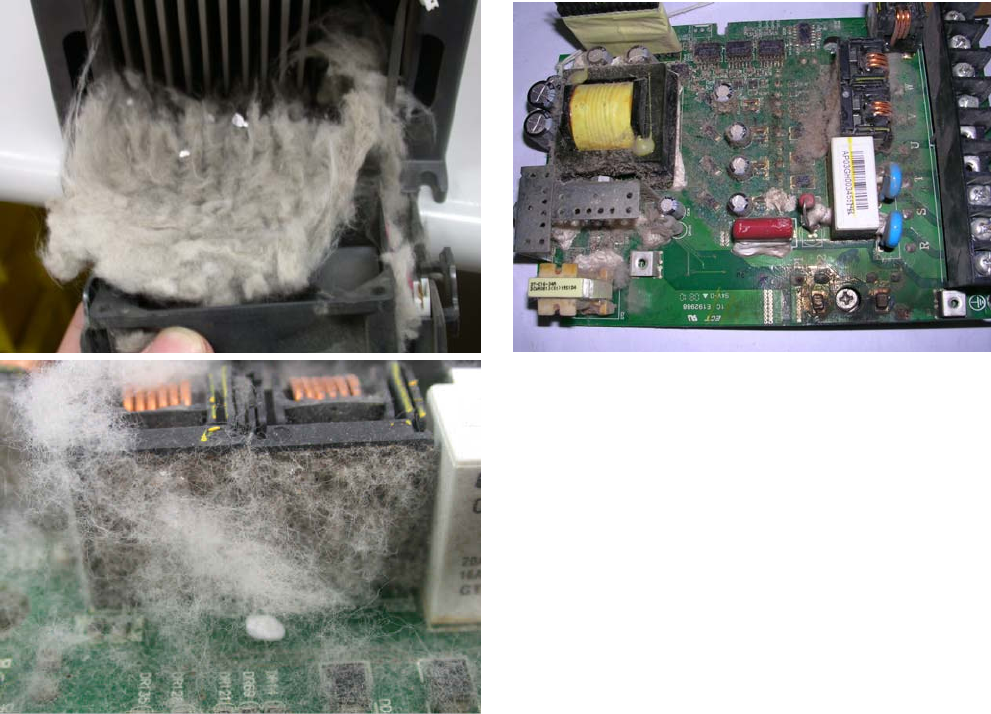
Chapter 18 Suggestions and Error Corrections for Standard AC Motor Drives |CT2000 Series
18-7
18-3 Fiber Dust Problem
Serious fiber dust problems generally occur in the textile industry. Please be aware of the possible
damages that fiber may cause to your drives:
1. Fiber that accumulates or adheres to the fans will lead to poor ventilation and cause
overheating problems.
2. Plant environments in the textile industry have higher degrees of humidity that may cause the
drive to burn out, become damaged or explode due to wet fiber dust adhering to the devices.
Solution:
Install the AC motor drive in a standard cabinet to keep it away from fiber dust. Clean and remove
fiber dust regularly to prevent damage to the drive.
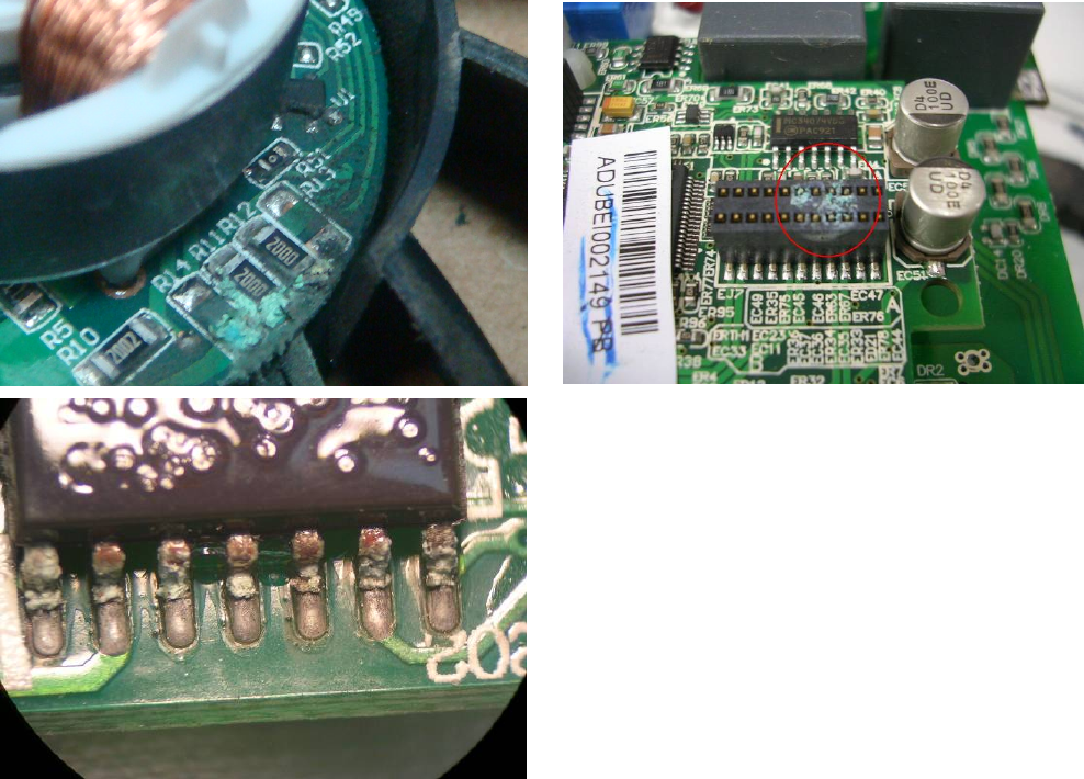
Chapter 18 Suggestions and Error Corrections for Standard AC Motor Drives |CT2000 Series
18-8
18-4 Erosion Problem
Erosion problems may occur if any fluids flow into the drives. Please be aware of the damages that
erosion may cause to your drive.
1. Erosion of internal components may cause the drive to malfunction and possibility to explode.
Solution:
Install the AC motor drive in a standard cabinet to keep it away from fluids. Clean the drive regularly
to prevent erosion.
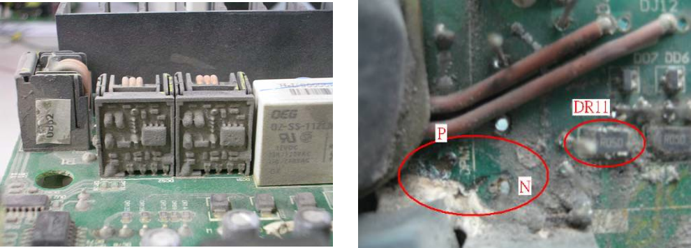
Chapter 18 Suggestions and Error Corrections for Standard AC Motor Drives |CT2000 Series
18-9
18-5 Industrial Dust Problem
Serious industrial dust pollution frequently occurs in stone processing plants, flour mills, cement
plants, and so on. Please be aware of the possible damage that industrial dust may cause to your
drives:
1. Dust accumulating on electronic components may cause overheating problem and shorten the
service life of the drive.
2. Conductive dust may damage the circuit board and may even cause the drive to explode.
Solution:
Install the AC motor drive in a standard cabinet and cover the drive with a dust cover. Clean the
cabinet and ventilation hole regularly for good ventilation.
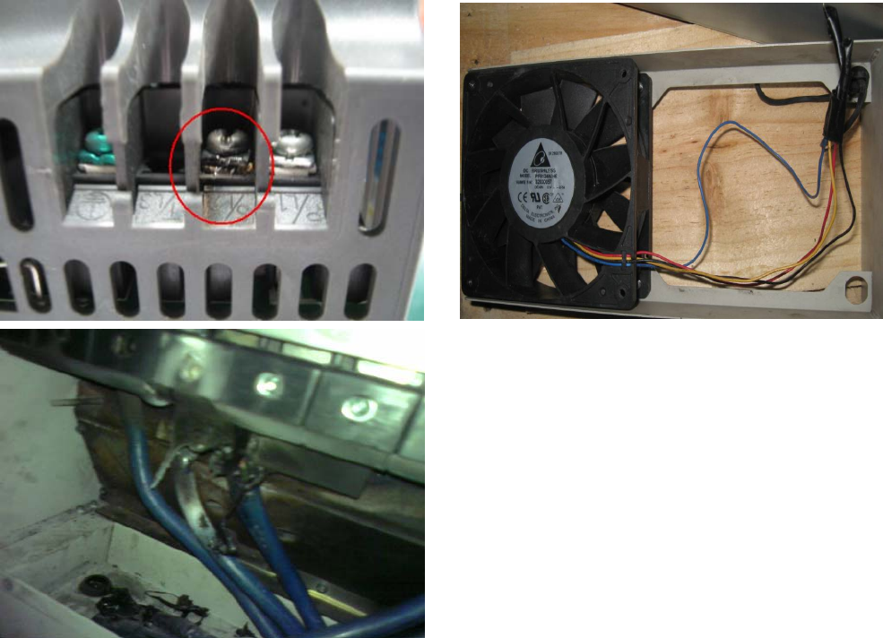
Chapter 18 Suggestions and Error Corrections for Standard AC Motor Drives |CT2000 Series
18-10
18-6 Wiring and Installation Problem
When wiring the drive, the most common problem is wrong wire installation or poor wiring. Please be
aware of the possible damages that poor wiring may cause to your drives:
1. Screws are not fully fastened. Occurrence of sparks as impedance increases.
2. If a customer has opened the drive and modified the internal circuit board, the internal
components may have been damaged.
Solution:
Ensure all screws are fastened when installing the AC motor drive. If the AC motor drive functions
abnormally, send it back to the repair station. DO NOT try to reassemble the internal components or
wire.
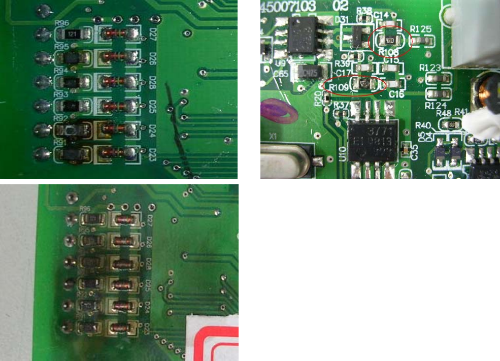
Chapter 18 Suggestions and Error Corrections for Standard AC Motor Drives |CT2000 Series
18-11
18-7 Multi-function Input/Output Terminals Problem
Multi-function input/output terminal errors are generally caused by over usage of terminals and not
following specifications. Please be aware of the possible damages that errors on multi-function
input/output terminals may cause to your drives:
1. Input/output circuit may burns out when the terminal usage exceeds its limit.
Solution:
Refer to the user manual for multi-function input output terminals usage and follow the specified
voltage and current. DO NOT exceed the specification limits.
