TUB 2765 SHS Welded Joints Design Of Structual Hollow Sections
User Manual: Design of Structual Hollow Sections Welded Joints
Open the PDF directly: View PDF ![]() .
.
Page Count: 48

Corus Tubes
Design of SHS welded joints
Structural & Conveyance Business

01 Design of SHS welded joints
Contents
1 Introduction 02
1.1 Product specification 03
2 Scope 04
2.1 Joint geometry 04
2.2 Material 06
2.3 Multiplanar joints 06
2.4 Load and moment interaction 07
3 General design guidance 08
3.1 Structural analysis 08
3.2 Welding 09
3.3 Fabrication 11
4 Parameters affecting joint capacity 13
4.1 General 13
4.2 Joint failure modes 13
4.3 Joints with a single bracing 15
4.4 Joints with a gap between bracings 16
4.5 Joints with cverlapped bracings 16
4.6 Joint reinforcement 17
5 Joint design formulae 20
5.1 CHS chord joints 20
5.2 RHS chord joints 25
5.3 Special joints in RHS 30
5.4
I
- or H- section chord joints 32
6 Design examples 35
6.1 Girder layout and member loads 35
6.2 Design philosophy 36
6.3 RHS girder design 36
6.4 CHS girder design 39
7 List of symbols 43
7.1 General alphabetic list 43
7.2 Pictorial list 44
8 References 45
Design of SHS
welded joints

Design of SHS welded joints 02
1. Introduction
In construction with structural hollow sections the members are generally
welded directly to each other and, as a result, member sizing has a direct
effect on both the joint capacity and the cost of fabrication. In order to obtain
a technically secure, economic and architecturally pleasing structure, both
the architect and design engineer must, from the very beginning, be aware of
the effects that their design decisions will have on the joint capacity, the
fabrication, assembly and the erection of the structure.
Structural hollow sections have a higher strength to weight ratio than open
section profiles such as
I
-, H- and L- sections. They also require a much
smaller weight of protection material, whether this is a fire protection or
corrosion coating, because of their lower external area.
A properly designed steel construction using structural hollow sections will
nearly always be lighter in terms of material weight than a similar construction
made with open section profiles and, although structural hollow sections are
more expensive than open section profiles on a per tonne basis, the overall
weight saving of steel and protective coatings will very often result in a much
more cost effective construction.
This publication has been produced to show how the joint capacity of
staticaly loaded joints can be calculated and how it can be affected by both
the geometric layout and the sizing of the members.
Considerable international research into the behaviour of structural hollow
section (SHS) welded joints for lattice type constructions has enabled
comprehensive design recommendations to be developed which embrace
the large majority of manufactured structural hollow sections.
These design recommendations have been developed by CIDECT (Comité
International pour la Développement et l'Étude de la Construction Tubulaire)
and the IIW (International Institute of Welding) and, as a result, have gained
considerable international recognition and acceptance. They have been used
in a series of CIDECT Design Guides [1,2] and are now incorporated into
Eurocode 3 : Annex K.[3]
The joint capacity formulae, reproduced in section 5, were developed and are
presented in a limit states form and are therefore fully compatible with the
requirements of BS 5950 : Part 1 [4] and Eurocode 3.
A software program [5], called CIDJOINT, has been developed by CIDECT for
the design of most of the joints described in this design publication. The
CIDJOINT design program requires MS-Windows version 3.x (or higher).
The design recomendations can be used with Corus Tubes Celsius®hot
finished hollow sections to EN 10219 [6, 7], cold formed Hybox®355 hollow
sections to EN 10219 [8, 9] and cold formed Strongbox®235 hollow sections
to Corus Tubes specification TS30 [10]
03 Design of SHS welded joints
1.1 Production specification
Corus Tubes produces four types of hollow section: Celsius® 275, Celsius® 355,
Hybox®355 and Strongbox®235.
Celsius®hot finished structural hollow sections are produced by the Corus Tubes Structural
& Conveyance Business. They are availble in two grades Celsius®275 and Celsius®355,
which fully comply with EN 10210 S275J2H and EN 10210 S355J2H respectively. All
Celsius®hot finished structural hollow sections have an improved corner profile of 2T
maximum. For full details see Corus Tubes publication CTO6.
Hybox®355 and Strongbox®235 cold formed hollow sections are produced by Corus
Tubes Cold Form Business. Hybox® 355 fully complies with EN 10219 S355J2H.
Strongbox®235 is in accordance with the Corus Tubes publication CTO5. The chemical
composition and mechanical properties of these products, are given below.
Note: For Strongbox®235, reduced section properties and thickness applies.
All thicknesses used in the design formulae and calculations are nominal, except for
Strongbox®235 which should use 0.9tnom or (tnom-0.5mm) whichever is the larger.
Chemical composition
Cold formed hollow sections Hot finished hollow sections
Strongbox®235 Hybox®355 Celsius® 275 Celsius® 355
Specification TS 30 (1) EN 10219 355J2H EN 10210 275J2H EN 10210 355J2H
C % max 0.17 0.22 0.20 0.22
Si % max - 0.55 - 0.55
Mn % max 1.40 1.60 1.50 1.60
P % max 0.045 0.035 0.035 0.035
S % max 0.045 0.035 0.035 0.035
Ni % max 0.009 - - -
CEV % t ≤16mm 0.35 0.45 0.41 0.45
(1) Corus Tubes specification TS 30, generally in accordance with EN 10219 235JRH.
Mechanical properties
Cold formed hollow sections Hot finished hollow sections
Strongbox®235 Hybox®355 Celsius® 275 Celsius® 355
Specification TS 30 (1) EN 10219 355J2H EN 10210 275J2H EN 10210 355J2H
Tensile strength Rm N/mm2
t < 3mm 340 min 510-680 430-580 510-680
3 < t ≤40mm 490-630 410-560 490-630
Yeild strength Rehmin N/mm2
t ≤16mm 235 355 275 355
t > 16mm - - - 345
Min Elongation %
Lo=5.65 √S0t ≤40mm 24(2)(3) 20(2)(3) 22 22
Impact properties
Min Ave energy (J) - 27 @ -20ºC 27 @ -20ºC 27 @ -20ºC
10 x 10 specimen
(1) Corus Tubes specification TS 30, generally in accordance with EN 10219 235JRH excluding
upper tensile limit and mass tolerance.
(2) 17% min for sizes 60 x 60, 80 x 40 and 76.1mm and below.
(3) Valve to be agreed for t< 3mm
Design of SHS welded joints 04
2 Scope
This publication has been written mainly for plane frame girder joints under predominantly static axial
and/or moment loading conditions, however, some advice on non-planar frame joints is also given.
Note: In calculations this publication uses the convention that tensile forces and stresses are positive
(+) and compressive ones are negative (-).
2.1 Joint geometry
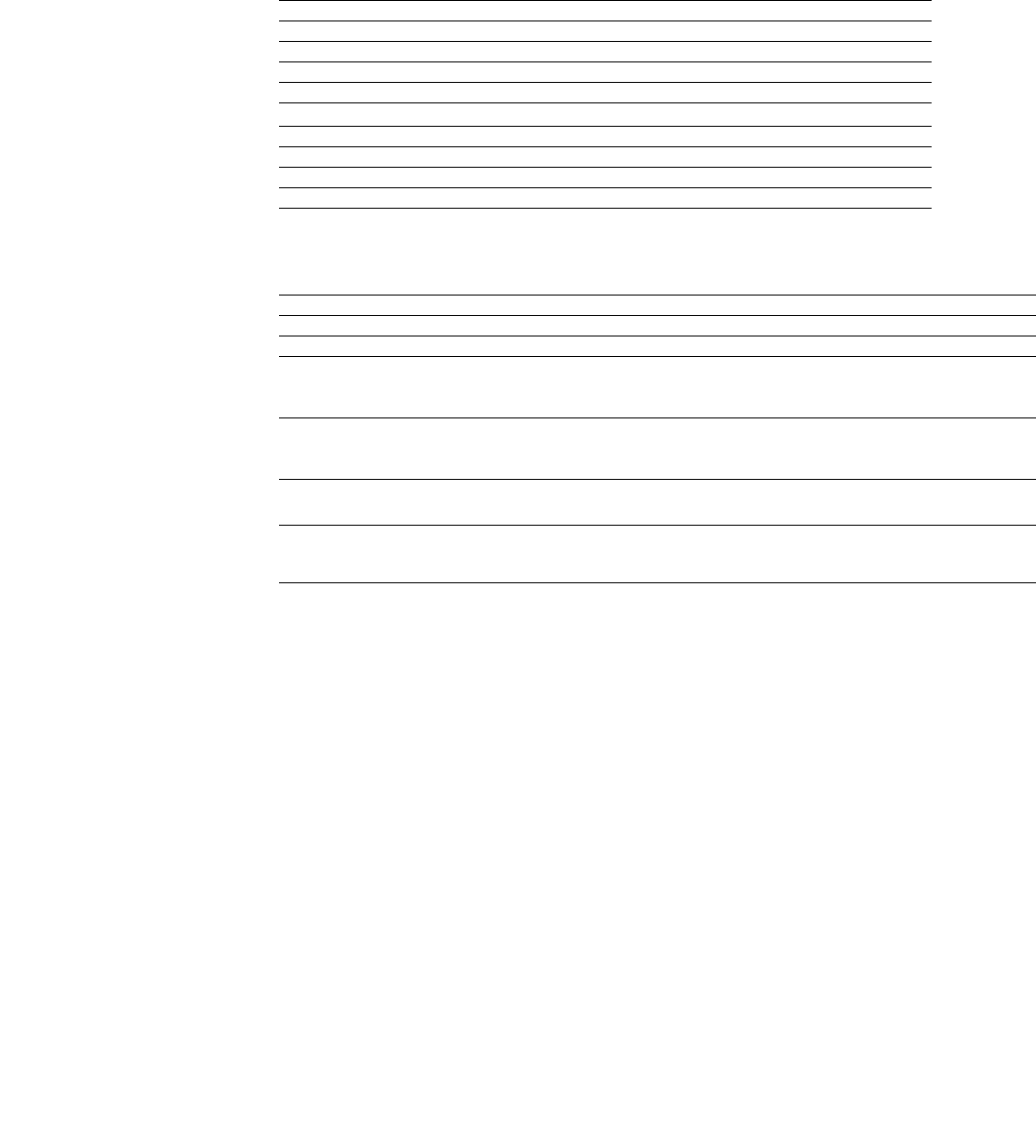
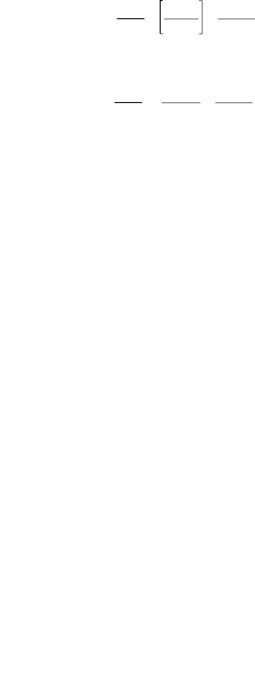
The main types of joint configuration covered in this publication are shown in figure 1, however, other
types of connections to structural hollow section main members, such as fin plates and cross plates,
are also discussed.
Figure 1 : Joint geometries
The angle between the chord and a bracing or between two bracings should be between 30º and 90º
inclusive. If the angle is less than 30º then :
1. the designer must ensure that a structurally adequate weld can be made in the acute angle.
and 2. any joint capacity calculation should be made using an angle of 30º instead of the actual angle.
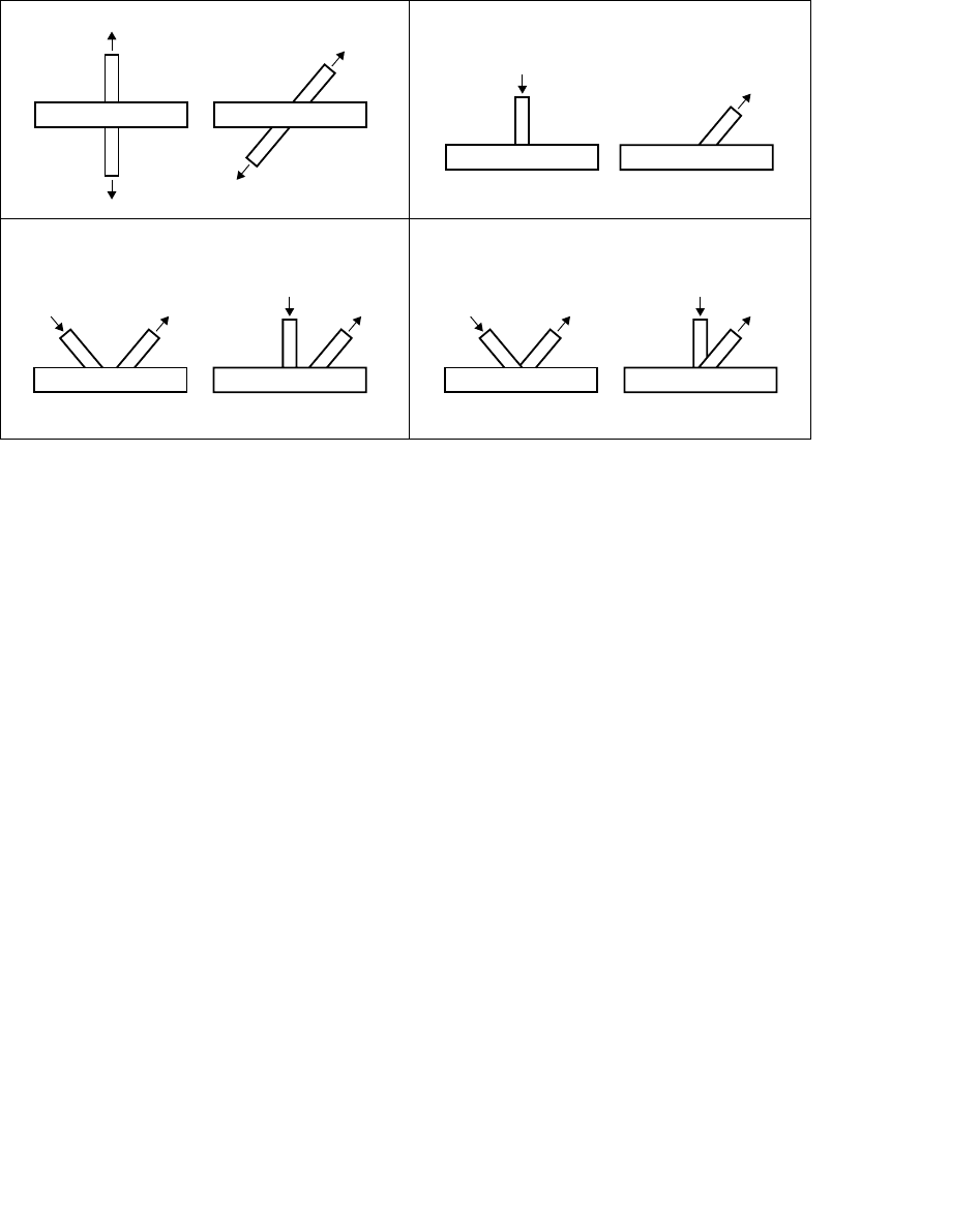
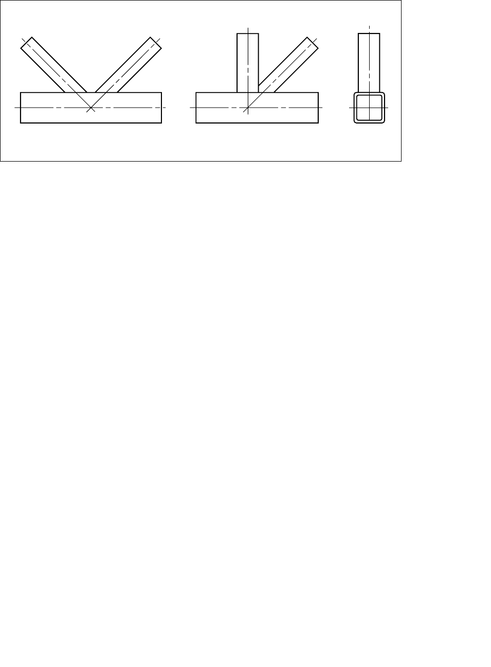
When K- or N-joints with overlapping bracings are being used, the overlap must be made with the first
bracing running through to the chord and the second bracing either sitting on both the chord and the
first bracing (partial overlap) or sitting fully on the first bracing (fully overlapped) as shown in (figure 2a).
The joint should never be made by cutting the toes from each bracing and butting them up together
(figure 2b), because this is both more difficult to fit together satisfactorily and, more importantly, can
result in joint capacities up to 20% lower than those calculated by the joint design formulae given in
section 5. A modified version of the type of joint shown in (figure 2b) can, however, be used provided
that a plate of sufficient thickness is inserted between the two bracings - see section 4.6.3 on RHS
chord overlap joint reinforcement.
X-joints T-and Y-joints
K-and N-joints with gap K-and N-joints with overlap
05 Design of SHS welded joints
Figure 2 : Method of overlapping bracings
2.1.1 Validity ranges
In section 5 validity ranges are given for various geometric parameters of the joints. These validity
ranges have been set to ensure that the modes of failure of the joints fall within the experimentally
proven limits of the design formulae. If joints fall outside of these limits other failure modes, not covered
by the formulae, may become critical. As an example, no check is required for chord shear in the gap
between the bracings of CHS K- and N-joints, but this failure mode could become critical outside the
validity limits given.
However, in general, if just one of these validity limits is slightly violated, and all of the joint’s other
geometric parameters are well inside the limits, then we would suggest that the actual joint capacity
should be reduced to about 0.85 times the capacity calculated using the design formulae.
2.1.2 Joint symbols
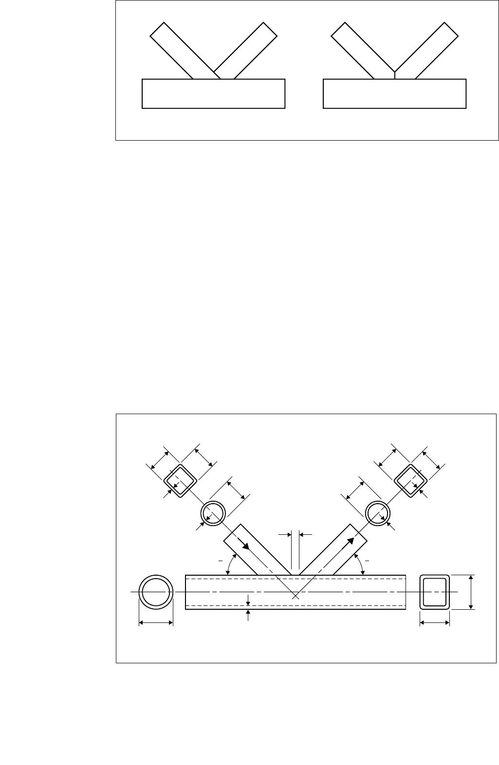
A list of all the symbols used in this publication is given in section 7, however the main geometric
symbols for the joint are shown below in figure 3.
Figure 3 : Joint geometric symbols
a) Correct method b) Incorrect method
h1b1
d1
d0b0
h0
t1
t1
t0
b2h2
d2
t2
t2
0102
g
Design of SHS welded joints 06
2.2 Material
The design formulae, given in section 5, have only been verified experimentally for SHS material with a
maximum nominal yield strength of 355N/mm2. Care should be taken if materials with higher nominal
yield strengths than this are used, since it is possible that, in some circumstances, deformations could
become excessive and critical to the integrity of the structure.
All dimensions used in the design formulae and parameter limits are nominal, except for
Strongbox®235 thicknesses which should use 0.9tnom or (tnom -0.5mm) whichever is the larger.
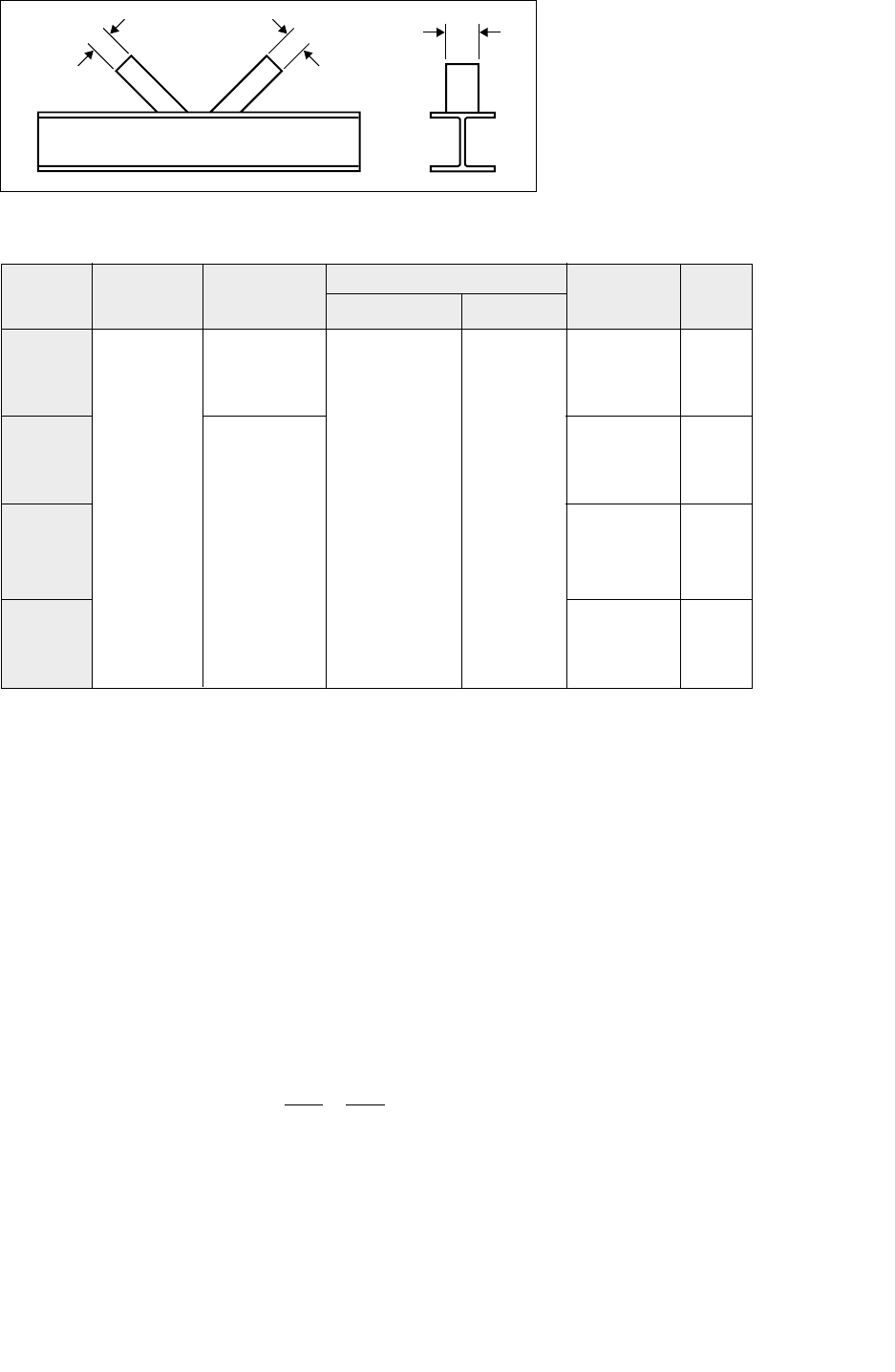
2.3 Multiplanar joints
Multiplanar joints, such as those found in triangular and box girders, can be designed using the same
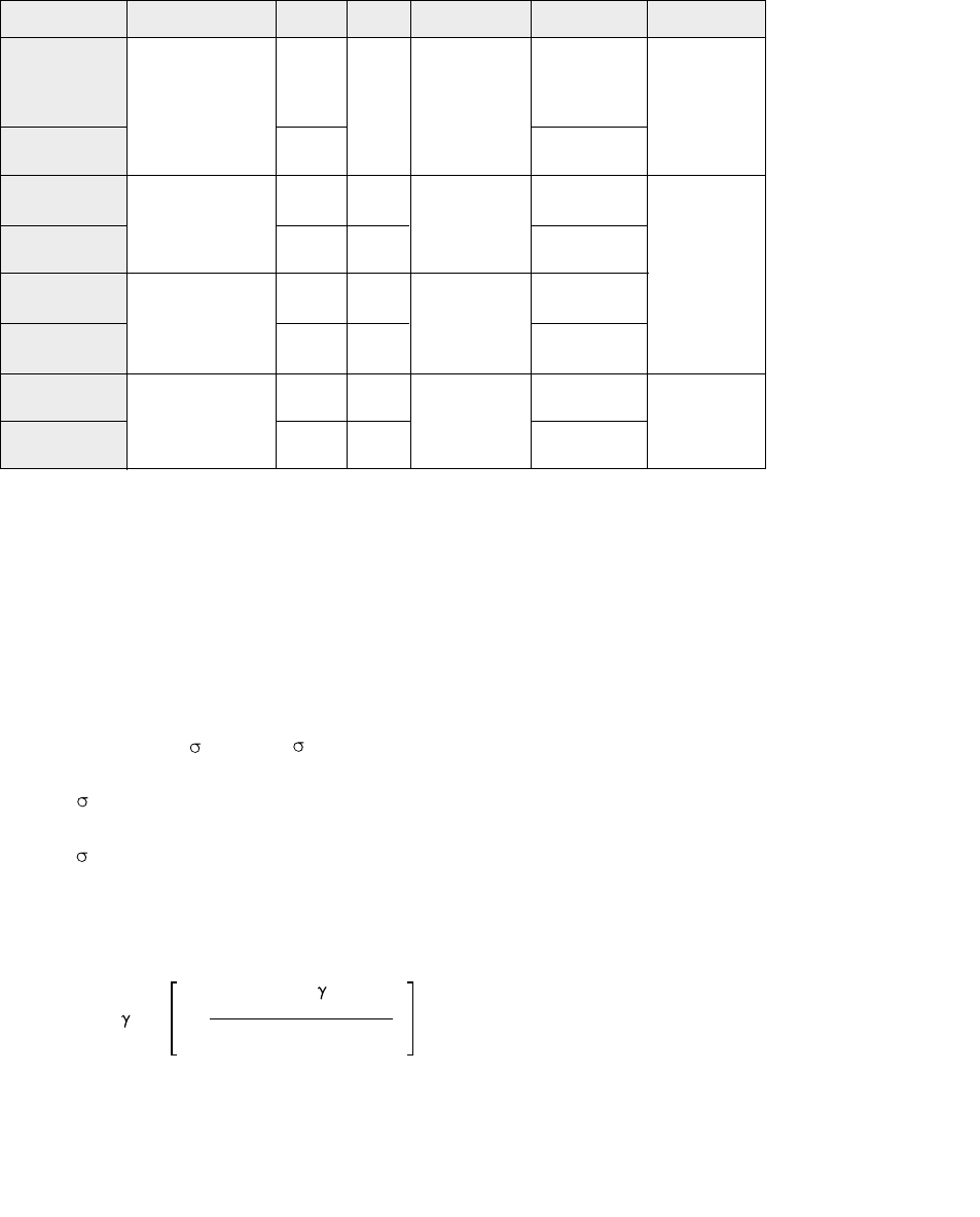
design formulae as for planar joints, but with the multiplanar factor, µ, given in table 1, applied to the
calculated chord face deformation capacity. The factors shown in table 1 have been determined for
angles between the planes of 60º to 90º.
Additionally the chord must be checked for the combined shear from the two sets of bracings.
Table 1 : Multiplanar factors
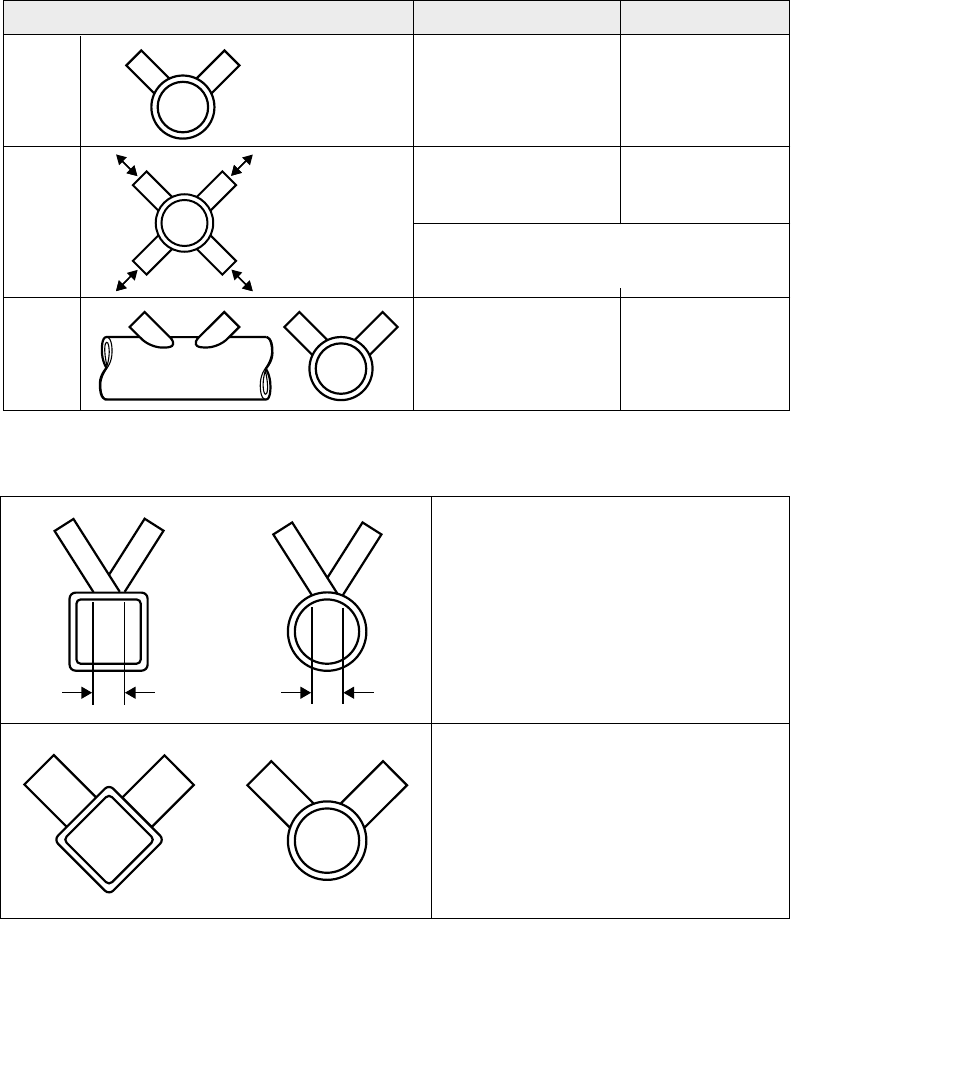
To determine if a joint should be considered to be a multiplanar joint or a planar joint refer to figure 4
Figure 4 : Multiplanar joints
Joint type CHS chords RHS chords
TT-
joint
XX-
joint
KK-
joint
XX
µ = 1.0 µ = 0.9
µ = 0.9
µ = 0.9
Design as a plane frame joint and
resolve bracing axial capacity into
the two planes.
RHS bracing - replace biwith X
CHS bracings - replace diwith lesser
of door an equivalent CHS bracing
having the same perimeter as the
combined bracing footprint perimeter.
Design as a planar joint and multiply
by the relevent multiplaner factor
from table 1
µ=1+0.33(N2,App/N1,App)
taking account of the sign (+ or -) and with
lN2,Appl≤lN1,Appl
µ=0.9(1+0.33
(N2,App/N1,App))
N1N2
N2N1
07 Design of SHS welded joints
2.4 Load and moment interaction
If primary bending moments as well as axial loads are present in the bracings at a connection then the
interaction effects of one on the other must be taken into account. Annex K of Eurocode No. 3 gives
the following interaction formulae
For CHS chord joints the interaction formula is :-
For RHS chord joints the interaction formula is :-
For
I-
and H- chord joints:-
use RHS interaction formula above.
Ni,App Mip,i,App 2Mop,i,App
+ + ≤1.0
Ni Mip,i Mop,i
Ni,App Mip,i,App Mop,i,App
+ + ≤1.0
Ni Mip,i Mop,i
Design of SHS welded joints 08
3 General design guidance
3.1 Structural analysis
Lattice structures have traditionally been designed on the basis of pin-jointed frames with their
members in tension or compression and the loads noding (meeting at a common point) at the centre of
each joint. The usual practice is to arrange the joint so that the centre line of the bracing members
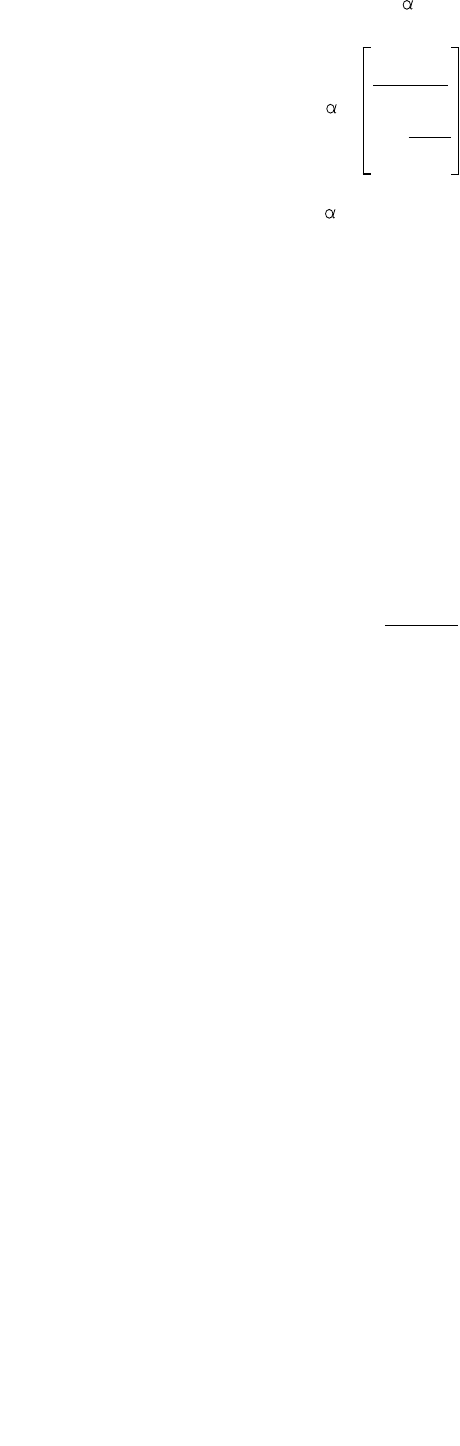
intersect on the centre line of the chord member, as shown in figure 5.
Figure 5 : Noding joints
The member sizes are determined in the normal way to carry the design loads and the welds at the
joint to transfer the loads in the members. However, a lattice girder constructed using structural hollow
sections is almost always welded, with one element welded directly to the next, e.g. bracing to chord.
This means that the sizing of the members has a direct effect on the actual capacity of the joint being
made. It is therefore imperative, if a structurally efficient and cost effective design is to result, that the
member sizes and thicknesses are selected in such a way that they do not compromise the capacity
of the joint. This is explained further in section 4.
While the assumption of centre line noding and pinned connections enables a good approximation of
the axial forces in the members to be obtained, clearly in a real girder with continuous chords and
welded connections, bending moments will be introduced into the chord members due to the inherent
stiffness of the joints. In addition, in order to achieve the desired gap or overlap conditions between the
bracings it may be necessary to depart from the noding conditions.
Many of the tests that have been carried out on welded joints, to derive the joint design
recommendations, have incorporated noding eccentricities (see figure 6), some as large as ±d0/2 or
±h0/2.
09 Design of SHS welded joints
e > 0
e < 0
a) gap joint with positive eccentricity b) overlap joint with negative eccentricity
Figure 6 : Definition of joint eccentricity
The effects of moments due to the joint stiffness, for joints within the parameter limits given in section
5, and noding eccentricities, within the limits given below, are automatically taken into account in the
joint design formulae given in section 5. It is good practice, however, to keep noding eccentricities to a
minimum, particularly if bracings node outside the chord centre line (positive eccentricity, figure 6 a).
The joint design formulae in section 5 should be used for eccentricities within the limits given below.
-0.55 (d0or h0) ≤e ≤+0.25 (d0or h0)
The effect of eccentricities outside these limits should be checked with reference to section 2.4 with
the moments due to the eccentricity being taken into account. In most instances, the chords will be
very much stiffer than the bracings and any moment, generated by the eccentricities, can be
considered as being equally distributed to each side of the chord.
3.2 Welding
Only the main points regarding welding of structural hollow section lattice type joints are given here.
More detailed information on welding methods, end preparation, weld strengths, weld types, weld
design, etc. is given in reference 13.
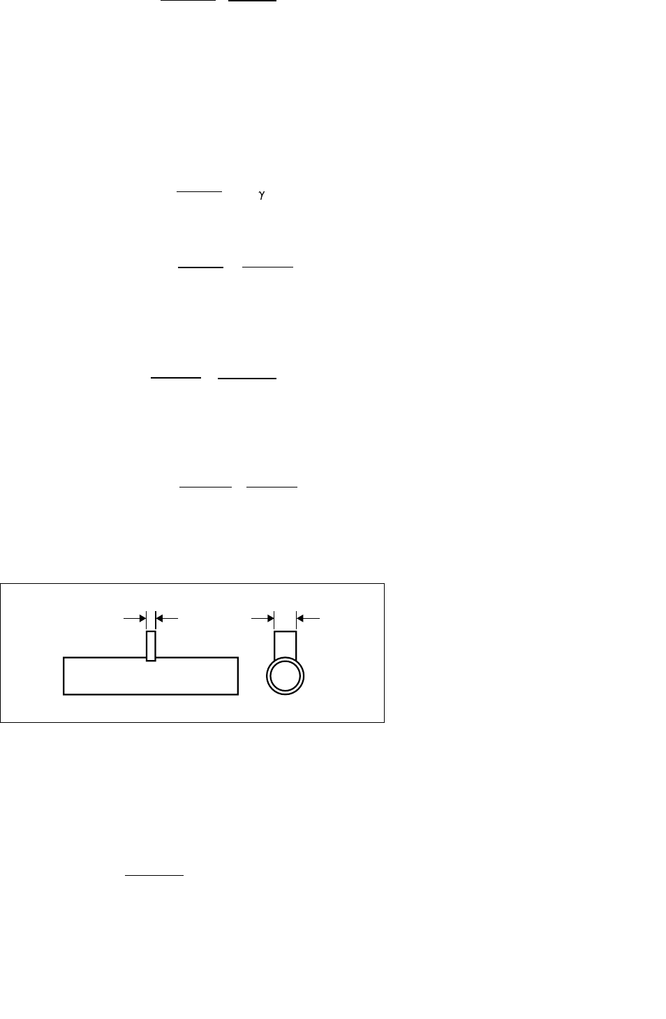
When a bracing member is under load, a non-uniform stress distribution is set up in the bracing close
to the joint, see figure 7, and therefore, the welds connecting the bracing to the chord must be
designed to have sufficient resistance to allow for this non-uniformity of stress.
The weld should normally be made around the whole perimeter of the bracing by means of a butt
weld, a fillet weld or a combination of the two. However, in partially overlapped bracing joints the
hidden part of the connection need not be welded provided that the bracing load components
perpendicular to the chord axis do not differ by more than 20%. In the case of 100% overlap joints the
toe of the overlapped bracing must be welded to the chord. In order to acheive this, the overlap may
be increased to a maximum of 110% to allow the toe of the overlapped bracing to be welded
satisfactorily to the chord.
Design of SHS welded joints 10
t
a
Figure 7 : Typical localised stress distribution at a joint
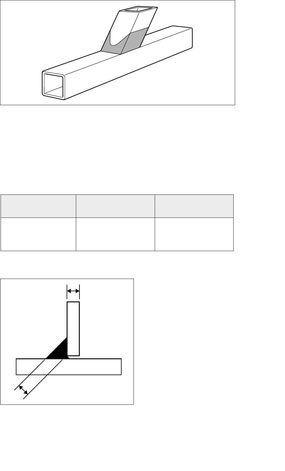
For bracing members in a lattice construction, the design resistance of a fillet weld should not normally
be less than the design resistance of the member. This requirement will be satisfied if the throat size (a)
is at least equal to or larger than the values shown in table 2, provided that electrodes of an equivalent
strength grade to the steel, in terms of both yield and tensile strength, are used, see also figure 8.
The requirements of table 2 may be waived where a smaller weld size can be justified with regard to
both resistance and deformational / rotational capacity, taking account of the possibility that only part
of the weld's length may be effective.
Steel grade Minimum throat Electrode grade
size, a mm EN 499
Celsius®275 0.94 x t* E35 2 xxxx
Celsius® 355 1.09 x t* E42 2 xxxx
Strongbox®235 0.91 x t* E35 2 xxxx
Hybox® 355 1.09 x t* E42 2 xxxx
* see figure 8
Table 2 : Prequalified Weld Throat Size
Figure 8 : Weld throat thickness
11 Design of SHS welded joints
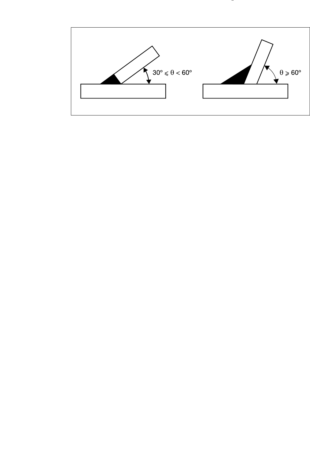
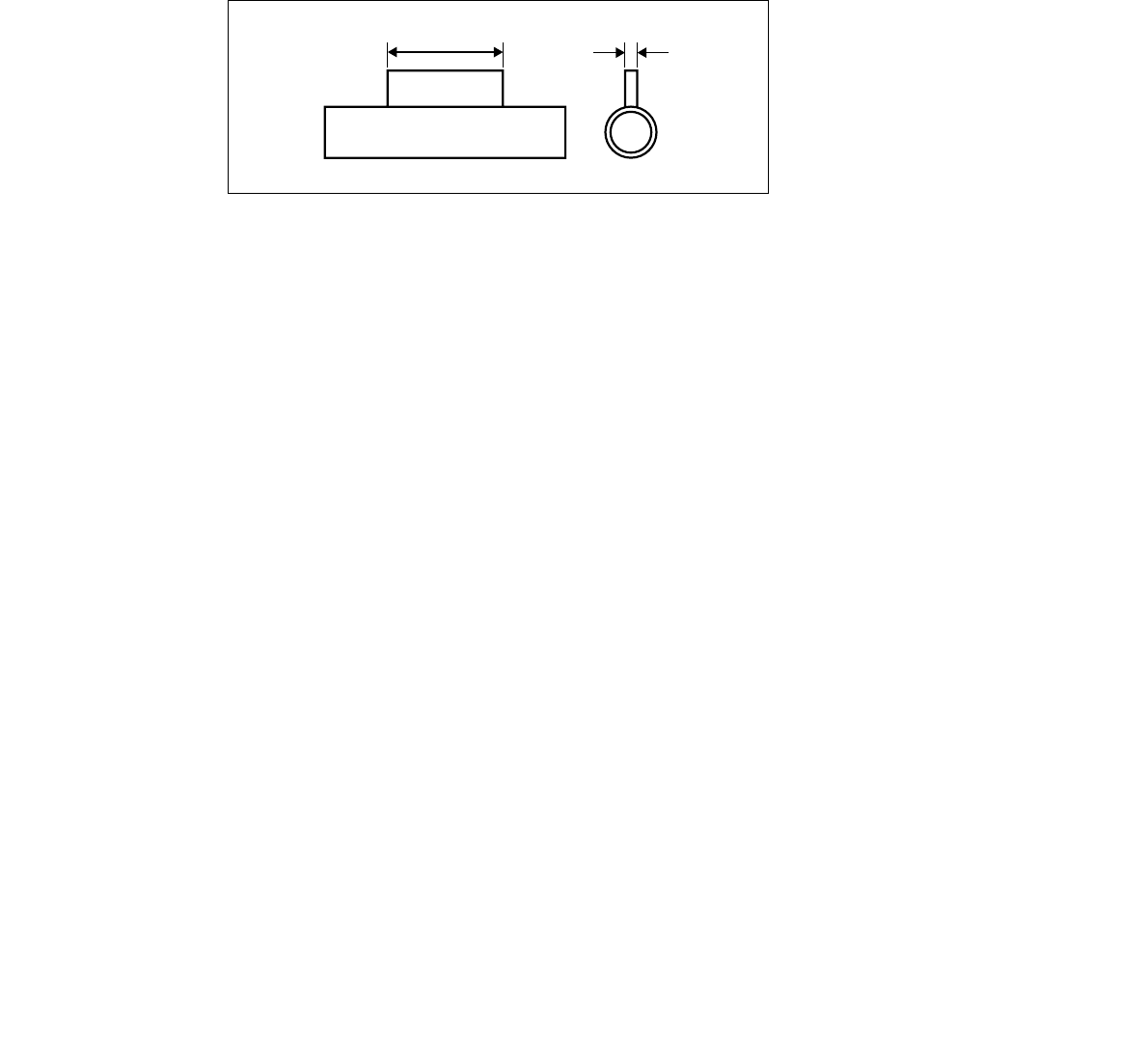
The weld at the toe of an inclined bracing is very important, see figure 9. Because of the non-uniform
stress distribution around the bracing at the chord face, the toe area tends to be more highly stressed
than the remainder of its periphery. As a result it is recommended that the toe of the bracing should be
bevelled and a butt weld should always be used if the bracing angle, 0, is less than 60º. If the angle is
60º or greater then the weld type used for the remainder of the weld should be used, i.e. either a fillet
or a butt weld.
Figure 9 : Weld detail at bracing toe
3.2.1 Welding in cold formed RHS corners
EN1993-1-1: Annex K: Table A4 restricts welding of bracing members to chord members within 5t of
the corner region of cold formed square or rectangular hollow section chord members unless the steel
is a fully killed (A1≥0.02%) type.
Both Corus Tubes Strongbox® 235 and Hybox®355 meet the fully killed requirements and can be
welded in the corner region unless the thickness is greater than12mm when the 5t restriction applies.
3.3 Fabrication
In a lattice type construction the end preparation and welding of the bracings is generally the largest
part of the fabrication costs and the chords the smallest. For example, in a typical 30m span girder,
whilst the chords would probably be made from three lengths of material with straight cuts and two
end-to-end butt welds, the bracings would number some twenty to twenty-five and each would require
bevel cutting or profiling, if using a CHS chord, and welding at each end.
As a general rule the number of bracing members should be as small as possible and this can usually
best be achieved by using K- type bracings rather than N-type bracings. Hollow sections are much
more efficient in compression than open sections, such as angles or channels, and as a result the
requirement to make compression bracings as short as possible does not occur and a K-type bracing
layout becomes much more efficient.
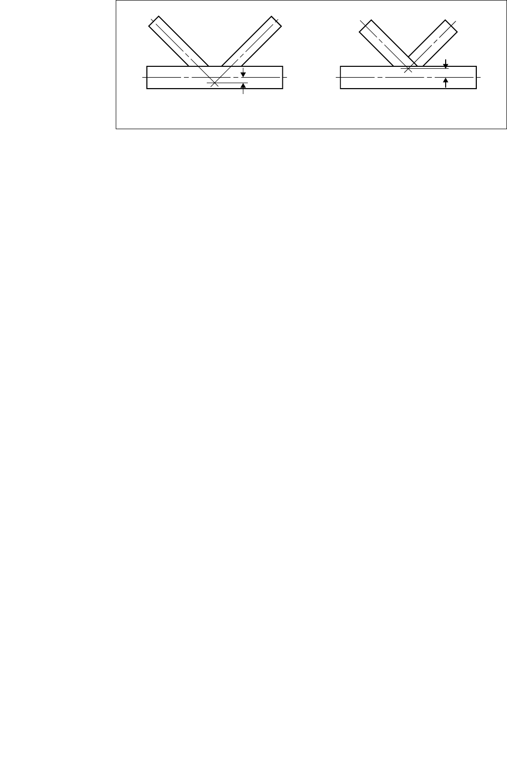
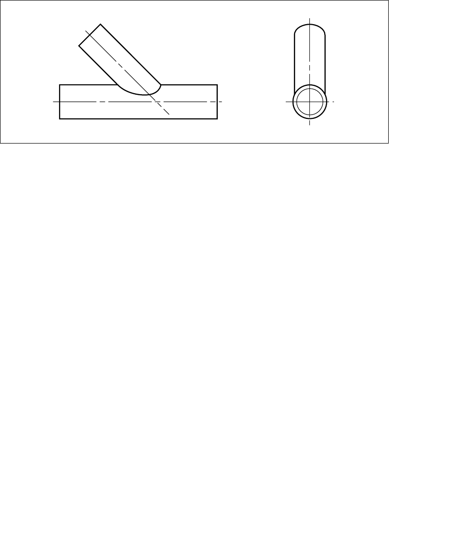
The ends of each bracing in a girder with circular hollow section chords have to be profile shaped to fit
around the curvature of the chord member, see figure 10, unless the bracing is very much smaller than
the chord. Also for joints with CHS bracings and chords and with overlapping bracings the overlapping
bracing has to be profile shaped to fit to both the chord and the other bracing.
Figure 10 : Connections to a circular chord
For joints with RHS chords and either RHS or CHS bracings, unless the bracings partially overlap, only
a single straight cut is required at the ends of the bracings.
As well as the end preparation of the bracings, the ease with which the members of a girder, or other
construction, can be put into position and welded will effect the overall costs. Generally it is much
easier, and therefore cheaper, to assemble and weld a girder with a gap between the bracings than a
similar one with the bracings overlapping. This is because with gap joints you have a much slacker
tolerance on fit up and the actual location of the panel points can easily be maintained by slight
adjustments as each bracing is fitted; this is not possible for joints with overlapping bracings, especially
partial overlapping ones, and unless extra care is taken it can result in accumulated errors in the panel
point locations.
More detailed information on fabrication, assembly and erection is given in reference 14
Design of SHS welded joints 12

13 Design of SHS welded joints
4.1 General
The effect that the various geometric parameters of the joint have on its load capacity is dependant
upon the joint type (single bracing, two bracings with a gap or an overlap) and the type of loading on
the joint (tension, compression, moment). Depending on these various conditions a number of different
failure modes, see section 4.2, are possible.
Design is always a compromise between various conflicting requirements and the following notes
highlight some of the points that need to be considered in arriving at an efficient design.
1) The joint
a) The joint capacity will always be higher if the thinner member at a joint sits on and is welded to
the thicker member rather than the other way around.
b) Joints with overlapping bracings will generally have a higher capacity than joints with a gap
between the bracings, all other things being equal.
c) The joint capacity, for all joint and load types (except fully overlapped joints), will be increased if
small thick chords rather than larger and thinner chords are used.
d) Joints with a gap between the bracings have a higher capacity if the bracing to chord width ratio
is as high as possible. This requires large thin bracings and small thick chords.
e) Joints with partially overlapping bracings have a higher capacity if both the chord and the
overlapped bracing are as small and thick as possible.
f) Joints with fully overlapping bracings have a higher capacity if the overlapped bracing is as small
and thick as possible. In this case the chord has no effect on the joint capacity.
g) On a size for size basis, joints with CHS chords will have a higher capacity than joints with RHS
chords
2) The overall girder requirements
a) The overall girder behaviour, e.g. lateral stability, is increased if the chord members are large and
thin. This also increases the compression chord strut capacity, due to its larger radius of gyration.
b) Consideration must also be given to the discussion on fabrication in section 3.3.
4.2 Joint failure modes
Joints in structural hollow sections can fail in a number of different failure modes depending on the joint
type, the geometric parameters of the joint and the type of loading. These various types of failure are
described in figures 11 to 16.
If the relevant geometric parameter limits given in section 5 are adhered to then the number of failure
modes is limited to those defined there; however, if this is not the case then other failure modes may
become critical.
4 Parameters affecting joint capacity
Design of SHS welded joints 14
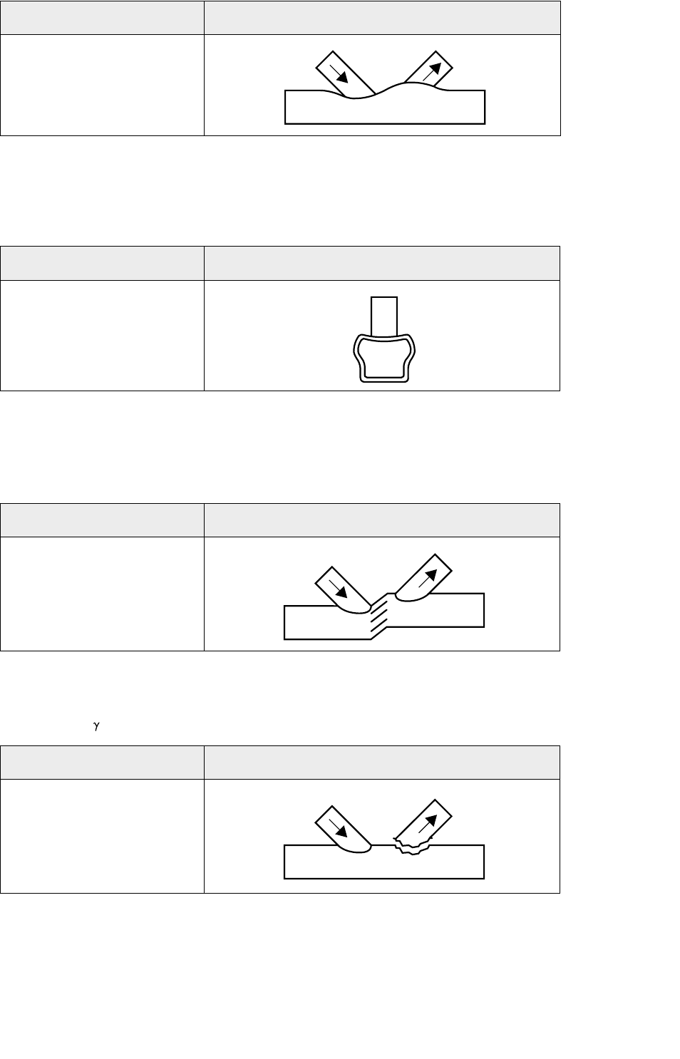
Mode Description
Chord face
deformation
Mode Description
Chord sidewall
buckling
Mode Description
Chord shear
Mode Description
Chord
punching shear
Chord face deformation, figure 11, is the most common failure mode for joints with a single bracing,
and for K- and N-joints with a gap between the bracings if the bracing to chord width ratio (ß) is less
than 0.85.
Figure 11 : Chord face deformation
Chord side wall buckling, figure 12, usually only occurs when the ß ratio is greater than about 0.85,
especially for joints with a single bracing. The failure mode also includes chord side wall yielding if the
bracing carries a tensile load.
Figure 12 : Chord side wall buckling
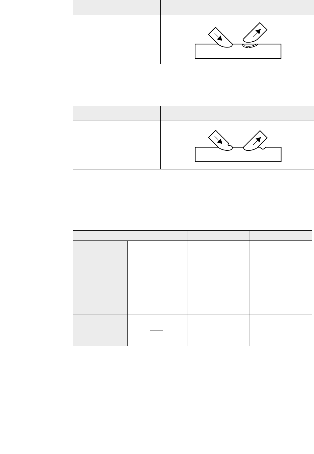
Chord shear, figure 13, does not often become critical, it is most likely to become so if rectangular
chords with the width (b0) greater than the depth (h0) are being used. If the validity ranges given in
section 5 are met then chord shear does not occur with CHS chords.
Figure 13 : Chord shear
Chord punching shear, figure 14, is not usually critical but can occur when the chord width to
thickness ratio (2 ) is small.
Figure 14 : Chord punching shear
15 Design of SHS welded joints
Bracing effective width failures, figure 15, are generally associated with RHS chord gap joints which
have large ß ratios and thin chords. It is also the predominant failure mode for RHS chord joints with
overlapping RHS bracings.
Figure 15 : Bracing effective width
Localised buckling of the chord or bracings, figure 16, is due to the non-uniform stress distribution
at the joint, and will not occur if the validity ranges given in section 5 are met.
Figure 16 : Localised buckling of the chord or bracings
4.3 Joints with a single bracing
The statements given in table 3 will only be true provided that the joint capacity does not exceed the
capacity of the members. In all cases the capacity is defined as a load along the axis of the bracing.
Note : (1) - provided that RHS chord side wall buckling does not become critical, when ß > 0.85
Table 3 : Effect of parameter changes on the capacity of T-, Y- and X-joints
Mode Description
Bracing
effective width
Mode Description
Chord or bracing
localised buckling
Joint parameter Parameter value Effect on capacity
Chord width to
thickness ratio
Bracing to chord
width ratio
Bracing angle
Bracing to chord
strength factor
reduced increased
increased increased
(1)
reduced increased
reduced increased
bo/toor do/ to
d1/d0or b1/ b0
θ
fy1 t1
fy0 t0
Design of SHS welded joints 16
4.4 Joint with a gap between bracing
The statements given in table 4 will only be true provided that the joint capacity does not exceed the
capacity of the members. In all cases the capacity is defined as a load along the axis of the bracing.
Note : (1) - provided that RHS chord side wall buckling does not become critical, when ß > 0.85
(2) - only true for CHS chord joints
Table 4 : Effect of parameter changes on the capacity of K- or N-joints with gap
4.5 Joints with overlapped bracings
The statements given in table 5 will only be true provided that the joint capacity does not exceed the
capacity of the members. In all cases the capacity is defined as a load along the axis of the bracing.
Note : (1) - only true for RHS joints
(2) - provided that RHS chord side wall buckling does not become critical, when ß > 0.85
(3) - only true for CHS chord joints
Table 5 : Effect of parameter changes on the capacity of K- or N-joints with overlap
Joint parameter Parameter value Effect on capacity
Chord width to
thickness ratio
Bracing to chord
width ratio
Bracing angle
Bracing to chord
strength factor
Gap between
bracings
reduced
increased
reduced
reduced
reduced
increased
increased
(1)
increased
increased
increased
(2)
Joint parameter Parameter value Effect on capacity
Chord width to
thickness ratio
Overlapped
bracing width to
thickness ratio
Bracing to chord
width ratio
Bracing angle
Overlapped
bracing to
chord strength
factor
Bracing to
bracing strength
factor
Overlap of
bracings
b0/t0or d0/ t0
d1/d0or b1/ b0
θ
fy1 t1
fy0 t0
g
reduced
reduced
increased
reduced
reduced
reduced
increased
increased
increased
(1)
increased
(2)
increased
(3)
increased
increased
increased
b0/t0or d0/ t0
bj/tj
d1/d0or b1/ b0
θ
fyj tj
fy0 t0
fy1 t1
fyj tj
Ov
17 Design of SHS welded joints
4.6 Joint reinforcement
If a joint does not have the design capacity required, and it is not possible to change either the joint
geometry or the member sizes, it may be possible to increase the design capacity with the use of
appropriate reinforcement. Adding reinforcement to a joint should only be carried out after careful
consideration. It is relatively expensive from a fabrication point of view and can be obtrusive from an
aesthetics view point.
The type of reinforcement required depends upon the criterion causing the lowest capacity. Methods
for reinforcing both CHS and RHS chord joints are given below. An alternative to the methods shown
is to insert a length of chord material, of the required thickness, at the joint location, the length of which
should be at least the same as the length, hr, given in the following methods.
The required thickness of the reinforcement, tr, should be calculated by re-arranging the relevant
formula given in section 5 to calculate the required chord thickness, t0, this is then the thickness of the
reinforcement required. In the case of CHS chord saddle and RHS chord face reinforcement only the
reinforcement thickness, and not the combined thickness of the chord and reinforcement, should be
used to determine the capacity of the reinforced joint. For RHS chord side wall reinforcement the
combined thickness may be used for the shear capacity, but for chord side wall buckling the chord
side wall and reinforcement should be considered as two separate plates and their capacities added
together.
The plate used for the reinforcement should be the same steel grade as the chord material. For CHS
saddle and RHS chord face reinforcement the plate should have good through thickness properties
with no laminations. The weld used to connect the reinforcement to the hollow section chord member
should be made around the total periphery of the plate.
When plates are welded all round to the chord face, as is the case for the reinforcement plates shown
in sections 4.6.1 and 4.6.2, special care and precautions should be taken if the structure is
subsequently to be galvanised.
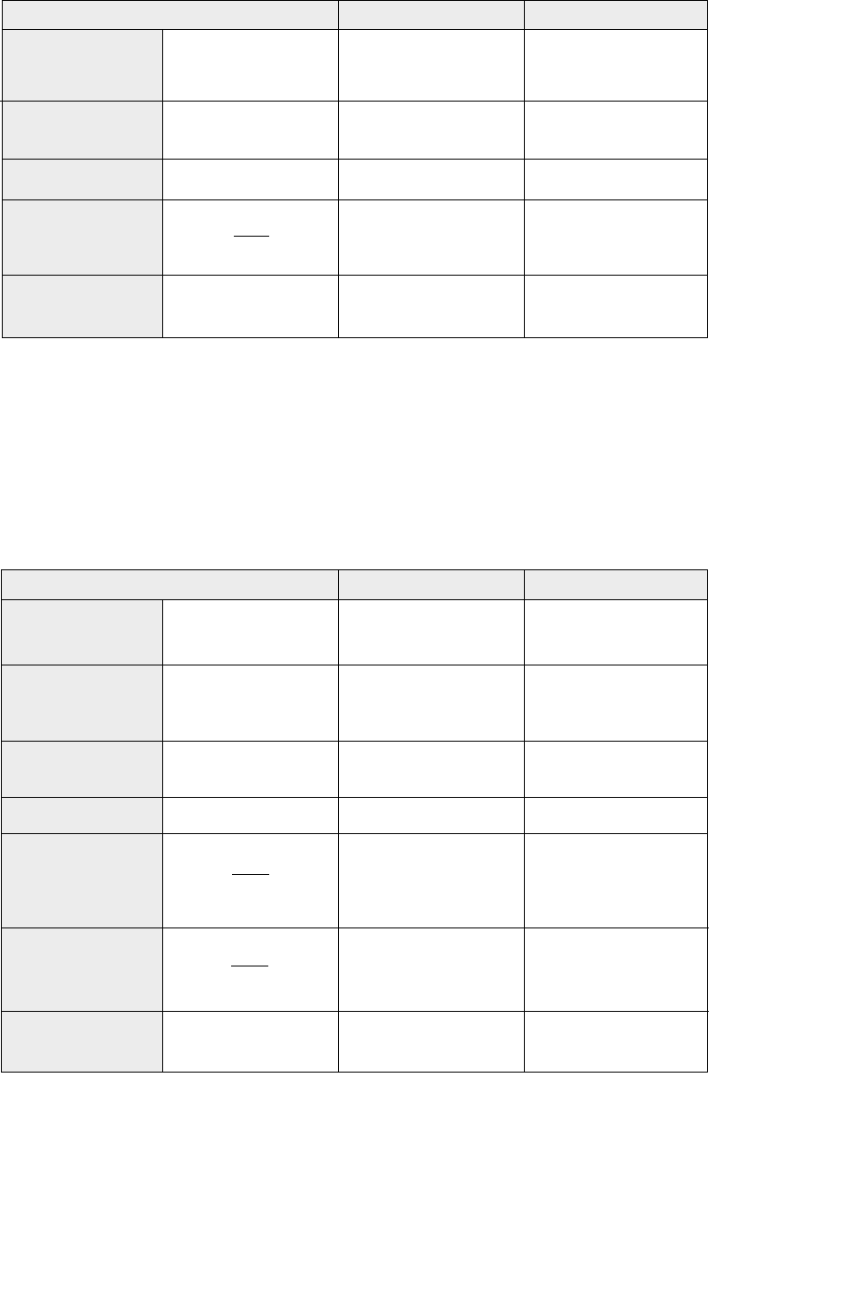
4.6.1 Reinforcement of CHS chord joints
The only external reinforcement method used with a CHS chord is saddle reinforcement, where either a
curved plate or part of a thicker CHS is used. The size and type of reinforcement is shown in figure 17.
The dimensions of the saddle should be as shown below.
Figure 17 : CHS chord saddle reinforcement
tr
g
hr
ds
d2
d1
ds= πd0/ 2
hr≥1.5 [d1/ sinθ1+ g + d2/ sinθ2]
for K- or N-gap joints
hr≥1.5 d1/ sinθ1
for T-, X- or Y-joints
tr= required reinforcement thickness
Design of SHS welded joints 18
g
brhr
h1
h2
tr
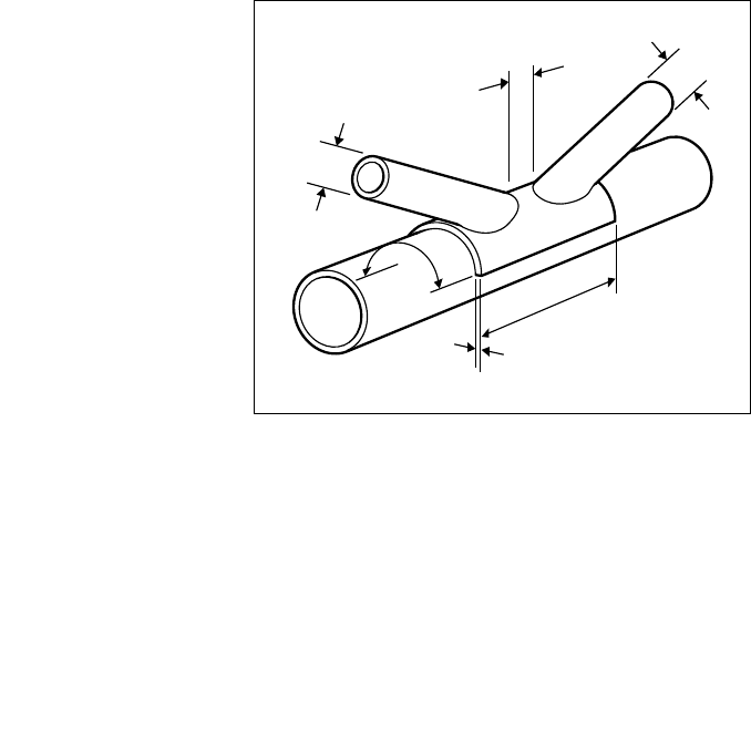
4.6.2 Reinforcement of RHS chord gap joints
A gap joint with RHS chords can be reinforced in several ways depending upon the critical design
criterion. If the critical criterion is chord face deformation or chord punching shear or bracing effective
width then reinforcing the face of the chord to which the bracings are attached is appropriate (see
figure 18). However, if the critical criterion is either chord side wall buckling or chord shear then plates
welded to the side walls of the chord should be used (see figure 19). The required dimensions of the
reinforcing plates are shown below.
Figure 18 : RHS chord face reinforcement
Figure 19 : RHS chord side wall reinforcement
g
br
hr
h1
h2
tr
hr≥1.5 [h1/ sinθ1+ g + h2/ sinθ2]
for K- or N-gap joints
hr≥1.5 h1/ sinθ1
for T-, X- or Y-joints
br≥h0 - 2t0
tr= required reinforcement thickness
hr≥1.5 [h1/ sinθ1+ g + h2/ sinθ2]
for K- or N-gap joints
hr≥h1/ sinθ1+ √(br(br-b1))
and ≥1.5 h1/ sinθ1
for T-, X- or Y-joints
br≥b0 - 2t0
tr= required reinforcement thickness
19 Design of SHS welded joints
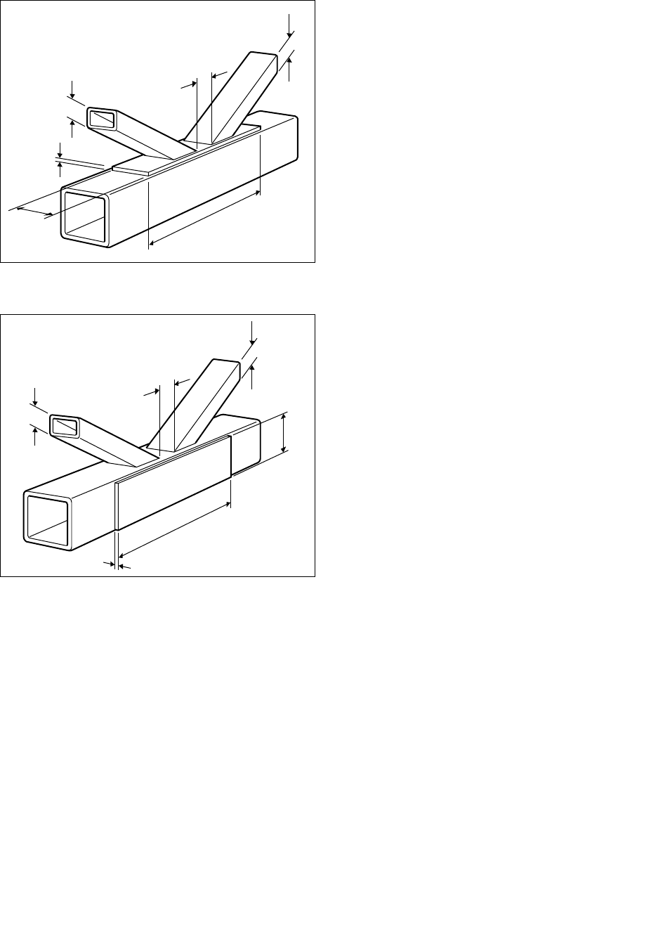
4.6.3 Reinforcement of RHS chord overlap joints
An overlap joint with RHS chords can be reinforced by using a transverse plate as shown in figure 20.
The plate width brshould generally be wider than the bracings to allow a fillet weld with a throat
thickness equal to the bracing thickness to be used.
This should be treated as a 50 to 80% overlap joint with trbeing used instead of the overlapped
bracing thickness tjin the calculation of beov (see section 5.2). This type of reinforcement can be used
in conjunction with the chord face reinforcement , shown in figure 18, if necessary.
Figure 20 : RHS chord transverse plate reinforcement
trbr
Design of SHS welded joints 20
5. Joint design formulae
When more than one failure criteria formula is given the value of the lowest resulting capacity
should be used. In all cases any applied factored moment should be taken as that acting at the
chord face and not that at the chord centre line.
5.1 CHS chord joints
All dimensions used in the design formulae and parameter limits are nominal, except for
Strongbox®235 thicknesses which should use 0,9tnom or (tnom -0.5mm) which ever
is the larger.
5.1.1 CHS chord joint parameter limits
Table 6 : CHS Joint Parameter limits
* can be physically > 4, but for calculation purposes should not be taken as > 4 for plate or > 2 for RHS bracing.
5.1.2 CHS chord joint functions
The following functions are used during the calculation of CHS chord joint capacities
Chord end load function, f(np)- see figure 21
f(np) = 1 + 0.3 p/fy0 - 0.3 ( p/fy0)2but not greater than 1.0,
p = the least compressive factored applied stress in the chord due to axial loads and
moments adjacent to the joint and is negative for compression
p/fy0 is the chord stress ratio shown in figure 21
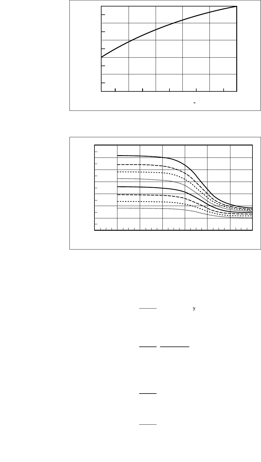
Gap/lap function, f(g) - see figure 22
0.024 1.2
f(g) = 0.2 1+
1 + exp(0.5 g/t0- 1.33)
Gap (g) is positive for a gap joint and negative for an overlap joint
CHS
Transverse
plate
Longitudinal
plate
RHS and I- or
H- section
≤50
≤40
≤50
≤40
≤50
≤40
≤50
≤40
≤50
-
-
-
-
-
-
gap ≥t1+t2
lap ≥25%
-
-
-
-
-
-
-
30º
≤θ≤
90º
θ≈90º
30º
≤θ≤
90º
di/d0≥0.2
b1/d0≥0.4
h1/d0≤4.0*
t1/d0≤0.2
b1/d0≥0.4
h1/d0≤4.0*
Joint type Bracing type d0/t0di/ti
(bi,hior dior ti)/d
0
Gap/lap Brace angle
T-,K- and
N-joints
X-joints
T-joints
X-joints
T-joints
X-joints
T-joints
X-joints
21 Design of SHS welded joints
Figure 21 : CHS joint - Chord end load function
Figure 22 : CHS joint - Gap/lap function
5.1.3 CHS chords and CHS bracings with axial loads
T- and Y-joints
fy0 t02
Chord face deformation, N1= (2.8 + 14.2 ß2) 0.2 f(np)
sinθ1
X-joints
fy0 t02 5.2
Chord face deformation, N1= f(np)
sinθ1 (1 - 0.81 ß)
K- and N-joints
fy0 t02
Chord face deformation, N1= (1.8 + 10.2 d1/d0) f(g) f(np)
(compression brace) sinθ1
sinθ1
Chord face deformation, N2= x N1
(tension brace) sinθ2
3.5
4.5
4
2.5
3
1.5
2
1-8-12-16 -4
Gap / chord thickness ratio - g/to
Gap function - f(g)
04812
do/to=45
do/to=30
do/to=40
do/to=50
do/to=35
do/to=25
do/to=15
do/to=20
0.0
0.2
0.4
0.6
0.8
1.0
-0.8-1.0 -0.6
Chord end load function - f(np)
-0.4 -0.2 0.0
Chord stress ratio - op /fyo
Design of SHS welded joints 22
For all these joint types, except those with overlapping bracings, the joint must also be checked for
chord punching shear failure when di≤d0- 2t0
fy0 t0πdi 1 + sin θi
Chord punching shear, Ni=
√3 2 sin2θi
5.1.4 CHS chords and CHS bracings with moments
T-, Y-, X-joints and K- and N-joints with gap
Chord face deformation criterion - this should be checked for all geometric joint configurations
fy0 t02di
In-plane moments, Mip,i = 4.85 ß √f(np)
sin θi
fy0 t02di 2.7
Out-of-plane moments, Mop,i = f(np)
sin θi 1 - 0.81 ß
Punching shear criterion - this must also be checked for these joint types when di≤d0- 2 t0
fy0 t0di21 + 3 sin θi
In-plane moments, Mip,i =
√3 4 sin2θi
fy0 t0di23 + sin θi
Out-of-plane moments, Mop,i =
√3 4 sin2θi
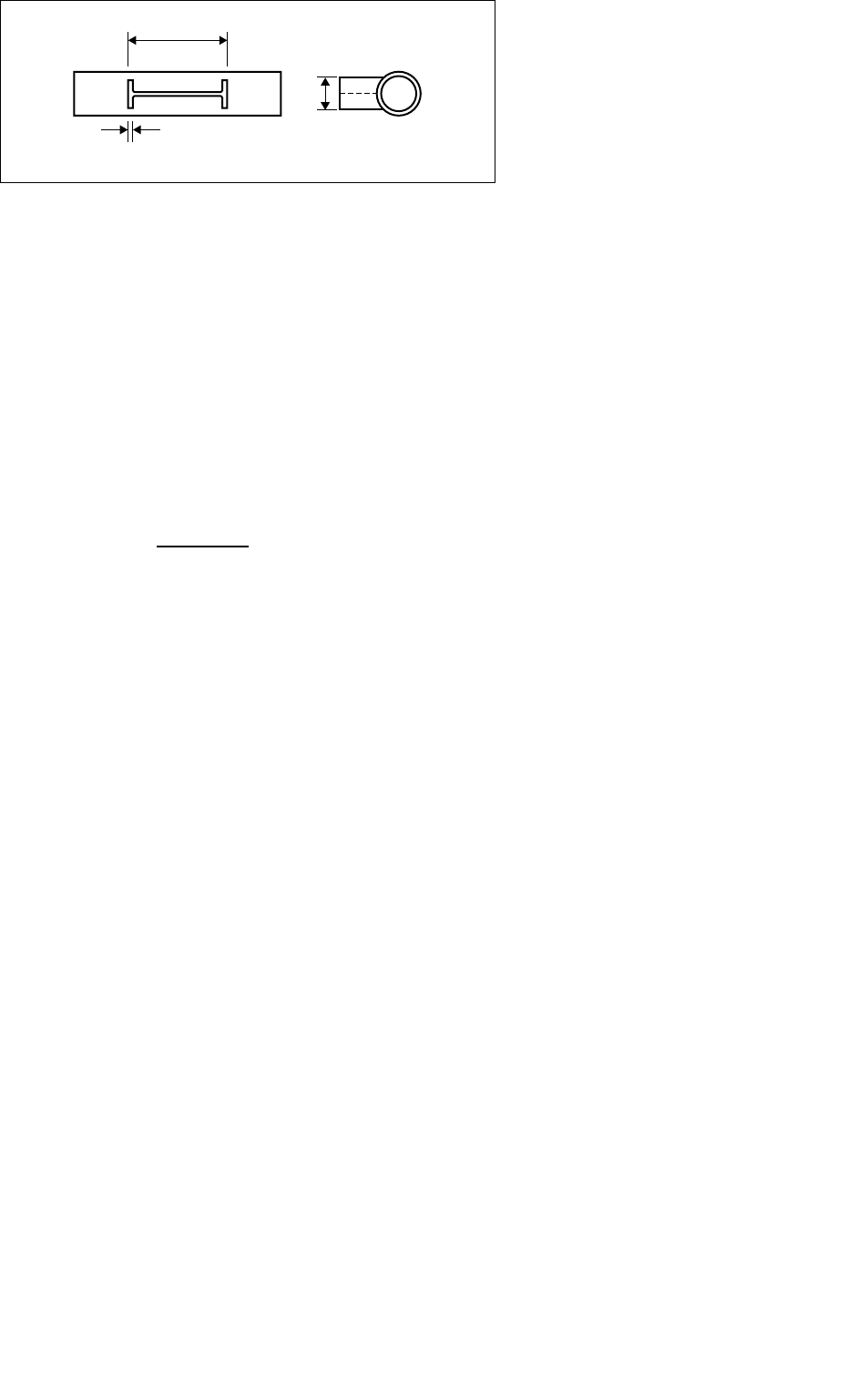
5.1.5 CHS chords with transverse gusset plates
T-joints axial load chord face deformation
N1= fy0 t02(4 + 20 ß2) f(np)
X-joints axial load chord face deformation
5 fy0 t02
N1= f(np)
(1 - 0.81 ß)
t1b1
23 Design of SHS welded joints
T- and X-joints out-of-plane moment chord face deformation
Mop,1 = 0.5 b1N1
T- and X-joints in-plane moment chord face deformation
Mip,1 = t1 N1
T- and X-joint chord punching shear
In all cases the following check must be made to ensure that any factored applied axial loads and
moments do not exceed the chord punching shear capacity.
Napp + 6 Mapp/ b1≤2 fy0 t0b1/√3
5.1.6 CHS chords with longitudinal gusset plates
T- and X-joints axial load chord face deformation
N1= 5 fy0 t02(1+ 0.25 h1/d0) f(np)
T- and X-joints out-of-plane moment chord face deformation
Mop,1 = 0.5 t1 N1
T- and X-joints in-plane moment chord face deformation
Mip,1 = h1N1
T- and X-joint chord punching shear
In all cases the following check must be made to ensure that any factored applied axial loads and
moments do not exceed the chord punching shear capacity.
Napp + 6 Mapp/h1≤2f
y0 t0h1/√3
h1t1
Design of SHS welded joints 24
5.1.7 CHS chords and I -, H - or RHS bracings
T-joints chord face deformation
N1= fy0 t02(4 + 20 ß2) (1+ 0.25 h1/d0) f(np)
Mip,1 = h1N1 / (1 + 0.25 h1/d0) for
I
- and H- bracings
Mip,1 = h1N1 for RHS bracings
Mop,1 = 0.5 b1N1
X-joints chord face deformation
5 fy0 t02
N1= (1 + 0.25 h1/d0) f(np)
(1 - 0.81 ß)
Mip,1 = h1N1 / (1 + 0.25 h1/d0) for
I-
and H- bracings
Mip,1 = h1N1 for RHS bracings
Mop,1 = 0.5 b1N1
T- and X-joint chord punching shear
In all cases the following check must be made to ensure that any factored applied axial loads and
moments do not exceed the chord punching shear capacity.
For I- and H-sections (Napp / A1+ Mapp / Wel.1) t1 ≤2 fy0 t0 / √3
For RHS sections (Napp / A1+ Mapp / Wel.1) t1 ≤fy0 t0 / √3
h1
b1
t1
5.2 RHS chord joints
All dimensions used in the design formulae and parameter limits are nominal, except for
Strongbox®235 thicknesses which should use 0.9tnom or (tnom -0.5mm) whichever is the larger.
5.2.1 RHS chord joint parameter limits
Table 7 : RHS joint Parameter limits
Note : in gap joints, if the gap is greater than 1.5(b0-bi), then it should be treated as two separateT- or Y-joints and the chord checked
for shear between the braces
* can be physically > 4, but should for calculation purposes not be taken as > 4 for plater or H-section bracings.
The angle between the chord and either an RHS or a CHS bracing and between braces should be
between 30º and 90º inclusive. Longitudinal plates should be at about 90º to the chord face.
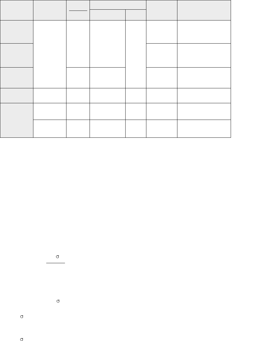
5.2.2 RHS chord joint functions
The following functions are used during the calculation of RHS chord joint capacities.
Chord end load function, f(n), f(m)
For all joints except those with a longitudinal gusset plate - see figure 23
0.4 0
f(n) = 1.3 + but not greater than 1.0,
fy0 ß
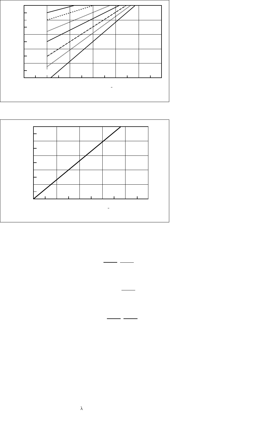
For joints with a longitudinal gusset plate only - see figure 24
f(m) = 1.3(1 + 0/ fy0)but not greater than 1.0,
0 = the most compressive factored applied stress in the chord due to axial loads and
moments adjacent to the joint and is negative for compression
0/ fy0 is the chord stress ratio shown in figures 23 and 24
25 Design of SHS welded joints
Joint type Bracing type Gap / lap
Compression Tension
T- a n d
X-joints
K- and N-
gap joints
K- and N-
lap joints
All types
T- a n d
X-joints
RHS
CHS
Transverse
plate
Longitudinal
plate
(boor ho)
to
≤35
≤40
≤35
≤50
-
-
≤35
and
≤34.5√(275/fyi)
≤30.4√(275/fyi)
≤41.5√(275/fyi)
-
-
(di or bi)/ bo
≥0.25
≥0.35 and ≥
0.1 + 0.01
b0/t0
≥0.25
≥0.4 and
≤0.8
≥0.5
t1/b0≤0.2
h1/b0≤4.0*
-
gap ≥t1+t2
and≥0.5(b0-(b1+b2)/2)
but ≤1.5(b0-(b1+b2)/2)
25% ≤lap ≤
100%
As above
-
-
≤30
≤30
(bior hior di) / ti
As above
Design of SHS welded joints 26
Figure 23 : RHS joint - Chord end load function (All except longitudinal gusset plate joints)
Figure 24 : RHS joint - Chord end load function (Longitudinal gusset plates only)
Bracing effective width functions
10 fy0 t0
Normal effective width, beff = bibut ≤bi
b0/t0fyi ti
10
Punching shear effective width, bep = bibut ≤bi
b0/t0
10 fyj tj
Overlap effective width, beov = bibut ≤bi
bj/tjfyi ti
(Suffix 'j' indicates the overlapped bracing)
Chord design strength for T-, Y- and X-joints, f(fb)
For tension in the bracing f(fb)= fy0
For compression in the bracing f(fb)= f
c for T- and Y-joints
f(fb) = 0.8 fcsinθifor X-joints
With fcobtained from BS5950: Part 1 Table 24 for strut curve c or Eurocode 3 Clause 5.5.1 for
a slenderness ratio, , of 3.46 (h0/t0- 2) / √(sinθi)
25
-0.8-1.0-1.2 -0.6
bi/bo=1.00
bi/bo=0.40
bi/bo=0.80
bi/bo=0.60
bi/bo=0.50
All except longitudinal gusset plate joints
0.0
0.2
0.4
0.6
0.8
1.0
Chord end load function - f(n)
-0.4 -0.2 0.0
bi/bo=0.35
bi/bo=0.30
Chord stress ratio-oo /fyo
0.0
0.2
0.4
0.6
0.8
1.0
-0.8-1.0 -0.6
Chord end load function - f(m)
-0.4 -0.2 0.0
Longitudinal gusset plate only
Chord stress ratio - oo /fyo
27 Design of SHS welded joints
Chord shear area, Av
The chord shear area, Av, in uniplanar K- and N-joints with a gap is dependant upon the type of
bracings and the size of the gap
Av= (2 h0+ b0) t0
1 0.5
with = 4 g2 for RHS bracings
1 +
3 t02
and = 0 for CHS bracings
In multiplanar girders the shear area, Av, given below should be used for the two shear planes
respectively, irrespective of the type of bracing.
Av= 2(h0- t0) t0 or 2(b0- t0) t0
5.2.3 RHS chords and RHS bracings with axial loads
A number of failure modes can be critical for RHS chord joints. In this section the design formulae for
all possible modes of failure, within the parameter limits, are given. The actual capacity of the joint
should always be taken as the lowest of these capacities.
T-, Y- and X-joints
fy0 t02 2h1
Chord face deformation, N1 = + 4√(1 - ß) f(n)
(ß ≤0.85 only) (1 - ß) sinθ1 b0 sinθ1
fy0 Av
Chord shear, N1 =
(X-joints with 0 < 90º only) √3 sinθ1 where = 0 in Av
f(fb) t02h1
Chord side wall buckling, N1 = + 10 t0
(ß =1.0) sinθ1 sinθ1
fy0 t02h1
Chord punching shear, N1 = + 2 bep
(0.85 ≤ß ≤(1 - 2t0/b0) only) √3 sinθ1 sinθ1
Bracing effective width, N1 = fy1 t1 [ 2h1- 4t1+ 2beff ]
(ß ≥0.85 only)
For 0.85 ≤ß ≤1 use linear interpolation between the capacity for chord face deformation at ß = 0.85
and the governing value for chord side wall failure (chord side wall buckling or chord shear) at ß = 1.0.
Design of SHS welded joints 28
K- and N-gap joints
6.3 fy0 t02√b0b1 + h1 + b2 + h2
Chord face deformation, Ni= f(n)
sinθi√t0 4b0
fy0 Av
Chord shear between bracings, Ni=
√3 sinθi
Bracing effective width, Ni= fyi ti [ 2 hi - 4 ti + bi + beff ]
fy0 t0 2 hi
Chord punching shear, Ni= + bi + bep
(ß ≤(1 - 2t0/b0) only) √3 sinθi sinθi
The chord axial load resistance in the gap between the bracings (N0gap) should also be checked
if the factored shear load in the gap (VApp) is greater than 0.5 times the shear capacity (Vp).
N0gap = fy0[A0- Av(2VApp/Vp- 1)2]
K- and N-overlap joints
Only the overlapping member i need be checked. The efficiency of the overlapped
member j should be taken as equal to that of the overlapping member.
i.e. Nj= Ni(Ajfyj)/(Aifyi)
bi/bj ≥0.75
25% ≤Ov< 50%
Bracing effective width, Ni= fyi ti [(Ov/ 50) (2 hi - 4 ti) + beff + beov]
50% ≤Ov< 80%
Bracing effective width, Ni= fyi ti [2 hi - 4 ti+ beff + beov]
Ov≥80%
Bracing effective width, Ni= fyi ti [2 hi - 4 ti+ bi + beov]
5.2.4 RHS chords and CHS bracings with axial loads
For all the joints described in section 5.2.3, if the bracings are CHS replace the bracing dimensions,
biand hi, with diand multiply the resulting capacity by π/4 (except for chord shear).
5.2.5 RHS chords and RHS bracings with moments
Treat K- and N-gap joints as individual T- or Y-joints
5.2.5.1 T- and X-joints with in-plane moments
1 - ß 2 h1/b
0
Chord face deformation, Mip,1 = fy0 t02h1 + + f(n)
(ß ≤0.85 only) 2 h1/b0 √(1 - ß) 1 - ß
Chord side wall crushing, Mip,1 = 0.5 fyk t0 (h1 + 5 t0)2
(0.85 ≤ß ≤1.0 only) with fyk = fy0 for T-joints and 0.8 fy0 for X-joints
Bracing effective width, Mip,1 = fy1 [W
pl,1 - (1 - beff/b1) b1 h1 t1]
(0.85 ≤ß ≤1.0 only)
29 Design of SHS welded joints
5.2.5.2 T- and X-joints with out-of-plane moments
h1 (1 + ß) 2b0b1(1 + ß) 0.5
Chord face deformation, Mop,1 = fy0 t02+ f(n)
(ß ≤0.85 only) 2 (1 - ß) (1 - ß)
Chord side wall crushing, Mop,1 = fyk t0 (h1 + 5 t0)(b0- t0)
(0.85 ≤ß ≤1.0 only) with fyk = fy0 for T-joints and 0.8 fy0 for X-joints
Bracing effective width, Mop,1 = fy1 [Wpl,1 - 0.5(1 - beff/b1)2b12t1]
(0.85 ≤ß ≤1.0 only)
Chord distortional failure (lozenging), Mop,1 = 2fy0 t0 [h1t0+(b0h0 t0 (b0+ h0))0.5]
(T joints only)
5.2.6 RHS chords with gusset plates or I - or H -section bracings
Transverse gusset plate
Plate effective width, N1 = fy1 t1 beff
Chord side wall crushing, N1 = fy0 t0 (2 t1 + 10 t0)
(b1≥b0- 2 t0only)
fy0 t0
Chord punching shear, N1 = (2 t1 + 2bep)
(b1≤b0- 2 t0only) √3
In-plane moment = Mip,1 = 0.5 N1t1
Out of plane moment = Mop,1 = 0.5 N1b1
Longitudinal gusset plate
fy0 t02
Chord face deformation, N1 = [2 h1/b0 + 4√(1 - t1/b0)] f(m)
1 - t1/b0
In-plane moment, Mip,1 = 0.5 h1N1
Out of plane moment, Mop,1 = 0.5 N1t1
t1b1
h1t1
Design of SHS welded joints 30
I- or H-section bracings
Base axial load capacity, N1, upon two transverse plates, similar to it's flanges, as specified in 5.2.6
above, ie.
Plate effective width, N1 = 2 fy1 t1 beff
Chord side wall crushing, N1 = 2 fy0 t0 (2 t1 + 10 t0)
(b1≥b0 - 2 t0 only)
2 fy0 t0
Chord punching shear, N1 = (2 t1 + 2 bep)
(b1≤b0 - 2 t 0 only) √3
In-plane moment, Mip,1 = 0.5 (h1- t1) N1
Out of plane moment, Mop,1 = 0.5 N1 b1
5.3 Special joints in RHS
All dimensions used in the design formulae and parameter limits are nominal, except for
Strongbox®235 thicknesses which should use 0.9tnom or (tnom -0.5mm) whichever is the larger.
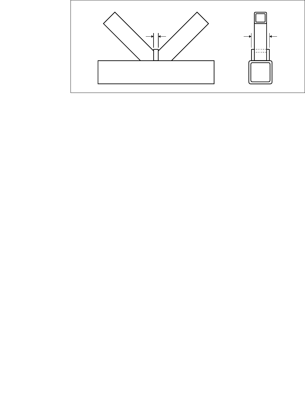
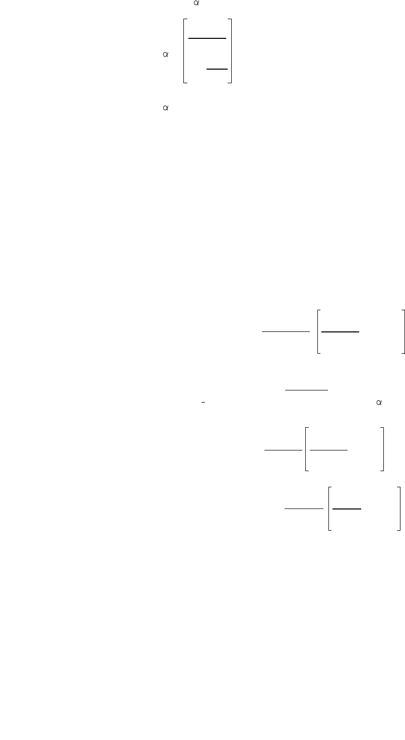
5.3.1 Welded knee joints
All members should be full plastic design sections. Loads should be predominantly moments with the
factored applied axial load no greater than 20% of the member tension capacity.
Unreinforced knee joints (see figure 25)
Figure 25 : Unreinforced knee joint
h1
b1
t1
Napp Mapp
+ ≤
Afy Wpl fy
3√(b0/h0) 1
0 ≤90º then = 90 = +
(b0/t0)0.8 1 + 2 b0/h0
0 > 90º then = θ= 1 - (√2 cos(0/2)) (1 - 90)
90 and θare shown graphically in figs 26 and 27
respectively.
0
h0
31 Design of SHS welded joints
Figure 26 : Knee joint efficiency for θ≤90º
Figure 27 : Knee joint efficiency for θ> 90º
Reinforced knee joints
Knee joints can easily be reinforced by using a plate as
shown in figure 28
If tp≥1.5 t and ≥10mm
then the joint will be 100% efficient and
Napp Mapp
+ ≤1.0
A fy Wpl fy
Figure 28 : Reinforced knee joint
30
1.00.5 1.5
0.0
0.5
0.4
0.6
0.7
0.8
0.9
1.0
90º Joint efficiency - 90
2.0 2.5 3.0
10
15
20
25
30
35
RHS shape ratio - b0 /h0
b0 /t0
0.60.5 0.7
0.4
0.5
0.4
0.6
0.7
0.8
0.9
1.0 180º
165º
150º
135º
120º
105º
90º
Angle
0.8 0.9 1.00.3
Efficiency at 0º - 0
90º Joint efficiency - 90
0
t
tp
Design of SHS welded joints 32
5.4
I
- or H-section chord joints
All dimensions used in the design formulae and parameter limits are nominal, except for
Strongbox®235 thicknesses which should use 0.9tnom or (tnom -0.5mm) whichever is the larger.
5.4.1 I- or H-section chord joint parameter limits
Table 8 : Joint Parameter limits
Note : 1) in gap joints, if the gap is greater than 1.5(bf- bi), then it should be treated as two separate T - or Y-joints
(check for chord shear in the gap).
2) the web depth dwshould not be greater than 400mm.
5.4.2 I- or H - section chord joint functions
Bracing effective width functions
Normal effective width, beff = tw+ 2 r + 7 tffy0 / fyi but ≤bi + hi - 2tifor RHS bracings,
≤ di /2 for CHS bracings
Web effective length, bw= hi / sin(θi) + 5(tf+ r) but ≤2 ti+ 10(tf+ r)
10 fyj tj
Overlap effective width, beov = bi but ≤bi
bj/ tj fyi ti
(Suffix 'j' indicates the overlapped bracing)
bi
hi
hi
bf/ tf
≤
20.7 √(275/fy0)
dw/ tw
≤
33.2 √(275/fy0)
≤
41.5 √(275/fy0)
Compression
bi/ tiand
hi/ ti≤
30.4 √(275/fyi)
di / ti≤
41.5 √(275/fyi)
Tension
bi/ ti
and hi/ ti
≤35
di/ ti
≤50
`Gap /lap
-
-
gap ≥t1+ t2
and ≤1.5(bf-bi)
25% ≤lap
≤100%
bi/b
j
-
-
-
≥0.75
(bior hior di)/ t
i
Joint type
X-joints
T- and Y-
joints
K- and N-
gap joints
K- and N-
lap joints
33 Design of SHS welded joints
Chord shear area, Av
The chord shear area, Av, in K- and N-joints with a gap is dependant upon the type of bracings and
the size of the gap
Av= A0 - (2 - ) bftf + (tw + 2r) tf
1 0.5
with = 4 g2 for RHS bracings
1 +
3 tf2
and = 0 for CHS bracings
5.4.3 I- or H - section chords and RHS bracings with axial loads
T-, Y- and X-joints
Chord web yielding, N1 = fy0 tw bw/ sin (θi)
Bracing effective width, N1 = 2 fy1 t1 beff
K- and N-gap joints
Chord web yielding, Ni = fy0 tw bw/ sin (θi)
fy0 Av
Chord shear, Ni =
√3 sin (θi)
The bracing effective width failure criterion, below, does not need to be checked provided that :
g / tf≤20 - 28 ß : ß ≤1.0 - 0.015 bf/tf: 0.75 ≤d1/ d2 or b1/ b2 ≤1.33
Bracing effective width, Ni = 2 fyi ti beff
The chord axial load resistance in the gap between the bracings (N0gap) should also be checked if the
factored shear load in the gap (VApp) is greater than 0.5 times the shear capacity (Vp).
N0gap = fy0[A0- Av(2VApp/Vp- 1)2]
K- and N-overlap joints
Only the overlapping member i need be checked. The efficiency of the overlapped member j should be
taken as equal to that of the overlapping member.
i.e. Ni= Ni(Ajfyj)/(Aifyi)
25% ≤Ov< 50%
Bracing effective width, Ni= fyi ti [(Ov/ 50) (hi - 2 ti) + beff + beov]
50% ≤Ov< 80%
Bracing effective width, Ni= fyi ti [hi - 2 ti+ beff + beov]
Ov≥80%
Bracing effective width, Ni= fyi ti [2 hi - 4 ti+ bi + beov]

5.4.4 I- or H - section chords and RHS bracings with in-plane moments
T-, Y- and X-joints
Chord web yielding, Mip,1 = 0.5 fy0 tw bw h1
Bracing effective width, Mip,1 = fy1 t1 beff (h1 - t1)
K- and N-gap joints
Treat these as two separate T- or Y-joints.
5.4.5 I- or H - section chords and CHS bracings
For joints with CHS bracings use the above formulae but replace hiand biwith diand multiply the
resulting capacities by π/4 (except chord shear).
Design of SHS welded joints 34
33
35 Design of SHS welded joints
6. Design examples
The example given here is for a simply supported, K-braced girder and is designed firstly for RHS and
secondly for CHS members. For each joint being checked the joint parameters and the joint capacities
for all possible failure modes must be calculated. The lowest capacity is then taken as the joint's actual
capacity.
Note - this process can be undertaken quickly by the use of appropriate computer design software, for example [5].
6.1 Girder layout and member loads
Girder basic details
Span 25m
Number of panels 10
Bracing angles 55°
Depth 1.785m
Span / depth ratio 14
External loading 100kN factored load per panel point excluding ends
Material Celsius®275
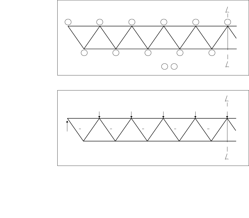
The structural analysis has been based on the assumption that all member centre lines node, bracings
are pinned and chords are continuous. The girder is symmetrical about its centre, so only half is shown
here. The girder and member load details are shown in figures 29 and 30
Figure 29: Girder layout, member and node numbering
Figure 30: Applied member factored loads
5 4 3 2
123 4
20 22 23 24 25 26 27
5
28 2921
11 12 13 14 15
1
2
1, 2 .... etc member numbers : , .... etc joint numbers
1
6 7 8 9 10
11
C
C
-314 -872 -1290 -1569 -1709
100 100 100 100 100
450
628 1115 1465
All loads in kN
1674 1744
C
C
+548 +427 +304 +183 +61

Design of SHS welded joints 36
6.2 Design philosophy
The following points should be born in mind when determining the member sizes and thicknesses.
1. Gap joints are more economic to fabricate than overlap joints.
2. For gap joints, smaller thicker chords give higher joint capacities than larger thinner ones.
3. For gap joints, larger thinner bracings give higher joint capacities than smaller thicker ones.
4. It is usually more economic to restrict the number of bracing sizes to about three, rather than to
match every bracing to the actual load applied to it. This may not be so true if very large numbers
of identical girders are to be produced.
5. The material can be obtained in 12.5m lengths, as a result the chords will be made from the same
material throughout their length ( other lengths are available).
6. The effective length factors for compression members have been taken as 0.9 for chords and 0.75
for the bracings between chord centres.
7. It is possible that in order to meet the joint parameter limits, it will be necessary to move away from
member centre line noding. Any moment generated due to joint eccentricities can be considered to
be distributed into the chord only with 50% taken on each side of the joint.
6.3 RHS girder design
6.3.1 RHS Member Selection Options
Top Chord : load -1709kN Bottom Chord : load +1744kN
Size Mass Capacity Size Mass Capacity
180x180x10.0 53.0 -1793 180x180x10.0 53.0 1857
150x150x12.5 53.4 -1767 150x150x12.5 53.4 1870
Bracing 20 : load +548kN Bracing 21 : load -548kN
Size Mass Capacity Size Mass Capacity
90x90x6.3 16.4 575 80x80x8.0 17.8 -577
80x80x8.0 17.8 625 120x120x5.0 18.0 -612
120x120x5.0 18.0 629
Bracing 22 : load +427kN Bracing 23 : load -427kN
Size Mass Capacity Size Mass Capacity
70x70x6.3 12.5 436 90x90x5.0 13.3 -439
60x60x8.0 12.8 449 80x80x6.3 14.4 -469
90x90x5.0 13.3 464 100x100x5.0 14.8 -497
Bracing 24 : load +304kN Bracing 25 : load -304kN
Size Mass Capacity Size Mass Capacity
90x90x3.6 9.72 340 90x90x3.6 9.72 -323
70x70x5.0 10.1 354 70x70x5.0 10.1 -321
Bracing 26 : load +183kN Bracing 27 : load -183kN
Size Mass Capacity Size Mass Capacity
60x60x3.0 5.34 187 70x70x3.0 6.28 -201
40x40x5.0 5.40 189 50x50x5.0 6.97 -190
60x60x4.0 6.97 -212
Bracing 28 : load +61kN Bracing 29 : load -61kN
Size Mass Capacity Size Mass Capacity
40x40x2.5 2.92 102 40x40x2.5 2.92 -67.0

37 Design of SHS welded joints
6.3.2 RHS Member Selection
Chord selection
Top and bottom chords will both be 150x150x12.5, since this is smaller and thicker than
180x180x10.0 and is only 0.75% heavier.
Bracing selection
Minimum brace to chord width ratio is 0.35, so bracings must not be smaller than 52.5mm (0.35x150),
from the size range available this means 60x60 minimum.
End bracings (20, 21): The lightest section to suit both bracing is 80x80x8, so this is selected.
Bracings 22, 23, 24 and 25: 90x90x5 are suitable for 22 and 23, this will also be used for 24 and 25,
so that the inner four bracings can be made as light as possible.
Bracings 26, 27, 28 and 29: The lightest section to suit these is determined by member 27 so 70x70x3
is chosen for all.
6.3.3 RHS Joint Capacity Check
6.3.3.1 RHS Joint parameter check
The table below contains all of the parameter checks required for all of the joints in the girder.
Joint or Parameter Limiting value Actual value Remarks
member
Chords b0/t0≤35 150/12.5 = 12 pass
Bracings bi/ti≤35 for tension 80/8 = 10
≤34.5 for compression 90/5 = 18 all pass
70/3 = 23.3
b1/b0≥0.35 and 80/150 = 0.53
≥0.1+0.01b0/t0= 0.22 90/150 = 0.60 all pass
70/150 = 0.47
Joints1, 9 gap ≥t1+ t2= 6 and 19.60 fail - increase to 40mm
and 10 ≥0.5(b0-(b1+b2)/2) = 40 and eccentricity = 14.6
≤1,5(b0-(b1+b2)/2) = 120
Joint 2 gap ≥t1+ t2= 8 and 7.37 fail - increase to 40mm
≥0.5(b0-(b1+b2)/2) = 35 and eccentricity = 23.3
≤1,5(b0-(b1+b2)/2) = 105
Joints 3, gap ≥t1+ t2= 10 and -4.84 (overlap) fail - increase to 40mm
7 and 8 ≥0.5(b0-(b1+b2)/2) = 30 and eccentricity = 32.0
≤1,5(b0-(b1+b2)/2) = 90
Joint 4 gap ≥t1+ t2= 13 and 1.27 fail - increase to 40mm
≥0.5(b0-(b1+b2)/2) = 32.5 and eccentricity = 27.7
≤1,5(b0-(b1+b2)/2) = 97.5
Joint 6 gap ≥t1+ t2= 16 and 7.37 fail - increase to 40mm
≥0.5(b0-(b1+b2)/2) = 35 and eccentricity = 23.3
≤1,5(b0-(b1+b2)/2) = 105

Design of SHS welded joints 38
In all cases it has been necessary to move away from member centre line noding in order to meet the
gap parameter limits. However, the joints at the centre of the girder (1, 2, 9 and 10) have small shear
forces and eccentricities and the chords, although they are subject to high axial forces, should be able
to accommodate these. At the girder ends, the chords carry relatively small axial loads, and although
the shear forces and eccentricities are higher, they should be able to carry the eccentricity moments.
6.3.3.2 RHS Joint capacity check
Generally, it is only necessary to check the capacity of selected joints, e.g. joints with the highest shear
loads, joints with the highest chord compression loads or where the bracing or chord sizes change.
Also, it should be noted that a tension chord joint will always have as high or a higher capacity than an
identical compression chord joint, because the chord end load function is always 1.0 for tension
chords, but is 1.0 or less for compression chords. Here, however, as an example, each joint has been
checked for completeness.
The results of the joint capacity checks for the normal K-joints (all except 5 and 11) are given in the
table below.
Joint Factored Calculated joint capacities, kN for failure modes Joint Gap Ecc.
number applied unity mm mm
load, kN Chord Chord Chord Bracing factor
face shear punching effective
deformation shear width
Joint 1 N27 = -183 270.1 821.8 725.0 221.1 0.83 40 14.6
N28 = 61 270.1 821.8 725.0 221.1 0.28
Joint 2 N25 = -304 403.9 821.8 932.2 467.5 0.75 40 23.3
N26 = 183 403.9 821.8 725.0 221.1 0.83
Joint 3 N23 = -427 572.2 821.8 932.2 467.5 0.91 40 32.0
N24 = 304 572.2 821.8 932.2 467.5 0.65
Joint 4 N21 = -548 626.3 821.8 828.6 633.6 0.88 40 27.7
N22 = 427 626.3 821.8 932.2 467.5 0.91
Joint 6 N21 = -548 609.9 821.8 828.6 633.6 0.90 40 23.3
N20 = 548 609.9 821.8 828.6 633.6 0.90
Joint 7 N23 = -427 686.1 821.8 932.2 467.5 0.91 40 32.0
N22 = 427 686.1 821.8 932.2 467.5 0.91
Joint 8 N25 = -304 686.1 821.8 932.2 467.5 0.65 40 32.0
N24 = 304 686.1 821.8 932.2 467.5 0.65
Joint 9 N27 = -183 533.7 821.8 725.0 221.1 0.83 40 14.6
N26 = 183 533.7 821.8 725.0 221.1 0.83
Joint 10 N29 = -61 533.7 821.8 725.0 221.1 0.28 40 14.6
N28 = 61 533.7 821.8 725.0 221.1 0.28

39 Design of SHS welded joints
The joints 5 and 11 can be regarded as special joints, and, although checked in a similar way to the
others, certain assumptions regarding their behaviour have to be made.
Joint 5 is at the end of the girder and the chord will have an end plate of some type to connect it to the
column. It has been shown that provided the plate thickness is the higher of either 10mm or the chord
thickness (12.5mm in this case) that the joint will behave as a symmetrical K- or N-joint, rather than a
weaker Y-joint. This is because the end plate will restrain the chord cross section from distorting.
Joint 11 should be treated in one of two different ways depending upon the method by which the two
lengths of chord material are connected together at the joint.
(a) if the chord/chord connection is a bolted flange site connection, then joint 11 can be treated in a
similar way to joint 5
(b) if the chord/chord connection is a butt weld, then joint 11 should be treated as a K-joint with both
bracings loaded in compression.
The checks on joints 5 and 11 are given in the table below, in which joint 11a is as for case (a) above
and joint 11b as for case (b) above.
Joint Factored Calculated joint capacities, kN for failure modes Joint
number applied unity
load, kN Chord Chord Chord Bracing factor
face shear punching effective
deformation shear width
Joint 5 N20 = 548 609.9 821.8 828.6 633.6 0.90
Joint 11a N29 = -61 270.1 821.8 725.0 221.1 0.28
Joint 11b N29 = -61 143 - - - 0.43
N30 = -61 143 - - - 0.43
Thus all the joints are within all the parameter limits, all the factored loads are below the respective joint
capacities and the girder is satisfactory.
6.4 CHS girder design
6.4.1 CHS Member Selection Options
Top Chord : load -1709kN Bottom Chord : load +1744kN
Size Mass Capacity Size Mass Capacity
323.9x6.3 49.3 -1718 219.1x10.0 51.6 1806
219.1x10.0 51.6 -1801 273.0x8.0 52.3 1832
Bracing 20 : load +548kN Bracing 21 : load -548kN
Size Mass Capacity Size Mass Capacity
139.7x5.0 16.6 582 139.7x5.0 16.6 567
114.3x6.3 16.8 588 114.3x6.3 16.8 562
Bracing 22 : load +427kN Bracing 23 : load -427kN
Size Mass Capacity Size Mass Capacity
114.3x5.0 13.5 472 114.3x5.0 13.5 452
Bracing 24 : load +304kN Bracing 25 : load -304kN
Size Mass Capacity Size Mass Capacity
76.1x5.0 8.77 307 114.3x3.6 9.80 330
114.3x3.6 9.80 344 88.9x3.6 10.3 336

Design of SHS welded joints 40
Bracing 26 : load +183kN Bracing 27 : load -183kN
Size Mass Capacity Size Mass Capacity
48.5x5.0 5.34 187 88.9x3.2 6.76 220
60.3x4.0 5.55 195 60.3x5.0 6.82 194
Bracing 28 : load +61kN Bracing 29 : load -61kN
Size Mass Capacity Size Mass Capacity
26.9x3.2 1.87 66 42.4x3.2 3.09 63
33.7x2.6 1.99 70 48.3x3.2 3.56 86
6.4.2 CHS Member Selection
Using the same procedure as for the RHS girder the following member sizes were selected.
Top and bottom chords : 219.1 x 10.0
Bracings 20 and 21 : 139.7 x 5.0
Bracings 22 to 25 : 114.3 x 5.0
Bracings 26 to 29 : 88.9 x 3.2
6.4.3 CHS Joint Capacity Check
Again, it has been assumed that gap joints will be used throughout the girder and initially that all centre
lines node, although, in order to meet the joint parameter limits it will be necessary to move away from
this.
6.4.3.1 CHS Joint parameter check
The table below contains all of the parameter checks required for all of the joints in the girder.
Joint or Parameter Limiting value Actual value Remarks
member
Chords d0/t0≤50 219.1/10 = 21.9 pass
Bracings di/ti≤50 for tension 139.7/5 = 27.9
and compression 114.3/5 = 22.9 all pass
88.9/3.2 = 27.8
Bracing on d1/d0≥0.2 139.7/219.1 = 0.64
chord 114.3/219.1 = 0.52 all pass
88.9/219.1 = 0.41
Joints 1, 9 gap ≥t1+ t2= 6.4 44.9 all pass
and 10
Joints 2 gap ≥t1+ t2= 8.2 29.4 pass
Joints 3, 4, gap ≥t1+ t2= 10.0 joint 3 & 7, g = 13.9 pass
6, 7, and 8 joint 8, g = 44.9 pass
joint 4, g = -1.62 fail, increase gap to
12.5, ecc = 10.1
joint 6, g = -17.1 fail, increase gap to
12.5, ecc = 21.2

41 Design of SHS welded joints
6.4.3.2 CHS Joint capacity check
The joint capacity check procedure is the same as for the RHS girder joints, and the general notes for
that girder still apply. The results of the joint capacity checks for the normal K-joints (all except 5 and
11) are given in the table below.
Joint Factored Calculated joint capacities, kN, for failure modes Joint
number applied unity
load, kN Chord face Chord punching factor
deformation shear
Joint 1 N27 = -183 185.2 601.1 0.99
N28 = 61 185.2 601.1 0.33
Joint 2 N25 = -304 292.5 772.8 1.04
N26 = 183 292.5 601.1 0.63
Joint 3 N23 = -427 387.3 772.8 1.10
N24 = 304 387.3 772.8 0.78
Joint 4 N21 = -548 542.5 944.6 1.01
N22 = 427 542.5 772.8 0.79
Joint 6 N21 = -548 577.7 944.6 0.95
N20 = 548 577.7 944.6 0.95
Joint 7 N27 = -427 492.9 772.8 0.87
N28 = 427 492.9 772.8 0.87
Joint 8 N25 = -304 360.9 601.1 0.84
N24 = 304 360.9 601.1 0.84
Joint 9 N27 = -183 360.9 601.1 0.51
N26 = 183 360.9 601.1 0.51
Joint 10 N29 = -61 360.9 601.1 0.17
N28 = 61 360.9 601.1 0.17
Joints 2, 3 and 4 all fail due to the chord face deformation criterion by 4%, 10% and 1% respectively.
Either member sizes or joint configurations will have to be changed, or the joints could be reinforced.
6.4.4 CHS Girder Reanalysis
There are various ways of increasing the capacity of the failed joints, for example :
1) Change the top chord to one diameter lower and one thickness higher, i.e. 193.7 x 12.5. This would
increase the girder weight by 3.84%, it would also mean that the profiling at each end of a bracing
would be different.
2) Change the compression bracings 21, 23 and 25 to one diameter up. This would increase the
weight by 1.44% and, in this case, increase the number of bracing sizes used in the girder to four. New
sizes would be member 21 - 168.3 x 5.0, members 23 and 25 - 139.7 x 5.0.
3) As 2) above, but rationalise the bracing sizes to give three sizes only. The new sizes would be
members 20 and 21 - 168.3 x 5.0, members 22 to 25 139.7 x 5.0 and members 26 to 29 remaining
as 88.9 x 3.2. This would increase the girder weight by 2.9%.
4) Reinforce the six failed joints by adding a saddle plate 12.5mm thick (see section 4.6.1).
If only one or two joints are involved, this could be an economic solution.
5) Change the joints to overlap joints. This will increase fabrication costs since the ends of the bracings
will require double profiling.
The actual choice from the above options will depend upon the circumstances of a particular project
such as:- number of identical girders required, material available or in stock, relative costs of
fabrication and materials, etc. In this particular case option 3) will be used.
40

Design of SHS welded joints 42
6.4.4.1 Re-selection of CHS sizes
The actual section sizes will now be as follows
Chords both 219.1 x 10.0, as before
Bracings 20 and 21 - 168.3 x 5.0
Bracings 22 to 25 - 139.7 x 5.0
Bracings 26 to 29 - 88.9 x 3.2, as before
This results in an increase in the girder weight of 2.9%.
6.4.4.2 Revised CHS girder parameter limits and joint capacity checks
The joint parameter limits are all satisfied, and the joint capacity check is given in the table below.
Due the size changes the bracing gaps result in different eccentricities of loading, these are also shown
in the table.
Joint Factored Calculated joint capacities, kN, Joint Gap Ecc.
number applied for failure modes unity mm mm
load, kN factor
Joint 1 N27 = -183 185.2 601.1 0.99 44.9 0.0
N28 = 61 185.2 601.1 0.33
Joint 2 N25 = -304 363.8 944.6 0.84 13.9 0.0
N26 = 183 363.8 601.1 0.50
Joint 3 N23 = -427 453.9 944.6 0.94 12.5 21.2
N24 = 304 453.9 944.6 0.67
Joint 4 N21 = -548 629.5 1138 0.87 12.5 33.6
N22 = 427 629.5 944.6 0.68
Joint 6 N21 = -548 670.3 1138 0.82 12.5 46.1
N20 = 548 670.3 1138 0.82
Joint 7 N27 = -427 577.7 944.6 0.74 12.5 21.2
N28 = 427 577.7 944.6 0.74
Joint 8 N25 = -304 577.7 944.6 0.53 12.5 21.1
N24 = 304 577.7 944.6 0.53
Joint 9 N27 = -183 360.9 601.1 0.51 44.9 0.0
N26 = 183 360.9 601.1 0.51
Joint 10 N29 = -61 360.9 601.1 0.17 44.9 0.0
N28 = 61 360.9 601.1 0.17
The joints with the most highly loaded chords, joints 1, 2, 9 and 10, have zero noding eccentricity and
the chords will not have to carry any moment due to eccentricity. Where there is an eccentricity, the
chords have relatively small axial loads (e.g. at joint 3 only 75% of its axial capacity) and will therefore
also be able to carry the moment generated.
Although they have not been checked here, joints 5 and 11 would be checked using the same
procedure as for the RHS girder.
Thus all the joints are within all the parameter limits, all the factored loads are below the respective joint
capacities and the girder is satisfactory.
41
Chord face Chord punching
deformation shear
43 Design of SHS welded joints
7. List of symbols
7.1 General alphabetic list
A0, Aiarea of chord and bracing member i, respectively
Avshear area of chord
E modulus of elasticity (205 000N/mm2)
Mip,i joint design capacity in terms of in plane moment in bracing member i
Mip,i,App factored applied in plane moment in bracing member i
Mop,i joint design capacity in terms of out of plane moment in bracing member i
Mop,i,App factored applied out of plane moment in bracing member i
Nijoint design capacity in terms of axial load in bracing member i
Ni,App factored applied axial load in bracing member i
Ovpercentage overlap, q sinθ/ hix 100%, see figure 31
VApp factored applied shear load in gap between bracings
Vpchord shear capacity
Wel,i elastic section modulus of member i
Wpl,i plastic section modulus of member i
a fillet weld throat thickness
b0, biwidth of RHS chord and bracing member i, respectively
beff effective bracing width, bracing to chord
bep effective bracing width for chord punching shear
beov effective bracing width, overlapping to overlapped bracing
bf
I
-section flange width
brwidth of reinforcement plate for RHS chord
d0, didiameter of chord and bracing member i, respectively
dsarc length of saddle reinforcement plate for CHS chord
dw
I
-section web depth
e joint eccentricity
fy0, fyi nominal yield (design) strength of chord and bracing member i, respectively
g gap / overlap between bracings at the chord face, a negative value denotes
an overlap
h0, hiheight of RHS chord and bracing member i, respectively
hrlength of reinforcement plate
q overlap between bracings at the chord face
t0, tithickness of chord and bracing member i, respectively
tf
I
-section flange thickness
trthickness of reinforcement plate
tw
I
-section web thickness
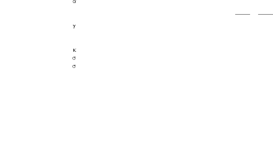
non-dimensional factor for the effectiveness of the chord face to carry shear
ßmean bracing to chord width ratio, b1/b0or d1/d0 or b1+b2or d1+d2
2b02d0
chord width to thickness ratio, d0/(2 t0) or b0/(2 t0)
µ multiplanar factor
θiangle between bracing member i and the chord
efficiency factor
0factored applied stress in RHS chord joint
pfactored applied stress in CHS chord joint
Member identification suffices, i
0 the chord member
1 the compression bracing for joints with more than one bracing or the bracing where
only one is present
2 the tension bracing for joints with more than one bracing
j the overlapped bracing for overlapped bracing joints
42
Design of SHS welded joints 44
43
d0
t0
b0
t0
h0
r
dw
tw
bf
tf
d
h1b1
d1
t1
t1
b2h2
d2
t2
t2
0102
g
hi
hi
q
0i
sin 0i
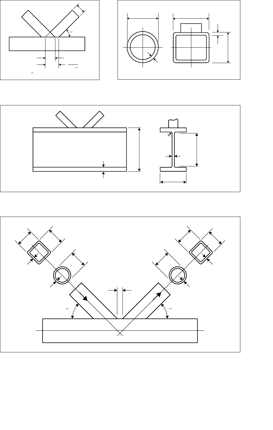
7.2 Pictorial
Ov= q sin 0i/ hix 100%
Figure 31 : Definition of percentage overlap Figure 32 : Definition of SHS chord symbols
dw= d - 2(tf+r)
Figure 33 : Definition of
I
-section chord symbols
Figure 34 : Definition of bracing symbols

45 Design of SHS welded joints
8. References
1. CIDECT*- ‘Design Guide for Circular Hollow Section (CHS) Joints under Predominantly Static
Loading’, Verlag TUV Rheinland, Cologne, Germany, 1991, ISBN 3-88585-975-0.
2. CIDECT* - ‘Design Guide for Rectangular Hollow Section (RHS) Joints under Predominantly
Static Loading’, Verlag TUV Rheinland, Cologne, Germany, 1992, ISBN 3-8249-0089-0.
3. BS DD ENV 1993-1-1 :1992/A1 :1994.Eurocode 3 - Design of Steel Structures : Part 1-1 -
General Rules and Rules for Buildings : Annex K - Hollow section lattice girder connections.
4. BS 5950 -1:2000 - Structural Use of Steelwork in Building :Part 1 - Code of Practice for
Design - Rolled and welded sections.
5. CIDJOINT software program, a design program requiring MS-Windows version 3.x (or higher)
and available in the UK from CSC (UK) Ltd, New Street, Pudsey, Leeds, LS28 8AQ.
6. EN 10210-1 - Hot finished structural hollow sections of non-alloy and fine grain structural
steels : Part 1 - Technical delivery requirements.
7. EN 10210-2 - Hot finished structural hollow sections of non-alloy and fine grain structural
steels : Part 2 - Tolerances, dimensions and sectional properties.
8. EN 10219-1 -Cold formed welded structural hollow sections of non-alloy and fine grain steels-
Part 1. Technical delivery requirements.
9. EN 10219-2 -Cold formed welded structural hollow sections of non-alloy and fine grain steels:
Part 2 - Tolerances, dimensions and sectional properties.
10. Corus Tubes specification TS30 - Strongbox®235.
11. Corus Tubes - Celsius structural hollow sections, CT06.
12. Corus Tubes - cold formed hollow sections, CT05.
13. Corus Tubes - SHS welding, CT15.
14. CIDECT*- Design guide for fabrication, asembly and erection of hollow section structures, Verlag
TUV Rheinland, Cologne, Germany, 1998, ISBN 3-8249-0443-8
*CIDECT design guides are available from the Steel Construction Institute, Silwood Park, Ascot,
Berkshire, SL5 7QN, England. E-mail: publications@steel-sci.com. URL: http//www.steel-sci.org.

www.corusgroup.com
Corus Tubes
Structural & Conveyance Business
Sales Enquiries contact:
UK Sales office
PO Box 6024,
Weldon Road
Corby, Northants
NN17 5ZN
United Kingdom
T +44 (0)1536 402121
F +44 (0)1536 404127
www.corustubes.com
corustubes.s-c@corusgroup.com
Technical Helpline (UK Freephone)
0500 123133 or +44 (0) 1724 405060
Corus Tubes
Structural & Conveyance Business
Sales Enquiries contact:
Netherlands Sales office
Postbus 39
4900 BB Oosterhout
The Netherlands
T +31 (0)162 482300
F +31 (0)162 466161
corustubes.s-c@corusgroup.com
CT16:1000:UK:08/2005
Care has been taken to ensure that this
information is accurate, but Corus Group plc,
including its subsidiaries, does not accept
responsibility or liability for errors or information
which is found to be misleading
Designed by Eikon Ltd
English Language
