AI 98 10 Door Management Guide Doormgt
User Manual: Doormgt AlarmHow.net Library
Open the PDF directly: View PDF ![]() .
.
Page Count: 4

165 Eileen Way, Syosset, NY 11791
TECHNICAL SUPPORT: 1-800-573-0154
This guide is intended to assist you in the design and layout of a simple PassPoint Access
Control system. Use this worksheet along with PassPoint’s “System Designer” worksheet to quote
PassPoint systems.
The PassPoint system operates on a Windows™ 95 platform using simple point and click
commands. The compact, yet sophisticated, design makes PassPoint Access easy to install
and service. LonWorks®-based communication principles make final connections and system
wiring simple to understand and easy to accomplish. Each Controller can manage two
card-readers. Additional controllers can be added to meet system requirements.
Take this guide to your job site to accurately keep track of door peripherals. To design simple
systems, please refer to the attached worksheets. For additional information on computer
specifications and design assistance, contact your Systems Specialist.
Access Control Door Management
Site Survey Guide
The
AI-98-10 Door Management Guide 6/2/98 2:28 PM Page 2
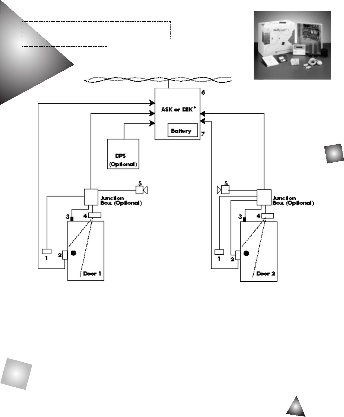
PASSPOINT FIELD PANELS
Two Door Controller:
1 Card Reader
2 Electric Lock**
3 Door Position Switch
4 Request to Exit (Optional)
5 Local Alarm (Optional)
6 DCM Controller
7 Battery for Controller
8 Door Power Supply (Optional)
22 AWG unshielded twisted pair
*Choose ASK for first panel on any system, then choose DEK for each additional (2) door expansion.
Access Starter Kit (ASK)
Echelon LonWorks Network
PassPoint Door Control Module Provides:
▲Adjustable momentary open times
▲Automatic re-locking of the electric lock on door closing or opening
▲Activation of local relay
▲Annunciation for door forced or door ajar
PassPoint is a trademark of Pittway Corp.
Windows is a trademark of Microsoft Corp.
LonWorks is a trademark of Echelon Corp. registered in the United States and other countries.
**Noise Suppression: Whenever you bring a new electric locking device into any facility, it is important
to remember that these devices generate transients (noise) that can interfere with the proper operation
of other electronic buildings systems. Take proper preventative action during installation to incorporate
“Transient Suppression” as close as possible to the coil of each locking device that you install.
FILL IN
DOOR NAME:
________________
DOOR LOCATION:
________________
FILL IN
DOOR NAME:
________________
DOOR LOCATION:
________________
AI-98-10 Door Management Guide 6/2/98 2:28 PM Page 3
PASSPOINT ACCESS CONTROL
Door Expansion Kit (DEK)
PC Requirements:
▲Pentium 90 with 16 MB RAM, 20 MB hard drive space available, 3-1/2" floppy drive, serial port, parallel port
REF. # ITEM APPLICATION/DESCRIPTION EXAMPLE FROM ADI UNIT PRICE QTY.EXTENDED PRICE
1 Card Reader Proximity PTPROX
2 Electronic Lock Electronic strike 12VDC and HE-7U12D30
or Strike Face plates HE-7000CPAC
or
Mag Locks (requires emergency Contact System
override device. Check with Specialist
Authority Having Jurisdiction
and NFPA guidelines for proper
application)
3 Door Position Detects if door is opened or 7939-2GY
Switch closed
4 Request to Exit Push-button or RU908M032D
Device Motion detector or other or VSDA5
5 Local Audible Audible annunciation for door AMSECO
Alarm forced open, door ajar or PAL-328N
(Optional) invalid card transactions
15 ma draw or less
6 ASK or DEK Two reader Controller, First choose
including transformer PTASKPROX
then expand
with PTDEK
7 Battery for each 12 VDC @ 7 amp/hr battery YANP712
ASK or DEK for ASK or DEK one needed
for each
SUB-TOTAL FOR DOOR PERIPHERALS
ADI PART #DESCRIPTION UNIT PRICE QTY.EXTENDED PRICE
PTACSWIN1 PassPoint “Express” Basic Access Control Software
Access Control Software:
USE
S
YSTEM
D
ESIGN
G
UIDE
TO QUOTE THIS
USE
S
YSTEM
D
ESIGN
G
UIDE
TO QUOTE THIS
USE
S
YSTEM
D
ESIGN
G
UIDE
TO QUOTE THIS
(
MOTION
DETECTOR
)
(
PUSH
BUTTON
)
L/SITSVY/D 4/98
AI-98-10 Door Management Guide 6/2/98 2:28 PM Page 4

Distance Limitations: The wiring shown in the drawing is recommended for typical installations only. In such an
application, the card reader controlled door would be approximately up to 500 feet maximum from the Door Control
Module. The wiring specifications shown would be suitable for such distances.
**Noise Suppression: You can use EL-EDS made by EDCO and available from ADI. Other methods include: for DC
powered devices, use a Reverse Biased Diode – #IN4004. For AC powered devices, use a MOV (Metal Oxide Varistor)
rated at 125% of the inductive load. Mount the suppression device across the inductive load, as close as possible to the
coil of each locking device that you install.
Shielding: At the reader controlled door end of the cable – ensure that shields are isolated from metal by masking with
tape or heat shrink. The shield/drain wires of all other cabling is earth grounded at the control panel side only; and not
at the reader side.
MAXIMUM
REF. # TOCONTROLLER FROM TYPICAL DISTANCE DESCRIPTION
1 Card Reader 500 Ft Five conductor # 18 or 22 AWG stranded shielded cable
2 Electric Lock 500 Ft Two conductor # 16 AWG shielded cable
3 Door Position Switch 500 Ft Two conductor # 18 AWG cable
4 Request to Exit 500 Ft Two conductor # 18 AWG cable
5 Local Audible Alarm 500 Ft Two conductor # 18 AWG cable
WIRING AND INSTALLATION RECOMMENDATIONS
Basic Single Leaf Door With:
1 Card Reader
2 Electric Locking Device**
3 Door Position Switch
4 Request to Exit Device
5 Local Audible Alarm
AI-98-10 Door Management Guide 6/2/98 2:28 PM Page 1
