Vna/J Driver Guide Mini VNAtiny
User Manual:
Open the PDF directly: View PDF ![]() .
.
Page Count: 21
vna/J 3.1.12
Driver guide for mini Radio Solutions
miniVNAtiny
Dietmar Krause
DL2SBA
Hindenburgstraße 29
D-70794 Filderstadt
http://creativecommons.org/licenses/by-nc-nd/3.0 Monday, 21. November 2016
vna/J - Driver guide for mRS miniVNAtiny - V 3.1.11
© Dietmar Krause, DL2SBA 2016 2 / 21
Table of contents
Changes .............................................................................................................................................. 3
Connectors ......................................................................................................................................... 4
Power Supply ...................................................................................................................................... 4
Firmware update ................................................................................................................................ 5
Check currently installed firmware .................................................................................................6
Download new firmware ................................................................................................................7
Upgrade firmware of miniVNAtiny ....................................................................................................9
Driver info dialog .............................................................................................................................. 11
Peak suppression .......................................................................................................................... 13
Peak suppression OFF ............................................................................................................... 13
Peak suppression ON ................................................................................................................ 13
Auto calibration ............................................................................................................................ 14
Generator miniVNAtiny ....................................................................................................................... 15
Output control .............................................................................................................................. 15
Frequency control......................................................................................................................... 15
Frequency list ............................................................................................................................... 15
Output power vs. frequency ..................................................................................................... 16
Main calibration datasets miniVNAtiny ............................................................................................... 17
Reflection ..................................................................................................................................... 17
Transmission ................................................................................................................................ 18
Measurement basics ......................................................................................................................... 19
License ............................................................................................................................................. 21
Dutch............................................................................................................................................ 21
English .......................................................................................................................................... 21
Deutsch ........................................................................................................................................ 21

vna/J - Driver guide for mRS miniVNAtiny - V 3.1.11
© Dietmar Krause, DL2SBA 2016 3 / 21
Changes
Version
Date
Who
Changes
3.0.0
06. September 2014
DL2SBA
Extracted from user miniVNApro manual
3.1.x
23. January 2015
DL2SBA
Updated “Driver info dialog” on page 11
3.1.11
5. November 2016
DL2SBA
Updated “Driver info dialog” on page 11
Generator output chart added on page 16
3.1.12
21. November 2016
DL2SBA
Fixed image on page “Output power vs.
frequency” on page 16

vna/J - Driver guide for mRS miniVNAtiny - V 3.1.11
© Dietmar Krause, DL2SBA 2016 4 / 21
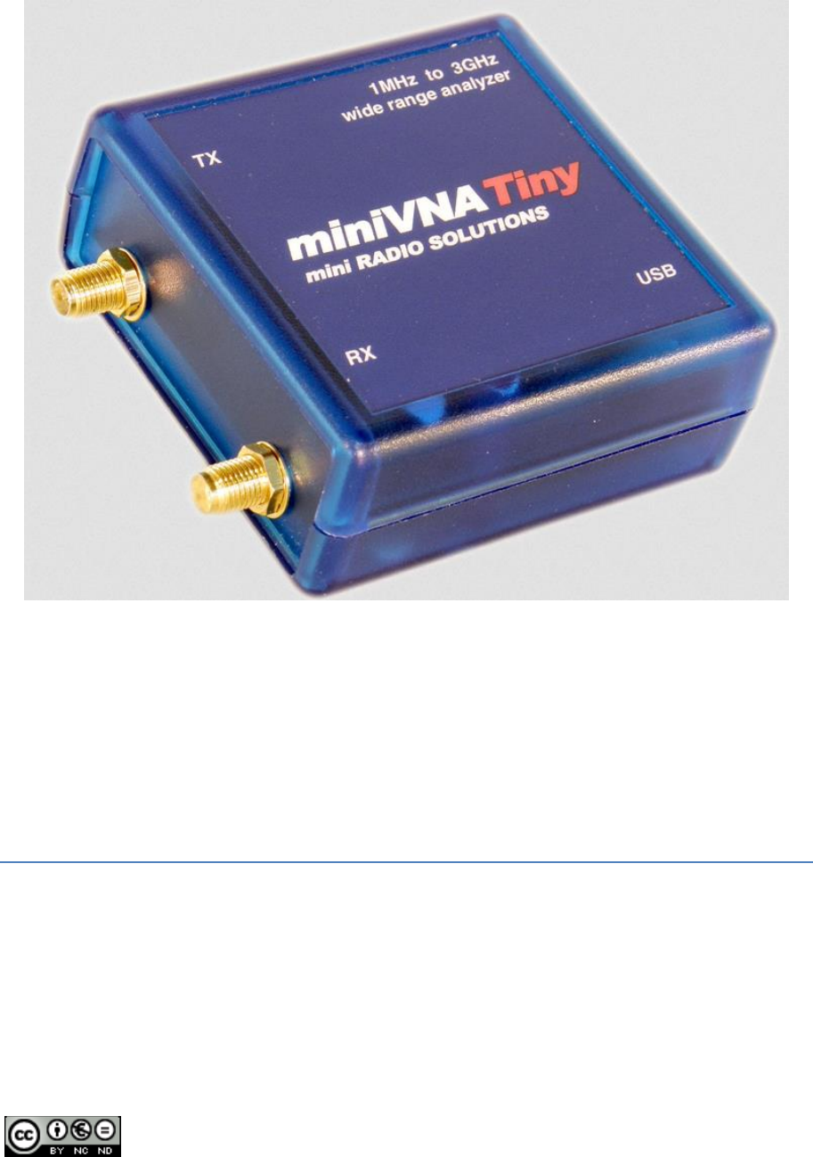
Connectors
#
Usage
USB
Connect a USB-mini type-B connector to this port. The other end of the cable
with a Type-A connector must be connected to a USB-Host adapter.
TX
This is the SMA port for reflection as well as transmission measurement.
RX
This is the 2nd SMA port for transmission measurement.
Power Supply
The miniVNAtiny is powered by the host computer via the build in USB-mini type-B connector.
vna/J - Driver guide for mRS miniVNAtiny - V 3.1.11
© Dietmar Krause, DL2SBA 2016 5 / 21
Firmware update
Attention: You're executing all these steps on your own risk!
Please use also other sources to verify the correctness of the described procedure.
Always execute the following actions only on a native operating system. Means not
inside a windows emulator like Wine on Linux or similar stuff.
I've tested the firmware upgrade with vna/J successfully on Windows 7 and Win-
dows 8.1 in 64-bit versions.
Do not use the firmware upload function on other operating systems as this may
brick your analyser!
It is highly recommended to update always to the latest stable firmware release to gain most from
the program features!
To upgrade the firmware inside the miniVNAtiny please execute these steps:
Check currently installed firmware version using vna/J
Download new firmware from mRS website
Upgrade firmware of miniVNAtiny using vna/J
These steps are described in detail in the following chapters.
vna/J - Driver guide for mRS miniVNAtiny - V 3.1.11
© Dietmar Krause, DL2SBA 2016 6 / 21
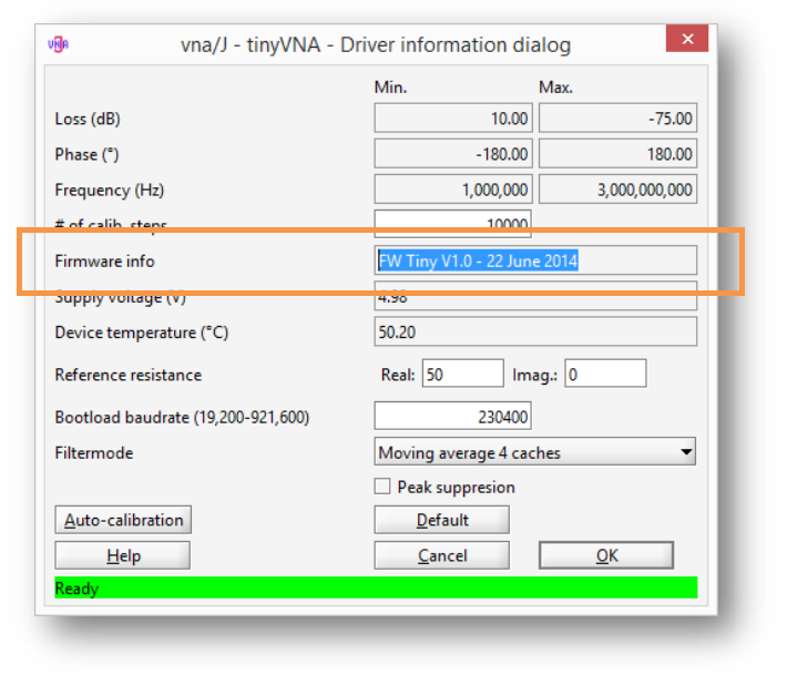
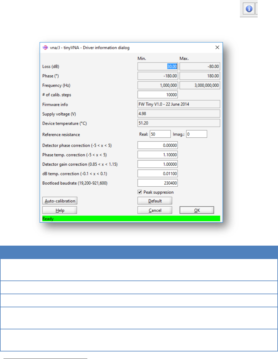
Check currently installed firmware
You have to determine the currently installed firmware version on your miniVNAtiny .
To do this, start vna/J, select the correct serial port and open the driver info dialog (menu ANALYS-
ER/INFO). The firmware version is displayed like this:
Relevant is the firmware number, here displayed as V1.0.
vna/J - Driver guide for mRS miniVNAtiny - V 3.1.11
© Dietmar Krause, DL2SBA 2016 7 / 21
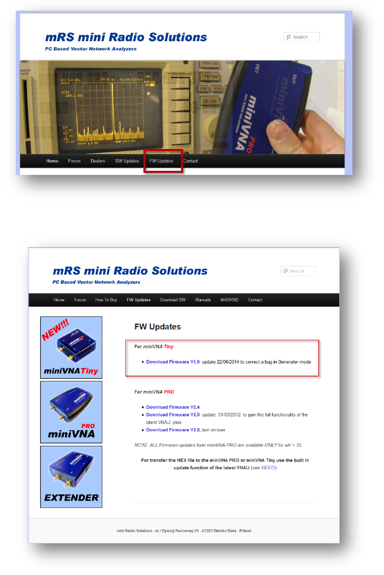
Download new firmware
Check the available firmware versions on the mRS website:
http://www.miniradiosolutions.com
Use the link FW Updated in the navigation bar
on the website to navigate to the firmware section.
If a newer version, as the one currently installed on the miniVNAtiny is available, currently a file named
pcv45c_V1.0.zip is available for download.
vna/J - Driver guide for mRS miniVNAtiny - V 3.1.11
© Dietmar Krause, DL2SBA 2016 8 / 21
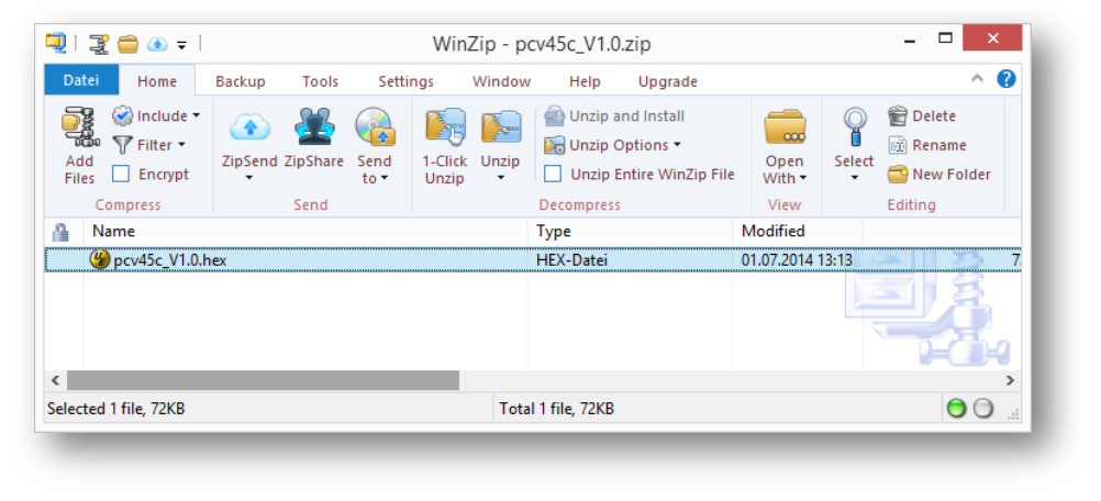
Download this file to your computer to your preferred download location.
Unzip the file so you have a file named pcv45c_V1.0.hex on your computer.
vna/J - Driver guide for mRS miniVNAtiny - V 3.1.11
© Dietmar Krause, DL2SBA 2016 9 / 21
Upgrade firmware of miniVNAtiny
Execute now these steps to write the downloaded firmware file to the miniVNAtiny.
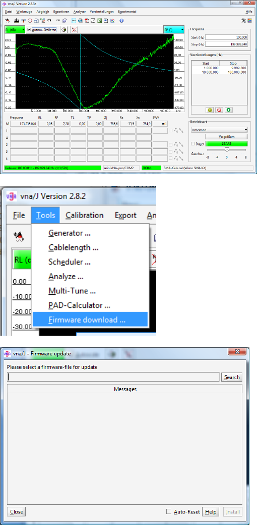
Open vna/J and ensure, that the cor-
rect analyser type and port is selected.
To verify, execute a test scan.
Select "Firmware download" from the
tools menu
Press the "Search" button to select the
previously downloaded new firmware
file.
vna/J - Driver guide for mRS miniVNAtiny - V 3.1.11
© Dietmar Krause, DL2SBA 2016 10 / 21
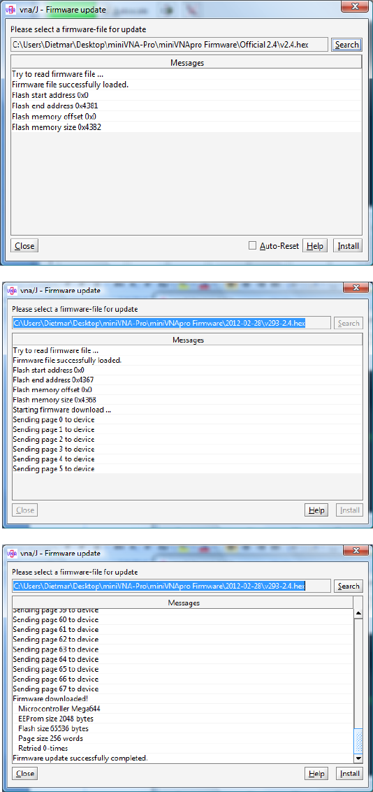
The firmware is loaded and some basic
information is displayed
Select the “Install” button and the
download of the firmware starts after
the soft-reset of the miniVNApro.
After firmware download was success-
ful, some information about the device
is displayed.
Close this dialog and the miniVNAtiny is
ready for use with the new firmware.
Remark: You can also use this procedure to downgrade to a previous firmware release!
vna/J - Driver guide for mRS miniVNAtiny - V 3.1.11
© Dietmar Krause, DL2SBA 2016 11 / 21
Driver info dialog
The driver info dialog for the miniVNApro is available via the menu ANALYSER/INFO or the
icon in the toolbar.
Control
Description
Range
#calibration steps
Sets the number of calibration steps used
as preset during calibration1.
200 to 25.000
Firmware info
Displays the firmware info
---
Supply voltage
Displays power-supply info
---
Device tempera-
ture
Displays the current device temperature.
---
Reference re-
sistance
Here the complex value can be specified,
which is used to calculate data in reflec-
Real -5000 … 5000
Imaginary -5000 … 5000
1
Please read chapter “Calibration procedure in the vna/J user guide for details regarding calibration data.

vna/J - Driver guide for mRS miniVNAtiny - V 3.1.11
© Dietmar Krause, DL2SBA 2016 12 / 21
Control
Description
Range
tion mode.
Detector phase
correction
Internal parameter.
Please use the default value
Phase temp. cor-
rection
Internal parameter.
Please use the default value
Detector gain cor-
rection
Internal parameter.
Please use the default value
dB temp. correc-
tion
Internal parameter.
Please use the default value
Bootloader baud
rate
Sets the baud rate used for firmware up-
dates.
Default is 230.400Bd.
19.2000Bd – 921.600Bd
Peak suppression
Due to internal oscillator switching two
anomalies occur at 1.045GHz and
1.500GHz.
See chapter ”Peak suppression” on page
13 for details.
Please restart application after changing
this option.
On, Off
Auto-calibration
Phase correction of the detector circuits
of the analyser.
See chapter “Auto calibration” on page 14
for details.
---
Default
Restore default values for all driver pa-
rameters
---
OK
Stores the parameters and close this dia-
log
---
Cancel
Do not change any parameters and close
this dialog
---
vna/J - Driver guide for mRS miniVNAtiny - V 3.1.11
© Dietmar Krause, DL2SBA 2016 13 / 21
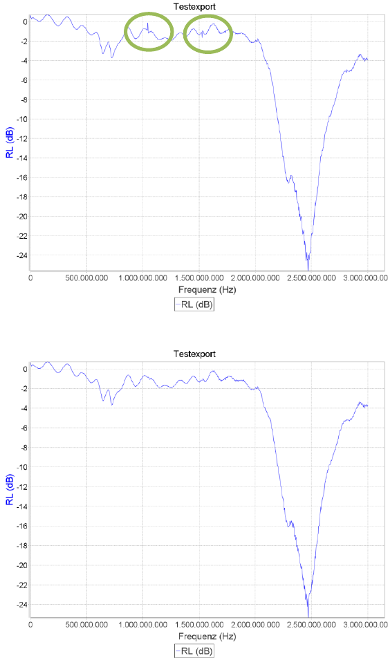
Peak suppression
Due to internal oscillator switching there are two peaks in the measured data at 1.045GHz and
1.500GHz.
These peaks are more or less aesthetical glitches than real problems. As they appear exactly at these
two frequencies, they can be visually ignored by the user.
These peaks can be removed when selecting filter mode 0 and checking the checkbox “Peak suppres-
sion”.
Peak suppression OFF
Peak suppression ON
vna/J - Driver guide for mRS miniVNAtiny - V 3.1.11
© Dietmar Krause, DL2SBA 2016 14 / 21
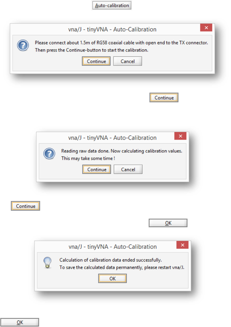
Auto calibration
For optimal results in reflection mode, a phase calibration of the detector circuits should be done.
This calibration can be started with the in the driver info dialog.
Please attach a RG-58 coaxial cable to the TX connector and click . Now four scans are
executed. After the fourth scan, a message box is show, that now the calibration data will be calcu-
lated.
Click . The time needed for calibration depends on the CPU performance of the PC.
When calculation is done a message box is shown. Confirm with button.
If you want to retain the new calibration data, do not forget to close the driver info dialog with the
button!
vna/J - Driver guide for mRS miniVNAtiny - V 3.1.11
© Dietmar Krause, DL2SBA 2016 15 / 21
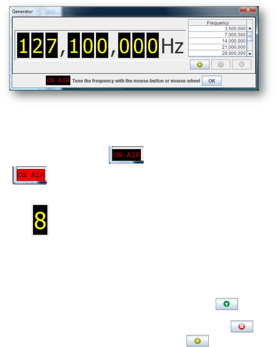
Generator miniVNAtiny
Using this dialog, the attached VNA can be used as a simple frequency generator.
The frequency range is determined by the loaded driver. Details can be viewed in the driver info dia-
log.
Output control
The output is switched on, when clicking . When the output is active, this field is invert-
ed: . To switch off the output, click on this field again.
Frequency control
Every digit of the frequency panel can be controlled with the mouse:
A left-click increases the number by one.
A right-click decreases the number by one.
The digit can also be controlled using the mouse-wheel.
Frequency list
By double-clicking with the left mouse button on an entry in the presets list, you can quickly set the
frequency to the desired value. A selected list entry can also be used clicking the button.
Entries in the presets list can be deleted by selection an entry in the list and clicking on .
A currently entered frequency can be added to the list clicking on the button.
vna/J - Driver guide for mRS miniVNAtiny - V 3.1.11
© Dietmar Krause, DL2SBA 2016 16 / 21
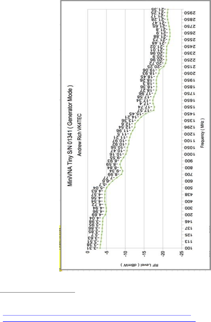
Output power vs. frequency
Thanks to Andrew Rich, VK4TEC and Geoff Robinson, VK4KJJ we have precise output power chart
over frequency. They used a ROHDE & SCHWARZ NRP2
2
and NRP-Z81
3
power sensor
4
.
2
https://www.rohde-schwarz.com/de/produkt/nrp2-produkt-startseite_63493-8475.html
3
https://www.rohde-schwarz.com/de/produkt/nrpz81-produkt-startseite_63493-9323.html
4
German high tech made its way around the globe ;-)
vna/J - Driver guide for mRS miniVNAtiny - V 3.1.11
© Dietmar Krause, DL2SBA 2016 17 / 21
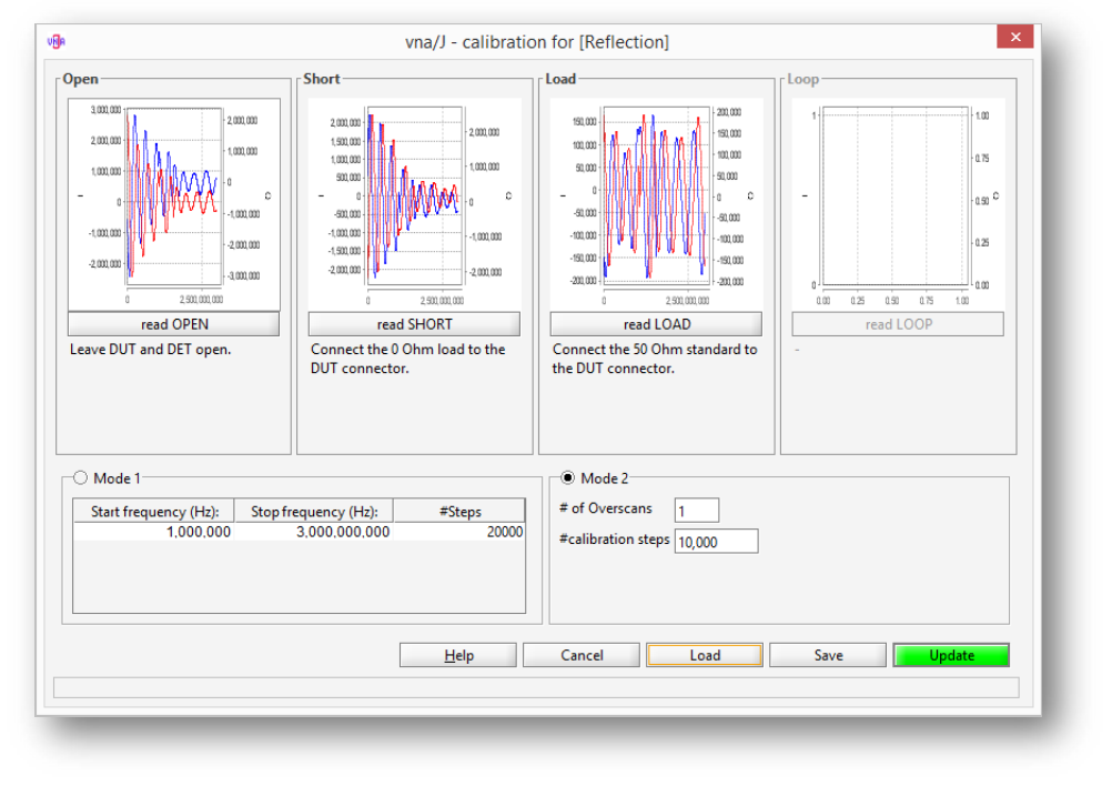
Main calibration datasets miniVNAtiny
Reflection
These calibration curves are created using the supplied WiMo SMA Calibration kit:

vna/J - Driver guide for mRS miniVNAtiny - V 3.1.11
© Dietmar Krause, DL2SBA 2016 18 / 21
Transmission
I've used two SMA-BNC adaptors and a short 20cm RG58A/U cable to create the calibration curves:
vna/J - Driver guide for mRS miniVNAtiny - V 3.1.11
© Dietmar Krause, DL2SBA 2016 19 / 21
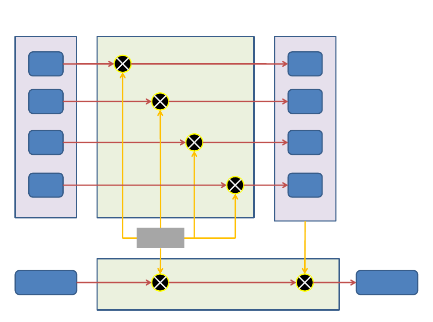
Measurement basics
Open
RAW
Short
RAW
Load
RAW
Phase/Gain/Temp
Correction
Open
RAW
Short
RAW
Load
RAW
RAW calibration
block
Corrected cali-
bration block
RAW scan
data
Calibrated
scan data
During load of cal. data
After scan
Loop
RAW
Loop
RAW

vna/J - Driver guide for mRS miniVNAtiny - V 3.1.11
© Dietmar Krause, DL2SBA 2016 20 / 21
While loading calibration data:
Load raw I/Q data from calibration file.
Data in calibration file is unmodified data
5
directly read from the vna
Calculate temperature correction factor
tcf = 1 – ((40°C – calibrationTemperature) * config.TempCorrection)
Calculate sine correction factor
scf = sin(config.phaseCorrection * π / 180.0)
Calculate cosine correction factor
ccf = cos(config.phaseCorrection * π / 180.0)
correct the I/Q data
o I = I * tcf
o Q = Q * tcf
o Q = (Q * config.gainCorrection - I * scf) / ccf;
Store corrected I/Q data in corrected calibration block
While loading scan data:
Read raw I/Q data from vna device
Calculate temperature correction factor
tcf = 1 – ((40°C – conversionTemperature) * config.TempCorrection)
Calculate sine correction factor
scf = sin(config.phaseCorrection * π / 180.0)
Calculate cosine correction factor
ccf = cos(config.phaseCorrection * π / 180.0)
correct the I/Q data
o I = I * tcf
o Q = Q * tcf
o Q = (Q * config.gainCorrection - I * scf) / ccf;
Calculate IF-phase correction
ipc = (calibrationTemperature – conversionTemperature) * config.ifPhaseCorrection
Calculate RL, RP, SWR based on the previously created calibration data and the cor-
rected raw data
Correct RP
RP = RP + ipc
Calculate X, R, Z
Now we have a calibrated sample
5
The filtering (moving average) is done directly after the I/Q data is read from the vna prior to all
calculations above.
vna/J - Driver guide for mRS miniVNAtiny - V 3.1.11
© Dietmar Krause, DL2SBA 2016 21 / 21
License
Dutch
This work is licensed under the Creative Commons Namensnennung-NichtKommerziell-
KeineBearbeitung 3.0 Niederlande License. To view a copy of this license, visit
http://creativecommons.org/licenses/by-nc-nd/3.0/nl/ or send a letter to Creative Com-
mons, 444 Castro Street, Suite 900, Mountain View, California, 94041, USA.
English
This work is licensed under the Creative Commons Namensnennung-NichtKommerziell-
KeineBearbeitung 3.0 Unported License. To view a copy of this license, visit
http://creativecommons.org/licenses/by-nc-nd/3.0/ or send a letter to Creative Commons,
444 Castro Street, Suite 900, Mountain View, California, 94041, USA.
Deutsch
This work is licensed under the Creative Commons Namensnennung-NichtKommerziell-
KeineBearbeitung 3.0 Deutschland License. To view a copy of this license, visit
http://creativecommons.org/licenses/by-nc-nd/3.0/de/ or send a letter to Creative Com-
mons, 444 Castro Street, Suite 900, Mountain View, California, 94041, USA.
