SWG 5 Ducane Oil Furnaces Spec Sheet
User Manual: SWG-5
Open the PDF directly: View PDF ![]() .
.
Page Count: 8
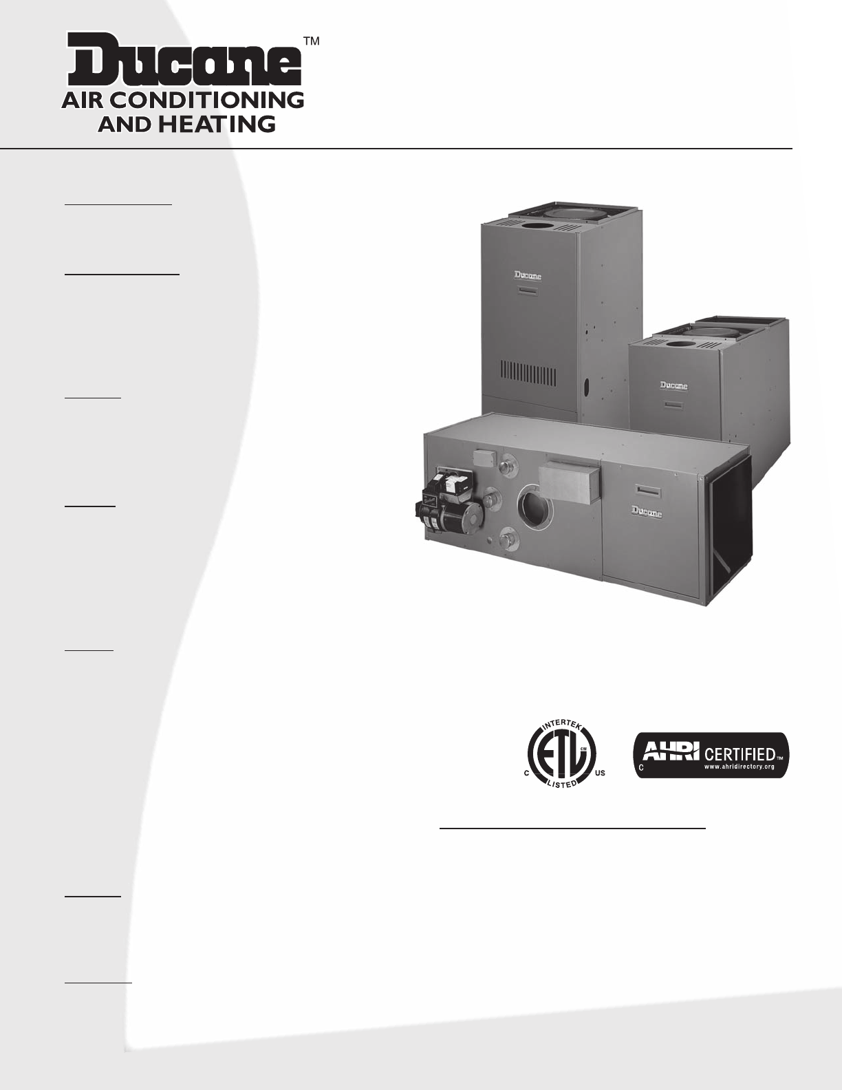
83% Oil Furnaces
Configurations
• Upflow/Highboy •Basement/Lowboy
• Horizonal/Counterflow
HeatExchanger
• Heavy-duty14gaugesteelwithalonglasting
ceramicfibercombustionchamber
• Easyaccesslargediameterstainlesssteelclean
outports
Cabinet
• Foil-facedhighdensityfiberglassinsulation
reducesheatlossandnoise
• Pre-paintedsteelformaximumdurability
Blower
• Directdrivewithslide-outdesign(upflowonly)
andquickplug-inwiring
• 4speedPSCdirectdrivemotorswithdynamically
balancedblowerwheelandresilientmotor
mountsforsmoothandquietoperation
Burner
• HighqualityBeckett™FlameRetentionAFG
Burnerforefficientcombustion
• HighefficiencyPSCBurnermotortoprovide
consistentoperationthroughalloperating
conditions
• Solidstateignitionprovidesaconsistent10,000
voltsforsmoothignition
• Colorcodedwiringforeasyservice
• 40VATransformerandcoolingfanrelayare
factorywiredforeasyadd-oncoolinginstallation
Venting
• Includesfieldinstalledbarometricdamper
• Optionalsidewallventkitavailable
Warranty
• 10yearlimitedpartswarranty/lifetimeheat
exchangerwarrantyavailable.Seelimited
warrantydocumentfordetails.
GeniSys™AdvancedBurnerControl
(Model:7505B1500)featuresthefollowing:
• Programmablevalve-ondelayandmotor-offdelay
• Threeindicatorlightsforsystemmonitoringand
diagnostics
• Twocommunicationportsforaddingalarm
contacts,programmingdisplay,and/orfuture
wirelesscommunications
• Weldedrelayprotectionwithredundantmotor
relays
• Limitedresetandlimitedrecycle
• Sleek,moderndesign
• TechnicianPumpPrimemode
LUF = Upflow / Highboy
LBF/R = Basement / Lowboy
LHF/R = Horizontal / Counterflow
LHR 168/196 = Horizontal only
Form No. DL831D-100 (11/2011)
Features
Model Number Guide
L 83 UF 1 D 84/95 E 20 - 1
Revision code
L - Oil Furnace
AFUE
83 = 83% Efficiency
1 = 1 Stage
08=2T
12=3T
14=3.5T
16=4T
20=5T
57 - 57,000
72 - 72,000
84 - 84,000
95 - 95,000
112 - 112,000
125 - 125,000
UF = Upflow - front flue
BF = Basement - front flue
BR = Basement - rear flue
HF = Horizontal - front flue
HR = Horizontal - rear flue E = 19.5''
(19.5 Horiz. only)
F = 22.5''
(20.5 Horiz. only)
V = Variable Speed
D = Direct Drive
CFM x 100
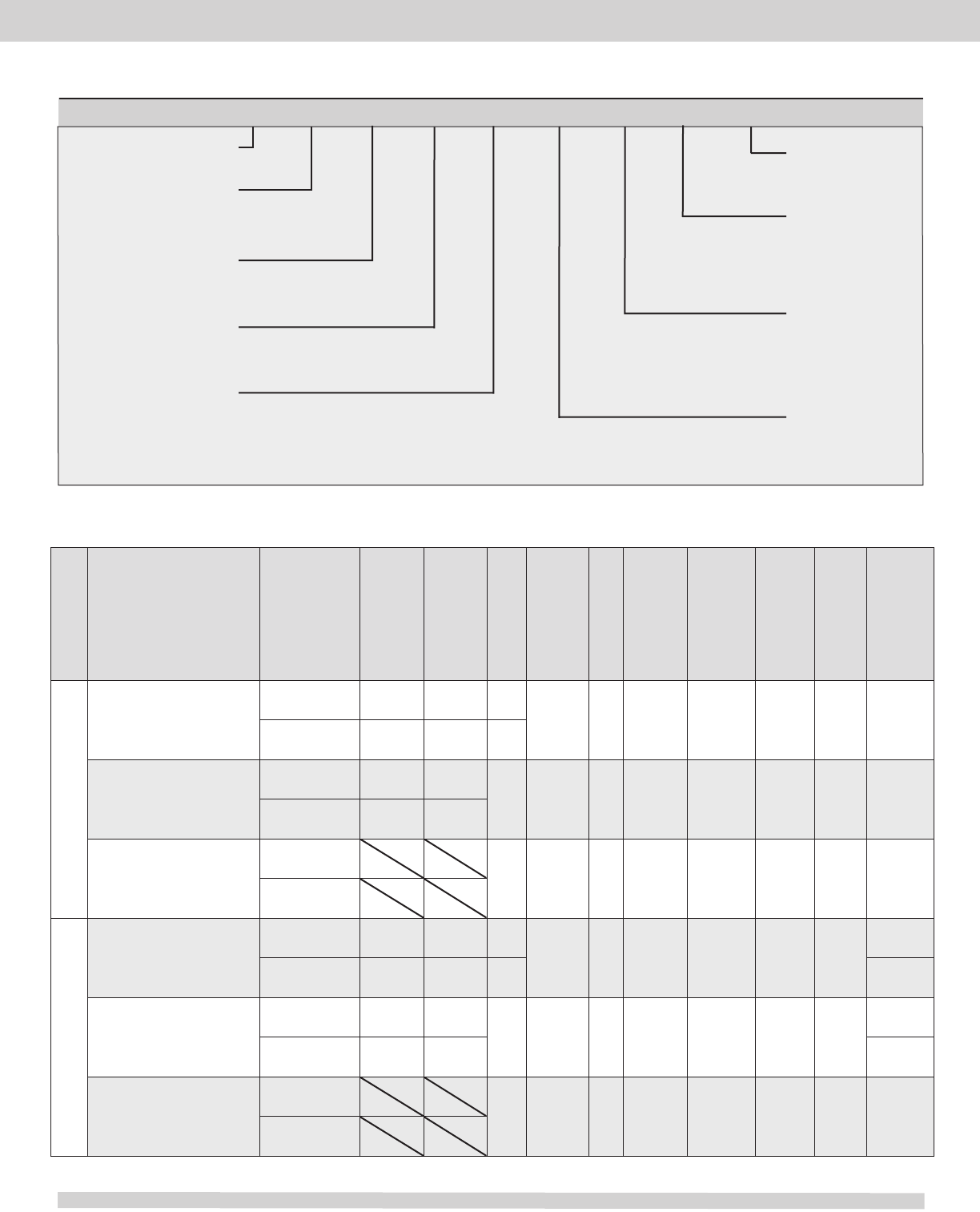
Physical and Electrical Data (Continued on next page)
Model Nozzle
Size
Input
(Btuh)
Output
(Btuh) AFUE
Nom.
Cooling
Cap.
Flue
Dia.
(in.)
Filter
Size
(in.)
Volts/Hz/
Phase
Max.
Time
Delay
Breaker
orFuse
(amp)
Trans.
(V.A.)
Shipping
Weight
(lb.)
L83UF1D57/72E12-1
.50GPH-80°A 67,500 57,000 84.0
2.0 - 3.0 616 X 25 120/60/1 15 40 230
.65GPH-80°B 85,500 72,000 84.0
L83UF1D84/95E16-1
.65GPH-80°B 101,000 84,000
83.0 2.5 - 4.0 616 X 25 120/60/1 15 40 250
.75GPH-80°B 113,500 95,000
L83UF1D112/125F20-1
.85GPH-80°B TBD TBD
83.0 3.0 - 5.0 6(2)
16 X 251120/60/1 15 40 ---
1.00GPH-80°B TBD TBD
L83BF/R1D57/72E12-1
.50GPH-80°A 67,500 57,000 84.0
2.0 - 3.0 618 X 19 120/60/1 15 40
220F
.65GPH-80°B 85,500 72,000 84.0 225R
L83BF/R1D84/95E16-1
.65GPH-80°B 101,000 85,000
83.0 2.5 - 4.0 618 X 19 120/60/1 15 40
225F
.75GPH-80°B 113,500 95,000 230R
L83BF/R1D112/125F20-1
.85GPH-80°B TBD TBD
83.0 3.0 - 5.0 619 X 21 120/60/1 15 40 ---
1.00GPH-80°B TBD TBD
Conguration
Upow/Highboy
Basement
- Page 2 -
83% Oil Furnaces
Nominal Output
Cabinet Width
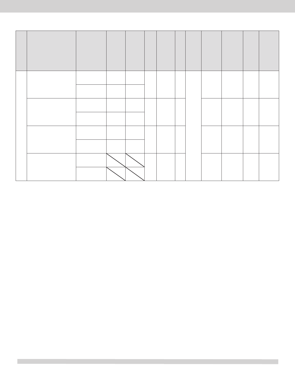
Physical and Electrical Data (Continued from previous page)
Model Nozzle
Size
Input
(Btuh)
Output
(Btuh) AFUE
Nom.
Cooling
Cap.
Flue
Dia.
(in.)
Filter
Size
(in.)
Volts/Hz/
Phase
Max.Time
Delay
Breaker
orFuse
(amp)
Trans.
(V.A.)
Shipping
Weight
(lb.)
L83HF1D84/95E12-1
.65GPH-80°B 101,000 85,000
83.0 2.0 - 3.0 6 120/60/1 15 40 250
.75GPH-80°B 113,500 95,000
L83HR1D57/72E12-1
.50GPH-80°A 67,500 57,000
83.0 2.0 - 3.0 6 120/60/1 15 40 225
.65GPH-80°B 84,000 72,000
L83HR1D84/95E12-1
.65GPH-80°B 101,000 85,000
83.0 2.0 - 3.0 6 120/60/1 15 40 250
.75GPH-80°B 113,500 95,000
L83HF/R1D112/125F20-1
.85GPH-80°B TBD TBD
83.0 3.0 - 5.0 6 120/60/1 15 40 ---
1.00GPH-80°B TBD TBD
Conguration
Horizontal/Counterow
1 Requires return air be brought to both sides above 1600 CFM.
Note: Upflow models shipped with filter(s) for side return.
All models are rated at 140 psi pump pressure except the
LUF80C57/72 and LBF/R 57/72 which is rated 100 psi.
Filters are not supplied
with these models
- Page 3 -
83% Oil Furnaces
83% Oil Furnaces
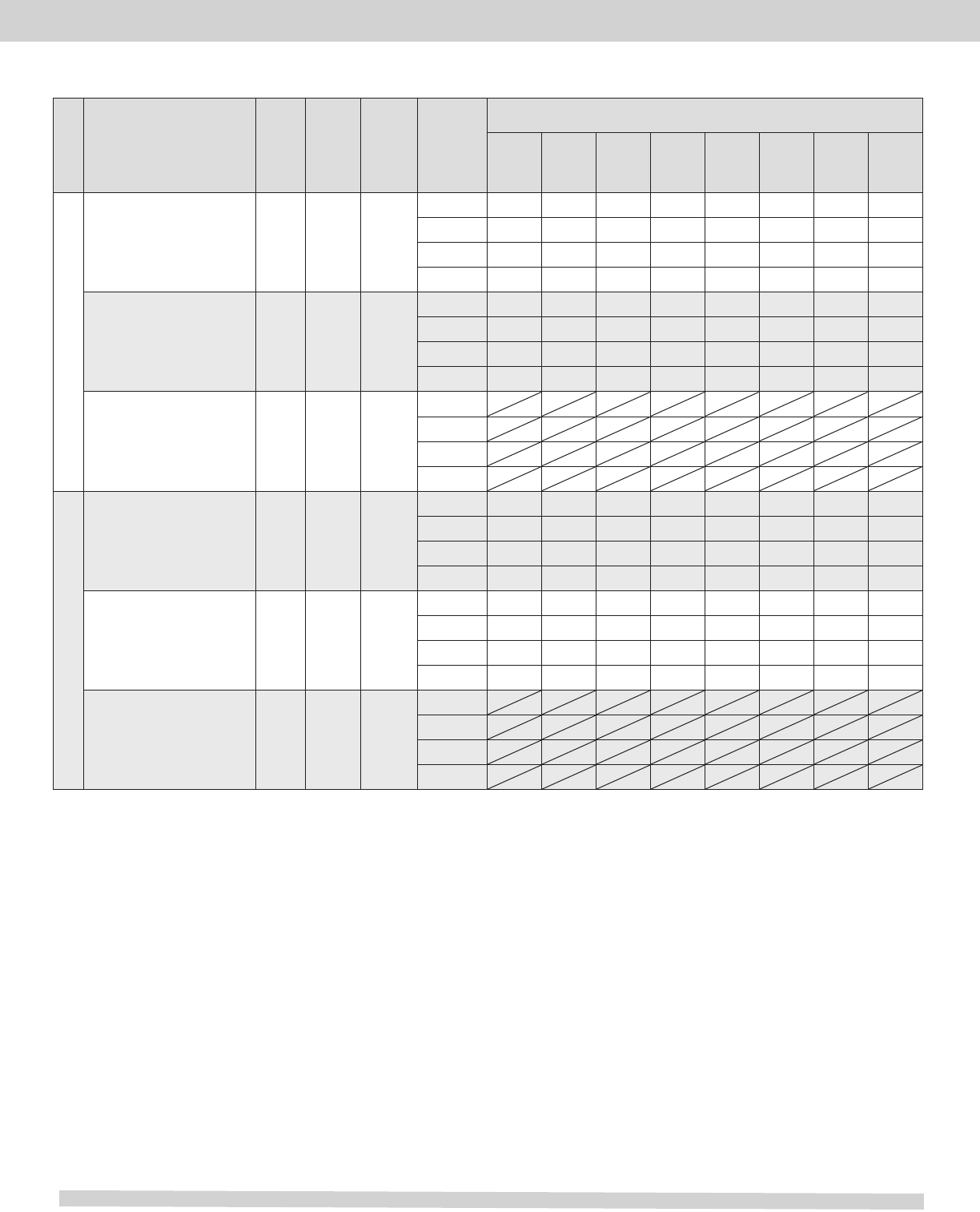
Blower Performance Data (Continued on next page)
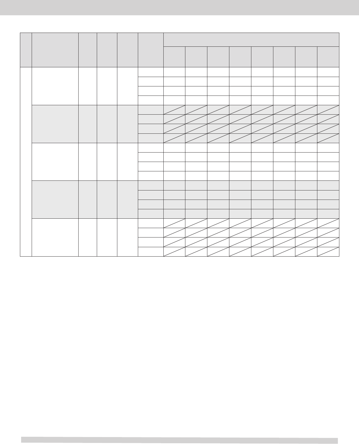
Model
Motor
Size
(hp)
Blower
Size Temp.
Rise°F Blower
Speed
CFM@ext.staticpressure-inW.C.
.20 .30 .40 .50 .60 .70 .80 .90
L83UF1D57/72E12-1 1/3 10 x 8 50 - 80
High 1,410 1,355 1,300 1,220 1,155 1,075 990 890
Med High 1,260 1,215 1,170 1,120 1,060 990 915 800
Med 1,040 1,025 990 960 910 860 790 680
Low 885 880 850 830 785 740 680 605
L83UF1D84/95E16-1 1/2 10 x 10 50 - 80
High 1,755 1,695 1,940 1,590 1,495 1,360 1,250 1,095
Med High 1,445 1,425 1,400 1,335 1,285 1,200 1,065 965
Med 1,190 1,180 1,145 1,110 1,055 985 895 825
Low 990 980 960 925 880 835 775 690
TBD
L83UF1D112/125F20-1 3/4 12 x 11 45 - 75
High
Med High
Med
Low
L83BF/R1D57/72E12-1 1/3 10 x 8 45 - 75
High 1,400 1,350 1,305 1,250 1,185 1,105 1,025 915
Med High 1,135 1,130 1,105 1,075 1,025 965 895 765
Med 930 915 905 865 845 800 730 630
Low 785 775 755 730 705 665 604 518
L83BF/R1D84/95E16-1 1/2 10 x 9 45 - 75
High 1,760 1,670 1,600 1,550 1,410 1,315 1,170 1,000
Med High 1,605 1,515 1,460 1,395 1,305 1,190 1,080 935
Med 1,375 1,345 1,300 1,260 1,190 1,075 975 830
Low 1,160 1,150 1,130 1,105 1,035 955 855 650
TBD
L83BF/R1D112/125F20-1 3/4 12 x 10 45 - 75
High
Med High
Med
Low
Description
Upow/Highboy
Basement/Lowboy
- Page 4 -
83% Oil Furnaces
Horizontal/Counterow
Blower Performance Data (Continued from previous page)
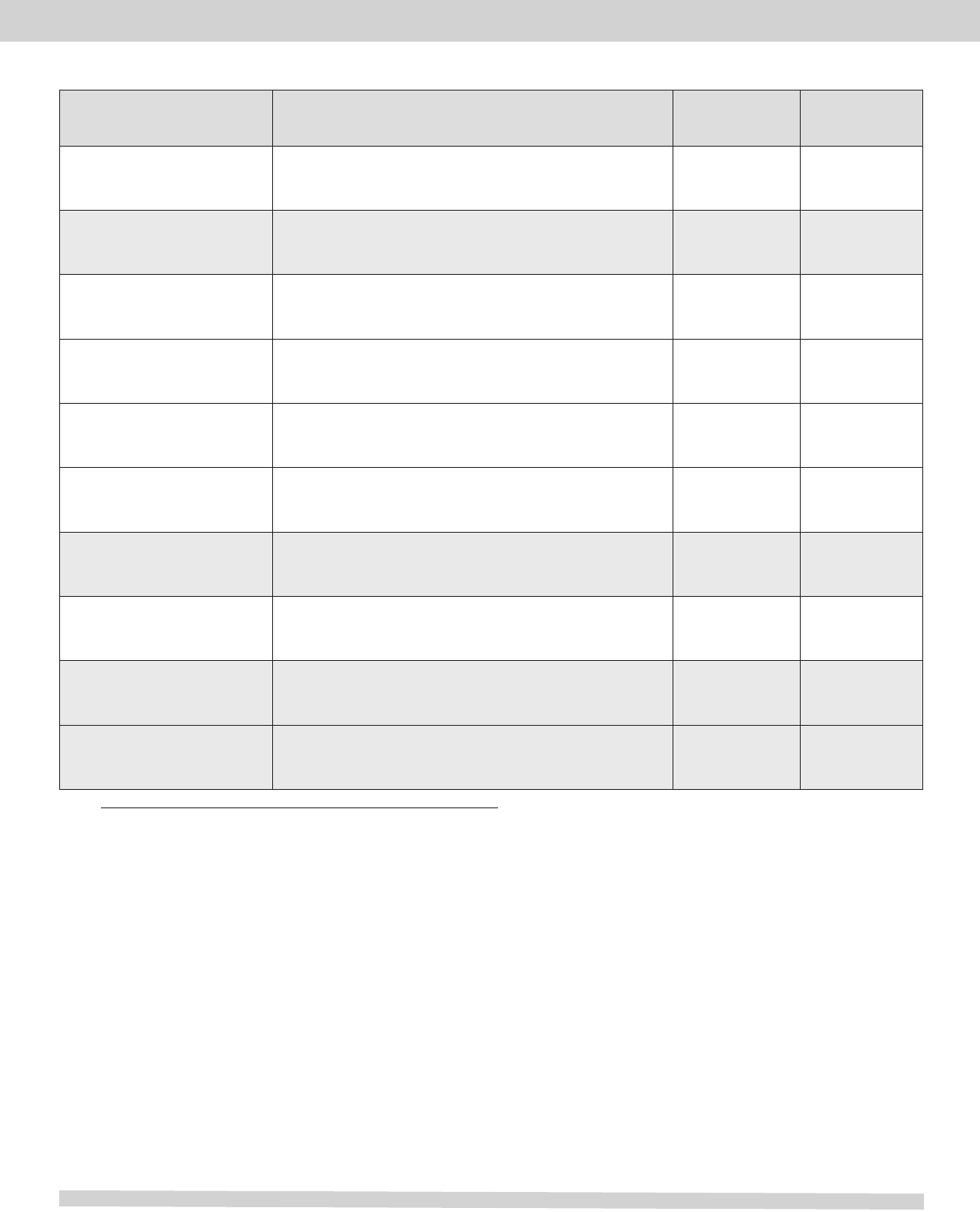
Model
Motor
Size
(hp)
Blower
Size Temp.
Rise°F Blower
Speed
CFM@ext.staticpressure-inW.C.
.20 .30 .40 .50 .60 .70 .80 .90
L83HF1D84/95E-12-1 1/2 10 x 10 45 - 75
High 1,410 1,320 1,280 1,195 1,090 1,000 850 790
Med High 1,340 1,280 1,190 1,100 1,015 900 801 680
Med 1,235 1,175 1,090 1,015 920 845 730 600
Low 1,090 1,035 975 900 855 770 665 545
TBD
L83HF1D112/125F20-1 3/4 12 x 9 45 - 75
High
Med High
Med
Low
L83HR1D57/72E12-1 1/3 10 x 8 45 - 75
High 1,405 1,340 1,275 1,205 1,125 1,010 915 785
Med High 1,255 1,205 1,155 1,090 1,020 920 815 685
Med 1,010 980 950 905 840 775 685 540
Low 835 820 800 760 715 650 560 405
L83HR1D84/95E12-1 1/2 10 x 10 45 - 75
High 1,485 1,400 1,305 1,210 1,105 995 870 740
Med High 1,380 1,305 1,220 1,150 1,035 930 800 670
Med 1,230 1,170 1,110 1,000 935 845 735 595
Low 1,055 1,020 970 910 835 755 640 505
TBD
L83HR1D112/125F20-1 3/4 12 x 9 45 - 75
High
Med High
Med
Low
Description
- Page 5 -
83% Oil Furnaces
Accessories
Description Usedwith Catalog
number
Kit
number
Clean Out Kit All models 1.841025 ABRSH380-3
Field Controls Side Wall Vent Kit *All models See Note Below See Note Below
Evaporator Coil Mounting Kit L83B(F/R)84/95 to EU1P (18,24,30,36,43,48) BN 1.841175 AGOILKDCC19
Evaporator Coil Mounting Kit L83BF/R84/95 & L83B(R)140/168 to EU1P (30,43,48,49,50,60) 1.841176 AGOILKDCC22
Evaporator Coil Mounting Kit L83BF/R112/125, L83BR140/168 & EU1P (60, 62) DN 1.841177 AGOILKDCC24
Evaporator Coil Mounting Kit L83BF/R112/125, L83BR140/168 & L83BR196 to EU1P59DN 1.841179 AGOILKDCC27
Combustion Air Kit All Models 1.841038 ABOOT571
Clean Out Cap Kit All Models 1.841037 ACAP570
Combustible Floor Base L83HF/R84/95, LHR57/72 1.841022 BASE537-1
Combustible Floor Base L83HF/R112/125 1.841023 ABASE538-1
- Page 6 -
Note: * This can be ordered from Field Controls, part number SWG-5-CK61.
83% Oil Furnaces
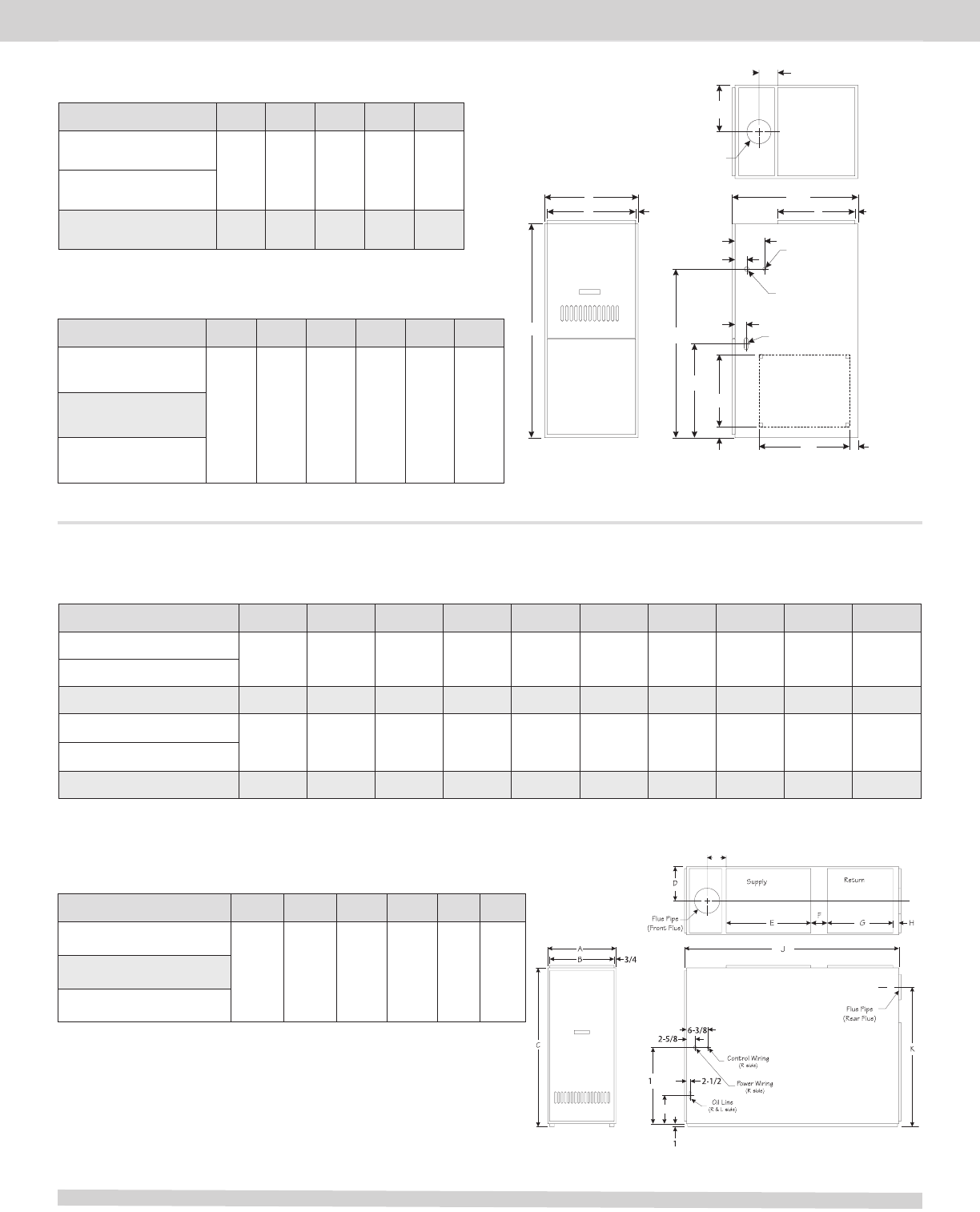
UPFLOW
Clearances to combustibles (in.)
Model Front Sides Rear Floor Above Flue
L83UF1D57/72E12-1
4 0 0 2 6L83UF1D84/95E16-1
L83UF1D112/125E20-1
A
Power Wiring
(R side)
Side Return
(R&Lside)
Supply
Control Wiring
(R side)
Oil Line
(L side)
Flue Pipe
E
4
B3/4 3/4
2 3/4
2 3/4
5 3/4
C
22
34
14
23 1/2
2 1/16
D
19/16
54
6
C
L
6
5-1/4
Dimensions (in.)
Model A B CD E F G H J K
L83BF1D57/72E12-1 19-1/2 18 37 9-3/4 21 3-1/4 16 1-1/2 52 N/A
L83BF1D84/95E16-1
L83BF1D112/125E20-1 22-1/2 21 37 11-1/4 21 3-1/4 16 1-1/2 52 N/A
L83BR1D57/72E12-1 19-1/2 18 37 N/A 21 3-1/4 16 1-1/2 52 27-5/8
L83BR1D84/95E16-1
L83BR1D112/125E20-1 22-1/2 21 37 N/A 21 3-1/4 16 1-1/2 52 27-5/8
BASEMENT
Clearances to Combustibles (in.)
Model Front Sides Rear Above Flue Floor
L8BF/R1D57/72E12-1
4 6 24 2 9L83BF/R1D84/95E16-1
L83BF/R1D112/125E20-1
Dimensions (in.)
Model A B CD E
L83UF1D57/72E12-1
19-1/2 18 30-5/8 19-5/8 9-3/4
L83UF1DC84/95E16-1
L83UF1D112/125E20-1 22-1/2 21 33-1/8 22-1/8 11-1/4
Combustible
Combustible
- Page 7 -
Form No. DL831D-100 (11/2011) ©2011 Allied Air Enterprises Inc., a Lennox International Inc. Company Printed in the U.S.A.
www.ducanehvac.com
1-800-448-5872
All specifications and illustrations
subject to change without notice
and without incurring obligations.
83% Oil Furnaces
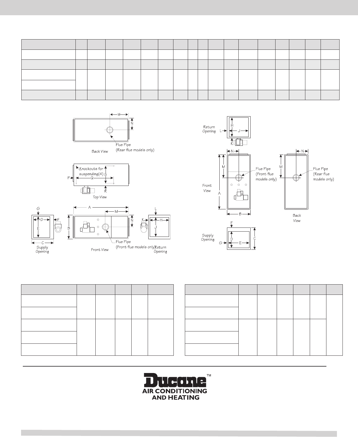
Dimensions (in.)
Model A B CD E F G H J K L M NPQR S
L83HF1D84/95E12-1 59 20-1/2 20-1/2 18-1/4 18-1/4 1-1/4 1-1/4 18 18 1-1/4 1-1/4 32-1/2 10-1/4 3 41-1/2 3 14-1/2
L83HF1D112/125E20-1 59 23-1/2 23-1/2 21-1/4 21-1/4 1-1/4 1-1/4 21 21 1-1/4 1-1/4 32-1/2 11-3/8 3 41-1/2 3 17-1/2
L83HR1D57/72E12-1 59 20-1/2 20-1/2 18-1/4 18-1/4 1-1/4 1-1/4 18 18 1-1/4 1-1/4 32-1/2 10-1/4 3 41-1/2 3 14-1/2
L83HR1D84/95E12-1
L83HR1D112/125E20-1 59 23-1/2 23-1/2 21-1/4 21-1/4 1-1/4 1-1/4 21 21 1-1/4 1-1/4 32-1/2 11-3/8 3 41-1/2 3 17-1/2
HORIZONTAL/COUNTERFLOW
Horizontal Position
Model Front Above Rear Flue Bottom
L83HF1D84/95E12-1
24 1 1 7 1
L83HF1D112/125E20-1
L83HR1D57/72E12-1
24 1 24 7 1L83HR1D84/95E12-1
L83HR1D112/125E20-1
Counterflow Position
Model Front Above Rear Flue Sides Floor
L83HF1D84/95E12-1
16 0 1 7 1
L83HF1D112/125E20-1
L83HR1D57/72E12-1
16 0 1 7 1L83HR1D84/95E12-1
L83HR1D112/125E20-1
Clearances To Combustibles (in.)
Non
Combustible
- Page 8 -
