Emulation For The Motorola M CORE User's Guide E3455 97000_MCORE_May98 97000 MCORE May98
User Manual: E3455-97000_MCORE_May98
Open the PDF directly: View PDF ![]() .
.
Page Count: 128 [warning: Documents this large are best viewed by clicking the View PDF Link!]
- Emulation for the Motorola M-CORE—At a Glance
- In This Book
- Contents
- Overview
- Connecting the Emulation Probe to a LAN
- Installing the Emulation Module
- Installing Software on an HP 16600A/700A
- Connecting to the Target System
- Configuring the Emulator
- Designing a Target System
- Using the Emulator with a Debugger
- Specifications and Characteristics
- Updating Firmware
- Solving Problems
- Troubleshooting Guide
- Emulation Probe Status Lights
- Emulation Module Status Lights
- Built-in Commands
- Problems with the Target System
- Problems with the LAN Interface (Probe only)
- Problems with the Serial Interface (Emulation probe only)
- Problems with the Emulation Probe Itself
- Returning the Parts to Hewlett-Packard for Service
- Index

User’s Guide
Publication number E3455-97000
May 1998
For Safety information, Warranties, and Regulatory information, see the
pages behind the index.
© Copyright Hewlett-Packard Company 1994-1998
All Rights Reserved
Emulation for the
Motorola M•CORE
Emulation for the Motorola M••CORE—At a Glance
Emulation Probe
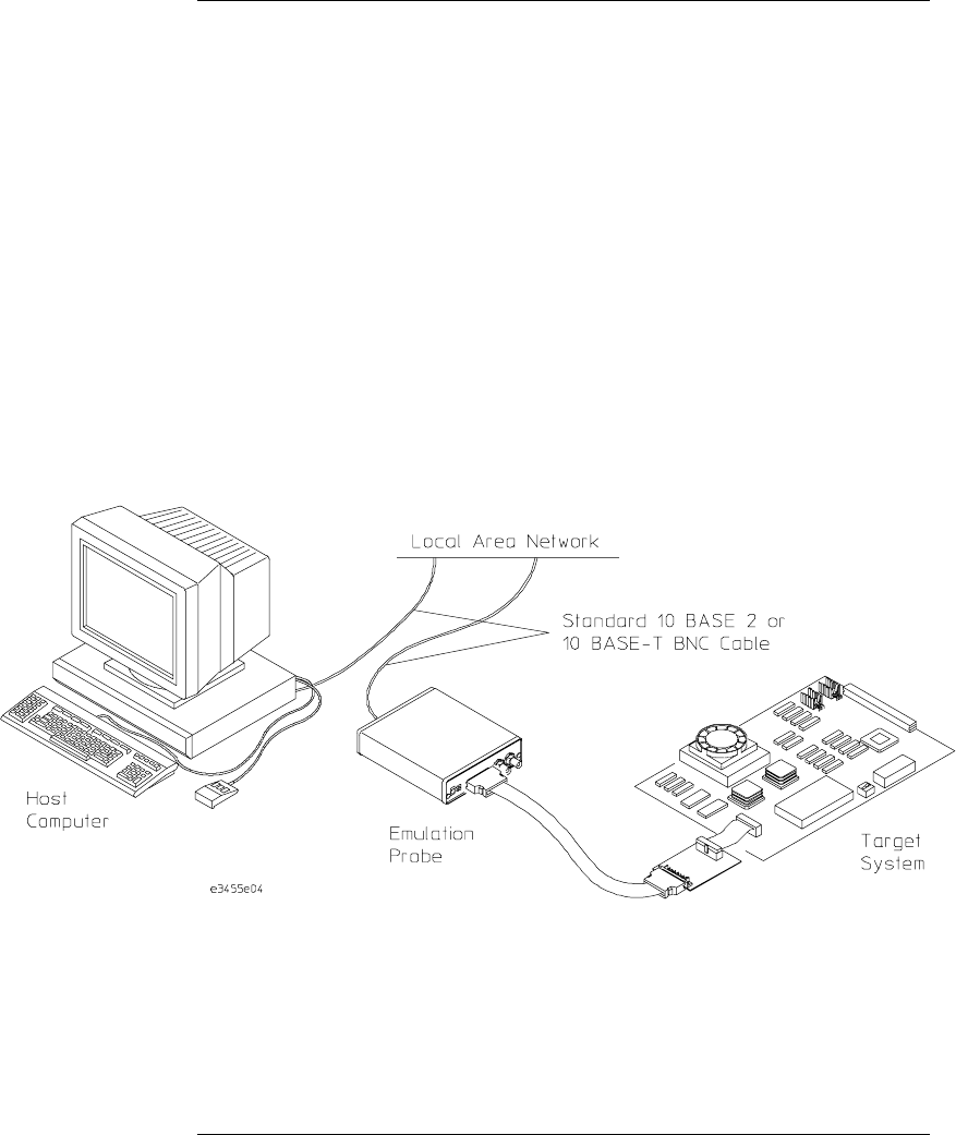
The emulation probe is a stand-alone emulator. You can connect the
emulation probe to a debug port on the target system through the provided
target interface module (TIM). The emulation probe can be controlled by a
debugger on a host computer or by the Emulation Control Interface on an HP
16600A/700A-series logic analysis system.
The emulation probe lets you use the target processor’s built-in JTAG
debugging features, including run control and access to registers and memory
ii
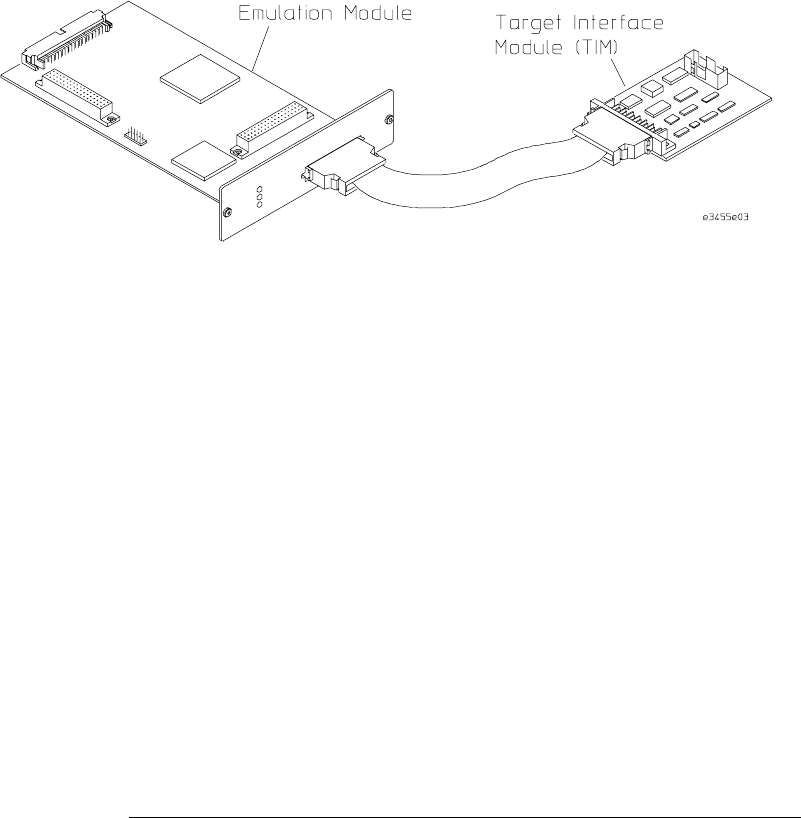
Emulation Module
The emulation module plugs into your HP 16600A/700A-series logic analysis
system frame. It can be controlled by a debugger on a host computer or by
the Emulation Control Iterface on an HP 16600A/700A-series logic analysis
system. The emulation module lets you use the target processor’s built-in
JTAG debugging features, including run control and access to registers and
memory.
iii

In This Book
This book documents the following products:
Emulation Probe
Processors supported Product ordered Includes
M•CORE Rev 1.5 Core
MMC2001 E5900A Option #090 HP E3455A emulation probe, HP E3455-66501 target
interface module (TIM)
Emulation Module
Processors supported Product ordered Includes
M•CORE Rev 1.5 Core
MMC2001 E5901A Option #090 HP 16610A emulation module, HP E3455-66501
target interface module (TIM)
iv

contents
1 Overview
Overview 2
Setup Flowchart 3
Emulation Probe 4
Equipment supplied 4
Minimum Equipment Required 6
Power-On/Power-Off Sequence for the Emulation Probe 7
To power on the system 7
To power off the system 7
To connect the emulation probe to a power source 8
Connection Sequence (Probe only) 9
Emulation Module 10
Equipment supplied 10
Minimum equipment required 12
Additional Information Sources 13
2 Connecting the Emulation Probe to a LAN
Connecting the Emulation Probe to a LAN 16
Setting Up a LAN Connection to a PC or Workstation 17
To obtain an IP address 18
To configure LAN parameters using the built-in terminal interface 19
To configure LAN parameters using BOOTP 22
To set the 10BASE-T configuration switches 24
To verify LAN communications 25
v

Setting Up a Serial Connection (Emulation probe only) 26
To set the serial configuration switches 27
To connect a serial cable 28
To verify serial communications 30
3 Installing the Emulation Module
Installing the Emulation Module 32
To install the emulation module in an HP 16700A-series logic analysis system
or an HP 16701A expansion frame 33
To install the emulation module in an HP 16600A-series logic analysis sys-
tem 35
4 Installing Software on an HP 16600A/700A
To install the software from CD-ROM (HP 16600A/700A) 39
5 Connecting to the Target System
Connecting to a Target System 42
To test the HP emulator 42
To connect to a target system via the OnCE port 43
6 Configuring the Emulator
Configuring the Emulator 46
To configure using the Emulation Control Interface 47
To configure using the built-in commands 48
To configure using a debugger 50
Contents
vi

General Configuration Items 51
To configure restriction to real-time runs 51
To configure the JTAG clock speed (communication speed) 52
To configure the Trigger Out BNC
(Emulation Probe only) 53
To configure the Trigger In BNC
(Emulation Probe only) 53
7 Designing a Target System
Designing a Target System 56
Target System Requirements for M•CORE 56
M•CORE JTAG Interface Connections and Resistors 58
8 Using the Emulator with a Debugger
Using the Emulator with a Debugger 60
Setting up Debugger Software 63
To connect the logic analysis system to the LAN 64
To change the port number of an emulator 65
To verify communication with the emulator 65
To export the logic analysis system’s display to a workstation 66
To export the logic analysis system’s display to a PC 67
Using the Software Development Systems debugger 68
Contents
vii

9 Specifications and Characteristics
Processor Compatibility 74
Electrical Characteristics 74
Emulation probe electrical characteristics 75
Emulation probe environmental characteristics 76
Emulation module electrical characteristics 76
10 Updating Firmware
Emulation Probe Firmware 79
To display current firmware version information 79
To update firmware for an emulation probe 79
Emulation Module Firmware 80
To display current firmware version information 80
To update firmware for an emulation module using the Emulation Control In-
terface 80
To update firmware for an emulation module using the Setup Assistant 81
11 Solving Problems
Solving Problems 84
Troubleshooting Guide 85
Emulation Probe Status Lights 86
Emulation Module Status Lights 88
Built-in Commands 89
Contents
viii

Problems with the Target System 91
What to check first 91
To interpret the initial prompt 93
If you see memory-related problems 95
Problems with the LAN Interface (Probe only) 97
If you cannot verify LAN communication 97
If you have LAN connection problems 98
If the "POL" LED is lit 99
If it takes a long time to connect to the network 100
Problems with the Serial Interface (Emulation probe only) 101
If you cannot verify RS-232 communication 101
If you have RS-232 connection problems with the MS Windows Terminal pro-
gram 101
Problems with the Emulation Probe Itself 103
To run the power up self test 103
To execute the built-in performance verification test 105
To run the built-in performance verification test using the logic analysis sys-
tem 105
To perform complete PV tests for an emulation probe 106
If a performance verification test fails 108
Returning the Parts to Hewlett-Packard for Service 111
To return a part to Hewlett-Packard 111
To obtain replacement parts 112
To clean the emulator 112
Contents
ix

x

1
Overview
1

Overview
This chapter describes:
•Setup flowchart
•Equipment used with the emulation probe
•Connection sequences for the emulation probe
•Equipment used with the emulation module
•Additional information sources
2
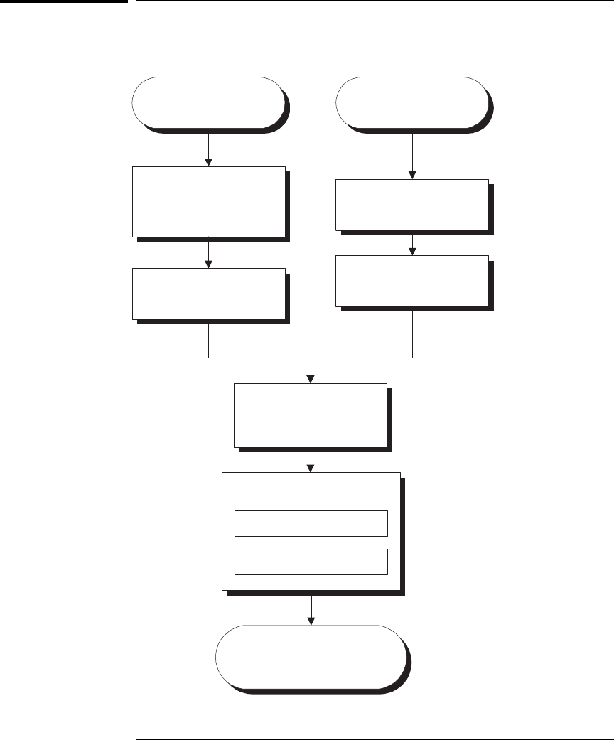
Setup Flowchart
Install emulation
module
(if necessary)
Install software on
logic analysis system
Installation done. Begin
making measurements.
Connect emulator
Connect emulator to target
interface module
Connect target interface
module to target
E3459F01.VSD
Connect power
supply
Connect to LAN
Update emulator
firmware
(if necessary)
Emulation module
HP E5901A
Emulation probe
HP E5900A
Chapter 1: Overview
Overview
3

Emulation Probe
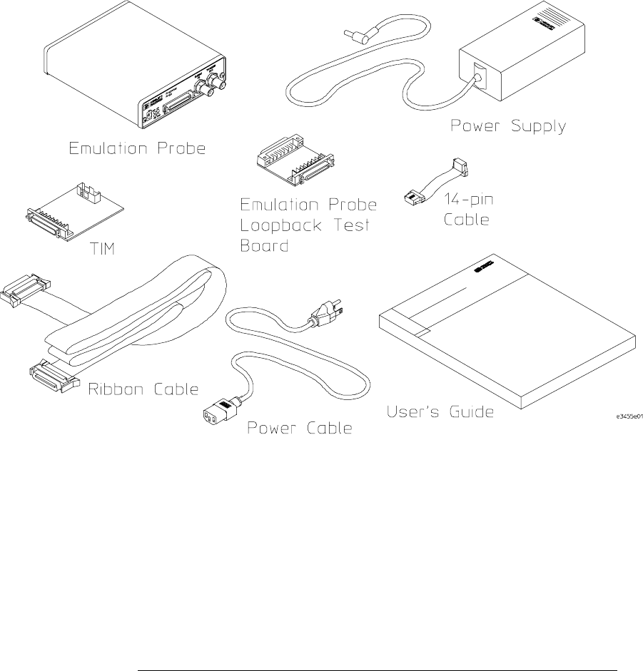
Equipment supplied
•An emulation probe.
•A 12V power supply for the emulation probe.
•A power cord.
•A target interface module (TIM) circuit board (HP part number
E3455-66501).
•An emulation probe loopback test board (HP part number
E3496-66502).
•A 50-pin ribbon cable (connects the emulation probe to the target
interface module).
•A 14-pin low density ribbon cable (connects the target interface
module to your target system).
•This User’s Guide.
4
Chapter 1: Overview
Emulation Probe
5

Minimum Equipment Required
The following equipment is required to use the emulation probe:
•A target system with the appropriate connector. The target system must
meet the criteria in chapter 7.
•A host computer, such as a PC or workstation. You can also connect the
emulation probe to an HP 16600A or HP16700A logic analysis system.
•A LAN (local area network) to connect the emulation probe to the host
computer.
•A user interface on the host computer, such as a high-level source
debugger or the logic analysis system’s Emulation Control Interface.
Chapter 1: Overview
Emulation Probe
6

Power-On/Power-Off Sequence for the
Emulation Probe
To power on the system
With all components connected, power on your system as follows:
1Logic analyzer, if you are using one.
2Emulation probe.
3Your target system.
To power off the system
Power off your system as follows:
1Your target system.
2Emulation probe.
3Logic analyzer, if you are using one.
7
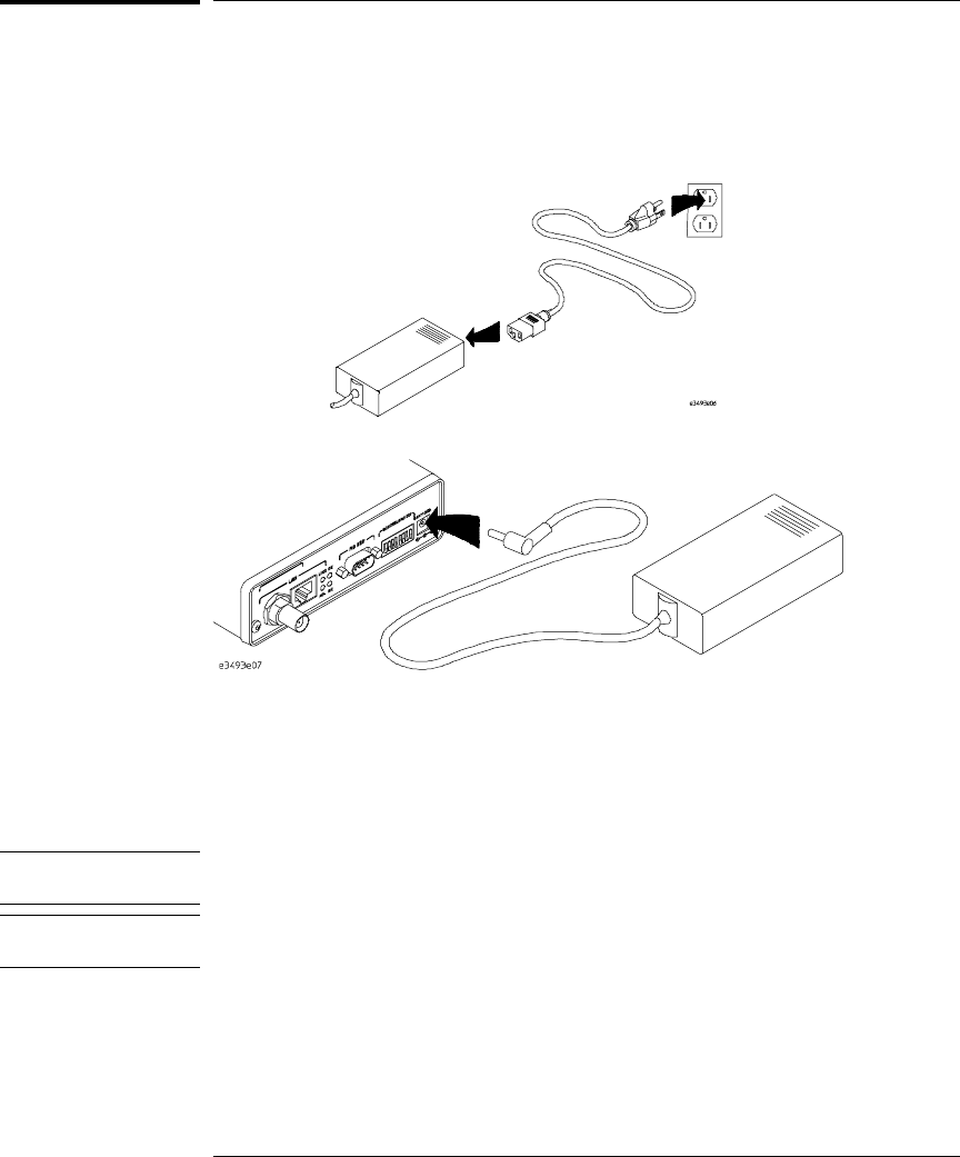
To connect the emulation probe to a power source
The emulation probe does not have an On/Off switch. To power on the
emulation probe:
1Connect the power cord to the power supply and to a socket outlet.
2Connect the 12V power cord to the back of the emulation probe.
The power light on the target side of the emulation probe will be illuminated.
The emulation probe is shipped from the factory with a power supply and
cord appropriate for your country. If the cord you received is not appropriate
for your electrical power outlet type, contact your Hewlett-Packard sales and
service office.
Warning Use only the supplied HP power supply and cord.
Failure to use the proper power supply could result in electric shock.
Caution Use only the supplied HP power supply and cord.
Failure to use the proper power supply could result in equipment damage.
Chapter 1: Overview
Power-On/Power-Off Sequence for the Emulation Probe
8

Connection Sequence (Probe only)
Disconnect power from the target system, emulation probe, and logic
analyzer before you make or break connections.
1Connect the emulation probe to a LAN (page 15).
2Connect the emulation probe to your target system (page 41).
3Configure the emulator (page 45).
9

Emulation Module
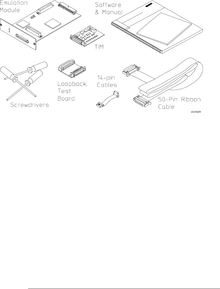
Equipment supplied
The equipment supplied with your emulation module includes:
•An HP16610A emulation module. If you ordered an emulation module as
part of your HP16600A or HP16700A-series logic analysis system, it is
already installed in the frame.
•A target interface module (TIM) circuit board.
•An emulation module loopback test board (HP part number E3496-66502).
•Firmware for the emulation module and/or updated software for the
Emulation Control Interface on a CD-ROM.
•A 50-pin ribbon cable for connecting the emulation module to the target
interface module.
•A 14-pin low density ribbon cable (connects the target interface module to
your target system).
•One Torx T-10 and one Torx T-15 and one Torx T-8 screwdriver (if the
emulation module was not installed at the factory).
•This User’s Guide.
10
Chapter 1: Overview
Emulation Module
11

Minimum equipment required
The following equipment is required to use the emulation module:
•An HP16600A or HP16700A logic analysis system.
•A user interface, such as a high-level source debugger or the logic analysis
system’s Emulation Control Interface.
Chapter 1: Overview
Emulation Module
12

Additional Information Sources
Additional or updated information can be found in the following places:
Newer editions of this manual may be available. Contact your local HP
representative.
•Application notes may be available from your local HP representative or on
the World Wide Web at:
http://www.hp.com/go/logicanalyzer
•If you have an HP 16600A or HP 16700A logic analysis system, the online
help for Emulation Control Interface has additional information on using
the emulation module.
•The measurement examples include valuable tips for making emulation
and analysis measurements. You can find the measurement examples
under the system help in your HP 16600A/700A-series logic analysis
system.
•If you cannot easily find the information you need, send email to
documentation@col.hp.com. Your comments will help HP improve future
manuals. (This address is for comments only; contact your local HP
representative if you need technical support.)
13

Chapter 1: Overview
Additional Information Sources
14

2
Connecting the Emulation
Probe to a LAN
15

Connecting the Emulation Probe to a LAN
You can connect your PC, workstation, or logic analysis system to the
emulation probe via a serial or LAN connection.
Serial connection
A serial connection allows you to complete all of the performance
verification tests and set LAN parameters. Other use of the serial port
is not supported.
LAN connection
A LAN connection will allow you to make your measurements quickly
and easily. A few of the performance verification tests cannot be run
over a LAN.
Recommended connection
Use a LAN connection for routine use, and a serial connection for LAN
configuration and for troubleshooting.
16

Setting Up a LAN Connection to a PC or
Workstation
The emulation probe has two LAN connectors:
•A BNC connector that can be directly connected to a IEEE 802.3
Type 10BASE2 cable (ThinLAN). When using this connector, the
emulation probe provides the functional equivalent of a Medium
Attachment Unit (MAU) for ThinLAN.
•An IEEE 802.3 Type 10BASE-T (StarLAN) connector.
Use either the 10BASE2 or the 10BASE-T connector. Do
not use both. The emulation probe will not work with
both connected at the same time.
You must assign an IP address (Internet address) to the emulation
probe before it can operate on the LAN. You can also set other
network parameters such as a gateway address. The IP address and
other network parameters are stored in nonvolatile memory within the
emulation probe.
The emulation probe automatically sets a subnet mask based on the
subnet mask used by other devices on the network.
You can configure LAN parameters in any of the following ways:
•Using the built-in terminal interface over a serial connection. This is
the most reliable method.
•Using BOOTP. BOOTP is part of the HP-UX, SunOS, and Solaris
operating systems.
17

To obtain an IP address
1Obtain the following information from your local network
administrator or system administrator:
•An IP address for the emulation probe.
You can also use a "LAN name" for the emulation probe, but you must
configure it using the integer dot notation (such as 127.0.0.1).
•The gateway address.
The gateway address is an IP address and is entered in integer dot notation.
The default gateway address is 0.0.0.0, which allows all connections on the
local network or subnet. If connections are to be made to workstations on
other networks or subnets, this address must be set to the address of the
gateway machine.
2Find out whether port numbers 6470 and 6471 are already in use on
your network.
The host computer interfaces communicate with the emulation probe
through two TCP service ports. The default base port number is 6470. The
second port has the next higher number (default 6471).
In almost all cases, the default numbers (6470, 6471) can be used without
change. If necessary, the default numbers can be changed if they conflict
with some other product on your network.
To change the port numbers, see page 19. If you have already set the IP
address, you can use a telnet connection instead of a serial connection to
connect to the emulation probe.
3Write down the link-level address of the emulation probe.
You will need this address if you use BOOTP to set the IP address.
The link-level address (LLA) is printed on a label above the LAN connectors
on the emulation probe. This address is configured in each emulation probe
shipped from the factory and cannot be changed.
IP Address of Processor probe
LAN Name of Emulation Probe
Gateway Address
Link-Level Address of Emulation Probe
Chapter 2: Connecting the Emulation Probe to a LAN
To obtain an IP address
18
To configure LAN parameters using the built-in
terminal interface
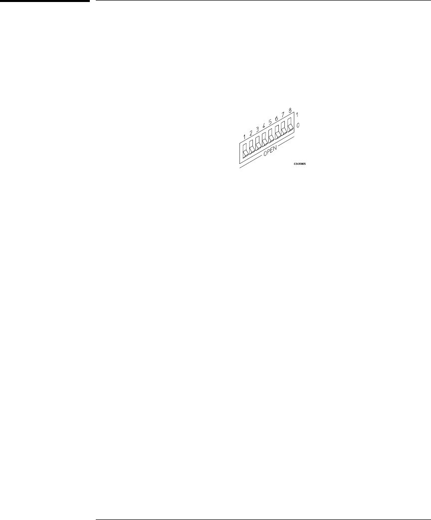
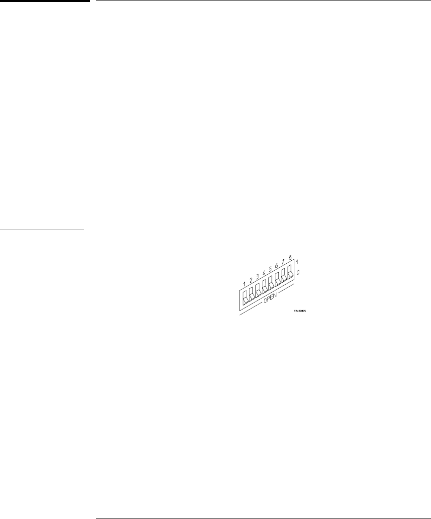
1Set configuration switches S1 through S4 to ON, and set the other
switches as appropriate for your serial interface.
Switch settings are printed on the bottom of the emulation probe. If you will
use a baud rate of 9600 baud, set the switches like this:
2Connect an ASCII terminal (or terminal emulator) to the emulation
probe’s RS-232 port with a 9-pin RS-232 cable.
Complete instructions for setting up a serial connection begin on page 26.
3Plug in the emulation probe’s power cord. Press the terminal’s
<RETURN> key a couple times. You should see a prompt such as
"p>", "?>", or "c>".
At this point, you are communicating with the emulation probe’s built-in
terminal interface.
4Display the current LAN configuration values by entering the lan
command:
R>lan
lan is disabled
lan -i 0.0.0.0
lan -g 0.0.0.0
lan -p 6470
Ethernet Address : 08000903212f
The "lan -i" line shows the current IP address (IP address) of the emulation
probe.
The Ethernet address, also known as the link level address, is preassigned at
the factory, and is printed on a label above the LAN connectors.
5Enter the following command:
lan -i <internet> [-g <gateway>] [-p <port>]
The lan command parameters are:
-i <internet> The IP address which you obtained from your network administrator.
Chapter 2: Connecting the Emulation Probe to a LAN
To configure LAN parameters using the built-in terminal interface
19
-g <gateway> The gateway address. Setting the gateway address allows access outside
your local network or subnet.
-p <port> This changes the base TCP service port number.
The default numbers (6470, 6471) can be changed if they conflict with some
other product on your network. TCP service port numbers must be greater
than 1024. If you change the base port, the new value must also be entered in
the /etc/services file on the host computer. For example, you could modify
the line:
hp64700 6470/tcp
The IP address and any other LAN parameters you change are stored in
nonvolatile memory and will take effect the next time the emulation probe is
powered off and back on again.
6Disconnect the power cord from the emulation probe, and connect
the emulation probe to your network.
This connection can be made by using either the 10BASE-T connector or the
10BASE2 (BNC) connector on the emulation probe. Do not use both
connectors at the same time.
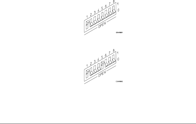
7Set the configuration switches to indicate the type of connection that
is to be made.
Switch S1 must be set to OFF, indicating that a LAN connection is being
made.
Switch S5 should be ON if you are connecting to the BNC connector:
Switch S5 should be OFF if you are connecting to the 10BASE-T connector:
Set all other switches to ON.
8Connect the power cord to the emulation probe.
Chapter 2: Connecting the Emulation Probe to a LAN
To configure LAN parameters using the built-in terminal interface
20

9Verify your emulation probe is now active and on the network. See
"To verify LAN communications" on page 25.
Once you have set a valid IP address, you can use the telnet utility to connect
to the emulation probe, and use the lan command to change LAN parameters.
Example To assign an IP address of 192.6.94.2 to the emulation probe, enter the
following command:
R>lan -i 192.6.94.2
Now, cycle power on the emulation probe so that the new address will take
effect.
See Also "Solving Problems," page 83, if you have problems verifying LAN
communication.
Chapter 2: Connecting the Emulation Probe to a LAN
To configure LAN parameters using the built-in terminal interface
21

To configure LAN parameters using BOOTP
Use this method only on a workstation which is running bootpd, the BOOTP
daemon.
1Make sure that BOOTP is enabled on your host computer.
If the following commands yield the results shown below, the BOOTP
protocol is enabled:
$ grep bootp /etc/services
bootps 67/udp
bootpc 68/udp
$ grep bootp /etc/inetd.conf
bootps dgram udp wait root /etc/bootpd bootpd
If the commands did not yield the results shown, you must either add BOOTP
support to your workstation or use a different method to configure the
emulation probe LAN parameters.
2Add an entry to the host BOOTP database file, /etc/bootptab. For
example:
# Global template for options common to all HP 64700
# emulators and Emulation Probes.
# Use a different gateway addresses if necessary.
hp64700.global:\
:gw=0.0.0.0:\
:vm=auto:\
:hn:\
:bs=auto:\
:ht=ether
# Specific emulator entry specifying hardware address
# (link-level address) and ip address.
hpprobe.div.hp.com:\
:tc=hp64700.global:\
:ha=080009090B0E:\
:ip=192.6.29.31
In this example, the "ha=080009090B0E" identifies the link-level address of
the emulation probe. The "ip=192.6.29.31" specifies the IP address that is
assigned to the emulation probe. The node name is "hpprobe.div.hp.com".
3Connect the emulation probe to your network.
This connection can be made by using either LAN connector on the
emulation probe.
Chapter 2: Connecting the Emulation Probe to a LAN
To configure LAN parameters using BOOTP
22

4Set the configuration switches to indicate the type of connection that
is to be made.
Switch S1 must be set to OFF, indicating that a LAN connection is being
made.
Switch S6 must be set to OFF to enable BOOTP mode.
Switch S5 should be set to OFF if you are connecting to the BNC connector
Switch S5 should be set to ON if you are connecting to the 10BASE-T
connector.
Set all other switches to ON.
5Connect the power cord to the emulation probe.
Verify that the power light stays on after 10 seconds.
The IP address will be stored in EEPROM.
6Set switch S6 back to ON.
Do this so that the emulation probe does not request its IP address each time
power is cycled. The IP address is stored in EEPROM, so BOOTP does not
need to be run again. Leaving this switch on will result in slower
performance, increased LAN traffic, and even failure to power up (if the
BOOTP server becomes inactive).
7Verify your emulation probe is now active and on the network. See
"To verify LAN communications" on page 25.
See Also For additional information about using bootpd, refer to the bootpd (1M) man
page.
Chapter 2: Connecting the Emulation Probe to a LAN
To configure LAN parameters using BOOTP
23

To set the 10BASE-T configuration switches
Set switches S7 and S8 to ON unless one of the following conditions is true:
•If the LAN cable exceeds the standard length, set switch S7 to OFF.
The emulation probe has a switch-selectable, twisted-pair receiver threshold.
With switch S7 set to OFF, the twisted-pair receiver threshold is lowered by
4.5 dB. This should allow you to use cable lengths of up to about 200 meters.
If you use a long cable, you should consult with your LAN cabling installer to
ensure that:
•The device at the other end of the cable has long cable capability, and
•The cable is high-grade, low-crosstalk cable with crosstalk attenuation
of greater than 27.5 dB.
When switch S7 is set to ON, the LAN port operates at standard 10BASE-T
levels. A maximum of 100 meters of UTP cable can be used.
•If your network doesn’t support Link Beat integrity checking or if the
emulation probe is connected to a non 10BASE-T network (such as
StarLAN) set this switch to LINK BEAT OFF (0 or OPEN).
In normal mode (switch S8 set to ON), a link integrity pulse is transmitted
every 15 milliseconds in the absence of transmitted data. It expects to
receive a similar pulse from the remote MAU. This is the standard link
integrity test for 10BASE-T networks. If your network doesn’t support the
Link Beat integrity checking or if the Software Probe is used on a non
10BASE-T network (such as StarLAN) set this switch to LINK BEAT OFF
(OFF).
Note Setting switch S8 to OFF when Link Beat integrity checking is required by
your network will cause the remote MAU to disable communications.
Chapter 2: Connecting the Emulation Probe to a LAN
To set the 10BASE-T configuration switches
24

To verify LAN communications
1Verify your emulation probe is now active and on the network by
issuing a telnet to the IP address.
This connection will give you access to the emulation probe’s built-in
terminal interface.
2To view the LAN parameters, enter the lan command at the terminal
interface prompt.
3To exit from this telnet session, type <CTRL>D at the prompt.
The best way to change the emulation probe’s IP address, once it has already
been set, is to telnet to the emulation probe and use the terminal interface
lan command to make the change. Remember, after making your changes,
you must cycle power or enter a terminal interface init -p command before
the changes take effect. Doing this will break the connection and end the
telnet session.
If You Have Problems
If you encounter problems, refer to the "Problems" chapter (page 83).
Example $ telnet 192.35.12.6
R>lan
lan is enabled
lan -i 192.35.12.6
lan -g 0.0.0.0
lan -p 6470
Ethernet Address : 08000F090B30
Chapter 2: Connecting the Emulation Probe to a LAN
To verify LAN communications
25

Setting Up a Serial Connection
(Emulation probe only)
To set up a serial connection, you will need to:
•Set the serial configuration switches
•Connect a serial cable between the host computer and the
emulation probe
•Verify communications
Serial connections on a workstation
If you are using a UNIX workstation as the host computer, you need to
use a serial device file. If a serial device file does not already exist on
your host, you need to create one. Once it exists, you need to ensure
that it has the appropriate permissions so that you can access it. See
the system documentation for your workstation for help with setting
up a serial device.
Serial connections on a PC
Serial connections are supported on PCs. You must use hardware
handshaking if you will use the serial connection for anything other
than setting LAN parameters.
If you are using a PC as the host computer, you do not need to set up
any special files.
26
To set the serial configuration switches
1Set switch S1 to ON (RS-232).
2Set switches S2-S4 to ON.
3Set switch S5 to ON (HW HANDSHAKE ON) if your serial interface
uses the DSR:CTS/RTS lines for flow control. Set S5 to OFF (HW
HANDSHAKE OFF) if your serial interface uses software flow
control (XON/XOFF).
If your serial interface supports hardware handshaking, you should use it (set
switch S5 to ON). Hardware handshaking will make the serial connection
much more reliable.
4Set switches S6-S8 for the baud rate you will use. These switch
settings are listed on the bottom of the emulation probe.
The higher baud rates may not work reliably with all hosts and user
interfaces. Make sure the baud rate you choose is supported by your host
and user interface.
Example To use a baud rate of 9600 baud, set the switches as follows:
Chapter 2: Connecting the Emulation Probe to a LAN
To set the serial configuration switches
27
To connect a serial cable
CAUTION Use a grounded, shielded cable. If the cable is not shielded, or if the cable is
not grounded at the serial controller, the emulation probe may be damaged
by electrostatic discharge.
Connect an RS-232C modem cable from the host computer to the emulation
probe. The recommended cable is HP part number C2932A. This is a 9-pin
cable with one-to-one pin connections.
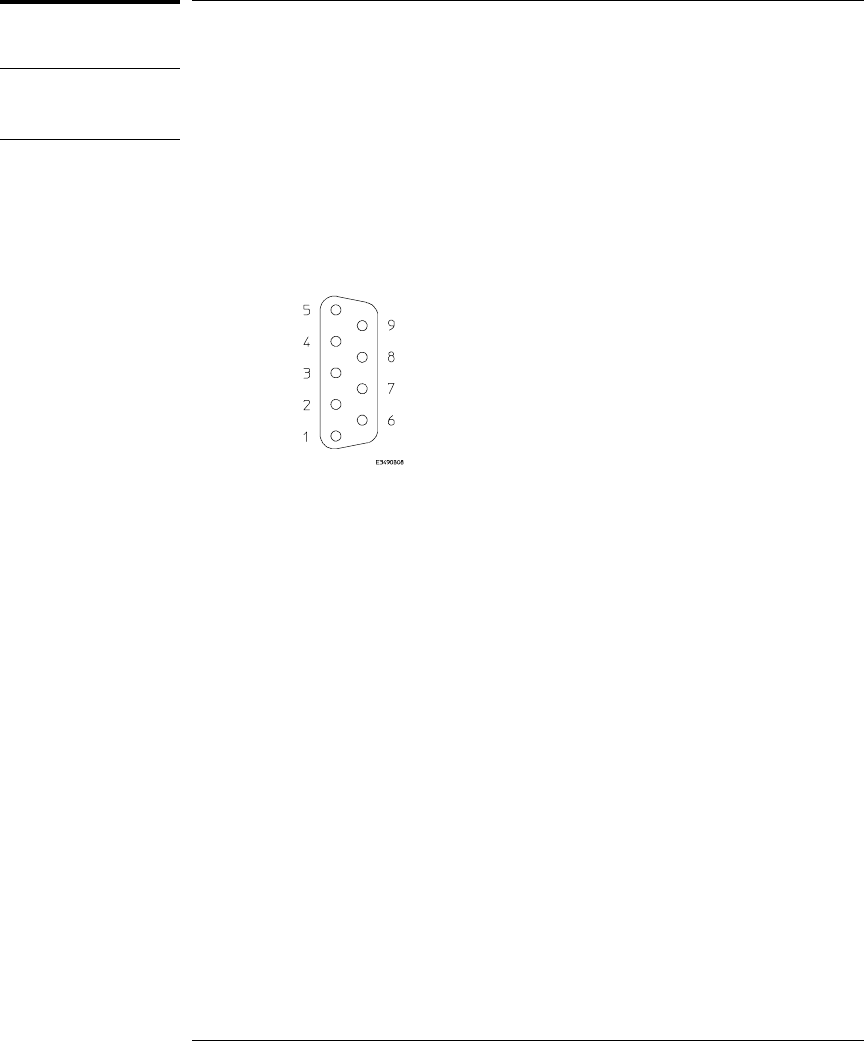
If you want to build your own RS-232 cable, follow the pinout shown in the
following figure:
Chapter 2: Connecting the Emulation Probe to a LAN
To connect a serial cable
28

If you want to build your own RS-232 cable, follow the pinout shown in the
following figure:
Serial Cable Pinout
Pin
Number Signal Signal Description
1 DCD Data Carrier Detect (not used)
2 TD Transmit Data (data coming from HP emulation probe)
3 RD Receive Data (data going to HP emulation probe)
4 DTR Data Terminal Ready (not used)
5 GND Signal Ground
6 DSR Data Set Ready (Output from HP emulation probe)
7 RTS Request to Send (Input to HP emulation probe)
8 CTS Clear to Send (connected to pin 6)
9 RING Ring Indicator (not used)
Chapter 2: Connecting the Emulation Probe to a LAN
To connect a serial cable
29

To verify serial communications
1Start a terminal emulator program on the host computer.
If you are using a PC, the Terminal application in Microsoft Windows will
work fine.
If you are using a UNIX workstation, you can use a terminal emulator such as
cu or kermit.
2Plug the power cord into the emulation probe.
When the emulation probe powers up, it sends a message (similar to the one
that follows) to the serial port and then displays a prompt:
Copyright (c) Hewlett-Packard Co. 1987
All Rights Reserved. Reproduction, adaptation, or translation without prior
written permission is prohibited, except as allowed under copyright laws.
HPE3499A Series Emulation System
Version: A.07.53 26Feb98
Location: Generics
HPE3455A Motorola M-Core Emulator
Version: A.01.00 31Mar98
R>
The version numbers may be different for your emulation probe.
3Press the Return or Enter key a few times.
You should see a prompt such as "p>", "R>", or "?>".
For information about the commands you can use, enter ? or help at the
prompt.
See Also "Problems with the Serial Interface," page 101.
Chapter 2: Connecting the Emulation Probe to a LAN
To verify serial communications
30

3
Installing the Emulation
Module

Installing the Emulation Module
This chapter shows you how to install an emulation module in your
HP 16600A/700A-series logic analysis system.
If your emulation module is already installed in your logic analysis
system frame, you may skip this chapter.
Caution These instructions are for trained service personnel. To avoid dangerous
electric shock, do not perform any service unless qualified to do so. Do not
attempt internal service or adjustment unless another person, capable of
rendering first aid and resuscitation, is present.
Electrostatic discharge can damage electronic components. Use grounded
wriststraps and mats when you handle modules.
32 Solutions for the MPC860/821
To install the emulation module in an
HP 16700A-series logic analysis system or an
HP 16701A expansion frame
You will need T-10 and T-15 Torx screw drivers (supplied with the module) .
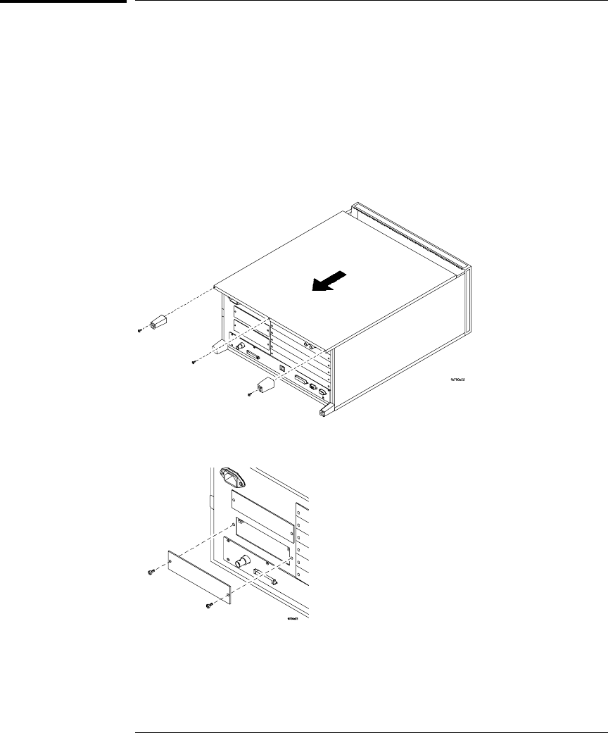
1Turn off the logic analysis system and REMOVE THE POWER CORD.
Remove any other cables (such as probes, mouse, or video monitor).
2Turn the logic analysis system frame upside-down.
3Remove the bottom cover.
4Remove the slot cover.
You may use either slot.
Chapter 3: Installing the Emulation Module
Installing the Emulation Module
Solutions for the MPC860/821 33
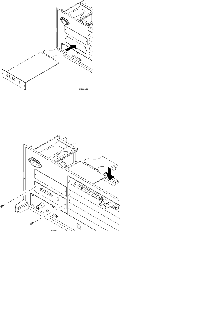
5Install the emulation module.
6Connect the cable and re-install the screws.
You may connect the cable to either of the two connectors. If you have two
emulation modules, note that many debuggers will work only with the "first"
module: the one toward the top of the frame ("Slot 1"), plugged into the
connector nearest the back of the frame.
7Reinstall the bottom cover, then turn the frame right-side-up.
8Plug in the power cord, reconnect the other cables, and turn on the
logic analysis system.
The new emulation module will be shown in the system window.
See Also See page 67 for information on giving the emulation module a "personality"
for your target processor.
Chapter 3: Installing the Emulation Module
Installing the Emulation Module
34 Solutions for the MPC860/821
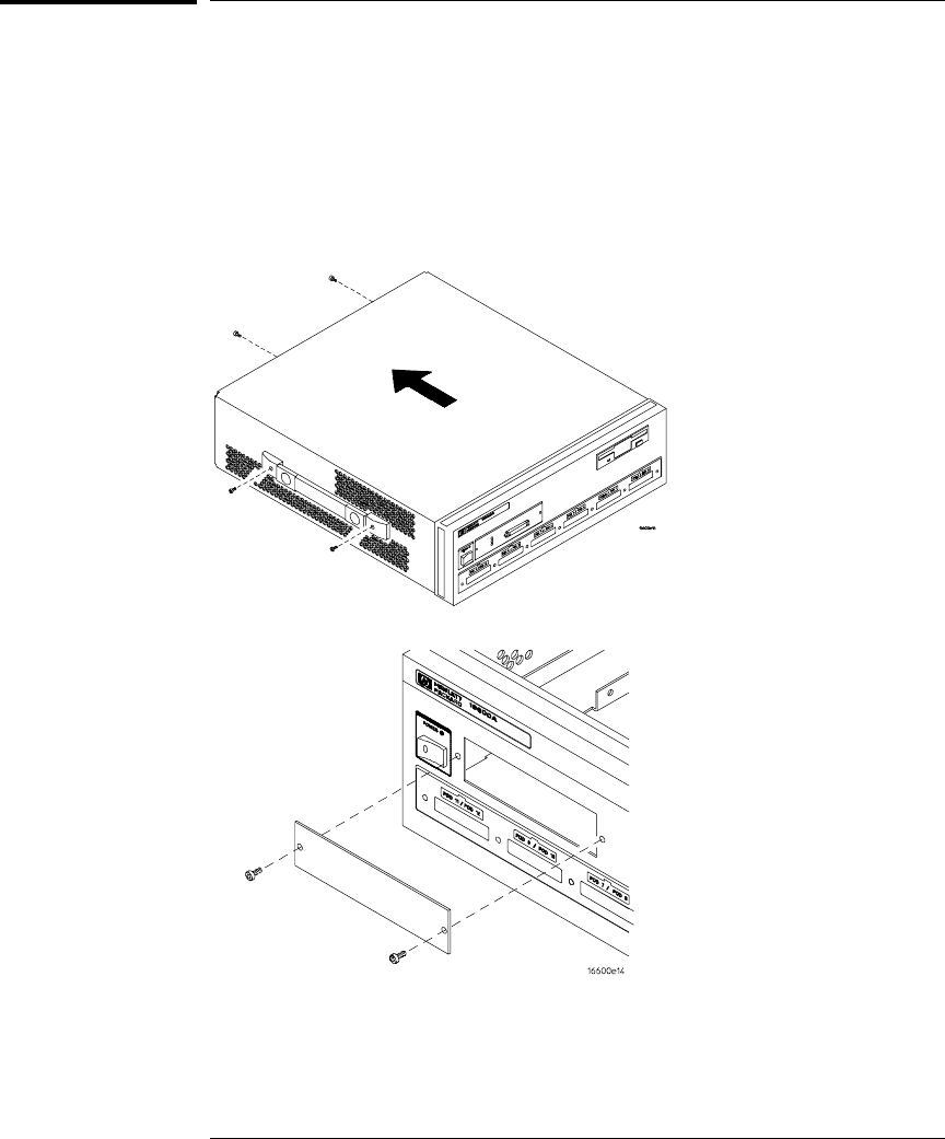
To install the emulation module in an
HP 16600A-series logic analysis system
You will need a T-8, T-10, and T-15 Torx screw drivers (supplied with the
modules).
1Turn off the logic analysis system and REMOVE THE POWER CORD.
Remove any other cables (such as probes, mouse, or video monitor).
2Slide the cover back.
3Remove the slot cover.
Chapter 3: Installing the Emulation Module
Installing the Emulation Module
Solutions for the MPC860/821 35
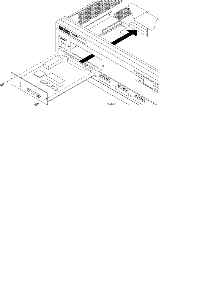
4Install the emulation module.
5Connect the cable and re-install the screws.
6Reinstall the cover.
Tighten the screws snugly ( 2 N•m or 18 inch-pounds).
7Plug in the power cord, reconnect the other cables, and turn on the
logic analysis system.
The new emulation module will be shown in the system window.
Chapter 3: Installing the Emulation Module
Installing the Emulation Module
36 Solutions for the MPC860/821

4
Installing Software on an
HP 16600A/700A

Installing Software on an HP 16600A/700A
This chapter explains how to install the software you will need for
your emulator.
Installing and loading
Installing the software will copy the files to the hard disk of your
logic analysis system. Later, you will need to load some of the files
into the appropriate hardware module.
What needs to be installed
If you ordered an emulator with your logic analysis system, the
software was installed at the factory.
The following files are installed from the CD-ROM:
•Emulation module firmware
•Emulation Control Interface
38 Solutions for the MPC860/821

To install the software from CD-ROM
(HP 16600A/700A)
Installing a processor support package from a CD-ROM will take just a few
minutes. If the processor support package requires an update to the
HP 16600A/700A operating system, installation may take approximately 45
minutes.
If the CD-ROM drive is not connected, see the instructions printed on the
CD-ROM package.
1Turn on the CE-ROM drive first and then turn on the logic analysis
system.
2Insert the CD-ROM in the drive.
3Click the System Admin icon.
4Click Install... .
5Select CD-ROM as the media, and click Apply.
6From the list of types of packages, double-click "PROC-SUPPORT."
A list of the processor support packages on the CD-ROM will be displayed.
7Click on the M•CORE package.
If you are unsure if this is the correct package, click Details for information
on what the package contains.
8Click Install... .
The dialog box will display "Progress: completed successfully" when the
installation is complete.
9Click Close.
The firmware is stored in /hplogic/run_control/firmware
See Also The online help for more information on installing, licensing, and removing
software.
Chapter 4: Installing Software on an HP 16600A/700A
To install the software from CD-ROM (HP 16600A/700A)
Solutions for the MPC860/821 39

40 Solutions for the MPC860/821

5
Connecting to the Target
System
41

Connecting to a Target System
To test the HP emulator
If this is the first time that you have used the emulator, you should run the
built-in performance verification test before you connect to a target system.
Refer to the "Solving Problems" chapter (beginning on page 83) for
information on performance verification.
42
To connect to a target system via the OnCE port
In order to connect the emulator to the microprocessor, one of the supported
connectors must be available on the target system (see page 55 for
information on designing a target system for use with the emulator).
1Remove power from the target system and the emulator.
2Plug one end of the 50-pin cable into the emulator.
3Plug the other end of the 50-pin cable into the target interface module.
4Connect the 14-pin cable from the TIM to the target system OnCE
connector.
5Turn on the power to the emulator.
6Turn on the power to the target.
Chapter 5: Connecting to the Target System
To connect to a target system via the OnCE port
43

44

6
Configuring the Emulator
45

Configuring the Emulator
The HP emulator has a number of user configurable parameters.
These parameters may be customized for specific target systems and
saved in configuration files for future use.
The easiest way to configure the emulation module is through the Emulation
Control Interface in the HP 16600A/700A-series logic analysis system.
If you use the Emulation Control Interface, please refer to the online help in the
Configuration window for information on each of the configuration options.
Other ways to configure the emulator are:
•the emulator’s built-in terminal interface
•your debugger
46

To configure using the Emulation Control Interface
The easiest way to configure the emulator is to use the Emulation Control
Interface.
1Start an Emulation Control Interface session.
For an emulation module:
•In the system window, click the HP Emulation Control Interface icon, and
select "Start Session...".
For an emulation probe:
•In the workspace window, drag the emulation probe icon onto the
workspace, then select "Start Session."
2Open a Configuration window.
Select "Configuration..." from the Emulation Control Interface icon or from
the Navigate menu in any Emulation Control Interface window.
3Set the configuration options, as needed.
The configuration selections will take effect when you close the configuration
window or when you move the mouse pointer outside the window.
4Save the configuration settings.
To save the configuration settings, open the File Manager window and click
Save....
See Also Help ➝Help on this window in the Configuration window for information
on each of the configuration options.
Help in the Emulation Control Interface menu for help on starting an
Emulation Control session.
Chapter 6: Configuring the Emulator
Configuring the Emulator
47

To configure using the built-in commands
If you are unable to configure the emulator with the Emulation Control
Interface or a debugger interface, you can configure the emulator using the
built-in "terminal interface" commands.
1Connect a terminal or terminal emulator to the emulator’s serial port,
or use a telnet session over the LAN.
2Enter cf to see the current configuration settings.
3Use the cf command to change the configuration settings.
See Also Enter help cf for help on the configuration commands.
For information on connecting a serial terminal or terminal emulator, see
page 26.
For information on other built-in commands, see page 89.
Example
To see a complete list of configuration items, use the command "help cf". For
example:
cf - display or set emulation configuration
cf - display current settings for all config items
cf <item> - display current setting for specified <item>
cf <item>=<value> - set new <value> for specified <item>
cf <item> <item>=<value> <item> - set and display can be combined
help cf <item> - display long help for specified <item>
--- VALID CONFIGURATION <item> NAMES ---
rrt - Restrict to real-time runs
speed - Set JTAG clock
proc - Set processor type
breakin - Select BNC break input option
trigout - Select BNC trigger output option
M>
Chapter 6: Configuring the Emulator
Configuring the Emulator
48

To see a more detailed description of any configuration item, use the
command "help cf <item>". For example:
M>help cf rrt
Restrict to real-time runs
cf rrt=yes
cf rrt=no
If yes (and while the processor is running the user program), any
command that requires the processor to be stopped will be rejected.
For example ’reg’ and ’m’.
If no, commands that require the processor to be stopped will
actually stop the processor, execute then resume running the
processor.
Chapter 6: Configuring the Emulator
Configuring the Emulator
49

To configure using a debugger
Because the HP emulator can be used with several third-party debuggers,
specific details for sending the configuration commands to the probe cannot
be given here. However, all debuggers should provide a way of directly
entering terminal mode commands to the probe. Ideally, you would create a
file that contains the configuration entries you need modified that can be
sent to the probe at the beginning of each debugger session. See your
debugger manual for more details.
Chapter 6: Configuring the Emulator
Configuring the Emulator
50

General Configuration Items
The general configuration items must be set correctly for each target
system.
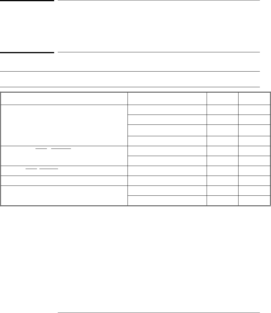
To configure restriction to real-time runs
Real-time runs configurationReal-time runs configuration
Value Emulator configured for Built-in command
no Allows commands which break to the monitor.
Examples include commands which display
memory or registers. These commands break to
the monitor to access the target processor, then
resume the user program.
cf rrt=no
yes No commands are allowed which break to the
monitor, except "break," "reset," "run," or "step."
The processor must be explicitly stopped before
these commands can be performed. (Default)
cf rrt=yes
If your debugger allows displaying or modifying memory or registers while
the processor is running, you must set rrt=no in order to use this feature.
To configure processor type Built-in command
M•CORE - Default Revision 1.5 Core cf proc=mcore
51

To configure the JTAG clock speed (communication
speed)
The HP emulator needs to be configured to communicate at a rate which is
compatible with your target processor. The JTAG Clock speed is independent
of processor clock speed. In general, cf speed=7 can always be used and
provides the best performance. With some target systems that have
additional loads on the JTAG lines or with target systems that do not quite
meet the requirements described in the "Designing a Target System" chapter
(page 55), setting speed to a slower setting may enable the probe to work.
TCK clock speed configuration
Value TCK is at least Built-in command
110 MHz (default) cf speed=7
25 MHz cf speed=6
32.5 MHz cf speed=5
41.25 MHz cf speed=4
5625 kHz cf speed=3
6312 kHz cf speed=2
7156 kHz cf speed=1
Chapter 6: Configuring the Emulator
General Configuration Items
52

To configure the Trigger Out BNC
(Emulation Probe only)
Trigger out configuration
Value The Trigger Out BNC will Built-in command
fixhigh Always be high cf trigout=fixhigh
fixlow Always be low cf trigout=fixlow
monhigh Go high when the processor is running in
background (Default) cf trigout=monhigh
monlow Go low when the processor is running in
background cf trigout=monlow
With an emulation module, this configuration item is always set to the default
setting and cannot be changed with a cf command. The Intermodule window
of the logic analyzer must be used instead.
To configure the Trigger In BNC
(Emulation Probe only)
Trigger in configuration
Value Meaning Built-in command
off Inputs to the Break In BNC will be ignored. cf breakin=off
rising The emulator will cause a break on a rising
edge. (Default) cf breakin=rising
falling The emulator will cause a break on a falling
edge. cf breakin=falling
With an emulation module, this configuration item is always set to the default
setting and cannot be changed with a cf command. The Intermodule window
of the logic analyzer must be used instead.
Chapter 6: Configuring the Emulator
General Configuration Items
53

54

7
Designing a Target System
55

Designing a Target System
This chapter will help you design a target system that will work with
the HP Emulator.
Target System Requirements for M•CORE
Required Signals
VDD
The VDD signal is used to sense when the target system is connected to the
Emulator. This signal is also used as a reference voltage for all signals driven
by the Emulator. The Emulator does not use this pin for power.
TDI signal
The TDI signal is a core JTAG signal ans should be connected to TDI on the
target.
TDO signal
The TDO signal is a core JTAG signal ans should be connected to TDO on the
target.
TCK signal
The TCK signal is a core JTAG signal.
TRST signal
The TRST signal is a core JTAG signal.
56

MCU_DE signal
The MCU_DE signal is used to quickly enter debug mode after receiving a
"BREAK IN" signal from the logic analyzer. This allows the logic analyzer
triggering capability to be used for complex breakpoints. Without MCU_DE,
the processor must be stopped by using the JTAG scan chains, and the
processor may not stop until several hundred instructions have been
executed. This may cause complications when attempting to correlate the
state of the logic analyzer and the Emulator after the breakpoint has been
reached. This signal is not required. However, it it strongly recommended.
TDO, TDI, TCK, TMS and TRST signals
TDO, TDI, TCK, TMS and TRST signal traces between the JTAG connector
and the M•CORE target must be less than 3 inches long. If these signals are
connected to other nodes, the other nodes must be daisy chained between
the JTAG connector at one end and the M•CORE microprocessor at the other
end. These signals are sensitive to crosstalk and must not be routed along
active signals such as clock lines on the target board.
The TDI, TCK, TMS and TRST signals must not be actively driven by the
target system when the debug port is being used.
Pull-up Resistors
The following signals should contain a 10K OHM pull-up resistor:
•TDI
•TCK
•*RST
•TMS
•*TRST
•*MCU_DE
Chapter 7: Designing a Target System
Target System Requirements for M••CORE
57
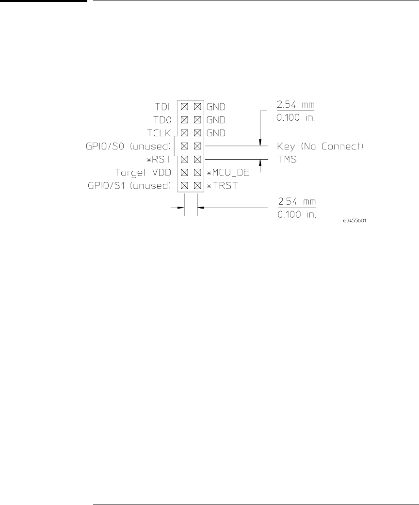
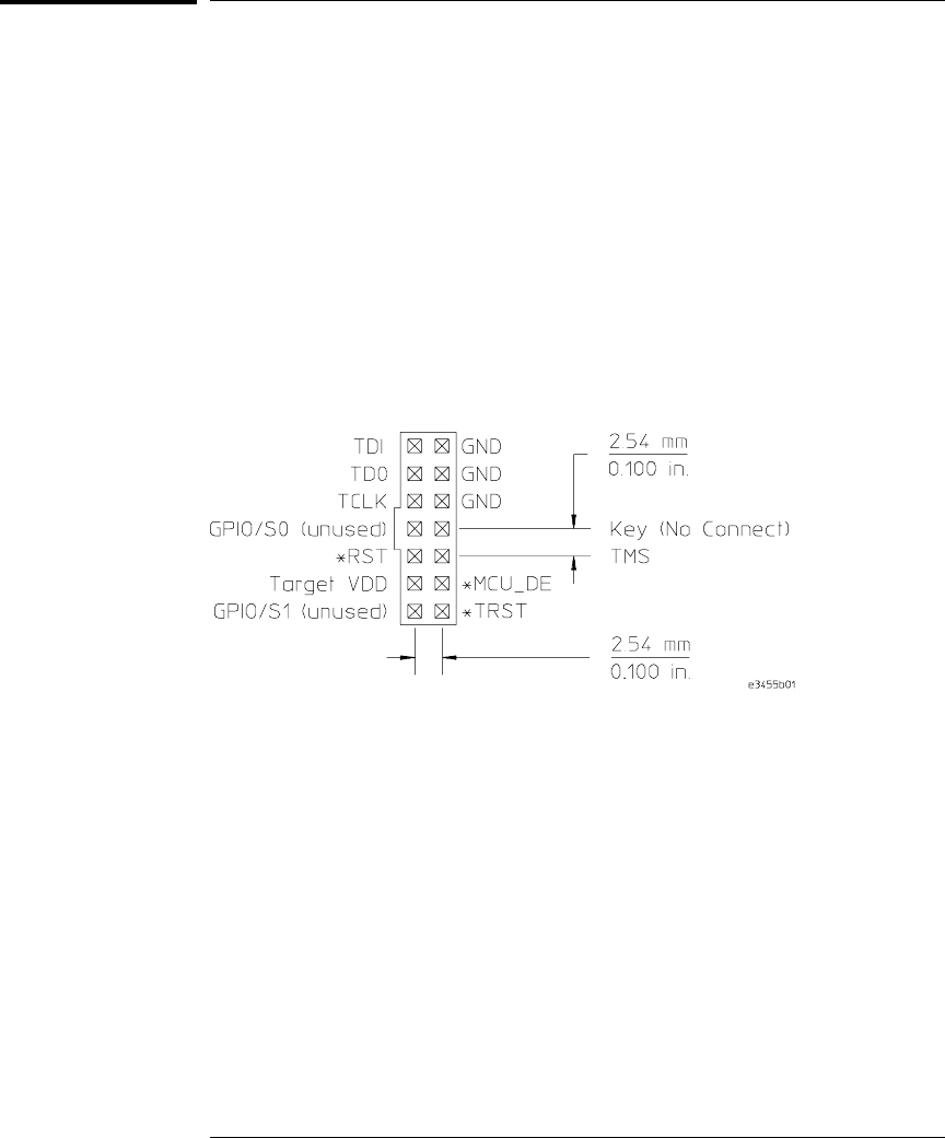
M•CORE JTAG Interface Connections and Resistors
The target system must have the Motorola 14-pin OnCE connector.
JTAG Header Connector (top view)
The connector on the target system should be placed as close as possible to
the processor to ensure signal integrity.
Chapter 7: Designing a Target System
M••CORE JTAG Interface Connections and Resistors
58

8
Using the Emulator with a
Debugger
59

Using the Emulator with a Debugger
Several prominent companies design and sell state-of-the-art source
debuggers which work with the HP emulation modules and emulation
probe.
Benefits of using a debugger
The debugger will enable you to control the execution of your
processor from the familiar environment of your debugger. Using a
debugger lets you step through your code at the source-code level.
With a debugger connection, you can set breakpoints, single-step
through source code, examine variables, and modify source code
variables from the debugger interface. The debugger can also be used
to download executable code to your target system.
Using a debugger to connect the emulator allows the entire design
team to have a consistent interface from software development to
hardware/software integration.
Debugger interfaces must be ordered directly from the debugger
vendor.
Compatibility with other logic analysis system tools
You can use your logic analysis system to collect and analyze trace data while
you use your debugger. If you are using an X windows workstation or a PC
with an X terminal emulator, you can display the logic analyzer windows right
next to your debugger.
60

Here is an example of what the display on your PC or workstation might look
like:
Chapter 8: Using the Emulator with a Debugger
Using the Emulator with a Debugger
61

Minimum requirements
To use a debugger with the emulator, you will need:
•A debugger which is compatible with the emulation probe
•A LAN connection to the PC or workstation that is running the
debugger
•X windows or an X terminal emulator, such as Reflection X on a PC.
This is required only if you wish to have the logic analysis system
user interface displayed on your PC or workstation screen, along
with the debugger.
Is your debugger compatible with the emulation probe?
Ask your debugger vendor whether the debugger can be used with an
HP emulation module or HP emulation probe (also known as a
"processor probe" or "software probe").
LAN connection
You will use a LAN connection to allow the debugger to communicate
with the emulator.
Compatibility with the Emulation Control Interface
Do not use the logic analysis system’s Emulation Control Interface and
your debugger at the same time.
Chapter 8: Using the Emulator with a Debugger
Using the Emulator with a Debugger
62

Setting up Debugger Software
The instructions in this manual assume that your PC or workstation is
already connected to the LAN, and that you have already installed the
debugger software according to the debugger vendor’s documentation.
To use your debugger with the emulator, follow these general steps:
•Connect the emulator to your target system (see page 41).
•Connect the logic analysis system to the LAN (page 64).
•Export the logic analysis system’s display to your PC or workstation
(page 66).
•Configure the emulation module (page 45).
•Begin using your debugger.
If you use the Emulation Control Interface to configure the emulator,
remember to end the Emulation Control Interface session before you
start the debugger.
Caution Do not use the Emulation Control Interface at the same time as a debugger.
The Emulation Control Interface and debuggers do not keep track of
commands issued by other tools. If you use both at the same time, the tools
may display incorrect information about the state of the processor, possibly
resulting in lost data.
See Also Refer to the documentation for your debugger for more information on
connecting the debugger to the emulation module.
63

To connect the logic analysis system to the LAN
Information on setting up a LAN connection is provided in the online help or
installation manual for your logic analysis system.
You debugger will require some information about the LAN connection before
it can connect to the emulator. This information may include:
•IP address (Internet address) or LAN name of the logic analysis system.
•Gateway address of the logic analysis system.
•Port number of the emulator.
Port numbers
Port number Use for
Debugger connections
6470 Slot 1 (First emulator in an HP 16600A/700A-series logic analysis
system)
6474 Slot 2 (Second emulator in an HP 16700A-series system)
6478 Slot 3 (Third emulator in an expansion frame)
6482 Slot 4 (Fourth emulator in an expansion frame)
Telnet connections
6472 Slot 1 (First emulator)
6476 Slot 2 (Second emulator)
6480 Slot 3 (Third emulator)
6484 Slot 4 (Fourth emulator)
Write the information here for future reference:
IP Address of Logic Analysis System
LAN Name of Logic Analysis System
Gateway Address
Port Number of Emulator
Chapter 8: Using the Emulator with a Debugger
Setting up Debugger Software
64

To change the port number of an emulator
Some debuggers do not provide a means to specify a port number. In that
case, the debugger will always connect to port 6470 (the first emulation
module). If you need to connect to another module, or if the port number of
the first module has been changed, you must change the port number to be
6470.
To view or change the port number:
1Click on the emulation module icon in the system window of the
logic analysis system, then select Update Firmware.
2Select Modify Lan Port....
3If necessary, enter the new port number in the Lan Port Address
field.
The new port number must be greater than 1024 and must not already be
assigned to another emulation module.
To verify communication with the emulator
1telnet to the IP address.
For example, on a UNIX system, enter "telnet <IP_address> 6472". This
connection will give you access to the emulator’s built-in terminal interface.
You should see a prompt, such as "M>".
2At the prompt, type:
ver
You should then see information about the emulator and firmware version.
3To exit from this telnet session, type <CTRL>D at the prompt.
See Also The online help or manual for your logic analysis system, for information on
physically connecting the system to the LAN and configuring LAN
parameters.
If you have problems verifying LAN communication, see page 97.
Chapter 8: Using the Emulator with a Debugger
Setting up Debugger Software
65

To export the logic analysis system’s display to a
workstation
By exporting the logic analyzer’s display, you can see and use the logic
analysis system’s windows on the screen of your workstation. To do this, you
must have telnet software and X windows installed on your computer.
1On the workstation, add the host name of the logic analysis system to
the list of systems allowed to make connections:
xhost +
<IP_address>
2Use telnet to connect to the logic analysis system.
telnet
<IP_address>
3Log in as "hplogic".
The logic analysis system will open a Session Manager window on your
display.
4In the Session Manager window, click Start Session on This
Display.
Example On a UNIX workstation, you could use the following commands to export the
display of a logic analysis system named "mylogic":
$ xhost +mylogic
$ telnet mylogic
Trying...
Connected to mylogic.mycompany.com.
Escape character is ’^]’.
Local flow control on
Telnet TERMINAL-SPEED option ON
HP Logic Analysis System
Please Log in as: hplogic [displayname:0]
login: hplogic
Connection closed by foreign host.
$
Chapter 8: Using the Emulator with a Debugger
Setting up Debugger Software
66

To export the logic analysis system’s display to a PC
By exporting the logic analyzer’s display, you can see and use the logic
analysis system’s windows on the screen of your PC . To do this, you must
have telnet software and an X terminal emulator installed on your computer.
The following instructions use the Reflection X emulator from WRQ, running
on Windows 95, as an example.
1On the PC, start the X terminal emulator software.
To start Reflection X, click the Reflection X Client Startup icon.
2Start a telnet connection to the logic analysis system.
Log in as "hplogic".
For Reflection X, enter the following values in the Reflection X Client Startup
dialog:
aIn the Host field, enter the LAN name or IP address of the logic
analysis system.
bIn the User Name field, enter "hplogic".
cLeave the Password field blank.
dLeave the Command field blank.
eClick Run to start the connection.
The logic analysis system will open a Session Manager window on your
display.
3In the Session Manager window, click Start Session on This
Display.
Chapter 8: Using the Emulator with a Debugger
Setting up Debugger Software
67
Using the Software Development Systems
debugger
Compatibility
Version 7.3 of the SingleStep debugger from Software Development Systems,
Inc. is one of several debuggers which connect to the HP emulation module.
This section provides information that is specific to using SingleStep with the
HP emulator. It is intended to be used in conjunction with the SingleStep
documentation provided by SDS.
Overview
Startup behavior
The following actions are performed at the start of a session and when you
select File➝Debug:
•If the target reset option is selected, the target is reset and programmed
with the register values in the configuration file (<filename>.cfg).
•Hardware breakpoints are disabled.
•Software breakpoints are enabled.
•All breakpoints are cleared.
•main() _exit breakpoints are set, if that option is selected.
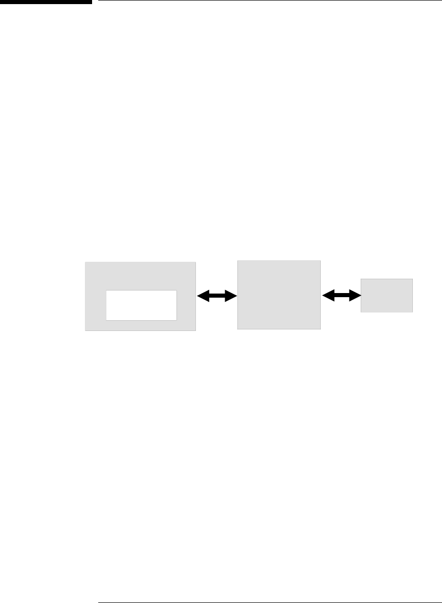
Host computer Logic analysis
system with
emulator Target
SingleStep
LAN
68

Getting started
1 Check that your Emulator is programmed with firmware for an
M•CORE processor:
If you are using an emulation probe, telnet to the emulation probe
and enter the ’ver’ command. Make sure that the emulation probe is
programmed for M•CORE.
2 Connect to the emulator:
aStart SingleStep running on your PC or workstation.
bWhen the small Debug dialog box appears in the middle of the screen,
click the Connection tab and then enter the IP address of the HP logic
analysis system.
If the Debug dialog box is not visible, select File➝Debug.
Note: SingleStep is hard-coded to connect to the emulator at port
6470 of the logic analysis system frame. See page 65 for more
information on port numbers.
3Configure the emulation module with the processor clock speed.
In the Debug dialog box, click the Connection tab and then enter the JTAG
clock speed. Select 10 MHz for processors running at >25 MHz.
4Initialize the target system.
The target system must have various registers and memory locations
initialized before it can access RAM and before SingleStep can download an
application. Normally, code in the target’s boot ROM performs this
initialization. However, when SingleStep resets the target, it immediately
places the processor in debug mode. Any initialization code which may exist
on the target board has not been run.
SingleStep provides a way for target initialization to occur without running
application code through the use of the "_config" alias. _config is used to
define a list of commands that will be used to initialize the target after a
reset. The _config alias should be defined in the sstep.ini file (in the "cmd"
directory) and will point to a file of type .cfg which contains the actual
initialization commands.
Chapter 8: Using the Emulator with a Debugger
Using the Software Development Systems debugger
69

An alternate way of creating the _config alias is to use the Target
Configuration tab in the "Debug" dialog box. The "Debug" dialog method and
the sstep.ini method are mutually exclusive. Use one or the other, but not
both.
5Set up the download and execution options in the Options tab of the
Debug dialog.
6Download the application and run:
Select the File tab and enter the application file name. Exit the "Debug"
dialog box by clicking OK.
Emulator initialization and target initialization occur every time the "Debug"
dialog is terminated via the OK button. A summary of the actions taken by
SingleStep is given here:
•Initialize the emulation module with the communication speed specified in
the "Debug" dialog.
•If "reset target" was selected then execute the commands specified by the
_reset alias. The _reset alias should be used to specify commands that are
specific to initializing the processor. It is executed each time the
processor is reset. The value of the _reset alias can be viewed by issuing a
"alias _reset" from the command window.
•Execute the commands specified by the _config alias. The _config alias
should be used to specify commands that are specific to initializing
(configuring) the target system. It is executed each time the processor is
reset and each time the debug dialog is exited. The value of the _config
alias can be viewed by issuing an "alias _config" from the command
window.
•If "load image" was selected then download the application and set the PC
based on object module file contents.
•If "execute until main" was selected then set a breakpoint at main() and
run.
Chapter 8: Using the Emulator with a Debugger
Using the Software Development Systems debugger
70

To send commands to the emulator
To view commands sent by SingleStep
SingleStep communicates to the emulator using the emulator’s "terminal
interface" commands. SingleStep automatically generates and sends the
commands required for normal operation. This communication between
SingleStep and the emulator can be observed by entering the following
command in the SingleStep command window:
control -ms
To send commands
"Terminal interface" commands may be sent directly to the emulator from the
SingleStep command window or included in SingleStep’s .cfg or .dbg
command files.
Commands should be enclosed in double quotes and given the prefix:
control -c.
Examples To see the speed that the emulator is using to communicate with the target
system you would issue the following command in the SingleStep command
window:
control -c "cf speed"
To change the speed to match a 25MHz processor clock you would issue the
following command in the command window:
control -c "cf speed=7"
Chapter 8: Using the Emulator with a Debugger
Using the Software Development Systems debugger
71

On-chip breakpoints and debugging ROM code
The M•CORE has a built-in hardware breakpoint capability. When SingleStep
steps one source line or sets a user defined breakpoint, it will first try to use a
software breakpoint. If the breakpoint does not work because the breakpoint
address is located in ROM, SingleStep will automatically attempt to use one
of the available hardware breakpoints. For more information, see the
SingleStep release notes.
To debug ROM based code, unselect "load application image" in the options
tab of the "Debug" dialog.
Error conditions
"!ERROR 800! Invalid command: bcast" usually means that there is not a
target interface module (TIM) connected to the emulator or the emulator
does not have firmware for the M•CORE family. Verify that the emulator is
connected to the target. Next, go to the system window of the logic analyzer
interface and verify that the Emulation Module icon (stop-light) is described
as a Motorola M•CORE Emulator. If it is not, follow the steps on page 142 to
update the firmware in the Emulator for M•CORE processors.
"command socket connection failed: WSAECONNREFUSED: connection
refused" usually means the emulator is not at port #6470 on the Logic
Analysis System. See step 2 of the getting started section above.
"unrecognized hostname" usually means that the debugger is unable to
establish communication with the emulator. Verify communication to the
emulator by doing a ping to the logic analyzer. If you are unable to ping the
logic analyzer refer to page 97 for more information.
See Also The SDS web site: http://www.sdsi.com
The SDS SingleStep Users Guide.
The configuration section beginning on page 59 for more information on
configuration options and the "cf" command.
Chapter 8: Using the Emulator with a Debugger
Using the Software Development Systems debugger
72

9
Specifications and
Characteristics
73
Processor Compatibility
The E3455A HP Emulator supports the M•CORE rev 1.5 core and the
MMC2001.
Electrical Characteristics
Maximum Ratings
Characteristics for HP emulator Symbol Min Max
TDO, RTCK Vih 0.8 x VDD 5 V
Vil 0.2 x VDD
Ii±1 µA
Cin 15 pF
TDI, TCK, TMS, TRST 1, MCU-DE Voh @ Ioh = -32 mA 0.8 x VDD 2.7 V
Vol @ Iol = 64 mA; VCC=4.5V 0.2 x VDD
TDI, TMS, TRST, MCU-DE Co25 pF
TCK Co45 pF
VDD Vih 1.2 V 5 V
Vil 0.8 V
1 These signals must not be actively driven by the target system when the debug port is being used.
2 Power Sense is used only to determine target powered status. The emulator does not draw power from this source.
3 Open collector outputs, pulled up to a generated voltage equivalent to the Power Sense voltage with a 2.61 K pullup resistor
Chapter 9: Specifications and Characteristics
Processor Compatibility
74

Emulation probe electrical characteristics
BNC, labeled TRIGGER OUT
Output Drive Logic high level with 50-ohm load >= 2.0 V. Logic low
level with 50-ohm load <= 0.4 V. Output function is selectable, see the
configuration chapter (page 59).
BNC, labeled BREAK IN
Input Edge-triggered TTL level input, 20 pf, with 2K ohms to ground in
parallel. Maximum input: 5 V above VCC; 5 V below ground. Input
function is selectable, see the configuration chapter (page 59).
Communications
Serial Port 9-pin female type “D” subminiature connector. RS-232 DCE
to 115.2 kbaud.
10BASE-T LAN Port RJ-45 connector. IEEE 802.3 10BASE-T
(StarLAN).
10BASE 2 LAN Port 50-ohm BNC connector. IEEE 802.3 10BASE2
(ThinLAN). When using this connector, the HP emulator provides the
functional equivalent of a Medium Attachment Unit (MAU) for ThinLAN.
Accessory Power Out 12 V, 3.0A, center negative
Power Supply
Input 100-240 V, 9.75 A, 50/60 Hz, IEC 320 connector.
Output 12 V, 3.3 A
Chapter 9: Specifications and Characteristics
Emulation probe electrical characteristics
75

Emulation probe environmental characteristics
Temperature Operating, +5 °C to +40 °C (+41 to +104 °F); nonoperating, -40 to +70 °C
(-40 to +158 °F).
Altitude Operating/nonoperating 4600 m (15 000 ft).
Relative Humidity 15% to 95%.
Emulation module electrical characteristics
Maximum Ratings
Characteristics for HP Emulation Module Symbol Min Max Unit
Input voltage rand Vin -0.5 5.5 V
Input voltage range (Vtt) 1.3 1.7 V
Input High Voltage Vih 2/3Vtt + 0.2 V
Input Low Voltage Vil 2/3Vtt - 0.2 V
Input High Current lih -15 µA
Input Low Current lil 100 µA
Output High Voltage Voh 2.4 3.3 V
Output Low Voltage Vol 0.5 V
Output High Current loh 8mA
Output Low Current lol -16 mA
Chapter 9: Specifications and Characteristics
Emulation probe environmental characteristics
76

10
Updating Firmware
77

Updating Firmware
Firmware gives your emulator a “personality” for a particular processor or
processor family.
After you have connected the emulator to your target system, you may need
to update the firmware to give it the right personality for your processor.
You must update the firmware if:
•You have an emulation module which was not shipped already installed in
the logic analysis system.
•You need to change the personality of the emulator for a new processor.
•You have an updated version of the firmware from HP.
The procedure for updating firmware for an emulation probe is
different from the procedure for updating firmware for an emulation
module.
78

Emulation Probe Firmware
To display current firmware version information
•Use telnet or a terminal emulator to access the built-in "terminal interface"
and use the ver command to view the version information for firmware
currently in the emulation probe.
To update firmware for an emulation probe
To update the firmware, you must have access to the World Wide Web and a
PC or a workstation connected to your emulation probe.
1Download the new firmware from the following World Wide Web site:
http://www.hp.com/go/emulator
The firmware will be in the “Technical Support Information” section of this
web site.
2Follow the instructions on the web site for installing the firmware.
If HP sends you firmware on a floppy disk, install the firmware from the
floppy disk. The README file on the floppy disk contains instructions for
installing the firmware using a PC or workstation.
79

Emulation Module Firmware
Always update firmware by installing a processor support package. This will
ensure that the version of the Emulation Control Interface software is
compatible the version of the emulator firmware.
To display current firmware version information
1In the Update Firmware window, click Display Current Version.
There are usually two firmware version numbers: one for “Generics” and one
for the personality of your processor.
To update firmware for an emulation module using the
Emulation Control Interface
1End any run control sessions which may be running.
2In the Workspace window, remove any Emulator icons from the
workspace.
3Install the processor support package from the CD-ROM, if
necessary.
In the system window, click the emulation module and select
Chapter 10: Updating Firmware
Emulation Module Firmware
80
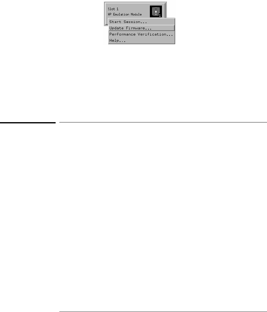
4Update Firmware.
5In the Update Firmware window, select the firmware to load into the
emulation module.
6Click Update Firmware.
In about 20 seconds, the firmware will be installed and the screen will update
to show the current firmware version.
See also “Installing Software” beginning on page 38 for instructions on how to install
the processor support package from the CD-ROM.
To update firmware for an emulation module using the
Setup Assistant
The Setup Assistant is an online tool for connecting and configuring your
logic analysis system for microprocessor and bus analysis. The Setup
Assistant is available on the HP 16600A and HP 16700A-series logic analysis
systems.
This menu-driven tool will guide you through the connection procedures for
connecting the logic analyzer to an analysis probe, an emulation module, or
other supported equipment. It will also guide you through connecting an
analysis probe to the target system.
1Install the processor support package from the CD-ROM.
2Start the Setup Assistant by clicking its icon in the system window.
3Follow the instructions displayed by the Setup Assistant.
See also Page 51 for instructions on how to install a the processor support
package from the CD-ROM.
Chapter 10: Updating Firmware
To update firmware for an emulation module using the Setup Assistant
81

82

11
Solving Problems
83

Solving Problems
If you have problems with the emulator, your first task is to determine
the source of the problem. Problems may originate in any of the
following places:
•The connection between the emulator and your workstation, PC, or
logic analyzer
•The emulator itself
•The connection between the emulator and the target interface
module
•The connection between the target interface module and the target
system
•The target system
You can use several means to determine the source of the problem:
•The troubleshooting guide on the next page
•The status lights on the emulator
•The emulator "performance verification" tests
•The emulator’s built-in "terminal interface" commands
84

Troubleshooting Guide
Common problems and what to do about them
Symptom What to do See also
Host computer reports LAN
connection problems Follow the checklist in the "If you have LAN problems" section. page 97
Commands from the Emulation
Control Interface or debugger have
no effect
1 Verify LAN communication. page 25
2 Check that you are using the correct firmware for your chip
and mask revision. page 84
3 Use a telnet connection (or serial connection) to try a few
built-in commands. If this works, your debugger may not be
configured properly. If this does not work, continue with the
next procedure....
page 89
Emulation probe built-in commands
do not work 1 Check that the emulator has been properly configured for
your target system. page 46
2 Run the emulator performance verification tests. page 105
3 If the performance verification tests pass, then there is an
electrical problem with the connection to the target processor
OR the target system may not have been designed according
to "Designing a Target System."
page 55,
page 91
"Slow or missing clock" message
after a logic analyzer run Check that the target system is running user code or is in reset.
(This message can appear if the processor is in background
mode.)
"Slow clock" message in the Run
Control tool or "c>" prompt in the
built-in terminal interface
Check that the clock rate is properly configured. page 52
Some commands fail Check the "restrict to real-time runs" configuration page 51
85

Emulation Probe Status Lights
The emulation probe communicates various modes and error
conditions via the status lights. The meanings of the status lights are
shown on the previous page.
The following table gives more information about the meaning of the
power and target status lights.
❍ = LED is off
● = LED is on
✳ = Not applicable (LED is off or on)
Power/Target Status Lights
Pwr/Target
LEDs Meaning
❍❍
❍❍
Emulation probe is not connected to power supply
❍●
❍❍
No target system power, or emulation probe is not connected to the target
system
❍●
❍●
Target system is in a reset state
●●
●❍
Only boot firmware is good (other firmware has been corrupted)
●●
❍❍
The target processor is executing in the background monitor
❍●
●❍
The target processor is executing user code
86
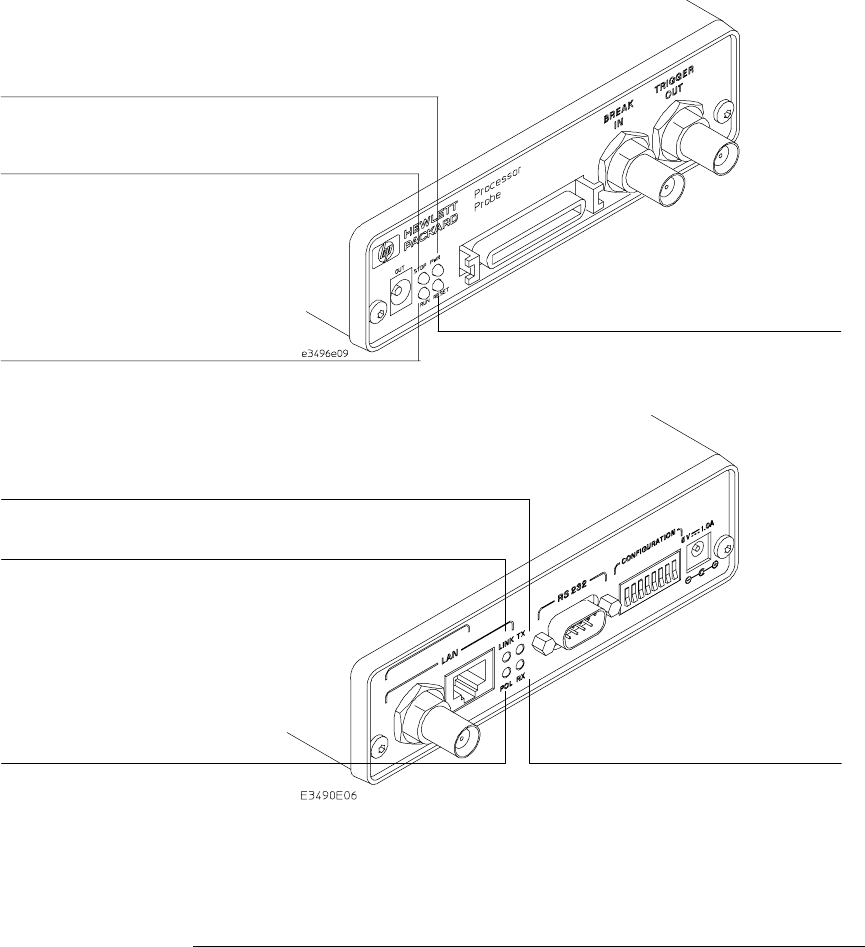
Emulation probe status lights
The following illustration shows the status lights on both sides of the
emulation probe and what they mean:
Lit when the target processor is
running in debug mode
Lit when the power supply is properly
connected to the emulation probe
Lit when the target system is
Lit when the target processor is
Lit when LAN data is being transmitted
Lit when 10BASE-T
connection has a good link;
not used for 10BASE2
Lit when the polarity on the
receive twisted pair is
reversed for a 10BASE-T
Lit when LAN data is being
Figure 7. Status Lights
Chapter 11: Solving Problems
Emulation Probe Status Lights
87

Emulation Module Status Lights
The emulation module uses status lights to communicate various
modes and error conditions.
The following table gives more information about the meaning of the
power and target status lights.
❍ = LED is off
● = LED is on
✳ = Not applicable (LED is off or on)
Power/Target Status Lights
Pwr/Target
LEDs Meaning
❍ Reset
❍ Break
❍ Run
No target system power, or emulation module is not connected to the
target system
● Reset
❍ Break
❍ Run
Target system is in a reset state
❍ Reset
● Break
❍ Run
The target processor is executing in Debug Mode
❍ Reset
❍ Break
● Run
The target processor is executing user code
❍ Reset
● Break
● Run
Only boot firmware is good (other firmware has been corrupted)
88

Built-in Commands
The emulator has some built-in "terminal interface" commands which you can
use for troubleshooting.
You can access the terminal interface via:
•A serial connection ( Emulation probe only, see page 26)
•A telnet (LAN) connection
•The Command Line window in the Emulation Control interface
•A "debugger command" window in your debugger
Here are a few useful commands:
Useful built-in commands
bBreak—go into the background monitor state
cf Configuration—read or write configuration options
help Help—display online help for built-in commands
init Initialize—init -c reinitializes everything in the emulator except for the LAN
software; init -p is the equivalent of cycling power (it will break LAN
connections)
lan configure LAN address
mMemory—read or write memory
reg Register—read or write a register
rRun—start running user code
rep Repeat—repeat a command or group of commands
rst Reset—reset the target processor (the emulator will wait for you to press the
target’s RESET button)
sStep—do a low-level single step
ver Version—display the product number and firmware version of the emulator
89

The prompt indicates the status of the emulator:
Emulator prompts
URunning user program
MRunning in background monitor
REmulation reset
rTarget reset
pNo target power
?Unknown state
Examples To set register GPR0, then view GPR0 to verify that it was set, enter:
M>reg ro=ffff
M>reg ro
reg ro=0000ffff
To break execution then step a single instruction, enter:
R>
M>b
M>s
PC=
xxxxxxxx
M>
To determine what firmware version is installed in the emulator, enter:
M>ver
See Also Use the help command for more information on these and other commands.
Note that some of commands listed in the help screens may not be available.
If you are writing your own debugger, contact HP for more information.
Chapter 11: Solving Problems
Built-in Commands
90

Problems with the Target System
What to check first
1Try some basic built-in commands (using a serial or telnet
connection):
U>rst
R>
This should reset the target and display a "R>" prompt. If you get a different
prompt, see page 82.
R>b
M>
This should stop the target and display an "M>" prompt.
M>reg r1
reg r1=007fd6a0
M>
This should read the value of the GPR1 register (the value will probably be
different on your target system).
M>m 0..
00000000 7c3043a6 7c2802a6 7c3143a6 4bf04111
00000010 00000000 00000000 00000000 00000000
00000020 00000000 00000000 00000000 00000000
00000030 00000000 00000000 00000000 00000000
00000040 00000000 00000000 00000000 00000000
00000050 00000000 00000000 00000000 00000000
00000060 00000000 00000000 00000000 00000000
00000070 00000000 00000000 00000000 00000000
M>
This should display memory values starting at address 0.
M>s
This should execute one instruction at the current program counter.
If any of these commands don’t work, there may be a problem with the design
of your target system, a problem with the revision of the processor you are
using, or a problem with the configuration of the emulator. The following
steps will help you identify the problem.
2Check that the emulator firmware matches your processor. To do
this, enter:
91

M>ver
3Check that the mask version for your processor is supported by the
emulator. See "Designing a Target System" beginning on page 55.
See Also Page 89 for information on entering built-in commands.
Chapter 11: Solving Problems
Problems with the Target System
92

To interpret the initial prompt
The initial prompt can be used to diagnose several common problems.
1Connect the emulator to your target system.
2Set the default configuration settings. Enter:
M>init -c
You can enter this command at any prompt. The emulator will respond with
the same information as printed by the "ver" command.
If the response is "!ERROR 905! Driver firmware is
incompatible with ID of attached device"
Make sure the target interface module is connected to the cable of the
emulator, then try the "init -c" command again.
If the initial prompt is "p>"
Check pin 6 on header, 3.3V (VDD).
If the initial prompt is "M>"
The processor entered debug mode without the help of the emulator. Is
another debugger connected?
Chapter 11: Solving Problems
Problems with the Target System
93

If the initial prompt is "U>"
The emulator is scanning the instruction register correctly. Now you can do
some more tests:
3Enter the reset command:
U>rst
R>
The "R>" prompt is a good response that indicates RESET is working.
If the prompt after rst is "U>"
The RESET lines are not working. Continue with more tests:
4Enter the break command:
U>b
M>
Chapter 11: Solving Problems
Problems with the Target System
94

If you see memory-related problems
1Enter:
M>m -d4 -a4 0=11111111,22222222,33333333,44444444
M>m -d4 -a4 0..
00000000 11111111 02222222 33333333 44444444
00000010 00000000 00000000 00000000 00000000
00000020 00000000 00000000 00000000 00000000
00000030 00000000 00000000 00000000 00000000
00000040 00000000 00000000 00000000 00000000
00000050 00000000 00000000 00000000 00000000
00000060 00000000 00000000 00000000 00000000
00000070 00000000 00000000 00000000 00000000
M>
•RAM must be at address 0.
•Read value not equal to the written value implies that the memory
controller is not setup correctly.
Chapter 11: Solving Problems
Problems with the Target System
95

3Hand load a little program:
M>m -d4 -a4 200000=2002,1200,1200,F7FC
M>reg r2=0
M>
This means: Add 1, GPR2, NOP, NOP, JMP .-4
Set the PC to this program:
M>reg PC=200000
M>
Step, then check the register:
M>s
PC=200002
M>reg r2
reg r2=00000001
M>
This should return"reg r2=00000001" .
Step some more and verify that GPR1 increments after every four steps:
M>s 4
PC=200002
M>reg r2
reg r2=00000002
M>
Chapter 11: Solving Problems
Problems with the Target System
96

Problems with the LAN Interface (Probe
only)
For LAN interface problems with the emulation module, refer to the online help
in the logic analysis system.
If you cannot verify LAN communication
If you cannot verify connection using the procedure in "To verify LAN
communication", or if the commands are not accepted by the emulation
probe:
Make sure that you have connected the emulation probe to the proper
power source and that the power light is lit.
Make sure that you wait for the power-on self test to complete before
connecting.
Make sure that the LAN cable is connected. Watch the LAN LED’s to see
whether the emulation prove is seeing LAN activity. Refer to your LAN
documentation for testing connectivity.
Make sure that only one of the LAN ports is connected.
Make sure the emulation probe communication configuration switches
are set correctly. Unplug the emulation probe power cord, then plug it
in again to make sure the switch settings are read correctly by the
emulation probe.
Check that the Emulation Control Interface or debugger was configured
with the correct LAN address. If the emulation probe is on a different
subnet than the host computer, check that the gateway address is
correct.
Make sure that the emulation probe’s IP address is set up correctly. Use
the RS-232 port to verify this that the IP address is set up correctly.
When you are connected to the RS-232 port, run performance
verification on the emulation probe’s LAN interface with the "pv"
command.
97

It’s also possible for there to be a problem with the emulation probe
firmware while the LAN interface is still up and running. In this case,
you must reboot the emulation probe by disconnecting power to the
emulation probe and reconnecting it again.
Use a serial connection to run the LAN performance verification tests
(see page 105).
If you have LAN connection problems
If the emulation probe does not accept commands from the logic
analyzer:
1. Check that switch S1 is "0" (attached to LAN, not RS-232).
2. Check that switch S5 is in the correct position for your LAN interface
(either 10BASE2 or 10BASE-T).
(Remember: if you change any switch settings, the changes do not take effect
until you cycle power.)
If the emulation probe still does not respond, you need to verify the IP
address and gateway mask of the emulator. To do this, connect the
emulation probe to a terminal or terminal emulator (see page 26),
change the switch settings so it is connected to RS-232, and enter the
"lan" command. The output looks something like this:
lan -i 15.5.24.116
lan -g 15.5.23.1
lan -p 6470
Ethernet Address : 08000909BAC1
"lan -i" shows the internet address is 15.5.24.116 in this case. If the Internet
address (IP) is not what you expect, you can change it with the ’lan -i <new
IP>’ command.
Chapter 11: Solving Problems
Problems with the LAN Interface (Probe only)
98

"lan -g" shows the gateway address. Make sure it is the address of your
gateway if you are connecting from another subnet, or 0.0.0.0 if you are
connecting from the local subnet.
"lan -p" shows the port is 6470.
If the "POL" LED is lit
The "POL" LED indicates that the polarity is reversed on the receive pair if
you are using a 10BASE-T connection. The emulation probe should still work
properly in this situation, but other LAN devices may not work.
Chapter 11: Solving Problems
Problems with the LAN Interface (Probe only)
99

If it takes a long time to connect to the network
Check the subnet masks on the other LAN devices connected to your
network. All of the devices should be configured to use the same subnet
mask.
Subnet mask error messages do not indicate a major problem. You can
continue using the emulation probe.
The emulation probe automatically sets its subnet mask based on the first
subnet mask it detects on the network. If it then detects other subnet masks,
it will generate error messages.
If there are many subnet masks in use on the local subnet, the emulation
probe may take a very long time to connect to the network after it is turned
on.
To "clean up" the network, connect a terminal to the emulation probe. You
can then see error messages which will help you identify which devices on
the network are using the wrong subnet masks.
Chapter 11: Solving Problems
Problems with the LAN Interface (Probe only)
100

Problems with the Serial Interface
(Emulation probe only)
If you cannot verify RS-232 communication
If the emulation probe prompt does not appear in the terminal emulator
window:
Make sure that you have connected the emulation probe to the proper
power source and that the power light is lit.
Make sure that you have properly configured the data communications
switches on the emulator and the data communications parameters on
the host computer. You should also verify that you are using the correct
cable.
The most common type of data communications configuration problem
involves the configuration of the emulation probe as a DTE device instead of
as a DCE device. If you are using the wrong type of cable, no prompt will be
displayed.
A cable with one-to-one connections will work with a PC or an HP Series 700
workstation.
If you have RS-232 connection problems with the MS
Windows Terminal program
Remember that Windows 3.1 only allows two active RS-232 connections
at a time. To be warned when you violate this restriction, choose
Always Warn in the Device Contention group box under 386 Enhanced
in the Control Panel.
Use the "Terminal" program (usually found in the Accessories windows
program group) and set up the "Communications..." settings as follows:
Baud Rate: 9600 (or whatever you have chosen for the
emulator)
Data Bits: 8
Parity: None
Flow Control: hardware
Stop Bits: 1
101

When you are connected, hit the Enter key. You should get a prompt back.
If nothing echos back, check the switch settings on the emulation probe.
If the switches are in the correct position and you still do not get a
prompt when you hit return, try turning OFF the power to the emulation
probe and turning it ON again.
If you still don’t get a prompt, make sure the RS-232 cable is connected
to the correct port on your PC, and that the cable is appropriate for
connecting the PC to a DCE device.
With certain RS-232 cards, connecting to an RS-232 port where the
emulation probe is turned OFF (or is not connected) will hang the PC. The
only way to get control back is to reboot the PC. Therefore, we recommend
that you always turn ON the emulation probe before attempting to connect
via RS-232.
Chapter 11: Solving Problems
Problems with the Serial Interface (Emulation probe only)
102

Problems with the Emulation Probe Itself
To run the power up self test
1Unplug the emulation probe, then plug it in.
2Watch the status lights. They should show the following pattern:
❍ = LED is off
● = LED is on
✳ = Not applicable (LED is off or on)
Normal sequence during power up self test
Pwr/Target
LEDs Meaning
1❍●
❍❍
Initial power up, system reset
2❍●
❍❍
XILINX array initialized successfully
3❍●
●❍
XILINX array tested successfully
4●●
❍❍
BOOT ROM space tested successfully
5❍●
●❍
GENERIC ROM space tested successfully
6●●
❍❍
DRIVER ROM space tested successfully
7❍●
●❍
RESERVED ROM space tested successfully
8●●
❍❍
RAM tested successfully
9❍●
●❍
LAN internal feedback tested successfully
10 ❍●
❍❍
Boundary scan master (BSM) test begun
11 ●●
●❍
BSM test completed, start system, load drivers, initialize LAN
If the power up self test fails, the RESET LED will flash the number of the
test, then stay lit.
If any of the LEDs fail to change, or all of them remain on, there is a system
failure.
Following power up, the LEDs will enter one of the following states:
103

❍●
❍❍
No target system power, or the emulation probe is not connected to the
target system, or
❍●
❍●
M•CORE is in debug mode
❍●
●❍
M•CORE is running user code
●●
●●
M•CORE is in an unknown state
●●
●❍
Only the boot ROM was used; other firmware in the Flash EPROM has
been corrupted
Starting a user interface will change the pattern to the one requested
by the interface.
If the power up self tests fail, try the following:
Check and reset the LAN address. LAN powerup failures will occur if the
emulation probe does not have a valid Link Level Address and IP
Address.
Disconnect all external connections, including the LAN, serial (RS-232),
and BNC Break and Trigger cables, then cycle power.
To ensure that the firmware is working as it should, reprogram the
firmware, then cycle power.
Chapter 11: Solving Problems
Problems with the Emulation Probe Itself
104

To execute the built-in performance verification test
In addition to the powerup tests, there are several additional performance
verification (PV) tests available.
Some of these tests can be performed through the logic analyzer. The LAN
tests can only be executed through the RS-232 port.
To fully test the emulation probe, you will need to run the PV test with
several hardware configurations:
•For the BREAK IN, TRIGGER OUT BNC FEEDBACK TEST, connect a
coaxial cable between BREAK IN and TRIGGER OUT.
•For the TARGET PROBE FEEDBACK TEST, connect the emulator
loopback test board (HP part number E3496-66502).
To run the built-in performance verification test using
the logic analysis system
1End any Emulation Control Interface or debugger sessions.
2Disconnect the 50-pin cable from the emulator, and plug the
loopback test board (HP part number E3496-66502) into the emulator.
3In the system window, click the emulator and select Performance
Verification.
4Click Start PV.
The results will appear onscreen.
Chapter 11: Solving Problems
Problems with the Emulation Probe Itself
105

To perform complete PV tests for an emulation probe
The LAN tests can only be executed through the RS-232 port. The
remainder of this section assumes that the tests are being run from a terminal
emulator connected to the RS-232 port.
1Disconnect the 50-pin cable from the emulation probe, and plug the
emulator loopback test board (HP part number E3496-66502) directly
into the emulation probe. Do not plug anything into the other end of
the emulator loopback test board.
On a good system, the RESET LED will light and the BKG and USER LEDs
will be out.
2Connect a coaxial cable between BREAK IN and TRIGGER OUT.
3Set all of the switches to CLOSED.
This is standard RS-232 at 9600 baud which can be connected directly to a 9
pin RS-232 interface that conforms to the IBM PC-AT 9 pin standard.
4Use a terminal emulator to connect to the emulator.
5Enter the pv 1 command.
6Plug the 16-pin cable of the stimulus board into the target interface
module.
7Enter the pv -d command.
See Also Options available for the "pv" command are explained in the help screen
displayed by typing "help pv" or "? pv" at the prompt.
Chapter 11: Solving Problems
Problems with the Emulation Probe Itself
106

Examples: Here are some examples of ways to use the pv command.
To execute both tests one time:
pv 1
To execute test 2 with maximum debug output repeatedly until a ^C is
entered:
pv -t2 -v9 0
To execute tests 3, 4, and 5 only for 2 cycles:
pv -t3-5 2
The results on a good system, with the BNC’s connected, and with the
loopback test board connected, are as follows:
c>pv 1
Testing: HPE3455A Series Emulation System
Test # 1: Powerup PV Results passed!
Test # 2: LAN 10Base2 Feedback Test passed!
Test # 3: LAN 10BaseT Feedback Test passed!
Test # 4: Break In and Trigger Out BNC Feedback Test passed!
Test # 5: Target Probe Feedback Test passed!
Test # 6: Boundary Scan Master Test passed!
PASSED Number of tests: 1 Number of failures: 0
Copyright (c) Hewlett-Packard Co. 1987
Copyright (c) International Business Machines Corp. 1995
All Rights Reserved. Reproduction, adaptation, or translation without prior
written permission is prohibited, except as allowed under copyright laws.
HPE3499B Series Emulation System
Version: A.07.53 26Feb98
Location: Generics
HPE3455A Motorola M-Core Emulator
Version: A.01.00 31Mar98
Chapter 11: Solving Problems
Problems with the Emulation Probe Itself
107

If a performance verification test fails
There are some things you can do if a failure is found on one of these tests.
Details of the failure can be obtained through using a verbose level of 2 or
more.
If the particular failure you see is not listed below, contact HP for assistance.
TEST 2: LAN 10BASE2 Feedback Test failed
For LAN 10BASE2 test, the following is an example of a failure which is not
caused by a broken emulator.
R>pv -t2 -v2 1
Testing: HPE3455A Series Emulation System
Test # 2: LAN 10Base2 Feedback Test failed!
FAILED - no lan connection (LAN probably not terminated)
FAILED Number of tests: 1 Number of failures: 1
Check to see that the port under test has a good cable connected to it and
that the cable is properly terminated with a 50 ohm terminator on each end
of the overall cable.
R>pv -t2 -v2 1
Testing: HPE3455A Series Emulation System
Test # 2: LAN 10Base2 Feedback Test failed!
FAILED due to excessive collisions
FAILED Number of tests: 1 Number of failures: 1
The most common cause of this problem is poor termination of the cable or
failure to remove the port under test from the LAN before performing the
test. Check to see that the terminators are good (50 Ohms) and that you are
isolated from any traffic on a system LAN.
R>pv -t2 -v2 1
Testing: HPE3455A Series Emulation System
Test # 2: LAN 10Base2 Feedback Test failed!
FAILED - invalid Ethernet address in EEPROM
FAILED Number of tests: 1 Number of failures: 1
Chapter 11: Solving Problems
Problems with the Emulation Probe Itself
108

First check to see that a correct LLA and IP address have been set in the
virtual EEPROM through the "lan" command. If the "lan" command shows bad
information for the LLA and IP, then try to set them to correct values. If you
are unable to set them to correct values, their is a failure in the FLASH ROM
which requires service from HP.
Test 3: 10BaseT Feedback Test failed
R>pv -t3 -v2 1
Testing: HPE3455A Series Emulation System
Test # 3: LAN 10BaseT Feedback Test failed!
FAILED Number of tests: 1 Number of failures: 1
In addition to the internal checks performed in Test 2, this test also checks
for shorts on the cable connected to the network. If this test fails, disconnect
the cable and run the test again. If it then passes, the cable is faulty. If it still
fails, it requires service from HP.
Chapter 11: Solving Problems
Problems with the Emulation Probe Itself
109

Test 4: Break In and Trigger Out BNC Feedback Test
R>pv -t4 -v2 1
Testing: HPE3455A Series Emulation System
Test # 4: Break In and Trigger Out BNC Feedback Test failed!
Break In not receiving Break Out HIGH
FAILED Number of tests: 1 Number of failures: 1
Before returning to HP, check to ensure that you have connected a good
Coaxial cable between the two BNCs. If the cable is good, the emulator is
bad.
TEST 5: Boundary Scan Master Test
TEST 6: I2C Test
If these tests are not executed, check that you have connected the emulator
loopback test board.
If these tests fail, return the emulator to HP for replacement.
Target Interface Module tests (pv -d tests)
If these tests are not executed, check that you have connected the target
interface module stimulus/loopback test board.
If these tests fail, return the target interface module to HP for replacement.
Chapter 11: Solving Problems
Problems with the Emulation Probe Itself
110

Returning the Parts to Hewlett-Packard for
Service
To return a part to Hewlett-Packard
1Follow the procedures in this chapter to make sure that the problem
is caused by a failure in the emulator or power supply, not by
configuration or communication problems.
2In the U.S., call 1-800-403-0801. Outside the U.S., call your nearest HP
sales office. Ask them for the address of the nearest HP service
center.
A list of HP sales offices is included at the back of this binder.
3Package the part and send it to the HP service center.
Keep any parts which you know are working. For example, if only the power
supply is broken, keep the target interface module, emulator and cables.
4When the part has been replaced, it will be sent back to you.
The unit returned to you will have the same serial number as the unit you
sent to HP.
The HP service center can also troubleshoot the hardware and replace the
failed part. To do this, send your entire measurement system to the service
center, including the logic analysis system, target interface module, and
cables.
In some parts of the world, on-site repair service is available. Ask an HP sales
or service representative for details. To return a part to Hewlett-Packard
111

To obtain replacement parts
The repair strategy for this emulation solution is board replacement. The
following table lists some parts that may be replaced if they are damaged or
lost. Contact your nearest Hewlett-Packard Sales Office for further
information on servicing the board.
Exchange assemblies are available when a repairable assembly is returned to
Hewlett-Packard. These assemblies have been set up on the "Exchange
Assembly" program. This allows you to exchange a faulty assembly with one
that has been repaired, calibrated, and performance verified by the factory.
The cost is significantly less than that of a new assembly.
Part numbers
Exchange Assemblies
Part Number Description
E3455-69401 Programmed emulator
Replacement Assemblies
Part number Description
0950-3043 Power Supply
E3494-61602 14-pin cable
E3496-61601 50-pin cable
E3496-66502 Processor probe loopback test board
E3455-66501 Target interface module (M•CORE)
E3481-66507 Stimulus/self-test board for the target interface module
To clean the emulator
If the emulator requires cleaning:
1Remove power from the instrument.
2Clean with a mild detergent and water.
3Make sure that the instrument is completely dry before reconnecting
it to a power source.
Chapter 11: Solving Problems
Problems with the Emulation Probe Itself
112

Index
A
address, IP
See IP address
altitude specifications, 76
B
BDM port
See debug port
BKG light, 87–88
BNC
break in, 53
LAN, 17
trigger out, 53
BNC, LAN, 75
BOOTP, 22–23
built-in commands
configuration, 48
LAN configuration, 19–21
list of commands, 89–90
C
cable
LAN, 24
power, 8
replacing, 112
serial, 28–29
CD-ROM, installing software from, 39
cf commands, 48
cleaning, 112
clocks
specifications, 74
configuration, 59, 61–62, 64–67, 69–72
configuration files
installing, 37, 39
connecting to the target system, 41, 43
connection
emulation module, 31–36
host workstation, 15, 18–25, 27–30
problems, LAN, 98
problems, RS-232, 101
sequence, 9
connector
10BASE-T, 17, 75
10BASE2, 17, 75
JTAG, 57
serial, 75
D
data communications
specifications, 75
DCE or DTE selection and RS-232 cable,
101
debug port
connecting to, 43
debugger
configuration, 50
writing, 90
debuggers
benefits of, 60
SDS, 68–72
setting up, 63–67
development port
See debug port
displaying on PC, 66–67
driver firmware error, 93
E
Emulation Control Interface
configuration, 47
debugger conflict, 63
emulation module
connecting, 32–36
HP 16600 installation, 35
HP 16700A installation, 33
port number, 65
ethernet address, 19
exporting a display, 66–67
F
files
loading vs. installing, 38
workstation setup, 63–67
firmware, updating, 78
flash EPROM, 78
G
gateway address, 20, 98
H
host computer
connecting to, 15, 18–25, 27–30
I
IEEE 802.3, 17
init command, 93
installation, software, 37, 39
internet address
See IP address
IP address, 17–19, 97–98
L
lan command, 19–21
LAN connection problems, 98, 108–109
LAN interface, 17
LAN parameters, configuring
BOOTP, 22–23
methods, 17
terminal interface, 19–21
lights
See status lights
link beat, 24
link level address, 19, 22
LINK light, 87
loading configurations, vs. installing, 37, 39
M
mask, subnet, 100
MAU, 17, 75
memory
testing, 95
monitor, 51
P
PC
connecting to, 15, 18–25, 27–30
performance verification test, 105
ping command, 98
POL light, 87, 99
port number, 20
port number, emulation module, 65
power cord, 8
power on/off sequence, 7–8
power supply, connecting, 8
power up self test, 103
prgflash, 78
problems, 83, 87, 90, 92–96, 98–100, 102,
104–110, 112
processor support package, 39
113

processors supported, iv
prompts, 90
list of, 90
troubleshooting, 93
R
real-time runs, configuring, 51
register commands, 91
requirements
minimum equipment, 6
RESET
light, 87–88
RS-232
See serial connection
run control unit
See processor probe
S
SDS debugger, 68–72
self test, 103
serial connection
DCE or DTE selection, 101
number of connections, 101
problems, 101
setting up, 26
verifying, 30
service ports, TCP, 20
service, how to obtain, 111
setup
See configuration
SingleStep debugger, 68–72
slow clock, 85
software
installing, 37, 39
software probe
See processor probe
specifications
altitude, 76
clock, 74
data communications, 75
temperature, 76
trigger in/out, 75
StarLAN, 17, 24
status lights, 86–88, 103
subnet mask, 17, 98, 100
switches
bootp, 23
LAN configuration, 19–21, 24
serial configuration, 27
T
target interface module, 43
target system
connecting to, 32–36, 42
problems with, 91–96
telnet, 25, 65, 97
temperature specifications, 76
terminal (MS Windows program), 101
terminal interface, 25, 65
See also built-in commands
LAN parameters, setting, 19–21
ThinLAN, 17, 75
trigger
in/out specifications, 75
troubleshooting, 85
TX light, 87
U
update, firmware, 78
USER light, 87–88
W
workstation
connecting to, 15, 18–25, 27–30
X
X windows, 66–67
Index
114

© Copyright Hewlett-
Packard Company1994- 1997
All Rights Reserved.
Reproduction, adaptation, or
translation without prior
written permission is
prohibited, except as allowed
under the copyright laws.
Restricted Rights Legend.
Use, duplication or disclosure
by the U.S. Government is
subject to restrictions as set
forth in subparagraph (c) (1)
(ii) of the Rights in Technical
Data and Computer Software
clause at DFARS
252.227-7013 for DOD
agencies, and subparagraphs
(c) (1) and (c) (2) of the
Commercial Computer
Software Restricted Rights
clause at FAR 52.227-19 for
other agencies.
Hewlett-packard Company
3000 Hanover Street
Palo Alto, California 94304
U.S.A.
Document Warranty
The information contained in
this document is subject to
change without notice.
Hewlett-Packard makes
no warranty of any kind
with regard to this
material, including, but
not limited to, the implied
warranties of
merchantability or fitness
for a particular purpose.
Hewlett-Packard shall not be
liable for errors contained
herein or for damages in
connection with the
furnishing, performance, or
use of this material.
Safety
This apparatus has been
designed and tested in
accordance with IEC
Publication 1010, Safety
Requirements for Measuring
Apparatus, and has been
supplied in a safe condition.
This is a Safety Class I
instrument (provided with
terminal for protective
earthing). Before applying
power, verify that the correct
safety precautions are taken
(see the following warnings).
In addition, note the external
markings on the instrument
that are described under
"Safety Symbols."
Warning
• Before turning on the
instrument, you must connect
the protective earth terminal
of the instrument to the
protective conductor of the
(mains) power cord. The
mains plug shall only be
inserted in a socket outlet
provided with a protective
earth contact. You must not
negate the protective action
by using an extension cord
(power cable) without a
protective conductor
(grounding). Grounding one
conductor of a two-conductor
outlet is not sufficient
protection.
• Only fuses with the
required rated current,
voltage, and specified type
(normal blow, time delay,
etc.) should be used. Do not
use repaired fuses or
short-circuited fuseholders.
To do so could cause a shock
or fire hazard.
• Service instructions are for
trained service personnel. To
avoid dangerous electric
shock, do not perform any
service unless qualified to do
so. Do not attempt internal
service or adjustment unless
another person, capable of
rendering first aid and
resuscitation, is present.
• If you energize this
instrument by an auto
transformer (for voltage
reduction), make sure the
common terminal is
connected to the earth
terminal of the power source.
• Whenever it is likely that
the ground protection is
impaired, you must make the
instrument inoperative and
secure it against any
unintended operation.
• Do not operate the
instrument in the presence of
flammable gasses or fumes.
Operation of any electrical
instrument in such an
environment constitutes a
definite safety hazard.
• Do not install substitute
parts or perform any
unauthorized modification to
the instrument.
• Capacitors inside the
instrument may retain a
charge even if the instrument
is disconnected from its
source of supply.
• Use caution when exposing
or handling the CRT.
Handling or replacing the
CRT shall be done only by
qualified maintenance
personnel.
Safety Symbols
Instruction manual symbol:
the product is marked with
this symbol when it is
necessary for you to refer to
the instruction manual in
order to protect against
damage to the product.
Hazardous voltage symbol.
Earth terminal symbol: Used
to indicate a circuit common
connected to grounded
chassis.
WARNING
The Warning sign denotes a
hazard. It calls attention to a
procedure, practice, or the
like, which, if not correctly
performed or adhered to,
could result in personal
injury. Do not proceed
beyond a Warning sign until
the indicated conditions are
fully understood and met.
CAUTION
The Caution sign denotes a
hazard. It calls attention to
an operating procedure,
practice, or the like, which, if
not correctly performed or
adhered to, could result in
damage to or destruction of
part or all of the product. Do
not proceed beyond a
Caution symbol until the
indicated conditions are fully
understood or met.
Hewlett-Packard
P.O. Box 2197
1900 Garden of the Gods Road
Colorado Springs, CO 80901-2197, U.S.A

Product Warranty
This Hewlett-Packard
product has a warranty
against defects in material
and workmanship for a period
of one year from date of
shipment. During the
warranty period,
Hewlett-Packard Company
will, at its option, either
repair or replace products
that prove to be defective.
For warranty service or
repair, this product must be
returned to a service facility
designated by
Hewlett-Packard.
For products returned to
Hewlett-Packard for warranty
service, the Buyer shall
prepay shipping charges to
Hewlett-Packard and
Hewlett-Packard shall pay
shipping charges to return
the product to the Buyer.
However, the Buyer shall pay
all shipping charges, duties,
and taxes for products
returned to Hewlett-Packard
from another country.
Hewlett-Packard warrants
that its software and firmware
designated by
Hewlett-Packard for use with
an instrument will execute its
programming instructions
when properly installed on
that instrument.
Hewlett-Packard does not
warrant that the operation of
the instrument software, or
firmware will be
uninterrupted or error free.
Limitation of Warranty
The foregoing warranty shall
not apply to defects resulting
from improper or inadequate
maintenance by the Buyer,
Buyer-supplied software or
interfacing, unauthorized
modification or misuse,
operation outside of the
environmental specifications
for the product, or improper
site preparation or
maintenance.
No other warranty is
expressed or implied.
Hewlett-Packard
specifically disclaims the
implied warranties of
merchantability or fitness
for a particular purpose.
Exclusive Remedies
The remedies provided herein
are the buyer’s sole and
exclusive remedies.
Hewlett-Packard shall not be
liable for any direct, indirect,
special, incidental, or
consequential damages,
whether based on contract,
tort, or any other legal theory.
Assistance
Product maintenance
agreements and other
customer assistance
agreements are available for
Hewlett-Packard products.
For any assistance, contact
your nearest Hewlett-Packard
Sales Office.
Certification
Hewlett-Packard Company
certifies that this product met
its published specifications at
the time of shipment from the
factory. Hewlett-Packard
further certifies that its
calibration measurements are
traceable to the United States
National Institute of
Standards and Technology, to
the extent allowed by the
Institute’s calibration facility,
and to the calibration
facilities of other
International Standards
Organization members.
About this edition
This is the Emulation for the
Motorola M•CORE User’s
Guide.
Publication number
E3455-97000, May 1998
Printed in USA.
UNIX is a registered
trademark in the United
States and other countries,
licensed exclusively through
X/Open Company Limited.
Windows, MS Windows,
Windows NT, and MS-DOS
are U.S. registered
trademarks of Microsoft
Corporation.

DECLARATION OF CONFORMITY
according to ISO/IEC Guide 22 and EN 45014
Manufacturer’s Name: Hewlett-Packard Company
Manufacturer’s Address: Colorado Springs Division
1900 Garden of the Gods Road
Colorado Springs, CO 80907 USA
declares that the product
Product Name: Processor Probe
Model Number(s): HP E3455A
Product Option(s): All
conforms to the following Product Specifications:
Safety: IEC 1010-1:1990+A1 / EN 61010-1:1993
UL 3111
CSA-C22.2 No. 1010.1:1993
EMC: CISPR 11:1990 / EN 55011:1991 Group 1 Class A
IEC 555-2:1982 + A1:1985 / EN 60555-2:1987
IEC 555-3:1982 + A1:1990 / EN 60555-3:1987 + A1:1991
IEC 801-2:1991 / EN 50082-1:1992 4 kV CD, 8 kV AD
IEC 801-3:1984 / EN 50082-1:1992 3 V/m, {1kHz 80% AM, 27-1000 MHz}
IEC 801-4:1988 / EN 50082-1:1992 0.5 kV Sig. Lines, 1 kV Power Lines
Supplementary Information:
The product herewith complies with the requirements of the Low Voltage Directive 73/23/EEC and the
EMC Directive 89/336/EEC and carries the CE-marking accordingly.
This product was tested in a typical configuration with Hewlett-Packard test systems.
Colorado Springs, 01/23/98
European Contact: Your local Hewlett-Packard Sales and Service Office or Hewlett-Packard GmbH, Department ZQ / Standards
Europe, Herrenberger Strasse 130, D-71034 Böblingen Germany (FAX: +49-7031-14-3143)
Ken Wyatt / Product Regulations Manager

Product Regulations
Safety IEC 1010-1:1990+A1 / EN 61010-1:1993
UL 3111
CSA-C22.2 No.1010.1:1993
EMC This Product meets the requirement of the European Communities (EC)
EMC Directive 89/336/EEC.
Emissions EN55011/CISPR 11 (ISM, Group 1, Class A equipment)
IEC 555-2 and IEC 555-3
Immunity EN50082-1 Code1Notes2
IEC 801-2 (ESD) 8kV AD
IEC 801-3 (Rad.) 3 V/m
IEC 801-4 (EFT) 1kV
1
1
1
1
1 Performance Codes:
1 PASS - Normal operation, no effect.
2 PASS - Temporary degradation, self recoverable.
3 PASS - Temporary degradation, operator intervention required.
4 FAIL - Not recoverable, component damage.
2 Notes:
1 The target cable assembly is sensitive to ESD events. Use standard
ESD preventative practices to avoid component damage.
Sound Pressure
Level N/A
