E 861_User_PZ205 861 User PZ205E121 Manual
E-861_User_PZ205E121_User%20Manual
User Manual:
Open the PDF directly: View PDF ![]() .
.
Page Count: 227 [warning: Documents this large are best viewed by clicking the View PDF Link!]
- Introduction
- First Steps
- Details of Operation
- Controller Parameters
- System Description
- Joystick Control
- Working with Controller Macros
- Data Recording
- Customizing the System
- GCS Commands
- Troubleshooting
- Customer Service
- Old Equipment Disposal
- Technical Data
- 15 Index
© Physik Instrumente (PI) GmbH & Co. KG
Auf der Römerstr. 1 ⋅ 76228 Karlsruhe, Germany
Tel. +49 721 4846-0 ⋅ Fax: +49 721 4846-299
info@pi.ws ⋅ www.pi.ws
PZ205E User Manual
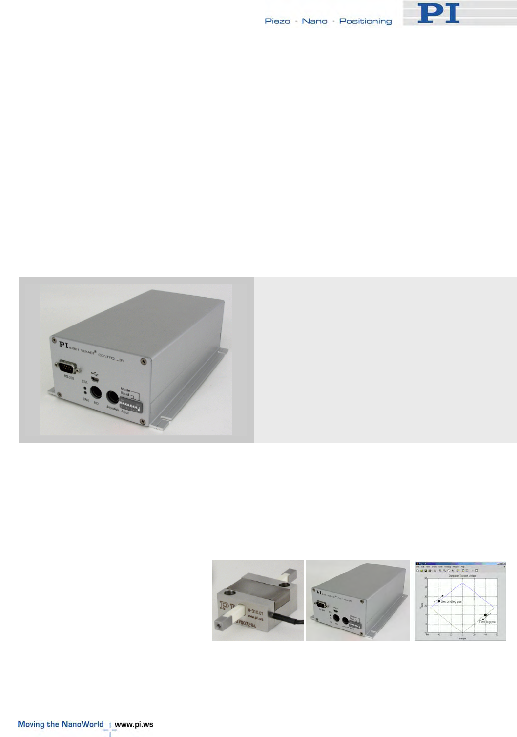
E-861 NEXACT® Controller
Release: 1.2.1 Date: 26 July 2010
This document describes the following
product:
■ E-861.1A1
NEXACT® Controller, 1 channel, linear
encoder


About This Document
Users of this Manual
This manual is designed to help the reader to operate the E-861 NEXACT® Controller. It assumes that
the reader has a fundamental understanding of basic servo systems, as well as motion control concepts
and applicable safety procedures.
The manual describes the physical specifications and dimensions of the E-861 as well as the software
and hardware installation procedures and the commands which are required to put the associated
motion system into operation.
Conventions
The notes and symbols used in this manual have the following meanings:
WARNING
Calls attention to a procedure, practice or condition which, if not
correctly performed or adhered to, could result in injury or death.
! CAUTION
Calls attention to a procedure, practice, or condition which, if not
correctly performed or adhered to, could result in damage to
equipment.
NOTE
Provides additional information or application hints.
The software tools and the mechanics which might be mentioned within this documentation are
described in their own manuals. All documents are available as PDF files. Updated releases are
available for download at www.pi.ws (http://www.pi.ws) or via email: contact your Physik Instrumente
Sales Engineer or write info@pi.ws (mailto:info@pi.ws).
Related Documents
E861_GCSLabVIEW_PZ208E
E-861_PIGCS_2_0_DLL_SM152E
IP1000_B_EN.pdf (GEMAC interpolation chip)
PIMikroMoveUserManual_SM148E
GCSData_User_SM146E
PiStageEditor_SM144E
All documents are available as PDF files on the distribution CD. Updated releases are available for
download at www.pi.ws or via email: contact your Physik Instrumente sales engineer or write
info@pi.ws.
Physik Instrumente (PI) GmbH & Co. KG is the owner of the following company names and trademarks:
PI®, PiezoWalk®, NEXACT®, PIMikroMove
The following designations are protected company names or registered trademarks of third parties:
Microsoft, Windows, LabVIEW
The products described in this document are in part protected by the following patents:
German Patent No. P4408618.0
Copyright by 1999–2010 Physik Instrumente (PI) GmbH & Co. KG, Karlsruhe, Germany
The text, photographs and drawings in this manual enjoy copyright protection. With regard thereto,
Physik Instrumente (PI) GmbH & Co. KG reserves all rights. Use of said text, photographs and drawings
is permitted only in part and only upon citation of the source.
First printing 26 July 2010
Document Number PZ205E, BRo, KSch, Release 1.2.1
E-861_User_PZ205_121.doc
Subject to change without notice. This manual is superseded by any new release. The newest release
is available for download at www.pi.ws (http://www.pi.ws).
Contents
1 Introduction 4
1.1 Prescribed Use.................................................................................... 5
1.2 Safety Precautions..............................................................................6
1.3 Unpacking ...........................................................................................8
1.4 Additional Components.......................................................................9
1.5 Motion System Requirements .............................................................9
1.6 Software Description.........................................................................10
2 First Steps 12
2.1 Requirements for Closed-Loop Operation and Custom Systems .....12
2.2 Getting Started..................................................................................12
2.3 Example for Commanding Motion.....................................................20
3 Details of Operation 23
3.1 Front and Rear Panel Elements........................................................23
3.1.1 Front Panel Elements ......................................................................... 23
3.1.2 DIP Switch Settings ............................................................................ 24
3.1.3 Rear Panel Elements.......................................................................... 26
3.2 Installing the E-861 ...........................................................................26
3.3 Installing the Software on the Host PC .............................................27
3.4 Connecting Controller or Daisy-Chain Network to Host PC ..............27
3.4.1 USB Interface .....................................................................................28
3.4.2 Baud Rate Settings............................................................................. 28
3.4.3 Address Settings ................................................................................ 29
3.5 Referencing.......................................................................................29
3.5.1 Reference Mode ................................................................................. 29
3.5.2 Perform a Reference Move ................................................................ 30
3.5.3 Set Absolute Position ......................................................................... 30
3.6 Using Trigger Input and Output.........................................................31
3.7 Updates.............................................................................................31
3.7.1 Software Updates ............................................................................... 31
3.7.2 Updating PIStages2.dat...................................................................... 32
3.7.3 Firmware Updates .............................................................................. 32
4 Controller Parameters 35
4.1 General Information ..........................................................................35
4.2 What to Consider for First Handling of Parameter Settings .............. 35
4.3 How to Store Parameter Settings...................................................... 37
4.3.1 Storing Parameter Settings to Volatile Memory Using Expanded
Single Axis Window ...................................................................................... 37
4.3.2 Storing Parameter Settings to Non-Volatile Memory Using
PIMikroMove Main Window .......................................................................... 38
4.3.3 Storing Parameters to Volatile and Non-Volatile Memory via
Commands.................................................................................................... 40
4.4 Parameter List...................................................................................41
4.5 Default-Stage-N Parameter Settings.................................................49
5 System Description 51
5.1 Basic Elements .................................................................................51
5.2 Accessible Items and Their Identifiers ..............................................53
5.3 Modes of Operation...........................................................................54
5.3.1 Servo Modes....................................................................................... 55
5.3.2 Motion Modes ..................................................................................... 56
5.3.3 Changing Motion and Servo Mode..................................................... 59
5.3.4 PiezoWalk Driving Mode .................................................................... 63
5.3.5 Application Notes................................................................................ 67
5.4 Control Basics................................................................................... 68
5.4.1 Control Value Generation ................................................................... 68
5.4.2 Trajectory Generation......................................................................... 71
5.4.3 Control Algorithm................................................................................ 76
5.4.4 Motion Error Handling......................................................................... 77
6 Joystick Control 79
7 Working with Controller Macros 82
7.1 Defining Macros ................................................................................82
7.2 Starting Macro Execution.................................................................. 84
7.3 Start-Up Macro..................................................................................84
7.4 Preparing for Stand-Alone Preparation............................................. 85
8 Data Recording 88
9 Customizing the System 89
9.1 Parameters for Customizing.............................................................. 90
9.2 Travel Range Adjustment.................................................................. 92
9.3 Tuning PID Control Parameters ........................................................95
9.4 How to Create a New Stage Type in the PI Stages Database..........98
9.5 Adjustment for Custom Sensor .........................................................99
9.5.1 Servo Loop Input Factor..................................................................... 99
9.5.2 Adjustment for Custom Sensor Using Custom Interpolation Board . 100
9.5.3 GEMAC Parameters......................................................................... 105
9.5.4 Custom Sensor Using GEMAC Interpolation Board......................... 106
10 GCS Commands 107
10.1 Format.............................................................................................107
10.1.1 Notation ............................................................................................ 107
10.1.2 GCS Syntax...................................................................................... 107
10.1.3 Target and Sender Address ............................................................. 110
10.2 Command Survey ...........................................................................111
10.3 Command Reference (alphabetical) ............................................... 114
10.4 Error Codes.....................................................................................192
11 Troubleshooting 207
12 Customer Service 210
13 Old Equipment Disposal 211
14 Technical Data 212
14.1 Specifications.................................................................................. 212
14.2 Mounting Hole Pattern ....................................................................214
14.3 Pin Assignments .............................................................................215
14.3.1 Motor Socket..................................................................................... 215
14.3.2 Sensor Socket .................................................................................. 216
14.3.3 RS-232 In and RS-232 Out Sockets ................................................ 216
14.3.4 USB Socket ...................................................................................... 217
14.3.5 I/O Socket......................................................................................... 218
14.3.6 C-170.IO Cable................................................................................. 219
14.3.7 Joystick Socket................................................................................. 220
14.3.8 Joystick Y-Cable............................................................................... 221
14.3.9 24 V DC Socket ................................................................................ 221
15 Index 222

Introduction
www.pi.ws E-861 PZ205E Release 1.2.1 Page 4
1 Introduction
The E-861 NEXACT® controller is designed to drive a single-axis
PiezoWalk® system with NEXACT® linear drive in open-loop or closed-
loop operation. NEXACT® PiezoWalk® technology overcomes the
limitations of conventional nanopositioning drives and combines virtually
unlimited travel ranges with high stiffness in a very small package.
Furthermore, NEXACT® linear drives provide piezo class resolution (far
below one nanometer) and millisecond responsiveness. The special drive
design also reduces the operating voltage to 45 V and below.
Two motion modes are provided: To move the runner over longer distances
a "nanostepping mode" is used, whereas for distances smaller than one
step, the "analog mode" enables high-dynamics positioning with resolutions
far below one nanometer. According to the desired motion modes, the
E-861 NEXACT® controller performs coordinated control of the four voltage
channels required for the NEXACT® linear drive.
Communication with the E-861 is provided either through the RS-232 or the
USB interface. For manual control, the unit can be operated with a joystick.
Flexible Automation
The E-861 NEXACT® Controller offers a number of features to facilitate
automation and handling tasks in research and industry. For example,
macros can be stored in the non-volatile memory for later recall.
Stand-alone capability is provided by a user-programmable autostart macro
to run automation tasks at power-up (no run-time computer communication
required!).
For easy synchronization of motion with internal or external trigger signals
four input and four output lines are provided.
Multi-Axis Control
Up to 16 E-861 NEXACT® Controllers can be daisy-chained and
addressed via the same interface.
The networking feature allows the user to start out with one controller and
add more units later for multi-axis setups.
Command Set
E-861 NEXACT® Controllers can be operated using the PI General
Command Set (GCS). PI-GCS allows networking of different controller
units, both for piezo-based and motorized positioning units, with minimal
programming effort.
Software / Programming
In addition to the user software for setup, system optimization and
operation, comprehensive LabVIEW and DLL libraries are provided to ease
programming custom applications.

Introduction
1.1 Prescribed Use
Based on their design and realization, E-861 NEXACT® Controller are
intended to drive capacitive loads, in the present case, piezoceramic
actuators. E-861s must not be used for applications other than stated in this
manual, especially not for driving ohmic (resistive) or inductive loads.
Observe the safety precautions given in this User Manual.
E-861s can be operated in closed-loop mode using incremental position
sensors. Consult the product specifications of the mechanics with which the
E-861 is to be operated to see what kind of position sensor is present.
The E-861 may only be used for applications suitable according to the
device specifications. Operation other than instructed in this User Manual
may affect the safeguards provided.
The verification of the technical specifications by the manufacturer does not
imply the validation of complete applications. In fact the operator is
responsible for the process validation and the appropriate releases.
The E-861 is a laboratory apparatus as defined by DIN EN 61010. It meets
the following minimum specifications for safe operation:
■ Indoor use only
■ Altitude up to 2000 m
■ Temperature range 5°C to 40°C
■ Max. relative humidity 80% for temperatures up to 31°C, decreasing
linearly to 50% relative humidity at 40°C
■ Line voltage fluctuations not greater than ±10% of the line voltage
■ Transient overvoltages as typical for public power supply
Note: The nominal level of the transient overvoltage is the standing
surge voltage according to the overvoltage category II (IEC 60364-4-
443).
■ Degree of pollution: 2
These data are no limitations for the specifications in the technical data
table.
www.pi.ws E-861 PZ205E Release 1.2.1 Page 5

Introduction
www.pi.ws E-861 PZ205E Release 1.2.1 Page 6
1.2 Safety Precautions
Controller
DANGER
Procedures which require opening the case should be carried out by
authorized, qualified personnel only.
Disconnect the controller from power when opening the case, and
when resetting internal switches or jumpers.
When the controller must be operated with the case open, voltages of
up to 48 VDC and currents of up to 2 A can be exposed. Do not touch
internal conductors.
WARNING⎯READ INSTRUCTION
Install and operate the E-861 NEXACT® Controller only when you
have read the operating instruction. Keep the instructions readily
available close to the device in a safe place. If the instructions are lost
or have become unusable, ask the manufacturer for a new copy. Add
all information given by the manufacturer to the instructions, e.g.
supplements or Technical Notes.
WARNING
Connect the AC power cord of the external power supply to the wall
socket (100 to 240 VAC).
To disconnect the system from the supply voltage completely, remove
the power plug from the wall socket.
Install the system near the AC outlet and such that the AC power plug
can be reached easily.
WARNING
All motion of the connected motors is software controlled, and software
may fail. Defective software or improper operation of the software may
result in unexpected motions. Be aware that some motorized
positioners can generate large forces which can cause personal injury
or other damage if not properly handled.

Introduction
! CAUTION
Place the system in a location with adequate ventilation to prevent
internal heat build-up. Allow at least 10 cm (4 inches) clearance from
the top and the rear of the unit and 5 cm (2 inches) from each side.
! CAUTION
Never connect the RS-232-IN and USB connectors of the same
controller to a PC at the same time as this can cause damage to the
controller.
! CAUTION
If no sensor is present in your system:
■ Do not switch servo on (SVO command)
■ Do not send commands for closed-loop motion, like MOV or MVR
■ Do not send the open-loop commands OMA and OMR, since they
use a sensor, too
Otherwise the connected mechanics can run into the hard stop at full
speed, which may cause damage to your hardware setup.
! CAUTION
Incorrect E-861 parameter values may lead to improper operation or
damage of your hardware. Be careful when changing parameters.
! CAUTION
The E-861 is equipped with a watchdog timer. This safety device
resets the E-861 in case of software failure.
! CAUTION
Do not enable a joystick via command when no joystick device is
connected to the controller hardware. Otherwise the corresponding
controller axis may start moving and could damage your application
setup.
www.pi.ws E-861 PZ205E Release 1.2.1 Page 7

Introduction
www.pi.ws E-861 PZ205E Release 1.2.1 Page 8
!
CAUTION
The boards inside the E-861 are ESD-sensitive (electrostatic discharge
sensitive) devices. Observe all precautions against static charge
buildup before handling these devices. Avoid touching circuit
components, pins and PCB traces. Discharge any static electricity you
may have on your body by briefly touching a conductive, grounded
object before you touch any electronic assembly.
Make sure that no conductive particles of any kind (metallic dust or
shavings, broken pencil leads, loose screws) contact the device
circuitry.
Mechanics !
CAUTION
Do not displace the moving platform of a NEXACT® stage or the
runner of a NEXACT® linear drive manually! Manual displacement can
cause irreparable damage to the piezo modules in the NEXACT®
linear drives.
1.3 Unpacking
Unpack the E-861 NEXACT® Controller with care. Compare the contents
against the items covered by the contract and against the packing list.
The following components are included:
■ NEXACT® Controller (E-861.1A1)
■ Power Supply 24 V, 42 W (C-663.PS), with line cord (3763)
■ RS-232 null-modem cable for connecting controller and host PC
(C-815.34)
■ RS-232 straight-through networking cable (C-862.CN) for daisy chain
■ USB cable (3 m, USB-A (m) / USB Mini-B (m)) for PC connection
(000014651) and EMI-suppression ferrite (000015165)
■ E-861 Distribution CD, containing host software (see "Software
Overview" (p. 10)), USB driver and manuals as PDF files (E-861.CD)
■ User Manual for E-861 in printed form (this document)

Introduction
If parts are missing or you notice signs of damage, contact your PI
representative or write to info@pi.ws immediately.
Save all packing materials in case the product needs to be shipped again.
1.4 Additional Components
Contact your PI representative or write an e-mail to info@pi.ws if you need
the following additional components:
Order
Number
Description
C-862.CN2 Long straight-through networking cable for daisy chain (interconnecting
E-861 controllers on RS-232 bus), 180 cm
C-819.20 Analog joystick, 2 axes
C-819.20Y Y-cable for connecting two E-861s to joystick
C-170.PB Pushbutton box with 4 buttons and 4 LEDs, for connection to the I/O socket
(p. 218)
C-170.IO Connector for I/O socket (p. 218), with cable, open end
1.5 Motion System Requirements
To start working with the E-861 NEXACT® controller, your motion system
must include the following components:
■ Power supply for E-861
■ The mechanics (NEXACT® linear drive or stage)
■ A PC with Windows operating system (XP, Vista, 7.0)
■ Communication interface to the PC:
A free COM port on the PC or
A free USB interface on the PC
■ RS-232 null modem cable or USB cable to connect controller and
host PC
■ E-861 CD with host software
www.pi.ws E-861 PZ205E Release 1.2.1 Page 9

Introduction
1.6 Software Description
The table below lists the software tools which are on the E-861 product CD
with application recommendations.
For more information see the corresponding software manuals.
Software
Tool
Supported
Operating
System
Short Description Recommended for
PITerminal Windows PITerminal is a Windows GUI which
can be used as a simple terminal with
almost all PI controllers.
Users who want to send the
commands of the PI General
Command Set (GCS) directly.
GCS Library Windows Allows program access to the E-861
from languages like C++.
The functions in the library are based
on the PI General Command Set
(GCS).
Windows operating systems:
PI_GCS2_DLL
Customers who want to use a
library for their applications.
The dynamic version of the
library is needed by the
LabVIEW driver set and by
PIMikroMove.
LabVIEW
drivers Windows LabVIEW is a software tool (available
separately from National Instruments)
for data acquisition and process
control. The E-861 LabVIEW software
consists of a collection of virtual
instrument (VI) drivers for the E-861
controller. This driver set supports the
PI General Command Set (GCS).
Included are VIs for GCS commands
and high-level VIs for various tasks.
Users who want to use
LabVIEW for programming their
applications based on the GCS.
See the GCS LabVIEW manual
of your controller for more
information.
PIMikroMove Windows PIMikroMove permits you to start your
motion system—host PC, controller
and stage(s)—immediately without the
need to write customized software. It
offers motion-control displays and
features that in many cases make it
unnecessary to deal with ASCII-
format commands. It also has a
complete command input facility,
which represents an easy way to
experiment with various commands.
PIMikroMove uses the GCS DLL
described above to command the
controller.
Note that the program offers
comprehensive online support.
Users who want to test the
equipment before or instead of
programming an application
and who want to learn how to
use the commands. For motor
controllers, PIMikroMove offers
an easy way to optimize the
servo parameters.
PIStageEditor Windows GUI tool for adding, removing and
editing stages (parameter sets) in
stage-parameter files (DAT-files) used
by the GCS library and the other host
software from PI
Users who want to check or edit
the content of the stage
databases used by the host
software
www.pi.ws E-861 PZ205E Release 1.2.1 Page 10

Introduction
TMS320F28xx
Updater Windows The TMS320F28xx Updater firmware
update program guides you through
the update of the firmware for your
E-861 system.
Users who want to update the
firmware.
www.pi.ws E-861 PZ205E Release 1.2.1 Page 11

First Steps
2 First Steps
2.1 Requirements for Closed-Loop Operation and
Custom Systems
Before you start with closed-loop operation make sure that the set
controller parameters match:
a) the properties of the mechanics
b) the properties of the sensor used for position feedback
c) your individual application
If you use a custom stage you can use the Default-Stage-N stage database
entry. This stage database entry contains parameter settings that you may
have to adjust to match with your stage’s properties.
See "Default-Stage-N Parameter Settings" (p. 49) for the parameter
settings the Default-Stage-N stage database entry features.
See “Customizing the System” (p. 89) for what parameters may need to be
adjusted.
See “How to Store Parameter Settings” (p. 37) for how to store parameters
to volatile and non-volatile memory.
In addition you have to check if the sensor properties of your custom stage
match with the GEMAC parameters reflecting the sensor properties.
Note that the GEMAC parameters are not part of a stage database entry.
See “GEMAC Parameters” (p. 105) and "Adjustment for Custom Sensor"
(p. 99) for details.
2.2 Getting Started
To simplify your first steps with the NEXACT® system, it is recommended
to use PIMikroMove (see the PIMikroMove Manual for more information).
!
CAUTION
Never connect the RS-232-IN and USB connectors of the same
controller to a PC at the same time as this can cause damage to the
controller.
www.pi.ws E-861 PZ205E Release 1.2.1 Page 12

First Steps
! CAUTION
If no sensor is present in your system, do not switch the servo on.
Otherwise the connected mechanics can run into the hardstop at full
speed which may cause damage to your hardware setup.
NOTE
It is recommended to check the parameter settings on the controller
before a stage database entry is chosen during setting up a connection
with PIMikroMove.
If the parameter settings must not be changed, then press OK (instead
of Assign -->) in the Select connected stages step, see figure of step
9b) below.
It is possible to generate user-defined stage database entries. See
"How to Create a New Stage Type in the PI Stages Database" (p. 98)
for how to generate a new parameter set ( = stage database entry).
Such a user-defined stage database entry will be available in
PIMikroMove in the Select connected stages step.
See "Storing Parameter Settings to Non-Volatile Memory Using
PIMikroMove Main Window" (p. 38) if you wish to store these settings
to the controller's non-volatile memory to make them power-up default
settings.
To start operation with the E-861 proceed as described below.
Note that closed-loop operation is only possible if your system features a
sensor.
1 Connect the NEXACT® stage to the "Motor" socket on the rear of the
E-861.
2 If present, connect the NEXACT® stage to the "Sensor" connector on the
rear of the of the E-861.
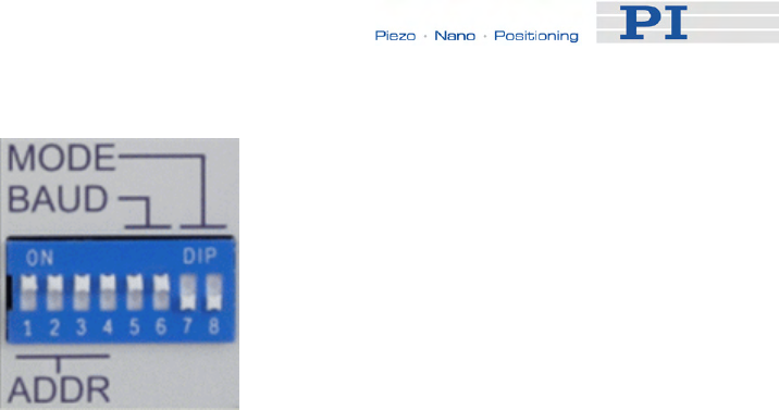
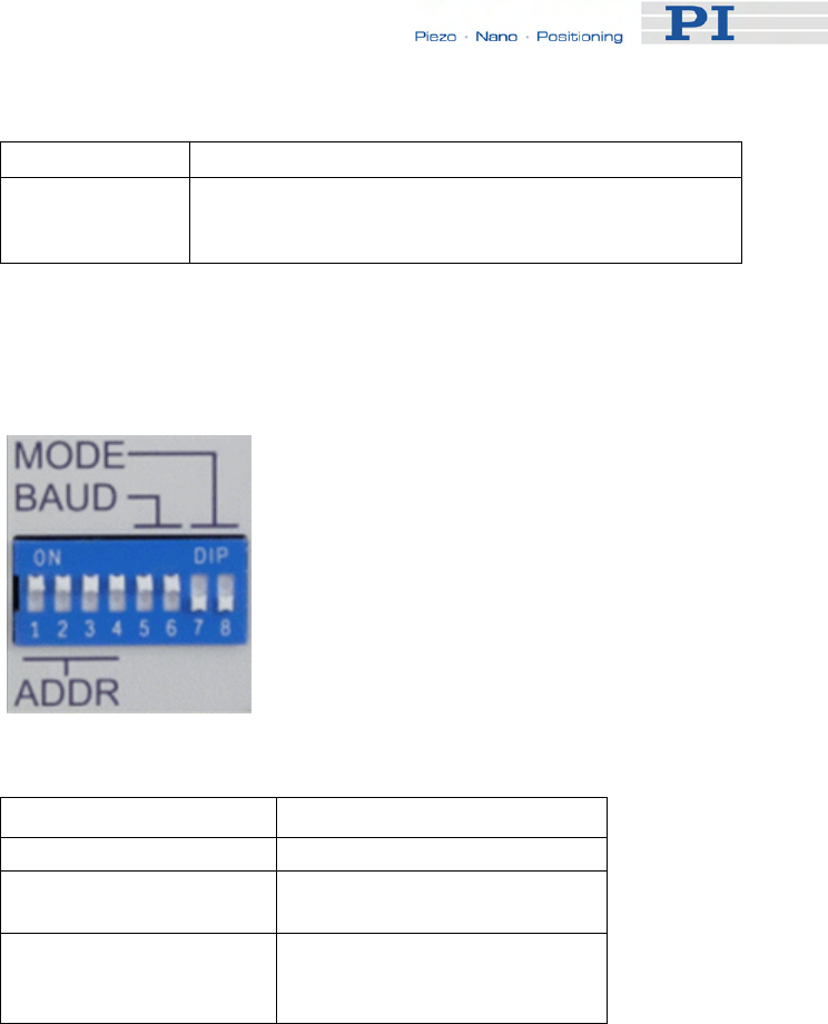
3 Starting operation for the first time, you should use the default DIP switch
settings of the E-861 which are as shown in the figure below:
Controller address = 1
Baudrate = 9600 baud
Mode = Normal operation
www.pi.ws E-861 PZ205E Release 1.2.1 Page 13
First Steps
If you want to change the default settings, see "DIP Switch Settings" for
details.
4 Connect the E-861 to the host PC.
Use either the RS-232 interface (via the "RS-232 In" socket on the
controller) or the USB interface and the corresponding cable which is
included in delivery.
Never connect both interfaces at the same time.
5 Connect E-861 and the included 24 VDC wide-range power supply (use
the "24 VDC" socket on the E-861 rear panel).
6 Connect the power supply of the E-861 to the line power (100-240 VAC).
The controller is powered on and immediately ready for operation (STA
LED lights up permanently).
7 Start PIMikroMove on the host PC.
See "Installing the Software on the Host PC" (p. 27) for installation.
8 Establish a connection to the E-861 controller from PIMikroMove.
a) Select the E-861 controller in the Start up controller window, see figure
below.
www.pi.ws E-861 PZ205E Release 1.2.1 Page 14
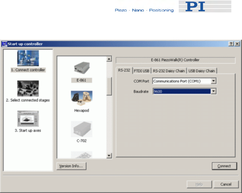
First Steps
This figure shows the Start up controller window at the Connect controller
step.
Here, the E-861 is physically connected via RS-232. 9600 baud is the
factory default baud rate setting.
The controller has address 1 as is determined by DIP switch settings at
the controller’s front panel.
b) Depending on the physical connection select the RS-232, FTDI USB,
RS-232 Daisy Chain or USB Daisy Chain tab card in the Start up
controller window.
When using the USB interface for the first time, two FTDI USB drivers
must be installed on the host PC. These drivers are provided on the
E-861 CD in the \USB Driver directory.
Note that with a daisy-chain there must be one controller with address 1.
It is not required that this controller is directly connected to the host PC,
i.e. this controller does not have to be the first controller of the daisy-
chain.
If there is no controller in a daisy-chain with address 1 an error message
occurs when you try to setup a connection.
See "Connecting Controller or Daisy-Chain Network to Host PC" (p. 27)
for detailed information.
c) For RS-232 connection choose the baud rate as preset by the DIP
switch settings at the controller’s front panel.
d) Press Connect in the Start up controller window to establish the
connection.
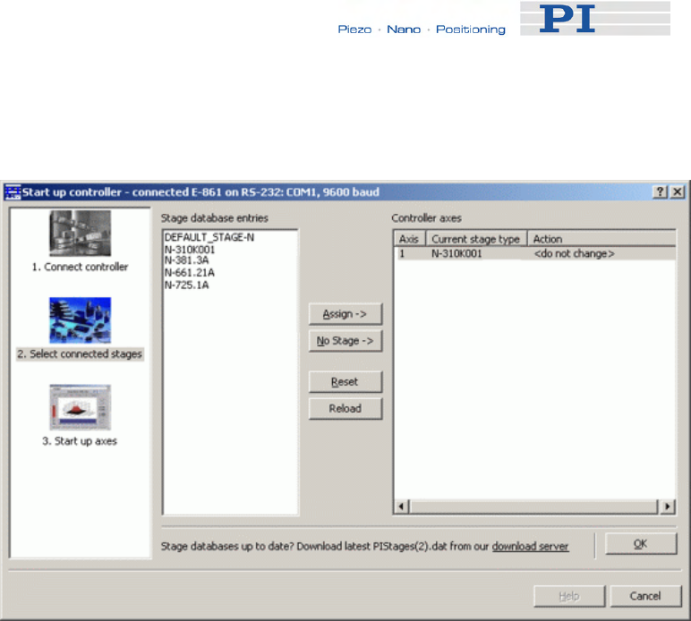
9 Choose the stage type to be connected.
Click Select connected stages on the E-861 menu of the PIMikroMove
www.pi.ws E-861 PZ205E Release 1.2.1 Page 15
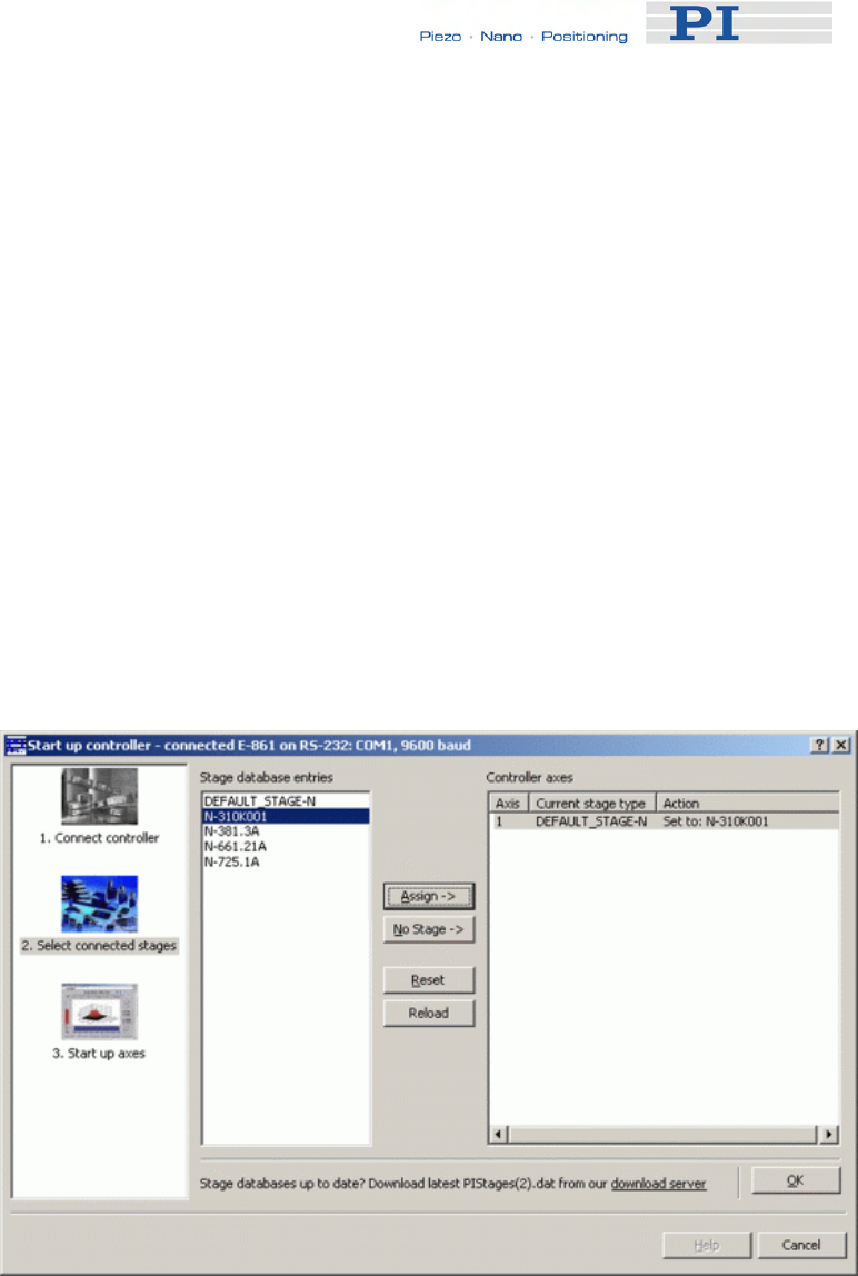
First Steps
main window if the stage selection dialog for the next step does not open
automatically.
There are the following possibilities:
a) The preset Current stage type in the Controller axes pane does not
match your stage.
b) The preset Current stage type does match your stage.
Details:
a) If the preset stage type is not to be used select the appropriate stage
type in the Stage database entries list and press the Assign -> button for
each axis.
The selected stage types are now visible in the Controller axes pane.
Set to: stage name occurs in the Action column, see figure below.
To accept the selection and to close the dialog, press the OK button.
The figure below shows the Start up controller window with the Select
connected stages step. Here a stage database entry for a specific stage
is chosen.
If you wish to store the settings you chose as power-up default settings
to the controller's non-volatile memory see "Storing Parameter Settings
to Non-Volatile Memory Using PIMikroMove Main Window" (p. 38) for
instructions.
b) If a connection is started <do not change> occurs automatically in the
Action column, see figure below.
www.pi.ws E-861 PZ205E Release 1.2.1 Page 16
First Steps
Then, if the preset stage type is to be used accept the preset stage
database entry by pressing the OK button.
If your stage features a sensor, go on with step 10 to reference the axis.
If your stage does not feature a sensor, proceed with step 11a) to
command motion.
Notes:
While choosing the stage type, the parameters for that stage type will
be loaded automatically from a stage database on the host PC to the
controller's volatile memory.
Make sure that you always have installed the latest version of the
PIStages2.dat stage database. See "Installing the Software on the Host
PC" (p. 27) and "Updating PIStages2.dat" (p. 32) for details.
The choice can later be changed with Select connected stages on the
E-861 menu in the PIMikroMove main window.
See "Controller Parameters" (p. 35) and "Customizing the System"
(p. 89) for more information regarding parameter settings.
10 Start reference moves for the axes.
Note that this step can only be performed if your mechanics features a
sensor and reference or limit switches. In addition, the relevant
parameters have to be enabled accordingly.
With Default-Stage-N parameter settings reference or limit switches are
disabled. Thus referencing is not possible with this parameter set.
Due to the nature of the incremental sensors used in the stages, the
www.pi.ws E-861 PZ205E Release 1.2.1 Page 17
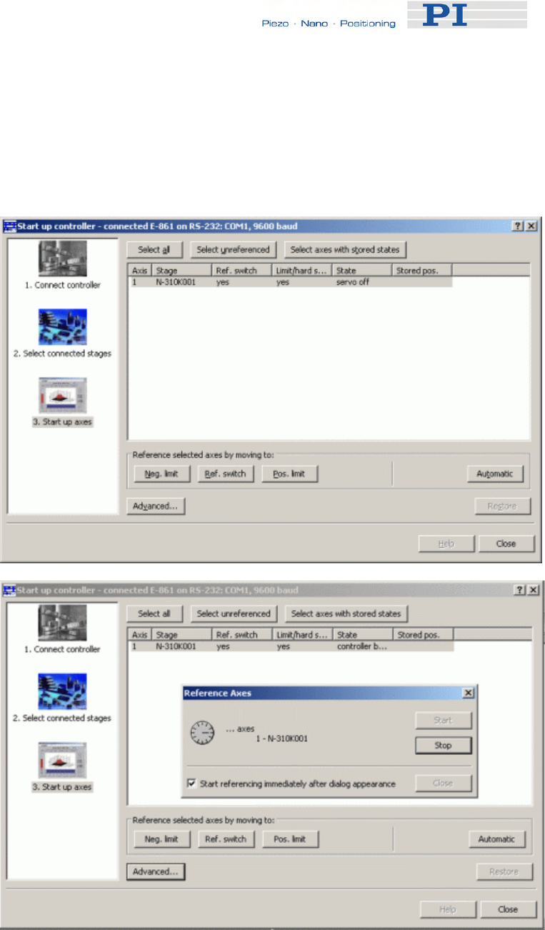
First Steps
controller cannot know the absolute position of an axis upon startup.
Reference and/or limit switches in the stage can be used to obtain
absolute position information.
The figures below show the Start up controller window with the Start up
axes step. Click Automatic to start the reference move.
When referencing is successfully finished, press the Close button. The
PIMikroMove main window will open.
See "Referencing" (p. 51) for more information.
www.pi.ws E-861 PZ205E Release 1.2.1 Page 18

First Steps
11 Start some test moves of the axis. Depending on your settings there are
the following possibilities:
a) Mechanics does not feature a sensor:
Select the PiezoWalk (R) channels tab in the PIMikroMove main window,
see figure below.
Insert an appropriate value in the Open-Loop Number of Steps field. To
exert motion press the associated arrow buttons.
b) Mechancis features a sensor:
Select the Axes tab in the PIMikroMove main window, see figures
below.
You can command motion either in open-loop or closed-loop operation.
Activate servo to command motion in closed-loop operation.
For example, perform a step of a predefined size by pressing the
associated arrow buttons for an axis
www.pi.ws E-861 PZ205E Release 1.2.1 Page 19
First Steps
www.pi.ws E-861 PZ205E Release 1.2.1 Page 20
For how to realize stand-alone operation see "Preparing for Stand-Alone
Operation" (p. 85).
See "Working with Controller Macros" (p. 82) for how to store macros in the
E-861's non-volatile memory for later recall and "Joystick Control" (p. 79)
for manual control by a joystick connected to the E-861.
2.3 Example for Commanding Motion
!
CAUTION
If no sensor is present in your system:
■ Do not switch servo on (SVO command)
■ Do not send commands for closed-loop motion, like MOV or MVR
■ Do not send the open-loop commands OMA and OMR, since they
use a sensor, too
Otherwise the connected mechanics can run into the hard stop at full
speed, which may cause damage to your hardware setup.
After setting up a connection with PIMikroMove you can perform some test
motion.
Note that your stage must feature a sensor to reference and to perform
closed-loop motion. The example described below requires that your
system features a sensor.
Proceed as follows:
1 Reference and activate servo first, see steps 10 and step 11 in
"Getting Started" (p. 12) for details.
Note that your stage must feature a sensor to reference and to
perform closed-loop motion.
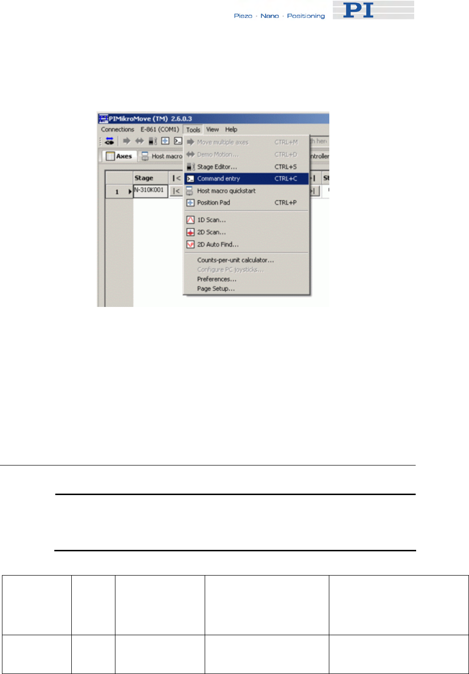
2 To send the commands as given below follow the Tools →
Command entry menu sequence in the PIMikroMove main window,
see figure below.

First Steps
3 Then you can send motion commands via the Command entry
window as listed in the example given below.
The example below shows how to perform closed-loop and open-loop
motion. See "Modes of Operation" (p. 54) for more information regarding
the motion modes of a NEXACT® linear stage and the transitions between
them.
MOV 1 6 Closed-loop motion, Axis 1 moves to absolute position 6 mm.
Note that motion can be performed either only in nanostepping
mode or in an alternating sequence of nanostepping and analog
motion. See "Motion Modes" (p. 56) for details.
MVR 1 -5 Closed-loop motion, moves Axis 1 relative to the last commanded
closed-loop target position.
SVO 1 0 Servo must be disabled to enable open-loop commands.
Disabling servo includes an automatic Relaxing procedure. (See
also "Changing Motion and Servo Mode" (p. 59) for details)
Therefore, a motion in analog mode can be performed by a next
OAD command.
OAD 1 40 Open-loop analog motion of PiezoWalk channel 1, set feed
voltage to +40 volts which corresponds to a motion of approx. 3.3
µm, depending on stage, load and motion direction, in positive
direction.
RNP 1 Relaxing brings the PiezoWalk channel 1 to a full-holding-force,
zero-drive voltage Relaxed state, is required before the motion
mode can be changed from analog to nanostepping motion in
open-loop operation (and vice versa), and before servo is
activated for closed-loop operation.
SVO 1 1 Servo is activated.
MOV 1 5 Closed-loop motion, Axis 1 moves to absolute position 5 mm.
www.pi.ws E-861 PZ205E Release 1.2.1 Page 21

First Steps
SVO 1 0 Servo must be disabled to enable open-loop commands.
Disabling servo includes an automatic Relaxing procedure.
OAD 1 -20 Open-loop analog motion of PiezoWalk channel 1, set feed
voltage to -20 volts which corresponds to a motion of approx. 1
µm, depending on stage, load and motion direction, in negative
direction.
RNP 1 Relaxing of PiezoWalk channel 1 is required to prepare stage for
nanostepping motion.
SSA 1 40 Voltage amplitude for nanostepping motion is set to +40 volts.
OSM 1 100 Open-loop nanostepping motion, PiezoWalk channel 1 moves
100 steps in positive direction.
OMA 1 6 Open-loop nanostepping motion, Axis 1 moves to absolute
position, i.e. to absolute position of approximately 6 mm.
OMR 1 -3 Open-loop nanostepping motion, moves Axis 1 relative to the last
commanded open-loop target position, here by 3 mm in negative
direction.
RNP 1 Relaxing of PiezoWalk channel 1 is required to prepare stage for
analog motion.
OAD 1 -40 Open-loop analog motion of PiezoWalk channel 1, set feed
voltage to -40 volts which corresponds to a motion of approx. 3.3
µm, depending on stage, load and motion direction, in negative
direction.
www.pi.ws E-861 PZ205E Release 1.2.1 Page 22
Details of Operation
www.pi.ws E-861 PZ205E Release 1.2.1 Page 23
3 Details of Operation
3.1 Front and Rear Panel Elements
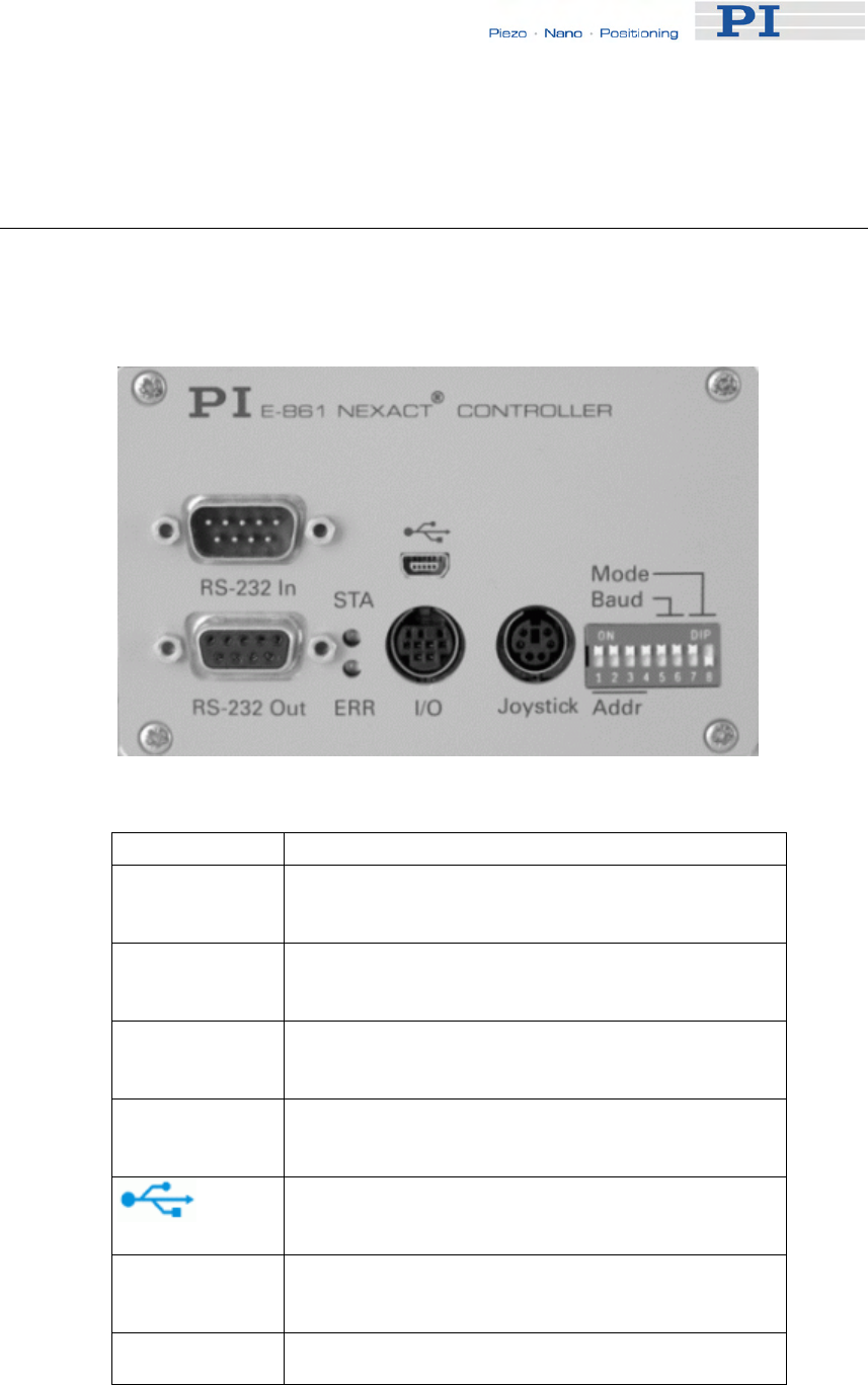
3.1.1 Front Panel Elements
Figure 1: Front Panel of E-861.1A1
Name Function
RS-232 In Serial connection to host PC or to previous
controller in a daisy-chain network. See "RS-232
In and RS-232 Out Sockets" (p. 216) for pinout.
RS-232 Out Serial connection to next controller in a daisy-
chain network. See "RS-232 In and RS-232 Out
Sockets" (p. 216) for pinout.
STA LED
(green) Power on and ready indicator. When power is
applied to the controller, the LED will glow for
normal operation.
ERR LED (red) Error indicator; when LED lights up, error code is
non-zero and can be queried and cleared using
the ERR? command (p. 127).
Universal Serial Bus (USB) for connection to host
PC. See "USB Socket" (p. 217) for more
information.
I/O Mini DIN 9-pin connector, provides digital I/O and
analog input lines. See "I/O Socket" (p. 218) for
pinout.
Joystick Mini DIN 6-pin connector for analog joystick
(input). See "Joystick Socket" (p. 220) for pinout.
Details of Operation
Name Function
Mode, Baud,
Addr 8-bit DIP switch, sets controller address, RS-232
baud rate and operating mode of unit. See "DIP
Switch Settings" for details.
3.1.2 DIP Switch Settings
Figure 2: Slider up = ON, slider down = OFF
Name Function
Addr (switch 1 to 4) Controller address (1 to 16)
Baud (switch 5 and 6) Baud rate (9600, 19200,
38400 or 115200**)
Mode (switch 7 and 8) Operating mode (normal
operation or firmware
update)
** older firmware revisions may not support 115200 baud
Factory settings are shown in bold in the following tables.
www.pi.ws E-861 PZ205E Release 1.2.1 Page 24

Details of Operation
Address SW1 SW2 SW3 SW4
1 ON ON ON ON
2 ON ON ON OFF
3 ON ON OFF ON
4 ON ON OFF OFF
5 ON OFF ON ON
6 ON OFF ON OFF
7 ON OFF OFF ON
8 ON OFF OFF OFF
9 OFF ON ON ON
10 OFF ON ON OFF
11 OFF ON OFF ON
12 OFF ON OFF OFF
13 OFF OFF ON ON
14 OFF OFF ON OFF
15 OFF OFF OFF ON
16 OFF OFF OFF OFF
Baud Rate* SW5 SW6
9600 ON ON
19200 ON OFF
38400 OFF ON
115200** OFF OFF
*Other settings are fixed at 8 data, 1 stop, no parity; Internal buffers are
used so there is no handshake required
**Older firmware revisions may not support 115200 baud
Mode SW7 SW8
Firmware
update OFF ON
Normal OFF OFF
www.pi.ws E-861 PZ205E Release 1.2.1 Page 25

Details of Operation
www.pi.ws E-861 PZ205E Release 1.2.1 Page 26
3.1.3 Rear Panel Elements
Figure 3: Rear Panel of E-861.1A1
Name Function
24 VDC Connector for power supply. See "24 VDC
Socket" (p. 221) for pinout.
Sensor Sub-D connector for position feedback devices
such as an incremental encoder and for the
signals of limit and reference sensors. See
"Sensor Socket" (p. 216) for pinout.
Motor Sub-D connector for NEXACT® drive. See
"Motor Socket" (p. 215) for pinout.
3.2 Installing the E-861
The E-861 can be used as desktop device or mounted on a base in any
orientation. If you want to mount the E-861 on a base, see "Mounting Hole
Pattern" (p. 214).
!
CAUTION
Place the system in a location with adequate ventilation to prevent
internal heat build-up. Allow at least 10 cm (4 inches) clearance from
the top and the rear of the unit and 5 cm (2 inches) from each side.

Details of Operation
Because grounding is not assured over the power connection, the E-861
chassis must be connected to a protective ground, e.g. via one of the fixing
screws on the front or rear panel.
3.3 Installing the Software on the Host PC
Windows operating systems:
1 Insert the E-861 CD in your host PC.
2 If the Setup Wizard does not open automatically, start it from the
root directory of the CD with the icon.
3 Follow the on-screen instructions and select the “typical”
installation. Typical components are LabVIEW drivers, GCS DLL,
PIMikroMove.
For an overview over the host software provided see "Software Description"
(p. 10).
3.4 Connecting Controller or Daisy-Chain
Network to Host PC
! CAUTION
Never connect the RS-232-IN and USB connectors of the same
controller to a PC at the same time as this can cause damage to the
controller.
Use either the RS-232 or the USB interface to connect the E-861 or an
E-861 daisy chain network to the host PC.
Up to 16 E-861 controllers can be controlled from a single host computer
interface. The RS-232 output stages of some PCs may not be capable of
driving more than 6 units; if this is a problem use USB to interface with the
PC.
Interconnect any additional controllers being networked to the network with
straight-through RS-232 cables chaining off the RS-232 OUT connector of
the controller connected to the PC (one straight-through RS-232 cable
(C-862.CN) comes with each E-861 controller).
NOTES
In a daisy-chain, connected via USB or via RS-232, there must be one
controller with address 1. It is not required that this controller is directly
www.pi.ws E-861 PZ205E Release 1.2.1 Page 27

Details of Operation
connected to the host PC, i.e. this controller does not have to be the
first controller of the daisy-chain.
If there is no controller in a daisy-chain with address 1 an error
message occurs when you try to setup a connection.
3.4.1 USB Interface
The first time you connect over the USB interface, be sure you are logged
on the PC as a user having administrator rights. After the E-861 is powered
on, a message will appear saying that new hardware has been detected.
Follow the on-screen instructions and insert the E-861 CD again. The
required hardware drivers are found in the \USB Driver directory.
The USB drivers will make the USB interface appear to all software on the
host PC as a new COM port. That port will be present only when the
controller is connected via USB and powered on. Depending on the way
the connection between E-861 and host PC is established in the host
software, it may be possible to select the baud rate of that PC COM port.
Make sure that the selection corresponds to the baud rate settings of the
E-861 (made via the DIP switches on the E-861 front panel).
3.4.2 Baud Rate Settings
The baud rate can be set to one of 9600, 19200, 38400 and 115200 using
the Baud DIP switches on the E-861 front panel, see "DIP Switch Settings"
for details (115200 may not be supported by older firmware revisions). All
controllers in a daisy chain network must be set to the same baud rate.
Other communication settings are fixed at 8 data, 1 stop, no parity; internal
buffers are used so there is no handshake required.
www.pi.ws E-861 PZ205E Release 1.2.1 Page 28

Details of Operation
3.4.3 Address Settings
The controller address of the E-861 can be set with the Addr DIP switches
on the front panel, see "DIP Switch Settings" for details. Possible controller
addresses are in the range of 1 to 16, address 1 is default. The host PC
always has the address 0.
See "Target and Sender Address" (p. 110) for more information about the
format of the command line.
In a daisy chain network, each E-861 must have a unique controller
address and one controller of the daisy-chain must have address 1. See
also “Connecting Controller or Daisy-Chain Network to Host PC” (p. 27) for
more information.
The communication on the interface is between the host computer and a
specifically addressed controller in the chain. With the broadcast address
255, all controllers can be addressed at the same time, but no reports are
displayed on the host PC.
NOTES
Except when making the required hardware settings, you have to deal
with addresses only if the connection between E-861 and host PC is
done via a terminal program without any intervening software layers
(e.g. DLLs). With PITerminal, this is the case if the connection is made
by pressing the Connect… button.
3.5 Referencing
Because the encoder signals used for position feedback provide only
relative motion information, the controller cannot know the absolute position
of an axis upon startup. This is why a referencing procedure is required
before absolute target positions can be commanded and reached.
For the implementation of the referencing functionality in the individual host
software components, see the appropriate manuals.
3.5.1 Reference Mode
The current reference mode setting of the controller (ask with RON?
(p. 170)) determines how referencing can be performed. By default, a
reference move must be performed (p. 30), but it is also possible to set
absolute positions manually (p. 30). To switch between the two reference
modes, use the RON command (p. 170).
www.pi.ws E-861 PZ205E Release 1.2.1 Page 29

Details of Operation
www.pi.ws E-861 PZ205E Release 1.2.1 Page 30
3.5.2 Perform a Reference Move
When the reference mode is set to "1" (factory default), referencing is done
by performing a reference move with FRF (p. 133), FPL (p. 131) or FNL
(p. 129).
NOTES
Neither relative nor absolute targets can be commanded as long as
referencing was not successfully performed.
FRF requires that the axis has a reference switch (ask with TRS?
(p. 188)), and FPL and FNL require that the axis has limit switches
(ask with LIM? (p. 146)). The limit switches can only be used for
reference moves if the travel range is not reduced by soft limits, see
"Travel Range Adjustment" (p. 92) for more information.
For best repeatability, always reference in the same way.
The FRF command always approaches the reference switch from the
same side, no matter where the axis is when it is issued.
3.5.3 Set Absolute Position
When the reference mode is set to "0", referencing is done by entering an
absolute position value using the POS command (p. 166).
NOTES
Only relative targets but no absolute targets can be commanded as
long as referencing was not successfully performed.
If the controller is given an incorrect position with POS, the axis can
run into a limit switch and will not be able to move away from the
switch due to the travel range limits given by the
MAX_TRAVEL_RANGE_POS parameter (ID 0x15; ask with TMX?
(p. 187)) and the MAX_TRAVEL_RANGE_NEG parameter (ID 0x30;
ask with TMN? (p. 186)).
Details of Operation
3.6 Using Trigger Input and Output
It is possible to trigger external devices and to program start/stop actions in
macros using the digital I/O lines of the E-861. See "I/O Socket" (p. 218) for
the lines and pinout. The number of digital I/O lines available on the E-861
can be queried using the TIO? command (p. 186).
You can set the states of the Output 1 to Output 4 lines (TTL, active high)
using the DIO command (p. 121), e.g. to trigger other devices. The lines
can be set individually or all at once according to a bit pattern. Furthermore,
you can program the Output 1 to Output 4 lines using the CTO command
(trigger configuration) and the TRO command (trigger enabling/disabling).
See "Configuring Trigger Output—Examples" for examples.
The states of the Input 1 to Input 4 lines (TTL, active high) can be queried
with the DIO? command (p. 121). These lines can be used to stop macros
and to trigger certain actions in macros via the MEX command (p. 149) or
the WAC command (p. 189), respectively. See "Working with Controller
Macros" (p. 82) for an example.
3.7 Updates
3.7.1 Software Updates
Updated releases of software and manuals are available for download at
www.pi.ws. While the manuals are freely accessible, you need a password
for the software download. This password is provided on the E-861 CD in
the E-861 Releasenews PDF file in the \Manuals directory.
To download the latest software (complete CD mirror) from the PI Website,
proceed as follows:
1 On the www.pi.ws front page, move the cursor to Manuals,
Software, ISO Statements in the Service section on the left.
2 Select Software from the list that pops up.
3 On the PI Download Server page, enter the Username and the
Password which are provided in the E-861 Releasenews xxxxx.pdf
on the E-861 CD and click on Login
4 Click on the E Piezo Drivers & Nanopositioning controllers
category.
5 Click on E-861.
6 Click on Software (if you click on Documents you will get the latest
manuals).
www.pi.ws E-861 PZ205E Release 1.2.1 Page 31

Details of Operation
7 Click on the latest CD-Mirror (includes the manual versions that
were with the release) or on the latest update zip file.
3.7.2 Updating PIStages2.dat
To install the latest version of PIStages2.dat from the PI Website proceed
as follows:
1. On the www.pi.ws front page, move the cursor to Manuals, Software,
ISO Statements in the Service section on the left.
2. Select Software from the list that pops up.
3. On the PI Support Site page, click on the General Software category
(no login or password is required).
4. Click on PI Stages.
5. Click on pistages2.
6. In the download window, switch to the ...\PI\GcsTranslator directory.
The location of the PI directory is that specified upon installation,
usually in C:\Documents and Settings\All Users\Application Data
(Windows XP) or C:\ProgramData (Windows Vista) (may differ in other-
language Windows versions).
Note that in PIMikroMove, you can use the Version Info entry in the
controller menu or the Search for controller software entry in the
Connections menu to identify the GcsTranslator path.
7. If desired, rename the existing PIStages2.dat (if present) so as to
preserve a copy for safety reasons.
8. Download the file from the server as PIStages2.dat.
3.7.3 Firmware Updates
The current firmware revision of your E-861 is contained in the response to
the *IDN? command.
Firmware updates can be made by running the TMS320F28XX Updater
firmware update program on the host computer. The program is available
on the E-861 CD and can be installed with the Setup Wizard or started
directly from the \TMS320F28xx_Updater directory of the CD. If you want to
run the Setup Wizard:
■ Insert the E-861 CD in your host PC.
www.pi.ws E-861 PZ205E Release 1.2.1 Page 32

Details of Operation
■ If the Setup Wizard does not open automatically, start it from the root
directory of the CD with the icon.
■ Follow the on-screen instructions, select the "custom" installation and
then select the TMS320F28XX Updater.
NOTES
The E-861 whose firmware is to be updated must be directly
connected to the host PC (no daisy chain, do not even connect a cable
to "RS-232 Out"), and the connection should be made via the RS-232
interface. USB connections are not recommended for firmware
updates.
If the controller is in firmware update mode, the DIP switch settings for
baud rate and controller address are ignored. The serial connection to
the host PC is made with an automatic baud rate setting
("Autobaudrate") in the firmware update program. If the Autobaudrate
connection should fail, try again to establish the connection.
When the controller is in firmware update mode, all LEDs on the front
panel will stay off.
Proceed as follows to update the E-861 firmware:
1 Only required if the firmware update introduces new parameters
(see the documentation that comes with the update):
In the PITerminal or the Command Entry window of PIMikroMove,
send SPA? and save the response to a text file for later restoration
of the controller parameter values.
2 Power down the E-861 and select the firmware update mode using
DIP switch 8 on the E-861 front panel:
switch 8 must be set to the ON position
3 Start the TMS320F28XX Updater firmware update program.
4 Power on the E-861.
5 Establish communication between E-861 and host PC in the
firmware update program (Autobaudrate connection).
6 Perform the update: Select the new bootloader file and the new
flash file for the update. Make sure that the correct files are
selected in the corresponding fields. Start the update process.
7 When the update has finished, close the firmware update program.
www.pi.ws E-861 PZ205E Release 1.2.1 Page 33

Details of Operation
8 Power down the E-861 and set it back to normal operation using
DIP switch 8:
switch 8 must be set to the OFF position
9 Power on the E-861. If the firmware update has not introduced new
parameters, the E-861 can be started for normal operation with the
new firmware. Otherwise proceed with step 10.
10 Only required if the firmware update introduces new parameters
(see the documentation that comes with the update):
Make sure you have created a parameter backup file (see step 1).
In the PITerminal or the Command Entry window of PIMikroMove,
send
ZZZ 100 Parameter
to set the new parameters to initial values. Since this command
also resets all other parameters, you have to set them back to the
values stored in the backup file using SPA (see "Controller
Parameters" (p. 35) for details on parameter handling and saving).
Furthermore, check the new parameters with SPA? and set them
to plausible values.
www.pi.ws E-861 PZ205E Release 1.2.1 Page 34

Controller Parameters
www.pi.ws E-861 PZ205E Release 1.2.1 Page 35
4 Controller Parameters
4.1 General Information
In this section you find information about:
■ What to consider for first handling of parameter settings
■ How to store parameter settings:
Storing parameter settings to controller’s volatile memory
Storing parameter settings to controller’s non-volatile memory
Storing parameters to volatile and non-volatile memory via commands
■ A parameter list with short descriptions of all available parameters,
including GEMAC parameters for the sensor’s hardware
■ A list of Default-Stage-N parameter settings
For information on how to store a set of parameter settings as a user-
defined stage database entry on your host PC, see "How to Create a New
Stage Type in the PI Stages Database" (p. 98) for detailed instructions.
The values of the parameters required for closed-loop operation depend on
your mechanics (stage configuration, sensor, load) and have to be adjusted
properly before initial operation of a closed-loop system.
See "Customizing the System" (p. 89) for detailed information.
For detailed information regarding the parameters for the GEMAC
interpolation circuit (IDs 0x7000010 to 0x700001F), see "GEMAC
Parameters" (p. 105) and the GEMAC manual IP1000_B_EN.pdf which is
provided on the E-861 CD.
Values stored in non-volatile memory are power-on defaults, so that the
system can be used in the desired way immediately.
4.2 What to Consider for First Handling of
Parameter Settings
To adapt the E-861 to your application, you can modify parameter values.
The parameters available depend on the controller firmware. With HPA?
(p. 138) you can obtain a list of all available parameters with information
about each (e.g. short descriptions). The volatile and non-volatile memory
parameter values can be read with the SPA? (p. 178) or SEP? (p. 174)
commands, respectively.
See "How to Store Parameter Settings" (p. 37) and "Parameters for
Customizing" (p. 90) for further information.

Controller Parameters
CAUTION !
Incorrect E-861 parameter values may lead to improper operation or
damage of your hardware. Be careful when changing parameters.
Values stored in non-volatile memory are power-on defaults, so that the
system can be used in the desired way immediately.
■ By default, the controller's non-volatile memory contains parameter
settings of Default Stage N.
■ With Default-Stage-N's parameter settings, e.g. reference and limit
switches are not recognized, and position is commanded in counts.
■ When you set up a connection with PIMikroMove you can choose a
specific stage database entry.
This database entry contains all required stage-specific parameter
settings except the GEMAC parameters of the sensor.
For details about these parameters see "GEMAC Parameters"
(p. 105) and the GEMAC manual IP1000_B_EN.pdf which is
provided on the E-861 CD.
While choosing the stage type the parameters for that stage type will
be loaded automatically from a stage database on the host PC to the
controller's volatile memory.
■ With stage-specific database entries reference switch, and – for
certain stages – limit switches can be recognized, and position is
commanded in mm.
■ If you want to store parameters that you need permanently for your
individual application you can use commands WPA or SEP to store
them to non-volatile memory.
See "How to Store Parameter Settings" (p. 37) below for details.
Note that stand-alone operation is only possible if all required
parameter settings are stored to non-volatile memory.
■ If you want to operate the controller with a custom stage not
delivered from PI you can use the Default-Stage-N's stage database
entry.
See "Default-Stage-N Parameter Settings" (p. 49) for details.
www.pi.ws E-861 PZ205E Release 1.2.1 Page 36

Controller Parameters
4.3 How to Store Parameter Settings
You have several possibilities to store parameter settings:
■ Store parameter settings to volatile memory in the expanded Single
axis window of PIMikroMove.
Find details in “Storing Parameter Settings to Volatile Memory Using
Expanded Single Axis Window” (p. 37).
■ Store parameter settings to non-volatile memory using the main
menu of PIMikroMove.
Find details in “Storing Parameter Settings to Non-Volatile Memory
Using PIMikroMove Main Window” (p. 38).
■ Store parameter settings to volatile or non-volatile memory using
commands SPA, SEP, RPA and WPA via a terminal program like
PITerminal or via the Command entry window of PIMikroMove.
Find details in “Storing Parameters to Volatile and Non-Volatile
Memory via Commands” (p. 40).
■ Store a set of parameter settings as a user-defined stage database
entry in the PI_UserStages2.dat file located on your host PC. It will
be loaded automatically to the controller's volatile memory.
See “How to Create a New Stage Type in the PI Stages Database”
(p. 98) in Section "Customizing the System" (p. 89) for detailed
instructions.
To store parameters according to the presented possibilities requires that:
■ PIMikroMove or PITerminal must be installed on your host PC, see
“Installing the Software on the Host PC” (p. 27) for details.
■ Communication between controller and host PC must be established
using PIMikroMove (or PITerminal), see “Getting Started" (p. 12) for
details.
4.3.1 Storing Parameter Settings to Volatile Memory Using
Expanded Single Axis Window
PIMikroMove main window must be open. Proceed as follows to adjust and
store parameter settings:
1 Open the expanded single axis window by following the View →
Single Axis Window menu sequence for the connected stage.
www.pi.ws E-861 PZ205E Release 1.2.1 Page 37
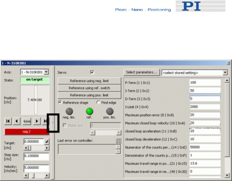
Controller Parameters
2 Click on the + at the right side of the single axis window, see figure
below.
3 In the list at the right side of the expanded single axis window you
can insert new settings.
If the parameter you wish to change does not occur in the list click
on Select parameters to display the parameter in the list.
Note that a new parameter setting is only sent to the controller
after <ENTER> is pressed while the cursor is in the text entry.
4.3.2 Storing Parameter Settings to Non-Volatile Memory
Using PIMikroMove Main Window
PIMikroMove main window must be open.
The procedure described stores current parameter settings of the
controller’s volatile memory to non-volatile memory.
1 To select parameters to be adjusted the Axes tab must be
displayed.
Press the Select columns to be displayed icon in the right top
corner of the PIMikroMove main window, see next figure.
www.pi.ws E-861 PZ205E Release 1.2.1 Page 38
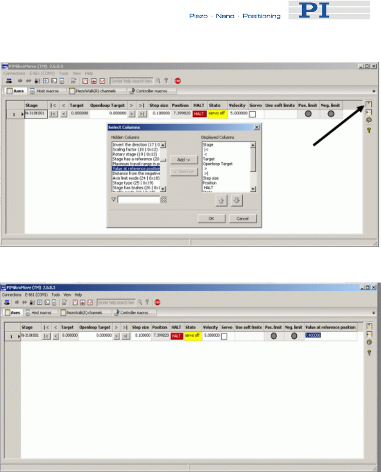
Controller Parameters
2 Adjust chosen parameter, see next figure.
3 To store adjusted parameter settings follow the E-861 → Save
parameters to non-volatile memory menu sequence in the PIMikroMove
main window, see next figure.
www.pi.ws E-861 PZ205E Release 1.2.1 Page 39
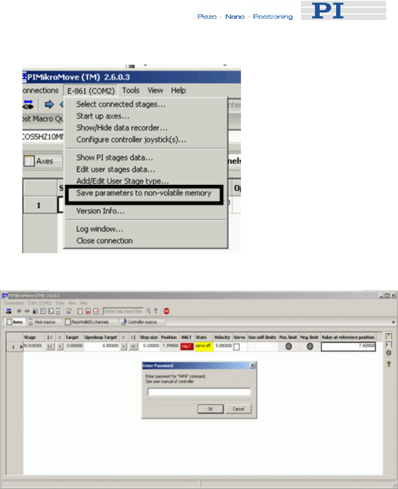
Controller Parameters
A password is required, see next figure.
4 To store adjusted GEMAC parameter settings to non-volatile memory
use password 4711.
For all other parameters use password 100.
Note that the adjusted settings are loaded from non-volatile memory to
volatile memory each time you power on or reboot the controller.
4.3.3 Storing Parameters to Volatile and Non-Volatile
Memory via Commands
Using the "general" modification commands SPA, RPA, SEP and WPA,
parameters can be changed in volatile memory (SPA (p. 175), RPA
(p. 171)) or in non-volatile memory (SEP (p. 173), WPA (p. 190)).
www.pi.ws E-861 PZ205E Release 1.2.1 Page 40
Controller Parameters
1 To store parameters using commands follow the Tools →
Command entry menu sequence in the PIMikroMove main window,
see next figure.
Example:
To set the slew rate to 100 ms send SPA 1 0x7000002 100.
It is recommended that any modifications be first made with SPA, and when
the controller runs well, saved using WPA. In addition to the "general"
modification commands, there are commands which change certain
specific parameters in volatile memory as e.g. VEL (p. 190) changes 0xA,
i.e. the closed-loop velocity (see table below).
4.4 Parameter List
! CAUTION
Wrong values of the E-861 parameters may lead to improper operation
or damage of your hardware. Be careful when changing parameters.
Parameter
ID (hexa-
decimal)
Data
Type
Password for
Writing to Non-
Volatile
Memory
Parameter
Description Possible Values/Notes
0x1 INT 100 P-Term of PID-parameter
set
for nanostepping mode 0 to 65535
www.pi.ws E-861 PZ205E Release 1.2.1 Page 41

Controller Parameters
Parameter
ID (hexa-
decimal)
Data
Type
Password for
Writing to Non-
Volatile
Memory
Parameter
Description Possible Values/Notes
0x2 INT 100 I-Term of PID-parameter
set
for nanostepping mode 0 to 65535
0x3 INT 100 D-Term of PID-parameter
set
for nanostepping mode 0 to 65535
0x4 LONG
INT 100 I-limit 0 to 2,000,000
0x8 FLOAT 100 Maximum position error
(user unit)
Used for stall detection. If the
position error (i.e. the absolute
value of the difference
between current position and
commanded position) in
closed-loop operation exceeds
the given maximum, the
controller sets error code
-1024 (“Motion error”), the
servo will be switched off and
the axis stops.
Note that with open-loop
referencing exceeding of
maximum position error is not
indicated.
0xA FLOAT 100 Maximum closed-loop
velocity (user unit/s)
Gives the maximum value
which can be set with the VEL
command (p. 188).
On power-on, the closed-loop
velocity is set by parameter
0x4B
0xB FLOAT 100
Current closed-loop
acceleration (user unit/s2),
also changed by ACC
command (p. 118).
Gives the current closed-loop
acceleration limited by
parameter 0x4A
0xC FLOAT 100 Closed-loop deceleration
(user unit/s2), also changed
by DEC command (p. 119).
Gives the current closed-loop
deceleration limited by
parameter 0x4B
0xE INT 100 Numerator of the counts-
per-physical-unit factor 1 to 1,000,000 for each
parameter.
www.pi.ws E-861 PZ205E Release 1.2.1 Page 42

Controller Parameters
Parameter
ID (hexa-
decimal)
Data
Type
Password for
Writing to Non-
Volatile
Memory
Parameter
Description Possible Values/Notes
0xF INT 100 Denominator of the counts-
per-physical-unit factor
The counts-per-physical-unit
factor determines the "user"
unit for closed-loop motion
commands. When you change
this factor, all other
parameters whose unit is
based on the "user" unit are
adapted automatically, e.g.
closed-loop velocity and
parameters regarding the
travel range.
0x14 INT 100 Stage has a reference 1 = the stage has a reference,
else 0
0x15 FLOAT 100
MAX_TRAVEL_RANGE_
POS
The maximum travel in
positive direction (user
unit)
"Soft limit", based on the home
(zero) position. If the soft limit
is smaller than the position
value for the positive limit
switch (which is given by the
sum of the parameters 0x16
and 0x2F), the positive limit
switch cannot be used for
referencing.
Smallest possible value is 0.
0x16 FLOAT 100
VALUE_AT_REF_POS
The position value at the
reference position (user
unit)
The position value which is to
be set when the mechanics
performs a reference move to
the reference switch.
0x17 FLOAT 100
DISTANCE_REF_TO_N_
LIM
The distance between
reference switch and
negative limit switch (user
unit)
Represents the physical
distance between the
reference switch and the
negative limit switch integrated
in the mechanics. When the
mechanics performs a
reference move to the
negative limit switch, the
position is set to the difference
of VALUE_AT_REF_POS and
DISTANCE_REF_TO_N_LIM.
0x18 INT 100 Axis limit mode 0 = positive limit switch active
high (pos-HI), negative limit
www.pi.ws E-861 PZ205E Release 1.2.1 Page 43

Controller Parameters
Parameter
ID (hexa-
decimal)
Data
Type
Password for
Writing to Non-
Volatile
Memory
Parameter
Description Possible Values/Notes
switch active high (neg-HI)
1 = positive limit switch active
low (pos-LO), neg-HI
2 = pos-HI, neg-LO
3 = pos-LO, neg-LO
0x2F 100
DISTANCE_REF_TO_P_
LIM
The distance between
reference switch and
positive limit switch (user
unit)
Represents the physical
distance between the
reference switch and the
positive limit switch integrated
in the mechanics. When the
mechanics performs a
reference move to the positive
limit switch, the position is set
to the sum of
VALUE_AT_REF_POS and
DISTANCE_REF_TO_P_LIM.
0x30 FLOAT 100
MAX_TRAVEL_RANGE_
NEG
The maximum travel in
negative direction (user
unit)
"Soft limit", based on the home
(zero) position. If the soft limit
is smaller than the absolute
value of the position set for the
negative limit switch (i.e. the
difference of the parameters
0x16 and 0x17), the negative
limit switch cannot be used for
referencing.
Smallest possible value is 0.
0x31 INT 100 Invert the reference 1 = invert the reference, else 0
0x32 INT 100
Stage has limit switches;
enables / disables the
stopping of the motion at
the limit switches
0 = Stage has limit switches
1 = Stage has no limit switches
0x36 INT 100 Settle window (counts)
In closed-loop operation, the
on-target status is true when
the current position is inside
the settle window and stays
there for at least the settle time
(parameter ID 0x3F). The
settle window is centered
around the target position.
The minimum value for stable
positioning is 2.
0x3C STRING 100 Stage name Default is
"DEFAULT_STAGE-N"
0x3F FLOAT 100 Settle time (s) 0 to 1.000 s;
see Settle window
0x47 INT 100 Default direction for 0 = detect automatically,
www.pi.ws E-861 PZ205E Release 1.2.1 Page 44

Controller Parameters
Parameter
ID (hexa-
decimal)
Data
Type
Password for
Writing to Non-
Volatile
Memory
Parameter
Description Possible Values/Notes
reference 1 = start in negative direction,
2 = start in positive direction
0x49 FLOAT 100
Current closed-loop
velocity (user unit/s) also
changed by VEL command
(p. 188)
Gives the current closed-loop
velocity limited by parameter
0xA
0x4A FLOAT 100 Maximum closed-loop
acceleration (user unit/s2)
Gives the maximum value
which can be set with the ACC
command (p. 118) (for
parameter 0xB)
0x4B FLOAT 100 Maximum closed-loop
deceleration (user unit/s2)
Gives the maximum value
which can be set with the DEC
command (p. 119) (for
parameter 0xC)
0x50 FLOAT 100 Closed-loop referencing
velocity (user units/s)
Is limited by Maximum closed-
loop velocity parameter (ID
0xA)
0x5A INT 100 Numerator of servo loop
input factor
0X5B INT 100 Denominator of servo loop
input factor
1 to 1,000,000 for each
parameter
The servo loop input factor
decouples servo loop
parameters from the encoder
resolution.
Not to be changed by the
customer.
Note that the servo loop input
factor is independent from 0xE
and 0xF, i.e. the counts-per-
physical-unit factor. The
counts-per-physical-unit factor
has no influence on control
loop stability, but is used for
input and output scaling of
position values.
0x94 FLOAT 100 Notch filter frequency 1
(Hz)
40 to 20000
The corresponding frequency
component in the control value
is reduced to compensate for
unwanted resonances in the
mechanics.
Only active in closed-loop
operation. Should normally not
be changed (try to change only
with very high loads).
0x95 FLOAT 100 Notch filter edge 0.1 to 10
Gives the slope of the filter
www.pi.ws E-861 PZ205E Release 1.2.1 Page 45

Controller Parameters
Parameter
ID (hexa-
decimal)
Data
Type
Password for
Writing to Non-
Volatile
Memory
Parameter
Description Possible Values/Notes
edge. Do not change.
0xAC FLOAT 100 Low-pass filter frequency
(Hz)
40 to 20000
Gives the cut-off frequency of
a low-pass filter which is only
active in closed-loop operation
and with analog mode motion
0x401 INT 100 P term of PID-parameter
set for analog mode 0 to 65535
0x402 INT 100 I term of PID-parameter set
for analog mode 0 to 65535
0x403 INT 100 D term of PID-parameter
set for analog mode 0 to 65535
0x7000000 INT 100 Travel range minimum
(user unit)
By default set to a very large
value which should not be
changed.
Can be used as travel range
limit for open-loop motion with
OSM (p. 163), OAD (p. 155),
OMA (p. 158), OMR (p. 161):
if the current position reaches
this value, the motion is
stopped. In this case, enlarge
the limit.
0x7000001 INT 100 Travel range maximum
(user unit)
By default set to a very large
value which should not be
changed.
Can be used as travel range
limit for open-loop motion with
OSM (p. 163), OAD (p. 155),
OMA (p. 158), OMR (p. 161):
if the current position reaches
this value, the motion is
stopped. In this case, enlarge
the limit.
0x7000002 INT 100 Slewrate (ms)
1 to 1000 ms
This value affects the time
which is required for the
"preparing for motion" and
"relaxing" changes of the
motion state. Depending on
the current motion state, a
change of state can take up to
four times the slewrate value.
See "Modes of Operation"
(p. 54) for details.
www.pi.ws E-861 PZ205E Release 1.2.1 Page 46

Controller Parameters
Parameter
ID (hexa-
decimal)
Data
Type
Password for
Writing to Non-
Volatile
Memory
Parameter
Description Possible Values/Notes
0x7000003 FLOAT 100 Bending voltage,
also changed by SSA
command (p. 180)
0 to 55 V, gives the step size
for open-loop nanostepping
motion
0x7000004 INT 100 Time to close servo
(ms)
1 to 1000 ms
Gives the time interval
between obtaining trajectory
voltage and closing of servo-
loop
0x7000201 FLOAT 100
Current open-loop velocity
(step cycles/s), also
changed by OVL command
(p. 165)
Gives the current open-loop
velocity, limited by parameter
0x7000204.
On power-on, the current
open-loop velocity is set by
parameter 0x7000201.
0x7000202 FLOAT 100
Current open-loop
acceleration (step
cycles/s2), also changed by
OAC command (p. 154)
Gives the current open-loop
acceleration, limited by
parameter 0x7000205.
0x7000203 FLOAT 100
Current open-loop
deceleration (step
cycles/s2), also changed by
ODC command (p. 157)
Gives the current open-loop
deceleration, limited by
parameter 0x7000206.
0x7000204 FLOAT 100 Maximum open-loop
velocity (step cycles/s)
Gives the maximum value
which can be set with the OVL
command (p. 165) (for
parameter 0x7000201).
0x7000205 FLOAT 100 Maximum open-loop
acceleration (step
cycles/s2)
Gives the maximum value
which can be set for parameter
0x7000202
0x7000206 FLOAT 100 Maximum open-loop
deceleration (step
cycles/s2)
Gives the maximum value
which can be set for parameter
0x7000203
0x7000207 INT 100 Open-loop referencing
velocity (step cycles/s)
Is limited by Maximum open-
loop velocity parameter (ID
0x7000204)
0x7001A00 INT 100 PiezoWalk Driving mode
Determines how closed-loop
motion is performed:
0 = nanostepping mode only
1 = alternating sequence of
analog mode and
nanostepping mode
0x7000601 CHAR Axis unit This parameter has to be set
consistent with the counts-per-
physical-units factor given by
www.pi.ws E-861 PZ205E Release 1.2.1 Page 47

Controller Parameters
Parameter
ID (hexa-
decimal)
Data
Type
Password for
Writing to Non-
Volatile
Memory
Parameter
Description Possible Values/Notes
parameters 0xE and 0xF
0x7000010 4711
GEMAC parameter 0
(Write register CFG0 on
the GEMAC interpolation
circuit)
Can be set with SPA and
saved with WPA. Not available
for SEP and SEP?
0x7000011 4711
GEMAC parameter 1
(Write register CFG1 on
the GEMAC interpolation
circuit)
Can be set with SPA and
saved with WPA. Not available
for SEP and SEP?
0x7000012 4711
GEMAC parameter 2
(Write register CFG2 on
the GEMAC interpolation
circuit)
Can be set with SPA and
saved with WPA. Not available
for SEP and SEP?
0x7000013 4711
GEMAC parameter 3
(Write register ERRMASK
on the GEMAC
interpolation circuit)
Can be set with SPA and
saved with WPA. Not available
for SEP and SEP?
0x7000014 4711
GEMAC parameter 4
(Write register PHASE on
the GEMAC interpolation
circuit)
Can be set with SPA and
saved with WPA. Not available
for SEP and SEP?
0x7000015 - GEMAC parameter 5
(reserved)
Read only.
Not included in SEP?
response
0x7000016 - GEMAC parameter 6
(reserved)
Read only.
Not included in SEP?
response
0x7000017 4711
GEMAC parameter 7
(Write register SGAIN on
the GEMAC interpolation
circuit)
Can be set with SPA and
saved with WPA. Not available
for SEP and SEP?
0x7000018 4711
GEMAC parameter 8
(Write register SOFF on
the GEMAC interpolation
circuit)
Can be set with SPA and
saved with WPA. Not available
for SEP and SEP?
0x7000019 4711
GEMAC parameter 9
(Write register CGAIN on
the GEMAC interpolation
circuit)
Can be set with SPA and
saved with WPA. Not available
for SEP and SEP?
0x700001A 4711
GEMAC parameter 10
(Write register COFF on
the GEMAC interpolation
circuit)
Can be set with SPA and
saved with WPA. Not available
for SEP and SEP?
0x700001B 4711 GEMAC parameter 11 Can be set with SPA and
www.pi.ws E-861 PZ205E Release 1.2.1 Page 48

Controller Parameters
www.pi.ws E-861 PZ205E Release 1.2.1 Page 49
Parameter
ID (hexa-
decimal)
Data
Type
Password for
Writing to Non-
Volatile
Memory
Parameter
Description Possible Values/Notes
(Write register SYNC on
the GEMAC interpolation
circuit)
saved with WPA. Not available
for SEP and SEP?
0x700001C - GEMAC parameter 12
(internal use)
Read only.
Not included in SEP?
response
0x700001D - GEMAC parameter 13
(internal use)
Read only.
Not included in SEP?
response
0x700001E - GEMAC parameter 14
(internal use)
Read only.
Not included in SEP?
response
0x700001F - GEMAC parameter 15
(internal use)
Read only.
Not included in SEP?
response
4.5 Default-Stage-N Parameter Settings
If you purchased an E-861 controller without a NEXACT® stage parameter
settings as listed below are stored on the controller's non-volatile memory.
If you operate a NEXACT® stage with an E-861 NEXACT® controller, you
can send the following query commands via a terminal program like
PITerminal, or via the command entry of PIMikroMove:
■ HPA? to get a list of all available parameters with short descriptions
■ SPA? to get all parameters with their present values as they are set
in the controller’s volatile memory
Note that with Default-Stage-N parameter settings, e.g. reference and limit
switches are not recognized (0x32 for limit switches is set to 1), and
position is commanded in counts.
The response to SPA? delivers the parameter settings:
==== new connection: E-861 on RS-232: COM1, 9600 baud ====
>>*IDN?
<<(c)2010 Physik Instrumente(PI) Karlsruhe,E-861 Version 7.2.0
>>spa?
<<1 0x1 = 100
<<1 0x2 = 50
<<1 0x3 = 0
<<1 0x4 = 2000

Controller Parameters
<<1 0x8 = 1000000.0
<<1 0xA = 1000000.0
<<1 0xB = 500000.0
<<1 0xC = 500000.0
<<1 0xE = 1
<<1 0xF = 1
<<1 0x14 = 0
<<1 0x15 = 2147483647.0
<<1 0x16 = 0.0
<<1 0x17 = 2147483647.0
<<1 0x18 = 0
<<1 0x2F = 2147483647.0
<<1 0x30 = -2147483647.0
<<1 0x31 = 0
<<1 0x32 = 1
<<1 0x36 = 10
<<1 0x3C = DEFAULT_STAGE-N
<<1 0x3F = 0.010000
<<1 0x47 = 0
<<1 0x49 = 250000.0
<<1 0x4A = 10000000.0
<<1 0x4B = 10000000.0
<<1 0x50 = 100000.0
<<1 0x5A = 50000
<<1 0x5B = 1
<<1 0x94 = 10000.000
<<1 0x95 = 0.800
<<1 0xAC = 200.000
<<1 0x401 = 100
<<1 0x402 = 100
<<1 0x403 = 0
<<1 0x7000000 = -2147483647.0
<<1 0x7000001 = 2147483647.0
<<1 0x7000002 = 10
<<1 0x7000003 = 55.0000
<<1 0x7000004 = 10
<<1 0x7000201 = 200
<<1 0x7000202 = 2000
<<1 0x7000203 = 2000
<<1 0x7000204 = 1500
<<1 0x7000205 = 2000
<<1 0x7000206 = 2000
<<1 0x7000207 = 100
<<1 0x7001A00 = 0
<<1 0x7000601 = counts
<<1 0x7000010 = 252
<<1 0x7000011 = 10
<<1 0x7000012 = 60
<<1 0x7000013 = 0
<<1 0x7000014 = 15
<<1 0x7000015 = 0
<<1 0x7000016 = 0
<<1 0x7000017 = 128
<<1 0x7000018 = 0
<<1 0x7000019 = 128
<<1 0x700001A = 0
<<1 0x700001B = 0
<<1 0x700001C = 255
<<1 0x700001D = 0
<<1 0x700001E = 0
<<1 0x700001F = 70
www.pi.ws E-861 PZ205E Release 1.2.1 Page 50

System Description
5 System Description
5.1 Basic Elements
For successful operation of the E-861, you should familiarize yourself with
the following features of the device.
Logical Axes:
The E-861 controls one logical axis of a mechanics. See "Accessible Items
and Their Identifiers" (p. 53) for details.
Input and Output Signals:
Input and output signals can be used for triggering purposes, and the input
signals of a joystick can furthermore be used for velocity control of the
E-861. See "Accessible Items and Their Identifiers" (p. 53) for details.
Communication Interfaces:
The E-861 can be controlled from a host computer (not included) with
ASCII commands sent via:
■ RS-232 serial connection
■ USB interface: The USB drivers will make the USB interface appear
to all software on the host PC as a new COM port. That port will be
present only when the controller is connected via USB and powered
on.
! CAUTION
Never connect the RS-232-IN and USB connectors of the same
controller to a PC at the same time as this can cause damage to the
controller.
Up to 16 E-861 controllers can be controlled from a single host computer
interface via a daisy chain.
See "Connecting Controller or Daisy-Chain Network to Host PC" (p. 27) for
more information.
Controller Firmware:
The firmware comprises the ASCII command set and the controller
parameters. For version information and updates see "Firmware Update".
■ ASCII Commands:
www.pi.ws E-861 PZ205E Release 1.2.1 Page 51

System Description
www.pi.ws E-861 PZ205E Release 1.2.1 Page 52
The E-861 understands the PI General Command Set (GCS; version
2.0).
The PI General Command Set (GCS) is supported by a wide range
of PI systems. This command set is well-suited for positioning tasks
with one or more axes. The command set itself is independent of the
specific hardware (controller or attached stages).
Commands are used, for example, to set operating modes, to initiate
motion of the mechanics and to query system and motion values.
See "GCS Commands" (p. 107) for more information.
■ Controller Parameters:
The hardware basics of the motion system (controller and connected
mechanics) are mirrored in controller parameters. Some of the
parameters are protected so that their factory settings cannot be
changed, other parameters can be modified by the user to adapt the
system to the individual application. See "Controller Parameters"
(p. 35) and "Customizing the System” (p. 89) for more information.
■ Special Features:
Data recorder: The E-861 comprises a real-time data recorder. It is
able to record several signals (e.g. current position, analog input)
from different data sources (e.g. logical axes or input channels). See
"Data Recording" (p. 88) for more information.
Macros: The E-861 can store macros. The macro feature allows
defining command sequences and storing them permanently in non-
volatile memory in the device. It is possible to define a macro that will
be executed automatically every time the E-861 is started, facilitating
stand-alone operation without a host computer. See "Working with
Controller Macros" (p. 82) for more information.
■ Control algorithm for Closed-Loop Operation:
For better position accuracy and performance, the E-861 can be
operated in closed-loop mode. A proportional-integral-differential
(P-I-D) servo-control algorithm (with sensor feedback) will then apply
corrections to the internal control value. See "Tuning PID Control
Parameters" (p. 95) for more information.
Software on Host PC
Usually, a host computer is used to operate or at least configure the E-861.
Therefore an ample array of software tools for installation on the host
computer comes with the E-861. For a complete list of all software on the
E-861 CD, see "Software Description" (p. 10).

System Description
5.2 Accessible Items and Their Identifiers
The identifiers listed below are used to address the appropriate items with
the commands of the PI General Command Set (GCS) which is supported
by the firmware of the E-861.
The identifiers of the following items are factory defaults and cannot be
changed by the user:
■ Logical axis/PiezoWalk channel: one axis/PiezoWalk channel,
the identifier is 1.
In the E-861 firmware, motion for logical axes (i.e. for the directions
of motion of a stage) is commanded with the closed-loop move
commands MOV (p. 151) and MVR (p. 153) and with the open-loop
move commands OMA (p. 158) and OMR (p. 161).
Motion for PiezoWalk channels (i.e. for single NEXACT® linear
drives) is commanded using the open-loop move commands OAD
(p. 155) and OSM (p. 163).
Since the E-861 is a single-axis / single-channel device, the terms
"axis" and "PiezoWalk channel" can be used synonymously.
■ Analog input channels: six channels, the identifiers are 1 to 6.
"Genuine" analog input lines, with the identifiers 1 to 4, are Input 1 to
Input 4 on the I/O socket (p. 218). Their number is reported by the
TAC? command (p. 185), and their values can be queried with the
TAV? command (p. 185). Note that these lines can also be used for
digital input (see below).
Further analog input lines are located on the Joystick socket (p. 220):
channel 5 is the input line for the joystick axis and 6 the input line for
the joystick button. They are not reported by TAC? and TAV?
commands. See also the Joystick information below.
The values of all six channels can be recorded using the record
option 81 of the DRC command (p. 122).
■ Digital output lines: four lines, the identifiers are 1 to 4.
1 to 4 identify the Output 1 to Output 4 digital output lines on the I/O
socket (p. 218).
See "Using Trigger Input and Output" (p. 31) for more information.
■ Digital input lines: four lines, the identifiers are 1 to 4.
1 to 4 identify the Input 1 to Input 4 digital input lines on the I/O
socket (p. 218) which can also be used for analog input (see above).
See "Using Trigger Input and Output" (p. 31) for more information.
■ Joystick: one joystick device, identifier is 1 with all joystick-related
commands. Note that the second joystick device shown in some
responses is an analog input which is currently deactivated and
provided for future applications.
www.pi.ws E-861 PZ205E Release 1.2.1 Page 53

System Description
www.pi.ws E-861 PZ205E Release 1.2.1 Page 54
The E-861 supports one axis and one button of the joystick.
The identifier of the joystick axis is 1 with joystick-related commands
(JAS? (p. 138), JAX (p. 139), JAX? (p. 140), JDT (p. 141), JLT
(p. 142), JLT? (p. 143)) and 5 with the DRC command, record option 81.
The identifier of the joystick button is 1 with the joystick-related JBS?
command (p. 140) and 6 with the DRC command, record option 81.
See "Joystick Control" (p. 79) and "Joystick Socket" (p. 220) for more
information.
■ Data recorder tables (memory tables for recorded data): 2
tables with 1024 points per table, the identifiers are 1 and 2.
See "Data Recording" (p. 88) for more information.
Each E-861 must have a unique controller address. The controller address
can be changed by the user if , for example, a daisy chain network is to be
set up:
■ Controller address: the E-861 device address in the range of 1 to
16 and, in a daisy-chain, one controller must have address 1. The
address can be set with the DIP switches on the front panel, see
"DIP Switch Settings" and "Target and Sender Address" (p. 110) for
details.
5.3 Modes of Operation
In this section you find information about the following items:
■ Servo modes
■ Motion modes, including:
A short description of the nanostepping mode working principle
A short description of the analog mode working principle
An assignment of move commands to motion and servo modes
■ Changing motion and servo mode including states and transitions
implemented in the controller’s firmware
■ PiezoWalk Driving mode parameter, i.e. automatic alternating
between nanostepping and analog motion modes, including:
A short description of the PiezoWalk Driving mode parameter
Advantages of alternating motion modes
What to consider if using automatic alternating of the two motion

System Description
modes
Motion sequence
Sequence of transitions and states
■ Application notes
5.3.1 Servo Modes
The E-861 provides the following servo modes:
■ Open-loop operation (also referred to as "servo-off state" in this
document): sensor feedback is not used
■ Closed-loop operation (also referred to as "servo-on state" in
this document): sensor feedback participates in the internal control
value generation.
A proportional-integral-differential (P-I-D) servo-controller is used to
generate corrections to the internal control value. In addition,
velocity, acceleration, deceleration as well as settle time and settle
window values are accessible as parameters. See "Parameters for
Customizing" (p. 90) and “Tuning PID Control Parameters” (p. 95) for
more information.
The servo mode can be selected with the SVO command (p. 183). Open-
loop operation is active after power-on. Using a start-up macro, you can set
up the device to start with closed-loop operation (see "Working with
Controller Macros" (p. 82) for more information).
You can query the current servo mode using the SVO? command (p. 185)
or with the #4 (p. 114) and SRG? commands (p. 178) which have a bit-
coded response.
For additional information see also "Control Value Generation" (p. 68),
"Control Algorithm" (p. 76) and "PiezoWalk Driving Mode" (p. 63).
! CAUTION
If no sensor is present in your system:
■ Do not switch servo on (SVO command)
■ Do not send commands for closed-loop motion, like MOV or MVR
■ Do not send the open-loop commands OMA and OMR, since they
use a sensor, too
www.pi.ws E-861 PZ205E Release 1.2.1 Page 55
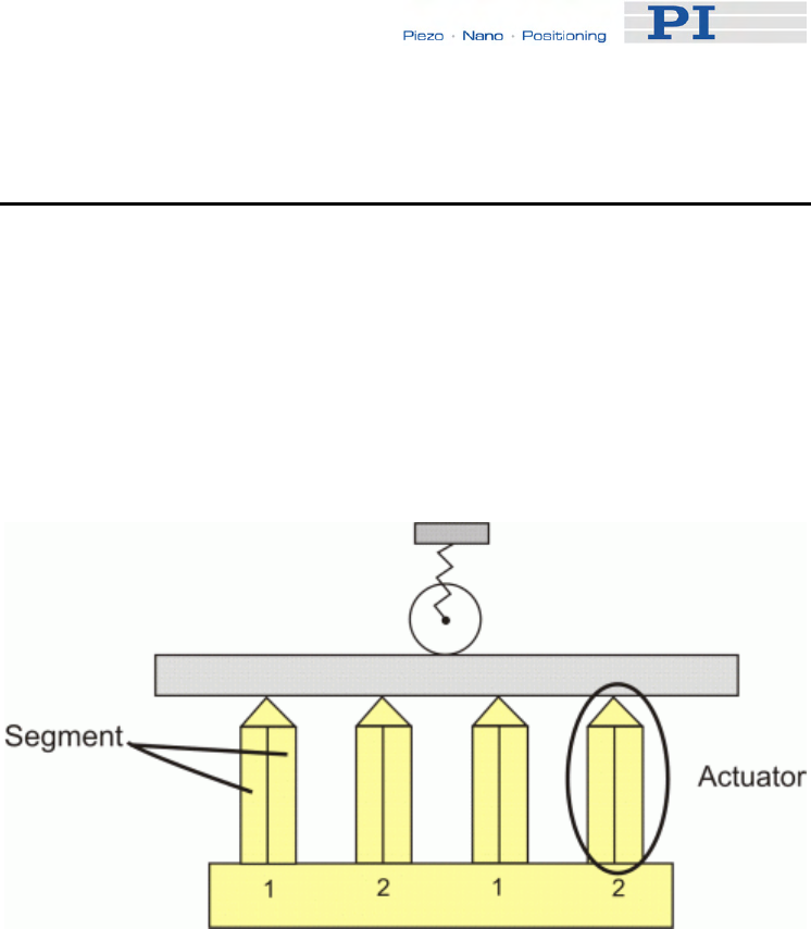
System Description
www.pi.ws E-861 PZ205E Release 1.2.1 Page 56
Otherwise the connected mechanics can run into the hard stop at full
speed, which may cause damage to your hardware setup.
5.3.2 Motion Modes
With the NEXACT® design two basic motion modes are realized based on
the design of a NEXACT® piezo drive module:
A piezo drive module consists of four NEXACT® piezo actuators. The
individual actuators themselves each consist of two segments (Figure 4) of
piezo bender elements.
Figure 4: Design of NEXACT® piezo drive module. The four NEXACT® piezo
actuators each consist of two segments. The numbers 1, 2 designate the
actuator pairs which are controlled in an identical way
The actuators of a piezo drive module are all cyclically controlled in pairs
(= actuator pairs). When a drive contains several piezo drive modules,
corresponding actuator pairs are controlled together. Every NEXACT®
drive therefore has to be controlled by means of four different signals for
the segments (U1 to U4). The voltage range for the bender elements is -10
to +45 V.
The feed is achieved by coordinated control of the segments. The actuator
pairs have different displacements. This causes the piezo drive module to
execute a stepping motion on the runner (see Nanostepping mode).
The two motion modes of the NEXACT® linear drives are implemented in
the E-861 firmware.
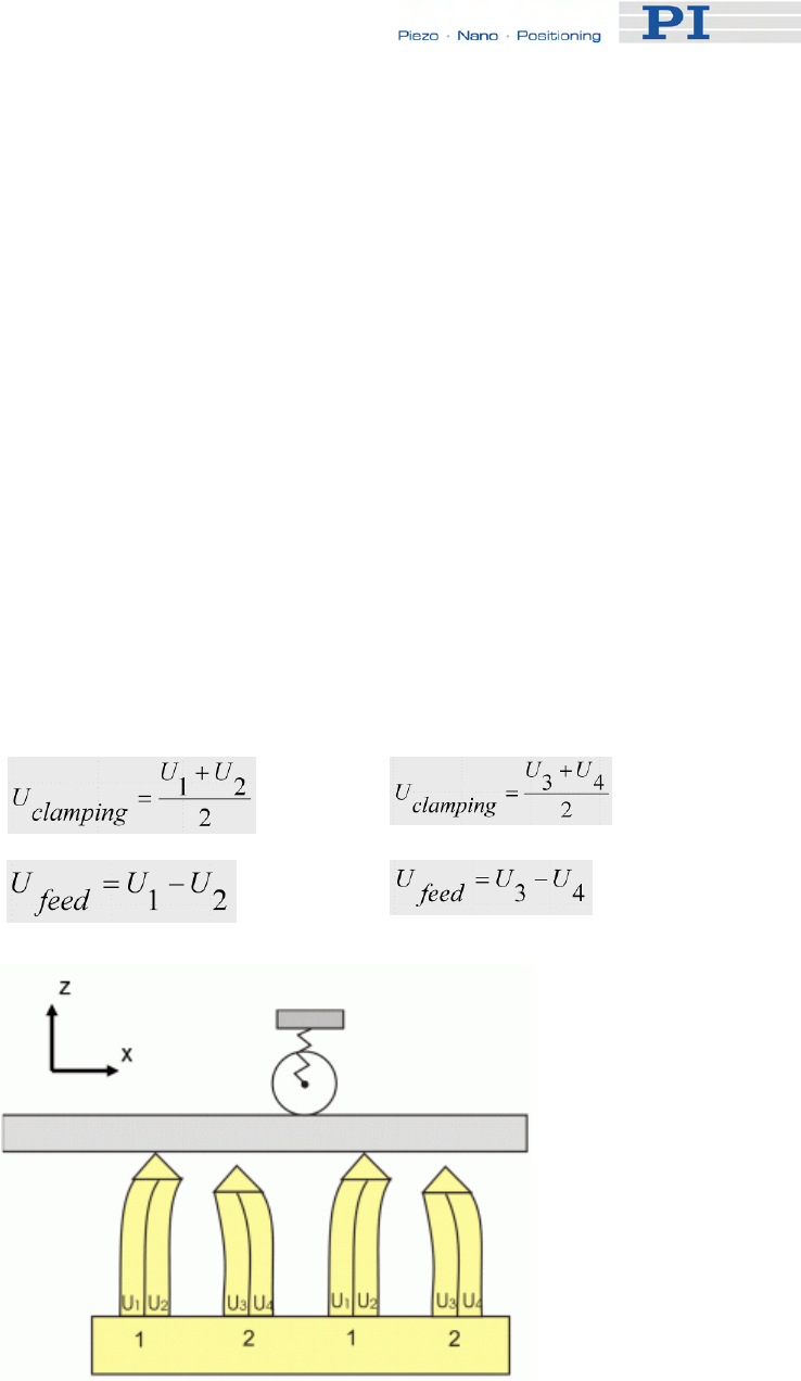
System Description
Nanostepping mode
Characteristics:
■ Stepping motion over long distances
■ High velocity over longer travel ranges, limited only by the length of
the runner
■ Motion consists of multiple steps of about 10 µm in length at
minimum (without load; 5 µm with 10 N load), values can vary
depending on the stage type.
Control:
In nanostepping mode the segments of both pairs of legs are controlled
with a phase shift. Decisive for the feed of the runner are the resulting
voltages below:
Actuator pair 1 (U1, U2
in Figure 5)
Actuator pair 2 (U3, U4
in Figure 5)
Clamping voltage
Feed voltage
Figure 5: The runner moves in the X-direction. The module is preloaded against the
runner in Z-direction.
www.pi.ws E-861 PZ205E Release 1.2.1 Page 57

System Description
www.pi.ws E-861 PZ205E Release 1.2.1 Page 58
The motion is realized by coordinated control of the feed and clamping
voltages for the piezo stacks in the NEXACT® drive, and can cover the
whole travel range of the mechanics.
Analog mode
Characteristics:
■ High-dynamics motion, limited by the step size in analog mode (a
few µm)
■ Positioning accurate to one picometer (open-loop)
Control:
All actuators are controlled in phase. The clamping voltage in analog mode
is 17.5 V, and hence the mean value of the possible piezo voltages of both
segments. The maximum travel range is thus available for the deflection
(see Figure 6).
NOTES
The actual step size can vary with the applied load.
The step size can differ for both directions of motion, depending on the
direction of force applied by the load: steps in the direction of the load
may be larger than the average step size, steps against the load may
be smaller.
The following motion commands are available:
■ Open-loop operation (servo off), nanostepping mode:
OSM (p. 163)
OMA (p. 158)
OMR (p. 161)
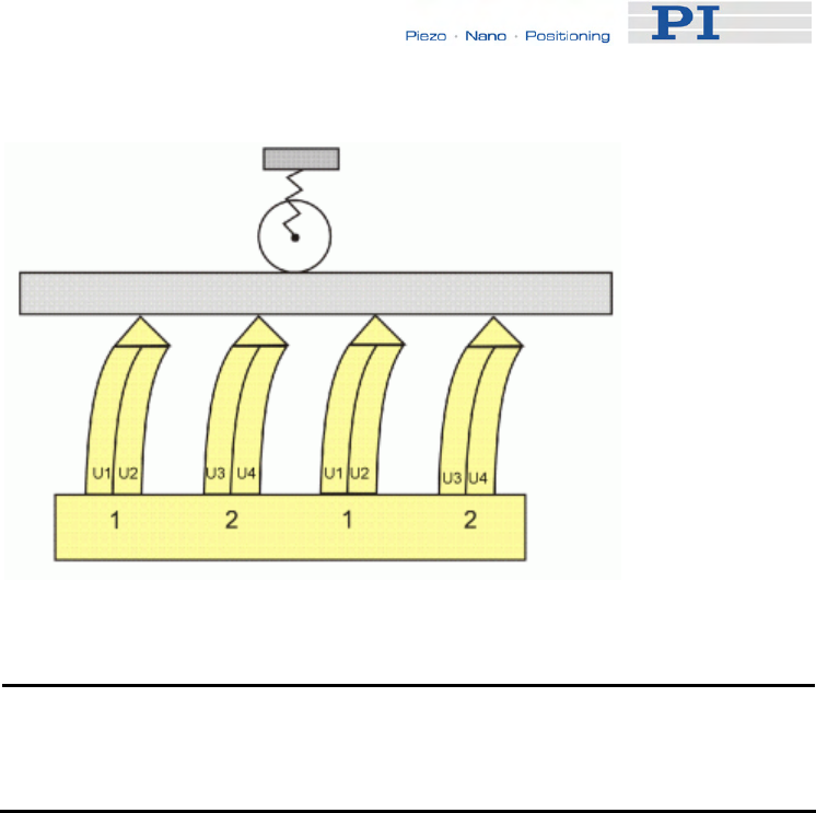
System Description
Figure 6: Analog mode: All NEXACT ® piezo actuators are in contact with the
runner. The actuator pairs 1 and 2 are controlled in an identical way
(segment voltages U1 = U3, U2 = U4)
NOTE
With the OSM command steps are commanded using floating point
numbers, i.e. motion is not limited to complete steps only.
■ Open-loop operation (servo off), analog mode:
OAD (p. 155)
■ Closed-loop operation (servo on):
MOV (p. 151)
MVR (p. 153)
5.3.3 Changing Motion and Servo Mode
The working principle of a NEXACT® linear drive requires defined
transitions between the individual motion and servo modes.
For that purpose, the following transitions and states are provided (the
numbers given below identify the transitions and states in the responses to
the #4 command (p. 114) and the SRG? command (p. 178)):
■ Relaxing transitions (1) in which the NEXACT® linear drive is
brought to a full-holding-force, zero-drive-voltage Relaxed state (3).
Relaxing transitions are performed for the following actions:
Switching the servo mode off with
SVO <AxisID> 0
www.pi.ws E-861 PZ205E Release 1.2.1 Page 59

System Description
to change from closed-loop motion (MOV (p. 151), MVR
(p. 153)) to open-loop nanostepping motion (OSM (p. 163),
OMA (p. 158) or OMR (p. 161)) or to open-loop analog
motion (OAD (p. 155)) includes an automatic Relaxing
procedure.
Starting Relaxing manually with
RNP <PiezoWalkChanID> 0
Sending an RNP command (p. 168) is required in open-loop
operation each time you want to change from nanostepping
motion (OSM, OMA or OMR) to analog motion (OAD) or vice
versa.
It is also required if you want to change from analog motion
to closed-loop operation.
■ Transitions which prepare the NEXACT® linear drive automatically
for the desired motion mode by adjusting the drive voltages
(transport and clamping voltages) accordingly.
The duration of Relaxing transition (1), Go to analog transition (2)
and Go to motion transition (5) is determined by the slew rate
(parameter ID 0x7000002).
Note that for all figures below, the following is valid:
The numbers in brackets give the transition state (bits 8 to 11 in the
response SRG? <AxisID>) and the servo mode (response to SVO?
<AxisID>).
#7 command (p. 116) queries if the controller is ready to perform a new
command. The response ° means that the controller is busy.
Transitions for open-loop analog motion:
Go to analog transition (2), is done by the first OAD sent for
a NEXACT® linear drive which is in the Relaxed state.
Go to analog transition (2) brings the drive in the Analog
state (0).
Once the drive is in the Analog state, each subsequent OAD
command will be executed immediately without any Go to
analog transition.
www.pi.ws E-861 PZ205E Release 1.2.1 Page 60
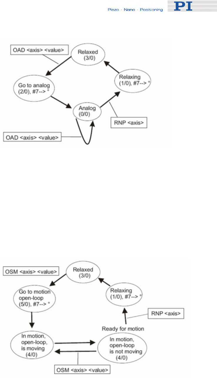
System Description
www.pi.ws Page 61
Figure 7: Changing states with a first sent OAD (open-loop analog motion)
Transitions for open-loop nanostepping motion:
Go to motion transition (5) in open-loop operation, is done by
the first OSM, OMA or OMR sent for a NEXACT® linear
drive which is in the Relaxed state.
Go to motion transition (5) brings the drive in the In Motion
state (4).
Once the drive is in the In Motion state, each subsequent
OSM, OMA or OMR command will be executed immediately
without any Go to motion transition.
Figure 8: Changing states with a first sent OSM (open-loop nanostepping motion).
Analog transitions are valid for first sent OMA or OMR commands.
E-861 PZ205E Release 1.2.1
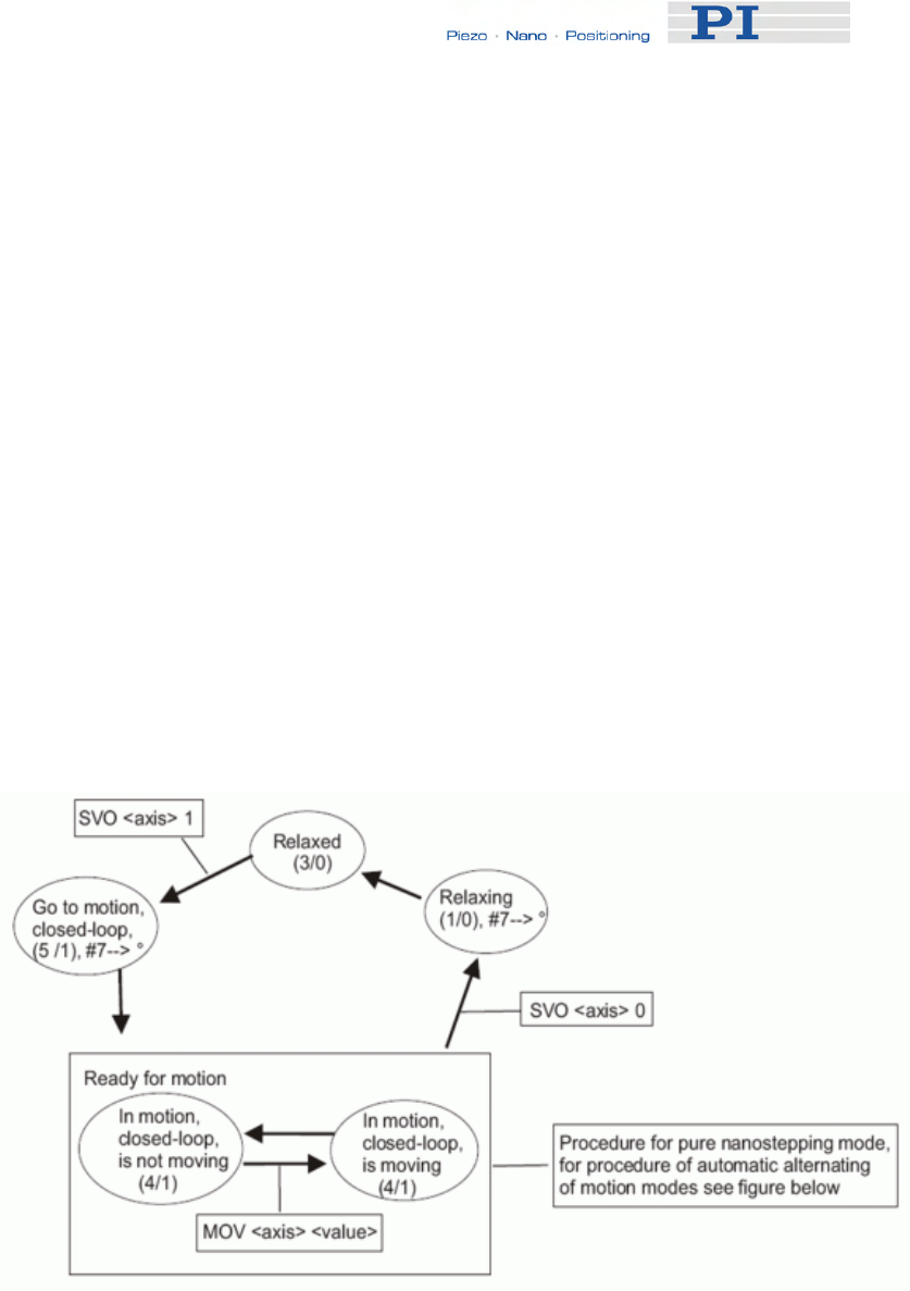
System Description
• Transitions for closed-loop motion
Go to motion transition (5) in closed-loop operation, is done
when
SVO <AxisID> 1
is sent to switch servo on for a NEXACT® linear drive which
is in the Relaxed state.
Go to motion transition (5) brings the drive in the In Motion
state (4).
Note that after switching servo on the controller can be busy
for approximately 100 ms, depending on slewrate setting.
Once the drive is in the In Motion state in closed-loop
operation, each subsequent closed-loop move command
(e.g. MOV or MVR) will be executed immediately without any
Go to motion transition.
Note that if the drive is in open-loop operation and in the In
Motion state (i.e. open-loop nanostepping motion was done
with OSM, OMA or OMR), switching servo on will cause no
Go to motion transition, and the drive is immediately ready
for closed-loop motion.
Figure 9: Changing states with first sent SVO command for subsequent closed-
loop motion
www.pi.ws E-861 PZ205E Release 1.2.1 Page 62

System Description
5.3.4 PiezoWalk Driving Mode
Closed-loop motion can be realized either as nanostepping motion or as a
mix of analog mode motion and nanostepping motion. The decision for one
of the options depends on your application.
See below for the decision criteria and further details.
Switching between the two options is done via the PiezoWalk Driving Mode
parameter (ID 0x7001A00). Note that only if servo is on you can activate
automatical alternating of motion modes by setting the PiezoWalk Driving
Mode parameter to 1 with the SPA command (p. 175).
Thus the following two options exist with closed-loop operation:
A) With 0x7001A00 set to 0:
■ only nanostepping mode is used
■ PID parameters for nanostepping mode are:
0x1 for P-term
0x2 for I-term
0x3 for D-term
B) With 0x7001A00 set to 1:
■ An alternating sequence of analog mode and nanostepping mode is
used
■ Two PID parameter sets:
PID set for nanostepping mode, as listed above
PID set for analog mode, as listed below:
0x401 for P-term
0x402 for I-term
0x403 for D-term
Advantages of Alternating Motion Modes
■ Increased stiffness when axis is on target (compared to use of
nanostepping mode)
■ Provided that system features appropriate mechanics, increased
accuracy can be obtained due to two PID parameter sets
www.pi.ws E-861 PZ205E Release 1.2.1 Page 63

System Description
■ The piezo voltages can be reduced (compared to motion in pure
nanostepping mode), increasing the actuators' lifetime
What You Have to Consider When Closed-Loop Motion is
Realized With Alternating Motion Modes
■ Depending on load and motion direction, settling can require
repeated change of motion mode. This may cause a repeated
opening and closing of the servo-loop.
■ Positioning may take longer than if you use only nanostepping mode.
■ For accurate positioning, sensors of the system must have a
minimum resolution of 20 nm.
Motion Sequence
How to perform closed-loop motion as a mix of analog and nanostepping
mode:
1 Make sure that servo is on
You can check the servo state using the SVO? command (p. 185)
(response must be 1=1).
To activate servo send:
SVO 1 1
2 Make sure that parameter 0x7001A00 is set to 1.
You can check the parameter value using the SPA? command
(p. 178).
Send SPA? 1 0x7001A00
To set the parameter send:
SPA 1 0x7001A00 1
3 Command motion with MOV or MVR.
Motion starts and ends in analog mode where the target position is
maintained with maximum stiffness, since both piezo stack pairs are in
contact with the runner of the NEXACT® linear drive. See Figure 10 for
detailed motion sequence.
With each change of motion mode (from analog mode to nanostepping
mode and vice versa) a Relaxing procedure is performed automatically, see
"Changing Motion and Servo Mode" (p. 59), and servo is switched off and
on automatically.
The criteria for the changes between the motion modes are given by the
E-861 firmware and cannot be changed.
www.pi.ws E-861 PZ205E Release 1.2.1 Page 64
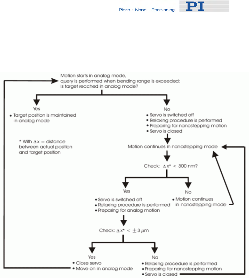
System Description
www.pi. 65 ws E-861 PZ205E Release 1.2.1 Page
Any changes of piezo voltage -as they occur with Relaxing procedures -
can induce undesired motion. Therefore checks as described in Figure 10
are necessary.
Figure 10: Closed-loop motion sequence with changes from analog mode to
nanostepping mode and vice versa
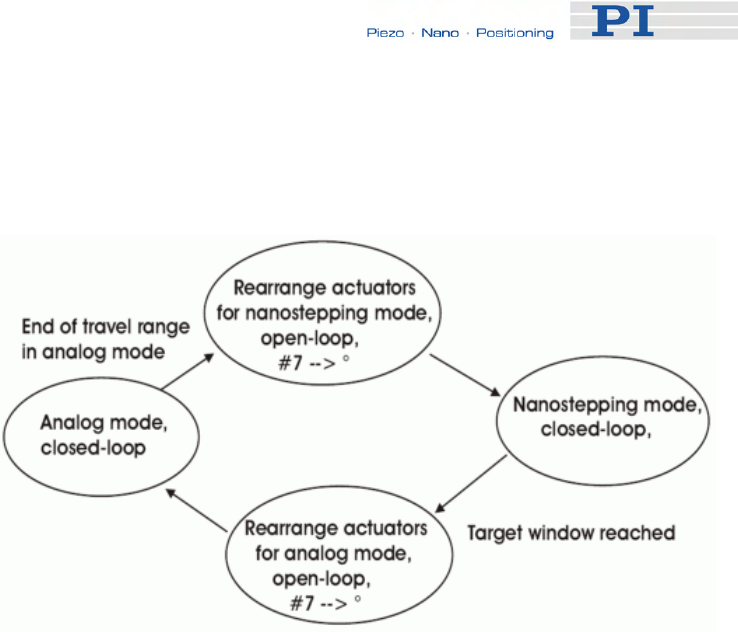
System Description
Sequence of Transitions and States
With alternating motion modes, transitions and states performed are as
described below:
Figure 11: State machine for alternating motion modes
#7 command (p. 116) queries if the controller is ready to perform a new
command. The response ° means that the controller is busy during both
rearranging-the-actuators steps.
The steps illustrated in the figure above consist of the transitions and states
as listed below. The numbers in brackets give the transition state (bits 8 to
11 in the response SRG? <AxisID>, see SRG? command (p. 178)).
■ Rearrange actuators for nanostepping mode consists of :
Relaxing transition (1)
Relaxed state (3)
Go to motion state (5)
A delay time set by parameter ID 0x7000004
■ Nanostepping mode consists of:
In motion state (4)
■ Rearrange actuators for analog mode consists of:
Relaxing transition (1)
Relaxed state (3)
Go to analog state (2)
A delay time set by parameter ID 0x7000004
www.pi.ws E-861 PZ205E Release 1.2.1 Page 66

System Description
■ Analog mode consists of:
Analog state (0)
5.3.5 Application Notes
Sending an RNP command brings the NEXACT® linear drive to a full-
holding-force, zero-drive-voltage Relaxed state.
Depending on the application conditions and parameter settings sending an
RNP command causes a positional error of a few tens of nanometers up to
one micrometer.
After switching from closed-loop to open-loop operation using the SVO
command, the open-loop motion commands (OAD (p. 155), OSM (p. 163),
OMA (p. 158), OMR (p. 161)) can be sent immediately.
After open-loop analog motion was done with OAD, an RNP command
(p. 168) must be sent before servo can be switched on with SVO.
In open-loop operation, an RNP command must be sent each time the
motion mode is to be changed from nanostepping (OSM, OMA, OMR) to
analog (OAD) motion and vice versa.
The following actions can take up to four times the slewrate value
(parameter ID 0x7000002):
■ Switching servo on or off
■ The first OAD after a change of motion mode
■ The first OSM or OMA or OMR after a change of motion mode
■ The RNP procedure
If a required transition between different motion modes was omitted, the
E-861 sends an error message.
You can query the current state of the system (E-861 and NEXACT® linear
drive) using the #4 command (p. 114) or the SRG? command (p. 178).
With #7 (p. 116), you can query if the controller is ready to perform a new
command. If the controller responds with °, it is not ready.
While a joystick connected to the E-861 is enabled with the JON command
(p. 145), the servo can be switched on or off for the axis, and no transition
is required. The axis can be controlled immediately by the joystick.
www.pi.ws E-861 PZ205E Release 1.2.1 Page 67

System Description
The recommended maximum step frequency for NEXACT® drives is
800 Hz. This applies to continuous operation. For short periods it is also
possible to work with higher frequencies (see considerations regarding
velocity in the Glossary of the included N310T0011 Technical Note with
details about the NEXACT® Technology).
5.4 Control Basics
In this section you find information about the following items:
■ Control value generation for both servo modes
■ Trajectory generation
■ Control algorithm
■ Motion error handling
5.4.1 Control Value Generation
The E-861 features closed-loop and open-loop servo modes for control of
the connected mechanics. The servo mode can be selected with the SVO
command (p. 183).
You can query the current servo mode using the SVO? command (p. 185)
or with the #4 (p. 114) and SRG? commands (p. 178) which have a bit-
coded response.
Open-loop mode is active after power-on. Using a start-up macro, you can
set up the device to start with closed-loop mode. The macro feature allows
defining command sequences and storing them permanently in non-volatile
memory in the controller. In addition to the servo mode setting you can, for
example, program conditional execution of motion. See "Working with
Controller Macros" (p. 82) for more information.
www.pi.ws E-861 PZ205E Release 1.2.1 Page 68
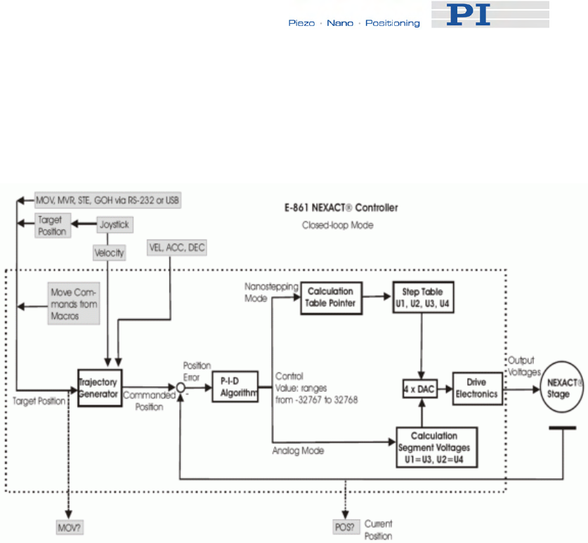
System Description
www.pi.ws E-861 PZ205E Release 1.2.1 Page 69
■ Closed-loop mode (servo on)
The block diagram below shows how the E-861 generates the output
voltage for the connected axis (NEXACT® stage) from given input for
closed-loop mode.
NEXACT® stages are generally operated in closed-loop mode. With the
E-861, a trajectory generator calculates the motion profile from the
given target position, velocity, acceleration and deceleration.
The position error resulting from the difference of the generated
trajectory and the current position (sensor feedback) is passed through
a proportional-integral-differential (P-I-D) algorithm. The result is the
control value for the drive electronics integrated in the E-861.
With the E-861 closed-loop motion can be performed either as
nanostepping motion or as a mix of analog mode motion and
nanostepping motion. Therefore there are two PID parameter sets, one
for nanostepping motion and one for analog motion.
See "PiezoWalk Driving Mode" (p. 63) for how to activate automatic
alternating of motion modes and details regarding the PiezoWalk
Driving mode's motion sequence.
With nanostepping motion the control value is in a range of -32767 to
32768. This value is processed so as to provide a constant input to the
drive electronics (by an integration step) and to obtain a residual value
between -32767 to 32768 as input for a step table.
This step table provides the four segment voltages U1 to U4. These are
responsible for the motion of the piezo segments in the NEXACT®
drive.
See also "Motion Modes" (p. 56) or read the N310T0011 Technical Note
delivered with the controller for further details regarding the
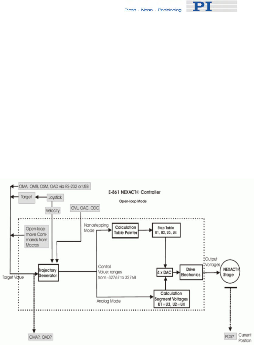
System Description
nanostepping motion sequence and how segment voltages are formed.
With analog motion the control value range of -32767 to + 32768 is used
according to the bending motion. Here, segment voltages U1 equals U3
and U2 equals U4.
You can use the following move commands:
for usual moves: MOV (p. 151), MVR (p. 153), GOH (p. 135),
STE (p. 181)
for reference moves: FNL (p. 129), FPL (p. 131), FRF (p. 133)
for hardware evaluation: FED (p. 128)
■ Open-loop mode (servo off)
The block diagram below shows how the E-861 generates the output
voltage for the connected axis (NEXACT® stage) from given input for
open-loop mode.
The open-loop mode omits servo-control algorithm. With open-loop
mode motion can be performed as nanostepping motion using the
OSM (p. 163), OMA (p. 158) and OMR (p. 161) commands or as
analog motion using the OAD (p. 155) command.
Note that OMA and OMR commands can only be used if your system
features a sensor, otherwise the connected mechanics can run into the
hard stop at full speed.
The commanded open-loop target can be queried using OMA? (p. 160)
www.pi.ws E-861 PZ205E Release 1.2.1 Page 70

System Description
respectively OAD? (p. 157).
With open-loop mode, you can also use the following move
commands:
for reference moves: FNL (p. 129), FPL (p. 131), FRF (p. 133)
for hardware evaluation: FED (p. 128)
Before absolute targets can be commanded (MOV, OMA), the mechanics
must be referenced. Depending on the reference mode setting, even
relative moves require referencing.
See "Referencing" (p. 51) for details.
Joystick operation is possible with both closed-loop and open-loop
operation.
While a joystick connected to the E-861 is enabled with the JON command,
this joystick controls the axis velocity ("commanded velocity" output by the
trajectory generator). During joystick control, the target position is set to the
travel range limits given by the Max_Travel_Range_pos and
Max_Travel_Range_neg parameters (0x15 and 0x30, see "Travel Range
Adjustment" (p. 92) for more information). When disabling a joystick, the
target position is set to the current position for joystick-controlled axes.
For further joystick-related commands see the "Joystick Control" (p. 79).
See "Motion Modes" (p. 56) for a short description of the nanostepping and
analog motion.
5.4.2 Trajectory Generation
A trajectory generator performs calculations to determine the current
position, velocity, acceleration and deceleration of the axis at any given
moment in time ("motion profile"). These values are called the commanded
values (see also "Control Value Generation" (p. 68)).
The profile that is created by the trajectory generator of the E-861 depends
on the motion parameters given by corresponding commands, by controller
parameters and/or by a joystick:
Motion
Parameter
Corresponding
Commands
Corresponding
Controller Parameter
Notes
Acceleration
(A) ACC (p. 118), ACC?
(p. 118)
for
closed-loop mode
Current closed-loop
acceleration (parameter ID
0xB; user unit/s2)
Changed by ACC or by
SPA / SEP, can be saved
with WPA
Limited by parameter
0x4A (Maximum
closed-loop
acceleration)
OAC (p. 154), OAC?
(p. 155)
for
open-loop mode
Current open-loop
acceleration (parameter ID
0x7000202; step cycles/s2)
Changed by OAC
command or by SPA /
Limited by parameter
0x7000205
(Maximum open-loop
acceleration)
www.pi.ws E-861 PZ205E Release 1.2.1 Page 71

System Description
Motion
Parameter
Corresponding
Commands
Corresponding
Controller Parameter
Notes
SEP, can be saved with
WPA
Deceleration
(D) DEC (p. 119), DEC?
(p. 120)
for
closed-loop mode
Current closed-loop
deceleration (parameter ID
0xC; user unit/s2)
Changed by DEC
(p. 119) or by SPA / SEP,
can be saved with WPA
Limited by parameter
0x4B (Maximum
closed-loop
deceleration)
ODC (p. 157), ODC?
(p. 158)
for
open-loop mode
Current open-loop
deceleration (parameter ID
0x7000203; step cycles/s2)
Changed by ODC
command or by SPA /
SEP, can be saved with
WPA
Limited by parameter
0x7000206
(Maximum open-loop
deceleration)
Velocity (V) VEL (p. 188), VEL?
(p. 189)
for
closed-loop mode
Current closed-loop
velocity (parameter ID
0x49; user unit/s)
Changed by VEL or by
SPA / SEP, can be saved
with WPA
OVL (p. 165), OVL?
(p. 166)
for
open-loop mode
Current open-loop velocity
(parameter ID 0x7000201;
step cycles/s)
Changed by OVL
command or by SPA /
SEP, can be saved with
WPA
Limited by parameter
0xA (Maximum closed-
loop velocity)
respectively by
parameter 0x7000204
(Maximum open-loop-
velocity)
A joystick connected to
the E-861 which is
enabled with the JON
command (p. 145)
applies a factor to the
current velocity set
with VEL respectively
OVL, see "Joystick
Control" (p. 79) for
details.
Target MOV (p. 151), MVR
(p. 153), GOH (p. 135),
STE (p. 181)
for
closed-loop mode
- A joystick connected to
the E-861 which is
enabled with the JON
command (p. 145) sets
the travel range limits
www.pi.ws E-861 PZ205E Release 1.2.1 Page 72

System Description
www.pi.ws E-861 PZ205E Release 1.2.1 Page 73
Motion
Parameter
Corresponding
Commands
Corresponding
Controller Parameter
Notes
OMA (p. 158), OMR
(p. 161), OSM (p. 163)
for
open-loop mode
as target position.
When disabling a
joystick, the target
position is set to the
current position for
joystick-controlled
axes. See "Joystick
Control" (p. 79) for
details.
When the servo is
switched on with the
SVO command
(p. 183) or when axis
motion has been
stopped with #24
(p. 117), STP (p. 182)
or HLT (p. 137), the
target position is set to
the current position.
Note that with open-loop mode the dimensions use step cycles instead of,
e.g., µm.
Furthermore, be aware that the distance achieved by step cycles in open-
loop is not as reproducible as a distance commanded in closed-loop mode:
with open-loop changing conditions such as changed load or motion
direction are not compensated by a servo loop.
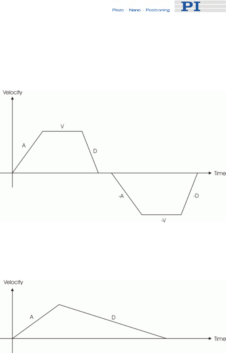
System Description
The trajectory generator of the E-861 supports trapezoidal point-to-point
profiles only: the axis accelerates linearly (at the given acceleration value)
until it reaches the given velocity. It continues in motion at that velocity,
then decelerates linearly (using the deceleration value) until it stops at the
specified target position.
Figure 12: Simple trapezoidal point-to-point profiles, A = acceleration, D =
deceleration, V = velocity
If deceleration must begin before the axis reaches the given velocity, the
profile will have no constant velocity portion, and the trapezoid becomes a
triangle.
Figure 13: Simple trapezoidal point-to-point profile, A = acceleration, D =
deceleration, no constant velocity
The slopes of the acceleration and deceleration segments may be
symmetric (if acceleration equals deceleration) or asymmetric (if
acceleration is not equal to deceleration).
The acceleration parameter is always used at the start of the motion.
Thereafter, the acceleration value will be used when the absolute velocity is
increasing, and deceleration will be used when the absolute velocity is
decreasing.
www.pi.ws E-861 PZ205E Release 1.2.1 Page 74

System Description
If no motion parameters are changed during the motion then the
acceleration value will be used until the maximum velocity is reached, and
the deceleration value will be used when ramping down to zero.
Figure 14: Complex trapezoidal profile, showing parameter changes; A =
acceleration; D = deceleration; V1, V2, -V2 = velocities
It is acceptable to change any of the motion parameters while the axis is
moving. The profile generator will always attempt to remain within the legal
bounds of motion specified by the parameters.
If, during the motion, the target position is changed in such a way that an
overshoot is unavoidable, the profile generator will decelerate until stopped,
then reverse direction to move to the specified position.
www.pi.ws E-861 PZ205E Release 1.2.1 Page 75
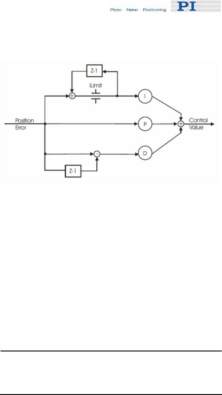
System Description
5.4.3 Control Algorithm
Figure 15: P-I-D algorithm with offset compension
The E-861 controller for NEXACT® stages uses a proportional-integral-
differential (P-I-D) algorithm.
See "Tuning the PID Control Parameters" (p. 95) for how PID control
parameters can be adjusted.
The controller features two sets of PID parameters. One is used if
nanostepping motion is performed. The second is used for analog motion:
■ PID parameter IDs for nanostepping mode are:
0x1 for P-term
0x2 for I-term
0x3 for D-term
■ PID parameter IDs for analog mode :
0x401 for P-term
0x402 for I-term
0x403 for D-term
NOTE
The PID set for analog motion is only active if the automatic alternating
of motion modes is activated by the PiezoWalk Driving mode
parameter (ID 0x7001A00) and if stage is in analog motion.
www.pi.ws E-861 PZ205E Release 1.2.1 Page 76

System Description
See "PiezoWalk Driving Mode" (p. 63) for further information about
alternating motion modes.
See also "Controller Parameters" (p. 35) for detailed parameter descriptions
and parameter handling.
When you are working with the host software from PI, you can select your
stage type from a database which contains, amongst others, initial values
for the parameters of the P-I-D algorithm.
The host software will then send the appropriate parameter values to the
controllers volatile memory. See also "How to Store Parameter Settings"
(p. 37) and "How to Create a New Stage Type in the PI Stages Database"
(p. 98) for more information.
5.4.4 Motion Error Handling
Under certain circumstances, the current axis position (position feedback)
may differ from the commanded position by an excessive amount. Such an
excessive position error can indicate a potentially dangerous condition such
as drive or encoder failure.
With the E-861 in closed-loop mode, it is possible to detect an excessive
position error in the form of a "motion error" (error code: -1024).
The "motion error" criterion is given by the Maximum position error
parameter (ID 0x8). You should set that parameter to the maximum position
error which is tolerable in your application.
See "Controller Parameters" (p. 35) for more information on how to change
parameter values.
If the position error falls out of the window formed by the Maximum position
error parameter, the servo is switched off automatically for the axis
concerned, all motion is stopped immediately, and error code -1024 is set
(see figure below). Proceed as follows in case of a motion error:
1 Get the code of the last occurred error. In case of a motion error
the response is -1024. The query resets the error to 0.
2 Check your hardware and make sure that it is safe for the stage to
move the axis.
3 Switch the servo on for the axis using the SVO command (p. 183).
This sets the target position to the current position of the axis.
www.pi.ws E-861 PZ205E Release 1.2.1 Page 77
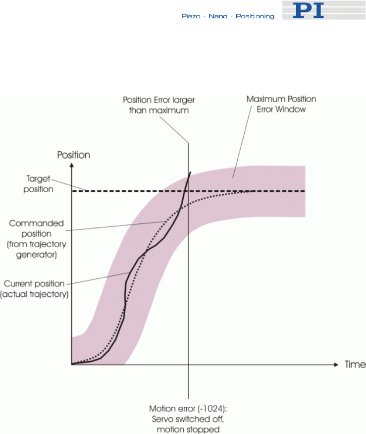
System Description
www.pi.ws 78 E-861 PZ205E Release 1.2.1 Page
The axis is now able to move again, and you can command a new target
position.
Figure 16: Motion error handling
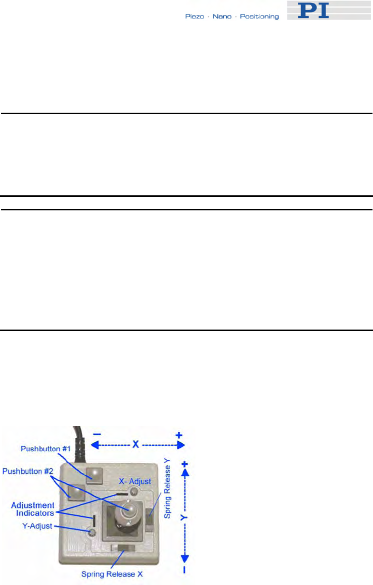
Joystick Control
6 Joystick Control
! CAUTION
Do not enable a joystick via command when no joystick device is
connected to the controller hardware. Otherwise the corresponding
controller axis may start moving and could damage your application
setup.
NOTE
Before a joystick can be operated correctly, a calibration routine may
need to be performed. Activating the joystick before calibration may
cause the axis to start moving even though the joystick is in the neutral
position.
To calibrate a joystick axis of C-819.20 turn the corresponding "Adjust"
knob on the joystick until the axis stops.
E-861 controllers offer convenient manual motion control. One C-819.20
analog joystick device can be connected to the Joystick socket (p. 220) of
the E-861. The E-861 supports one axis and one button of the joystick
device. See "Accessible Items and Their Identifiers" (p. 53) for the joystick
related identifiers to use in commands.
Figure 17: C-819.20 joystick device
The two joystick axes of an C-819.20 joystick device can be connected
through the C-819.20Y cable to two E-861 controllers. In this case, on both
controllers the joystick axis 1 must be selected for operation (the Y-cable
maps the signals internally). If the "Axis Y" branch of the Y-cable is to be
used, the "Axis X" branch must also be connected to a controller to provide
www.pi.ws E-861 PZ205E Release 1.2.1 Page 79

Joystick Control
the supply power for the joystick device.
When a joystick is connected directly to the controller, it is the velocity of
the motion axes that is determined by the displacement of the
corresponding joystick axes.
For each joystick axis there is a lookup table that defines the velocity
response for a certain amplitude of the joystick axis. The values in the
lookup table are factors which will during joystick control be applied to the
velocity set with VEL (p. 188) (closed-loop operation) or OVL (p. 165)
(open-loop operation) for the controller axis, the range is -1.0 to 1.0.
To change a lookup table, you can load default profiles provided by the
controller, or you can write a custom profile to the lookup table point-by-
point (256 values).
While a joystick is active on a controller axis which is equipped with a
position sensor, it is possible to switch from open-loop to closed-loop
operation and vice versa with the SVO command (p. 183).
When disabling a joystick, the target position is set to the current position
for joystick controlled axes which are in closed-loop operation.
Commands for joystick handling:
JON (p. 145) Enables or disables a specified joystick device for joystick
operation.
While a joystick is active on a controller axis, move
commands are neither accepted from the command line
nor from macros for that axis.
JON? (p. 145) Queries the current activation state of the joystick devices.
JAX (p. 139) Sets the controller axis which is to be controlled by a
joystick axis.
Each axis of a controller can only be controlled by one
joystick axis.
JAX? (p. 140) Queries the current assignment of controller axes to
joystick axes.
JAS? (p. 138) Queries the current status of joystick axes. The response
corresponds to the current displacement of the joystick
axis and is the factor which is currently applied to the
current valid velocity setting of the controlled motion axis,
according to the lookup table.
JBS? (p. 140) Queries the current status of joystick buttons. The
response indicates if the joystick button is pressed;
0 = not pressed, 1 = pressed.
www.pi.ws E-861 PZ205E Release 1.2.1 Page 80

Joystick Control
www.pi.ws E-861 PZ205E Release 1.2.1 Page 81
JDT (p. 141) Sets predefined lookup-table types for the joystick axes.
The current lookup-table content for the specified joystick
axis is overwritten by the selection made with JDT.
The E-861 provides the following lookup-table types for
special applications:
1 = linear (power-on default)
2 = parabolic
JLT (p. 142) Fills the lookup table for a joystick axis point-by-point. This
overwrites the current lookup table content for this joystick
axis. See the command description for an example.
JLT? (p. 143) Reads the current lookup-table values.

Working with Controller Macros
7 Working with Controller
Macros
The macro feature allows defining command sequences and storing them
permanently in non-volatile memory in the controller. Each defined macro
can be called up by its own user-defined name.
In addition, it is possible to define a macro that will be executed
automatically every time the E-861 is started, making possible stand-alone
operation without a host computer. See the subsections below and the
MAC command (p. 146) description for more details and examples.
NOTE
Macros can only be real-time processed if controller is not busy with
extensive communication, as e.g. reading out the data recorder. The
more commands are sent during performance of a macro the less real-
time processing of the macro is possible.
NOTE
PIMikroMove offers a comfortable macro editor on the Controller
macros tab card. Furthermore, PIMikroMove offers the "Host macro"
feature which makes it possible to save macros on the host PC.
7.1 Defining Macros
To define a macro command sequence, first activate macro recording
mode with the command MAC BEG <macroname> where <macroname> is
a user-settable name with a maximum of 8 characters. While in macro
recording mode, commands are not executed but stored in macro storage.
Recording mode is exited by the MAC END command.
A macro can call another macro. Further nesting is not allowed (only one
nesting level). A macro can call itself to form an infinite loop.
During macro recording no macro execution is allowed.
A macro can be overwritten by a macro with the same name.
A running macro sends no responses to any interface. This means
questioning commands are allowed in macros but not answered and
therefore useless.
www.pi.ws E-861 PZ205E Release 1.2.1 Page 82

Working with Controller Macros
The following commands provided by the E-861 can only be used in
macros:
DEL (p. 120), MEX (p. 149) and WAC (p. 189). Using MEX and WAC, it is
possible to set stop conditions or conditions for further macro processing.
Macro recording is possible when a joystick is active on the axis.
Example 1 (for a system with position sensor): Note how macro3 calls
macros #1 and #2 for execution.
MAC BEG macro1
MVR 1 12.5
WAC ONT? 1 = 1
MAC END
MAC BEG macro2
MVR 1 -12.5
WAC ONT? 1 = 1
MAC END
MAC BEG macro3
MAC START macro1
MAC START macro2
MAC END
During macro recording for a controller whose address is different from 1,
the address must as target ID be part of each command line to be
recorded, but will not become part of the macro content.
Example 2 (for a system with position sensor): The controller address is set
to 2 with the DIP switches. Macro addrtest is to be recorded:
2 MAC BEG addrtest
2 SVO 1 1
2 DEL 1000
2 FRF 1
2 MAC END
Now you can check the content of macro addrtest by sending
2 MAC? addrtest
The answer is
SVO 1 1
DEL 1000
FRF 1
i.e. the target ID has not become part of the macro.
www.pi.ws E-861 PZ205E Release 1.2.1 Page 83

Working with Controller Macros
www.pi.ws E-861 PZ205E Release 1.2.1 Page 84
See "Target and Sender Address" (p. 110) for more information.
7.2 Starting Macro Execution
A defined macro can be run by the command MAC START <macroname>
where <macroname> is the name that was given to the macro to be run.
To run a macro multiple times, call it with MAC NSTART <macroname> n
where n gives the number of times the macro is to be run.
Simultaneous execution of multiple macros is not possible. Only one macro
can be executed at a time.
Any commands can be sent from the command line when a macro is
running. The macro content and move commands received from the
command line may overwrite each other, and only the last move command
will be executed, irrespective of its source.
Macro execution can be stopped from the command line with #24 (p. 117),
STP (p. 182) and HLT (p. 137).
A running macro may not be deleted.
Macro execution is not allowed when a joystick is active on the axis. See
"Joystick Control" (p. 79) for details.
You can query with #8 (p. 116) if a macro is currently running on the
controller and ask for the names of currently running macros with the
RMC? command (p. 168).
7.3 Start-Up Macro
With MAC DEF <macroname> it is possible to set the specified macro as
start-up macro. This macro will be automatically executed with the next
power-on or reboot of the controller.
Example (for a system with position sensor):
MAC BEG startcl
JON 1 0
SVO 1 1
DEL 1000
FNL 1
MAC END
MAC DEF startcl
In the example, axis 1 will after power-on be immediately ready for closed-
loop operation since the startup macro switches the servo on and performs

Working with Controller Macros
a reference move to the negative limit switch.
To ask for the current start-up macro setting, send
MAC DEF?
To undo the current start-up macro selection, send
MAC DEF
i.e. omit <macroname>.
Deleting a macro with MAC DEL <macroname> does not delete the start-
up macro selection.
7.4 Preparing for Stand-Alone Preparation
If you want to operate controller and a stage without a host PC you can do
so by using macros.
Stand-alone operation is possible if you store macros as auto-start macros,
i.e. the content of the macro is performed automatically after the controller
is powered on.
For example, you can program a macro for motion within a fixed travel
range or a macro to enable a joystick or a pushbutton box directly after
booting the controller. Thus you can command motion flexible.
Before you start stand-alone operation you must make sure that the
parameter settings stored in the controller’s non-volatile memory are
appropriate for the stage connected:
For example, the controller must recognize the reference switch (i.e. 0x14
must be 1) to be capable to perform referencing in an autostart macro. This
is not possible with Default-Stage-N parameter settings in the controller’s
non-volatile memory.
See “Storing Parameter Settings to Non-Volatile Memory Using
PIMikroMove Main Window” (p. 38) or “Storing Parameters to Volatile and
Non-Volatile Memory via Commands” (p. 40), for instructions.
! CAUTION
Do not enable a joystick via command when no joystick device is
connected to the controller hardware. Otherwise the corresponding
controller axis may start moving and could damage your application
setup.
www.pi.ws E-861 PZ205E Release 1.2.1 Page 85
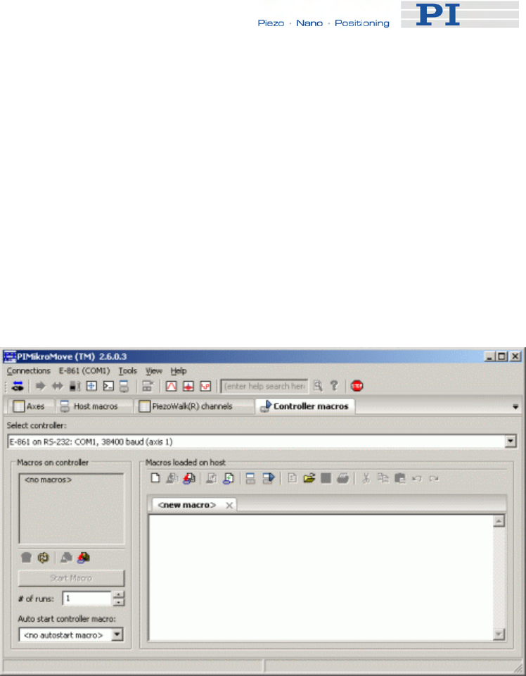
Working with Controller Macros
www.pi.ws E-861 PZ205E Release 1.2.1 Page 86
An example follows of how to generate a start-up macro that:
■ Switches servo on
■ References the stage
■ Activates joystick operation
To generate the auto start macro as described proceed as follows:
1 Select the Controller macros tab of the PIMikroMove main window,
see next figure.
2 Insert a macro with the following commands:
SVO 1 1
DEL 500
FRF 1
WAC FRF? 1 = 1
JAX 1 1 1
JON 1 1
3 Send macro to controller, see next figure.
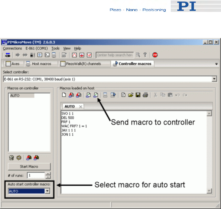
Working with Controller Macros
4 Select macro for autostart, see figure above.
This macro will be executed automatically every time the controller
is powered on or rebooted.
www.pi.ws E-861 PZ205E Release 1.2.1 Page 87

Data Recording
8 Data Recording
For general information regarding the data recording you can send the
HDR? command (p. 135) which lists available record options and trigger
options and gives additional information about data recording. The E-861
has 2 data recorder tables (ask with TNR? (p. 187)) with 1024 data points
per table.
The data recorder configuration, i.e. the assignment of data sources and
record options to the recorder tables, can be changed with DRC (p. 122),
and the current configuration can be read with DRC? (p. 123). Data
recorder tables with record option 0 are deactivated, i.e. nothing is recorded
(power-on default).
Recording can be triggered in several ways. Ask with DRT? (p. 127) for the
current trigger option and use DRT (p. 126) to change it. A trigger option
set with DRT will become valid for all data recorder tables with non-zero
record option. By default data recording is triggered when a step response
measurement is made with STE (p. 181).
The record table rate can be set with the RTR command (p. 171). The
power-on default of this value is one servo cycle (ask with RTR? (p. 172)).
You can cover longer periods by increasing the record table rate.
Recording always takes place for all data recorder tables with non-zero
record options.
Recording ends when the content of the data recorder tables has reached
the maximum number of points.
The last recorded data can be read with the DRR? command (p. 124). The
data are reported in GCS array format, for details regarding the GCS array
see the separate manual (SM146E) which is provided on the E-861 CD.
Reading can take long depending on the number of points to be read! It is
possible to read the data while recording is still in progress.
When the controller is powered down, the content of the data recorder
tables and all data recorder configuration and trigger settings are lost. The
configuration and trigger settings are reset to their factory defaults on
power on.
www.pi.ws E-861 PZ205E Release 1.2.1 Page 88

Customizing the System
9 Customizing the System
This section contains information about:
■ Which parameters you may have to change to adjust the controller to
your individual application or to use a custom stage
■ Which parameters you may adjust regarding travel range
■ How to tune PID control parameters
■ How you can generate a user-defined stage database entry
In addition, you find the following information for adjustment of the E-861
controller for a custom sensor:
■ When to adjust servo loop input factor parameters
■ How to adjust controller for a custom sensor that uses a custom
interpolation board
■ What sensor properties are required for using the controller's
GEMAC interpolation board
■ What to provide if a custom sensor is to use the controller’s GEMAC
interpolation board
Adjustment and storing of adjusted parameter settings can be required in
the following cases:
If your application requires adjustment regarding:
■ Travel range and/or a modified home position
■ Physical units and axis unit
If you use a custom stage you have to provide for the following:
■ The logic of your reference and limit switches must be reflected in
the controller’s parameter settings
www.pi.ws E-861 PZ205E Release 1.2.1 Page 89

Customizing the System
www.pi.ws E-861 PZ205E Release 1.2.1 Page 90
■ The parameters of your stage’s sensor must match the GEMAC
interpolation board’s requirements. This interpolation board is part of
the E-861 controller
■ The resolution of your stage’s sensor must be reflected by the servo-
loop input factor
For instructions on how to store adjusted parameter settings to volatile and
non-volatile memory read “How to Store Parameter Settings” (p. 37).
For instructions on how to generate a custom stage database entry see
"How to Create a New Stage Type in the PI Stages Database" (p. 98).
See “Adjustment for Custom Sensor” (p. 99) for what to consider for
operating the E-861 controller with a stage with custom sensor.
9.1 Parameters for Customizing
The properties of your mechanics (stage configuration, sensor, load) must
be reflected in the corresponding parameters of the E-861 firmware.
The following parameters may have to be adjusted depending on your
application:
■ Parameters which affect the travel range. These parameters are:
Parameter ID Function
0x15 Maximum travel in positive direction
0x16 Position value at reference position
0x17 Distance between reference switch and negative limit
switch
0x2F Distance between reference switch and positive limit
switch
0x30 Maximum travel in negative direction
See "Travel Range Adjustment" (p. 92) for details.
■ The numerator and denominator of the counts-per-physical-unit
factor (parameter IDs 0xE and 0xF) which determines the "user" unit
for motion commands and the settings of all other parameters whose
unit is based on the "user" unit
■ Parameter for Axis unit (ID 0x7000601), since it is not adjusted
automatically by the counts-per-physical-unit factor
■ Further parameters if this is necessary for your application
■ PID control parameters should be adjusted during closed-loop
operation of the system until the system performance proves
satisfactory, e.g. by measuring the step response of the system (STE

Customizing the System
command and DRR? command (p. 124)).
The P, I and D values depend on the applied load and motion
parameters (velocity, settling behavior).
See also "Tuning PID Control Parameters" (p. 95) for how PID
control parameters can be adjusted.
The following parameters may have to be adjusted if you use a custom
stage:
■ Parameters for the limit and reference switches and their signal logic
to make them fit to your hardware. These parameters are:
Parameter ID Function
0x14 Stage has a reference switch
1 if yes, 0 if no
0x31 Invert the reference
1 if invert, 0 if no inversion
0x32 Stage has limit switches
0 if yes, 1 if no
■ The E-861 is equipped with a GEMAC interpolation board for
incremental measuring systems.
Check if your sensor hardware (encoder) is compatible with the
preset values of the parameters for the GEMAC interpolation board
(IDs 0x7000010 to 0x700001F).
See "GEMAC Parameters" (p. 105) for details.
■ Parameters for numerator and denominator of the servo loop input
factor (IDs 0x5A and 0x5B) are preset to 50000 counts per 1 mm.
Needs to be adjusted only if your sensor resolution differs from
50000 counts per 1 mm.
See “Servo Loop Input Factor” (p. 99) for more information of this
factor’s function.
If you want to operate the controller with a custom stage not delivered from
PI and if you use PI software, as e.g. PIMikroMove, you can use the
Default-Stage-N's stage database entry, i.e. a given set of parameter
settings.
Ensure that the parameter settings of Default Stage N correspond to your
mechanics – make adjustments if necessary.
See “Controller Parameters” (p. 35) for how to handle parameter settings
and how to store them.
www.pi.ws E-861 PZ205E Release 1.2.1 Page 91

Customizing the System
9.2 Travel Range Adjustment
The figures below give a universal hardware scheme of a positioning stage
with incremental sensor, reference and limit switches. To work with such a
stage in closed-loop operation, the corresponding controller parameters
must be adjusted properly (see "Controller Parameters" (p. 35) for how to
modify parameter values).
In the example shown in the first figure, the travel range, i.e. the distance
from negative to positive limit switch is 20 mm, the distance between the
negative limit switch and the reference switch is 8 mm, and the distance
between reference switch and positive limit switch is 12 mm (you can use
the FED command (p. 128) in combination with the POS? command
(p. 167) to identify the values). These hardware properties are represented by
the following controller parameters in the E-861 firmware:
DISTANCE_REF_TO_N_LIM (parameter ID 0x17) = 8
DISTANCE_REF_TO_P_LIM (parameter ID 0x2F) = 12
To allow for flexible localization of the home position (0), a special
parameter is provided. It gives the offset between reference switch and
home position which is to be valid for the stage after a reference move (see
below). In the example, the home position is to be located at the negative
limit switch after a reference move, and hence the offset between reference
switch and home position is 8 mm.
VALUE_AT_REF_POS (parameter ID 0x16) = 8
To allow for absolute moves, either an absolute "initial" position can be set
with the POS command (p. 166), or the stage can perform a reference
move to a known position where a defined position value will be set as the
current position (see "Referencing" (p. 51) for further details). By default, a
reference move is required. In the example, known positions for reference
moves are given by the reference switch and the limit switches. Depending
on the switch used for the reference move, a certain combination of the
above-mentioned parameters is used to calculate the position to be set at
the end of the move:
■ Reference switch (FRF command (p. 133)): the stage is moved to
the reference switch, and the value of VALUE_AT_REF_POS is set
as the current position.
■ Negative limit switch (FNL command (p. 129)): the stage is moved to
the negative limit switch and the difference of VALUE_AT_REF_POS
and DISTANCE_REF_TO_N_LIM is set as the current position (can
be negative).
www.pi.ws E-861 PZ205E Release 1.2.1 Page 92
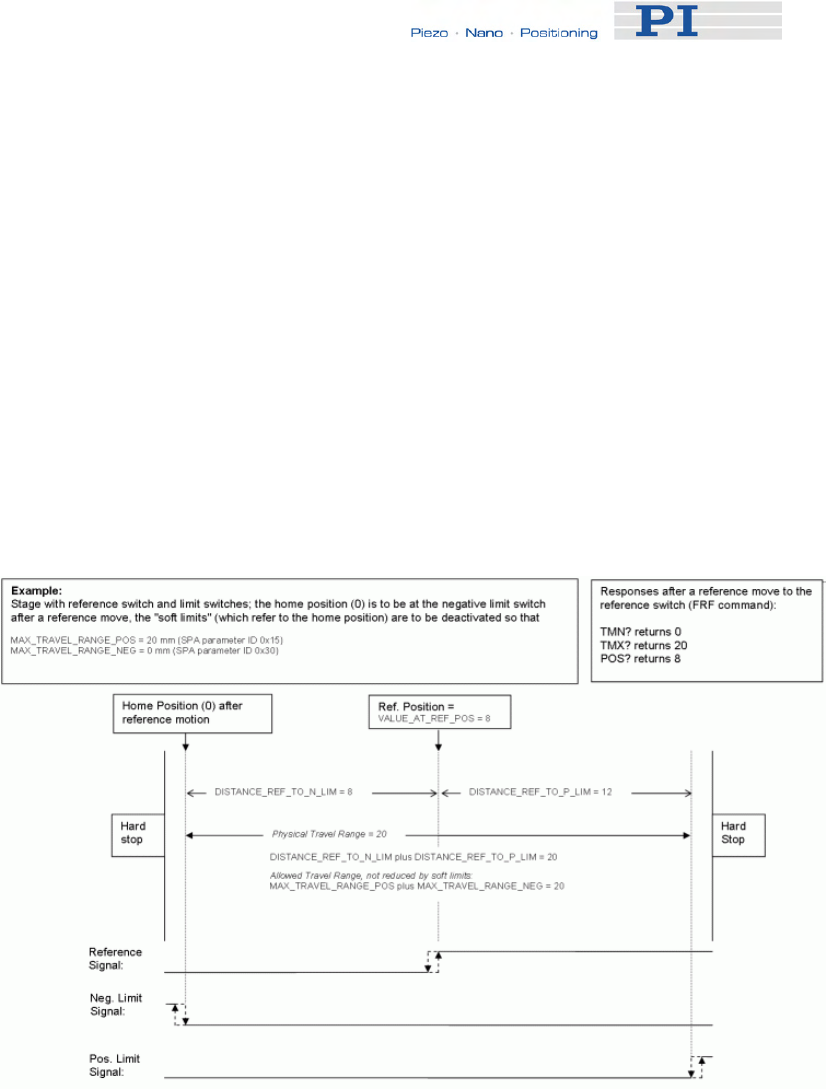
Customizing the System
■ Positive limit switch (FPL command (p. 131)): the stage is moved to
the positive limit switch and the sum of VALUE_AT_REF_POS and
DISTANCE_REF_TO_P_LIM is set as the current position.
It is furthermore possible to set "soft limits" which establish a "safety
distance" which the stage will not enter on both ends of the travel range. In
the E-861 firmware, those soft limits always refer to the current home
position (0; in the example located at the negative limit switch after a
reference move). The soft limits are to be deactivated in the example so
that the corresponding parameters must be as follows:
MAX_TRAVEL_RANGE_POS (parameter ID 0x15) = 20 mm
MAX_TRAVEL_RANGE_NEG (parameter ID 0x30) = 0 mm
(This means that the stage can move 20 mm in positive direction, starting
from the home position, and 0 mm in negative direction, starting from the
home position.)
Figure 18: Positioning stage and corresponding controller parameters
www.pi.ws E-861 PZ205E Release 1.2.1 Page 93
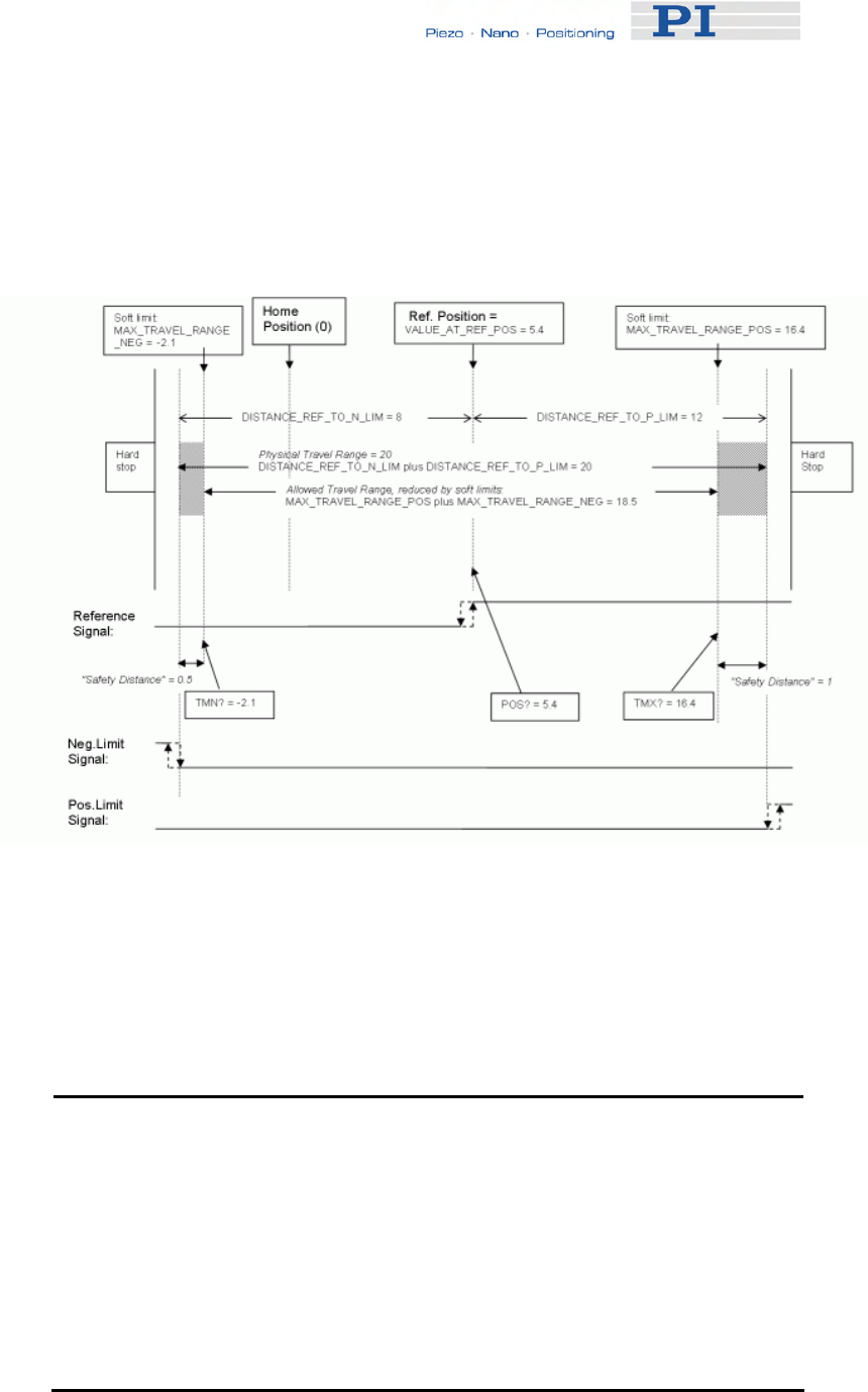
Customizing the System
www.pi.ws E-861 PZ205E Release 1.2.1 Page 94
Now in the same example, a "safety distance" is to be established on both
ends of the travel range by setting soft limits, and the home position is to be
located at about 1/3 of the distance between the new negative end of the
travel range and the reference switch. The limit switches cannot be used for
reference moves anymore.
Figure 19: Positioning stage, soft limits set in the controller to reduce the travel
range
After the stage was referenced again by moving it to the reference switch
(FRF command), the following responses will be given:
TMN? (p. 186) returns -2.1
TMX? (p. 187) returns 16.4
POS? (p. 167) returns 5.4
!
CAUTION
If the soft limits (MAX_TRAVEL_RANGE_POS and
MAX_TRAVEL_RANGE_NEG) are used to reduce the travel range,
the limit switches cannot be used for reference moves. The FNL and
FPL commands will provoke an error message, and only the reference
switch can be used for a reference move (FRF).
Be careful when setting the values for VALUE_AT_REF_POS,
MAX_TRAVEL_RANGE_POS and MAX_TRAVEL_RANGE_NEG
because there is no plausibility check.
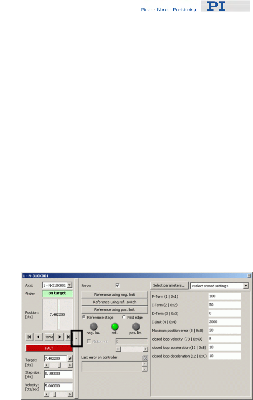
Customizing the System
The soft limits may not be outside of the physical travel range:
MAX_TRAVEL_RANGE_POS ≤ DISTANCE_REF_TO_P_LIM +
VALUE_AT_REF_POS
MAX_TRAVEL_RANGE_NEG ≥ VALUE_AT_REF_POS -
DISTANCE_REF_TO_N_LIM
Otherwise, reference moves to the limit switches would have incorrect
results because the values of the soft limits would be set at the end of
the referencing procedure.
Be careful when referencing the stage by setting an initial absolute
position with POS since the values for MAX_TRAVEL_RANGE_POS
and MAX_TRAVEL_RANGE_NEG are not adapted. In the worst case,
the soft limits will now be outside of the physical travel range, and the
stage will no longer be able to move since the closed-loop move
commands check the soft limit settings.
9.3 Tuning PID Control Parameters
If PID tuning is required it is recommended to use the controller's data
recorder and PIMikroMove.
PIMikroMove main window must be open.
To adjust PID control parameters proceed as follows:
1 Open the expanded single axis window by following the View →
Single Axis Window menu sequence for the connected stage.
2 Click on the + at the right side of the single axis window, see figure
below.
www.pi.ws E-861 PZ205E Release 1.2.1 Page 95
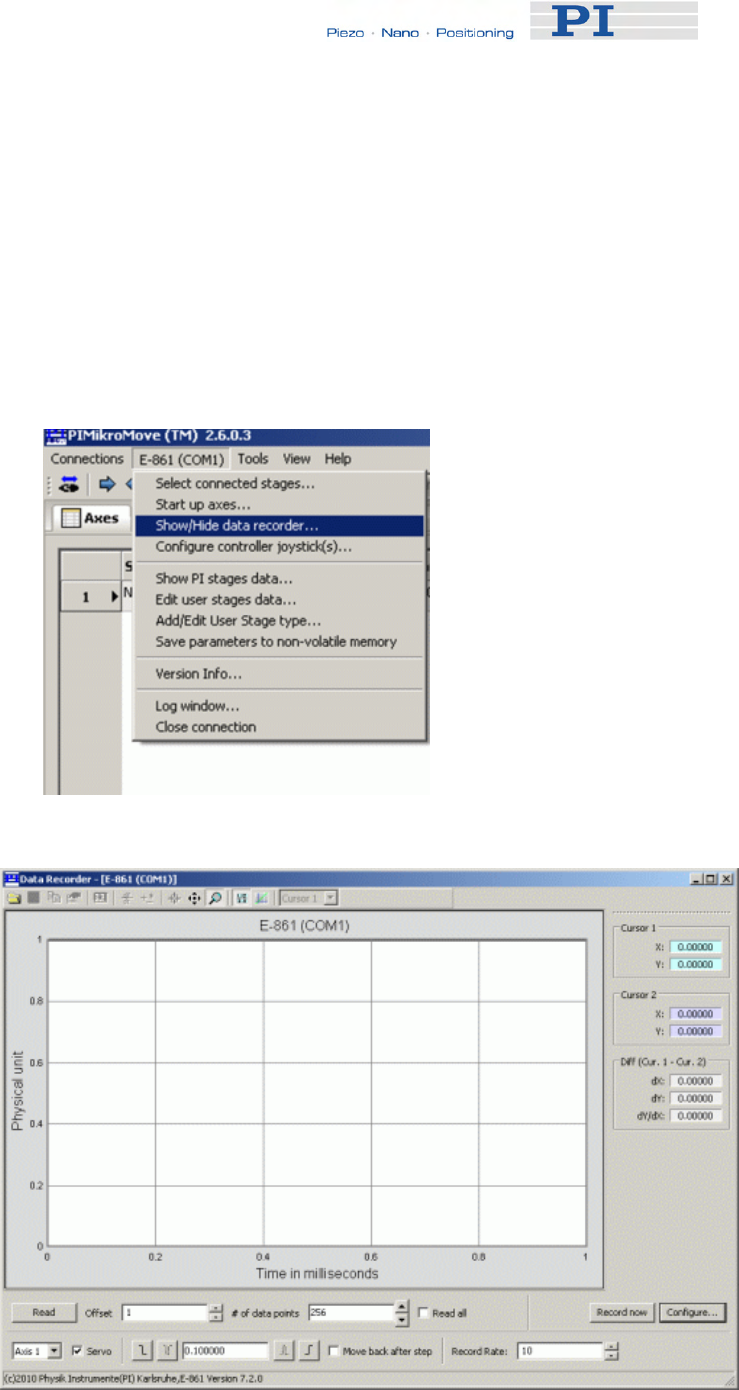
Customizing the System
3 In the list at the right side of the expanded single axis window you
can check the current settings and you may insert new settings.
If a parameter you wish to adjust does not occur in the list click on
Select parameters to display the parameter in the list.
Note that a new parameter setting is only sent to the controller
after <ENTER> is pressed while the cursor is in the text entry.
4 To display a step response open the controller's data recorder.
To do so follow the E-861 → Show/Hide data recorder menu
sequence, see figure below.
The Data Recorder window opens as shown in the next figure:
www.pi.ws E-861 PZ205E Release 1.2.1 Page 96
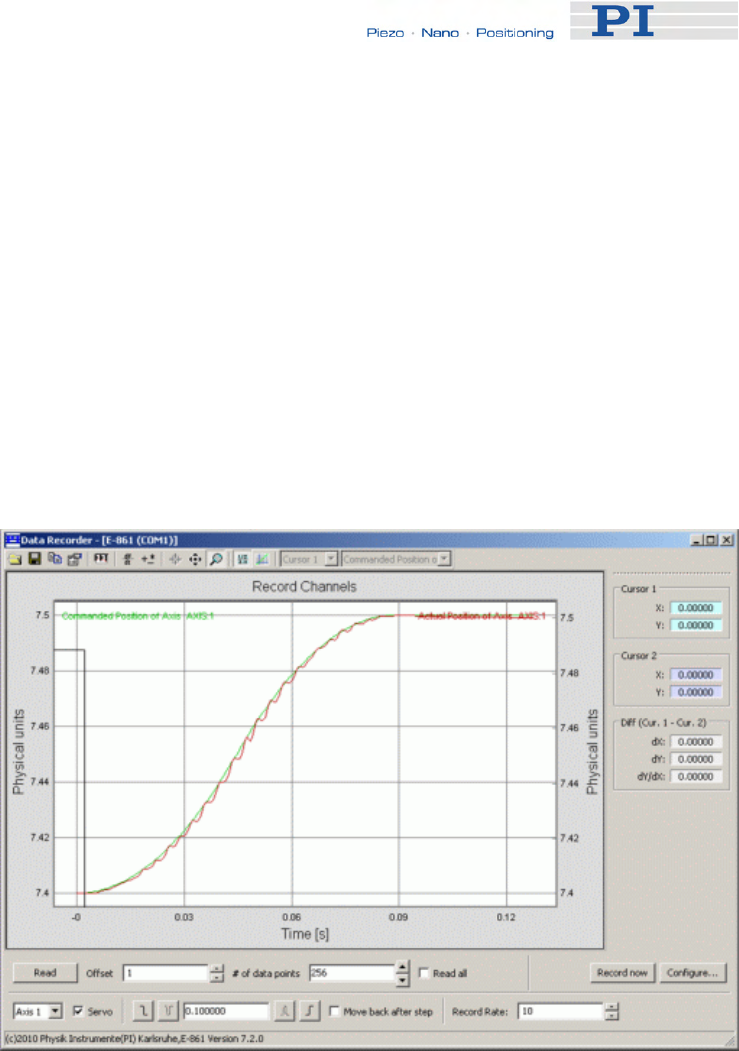
Customizing the System
www.pi.ws 97
5 Configure the data recorder.
For detailed information read the following sections in the SM148E
PIMikroMove Manual:
"Data Recorder"
"Configure Data Recorder"
"Perform Step or Impulse Measurements"
Make sure that data recorder settings are adjusted such as, for
example, step size to be recorded, record rate and number of data
points on the Data Recorder screen.
6 Press the step response button (positive slope) to start and record
a step response.
See figure below for an example:
7 If the step response does not prove satisfactory, adjust the PID
settings in the expanded Single axis window.
8 Press enter for each adjusted parameter setting in the expanded
Single axis window separately.
9 Start and record another step response on the Data Recorder
screen.
If the result is not satisfactory repeat steps 7 to 9 with different PID
settings.
E-861 PZ205E Release 1.2.1 Page
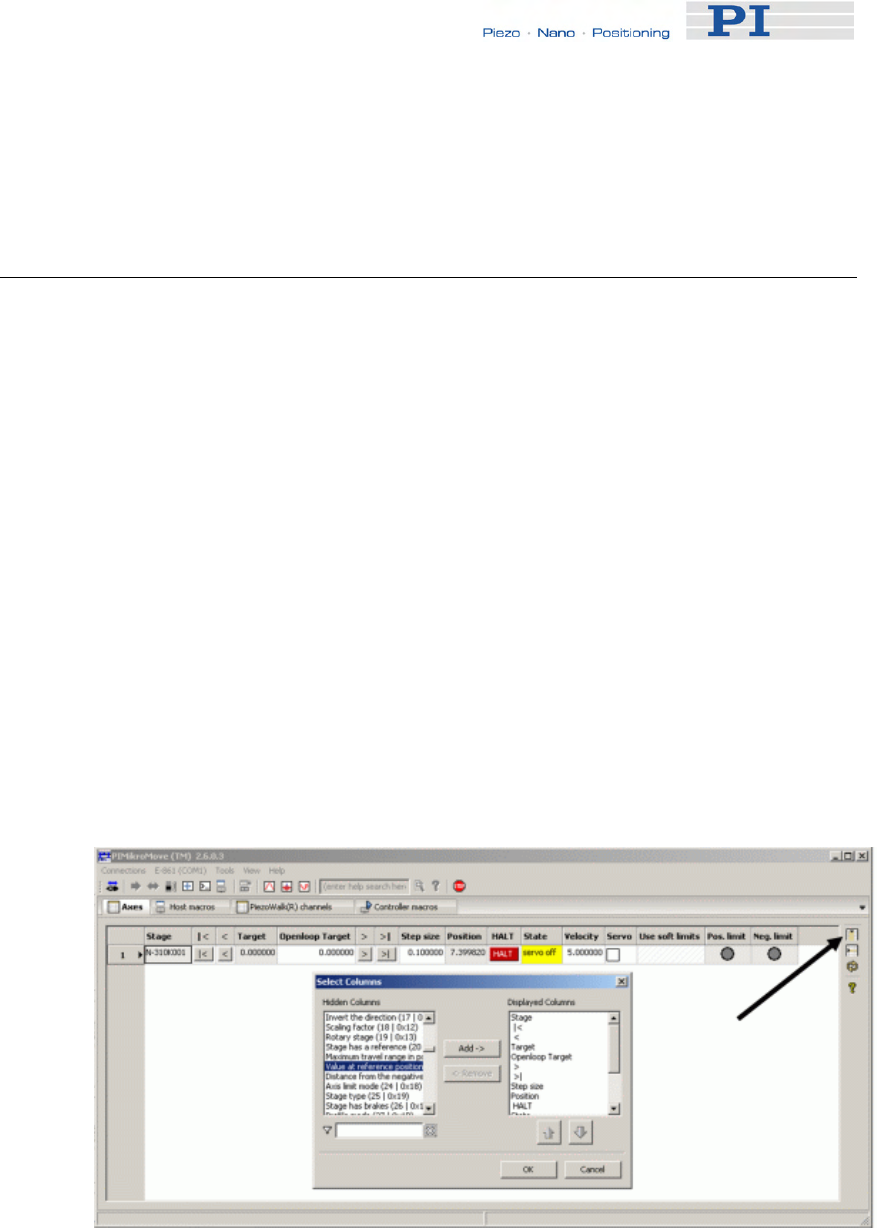
Customizing the System
10 If you wish to read the position data of a step response in
PIMikroMove’s Command entry window send a DRR? command to
read the data from the controller’s data recorder.
9.4 How to Create a New Stage Type in the PI
Stages Database
The easiest way to add a new stage type to the UserStages2 database is to
modify the parameters of an existing stage type and save them under a
new name. Thereafter you can select this newly defined stage in
PIMikroMove or in other PI software as well.
Proceed as follows:
1 Assign the stage type that comes closest to your stage to the
appropriate axis. See Select connected stages step, i.e. step 9, of
the "Getting Started" (p. 12) section for how to do this.
Afterwards the Start Up Axes dialog may open—you can close this
dialog because at this point it is not necessary to reference the
axis.
2 On the Axes tab card, display the columns for the parameters you
want to modify.
Press the Select columns to be displayed icon in the right top
corner of the PIMikroMove main window, see next figure.
3 Change the values of the parameters you want to modify by typing
them into the appropriate fields of the Axes tab card. Note that only
fields with white backgrounds can be edited.
www.pi.ws E-861 PZ205E Release 1.2.1 Page 98

Customizing the System
4 Save the modified settings as a new stage using the Add/Edit User
Stage type... item from the corresponding controller menu. You
simply have to define a new name for your stage and click OK.
5 The new stage is now displayed on the Axes tab card, and you can
work with it (e.g. reference the stage: right-click on the axis row
and select the Start up axes... item in the controller menu of the
corresponding controller.
If you want to further modify the stage parameters, use the
Add/Edit User Stage Type menu item again to save the changes.
9.5 Adjustment for Custom Sensor
E-861 controllers feature sensor boards with interpolation circuitry, that are
adjusted to encoders of PI’s NEXACT® drives.
If you use a custom stage with a custom sensor it is recommended to use
also custom interpolation hardware suitable for that sensor.
See “Adjustment for Custom Sensor Using Custom Interpolation Board”
(p. 100) for how to proceed for adjusting the controller hardware.
It is also possible to adjust the controller to a custom sensor using the
GEMAC interpolation board.
See “GEMAC Parameters” (p. 105) for details about the GEMAC
parameters.
See "Adjustment for Custom Sensor Using GEMAC Interpolation Board"
(p. 106) for what you need to provide and what requirements must be
fulfilled.
Details and instructions for the adjustment procedure are given in the
E861T0008 Technical Note. Call your PI representative or write to
info@pi.ws to ask for this Technical Note if required.
Irrespective of whether you use a sensor with its own interpolation circuitry
or a sensor using the GEMAC interpolation board you have to make sure
that the servo loop input factor matches the custom sensor’s resolution.
See “Servo Loop Input Factor” below to find out if you have to adjust the
corresponding parameters.
9.5.1 Servo Loop Input Factor
Parameters 0x5A and 0x5B represent numerator and denominator of the
servo loop input factor. This factor decouples servo loop parameters from
the encoder resolution.
This factor has to be adjusted only if a custom sensor with a resolution
other than 50000 counts per 1 mm is to be used.
www.pi.ws E-861 PZ205E Release 1.2.1 Page 99

Customizing the System
www.pi.ws E-861 PZ205E Release 1.2.1 Page 100
0x5A and 0x5B have to be set carefully to guarantee a stable control loop.
See “How to Store Parameter Settings” (p. 37) for further details.
Note that the servo loop input factor formed by 0x5A and 0x5B is
independent from 0xE and 0xF, i.e. the counts-per-physical-unit factor. The
counts-per-physical-unit factor has no influence on control loop stability, but
is used for input and output scaling of position values.
9.5.2 Adjustment for Custom Sensor Using Custom
Interpolation Board
If you wish to use a drive with a custom specific sensor that features its
own interpolation circuitry, you have to remove the GEMAC interpolation
board and adjust the controller to process digital sensor, i.e. encoder,
inputs.
To adjust the controller for a sensor with its own interpolation circuitry you
have to provide the following items:
■ A Phillips head screwdriver to remove/fix top plate from/to controller
■ Sensor with interpolation circuitry that provides a sensor reference
signal with TTL level and a minimum pulse length of more than 50 µs
■ Documentation of the sensor manufacturer for sensor calibration
In addition, you have to make sure that the servo loop input factor matches
the custom sensor’s resolution.
See “Servo Loop Input Factor” (p. 99) for details about this factor.
See “How to Store Parameter Settings” (p. 37) for details on how to store
parameter settings to volatile and non-volatile memory of the controller.
DANGER
Procedures which require opening the case should be carried out by
authorized, qualified personnel only.
Disconnect the controller from power when opening the case, and
when resetting internal switches or jumpers.
When the controller must be operated with the case open, voltages of
up to 48 VDC and currents of up to 2 A can be exposed. Do not touch
internal conductors.
!
CAUTION
The boards inside the E-861 are ESD-sensitive (electrostatic discharge
sensitive) devices. Observe all precautions against static charge
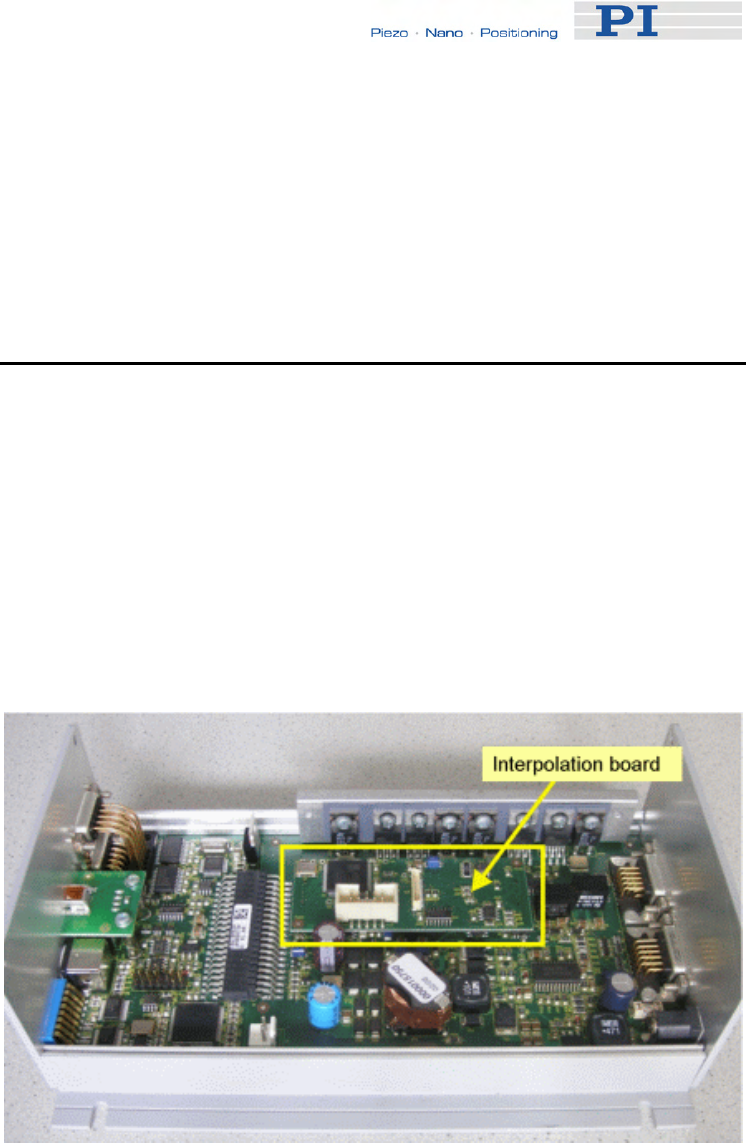
Customizing the System
buildup before handling these devices. Avoid touching circuit
components, pins and PCB traces. Discharge any static electricity you
may have on your body by briefly touching a conductive, grounded
object before you touch any electronic assembly.
Make sure that no conductive particles of any kind (metallic dust or
shavings, broken pencil leads, loose screws) contact the device
circuitry.
To adjust the E-861 controller for sensor signals from a custom sensor
which uses its own interpolation board proceed as follows:
1 Disconnect the E-861 from the power supply to power it down.
2 Unscrew the 2x2 cross-head screws at the front and the rear of the
controller.
3 Unscrew the 2 cross-head screws at the left side of the controller.
4 Remove top plate from the controller. Now you have access to the
GEMAC interpolation board, see next figure.
5 Remove interpolation board. Below the interpolation board a DIP
switch is located.
6 To use digital encoder input set all DIP switches to ON, see next
figure.
Now the pinout of column “Without interpolation board” in the
sensor pinout table below is valid.
www.pi.ws E-861 PZ205E Release 1.2.1 Page 101

Customizing the System
7 Attach top plate to controller by tightening the 2x2 cross-head
screws to controller rear and front plates.
8 Connect sensor to sub-D sensor connector at rear of controller.
9 Reconnect the power supply to the E-861 to power it on.
10 Give an appropriate sensor reference signal to pin 1 of the sensor
connector at the controller rear.
The reference signal is appropriate if it features:
TTL level
a minimum pulse length of more than 50 µs, since 50 µs is
the controller servo loop time
11 Perform a sensor calibration as described in the sensor
manufacturer’s documentation.
Note that the reference pulse of the ruler, i.e. input signals to pin 3
and pin 8, cannot be used.
12 Check for proper function of the servo loop with the new sensor. To
do so proceed as follows:
a) Open a connection using PIMikroMove, see steps 1 to 10 of
“Getting Started” (p. 12) for instructions.
b) To send the commands as given below follow the Tools →
Command entry menu sequence in the PIMikroMove main window,
see figure below. Now you can send commands via the Command
entry window.
www.pi.ws E-861 PZ205E Release 1.2.1 Page 102
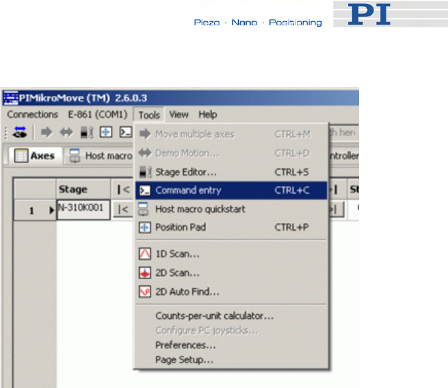
Customizing the System
c) Activate servo by sending SVO 1 1
d) Send MOV 1 10
e) Send POS?
f) Compare response with commanded target position. If both
values are consistent proceed with step 13. If they are not, repeat
step 11.
13 If you are sure that the motion system works properly, shut down
controller.
www.pi.ws E-861 PZ205E Release 1.2.1 Page 103

Customizing the System
Pinout of Sensor Connector (15-pin sub-D connector)
Pin With interpolation
board Without interpolation
board
1 REF REF
2 VDD (5 V output) VDD (5 V output)
3 REFP
(Positive reference trace
from ruler)
cannot be used
4 COSP B+
5 SINP A+
6 PLIMIT PLIMIT
7 NLIMIT NLIMIT
8 Ref
(negative reference
trace from ruler)
cannot be used
9 COSN B -
10 SINN A -
11 internal use internal use
12 VDD (5 V output) VDD (5 V output)
13 GND GND
14 GND GND
15 GND GND
www.pi.ws E-861 PZ205E Release 1.2.1 Page 104

Customizing the System
9.5.3 GEMAC Parameters
The E-861 is equipped with a GEMAC interpolation board for incremental
measuring systems.
The GEMAC parameters are set in the volatile or non-volatile memory of
the controller, see "How to Store Parameter Settings" (p. 37) for
instructions.Note that the parameters for the GEMAC board (IDs
0x7000010 to 0x700001) are not part of a parameter set, i.e. stage
database entry located on the host PC.
The parameters for the GEMAC board are preset for the following encoder
hardware properties:
■ Differential analog transmission of the sensor signals.
Note that the controller cannot process single-ended signals, even
though the GEMAC board would allow it
■ Sine and cosine signals have to be phase shifted by 90° relative to
one another (obligatory)
■ Sensor signal amplitude, i.e. of ± sin and ± cos: 1.0 Vpp (obligatory)
■ Offset for sensor signal, i.e. ± sin and ± cos: 2.5 V (obligatory)
It is strongly recommended to use these parameter values, i.e. your sensor
hardware properties must match the above-mentioned values, otherwise
the GEMAC interpolation board may not work properly.
See the manual for the GEMAC interpolation board (IP1000_B_EN.pdf;
provided on the E-861 CD) for information about interpolation details.
If you are sure that you wish to adjust GEMAC parameters proceed as
follows:
1 Set the GEMAC parameters in volatile memory using SPA.
See "Parameter List" (p. 41) for assignment of E-861 parameters
to the write registers of the GEMAC circuitry.
The following example shows how to configure the GEMAC CFGO
write register (e.g. interval time, interpolation rate) for axis 1:
Send SPA 1 0x7000010 252
See p. 16 of IP1000_EN.pdf for bit mapping of CFG0 write register.
The setting is made in volatile memory only.
2 Test the functioning of the system.
3 If everything is okay and you want to use this system configuration
after the next power-on, save the settings for the GEMAC
www.pi.ws E-861 PZ205E Release 1.2.1 Page 105
Customizing the System
parameters from volatile to non-volatile memory.
For example:
Send WPA 4711
The password "4711" affects only the GEMAC parameters (for all
other parameters, the passwort "100" is required). Since WPA is
used without specifying any parameters, all currently valid GEMAC
parameter values from volatile memory are saved, except for the
write-protected parameters (see Note below).
NOTE
The GEMAC parameters cannot be changed with SEP. Use SPA and
WPA to save their values to non-volatile memory.
The GEMAC parameters with the IDs 0x7000015, 0x7000016,
0x700001C, 0x700001D, 0x7000001E and 0x700001F are write-
protected and cannot be changed.
The E-861 will send no error message if you try to change those
parameters.
9.5.4 Custom Sensor Using GEMAC Interpolation Board
If a custom sensor is to use the GEMAC interpolation board you have to
provide the following items:
■ Sensor delivering signals that match the requirements of the GEMAC
interpolation board
See “GEMAC Parameters” (p. 105) for required sensor properties.
■ Documentation of the sensor manufacturer for sensor calibration
■ IP1000_B_EN.pdf, i.e. documentation of GEMAC interpolation board
In addition, the following condition has to be met:
■ The servo loop input factor matches the custom sensor’s resolution.
See “Servo Loop Input Factor” (p. 99) for details about this factor.
See “How to Store Parameter Settings” (p. 37) for instructions.
Details and preparation instructions for custom sensor calibration using the
controller's interpolation board are given in the E861T0008 Technical Note.
Call your PI representative or write to info@pi.ws to ask for this Technical
Note if required.
www.pi.ws E-861 PZ205E Release 1.2.1 Page 106

GCS Commands
www.pi.ws E-861 PZ205E Release 1.2.1 Page 107
10 GCS Commands
The PI General Command Set (GCS) is supported by a wide range of PI
systems. This command set is well-suited for positioning tasks with one or
more axes. The command set itself is independent of the specific hardware
(controller or attached stages).
Commands are used to set operating modes, initiate axis motion and to
query system and motion values. Because of the variety of functions and
parameters, a sequence of commands must often be transferred in order to
achieve a desired system action.
You can type commands, for example, in the Command Terminal or
Command Entry windows, respectively, of NanoCapture and PIMikroMove,
or in the PITerminal.
10.1 Format
10.1.1 Notation
The following notation is used to define the GCS syntax and to describe the
commands:
<...> Angle brackets indicate an argument of a command, can be
an item identifier (p. 53) or a command-specific parameter
[…] Square brackets indicate an optional entry
{…} Braces indicate a repetition of entries, i.e. that it is possible
to access more than one item (e.g. several axes) in one
command line.
LF LineFeed (ASCII char #10), is the default termination
character
SP Space (ASCII char #32)
10.1.2 GCS Syntax
Except as listed below, a GCS command consists of 3 characters, e.g.
CMD. The corresponding query command has a "?" appended, e.g. CMD?.
Command mnemonic:
CMD ::= character1 character2 character3 [?]

GCS Commands
Exceptions:
■ Special commands, e.g. fast polling commands, consist only of one
character. The 24th ASCII character e.g. is called #24. Note that
these commands are not followed by a termination character (but the
responses to them are).
■ *IDN? (for GPIB compatibility).
The command mnemonic is not case-sensitive.
General:
CMD[{{SP}<argument>}]LF
That means the command mnemonic and all arguments (e.g. axis IDs,
channel IDs, parameters, etc.) must be separated from each other by one
space.
Example:
Send: MOVSP1SP10.0LF
to move Axis 1 to position 10.0 (the unit depends on the controller, can be
µm or mm, for example)
More than one command mnemonic per line is not allowed. Several groups
of arguments following a command mnemonic are allowed, e.g.
MOVSP1SP17.3SP2SP2.05LF
if there were 2 axes. The command line ends with the termination
character (LF).
If part of a command line cannot be executed, the line is not executed at all.
When all arguments are optional and are omitted, the command is
executed for all possible argument values. For example,
RPALF
resets all parameters in volatile memory.
The <AxisID> argument is used for the logical axes of the controller.
Depending on the controller, an axis could be identified with up to 16
characters—all alphanumeric characters and the underscore are allowed.
See "Accessible Items and Their Identifiers" (p. 53) for the identifiers
supported by the E-861.
Definitions for query commands (report commands):
CMD?[{{SP}<argument>}]LF
When all arguments are optional and are omitted, all possible values are
reported. For example,
POS?
www.pi.ws E-861 PZ205E Release 1.2.1 Page 108

GCS Commands
queries the position of all axes.
Reply syntax:
[<argument>[{SP<argument>}]"="]<value>LF
Multi-line reply syntax:
{[<argument>[{SP<argument>}]"="]<value>SP LF}
[<argument>[{SP<argument>}]"="]<value>LF for the last line!
The command
CMD?SP<arg3>SP <arg1>SP <arg2>LF
replies in the same order:
<arg3>"="<value3>SP LF
<arg1>"="<value1>SP LF
<arg2>"="<value2> LF
Example:
Send: TSP?SP2SP1
Report: 2=-1158.4405SP LF
1=+0000.0000LF
NOTE
With the E-861, you can address only one single item (e.g. axis or
channel) per command line, or, if the command supports this, address
all items by omitting the item identifier.
Example:
You can send
SEP 100 1 0x32 0
to save a new value of parameter 0x32 for axis 1 to non-volatile
memory
but it is not possible to send
SEP 100 1 0x32 0 1 0x14 1
www.pi.ws E-861 PZ205E Release 1.2.1 Page 109

GCS Commands
www.pi.ws E-861 PZ205E Release 1.2.1 Page 110
10.1.3 Target and Sender Address
In principle, the addresses of the target controller and the sender are
required in every command line, even with single-character commands like
#4 or when recording a macro. But because only the host PC may send
command lines to the E-861s, its address (0) can be omitted. Both target
and sender address, however, are part of any controller response.
Example:
In a terminal, e.g. PITerminal, you can ask with the *IDN? command for the
identification string of the E-861 with address 2 either by sending
2 0 *idn?
or by sending
2 *idn?
The response in either case is
0 2 (c)2010 Physik Instrumente(PI) Karlsruhe,E-861 Version 7.2.0
Exception:
The target address can be omitted if the target E-861 has the address 1,
even if this E-861 is part of a daisy chain. If the target address is omitted,
the target and sender addresses will also be omitted in any response of the
controller.
Example:
If you send
*idn?
the controller with the address 1 will respond with
(c)2010 Physik Instrumente(PI) Karlsruhe,E-861 Version 7.2.0
If you send
1 *idn?
it will respond with
0 1 (c)2010 Physik Instrumente(PI) Karlsruhe,E-861 Version 7.2.0
See "DIP Switch Settings" for how to set the controller address. Possible
controller addresses are in the range of 1 to 16, address 1 is default. The
host PC always has the address 0. With the broadcast address 255, all
controllers in a daisy chain can be addressed at the same time, but no
reports are displayed on the host PC.
NOTES
In a daisy-chain, connected via USB or via RS-232, there must be one
controller with address 1. It is not required that this controller is directly
connected to the host PC, i.e. this controller does not have to be the
first controller of the daisy-chain.
If there is no controller in a daisy-chain with address 1 an error
message occurs when you try to setup a connection.

GCS Commands
10.2 Command Survey
#4 (p. 114) Request Status Register
#5 (p. 115) Request Motion Status
#7 (p. 116) Request Controller Ready Status
#8 (p. 116) Query If Macro Is Running
#24 (p. 117) Stop All Motion
*IDN? (p. 117) Get Device Identification
ACC (p. 118) Set Acceleration
ACC? (p. 118) Get Acceleration
CST? (p. 119) Get Stage Type Of Selected Axis
CSV? (p. 119) Get Current Syntax Version
DEC (p. 119) Set Deceleration
DEC? (p. 120) Get Deceleration
DEL (p. 120) Delay The Command Interpreter
DIO (p. 121) Set Digital Output Lines
DIO? (p. 121) Get Digital Input Lines
DRC (p. 122) Set Data Recorder Configuration
DRC? (p. 123) Get Data Recorder Configuration
DRR? (p. 124) Get Recorded Data Values
DRT (p. 126) Set Data Recorder Trigger Source
DRT? (p. 127) Get Data Recorder Trigger Source
ERR? (p. 127) Get Error Number
FED (p. 128) Find Edge
FNL (p. 129) Fast Move To Negative Limit
www.pi.ws E-861 PZ205E Release 1.2.1 Page 111

GCS Commands
www.pi.ws E-861 PZ205E Release 1.2.1 Page 112
FPL (p. 131) Fast Move To Positive Limit
FRF (p. 133) Fast Move To Reference Switch
FRF? (p. 134) Get Referencing Result
GOH (p. 135) Go To Home Position
HDR? (p. 135) Get All Data Recorder Options
HLP? (p. 136) Get List of Available Commands
HLT (p. 137) Halt Motion Smoothly
HPA? (p. 138) Get List of Available Parameters
JAS? (p. 138) Query Joystick Axis Status
JAX (p. 139) Set Axis Controlled By Joystick
JAX? (p. 140) Get Axis Controlled By Joystick
JBS? (p. 140) Query Joystick Button Status
JDT (p. 141) Set Joystick Default Lookup Table
JLT (p. 142) Fill Joystick Lookup Table
JLT? (p. 143) Get Joystick Lookup Table Values
JON (p. 145) Set Joystick Activation Status
JON? (p. 145) Get Joystick Activation Status
LIM? (p. 146) Indicate Limit Switches
MAC (p. 146) Call Macro Function
MAC? (p. 149) List Macros
MEX (p. 149) Stop Macro Execution Due To Condition
MOV (p. 151) Set Target Position
MOV? (p. 152) Get Target Position
MVR (p. 153) Set Target Relative To Current Position
OAC (p. 154) Set Open-Loop Acceleration

GCS Commands
OAC? (p. 155) Get Open-Loop Acceleration
OAD (p. 155) Open-Loop Analog Driving
OAD? (p. 157) Get Voltage For Open-Loop Analog Motion
ODC (p. 157) Set Open-Loop Deceleration
ODC? (p. 158) Get Open-Loop Deceleration
OMA (p. 158) Absolute Open-Loop Motion
OMA? (p. 160) Get Open-Loop Target Position
OMR (p. 161) Relative Open-Loop Motion
ONT? (p. 163) Get On Target State
OSM (p. 163) Open-Loop Step Moving
OVL (p. 165) Set Open-Loop Velocity
OVL? (p. 166) Get Open-Loop Velocity
POS (p. 166) Set Real Position
POS? (p. 167) Get Real Position
RBT (p. 167) Reboot System
RMC? (p. 168) List Running Macros
RNP (p. 168) Relax PiezoWalk Piezos
RON (p. 170) Set Reference Mode
RON? (p. 170) Get Reference Mode
RPA (p. 171) Reset Volatile Memory Parameters
RTR (p. 171) Set Record Table Rate
RTR? (p. 172) Get Record Table Rate
SAI? (p. 172) Get List Of Current Axis Identifiers
SEP (p. 173) Set Nonvolatile Memory Parameters
SEP? (p. 174) Get Nonvolatile Memory Parameters
www.pi.ws E-861 PZ205E Release 1.2.1 Page 113

GCS Commands
SPA (p. 175) Set Volatile Memory Parameters
SPA? (p. 178) Get Volatile Memory Parameters
SRG? (p. 178) Query Status Register Value
SSA (p. 180) Set Step Amplitude
SSA? (p. 180) Get Step Amplitude
STE (p. 181) Start Step And Response - Measurement
STP (p. 182) Stop All Motion
SVO (p. 183) Set Servo State (Open-Loop / Closed-Loop
Operation)
SVO? (p. 185) Get Servo State (Open-Loop / Closed-Loop Operation)
TAC? (p. 185) Tell Analog Channels
TAV? (p. 185) Get Analog Input Voltage
TIO? (p. 186) Tell Digital I/O Lines
TMN? (p. 186) Get Minimum Commandable Position
TMX? (p. 187) Get Maximum Commandable Position
TNR? (p. 187) Get Number Of Record Tables
TRS? (p. 188) Indicate Reference Switch
VEL (p. 188) Set Closed-Loop Velocity
VEL? (p. 189) Get Closed-Loop Velocity
WAC (p. 189) Wait For Condition For Macro Execution
WPA (p. 190) Save Parameters To Nonvolatile Memory
10.3 Command Reference (alphabetical)
#4 (Request Status Register)
Description: Requests system status information.
Format: #4 (single ASCII character number 4)
Arguments: none
www.pi.ws E-861 PZ205E Release 1.2.1 Page 114

GCS Commands
Response: The answer is bit-mapped. See below for the individual
codes.
Notes: This command is identical in function to SRG? (p. 178), but only
one character must be send via the interface. Therefore #4 can
also be used while the controller is performing time-consuming
tasks.
Note that this command might deliver no response as long as the
controller performs a motion with the PiezoWalk Driving mode
parameter 0x7001A00 set to 1, i.e. if automatic alternating of
motion modes is activated and being performed.
For the E-861, the response is the sum of the following codes, in
hexadecimal format:
Bit 15 14 13 12 11 10 9 8
Descrip-
tion On
Target Is
referen-
cing
Is
moving Servo
On Transitions between motion and
servo modes:
Analog = 0
Relaxing = 1
Go to analog = 2
Relaxed = 3
In motion = 4
Go to motion = 5
See "Modes of Operation"
(p. 54) for details.
Bit 7 6 5 4 3 2 1 0
Descrip-
tion Digital
Input 4 Digital
Input 3 Digital
Input 2 Digital
Input 1 - Positive
Limit Refe-
rence Negative
Limit
Example: Send: #4
Receive: 0x9405
Note: The response is given in hexadecimal format. It
means that the axis is on target, the servo is on, the axis is ready
for closed-loop motion (In motion state), the states of the digital
input lines 1 to 4 are low, and the stage is on the positive side of
the reference switch (limits are not active, note that the logic of the
signals is inverted in this example)
#5 (Request Motion Status)
Description: Requests motion status of the axes.
Format: #5 (single ASCII character number 5)
Arguments: none
www.pi.ws E-861 PZ205E Release 1.2.1 Page 115

GCS Commands
Response: The answer <uint> is bit-mapped and returned as the
hexadecimal sum of the following codes:
1=first axis is moving
2=second axis is moving
4=third axis is moving
...
Examples: 0 indicates motion of all axes complete
3 indicates that the first and the second axis are
moving
#7 (Request Controller Ready Status)
Description: Asks controller for ready status (tests if controller is
ready to perform a new command).
Note: Use #5 (p. 115) instead of #7 to verify if motion
has finished.
Format: #7 (single ASCII character number 7)
Arguments: none
Response: B1h (ASCII character 177 = "±" in Windows) if
controller is ready
B0h (ASCII character 176 = "°" in Windows) if
controller is not ready
(e.g. performing a referencing command)
Troubleshooting: The response characters may appear differently in
non-Western character sets or other operating
systems. They may be indistinguishable on the
controller screen.
#8 (Query If Macro Is Running)
Description: Tests if a macro is running on the controller.
Format: #8 (single ASCII character number 8)
Arguments: none
Response: <uint>=0 no macro is running
<uint>=1 a macro is currently running
www.pi.ws E-861 PZ205E Release 1.2.1 Page 116

GCS Commands
#24 (Stop All Axes)
Description: Stops all axes abruptly. For details see the notes
below.
Sets error code to 10.
This command is identical in function to STP (p. 182),
but only one character must be send via the interface.
Therefore #24 can also be used while the controller is
performing time-consuming tasks.
Format: #24 (ASCII character 24)
Arguments: none
Response: none
Notes: #24 stops all motion caused by move commands
(MOV (p. 151), MVR (p. 153), OAD (p. 155), OSM
(p. 163), OMA (p. 158), OMR (p. 161), STE (p. 181)),
referencing commands (FNL (p. 129), FPL (p. 131),
FRF (p. 133)) and macros (MAC (p. 146)).
After the axes are stopped, if servo is on, their target
positions are set to their current positions.
HLT (p. 137) in contrast to STP stops motion with
given system deceleration with regard to system
inertia.
*IDN? (Get Device Identification)
Description: Reports the device identity number.
Format: *IDN?
Arguments: none
Response: One-line string terminated by line feed with controller
name, serial number and firmware version
Notes: For E-861, *IDN? replies something like:
(c)2010 Physik Instrumente(PI) Karlsruhe,E-861
Version 7.2.0
www.pi.ws E-861 PZ205E Release 1.2.1 Page 117

GCS Commands
www.pi.ws E-861 PZ205E Release 1.2.1 Page 118
ACC (Set Closed-Loop Acceleration)
Description: Set acceleration of given axes.
The ACC setting only takes effect when the given axis
is in closed-loop operation (servo on).
ACC can be changed while the axis is moving.
Format: ACC {<AxisID> <Acceleration>}
Arguments: <AxisID> is one axis of the controller
<Acceleration> is the acceleration value in physical
units/s2.
Response: none
Troubleshooting: Illegal axis identifiers
Notes: The lowest possible value for <Acceleration> is 0.
ACC changes the value of the Current closed-loop
acceleration parameter (ID 0xB) in volatile memory
(can be saved as power-on default with WPA (p. 190),
can also be changed with SPA (p. 175) and SEP
(p. 173)).
The maximum value which can be set with the ACC
command is given by the Maximum closed-loop
acceleration parameter, ID 0x4A (can be changed
with SPA (p. 175) and SEP (p. 173)).
ACC? (Get Closed-Loop Acceleration)
Description: Get the current value of the closed-loop acceleration.
If all arguments are omitted, gets current value of all
axes.
Format: ACC? [{<AxisID>}]
Arguments: <AxisID> is one axis of the controller
Response: {<AxisID>"="<float> LF}
where
<float> is the current active closed-loop acceleration
value in physical units / s2.

GCS Commands
CST? (Get Assignment of Stages to Axes)
Description: Returns the name of the connected stage for the
queried axis.
Format: CST? [{<AxisID>}]
Arguments: <AxisID> is one axis of the controller
Response: {<AxisID>"="<string> LF}
where
<string> is the name of the stage assigned to the axis.
Notes: The stage name is read from the Stage Name
parameter (ID 0x3C) whose factory default value is
"DEFAULT_STAGE-N". You can set the parameter
value to the name of your stage using SPA (p. 175) or
SEP (p. 173). See also "Controller Parameters"
(p. 35).
CSV? (Get Current Syntax Version)
Description: Get current GCS syntax version used in the firmware.
Format: CSV?
Arguments: none
Response: The current GCS syntax version, can be 1.0 (for GCS
1.0) or 2.0 (for GCS 2.0)
DEC (Set Closed-Loop Deceleration)
Description: Set deceleration of given axes.
The DEC setting only takes effect when the given
axis is in closed-loop operation (servo on).
DEC can be changed while the axis is moving.
Format: DEC {<AxisID> <Deceleration>}
Arguments: <AxisID> is one axis of the controller
<Deceleration> is the deceleration value in physical
units/s2.
Response: none
Troubleshooting: Illegal axis identifiers
www.pi.ws E-861 PZ205E Release 1.2.1 Page 119

GCS Commands
Notes: The lowest possible value for <Deceleration> is 0.
DEC changes the value of the Current closed-loop
deceleration parameter (ID 0xC) in volatile memory
(can be saved as power-on default with WPA
(p. 190), can also be changed with SPA (p. 175) and
SEP
(p. 173)).
The maximum value which can be set with the DEC
command is given by the Maximum closed-loop
deceleration parameter, ID 0x4B (can be changed
with SPA (p. 175) and SEP (p. 173)).
DEC? (Get Closed-Loop Deceleration)
Description: Get the current value of the closed-loop deceleration.
If all arguments are omitted, gets current value of all
axes.
Format: DEC? [{<AxisID>}]
Arguments: <AxisID> is one axis of the controller
Response: {<AxisID>"="<float> LF}
where
<float> is the current active closed-loop deceleration
value in physical units / s2.
DEL (Delay The Command Interpreter)
Description: Delays <uint> milliseconds.
Format: DEL <uint>
Arguments: <uint> is the delay value in milliseconds.
Response: none
Notes: See the MAC command (p. 146) and "Working with
Controller Macros" (p. 82) for more information.
www.pi.ws E-861 PZ205E Release 1.2.1 Page 120

GCS Commands
DIO (Set Digital Output Line)
Description: Switches the specified digital output line(s) to
specified state(s).
Use TIO? (p. 186) to get the number of installed digital
I/O lines.
Format: DIO {<DIOID> <OutputOn>}
Arguments: <DIOID> is one digital output line of the controller, see
below for details
<OutputOn> is the state of the digital output line, see
below for details
Response: none
Notes: Using the DIO command, you can activate/deactivate
the Output 1 to Output 4 lines which are located on
the "I/O" socket (p. 218). With the E-861, you can
either set a single line per DIO command, or all lines
at once.
The <DIOID> identifiers to use for the lines are 1 to 4.
With the identifier 0, all lines are set according to a bit
pattern given by <OutputOn>.
If <OutputOn>=1 the line is set to HIGH/ON, if
<OutputOn>=0 it is set to LOW/OFF. If <DIOID> = 0, a
bit pattern can be set in decimal or hexadecimal
format which gives the states for all lines.
Do not use DIO on output lines for which the trigger
output is activated with TRO.
DIO? (Get Digital Input Lines)
Description: Lists the states of the specified digital input lines. Can
be used to query externally generated signals.
Use TIO? (p. 186) to get the number of installed digital
I/O lines.
Format: DIO? [{<DIOID>}]
Arguments: <DIOID> is the identifier of the digital input line, see
below for details
www.pi.ws E-861 PZ205E Release 1.2.1 Page 121

GCS Commands
Response: {<DIOID>"="<InputOn> LF}
where
<InputOn> gives the state of the digital input line, see
below for details
Notes: Using the DIO? command, you can directly read the
Input 1 to Input 4 lines which are located on the "I/O"
socket (p. 218). With the E-861, you can either read a
single line per DIO? command, or all lines at once.
The <DIOID> identifiers to use for the lines are 1 to 4.
If the identifier is omitted or 0, all lines are queried.
If <InputOn>=0, the digital input is LOW/OFF, if
<InputOn>=1, the digital input is HIGH/ON. If
<DIOID> is 0, <InputOn> is a bit pattern which gives
the states of all lines in hexadecimal format.
DRC (Set Data Recorder Configuration)
Description: Set data recorder configuration: determines the data
source and the kind of data (RecordOption) used for
the given data recorder table.
Format: DRC <RecTableID> <Source> <RecOption>
Arguments: <RecTableID>: is one data recorder table of the
controller, see below
<Source>: is the data source, for example an axis,
output signal channel or input signal channel of the
controller. The required source depends on the
selected record option.
<RecOption>: is the kind of data to be recorded
(record option).
See below for a list of the available record options and
the corresponding data sources.
Response: none
www.pi.ws E-861 PZ205E Release 1.2.1 Page 122

GCS Commands
Notes: The E-861 has two data recorder tables with 1024
points per table.
With HDR? (p. 135) you will obtain a list of available
record and trigger options and additional information
about data recording. The number of available data
recorder tables can be read with TNR? (p. 187).
For detailed information see "Data Recording" (p. 88).
Available record
options with the
appropriate data
sources:
0=Nothing is recorded
1=Target Position of axis (i.e. target position in
closed-loop operation)
2=Current Position of axis
3=Position Error of axis
70=Commanded Velocity of axis (open-loop or
closed-loop velocity, depending on the current servo
state)
71=Commanded Acceleration of axis (open-loop or
closed-loop acceleration, depending on the current
servo state)
73=Motor Output of axis
80=Signal Status Register of axis
81=Analog Input of input channel
Note: The input channels can be the Input 1 to 4 lines
of the I/O socket (p. 218) (use source ID 1 to 4) and
the joystick axis (source ID 5) and joystick button
inputs (source ID 6) on the Joystick socket (p. 220).
The source ID 7 is reserved for an additional analog
input channel.
DRC? (get Data Recorder Configuration)
Description: Returns settings made with DRC (p. 122).
Format: DRC? [{<RecTableID>}]
Arguments: <RecTableID>: is one data recorder table of the
controller; if omitted settings for all tables are given.
www.pi.ws E-861 PZ205E Release 1.2.1 Page 123

GCS Commands
Response: The current DRC settings:
{<RecTableID>"="<Source> <RecOption> LF}
where
<Source>: is the data source, for example an axis or
an output signal channel of the controller. The source
type depends on the record option.
<RecOption>: is the kind of data to be recorded
See DRC for a list of the available record options and
the corresponding data sources.
DRR? (Get Recorded Data Values)
Description: Reading of the last recorded Data Set.
Reading can take some time depending on the
number of points to be read!
It is possible to read the data while recording is still in
progress.
Format: DRR? [<StartPoint> <NumberOfPoints>
[{<RecTableID>}]]
Arguments: <StartPoint>: is the first point to be read from the data
recorder table, starts with index 1
<NumberOfPoints>: is the number of points to be read
per table
<RecTableID>: is one data recorder table of the
controller
Response: The recorded data in GCS array format, see the
separate manual for GCS array, SM 146E, and the
example below
Notes: If <DataRecorderTable> is omitted, the data from all
tables with non-zero record option (see DRC (p. 122))
is read.
With HDR? (p. 135) you will obtain a list of available
record options and trigger options and additional
information about data recording.
For detailed information see "Data Recording" (p. 88).
www.pi.ws E-861 PZ205E Release 1.2.1 Page 124

GCS Commands
Example: drr? 1 20
# REM E-861
#
# VERSION = 1
# TYPE = 1
# SEPARATOR = 32
# DIM = 2
# SAMPLE_TIME = 0.000020
# NDATA = 20
#
# NAME0 = Actual Position of Axis AXIS:1
# NAME1 = Position Error of Axis AXIS:1
#
# END_HEADER
5.00000 0.00000
4.99998 0.00002
5.00000 0.00000
5.00000 0.00000
5.00000 0.00000
5.00000 0.00000
5.00000 0.00000
4.99998 0.00002
5.00000 0.00000
4.99998 0.00002
5.00000 0.00000
5.00000 0.00000
5.00000 0.00000
5.00000 0.00000
4.99998 0.00002
5.00000 0.00000
4.99998 0.00002
4.99998 0.00002
5.00000 0.00002
4.99998 0.00004
www.pi.ws E-861 PZ205E Release 1.2.1 Page 125

GCS Commands
DRT (Set Data Recorder Trigger Source)
Description: Defines a trigger source for the given data recorder
table.
Format: DRT <RecTableID> <TriggerSource> <Value>
Arguments: <RecTableID> is one data recorder table of the
controller. See below for details.
<TriggerSource> ID of the trigger source, see below
for a list of available options
<Value> depends on the trigger source, can be a
dummy, see below
Response: none
Notes: By default data recording is triggered when a step
response measurement is made with STE (p. 181).
A trigger option set with DRT will become valid for all
data recorder tables with non-zero record option (see
DRC (p. 122)).
With HDR? (p. 135) you will obtain a list of available
record options and trigger options and additional
information about data recording.
For detailed information see "Data Recording" (p. 88).
Available trigger
options: 0 = default setting; data recording is triggered with
STE; <Value> must be a dummy
1 = any command changing position (e.g. MVR
(p. 153), MOV (p. 151), OAD (p. 155), OSM (p. 163));
<Value> must be a dummy
2 = next command, resets trigger after execution;
<Value> must be a dummy
3 = reserved
4 = reserved
5 = reserved
6 = any command changing position (e.g. MVR, MOV,
OAD, OSM), resets trigger after execution; <Value>
must be a dummy
www.pi.ws E-861 PZ205E Release 1.2.1 Page 126

GCS Commands
DRT? (Get Data Recorder Trigger Source)
Description: Returns the trigger source for the data recorder tables.
Format: DRT? [{<RecTableID>}]
Arguments: <RecTableID> is one data recorder table of the
controller
Response: {<RecTableID>"="<TriggerSource> <Value> LF}
where
<TriggerSource> is the ID of the trigger source, see
DRT (p. 126) for details
<Value> depends on the trigger source, if 0 it is a
dummy, see DRT for details
Notes: Since all data recorder tables of the E-861 have the
same trigger source, the DRT? response is given as a
single line of the form
0=<TriggerSource> <Value>
ERR? (Get Error Number)
Description: Get error code <int> of the last occurred error and
reset the error to 0.
Only the last error is buffered. Therefore you should
call ERR? after each command.
The error codes and their descriptions are fully listed
in "Error Codes" (p. 192).
Format: ERR?
Arguments: none
Response: The error code of the last occurred error (int).
Troubleshooting: Communication breakdown
www.pi.ws E-861 PZ205E Release 1.2.1 Page 127

GCS Commands
FED (Find Edge)
Description: Moves given axis to a given signal edge.
In contrast to the referencing commands (FNL
(p. 129), FPL (p. 131) and FRF (p. 133)), this
command does not change the reference state of
the axis and does not set a certain position value at
the selected edge. It does move out of the limit
condition, therefore the axis motion finishes at the
same position as with the corresponding referencing
commands.
If multiple axes are given in the command, they are
moved synchronously.
Caution: Do not use this command if no
sensor is present in your system.
Otherwise the connected mechanics can
run into the hardstop at full speed which
may cause damage to your hardware
setup.
Format: FED {<AxisID> <EdgeID> <Param>}
Arguments: <AxisID> is one axis of the controller.
<EdgeID> is the type of edge the axis has to move
to. See below for available edge types.
<Param> depends on the selected edge and
qualifies it. See below for details.
Response: none
Troubleshooting: Illegal axis identifier; limit switches and/or reference
switch are disabled (see below); servo is off
Notes: This command can be used both with servo enabled
or disabled (open-loop and closed-loop operation)
for the commanded axis, see SVO (p. 183)
command description .
The E-861 firmware detects the presence or
absence of reference switch and limit switches using
controller parameters (ID 0x14 for reference switch;
ID 0x32 for limit switches).
According to the values of those parameters, the
E-861 enables or disables FED motions to the
appropriate signal edges.
Adapt the parameter values to your hardware using
www.pi.ws E-861 PZ205E Release 1.2.1 Page 128

GCS Commands
www.pi.ws E-861 PZ205E Release 1.2.1 Page 129
SPA (p. 175) or SEP (p. 173). See "Controller
Parameters" (p. 35) for more information.
FED can be used to measure the physical travel
range of a new mechanics and thus to identify the
values for the corresponding controller parameters:
the distance from negative to positive limit switch,
the distance between the negative limit switch and
the reference switch (DISTANCE_REF_TO_N_LIM,
parameter ID 0x17), and the distance between
reference switch and positive limit switch
(DISTANCE_REF_TO_P_LIM, parameter ID 0x2F).
See "Travel Range Adjustment" (p. 92) for more
information.
The motion can be interrupted by #24 (p. 117), STP
(p. 182) and HLT (p. 137).
Motion commands like FED are not allowed when
the joystick is active for the axis. See "Joystick
Control" (p. 79) for details.
Available edge
types and
parameters:
The following edge types with their parameter
settings are available:
1 = negative limit switch, <Param> must be 0
2 = positive limit switch, <Param> must be 0
3 = reference switch, <Param> must be 0
FNL (Fast Reference Move To Negative Limit)
Description: Performs a reference move.
Moves the given axis to the negative physical limit of
its travel range and sets the current position to a
defined value. See below for details.
If multiple axes are given in the command, they are
moved synchronously.
Caution: Do not use this command if no
sensor is present in your system.
Otherwise the connected mechanics can
run into the hardstop at full speed which
may cause damage to your hardware
setup.

GCS Commands
Format: FNL [{<AxisID>}]
Arguments: <AxisID> is one axis of the controller, if omitted, all
axes are affected.
Response: none
Troubleshooting: Illegal axis identifier
Notes: This command can be used both with servo enabled
or disabled for the commanded axis, see SVO
(p. 183) command description.
If reference move was successful, absolute motion
will afterwards be possible in open-loop and in closed-
loop operation.
The reference mode must be set to "1" (factory
default) with the RON command (p. 170) if
referencing is to be done by performing a reference
move. See "Referencing" (p. 51) for further details.
With the E-861, the negative limit switch of the
mechanics is used to determine the negative physical
limit of the travel range. The difference of
VALUE_AT_REF_POS (parameter ID 0x16) and
DISTANCE_REF_TO_N_LIM (parameter ID 0x17) is
set as the current position when the axis is at the
negative limit switch (value can be negative).
This command can be interrupted by #24 (p. 117),
STP (p. 182) and HLT (p. 137).
Use FRF? (p. 134) to check whether the reference
move was successful.
Use FRF (p. 133) instead of FNL to perform a
reference move for an axis which has no limit
switches but a reference sensor.
For best repeatability, always reference in the same
way.
If the soft limits (MAX_TRAVEL_RANGE_POS and
MAX_TRAVEL_RANGE_NEG) are used to reduce
the travel range, the limit switches cannot be used for
reference moves. The FNL and FPL commands will
provoke an error message, and only the reference
switch can be used for a reference move (FRF).
The soft limits may not be outside of the physical
travel range:
www.pi.ws E-861 PZ205E Release 1.2.1 Page 130

GCS Commands
MAX_TRAVEL_RANGE_POS ≤
DISTANCE_REF_TO_P_LIM +
VALUE_AT_REF_POS
MAX_TRAVEL_RANGE_NEG ≥
VALUE_AT_REF_POS -
DISTANCE_REF_TO_N_LIM
Otherwise, reference moves to the limit switches
would have incorrect results because the values of
the soft limits would be set at the end of the
referencing procedure.
See "Travel Range Adjustment" (p. 92) for more
information.
FPL (Fast Reference Move To Positive Limit)
Description: Performs a reference move.
Moves the given axis to the positive physical limit of
its travel range and sets the current position to a
defined value. See below for details.
If multiple axes are given in the command, they are
moved synchronously.
Caution: Do not use this command if no
sensor is present in your system.
Otherwise the connected mechanics can
run into the hardstop at full speed which
may cause damage to your hardware
setup.
Format: FPL [{<AxisID>}]
Arguments: <AxisID> is one axis of the controller, if omitted, all
axes are affected.
Response: none
Troubleshooting: Illegal axis identifier
Notes: This command can be used both with servo enabled
or disabled for the commanded axis, see SVO
(p. 183) command description.
If reference move was successful, absolute motion
will afterwards be possible in open-loop and in
closed-loop operation.
The reference mode must be set to "1" (factory
default) with the RON command (p. 170) if
www.pi.ws E-861 PZ205E Release 1.2.1 Page 131

GCS Commands
referencing is to be done by performing a reference
move. See "Referencing" (p. 51) for further details.
With the E-861, the positive limit switch of the
mechanics is used to determine the positive physical
limit of the travel range. The sum of
VALUE_AT_REF_POS (parameter ID 0x16) and
DISTANCE_REF_TO_P_LIM (parameter ID 0x2F) is
set as the current position when the axis is at the
positive limit switch.
This command can be interrupted by #24 (p. 117),
STP (p. 182) and HLT (p. 137).
Use FRF? (p. 134) to check whether the reference
move was successful.
Use FRF (p. 133) instead of FPL to perform a
reference move for an axis which has no limit
switches but a reference sensor.
For best repeatability, always reference in the same
way.
If the soft limits (MAX_TRAVEL_RANGE_POS and
MAX_TRAVEL_RANGE_NEG) are used to reduce
the travel range, the limit switches cannot be used
for reference moves. The FNL and FPL commands
will provoke an error message, and only the
reference switch can be used for a reference move
(FRF).
The soft limits may not be outside of the physical
travel range:
MAX_TRAVEL_RANGE_POS ≤
DISTANCE_REF_TO_P_LIM +
VALUE_AT_REF_POS
MAX_TRAVEL_RANGE_NEG ≥
VALUE_AT_REF_POS -
DISTANCE_REF_TO_N_LIM
Otherwise, reference moves to the limit switches
would have incorrect results because the values of
the soft limits would be set at the end of the
referencing procedure.
See "Travel Range Adjustment" (p. 92) for more
information.
www.pi.ws E-861 PZ205E Release 1.2.1 Page 132

GCS Commands
www.pi.ws E-861 PZ205E Release 1.2.1 Page 133
FRF (Fast Reference Move To Reference Switch)
Description: Performs a reference move.
Moves the given axis to the reference switch and
sets the current position to a defined value. See
below for details.
If multiple axes are given in the command, they are
moved synchronously.
Caution: Do not use this command if no
sensor is present in your system.
Otherwise the connected mechanics can
run into the hardstop at full speed which
may cause damage to your hardware
setup.
Format: FRF [{<AxisID>}]
Arguments: <AxisID> is one axis of the controller, if omitted, all
axes are affected.
Response: none
Troubleshooting: Illegal axis identifier
Notes: This command can be used both with servo enabled
or disabled for the commanded axis, see SVO
(p. 183) command description.
If reference move was successful, absolute motion
will afterwards be possible in open-loop and in
closed-loop operation.
The reference mode must be set to "1" (factory
default) with the RON command (p. 170) if
referencing is to be done by performing a reference
move. See "Referencing" (p. 51) for further details.
The value of the VALUE_AT_REF_POS parameter
(ID 0x16) is set as the current position when the axis
is at the reference switch.
This command can be interrupted by #24 (p. 117),
STP (p. 182) and HLT (p. 137).
Use FRF? (p. 134) to check whether the reference
move was successful.
Use FNL (p. 129) or FPL (p. 131) instead of FRF to

GCS Commands
perform a reference move for an axis which has no
reference sensor but limit switches.
For best repeatability, always reference in the same
way. The FRF command always approaches the
reference switch from the same side, no matter
where the axis is when it is issued.
See "Travel Range Adjustment" (p. 92) for more
information.
FRF? (Get Referencing Result)
Description: Indicates whether the given axis is referenced or
not.
An axis is considered as "referenced" when the
current position value is set to a known position.
This is the case when a reference move was
successfully performed with FNL (p. 129), FPL
(p. 131) or FRF (p. 133) or when the position was
set directly with POS (p. 166) (depending on the
referencing mode set with RON (p. 170)).
Format: FRF? [{<AxisID>}]
Arguments: <AxisID>: is one axis of the controller
Response: {<AxisID>"="<uint> LF}
where
<uint> indicates whether the axis was successfully
referenced (=1) or not (=0).
Troubleshooting: Illegal axis identifier
www.pi.ws E-861 PZ205E Release 1.2.1 Page 134

GCS Commands
www.pi.ws E-861 PZ205E Release 1.2.1 Page 135
GOH (Go To Home Position)
Description: Move given axes to home position.
GOH [{<AxisID>}]
is the same as
MOV {<AxisID> 0}
Servo must be enabled for the commanded axis
prior to using this command (closed-loop operation).
This command can be interrupted by #24 (p. 117),
STP (p. 182) and HLT (p. 137).
Caution: Do not use this command if no
sensor is present in your system.
Otherwise the connected mechanics can
run into the hardstop at full speed which
may cause damage to your hardware
setup.
Format: GOH [{<AxisID>}]
Arguments: <AxisID>: is one axis of the controller, if omitted, all
axes are affected
Response: none
Troubleshooting: Illegal axis identifier
HDR? (Get All Data Recorder Options)
Description: List a help string which contains all information
available about data recording (record options and
trigger options, information about additional
parameters and commands concerned with data
recording).
Format: HDR?
Arguments: none

GCS Commands
Response: #RecordOptions
{<RecordOption>"="<DescriptionString>[ of
<Channel>]}
#TriggerOptions
[{<TriggerOption>"="<DescriptionString>}]
#Parameters to be set with SPA
[{<ParameterID>“=“<DescriptionString>}]
#Additional information
[{<Command description>"("<Command>")"}]
end of help
Example: For the E-861, the HDR? response is as follows:
#RecordOptions
0=Nothing is recorded
1=Commanded Position of Axis
2=Actual Position of Axis
3=Position Error of Axis
70=Commanded Velocity of Axis
71=Commanded Acceleration of Axis
73=Motor Output of Axis
80=Signal Status Register of Axis
81=Analog input (Channel = 1 to 7)
#TriggerOptions
0=default setting
1=any command changing position (e.g. MOV)
2=next command
6=any command changing position (e.g. MOV), reset
trigger after execution
#Additional information
2 record tables
1024 datapoints per table
end of help
Note: TriggerOptions = 0 (default) means that
recording is triggered by the STE (p. 181) command.
HLP? (Get List Of Available Commands)
Description: List a help string which contains all commands
available.
Format: HLP?
Arguments: none
Response: List of commands available
Troubleshooting: Communication breakdown
www.pi.ws E-861 PZ205E Release 1.2.1 Page 136

GCS Commands
www.pi.ws E-861 PZ205E Release 1.2.1 Page 137
HLT (Halt Motion Smoothly)
Description: Halt the motion of given axes smoothly. For details
see the notes below.
Error code 10 is set.
#24 (p. 117) and STP (p. 182) in contrast abort
current motion as fast as possible for the controller
without taking care of systems inertia or oscillations.
Format: HLT [{<AxisID>}]
Arguments: <AxisID>: is one axis of the controller, if omitted all
axes are halted
Response: none
Troubleshooting: Illegal axis identifier
Notes: HLT stops motion with given system deceleration
with regard to system inertia.
HLT stops all motion caused by move commands
(MOV (p. 151), MVR (p. 153), OAD (p. 155), OMA
(p. 158), OMR (p. 161), OSM (p. 163), STE
(p. 181)), referencing commands (FNL (p. 129), FPL
(p. 131), FRF (p. 133)) and macros (MAC (p. 146)).
After the axes are stopped, if servo is on their target
positions are set to their current positions.

GCS Commands
HPA? (Get List Of Available Parameters)
Description:
Responds with a help string which contains all
available parameters with short descriptions. See
"Controller Parameters" (p. 35) for further details.
The listed parameters can be changed and/or saved
using the following commands:
SPA (p. 175) affects the parameter settings in volatile
memory (RAM).
WPA (p. 190) copies parameter settings from RAM to
non-volatile memory.
SEP (p. 173) writes parameter settings directly into
non-volatile memory (without changing RAM settings).
RPA (p. 171) resets RAM to the values from non-
volatile memory.
Format: HPA?
Arguments: none
Response: {<PamID>"="<string> LF}
where
<PamID> is the ID of one parameter, hexadecimal
format
<string> is a string which describes the corresponding
parameter.
The string has following format:
<ParameterDescription> is the parameter name
JAS? (Query Joystick Axis Status)
Description: Get the current status of the given axis of the given
joystick device which is directly connected to the
controller.
Format: JAS? [{<JoystickID> <JoystickAxis>}]
www.pi.ws E-861 PZ205E Release 1.2.1 Page 138

GCS Commands
Arguments: <JoystickID> is one joystick device connected to the
controller; see below for details
<JoystickAxis> is one of the axes of the joystick
device; see below for details
Response: {<JoystickID> <JoystickAxis>"="<Amplitude>}
where
<Amplitude> is the factor which is currently applied to
the current valid velocity setting of the controlled
motion axis, corresponds to the current displacement
of the joystick axis. See below for details.
Notes: One joystick device can be connected to the Joystick
socket (p. 220) of the E-861, the identifier is 1. The
E-861 supports one axis of the joystick device, the
identifier of the joystick axis is 1. See also "Accessible
Items and Their Identifiers" (p. 53).
The <Amplitude> factor is applied to the velocity set
with VEL (p. 188) (closed-loop operation) or OVL
(p. 165) (open-loop operation), the range is -1.0 to 1.0.
Examples: With a factor of 0, the joystick axis is at the
center position; with a factor of -0.7, the displacement
of the joystick axis is about 2/3 in negative direction,
provided that a linear lookup table is currently valid
(see JLT (p. 142) for an example).
JAX (Set Axis Controlled By Joystick)
Description: Set axis controlled by a joystick which is directly
connected to the controller.
Each axis of the controller can only be controlled by
one joystick axis.
Format: JAX <JoystickID> <JoystickAxis> <AxisID>
Arguments: <JoystickID> is one joystick device connected to the
controller; see below for details
<JoystickAxis> is one of the axes of the joystick
device; see below for details
<AxisID> is one axis of the controller
Response: none
www.pi.ws E-861 PZ205E Release 1.2.1 Page 139

GCS Commands
Notes: One joystick device can be connected to the Joystick
socket (p. 220) of the E-861, the identifier is 1. The
E-861 supports one axis of the joystick device, the
identifier of the joystick axis is 1. See also "Accessible
Items and Their Identifiers" (p. 53).
JAX? (Get Axis Controlled By Joystick)
Description: Get axis controlled by a joystick which is directly
connected to the controller.
Format: JAX? [{<JoystickID> <JoystickAxis>}]
Arguments: <JoystickID> is one joystick device connected to the
controller; see below for details
<JoystickAxis> is one of the axes of the joystick
device; see below for details
Response: {<JoystickID> <JoystickAxis>"="{<AxisID> }LF}
where
<AxisID> is one axis of the controller
Notes: One joystick device can be connected to the Joystick
socket (p. 220) of the E-861, the identifier is 1. The
E-861 supports one axis of the joystick device, the
identifier of the joystick axis is 1. See also "Accessible
Items and Their Identifiers" (p. 53).
JBS? (Query Joystick Button Status)
Description: Get the current status of the given button of the given
joystick device which is directly connected to the
controller.
Format: JBS? [{<JoystickID> <JoystickButton>}]
Arguments: <JoystickID> is one joystick device connected to the
controller; see below for details
<JoystickButton> is one of the buttons of the joystick
device; see below for details
www.pi.ws E-861 PZ205E Release 1.2.1 Page 140

GCS Commands
Response: {<JoystickID> <JoystickButton> "="<State>}
where
<State> indicates if the joystick button is pressed; 0 =
not pressed, 1 = pressed
Notes: One joystick device can be connected to the Joystick
socket (p. 220) of the E-861, the identifier is 1. The
E-861 supports one button of the joystick device, the
identifier of the joystick button is 1. See also
"Accessible Items and Their Identifiers" (p. 53).
JDT (Set Joystick Default Lookup Table)
Description: Set lookup table type for the given axis of the given
joystick device which is directly connected to the
controller.
The current valid lookup-table content for the specified
joystick axis is overwritten by the selection made with
JDT.
Format: JDT {<JoystickID> <JoystickAxis> <uint>}
Arguments: <JoystickID> is one joystick device connected to the
controller; see below for details
<JoystickAxis> is one of the axes of the joystick
device; see below for details
<uint> defines the type of lookup-table profile to use;
see below for details
Response: none
Notes: One joystick device can be connected to the Joystick
socket (p. 220) of the E-861, the identifier is 1. The
E-861 supports one axis of the joystick device, the
identifier of the joystick axis is 1. See also "Accessible
Items and Their Identifiers" (p. 53).
Available lookup
tables: The E-861 provides the following types for the lookup-
table profile:
1 = linear (power-on default)
2 = parabolic
www.pi.ws E-861 PZ205E Release 1.2.1 Page 141

GCS Commands
JLT (Fill Joystick Lookup Table)
Description: Fill the lookup table for the given axis of the given
joystick device which is directly connected to the
controller.
The amplitudes of the joystick axes (i.e. their
displacements) are mapped to the current valid
velocity settings of the controller axes. For each
joystick axis there is a lookup table that defines this
mapping. With JLT this table can be written, or a
default table profile provided by the controller can be
loaded with the JDT command (p. 141).
Format: JLT <JoystickID> <JoystickAxis> <Addr> <floatn>
Arguments: <JoystickID> is one joystick device connected to the
controller; see below for details
<JoystickAxis> is one of the axes of the joystick
device; see below for details
<Addr> is the index of a point in the lookup table,
starts with 1
<floatn> is the value of point n; 256 values must be
written. The first point corresponds to the maximum
joystick axis displacement in negative direction, the
256th point to the maximum displacement in positive
direction.
Response: none
Notes: One joystick device can be connected to the Joystick
socket (p. 220) of the E-861, the identifier is 1. The
E-861 supports one axis of the joystick device, the
identifier of the joystick axis is 1. See also "Accessible
Items and Their Identifiers" (p. 53).
The <floatn> values are factors which will during
joystick control be applied to the velocity set with VEL
(p. 188) (closed-loop operation) or OVL (p. 165)
(open-loop operation), the range is -1.0 to 1.0.
www.pi.ws E-861 PZ205E Release 1.2.1 Page 142

GCS Commands
Notes: Example:
In the current lookup table, point 1 has the value 1,
hence the controlled axis will move with full velocity in
positive direction at the maximum positive
displacement of the joystick.
Points 122 to 135 have the value 0, i.e. at the center
position of the joystick and in a small area around the
center, the velocity is 0 and the controlled axis will not
move.
Point 236 has the value -0.7021, i.e. when the
displacement of the joystick axis is about 2/3 in
negative direction, the controlled axis will move in
negative direction with about 2/3 of the velocity.
Point 256 has the value -1, i.e. the controlled axis will
move with full velocity in negative direction at the
maximum negative displacement of the joystick.
JLT? (Get Joystick Lookup Table Values)
Description: Reading of the current valid lookup table values.
Format: JLT? [<StartPoint> <NumberOfPoints> [{<JoystickID>
<JoystickAxis>}]]
Arguments: <StartPoint>: is the start point in the lookup table,
starts with 1
<NumberOfPoints>: is the number of points to be read
per joystick axis; maximum number is 256
<JoystickID> is one joystick device connected to the
controller; see below for details
<JoystickAxis> is one of the axes of the joystick
device; see below for details
Response: The lookup table content in GCS array format, see the
separate manual for GCS array, SM 146E, and the
example below
www.pi.ws E-861 PZ205E Release 1.2.1 Page 143

GCS Commands
Notes: With the E-861, <JoystickID> and <JoystickAxis>
must be omitted in the JLT? command, while
<StartPoint> and <NumberOfPoints> are always
required.
The <floatn> values in the lookup table are factors
which will during joystick control be applied to the
velocity set with VEL (p. 188) (closed-loop operation)
or OVL (p. 165) (open-loop operation), the range is -
1.0 to 1.0.
Example: jlt? 1 20
# TYPE = 1
#
# SEPARATOR = 32
# DIM = 0
# NDATA = 20
# NAME0 = Joysticktable 1
# END HEADER
1.0000
0.9833
0.9677
0.9521
0.9365
0.9208
0.9052
0.8896
0.8750
0.8593
0.8447
0.8300
0.8154
0.8007
0.7861
0.7714
0.7578
0.7431
0.7294
0.7158
www.pi.ws E-861 PZ205E Release 1.2.1 Page 144

GCS Commands
JON (Set Joystick Activation Status)
Description: Enable or disable a joystick device which is directly
connected to the controller.
For joystick control of a controller axis, this axis must
be assigned to a joystick axis with JAX (p. 139), and
the corresponding joystick device must be enabled
with JON.
Format: JON {<JoystickID> <uint>}
Arguments: <JoystickID> is one joystick device connected to the
controller; see below for details
<uint> 1 enables the joystick device, 0 disables
joystick device
Response: none
Notes: One joystick device can be connected to the Joystick
socket (p. 220) of the E-861, the identifier is 1. See
also "Accessible Items and Their Identifiers" (p. 53).
Motion commands like MOV (p. 151) or OSM (p. 163)
are not allowed when a joystick is active on the axis.
See "Joystick Control" (p. 79) for details.
JON? (Get Joystick Activation Status)
Description: Get activation state of the given joystick device which
is directly connected to the controller.
Format: JON? [{<JoystickID>}]
Arguments: <JoystickID> is one joystick device connected to the
controller; see below for details
Response: {<JoystickID>"="<uint>}
where
<uint> is the joystick activation state: 1 = joystick
device enabled, 0 = joystick device disabled
Notes: One joystick device can be connected to the Joystick
socket (p. 220) of the E-861, the identifier is 1. See
also "Accessible Items and Their Identifiers" (p. 53).
www.pi.ws E-861 PZ205E Release 1.2.1 Page 145

GCS Commands
LIM? (Indicate Limit Switches)
Description: Indicates whether axes have limit switches.
Format: LIM? [{<AxisID>}]
Arguments: <AxisID>: is one axis of the controller
Response: {<AxisID>"="<uint> LF}
where
<uint> indicates whether the axis has limit switches
(=1) or not (=0).
Troubleshooting:
Illegal axis identifier
Notes: The E-861 firmware detects the presence or absence
of limit switches using a controller parameter (ID
0x32). According to the value of this parameter, the
E-861 enables or disables the stopping of the motion
at the limit switches and reference moves using FNL
(p. 129) or FPL (p. 131). Adapt the parameter value to
your hardware using SPA (p. 175) or SEP (p. 173).
See "Controller Parameters" (p. 35) for more
information.
MAC (Call Macro Function)
Description: Call a macro function. Permits recording, deleting and
running macros on the controller.
Format: MAC <keyword> {<parameter>}
in particular:
MAC BEG <macroname>
MAC DEF <macroname>
MAC DEF?
MAC DEL <macroname>
MAC END
MAC NSTART <macroname> <uint>
MAC START <macroname>
www.pi.ws E-861 PZ205E Release 1.2.1 Page 146

GCS Commands
Arguments: <keyword> determines which macro function is
called. The following keywords and parameters are
used:
MAC BEG <macroname>
Start recording a macro to be named macroname on
the controller; may not be used in a macro; the
commands that follow become the macro, so if
successful, the error code cannot be queried. End the
recording with MAC END.
MAC END
Stop macro recording (cannot become part of a
macro)
MAC DEF <macroname>
Set specified macro as start-up macro. This macro
will be automatically executed with the next power-on
or reboot of the controller. If <macroname> is omitted,
the current start-up macro selection is canceled.
MAC DEF?
Ask for the start-up macro
Response: <macroname>
If no start-up macro is defined, the response is an
empty string with the terminating character.
MAC DEL <macroname>
Deletes specified macro.
: MAC NSTART <macroname> <uint>
Repeat the specified macro <uint> times. Another
execution is started when the last one is finished.
MAC START <macroname>
Starts one execution of specified macro.
Response: none
Troubleshooting: Macro recording is active (keywords BEG, DEL) or
inactive (END)
Macro contains a disallowed MAC command
www.pi.ws E-861 PZ205E Release 1.2.1 Page 147

GCS Commands
www.pi.ws E-861 PZ205E Release 1.2.1 Page 148
Notes: During macro recording no macro execution is
allowed.
When a macro is recorded for a controller whose
address is different from 1, the target ID must be part
of each command line, but will not become part of the
macro content. See "Defining Macros" (p. 82) and
"Target and Sender Address" (p. 110) for more
information.
A macro can be overwritten by a macro with the same
name.
A running macro sends no responses to any
interface. This means questioning commands are
allowed in macros but not answered and therefore
useless.
The following commands provided by the E-861 can
only be used in macros:
DEL (p. 120), MEX (p. 149) and WAC (p. 189).
A macro can start another macro. Further nesting is
not allowed (only one nesting level). A macro can call
itself to form an infinite loop.
Any commands can be sent from the command line
when a macro is running. The macro content and
move commands received from the command line
may overwrite each other, and only the last move
command will be executed, irrespective of its source.
Macro execution can be stopped with #24 (p. 117),
STP (p. 182) and HLT (p. 137).
Simultaneous execution of multiple macros is not
possible. Only one macro can be executed at a time.
A running macro may not be deleted.
Macro execution is not allowed when a joystick is
active on the axis, but macro recording is possible.
See "Joystick Control" (p. 79) for details.
You can query with #8 (p. 116) if a macro is currently
running on the controller.
Warning: The number of write cycles of
non-volatile memory is limited.

GCS Commands
MAC? (List Macros)
Description: List macros or content of a given macro.
Format: MAC? [<macroname>]
Arguments <macroname>: name of the macro whose content
shall be listed; if omitted, the names of all stored
macros are listed.
Response: <string>
if <macroname> was given, <string> is the content of
this macro;
if <macroname> was omitted, <string> is a list with the
names of all stored macros
Troubleshooting:
Macro <macroname> not found
MEX (Stop Macro Execution Due To Condition)
Description: Stop macro execution due to a given condition of the
following type: a specified value is compared with a
queried value according to a specified rule.
Can only be used in macros.
When the macro interpreter accesses this command
the condition is checked. If it is true the current macro
is stopped, otherwise macro execution is continued
with the next line. Should the condition be fulfilled
later, the interpreter will ignore it.
See also WAC (p. 189).
Format: MEX <CMD?> <OP> <value>
Arguments <CMD?> is one questioning command in its usual
syntax. The answer must consist of a single value. For
an example see below.
<OP> is the operator to be used. The following
operators are possible:
= <= < > >= !=
<value> is the value to be compared with the
response of <CMD?>
www.pi.ws E-861 PZ205E Release 1.2.1 Page 149

GCS Commands
Response: none
Example: Send: MAC START AMC001
Note: Macro "AMC001" has the following contents:
MAC START AMC002
MAC START AMC003
MEX DIO? 4 = 1
MAC START AMC001
Macro " AMC002" has the following contents:
MEX DIO? 4 = 1
MEX DIO? 1 = 0
MVR 1 1.0
DEL 100
Macro AMC003" has the following content:
MEX DIO? 4 = 1
MEX DIO? 2 = 0
MVR 1 -1.0
DEL 100
Macro AMC001 forms an infinite loop by permanently
calling AMC002, AMC003 and itself.
AMC002 checks the state of the digital input channel 1
(located on the I/O socket (p. 218)). If it is not set (0),
the macro is aborted, otherwise the macro will move
axis 1 by 1.0 in positive direction (relative move).
AMC003 checks the state of the digital input channel 2
and moves axis 1 in negative direction accordingly.
Connecting the digital input channels 1, 2 and 4 with
pushbuttons, e.g. with the C-170.PB pushbutton box,
it is possible to implement interactive control of an axis
without any software assistance. The delay (DEL 100)
is required to avoid generation of multiple MVR
commands while pressing the pushbutton for a short
time.
Channel 4 is used as a global exit. Since MEX stops
execution of the current macro only, it must also be
included in the calling macro, which would otherwise
continue.
www.pi.ws E-861 PZ205E Release 1.2.1 Page 150

GCS Commands
MOV (Set Target Position)
Description: Set new absolute target position for given axis.
Servo must be enabled for the commanded axis prior
to using this command (closed-loop operation).
Format: MOV {<AxisID> <Position>}
Arguments: <AxisID> is one axis of the controller
<Position> is the new absolute target position in
physical units.
Response: none
Caution: Do not use this command if no
sensor is present in your system. Otherwise
the connected mechanics can run into the
hardstop at full speed which may cause
damage to your hardware setup.
Notes: The target position must be inside the travel range
limits. Use TMN? (p. 186) and TMX? (p. 187) to ask
for the current valid travel range limits.
The motion can be interrupted by #24 (p. 117), STP
(p. 182) and HLT (p. 137).
During a move, a new move command resets the
target to a new value and the old one may never be
reached.
This is also valid with macros: move commands can
be sent from the command line when a macro is
running.
The macro content and move commands received
from the command line may overwrite each other, and
only the last move command will be executed,
irrespective of its source.
Motion commands like MOV are not allowed when a
joystick is active on the axis. See "Joystick Control"
(p. 79) for details.
Example 1: Send: MOV 1 10
Note: Axis 1 moves to 10 (target position in mm)
www.pi.ws E-861 PZ205E Release 1.2.1 Page 151

GCS Commands
Example 2: Send: MOV 1 243
Send: ERR?
Receive: 7
Note: The axis does not move. The error code "7" in
the reply to the ERR? command (p. 127) indicates that
the target position given in the move command is out
of limits.
MOV? (Get Target Position)
Description: Returns last valid commanded target position.
Format: MOV? [{<AxisID>}]
Arguments: <AxisID> is one axis of the controller
Response: {<AxisID>"="<float> LF}
where
<float> is the last commanded target position in
physical units
Troubleshooting: Illegal axis identifier
Notes: The target position can be changed by commands
that cause motion (e.g. MOV (p. 151), MVR (p. 153),
GOH (p. 135), STE (p. 181)) or by the joystick (when
disabling a joystick, the target position is set to the
current position for joystick-controlled axes which are
in closed-loop operation).
MOV? gets the commanded positions. Use POS?
(p. 167) to get the current positions.
Note that if servo is disabled, MOV? does not deliver
the last commanded position, but 0.
www.pi.ws E-861 PZ205E Release 1.2.1 Page 152

GCS Commands
www.pi.ws E-861 PZ205E Release 1.2.1 Page 153
MVR (Set Target Relative To Current Position)
Description: Move given axes relative to the last commanded target
position.
The new target position is calculated by adding the
given value <Distance> to the last commanded target
value.
Servo must be enabled for the commanded axis prior
to using this command (closed-loop operation).
Format: MVR {<AxisID> <Distance>}
Arguments: <AxisID> is one axis of the controller.
<Distance> gives the distance to move; the sum of the
distance and the last commanded target position is set
as new target position (in physical units).
Response: none
Caution: Do not use this command if no
sensor is present in your system. Otherwise
the connected mechanics can run into the
hardstop at full speed which may cause
damage to your hardware setup.
Notes: The target position must be inside the travel range
limits. Use TMN? (p. 186) and TMX? (p. 187) to ask
for the current valid travel range limits, and MOV?
(p. 152) for the current target.
The motion can be interrupted by #24 (p. 117), STP
(p. 182) and HLT (p. 137).
During a move, a new move command resets the
target to a new value and the old one may never be
reached. This is also valid with macros: move
commands can be sent from the command line when
a macro is running. The macro content and move
commands received from the command line may
overwrite each other, and only the last move
command will be executed, irrespective of its source.
Motion commands like MVR are not allowed when a
joystick is active on the axis. See "Joystick Control"
(p. 79) for details.

GCS Commands
Example: Send: MOV 1 0.5
Note: This is an absolute move.
Send: POS? 1
Receive: 1=0.500000
Send: MOV? 1
Receive: 1=0.500000
Send: MVR 1 2
Note: This is a relative move.
Send: POS? 1
Receive: 1=2.500000
Send: MVR 1 2000
Note: New target position of axis 1 would
exceed motion range. Command is ignored, i.e. the
target position remains unchanged, and the axis does
not move.
Send: MOV? 1
Receive: 1=2.500000
Send: POS? 1
Receive: 1=2.500000
OAC (Set Open-Loop Acceleration)
Description: Set open-loop acceleration of given axes.
The OAC setting only takes effect when the given axis
is in open-loop operation (servo off).
OAC can be changed while the axis is moving.
Format: OAC {<AxisID> <Acceleration>}
Arguments: <AxisID> is one axis of the controller
<Acceleration> is the acceleration value in step
cycles/s2.
Response: none
Troubleshooting: Illegal axis identifiers
Notes: The lowest possible value for <Acceleration> is 0.
OAC changes the value of the Current open-loop
acceleration parameter (ID 0x7000202) in volatile
memory (can be saved as power-on default with WPA
(p. 190), can also be changed with SPA (p. 175) and
SEP (p. 173)).
The maximum value which can be set with the OAC
command is given by the Maximum open-loop
www.pi.ws E-861 PZ205E Release 1.2.1 Page 154

GCS Commands
acceleration parameter, ID 0x7000205 (can be
changed with SPA (p. 175) and SEP (p. 173)).
OAC? (Get Open-Loop Acceleration)
Description: Get the current value of open-loop acceleration.
If all arguments are omitted, gets current value of all
axes.
Format: OAC? [{<AxisID>}]
Arguments: <AxisID> is one axis of the controller
Response: {<AxisID>"="<float> LF}
where
<float> is the current active open-loop acceleration
value in step cycles / s2.
OAD (Open-Loop Analog Driving)
Description: Open-loop analog driving of the given PiezoWalk
channel.
Servo must be disabled for the commanded axis prior
to using this command (open-loop operation).
Format: OAD {PiezoWalkChanID Vol}
Arguments <PiezoWalkChanID> is one PiezoWalk channel
<Vol> is the feed voltage amplitude in V. (See “Motion
Modes” (p. 56) for details).
The allowable range is between -55 and 55.
The sign determines the motion direction.
Response: none
Troubleshooting: Illegal PiezoWalk channel identifier; the PiezoWalk
channel is not in the Relaxed state (RNP (p. 168)
required); the servo is on for the axis; joystick is
enabled for the axis
www.pi.ws E-861 PZ205E Release 1.2.1 Page 155

GCS Commands
Notes: Analog driving means a motion with highest motion
resolution. All piezos are in contact with the runner
and move in the same direction. To achieve this, all
the piezos are driven by the same "feed" voltage.
In open-loop operation, an RNP command must be
sent each time the motion mode is to be changed
from nanostepping motion (OSM command (p. 163))
to analog motion (OAD command) and vice versa.
RNP brings the drive to a full-holding-force, zero-
drive-voltage Relaxed state.
The first OAD sent for a NEXACT® linear drive which
is in the Relaxed state prepares the drive for analog
motion (brings it to the Analog state) before the actual
motion is done. Once the drive is in the Analog state,
each subsequent OAD motion will be executed
immediately.
The first OAD after a change of motion mode and the
RNP procedure can take up to four times the slewrate
value (parameter ID 0x7000002; can be changed with
SPA (p. 175) and SEP (p. 173)).
Note that the OAD command does not use the
trajectory generator as all other move commands do,
but OAD motion is determined by the slewrate value
only.
After open-loop analog motion was done with OAD,
an RNP command must be sent first before the servo
can be switched on with SVO (p. 183).
See "Modes of Operation" (p. 54) and "Example for
Commanding Motion" (p. 20) for more information and
an example.
You can query the current state of the system (E-861
and NEXACT® linear drive) using the #4 command
(p. 114) and the SRG? command (p. 178).
See "Changing Motion and Servo Mode" (p. 59) for
more information.
Motion commands like OAD are not allowed when a
joystick is active on the axis. See "Joystick Control"
(p. 79) for details.
www.pi.ws E-861 PZ205E Release 1.2.1 Page 156

GCS Commands
OAD? (Get Voltage for Open-Loop Analog Motion)
Description: Reads last-commanded open-loop analog-driving
voltage of a given PiezoWalk channel.
Format: OAD? [{PiezoWalkChanID}]
Arguments: <PiezoWalkChanID> is one PiezoWalk channel
Response: {<PiezoWalkChanID>"="<float> LF}
where
<float> is the last-commanded feed voltage amplitude
in V
Troubleshooting:
Illegal PiezoWalk channel identifier
ODC (Set Open-Loop Deceleration)
Description: Set open-loop deceleration of given axes.
The ODC setting only takes effect when the given
axis is in open-loop operation (servo off).
ODC can be changed while the axis is moving.
Format: ODC {<AxisID> <Deceleration>}
Arguments: <AxisID> is one axis of the controller
<Deceleration> is the open-loop deceleration value in
step cycles/s2.
Response: none
Troubleshooting: Illegal axis identifiers
Notes: The lowest possible value for <Deceleration> is 0.
ODC changes the value of the Current open-loop
deceleration parameter (ID 0x7000203) in volatile
memory (can be saved as power-on default with WPA
(p. 190), can also be changed with SPA (p. 175) and
SEP (p. 173)).
The maximum value which can be set with the ODC
command is given by the Maximum open-loop
deceleration parameter, ID 0x7000206 (can be
changed with SPA (p. 175) and SEP (p. 173)).
www.pi.ws E-861 PZ205E Release 1.2.1 Page 157

GCS Commands
ODC? (Get Open-Loop Deceleration)
Description: Get the current value of the open-loop deceleration.
If all arguments are omitted, gets current value of all
axes.
Format: ODC? [{<AxisID>}]
Arguments: <AxisID> is one axis of the controller
Response: {<AxisID>"="<float> LF}
where
<float> is the current active open-loop deceleration
value in step cycles / s2.
OMA (Absolute Open-Loop Motion)
Description: Commands specified axis to the given absolute
position. Motion is realized in open-loop nanostepping
mode.
Servo must be disabled for the commanded axis prior
to using this command (open-loop operation).
With OMA there is no position control (i.e. the target
position is not maintained by any control loop). Due to
the motion profile (velocity, acceleration), there will
typically be an overshoot. The E-861 counts the
overshoot steps, and the axis moves back the
corresponding number of steps.
Caution: Do not use this command if no
sensor is present in your system.
Otherwise the connected mechanics can
run into the hardstop at full speed which
may cause damage to your hardware
setup.
Format: OMA {<AxisID> <Position>}
Arguments: <AxisID> is one axis of the controller
<Position> is the new absolute target position in
physical units, float
Response: none
www.pi.ws E-861 PZ205E Release 1.2.1 Page 158

GCS Commands
www.pi.ws E-861 PZ205E Release 1.2.1 Page 159
Troubleshooting: Illegal axis identifier; the axis is not in the Relaxed state
(RNP (p. 168) required); the servo is on for the axis;
joystick is enabled for the axis
Notes: The velocity for open-loop nanostepping motion
depends on the step size and on the step frequency.
The step size is given by the amplitude of the feed
voltage which can be set with SSA (p. 180) and queried
with SSA? (p. 180). The step frequency can be set with
OVL (p. 165) and queried with OVL? (p. 166).
In open-loop operation, an RNP command must be sent
each time the motion mode is to be changed from
nanostepping motion (OMA, OMR (p. 161) or OSM
command (p. 163)) to analog motion (OAD (p. 155)
command) and vice versa.
RNP brings the drive to a full-holding-force, zero-drive-
voltage Relaxed state.
See "Modes of Operation" (p. 54) and "Example for
Commanding Motion" (p. 20) for more information and
an example.
The first OMA sent for a NEXACT® linear drive which is
in the Relaxed state prepares the drive for nanostepping
motion (brings it to the In Motion state) before the actual
motion is done. Once the drive is in the In Motion state,
each subsequent OMA motion will be executed
immediately.
Note that a second OMA command cannot be
processed as long as a motion commanded with a first
OMA or OMR is still performed.
The first OMA after a change of motion mode and the
RNP procedure can take up to four times the slewrate
value (parameter ID 0x7000002; can be changed with
SPA (p. 175) and SEP (p. 173)).

GCS Commands
You can query the current state of the system (E-861
and NEXACT® linear drive) using the #4 command
(p. 114) and the SRG? command (p. 178).
See "Changing Motion and Servo Mode" (p. 59) for more
information.
The motion can be interrupted by #24 (p. 117), STP
(p. 182) and HLT (p. 137).
Motion commands like OMA are not allowed when a
joystick is active on the axis. See "Joystick Control"
(p. 79) for details.
OMA? (Get Open-Loop Target Position)
Description: Returns last valid commanded open-loop target
position. The open-loop target position is changed by
OMA (p. 158) and OMR (p. 161).
Note that OMA? gets the commanded positions. Use
POS? (p. 167) to get the current positions.
Format: OMA? {[<AxisID>]}
Arguments: <AxisID> is one axis of the controller
<Position> is the last commanded open-loop target
position in physical units. Format of <Position> is
floating point number.
Response: {<AxisID>"="<Position>LF}
Notes: OMA? gets the commanded positions. Use POS?
(p. 167) to get the current positions.
Note that if servo is enabled, OMA? does not deliver
the last commanded position, but 0.
www.pi.ws E-861 PZ205E Release 1.2.1 Page 160

GCS Commands
OMR (Relative Open-Loop Motion)
Description: Commands specified axis to a position relative to the
last commanded open-loop target position. The new
open-loop target position is calculated by adding the
given value <Distance> to the last commanded target
value.
Motion is realized in nanostepping mode.
Servo must be disabled for the commanded axis prior
to using this command (open-loop operation).
With OMR there is no position control (i.e. the target
position is not maintained by a control loop). Due to
the motion profile (velocity, acceleration), there will
typically be an overshoot. The E-861 counts the
overshoot steps, and the axis moves back the
corresponding number of steps.
Caution: Do not use this command if no
sensor is present in your system.
Otherwise the connected mechanics can
run into the hardstop at full speed which
may cause damage to your hardware
setup.
Format: OMR {<AxisID> <Distance>}
Arguments: <AxisID> is one axis of the controller
<Distance> is added to the last commanded open-
loop target position. The sum is set as new open-loop
target position in physical units. Format of <Distance>
is floating point number.
Response: none
Troubleshooting: Illegal axis identifier; the axis is not in the Relaxed
state (RNP (p. 168) required); the servo is on for the
axis; joystick is enabled for the axis
www.pi.ws E-861 PZ205E Release 1.2.1 Page 161

GCS Commands
www.pi.ws E-861 PZ205E Release 1.2.1 Page 162
Notes: The velocity for open-loop nanostepping motion
depends on the step size and on the step frequency.
The step size is given by the amplitude of the feed
voltage which can be set with SSA (p. 180) and
queried with SSA? (p. 180). The step frequency can
be set with OVL (p. 165) and queried with OVL?
(p. 166).
In open-loop operation, an RNP command must be
sent each time the motion mode is to be changed
from nanostepping motion (OMA (p. 158), OMR or
OSM command (p. 163)) to analog motion (OAD
(p. 155) command) and vice versa. RNP brings the
drive to a full-holding-force, zero-drive-voltage
Relaxed state.
See "Modes of Operation" (p. 54) and "Example for
Commanding Motion" (p. 20) for more information and
an example.
The first OMR sent for a NEXACT® linear drive which
is in the Relaxed state prepares the drive for
nanostepping motion (brings it to the In Motion state)
before the actual motion is done. Once the drive is in
the In Motion state, each subsequent OMR motion will
be executed immediately.
Note that a second OMR command cannot be
processed as long as a motion commanded with a
first OMR or OMA is still performed.
The first OMR after a change of motion mode and the
RNP procedure can take up to four times the slewrate
value (parameter ID 0x7000002; can be changed with
SPA (p. 175) and SEP (p. 173)).
You can query the current state of the system (E-861
and NEXACT® linear drive) using the #4 command
(p. 114) and the SRG? command (p. 178).
See "Changing Motion and Servo Mode" (p. 59) for
more information.
The motion can be interrupted by #24 (p. 117), STP
(p. 182) and HLT (p. 137).
Motion commands like OMR are not allowed when a
joystick is active on the axis. See "Joystick Control"
(p. 79) for details.

GCS Commands
ONT? (Get On Target State)
Description: Get on-target status of given axis.
If all arguments are omitted, gets status of all axes.
Format: ONT? [{<AxisID>}]
Arguments: <AxisID> is one axis of the controller.
Response: {<AxisID>"="<uint> LF}
where
<uint> = "1" when the specified axis is on-target, "0"
otherwise.
Troubleshooting:Illegal axis identifier
Notes: The detection of the on-target status differs for closed-
loop and open-loop operation.
Closed-loop operation:
The on-target status is influenced by two parameters:
settle window (parameter ID 0x36) and settle time
(parameter ID 0x3F).
The on-target status is true when the current position
is inside the settle window and stays there for at least
the settle time. The settle window is centered around
the target position.
Open-loop operation:
The on-target status is true when the trajectory has
finished which was internally calculated for the motion.
OSM (Open-Loop Step Moving)
Description: Open-loop nanosteppping motion of the given
PiezoWalk channel.
Servo must be disabled for the commanded axis prior
to using this command (open-loop operation).
Format: OSM {PiezoWalkChanID Steps}
www.pi.ws E-861 PZ205E Release 1.2.1 Page 163

GCS Commands
Arguments: <PiezoWalkChanID> is one PiezoWalk channel
<Steps> is the number of steps to perform
Response: none
Troubleshooting: Illegal PiezoWalk channel identifier; the PiezoWalk
channel is not in the Relaxed state (RNP (p. 168)
required); the servo is on for the axis; joystick is
enabled for the axis
Notes: The NEXACT® linear drive performs the given
number of steps of a pre-defined size and can thus
cover the whole runner (i.e. the travel range is only
limited by the length of the runner).
Steps are commanded using floating point numbers,
i.e. you can also command any part of a full step.
The velocity for open-loop nanostepping motion
depends on the step size and on the step frequency.
The step size is given by the amplitude of the feed
voltage which can be set with SSA (p. 180) and
queried with SSA? (p. 180). The step frequency can
be set with OVL (p. 165) and queried with OVL?
(p. 166).
With each new OSM command, the number of steps
to perform is counted starting from zero (there is no
adding up of steps).
In open-loop operation, an RNP command (p. 168)
must be sent each time the motion mode is to be
changed from nanostepping motion (OSM, OMA
(p. 158) or OMR (p. 161) commands) to analog
motion (OAD command (p. 155)) and vice versa. RNP
brings the drive to a full-holding-force, zero-drive-
voltage Relaxed state.
The first OSM sent for a NEXACT® linear drive which
is in the Relaxed state prepares the drive for
nanostepping motion (brings it to the In Motion state)
before the actual motion is done. Once the drive is in
the In Motion state, each subsequent OSM motion will
be executed immediately.
The first OSM after a change of motion mode and the
RNP procedure can take up to four times the slewrate
value (parameter ID 0x7000002; can be changed with
SPA (p. 175) and SEP (p. 173)).
www.pi.ws E-861 PZ205E Release 1.2.1 Page 164

GCS Commands
You can query the current state of the system (E-861
and NEXACT® linear drive) using the #4 command
(p. 114) and the SRG? command (p. 178).
See "Modes of Operation" (p. 54) for more information
and "Examples for Commanding Motion (p. 20)" for
an example.
The motion can be interrupted by #24 (p. 117), STP
(p. 182) and HLT (p. 137).
Motion commands like OSM are not allowed when a
joystick is active on the axis. See "Joystick Control"
(p. 79) for details.
OVL (Set Open-Loop Velocity)
Description: Set velocity for open-loop nanostepping motion of
given PiezoWalk channel.
The OVL setting only takes effect when the given axis
is in open-loop operation (servo off).
OVL can be changed while the PiezoWalk channel is
moving.
Format: OVL {<PiezoWalkChanID> <OpenLoopVel>}
Arguments: <PiezoWalkChanID> is one PiezoWalk channel
<OpenLoopVel> is the open-loop velocity value in
[step cycles / s].
Response: none
Troubleshooting: Illegal PiezoWalk channel identifier
Notes: <OpenLoopVel> is positive or zero.
The velocity for open-loop nanostepping motion is
also influenced by the step amplitude set with SSA
(p. 180).
OVL changes the values of the Current open-loop
velocity parameter (ID 0x7000201) in volatile memory
(can also be changed with SPA (p. 175) and SEP
(p. 173)).
www.pi.ws E-861 PZ205E Release 1.2.1 Page 165

GCS Commands
The maximum value which can be set with the OVL
command is given by the Maximum open-loop
velocity parameter, ID 0x7000204 (can be changed
with SPA (p. 175) and SEP (p. 173)).
On power-on, the current open-loop velocity is set by
the Current open-loop velocity parameter, ID
0x7000201.
OVL? (Get Open-Loop Velocity)
Description: Get the current value of the velocity for open-loop
nanostepping motion.
If all arguments are omitted, gets current values of all
PiezoWalk channels.
Format: OVL? [{<PiezoWalkChanID>}]
Arguments: <PiezoWalkChanID> is one PiezoWalk channel
Response: {<PiezoWalkChanID>"="<float> LF}
where
<float> is the current active velocity value for open-
loop nanostepping motion, in step cycles / s.
POS (Set Real Position)
Description: Sets the current position (does not cause motion).
Format: POS { <AxisID> <Position>}
Arguments: <AxisID> is one axis of the controller.
<Position> is the new current position in physical
units.
Response: none
Troubleshooting: Illegal axis identifier
Notes: Setting the current position with POS is only possible
when the reference mode is set to "0", see RON
(p. 170).
An axis is considered as "referenced" when the
position was set with POS (for more information refer
to "Referencing" (p. 51)).
www.pi.ws E-861 PZ205E Release 1.2.1 Page 166

GCS Commands
The minimum and maximum commandable positions
(TMN? (p. 186), TMX? (p. 187)) are not adapted when
a position is set with POS.
This may result in target positions which are allowed
by the software and cannot be reached by the
hardware.
Also target positions are possible which can be
reached by the hardware but are denied by the
software.
Furthermore, the home position can be outside of the
physical travel range after using POS.
POS? (Get Real Position)
Description: Returns the current axis position.
If all arguments are omitted, gets current position of all
axes.
Format: POS? [{<AxisID>}]
Arguments: <AxisID> is one axis of the controller.
Response: {<AxisID>"="<float> LF}
where
<float> is the current axis position in physical units
Troubleshooting:
Illegal axis identifier
RBT (Reboot System)
Description: Reboot system. Controller behaves just like after
power-on.
Format: RBT
Arguments: none
Response: none
www.pi.ws E-861 PZ205E Release 1.2.1 Page 167

GCS Commands
www.pi.ws E-861 PZ205E Release 1.2.1 Page 168
RMC? (List Running Macros)
Description: List macros which are currently running.
Format: RMC?
Arguments: none
Response: {<macroname> LF}
where
<macroname> is the name of one macro which is
saved on the controller and currently running. The
response is an empty line when no macro is running.
RNP (Relax PiezoWalk Piezos)
Description: "Relax" the piezos of a given PiezoWalk channel
without performing any motion. The aim of this
procedure is to reduce all applied voltages when the
final position is reached and thus to increase the
lifetime of the piezos.
Format: RNP {PiezoWalkChanID Vol}
Arguments <PiezoWalkChanID> is one PiezoWalk channel
<Vol> must be 0 to set the voltages to 0 V
Response: none
Troubleshooting: Illegal PiezoWalk channel identifier; servo is on

GCS Commands
Notes: Servo must be disabled for the commanded axis prior
to using this command (open-loop operation).
With the Relaxing procedure performed by RNP, the
NEXACT® linear drive is brought to a full-holding-
force, zero-drive-voltage Relaxed state.
RNP should reduce the voltages to zero without
changing the position of the NEXACT® linear drive.
But depending on the current load, which may lead to
a small motion of the movable part of the mechanics
during the RNP procedure, small changes in position
can occur.
In open-loop operation, an RNP command must be
sent each time the motion mode is to be changed
from nanostepping motion (OMA (p. 158), OMR
(p. 161), OSM (p. 163)) to analog motion (OAD
(p. 155)) or vice versa.
After open-loop analog motion was done with OAD,
an RNP command must be sent first before the servo
can be switched on with SVO (p. 183).
The RNP procedure can take up to four times the
slewrate value (parameter ID 0x7000002; can be
changed with SPA (p. 175) and SEP (p. 173)).
You can query the current state of the system (E-861
and NEXACT® linear drive) using the #4 command
(p. 114) and the SRG? command (p. 178).
See "Modes of Operation" (p. 54), "Changing Motion
and Servo Mode (p. 59)" and "Example for
Commanding Motion (p. 20)" for more information and
an example.
www.pi.ws E-861 PZ205E Release 1.2.1 Page 169

GCS Commands
RON (Set Reference Mode)
Description: Set reference mode of given axes.
Format: RON {<AxisID> <ReferenceOn>}
Arguments: <AxisID> is one axis of the controller.
<ReferenceOn> can be 0 or 1:
0= referencing moves with FRF (p. 133), FNL (p. 129)
and FPL (p. 131) are not possible, absolute position
must be set with POS (p. 166) to reference the axis.
1= FRF or FNL or FPL is required to reference the
axis, usage of POS is not allowed.
1 is default.
Response: none
Troubleshooting: Illegal axis identifier
Notes: For more information refer to "Referencing" (p. 51)
and "Travel Range Adjustment" (p. 92).
RON? (Get Reference Mode)
Description: Get reference mode of given axes.
Format: RON? [{ <AxisID>}]
Arguments: <AxisID> is one axis of the controller.
Response: {<AxisID>"="<ReferenceOn> LF}
where
<ReferenceOn> is the current reference mode of the
controller, see RON (p. 170)
Troubleshooting: Illegal axis identifier
www.pi.ws E-861 PZ205E Release 1.2.1 Page 170

GCS Commands
RPA (Reset Volatile Memory Parameters)
Description: Resets the given parameter of the given item. The
value from non-volatile memory is written into volatile
memory.
Related commands:
With HPA? (p. 138) you can obtain a list of the
available parameters. SPA (p. 175) affects the
parameter settings in volatile memory, WPA (p. 190)
writes parameter settings from volatile to non-volatile
memory, and SEP (p. 173) writes parameter settings
directly into non-volatile memory (without changing
the settings in volatile memory).
See SPA for an example.
Format: RPA [{<ItemID> <PamID>}]
Arguments: <ItemID> is the item for which a parameter is to be
reset. See below for details.
<PamID> is the parameter ID, can be written in
hexadecimal or decimal format. See below for details.
Response: none
Troubleshooting: Illegal item identifier, wrong parameter ID
Notes: With the E-861, you can reset either all parameters or
one single parameter with RPA.
Available item
IDs and
parameter IDs:
An item is an axis / a PiezoWalk channel, the
identifier is always 1. See "Accessible Items and
Their Identifiers" (p. 53) for more information.
Valid parameter IDs are given in "Controller
Parameters" (p. 35).
RTR (Set Record Table Rate)
Description: Sets the record table rate, i.e. the number of servo-
loop cycles to be used in data recording operations.
Settings larger than 1 make it possible to cover longer
time periods.
Format: RTR <RecordTableRate>
Arguments: <RecordTableRate> is the table rate to be used for
recording operations (unit: number of servo-loop
cycles), must be an integer value larger than zero
www.pi.ws E-861 PZ205E Release 1.2.1 Page 171

GCS Commands
Response: None
Notes: The duration of the recording can be calculated as
follows:
Rec. Duration = Servo Cycle Time * RTR value *
Number of Points
where
Servo Cycle Time is 20 µs for the E-861
Number of Points is 1024 for the E-861 (length of data
recorder table)
For more information see "Data Recording" (p. 88).
The record table rate set with RTR is saved in volatile
memory (RAM) only.
RTR? (Get Record Table Rate)
Description: Gets the current record table rate, i.e. the number of
servo-loop cycles used in data recording operations.
Format: RTR?
Arguments: None
Response: <RecordTableRate> is the table rate used for
recording operations (unit: number of servo-loop
cycles)
SAI? (Get List Of Current Axis Identifiers)
Description: Gets the axis identifiers.
See also "Accessible Items and Their Identifiers"
(p. 53).
Format: SAI? [ALL]
Arguments: [ALL] is optional. For controllers which allow for axis
deactivation, [ALL] ensures that the answer also
includes the axes which are "deactivated".
www.pi.ws E-861 PZ205E Release 1.2.1 Page 172

GCS Commands
Response: {<AxisID> LF}
<AxisID> is one axis of the controller.
SEP (Set Non-Volatile Memory Parameters)
Description: Set a parameter of a given item to a different value in
non-volatile memory, where it becomes the new
power-on default.
After parameters were set with SEP, you can use RPA
(p. 171) to activate them (write them to volatile
memory) without controller reboot.
Caution: This command is for setting
hardware-specific parameters. Wrong
values may lead to improper operation or
damage of your hardware!
Related commands:
HPA? (p. 138) returns a list of the available
parameters.
SPA (p. 175) writes parameter settings into volatile
memory (without changing the settings in non-volatile
memory).
WPA (p. 190) writes parameter settings from volatile
to non-volatile memory.
See SPA for an example.
Format: SEP <Pswd> {<ItemID> <PamID> <PamValue>}
Arguments <Pswd> is the password for writing to non-volatile
memory, default is "100"
<ItemID> is the item for which a parameter is to be
changed in non-volatile memory. See below for
details.
<PamID> is the parameter ID, can be written in
hexadecimal or decimal format. See below for details.
<PamValue> is the value to which the given
parameter of the given item is set
www.pi.ws E-861 PZ205E Release 1.2.1 Page 173

GCS Commands
Response: none
Troubleshooting: Illegal item identifier, wrong parameter ID, invalid
password
Notes: Warning: The number of write cycles of
non-volatile memory is limited. Write
default values only when necessary.
With the E-861, you can write only one single
parameter per SEP command.
The GEMAC parameters (ID 0x7000010 to ID
0x700001F) cannot be changed with SEP. Use SPA
and WPA instead to save their values to non-volatile
memory. See "GEMAC Parameters"
(p. 105) for more information.
Available item
IDs and
parameter IDs:
An item is an axis / a PiezoWalk channel, the
identifier is always 1. See "Accessible Items and Their
Identifiers" (p. 53) for more information.
Valid parameter IDs are given in "Controller
Parameters" (p. 35).
SEP? (Get Non-Volatile Memory Parameters)
Description: Get the value of a parameter of a given item from non-
volatile memory.
With HPA? (p. 138) you can obtain a list of the
available parameters and their IDs.
Format: SEP? [{<ItemID> <PamID>}]
Arguments: <ItemID> is the item for which a parameter value from
non-volatile memory is to be queried. See below for
details.
<PamID> is the parameter ID, can be written in
hexadecimal or decimal format. See below for details.
Response: {<ItemID> <PamID>"="<PamValue> LF}
where
<PamValue> is the value of the given parameter for
the given item
www.pi.ws E-861 PZ205E Release 1.2.1 Page 174

GCS Commands
www.pi.ws E-861 PZ205E Release 1.2.1 Page 175
Troubleshooting:
Illegal item identifier, wrong parameter ID
Notes: With the E-861, you can query either all parameters or
one single parameter per SEP? command.
The GEMAC parameters (ID 0x7000010 to ID
0x700001F) cannot be queried with SEP?. Use SPA?
(p. 178) immediately after power-on or reboot to read
the non-volatile values of these parameters. See
"GEMAC Parameters" (p. 105) for more information.
Available item
IDs and
parameter IDs:
An item is an axis / a PiezoWalk channel, the identifier
is always 1. See "Accessible Items and Their
Identifiers" (p. 53) for more information.
Valid parameter IDs are given in "Controller
Parameters" (p. 35).
SPA (Set Volatile Memory Parameters)
Description: Set a parameter of a given item to a value in volatile
memory (RAM). Parameter changes will be lost when
the controller is powered down or rebooted or when
the parameters are restored with RPA (p. 171).
Caution: This command is for setting
hardware-specific parameters. Wrong
values may lead to improper operation or
damage of your hardware!
Related commands:
HPA? (p. 138) returns a list of the available
parameters.
SEP (p. 173) writes parameter settings directly into
non-volatile memory (without changing the settings in
volatile memory).
WPA (p. 190) writes parameter settings from volatile
to non-volatile memory.
RPA resets volatile memory to the value in non-
volatile memory.
Format: SPA {<ItemID> <PamID> <PamValue>}

GCS Commands
Arguments: <ItemID> is the item for which a parameter is to be
changed in volatile memory. See below for details.
<PamID> is the parameter ID, can be written in
hexadecimal or decimal format. See below for details.
<PamValue> is the value to which the given
parameter of the given item is set
Response: none
Troubleshooting: Illegal item identifier, wrong parameter ID, value out of
range
Notes: With the E-861, you can write only one single
parameter per SPA command.
The GEMAC parameters with the IDs 0x7000015,
0x7000016, 0x700001C, 0x700001D, 0x7000001E
and 0x700001F are write-protected and cannot be
changed with SPA, even though the E-861 will send
no error message if you try to change those
parameters anyway.
Available item
IDs and
parameter IDs:
An item is an axis / a PiezoWalk channel, the
identifier is always 1. See "Accessible Items and Their
Identifiers" (p. 53) for more information.
Valid parameter IDs are given in "Controller
Parameters" (p. 35).
Example 1: Send: SPA 1 0x1 100
Note: Set the P-term of the servo-loop for axis 1 to
100, parameter ID written in hexadecimal format
Send: SPA 1 1 150
Note: Sets the P-term of the servo-loop for axis 1 to
150, parameter ID written in decimal format
www.pi.ws E-861 PZ205E Release 1.2.1 Page 176

GCS Commands
Example 2: The P, I and D values of the servo algorithm must be
adapted to a new load applied to the connected
mechanics.
Send: SPA 1 0x1 150
Note: The P-term is set to 150 for axis 1. The setting
is made in volatile memory only.
Now set the I- and D-terms in volatile memory using
SPA and then test the functioning of the system. If the
closed-loop system performance proves satisfactory
and you want to use this system configuration after
the next power-on, save the parameter settings from
volatile to non-volatile memory.
Send: WPA 100
Note: This command saves the values of all
parameters whose password is 100 (see the list in
"Controller Parameters" (p. 35)), since WPA is used
without specifying any parameter.
Example 3: Send: SEP 100 1 0xA 20
Note: The maximum value of the closed-loop
velocity is to be set to 20 mm/s for axis 1. The setting
is made in non-volatile memory and hence is the new
power-on default, but is not yet active. To use the new
settings immediately, you now have to load them to
volatile memory (otherwise they would become active
after the next power-on or reboot of the controller).
Send: RPA
Note: The new configuration is now active.
Send: SPA? 1 0xA
Receive: 1 0xA=20.00000
Note: Check the parameter settings in volatile
memory.
www.pi.ws E-861 PZ205E Release 1.2.1 Page 177

GCS Commands
SPA? (Get Volatile Memory Parameters)
Description: Get the value of a parameter of a given item from
volatile memory (RAM).
With HPA? (p. 138) you can obtain a list of the
available parameters and their IDs.
Format: SPA? [{<ItemID> <PamID>}]
Arguments: <ItemID> is the item for which a parameter is to be
queried in volatile memory. See below for details.
<PamID> is the parameter ID, can be written in
hexadecimal or decimal format. See below for details.
Response: {<ItemID> <PamID>"="<PamValue> LF}
where
<PamValue> is the value of the given parameter for
the given item
Troubleshooting: Illegal item identifier, wrong parameter ID
Notes: With the E-861, you can query either all parameters
or one single parameter per SPA? command.
Available item
IDs and
parameter IDs:
An item is an axis / a PiezoWalk channel, the
identifier is always 1. See "Accessible Items and
Their Identifiers" (p. 53) for more information.
Valid parameter IDs are given in "Controller
Parameters" (p. 35).
SRG? (Query Status Register Value)
Description: Returns register values for queried axes and register
numbers.
Format: SRG? {<AxisID> <RegisterID>}
Arguments: <AxisID>: is one axis of the controller
<RegisterID>: is the ID of the specified register, see
below for available registers
www.pi.ws E-861 PZ205E Release 1.2.1 Page 178

GCS Commands
Response: {<AxisID><RegisterID>"="<Value> LF}
where
<Value> is the value of the register, see below for details
Note: This command is identical in function to #4 (p. 114) which should be
preferred when the controller is performing time-consuming tasks.
Note that this command might deliver no response as long as the
controller performs a motion with the PiezoWalk Driving mode
parameter 0x7001A00 set to 1, i.e. if automatic alternating of motion
modes is activated and being performed.
Possible
register IDs
and response
values:
<RegisterID> can be 1
<Value> is the bit-mapped answer and returned as the sum of the
individual codes, in hexadecimal format:
Bit 15 14 13 12 11 10 9 8
Descrip-
tion On
Target Is referen-
cing Is
moving Servo
On Transitions between motion
and servo modes:
Analog = 0
Relaxing = 1
Go to analog = 2
Relaxed = 3
In motion = 4
Go to motion = 5
See "Modes of Operation"
(p. 54) for details.
Bit 7 6 5 4 3 2 1 0
Descrip-
tion Digital
Input 4 Digital
Input 3 Digital
Input 2 Digital
Input 1 - Positive
Limit Refe-
rence Negative
Limit
Example: Send: SRG? 1 1
Receive 1 1=0x9405
Note: The response is given in hexadecimal format.
It means that the axis is on target, the servo is on,
the axis is ready for closed-loop motion
(In motion state),
the states of the digital input lines 1 to 4 are low,
and the stage is on the positive side of the reference
switch (limits are not active, note that the logic of the
signals is inverted in this example)
www.pi.ws E-861 PZ205E Release 1.2.1 Page 179

GCS Commands
SSA (Set Step Amplitude)
Description: Set the voltage amplitude for nanostepping motion of
given PiezoWalk channel. See below for details.
Format: SSA {<PiezoWalkChanID> <Vol>}
Arguments: <PiezoWalkChanID> is one PiezoWalk channel
<Vol> is the voltage amplitude for nanostepping
motion, see below for details.
Response: none
Troubleshooting: Illegal PiezoWalk channel identifier
Notes: With the E-861, <Vol> gives the feed voltage
amplitude which can be 0 to 55 V for NEXACT® linear
drives.
SSA changes the value of the Bending Voltage
parameter (ID 0x07000003) in volatile memory (can
be saved as power-on default with WPA (p. 190), can
also be changed with SPA (p. 175) and SEP (p. 173)).
The SSA setting takes effect for nanostepping motion
in open-loop operation (servo off). Decreasing the
step size will decrease the velocity for open-loop
nanostepping motion. The velocity for open-loop
nanostepping motion is also influenced by the open-
loop velocity set with OVL (p. 165).
SSA can be used while the PiezoWalk channel is
moving.
SSA? (Get Step Amplitude)
Description: Get the current value of the voltage amplitude used for
nanostepping motion. See SSA (p. 180) for details
about the motion affected by the current voltage
amplitude setting.
If all arguments are omitted, gets current values of all
PiezoWalk channels.
Format: SSA? [{<PiezoWalkChanID>}]
Arguments: <PiezoWalkChanID> is one PiezoWalk channel
www.pi.ws E-861 PZ205E Release 1.2.1 Page 180

GCS Commands
Response: {<PiezoWalkChanID>"="<float> LF}
where
<float> is the current active voltage amplitude in V.
STE (Start Step And Response Measurement)
Description: Starts performing a step and recording the step
response for the given axis.
The data recorder configuration, i.e. the assignment
of data sources and record options to the recorder
tables, can be set with DRC (p. 122).
The recorded data can be read with the DRR?
(p. 124) command.
Caution: Do not use this command if no
sensor is present in your system.
Otherwise the connected mechanics can
run into the hardstop at full speed which
may cause damage to your hardware
setup.
Format: STE <AxisID> <Amplitude>
Arguments <AxisID> is one axis of the controller
<Amplitude> is the height of the step. See below for
details.
Response: none
Troubleshooting: The control value resulting from the specified step
height is out of limits. Use TMN? (p. 186) and TMX?
(p. 187) to ask for the current valid travel range limits
for closed-loop operation.
Motion commands like STE are not allowed when the
joystick is active for the axis. See "Joystick Control"
(p. 79) for details.
www.pi.ws E-861 PZ205E Release 1.2.1 Page 181

GCS Commands
Notes: Step response measurements provide meaningful
results only in closed-loop operation.
A "step" consists of a relative move of the specified
amplitude which is performed relative to the current
position. The axis must not be referenced before a
measurement is performed.
STP (Stop All Axes)
Description: Stops all motion abruptly. For details see the notes
below.
Sets error code to 10.
This command is identical in function to #24 (p. 117)
which should be preferred when the controller is
performing time-consuming tasks.
Format: STP
Arguments: none
Response: none
Troubleshooting: Communication breakdown
Notes: STP stops all motion caused by move commands
(MOV (p. 151), MVR (p. 153), OAD (p. 155), OMA
(p. 158), OMR (p. 161), OSM (p. 163), STE (p.
181)), referencing commands (FNL (p. 129), FPL
(p. 131), FRF (p. 133)) and macros (MAC (p. 146)).
After the axes are stopped, if servo is on, their target
positions are set to their current positions.
HLT (p. 137) in contrast to STP stops motion with
given system deceleration with regard to system
inertia.
www.pi.ws E-861 PZ205E Release 1.2.1 Page 182

GCS Commands
www.pi.ws E-861 PZ205E Release 1.2.1 Page 183
SVO (Set Servo State)
Description: Sets servo-control state for given axes (open-loop or
closed-loop operation).
Format: SVO {<AxisID> <ServoState>}
Arguments: <AxisID> is one axis of the controller
<ServoState> can have the following values:
0 = servo off (open-loop operation)
1 = servo on (closed-loop operation)
Response: none
Troubleshooting: Illegal axis identifier
Caution: Do not use this command if no
sensor is present in your system.
Otherwise the connected mechanics can
run into the hardstop at full speed which
may cause damage to your hardware
setup.

GCS Commands
Notes: Switching the servo on includes preparation of a
"relaxed" NEXACT® linear drive for closed-loop
motion.
This action can take up to four times the slewrate
value (parameter ID 0x7000002).
After open-loop analog motion was done with OAD,
an RNP (p. 168) command must be sent first before
servo can be switched on with SVO.
See "Changing Motion and Servo Mode" (p. 59) and
"Example for Commanding Motion" (p. 20) for
details.
When switching from open-loop to closed-loop
operation, the target is set to the current position to
avoid jumps of the mechanics.
Switching the servo off includes an automatic
Relaxing procedure which brings the NEXACT®
linear drive to a full-holding-force, zero-drive-voltage
Relaxed state.
This action can take up to four times the slewrate
value (parameter ID 0x7000002).
When servo is switched off while the axis is moving,
the axis stops. Exception: While the axis is under
joystick control (a joystick connected to the E-861 is
enabled with the JON command (p. 145)), motion
will continue when the servo is switched on or off for
the axis.
The current servo state affects the applicable move
commands:
servo-control off: use OSM (p. 163), OMA (p. 158),
OMR (p. 161) and OAD (p. 155)
servo-control on: use MOV (p. 151) and MVR
(p. 153).
Using a startup macro, you can configure the
controller so that servo is automatically switched on
upon power-on or reboot.
See "Start-Up Macro" (p. 84) for details.
www.pi.ws E-861 PZ205E Release 1.2.1 Page 184

GCS Commands
SVO? (Get Servo State)
Description: Gets servo-control state of given axes.
If all arguments are omitted, gets status of all axes.
Format: SVO? [{<AxisID>}]
Arguments: <AxisID> is one axis of the controller
Response: {<AxisID>"="<ServoState> LF}
where
<ServoState> is the current servo state of the axis:
0 = servo off (open-loop operation)
1 = servo on (closed-loop operation)
Troubleshooting:
Illegal axis identifier
TAC? (Tell Analog Channels)
Description: Get the number of installed analog lines.
Format: TAC?
Parameter: none
Response: <uint> gives the total number of analog lines.
Notes: Gets the number of analog input lines located on the
I/O socket (p. 218) of the E-861 (Input 1 to Input 4).
Note that these lines can also be used for digital input.
See "Accessible Items and Their Identifiers" (p. 53) for
more information.
TAV? (Get Analog Input Voltage)
Description: Get voltage at analog input.
Format: TAV? [{<AnalogInputID>}]
Arguments: <AnalogInputID> is the identifier of the analog input
channel, see below for details
Response: <float> is the current voltage at the analog input in
volts
www.pi.ws E-861 PZ205E Release 1.2.1 Page 185

GCS Commands
Notes: Using the TAV? command, you can directly read the
Input 1 to Input 4 lines on the I/O socket (p. 218) of
the E-861. The identifiers of the lines are 1 to 4. See
"Accessible Items and Their Identifiers" (p. 53) for
more information.
You can record the values of the analog input lines
using the DRC record option 81 (p. 122).
TIO? (Tell Digital I/O Lines)
Description: Tell number of installed digital I/O lines
Format: TIO?
Arguments: none
Response: I=<uint1>
O=<uint2>
where
<uint1> is the number of digital input lines.
<uint2> is the number of digital output lines.
Notes: The digital output lines reported by TIO? are Output 1
to Output 4. They can be set with DIO (p. 121).
The digital input lines reported by TIO? are Input 1 to
Input 4. The can be read with DIO? (p. 121), #4
(p. 114) and SRG? (p. 178).
All the lines are located on the I/O socket (p. 218) of
the E-861.
TMN? (Get Minimum Commandable Position)
Description: Get the minimum commandable position in physical
units.
Format: TMN? [{ <AxisID>}]
Arguments: <AxisID> is one axis of the controller
www.pi.ws E-861 PZ205E Release 1.2.1 Page 186

GCS Commands
Response: {<AxisID>"="<float> LF}
where
<float> is the minimum commandable position in
physical units
Note: The minimum commandable position is defined by the
MAX_TRAVEL_RANGE_NEG parameter, ID 0x30.
TMX? (Get Maximum Commandable Position)
Description: Get the maximum commandable position in physical
units.
Format: TMX? [{ <AxisID>}]
Arguments: <AxisID> is one axis of the controller
Response: {<AxisID>"="<float> LF}
where
<float> is the maximum commandable position in
physical units
Note: The maximum commandable position is defined by
the MAX_TRAVEL_RANGE_POS parameter, ID
0x15.
TNR? (Get Number of Record Tables)
Description: Get the number of data recorder tables currently
available on the controller.
Format: TNR?
Arguments: none
Response :<uint> is the number of data recorder tables which are
currently available
Notes: The E-861 has 2 data recorder tables with 1024 data
points per table.
For more information see "Data Recording" (p. 88).
www.pi.ws E-861 PZ205E Release 1.2.1 Page 187

GCS Commands
TRS? (Indicate Reference Switch)
Description: Indicates whether axes have a reference sensor with
direction sensing.
Format: TRS? [{<AxisID>}]
Arguments: <AxisID>: is one axis of the controller
Response: {<AxisID>"="<uint> LF}
where
<uint> indicates whether the axis has a direction-
sensing reference sensor (=1) or not (=0).
Troubleshooting:
Illegal axis identifier
Notes: The E-861 firmware detects the presence or absence
of a reference switch using a controller parameter (ID
0x14).
According to the value of this parameter, the E-861
enables or disables reference moves to the reference
switch (FRF command (p. 133)).
Adapt the parameter value to your hardware using
SPA (p. 175) or SEP (p. 173).
See "Controller Parameters" (p. 35) for more
information.
VEL (Set Closed-Loop Velocity)
Description: Set velocity of given axes.
VEL can be changed while the axis is moving.
Format: VEL {<AxisID> <Velocity>}
Arguments: <AxisID> is one axis of the controller
<Velocity> is the velocity value in physical units/s.
Response: none
Troubleshooting: Illegal axis identifiers
Notes: The VEL setting only takes effect when the given axis
is in closed-loop operation (servo on).
The lowest possible value for <Velocity> is 0.
VEL changes the values of the Current closed-loop
www.pi.ws E-861 PZ205E Release 1.2.1 Page 188

GCS Commands
velocity parameter (ID 0x49) in volatile memory (can
also be changed with SPA (p. 175) and SEP (p. 173)).
The maximum value which can be set with the VEL
command is given by the Maximum closed-loop
velocity parameter, ID 0xA (can be changed with SPA
(p. 175) and SEP (p. 173)).
On power-on, the current closed-loop velocity is set
by the Current closed-loop velocity parameter, ID
0x7000201.
VEL? (Get Closed-Loop Velocity)
Description: Get the current velocity value.
If all arguments are omitted, gets current value of all
axes.
Format: VEL? [{<AxisID>}]
Arguments: <AxisID> is one axis of the controller
Response: {<AxisID>"="<float> LF}
where
<float> is the current active velocity value in
physical units / s.
Notes: VEL? queries the current value of the closed-loop
velocity. The open-loop velocity can be queried with
the OVL? command (p. 166).
WAC (Wait For Condition)
Description: Wait until a given condition of the following type
occurs: a specified value is compared with a queried
value according a specified rule.
Can only be used in macros.
See also MEX (p. 149).
Format: WAC <CMD?> <OP> <value>
www.pi.ws E-861 PZ205E Release 1.2.1 Page 189

GCS Commands
www.pi.ws E-861 PZ205E Release 1.2.1 Page 190
Arguments:<CMD?> is one questioning command in its usual
syntax. The answer must consist of a single value. For
an example see below.
<OP> is the operator to be used. The following
operators are possible:
= <= < > >= !=
<value> is the value to be compared with the
response of <CMD?>
Response: none
Example: Send: MAC BEG AMC028
MVR 1 1
WAC ONT? 1 = 1
MVR 1 -1
WAC ONT? 1 = 1
MAC START AMC028
MAC END
MAC START AMC028
Note: Macro AMC028 is recorded and then started.
WAC ONT? 1 = 1 waits until the answer to ONT? 1 is
1=1. To form an infinite loop, the macro calls itself.
WPA (Save Parameters To Non-Volatile Memory)
Description: Write the currently valid value of a parameter of a
given item from volatile memory (RAM) to non-volatile
memory. The values saved this way become the
power-on defaults.
Caution: If current parameter values are
incorrect, the system may malfunction. Be
sure that you have the correct parameter
settings before using the WPA command.
RAM settings not saved with WPA will be lost when
the controller is powered down or rebooted or when
RPA (p. 171) is used to restore the parameters.
With HPA? (p. 138) you can obtain a list of all
available parameters.

GCS Commands
Use SPA? (p. 175) to check the current parameter
settings in volatile memory.
See SPA (p. 175) for an example.
Format: WPA <Pswd> [{<ItemID> <PamID>}]
Arguments:<Pswd> is the password for writing to non-volatile
memory. See below for details.
<ItemID> is the item for which parameters are to be
saved from volatile to non-volatile memory. See below
for details.
<PamID> is the parameter ID, can be written in
hexadecimal or decimal format. See below for details.
Response: none
Troubleshooting: Illegal item identifier, wrong parameter ID, invalid
password
Notes: Parameters can be changed in volatile memory with
SPA (p. 175) and SSA (p. 180).
When WPA is used without specifying any arguments
except of the password, the currently valid values of
all parameters affected by the specified password are
saved. Otherwise only one single parameter can be
saved per WPA command.
Warning: The number of write cycles of
non-volatile memory is limited. Write
default values only when necessary.
Valid passwords: The password for writing to non-volatile memory
depends on the parameter and can be "100" or
"4711". See the parameter list in "Controller
Parameters" (p. 35) for the password assignment.
Available item
IDs and
parameter IDs:
An item is an axis / a PiezoWalk channel, the
identifier is always 1. See "Accessible Items and Their
Identifiers" (p. 53) for more information.
Valid parameter IDs are given in "Controller
Parameters" (p. 35).
www.pi.ws E-861 PZ205E Release 1.2.1 Page 191

GCS Commands
10.4 Error Codes
The error codes listed here are those of the PI General Command Set. As
such, some may be not relevant to your controller and will simply never
occur.
Controller Errors
0 PI_CNTR_NO_ERROR No error
1 PI_CNTR_PARAM_SYNTAX Parameter syntax error
2 PI_CNTR_UNKNOWN_COMMAND Unknown command
3 PI_CNTR_COMMAND_TOO_LONG Command length out of limits
or command buffer overrun
4 PI_CNTR_SCAN_ERROR Error while scanning
5 PI_CNTR_MOVE_WITHOUT_REF_OR_NO_SERVO
Unallowable move attempted
on unreferenced axis, or
move attempted with servo
off
6 PI_CNTR_INVALID_SGA_PARAM Parameter for SGA not valid
7 PI_CNTR_POS_OUT_OF_LIMITS Position out of limits
8 PI_CNTR_VEL_OUT_OF_LIMITS Velocity out of limits
9 PI_CNTR_SET_PIVOT_NOT_POSSIBLE Attempt to set pivot point
while U,V and W not all 0
10 PI_CNTR_STOP Controller was stopped by
command
11 PI_CNTR_SST_OR_SCAN_RANGE Parameter for SST or for one
of the embedded scan
algorithms out of range
12 PI_CNTR_INVALID_SCAN_AXES Invalid axis combination for
fast scan
13 PI_CNTR_INVALID_NAV_PARAM Parameter for NAV out of
range
14 PI_CNTR_INVALID_ANALOG_INPUT Invalid analog channel
15 PI_CNTR_INVALID_AXIS_IDENTIFIER Invalid axis identifier
16 PI_CNTR_INVALID_STAGE_NAME Unknown stage name
17 PI_CNTR_PARAM_OUT_OF_RANGE Parameter out of range
18 PI_CNTR_INVALID_MACRO_NAME Invalid macro name
19 PI_CNTR_MACRO_RECORD Error while recording macro
20 PI_CNTR_MACRO_NOT_FOUND Macro not found
21 PI_CNTR_AXIS_HAS_NO_BRAKE Axis has no brake
22 PI_CNTR_DOUBLE_AXIS Axis identifier specified more
than once
23 PI_CNTR_ILLEGAL_AXIS Illegal axis
www.pi.ws E-861 PZ205E Release 1.2.1 Page 192

GCS Commands
24 PI_CNTR_PARAM_NR Incorrect number of
parameters
25 PI_CNTR_INVALID_REAL_NR Invalid floating point number
26 PI_CNTR_MISSING_PARAM Parameter missing
27 PI_CNTR_SOFT_LIMIT_OUT_OF_RANGE Soft limit out of range
28 PI_CNTR_NO_MANUAL_PAD No manual pad found
29 PI_CNTR_NO_JUMP No more step-response
values
30 PI_CNTR_INVALID_JUMP No step-response values
recorded
31 PI_CNTR_AXIS_HAS_NO_REFERENCE Axis has no reference sensor
32 PI_CNTR_STAGE_HAS_NO_LIM_SWITCH Axis has no limit switch
33 PI_CNTR_NO_RELAY_CARD No relay card installed
34 PI_CNTR_CMD_NOT_ALLOWED_FOR_STAGE Command not allowed for
selected stage(s)
35 PI_CNTR_NO_DIGITAL_INPUT No digital input installed
36 PI_CNTR_NO_DIGITAL_OUTPUT No digital output configured
37 PI_CNTR_NO_MCM No more MCM responses
38 PI_CNTR_INVALID_MCM No MCM values recorded
39 PI_CNTR_INVALID_CNTR_NUMBER Controller number invalid
40 PI_CNTR_NO_JOYSTICK_CONNECTED No joystick configured
41 PI_CNTR_INVALID_EGE_AXIS Invalid axis for electronic
gearing, axis cannot be slave
42 PI_CNTR_SLAVE_POSITION_OUT_OF_RANGE Position of slave axis is out
of range
43 PI_CNTR_COMMAND_EGE_SLAVE Slave axis cannot be
commanded directly when
electronic gearing is enabled
44 PI_CNTR_JOYSTICK_CALIBRATION_FAILED Calibration of joystick failed
45 PI_CNTR_REFERENCING_FAILED Referencing failed
46 PI_CNTR_OPM_MISSING OPM (Optical Power Meter)
missing
47 PI_CNTR_OPM_NOT_INITIALIZED OPM (Optical Power Meter)
not initialized or cannot be
initialized
48 PI_CNTR_OPM_COM_ERROR OPM (Optical Power Meter)
Communication Error
49 PI_CNTR_MOVE_TO_LIMIT_SWITCH_FAILED Move to limit switch failed
50 PI_CNTR_REF_WITH_REF_DISABLED Attempt to reference axis
with referencing disabled
51 PI_CNTR_AXIS_UNDER_JOYSTICK_CONTROL Selected axis is controlled by
joystick
www.pi.ws E-861 PZ205E Release 1.2.1 Page 193

GCS Commands
52 PI_CNTR_COMMUNICATION_ERROR Controller detected
communication error
53 PI_CNTR_DYNAMIC_MOVE_IN_PROCESS MOV! motion still in progress
54 PI_CNTR_UNKNOWN_PARAMETER Unknown parameter
55 PI_CNTR_NO_REP_RECORDED No commands were
recorded with REP
56 PI_CNTR_INVALID_PASSWORD Password invalid
57 PI_CNTR_INVALID_RECORDER_CHAN Data Record Table does not
exist
58 PI_CNTR_INVALID_RECORDER_SRC_OPT Source does not exist;
number too low or too high
59 PI_CNTR_INVALID_RECORDER_SRC_CHAN Source Record Table
number too low or too high
60 PI_CNTR_PARAM_PROTECTION Protected Param: current
Command Level (CCL) too
low
61 PI_CNTR_AUTOZERO_RUNNING Command execution not
possible while Autozero is
running
62 PI_CNTR_NO_LINEAR_AXIS Autozero requires at least
one linear axis
63 PI_CNTR_INIT_RUNNING Initialization still in progress
64 PI_CNTR_READ_ONLY_PARAMETER Parameter is read-only
65 PI_CNTR_PAM_NOT_FOUND Parameter not found in non-
volatile memory
66 PI_CNTR_VOL_OUT_OF_LIMITS Voltage out of limits
67 PI_CNTR_WAVE_TOO_LARGE Not enough memory
available for requested wave
curve
68 PI_CNTR_NOT_ENOUGH_DDL_MEMORY Not enough memory
available for DDL table; DDL
cannot be started
69 PI_CNTR_DDL_TIME_DELAY_TOO_LARGE Time delay larger than DDL
table; DDL cannot be started
70 PI_CNTR_DIFFERENT_ARRAY_LENGTH The requested arrays have
different lengths; query them
separately
71 PI_CNTR_GEN_SINGLE_MODE_RESTART Attempt to restart the
generator while it is running
in single step mode
72 PI_CNTR_ANALOG_TARGET_ACTIVE
Motion commands and wave
generator activation are not
allowed when analog target
is active
www.pi.ws E-861 PZ205E Release 1.2.1 Page 194

GCS Commands
73 PI_CNTR_WAVE_GENERATOR_ACTIVE Motion commands are not
allowed when wave
generator is active
74 PI_CNTR_AUTOZERO_DISABLED
No sensor channel or no
piezo channel connected to
selected axis (sensor and
piezo matrix)
75 PI_CNTR_NO_WAVE_SELECTED Generator started (WGO)
without having selected a
wave table (WSL).
76 PI_CNTR_IF_BUFFER_OVERRUN Interface buffer did overrun
and command couldn't be
received correctly
77 PI_CNTR_NOT_ENOUGH_RECORDED_DATA Data Record Table does not
hold enough recorded data
78 PI_CNTR_TABLE_DEACTIVATED Data Record Table is not
configured for recording
79 PI_CNTR_OPENLOOP_VALUE_SET_WHEN_SERVO_ON Open-loop commands (SVA,
SVR) are not allowed when
servo is on
80 PI_CNTR_RAM_ERROR Hardware error affecting
RAM
81 PI_CNTR_MACRO_UNKNOWN_COMMAND Not macro command
82 PI_CNTR_MACRO_PC_ERROR Macro counter out of range
83 PI_CNTR_JOYSTICK_ACTIVE Joystick is active
84 PI_CNTR_MOTOR_IS_OFF Motor is off
85 PI_CNTR_ONLY_IN_MACRO Macro-only command
86 PI_CNTR_JOYSTICK_UNKNOWN_AXIS Invalid joystick axis
87 PI_CNTR_JOYSTICK_UNKNOWN_ID Joystick unknown
88 PI_CNTR_REF_MODE_IS_ON Move without referenced
stage
89 PI_CNTR_NOT_ALLOWED_IN_CURRENT_MOTION_MODE Command not allowed in
current motion mode
90 PI_CNTR_DIO_AND_TRACING_NOT_POSSIBLE
No tracing possible while
digital IOs are used on this
HW revision. Reconnect to
switch operation mode.
91 PI_CNTR_COLLISION Move not possible, would
cause collision
92 PI_CNTR_SLAVE_NOT_FAST_ENOUGH Stage is not capable of
following the master. Check
the gear ratio.
100 PI_LABVIEW_ERROR PI LabVIEW driver reports
error. See source control for
details.
200 PI_CNTR_NO_AXIS No stage connected to axis
www.pi.ws E-861 PZ205E Release 1.2.1 Page 195

GCS Commands
201 PI_CNTR_NO_AXIS_PARAM_FILE File with axis parameters not
found
202 PI_CNTR_INVALID_AXIS_PARAM_FILE Invalid axis parameter file
203 PI_CNTR_NO_AXIS_PARAM_BACKUP Backup file with axis
parameters not found
204 PI_CNTR_RESERVED_204 PI internal error code 204
205 PI_CNTR_SMO_WITH_SERVO_ON SMO with servo on
206 PI_CNTR_UUDECODE_INCOMPLETE_HEADER uudecode: incomplete
header
207 PI_CNTR_UUDECODE_NOTHING_TO_DECODE uudecode: nothing to decode
208 PI_CNTR_UUDECODE_ILLEGAL_FORMAT uudecode: illegal UUE format
209 PI_CNTR_CRC32_ERROR CRC32 error
210 PI_CNTR_ILLEGAL_FILENAME Illegal file name (must be 8-0
format)
211 PI_CNTR_FILE_NOT_FOUND File not found on controller
212 PI_CNTR_FILE_WRITE_ERROR Error writing file on controller
213 PI_CNTR_DTR_HINDERS_VELOCITY_CHANGE VEL command not allowed in
DTR Command Mode
214 PI_CNTR_POSITION_UNKNOWN Position calculations failed
215 PI_CNTR_CONN_POSSIBLY_BROKEN The connection between
controller and stage may be
broken
216 PI_CNTR_ON_LIMIT_SWITCH
The connected stage has
driven into a limit switch,
some controllers need CLR
to resume operation
217 PI_CNTR_UNEXPECTED_STRUT_STOP Strut test command failed
because of an unexpected
strut stop
218 PI_CNTR_POSITION_BASED_ON_ESTIMATION While MOV! is running
position can only be
estimated!
219 PI_CNTR_POSITION_BASED_ON_INTERPOLATION Position was calculated
during MOV motion
230 PI_CNTR_INVALID_HANDLE Invalid handle
231 PI_CNTR_NO_BIOS_FOUND No bios found
232 PI_CNTR_SAVE_SYS_CFG_FAILED Save system configuration
failed
233 PI_CNTR_LOAD_SYS_CFG_FAILED Load system configuration
failed
301 PI_CNTR_SEND_BUFFER_OVERFLOW Send buffer overflow
302 PI_CNTR_VOLTAGE_OUT_OF_LIMITS Voltage out of limits
303 PI_CNTR_OPEN_LOOP_MOTION_SET_WHEN_SERVO_ON Open-loop motion attempted
when servo ON
www.pi.ws E-861 PZ205E Release 1.2.1 Page 196

GCS Commands
304 PI_CNTR_RECEIVING_BUFFER_OVERFLOW Received command is too
long
305 PI_CNTR_EEPROM_ERROR Error while reading/writing
EEPROM
306 PI_CNTR_I2C_ERROR Error on I2C bus
307 PI_CNTR_RECEIVING_TIMEOUT Timeout while receiving
command
308 PI_CNTR_TIMEOUT A lengthy operation has not
finished in the expected time
309 PI_CNTR_MACRO_OUT_OF_SPACE Insufficient space to store
macro
310 PI_CNTR_EUI_OLDVERSION_CFGDATA Configuration data has old
version number
311 PI_CNTR_EUI_INVALID_CFGDATA Invalid configuration data
333 PI_CNTR_HARDWARE_ERROR Internal hardware error
400 PI_CNTR_WAV_INDEX_ERROR Wave generator index error
401 PI_CNTR_WAV_NOT_DEFINED Wave table not defined
402 PI_CNTR_WAV_TYPE_NOT_SUPPORTED Wave type not supported
403 PI_CNTR_WAV_LENGTH_EXCEEDS_LIMIT Wave length exceeds limit
404 PI_CNTR_WAV_PARAMETER_NR Wave parameter number
error
405 PI_CNTR_WAV_PARAMETER_OUT_OF_LIMIT Wave parameter out of range
406 PI_CNTR_WGO_BIT_NOT_SUPPORTED WGO command bit not
supported
502 PI_CNTR_REDUNDANCY_LIMIT_EXCEEDED Position consistency check
failed
503 PI_CNTR_COLLISION_SWITCH_ACTIVATED Hardware collision sensor(s)
are activated
504 PI_CNTR_FOLLOWING_ERROR Strut following error
occurred, e.g. caused by
overload or encoder failure
555 PI_CNTR_UNKNOWN_ERROR BasMac: unknown controller
error
601 PI_CNTR_NOT_ENOUGH_MEMORY not enough memory
602 PI_CNTR_HW_VOLTAGE_ERROR hardware voltage error
603 PI_CNTR_HW_TEMPERATURE_ERROR hardware temperature out of
range
1000 PI_CNTR_TOO_MANY_NESTED_MACROS Too many nested macros
1001 PI_CNTR_MACRO_ALREADY_DEFINED Macro already defined
1002 PI_CNTR_NO_MACRO_RECORDING Macro recording not
activated
1003 PI_CNTR_INVALID_MAC_PARAM Invalid parameter for MAC
1004 PI_CNTR_RESERVED_1004 PI internal error code 1004
www.pi.ws E-861 PZ205E Release 1.2.1 Page 197

GCS Commands
1005 PI_CNTR_CONTROLLER_BUSY
Controller is busy with some
lengthy operation (e.g.
reference move, fast scan
algorithm)
2000 PI_CNTR_ALREADY_HAS_SERIAL_NUMBER Controller already has a
serial number
4000 PI_CNTR_SECTOR_ERASE_FAILED Sector erase failed
4001 PI_CNTR_FLASH_PROGRAM_FAILED Flash program failed
4002 PI_CNTR_FLASH_READ_FAILED Flash read failed
4003 PI_CNTR_HW_MATCHCODE_ERROR HW match code
missing/invalid
4004 PI_CNTR_FW_MATCHCODE_ERROR FW match code
missing/invalid
4005 PI_CNTR_HW_VERSION_ERROR HW version missing/invalid
4006 PI_CNTR_FW_VERSION_ERROR FW version missing/invalid
4007 PI_CNTR_FW_UPDATE_ERROR FW update failed
5000 PI_CNTR_INVALID_PCC_SCAN_DATA PicoCompensation scan data
is not valid
5001 PI_CNTR_PCC_SCAN_RUNNING
PicoCompensation is
running, some actions
cannot be executed during
scanning/recording
5002 PI_CNTR_INVALID_PCC_AXIS Given axis cannot be defined
as PPC axis
5003 PI_CNTR_PCC_SCAN_OUT_OF_RANGE Defined scan area is larger
than the travel range
5004 PI_CNTR_PCC_TYPE_NOT_EXISTING Given PicoCompensation
type is not defined
5005 PI_CNTR_PCC_PAM_ERROR PicoCompensation
parameter error
5006 PI_CNTR_PCC_TABLE_ARRAY_TOO_LARGE PicoCompensation table is
larger than maximum table
length
5100 PI_CNTR_NEXLINE_ERROR Common error in NEXLINE®
firmware module
5101 PI_CNTR_CHANNEL_ALREADY_USED Output channel for
NEXLINE® cannot be
redefined for other usage
5102 PI_CNTR_NEXLINE_TABLE_TOO_SMALL Memory for NEXLINE®
signals is too small
5103 PI_CNTR_RNP_WITH_SERVO_ON RNP cannot be executed if
axis is in closed loop
5104 PI_CNTR_RNP_NEEDED Relax procedure (RNP)
needed
5200 PI_CNTR_AXIS_NOT_CONFIGURED Axis must be configured for
this action
www.pi.ws E-861 PZ205E Release 1.2.1 Page 198

GCS Commands
Interface Errors
0 COM_NO_ERROR No error occurred during
function call
-1 COM_ERROR Error during com operation
(could not be specified)
-2 SEND_ERROR Error while sending data
-3 REC_ERROR Error while receiving data
-4 NOT_CONNECTED_ERROR Not connected (no port with
given ID open)
-5 COM_BUFFER_OVERFLOW Buffer overflow
-6 CONNECTION_FAILED Error while opening port
-7 COM_TIMEOUT Timeout error
-8 COM_MULTILINE_RESPONSE There are more lines waiting
in buffer
-9 COM_INVALID_ID There is no interface or DLL
handle with the given ID
-10 COM_NOTIFY_EVENT_ERROR Event/message for
notification could not be
opened
-11 COM_NOT_IMPLEMENTED Function not supported by
this interface type
-12 COM_ECHO_ERROR Error while sending "echoed"
data
-13 COM_GPIB_EDVR IEEE488: System error
-14 COM_GPIB_ECIC IEEE488: Function requires
GPIB board to be CIC
-15 COM_GPIB_ENOL IEEE488: Write function
detected no listeners
-16 COM_GPIB_EADR IEEE488: Interface board not
addressed correctly
-17 COM_GPIB_EARG IEEE488: Invalid argument to
function call
-18 COM_GPIB_ESAC IEEE488: Function requires
GPIB board to be SAC
-19 COM_GPIB_EABO IEEE488: I/O operation
aborted
-20 COM_GPIB_ENEB IEEE488: Interface board not
found
-21 COM_GPIB_EDMA IEEE488: Error performing
DMA
www.pi.ws E-861 PZ205E Release 1.2.1 Page 199

GCS Commands
-22 COM_GPIB_EOIP IEEE488: I/O operation
started before previous
operation completed
-23 COM_GPIB_ECAP IEEE488: No capability for
intended operation
-24 COM_GPIB_EFSO IEEE488: File system
operation error
-25 COM_GPIB_EBUS IEEE488: Command error
during device call
-26 COM_GPIB_ESTB IEEE488: Serial poll-status
byte lost
-27 COM_GPIB_ESRQ IEEE488: SRQ remains
asserted
-28 COM_GPIB_ETAB IEEE488: Return buffer full
-29 COM_GPIB_ELCK IEEE488: Address or board
locked
-30 COM_RS_INVALID_DATA_BITS
RS-232: 5 data bits with 2
stop bits is an invalid
combination, as is 6, 7, or 8
data bits with 1.5 stop bits
-31 COM_ERROR_RS_SETTINGS RS-232: Error configuring the
COM port
-32 COM_INTERNAL_RESOURCES_ERROR Error dealing with internal
system resources (events,
threads, ...)
-33 COM_DLL_FUNC_ERROR A DLL or one of the required
functions could not be loaded
-34 COM_FTDIUSB_INVALID_HANDLE FTDIUSB: invalid handle
-35 COM_FTDIUSB_DEVICE_NOT_FOUND FTDIUSB: device not found
-36 COM_FTDIUSB_DEVICE_NOT_OPENED FTDIUSB: device not opened
-37 COM_FTDIUSB_IO_ERROR FTDIUSB: IO error
-38 COM_FTDIUSB_INSUFFICIENT_RESOURCES FTDIUSB: insufficient
resources
-39 COM_FTDIUSB_INVALID_PARAMETER FTDIUSB: invalid parameter
-40 COM_FTDIUSB_INVALID_BAUD_RATE FTDIUSB: invalid baud rate
-41 COM_FTDIUSB_DEVICE_NOT_OPENED_FOR_ERASE FTDIUSB: device not opened
for erase
-42 COM_FTDIUSB_DEVICE_NOT_OPENED_FOR_WRITE FTDIUSB: device not opened
for write
-43 COM_FTDIUSB_FAILED_TO_WRITE_DEVICE FTDIUSB: failed to write
device
-44 COM_FTDIUSB_EEPROM_READ_FAILED FTDIUSB: EEPROM read
failed
-45 COM_FTDIUSB_EEPROM_WRITE_FAILED FTDIUSB: EEPROM write
failed
www.pi.ws E-861 PZ205E Release 1.2.1 Page 200

GCS Commands
-46 COM_FTDIUSB_EEPROM_ERASE_FAILED FTDIUSB: EEPROM erase
failed
-47 COM_FTDIUSB_EEPROM_NOT_PRESENT FTDIUSB: EEPROM not
present
-48 COM_FTDIUSB_EEPROM_NOT_PROGRAMMED FTDIUSB: EEPROM not
programmed
-49 COM_FTDIUSB_INVALID_ARGS FTDIUSB: invalid arguments
-50 COM_FTDIUSB_NOT_SUPPORTED FTDIUSB: not supported
-51 COM_FTDIUSB_OTHER_ERROR FTDIUSB: other error
-52 COM_PORT_ALREADY_OPEN Error while opening the COM
port: was already open
-53 COM_PORT_CHECKSUM_ERROR Checksum error in received
data from COM port
-54 COM_SOCKET_NOT_READY Socket not ready, you should
call the function again
-55 COM_SOCKET_PORT_IN_USE Port is used by another
socket
-56 COM_SOCKET_NOT_CONNECTED Socket not connected (or not
valid)
-57 COM_SOCKET_TERMINATED Connection terminated (by
peer)
-58 COM_SOCKET_NO_RESPONSE Can't connect to peer
-59 COM_SOCKET_INTERRUPTED Operation was interrupted by
a nonblocked signal
-60 COM_PCI_INVALID_ID No device with this ID is
present
-61 COM_PCI_ACCESS_DENIED Driver could not be opened
(on Vista: run as
administrator!)
DLL Errors
-1001 PI_UNKNOWN_AXIS_IDENTIFIER Unknown axis identifier
-1002 PI_NR_NAV_OUT_OF_RANGE Number for NAV out of
range--must be in [1,10000]
-1003 PI_INVALID_SGA Invalid value for SGA--must
be one of 1, 10, 100, 1000
-1004 PI_UNEXPECTED_RESPONSE Controller sent unexpected
response
-1005 PI_NO_MANUAL_PAD
No manual control pad
installed, calls to SMA and
related commands are not
allowed
www.pi.ws E-861 PZ205E Release 1.2.1 Page 201

GCS Commands
-1006 PI_INVALID_MANUAL_PAD_KNOB Invalid number for manual
control pad knob
-1007 PI_INVALID_MANUAL_PAD_AXIS Axis not currently controlled
by a manual control pad
-1008 PI_CONTROLLER_BUSY
Controller is busy with some
lengthy operation (e.g.
reference move, fast scan
algorithm)
-1009 PI_THREAD_ERROR Internal error--could not start
thread
-1010 PI_IN_MACRO_MODE Controller is (already) in
macro mode--command not
valid in macro mode
-1011 PI_NOT_IN_MACRO_MODE Controller not in macro
mode--command not valid
unless macro mode active
-1012 PI_MACRO_FILE_ERROR Could not open file to write or
read macro
-1013 PI_NO_MACRO_OR_EMPTY No macro with given name
on controller, or macro is
empty
-1014 PI_MACRO_EDITOR_ERROR Internal error in macro editor
-1015 PI_INVALID_ARGUMENT
One or more arguments
given to function is invalid
(empty string, index out of
range, ...)
-1016 PI_AXIS_ALREADY_EXISTS Axis identifier is already in
use by a connected stage
-1017 PI_INVALID_AXIS_IDENTIFIER Invalid axis identifier
-1018 PI_COM_ARRAY_ERROR Could not access array data
in COM server
-1019 PI_COM_ARRAY_RANGE_ERROR Range of array does not fit
the number of parameters
-1020 PI_INVALID_SPA_CMD_ID Invalid parameter ID given to
SPA or SPA?
-1021 PI_NR_AVG_OUT_OF_RANGE Number for AVG out of
range--must be >0
-1022 PI_WAV_SAMPLES_OUT_OF_RANGE Incorrect number of samples
given to WAV
-1023 PI_WAV_FAILED Generation of wave failed
-1024 PI_MOTION_ERROR Motion error: position error
too large, servo is switched
off automatically
-1025 PI_RUNNING_MACRO Controller is (already)
running a macro
-1026 PI_PZT_CONFIG_FAILED Configuration of PZT stage
or amplifier failed
www.pi.ws E-861 PZ205E Release 1.2.1 Page 202

GCS Commands
-1027 PI_PZT_CONFIG_INVALID_PARAMS Current settings are not valid
for desired configuration
-1028 PI_UNKNOWN_CHANNEL_IDENTIFIER Unknown channel identifier
-1029 PI_WAVE_PARAM_FILE_ERROR Error while reading/writing
wave generator parameter
file
-1030 PI_UNKNOWN_WAVE_SET Could not find description of
wave form. Maybe WG.INI is
missing?
-1031 PI_WAVE_EDITOR_FUNC_NOT_LOADED The WGWaveEditor DLL
function was not found at
startup
-1032 PI_USER_CANCELLED The user cancelled a dialog
-1033 PI_C844_ERROR Error from C-844 Controller
-1034 PI_DLL_NOT_LOADED DLL necessary to call
function not loaded, or
function not found in DLL
-1035 PI_PARAMETER_FILE_PROTECTED The open parameter file is
protected and cannot be
edited
-1036 PI_NO_PARAMETER_FILE_OPENED There is no parameter file
open
-1037 PI_STAGE_DOES_NOT_EXIST Selected stage does not
exist
-1038 PI_PARAMETER_FILE_ALREADY_OPENED There is already a parameter
file open. Close it before
opening a new file
-1039 PI_PARAMETER_FILE_OPEN_ERROR Could not open parameter
file
-1040 PI_INVALID_CONTROLLER_VERSION The version of the connected
controller is invalid
-1041 PI_PARAM_SET_ERROR Parameter could not be set
with SPA--parameter not
defined for this controller!
-1042 PI_NUMBER_OF_POSSIBLE_WAVES_EXCEEDED The maximum number of
wave definitions has been
exceeded
-1043 PI_NUMBER_OF_POSSIBLE_GENERATORS_EXCEEDED The maximum number of
wave generators has been
exceeded
-1044 PI_NO_WAVE_FOR_AXIS_DEFINED No wave defined for
specified axis
-1045 PI_CANT_STOP_OR_START_WAV Wave output to axis already
stopped/started
-1046 PI_REFERENCE_ERROR Not all axes could be
referenced
www.pi.ws E-861 PZ205E Release 1.2.1 Page 203

GCS Commands
-1047 PI_REQUIRED_WAVE_NOT_FOUND Could not find parameter set
required by frequency
relation
-1048 PI_INVALID_SPP_CMD_ID Command ID given to SPP
or SPP? is not valid
-1049 PI_STAGE_NAME_ISNT_UNIQUE A stage name given to CST
is not unique
-1050 PI_FILE_TRANSFER_BEGIN_MISSING
A uuencoded file transferred
did not start with "begin"
followed by the proper
filename
-1051 PI_FILE_TRANSFER_ERROR_TEMP_FILE Could not create/read file on
host PC
-1052 PI_FILE_TRANSFER_CRC_ERROR Checksum error when
transferring a file to/from the
controller
-1053 PI_COULDNT_FIND_PISTAGES_DAT
The PiStages.dat database
could not be found. This file
is required to connect a
stage with the CST
command
-1054 PI_NO_WAVE_RUNNING No wave being output to
specified axis
-1055 PI_INVALID_PASSWORD Invalid password
-1056 PI_OPM_COM_ERROR
Error during communication
with OPM (Optical Power
Meter), maybe no OPM
connected
-1057 PI_WAVE_EDITOR_WRONG_PARAMNUM WaveEditor: Error during
wave creation, incorrect
number of parameters
-1058 PI_WAVE_EDITOR_FREQUENCY_OUT_OF_RANGE WaveEditor: Frequency out
of range
-1059 PI_WAVE_EDITOR_WRONG_IP_VALUE WaveEditor: Error during
wave creation, incorrect
index for integer parameter
-1060 PI_WAVE_EDITOR_WRONG_DP_VALUE
WaveEditor: Error during
wave creation, incorrect
index for floating point
parameter
-1061 PI_WAVE_EDITOR_WRONG_ITEM_VALUE WaveEditor: Error during
wave creation, could not
calculate value
-1062 PI_WAVE_EDITOR_MISSING_GRAPH_COMPONENT WaveEditor: Graph display
component not installed
www.pi.ws E-861 PZ205E Release 1.2.1 Page 204

GCS Commands
-1063 PI_EXT_PROFILE_UNALLOWED_CMD
User Profile Mode:
Command is not allowed,
check for required
preparatory commands
-1064 PI_EXT_PROFILE_EXPECTING_MOTION_ERROR
User Profile Mode: First
target position in User Profile
is too far from current
position
-1065 PI_EXT_PROFILE_ACTIVE Controller is (already) in User
Profile Mode
-1066 PI_EXT_PROFILE_INDEX_OUT_OF_RANGE User Profile Mode: Block or
Data Set index out of allowed
range
-1067 PI_PROFILE_GENERATOR_NO_PROFILE ProfileGenerator: No profile
has been created yet
-1068 PI_PROFILE_GENERATOR_OUT_OF_LIMITS ProfileGenerator: Generated
profile exceeds limits of one
or both axes
-1069 PI_PROFILE_GENERATOR_UNKNOWN_PARAMETER ProfileGenerator: Unknown
parameter ID in Set/Get
Parameter command
-1070 PI_PROFILE_GENERATOR_PAR_OUT_OF_RANGE ProfileGenerator: Parameter
out of allowed range
-1071 PI_EXT_PROFILE_OUT_OF_MEMORY User Profile Mode: Out of
memory
-1072 PI_EXT_PROFILE_WRONG_CLUSTER User Profile Mode: Cluster is
not assigned to this axis
-1073 PI_UNKNOWN_CLUSTER_IDENTIFIER Unknown cluster identifier
-1074 PI_INVALID_DEVICE_DRIVER_VERSION
The installed device driver
doesn't match the required
version. Please see the
documentation to determine
the required device driver
version.
-1075 PI_INVALID_LIBRARY_VERSION
The library used doesn't
match the required version.
Please see the
documentation to determine
the required library version.
-1076 PI_INTERFACE_LOCKED The interface is currently
locked by another function.
Please try again later.
-1077 PI_PARAM_DAT_FILE_INVALID_VERSION
Version of parameter DAT
file does not match the
required version. Current
files are available at
www.pi.ws.
www.pi.ws E-861 PZ205E Release 1.2.1 Page 205

GCS Commands
-1078 PI_CANNOT_WRITE_TO_PARAM_DAT_FILE Cannot write to parameter
DAT file to store user defined
stage type.
-1079 PI_CANNOT_CREATE_PARAM_DAT_FILE Cannot create parameter
DAT file to store user defined
stage type.
-1080 PI_PARAM_DAT_FILE_INVALID_REVISION Parameter DAT file does not
have correct revision.
-1081 PI_USERSTAGES_DAT_FILE_INVALID_REVISION User stages DAT file does
not have correct revision.
www.pi.ws E-861 PZ205E Release 1.2.1 Page 206

Troubleshooting
11 Troubleshooting
Communication with controller does not work
Communication cable is wrong or defective
⇒ Check cable. Does it work properly with another device?
For RS-232, a null-modem cable must be used.
The interface is not configured correctly
⇒ With the RS-232 interface, check port and baud rate (depending on your
controller, the baud rate may be set via DIP switches on the front panel or
via a controller parameter).
It is recommended that the host PC have a "genuine" RS-232 interface on
board.
If the host PC uses a USB-to-serial adapter instead, data loss could occur
during communication, especially when transferring large amounts of data.
⇒ The USB drivers will make the USB interface appear to all software on
the host PC as a new COM port. That port will be present only when the
controller is connected via USB and powered on.
⇒ All controllers in a daisy chain network must be set to the same baud
rate.
⇒ Up to 16 E-861 controllers can be controlled from a single host computer
interface. The RS-232 output stages of some PCs may not be capable of
driving more than 6 units; if this is a problem use USB to interface with the
PC.
⇒ The RS-232 cable must never be connected to a PC at the same time an
USB cable is connected.
Another program is using the interface
⇒ Close the other program.
www.pi.ws E-861 PZ205E Release 1.2.1 Page 207

Troubleshooting
Specific software has problems
⇒ See if the system works with some other software, e.g. a terminal or
development environment. You can, for example, test the communication
by simply starting a terminal program, e.g. PI Terminal, and entering
commands like *IDN? or HLP?. Note that multi-character commands are
transferred as terminated by a LF (line feed) character and are executed
only after the LF is received.
Stage does not move
Cable not connected properly
⇒ Check the connecting cable(s)
Stage or stage cable is defective
⇒ Exchange stage with a working stage to test a new combination of
controller and stage:
With E-7xx controllers, this is only possible with stages which are equipped
with ID-chips.
With E-861 controllers, the encoder hardware of closed-loop systems must
be identical or the parameters of the GEMAC interpolation circuit must be
adapted, see "GEMAC Parameters" (p. 105) for more information.
Controller address wrong or missing
⇒ Check the current controller address (see "DIP Switch Settings").
⇒ In principle, the address of the target controller is required in every
command line, even when recording macros or sending single-character
commands. It can only be omitted if the target E-861 has the address 1.
See "Target and Sender Address" (p. 110) for more information.
⇒ In a daisy-chain, connected via USB or via RS-232, there must be one
controller with address 1. It is not required that this controller is directly
connected to the host PC, i.e. this controller does not have to be the first
controller of the daisy-chain.
www.pi.ws E-861 PZ205E Release 1.2.1 Page 208

Troubleshooting
If there is no controller in a daisy-chain with address 1 an error message
occurs when you try to setup a connection.
Wrong command or wrong syntax
⇒ Check the error code with the ERR? command (p. 127). "Error Codes"
(p. 192) gives the complete error reference.
Wrong axis commanded
⇒ Check if the correct axis identifier is used and if the commanded axis is
that of the desired stage (axis identifier also required with single-axis
systems!)
Wrong controller parameter settings
⇒ Check the parameter settings with SPA? (p. 178) and SEP? (p. 174).
See "Controller Parameters" (p. 35) for more information.
Custom software accessing PI drivers does not run.
Wrong combination of driver routines/VIs
⇒ Check if system runs with Terminal program. If yes read the software
manual and compare sample code from the E-861 CD to check the
necessary driver routines.
www.pi.ws E-861 PZ205E Release 1.2.1 Page 209

Customer Service
12 Customer Service
Call your PI representative or write to info@pi.ws; please have the following
information about your system ready:
■ Product codes and serial numbers of all products in the system
■ Current firmware version of the controller (if present)
■ Version of drivers and / or host software (if present)
■ Operating system on host PC (if present)
www.pi.ws E-861 PZ205E Release 1.2.1 Page 210
Old Equipment Disposal
13 Old Equipment Disposal
In accordance with EU directive 2002 / 96 / EC (WEEE), as of 13 August
2005, electrical and electronic equipment may not be disposed of in the
member states of the EU mixed with other wastes.
To meet the manufacturer’s product responsibility with regard to this
product, Physik Instrumente (PI) GmbH & Co. KG will ensure
environmentally correct disposal of old PI equipment that was first put into
circulation after 13 August 2005, free of charge.
If you have such old equipment from PI, you can send it to the following
address postage-free:
Physik Instrumente (PI) GmbH & Co. KG
Auf der Römerstr. 1
76228 Karlsruhe, Germany
www.pi.ws E-861 PZ205E Release 1.2.1 Page 211

Technical Data
www.pi.ws E-861 PZ205E Release 1.2.1 Page 212
14 Technical Data
14.1 Specifications
E-861.1A1
Function Controller for NEXACT® drives / systems
Drive type NEXACT® linear drive
Channels 1
Motion and control
Servo characteristics P-I-D- amplifier, parameter change on-the-fly
Trajectory profile modes Trapezoidal
Encoder input Analog encoder input sine-cosine,
interpolation circuit preset for differential transmission,
1 Vpp and 2.5 V offset of the encoder signal
Stall detection Servo off, triggered by programmable position error
Input limit switch 2 x TTL (pull-up/pull-down, programmable)
Input reference switch 1 x TTL
Electrical properties
Output power max. 40 W
Output voltage -10 to +45 V
Current consumption max. 2 A
Interfaces and operation
Communication interfaces USB 1.0, RS-232 (9-pin (m) Sub-D)
Motor connector Sub-D 15-pin (f) High Density
Sensor connector Sub-D 15-pin (m) High Density
Controller network Up to 16 units on single interface
I/O ports 4 analog/digital in, 4 digital out (TTL)
Command set PI General Command Set (GCS)
User software PIMikroMove, PI Terminal
Software drivers GCS-DLL, LabVIEW drivers
Supported functionality Start-up macro; data recorder for categories like current

Technical Data
position or velocity; internal safety circuitry: watchdog
timer
Manual control (optional) Joystick, Y-cable for 2D motion, pushbutton box
Miscellaneous
Operating voltage 24 V
included: external power supply, 24 V, 2.5 A
Operating temperature range 0°C to +50°C
Mass 1.1 kg
Dimensions 206 x 130 x 66 mm (with mounting rails)
www.pi.ws E-861 PZ205E Release 1.2.1 Page 213
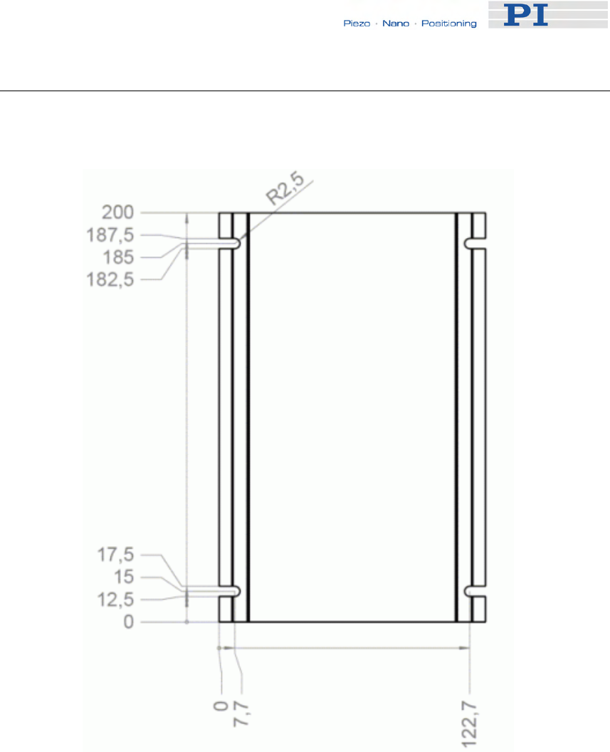
Technical Data
14.2 Mounting Hole Pattern
Dimensions in millimeters, decimal places separated by commas
Figure 20: Bottom side of the E-861 case
www.pi.ws E-861 PZ205E Release 1.2.1 Page 214

Technical Data
14.3 Pin Assignments
14.3.1 Motor Socket
Connector type: Sub-D 15 (f), 3 row
Pin Signal
direction Function
1 OUT Piezo 1
2 OUT Piezo 3
3 int. use internal use
4 nc nc
5 nc nc
6 OUT Piezo 0
7 OUT Piezo 2
8 IN AMP (amplifier
enable)*
9 nc nc
10 nc nc
11 AGND Piezo GND
12 AGND Piezo GND
13 AGND Piezo GND
14 GND Digital GND
15 GND Digital GND
*This pin is connected to GND in the connector shell of the NEXACT® drive
to enable the amplifiers. If this connection is removed, all piezo voltages will
be zero.
www.pi.ws E-861 PZ205E Release 1.2.1 Page 215

Technical Data
14.3.2 Sensor Socket
Connector type: Sub-D 15 (m), 3 row
Pin Signal
direction Function
1 IN REF (reference switch)
2 OUT VDD (supply voltage encoder)
3 IN REFP (positive reference trace
from ruler*)
4 IN COSP (positive cosine encoder
signal)
5 IN SINP (positive sine encoder
signal)
6 IN PLIMIT (positive limit switch)
7 IN NLIMIT (negative limit switch)
8 IN REFN (negative reference trace
from ruler*)
9 IN COSN (negative cosine encoder
signal)
10 IN SINN (negative sine encoder
signal)
11 int. use internal use
12 OUT VDD (supply voltage limit board)
13 GND Digital GND for reference and
limit switches
14 AGND Encoder signal GND
15 AGND Encoder signal GND
* For the operation of the controller in closed-loop mode these signals are
not obligatory.
14.3.3 RS-232 In and RS-232 Out Sockets
Connector Labels: RS-232 IN and RS-232 OUT
Connector Types: Sub-D, 9-pin, male for OUT, female for IN
The RS-232 cable must never be connected to a PC at the same time an
USB cable is connected.
The IN and OUT lines are permanently bussed together, straight-through.
Only when the USB interface is active, does the controller assert signals on
www.pi.ws E-861 PZ205E Release 1.2.1 Page 216
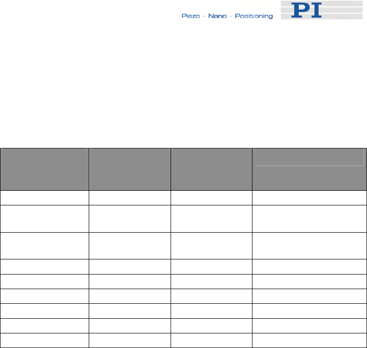
Technical Data
the RxD (receive) line, pin 2, otherwise that line is driven by the host PC
only. This is the reason an RS-232-only network may be limited to as few
as 6 units.
Note that the controller RS-232 bus is wired as a DTE and, if connected to
a PC, requires a cross-over (null-modem) cable.
Pin on all E-861
Connectors Signal name
on all E-861
Connectors*
Signal
direction Function
1 n.c.
2 RxD* PC to
controller** Commands
3 TxD* Controller** to
PC Reports (responses)
4 n.c.
5 GND GND
6 n.c.
7 n.c.
8 n.c.
9 n.c.
*The RS-232 connection with the PC is via null-modem cable, so the
connected signal names on the PC side are reversed.
** If the PC connection is via USB, then the E-861 connected to the PC
copies everything received from the host over USB to the E-861 RxD line of
both its RS-232 connectors. It also copies everything it sees on the E-861
TxD line to the host via USB.
14.3.4 USB Socket
Connector type: industry-standard USB Mini-B
When the USB interface is active, the controller asserts signals on the
transmit line (TxD) of the RS-232 connectors for networking up to 15 further
controllers. As a result the RS-232 cable must not be connected to the host
PC when using USB.
www.pi.ws E-861 PZ205E Release 1.2.1 Page 217

Technical Data
14.3.5 I/O Socket
Connector type: Mini DIN 9-pin
Pin Signal Function Identifier to use
in GCS
Commands
(see below)
1 input Input 1 (analog: 0 to +5V /
digital: TTL) 1
2 input Input 2 (analog: 0 to +5V /
digital: TTL) 2
3 input Input 3 (analog: 0 to +5V /
digital: TTL) 3
4 input Input 4 (analog: 0 to +5V /
digital: TTL) 4
5 output Output 1 (digital, TTL) 1
6 output Output 2 (digital, TTL) 2
7 output Output 3 (digital, TTL) 3
8 output Output 4 (digital, TTL) 4
9 output Vcc (+5V) -
If the Input 1 to Input 4 lines are used as analog input lines:
Their number is reported by the TAC? command (p. 185), their analog input
values can be queried with the TAV? command (p. 185) and recorded
using the record option 81 of the DRC command (p. 122).
If the Input 1 to Input 4 lines are used as digital input lines:
Their states (high/low) can be queried with the DIO? command (p. 121), the
#4 command (p. 114) and the SRG? command (p. 178).
The states of the Output 1 to Output 4 lines (high/low) can be set using the
DIO command (p. 121). Furthermore, you can program the Output 1 to
www.pi.ws E-861 PZ205E Release 1.2.1 Page 218

Technical Data
Output 4 lines using the CTO command (trigger configuration) and the TRO
command (trigger enabling/disabling). See "Configuring Trigger Output—
Examples" for examples.
14.3.6 C-170.IO Cable
The C-170.IO cable with open end is equipped with a Mini DIN 9-pin
connector. You can use it to make the signals of the I/O socket (p. 218)
available. This cable has to be ordered separately.
Specifications:
Temperature range: -25 °C to +85 °C
Current rating: 1 A AC/DC
Insulation resistance: 50 MΩ min.
Voltage rating: 50 V AC/DC
Withstanding voltage: 500 V AC for 1 minute
Pin of Mini
DIN 9-pin Wire Color Signal on I/O Socket of E-861
1 Black Input 1 (analog: 0 to +5V / digital:
TTL)
2 White Input 2 (analog: 0 to +5V / digital:
TTL)
3 Red Input 3 (analog: 0 to +5V / digital:
TTL)
4 Yellow Input 4 (analog: 0 to +5V / digital:
TTL)
5 Purple Output 1 (digital, TTL)
6 Blue Output 2 (digital, TTL)
7 Green Output 3 (digital, TTL)
8 Brown Output 4 (digital, TTL)
www.pi.ws E-861 PZ205E Release 1.2.1 Page 219

Technical Data
www.pi.ws E-861 PZ205E Release 1.2.1 Page 220
Pin of Mini Wire Color Signal on I/O Socket of E-861
DIN 9-pin
9 Gray Vcc (+5V)
Shell Shield, black
coated (thicker
than the black wire
connected to pin
1)
-
14.3.7 Joystick Socket
Connector type: Mini DIN 6-pin
Pin Signal
direction Function Identifier to use
in GCS Commands
(see below)
1 GND -
2 n.c. -
3 output Vcc (3.3 V) -
4 input Input: Joystick
Axis analog 0 to
3.3 V
1 for JAS? (p. 138),
JAX (p. 139),
JAX? (p. 140),
JDT (p. 141),
JLT (p. 142),
JLT? (p. 143)
5 for DRC (p. 122)
5 n.c. -
6 input Input: Joystick
Button #1 1 for JBS? (p. 140)
6 for DRC
The input values of the joystick axis and the joystick button can be recorded
using the record option 81 of the DRC command.
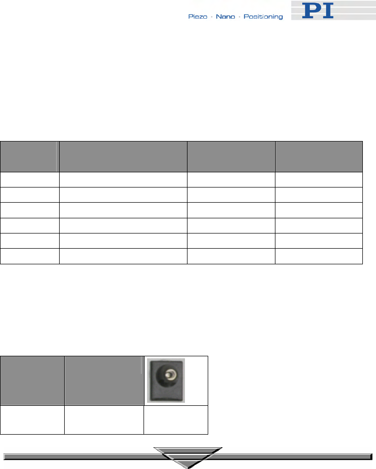
Technical Data
14.3.8 Joystick Y-Cable
The joystick Y-cable (C-819.20Y) maps the signals of the second joystick
axis (Y) and button to the first-axis inputs for the second controller.
Joystick
Pin Signal Controller 1
Pin Controller 2
Pin
1 GND 1 1
2 Button 2, 0 or 3.3 V 6
3 Vcc (3.3 V) output Vcc (3.3 V)
4 X-axis signal, 0 to 3.3 V 4
5 Y-axis signal, 0 to 3.3 V 4
6 Button 1, 0 or 3.3 V 6
14.3.9 24 V DC Socket
Connector type: barrel connector
Pin Function
Center
+24 VDC
www.pi.ws E-861 PZ205E Release 1.2.1 Page 221
15 Index
2
24 V DC Socket - 26, 221
A
Accessible Items and Their Identifiers -
51, 53, 79, 107, 108, 139, 140, 141,
142, 145, 171, 172, 174, 175, 176, 178,
185, 186, 191
Additional Components - 9
Address Settings - 29
Adjustment for Custom Sensor - 12, 90,
99
Adjustment for Custom Sensor Using
Custom Interpolation Board - 99, 100
Application Notes - 67
B
Basic Elements - 51
Baud Rate Settings - 28
C
C-170.IO Cable - 219
Changing Motion and Servo Mode - 21,
59, 64, 156, 160, 162, 169, 184
Command Reference (alphabetical) -
114
Command Survey - 111
Connecting Controller or Daisy-Chain
Network to Host PC - 15, 27, 51
Control Algorithm - 55, 76
Control Basics - 17, 68
Control Value Generation - 55, 68, 71
Controller - 207
Controller Parameters - 17, 34, 35, 52,
77, 91, 92, 119, 128, 138, 146, 171,
174, 175, 176, 177, 178, 188, 191, 209
Custom Sensor Using GEMAC
Interpolation Board - 99, 106
Customer Service - 210
Customizing the System - 12, 17, 35, 37,
52, 89
D
Data Recording - 52, 54, 88, 123, 124,
126, 172, 187
Default-Stage-N Parameter Settings -
12, 36, 49
Defining Macros - 82, 148
Details of Operation - 23
DIP Switch Settings - 24
E
Error Codes - 127, 192, 209
Example for Commanding Motion - 20,
156, 159, 162, 165, 169, 184
F
Firmware Updates - 32
First Steps - 12
Format - 107
Front and Rear Panel Elements - 23
Front Panel Elements - 23
G
GCS Commands - 52, 107
GCS Syntax - 107
GEMAC Parameters - 12, 35, 36, 91, 99,
105, 106, 174, 175, 208
Getting Started - 12, 20, 37, 98, 102
H
How to Create a New Stage Type in the
PI Stages Database - 13, 35, 37, 77,
90, 98
How to Store Parameter Settings - 12,
35, 36, 37, 77, 90, 100, 105, 106
I
I/O Socket - 9, 23, 31, 53, 121, 122, 123,
150, 185, 186, 218, 219
Installing the Software on the Host PC -
14, 17, 27, 37
Introduction - 4
J
Joystick Control - 20, 54, 71, 72, 79, 84,
129, 145, 148, 151, 153, 156, 160, 162,
165, 181
Joystick Socket - 23, 53, 54, 79, 123,
139, 140, 141, 142, 145, 220
Joystick Y-Cable - 221
M
Modes of Operation - 21, 46, 54, 115,
156, 159, 162, 165, 169, 179
Motion Error Handling - 77
Motion Modes - 21, 56, 69, 71
Motion System Requirements - 9
Motor Socket - 26, 215
Mounting Hole Pattern - 26, 214
N
Notation - 107
O
Old Equipment Disposal - 211
P
Parameter List - 41, 105
Parameters for Customizing - 35, 55, 90
Perform a Reference Move - 29, 30
PiezoWalk Driving Mode - 55, 63
Pin Assignments - 215
Preparing for Stand-Alone Preparation -
20, 85
Prescribed Use - 5
R
Rear Panel Elements - 26
Reference Mode - 29
Referencing - 18, 29, 71, 92, 130, 131,
133, 166, 170
Requirements for Closed-Loop
Operation and Custom Systems - 12
RS-232 In and RS-232 Out Sockets - 23,
216
S
Safety Precautions - 6
Sensor Socket - 26, 216
Servo Loop Input Factor - 91, 99, 100,
106
Servo Modes - 55
Set Absolute Position - 29, 30
Software Description - 8, 10, 27, 52
Software Updates - 31
Specifications - 212
Starting Macro Execution - 84
Start-Up Macro - 84, 184
System Description - 51
T
Target and Sender Address - 29, 54, 84,
110, 148, 208
Technical Data - 212
Trajectory Generation - 71
Travel Range Adjustment - 30, 71, 90,
92, 129, 130, 131, 133, 170
Troubleshooting - 207
Tuning PID Control Parameters - 52, 76,
91, 95
U
Unpacking - 8
Updates - 31
Updating PIStages2.dat - 17, 32
USB Interface - 28
USB Socket - 23, 217
Using Trigger Input and Output - 31, 53
W
What to Consider for First Handling of
Parameter Settings - 35
Working with Controller Macros - 20, 31,
52, 55, 68, 82, 120
