Config(EC) EC
User Manual: EC
Open the PDF directly: View PDF ![]() .
.
Page Count: 1281 [warning: Documents this large are best viewed by clicking the View PDF Link!]
- QUICK REFERENCE INDEX
- Table of Contents
- FOR CALIFORNIA
- BASIC INSPECTION
- DIAGNOSIS AND REPAIR WORKFLOW
- INSPECTION AND ADJUSTMENT
- FUNCTION DIAGNOSIS
- ENGINE CONTROL SYSTEM
- MULTIPORT FUEL INJECTION SYSTEM
- ELECTRIC IGNITION SYSTEM
- AIR CONDITIONING CUT CONTROL
- AUTOMATIC SPEED CONTROL DEVICE (ASCD)
- CAN COMMUNICATION
- COOLING FAN CONTROL
- EVAPORATIVE EMISSION SYSTEM
- INTAKE VALVE TIMING CONTROL
- TUMBLE CONTROL VALVE CONTROL
- ON BOARD DIAGNOSTIC (OBD) SYSTEM
- Diagnosis Description
- INTRODUCTION
- TWO TRIP DETECTION LOGIC
- DTC AND FREEZE FRAME DATA
- SYSTEM READINESS TEST (SRT) CODE
- MALFUNCTION INDICATOR LAMP (MIL)
- OBD System Operation Chart
- Relationship Between MIL, 1st Trip DTC, DTC and Detectable Items
- Summary Chart
- Relationship Between MIL, DTC, 1st Trip DTC and Driving Patterns for “Misfire <Exhaust Quality Deterioration>”, “Fuel Injection System”
- Explanation for Driving Patterns for “Misfire <Exhaust Quality Deterioration>”, “Fuel Injection System”
- Relationship Between MIL, DTC, 1st Trip DTC and Driving Patterns Except For “Misfire <Exhaust Quality Deterioration>”, “Fuel Injection System”
- Explanation for Driving Patterns Except for “Misfire <Exhaust Quality Deterioration>”, “Fuel Injection System”
- CONSULT-III Function
- Diagnosis Tool Function
- Diagnosis Description
- COMPONENT DIAGNOSIS
- TROUBLE DIAGNOSIS - SPECIFICATION VALUE
- POWER SUPPLY AND GROUND CIRCUIT
- U0101 CAN COMM CIRCUIT
- U0140 CAN COMM CIRCUIT
- U1001 CAN COMM CIRCUIT
- P0011 IVT CONTROL
- P0031, P0032 A/F SENSOR 1 HEATER
- P0037, P0038 HO2S2 HEATER
- P0043, P0044 HO2S3 HEATER
- P0075 IVT CONTROL SOLENOID VALVE
- P0101 MAF SENSOR
- P0102, P0103 MAF SENSOR
- P0112, P0113 IAT SENSOR
- P0116 ECT SENSOR
- P0117, P0118 ECT SENSOR
- P0122, P0123 TP SENSOR
- P0125 ECT SENSOR
- P0127 IAT SENSOR
- P0128 THERMOSTAT FUNCTION
- P0130 A/F SENSOR 1
- P0131 A/F SENSOR 1
- P0132 A/F SENSOR 1
- P0133 A/F SENSOR 1
- P0137 HO2S2
- P0138 HO2S2
- P0139 HO2S2
- P0143 HO2S3
- P0144 HO2S3
- P0145 HO2S3
- P0146 HO2S3
- P0171 FUEL INJECTION SYSTEM FUNCTION
- P0172 FUEL INJECTION SYSTEM FUNCTION
- P0181 FTT SENSOR
- P0182, P0183 FTT SENSOR
- P0222, P0223 TP SENSOR
- P0300, P0301, P0302, P0303, P0304 MISFIRE
- P0327, P0328 KS
- P0335 CKP SENSOR (POS)
- P0340 CMP SENSOR (PHASE)
- P0420 THREE WAY CATALYST FUNCTION
- P0441 EVAP CONTROL SYSTEM
- P0442 EVAP CONTROL SYSTEM
- P0443 EVAP CANISTER PURGE VOLUME CONTROL SOLENOID VALVE
- P0444, P0445 EVAP CANISTER PURGE VOLUME CONTROL SOLENOID VALVE
- P0447 EVAP CANISTER VENT CONTROL VALVE
- P0448 EVAP CANISTER VENT CONTROL VALVE
- P0451 EVAP CONTROL SYSTEM PRESSURE SENSOR
- P0452 EVAP CONTROL SYSTEM PRESSURE SENSOR
- P0453 EVAP CONTROL SYSTEM PRESSURE SENSOR
- P0455 EVAP CONTROL SYSTEM
- P0456 EVAP CONTROL SYSTEM
- P0460 FUEL LEVEL SENSOR
- P0461 FUEL LEVEL SENSOR
- P0462, P0463 FUEL LEVEL SENSOR
- P0500 VSS
- P0506 ISC SYSTEM
- P0507 ISC SYSTEM
- P0603 ECM POWER SUPPLY
- P0605 ECM
- P0607 ECM
- P0643 SENSOR POWER SUPPLY
- P0850 PNP SWITCH
- P1148 CLOSED LOOP CONTROL
- P1212 TCS COMMUNICATION LINE
- P1217 ENGINE OVER TEMPERATURE
- P1225 TP SENSOR
- P1226 TP SENSOR
- P1421 COLD START CONTROL
- P1564 ASCD STEERING SWITCH
- P1572 ASCD BRAKE SWITCH
- P1574 ASCD VEHICLE SPEED SENSOR
- P1715 INPUT SPEED SENSOR (PRIMARY SPEED SENSOR)
- P1805 BRAKE SWITCH
- P2004 TUMBLE CONTROL VALVE
- P2014 TUMBLE CONTROL VALVE POSITION SENSOR
- P2100, P2103 THROTTLE CONTROL MOTOR RELAY
- P2101 ELECTRIC THROTTLE CONTROL FUNCTION
- P2118 THROTTLE CONTROL MOTOR
- P2119 ELECTRIC THROTTLE CONTROL ACTUATOR
- P2122, P2123 APP SENSOR
- P2127, P2128 APP SENSOR
- P2135 TP SENSOR
- P2138 APP SENSOR
- P2423 HC ADSORPTION CATALYST FUNCTION
- P2A00 A/F SENSOR 1
- ASCD BRAKE SWITCH
- ASCD INDICATOR
- COOLING FAN
- ELECTRICAL LOAD SIGNAL
- FUEL INJECTOR
- FUEL PUMP
- IGNITION SIGNAL
- MALFUNCTION INDICATOR LAMP
- ON BOARD REFUELING VAPOR RECOVERY (ORVR)
- POSITIVE CRANKCASE VENTILATION
- REFRIGERANT PRESSURE SENSOR
- ECU DIAGNOSIS
- SYMPTOM DIAGNOSIS
- PRECAUTION
- PREPARATION
- ON-VEHICLE MAINTENANCE
- ON-VEHICLE REPAIR
- SERVICE DATA AND SPECIFICATIONS (SDS)
- BASIC INSPECTION
- FOR USA (FEDERAL) AND CANADA
- BASIC INSPECTION
- DIAGNOSIS AND REPAIR WORKFLOW
- INSPECTION AND ADJUSTMENT
- FUNCTION DIAGNOSIS
- ENGINE CONTROL SYSTEM
- MULTIPORT FUEL INJECTION SYSTEM
- ELECTRIC IGNITION SYSTEM
- AIR CONDITIONING CUT CONTROL
- AUTOMATIC SPEED CONTROL DEVICE (ASCD)
- CAN COMMUNICATION
- COOLING FAN CONTROL
- EVAPORATIVE EMISSION SYSTEM
- INTAKE VALVE TIMING CONTROL
- ON BOARD DIAGNOSTIC (OBD) SYSTEM
- Diagnosis Description
- INTRODUCTION
- TWO TRIP DETECTION LOGIC
- DTC AND FREEZE FRAME DATA
- SYSTEM READINESS TEST (SRT) CODE
- MALFUNCTION INDICATOR LAMP (MIL)
- OBD System Operation Chart
- Relationship Between MIL, 1st Trip DTC, DTC and Detectable Items
- Summary Chart
- Relationship Between MIL, DTC, 1st Trip DTC and Driving Patterns for “Misfire <Exhaust Quality Deterioration>”, “Fuel Injection System”
- Explanation for Driving Patterns for “Misfire <Exhaust Quality Deterioration>”, “Fuel Injection System”
- Relationship Between MIL, DTC, 1st Trip DTC and Driving Patterns Except For “Misfire <Exhaust Quality Deterioration>”, “Fuel Injection System”
- Explanation for Driving Patterns Except for “Misfire <Exhaust Quality Deterioration>”, “Fuel Injection System”
- CONSULT-III Function
- Diagnosis Tool Function
- Diagnosis Description
- COMPONENT DIAGNOSIS
- TROUBLE DIAGNOSIS - SPECIFICATION VALUE
- POWER SUPPLY AND GROUND CIRCUIT
- U0101 CAN COMM CIRCUIT
- U0140 CAN COMM CIRCUIT
- U1001 CAN COMM CIRCUIT
- P0011 IVT CONTROL
- P0031, P0032 A/F SENSOR 1 HEATER
- P0037, P0038 HO2S2 HEATER
- P0075 IVT CONTROL SOLENOID VALVE
- P0101 MAF SENSOR
- P0102, P0103 MAF SENSOR
- P0112, P0113 IAT SENSOR
- P0116 ECT SENSOR
- P0117, P0118 ECT SENSOR
- P0122, P0123 TP SENSOR
- P0125 ECT SENSOR
- P0127 IAT SENSOR
- P0128 THERMOSTAT FUNCTION
- P0130 A/F SENSOR 1
- P0131 A/F SENSOR 1
- P0132 A/F SENSOR 1
- P0133 A/F SENSOR 1
- P0137 HO2S2
- P0138 HO2S2
- P0139 HO2S2
- P0171 FUEL INJECTION SYSTEM FUNCTION
- P0172 FUEL INJECTION SYSTEM FUNCTION
- P0181 FTT SENSOR
- P0182, P0183 FTT SENSOR
- P0222, P0223 TP SENSOR
- P0300, P0301, P0302, P0303, P0304 MISFIRE
- P0327, P0328 KS
- P0335 CKP SENSOR (POS)
- P0340 CMP SENSOR (PHASE)
- P0420 THREE WAY CATALYST FUNCTION
- P0441 EVAP CONTROL SYSTEM
- P0442 EVAP CONTROL SYSTEM
- P0443 EVAP CANISTER PURGE VOLUME CONTROL SOLENOID VALVE
- P0444, P0445 EVAP CANISTER PURGE VOLUME CONTROL SOLENOID VALVE
- P0447 EVAP CANISTER VENT CONTROL VALVE
- P0448 EVAP CANISTER VENT CONTROL VALVE
- P0451 EVAP CONTROL SYSTEM PRESSURE SENSOR
- P0452 EVAP CONTROL SYSTEM PRESSURE SENSOR
- P0453 EVAP CONTROL SYSTEM PRESSURE SENSOR
- P0455 EVAP CONTROL SYSTEM
- P0456 EVAP CONTROL SYSTEM
- P0460 FUEL LEVEL SENSOR
- P0461 FUEL LEVEL SENSOR
- P0462, P0463 FUEL LEVEL SENSOR
- P0500 VSS
- P0506 ISC SYSTEM
- P0507 ISC SYSTEM
- P0603 ECM POWER SUPPLY
- P0605 ECM
- P0607 ECM
- P0643 SENSOR POWER SUPPLY
- P0850 PNP SWITCH
- P1148 CLOSED LOOP CONTROL
- P1212 TCS COMMUNICATION LINE
- P1217 ENGINE OVER TEMPERATURE
- P1225 TP SENSOR
- P1226 TP SENSOR
- P1421 COLD START CONTROL
- P1564 ASCD STEERING SWITCH
- P1572 ASCD BRAKE SWITCH
- P1574 ASCD VEHICLE SPEED SENSOR
- P1715 INPUT SPEED SENSOR (PRIMARY SPEED SENSOR)
- P1805 BRAKE SWITCH
- P2100, P2103 THROTTLE CONTROL MOTOR RELAY
- P2101 ELECTRIC THROTTLE CONTROL FUNCTION
- P2118 THROTTLE CONTROL MOTOR
- P2119 ELECTRIC THROTTLE CONTROL ACTUATOR
- P2122, P2123 APP SENSOR
- P2127, P2128 APP SENSOR
- P2135 TP SENSOR
- P2138 APP SENSOR
- P2A00 A/F SENSOR 1
- ASCD BRAKE SWITCH
- ASCD INDICATOR
- COOLING FAN
- ELECTRICAL LOAD SIGNAL
- FUEL INJECTOR
- FUEL PUMP
- IGNITION SIGNAL
- MALFUNCTION INDICATOR LAMP
- ON BOARD REFUELING VAPOR RECOVERY (ORVR)
- POSITIVE CRANKCASE VENTILATION
- REFRIGERANT PRESSURE SENSOR
- ECU DIAGNOSIS
- SYMPTOM DIAGNOSIS
- PRECAUTION
- PREPARATION
- ON-VEHICLE MAINTENANCE
- ON-VEHICLE REPAIR
- SERVICE DATA AND SPECIFICATIONS (SDS)
- BASIC INSPECTION
- FOR MEXICO
- BASIC INSPECTION
- FUNCTION DIAGNOSIS
- ENGINE CONTROL SYSTEM
- MULTIPORT FUEL INJECTION SYSTEM
- ELECTRIC IGNITION SYSTEM
- AIR CONDITIONING CUT CONTROL
- AUTOMATIC SPEED CONTROL DEVICE (ASCD)
- CAN COMMUNICATION
- COOLING FAN CONTROL
- EVAPORATIVE EMISSION SYSTEM
- INTAKE VALVE TIMING CONTROL
- ON BOARD DIAGNOSTIC (OBD) SYSTEM
- Diagnosis Description
- INTRODUCTION
- TWO TRIP DETECTION LOGIC
- DTC AND FREEZE FRAME DATA
- SYSTEM READINESS TEST (SRT) CODE
- MALFUNCTION INDICATOR LAMP (MIL)
- OBD System Operation Chart
- Relationship Between MIL, 1st Trip DTC, DTC and Detectable Items
- Summary Chart
- Relationship Between MIL, DTC, 1st Trip DTC and Driving Patterns for “Misfire <Exhaust Quality Deterioration>”, “Fuel Injection System”
- Explanation for Driving Patterns for “Misfire <Exhaust Quality Deterioration>”, “Fuel Injection System”
- Relationship Between MIL, DTC, 1st Trip DTC and Driving Patterns Except For “Misfire <Exhaust Quality Deterioration>”, “Fuel Injection System”
- Explanation for Driving Patterns Except for “Misfire <Exhaust Quality Deterioration>”, “Fuel Injection System”
- CONSULT-III Function
- Diagnosis Tool Function
- Diagnosis Description
- COMPONENT DIAGNOSIS
- TROUBLE DIAGNOSIS - SPECIFICATION VALUE
- POWER SUPPLY AND GROUND CIRCUIT
- U0101 CAN COMM CIRCUIT
- U0140 CAN COMM CIRCUIT
- U1001 CAN COMM CIRCUIT
- P0011 IVT CONTROL
- P0031, P0032 A/F SENSOR 1 HEATER
- P0037, P0038 HO2S2 HEATER
- P0075 IVT CONTROL SOLENOID VALVE
- P0101 MAF SENSOR
- P0102, P0103 MAF SENSOR
- P0112, P0113 IAT SENSOR
- P0117, P0118 ECT SENSOR
- P0122, P0123 TP SENSOR
- P0125 ECT SENSOR
- P0127 IAT SENSOR
- P0128 THERMOSTAT FUNCTION
- P0130 A/F SENSOR 1
- P0131 A/F SENSOR 1
- P0132 A/F SENSOR 1
- P0133 A/F SENSOR 1
- P0137 HO2S2
- P0138 HO2S2
- P0139 HO2S2
- P0171 FUEL INJECTION SYSTEM FUNCTION
- P0172 FUEL INJECTION SYSTEM FUNCTION
- P0222, P0223 TP SENSOR
- P0300, P0301, P0302, P0303, P0304 MISFIRE
- P0327, P0328 KS
- P0335 CKP SENSOR (POS)
- P0340 CMP SENSOR (PHASE)
- P0420 THREE WAY CATALYST FUNCTION
- P0444, P0445 EVAP CANISTER PURGE VOLUME CONTROL SOLENOID VALVE
- P0500 VSS
- P0506 ISC SYSTEM
- P0507 ISC SYSTEM
- P0603 ECM POWER SUPPLY
- P0605 ECM
- P0607 ECM
- P0643 SENSOR POWER SUPPLY
- P0850 PNP SWITCH
- P1148 CLOSED LOOP CONTROL
- P1217 ENGINE OVER TEMPERATURE
- P1225 TP SENSOR
- P1226 TP SENSOR
- P1421 COLD START CONTROL
- P1564 ASCD STEERING SWITCH
- P1572 ASCD BRAKE SWITCH
- P1574 ASCD VEHICLE SPEED SENSOR
- P1715 INPUT SPEED SENSOR (PRIMARY SPEED SENSOR)
- P1805 BRAKE SWITCH
- P2100, P2103 THROTTLE CONTROL MOTOR RELAY
- P2101 ELECTRIC THROTTLE CONTROL FUNCTION
- P2118 THROTTLE CONTROL MOTOR
- P2119 ELECTRIC THROTTLE CONTROL ACTUATOR
- P2122, P2123 APP SENSOR
- P2127, P2128 APP SENSOR
- P2135 TP SENSOR
- P2138 APP SENSOR
- P2A00 A/F SENSOR 1
- ASCD BRAKE SWITCH
- ASCD INDICATOR
- COOLING FAN
- ELECTRICAL LOAD SIGNAL
- FUEL INJECTOR
- FUEL PUMP
- IGNITION SIGNAL
- MALFUNCTION INDICATOR LAMP
- POSITIVE CRANKCASE VENTILATION
- REFRIGERANT PRESSURE SENSOR
- ECU DIAGNOSIS
- SYMPTOM DIAGNOSIS
- PRECAUTION
- PREPARATION
- ON-VEHICLE MAINTENANCE
- SERVICE DATA AND SPECIFICATIONS (SDS)
- POWER SUPPLY ROUTING CIRCUIT
- FUSE BLOCK - JUNCTION BOX (J/B)
- FUSE, FUSIBLE LINK AND RELAY BOX
- FOR CALIFORNIA

EC-1
ENGINE
C
D
E
F
G
H
I
J
K
L
M
SECTION EC A
EC
N
O
P
CONTENTS
ENGINE CONTROL SYSTEM
FOR CALIFORNIA
BASIC INSPECTION ...................................18
DIAGNOSIS AND REPAIR WORKFLOW .........18
Work Flow ...............................................................18
Diagnostic Work Sheet ............................................21
INSPECTION AND ADJUSTMENT ....................22
BASIC INSPECTION .................................................22
BASIC INSPECTION : Special Repair Require-
ment ........................................................................22
ADDITIONAL SERVICE WHEN REPLACING
CONTROL UNIT ........................................................25
ADDITIONAL SERVICE WHEN REPLACING
CONTROL UNIT : Description ................................25
ADDITIONAL SERVICE WHEN REPLACING
CONTROL UNIT : Special Repair Requirement .....25
IDLE SPEED ..............................................................25
IDLE SPEED : Description ......................................25
IDLE SPEED : Special Repair Requirement ...........26
IGNITION TIMING ......................................................26
IGNITION TIMING : Description ..............................26
IGNITION TIMING : Special Repair Requirement ....26
VIN REGISTRATION .................................................26
VIN REGISTRATION : Description .........................26
VIN REGISTRATION : Special Repair Require-
ment ........................................................................26
ACCELERATOR PEDAL RELEASED POSITION
LEARNING ................................................................27
ACCELERATOR PEDAL RELEASED POSITION
LEARNING : Description .........................................27
ACCELERATOR PEDAL RELEASED POSITION
LEARNING : Special Repair Requirement ..............27
THROTTLE VALVE CLOSED POSITION LEARN-
ING .............................................................................27
THROTTLE VALVE CLOSED POSITION
LEARNING : Description .........................................27
THROTTLE VALVE CLOSED POSITION
LEARNING : Special Repair Requirement ..............27
IDLE AIR VOLUME LEARNING ................................27
IDLE AIR VOLUME LEARNING : Description .........27
IDLE AIR VOLUME LEARNING : Special Repair
Requirement ............................................................27
MIXTURE RATIO SELF-LEARNING VALUE
CLEAR .......................................................................29
MIXTURE RATIO SELF-LEARNING VALUE
CLEAR : Description ................................................29
MIXTURE RATIO SELF-LEARNING VALUE
CLEAR : Special Repair Requirement .....................29
FUNCTION DIAGNOSIS ..............................31
ENGINE CONTROL SYSTEM ..........................31
System Diagram .....................................................31
System Description ..................................................32
Component Parts Location ....................................32
Component Description ...........................................36
MULTIPORT FUEL INJECTION SYSTEM .......38
System Diagram .....................................................38
System Description ..................................................38
Component Parts Location ....................................41
Component Description ...........................................45
ELECTRIC IGNITION SYSTEM ........................46
System Diagram .....................................................46
System Description ..................................................46
Component Parts Location ....................................47
Component Description ...........................................51
AIR CONDITIONING CUT CONTROL ..............52
System Diagram ......................................................52
System Description ..................................................52
Component Parts Location ....................................53
Component Description ...........................................57
Revision: 2008 August 2009 Rogue

EC-2
AUTOMATIC SPEED CONTROL DEVICE
(ASCD) ............................................................... 58
System Diagram ..................................................... 58
System Description ................................................. 58
Component Parts Location ................................... 59
Component Description ......................................... 63
CAN COMMUNICATION ................................... 64
System Description ................................................. 64
COOLING FAN CONTROL ............................... 65
System Diagram ..................................................... 65
System Description ................................................. 65
Component Parts Location ................................... 67
Component Description .......................................... 71
EVAPORATIVE EMISSION SYSTEM ............... 72
System Diagram ..................................................... 72
System Description ................................................. 73
Component Parts Location ................................... 75
Component Description ......................................... 79
INTAKE VALVE TIMING CONTROL ................. 80
System Diagram ..................................................... 80
System Description ................................................. 80
Component Parts Location ................................... 81
Component Description .......................................... 85
TUMBLE CONTROL VALVE CONTROL .......... 86
System Diagram ..................................................... 86
System Description ................................................. 86
Component Parts Location ................................... 87
Component Description .......................................... 91
ON BOARD DIAGNOSTIC (OBD) SYSTEM ..... 92
Diagnosis Description ............................................. 92
CONSULT-III Function ..........................................105
Diagnosis Tool Function ......................................114
COMPONENT DIAGNOSIS .......................116
TROUBLE DIAGNOSIS - SPECIFICATION
VALUE .............................................................116
Description .............................................................116
Component Function Check ..................................116
Diagnosis Procedure .............................................117
POWER SUPPLY AND GROUND CIRCUIT ...124
Diagnosis Procedure .............................................124
U0101 CAN COMM CIRCUIT ..........................128
Description .............................................................128
DTC Logic ..............................................................128
Diagnosis Procedure .............................................128
U0140 CAN COMM CIRCUIT ..........................129
Description .............................................................129
DTC Logic ..............................................................129
Diagnosis Procedure .............................................129
U1001 CAN COMM CIRCUIT ..........................130
Description ............................................................130
DTC Logic .............................................................130
Diagnosis Procedure .............................................130
P0011 IVT CONTROL ......................................131
DTC Logic .............................................................131
Diagnosis Procedure .............................................132
Component Inspection ..........................................133
P0031, P0032 A/F SENSOR 1 HEATER ..........135
Description ............................................................135
DTC Logic .............................................................135
Diagnosis Procedure .............................................135
Component Inspection ..........................................137
P0037, P0038 HO2S2 HEATER .......................138
Description ............................................................138
DTC Logic .............................................................138
Diagnosis Procedure .............................................139
Component Inspection ..........................................140
P0043, P0044 HO2S3 HEATER .......................141
Description ............................................................141
DTC Logic .............................................................141
Diagnosis Procedure .............................................142
Component Inspection ..........................................143
P0075 IVT CONTROL SOLENOID VALVE ......144
Description ............................................................144
DTC Logic .............................................................144
Diagnosis Procedure .............................................144
Component Inspection ..........................................145
P0101 MAF SENSOR .......................................147
Description ............................................................147
DTC Logic .............................................................147
Component Function Check .................................148
Diagnosis Procedure .............................................149
Component Inspection ..........................................151
P0102, P0103 MAF SENSOR ........................
..154
Description ............................................................154
DTC Logic .............................................................154
Diagnosis Procedure .............................................155
Component Inspection ..........................................156
P0112, P0113 IAT SENSOR ............................159
Description ............................................................159
DTC Logic .............................................................159
Diagnosis Procedure .............................................159
Component Inspection ..........................................161
P0116 ECT SENSOR .......................................162
Description ............................................................162
DTC Logic .............................................................162
Diagnosis Procedure .............................................163
Component Inspection ..........................................163
P0117, P0118 ECT SENSOR ...........................164
Description ............................................................164
DTC Logic .............................................................164
Revision: 2008 August 2009 Rogue

EC-3
C
D
E
F
G
H
I
J
K
L
M
EC
A
N
O
P
Diagnosis Procedure ............................................. 164
Component Inspection .......................................... 165
P0122, P0123 TP SENSOR .............................167
Description ............................................................ 167
DTC Logic ............................................................. 167
Diagnosis Procedure ............................................. 167
Component Inspection .......................................... 169
Special Repair Requirement ................................. 169
P0125 ECT SENSOR .......................................170
Description ............................................................ 170
DTC Logic ............................................................. 170
Diagnosis Procedure ............................................. 171
Component Inspection .......................................... 171
P0127 IAT SENSOR .........................................173
Description ............................................................ 173
DTC Logic ............................................................. 173
Diagnosis Procedure ............................................. 174
Component Inspection .......................................... 174
P0128 THERMOSTAT FUNCTION ..................175
DTC Logic ............................................................. 175
Diagnosis Procedure ............................................. 175
Component Inspection .......................................... 176
P0130 A/F SENSOR 1 ......................................177
Description ............................................................ 177
DTC Logic ............................................................. 177
Component Function Check .................................. 178
Diagnosis Procedure ............................................. 179
P0131 A/F SENSOR 1 ......................................181
Description ............................................................ 181
DTC Logic ............................................................. 181
Diagnosis Procedure ............................................. 182
P0132 A/F SENSOR 1 ......................................184
Description ............................................................ 184
DTC Logic ............................................................. 184
Diagnosis Procedure ............................................. 185
P0133 A/F SENSOR 1 ......................................187
Description ............................................................ 187
DTC Logic ............................................................. 187
Diagnosis Procedure ............................................. 189
P0137 HO2S2 ...................................................192
Description ............................................................ 192
DTC Logic ............................................................. 192
Component Function Check .................................. 193
Diagnosis Procedure ............................................. 194
Component Inspection .......................................... 195
P0138 HO2S2 ...................................................198
Description ............................................................ 198
DTC Logic ............................................................. 198
Component Function Check .................................. 199
Diagnosis Procedure ............................................. 200
Component Inspection .......................................... 203
P0139 HO2S2 .................................................. 205
Description .............................................................205
DTC Logic ..............................................................205
Component Function Check ..................................206
Diagnosis Procedure .............................................207
Component Inspection ...........................................208
P0143 HO2S3 .................................................. 211
Description .............................................................211
DTC Logic ..............................................................211
Diagnosis Procedure .............................................212
Component Inspection ...........................................213
P0144 HO2S3 .................................................. 216
Description .............................................................216
DTC Logic ..............................................................216
Diagnosis Procedure .............................................217
Component Inspection ...........................................218
P0145 HO2S3 .................................................. 221
Description .............................................................221
DTC Logic ..............................................................221
Diagnosis Procedure .............................................222
Component Inspection ...........................................223
P0146 HO2S3 .................................................. 226
Description .............................................................226
DTC Logic ..............................................................226
Diagnosis Procedure .............................................227
Component Inspection ...........................................228
P0171 FUEL INJECTION SYSTEM FUNC-
TION ................................................................ 231
DTC Logic ..............................................................231
Diagnosis Procedure .............................................232
P0172 FUEL INJECTION SYSTEM FUNC-
TION ................................................................ 235
DTC Logic ..............................................................235
Diagnosis Procedure .............................................236
P0181 FTT SENSOR .......................................239
Description .............................................................239
DTC Logic ..............................................................239
Diagnosis Procedure .............................................240
Component Inspection ...........................................241
P0182, P0183 FTT SENSOR .......................... 242
Description .............................................................242
DTC Logic ..............................................................242
Diagnosis Procedure .............................................242
Component Inspection ...........................................243
P0222, P0223 TP SENSOR ............................ 245
Description .............................................................245
DTC Logic ..............................................................245
Diagnosis Procedure .............................................245
Component Inspection ...........................................247
Special Repair Requirement ..................................247
Revision: 2008 August 2009 Rogue

EC-4
P0300, P0301, P0302, P0303, P0304 MIS-
FIRE .................................................................248
DTC Logic ..............................................................248
Diagnosis Procedure .............................................249
P0327, P0328 KS .............................................254
Description .............................................................254
DTC Logic ..............................................................254
Diagnosis Procedure .............................................254
Component Inspection ...........................................255
P0335 CKP SENSOR (POS) ...........................256
Description .............................................................256
DTC Logic ..............................................................256
Diagnosis Procedure .............................................257
Component Inspection ...........................................259
P0340 CMP SENSOR (PHASE) ......................260
Description .............................................................260
DTC Logic ..............................................................260
Diagnosis Procedure .............................................261
Component Inspection ...........................................262
P0420 THREE WAY CATALYST FUNCTION . 264
DTC Logic ..............................................................264
Diagnosis Procedure .............................................265
P0441 EVAP CONTROL SYSTEM ..................268
DTC Logic ..............................................................268
Component Function Check ..................................269
Diagnosis Procedure .............................................270
P0442 EVAP CONTROL SYSTEM ..................273
DTC Logic ..............................................................273
Diagnosis Procedure .............................................274
Component Inspection ...........................................278
P0443 EVAP CANISTER PURGE VOLUME
CONTROL SOLENOID VALVE .......................279
Description .............................................................279
DTC Logic ..............................................................279
Diagnosis Procedure .............................................280
Component Inspection ...........................................282
P0444, P0445 EVAP CANISTER PURGE
VOLUME CONTROL SOLENOID VALVE ......283
Description .............................................................283
DTC Logic ..............................................................283
Diagnosis Procedure .............................................283
Component Inspection ...........................................285
P0447 EVAP CANISTER VENT CONTROL
VALVE .............................................................286
Description .............................................................286
DTC Logic ..............................................................286
Diagnosis Procedure .............................................286
Component Inspection ...........................................288
P0448 EVAP CANISTER VENT CONTROL
VALVE .............................................................290
Description .............................................................290
DTC Logic .............................................................290
Diagnosis Procedure .............................................291
Component Inspection ..........................................292
P0451 EVAP CONTROL SYSTEM PRES-
SURE SENSOR ................................................294
Description ............................................................294
DTC Logic .............................................................294
Diagnosis Procedure .............................................294
Component Inspection ..........................................296
P0452 EVAP CONTROL SYSTEM PRES-
SURE SENSOR ................................................297
Description ............................................................297
DTC Logic .............................................................297
Diagnosis Procedure .............................................298
Component Inspection ..........................................300
P0453 EVAP CONTROL SYSTEM PRES-
SURE SENSOR ................................................302
Description ............................................................302
DTC Logic .............................................................302
Diagnosis Procedure .............................................303
Component Inspection ..........................................306
P0455 EVAP CONTROL SYSTEM ..................308
DTC Logic .............................................................308
Diagnosis Procedure .............................................309
Component Inspection ..........................................312
P0456 EVAP CONTROL SYSTEM ..................314
DTC Logic .............................................................314
Component Function Check .................................316
Diagnosis Procedure .............................................316
Component Inspection ..........................................319
P0460 FUEL LEVEL SENSOR .........................321
Description ............................................................321
DTC Logic .............................................................321
Diagnosis Procedure .............................................321
P0461 FUEL LEVEL SENSOR .........................322
Description ............................................................322
DTC Logic .............................................................322
Component Function Check .................................322
Diagnosis Procedure .............................................323
P0462, P0463 FUEL LEVEL SENSOR ............324
Description ............................................................324
DTC Logic .............................................................324
Diagnosis Procedure .............................................324
P0500 VSS ........................................................325
Description ............................................................325
DTC Logic .............................................................325
Component Function Check .................................326
Diagnosis Procedure .............................................326
P0506 ISC SYSTEM .........................................327
Description ............................................................327
DTC Logic .............................................................327
Revision: 2008 August 2009 Rogue

EC-5
C
D
E
F
G
H
I
J
K
L
M
EC
A
N
O
P
Diagnosis Procedure ............................................. 327
P0507 ISC SYSTEM .........................................329
Description ............................................................ 329
DTC Logic ............................................................. 329
Diagnosis Procedure ............................................. 329
P0603 ECM POWER SUPPLY .........................331
Description ............................................................ 331
DTC Logic ............................................................. 331
Diagnosis Procedure ............................................. 331
P0605 ECM .......................................................333
Description ............................................................ 333
DTC Logic ............................................................. 333
Diagnosis Procedure ............................................. 334
P0607 ECM .......................................................335
Description ............................................................ 335
DTC Logic ............................................................. 335
Diagnosis Procedure ............................................. 335
P0643 SENSOR POWER SUPPLY .................336
DTC Logic ............................................................. 336
Diagnosis Procedure ............................................. 336
P0850 PNP SWITCH ........................................338
Description ............................................................ 338
DTC Logic ............................................................. 338
Component Function Check .................................. 339
Diagnosis Procedure ............................................. 339
P1148 CLOSED LOOP CONTROL ..................341
DTC Logic ............................................................. 341
P1212 TCS COMMUNICATION LINE ..............342
Description ............................................................ 342
DTC Logic ............................................................. 342
Diagnosis Procedure ............................................. 342
P1217 ENGINE OVER TEMPERATURE .........343
DTC Logic ............................................................. 343
Component Function Check .................................. 343
Diagnosis Procedure ............................................. 344
P1225 TP SENSOR ..........................................347
Description ............................................................ 347
DTC Logic ............................................................. 347
Diagnosis Procedure ............................................. 347
Special Repair Requirement ................................. 348
P1226 TP SENSOR ..........................................349
Description ............................................................ 349
DTC Logic ............................................................. 349
Diagnosis Procedure ............................................. 349
Special Repair Requirement ................................. 350
P1421 COLD START CONTROL .....................351
Description ............................................................ 351
DTC Logic ............................................................. 351
Diagnosis Procedure ............................................. 351
P1564 ASCD STEERING SWITCH ................. 353
Description .............................................................353
DTC Logic ..............................................................353
Diagnosis Procedure .............................................353
Component Inspection ...........................................355
P1572 ASCD BRAKE SWITCH ...................... 356
Description .............................................................356
DTC Logic ..............................................................356
Diagnosis Procedure .............................................357
Component Inspection (ASCD Brake Switch) .......359
Component Inspection (Stop Lamp Switch) ..........360
P1574 ASCD VEHICLE SPEED SENSOR ..... 361
Description .............................................................361
DTC Logic ..............................................................361
Diagnosis Procedure .............................................361
P1715 INPUT SPEED SENSOR (PRIMARY
SPEED SENSOR) ........................................... 363
Description .............................................................363
DTC Logic ..............................................................363
Diagnosis Procedure .............................................363
P1805 BRAKE SWITCH ................................. 365
Description .............................................................365
DTC Logic ..............................................................365
Diagnosis Procedure .............................................365
Component Inspection (Stop Lamp Switch) ..........366
P2004 TUMBLE CONTROL VALVE ............... 367
Description .............................................................367
DTC Logic ..............................................................367
Diagnosis Procedure .............................................368
Component Inspection ...........................................371
P2014 TUMBLE CONTROL VALVE POSI-
TION SENSOR ................................................372
Description .............................................................372
DTC Logic ..............................................................372
Diagnosis Procedure .............................................372
P2100, P2103 THROTTLE CONTROL MO-
TOR RELAY .................................................... 375
Description .............................................................375
DTC Logic ..............................................................375
Diagnosis Procedure .............................................375
P2101 ELECTRIC THROTTLE CONTROL
FUNCTION ...................................................... 377
Description .............................................................377
DTC Logic ..............................................................377
Diagnosis Procedure .............................................377
Component Inspection ...........................................380
Special Repair Requirement ..................................380
P2118 THROTTLE CONTROL MOTOR ......... 381
Description .............................................................381
DTC Logic ..............................................................381
Diagnosis Procedure .............................................381
Component Inspection ...........................................382
Revision: 2008 August 2009 Rogue

EC-6
Special Repair Requirement ..................................382
P2119 ELECTRIC THROTTLE CONTROL
ACTUATOR .....................................................383
Description .............................................................383
DTC Logic ..............................................................383
Diagnosis Procedure .............................................383
Special Repair Requirement ..................................384
P2122, P2123 APP SENSOR ..........................385
Description .............................................................385
DTC Logic ..............................................................385
Diagnosis Procedure .............................................385
Component Inspection ...........................................387
Special Repair Requirement ..................................387
P2127, P2128 APP SENSOR ..........................388
Description .............................................................388
DTC Logic ..............................................................388
Diagnosis Procedure .............................................388
Component Inspection ...........................................390
Special Repair Requirement ..................................391
P2135 TP SENSOR .........................................392
Description .............................................................392
DTC Logic ..............................................................392
Diagnosis Procedure .............................................392
Component Inspection ...........................................394
Special Repair Requirement ..................................395
P2138 APP SENSOR ......................................396
Description .............................................................396
DTC Logic ..............................................................396
Diagnosis Procedure .............................................397
Component Inspection ...........................................399
Special Repair Requirement ..................................399
P2423 HC ADSORPTION CATALYST FUNC-
TION .................................................................400
DTC Logic ..............................................................400
Diagnosis Procedure .............................................401
P2A00 A/F SENSOR 1 ....................................404
Description .............................................................404
DTC Logic ..............................................................404
Diagnosis Procedure .............................................405
ASCD BRAKE SWITCH ..................................408
Description .............................................................408
Component Function Check ..................................408
Diagnosis Procedure .............................................408
Component Inspection (ASCD Brake Switch) .......409
ASCD INDICATOR ..........................................410
Description .............................................................410
Component Function Check ..................................410
Diagnosis Procedure .............................................410
COOLING FAN ................................................411
Description .............................................................411
Component Function Check ..................................411
Diagnosis Procedure .............................................412
Component Inspection (Cooling Fan Motor) .........416
Component Inspection (Cooling Fan Relay) .........416
ELECTRICAL LOAD SIGNAL ..........................417
Description ............................................................417
Component Function Check .................................417
Diagnosis Procedure .............................................417
FUEL INJECTOR ..............................................419
Description ............................................................419
Component Function Check .................................419
Diagnosis Procedure .............................................419
Component Inspection ..........................................420
FUEL PUMP .....................................................422
Description ............................................................422
Component Function Check .................................422
Diagnosis Procedure .............................................422
Component Inspection ..........................................424
IGNITION SIGNAL ............................................425
Description ............................................................425
Component Function Check .................................425
Diagnosis Procedure .............................................425
Component Inspection (Ignition Coil with Power
Transistor) .............................................................428
Component Inspection (Condenser-1) ..................429
MALFUNCTION INDICATOR LAMP ................430
Description ............................................................430
Component Function Check .................................430
Diagnosis Procedure .............................................430
ON BOARD REFUELING VAPOR RECOV-
ERY (ORVR) .....................................................431
Description ............................................................431
Component Function Check .................................431
Diagnosis Procedure .............................................431
Component Inspection ..........................................434
POSITIVE CRANKCASE VENTILATION .........436
Description ............................................................436
Component Inspection ..........................................436
REFRIGERANT PRESSURE SENSOR ...........437
Description ............................................................437
Component Function Check .................................437
Diagnosis Procedure .............................................437
ECU DIAGNOSIS ......................................439
ECM ..................................................................439
Reference Value ...................................................439
Wiring Diagram — ENGINE CONTROL SYSTEM
— ..........................................................................450
Fail safe ................................................................462
DTC Inspection Priority Chart .............................464
DTC Index ............................................................466
How to Set SRT Code .......................................469
Test Value and Test Limit ..................................471
Revision: 2008 August 2009 Rogue

EC-7
C
D
E
F
G
H
I
J
K
L
M
EC
A
N
O
P
SYMPTOM DIAGNOSIS ............................ 478
ENGINE CONTROL SYSTEM SYMPTOMS ....478
Symptom Table ..................................................... 478
NORMAL OPERATING CONDITION ...............482
Description ............................................................ 482
PRECAUTION ............................................483
PRECAUTIONS ................................................483
Precaution for Supplemental Restraint System
(SRS) "AIR BAG" and "SEAT BELT PRE-TEN-
SIONER" ............................................................... 483
Precaution for Procedure without Cowl Top Cover .. 483
Precautions For Xenon Headlamp Service ........... 483
On Board Diagnostic (OBD) System of Engine
and CVT ................................................................ 484
General Precautions ............................................. 484
PREPARATION .........................................487
PREPARATION ................................................487
Special Service Tools ............................................ 487
Commercial Service Tools .................................... 487
ON-VEHICLE MAINTENANCE ..................489
FUEL PRESSURE ............................................489
Inspection .............................................................. 489
EVAP LEAK CHECK ........................................490
Inspection .............................................................. 490
ON-VEHICLE REPAIR ............................... 492
EVAP CANISTER .............................................492
Exploded View ...................................................... 492
Removal and Installation ....................................... 492
Inspection .............................................................. 493
SERVICE DATA AND SPECIFICATIONS
(SDS) ..........................................................494
SERVICE DATA AND SPECIFICATIONS
(SDS) ................................................................494
Idle Speed ............................................................. 494
Ignition Timing ....................................................... 494
Calculated Load Value .......................................... 494
Mass Air Flow Sensor ........................................... 494
FOR USA (FEDERAL) AND CANADA
BASIC INSPECTION ................................. 495
DIAGNOSIS AND REPAIR WORKFLOW .......495
Work Flow ............................................................. 495
Diagnostic Work Sheet .......................................... 498
INSPECTION AND ADJUSTMENT ..................499
BASIC INSPECTION ............................................... 499
BASIC INSPECTION : Special Repair Require-
ment .......................................................................499
ADDITIONAL SERVICE WHEN REPLACING
CONTROL UNIT ......................................................502
ADDITIONAL SERVICE WHEN REPLACING
CONTROL UNIT : Description ...............................502
ADDITIONAL SERVICE WHEN REPLACING
CONTROL UNIT : Special Repair Requirement ....502
IDLE SPEED ............................................................503
IDLE SPEED : Description ....................................503
IDLE SPEED : Special Repair Requirement .........503
IGNITION TIMING ....................................................503
IGNITION TIMING : Description ............................503
IGNITION TIMING : Special Repair Requirement ..503
VIN REGISTRATION ...............................................503
VIN REGISTRATION : Description ........................503
VIN REGISTRATION : Special Repair Require-
ment .......................................................................504
ACCELERATOR PEDAL RELEASED POSITION
LEARNING ...............................................................504
ACCELERATOR PEDAL RELEASED POSITION
LEARNING : Description .......................................504
ACCELERATOR PEDAL RELEASED POSITION
LEARNING : Special Repair Requirement ............504
THROTTLE VALVE CLOSED POSITION LEARN-
ING ...........................................................................504
THROTTLE VALVE CLOSED POSITION
LEARNING : Description .......................................504
THROTTLE VALVE CLOSED POSITION
LEARNING : Special Repair Requirement ............504
IDLE AIR VOLUME LEARNING ..............................504
IDLE AIR VOLUME LEARNING : Description .......504
IDLE AIR VOLUME LEARNING : Special Repair
Requirement ..........................................................505
MIXTURE RATIO SELF-LEARNING VALUE
CLEAR .....................................................................506
MIXTURE RATIO SELF-LEARNING VALUE
CLEAR : Description ..............................................506
MIXTURE RATIO SELF-LEARNING VALUE
CLEAR : Special Repair Requirement ...................506
FUNCTION DIAGNOSIS ............................508
ENGINE CONTROL SYSTEM ........................ 508
System Diagram ...................................................508
System Description ................................................509
Component Parts Location ..................................509
Component Description .........................................513
MULTIPORT FUEL INJECTION SYSTEM .....515
System Diagram ...................................................515
System Description ................................................515
Component Parts Location ..................................518
Component Description .........................................522
Revision: 2008 August 2009 Rogue

EC-8
ELECTRIC IGNITION SYSTEM .......................523
System Diagram ...................................................523
System Description ................................................523
Component Parts Location ..................................524
Component Description .........................................528
AIR CONDITIONING CUT CONTROL ............529
System Diagram ....................................................529
System Description ................................................529
Component Parts Location ..................................530
Component Description .........................................534
AUTOMATIC SPEED CONTROL DEVICE
(ASCD) .............................................................535
System Diagram ....................................................535
System Description ................................................535
Component Parts Location ..................................536
Component Description ........................................540
CAN COMMUNICATION .................................541
System Description ................................................541
COOLING FAN CONTROL .............................542
System Diagram ....................................................542
System Description ................................................542
Component Parts Location ..................................544
Component Description .........................................548
EVAPORATIVE EMISSION SYSTEM .............549
System Diagram ....................................................549
System Description ................................................550
Component Parts Location ..................................552
Component Description ........................................556
INTAKE VALVE TIMING CONTROL ...............557
System Diagram ....................................................557
System Description ................................................557
Component Parts Location ..................................558
Component Description .........................................562
ON BOARD DIAGNOSTIC (OBD) SYSTEM ...563
Diagnosis Description ............................................563
CONSULT-III Function ..........................................576
Diagnosis Tool Function ......................................584
COMPONENT DIAGNOSIS .......................587
TROUBLE DIAGNOSIS - SPECIFICATION
VALUE .............................................................587
Description .............................................................587
Component Function Check ..................................587
Diagnosis Procedure .............................................588
POWER SUPPLY AND GROUND CIRCUIT ...595
Diagnosis Procedure .............................................595
U0101 CAN COMM CIRCUIT ..........................599
Description .............................................................599
DTC Logic ..............................................................599
Diagnosis Procedure .............................................599
U0140 CAN COMM CIRCUIT ...........................600
Description ............................................................600
DTC Logic .............................................................600
Diagnosis Procedure .............................................600
U1001 CAN COMM CIRCUIT ...........................601
Description ............................................................601
DTC Logic .............................................................601
Diagnosis Procedure .............................................601
P0011 IVT CONTROL ......................................602
DTC Logic .............................................................602
Diagnosis Procedure .............................................603
Component Inspection ..........................................604
P0031, P0032 A/F SENSOR 1 HEATER ..........606
Description ............................................................606
DTC Logic .............................................................606
Diagnosis Procedure .............................................606
Component Inspection ..........................................608
P0037, P0038 HO2S2 HEATER .......................609
Description ............................................................609
DTC Logic .............................................................609
Diagnosis Procedure .............................................610
Component Inspection ..........................................611
P0075 IVT CONTROL SOLENOID VALVE ......612
Description ............................................................612
DTC Logic .............................................................612
Diagnosis Procedure .............................................612
Component Inspection ..........................................613
P0101 MAF SENSOR .......................................615
Description ............................................................615
DTC Logic .............................................................615
Component Function Check .................................616
Diagnosis Procedure .............................................617
Component Inspection ..........................................619
P0102, P0103 MAF SENSOR ..........................622
Description ............................................................622
DTC Logic .............................................................622
Diagnosis Procedure .............................................623
Component Inspection ..........................................624
P0112, P0113 IAT SENSOR ............................627
Description ............................................................627
DTC Logic .............................................................627
Diagnosis Procedure .............................................627
Component Inspection ..........................................629
P0116 ECT SENSOR .......................................630
Description ............................................................630
DTC Logic .............................................................630
Diagnosis Procedure .............................................631
Component Inspection ..........................................631
P0117, P0118 ECT SENSOR ...........................632
Description ............................................................632
DTC Logic .............................................................632
Revision: 2008 August 2009 Rogue

EC-9
C
D
E
F
G
H
I
J
K
L
M
EC
A
N
O
P
Diagnosis Procedure ............................................. 632
Component Inspection .......................................... 633
P0122, P0123 TP SENSOR .............................635
Description ............................................................ 635
DTC Logic ............................................................. 635
Diagnosis Procedure ............................................. 635
Component Inspection .......................................... 637
Special Repair Requirement ................................. 637
P0125 ECT SENSOR .......................................638
Description ............................................................ 638
DTC Logic ............................................................. 638
Diagnosis Procedure ............................................. 639
Component Inspection .......................................... 639
P0127 IAT SENSOR .........................................641
Description ............................................................ 641
DTC Logic ............................................................. 641
Diagnosis Procedure ............................................. 642
Component Inspection .......................................... 642
P0128 THERMOSTAT FUNCTION ..................643
DTC Logic ............................................................. 643
Diagnosis Procedure ............................................. 643
Component Inspection .......................................... 644
P0130 A/F SENSOR 1 ......................................645
Description ............................................................ 645
DTC Logic ............................................................. 645
Component Function Check .................................. 646
Diagnosis Procedure ............................................. 647
P0131 A/F SENSOR 1 ......................................649
Description ............................................................ 649
DTC Logic ............................................................. 649
Diagnosis Procedure ............................................. 650
P0132 A/F SENSOR 1 ......................................652
Description ............................................................ 652
DTC Logic ............................................................. 652
Diagnosis Procedure ............................................. 653
P0133 A/F SENSOR 1 ......................................655
Description ............................................................ 655
DTC Logic ............................................................. 655
Diagnosis Procedure ............................................. 657
P0137 HO2S2 ...................................................660
Description ............................................................ 660
DTC Logic ............................................................. 660
Component Function Check .................................. 661
Diagnosis Procedure ............................................. 662
Component Inspection .......................................... 663
P0138 HO2S2 ...................................................666
Description ............................................................ 666
DTC Logic ............................................................. 666
Component Function Check .................................. 667
Diagnosis Procedure ............................................. 668
Component Inspection .......................................... 671
P0139 HO2S2 .................................................. 673
Description .............................................................673
DTC Logic ..............................................................673
Component Function Check ..................................674
Diagnosis Procedure .............................................675
Component Inspection ...........................................676
P0171 FUEL INJECTION SYSTEM FUNC-
TION ................................................................ 679
DTC Logic ..............................................................679
Diagnosis Procedure .............................................680
P0172 FUEL INJECTION SYSTEM FUNC-
TION ................................................................ 683
DTC Logic ..............................................................683
Diagnosis Procedure .............................................684
P0181 FTT SENSOR .......................................687
Description .............................................................687
DTC Logic ..............................................................687
Diagnosis Procedure .............................................688
Component Inspection ...........................................689
P0182, P0183 FTT SENSOR .......................... 690
Description .............................................................690
DTC Logic ..............................................................690
Diagnosis Procedure .............................................690
Component Inspection ...........................................691
P0222, P0223 TP SENSOR ............................ 693
Description .............................................................693
DTC Logic ..............................................................693
Diagnosis Procedure .............................................693
Component Inspection ...........................................695
Special Repair Requirement ..................................695
P0300, P0301, P0302, P0303, P0304 MIS-
FIRE ................................................................. 696
DTC Logic ..............................................................696
Diagnosis Procedure .............................................697
P0327, P0328 KS ............................................ 701
Description .............................................................701
DTC Logic ..............................................................701
Diagnosis Procedure .............................................701
Component Inspection ...........................................702
P0335 CKP SENSOR (POS) ........................... 703
Description .............................................................703
DTC Logic ..............................................................703
Diagnosis Procedure .............................................704
Component Inspection ...........................................706
P0340 CMP SENSOR (PHASE) ..................... 707
Description .............................................................707
DTC Logic ..............................................................707
Diagnosis Procedure .............................................708
Component Inspection ...........................................709
P0420 THREE WAY CATALYST FUNCTION . 711
DTC Logic ..............................................................711
Revision: 2008 August 2009 Rogue

EC-10
Component Function Check ..................................712
Diagnosis Procedure .............................................712
P0441 EVAP CONTROL SYSTEM ..................716
DTC Logic ..............................................................716
Component Function Check ..................................717
Diagnosis Procedure .............................................718
P0442 EVAP CONTROL SYSTEM ..................721
DTC Logic ..............................................................721
Diagnosis Procedure .............................................722
Component Inspection ...........................................726
P0443 EVAP CANISTER PURGE VOLUME
CONTROL SOLENOID VALVE .......................727
Description .............................................................727
DTC Logic ..............................................................727
Diagnosis Procedure .............................................728
Component Inspection ...........................................730
P0444, P0445 EVAP CANISTER PURGE
VOLUME CONTROL SOLENOID VALVE ......731
Description .............................................................731
DTC Logic ..............................................................731
Diagnosis Procedure .............................................731
Component Inspection ...........................................733
P0447 EVAP CANISTER VENT CONTROL
VALVE .............................................................734
Description .............................................................734
DTC Logic ..............................................................734
Diagnosis Procedure .............................................734
Component Inspection ...........................................736
P0448 EVAP CANISTER VENT CONTROL
VALVE .............................................................738
Description .............................................................738
DTC Logic ..............................................................738
Diagnosis Procedure .............................................739
Component Inspection ...........................................740
P0451 EVAP CONTROL SYSTEM PRES-
SURE SENSOR ...............................................742
Description .............................................................742
DTC Logic ..............................................................742
Diagnosis Procedure .............................................742
Component Inspection ...........................................744
P0452 EVAP CONTROL SYSTEM PRES-
SURE SENSOR ...............................................745
Description .............................................................745
DTC Logic ..............................................................745
Diagnosis Procedure .............................................746
Component Inspection ...........................................748
P0453 EVAP CONTROL SYSTEM PRES-
SURE SENSOR ...............................................750
Description .............................................................750
DTC Logic ..............................................................750
Diagnosis Procedure .............................................751
Component Inspection ..........................................754
P0455 EVAP CONTROL SYSTEM ..................755
DTC Logic .............................................................755
Diagnosis Procedure .............................................756
Component Inspection ..........................................759
P0456 EVAP CONTROL SYSTEM ..................761
DTC Logic .............................................................761
Component Function Check .................................763
Diagnosis Procedure .............................................763
Component Inspection ..........................................766
P0460 FUEL LEVEL SENSOR .........................768
Description ............................................................768
DTC Logic .............................................................768
Diagnosis Procedure .............................................768
P0461 FUEL LEVEL SENSOR .........................769
Description ............................................................769
DTC Logic .............................................................769
Component Function Check .................................769
Diagnosis Procedure .............................................770
P0462, P0463 FUEL LEVEL SENSOR ............771
Description ............................................................771
DTC Logic .............................................................771
Diagnosis Procedure .............................................771
P0500 VSS ........................................................773
Description ............................................................773
DTC Logic .............................................................773
Component Function Check .................................774
Diagnosis Procedure .............................................774
P0506 ISC SYSTEM .........................................775
Description ............................................................775
DTC Logic .............................................................775
Diagnosis Procedure .............................................775
P0507 ISC SYSTEM .........................................777
Description ............................................................777
DTC Logic .............................................................777
Diagnosis Procedure .............................................777
P0603 ECM POWER SUPPLY .........................779
Description ............................................................779
DTC Logic .............................................................779
Diagnosis Procedure .............................................779
P0605 ECM .......................................................781
Description ............................................................781
DTC Logic .............................................................781
Diagnosis Procedure .............................................782
P0607 ECM .......................................................783
Description ............................................................783
DTC Logic .............................................................783
Diagnosis Procedure .............................................783
P0643 SENSOR POWER SUPPLY ..................784
DTC Logic .............................................................784
Revision: 2008 August 2009 Rogue

EC-11
C
D
E
F
G
H
I
J
K
L
M
EC
A
N
O
P
Diagnosis Procedure ............................................. 784
P0850 PNP SWITCH ........................................786
Description ............................................................ 786
DTC Logic ............................................................. 786
Component Function Check .................................. 787
Diagnosis Procedure ............................................. 787
P1148 CLOSED LOOP CONTROL ..................789
DTC Logic ............................................................. 789
P1212 TCS COMMUNICATION LINE ..............790
Description ............................................................ 790
DTC Logic ............................................................. 790
Diagnosis Procedure ............................................. 790
P1217 ENGINE OVER TEMPERATURE .........791
DTC Logic ............................................................. 791
Component Function Check .................................. 791
Diagnosis Procedure ............................................. 792
P1225 TP SENSOR ..........................................795
Description ............................................................ 795
DTC Logic ............................................................. 795
Diagnosis Procedure ............................................. 795
Special Repair Requirement ................................. 796
P1226 TP SENSOR ..........................................797
Description ............................................................ 797
DTC Logic ............................................................. 797
Diagnosis Procedure ............................................. 797
Special Repair Requirement ................................. 798
P1421 COLD START CONTROL .....................799
Description ............................................................ 799
DTC Logic ............................................................. 799
Diagnosis Procedure ............................................. 799
P1564 ASCD STEERING SWITCH ..................801
Description ............................................................ 801
DTC Logic ............................................................. 801
Diagnosis Procedure ............................................. 801
Component Inspection .......................................... 803
P1572 ASCD BRAKE SWITCH .......................804
Description ............................................................ 804
DTC Logic ............................................................. 804
Diagnosis Procedure ............................................. 805
Component Inspection (ASCD Brake Switch) ....... 807
Component Inspection (Stop Lamp Switch) .......... 808
P1574 ASCD VEHICLE SPEED SENSOR ......809
Description ............................................................ 809
DTC Logic ............................................................. 809
Diagnosis Procedure ............................................. 809
P1715 INPUT SPEED SENSOR (PRIMARY
SPEED SENSOR) ............................................811
Description ............................................................ 811
DTC Logic ............................................................. 811
Diagnosis Procedure ............................................. 811
P1805 BRAKE SWITCH ................................. 813
Description .............................................................813
DTC Logic ..............................................................813
Diagnosis Procedure .............................................813
Component Inspection (Stop Lamp Switch) ..........814
P2100, P2103 THROTTLE CONTROL MO-
TOR RELAY .................................................... 815
Description .............................................................815
DTC Logic ..............................................................815
Diagnosis Procedure .............................................815
P2101 ELECTRIC THROTTLE CONTROL
FUNCTION ...................................................... 817
Description .............................................................817
DTC Logic ..............................................................817
Diagnosis Procedure .............................................817
Component Inspection ...........................................820
Special Repair Requirement ..................................820
P2118 THROTTLE CONTROL MOTOR ......... 821
Description .............................................................821
DTC Logic ..............................................................821
Diagnosis Procedure .............................................821
Component Inspection ...........................................822
Special Repair Requirement ..................................822
P2119 ELECTRIC THROTTLE CONTROL
ACTUATOR ..................................................... 823
Description .............................................................823
DTC Logic ..............................................................823
Diagnosis Procedure .............................................823
Special Repair Requirement ..................................824
P2122, P2123 APP SENSOR .........................825
Description .............................................................825
DTC Logic ..............................................................825
Diagnosis Procedure .............................................825
Component Inspection ...........................................827
Special Repair Requirement ..................................827
P2127, P2128 APP SENSOR .........................828
Description .............................................................828
DTC Logic ..............................................................828
Diagnosis Procedure .............................................828
Component Inspection ...........................................830
Special Repair Requirement ..................................831
P2135 TP SENSOR .........................................832
Description .............................................................832
DTC Logic ..............................................................832
Diagnosis Procedure .............................................832
Component Inspection ...........................................834
Special Repair Requirement ..................................835
P2138 APP SENSOR ...................................... 836
Description .............................................................836
DTC Logic ..............................................................836
Diagnosis Procedure .............................................836
Component Inspection ...........................................839
Revision: 2008 August 2009 Rogue

EC-12
Special Repair Requirement ..................................839
P2A00 A/F SENSOR 1 ....................................840
Description .............................................................840
DTC Logic ..............................................................840
Diagnosis Procedure .............................................841
ASCD BRAKE SWITCH ..................................844
Description .............................................................844
Component Function Check ..................................844
Diagnosis Procedure .............................................844
Component Inspection (ASCD Brake Switch) .......845
ASCD INDICATOR ..........................................846
Description .............................................................846
Component Function Check ..................................846
Diagnosis Procedure .............................................846
COOLING FAN ................................................847
Description .............................................................847
Component Function Check ..................................847
Diagnosis Procedure .............................................848
Component Inspection (Cooling Fan Motor) ..........852
Component Inspection (Cooling Fan Relay) ..........852
ELECTRICAL LOAD SIGNAL .........................853
Description .............................................................853
Component Function Check ..................................853
Diagnosis Procedure .............................................853
FUEL INJECTOR .............................................855
Description .............................................................855
Component Function Check ..................................855
Diagnosis Procedure .............................................855
Component Inspection ...........................................856
FUEL PUMP .....................................................858
Description .............................................................858
Component Function Check ..................................858
Diagnosis Procedure .............................................858
Component Inspection ...........................................860
IGNITION SIGNAL ...........................................861
Description .............................................................861
Component Function Check ..................................861
Diagnosis Procedure .............................................861
Component Inspection (Ignition Coil with Power
Transistor) .............................................................864
Component Inspection (Condenser-1) ..................865
MALFUNCTION INDICATOR LAMP ...............866
Description .............................................................866
Component Function Check ..................................866
Diagnosis Procedure .............................................866
ON BOARD REFUELING VAPOR RECOV-
ERY (ORVR) ....................................................867
Description .............................................................867
Component Function Check ..................................867
Diagnosis Procedure .............................................867
Component Inspection ...........................................870
POSITIVE CRANKCASE VENTILATION .........872
Description ............................................................872
Component Inspection ..........................................872
REFRIGERANT PRESSURE SENSOR ...........873
Description ............................................................873
Component Function Check .................................873
Diagnosis Procedure .............................................873
ECU DIAGNOSIS ......................................875
ECM ..................................................................875
Reference Value ...................................................875
Wiring Diagram — ENGINE CONTROL SYSTEM
— ..........................................................................885
Fail Safe ...............................................................897
DTC Inspection Priority Chart .............................899
DTC Index ............................................................900
How to Set SRT Code .......................................903
Test Value and Test Limit ..................................905
SYMPTOM DIAGNOSIS ...........................912
ENGINE CONTROL SYSTEM SYMPTOMS ....912
Symptom Table .....................................................912
NORMAL OPERATING CONDITION ...............916
Description ............................................................916
PRECAUTION ...........................................917
PRECAUTIONS ................................................917
Precaution for Supplemental Restraint System
(SRS) "AIR BAG" and "SEAT BELT PRE-TEN-
SIONER" ...............................................................917
Precaution for Procedure without Cowl Top Cover .917
Precautions For Xenon Headlamp Service ...........917
On Board Diagnostic (OBD) System of Engine
and CVT ................................................................918
General Precautions .............................................918
PREPARATION .........................................921
PREPARATION ................................................921
Special Service Tools ...........................................921
Commercial Service Tools ....................................921
ON-VEHICLE MAINTENANCE .................923
FUEL PRESSURE ............................................923
Inspection ..............................................................923
EVAP LEAK CHECK ........................................924
Inspection ..............................................................924
ON-VEHICLE REPAIR ..............................926
EVAP CANISTER .............................................926
Exploded View ......................................................926
Removal and Installation .......................................926
Inspection ..............................................................927
Revision: 2008 August 2009 Rogue

EC-13
C
D
E
F
G
H
I
J
K
L
M
EC
A
N
O
P
SERVICE DATA AND SPECIFICATIONS
(SDS) ..........................................................928
SERVICE DATA AND SPECIFICATIONS
(SDS) ................................................................928
Idle Speed ............................................................. 928
Ignition Timing ....................................................... 928
Calculated Load Value .......................................... 928
Mass Air Flow Sensor ........................................... 928
FOR MEXICO
BASIC INSPECTION ................................. 929
DIAGNOSIS AND REPAIR WORKFLOW .......929
Work Flow ............................................................. 929
Diagnostic Work Sheet .......................................... 932
INSPECTION AND ADJUSTMENT ..................933
BASIC INSPECTION ............................................... 933
BASIC INSPECTION : Special Repair Require-
ment ...................................................................... 933
ADDITIONAL SERVICE WHEN REPLACING
CONTROL UNIT ......................................................936
ADDITIONAL SERVICE WHEN REPLACING
CONTROL UNIT : Description .............................. 936
ADDITIONAL SERVICE WHEN REPLACING
CONTROL UNIT : Special Repair Requirement ... 936
IDLE SPEED ............................................................ 936
IDLE SPEED : Description .................................... 936
IDLE SPEED : Special Repair Requirement ......... 936
IGNITION TIMING .................................................... 937
IGNITION TIMING : Description ............................ 937
IGNITION TIMING : Special Repair Requirement .. 937
ACCELERATOR PEDAL RELEASED POSITION
LEARNING .............................................................. 937
ACCELERATOR PEDAL RELEASED POSITION
LEARNING : Description ....................................... 937
ACCELERATOR PEDAL RELEASED POSITION
LEARNING : Special Repair Requirement ............ 937
THROTTLE VALVE CLOSED POSITION LEARN-
ING ........................................................................... 937
THROTTLE VALVE CLOSED POSITION
LEARNING : Description ....................................... 938
THROTTLE VALVE CLOSED POSITION
LEARNING : Special Repair Requirement ............ 938
IDLE AIR VOLUME LEARNING .............................. 938
IDLE AIR VOLUME LEARNING : Description ....... 938
IDLE AIR VOLUME LEARNING : Special Repair
Requirement .......................................................... 938
MIXTURE RATIO SELF-LEARNING VALUE
CLEAR ..................................................................... 940
MIXTURE RATIO SELF-LEARNING VALUE
CLEAR : Description ............................................. 940
MIXTURE RATIO SELF-LEARNING VALUE
CLEAR : Special Repair Requirement ...................940
FUNCTION DIAGNOSIS ............................941
ENGINE CONTROL SYSTEM ........................ 941
System Diagram ...................................................941
System Description ................................................942
Component Parts Location ..................................942
Component Description .........................................946
MULTIPORT FUEL INJECTION SYSTEM .....947
System Diagram ...................................................947
System Description ................................................947
Component Parts Location ..................................950
Component Description .........................................953
ELECTRIC IGNITION SYSTEM ...................... 955
System Diagram ...................................................955
System Description ................................................955
Component Parts Location ..................................956
Component Description .........................................960
AIR CONDITIONING CUT CONTROL ............ 961
System Diagram ....................................................961
System Description ................................................961
Component Parts Location ..................................962
Component Description .........................................965
AUTOMATIC SPEED CONTROL DEVICE
(ASCD) ............................................................ 966
System Diagram ....................................................966
System Description ................................................966
Component Parts Location ..................................967
Component Description ........................................971
CAN COMMUNICATION ................................. 972
System Description ................................................972
COOLING FAN CONTROL .............................973
System Diagram ....................................................973
System Description ................................................973
Component Parts Location ..................................975
Component Description .........................................978
EVAPORATIVE EMISSION SYSTEM ............. 979
System Diagram ....................................................979
System Description ................................................979
Component Parts Location ..................................980
Component Description ........................................984
INTAKE VALVE TIMING CONTROL .............. 985
System Diagram ....................................................985
System Description ................................................985
Component Parts Location ..................................986
Component Description .........................................989
ON BOARD DIAGNOSTIC (OBD) SYSTEM .. 990
Diagnosis Description ............................................990
CONSULT-III Function ........................................1003
Diagnosis Tool Function ....................................1010
Revision: 2008 August 2009 Rogue

EC-14
COMPONENT DIAGNOSIS .....................1012
TROUBLE DIAGNOSIS - SPECIFICATION
VALUE ............................................................
1012
Description ...........................................................1012
Component Function Check ................................1012
Diagnosis Procedure ...........................................1013
POWER SUPPLY AND GROUND CIRCUIT ..1020
Diagnosis Procedure ...........................................1020
U0101 CAN COMM CIRCUIT .........................1024
Description ...........................................................1024
DTC Logic ............................................................1024
Diagnosis Procedure ...........................................1024
U0140 CAN COMM CIRCUIT .........................1025
Description ...........................................................1025
DTC Logic ............................................................1025
Diagnosis Procedure ...........................................1025
U1001 CAN COMM CIRCUIT .........................1026
Description ...........................................................1026
DTC Logic ............................................................1026
Diagnosis Procedure ...........................................1026
P0011 IVT CONTROL .....................................1027
DTC Logic ............................................................1027
Diagnosis Procedure ...........................................1028
Component Inspection .........................................1029
P0031, P0032 A/F SENSOR 1 HEATER ........1031
Description ...........................................................1031
DTC Logic ............................................................1031
Diagnosis Procedure ...........................................1031
Component Inspection .........................................1033
P0037, P0038 HO2S2 HEATER .....................1034
Description ...........................................................1034
DTC Logic ............................................................1034
Diagnosis Procedure ...........................................1035
Component Inspection .........................................1036
P0075 IVT CONTROL SOLENOID VALVE ....1037
Description ...........................................................1037
DTC Logic ............................................................1037
Diagnosis Procedure ...........................................1037
Component Inspection .........................................1038
P0101 MAF SENSOR .....................................1040
Description ...........................................................1040
DTC Logic ............................................................1040
Component Function Check ................................1041
Diagnosis Procedure ...........................................1042
Component Inspection .........................................1044
P0102, P0103 MAF SENSOR .........................1047
Description ...........................................................1047
DTC Logic ............................................................1047
Diagnosis Procedure ...........................................1048
Component Inspection .........................................1049
P0112, P0113 IAT SENSOR ..........................1052
Description ...........................................................1052
DTC Logic ............................................................1052
Diagnosis Procedure ............................................1052
Component Inspection .........................................1054
P0117, P0118 ECT SENSOR .........................1055
Description ...........................................................1055
DTC Logic ............................................................1055
Diagnosis Procedure ............................................1055
Component Inspection .........................................1056
P0122, P0123 TP SENSOR ............................1058
Description ...........................................................1058
DTC Logic ............................................................1058
Diagnosis Procedure ............................................1058
Component Inspection .........................................1060
Special Repair Requirement ................................1060
P0125 ECT SENSOR .....................................1061
Description ...........................................................1061
DTC Logic ............................................................1061
Diagnosis Procedure ............................................1062
Component Inspection .........................................1062
P0127 IAT SENSOR .......................................1064
Description ...........................................................1064
DTC Logic ............................................................1064
Diagnosis Procedure ............................................1065
Component Inspection .........................................1065
P0128 THERMOSTAT FUNCTION ................1066
DTC Logic ............................................................1066
Diagnosis Procedure ............................................1066
Component Inspection .........................................1067
P0130 A/F SENSOR 1 ....................................1068
Description ...........................................................1068
DTC Logic ............................................................1068
Component Function Check ................................1069
Diagnosis Procedure ............................................1070
P0131 A/F SENSOR 1 ....................................1072
Description ...........................................................1072
DTC Logic ............................................................1072
Diagnosis Procedure ............................................1073
P0132 A/F SENSOR 1 ....................................1075
Description ...........................................................1075
DTC Logic ............................................................1075
Diagnosis Procedure ............................................1076
P0133 A/F SENSOR 1 ....................................1078
Description ...........................................................1078
DTC Logic ............................................................1078
Diagnosis Procedure ............................................1080
P0137 HO2S2 .................................................1083
Description ...........................................................1083
DTC Logic ............................................................1083
Component Function Check ................................1084
Revision: 2008 August 2009 Rogue

EC-15
C
D
E
F
G
H
I
J
K
L
M
EC
A
N
O
P
Diagnosis Procedure ...........................................1085
Component Inspection ........................................1086
P0138 HO2S2 .................................................1089
Description ..........................................................1089
DTC Logic ...........................................................1089
Component Function Check ................................1090
Diagnosis Procedure ...........................................1091
Component Inspection ........................................1094
P0139 HO2S2 .................................................1096
Description ..........................................................1096
DTC Logic ...........................................................1096
Component Function Check ................................1097
Diagnosis Procedure ...........................................1098
Component Inspection ........................................1099
P0171 FUEL INJECTION SYSTEM FUNC-
TION ...............................................................1102
DTC Logic ...........................................................1102
Diagnosis Procedure ...........................................1103
P0172 FUEL INJECTION SYSTEM FUNC-
TION ...............................................................1106
DTC Logic ...........................................................1106
Diagnosis Procedure ...........................................1107
P0222, P0223 TP SENSOR ...........................1110
Description ..........................................................1110
DTC Logic ...........................................................1110
Diagnosis Procedure ...........................................1110
Component Inspection ........................................1112
Special Repair Requirement ...............................1112
P0300, P0301, P0302, P0303, P0304 MIS-
FIRE ................................................................1113
DTC Logic ...........................................................1113
Diagnosis Procedure ...........................................1114
P0327, P0328 KS ...........................................1118
Description ..........................................................1118
DTC Logic ...........................................................1118
Diagnosis Procedure ...........................................1118
Component Inspection ........................................1119
P0335 CKP SENSOR (POS) ..........................1120
Description ..........................................................1120
DTC Logic ...........................................................1120
Diagnosis Procedure ...........................................1121
Component Inspection ........................................1123
P0340 CMP SENSOR (PHASE) .....................1124
Description ..........................................................1124
DTC Logic ...........................................................1124
Diagnosis Procedure ...........................................1125
Component Inspection ........................................1126
P0420 THREE WAY CATALYST FUNCTION 1128
DTC Logic ...........................................................1128
Component Function Check ................................1129
Diagnosis Procedure ...........................................1129
P0444, P0445 EVAP CANISTER PURGE
VOLUME CONTROL SOLENOID VALVE .....1133
Description ...........................................................1133
DTC Logic ............................................................1133
Diagnosis Procedure ...........................................1133
Component Inspection .........................................1135
P0500 VSS .....................................................1136
Description ...........................................................1136
DTC Logic ............................................................1136
Component Function Check ................................1137
Diagnosis Procedure ...........................................1137
P0506 ISC SYSTEM .......................................1138
Description ...........................................................1138
DTC Logic ............................................................1138
Diagnosis Procedure ...........................................1138
P0507 ISC SYSTEM .......................................1140
Description ...........................................................1140
DTC Logic ............................................................1140
Diagnosis Procedure ...........................................1140
P0603 ECM POWER SUPPLY ......................1142
Description ...........................................................1142
DTC Logic ............................................................1142
Diagnosis Procedure ...........................................1142
P0605 ECM ....................................................1144
Description ...........................................................1144
DTC Logic ............................................................1144
Diagnosis Procedure ...........................................1145
P0607 ECM ....................................................1146
Description ...........................................................1146
DTC Logic ............................................................1146
Diagnosis Procedure ...........................................1146
P0643 SENSOR POWER SUPPLY ...............1147
DTC Logic ............................................................1147
Diagnosis Procedure ...........................................1147
P0850 PNP SWITCH ......................................1149
Description ...........................................................1149
DTC Logic ............................................................1149
Component Function Check ................................1150
Diagnosis Procedure ...........................................1150
P1148 CLOSED LOOP CONTROL ...............1152
DTC Logic ............................................................1152
P1217 ENGINE OVER TEMPERATURE .......1153
DTC Logic ............................................................1153
Component Function Check ................................1153
Diagnosis Procedure ...........................................1154
P1225 TP SENSOR ........................................1157
Description ...........................................................1157
DTC Logic ............................................................1157
Diagnosis Procedure ...........................................1157
Special Repair Requirement ................................1158
Revision: 2008 August 2009 Rogue

EC-16
P1226 TP SENSOR ........................................1159
Description ...........................................................1159
DTC Logic ............................................................1159
Diagnosis Procedure ...........................................1159
Special Repair Requirement ................................1160
P1421 COLD START CONTROL ...................1161
Description ...........................................................1161
DTC Logic ............................................................1161
Diagnosis Procedure ...........................................1161
P1564 ASCD STEERING SWITCH ................1163
Description ...........................................................1163
DTC Logic ............................................................1163
Diagnosis Procedure ...........................................1163
Component Inspection .........................................1165
P1572 ASCD BRAKE SWITCH ......................1166
Description ...........................................................1166
DTC Logic ............................................................1166
Diagnosis Procedure ...........................................1167
Component Inspection (ASCD Brake Switch) .....1169
Component Inspection (Stop Lamp Switch) ........1170
P1574 ASCD VEHICLE SPEED SENSOR .....1171
Description ...........................................................1171
DTC Logic ............................................................1171
Diagnosis Procedure ...........................................1171
P1715 INPUT SPEED SENSOR (PRIMARY
SPEED SENSOR) ...........................................
1173
Description ...........................................................1173
DTC Logic ............................................................1173
Diagnosis Procedure ...........................................1173
P1805 BRAKE SWITCH .................................1175
Description ...........................................................1175
DTC Logic ............................................................1175
Diagnosis Procedure ...........................................1175
Component Inspection (Stop Lamp Switch) ........1176
P2100, P2103 THROTTLE CONTROL MO-
TOR RELAY ....................................................
1177
Description ...........................................................1177
DTC Logic ............................................................1177
Diagnosis Procedure ...........................................1177
P2101 ELECTRIC THROTTLE CONTROL
FUNCTION ......................................................
1179
Description ...........................................................1179
DTC Logic ............................................................1179
Diagnosis Procedure ...........................................1179
Component Inspection .........................................1182
Special Repair Requirement ................................1182
P2118 THROTTLE CONTROL MOTOR .........1183
Description ...........................................................1183
DTC Logic ............................................................1183
Diagnosis Procedure ...........................................1183
Component Inspection .........................................1184
Special Repair Requirement ................................1184
P2119 ELECTRIC THROTTLE CONTROL
ACTUATOR ....................................................1185
Description ...........................................................1185
DTC Logic ............................................................1185
Diagnosis Procedure ............................................1185
Special Repair Requirement ................................1186
P2122, P2123 APP SENSOR .........................1187
Description ...........................................................1187
DTC Logic ............................................................1187
Diagnosis Procedure ............................................1187
Component Inspection .........................................1189
Special Repair Requirement ................................1189
P2127, P2128 APP SENSOR .........................1190
Description ...........................................................1190
DTC Logic ............................................................1190
Diagnosis Procedure ............................................1190
Component Inspection .........................................1192
Special Repair Requirement ................................1193
P2135 TP SENSOR ........................................1194
Description ...........................................................1194
DTC Logic ............................................................1194
Diagnosis Procedure ............................................1194
Component Inspection .........................................1196
Special Repair Requirement ................................1197
P2138 APP SENSOR .....................................1198
Description ...........................................................1198
DTC Logic ............................................................1198
Diagnosis Procedure ............................................1198
Component Inspection .........................................1200
Special Repair Requirement ................................1201
P2A00 A/F SENSOR 1 ...................................1202
Description ...........................................................1202
DTC Logic ............................................................1202
Diagnosis Procedure ............................................1203
ASCD BRAKE SWITCH .................................1206
Description ...........................................................1206
Component Function Check ................................1206
Diagnosis Procedure ............................................1206
Component Inspection (ASCD Brake Switch) ......1207
ASCD INDICATOR .........................................1208
Description ...........................................................1208
Component Function Check ................................1208
Diagnosis Procedure ............................................1208
COOLING FAN ...............................................1209
Description ...........................................................1209
Component Function Check ................................1209
Diagnosis Procedure ............................................1210
Component Inspection (Cooling Fan Motor) ........1214
Component Inspection (Cooling Fan Relay) ........1214
ELECTRICAL LOAD SIGNAL ........................1215
Description ...........................................................1215
Component Function Check ................................1215
Revision: 2008 August 2009 Rogue

EC-17
C
D
E
F
G
H
I
J
K
L
M
EC
A
N
O
P
Diagnosis Procedure ...........................................1215
FUEL INJECTOR ...........................................1217
Description ..........................................................1217
Component Function Check ................................1217
Diagnosis Procedure ...........................................1217
Component Inspection ........................................1218
FUEL PUMP ...................................................1220
Description ..........................................................1220
Component Function Check ................................1220
Diagnosis Procedure ...........................................1220
Component Inspection ........................................1222
IGNITION SIGNAL .........................................1223
Description ..........................................................1223
Component Function Check ................................1223
Diagnosis Procedure ...........................................1223
Component Inspection (Ignition Coil with Power
Transistor) ...........................................................1226
Component Inspection (Condenser-1) ................1227
MALFUNCTION INDICATOR LAMP .............1228
Description ..........................................................1228
Component Function Check ................................1228
Diagnosis Procedure ...........................................1228
POSITIVE CRANKCASE VENTILATION ......1229
Description ..........................................................1229
Component Inspection ........................................1229
REFRIGERANT PRESSURE SENSOR .........1230
Description ..........................................................1230
Component Function Check ................................1230
Diagnosis Procedure ...........................................1230
ECU DIAGNOSIS ......................................1232
ECM ................................................................1232
Reference Value .................................................1232
Wiring Diagram — ENGINE CONTROL SYSTEM
— .........................................................................1242
Fail Safe .............................................................1254
DTC Inspection Priority Chart ...........................1256
DTC Index ..........................................................1257
How to Set SRT Code ......................................1260
Test Value and Test Limit .................................1262
SYMPTOM DIAGNOSIS ...........................1268
ENGINE CONTROL SYSTEM SYMPTOMS ..1268
Symptom Table ...................................................1268
NORMAL OPERATING CONDITION ............1272
Description ...........................................................1272
PRECAUTION ...........................................1273
PRECAUTIONS ..............................................1273
Precaution for Supplemental Restraint System
(SRS) "AIR BAG" and "SEAT BELT PRE-TEN-
SIONER" .............................................................1273
Precaution for Procedure without Cowl Top Cover 1273
Precautions For Xenon Headlamp Service .........1273
On Board Diagnostic (OBD) System of Engine
and CVT ..............................................................1274
General Precautions ............................................1274
PREPARATION ........................................1277
PREPARATION ..............................................1277
Special Service Tools ..........................................1277
Commercial Service Tools ...................................1277
ON-VEHICLE MAINTENANCE .................1279
FUEL PRESSURE ..........................................1279
Inspection ............................................................1279
EVAP CANISTER ...........................................1280
Inspection ............................................................1280
SERVICE DATA AND SPECIFICATIONS
(SDS) .........................................................1281
SERVICE DATA AND SPECIFICATIONS
(SDS) ..............................................................1281
Idle Speed ...........................................................1281
Ignition Timing .....................................................1281
Calculated Load Value ........................................1281
Mass Air Flow Sensor ..........................................1281
Revision: 2008 August 2009 Rogue
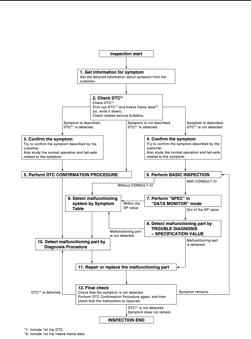
EC-18
< BASIC INSPECTION > [FOR CALIFORNIA]
DIAGNOSIS AND REPAIR WORKFLOW
BASIC INSPECTION
DIAGNOSIS AND REPAIR WORKFLOW
Work Flow INFOID:0000000004493280
OVERALL SEQUENCE
DETAILED FLOW
JMBIA1416G
B
Revision: 2008 August 2009 Rogue

DIAGNOSIS AND REPAIR WORKFLOW
EC-19
< BASIC INSPECTION > [FOR CALIFORNIA]
C
D
E
F
G
H
I
J
K
L
M
A
EC
N
P
O
1.GET INFORMATION FOR SYMPTOM
Get the detailed information from the customer about the symptom (the condition and the environment when
the incident/malfunction occurred) using the “Diagnostic Work Sheet”. (Refer to EC-21, "Diagnostic Work
Sheet".)
>> GO TO 2.
2.CHECK DTC
1. Check DTC.
2. Perform the following procedure if DTC is displayed.
- Record DTC and freeze frame data. (Print them out with CONSULT-III or GST.)
- Erase DTC. (Refer to “” EC-92, "Diagnosis Description".)
- Study the relationship between the cause detected by DTC and the symptom described by the customer.
(Symptom Table is useful. Refer to EC-478, "Symptom Table".)
3. Check related service bulletins for information.
Are any symptoms described and is any DTCs detected?
Symptom is described, DTC is detected>>GO TO 3.
Symptom is described, DTC is not detected>>GO TO 4.
Symptom is not described, DTC is detected>>GO TO 5.
3.CONFIRM THE SYMPTOM
Try to confirm the symptom described by the customer (except MIL ON).
Also study the normal operation and fail-safe related to the symptom. Refer to EC-482, "Description" and EC-
462, "Fail safe".
Diagnosis Work Sheet is useful to verify the incident.
Verify relation between the symptom and the condition when the symptom is detected.
>> GO TO 5.
4.CONFIRM THE SYMPTOM
Try to confirm the symptom described by the customer.
Also study the normal operation and fail-safe related to the symptom. Refer to EC-482, "Description" and EC-
462, "Fail safe".
Diagnosis Work Sheet is useful to verify the incident.
Verify relation between the symptom and the condition when the symptom is detected.
>> GO TO 6.
5.PERFORM DTC CONFIRMATION PROCEDURE
Perform DTC CONFIRMATION PROCEDURE for the displayed DTC, and then check that DTC is detected
again.
If two or more DTCs are detected, refer to EC-464, "DTC Inspection Priority Chart" and determine trouble
diagnosis order.
NOTE:
• Freeze frame data is useful if the DTC is not detected.
• Perform Component Function Check if DTC CONFIRMATION PROCEDURE is not included on Service
Manual. This simplified check procedure is an effective alternative though DTC cannot be detected during
this check.
If the result of Component Function Check is NG, it is the same as the detection of DTC by DTC CONFIR-
MATION PROCEDURE.
Is DTC detected?
YES >> GO TO 10.
NO >> Check according to GI-41, "Intermittent Incident".
6.PERFORM BASIC INSPECTION
Perform EC-22, "BASIC INSPECTION : Special Repair Requirement".
Do you have CONSULT-III?
Revision: 2008 August 2009 Rogue

EC-20
< BASIC INSPECTION > [FOR CALIFORNIA]
DIAGNOSIS AND REPAIR WORKFLOW
YES >> GO TO 7.
NO >> GO TO 9.
7.PERFORM SPEC IN DATA MONITOR MODE
With CONSULT-III
Check that “MAS A/F SE-B1”, “B/FUEL SCHDL” and “A/F ALPHA-B1” are within the SP value using CON-
SULT-III in “SPEC” of “DATA MONITOR” mode with CONSULT-lll. Refer to EC-116, "Component Function
Check".
Is the measurement value within the SP value?
YES >> GO TO 9.
NO >> GO TO 8.
8.DETECT MALFUNCTIONING PART BY TROUBLE DIAGNOSIS - SPECIFICATION VALUE
Detect malfunctioning part according to EC-117, "Diagnosis Procedure".
Is a malfunctioning part detected?
YES >> GO TO 11.
NO >> GO TO 9.
9.DETECT MALFUNCTIONING SYSTEM BY SYMPTOM TABLE
Detect malfunctioning system according to EC-478, "Symptom Table" based on the confirmed symptom in
step 4, and determine the trouble diagnosis order based on possible causes and symptoms.
>> GO TO 10.
10.DETECT MALFUNCTIONING PART BY DIAGNOSIS PROCEDURE
Inspect according to Diagnosis Procedure of the system.
NOTE:
The Diagnosis Procedure in EC section described based on open circuit inspection. A short circuit inspection
is also required for the circuit check in the Diagnosis Procedure. For details, refer to “Circuit Inspection” in GI-
44, "Circuit Inspection".
Is a malfunctioning part detected?
YES >> GO TO 11.
NO >> Monitor input data from related sensors or check the voltage of related ECM terminals using CON-
SULT-III. Refer to EC-439, "Reference Value".
11.REPAIR OR REPLACE THE MALFUNCTIONING PART
1. Repair or replace the malfunctioning part.
2. Reconnect parts or connectors disconnected during Diagnosis Procedure again after repair and replace-
ment.
3. Check DTC. If DTC is displayed, erase it. (Refer to “” EC-92, "Diagnosis Description".)
>> GO TO 12.
12.FINAL CHECK
When DTC was detected in step 2, perform DTC CONFIRMATION PROCEDURE or Component Function
Check again, and then check that the malfunction have been completely repaired.
When symptom was described from the customer, refer to confirmed symptom in step 3 or 4, and check that
the symptom is not detected.
Is DTC detected and does symptom remain?
YES-1 >> DTC is detected: GO TO 10.
YES-2 >> Symptom remains: GO TO 6.
NO >> Before returning the vehicle to the customer, check to always erase unnecessary DTC in ECM
and TCM (Transmission Control Module). (Refer to “” EC-92, "Diagnosis Description".) If the com-
pletion of SRT is needed, drive vehicle under the specific DRIVING PATTERN in EC-469,
"How to Set SRT Code".
Revision: 2008 August 2009 Rogue
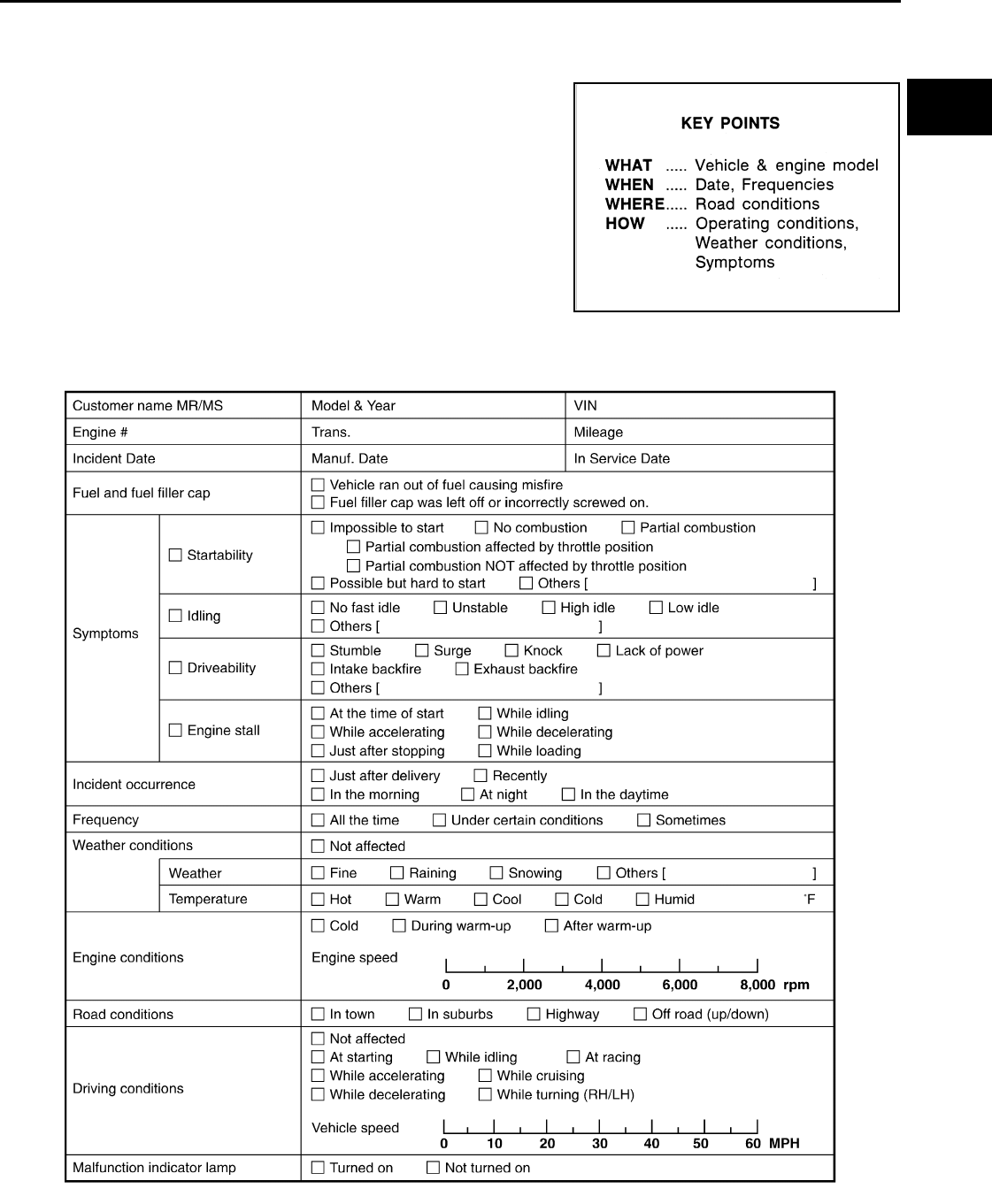
DIAGNOSIS AND REPAIR WORKFLOW
EC-21
< BASIC INSPECTION > [FOR CALIFORNIA]
C
D
E
F
G
H
I
J
K
L
M
A
EC
N
P
O
Diagnostic Work Sheet INFOID:0000000004493281
DESCRIPTION
There are many operating conditions that lead to the malfunction of
engine components. A good grasp of such conditions can make trou-
bleshooting faster and more accurate.
In general, each customer feels differently about symptoms. It is
important to fully understand the symptoms or conditions for a cus-
tomer complaint.
Utilize a diagnostic worksheet like WORK SHEET SAMPLE below in
order to organize all the information for troubleshooting.
Some conditions may cause the MIL illuminate or blink, and DTC to
be detected. Examples:
• Vehicle ran out of fuel, which caused the engine to misfire.
• Fuel filler cap was left off or incorrectly screwed on, allowing fuel to
evaporate into the atmosphere.
WORKSHEET SAMPLE
SEF907L
MTBL0017
Revision: 2008 August 2009 Rogue
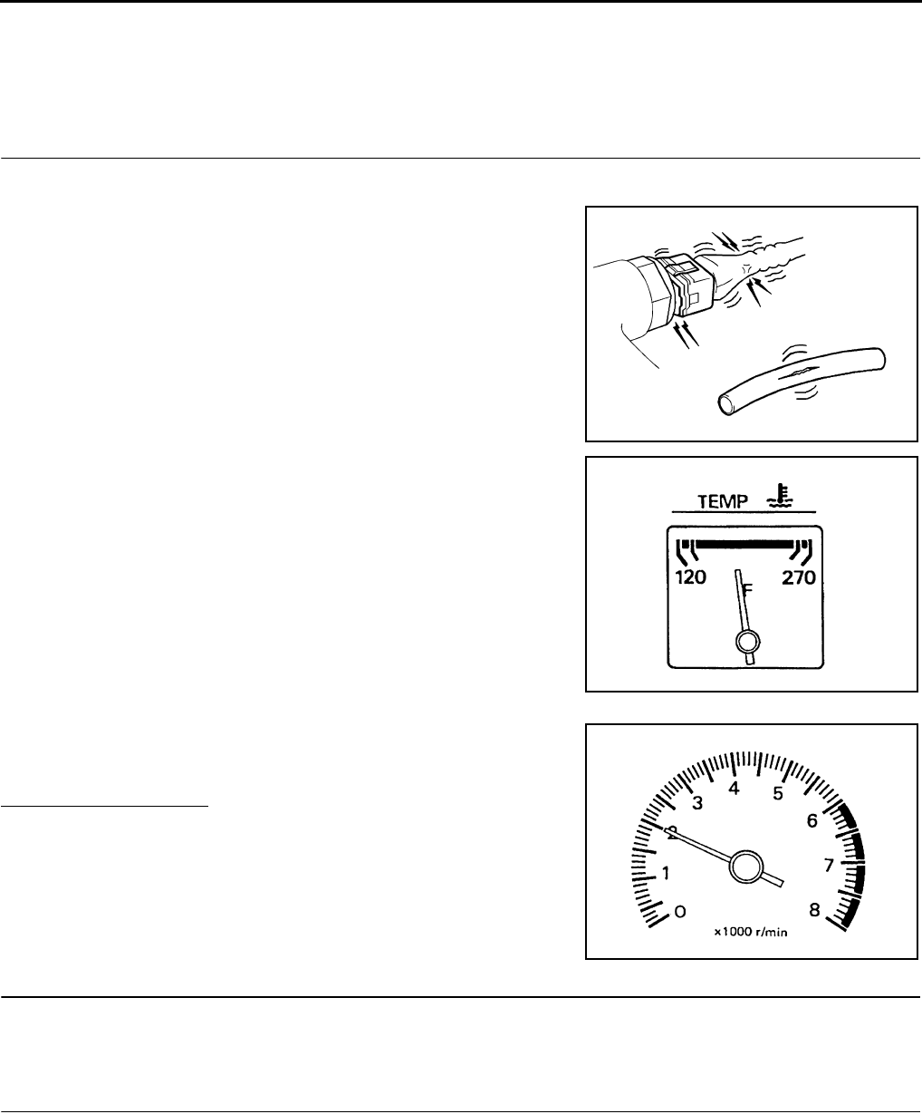
EC-22
< BASIC INSPECTION > [FOR CALIFORNIA]
INSPECTION AND ADJUSTMENT
INSPECTION AND ADJUSTMENT
BASIC INSPECTION
BASIC INSPECTION : Special Repair Requirement INFOID:0000000004493282
1.INSPECTION START
1. Check service records for any recent repairs that may indicate a related malfunction, or a current need for
scheduled maintenance.
2. Open engine hood and check the following:
- Harness connectors for improper connections
- Wiring harness for improper connections, pinches and cut
- Vacuum hoses for splits, kinks and improper connections
- Hoses and ducts for leakage
- Air cleaner clogging
- Gasket
3. Check that electrical or mechanical loads are not applied.
- Headlamp switch is OFF.
- Air conditioner switch is OFF.
- Rear window defogger switch is OFF.
- Steering wheel is in the straight-ahead position, etc.
4. Start engine and warm it up until engine coolant temperature
indicator points to the middle of gauge.
Check that engine stays below 1,000 rpm.
5. Run engine at approximately 2,000 rpm for approximately 2 min-
utes under no load.
6. Check that no DTC is displayed with CONSULT-III or GST.
Are any DTCs detected?
YES >> GO TO 2.
NO >> GO TO 3.
2.REPAIR OR REPLACE
Repair or replace components as necessary according to corresponding Diagnosis Procedure.
>> GO TO 3
3.CHECK IDLE SPEED
1. Run engine at approximately 2,000 rpm for approximately 2 minutes under no load.
SEF983U
SEF976U
SEF977U
Revision: 2008 August 2009 Rogue
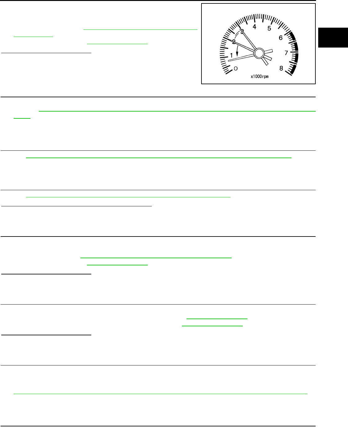
INSPECTION AND ADJUSTMENT
EC-23
< BASIC INSPECTION > [FOR CALIFORNIA]
C
D
E
F
G
H
I
J
K
L
M
A
EC
N
P
O
2. Rev engine (2,000 to 3,000 rpm) two or three times under no
load, then run engine at idle speed for approximately 1 minute.
3. Check idle speed.
For procedure, refer to EC-26, "IDLE SPEED : Special Repair
Requirement".
For specification, refer to EC-494, "Idle Speed".
Is the inspection result normal?
YES >> GO TO 10.
NO >> GO TO 4.
4.PERFORM ACCELERATOR PEDAL RELEASED POSITION LEARNING
1. Stop engine.
2. Perform EC-27, "ACCELERATOR PEDAL RELEASED POSITION LEARNING : Special Repair Require-
ment".
>> GO TO 5.
5.PERFORM THROTTLE VALVE CLOSED POSITION LEARNING
Perform EC-27, "THROTTLE VALVE CLOSED POSITION LEARNING : Special Repair Requirement".
>> GO TO 6.
6.PERFORM IDLE AIR VOLUME LEARNING
Perform EC-27, "IDLE AIR VOLUME LEARNING : Special Repair Requirement".
Is Idle Air Volume Learning carried out successfully?
YES >> GO TO 7.
NO >> Follow the instruction of Idle Air Volume Learning. Then GO TO 4.
7.CHECK IDLE SPEED AGAIN
1. Start engine and warm it up to normal operating temperature.
2. Check idle speed.
For procedure, refer to EC-26, "IDLE SPEED : Special Repair Requirement".
For specification, refer to EC-494, "Idle Speed".
Is the inspection result normal?
YES >> GO TO 10.
NO >> GO TO 8.
8.DETECT MALFUNCTIONING PART
Check the Following.
• Check camshaft position sensor (PHASE) and circuit. Refer to EC-260, "DTC Logic".
• Check crankshaft position sensor (POS) and circuit. Refer to EC-256, "DTC Logic".
Is the inspection result normal?
YES >> GO TO 9.
NO >> Repair or replace. Then GO TO 4.
9.CHECK ECM FUNCTION
1. Substitute with a non-malfunctioning ECM to check ECM function. (ECM may be the cause of incident,
although this is rare.)
2. Perform initialization of NVIS (NATS) system and registration of all NVIS (NATS) ignition key IDs. Refer to
EC-25, "ADDITIONAL SERVICE WHEN REPLACING CONTROL UNIT : Special Repair Requirement".
>> GO TO 4.
10.CHECK IGNITION TIMING
1. Run engine at idle.
2. Check ignition timing with a timing light.
PBIA8513J
Revision: 2008 August 2009 Rogue

EC-24
< BASIC INSPECTION > [FOR CALIFORNIA]
INSPECTION AND ADJUSTMENT
For procedure, refer to EC-26, "IGNITION TIMING : Special Repair Requirement".
For specification, refer to EC-494, "Ignition Timing".
Is the inspection result normal?
YES >> GO TO 19.
NO >> GO TO 11.
11.PERFORM ACCELERATOR PEDAL RELEASED POSITION LEARNING
1. Stop engine.
2. Perform EC-27, "ACCELERATOR PEDAL RELEASED POSITION LEARNING : Special Repair Require-
ment".
>> GO TO 12.
12.PERFORM THROTTLE VALVE CLOSED POSITION LEARNING
Perform EC-27, "THROTTLE VALVE CLOSED POSITION LEARNING : Special Repair Requirement".
>> GO TO 13.
13.PERFORM IDLE AIR VOLUME LEARNING
Perform EC-27, "IDLE AIR VOLUME LEARNING : Special Repair Requirement".
Is Idle Air Volume Learning carried out successfully?
YES >> GO TO 14.
NO >> Follow the instruction of Idle Air Volume Learning. Then GO TO 4.
14.CHECK IDLE SPEED AGAIN
1. Start engine and warm it up to normal operating temperature.
2. Check idle speed.
For procedure, refer to EC-26, "IDLE SPEED : Special Repair Requirement".
For specification, refer to EC-494, "Idle Speed".
Is the inspection result normal?
YES >> GO TO 15.
NO >> GO TO 17.
15.CHECK IGNITION TIMING AGAIN
1. Run engine at idle.
2. Check ignition timing with a timing light.
For procedure, refer to EC-26, "IGNITION TIMING : Special Repair Requirement".
For specification, refer to EC-494, "Ignition Timing".
Is the inspection result normal?
YES >> GO TO 19.
NO >> GO TO 16.
16.CHECK TIMING CHAIN INSTALLATION
Check timing chain installation. Refer to EM-70, "Removal and Installation".
Is the inspection result normal?
YES >> GO TO 17.
NO >> Repair the timing chain installation. Then GO TO 4.
17.DETECT MALFUNCTIONING PART
Check the following.
• Check camshaft position sensor (PHASE) and circuit. Refer to EC-260, "DTC Logic".
• Check crankshaft position sensor (POS) and circuit. Refer to EC-256, "DTC Logic".
Is the inspection result normal?
YES >> GO TO 18.
NO >> Repair or replace. Then GO TO 4.
18.CHECK ECM FUNCTION
Revision: 2008 August 2009 Rogue

INSPECTION AND ADJUSTMENT
EC-25
< BASIC INSPECTION > [FOR CALIFORNIA]
C
D
E
F
G
H
I
J
K
L
M
A
EC
N
P
O
1. Substitute with a non-malfunctioning ECM to check ECM function. (ECM may be the cause of incident,
although this is rare.)
2. Perform initialization of NVIS (NATS) system and registration of all NVIS (NATS) ignition key IDs. Refer to
EC-25, "ADDITIONAL SERVICE WHEN REPLACING CONTROL UNIT : Special Repair Requirement".
>> GO TO 4.
19.INSPECTION END
If ECM is replaced during this BASIC INSPECTION procedure, go to EC-25, "ADDITIONAL SERVICE WHEN
REPLACING CONTROL UNIT : Special Repair Requirement".
>> INSPECTION END
ADDITIONAL SERVICE WHEN REPLACING CONTROL UNIT
ADDITIONAL SERVICE WHEN REPLACING CONTROL UNIT : Description
INFOID:0000000004493283
When replacing ECM, the following procedure must be performed.
ADDITIONAL SERVICE WHEN REPLACING CONTROL UNIT : Special Repair Re-
quirement INFOID:0000000004493284
1.PERFORM INITIALIZATION OF NIVS (NATS) SYSTEM AND REGISTRATION OF ALL NATS IGNITION
KEY IDS
Refer to SEC-9, "ECM RE-COMMUNICATING FUNCTION : Special Repair Requirement" (With Intelligent key
system), SEC-154, "ECM RE-COMMUNICATING FUNCTION : Special Repair Requirement" (Without Intelli-
gent key system).
>> GO TO 2.
2.PERFORM VIN REGISTRATION
Refer to EC-26, "VIN REGISTRATION : Special Repair Requirement".
>> GO TO 3.
3.PERFORM ACCELERATOR PEDAL RELEASED POSITION LEARNING
Refer to EC-27, "ACCELERATOR PEDAL RELEASED POSITION LEARNING : Special Repair Requirement".
>> GO TO 4.
4.PERFORM THROTTLE VALVE CLOSED POSITION LEARNING
Refer to EC-27, "THROTTLE VALVE CLOSED POSITION LEARNING : Special Repair Requirement".
>> GO TO 5.
5.PERFORM IDLE AIR VOLUME LEARNING
Refer to EC-27, "IDLE AIR VOLUME LEARNING : Special Repair Requirement".
>> END
IDLE SPEED
IDLE SPEED : Description INFOID:0000000004493285
This describes how to check the idle speed. For the actual procedure, follow the instructions in “BASIC
INSPECTION”.
Revision: 2008 August 2009 Rogue
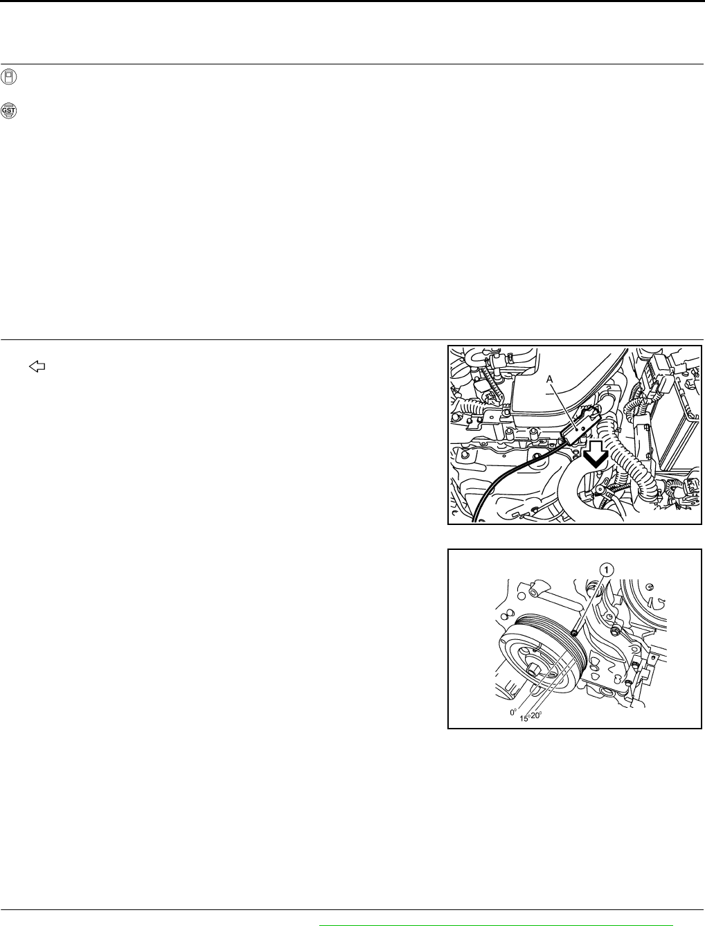
EC-26
< BASIC INSPECTION > [FOR CALIFORNIA]
INSPECTION AND ADJUSTMENT
IDLE SPEED : Special Repair Requirement INFOID:0000000004493286
1.CHECK IDLE SPEED
With CONSULT-III
Check idle speed in “DATA MONITOR” mode with CONSULT-III.
With GST
Check idle speed with Service $01 of GST.
>> INSPECTION END
IGNITION TIMING
IGNITION TIMING : Description INFOID:0000000004493287
This describes how to check the ignition timing. For the actual procedure, follow the instructions in “BASIC
INSPECTION”.
IGNITION TIMING : Special Repair Requirement INFOID:0000000004493288
1.CHECK IGNITION TIMING
1. Attach timing light (A) to No. 1 ignition coil wire as shown.
- : Vehicle front
2. Check ignition timing.
- Timing indicator (1)
>> INSPECTION END
VIN REGISTRATION
VIN REGISTRATION : Description INFOID:0000000004493289
VIN Registration is an operation to register VIN in ECM. It must be performed each time ECM is replaced.
NOTE:
Accurate VIN which is registered in ECM may be required for Inspection & Maintenance (I/M).
VIN REGISTRATION : Special Repair Requirement INFOID:0000000004493290
1.CHECK VIN
Check the VIN of the vehicle and note it. Refer to GI-22, "Information About Identification or Model Code".
>> GO TO 2.
JMBIA0928ZZ
ALBIA0048ZZ
Revision: 2008 August 2009 Rogue

INSPECTION AND ADJUSTMENT
EC-27
< BASIC INSPECTION > [FOR CALIFORNIA]
C
D
E
F
G
H
I
J
K
L
M
A
EC
N
P
O
2.PERFORM VIN REGISTRATION
With CONSULT-III
1. Turn ignition switch ON with engine stopped.
2. Select “VIN REGISTRATION” in “WORK SUPPORT” mode.
3. Follow the instructions on the CONSULT-III display.
>> END
ACCELERATOR PEDAL RELEASED POSITION LEARNING
ACCELERATOR PEDAL RELEASED POSITION LEARNING : Description INFOID:0000000004493291
Accelerator Pedal Released Position Learning is a function of ECM to learn the fully released position of the
accelerator pedal by monitoring the accelerator pedal position sensor output signal. It must be performed each
time harness connector of accelerator pedal position sensor or ECM is disconnected.
ACCELERATOR PEDAL RELEASED POSITION LEARNING : Special Repair Re-
quirement INFOID:0000000004493292
1.START
1. Check that accelerator pedal is fully released.
2. Turn ignition switch ON and wait at least 2 seconds.
3. Turn ignition switch OFF and wait at least 10 seconds.
4. Turn ignition switch ON and wait at least 2 seconds.
5. Turn ignition switch OFF and wait at least 10 seconds.
>> END
THROTTLE VALVE CLOSED POSITION LEARNING
THROTTLE VALVE CLOSED POSITION LEARNING : Description INFOID:0000000004493293
Throttle Valve Closed Position Learning is a function of ECM to learn the fully closed position of the throttle
valve by monitoring the throttle position sensor output signal. It must be performed each time harness connec-
tor of electric throttle control actuator or ECM is disconnected.
THROTTLE VALVE CLOSED POSITION LEARNING : Special Repair Requirement
INFOID:0000000004493294
1.START
1. Check that accelerator pedal is fully released.
2. Turn ignition switch ON.
3. Turn ignition switch OFF and wait at least 10 seconds.
Check that throttle valve moves during the above 10 seconds by confirming the operating sound.
>> END
IDLE AIR VOLUME LEARNING
IDLE AIR VOLUME LEARNING : Description INFOID:0000000004493295
Idle Air Volume Learning is a function of ECM to learn the idle air volume that keeps each engine idle speed
within the specific range. It must be performed under the following conditions:
• Each time the electric throttle control actuator or ECM is replaced.
• Idle speed or ignition timing is out of the specification.
IDLE AIR VOLUME LEARNING : Special Repair Requirement INFOID:0000000004493296
1.PRECONDITIONING
Check that all of the following conditions are satisfied.
Revision: 2008 August 2009 Rogue

EC-28
< BASIC INSPECTION > [FOR CALIFORNIA]
INSPECTION AND ADJUSTMENT
Learning will be cancelled if any of the following conditions are missed for even a moment.
• Battery voltage: More than 12.9V (At idle)
• Engine coolant temperature: 70 - 100°C (158 - 212°F)
• PNP switch: ON
• Electric load switch: OFF
(Air conditioner, headlamp, rear window defogger)
On vehicles equipped with daytime light systems, if the parking brake is applied before the engine is
started the headlamp will not illuminate.
• Steering wheel: Neutral (Straight-ahead position)
• Vehicle speed: Stopped
• Transmission: Warmed-up
- With CONSULT-III: Drive vehicle until “ATF TENP SEN” in “DATA MONITOR” mode of “CVT” system indi-
cates less than 0.9V.
- Without CONSULT-III: Drive vehicle for 10 minutes.
Do you have CONSULT-III?
YES >> GO TO 2.
NO >> GO TO 3.
2.IDLE AIR VOLUME LEARNING
With CONSULT-III
1. Perform Accelerator Pedal Released Position Learning. Refer to EC-27, "ACCELERATOR PEDAL
RELEASED POSITION LEARNING : Special Repair Requirement".
2. Perform Throttle Valve Closed Position Learning. Refer to EC-27, "THROTTLE VALVE CLOSED POSI-
TION LEARNING : Special Repair Requirement".
3. Start engine and warm it up to normal operating temperature.
4. Select “IDLE AIR VOL LEARN” in “WORK SUPPORT” mode.
5. Touch “START” and wait 20 seconds.
Is “CMPLT” displayed on CONSULT-III screen?
YES >> GO TO 4.
NO >> GO TO 5.
3.IDLE AIR VOLUME LEARNING
Without CONSULT-III
NOTE:
•It is better to count the time accurately with a clock.
•It is impossible to switch the diagnostic mode when an accelerator pedal position sensor circuit has
a malfunction.
1. Perform Accelerator Pedal Released Position Learning. Refer to EC-27, "ACCELERATOR PEDAL
RELEASED POSITION LEARNING : Special Repair Requirement".
2. Perform Throttle Valve Closed Position Learning. Refer to EC-27, "THROTTLE VALVE CLOSED POSI-
TION LEARNING : Special Repair Requirement".
3. Start engine and warm it up to normal operating temperature.
4. Turn ignition switch OFF and wait at least 10 seconds.
5. Confirm that accelerator pedal is fully released, turn ignition switch ON and wait 3 seconds.
6. Repeat the following procedure quickly five times within 5 seconds.
- Fully depress the accelerator pedal.
- Fully release the accelerator pedal.
7. Wait 7 seconds, fully depress the accelerator pedal for approx. 20 seconds until the MIL stops blinking
and turns ON.
8. Fully release the accelerator pedal within 3 seconds after the MIL turns ON.
9. Start engine and let it idle.
Revision: 2008 August 2009 Rogue
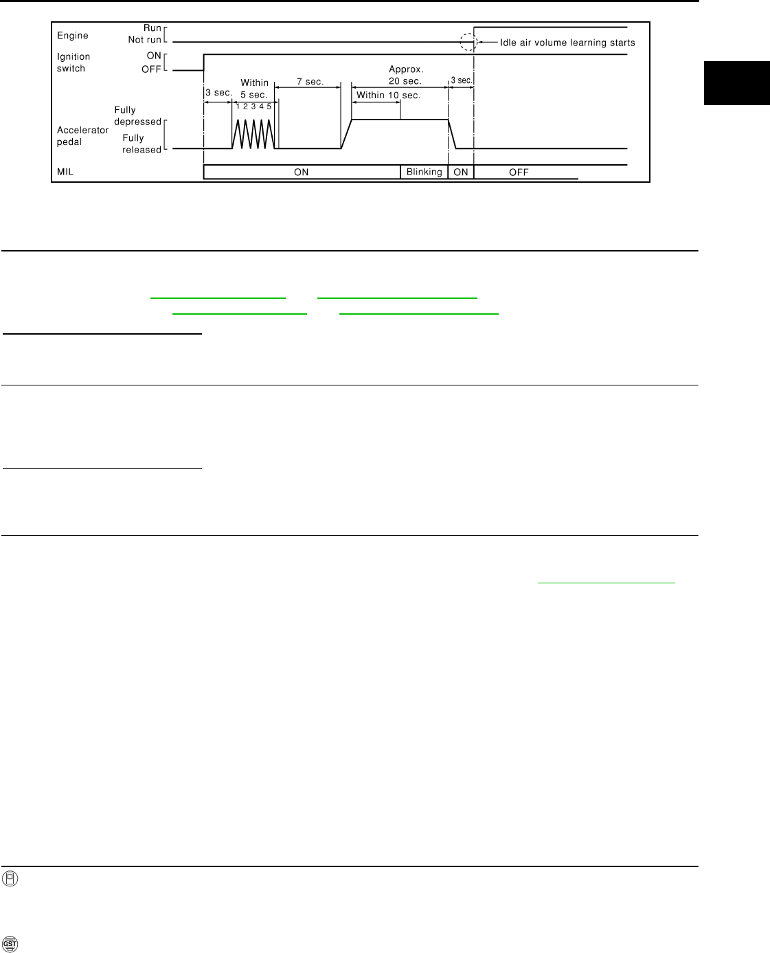
INSPECTION AND ADJUSTMENT
EC-29
< BASIC INSPECTION > [FOR CALIFORNIA]
C
D
E
F
G
H
I
J
K
L
M
A
EC
N
P
O
10. Wait 20 seconds.
>> GO TO 4.
4.CHECK IDLE SPEED AND IGNITION TIMING
Rev up the engine two or three times and check that idle speed and ignition timing are within the specifica-
tions.
For procedure, refer to EC-494, "Idle Speed" and EC-494, "Ignition Timing".
For specifications, refer to EC-494, "Idle Speed" and EC-494, "Ignition Timing".
Is the inspection result normal?
YES >> INSPECTION END
5.DETECT MALFUNCTIONING PART
Check the following
• Check that throttle valve is fully closed.
• Check PCV valve operation.
• Check that downstream of throttle valve is free from air leakage.
Is the inspection result normal?
YES >> GO TO 6.
NO >> Repair or replace malfunctioning part.
6.DETECT MALFUNCTIONING PART
Engine component parts and their installation condition are questionable. Check and eliminate the cause of
the incident.
It is useful to perform “TROUBLE DIAGNOSIS - SPECIFICATION VALUE”. Refer to EC-116, "Description".
If any of the following conditions occur after the engine has started, eliminate the cause of the incident and
perform Idle Air Volume Learning again:
• Engine stalls.
• Incorrect idle.
>> INSPECTION END
MIXTURE RATIO SELF-LEARNING VALUE CLEAR
MIXTURE RATIO SELF-LEARNING VALUE CLEAR : Description INFOID:0000000004493297
This describes how to erase the mixture ratio self-learning value. For the actual procedure, follow the instruc-
tions in “Diagnosis Procedure”.
MIXTURE RATIO SELF-LEARNING VALUE CLEAR : Special Repair Requirement
INFOID:0000000004493298
1.START
With CONSULT-III
1. Start engine and warm it up to normal operating temperature.
2. Select “SELF-LEARNING CONT” in “WORK SUPPORT” mode with CONSULT-III.
3. Clear mixture ratio self-learning value by touching “CLEAR”.
With GST
1. Start engine and warm it up to normal operating temperature.
SEC897C
Revision: 2008 August 2009 Rogue

EC-30
< BASIC INSPECTION > [FOR CALIFORNIA]
INSPECTION AND ADJUSTMENT
2. Turn ignition switch OFF.
3. Disconnect mass air flow sensor harness connector.
4. Restart engine and let it idle for at least 5 seconds.
5. Stop engine and reconnect mass air flow sensor harness connector.
6. Select Service $03 with GST. check DTC P0102 is detected.
7. Select Service $04 with GST to erase the DTC P0102.
>> END
Revision: 2008 August 2009 Rogue
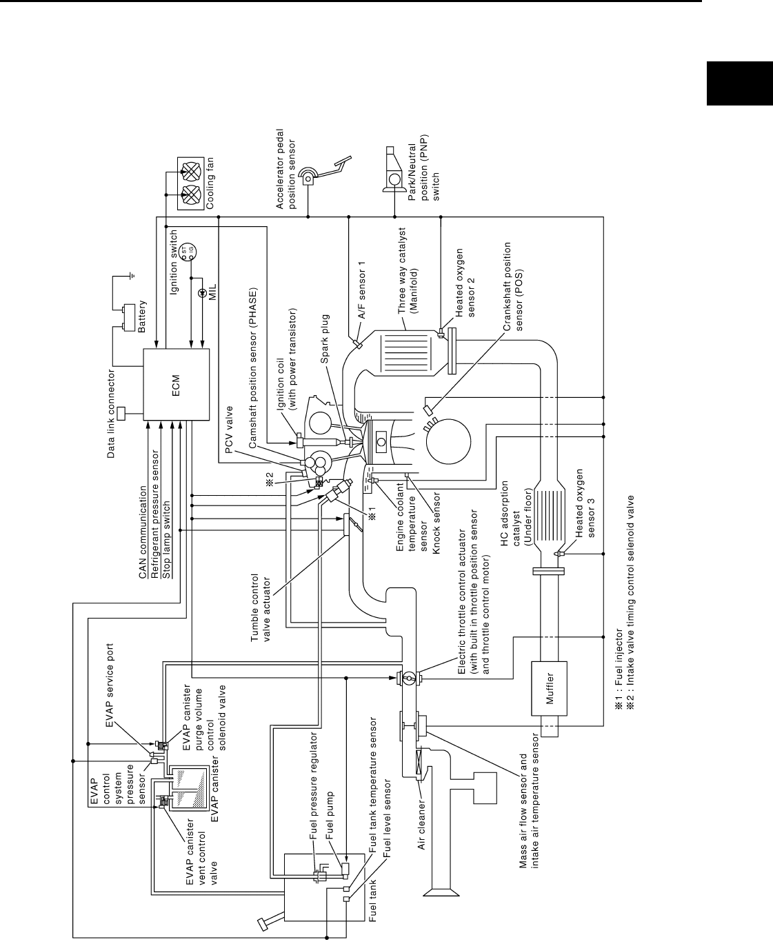
ENGINE CONTROL SYSTEM
EC-31
< FUNCTION DIAGNOSIS > [FOR CALIFORNIA]
C
D
E
F
G
H
I
J
K
L
M
A
EC
N
P
O
FUNCTION DIAGNOSIS
ENGINE CONTROL SYSTEM
System Diagram INFOID:0000000004493299
JMBIA0933G
B
Revision: 2008 August 2009 Rogue
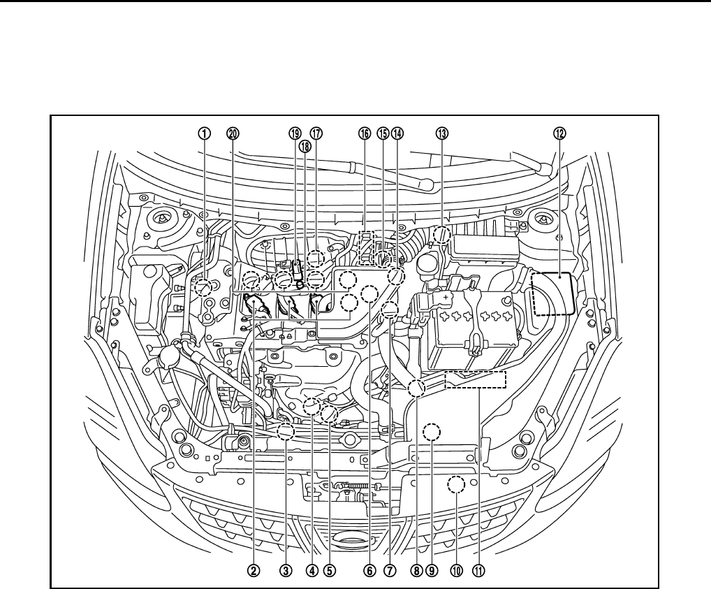
EC-32
< FUNCTION DIAGNOSIS > [FOR CALIFORNIA]
ENGINE CONTROL SYSTEM
System Description INFOID:0000000004493300
ECM performs various controls such as fuel injection control and ignition timing control.
Component Parts Location INFOID:0000000004493301
1. Intake valve timing control solenoid
valve
2. Ignition coil (with power transistor)
and spark plug
3. Cooling fan motor-2
4. Air fuel ratio (A/F) sensor 1 5. Heated oxygen sensor 2 6. Camshaft position sensor (PHASE)
7. Engine coolant temperature sensor 8. Park/neutral position (PNP) switch 9. Cooling fan motor-1
10. Refrigerant pressure sensor 11. ECM 12. IPDM E/R
13. Mass air flow sensor (with intake air
temperature sensor) 14. Tumble control valve actuator 15. Crankshaft position sensor (POS)
16. Electric throttle control actuator
(with built in throttle position sensor
and throttle control motor)
17. Knock sensor 18. EVAP service port
19. EVAP canister purge volume control
solenoid valve
20. Fuel injector
JMBIA0932ZZ
Revision: 2008 August 2009 Rogue
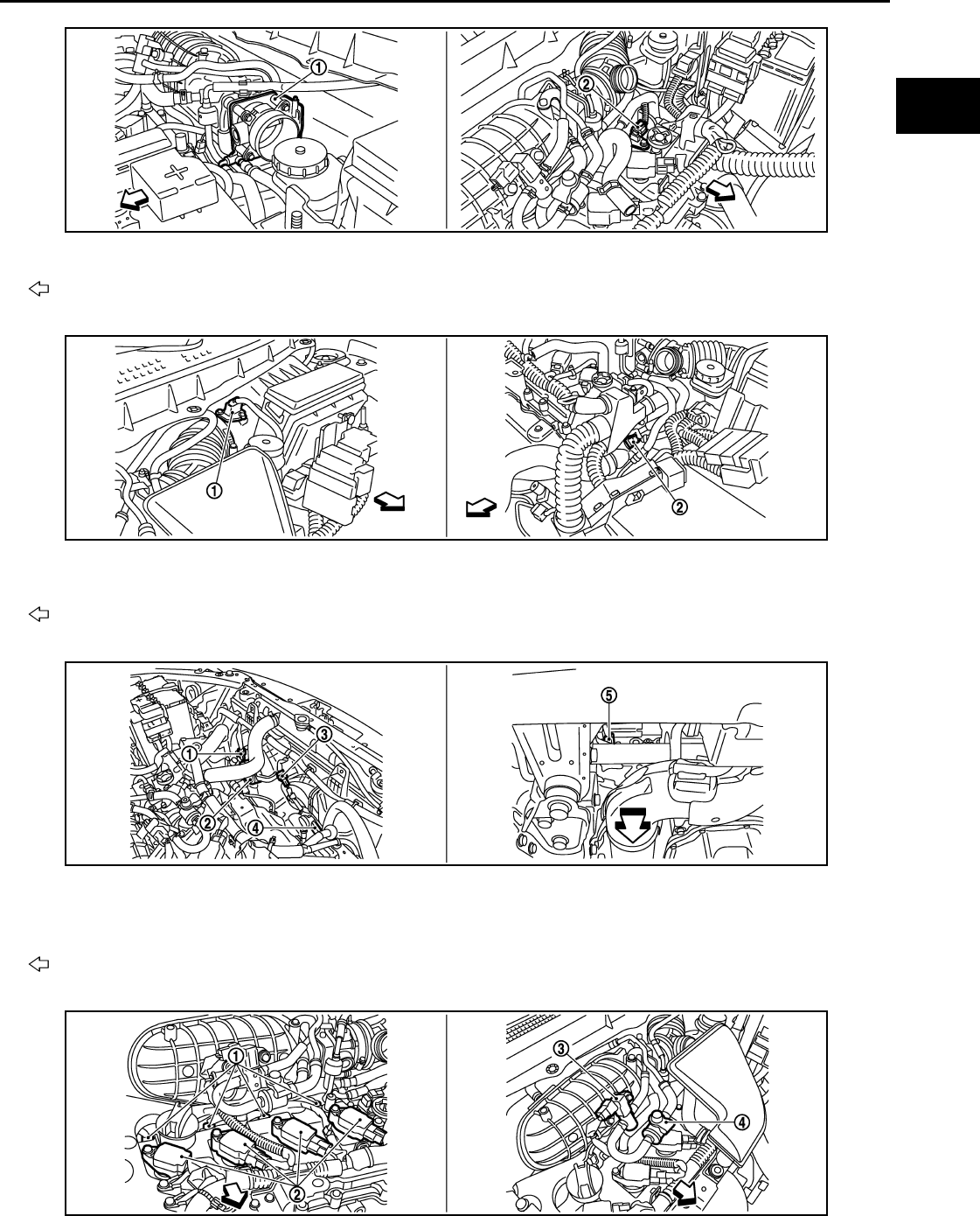
ENGINE CONTROL SYSTEM
EC-33
< FUNCTION DIAGNOSIS > [FOR CALIFORNIA]
C
D
E
F
G
H
I
J
K
L
M
A
EC
N
P
O
1. Electric throttle control actuator 2. Camshaft position sensor (PHASE)
Vehicle front
1. Mass air flow sensor (with intake air
temperature sensor) 2. Engine coolant temperature sensor
Vehicle front
1. Cooling fan motor-1 harness con-
nector
2. Cooling fan motor-1 3. Cooling fan motor-2 harness con-
nector
4. Cooling fan motor-2 5. Crankshaft position sensor (POS)
Vehicle front
JMBIA0917ZZ
JMBIA0918ZZ
JMBIA0919ZZ
JMBIA0921ZZ
Revision: 2008 August 2009 Rogue
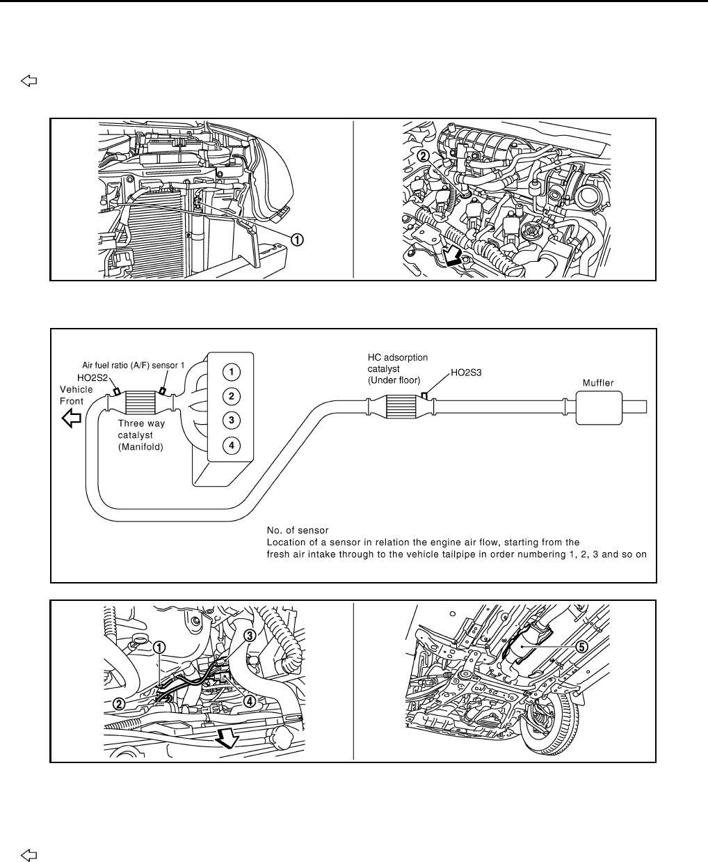
EC-34
< FUNCTION DIAGNOSIS > [FOR CALIFORNIA]
ENGINE CONTROL SYSTEM
1. Fuel injector 2. Ignition coil (with power transistor)
and spark plug
3. EVAP canister purge volume control
solenoid valve
4. EVAP service port
Vehicle front
1. Refrigerant pressure sensor 2. PCV valve
JMBIA0922ZZ
JMBIA0910G
B
1. Air fuel ratio (A/F) sensor 1 2. Heated oxygen sensor 2 3. Air fuel ratio (A/F) sensor 1 harness
connector
4. Heated oxygen sensor 2 harness
connector 5. HC adsorption catalyst (Under floor)
Vehicle front
JMBIA0920ZZ
Revision: 2008 August 2009 Rogue
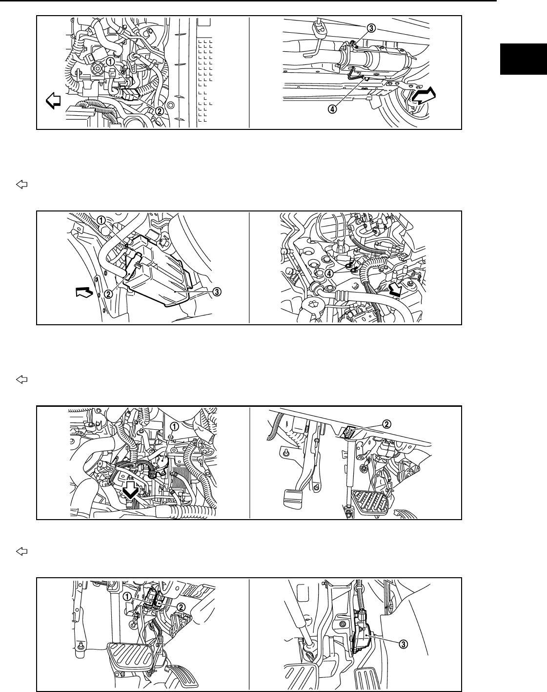
ENGINE CONTROL SYSTEM
EC-35
< FUNCTION DIAGNOSIS > [FOR CALIFORNIA]
C
D
E
F
G
H
I
J
K
L
M
A
EC
N
P
O
1. Tumble control valve actuator 2. Condenser 3. Heated oxygen sensor 3
4. Heated oxygen sensor 3 harness
connector
Vehicle front
1. EVAP control system pressure sen-
sor
2. EVAP canister vent control valve 3. EVAP canister
4. Body ground
Vehicle front
1. Park/neutral position (PNP) switch 2. Data link connector
Vehicle front
JMBIA0931ZZ
JMBIA0923ZZ
JMBIA0927ZZ
JMBIA0924ZZ
Revision: 2008 August 2009 Rogue
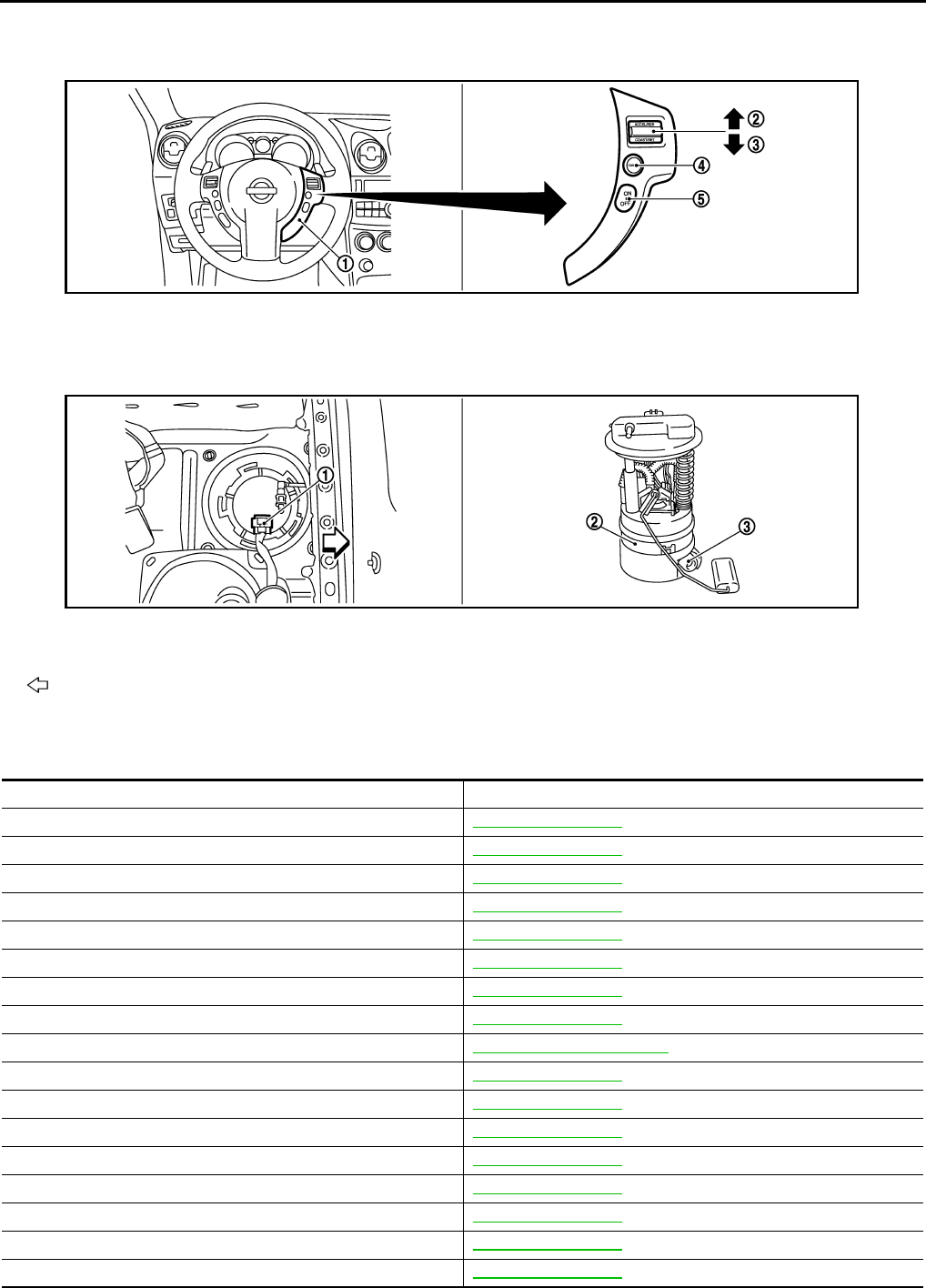
EC-36
< FUNCTION DIAGNOSIS > [FOR CALIFORNIA]
ENGINE CONTROL SYSTEM
Component Description INFOID:0000000004493302
1. Stop lamp switch 2. ASCD brake switch 3. Accelerator pedal position sensor
1. ASCD steering switch 2. RESUME/ACCERELATE switch 3. SET/COAST switch
4. CANSEL switch 5. MAIN switch
1. Fuel level sensor unit and fuel pump
harness connector
2. Fuel level sensor unit and fuel pump 3. Fuel pressure regulator
Vehicle front
JMBIA0925ZZ
JMBIA0926ZZ
Component Reference
A/F sensor 1 EC-177, "Description"
A/F sensor 1 heater EC-135, "Description"
Accelerator pedal position sensor EC-385, "Description"
ASCD brake switch EC-356, "Description"
ASCD steering switch EC-353, "Description"
ASCD vehicle speed sensor EC-361, "Description"
Camshaft position sensor (PHASE) EC-260, "Description"
Crankshaft position sensor (POS) EC-256, "Description"
Cooling fan motor EC-65, "System Description"
Electric throttle control actuator EC-383, "Description"
Engine coolant temperature sensor EC-164, "Description"
EVAP canister purge volume control solenoid valve EC-279, "Description"
EVAP canister vent control valve EC-286, "Description"
EVAP control system pressure sensor EC-294, "Description"
Fuel injector EC-419, "Description"
Fuel level sensor EC-321, "Description"
Fuel pump EC-422, "Description"
Revision: 2008 August 2009 Rogue

ENGINE CONTROL SYSTEM
EC-37
< FUNCTION DIAGNOSIS > [FOR CALIFORNIA]
C
D
E
F
G
H
I
J
K
L
M
A
EC
N
P
O
Fuel tank temperature sensor EC-239, "Description"
Heated oxygen sensor 2 EC-192, "Description"
Heated oxygen sensor 2 heater EC-138, "Description"
Heated oxygen sensor 3 EC-211, "Description"
Heated oxygen sensor 3 heater EC-141, "Description"
Ignition signal EC-425, "Description"
Intake air temperature sensor EC-159, "Description"
Intake valve timing control solenoid valve EC-80, "System Description"
Knock sensor EC-254, "Description"
Mass air flow sensor EC-147, "Description"
Park/neutral position switch EC-338, "Description"
PCV valve EC-436, "Description"
Refrigerant pressure sensor EC-437, "Description"
Stop lamp switch EC-365, "Description"
Throttle control motor EC-381, "Description"
Throttle control motor relay EC-375, "Description"
Throttle position sensor EC-167, "Description"
Tumble control valve EC-367, "Description"
Tumble control valve position sensor EC-372, "Description"
Component Reference
Revision: 2008 August 2009 Rogue
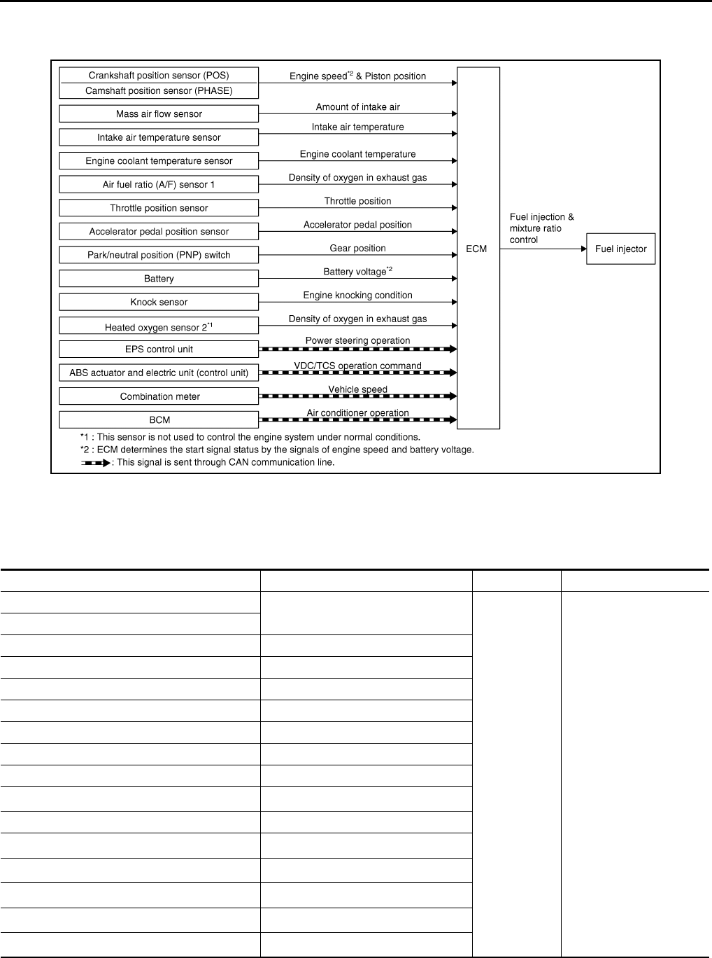
EC-38
< FUNCTION DIAGNOSIS > [FOR CALIFORNIA]
MULTIPORT FUEL INJECTION SYSTEM
MULTIPORT FUEL INJECTION SYSTEM
System Diagram INFOID:0000000004493303
System Description INFOID:0000000004493304
INPUT/OUTPUT SIGNAL CHART
*1: This sensor is not used to control the engine system under normal conditions.
*2: This signal is sent to the ECM through CAN communication line.
JMBIA1014G
B
Sensor Input signal to ECM ECM function Actuator
Crankshaft position sensor (POS) Engine speed*3
Piston position
Fuel injection
& mixture ratio
control Fuel injector
Camshaft position sensor (PHASE)
Mass air flow sensor Amount of intake air
Intake air temperature sensor Intake air temperature
Engine coolant temperature sensor Engine coolant temperature
Air fuel ratio (A/F) sensor 1 Density of oxygen in exhaust gas
Throttle position sensor Throttle position
Accelerator pedal position sensor Accelerator pedal position
Park/neutral position (PNP) switch Gear position
Battery Battery voltage*3
Knock sensor Engine knocking condition
Heated oxygen sensor 2*1Density of oxygen in exhaust gas
EPS control unit Power steering operation*2
ABS actuator and electric unit (control unit) ABS operation command*2
Combination meter Vehicle speed*2
BCM Air conditioner operation*2
Revision: 2008 August 2009 Rogue
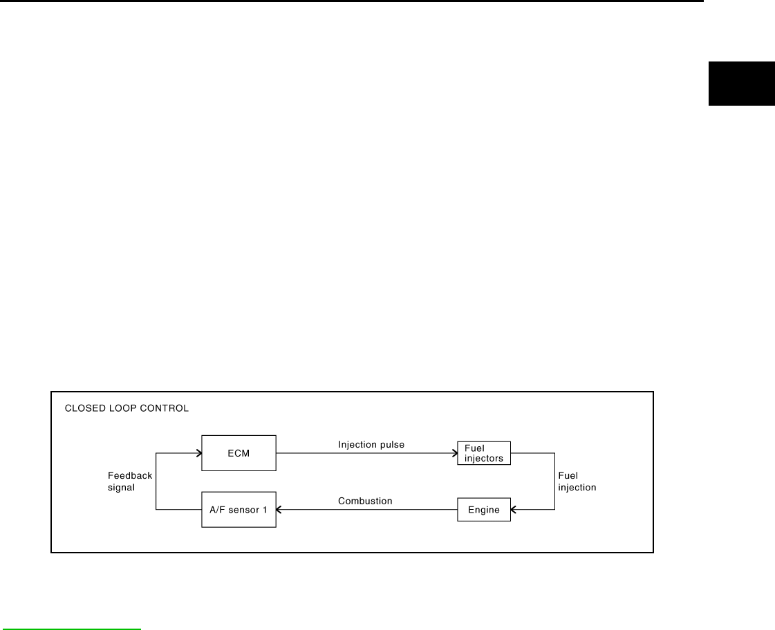
MULTIPORT FUEL INJECTION SYSTEM
EC-39
< FUNCTION DIAGNOSIS > [FOR CALIFORNIA]
C
D
E
F
G
H
I
J
K
L
M
A
EC
N
P
O
*3: ECM determines the start signal status by the signals of engine speed and battery voltage.
SYSTEM DESCRIPTION
The amount of fuel injected from the fuel injector is determined by the ECM. The ECM controls the length of
time the valve remains open (injection pulse duration). The amount of fuel injected is a program value in the
ECM memory. The program value is preset by engine operating conditions. These conditions are determined
by input signals (for engine speed and intake air) from the crankshaft position sensor (POS), camshaft position
sensor (PHASE) and the mass air flow sensor.
VARIOUS FUEL INJECTION INCREASE/DECREASE COMPENSATION
In addition, the amount of fuel injected is compensated to improve engine performance under various operat-
ing conditions as listed below.
<Fuel increase>
• During warm-up
• When starting the engine
• During acceleration
• Hot-engine operation
• When selector lever is changed from N to D
• High-load, high-speed operation
<Fuel decrease>
• During deceleration
• During high engine speed operation
MIXTURE RATIO FEEDBACK CONTROL (CLOSED LOOP CONTROL)
The mixture ratio feedback system provides the best air-fuel mixture ratio for driveability and emission control.
The three way catalyst (manifold) can better reduce CO, HC and NOx emissions. This system uses A/F sen-
sor 1 in the exhaust manifold to monitor whether the engine operation is rich or lean. The ECM adjusts the
injection pulse width according to the sensor voltage signal. For more information about A/F sensor 1, refer to
EC-177, "DTC Logic". This maintains the mixture ratio within the range of stoichiometric (ideal air-fuel mix-
ture).
This stage is referred to as the closed loop control condition.
Heated oxygen sensor 2 is located downstream of the three way catalyst (manifold). Even if the switching
characteristics of A/F sensor 1 shift, the air-fuel ratio is controlled to stoichiometric by the signal from heated
oxygen sensor 2.
• Open Loop Control
The open loop system condition refers to when the ECM detects any of the following conditions. Feedback
control stops in order to maintain stabilized fuel combustion.
- Deceleration and acceleration
- High-load, high-speed operation
- Malfunction of A/F sensor 1 or its circuit
- Insufficient activation of A/F sensor 1 at low engine coolant temperature
- High engine coolant temperature
- During warm-up
- After shifting from N to D
- When starting the engine
MIXTURE RATIO SELF-LEARNING CONTROL
The mixture ratio feedback control system monitors the mixture ratio signal transmitted from A/F sensor 1.
This feedback signal is then sent to the ECM. The ECM controls the basic mixture ratio as close to the theoret-
ical mixture ratio as possible. However, the basic mixture ratio is not necessarily controlled as originally
PBIB2793E
Revision: 2008 August 2009 Rogue
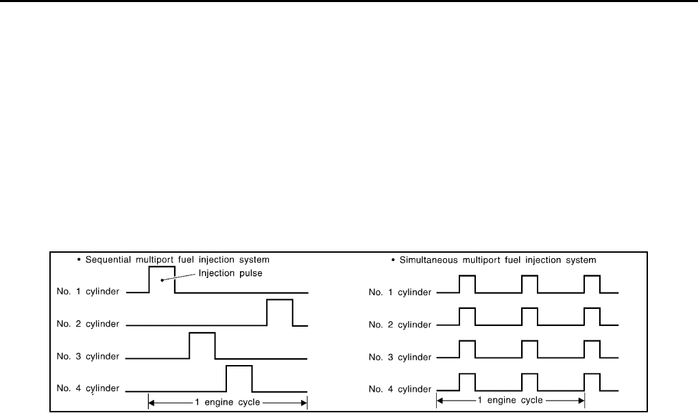
EC-40
< FUNCTION DIAGNOSIS > [FOR CALIFORNIA]
MULTIPORT FUEL INJECTION SYSTEM
designed. Both manufacturing differences (i.e., mass air flow sensor hot wire) and characteristic changes dur-
ing operation (i.e., fuel injector clogging) directly affect mixture ratio.
Accordingly, the difference between the basic and theoretical mixture ratios is monitored in this system. This is
then computed in terms of “injection pulse duration” to automatically compensate for the difference between
the two ratios.
“Fuel trim” refers to the feedback compensation value compared against the basic injection duration. Fuel trim
includes short-term fuel trim and long-term fuel trim.
“Short-term fuel trim” is the short-term fuel compensation used to maintain the mixture ratio at its theoretical
value. The signal from A/F sensor 1 indicates whether the mixture ratio is RICH or LEAN compared to the the-
oretical value. The signal then triggers a reduction in fuel volume if the mixture ratio is rich, and an increase in
fuel volume if it is lean.
“Long-term fuel trim” is overall fuel compensation carried out over time to compensate for continual deviation
of the short-term fuel trim from the central value. Continual deviation will occur due to individual engine differ-
ences, wear over time and changes in the usage environment.
FUEL INJECTION TIMING
Two types of systems are used.
• Sequential Multiport Fuel Injection System
Fuel is injected into each cylinder during each engine cycle according to the firing order. This system is used
when the engine is running.
• Simultaneous Multiport Fuel Injection System
Fuel is injected simultaneously into all four cylinders twice each engine cycle. In other words, pulse signals
of the same width are simultaneously transmitted from the ECM.
The four injectors will then receive the signals two times for each engine cycle.
This system is used when the engine is being started and/or if the fail-safe system (CPU) is operating.
FUEL SHUT-OFF
Fuel to each cylinder is cut off during deceleration, operation of the engine at excessively high speeds or oper-
ation of the vehicle at excessively high speeds.
SEF337W
Revision: 2008 August 2009 Rogue

MULTIPORT FUEL INJECTION SYSTEM
EC-41
< FUNCTION DIAGNOSIS > [FOR CALIFORNIA]
C
D
E
F
G
H
I
J
K
L
M
A
EC
N
P
O
Component Parts Location INFOID:0000000004493305
1. Intake valve timing control solenoid
valve
2. Ignition coil (with power transistor)
and spark plug
3. Cooling fan motor-2
4. Air fuel ratio (A/F) sensor 1 5. Heated oxygen sensor 2 6. Camshaft position sensor (PHASE)
7. Engine coolant temperature sensor 8. Park/neutral position (PNP) switch 9. Cooling fan motor-1
10. Refrigerant pressure sensor 11. ECM 12. IPDM E/R
13. Mass air flow sensor (with intake air
temperature sensor)
14. Tumble control valve actuator 15. Crankshaft position sensor (POS)
16. Electric throttle control actuator
(with built in throttle position sensor
and throttle control motor)
17. Knock sensor 18. EVAP service port
19. EVAP canister purge volume control
solenoid valve 20. Fuel injector
1. Electric throttle control actuator 2. Camshaft position sensor (PHASE)
Vehicle front
JMBIA0932ZZ
JMBIA0917ZZ
Revision: 2008 August 2009 Rogue

EC-42
< FUNCTION DIAGNOSIS > [FOR CALIFORNIA]
MULTIPORT FUEL INJECTION SYSTEM
1. Mass air flow sensor (with intake air
temperature sensor)
2. Engine coolant temperature sensor
Vehicle front
1. Cooling fan motor-1 harness con-
nector
2. Cooling fan motor-1 3. Cooling fan motor-2 harness con-
nector
4. Cooling fan motor-2 5. Crankshaft position sensor (POS)
Vehicle front
1. Fuel injector 2. Ignition coil (with power transistor)
and spark plug 3. EVAP canister purge volume control
solenoid valve
4. EVAP service port
Vehicle front
JMBIA0918ZZ
JMBIA0919ZZ
JMBIA0921ZZ
Revision: 2008 August 2009 Rogue

MULTIPORT FUEL INJECTION SYSTEM
EC-43
< FUNCTION DIAGNOSIS > [FOR CALIFORNIA]
C
D
E
F
G
H
I
J
K
L
M
A
EC
N
P
O
1. Refrigerant pressure sensor 2. PCV valve
JMBIA0922ZZ
JMBIA0910G
B
1. Air fuel ratio (A/F) sensor 1 2. Heated oxygen sensor 2 3. Air fuel ratio (A/F) sensor 1 harness
connector
4. Heated oxygen sensor 2 harness
connector
5. HC adsorption catalyst (Under floor)
Vehicle front
JMBIA0920ZZ
JMBIA0931ZZ
Revision: 2008 August 2009 Rogue

EC-44
< FUNCTION DIAGNOSIS > [FOR CALIFORNIA]
MULTIPORT FUEL INJECTION SYSTEM
1. Tumble control valve actuator 2. Condenser 3. Heated oxygen sensor 3
4. Heated oxygen sensor 3 harness
connector
Vehicle front
1. EVAP control system pressure sen-
sor 2. EVAP canister vent control valve 3. EVAP canister
4. Body ground
Vehicle front
1. Park/neutral position (PNP) switch 2. Data link connector
Vehicle front
1. Stop lamp switch 2. ASCD brake switch 3. Accelerator pedal position sensor
JMBIA0923ZZ
JMBIA0927ZZ
JMBIA0924ZZ
Revision: 2008 August 2009 Rogue
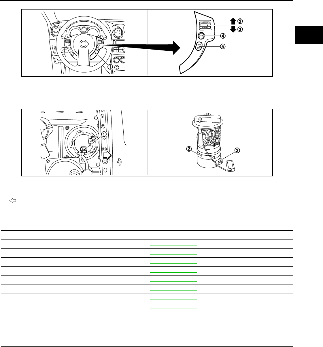
MULTIPORT FUEL INJECTION SYSTEM
EC-45
< FUNCTION DIAGNOSIS > [FOR CALIFORNIA]
C
D
E
F
G
H
I
J
K
L
M
A
EC
N
P
O
Component Description INFOID:0000000004493306
1. ASCD steering switch 2. RESUME/ACCERELATE switch 3. SET/COAST switch
4. CANSEL switch 5. MAIN switch
1. Fuel level sensor unit and fuel pump
harness connector 2. Fuel level sensor unit and fuel pump 3. Fuel pressure regulator
Vehicle front
JMBIA0925ZZ
JMBIA0926ZZ
Component Reference
A/F sensor 1 EC-177, "Description"
Accelerator pedal position sensor EC-385, "Description"
Camshaft position sensor (PHASE) EC-260, "Description"
Crankshaft position sensor (POS) EC-256, "Description"
Engine coolant temperature sensor EC-164, "Description"
Fuel injector EC-419, "Description"
Heated oxygen sensor 2 EC-138, "Description"
Intake air temperature sensor EC-159, "Description"
Knock sensor EC-254, "Description"
Mass air flow sensor EC-147, "Description"
Park/neutral position switch EC-338, "Description"
Throttle position sensor EC-167, "Description"
Revision: 2008 August 2009 Rogue
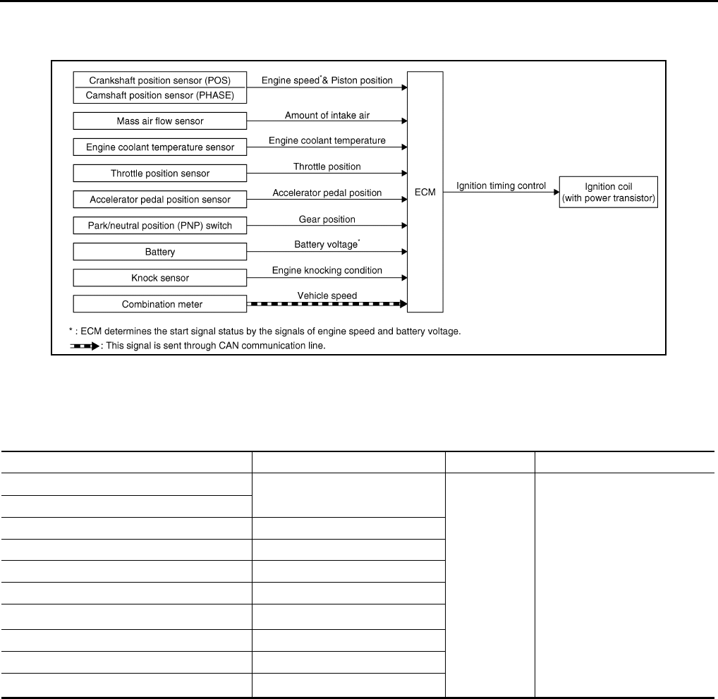
EC-46
< FUNCTION DIAGNOSIS > [FOR CALIFORNIA]
ELECTRIC IGNITION SYSTEM
ELECTRIC IGNITION SYSTEM
System Diagram INFOID:0000000004493307
System Description INFOID:0000000004493308
INPUT/OUTPUT SIGNAL CHART
*1: This signal is sent to the ECM through CAN communication line.
*2: ECM determines the start signal status by the signals of engine speed and battery voltage.
SYSTEM DESCRIPTION
Ignition order: 1 - 3 - 4 - 2
The ignition timing is controlled by the ECM to maintain the best air-fuel ratio for every running condition of the
engine. The ignition timing data is stored in the ECM.
The ECM receives information such as the injection pulse width and camshaft position sensor (PHASE) sig-
nal. Computing this information, ignition signals are transmitted to the power transistor.
During the following conditions, the ignition timing is revised by the ECM according to the other data stored in
the ECM.
• At starting
• During warm-up
• At idle
• At low battery voltage
• During acceleration
The knock sensor retard system is designed only for emergencies. The basic ignition timing is programmed
within the anti-knocking zone, if recommended fuel is used under dry conditions. The retard system does not
JMBIA0174G
B
Sensor Input signal to ECM ECM function Actuator
Crankshaft position sensor (POS) Engine speed*2
Piston position
Ignition timing
control
Ignition coil (with power transis-
tor)
Camshaft position sensor (PHASE)
Mass air flow sensor Amount of intake air
Engine coolant temperature sensor Engine coolant temperature
Throttle position sensor Throttle position
Accelerator pedal position sensor Accelerator pedal position
Battery Battery voltage*2
Knock sensor Engine knocking
Park/neutral position (PNP) switch Gear position
Combination meter Vehicle speed*1
Revision: 2008 August 2009 Rogue

ELECTRIC IGNITION SYSTEM
EC-47
< FUNCTION DIAGNOSIS > [FOR CALIFORNIA]
C
D
E
F
G
H
I
J
K
L
M
A
EC
N
P
O
operate under normal driving conditions. If engine knocking occurs, the knock sensor monitors the condition.
The signal is transmitted to the ECM. The ECM retards the ignition timing to eliminate the knocking condition.
Component Parts Location INFOID:0000000004493309
1. Intake valve timing control solenoid
valve
2. Ignition coil (with power transistor)
and spark plug
3. Cooling fan motor-2
4. Air fuel ratio (A/F) sensor 1 5. Heated oxygen sensor 2 6. Camshaft position sensor (PHASE)
7. Engine coolant temperature sensor 8. Park/neutral position (PNP) switch 9. Cooling fan motor-1
10. Refrigerant pressure sensor 11. ECM 12. IPDM E/R
13. Mass air flow sensor (with intake air
temperature sensor) 14. Tumble control valve actuator 15. Crankshaft position sensor (POS)
16. Electric throttle control actuator
(with built in throttle position sensor
and throttle control motor)
17. Knock sensor 18. EVAP service port
19. EVAP canister purge volume control
solenoid valve
20. Fuel injector
JMBIA0932ZZ
JMBIA0917ZZ
Revision: 2008 August 2009 Rogue
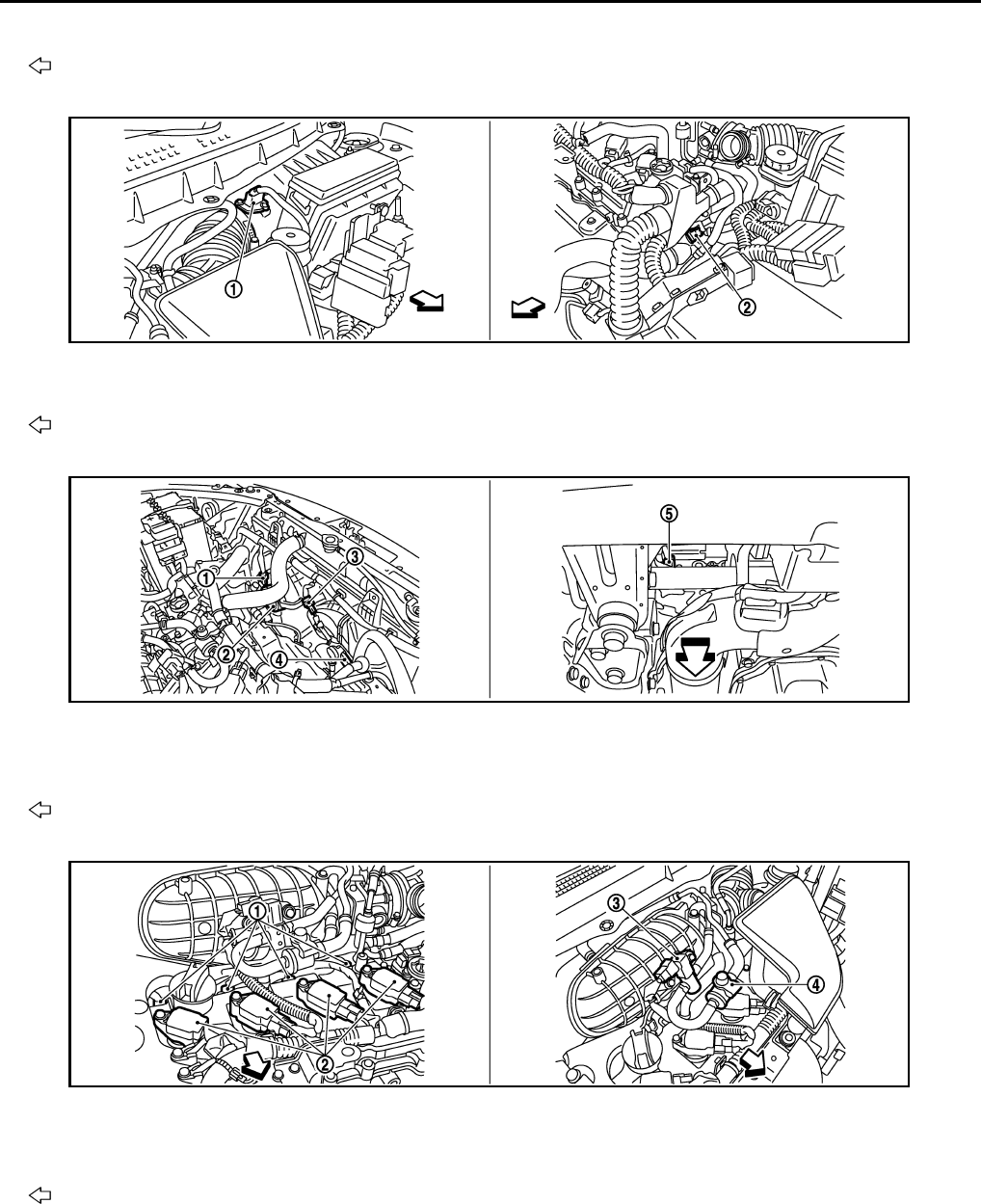
EC-48
< FUNCTION DIAGNOSIS > [FOR CALIFORNIA]
ELECTRIC IGNITION SYSTEM
1. Electric throttle control actuator 2. Camshaft position sensor (PHASE)
Vehicle front
1. Mass air flow sensor (with intake air
temperature sensor)
2. Engine coolant temperature sensor
Vehicle front
1. Cooling fan motor-1 harness con-
nector
2. Cooling fan motor-1 3. Cooling fan motor-2 harness con-
nector
4. Cooling fan motor-2 5. Crankshaft position sensor (POS)
Vehicle front
1. Fuel injector 2. Ignition coil (with power transistor)
and spark plug
3. EVAP canister purge volume control
solenoid valve
4. EVAP service port
Vehicle front
JMBIA0918ZZ
JMBIA0919ZZ
JMBIA0921ZZ
Revision: 2008 August 2009 Rogue

ELECTRIC IGNITION SYSTEM
EC-49
< FUNCTION DIAGNOSIS > [FOR CALIFORNIA]
C
D
E
F
G
H
I
J
K
L
M
A
EC
N
P
O
1. Refrigerant pressure sensor 2. PCV valve
JMBIA0922ZZ
JMBIA0910G
B
1. Air fuel ratio (A/F) sensor 1 2. Heated oxygen sensor 2 3. Air fuel ratio (A/F) sensor 1 harness
connector
4. Heated oxygen sensor 2 harness
connector
5. HC adsorption catalyst (Under floor)
Vehicle front
JMBIA0920ZZ
JMBIA0931ZZ
Revision: 2008 August 2009 Rogue

EC-50
< FUNCTION DIAGNOSIS > [FOR CALIFORNIA]
ELECTRIC IGNITION SYSTEM
1. Tumble control valve actuator 2. Condenser 3. Heated oxygen sensor 3
4. Heated oxygen sensor 3 harness
connector
Vehicle front
1. EVAP control system pressure sen-
sor 2. EVAP canister vent control valve 3. EVAP canister
4. Body ground
Vehicle front
1. Park/neutral position (PNP) switch 2. Data link connector
Vehicle front
1. Stop lamp switch 2. ASCD brake switch 3. Accelerator pedal position sensor
JMBIA0923ZZ
JMBIA0927ZZ
JMBIA0924ZZ
Revision: 2008 August 2009 Rogue
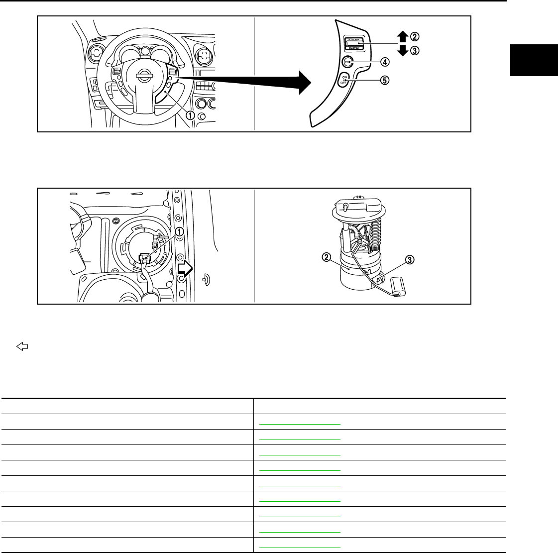
ELECTRIC IGNITION SYSTEM
EC-51
< FUNCTION DIAGNOSIS > [FOR CALIFORNIA]
C
D
E
F
G
H
I
J
K
L
M
A
EC
N
P
O
Component Description INFOID:0000000004493310
1. ASCD steering switch 2. RESUME/ACCERELATE switch 3. SET/COAST switch
4. CANSEL switch 5. MAIN switch
1. Fuel level sensor unit and fuel pump
harness connector 2. Fuel level sensor unit and fuel pump 3. Fuel pressure regulator
Vehicle front
JMBIA0925ZZ
JMBIA0926ZZ
Component Reference
Accelerator pedal position sensor EC-385, "Description"
Camshaft position sensor (PHASE) EC-260, "Description"
Crankshaft position sensor (POS) EC-256, "Description"
Engine coolant temperature sensor EC-164, "Description"
Ignition signal EC-425, "Description"
Knock sensor EC-254, "Description"
Mass air flow sensor EC-147, "Description"
Park/neutral position switch EC-338, "Description"
Throttle position sensor EC-167, "Description"
Revision: 2008 August 2009 Rogue
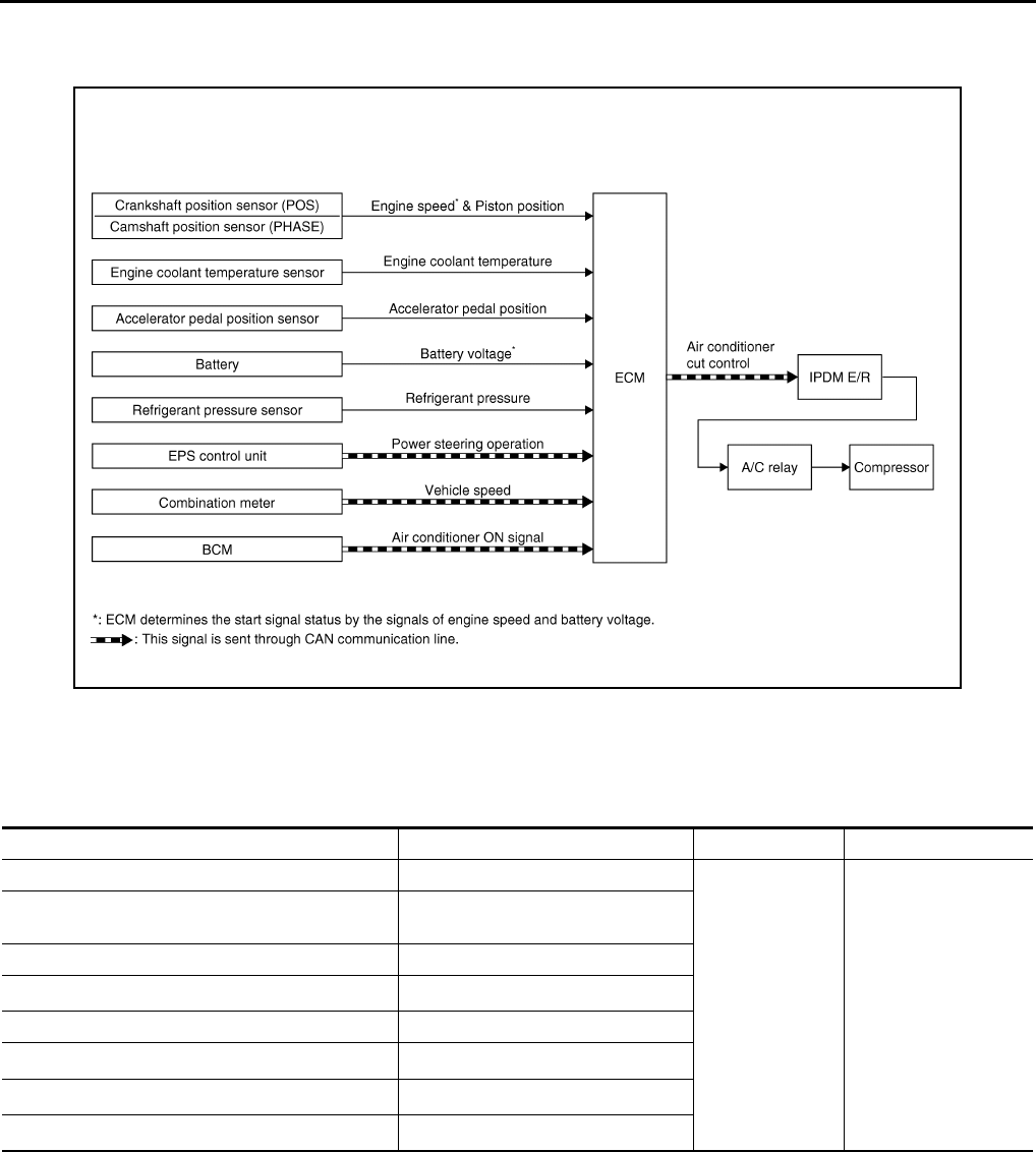
EC-52
< FUNCTION DIAGNOSIS > [FOR CALIFORNIA]
AIR CONDITIONING CUT CONTROL
AIR CONDITIONING CUT CONTROL
System Diagram INFOID:0000000004493311
System Description INFOID:0000000004493312
INPUT/OUTPUT SIGNAL CHART
*1: This signal is sent to the ECM through CAN communication line.
*2: ECM determines the start signal status by the signals of engine speed and battery voltage.
SYSTEM DESCRIPTION
This system improves engine operation when the air conditioner is used.
Under the following conditions, the air conditioner is turned off.
• When the accelerator pedal is fully depressed.
• When cranking the engine.
• At high engine speeds.
• When the engine coolant temperature becomes excessively high.
• When operating power steering during low engine speed or low vehicle speed.
• When engine speed is excessively low.
JMBIA1015G
B
Sensor Input signal to ECM ECM function Actuator
Accelerator pedal position sensor Accelerator pedal position
Air conditioner
cut control
IPDM E/R
↓
Air conditioner relay
↓
Compressor
Crankshaft position sensor (POS)
Camshaft position sensor (PHASE) Engine speed*2
Engine coolant temperature sensor Engine coolant temperature
Battery Battery voltage*2
Refrigerant pressure sensor Refrigerant pressure
EPS control unit Power steering operation*1
Combination meter Vehicle speed*1
BCM Air conditioner ON signal*1
Revision: 2008 August 2009 Rogue
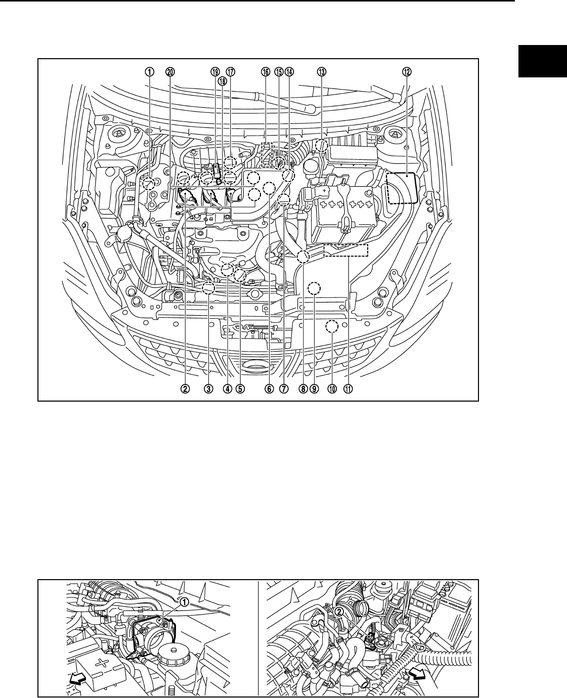
AIR CONDITIONING CUT CONTROL
EC-53
< FUNCTION DIAGNOSIS > [FOR CALIFORNIA]
C
D
E
F
G
H
I
J
K
L
M
A
EC
N
P
O
• When refrigerant pressure is excessively low or high.
Component Parts Location INFOID:0000000004493313
1. Intake valve timing control solenoid
valve 2. Ignition coil (with power transistor)
and spark plug 3. Cooling fan motor-2
4. Air fuel ratio (A/F) sensor 1 5. Heated oxygen sensor 2 6. Camshaft position sensor (PHASE)
7. Engine coolant temperature sensor 8. Park/neutral position (PNP) switch 9. Cooling fan motor-1
10. Refrigerant pressure sensor 11. ECM 12. IPDM E/R
13. Mass air flow sensor (with intake air
temperature sensor)
14. Tumble control valve actuator 15. Crankshaft position sensor (POS)
16. Electric throttle control actuator
(with built in throttle position sensor
and throttle control motor)
17. Knock sensor 18. EVAP service port
19. EVAP canister purge volume control
solenoid valve
20. Fuel injector
JMBIA0932ZZ
JMBIA0917ZZ
Revision: 2008 August 2009 Rogue

EC-54
< FUNCTION DIAGNOSIS > [FOR CALIFORNIA]
AIR CONDITIONING CUT CONTROL
1. Electric throttle control actuator 2. Camshaft position sensor (PHASE)
Vehicle front
1. Mass air flow sensor (with intake air
temperature sensor)
2. Engine coolant temperature sensor
Vehicle front
1. Cooling fan motor-1 harness con-
nector
2. Cooling fan motor-1 3. Cooling fan motor-2 harness con-
nector
4. Cooling fan motor-2 5. Crankshaft position sensor (POS)
Vehicle front
1. Fuel injector 2. Ignition coil (with power transistor)
and spark plug
3. EVAP canister purge volume control
solenoid valve
4. EVAP service port
Vehicle front
JMBIA0918ZZ
JMBIA0919ZZ
JMBIA0921ZZ
Revision: 2008 August 2009 Rogue

AIR CONDITIONING CUT CONTROL
EC-55
< FUNCTION DIAGNOSIS > [FOR CALIFORNIA]
C
D
E
F
G
H
I
J
K
L
M
A
EC
N
P
O
1. Refrigerant pressure sensor 2. PCV valve
JMBIA0922ZZ
JMBIA0910G
B
1. Air fuel ratio (A/F) sensor 1 2. Heated oxygen sensor 2 3. Air fuel ratio (A/F) sensor 1 harness
connector
4. Heated oxygen sensor 2 harness
connector
5. HC adsorption catalyst (Under floor)
Vehicle front
JMBIA0920ZZ
JMBIA0931ZZ
Revision: 2008 August 2009 Rogue

EC-56
< FUNCTION DIAGNOSIS > [FOR CALIFORNIA]
AIR CONDITIONING CUT CONTROL
1. Tumble control valve actuator 2. Condenser 3. Heated oxygen sensor 3
4. Heated oxygen sensor 3 harness
connector
Vehicle front
1. EVAP control system pressure sen-
sor 2. EVAP canister vent control valve 3. EVAP canister
4. Body ground
Vehicle front
1. Park/neutral position (PNP) switch 2. Data link connector
Vehicle front
1. Stop lamp switch 2. ASCD brake switch 3. Accelerator pedal position sensor
JMBIA0923ZZ
JMBIA0927ZZ
JMBIA0924ZZ
Revision: 2008 August 2009 Rogue

AIR CONDITIONING CUT CONTROL
EC-57
< FUNCTION DIAGNOSIS > [FOR CALIFORNIA]
C
D
E
F
G
H
I
J
K
L
M
A
EC
N
P
O
Component Description INFOID:0000000004493314
1. ASCD steering switch 2. RESUME/ACCERELATE switch 3. SET/COAST switch
4. CANSEL switch 5. MAIN switch
1. Fuel level sensor unit and fuel pump
harness connector 2. Fuel level sensor unit and fuel pump 3. Fuel pressure regulator
Vehicle front
JMBIA0925ZZ
JMBIA0926ZZ
Component Reference
Accelerator pedal position sensor EC-385, "Description"
Camshaft position sensor (PHASE) EC-260, "Description"
Crankshaft position sensor (POS) EC-256, "Description"
Engine coolant temperature sensor EC-164, "Description"
Refrigerant pressure sensor EC-437, "Description"
Revision: 2008 August 2009 Rogue
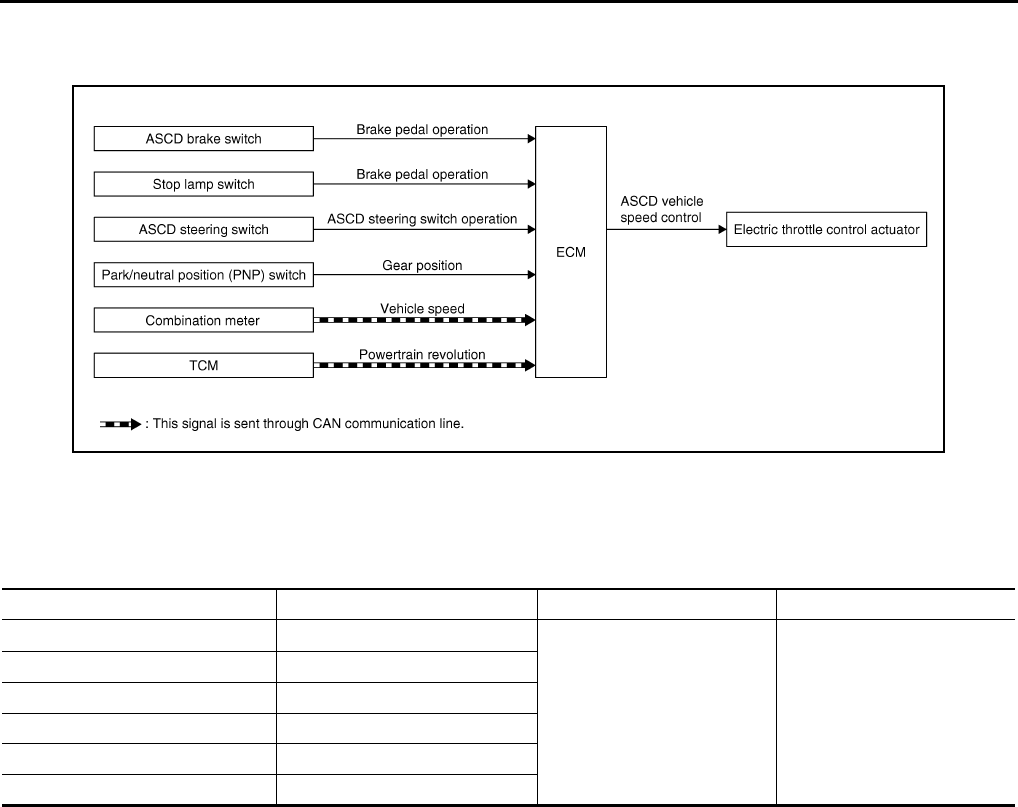
EC-58
< FUNCTION DIAGNOSIS > [FOR CALIFORNIA]
AUTOMATIC SPEED CONTROL DEVICE (ASCD)
AUTOMATIC SPEED CONTROL DEVICE (ASCD)
System Diagram INFOID:0000000004493315
System Description INFOID:0000000004493316
INPUT/OUTPUT SIGNAL CHART
*: This signal is sent to the ECM through CAN communication line
BASIC ASCD SYSTEM
Refer to Owner's Manual for ASCD operating instructions.
Automatic Speed Control Device (ASCD) allows a driver to keep vehicle at predetermined constant speed
without depressing accelerator pedal. Driver can set vehicle speed in advance between approximately 38 km/
h (24 MPH) and 144 km/h (89 MPH).
ECM controls throttle angle of electric throttle control actuator to regulate engine speed.
Operation status of ASCD is indicated by CRUISE lamp and SET lamp on combination meter. If any malfunc-
tion occurs in the ASCD system, it automatically deactivates control.
NOTE:
Always drive vehicle in a safe manner according to traffic conditions and obey all traffic laws.
SET OPERATION
Press MAIN switch. (The CRUISE lamp on combination meter illuminates.)
When vehicle speed reaches a desired speed between approximately 38 km/h (24 MPH) and 144 km/h (89
MPH), press SET/COAST switch. (Then SET lamp on combination meter illuminates.)
ACCELERATE OPERATION
If the RESUME/ACCELERATE switch is pressed during cruise control driving, increase the vehicle speed until
the switch is released or vehicle speed reaches maximum speed controlled by the system.
And then ASCD will maintain the new set speed.
CANCEL OPERATION
When any of following conditions exist, cruise operation will be canceled.
• CANCEL switch is pressed
• More than 2 switches on ASCD steering switch are pressed at the same time (Set speed will be cleared)
• Brake pedal is depressed
JMBIA0935G
B
Sensor Input signal to ECM ECM function Actuator
ASCD brake switch Brake pedal operation
ASCD vehicle speed control Electric throttle control
actuator
Stop lamp switch Brake pedal operation
ASCD steering switch ASCD steering switch operation
Park/neutral position (PNP) switch Gear position
Combination meter Vehicle speed*
TCM Powertrain revolution*
Revision: 2008 August 2009 Rogue

AUTOMATIC SPEED CONTROL DEVICE (ASCD)
EC-59
< FUNCTION DIAGNOSIS > [FOR CALIFORNIA]
C
D
E
F
G
H
I
J
K
L
M
A
EC
N
P
O
• Selector lever position is changed to N, P or R
• Vehicle speed decreased to 13 km/h (8 MPH) lower than the set speed
• TCS system is operated
When the ECM detects any of the following conditions, the ECM will cancel the cruise operation and inform
the driver by blinking indicator lamp.
• Engine coolant temperature is slightly higher than the normal operating temperature, CRUISE lamp may
blink slowly.
When the engine coolant temperature decreases to the normal operating temperature, CRUISE lamp will
stop blinking and the cruise operation will be able to work by pressing SET/COAST switch or RESUME/
ACCELERATE switch.
• Malfunction for some self-diagnoses regarding ASCD control: SET lamp will blink quickly.
If MAIN switch is turned to OFF while ASCD is activated, all of ASCD operations will be canceled and vehicle
speed memory will be erased.
COAST OPERATION
When the SET/COAST switch is pressed during cruise control driving, decrease vehicle set speed until the
switch is released. And then ASCD will maintain the new set speed.
RESUME OPERATION
When the RESUME/ACCELERATE switch is pressed after canceling operation other than pressing the MAIN
switch, vehicle speed will return to last set speed. To resume vehicle set speed, vehicle condition must meet
following conditions.
• Brake pedal is released
• Selector lever is in a position other than P and N
• Vehicle speed is greater than 38 km/h (24 MPH) and less than 144 km/h (89 MPH)
Component Parts Location INFOID:0000000004493317
JMBIA0932ZZ
1. Intake valve timing control solenoid
valve
2. Ignition coil (with power transistor)
and spark plug
3. Cooling fan motor-2
4. Air fuel ratio (A/F) sensor 1 5. Heated oxygen sensor 2 6. Camshaft position sensor (PHASE)
Revision: 2008 August 2009 Rogue
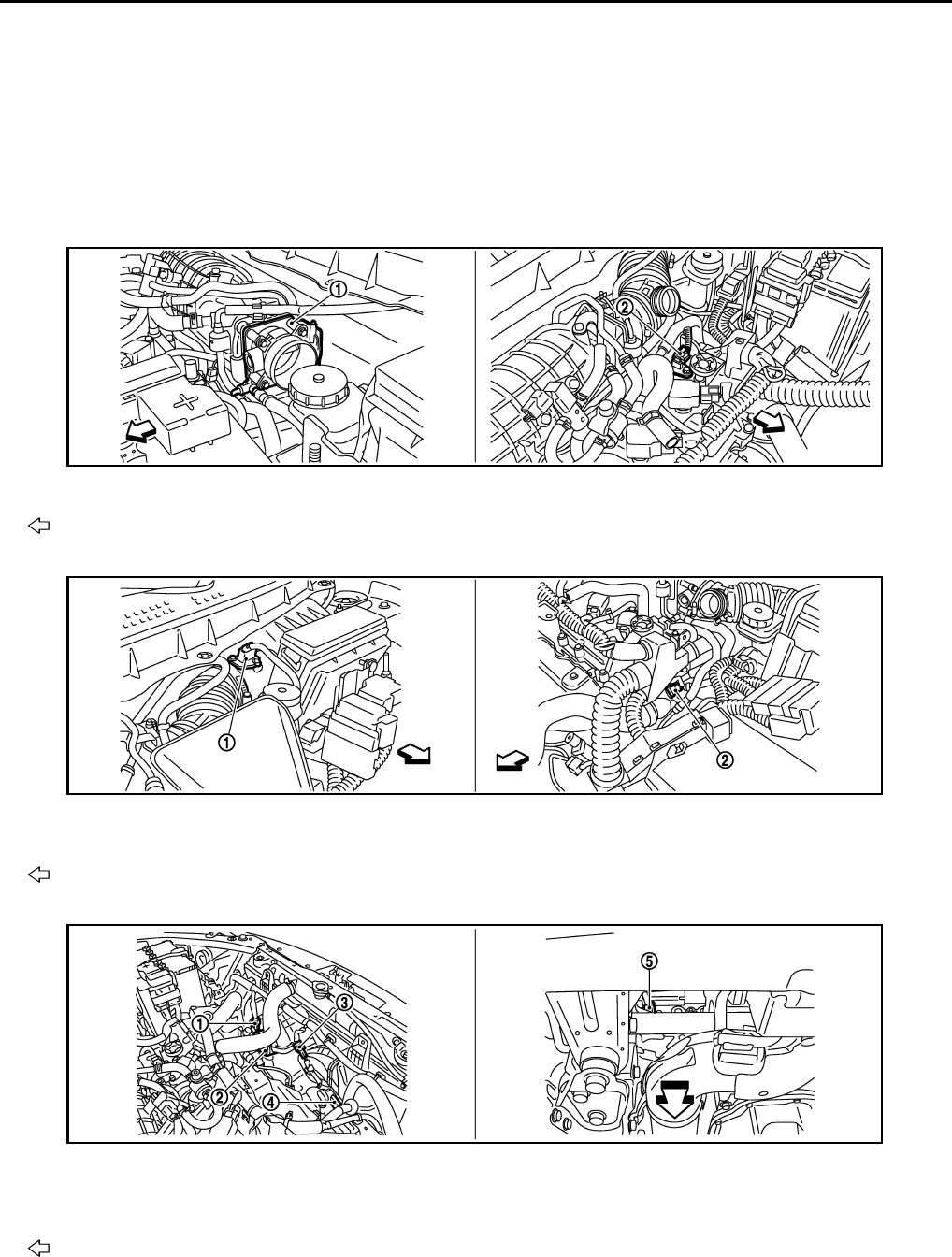
EC-60
< FUNCTION DIAGNOSIS > [FOR CALIFORNIA]
AUTOMATIC SPEED CONTROL DEVICE (ASCD)
7. Engine coolant temperature sensor 8. Park/neutral position (PNP) switch 9. Cooling fan motor-1
10. Refrigerant pressure sensor 11. ECM 12. IPDM E/R
13. Mass air flow sensor (with intake air
temperature sensor)
14. Tumble control valve actuator 15. Crankshaft position sensor (POS)
16. Electric throttle control actuator
(with built in throttle position sensor
and throttle control motor)
17. Knock sensor 18. EVAP service port
19. EVAP canister purge volume control
solenoid valve 20. Fuel injector
1. Electric throttle control actuator 2. Camshaft position sensor (PHASE)
Vehicle front
1. Mass air flow sensor (with intake air
temperature sensor)
2. Engine coolant temperature sensor
Vehicle front
1. Cooling fan motor-1 harness con-
nector
2. Cooling fan motor-1 3. Cooling fan motor-2 harness con-
nector
4. Cooling fan motor-2 5. Crankshaft position sensor (POS)
Vehicle front
JMBIA0917ZZ
JMBIA0918ZZ
JMBIA0919ZZ
Revision: 2008 August 2009 Rogue
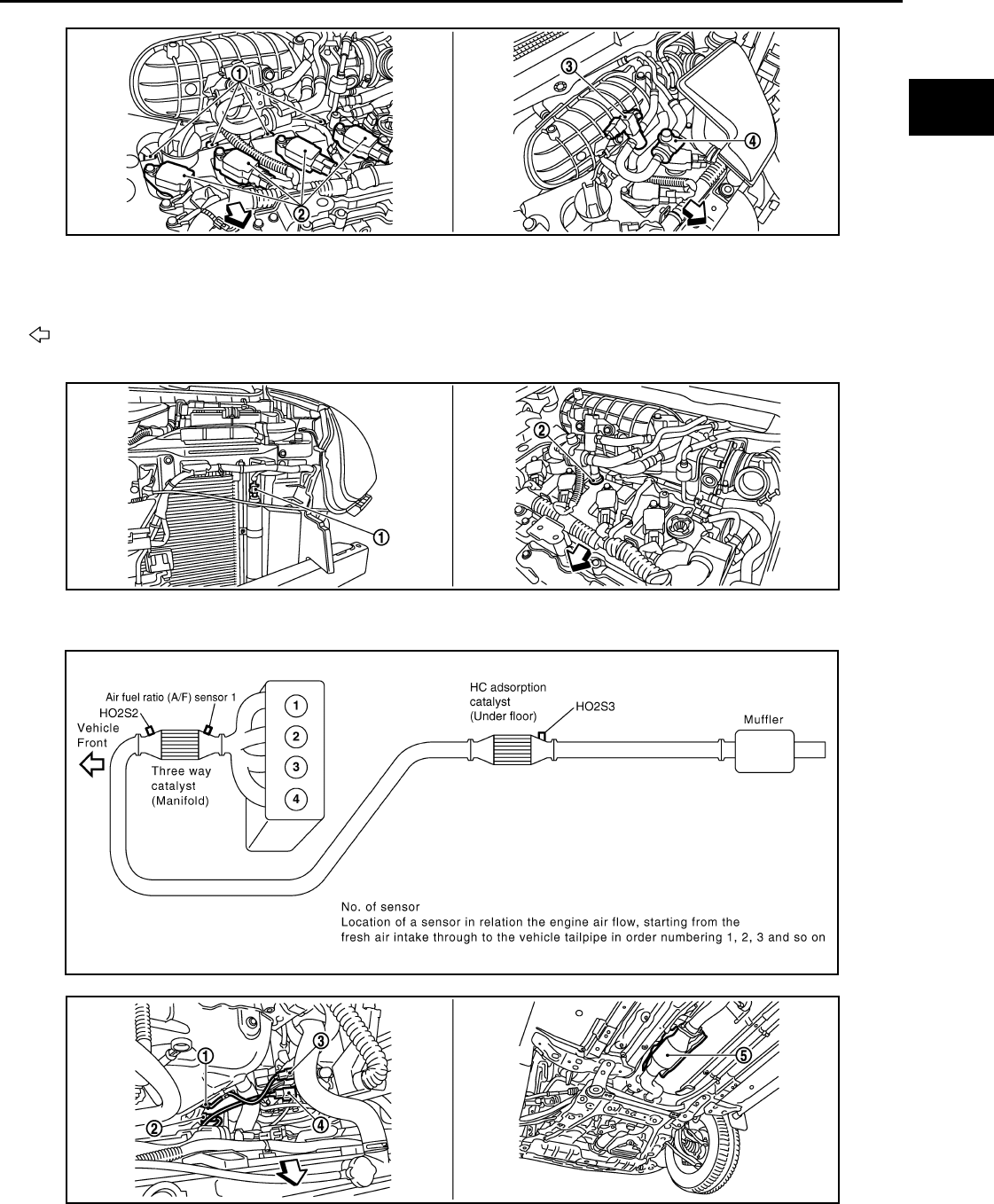
AUTOMATIC SPEED CONTROL DEVICE (ASCD)
EC-61
< FUNCTION DIAGNOSIS > [FOR CALIFORNIA]
C
D
E
F
G
H
I
J
K
L
M
A
EC
N
P
O
1. Fuel injector 2. Ignition coil (with power transistor)
and spark plug
3. EVAP canister purge volume control
solenoid valve
4. EVAP service port
Vehicle front
1. Refrigerant pressure sensor 2. PCV valve
JMBIA0921ZZ
JMBIA0922ZZ
JMBIA0910G
B
JMBIA0920ZZ
Revision: 2008 August 2009 Rogue
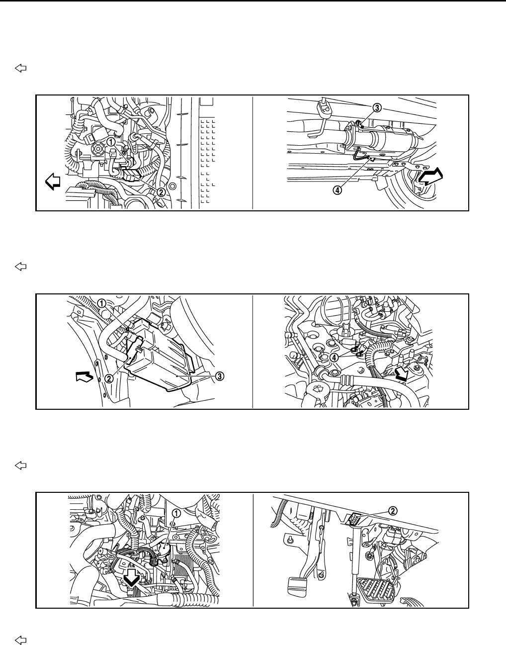
EC-62
< FUNCTION DIAGNOSIS > [FOR CALIFORNIA]
AUTOMATIC SPEED CONTROL DEVICE (ASCD)
1. Air fuel ratio (A/F) sensor 1 2. Heated oxygen sensor 2 3. Air fuel ratio (A/F) sensor 1 harness
connector
4. Heated oxygen sensor 2 harness
connector 5. HC adsorption catalyst (Under floor)
Vehicle front
1. Tumble control valve actuator 2. Condenser 3. Heated oxygen sensor 3
4. Heated oxygen sensor 3 harness
connector
Vehicle front
1. EVAP control system pressure sen-
sor
2. EVAP canister vent control valve 3. EVAP canister
4. Body ground
Vehicle front
1. Park/neutral position (PNP) switch 2. Data link connector
Vehicle front
JMBIA0931ZZ
JMBIA0923ZZ
JMBIA0927ZZ
Revision: 2008 August 2009 Rogue
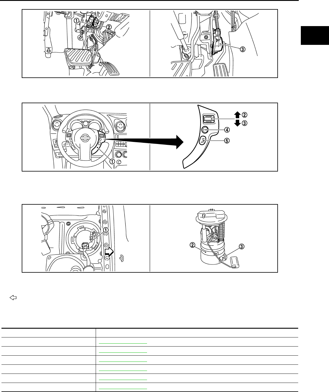
AUTOMATIC SPEED CONTROL DEVICE (ASCD)
EC-63
< FUNCTION DIAGNOSIS > [FOR CALIFORNIA]
C
D
E
F
G
H
I
J
K
L
M
A
EC
N
P
O
Component Description INFOID:0000000004493318
1. Stop lamp switch 2. ASCD brake switch 3. Accelerator pedal position sensor
1. ASCD steering switch 2. RESUME/ACCERELATE switch 3. SET/COAST switch
4. CANSEL switch 5. MAIN switch
1. Fuel level sensor unit and fuel pump
harness connector
2. Fuel level sensor unit and fuel pump 3. Fuel pressure regulator
Vehicle front
JMBIA0924ZZ
JMBIA0925ZZ
JMBIA0926ZZ
Component Reference
ASCD steering switch EC-353, "Description"
ASCD clutch switch EC-356, "Description"
ASCD brake switch EC-356, "Description"
Stop lamp switch EC-365, "Description"
Electric throttle control actuator EC-383, "Description"
ASCD indicator EC-410, "Description"
Revision: 2008 August 2009 Rogue

EC-64
< FUNCTION DIAGNOSIS > [FOR CALIFORNIA]
CAN COMMUNICATION
CAN COMMUNICATION
System Description INFOID:0000000004493319
CAN (Controller Area Network) is a serial communication line for real time application. It is an on-vehicle mul-
tiplex communication line with high data communication speed and excellent error detection ability. Many elec-
tronic control units are equipped onto a vehicle, and each control unit shares information and links with other
control units during operation (not independent). In CAN communication, control units are connected with 2
communication lines (CAN H line, CAN L line) allowing a high rate of information transmission with less wiring.
Each control unit transmits/receives data but selectively reads required data only.
Refer to LAN-24, "CAN Communication Signal Chart", about CAN communication for detail..
Revision: 2008 August 2009 Rogue

COOLING FAN CONTROL
EC-65
< FUNCTION DIAGNOSIS > [FOR CALIFORNIA]
C
D
E
F
G
H
I
J
K
L
M
A
EC
N
P
O
COOLING FAN CONTROL
System Diagram INFOID:0000000004493320
System Description INFOID:0000000004493321
INPUT/OUTPUT SIGNAL CHART
*1: The ECM determines the start signal status by the signals of engine speed and battery voltage.
*2: This signal is sent to ECM through CAN communication line.
SYSTEM DESCRIPTION
ECM controls cooling fan speed corresponding to vehicle speed, engine coolant temperature, refrigerant pres-
sure, air conditioner ON signal. Then control system has 3-step control [HIGH/LOW/OFF].
JMBIA0177G
B
Sensor Input signal to ECM ECM function Actuator
Crankshaft position sensor (POS)
Camshaft position sensor (PHASE) Engine speed*1
Cooling fan
control
IPDM E/R
↓
Cooling fan relay
↓
Cooling fan motor
Engine coolant temperature sensor Engine coolant temperature
Refrigerant pressure sensor Refrigerant pressure
Battery Battery voltage*1
Combination meter Vehicle speed*2
BCM Air conditioner ON signal*2
Revision: 2008 August 2009 Rogue
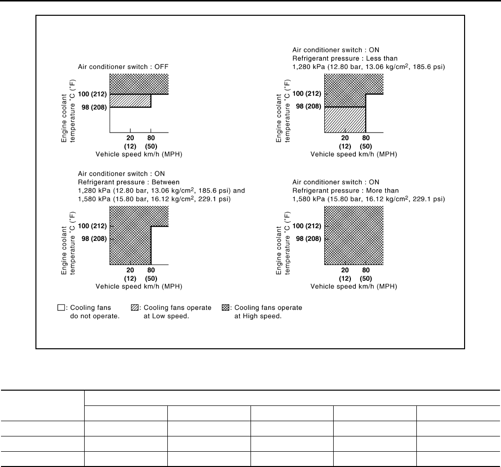
EC-66
< FUNCTION DIAGNOSIS > [FOR CALIFORNIA]
COOLING FAN CONTROL
Cooling Fan Operation
Cooling Fan Relay Operation
The ECM controls cooling fan relays through CAN communication line.
JMBIA0936G
B
Cooling fan speed Cooling fan relay
12345
Stop (OFF) OFF OFF OFF OFF OFF
Low (LOW) OFF OFF OFF ON OFF
High (HI) ON ON ON OFF ON
Revision: 2008 August 2009 Rogue

COOLING FAN CONTROL
EC-67
< FUNCTION DIAGNOSIS > [FOR CALIFORNIA]
C
D
E
F
G
H
I
J
K
L
M
A
EC
N
P
O
Component Parts Location INFOID:0000000004493322
1. Intake valve timing control solenoid
valve
2. Ignition coil (with power transistor)
and spark plug
3. Cooling fan motor-2
4. Air fuel ratio (A/F) sensor 1 5. Heated oxygen sensor 2 6. Camshaft position sensor (PHASE)
7. Engine coolant temperature sensor 8. Park/neutral position (PNP) switch 9. Cooling fan motor-1
10. Refrigerant pressure sensor 11. ECM 12. IPDM E/R
13. Mass air flow sensor (with intake air
temperature sensor)
14. Tumble control valve actuator 15. Crankshaft position sensor (POS)
16. Electric throttle control actuator
(with built in throttle position sensor
and throttle control motor)
17. Knock sensor 18. EVAP service port
19. EVAP canister purge volume control
solenoid valve 20. Fuel injector
1. Electric throttle control actuator 2. Camshaft position sensor (PHASE)
Vehicle front
JMBIA0932ZZ
JMBIA0917ZZ
Revision: 2008 August 2009 Rogue

EC-68
< FUNCTION DIAGNOSIS > [FOR CALIFORNIA]
COOLING FAN CONTROL
1. Mass air flow sensor (with intake air
temperature sensor)
2. Engine coolant temperature sensor
Vehicle front
1. Cooling fan motor-1 harness con-
nector
2. Cooling fan motor-1 3. Cooling fan motor-2 harness con-
nector
4. Cooling fan motor-2 5. Crankshaft position sensor (POS)
Vehicle front
1. Fuel injector 2. Ignition coil (with power transistor)
and spark plug 3. EVAP canister purge volume control
solenoid valve
4. EVAP service port
Vehicle front
JMBIA0918ZZ
JMBIA0919ZZ
JMBIA0921ZZ
Revision: 2008 August 2009 Rogue
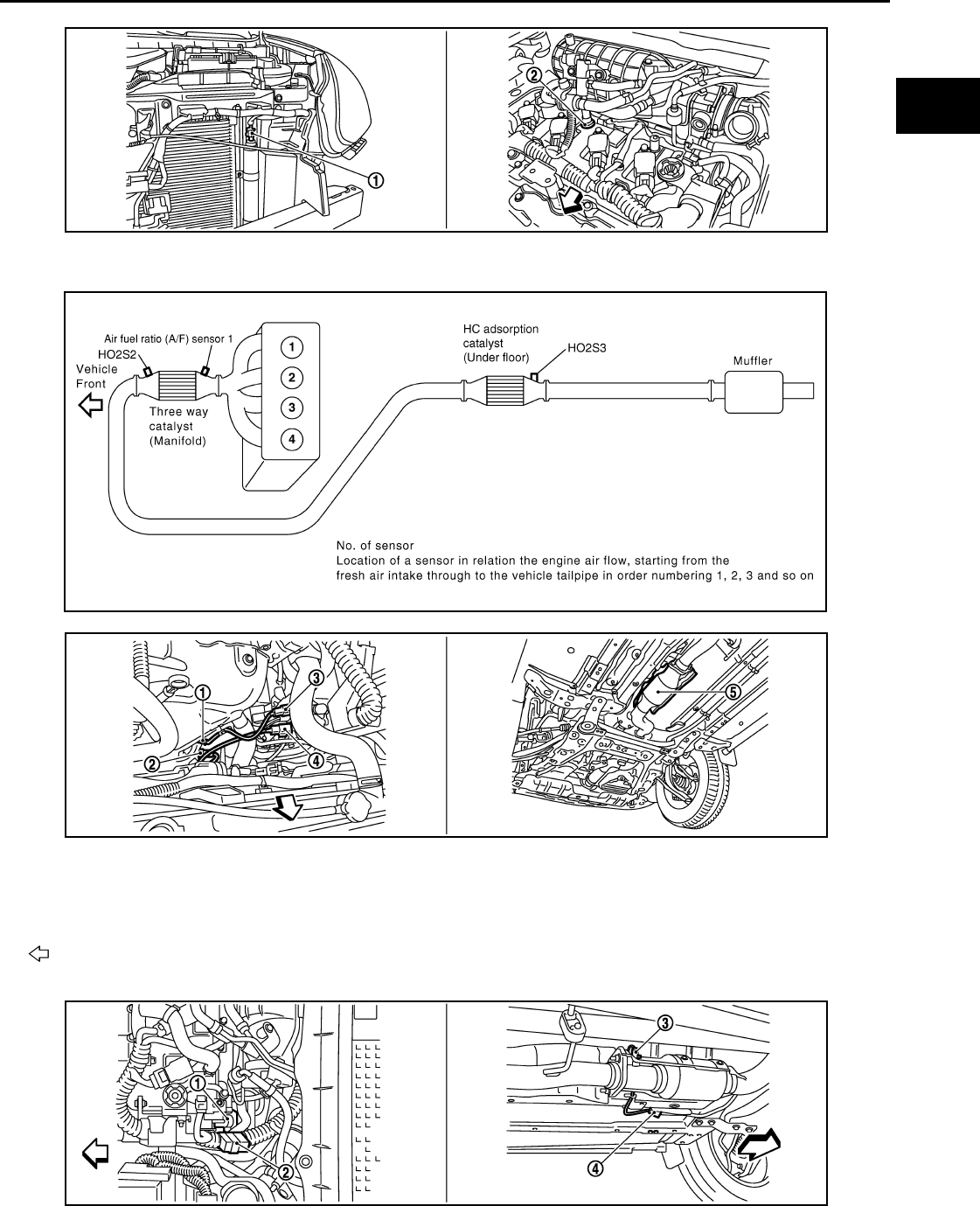
COOLING FAN CONTROL
EC-69
< FUNCTION DIAGNOSIS > [FOR CALIFORNIA]
C
D
E
F
G
H
I
J
K
L
M
A
EC
N
P
O
1. Refrigerant pressure sensor 2. PCV valve
JMBIA0922ZZ
JMBIA0910G
B
1. Air fuel ratio (A/F) sensor 1 2. Heated oxygen sensor 2 3. Air fuel ratio (A/F) sensor 1 harness
connector
4. Heated oxygen sensor 2 harness
connector
5. HC adsorption catalyst (Under floor)
Vehicle front
JMBIA0920ZZ
JMBIA0931ZZ
Revision: 2008 August 2009 Rogue

EC-70
< FUNCTION DIAGNOSIS > [FOR CALIFORNIA]
COOLING FAN CONTROL
1. Tumble control valve actuator 2. Condenser 3. Heated oxygen sensor 3
4. Heated oxygen sensor 3 harness
connector
Vehicle front
1. EVAP control system pressure sen-
sor 2. EVAP canister vent control valve 3. EVAP canister
4. Body ground
Vehicle front
1. Park/neutral position (PNP) switch 2. Data link connector
Vehicle front
1. Stop lamp switch 2. ASCD brake switch 3. Accelerator pedal position sensor
JMBIA0923ZZ
JMBIA0927ZZ
JMBIA0924ZZ
Revision: 2008 August 2009 Rogue

COOLING FAN CONTROL
EC-71
< FUNCTION DIAGNOSIS > [FOR CALIFORNIA]
C
D
E
F
G
H
I
J
K
L
M
A
EC
N
P
O
Component Description INFOID:0000000004493323
1. ASCD steering switch 2. RESUME/ACCERELATE switch 3. SET/COAST switch
4. CANSEL switch 5. MAIN switch
1. Fuel level sensor unit and fuel pump
harness connector 2. Fuel level sensor unit and fuel pump 3. Fuel pressure regulator
Vehicle front
JMBIA0925ZZ
JMBIA0926ZZ
Component Reference
Camshaft position sensor (PHASE) EC-260, "Description"
Crankshaft position sensor (POS) EC-256, "Description"
Cooling fan motor EC-65, "System Description"
Engine coolant temperature sensor EC-164, "Description"
Refrigerant pressure sensor EC-437, "Description"
Revision: 2008 August 2009 Rogue
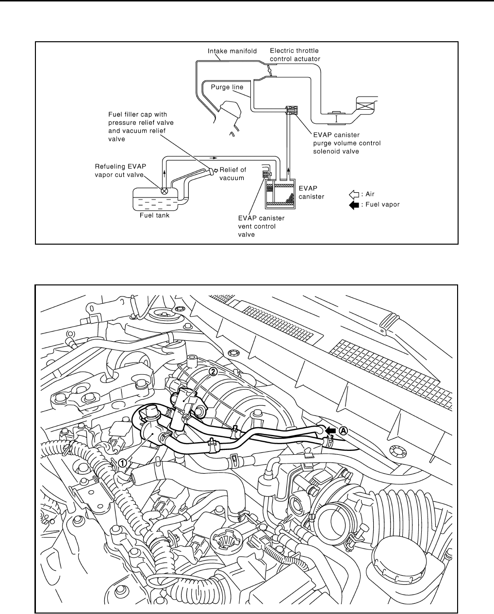
EC-72
< FUNCTION DIAGNOSIS > [FOR CALIFORNIA]
EVAPORATIVE EMISSION SYSTEM
EVAPORATIVE EMISSION SYSTEM
System Diagram INFOID:0000000004493324
EVAPORATIVE EMISSION LINE DRAWING
PBIB1631E
1. EVAP service port 2. EVAP canister purge volume control
solenoid valve
A. From next figure
JMBIA0909ZZ
Revision: 2008 August 2009 Rogue
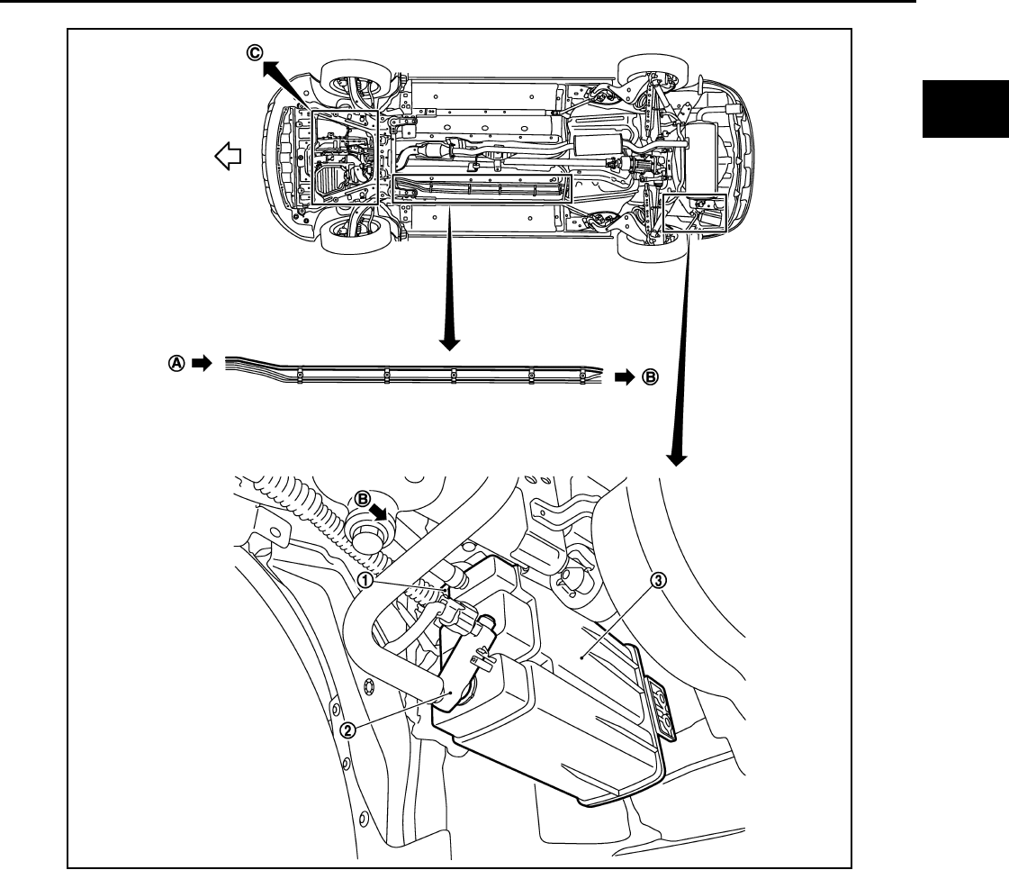
EVAPORATIVE EMISSION SYSTEM
EC-73
< FUNCTION DIAGNOSIS > [FOR CALIFORNIA]
C
D
E
F
G
H
I
J
K
L
M
A
EC
N
P
O
NOTE:
Do not use soapy water or any type of solvent while installing vacuum hose or purge hoses.
System Description INFOID:0000000004493325
INPUT/OUTPUT SIGNAL CHART
1. EVAP control system pressure sensor 2. EVAP canister vent control valve 3. EVAP canister
A. To previous figure B. To/From B in this figure
JMBIA0908ZZ
Revision: 2008 August 2009 Rogue

EC-74
< FUNCTION DIAGNOSIS > [FOR CALIFORNIA]
EVAPORATIVE EMISSION SYSTEM
*1: ECM determines the start signal status by the signals of engine speed and battery voltage.
*2: This signal is sent to the ECM through CAN communication line.
SYSTEM DESCRIPTION
The evaporative emission system is used to reduce hydrocarbons emitted into the atmosphere from the fuel
system. This reduction of hydrocarbons is accomplished by activated charcoals in the EVAP canister.
The fuel vapor in the sealed fuel tank is led into the EVAP canister which contains activated carbon and the
vapor is stored there when the engine is not operating or when refueling to the fuel tank.
The vapor in the EVAP canister is purged by the air through the purge line to the intake manifold when the
engine is operating. EVAP canister purge volume control solenoid valve is controlled by ECM. When the
engine operates, the flow rate of vapor controlled by EVAP canister purge volume control solenoid valve is
proportionally regulated as the air flow increases.
EVAP canister purge volume control solenoid valve also shuts off the vapor purge line during decelerating.
Sensor Input signal to ECM ECM function Actuator
Crankshaft position sensor (POS)
Camshaft position sensor (PHASE) Engine speed*1
EVAP canister
purge flow control
EVAP canister purge vol-
ume control solenoid valve
Mass air flow sensor Amount of intake air
Engine coolant temperature sensor Engine coolant temperature
Battery Battery voltage*1
Throttle position sensor Throttle position
Accelerator pedal position sensor Accelerator pedal position
Air fuel ratio (A/F) sensor 1 Density of oxygen in exhaust gas
(Mixture ratio feedback signal)
Fuel tank temperature sensor Fuel temperature in fuel tank
EVAP control system pressure sensor Pressure in purge line
Combination meter Vehicle speed*2
Revision: 2008 August 2009 Rogue
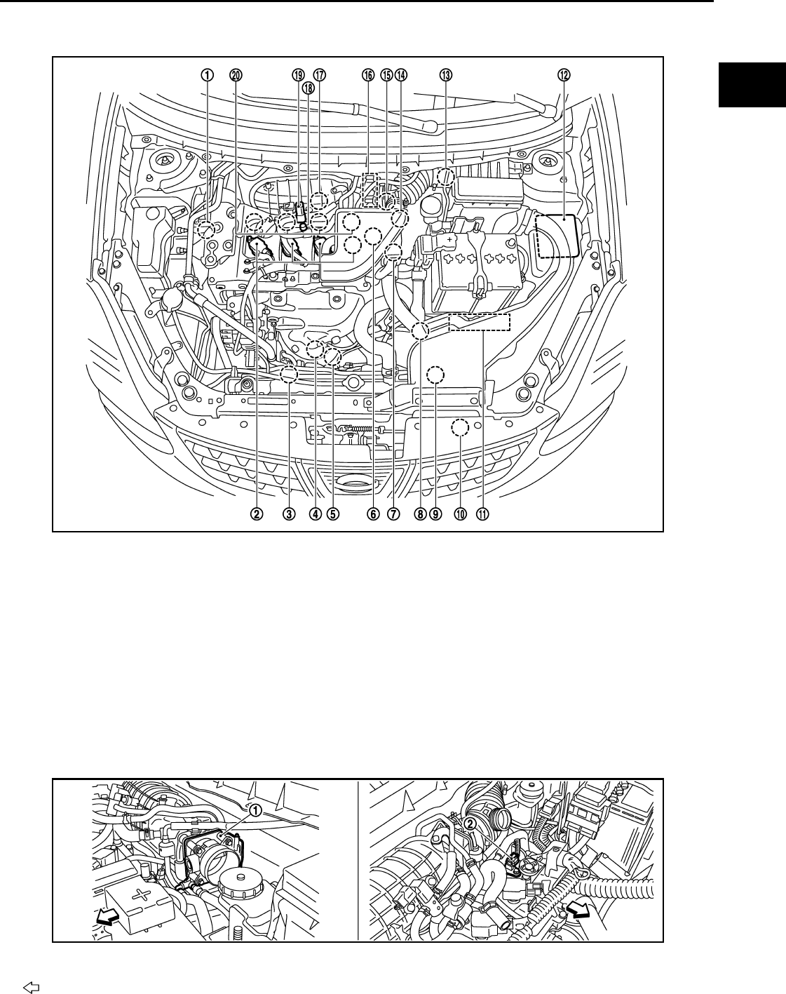
EVAPORATIVE EMISSION SYSTEM
EC-75
< FUNCTION DIAGNOSIS > [FOR CALIFORNIA]
C
D
E
F
G
H
I
J
K
L
M
A
EC
N
P
O
Component Parts Location INFOID:0000000004493326
1. Intake valve timing control solenoid
valve
2. Ignition coil (with power transistor)
and spark plug
3. Cooling fan motor-2
4. Air fuel ratio (A/F) sensor 1 5. Heated oxygen sensor 2 6. Camshaft position sensor (PHASE)
7. Engine coolant temperature sensor 8. Park/neutral position (PNP) switch 9. Cooling fan motor-1
10. Refrigerant pressure sensor 11. ECM 12. IPDM E/R
13. Mass air flow sensor (with intake air
temperature sensor)
14. Tumble control valve actuator 15. Crankshaft position sensor (POS)
16. Electric throttle control actuator
(with built in throttle position sensor
and throttle control motor)
17. Knock sensor 18. EVAP service port
19. EVAP canister purge volume control
solenoid valve 20. Fuel injector
1. Electric throttle control actuator 2. Camshaft position sensor (PHASE)
Vehicle front
JMBIA0932ZZ
JMBIA0917ZZ
Revision: 2008 August 2009 Rogue

EC-76
< FUNCTION DIAGNOSIS > [FOR CALIFORNIA]
EVAPORATIVE EMISSION SYSTEM
1. Mass air flow sensor (with intake air
temperature sensor)
2. Engine coolant temperature sensor
Vehicle front
1. Cooling fan motor-1 harness con-
nector
2. Cooling fan motor-1 3. Cooling fan motor-2 harness con-
nector
4. Cooling fan motor-2 5. Crankshaft position sensor (POS)
Vehicle front
1. Fuel injector 2. Ignition coil (with power transistor)
and spark plug 3. EVAP canister purge volume control
solenoid valve
4. EVAP service port
Vehicle front
JMBIA0918ZZ
JMBIA0919ZZ
JMBIA0921ZZ
Revision: 2008 August 2009 Rogue

EVAPORATIVE EMISSION SYSTEM
EC-77
< FUNCTION DIAGNOSIS > [FOR CALIFORNIA]
C
D
E
F
G
H
I
J
K
L
M
A
EC
N
P
O
1. Refrigerant pressure sensor 2. PCV valve
JMBIA0922ZZ
JMBIA0910G
B
1. Air fuel ratio (A/F) sensor 1 2. Heated oxygen sensor 2 3. Air fuel ratio (A/F) sensor 1 harness
connector
4. Heated oxygen sensor 2 harness
connector
5. HC adsorption catalyst (Under floor)
Vehicle front
JMBIA0920ZZ
JMBIA0931ZZ
Revision: 2008 August 2009 Rogue

EC-78
< FUNCTION DIAGNOSIS > [FOR CALIFORNIA]
EVAPORATIVE EMISSION SYSTEM
1. Tumble control valve actuator 2. Condenser 3. Heated oxygen sensor 3
4. Heated oxygen sensor 3 harness
connector
Vehicle front
1. EVAP control system pressure sen-
sor 2. EVAP canister vent control valve 3. EVAP canister
4. Body ground
Vehicle front
1. Park/neutral position (PNP) switch 2. Data link connector
Vehicle front
1. Stop lamp switch 2. ASCD brake switch 3. Accelerator pedal position sensor
JMBIA0923ZZ
JMBIA0927ZZ
JMBIA0924ZZ
Revision: 2008 August 2009 Rogue
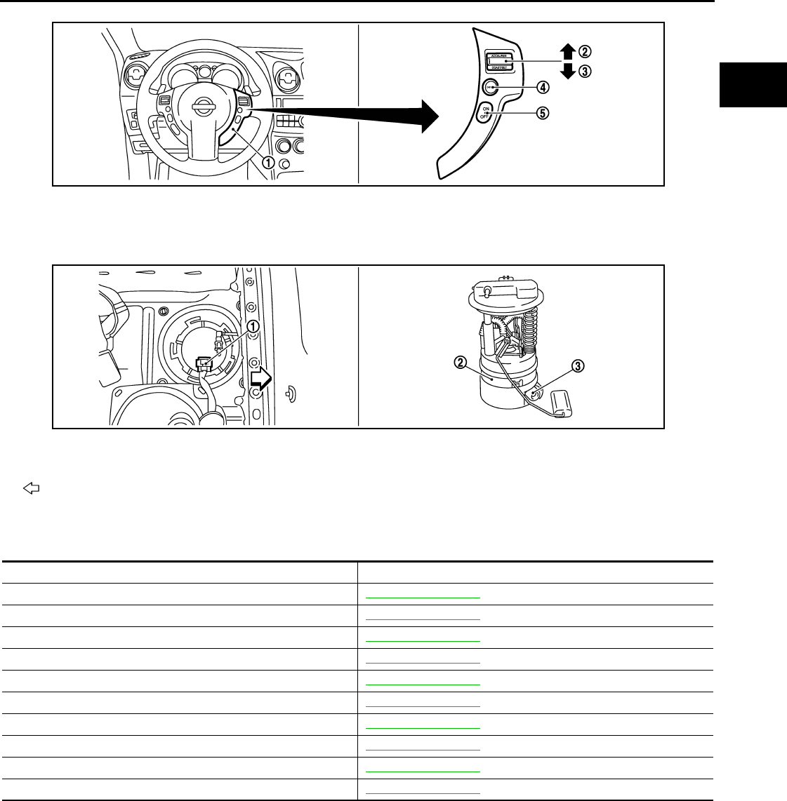
EVAPORATIVE EMISSION SYSTEM
EC-79
< FUNCTION DIAGNOSIS > [FOR CALIFORNIA]
C
D
E
F
G
H
I
J
K
L
M
A
EC
N
P
O
Component Description INFOID:0000000004493327
1. ASCD steering switch 2. RESUME/ACCERELATE switch 3. SET/COAST switch
4. CANSEL switch 5. MAIN switch
1. Fuel level sensor unit and fuel pump
harness connector 2. Fuel level sensor unit and fuel pump 3. Fuel pressure regulator
Vehicle front
JMBIA0925ZZ
JMBIA0926ZZ
Component Reference
A/F sensor 1 EC-177, "Description"
Accelerator pedal position sensor EC-385, "Description"
Camshaft position sensor (PHASE) EC-260, "Description"
Crankshaft position sensor (POS) EC-256, "Description"
Engine coolant temperature sensor EC-164, "Description"
EVAP canister purge volume control solenoid valve EC-279, "Description"
EVAP control system pressure sensor EC-294, "Description"
Fuel tank temperature sensor EC-239, "Description"
Mass air flow sensor EC-147, "Description"
Throttle position sensor EC-167, "Description"
Revision: 2008 August 2009 Rogue
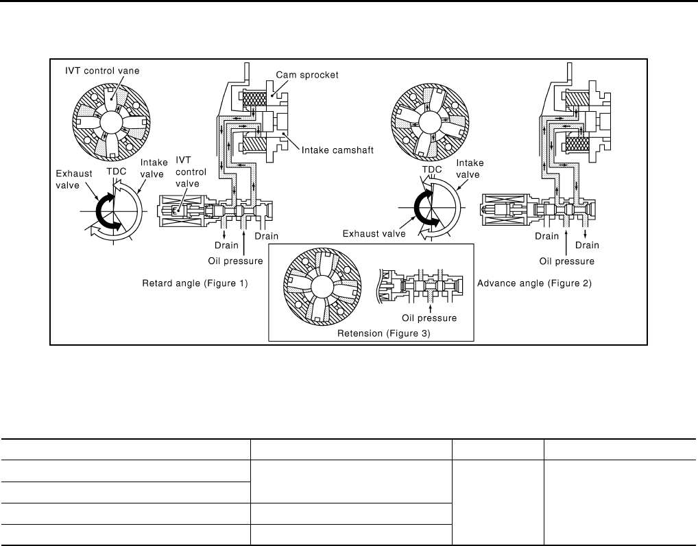
EC-80
< FUNCTION DIAGNOSIS > [FOR CALIFORNIA]
INTAKE VALVE TIMING CONTROL
INTAKE VALVE TIMING CONTROL
System Diagram INFOID:0000000004493328
System Description INFOID:0000000004493329
INPUT/OUTPUT SIGNAL CHART
*: This signal is sent to the ECM through CAN communication line
SYSTEM DESCRIPTION
This mechanism hydraulically controls cam phases continuously with the fixed operating angle of the intake
valve.
The ECM receives signals such as crankshaft position, camshaft position, engine speed, and engine coolant
temperature. Then, the ECM sends ON/OFF pulse duty signals to the intake valve timing (IVT) control sole-
noid valve depending on driving status. This makes it possible to control the shut/open timing of the intake
valve to increase engine torque in low/mid speed range and output in high-speed range.
JMBIA0060G
B
Sensor Input signal to ECM ECM function Actuator
Crankshaft position sensor (POS) Engine speed and piston position Intake valve
timing control Intake valve timing control
solenoid valve
Camshaft position sensor (PHASE)
Engine coolant temperature sensor Engine coolant temperature
Combination meter Vehicle speed*
Revision: 2008 August 2009 Rogue

INTAKE VALVE TIMING CONTROL
EC-81
< FUNCTION DIAGNOSIS > [FOR CALIFORNIA]
C
D
E
F
G
H
I
J
K
L
M
A
EC
N
P
O
Component Parts Location INFOID:0000000004493330
1. Intake valve timing control solenoid
valve
2. Ignition coil (with power transistor)
and spark plug
3. Cooling fan motor-2
4. Air fuel ratio (A/F) sensor 1 5. Heated oxygen sensor 2 6. Camshaft position sensor (PHASE)
7. Engine coolant temperature sensor 8. Park/neutral position (PNP) switch 9. Cooling fan motor-1
10. Refrigerant pressure sensor 11. ECM 12. IPDM E/R
13. Mass air flow sensor (with intake air
temperature sensor)
14. Tumble control valve actuator 15. Crankshaft position sensor (POS)
16. Electric throttle control actuator
(with built in throttle position sensor
and throttle control motor)
17. Knock sensor 18. EVAP service port
19. EVAP canister purge volume control
solenoid valve 20. Fuel injector
1. Electric throttle control actuator 2. Camshaft position sensor (PHASE)
Vehicle front
JMBIA0932ZZ
JMBIA0917ZZ
Revision: 2008 August 2009 Rogue

EC-82
< FUNCTION DIAGNOSIS > [FOR CALIFORNIA]
INTAKE VALVE TIMING CONTROL
1. Mass air flow sensor (with intake air
temperature sensor)
2. Engine coolant temperature sensor
Vehicle front
1. Cooling fan motor-1 harness con-
nector
2. Cooling fan motor-1 3. Cooling fan motor-2 harness con-
nector
4. Cooling fan motor-2 5. Crankshaft position sensor (POS)
Vehicle front
1. Fuel injector 2. Ignition coil (with power transistor)
and spark plug 3. EVAP canister purge volume control
solenoid valve
4. EVAP service port
Vehicle front
JMBIA0918ZZ
JMBIA0919ZZ
JMBIA0921ZZ
Revision: 2008 August 2009 Rogue

INTAKE VALVE TIMING CONTROL
EC-83
< FUNCTION DIAGNOSIS > [FOR CALIFORNIA]
C
D
E
F
G
H
I
J
K
L
M
A
EC
N
P
O
1. Refrigerant pressure sensor 2. PCV valve
JMBIA0922ZZ
JMBIA0910G
B
1. Air fuel ratio (A/F) sensor 1 2. Heated oxygen sensor 2 3. Air fuel ratio (A/F) sensor 1 harness
connector
4. Heated oxygen sensor 2 harness
connector
5. HC adsorption catalyst (Under floor)
Vehicle front
JMBIA0920ZZ
JMBIA0931ZZ
Revision: 2008 August 2009 Rogue

EC-84
< FUNCTION DIAGNOSIS > [FOR CALIFORNIA]
INTAKE VALVE TIMING CONTROL
1. Tumble control valve actuator 2. Condenser 3. Heated oxygen sensor 3
4. Heated oxygen sensor 3 harness
connector
Vehicle front
1. EVAP control system pressure sen-
sor 2. EVAP canister vent control valve 3. EVAP canister
4. Body ground
Vehicle front
1. Park/neutral position (PNP) switch 2. Data link connector
Vehicle front
1. Stop lamp switch 2. ASCD brake switch 3. Accelerator pedal position sensor
JMBIA0923ZZ
JMBIA0927ZZ
JMBIA0924ZZ
Revision: 2008 August 2009 Rogue
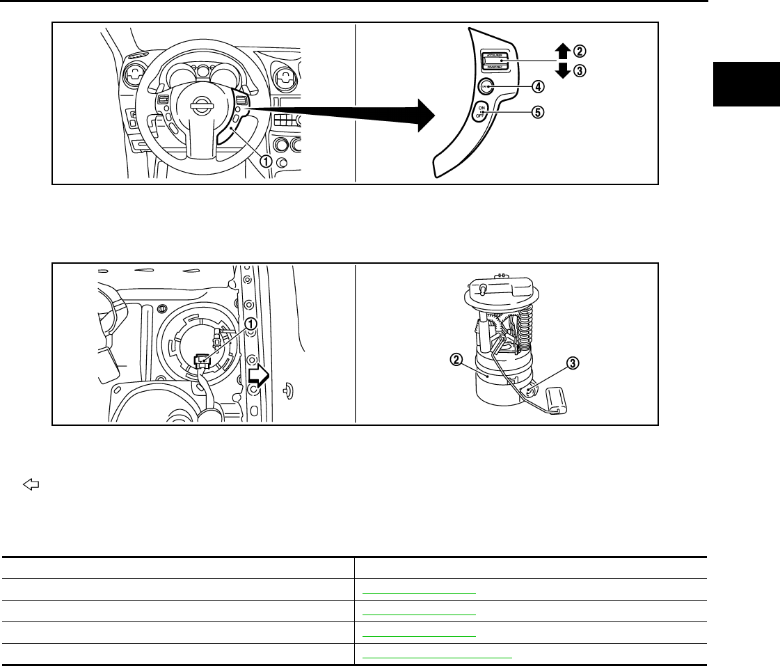
INTAKE VALVE TIMING CONTROL
EC-85
< FUNCTION DIAGNOSIS > [FOR CALIFORNIA]
C
D
E
F
G
H
I
J
K
L
M
A
EC
N
P
O
Component Description INFOID:0000000004493331
1. ASCD steering switch 2. RESUME/ACCERELATE switch 3. SET/COAST switch
4. CANSEL switch 5. MAIN switch
1. Fuel level sensor unit and fuel pump
harness connector 2. Fuel level sensor unit and fuel pump 3. Fuel pressure regulator
Vehicle front
JMBIA0925ZZ
JMBIA0926ZZ
Component Reference
Camshaft position sensor (PHASE) EC-260, "Description"
Crankshaft position sensor (POS) EC-256, "Description"
Engine coolant temperature sensor EC-164, "Description"
Intake valve timing control solenoid valve EC-80, "System Description"
Revision: 2008 August 2009 Rogue
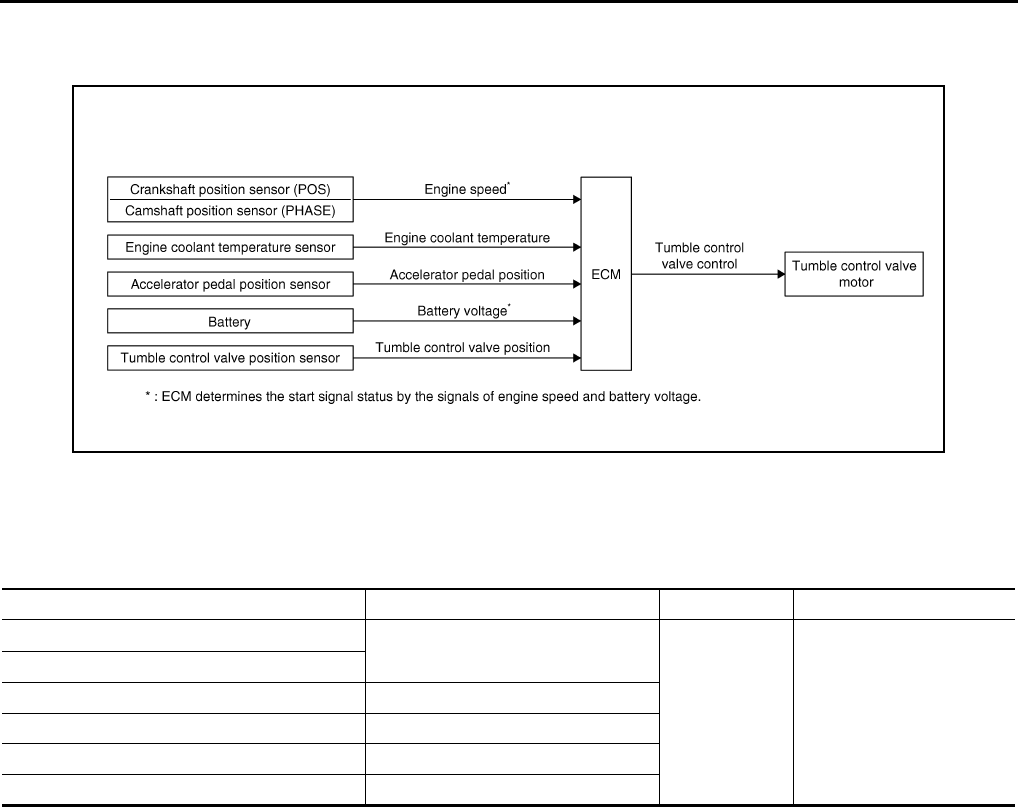
EC-86
< FUNCTION DIAGNOSIS > [FOR CALIFORNIA]
TUMBLE CONTROL VALVE CONTROL
TUMBLE CONTROL VALVE CONTROL
System Diagram INFOID:0000000004493332
System Description INFOID:0000000004493333
INPUT/OUTPUT SIGNAL CHART
*: ECM determines the start signal status by the signals of engine speed and battery voltage.
SYSTEM DESCRIPTION
Tumble control valve has a valve portion in the intake passage of each cylinder.
While idling and during low engine coolant temperature, the tumble control valve closes. Thus the velocity of
the air in the intake passage increases, promoting the vaporization of the fuel and producing a tumble in the
combustion chamber.
Because of this operation, this system tends to increase the burning speed of the gas mixture, improve fuel
consumption, and increase the stability in running conditions.
Also, except when idling and during low engine coolant temperature, this system opens the tumble control
valve.
In this condition, this system tends to increase power by improving intake efficiency via reduction of intake flow
resistance.
The tumble control valve is operated by the ECM.
JMBIA0162G
B
Sensor Input signal to ECM ECM function Actuator
Crankshaft position sensor (POS) Engine speed*
Tumble control
valve control Tumble control valve motor
Camshaft position sensor (PHASE)
Battery Battery voltage*
Engine coolant temperature sensor Engine coolant temperature
Accelerator pedal position sensor Accelerator pedal position
Tumble control valve position sensor Tumble control valve position
Revision: 2008 August 2009 Rogue

TUMBLE CONTROL VALVE CONTROL
EC-87
< FUNCTION DIAGNOSIS > [FOR CALIFORNIA]
C
D
E
F
G
H
I
J
K
L
M
A
EC
N
P
O
Component Parts Location INFOID:0000000004493334
1. Intake valve timing control solenoid
valve
2. Ignition coil (with power transistor)
and spark plug
3. Cooling fan motor-2
4. Air fuel ratio (A/F) sensor 1 5. Heated oxygen sensor 2 6. Camshaft position sensor (PHASE)
7. Engine coolant temperature sensor 8. Park/neutral position (PNP) switch 9. Cooling fan motor-1
10. Refrigerant pressure sensor 11. ECM 12. IPDM E/R
13. Mass air flow sensor (with intake air
temperature sensor)
14. Tumble control valve actuator 15. Crankshaft position sensor (POS)
16. Electric throttle control actuator
(with built in throttle position sensor
and throttle control motor)
17. Knock sensor 18. EVAP service port
19. EVAP canister purge volume control
solenoid valve 20. Fuel injector
1. Electric throttle control actuator 2. Camshaft position sensor (PHASE)
Vehicle front
JMBIA0932ZZ
JMBIA0917ZZ
Revision: 2008 August 2009 Rogue
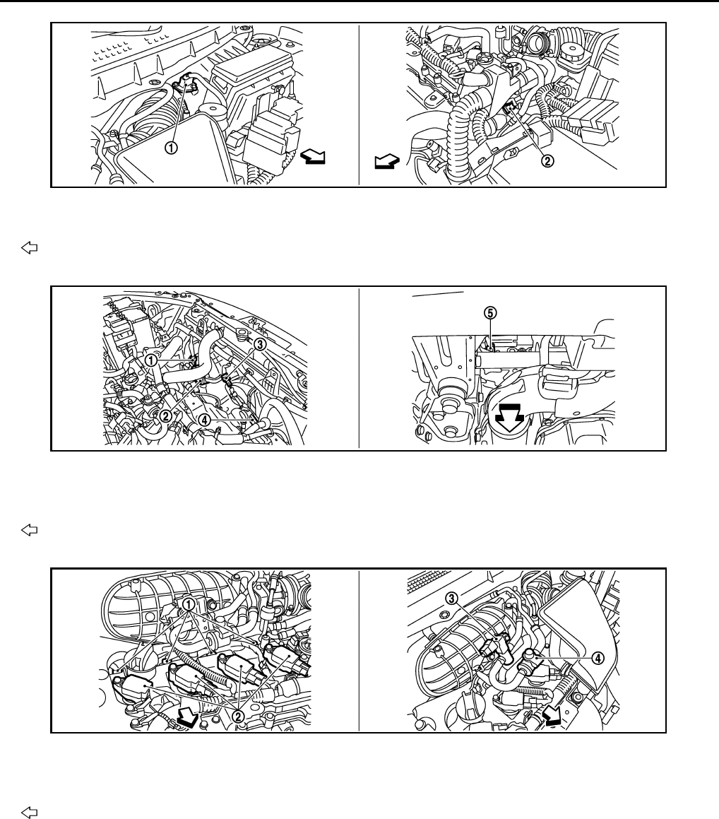
EC-88
< FUNCTION DIAGNOSIS > [FOR CALIFORNIA]
TUMBLE CONTROL VALVE CONTROL
1. Mass air flow sensor (with intake air
temperature sensor)
2. Engine coolant temperature sensor
Vehicle front
1. Cooling fan motor-1 harness con-
nector
2. Cooling fan motor-1 3. Cooling fan motor-2 harness con-
nector
4. Cooling fan motor-2 5. Crankshaft position sensor (POS)
Vehicle front
1. Fuel injector 2. Ignition coil (with power transistor)
and spark plug 3. EVAP canister purge volume control
solenoid valve
4. EVAP service port
Vehicle front
JMBIA0918ZZ
JMBIA0919ZZ
JMBIA0921ZZ
Revision: 2008 August 2009 Rogue

TUMBLE CONTROL VALVE CONTROL
EC-89
< FUNCTION DIAGNOSIS > [FOR CALIFORNIA]
C
D
E
F
G
H
I
J
K
L
M
A
EC
N
P
O
1. Refrigerant pressure sensor 2. PCV valve
JMBIA0922ZZ
JMBIA0910G
B
1. Air fuel ratio (A/F) sensor 1 2. Heated oxygen sensor 2 3. Air fuel ratio (A/F) sensor 1 harness
connector
4. Heated oxygen sensor 2 harness
connector
5. HC adsorption catalyst (Under floor)
Vehicle front
JMBIA0920ZZ
JMBIA0931ZZ
Revision: 2008 August 2009 Rogue
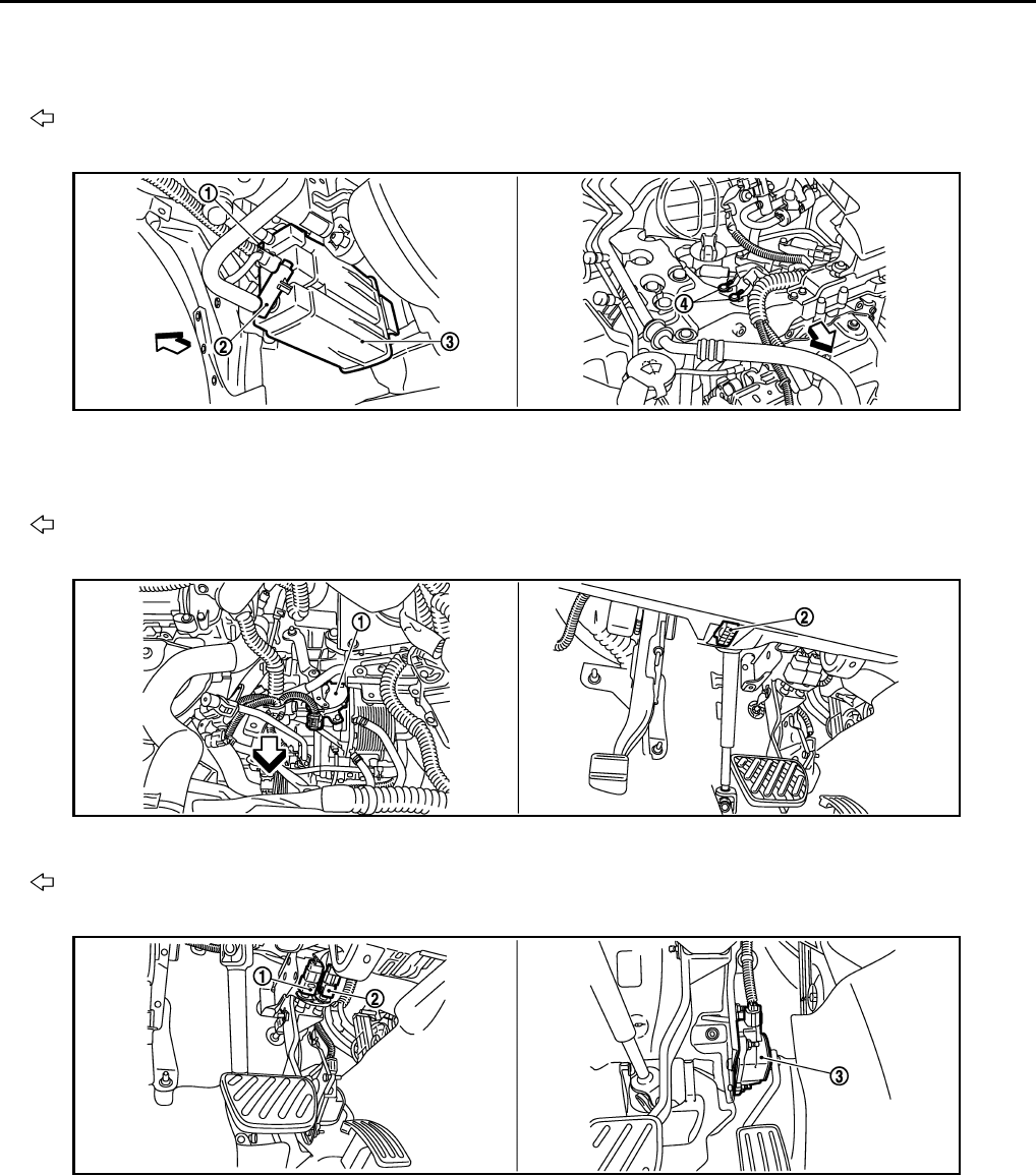
EC-90
< FUNCTION DIAGNOSIS > [FOR CALIFORNIA]
TUMBLE CONTROL VALVE CONTROL
1. Tumble control valve actuator 2. Condenser 3. Heated oxygen sensor 3
4. Heated oxygen sensor 3 harness
connector
Vehicle front
1. EVAP control system pressure sen-
sor 2. EVAP canister vent control valve 3. EVAP canister
4. Body ground
Vehicle front
1. Park/neutral position (PNP) switch 2. Data link connector
Vehicle front
1. Stop lamp switch 2. ASCD brake switch 3. Accelerator pedal position sensor
JMBIA0923ZZ
JMBIA0927ZZ
JMBIA0924ZZ
Revision: 2008 August 2009 Rogue
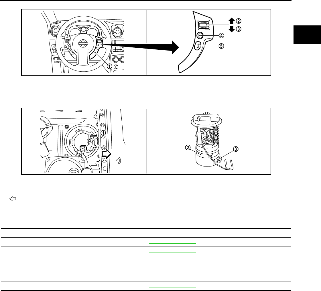
TUMBLE CONTROL VALVE CONTROL
EC-91
< FUNCTION DIAGNOSIS > [FOR CALIFORNIA]
C
D
E
F
G
H
I
J
K
L
M
A
EC
N
P
O
Component Description INFOID:0000000004493335
1. ASCD steering switch 2. RESUME/ACCERELATE switch 3. SET/COAST switch
4. CANSEL switch 5. MAIN switch
1. Fuel level sensor unit and fuel pump
harness connector 2. Fuel level sensor unit and fuel pump 3. Fuel pressure regulator
Vehicle front
JMBIA0925ZZ
JMBIA0926ZZ
Component Reference
Accelerator pedal position sensor EC-385, "Description"
Camshaft position sensor (PHASE) EC-260, "Description"
Crankshaft position sensor (POS) EC-256, "Description"
Engine coolant temperature sensor EC-164, "Description"
Tumble control valve EC-367, "Description"
Tumble control valve position sensor EC-367, "Description"
Revision: 2008 August 2009 Rogue
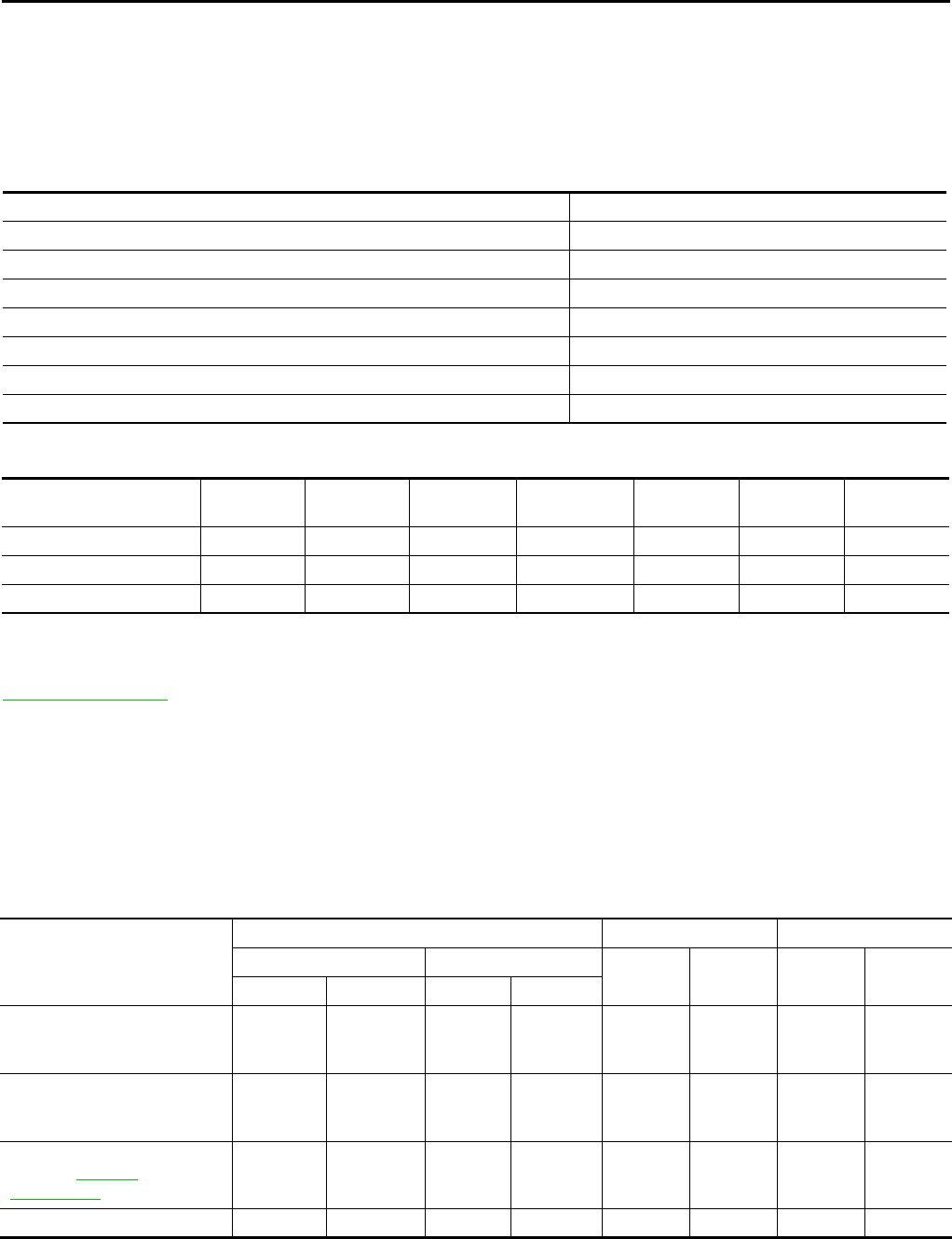
EC-92
< FUNCTION DIAGNOSIS > [FOR CALIFORNIA]
ON BOARD DIAGNOSTIC (OBD) SYSTEM
ON BOARD DIAGNOSTIC (OBD) SYSTEM
Diagnosis Description INFOID:0000000004493336
INTRODUCTION
The ECM has an on board diagnostic system, which detects malfunctions related to engine sensors or actua-
tors. The ECM also records various emission-related diagnostic information including:
The above information can be checked using procedures listed in the table below.
×: Applicable —: Not applicable
*: When DTC and 1st trip DTC simultaneously appear on the display, they cannot be clearly distinguished from each other.
The malfunction indicator lamp (MIL) on the instrument panel illuminates when the same malfunction is
detected in two consecutive trips (Two trip detection logic), or when the ECM enters fail-safe mode. (Refer to
EC-462, "Fail safe".)
TWO TRIP DETECTION LOGIC
When a malfunction is detected for the first time, 1st trip DTC and 1st trip Freeze Frame data are stored in the
ECM memory. The MIL will not illuminate at this stage. <1st trip>
If the same malfunction is detected again during the next drive, the DTC and Freeze Frame data are stored in
the ECM memory, and the MIL illuminates. The MIL illuminates at the same time the DTC is stored. <2nd trip>
The “trip” in the “Two Trip Detection Logic” means a driving mode in which self-diagnosis is performed during
vehicle operation. Specific on board diagnostic items will cause the ECM to illuminate or blink the MIL, and
store DTC and Freeze Frame data, even in the 1st trip, as shown below.
×: Applicable —: Not applicable
DTC AND FREEZE FRAME DATA
DTC and 1st Trip DTC
Emission-related diagnostic information Diagnostic service
Diagnostic Trouble Code (DTC) Service $03 of SAE J1979
Freeze Frame data Service $02 of SAE J1979
System Readiness Test (SRT) code Service $01 of SAE J1979
1st Trip Diagnostic Trouble Code (1st Trip DTC) Service $07 of SAE J1979
1st Trip Freeze Frame data
Test values and Test limits Service $06 of SAE J1979
Calibration ID Service $09 of SAE J1979
DTC 1st trip DTC Freeze
Frame data 1st trip Freeze
Frame data SRT code SRT status Test value
CONSULT-III ××× × ××—
GST ××× —×××
ECM ××*— — — ×—
Items
MIL DTC 1st trip DTC
1st trip 2nd trip 1st trip
displaying 2nd trip
displaying 1st trip
displaying 2nd trip
displaying
Blinking illuminate Blinking illuminate
Misfire (Possible three way cat-
alyst damage) — DTC: P0300 -
P0304 is being detected
×—————×—
Misfire (Possible three way cat-
alyst damage) — DTC: P0300 -
P0304 is being detected
——×——×——
One trip detection diagnoses
(Refer to EC-466,
"DTC Index".)
—×—— ×———
Except above — — — ×—××—
Revision: 2008 August 2009 Rogue

ON BOARD DIAGNOSTIC (OBD) SYSTEM
EC-93
< FUNCTION DIAGNOSIS > [FOR CALIFORNIA]
C
D
E
F
G
H
I
J
K
L
M
A
EC
N
P
O
The 1st trip DTC (whose number is the same as the DTC number) is displayed for the latest self-diagnostic
result obtained. If the ECM memory was cleared previously, and the 1st trip DTC did not recur, the 1st trip DTC
will not be displayed.
If a malfunction is detected during the 1st trip, the 1st trip DTC is saved in the ECM memory. The MIL will not
illuminate (two trip detection logic). If the same malfunction is not detected in the 2nd trip (meeting the required
driving pattern), the 1st trip DTC is cleared from the ECM memory. If the same malfunction is detected in the
2nd trip, both the 1st trip DTC and DTC are saved in the ECM memory and the MIL illuminates. In other words,
the DTC is stored in the ECM memory and the MIL illuminate when the same malfunction occurs in two con-
secutive trips. If a 1st trip DTC is stored and a non-diagnostic operation is performed between the 1st and 2nd
trips, only the 1st trip DTC will continue to be stored. For malfunctions that blink or illuminate the MIL during
the 1st trip, the DTC and 1st trip DTC are stored in the ECM memory.
Procedures for clearing the DTC and the 1st trip DTC from the ECM memory are described in “How to Erase
DTC and 1st Trip DTC.
For malfunctions in which 1st trip DTCs are displayed, refer to EC-466, "DTC Index". These items are
required by legal regulations to continuously monitor the system/component. In addition, the items monitored
non-continuously are also displayed on CONSULT-III.
1st trip DTC is specified in Service $07 of SAE J1979. 1st trip DTC detection occurs without illuminating the
MIL and therefore does not warn the driver of a malfunction. However, 1st trip DTC detection will not prevent
the vehicle from being tested, for example during Inspection/Maintenance (I/M) tests.
When a 1st trip DTC is detected, check, print out or write down and erase (1st trip) DTC and Freeze Frame
data as specified in Work Flow procedure Step 2, refer to EC-18, "Work Flow". Then perform DTC CONFIR-
MATION PROCEDURE or Component Function Check to try to duplicate the malfunction. If the malfunction is
duplicated, the item requires repair.
Freeze Frame Data and 1st Trip Freeze Frame Data
The ECM records the driving conditions such as fuel system status, calculated load value, engine coolant tem-
perature, short-term fuel trim, long-term fuel trim, engine speed, vehicle speed, absolute throttle position, base
fuel schedule and intake air temperature at the moment a malfunction is detected.
Data which are stored in the ECM memory, along with the 1st trip DTC, are called 1st trip freeze frame data.
The data, stored together with the DTC data, are called freeze frame data and displayed on CONSULT-III or
GST. The 1st trip freeze frame data can only be displayed on the CONSULT-III screen, not on the GST.
Only one set of freeze frame data (either 1st trip freeze frame data or freeze frame data) can be stored in the
ECM. 1st trip freeze frame data is stored in the ECM memory along with the 1st trip DTC. There is no priority
for 1st trip freeze frame data and it is updated each time a different 1st trip DTC is detected. However, once
freeze frame data (2nd trip detection/MIL on) is stored in the ECM memory, 1st trip freeze frame data is no
longer stored. Remember, only one set of freeze frame data can be stored in the ECM. The ECM has the fol-
lowing priorities to update the data.
For example, the EGR malfunction (Priority: 2) was detected and the freeze frame data was saved in the 2nd
trip. After that when the misfire (Priority: 1) is detected in another trip, the freeze frame data will be updated
from the EGR malfunction to the misfire. The 1st trip freeze frame data is updated each time a different mal-
function is detected. There is no priority for 1st trip freeze frame data. However, once freeze frame data is
stored in the ECM memory, 1st trip freeze data is no longer stored (because only one freeze frame data or 1st
trip freeze frame data can be stored in the ECM). If freeze frame data is stored in the ECM memory and freeze
frame data with the same priority occurs later, the first (original) freeze frame data remains unchanged in the
ECM memory.
Both 1st trip freeze frame data and freeze frame data (along with the DTCs) are cleared when the ECM mem-
ory is erased. Procedures for clearing the ECM memory are described in “How to Erase DTC and 1st Trip
DTC”.
How to Read DTC and 1st Trip DTC
With CONSULT-III
With GST
CONSULT-III or GST (Generic Scan Tool) Examples: P0340, P0850, P1148, etc.
These DTCs are prescribed by SAE J2012.
Priority Items
1Freeze frame data Misfire — DTC: P0300 - P0304
Fuel Injection System Function — DTC: P0171, P0172
2 Except the above items (Includes CVT related items)
3 1st trip freeze frame data
Revision: 2008 August 2009 Rogue

EC-94
< FUNCTION DIAGNOSIS > [FOR CALIFORNIA]
ON BOARD DIAGNOSTIC (OBD) SYSTEM
(CONSULT-III also displays the malfunctioning component or system.)
No Tools
The number of blinks of the MIL in the Diagnostic Test Mode II (Self-Diagnostic Results) indicates the DTC.
Example: 0340, 0850, 1148, etc.
These DTCs are controlled by NISSAN.
•1st trip DTC No. is the same as DTC No.
•Output of a DTC indicates a malfunction. However, GST and the Diagnostic Test Mode II do not indi-
cate whether the malfunction is still occurring or has occurred in the past and has returned to nor-
mal. CONSULT-III can identify malfunction status as shown below. Therefore, using CONSULT-III (if
available) is recommended.
DTC or 1st trip DTC of a malfunction is displayed in “SELF-DIAGNOSTIC RESULTS” mode of CONSULT-III.
Time data indicates how many times the vehicle was driven after the last detection of a DTC.
If the DTC is being detected currently, the time data will be [0].
If a 1st trip DTC is stored in the ECM, the time data will be [1t].
How to Erase DTC and 1st Trip DTC
With CONSULT-III
NOTE:
•If the ignition switch stays ON after repair work, be sure to turn ignition switch OFF once.
Wait at least 10 seconds and then turn it ON (engine stopped) again.
•If the DTC is not for CVT related items (see EC-466, "DTC Index"), skip step 1.
1. Erase DTC in TCM. Refer to TM-42, "Diagnosis Description".
2. Select “ENGINE” with CONSULT-III.
3. Select “SELFDIAGNOSTIC RESULT”.
4. Touch “ERASE”. (DTC in ECM will be erased.)
With GST
NOTE:
•If the ignition switch stays ON after repair work, be sure to turn ignition switch OFF once.
Wait at least 10 seconds and then turn it ON (engine stopped) again.
1. Select Diagnostic Service $04 with GST (Generic Scan Tool).
No Tools
NOTE:
•If the ignition switch stays ON after repair work, be sure to turn ignition switch OFF once.
Wait at least 10 seconds and then turn it ON (engine stopped) again.
1. Erase DTC in ECM. Refer to How to Erase Diagnostic Test Mode II (Self-diagnostic Results).
•If the battery is disconnected, the emission-related diagnostic information will be cleared within 24
hours.
•The following data are cleared when the ECM memory is erased.
- Diagnostic trouble codes
- 1st trip diagnostic trouble codes
- Freeze frame data
- 1st trip freeze frame data
- System readiness test (SRT) codes
- Test values
Actual work procedures are explained using a DTC as an example. Be careful so that not only the DTC, but all
of the data listed above, are cleared from the ECM memory during work procedures.
SYSTEM READINESS TEST (SRT) CODE
System Readiness Test (SRT) code is specified in Service $01 of SAE J1979.
As part of an enhanced emissions test for Inspection & Maintenance (I/M), certain states require the status of
SRT be used to indicate whether the ECM has completed self-diagnosis of major emission systems and com-
ponents. Completion must be verified in order for the emissions inspection to proceed.
If a vehicle is rejected for a State emissions inspection due to one or more SRT items indicating “INCMP”, use
the information in this Service Manual to set the SRT to “CMPLT”.
In most cases the ECM will automatically complete its self-diagnosis cycle during normal usage, and the SRT
status will indicate “CMPLT” for each application system. Once set as “CMPLT”, the SRT status remains
“CMPLT” until the self-diagnosis memory is erased.
Occasionally, certain portions of the self-diagnostic test may not be completed as a result of the customer's
normal driving pattern; the SRT will indicate “INCMP” for these items.
NOTE:
Revision: 2008 August 2009 Rogue
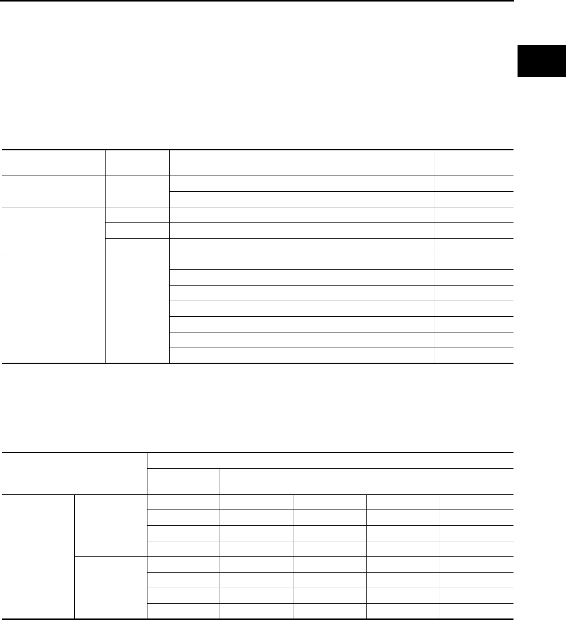
ON BOARD DIAGNOSTIC (OBD) SYSTEM
EC-95
< FUNCTION DIAGNOSIS > [FOR CALIFORNIA]
C
D
E
F
G
H
I
J
K
L
M
A
EC
N
P
O
The SRT will also indicate “INCMP” if the self-diagnosis memory is erased for any reason or if the ECM mem-
ory power supply is interrupted for several hours.
If, during the state emissions inspection, the SRT indicates “CMPLT” for all test items, the inspector will con-
tinue with the emissions test. However, if the SRT indicates “INCMP” for one or more of the SRT items the
vehicle is returned to the customer untested.
NOTE:
If MIL is ON during the state emissions inspection, the vehicle is also returned to the customer untested even
though the SRT indicates “CMPLT” for all test items. Therefore, it is important to check SRT (“CMPLT”) and
DTC (No DTCs) before the inspection.
SRT Item
The table below shows required self-diagnostic items to set the SRT to “CMPLT”.
*: If completion of several SRTs is required, perform driving patterns (DTC CONFIRMATION PROCEDURE), one by one based on the
priority for models with CONSULT-III.
SRT Set Timing
SRT is set as “CMPLT” after self-diagnosis has been performed one or more times. Completion of SRT is
done regardless of whether the result is OK or NG. The set timing is different between OK and NG results and
is shown in the table below.
SRT item
(CONSULT-III indication)
Performance
Priority* Required self-diagnostic items to set the SRT to “CMPLT” Corresponding
DTC No.
CATALYST 2 Three way catalyst function P0420
HC adsorption catalyst function P2423
EVAP SYSTEM 2 EVAP control system purge flow monitoring P0441
1 EVAP control system P0442
2 EVAP control system P0456
HO2S 2 Air fuel ratio (A/F) sensor 1 P0133
Heated oxygen sensor 2 P0137
Heated oxygen sensor 2 P0138
Heated oxygen sensor 2 P0139
Heated oxygen sensor 3 P0143
Heated oxygen sensor 3 P0144
Heated oxygen sensor 3 P0145
Self-diagnosis result
Example
Diagnosis Ignition cycle
← ON →OFF ← ON →OFF ← ON →OFF ← ON →
All OK Case 1 P0400 OK (1) — (1) OK (2) — (2)
P0402 OK (1) — (1) — (1) OK (2)
P1402 OK (1) OK (2) — (2) — (2)
SRT of EGR “CMPLT” “CMPLT” “CMPLT” “CMPLT”
Case 2 P0400 OK (1) — (1) — (1) — (1)
P0402 — (0) — (0) OK (1) — (1)
P1402 OK (1) OK (2) — (2) — (2)
SRT of EGR “INCMP” “INCMP” “CMPLT” “CMPLT”
Revision: 2008 August 2009 Rogue

EC-96
< FUNCTION DIAGNOSIS > [FOR CALIFORNIA]
ON BOARD DIAGNOSTIC (OBD) SYSTEM
OK: Self-diagnosis is carried out and the result is OK.
NG: Self-diagnosis is carried out and the result is NG.
—: Self-diagnosis is not carried out.
When all SRT related self-diagnoses show OK results in a single cycle (Ignition OFF-ON-OFF), the SRT will
indicate “CMPLT”. → Case 1 above
When all SRT related self-diagnoses show OK results through several different cycles, the SRT will indicate
“CMPLT” at the time the respective self-diagnoses have at least one OK result. → Case 2 above
If one or more SRT related self-diagnoses show NG results in 2 consecutive cycles, the SRT will also indicate
“CMPLT”. → Case 3 above
The table above shows that the minimum number of cycles for setting SRT as “INCMP” is the number one (1)
for each self-diagnosis (Case 1 & 2) or the number two (2) for one of self-diagnoses (Case 3). However, in
preparation for the state emissions inspection, it is unnecessary for each self-diagnosis to be executed twice
(Case 3) for the following reasons:
• The SRT will indicate “CMPLT” at the time the respective self-diagnoses have one (1) OK result.
• The emissions inspection requires “CMPLT” of the SRT only with OK self-diagnosis results.
• During SRT driving pattern, the 1st trip DTC (NG) is detected prior to “CMPLT” of SRT and the self-diagnosis
memory must be erased from the ECM after repair.
• If the 1st trip DTC is erased, all the SRT will indicate “INCMP”.
NOTE:
SRT can be set as “CMPLT” together with the DTC(s). Therefore, DTC check must always be carried out
prior to the state emission inspection even though the SRT indicates “CMPLT”.
SRT Service Procedure
If a vehicle has failed the state emissions inspection due to one or more SRT items indicating “INCMP”, review
the flowchart diagnostic sequence on the next page.
NG exists Case 3 P0400 OK OK — —
P0402 — — — —
P1402 NG — NG NG
(Consecutive
NG)
(1st trip)
DTC 1st trip DTC — 1st trip DTC DTC
(= MIL ON)
SRT of EGR “INCMP” “INCMP” “INCMP” “CMPLT”
Revision: 2008 August 2009 Rogue

ON BOARD DIAGNOSTIC (OBD) SYSTEM
EC-97
< FUNCTION DIAGNOSIS > [FOR CALIFORNIA]
C
D
E
F
G
H
I
J
K
L
M
A
EC
N
P
O
How to Display SRT Status
WITH CONSULT-III
Selecting “SRT STATUS” in “DTC CONFIRMATION” mode with CONSULT-III.
For items whose SRT codes are set, “CMPLT” is displayed on the CONSULT-III screen; for items whose SRT
codes are not set, “INCMP” is displayed.
NOTE:
Though displayed on the CONSULT-III screen, “HO2S HTR” is not SRT item.
WITH GST
Selecting Service $01 with GST (Generic Scan Tool)
NO TOOLS
A SRT code itself cannot be displayed, however SRT status can.
1. Turn ignition switch ON and wait 20 seconds.
2. SRT status is indicated as shown below.
• When all SRT codes are set, MIL illuminates continuously.
JMBIA1574G
B
Revision: 2008 August 2009 Rogue
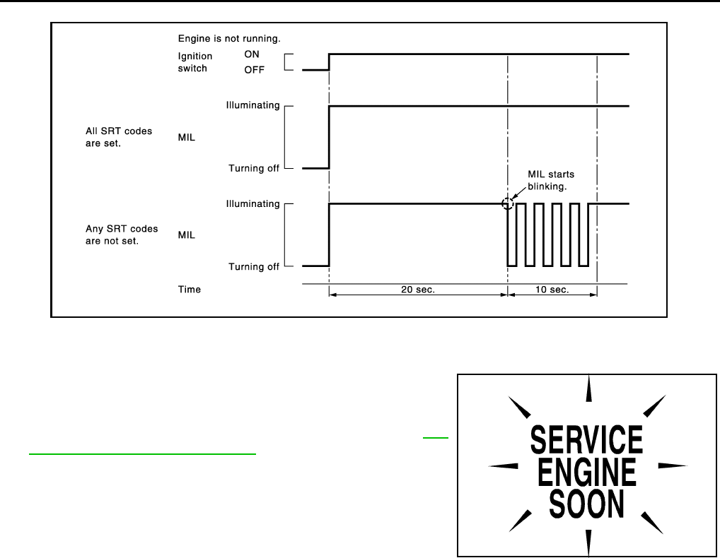
EC-98
< FUNCTION DIAGNOSIS > [FOR CALIFORNIA]
ON BOARD DIAGNOSTIC (OBD) SYSTEM
• When any SRT codes are not set, MIL will flash periodically for 10 seconds.
MALFUNCTION INDICATOR LAMP (MIL)
Description
The MIL is located on the instrument panel.
1. The MIL will illuminate when the ignition switch is turned ON
without the engine running. This is a bulb check.
If the MIL does not illuminate, check MIL circuit. Refer to EC-
430, "Component Function Check".
2. When the engine is started, the MIL should turn off.
If the MIL remains on, the on board diagnostic system has
detected an engine system malfunction.
On Board Diagnostic System Function
The on board diagnostic system has the following three functions.
JMBIA1515G
B
SEF217U
Revision: 2008 August 2009 Rogue
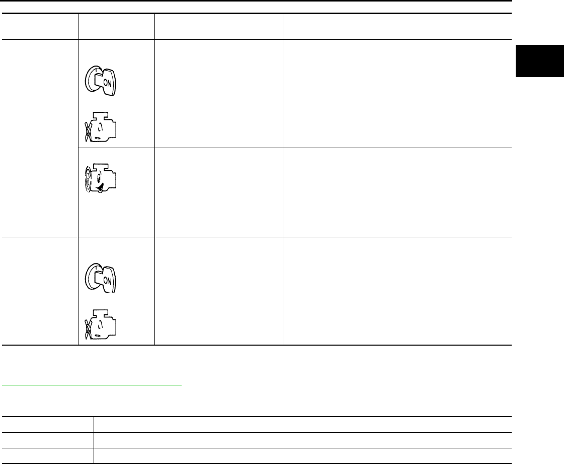
ON BOARD DIAGNOSTIC (OBD) SYSTEM
EC-99
< FUNCTION DIAGNOSIS > [FOR CALIFORNIA]
C
D
E
F
G
H
I
J
K
L
M
A
EC
N
P
O
Diagnostic Test Mode I — Bulb Check
In this mode, the MIL on the instrument panel should stay ON. If it remains OFF, check MIL circuit. Refer to
EC-430, "Component Function Check".
Diagnostic Test Mode I — Malfunction Warning
This DTC number is clarified in Diagnostic Test Mode II (SELF-DIAGNOSTIC RESULTS)
Diagnostic Test Mode II — Self-diagnostic Results
In this mode, the DTC and 1st trip DTC are indicated by the number of blinks of the MIL as shown below.
The DTC and 1st trip DTC are displayed at the same time. If the MIL does not illuminate in diagnostic test
mode I (Malfunction warning), all displayed items are 1st trip DTCs. If only one code is displayed when the MIL
illuminates in diagnostic test mode II (SELF-DIAGNOSTIC RESULTS), it is a DTC; if two or more codes are
displayed, they may be either DTCs or 1st trip DTCs. DTC No. is same as that of 1st trip DTC. These uniden-
Diagnostic Test
Mode
KEY and ENG.
Status
Function Explanation of Function
Mode I Ignition switch in
ON position
Engine stopped
BULB CHECK This function checks the MIL bulb for damage (blown, open
circuit, etc.).
If the MIL does not come on, check MIL circuit.
Engine running MALFUNCTION
WARNING
When a malfunction is detected twice in two consecutive
driving cycles (two trip detection logic), the MIL will illumi-
nate to inform the driver that a malfunction has been detect-
ed.
The following malfunctions will illuminate or blink the MIL in
the 1st trip.
• Misfire (Possible three way catalyst damage)
• One trip detection diagnoses
Mode II Ignition switch in
ON position
Engine stopped
SELF-DIAGNOSTIC
RESULTS This function allows DTCs and 1st trip DTCs to be read.
MIL Condition
ON When the malfunction is detected.
OFF No malfunction.
Revision: 2008 August 2009 Rogue
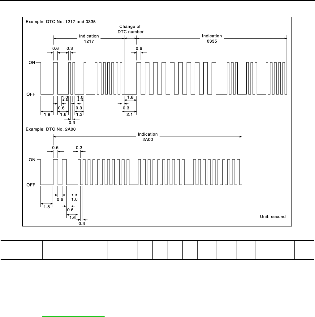
EC-100
< FUNCTION DIAGNOSIS > [FOR CALIFORNIA]
ON BOARD DIAGNOSTIC (OBD) SYSTEM
tified codes can be identified by using the CONSULT-III or GST. A DTC will be used as an example for how to
read a code.
A particular trouble code can be identified by the number of four-digit numeral flashes as per the following.
The length of time the 1,000th-digit numeral flashes on and off is 1.2 seconds consisting of an ON (0.6-sec-
onds) - OFF (0.6-seconds) cycle.
The 100th-digit numeral and lower digit numerals consist of a 0.3-seconds ON and 0.3-seconds OFF cycle.
A change from one digit numeral to another occurs at an interval of 1.0-second OFF. In other words, the later
numeral appears on the display 1.3 seconds after the former numeral has disappeared.
A change from one trouble code to another occurs at an interval of 1.8-seconds OFF.
In this way, all the detected malfunctions are classified by their DTC numbers. The DTC 0000 refers to no mal-
function. (See EC-466, "DTC Index")
How to Switch Diagnostic Test Mode
NOTE:
•It is better to count the time accurately with a clock.
•It is impossible to switch the diagnostic mode when an accelerator pedal position sensor circuit has
a malfunction.
•ECM always returns to Diagnostic Test Mode I after the ignition switch is turned OFF.
HOW TO SET DIAGNOSTIC TEST MODE II (SELF-DIAGNOSTIC RESULTS)
1. Confirm that accelerator pedal is fully released, turn ignition switch ON and wait 3 seconds.
2. Repeat the following procedure quickly five times within 5 seconds.
- Fully depress the accelerator pedal.
- Fully release the accelerator pedal.
3. Wait 7 seconds, fully depress the accelerator pedal and keep it depressed for approx. 10 seconds until the
MIL starts blinking.
NOTE:
Do not release the accelerator pedal for 10 seconds if MIL starts blinking during this period. This
blinking is displaying SRT status and is continued for another 10 seconds.
Number 0 123456789 A B C D E F
Flashes 10 1 2 3 4 5 6 7 8 9 11 12 13 14 15 16
JMBIA1140G
B
Revision: 2008 August 2009 Rogue
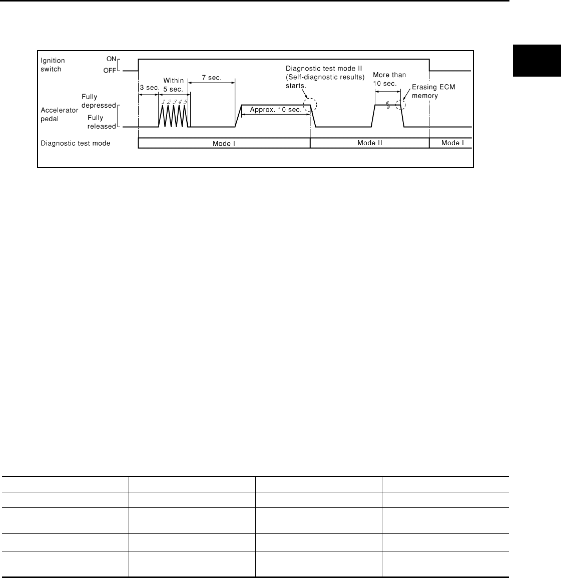
ON BOARD DIAGNOSTIC (OBD) SYSTEM
EC-101
< FUNCTION DIAGNOSIS > [FOR CALIFORNIA]
C
D
E
F
G
H
I
J
K
L
M
A
EC
N
P
O
4. Fully release the accelerator pedal.
ECM has entered to Diagnostic Test Mode II (Self-diagnostic results).
NOTE:
Wait until the same DTC (or 1st trip DTC) appears to completely confirm all DTCs.
HOW TO ERASE DIAGNOSTIC TEST MODE II (SELF-DIAGNOSTIC RESULTS)
1. Set ECM in Diagnostic Test Mode II (Self-diagnostic results). Refer to “How to Set Diagnostic Test Mode II
(Self-diagnostic Results)”.
2. Fully depress the accelerator pedal and keep it depressed for more than 10 seconds.
The emission-related diagnostic information has been erased from the backup memory in the ECM.
3. Fully release the accelerator pedal, and confirm the DTC 0000 is displayed.
•If the battery is disconnected, the DTC will be lost from the backup memory within 24 hours.
•Do not erase the stored memory before starting trouble diagnoses.
OBD System Operation Chart
Relationship Between MIL, 1st Trip DTC, DTC and Detectable Items
• When a malfunction is detected for the first time, the 1st trip DTC and the 1st trip freeze frame data are
stored in the ECM memory.
• When the same malfunction is detected in two consecutive trips, the DTC and the freeze frame data are
stored in the ECM memory, and the MIL will come on.
• The MIL will turn off after the vehicle is driven 3 times (driving pattern B) with no malfunction. A is counted
only when the recorded driving pattern is met (as stored in the ECM). If another malfunction occurs while
counting, the counter will reset.
• The DTC and the freeze frame data will be stored until the vehicle is driven 40 times (driving pattern A) with-
out the same malfunction recurring (except for Misfire and Fuel Injection System). For Misfire and Fuel Injec-
tion System, the DTC and freeze frame data will be stored until the vehicle is driven 80 times (driving pattern
C) without the same malfunction recurring. The “TIME” in “SELF-DIAGNOSTIC RESULTS” mode of CON-
SULT-III will count the number of times the vehicle is driven.
• The 1st trip DTC is not displayed when the self-diagnosis results in OK for the 2nd trip.
Summary Chart
For details about patterns B and C under “Fuel Injection System” and “Misfire”, see “EXPLANATION FOR DRIVING PATTERNS FOR
“MISFIRE <EXHAUST QUALITY DETERIORATION>”, “FUEL INJECTION SYSTEM”.
For details about patterns A and B under Other, see “EXPLANATION FOR DRIVING PATTERNS FOR “MISFIRE <EXHAUST QUALITY
DETERIORATION>”, “FUEL INJECTION SYSTEM”.
*1: Clear timing is at the moment OK is detected.
*2: Clear timing is when the same malfunction is detected in the 2nd trip.
Relationship Between MIL, DTC, 1st Trip DTC and Driving Patterns for “Misfire <Exhaust Quality Deterioration>”,
“Fuel Injection System”
PBIB0092E
Items Fuel Injection System Misfire Other
MIL (turns off) 3 (pattern B) 3 (pattern B) 3 (pattern B)
DTC, Freeze Frame Data (no
display) 80 (pattern C) 80 (pattern C) 40 (pattern A)
1st Trip DTC (clear) 1 (pattern C), *11 (pattern C), *11 (pattern B)
1st Trip Freeze Frame Data
(clear) *1, *2 *1, *2 1 (pattern B)
Revision: 2008 August 2009 Rogue

EC-102
< FUNCTION DIAGNOSIS > [FOR CALIFORNIA]
ON BOARD DIAGNOSTIC (OBD) SYSTEM
Explanation for Driving Patterns for “Misfire <Exhaust Quality Deterioration>”, “Fuel Injection System”
<Driving Pattern B>
Driving pattern B means the vehicle operation as per the following:
All components and systems should be monitored at least once by the OBD system.
*1: When the same malfunction is de-
tected in two consecutive trips, MIL
will illuminate.
*2: MIL will turn off after vehicle is driven
3 times (pattern B) without any mal-
functions.
*3: When the same malfunction is de-
tected in two consecutive trips, the
DTC and the freeze frame data will be
stored in ECM.
*4: The DTC and the freeze frame data
will not be displayed any longer after
vehicle is driven 80 times (pattern C)
without the same malfunction. (The
DTC and the freeze frame data still
remain in ECM.)
*5: When a malfunction is detected for
the first time, the 1st trip DTC and the
1st trip freeze frame data will be
stored in ECM.
*6: The 1st trip DTC and the 1st trip
freeze frame data will be cleared at
the moment OK is detected.
*7: When the same malfunction is de-
tected in the 2nd trip, the 1st trip
freeze frame data will be cleared.
*8: 1st trip DTC will be cleared when ve-
hicle is driven once (pattern C) with-
out the same malfunction after DTC
is stored in ECM.
JMBIA1417G
B
Revision: 2008 August 2009 Rogue

ON BOARD DIAGNOSTIC (OBD) SYSTEM
EC-103
< FUNCTION DIAGNOSIS > [FOR CALIFORNIA]
C
D
E
F
G
H
I
J
K
L
M
A
EC
N
P
O
• The B counter will be cleared when the malfunction is detected once regardless of the driving pattern.
• The B counter will be counted up when driving pattern B is satisfied without any malfunction.
• The MIL will turn off when the B counter reaches 3. (*2 in “OBD SYSTEM OPERATION CHART”)
<Driving Pattern C>
Driving pattern C means opreating vehicle as per the following:
The following conditions should be satisfied at the same time:
Engine speed: (Engine speed in the freeze frame data) ± 375 rpm
Calculated load value: (Calculated load value in the freeze frame data) × (1 ± 0.1) [%]
Engine coolant temperature (T) condition:
• When the freeze frame data shows lower than 70°C (158°F), T should be lower than 70°C (158°F).
• When the freeze frame data shows higher than or equal to 70°C (158°F), T should be higher than or equal to
70°C (158°F).
Example:
If the stored freeze frame data is as per the following:
Engine speed: 850 rpm, Calculated load value: 30%, Engine coolant temperature: 80°C (176°F)
To be satisfied with driving pattern C, the vehicle should run under the following conditions:
Engine speed: 475 - 1,225 rpm, Calculated load value: 27 - 33%, Engine coolant temperature: more than 70°C
(158°F)
• The C counter will be cleared when the malfunction is detected regardless of vehicle conditions above.
• The C counter will be counted up when vehicle conditions above are satisfied without the same malfunction.
• The DTC will not be displayed after C counter reaches 80.
• The 1st trip DTC will be cleared when C counter is counted once without the same malfunction after DTC is
stored in ECM.
Relationship Between MIL, DTC, 1st Trip DTC and Driving Patterns Except For “Misfire <Exhaust Quality Deteriora-
tion>”, “Fuel Injection System”
Revision: 2008 August 2009 Rogue

EC-104
< FUNCTION DIAGNOSIS > [FOR CALIFORNIA]
ON BOARD DIAGNOSTIC (OBD) SYSTEM
*1: When the same malfunction is de-
tected in two consecutive trips, MIL
will illuminate.
*2: MIL will turn off after vehicle is driven
3 times (pattern B) without any mal-
functions.
*3: When the same malfunction is de-
tected in two consecutive trips, the
DTC and the freeze frame data will be
stored in ECM.
JMBIA1418G
B
Revision: 2008 August 2009 Rogue
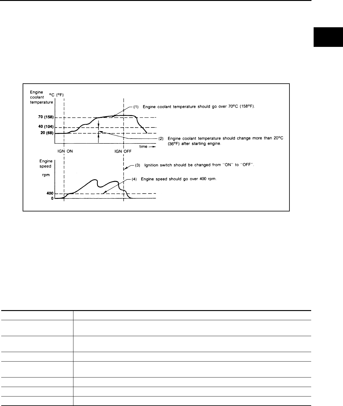
ON BOARD DIAGNOSTIC (OBD) SYSTEM
EC-105
< FUNCTION DIAGNOSIS > [FOR CALIFORNIA]
C
D
E
F
G
H
I
J
K
L
M
A
EC
N
P
O
Explanation for Driving Patterns Except for “Misfire <Exhaust Quality Deterioration>”, “Fuel Injection System”
<Driving Pattern A>
• The A counter will be cleared when the malfunction is detected regardless of (1) - (4).
• The A counter will be counted up when (1) - (4) are satisfied without the same malfunction.
• The DTC will not be displayed after the A counter reaches 40.
<Driving Pattern B>
Driving pattern B means opreating vehicle as per the following:
All components and systems should be monitored at least once by the OBD system.
• The B counter will be cleared when the malfunction is detected once regardless of the driving pattern.
• The B counter will be counted up when driving pattern B is satisfied without any malfunctions.
• The MIL will turn off when the B counter reaches 3 (*2 in OBD SYSTEM OPERATION CHART).
CONSULT-III Function INFOID:0000000004493337
FUNCTION
*: The following emission-related diagnostic information is cleared when the ECM memory is erased.
• Diagnostic trouble codes
• 1st trip diagnostic trouble codes
• Freeze frame data
*4: The DTC and the freeze frame data
will not be displayed any longer after
vehicle is driven 40 times (pattern A)
without the same malfunction.
(The DTC and the freeze frame data
still remain in ECM.)
*5: When a malfunction is detected for
the first time, the 1st trip DTC and the
1st trip freeze frame data will be
stored in ECM.
*6: 1st trip DTC will be cleared after vehi-
cle is driven once (pattern B) without
the same malfunction.
*7: When the same malfunction is de-
tected in the 2nd trip, the 1st trip
freeze frame data will be cleared.
JMBIA1920G
B
Diagnostic test mode Function
Work Support This mode enables a technician to adjust some devices faster and more accurately by following the in-
dications on the CONSULT-III screen.
Self Diagnostic Result Self-diagnostic results such as 1st trip DTC, DTC and 1st trip freeze frame data or freeze frame data
can be read and erased quickly.*
Data Monitor Input/Output data in the ECM can be read.
Active Test Diagnostic Test Mode in which CONSULT-III drives some actuators apart from the ECMs and also shifts
some parameters in a specified range.
DTC & SRT Confirmation The status of system monitoring tests and the self-diagnosis status/results can be confirmed.
Function Test This mode is used to inform customers when their vehicle requires periodic maintenance.
ECU Part Number ECM part number can be read.
Revision: 2008 August 2009 Rogue

EC-106
< FUNCTION DIAGNOSIS > [FOR CALIFORNIA]
ON BOARD DIAGNOSTIC (OBD) SYSTEM
• 1st trip freeze frame data
• System readiness test (SRT) codes
•Test values
ENGINE CONTROL COMPONENT PARTS/CONTROL SYSTEMS APPLICATION
Item
DIAGNOSTIC TEST MODE
Work
Support
Self Diagnostic Result
Data
Monitor Active
Test
DTC & SRT Confir-
mation
DTC*1 FREEZE
FRAME
DATA*2
SRT STA-
TUS
DTC
WORK
SUP-
PORT
ENGINE CONTROL COMPONENT PARTS
INPUT
Crankshaft position sensor (POS) ×××
Camshaft position sensor (PHASE) ×××
Mass air flow sensor ××
Engine coolant temperature sensor ××××
Air fuel ratio (A/F) sensor 1 ××××
Heated oxygen sensor 2 ××××
Heated oxygen sensor 3 ×××
Vehicle speed signal ×××
Accelerator pedal position sensor ××
Throttle position sensor ×××
Fuel tank temperature sensor ×××
EVAP control system pressure sensor ××
Intake air temperature sensor ×××
Knock sensor ×
Refrigerant pressure sensor ×
Closed throttle position switch (accel-
erator pedal position sensor signal) ×
Air conditioner switch ×
Park/neutral position (PNP) switch ××
Stop lamp switch ××
Battery voltage ×
Load signal ×
Primary speed sensor ××
Tumble control valve position sensor ××
Fuel level sensor ××
ASCD steering switch ××
ASCD brake switch ××
Revision: 2008 August 2009 Rogue
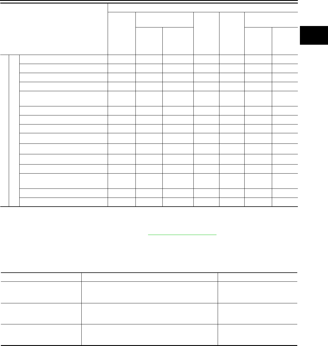
ON BOARD DIAGNOSTIC (OBD) SYSTEM
EC-107
< FUNCTION DIAGNOSIS > [FOR CALIFORNIA]
C
D
E
F
G
H
I
J
K
L
M
A
EC
N
P
O
X: Applicable
*1: This item includes 1st trip DTCs.
*2: This mode includes 1st trip freeze frame data or freeze frame data. The items appear on CONSULT-III screen in freeze frame data
mode only if a 1st trip DTC or DTC is detected. For details, refer to EC-92, "Diagnosis Description".
*3: Always “CMPLT” is displayed.
WORK SUPPORT MODE
Work Item
ENGINE COTNROL COMPONENT PARTS
OUTPUT
Fuel injector ×××
Power transistor (Ignition timing) ××
Throttle control motor relay ××
Throttle control motor ×
EVAP canister purge volume control
solenoid valve ××××
Air conditioner relay ×
Fuel pump relay ×××
Cooling fan relay ×××
Air fuel ratio (A/F) sensor 1 heater ××
×*3
Heated oxygen sensor 2 heater ××
×*3
Heated oxygen sensor 3 heater ××
×*3
EVAP canister vent control valve ×× ××
Intake valve timing control solenoid
valve ×××
Tumble control valve motor ×××
Calculated load value ××
Item
DIAGNOSTIC TEST MODE
Work
Support
Self Diagnostic Result
Data
Monitor Active
Test
DTC & SRT Confir-
mation
DTC*1 FREEZE
FRAME
DATA*2
SRT STA-
TUS
DTC
WORK
SUP-
PORT
WORK ITEM CONDITION USAGE
FUEL PRESSURE RELEASE • FUEL PUMP WILL STOP BY TOUCHING “START” DUR-
ING IDLING.
CRANK A FEW TIMES AFTER ENGINE STALLS.
When releasing fuel pressure from
fuel line
IDLE AIR VOL LEARN • THE IDLE AIR VOLUME THAT KEEPS THE ENGINE
WITHIN THE SPECIFIED RANGE IS MEMORIZED IN
ECM.
When learning the idle air volume
SELF-LEARNING CONT • THE COEFFICIENT OF SELF-LEARNING CONTROL
MIXTURE RATIO RETURNS TO THE ORIGINAL COEF-
FICIENT.
When clearing mixture ratio self-
learning value
Revision: 2008 August 2009 Rogue

EC-108
< FUNCTION DIAGNOSIS > [FOR CALIFORNIA]
ON BOARD DIAGNOSTIC (OBD) SYSTEM
*: This function is not necessary in the usual service procedure.
SELF-DIAGNOSTIC RESULT MODE
Self Diagnostic Item
Regarding items of DTC and 1st trip DTC, refer to EC-466, "DTC Index".)
Freeze Frame Data and 1st Trip Freeze Frame Data
EVAP SYSTEM CLOSE CLOSE THE EVAP CANISTER VENT CONTROL VALVE IN
ORDER TO MAKE EVAP SYSTEM CLOSE UNDER THE
FOLLOWING CONDITIONS.
• IGN SW ON
• ENGINE NOT RUNNING
• AMBIENT TEMPERATURE IS ABOVE 0°C (32°F).
• NO VACUUM AND NO HIGH PRESSURE IN EVAP SYS-
TEM
• FUEL TANK TEMP. IS MORE THAN 0°C (32°F).
• WITHIN 10 MINUTES AFTER STARTING “EVAP SYS-
TEM CLOSE”
• WHEN TRYING TO EXECUTE “EVAP SYSTEM CLOSE”
UNDER THE CONDITION EXCEPT ABOVE, CONSULT-
III WILL DISCONTINUE IT AND DISPLAY APPROPRI-
ATE INSTRUCTION.
NOTE:
WHEN STARTING ENGINE, CONSULT-III MAY DIS-
PLAY “BATTERY VOLTAGE IS LOW. CHARGE BAT-
TERY”, EVEN WHEN USING A CHARGED BATTERY.
When detecting EVAP vapor leak
in the EVAP system
VIN REGISTRATION • IN THIS MODE, VIN IS REGISTERED IN ECM. When registering VIN in ECM
TARGET IDLE RPM ADJ* • IDLE CONDITION When setting target idle speed
TARGET IGN TIM ADJ* • IDLE CONDITION When adjusting target ignition tim-
ing
WORK ITEM CONDITION USAGE
Freeze frame data
item* Description
DIAG TROUBLE
CODE
[PXXXX]
• The engine control component part/control system has a trouble code that is displayed as PXXXX. (Refer to
EC-466, "DTC Index".)
FUEL SYS-B1
• “Fuel injection system status” at the moment a malfunction is detected is displayed.
• One of the following mode is displayed.
Mode2: Open loop due to detected system malfunction
Mode3: Open loop due to driving conditions (power enrichment, deceleration enleanment)
Mode4: Closed loop - using oxygen sensor(s) as feedback for fuel control
Mode5: Open loop - has not yet satisfied condition to go to closed loop
CAL/LD VALUE [%] • The calculated load value at the moment a malfunction is detected is displayed.
COOLANT TEMP
[°C] or [°F] • The engine coolant temperature at the moment a malfunction is detected is displayed.
L-FUEL TRM-B1 [%]
• “Long-term fuel trim” at the moment a malfunction is detected is displayed.
• The long-term fuel trim indicates much more gradual feedback compensation to the base fuel schedule than
short-term fuel trim.
S-FUEL TRM-B1 [%] • “Short-term fuel trim” at the moment a malfunction is detected is displayed.
• The short-term fuel trim indicates dynamic or instantaneous feedback compensation to the base fuel sched-
ule.
ENGINE SPEED
[rpm] • The engine speed at the moment a malfunction is detected is displayed.
VEHICL SPEED
[km/h] or [mph] • The vehicle speed at the moment a malfunction is detected is displayed.
ABSOL TH·P/S [%] • The throttle valve opening angle at the moment a malfunction is detected is displayed.
B/FUEL SCHDL
[msec] • The base fuel schedule at the moment a malfunction is detected is displayed.
Revision: 2008 August 2009 Rogue

ON BOARD DIAGNOSTIC (OBD) SYSTEM
EC-109
< FUNCTION DIAGNOSIS > [FOR CALIFORNIA]
C
D
E
F
G
H
I
J
K
L
M
A
EC
N
P
O
*: The items are the same as those of 1st trip freeze frame data.
DATA MONITOR MODE
Monitored Item
INT/A TEMP SE
[°C] or [°F] • The intake air temperature at the moment a malfunction is detected is displayed.
FUEL SYS-B2
• There items are displayed but are not applicable to this model.
L-FUEL TRM-B2 [%]
S-FUEL TRM-B2 [%]
INT MANI PRES
[kPa]
COMBUST CONDI-
TION
Freeze frame data
item* Description
Monitored item Unit Description Remarks
ENG SPEED rpm
• Indicates the engine speed computed from the
signal of the crankshaft position sensor (POS)
and camshaft position sensor (PHASE).
• Accuracy becomes poor if engine
speed drops below the idle rpm.
• If the signal is interrupted while the
engine is running, an abnormal value
may be indicated.
MAS A/F SE-B1 V • The signal voltage of the mass air flow sensor is
displayed.
• When the engine is stopped, a certain
value is indicated.
• When engine is running, specification
range is indicated in “SPEC”.
B/FUEL SCHDL msec
• “Base fuel schedule” indicates the fuel injection
pulse width programmed into ECM, prior to any
learned on board correction.
• When engine is running, specification
range is indicated in “SPEC”.
A/F ALPHA-B1 % • The mean value of the air-fuel ratio feedback cor-
rection factor per cycle is indicated.
• When the engine is stopped, a certain
value is indicated.
• When engine is running, specification
range is indicated in “SPEC”.
• This data also includes the data for
the air-fuel ratio learning control.
COOLAN TEMP/S °C or °F• The engine coolant temperature (determined by
the signal voltage of the engine coolant tempera-
ture sensor) is displayed.
• When the engine coolant temperature
sensor is open or short-circuited,
ECM enters fail-safe mode. The en-
gine coolant temperature determined
by the ECM is displayed.
A/F SEN1 (B1) V • The A/F signal computed from the input signal of
the air fuel ratio (A/F) sensor 1 is displayed.
HO2S2 (B1) V • The signal voltage of the heated oxygen sensor 2
is displayed.
HO2S3 (B1) V • The signal voltage of the heated oxygen sensor 3
is displayed.
HO2S2 MNTR(B1) RICH/LEAN
• Display of heated oxygen sensor 2 signal:
RICH: means the amount of oxygen after three
way catalyst is relatively small.
LEAN: means the amount of oxygen after three
way catalyst is relatively large.
• When the engine is stopped, a certain
value is indicated.
VHCL SPEED SE km/h or mph
• The vehicle speed computed from the vehicle
speed signal sent from combination meter is dis-
played.
BATTERY VOLT V • The power supply voltage of ECM is displayed.
Revision: 2008 August 2009 Rogue

EC-110
< FUNCTION DIAGNOSIS > [FOR CALIFORNIA]
ON BOARD DIAGNOSTIC (OBD) SYSTEM
ACCEL SEN 1 V• The accelerator pedal position sensor signal volt-
age is displayed.
• ACCEL SEN 2 signal is converted by
ECM internally. Thus, it differs from
ECM terminal voltage signal.
ACCEL SEN 2
TP SEN 1-B1
V• The throttle position sensor signal voltage is dis-
played.
• TP SEN 2-B1 signal is converted by
ECM internally. Thus, it differs from
ECM terminal voltage signal.
TP SEN 2-B1
FUEL T/TMP SE °C or °F
• The fuel temperature (determined by the signal
voltage of the fuel tank temperature sensor) is dis-
played.
INT/A TEMP SE °C or °F• The intake air temperature (determined by the sig-
nal voltage of the intake air temperature sensor) is
indicated.
EVAP SYS PRES V • The signal voltage of EVAP control system pres-
sure sensor is displayed.
FUEL LEVEL SE V • The signal voltage of the fuel level sensor is dis-
played.
START SIGNAL ON/OFF
• Indicates start signal status [ON/OFF] computed
by the ECM according to the signals of engine
speed and battery voltage.
• After starting the engine, [OFF] is dis-
played regardless of the starter sig-
nal.
CLSD THL POS ON/OFF • Indicates idle position [ON/OFF] computed by
ECM according to the accelerator pedal position
sensor signal.
AIR COND SIG ON/OFF
• Indicates [ON/OFF] condition of the air condition-
er switch as determined by the air conditioner sig-
nal.
P/N POSI SW ON/OFF • Indicates [ON/OFF] condition from the park/neu-
tral position (PNP) switch signal.
PW/ST SIGNAL ON/OFF
• [ON/OFF] condition of the power steering system
(determined by the signal sent from EPS control
unit) is indicated.
LOAD SIGNAL ON/OFF
• Indicates [ON/OFF] condition from the electrical
load signal.
ON: Rear window defogger switch is ON and/or
lighting switch is in 2nd position.
OFF: Both rear window defogger switch and light-
ing switch are OFF.
IGNITION SW ON/OFF • Indicates [ON/OFF] condition from ignition switch
signal.
HEATER FAN SW ON/OFF • Indicates [ON/OFF] condition from the heater fan
switch signal.
BRAKE SW ON/OFF • Indicates [ON/OFF] condition from the stop lamp
switch signal.
INJ PULSE-B1 msec • Indicates the actual fuel injection pulse width com-
pensated by ECM according to the input signals.
• When the engine is stopped, a certain
computed value is indicated.
IGN TIMING BTDC • Indicates the ignition timing computed by ECM
according to the input signals. • When the engine is stopped, a certain
value is indicated.
CAL/LD VALUE % • “Calculated load value” indicates the value of the
current air flow divided by peak air flow.
MASS AIRFLOW g·m/s
• Indicates the mass air flow computed by ECM ac-
cording to the signal voltage of the mass air flow
sensor.
PURG VOL C/V %
• Indicates the EVAP canister purge volume control
solenoid valve control value computed by the
ECM according to the input signals.
• The opening becomes larger as the value in-
creases.
Monitored item Unit Description Remarks
Revision: 2008 August 2009 Rogue

ON BOARD DIAGNOSTIC (OBD) SYSTEM
EC-111
< FUNCTION DIAGNOSIS > [FOR CALIFORNIA]
C
D
E
F
G
H
I
J
K
L
M
A
EC
N
P
O
INT/V TIM (B1) °CA • Indicates [°CA] of intake camshaft advance angle.
INT/V SOL(B1) %
• The control value of the intake valve timing control
solenoid valve (determined by ECM according to
the input signals) is indicated.
• The advance angle becomes larger as the value
increases.
SWRL CONT S/V ON/OFF
• The control condition of the tumble control valve
(determined by ECM according to the input sig-
nals) is indicated.
ON: Closed
OFF: Open
TMBL POS SEN V • The tumble control valve position sensor signal
voltage is displayed.
AIR COND RLY ON/OFF • The air conditioner relay control condition (deter-
mined by ECM according to the input signals) is
indicated.
FUEL PUMP RLY ON/OFF • Indicates the fuel pump relay control condition de-
termined by ECM according to the input signals.
VENT CONT/V ON/OFF
• The control condition of the EVAP canister vent
control valve (determined by ECM according to
the input signals) is indicated.
ON: Closed
OFF: Open
THRTL RELAY ON/OFF
• Indicates the throttle control motor relay control
condition determined by the ECM according to the
input signals.
COOLING FAN HI/LOW/OFF
• Indicates the condition of the cooling fan (deter-
mined by ECM according to the input signals).
HI: High speed operation
LOW: Low speed operation
OFF: Stop
HO2S2 HTR (B1) ON/OFF
• Indicates [ON/OFF] condition of heated oxygen
sensor 2 heater determined by ECM according to
the input signals.
HO2S3 HTR(B1) ON/OFF • Indicates [ON/OFF] condition of heated oxygen
sensor 3 heater determined by ECM according to
the input signals.
I/P PULLY SPD rpm • Indicates the engine speed computed from the
turbine revolution sensor signal.
VEHICLE SPEED km/h or mph • The vehicle speed computed from the vehicle
speed signal sent from TCM is displayed.
IDL A/V LEARN YET/CMPLT
• Displays the condition of Idle Air Volume Learning
YET: Idle air volume learning has not been per-
formed yet.
CMPLT: Idle air volume learning has already been
performed successfully.
TRVL AFTER MIL km or mile • Distance traveled while MIL is activated.
A/F S1 HTR(B1) %
• Air fuel ratio (A/F) sensor 1 heater control value
computed by ECM according to the input signals.
• The current flow to the heater becomes larger as
the value increases.
AC PRESS SEN V • The signal voltage from the refrigerant pressure
sensor is displayed.
VHCL SPEED SE km/h or mph
• The vehicle speed computed from the vehicle
speed signal sent from combination meter is dis-
played.
SET VHCL SPD km/h or mph • The preset vehicle speed is displayed.
Monitored item Unit Description Remarks
Revision: 2008 August 2009 Rogue

EC-112
< FUNCTION DIAGNOSIS > [FOR CALIFORNIA]
ON BOARD DIAGNOSTIC (OBD) SYSTEM
NOTE:
Any monitored item that does not match the vehicle being diagnosed is deleted from the display automatically.
ACTIVE TEST MODE
Test Item
MAIN SW ON/OFF • Indicates [ON/OFF] condition from MAIN switch
signal.
CANCEL SW ON/OFF • Indicates [ON/OFF] condition from CANCEL
switch signal.
RESUME/ACC SW ON/OFF • Indicates [ON/OFF] condition from RESUME/AC-
CELERATE switch signal.
SET SW ON/OFF • Indicates [ON/OFF] condition from SET/COAST
switch signal.
BRAKE SW1 ON/OFF • Indicates [ON/OFF] condition from ASCD brake
switch signal.
BRAKE SW2 ON/OFF • Indicates [ON/OFF] condition of stop lamp switch
signal.
VHCL SPD CUT NON/CUT
• Indicates the vehicle cruise condition.
NON: Vehicle speed is maintained at the ASCD
set speed.
CUT: Vehicle speed decreased to excessively low
compared with the ASCD set speed, and ASCD
operation is cut off.
LO SPEED CUT NON/CUT
• Indicates the vehicle cruise condition.
NON: Vehicle speed is maintained at the ASCD
set speed.
CUT: Vehicle speed decreased to excessively
low, and ASCD operation is cut off.
AT OD MONITOR ON/OFF • Indicates [ON/OFF] condition of A/T O/D accord-
ing to the input signal from the TCM.
AT OD CANCEL ON/OFF • Indicates [ON/OFF] condition of A/T O/D cancel
request signal.
CRUISE LAMP ON/OFF
• Indicates [ON/OFF] condition of CRUISE lamp
determined by the ECM according to the input sig-
nals.
SET LAMP ON/OFF • Indicates [ON/OFF] condition of SET lamp deter-
mined by the ECM according to the input signals.
A/F ADJ-B1 —
• Indicates the correction of factor stored in ECM.
The factor is calculated from the difference be-
tween the target air-fuel ratio stored in ECM and
the air-fuel ratio calculated from A/F sensor 1 sig-
nal.
Monitored item Unit Description Remarks
TEST ITEM CONDITION JUDGMENT CHECK ITEM (REMEDY)
FUEL INJECTION
• Engine: Return to the original
trouble condition
• Change the amount of fuel injec-
tion using CONSULT-III.
If trouble symptom disappears, see
CHECK ITEM.
• Harness and connectors
• Fuel injector
• Air fuel ratio (A/F) sensor 1
IGNITION TIMING
• Engine: Return to the original
trouble condition
• Timing light: Set
• Retard the ignition timing using
CONSULT-III.
If trouble symptom disappears, see
CHECK ITEM. • Perform Idle Air Volume Learn-
ing.
Revision: 2008 August 2009 Rogue

ON BOARD DIAGNOSTIC (OBD) SYSTEM
EC-113
< FUNCTION DIAGNOSIS > [FOR CALIFORNIA]
C
D
E
F
G
H
I
J
K
L
M
A
EC
N
P
O
*: Leaving cooling fan OFF with CONSULT-III while engine is running may cause the engine to overheat.
DTC & SRT CONFIRMATION MODE
SRT STATUS Mode
For details, refer to EC-92, "Diagnosis Description".
SRT WORK SUPPORT Mode
This mode enables a technician to drive a vehicle to set the SRT while monitoring the SRT status.
DTC WORK SUPPORT Mode
POWER BALANCE
• Engine: After warming up, idle the
engine.
• A/C switch OFF
• Selector lever position: P or N
• Cut off each fuel injector signal
one at a time using CONSULT-III.
Engine runs rough or dies.
• Harness and connectors
• Compression
• Fuel injector
• Power transistor
•Spark plug
•Ignition coil
COOLING FAN*
• Ignition switch: ON
• Turn the cooling fan “LOW”, “HI”
and “OFF” using CONSULT-III. Cooling fan moves and stops.
• Harness and connectors
• IPDM E/R (Cooling fan relay)
• Cooling fan motor
ENG COOLANT
TEMP
• Engine: Return to the original
trouble condition
• Change the engine coolant tem-
perature using CONSULT-III.
If trouble symptom disappears, see
CHECK ITEM.
• Harness and connectors
• Engine coolant temperature
sensor
• Fuel injector
FUEL PUMP RELAY
• Ignition switch: ON (Engine
stopped)
• Turn the fuel pump relay “ON”
and “OFF” using CONSULT-III
and listen to operating sound.
Fuel pump relay makes the operat-
ing sound.
• Harness and connectors
•Fuel pump relay
PURG VOL CONT/V
• Engine: After warming up, run en-
gine at 1,500 rpm.
• Change the EVAP canister purge
volume control solenoid valve
opening percent using CON-
SULT-III.
Engine speed changes according
to the opening percent.
• Harness and connectors
• Solenoid valve
FUEL/T TEMP SEN • Change the fuel tank temperature using CONSULT-III.
VENT CONTROL/V
• Ignition switch: ON (Engine
stopped)
• Turn solenoid valve “ON” and
“OFF” using CONSULT-III and lis-
ten to operating sound.
Solenoid valve makes an operating
sound.
• Harness and connectors
• Solenoid valve
V/T ASSIGN ANGLE
• Engine: Return to the original
trouble condition
• Change intake valve timing using
CONSULT-III.
If trouble symptom disappears, see
CHECK ITEM.
• Harness and connectors
• Intake valve timing control sole-
noid valve
TUMBLE CONTROL
VALVE
• Ignition switch: ON
• Turn tumble control valve “ON”
and “OFF” using CONSULT-III
and listen to operating sound.
Tumble control valve motor makes
an operating sound. • Harness and connectors
• Tumble control valve motor
TEST ITEM CONDITION JUDGMENT CHECK ITEM (REMEDY)
Test mode Test item Corresponding DTC No. Reference page
EVAPORATIVE SYSTEM
EVP SML LEAK P0442/P1442* P0442 EC-273
P0455 EC-308
EVP V/S LEAK P0456/P1456* P0456 EC-314
PURG VOL CN/V P1444 P0443 EC-279
PURG FLOW P0441 P0441 EC-268
A/F SEN1 A/F SEN1(B1) P1278/P1279 P0133 EC-187
A/F SEN1(B1) P1276 P0130 EC-177
Revision: 2008 August 2009 Rogue
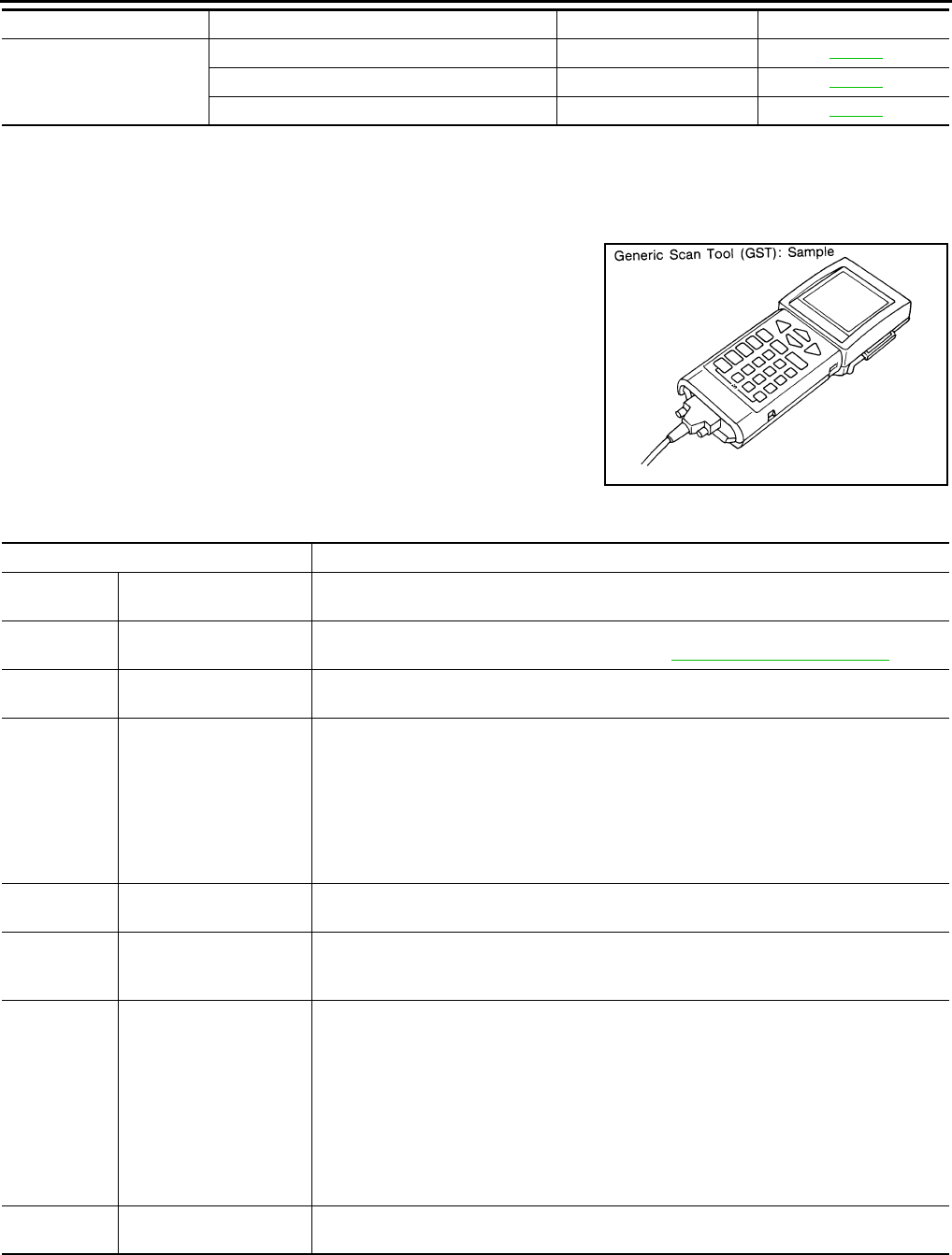
EC-114
< FUNCTION DIAGNOSIS > [FOR CALIFORNIA]
ON BOARD DIAGNOSTIC (OBD) SYSTEM
*: DTC P1442 and P1456 does not apply to S35 models but appears in DTC Work Support Mode screens.
Diagnosis Tool Function INFOID:0000000004493338
DESCRIPTION
Generic Scan Tool (OBD II scan tool) complying with SAE J1978 has
several functions explained below.
ISO 15765-4 is used as the protocol.
The name “GST” or “Generic Scan Tool” is used in this service man-
ual.
FUNCTION
INSPECTION PROCEDURE
1. Turn ignition switch OFF.
HO2S2
HO2S2(B1) P1146 P0138 EC-198
HO2S2(B1) P1147 P0137 EC-192
HO2S2(B1) P0139 P0139 EC-205
Test mode Test item Corresponding DTC No. Reference page
SEF139P
Diagnostic Service Function
Service $01 READINESS TESTS This diagnostic service gains access to current emission-related data values, including an-
alog inputs and outputs, digital inputs and outputs, and system status information.
Service $02 (FREEZE DATA) This diagnostic service gains access to emission-related data value that were stored by
ECM during the freeze frame. For details, refer to EC-92, "Diagnosis Description".
Service $03 DTCs This diagnostic service gains access to emission-related power train trouble codes which
were stored by ECM.
Service $04 CLEAR DIAG INFO
This diagnostic service can clear all emission-related diagnostic information. This in-
cludes:
• Clear number of diagnostic trouble codes (Service $01)
• Clear diagnostic trouble codes (Service $03)
• Clear trouble code for freeze frame data (Service $01)
• Clear freeze frame data (Service $02)
• Reset status of system monitoring test (Service $01)
• Clear on board monitoring test results (Service $06 and $07)
Service $06 (ON BOARD TESTS) This diagnostic service accesses the results of on board diagnostic monitoring tests of
specific components/systems that are not continuously monitored.
Service $07 (ON BOARD TESTS)
This diagnostic service enables the off board test drive to obtain test results for emission-
related powertrain components/systems that are continuously monitored during normal
driving conditions.
Service $08 —
This diagnostic service can close EVAP system in ignition switch ON position (Engine
stopped). When this diagnostic service is performed, EVAP canister vent control valve can
be closed.
In the following conditions, this diagnostic service cannot function.
• Low ambient temperature
• Low battery voltage
• Engine running
• Ignition switch OFF
• Low fuel temperature
• Too much pressure is applied to EVAP system
Service $09 (CALIBRATION ID) This diagnostic service enables the off-board test device to request specific vehicle infor-
mation such as Vehicle Identification Number (VIN) and Calibration IDs.
Revision: 2008 August 2009 Rogue
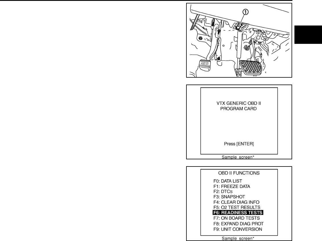
ON BOARD DIAGNOSTIC (OBD) SYSTEM
EC-115
< FUNCTION DIAGNOSIS > [FOR CALIFORNIA]
C
D
E
F
G
H
I
J
K
L
M
A
EC
N
P
O
2. Connect “GST” to data link connector (1), which is located under
LH dash panel.
3. Turn ignition switch ON.
4. Enter the program according to instruction on the screen or in
the operation manual.
(*: Regarding GST screens in this section, sample screens are
shown.)
5. Perform each diagnostic mode according to each service proce-
dure.
For further information, see the GST Operation Manual of
the tool maker.
JMBIA1073ZZ
SEF398S
SEF416S
Revision: 2008 August 2009 Rogue

EC-116
< COMPONENT DIAGNOSIS > [FOR CALIFORNIA]
TROUBLE DIAGNOSIS - SPECIFICATION VALUE
COMPONENT DIAGNOSIS
TROUBLE DIAGNOSIS - SPECIFICATION VALUE
Description INFOID:0000000004493339
The specification (SP) value indicates the tolerance of the value that is displayed in “SPEC” of “DATA MONI-
TOR” mode of CONSULT-III during normal operation of the Engine Control System. When the value in “SPEC”
of “DATA MONITOR” mode is within the SP value, the Engine Control System is confirmed OK. When the
value in “SPEC” of “DATA MONITOR” mode is NOT within the SP value, the Engine Control System may have
one or more malfunctions.
The SP value is used to detect malfunctions that may affect the Engine Control System, but will not illuminate
the MIL.
The SP value will be displayed for the following three items:
• B/FUEL SCHDL (The fuel injection pulse width programmed into ECM prior to any learned on board correc-
tion)
• A/F ALPHA-B1 (The mean value of air-fuel ratio feedback correction factor per cycle)
• MAS A/F SE-B1 (The signal voltage of the mass air flow sensor)
Component Function Check INFOID:0000000004493340
1.START
Check that all of the following conditions are satisfied.
• Vehicle driven distance: More than 5,000 km (3,107 miles)
• Barometric pressure: 98.3 - 104.3 kPa (1.003 - 1.064 kg/cm2, 14.25 - 15.12 psi)
• Atmospheric temperature: 20 - 30°C (68 - 86°F)
• Engine coolant temperature: 75 - 95°C (167 - 203°F)
• Engine speed: Idle
• Transmission: Warmed-up
- After the engine is warmed up to normal operating temperature, drive vehicle until “FLUID TEMP SE” (CVT
fluid temperature sensor signal) indicates more than 60°C (140°F).
• Electrical load: Not applied
- Rear window defogger switch and air conditioner switch lighting switch are OFF. Steering wheel is straight
ahead.
>> GO TO 2.
2.PERFORM “SPEC” OF “DATA MONITOR” MODE
With CONSULT-III
NOTE:
Perform “SPEC” in “DATA MONITOR” mode in maximum scale display.
1. Perform EC-22, "BASIC INSPECTION : Special Repair Requirement".
2. Select “B/FUEL SCHDL”, “A/F ALPHA-B1” and “MAS A/F SE-B1” in “SPEC” of “DATA MONITOR” mode
with CONSULT-III.
3. Check that monitor items are within the SP value.
Is the inspection result normal?
YES >> END
NO >> Go to EC-117, "Diagnosis Procedure".
Revision: 2008 August 2009 Rogue

TROUBLE DIAGNOSIS - SPECIFICATION VALUE
EC-117
< COMPONENT DIAGNOSIS > [FOR CALIFORNIA]
C
D
E
F
G
H
I
J
K
L
M
A
EC
N
P
O
Diagnosis Procedure INFOID:0000000004493341
OVERALL SEQUENCE
PBIB2318E
Revision: 2008 August 2009 Rogue
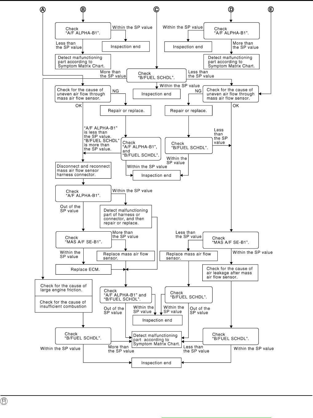
EC-118
< COMPONENT DIAGNOSIS > [FOR CALIFORNIA]
TROUBLE DIAGNOSIS - SPECIFICATION VALUE
DETAILED PROCEDURE
1.CHECK “A/F ALPHA-B1”
With CONSULT-III
1. Start engine.
2. Confirm that the testing conditions are met. Refer to EC-116, "Component Function Check".
3. Select “A/F ALPHA-B1” in “SPEC” of “DATA MONITOR” mode, and check that each indication is within
the SP value.
PBIB3213E
Revision: 2008 August 2009 Rogue

TROUBLE DIAGNOSIS - SPECIFICATION VALUE
EC-119
< COMPONENT DIAGNOSIS > [FOR CALIFORNIA]
C
D
E
F
G
H
I
J
K
L
M
A
EC
N
P
O
NOTE:
Check “A/F ALPHA-B1” for approximately 1 minute because they may fluctuate. It is NG if the indication is
out of the SP value even a little.
Is the measurement value within the SP value?
YES >> GO TO 17.
NO-1 >> Less than the SP value: GO TO 2.
NO-2 >> More than the SP value: GO TO 3.
2.CHECK “B/FUEL SCHDL”
Select “B/FUEL SCHDL” in “SPEC” of “DATA MONITOR” mode, and check that the indication is within the SP
value.
Is the measurement value within the SP value?
YES >> GO TO 4.
NO >> More than the SP value: GO TO 19.
3.CHECK “B/FUEL SCHDL”
Select “B/FUEL SCHDL” in “SPEC” of “DATA MONITOR” mode, and check that the indication is within the SP
value.
Is the measurement value within the SP value?
YES >> GO TO 6.
NO-1 >> More than the SP value: GO TO 6.
NO-2 >> Less than the SP value: GO TO 25.
4.CHECK “A/F ALPHA-B1”
1. Stop the engine.
2. Disconnect PCV hose, and then plug it.
3. Start engine.
4. Select “A/F ALPHA-B1” in “SPEC” of “DATA MONITOR” mode, and check that each indication is within
the SP value.
Is the measurement value within the SP value?
YES >> GO TO 5.
NO >> GO TO 6.
5.CHANGE ENGINE OIL
1. Stop the engine.
2. Change engine oil.
NOTE:
This symptom may occur when a large amount of gasoline is mixed with engine oil because of driving
conditions (such as when engine oil temperature does not rise enough since a journey distance is too
short during winter). The symptom will not be detected after changing engine oil or changing driving con-
ditions.
>> INSPECTION END
6.CHECK FUEL PRESSURE
Check fuel pressure. (Refer to EC-489, "Inspection".)
Is the inspection result normal?
YES >> GO TO 9.
NO-1 >> Fuel pressure is too high: Replace “fuel filter and fuel pump assembly” and then GO TO 8.
NO-2 >> Fuel pressure is too low: GO TO 7.
7.DETECT MALFUNCTIONING PART
Check fuel hoses and fuel tubes for clogging
Is the inspection result normal?
YES >> Replace “fuel filter and fuel pump assembly” and then GO TO 8.
NO >> Repair or replace and then GO TO 8.
8.CHECK “A/F ALPHA-B1”
Revision: 2008 August 2009 Rogue

EC-120
< COMPONENT DIAGNOSIS > [FOR CALIFORNIA]
TROUBLE DIAGNOSIS - SPECIFICATION VALUE
1. Start engine.
2. Select “A/F ALPHA-B1” in “SPEC” of “DATA MONITOR” mode, and check that each indication is within
the SP value.
Is the measurement value within the SP value?
YES >> INSPECTION END
NO >> GO TO 9.
9.PERFORM POWER BALANCE TEST
1. Perform “POWER BALANCE” in “ACTIVE TEST” mode.
2. Check that the each cylinder produces a momentary engine speed drop.
Is the inspection result normal?
YES >> GO TO 12.
NO >> GO TO 10.
10.DETECT MALFUNCTIONING PART
Check the following below.
1. Ignition coil and its circuit (Refer to EC-425, "Component Function Check".)
2. Fuel injector and its circuit (Refer to EC-419, "Component Function Check".)
3. Intake air leakage
4. Low compression pressure (Refer to EM-23, "Inspection".)
Is the inspection result normal?
YES >> Replace fuel injector and then GO TO 11.
NO >> Repair or replace malfunctioning part and then GO TO 11.
11.CHECK “A/F ALPHA-B1”
1. Start engine.
2. Select “A/F ALPHA-B1” in “SPEC” of “DATA MONITOR” mode, and check that each indication is within
the SP value.
Is the measurement value within the SP value?
YES >> INSPECTION END
NO >> GO TO 12.
12.CHECK A/F SENSOR 1 FUNCTION
Perform all DTC CONFIRMATION PROCEDURE related with A/F sensor 1.
• For DTC P0130, refer to EC-177, "DTC Logic".
• For DTC P0131, refer to EC-181, "DTC Logic".
• For DTC P0132, refer to EC-184, "DTC Logic".
• For DTC P0133, refer to EC-187, "DTC Logic".
• For DTC P2A00, refer to EC-404, "DTC Logic".
Are any DTC detected?
YES >> GO TO 15.
NO >> GO TO 13.
13.CHECK A/F SENSOR 1 CIRCUIT
Perform DIAGNOSTIC PROCEDURE according to corresponding DTC.
>> GO TO 14.
14.CHECK “A/F ALPHA-B1”
1. Start engine.
2. Select “A/F ALPHA-B1” in “SPEC” of “DATA MONITOR” mode, and check that each indication is within
the SP value.
Is the measurement value within the SP value?
YES >> INSPECTION END
NO >> GO TO 15.
15.DISCONNECT AND RECONNECT ECM HARNESS CONNECTOR
1. Stop the engine.
Revision: 2008 August 2009 Rogue

TROUBLE DIAGNOSIS - SPECIFICATION VALUE
EC-121
< COMPONENT DIAGNOSIS > [FOR CALIFORNIA]
C
D
E
F
G
H
I
J
K
L
M
A
EC
N
P
O
2. Disconnect ECM harness connector. Check pin terminal and connector for damage, and then reconnect it.
>> GO TO 16.
16.CHECK “A/F ALPHA-B1”
1. Start engine.
2. Select “A/F ALPHA-B1” in “SPEC” of “DATA MONITOR” mode, and check that each indication is within
the SP value.
Is the measurement value within the SP value?
YES >> INSPECTION END
NO >> Detect malfunctioning part according to EC-478, "Symptom Table".
17.CHECK “B/FUEL SCHDL”
Select “B/FUEL SCHDL” in “SPEC” of “DATA MONITOR” mode, and check that the indication is within the SP
value.
Is the measurement value within the SP value?
YES >> INSPECTION END
NO-1 >> More than the SP value: GO TO 18.
NO-2 >> Less than the SP value: GO TO 25.
18.DETECT MALFUNCTIONING PART
1. Check for the cause of large engine friction. Refer to the following.
- Engine oil level is too high
- Engine oil viscosity
- Belt tension of power steering, alternator, A/C compressor, etc. is excessive
- Noise from engine
- Noise from transmission, etc.
2. Check for the cause of insufficient combustion. Refer to the following.
- Valve clearance malfunction
- Intake valve timing control function malfunction
- Camshaft sprocket installation malfunction, etc.
>> Repair or replace malfunctioning part, and then GO TO 30.
19.CHECK INTAKE SYSTEM
Check for the cause of uneven air flow through mass air flow sensor. Refer to the following.
• Crushed air ducts
• Malfunctioning seal of air cleaner element
• Uneven dirt of air cleaner element
• Improper specification of intake air system
Is the inspection result normal?
YES >> GO TO 21.
NO >> Repair or replace malfunctioning part, and then GO TO 20.
20.CHECK “A/F ALPHA-B1”, AND “B/FUEL SCHDL”
Select “A/F ALPHA-B1” and “B/FUEL SCHDL” in “SPEC” of “DATA MONITOR” mode, and check that each
indication is within the SP value.
Is the measurement value within the SP value?
YES >> INSPECTION END
NO >> “B/FUEL SCHDL” is more, “A/F ALPHA-B1” is less than the SP value: GO TO 21.
21.DISCONNECT AND RECONNECT MASS AIR FLOW SENSOR HARNESS CONNECTOR
1. Stop the engine.
2. Disconnect mass air flow sensor harness connector. Check pin terminal and connector for damage and
then reconnect it again.
>> GO TO 22.
Revision: 2008 August 2009 Rogue

EC-122
< COMPONENT DIAGNOSIS > [FOR CALIFORNIA]
TROUBLE DIAGNOSIS - SPECIFICATION VALUE
22.CHECK “A/F ALPHA-B1”
1. Start engine.
2. Select “A/F ALPHA-B1” in “SPEC” of “DATA MONITOR” mode, and check that each indication is within
the SP value.
Is the measurement value within the SP value?
YES >> Detect malfunctioning part of mass air flow sensor circuit and repair it. Refer to EC-147, "DTC
Logic". Then GO TO 29.
NO >> GO TO 23.
23.CHECK “MAS A/F SE-B1”
Select “MAS A/F SE-B1” in “SPEC” of “DATA MONITOR” mode, and check that the indication is within the SP
value.
Is the measurement value within the SP value?
YES >> GO TO 24.
NO >> More than the SP value: Replace mass air flow sensor, and then GO TO 29.
24.REPLACE ECM
1. Replace ECM.
2. Go to EC-25, "ADDITIONAL SERVICE WHEN REPLACING CONTROL UNIT : Special Repair Require-
ment".
>> GO TO 29.
25.CHECK INTAKE SYSTEM
Check for the cause of uneven air flow through mass air flow sensor. Refer to the following.
• Crushed air ducts
• Malfunctioning seal in air cleaner element
• Uneven dirt in air cleaner element
• Improper specification in intake air system
Is the inspection result normal?
YES >> GO TO 27.
NO >> Repair or replace malfunctioning part, and then GO TO 26.
26.CHECK “B/FUEL SCHDL”
Select “B/FUEL SCHDL” in “SPEC” of “DATA MONITOR” mode, and check that the indication is within the SP
value.
Is the measurement value within the SP value?
YES >> INSPECTION END
NO >> Less than the SP value: GO TO 27.
27.CHECK “MAS A/F SE-B1”
Select “MAS A/F SE-B1” in “SPEC” of “DATA MONITOR” mode, and check that the indication is within the SP
value.
Is the measurement value within the SP value?
YES >> GO TO 28.
NO >> Less than the SP value: Replace mass air flow sensor, and then GO TO 30.
28.CHECK INTAKE SYSTEM
Check for the cause of air leak after the mass air flow sensor. Refer to the following.
• Disconnection, looseness, and cracks in air duct
• Looseness of oil filler cap
• Disconnection of oil level gauge
• Open stuck, breakage, hose disconnection, or cracks in PCV valve
• Disconnection or cracks in EVAP purge hose, stuck open of EVAP canister purge volume control solenoid
valve
• Malfunctioning seal in rocker cover gasket
• Disconnection, looseness, or cracks in hoses, such as a vacuum hose, connecting to intake air system parts
Revision: 2008 August 2009 Rogue

TROUBLE DIAGNOSIS - SPECIFICATION VALUE
EC-123
< COMPONENT DIAGNOSIS > [FOR CALIFORNIA]
C
D
E
F
G
H
I
J
K
L
M
A
EC
N
P
O
• Malfunctioning seal in intake air system, etc.
>> GO TO 30.
29.CHECK “A/F ALPHA-B1” AND “B/FUEL SCHDL”
Select “A/F ALPHA-B1” and “B/FUEL SCHDL” in “SPEC” of “DATA MONITOR” mode, and check that each
indication is within the SP value.
Is the measurement value within the SP value?
YES >> INSPECTION END
NO >> Detect malfunctioning part according to EC-478, "Symptom Table".
30.CHECK “B/FUEL SCHDL”
Select “B/FUEL SCHDL” in “SPEC” of “DATA MONITOR” mode, and then check that the indication is within
the SP value.
Is the measurement value within the SP value?
YES >> INSPECTION END
NO >> Detect malfunctioning part according to EC-478, "Symptom Table".
Revision: 2008 August 2009 Rogue

EC-124
< COMPONENT DIAGNOSIS > [FOR CALIFORNIA]
POWER SUPPLY AND GROUND CIRCUIT
POWER SUPPLY AND GROUND CIRCUIT
Diagnosis Procedure INFOID:0000000004493342
1.INSPECTION START
Start engine.
Is engine running?
YES >> GO TO 8.
NO >> GO TO 2.
2.CHECK ECM POWER SUPPLY CIRCUIT-I
1. Turn ignition switch OFF and then ON.
2. Check the voltage between ECM harness connector and ground.
Is the inspection result normal?
YES >> GO TO 4.
NO >> GO TO 3.
3.DETECT MALFUNCTIONING PART
Check the following.
• IPDM E/R harness connector E14
• 15A fuse (No. 64)
• Harness for open or short between ECM and fuse
>> Repair open circuit or short to ground or short to power in harness or connectors.
4.CHECK GROUND CONNECTION-I
1. Turn ignition switch OFF.
2. Check ground connection E21. Refer to Ground Inspection in GI-44, "Circuit Inspection".
Is the inspection result normal?
YES >> GO TO 5.
NO >> Repair or replace ground connection.
5.CHECK ECM GROUND CIRCUIT FOR OPEN AND SHORT-I
1. Disconnect ECM harness connectors.
2. Check the continuity between ECM harness connector and ground.
3. Also check harness for short to power.
Is the inspection result normal?
YES >> GO TO 7.
NO >> GO TO 6.
ECM Ground Voltage
Connector Terminal
E16 93 Ground Battery voltage
ECM Ground Continuity
Connector Terminal
F7 12
Ground Existed
16
E16
107
108
111
112
Revision: 2008 August 2009 Rogue

POWER SUPPLY AND GROUND CIRCUIT
EC-125
< COMPONENT DIAGNOSIS > [FOR CALIFORNIA]
C
D
E
F
G
H
I
J
K
L
M
A
EC
N
P
O
6.DETECT MALFUNCTIONING PART
Check the following.
• Harness connectors F121, E7
• Harness for open or short between ECM and ground
>> Repair open circuit or short to power in harness or connectors.
7.CHECK ECM POWER SUPPLY CIRCUIT-II
1. Reconnect ECM harness connectors.
2. Turn ignition switch ON.
3. Check the voltage between IPDM E/R harness connector and ground.
Is the inspection result normal?
YES >> Go to EC-425, "Diagnosis Procedure".
NO >> GO TO 8.
8.CHECK ECM POWER SUPPLY CIRCUIT-III
1. Turn ignition switch OFF and wait at least 10 seconds.
2. Check the voltage between ECM harness connector and ground.
Is the inspection result normal?
YES >> GO TO 14.
NO-1 >> Battery voltage does not exist: GO TO 9.
NO-2 >> Battery voltage exists for more than a few seconds: GO TO 11.
9.CHECK ECM POWER SUPPLY CIRCUIT-IV
1. Turn ignition switch OFF and wait at least 10 seconds.
2. Check the voltage between ECM harness connector and ground.
Is the inspection result normal?
YES >> GO TO 10.
NO >> GO TO 11.
10.CHECK ECM POWER SUPPLY CIRCUIT-V
1. Disconnect ECM harness connector.
2. Disconnect IPDM E/R harness connector E15.
3. Check the continuity between ECM harness connector and IPDM E/R harness connector.
4. Also check harness for short to ground and short to power.
IPDM E/R Ground Voltage
Connector Terminal
E15 47 Ground Battery voltage
ECM Ground Voltage
Connector Terminal
E16 105 Ground After turning ignition switch OFF, battery voltage will ex-
ist for a few seconds, then drop to approximately 0V.
ECM Ground Voltage
Connector Terminal
F7 24 Ground Battery voltage
ECM IPDM E/R Continuity
Connector Terminal Connector Terminal
E16 105 E15 48 Existed
Revision: 2008 August 2009 Rogue

EC-126
< COMPONENT DIAGNOSIS > [FOR CALIFORNIA]
POWER SUPPLY AND GROUND CIRCUIT
Is the inspection result normal?
YES >> GO TO 17.
NO >> Repair open circuit or short to ground or short to power in harness or connectors.
11.CHECK ECM POWER SUPPLY CIRCUIT-VI
1. Disconnect ECM harness connector.
2. Disconnect IPDM E/R harness connector E15.
3. Check the continuity between ECM harness connector and IPDM E/R harness connector.
4. Also check harness for short to ground and short to power.
Is the inspection result normal?
YES >> GO TO 13.
NO >> GO TO 12.
12.DETECT MALFUNCTIONING PART
Check the following.
• Harness or connectors F121, E7
• Harness for open or short between ECM and IPDM E/R
>> Repair open circuit or short to ground or short power in harness or connectors.
13.CHECK 20A FUSE
1. Disconnect 20A fuse (No. 62) from IPDM E/R.
2. Check 20A fuse.
Is the inspection result normal?
YES >> GO TO 17.
NO >> Replace 20A fuse.
14.CHECK GROUND CONNECTION-II
1. Turn ignition switch OFF.
2. Check ground connection E21. Refer to Ground Inspection in GI-44, "Circuit Inspection".
Is the inspection result normal?
YES >> GO TO 15.
NO >> Repair or replace ground connection.
15.CHECK ECM GROUND CIRCUIT FOR OPEN AND SHORT-II
1. Disconnect ECM harness connector.
2. Check the continuity between ECM harness connector and ground.
3. Also check harness for short to power.
Is the inspection result normal?
YES >> GO TO 17.
ECM IPDM E/R Continuity
Connector Terminal Connector Terminal
F7 24 E15 51 Existed
ECM Ground Continuity
Connector Terminal
F7 12
Ground Existed
16
E16
107
108
111
112
Revision: 2008 August 2009 Rogue

POWER SUPPLY AND GROUND CIRCUIT
EC-127
< COMPONENT DIAGNOSIS > [FOR CALIFORNIA]
C
D
E
F
G
H
I
J
K
L
M
A
EC
N
P
O
NO >> GO TO 16.
16.DETECT MALFUNCTIONING PART
Check the following.
• Harness or connectors F121, E7
• Harness for open or short between ECM and ground
>> Repair open circuit or short to power in harness or connectors.
17.CHECK INTERMITTENT INCIDENT
Refer to GI-41, "Intermittent Incident".
Is the inspection result normal?
YES >> Replace IPDM E/R.
NO >> Repair open circuit or short to power in harness or connectors.
Revision: 2008 August 2009 Rogue

EC-128
< COMPONENT DIAGNOSIS > [FOR CALIFORNIA]
U0101 CAN COMM CIRCUIT
U0101 CAN COMM CIRCUIT
Description INFOID:0000000004503938
CAN (Controller Area Network) is a serial communication line for real time application. It is an on-vehicle mul-
tiplex communication line with high data communication speed and excellent error detection ability. Many elec-
tronic control units are equipped onto a vehicle, and each control unit shares information and links with other
control units during operation (not independent). In CAN communication, control units are connected with 2
communication lines (CAN H line, CAN L line) allowing a high rate of information transmission with less wiring.
Each control unit transmits/receives data but selectively reads required data only.
DTC Logic INFOID:0000000004503939
DTC DETECTION LOGIC
DTC CONFIRMATION PROCEDURE
1.PERFORM DTC CONFIRMATION PROCEDURE
1. Turn ignition switch ON and wait at least 3 seconds.
2. Check DTC.
Is DTC detected?
YES >> EC-128, "Diagnosis Procedure".
NO >> INSPECTION END
Diagnosis Procedure INFOID:0000000004503940
Go to LAN-15, "Trouble Diagnosis Flow Chart".
DTC No. Trouble diagnosis
name DTC detecting condition Possible cause
U0101 Lost communication
with TCM
When ECM is not transmitting or receiving CAN com-
munication signal of OBD (emission-related diagno-
sis) with TCM for 2 seconds or more.
• CAN communication line between
TCM and ECM
(CAN communication line is open or
shorted)
Revision: 2008 August 2009 Rogue

U0140 CAN COMM CIRCUIT
EC-129
< COMPONENT DIAGNOSIS > [FOR CALIFORNIA]
C
D
E
F
G
H
I
J
K
L
M
A
EC
N
P
O
U0140 CAN COMM CIRCUIT
Description INFOID:0000000004503935
CAN (Controller Area Network) is a serial communication line for real time application. It is an on-vehicle mul-
tiplex communication line with high data communication speed and excellent error detection ability. Many elec-
tronic control units are equipped onto a vehicle, and each control unit shares information and links with other
control units during operation (not independent). In CAN communication, control units are connected with 2
communication lines (CAN H line, CAN L line) allowing a high rate of information transmission with less wiring.
Each control unit transmits/receives data but selectively reads required data only.
DTC Logic INFOID:0000000004503936
DTC DETECTION LOGIC
DTC CONFIRMATION PROCEDURE
1.PERFORM DTC CONFIRMATION PROCEDURE
1. Turn ignition switch ON and wait at least 3 seconds.
2. Check DTC.
Is DTC detected?
YES >> EC-129, "Diagnosis Procedure".
NO >> INSPECTION END
Diagnosis Procedure INFOID:0000000004503937
Go to LAN-15, "Trouble Diagnosis Flow Chart".
DTC No. Trouble diagnosis
name DTC detecting condition Possible cause
U0140 Lost communication
with BCM
When ECM is not transmitting or receiving CAN com-
munication signal of OBD (emission-related diagno-
sis) with BCM for 2 seconds or more.
• CAN communication line between
BCM and ECM
(CAN communication line is open or
shorted)
Revision: 2008 August 2009 Rogue

EC-130
< COMPONENT DIAGNOSIS > [FOR CALIFORNIA]
U1001 CAN COMM CIRCUIT
U1001 CAN COMM CIRCUIT
Description INFOID:0000000004529350
CAN (Controller Area Network) is a serial communication line for real time application. It is an on-vehicle mul-
tiplex communication line with high data communication speed and excellent error detection ability. Many elec-
tronic control units are equipped onto a vehicle, and each control unit shares information and links with other
control units during operation (not independent). In CAN communication, control units are connected with 2
communication lines (CAN H line, CAN L line) allowing a high rate of information transmission with less wiring.
Each control unit transmits/receives data but selectively reads required data only.
DTC Logic INFOID:0000000004529163
DTC DETECTION LOGIC
DTC CONFIRMATION PROCEDURE
1.PERFORM DTC CONFIRMATION PROCEDURE
1. Turn ignition switch ON and wait at least 3 seconds.
2. Check 1st trip DTC.
Is 1st trip DTC detected?
YES >> EC-130, "Diagnosis Procedure".
NO >> INSPECTION END
Diagnosis Procedure INFOID:0000000004529351
Go to LAN-15, "Trouble Diagnosis Flow Chart".
DTC No. Trouble diagnosis
name DTC detecting condition Possible cause
U1001 CAN communication
line
When ECM is not transmitting or receiving CAN com-
munication signal other than OBD (emission-related
diagnosis) for 2 seconds or more.
• Harness or connectors
(CAN communication line is open or
shorted)
Revision: 2008 August 2009 Rogue

P0011 IVT CONTROL
EC-131
< COMPONENT DIAGNOSIS > [FOR CALIFORNIA]
C
D
E
F
G
H
I
J
K
L
M
A
EC
N
P
O
P0011 IVT CONTROL
DTC Logic INFOID:0000000004493346
DTC DETECTION LOGIC
NOTE:
If DTC P0011 is displayed with DTC P0075, first perform the trouble diagnosis for EC-336, "DTC Logic".
DTC CONFIRMATION PROCEDURE
1.PRECONDITIONING
If DTC CONFIRMATION PROCEDURE has been previously conducted, always turn ignition switch OFF and
wait at least 10 seconds before conducting the next test.
TESTING CONDITION:
Before performing the following procedure, confirm that battery voltage is between 10V and 16V at
idle.
>> GO TO 2.
2.PERFORM DTC CONFIRMATION PROCEDURE-I
With CONSULT-III
1. Turn ignition switch ON and select “DATA MONITOR” mode with CONSULT-III.
2. Start engine and warm it up to the normal operating temperature.
3. Maintain the following conditions for at least 6 consecutive seconds. Hold the accelerator pedal as steady
as possible.
CAUTION:
Always drive at a safe speed.
4. Stop vehicle with engine running and let engine idle for 10 seconds.
5. Check 1st trip DTC.
With GST
Follow the procedure “With CONSULT-III” above.
Is 1st trip DTC detected?
YES >> Go to EC-132, "Diagnosis Procedure"
NO >> GO TO 3.
3.PERFORM DTC CONFIRMATION PROCEDURE-II
With CONSULT-III
1. Maintain the following conditions for at least 20 consecutive seconds.
DTC No. Trouble diagnosis
name Detecting condition Possible cause
P0011 Intake valve timing
control performance
There is a gap between angle of target and
phase-control angle degree.
• Crankshaft position sensor (POS)
• Camshaft position sensor (PHASE)
• Intake valve control solenoid valve
• Accumulation of debris to the signal pick-up
portion of the camshaft
• Timing chain installation
• Foreign matter caught in the oil groove for in-
take valve timing control
VHCL SPEED SE 100 - 120 km/h (63 - 75 mph)
ENG SPEED 1,200 - 2,000 rpm
COOLAN TEMP/S More than 60°C (140°F)
B/FUEL SCHDL More than 3.5 msec
Selector lever D position
Revision: 2008 August 2009 Rogue
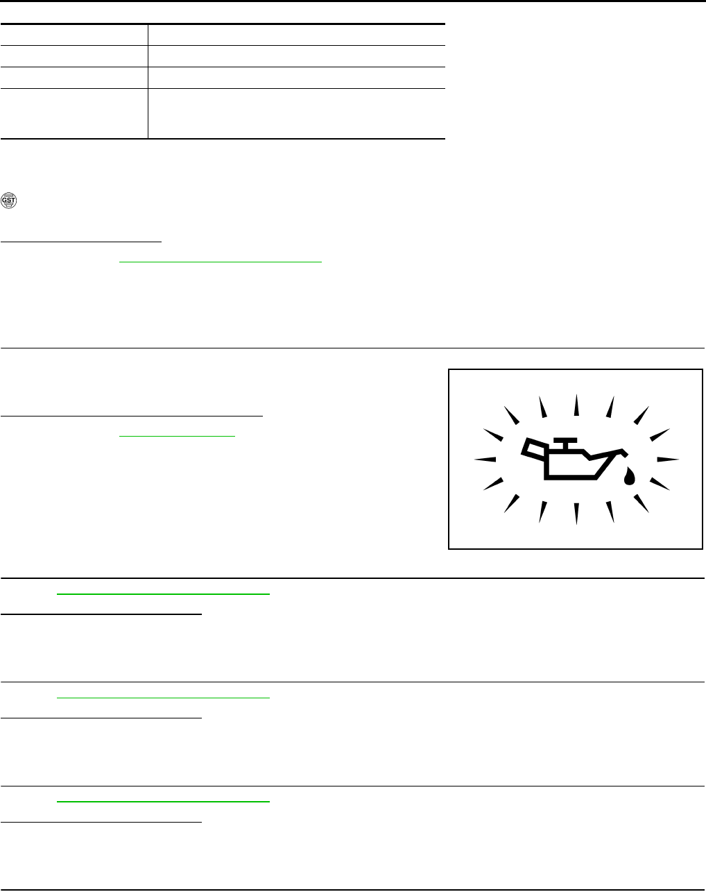
EC-132
< COMPONENT DIAGNOSIS > [FOR CALIFORNIA]
P0011 IVT CONTROL
CAUTION:
Always drive at a safe speed.
2. Check 1st trip DTC.
With GST
Follow the procedure “With CONSULT-III” above.
Is 1st trip DTC detected?
YES >> Go to EC-132, "Diagnosis Procedure"
NO >> INSPECTION END
Diagnosis Procedure INFOID:0000000004493347
1.CHECK OIL PRESSURE WARNING LAMP
1. Start engine.
2. Check oil pressure warning lamp and confirm it is not illumi-
nated.
Is oil pressure warning lamp illuminated?
YES >> Go to LU-5, "Inspection".
NO >> GO TO 2.
2.CHECK INTAKE VALVE TIMING CONTROL SOLENOID VALVE
Refer to EC-133, "Component Inspection".
Is the inspection result normal?
YES >> GO TO 3.
NO >> Replace intake valve timing control solenoid valve.
3.CHECK CRANKSHAFT POSITION SENSOR (POS)
Refer to EC-259, "Component Inspection".
Is the inspection result normal?
YES >> GO TO 4.
NO >> Replace crankshaft position sensor (POS).
4.CHECK CAMSHAFT POSITION SENSOR (PHASE)
Refer to EC-262, "Component Inspection".
Is the inspection result normal?
YES >> GO TO 5.
NO >> Replace camshaft position sensor (PHASE).
5.CHECK CAMSHAFT (INTAKE)
Check the following.
ENG SPEED 1,200 - 3,175 rpm (A constant rotation is maintained.)
COOLAN TEMP/S More than 70°C (221°F)
Selector lever 1st or 2nd position
Driving locationl Driving vehicle uphill
(Increased engine load will help maintain the driving
conditions required for this test.)
PBIA8559J
Revision: 2008 August 2009 Rogue
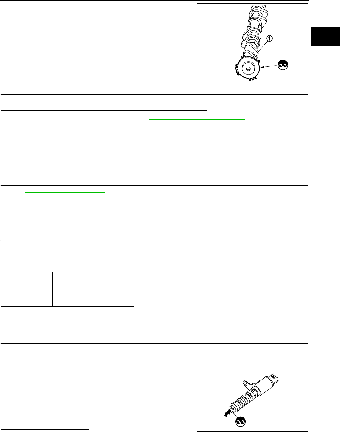
P0011 IVT CONTROL
EC-133
< COMPONENT DIAGNOSIS > [FOR CALIFORNIA]
C
D
E
F
G
H
I
J
K
L
M
A
EC
N
P
O
• Accumulation of debris on the signal plate of camshaft (1) rear end
• Chipping signal plate of camshaft rear end
Is the inspection result normal?
YES >> GO TO 6.
NO >> Remove debris and clean the signal plate of camshaft
rear end or replace camshaft.
6.CHECK TIMING CHAIN INSTALLATION
Check service records for any recent repairs that may cause timing chain misalignment.
Are there any service records that may cause timing chain misalignment?
YES >> Check timing chain installation. Refer to EM-70, "Removal and Installation".
NO >> GO TO 7.
7.CHECK LUBRICATION CIRCUIT
Refer to EM-53, "Inspection".
Is the inspection result normal?
YES >> GO TO 8.
NO >> Clean lubrication line.
8.CHECK INTERMITTENT INCIDENT
Refer to GI-41, "Intermittent Incident".
>> INSPECTION END
Component Inspection INFOID:0000000004493348
1.CHECK INTAKE VALVE TIMING CONTROL SOLENOID VALVE-I
1. Turn ignition switch OFF.
2. Disconnect intake valve timing control solenoid valve harness connector.
3. Check resistance between intake valve timing control solenoid valve terminals as follows.
Is the inspection result normal?
YES >> GO TO 2.
NO >> Replace intake valve timing control solenoid valve.
2.CHECK INTAKE VALVE TIMING CONTROL SOLENOID VALVE-II
1. Remove intake valve timing control solenoid valve.
2. Provide 12V DC between intake valve timing control solenoid
valve terminals 1 and 2, and then interrupt it. Check that the
plunger moves as shown in the figure.
CAUTION:
Never apply 12V DC continuously for 5 seconds or more.
Doing so may result in damage to the coil in intake valve
timing control solenoid valve.
NOTE:
Always replace O-ring when intake valve timing control
solenoid valve is removed.
Is the inspection result normal?
JMBIA0096ZZ
Terminals Resistance
1 and 2 7.0 - 7.5 Ω [at 20°C (68°F)]
1 or 2 and ground ∞ Ω
(Continuity should not exist)
JMBIA0097ZZ
Revision: 2008 August 2009 Rogue

EC-134
< COMPONENT DIAGNOSIS > [FOR CALIFORNIA]
P0011 IVT CONTROL
YES >> INSPECTION END
NO >> Replace intake valve timing control solenoid valve.
Revision: 2008 August 2009 Rogue

P0031, P0032 A/F SENSOR 1 HEATER
EC-135
< COMPONENT DIAGNOSIS > [FOR CALIFORNIA]
C
D
E
F
G
H
I
J
K
L
M
A
EC
N
P
O
P0031, P0032 A/F SENSOR 1 HEATER
Description INFOID:0000000004493349
SYSTEM DESCRIPTION
The ECM performs ON/OFF duty control of the A/F sensor 1 heater corresponding to the engine operating
condition to keep the temperature of A/F sensor 1 element within the specified range.
DTC Logic INFOID:0000000004493350
DTC DETECTION LOGIC
DTC CONFIRMATION PROCEDURE
1.PRECONDITIONING
If DTC CONFIRMATION PROCEDURE has been previously conducted, always turn ignition switch OFF and
wait at least 10 seconds before conducting the next test.
TESTING CONDITION:
Before performing the following procedure, confirm that battery voltage is more than between 11V at
idle.
>> GO TO 2.
2.PERFORM DTC CONFIRMATION PROCEDURE
1. Start engine and let it idle for at least 10 seconds.
2. Check 1st trip DTC.
Is 1st trip DTC detected?
YES >> Go to EC-135, "Diagnosis Procedure".
NO >> INSPECTION END
Diagnosis Procedure INFOID:0000000004493351
1.CHECK GROUND CONNECTION
1. Turn ignition switch OFF.
2. Check ground connection E21. Refer to Ground Inspection in GI-44, "Circuit Inspection".
Is the inspection result normal?
YES >> GO TO 2.
NO >> Repair or replace ground connection.
2.CHECK AIR FUEL RATIO (A/F) SENSOR 1 POWER SUPPLY CIRCUIT
1. Disconnect air fuel ratio (A/F) sensor 1 harness connector.
2. Turn ignition switch ON.
Sensor Input signal to ECM ECM function Actuator
Camshaft position sensor (PHASE)
Crankshaft position sensor (POS) Engine speed Air fuel ratio (A/F) sensor 1
heater control Air fuel ratio (A/F) sensor 1
heater
Mass air flow sensor Amount of intake air
DTC No. Trouble diagnosis name DTC detecting condition Possible cause
P0031 Air fuel ratio (A/F) sensor
1 heater control circuit low
The current amperage in the A/F sensor 1 heater
circuit is out of the normal range.
(An excessively low voltage signal is sent to ECM
through the A/F sensor 1 heater.)
• Harness or connectors
(The A/F sensor 1 heater circuit is
open or shorted.)
• A/F sensor 1 heater
P0032
Air fuel ratio (A/F) sensor
1 heater control circuit
high
The current amperage in the A/F sensor 1 heater
circuit is out of the normal range.
(An excessively high voltage signal is sent to ECM
through the A/F sensor 1 heater.)
• Harness or connectors
(The A/F sensor 1 heater circuit is
shorted.)
• A/F sensor 1 heater
Revision: 2008 August 2009 Rogue
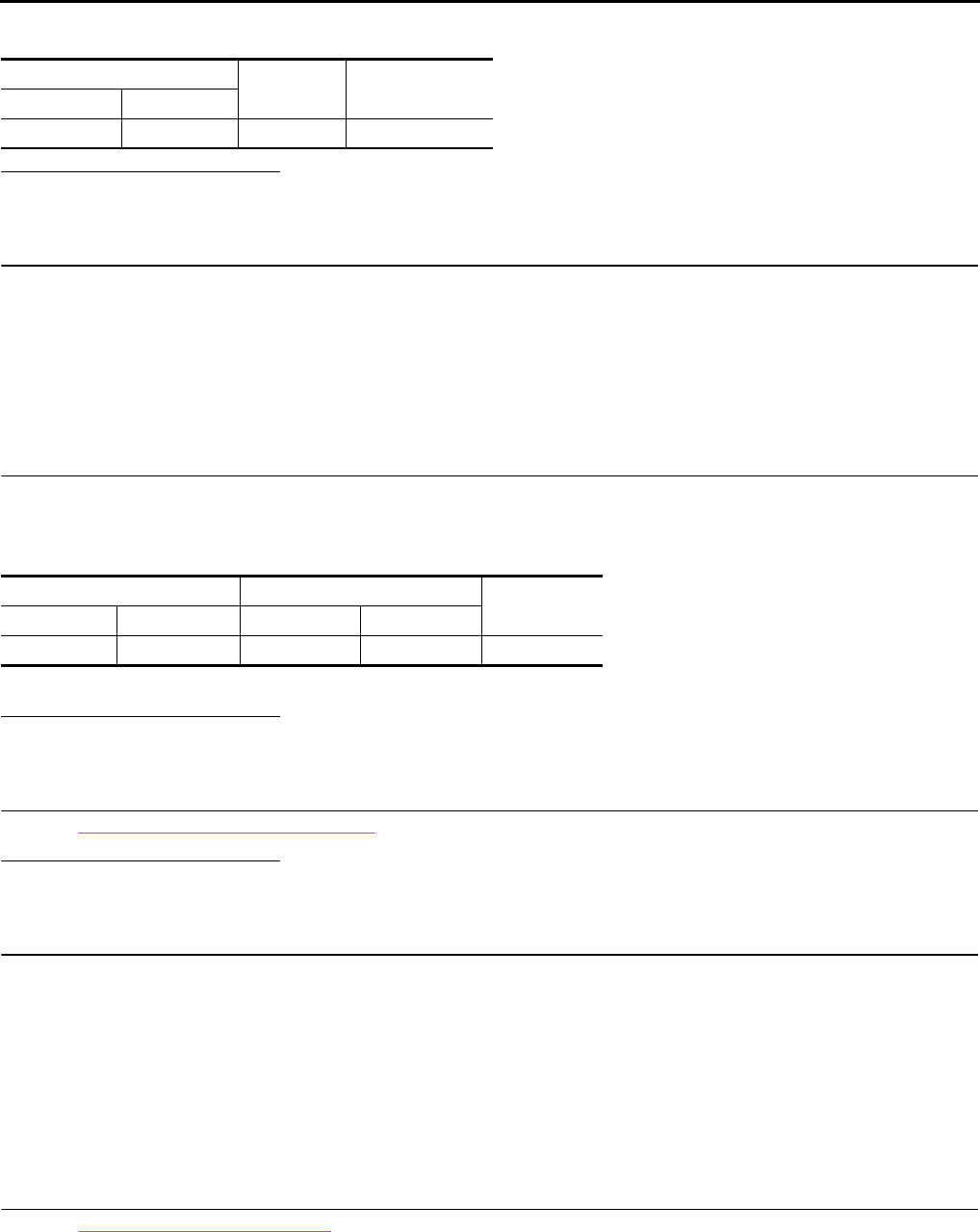
EC-136
< COMPONENT DIAGNOSIS > [FOR CALIFORNIA]
P0031, P0032 A/F SENSOR 1 HEATER
3. Check the voltage between A/F sensor 1 harness connector and ground.
Is the inspection result normal?
YES >> GO TO 4.
NO >> GO TO 3.
3.DETECT MALFUNCTIONING PART
Check the following.
• Harness connectors F123, E6
• IPDM E/R harness connector E14
• 15A fuse (No. 63)
• Harness for open or short between A/F sensor 1 and fuse
>> Repair or replace harness or connectors.
4.CHECK A/F SENSOR 1 HEATER OUTPUT SIGNAL CIRCUIT
1. Turn ignition switch OFF.
2. Disconnect ECM harness connector.
3. Check the continuity between A/F sensor 1 harness connector and ECM harness connector.
4. Also check harness for short to ground and short to power.
Is the inspection result normal?
YES >> GO TO 5.
NO >> Repair open circuit or short to ground or short to power in harness or connectors.
5.CHECK A/F SENSOR 1 HEATER
Refer to EC-137, "Component Inspection".
Is the inspection result normal?
YES >> GO TO 7.
NO >> GO TO 6.
6.REPLACE AIR FUEL RATIO (A/F) SENSOR 1
Replace air fuel ratio (A/F) sensor 1.
CAUTION:
• Discard any A/F sensor which has been dropped from a height of more than 0.5 m (19.7 in) onto a
hard surface such as a concrete floor; use a new one.
• Before installing new A/F sensor, clean exhaust system threads using oxygen sensor thread cleaner
[commercial service tool (J-43897-18 or J-43897-12)] and approved anti-seize lubricant (commercial
service tool).
>> INSPECTION END
7.CHECK INTERMITTENT INCIDENT
Perform GI-41, "Intermittent Incident".
>> INSPECTION END
A/F sensor 1 Ground Voltage
Connector Terminal
F28 4 Ground Battery voltage
A/F sensor 1 ECM Continuity
Connector Terminal Connector Terminal
F28 3 F7 4 Existed
Revision: 2008 August 2009 Rogue

P0031, P0032 A/F SENSOR 1 HEATER
EC-137
< COMPONENT DIAGNOSIS > [FOR CALIFORNIA]
C
D
E
F
G
H
I
J
K
L
M
A
EC
N
P
O
Component Inspection INFOID:0000000004493352
1.CHECK AIR FUEL RATIO (A/F) SENSOR 1
1. Turn ignition switch OFF.
2. Disconnect A/F sensor 1 harness connector.
3. Check resistance between A/F sensor 1 terminals as follows.
Is the inspection result normal?
YES >> INSPECTION END
NO >> GO TO 2.
2.REPLACE AIR FUEL RATIO (A/F) SENSOR 1
Replace air fuel ratio (A/F) sensor 1.
CAUTION:
• Discard any A/F sensor which has been dropped from a height of more than 0.5 m (19.7 in) onto a
hard surface such as a concrete floor; use a new one.
• Before installing new A/F sensor, clean exhaust system threads using Heated oxygen sensor thread
cleaner [commercial service tool (J-43897-18 or J-43897-12)] and approved anti-seize lubricant (com-
mercial service tool).
>> INSPECTION END
Terminals Resistance
3 and 4 1.98 - 2.66 Ω [at 25°C (77°F)]
3 and 1, 2 ∞ Ω
(Continuity should not exist)
4 and 1, 2
Revision: 2008 August 2009 Rogue

EC-138
< COMPONENT DIAGNOSIS > [FOR CALIFORNIA]
P0037, P0038 HO2S2 HEATER
P0037, P0038 HO2S2 HEATER
Description INFOID:0000000004493353
SYSTEM DESCRIPTION
The ECM performs ON/OFF control of the heated oxygen sensor 2 heater corresponding to the engine speed,
amount of intake air and engine coolant temperature.
OPERATION
DTC Logic INFOID:0000000004493354
DTC DETECTION LOGIC
DTC CONFIRMATION PROCEDURE
1.PRECONDITIONING
If DTC CONFIRMATION PROCEDURE has been previously conducted, always turn ignition switch OFF and
wait at least 10 seconds before conducting the next test.
TESTING CONDITION:
Before performing the following procedure, confirm that battery voltage is more than 11V at idle.
>> GO TO 2.
2.PERFORM DTC CONFIRMATION PROCEDURE
1. Start engine and warm it up to the normal operating temperature.
2. Turn ignition switch OFF and wait at least 10 seconds.
3. Start engine and keep the engine speed between 3,500 and 4,000 rpm for at least 1 minute under no load.
4. Let engine idle for 1 minute.
5. Check 1st trip DTC.
Is 1st tip DTC detected?
YES >> Go to EC-139, "Diagnosis Procedure".
NO >> INSPECTION END
Sensor Input signal to ECM ECM function Actuator
Camshaft position sensor (PHASE)
Crankshaft position sensor (POS) Engine speed Heated oxygen sensor 2
heater control Heated oxygen sensor 2 heater
Engine coolant temperature sensor Engine coolant temperature
Mass air flow sensor Amount of intake air
Engine speed Heated oxygen sensor 2 heater
Above 3,600 rpm OFF
Below 3,600 rpm after the following conditions are met.
• Engine: After warming up
• Keeping the engine speed between 3,500 and 4,000 rpm for 1
minute and at idle for 1 minute under no load
ON
DTC No. Trouble diagnosis
name DTC detecting condition Possible cause
P0037
Heated oxygen
sensor 2 heater
control circuit low
The current amperage in the heated oxygen sensor
2 heater circuit is out of the normal range.
(An excessively low voltage signal is sent to ECM
through the heated oxygen sensor 2 heater.)
• Harness or connectors
(The heated oxygen sensor 2 heater circuit
is open or shorted.)
• Heated oxygen sensor 2 heater
P0038
Heated oxygen
sensor 2 heater
control circuit high
The current amperage in the heated oxygen sensor
2 heater circuit is out of the normal range.
(An excessively high voltage signal is sent to ECM
through the heated oxygen sensor 2 heater.)
• Harness or connectors
(The heated oxygen sensor 2 heater circuit
is shorted.)
• Heated oxygen sensor 2 heater
Revision: 2008 August 2009 Rogue

P0037, P0038 HO2S2 HEATER
EC-139
< COMPONENT DIAGNOSIS > [FOR CALIFORNIA]
C
D
E
F
G
H
I
J
K
L
M
A
EC
N
P
O
Diagnosis Procedure INFOID:0000000004493355
1.CHECK GROUND CONNECTION
1. Turn ignition switch OFF.
2. Check ground connection E21. Refer to Ground Inspection in GI-44, "Circuit Inspection".
Is the inspection result normal?
YES >> GO TO 2.
NO >> Repair or replace ground connection.
2.CHECK HO2S2 POWER SUPPLY CIRCUIT
1. Disconnect heated oxygen sensor 2 (HO2S2) harness connector.
2. Turn ignition switch ON.
3. Check the voltage between HO2S2 harness connector and ground.
Is the inspection result normal?
YES >> GO TO 4.
NO >> GO TO 3.
3.DETECT MALFUNCTIONING PART
Check the following.
• Harness connectors F123, E6
• IPDM E/R connector E14
• 15A fuse (No. 63)
• Harness for open or short between heated oxygen sensor 2 and fuse
>> Repair open circuit or short to ground or short to power in harness or connectors.
4.CHECK HO2S2 OUTPUT SIGNAL CIRCUIT FOR OPEN AND SHORT
1. Turn ignition switch OFF.
2. Disconnect ECM harness connector.
3. Check the continuity between HO2S2 harness connector and ECM harness connector.
4. Also check harness for short to ground and short to power.
Is the inspection result normal?
YES >> GO TO 5.
NO >> Repair open circuit or short to ground or short to power in harness or connectors.
5.CHECK HEATED OXYGEN SENSOR 2 HEATER
Refer to EC-140, "Component Inspection".
Is the inspection result normal?
YES >> GO TO 7.
NO >> GO TO 6.
6.REPLACE HEATED OXYGEN SENSOR 2
Replace heated oxygen sensor 2.
CAUTION:
• Discard any heated oxygen sensor which has been dropped from a height of more than 0.5 m (19.7
in) onto a hard surface such as a concrete floor; use a new one.
HO2S2 Ground Voltage
Connector Terminal
F31 2 Ground Battery voltage
HO2S2 ECM Continuity
Connector Terminal Connector Terminal
F31 3 F7 13 Existed
Revision: 2008 August 2009 Rogue

EC-140
< COMPONENT DIAGNOSIS > [FOR CALIFORNIA]
P0037, P0038 HO2S2 HEATER
• Before installing new heated oxygen sensor, clean exhaust system threads using oxygen sensor
thread cleaner [commercial service tool (J-43897-18 or J-43897-12)] and approved anti-seize lubri-
cant (commercial service tool).
>> INSPECTION END
7.CHECK INTERMITTENT INCIDENT
Refer to GI-41, "Intermittent Incident".
>> INSPECTION END
Component Inspection INFOID:0000000004493356
1.CHECK HEATED OXYGEN SENSOR 2 HEATER
1. Turn ignition switch OFF.
2. Disconnect heated oxygen sensor 2 (HO2S2) harness connector.
3. Check resistance between HO2S2 terminals as follows.
Is the inspection result normal?
YES >> INSPECTION END
NO >> GO TO 2.
2.REPLACE HEATED OXYGEN SENSOR 2
Replace heated oxygen sensor 2.
CAUTION:
• Discard any heated oxygen sensor which has been dropped from a height of more than 0.5 m (19.7
in) onto a hard surface such as a concrete floor; use a new one.
• Before installing new heated oxygen sensor, clean exhaust system threads using oxygen sensor
thread cleaner [commercial service tool (J-43897-18 or J-43897-12)] and approved anti-seize lubri-
cant (commercial service tool).
>> INSPECTION END
Terminals Resistance
2 and 3 3.3 - 4.4 Ω [at 25°C (77°F)]
1 and 2, 3, 4 ∞ Ω
(Continuity should not exist)
4 and 1, 2, 3
Revision: 2008 August 2009 Rogue

P0043, P0044 HO2S3 HEATER
EC-141
< COMPONENT DIAGNOSIS > [FOR CALIFORNIA]
C
D
E
F
G
H
I
J
K
L
M
A
EC
N
P
O
P0043, P0044 HO2S3 HEATER
Description INFOID:0000000004493357
SYSTEM DESCRIPTION
The ECM performs ON/OFF control of the heated oxygen sensor 3 heater corresponding to the engine speed,
amount of intake air and engine coolant temperature.
OPERATION
DTC Logic INFOID:0000000004493358
DTC DETECTION LOGIC
DTC CONFIRMATION PROCEDURE
1.PRECONDITIONING
If DTC CONFIRMATION PROCEDURE has been previously conducted, always turn ignition switch OFF and
wait at least 10 seconds before conducting the next test.
TESTING CONDITION:
Before performing the following procedure, confirm that battery voltage is between 10.5V and 16V at
idle.
>> GO TO 2.
2.PERFORM DTC CONFIRMATION PROCEDURE
CAUTION:
Always drive vehicle in safe manner according to traffic conditions and obey all traffic laws.
1. Start engine and warm it up to the normal operating temperature.
2. Turn ignition switch OFF and wait at least 10 seconds.
3. Start engine and drive vehicle at a speed of 80 km/h (50 MPH) or more for at least 3 consecutive minutes.
NOTE:
Keep the vehicle speed as steady as possible during the cruising.
4. Check 1st trip DTC.
Sensor Input signal to ECM ECM function Actuator
Camshaft position sensor (PHASE) Engine speed Heated oxygen sensor 3
heater control Heated oxygen sensor 3 heater
Crankshaft position sensor (POS)
Engine coolant temperature sensor Engine coolant temperature
Mass air flow sensor Amount of intake air
Engine speed Heated oxygen sensor 3 heater
Above 3,600 rpm OFF
Below 3,600 rpm after the following conditions are met.
• Engine: After warming up
• Driving for 3 minutes at a speed of 80 km/h (50 MPH) or more
(Keep the vehicle speed as steady as possible during the cruising.)
ON
DTC No. Trouble diagnosis name DTC detecting condition Possible cause
P0043 Heated oxygen sensor 3
heater control circuit low
The current amperage in the heated oxygen sensor
3 heater circuit is out of the normal range.
(An excessively low voltage signal is sent to ECM
through the heated oxygen sensor 3 heater.)
• Harness or connectors
(The heated oxygen sensor 3 heater
circuit is open or shorted.)
• Heated oxygen sensor 3 heater
P0044 Heated oxygen sensor 3
heater control circuit high
The current amperage in the heated oxygen sensor
3 heater circuit is out of the normal range.
(An excessively high voltage signal is sent to ECM
through the heated oxygen sensor 3 heater.)
• Harness or connectors
(The heated oxygen sensor 3 heater
circuit is shorted.)
• Heated oxygen sensor 3 heater
Revision: 2008 August 2009 Rogue

EC-142
< COMPONENT DIAGNOSIS > [FOR CALIFORNIA]
P0043, P0044 HO2S3 HEATER
Is 1st tip DTC detected?
YES >> Go to EC-142, "Diagnosis Procedure".
NO >> INSPECTION END
Diagnosis Procedure INFOID:0000000004493359
1.CHECK GROUND CONNECTION
1. Turn ignition switch OFF.
2. Check ground connection E21. Refer to Ground Inspection in GI-44, "Circuit Inspection".
Is the inspection result normal?
YES >> GO TO 2.
NO >> Repair or replace ground connection.
2.CHECK HO2S3 POWER SUPPLY CIRCUIT
1. Disconnect heated oxygen sensor 3 (HO2S3) harness connector.
2. Turn ignition switch ON.
3. Check the voltage between HO2S3 harness connector and ground.
Is the inspection result normal?
YES >> GO TO 4.
NO >> GO TO 3.
3.DETECT MALFUNCTIONING PART
Check the following.
• IPDM E/R harness connector E14
• 15A fuse (No. 63)
• Harness for open or short between heated oxygen sensor 3 and fuse
>> Repair open circuit or short to ground or short to power in harness or connectors.
4.CHECK HO2S3 OUTPUT SIGNAL CIRCUIT FOR OPEN AND SHORT
1. Turn ignition switch OFF.
2. Disconnect ECM harness connector.
3. Check harness continuity between HO2S3 harness connector and ECM harness connector.
4. Also check harness for short to ground and short to power.
Is the inspection result normal?
YES >> GO TO 6.
NO >> GO TO 5.
5.DETECT MALFUNCTIONING PART
Check the following.
• Harness connectors E7, F121
• Harness for open or short between heated oxygen sensor 3 and ECM
>> Repair open circuit or short to ground or short to power in harness or connectors.
6.CHECK HEATED OXYGEN SENSOR 3 HEATER
Refer to EC-143, "Component Inspection".
HO2S3 Ground Voltage
Connector Terminal
E50 2 Ground Battery voltage
HO2S3 ECM Continuity
Connector Terminal Connector Terminal
E50 3 F7 17 Existed
Revision: 2008 August 2009 Rogue

P0043, P0044 HO2S3 HEATER
EC-143
< COMPONENT DIAGNOSIS > [FOR CALIFORNIA]
C
D
E
F
G
H
I
J
K
L
M
A
EC
N
P
O
Is the inspection result normal?
YES >> GO TO 8.
NO >> GO TO 7.
7.REPLACE HEATED OXYGEN SENSOR 3
Replace heated oxygen sensor 3.
CAUTION:
• Discard any heated oxygen sensor which has been dropped from a height of more than 0.5 m (19.7
in) onto a hard surface such as a concrete floor; use a new one.
• Before installing new heated oxygen sensor, clean exhaust system threads using oxygen sensor
thread cleaner [commercial service tool (J-43897-18 or J-43897-12)] and approved anti-seize lubri-
cant (commercial service tool).
>> INSPECTION END
8.CHECK INTERMITTENT INCIDENT
Refer to GI-41, "Intermittent Incident".
>> INSPECTION END
Component Inspection INFOID:0000000004493360
1.CHECK HEATED OXYGEN SENSOR 3 HEATER
1. Turn ignition switch OFF.
2. Disconnect heated oxygen sensor 3 (HO2S3) harness connector.
3. Check resistance between HO2S3 terminals as follows.
Is the inspection result normal?
YES >> INSPECTION END
NO >> GO TO 2.
2.REPLACE HEATED OXYGEN SENSOR 3
Replace heated oxygen sensor 3.
CAUTION:
• Discard any heated oxygen sensor which has been dropped from a height of more than 0.5 m (19.7
in) onto a hard surface such as a concrete floor; use a new one.
• Before installing new heated oxygen sensor, clean exhaust system threads using oxygen sensor
thread cleaner [commercial service tool (J-43897-18 or J-43897-12)] and approved anti-seize lubri-
cant (commercial service tool).
>> INSPECTION END
Terminal Resistance
2 and 3 3.4 - 4.4 Ω [at 25°C (77°F)]
1 and 2, 3, 4 ∞ Ω
(Continuity should not exist)
4 and 1, 2, 3
Revision: 2008 August 2009 Rogue

EC-144
< COMPONENT DIAGNOSIS > [FOR CALIFORNIA]
P0075 IVT CONTROL SOLENOID VALVE
P0075 IVT CONTROL SOLENOID VALVE
Description INFOID:0000000004493361
Intake valve timing control solenoid valve is activated by ON/OFF
pulse duty (ratio) signals from the ECM.
The intake valve timing control solenoid valve changes the oil
amount and direction of flow through intake valve timing control unit
or stops oil flow.
The longer pulse width advances valve timing.
The shorter pulse width retards valve timing.
When ON and OFF pulse widths become equal, the solenoid valve
stops oil pressure flow to fix the intake valve angle at the control
position.
DTC Logic INFOID:0000000004493362
DTC DETECTION LOGIC
DTC CONFIRMATION PROCEDURE
1.PRECONDITIONING
If DTC CONFIRMATION PROCEDURE has been previously conducted, always turn ignition switch OFF and
wait at least 10 seconds before conducting the next test.
>> GO TO2.
2.PERFORM DTC CONFIRMATION PROCEDURE
1. Start engine and let it idle for 5 seconds.
2. Check 1st trip DTC.
Is 1st trip DTC detected?
YES >> Go to EC-144, "Diagnosis Procedure".
NO >> INSPECTION END
Diagnosis Procedure INFOID:0000000004493363
1.CHECK INTAKE VALVE TIMING CONTROL SOLENOID VALVE POWER SUPPLY CIRCUIT
1. Turn ignition switch OFF.
2. Disconnect intake valve timing control solenoid valve harness connector.
3. Turn ignition switch ON.
4. Check the voltage between intake valve timing control solenoid valve harness connector and ground.
Is the inspection result normal?
YES >> GO TO 3.
NO >> GO TO 2.
JMBIA0098G
B
DTC No. Trouble diagnosis name DTC detecting condition Possible cause
P0075 Intake valve timing control
solenoid valve circuit
An improper voltage is sent to the ECM through
intake valve timing control solenoid valve.
• Harness or connectors
(Intake valve timing control solenoid valve
circuit is open or shorted.)
• Intake valve timing control solenoid valve
Intake valve timing control
solenoid valve Ground Voltage
Connector Terminal
F45 2 Ground Battery voltage
Revision: 2008 August 2009 Rogue

P0075 IVT CONTROL SOLENOID VALVE
EC-145
< COMPONENT DIAGNOSIS > [FOR CALIFORNIA]
C
D
E
F
G
H
I
J
K
L
M
A
EC
N
P
O
2.DETECT MALFUNCTIONING PART
Check the following.
• Harness connectors E7, F121
• Harness for open or short between intake valve timing control solenoid valve and IPDM E/R
>> Repair open circuit or short to ground or short to power in harness or connectors.
3.CHECK INTAKE VALVE TIMING CONTROL SOLENOID VALVE OUTPUT SIGNAL CIRCUIT FOR OPEN
AND SHORT
1. Turn ignition switch OFF.
2. Disconnect ECM harness connector.
3. Check the continuity between intake valve timing control solenoid valve harness connector and ECM har-
ness connector.
4. Also check harness for short to ground and short to power.
Is the inspection result normal?
YES >> GO TO 4.
NO >> Repair open circuit or short to ground or short to power in harness or connectors.
4.CHECK INTAKE VALVE TIMING CONTROL SOLENOID VALVE
Refer to EC-145, "Component Inspection".
Is the inspection result normal?
YES >> GO TO 5.
NO >> Replace intake valve timing control solenoid valve.
5.CHECK INTERMITTENT INCIDENT
Refer to GI-41, "Intermittent Incident".
>> INSPECTION END
Component Inspection INFOID:0000000004507196
1.CHECK INTAKE VALVE TIMING CONTROL SOLENOID VALVE-I
1. Turn ignition switch OFF.
2. Disconnect intake valve timing control solenoid valve harness connector.
3. Check resistance between intake valve timing control solenoid valve terminals as follows.
Is the inspection result normal?
YES >> GO TO 2.
NO >> Replace intake valve timing control solenoid valve.
2.CHECK INTAKE VALVE TIMING CONTROL SOLENOID VALVE-II
1. Remove intake valve timing control solenoid valve.
Intake valve timing control
solenoid valve ECM Continuity
Connector Terminal Connector Terminal
F45 1 F8 78 Existed
Terminals Resistance
1 and 2 7.0 - 7.5 Ω [at 20°C (68°F)]
1 or 2 and ground ∞ Ω
(Continuity should not exist)
Revision: 2008 August 2009 Rogue
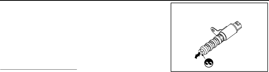
EC-146
< COMPONENT DIAGNOSIS > [FOR CALIFORNIA]
P0075 IVT CONTROL SOLENOID VALVE
2. Provide 12V DC between intake valve timing control solenoid
valve terminals 1 and 2, and then interrupt it. Check that the
plunger moves as shown in the figure.
CAUTION:
Never apply 12V DC continuously for 5 seconds or more.
Doing so may result in damage to the coil in intake valve
timing control solenoid valve.
NOTE:
Always replace O-ring when intake valve timing control
solenoid valve is removed.
Is the inspection result normal?
YES >> INSPECTION END
NO >> Replace intake valve timing control solenoid valve.
JMBIA0097ZZ
Revision: 2008 August 2009 Rogue

P0101 MAF SENSOR
EC-147
< COMPONENT DIAGNOSIS > [FOR CALIFORNIA]
C
D
E
F
G
H
I
J
K
L
M
A
EC
N
P
O
P0101 MAF SENSOR
Description INFOID:0000000004493365
The mass air flow sensor (1) is placed in the stream of intake air. It
measures the intake flow rate by measuring a part of the entire
intake flow. The mass air flow sensor controls the temperature of the
hot wire to a certain amount. The heat generated by the hot wire is
reduced as the intake air flows around it. The greater air flow, the
greater the heat loss.
Therefore, the electric current supplied to hot wire is changed to
maintain the temperature of the hot wire as air flow increases. The
ECM detects the air flow by means of this current change.
DTC Logic INFOID:0000000004493366
DTC DETECTION LOGIC
DTC CONFIRMATION PROCEDURE
1.PRECONDITIONING
If DTC CONFIRMATION PROCEDURE has been previously conducted, always turn ignition switch OFF and
wait at least 10 seconds before conducting the next test.
If engine will not start or stops soon, wait at least 10 seconds with engine stopped (Ignition switch ON) instead
of running engine at idle speed.
>> GO TO 2.
2.PERFORM DTC CONFIRMATION PROCEDURE FOR MALFUNCTION A
1. Start engine and warm it up to normal operating temperature.
2. Run engine for at least 10 seconds at idle speed.
3. Check 1st trip DTC.
Is 1st trip DTC detected?
YES >> Go to EC-149, "Diagnosis Procedure".
NO-1 >> With CONSULT-III: GO TO 3.
NO-2 >> Without CONSULT-III: GO TO 5.
3.CHECK MASS AIR FLOW SENSOR FUNCTION
1. Turn ignition switch ON.
2. Start engine and warm it up to normal operating temperature.
If engine cannot be started, go to EC-149, "Diagnosis Procedure".
PBIA9559J
DTC No. Trouble diagnosis name DTC detecting condition Possible cause
P0101 Mass air flow sensor circuit
range/performance
A) A high voltage from the sensor is sent to ECM
under light load driving condition.
• Harness or connectors
(The sensor circuit is open or
shorted.)
• Mass air flow sensor
• EVAP control system pressure
sensor
B) A low voltage from the sensor is sent to ECM
under heavy load driving condition.
• Harness or connectors
(The sensor circuit is open or
shorted.)
• Intake air leaks
• Mass air flow sensor
• EVAP control system pressure
sensor
• Intake air temperature sensor
Revision: 2008 August 2009 Rogue

EC-148
< COMPONENT DIAGNOSIS > [FOR CALIFORNIA]
P0101 MAF SENSOR
3. Select “DATA MONITOR” mode with CONSULT-III.
4. Check the voltage of “MAS A/F SE-B1” with “DATA MONITOR”.
5. Increases engine speed to approximately 4,000 rpm.
6. Monitor the linear voltage rise in response to engine speed
increases.
Is the inspection result normal?
YES >> GO TO 4.
NO >> Go to EC-149, "Diagnosis Procedure".
4.PERFORM DTC CONFIRMATION PROCEDURE FOR MALFUNCTION B
1. Maintain the following conditions for at least 10 consecutive seconds.
CAUTION:
Always drive vehicle at a safe speed.
2. Check 1st trip DTC.
Is 1st trip DTC detected?
YES >> Go to EC-149, "Diagnosis Procedure".
NO >> INSPECTION END
5.PERFORM COMPONENT FUNCTION CHECK FOR MALFUNCTION B
Perform component function check. Refer to EC-148, "Component Function Check".
NOTE:
Use component function check to check the overall function of the mass air flow sensor circuit. During this
check, a 1st trip DTC might not be confirmed.
Is the inspection result normal?
YES >> INSPECTION END
NO >> Go to EC-149, "Diagnosis Procedure".
Component Function Check INFOID:0000000004493367
1.PERFORM COMPONENT FUNCTION CHECK FOR MALFUNCTION B
With GST
1. Start engine and warm it up to normal operating temperature.
2. Select Service $01 with GST.
PBIB3457E
ENG SPEED More than 2,000 rpm
THRTL SEN 1-B1 More than 1.5V
THRTL SEN 2-B1 More than 1.5V
Selector lever Suitable position
Driving location Driving vehicle uphill (Increased engine load) will help
maintain the driving conditions required for this test.
Revision: 2008 August 2009 Rogue

P0101 MAF SENSOR
EC-149
< COMPONENT DIAGNOSIS > [FOR CALIFORNIA]
C
D
E
F
G
H
I
J
K
L
M
A
EC
N
P
O
3. Check the mass air flow sensor signal with Service $01.
4. Check for linear mass air flow sensor signal value rise in
response to increases to approximately 4,000 rpm in engine
speed.
Is the inspection result normal?
YES >> INSPECTION END
NO >> Go to EC-149, "Diagnosis Procedure".
Diagnosis Procedure INFOID:0000000004493368
1.INSPECTION START
Confirm the detected malfunction (A or B). Refer to EC-147, "DTC Logic".
Which malfunction is detected?
A >> GO TO 3.
B >> GO TO 2.
2.CHECK INTAKE SYSTEM
Check the following for connection.
• Air duct
• Vacuum hoses
• Intake air passage between air duct and intake manifold
Is the inspection result normal?
YES >> GO TO 3.
NO >> Reconnect the parts.
3.CHECK GROUND CONNECTION
1. Turn ignition switch OFF.
2. Check ground connection E21. Refer to Ground Inspection in GI-44, "Circuit Inspection".
Is the inspection result normal?
YES >> GO TO 4.
NO >> Repair or replace ground connection.
4.CHECK MAF SENSOR POWER SUPPLY CIRCUIT
1. Disconnect mass air flow (MAF) sensor harness connector.
2. Turn ignition switch ON.
3. Check the voltage between MAF sensor harness connector and ground.
Is the inspection result normal?
YES >> GO TO 6.
NO >> GO TO 5.
5.DETECT MALFUNCTIONING PART
Check the following.
• Harness for open or short between mass air flow sensor and ECM
• Harness for open or short between mass air flow sensor and IPDM E/R
>> Repair open circuit or short to ground or short to power in harness or connectors.
6.CHECK MAF SENSOR GROUND CIRCUIT FOR OPEN AND SHORT
1. Turn ignition switch OFF.
SEF534P
MAF sensor Ground Voltage
Connector Terminal
E18 5 Ground Battery voltage
Revision: 2008 August 2009 Rogue

EC-150
< COMPONENT DIAGNOSIS > [FOR CALIFORNIA]
P0101 MAF SENSOR
2. Disconnect ECM harness connector.
3. Check the continuity between MAF sensor harness connector and ECM harness connector.
4. Also check harness for short to ground and short to power.
Is the inspection result normal?
YES >> GO TO 8.
NO >> GO TO 7.
7.DETECT MALFUNCTIONING PART
Check the following.
• Harness connectors E6, F123
• Harness for open or short between mass air flow sensor and ECM
>> Repair open circuit or short to ground or short to power in harness or connectors.
8.CHECK MAF SENSOR INPUT SIGNAL CIRCUIT FOR OPEN AND SHORT
1. Check the continuity between MAF sensor harness connector and ECM harness connector.
2. Also check harness for short to ground and short to power.
Is the inspection result normal?
YES >> GO TO 10.
NO >> GO TO 9.
9.DETECT MALFUNCTIONING PART
Check the following.
• Harness connectors E6, F123
• Harness for open or short between mass air flow sensor and ECM
>> Repair open circuit or short to ground or short to power in harness or connectors.
10.CHECK INTAKE AIR TEMPERATURE SENSOR
Refer to EC-161, "Component Inspection".
Is the inspection result normal?
YES >> GO TO 11.
NO >> Replace mass air flow sensor (with intake air temperature sensor).
11.CHECK EVAP CONTROL SYSTEM PRESSURE SENSOR
Refer to EC-296, "Component Inspection".
Is the inspection result normal?
YES >> GO TO 12.
NO >> Replace EVAP control system pressure sensor.
12.CHECK MASS AIR FLOW SENSOR
Refer to EC-151, "Component Inspection".
Is the inspection result normal?
YES >> GO TO 13.
NO >> Replace mass air flow sensor.
13.CHECK INTERMITTENT INCIDENT
MAF sensor ECM Continuity
Connector Terminal Connector Terminal
E18 4 F7 56 Existed
MAF sensor ECM Continuity
Connector Terminal Connector Terminal
E18 3 F8 58 Existed
Revision: 2008 August 2009 Rogue

P0101 MAF SENSOR
EC-151
< COMPONENT DIAGNOSIS > [FOR CALIFORNIA]
C
D
E
F
G
H
I
J
K
L
M
A
EC
N
P
O
Refer to GI-41, "Intermittent Incident".
>> INSPECTION END
Component Inspection INFOID:0000000004493369
1.CHECK MASS AIR FLOW SENSOR-I
With CONSULT-III
1. Turn ignition switch OFF.
2. Reconnect all harness connectors disconnected.
3. Start engine and warm it up to normal operating temperature.
4. Connect CONSULT-III and select “DATA MONITOR” mode.
5. Select “MAS A/F SE-B1” and check indication.
*: Check for linear voltage rise in response to engine being increased to approximately 4,000 rpm.
Without CONSULT-III
1. Turn ignition switch OFF.
2. Reconnect all harness connectors disconnected.
3. Start engine and warm it up to normal operating temperature.
4. Check the voltage between ECM harness connector terminals under the following conditions.
*: Check for linear voltage rise in response to engine being increased to approximately 4,000 rpm.
Is the inspection result normal?
YES >> INSPECTION END
NO >> GO TO 2.
2.CHECK FOR THE CAUSE OF UNEVEN AIR FLOW THROUGH MASS AIR FLOW SENSOR
1. Turn ignition switch OFF.
2. Check for the cause of uneven air flow through mass air flow sensor. Refer to the following.
- Crushed air ducts
- Malfunctioning seal of air cleaner element
- Uneven dirt of air cleaner element
- Improper specification of intake air system parts
Is the inspection result normal?
YES >> GO TO 4.
NO >> GO TO 3.
3.CHECK MASS AIR FLOW SENSOR-II
With CONSULT-III
1. Repair or replace malfunctioning part.
2. Start engine and warm it up to normal operating temperature.
Monitor item Condition MAS A/F SE-B1
MAS A/F SE-B1
Ignition switch ON (Engine stopped.) Approx. 0.4V
Idle (Engine is warmed-up to normal operating temperature.) 0.8 - 1.2V
2,500 rpm (Engine is warmed-up to normal operating temperature.) 1.4 - 1.8V
Idle to approx. 4,000 rpm 0.8 - 1.2V to Approx. 2.4V*
ECM
Condition Voltage
Connector +−
Terminal Terminal
F8 58
(MAF sensor
signal)
56
(Sensor
gound)
Ignition switch ON (Engine stopped.) Approx. 0.4 V
Idle (Engine is warmed-up to normal operating temperature.) 0.8 - 1.2 V
2,500 rpm (Engine is warmed-up to normal operating temper-
ature.) 1.4 - 1.8 V
Idle to approx. 4,000 rpm 0.8 - 1.2 V to Approx. 2.4 V*
Revision: 2008 August 2009 Rogue
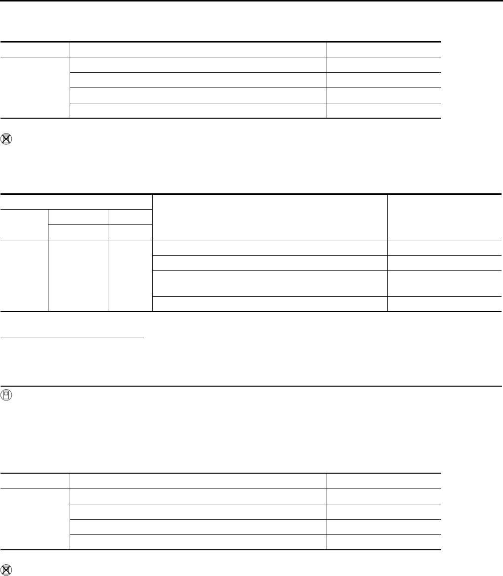
EC-152
< COMPONENT DIAGNOSIS > [FOR CALIFORNIA]
P0101 MAF SENSOR
3. Connect CONSULT-III and select “DATA MONITOR” mode.
4. Select “MAS A/F SE-B1” and check indication.
*: Check for linear voltage rise in response to engine being increased to approximately 4,000 rpm.
Without CONSULT-III
1. Repair or replace malfunctioning part.
2. Start engine and warm it up to normal operating temperature.
3. Check the voltage between ECM harness connector terminals under the following conditions.
*: Check for linear voltage rise in response to engine being increased to approximately 4,000 rpm.
Is the inspection result normal?
YES >> INSPECTION END
NO >> GO TO 4.
4.CHECK MASS AIR FLOW SENSOR-III
With CONSULT-III
1. Turn ignition switch OFF.
2. Disconnect mass air flow sensor harness connector and reconnect it again.
3. Start engine and warm it up to normal operating temperature.
4. Connect CONSULT-III and select “DATA MONITOR” mode.
5. Select “MAS A/F SE-B1” and check indication.
*: Check for linear voltage rise in response to engine being increased to approximately 4,000 rpm.
Without CONSULT-III
1. Turn ignition switch OFF.
2. Disconnect mass air flow sensor harness connector and reconnect it again.
3. Start engine and warm it up to normal operating temperature.
4. Check the voltage between ECM harness connector terminals under the following conditions.
Monitor item Condition MAS A/F SE-B1
MAS A/F SE-B1
Ignition switch ON (Engine stopped.) Approx. 0.4V
Idle (Engine is warmed-up to normal operating temperature.) 0.8 - 1.2V
2,500 rpm (Engine is warmed-up to normal operating temperature.) 1.4 - 1.8V
Idle to approx. 4,000 rpm 0.8 - 1.2V to Approx. 2.4V*
ECM
Condition Voltage
Connector +−
Terminal Terminal
F8
58
(MAF sensor
signal)
56
(Sensor
gound)
Ignition switch ON (Engine stopped.) Approx. 0.4 V
Idle (Engine is warmed-up to normal operating temperature.) 0.8 - 1.2 V
2,500 rpm (Engine is warmed-up to normal operating temper-
ature.) 1.4 - 1.8V
Idle to approx. 4,000 rpm 0.8 - 1.2 V to Approx. 2.4 V*
Monitor item Condition MAS A/F SE-B1
MAS A/F SE-B1
Ignition switch ON (Engine stopped.) Approx. 0.4V
Idle (Engine is warmed-up to normal operating temperature.) 0.8 - 1.2V
2,500 rpm (Engine is warmed-up to normal operating temperature.) 1.4 - 1.8V
Idle to approx. 4,000 rpm 0.8 - 1.2V to Approx. 2.4V*
Revision: 2008 August 2009 Rogue

P0101 MAF SENSOR
EC-153
< COMPONENT DIAGNOSIS > [FOR CALIFORNIA]
C
D
E
F
G
H
I
J
K
L
M
A
EC
N
P
O
*: Check for linear voltage rise in response to engine being increased to approximately 4,000 rpm.
Is the inspection result normal?
YES >> INSPECTION END
NO >> Clean or replace mass air flow sensor.
ECM
Condition Voltage
Connector +−
Terminal Terminal
F8
58
(MAF sensor
signal)
56
(Sensor
gound)
Ignition switch ON (Engine stopped.) Approx. 0.4 V
Idle (Engine is warmed-up to normal operating temperature.) 0.8 - 1.2 V
2,500 rpm (Engine is warmed-up to normal operating temper-
ature.) 1.4 - 1.8 V
Idle to approx. 4,000 rpm 0.8 - 1.2 V to Approx. 2.4 V*
Revision: 2008 August 2009 Rogue
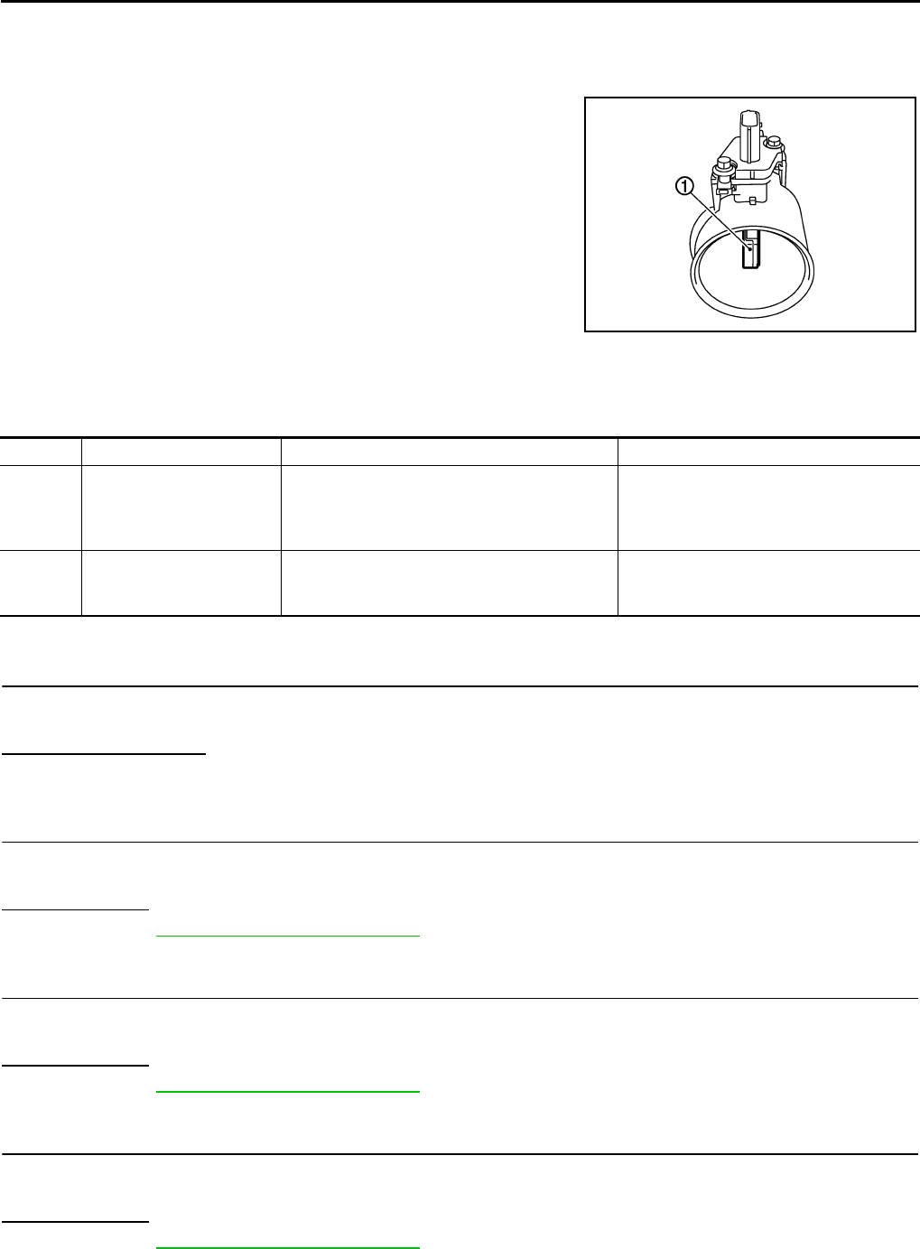
EC-154
< COMPONENT DIAGNOSIS > [FOR CALIFORNIA]
P0102, P0103 MAF SENSOR
P0102, P0103 MAF SENSOR
Description INFOID:0000000004493370
The mass air flow sensor (1) is placed in the stream of intake air. It
measures the intake flow rate by measuring a part of the entire
intake flow. The mass air flow sensor controls the temperature of the
hot wire to a certain amount. The heat generated by the hot wire is
reduced as the intake air flows around it. The greater air flow, the
greater the heat loss.
Therefore, the electric current supplied to hot wire is changed to
maintain the temperature of the hot wire as air flow increases. The
ECM detects the air flow by means of this current change.
DTC Logic INFOID:0000000004493371
DTC DETECTION LOGIC
DTC CONFIRMATION PROCEDURE
1.PRECONDITIONING
If DTC CONFIRMATION PROCEDURE has been previously conducted, always turn ignition switch OFF and
wait at least 10 seconds before conducting the next test.
Which DTC is detected?
P0102 >> GO TO 2.
P0103 >> GO TO 3.
2.PERFORM DTC CONFIRMATION PROCEDURE FOR DTC P0102
1. Start engine and wait at least 5 seconds.
2. Check DTC.
Is DTC detected?
YES >> Go to EC-155, "Diagnosis Procedure".
NO >> INSPECTION END
3.PERFORM DTC CONFIRMATION PROCEDURE FOR DTC P0103-I
1. Turn ignition switch ON and wait at least 5 seconds.
2. Check DTC.
Is DTC detected?
YES >> Go to EC-155, "Diagnosis Procedure".
NO >> GO TO 4.
4.PERFORM DTC CONFIRMATION PROCEDURE FOR DTC P0103-II
1. Start engine and wait at least 5 seconds.
2. Check DTC.
Is DTC detected?
YES >> Go to EC-155, "Diagnosis Procedure".
NO >> INSPECTION END
PBIA9559J
DTC No. Trouble diagnosis name DTC detecting condition Possible cause
P0102 Mass air flow sensor circuit
low input An excessively low voltage from the sensor is
sent to ECM.
• Harness or connectors
(The sensor circuit is open or shorted.)
• Intake air leaks
• Mass air flow sensor
P0103 Mass air flow sensor circuit
high input
An excessively high voltage from the sensor is
sent to ECM.
• Harness or connectors
(The sensor circuit is open or shorted.)
• Mass air flow sensor
Revision: 2008 August 2009 Rogue

P0102, P0103 MAF SENSOR
EC-155
< COMPONENT DIAGNOSIS > [FOR CALIFORNIA]
C
D
E
F
G
H
I
J
K
L
M
A
EC
N
P
O
Diagnosis Procedure INFOID:0000000004493372
1.INSPECTION START
Confirm the detected DTC.
Which DTC is detected?
P0102 >> GO TO 2.
P0103 >> GO TO 3.
2.CHECK INTAKE SYSTEM
Check the following for connection.
• Air duct
• Vacuum hoses
• Intake air passage between air duct to intake manifold
Is the inspection result normal?
YES >> GO TO 3.
NO >> Reconnect the parts.
3.CHECK GROUND CONNECTION
1. Turn ignition switch OFF.
2. Check ground connection E21. Refer to Ground Inspection in GI-44, "Circuit Inspection".
Is the inspection result normal?
YES >> GO TO 4.
NO >> Repair or replace ground connection.
4.CHECK MAF SENSOR POWER SUPPLY CIRCUIT
1. Disconnect mass air flow (MAF) sensor harness connector.
2. Turn ignition switch ON.
3. Check the voltage between MAF sensor harness connector and ground.
Is the inspection result normal?
YES >> GO TO 6.
NO >> GO TO 5.
5.DETECT MALFUNCTIONING PART
Check the following.
• Harness for open or short between mass air flow sensor and ECM
• Harness for open or short between mass air flow sensor and IPDM E/R
>> Repair open circuit or short to ground or short to power in harness or connectors.
6.CHECK MAF SENSOR GROUND CIRCUIT FOR OPEN AND SHORT
1. Turn ignition switch OFF.
2. Disconnect ECM harness connector.
3. Check the continuity between MAF sensor harness connector and ECM harness connector.
4. Also check harness for short to ground and short to power.
Is the inspection result normal?
YES >> GO TO 8.
MAF sensor Ground Voltage
Connector Terminal
E18 5 Ground Battery voltage
MAF sensor ECM Continuity
Connector Terminal Connector Terminal
E18 4 F8 56 Existed
Revision: 2008 August 2009 Rogue
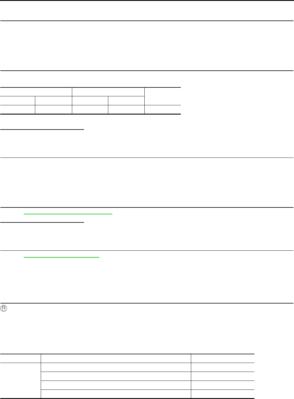
EC-156
< COMPONENT DIAGNOSIS > [FOR CALIFORNIA]
P0102, P0103 MAF SENSOR
NO >> GO TO 7.
7.DETECT MALFUNCTIONING PART
Check the following.
• Harness connectors E6, F123
• Harness for open or short between mass air flow sensor and ECM
>> Repair open circuit or short to ground or short to power in harness or connectors.
8.CHECK MAF SENSOR INPUT SIGNAL CIRCUIT FOR OPEN AND SHORT
1. Check the continuity between MAF sensor harness connector and ECM harness connector.
2. Also check harness for short to ground and short to power.
Is the inspection result normal?
YES >> GO TO 10.
NO >> GO TO 9.
9.DETECT MALFUNCTIONING PART
Check the following.
• Harness connectors E6, F123
• Harness for open or short between mass air flow sensor and ECM
>> Repair open circuit or short to ground or short to power in harness or connectors.
10.CHECK MASS AIR FLOW SENSOR
Refer to EC-156, "Component Inspection".
Is the inspection result normal?
YES >> GO TO 11.
NO >> Replace mass air flow sensor.
11.CHECK INTERMITTENT INCIDENT
Refer to GI-41, "Intermittent Incident".
>> INSPECTION END
Component Inspection INFOID:0000000004493373
1.CHECK MASS AIR FLOW SENSOR-I
With CONSULT-III
1. Turn ignition switch OFF.
2. Reconnect all harness connectors disconnected.
3. Start engine and warm it up to normal operating temperature.
4. Connect CONSULT-III and select “DATA MONITOR” mode.
5. Select “MAS A/F SE-B1” and check indication.
*: Check for linear voltage rise in response to engine being increased to approximately 4,000 rpm.
MAF sensor ECM Continuity
Connector Terminal Connector Terminal
E18 3 F8 58 Existed
Monitor item Condition MAS A/F SE-B1
MAS A/F SE-B1
Ignition switch ON (Engine stopped.) Approx. 0.4V
Idle (Engine is warmed-up to normal operating temperature.) 0.8 - 1.2V
2,500 rpm (Engine is warmed-up to normal operating temperature.) 1.4 - 1.8V
Idle to approx. 4,000 rpm 0.8 - 1.2V to Approx. 2.4V*
Revision: 2008 August 2009 Rogue

P0102, P0103 MAF SENSOR
EC-157
< COMPONENT DIAGNOSIS > [FOR CALIFORNIA]
C
D
E
F
G
H
I
J
K
L
M
A
EC
N
P
O
Without CONSULT-III
1. Turn ignition switch OFF.
2. Reconnect all harness connectors disconnected.
3. Start engine and warm it up to normal operating temperature.
4. Check the voltage between ECM harness connector terminals under the following conditions.
*: Check for linear voltage rise in response to engine being increased to approximately 4,000 rpm.
Is the inspection result normal?
YES >> INSPECTION END
NO >> GO TO 2.
2.CHECK FOR THE CAUSE OF UNEVEN AIR FLOW THROUGH MASS AIR FLOW SENSOR
1. Turn ignition switch OFF.
2. Check for the cause of uneven air flow through mass air flow sensor. Refer to the following.
- Crushed air ducts
- Malfunctioning seal of air cleaner element
- Uneven dirt of air cleaner element
- Improper specification of intake air system parts
Is the inspection result normal?
YES >> GO TO 4.
NO >> GO TO 3.
3.CHECK MASS AIR FLOW SENSOR-II
With CONSULT-III
1. Repair or replace malfunctioning part.
2. Start engine and warm it up to normal operating temperature.
3. Connect CONSULT-III and select “DATA MONITOR” mode.
4. Select “MAS A/F SE-B1” and check indication.
*: Check for linear voltage rise in response to engine being increased to approximately 4,000 rpm.
Without CONSULT-III
1. Repair or replace malfunctioning part.
2. Start engine and warm it up to normal operating temperature.
3. Check the voltage between ECM harness connector terminals under the following conditions.
ECM
Condition Voltage
Connector +−
Terminal Terminal
F8
58
(MAF sensor
signal)
56
(Sensor
gound)
Ignition switch ON (Engine stopped.) Approx. 0.4 V
Idle (Engine is warmed-up to normal operating temperature.) 0.8 - 1.2 V
2,500 rpm (Engine is warmed-up to normal operating temper-
ature.) 1.4 - 1.8 V
Idle to approx. 4,000 rpm 0.8 - 1.2 V to Approx. 2.4 V*
Monitor item Condition MAS A/F SE-B1
MAS A/F SE-B1
Ignition switch ON (Engine stopped.) Approx. 0.4V
Idle (Engine is warmed-up to normal operating temperature.) 0.8 - 1.2V
2,500 rpm (Engine is warmed-up to normal operating temperature.) 1.4 - 1.8V
Idle to approx. 4,000 rpm 0.8 - 1.2V to Approx. 2.4V*
Revision: 2008 August 2009 Rogue
EC-158
< COMPONENT DIAGNOSIS > [FOR CALIFORNIA]
P0102, P0103 MAF SENSOR
*: Check for linear voltage rise in response to engine being increased to approximately 4,000 rpm.
Is the inspection result normal?
YES >> INSPECTION END
NO >> GO TO 4.
4.CHECK MASS AIR FLOW SENSOR-III
With CONSULT-III
1. Turn ignition switch OFF.
2. Disconnect mass air flow sensor harness connector and reconnect it again.
3. Start engine and warm it up to normal operating temperature.
4. Connect CONSULT-III and select “DATA MONITOR” mode.
5. Select “MAS A/F SE-B1” and check indication.
*: Check for linear voltage rise in response to engine being increased to approximately 4,000 rpm.
Without CONSULT-III
1. Turn ignition switch OFF.
2. Disconnect mass air flow sensor harness connector and reconnect it again.
3. Start engine and warm it up to normal operating temperature.
4. Check the voltage between ECM harness connector terminals under the following conditions.
*: Check for linear voltage rise in response to engine being increased to approximately 4,000 rpm.
Is the inspection result normal?
YES >> INSPECTION END
NO >> Clean or replace mass air flow sensor.
ECM
Condition Voltage
Connector +−
Terminal Terminal
F8
58
(MAF sensor
signal)
56
(Sensor
gound)
Ignition switch ON (Engine stopped.) Approx. 0.4 V
Idle (Engine is warmed-up to normal operating temperature.) 0.8 - 1.2 V
2,500 rpm (Engine is warmed-up to normal operating temper-
ature.) 1.4 - 1.8V
Idle to approx. 4,000 rpm 0.8 - 1.2 V to Approx. 2.4 V*
Monitor item Condition MAS A/F SE-B1
MAS A/F SE-B1
Ignition switch ON (Engine stopped.) Approx. 0.4V
Idle (Engine is warmed-up to normal operating temperature.) 0.8 - 1.2V
2,500 rpm (Engine is warmed-up to normal operating temperature.) 1.4 - 1.8V
Idle to approx. 4,000 rpm 0.8 - 1.2V to Approx. 2.4V*
ECM
Condition Voltage
Connector +−
Terminal Terminal
F8
58
(MAF sensor
signal)
56
(Sensor
gound)
Ignition switch ON (Engine stopped.) Approx. 0.4 V
Idle (Engine is warmed-up to normal operating temperature.) 0.8 - 1.2 V
2,500 rpm (Engine is warmed-up to normal operating temper-
ature.) 1.4 - 1.8 V
Idle to approx. 4,000 rpm 0.8 - 1.2 V to Approx. 2.4 V*
Revision: 2008 August 2009 Rogue

P0112, P0113 IAT SENSOR
EC-159
< COMPONENT DIAGNOSIS > [FOR CALIFORNIA]
C
D
E
F
G
H
I
J
K
L
M
A
EC
N
P
O
P0112, P0113 IAT SENSOR
Description INFOID:0000000004493374
The intake air temperature sensor is built-into the mass air flow sen-
sor (1). The sensor detects intake air temperature and transmits a
signal to the ECM.
The temperature sensing unit uses a thermistor which is sensitive to
the change in temperature. Electrical resistance of the thermistor
decreases in response to the rise in temperature.
<Reference data>
*: This data is reference value and is measured between ECM terminal 50 (Intake air
temperature sensor) and 58 (Sensor ground).
DTC Logic INFOID:0000000004493375
DTC DETECTION LOGIC
DTC CONFIRMATION PROCEDURE
1.PRECONDITIONING
If DTC CONFIRMATION PROCEDURE has been previously conducted, always turn ignition switch OFF and
wait at least 10 seconds before conducting the next test.
>> GO TO 2.
2.PERFORM DTC CONFIRMATION PROCEDURE
1. Turn ignition switch ON and wait at least 5 seconds.
2. Check 1st trip DTC.
Is 1st trip DTC detected?
YES >> Go to EC-159, "Diagnosis Procedure".
NO >> INSPECTION END
Diagnosis Procedure INFOID:0000000004493376
1.CHECK GROUND CONNECTION
1. Turn ignition switch OFF.
2. Check ground connection E21. Refer to Ground Inspection in GI-44, "Circuit Inspection".
PBIA9559J
Intake air temperature
[°C (°F)] Voltage* (V) Resistance (kΩ)
25 (77) 3.3 1.800 - 2.200
80 (176) 1.2 0.283 - 0.359
SEF012P
DTC No. Trouble diagnosis name DTC detecting condition Possible cause
P0112 Intake air temperature
sensor circuit low input An excessively low voltage from the sensor is
sent to ECM. • Harness or connectors
(The sensor circuit is open or shorted.)
• Intake air temperature sensor
P0113 Intake air temperature
sensor circuit high input
An excessively high voltage from the sensor is
sent to ECM.
Revision: 2008 August 2009 Rogue

EC-160
< COMPONENT DIAGNOSIS > [FOR CALIFORNIA]
P0112, P0113 IAT SENSOR
Is the inspection result normal?
YES >> GO TO 2.
NO >> Repair or replace ground connection.
2.CHECK INTAKE AIR TEMPERATURE SENSOR POWER SUPPLY CIRCUIT
1. Disconnect mass air flow sensor (with intake air temperature sensor) harness connector.
2. Turn ignition switch ON.
3. Check the voltage between mass air flow sensor harness connector and ground.
Is the inspection result normal?
YES >> GO TO 4.
NO >> GO TO 3.
3.DETECT MALFUNCTIONING PART
Check the following.
• Harness connectors E6, F123
• Harness for open or short between mass air flow sensor and ECM
>> Repair open circuit or short to ground or short to power in harness or connectors.
4.CHECK INTAKE AIR TEMPERATURE SENSOR GROUND CIRCUIT FOR OPEN AND SHORT
1. Turn ignition switch OFF.
2. Disconnect ECM harness connector.
3. Check the continuity between mass air flow sensor harness connector and ECM harness connector.
4. Also check harness for short to ground and short to power.
Is the inspection result normal?
YES >> GO TO 6.
NO >> GO TO 5.
5.DETECT MALFUNCTIONING PART
Check the following.
• Harness connectors E6, F123
• Harness for open or short between mass air flow sensor and ECM
>> Repair open circuit or short to ground or short to power in harness or connectors.
6.CHECK INTAKE AIR TEMPERATURE SENSOR
Refer to EC-161, "Component Inspection".
Is the inspection result normal?
YES >> GO TO 7.
NO >> Replace mass air flow sensor (with intake air temperature sensor).
7.CHECK INTERMITTENT INCIDENT
Refer to GI-41, "Intermittent Incident".
>> INSPECTION END
MAF sensor Ground Voltage
Connector Terminal
E18 2 Ground Approx. 5 V
MAF sensor ECM Continuity
Connector Terminal Connector Terminal
E18 1 F8 56 Existed
Revision: 2008 August 2009 Rogue

P0112, P0113 IAT SENSOR
EC-161
< COMPONENT DIAGNOSIS > [FOR CALIFORNIA]
C
D
E
F
G
H
I
J
K
L
M
A
EC
N
P
O
Component Inspection INFOID:0000000004493377
1.CHECK INTAKE AIR TEMPERATURE SENSOR
1. Turn ignition switch OFF.
2. Disconnect mass air flow sensor harness connector.
3. Check resistance between mass air flow sensor terminals as follows.
Is the inspection result normal?
YES >> INSPECTION END
NO >> Replace mass air flow sensor (with intake air temperature sensor).
Terminals Condition Resistance (kΩ)
1 and 2 Intake air temperature [°C (°F)] 25 (77) 1.800 - 2.200
Revision: 2008 August 2009 Rogue
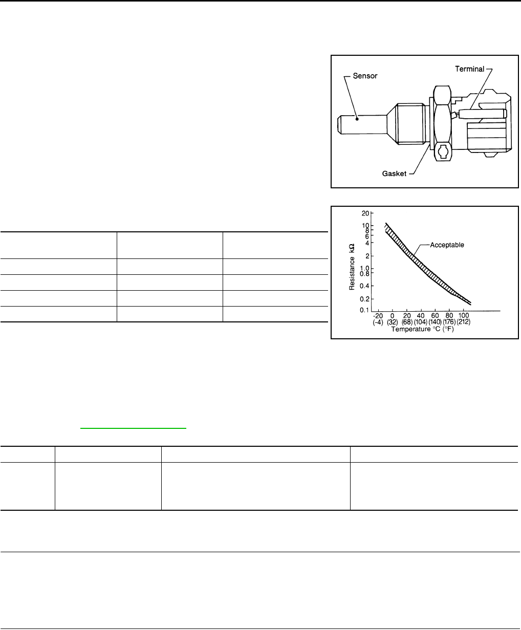
EC-162
< COMPONENT DIAGNOSIS > [FOR CALIFORNIA]
P0116 ECT SENSOR
P0116 ECT SENSOR
Description INFOID:0000000004507132
The engine coolant temperature sensor is used to detect the engine
coolant temperature. The sensor modifies a voltage signal from the
ECM. The modified signal returns to the ECM as the engine coolant
temperature input. The sensor uses a thermistor which is sensitive to
the change in temperature. The electrical resistance of the ther-
mistor decreases as temperature increases.
<Reference data>
*: These data are reference values and are measured between ECM terminals 46
(Engine coolant temperature sensor) and 52 (Sensor ground).
DTC Logic INFOID:0000000004507124
DTC DETECTION LOGIC
NOTE:
If DTC P0116 is displayed with P0117 or P0118, first perform the trouble diagnosis for DTC P0117,
P0118. Refer to EC-164, "DTC Logic".
DTC CONFIRMATION PROCEDURE
1.PRECONDITIONING
If DTC confirmation procedure has been previously conducted, always turn ignition switch OFF and wait at
least 10 seconds before conducting the next test.
>> GO TO 2.
2.PERFORM DTC CONFIRMATION PROCEDURE
1. Start engine and warm it up to normal operating temperature.
2. Rev engine up to 2,000 rpm for more than 10 minutes.
3. Move the vehicle to a cool place, then stop engine and turn ignition switch OFF.
4. Check resistance between “fuel level sensor unit and fuel pump” terminals 1 and 2.
5. Soak the vehicle until the resistance between “fuel level sensor unit and fuel pump” terminals 1 and 2
becomes 0.5 kΩ higher than the value measured before soaking.
CAUTION:
Never turn ignition switch ON during soaking.
SEF594K
Engine coolant temperature
[°C (°F)] Voltage* (V) Resistance (kΩ)
–10 (14) 4.4 7.0 - 11.4
20 (68) 3.5 2.37 - 2.63
50 (122) 2.2 0.68 - 1.00
90 (194) 0.9 0.236 - 0.260
SEF012P
DTC No. Trouble diagnosis name DTC detecting condition Possible cause
P0116 Engine coolant tempera-
ture sensor circuit range/
performance
Engine coolant temperature signal from engine
coolant temperature sensor does not fluctuate,
even when some time has passed after starting
the engine with pre-warming up condition.
• Harness or connectors
(High or low resistance in the circuit)
• Engine coolant temperature sensor
Revision: 2008 August 2009 Rogue
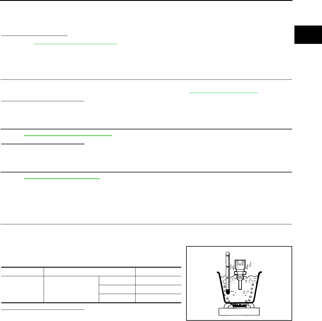
P0116 ECT SENSOR
EC-163
< COMPONENT DIAGNOSIS > [FOR CALIFORNIA]
C
D
E
F
G
H
I
J
K
L
M
A
EC
N
P
O
NOTE:
Soak time changes depending on ambient air temperature. It may take several hours.
6. Start engine and let it idle for 5 minutes.
7. Check 1st trip DTC.
Is 1st trip DTC detected?
YES >> EC-163, "Diagnosis Procedure".
NO >> INSPECTION END
Diagnosis Procedure INFOID:0000000004507125
1.CHECK GROUND CONNECTION
1. Turn ignition switch OFF.
2. Check ground connection E9. Refer to GROUND INSPECTION in GI-44, "Circuit Inspection".
Is the inspection result normal?
YES >> GO TO 2.
NO >> Repair or replace ground connection.
2.CHECK ENGINE COOLANT TEMPERATURE SENSOR
Refer to EC-163, "Component Inspection".
Is the inspection result normal?
YES >> GO TO 3.
NO >> Replace engine coolant temperature sensor.
3.CHECK INTERMITTENT INCIDENT
Refer to GI-41, "Intermittent Incident".
>> INSPECTION END
Component Inspection INFOID:0000000004507134
1.CHECK ENGINE COOLANT TEMPERATURE SENSOR
1. Turn ignition switch OFF.
2. Disconnect engine coolant temperature sensor harness connector.
3. Remove engine coolant temperature sensor.
4. Check resistance between engine coolant temperature sensor
terminals by heating with hot water as shown in the figure.
Is the inspection result normal?
YES >> INSPECTION END
NO >> Replace engine coolant temperature sensor.
Terminals Condition Resistance
1 and 2 Temperature [°C (°F)]
20 (68) 2.37 - 2.63 Ω
50 (122) 0.68 - 1.00 Ω
90 (194) 0.236 - 0.260 Ω
JMBIA0080ZZ
Revision: 2008 August 2009 Rogue

EC-164
< COMPONENT DIAGNOSIS > [FOR CALIFORNIA]
P0117, P0118 ECT SENSOR
P0117, P0118 ECT SENSOR
Description INFOID:0000000004493378
The engine coolant temperature sensor is used to detect the engine
coolant temperature. The sensor modifies a voltage signal from the
ECM. The modified signal returns to the ECM as the engine coolant
temperature input. The sensor uses a thermistor which is sensitive to
the change in temperature. The electrical resistance of the ther-
mistor decreases as temperature increases.
<Reference data>
*: These data are reference values and are measured between ECM terminals 46
(Engine coolant temperature sensor) and 52 (Sensor ground).
DTC Logic INFOID:0000000004493379
DTC DETECTION LOGIC
DTC CONFIRMATION PROCEDURE
1.PRECONDITIONING
If DTC CONFIRMATION PROCEDURE has been previously conducted, always turn ignition switch OFF and
wait at least 10 seconds before conducting the next test.
>> GO TO 2.
2.PERFORM DTC CONFIRMATION PROCEDURE
1. Turn ignition switch ON and wait at least 5 seconds.
2. Check DTC.
Is DTC detected?
YES >> Go to EC-164, "Diagnosis Procedure".
NO >> INSPECTION END
Diagnosis Procedure INFOID:0000000004493380
1.CHECK GROUND CONNECTION
1. Turn ignition switch OFF.
SEF594K
Engine coolant temperature
[°C (°F)] Voltage* (V) Resistance (kΩ)
–10 (14) 4.4 7.0 - 11.4
20 (68) 3.5 2.37 - 2.63
50 (122) 2.2 0.68 - 1.00
90 (194) 0.9 0.236 - 0.260
SEF012P
DTC No. Trouble Diagnosis Name DTC Detecting Condition Possible Cause
P0117 Engine coolant temperature
sensor circuit low input An excessively low voltage from the sensor is
sent to ECM. • Harness or connectors
(The sensor circuit is open or shorted.)
• Engine coolant temperature sensor
P0118 Engine coolant temperature
sensor circuit high input
An excessively high voltage from the sensor is
sent to ECM.
Revision: 2008 August 2009 Rogue

P0117, P0118 ECT SENSOR
EC-165
< COMPONENT DIAGNOSIS > [FOR CALIFORNIA]
C
D
E
F
G
H
I
J
K
L
M
A
EC
N
P
O
2. Check ground connection E21. Refer to Ground Inspection in GI-44, "Circuit Inspection".
Is the inspection result normal?
YES >> GO TO 2.
NO >> Repair or replace ground connection.
2.CHECK ECT SENSOR POWER SUPPLY CIRCUIT
1. Disconnect engine coolant temperature (ECT) sensor harness connector.
2. Turn ignition switch ON.
3. Check the voltage between ECT sensor harness connector and ground.
Is the inspection result normal?
YES >> GO TO 3.
NO >> Repair open circuit or short to ground or short to power in harness or connectors.
3.CHECK ECT SENSOR GROUND CIRCUIT FOR OPEN AND SHORT
1. Turn ignition switch OFF.
2. Disconnect ECM harness connector.
3. Check the continuity between ECT sensor harness connector and ECM harness connector.
4. Also check harness for short to ground and short to power.
Is the inspection result normal?
YES >> GO TO 4.
NO >> Repair open circuit or short to ground or short to power in harness or connectors.
4.CHECK ENGINE COOLANT TEMPERATURE SENSOR
Refer to EC-165, "Component Inspection".
Is the inspection result normal?
YES >> GO TO 5.
NO >> Replace engine coolant temperature sensor.
5.CHECK INTERMITTENT INCIDENT
Refer to GI-41, "Intermittent Incident".
>> INSPECTION END
Component Inspection INFOID:0000000004493381
1.CHECK ENGINE COOLANT TEMPERATURE SENSOR
1. Turn ignition switch OFF.
2. Disconnect engine coolant temperature sensor harness connector.
3. Remove engine coolant temperature sensor.
ECT sensor Ground Voltage
Connector Terminal
F80 1 Ground Approx. 5 V
ECT sensor ECM Continuity
Connector Terminal Connector Terminal
F80 2 F8 52 Existed
Revision: 2008 August 2009 Rogue

EC-166
< COMPONENT DIAGNOSIS > [FOR CALIFORNIA]
P0117, P0118 ECT SENSOR
4. Check resistance between engine coolant temperature sensor
terminals by heating with hot water as shown in the figure.
Is the inspection result normal?
YES >> INSPECTION END
NO >> Replace engine coolant temperature sensor.
Terminals Condition Resistance
1 and 2 Temperature [°C (°F)]
20 (68) 2.37 - 2.63 Ω
50 (122) 0.68 - 1.00 Ω
90 (194) 0.236 - 0.260 Ω
JMBIA0080ZZ
Revision: 2008 August 2009 Rogue

P0122, P0123 TP SENSOR
EC-167
< COMPONENT DIAGNOSIS > [FOR CALIFORNIA]
C
D
E
F
G
H
I
J
K
L
M
A
EC
N
P
O
P0122, P0123 TP SENSOR
Description INFOID:0000000004493382
Electric throttle control actuator consists of throttle control motor,
throttle position sensor, etc. The throttle position sensor responds to
the throttle valve movement.
The throttle position sensor has two sensors. These sensors are a
kind of potentiometer which transform the throttle valve position into
output voltage, and emit the voltage signals to the ECM. The ECM
judges the current opening angle of the throttle valve from these sig-
nals and controls the throttle valve opening angle in response to
driving conditions via the throttle control motor.
DTC Logic INFOID:0000000004493383
DTC DETECTION LOGIC
NOTE:
If DTC P0122 or P0123 is displayed with DTC P0643, first perform the trouble diagnosis for DTC P0643.
Refer to EC-336, "DTC Logic".
DTC CONFIRMATION PROCEDURE
1.PRECONDITIONING
If DTC CONFIRMATION PROCEDURE has been previously conducted, always turn ignition switch OFF and
wait at least 10 seconds before conducting the next test.
TESTING CONDITION:
Before performing the following procedure, confirm that battery voltage is more than 8V at idle.
>> GO TO 2.
2.PERFORM DTC CONFIRMATION PROCEDURE
1. Start engine and let it idle for 1 second.
2. Check DTC.
Is DTC detected?
YES >> Go to EC-167, "Diagnosis Procedure".
NO >> INSPECTION END
Diagnosis Procedure INFOID:0000000004493384
1.CHECK GROUND CONNECTION
1. Turn ignition switch OFF.
2. Check ground connection E21. Refer to Ground Inspection in GI-44, "Circuit Inspection".
Is the inspection result normal?
YES >> GO TO 2.
NO >> Repair or replace ground connection.
2.CHECK THROTTLE POSITION SENSOR 2 POWER SUPPLY CIRCUIT
1. Disconnect electric throttle control actuator harness connector.
2. Turn ignition switch ON.
PBIB0145E
DTC No. Trouble diagnosis name DTC detecting condition Possible cause
P0122 Throttle position sensor
2 circuit low input An excessively low voltage from the TP sensor
2 is sent to ECM. • Harness or connectors
(TP sensor 2 circuit is open or shorted.)
• Electric throttle control actuator
(TP sensor 2)
P0123 Throttle position sensor
2 circuit high input
An excessively high voltage from the TP sensor
2 is sent to ECM.
Revision: 2008 August 2009 Rogue

EC-168
< COMPONENT DIAGNOSIS > [FOR CALIFORNIA]
P0122, P0123 TP SENSOR
3. Check the voltage between electric throttle control actuator harness connector and ground.
Is the inspection result normal?
YES >> GO TO 3.
NO >> Repair open circuit or short to ground or short to power in harness or connectors.
3.CHECK THROTTLE POSITION SENSOR 2 GROUND CIRCUIT FOR OPEN AND SHORT
1. Turn ignition switch OFF.
2. Disconnect ECM harness connector.
3. Check the continuity between electric throttle control actuator harness connector and ECM harness con-
nector.
4. Also check harness for short to ground and short to power.
Is the inspection result normal?
YES >> GO TO 4.
NO >> Repair open circuit or short to ground or short to power in harness or connectors.
4.CHECK THROTTLE POSITION SENSOR 2 INPUT SIGNAL CIRCUIT FOR OPEN AND SHORT
1. Check the continuity between electric throttle control actuator harness connector and ECM harness con-
nector.
2. Also check harness for short to ground and short to power.
Is the inspection result normal?
YES >> GO TO 5.
NO >> Repair open circuit or short to ground or short to power in harness or connectors.
5.CHECK THROTTLE POSITION SENSOR
Refer to EC-169, "Component Inspection".
Is the inspection result normal?
YES >> GO TO 7.
NO >> GO TO 6.
6.REPLACE ELECTRIC THROTTLE CONTROL ACTUATOR
1. Replace electric throttle control actuator.
2. Perform EC-169, "Special Repair Requirement".
>> INSPECTION END
7.CHECK INTERMITTENT INCIDENT
Refer to GI-41, "Intermittent Incident".
>> INSPECTION END
Electric throttle control actuator Ground Voltage
Connector Terminal
F29 1 Ground Approx. 5 V
Electric throttle control actuator ECM Continuity
Connector Terminal Connector Terminal
F29 4 F8 36 Existed
Electric throttle control actuator ECM Continuity
Connector Terminal Connector Terminal
F29 3 F8 38 Existed
Revision: 2008 August 2009 Rogue
P0122, P0123 TP SENSOR
EC-169
< COMPONENT DIAGNOSIS > [FOR CALIFORNIA]
C
D
E
F
G
H
I
J
K
L
M
A
EC
N
P
O
Component Inspection INFOID:0000000004493385
1.CHECK THROTTLE POSITION SENSOR
1. Turn ignition switch OFF.
2. Reconnect all harness connectors disconnected.
3. Perform EC-27, "THROTTLE VALVE CLOSED POSITION LEARNING : Special Repair Requirement".
4. Turn ignition switch ON.
5. Set selector lever to the D position.
6. Check the voltage between ECM harness connector terminals.
Is the inspection result normal?
YES >> INSPECTION END
NO >> GO TO 2.
2.REPLACE ELECTRIC THROTTLE CONTROL ACTUATOR
1. Replace electric throttle control actuator.
2. Perform EC-169, "Special Repair Requirement".
>> INSPECTION END
Special Repair Requirement INFOID:0000000004493386
1.PERFORM THROTTLE VALVE CLOSED POSITION LEARNING
Refer to EC-27, "THROTTLE VALVE CLOSED POSITION LEARNING : Special Repair Requirement"
>> GO TO 2.
2.PERFORM IDLE AIR VOLUME LEARNING
Refer to EC-27, "IDLE AIR VOLUME LEARNING : Special Repair Requirement"
>> END
ECM
Condition Voltage +−
Connector Terminal Connector Terminal
F8
37
(TP sensor 1
signal) F8
36
(Sensor
ground) Accelerator pedal
Fully released More than 0.36 V
Fully depressed Less than 4.75 V
38
(TP sensor 2
signal)
Fully released Less than 4.75 V
Fully depressed More than 0.36 V
Revision: 2008 August 2009 Rogue
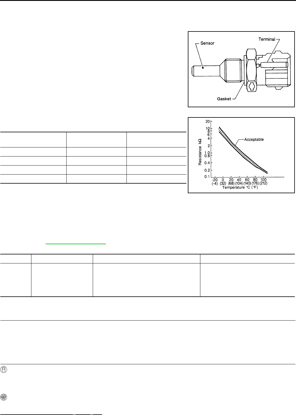
EC-170
< COMPONENT DIAGNOSIS > [FOR CALIFORNIA]
P0125 ECT SENSOR
P0125 ECT SENSOR
Description INFOID:0000000004507181
The engine coolant temperature sensor is used to detect the engine
coolant temperature. The sensor modifies a voltage signal from the
ECM. The modified signal returns to the ECM as the engine coolant
temperature input. The sensor uses a thermistor which is sensitive to
the change in temperature. The electrical resistance of the ther-
mistor decreases as temperature increases.
<Reference data>
*: These data are reference values and are measured between ECM terminals 46
(Engine coolant temperature sensor) and 52 (Sensor ground).
DTC Logic INFOID:0000000004493388
DTC DETECTION LOGIC
NOTE:
If DTC P0125 is displayed with P0117 or P0118, first perform the trouble diagnosis for DTC P0117 or
P0118. Refer to EC-164, "DTC Logic".
DTC CONFIRMATION PROCEDURE
1.PRECONDITIONING
If DTC CONFIRMATION PROCEDURE has been previously conducted, always turn ignition switch OFF and
wait at least 10 seconds before conducting the next test.
>> GO TO 2.
2.CHECK ENGINE COOLANT TEMPERATURE SENSOR FUNCTION
With CONSULT-III
1. Turn ignition switch ON.
2. Select “DATA MONITOR” mode with CONSULT-III.
3. Check that “COOLAN TEMP/S” indication is above 5°C (41°F).
With GST
Follow the procedure “With CONSULT-III” above.
Is the temperature above 5°C (41°F)?
SEF594K
Engine coolant temperature
[°C (°F)] Voltage* (V) Resistance (kΩ)
–10 (14) 4.4 7.0 - 11.4
20 (68) 3.5 2.37 - 2.63
50 (122) 2.2 0.68 - 1.00
90 (194) 0.9 0.236 - 0.260
SEF012P
DTC No. Trouble diagnosis name DTC detecting condition Possible cause
P0125
Insufficient engine coolant
temperature for closed
loop fuel control
• Voltage sent to ECM from the sensor is not
practical, even when some time has passed
after starting the engine.
• Engine coolant temperature is insufficient for
closed loop fuel control.
• Harness or connectors
(High resistance in the circuit)
• Engine coolant temperature sensor
•Thermostat
Revision: 2008 August 2009 Rogue

P0125 ECT SENSOR
EC-171
< COMPONENT DIAGNOSIS > [FOR CALIFORNIA]
C
D
E
F
G
H
I
J
K
L
M
A
EC
N
P
O
YES >> INSPECTION END
NO >> GO TO 3.
3.PERFORM DTC CONFIRMATION PROCEDURE
With CONSULT-III
1. Start engine and run it for 65 minutes at idle speed.
2. Check 1st tip DTC.
If “COOLAN TEMP/S” indication increases to more than 5°C (41°F) within 65 minutes, stop engine
because the test result will be OK.
CAUTION:
Never overheat engine.
With GST
Follow the procedure “With CONSULT-III” above.
Is 1st trip DTC detected?
YES >> EC-171, "Diagnosis Procedure"
NO >> INSPECTION END
Diagnosis Procedure INFOID:0000000004493389
1.CHECK GROUND CONNECTION
1. Turn ignition switch OFF.
2. Check ground connection E21. Refer to Ground Inspection in GI-44, "Circuit Inspection".
Is the inspection result normal?
YES >> GO TO 2.
NO >> Repair or replace ground connection.
2.CHECK ENGINE COOLANT TEMPERATURE SENSOR
Refer to EC-171, "Component Inspection".
Is the inspection result normal?
YES >> GO TO 3.
NO >> Replace engine coolant temperature sensor.
3.CHECK THERMOSTAT OPERATION
When the engine is cold [lower than 70°C (158°F)] condition, grasp lower radiator hose and confirm that the
engine coolant does not flow.
Is the inspection result normal?
YES >> GO TO 4.
NO >> Repair or replace thermostat. Refer to CO-25, "Removal and Installation".
4.CHECK INTERMITTENT INCIDENT
Refer to GI-41, "Intermittent Incident".
>> INSPECTION END
Component Inspection INFOID:0000000004507182
1.CHECK ENGINE COOLANT TEMPERATURE SENSOR
1. Turn ignition switch OFF.
2. Disconnect engine coolant temperature sensor harness connector.
3. Remove engine coolant temperature sensor.
Revision: 2008 August 2009 Rogue
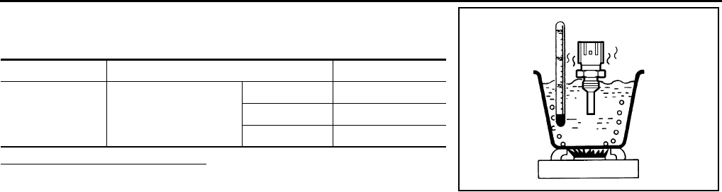
EC-172
< COMPONENT DIAGNOSIS > [FOR CALIFORNIA]
P0125 ECT SENSOR
4. Check resistance between engine coolant temperature sensor
terminals by heating with hot water as shown in the figure.
Is the inspection result normal?
YES >> INSPECTION END
NO >> Replace engine coolant temperature sensor.
Terminals Condition Resistance
1 and 2 Temperature [°C (°F)]
20 (68) 2.37 - 2.63 Ω
50 (122) 0.68 - 1.00 Ω
90 (194) 0.236 - 0.260 Ω
JMBIA0080ZZ
Revision: 2008 August 2009 Rogue

P0127 IAT SENSOR
EC-173
< COMPONENT DIAGNOSIS > [FOR CALIFORNIA]
C
D
E
F
G
H
I
J
K
L
M
A
EC
N
P
O
P0127 IAT SENSOR
Description INFOID:0000000004493391
The intake air temperature sensor is built-into the mass air flow sen-
sor (1). The sensor detects intake air temperature and transmits a
signal to the ECM.
The temperature sensing unit uses a thermistor which is sensitive to
the change in temperature. Electrical resistance of the thermistor
decreases in response to the rise in temperature.
<Reference data>
*: This data is reference value and is measured between ECM terminal 50 (Intake air
temperature sensor) and 58 (Sensor ground).
DTC Logic INFOID:0000000004493392
DTC DETECTION LOGIC
DTC CONFIRMATION PROCEDURE
1.PRECONDITIONING
If DTC CONFIRMATION PROCEDURE has been previously conducted, always turn ignition switch OFF and
wait at least 10 seconds before conducting the next test.
TESTING CONDITION:
This test may be conducted with the drive wheels lifted in the shop or by driving the vehicle. If a road
test is expected to be easier, it is unnecessary to lift the vehicle.
>> GO TO 2.
2.PERFORM DTC CONFIRMATION PROCEDURE
With CONSULT-III
1. Wait until engine coolant temperature is less than 90°C (194°F)
- Turn ignition switch ON.
- Select “DATA MONITOR” mode with CONSULT-III.
- Check the engine coolant temperature.
- If the engine coolant temperature is not less than 90°C (194°F), turn ignition switch OFF and cool down
engine.
NOTE:
Perform the following steps before engine coolant temperature is above 90°C (194°F).
PBIA9559J
Intake air temperature
[°C (°F)] Voltage* (V) Resistance (kΩ)
25 (77) 3.3 1.800 - 2.200
80 (176) 1.2 0.283 - 0.359
SEF012P
DTC No. Trouble diagnosis name DTC detecting condition Possible cause
P0127 Intake air temperature
too high
Rationally incorrect voltage from the sensor is
sent to ECM, compared with the voltage signal
from engine coolant temperature sensor.
• Harness or connectors
(The sensor circuit is open or shorted)
• Intake air temperature sensor
Revision: 2008 August 2009 Rogue
EC-174
< COMPONENT DIAGNOSIS > [FOR CALIFORNIA]
P0127 IAT SENSOR
2. Start engine.
3. Hold vehicle speed at more than 70 km/h (43 MPH) for 100 consecutive seconds.
CAUTION:
Always drive vehicle at a safe speed.
4. Check 1st trip DTC.
With GST
Follow the procedure “With CONSULT-III” above.
Is 1st trip DTC detected?
YES >> Go to EC-174, "Diagnosis Procedure".
NO >> INSPECTION END
Diagnosis Procedure INFOID:0000000004493393
1.CHECK GROUND CONNECTION
1. Turn ignition switch OFF.
2. Check ground connection E21. Refer to Ground Inspection in GI-44, "Circuit Inspection".
Is the inspection result normal?
YES >> GO TO 2.
NO >> Repair or replace ground connection.
2.CHECK INTAKE AIR TEMPERATURE SENSOR
Refer to EC-174, "Component Inspection".
Is the inspection result normal?
YES >> GO TO 3.
NO >> Replace mass air flow sensor (with intake air temperature sensor).
3.CHECK INTERMITTENT INCIDENT
Refer to GI-41, "Intermittent Incident".
>> INSPECTION END
Component Inspection INFOID:0000000004493394
1.CHECK INTAKE AIR TEMPERATURE SENSOR
1. Turn ignition switch OFF.
2. Disconnect mass air flow sensor harness connector.
3. Check resistance between mass air flow sensor terminals as follows.
Is the inspection result normal?
YES >> INSPECTION END
NO >> Replace mass air flow sensor (with intake air temperature sensor).
Terminals Condition Resistance (kΩ)
1 and 2 Intake air temperature [°C (°F)] 25 (77) 1.800 - 2.200
Revision: 2008 August 2009 Rogue

P0128 THERMOSTAT FUNCTION
EC-175
< COMPONENT DIAGNOSIS > [FOR CALIFORNIA]
C
D
E
F
G
H
I
J
K
L
M
A
EC
N
P
O
P0128 THERMOSTAT FUNCTION
DTC Logic INFOID:0000000004493395
DTC DETECTION LOGIC
NOTE:
If DTC P0128 is displayed with DTC PP0300, P0301, P0302, P0303 or P0304, first perform the trouble
diagnosis for DTC P0300, P0301, P0302, P0303, P0304. Refer to EC-248, "DTC Logic".
Engine coolant temperature has not risen enough to open the thermostat even though the engine has run long
enough.
This is due to a leak in the seal or the thermostat stuck being open.
DTC CONFIRMATION PROCEDURE
1.PRECONDITIONING
If DTC CONFIRMATION PROCEDURE has been previously conducted, always turn ignition switch OFF and
wait at least 10 seconds before conducting the next test.
TESTING CONDITION:
•For best results, perform at ambient temperature of –10°C (14°F) or higher.
•For best results, perform at engine coolant temperature of –10°C (14°F) to 56°C (133°F).
•Before performing the following procedure, do not add fuel.
>> GO TO 2.
2.PERFORM DTC CONFIRMATION PROCEDURE
With CONSULT-III
1. Turn A/C switch OFF.
2. Turn blower fan switch OFF.
3. Turn ignition switch ON.
4. Select “COOLAN TEMP/S” in “DATA MONITOR” mode with CONSULT-III.
5. Check the indication of “COOLAN TEMP/S”
If it is below 56°C (133°F), go to next step.
If it is above 56°C (133°F), cool down the engine to less than 56°C (133°F). Then go to next steps.
6. Start engine drive vehicle for 10 consecutive minutes under the following conditions.
CAUTION:
Always drive vehicle at a safe speed.
NOTE:
If “COOLAN TEMP/S” increases to more than 75°C (160°F) within 10 minutes, turn ignition switch
OFF because the test result will be OK.
7. Check 1st trip DTC.
With GST
Follow the procedure “With CONSULT-III” above.
Is 1st trip DTC detected?
YES >> Go to EC-175, "Diagnosis Procedure".
NO >> INSPECTION END
Diagnosis Procedure INFOID:0000000004493396
1.CHECK ENGINE COOLANT TEMPERATURE SENSOR
Refer to EC-176, "Component Inspection".
DTC No. Trouble diagnosis name DTC detecting condition Possible cause
P0128 Thermostat function
The engine coolant temperature does not
reach to specified temperature even though
the engine has run long enough.
•Thermostat
• Leakage from sealing portion of thermostat
• Engine coolant temperature sensor
VHCL SPEED SE More than 56 km/h (35 MPH)
Revision: 2008 August 2009 Rogue
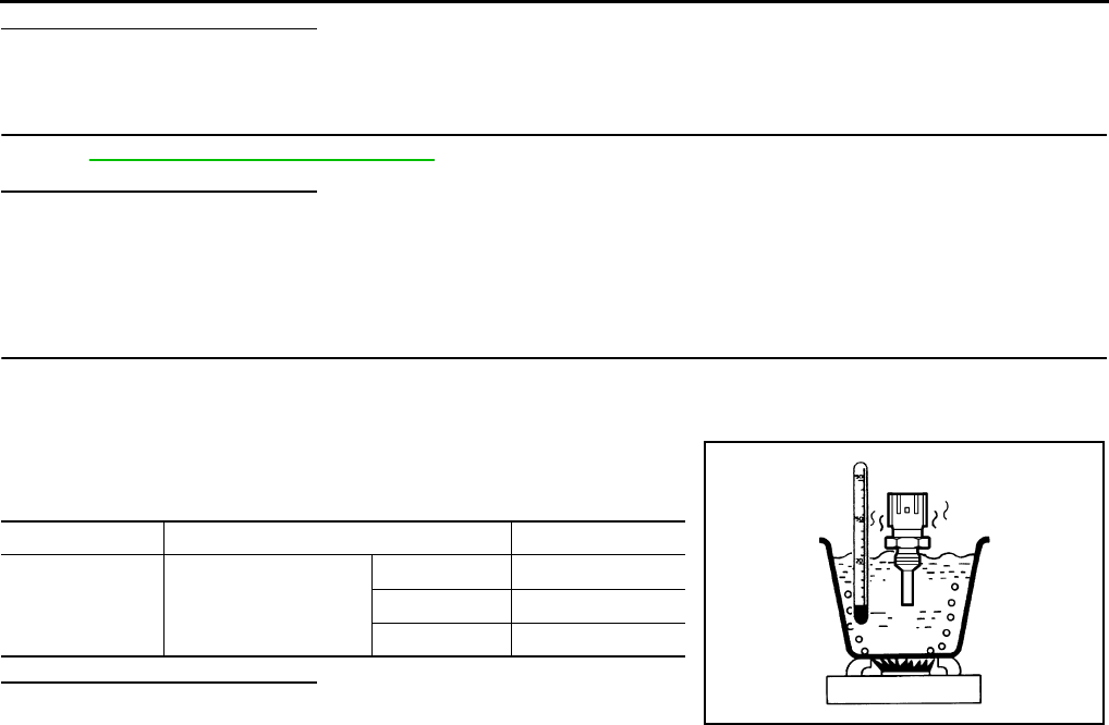
EC-176
< COMPONENT DIAGNOSIS > [FOR CALIFORNIA]
P0128 THERMOSTAT FUNCTION
Is the inspection result normal?
YES >> GO TO 2.
NO >> Replace engine coolant temperature sensor.
2.CHECK THERMOSTAT
Refer to CO-25, "Removal and Installation".
Is the inspection result normal?
YES >> INSPECTION END
NO >> Replace thermostat.
Component Inspection INFOID:0000000004493397
1.CHECK ENGINE COOLANT TEMPERATURE SENSOR
1. Turn ignition switch OFF.
2. Disconnect engine coolant temperature sensor harness connector.
3. Remove engine coolant temperature sensor.
4. Check resistance between engine coolant temperature sensor
terminals by heating with hot water as shown in the figure.
Is the inspection result normal?
YES >> INSPECTION END
NO >> Replace engine coolant temperature sensor.
Terminals Condition Resistance
1 and 2 Temperature [°C (°F)]
20 (68) 2.37 - 2.63 Ω
50 (122) 0.68 - 1.00 Ω
90 (194) 0.236 - 0.260 Ω
JMBIA0080ZZ
Revision: 2008 August 2009 Rogue

P0130 A/F SENSOR 1
EC-177
< COMPONENT DIAGNOSIS > [FOR CALIFORNIA]
C
D
E
F
G
H
I
J
K
L
M
A
EC
N
P
O
P0130 A/F SENSOR 1
Description INFOID:0000000004493398
The air fuel ratio (A/F) sensor 1 is a planar one-cell limit current sen-
sor. The sensor element of the A/F sensor 1 is composed an elec-
trode layer, which transports ions. It has a heater in the element.
The sensor is capable of precise measurement = 1, but also in the
lean and rich range. Together with its control electronics, the sensor
outputs a clear, continuous signal throughout a wide range.
The exhaust gas components diffuse through the diffusion layer at
the sensor cell. An electrode layer is applied voltage, and this current
relative oxygen density in lean. Also this current relative hydrocar-
bon density in rich.
Therefore, the A/F sensor 1 is able to indicate air fuel ratio by this
electrode layer of current. In addition, a heater is integrated in the
sensor to ensure the required operating temperature of approxi-
mately 800°C (1,472°F).
DTC Logic INFOID:0000000004493399
DTC DETECTION LOGIC
To judge malfunctions, the diagnosis checks that the A/F signal computed by ECM from the A/F sensor 1 sig-
nal fluctuates according to fuel feedback control.
DTC CONFIRMATION PROCEDURE
1.PRECONDITIONING
If DTC CONFIRMATION PROCEDURE has been previously conducted, always turn ignition switch OFF and
wait at least 10 seconds before conducting the next test.
TESTING CONDITION:
Before performing the following procedure, confirm that battery voltage is more than 11V at idle.
>> GO TO 2.
2.PERFORM DTC CONFIRMATION PROCEDURE FOR MALFUNCTION A
1. Start engine and warm it up to normal operating temperature.
2. Let it idle for 2 minutes.
3. Check 1st trip DTC.
Is 1st trip DTC detected?
YES >> Go to EC-179, "Diagnosis Procedure".
NO-1 >> With CONSULT-III: GO TO 3.
NO-2 >> Without CONSULT-III: GO TO 7.
JMBIA0112GB
PBIB3354E
DTC No. Trouble diagnosis name DTC detecting condition Possible Cause
P0130 Air fuel ratio (A/F) sensor 1
circuit
A)
The A/F signal computed by ECM from the A/F
sensor 1 signal is constantly in a range other
than approx. 2.2V.
• Harness or connectors
(The A/F sensor 1 circuit is open
or shorted.)
• A/F sensor 1
B) The A/F signal computed by ECM from the A/F
sensor 1 signal is constantly approx. 2.2V.
Revision: 2008 August 2009 Rogue

EC-178
< COMPONENT DIAGNOSIS > [FOR CALIFORNIA]
P0130 A/F SENSOR 1
3.CHECK AIR FUEL RATIO (A/F) SENSOR 1 FUNCTION
1. Select “A/F SEN1 (B1)” in “DATA MONITOR” mode with CONSULT-III.
2. Check “A/F SEN1 (B1)” indication.
Does the indication fluctuate around 2.2 V?
YES >> GO TO 4.
NO >> Go to EC-179, "Diagnosis Procedure".
4.PERFORM DTC CONFIRMATION PROCEDURE FOR MALFUNCTION B-I
1. Select “A/F SEN1 (B1) P1276” of “A/F SEN1” in “DTC WORK SUPPORT” mode with CONSULT-III.
2. Touch “START”.
3. When the following conditions are met, “TESTING” will be displayed on the CONSULT-III screen.
If “TESTING” is not displayed after 20 seconds, retry from step 2.
CAUTION:
Always drive vehicle at a safe speed.
Is “TESTING” displayed on CONSULT-III screen?
YES >> GO TO 5.
NO >> Check A/F sensor 1 function again. GO TO 3.
5.PERFORM DTC CONFIRMATION PROCEDURE FOR MALFUNCTION B-II
Release accelerator pedal fully.
NOTE:
Never apply brake when releasing the accelerator pedal.
Which does “TESTING” change to?
COMPLETED>>GO TO 6.
OUT OF CONDITION>>Retry DTC CONFIRMATION PROCEDURE. GO TO 4.
6.PERFORM DTC CONFIRMATION PROCEDURE FOR MALFUNCTION B-III
Touch “SELF-DIAG RESULT”
Which is displayed on CONSULT-III screen?
OK >> INSPECTION END
NG >> Go to EC-179, "Diagnosis Procedure".
7.PERFORM COMPONENT FUNCTION CHECK FOR MALFUNCTION B
Perform Component Function Check. Refer to EC-178, "Component Function Check".
NOTE:
Use component function check to check the overall function of the A/F sensor 1 circuit. During this check, a
1st trip DTC might not be confirmed.
Is the inspection result normal?
YES >> INSPECTION END
NO >> Go to EC-179, "Diagnosis Procedure".
Component Function Check INFOID:0000000004493400
1.PERFORM COMPONENT FUNCTION CHECK
With GST
1. Start engine and warm it up to normal operating temperature.
2. Drive the vehicle at a speed of 80 km/h (50 MPH) for a few minutes in the suitable gear position.
3. Shift the selector lever to the D position, then release the accelerator pedal fully until the vehicle speed
decreases to 50 km/h (31 MPH).
CAUTION:
ENG SPEED 1,000 - 3,200 rpm
VHCL SPEED SE More than 64 km/h (40 mph)
B/FUEL SCHDL 1.0 - 11.5 msec
Selector lever D position
Revision: 2008 August 2009 Rogue

P0130 A/F SENSOR 1
EC-179
< COMPONENT DIAGNOSIS > [FOR CALIFORNIA]
C
D
E
F
G
H
I
J
K
L
M
A
EC
N
P
O
Always drive vehicle at a safe speed.
NOTE:
Never apply brake when releasing the accelerator pedal.
4. Repeat steps 2 and 3 for five times.
5. Stop the vehicle and turn ignition switch OFF.
6. Wait at least 10 seconds and restart engine.
7. Repeat steps 2 and 3 for five times.
8. Stop the vehicle and connect GST to the vehicle.
9. Check 1st trip DTC.
Is 1st trip DTC detected?
YES >> Go to EC-179, "Diagnosis Procedure".
NO >> INSPECTION END
Diagnosis Procedure INFOID:0000000004493401
1.CHECK GROUND CONNECTION
1. Turn ignition switch OFF.
2. Check ground connection E21. Refer to Ground Inspection in GI-44, "Circuit Inspection".
Is the inspection result normal?
YES >> GO TO 2.
NO >> Repair or replace ground connection.
2.CHECK AIR FUEL RATIO (A/F) SENSOR 1 POWER SUPPLY CIRCUIT
1. Disconnect A/F sensor 1 harness connector.
2. Turn ignition switch ON.
3. Check the voltage between A/F sensor 1 harness connector and ground.
Is the inspection result normal?
YES >> GO TO 4.
NO >> GO TO 3.
3.DETECT MALFUNCTIONING PART
Check the following.
• Harness connectors E6, F123
• IPDM E/R harness connector E14
• 15A fuse (No. 63)
• Harness for open or short between A/F sensor 1 and fuse
>> Repair or replace harness or connectors.
4.CHECK A/F SENSOR 1 INPUT SIGNAL CIRCUIT FOR OPEN AND SHORT
1. Turn ignition switch OFF.
2. Disconnect ECM harness connector.
3. Check the continuity between A/F sensor 1 harness connector and ECM harness connector.
4. Check the continuity between A/F sensor 1 harness connector or ECM harness connector and ground.
A/F sensor 1 Ground Voltage
Connector Terminal
F28 4 Ground Battery voltage
A/F sensor 1 ECM Continuity
Connector Terminal Connector Terminal
F28 1F8 45 Existed
249
Revision: 2008 August 2009 Rogue

EC-180
< COMPONENT DIAGNOSIS > [FOR CALIFORNIA]
P0130 A/F SENSOR 1
5. Also check harness for short to power.
Is the inspection result normal?
YES >> GO TO 5.
NO >> Repair open circuit or short to ground or short to power in harness or connectors.
5.CHECK INTERMITTENT INCIDENT
Perform GI-41, "Intermittent Incident".
Is the inspection result normal?
YES >> GO TO 6.
NO >> Repair or replace.
6.REPLACE AIR FUEL RATIO (A/F) SENSOR 1
Replace air fuel ratio (A/F) sensor 1.
CAUTION:
• Discard any A/F sensor which has been dropped from a height of more than 0.5 m (19.7 in) onto a
hard surface such as a concrete floor; use a new one.
• Before installing new A/F sensor, clean exhaust system threads using oxygen sensor thread cleaner
[commercial service tool (J-43897-18 or J-43897-12)] and approved anti-seize lubricant (commercial
service tool).
>> INSPECTION END
A/F sensor 1 ECM Ground Continuity
Connector Terminal Connector Terminal
F28 1F8 45 Ground Not existed
249
Revision: 2008 August 2009 Rogue

P0131 A/F SENSOR 1
EC-181
< COMPONENT DIAGNOSIS > [FOR CALIFORNIA]
C
D
E
F
G
H
I
J
K
L
M
A
EC
N
P
O
P0131 A/F SENSOR 1
Description INFOID:0000000004493402
The air fuel ratio (A/F) sensor 1 is a planar one-cell limit current sen-
sor. The sensor element of the A/F sensor 1 is composed an elec-
trode layer, which transports ions. It has a heater in the element.
The sensor is capable of precise measurement = 1, but also in the
lean and rich range. Together with its control electronics, the sensor
outputs a clear, continuous signal throughout a wide range.
The exhaust gas components diffuse through the diffusion layer at
the sensor cell. An electrode layer is applied voltage, and this current
relative oxygen density in lean. Also this current relative hydrocar-
bon density in rich.
Therefore, the A/F sensor 1 is able to indicate air fuel ratio by this
electrode layer of current. In addition, a heater is integrated in the
sensor to ensure the required operating temperature of approxi-
mately 800°C (1,472°F).
DTC Logic INFOID:0000000004493403
DTC DETECTION LOGIC
To judge the malfunction, the diagnosis checks that the A/F signal computed by ECM from the A/F sensor 1
signal is not inordinately low.
DTC CONFIRMATION PROCEDURE
1.PRECONDITIONING
If DTC CONFIRMATION PROCEDURE has been previously conducted, always turn ignition switch OFF and
wait at least 10 seconds before conducting the next test.
TESTING CONDITION:
Before performing the following procedure, confirm that battery voltage is more than 10.5V at idle.
>> GO TO 2.
2.CHECK A/F SENSOR FUNCTION
With CONSULT-III
1. Start engine and warm it up to normal operating temperature.
2. Select “A/F SEN1 (B1)” in “DATA MONITOR” mode with CONSULT-III.
3. Check “A/F SEN1 (B1)” indication.
With GST
Follow the procedure “With CONSULT-III” above.
Is the indication constantly approx. 0V?
YES >> Go to EC-182, "Diagnosis Procedure".
JMBIA0112GB
PBIB3354E
DTC No. Trouble diagnosis name DTC detecting condition Possible Cause
P0131 Air fuel ratio (A/F) sensor 1
circuit low voltage
• The A/F signal computed by ECM from the A/
F sensor 1 signal is constantly approx. 0V.
• Harness or connectors
(The A/F sensor 1 circuit is open or
shorted.)
• A/F sensor 1
Revision: 2008 August 2009 Rogue

EC-182
< COMPONENT DIAGNOSIS > [FOR CALIFORNIA]
P0131 A/F SENSOR 1
NO >> GO TO 3.
3.PERFORM DTC CONFIRMATION PROCEDURE
With CONSULT-III
1. Turn ignition switch OFF, wait at least 10 seconds and then restart engine.
2. Drive and accelerate vehicle to more than 40 km/h (25 MPH) within 20 seconds after restarting engine.
CAUTION:
Always drive vehicle at a safe speed.
3. Maintain the following conditions for approximately 20 consecutive seconds.
NOTE:
•Keep the accelerator pedal as steady as possible during the cruising.
•If this procedure is not completed within 1 minute after restarting engine at step 1, return to step
1.
4. Check 1st trip DTC.
With GST
Follow the procedure “With CONSULT-III” above.
Is 1st trip DTC detected?
YES >> Go to EC-182, "Diagnosis Procedure".
NO >> INSPECTION END
Diagnosis Procedure INFOID:0000000004493404
1.CHECK GROUND CONNECTION
1. Turn ignition switch OFF.
2. Check ground connection E21. Refer to Ground Inspection in GI-44, "Circuit Inspection".
Is the inspection result normal?
YES >> GO TO 2.
NO >> Repair or replace ground connection.
2.CHECK AIR FUEL RATIO (A/F) SENSOR 1 POWER SUPPLY CIRCUIT
1. Disconnect A/F sensor 1 harness connector.
2. Turn ignition switch ON.
3. Check the voltage between A/F sensor 1 harness connector and ground.
Is the inspection result normal?
YES >> GO TO 4.
NO >> GO TO 3.
3.DETECT MALFUNCTIONING PART
Check the following.
• Harness connectors E6, F123
• IPDM E/R harness connector E14
• 15A fuse (No. 63)
• Harness for open or short between A/F sensor 1 and fuse
>> Repair or replace harness or connectors.
ENG SPEED 1,000 - 3,200 rpm
VHCL SPEED SE More than 40 km/h (25 mph)
B/FUEL SCHDL 1.5 - 9.0 msec
Selector lever Suitable position
A/F sensor 1 Ground Voltage
Connector Terminal
F28 4 Ground Battery voltage
Revision: 2008 August 2009 Rogue

P0131 A/F SENSOR 1
EC-183
< COMPONENT DIAGNOSIS > [FOR CALIFORNIA]
C
D
E
F
G
H
I
J
K
L
M
A
EC
N
P
O
4.CHECK A/F SENSOR 1 INPUT SIGNAL CIRCUIT FOR OPEN AND SHORT
1. Turn ignition switch OFF.
2. Disconnect ECM harness connector.
3. Check the continuity between A/F sensor 1 harness connector and ECM harness connector.
4. Check the continuity between A/F sensor 1 harness connector or ECM harness connector and ground.
5. Also check harness for short to power.
Is the inspection result normal?
YES >> GO TO 5.
NO >> Repair open circuit or short to ground or short to power in harness or connectors.
5.CHECK INTERMITTENT INCIDENT
Perform GI-41, "Intermittent Incident".
Is the inspection result normal?
YES >> GO TO 6.
NO >> Repair or replace.
6.REPLACE AIR FUEL RATIO (A/F) SENSOR 1
Replace air fuel ratio (A/F) sensor 1.
CAUTION:
• Discard any A/F sensor which has been dropped from a height of more than 0.5 m (19.7 in) onto a
hard surface such as a concrete floor; use a new one.
• Before installing new A/F sensor, clean exhaust system threads using oxygen sensor thread cleaner
[commercial service tool (J-43897-18 or J-43897-12)] and approved anti-seize lubricant (commercial
service tool).
>> INSPECTION END
A/F sensor 1 ECM Continuity
Connector Terminal Connector Terminal
F28 1F8 45 Existed
249
A/F sensor 1 ECM Ground Continuity
Connector Terminal Connector Terminal
F28 1F8 45 Ground Not existed
249
Revision: 2008 August 2009 Rogue
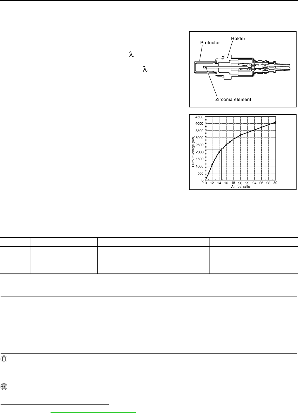
EC-184
< COMPONENT DIAGNOSIS > [FOR CALIFORNIA]
P0132 A/F SENSOR 1
P0132 A/F SENSOR 1
Description INFOID:0000000004493405
The air fuel ratio (A/F) sensor 1 is a planar one-cell limit current sen-
sor. The sensor element of the A/F sensor 1 is composed an elec-
trode layer, which transports ions. It has a heater in the element.
The sensor is capable of precise measurement = 1, but also in the
lean and rich range. Together with its control electronics, the sensor
outputs a clear, continuous signal throughout a wide range.
The exhaust gas components diffuse through the diffusion layer at
the sensor cell. An electrode layer is applied voltage, and this current
relative oxygen density in lean. Also this current relative hydrocar-
bon density in rich.
Therefore, the A/F sensor 1 is able to indicate air fuel ratio by this
electrode layer of current. In addition, a heater is integrated in the
sensor to ensure the required operating temperature of approxi-
mately 800°C (1,472°F).
DTC Logic INFOID:0000000004493406
DTC DETECTION LOGIC
To judge the malfunction, the diagnosis checks that the A/F signal computed by ECM from the A/F sensor 1
signal is not inordinately high.
DTC CONFIRMATION PROCEDURE
1.PRECONDITIONING
If DTC CONFIRMATION PROCEDURE has been previously conducted, always turn ignition switch OFF and
wait at least 10 seconds before conducting the next test.
TESTING CONDITION:
Before performing the following procedure, confirm that battery voltage is more than 10.5V at idle.
>> GO TO 2.
2.CHECK A/F SENSOR FUNCTION
With CONSULT-III
1. Start engine and warm it up to normal operating temperature.
2. Select “A/F SEN1 (B1)” in “DATA MONITOR” mode with CONSULT-III.
3. Check “A/F SEN1 (B1)” indication.
With GST
Follow the procedure “With CONSULT-III” above.
Is the indication constantly approx. 5 V?
YES >> Go to EC-185, "Diagnosis Procedure".
JMBIA0112GB
PBIB3354E
DTC No. Trouble diagnosis name DTC detecting condition Possible Cause
P0132 Air fuel ratio (A/F) sensor 1
circuit high voltage
• The A/F signal computed by ECM from the A/F
sensor 1 signal is constantly approx. 5V.
• Harness or connectors
(The A/F sensor 1 circuit is open or
shorted.)
• A/F sensor 1
Revision: 2008 August 2009 Rogue
P0132 A/F SENSOR 1
EC-185
< COMPONENT DIAGNOSIS > [FOR CALIFORNIA]
C
D
E
F
G
H
I
J
K
L
M
A
EC
N
P
O
NO >> GO TO 3.
3.PERFORM DTC CONFIRMATION PROCEDURE
With CONSULT-III
1. Turn ignition switch OFF, wait at least 10 seconds and then restart engine.
2. Drive and accelerate vehicle to more than 40 km/h (25 MPH) within 20 seconds after restarting engine.
CAUTION:
Always drive vehicle at a safe speed.
3. Maintain the following conditions for approximately 20 consecutive seconds.
NOTE:
•Keep the accelerator pedal as steady as possible during the cruising.
•If this procedure is not completed within 1 minute after restarting engine at step 1, return to step
1.
4. Check 1st trip DTC.
With GST
Follow the procedure “With CONSULT-III” above.
Is 1st trip DTC detected?
YES >> Go to EC-185, "Diagnosis Procedure".
NO >> INSPECTION END
Diagnosis Procedure INFOID:0000000004493407
1.CHECK GROUND CONNECTION
1. Turn ignition switch OFF.
2. Check ground connection E21. Refer to Ground Inspection in GI-44, "Circuit Inspection".
Is the inspection result normal?
YES >> GO TO 2.
NO >> Repair or replace ground connection.
2.CHECK AIR FUEL RATIO (A/F) SENSOR 1 POWER SUPPLY CIRCUIT
1. Disconnect A/F sensor 1 harness connector.
2. Turn ignition switch ON.
3. Check the voltage between A/F sensor 1 harness connector and ground.
Is the inspection result normal?
YES >> GO TO 4.
NO >> GO TO 3.
3.DETECT MALFUNCTIONING PART
Check the following.
• Harness connectors E6, F123
• IPDM E/R harness connector E14
• 15A fuse (No. 63)
• Harness for open or short between A/F sensor 1 and fuse
>> Repair or replace harness or connectors.
ENG SPEED 1,000 - 3,200 rpm
VHCL SPEED SE More than 40 km/h (25 mph)
B/FUEL SCHDL 1.5 - 9.0 msec
Selector lever Suitable position
A/F sensor 1 Ground Voltage
Connector Terminal
F28 4 Ground Battery voltage
Revision: 2008 August 2009 Rogue

EC-186
< COMPONENT DIAGNOSIS > [FOR CALIFORNIA]
P0132 A/F SENSOR 1
4.CHECK A/F SENSOR 1 INPUT SIGNAL CIRCUIT FOR OPEN AND SHORT
1. Turn ignition switch OFF.
2. Disconnect ECM harness connector.
3. Check the continuity between A/F sensor 1 harness connector and ECM harness connector.
4. Check the continuity between A/F sensor 1 harness connector or ECM harness connector and ground.
5. Also check harness for short to power.
Is the inspection result normal?
YES >> GO TO 5.
NO >> Repair open circuit or short to ground or short to power in harness or connectors.
5.CHECK INTERMITTENT INCIDENT
Perform GI-41, "Intermittent Incident".
Is the inspection result normal?
YES >> GO TO 6.
NO >> Repair or replace.
6.REPLACE AIR FUEL RATIO (A/F) SENSOR 1
Replace air fuel ratio (A/F) sensor 1.
CAUTION:
• Discard any A/F sensor which has been dropped from a height of more than 0.5 m (19.7 in) onto a
hard surface such as a concrete floor; use a new one.
• Before installing new A/F sensor, clean exhaust system threads using oxygen sensor thread cleaner
[commercial service tool (J-43897-18 or J-43897-12)] and approved anti-seize lubricant (commercial
service tool).
>> INSPECTION END
A/F sensor 1 ECM Continuity
Connector Terminal Connector Terminal
F28 1F8 45 Existed
249
A/F sensor 1 ECM Ground Continuity
Connector Terminal Connector Terminal
F28 1F8 45 Ground Not existed
249
Revision: 2008 August 2009 Rogue

P0133 A/F SENSOR 1
EC-187
< COMPONENT DIAGNOSIS > [FOR CALIFORNIA]
C
D
E
F
G
H
I
J
K
L
M
A
EC
N
P
O
P0133 A/F SENSOR 1
Description INFOID:0000000004493408
The air fuel ratio (A/F) sensor 1 is a planar one-cell limit current sen-
sor. The sensor element of the A/F sensor 1 is composed an elec-
trode layer, which transports ions. It has a heater in the element.
The sensor is capable of precise measurement = 1, but also in the
lean and rich range. Together with its control electronics, the sensor
outputs a clear, continuous signal throughout a wide range.
The exhaust gas components diffuse through the diffusion layer at
the sensor cell. An electrode layer is applied voltage, and this current
relative oxygen density in lean. Also this current relative hydrocar-
bon density in rich.
Therefore, the A/F sensor 1 is able to indicate air fuel ratio by this
electrode layer of current. In addition, a heater is integrated in the
sensor to ensure the required operating temperature of approxi-
mately 800°C (1,472°F).
DTC Logic INFOID:0000000004493409
DTC DETECTION LOGIC
To judge the malfunction of A/F sensor 1, this diagnosis measures response time of the A/F signal computed
by ECM from the A/F sensor 1 signal. The time is compensated by engine operating (speed and load), fuel
feedback control constant, and the A/F sensor 1 temperature index. Judgment is based on whether the com-
pensated time (the A/F signal cycling time index) is inordinately long or not.
DTC CONFIRMATION PROCEDURE
1.PRECONDITIONING
If DTC CONFIRMATION PROCEDURE has been previously conducted, always turn ignition switch OFF and
wait at least 10 seconds before conducting the next test.
TESTING CONDITION:
Before performing the following procedure, confirm that battery voltage is more than 11V at idle.
Do you have CONSULT-III?
YES >> GO TO 2.
NO >> GO TO 5.
JMBIA0112GB
PBIB3354E
DTC No. Trouble diagnosis name DTC detecting condition Possible Cause
P0133 Air fuel ratio (A/F) sensor 1
circuit slow response
• The response of the A/F signal computed by
ECM from A/F sensor 1 signal takes more than
the specified time.
• Harness or connectors
(The A/F sensor 1 circuit is open or
shorted.)
• A/F sensor 1
• A/F sensor 1 heater
• Fuel pressure
• Fuel injector
• Intake air leaks
• Exhaust gas leaks
•PCV
• Mass air flow sensor
Revision: 2008 August 2009 Rogue

EC-188
< COMPONENT DIAGNOSIS > [FOR CALIFORNIA]
P0133 A/F SENSOR 1
2.PERFORM DTC CONFIRMATION PROCEDURE-I
With CONSULT-III
1. Start engine and warm it up to normal operating temperature.
2. Turn ignition switch OFF and wait at least 10 seconds.
3. Start engine and keep the engine speed between 3,500 and 4,000 rpm for at least 1minute under no load.
4. Let engine idle for 1 minute.
5. Select “A/F SEN1(B1) P1278/P1279” of “A/F SEN1” in “DTC WORK SUPPORT” mode with CONSULT-III.
6. Touch “START”.
Is “COMPLETED” displayed on COUSULT-III?
YES >> GO TO 3
NO >> GO TO 4.
3.PERFORM DTC CONFIRMATION PROCEDURE-II
Touch “SELF-DIAG RESULT”.
Which is displayed on CONSULT-III?
OK >> INSPECTION END
NG >> Go to EC-189, "Diagnosis Procedure".
4.PERFORM DTC CONFIRMATION PROCEDURE
1. After perform the following procedure, “TESTING” will be displayed on the CONSULT-III screen.
- Increase the engine speed up to between 4,000 and 5,000 rpm and maintain that speed for 10 seconds.
- Fully release accelerator pedal and then let engine idle for approximately 10 seconds.
If “TESTING” is not displayed after 10 seconds, refer to EC-116, "Component Function Check".
2. Wait for approximately 20 seconds idle at under the condition that “TESTING” is displayed on the CON-
SULT-III screen.
3. Check that “TESTING” changes to “COMPLETED”.
If “TESTING” changed to “OUT OF CONDITION”, refer to EC-116, "Component Function Check".
4. Touch “SELF-DIAG RESULT”.
Which is displayed on CONSULT-III?
OK >> INSPECTION END
NG >> Go to EC-189, "Diagnosis Procedure".
5.CHECK AIR-FUEL RATIO SELF-LEARNING VALUE
With GST
1. Start engine and warm it up to normal operating temperature.
2. Select Service $01 with GST.
3. Calculate the total value of “Short-term fuel trim” and “Long-term fuel trim” indications.
Is the total percentage within ±15%?
YES >> GO TO 7.
NO >> GO TO 6.
6.DETECT MALFUNCTIONING PART
Check the following.
• Intake air leaks
• Exhaust gas leaks
• Incorrect fuel pressure
• Lack of fuel
• Fuel injector
• Incorrect PCV hose connection
• PCV valve
• Mass air flow sensor
>> Repair or replace malfunctioning part.
7.PERFORM DTC CONFIRMATION PROCEDURE
1. Turn ignition switch OFF and wait at least 10 seconds.
2. Start engine and keep the engine speed between 3,500 and 4,000 rpm for at least 1minute under no load.
Revision: 2008 August 2009 Rogue

P0133 A/F SENSOR 1
EC-189
< COMPONENT DIAGNOSIS > [FOR CALIFORNIA]
C
D
E
F
G
H
I
J
K
L
M
A
EC
N
P
O
3. Let engine idle for 1 minute.
4. Increase the engine speed up to between 4,000 and 5,000 rpm and maintain that speed for 10 seconds.
5. Fully release accelerator pedal and then let engine idle for approximately 1 minute.
6. Check 1st trip DTC detected?.
Is 1st trip DTC detected?
YES >> Go to EC-189, "Diagnosis Procedure".
NO >> INSPECTION END
Diagnosis Procedure INFOID:0000000004493410
1.CHECK GROUND CONNECTION
1. Turn ignition switch OFF.
2. Check ground connection E21. Refer to Ground Inspection in GI-44, "Circuit Inspection".
Is the inspection result normal?
YES >> GO TO 2.
NO >> Repair or replace ground connection.
2.RETIGHTEN A/F SENSOR 1
Loosen and retighten the A/F sensor 1. Refer to EM-32, "Removal and Installation".
>> GO TO 3.
3.CHECK EXHAUST GAS LEAK
1. Start engine and run it at idle.
2. Listen for an exhaust gas leak before three way catalyst (manifold).
Is exhaust gas leak detected?
YES >> Repair or replace.
NO >> GO TO 4.
4.CHECK FOR INTAKE AIR LEAK
Listen for an intake air leak after the mass air flow sensor.
Is intake air leak detected?
YES >> Repair or replace.
NO >> GO TO 5.
5.CLEAR THE MIXTURE RATIO SELF-LEARNING VALUE
1. Clear the mixture ratio self-learning value. Refer to EC-29, "MIXTURE RATIO SELF-LEARNING VALUE
CLEAR : Special Repair Requirement".
2. Run engine for at least 10 minutes at idle speed.
Is the 1st trip DTC P0171 or P172 detected? Is it difficult to start engine?
YES >> Perform trouble diagnosis for DTC P0171 or P0172. Refer to EC-231, "DTC Logic" or EC-235,
"DTC Logic".
NO >> GO TO 6.
6.CHECK AIR FUEL RATIO (A/F) SENSOR 1 POWER SUPPLY CIRCUIT
1. Disconnect A/F sensor 1 harness connector.
JMBIA0163G
B
Revision: 2008 August 2009 Rogue

EC-190
< COMPONENT DIAGNOSIS > [FOR CALIFORNIA]
P0133 A/F SENSOR 1
2. Turn ignition switch ON.
3. Check the voltage between A/F sensor 1 harness connector and ground.
Is the inspection result normal?
YES >> GO TO 8.
NO >> GO TO 7.
7.DETECT MALFUNCTIONING PART
Check the following.
• Harness connectors E6, F123
• IPDM E/R harness connector E14
• 15A fuse (No. 63)
• Harness for open or short between A/F sensor 1 and fuse
>> Repair or replace harness or connectors.
8.CHECK A/F SENSOR 1 INPUT SIGNAL CIRCUIT FOR OPEN AND SHORT
1. Turn ignition switch OFF.
2. Disconnect ECM harness connector.
3. Check the continuity between A/F sensor 1 harness connector and ECM harness connector.
4. Check the continuity between A/F sensor 1 harness connector or ECM harness connector and ground.
5. Also check harness for short to power.
Is the inspection result normal?
YES >> GO TO 9.
NO >> Repair open circuit or short to ground or short to power in harness or connectors.
9.CHECK AIR FUEL RATIO (A/F) SENSOR 1 HEATER
Refer to EC-137, "Component Inspection".
Is the inspection result normal?
YES >> GO TO 10.
NO >> GO TO 13.
10.CHECK MASS AIR FLOW SENSOR
Check mass air flow sensor.
Refer to EC-151, "Component Inspection".
Is the inspection result normal?
YES >> GO TO 11.
NO >> Replace mass air flow sensor.
11.CHECK PCV VALVE
A/F sensor 1 Ground Voltage
Connector Terminal
F28 4 Ground Battery voltage
A/F sensor 1 ECM Continuity
Connector Terminal Connector Terminal
F28 1F8 45 Existed
249
A/F sensor 1 ECM Ground Continuity
Connector Terminal Connector Terminal
F28 1F8 45 Ground Not existed
249
Revision: 2008 August 2009 Rogue

P0133 A/F SENSOR 1
EC-191
< COMPONENT DIAGNOSIS > [FOR CALIFORNIA]
C
D
E
F
G
H
I
J
K
L
M
A
EC
N
P
O
Refer to EC-436, "Component Inspection".
Is the inspection result normal?
YES >> GO TO 12.
NO >> Repair or replace PCV valve.
12.CHECK INTERMITTENT INCIDENT
Perform GI-41, "Intermittent Incident".
Is the inspection result normal?
YES >> GO TO 13.
NO >> Repair or replace.
13.REPLACE AIR FUEL RATIO (A/F) SENSOR 1
Replace air fuel ratio (A/F) sensor 1.
CAUTION:
• Discard any A/F sensor which has been dropped from a height of more than 0.5 m (19.7 in) onto a
hard surface such as a concrete floor; use a new one.
• Before installing new A/F sensor, clean exhaust system threads using oxygen sensor thread cleaner
[commercial service tool (J-43897-18 or J-43897-12)] and approved anti-seize lubricant (commercial
service tool).
>> INSPECTION END
Revision: 2008 August 2009 Rogue

EC-192
< COMPONENT DIAGNOSIS > [FOR CALIFORNIA]
P0137 HO2S2
P0137 HO2S2
Description INFOID:0000000004493411
The heated oxygen sensor 2, after three way catalyst (manifold),
monitors the oxygen level in the exhaust gas.
Even if switching characteristics of the air fuel ratio (A/F) sensor 1
are shifted, the air-fuel ratio is controlled to stoichiometric, by the sig-
nal from the heated oxygen sensor 2.
This sensor is made of ceramic zirconia. The zirconia generates volt-
age from approximately 1V in richer conditions to 0V in leaner condi-
tions.
Under normal conditions the heated oxygen sensor 2 is not used for
engine control operation.
DTC Logic INFOID:0000000004493412
DTC DETECTION LOGIC
The heated oxygen sensor 2 has a much longer switching time
between rich and lean than the air fuel ratio (A/F) sensor 1. The oxy-
gen storage capacity of the three way catalyst (manifold) causes the
longer switching time. To judge the malfunctions of heated oxygen
sensor 2, ECM monitors whether the maximum voltage of the sensor
is sufficiently high during various driving conditions such as fuel cut.
DTC CONFIRMATION PROCEDURE
1.INSPECTION START
Do you have CONSULT-III?
Do you have CONSULT-III?
YES >> GO TO 2.
NO >> GO TO 5.
2.PRECONDITIONING
If DTC CONFIRMATION PROCEDURE has been previously conducted, always turn ignition switch OFF and
wait at least 10 seconds before conducting the next test.
TESTING CONDITION:
For better results, perform “DTC WORK SUPPORT” at a temperature of 0 to 30 °C (32 to 86 °F).
>> GO TO 3.
3.PERFORM DTC CONFIRMATION PROCEDURE
With CONSULT-III
SEF327R
JMBIA1669G
B
DTC No. Trouble diagnosis name DTC detecting condition Possible cause
P0137 Heated oxygen sensor 2
circuit low voltage
The maximum voltage from the sensor does not
reach the specified voltage.
• Harness or connectors
(The sensor circuit is open or shorted)
• Heated oxygen sensor 2
• Fuel pressure
• Fuel injector
• Intake air leaks
Revision: 2008 August 2009 Rogue

P0137 HO2S2
EC-193
< COMPONENT DIAGNOSIS > [FOR CALIFORNIA]
C
D
E
F
G
H
I
J
K
L
M
A
EC
N
P
O
1. Turn ignition switch ON and select “DATA MONITOR” mode with CONSULT-III.
2. Start engine and warm it up to the normal operating temperature.
3. Turn ignition switch OFF and wait at least 10 seconds.
4. Start engine and keep the engine speed between 3,500 and 4,000 rpm for at least 1 minute under no load.
5. Let engine idle for 1 minute.
6. Check that “COOLAN TEMP/S” indicates more than 70°C (158°F).
If not, warm up engine and go to next step when “COOLAN TEMP/S” indication reaches 70°C (158°F).
7. Open engine hood.
8. Select “HO2S2 (B1) P1147” of “HO2S2” in “DTC WORK SUPPORT” mode with CONSULT-III.
9. Follow the instruction of CONSULT-III display.
NOTE:
It will take at most 10 minutes until “COMPLETED” is displayed.
10. Touch “SELF-DIAG RESULT”.
Which is displayed on CONSULT-III screen?
OK >> INSPECTION END
NG >> Go to EC-194, "Diagnosis Procedure".
CAN NOT BE DIAGNOSED>>GO TO 4.
4.PERFORM DTC CONFIRMATION PROCEDURE AGAIN
1. Turn ignition switch OFF and leave the vehicle in a cool place (soak the vehicle).
2. Perform DTC CONFIRMATION PROCEDURE again.
>> GO TO 3.
5.PERFORM COMPONENT FUNCTION CHECK
Perform Component Function Check. Refer to EC-193, "Component Function Check".
NOTE:
Use component function check to check the overall function of the heated oxygen sensor 2 circuit. During this
check, a 1st trip DTC might not be confirmed.
Is the inspection result normal?
YES >> INSPECTION END
NO >> Go to EC-194, "Diagnosis Procedure".
Component Function Check INFOID:0000000004493413
1.PERFORM COMPONENT FUNCTION CHECK-I
Without CONSULT-III
1. Start engine and warm it up to the normal operating temperature.
2. Turn ignition switch OFF and wait at least 10 seconds.
3. Start engine and keep the engine speed between 3,500 and 4,000 rpm for at least 1 minute under no load.
4. Let engine idle for 1 minute.
5. Check the voltage between ECM harness connector terminals under the following condition.
Is the inspection result normal?
YES >> INSPECTION END
NO >> GO TO 2.
2.PERFORM COMPONENT FUNCTION CHECK-II
Check the voltage between ECM harness connectors under the following condition.
ECM ECM Condition Voltage
Connector Terminal Connector Terminal
F8 33
(HO2S2 signal) F8 35
(Sensor
ground)
Revving up to 4,000 rpm under
no load at least 10 times
The voltage should be above 0.70V
at least once during this procedure.
Revision: 2008 August 2009 Rogue
EC-194
< COMPONENT DIAGNOSIS > [FOR CALIFORNIA]
P0137 HO2S2
Is the inspection result normal?
YES >> INSPECTION END
NO >> GO TO 3.
3.PERFORM COMPONENT FUNCTION CHECK-III
Check the voltage between ECM harness connector and ground under the following condition.
Is the inspection result normal?
YES >> INSPECTION END
NO >> Go to EC-194, "Diagnosis Procedure".
Diagnosis Procedure INFOID:0000000004493414
1.CHECK GROUND CONNECTION
1. Turn ignition switch OFF.
2. Check ground connection E21. Refer to Ground Inspection in GI-44, "Circuit Inspection".
Is the inspection result normal?
YES >> GO TO 2.
NO >> Repair or replace ground connection.
2.CLEAR THE MIXTURE RATIO SELF-LEARNING VALUE
1. Clear the mixture ratio self-learning value. Refer to EC-29, "MIXTURE RATIO SELF-LEARNING VALUE
CLEAR : Special Repair Requirement".
2. Run engine for at least 10 minutes at idle speed.
Is the 1st trip DTC P0171 detected? Is it difficult to start engine?
YES >> Perform trouble diagnosis for DTC P0171. Refer to EC-231, "DTC Logic".
NO >> GO TO 3.
3.CHECK HO2S2 GROUND CIRCUIT FOR OPEN AND SHORT
1. Turn ignition switch OFF.
2. Disconnect heated oxygen sensor 2 (HO2S2) harness connector.
3. Disconnect ECM harness connector.
4. Check the continuity between HO2S2 harness connector and ECM harness connector.
5. Also check harness for short to ground and short to power.
Is the inspection result normal?
YES >> GO TO 4.
NO >> Repair open circuit or short to ground or short to power in harness or connectors.
4.CHECK HO2S2 INPUT SIGNAL CIRCUIT FOR OPEN AND SHORT
1. Check the continuity between HO2S2 harness connector and ECM harness connector.
ECM ECM Condition Voltage
Connector Terminal Connector Terminal
F8 33
(HO2S2 signal) F8 35
(Sensor
ground)
Keeping engine speed at idle for
10 minutes
The voltage should be above 0.70V
at least once during this procedure.
ECM ECM Condition Voltage
Connector Terminal Connector Terminal
F8 33
(HO2S2 signal) F8
35
(Sensor
ground)
Coasting from 80 km/h (50 MPH)
in D position The voltage should be above 0.70V
at least once during this procedure.
HO2S2 ECM Continuity
Connector Terminal Connector Terminal
F31 1 F8 35 Existed
Revision: 2008 August 2009 Rogue

P0137 HO2S2
EC-195
< COMPONENT DIAGNOSIS > [FOR CALIFORNIA]
C
D
E
F
G
H
I
J
K
L
M
A
EC
N
P
O
2. Check the continuity between HO2S2 harness connector or ECM harness connector and ground.
3. Also check harness for short to power.
Is the inspection result normal?
YES >> GO TO 5.
NO >> Repair open circuit or short to ground or short to power in harness or connectors.
5.CHECK HEATED OXYGEN SENSOR 2
Refer to EC-195, "Component Inspection".
Is the inspection result normal?
YES >> GO TO 7.
NO >> GO TO 6.
6.REPLACE HEATED OXYGEN SENSOR 2
Replace heated oxygen sensor 2.
CAUTION:
• Discard any heated oxygen sensor which has been dropped from a height of more than 0.5 m (19.7
in) onto a hard surface such as a concrete floor; use a new one.
• Before installing new heated oxygen sensor, clean exhaust system threads using oxygen sensor
thread cleaner [commercial service tool (J-43897-18 or J-43897-12)] and approved anti-seize lubri-
cant (commercial service tool).
>> INSPECTION END
7.CHECK INTERMITTENT INCIDENT
Refer to GI-41, "Intermittent Incident".
>> INSPECTION END
Component Inspection INFOID:0000000004493415
1.INSPECTION START
Do you have CONSULT-III?
Do you have CONSULT-III?
YES >> GO TO 2.
NO >> GO TO 3.
2.CHECK HEATED OXYGEN SENSOR 2
With CONSULT-III
1. Turn ignition switch ON and select “DATA MONITOR” mode with CONSULT-III.
2. Start engine and warm it up to the normal operating temperature.
3. Turn ignition switch OFF and wait at least 10 seconds.
4. Start engine and keep the engine speed between 3,500 and 4,000 rpm for at least 1 minute under no load.
5. Let engine idle for 1 minute.
6. Select “FUEL INJECTION” in “ACTIVE TEST” mode, and select “HO2S2 (B1)” as the monitor item with
CONSULT-III.
HO2S2 ECM Continuity
Connector Terminal Connector Terminal
F31 4 F8 33 Existed
HO2S2 ECM Ground Continuity
Connector Terminal Connector Terminal
F31 4 F8 33 Ground Not existed
Revision: 2008 August 2009 Rogue
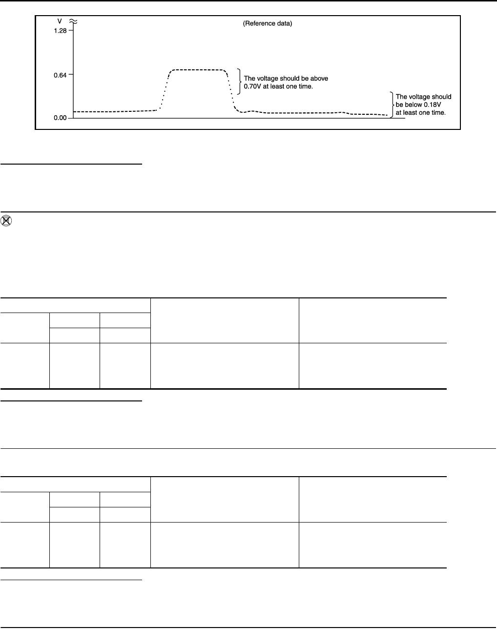
EC-196
< COMPONENT DIAGNOSIS > [FOR CALIFORNIA]
P0137 HO2S2
7. Check “HO2S2 (B1)” at idle speed when adjusting “FUEL INJECTION” to ±25%.
“HO2S2 (B1)” should be above 0.70 V at least once when the “FUEL INJECTION” is +25%.
“HO2S2 (B1)” should be below 0.18 V at least once when the “FUEL INJECTION” is −25%.
Is the inspection result normal?
YES >> INSPECTION END
NO >> GO TO 6.
3.CHECK HEATED OXYGEN SENSOR 2-I
Without CONSULT-III
1. Start engine and warm it up to the normal operating temperature.
2. Turn ignition switch OFF and wait at least 10 seconds.
3. Start engine and keep the engine speed between 3,500 and 4,000 rpm for at least 1 minute under no load.
4. Let engine idle for 1 minute.
5. Check the voltage between ECM harness connector and ground under the following condition.
Is the inspection result normal?
YES >> INSPECTION END
NO >> GO TO 4.
4.CHECK HEATED OXYGEN SENSOR 2-II
Check the voltage between ECM harness connector and ground under the following condition.
Is the inspection result normal?
YES >> INSPECTION END
NO >> GO TO 5.
5.CHECK HEATED OXYGEN SENSOR 2-III
Check the voltage between ECM harness connector and ground under the following condition.
JMBIA1670G
B
ECM
Condition Voltage
Connector +−
Terminal Terminal
F8
33
(HO2S2
signal)
35
(Sensor
ground)
Revving up to 4,000 rpm under no load
at least 10 times
The voltage should be above 0.70 V at
least once during this procedure.
The voltage should be below 0.18 V at
least once during this procedure.
ECM
Condition Voltage
Connector +−
Terminal Terminal
F8 33
(HO2S2
signal)
35
(Sensor
ground)
Keeping engine speed at idle for 10
minutes
The voltage should be above 0.70V at
least once during this procedure.
The voltage should be below 0.18V at
least once during this procedure.
Revision: 2008 August 2009 Rogue

P0137 HO2S2
EC-197
< COMPONENT DIAGNOSIS > [FOR CALIFORNIA]
C
D
E
F
G
H
I
J
K
L
M
A
EC
N
P
O
Is the inspection result normal?
YES >> INSPECTION END
NO >> GO TO 6.
6.REPLACE HEATED OXYGEN SENSOR 2
Replace heated oxygen sensor 2.
CAUTION:
• Discard any heated oxygen sensor which has been dropped from a height of more than 0.5 m (19.7
in) onto a hard surface such as a concrete floor; use a new one.
• Before installing new heated oxygen sensor, clean exhaust system threads using oxygen sensor
thread cleaner [commercial service tool (J-43897-18 or J-43897-12)] and approved anti-seize lubri-
cant (commercial service tool).
>> INSPECTION END
ECM
Condition Voltage
Connector +−
Terminal Terminal
F8
33
(HO2S2
signal)
35
(Sensor
ground)
Coasting from 80 km/h (50 MPH) in D
position
The voltage should be above 0.70 V at
least once during this procedure.
The voltage should be below 0.18 V at
least once during this procedure.
Revision: 2008 August 2009 Rogue
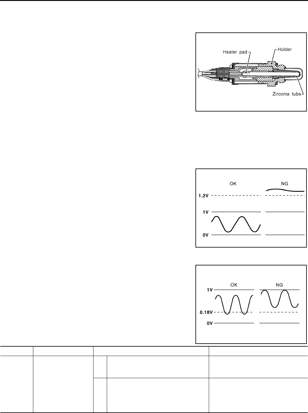
EC-198
< COMPONENT DIAGNOSIS > [FOR CALIFORNIA]
P0138 HO2S2
P0138 HO2S2
Description INFOID:0000000004493416
The heated oxygen sensor 2, after three way catalyst (manifold),
monitors the oxygen level in the exhaust gas.
Even if switching characteristics of the air fuel ratio (A/F) sensor 1
are shifted, the air-fuel ratio is controlled to stoichiometric, by the sig-
nal from the heated oxygen sensor 2.
This sensor is made of ceramic zirconia. The zirconia generates volt-
age from approximately 1V in richer conditions to 0V in leaner condi-
tions.
Under normal conditions the heated oxygen sensor 2 is not used for
engine control operation.
DTC Logic INFOID:0000000004493417
DTC DETECTION LOGIC
The heated oxygen sensor 2 has a much longer switching time between rich and lean than the air fuel ratio (A/
F) sensor 1. The oxygen storage capacity of the three way catalyst (manifold) causes the longer switching
time.
MALFUNCTION A
To judge the malfunctions of heated oxygen sensor 2, ECM monitors
whether the voltage is unusually high during various driving condi-
tions such as fuel cut.
MALFUNCTION B
To judge the malfunctions of heated oxygen sensor 2, ECM monitors
whether the minimum voltage of sensor is sufficiently low during var-
ious driving conditions such as fuel cut.
DTC CONFIRMATION PROCEDURE
SEF327R
PBIB1848E
PBIB2376E
DTC No. Trouble diagnosis name DTC detecting condition Possible cause
P0138 Heated oxygen sensor 2
circuit high voltage
A) An excessively high voltage from the sen-
sor is sent to ECM.
• Harness or connectors
(The sensor circuit is open or shorted)
• Heated oxygen sensor 2
B) The minimum voltage from the sensor is
not reached to the specified voltage.
• Harness or connectors
(The sensor circuit is open or shorted)
• Heated oxygen sensor 2
• Fuel pressure
• Fuel injector
Revision: 2008 August 2009 Rogue

P0138 HO2S2
EC-199
< COMPONENT DIAGNOSIS > [FOR CALIFORNIA]
C
D
E
F
G
H
I
J
K
L
M
A
EC
N
P
O
1.PRECONDITIONING
If DTC CONFIRMATION PROCEDURE has been previously conducted, always turn ignition switch OFF and
wait at least 10 seconds before conducting the next test.
>> GO TO 2.
2.PERFORM DTC CONFIRMATION PROCEDURE FOR MALFUNCTION A
1. Start engine and warm it up to the normal operating temperature.
2. Turn ignition switch OFF and wait at least 10 seconds.
3. Start engine and keep the engine speed between 3,500 and 4,000 rpm for at least 1 minute under no load.
4. Check 1st trip DTC.
Is 1st trip DTC detected?
YES >> Go to EC-200, "Diagnosis Procedure".
NO-1 >> With CONSULT-III: GO TO 3.
NO-2 >> Without CONSULT-III: GO TO 5.
3.PERFORM DTC CONFIRMATION PROCEDURE FOR MALFUNCTION B
NOTE:
For better results, perform “DTC WORK SUPPORT” at a temperature of 0 to 30 °C (32 to 86 °F).
1. Turn ignition switch ON and select “DATA MONITOR” mode with CONSULT-III.
2. Start engine and warm it up to the normal operating temperature.
3. Turn ignition switch OFF and wait at least 10 seconds.
4. Start engine and keep the engine speed between 3,500 and 4,000 rpm for at least 1 minute under no load.
5. Let engine idle for 1 minute.
6. Check that “COOLAN TEMP/S” indicates more than 70°C (158°F).
If not, warm up engine and go to next step when “COOLAN TEMP/S” indication reaches 70°C (158°F).
7. Open engine hood.
8. Select “HO2S2 (B1) P1146” of “HO2S2” in “DTC WORK SUPPORT” mode with CONSULT-III.
9. Follow the instruction of CONSULT-III display.
NOTE:
It will take at most 10 minutes until “COMPLETED” is displayed.
10. Touch “SELF-DIAG RESULT”.
Which is displayed on CONSULT-III
OK >> INSPECTION END
NG >> Go to EC-200, "Diagnosis Procedure".
CAN NOT BE DIAGNOSED>>GO TO 4.
4.PERFORM DTC CONFIRMATION PROCEDURE FOR MALUNCTION B AGAIN
1. Turn ignition switch OFF and leave the vehicle in a cool place (soak the vehicle).
2. Perform DTC CONFIRMATION PROCEDURE again.
>> GO TO 3.
5.PERFORM COMPONENT FUNCTION CHECK FOR MALFUNCTION B
Perform component function check. Refer to EC-200, "Diagnosis Procedure".
NOTE:
Use component function check to check the overall function of the heated oxygen sensor 2 circuit. During this
check, a 1st trip DTC might not be confirmed.
Is the inspection result normal?
YES >> INSPECTION END
NO >> Go to EC-200, "Diagnosis Procedure".
Component Function Check INFOID:0000000004493418
1.PERFORM COMPONENT FUNCTION CHECK-I
Without CONSULT-III
1. Start engine and warm it up to the normal operating temperature.
Revision: 2008 August 2009 Rogue

EC-200
< COMPONENT DIAGNOSIS > [FOR CALIFORNIA]
P0138 HO2S2
2. Turn ignition switch OFF and wait at least 10 seconds.
3. Start engine and keep the engine speed between 3,500 and 4,000 rpm for at least 1 minute under no load.
4. Let engine idle for 1 minute.
5. Check the voltage between ECM harness connector terminals under the following condition.
Is the inspection result normal?
YES >> INSPECTION END
NO >> GO TO 2.
2.PERFORM COMPONENT FUNCTION CHECK-II
Check the voltage between ECM harness connectors under the following condition.
Is the inspection result normal?
YES >> INSPECTION END
NO >> GO TO 3.
3.PERFORM COMPONENT FUNCTION CHECK-III
Check the voltage between ECM harness connector and ground under the following condition.
Is the inspection result normal?
YES >> INSPECTION END
NO >> Go to EC-200, "Diagnosis Procedure".
Diagnosis Procedure INFOID:0000000004493419
1.INSPECTION START
Confirm the detected malfunction (A or B). Refer to EC-198, "DTC Logic".
Which malfunction is detected?
A>>GO TO 2.
B>>GO TO 9.
2.CHECK GROUND CONNECTION
1. Turn ignition switch OFF.
2. Check ground connection E21. Refer to Ground Inspection in GI-44, "Circuit Inspection".
Is the inspection result normal?
YES >> GO TO 3.
NO >> Repair or replace ground connection.
3.CHECK HO2S2 GROUND CIRCUIT FOR OPEN AND SHORT
1. Disconnect heated oxygen sensor 2 harness connector.
ECM ECM Condition Voltage
Connector Terminal Connector Terminal
F8 33
(HO2S2 signal) F8 35
(Sensor
ground)
Revving up to 4,000 rpm under
no load at least 10 times
The voltage should be below 0.18 V
at least once during this procedure.
ECM ECM Condition Voltage
Connector Terminal Connector Terminal
F8 33
(HO2S2 signal) F8
35
(Sensor
ground)
Keeping engine speed at idle for
10 minutes The voltage should be below 0.18 V
at least once during this procedure.
ECM ECM Condition Voltage
Connector Terminal Connector Terminal
F8 33
(HO2S2 signal) F8
35
(Sensor
ground)
Coasting from 80 km/h (50 MPH)
in D position
The voltage should be below 0.18 V
at least once during this procedure.
Revision: 2008 August 2009 Rogue

P0138 HO2S2
EC-201
< COMPONENT DIAGNOSIS > [FOR CALIFORNIA]
C
D
E
F
G
H
I
J
K
L
M
A
EC
N
P
O
2. Disconnect ECM harness connector.
3. Check the continuity between HO2S2 harness connector and ECM harness connector.
4. Also check harness for short to ground and short to power.
Is the inspection result normal?
YES >> GO TO 4.
NO >> Repair open circuit or short to ground or short to power in harness or connectors.
4.CHECK HO2S2 INPUT SIGNAL CIRCUIT FOR OPEN AND SHORT
1. Check the continuity between HO2S2 harness connector and ECM harness connector.
2. Check the continuity between HO2S2 harness connector or ECM harness connector and ground.
3. Also check harness for short to power.
Is the inspection result normal?
YES >> GO TO 5.
NO >> Repair open circuit or short to ground or short to power in harness or connectors.
5.CHECK HO2S2 CONNECTOR FOR WATER
Check connectors for water.
Is the inspection result normal?
YES >> GO TO 6.
NO >> Repair or replace harness or connectors.
6.CHECK HEATED OXYGEN SENSOR 2
Refer to EC-203, "Component Inspection".
Is the inspection result normal?
YES >> GO TO 8.
NO >> GO TO 7.
7.REPLACE HEATED OXYGEN SENSOR 2
Replace heated oxygen sensor 2.
CAUTION:
• Discard any heated oxygen sensor which has been dropped from a height of more than 0.5 m (19.7
in) onto a hard surface such as a concrete floor; use a new one.
• Before installing new heated oxygen sensor, clean exhaust system threads using oxygen sensor
thread cleaner [commercial service tool (J-43897-18 or J-43897-12)] and approved anti-seize lubri-
cant (commercial service tool).
>> INSPECTION END
8.CHECK INTERMITTENT INCIDENT
HO2S2 ECM Continuity
Connector Terminal Connector Terminal
F31 1 F8 35 Existed
HO2S2 ECM Continuity
Connector Terminal Connector Terminal
F31 4 F8 33 Existed
HO2S2 ECM Ground Continuity
Connector Terminal Connector Terminal
F31 4 F8 33 Ground Not existed
Water should not exist.
Revision: 2008 August 2009 Rogue

EC-202
< COMPONENT DIAGNOSIS > [FOR CALIFORNIA]
P0138 HO2S2
Refer to GI-41, "Intermittent Incident".
>> INSPECTION END
9.CHECK GROUND CONNECTION
1. Turn ignition switch OFF.
2. Check ground connection E21. Refer to Ground Inspection in GI-44, "Circuit Inspection".
Is the inspection result normal?
YES >> GO TO 10.
NO >> Repair or replace ground connection.
10.CLEAR THE MIXTURE RATIO SELF-LEARNING VALUE
1. Clear the mixture ratio self-learning value. Refer to EC-29, "MIXTURE RATIO SELF-LEARNING VALUE
CLEAR : Special Repair Requirement".
2. Run engine for at least 10 minutes at idle speed.
Is the 1st trip DTC P0172 detected? Is it difficult to start engine?
YES >> Perform trouble diagnosis for DTC P0172. Refer to EC-235, "DTC Logic".
NO >> GO TO 11.
11.CHECK HO2S2 GROUND CIRCUIT FOR OPEN AND SHORT
1. Turn ignition switch OFF.
2. Disconnect heated oxygen sensor 2 harness connector.
3. Disconnect ECM harness connector.
4. Check the continuity between HO2S2 harness connector and ECM harness connector.
5. Also check harness for short to ground and short to power.
Is the inspection result normal?
YES >> GO TO 12.
NO >> Repair open circuit or short to ground or short to power in harness or connectors.
12.CHECK HO2S2 INPUT SIGNAL CIRCUIT FOR OPEN AND SHORT
1. Check the continuity between HO2S2 harness connector and ECM harness connector.
2. Check the continuity between HO2S2 harness connector or ECM harness connector and ground.
3. Also check harness for short to power.
Is the inspection result normal?
YES >> GO TO 13.
NO >> Repair open circuit or short to ground or short to power in harness or connectors.
13.CHECK HEATED OXYGEN SENSOR 2
Refer to EC-203, "Component Inspection".
Is the inspection result normal?
YES >> GO TO 15.
HO2S2 ECM Continuity
Connector Terminal Connector Terminal
F31 1 F8 35 Existed
HO2S2 ECM Continuity
Connector Terminal Connector Terminal
F31 4 F8 33 Existed
HO2S2 ECM Ground Continuity
Connector Terminal Connector Terminal
F31 4 F8 33 Ground Not existed
Revision: 2008 August 2009 Rogue
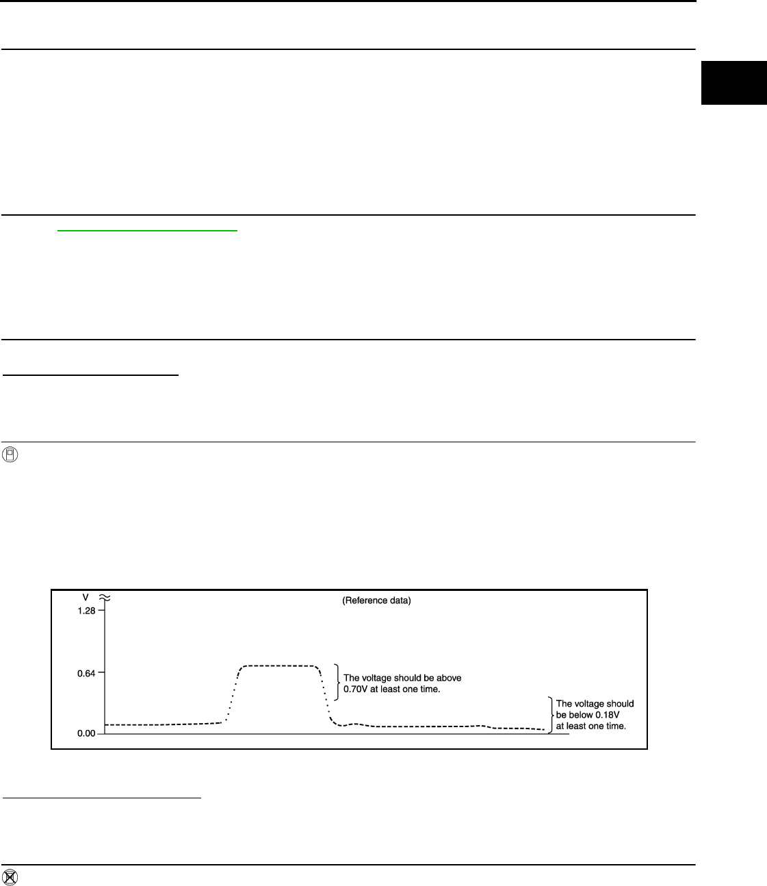
P0138 HO2S2
EC-203
< COMPONENT DIAGNOSIS > [FOR CALIFORNIA]
C
D
E
F
G
H
I
J
K
L
M
A
EC
N
P
O
NO >> GO TO 14.
14.REPLACE HEATED OXYGEN SENSOR 2
Replace heated oxygen sensor 2.
CAUTION:
• Discard any heated oxygen sensor which has been dropped from a height of more than 0.5 m (19.7
in) onto a hard surface such as a concrete floor; use a new one.
• Before installing new oxygen sensor, clean exhaust system threads using oxygen sensor thread
cleaner tool J-43897-18 or J-43897-12 and approved anti-seize lubricant.
>> INSPECTION END
15.CHECK INTERMITTENT INCIDENT
Refer to GI-41, "Intermittent Incident".
>> INSPECTION END
Component Inspection INFOID:0000000004493420
1.INSPECTION START
Do you have CONSULT-III?
Do you have CONSULT-III?
YES >> GO TO 2.
NO >> GO TO 3.
2.CHECK HEATED OXYGEN SENSOR 2
With CONSULT-III
1. Turn ignition switch ON and select “DATA MONITOR” mode with CONSULT-III.
2. Start engine and warm it up to the normal operating temperature.
3. Turn ignition switch OFF and wait at least 10 seconds.
4. Start engine and keep the engine speed between 3,500 and 4,000 rpm for at least 1 minute under no load.
5. Let engine idle for 1 minute.
6. Select “FUEL INJECTION” in “ACTIVE TEST” mode, and select “HO2S2 (B1)” as the monitor item with
CONSULT-III.
7. Check “HO2S2 (B1)” at idle speed when adjusting “FUEL INJECTION” to ±25%.
“HO2S2 (B1)” should be above 0.70 V at least once when the “FUEL INJECTION” is +25%.
“HO2S2 (B1)” should be below 0.18 V at least once when the “FUEL INJECTION” is −25%.
Is the inspection result normal?
YES >> INSPECTION END
NO >> GO TO 6.
3.CHECK HEATED OXYGEN SENSOR 2-I
Without CONSULT-III
1. Start engine and warm it up to the normal operating temperature.
2. Turn ignition switch OFF and wait at least 10 seconds.
3. Start engine and keep the engine speed between 3,500 and 4,000 rpm for at least 1 minute under no load.
4. Let engine idle for 1 minute.
5. Check the voltage between ECM harness connector and ground under the following condition.
JMBIA1670G
B
Revision: 2008 August 2009 Rogue

EC-204
< COMPONENT DIAGNOSIS > [FOR CALIFORNIA]
P0138 HO2S2
Is the inspection result normal?
YES >> INSPECTION END
NO >> GO TO 4.
4.CHECK HEATED OXYGEN SENSOR 2-II
Check the voltage between ECM harness connector and ground under the following condition.
Is the inspection result normal?
YES >> INSPECTION END
NO >> GO TO 5.
5.CHECK HEATED OXYGEN SENSOR 2-III
Check the voltage between ECM harness connector and ground under the following condition.
Is the inspection result normal?
YES >> INSPECTION END
NO >> GO TO 6.
6.REPLACE HEATED OXYGEN SENSOR 2
Replace heated oxygen sensor 2.
CAUTION:
• Discard any heated oxygen sensor which has been dropped from a height of more than 0.5 m (19.7
in) onto a hard surface such as a concrete floor; use a new one.
• Before installing new heated oxygen sensor, clean exhaust system threads using oxygen sensor
thread cleaner [commercial service tool (J-43897-18 or J-43897-12)] and approved anti-seize lubri-
cant (commercial service tool).
>> INSPECTION END
ECM
Condition Voltage
Connector +−
Terminal Terminal
F8
33
(HO2S2
signal)
35
(Sensor
ground)
Revving up to 4,000 rpm under no load
at least 10 times
The voltage should be above 0.70 V at
least once during this procedure.
The voltage should be below 0.18 V at
least once during this procedure.
ECM
Condition Voltage
Connector +−
Terminal Terminal
F8
33
(HO2S2
signal)
35
(Sensor
ground)
Keeping engine speed at idle for 10
minutes
The voltage should be above 0.70V at
least once during this procedure.
The voltage should be below 0.18V at
least once during this procedure.
ECM
Condition Voltage
Connector +−
Terminal Terminal
F8 33
(HO2S2
signal)
35
(Sensor
ground)
Coasting from 80 km/h (50 MPH) in D
position
The voltage should be above 0.70 V at
least once during this procedure.
The voltage should be below 0.18 V at
least once during this procedure.
Revision: 2008 August 2009 Rogue
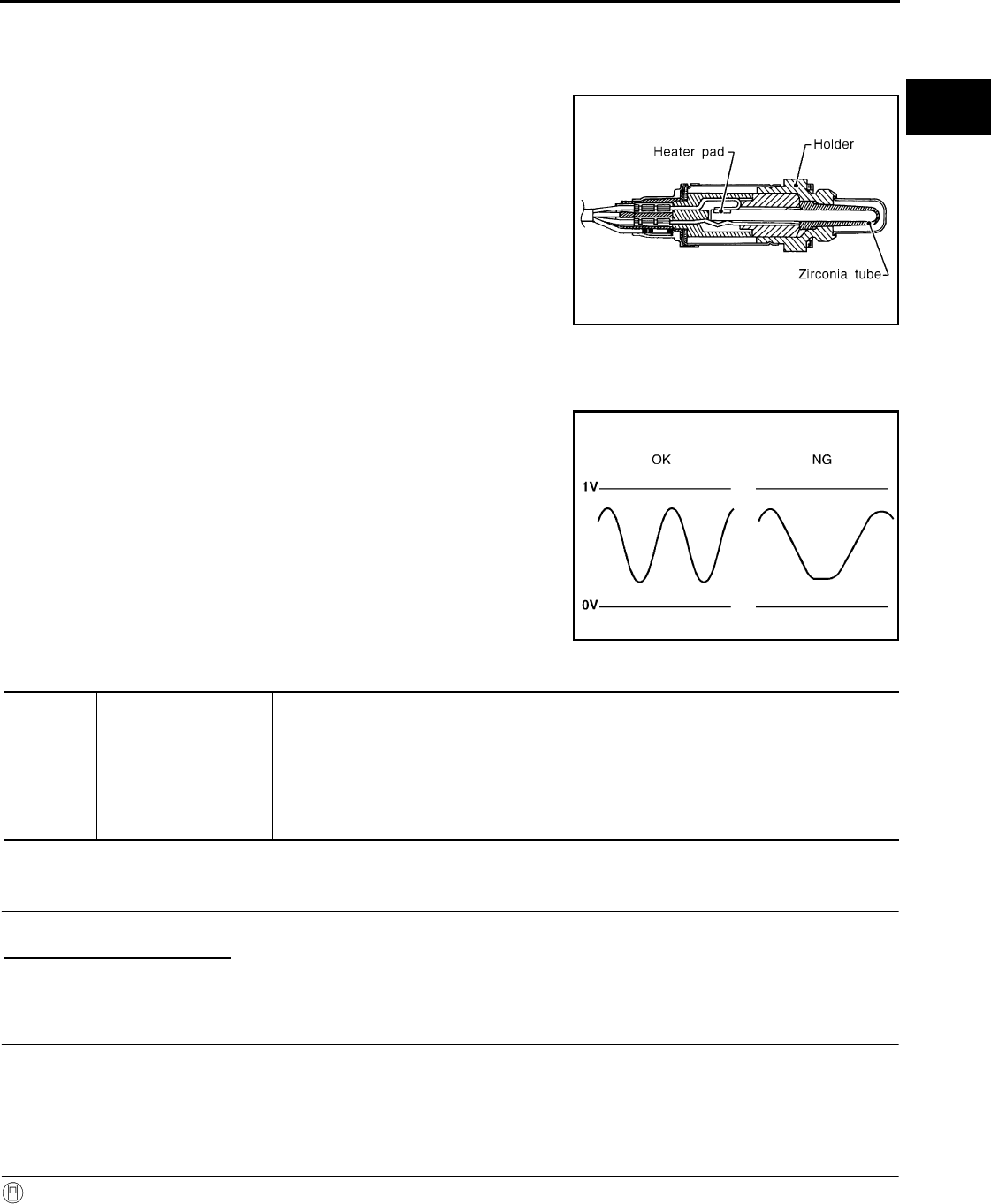
P0139 HO2S2
EC-205
< COMPONENT DIAGNOSIS > [FOR CALIFORNIA]
C
D
E
F
G
H
I
J
K
L
M
A
EC
N
P
O
P0139 HO2S2
Description INFOID:0000000004493421
The heated oxygen sensor 2, after three way catalyst (manifold),
monitors the oxygen level in the exhaust gas.
Even if switching characteristics of the air fuel ratio (A/F) sensor 1
are shifted, the air-fuel ratio is controlled to stoichiometric, by the sig-
nal from the heated oxygen sensor 2.
This sensor is made of ceramic zirconia. The zirconia generates volt-
age from approximately 1V in richer conditions to 0V in leaner condi-
tions.
Under normal conditions the heated oxygen sensor 2 is not used for
engine control operation.
DTC Logic INFOID:0000000004493422
DTC DETECTION LOGIC
The heated oxygen sensor 2 has a much longer switching time
between rich and lean than the air fuel ratio (A/F) sensor 1. The oxy-
gen storage capacity of the three way catalyst (mamifold) causes the
longer switching time. To judge the malfunctions of heated oxygen
sensor 2, ECM monitors whether the switching response of the sen-
sor's voltage is faster than specified during various driving conditions
such as fuel cut.
DTC CONFIRMATION PROCEDURE
1.INSPECTION START
Do you have CONSULT-III?
Do you have CONSULT-III?
YES >> GO TO 2.
NO >> GO TO 5.
2.PRECONDITIONING
If DTC CONFIRMATION PROCEDURE has been previously conducted, always turn ignition switch OFF and
wait at least 10 seconds before conducting the next test.
>> GO TO 3.
3.PERFORM DTC CONFIRMATION PROCEDURE
With CONSULT-III
1. Turn ignition switch ON and select “DATA MONITOR” mode with CONSULT-III.
2. Start engine and warm it up to the normal operating temperature.
SEF327R
SEF302U
DTC No. Trouble diagnosis name DTC detecting condition Possible cause
P0139 Heated oxygen sensor 2
circuit slow response
It takes more time for the sensor to respond be-
tween rich and lean than the specified time.
• Harness or connectors
(The sensor circuit is open or shorted)
• Heated oxygen sensor 2
• Fuel pressure
• Fuel injector
• Intake air leaks
Revision: 2008 August 2009 Rogue

EC-206
< COMPONENT DIAGNOSIS > [FOR CALIFORNIA]
P0139 HO2S2
3. Start engine and warm it up to the normal operating temperature.
4. Start engine and keep the engine speed between 3,500 and 4,000 rpm for at least 1 minute under no load.
5. Let engine idle for 1 minute.
6. Open engine hood.
7. Select “HO2S2 (B1) P0139” of “HO2S2” in “DTC WORK SUPPORT” mode with CONSULT-III.
8. Follow the instruction of CONSULT-III display.
NOTE:
It will take at most 10 minutes until “COMPLETED” is displayed.
9. Touch “SELF-DIAG RESULT”.
Which is displayed on CONSULT-III?
OK >> INSPECTION END
NG >> GO TO 4.
CAN NOT BE DIAGNOSED>>GO TO 4.
4.PERFORM THE RESULT OF DTC CONFIRMATION PROCEDURE
1. Turn ignition switch OFF and leave the vehicle in a cool place (soak the vehicle).
2. Perform DTC CONFIRMATION PROCEDURE again.
>> GO TO 3.
5.PERFORM COMPONENT FUNCTION CHECK
Perform Component Function Check. Refer to EC-206, "Component Function Check".
NOTE:
Use Component Function Check to check the overall function of the heated oxygen sensor 2 circuit. During
this check, a 1st trip DTC might not be confirmed.
Is the inspection result normal?
YES >> INSPECTION END
NO >> Go to EC-207, "Diagnosis Procedure".
Component Function Check INFOID:0000000004493423
1.PERFORM COMPONENT FUNCTION CHECK-I
Without CONSULT-III
1. Start engine and warm it up to the normal operating temperature.
2. Turn ignition switch OFF and wait at least 10 seconds.
3. Start engine and keep the engine speed between 3,500 and 4,000 rpm for at least 1 minute under no load.
4. Let engine idle for 1 minute.
5. Check the voltage between ECM harness connector terminals under the following condition.
Is the inspection result normal?
YES >> INSPECTION END
NO >> GO TO 2.
2.PERFORM COMPONENT FUNCTION CHECK-II
Check the voltage between ECM harness connectors under the following condition.
ECM ECM Condition Voltage
Connector Terminal Connector Terminal
F8
33
(HO2S2
signal) F8
35
(Sensor
ground)
Revving up to 4,000 rpm under
no load at least 10 times
A change of voltage should be more than
0.80 V for 1 second during this procedure.
ECM ECM Condition Voltage
Connector Terminal Connector Terminal
F8 33
(HO2S2
signal)
F8 35
(Sensor
ground)
Keeping engine speed at idle for
10 minutes
A change of voltage should be more than
0.80 V for 1 second during this procedure.
Revision: 2008 August 2009 Rogue

P0139 HO2S2
EC-207
< COMPONENT DIAGNOSIS > [FOR CALIFORNIA]
C
D
E
F
G
H
I
J
K
L
M
A
EC
N
P
O
Is the inspection result normal?
YES >> INSPECTION END
NO >> GO TO 3.
3.PERFORM COMPONENT FUNCTION CHECK-III
Check the voltage between ECM harness connector and ground under the following condition.
Is the inspection result normal?
YES >> INSPECTION END
NO >> Go to EC-207, "Diagnosis Procedure".
Diagnosis Procedure INFOID:0000000004493424
1.CHECK GROUND CONNECTION
1. Turn ignition switch OFF.
2. Check ground connection E21. Refer to Ground Inspection in GI-44, "Circuit Inspection".
Is the inspection result normal?
YES >> GO TO 2.
NO >> Repair or replace ground connection.
2.CLEAR THE MIXTURE RATIO SELF-LEARNING VALUE
1. Clear the mixture ratio self-learning value. Refer to EC-29, "MIXTURE RATIO SELF-LEARNING VALUE
CLEAR : Special Repair Requirement".
2. Run engine for at least 10 minutes at idle speed.
Is the 1st trip DTC P0171 or P0172 detected? Is it difficult to start engine?
YES >> Perform trouble diagnosis for DTC P0171 or P0172. Refer to EC-231, "DTC Logic" or EC-235,
"DTC Logic".
NO >> GO TO 3.
3.CHECK HO2S2 GROUND CIRCUIT FOR OPEN AND SHORT
1. Turn ignition switch OFF.
2. Disconnect heated oxygen sensor 2 harness connector.
3. Disconnect ECM harness connector.
4. Check the continuity between HO2S2 harness connector and ECM harness connector.
5. Also check harness for short to ground and short to power.
Is the inspection result normal?
YES >> GO TO 4.
NO >> Repair open circuit or short to ground or short to power in harness or connectors.
4.CHECK HO2S2 INPUT SIGNAL CIRCUIT FOR OPEN AND SHORT
1. Check the continuity between HO2S2 harness connector and ECM harness connector.
ECM ECM Condition Voltage
Connector Terminal Connector Terminal
F8
33
(HO2S2
signal)
F8
35
(Sensor
ground)
Coasting from 80 km/h (50 MPH)
in D position A change of voltage should be more than
0.80 V for 1 second during this procedure.
HO2S2 ECM Continuity
Connector Terminal Connector Terminal
F31 1 F8 35 Existed
HO2S2 ECM Continuity
Connector Terminal Connector Terminal
F31 4 F8 33 Existed
Revision: 2008 August 2009 Rogue

EC-208
< COMPONENT DIAGNOSIS > [FOR CALIFORNIA]
P0139 HO2S2
2. Check the continuity between HO2S2 harness connector or ECM harness connector and ground.
3. Also check harness for short to power.
Is the inspection result normal?
YES >> GO TO 5.
NO >> Repair open circuit or short to ground or short to power in harness or connectors.
5.CHECK HEATED OXYGEN SENSOR 2
Refer to EC-208, "Component Inspection".
Is the inspection result normal?
YES >> GO TO 7.
NO >> GO TO 6.
6.REPLACE HEATED OXYGEN SENSOR 2
Replace heated oxygen sensor 2.
CAUTION:
• Discard any heated oxygen sensor which has been dropped from a height of more than 0.5 m (19.7
in) onto a hard surface such as a concrete floor; use a new one.
• Before installing new heated oxygen sensor, clean exhaust system threads using oxygen sensor
thread cleaner [commercial service tool (J-43897-18 or J-43897-12)] and approved anti-seize lubri-
cant (commercial service tool).
>> INSPECTION END
7.CHECK INTERMITTENT INCIDENT
Refer to GI-41, "Intermittent Incident".
>> INSPECTION END
Component Inspection INFOID:0000000004493425
1.INSPECTION START
Do you have CONSULT-III?
Do you have CONSULT-III?
YES >> GO TO 2.
NO >> GO TO 3.
2.CHECK HEATED OXYGEN SENSOR 2
With CONSULT-III
1. Turn ignition switch ON and select “DATA MONITOR” mode with CONSULT-III.
2. Start engine and warm it up to the normal operating temperature.
3. Turn ignition switch OFF and wait at least 10 seconds.
4. Start engine and keep the engine speed between 3,500 and 4,000 rpm for at least 1 minute under no load.
5. Let engine idle for 1 minute.
6. Select “FUEL INJECTION” in “ACTIVE TEST” mode, and select “HO2S2 (B1)” as the monitor item with
CONSULT-III.
HO2S2 ECM Ground Continuity
Connector Terminal Connector Terminal
F31 4 F8 33 Ground Not existed
Revision: 2008 August 2009 Rogue

P0139 HO2S2
EC-209
< COMPONENT DIAGNOSIS > [FOR CALIFORNIA]
C
D
E
F
G
H
I
J
K
L
M
A
EC
N
P
O
7. Check “HO2S2 (B1)” at idle speed when adjusting “FUEL INJECTION” to ±25%.
“HO2S2 (B1)” should be above 0.70 V at least once when the “FUEL INJECTION” is +25%.
“HO2S2 (B1)” should be below 0.18 V at least once when the “FUEL INJECTION” is −25%.
Is the inspection result normal?
YES >> INSPECTION END
NO >> GO TO 6.
3.CHECK HEATED OXYGEN SENSOR 2-I
Without CONSULT-III
1. Start engine and warm it up to the normal operating temperature.
2. Turn ignition switch OFF and wait at least 10 seconds.
3. Start engine and keep the engine speed between 3,500 and 4,000 rpm for at least 1 minute under no load.
4. Let engine idle for 1 minute.
5. Check the voltage between ECM harness connector and ground under the following condition.
Is the inspection result normal?
YES >> INSPECTION END
NO >> GO TO 4.
4.CHECK HEATED OXYGEN SENSOR 2-II
Check the voltage between ECM harness connector and ground under the following condition.
Is the inspection result normal?
YES >> INSPECTION END
NO >> GO TO 5.
5.CHECK HEATED OXYGEN SENSOR 2-III
Check the voltage between ECM harness connector and ground under the following condition.
JMBIA1670G
B
ECM
Condition Voltage
Connector +−
Terminal Terminal
F8
33
(HO2S2
signal)
35
(Sensor
ground)
Revving up to 4,000 rpm under no load
at least 10 times
The voltage should be above 0.70 V at
least once during this procedure.
The voltage should be below 0.18 V at
least once during this procedure.
ECM
Condition Voltage
Connector +−
Terminal Terminal
F8 33
(HO2S2
signal)
35
(Sensor
ground)
Keeping engine speed at idle for 10
minutes
The voltage should be above 0.70V at
least once during this procedure.
The voltage should be below 0.18V at
least once during this procedure.
Revision: 2008 August 2009 Rogue

EC-210
< COMPONENT DIAGNOSIS > [FOR CALIFORNIA]
P0139 HO2S2
Is the inspection result normal?
YES >> INSPECTION END
NO >> GO TO 6.
6.REPLACE HEATED OXYGEN SENSOR 2
Replace heated oxygen sensor 2.
CAUTION:
• Discard any heated oxygen sensor which has been dropped from a height of more than 0.5 m (19.7
in) onto a hard surface such as a concrete floor; use a new one.
• Before installing new heated oxygen sensor, clean exhaust system threads using oxygen sensor
thread cleaner [commercial service tool (J-43897-18 or J-43897-12)] and approved anti-seize lubri-
cant (commercial service tool).
>> INSPECTION END
ECM
Condition Voltage
Connector +−
Terminal Terminal
F8
33
(HO2S2
signal)
35
(Sensor
ground)
Coasting from 80 km/h (50 MPH) in D
position
The voltage should be above 0.70 V at
least once during this procedure.
The voltage should be below 0.18 V at
least once during this procedure.
Revision: 2008 August 2009 Rogue
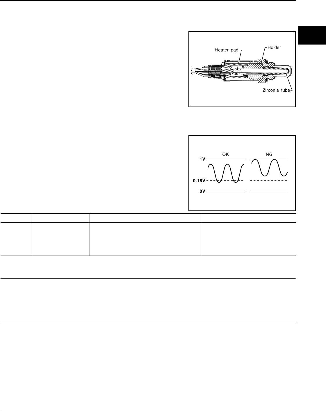
P0143 HO2S3
EC-211
< COMPONENT DIAGNOSIS > [FOR CALIFORNIA]
C
D
E
F
G
H
I
J
K
L
M
A
EC
N
P
O
P0143 HO2S3
Description INFOID:0000000004493426
The heated oxygen sensor 3, after HC adsorption catalyst (Under
floor), monitors the oxygen level in the exhaust gas.
This sensor is made of ceramic zirconia. The zirconia generates volt-
age from approximately 1V in richer conditions to 0V in leaner condi-
tions.
Under normal conditions the heated oxygen sensor 3 is not used for
engine control operation.
DTC Logic INFOID:0000000004493427
DTC DETECTION LOGIC
The heated oxygen sensor 3 has a much longer switching time
between rich and lean than the air fuel ratio (A/F) sensor 1. The oxy-
gen storage capacity of the three way catalyst (manifold) causes the
longer switching time. To judge the malfunctions of heated oxygen
sensor 3, ECM monitors whether the minimum voltage of sensor is
sufficiently low during various driving conditions such as fuel cut.
DTC CONFIRMATION PROCEDURE
1.PRECONDITIONING
If DTC CONFIRMATION PROCEDURE has been previously conducted, always turn ignition switch OFF and
wait at least 10 seconds before conducting the next test.
>> GO TO 2.
2.PERFORM DTC CONFIRMATION PROCEDURE
1. Start engine and warm it up to the normal operating temperature.
2. Repeat the following procedure 3 times.
- Drive vehicle at a speed of 80 km/h (50 MPH) or more for at least 3 consecutive minutes.
CAUTION:
Always drive vehicle in safe manner according to traffic conditions and obey all traffic laws.
NOTE:
•Keep the vehicle speed as steady as possible during the cruising.
•Never raise engine speed above 3,600 rpm in this step.
- Release accelerator pedal fully and stop vehicle with engine running.
NOTE:
Never turn ignition switch OFF.
3. Check 1st trip DTC.
Is 1st tip DTC detected?
SEF327R
PBIB2376E
DTC No. Trouble diagnosis name DTC detecting condition Possible cause
P0143 Heated oxygen sensor 3
circuit high voltage
The minimum voltage from the sensor is not
reached to the specified voltage.
• Harness or connectors
(The sensor circuit is open or shorted)
• Heated oxygen sensor 3
• Fuel pressure
• Fuel injector
Revision: 2008 August 2009 Rogue

EC-212
< COMPONENT DIAGNOSIS > [FOR CALIFORNIA]
P0143 HO2S3
YES >> Go to EC-212, "Diagnosis Procedure".
NO >> INSPECTION END
Diagnosis Procedure INFOID:0000000004493428
1.CHECK GROUND CONNECTION
1. Turn ignition switch OFF.
2. Check ground connection E21. Refer to Ground Inspection in GI-44, "Circuit Inspection".
Is the inspection result normal?
YES >> GO TO 2.
NO >> Repair or replace ground connection.
2.CLEAR THE MIXTURE RATIO SELF-LEARNING VALUE
1. Clear the mixture ratio self-learning value. Refer to EC-29, "MIXTURE RATIO SELF-LEARNING VALUE
CLEAR : Special Repair Requirement".
2. Run engine for at least 10 minutes at idle speed.
Is the 1st trip DTC P0172 detected? Is it difficult to start engine?
YES >> Perform trouble diagnosis for DTC P0172. Refer to EC-236, "Diagnosis Procedure".
NO >> GO TO 3.
3.CHECK HO2S3 GROUND CIRCUIT FOR OPEN AND SHORT
1. Turn ignition switch OFF.
2. Disconnect heated oxygen sensor 3 harness connector.
3. Disconnect ECM harness connector.
4. Check the continuity between HO2S3 harness connector and ECM harness connector.
5. Also check harness for short to ground and short to power.
Is the inspection result normal?
YES >> GO TO 5.
NO >> GO TO 4.
4.DETECT MALFUNCTIONING PART
Check the following.
• Harness connectors E7, F121
• Harness for open or short between heated oxygen sensor 3 and ECM
>> Repair open circuit or short to ground or short to power in harness or connectors.
5.CHECK HO2S3 INPUT SIGNAL CIRCUIT FOR OPEN AND SHORT
1. Check the continuity between HO2S3 harness connector and ECM harness connector.
2. Check the continuity between HO2S3 harness connector or ECM harness connector and ground.
3. Also check harness for short to power.
Is the inspection result normal?
HO2S3 ECM Continuity
Connector Terminal Connector Terminal
E50 1 F8 35 Existed
HO2S3 ECM Continuity
Connector Terminal Connector Terminal
E50 4 F8 34 Existed
HO2S3 ECM Ground Continuity
Connector Terminal Connector Terminal
E50 4 F8 34 Ground Not existed
Revision: 2008 August 2009 Rogue

P0143 HO2S3
EC-213
< COMPONENT DIAGNOSIS > [FOR CALIFORNIA]
C
D
E
F
G
H
I
J
K
L
M
A
EC
N
P
O
YES >> GO TO 7.
NO >> GO TO 6.
6.DETECT MALFUNCTIONING PART
Check the following.
• Harness connectors E7, F121
• Harness for open or short between heated oxygen sensor 3 and ECM
>> Repair open circuit or short to ground or short to power in harness or connectors.
7.CHECK HEATED OXYGEN SENSOR 3
Refer to EC-213, "Component Inspection".
Is the inspection result normal?
YES >> GO TO 9.
NO >> GO TO 8.
8.REPLACE HEATED OXYGEN SENSOR 3
Replace heated oxygen sensor 3.
CAUTION:
• Discard any heated oxygen sensor which has been dropped from a height of more than 0.5 m (19.7
in) onto a hard surface such as a concrete floor; use a new one.
• Before installing new heated oxygen sensor, clean exhaust system threads using oxygen sensor
thread cleaner [commercial service tool (J-43897-18 or J-43897-12)] and approved anti-seize lubri-
cant (commercial service tool).
>> INSPECTION END
9.CHECK INTERMITTENT INCIDENT
Refer to GI-41, "Intermittent Incident".
>> INSPECTION END
Component Inspection INFOID:0000000004493429
1.INSPECTION START
Do you have CONSULT-III?
Do you have CONSULT-III?
YES >> GO TO 2.
NO >> GO TO 3.
2.CHECK HEATED OXYGEN SENSOR 3
With CONSULT-III
CAUTION:
Always drive vehicle in safe manner according to traffic conditions and obey all traffic laws.
1. Turn ignition switch ON and select “DATA MONITOR” mode with CONSULT-III.
2. Start engine and warm it up to the normal operating temperature.
3. Turn ignition switch OFF and wait at least 10 seconds.
4. Start the engine and drive vehicle at a speed of 80 km/h (50 MPH) or more for at least 3 consecutive min-
utes.
NOTE:
Keep the vehicle speed as steady as possible during the cruising.
5. Select “FUEL INJECTION” in “ACTIVE TEST” mode, and select “HO2S3 (B1)” as the monitor item with
CONSULT-III.
Revision: 2008 August 2009 Rogue
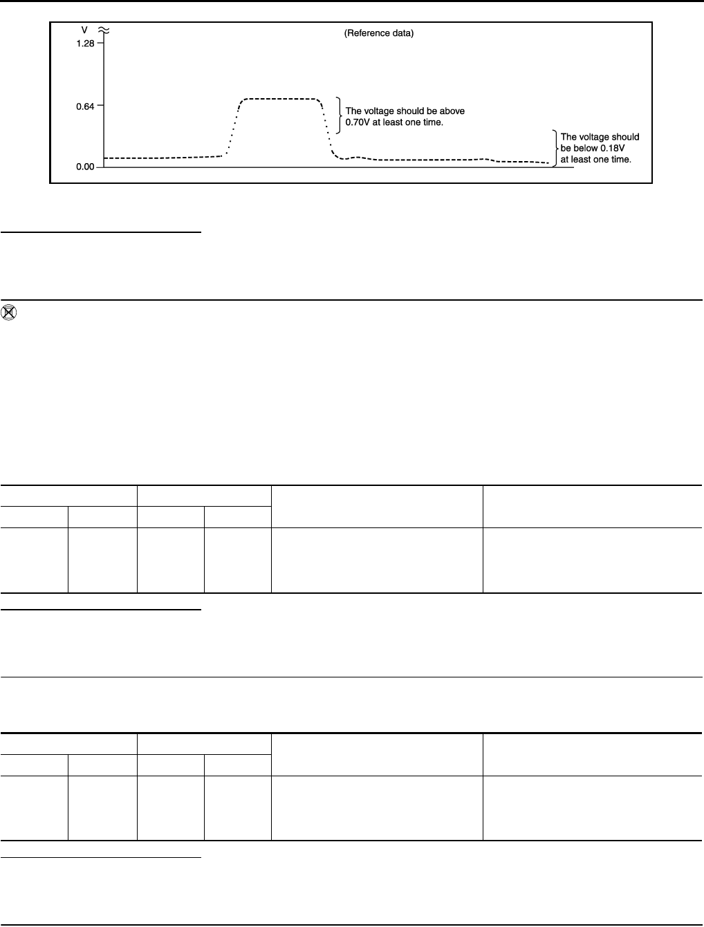
EC-214
< COMPONENT DIAGNOSIS > [FOR CALIFORNIA]
P0143 HO2S3
6. Check “HO2S3 (B1)” at idle speed when adjusting “FUEL INJECTION” to ±25%.
“HO2S3 (B1)” should be above 0.70 V at least once when the “FUEL INJECTION” is +25%.
“HO2S3 (B1)” should be below 0.18 V at least once when the “FUEL INJECTION” is −25%.
Is the inspection result normal?
YES >> INSPECTION END
NO >> GO TO 6.
3.CHECK HEATED OXYGEN SENSOR 3-I
Without CONSULT-III
CAUTION:
Always drive vehicle in safe manner according to traffic conditions and obey all traffic laws.
1. Start engine and warm it up to the normal operating temperature.
2. Turn ignition switch OFF and wait at least 10 seconds.
3. Start the engine and drive vehicle at a speed of 80 km/h (50 MPH) or more for at least 3 consecutive min-
utes.
NOTE:
Keep the vehicle speed as steady as possible during the cruising.
4. Check the voltage between ECM harness connector terminals under the following condition.
Is the inspection result normal?
YES >> INSPECTION END
NO >> GO TO 4.
4.CHECK HEATED OXYGEN SENSOR 3-II
1. Keep vehicle at idling for 10 minutes.
2. Check the voltage between ECM harness connector and ground under the following condition.
Is the inspection result normal?
YES >> INSPECTION END
NO >> GO TO 5.
5.CHECK HEATED OXYGEN SENSOR 3-III
Check the voltage between ECM harness connector and ground under the following condition.
JMBIA1670G
B
ECM ECM Condition Voltage
Connector Terminal Connector Terminal
F8
34
(HO2S3
signal) F8
35
(Sensor
ground)
Revving up to 4,000 rpm under no load
at least 10 times
The voltage should be above 0.70 V at
least once during this procedure.
The voltage should be below 0.18 V at
least once during this procedure.
ECM ECM Condition Voltage
Connector Terminal Connector Terminal
F8
34
(HO2S3
signal)
F8
35
(Sensor
ground)
Revving up to 4,000 rpm under no load
at least 10 times
The voltage should be above 0.70 V at
least once during this procedure.
The voltage should be below 0.18 V at
least once during this procedure.
Revision: 2008 August 2009 Rogue

P0143 HO2S3
EC-215
< COMPONENT DIAGNOSIS > [FOR CALIFORNIA]
C
D
E
F
G
H
I
J
K
L
M
A
EC
N
P
O
Is the inspection result normal?
YES >> INSPECTION END
NO >> GO TO 6.
6.REPLACE HEATED OXYGEN SENSOR 3
Replace heated oxygen sensor 3.
CAUTION:
• Discard any heated oxygen sensor which has been dropped from a height of more than 0.5 m (19.7
in) onto a hard surface such as a concrete floor; use a new one.
• Before installing new heated oxygen sensor, clean exhaust system threads using oxygen sensor
thread cleaner [commercial service tool (J-43897-18 or J-43897-12)] and approved anti-seize lubri-
cant (commercial service tool).
>> INSPECTION END
ECM ECM Condition Voltage
Connector Terminal Connector Terminal
F8
34
(HO2S3
signal) F8
35
(Sensor
ground)
Coasting from 80 km/h (50 MPH) in D
position
The voltage should be above 0.70 V at
least once during this procedure.
The voltage should be below 0.18 V at
least once during this procedure.
Revision: 2008 August 2009 Rogue
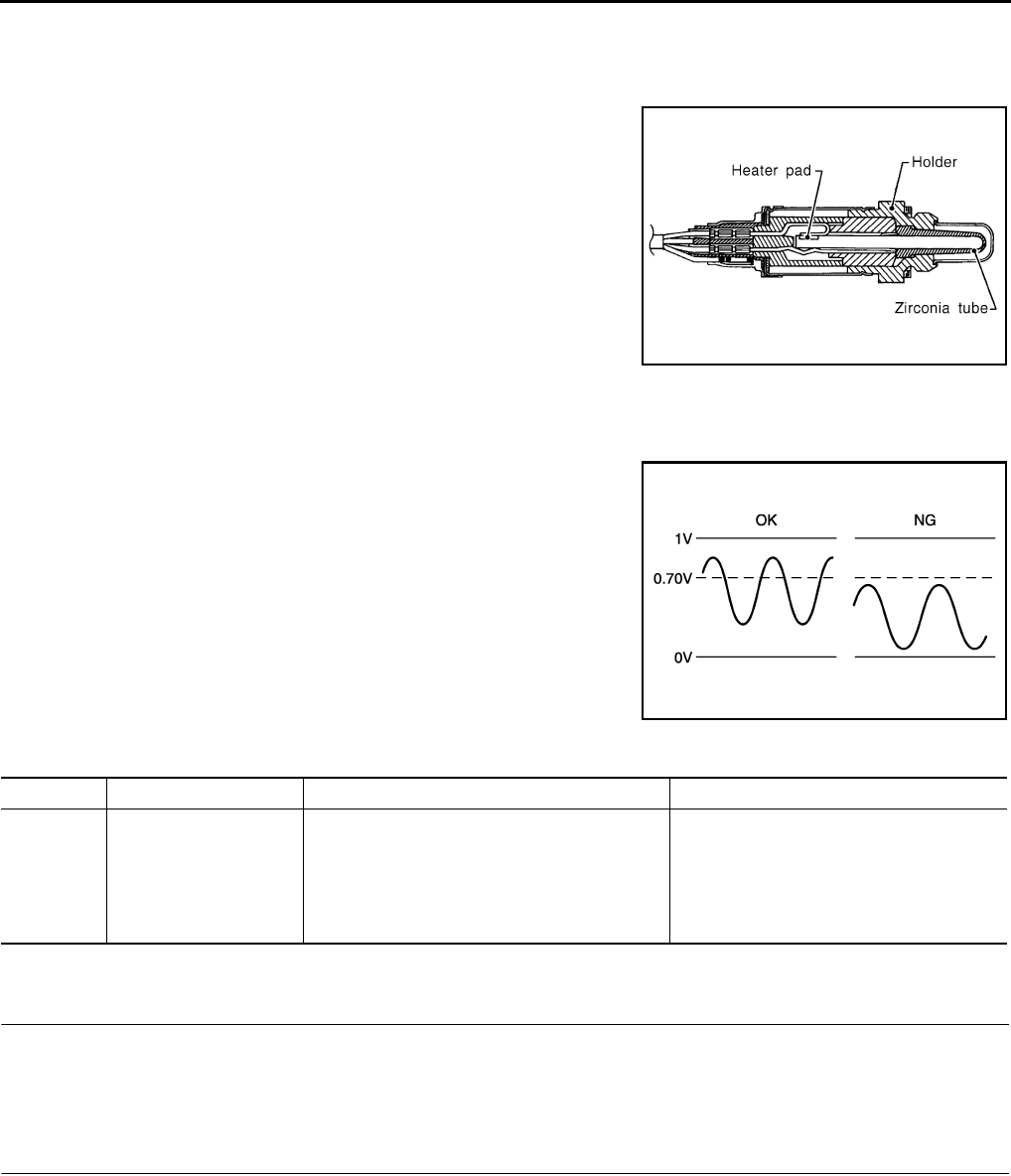
EC-216
< COMPONENT DIAGNOSIS > [FOR CALIFORNIA]
P0144 HO2S3
P0144 HO2S3
Description INFOID:0000000004493430
The heated oxygen sensor 3, after HC adsorption catalyst (Under
floor), monitors the oxygen level in the exhaust gas.
This sensor is made of ceramic zirconia. The zirconia generates volt-
age from approximately 1V in richer conditions to 0V in leaner condi-
tions.
Under normal conditions the heated oxygen sensor 3 is not used for
engine control operation.
DTC Logic INFOID:0000000004493431
DTC DETECTION LOGIC
The heated oxygen sensor 3 has a much longer switching time
between rich and lean than the air fuel ratio (A/F) sensor 1. The oxy-
gen storage capacity of the three way catalyst (manifold) causes the
longer switching time. To judge the malfunctions of heated oxygen
sensor 3, ECM monitors whether the maximum voltage of the sensor
is sufficiently high during various driving conditions such as fuel cut.
DTC CONFIRMATION PROCEDURE
1.PRECONDITIONING
If DTC CONFIRMATION PROCEDURE has been previously conducted, always turn ignition switch OFF and
wait at least 10 seconds before conducting the next test.
>> GO TO 2.
2.PERFORM DTC CONFIRMATION PROCEDURE
1. Start engine and warm it up to the normal operating temperature.
2. Repeat the following procedure 3 times.
- Drive vehicle at a speed of 80 km/h (50 MPH) or more for at least 3 consecutive minutes.
CAUTION:
Always drive vehicle in safe manner according to traffic conditions and obey all traffic laws.
NOTE:
•Keep the vehicle speed as steady as possible during the cruising.
•Never raise engine speed above 3,600 rpm in this step.
- Release accelerator pedal fully and stop vehicle with engine running.
NOTE:
SEF327R
JMBIA1669G
B
DTC No. Trouble diagnosis name DTC detecting condition Possible cause
P0144 Heated oxygen sensor 3
circuit low voltage
The maximum voltage from the sensor is not
reached to the specified voltage.
• Harness or connectors
(The sensor circuit is open or shorted)
• Heated oxygen sensor 3
• Fuel pressure
• Fuel injector
• Intake air leaks
Revision: 2008 August 2009 Rogue

P0144 HO2S3
EC-217
< COMPONENT DIAGNOSIS > [FOR CALIFORNIA]
C
D
E
F
G
H
I
J
K
L
M
A
EC
N
P
O
Never turn ignition switch OFF.
3. Check 1st trip DTC.
Is 1st tip DTC detected?
YES >> Go to EC-217, "Diagnosis Procedure".
NO >> INSPECTION END
Diagnosis Procedure INFOID:0000000004493432
1.CHECK GROUND CONNECTION
1. Turn ignition switch OFF.
2. Check ground connection E21. Refer to Ground Inspection in GI-44, "Circuit Inspection".
Is the inspection result normal?
YES >> GO TO 2.
NO >> Repair or replace ground connection.
2.CLEAR THE MIXTURE RATIO SELF-LEARNING VALUE
1. Clear the mixture ratio self-learning value. Refer to EC-29, "MIXTURE RATIO SELF-LEARNING VALUE
CLEAR : Special Repair Requirement".
2. Run engine for at least 10 minutes at idle speed.
Is the 1st trip DTC P0171 or P0172 detected? Is it difficult to start engine?
YES >> Perform trouble diagnosis for DTC P0171 or P0172. Refer to EC-231, "DTC Logic" or EC-235,
"DTC Logic".
NO >> GO TO 3.
3.CHECK HO2S3 GROUND CIRCUIT FOR OPEN AND SHORT
1. Turn ignition switch OFF.
2. Disconnect heated oxygen sensor 3 harness connector.
3. Disconnect ECM harness connector.
4. Check the continuity between HO2S3 harness connector and ECM harness connector.
5. Also check harness for short to ground and short to power.
Is the inspection result normal?
YES >> GO TO 5.
NO >> GO TO 4.
4.DETECT MALFUNCTIONING PART
Check the following.
• Harness connectors E7, F121
• Harness for open or short between heated oxygen sensor 3 and ECM
>> Repair open circuit or short to ground or short to power in harness or connectors.
5.CHECK HO2S3 INPUT SIGNAL CIRCUIT FOR OPEN AND SHORT
1. Check the continuity between HO2S3 harness connector and ECM harness connector.
2. Check the continuity between HO2S3 harness connector or ECM harness connector and ground.
HO2S3 ECM Continuity
Connector Terminal Connector Terminal
E50 1 F8 35 Existed
HO2S3 ECM Continuity
Connector Terminal Connector Terminal
E50 4 F8 34 Existed
Revision: 2008 August 2009 Rogue
EC-218
< COMPONENT DIAGNOSIS > [FOR CALIFORNIA]
P0144 HO2S3
3. Also check harness for short to power.
Is the inspection result normal?
YES >> GO TO 7.
NO >> GO TO 6.
6.DETECT MALFUNCTIONING PART
Check the following.
• Harness connectors E7, F121
• Harness for open or short between heated oxygen sensor 3 and ECM
>> Repair open circuit or short to ground or short to power in harness or connectors.
7.CHECK HEATED OXYGEN SENSOR 3
Refer to EC-218, "Component Inspection".
Is the inspection result normal?
YES >> GO TO 9.
NO >> GO TO 8.
8.REPLACE HEATED OXYGEN SENSOR 3
Replace heated oxygen sensor 3.
CAUTION:
• Discard any heated oxygen sensor which has been dropped from a height of more than 0.5 m (19.7
in) onto a hard surface such as a concrete floor; use a new one.
• Before installing new heated oxygen sensor, clean exhaust system threads using oxygen sensor
thread cleaner [commercial service tool (J-43897-18 or J-43897-12)] and approved anti-seize lubri-
cant (commercial service tool).
>> INSPECTION END
9.CHECK INTERMITTENT INCIDENT
Refer to GI-41, "Intermittent Incident".
>> INSPECTION END
Component Inspection INFOID:0000000004493433
1.INSPECTION START
Do you have CONSULT-III?
Do you have CONSULT-III?
YES >> GO TO 2.
NO >> GO TO 3.
2.CHECK HEATED OXYGEN SENSOR 3
With CONSULT-III
CAUTION:
Always drive vehicle in safe manner according to traffic conditions and obey all traffic laws.
1. Turn ignition switch ON and select “DATA MONITOR” mode with CONSULT-III.
2. Start engine and warm it up to the normal operating temperature.
3. Turn ignition switch OFF and wait at least 10 seconds.
4. Start the engine and drive vehicle at a speed of 80 km/h (50 MPH) or more for at least 3 consecutive min-
utes.
NOTE:
HO2S3 ECM Ground Continuity
Connector Terminal Connector Terminal
E50 4 F8 34 Ground Not existed
Revision: 2008 August 2009 Rogue
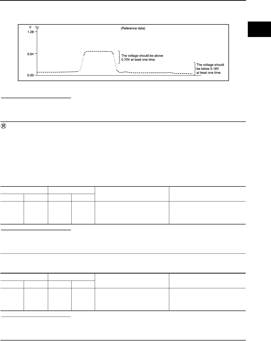
P0144 HO2S3
EC-219
< COMPONENT DIAGNOSIS > [FOR CALIFORNIA]
C
D
E
F
G
H
I
J
K
L
M
A
EC
N
P
O
Keep the vehicle speed as steady as possible during the cruising.
5. Select “FUEL INJECTION” in “ACTIVE TEST” mode, and select “HO2S3 (B1)” as the monitor item with
CONSULT-III.
6. Check “HO2S3 (B1)” at idle speed when adjusting “FUEL INJECTION” to ±25%.
“HO2S3 (B1)” should be above 0.70 V at least once when the “FUEL INJECTION” is +25%.
“HO2S3 (B1)” should be below 0.18 V at least once when the “FUEL INJECTION” is −25%.
Is the inspection result normal?
YES >> INSPECTION END
NO >> GO TO 6.
3.CHECK HEATED OXYGEN SENSOR 3-I
Without CONSULT-III
CAUTION:
Always drive vehicle in safe manner according to traffic conditions and obey all traffic laws.
1. Start engine and warm it up to the normal operating temperature.
2. Turn ignition switch OFF and wait at least 10 seconds.
3. Start the engine and drive vehicle at a speed of 80 km/h (50 MPH) or more for at least 3 consecutive min-
utes.
NOTE:
Keep the vehicle speed as steady as possible during the cruising.
4. Check the voltage between ECM harness connector terminals under the following condition.
Is the inspection result normal?
YES >> INSPECTION END
NO >> GO TO 4.
4.CHECK HEATED OXYGEN SENSOR 3-II
1. Keep vehicle at idling for 10 minutes.
2. Check the voltage between ECM harness connector and ground under the following condition.
Is the inspection result normal?
YES >> INSPECTION END
NO >> GO TO 5.
5.CHECK HEATED OXYGEN SENSOR 3-III
JMBIA1670G
B
ECM ECM Condition Voltage
Connector Terminal Connector Terminal
F8
34
(HO2S3
signal) F8
35
(Sensor
ground)
Revving up to 4,000 rpm under no load
at least 10 times
The voltage should be above 0.70 V at
least once during this procedure.
The voltage should be below 0.18 V at
least once during this procedure.
ECM ECM Condition Voltage
Connector Terminal Connector Terminal
F8
34
(HO2S3
signal)
F8
35
(Sensor
ground)
Revving up to 4,000 rpm under no load
at least 10 times
The voltage should be above 0.70 V at
least once during this procedure.
The voltage should be below 0.18 V at
least once during this procedure.
Revision: 2008 August 2009 Rogue

EC-220
< COMPONENT DIAGNOSIS > [FOR CALIFORNIA]
P0144 HO2S3
Check the voltage between ECM harness connector and ground under the following condition.
Is the inspection result normal?
YES >> INSPECTION END
NO >> GO TO 6.
6.REPLACE HEATED OXYGEN SENSOR 3
Replace heated oxygen sensor 3.
CAUTION:
• Discard any heated oxygen sensor which has been dropped from a height of more than 0.5 m (19.7
in) onto a hard surface such as a concrete floor; use a new one.
• Before installing new heated oxygen sensor, clean exhaust system threads using oxygen sensor
thread cleaner [commercial service tool (J-43897-18 or J-43897-12)] and approved anti-seize lubri-
cant (commercial service tool).
>> INSPECTION END
ECM ECM Condition Voltage
Connector Terminal Connector Terminal
F8
34
(HO2S3
signal) F8
35
(Sensor
ground)
Coasting from 80 km/h (50 MPH) in D
position
The voltage should be above 0.70 V at
least once during this procedure.
The voltage should be below 0.18 V at
least once during this procedure.
Revision: 2008 August 2009 Rogue
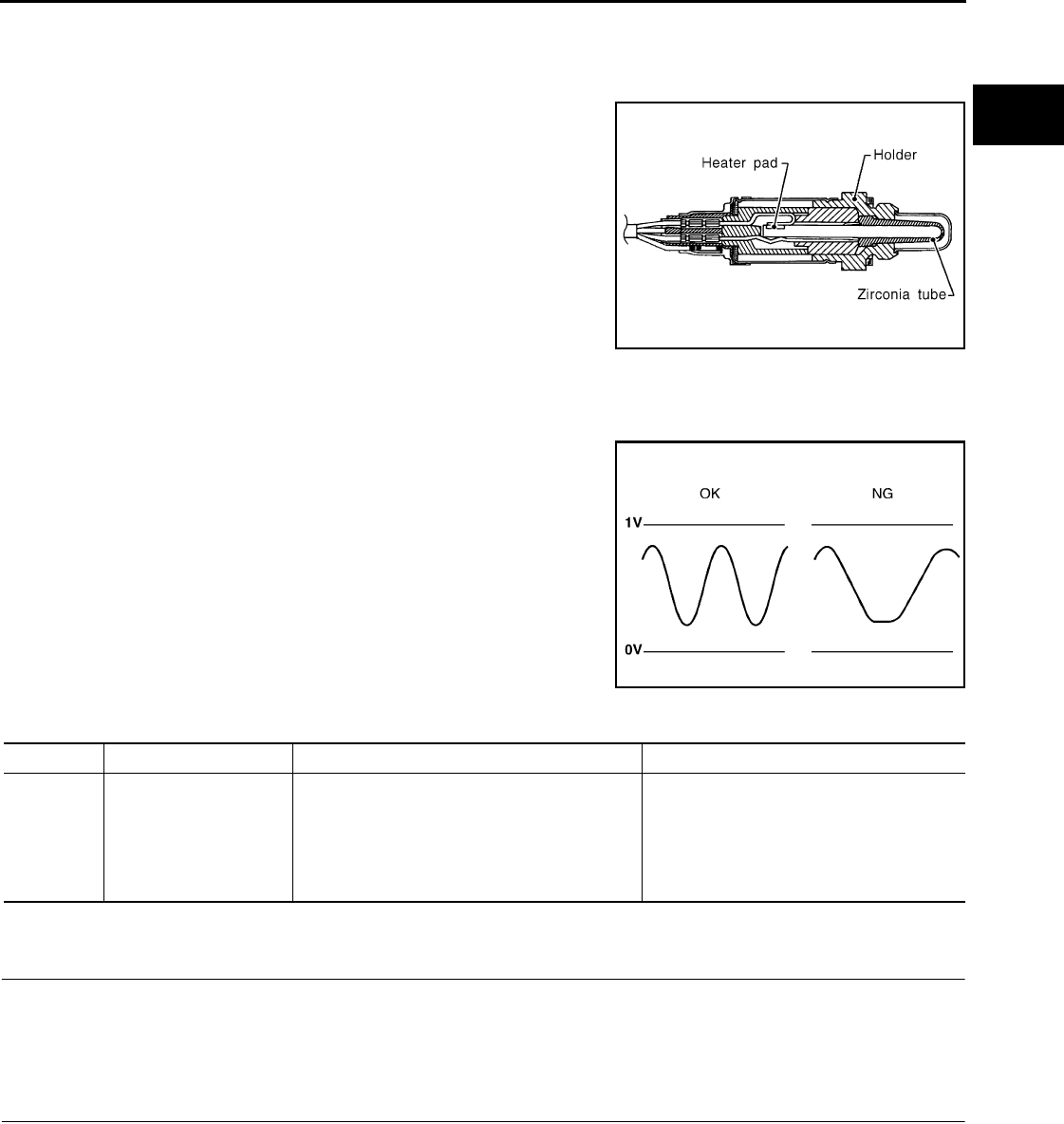
P0145 HO2S3
EC-221
< COMPONENT DIAGNOSIS > [FOR CALIFORNIA]
C
D
E
F
G
H
I
J
K
L
M
A
EC
N
P
O
P0145 HO2S3
Description INFOID:0000000004493434
The heated oxygen sensor 3, after HC adsorption catalyst (Under
floor), monitors the oxygen level in the exhaust gas.
This sensor is made of ceramic zirconia. The zirconia generates volt-
age from approximately 1V in richer conditions to 0V in leaner condi-
tions.
Under normal conditions the heated oxygen sensor 3 is not used for
engine control operation.
DTC Logic INFOID:0000000004493435
DTC DETECTION LOGIC
The heated oxygen sensor 3 has a much longer switching time
between rich and lean than the air fuel ratio (A/F) sensor 1. The oxy-
gen storage capacity of the three way catalyst (manifold) causes the
longer switching time. To judge the malfunctions of heated oxygen
sensor 3, ECM monitors whether the switching response of the sen-
sor's voltage is faster than specified during various driving conditions
such as fuel cut.
DTC CONFIRMATION PROCEDURE
1.PRECONDITIONING
If DTC CONFIRMATION PROCEDURE has been previously conducted, always turn ignition switch OFF and
wait at least 10 seconds before conducting the next test.
>> GO TO 2.
2.PERFORM DTC CONFIRMATION PROCEDURE
1. Start engine and warm it up to the normal operating temperature.
2. Repeat the following procedure 3 times.
- Drive vehicle at a speed of 80 km/h (50 MPH) or more for at least 3 consecutive minutes.
CAUTION:
Always drive vehicle in safe manner according to traffic conditions and obey all traffic laws.
NOTE:
•Keep the vehicle speed as steady as possible during the cruising.
•Never raise engine speed above 3,600 rpm in this step.
- Release accelerator pedal fully and stop vehicle with engine running.
NOTE:
SEF327R
SEF302U
DTC No. Trouble diagnosis name DTC detecting condition Possible cause
P0145 Heated oxygen sensor 3
circuit slow response
It takes more time for the sensor to respond be-
tween rich and lean than the specified time.
• Harness or connectors
(The sensor circuit is open or shorted)
• Heated oxygen sensor 3
• Fuel pressure
• Fuel injector
• Intake air leaks
Revision: 2008 August 2009 Rogue

EC-222
< COMPONENT DIAGNOSIS > [FOR CALIFORNIA]
P0145 HO2S3
Never turn ignition switch OFF.
3. Check 1st trip DTC.
Is 1st tip DTC detected?
YES >> Go to EC-222, "Diagnosis Procedure".
NO >> INSPECTION END
Diagnosis Procedure INFOID:0000000004493436
1.CHECK GROUND CONNECTION
1. Turn ignition switch OFF.
2. Check ground connection E21. Refer to Ground Inspection in GI-44, "Circuit Inspection".
Is the inspection result normal?
YES >> GO TO 2.
NO >> Repair or replace ground connection.
2.CLEAR THE MIXTURE RATIO SELF-LEARNING VALUE
1. Clear the mixture ratio self-learning value. Refer to EC-29, "MIXTURE RATIO SELF-LEARNING VALUE
CLEAR : Special Repair Requirement".
2. Run engine for at least 10 minutes at idle speed.
Is the 1st trip DTC P0171 or P0172 detected? Is it difficult to start engine?
YES >> Perform trouble diagnosis for DTC P0171 or P0172. Refer to EC-231, "DTC Logic" or EC-235,
"DTC Logic".
NO >> GO TO 3.
3.CHECK HO2S3 GROUND CIRCUIT FOR OPEN AND SHORT
1. Turn ignition switch OFF.
2. Disconnect heated oxygen sensor 3 harness connector.
3. Disconnect ECM harness connector.
4. Check the continuity between HO2S3 harness connector and ECM harness connector.
5. Also check harness for short to ground and short to power.
Is the inspection result normal?
YES >> GO TO 5.
NO >> GO TO 4.
4.DETECT MALFUNCTIONING PART
Check the following.
• Harness connectors E7, F121
• Harness for open or short between heated oxygen sensor 3 and ECM
>> Repair open circuit or short to ground or short to power in harness or connectors.
5.CHECK HO2S3 INPUT SIGNAL CIRCUIT FOR OPEN AND SHORT
1. Check the continuity between HO2S3 harness connector and ECM harness connector.
2. Check the continuity between HO2S3 harness connector or ECM harness connector and ground.
HO2S3 ECM Continuity
Connector Terminal Connector Terminal
E50 1 F8 35 Existed
HO2S3 ECM Continuity
Connector Terminal Connector Terminal
E50 4 F8 34 Existed
Revision: 2008 August 2009 Rogue

P0145 HO2S3
EC-223
< COMPONENT DIAGNOSIS > [FOR CALIFORNIA]
C
D
E
F
G
H
I
J
K
L
M
A
EC
N
P
O
3. Also check harness for short to power.
Is the inspection result normal?
YES >> GO TO 7.
NO >> GO TO 6.
6.DETECT MALFUNCTIONING PART
Check the following.
• Harness connectors E7, F121
• Harness for open or short between heated oxygen sensor 3 and ECM
>> Repair open circuit or short to ground or short to power in harness or connectors.
7.CHECK HEATED OXYGEN SENSOR 3
Refer to EC-223, "Component Inspection".
Is the inspection result normal?
YES >> GO TO 9.
NO >> GO TO 8.
8.REPLACE HEATED OXYGEN SENSOR 3
Replace heated oxygen sensor 3.
CAUTION:
• Discard any heated oxygen sensor which has been dropped from a height of more than 0.5 m (19.7
in) onto a hard surface such as a concrete floor; use a new one.
• Before installing new heated oxygen sensor, clean exhaust system threads using oxygen sensor
thread cleaner [commercial service tool (J-43897-18 or J-43897-12)] and approved anti-seize lubri-
cant (commercial service tool).
>> INSPECTION END
9.CHECK INTERMITTENT INCIDENT
Refer to GI-41, "Intermittent Incident".
>> INSPECTION END
Component Inspection INFOID:0000000004493437
1.INSPECTION START
Do you have CONSULT-III?
Do you have CONSULT-III?
YES >> GO TO 2.
NO >> GO TO 3.
2.CHECK HEATED OXYGEN SENSOR 3
With CONSULT-III
CAUTION:
Always drive vehicle in safe manner according to traffic conditions and obey all traffic laws.
1. Turn ignition switch ON and select “DATA MONITOR” mode with CONSULT-III.
2. Start engine and warm it up to the normal operating temperature.
3. Turn ignition switch OFF and wait at least 10 seconds.
4. Start the engine and drive vehicle at a speed of 80 km/h (50 MPH) or more for at least 3 consecutive min-
utes.
NOTE:
HO2S3 ECM Ground Continuity
Connector Terminal Connector Terminal
E50 4 F8 34 Ground Not existed
Revision: 2008 August 2009 Rogue
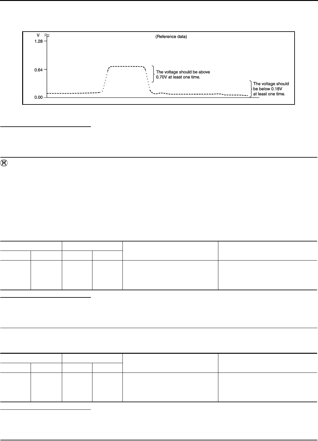
EC-224
< COMPONENT DIAGNOSIS > [FOR CALIFORNIA]
P0145 HO2S3
Keep the vehicle speed as steady as possible during the cruising.
5. Select “FUEL INJECTION” in “ACTIVE TEST” mode, and select “HO2S3 (B1)” as the monitor item with
CONSULT-III.
6. Check “HO2S3 (B1)” at idle speed when adjusting “FUEL INJECTION” to ±25%.
“HO2S3 (B1)” should be above 0.70 V at least once when the “FUEL INJECTION” is +25%.
“HO2S3 (B1)” should be below 0.18 V at least once when the “FUEL INJECTION” is −25%.
Is the inspection result normal?
YES >> INSPECTION END
NO >> GO TO 6.
3.CHECK HEATED OXYGEN SENSOR 3-I
Without CONSULT-III
CAUTION:
Always drive vehicle in safe manner according to traffic conditions and obey all traffic laws.
1. Start engine and warm it up to the normal operating temperature.
2. Turn ignition switch OFF and wait at least 10 seconds.
3. Start the engine and drive vehicle at a speed of 80 km/h (50 MPH) or more for at least 3 consecutive min-
utes.
NOTE:
Keep the vehicle speed as steady as possible during the cruising.
4. Check the voltage between ECM harness connector terminals under the following condition.
Is the inspection result normal?
YES >> INSPECTION END
NO >> GO TO 4.
4.CHECK HEATED OXYGEN SENSOR 3-II
1. Keep vehicle at idling for 10 minutes.
2. Check the voltage between ECM harness connector and ground under the following condition.
Is the inspection result normal?
YES >> INSPECTION END
NO >> GO TO 5.
5.CHECK HEATED OXYGEN SENSOR 3-III
JMBIA1670G
B
ECM ECM Condition Voltage
Connector Terminal Connector Terminal
F8
34
(HO2S3
signal) F8
35
(Sensor
ground)
Revving up to 4,000 rpm under no load
at least 10 times
The voltage should be above 0.70 V at
least once during this procedure.
The voltage should be below 0.18 V at
least once during this procedure.
ECM ECM Condition Voltage
Connector Terminal Connector Terminal
F8
34
(HO2S3
signal)
F8
35
(Sensor
ground)
Revving up to 4,000 rpm under no load
at least 10 times
The voltage should be above 0.70 V at
least once during this procedure.
The voltage should be below 0.18 V at
least once during this procedure.
Revision: 2008 August 2009 Rogue

P0145 HO2S3
EC-225
< COMPONENT DIAGNOSIS > [FOR CALIFORNIA]
C
D
E
F
G
H
I
J
K
L
M
A
EC
N
P
O
Check the voltage between ECM harness connector and ground under the following condition.
Is the inspection result normal?
YES >> INSPECTION END
NO >> GO TO 6.
6.REPLACE HEATED OXYGEN SENSOR 3
Replace heated oxygen sensor 3.
CAUTION:
• Discard any heated oxygen sensor which has been dropped from a height of more than 0.5 m (19.7
in) onto a hard surface such as a concrete floor; use a new one.
• Before installing new heated oxygen sensor, clean exhaust system threads using oxygen sensor
thread cleaner [commercial service tool (J-43897-18 or J-43897-12)] and approved anti-seize lubri-
cant (commercial service tool).
>> INSPECTION END
ECM ECM Condition Voltage
Connector Terminal Connector Terminal
F8
34
(HO2S3
signal) F8
35
(Sensor
ground)
Coasting from 80 km/h (50 MPH) in D
position
The voltage should be above 0.70 V at
least once during this procedure.
The voltage should be below 0.18 V at
least once during this procedure.
Revision: 2008 August 2009 Rogue
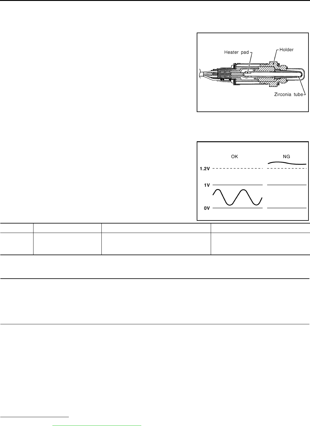
EC-226
< COMPONENT DIAGNOSIS > [FOR CALIFORNIA]
P0146 HO2S3
P0146 HO2S3
Description INFOID:0000000004493438
The heated oxygen sensor 3, after HC adsorption catalyst (Under
floor), monitors the oxygen level in the exhaust gas.
This sensor is made of ceramic zirconia. The zirconia generates volt-
age from approximately 1V in richer conditions to 0V in leaner condi-
tions.
Under normal conditions the heated oxygen sensor 3 is not used for
engine control operation.
DTC Logic INFOID:0000000004493439
DTC DETECTION LOGIC
The heated oxygen sensor 3 has a much longer switching time
between rich and lean than the air fuel ratio (A/F) sensor 1. The oxy-
gen storage capacity of the three way catalyst (manifold) causes the
longer switching time. To judge the malfunctions of heated oxygen
sensor 3, ECM monitors whether the voltage is unusually high during
various driving conditions such as fuel cut.
DTC CONFIRMATION PROCEDURE
1.PRECONDITIONING
If DTC CONFIRMATION PROCEDURE has been previously conducted, always turn ignition switch OFF and
wait at least 10 seconds before conducting the next test.
>> GO TO 2.
2.PERFORM DTC CONFIRMATION PROCEDURE
1. Start engine and warm it up to the normal operating temperature.
2. Repeat the following procedure 3 times.
- Drive vehicle at a speed of 80 km/h (50 MPH) or more for at least 3 consecutive minutes.
CAUTION:
Always drive vehicle in safe manner according to traffic conditions and obey all traffic laws.
NOTE:
•Keep the vehicle speed as steady as possible during the cruising.
•Never raise engine speed above 3,600 rpm in this step.
- Release accelerator pedal fully and stop vehicle with engine running.
NOTE:
Never turn ignition switch OFF.
3. Check 1st trip DTC.
Is 1st tip DTC detected?
YES >> Go to EC-227, "Diagnosis Procedure".
NO >> INSPECTION END
SEF327R
PBIB1848E
DTC No. Trouble diagnosis name DTC detecting condition Possible cause
P0146 Heated oxygen sensor 3
circuit no activity detected
An excessively high voltage from the sensor is
sent to ECM.
• Harness or connectors
(The sensor circuit is open or shorted)
• Heated oxygen sensor 3
Revision: 2008 August 2009 Rogue

P0146 HO2S3
EC-227
< COMPONENT DIAGNOSIS > [FOR CALIFORNIA]
C
D
E
F
G
H
I
J
K
L
M
A
EC
N
P
O
Diagnosis Procedure INFOID:0000000004493440
1.CHECK GROUND CONNECTION
1. Turn ignition switch OFF.
2. Check ground connection E21. Refer to Ground Inspection in GI-44, "Circuit Inspection".
Is the inspection result normal?
YES >> GO TO 2.
NO >> Repair or replace ground connection.
2.CHECK HO2S3 GROUND CIRCUIT FOR OPEN AND SHORT
1. Turn ignition switch OFF.
2. Disconnect heated oxygen sensor 3 harness connector.
3. Disconnect ECM harness connector.
4. Check the continuity between HO2S3 harness connector and ECM harness connector.
5. Also check harness for short to ground and short to power.
Is the inspection result normal?
YES >> GO TO 4.
NO >> GO TO 3.
3.DETECT MALFUNCTIONING PART
Check the following.
• Harness connectors E7, F121
• Harness for open or short between heated oxygen sensor 3 and ECM
>> Repair open circuit or short to ground or short to power in harness or connectors.
4.CHECK HO2S3 INPUT SIGNAL CIRCUIT FOR OPEN AND SHORT
1. Check the continuity between HO2S3 harness connector and ECM harness connector.
2. Check the continuity between HO2S3 harness connector or ECM harness connector and ground.
3. Also check harness for short to power.
Is the inspection result normal?
YES >> GO TO 6.
NO >> GO TO 5.
5.DETECT MALFUNCTIONING PART
Check the following.
• Harness connectors E7, F121
• Harness for open or short between heated oxygen sensor 3 and ECM
>> Repair open circuit or short to ground or short to power in harness or connectors.
HO2S3 ECM Continuity
Connector Terminal Connector Terminal
E50 1 F8 35 Existed
HO2S3 ECM Continuity
Connector Terminal Connector Terminal
E50 4 F8 34 Existed
HO2S3 ECM Ground Continuity
Connector Terminal Connector Terminal
E50 4 F8 34 Ground Not existed
Revision: 2008 August 2009 Rogue

EC-228
< COMPONENT DIAGNOSIS > [FOR CALIFORNIA]
P0146 HO2S3
6.CHECK HO2S3 CONNECTOR FOR WATER
Check connectors for water.
Is the inspection result normal?
YES >> GO TO 7.
NO >> Repair or replace harness or connectors.
7.CHECK HEATED OXYGEN SENSOR 3
Refer to EC-228, "Component Inspection".
Is the inspection result normal?
YES >> GO TO 9.
NO >> GO TO 8.
8.REPLACE HEATED OXYGEN SENSOR 3
Replace heated oxygen sensor 3.
CAUTION:
• Discard any heated oxygen sensor which has been dropped from a height of more than 0.5 m (19.7
in) onto a hard surface such as a concrete floor; use a new one.
• Before installing new heated oxygen sensor, clean exhaust system threads using oxygen sensor
thread cleaner [commercial service tool (J-43897-18 or J-43897-12)] and approved anti-seize lubri-
cant (commercial service tool).
>> INSPECTION END
9.CHECK INTERMITTENT INCIDENT
Refer to GI-41, "Intermittent Incident".
>> INSPECTION END
Component Inspection INFOID:0000000004493441
1.INSPECTION START
Do you have CONSULT-III?
Do you have CONSULT-III?
YES >> GO TO 2.
NO >> GO TO 3.
2.CHECK HEATED OXYGEN SENSOR 3
With CONSULT-III
CAUTION:
Always drive vehicle in safe manner according to traffic conditions and obey all traffic laws.
1. Turn ignition switch ON and select “DATA MONITOR” mode with CONSULT-III.
2. Start engine and warm it up to the normal operating temperature.
3. Turn ignition switch OFF and wait at least 10 seconds.
4. Start the engine and drive vehicle at a speed of 80 km/h (50 MPH) or more for at least 3 consecutive min-
utes.
NOTE:
Keep the vehicle speed as steady as possible during the cruising.
5. Select “FUEL INJECTION” in “ACTIVE TEST” mode, and select “HO2S3 (B1)” as the monitor item with
CONSULT-III.
Water should not exist.
Revision: 2008 August 2009 Rogue
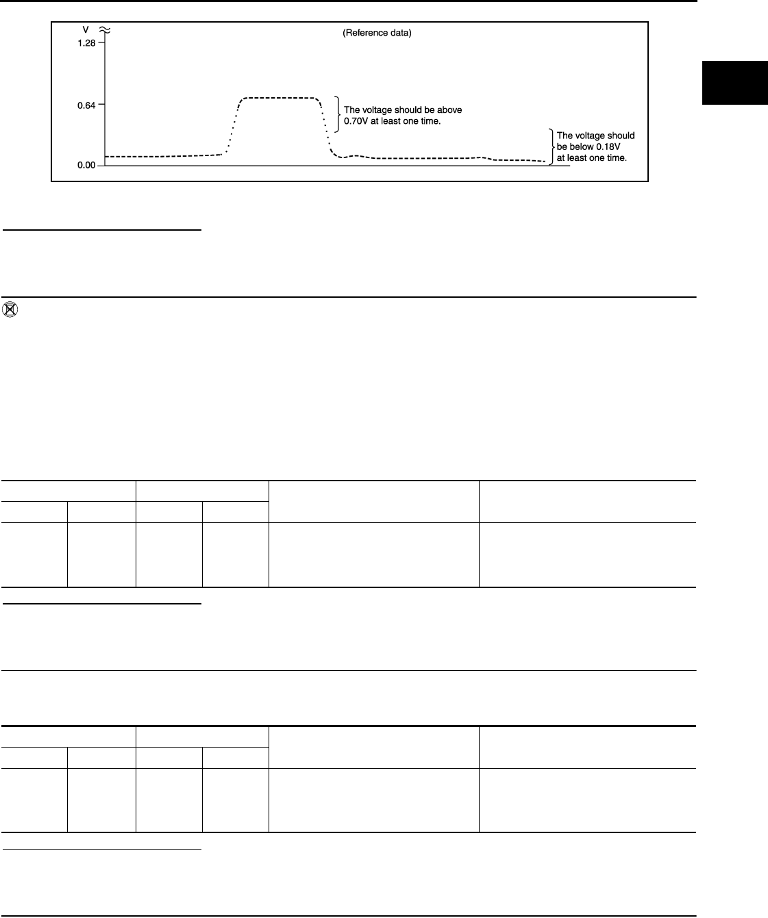
P0146 HO2S3
EC-229
< COMPONENT DIAGNOSIS > [FOR CALIFORNIA]
C
D
E
F
G
H
I
J
K
L
M
A
EC
N
P
O
6. Check “HO2S3 (B1)” at idle speed when adjusting “FUEL INJECTION” to ±25%.
“HO2S3 (B1)” should be above 0.70 V at least once when the “FUEL INJECTION” is +25%.
“HO2S3 (B1)” should be below 0.18 V at least once when the “FUEL INJECTION” is −25%.
Is the inspection result normal?
YES >> INSPECTION END
NO >> GO TO 6.
3.CHECK HEATED OXYGEN SENSOR 3-I
Without CONSULT-III
CAUTION:
Always drive vehicle in safe manner according to traffic conditions and obey all traffic laws.
1. Start engine and warm it up to the normal operating temperature.
2. Turn ignition switch OFF and wait at least 10 seconds.
3. Start the engine and drive vehicle at a speed of 80 km/h (50 MPH) or more for at least 3 consecutive min-
utes.
NOTE:
Keep the vehicle speed as steady as possible during the cruising.
4. Check the voltage between ECM harness connector terminals under the following condition.
Is the inspection result normal?
YES >> INSPECTION END
NO >> GO TO 4.
4.CHECK HEATED OXYGEN SENSOR 3-II
1. Keep vehicle at idling for 10 minutes.
2. Check the voltage between ECM harness connector and ground under the following condition.
Is the inspection result normal?
YES >> INSPECTION END
NO >> GO TO 5.
5.CHECK HEATED OXYGEN SENSOR 3-III
Check the voltage between ECM harness connector and ground under the following condition.
JMBIA1670G
B
ECM ECM Condition Voltage
Connector Terminal Connector Terminal
F8
34
(HO2S3
signal) F8
35
(Sensor
ground)
Revving up to 4,000 rpm under no load
at least 10 times
The voltage should be above 0.70 V at
least once during this procedure.
The voltage should be below 0.18 V at
least once during this procedure.
ECM ECM Condition Voltage
Connector Terminal Connector Terminal
F8
34
(HO2S3
signal)
F8
35
(Sensor
ground)
Revving up to 4,000 rpm under no load
at least 10 times
The voltage should be above 0.70 V at
least once during this procedure.
The voltage should be below 0.18 V at
least once during this procedure.
Revision: 2008 August 2009 Rogue

EC-230
< COMPONENT DIAGNOSIS > [FOR CALIFORNIA]
P0146 HO2S3
Is the inspection result normal?
YES >> INSPECTION END
NO >> GO TO 6.
6.REPLACE HEATED OXYGEN SENSOR 3
Replace heated oxygen sensor 3.
CAUTION:
• Discard any heated oxygen sensor which has been dropped from a height of more than 0.5 m (19.7
in) onto a hard surface such as a concrete floor; use a new one.
• Before installing new heated oxygen sensor, clean exhaust system threads using oxygen sensor
thread cleaner [commercial service tool (J-43897-18 or J-43897-12)] and approved anti-seize lubri-
cant (commercial service tool).
>> INSPECTION END
ECM ECM Condition Voltage
Connector Terminal Connector Terminal
F8
34
(HO2S3
signal) F8
35
(Sensor
ground)
Coasting from 80 km/h (50 MPH) in D
position
The voltage should be above 0.70 V at
least once during this procedure.
The voltage should be below 0.18 V at
least once during this procedure.
Revision: 2008 August 2009 Rogue

P0171 FUEL INJECTION SYSTEM FUNCTION
EC-231
< COMPONENT DIAGNOSIS > [FOR CALIFORNIA]
C
D
E
F
G
H
I
J
K
L
M
A
EC
N
P
O
P0171 FUEL INJECTION SYSTEM FUNCTION
DTC Logic INFOID:0000000004493442
DTC DETECTION LOGIC
With the Air/Fuel Mixture Ratio Self-Learning Control, the actual mixture ratio can be brought closely to the
theoretical mixture ratio based on the mixture ratio feedback signal from A/F sensor 1. The ECM calculates
the necessary compensation to correct the offset between the actual and the theoretical ratios.
In case the amount of the compensation value is extremely large (the actual mixture ratio is too lean.), the
ECM judges the condition as the fuel injection system malfunction and illuminates the MIL (2 trip detection
logic).
DTC CONFIRMATION PROCEDURE
1.PRECONDITIONING
If DTC CONFIRMATION PROCEDURE has been previously conducted, always turn ignition switch OFF and
wait at least 10 seconds before conducting the next test.
>> GO TO 2.
2.PERFORM DTC CONFIRMATION PROCEDURE-I
1. Clear the mixture ratio self-learning value. Refer to EC-29, "MIXTURE RATIO SELF-LEARNING VALUE
CLEAR : Special Repair Requirement".
2. Start engine.
Is it difficult to start engine?
YES >> GO TO 3.
NO >> GO TO 4.
3.RESTART ENGINE
If it is difficult to start engine, the fuel injection system has a malfunction, too.
Crank engine while depressing accelerator pedal.
NOTE:
When depressing accelerator pedal three-fourths (3/4) or more, the control system does not start the
engine. Do not depress accelerator pedal too much.
Does engine start?
YES >> Go to EC-232, "Diagnosis Procedure".
NO >> Check exhaust and intake air leak visually.
4.PERFORM DTC CONFIRMATION PROCEDURE-II
1. Start engine and let it idle for at least 5 minutes.
2. Check 1st trip DTC.
Is 1st trip DTC detected?
YES >> Go to EC-232, "Diagnosis Procedure".
NO >> GO TO 5.
Sensor Input signal to ECM ECM function Actuator
A/F sensor 1 Density of oxygen in exhaust gas
(Mixture ratio feedback signal) Fuel injection control Fuel injector
DTC No. Trouble diagnosis name DTC detecting condition Possible cause
P0171 Fuel injection system too
lean
• Fuel injection system does not operate properly.
• The amount of mixture ratio compensation is too
large. (The mixture ratio is too lean.)
• Intake air leaks
• A/F sensor 1
• Fuel injector
• Exhaust gas leaks
• Incorrect fuel pressure
• Lack of fuel
• Mass air flow sensor
• Incorrect PCV hose connection
Revision: 2008 August 2009 Rogue

EC-232
< COMPONENT DIAGNOSIS > [FOR CALIFORNIA]
P0171 FUEL INJECTION SYSTEM FUNCTION
5.PERFORM DTC CONFIRMATION PROCEDURE-III
1. Turn ignition switch OFF and wait at least 10 seconds.
2. Start engine.
3. Maintain the following conditions for at least 10 consecutive minutes.
Hold the accelerator pedal as steady as possible.
CAUTION:
Always drive vehicle at a safe speed.
4. Check 1st trip DTC.
Is 1st trip DTC detected?
YES >> Go to EC-232, "Diagnosis Procedure".
NO >> INSPECTION END
Diagnosis Procedure INFOID:0000000004493443
1.CHECK EXHAUST GAS LEAK
1. Start engine and run it at idle.
2. Listen for an exhaust gas leak before three way catalyst (manifold).
Is exhaust gas leak detected?
YES >> Repair or replace.
NO >> GO TO 2.
2.CHECK FOR INTAKE AIR LEAK
1. Listen for an intake air leak after the mass air flow sensor.
2. Check PCV hose connection.
Intake air leak detected?
YES >> Repair or replace.
NO >> GO TO 3.
3.CHECK A/F SENSOR 1 INPUT SIGNAL CIRCUIT
1. Turn ignition switch OFF.
2. Disconnect corresponding A/F sensor 1 harness connector.
3. Disconnect ECM harness connector.
4. Check the continuity between A/F sensor 1 harness connector and ECM harness connector.
5. Check the continuity between A/F sensor 1 harness connector or ECM harness connector and ground.
VHCL SPEED SE 50 - 120 km/h (31 - 75 MPH)
JMBIA0163G
B
A/F sensor 1 ECM Continuity
Connector Terminal Connector Terminal
F28 1F8 45 Existed
249
Revision: 2008 August 2009 Rogue

P0171 FUEL INJECTION SYSTEM FUNCTION
EC-233
< COMPONENT DIAGNOSIS > [FOR CALIFORNIA]
C
D
E
F
G
H
I
J
K
L
M
A
EC
N
P
O
6. Also check harness for short to power.
Is the inspection result normal?
YES >> GO TO 4.
NO >> Repair open circuit or short to ground or short to power in harness or connectors.
4.CHECK FUEL PRESSURE
1. Check fuel pressure. Refer to EC-489, "Inspection".
Is the inspection result normal?
YES >> GO TO 6.
NO >> GO TO 5.
5. DETECT MALFUNCTIONING PART
Check fuel hoses and fuel tubes for clogging.
Is the inspection result normal?
YES >> Replace “fuel filter and fuel pump assembly”.
NO >> Repair or replace
6.CHECK MASS AIR FLOW SENSOR
With CONSULT-III
1. Install all removed parts.
2. Check “MASS AIR FLOW” in “DATA MONITOR” mode with CONSULT-III.
For specification, refer to EC-494, "Mass Air Flow Sensor".
With GST
1. Install all removed parts.
2. Check mass air flow sensor signal in Service $01 with GST.
For specification, refer to EC-494, "Mass Air Flow Sensor".
Is the measurement value within the specification?
YES >> GO TO 7.
NO >> Check connectors for rusted terminals or loose connections in the mass air flow sensor circuit or
grounds. Refer to EC-147, "DTC Logic".
7.CHECK FUNCTION OF FUEL INJECTOR
With CONSULT-III
1. Start engine.
2. Perform “POWER BALANCE” in “ACTIVE TEST” mode with CONSULT-III.
3. Check that each circuit produces a momentary engine speed drop.
Without CONSULT-III
1. Let engine idle.
2. Listen to each fuel injector operating sound.
Is the inspection result normal?
YES >> GO TO 8.
NO >> Perform trouble diagnosis for FUEL INJECTOR, refer to
EC-419, "Component Function Check".
A/F sensor 1 ECM Ground Continuity
Connector Terminal Connector Terminal
F28 1F8 45 Ground Not existed
249
Clicking noise should be heard.
PBIB3332E
Revision: 2008 August 2009 Rogue

EC-234
< COMPONENT DIAGNOSIS > [FOR CALIFORNIA]
P0171 FUEL INJECTION SYSTEM FUNCTION
8.CHECK FUEL INJECTOR
1. Turn ignition switch OFF.
2. Confirm that the engine is cooled down and there are no fire hazards near the vehicle.
3. Disconnect all fuel injector harness connectors.
4. Remove fuel tube assembly. Refer to EM-43, "Removal and Installation".
Keep fuel hose and all fuel injectors connected to fuel tube.
5. Disconnect all ignition coil harness connectors.
6. Prepare pans or saucers under each fuel injector.
7. Crank engine for approximately 3 seconds.
Is the inspection result normal?
YES >> GO TO 9.
NO >> Replace fuel injectors from which fuel does not spray
out. Always replace O-ring with new ones.
9.CHECK INTERMITTENT INCIDENT
Refer to GI-41, "Intermittent Incident".
>> INSPECTION END
Fuel should be sprayed evenly for each fuel injector.
PBIA9666J
Revision: 2008 August 2009 Rogue

P0172 FUEL INJECTION SYSTEM FUNCTION
EC-235
< COMPONENT DIAGNOSIS > [FOR CALIFORNIA]
C
D
E
F
G
H
I
J
K
L
M
A
EC
N
P
O
P0172 FUEL INJECTION SYSTEM FUNCTION
DTC Logic INFOID:0000000004493444
DTC DETECTION LOGIC
With the Air/Fuel Mixture Ratio Self-Learning Control, the actual mixture ratio can be brought closely to the
theoretical mixture ratio based on the mixture ratio feedback signal from A/F sensor 1. The ECM calculates
the necessary compensation to correct the offset between the actual and the theoretical ratios.
In case the amount of the compensation value is extremely large (the actual mixture ratio is too rich.), the
ECM judges the condition as the fuel injection system malfunction and illuminates the MIL (2 trip detection
logic).
DTC CONFIRMATION PROCEDURE
1.PRECONDITIONING
If DTC CONFIRMATION PROCEDURE has been previously conducted, always turn ignition switch OFF and
wait at least 10 seconds before conducting the next test.
>> GO TO 2.
2.PERFORM DTC CONFIRMATION PROCEDURE-I
1. Clear the mixture ratio self-learning value. Refer to EC-29, "MIXTURE RATIO SELF-LEARNING VALUE
CLEAR : Special Repair Requirement".
2. Start engine.
Is it difficult to start engine?
YES >> GO TO 3.
NO >> GO TO 4.
3.RESTART ENGINE
If it is difficult to start engine, the fuel injection system has a malfunction, too.
Crank engine while depressing accelerator pedal.
NOTE:
When depressing accelerator pedal three-fourths (3/4) or more, the control system does not start the
engine. Do not depress accelerator pedal too much.
Does engine start?
YES >> Go to EC-236, "Diagnosis Procedure".
NO >> Remove spark plugs and check for fouling, etc.
4.PERFORM DTC CONFIRMATION PROCEDURE-II
1. Start engine and let it idle for at least 5 minutes.
2. Check 1st trip DTC.
Is 1st trip DTC detected?
YES >> Go to EC-236, "Diagnosis Procedure".
NO >> GO TO 5.
5.PERFORM DTC CONFIRMATION PROCEDURE-III
1. Turn ignition switch OFF and wait at least 10 seconds.
Sensor Input signal to ECM ECM function Actuator
A/F sensor 1 Density of oxygen in exhaust gas
(Mixture ratio feedback signal) Fuel injection control Fuel injector
DTC No. Trouble diagnosis name DTC detecting condition Possible cause
P0172 Fuel injection system too
rich
• Fuel injection system does not operate properly.
• The amount of mixture ratio compensation is too
large. (The mixture ratio is too rich.)
• A/F sensor 1
• Fuel injector
• Exhaust gas leaks
• Incorrect fuel pressure
• Mass air flow sensor
Revision: 2008 August 2009 Rogue

EC-236
< COMPONENT DIAGNOSIS > [FOR CALIFORNIA]
P0172 FUEL INJECTION SYSTEM FUNCTION
2. Start engine.
3. Maintain the following conditions for at least 10 consecutive minutes.
Hold the accelerator pedal as steady as possible.
CAUTION:
Always drive vehicle at a safe speed.
4. Check 1st trip DTC.
Is 1st trip DTC detected?
YES >> Go to EC-236, "Diagnosis Procedure".
NO >> INSPECTION END
Diagnosis Procedure INFOID:0000000004493445
1.CHECK EXHAUST GAS LEAK
1. Start engine and run it at idle.
2. Listen for an exhaust gas leak before three way catalyst (manifold).
Is exhaust gas leak detected?
YES >> Repair or replace.
NO >> GO TO 2.
2.CHECK FOR INTAKE AIR LEAK
Listen for an intake air leak after the mass air flow sensor.
Is intake air leak detected?
YES >> Repair or replace.
NO >> GO TO 3.
3.CHECK A/F SENSOR 1 INPUT SIGNAL CIRCUIT
1. Turn ignition switch OFF.
2. Disconnect corresponding A/F sensor 1 harness connector.
3. Disconnect ECM harness connector.
4. Check the continuity between A/F sensor 1 harness connector and ECM harness connector.
5. Check the continuity between A/F sensor 1 harness connector or ECM harness connector and ground.
6. Also check harness for short to power.
VHCL SPEED SE 50 - 120 km/h (31 - 75 MPH)
JMBIA0163G
B
A/F sensor 1 ECM Continuity
Connector Terminal Connector Terminal
F28 1F8 45 Existed
249
A/F sensor 1 ECM Ground Continuity
Connector Terminal Connector Terminal
F28 1F8 45 Ground Not existed
249
Revision: 2008 August 2009 Rogue
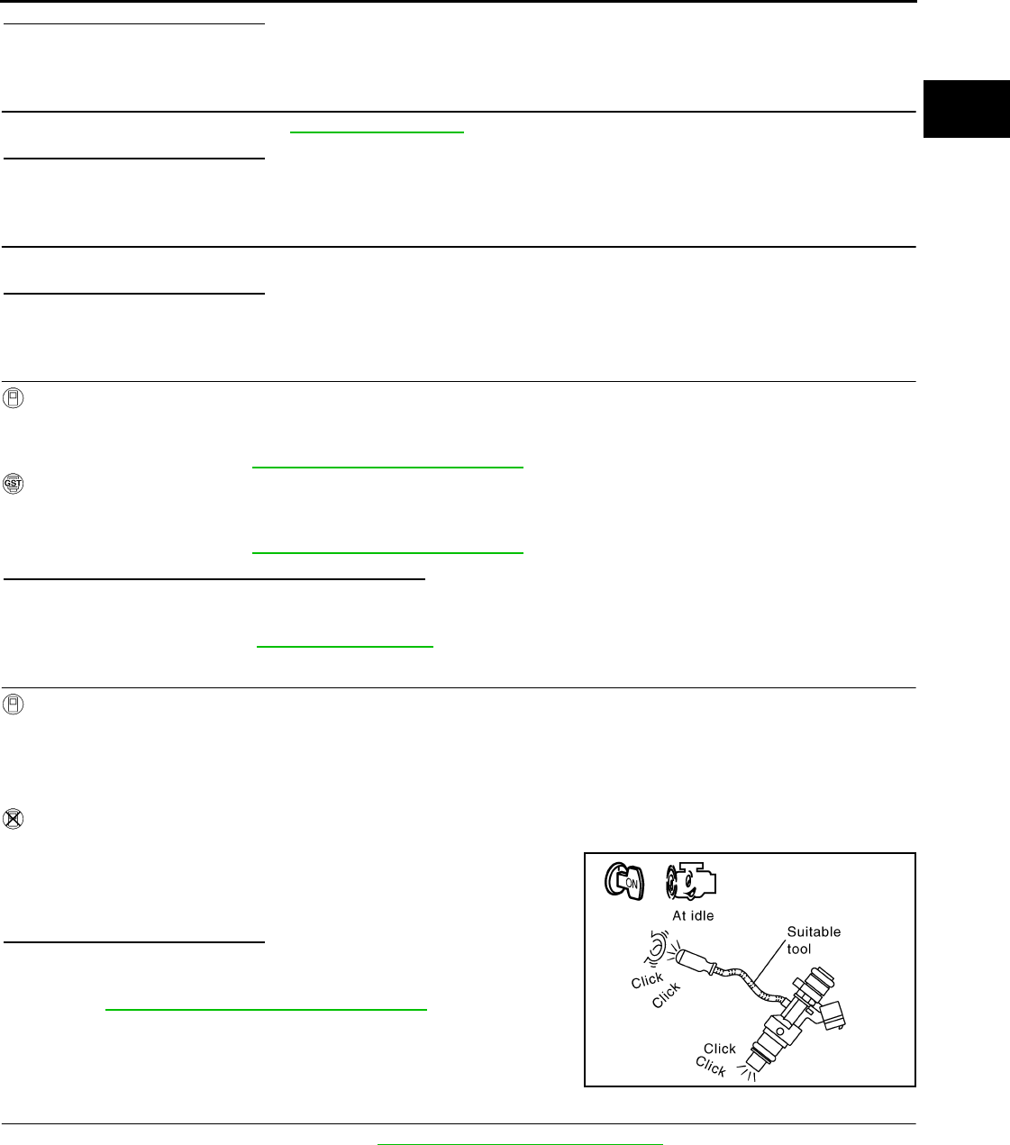
P0172 FUEL INJECTION SYSTEM FUNCTION
EC-237
< COMPONENT DIAGNOSIS > [FOR CALIFORNIA]
C
D
E
F
G
H
I
J
K
L
M
A
EC
N
P
O
Is the inspection result normal?
YES >> GO TO 4.
NO >> Repair open circuit or short to ground or short to power in harness or connectors.
4.CHECK FUEL PRESSURE
1. Check fuel pressure. Refer to EC-489, "Inspection".
Is the inspection result normal?
YES >> GO TO 6.
NO >> GO TO 5.
5. DETECT MALFUNCTIONING PART
Check fuel hoses and fuel tubes for clogging.
Is the inspection result normal?
YES >> Replace “fuel filter and fuel pump assembly”.
NO >> Repair or replace
6.CHECK MASS AIR FLOW SENSOR
With CONSULT-III
1. Install all removed parts.
2. Check “MASS AIR FLOW” in “DATA MONITOR” mode with CONSULT-III.
For specification, refer to EC-494, "Mass Air Flow Sensor".
With GST
1. Install all removed parts.
2. Check mass air flow sensor signal in “Service $01” with GST.
For specification, refer to EC-494, "Mass Air Flow Sensor".
Is the measurement value within the specification?
YES >> GO TO 7.
NO >> Check connectors for rusted terminals or loose connections in the mass air flow sensor circuit or
grounds. Refer to EC-147, "DTC Logic".
7.CHECK FUNCTION OF FUEL INJECTOR
With CONSULT-III
1. Start engine.
2. Perform “POWER BALANCE” in “ACTIVE TEST” mode with CONSULT-III.
3. Check that each circuit produces a momentary engine speed drop.
Without CONSULT-III
1. Let engine idle.
2. Listen to each fuel injector operating sound.
Is the inspection result normal?
YES >> GO TO 8.
NO >> Perform trouble diagnosis for FUEL INJECTOR, refer to
EC-419, "Component Function Check".
8.CHECK FUEL INJECTOR
1. Remove fuel injector assembly. Refer to EM-43, "Removal and Installation".
Keep fuel hose and all fuel injectors connected to fuel tube.
2. Confirm that the engine is cooled down and there are no fire hazards near the vehicle.
3. Disconnect all fuel injector harness connectors.
4. Disconnect all ignition coil harness connectors.
5. Prepare pans or saucers under each fuel injector.
6. Crank engine for approximately 3 seconds.
Clicking noise should be heard.
PBIB3332E
Revision: 2008 August 2009 Rogue

EC-238
< COMPONENT DIAGNOSIS > [FOR CALIFORNIA]
P0172 FUEL INJECTION SYSTEM FUNCTION
Check that fuel does not drip from fuel injector.
Is the inspection result normal?
YES >> GO TO 9.
NO >> Replace the fuel injectors from which fuel is dripping. Always replace O-ring with new one.
9.CHECK INTERMITTENT INCIDENT
Refer to GI-41, "Intermittent Incident".
>> INSPECTION END
Revision: 2008 August 2009 Rogue

P0181 FTT SENSOR
EC-239
< COMPONENT DIAGNOSIS > [FOR CALIFORNIA]
C
D
E
F
G
H
I
J
K
L
M
A
EC
N
P
O
P0181 FTT SENSOR
Description INFOID:0000000004493446
The fuel tank temperature sensor is used to detect the fuel tempera-
ture inside the fuel tank. The sensor modifies a voltage signal from
the ECM. The modified signal returns to the ECM as the fuel temper-
ature input. The sensor uses a thermistor which is sensitive to the
change in temperature. The electrical resistance of the thermistor
decreases as temperature increases.
<Reference data>
*: These data are reference values and are measured between ECM terminals 95 (Fuel tank temperature sensor) and 104 (Sensor
ground).
DTC Logic INFOID:0000000004493447
DTC DETECTION LOGIC
DTC CONFIRMATION PROCEDURE
1.PRECONDITIONING
If DTC CONFIRMATION PROCEDURE has been previously conducted, always turn ignition switch OFF and
wait at least 10 seconds before conducting the next test.
>> GO TO 2.
2.PERFORM DTC CONFIRMATION PROCEDURE-I
1. Turn ignition switch and wait at least 10 seconds.
2. Check 1st trip DTC.
Is 1st trip DTC detected?
YES >> Go to EC-240, "Diagnosis Procedure".
NO >> GO TO 3.
3.CHECK ENGINE COOLANT TEMPERATURE
With CONSULT-III
1. Select “COOLAN TEMP/S” in “DATA MONITOR” mode with CONSULT-III.
2. Check “COOLAN TEMP/S” indication.
With GST
Follow the procedure “With CONSULT-III” above.
Is “COOLAN TEMP/S” indication less than 60°C (140°F)?
YES >> INSPECTION END
NO >> GO TO 4.
4.PERFORM DTC CONFIRMATION PROCEDURE-II
With CONSULT-III
1. Cool engine down until “COOLAN TEMP/S” indication is less than 60°C (140°F).
Fluid temperature
[°C (°F)]
Voltage*
(V)
Resistance
(kΩ)
20 (68) 3.5 2.3 - 2.7
50 (122) 2.2 0.79 - 0.90
SEF012P
DTC No. Trouble diagnosis name DTC detecting condition Possible cause
P0181 Fuel tank temperature
sensor circuit range/per-
formance
Rationally incorrect voltage from the sensor is
sent to ECM, compared with the voltage signals
from engine coolant temperature sensor and in-
take air temperature sensor.
• Harness or connectors
(The sensor circuit is open or shorted)
• Fuel tank temperature sensor
Revision: 2008 August 2009 Rogue

EC-240
< COMPONENT DIAGNOSIS > [FOR CALIFORNIA]
P0181 FTT SENSOR
2. Wait at least 10 seconds.
3. Check 1st trip DTC.
With GST
Follow the procedure “With CONSULT-III” above.
Is 1st trip DTC detected?
YES >> Go to EC-240, "Diagnosis Procedure".
NO >> INSPECTION END
Diagnosis Procedure INFOID:0000000004493448
1.CHECK GROUND CONNECTION
1. Turn ignition switch OFF.
2. Check ground connection E21. Refer to Ground Inspection in GI-44, "Circuit Inspection".
Is the inspection result normal?
YES >> GO TO 2.
NO >> Repair or replace ground connection.
2.CHECK FUEL TANK TEMPERATURE SENSOR POWER SUPPLY CIRCUIT
1. Turn ignition switch OFF.
2. Disconnect “fuel level sensor unit and fuel pump” harness connector.
3. Turn ignition switch ON.
4. Check the voltage between “fuel level sensor unit and fuel pump” harness connector and ground.
Is the inspection result normal?
YES >> GO TO 4.
NO >> GO TO 3.
3.DETECT MALFUNCTIONING PART
Check the following.
• Harness connectors M11, B1
• Harness connectors M77, E105
• Harness for open or short between ECM and “fuel level sensor unit and fuel pump”
>> Repair open circuit or short to ground or short to power in harness or connector.
4.CHECK FUEL TANK TEMPERATURE SENSOR GROUND CIRCUIT FOR OPEN AND SHORT
1. Turn ignition switch OFF.
2. Check the continuity between “fuel level sensor unit and fuel pump” harness connector and ECM harness
connector.
3. Also check harness for short to ground and short to power.
Is the inspection result normal?
YES >> GO TO 6.
NO >> GO TO 5.
5.DETECT MALFUNCTIONING PART
Check the following.
• Harness connectors B1, M11
• Harness connectors M77, E105
Fuel level sensor unit and fuel pump Ground Voltage
Connector Terminal
B40 2 Ground Approx. 5 V
Fuel level sensor unit and fuel pump ECM Continuity
Connector Terminal Connector Terminal
B40 1 E16 104 Existed
Revision: 2008 August 2009 Rogue
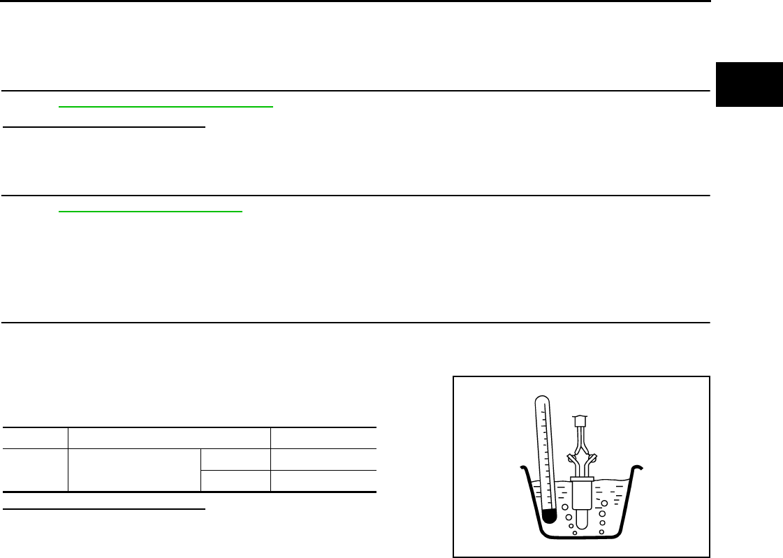
P0181 FTT SENSOR
EC-241
< COMPONENT DIAGNOSIS > [FOR CALIFORNIA]
C
D
E
F
G
H
I
J
K
L
M
A
EC
N
P
O
• Harness for open or short between “fuel level sensor unit and fuel pump” and ECM
>> Repair open circuit or short to ground or short to power in harness or connector.
6.CHECK FUEL TANK TEMPERATURE SENSOR
Refer to EC-241, "Component Inspection".
Is the inspection result normal?
YES >> GO TO 7.
NO >> Replace “fuel level sensor unit and fuel pump”.
7.CHECK INTERMITTENT INCIDENT
Refer to GI-41, "Intermittent Incident".
>> INSPECTION END
Component Inspection INFOID:0000000004493449
1.CHECK FUEL TANK TEMPERATURE SENSOR
1. Turn ignition switch OFF.
2. Disconnect “fuel level sensor unit and fuel pump” harness connector.
3. Remove fuel level sensor unit.
4. Check resistance between “fuel level sensor unit and fuel pump”
terminals by heating with hot water as shown in the figure.
Is the inspection result normal?
YES >> INSPECTION END
NO >> Replace “fuel level sensor unit and fuel pump”.
Terminals Condition Resistance (kΩ)
1 and 2 Temperature [°C (°F)] 20 (68) 2.3 - 2.7
50 (122) 0.79 - 0.90
JMBIA0167ZZ
Revision: 2008 August 2009 Rogue

EC-242
< COMPONENT DIAGNOSIS > [FOR CALIFORNIA]
P0182, P0183 FTT SENSOR
P0182, P0183 FTT SENSOR
Description INFOID:0000000004493450
The fuel tank temperature sensor is used to detect the fuel tempera-
ture inside the fuel tank. The sensor modifies a voltage signal from
the ECM. The modified signal returns to the ECM as the fuel temper-
ature input. The sensor uses a thermistor which is sensitive to the
change in temperature. The electrical resistance of the thermistor
decreases as temperature increases.
<Reference data>
*: These data are reference values and are measured between ECM terminals 95 (Fuel tank temperature sensor) and 104 (Sensor
ground).
DTC Logic INFOID:0000000004493451
DTC DETECTION LOGIC
DTC CONFIRMATION PROCEDURE
1.PRECONDITIONING
If DTC CONFIRMATION PROCEDURE has been previously conducted, always turn ignition switch OFF and
wait at least 10 seconds before conducting the next test.
>> GO TO 2.
2.PERFORM DTC CONFIRMATION PROCEDURE
1. Turn ignition switch ON and wait at least 5 seconds.
2. Check 1st trip DTC.
Is 1st trip DTC detected?
YES >> Go to EC-242, "Diagnosis Procedure".
NO >> INSPECTION END
Diagnosis Procedure INFOID:0000000004529900
1.CHECK GROUND CONNECTION
1. Turn ignition switch OFF.
2. Check ground connection E21. Refer to Ground Inspection in GI-44, "Circuit Inspection".
Is the inspection result normal?
YES >> GO TO 2.
NO >> Repair or replace ground connection.
2.CHECK FUEL TANK TEMPERATURE SENSOR POWER SUPPLY CIRCUIT
1. Turn ignition switch OFF.
2. Disconnect “fuel level sensor unit and fuel pump” harness connector.
3. Turn ignition switch ON.
Fluid temperature
[°C (°F)]
Voltage*
(V)
Resistance
(kΩ)
20 (68) 3.5 2.3 - 2.7
50 (122) 2.2 0.79 - 0.90
SEF012P
DTC No. Trouble diagnosis name DTC detecting condition Possible cause
P0182 Fuel tank temperature
sensor circuit low input
An excessively low voltage from the sensor is
sent to ECM. • Harness or connectors
(The sensor circuit is open or shorted.)
• Fuel tank temperature sensor
P0183 Fuel tank temperature
sensor circuit high input
An excessively high voltage from the sensor is
sent to ECM.
Revision: 2008 August 2009 Rogue

P0182, P0183 FTT SENSOR
EC-243
< COMPONENT DIAGNOSIS > [FOR CALIFORNIA]
C
D
E
F
G
H
I
J
K
L
M
A
EC
N
P
O
4. Check the voltage between “fuel level sensor unit and fuel pump” harness connector and ground.
Is the inspection result normal?
YES >> GO TO 4.
NO >> GO TO 3.
3.DETECT MALFUNCTIONING PART
Check the following.
• Harness connectors M11, B1
• Harness connectors M77, E105
• Harness for open or short between ECM and “fuel level sensor unit and fuel pump”
>> Repair open circuit or short to ground or short to power in harness or connector.
4.CHECK FUEL TANK TEMPERATURE SENSOR GROUND CIRCUIT FOR OPEN AND SHORT
1. Turn ignition switch OFF.
2. Check the continuity between “fuel level sensor unit and fuel pump” harness connector and ECM harness
connector.
3. Also check harness for short to ground and short to power.
Is the inspection result normal?
YES >> GO TO 6.
NO >> GO TO 5.
5.DETECT MALFUNCTIONING PART
Check the following.
• Harness connectors B1, M11
• Harness connectors M77, E105
• Harness for open or short between “fuel level sensor unit and fuel pump” and ECM
>> Repair open circuit or short to ground or short to power in harness or connector.
6.CHECK FUEL TANK TEMPERATURE SENSOR
Refer to EC-241, "Component Inspection".
Is the inspection result normal?
YES >> GO TO 7.
NO >> Replace “fuel level sensor unit and fuel pump”.
7.CHECK INTERMITTENT INCIDENT
Refer to GI-41, "Intermittent Incident".
>> INSPECTION END
Component Inspection INFOID:0000000004493453
1.CHECK FUEL TANK TEMPERATURE SENSOR
1. Turn ignition switch OFF.
2. Disconnect “fuel level sensor unit and fuel pump” harness connector.
3. Remove fuel level sensor unit.
Fuel level sensor unit and fuel pump Ground Voltage
Connector Terminal
B40 2 Ground Approx. 5 V
Fuel level sensor unit and fuel pump ECM Continuity
Connector Terminal Connector Terminal
B40 1 E16 104 Existed
Revision: 2008 August 2009 Rogue
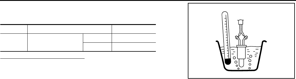
EC-244
< COMPONENT DIAGNOSIS > [FOR CALIFORNIA]
P0182, P0183 FTT SENSOR
4. Check resistance between “fuel level sensor unit and fuel pump”
terminals by heating with hot water as shown in the figure.
Is the inspection result normal?
YES >> INSPECTION END
NO >> Replace “fuel level sensor unit and fuel pump”.
Terminals Condition Resistance (kΩ)
1 and 2 Temperature [°C (°F)] 20 (68) 2.3 - 2.7
50 (122) 0.79 - 0.90
JMBIA0167ZZ
Revision: 2008 August 2009 Rogue
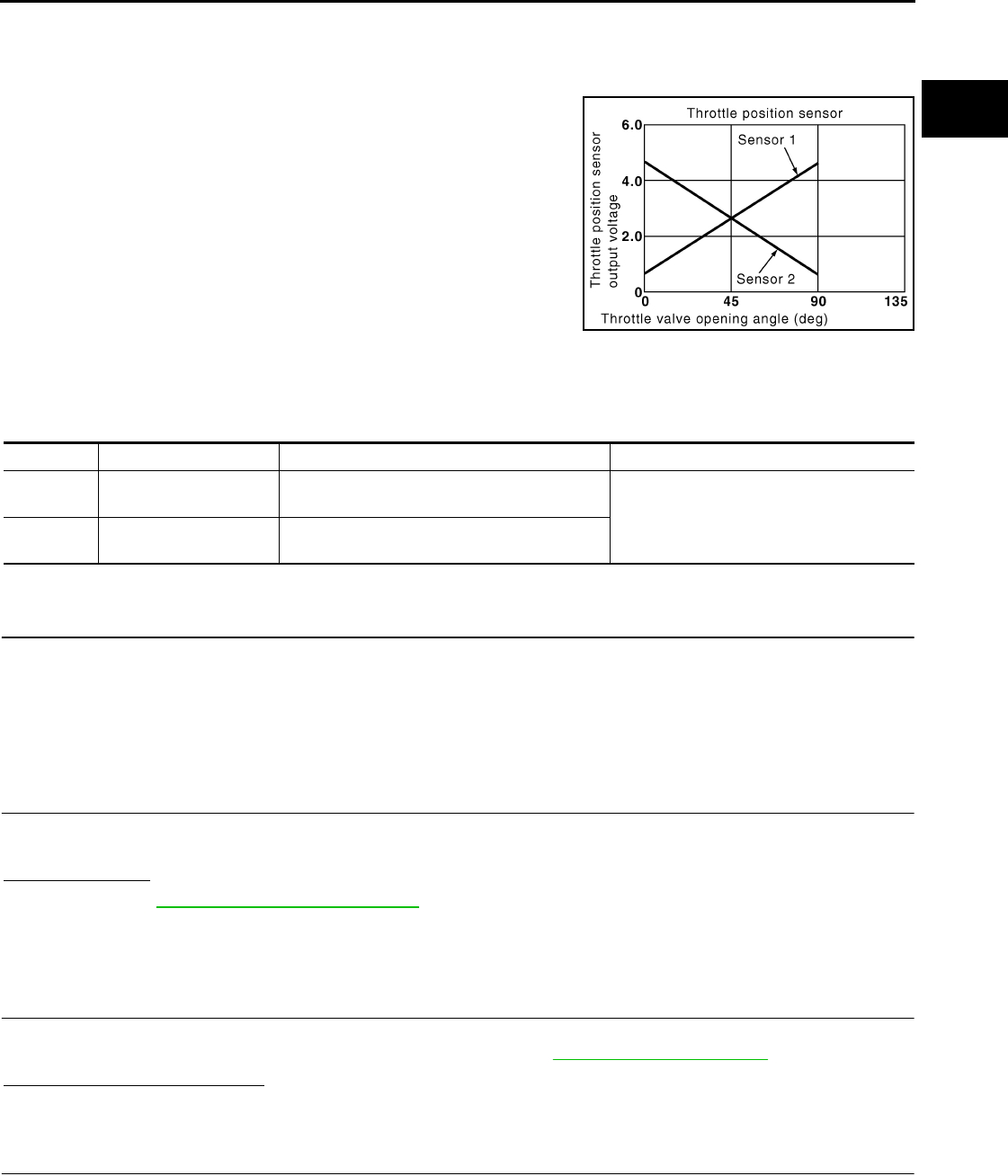
P0222, P0223 TP SENSOR
EC-245
< COMPONENT DIAGNOSIS > [FOR CALIFORNIA]
C
D
E
F
G
H
I
J
K
L
M
A
EC
N
P
O
P0222, P0223 TP SENSOR
Description INFOID:0000000004493454
Electric throttle control actuator consists of throttle control motor,
throttle position sensor, etc. The throttle position sensor responds to
the throttle valve movement.
The throttle position sensor has two sensors. These sensors are a
kind of potentiometer which transform the throttle valve position into
output voltage, and emit the voltage signals to the ECM. The ECM
judges the current opening angle of the throttle valve from these sig-
nals and controls the throttle valve opening angle in response to
driving conditions via the throttle control motor.
DTC Logic INFOID:0000000004493455
DTC DETECTION LOGIC
DTC CONFIRMATION PROCEDURE
1.PRECONDITIONING
If DTC CONFIRMATION PROCEDURE has been previously conducted, always turn ignition switch OFF and
wait at least 10 seconds before conducting the next test.
TESTING CONDITION:
Before performing the following procedure, confirm that battery voltage is more than 8V at idle.
>> GO TO 2.
2.PERFORM DTC CONFIRMATION PROCEDURE
1. Start engine and let it idle for 1 second.
2. Check DTC.
Is DTC detected?
YES >> Go to EC-245, "Diagnosis Procedure".
NO >> INSPECTION END
Diagnosis Procedure INFOID:0000000004493456
1.CHECK GROUND CONNECTION
1. Turn ignition switch OFF.
2. Check ground connection E21. Refer to Ground Inspection in GI-44, "Circuit Inspection".
Is the inspection result normal?
YES >> GO TO 2.
NO >> Repair or replace ground connection.
2.CHECK THROTTLE POSITION SENSOR 1 POWER SUPPLY CIRCUIT
1. Disconnect electric throttle control actuator harness connector.
2. Turn ignition switch ON.
3. Check the voltage between electric throttle control actuator harness connector and ground.
PBIB0145E
DTC No. Trouble diagnosis name DTC detecting condition Possible cause
P0222 Throttle position sensor
1 circuit low input An excessively low voltage from the TP sensor
1 is sent to ECM. • Harness or connectors
(TP sensor 1 circuit is open or shorted.)
• Electric throttle control actuator
(TP sensor 1)
P0223 Throttle position sensor
1 circuit high input
An excessively high voltage from the TP sensor
1 is sent to ECM.
Revision: 2008 August 2009 Rogue

EC-246
< COMPONENT DIAGNOSIS > [FOR CALIFORNIA]
P0222, P0223 TP SENSOR
Is the inspection result normal?
YES >> GO TO 3.
NO >> Repair open circuit or short to ground or short to power in harness or connectors.
3.CHECK THROTTLE POSITION SENSOR 1 GROUND CIRCUIT FOR OPEN AND SHORT
1. Turn ignition switch OFF.
2. Disconnect ECM harness connector.
3. Check the continuity between electric throttle control actuator harness connector and ECM harness con-
nector.
4. Also check harness for short to ground and short to power.
Is the inspection result normal?
YES >> GO TO 4.
NO >> Repair open circuit or short to ground or short to power in harness or connectors.
4.CHECK THROTTLE POSITION SENSOR 1 INPUT SIGNAL CIRCUIT FOR OPEN AND SHORT
1. Check the continuity between electric throttle control actuator harness connector and ECM harness con-
nector.
2. Also check harness for short to ground and short to power.
Is the inspection result normal?
YES >> GO TO 5.
NO >> Repair open circuit or short to ground or short to power in harness or connectors.
5.CHECK THROTTLE POSITION SENSOR
Refer to EC-247, "Component Inspection".
Is the inspection result normal?
YES >> GO TO 7.
NO >> GO TO 6.
6.REPLACE ELECTRIC THROTTLE CONTROL ACTUATOR
1. Replace electric throttle control actuator.
2. Go to EC-247, "Special Repair Requirement".
>> INSPECTION END
7.CHECK INTERMITTENT INCIDENT
Refer to GI-41, "Intermittent Incident".
>> INSPECTION END
Electric throttle control actuator Ground Voltage
Connector Terminal
F29 1 Ground Approx. 5 V
Electric throttle control actuator ECM Continuity
Connector Terminal Connector Terminal
F29 4 F8 36 Existed
Electric throttle control actuator ECM Continuity
Connector Terminal Connector Terminal
F29 2 F8 37 Existed
Revision: 2008 August 2009 Rogue

P0222, P0223 TP SENSOR
EC-247
< COMPONENT DIAGNOSIS > [FOR CALIFORNIA]
C
D
E
F
G
H
I
J
K
L
M
A
EC
N
P
O
Component Inspection INFOID:0000000004493457
1.CHECK THROTTLE POSITION SENSOR
1. Turn ignition switch OFF.
2. Reconnect all harness connectors disconnected.
3. Perform EC-27, "THROTTLE VALVE CLOSED POSITION LEARNING : Special Repair Requirement".
4. Turn ignition switch ON.
5. Set selector lever to the D position.
6. Check the voltage between ECM harness connector terminals.
Is the inspection result normal?
YES >> INSPECTION END
NO >> GO TO 2.
2.REPLACE ELECTRIC THROTTLE CONTROL ACTUATOR
1. Replace electric throttle control actuator.
2. Perform EC-247, "Special Repair Requirement".
>> INSPECTION END
Special Repair Requirement INFOID:0000000004493458
1.PERFORM THROTTLE VALVE CLOSED POSITION LEARNING
Refer to EC-27, "THROTTLE VALVE CLOSED POSITION LEARNING : Special Repair Requirement"
>> GO TO 2.
2.PERFORM IDLE AIR VOLUME LEARNING
Refer to EC-27, "IDLE AIR VOLUME LEARNING : Special Repair Requirement"
>> END
ECM
Condition Voltage +−
Connector Terminal Connector Terminal
F8
37
(TP sensor 1
signal) F8
36
(Sensor
ground) Accelerator pedal
Fully released More than 0.36 V
Fully depressed Less than 4.75 V
38
(TP sensor 2
signal)
Fully released Less than 4.75 V
Fully depressed More than 0.36 V
Revision: 2008 August 2009 Rogue
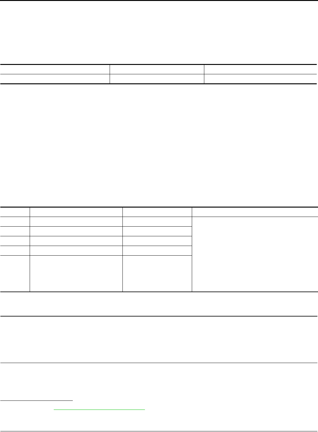
EC-248
< COMPONENT DIAGNOSIS > [FOR CALIFORNIA]
P0300, P0301, P0302, P0303, P0304 MISFIRE
P0300, P0301, P0302, P0303, P0304 MISFIRE
DTC Logic INFOID:0000000004493459
DTC DETECTION LOGIC
When a misfire occurs, engine speed will fluctuate. If the engine speed fluctuates enough to cause the crank-
shaft position (CKP) sensor (POS) signal to vary, ECM can determine that a misfire is occurring.
The misfire detection logic consists of the following two conditions.
1. One Trip Detection Logic (Three Way Catalyst Damage)
On the 1st trip, when a misfire condition occurs that can damage the three way catalyst (TWC) due to
overheating, the MIL will blink.
When a misfire condition occurs, the ECM monitors the CKP sensor signal every 200 engine revolutions
for a change.
When the misfire condition decreases to a level that will not damage the TWC, the MIL will turn off.
If another misfire condition occurs that can damage the TWC on a second trip, the MIL will blink.
When the misfire condition decreases to a level that will not damage the TWC, the MIL will remain on.
If another misfire condition occurs that can damage the TWC, the MIL will begin to blink again.
2. Two Trip Detection Logic (Exhaust quality deterioration)
For misfire conditions that will not damage the TWC (but will affect vehicle emissions), the MIL will only
light when the misfire is detected on a second trip. During this condition, the ECM monitors the CKP sen-
sor signal every 1,000 engine revolutions.
A misfire malfunction can be detected in any one cylinder or in multiple cylinders.
DTC CONFIRMATION PROCEDURE
1.PRECONDITIONING
If DTC CONFIRMATION PROCEDURE has been previously conducted, always turn ignition switch OFF and
wait at least 10 seconds before conducting the next test.
>> GO TO 2.
2.PERFORM DTC CONFIRMATION PROCEDURE-I
1. Start engine and warm it up to normal operating temperature.
2. Turn ignition switch OFF and wait at least 10 seconds.
3. Restart engine and let it idle for approximately 15 minutes.
4. Check 1st trip DTC.
Is 1st trip DTC detected?
YES >> Go to EC-249, "Diagnosis Procedure".
NO >> GO TO 3.
3.PERFORM DTC CONFIRMATION PROCEDURE-II
1. Turn ignition switch OFF and wait at least 10 seconds.
Sensor Input signal to ECM ECM function
Crankshaft position sensor (POS) Engine speed On board diagnosis of misfire
DTC No. Trouble diagnosis name DTC detecting condition Possible cause
P0300 Multiple cylinder misfires detected Multiple cylinder misfire. • Improper spark plug
• Insufficient compression
• Incorrect fuel pressure
• The fuel injector circuit is open or shorted
• Fuel injector
• Intake air leak
• The ignition signal circuit is open or shorted
• Lack of fuel
• Signal plate
• A/F sensor 1
• Incorrect PCV hose connection
P0301 No.1 cylinder misfire detected No. 1 cylinder misfires.
P0302 No. 2 cylinder misfire detected No. 2 cylinder misfires.
P0303 No. 3 cylinder misfire detected No. 3 cylinder misfires.
P0304 No. 4 cylinder misfire detected No. 4 cylinder misfires.
Revision: 2008 August 2009 Rogue

P0300, P0301, P0302, P0303, P0304 MISFIRE
EC-249
< COMPONENT DIAGNOSIS > [FOR CALIFORNIA]
C
D
E
F
G
H
I
J
K
L
M
A
EC
N
P
O
2. Start engine and drive the vehicle under similar conditions to (1st trip) Freeze Frame Data for a certain
time. Refer to the table below.
Hold the accelerator pedal as steady as possible.
Similar conditions to (1st trip) Freeze Frame Data mean that the following conditions should be satisfied at
the same time.
CAUTION:
Always drive vehicle in safe manner according to traffic conditions and obey all traffic laws when
driving.
Driving time varies according to the engine speed in the freeze frame data.
3. Check 1st trip DTC.
Is 1st trip DTC detected?
YES >> Go to EC-249, "Diagnosis Procedure".
NO >> INSPECTION END
Diagnosis Procedure INFOID:0000000004493460
1.CHECK FOR INTAKE AIR LEAK AND PCV HOSE
1. Start engine and run it at idle speed.
2. Listen for the sound of the intake air leak.
3. Check PCV hose connection.
Is intake air leak detected?
YES >> Discover air leak location and repair.
NO >> GO TO 2.
2.CHECK FOR EXHAUST SYSTEM CLOGGING
Stop engine and visually check exhaust tube, three way catalyst and muffler for dents.
Is the inspection result normal?
YES-1 >> With CONSULT-III: GO TO 3.
YES-2 >> Without CONSULT-III: GO TO 4.
NO >> Repair or replace malfunctioning part.
3.PERFORM POWER BALANCE TEST
With CONSULT-III
1. Start engine.
2. Perform “POWER BALANCE” in “ACTIVE TEST” mode with CONSULT-III.
3. Check that each circuit produces a momentary engine speed drop.
Is the inspection result normal?
YES >> GO TO 9.
NO >> GO TO 4.
4.CHECK FUNCTION OF FUEL INJECTOR
1. Start engine and let engine idle.
Engine speed Engine speed in the freeze frame data ± 400 rpm
Vehicle speed Vehicle speed in the freeze frame data ± 10 km/h (6 MPH)
Base fuel schedule Base fuel schedule in freeze frame data × (1 ± 0.1)
Engine coolant temperature (T)
condition
When the freeze frame data shows lower than 70 °C (158 °F),
T should be lower than 70 °C (158 °F).
When the freeze frame data shows higher than or equal to 70 °C (158 °F),
T should be higher than or equal to 70 °C (158 °F).
Engine speed Time
Around 1,000 rpm Approximately 10 minutes
Around 2,000 rpm Approximately 5 minutes
More than 3,000 rpm Approximately 3.5 minutes
Revision: 2008 August 2009 Rogue
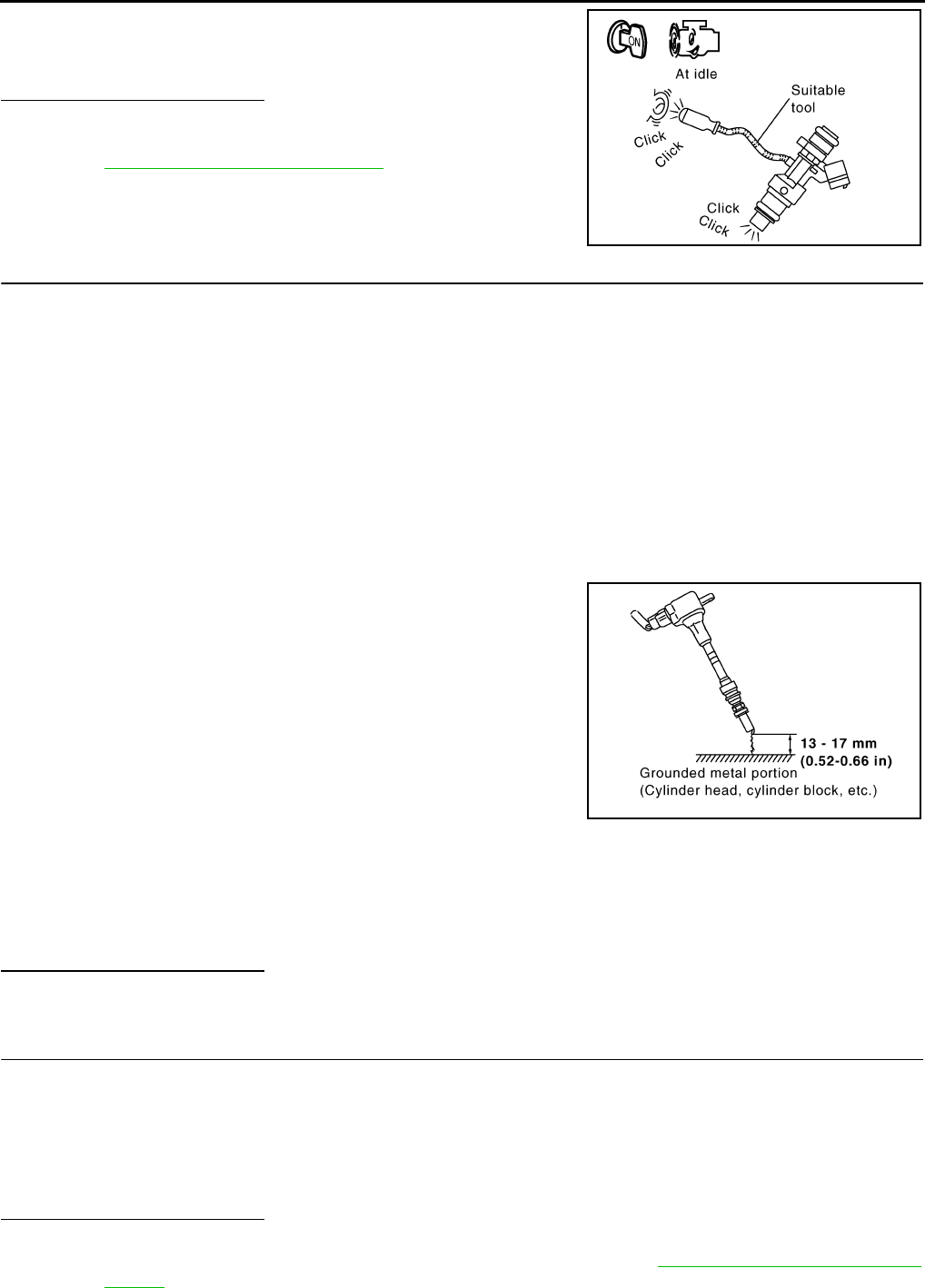
EC-250
< COMPONENT DIAGNOSIS > [FOR CALIFORNIA]
P0300, P0301, P0302, P0303, P0304 MISFIRE
2. Listen to each fuel injector operation.
Is the inspection result normal?
YES >> GO TO 5.
NO >> Perform trouble diagnosis for FUEL INJECTOR, refer to
EC-420, "Component Inspection".
5.CHECK FUNCTION OF IGNITION COIL-I
CAUTION:
Perform the following procedure in a place with no combustible objects and good ventilation.
1. Turn ignition switch OFF.
2. Remove fuel pump fuse in IPDM E/R to release fuel pressure.
NOTE:
Do not use CONSULT-III to release fuel pressure, or fuel pressure applies again during the following pro-
cedure.
3. Start engine.
4. After engine stalls, crank it two or three times to release all fuel pressure.
5. Turn ignition switch OFF.
6. Remove all ignition coil harness connectors to avoid the electrical discharge from the ignition coils.
7. Remove ignition coil and spark plug of the cylinder to be checked.
8. Crank engine for 5 seconds or more to remove combustion gas in the cylinder.
9. Connect spark plug and harness connector to ignition coil.
10. Fix ignition coil using a rope etc. with gap of 13 - 17 mm (0.52 -
0.66 in) between the edge of the spark plug and grounded metal
portion as shown in the figure.
11. Crank engine for approximately 3 seconds, and check whether
spark is generated between the spark plug and the grounded
metal portion.
CAUTION:
• Never place the spark plug and the ignition coil within 50
cm (19.7 in) each other. Be careful not to get an electrical
shock while checking, because the electrical discharge
voltage becomes 20kV or more.
• It might damage the ignition coil if the gap of more than 17 mm (0.66 in) is made.
NOTE:
When the gap is less than 13 mm (0.52 in), a spark might be generated even if the coil is malfunc-
tioning.
Is the inspection result normal?
YES >> GO TO 9.
NO >> GO TO 6.
6.CHECK FUNCTION OF IGNITION COIL-II
1. Turn ignition switch OFF.
2. Disconnect spark plug and connect a non-malfunctioning spark plug.
3. Crank engine for approximately 3 seconds, and recheck whether spark is generated between the spark
plug and the grounded metal portion.
Is the inspection result normal?
YES >> GO TO 7.
NO >> Check ignition coil, power transistor and their circuits. Refer to EC-425, "Component Function
Check".
Clicking noise should be heard.
PBIB3332E
Spark should be generated.
JMBIA0066G
B
Spark should be generated.
Revision: 2008 August 2009 Rogue
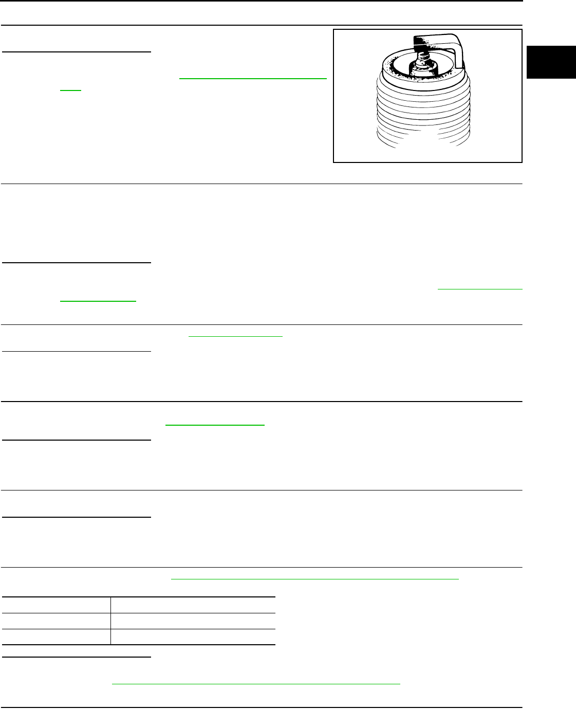
P0300, P0301, P0302, P0303, P0304 MISFIRE
EC-251
< COMPONENT DIAGNOSIS > [FOR CALIFORNIA]
C
D
E
F
G
H
I
J
K
L
M
A
EC
N
P
O
7.CHECK SPARK PLUG
Check the initial spark plug for fouling, etc.
Is the inspection result normal?
YES >> Replace spark plug(s) with standard type one(s). For
spark plug type, refer to EM-18, "Removal and Installa-
tion".
NO >> Repair or clean spark plug. Then GO TO 8.
8.CHECK FUNCTION OF IGNITION COIL-III
1. Reconnect the initial spark plugs.
2. Crank engine for approximately 3 seconds, and recheck whether spark is generated between the spark
plug and the grounded portion.
Is the inspection result normal?
YES >> INSPECTION END
NO >> Replace spark plug(s) with standard type one(s). For spark plug type, refer to EM-18, "Removal
and Installation".
9.CHECK COMPRESSION PRESSURE
Check compression pressure. Refer to EM-23, "Inspection".
Is the inspection result normal?
YES >> GO TO 10.
NO >> Check pistons, piston rings, valves, valve seats and cylinder head gaskets.
10.CHECK FUEL PRESSURE
1. Install all removed parts.
2. Check fuel pressure. Refer to EC-489, "Inspection".
Is the inspection result normal?
YES >> GO TO 12.
NO >> GO TO 11.
11.DETECT MALFUNCTIONING PART
Check fuel hoses and fuel tubes for clogging.
Is the inspection result normal?
YES >> Replace “fuel filter and fuel pump assembly”.
NO >> Repair or replace.
12.CHECK IGNITION TIMING
Check the following items. Refer to EC-22, "BASIC INSPECTION : Special Repair Requirement".
Is the inspection result normal?
YES >> GO TO 13.
NO >> Follow the EC-22, "BASIC INSPECTION : Special Repair Requirement".
13.CHECK A/F SENSOR 1 INPUT SIGNAL CIRCUIT
1. Turn ignition switch OFF.
2. Disconnect corresponding A/F sensor 1 harness connector.
SEF156I
Spark should be generated.
Items Specifications
idle speed 700 ± 50 rpm (in P or N position)
Ignition timing 15 ± 5°BTDC (in P or N position)
Revision: 2008 August 2009 Rogue
EC-252
< COMPONENT DIAGNOSIS > [FOR CALIFORNIA]
P0300, P0301, P0302, P0303, P0304 MISFIRE
3. Disconnect ECM harness connector.
4. Check the continuity between A/F sensor 1 harness connector and ECM harness connector.
5. Check the continuity between A/F sensor 1 harness connector or ECM harness connector and ground.
6. Also check harness for short to power.
Is the inspection result normal?
YES >> GO TO 14.
NO >> Repair open circuit or short to ground or short to power in harness or connectors.
14.CHECK A/F SENSOR 1 HEATER
Refer to EC-137, "Component Inspection".
Is the inspection result normal?
YES >> GO TO 15.
NO >> Replace A/F sensor 1.
15.CHECK MASS AIR FLOW SENSOR
With CONSULT-III
1. Install all removed parts.
2. Check “MASS AIR FLOW” in “DATA MONITOR” mode with CONSULT-III.
For specification, refer to EC-494, "Idle Speed".
With GST
1. Install all removed parts.
2. Check mass air flow sensor signal in Service $01 with GST.
For specification, refer to EC-494, "Idle Speed".
Is the measurement value within the specification?
YES >> GO TO 16.
NO >> Check connectors for rusted terminals or loose connections in the mass air flow sensor circuit or
ground. Refer to EC-147, "DTC Logic".
16.CHECK SYMPTOM TABLE
Check items on the rough idle symptom in EC-478, "Symptom Table".
Is the inspection result normal?
YES >> GO TO 17.
NO >> Repair or replace.
17.ERASE THE 1ST TRIP DTC
Some tests may cause a 1st trip DTC to be set.
Erase the 1st trip DTC from the ECM memory after performing the tests. Refer to EC-92, "Diagnosis Descrip-
tion".
>> GO TO 18.
18.CHECK INTERMITTENT INCIDENT
Refer to GI-41, "Intermittent Incident".
A/F sensor 1 ECM Continuity
Connector Terminal Connector Terminal
F28 1F8 45 Existed
249
A/F sensor 1 ECM Ground Continuity
Connector Terminal Connector Terminal
F28 1F8 45 Ground Not existed
249
Revision: 2008 August 2009 Rogue

P0300, P0301, P0302, P0303, P0304 MISFIRE
EC-253
< COMPONENT DIAGNOSIS > [FOR CALIFORNIA]
C
D
E
F
G
H
I
J
K
L
M
A
EC
N
P
O
>> INSPECTION END
Revision: 2008 August 2009 Rogue

EC-254
< COMPONENT DIAGNOSIS > [FOR CALIFORNIA]
P0327, P0328 KS
P0327, P0328 KS
Description INFOID:0000000004493461
The knock sensor is attached to the cylinder block. It senses engine knocking using a piezoelectric element. A
knocking vibration from the cylinder block is sensed as vibrational pressure. This pressure is converted into a
voltage signal and sent to the ECM.
DTC Logic INFOID:0000000004493462
DTC DETECTION LOGIC
DTC CONFIRMATION PROCEDURE
1.PRECONDITIONING
If DTC CONFIRMATION PROCEDURE has been previously conducted, always turn ignition switch OFF and
wait at least 10 seconds before conducting the next test.
TESTING CONDITION:
Before performing the following procedure, confirm that battery voltage is more than 10V at idle.
>> GO TO 2.
2.PERFORM DTC CONFIRMATION PROCEDURE
1. Start engine and run it for at least 5 seconds at idle speed.
2. Check 1st trip DTC.
Is 1st trip DTC detected?
YES >> Go to EC-254, "Diagnosis Procedure".
NO >> INSPECTION END
Diagnosis Procedure INFOID:0000000004493463
1.CHECK GROUND CONNECTION
1. Turn ignition switch OFF.
2. Check ground connection E21. Refer to Ground Inspection in GI-44, "Circuit Inspection".
Is the inspection result normal?
YES >> GO TO 2.
NO >> Repair or replace ground connection.
2.CHECK KNOCK SENSOR GROUND CIRCUIT FOR OPEN AND SHORT
1. Disconnect knock sensor harness connector and disconnect ECM harness connector.
2. Check the continuity between knock sensor harness connector and ECM harness connector.
3. Also check harness for short to ground and short to power.
Is the inspection result normal?
YES >> GO TO 3.
NO >> Repair open circuit or short to ground or short to power in harness or connectors.
DTC No. Trouble diagnosis
name DTC detected condition Possible cause
P0327 Knock sensor circuit
low input
An excessively low voltage from the sensor is
sent to ECM. • Harness or connectors
(The sensor circuit is open or shorted.)
• Knock sensor
P0328 Knock sensor circuit
high input
An excessively high voltage from the sensor is
sent to ECM.
Knock sensor ECM Continuity
Connector Terminal Connector Terminal
F16 2 F8 67 Existed
Revision: 2008 August 2009 Rogue
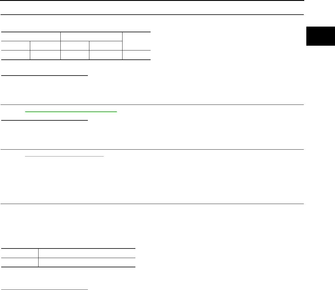
P0327, P0328 KS
EC-255
< COMPONENT DIAGNOSIS > [FOR CALIFORNIA]
C
D
E
F
G
H
I
J
K
L
M
A
EC
N
P
O
3.CHECK KNOCK SENSOR INPUT SIGNAL CIRCUIT FOR OPEN AND SHORT
1. Check the continuity between knock sensor harness connector and ECM harness connector.
2. Also check harness for short to ground and short to power.
Is the inspection result normal?
YES >> GO TO 4.
NO >> Repair open circuit or short to ground or short to power in harness or connectors.
4.CHECK KNOCK SENSOR
Refer to EC-255, "Component Inspection".
Is the inspection result normal?
YES >> GO TO 5.
NO >> Replace knock sensor.
5.CHECK INTERMITTENT INCIDENT
Refer to GI-41, "Intermittent Incident".
>> INSPECTION END
Component Inspection INFOID:0000000004493464
1.CHECK KNOCK SENSOR
1. Turn ignition switch OFF.
2. Disconnect knock sensor harness connector.
3. Check resistance between knock sensor terminals as follows.
NOTE:
It is necessary to use an ohmmeter which can measure more than 10 MΩ.
CAUTION:
Never use any knock sensors that have been dropped or physically damaged. Use only new ones.
Is the inspection result normal?
YES >> INSPECTION END
NO >> Replace knock sensor.
Knock sensor ECM Continuity
Connector Terminal Connector Terminal
F16 1 F8 61 Existed
Terminals Resistance
1 and 2 Approx. 532 - 588 kΩ [at 20°C (68°F)]
Revision: 2008 August 2009 Rogue
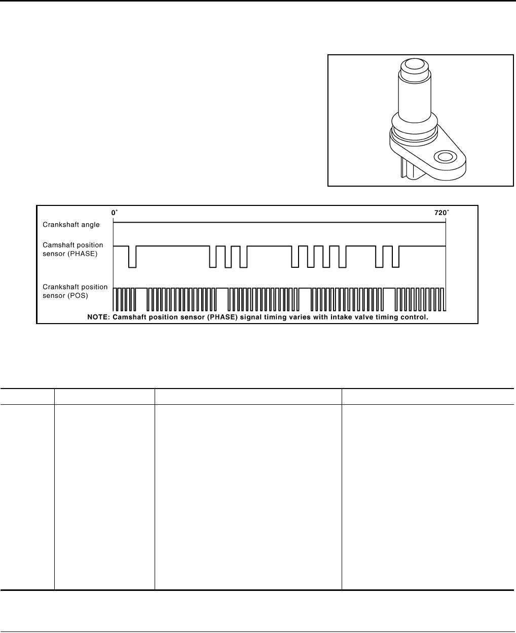
EC-256
< COMPONENT DIAGNOSIS > [FOR CALIFORNIA]
P0335 CKP SENSOR (POS)
P0335 CKP SENSOR (POS)
Description INFOID:0000000004493465
The crankshaft position sensor (POS) is located on the oil pan facing
the gear teeth (cogs) of the signal plate. It detects the fluctuation of
the engine revolution.
The sensor consists of a permanent magnet and Hall IC.
When the engine is running, the high and low parts of the teeth
cause the gap with the sensor to change.
The changing gap causes the magnetic field near the sensor to
change.
Due to the changing magnetic field, the voltage from the sensor
changes.
The ECM receives the voltage signal and detects the fluctuation of
the engine revolution.
ECM receives the signals as shown in the figure.
DTC Logic INFOID:0000000004493466
DTC DETECTION LOGIC
DTC CONFIRMATION PROCEDURE
1.PRECONDITIONING
If DTC CONFIRMATION PROCEDURE has been previously conducted, always turn ignition switch OFF and
wait at least 10 seconds before conducting the next test.
TESTING CONDITION:
Before performing the following procedure, confirm that battery voltage is more than 10.5V with igni-
tion switch ON.
>> GO TO 2.
JMBIA0062ZZ
JMBIA0714G
B
DTC No. Trouble diagnosis name DTC detecting condition Possible cause
P0335 Crankshaft position sen-
sor (POS) circuit
• The crankshaft position sensor (POS) signal
is not detected by the ECM during the first
few seconds of engine cranking.
• The proper pulse signal from the crankshaft
position sensor (POS) is not sent to ECM
while the engine is running.
• The crankshaft position sensor (POS) signal
is not in the normal pattern during engine run-
ning.
• Harness or connectors
[Crankshaft position sensor (POS) circuit
is open or shorted.]
(Refrigerant pressure sensor circuit is
shorted.)
(Accelerator pedal position sensor circuit
is shorted.)
(EVAP control system pressure sensor
circuit is shorted.)
(Tumble control valve position sensor cir-
cuit is shorted.)
• Crankshaft position sensor (POS)
• Refrigerant pressure sensor
• Accelerator pedal position sensor
• EVAP control system pressure sensor
• Tumble control valve position sensor
• Signal plate
Revision: 2008 August 2009 Rogue

P0335 CKP SENSOR (POS)
EC-257
< COMPONENT DIAGNOSIS > [FOR CALIFORNIA]
C
D
E
F
G
H
I
J
K
L
M
A
EC
N
P
O
2.PERFORM DTC CONFIRMATION PROCEDURE
1. Start engine and let it idle for at least 5 seconds.
If engine does not start, crank engine for at least 2 seconds.
2. Check 1st trip DTC.
Is 1st trip DTC detected?
YES >> Go to EC-257, "Diagnosis Procedure".
NO >> INSPECTION END
Diagnosis Procedure INFOID:0000000004493467
1.CHECK GROUND CONNECTION
1. Turn ignition switch OFF.
2. Check ground connection E21. Refer to Ground Inspection in GI-44, "Circuit Inspection".
Is the inspection result normal?
YES >> GO TO 2.
NO >> Repair or replace ground connection.
2.CHECK CRANKSHAFT POSITION (CKP) SENSOR (POS) POWER SUPPLY CIRCUIT-I
1. Disconnect crankshaft position (CKP) sensor (POS) harness connector.
2. Turn ignition switch ON.
3. Check the voltage between CKP sensor (POS) harness connector and ground.
Is the inspection result normal?
YES >> GO TO 8.
NO >> GO TO 3.
3.CHECK CRANKSHAFT POSITION (CKP) SENSOR (POS) POWER SUPPLY CIRCUIT-II
1. Turn ignition switch ON.
2. Disconnect ECM harness connector.
3. Check the continuity between CKP sensor (POS) harness connector and ECM harness connector.
Is the inspection result normal?
YES >> GO TO 4.
NO >> Repair open circuit.
4.CHECK SENSOR POWER SUPPLY CIRCUIT
Check harness for short to power and short to ground, between the following terminals.
Is the inspection result normal?
CKP sensor (POS) Ground Voltage
Connector Terminal
F20 1 Ground Approx. 5 V
CKP sensor (POS) ECM Continuity
Connector Terminal Connector Terminal
F20 1 F8 76 Existed
ECM Sensor
Connector Terminal Name Connector Terminal
F8 72 Tumble control valve position sensor F41 1
Refrigerant pressure sensor E49 3
76 CKP sensor (POS) F20 1
E16 87 APP sensor E110 5
91 EVAP control system pressure sensor B47 3
Revision: 2008 August 2009 Rogue

EC-258
< COMPONENT DIAGNOSIS > [FOR CALIFORNIA]
P0335 CKP SENSOR (POS)
YES >> GO TO 5.
NO >> Repair short to ground or short to power in harness or connectors.
5.CHECK COMPONENTS
Check the following.
• Refrigerant pressure sensor (Refer to EC-437, "Diagnosis Procedure".)
• EVAP control system pressure sensor (Refer to EC-296, "Component Inspection".)
• Tumble control valve position sensor (Refer to EC-368, "Diagnosis Procedure".)
Is the inspection result normal?
YES >> GO TO 6.
NO >> Replace malfunctioning components.
6.CHECK APP SENSOR
Refer to EC-399, "Component Inspection".
Is the inspection result normal?
YES >> GO TO 12.
NO >> GO TO 7.
7.REPLACE ACCELERATOR PEDAL ASSEMBLY
1. Replace accelerator pedal assembly. Refer to ACC-3, "Removal and Installation".
2. Go to EC-27, "ACCELERATOR PEDAL RELEASED POSITION LEARNING : Special Repair Require-
ment".
>> INSPECTION END
8.CHECK CKP SENSOR (POS) GROUND CIRCUIT FOR OPEN AND SHORT
1. Turn ignition switch OFF.
2. Check the continuity between CKP sensor (POS) harness connector and ECM harness connector.
3. Also check harness for short to ground and short to power.
Is the inspection result normal?
YES >> GO TO 9.
NO >> Repair open circuit or short to ground or short to power in harness or connectors.
9.CHECK CKP SENSOR (POS) INPUT SIGNAL CIRCUIT FOR OPEN AND SHORT
1. Disconnect ECM harness connector.
2. Check the continuity between CKP sensor (POS) harness connector and ECM harness connector.
3. Also check harness for short to ground and short to power.
Is the inspection result normal?
YES >> GO TO 10.
NO >> Repair open circuit or short to ground or short to power in harness or connectors.
10.CHECK CRANKSHAFT POSITION SENSOR (POS)
Refer to EC-259, "Component Inspection".
Is the inspection result normal?
YES >> GO TO 11.
NO >> Replace crankshaft position sensor (POS).
CKP sensor (POS) ECM Continuity
Connector Terminal Connector Terminal
F20 2 F8 60 Existed
CKP sensor (POS) ECM Continuity
Connector Terminal Connector Terminal
F20 3 F8 65 Existed
Revision: 2008 August 2009 Rogue
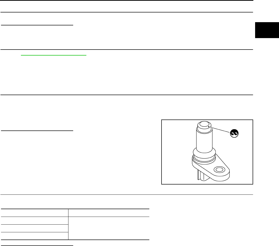
P0335 CKP SENSOR (POS)
EC-259
< COMPONENT DIAGNOSIS > [FOR CALIFORNIA]
C
D
E
F
G
H
I
J
K
L
M
A
EC
N
P
O
11.CHECK GEAR TOOTH
Visually check for chipping signal plate gear tooth.
Is the inspection result normal?
YES >> GO TO 12.
NO >> Replace the signal plate.
12.CHECK INTERMITTENT INCIDENT
Refer to GI-41, "Intermittent Incident".
>> INSPECTION END
Component Inspection INFOID:0000000004493468
1.CHECK CRANKSHAFT POSITION SENSOR (POS)-I
1. Turn ignition switch OFF.
2. Loosen the fixing bolt of the sensor.
3. Disconnect crankshaft position sensor (POS) harness connector.
4. Remove the sensor.
5. Visually check the sensor for chipping.
Is the inspection result normal?
YES >> GO TO 2.
NO >> Replace crankshaft position sensor (POS).
2.CHECK CRANKSHAFT POSITION SENSOR (POS)-II
Check resistance between crankshaft position sensor (POS) terminals as follows.
Is the inspection result normal?
YES >> INSPECTION END
NO >> Replace crankshaft position sensor (POS).
JMBIA0063ZZ
Terminals (Polarity) Resistance [Ω at 25°C (77°F)]
1 (+) - 2 (-)
Except 0 or ∞1 (+) - 3 (-)
2 (+) - 3 (-)
Revision: 2008 August 2009 Rogue

EC-260
< COMPONENT DIAGNOSIS > [FOR CALIFORNIA]
P0340 CMP SENSOR (PHASE)
P0340 CMP SENSOR (PHASE)
Description INFOID:0000000004493469
The camshaft position sensor (PHASE) senses the retraction of
camshaft (INT) to identify a particular cylinder. The camshaft position
sensor (PHASE) senses the piston position.
When the crankshaft position sensor (POS) system becomes inoper-
ative, the camshaft position sensor (PHASE) provides various con-
trols of engine parts instead, utilizing timing of cylinder identification
signals.
The sensor consists of a permanent magnet and Hall IC.
When engine is running, the high and low parts of the teeth cause
the gap with the sensor to change.
The changing gap causes the magnetic field near the sensor to
change.
Due to the changing magnetic field, the voltage from the sensor changes.
ECM receives the signals as shown in the figure.
DTC Logic INFOID:0000000004493470
DTC DETECTION LOGIC
NOTE:
If DTC P0340 is displayed with DTC P0643, first perform the trouble diagnosis for DTC P0643. Refer to
EC-336, "DTC Logic".
DTC CONFIRMATION PROCEDURE
1.PRECONDITIONING
If DTC CONFIRMATION PROCEDURE has been previously conducted, always turn ignition switch OFF and
wait at least 10 seconds before conducting the next test.
TESTING CONDITION:
Before performing the following procedure, confirm that battery voltage is more than 10.5V with igni-
tion switch ON.
>> GO TO 2.
2.PERFORM DTC CONFIRMATION PROCEDURE-I
1. Start engine and let it idle for at least 5 seconds.
JMBIA0064ZZ
JMBIA0714G
B
DTC No. Trouble diagnosis name DTC detecting condition Possible cause
P0340 Camshaft position sen-
sor (PHASE) circuit
• The cylinder No. signal is not sent to ECM for
the first few seconds during engine cranking.
• The cylinder No. signal is not sent to ECM
during engine running.
• The cylinder No. signal is not in the normal
pattern during engine running.
• Harness or connectors
(The sensor circuit is open or shorted)
• Camshaft position sensor (PHASE)
• Camshaft (INT)
• Starter motor (Refer to STR-5, "System
Diagram".)
• Starting system circuit (Refer to STR-5,
"System Diagram".)
• Dead (Weak) battery
Revision: 2008 August 2009 Rogue

P0340 CMP SENSOR (PHASE)
EC-261
< COMPONENT DIAGNOSIS > [FOR CALIFORNIA]
C
D
E
F
G
H
I
J
K
L
M
A
EC
N
P
O
If engine does not start, crank engine for at least 2 seconds.
2. Check 1st trip DTC.
Is 1st trip DTC detected?
YES >> Go to EC-261, "Diagnosis Procedure".
NO >> GO TO 3.
3.PERFORM DTC CONFIRMATION PROCEDURE-II
1. Maintaining engine speed at more than 800 rpm for at least 5 seconds.
2. Check 1st trip DTC.
Is 1st trip DTC detected?
YES >> Go to EC-261, "Diagnosis Procedure".
NO >> INSPECTION END
Diagnosis Procedure INFOID:0000000004493471
1.CHECK STARTING SYSTEM
Turn ignition switch to START position.
Does the engine turn over? Does the starter motor operate?
YES >> GO TO 2.
NO >> Check starting system.
2.CHECK GROUND CONNECTION
1. Turn ignition switch OFF.
2. Check ground connection E21. Refer to Ground Inspection in GI-44, "Circuit Inspection".
Is the inspection result normal?
YES >> GO TO 3.
NO >> Repair or replace ground connection.
3.CHECK CAMSHAFT POSITION (CMP) SENSOR (PHASE) POWER SUPPLY CIRCUIT
1. Disconnect camshaft position (CMP) sensor (PHASE) harness connector.
2. Turn ignition switch ON.
3. Check the voltage between CMP sensor (PHASE) harness connector and ground.
Is the inspection result normal?
YES >> GO TO 4.
NO >> Repair open circuit or short to ground or short to power in harness or connectors.
4.CHECK CMP SENSOR (PHASE) GROUND CIRCUIT FOR OPEN AND SHORT
1. Turn ignition switch OFF.
2. Check the continuity between CMP sensor (PHASE) harness connector and ECM harness connector.
3. Also check harness for short to power.
Is the inspection result normal?
YES >> GO TO 5.
NO >> Repair open circuit or short to ground or short to power in harness or connectors.
5.CHECK CMP SENSOR (PHASE) INPUT SIGNAL CIRCUIT FOR OPEN AND SHORT
1. Disconnect ECM harness connector.
2. Check the continuity between CMP sensor (PHASE) harness connector and ECM harness connector.
CMP sensor (PHASE) Ground Voltage
Connector Terminal
F26 1 Ground Approx. 5 V
CMP sensor (PHASE) ECM Continuity
Connector Terminal Connector Terminal
F26 2 F8 64 Existed
Revision: 2008 August 2009 Rogue
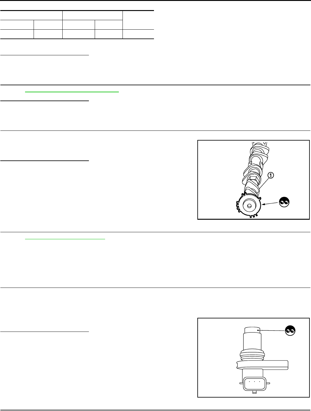
EC-262
< COMPONENT DIAGNOSIS > [FOR CALIFORNIA]
P0340 CMP SENSOR (PHASE)
3. Also check harness for short to ground and short to power.
Is the inspection result normal?
YES >> GO TO 6.
NO >> Repair open circuit or short to ground or short to power in harness or connectors.
6.CHECK CAMSHAFT POSITION SENSOR (PHASE)
Refer to EC-262, "Component Inspection".
Is the inspection result normal?
YES >> GO TO 7.
NO >> Replace camshaft position sensor (PHASE).
7.CHECK CAMSHAFT (INT)
Check the following.
• Accumulation of debris to the signal plate of camshaft (1) rear end
• Chipping signal plate of camshaft rear end
Is the inspection result normal?
YES >> GO TO 8.
NO >> Remove debris and clean the signal plate of camshaft
rear end or replace camshaft.
8.CHECK INTERMITTENT INCIDENT
Refer to GI-41, "Intermittent Incident".
>> INSPECTION END
Component Inspection INFOID:0000000004493472
1.CHECK CAMSHAFT POSITION SENSOR (PHASE)-I
1. Turn ignition switch OFF.
2. Loosen the fixing bolt of the sensor.
3. Disconnect camshaft position sensor (PHASE) harness connector.
4. Remove the sensor.
5. Visually check the sensor for chipping.
Is the inspection result normal?
YES >> GO TO 2.
NO >> Replace camshaft position sensor (PHASE).
2.CHECK CAMSHAFT POSITION SENSOR (PHASE)-II
Check resistance camshaft position sensor (PHASE) terminals as follows.
CMP sensor (PHASE) ECM Continuity
Connector Terminal Connector Terminal
F26 3 F8 69 Existed
JMBIA0096ZZ
JMBIA0065ZZ
Revision: 2008 August 2009 Rogue

P0340 CMP SENSOR (PHASE)
EC-263
< COMPONENT DIAGNOSIS > [FOR CALIFORNIA]
C
D
E
F
G
H
I
J
K
L
M
A
EC
N
P
O
Is the inspection result normal?
YES >> INSPECTION END
NO >> Replace camshaft position sensor (PHASE).
Terminals (Polarity) Resistance
1 (+) - 2 (-)
Except 0 or ∞ Ω [at 25°C (77°F)]1 (+) - 3 (-)
2 (+) - 3 (-)
Revision: 2008 August 2009 Rogue
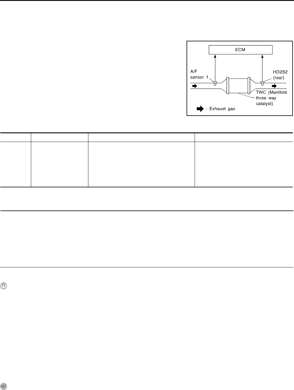
EC-264
< COMPONENT DIAGNOSIS > [FOR CALIFORNIA]
P0420 THREE WAY CATALYST FUNCTION
P0420 THREE WAY CATALYST FUNCTION
DTC Logic INFOID:0000000004493473
DTC DETECTION LOGIC
The ECM monitors the switching frequency ratio of air fuel ratio (A/F)
sensor 1 and heated oxygen sensor 2.
A three way catalyst (manifold) with high oxygen storage capacity
will indicate a low switching frequency of heated oxygen sensor 2.
As oxygen storage capacity decreases, the heated oxygen sensor 2
switching frequency will increase.
When the frequency ratio of A/F sensor 1 and heated oxygen sensor
2 approaches a specified limit value, the three way catalyst (mani-
fold) malfunction is diagnosed.
DTC CONFIRMATION PROCEDURE
1.PRECONDITIONING
If DTC CONFIRMATION PROCEDURE has been previously conducted, always turn ignition switch OFF and
wait at least 10 seconds before conducting the next test.
TESTING CONDITION:
Do not maintain engine speed for more than the specified minutes below.
>> GO TO 2.
2.PERFORM DTC CONFIRMATION PROCEDURE
CAUTION:
Always drive vehicle in safe manner according to traffic conditions and obey all traffic laws.
With CONSULT-III
1. Start engine and warm it up to the normal operating temperature.
2. Repeat the following procedure 3 times.
- Drive vehicle at a speed of 80 km/h (50 MPH) or more for at least 3 consecutive minutes.
NOTE:
Keep the vehicle speed as steady as possible during the cruising.
- Stop vehicle with engine running.
NOTE:
Never turn ignition switch OFF.
3. Select “DTC & SRT CONFIRMATION” then “SRT WORK SUPPORT” mode with CONSULT-III.
4. Drive vehicle at a speed of 80 km/h (50 MPH) or more until “INCMP” of “CATALYST” changes to “CMPLT”
NOTE:
•Keep the vehicle speed as steady as possible during the cruising.
•It will take at most 3 minutes until “INCMP” of “CATALYST” changes to “CMPLT”.
5. Check 1 st trip DTC.
With GST
1. Start engine and warm it up to the normal operating temperature.
2. Repeat the following procedure 3 times.
- Drive vehicle at a speed of 80 km/h (50 MPH) or more for at least 3 consecutive minutes.
SEF484YB
DTC No. Trouble diagnosis name DTC detecting condition Possible cause
P0420 Catalyst system efficien-
cy below threshold
• Three way catalyst (manifold) does not oper-
ate properly.
• Three way catalyst (manifold) does not have
enough oxygen storage capacity.
• Three way catalyst (manifold)
• Exhaust tube
• Intake air leaks
• Fuel injector
• Fuel injector leaks
• Spark plug
• Improper ignition timing
Revision: 2008 August 2009 Rogue
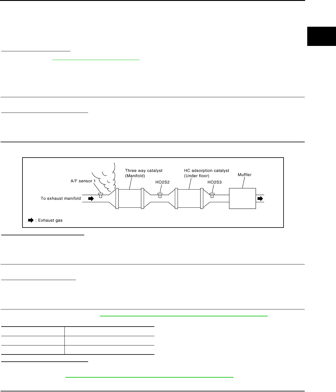
P0420 THREE WAY CATALYST FUNCTION
EC-265
< COMPONENT DIAGNOSIS > [FOR CALIFORNIA]
C
D
E
F
G
H
I
J
K
L
M
A
EC
N
P
O
NOTE:
Keep the vehicle speed as steady as possible during the cruising.
- Stop vehicle with engine running.
NOTE:
Never turn ignition switch OFF.
3. Check 1 st trip DTC.
Is 1st trip DTC detected?
YES >> Go to EC-265, "Diagnosis Procedure".
NO >> INSPECTION END
Diagnosis Procedure INFOID:0000000004493474
1.CHECK EXHAUST SYSTEM
Visually check exhaust tubes and muffler for dents.
Is the inspection result normal?
YES >> GO TO 2.
NO >> Repair or replace.
2.CHECK EXHAUST GAS LEAK
1. Start engine and run it at idle.
2. Listen for an exhaust gas leak before the three way catalyst (manifold).
Is exhaust gas leak detected?
YES >> Repair or replace.
NO >> GO TO 3.
3.CHECK INTAKE AIR LEAK
Listen for an intake air leak after the mass air flow sensor.
Is intake air leak detected?
YES >> Repair or replace.
NO >> GO TO 4.
4.CHECK IGNITION TIMING
Check the following items. Refer to EC-22, "BASIC INSPECTION : Special Repair Requirement".
Is the inspection result normal?
YES >> GO TO 5.
NO >> Follow the EC-22, "BASIC INSPECTION : Special Repair Requirement".
5.CHECK FUEL INJECTOR
1. Stop engine and then turn ignition switch ON.
2. Check the voltage between ECM harness connector and ground.
JMBIA0163G
B
Items Specifications
idle speed 700 ± 50 rpm (in P or N position)
Ignition timing 15 ± 5° BTDC (in P or N position)
Revision: 2008 August 2009 Rogue
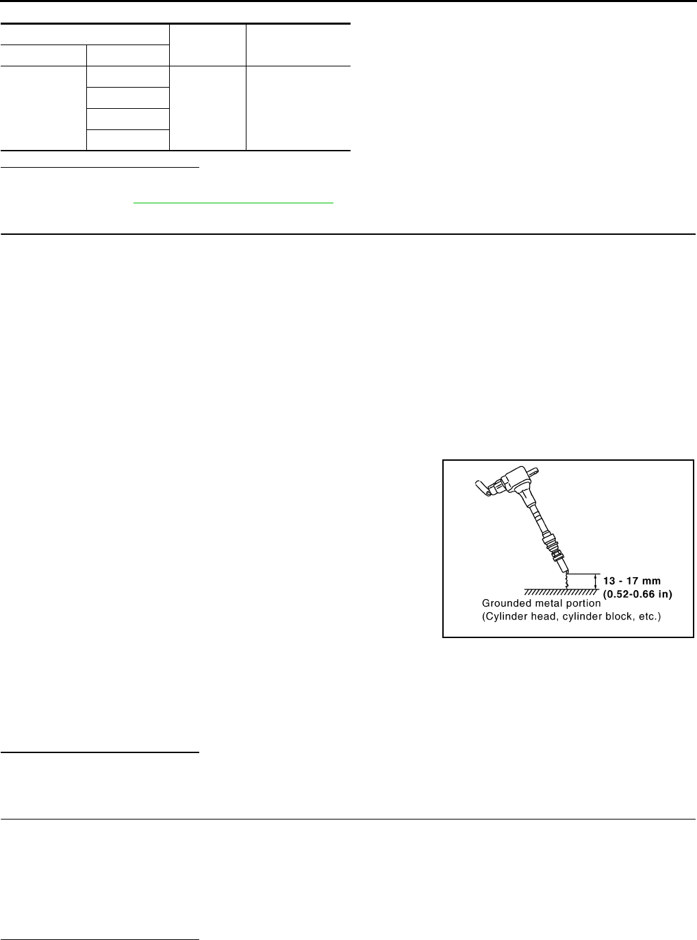
EC-266
< COMPONENT DIAGNOSIS > [FOR CALIFORNIA]
P0420 THREE WAY CATALYST FUNCTION
Is the inspection result normal?
YES >> GO TO 6.
NO >> Perform EC-419, "Diagnosis Procedure".
6.CHECK FUNCTION OF IGNITION COIL-I
CAUTION:
Perform the following procedure in a place with no combustible objects and good ventilation.
1. Turn ignition switch OFF.
2. Remove fuel pump fuse in IPDM E/R to release fuel pressure.
NOTE:
Do not use CONSULT-III to release fuel pressure, or fuel pressure applies again during the following pro-
cedure.
3. Start engine.
4. After engine stalls, crank it two or three times to release all fuel pressure.
5. Turn ignition switch OFF.
6. Remove all ignition coil harness connectors to avoid the electrical discharge from the ignition coils.
7. Remove ignition coil and spark plug of the cylinder to be checked.
8. Crank engine for 5 seconds or more to remove combustion gas in the cylinder.
9. Connect spark plug and harness connector to ignition coil.
10. Fix ignition coil using a rope etc. with gap of 13 - 17 mm (0.52 -
0.66 in) between the edge of the spark plug and grounded metal
portion as shown in the figure.
11. Crank engine for approximately 3 seconds, and check whether
spark is generated between the spark plug and the grounded
metal portion.
CAUTION:
• Never place the spark plug and the ignition coil within 50
cm (19.7 in) each other. Be careful not to get an electrical
shock while checking, because the electrical discharge
voltage becomes 20kV or more.
• It might damage the ignition coil if the gap of more than 17 mm (0.66 in) is made.
NOTE:
When the gap is less than 13 mm (0.52 in), a spark might be generated even if the coil is malfunc-
tioning.
Is the inspection result normal?
YES >> GO TO 10.
NO >> GO TO 7.
7.CHECK FUNCTION OF IGNITION COIL-II
1. Turn ignition switch OFF.
2. Disconnect spark plug and connect a non-malfunctioning spark plug.
3. Crank engine for approximately 3 seconds, and recheck whether spark is generated between the spark
plug and the grounded metal portion.
Is the inspection result normal?
YES >> GO TO 8.
ECM Ground Voltage
Connector Terminal
F7
29
Ground Battery voltage
30
31
32
Spark should be generated.
JMBIA0066G
B
Spark should be generated.
Revision: 2008 August 2009 Rogue
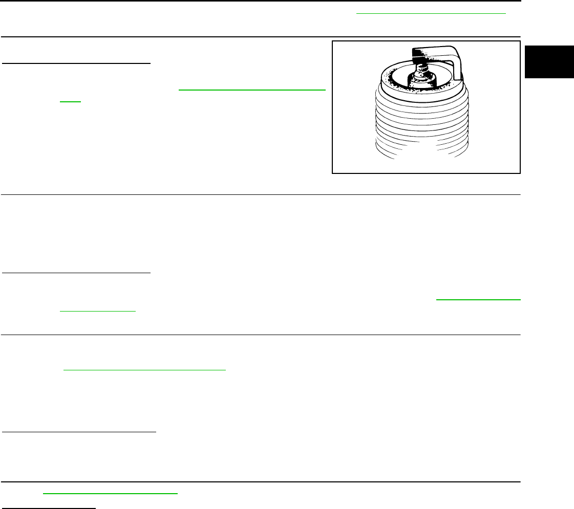
P0420 THREE WAY CATALYST FUNCTION
EC-267
< COMPONENT DIAGNOSIS > [FOR CALIFORNIA]
C
D
E
F
G
H
I
J
K
L
M
A
EC
N
P
O
NO >> Check ignition coil, power transistor and their circuits. Refer to EC-425, "Diagnosis Procedure".
8.CHECK SPARK PLUG
Check the initial spark plug for fouling, etc.
Is the inspection result normal?
YES >> Replace spark plug(s) with standard type one(s). For
spark plug type, refer to EM-18, "Removal and Installa-
tion".
NO >> Repair or clean spark plug. Then GO TO 9.
9.CHECK FUNCTION OF IGNITION COIL-III
1. Reconnect the initial spark plugs.
2. Crank engine for approximately three seconds, and recheck whether spark is generated between the
spark plug and the grounded portion.
Is the inspection result normal?
YES >> INSPECTION END
NO >> Replace spark plug(s) with standard type one(s). For spark plug type, refer to EM-18, "Removal
and Installation".
10.CHECK FUEL INJECTOR
1. Turn ignition switch OFF.
2. Remove fuel injector assembly.
Refer to EM-43, "Removal and Installation".
Keep fuel hose and all fuel injectors connected to fuel tube.
3. Disconnect all ignition coil harness connectors.
4. Reconnect all fuel injector harness connectors disconnected.
5. Turn ignition switch ON.
Does fuel drip from fuel injector?
YES >> GO TO 11.
NO >> Replace the fuel injector(s) from which fuel is dripping.
11.CHECK INTERMITTENT INCIDENT
Refer to GI-41, "Intermittent Incident".
Is the trouble fixed?
YES >> INSPECTION END
NO >> Replace three way catalyst assembly.
SEF156I
Spark should be generated.
Revision: 2008 August 2009 Rogue
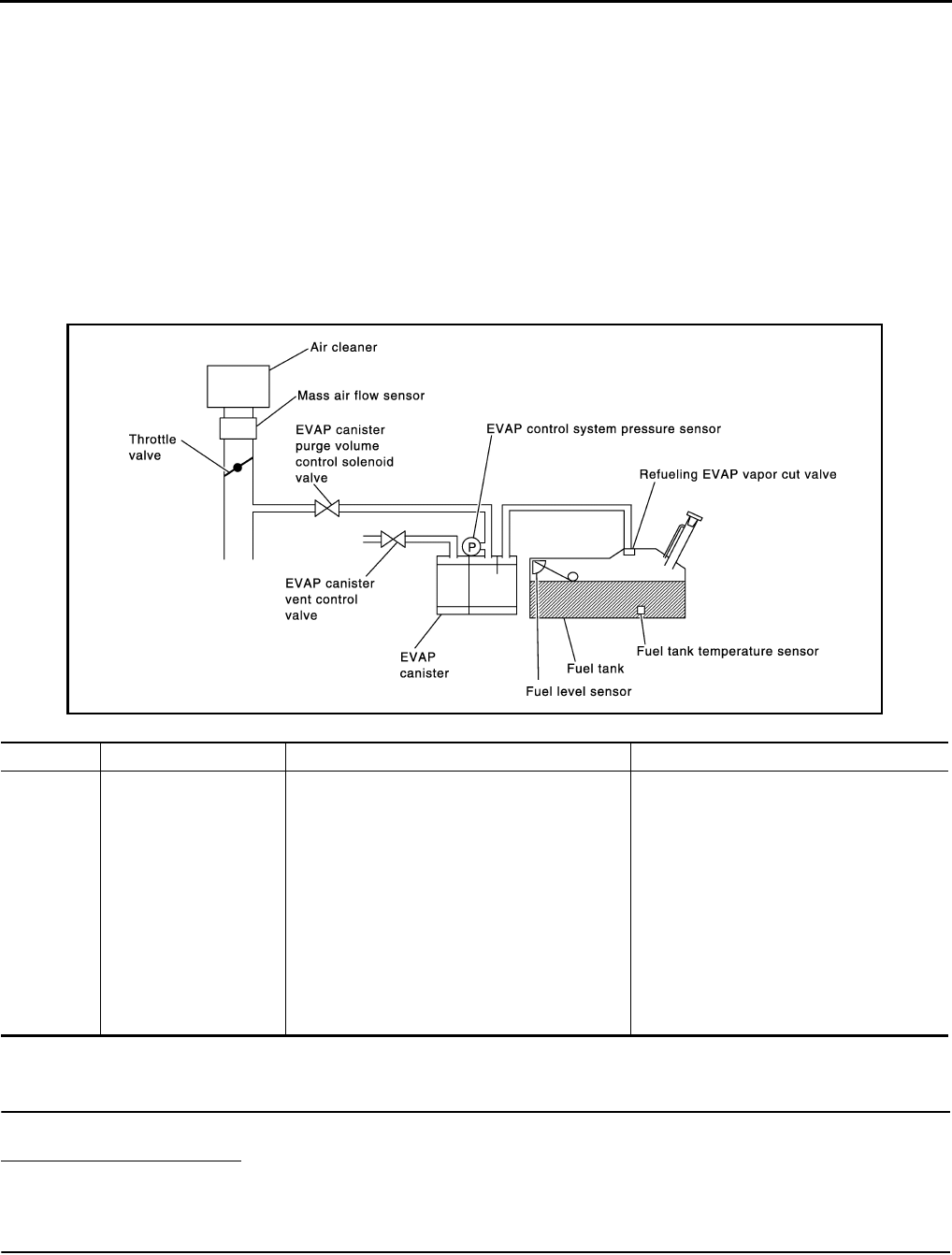
EC-268
< COMPONENT DIAGNOSIS > [FOR CALIFORNIA]
P0441 EVAP CONTROL SYSTEM
P0441 EVAP CONTROL SYSTEM
DTC Logic INFOID:0000000004493475
DTC DETECTION LOGIC
NOTE:
If DTC P0441 is displayed with other DTC such as P2122, P2123, P2127, P2128 or P2138, first perform
trouble diagnosis for other DTC.
In this evaporative emission (EVAP) control system, purge flow occurs during non-closed throttle conditions.
Purge volume is related to air intake volume. Under normal purge conditions (non-closed throttle), the EVAP
canister purge volume control solenoid valve is open to admit purge flow. Purge flow exposes the EVAP con-
trol system pressure sensor to intake manifold vacuum.
Under normal conditions (non-closed throttle), sensor output voltage indicates if pressure drop and purge flow
are adequate. If not, a malfunction is determined.
DTC CONFIRMATION PROCEDURE
1.INSPECTION START
Do you have CONSULT-III?
Do you have CONSULT-III?
YES >> GO TO 2.
NO >> GO TO 6.
2.PRECONDITIONING
If DTC CONFIRMATION PROCEDURE has been previously conducted, always turn ignition switch OFF and
wait at least 10 seconds before conducting the next test.
TESTING CONDITION:
DTC No. Trouble diagnosis name DTC detecting condition Possible cause
P0441 EVAP control system in-
correct purge flow
EVAP control system does not operate proper-
ly, EVAP control system has a leak between in-
take manifold and EVAP control system
pressure sensor.
• EVAP canister purge volume control so-
lenoid valve stuck closed
• EVAP control system pressure sensor
and the circuit
• Loose, disconnected or improper con-
nection of rubber tube
• Blocked rubber tube
• Cracked EVAP canister
• EVAP canister purge volume control so-
lenoid valve circuit
• Accelerator pedal position sensor
• Blocked purge port
• EVAP canister vent control valve
PBIB1026E
Revision: 2008 August 2009 Rogue

P0441 EVAP CONTROL SYSTEM
EC-269
< COMPONENT DIAGNOSIS > [FOR CALIFORNIA]
C
D
E
F
G
H
I
J
K
L
M
A
EC
N
P
O
Always perform test at a temperature of 5°C (41°F) or more.
>> GO TO 3.
3.PERFORM DTC CONFIRMATION PROCEDURE-I
With CONSULT-III
1. Start engine and warm it up to normal operating temperature.
2. Turn ignition switch OFF and wait at least 10 seconds.
3. Start engine and let it idle for at least 70 seconds.
4. Select “PURG FLOW P0441” of “EVAPORATIVE SYSTEM” in “DTC WORK SUPPORT” mode with CON-
SULT-III.
5. Touch “START”.
Is COMPLETED displayed on CONSULT-III screen?
YES >> GO TO 5.
NO >> GO TO 4.
4.PERFORM DTC CONFIRMATION PROCEDURE-II
When the following conditions are met, “TESTING” will be displayed on the CONSULT-III screen. Maintain the
conditions continuously until “TESTING” changes to “COMPLETED”. (It will take at least 35 seconds.)
CAUTION:
Always drive vehicle at a safe speed.
If “TESTING” does not change for a long time, retry from step 2.
Is “COMPLETED” displayed on CONSULT-III screen?
YES >> GO TO 5.
NO >> Perform DTC CONFIRMATION PROCEDURE again. GO TO 3.
5.PERFORM DTC CONFIRMATION PROCEDURE-III
Touch “SELF-DIAG RESULT”.
Which is displayed on CONSULT-III screen?
OK >> INSPECTION END
NG >> Go to EC-270, "Diagnosis Procedure".
6.PERFORM COMPONENT FUNCTION CHECK
Perform Component Function Check. Refer to EC-269, "Component Function Check".
NOTE:
Use Component Function Check to check the overall function of the EVAP control system purge flow monitor-
ing. During this check, a 1st trip DTC might not be confirmed.
Is the inspection result normal?
YES >> INSPECTION END
NO >> Go to EC-270, "Diagnosis Procedure".
Component Function Check INFOID:0000000004493476
1.PERFORM COMPONENT FUNCTION CHECK
Without CONSULT-III
1. Lift up drive wheels.
2. Start engine and warm it up to normal operating temperature.
3. Turn ignition switch OFF, wait at least 10 seconds.
4. Start engine and wait at least 70 seconds.
5. Set voltmeter probes to ECM harness connector terminals.
Selector lever Suitable position
VHCL SPEED SE 32 - 120 km/h (20 - 75 mph)
ENG SPEED 500 - 3,800 rpm
B/FUEL SCHDL 1.0 - 10.0 msec
COOLAN TEMP/S More than 0°C (32°F)
Revision: 2008 August 2009 Rogue

EC-270
< COMPONENT DIAGNOSIS > [FOR CALIFORNIA]
P0441 EVAP CONTROL SYSTEM
6. Check EVAP control system pressure sensor value at idle speed and note it.
7. Establish and maintain the following conditions for at least 1 minute.
8. Verify that EVAP control system pressure sensor value stays 0.1V less than the value at idle speed (mea-
sured at step 6) for at least 1 second.
Is the inspection result normal?
YES >> INSPECTION END
NO >> Go to EC-270, "Diagnosis Procedure".
Diagnosis Procedure INFOID:0000000004493477
1.CHECK EVAP CANISTER
1. Turn ignition switch OFF.
2. Check EVAP canister for cracks.
Is the inspection result normal?
YES-1 >> With CONSULT-III: GO TO 2.
YES-2 >> Without CONSULT-III: GO TO 3.
NO >> Replace EVAP canister.
2.CHECK PURGE FLOW
With CONSULT-III
1. Disconnect vacuum hose connected to EVAP canister purge volume control solenoid valve at EVAP ser-
vice port and install vacuum gauge. For the location of EVAP service port, refer to EC-72, "System Dia-
gram".
2. Start engine and let it idle.
3. Select “PURG VOL CONT/V” in “ACTIVE TEST” mode with CONSULT-III.
4. Rev engine up to 2,000 rpm.
5. Touch “Qd” and “Qu” on CONSULT-III screen to adjust “PURG VOL C/V” opening and check vacuum
existence.
Is the inspection result normal?
YES >> GO TO 7.
NO >> GO TO 4.
3.CHECK PURGE FLOW
Without CONSULT-III
1. Start engine and warm it up to normal operating temperature.
2. Stop engine.
ECM ECM
Connector Terminal Connector Terminal
E16 86
(EVAP control system
pressure sensor signal)
E16 96
(Sensor
ground)
Air conditioner switch ON
Headlamp switch ON
Rear window defogger switch ON
Engine speed Approx. 3,000 rpm
Selector lever Any position other than P, N or R
PURG VOL C/V Vacuum
100% Existed
0% Not existed
Revision: 2008 August 2009 Rogue
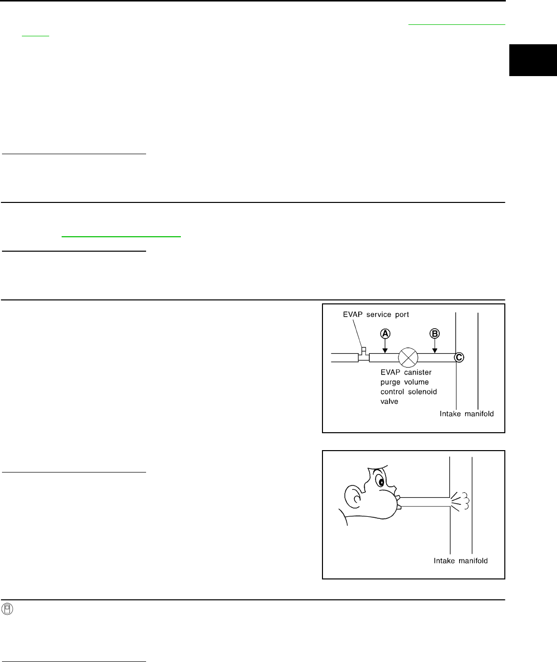
P0441 EVAP CONTROL SYSTEM
EC-271
< COMPONENT DIAGNOSIS > [FOR CALIFORNIA]
C
D
E
F
G
H
I
J
K
L
M
A
EC
N
P
O
3. Disconnect vacuum hose connected to EVAP canister purge volume control solenoid valve at EVAP ser-
vice port and install vacuum gauge. For the location of EVAP service port, refer to EC-72, "System Dia-
gram".
4. Start engine and let it idle.
Do not depress accelerator pedal even slightly.
5. Check vacuum gauge indication before 60 seconds pass after starting engine.
6. Rev engine up to 2,000rpm after 100 seconds pass after starting engine.
Is the inspection result normal?
YES >> GO TO 7.
NO >> GO TO 4.
4.CHECK EVAP PURGE LINE
1. Turn ignition switch OFF.
2. Check EVAP purge line for improper connection or disconnection.
Refer to EC-72, "System Diagram".
Is the inspection result normal?
YES >> GO TO 5.
NO >> Repair EVAP purge line.
5.CHECK EVAP PURGE HOSE AND PURGE PORT
1. Disconnect purge hoses connected to EVAP service port A and
EVAP canister purge volume control solenoid valve B.
2. Blow air into each hose and EVAP purge port C.
3. Check that air flows freely.
Is the inspection result normal?
YES-1 >> With CONSULT-III: GO TO 6.
YES-2 >> Without CONSULT-III: GO TO 7.
NO >> Repair or clean hoses and/or purge port.
6.CHECK EVAP CANISTER PURGE VOLUME CONTROL SOLENOID VALVE
With CONSULT-III
1. Start engine.
2. Perform “PURG VOL CONT/V” in “ACTIVE TEST” mode with CONSULT-III. Check that engine speed var-
ies according to the valve opening.
Is the inspection result normal?
YES >> GO TO 8.
NO >> GO TO 7.
Vacuum should not exist.
Vacuum should exist.
SEF367U
SEF368U
Revision: 2008 August 2009 Rogue

EC-272
< COMPONENT DIAGNOSIS > [FOR CALIFORNIA]
P0441 EVAP CONTROL SYSTEM
7.CHECK EVAP CANISTER PURGE VOLUME CONTROL SOLENOID VALVE
Refer to EC-282, "Component Inspection".
Is the inspection result normal?
YES >> GO TO 8.
NO >> Replace EVAP canister purge volume control solenoid valve.
8.CHECK EVAP CONTROL SYSTEM PRESSURE SENSOR CONNECTOR
1. Disconnect EVAP control system pressure sensor harness connector.
2. Check connectors for water.
Is the inspection result normal?
YES >> GO TO 9.
NO >> Replace EVAP control system pressure sensor.
9.CHECK EVAP CONTROL SYSTEM PRESSURE SENSOR FUNCTION
Refer to EC-297, "DTC Logic" for DTC P0452, EC-302, "DTC Logic" for DTC P0453.
Is the inspection result normal?
YES >> GO TO 10.
NO >> Replace EVAP control system pressure sensor.
10.CHECK RUBBER TUBE FOR CLOGGING
1. Disconnect rubber tube connected to EVAP canister vent control valve.
2. Check the rubber tube for clogging.
Is the inspection result normal?
YES >> GO TO 11.
NO >> Clean the rubber tube using an air blower.
11.CHECK EVAP CANISTER VENT CONTROL VALVE
Refer to EC-288, "Component Inspection".
Is the inspection result normal?
YES >> GO TO 12.
NO >> Replace EVAP canister vent control valve.
12.CHECK EVAP PURGE LINE
Inspect EVAP purge line (pipe and rubber tube). Check for evidence of leaks.
Refer to EC-72, "System Diagram".
Is the inspection result normal?
YES >> GO TO 13.
NO >> Replace it.
13.CLEAN EVAP PURGE LINE
Clean EVAP purge line (pipe and rubber tube) using air blower.
>> GO TO 14.
14.CHECK INTERMITTENT INCIDENT
Refer to GI-41, "Intermittent Incident".
>> INSPECTION END
Water should not exist.
Revision: 2008 August 2009 Rogue
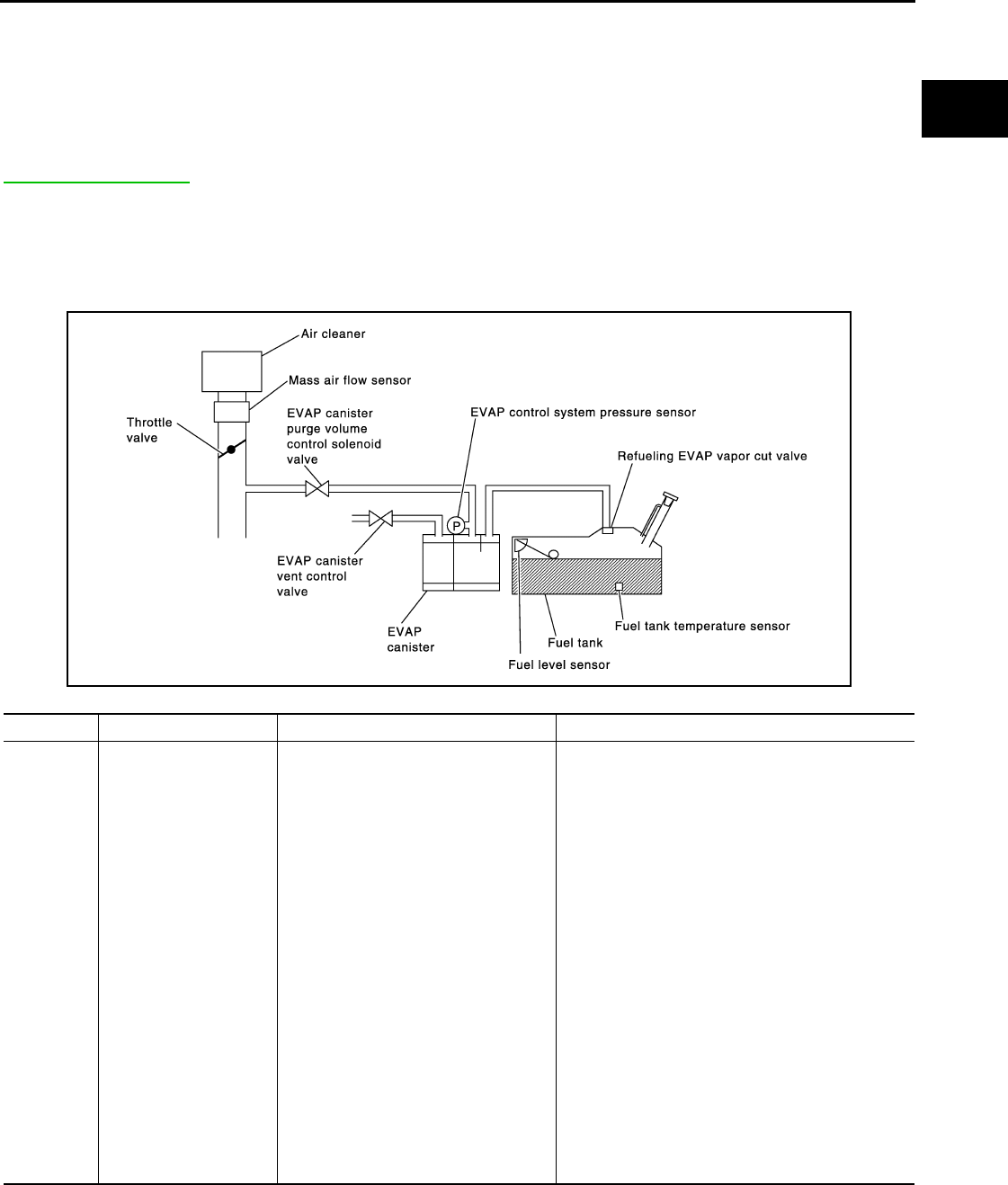
P0442 EVAP CONTROL SYSTEM
EC-273
< COMPONENT DIAGNOSIS > [FOR CALIFORNIA]
C
D
E
F
G
H
I
J
K
L
M
A
EC
N
P
O
P0442 EVAP CONTROL SYSTEM
DTC Logic INFOID:0000000004493478
DTC DETECTION LOGIC
NOTE:
If DTC P0442 is displayed with DTC P0456, first perform the trouble diagnosis for DTC P0456. Refer to
EC-314, "DTC Logic".
This diagnosis detects leaks in the EVAP purge line using engine intake manifold vacuum.
If pressure does not increase, the ECM will check for leaks in the line between the fuel tank and EVAP canister
purge volume control solenoid valve, under the following “Vacuum test” conditions.
The EVAP canister vent control valve is closed to shut the EVAP purge line off. The EVAP canister purge vol-
ume control solenoid valve will then be opened to depressurize the EVAP purge line using intake manifold
vacuum. After this occurs, the EVAP canister purge volume control solenoid valve will be closed.
CAUTION:
• Use only a genuine NISSAN fuel filler cap as a replacement. If an incorrect fuel filler cap is used, the
MIL may illuminate.
• If the fuel filler cap is not tightened properly, the MIL may illuminate.
DTC No. Trouble diagnosis name DTC detecting condition Possible cause
P0442
EVAP control system
small leak detected
(negative pressure)
EVAP control system has a leak, EVAP
control system does not operate prop-
erly.
• Incorrect fuel tank vacuum relief valve
• Incorrect fuel filler cap used
• Fuel filler cap remains open or fails to close.
• Foreign matter caught in fuel filler cap.
• Leak is in line between intake manifold and EVAP
canister purge volume control solenoid valve.
• Foreign matter caught in EVAP canister vent con-
trol valve.
• EVAP canister or fuel tank leaks
• EVAP purge line (pipe and rubber tube) leaks
• EVAP purge line rubber tube bent
• Loose or disconnected rubber tube
• EVAP canister vent control valve and the circuit
• EVAP canister purge volume control solenoid
valve and the circuit
• Fuel tank temperature sensor
• O-ring of EVAP canister vent control valve is
missing or damaged
• EVAP canister is saturated with water
• EVAP control system pressure sensor
• Fuel level sensor and the circuit
• Refueling EVAP vapor cut valve
• ORVR system leaks
PBIB1026E
Revision: 2008 August 2009 Rogue

EC-274
< COMPONENT DIAGNOSIS > [FOR CALIFORNIA]
P0442 EVAP CONTROL SYSTEM
• Use only a genuine NISSAN rubber tube as a replacement.
DTC CONFIRMATION PROCEDURE
1.PRECONDITIONING
If DTC CONFIRMATION PROCEDURE has been previously conducted, always turn ignition switch OFF and
wait at least 10 seconds before conducting the next test.
TESTING CONDITION:
•Perform “DTC WORK SUPPORT” when the fuel level is between 1/4 and 3/4 full, and vehicle is placed
on flat level surface.
•Always perform test at a temperature of 0 to 30°C (32 to 86°F).
NOTE:
Check that EVAP hoses are connected to EVAP canister purge volume control solenoid valve properly.
Do you have CONSULT-III?
YES >> GO TO 2.
NO >> GO TO 3.
2.PERFORM DTC CONFIRMATION PROCEDURE
With CONSULT-III
1. Turn ignition switch ON.
2. Turn ignition switch OFF and wait at least 10 seconds.
3. Turn ignition switch ON and select “DATA MONITOR” mode with CONSULT-III.
4. Check that the following conditions are met.
COOLAN TEMP/S: 0 - 100°C (32 - 212°F)
INT/A TEMP SE: 0 - 60°C (32 - 140°F)
5. Select “EVAP SML LEAK P0442/P1442” of “EVAPORATIVE SYSTEM” in “DTC WORK SUPPORT” mode
with CONSULT-III.
Follow the instructions displayed.
NOTE:
If the engine speed cannot be maintained within the range displayed on the CONSULT-III screen, go to
EC-22, "BASIC INSPECTION : Special Repair Requirement".
Which is displayed on CONSULT-III screen?
OK >> INSPECTION END
NG >> Go to EC-274, "Diagnosis Procedure".
3.PERFORM COMPONENT FUNCTION CHECK
With GST
NOTE:
Be sure to read the explanation of DRIVING PATTERN in EC-469, "How to Set SRT Code" before driving
vehicle.
1. Start engine.
2. Drive vehicle according to DRIVING PATTERN.
3. Stop vehicle.
4. Turn ignition switch OFF, wait at least 10 seconds and then turn ON.
5. Select Service $07 with GST.
Is 1st trip DTC displayed?
YES-1 >> P0441: Go to EC-270, "Diagnosis Procedure".
YES-2 >> P0442: Go to EC-274, "Diagnosis Procedure".
NO >> INSPECTION END
Diagnosis Procedure INFOID:0000000004493479
1.CHECK FUEL FILLER CAP DESIGN
1. Turn ignition switch OFF.
Revision: 2008 August 2009 Rogue
P0442 EVAP CONTROL SYSTEM
EC-275
< COMPONENT DIAGNOSIS > [FOR CALIFORNIA]
C
D
E
F
G
H
I
J
K
L
M
A
EC
N
P
O
2. Check for genuine NISSAN fuel filler cap design.
Is the inspection result normal?
YES >> GO TO 2.
NO >> Replace with genuine NISSAN fuel filler cap.
2.CHECK FUEL FILLER CAP INSTALLATION
Check that the cap is tightened properly by rotating the cap clockwise.
Is the inspection result normal?
YES >> GO TO 3.
NO >> Open fuel filler cap, then clean cap and fuel filler neck threads using air blower. Then retighten
until ratcheting sound is heard.
3.CHECK FUEL FILLER CAP FUNCTION
Check for air releasing sound while opening the fuel filler cap.
Is the inspection result normal?
YES >> GO TO 5.
NO >> GO TO 4.
4.CHECK FUEL TANK VACUUM RELIEF VALVE
Refer to EC-278, "Component Inspection".
Is the inspection result normal?
YES >> GO TO 5.
NO >> Replace fuel filler cap with a genuine one.
5.CHECK FOR EVAP LEAK
Refer to EC-72, "System Diagram".
Is there any leak in EVAP line?
YES >> Repair or replace.
NO >> GO TO 6.
6.CHECK EVAP CANISTER VENT CONTROL VALVE
Check the following.
• EVAP canister vent control valve is installed properly.
Refer to EC-492, "Exploded View".
• EVAP canister vent control valve.
Refer to EC-288, "Component Inspection".
Is the inspection result normal?
YES >> GO TO 7.
NO >> Repair or replace EVAP canister vent control valve and O-ring.
7.CHECK IF EVAP CANISTER IS SATURATED WITH WATER
1. Remove EVAP canister with EVAP canister vent control valve and EVAP control system pressure sensor
attached.
SEF915U
Revision: 2008 August 2009 Rogue

EC-276
< COMPONENT DIAGNOSIS > [FOR CALIFORNIA]
P0442 EVAP CONTROL SYSTEM
2. Does water drain from the EVAP canister?
Does water drain from the EVAP canister?
YES >> GO TO 8.
NO-1 >> With CONSULT-III: GO TO 10.
NO-2 >> Without CONSULT-III: GO TO 11.
8.CHECK EVAP CANISTER
Weigh the EVAP canister with the EVAP canister vent control valve and EVAP control system pressure sensor
attached.
The weight should be less than 2.1 kg (4.6 lb).
Is the inspection result normal?
YES-1 >> With CONSULT-III: GO TO 10.
YES-2 >> Without CONSULT-III: GO TO 11.
NO >> GO TO 9.
9.DETECT MALFUNCTIONING PART
Check the following.
• EVAP canister for damage
• EVAP hose between EVAP canister and vehicle frame for clogging or poor connection
>> Repair hose or replace EVAP canister.
10.CHECK EVAP CANISTER PURGE VOLUME CONTROL SOLENOID VALVE OPERATION
With CONSULT-III
1. Disconnect vacuum hose from EVAP canister purge volume control solenoid valve at EVAP service port.
2. Start engine.
3. Perform “PURG VOL CONT/V” in “ACTIVE TEST” mode.
4. Touch “Qu” on CONSULT-III screen to increase “PURG VOL C/V” opening to 100%.
5. Check vacuum hose for vacuum.
Is the inspection result normal?
YES >> GO TO 13.
NO >> GO TO 12.
11.CHECK EVAP CANISTER PURGE VOLUME CONTROL SOLENOID VALVE OPERATION
Without CONSULT-III
1. Start engine and warm it up to normal operating temperature.
2. Stop engine.
3. Disconnect vacuum hose from EVAP canister purge volume control solenoid valve at EVAP service port.
4. Start engine and let it idle for at least 80 seconds.
5. Check vacuum hose for vacuum when revving engine up to 2,000 rpm.
Is the inspection result normal?
YES >> GO TO 13.
NO >> GO TO 12.
12.CHECK VACUUM HOSE
Check vacuum hoses for clogging or disconnection. Refer to EC-72, "System Diagram".
Is the inspection result normal?
PBIB1213E
Vacuum should exist.
Vacuum should exist.
Revision: 2008 August 2009 Rogue

P0442 EVAP CONTROL SYSTEM
EC-277
< COMPONENT DIAGNOSIS > [FOR CALIFORNIA]
C
D
E
F
G
H
I
J
K
L
M
A
EC
N
P
O
YES >> GO TO 13.
NO >> Repair or reconnect the hose.
13.CHECK EVAP CANISTER PURGE VOLUME CONTROL SOLENOID VALVE
Refer to EC-282, "Component Inspection".
Is the inspection result normal?
YES >> GO TO 14.
NO >> Replace EVAP canister purge volume control solenoid valve.
14.CHECK FUEL TANK TEMPERATURE SENSOR
Refer to EC-241, "Component Inspection".
Is the inspection result normal?
YES >> GO TO 15.
NO >> Replace fuel level sensor unit.
15.CHECK EVAP CONTROL SYSTEM PRESSURE SENSOR
Refer to EC-294, "DTC Logic".
Is the inspection result normal?
YES >> GO TO 16.
NO >> Replace EVAP control system pressure sensor.
16.CHECK EVAP PURGE LINE
Check EVAP purge line (pipe, rubber tube, fuel tank and EVAP canister) for cracks or improper connection.
Refer to EC-72, "System Diagram".
Is the inspection result normal?
YES >> GO TO 17.
NO >> Repair or reconnect the hose.
17.CLEAN EVAP PURGE LINE
Clean EVAP purge line (pipe and rubber tube) using air blower.
>> GO TO 18.
18.CHECK EVAP/ORVR LINE
Check EVAP/ORVR line between EVAP canister and fuel tank for clogging, kinks, looseness and improper
connection. For location, refer to EC-431, "Description".
Is the inspection result normal?
YES >> GO TO 19.
NO >> Repair or replace hoses and tubes.
19.CHECK RECIRCULATION LINE
Check recirculation line between filler neck tube and fuel tank for clogging, kinks, cracks, looseness and
improper connection.
Is the inspection result normal?
YES >> GO TO 20.
NO >> Repair or replace hose, tube or filler neck tube.
20.CHECK REFUELING EVAP VAPOR CUT VALVE
Refer to EC-434, "Component Inspection".
Is the inspection result normal?
YES >> GO TO 21.
NO >> Replace refueling EVAP vapor cut valve with fuel tank.
21.CHECK FUEL LEVEL SENSOR
Refer to FL-10, "2WD : Inspection" (2WD), FL-14, "AWD : Inspection" (AWD).
Is the inspection result normal?
YES >> GO TO 22.
Revision: 2008 August 2009 Rogue

EC-278
< COMPONENT DIAGNOSIS > [FOR CALIFORNIA]
P0442 EVAP CONTROL SYSTEM
NO >> Replace fuel level sensor unit.
22.CHECK INTERMITTENT INCIDENT
Refer to GI-41, "Intermittent Incident".
>> INSPECTION END
Component Inspection INFOID:0000000004493480
1.CHECK FUEL FILLER CAP
1. Turn ignition switch OFF.
2. Remove fuel filler cap.
3. Wipe clean valve housing.
4. Install fuel filler cap adapter (commercial service tool) to fuel filler cap.
5. Check valve opening pressure and vacuum.
Is the inspection result normal?
YES >> INSPECTION END
NO >> GO TO 2.
2.REPLACE FUEL FILLER CAP
Replace fuel filler cap.
CAUTION:
Use only a genuine fuel filler cap as a replacement. If an incorrect fuel filler cap is used, the MIL may
illuminate.
>> INSPECTION END
SEF445Y
Pressure: 15.3 - 20.0 kPa (0.156 - 0.204 kg/cm2, 2.22 -
2.90 psi)
Vacuum: −6.0 to −3.3 kPa (−0.061 to −0.034 kg/cm2,
−0.87 to −0.48 psi)
SEF943S
Revision: 2008 August 2009 Rogue

P0443 EVAP CANISTER PURGE VOLUME CONTROL SOLENOID VALVE
EC-279
< COMPONENT DIAGNOSIS > [FOR CALIFORNIA]
C
D
E
F
G
H
I
J
K
L
M
A
EC
N
P
O
P0443 EVAP CANISTER PURGE VOLUME CONTROL SOLENOID VALVE
Description INFOID:0000000004493481
The EVAP canister purge volume control solenoid valve is used to
control the flow rate of fuel vapor from the EVAP canister. The EVAP
canister purge volume control solenoid valve is moved by ON/OFF
pulses from the ECM. The longer the ON pulse, the greater the
amount of fuel vapor that will flow through the valve.
DTC Logic INFOID:0000000004493482
DTC DETECTION LOGIC
DTC CONFIRMATION PROCEDURE
1.PRECONDITIONING
If DTC CONFIRMATION PROCEDURE has been previously conducted, always turn ignition switch OFF and
wait at least 10 seconds before conducting the next test.
TESTING CONDITION:
Always perform test at a temperature of 5°C (41°F) or more.
Do you have CONSULT-III
YES >> GO TO 2.
NO >> GO TO 3.
2.PERFORM DTC CONFIRMATION PROCEDURE
With CONSULT-III
1. Start engine and warm it up to normal operating temperature.
2. Turn ignition switch OFF and wait at least 10 seconds.
3. Turn ignition switch ON.
4. Select “PURG VOL CN/V P1444” of “EVAPORATIVE SYSTEM” in “DTC WORK SUPPORT” mode with
CONSULT-III.
5. Touch “START”.
6. Start engine and let it idle until “TESTING” on CONSULT-III changes to “COMPLETED”. (It will take
approximately 10 seconds.)
If “TESTING” is not displayed after 5 minutes, retry from step 2.
7. Touch “SELF-DIAG RESULT”.
Which is displayed on CONSULT-III?
OK >> INSPECTION END
NG >> Go to EC-280, "Diagnosis Procedure".
3.PERFORM DTC CONFIRMATION PROCEDURE
JMBIA0069ZZ
DTC No. Trouble diagnosis name DTC detecting condition Possible cause
P0443 EVAP canister purge
volume control solenoid
valve
The canister purge flow is detected during the
specified driving conditions, even when EVAP
canister purge volume control solenoid valve is
completely closed.
• EVAP control system pressure sensor
• EVAP canister purge volume control so-
lenoid valve
(The valve is stuck open.)
• EVAP canister vent control valve
• EVAP canister
•Hoses
(Hoses are connected incorrectly or
clogged.)
Revision: 2008 August 2009 Rogue

EC-280
< COMPONENT DIAGNOSIS > [FOR CALIFORNIA]
P0443 EVAP CANISTER PURGE VOLUME CONTROL SOLENOID VALVE
With GST
1. Start engine and warm it up to normal operating temperature.
2. Turn ignition switch OFF and wait at least 10 seconds.
3. Start engine and let it idle for at least 20 seconds.
4. Check 1st trip DTC.
Is 1st trip DTC displayed?
YES >> Go to EC-280, "Diagnosis Procedure".
NO >> INSPECTION END
Diagnosis Procedure INFOID:0000000004493483
1.CHECK EVAP CANISTER PURGE VOLUME CONTROL SOLENOID VALVE POWER SUPPLY CIRCUIT
1. Turn ignition switch OFF.
2. Disconnect EVAP canister purge volume control solenoid valve harness connector.
3. Turn ignition switch ON.
4. Check the voltage between EVAP canister purge volume control solenoid valve harness connector and
ground.
Is the inspection result normal?
YES >> GO TO 3.
NO >> GO TO 2.
2.DETECT MALFUNCTIONING PART
Check the following.
• Harness connectors E7, F121
• Harness for open or short between EVAP canister purge volume control solenoid valve and IPDM E/R
• Harness for open or short between EVAP canister purge volume control solenoid valve and ECM
>> Repair open circuit or short to ground or short to power in harness or connectors.
3.CHECK EVAP CANISTER PURGE VOLUME CONTROL SOLENOID VALVE OUTPUT SIGNAL CIRCUIT
FOR OPEN AND SHORT
1. Turn ignition switch OFF.
2. Disconnect ECM harness connector.
3. Check the continuity between EVAP canister purge volume control solenoid valve harness connector and
ECM harness connector.
4. Also check harness for short to ground and short to power.
Is the inspection result normal?
YES >> GO TO 4.
NO >> Repair open circuit or short to ground or short to power in harness or connectors.
4.CHECK EVAP CONTROL SYSTEM PRESSURE SENSOR CONNECTOR
1. Disconnect EVAP control system pressure sensor harness connector.
2. Check connectors for water.
EVAP canister purge volume
control solenoid valve Ground Voltage
Connector Terminal
F32 1 Ground Battery voltage
EVAP canister purge volume
control solenoid valve ECM Continuity
Connector Terminal Connector Terminal
F32 2 F7 25 Existed
Water should not exist.
Revision: 2008 August 2009 Rogue

P0443 EVAP CANISTER PURGE VOLUME CONTROL SOLENOID VALVE
EC-281
< COMPONENT DIAGNOSIS > [FOR CALIFORNIA]
C
D
E
F
G
H
I
J
K
L
M
A
EC
N
P
O
Is the inspection result normal?
YES >> GO TO 5.
NO >> Replace EVAP control system pressure sensor.
5.CHECK EVAP CONTROL SYSTEM PRESSURE SENSOR
Refer to EC-296, "Component Inspection".
Is the inspection result normal?
YES-1 >> With CONSULT-III: GO TO 6.
YES-2 >> Without CONSULT-III: GO TO 7.
NO >> Replace EVAP control system pressure sensor.
6.CHECK EVAP CANISTER PURGE VOLUME CONTROL SOLENOID VALVE
With CONSULT-III
1. Turn ignition switch OFF.
2. Reconnect harness connectors disconnected.
3. Start engine.
4. Perform “PURG VOL CONT/V” in “ACTIVE TEST” mode with CONSULT-III. Check that engine speed var-
ies according to the valve opening.
Is the inspection result normal?
YES >> GO TO 8.
NO >> GO TO 7.
7.CHECK EVAP CANISTER PURGE VOLUME CONTROL SOLENOID VALVE
Refer to EC-282, "Component Inspection".
Is the inspection result normal?
YES >> GO TO 8.
NO >> Replace EVAP canister purge volume control solenoid valve.
8.CHECK RUBBER TUBE FOR CLOGGING
1. Disconnect rubber tube connected to EVAP canister vent control valve.
2. Check the rubber tube for clogging.
Is the inspection result normal?
YES >> GO TO 9.
NO >> Clean the rubber tube using an air blower.
9.CHECK EVAP CANISTER VENT CONTROL VALVE
Refer to EC-288, "Component Inspection".
Is the inspection result normal?
YES >> GO TO 10.
NO >> Replace EVAP canister vent control valve.
10.CHECK IF EVAP CANISTER IS SATURATED WITH WATER
1. Remove EVAP canister with EVAP canister vent control valve and EVAP control system pressure sensor
attached.
2. Check if water will drain from EVAP canister.
Does water drain from the EVAP canister?
YES >> GO TO 11.
NO >> GO TO 13.
11.CHECK EVAP CANISTER
PBIB1213E
Revision: 2008 August 2009 Rogue
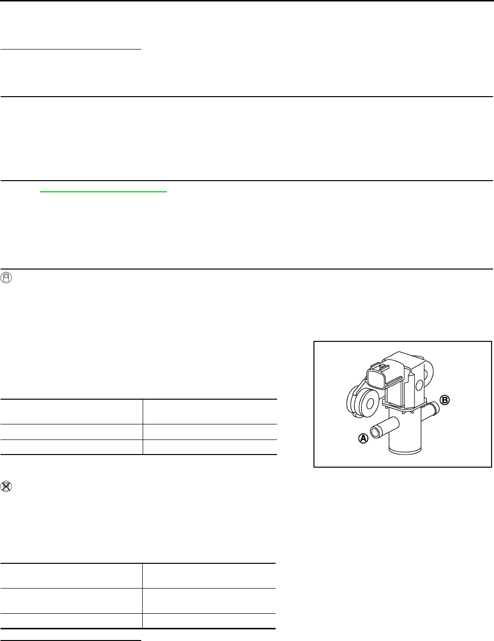
EC-282
< COMPONENT DIAGNOSIS > [FOR CALIFORNIA]
P0443 EVAP CANISTER PURGE VOLUME CONTROL SOLENOID VALVE
Weigh the EVAP canister with the EVAP canister vent control valve and EVAP control system pressure sensor
attached.
The weight should be less than 2.1 kg (4.6 lb).
Is the inspection result normal?
YES >> GO TO 13.
NO >> GO TO 12.
12.DETECT MALFUNCTIONING PART
Check the following.
• EVAP canister for damage
• EVAP hose between EVAP canister and vehicle frame for clogging or poor connection
>> Repair hose or replace EVAP canister.
13.CHECK INTERMITTENT INCIDENT
Refer to GI-41, "Intermittent Incident".
>> INSPECTION END
Component Inspection INFOID:0000000004493484
1.CHECK EVAP CANISTER PURGE VOLUME CONTROL SOLENOID VALVE
With CONSULT-III
1. Turn ignition switch OFF.
2. Reconnect all harness connectors disconnected.
3. Disconnect EVAP purge hoses connected to EVAP canister purge volume control solenoid valve.
4. Turn ignition switch ON.
5. Select “PURG VOL CONT/V” in “ACTIVE TEST” mode with CONSULT-III.
6. Touch “Qd” and “Qu” on CONSULT-III screen to adjust “PURG
VOL C/V” opening and check air passage continuity of EVAP
canister purge volume control solenoid valve under the following
conditions.
Without CONSULT-III
1. Turn ignition switch OFF.
2. Disconnect EVAP canister purge volume control solenoid valve harness connector.
3. Disconnect EVAP purge hoses connected to EVAP canister purge volume control solenoid valve.
4. Check air passage continuity of EVAP canister purge volume control solenoid valve under the following
conditions.
Is the inspection result normal?
YES >> INSPECTION END
NO >> Replace EVAP canister purge volume control solenoid valve
Condition
(PURG VOL C/V value)
Air passage continuity
between (A) and (B)
100% Existed
0% Not existed
JMBIA0068ZZ
Condition Air passage continuity
between (A) and (B)
12V direct current supply between
terminals 1 and 2 Existed
No supply Not existed
Revision: 2008 August 2009 Rogue

P0444, P0445 EVAP CANISTER PURGE VOLUME CONTROL SOLENOID
VALVE
EC-283
< COMPONENT DIAGNOSIS > [FOR CALIFORNIA]
C
D
E
F
G
H
I
J
K
L
M
A
EC
N
P
O
P0444, P0445 EVAP CANISTER PURGE VOLUME CONTROL SOLENOID
VALVE
Description INFOID:0000000004493485
The EVAP canister purge volume control solenoid valve is used to
control the flow rate of fuel vapor from the EVAP canister. The EVAP
canister purge volume control solenoid valve is moved by ON/OFF
pulses from the ECM. The longer the ON pulse, the greater the
amount of fuel vapor that will flow through the valve.
DTC Logic INFOID:0000000004493486
DTC DETECTION LOGIC
DTC CONFIRMATION PROCEDURE
1.CONDITIONING
If DTC CONFIRMATION PROCEDURE has been previously conducted, always turn ignition switch OFF and
wait at least 10 seconds before conducting the next test.
TESTING CONDITION:
Before performing the following procedure, confirm battery voltage is more than 11V at idle.
>> GO TO 2.
2.PERFORM DTC CONFIRMATION PROCEDURE
1. Start engine and let it idle for at least 13 seconds.
2. Check 1st trip DTC.
Is 1st trip DTC detected?
YES >> Go to EC-283, "Diagnosis Procedure".
NO >> INSPECTION END
Diagnosis Procedure INFOID:0000000004493487
1.CHECK EVAP CANISTER PURGE VOLUME CONTROL SOLENOID VALVE POWER SUPPLY CIRCUIT
1. Turn ignition switch OFF.
2. Disconnect EVAP canister purge volume control solenoid valve harness connector.
3. Turn ignition switch ON.
4. Check the voltage between EVAP canister purge volume control solenoid valve harness connector and
ground.
JMBIA0069ZZ
DTC No. Trouble diagnosis name DTC detecting condition Possible cause
P0444 EVAP canister purge volume
control solenoid valve circuit
open
An excessively low voltage signal is sent
to ECM through the valve
• Harness or connectors
(The solenoid valve circuit is open or
shorted.)
• EVAP canister purge volume control so-
lenoid valve
P0445
EVAP canister purge volume
control solenoid valve circuit
shorted
An excessively high voltage signal is sent
to ECM through the valve
• Harness or connectors
(The solenoid valve circuit is shorted.)
• EVAP canister purge volume control so-
lenoid valve
Revision: 2008 August 2009 Rogue

EC-284
< COMPONENT DIAGNOSIS > [FOR CALIFORNIA]
P0444, P0445 EVAP CANISTER PURGE VOLUME CONTROL SOLENOID
VALVE
Is the inspection result normal?
YES >> GO TO 3.
NO >> GO TO 2.
2.DETECT MALFUNCTIONING PART
Check the following.
• Harness connectors E7, F121
• Harness for open or short between EVAP canister purge volume control solenoid valve and IPDM E/R
• Harness for open or short between EVAP canister purge volume control solenoid valve and ECM
>> Repair open circuit or short to ground or short to power in harness or connectors.
3.CHECK EVAP CANISTER PURGE VOLUME CONTROL SOLENOID VALVE OUTPUT SIGNAL CIRCUIT
FOR OPEN AND SHORT
1. Turn ignition switch OFF.
2. Disconnect ECM harness connector.
3. Check the continuity between EVAP canister purge volume control solenoid valve harness connector and
ECM harness connector.
4. Also check harness for short to ground and short to power.
Is the inspection result normal?
YES-1 >> With CONSULT-III: GO TO 4.
YES-2 >> Without CONSULT-III: GO TO 5.
NO >> Repair open circuit or short to ground or short to power in harness or connectors.
4.CHECK EVAP CANISTER PURGE VOLUME CONTROL SOLENOID VALVE OPERATION
With CONSULT-III
1. Reconnect all harness connectors disconnected.
2. Start engine.
3. Perform “PURG VOL CONT/V” in “ACTIVE TEST” mode with CONSULT-III. Check that engine speed var-
ies according to the valve opening.
Is the inspection result normal?
YES >> GO TO 6.
NO >> GO TO 5.
5.CHECK EVAP CANISTER PURGE VOLUME CONTROL SOLENOID VALVE
Refer to EC-285, "Component Inspection".
Is the inspection result normal?
YES >> GO TO 6.
NO >> Replace EVAP canister purge volume control solenoid valve.
6.CHECK INTERMITTENT INCIDENT
Refer to GI-41, "Intermittent Incident".
>> INSPECTION END
EVAP canister purge volume
control solenoid valve Ground Voltage
Connector Terminal
F32 1 Ground Battery voltage
EVAP canister purge volume
control solenoid valve ECM Continuity
Connector Terminal Connector Terminal
F32 2 F7 25 Existed
Revision: 2008 August 2009 Rogue

P0444, P0445 EVAP CANISTER PURGE VOLUME CONTROL SOLENOID
VALVE
EC-285
< COMPONENT DIAGNOSIS > [FOR CALIFORNIA]
C
D
E
F
G
H
I
J
K
L
M
A
EC
N
P
O
Component Inspection INFOID:0000000004493488
1.CHECK EVAP CANISTER PURGE VOLUME CONTROL SOLENOID VALVE
With CONSULT-III
1. Turn ignition switch OFF.
2. Reconnect all harness connectors disconnected.
3. Disconnect EVAP purge hoses connected to EVAP canister purge volume control solenoid valve.
4. Turn ignition switch ON.
5. Select “PURG VOL CONT/V” in “ACTIVE TEST” mode with CONSULT-III.
6. Touch “Qd” and “Qu” on CONSULT-III screen to adjust “PURG
VOL C/V” opening and check air passage continuity of EVAP
canister purge volume control solenoid valve under the following
conditions.
Without CONSULT-III
1. Turn ignition switch OFF.
2. Disconnect EVAP canister purge volume control solenoid valve harness connector.
3. Disconnect EVAP purge hoses connected to EVAP canister purge volume control solenoid valve.
4. Check air passage continuity of EVAP canister purge volume control solenoid valve under the following
conditions.
Is the inspection result normal?
YES >> INSPECTION END
NO >> Replace EVAP canister purge volume control solenoid valve
Condition
(PURG VOL C/V value)
Air passage continuity
between (A) and (B)
100% Existed
0% Not existed
JMBIA0068ZZ
Condition Air passage continuity
between (A) and (B)
12V direct current supply between
terminals 1 and 2 Existed
No supply Not existed
Revision: 2008 August 2009 Rogue
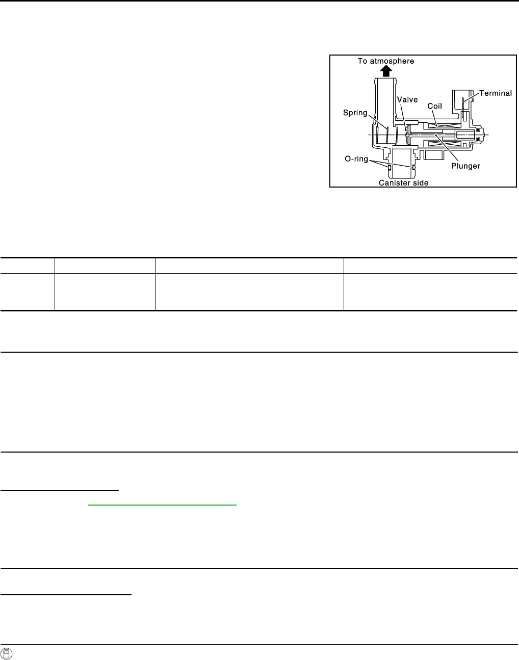
EC-286
< COMPONENT DIAGNOSIS > [FOR CALIFORNIA]
P0447 EVAP CANISTER VENT CONTROL VALVE
P0447 EVAP CANISTER VENT CONTROL VALVE
Description INFOID:0000000004493489
The EVAP canister vent control valve is located on the EVAP canis-
ter and is used to seal the canister vent.
This solenoid valve responds to signals from the ECM. When the
ECM sends an ON signal, the coil in the solenoid valve is energized.
A plunger will then move to seal the canister vent. The ability to seal
the vent is necessary for the on board diagnosis of other evaporative
emission control system components.
This solenoid valve is used only for diagnosis, and usually remains
opened.
When the vent is closed, under normal purge conditions, the evapo-
rative emission control system is depressurized and allows “EVAP
Control System” diagnosis.
DTC Logic INFOID:0000000004493490
DTC DETECTION LOGIC
DTC CONFIRMATION PROCEDURE
1.PRECONDITIONING
If DTC CONFIRMATION PROCEDURE has been previously conducted, always turn ignition switch OFF and
wait at least 10 seconds before conducting the next test.
TESTING CONDITION:
Before performing the following procedure, confirm battery voltage is more than 11V at idle.
>> GO TO 2.
2.PERFORM DTC CONFIRMATION PROCEDURE
1. Start engine and wait at least 8 seconds.
2. Check 1st trip DTC.
Is 1st trip DTC detected?
YES >> Go to EC-286, "Diagnosis Procedure".
NO >> INSPECTION END
Diagnosis Procedure INFOID:0000000004493491
1.INSPECTION START
Do you have CONSULT-III?
Do you have CONSULT-III?
YES >> GO TO 2.
NO >> GO TO 3.
2.CHECK EVAP CANISTER VENT CONTROL VALVE CIRCUIT
With CONSULT-III
1. Turn ignition switch OFF and then ON.
2. Select “VENT CONTROL/V” in “ACTIVE TEST” mode with CONSULT-III.
3. Touch “ON/OFF” on CONSULT-III screen.
4. Check for operating sound of the valve.
PBIB1263E
DTC No. Trouble diagnosis name DTC detecting condition Possible cause
P0447 EVAP canister vent con-
trol valve circuit open An improper voltage signal is sent to ECM
through EVAP canister vent control valve.
• Harness or connectors
(The valve circuit is open or shorted.)
• EVAP canister vent control valve
Revision: 2008 August 2009 Rogue

P0447 EVAP CANISTER VENT CONTROL VALVE
EC-287
< COMPONENT DIAGNOSIS > [FOR CALIFORNIA]
C
D
E
F
G
H
I
J
K
L
M
A
EC
N
P
O
Is the inspection result normal?
YES >> GO TO 7.
NO >> GO TO 3.
3.CHECK EVAP CANISTER VENT CONTROL VALVE POWER SUPPLY CIRCUIT
1. Turn ignition switch OFF.
2. Disconnect EVAP canister vent control valve harness connector.
3. Turn ignition switch ON.
4. Check the voltage between EVAP canister vent control valve harness connector and ground.
Is the inspection result normal?
YES >> GO TO 5.
NO >> GO TO 4.
4.DETECT MALFUNCTIONING PART
Check the following.
• Harness connectors E105, M77
• Harness connectors M11, B1
• Harness for open or short between EVAP canister vent control valve and IPDM E/R
>> Repair open circuit or short to ground or short to power in harness or connectors.
5.CHECK EVAP CANISTER VENT CONTROL VALVE OUTPUT SIGNAL CIRCUIT FOR OPEN AND SHORT
1. Turn ignition switch OFF.
2. Disconnect ECM harness connector.
3. Check the continuity between EVAP canister vent control valve harness connector and ECM harness con-
nector.
4. Also check harness for short to ground and short to power.
Is the inspection result normal?
YES >> GO TO 7.
NO >> GO TO 6.
6.DETECT MALFUNCTIONING PART
Check the following.
• Harness connectors E105, M77
• Harness connectors M11, B1
• Harness for open or short between EVAP canister vent control valve and ECM
>> Repair open circuit or short to ground or short to power in harness or connectors.
7.CHECK RUBBER TUBE FOR CLOGGING
1. Disconnect rubber tube connected to EVAP canister vent control valve.
2. Check the rubber tube for clogging.
Is the inspection result normal?
YES >> GO TO 8.
NO >> Clean the rubber tube using an air blower.
Clicking sound should be heard.
EVAP canister vent control valve Ground Voltage
Connector Terminal
B48 1 Ground Battery voltage
EVAP canister vent control valve ECM Continuity
Connector Terminal Connector Terminal
B48 2 E16 109 Existed
Revision: 2008 August 2009 Rogue

EC-288
< COMPONENT DIAGNOSIS > [FOR CALIFORNIA]
P0447 EVAP CANISTER VENT CONTROL VALVE
8.CHECK EVAP CANISTER VENT CONTROL VALVE
Refer to EC-288, "Component Inspection".
Is the inspection result normal?
YES >> GO TO 9.
NO >> Replace EVAP canister vent control valve.
9.CHECK INTERMITTENT INCIDENT
Refer to GI-41, "Intermittent Incident".
>> INSPECTION END
Component Inspection INFOID:0000000004493492
1.CHECK EVAP CANISTER VENT CONTROL VALVE-I
1. Turn ignition switch OFF.
2. Remove EVAP canister vent control valve from EVAP canister.
3. Check portion (A) of EVAP canister vent control valve for rust.
Is it rusted?
YES >> Replace EVAP canister vent control valve
NO >> GO TO 2.
2.CHECK EVAP CANISTER VENT CONTROL VALVE-II
With CONSULT-III
1. Reconnect harness connectors disconnected.
2. Turn ignition switch ON.
3. Perform “VENT CONTROL/V” in “ACTIVE TEST” mode.
4. Check air passage continuity and operation delay time.
Check that new O-ring is installed properly.
Operation takes less than 1 second.
Without CONSULT-III
Check air passage continuity and operation delay time under the fol-
lowing conditions.
Check that new O-ring is installed properly.
Operation takes less than 1 second.
Is the inspection result normal?
YES >> INSPECTION END
NO >> GO TO 3.
3.CHECK EVAP CANISTER VENT CONTROL VALVE-III
JMBIA0168ZZ
Condition (VENT CONT/V) Air passage continuity between (A) and (B)
ON Not existed
OFF Existed
Condition Air passage continuity between (A) and (B)
12V direct current supply between
terminals (1) and (2) Not existed
OFF Existed
JMBIA0169ZZ
Revision: 2008 August 2009 Rogue
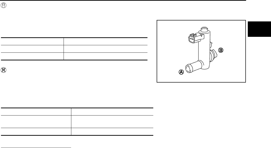
P0447 EVAP CANISTER VENT CONTROL VALVE
EC-289
< COMPONENT DIAGNOSIS > [FOR CALIFORNIA]
C
D
E
F
G
H
I
J
K
L
M
A
EC
N
P
O
With CONSULT-III
1. Clean the air passage [portion (A) to (B)] of EVAP canister vent control valve using an air blower.
2. Perform “VENT CONTROL/V” in “ACTIVE TEST” mode.
3. Check air passage continuity and operation delay time.
Check that new O-ring is installed properly.
Operation takes less than 1 second.
Without CONSULT-III
1. Clean the air passage [portion (A) to (B)] of EVAP canister vent
control valve using an air blower.
2. Check air passage continuity and operation delay time under the
following conditions.
Check that new O-ring is installed properly.
Operation takes less than 1 second.
Is the inspection result normal?
YES >> INSPECTION END
NO >> Replace EVAP canister vent control valve
Condition (VENT CONT/V) Air passage continuity between (A) and (B)
ON Not existed
OFF Existed
Condition Air passage continuity between (A) and (B)
12V direct current supply between
terminals (1) and (2) Not existed
OFF Existed
JMBIA0169ZZ
Revision: 2008 August 2009 Rogue
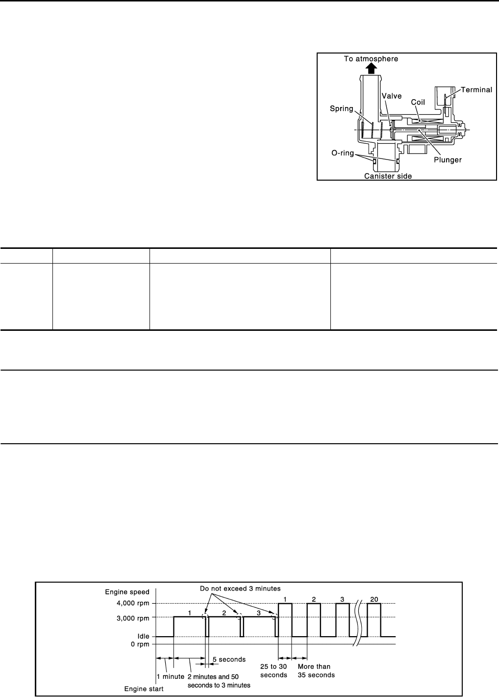
EC-290
< COMPONENT DIAGNOSIS > [FOR CALIFORNIA]
P0448 EVAP CANISTER VENT CONTROL VALVE
P0448 EVAP CANISTER VENT CONTROL VALVE
Description INFOID:0000000004493493
The EVAP canister vent control valve is located on the EVAP canis-
ter and is used to seal the canister vent.
This solenoid valve responds to signals from the ECM. When the
ECM sends an ON signal, the coil in the solenoid valve is energized.
A plunger will then move to seal the canister vent. The ability to seal
the vent is necessary for the on board diagnosis of other evaporative
emission control system components.
This solenoid valve is used only for diagnosis, and usually remains
opened.
When the vent is closed, under normal purge conditions, the evapo-
rative emission control system is depressurized and allows “EVAP
Control System” diagnosis.
DTC Logic INFOID:0000000004493494
DTC DETECTION LOGIC
DTC CONFIRMATION PROCEDURE
1.PRECONDITIONING
If DTC CONFIRMATION PROCEDURE has been previously conducted, always turn ignition switch OFF and
wait at least 10 seconds before conducting the next test.
>> GO TO 2.
2.PERFORM DTC CONFIRMATION PROCEDURE
1. Turn ignition switch ON and wait at least 5 seconds.
2. Turn ignition switch OFF and wait at least 10 seconds.
3. Start engine and let it idle for at least 1 minute.
4. Repeat next procedures three times.
- Increase the engine speed up to between 3,000 and 3,500 rpm and maintain that speed for 2 minutes and
50 seconds to 3 minutes.
Do not exceed 3 minutes.
- Fully released accelerator pedal and keep engine idle for approximately 5 seconds.
5. Repeat next procedure 20 times.
- Quickly increase the engine speed up to between 4,000 to 4,500 rpm and maintain that speed for 25 to 30
seconds.
- Fully released accelerator pedal and keep engine idle for at least 35 seconds.
PBIB1263E
DTC No. Trouble diagnosis name DTC detecting condition Possible cause
P0448 EVAP canister vent con-
trol valve close EVAP canister vent control valve remains
closed under specified driving conditions.
• EVAP canister vent control valve
• EVAP control system pressure sensor
and the circuit
• Blocked rubber tube to EVAP canister
vent control valve
• EVAP canister is saturated with water
JMBIA1516G
B
Revision: 2008 August 2009 Rogue
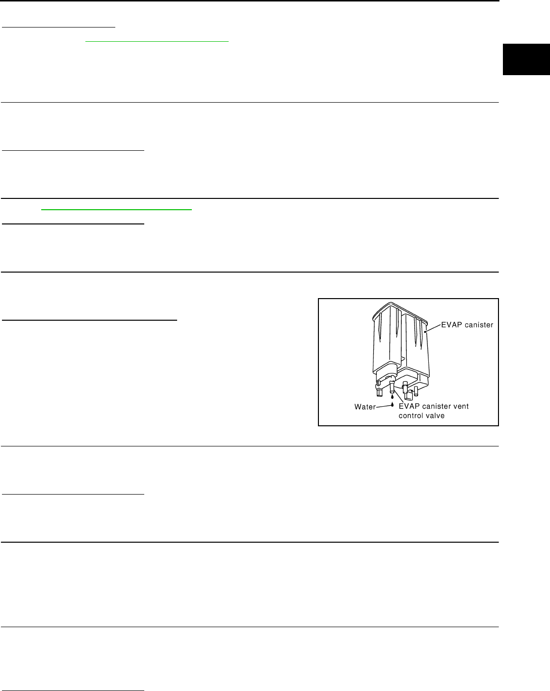
P0448 EVAP CANISTER VENT CONTROL VALVE
EC-291
< COMPONENT DIAGNOSIS > [FOR CALIFORNIA]
C
D
E
F
G
H
I
J
K
L
M
A
EC
N
P
O
6. Check 1st trip DTC.
Is 1st trip DTC detected?
YES >> Go to EC-291, "Diagnosis Procedure".
NO >> INSPECTION END
Diagnosis Procedure INFOID:0000000004493495
1.CHECK RUBBER TUBE
1. Turn ignition switch OFF.
2. Disconnect rubber tube connected to EVAP canister vent control valve.
3. Check the rubber tube for clogging.
Is the inspection result normal?
YES >> GO TO 2.
NO >> Clean rubber tube using an air blower.
2.CHECK EVAP CANISTER VENT CONTROL VALVE
Refer to EC-292, "Component Inspection".
Is the inspection result normal?
YES >> GO TO 3.
NO >> Replace EVAP canister vent control valve.
3.CHECK IF EVAP CANISTER IS SATURATED WITH WATER
1. Remove EVAP canister with EVAP canister vent control valve and EVAP control system pressure sensor
attached.
2. Check if water will drain from the EVAP canister.
Does water drain from EVAP canister?
YES >> GO TO 4.
NO >> GO TO 6.
4.CHECK EVAP CANISTER
Weigh the EVAP canister with the EVAP canister vent control valve and EVAP control system pressure sensor
attached.
The weight should be less than 2.1 kg (4.6 lb).
Is the inspection result normal?
YES >> GO TO 6.
NO >> GO TO 5.
5.DETECT MALFUNCTIONING PART
Check the following.
• EVAP canister for damage
• EVAP hose between EVAP canister and vehicle frame for clogging or poor connection
>> Repair hose or replace EVAP canister.
6.CHECK EVAP CONTROL SYSTEM PRESSURE SENSOR CONNECTOR
1. Disconnect EVAP control system pressure sensor harness connector.
2. Check connectors for water.
Is the inspection result normal?
PBIB1213E
Water should not exist.
Revision: 2008 August 2009 Rogue
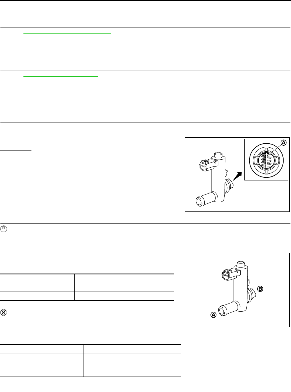
EC-292
< COMPONENT DIAGNOSIS > [FOR CALIFORNIA]
P0448 EVAP CANISTER VENT CONTROL VALVE
YES >> GO TO 7.
NO >> Replace EVAP control system pressure sensor.
7.CHECK EVAP CONTROL SYSTEM PRESSURE SENSOR
Refer to EC-296, "Component Inspection".
Is the inspection result normal?
YES >> GO TO 8.
NO >> Replace EVAP control system pressure sensor.
8.CHECK INTERMITTENT INCIDENT
Refer to GI-41, "Intermittent Incident".
>> INSPECTION END
Component Inspection INFOID:0000000004493496
1.CHECK EVAP CANISTER VENT CONTROL VALVE-I
1. Turn ignition switch OFF.
2. Remove EVAP canister vent control valve from EVAP canister.
3. Check portion (A) of EVAP canister vent control valve for rust.
Is it rusted?
YES >> Replace EVAP canister vent control valve
NO >> GO TO 2.
2.CHECK EVAP CANISTER VENT CONTROL VALVE-II
With CONSULT-III
1. Reconnect harness connectors disconnected.
2. Turn ignition switch ON.
3. Perform “VENT CONTROL/V” in “ACTIVE TEST” mode.
4. Check air passage continuity and operation delay time.
Check that new O-ring is installed properly.
Operation takes less than 1 second.
Without CONSULT-III
Check air passage continuity and operation delay time under the fol-
lowing conditions.
Check that new O-ring is installed properly.
Operation takes less than 1 second.
Is the inspection result normal?
YES >> INSPECTION END
NO >> GO TO 3.
JMBIA0168ZZ
Condition (VENT CONT/V) Air passage continuity between (A) and (B)
ON Not existed
OFF Existed
Condition Air passage continuity between (A) and (B)
12V direct current supply between
terminals (1) and (2) Not existed
OFF Existed
JMBIA0169ZZ
Revision: 2008 August 2009 Rogue

P0448 EVAP CANISTER VENT CONTROL VALVE
EC-293
< COMPONENT DIAGNOSIS > [FOR CALIFORNIA]
C
D
E
F
G
H
I
J
K
L
M
A
EC
N
P
O
3.CHECK EVAP CANISTER VENT CONTROL VALVE-III
With CONSULT-III
1. Clean the air passage [portion (A) to (B)] of EVAP canister vent control valve using an air blower.
2. Perform “VENT CONTROL/V” in “ACTIVE TEST” mode.
3. Check air passage continuity and operation delay time.
Check that new O-ring is installed properly.
Operation takes less than 1 second.
Without CONSULT-III
1. Clean the air passage [portion (A) to (B)] of EVAP canister vent
control valve using an air blower.
2. Check air passage continuity and operation delay time under the
following conditions.
Check that new O-ring is installed properly.
Operation takes less than 1 second.
Is the inspection result normal?
YES >> INSPECTION END
NO >> Replace EVAP canister vent control valve
Condition (VENT CONT/V) Air passage continuity between (A) and (B)
ON Not existed
OFF Existed
Condition Air passage continuity between (A) and (B)
12V direct current supply between
terminals (1) and (2) Not existed
OFF Existed
JMBIA0169ZZ
Revision: 2008 August 2009 Rogue
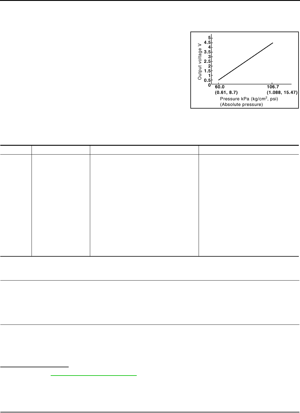
EC-294
< COMPONENT DIAGNOSIS > [FOR CALIFORNIA]
P0451 EVAP CONTROL SYSTEM PRESSURE SENSOR
P0451 EVAP CONTROL SYSTEM PRESSURE SENSOR
Description INFOID:0000000004493497
The EVAP control system pressure sensor detects pressure in the
purge line. The sensor output voltage to the ECM increases as pres-
sure increases.
DTC Logic INFOID:0000000004493498
DTC DETECTION LOGIC
DTC CONFIRMATION PROCEDURE
1.PRECONDITIONING
If DTC CONFIRMATION PROCEDURE has been previously conducted, always turn ignition switch OFF and
wait at least 10 seconds before conducting the next test.
>> GO TO 2.
2.PERFORM DTC CONFIRMATION PROCEDURE
1. Turn ignition switch OFF and wait at least 10 seconds.
2. Start engine and wait at least 40 seconds.
NOTE:
Do not depress accelerator pedal even slightly.
3. Check 1st trip DTC.
Is 1st trip DTC detected?
YES >> Go to EC-294, "Diagnosis Procedure".
NO >> INSPECTION END
Diagnosis Procedure INFOID:0000000004493499
1.CHECK GROUND CONNECTION
1. Turn ignition switch OFF.
PBIB3370E
DTC No. Trouble diagnosis name DTC detecting condition Possible cause
P0451
EVAP control system
pressure sensor perfor-
mance
ECM detects a sloshing signal from the EVAP
control system pressure sensor
• Harness or connectors
(EVAP control system pressure sensor
circuit is shorted.)
[Crankshaft position sensor (POS) circuit
is shorted.]
(Accelerator pedal position sensor circuit
is shorted.)
(Refrigerant pressure sensor circuit is
shorted.)
(Tumble control valve position sensor cir-
cuit is shorted.)
• EVAP control system pressure sensor
• Crankshaft position sensor (POS)
• Accelerator pedal position sensor
• Refrigerant pressure sensor
• Tumble control valve position sensor
Revision: 2008 August 2009 Rogue

P0451 EVAP CONTROL SYSTEM PRESSURE SENSOR
EC-295
< COMPONENT DIAGNOSIS > [FOR CALIFORNIA]
C
D
E
F
G
H
I
J
K
L
M
A
EC
N
P
O
2. Check ground connection E21. Refer to Ground Inspection in GI-44, "Circuit Inspection".
Is the inspection result normal?
YES >> GO TO 2.
NO >> Repair or replace ground connection.
2.CHECK EVAP CONTROL SYSTEM PRESSURE SENSOR CONNECTOR FOR WATER
1. Disconnect EVAP control system pressure sensor harness connector.
2. Check sensor harness connector for water.
Is the inspection result normal?
YES >> GO TO 3.
NO >> Repair or replace harness connector.
3.CHECK EVAP CONTROL SYSTEM PRESSURE SENSOR POWER SUPPLY CIRCUIT
1. Turn ignition switch ON.
2. Check the voltage between EVAP control system pressure sensor harness connector and ground.
Is the inspection result normal?
YES >> GO TO 8.
NO >> GO TO 4.
4.CHECK SENSOR POWER SUPPLY CIRCUIT
Check harness for short to power and short to ground, between the following terminals.
Is the inspection result normal?
YES >> GO TO 5.
NO >> Repair short to ground or short to power in harness or connectors.
5.CHECK COMPONENT
Check the following.
• Crankshaft position sensor (POS) (Refer to EC-259, "Component Inspection".)
• Refrigerant pressure sensor (Refer to EC-437, "Diagnosis Procedure".)
• Tumble control valve position sensor (Refer to EC-368, "Diagnosis Procedure".)
Is the inspection result normal?
YES >> GO TO 6.
NO >> Replace malfunctioning component.
6.CHECK APP SENSOR
Refer to EC-399, "Component Inspection".
Is the inspection result normal?
YES >> GO TO 9.
NO >> GO TO 7.
Water should not exist.
EVAP control system pressure sensor Ground Voltage
Connector Terminal
B47 3 Ground Approx. 5 V
ECM Sensor
Connector Terminal Name Connector Terminal
F8 72 Tumble control valve position sensor F41 1
Refrigerant pressure sensor E49 3
76 CKP sensor (POS) F20 1
E10 87 APP sensor E110 5
91 EVAP control system pressure sensor B47 3
Revision: 2008 August 2009 Rogue

EC-296
< COMPONENT DIAGNOSIS > [FOR CALIFORNIA]
P0451 EVAP CONTROL SYSTEM PRESSURE SENSOR
7.REPLACE ACCELERATOR PEDAL ASSEMBLY
1. Replace accelerator pedal assembly. Refer to ACC-3, "Removal and Installation".
2. Go to EC-27, "ACCELERATOR PEDAL RELEASED POSITION LEARNING : Special Repair Require-
ment".
>> INSPECTION END
8.CHECK EVAP CONTROL SYSTEM PRESSURE SENSOR
Refer to EC-296, "Component Inspection".
Is the inspection result normal?
YES >> GO TO 9.
NO >> Replace EVAP control system pressure sensor.
9.CHECK INTERMITTENT INCIDENT
Refer to GI-41, "Intermittent Incident".
>> INSPECTION END
Component Inspection INFOID:0000000004493500
1.CHECK EVAP CONTROL SYSTEM PRESSURE SENSOR
1. Turn ignition switch OFF.
2. Remove EVAP control system pressure sensor with its harness connector.
Always replace O-ring with a new one.
3. Install a vacuum pump to EVAP control system pressure sensor.
4. Turn ignition switch ON and check output voltage between ECM harness connector terminals under the
following conditions.
CAUTION:
• Always calibrate the vacuum pump gauge when using it.
• Never apply below -93.3 kPa (-0.952 kg/cm2, -13.53 psi) or pressure over 101.3 kPa (1.033 kg/cm2,
14.69 psi).
Is the inspection result normal?
YES >> INSPECTION END
NO >> Replace EVAP control system pressure sensor
ECM Condition
[Applied vacuum kPa (kg/cm2, psi)] Voltage
Connector +−
Terminal Terminal
E16
86
(EVAP control
system pressure
sensor signal)
96
(Sensor
ground)
Not applied 1.8 - 4.8 V
-26.7 (-0.272, -3.87) 2.1 to 2.5 V lower than above value
Revision: 2008 August 2009 Rogue
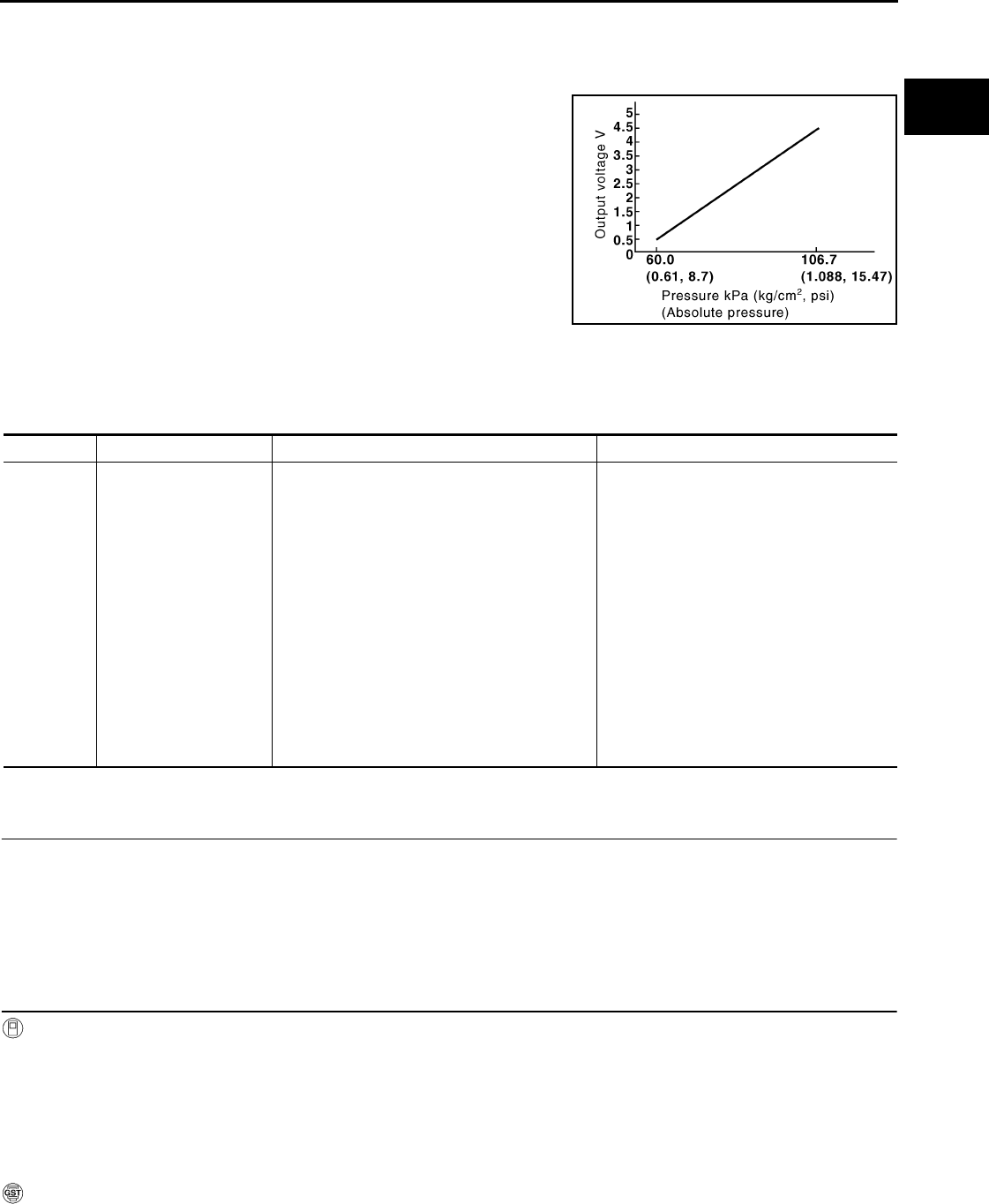
P0452 EVAP CONTROL SYSTEM PRESSURE SENSOR
EC-297
< COMPONENT DIAGNOSIS > [FOR CALIFORNIA]
C
D
E
F
G
H
I
J
K
L
M
A
EC
N
P
O
P0452 EVAP CONTROL SYSTEM PRESSURE SENSOR
Description INFOID:0000000004493501
The EVAP control system pressure sensor detects pressure in the
purge line. The sensor output voltage to the ECM increases as pres-
sure increases.
DTC Logic INFOID:0000000004493502
DTC DETECTION LOGIC
DTC CONFIRMATION PROCEDURE
1.PRECONDITIONING
If DTC CONFIRMATION PROCEDURE has been previously conducted, always turn ignition switch OFF and
wait at least 10 seconds before conducting the next test.
TESTING CONDITION:
Always perform test at a temperature of 5°C (41°F) or more.
>> GO TO 2.
2.PERFORM DTC CONFIRMATION PROCEDURE
With CONSULT-III
1. Start engine and warm it up to normal operating temperature.
2. Turn ignition switch OFF and wait at least 10 seconds.
3. Turn ignition switch ON.
4. Select “DATA MONITOR” mode with CONSULT-III.
5. Check that “FUEL T/TMP SE” is more than 0°C (32°F).
6. Start engine and wait at least 20 seconds.
7. Check 1st trip DTC.
With GST
1. Start engine and warm it up to normal operating temperature.
2. Set voltmeter probes to ECM harness connector and ground as follows.
PBIB3370E
DTC No. Trouble diagnosis name DTC detecting condition Possible cause
P0452
EVAP control system
pressure sensor low in-
put
An excessively low voltage from the sensor is
sent to ECM.
• Harness or connectors
(EVAP control system pressure sensor
circuit is open or shorted.)
[Crankshaft position sensor (POS) circuit
is shorted.)
(Accelerator pedal position sensor circuit
is shorted.)
(Refrigerant pressure sensor circuit is
shorted.)
(Tumble control valve position sensor cir-
cuit is shorted.)
• EVAP control system pressure sensor
• Crankshaft position sensor (POS)
• Accelerator pedal position sensor
• Refrigerant pressure sensor
• Tumble control valve position sensor
Revision: 2008 August 2009 Rogue

EC-298
< COMPONENT DIAGNOSIS > [FOR CALIFORNIA]
P0452 EVAP CONTROL SYSTEM PRESSURE SENSOR
3. Check that the voltage is less than 4.2V.
4. Turn ignition switch OFF and wait at least 10 seconds.
5. Start engine and wait at least 20 seconds.
6. Check 1st trip DTC.
Is 1st trip DTC detected?
YES >> Go to EC-298, "Diagnosis Procedure".
NO >> INSPECTION END
Diagnosis Procedure INFOID:0000000004493503
1.CHECK GROUND CONNECTION
1. Turn ignition switch OFF.
2. Check ground connection E21. Refer to Ground Inspection in GI-44, "Circuit Inspection".
Is the inspection result normal?
YES >> GO TO 2.
NO >> Repair or replace ground connection.
2.CHECK CONNECTOR
1. Disconnect EVAP control system pressure sensor harness connector.
2. Check sensor harness connector for water.
Is the inspection result normal?
YES >> GO TO 3.
NO >> Repair or replace harness connector.
3.CHECK EVAP CONTROL SYSTEM PRESSURE SENSOR POWER SUPPLY CIRCUIT-I
1. Turn ignition switch ON.
2. Check the voltage between EVAP control system pressure sensor harness connector and ground.
Is the inspection result normal?
YES >> GO TO 10.
NO >> GO TO 4.
4.CHECK EVAP CONTROL SYSTEM PRESSURE SENSOR POWER SUPPLY CIRCUIT-II
1. Turn ignition switch OFF.
2. Disconnect ECM harness connector.
3. Check the continuity between EVAP control system pressure sensor harness connector and ECM har-
ness connector.
Is the inspection result normal?
YES >> GO TO 6.
ECM ECM
Connector Terminal Connector Terminal
E16 95
(Fuel tank temperature sensor signal) E16 104
(Sensor ground)
Water should not exist.
EVAP control system pressure sensor Ground Voltage
Connector Terminal
B47 3 Ground Approx. 5 V
EVAP control system pressure
sensor ECM Continuity
Connector Terminal Connector Terminal
B47 3 E16 91 Existed
Revision: 2008 August 2009 Rogue
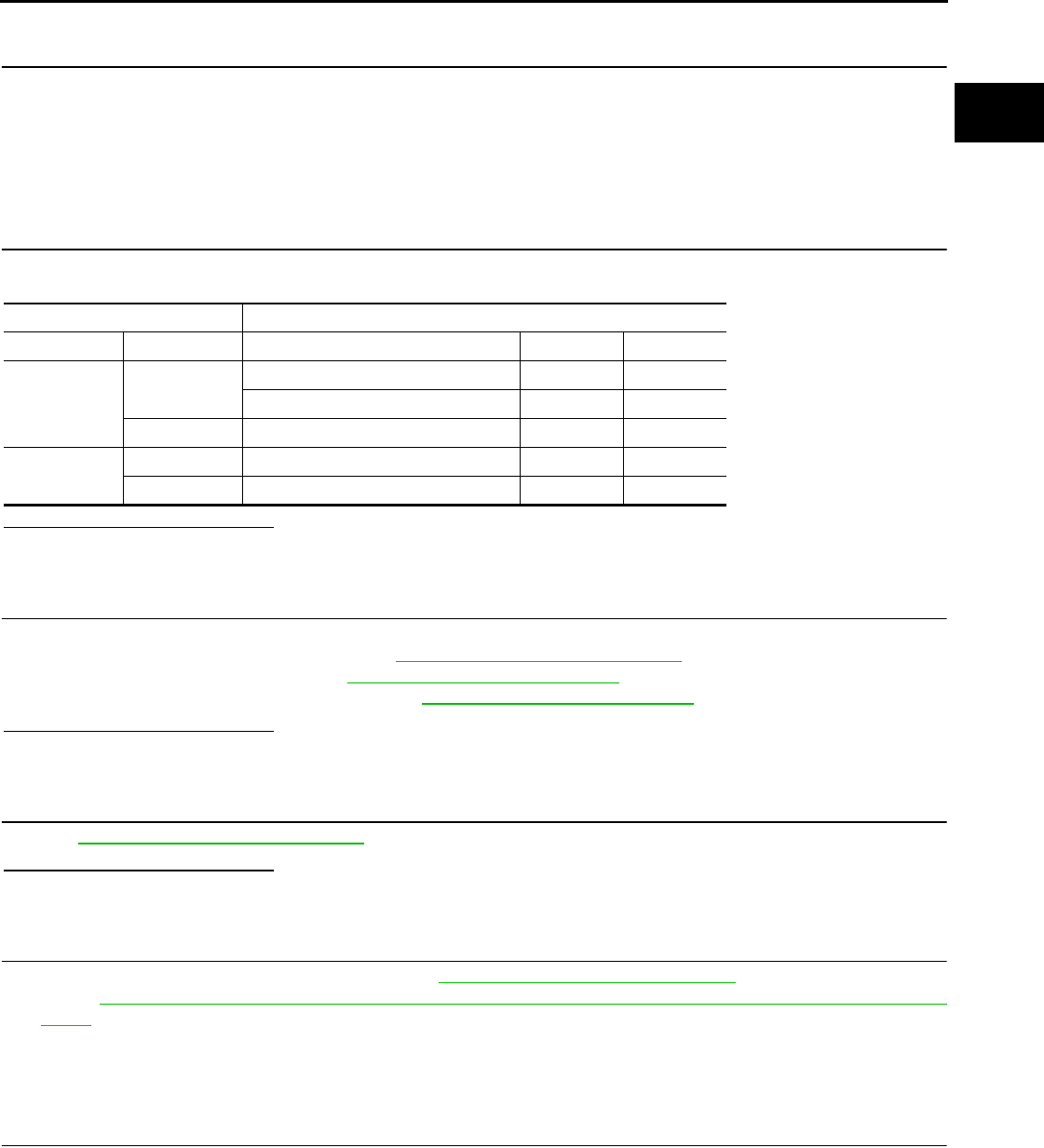
P0452 EVAP CONTROL SYSTEM PRESSURE SENSOR
EC-299
< COMPONENT DIAGNOSIS > [FOR CALIFORNIA]
C
D
E
F
G
H
I
J
K
L
M
A
EC
N
P
O
NO >> GO TO 5.
5.DETECT MALFUNCTIONING PART
Check the following.
• Harness connectors B1, M11
• Harness connectors M77, E105
• Harness for open or short between EVAP control system pressure sensor and ECM
>> Repair open circuit or short to ground or short to power in harness or connectors.
6.CHECK SENSOR POWER SUPPLY CIRCUIT
Check harness for short to power and short to ground, between the following terminals.
Is the inspection result normal?
YES >> GO TO 7.
NO >> Repair short to ground or short to power in harness or connectors.
7.CHECK COMPONENT
Check the following.
• Crankshaft position sensor (POS) (Refer to EC-259, "Component Inspection".)
• Refrigerant pressure sensor (Refer to EC-437, "Diagnosis Procedure".)
• Tumble control valve position sensor (Refer to EC-368, "Diagnosis Procedure".)
Is the inspection result normal?
YES >> GO TO 8.
NO >> Replace malfunctioning component.
8.CHECK APP SENSOR
Refer to EC-399, "Component Inspection".
Is the inspection result normal?
YES >> GO TO 10.
NO >> GO TO 9.
9.REPLACE ACCELERATOR PEDAL ASSEMBLY
1. Replace accelerator pedal assembly. Refer to ACC-3, "Removal and Installation".
2. Go to EC-27, "ACCELERATOR PEDAL RELEASED POSITION LEARNING : Special Repair Require-
ment".
>> INSPECTION END
10.CHECK EVAP CONTROL SYSTEM PRESSURE SENSOR GROUND CIRCUIT FOR OPEN AND
SHORT
1. Turn ignition switch OFF.
2. Disconnect ECM harness connector.
3. Check the continuity between EVAP control system pressure sensor harness connector and ECM har-
ness connector.
ECM Sensor
Connector Terminal Name Connector Terminal
F8 72 Tumble control valve position sensor F41 1
Refrigerant pressure sensor E49 3
76 CKP sensor (POS) F20 1
E10 87 APP sensor E110 5
91 EVAP control system pressure sensor B47 3
Revision: 2008 August 2009 Rogue

EC-300
< COMPONENT DIAGNOSIS > [FOR CALIFORNIA]
P0452 EVAP CONTROL SYSTEM PRESSURE SENSOR
4. Also check harness for short to ground and short to power.
Is the inspection result normal?
YES >> GO TO 12.
NO >> GO TO 11.
11.DETECT MALFUNCTIONING PART
Check the following.
• Harness connectors B1, M11
• Harness connectors M77, E105
• Harness for open or short between EVAP control system pressure sensor and ECM
>> Repair open circuit or short to ground or short to power in harness or connectors.
12.CHECK EVAP CONTROL SYSTEM PRESSURE SENSOR INPUT SIGNAL CIRCUIT FOR OPEN AND
SHORT
1. Check the continuity between EVAP control system pressure sensor harness connector and ECM har-
ness connector.
2. Also check harness for short to ground and short to power.
Is the inspection result normal?
YES >> GO TO 14.
NO >> GO TO 13.
13.DETECT MALFUNCTIONING PART
Check the following.
• Harness connectors B1, M11
• Harness connectors B10, E29
• Harness for open or short between EVAP control system pressure sensor and ECM
>> Repair open circuit or short to ground or short to power in harness or connectors.
14.CHECK EVAP CONTROL SYSTEM PRESSURE SENSOR
Refer to EC-300, "Component Inspection".
Is the inspection result normal?
YES >> GO TO 15.
NO >> Replace EVAP control system pressure sensor.
15.CHECK INTERMITTENT INCIDENT
Refer to GI-41, "Intermittent Incident".
>> INSPECTION END
Component Inspection INFOID:0000000004493504
1.CHECK EVAP CONTROL SYSTEM PRESSURE SENSOR
1. Turn ignition switch OFF.
EVAP control system pressure
sensor ECM Continuity
Connector Terminal Connector Terminal
B47 1 E16 96 Existed
EVAP control system pressure
sensor ECM Continuity
Connector Terminal Connector Terminal
B47 2 E16 86 Existed
Revision: 2008 August 2009 Rogue

P0452 EVAP CONTROL SYSTEM PRESSURE SENSOR
EC-301
< COMPONENT DIAGNOSIS > [FOR CALIFORNIA]
C
D
E
F
G
H
I
J
K
L
M
A
EC
N
P
O
2. Remove EVAP control system pressure sensor with its harness connector.
Always replace O-ring with a new one.
3. Install a vacuum pump to EVAP control system pressure sensor.
4. Turn ignition switch ON and check output voltage between ECM harness connector terminals under the
following conditions.
CAUTION:
• Always calibrate the vacuum pump gauge when using it.
• Never apply below -93.3 kPa (-0.952 kg/cm2, -13.53 psi) or pressure over 101.3 kPa (1.033 kg/cm2,
14.69 psi).
Is the inspection result normal?
YES >> INSPECTION END
NO >> Replace EVAP control system pressure sensor
ECM Condition
[Applied vacuum kPa (kg/cm2, psi)] Voltage
Connector +−
Terminal Terminal
E16
86
(EVAP control
system pressure
sensor signal)
96
(Sensor
ground)
Not applied 1.8 - 4.8 V
-26.7 (-0.272, -3.87) 2.1 to 2.5 V lower than above value
Revision: 2008 August 2009 Rogue
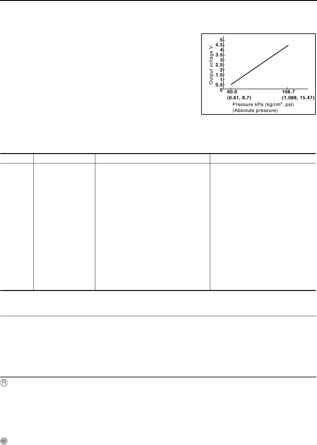
EC-302
< COMPONENT DIAGNOSIS > [FOR CALIFORNIA]
P0453 EVAP CONTROL SYSTEM PRESSURE SENSOR
P0453 EVAP CONTROL SYSTEM PRESSURE SENSOR
Description INFOID:0000000004493505
The EVAP control system pressure sensor detects pressure in the
purge line. The sensor output voltage to the ECM increases as pres-
sure increases.
DTC Logic INFOID:0000000004493506
DTC DETECTION LOGIC
DTC CONFIRMATION PROCEDURE
1.PRECONDITIONING
If DTC CONFIRMATION PROCEDURE has been previously conducted, always turn ignition switch OFF and
wait at least 10 seconds before conducting the next test.
TESTING CONDITION:
Always perform test at a temperature of 5°C (41°F) or more.
>> GO TO 2.
2.PERFORM DTC CONFIRMATION PROCEDURE
With CONSULT-III
1. Start engine and warm it up to normal operating temperature.
2. Turn ignition switch OFF and wait at least 10 seconds.
3. Turn ignition switch ON.
4. Select “DATA MONITOR” mode with CONSULT-III.
5. Check that “FUEL T/TMP SE” is more than 0°C (32°F).
6. Start engine and wait at least 20 seconds.
7. Check 1st trip DTC.
With GST
PBIB3370E
DTC No. Trouble diagnosis name DTC detecting condition Possible cause
P0453
EVAP control system
pressure sensor high in-
put
An excessively high voltage from the sensor is
sent to ECM.
• Harness or connectors
(EVAP control system pressure sensor
circuit is open or shorted.)
[Crankshaft position sensor (POS) circuit
is shorted.]
(Accelerator pedal circuit is shorted.)
(Refrigerant pressure sensor circuit is
shorted.)
(Tumble control valve position sensor cir-
cuit is shorted.)
• EVAP control system pressure sensor
• Crankshaft position sensor (POS)
• Accelerator pedal position sensor
• Refrigerant pressure sensor
• Tumble control valve position sensor
• EVAP canister vent control valve
• EVAP canister
• Rubber hose from EVAP canister vent
control valve to vehicle frame
Revision: 2008 August 2009 Rogue

P0453 EVAP CONTROL SYSTEM PRESSURE SENSOR
EC-303
< COMPONENT DIAGNOSIS > [FOR CALIFORNIA]
C
D
E
F
G
H
I
J
K
L
M
A
EC
N
P
O
1. Start engine and warm it up to normal operating temperature.
2. Set voltmeter probes to ECM harness connector and ground as follows.
3. Check that the voltage is less than 4.2V.
4. Turn ignition switch OFF and wait at least 10 seconds.
5. Start engine and wait at least 20 seconds.
6. Check 1st trip DTC.
Is 1st trip DTC detected?
YES >> Go to EC-303, "Diagnosis Procedure".
NO >> INSPECTION END
Diagnosis Procedure INFOID:0000000004493507
1.CHECK GROUND CONNECTION
1. Turn ignition switch OFF.
2. Check ground connection E21. Refer to Ground Inspection in GI-44, "Circuit Inspection".
Is the inspection result normal?
YES >> GO TO 2.
NO >> Repair or replace ground connection.
2.CHECK CONNECTOR
1. Disconnect EVAP control system pressure sensor harness connector.
2. Check sensor harness connector for water.
Is the inspection result normal?
YES >> GO TO 3.
NO >> Repair or replace harness connector.
3.CHECK EVAP CONTROL SYSTEM PRESSURE SENSOR POWER SUPPLY CIRCUIT
1. Turn ignition switch ON.
2. Check the voltage between EVAP control system pressure sensor harness connector and ground.
Is the inspection result normal?
YES >> GO TO 10.
NO >> GO TO 4.
4.CHECK EVAP CONTROL SYSTEM PRESSURE SENSOR POWER SUPPLY CIRCUIT-II
1. Turn ignition switch OFF.
2. Disconnect ECM harness connector.
3. Check the continuity between EVAP control system pressure sensor harness connector and ECM har-
ness connector.
ECM ECM
Connector Terminal Connector Terminal
E16 95
(Fuel tank temperature sensor signal) E16 104
(Sensor ground)
Water should not exist.
EVAP control system pressure sensor Ground Voltage
Connector Terminal
B47 3 Ground Approx. 5 V
EVAP control system pressure
sensor ECM Continuity
Connector Terminal Connector Terminal
B47 3 E16 91 Existed
Revision: 2008 August 2009 Rogue
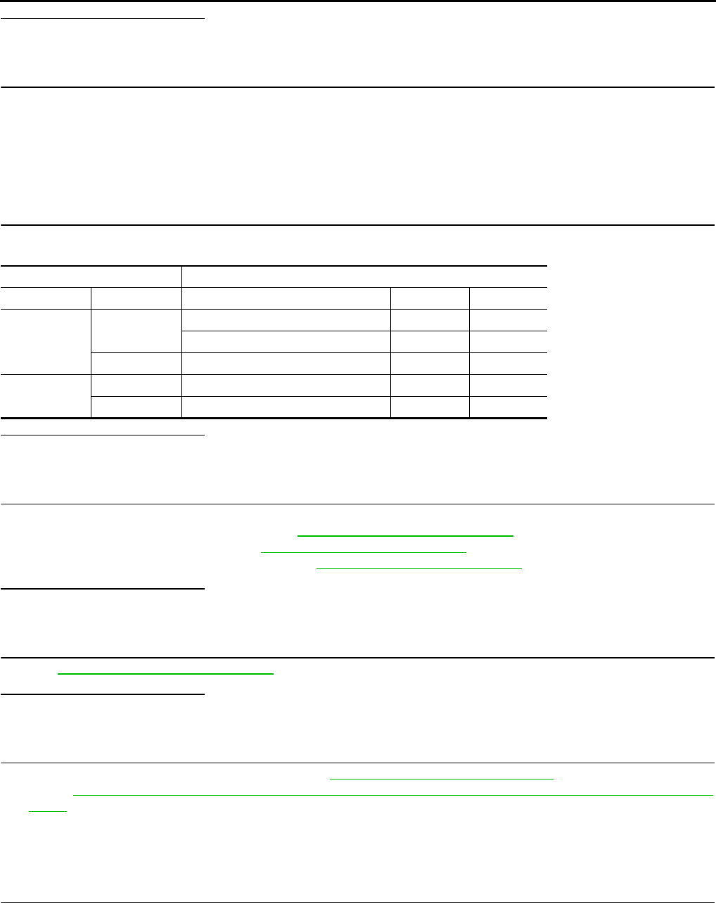
EC-304
< COMPONENT DIAGNOSIS > [FOR CALIFORNIA]
P0453 EVAP CONTROL SYSTEM PRESSURE SENSOR
Is the inspection result normal?
YES >> GO TO 6.
NO >> GO TO 5.
5.DETECT MALFUNCTIONING PART
Check the following.
• Harness connectors B1, M11
• Harness connectors M77, E105
• Harness for open or short between EVAP control system pressure sensor and ECM
>> Repair open circuit or short to ground or short to power in harness or connectors.
6.CHECK SENSOR POWER SUPPLY CIRCUIT
Check harness for short to power and short to ground, between the following terminals.
Is the inspection result normal?
YES >> GO TO 7.
NO >> Repair short to ground or short to power in harness or connectors.
7.CHECK COMPONENT
Check the following.
• Crankshaft position sensor (POS) (Refer to EC-259, "Component Inspection".)
• Refrigerant pressure sensor (Refer to EC-437, "Diagnosis Procedure".)
• Tumble control valve position sensor (Refer to EC-368, "Diagnosis Procedure".)
Is the inspection result normal?
YES >> GO TO 8.
NO >> Replace malfunctioning component.
8.CHECK APP SENSOR
Refer to EC-399, "Component Inspection".
Is the inspection result normal?
YES >> GO TO 10.
NO >> GO TO 9.
9.REPLACE ACCELERATOR PEDAL ASSEMBLY
1. Replace accelerator pedal assembly. Refer to ACC-3, "Removal and Installation".
2. Go to EC-27, "ACCELERATOR PEDAL RELEASED POSITION LEARNING : Special Repair Require-
ment".
>> INSPECTION END
10.CHECK EVAP CONTROL SYSTEM PRESSURE SENSOR GROUND CIRCUIT FOR OPEN AND
SHORT
1. Turn ignition switch OFF.
2. Disconnect ECM harness connector.
3. Check the continuity between EVAP control system pressure sensor harness connector and ECM har-
ness connector.
ECM Sensor
Connector Terminal Name Connector Terminal
F8 72 Tumble control valve position sensor F41 1
Refrigerant pressure sensor E49 3
76 CKP sensor (POS) F20 1
E10 87 APP sensor E110 5
91 EVAP control system pressure sensor B47 3
Revision: 2008 August 2009 Rogue

P0453 EVAP CONTROL SYSTEM PRESSURE SENSOR
EC-305
< COMPONENT DIAGNOSIS > [FOR CALIFORNIA]
C
D
E
F
G
H
I
J
K
L
M
A
EC
N
P
O
4. Also check harness for short to ground and short to power.
Is the inspection result normal?
YES >> GO TO 12.
NO >> GO TO 11.
11.DETECT MALFUNCTIONING PART
Check the following.
• Harness connectors B1, M11
• Harness connectors M77, E105
• Harness for open or short between EVAP control system pressure sensor and ECM
>> Repair open circuit or short to ground or short to power in harness or connectors.
12.CHECK EVAP CONTROL SYSTEM PRESSURE SENSOR INPUT SIGNAL CIRCUIT FOR OPEN AND
SHORT
1. Check the continuity between EVAP control system pressure sensor harness connector and ECM har-
ness connector.
2. Also check harness for short to ground and short to power.
Is the inspection result normal?
YES >> GO TO 14.
NO >> GO TO 13.
13.DETECT MALFUNCTIONING PART
Check the following.
• Harness connectors B1, M11
• Harness connectors M77, E105
• Harness for open or short between EVAP control system pressure sensor and ECM
>> Repair open circuit or short to ground or short to power in harness or connectors.
14.CHECK RUBBER TUBE
1. Disconnect rubber tube connected to EVAP canister vent control valve.
2. Check the rubber tube for clogging.
Is the inspection result normal?
YES >> GO TO 15.
NO >> Clean the rubber tube using an air blower, repair or replace rubber tube.
15.CHECK EVAP CANISTER VENT CONTROL VALVE
Refer to EC-288, "Component Inspection".
Is the inspection result normal?
YES >> GO TO 16.
NO >> Replace EVAP canister vent control valve.
16.CHECK EVAP CONTROL SYSTEM PRESSURE SENSOR
Refer to EC-306, "Component Inspection".
EVAP control system pressure
sensor ECM Continuity
Connector Terminal Connector Terminal
B47 1 E16 96 Existed
EVAP control system pressure
sensor ECM Continuity
Connector Terminal Connector Terminal
B47 2 E16 86 Existed
Revision: 2008 August 2009 Rogue
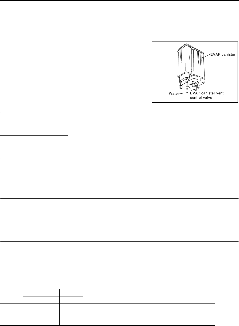
EC-306
< COMPONENT DIAGNOSIS > [FOR CALIFORNIA]
P0453 EVAP CONTROL SYSTEM PRESSURE SENSOR
Is the inspection result normal?
YES >> GO TO 17.
NO >> Replace EVAP control system pressure sensor.
17.CHECK IF EVAP CANISTER IS SATURATED WITH WATER
1. Remove EVAP canister with EVAP canister vent control valve and EVAP control system pressure sensor
attached.
2. Check if water will drain from the EVAP canister.
Does water drain from EVAP canister?
YES >> GO TO 18.
NO >> GO TO 20.
18.CHECK EVAP CANISTER
Weigh the EVAP canister with the EVAP canister vent control valve and EVAP control system pressure sensor
attached.
The weight should be less than 2.1 kg (4.6 lb).
Is the inspection result normal?
YES >> GO TO 20.
NO >> GO TO 19.
19.DETECT MALFUNCTIONING PART
Check the following.
• EVAP canister for damage
• EVAP hose between EVAP canister and vehicle frame for clogging or poor connection
>> Repair hose or replace EVAP canister.
20.CHECK INTERMITTENT INCIDENT
Refer to GI-41, "Intermittent Incident".
>> INSPECTION END
Component Inspection INFOID:0000000004493508
1.CHECK EVAP CONTROL SYSTEM PRESSURE SENSOR
1. Turn ignition switch OFF.
2. Remove EVAP control system pressure sensor with its harness connector.
Always replace O-ring with a new one.
3. Install a vacuum pump to EVAP control system pressure sensor.
4. Turn ignition switch ON and check output voltage between ECM harness connector terminals under the
following conditions.
CAUTION:
PBIB1213E
ECM Condition
[Applied vacuum kPa (kg/cm2, psi)] Voltage
Connector +−
Terminal Terminal
E16
86
(EVAP control
system pressure
sensor signal)
96
(Sensor
ground)
Not applied 1.8 - 4.8 V
-26.7 (-0.272, -3.87) 2.1 to 2.5 V lower than above value
Revision: 2008 August 2009 Rogue

P0453 EVAP CONTROL SYSTEM PRESSURE SENSOR
EC-307
< COMPONENT DIAGNOSIS > [FOR CALIFORNIA]
C
D
E
F
G
H
I
J
K
L
M
A
EC
N
P
O
• Always calibrate the vacuum pump gauge when using it.
• Never apply below -93.3 kPa (-0.952 kg/cm2, -13.53 psi) or pressure over 101.3 kPa (1.033 kg/cm2,
14.69 psi).
Is the inspection result normal?
YES >> INSPECTION END
NO >> Replace EVAP control system pressure sensor
Revision: 2008 August 2009 Rogue

EC-308
< COMPONENT DIAGNOSIS > [FOR CALIFORNIA]
P0455 EVAP CONTROL SYSTEM
P0455 EVAP CONTROL SYSTEM
DTC Logic INFOID:0000000004493509
DTC DETECTION LOGIC
This diagnosis detects a very large leak (fuel filler cap fell off etc.) in EVAP system between the fuel tank and
EVAP canister purge volume control solenoid valve.
CAUTION:
• Use only a genuine NISSAN fuel filler cap as a replacement. If an incorrect fuel filler cap is used, the
MIL may illuminate.
• If the fuel filler cap is not tightened properly, the MIL may illuminate.
• Use only a genuine NISSAN rubber tube as a replacement.
DTC CONFIRMATION PROCEDURE
1.PRECONDITIONING
CAUTION:
DTC No. Trouble diagnosis name DTC detecting condition Possible cause
P0455 EVAP control system
gross leak detected
EVAP control system has a very large leak such
as fuel filler cap fell off, EVAP control system
does not operate properly.
• Fuel filler cap remains open or fails to
close.
• Incorrect fuel tank vacuum relief valve
• Incorrect fuel filler cap used
• Foreign matter caught in fuel filler cap.
• Leak is in line between intake manifold
and EVAP canister purge volume control
solenoid valve.
• Foreign matter caught in EVAP canister
vent control valve.
• EVAP canister or fuel tank leaks
• EVAP purge line (pipe and rubber tube)
leaks
• EVAP purge line rubber tube bent.
• Loose or disconnected rubber tube
• EVAP canister vent control valve and the
circuit
• EVAP canister purge volume control so-
lenoid valve and the circuit
• Fuel tank temperature sensor
• O-ring of EVAP canister vent control
valve is missing or damaged.
• EVAP control system pressure sensor
• Refueling EVAP vapor cut valve
• ORVR system leaks
PBIB1026E
Revision: 2008 August 2009 Rogue

P0455 EVAP CONTROL SYSTEM
EC-309
< COMPONENT DIAGNOSIS > [FOR CALIFORNIA]
C
D
E
F
G
H
I
J
K
L
M
A
EC
N
P
O
Never remove fuel filler cap during the DTC CONFIRMATION PROCEDURE.
If DTC CONFIRMATION PROCEDURE has been previously conducted, always turn ignition switch OFF and
wait at least 10 seconds before conducting the next test.
NOTE:
Check that EVAP hoses are connected to EVAP canister purge volume control solenoid valve properly.
TESTING CONDITION:
•Perform “DTC WORK SUPPORT” when the fuel level is between 1/4 and 3/4 full, and vehicle is placed
on flat level surface.
•Open engine hood before conducting the following procedures.
Do you have CONSULT-III?
YES >> GO TO 2.
NO >> GO TO 4.
2.PERFORM DTC CONFIRMATION PROCEDURE
With CONSULT-III
1. Tighten fuel filler cap securely until ratcheting sound is heard.
2. Turn ignition switch ON.
3. Turn ignition switch OFF and wait at least 10 seconds.
4. Turn ignition switch ON and select “DATA MONITOR” mode with CONSULT-III.
5. Check that the following conditions are met.
COOLAN TEMP/S: 0 - 100°C (32 - 212°F)
INT/A TEMP SE: 0 - 60°C (32 - 140°F)
6. Select “EVAP SML LEAK P0442/P1442” of “EVAPORATIVE SYSTEM” in “DTC WORK SUPPORT” mode
with CONSULT-III.
Follow the instructions displayed.
NOTE:
If the engine speed cannot be maintained within the range displayed on the CONSULT-III screen, go to
EC-22, "BASIC INSPECTION : Special Repair Requirement".
Which is displayed on CONSULT-III screen?
OK >> INSPECTION END
NG >> GO TO 3.
3.CHECK DTC
Check DTC.
Which DTC is detected?
P0455 >> Go to EC-309, "Diagnosis Procedure".
P0442 >> Go to EC-274, "Diagnosis Procedure".
4.PERFORM DTC CONFIRMATION PROCEDURE
With GST
NOTE:
Be sure to read the explanation of DIRVING PATTERN in EC-469, "How to Set SRT Code" before driving
vehicle.
1. Start engine.
2. Drive vehicle according to DRIVING PATTERN.
3. Stop vehicle.
4. Turn ignition switch OFF, wait at least 10 seconds and then turn ON.
5. Check 1st trip DTC.
Is 1st trip DTC detected?
YES-1 >> P0455: Go to EC-309, "Diagnosis Procedure".
YES-2 >> P0442: Go to EC-274, "Diagnosis Procedure".
YES-3 >> P0441: Go to EC-270, "Diagnosis Procedure".
NO >> INSPECTION END
Diagnosis Procedure INFOID:0000000004493510
1.CHECK FUEL FILLER CAP DESIGN
1. Turn ignition switch OFF.
Revision: 2008 August 2009 Rogue

EC-310
< COMPONENT DIAGNOSIS > [FOR CALIFORNIA]
P0455 EVAP CONTROL SYSTEM
2. Check for genuine NISSAN fuel filler cap design.
Is the inspection result normal?
YES >> GO TO 2.
NO >> Replace with genuine NISSAN fuel filler cap.
2.CHECK FUEL FILLER CAP INSTALLATION
Check that the cap is tightened properly by rotating the cap clockwise.
Is the inspection result normal?
YES >> GO TO 3.
NO >> Open fuel filler cap, then clean cap and fuel filler neck threads using air blower. Then retighten
until ratcheting sound is heard.
3.CHECK FUEL FILLER CAP FUNCTION
Check for air releasing sound while opening the fuel filler cap.
Is the inspection result normal?
YES >> GO TO 5.
NO >> GO TO 4.
4.CHECK FUEL TANK VACUUM RELIEF VALVE
Refer to EC-312, "Component Inspection".
Is the inspection result normal?
YES >> GO TO 5.
NO >> Replace fuel filler cap with a genuine one.
5.CHECK EVAP PURGE LINE
Check EVAP purge line (pipe, rubber tube, fuel tank and EVAP canister) for cracks, improper connection or
disconnection.
Refer to EC-72, "System Diagram".
Is the inspection result normal?
YES >> GO TO 6.
NO >> Repair or reconnect the hose.
6.CLEAN EVAP PURGE LINE
Clean EVAP purge line (pipe and rubber tube) using air blower.
>> GO TO 7.
7.CHECK EVAP CANISTER VENT CONTROL VALVE
Check the following.
• EVAP canister vent control valve is installed properly.
Refer to EC-492, "Exploded View".
• EVAP canister vent control valve.
Refer to EC-288, "Component Inspection".
Is the inspection result normal?
YES >> GO TO 8.
NO >> Repair or replace EVAP canister vent control valve and O-ring.
8.CHECK FOR EVAP LEAK
Refer to EC-72, "System Diagram".
Is there any leak in EVAP line?
SEF915U
Revision: 2008 August 2009 Rogue

P0455 EVAP CONTROL SYSTEM
EC-311
< COMPONENT DIAGNOSIS > [FOR CALIFORNIA]
C
D
E
F
G
H
I
J
K
L
M
A
EC
N
P
O
YES >> Repair or replace.
NO-1 >> With CONSULT-III: GO TO 9.
NO-2 >> Without CONSULT-III: GO TO 10.
9.CHECK EVAP CANISTER PURGE VOLUME CONTROL SOLENOID VALVE OPERATION
With CONSULT-III
1. Disconnect vacuum hose from EVAP canister purge volume control solenoid valve at EVAP service port.
2. Start engine.
3. Perform “PURG VOL CONT/V” in “ACTIVE TEST” mode.
4. Touch “Qu” on CONSULT-III screen to increase “PURG VOL C/V” opening to 100%.
5. Check vacuum hose for vacuum.
Is the inspection result normal?
YES >> GO TO 12.
NO >> GO TO 11.
10.CHECK EVAP CANISTER PURGE VOLUME CONTROL SOLENOID VALVE OPERATION
Without CONSULT-III
1. Start engine and warm it up to normal operating temperature.
2. Stop engine.
3. Disconnect vacuum hose from EVAP canister purge volume control solenoid valve at EVAP service port.
4. Start engine and let it idle for at least 80 seconds.
5. Check vacuum hose for vacuum when revving engine up to 2,000 rpm.
Is the inspection result normal?
YES >> GO TO 13.
NO >> GO TO 11.
11.CHECK VACUUM HOSE
Check vacuum hoses for clogging or disconnection. Refer to EC-72, "System Diagram".
Is the inspection result normal?
YES-1 >> With CONSULT-III: GO TO 12.
YES-2 >> Without CONSULT-III: GO TO 13.
NO >> Repair or reconnect the hose.
12.CHECK EVAP CANISTER PURGE VOLUME CONTROL SOLENOID VALVE
With CONSULT-III
1. Start engine.
2. Perform “PURG VOL CONT/V” in “ACTIVE TEST” mode with CONSULT-III. Check that engine speed var-
ies according to the valve opening.
Does engine speed vary according to the valve opening?
YES >> GO TO 14.
NO >> GO TO 13.
13.CHECK EVAP CANISTER PURGE VOLUME CONTROL SOLENOID VALVE
Refer to EC-282, "Component Inspection".
Is the inspection result normal?
YES >> GO TO 14.
NO >> Replace EVAP canister purge volume control solenoid valve.
14.CHECK FUEL TANK TEMPERATURE SENSOR
Refer to EC-241, "Component Inspection".
Is the inspection result normal?
YES >> GO TO 15.
NO >> Replace fuel level sensor unit.
Vacuum should exist.
Vacuum should exist.
Revision: 2008 August 2009 Rogue
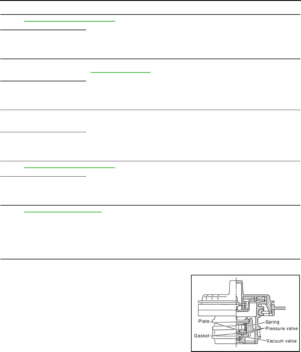
EC-312
< COMPONENT DIAGNOSIS > [FOR CALIFORNIA]
P0455 EVAP CONTROL SYSTEM
15.CHECK EVAP CONTROL SYSTEM PRESSURE SENSOR
Refer to EC-296, "Component Inspection".
Is the inspection result normal?
YES >> GO TO 16.
NO >> Replace EVAP control system pressure sensor.
16.CHECK EVAP/ORVR LINE
Check EVAP/ORVR line between EVAP canister and fuel tank for clogging, kinks, looseness and improper
connection. For location, refer to EC-431, "Description".
Is the inspection result normal?
YES >> GO TO 17.
NO >> Repair or replace hoses and tubes.
17.CHECK RECIRCULATION LINE
Check recirculation line between filler neck tube and fuel tank for clogging, kinks, cracks, looseness and
improper connection.
Is the inspection result normal?
YES >> GO TO 18.
NO >> Repair or replace hose, tube or filler neck tube.
18.CHECK REFUELING EVAP VAPOR CUT VALVE
Refer to EC-434, "Component Inspection".
Is the inspection result normal?
YES >> GO TO 19.
NO >> Replace refueling EVAP vapor cut valve with fuel tank.
19.CHECK INTERMITTENT INCIDENT
Refer to GI-41, "Intermittent Incident".
>> INSPECTION END
Component Inspection INFOID:0000000004529902
1.CHECK FUEL FILLER CAP
1. Turn ignition switch OFF.
2. Remove fuel filler cap.
3. Wipe clean valve housing.
4. Install fuel filler cap adapter (commercial service tool) to fuel filler cap.
SEF445Y
Revision: 2008 August 2009 Rogue
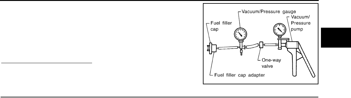
P0455 EVAP CONTROL SYSTEM
EC-313
< COMPONENT DIAGNOSIS > [FOR CALIFORNIA]
C
D
E
F
G
H
I
J
K
L
M
A
EC
N
P
O
5. Check valve opening pressure and vacuum.
Is the inspection result normal?
YES >> INSPECTION END
NO >> GO TO 2.
2.REPLACE FUEL FILLER CAP
Replace fuel filler cap.
CAUTION:
Use only a genuine fuel filler cap as a replacement. If an incorrect fuel filler cap is used, the MIL may
illuminate.
>> INSPECTION END
Pressure: 15.3 - 20.0 kPa (0.156 - 0.204 kg/cm2, 2.22 -
2.90 psi)
Vacuum: −6.0 to −3.3 kPa (−0.061 to −0.034 kg/cm2,
−0.87 to −0.48 psi)
SEF943S
Revision: 2008 August 2009 Rogue
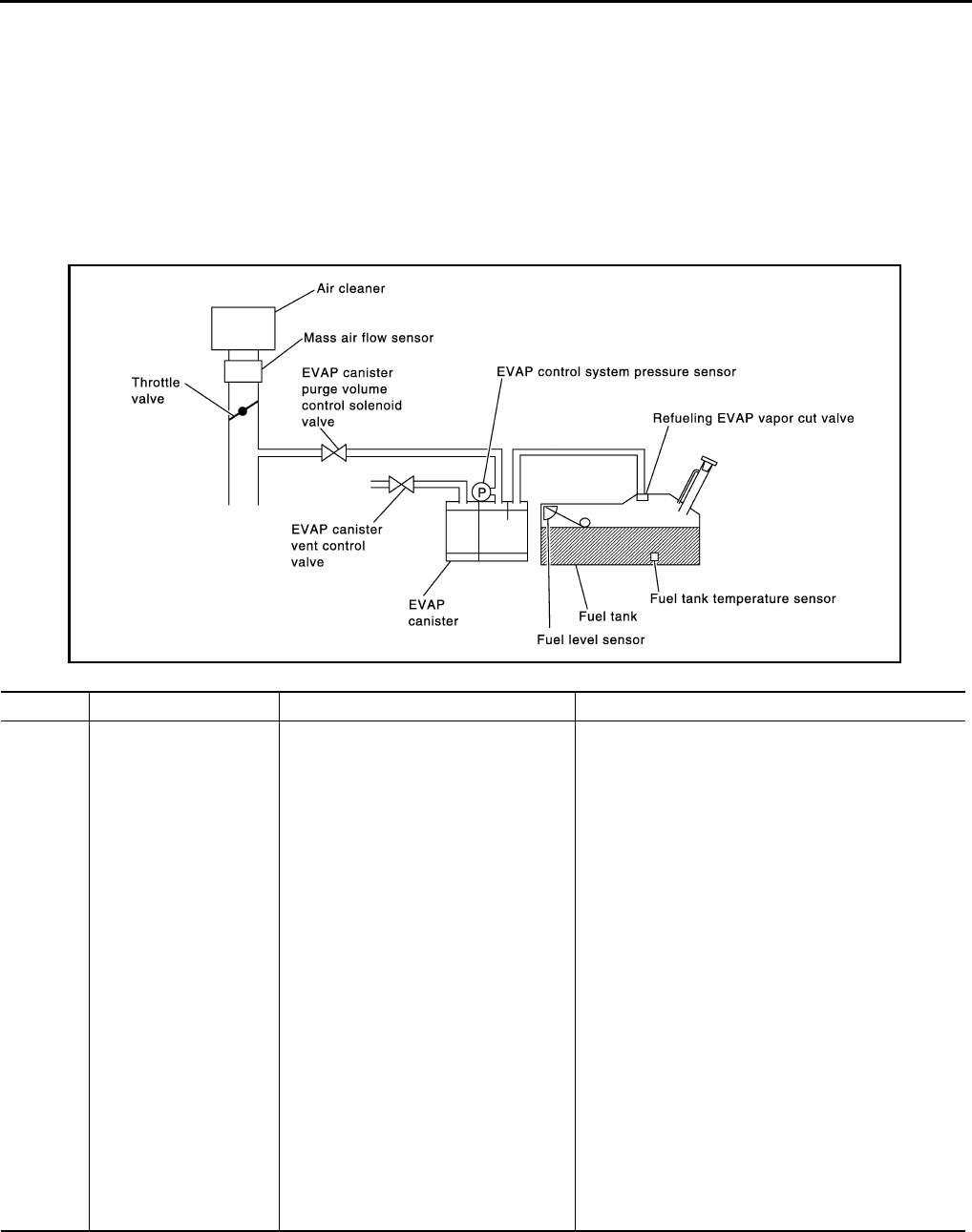
EC-314
< COMPONENT DIAGNOSIS > [FOR CALIFORNIA]
P0456 EVAP CONTROL SYSTEM
P0456 EVAP CONTROL SYSTEM
DTC Logic INFOID:0000000004493512
DTC DETECTION LOGIC
This diagnosis detects very small leaks in the EVAP line between fuel tank and EVAP canister purge volume
control solenoid valve, using the intake manifold vacuum in the same way as conventional EVAP small leak
diagnosis.
If ECM judges a leak which corresponds to a very small leak, the very small leak P0456 will be detected.
If ECM judges a leak equivalent to a small leak, EVAP small leak P0442 will be detected.
If ECM judges that there are no leaks, the diagnosis will be OK.
CAUTION:
• Use only a genuine NISSAN fuel filler cap as a replacement. If an incorrect fuel filler cap is used, the
MIL may illuminate.
• If the fuel filler cap is not tightened properly, the MIL may illuminate.
• Use only a genuine NISSAN rubber tube as a replacement.
DTC No. Trouble diagnosis name DTC detecting condition Possible cause
P0456
Evaporative emission
control system very
small leak (negative
pressure check)
• EVAP system has a very small leak.
• EVAP system does not operate prop-
erly.
• Incorrect fuel tank vacuum relief valve
• Incorrect fuel filler cap used
• Fuel filler cap remains open or fails to close.
• Foreign matter caught in fuel filler cap.
• Leak is in line between intake manifold and EVAP
canister purge volume control solenoid valve.
• Foreign matter caught in EVAP canister vent con-
trol valve.
• EVAP canister or fuel tank leaks
• EVAP purge line (pipe and rubber tube) leaks
• EVAP purge line rubber tube bent
• Loose or disconnected rubber tube
• EVAP canister vent control valve and the circuit
• EVAP canister purge volume control solenoid
valve and the circuit
• Fuel tank temperature sensor
• O-ring of EVAP canister vent control valve is miss-
ing or damaged
• EVAP canister is saturated with water
• EVAP control system pressure sensor
• Refueling EVAP vapor cut valve
• ORVR system leaks
• Fuel level sensor and the circuit
• Foreign matter caught in EVAP canister purge vol-
ume control solenoid valve
PBIB1026E
Revision: 2008 August 2009 Rogue

P0456 EVAP CONTROL SYSTEM
EC-315
< COMPONENT DIAGNOSIS > [FOR CALIFORNIA]
C
D
E
F
G
H
I
J
K
L
M
A
EC
N
P
O
DTC CONFIRMATION PROCEDURE
1.INSPECTION START
Do you have CONSULT-III?
Do you have CONSULT-III?
YES >> GO TO 2.
NO >> GO TO 4.
2.PRECONDITIONING
If DTC CONFIRMATION PROCEDURE has been previously conducted, always turn ignition switch OFF and
wait at least 10 seconds before conducting the next test.
NOTE:
•If DTC P0456 is displayed with P0442, first perform trouble diagnosis for DTC P0456.
•After repair, check that the hoses and clips are installed properly.
•Check that EVAP hoses are connected to EVAP canister purge volume control solenoid valve prop-
erly.
TESTING CONDITION:
•Open engine hood before conducting the following procedure.
•If any of following conditions are met just before the DTC CONFIRMATION PROCEDURE, leave the
vehicle for more than 1 hour.
-Fuel filler cap is removed.
-Fuel is refilled or drained.
-EVAP component part/parts is/are removed.
•Before performing the following procedure, confirm that battery voltage is more than 11V at idle.
>> GO TO 3.
3.PERFORM DTC CONFIRMATION PROCEDURE
With CONSULT-III
1. Turn ignition switch ON and select “DATA MONITOR” mode with CONSULT-III.
2. Check that the following conditions are met.
FUEL LEVEL SE: 0.25 - 1.4V
COOLAN TEMP/S: 0 - 32°C (32 - 90°F)
FUEL T/TMP SE: 0 - 35°C (32 - 95°F)
INT A/TEMP SE: More than 0°C (32°F)
If NG, turn ignition switch OFF and leave the vehicle in a cool place (soak the vehicle), or refill/drain fuel
until the output voltage the “FUEL LEVEL SE” meets within the range above and leave the vehicle for
more than 1 hour. Then start from step 1.
3. Turn ignition switch OFF and wait at least 10 seconds.
4. Turn ignition switch ON.
5. Select “EVAP V/S LEAK P0456/P1456” of “EVAPORATIVE SYSTEM” in “DTC WORK SUPPORT” mode
with CONSULT-III.
Follow the instructions displayed.
NOTE:
If the engine speed cannot be maintained within the range displayed on CONSULT-III screen, go to
EC-22, "BASIC INSPECTION : Special Repair Requirement".
Which is displayed on CONSULT-III?
OK >> INSPECTION END
NG >> Go to EC-316, "Diagnosis Procedure".
4.PERFORM COMPONENT FUNCTION CHECK
Perform Component Function Check. Refer to EC-316, "Component Function Check".
NOTE:
Use Component Function Check to check the overall function of the EVAP very small leak function. During this
check, a 1st trip DTC might not be confirmed.
Is the inspection result normal?
YES >> INSPECTION END
NO >> Go to EC-316, "Diagnosis Procedure".
Revision: 2008 August 2009 Rogue
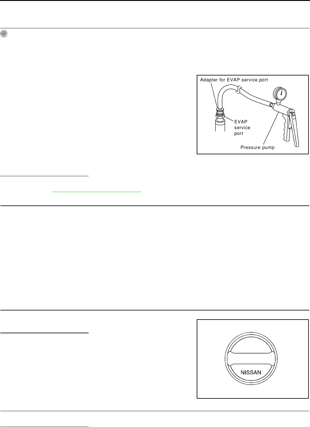
EC-316
< COMPONENT DIAGNOSIS > [FOR CALIFORNIA]
P0456 EVAP CONTROL SYSTEM
Component Function Check INFOID:0000000004493513
1.PERFORM COMPONENT FUNCTION CHECK
With GST
CAUTION:
• Never use compressed air, doing so may damage the EVAP system.
• Never start engine.
• Never exceeded 4.12 kPa (0.042 kg/cm2, 0.6 psi).
1. Attach the EVAP service port adapter (commercial service tool) securely to the EVAP service port.
2. Set the pressure pump and a hose.
3. Also set a vacuum gauge via 3-way connector and a hose.
4. Turn ignition switch ON.
5. Connect GST and select Service $08.
6. Using Service $08 control the EVAP canister vent control valve
(close).
7. Apply pressure and check that the following conditions are satis-
fied.
Pressure to be applied: 2.7 kPa (0.028 kg/cm2, 0.39 psi)
Time to be waited after the pressure drawn in to the EVAP
system and the pressure to be dropped: 60 seconds and
the pressure should not be dropped more than 0.4 kPa
(0.004 kg/cm2, 0.06 psi).
Is the inspection result normal?
YES >> GO TO 2.
NO >> Go to EC-316, "Diagnosis Procedure".
2.RELEASE PRESSURE
1. Disconnect GST.
2. Start engine and warm it up to normal operating temperature.
3. Turn ignition switch OFF and wait at least 10 seconds.
4. Restart engine and let it idle for 90 seconds.
5. Keep engine speed at 2,000 rpm for 30 seconds.
6. Turn ignition switch OFF.
NOTE:
For more information, refer to GST Instruction Manual.
>> INSPECTION END
Diagnosis Procedure INFOID:0000000004493514
1.CHECK FUEL FILLER CAP DESIGN
1. Turn ignition switch OFF.
2. Check for genuine NISSAN fuel filler cap design.
Is the inspection result normal?
YES >> GO TO 2.
NO >> Replace with genuine NISSAN fuel filler cap.
2.CHECK FUEL FILLER CAP INSTALLATION
Check that the cap is tightened properly by rotating the cap clockwise.
Is the inspection result normal?
SEF462UI
SEF915U
Revision: 2008 August 2009 Rogue
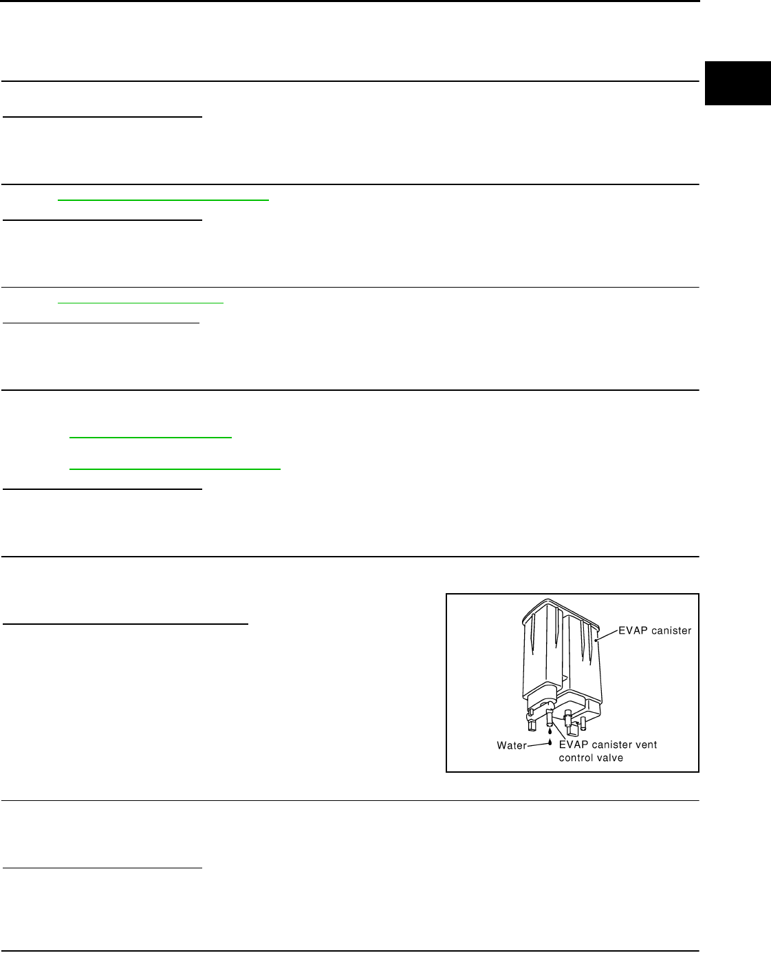
P0456 EVAP CONTROL SYSTEM
EC-317
< COMPONENT DIAGNOSIS > [FOR CALIFORNIA]
C
D
E
F
G
H
I
J
K
L
M
A
EC
N
P
O
YES >> GO TO 3.
NO >> Open fuel filler cap, then clean cap and fuel filler neck threads using air blower. Then retighten
until ratcheting sound is heard.
3.CHECK FUEL FILLER CAP FUNCTION
Check for air releasing sound while opening the fuel filler cap.
Is the inspection result normal?
YES >> GO TO 5.
NO >> GO TO 4.
4.CHECK FUEL TANK VACUUM RELIEF VALVE
Refer to EC-319, "Component Inspection".
Is the inspection result normal?
YES >> GO TO 5.
NO >> Replace fuel filler cap with a genuine one.
5.CHECK FOR EVAP LEAK
Refer to EC-72, "System Diagram".
Is there any leak in EVAP line?
YES >> Repair or replace.
NO >> GO TO 6.
6.CHECK EVAP CANISTER VENT CONTROL VALVE
Check the following.
• EVAP canister vent control valve is installed properly.
Refer to EC-492, "Exploded View".
• EVAP canister vent control valve.
Refer to EC-288, "Component Inspection".
Is the inspection result normal?
YES >> GO TO 7.
NO >> Repair or replace EVAP canister vent control valve and O-ring.
7.CHECK IF EVAP CANISTER IS SATURATED WITH WATER
1. Remove EVAP canister with EVAP canister vent control valve and EVAP control system pressure sensor
attached.
2. Check if water will drain from the EVAP canister.
Does water drain from EVAP canister?
YES >> GO TO 8.
NO-1 >> With CONSULT-III: GO TO 10.
NO-2 >> Without CONSULT-III: GO TO 11.
8.CHECK EVAP CANISTER
Weigh the EVAP canister with the EVAP canister vent control valve and EVAP control system pressure sensor
attached.
The weight should be less than 2.1 kg (4.6 lb).
Is the inspection result normal?
YES-1 >> With CONSULT-III: GO TO 10.
YES-2 >> Without CONSULT-III: GO TO 11.
NO >> GO TO 9.
9.DETECT MALFUNCTIONING PART
Check the following.
PBIB1213E
Revision: 2008 August 2009 Rogue
EC-318
< COMPONENT DIAGNOSIS > [FOR CALIFORNIA]
P0456 EVAP CONTROL SYSTEM
• EVAP canister for damage
• EVAP hose between EVAP canister and vehicle frame for clogging or poor connection
>> Repair hose or replace EVAP canister.
10.CHECK EVAP CANISTER PURGE VOLUME CONTROL SOLENOID VALVE OPERATION
With CONSULT-III
1. Disconnect vacuum hose connected to EVAP service port and EVAP canister purge volume control sole-
noid valve from EVAP service port.
2. Start engine.
3. Perform “PURG VOL CONT/V” in “ACTIVE TEST” mode.
4. Touch “Qu” on CONSULT-III screen to increase “PURG VOL C/V” opening to 100%.
5. Check vacuum hose for vacuum.
Is the inspection result normal?
YES >> GO TO 13.
NO >> GO TO 12.
11.CHECK EVAP CANISTER PURGE VOLUME CONTROL SOLENOID VALVE OPERATION
Without CONSULT-III
1. Start engine and warm it up to normal operating temperature.
2. Stop engine.
3. Disconnect vacuum hose connected to EVAP service port and EVAP canister purge volume control sole-
noid valve from EVAP service port.
4. Start engine and let it idle for at least 80 seconds.
5. Check vacuum hose for vacuum when revving engine up to 2,000 rpm.
Is the inspection result normal?
YES >> GO TO 14.
NO >> GO TO 12.
12.CHECK VACUUM HOSE
Check vacuum hoses for clogging or disconnection. Refer to EC-72, "System Diagram".
Is the inspection result normal?
YES >> GO TO 13.
NO >> Repair or reconnect the hose.
13.CHECK EVAP CANISTER PURGE VOLUME CONTROL SOLENOID VALVE
Refer to EC-280, "Diagnosis Procedure".
Is the inspection result normal?
YES >> GO TO 14.
NO >> Replace EVAP canister purge volume control solenoid valve.
14.CHECK FUEL TANK TEMPERATURE SENSOR
Refer to EC-241, "Component Inspection".
Is the inspection result normal?
YES >> GO TO 15.
NO >> Replace fuel level sensor unit.
15.CHECK EVAP CONTROL SYSTEM PRESSURE SENSOR
Refer to EC-296, "Component Inspection".
Is the inspection result normal?
YES >> GO TO 16.
NO >> Replace EVAP control system pressure sensor.
Vacuum should exist.
Vacuum should exist.
Revision: 2008 August 2009 Rogue

P0456 EVAP CONTROL SYSTEM
EC-319
< COMPONENT DIAGNOSIS > [FOR CALIFORNIA]
C
D
E
F
G
H
I
J
K
L
M
A
EC
N
P
O
16.CHECK EVAP PURGE LINE
Check EVAP purge line (pipe, rubber tube, fuel tank and EVAP canister) for cracks or improper connection.
Refer to EC-72, "System Diagram".
Is the inspection result normal?
YES >> GO TO 17.
NO >> Repair or reconnect the hose.
17.CLEAN EVAP PURGE LINE
Clean EVAP purge line (pipe and rubber tube) using air blower.
>> GO TO 18.
18.CHECK EVAP/ORVR LINE
Check EVAP/ORVR line between EVAP canister and fuel tank for clogging, kinks, looseness and improper
connection. For location, refer to EC-431, "Description".
Is the inspection result normal?
YES >> GO TO 19.
NO >> Repair or replace hoses and tubes.
19.CHECK RECIRCULATION LINE
Check recirculation line between filler neck tube and fuel tank for clogging, kinks, cracks, looseness and
improper connection.
Is the inspection result normal?
YES >> GO TO 20.
NO >> Repair or replace hose, tube or filler neck tube.
20.CHECK REFUELING EVAP VAPOR CUT VALVE
Refer to EC-434, "Component Inspection".
Is the inspection result normal?
YES >> GO TO 21.
NO >> Replace refueling EVAP vapor cut valve with fuel tank.
21.CHECK FUEL LEVEL SENSOR
Refer to FL-10, "2WD : Inspection" (2WD), FL-14, "AWD : Inspection" (AWD).
Is the inspection result normal?
YES >> GO TO 22.
NO >> Replace fuel level sensor unit.
22.CHECK INTERMITTENT INCIDENT
Refer to GI-41, "Intermittent Incident".
>> INSPECTION END
Component Inspection INFOID:0000000004529911
1.CHECK FUEL FILLER CAP
1. Turn ignition switch OFF.
2. Remove fuel filler cap.
Revision: 2008 August 2009 Rogue
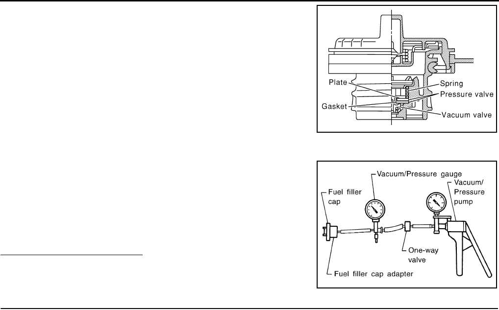
EC-320
< COMPONENT DIAGNOSIS > [FOR CALIFORNIA]
P0456 EVAP CONTROL SYSTEM
3. Wipe clean valve housing.
4. Install fuel filler cap adapter (commercial service tool) to fuel filler cap.
5. Check valve opening pressure and vacuum.
Is the inspection result normal?
YES >> INSPECTION END
NO >> GO TO 2.
2.REPLACE FUEL FILLER CAP
Replace fuel filler cap.
CAUTION:
Use only a genuine fuel filler cap as a replacement. If an incorrect fuel filler cap is used, the MIL may
illuminate.
>> INSPECTION END
SEF445Y
Pressure: 15.3 - 20.0 kPa (0.156 - 0.204 kg/cm2, 2.22 -
2.90 psi)
Vacuum: −6.0 to −3.3 kPa (−0.061 to −0.034 kg/cm2,
−0.87 to −0.48 psi)
SEF943S
Revision: 2008 August 2009 Rogue

P0460 FUEL LEVEL SENSOR
EC-321
< COMPONENT DIAGNOSIS > [FOR CALIFORNIA]
C
D
E
F
G
H
I
J
K
L
M
A
EC
N
P
O
P0460 FUEL LEVEL SENSOR
Description INFOID:0000000004493516
The fuel level sensor is mounted in the fuel level sensor unit.
The sensor detects a fuel level in the fuel tank and transmits a signal to the combination meter. The combina-
tion meter sends the fuel level sensor signal to the ECM through the CAN communication line.
It consists of two parts, one is mechanical float and the other is variable resistor. Fuel level sensor output volt-
age changes depending on the movement of the fuel mechanical float.
DTC Logic INFOID:0000000004493517
DTC DETECTION LOGIC
NOTE:
•If DTC P0460 is displayed with DTC UXXXX, first perform the trouble diagnosis for DTC UXXXX.
•If DTC P0460 is displayed with DTC P0607, first perform the trouble diagnosis for DTC P0607. Refer
to EC-335, "DTC Logic".
When the vehicle is parked, the fuel level in the fuel tank is naturally stable. It means that output signal of the
fuel level sensor does not change. If ECM senses sloshing signal from the sensor, fuel level sensor malfunc-
tion is detected.
DTC CONFIRMATION PROCEDURE
1.PRECONDITIONING
If DTC CONFIRMATION PROCEDURE has been previously conducted, always turn ignition switch OFF and
wait at least 10 seconds before conducting the next test.
>> GO TO 2.
2.PERFORM DTC CONFIRMATION PROCEDURE
1. Start engine and wait maximum of 2 consecutive minutes.
2. Check 1st trip DTC.
Is 1st trip DTC detected?
YES >> Go to EC-321, "Diagnosis Procedure".
NO >> INSPECTION END
Diagnosis Procedure INFOID:0000000004493518
1.CHECK COMBINATION METER FUNCTION
Refer to MWI-43, "Component Function Check".
Is the inspection result normal?
YES >> GO TO 2.
NO >> Go to MWI-43, "Diagnosis Procedure".
2.CHECK INTERMITTENT INCIDENT
Refer to GI-41, "Intermittent Incident".
>> INSPECTION END
DTC No. Trouble diagnosis name DTC detecting condition Possible cause
P0460 Fuel level sensor circuit
noise
Even though the vehicle is parked, a signal be-
ing varied is sent from the fuel level sensor to
ECM.
• Harness or connectors
(The CAN communication line is open or
shorted)
• Harness or connectors
(The sensor circuit is open or shorted)
• Combination meter
• Fuel level sensor
Revision: 2008 August 2009 Rogue

EC-322
< COMPONENT DIAGNOSIS > [FOR CALIFORNIA]
P0461 FUEL LEVEL SENSOR
P0461 FUEL LEVEL SENSOR
Description INFOID:0000000004529912
The fuel level sensor is mounted in the fuel level sensor unit.
The sensor detects a fuel level in the fuel tank and transmits a signal to the combination meter. The combina-
tion meter sends the fuel level sensor signal to the ECM through the CAN communication line.
It consists of two parts, one is mechanical float and the other is variable resistor. Fuel level sensor output volt-
age changes depending on the movement of the fuel mechanical float.
DTC Logic INFOID:0000000004493520
DTC DETECTION LOGIC
NOTE:
•If DTC P0461 is displayed with DTC UXXXX, first perform the trouble diagnosis for DTC UXXXX.
•If DTC P0461 is displayed with DTC P0607, first perform the trouble diagnosis for DTC P0607. Refer
to EC-335, "DTC Logic".
Driving long distances naturally affect fuel gauge level.
This diagnosis detects the fuel gauge malfunction of the gauge not moving even after a long distance has
been driven.
DTC CONFIRMATION PROCEDURE
1.PERFORM COMPONENT FUNCTION CHECK
Perform Component Function Check. Refer to EC-322, "Component Function Check".
Use Component Function Check to check the overall function of the fuel level sensor. During this check, a 1st
trip DTC might not be confirmed.
Is the inspection result normal?
YES >> INSPECTION END
NO >> Go to EC-323, "Diagnosis Procedure".
Component Function Check INFOID:0000000004493521
1.PRECONDITIONING
WARNING:
When performing the following procedure, always observe the handling of the fuel. Refer to FL-7,
"2WD : Removal and Installation" (2WD), FL-11, "AWD : Removal and Installation" (AWD).
TESTING CONDITION:
Before starting component function check, preparation of draining fuel and refilling fuel is required.
Do you have CONSULT-III?
YES >> GO TO 2.
NO >> GO TO 3.
2.PERFORM COMPONENT FUNCTION CHECK
With CONSULT-III
NOTE:
Start from step 10, if it is possible to confirm that the fuel cannot be drained by 30 (7-7/8 US gal, 6-5/
8 Imp gal) in advance.
1. Prepare a fuel container and a spare hose.
DTC No. Trouble diagnosis name DTC detecting condition Possible cause
P0461 Fuel level sensor circuit
range/performance
The output signal of the fuel level sensor does
not change within the specified range even
though the vehicle has been driven a long dis-
tance.
• Harness or connectors
(The CAN communication line is open or
shorted)
• Harness or connectors
(The sensor circuit is open or shorted)
• Combination meter
• Fuel level sensor
Revision: 2008 August 2009 Rogue

P0461 FUEL LEVEL SENSOR
EC-323
< COMPONENT DIAGNOSIS > [FOR CALIFORNIA]
C
D
E
F
G
H
I
J
K
L
M
A
EC
N
P
O
2. Release fuel pressure from fuel line, refer to EC-489, "Inspection".
3. Remove the fuel feed hose on the fuel level sensor unit.
4. Connect a spare fuel hose where the fuel feed hose was removed.
5. Turn ignition switch OFF and wait at least 10 seconds then turn ON.
6. Select “FUEL LEVEL SE” in “DATA MONITOR” mode with CONSULT-III.
7. Check “FUEL LEVEL SE” output voltage and note it.
8. Select “FUEL PUMP RELAY” in “ACTIVE TEST” mode with CONSULT-III.
9. Touch “ON” and drain fuel approximately 30 (7-7/8 US gal, 6-5/8 Imp gal) and stop it.
10. Check “FUEL LEVEL SE” output voltage and note it.
11. Fill fuel into the fuel tank for 30 (7-7/8 US gal, 6-5/8 Imp gal).
12. Check “FUEL LEVEL SE” output voltage and note it.
13. Confirm whether the voltage changes more than 0.03V during step 7 to 10 and 10 to 12.
Is the inspection result normal?
YES >> INSPECTION END
NO >> Go to EC-323, "Diagnosis Procedure".
3.PERFORM COMPONENT FUNCTION CHECK
Without CONSULT-III
NOTE:
Start from step 8, if it is possible to confirm that the fuel cannot be drained by 30 (7-7/8 US gal, 6-5/8
Imp gal) in advance.
1. Prepare a fuel container and a spare hose.
2. Release fuel pressure from fuel line. Refer to EC-489, "Inspection".
3. Remove the fuel feed hose on the fuel level sensor unit.
4. Connect a spare fuel hose where the fuel feed hose was removed.
5. Turn ignition switch ON.
6. Drain fuel by 30 (7-7/8 US gal, 6-5/8 Imp gal) from the fuel tank using proper equipment.
7. Confirm that the fuel gauge indication varies.
8. Fill fuel into the fuel tank for 30 (7-7/8 US gal, 6-5/8 Imp gal).
9. Confirm that the fuel gauge indication varies.
Is the inspection result normal?
YES >> INSPECTION END
NO >> Go to EC-323, "Diagnosis Procedure".
Diagnosis Procedure INFOID:0000000004529914
1.CHECK COMBINATION METER FUNCTION
Refer to MWI-43, "Component Function Check".
Is the inspection result normal?
YES >> GO TO 2.
NO >> Go to MWI-43, "Diagnosis Procedure".
2.CHECK INTERMITTENT INCIDENT
Refer to GI-41, "Intermittent Incident".
>> INSPECTION END
Revision: 2008 August 2009 Rogue

EC-324
< COMPONENT DIAGNOSIS > [FOR CALIFORNIA]
P0462, P0463 FUEL LEVEL SENSOR
P0462, P0463 FUEL LEVEL SENSOR
Description INFOID:0000000004529913
The fuel level sensor is mounted in the fuel level sensor unit.
The sensor detects a fuel level in the fuel tank and transmits a signal to the combination meter. The combina-
tion meter sends the fuel level sensor signal to the ECM through the CAN communication line.
It consists of two parts, one is mechanical float and the other is variable resistor. Fuel level sensor output volt-
age changes depending on the movement of the fuel mechanical float.
DTC Logic INFOID:0000000004493524
DTC DETECTION LOGIC
NOTE:
•If DTC P0462 or P0463 is displayed with DTC UXXXX, first perform the trouble diagnosis for DTC
UXXXX.
•If DTC P0462 or P0463 is displayed with DTC P0607, first perform the trouble diagnosis for DTC
P0607. Refer to EC-335, "DTC Logic".
DTC CONFIRMATION PROCEDURE
1.PRECONDITIONING
If DTC CONFIRMATION PROCEDURE has been previously conducted, always turn ignition switch OFF and
wait at least 10 seconds before conducting the next test.
TESTING CONDITION:
Before performing the following procedure, confirm that battery voltage is between 11V and 16V at
ignition switch ON.
>> GO TO 2.
2.PERFORM DTC CONFIRMATION PROCEDURE
1. Turn ignition switch ON and wait at least 5 seconds.
2. Check 1st trip DTC.
Is 1st trip DTC detected?
YES >> Go to EC-324, "Diagnosis Procedure".
NO >> INSPECTION END
Diagnosis Procedure INFOID:0000000004529915
1.CHECK COMBINATION METER FUNCTION
Refer to MWI-43, "Component Function Check".
Is the inspection result normal?
YES >> GO TO 2.
NO >> Go to MWI-43, "Diagnosis Procedure".
2.CHECK INTERMITTENT INCIDENT
Refer to GI-41, "Intermittent Incident".
>> INSPECTION END
DTC No. Trouble diagnosis name DTC detecting condition Possible cause
P0462 Fuel level sensor circuit
low input
An excessively low voltage from the sensor is
sent to ECM.
• Harness or connectors
(The CAN communication line is open or
shorted)
• Harness or connectors
(The sensor circuit is open or shorted)
• Combination meter
• Fuel level sensor
P0463 Fuel level sensor circuit
high input
An excessively high voltage from the sensor is
sent to ECM.
Revision: 2008 August 2009 Rogue

P0500 VSS
EC-325
< COMPONENT DIAGNOSIS > [FOR CALIFORNIA]
C
D
E
F
G
H
I
J
K
L
M
A
EC
N
P
O
P0500 VSS
Description INFOID:0000000004493526
The vehicle speed signal is sent to the combination meter from the “ABS actuator and electric unit (control
unit)” by CAN communication line. The combination meter then sends a signal to the ECM by CAN communi-
cation line.
DTC Logic INFOID:0000000004493527
DTC DETECTION LOGIC
NOTE:
•If DTC P0500 is displayed with DTC UXXXX, first perform the trouble diagnosis for DTC UXXXX.
•If DTC P0500 is displayed with DTC P0607, first perform the trouble diagnosis for DTC P0607. Refer
to EC-335, "DTC Logic".
DTC CONFIRMATION PROCEDURE
1.INSPECTION START
Do you have CONSULT-III?
Do you have CONSULT-III?
YES >> GO TO 2.
NO >> GO TO 5.
2.PRECONDITIONING
If DTC CONFIRMATION PROCEDURE has been previously conducted, always turn ignition switch OFF and
wait at least 10 seconds before conducting the next test.
>> GO TO 3.
3.CHECK VEHICLE SPEED SENSOR FUNCTION
NOTE:
This procedure may be conducted with the drive wheels lifted in the shop or by driving the vehicle. If a
road test is expected to be easier, it is unnecessary to lift the vehicle.
With CONSULT-III
1. Start engine.
2. Read “VHCL SPEED SE” in “DATA MONITOR” mode with CONSULT-III. The vehicle speed on CON-
SULT-III should exceed 10 km/h (6 mph) when rotating wheels with suitable gear position.
Is the inspection result normal?
YES >> GO TO 4.
NO >> Go to EC-326, "Diagnosis Procedure".
4.PERFORM DTC CONFIRMATION PROCEDURE
1. Select “DATA MONITOR” mode with CONSULT-III.
2. Warm engine up to normal operating temperature.
3. Maintain the following conditions for at least 50 consecutive seconds.
CAUTION:
Always drive vehicle at a safe speed.
DTC No. Trouble diagnosis name DTC detecting condition Possible cause
P0500 Vehicle speed sensor
The almost 0 km/h (0 MPH) signal from
vehicle speed sensor is sent to ECM even
when vehicle is being driven.
• Harness or connectors
(The CAN communication line is open or short-
ed)
• Harness or connectors
(The vehicle speed signal circuit is open or
shorted)
• Vehicle speed sensor
• Combination meter
• ABS actuator and electric unit (control unit)
Revision: 2008 August 2009 Rogue

EC-326
< COMPONENT DIAGNOSIS > [FOR CALIFORNIA]
P0500 VSS
4. Check 1st trip DTC.
Is 1st trip DTC detected?
YES >> Go to EC-326, "Diagnosis Procedure".
NO >> INSPECTION END
5.PERFORM COMPONENT FUNCTION CHECK
Perform Component Function Check. Refer to EC-326, "Component Function Check".
Use Component Function Check to check the overall function of the vehicle speed sensor circuit. During this
check, a 1st trip DTC might not be confirmed.
Is the inspection result normal?
YES >> INSPECTION END
NO >> Go to EC-326, "Diagnosis Procedure".
Component Function Check INFOID:0000000004493528
1.PERFORM COMPONENT FUNCTION CHECK
With GST
1. Lift up drive wheels.
2. Start engine.
3. Read vehicle speed sensor signal in Service $01 with GST.
The vehicle speed sensor on GST should be able to exceed 10 km/h (6 MPH) when rotating wheels with
suitable gear position.
Is the inspection result normal?
YES >> INSPECTION END
NO >> Go to EC-326, "Diagnosis Procedure".
Diagnosis Procedure INFOID:0000000004493529
1.CHECK DTC WITH “ABS ACTUATOR AND ELECTRIC UNIT (CONTROL UNIT)”
Refer to BRC-15, "CONSULT-III Function" (ABS models), BRC-93, "CONSULT-III Function" (VDC models).
Is the inspection result normal?
YES >> GO TO 2.
NO >> Repair or replace.
2.CHECK COMBINATION METER
Refer to MWI-33, "CONSULT-III Function (METER/M&A)".
>> INSPECTION END
ENG SPEED 1,350 - 6,000 rpm
COOLAN TEMP/S More than 70°C (158°F)
B/FUEL SCHDL 5.5 - 31.8 msec
Selector lever Except P or N position
PW/ST SIGNAL OFF
Revision: 2008 August 2009 Rogue

P0506 ISC SYSTEM
EC-327
< COMPONENT DIAGNOSIS > [FOR CALIFORNIA]
C
D
E
F
G
H
I
J
K
L
M
A
EC
N
P
O
P0506 ISC SYSTEM
Description INFOID:0000000004493530
The ECM controls the engine idle speed to a specified level through the fine adjustment of the air, which is let
into the intake manifold, by operating the electric throttle control actuator. The operating of the throttle valve is
varied to allow for optimum control of the engine idling speed. The crankshaft position sensor (POS) detects
the actual engine speed and sends a signal to the ECM.
The ECM controls the electric throttle control actuator so that the engine speed coincides with the target value
memorized in the ECM. The target engine speed is the lowest speed at which the engine can operate steadily.
The optimum value stored in the ECM is determined by taking into consideration various engine conditions,
such as during warming up, deceleration and engine load (air conditioner, power steering and cooling fan
operation, etc.).
DTC Logic INFOID:0000000004493531
DTC DETECTION LOGIC
NOTE:
If DTC P0506 is displayed with other DTC, first perform the trouble diagnosis for the other DTC.
DTC CONFIRMATION PROCEDURE
1.PRECONDITIONING
If DTC CONFIRMATION PROCEDURE has been previously conducted, always turn ignition switch OFF and
wait at least 10 seconds before conducting the next test.
If the target idle speed is out of the specified value, perform EC-27, "IDLE AIR VOLUME LEARNING :
Special Repair Requirement", before conducting DTC CONFIRMATION PROCEDURE.
TESTING CONDITION:
•Before performing the following procedure, confirm that battery voltage is more than 11V at idle.
•Always perform the test at a temperature above −10°C (14°F).
>> GO TO 2.
2.PERFORM DTC CONFIRMATION PROCEDURE
1. Start engine and warm it up to normal operating temperature.
2. Turn ignition switch OFF and wait at least 10 seconds.
3. Start engine and run it for at least 1 minute at idle speed.
4. Check 1st trip DTC.
Is 1st trip DTC detected?
YES >> Go to EC-327, "Diagnosis Procedure".
NO >> INSPECTION END
Diagnosis Procedure INFOID:0000000004493532
1.CHECK INTAKE AIR LEAK
1. Start engine and let it idle.
2. Listen for an intake air leak after the mass air flow sensor.
Is intake air leak detected?
YES >> Discover air leak location and repair.
NO >> GO TO 2.
2.REPLACE ECM
1. Stop engine.
2. Replace ECM.
DTC No. Trouble diagnosis name DTC detecting condition Possible cause
P0506 Idle speed control system
RPM lower than expected The idle speed is less than the target idle
speed by 100 rpm or more. • Electric throttle control actuator
• Intake air leak
Revision: 2008 August 2009 Rogue


P0507 ISC SYSTEM
EC-329
< COMPONENT DIAGNOSIS > [FOR CALIFORNIA]
C
D
E
F
G
H
I
J
K
L
M
A
EC
N
P
O
P0507 ISC SYSTEM
Description INFOID:0000000004529916
The ECM controls the engine idle speed to a specified level through the fine adjustment of the air, which is let
into the intake manifold, by operating the electric throttle control actuator. The operating of the throttle valve is
varied to allow for optimum control of the engine idling speed. The crankshaft position sensor (POS) detects
the actual engine speed and sends a signal to the ECM.
The ECM controls the electric throttle control actuator so that the engine speed coincides with the target value
memorized in the ECM. The target engine speed is the lowest speed at which the engine can operate steadily.
The optimum value stored in the ECM is determined by taking into consideration various engine conditions,
such as during warming up, deceleration and engine load (air conditioner, power steering and cooling fan
operation, etc.).
DTC Logic INFOID:0000000004493534
DTC DETECTION LOGIC
NOTE:
If DTC P0507 is displayed with other DTC, first perform the trouble diagnosis for the other DTC.
DTC CONFIRMATION PROCEDURE
1.PRECONDITIONING
If DTC CONFIRMATION PROCEDURE has been previously conducted, always turn ignition switch OFF and
wait at least 10 seconds before conducting the next test.
If the target idle speed is out of the specified value, perform EC-27, "IDLE AIR VOLUME LEARNING :
Special Repair Requirement", before conducting DTC CONFIRMATION PROCEDURE.
TESTING CONDITION:
•Before performing the following procedure, confirm that battery voltage is more than 11V at idle.
•Always perform the test at a temperature above −10°C (14°F).
>> GO TO 2.
2.PERFORM DTC CONFIRMATION PROCEDURE
1. Start engine and warm it up to normal operating temperature.
2. Turn ignition switch OFF and wait at least 10 seconds.
3. Start engine and run it for at least 1 minute at idle speed.
4. Check 1st trip DTC.
Is 1st trip DTC detected?
YES >> Go to EC-329, "Diagnosis Procedure".
NO >> INSPECTION END
Diagnosis Procedure INFOID:0000000004493535
1.CHECK PCV HOSE CONNECTION
Confirm that PCV hose is connected correctly.
Is the inspection result normal?
YES >> GO TO 2.
NO >> Repair or replace.
2.CHECK INTAKE AIR LEAK
1. Start engine and let it idle.
2. Listen for an intake air leak after the mass air flow sensor.
DTC No. Trouble diagnosis name DTC detecting condition Possible cause
P0507 Idle speed control sys-
tem RPM higher than
expected
The idle speed is more than the target idle
speed by 200 rpm or more.
• Electric throttle control actuator
• Intake air leak
• PCV system
Revision: 2008 August 2009 Rogue

EC-330
< COMPONENT DIAGNOSIS > [FOR CALIFORNIA]
P0507 ISC SYSTEM
Is intake air leak detected?
YES >> Discover air leak location and repair.
NO >> GO TO 3.
3.REPLACE ECM
1. Stop engine.
2. Replace ECM.
3. Go to EC-25, "ADDITIONAL SERVICE WHEN REPLACING CONTROL UNIT : Special Repair Require-
ment".
>> INSPECTION END
Revision: 2008 August 2009 Rogue

P0603 ECM POWER SUPPLY
EC-331
< COMPONENT DIAGNOSIS > [FOR CALIFORNIA]
C
D
E
F
G
H
I
J
K
L
M
A
EC
N
P
O
P0603 ECM POWER SUPPLY
Description INFOID:0000000004493536
Battery voltage is supplied to the ECM even when the ignition switch
is turned OFF for the ECM memory function of the DTC memory, the
air-fuel ratio feedback compensation value memory, the idle air vol-
ume learning value memory, etc.
DTC Logic INFOID:0000000004493537
DTC DETECTION LOGIC
DTC CONFIRMATION PROCEDURE
1.PRECONDITIONING
If DTC CONFIRMATION PROCEDURE has been previously conducted, always turn ignition switch OFF and
wait at least 10 seconds before conducting the next test.
>> GO TO 2.
2.PERFORM DTC CONFIRMATION PROCEDURE
1. Turn ignition switch ON and wait at least 1 second.
2. Start engine and let it idle for 1 second.
3. Turn ignition switch OFF, wait at least 10 seconds, and then turn it ON.
4. Repeat steps 2 and 3 for four times.
5. Check 1st trip DTC.
Is 1st trip DTC detected?
YES >> Go to EC-331, "Diagnosis Procedure".
NO >> INSPECTION END
Diagnosis Procedure INFOID:0000000004493538
1.CHECK ECM POWER SUPPLY
1. Turn ignition switch OFF.
2. Disconnect ECM harness connector.
3. Check the voltage between ECM harness connector and ground.
Is the inspection result normal?
YES >> GO TO 3.
NO >> GO TO 2.
PBIA9222J
DTC No. Trouble diagnosis name DTC detecting condition Possible cause
P0603 ECM power supply cir-
cuit
ECM backup RAM system does not function
properly.
• Harness or connectors
[ECM power supply (backup) circuit is
open or shorted.]
•ECM
ECM Ground Voltage
Connector Terminal
F8 77 Ground Battery voltage
Revision: 2008 August 2009 Rogue

EC-332
< COMPONENT DIAGNOSIS > [FOR CALIFORNIA]
P0603 ECM POWER SUPPLY
2.DETECT MALFUNCTIONING PART
Check the following.
• Harness connectors E8, F122
• 20A fuse (No. 62)
• IPDM E/R harness connector E15
• Harness for open or short between ECM and battery
>> Repair or replace harness or connectors.
3.CHECK INTERMITTENT INCIDENT
Refer to GI-41, "Intermittent Incident".
Is the inspection result normal?
YES >> GO TO 4.
NO >> Repair or replace harness or connectors.
4.PERFORM DTC CONFIRMATION PROCEDURE
1. Erase DTC.
2. Perform DTC CONFIRMATION PROCEDURE.
See EC-331, "DTC Logic".
Is the 1st trip DTC P0603 displayed again?
YES >> GO TO 5.
NO >> INSPECTION END
5.REPLACE ECM
1. Replace ECM.
2. Go to EC-25, "ADDITIONAL SERVICE WHEN REPLACING CONTROL UNIT : Special Repair Require-
ment".
>> INSPECTION END
Revision: 2008 August 2009 Rogue
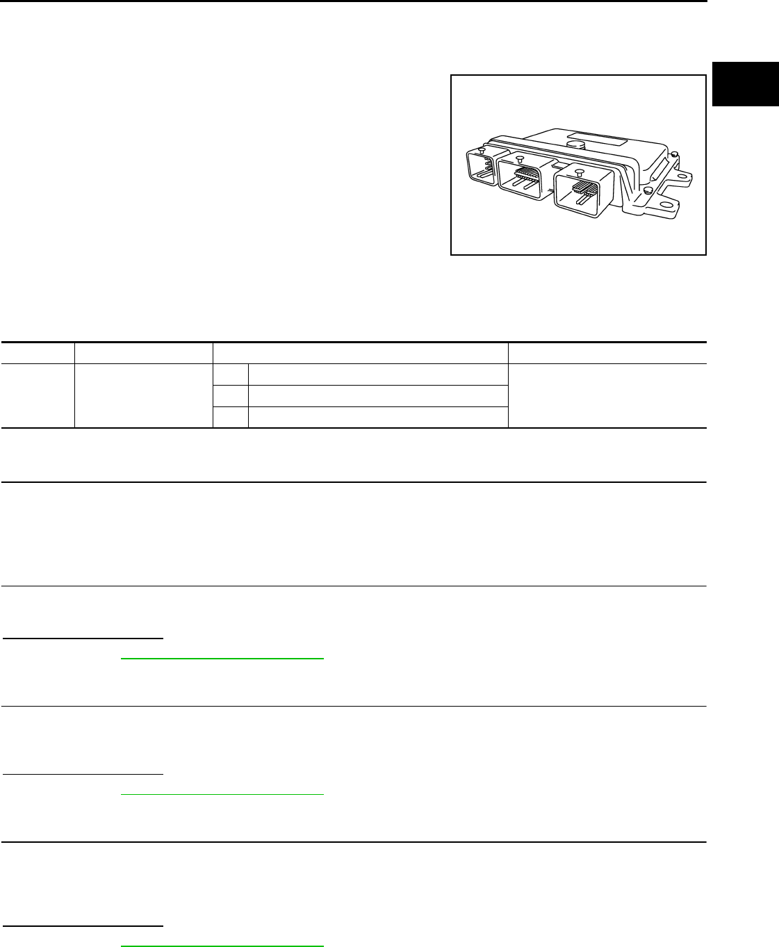
P0605 ECM
EC-333
< COMPONENT DIAGNOSIS > [FOR CALIFORNIA]
C
D
E
F
G
H
I
J
K
L
M
A
EC
N
P
O
P0605 ECM
Description INFOID:0000000004493539
The ECM consists of a microcomputer and connectors for signal
input and output and for power supply. The ECM controls the engine.
DTC Logic INFOID:0000000004493540
DTC DETECTION LOGIC
DTC CONFIRMATION PROCEDURE
1.PRECONDITIONING
If DTC CONFIRMATION PROCEDURE has been previously conducted, always turn ignition switch OFF and
wait at least 10 seconds before conducting the next test.
>> GO TO 2.
2.PERFORM DTC CONFIRMATION PROCEDURE FOR MALFUNCTION A
1. Turn ignition switch ON.
2. Check 1st trip DTC.
Is 1st trip DTC detected?
YES >> Go to EC-334, "Diagnosis Procedure".
NO >> GO TO 3.
3.PERFORM DTC CONFIRMATION PROCEDURE FOR MALFUNCTION B
1. wait at least 1 second.
2. Turn ignition switch OFF, wait at least 10 seconds, and then turn it ON.
3. Check 1st trip DTC.
Is 1st trip DTC detected?
YES >> Go to EC-334, "Diagnosis Procedure".
NO >> GO TO 4.
4.PERFORM DTC CONFIRMATION PROCEDURE FOR MALFUNCTION C
1. wait at least 1 second.
2. Turn ignition switch OFF, wait at least 10 seconds, and then turn it ON.
3. Repeat step 2 for 32 times.
4. Check 1st trip DTC.
Is 1st trip DTC detected?
YES >> Go to EC-334, "Diagnosis Procedure".
NO >> INSPECTION END
PBIA9222J
DTC No. Trouble diagnosis name DTC detecting condition Possible cause
P0605 Engine control module
A) ECM calculation function is malfunctioning.
•ECMB) ECM EEP-ROM system is malfunctioning.
C) ECM self shut-off function is malfunctioning.
Revision: 2008 August 2009 Rogue

EC-334
< COMPONENT DIAGNOSIS > [FOR CALIFORNIA]
P0605 ECM
Diagnosis Procedure INFOID:0000000004493541
1.INSPECTION START
1. Erase DTC.
2. Perform DTC CONFIRMATION PROCEDURE.
See EC-333, "DTC Logic".
Is the 1st trip DTC P0605 displayed again?
YES >> GO TO 2.
NO >> INSPECTION END
2.REPLACE ECM
1. Replace ECM.
2. Go to EC-25, "ADDITIONAL SERVICE WHEN REPLACING CONTROL UNIT : Special Repair Require-
ment".
>> INSPECTION END
Revision: 2008 August 2009 Rogue

P0607 ECM
EC-335
< COMPONENT DIAGNOSIS > [FOR CALIFORNIA]
C
D
E
F
G
H
I
J
K
L
M
A
EC
N
P
O
P0607 ECM
Description INFOID:0000000004493542
CAN (Controller Area Network) is a serial communication line for real time application. It is an on-vehicle mul-
tiplex communication line with high data communication speed and excellent error detection ability. Many elec-
tronic control units are equipped onto a vehicle, and each control unit shares information and links with other
control units during operation (not independent). In CAN communication, control units are connected with 2
communication lines (CAN H line, CAN L line) allowing a high rate of information transmission with less wiring.
Each control unit transmits/receives data but selectively reads required data only.
DTC Logic INFOID:0000000004493543
DTC DETECTION LOGIC
DTC CONFIRMATION PROCEDURE
1.PRECONDITIONING
If DTC CONFIRMATION PROCEDURE has been previously conducted, always turn ignition switch OFF and
wait at least 10 seconds before conducting the next test.
>> GO TO 2.
2.PERFORM DTC CONFIRMATION PROCEDURE
1. Turn ignition switch ON.
2. Check DTC.
Is DTC detected?
YES >> Go to EC-335, "Diagnosis Procedure".
NO >> INSPECTION END
Diagnosis Procedure INFOID:0000000004493544
1.INSPECTION START
1. Erase DTC.
2. Perform DTC CONFIRMATION PROCEDURE.
See EC-335, "DTC Logic".
Is the DTC P0607 displayed again?
YES >> GO TO 2.
NO >> INSPECTION END
2.REPLACE ECM
1. Replace ECM.
2. Go to EC-25, "ADDITIONAL SERVICE WHEN REPLACING CONTROL UNIT : Special Repair Require-
ment".
>> INSPECTION END
DTC No. Trouble diagnosis name DTC detecting condition Possible cause
P0607 CAN communication bus When detecting error during the initial diagno-
sis of CAN controller of ECM. •ECM
Revision: 2008 August 2009 Rogue

EC-336
< COMPONENT DIAGNOSIS > [FOR CALIFORNIA]
P0643 SENSOR POWER SUPPLY
P0643 SENSOR POWER SUPPLY
DTC Logic INFOID:0000000004493545
DTC DETECTION LOGIC
DTC CONFIRMATION PROCEDURE
1.PRECONDITIONING
If DTC CONFIRMATION PROCEDURE has been previously conducted, always turn ignition switch OFF and
wait at least 10 seconds before conducting the next test.
TESTING CONDITION:
Before performing the following procedure, confirm that battery voltage is more than 8V at idle.
>> GO TO 2.
2.PERFORM DTC CONFIRMATION PROCEDURE
1. Start engine and let it idle for 1 second.
2. Check DTC.
Is DTC detected?
YES >> Go to EC-336, "Diagnosis Procedure".
NO >> INSPECTION END
Diagnosis Procedure INFOID:0000000004493546
1.CHECK GROUND CONNECTION
1. Turn ignition switch OFF.
2. Check ground connection E21. Refer to Ground Inspection in GI-44, "Circuit Inspection".
Is the inspection result normal?
YES >> GO TO 2.
NO >> Repair or replace ground connection.
2.CHECK ACCELERATOR PEDAL POSITION SENSOR 1 POWER SUPPLY CIRCUIT
1. Disconnect accelerator pedal position (APP) sensor harness connector.
2. Turn ignition switch ON.
3. Check the voltage between APP sensor harness connector and ground.
Is the inspection result normal?
YES >> GO TO 7.
NO >> GO TO 3.
3.CHECK SENSOR POWER SUPPLY CIRCUIT
Check harness for short to power and short to ground, between the following terminals.
DTC No. Trouble diagnosis
name DTC detecting condition Possible cause
P0643 Sensor power supply
circuit short
ECM detects that the voltage of power
source for sensor is excessively low or high.
• Harness or connectors
(APP sensor 1 circuit is shorted.)
(TP sensor circuit is shorted.)
[Camshaft position sensor (PHASE) circuit is
shorted.]
• Accelerator pedal position sensor
• Throttle position sensor
• Camshaft position sensor (PHASE)
APP sensor Ground Voltage
Connector Terminal
E110 4 Ground Approx. 5 V
Revision: 2008 August 2009 Rogue

P0643 SENSOR POWER SUPPLY
EC-337
< COMPONENT DIAGNOSIS > [FOR CALIFORNIA]
C
D
E
F
G
H
I
J
K
L
M
A
EC
N
P
O
Is the inspection result normal?
YES >> GO TO 4.
NO >> Repair short to ground or short to power in harness or connectors.
4.CHECK COMPONENT
Check the following.
• Camshaft position sensor (PHASE) (Refer to EC-262, "Component Inspection".)
Is the inspection result normal?
YES >> GO TO 5.
NO >> Replace malfunctioning component.
5.CHECK TP SENSOR
Refer to EC-169, "Component Inspection".
Is the inspection result normal?
YES >> GO TO 9.
NO >> GO TO 6.
6.REPLACE ELECTRIC THROTTLE CONTROL ACTUATOR
1. Replace electric throttle control actuator.
2. Go to EC-27, "ACCELERATOR PEDAL RELEASED POSITION LEARNING : Special Repair Require-
ment".
>> INSPECTION END
7.CHECK APP SENSOR
Refer to EC-399, "Component Inspection".
Is the inspection result normal?
YES >> GO TO 9.
NO >> GO TO 8.
8.REPLACE ACCELERATOR PEDAL ASSEMBLY
1. Replace accelerator pedal assembly. Refer to ACC-3, "Removal and Installation".
2. Go to EC-399, "Special Repair Requirement".
>> INSPECTION END
9.CHECK INTERMITTENT INCIDENT
Refer to GI-41, "Intermittent Incident".
>> INSPECTION END
ECM Sensor
Connector Terminal Name Connector Terminal
F8 47 Electric throttle control actuator F29 1
59 CMP sensor (PHASE) F26 1
E16 83 APP sensor E110 4
Revision: 2008 August 2009 Rogue

EC-338
< COMPONENT DIAGNOSIS > [FOR CALIFORNIA]
P0850 PNP SWITCH
P0850 PNP SWITCH
Description INFOID:0000000004493547
When the selector lever position is P or N, park/neutral position (PNP) switch is ON.
ECM detects the position because the continuity of the line (the ON signal) exists.
DTC Logic INFOID:0000000004493548
DTC DETECTION LOGIC
DTC CONFIRMATION PROCEDURE
1.INSPECTION START
Do you have CONSULT-III?
Do you have CONSULT-III?
YES >> GO TO 2.
NO >> GO TO 5.
2.PRECONDITIONING
If DTC CONFIRMATION PROCEDURE has been previously conducted, always turn ignition switch OFF and
wait at least 10 seconds before conducting the next test.
>> GO TO 3.
3.CHECK PNP SWITCH FUNCTION
With CONSULT-III
1. Turn ignition switch ON.
2. Select “P/N POSI SW” in “DATA MONITOR” mode with CONSULT-III. Then check the “P/N POSI SW” sig-
nal under the following conditions.
Is the inspection result normal?
YES >> GO TO 4.
NO >> Go to EC-339, "Diagnosis Procedure".
4.PERFORM DTC CONFIRMATION PROCEDURE
1. Select “DATA MONITOR” mode with CONSULT-III.
2. Start engine and warm it up to normal operating temperature.
3. Maintain the following conditions for at least 50 consecutive seconds.
CAUTION:
Always drive vehicle at a safe speed.
DTC No. Trouble diagnosis name DTC detecting condition Possible cause
P0850 Park/neutral position
switch
The signal of the park/neutral position (PNP)
signal does not change during driving after the
engine is started.
• Harness or connectors
[The park/neutral position (PNP) switch
circuit is open or shorted.]
• Park/neutral position (PNP) switch
Position (Selector lever) Known-good signal
N or P position ON
Except above position OFF
ENG SPEED 1,300 - 6,375 rpm
COOLAN TEMP/S More than 70°C (158°F)
B/FUEL SCHDL 3.0 - 31.8 msec
Revision: 2008 August 2009 Rogue

P0850 PNP SWITCH
EC-339
< COMPONENT DIAGNOSIS > [FOR CALIFORNIA]
C
D
E
F
G
H
I
J
K
L
M
A
EC
N
P
O
4. Check 1st trip DTC.
Is 1st trip DTC detected?
YES >> Go to EC-339, "Diagnosis Procedure".
NO >> INSPECTION END
5.PERFORM COMPONENT FUNCTION CHECK
Perform Component Function Check. Refer to EC-339, "Component Function Check".
NOTE:
Use Component Function Check to check the overall function of the park/neutral position (PNP) switch circuit.
During this check, a 1st trip DTC might not be confirmed.
Is the inspection result normal?
YES >> INSPECTION END
NO >> Go to EC-339, "Diagnosis Procedure".
Component Function Check INFOID:0000000004493549
1.PERFORM COMPONENT FUNCTION CHECK
1. Turn ignition switch ON.
2. Check the voltage between ECM harness connector and ground.
Is the inspection result normal?
YES >> INSPECTION END
NO >> Go to EC-339, "Diagnosis Procedure".
Diagnosis Procedure INFOID:0000000004493550
1.CHECK PNP SWITCH POWER SUPPLY CIRCUIT
1. Turn ignition switch OFF.
2. Disconnect Park/neutral position (PNP) switch harness connector.
3. Turn ignition switch ON.
4. Check the voltage between PNP switch harness connector and ground.
Is the inspection result normal?
YES >> GO TO 3.
NO >> GO TO 2.
2.DETECT MALFUNCTIONING PART
Check the following.
• Harness connectors E6, F123
• IPDM E/R harness connector E15
• 10A fuse (No. 58)
• Harness for open or short between PNP switch and IPDM E/R
>> Repair open circuit or short to ground or short to power in harness or connectors.
VHCL SPEED SE More than 64 km/h (40 mph)
Selector lever Suitable position
ECM Ground Condition Voltage
Connector Terminal
E16 102
(PNP switch signal) Ground Selector lever P or N BATTERY VOLTAGE
Except above Approx. 0V
PNP switch Ground Voltage
Connector Terminal
F21 1 Ground Battery voltage
Revision: 2008 August 2009 Rogue
EC-340
< COMPONENT DIAGNOSIS > [FOR CALIFORNIA]
P0850 PNP SWITCH
3.CHECK PNP SWITCH INPUT SIGNAL CIRCUIT FOR OPEN AND SHORT-I
1. Turn ignition switch OFF.
2. Disconnect ECM harness connector.
3. Check the continuity between PNP switch harness connector and ECM harness connector.
4. Also check harness for short to ground and short to power.
Is the inspection result normal?
YES >> GO TO 5.
NO >> GO TO 4.
4.DETECT MALFUNCTIONING PART
Check the following.
• Harness for open or short between PNP switch and ECM
>> Repair open circuit or short to ground or short to power in harness or connectors.
5.CHECK PNP SWITCH
Refer to TM-54, "Component Inspection (Park/Neutral Position Switch)".
Is the inspection result normal?
YES >> GO TO 6.
NO >> Replace PNP switch.
6.CHECK INTERMITTENT INCIDENT
Refer to GI-41, "Intermittent Incident".
>> INSPECTION END
PNP switch ECM Continuity
Connector Terminal Connector Terminal
F21 2 E16 102 Existed
Revision: 2008 August 2009 Rogue

P1148 CLOSED LOOP CONTROL
EC-341
< COMPONENT DIAGNOSIS > [FOR CALIFORNIA]
C
D
E
F
G
H
I
J
K
L
M
A
EC
N
P
O
P1148 CLOSED LOOP CONTROL
DTC Logic INFOID:0000000004493551
DTC DETECTION LOGIC
NOTE:
DTC P1148 is displayed with another DTC for A/F sensor 1.
Perform the trouble diagnosis for the corresponding DTC.
DTC No. Trouble diagnosis name DTC detecting condition Possible cause
P1148 Closed loop control
function
The closed loop control function for bank 1 does
not operate even when vehicle is being driven
in the specified condition.
• Harness or connectors
(The A/F sensor 1 circuit is open or short-
ed.)
• A/F sensor 1
• A/F sensor 1 heater
The closed loop control function for bank 2 does
not operate even when vehicle is being driven
in the specified condition.
Revision: 2008 August 2009 Rogue

EC-342
< COMPONENT DIAGNOSIS > [FOR CALIFORNIA]
P1212 TCS COMMUNICATION LINE
P1212 TCS COMMUNICATION LINE
Description INFOID:0000000004493552
This CAN communication line is used to control the smooth engine operation during the TCS operation. Pulse
signals are exchanged between ECM and “ABS actuator and electric unit (control unit)”.
DTC Logic INFOID:0000000004493553
DTC DETECTION LOGIC
NOTE:
•If DTC P1212 is displayed with DTC UXXXX, first perform the trouble diagnosis for DTC UXXXX.
•If DTC P1212 is displayed with DTC P0607, first perform the trouble diagnosis for DTC P0607. Refer
to EC-335, "DTC Logic".
•Be sure to erase the malfunction information such as DTC not only for “ABS actuator and electric
unit (control unit)” but also for ECM after TCS related repair.
Freeze frame data is not stored in the ECM for this self-diagnosis.
DTC CONFIRMATION PROCEDURE
1.PRECONDITIONING
TESTING CONDITION:
Before performing the following procedure, confirm that battery voltage is more than 10.5V at idle.
>> GO TO 2.
2.PERFORM DTC CONFIRMATION PROCEDURE
1. Start engine and let it idle for at least 10 seconds.
2. Check 1st trip DTC.
Is 1st trip DTC detected?
YES >> Go to EC-342, "Diagnosis Procedure".
NO >> INSPECTION END
Diagnosis Procedure INFOID:0000000004493554
Go to BRC-6, "Work Flow".
DTC No. Trouble diagnosis name DTC detecting condition Possible cause
P1212 TCS communication line
ECM cannot receive the information from
“ABS actuator and electric unit (control
unit)” continuously.
• Harness or connectors
(The CAN communication line is open or short-
ed.)
• ABS actuator and electric unit (control unit)
• Dead (Weak) battery
Revision: 2008 August 2009 Rogue

P1217 ENGINE OVER TEMPERATURE
EC-343
< COMPONENT DIAGNOSIS > [FOR CALIFORNIA]
C
D
E
F
G
H
I
J
K
L
M
A
EC
N
P
O
P1217 ENGINE OVER TEMPERATURE
DTC Logic INFOID:0000000004493555
DTC DETECTION LOGIC
NOTE:
•If DTC P1217 is displayed with DTC UXXXX, first perform the trouble diagnosis for DTC UXXXX.
•If DTC P1217 is displayed with DTC P0607, first perform the trouble diagnosis for DTC P0607. Refer
to EC-335, "DTC Logic".
If the cooling fan or another component in the cooling system malfunctions, engine coolant temperature will
rise.
When the engine coolant temperature reaches an abnormally high temperature condition, a malfunction is
indicated.
CAUTION:
When a malfunction is indicated, always replace the coolant. Refer to CO-9, "Draining" and CO-10,
"Refilling". Also, replace the engine oil. Refer to LU-6, "Draining" and LU-7, "Refilling".
1. Fill radiator with coolant up to specified level with a filling speed of 2 liters per minute. Always use
coolant with the proper mixture ratio. Refer to MA-18, "FOR NORTH AMERICA : Anti-Freeze Cool-
ant Mixture Ratio".
2. After refilling coolant, run engine to ensure that no water-flow noise is emitted.
DTC CONFIRMATION PROCEDURE
1.PERFORM COMPONENT FUNCTION CHECK
Perform Component Function Check. Refer to EC-343, "Component Function Check".
NOTE:
Use Component Function Check to check the overall function of the cooling fan. During this check, a DTC
might not be confirmed.
Is the inspection result normal?
YES >> INSPECTION END
NO >> Go to EC-344, "Diagnosis Procedure".
Component Function Check INFOID:0000000004493556
1.PERFORM COMPONENT FUNCTION CHECK-I
WARNING:
Never remove the radiator cap when the engine is hot. Serious burns could be caused by high pres-
sure fluid escaping from the radiator.
Wrap a thick cloth around cap. Carefully remove the cap by turning it a quarter turn to allow built-up
pressure to escape. Then turn the cap all the way off.
DTC No. Trouble diagnosis name DTC detecting condition Possible cause
P1217 Engine over tempera-
ture (Overheat)
• Cooling fan does not operate properly (Over-
heat).
• Cooling fan system does not operate proper-
ly (Overheat).
• Engine coolant was not added to the system
using the proper filling method.
• Engine coolant is not within the specified
range.
• Harness or connectors
(The cooling fan circuit is open or short-
ed.)
• IPDM E/R (Cooling fan relay-1)
• Cooling fan relays-2 and -3
• Cooling fan motor
• Radiator hose
•Radiator
•Radiator cap
• Reservoir tank
• Water pump
•Thermostat
• Water control valve
Revision: 2008 August 2009 Rogue

EC-344
< COMPONENT DIAGNOSIS > [FOR CALIFORNIA]
P1217 ENGINE OVER TEMPERATURE
Check the coolant level in the reservoir tank and radiator.
Allow engine to cool before checking coolant level.
Is the coolant level in the reservoir tank and/or radiator below the
proper range?
YES >> Go to EC-344, "Diagnosis Procedure".
NO >> GO TO 2.
2.PERFORM COMPONENT FUNCTION CHECK-II
Confirm whether customer filled the coolant or not.
Did customer fill the coolant?
YES >> Go to EC-344, "Diagnosis Procedure".
NO >> GO TO 3.
3.PERFORM COMPONENT FUNCTION CHECK-III
With CONSULT-III
1. Turn ignition switch ON.
2. Perform “COOLING FAN” in “ACTIVE TEST” mode with CONSULT-III.
3. Check that cooling fan motors-1 and -2 operate at each speed (LOW/HI).
Without CONSULT-III
Perform IPDM E/R auto active test and check cooling fan motors operation, refer to PCS-8, "Diagnosis
Description".
Is the inspection result normal?
YES >> INSPECTION END
NO >> Go to EC-344, "Diagnosis Procedure".
Diagnosis Procedure INFOID:0000000004493557
1.CHECK COOLING FAN OPERATION
With CONSULT-III
1. Turn ignition switch ON.
2. Perform “COOLING FAN” in “ACTIVE TEST” mode with CONSULT-III.
3. Check that cooling fan motors-1 and -2 operate at each speed (LOW/HI).
Without CONSULT-III
1. Perform IPDM E/R auto active test and check cooling fan motors operation, refer to PCS-8, "Diagnosis
Description".
2. Check that cooling fan motors-1 and -2 operate at each speed (Low/High).
Is the inspection result normal?
YES >> GO TO 2.
NO >> Go to EC-412, "Diagnosis Procedure".
2.CHECK COOLING SYSTEM FOR LEAK-I
Check cooling system for leak. Refer to CO-9, "Inspection".
Is leakage detected?
YES >> GO TO 3.
NO >> GO TO 4.
3.CHECK COOLING SYSTEM FOR LEAK-II
Check the following for leak.
•Hose
• Radiator
• Water pump
SEF621W
Revision: 2008 August 2009 Rogue

P1217 ENGINE OVER TEMPERATURE
EC-345
< COMPONENT DIAGNOSIS > [FOR CALIFORNIA]
C
D
E
F
G
H
I
J
K
L
M
A
EC
N
P
O
>> Repair or replace malfunctioning part.
4.CHECK RADIATOR CAP
Check radiator cap. Refer to CO-13, "RADIATOR CAP : Inspection".
Is the inspection result normal?
YES >> GO TO 5.
NO >> Replace radiator cap.
5.CHECK THERMOSTAT
Check thermostat. Refer to CO-26, "Inspection".
Is the inspection result normal?
YES >> GO TO 6.
NO >> Replace thermostat.
6.CHECK WATER CONTROL VALVE
Check water control valve. Refer to CO-26, "Inspection".
Is the inspection result normal?
YES >> GO TO 7.
NO >> Replace water control valve
7.CHECK ENGINE COOLANT TEMPERATURE SENSOR
Refer to EC-165, "Component Inspection".
Is the inspection result normal?
YES >> GO TO 8.
NO >> Replace engine coolant temperature sensor.
8.CHECK MAIN 13 CAUSES
If the cause cannot be isolated, check the following.
Engine Step Inspection item Equipment Standard Reference page
OFF 1 • Blocked radiator
• Blocked condenser
• Blocked radiator grille
• Blocked bumper
• Visual No blocking —
2 • Coolant mixture • Coolant tester MA-18, "FOR NORTH AMERICA : Anti-Freeze Cool-
ant Mixture Ratio"
3 • Coolant level • Visual Coolant up to MAX level in
reservoir tank and radiator
filler neck
CO-9, "Inspection"
4 • Radiator cap • Pressure tester CO-13, "RADIATOR CAP : Inspection"
ON*25 • Coolant leaks • Visual No leaks CO-9, "Inspection"
ON*26 • Thermostat • Touch the upper and
lower radiator hoses
Both hoses should be hot CO-26, "Inspection"
ON*17 • Cooling fan motor • CONSULT-III Operating EC-411, "Component
Function Check"
OFF 8 • Combustion gas leak • Color checker chemical
tester 4 Gas analyzer
Negative —
ON*39 • Coolant temperature
gauge
• Visual Gauge less than 3/4 when
driving
—
• Coolant overflow to res-
ervoir tank
• Visual No overflow during driving
and idling
CO-9, "Inspection"
OFF*410 • Coolant return from res-
ervoir tank to radiator • Visual Should be initial level in
reservoir tank CO-9, "Inspection"
OFF 11 • Water control valve • Remove and inspect
the valve Within the specified value CO-26, "Inspection"
Revision: 2008 August 2009 Rogue

EC-346
< COMPONENT DIAGNOSIS > [FOR CALIFORNIA]
P1217 ENGINE OVER TEMPERATURE
*1: Turn the ignition switch ON.
*2: Engine running at 3,000 rpm for 10 minutes.
*3: Drive at 90 km/h (56 MPH) for 30 minutes and then let idle for 10 minutes.
*4: After 60 minutes of cool down time.
For more information, refer to CO-4, "Troubleshooting Chart".
>> INSPECTION END
OFF 12 • Cylinder head • Straight gauge feeler
gauge 0.1 mm (0.004 in) Maxi-
mum distortion (warping) EM-85, "Inspection"
13 • Cylinder block and pis-
tons
• Visual No scuffing on cylinder
walls or piston
EM-96, "Inspection"
Engine Step Inspection item Equipment Standard Reference page
Revision: 2008 August 2009 Rogue

P1225 TP SENSOR
EC-347
< COMPONENT DIAGNOSIS > [FOR CALIFORNIA]
C
D
E
F
G
H
I
J
K
L
M
A
EC
N
P
O
P1225 TP SENSOR
Description INFOID:0000000004493558
Electric throttle control actuator consists of throttle control motor,
throttle position sensor, etc. The throttle position sensor responds to
the throttle valve movement.
The throttle position sensor has two sensors. These sensors are a
kind of potentiometer which transform the throttle valve position into
output voltage, and emit the voltage signals to the ECM. The ECM
judges the current opening angle of the throttle valve from these sig-
nals and controls the throttle valve opening angle in response to
driving conditions via the throttle control motor.
DTC Logic INFOID:0000000004493559
DTC DETECTION LOGIC
DTC CONFIRMATION PROCEDURE
1.PRECONDITIONING
If DTC CONFIRMATION PROCEDURE has been previously conducted, always turn ignition switch OFF and
wait at least 10 seconds before conducting the next test.
TESTING CONDITION:
Before performing the following procedure, confirm that battery voltage is more than 10V at idle.
>> GO TO 2.
2.PERFORM DTC CONFIRMATION PROCEDURE
1. Turn ignition switch ON.
2. Turn ignition switch OFF and wait at least 10 seconds.
3. Turn ignition switch ON.
4. Check 1st trip DTC.
Is 1st trip DTC detected?
YES >> Go to EC-347, "Diagnosis Procedure".
NO >> INSPECTION END
Diagnosis Procedure INFOID:0000000004493560
1.CHECK ELECTRIC THROTTLE CONTROL ACTUATOR VISUALLY
1. Turn ignition switch OFF.
2. Remove the intake air duct.
PBIB0145E
DTC No. Trouble diagnosis name DTC detecting condition Possible cause
P1225 Closed throttle position
learning performance Closed throttle position learning value is exces-
sively low. • Electric throttle control actuator
(TP sensor 1 and 2)
Revision: 2008 August 2009 Rogue

EC-348
< COMPONENT DIAGNOSIS > [FOR CALIFORNIA]
P1225 TP SENSOR
3. Check if foreign matter is caught between the throttle valve (1)
and the housing.
Is the inspection result normal?
YES >> GO TO 2.
NO >> Remove the foreign matter and clean the electric throttle
control actuator inside.
2.REPLACE ELECTRIC THROTTLE CONTROL ACTUATOR
1. Replace electric throttle control actuator.
2. Go to EC-348, "Special Repair Requirement".
>> INSPECTION END
Special Repair Requirement INFOID:0000000004493561
1.PERFORM THROTTLE VALVE CLOSED POSITION LEARNING
Refer to EC-27, "THROTTLE VALVE CLOSED POSITION LEARNING : Special Repair Requirement"
>> GO TO 2.
2.PERFORM IDLE AIR VOLUME LEARNING
Refer to EC-27, "IDLE AIR VOLUME LEARNING : Special Repair Requirement"
>> END
2. Electric throttle control actuator
: Vehicle front
ALBIA0061ZZ
Revision: 2008 August 2009 Rogue

P1226 TP SENSOR
EC-349
< COMPONENT DIAGNOSIS > [FOR CALIFORNIA]
C
D
E
F
G
H
I
J
K
L
M
A
EC
N
P
O
P1226 TP SENSOR
Description INFOID:0000000004493562
Electric throttle control actuator consists of throttle control motor,
throttle position sensor, etc. The throttle position sensor responds to
the throttle valve movement.
The throttle position sensor has two sensors. These sensors are a
kind of potentiometer which transform the throttle valve position into
output voltage, and emit the voltage signals to the ECM. The ECM
judges the current opening angle of the throttle valve from these sig-
nals and controls the throttle valve opening angle in response to
driving conditions via the throttle control motor.
DTC Logic INFOID:0000000004493563
DTC DETECTION LOGIC
DTC CONFIRMATION PROCEDURE
1.PRECONDITIONING
If DTC CONFIRMATION PROCEDURE has been previously conducted, always turn ignition switch OFF and
wait at least 10 seconds before conducting the next test.
TESTING CONDITION:
Before performing the following procedure, confirm that battery voltage is more than 10V at idle.
>> GO TO 2.
2.PERFORM DTC CONFIRMATION PROCEDURE
1. Turn ignition switch ON.
2. Turn ignition switch OFF, wait at least 10 seconds.
3. Turn ignition switch ON.
4. Repeat steps 2 and 3 for 32 times.
5. Check 1st trip DTC.
Is 1st trip DTC detected?
YES >> Go to EC-349, "Diagnosis Procedure".
NO >> INSPECTION END
Diagnosis Procedure INFOID:0000000004529917
1.CHECK ELECTRIC THROTTLE CONTROL ACTUATOR VISUALLY
1. Turn ignition switch OFF.
2. Remove the intake air duct.
PBIB0145E
DTC No. Trouble diagnosis name DTC detecting condition Possible cause
P1226 Closed throttle position
learning performance Closed throttle position learning is not per-
formed successfully, repeatedly. • Electric throttle control actuator
(TP sensor 1 and 2)
Revision: 2008 August 2009 Rogue

EC-350
< COMPONENT DIAGNOSIS > [FOR CALIFORNIA]
P1226 TP SENSOR
3. Check if foreign matter is caught between the throttle valve (1)
and the housing.
Is the inspection result normal?
YES >> GO TO 2.
NO >> Remove the foreign matter and clean the electric throttle
control actuator inside.
2.REPLACE ELECTRIC THROTTLE CONTROL ACTUATOR
1. Replace electric throttle control actuator.
2. Go to EC-348, "Special Repair Requirement".
>> INSPECTION END
Special Repair Requirement INFOID:0000000004493565
1.PERFORM THROTTLE VALVE CLOSED POSITION LEARNING
Refer to EC-27, "THROTTLE VALVE CLOSED POSITION LEARNING : Special Repair Requirement"
>> GO TO 2.
2.PERFORM IDLE AIR VOLUME LEARNING
Refer to EC-27, "IDLE AIR VOLUME LEARNING : Special Repair Requirement"
>> END
2. Electric throttle control actuator
: Vehicle front
ALBIA0061ZZ
Revision: 2008 August 2009 Rogue

P1421 COLD START CONTROL
EC-351
< COMPONENT DIAGNOSIS > [FOR CALIFORNIA]
C
D
E
F
G
H
I
J
K
L
M
A
EC
N
P
O
P1421 COLD START CONTROL
Description INFOID:0000000004493566
ECM controls ignition timing and engine idle speed when engine is started with prewarming up condition.
This control promotes the activation of three way catalyst by heating the catalyst and reduces emissions.
DTC Logic INFOID:0000000004493567
DTC DETECTION LOGIC
NOTE:
If DTC P1421 is displayed with other DTC, first perform the trouble diagnosis for other DTC.
DTC CONFIRMATION PROCEDURE
1.PRECONDITIONING
If DTC CONFIRMATION PROCEDURE has been previously conducted, always turn ignition switch OFF and
wait at least 10 seconds before conducting the next test.
TESTING CONDITION:
Before performing the following procedure, confirm that battery voltage is more than 11V at idle.
>> GO TO 2.
2.PERFORM DTC CONFIRMATION PROCEDURE
With CONSULT-III
1. Turn ignition switch OFF and wait at least 10 seconds.
2. Turn ignition switch ON.
3. Select “DATA MONITOR” mode with CONSULT-III.
4. Check that the “COOLAN TEMP/S” indication is between 4°C (39°F) and 36°C (97°F).
If “COOLAN TEMP/S” indication is within the specified value, go to the following step.
If “COOLANT TEMP/S” indication is out of the specified value, cool engine down or warm engine up and
go to step 1.
5. Start engine and let it idle for 5 minutes.
6. Check 1st trip DTC.
With GST
Follow the procedure “With CONSULT-III” above.
Is 1st trip DTC detected?
YES >> Go to EC-351, "Diagnosis Procedure".
NO >> INSPECTION END
Diagnosis Procedure INFOID:0000000004493568
1.PERFORM IDLE AIR VOLUME LEARNING
Perform EC-27, "IDLE AIR VOLUME LEARNING : Special Repair Requirement".
Is Idle Air Volume Learning carried out successfully?
YES >> GO TO 2.
NO >> Follow the instruction of Idle Air Volume Learning.
2.CHECK INTAKE SYSTEM
Check for the cause of intake air volume lacking. Refer to the following.
• Crushed intake air passage
• Intake air passage clogging
DTC No. Trouble diagnosis name DTC detecting condition Possible cause
P1421 Cold start emission reduction
strategy monitoring
ECM does not control ignition timing and engine
idle speed properly when engine is started with
prewarming up condition.
• Lack of intake air volume
• Fuel injection system
•ECM
Revision: 2008 August 2009 Rogue

EC-352
< COMPONENT DIAGNOSIS > [FOR CALIFORNIA]
P1421 COLD START CONTROL
Is the inspection result normal?
YES >> GO TO 3.
NO >> Repair or replace malfunctioning part
3.CHECK FUEL INJECTION SYSTEM FUNCTION
Perform DTC CONFIRMATION PROCEDURE for DTC P0171. Refer to EC-231, "DTC Logic".
Is the inspection result normal?
YES >> GO TO 4.
NO >> Go to EC-232, "Diagnosis Procedure" for DTC P0171.
4.PERFORM DTC CONFIRMATION PROCEDURE
1. Turn ignition switch ON.
2. Erase DTC.
3. Perform DTC CONFIRMATION PROCEDURE.
See EC-351, "DTC Logic".
Is the 1st trip DTC P1421 displayed again?
YES >> GO TO 5.
NO >> INSPECTION END
5.REPLACE ECM
1. Replace ECM.
2. Go to EC-25, "ADDITIONAL SERVICE WHEN REPLACING CONTROL UNIT : Special Repair Require-
ment".
>> INSPECTION END
Revision: 2008 August 2009 Rogue

P1564 ASCD STEERING SWITCH
EC-353
< COMPONENT DIAGNOSIS > [FOR CALIFORNIA]
C
D
E
F
G
H
I
J
K
L
M
A
EC
N
P
O
P1564 ASCD STEERING SWITCH
Description INFOID:0000000004493569
ASCD steering switch has variant values of electrical resistance for each button. ECM reads voltage variation
of switch, and determines which button is operated.
Refer to EC-58, "System Description" for the ASCD function.
DTC Logic INFOID:0000000004493570
DTC DETECTION LOGIC
NOTE:
If DTC P1564 is displayed with DTC P0605, first perform the trouble diagnosis for DTC P0605. Refer to
EC-333, "DTC Logic".
DTC CONFIRMATION PROCEDURE
1.PRECONDITIONING
If DTC CONFIRMATION PROCEDURE has been previously conducted, always turn ignition switch OFF and
wait at least 10 seconds before conducting the next test.
>> GO TO 2.
2.PERFORM DTC CONFIRMATION PROCEDURE
1. Turn ignition switch ON.
2. Wait at least 10 seconds.
3. Press MAIN switch for at least 10 seconds, then release it and wait at least 10 seconds.
4. Press CANCEL switch for at least 10 seconds, then release it and wait at least 10 seconds.
5. Press RESUME/ACCELERATE switch for at least 10 seconds, then release it and wait at least 10 sec-
onds.
6. Press SET/COAST switch for at least 10 seconds, then release it and wait at least 10 seconds.
7. Check DTC.
Is DTC detected?
YES >> Go to EC-353, "Diagnosis Procedure".
NO >> INSPECTION END
Diagnosis Procedure INFOID:0000000004493571
1.CHECK GROUND CONNECTION
1. Turn ignition switch OFF.
2. Check ground connection E21. Refer to Ground Inspection in GI-44, "Circuit Inspection".
Is the inspection result normal?
YS >> GO TO 2.
NO >> Repair or replace ground connection.
2.CHECK ASCD STEERING SWITCH CIRCUIT
With CONSULT-III
1. Turn ignition switch ON.
DTC No. Trouble diagnosis
name DTC detecting condition Possible cause
P1564 ASCD steering switch
• An excessively high voltage signal from the
ASCD steering switch is sent to ECM.
• ECM detects that input signal from the
ASCD steering switch is out of the specified
range.
• ECM detects that the ASCD steering switch
is stuck ON.
• Harness or connectors
(The switch circuit is open or shorted.)
• ASCD steering switch
•ECM
Revision: 2008 August 2009 Rogue

EC-354
< COMPONENT DIAGNOSIS > [FOR CALIFORNIA]
P1564 ASCD STEERING SWITCH
2. Select “MAIN SW”, “CANCEL SW”, “RESUME/ACC SW” and “SET SW” in “DATA MONITOR” mode with
CONSULT-III.
3. Check each item indication under the following conditions.
Without CONSULT-III
1. Turn ignition switch ON.
2. Check the voltage between ECM harness connectors.
Is the inspection result normal?
YES >> GO TO 8.
NO >> GO TO 3.
3.CHECK ASCD STEERING SWITCH GROUND CIRCUIT FOR OPEN AND SHORT
1. Turn ignition switch OFF.
2. Disconnect ECM harness connector.
3. Disconnect combination switch harness connector M352.
4. Check the continuity between combination switch and ECM harness connector.
5. Also check harness for short to ground and short to power.
Is the inspection result normal?
YES >> GO TO 5.
NO >> GO TO 4.
4.DETECT MALFUNCTIONING PART
Check the following.
• Harness connectors M77, E105
• Combination switch (spiral cable)
• Harness for open and short between ECM and combination switch
>> Repair open circuit or short to ground or short to power in harness or connectors.
5.CHECK ASCD STEERING SWITCH INPUT SIGNAL CIRCUIT FOR OPEN AND SHORT
Monitor item Condition Indication
MAIN SW MAIN switch Pressed ON
Released OFF
CANCEL SW CANCEL switch Pressed ON
Released OFF
RESUME/ACC SW RESUME/ACCELERATE switch Pressed ON
Released OFF
SET SW SET/COAST switch Pressed ON
Released OFF
ECM ECM Condition Voltage
Connector Terminal Connector Terminal
E16
85
(ASCD steering
switch signal)
E16
92
(Switch
ground)
MAIN switch: Pressed Approx. 0 V
CANSEL switch: Pressed Approx. 1 V
SET/COAST switch: Pressed Approx. 2 V
RESUME/ACCELERATE switch: Pressed Approx. 3 V
All ASCD steering switches: Released Approx. 4 V
Combination switch ECM Continuity
Connector Terminal Connector Terminal
—18E1692Existed
Revision: 2008 August 2009 Rogue

P1564 ASCD STEERING SWITCH
EC-355
< COMPONENT DIAGNOSIS > [FOR CALIFORNIA]
C
D
E
F
G
H
I
J
K
L
M
A
EC
N
P
O
1. Check the continuity between ECM harness connector and combination switch.
2. Also check harness for short to ground and short to power.
Is the inspection result normal?
YES >> GO TO 7.
NO >> GO TO 6.
6.DETECT MALFUNCTIONING PART
Check the following.
• Harness connectors M77, E105
• Combination switch (spiral cable)
• Harness for open and short between ECM and combination switch
>> Repair open circuit or short to ground or short to power in harness or connectors.
7.CHECK ASCD STEERING SWITCH
Refer to EC-355, "Component Inspection".
Is the inspection result normal?
YES >> GO TO 8.
NO >> Replace ASCD steering switch.
8.CHECK INTERMITTENT INCIDENT
Refer to GI-41, "Intermittent Incident".
>> INSPECTION END
Component Inspection INFOID:0000000004493572
1.CHECK ASCD STEERING SWITCH
1. Disconnect combination switch (spiral cable) harness connector M352.
2. Check the continuity between combination switch harness connector terminals under following conditions.
Is the inspection result normal?
YES >> INSPECTION END
NO >> Replace ASCD steering switch
Combination switch ECM Continuity
Connector Terminal Connector Terminal
— 21 E10 85 Existed
Combination meter Condition Resistance
Connector Terminals
M352 18 and 21
MAIN switch: Pressed Approx. 0 Ω
CANCEL switch: Pressed Approx. 250 Ω
SET/COAST switch: Pressed Approx. 660 Ω
RESUME/ACCELERATE switch: Pressed Approx. 1,480 Ω
All ASCD steering switches: Released Approx. 4,000 Ω
Revision: 2008 August 2009 Rogue

EC-356
< COMPONENT DIAGNOSIS > [FOR CALIFORNIA]
P1572 ASCD BRAKE SWITCH
P1572 ASCD BRAKE SWITCH
Description INFOID:0000000004493573
When the brake pedal is depressed, ASCD brake switch is turned OFF and stop lamp switch is turned ON.
ECM detects the state of the brake pedal by those two types of input (ON/OFF signal).
Refer to EC-58, "System Description" for the ASCD function.
DTC Logic INFOID:0000000004493574
DTC DETECTION LOGIC
NOTE:
•If DTC P1572 is displayed with DTC P0605, first perform the trouble diagnosis for DTC P0605. Refer
to EC-333, "DTC Logic".
•This self-diagnosis has the one trip detection logic. When malfunction A is detected, DTC is not
stored in ECM memory. And in that case, 1st trip DTC and 1st trip freeze frame data are displayed.
1st trip DTC is erased when ignition switch is turned OFF. And even when malfunction A is detected
in two consecutive trips, DTC is not stored in ECM memory.
DTC CONFIRMATION PROCEDURE
1.PRECONDITIONING
If DTC CONFIRMATION PROCEDURE has been previously conducted, always turn ignition switch OFF and
wait at least 10 seconds before conducting the next test.
NOTE:
The procedure for malfunction B is not described. It takes an extremely long time to complete the procedure
for malfunction B. By performing the procedure for malfunction A, the condition that causes malfunction B can
be detected.
>> GO TO 2.
2.PERFORM DTC CONFIRMATION PROCEDURE FOR MALFUNCTION A - I
1. Start engine.
2. Press MAIN switch and check that CRUISE indicator is displayed in combination meter.
3. Drive the vehicle for at least 5 consecutive seconds under the following conditions.
CAUTION:
Always drive vehicle at a safe speed.
NOTE:
This procedure may be conducted with the drive wheels lifted in the shop or by driving the vehicle.
If a road test is expected to be easier, it is unnecessary to lift the vehicle.
4. Check 1st trip DTC.
Is 1st trip DTC detected?
YES >> Go to EC-357, "Diagnosis Procedure".
NO >> GO TO 3.
DTC No. Trouble diagnosis
name DTC detecting condition Possible cause
P1572 ASCD brake switch
A)
When the vehicle speed is above 30 km/h
(19 MPH), ON signals from the stop lamp
switch and the ASCD brake switch are sent
to the ECM at the same time.
• Harness or connectors
(The stop lamp switch circuit is shorted.)
• Harness or connectors
(The ASCD brake switch circuit is shorted.)
• Stop lamp switch
• ASCD brake switch
• Incorrect stop lamp switch installation
• Incorrect ASCD brake switch installation
•ECM
B)
ASCD brake switch signal is not sent to
ECM for extremely long time while the ve-
hicle is being driven.
Vehicle speed More than 30 km/h (19 mph)
Selector lever Suitable position
Revision: 2008 August 2009 Rogue

P1572 ASCD BRAKE SWITCH
EC-357
< COMPONENT DIAGNOSIS > [FOR CALIFORNIA]
C
D
E
F
G
H
I
J
K
L
M
A
EC
N
P
O
3.PERFORM DTC CONFIRMATION PROCEDURE FOR MALFUNCTION A - II
1. Drive the vehicle for at least 5 consecutive seconds under the following conditions.
CAUTION:
Always drive vehicle at a safe speed.
NOTE:
This procedure may be conducted with the drive wheels lifted in the shop or by driving the vehicle.
If a road test is expected to be easier, it is unnecessary to lift the vehicle.
2. Check 1st trip DTC.
Is 1st trip DTC detected?
YES >> Go to EC-357, "Diagnosis Procedure".
NO >> INSPECTION END
Diagnosis Procedure INFOID:0000000004493575
1.CHECK OVERALL FUNCTION-I
With CONSULT-III
1. Turn ignition switch ON.
2. Select “BRAKE SW1” in “DATA MONITOR” mode with CONSULT-III.
3. Check “BRAKE SW1” indication under the following conditions.
Without CONSULT-III
1. Turn ignition switch ON.
2. Check the voltage between ECM harness connector and ground.
Is the inspection result normal?
YES >> GO TO 2.
NO >> GO TO 3.
2.CHECK OVERALL FUNCTION-II
With CONSULT-III
Select “BRAKE SW2” and check indication in “DATA MONITOR” mode.
Without CONSULT-III
Check the voltage between ECM harness connector and ground.
Vehicle speed More than 30 km/h (19 mph)
Selector lever Suitable position
Driving location Depress the brake pedal for more than five seconds so as
not to come off from the above-mentioned vehicle speed.
Monitor item Condition Indication
BRAKE SW1 Brake pedal Slightly depressed OFF
Fully released ON
ECM Ground Condition Voltage
Connector Terminal
E16 110
(ASCD brake switch signal) Ground Brake pedal Slightly depressed Approx. 0V
Fully released Battery voltage
Monitor item Condition Indication
BRAKE SW2 Brake pedal Slightly depressed ON
Fully released OFF
Revision: 2008 August 2009 Rogue

EC-358
< COMPONENT DIAGNOSIS > [FOR CALIFORNIA]
P1572 ASCD BRAKE SWITCH
Is the inspection result normal?
YES >> GO TO 11.
NO >> GO TO 7.
3.CHECK ASCD BRAKE SWITCH POWER SUPPLY CIRCUIT
1. Turn ignition switch OFF.
2. Disconnect ASCD brake switch harness connector.
3. Turn ignition switch ON.
4. Check the voltage between ASCD brake switch harness connector and ground.
Is the inspection result normal?
YES >> GO TO 5.
NO >> GO TO 4.
4.DETECT MALFUNCTIONING PART
Check the following.
• Junction block connector E105, M77
• 10A fuse (No.1)
• Harness for open or short between ASCD brake switch and fuse
>> Repair open circuit or short to ground or short to power in harness or connectors.
5.CHECK ASCD BRAKE SWITCH INPUT SIGNAL CIRCUIT FOR OPEN AND SHORT
1. Turn ignition switch OFF.
2. Disconnect ECM harness connector.
3. Check the continuity between ASCD brake switch harness connector and ECM harness connector.
4. Also check harness for short to ground and short to power.
Is the inspection result normal?
YES >> GO TO 6.
NO >> Repair open circuit or short to ground or short to power in harness or connectors.
6.CHECK ASCD BRAKE SWITCH
Refer to EC-359, "Component Inspection (ASCD Brake Switch)".
Is the inspection result normal?
YES >> GO TO 11.
NO >> Replace ASCD brake switch.
7.CHECK STOP LAMP SWITCH POWER SUPPLY CIRCUIT
1. Turn ignition switch OFF.
2. Disconnect stop lamp switch harness connector.
3. Check the voltage between stop lamp switch harness connector and ground.
ECM Ground Condition Voltage
Connector Terminal
E16 106
(Stop lamp switch signal) Ground Brake pedal Slightly depressed Battery voltage
Fully released Approx. 0V
ASCD brake switch Ground Voltage
Connector Terminal
E112 1 Ground Battery voltage
ASCD brake switch ECM Continuity
Connector Terminal Connector Terminal
E112 2 E16 110 Existed
Revision: 2008 August 2009 Rogue

P1572 ASCD BRAKE SWITCH
EC-359
< COMPONENT DIAGNOSIS > [FOR CALIFORNIA]
C
D
E
F
G
H
I
J
K
L
M
A
EC
N
P
O
Is the inspection result normal?
YES >> GO TO 9.
NO >> GO TO 8.
8.DETECT MALFUNCTIONING PART
Check the following.
• Harness connectors E105, M77
• 10A fuse (No.11)
• Harness for open or short between stop lamp switch and battery
>> Repair open circuit or short to ground or short to power in harness or connectors.
9.CHECK STOP LAMP SWITCH INPUT SIGNAL CIRCUIT FOR OPEN AND SHORT
1. Disconnect ECM harness connector.
2. Check the continuity between ECM harness connector and stop lamp switch harness connector.
3. Also check harness for short to ground and short to power.
Is the inspection result normal?
YES >> GO TO 10.
NO >> Repair open circuit or short to ground or short to power in harness or connectors.
10.CHECK STOP LAMP SWITCH
Refer to EC-360, "Component Inspection (Stop Lamp Switch)".
Is the inspection result normal?
YES >> GO TO 11.
NO >> Replace stop lamp switch.
11.CHECK INTERMITTENT INCIDENT
Refer to GI-41, "Intermittent Incident".
>> INSPECTION END
Component Inspection (ASCD Brake Switch) INFOID:0000000004493576
1.CHECK ASCD BRAKE SWITCH-I
1. Turn ignition switch OFF.
2. Disconnect ASCD brake switch harness connector.
3. Check the continuity between ASCD brake switch terminals under the following conditions.
Is the inspection result normal?
YES >> INSPECTION END
NO >> GO TO 2.
2.CHECK ASCD BRAKE SWITCH-II
Stop lamp switch Ground Voltage
Connector Terminal
E115 1 Ground Battery voltage
ECM Stop lamp switch Continuity
Connector Terminal Connector Terminal
E16 106 E115 2 Existed
Terminals Condition Continuity
1 and 2 Brake pedal Fully released Existed
Slightly depressed Not existed
Revision: 2008 August 2009 Rogue

EC-360
< COMPONENT DIAGNOSIS > [FOR CALIFORNIA]
P1572 ASCD BRAKE SWITCH
1. Adjust ASCD brake switch installation. Refer to BR-9, "Inspection and Adjustment".
2. Check the continuity between ASCD brake switch terminals under the following conditions.
Is the inspection result normal?
YES >> INSPECTION END
NO >> Replace ASCD brake switch.
Component Inspection (Stop Lamp Switch) INFOID:0000000004493577
1.CHECK STOP LAMP SWITCH-I
1. Turn ignition switch OFF.
2. Disconnect stop lamp switch harness connector.
3. Check the continuity between stop lamp switch terminals under the following conditions.
Is the inspection result normal?
YES >> INSPECTION END
NO >> GO TO 2.
2.CHECK STOP LAMP SWITCH-II
1. Adjust stop lamp switch installation. Refer to BR-9, "Inspection and Adjustment".
2. Check the continuity between stop lamp switch terminals under the following conditions.
Is the inspection result normal?
YES >> INSPECTION END
NO >> Replace stop lamp switch.
Terminals Condition Continuity
1 and 2 Brake pedal Fully released Existed
Slightly depressed Not existed
Terminals Condition Continuity
1 and 2 Brake pedal Fully released Not existed
Slightly depressed Existed
Terminals Condition Continuity
1 and 2 Brake pedal Fully released Not existed
Slightly depressed Existed
Revision: 2008 August 2009 Rogue

P1574 ASCD VEHICLE SPEED SENSOR
EC-361
< COMPONENT DIAGNOSIS > [FOR CALIFORNIA]
C
D
E
F
G
H
I
J
K
L
M
A
EC
N
P
O
P1574 ASCD VEHICLE SPEED SENSOR
Description INFOID:0000000004493578
The ECM receives two vehicle speed sensor signals via CAN communication line. One is sent from combina-
tion meter, and the other is from TCM (Transmission control module). The ECM uses these signals for ASCD
control. Refer to EC-58, "System Description" for ASCD functions.
DTC Logic INFOID:0000000004493579
DTC DETECTION LOGIC
NOTE:
•If DTC P1574 is displayed with DTC UXXXX, first perform the trouble diagnosis for DTC UXXXX.
•If DTC P1574 is displayed with DTC P0500, first perform the trouble diagnosis for DTC P0500. Refer
to EC-325, "DTC Logic"
•If DTC P1574 is displayed with DTC P0605, first perform the trouble diagnosis for DTC P0605. Refer
to EC-333, "DTC Logic"
•If DTC P1574 is displayed with DTC P0607, first perform the trouble diagnosis for DTC P0607. Refer
to EC-335, "DTC Logic".
DTC CONFIRMATION PROCEDURE
1.PRECONDITIONING
If DTC CONFIRMATION PROCEDURE has been previously conducted, always turn ignition switch OFF and
wait at least 10 seconds before conducting the next test.
>> GO TO 2.
2.PERFORM DTC CONFIRMATION PROCEDURE
1. Start engine.
2. Drive the vehicle at more than 40 km/h (25 MPH).
CAUTION:
Always drive vehicle at a safe speed.
NOTE:
This procedure may be conducted with the drive wheels lifted in the shop or by driving the vehicle.
If a road test is expected to be easier, it is unnecessary to lift the vehicle.
3. Check DTC.
Is DTC detected?
YES >> Go to EC-361, "Diagnosis Procedure".
NO >> INSPECTION END
Diagnosis Procedure INFOID:0000000004493580
1.CHECK DTC WITH TCM
Check DTC with TCM. Refer to TM-44, "CONSULT-III Function (TRANSMISSION)".
Is the inspection result normal?
YES >> GO TO 2.
NO >> Perform trouble shooting relevant to DTC indicated.
DTC No. Trouble diagnosis
name DTC detecting condition Possible cause
P1574 ASCD vehicle speed
sensor
The difference between the two vehicle speed
signals is out of the specified range.
• Harness or connectors
(The CAN communication line is open or
shorted.)
(Combination meter circuit is open or shorted.)
• Combination meter
• ABS actuator and electric unit (control unit)
• Wheel sensor
•TCM
•ECM
Revision: 2008 August 2009 Rogue

EC-362
< COMPONENT DIAGNOSIS > [FOR CALIFORNIA]
P1574 ASCD VEHICLE SPEED SENSOR
2.CHECK DTC WITH “ABS ACTUATOR AND ELECTRIC UNIT (CONTROL UNIT)”
Refer to BRC-15, "CONSULT-III Function" (ABS models), BRC-93, "CONSULT-III Function" (VDC models).
Is the inspection result normal?
YES >> GO TO 3.
NO >> Repair or replace.
3.CHECK COMBINATION METER
Check combination meter function.
Refer to MWI-33, "CONSULT-III Function (METER/M&A)".
>> INSPECTION END
Revision: 2008 August 2009 Rogue

P1715 INPUT SPEED SENSOR (PRIMARY SPEED SENSOR)
EC-363
< COMPONENT DIAGNOSIS > [FOR CALIFORNIA]
C
D
E
F
G
H
I
J
K
L
M
A
EC
N
P
O
P1715 INPUT SPEED SENSOR (PRIMARY SPEED SENSOR)
Description INFOID:0000000004493581
ECM receives primary speed sensor signal from TCM through CAN communication line. ECM uses this signal
for engine control.
DTC Logic INFOID:0000000004493582
DTC DETECTION LOGIC
NOTE:
•If DTC P1715 is displayed with DTC UXXXX, first perform the trouble diagnosis for DTC UXXXX.
•If DTC P1715 is displayed with DTC P0335, first perform the trouble diagnosis for DTC P0335. Refer
to EC-256, "DTC Logic".
•If DTC P1715 is displayed with DTC P0340, first perform the trouble diagnosis for DTC P0340. Refer
to EC-260, "DTC Logic".
•If DTC P1715 is displayed with DTC P0605, first perform the trouble diagnosis for DTC P0605. Refer
to EC-333, "DTC Logic".
•If DTC P1715 is displayed with DTC P0607, first perform the trouble diagnosis for DTC P0607. Refer
to EC-335, "DTC Logic".
DTC CONFIRMATION PROCEDURE
1.PRECONDITIONING
If DTC CONFIRMATION PROCEDURE has been previously conducted, always turn ignition switch OFF and
wait at least 10 seconds before conducting the next test.
>> GO TO 2.
2.PERFORM DTC CONFIRMATION PROCEDURE
1. Start engine and drive the vehicle at more than 50 km/h (31 MPH) for at least 5 seconds.
CAUTION:
Always drive vehicle at a safe speed.
2. Check 1st trip DTC.
Is 1st trip DTC detected?
YES >> Go to EC-363, "Diagnosis Procedure".
NO >> INSPECTION END
Diagnosis Procedure INFOID:0000000004493583
1.CHECK DTC WITH TCM
Check DTC with TCM. Refer to TM-44, "CONSULT-III Function (TRANSMISSION)".
Is the inspection result normal?
YES >> GO TO 2.
NO >> Perform trouble shooting relevant to DTC indicated.
2.REPLACE TCM
Replace TCM.
DTC No. Trouble diagnosis name DTC detecting condition Possible cause
P1715 Input speed sensor
(Primary speed sensor)
(TCM output)
Primary speed sensor signal is different
from the theoretical value calculated by
ECM from secondary speed sensor signal
and engine rpm signal.
• Harness or connectors
(The CAN communication line is open or short-
ed)
• Harness or connectors
(Primary speed sensor circuit is open or short-
ed)
•TCM
Revision: 2008 August 2009 Rogue

EC-364
< COMPONENT DIAGNOSIS > [FOR CALIFORNIA]
P1715 INPUT SPEED SENSOR (PRIMARY SPEED SENSOR)
>> INSPECTION END
Revision: 2008 August 2009 Rogue

P1805 BRAKE SWITCH
EC-365
< COMPONENT DIAGNOSIS > [FOR CALIFORNIA]
C
D
E
F
G
H
I
J
K
L
M
A
EC
N
P
O
P1805 BRAKE SWITCH
Description INFOID:0000000004493584
Brake switch signal is applied to the ECM through the stop lamp switch when the brake pedal is depressed.
This signal is used mainly to decrease the engine speed when the vehicle is being driven.
DTC Logic INFOID:0000000004493585
DTC DETECTION LOGIC
DTC CONFIRMATION PROCEDURE
1.PERFORM DTC CONFIRMATION PROCEDURE
1. Turn ignition switch ON.
2. Fully depress the brake pedal for at least 5 seconds.
3. Erase the DTC with CONSULT-III.
4. Check 1st trip DTC.
Is 1st trip DTC detected?
YES >> Go to EC-365, "Diagnosis Procedure".
NO >> INSPECTION END
Diagnosis Procedure INFOID:0000000004493586
1.CHECK STOP LAMP SWITCH CIRCUIT
1. Turn ignition switch OFF.
2. Check the stop lamp when depressing and releasing the brake pedal.
Is 1st trip DTC detected?
YES >> GO TO 4.
NO >> GO TO 2.
2.CHECK STOP LAMP SWITCH POWER SUPPLY CIRCUIT
1. Turn ignition switch OFF.
2. Disconnect stop lamp switch harness connector.
3. Check the voltage between stop lamp switch harness connector and ground.
Is the inspection result normal?
YES >> GO TO 4.
NO >> GO TO 3.
3.DETECT MALFUNCTIONING PART
Check the following.
• Harness connectors E105, M77
DTC No. Trouble diagnosis name DTC detecting condition Possible cause
P1805 Brake switch
A brake switch signal is not sent to ECM for ex-
tremely long time while the vehicle is being driv-
en.
• Harness or connectors
(Stop lamp switch circuit is open or short-
ed.)
• Stop lamp switch
Brake pedal Stop lamp
Fully released Not illuminated
Slightly depressed Illuminated
Stop lamp switch Ground Voltage
Connector Terminal
E115 1 Ground Battery voltage
Revision: 2008 August 2009 Rogue

EC-366
< COMPONENT DIAGNOSIS > [FOR CALIFORNIA]
P1805 BRAKE SWITCH
• 10A fuse (No. 11)
• Harness for open or short between stop lamp switch and battery
>> Repair open circuit or short to ground or short to power in harness or connectors.
4.CHECK STOP LAMP SWITCH INPUT SIGNAL CIRCUIT FOR OPEN AND SHORT
1. Disconnect ECM harness connector.
2. Check the continuity between ECM harness connector and stop lamp switch harness connector.
3. Also check harness for short to ground and short to power.
Is the inspection result normal?
YES >> GO TO 5.
NO >> Repair open circuit or short to ground or short to power in harness or connectors.
5.CHECK STOP LAMP SWITCH
Refer to EC-366, "Component Inspection (Stop Lamp Switch)".
Is the inspection result normal?
YES >> GO TO 6.
NO >> Replace stop lamp switch.
6.CHECK INTERMITTENT INCIDENT
Refer to GI-41, "Intermittent Incident".
>> INSPECTION END
Component Inspection (Stop Lamp Switch) INFOID:0000000004529919
1.CHECK STOP LAMP SWITCH-I
1. Turn ignition switch OFF.
2. Disconnect stop lamp switch harness connector.
3. Check the continuity between stop lamp switch terminals under the following conditions.
Is the inspection result normal?
YES >> INSPECTION END
NO >> GO TO 2.
2.CHECK STOP LAMP SWITCH-II
1. Adjust stop lamp switch installation. Refer to BR-9, "Inspection and Adjustment".
2. Check the continuity between stop lamp switch terminals under the following conditions.
Is the inspection result normal?
YES >> INSPECTION END
NO >> Replace stop lamp switch.
ECM Stop lamp switch Continuity
Connector Terminal Connector Terminal
E16 106 E115 2 Existed
Terminals Condition Continuity
1 and 2 Brake pedal Fully released Not existed
Slightly depressed Existed
Terminals Condition Continuity
1 and 2 Brake pedal Fully released Not existed
Slightly depressed Existed
Revision: 2008 August 2009 Rogue
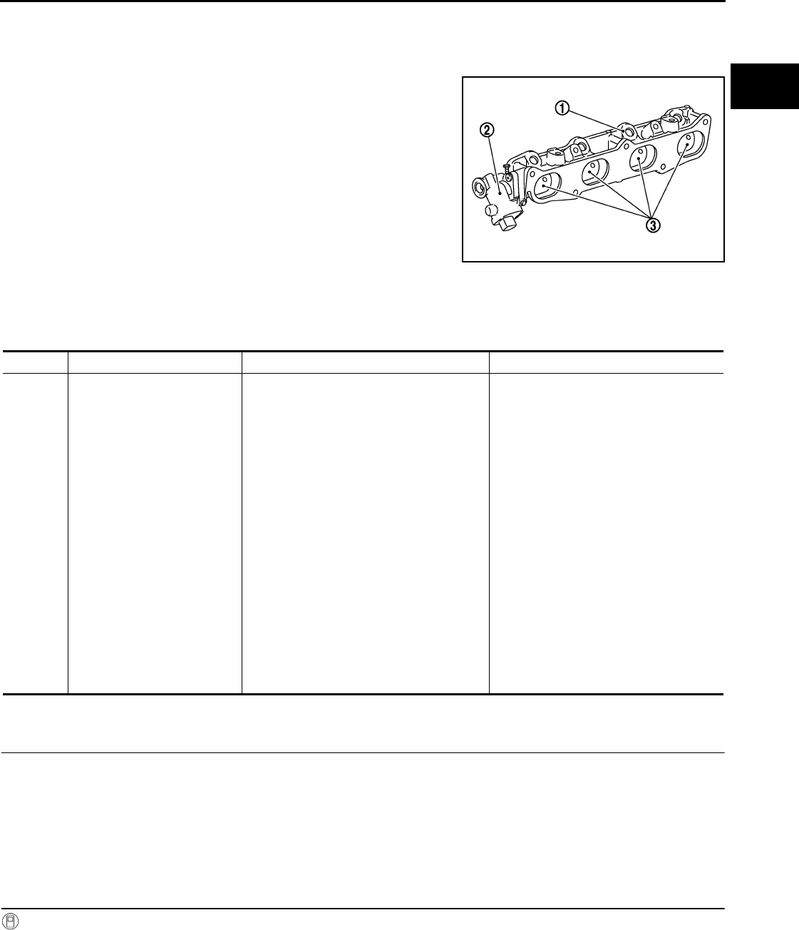
P2004 TUMBLE CONTROL VALVE
EC-367
< COMPONENT DIAGNOSIS > [FOR CALIFORNIA]
C
D
E
F
G
H
I
J
K
L
M
A
EC
N
P
O
P2004 TUMBLE CONTROL VALVE
Description INFOID:0000000004493588
Tumble control valve (3) is installed in the intake manifold adapter
(1).
Tumble control valve actuator (2) is connected to the front end of the
valve shaft.
Tumble control valve actuator consists of motor and position sensor,
etc.
The motor opens or closes the valve by the output signal of the
ECM.
The sensor consists of a permanent magnet and Hall IC. It senses
the valve shaft movement and feeds the voltage signals to the ECM.
DTC Logic INFOID:0000000004493589
DTC DETECTION LOGIC
DTC CONFIRMATION PROCEDURE
1.PRECONDITIONING
If DTC CONFIRMATION PROCEDURE has been previously conducted, always turn ignition switch OFF and
wait at least 10 seconds before conducting the next test.
TESTING CONDITION:
•Before performing the following procedure, confirm that battery voltage is more than 11V at idle.
•Always perform the test at a temperature above 0°C (32°F)
>> GO TO 2.
2.PERFORM DTC CONFIRMATION PROCEDURE
With CONSULT-III
1. Turn ignition switch ON.
2. Select “DATA MONITOR” mode with CONSULT-III.
3. Check that “COOLAN TEMP/S” indicates between 5°C (41°F) to 60°C (140°F).
If not, cool engine down or warm engine up until “COOLAN TEMP/S” indicates between 5°C (41°F) to
60°C (140°F). Then go to the following steps.
JMBIA0117ZZ
DTC No. Trouble diagnosis name DTC detecting condition Possible cause
P2004 Tumble control valve stuck
The target angle of tumble control valve con-
trolled by ECM and the input signal from
tumble control valve position sensor is not in
the normal range.
• Harness or connectors
(Tumble control valve motor circuit is
open or shorted.)
(Tumble control valve position sensor
circuit is open or shorted.)
(Accelerator pedal position sensor 2 cir-
cuit is shorted.)
[Crankshaft position sensor (POS) cir-
cuit is shorted.]
(EVAP control system pressure sensor
circuit is shorted.)
(Refrigerant pressure sensor circuit is
shorted.)
• Tumble control valve actuator
(Tumble control valve motor)
(Tumble control valve position sensor)
• Accelerator pedal position sensor
(APP sensor 2)
• Crankshaft position sensor (POS)
• EVAP control system pressure sensor
• Refrigerant pressure sensor
Revision: 2008 August 2009 Rogue
EC-368
< COMPONENT DIAGNOSIS > [FOR CALIFORNIA]
P2004 TUMBLE CONTROL VALVE
4. Fully release accelerator pedal and wait at least 5 seconds.
5. Depress accelerator pedal and wait at least 5 seconds.
6. Check 1st trip DTC.
With GST
Following the procedure “With CONSULT-III” above.
Is 1st trip DTC detected?
YES >> Go to EC-368, "Diagnosis Procedure".
NO >> INSPECTION END
Diagnosis Procedure INFOID:0000000004493590
1.CHECK GROUND CONNECTION
1. Turn ignition switch OFF.
2. Check ground connection E21. Refer to Ground Inspection in GI-44, "Circuit Inspection".
Is the inspection result normal?
YES >> GO TO 2.
NO >> Repair or replace ground connection.
2.CHECK TUMBLE CONTROL VALVE MOTOR POWER SUPPLY CIRCUIT-I
Check the voltage between ECM harness connector and ground.
Is the inspection result normal?
YES >> GO TO 5.
NO >> GO TO 3.
3.CHECK TUMBLE CONTROL VALVE MOTOR POWER SUPPLY CIRCUIT-II
1. Turn ignition switch OFF.
2. Disconnect ECM harness connector.
3. Disconnect IPDM E/R harness connector.
4. Check the continuity between IPDM E/R harness connector and ECM harness connector.
5. Also check harness for short to ground and short to power.
Is the inspection result normal?
YES >> Refer to EC-124, "Diagnosis Procedure".
NO >> GO TO 4.
4.DETECT MALFUNCTIOMNING PART
Check the following.
• Harness connectors E7, F121
• Harness for open or short between ECM and IPDM E/R
>> Repair open circuit or short to ground or short to power in harness or connectors.
5.CHECK TUMBLE CONTROL VALVE MOTOR OUTPUT SIGNAL CIRCUIT FOR OPEN AND SHORT
1. Disconnect tumble control valve actuator harness connector.
2. Disconnect ECM harness connector.
3. Check the continuity between tumble control valve actuator harness connector and ECM harness connec-
tor.
ECM Ground Condition Voltage
Connector Terminal
F7 7 Ground Ignition switch OFF Approx. 0V
Ignition switch ON Battery voltage
IPDM E/R ECM Continuity
Connector Terminal Connector Terminal
E15 47 F7 7 Existed
Revision: 2008 August 2009 Rogue

P2004 TUMBLE CONTROL VALVE
EC-369
< COMPONENT DIAGNOSIS > [FOR CALIFORNIA]
C
D
E
F
G
H
I
J
K
L
M
A
EC
N
P
O
4. Also check harness for short to ground and short to power.
Is the inspection result normal?
YES >> GO TO 6.
NO >> Repair open circuit or short to ground or short to power in harness or connectors.
6.CHECK TUMBLE CONTROL VALVE POSITION SENSOR POWER SUPPLY CIRCUIT-I
1. Reconnect ECM harness connector disconnected.
2. Turn ignition switch ON.
3. Check the voltage between tumble control valve actuator harness connector and ground.
Is the inspection result normal?
YES >> GO TO 12.
NO >> GO TO 7.
7.CHECK TUMBLE CONTROL VALVE POSITION SENSOR POWER SUPPLY CIRCUIT-II
1. Turn ignition switch OFF.
2. Disconnect ECM harness connector.
3. Check the continuity between tumble control valve actuator harness connector and ECM harness connec-
tor.
Is the inspection result normal?
YES >> GO TO 8.
NO >> Repair open circuit.
8.CHECK SENSOR POWER SUPPLY CIRCUIT
Check harness for short to power and short to ground, between the following terminals.
Is the inspection result normal?
YES >> GO TO 9.
NO >> Repair short to ground or short to power in harness or connectors.
Tumble control valve actuator ECM Continuity
Connector Terminal Connector Terminal
F41
4
F7
1 Not existed
3Existed
51Existed
3 Not existed
Tumble control valve actuator Ground Voltage
Connector Terminal
F41 1 Ground Approx. 5 V
Tumble control valve actuator ECM Continuity
Connector Terminal Connector Terminal
F41 1 F8 72 Existed
ECM Sensor
Connector Terminal Name Connector Terminal
F8 72 Tumble control valve actuator F41 1
Refrigerant pressure sensor E49 3
76 CKP sensor (POS) F20 1
E16 87 APP sensor E110 5
91 EVAP control system pressure sensor B47 3
Revision: 2008 August 2009 Rogue

EC-370
< COMPONENT DIAGNOSIS > [FOR CALIFORNIA]
P2004 TUMBLE CONTROL VALVE
9.CHECK COMPONENT
Check the following.
• Refrigerant pressure sensor (Refer to EC-437, "Diagnosis Procedure".)
• Crankshaft position sensor (POS) (Refer to EC-259, "Component Inspection".)
• EVAP control system pressure sensor (Refer to EC-296, "Component Inspection".)
Is the inspection result normal?
YES >> GO TO 10.
NO >> Replace malfunctioning components.
10.CHECK APP SENSOR
Refer to EC-399, "Component Inspection".
Is the inspection result normal?
YES >> GO TO 15.
NO >> GO TO 11.
11.REPLACE ACCELERATOR PEDAL ASSEMBLY
1. Replace accelerator pedal assembly. Refer to ACC-3, "Removal and Installation".
2. Refer to EC-399, "Special Repair Requirement".
>> INSPECTION END
12.CHECK TUMBLE CONTROL VALVE POSITION SENSOR GROUND CIRCUIT FOR OPEN AND SHORT
1. Turn ignition switch OFF.
2. Disconnect ECM harness connector.
3. Check the continuity between tumble control valve actuator harness connector and ECM harness connec-
tor.
4. Also check harness for short to ground and short to power.
Is the inspection result normal?
YES >> GO TO 13.
NO >> Repair open circuit or short to ground or short to power in harness or connectors.
13.CHECK TUMBLE CONTROL VALVE POSITION SENSOR INPUT SIGNAL CIRCUIT FOR OPEN AND
SHORT
1. Check the continuity between tumble control valve actuator harness connector and ECM harness connec-
tor.
2. Also check harness for short to ground and short to power.
Is the inspection result normal?
YES >> GO TO 14.
NO >> Repair open circuit or short to ground or short to power in harness or connectors.
14.CHECK TUMBLE CONTROL VALVE
Refer to EC-371, "Component Inspection".
Is the inspection result normal?
YES >> GO TO 15.
NO >> Replace intake manifold adapter.
Tumble control valve actuator ECM Continuity
Connector Terminal Connector Terminal
F41 2 F8 52 Existed
Tumble control valve actuator ECM Continuity
Connector Terminal Connector Terminal
F41 3 F8 54 Existed
Revision: 2008 August 2009 Rogue
P2004 TUMBLE CONTROL VALVE
EC-371
< COMPONENT DIAGNOSIS > [FOR CALIFORNIA]
C
D
E
F
G
H
I
J
K
L
M
A
EC
N
P
O
15.CHECK INTERMITTENT INCIDENT
Refer to GI-41, "Intermittent Incident".
Is the inspection result normal?
YES >> Replace intake manifold adapter.
NO >> Repair or replace harness or connectors.
Component Inspection INFOID:0000000004493591
1.CHECK TUMBLE CONTROL VALVE
With CONSULT-III
1. Turn ignition switch OFF.
2. Remove intake manifold adapter. Refer to EM-29, "Removal and Installation".
3. Visually check the valve for damage and check if foreign matter is caught between the valve and the
housing.
4. Connect tumble control valve actuator harness connector.
5. Turn ignition switch ON.
6. Perform “TUMBLE CONTROL VALVE” in “ACTIVE TEST” mode with CONSULT-III.
7. Touch “ON/OFF” and check that the valve opens and closes.
Without CONSULT-III
1. Turn ignition switch OFF.
2. Remove intake manifold adapter. Refer to EM-29, "Removal and Installation".
3. Visually check the valve for damage and check if foreign matter is caught between the valve and the
housing.
4. Supply tumble control valve actuator terminals with battery voltage within 2 seconds and check operation.
CAUTION:
Never apply 12V DC continuously for 30 seconds or more. Doing so may result in damage to the
coil in tumble control valve motor.
Is the inspection result normal?
YES >> INSPECTION END
NO >> Replace intake manifold adaptor.
Tumble control valve actuator
OperationTerminal
(+) (-)
45Open
54Close
Revision: 2008 August 2009 Rogue
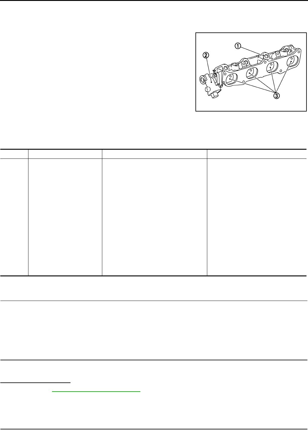
EC-372
< COMPONENT DIAGNOSIS > [FOR CALIFORNIA]
P2014 TUMBLE CONTROL VALVE POSITION SENSOR
P2014 TUMBLE CONTROL VALVE POSITION SENSOR
Description INFOID:0000000004493592
Tumble control valve position sensor is built into the tumble control
valve actuator (2).
• Intake manifold adapter (1)
• Tumble control valve (2)
The sensor consists of a permanent magnet and Hall IC. It senses
the valve shaft movement and feeds the voltage signals to the ECM.
DTC Logic INFOID:0000000004493593
DTC DETECTION LOGIC
DTC CONFIRMATION PROCEDURE
1.PRECONDITIONING
If DTC CONFIRMATION PROCEDURE has been previously conducted, always turn ignition switch OFF and
wait at least 10 seconds before conducting the next test.
TESTING CONDITION:
Before performing the following procedure, confirm that battery voltage is more than 11V at idle.
>> GO TO 2.
2.PERFORM DTC CONFIRMATION PROCEDURE
1. Start engine and let it idle for 5 seconds.
2. Check 1st trip DTC.
Is 1st trip DTC detected?
YES >> Go to EC-372, "Diagnosis Procedure".
NO >> INSPECTION END
Diagnosis Procedure INFOID:0000000004493594
1.CHECK GROUND CONNECTION
JMBIA0117ZZ
DTC No. Trouble diagnosis name DTC detecting condition Possible cause
P2014 Tumble control valve position
sensor circuit
An excessively low or high voltage from the
sensor is sent to ECM.
• Harness or connectors
(Tumble control valve position sensor
circuit is open or shorted.)
(Accelerator pedal position sensor 2 cir-
cuit is shorted.)
[Crankshaft position sensor (POS) cir-
cuit is shorted.]
(EVAP control system pressure sensor
circuit is shorted.)
(Refrigerant pressure sensor circuit is
shorted.)
• Tumble control valve actuator
(Tumble control valve position sensor)
• Accelerator pedal position sensor
(APP sensor 2)
• Crankshaft position sensor (POS)
• EVAP control system pressure sensor
• Refrigerant pressure sensor
Revision: 2008 August 2009 Rogue

P2014 TUMBLE CONTROL VALVE POSITION SENSOR
EC-373
< COMPONENT DIAGNOSIS > [FOR CALIFORNIA]
C
D
E
F
G
H
I
J
K
L
M
A
EC
N
P
O
1. Turn ignition switch OFF.
2. Check ground connection E21. Refer to Ground Inspection in GI-44, "Circuit Inspection".
Is the inspection result normal?
YES >> GO TO 2.
NO >> Repair or replace ground connection.
2.CHECK TUMBLE CONTROL VALVE POSITION SENSOR POWER SUPPLY CIRCUIT-I
1. Reconnect ECM harness connector disconnected.
2. Turn ignition switch ON.
3. Check the voltage between tumble control valve actuator harness connector and ground.
Is the inspection result normal?
YES >> GO TO 8.
NO >> GO TO 3.
3.CHECK TUMBLE CONTROL VALVE POSITION SENSOR POWER SUPPLY CIRCUIT-II
1. Turn ignition switch OFF.
2. Disconnect ECM harness connector.
3. Check the continuity between tumble control valve actuator harness connector and ECM harness connec-
tor.
Is the inspection result normal?
YES >> GO TO 4.
NO >> Repair open circuit.
4.CHECK SENSOR POWER SUPPLY CIRCUIT
Check harness for short to power and short to ground, between the following terminals.
Is the inspection result normal?
YES >> GO TO 5.
NO >> Repair short to ground or short to power in harness or connectors.
5.CHECK COMPONENT
Check the following.
• Refrigerant pressure sensor (Refer to EC-437, "Diagnosis Procedure".)
• Crankshaft position sensor (POS) (Refer to EC-259, "Component Inspection".)
• EVAP control system pressure sensor (Refer to EC-296, "Component Inspection".)
Is the inspection result normal?
YES >> GO TO 6.
NO >> Replace malfunctioning components.
Tumble control valve actuator Ground Voltage
Connector Terminal
F41 1 Ground Approx. 5 V
Tumble control valve actuator ECM Continuity
Connector Terminal Connector Terminal
F41 1 F8 72 Existed
ECM Sensor
Connector Terminal Name Connector Terminal
F8 72 Tumble control valve actuator F41 1
Refrigerant pressure sensor E49 3
76 CKP sensor (POS) F20 1
E16 87 APP sensor E110 5
91 EVAP control system pressure sensor B47 3
Revision: 2008 August 2009 Rogue

EC-374
< COMPONENT DIAGNOSIS > [FOR CALIFORNIA]
P2014 TUMBLE CONTROL VALVE POSITION SENSOR
6.CHECK APP SENSOR
Refer to EC-399, "Component Inspection".
Is the inspection result normal?
YES >> GO TO 10.
NO >> GO TO 7.
7.REPLACE ACCELERATOR PEDAL ASSEMBLY
1. Replace accelerator pedal assembly. Refer to ACC-3, "Removal and Installation".
2. Go to EC-399, "Special Repair Requirement".
>> INSPECTION END
8.CHECK TUMBLE CONTROL VALVE POSITION SENSOR GROUND CIRCUIT FOR OPEN AND SHORT
1. Turn ignition switch OFF.
2. Disconnect ECM harness connector.
3. Check the continuity between tumble control valve actuator harness connector and ECM harness connec-
tor.
4. Also check harness for short to ground and short to power.
Is the inspection result normal?
YES >> GO TO 9.
NO >> Repair open circuit or short to ground or short to power in harness or connectors.
9.CHECK TUMBLE CONTROL VALVE POSITION SENSOR INPUT SIGNAL CIRCUIT FOR OPEN AND
SHORT
1. Check the continuity between tumble control valve actuator harness connector and ECM harness connec-
tor.
2. Also check harness for short to ground and short to power.
Is the inspection result normal?
YES >> GO TO 10.
NO >> Repair open circuit or short to ground or short to power in harness or connectors.
10.CHECK INTERMITTENT INCIDENT
Refer to GI-41, "Intermittent Incident".
Is the inspection result normal?
YES >> Replace intake manifold adapter.
NO >> Repair or replace harness or connectors.
Tumble control valve actuator ECM Continuity
Connector Terminal Connector Terminal
F41 2 F8 52 Existed
Tumble control valve actuator ECM Continuity
Connector Terminal Connector Terminal
F41 3 F8 54 Existed
Revision: 2008 August 2009 Rogue

P2100, P2103 THROTTLE CONTROL MOTOR RELAY
EC-375
< COMPONENT DIAGNOSIS > [FOR CALIFORNIA]
C
D
E
F
G
H
I
J
K
L
M
A
EC
N
P
O
P2100, P2103 THROTTLE CONTROL MOTOR RELAY
Description INFOID:0000000004493595
Power supply for the throttle control motor is provided to the ECM via throttle control motor relay. The throttle
control motor relay is controlled ON/OFF by the ECM. When the ignition switch is turned ON, the ECM sends
an ON signal to throttle control motor relay and battery voltage is provided to the ECM. When the ignition
switch is turned OFF, the ECM sends an OFF signal to throttle control motor relay and battery voltage is not
provided to the ECM.
DTC Logic INFOID:0000000004493596
DTC DETECTION LOGIC
DTC CONFIRMATION PROCEDURE
1.PRECONDITIONING
If DTC CONFIRMATION PROCEDURE has been previously conducted, always turn ignition switch OFF and
wait at least 10 seconds before conducting the next test.
TESTING CONDITION:
Before performing the following procedure, confirm that battery voltage is more than 8V.
Witch DTC is detected?
P2100 >> GO TO 2.
P2103 >> GO TO 3.
2.PERFORM DTC CONFIRMATION PROCEDURE FOR DTC P2100
1. Turn ignition switch ON and wait at least 2 seconds.
2. Start engine and let it idle for 5 seconds.
3. Check DTC.
Is DTC detected?
YES >> Go to EC-375, "Diagnosis Procedure".
NO >> INSPECTION END
3.PERFORM DTC CONFIRMATION PROCEDURE FOR DTC P2103
1. Turn ignition switch ON and wait at least 1 second.
2. Check DTC.
Is DTC detected?
YES >> Go to EC-375, "Diagnosis Procedure".
NO >> INSPECTION END
Diagnosis Procedure INFOID:0000000004493597
1.CHECK THROTTLE CONTROL MOTOR RELAY POWER SUPPLY CIRCUIT
1. Turn ignition switch OFF.
2. Disconnect ECM harness connector.
3. Disconnect IPDM E/R harness connector.
4. Check the continuity between ECM harness connector and IPDM E/R harness connector.
DTC No. Trouble diagnosis name DTC detecting condition Possible cause
P2100 Throttle control motor
relay circuit open
ECM detects that the voltage of power source
for throttle control motor is excessively low.
• Harness or connectors
(Throttle control motor relay circuit is
open)
• Throttle control motor relay
P2103 Throttle control motor
relay circuit short
ECM detects that the throttle control motor relay
is stuck ON.
• Harness or connectors
(Throttle control motor relay circuit is
shorted)
• Throttle control motor relay
Revision: 2008 August 2009 Rogue

EC-376
< COMPONENT DIAGNOSIS > [FOR CALIFORNIA]
P2100, P2103 THROTTLE CONTROL MOTOR RELAY
5. Also check harness for short to ground and short to power.
Is the inspection result normal?
YES >> GO TO 3.
NO >> GO TO 2.
2.DETECT MALFUNCTION PART
Check the following.
• Harness connectors E7, F121
• Harness for open or short between ECM and IPDM E/R
>> Repair open circuit or short to ground or short to power in harness or connectors.
3.CHECK THROTTLE CONTROL MOTOR RELAY INPUT SIGNAL CIRCUIT
1. Check the continuity between ECM harness connector and IPDM E/R harness connector.
2. Also check harness for short to ground and short to power.
Is the inspection result normal?
YES >> GO TO 5.
NO >> GO TO 4.
4.DETECT MALFUNCTION PART
Check the following.
• Harness connectors E7, F121
• Harness for open or short between ECM and IPDM E/R
>> Repair open circuit or short to ground or short to power in harness or connectors.
5.CHECK FUSE
1. Disconnect 15A fuse (No. 61) from IPDM E/R.
2. Check it 15A fuse is blown.
Is the inspection result normal?
YES >> GO TO 6.
NO >> Replace 15A fuse.
6.CHECK INTERMITTENT INCIDENT
Refer to GI-41, "Intermittent Incident".
Is the inspection result normal?
YES >> Replace IPDM E/R.
NO >> Repair or replace harness or connectors.
ECM IPDM E/R Continuity
Connector Terminal Connector Terminal
F7 15 E13 32 Existed
ECM IPDM E/R Continuity
Connector Terminal Connector Terminal
F7 2 E15 52 Existed
Revision: 2008 August 2009 Rogue

P2101 ELECTRIC THROTTLE CONTROL FUNCTION
EC-377
< COMPONENT DIAGNOSIS > [FOR CALIFORNIA]
C
D
E
F
G
H
I
J
K
L
M
A
EC
N
P
O
P2101 ELECTRIC THROTTLE CONTROL FUNCTION
Description INFOID:0000000004493598
Electric throttle control actuator consists of throttle control motor, throttle position sensor, etc.
The throttle control motor is operated by the ECM and it opens and closes the throttle valve.
The current opening angle of the throttle valve is detected by the throttle position sensor. The throttle position
sensor provides feedback to the ECM, when opens/closes the throttle valve in response to driving conditions
via the throttle control motor.
DTC Logic INFOID:0000000004493599
DTC DETECTION LOGIC
NOTE:
If DTC P2101 is displayed with DTC P2100 or P2119, first perform the trouble diagnosis for DTC P2100
or P2119. Refer to EC-375, "DTC Logic" or EC-383, "DTC Logic".
DTC CONFIRMATION PROCEDURE
1.PRECONDITIONING
If DTC CONFIRMATION PROCEDURE has been previously conducted, always turn ignition switch OFF and
wait at least 10 seconds before conducting the next test.
TESTING CONDITION:
Before performing the following procedure, confirm that battery voltage is more than 11V when engine
is running.
>> GO TO 2.
2.PERFORM DTC CONFIRMATION PROCEDURE
1. Turn ignition switch ON and wait at least 2 seconds.
2. Start engine and let it idle for 5 seconds.
3. Check DTC.
Is DTC detected?
YES >> Go to EC-377, "Diagnosis Procedure".
NO >> INSPECTION END
Diagnosis Procedure INFOID:0000000004493600
1.CHECK GROUND CONNECTION
1. Turn ignition switch OFF.
2. Check ground connection E21. Refer to Ground Inspection in GI-44, "Circuit Inspection".
Is the inspection result normal?
YES >> GO TO 2.
NO >> Repair or replace ground connection.
2.CHECK THROTTLE CONTROL MOTOR RELAY INPUT SIGNAL CIRCUIT-I
1. Check the voltage between ECM harness connector and ground.
DTC No. Trouble diagnosis name DTC detecting condition Possible cause
P2101 Electric throttle control
performance
Electric throttle control function does not oper-
ate properly.
• Harness or connectors
(Throttle control motor circuit is open or
shorted)
• Electric throttle control actuator
Revision: 2008 August 2009 Rogue

EC-378
< COMPONENT DIAGNOSIS > [FOR CALIFORNIA]
P2101 ELECTRIC THROTTLE CONTROL FUNCTION
Is the inspection result normal?
YES >> GO TO 9.
NO >> GO TO 3.
3.CHECK THROTTLE CONTROL MOTOR RELAY POWER SUPPLY CIRCUIT
1. Disconnect ECM harness connector.
2. Disconnect IPDM E/R harness connector.
3. Check the continuity between ECM harness connector and IPDM E/R harness connector.
4. Also check harness for short to ground and short to power.
Is the inspection result normal?
YES >> GO TO 5.
NO >> GO TO 4.
4.DETECT MALFUNCTION PART
Check the following.
• Harness connectors E7, F121
• Harness for open or short between ECM and IPDM E/R
>> Repair open circuit or short to ground or short to power in harness or connectors.
5.CHECK THROTTLE CONTROL MOTOR RELAY INPUT SIGNAL CIRCUIT-II
1. Check the continuity between ECM harness connector and IPDM E/R harness connector.
2. Also check harness for short to ground and short to power.
Is the inspection result normal?
YES >> GO TO 7.
NO >> GO TO 6.
6.DETECT MALFUNCTION PART
Check the following.
• Harness connectors E7, F121
• Harness for open or short between ECM and IPDM E/R
>> Repair open circuit or short to ground or short to power in harness or connectors.
7.CHECK FUSE
1. Disconnect 15A fuse (No. 61) from IPDM E/R.
2. Check it 15A fuse is blown.
Is the inspection result normal?
YES >> GO TO 8.
NO >> Replace 15A fuse.
ECM Ground Condition Voltage
Connector Terminal
F7 2 Ground Ignition switch OFF Approx. 0V
Ignition switch ON Battery voltage
IPDM E/R ECM Continuity
Connector Terminal Connector Terminal
E13 32 F7 15 Existed
IPDM E/R ECM Continuity
Connector Terminal Connector Terminal
E15 52 F7 2 Existed
Revision: 2008 August 2009 Rogue

P2101 ELECTRIC THROTTLE CONTROL FUNCTION
EC-379
< COMPONENT DIAGNOSIS > [FOR CALIFORNIA]
C
D
E
F
G
H
I
J
K
L
M
A
EC
N
P
O
8.CHECK INTERMITTENT INCIDENT
Refer to GI-41, "Intermittent Incident".
Is the inspection result normal?
YES >> Replace IPDM E/R.
NO >> Repair or replace harness or connectors.
9.CHECK THROTTLE CONTROL MOTOR OUTPUT SIGNAL CIRCUIT FOR OPEN OR SHORT
1. Turn ignition switch OFF.
2. Disconnect electric throttle control actuator harness connector.
3. Disconnect ECM harness connector.
4. Check the continuity between electric throttle control actuator harness connector and ECM harness con-
nector.
5. Also check harness for short to ground and short to power.
Is the inspection result normal?
YES >> GO TO 10.
NO >> Repair or replace.
10.CHECK ELECTRIC THROTTLE CONTROL ACTUATOR VISUALLY
1. Remove the intake air duct.
2. Check if foreign matter is caught between the throttle valve (1)
and the housing.
- : Vehicle front
- Electric throttle control actuator (2)
Is the inspection result normal?
YES >> GO TO 11.
NO >> Remove the foreign matter and clean the electric throttle
control actuator inside.
11.CHECK THROTTLE CONTROL MOTOR
Refer to EC-380, "Component Inspection".
Is the inspection result normal?
YES >> GO TO 12.
NO >> GO TO 13.
12.CHECK INTERMITTENT INCIDENT
Refer to GI-41, "Intermittent Incident".
Is the inspection result normal?
YES >> GO TO 13.
NO >> Repair or replace harness or connectors.
13.REPLACE ELECTRIC THROTTLE CONTROL ACTUATOR
1. Replace malfunction electric throttle control actuator.
2. Go to EC-380, "Special Repair Requirement".
>> INSPECTION END
Electric throttle control actuator ECM Continuity
Connector Terminal Connector Terminal
F29
5
F7
5 Not existed
6 Existed
65 Existed
6 Not existed
ALBIA0061ZZ
Revision: 2008 August 2009 Rogue

EC-380
< COMPONENT DIAGNOSIS > [FOR CALIFORNIA]
P2101 ELECTRIC THROTTLE CONTROL FUNCTION
Component Inspection INFOID:0000000004493601
1.CHECK THROTTLE CONTROL MOTOR
1. Disconnect electric throttle control actuator harness connector.
2. Check resistance between electric throttle control actuator terminals as follows.
Is the inspection result normal?
YES >> INSPECTION END
NO >> GO TO 2.
2.REPLACE ELECTRIC THROTTLE CONTROL ACTUATOR
1. Replace electric throttle control actuator.
2. Go to EC-380, "Special Repair Requirement".
>> INSPECTION END
Special Repair Requirement INFOID:0000000004493602
1.PERFORM THROTTLE VALVE CLOSED POSITION LEARNING
Refer to EC-27, "THROTTLE VALVE CLOSED POSITION LEARNING : Special Repair Requirement"
>> GO TO 2.
2.PERFORM IDLE AIR VOLUME LEARNING
Refer to EC-27, "IDLE AIR VOLUME LEARNING : Special Repair Requirement"
>> END
Terminals Resistance
5 and 6 Approx. 1 - 15 Ω [at 25 °C (77°F)]
Revision: 2008 August 2009 Rogue

P2118 THROTTLE CONTROL MOTOR
EC-381
< COMPONENT DIAGNOSIS > [FOR CALIFORNIA]
C
D
E
F
G
H
I
J
K
L
M
A
EC
N
P
O
P2118 THROTTLE CONTROL MOTOR
Description INFOID:0000000004493603
The throttle control motor is operated by the ECM and it opens and closes the throttle valve.
The current opening angle of the throttle valve is detected by the throttle position sensor. The throttle position
sensor provides feedback to the ECM, when opens/closes the throttle valve in response to driving conditions
via the throttle control motor.
DTC Logic INFOID:0000000004493604
DTC DETECTION LOGIC
DTC CONFIRMATION PROCEDURE
1.PRECONDITIONING
If DTC CONFIRMATION PROCEDURE has been previously conducted, always turn ignition switch OFF and
wait at least 10 seconds before conducting the next test.
>> GO TO 2.
2.PERFORM DTC CONFIRMATION PROCEDURE
1. Turn ignition switch ON and wait at least 2 seconds.
2. Start engine and let it idle for 5 seconds.
3. Check DTC.
Is DTC detected?
YES >> Go to EC-381, "Diagnosis Procedure".
NO >> INSPECTION END
Diagnosis Procedure INFOID:0000000004493605
1.CHECK GROUND CONNECTION
1. Turn ignition switch OFF.
2. Check ground connection E21. Refer to Ground Inspection in GI-44, "Circuit Inspection".
Is the inspection result normal?
YES >> GO TO 2.
NO >> Repair or replace ground connection.
2.CHECK THROTTLE CONTROL MOTOR OUTPUT SIGNAL CIRCUIT FOR OPEN AND SHORT
1. Disconnect electric throttle control actuator harness connector.
2. Disconnect ECM harness connector.
3. Check the continuity between electric throttle control actuator harness connector and ECM harness con-
nector.
DTC No. Trouble diagnosis name DTC detecting condition Possible cause
P2118 Throttle control motor
circuit short ECM detects short in both circuits between
ECM and throttle control motor.
• Harness or connectors
(Throttle control motor circuit is shorted.)
• Electric throttle control actuator
(Throttle control motor)
Electric throttle control actuator ECM Continuity
Connector Terminal Connector Terminal
F29
5
F7
5 Not existed
6 Existed
65 Existed
6 Not existed
Revision: 2008 August 2009 Rogue

EC-382
< COMPONENT DIAGNOSIS > [FOR CALIFORNIA]
P2118 THROTTLE CONTROL MOTOR
4. Also check harness for short to ground and short to power.
Is the inspection result normal?
YES >> GO TO 3.
NO >> Repair or replace.
3.CHECK THROTTLE CONTROL MOTOR
Refer to EC-382, "Component Inspection".
Is the inspection result normal?
YES >> GO TO 4.
NO >> GO TO 5.
4.CHECK INTERMITTENT INCIDENT
Refer to GI-41, "Intermittent Incident".
Is the inspection result normal?
YES >> GO TO 5.
NO >> Repair or replace harness or connectors.
5.REPLACE ELECTRIC THROTTLE CONTROL ACTUATOR
1. Replace electric throttle control actuator.
2. Go to EC-382, "Special Repair Requirement".
>> INSPECTION END
Component Inspection INFOID:0000000004493606
1.CHECK THROTTLE CONTROL MOTOR
1. Disconnect electric throttle control actuator harness connector.
2. Check resistance between electric throttle control actuator terminals as follows.
Is the inspection result normal?
YES >> INSPECTION END
NO >> GO TO 2.
2.REPLACE ELECTRIC THROTTLE CONTROL ACTUATOR
1. Replace electric throttle control actuator.
2. Go to EC-382, "Special Repair Requirement".
>> INSPECTION END
Special Repair Requirement INFOID:0000000004493607
1.PERFORM THROTTLE VALVE CLOSED POSITION LEARNING
Refer to EC-27, "THROTTLE VALVE CLOSED POSITION LEARNING : Special Repair Requirement"
>> GO TO 2.
2.PERFORM IDLE AIR VOLUME LEARNING
Refer to EC-27, "IDLE AIR VOLUME LEARNING : Special Repair Requirement"
>> END
Terminals Resistance
5 and 6 Approx. 1 - 15 Ω [at 25 °C (77°F)]
Revision: 2008 August 2009 Rogue

P2119 ELECTRIC THROTTLE CONTROL ACTUATOR
EC-383
< COMPONENT DIAGNOSIS > [FOR CALIFORNIA]
C
D
E
F
G
H
I
J
K
L
M
A
EC
N
P
O
P2119 ELECTRIC THROTTLE CONTROL ACTUATOR
Description INFOID:0000000004493608
Electric throttle control actuator consists of throttle control motor, throttle position sensor, etc.
The throttle control motor is operated by the ECM and it opens and closes the throttle valve.
The throttle position sensor detects the throttle valve position, and sends the voltage signals to the ECM. The
ECM judges the current opening angle of the throttle valve from these signals and opens/closes the throttle
valve in response to driving conditions via the throttle control motor.
DTC Logic INFOID:0000000004493609
DTC DETECTION LOGIC
DTC CONFIRMATION PROCEDURE
1.PRECONDITIONING
If DTC CONFIRMATION PROCEDURE has been previously conducted, always turn ignition switch OFF and
wait at least 10 seconds before conducting the next test.
>> GO TO 2.
2.PERFORM DTC CONFIRMATION PROCEDURE FOR MALFUNCTION A AND B
1. Turn ignition switch ON and wait at least 1 second.
2. Set selector lever to D position and wait at least 3 seconds.
3. Set selector lever to P position.
4. Turn ignition switch OFF and wait at least 10 seconds.
5. Turn ignition switch ON and wait at least 1 second.
6. Set selector lever to D position and wait at least 3 seconds.
7. Set selector lever to P position.
8. Turn ignition switch OFF, wait at least 10 seconds, and then turn ON.
9. Check DTC.
Is DTC detected?
YES >> Go to EC-383, "Diagnosis Procedure".
NO >> GO TO 3.
3.PERFORM DTC CONFIRMATION PROCEDURE FOR MALFUNCTION C
1. Turn ignition switch ON and wait at least 1 second.
2. Set selector lever to D position and wait at least 3 seconds.
3. Set selector to N or P position.
4. Start engine and let it idle for 3 seconds.
5. Check DTC.
Is DTC detected?
YES >> Go to EC-383, "Diagnosis Procedure".
NO >> INSPECTION END
Diagnosis Procedure INFOID:0000000004529918
1.CHECK ELECTRIC THROTTLE CONTROL ACTUATOR VISUALLY
1. Turn ignition switch OFF.
2. Remove the intake air duct.
DTC No. Trouble diagnosis name DTC detecting condition Possible cause
P2119 Electric throttle control
actuator
A) Electric throttle control actuator does not function
properly due to the return spring malfunction.
• Electric throttle control actuator
B) Throttle valve opening angle in fail-safe mode is
not in specified range.
C) ECM detects that the throttle valve is stuck open.
Revision: 2008 August 2009 Rogue

EC-384
< COMPONENT DIAGNOSIS > [FOR CALIFORNIA]
P2119 ELECTRIC THROTTLE CONTROL ACTUATOR
3. Check if foreign matter is caught between the throttle valve (1)
and the housing.
Is the inspection result normal?
YES >> GO TO 2.
NO >> Remove the foreign matter and clean the electric throttle
control actuator inside.
2.REPLACE ELECTRIC THROTTLE CONTROL ACTUATOR
1. Replace electric throttle control actuator.
2. Go to EC-348, "Special Repair Requirement".
>> INSPECTION END
Special Repair Requirement INFOID:0000000004493611
1.PERFORM THROTTLE VALVE CLOSED POSITION LEARNING
Refer to EC-27, "THROTTLE VALVE CLOSED POSITION LEARNING : Special Repair Requirement"
>> GO TO 2.
2.PERFORM IDLE AIR VOLUME LEARNING
Refer to EC-27, "IDLE AIR VOLUME LEARNING : Special Repair Requirement"
>> END
2. Electric throttle control actuator
: Vehicle front
ALBIA0061ZZ
Revision: 2008 August 2009 Rogue

P2122, P2123 APP SENSOR
EC-385
< COMPONENT DIAGNOSIS > [FOR CALIFORNIA]
C
D
E
F
G
H
I
J
K
L
M
A
EC
N
P
O
P2122, P2123 APP SENSOR
Description INFOID:0000000004493612
The accelerator pedal position sensor is installed on the upper end
of the accelerator pedal assembly. The sensor detects the accelera-
tor position and sends a signal to the ECM.
Accelerator pedal position sensor has two sensors. These sensors
are a kind of potentiometer which transform the accelerator pedal
position into output voltage, and emit the voltage signals to the ECM.
The ECM judges the current opening angle of the accelerator pedal
from these signals and controls the throttle control motor based on
these signals.
Idle position of the accelerator pedal is determined by the ECM
receiving the signal from the accelerator pedal position sensor. The
ECM uses this signal for engine operations such as fuel cut.
DTC Logic INFOID:0000000004493613
DTC DETECTION LOGIC
NOTE:
If DTC P2122 or P2123 is displayed with DTC P0643, first perform the trouble diagnosis for DTC P0643.
Refer to EC-336, "DTC Logic".
DTC CONFIRMATION PROCEDURE
1.PRECONDITIONING
If DTC CONFIRMATION PROCEDURE has been previously conducted, always turn ignition switch OFF and
wait at least 10 seconds before conducting the next test.
TESTING CONDITION:
Before performing the following procedure, confirm that battery voltage is more than 8V at idle.
>> GO TO 2.
2.PERFORM DTC CONFIRMATION PROCEDURE
1. Start engine and let it idle for 1 second.
2. Check DTC.
Is DTC detected?
YES >> Go to EC-385, "Diagnosis Procedure".
NO >> INSPECTION END
Diagnosis Procedure INFOID:0000000004493614
1.CHECK GROUND CONNECTION
1. Turn ignition switch OFF.
2. Check ground connection E21. Refer to Ground Inspection in GI-44, "Circuit Inspection".
Is the inspection result normal?
YES >> GO TO 2.
NO >> Repair or replace ground connection.
2.CHECK APP SENSOR 1 POWER SUPPLY CIRCUIT
1. Disconnect accelerator pedal position (APP) sensor harness connector.
PBIB1741E
DTC No. Trouble diagnosis name DTC detecting condition Possible cause
P2122 Accelerator pedal position
sensor 1 circuit low input
An excessively low voltage from the APP
sensor 1 is sent to ECM. • Harness or connectors
(APP sensor 1 circuit is open or shorted.)
• Accelerator pedal position sensor
(APP sensor 1)
P2123 Accelerator pedal position
sensor 1 circuit high input
An excessively high voltage from the APP
sensor 1 is sent to ECM.
Revision: 2008 August 2009 Rogue

EC-386
< COMPONENT DIAGNOSIS > [FOR CALIFORNIA]
P2122, P2123 APP SENSOR
2. Turn ignition switch ON.
3. Check the voltage between APP sensor harness connector and ground.
Is the inspection result normal?
YES >> GO TO 3.
NO >> Repair open circuit or short to ground or short to power in harness or connectors.
3.CHECK APP SENSOR 1 GROUND CIRCUIT FOR OPEN AND SHORT
1. Turn ignition switch OFF.
2. Disconnect ECM harness connector.
3. Check the continuity between APP sensor harness connector and ECM harness connector.
4. Also check harness for short to ground and short to power.
Is the inspection result normal?
YES >> GO TO 4.
NO >> Repair open circuit or short to ground or short to power in harness or connectors.
4.CHECK APP SENSOR INPUT SIGNAL CIRCUIT FOR OPEN AND SHORT
1. Check the continuity between APP sensor harness connector and ECM harness connector.
2. Also check harness for short to ground and short to power.
Is the inspection result normal?
YES >> GO TO 5.
NO >> Repair open circuit or short to ground or short to power in harness or connectors.
5.CHECK APP SENSOR
Refer to EC-387, "Component Inspection".
Is the inspection result normal?
YES >> GO TO 7.
NO >> GO TO 6.
6.REPLACE ACCELERATOR PEDAL ASSEMBLY
1. Replace accelerator pedal assembly.
2. Go to EC-387, "Special Repair Requirement".
>> INSPECTION END
7.CHECK INTERMITTENT INCIDENT
Refer to GI-41, "Intermittent Incident".
>> INSPECTION END
APP sensor Ground Voltage
Connector Terminal
E110 4 Ground Approx. 5 V
APP sensor ECM Continuity
Connector Terminal Connector Terminal
E110 2 E16 84 Existed
APP sensor ECM Continuity
Connector Terminal Connector Terminal
E110 3 E16 81 Existed
Revision: 2008 August 2009 Rogue
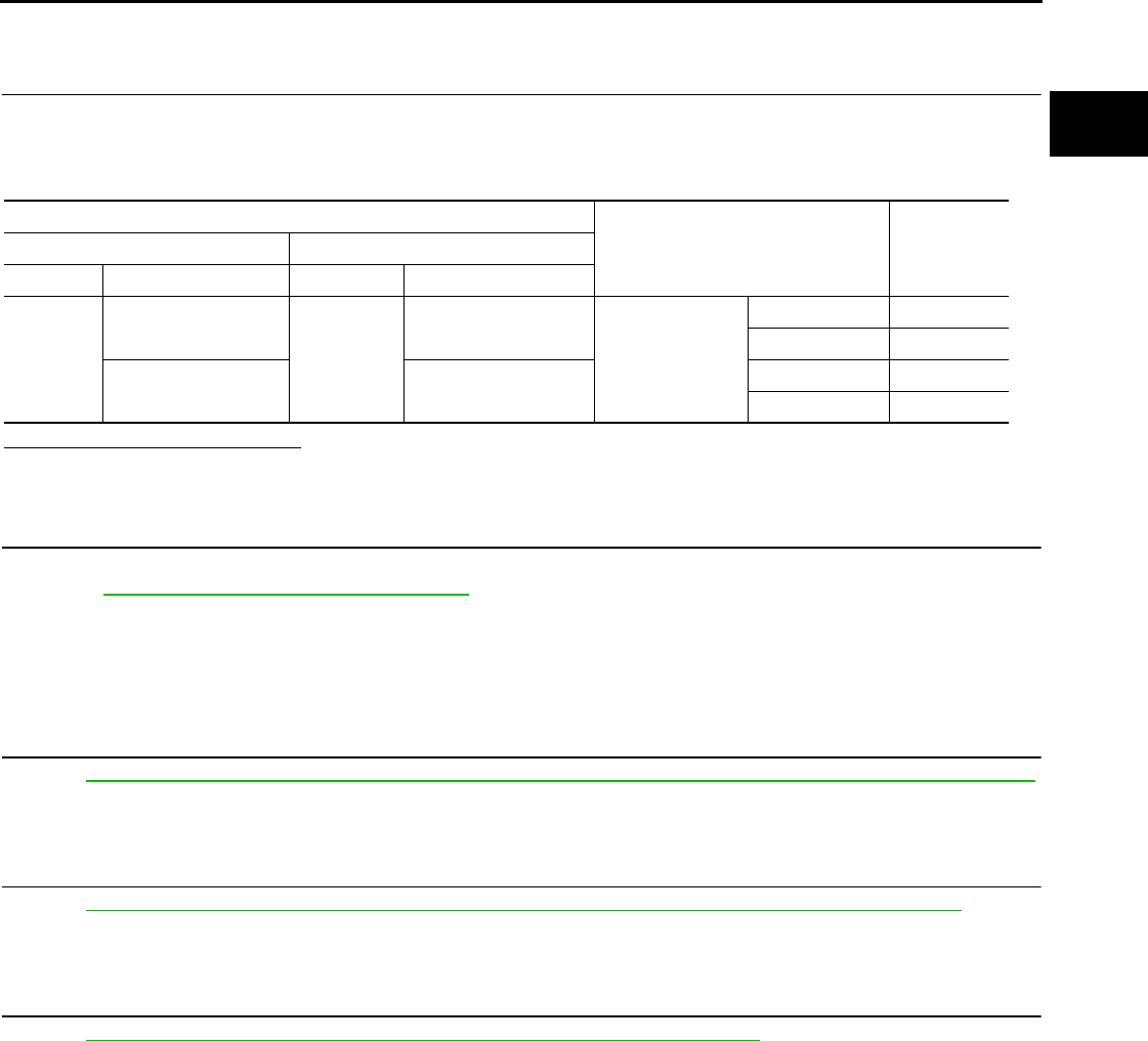
P2122, P2123 APP SENSOR
EC-387
< COMPONENT DIAGNOSIS > [FOR CALIFORNIA]
C
D
E
F
G
H
I
J
K
L
M
A
EC
N
P
O
Component Inspection INFOID:0000000004493615
1.CHECK ACCELERATOR PEDAL POSITION SENSOR
1. Reconnect all harness connectors disconnected.
2. Turn ignition switch ON.
3. Check the voltage between ECM harness connector terminals.
Is the inspection result normal?
YES >> INSPECTION END
NO >> GO TO 2.
2.REPLACE ACCELERATOR PEDAL ASSEMBLY
1. Replace accelerator pedal assembly.
2. Go to EC-387, "Special Repair Requirement".
>> INSPECTION END
Special Repair Requirement INFOID:0000000004493616
1.PERFORM ACCELERATOR PEDAL RELEASED POSITION LEARNING
Refer to EC-27, "ACCELERATOR PEDAL RELEASED POSITION LEARNING : Special Repair Requirement".
>> GO TO 2.
2.PERFORM THROTTLE VALVE CLOSED POSITION LEARNING
Refer to EC-27, "THROTTLE VALVE CLOSED POSITION LEARNING : Special Repair Requirement".
>> GO TO 3.
3.PERFORM IDLE AIR VOLUME LEARNING
Refer to EC-27, "IDLE AIR VOLUME LEARNING : Special Repair Requirement".
>> END
ECM
Condition Voltage+−
Connector Terminal Connector Terminal
E16
81
(APP sensor 1 signal) E16
84
(Sensor ground) Accelerator pedal
Fully released 0.6 - 0.9 V
Fully depressed 3.9 - 4.7 V
82
(APP sensor 2 signal)
100
(Sensor ground)
Fully released 0.3 - 0.6 V
Fully depressed 1.95 - 2.4 V
Revision: 2008 August 2009 Rogue
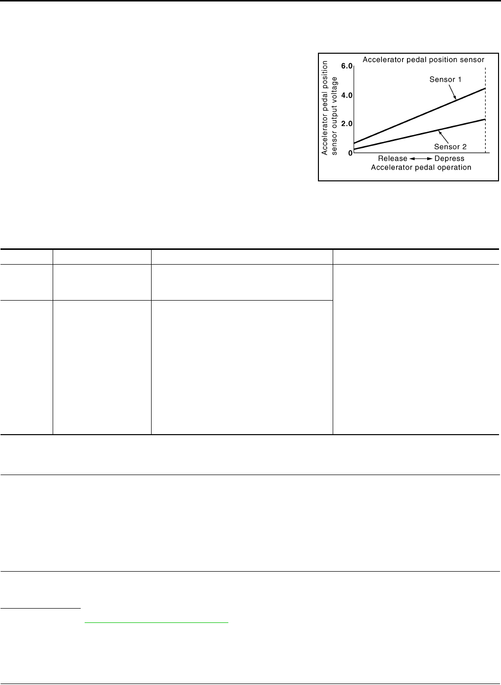
EC-388
< COMPONENT DIAGNOSIS > [FOR CALIFORNIA]
P2127, P2128 APP SENSOR
P2127, P2128 APP SENSOR
Description INFOID:0000000004493617
The accelerator pedal position sensor is installed on the upper end
of the accelerator pedal assembly. The sensor detects the accelera-
tor position and sends a signal to the ECM.
Accelerator pedal position sensor has two sensors. These sensors
are a kind of potentiometer which transform the accelerator pedal
position into output voltage, and emit the voltage signals to the ECM.
The ECM judges the current opening angle of the accelerator pedal
from these signals and controls the throttle control motor based on
these signals.
Idle position of the accelerator pedal is determined by the ECM
receiving the signal from the accelerator pedal position sensor. The
ECM uses this signal for engine operations such as fuel cut.
DTC Logic INFOID:0000000004493618
DTC DETECTION LOGIC
DTC CONFIRMATION PROCEDURE
1.PRECONDITIONING
If DTC CONFIRMATION PROCEDURE has been previously conducted, always turn ignition switch OFF and
wait at least 10 seconds before conducting the next test.
TESTING CONDITION:
Before performing the following procedure, confirm that battery voltage is more than 8V at idle.
>> GO TO 2.
2.PERFORM DTC CONFIRMATION PROCEDURE
1. Start engine and let it idle for 1 second.
2. Check DTC.
Is DTC detected?
YES >> Go to EC-388, "Diagnosis Procedure".
NO >> INSPECTION END
Diagnosis Procedure INFOID:0000000004493619
1.CHECK GROUND CONNECTION
1. Turn ignition switch OFF.
PBIB1741E
DTC No. Trouble diagnosis name DTC detecting condition Possible cause
P2127
Accelerator pedal posi-
tion sensor 2 circuit low
input
An excessively low voltage from the APP sen-
sor 2 is sent to ECM.
• Harness or connectors
(APP sensor 2 circuit is open or shorted.)
[Crankshaft position sensor (POS) circuit
is shorted.]
(Refrigerant pressure sensor circuit is
shorted.)
(EVAP control system pressure sensor
circuit is shorted.)
(Tumble control valve position sensor cir-
cuit is shorted.)
• Accelerator pedal position sensor
(APP sensor 2)
• Crankshaft position sensor (POS)
• Refrigerant pressure sensor
• EVAP control system pressure sensor
• Tumble control valve position sensor
P2128
Accelerator pedal posi-
tion sensor 2 circuit high
input
An excessively high voltage from the APP sen-
sor 2 is sent to ECM.
Revision: 2008 August 2009 Rogue

P2127, P2128 APP SENSOR
EC-389
< COMPONENT DIAGNOSIS > [FOR CALIFORNIA]
C
D
E
F
G
H
I
J
K
L
M
A
EC
N
P
O
2. Check ground connection E21. Refer to Ground Inspection in GI-44, "Circuit Inspection".
Is the inspection result normal?
YES >> GO TO 2.
NO >> Repair or replace ground connection.
2.CHECK APP SENSOR 2 POWER SUPPLY CIRCUIT-I
1. Disconnect accelerator pedal position (APP) sensor harness connector.
2. Turn ignition switch ON.
3. Check the voltage between APP sensor harness connector and ground.
Is the inspection result normal?
YES >> GO TO 6.
NO >> GO TO 3.
3.CHECK APP SENSOR 2 POWER SUPPLY CIRCUIT-II
1. Turn ignition switch OFF.
2. Disconnect ECM harness connector.
3. Check the continuity between APP sensor harness connector and ECM harness connector.
Is the inspection result normal?
YES >> GO TO 4.
NO >> Repair open circuit.
4.CHECK SENSOR POWER SUPPLY CIRCUIT
Check harness for short to power and short to ground, between the following terminals.
Is the inspection result normal?
YES >> GO TO 5.
NO >> Repair short to ground or short to power in harness or connectors.
5.CHECK COMPONENT
Check the following.
• Crankshaft position sensor (POS) (Refer to EC-259, "Component Inspection".)
• EVAP control system pressure sensor (Refer to EC-296, "Component Inspection".)
• Refrigerant pressure sensor (Refer to EC-437, "Diagnosis Procedure".)
• Tumble control valve position sensor (Refer to EC-368, "Diagnosis Procedure".)
Is the inspection result normal?
YES >> GO TO 10.
NO >> Replace malfunctioning component.
APP sensor Ground Voltage
Connector Terminal
E110 5 Ground Approx. 5 V
APP sensor ECM Continuity
Connector Terminal Connector Terminal
E110 5 E16 87 Existed
ECM Sensor
Connector Terminal Name Connector Terminal
F8 72 Tumble control valve position sensor F41 1
Refrigerant pressure sensor E49 3
76 CKP sensor (POS) F20 1
E16 87 APP sensor E110 5
91 EVAP control system pressure sensor B47 3
Revision: 2008 August 2009 Rogue

EC-390
< COMPONENT DIAGNOSIS > [FOR CALIFORNIA]
P2127, P2128 APP SENSOR
6.CHECK APP SENSOR 2 GROUND CIRCUIT FOR OPEN AND SHORT
1. Turn ignition switch OFF.
2. Disconnect ECM harness connector.
3. Check the continuity between APP sensor harness connector and ECM harness connector.
4. Also check harness for short to ground and short to power.
Is the inspection result normal?
YES >> GO TO 7.
NO >> Repair open circuit or short to ground or short to power in harness or connectors.
7.CHECK APP SENSOR 2 INPUT SIGNAL CIRCUIT FOR OPEN AND SHORT
1. Check the continuity between APP sensor harness connector and ECM harness connector.
2. Also check harness for short to ground and short to power.
Is the inspection result normal?
YES >> GO TO 8.
NO >> Repair open circuit or short to ground or short to power in harness or connectors.
8.CHECK APP SENSOR
Refer to EC-399, "Component Inspection".
Is the inspection result normal?
YES >> GO TO 10.
NO >> GO TO 9.
9.REPLACE ACCELERATOR PEDAL ASSEMBLY
1. Replace accelerator pedal assembly. Refer to ACC-3, "Removal and Installation".
2. Go to EC-399, "Special Repair Requirement".
>> INSPECTION END
10.CHECK INTERMITTENT INCIDENT
Refer to GI-41, "Intermittent Incident".
>> INSPECTION END
Component Inspection INFOID:0000000004493620
1.CHECK ACCELERATOR PEDAL POSITION SENSOR
1. Reconnect all harness connectors disconnected.
2. Turn ignition switch ON.
3. Check the voltage between ECM harness connector terminals.
APP sensor ECM Continuity
Connector Terminal Connector Terminal
E110 1 E16 100 Existed
APP sensor ECM Continuity
Connector Terminal Connector Terminal
E110 6 E16 82 Existed
Revision: 2008 August 2009 Rogue
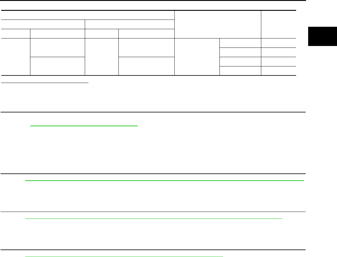
P2127, P2128 APP SENSOR
EC-391
< COMPONENT DIAGNOSIS > [FOR CALIFORNIA]
C
D
E
F
G
H
I
J
K
L
M
A
EC
N
P
O
Is the inspection result normal?
YES >> INSPECTION END
NO >> GO TO 2.
2.REPLACE ACCELERATOR PEDAL ASSEMBLY
1. Replace accelerator pedal assembly.
2. Go to EC-391, "Special Repair Requirement".
>> INSPECTION END
Special Repair Requirement INFOID:0000000004493621
1.PERFORM ACCELERATOR PEDAL RELEASED POSITION LEARNING
Refer to EC-27, "ACCELERATOR PEDAL RELEASED POSITION LEARNING : Special Repair Requirement".
>> GO TO 2.
2.PERFORM THROTTLE VALVE CLOSED POSITION LEARNING
Refer to EC-27, "THROTTLE VALVE CLOSED POSITION LEARNING : Special Repair Requirement".
>> GO TO 3.
3.PERFORM IDLE AIR VOLUME LEARNING
Refer to EC-27, "IDLE AIR VOLUME LEARNING : Special Repair Requirement".
>> END
ECM
Condition Voltage+−
Connector Terminal Connector Terminal
E16
81
(APP sensor 1 signal) E16
84
(Sensor ground) Accelerator pedal
Fully released 0.6 - 0.9 V
Fully depressed 3.9 - 4.7 V
82
(APP sensor 2 signal)
100
(Sensor ground)
Fully released 0.3 - 0.6 V
Fully depressed 1.95 - 2.4 V
Revision: 2008 August 2009 Rogue
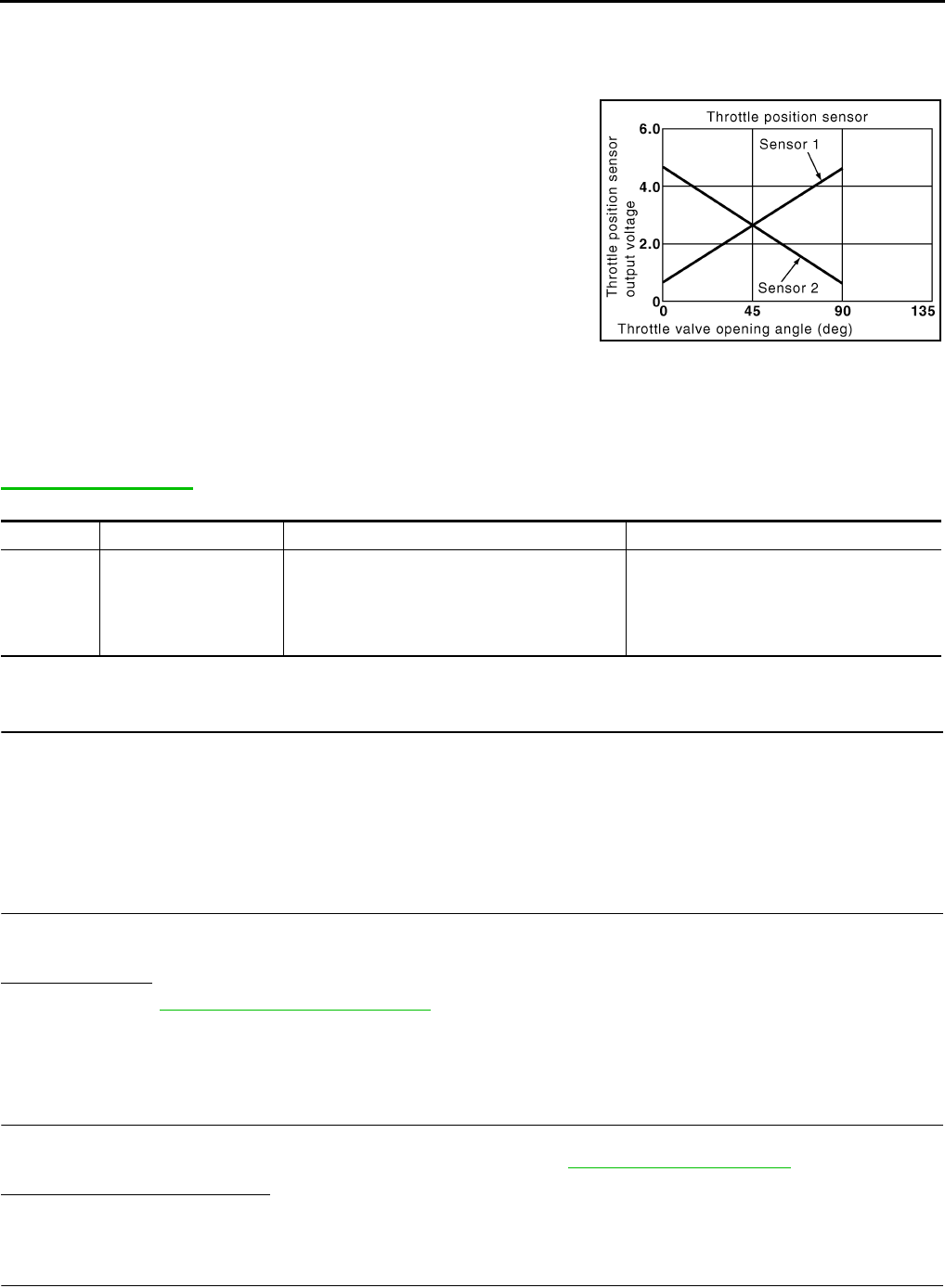
EC-392
< COMPONENT DIAGNOSIS > [FOR CALIFORNIA]
P2135 TP SENSOR
P2135 TP SENSOR
Description INFOID:0000000004493622
Electric throttle control actuator consists of throttle control motor,
throttle position sensor, etc. The throttle position sensor responds to
the throttle valve movement.
The throttle position sensor has two sensors. These sensors are a
kind of potentiometer which transform the throttle valve position into
output voltage, and emit the voltage signals to the ECM. The ECM
judges the current opening angle of the throttle valve from these sig-
nals and controls the throttle valve opening angle in response to
driving conditions via the throttle control motor.
DTC Logic INFOID:0000000004493623
DTC DETECTION LOGIC
NOTE:
If DTC P2135 is displayed with DTC P0643, first perform the trouble diagnosis for DTC P0643. Refer to
EC-336, "DTC Logic".
DTC CONFIRMATION PROCEDURE
1.PRECONDITIONING
If DTC CONFIRMATION PROCEDURE has been previously conducted, always turn ignition switch OFF and
wait at least 10 seconds before conducting the next test.
TESTING CONDITION:
Before performing the following procedure, confirm that battery voltage is more than 8V at idle.
>> GO TO 2.
2.PERFORM DTC CONFIRMATION PROCEDURE
1. Start engine and let it idle for 1 second.
2. Check DTC.
Is DTC detected?
YES >> Go to EC-392, "Diagnosis Procedure".
NO >> INSPECTION END
Diagnosis Procedure INFOID:0000000004493624
1.CHECK GROUND CONNECTION
1. Turn ignition switch OFF.
2. Check ground connection E21. Refer to Ground Inspection in GI-44, "Circuit Inspection".
Is the inspection result normal?
YES >> GO TO 2.
NO >> Repair or replace ground connection.
2.CHECK THROTTLE POSITION SENSOR POWER SUPPLY CIRCUIT-I
1. Disconnect electric throttle control actuator harness connector.
PBIB0145E
DTC No. Trouble diagnosis name DTC detecting condition Possible cause
P2135
Throttle position sensor
circuit range/perfor-
mance
Rationally incorrect voltage is sent to ECM
compared with the signals from TP sensor 1
and TP sensor 2.
• Harness or connector
(TP sensor 1 or 2 circuit is open or short-
ed.)
• Electric throttle control actuator
(TP sensor 1 or 2)
Revision: 2008 August 2009 Rogue

P2135 TP SENSOR
EC-393
< COMPONENT DIAGNOSIS > [FOR CALIFORNIA]
C
D
E
F
G
H
I
J
K
L
M
A
EC
N
P
O
2. Turn ignition switch ON.
3. Check the voltage between electric throttle control actuator harness connector and ground.
Is the inspection result normal?
YES >> GO TO 3.
NO >> Repair open circuit or short to ground or short to power in harness or connectors
3.CHECK THROTTLE POSITION SENSOR POWER SUPPLY CIRCUIT-II
1. Turn ignition switch OFF.
2. Disconnect ECM harness connector.
3. Check the continuity between electric throttle control actuator harness connector and ground.
4. Also check harness for short to ground and short to power.
Is the inspection result normal?
YES >> GO TO 4.
NO >> Repair open circuit or short to ground or short to power in harness or connectors.
4.CHECK THROTTLE POSITION SENSOR GROUND CIRCUIT FOR OPEN AND SHORT
1. Turn ignition switch OFF.
2. Disconnect ECM harness connector.
3. Check the continuity between electric throttle control actuator harness connector and ground.
4. Also check harness for short to ground and short to power.
Is the inspection result normal?
YES >> GO TO 5.
NO >> Repair open circuit or short to ground or short to power in harness or connectors.
5.CHECK SENSOR POWER SUPPLY CIRCUIT
Check harness for short to power and short to ground, between the following terminals.
Is the inspection result normal?
YES >> GO TO 6.
NO >> Repair short to ground or short to power in harness or connectors.
6.CHECK THROTTLE POSITION SENSOR INPUT SIGNAL CIRCUIT FOR OPEN AND SHORT
1. Check the continuity between electric throttle control actuator harness connector and ground.
Electric throttle control actuator Ground Voltage
Connector Terminal
F29 1 Ground Approx. 5 V
Electric throttle control actuator ECM Continuity
Connector Terminal Connector Terminal
F29 4 F8 36 Existed
Electric throttle control actuator ECM Continuity
Connector Terminal Connector Terminal
F29 4 F8 36 Existed
ECM Sensor
Connector Terminal Name Connector Terminal
F8 47 Electric throttle control actuator F29 1
59 CMP sensor (PHASE) F26 1
E16 83 APP sensor E110 4
Revision: 2008 August 2009 Rogue

EC-394
< COMPONENT DIAGNOSIS > [FOR CALIFORNIA]
P2135 TP SENSOR
2. Also check harness for short to ground and short to power.
Is the inspection result normal?
YES >> GO TO 7.
NO >> Repair open circuit or short to ground or short to power in harness or connectors.
7.CHECK THROTTLE POSITION SENSOR
Refer to EC-394, "Component Inspection".
Is the inspection result normal?
YES >> GO TO 9.
NO >> GO TO 8.
8.REPLACE ELECTRIC THROTTLE CONTROL ACTUATOR
1. Replace electric throttle control actuator.
2. Go to EC-395, "Special Repair Requirement".
>> INSPECTION END
9.CHECK INTERMITTENT INCIDENT
Refer to GI-41, "Intermittent Incident".
>> INSPECTION END
Component Inspection INFOID:0000000004493625
1.CHECK THROTTLE POSITION SENSOR
1. Turn ignition switch OFF.
2. Reconnect all harness connectors disconnected.
3. Perform EC-27, "THROTTLE VALVE CLOSED POSITION LEARNING : Special Repair Requirement".
4. Turn ignition switch ON.
5. Set selector lever to the D position.
6. Check the voltage between ECM harness connector terminals.
Is the inspection result normal?
YES >> INSPECTION END
NO >> GO TO 2.
2.REPLACE ELECTRIC THROTTLE CONTROL ACTUATOR
1. Replace electric throttle control actuator.
2. Perform EC-395, "Special Repair Requirement".
Electric throttle control actuator ECM Continuity
Connector Terminal Connector Terminal
F29 2F8 37 Existed
338
ECM
Condition Voltage +−
Connector Terminal Connector Terminal
F8
37
(TP sensor 1
signal) F8 36
(Sensor
ground)
Accelerator pedal
Fully released More than 0.36 V
Fully depressed Less than 4.75 V
38
(TP sensor 2
signal)
Fully released Less than 4.75 V
Fully depressed More than 0.36 V
Revision: 2008 August 2009 Rogue

P2135 TP SENSOR
EC-395
< COMPONENT DIAGNOSIS > [FOR CALIFORNIA]
C
D
E
F
G
H
I
J
K
L
M
A
EC
N
P
O
>> INSPECTION END
Special Repair Requirement INFOID:0000000004493626
1.PERFORM THROTTLE VALVE CLOSED POSITION LEARNING
Refer to EC-27, "THROTTLE VALVE CLOSED POSITION LEARNING : Special Repair Requirement"
>> GO TO 2.
2.PERFORM IDLE AIR VOLUME LEARNING
Refer to EC-27, "IDLE AIR VOLUME LEARNING : Special Repair Requirement"
>> END
Revision: 2008 August 2009 Rogue
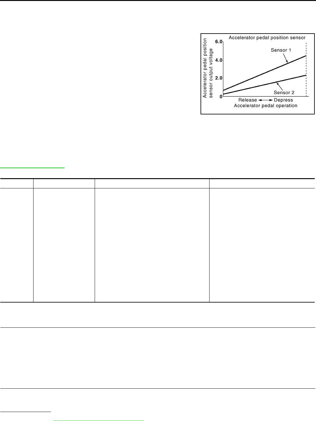
EC-396
< COMPONENT DIAGNOSIS > [FOR CALIFORNIA]
P2138 APP SENSOR
P2138 APP SENSOR
Description INFOID:0000000004493627
The accelerator pedal position sensor is installed on the upper end
of the accelerator pedal assembly. The sensor detects the accelera-
tor position and sends a signal to the ECM.
Accelerator pedal position sensor has two sensors. These sensors
are a kind of potentiometer which transform the accelerator pedal
position into output voltage, and emit the voltage signals to the ECM.
The ECM judges the current opening angle of the accelerator pedal
from these signals and controls the throttle control motor based on
these signals.
Idle position of the accelerator pedal is determined by the ECM
receiving the signal from the accelerator pedal position sensor. The
ECM uses this signal for engine operations such as fuel cut.
DTC Logic INFOID:0000000004493628
DTC DETECTION LOGIC
NOTE:
If DTC P2138 is displayed with DTC P0643, first perform the trouble diagnosis for DTC P0643. Refer to
EC-336, "DTC Logic".
DTC CONFIRMATION PROCEDURE
1.PRECONDITIONING
If DTC CONFIRMATION PROCEDURE has been previously conducted, always turn ignition switch OFF and
wait at least 10 seconds before conducting the next test.
TESTING CONDITION:
Before performing the following procedure, confirm that battery voltage is more than 8V at idle.
>> GO TO 2.
2.PERFORM DTC CONFIRMATION PROCEDURE
1. Start engine and let it idle for 1 second.
2. Check DTC.
Is DTC detected?
YES >> Go to EC-397, "Diagnosis Procedure".
NO >> INSPECTION END
PBIB1741E
DTC No. Trouble diagnosis name DTC detecting condition Possible cause
P2138
Accelerator pedal posi-
tion sensor circuit range/
performance
Rationally incorrect voltage is sent to ECM
compared with the signals from APP sensor 1
and APP sensor 2.
• Harness or connector
(APP sensor 1 or 2 circuit is open or
shorted.)
[Crankshaft position sensor (POS) circuit
is shorted.)
(Refrigerant pressure sensor circuit is
shorted.)
(EVAP control system sensor circuit is
shorted.)
(Tumble control valve position sensor cir-
cuit is shorted.)
• Accelerator pedal position sensor
(APP sensor 1 or 2)
• Crankshaft position sensor (POS)
• Refrigerant pressure sensor
• EVAP control system pressure sensor
• Tumble control valve position sensor
Revision: 2008 August 2009 Rogue

P2138 APP SENSOR
EC-397
< COMPONENT DIAGNOSIS > [FOR CALIFORNIA]
C
D
E
F
G
H
I
J
K
L
M
A
EC
N
P
O
Diagnosis Procedure INFOID:0000000004493629
1.CHECK GROUND CONNECTION
1. Turn ignition switch OFF.
2. Check ground connection E21. Refer to Ground Inspection in GI-44, "Circuit Inspection".
Is the inspection result normal?
YES >> GO TO 2.
NO >> Repair or replace ground connection.
2.CHECK APP SENSOR 1 POWER SUPPLY CIRCUIT
1. Disconnect accelerator pedal position (APP) sensor harness connector.
2. Turn ignition switch ON.
3. Check the voltage between APP sensor harness connector and ground.
Is the inspection result normal?
YES >> GO TO 3.
NO >> Repair open circuit or short to ground or shot to power in harness or connectors.
3.CHECK APP SENSOR 2 POWER SUPPLY CIRCUIT-I
1. Turn ignition switch ON.
2. Check the voltage between APP sensor harness connector and ground.
Is the inspection result normal?
YES >> GO TO 7.
NO >> GO TO 4.
4.CHECK APP SENSOR 2 POWER SUPPLY CIRCUIT-II
1. Turn ignition switch OFF.
2. Disconnect ECM harness connector.
3. Check the continuity between APP sensor harness connector and ECM harness connector.
Is the inspection result normal?
YES >> GO TO 5.
NO >> Repair open circuit or short to ground or shot to power in harness or connectors.
5.CHECK SENSOR POWER SUPPLY CIRCUIT
Check harness for short to power and short to ground, between the following terminals.
APP sensor Ground Voltage
Connector Terminal
E110 4 Ground Approx. 5 V
APP sensor Ground Voltage
Connector Terminal
E110 5 Ground Approx. 5 V
APP sensor ECM Continuity
Connector Terminal Connector Terminal
E110 5 E16 87 Existed
ECM Sensor
Connector Terminal Name Connector Terminal
F8 72 Tumble control valve position sensor F41 1
Refrigerant pressure sensor E49 3
76 CKP sensor (POS) F20 1
Revision: 2008 August 2009 Rogue

EC-398
< COMPONENT DIAGNOSIS > [FOR CALIFORNIA]
P2138 APP SENSOR
Is the inspection result normal?
YES >> GO TO 6.
NO >> Repair short to ground or short to power in harness or connectors.
6.CHECK COMPONENT
Check the following.
• Crankshaft position sensor (POS) (Refer to EC-259, "Component Inspection".)
• EVAP control system pressure sensor (Refer to EC-296, "Component Inspection".)
• Refrigerant pressure sensor (Refer to EC-437, "Diagnosis Procedure".)
• Tumble control valve position sensor (Refer to EC-368, "Diagnosis Procedure".)
Is the inspection result normal?
YES >> GO TO 11.
NO >> Replace malfunctioning component.
7.CHECK APP SENSOR GROUND CIRCUIT FOR OPEN AND SHORT
1. Turn ignition switch OFF.
2. Disconnect ECM harness connector.
3. Check the continuity between APP sensor harness connector and ECM harness connector as follows.
4. Also check harness for short to ground and short to power.
Is the inspection result normal?
YES >> GO TO 8.
NO >> Repair open circuit or short to ground or shot to power in harness or connectors.
8.CHECK APP SENSOR INPUT SIGNAL CIRCUIT FOR OPEN AND SHORT
1. Check the continuity between APP sensor harness connector and ECM harness connector as follows.
2. Also check harness for short to ground and short to power.
Is the inspection result normal?
YES >> GO TO 9.
NO >> Repair open circuit or short to ground or shot to power in harness or connectors.
9.CHECK APP SENSOR
Refer to EC-399, "Component Inspection".
Is the inspection result normal?
YES >> GO TO 11.
NO >> GO TO 10.
10.REPLACE ACCELERATOR PEDAL ASSEMBLY
1. Replace accelerator pedal assembly. Refer to ACC-3, "Removal and Installation".
2. Go to EC-399, "Special Repair Requirement".
E16 87 APP sensor E110 5
91 EVAP control system pressure sensor B47 3
ECM Sensor
Connector Terminal Name Connector Terminal
APP sensor ECM Continuity
Connector Terminal Connector Terminal
E110 2E16 84 Existed
1100
APP sensor ECM Continuity
Connector Terminal Connector Terminal
E110 6E16 82 Existed
381
Revision: 2008 August 2009 Rogue
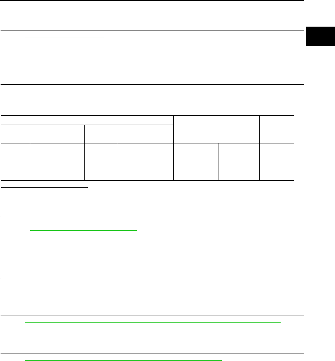
P2138 APP SENSOR
EC-399
< COMPONENT DIAGNOSIS > [FOR CALIFORNIA]
C
D
E
F
G
H
I
J
K
L
M
A
EC
N
P
O
>> INSPECTION END
11.CHECK INTERMITTENT INCIDENT
Refer to GI-41, "Intermittent Incident".
>> INSPECTION END
Component Inspection INFOID:0000000004493630
1.CHECK ACCELERATOR PEDAL POSITION SENSOR
1. Reconnect all harness connectors disconnected.
2. Turn ignition switch ON.
3. Check the voltage between ECM harness connector terminals.
Is the inspection result normal?
YES >> INSPECTION END
NO >> GO TO 2.
2.REPLACE ACCELERATOR PEDAL ASSEMBLY
1. Replace accelerator pedal assembly.
2. Go to EC-399, "Special Repair Requirement".
>> INSPECTION END
Special Repair Requirement INFOID:0000000004493631
1.PERFORM ACCELERATOR PEDAL RELEASED POSITION LEARNING
Refer to EC-27, "ACCELERATOR PEDAL RELEASED POSITION LEARNING : Special Repair Requirement".
>> GO TO 2.
2.PERFORM THROTTLE VALVE CLOSED POSITION LEARNING
Refer to EC-27, "THROTTLE VALVE CLOSED POSITION LEARNING : Special Repair Requirement".
>> GO TO 3.
3.PERFORM IDLE AIR VOLUME LEARNING
Refer to EC-27, "IDLE AIR VOLUME LEARNING : Special Repair Requirement".
>> END
ECM
Condition Voltage+−
Connector Terminal Connector Terminal
E16
81
(APP sensor 1 signal) E16
84
(Sensor ground) Accelerator pedal
Fully released 0.6 - 0.9 V
Fully depressed 3.9 - 4.7 V
82
(APP sensor 2 signal)
100
(Sensor ground)
Fully released 0.3 - 0.6 V
Fully depressed 1.95 - 2.4 V
Revision: 2008 August 2009 Rogue
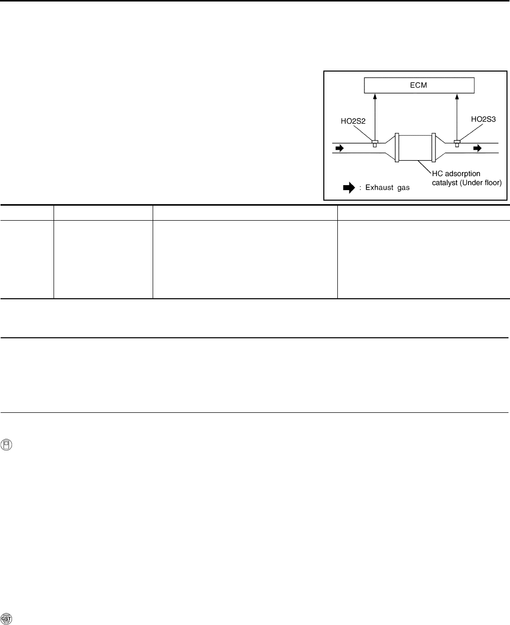
EC-400
< COMPONENT DIAGNOSIS > [FOR CALIFORNIA]
P2423 HC ADSORPTION CATALYST FUNCTION
P2423 HC ADSORPTION CATALYST FUNCTION
DTC Logic INFOID:0000000004493632
DTC DETECTION LOGIC
The ECM monitors the phase gap between heated oxygen sensor 2
signal and heated oxygen sensor 3 signal.
The phase gap between heated oxygen sensor 2 signal and heated
oxygen sensor 3 signal becomes small as the HC adsorption cata-
lyst (under floor) is deteriorated.
When the phase gap between heated oxygen sensor 2 signal and
heated oxygen sensor 3 signal approaches a specified limit value,
the HC adsorption catalyst (under floor) malfunction is diagnosed.
DTC CONFIRMATION PROCEDURE
1.PRECONDITIONING
If DTC CONFIRMATION PROCEDURE has been previously conducted, always turn ignition switch OFF and
wait at least 10 seconds before conducting the next test.
>> GO TO 2.
2.PERFORM DTC CONFIRMATION PROCEDURE
CAUTION:
Always drive vehicle in safe manner according to traffic conditions and obey all traffic laws.
With CONSULT-III
1. Start engine and warm it up to the normal operating temperature.
2. Repeat the following procedure 3 times.
- Drive vehicle at a speed of 80 km/h (50 MPH) or more for at least 3 consecutive minutes.
NOTE:
Keep the vehicle speed as steady as possible during the cruising.
- Stop vehicle with engine running.
NOTE:
Never turn ignition switch OFF.
3. Select “DTC & SRT CONFIRMATION” then “SRT WORK SUPPORT” mode with CONSULT-III.
4. Drive vehicle at a speed of 80 km/h (50 MPH) or more until “INCMP” of “CATALYST” changes to “CMPLT”
NOTE:
•Keep the vehicle speed as steady as possible during the cruising.
•It will take at most 3 minutes until “INCMP” of “CATALYST” changes to “CMPLT”.
5. Check 1st trip DTC.
With GST
1. Start engine and warm it up to the normal operating temperature.
2. Repeat the following procedure 3 times.
- Drive vehicle at a speed of 80 km/h (50 MPH) or more for at least 3 consecutive minutes.
NOTE:
Keep the vehicle speed as steady as possible during the cruising.
- Stop vehicle with engine running.
NOTE:
JMBIA0119GB
DTC No. Trouble diagnosis name DTC detecting condition Possible cause
P2423
HC adsorption catalyst
efficiency below thresh-
old
• HC adsorption catalyst (under floor) does not
operate properly.
• HC adsorption catalyst (under floor) does not
have enough oxygen storage capacity.
• HC adsorption catalyst (under floor)
• Exhaust tube
• Intake air leaks
• Fuel injector
• Fuel injector leaks
• Spark plug
• Improper ignition timing
Revision: 2008 August 2009 Rogue
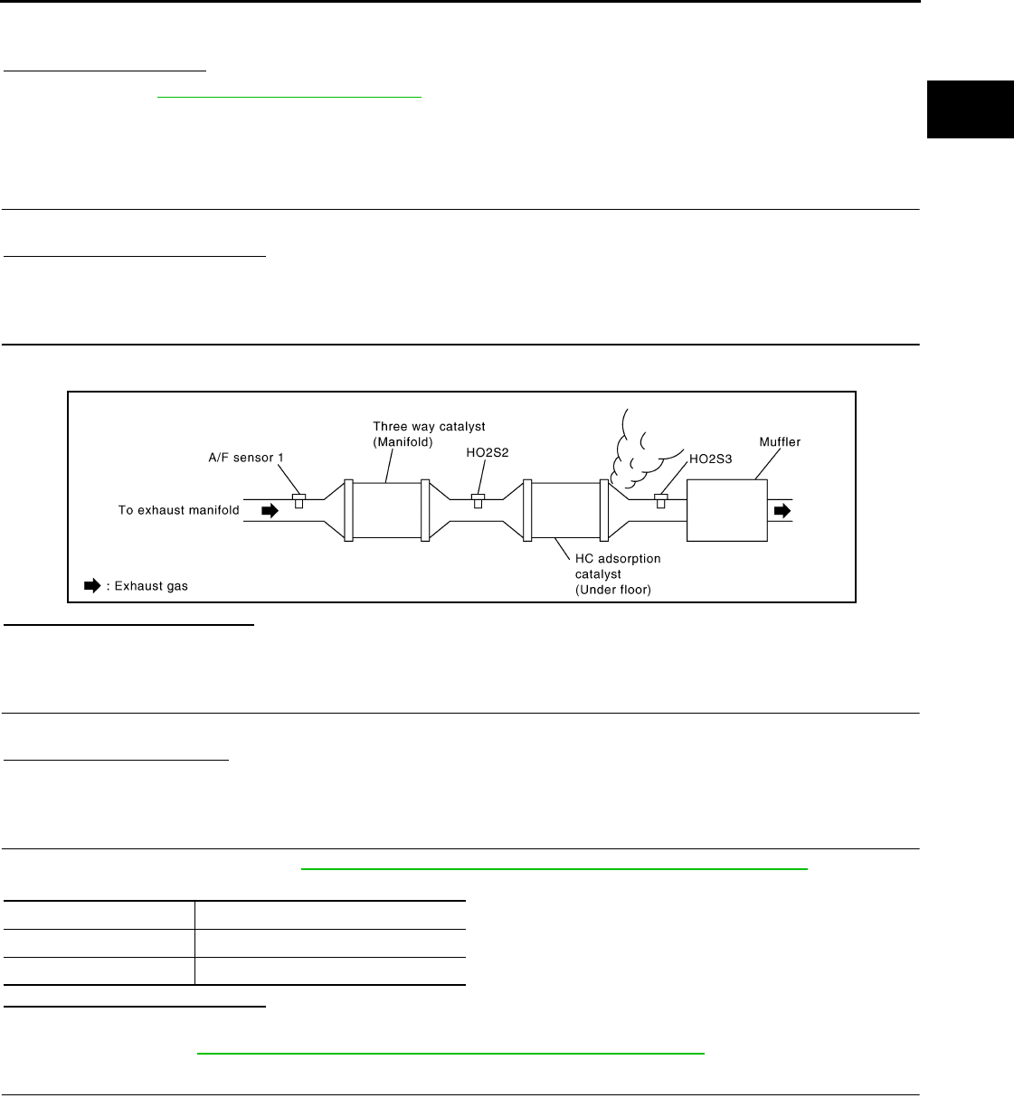
P2423 HC ADSORPTION CATALYST FUNCTION
EC-401
< COMPONENT DIAGNOSIS > [FOR CALIFORNIA]
C
D
E
F
G
H
I
J
K
L
M
A
EC
N
P
O
Never turn ignition switch OFF.
3. Check 1st trip DTC.
Is 1st tip DTC detected?
YES >> Go to EC-401, "Diagnosis Procedure".
NO >> INSPECTION END
Diagnosis Procedure INFOID:0000000004493633
1.CHECK EXHAUST SYSTEM
Visually check exhaust tubes and muffler for dent.
Is the inspection result normal?
YES >> GO TO 2.
NO >> Repair or replace.
2.CHECK EXHAUST GAS LEAK
1. Start engine and run it at idle.
2. Listen for an exhaust gas leak before the HC adsorption catalyst (under floor).
Is exhaust gas leak detected?
YES >> Repair or replace.
NO >> GO TO 3.
3.CHECK INTAKE AIR LEAK
Listen for an intake air leak after the mass air flow sensor.
Is intake air leak detected?
YES >> Repair or replace.
NO >> GO TO 4.
4.CHECK IGNITION TIMING
Check the following items. Refer to EC-22, "BASIC INSPECTION : Special Repair Requirement".
Is the inspection result normal?
YES >> GO TO 5.
NO >> Follow the EC-22, "BASIC INSPECTION : Special Repair Requirement".
5.CHECK FUEL INJECTOR
1. Stop engine and then turn ignition switch ON.
2. Check the voltage between ECM harness connector and ground.
JMBIA0120G
B
Items Specifications
idle speed 700 ± 50 rpm (in P or N position)
Ignition timing 15 ± 5° BTDC (in P or N position)
Revision: 2008 August 2009 Rogue

EC-402
< COMPONENT DIAGNOSIS > [FOR CALIFORNIA]
P2423 HC ADSORPTION CATALYST FUNCTION
Is the inspection result normal?
YES >> GO TO 6.
NO >> Perform EC-419, "Diagnosis Procedure".
6.CHECK FUNCTION OF IGNITION COIL-I
CAUTION:
Perform the following procedure in a place with no combustible objects and good ventiration.
1. Turn ignition switch OFF.
2. Remove fuel pump fuse in IPDM E/R to release fuel pressure.
NOTE:
Do not use CONSULT-III to release fuel pressure, or fuel pressure applies again during the following pro-
cedure.
3. Start engine.
4. After engine stalls, crank it two or three times to release all fuel pressure.
5. Turn ignition switch OFF.
6. Remove all ignition coil harness connectors to avoid the electrical discharge from the ignition coils.
7. Remove ignition coil and spark plug of the cylinder to be checked.
8. Crank engine for 5 seconds or more to remove combustion gas in the cylinder.
9. Connect spark plug and harness connector to ignition coil.
10. Fix ignition coil using a rope etc. with gap of 13 - 17 mm (0.52 -
0.66 in) between the edge of the spark plug and grounded metal
portion as shown in the figure.
11. Crank engine for approximately 3 seconds, and check whether
spark is generated between the spark plug and the grounded
metal portion.
CAUTION:
• Never place the spark plug and the ignition coil within 50
cm (19.7 in) each other. Be careful not to get an electrical
shock while checking, because the electrical discharge
voltage becomes 20kV or more.
• It might damage the ignition coil if the gap of more than 17 mm (0.66 in) is made.
NOTE:
When the gap is less than 13 mm (0.52 in), a spark might be generated even if the coil is malfunc-
tioning.
Is the inspection result normal?
YES >> GO TO 10.
NO >> GO TO 7.
7.CHECK FUNCTION OF IGNITION COIL-II
1. Turn ignition switch OFF.
2. Disconnect spark plug and connect a non-malfunctioning spark plug.
3. Crank engine for approximately 3 seconds, and recheck whether spark is generated between the spark
plug and the grounded metal portion.
Is the inspection result normal?
YES >> GO TO 8.
ECM Ground Voltage
Connector Terminal
F7
29
Ground Battery voltage
30
31
32
Spark should be generated.
JMBIA0066G
B
Spark should be generated.
Revision: 2008 August 2009 Rogue
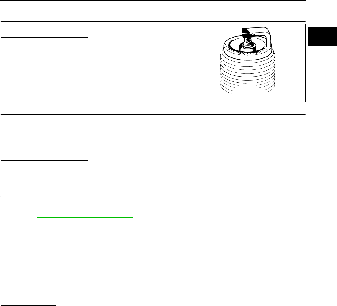
P2423 HC ADSORPTION CATALYST FUNCTION
EC-403
< COMPONENT DIAGNOSIS > [FOR CALIFORNIA]
C
D
E
F
G
H
I
J
K
L
M
A
EC
N
P
O
NO >> Check ignition coil, power transistor and their circuits. Refer to EC-425, "Diagnosis Procedure".
8.CHECK SPARK PLUG
Check the initial spark plug for fouling, etc.
Is the inspection result normal?
YES >> Replace spark plug(s) with standard type one(s). For
spark plug type, refer to EM-19, "Inspection".
NO >> Repair or clean spark plug. Then GO TO 9.
9.CHECK FUNCTION OF IGNITION COIL-III
1. Reconnect the initial spark plugs.
2. Crank engine for approximately 3 seconds, and recheck whether spark is generated between the spark
plug and the grounded portion.
Is the inspection result normal?
YES >> INSPECTION END
NO >> Replace spark plug(s) with standard type one(s). For spark plug type, refer to EM-19, "Inspec-
tion".
10.CHECK FUEL INJECTOR
1. Turn ignition switch OFF.
2. Remove fuel injector assembly.
Refer to EM-43, "Removal and Installation".
Keep fuel hose and all fuel injectors connected to fuel tube.
3. Disconnect all ignition coil harness connectors.
4. Reconnect all fuel injector harness connectors disconnected.
5. Turn ignition switch ON.
Check that fuel does not drip from fuel injector.
Is the inspection result normal?
YES >> GO TO 11.
NO >> Replace the fuel injector(s) from which fuel is dripping.
11.CHECK INTERMITTENT INCIDENT
Refer to GI-41, "Intermittent Incident".
Is the trouble fixed?
YES >> INSPECTION END
NO >> Replace HC adsorption catalyst (under floor).
SEF156I
Spark should be generated.
Revision: 2008 August 2009 Rogue
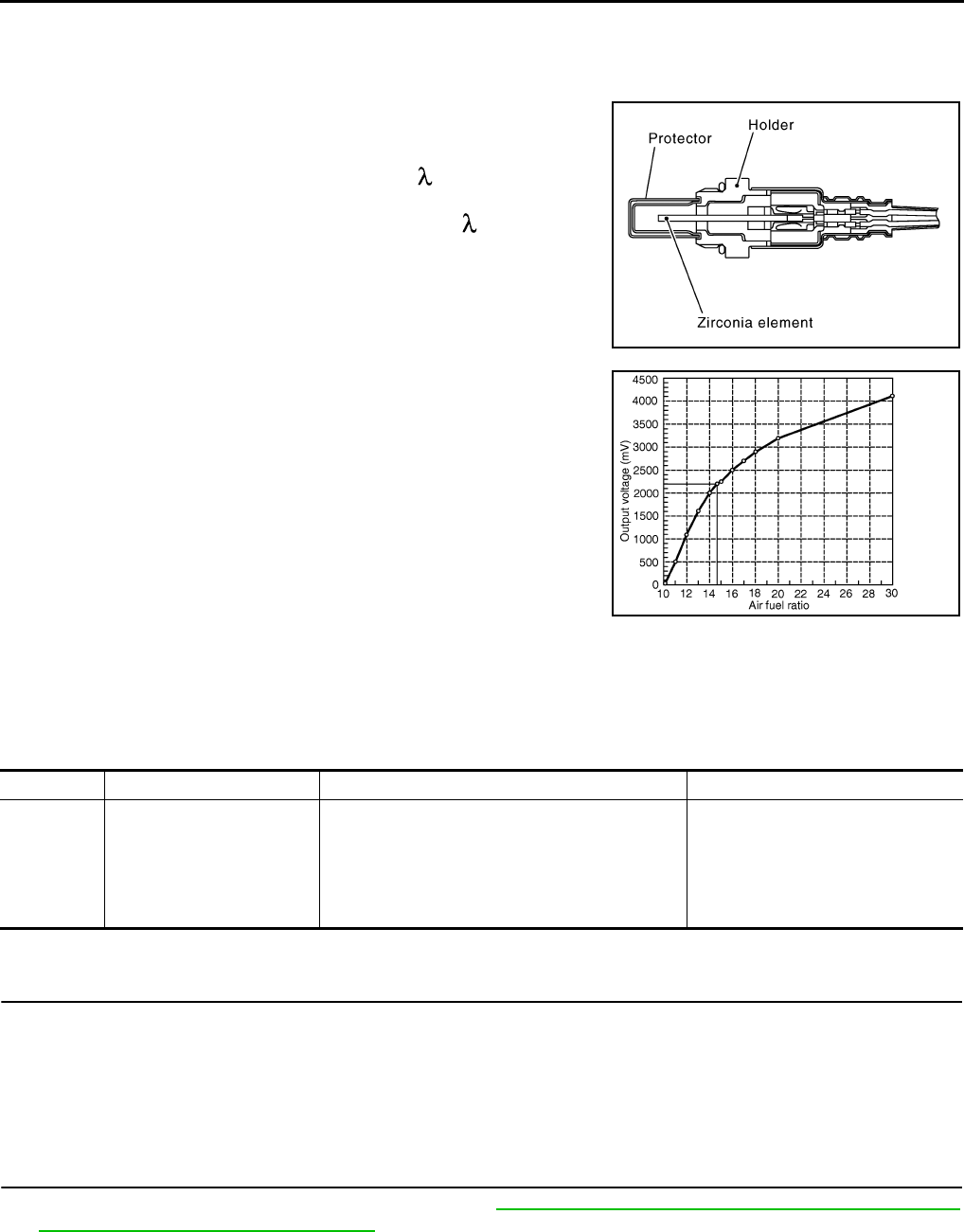
EC-404
< COMPONENT DIAGNOSIS > [FOR CALIFORNIA]
P2A00 A/F SENSOR 1
P2A00 A/F SENSOR 1
Description INFOID:0000000004493634
The air fuel ratio (A/F) sensor 1 is a planar one-cell limit current sen-
sor. The sensor element of the A/F sensor 1 is composed an elec-
trode layer, which transports ions. It has a heater in the element.
The sensor is capable of precise measurement = 1, but also in the
lean and rich range. Together with its control electronics, the sensor
outputs a clear, continuous signal throughout a wide range.
The exhaust gas components diffuse through the diffusion layer at
the sensor cell. An electrode layer is applied voltage, and this current
relative oxygen density in lean. Also this current relative hydrocar-
bon density in rich.
Therefore, the A/F sensor 1 is able to indicate air fuel ratio by this
electrode layer of current. In addition, a heater is integrated in the
sensor to ensure the required operating temperature of approxi-
mately 800°C (1,472°F).
DTC Logic INFOID:0000000004493635
DTC DETECTION LOGIC
To judge the malfunction, the A/F signal computed by ECM from the A/F sensor 1 signal is monitored so it will
not shift to LEAN side or RICH side.
DTC CONFIRMATION PROCEDURE
1.PRECONDITIONING
If DTC CONFIRMATION PROCEDURE has been previously conducted, always turn ignition switch OFF and
wait at least 10 seconds before conducting the next test.
TESTING CONDITION:
Before performing the following procedure, confirm that battery voltage is more than 11V at idle.
>> GO TO 2.
2.PERFORM DTC CONFIRMATION PROCEDURE
1. Clear the mixture ratio self-learning value. Refer to EC-29, "MIXTURE RATIO SELF-LEARNING VALUE
CLEAR : Special Repair Requirement".
2. Turn ignition switch OFF and wait at least 10 seconds.
3. Start engine and keep the engine speed between 3,500 and 4,000 rpm for 1 minute under no load.
4. Let engine idle for 1 minute.
5. Keep engine speed between 2,500 and 3,000 rpm for 20 minutes.
6. Check 1st trip DTC$.
JMBIA0112GB
PBIB3354E
DTC No. Trouble diagnosis name DTC detecting condition Possible Cause
P2A00 Air fuel ratio (A/F) sensor 1
circuit range/performance
• The output voltage computed by ECM from the
A/F sensor 1 signal shifts to the lean side for a
specified period.
• The A/F signal computed by ECM from the A/F
sensor 1 signal shifts to the rich side for a spec-
ified period.
• A/F sensor 1
• A/F sensor 1 heater
• Fuel pressure
• Fuel injector
• Intake air leaks
Revision: 2008 August 2009 Rogue

P2A00 A/F SENSOR 1
EC-405
< COMPONENT DIAGNOSIS > [FOR CALIFORNIA]
C
D
E
F
G
H
I
J
K
L
M
A
EC
N
P
O
Is 1st trip DTC detected?
YES >> Go to EC-405, "Diagnosis Procedure".
NO >> INSPECTION END
Diagnosis Procedure INFOID:0000000004493636
1.CHECK GROUND CONNECTION
1. Turn ignition switch OFF.
2. Check ground connection E21. Refer to Ground Inspection in GI-44, "Circuit Inspection".
Is the inspection result normal?
YES >> GO TO 2.
NO >> Repair or replace ground connection.
2.RETIGHTEN A/F SENSOR 1
1. Loosen and retighten the A/F sensor 1. Refer to EM-32, "Removal and Installation".
>> GO TO 3.
3.CHECK FOR INTAKE AIR LEAK
1. Start engine and run it at idle.
2. Listen for an intake air leak after the mass air flow sensor.
Is intake air leak detected?
YES >> GO TO 4.
NO >> Repair or replace.
4.CLEAR THE MIXTURE RATIO SELF-LEARNING VALUE
1. Clear the mixture ratio self-learning value. Refer to EC-29, "MIXTURE RATIO SELF-LEARNING VALUE
CLEAR : Special Repair Requirement".
2. Run engine for at least 10 minutes at idle speed.
Is the 1st trip DTC P0171 or P0172 detected? Is it difficult to start engine?
YES >> Perform trouble diagnosis for DTC P0171or P0172. Refer to EC-231, "DTC Logic" or EC-235,
"DTC Logic".
NO >> GO TO 5.
5.CHECK HARNESS CONNECTOR
1. Turn ignition switch OFF.
2. Disconnect A/F sensor 1 harness connector.
3. Check harness connector for water.
Is the inspection result normal?
YES >> GO TO 6.
NO >> Repair or replace harness connector.
6.CHECK A/F SENSOR 1 POWER SUPPLY CIRCUIT
1. Turn ignition switch ON.
2. Check the voltage between A/F sensor 1 harness connector and ground.
Is the inspection result normal?
YES >> GO TO 8.
NO >> GO TO 7.
7.DETECT MALFUNCTIONING PART
Water should not exit.
A/F sensor 1 Ground Voltage
Connector Terminal
F28 4 Ground Battery voltage
Revision: 2008 August 2009 Rogue
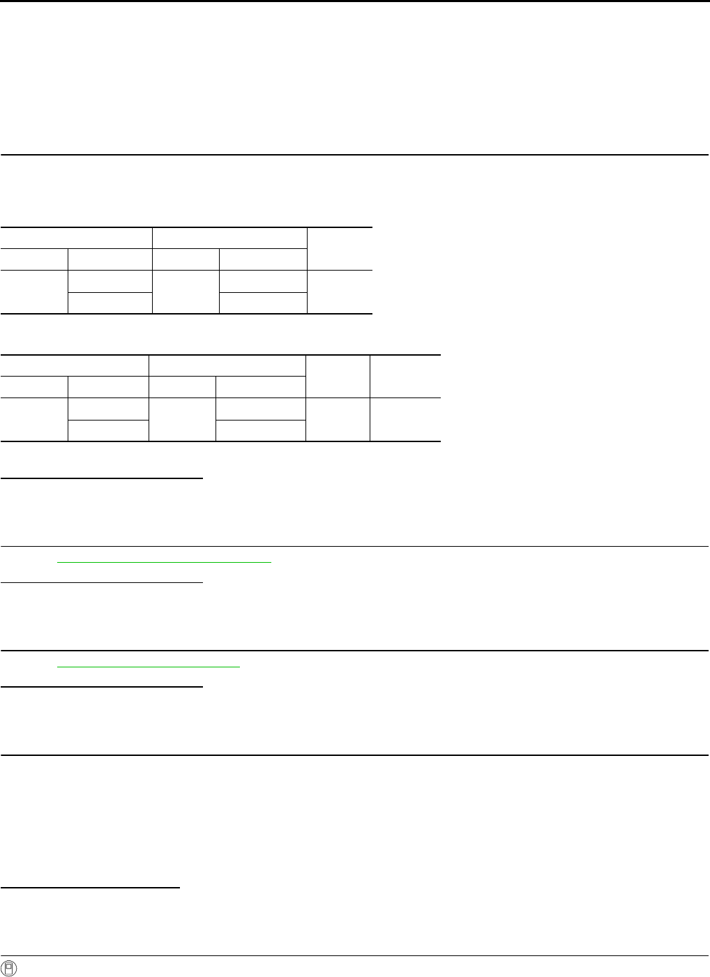
EC-406
< COMPONENT DIAGNOSIS > [FOR CALIFORNIA]
P2A00 A/F SENSOR 1
Check the following.
• Harness connectors E6, F123
• IPDM E/R harness connector E14
• 15A fuse (No. 63)
• Harness for open or short between A/F sensor 1 and fuse
>> Repair or replace harness or connectors.
8.CHECK A/F SENSOR 1 INPUT SIGNAL CIRCUIT FOR OPEN AND SHORT
1. Turn ignition switch OFF.
2. Disconnect ECM harness connector.
3. Check the continuity between A/F sensor 1 harness connector and ECM harness connector.
4. Check the continuity between ECM harness connector or A/F sensor 1 harness connector and ground.
5. Also check harness for short to power.
Is the inspection result normal?
YES >> GO TO 9.
NO >> Repair open circuit or short to ground or short to power in harness or connectors.
9.CHECK A/F SENSOR 1 HEATER
Refer to EC-137, "Component Inspection".
Is the inspection result normal?
YES >> GO TO 10.
NO >> GO TO 11.
10.CHECK INTERMITTENT INCIDENT
Perform GI-41, "Intermittent Incident".
Is the inspection result normal?
YES >> GO TO 11.
NO >> Repair or replace.
11.REPLACE AIR FUEL RATIO (A/F) SENSOR 1
Replace air fuel ratio (A/F) sensor 1.
CAUTION:
• Discard any A/F sensor which has been dropped from a height of more than 0.5 m (19.7 in) onto a
hard surface such as a concrete floor; use a new one.
• Before installing new A/F sensor, clean exhaust system threads using oxygen sensor thread cleaner
[commercial service tool (J-43897-18 or J-43897-12)] and approved anti-seize lubricant (commercial
service tool).
Do you have CONSULT-III?
YES >> GO TO 12.
NO >> GO TO 13.
12.CONFIRM A/F ADJUSTMENT DATA
With CONSULT-III
1. Turn ignition switch ON.
A/F sensor 1 ECM Continuity
Connector Terminal Connector Terminal
F28 1F8 45 Existed
249
A/F sensor 1 ECM Ground Continuity
Connector Terminal Connector Terminal
F28 1F8 45 Ground Not existed
249
Revision: 2008 August 2009 Rogue

P2A00 A/F SENSOR 1
EC-407
< COMPONENT DIAGNOSIS > [FOR CALIFORNIA]
C
D
E
F
G
H
I
J
K
L
M
A
EC
N
P
O
2. Select “A/F ADJ-B1” in “DATA MONITOR” mode with CONSULT-III.
3. Check that “0.000” is displayed on CONSULT-III screen.
Is “0.000” displayed?
YES >> INSPECTION END
NO >> GO TO 13.
13.CLEAR THE MIXTURE RATIO SELF-LEARNING VALUE
Clear the mixture ratio self-learning value. Refer to EC-29, "MIXTURE RATIO SELF-LEARNING VALUE
CLEAR : Special Repair Requirement".
Do you have CONSULT-III?
YES >> GO TO 14.
NO >> INSPECTION END
14.CONFIRM A/F ADJUSTMENT DATA
With CONSULT-III
1. Turn ignition switch ON.
2. Select “A/F ADJ-B1” in “DATA MONITOR” mode with CONSULT-III.
3. Check that “0.000” is displayed on CONSULT-III screen.
>> INSPECTION END
Revision: 2008 August 2009 Rogue

EC-408
< COMPONENT DIAGNOSIS > [FOR CALIFORNIA]
ASCD BRAKE SWITCH
ASCD BRAKE SWITCH
Description INFOID:0000000004493637
When the brake pedal is depressed, ASCD brake switch is turned OFF and stop lamp switch is turned ON.
ECM detects the state of the brake pedal by those two types of input (ON/OFF signal).
Refer to EC-58, "System Description" for the ASCD function.
Component Function Check INFOID:0000000004493638
1.CHECK FOR ASCD BRAKE SWITCH FUNCTION
With CONSULT-III
1. Turn ignition switch ON.
2. Select “BRAKE SW1” in “DATA MONITOR” mode with CONSULT-III.
3. Check “BRAKE SW1” indication under the following conditions.
Without CONSULT-III
1. Turn ignition switch ON.
2. Check the voltage between ECM harness connector and ground.
Is the inspection result normal?
YES >> INSPECTION END.
NO >> Refer to EC-408, "Diagnosis Procedure".
Diagnosis Procedure INFOID:0000000004493639
1.CHECK ASCD BRAKE SWITCH POWER SUPPLY CIRCUIT
1. Turn ignition switch OFF.
2. Disconnect ASCD brake switch harness connector.
3. Turn ignition switch ON.
4. Check the voltage between ASCD brake switch harness connector and ground.
Is the inspection result normal?
YES >> GO TO 3.
NO >> GO TO 2.
2.DETECT MALFUNCTIONING PART
Check the following.
• Harness connectors E105, M77
• 10A fuse (No. 1)
• Harness for open or short between ASCD brake switch and fuse
>> Repair open circuit or short to ground or short to power in harness or connectors.
Monitor item Condition Indication
BRAKE SW1 Brake pedal Slightly depressed OFF
Fully released ON
ECM Ground Condition Voltage
Connector Terminal
E16 110
(ASCD brake switch signal) Ground Brake pedal Slightly depressed Approx. 0V
Fully released Battery voltage
ASCD brake switch Ground Voltage
Connector Terminal
E112 1 Ground Battery voltage
Revision: 2008 August 2009 Rogue

ASCD BRAKE SWITCH
EC-409
< COMPONENT DIAGNOSIS > [FOR CALIFORNIA]
C
D
E
F
G
H
I
J
K
L
M
A
EC
N
P
O
3.CHECK ASCD BRAKE SWITCH INPUT SIGNAL CIRCUIT FOR OPEN AND SHORT
1. Turn ignition switch OFF.
2. Disconnect ECM harness connector.
3. Check the continuity between ASCD brake switch harness connector and ECM harness connector.
4. Also check harness for short to ground and short to power.
Is the inspection result normal?
YES >> GO TO 4.
NO >> Repair open circuit or short to ground or short to power in harness or connectors.
4.CHECK ASCD BRAKE SWITCH
Refer to EC-409, "Component Inspection (ASCD Brake Switch)".
Is the inspection result normal?
YES >> GO TO 5.
NO >> Replace ASCD brake switch.
5.CHECK INTERMITTENT INCIDENT
Refer to GI-41, "Intermittent Incident".
>> INSPECTION END
Component Inspection (ASCD Brake Switch) INFOID:0000000004493640
1.CHECK ASCD BRAKE SWITCH-I
1. Turn ignition switch OFF.
2. Disconnect ASCD brake switch harness connector.
3. Check the continuity between ASCD brake switch terminals under the following conditions.
Is the inspection result normal?
YES >> INSPECTION END
NO >> GO TO 2.
2.CHECK ASCD BRAKE SWITCH-II
1. Adjust ASCD brake switch installation. Refer to BR-9, "Inspection and Adjustment".
2. Check the continuity between ASCD brake switch terminals under the following conditions.
Is the inspection result normal?
YES >> INSPECTION END
NO >> Replace ASCD brake switch.
ASCD brake switch ECM Continuity
Connector Terminal Connector Terminal
E112 2 E16 110 Existed
Terminals Condition Continuity
1 and 2 Brake pedal Fully released Existed
Slightly depressed Not existed
Terminals Condition Continuity
1 and 2 Brake pedal Fully released Existed
Slightly depressed Not existed
Revision: 2008 August 2009 Rogue

EC-410
< COMPONENT DIAGNOSIS > [FOR CALIFORNIA]
ASCD INDICATOR
ASCD INDICATOR
Description INFOID:0000000004493641
ASCD indicator lamp illuminates to indicate ASCD operation status. Lamp has two indicators, CRUISE and
SET, and is integrated in combination meter.
CRUISE lamp illuminates when MAIN switch on ASCD steering switch is turned ON to indicated that ASCD
system is ready for operation.
SET lamp illuminates when the following conditions are met.
• CRUISE lamp is illuminated.
• SET/COAST switch on ASCD steering switch is turned ON while vehicle speed is within the range of the
ASCD setting.
SET lamp remains lit during ASCD control.
Refer to EC-58, "System Description" for the ASCD function.
Component Function Check INFOID:0000000004493642
1.ASCD INDICATOR FUNCTION
Check ASCD indicator under the following conditions.
Is the inspection result normal?
YES >> INSPECTION END
NO >> Go to EC-410, "Diagnosis Procedure".
Diagnosis Procedure INFOID:0000000004493643
1.CHECK DTC
Check that DTC UXXXX is not displayed.
Is the inspection result normal?
YES >> GO TO 2.
NO >> Perform trouble diagnosis for DTC UXXXX.
2.CHECK COMBINATION METER OPERATION
Refer to MWI-33, "CONSULT-III Function (METER/M&A)".
Is the inspection result normal?
YES >> GO TO 3.
NO >> Check combination meter circuit. Refer to MWI-9, "SPEEDOMETER : System Diagram".
3.CHECK INTERMITTENT INCIDENT
Refer to GI-41, "Intermittent Incident".
>> INSPECTION END
ASCD INDICATOR CONDITION SPECIFICATION
CRUISE LAMP • Ignition switch: ON • MAIN switch: Pressed at the
1st time →at the 2nd time ON → OFF
SET LAMP
•MAIN switch: ON
• When vehicle speed: Be-
tween 40 km/h (25 MPH) and
144 km/h (89 MPH)
• ASCD: Operating ON
• ASCD: Not operating OFF
Revision: 2008 August 2009 Rogue
COOLING FAN
EC-411
< COMPONENT DIAGNOSIS > [FOR CALIFORNIA]
C
D
E
F
G
H
I
J
K
L
M
A
EC
N
P
O
COOLING FAN
Description INFOID:0000000004493644
The ECM controls the cooling fan corresponding to the vehicle speed, engine coolant temperature, refrigerant
pressure, and air conditioner ON signal. The control system has 3-step control [HIGH/LOW/OFF].
COOLING FAN MOTOR
The cooling fan operates at each speed when the current flows in the cooling fan motor as follows.
.The cooling fan operates at low (LOW) speed when cooling fan motors-1 and -2 are circuited in series under
the middle speed condition
Refer to EC-65, "System Description".
Component Function Check INFOID:0000000004493645
1.CHECK COOLING FAN LOW SPEED FUNCTION
With CONSULT-III
1. Turn ignition switch ON.
2. Perform “COOLING FAN” in “ACTIVE TEST” mode with CONSULT-III and touch “LOW” on the CON-
SULT-III screen.
3. Check that cooling fans operates at low speed.
Without CONSULT-III
1. Start engine and let it idle.
2. Turn air conditioner switch and blower fan switch ON.
3. Check that cooling fan operates at low speed.
Is the inspection result normal?
YES >> GO TO 2.
NO >> Check cooling fan low speed control circuit. Refer to “PROCEDURE A” in EC-412, "Diagnosis
Procedure".
2.CHECK COOLING FAN HIGH SPEED FUNCTION
With CONSULT-III
1. Touch “HI” on the CONSULT-III screen.
2. Check that cooling fans operates at higher speed than low speed.
Without CONSULT-III
1. Turn ignition switch OFF.
2. Turn air conditioner switch and blower fan switch OFF.
3. Disconnect engine coolant temperature sensor harness connector.
4. Connect 150Ω resistor to engine coolant temperature sensor harness connector.
5. Restart engine and check that cooling fan operates at higher speed than low speed.
Is the inspection result normal?
YES >> INSPECTION END
NO >> Check cooling fan high speed control circuit. Refer to “PROCEDURE B” in EC-412, "Diagnosis
Procedure".
Cooling fan speed Cooling fan motor terminals
(+) (-)
Middle (MID)
1 3 and 4
2 3 and 4
1 and 2 3
1 and 2 4
High (HI) 1 and 2 3 and 4
Revision: 2008 August 2009 Rogue

EC-412
< COMPONENT DIAGNOSIS > [FOR CALIFORNIA]
COOLING FAN
Diagnosis Procedure INFOID:0000000004493646
PROCEDURE A
1.CHECK GROUND CONNECTION
1. Turn ignition switch OFF.
2. Check ground connection E38. Refer to Ground Inspection in GI-44, "Circuit Inspection".
Is the inspection result normal?
YES >> GO TO 2.
NO >> Repair or replace ground connection.
2.CHECK COOLING FAN MOTORS POWER SUPPLY CIRCUIT-I
1. Disconnect cooling fan motor-2 harness connector.
2. Check the voltage between cooling fan motor-2 harness connector and ground.
3. Also check harness for short to ground or short to power.
Is the inspection result normal?
YES >> GO TO 4.
NO >> GO TO 3.
3.DETECT MALFUNCTIONING PART
Check the following.
• 40A fusible link (letter M)
• Harness for open or short between cooling fan motor-2 and battery
>> Repair open circuit or short to ground or short to power in harness or connectors.
4.CHECK COOLING FAN MOTORS POWER SUPPLY CIRCUIT-II
1. Disconnect cooling fan relay-4.
2. Turn ignition switch ON.
3. Check the voltage between cooling fan relay-4 harness connector and ground.
4. Also check harness for short to ground or short to power.
Is the inspection result normal?
YES >> GO TO 6.
NO >> GO TO 5.
5.DETECT MALFUNCTIONING PART
Check the following.
• IPDM E/R harness connector E14
• 15A fuse (No. 63)
• Harness for open or short between cooling fan relay-4 and fuse
>> Repair open circuit or short to ground or short to power in harness or connectors.
6.CHECK COOLING FAN MOTORS GROUND CIRCUIT FOR OPEN AND SHORT
1. Turn ignition switch OFF.
2. Disconnect cooling fan motor-1 harness connector.
Cooling fan motor-2 Ground Voltage
Connector Terminal
E54 1Ground Battery voltage
2
Cooling fan relay-4 Ground Voltage
Connector Terminal
E57 2 Ground Battery voltage
Revision: 2008 August 2009 Rogue

COOLING FAN
EC-413
< COMPONENT DIAGNOSIS > [FOR CALIFORNIA]
C
D
E
F
G
H
I
J
K
L
M
A
EC
N
P
O
3. Check the continuity between cooling fan motor-1 harness connector and ground.
4. Also check harness for short to ground or short to power.
Is the inspection result normal?
YES >> GO TO 7.
NO >> Repair open circuit or short to ground or short to power in harness or connectors.
7.CHECK COOLING FAN MOTORS CIRCUIT FOR OPEN AND SHORT
1. Disconnect IPDM E/R harness connector E13.
2. Check the continuity between cooling fan motor-2 harness connector and cooling fan relay-4 harness con-
nector.
3. Check the continuity between cooling fan relay-4 harness connector and cooling fan motor-1 harness con-
nector and ground.
4. Check the continuity between cooling fan relay-4 harness connector and IPDM E/R harness connector.
5. Also check harness for short to ground and short to power.
Is the inspection result normal?
YES >> GO TO 8.
NO >> Repair open circuit or short to ground or short to power in harness or connectors.
8.CHECK COOLING FAN RELAY-4
Refer to EC-416, "Component Inspection (Cooling Fan Relay)".
Is the inspection result normal?
YES >> GO TO 9.
NO >> Replace cooling fan relay.
9.CHECK COOLING FAN MOTORS
Refer to EC-416, "Component Inspection (Cooling Fan Motor)".
Is the inspection result normal?
YES >> GO TO 10.
NO >> Replace malfunctioning cooling fan motor.
10.CHECK INTERMITTENT INCIDENT
Perform GI-41, "Intermittent Incident".
Is the inspection result normal?
YES >> Replace IPDM E/R.
NO >> Repair or replace harness or connector.
Cooling fan motor-1 Ground Continuity
Connector Terminal
E53 3Ground Existed
4
Cooling fan motor-2 Cooling fan relay-4 Continuity
Connector Terminal Connector Terminal
E543E573Existed
Cooling fan relay-4 Cooling fan motor-1 Continuity
Connector Terminal Connector Terminal
E57 5 E53 2 Existed
Cooling fan relay-4 IPDM E/R Continuity
Connector Terminal Connector Terminal
E57 1 E13 31 Existed
Revision: 2008 August 2009 Rogue

EC-414
< COMPONENT DIAGNOSIS > [FOR CALIFORNIA]
COOLING FAN
PROCEDURE B
1.CHECK GROUND CONNECTION
1. Turn ignition switch OFF.
2. Check ground connection E21, E38. Refer to Ground Inspection in GI-44, "Circuit Inspection".
Is the inspection result normal?
YES >> GO TO 2.
NO >> Repair or replace ground connection.
2.CHECK IPDM E/R POWER SUPPLY AND GROUND CIRCUIT
Power supply and ground circuit. Refer to PCS-15, "Diagnosis Procedure".
Is the inspection result normal?
YES >> GO TO 3.
NO >> Repair or replace malfunctioning part.
3.CHECK COOLING FAN MOTORS POWER SUPPLY CIRCUIT-I
1. Disconnect cooling fan motor-2 harness connector.
2. Check the voltage between cooling fan motor-2 harness connector and ground.
3. Also check harness for short to ground or short to power.
Is the inspection result normal?
YES >> GO TO 5.
NO >> GO TO 4.
4.DETECT MALFUNCTIONING PART
Check the following.
• 40A fusible link (letter M)
• Harness for open or short between cooling fan motor-2 and battery
>> Repair open circuit or short to ground or short to power in harness or connectors.
5.CHECK COOLING FAN MOTORS POWER SUPPLY CIRCUIT-II
1. Disconnect cooling fan relay-5.
2. Turn ignition switch ON.
3. Check the voltage between cooling fan relay-5 harness connector and ground.
4. Also check harness for short to ground or short to power.
Is the inspection result normal?
YES >> GO TO 7.
NO >> GO TO 6.
6.DETECT MALFUNCTIONING PART
Check the following.
• IPDM E/R harness connector E14
• 15A fuse (No. 63)
• Harness for open or short between cooling fan relay-5 and fuse
Cooling fan motor-2 Ground Voltage
Connector Terminal
E54 1Ground Battery voltage
2
Cooling fan relay-5 Ground Voltage
Connector Terminal
E59 2 Ground Battery voltage
Revision: 2008 August 2009 Rogue

COOLING FAN
EC-415
< COMPONENT DIAGNOSIS > [FOR CALIFORNIA]
C
D
E
F
G
H
I
J
K
L
M
A
EC
N
P
O
>> Repair open circuit or short to ground or short to power in harness or connectors.
7.CHECK COOLING FAN MOTORS GROUND CIRCUIT FOR OPEN AND SHORT
1. Turn ignition switch OFF.
2. Disconnect cooling fan motor-1 harness connector.
3. Check the continuity between cooling fan motor-1 harness connector and ground.
4. Check the continuity between cooling fan relay-5 harness connector and ground.
5. Also check harness for short to ground or short to power.
Is the inspection result normal?
YES >> GO TO 8.
NO >> Repair open circuit or short to ground or short to power in harness or connectors.
8.CHECK COOLING FAN MOTORS CIRCUIT FOR OPEN AND SHORT
1. Disconnect IPDM E/R harness connector E15.
2. Check the continuity between cooling fan motor-2 harness connector and cooling fan relay-5 harness con-
nector.
3. Check the continuity between cooling fan motor-2 harness connector and IPDM E/R harness connector.
4. Check the continuity between cooling fan relay-5 harness connector and IPDM E/R harness connector.
5. Check the continuity between cooling fan motor-1 harness connector and IPDM E/R harness connector.
6. Also check harness for short to ground and short to power.
Is the inspection result normal?
YES >> GO TO 9.
NO >> Repair open circuit or short to ground or short to power in harness or connectors.
Cooling fan motor-1 Ground Continuity
Connector Terminal
E53 3Ground Existed
4
Cooling fan relay-5 Ground Continuity
Connector Terminal
E59 5 Ground Existed
Cooling fan motor-2 Cooling fan relay-5 Continuity
Connector Terminal Connector Terminal
E54 4 E59 3 Existed
Cooling fan motor-2 IPDM E/R Continuity
Connector Terminal Connector Terminal
E54 3 E10 7 Existed
Cooling fan relay-5 IPDM E/R Continuity
Connector Terminal Connector Terminal
E59 1 E15 50 Existed
Cooling fan motor-1 IPDM E/R Continuity
Connector Terminal Connector Terminal
E53 1E10 4Existed
28
Revision: 2008 August 2009 Rogue
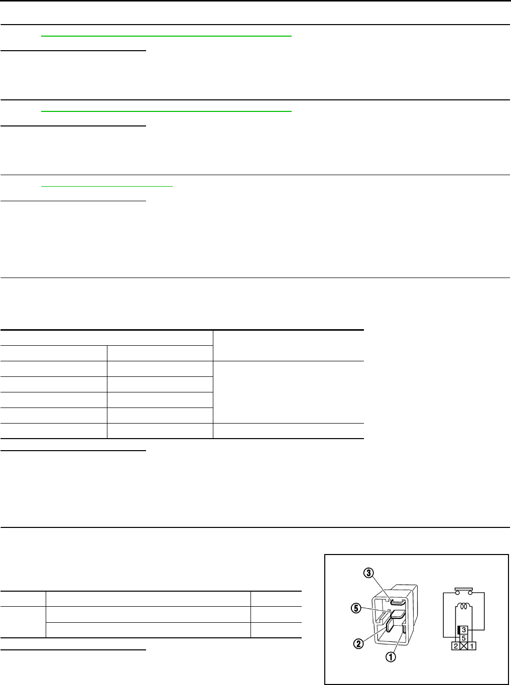
EC-416
< COMPONENT DIAGNOSIS > [FOR CALIFORNIA]
COOLING FAN
9.CHECK COOLING FAN RELAY-5
Refer to EC-416, "Component Inspection (Cooling Fan Relay)".
Is the inspection result normal?
YES >> GO TO 10.
NO >> Replace cooling fan relay.
10.CHECK COOLING FAN MOTORS
Refer to EC-416, "Component Inspection (Cooling Fan Motor)".
Is the inspection result normal?
YES >> GO TO 11.
NO >> Replace malfunctioning cooling fan motor.
11.CHECK INTERMITTENT INCIDENT
Perform GI-41, "Intermittent Incident".
Is the inspection result normal?
YES >> Replace IPDM E/R.
NO >> Repair or replace harness or connector.
Component Inspection (Cooling Fan Motor) INFOID:0000000004493647
1.CHECK COOLING FAN MOTORS
1. Turn ignition switch OFF.
2. Disconnect cooling fan motor-1 and -2 harness connectors E53, E54.
3. Supply cooling fan motor terminals with battery voltage and check operation.
Is the inspection result normal?
YES >> INSPECTION END
NO >> Replace cooling fan motor.
Component Inspection (Cooling Fan Relay) INFOID:0000000004493648
1.CHECK COOLING FAN RELAYS
1. Turn ignition switch OFF.
2. Remove cooling fan relay.
3. Check the continuity between cooling fan relay terminals under
the following conditions.
Is the inspection result normal?
YES >> INSPECTION END
NO >> Replace cooling fan relay.
Cooling fan motor terminals Operation
(+) (-)
1 3 and 4
Cooling fans operates at low speed.
2 3 and 4
1 and 2 3
1 and 2 4
1 and 2 3 and 4 Cooling fans operates at high speed.
Terminals Conditions Continuity
3 and 5 12V direct current supply between terminals 1 and 2 Existed
No current supply Not existed
PBIB0098E
Revision: 2008 August 2009 Rogue

ELECTRICAL LOAD SIGNAL
EC-417
< COMPONENT DIAGNOSIS > [FOR CALIFORNIA]
C
D
E
F
G
H
I
J
K
L
M
A
EC
N
P
O
ELECTRICAL LOAD SIGNAL
Description INFOID:0000000004493649
The electrical load signal (Headlamp switch signal, rear window defogger switch signal, etc.) is transferred
through the CAN communication line from BCM to ECM via IPDM E/R.
Component Function Check INFOID:0000000004493650
1.CHECK REAR WINDOW DEFOGGER SWITCH FUNCTION
1. Turn ignition switch ON.
2. Connect CONSULT-III and select “DATA MONITOR” mode.
3. Select “LOAD SIGNAL” and check indication under the following conditions.
Is the inspection result normal?
YES >> GO TO 2.
NO >> Go to EC-417, "Diagnosis Procedure".
2.CHECK LIGHTING SWITCH FUNCTION
Check “LOAD SIGNAL” indication under the following conditions.
Is the inspection result normal?
YES >> GO TO 3.
NO >> Go to EC-417, "Diagnosis Procedure".
3.CHECK HEATER FAN CONTROL SWITCH FUNCTION
Select “HEATER FAN SW” and check indication under the following conditions.
Is the inspection result normal?
YES >> INSPECTION END
NO >> Go to EC-417, "Diagnosis Procedure".
Diagnosis Procedure INFOID:0000000004493651
1.INSPECTION START
Confirm the malfunctioning circuit (rear window defogger, headlamp or heater fan). Refer to EC-417, "Compo-
nent Function Check".
Which circuit is related to the incident?
Rear window defogger>>GO TO 2.
Headlamp>>GO TO 3.
Heater fan>>GO TO 4.
2.CHECK REAR WINDOW DEFOGGER SYSTEM
Refer to DEF-4, "System Diagram".
Monitor item Condition Indication
LOAD SIGNAL Rear window defogger switch ON ON
OFF OFF
Monitor item Condition Indication
LOAD SIGNAL Lighting switch ON at 2nd position ON
OFF OFF
Monitor item Condition Indication
HEATER FAN SW Heater fan control switch ON ON
OFF OFF
Revision: 2008 August 2009 Rogue

EC-418
< COMPONENT DIAGNOSIS > [FOR CALIFORNIA]
ELECTRICAL LOAD SIGNAL
>> INSPECTION END
3.CHECK HEADLAMP SYSTEM
Refer to EXL-8, "System Diagram" (XENON TYPE) or EXL-136, "System Diagram" (HALOGEN TYPE).
>> INSPECTION END
4.CHECK HEATER FAN CONTROL SYSTEM
Refer to VTL-3, "System Description".
>> INSPECTION END
Revision: 2008 August 2009 Rogue

FUEL INJECTOR
EC-419
< COMPONENT DIAGNOSIS > [FOR CALIFORNIA]
C
D
E
F
G
H
I
J
K
L
M
A
EC
N
P
O
FUEL INJECTOR
Description INFOID:0000000004493652
The fuel injector is a small, precise solenoid valve. When the ECM
supplies a ground to the fuel injector circuit, the coil in the fuel injec-
tor is energized. The energized coil pulls the ball valve back and
allows fuel to flow through the fuel injector into the intake manifold.
The amount of fuel injected depends upon the injection pulse dura-
tion. Pulse duration is the length of time the fuel injector remains
open. The ECM controls the injection pulse duration based on
engine fuel needs.
Component Function Check INFOID:0000000004493653
1.INSPECTION START
Turn ignition switch to START.
Are any cylinders ignited?
YES >> GO TO 2.
NO >> Go to EC-419, "Diagnosis Procedure".
2.CHECK FUEL INJECTOR FUNCTION
With CONSULT-III
1. Start engine.
2. Perform “POWER BALANCE” in “ACTIVE TEST” mode with CONSULT-III.
3. Check that each circuit produces a momentary engine speed drop.
Without CONSULT-III
1. Let engine idle.
2. Listen to each fuel injector operating sound.
Is the inspection result normal?
YES >> INSPECTION END
NO >> Go to EC-419, "Diagnosis Procedure".
Diagnosis Procedure INFOID:0000000004493654
1.CHECK FUEL INJECTOR POWER SUPPLY CIRCUIT
1. Turn ignition switch OFF.
2. Disconnect fuel injector harness connector.
3. Turn ignition switch ON.
4. Check the voltage between fuel injector harness connector and ground.
PBIA9664J
Clicking noise should be heard.
PBIB3332E
Revision: 2008 August 2009 Rogue

EC-420
< COMPONENT DIAGNOSIS > [FOR CALIFORNIA]
FUEL INJECTOR
Is the inspection result normal?
YES >> GO TO 3.
NO >> GO TO 2.
2.DETECT MALFUNCTIONING PART
Check the following.
• Harness connectors E7, F121
• IPDM E/R harness connector E14
• 15A fuse (No. 64)
• Harness for open or short between fuel injector and fuse
>> Repair open circuit or short to ground or short to power in harness or connectors.
3.CHECK FUEL INJECTOR OUTPUT SIGNAL CIRCUIT FOR OPEN AND SHORT
1. Turn ignition switch OFF.
2. Disconnect ECM harness connector.
3. Check the continuity between fuel injector harness connector and ECM harness connector.
4. Also check harness for short to ground and short to power.
Is the inspection result normal?
YES >> GO TO 4.
NO >> Repair open circuit or short to ground or short to power in harness or connectors.
4.CHECK FUEL INJECTOR
Refer to EC-420, "Component Inspection".
Is the inspection result normal?
YES >> GO TO 5.
NO >> Replace malfunctioning fuel injector.
5.CHECK INTERMITTENT INCIDENT
Refer to GI-41, "Intermittent Incident".
Is the inspection result normal?
YES >> Replace IPDM E/R.
NO >> Repair open circuit or short to ground or short to power in harness or connectors.
Component Inspection INFOID:0000000004493655
1.CHECK FUEL INJECTOR
1. Turn ignition switch OFF.
2. Disconnect fuel injector harness connector.
Fuel injector Ground Voltage
Cylinder Connector Terminal
1F37 1
Ground Battery voltage
2F38 1
3F39 1
4F40 1
Fuel injector ECM Continuity
Cylinder Connector Terminal Connector Terminal
1F372
F7
32
Existed
2F382 31
3F392 30
4F402 29
Revision: 2008 August 2009 Rogue

FUEL INJECTOR
EC-421
< COMPONENT DIAGNOSIS > [FOR CALIFORNIA]
C
D
E
F
G
H
I
J
K
L
M
A
EC
N
P
O
3. Check resistance between fuel injector terminals as follows.
Is the inspection result normal?
YES >> INSPECTION END
NO >> Replace malfunctioning fuel injector.
Terminals Resistance
1 and 2 11.1 - 14.3 Ω [at 10 -60°C (50 - 140°F)]
Revision: 2008 August 2009 Rogue

EC-422
< COMPONENT DIAGNOSIS > [FOR CALIFORNIA]
FUEL PUMP
FUEL PUMP
Description INFOID:0000000004493656
*: ECM determines the start signal status by the signals of engine speed and battery voltage.
The ECM activates the fuel pump for several seconds after the ignition switch is turned ON to improve engine
startability. If the ECM receives a engine speed signal from the camshaft position sensor (PHASE), it knows
that the engine is rotating, and causes the pump to operate. If the engine speed signal is not received when
the ignition switch is ON, the engine stalls. The ECM stops pump operation and prevents battery discharging,
thereby improving safety. The ECM does not directly drive the fuel pump. It controls the ON/OFF fuel pump
relay, which in turn controls the fuel pump.
Component Function Check INFOID:0000000004493657
1.CHECK FUEL PUMP FUNCTION
1. Turn ignition switch ON.
2. Pinch fuel feed hose (1) with two fingers.
- : Vehicle front
Is the inspection result normal?
YES >> INSPECTION END
NO >> EC-422, "Diagnosis Procedure".
Diagnosis Procedure INFOID:0000000004493658
1.CHECK FUEL PUMP POWER SUPPLY CIRCUIT-I
1. Turn ignition switch OFF.
2. Disconnect ECM harness connector.
3. Turn ignition switch ON.
4. Check the voltage between ECM harness connector and ground.
Is the inspection result normal?
YES >> GO TO 9.
NO >> GO TO 2.
2.CHECK FUEL PUMP POWER SUPPLY CIRCUIT-II
Sensor Input signal to ECM ECM function Actuator
Crankshaft position sensor (POS)
Camshaft position sensor (PHASE) Engine speed* Fuel pump control Fuel pump relay
↓
Fuel pump
Battery Battery voltage*
Condition Fuel pump operation
Ignition switch is turned to ON. Operates for 1 second.
Engine running and cranking Operates.
When engine is stopped Stops in 1.5 seconds.
Except as shown above Stops.
Fuel pressure pulsation should be felt on the fuel feed
hose for 1 second after ignition switch is turned ON.
JMBIA0929ZZ
ECM Ground Voltage
Connector Terminal
F7 14 Ground Battery voltage
Revision: 2008 August 2009 Rogue

FUEL PUMP
EC-423
< COMPONENT DIAGNOSIS > [FOR CALIFORNIA]
C
D
E
F
G
H
I
J
K
L
M
A
EC
N
P
O
1. Turn ignition switch OFF.
2. Disconnect IDPDM E/R harness connector E13.
3. Check the continuity between IPDM E/R harness connector and ECM harness connector.
Is the inspection result normal?
YES >> GO TO 4.
NO >> GO TO 3.
3.DETECT MALFUNCTIONING PART
Check the following.
• Harness connectors E6, F123
• IPDM E/R connector E13
• Harness for open or short between ECM and IPDM E/R
>> Repair open circuit or short to ground or short to power in harness or connectors.
4.CHECK 15A FUSE
1. Disconnect 15A fuse (No. 57) from IPDM E/R.
2. Check 15A fuse.
Is the inspection result normal?
YES >> GO TO 5.
NO >> Replace fuse.
5.CHECK FUEL PUMP POWER SUPPLY CIRCUIT-III
1. Disconnect “fuel level sensor unit and fuel pump” harness connector.
2. Check the continuity between IPDM E/R harness connector and “fuel level sensor unit and fuel pump” and
ground.
Is the inspection result normal?
YES >> GO TO 7.
NO >> GO TO 6.
6.DETECT MALFUNCTIONING PART
Check the following.
• Harness connectors E105, M77
• Harness connectors M11, B1
• Harness for open or short between “fuel level sensor unit and fuel pump” and IPDM E/R
>> Repair open circuit or short to ground or short to power in harness or connectors.
7.CHECK FUEL PUMP GROUND CIRCUIT
1. Check the continuity between “fuel level sensor unit and fuel pump” and ground.
2. Also heck harness for short to power.
ECM IPDM E/R Continuity
Connector Terminal Connector Terminal
F7 14 E13 33 Existed
IPDM E/R Fuel level sensor unit
and fuel pump Continuity
Connector Terminal Connector Terminal
E14 46 B40 5 Existed
Fuel level sensor unit
and fuel pump Ground Continuity
Connector Terminal
B40 3 Ground Existed
Revision: 2008 August 2009 Rogue

EC-424
< COMPONENT DIAGNOSIS > [FOR CALIFORNIA]
FUEL PUMP
Is the inspection result normal?
YES >> GO TO 8.
NO >> Repair open circuit or short to power in harness or connectors.
8.CHECK FUEL PUMP
Refer to EC-424, "Component Inspection".
Is the inspection result normal?
YES >> GO TO 9.
NO >> Replace fuel pump.
9.CHECK INTERMITTENT INCIDENT
Refer to GI-41, "Intermittent Incident".
Is the inspection result normal?
YES >> Replace IPDM E/R.
NO >> Repair or replace harness or connectors.
Component Inspection INFOID:0000000004493659
1.CHECK FUEL PUMP
1. Turn ignition switch OFF.
2. Disconnect “fuel level sensor unit and fuel pump” harness connector.
3. Check resistance between “fuel level sensor unit and fuel pump” terminals as follows.
Is the inspection result normal?
YES >> INSPECTION END
NO >> Replace “fuel level sensor unit and fuel pump”.
Terminals Resistance
3 and 5 0.2 - 5.0 Ω [at 25°C (77°F)]
Revision: 2008 August 2009 Rogue

IGNITION SIGNAL
EC-425
< COMPONENT DIAGNOSIS > [FOR CALIFORNIA]
C
D
E
F
G
H
I
J
K
L
M
A
EC
N
P
O
IGNITION SIGNAL
Description INFOID:0000000004493660
The ignition signal from the ECM is sent to and amplified by the power transistor. The power transistor turns
ON and OFF the ignition coil primary circuit. This ON/OFF operation induces the proper high voltage in the coil
secondary circuit.
Component Function Check INFOID:0000000004493661
1.INSPECTION START
Turn ignition switch OFF, and restart engine.
Does the engine start?
YES-1 >> With CONSULT-III: GO TO 2.
YES-2 >> Without CONSULT-III: GO TO 3.
NO >> Go to EC-425, "Diagnosis Procedure".
2.IGNITION SIGNAL FUNCTION
With CONSULT-III
1. Perform “POWER BALANCE” in “ACTIVE TEST” mode with CONSULT-III.
2. Check that each circuit produces a momentary engine speed drop.
Is the inspection result normal?
YES >> INSPECTION END
NO >> Go to EC-425, "Diagnosis Procedure".
3.IGNITION SIGNAL FUNCTION
Without CONSULT-III
1. Let engine idle.
2. Read the voltage signal between ECM harness connector and ground.
NOTE:
The pulse cycle changes depending on rpm at idle.
Is the inspection result normal?
YES >> INSPECTION END
NO >> Go to EC-425, "Diagnosis Procedure".
Diagnosis Procedure INFOID:0000000004493662
1.CHECK IGNITION COIL POWER SUPPLY CIRCUIT-I
1. Turn ignition switch OFF, wait at least 10 seconds and then turn it ON.
2. Check the voltage between ECM harness connector and ground.
ECM Ground Voltage signal
Connector Terminal
F7
9
Ground
10
11
21
JMBIA0900G
B
ECM Ground Voltage
Connector Terminal
E16 105 Ground Battery voltage
Revision: 2008 August 2009 Rogue

EC-426
< COMPONENT DIAGNOSIS > [FOR CALIFORNIA]
IGNITION SIGNAL
Is the inspection result normal?
YES >> GO TO 2.
NO >> Go to EC-124, "Diagnosis Procedure".
2.CHECK IGNITION COIL POWER SUPPLY CIRCUIT-II
1. Turn ignition switch OFF.
2. Disconnect condenser-1 harness connector.
3. Turn ignition switch ON.
4. Check the voltage between condenser-1 harness connector and ground.
Is the inspection result normal?
YES >> GO TO 5.
NO >> GO TO 3.
3.CHECK IGNITION COIL POWER SUPPLY CIRCUIT-III
1. Turn ignition switch OFF.
2. Disconnect IPDM E/R harness connector E15.
3. Check the continuity between IPDM E/R harness connector and condenser-1 harness connector.
4. Also check harness for short to ground and short to power.
Is the inspection result normal?
YES >> Go to EC-124, "Diagnosis Procedure".
NO >> GO TO 4.
4.DETECT MALFUNCTIONING PART
Check the following.
• Harness connectors E7, F121
• Harness for open or short between IPDM E/R and condenser-1
>> Repair open circuit or short to ground or short to power in harness or connectors.
5.CHECK CONDENSER-1 GROUND CIRCUIT FOR OPEN AND SHORT
1. Turn ignition switch OFF.
2. Check the continuity between condenser-1 harness connector and ground.
3. Also check harness for short to power.
Is the inspection result normal?
YES >> GO TO 6.
NO >> Repair open circuit or short to ground or short to power in harness or connectors.
6.CHECK CONDENSER
Refer to EC-429, "Component Inspection (Condenser-1)"
Is the inspection result normal?
YES >> GO TO 7.
NO >> Replace condenser.
Condenser Ground Voltage
Connector Terminal
F13 1 Ground Battery voltage
IPDM E/R Condenser-1 Continuity
Connector Terminal Connector Terminal
E15 47 F13 1 Existed
Condenser-1 Ground Continuity
Connector Terminal
F13 2 Ground Existed
Revision: 2008 August 2009 Rogue

IGNITION SIGNAL
EC-427
< COMPONENT DIAGNOSIS > [FOR CALIFORNIA]
C
D
E
F
G
H
I
J
K
L
M
A
EC
N
P
O
7.CHECK IGNITION COIL POWER SUPPLY CIRCUIT-IV
1. Reconnect all harness connectors disconnected.
2. Disconnect ignition coil harness connector.
3. Turn ignition switch ON.
4. Check the voltage between ignition coil harness connector and ground.
Is the inspection result normal?
YES >> GO TO 8.
NO >> Repair open circuit or short to ground or short to power in harness or connectors.
8.CHECK IGNITION COIL GROUND CIRCUIT FOR OPEN AND SHORT
1. Turn ignition switch OFF.
2. Check the continuity between ignition coil harness connector and ground.
3. Also check harness for short to power.
Is the inspection result normal?
YES >> GO TO 9.
NO >> Repair open circuit or short to ground or short to power in harness or connectors.
9.CHECK IGNITION COIL OUTPUT SIGNAL CIRCUIT FOR OPEN AND SHORT
1. Disconnect ECM harness connector.
2. Check the continuity between ECM harness connector and ignition coil harness connector.
3. Also check harness for short to ground and short to power.
Is the inspection result normal?
YES >> GO TO 10.
NO >> Repair open circuit or short to ground or short to power in harness or connectors.
10.CHECK IGNITION COIL WITH POWER TRANSISTOR
Refer to EC-428, "Component Inspection (Ignition Coil with Power Transistor)".
Is the inspection result normal?
YES >> GO TO 11.
NO >> Replace malfunctioning ignition coil with power transistor.
Ignition coil Ground Voltage
Cylinder Connector Terminal
1F33 3
Ground Battery voltage
2F34 3
3F35 3
4F36 3
Ignition coil Ground Continuity
Cylinder Connector Terminal
1F33 2
Ground Existed
2F34 2
3F35 2
4F36 2
Ignition coil ECM Continuity
Cylinder Connector Terminal Connector Terminal
1F33 1
F7
11
Existed
2F34 1 10
3F35 1 9
4F36 1 21
Revision: 2008 August 2009 Rogue

EC-428
< COMPONENT DIAGNOSIS > [FOR CALIFORNIA]
IGNITION SIGNAL
11.CHECK INTERMITTENT INCIDENT
Refer to GI-41, "Intermittent Incident".
>> INSPECTION END
Component Inspection (Ignition Coil with Power Transistor) INFOID:0000000004493663
1.CHECK IGNITION COIL WITH POWER TRANSISTOR-I
1. Turn ignition switch OFF.
2. Disconnect ignition coil harness connector.
3. Check resistance between ignition coil terminals as follows.
Is the inspection result normal?
YES >> GO TO 2.
NO >> Replace malfunctioning ignition coil with power transistor.
2.CHECK IGNITION COIL WITH POWER TRANSISTOR-II
CAUTION:
Perform the following procedure in a place with no combustible objects and good ventilation.
1. Turn ignition switch OFF.
2. Reconnect all harness connectors disconnected.
3. Remove fuel pump fuse in IPDM E/R to release fuel pressure.
NOTE:
Do not use CONSULT-III to release fuel pressure, or fuel pressure applies again during the following pro-
cedure.
4. Start engine.
5. After engine stalls, crank it two or three times to release all fuel pressure.
6. Turn ignition switch OFF.
7. Remove all ignition coil harness connectors to avoid the electrical discharge from the ignition coils.
8. Remove ignition coil and spark plug of the cylinder to be checked.
9. Crank engine for 5 seconds or more to remove combustion gas in the cylinder.
10. Connect spark plug and harness connector to ignition coil.
11. Fix ignition coil using a rope etc. with gap of 13 - 17 mm (0.52 -
0.66 in) between the edge of the spark plug and grounded metal
portion as shown in the figure.
12. Crank engine for approximately three seconds, and check
whether spark is generated between the spark plug and the
grounded metal portion.
CAUTION:
• Never place the spark plug and the ignition coil within 50
cm (19.7 in) each other. Be careful not to get an electrical
shock while checking, because the electrical discharge
voltage becomes 20kV or more.
• It might damage the ignition coil if the gap of more than 17 mm (0.66 in) is made.
NOTE:
When the gap is less than 13 mm (0.52 in), a spark might be generated even if the coil is malfunc-
tioning.
Is the inspection result normal?
YES >> INSPECTION END
NO >> Replace malfunctioning ignition coil with power transistor.
Terminals Resistance [Ω at 25°C (77°F)]
1 and 2 Except 0 or ∞
1 and 3 Except 0
2 and 3
Spark should be generated.
JMBIA0066G
B
Revision: 2008 August 2009 Rogue

IGNITION SIGNAL
EC-429
< COMPONENT DIAGNOSIS > [FOR CALIFORNIA]
C
D
E
F
G
H
I
J
K
L
M
A
EC
N
P
O
Component Inspection (Condenser-1) INFOID:0000000004493664
1.CHECK CONDENSER-1
1. Turn ignition switch OFF.
2. Disconnect condenser-1 harness connector.
3. Check resistance between condenser-1 terminals as follows.
Is the inspection result normal?
YES >> INSPECTION END
NO >> Replace condenser-1.
Terminals Resistance
1 and 2 Above 1 MΩ [at 25°C (77°F)]
Revision: 2008 August 2009 Rogue
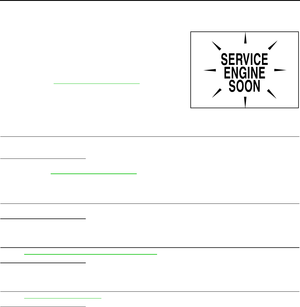
EC-430
< COMPONENT DIAGNOSIS > [FOR CALIFORNIA]
MALFUNCTION INDICATOR LAMP
MALFUNCTION INDICATOR LAMP
Description INFOID:0000000004493665
The Malfunction Indicator Lamp (MIL) is located on the combination
meter.
The MIL will illuminate when the ignition switch is turned ON without
the engine running. This is a bulb check.
When the engine is started, the MIL should turn off. If the MIL
remains illuminated, the on board diagnostic system has detected an
engine system malfunction.
For details, refer to EC-430, "Diagnosis Procedure".
Component Function Check INFOID:0000000004493666
1.CHECK MIL FUNCTION
1. Turn ignition switch ON.
2. Check that MIL illuminate.
Is the inspection result normal?
YES >> INSPECTION END
NO >> Go to EC-430, "Diagnosis Procedure".
Diagnosis Procedure INFOID:0000000004493667
1.CHECK DTC
Check that DTC UXXXX is not displayed.
Is the inspection result normal?
YES >> GO TO 2.
NO >> Perform trouble diagnosis for DTC UXXXX.
2.CHECK DTC WITH METER
Refer to MWI-33, "CONSULT-III Function (METER/M&A)".
Is the inspection result normal?
YES >> GO TO 3.
NO >> Repair or replace.
3.CHECK INTERMITTENT INCIDENT
Refer to GI-41, "Intermittent Incident".
Is the inspection result normal?
YES >> Replace combination meter.
NO >> Repair or replace.
SEF217U
Revision: 2008 August 2009 Rogue

ON BOARD REFUELING VAPOR RECOVERY (ORVR)
EC-431
< COMPONENT DIAGNOSIS > [FOR CALIFORNIA]
C
D
E
F
G
H
I
J
K
L
M
A
EC
N
P
O
ON BOARD REFUELING VAPOR RECOVERY (ORVR)
Description INFOID:0000000004493668
From the beginning of refueling, the air and vapor inside the fuel tank go through refueling EVAP vapor cut
valve and EVAP/ORVR line to the EVAP canister. The vapor is absorbed by the EVAP canister and the air is
released to the atmosphere.
When the refueling has reached the full level of the fuel tank, the refueling EVAP vapor cut valve is closed and
refueling is stopped because of auto shut-off. The vapor which was absorbed by the EVAP canister is purged
during driving.
WARNING:
When conducting inspections below, be sure to observe the following:
• Put a “CAUTION: FLAMMABLE” sign in workshop.
• Never smoke while servicing fuel system. Keep open flames and sparks away from work area.
• Always furnish the workshop with a CO2 fire extinguisher.
CAUTION:
• Before removing fuel line parts, carry out the following procedures:
- Put drained fuel in an explosion-proof container and put lid on securely.
- Release fuel pressure from fuel line. Refer to EC-489, "Inspection".
- Disconnect battery ground cable.
• Always replace O-ring when the fuel gauge retainer is removed.
• Never kink or twist hose and tube when they are installed.
• Never tighten hose and clamps excessively to avoid damaging hoses.
• After installation, run engine and check for fuel leaks at connections.
• Never attempt to top off the fuel tank after the fuel pump nozzle shuts off automatically.
Continued refueling may cause fuel overflow, resulting in fuel spray and possibly a fire.
Component Function Check INFOID:0000000004493669
1.CHECK ORVR FUNCTION
Check whether the following symptoms are present.
• Fuel odor from EVAP canister is strong.
• Cannot refuel/Fuel odor from the fuel filler opening is strong while refueling.
Are any symptoms present?
YES >> Go to EC-431, "Diagnosis Procedure".
NO >> INSPECTION END
Diagnosis Procedure INFOID:0000000004493670
1.INSPECTION START
Check whether the following symptoms are present.
A: Fuel odor from EVAP canister is strong.
PBIB1068E
Revision: 2008 August 2009 Rogue
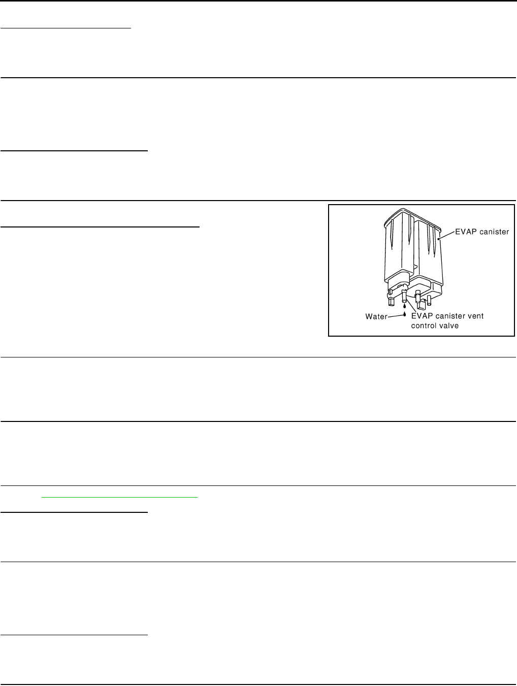
EC-432
< COMPONENT DIAGNOSIS > [FOR CALIFORNIA]
ON BOARD REFUELING VAPOR RECOVERY (ORVR)
B: Cannot refuel/Fuel odor from the fuel filler opening is strong while refueling.
Which symptom is present?
A>>GO TO 2.
B>>GO TO 7.
2.CHECK EVAP CANISTER
1. Remove EVAP canister with EVAP canister vent control valve and EVAP control system pressure sensor
attached.
2. Weigh the EVAP canister with EVAP canister vent control valve and EVAP control system pressure sensor
attached.
The weight should be less than 2.1 kg (4.6 lb).
Is the inspection result normal?
YES >> GO TO 3.
NO >> GO TO 4.
3.CHECK IF EVAP CANISTER IS SATURATED WITH WATER
Check if water will drain from EVAP canister.
Does water drain from the EVAP canister?
YES >> GO TO 4.
NO >> GO TO 6.
4.REPLACE EVAP CANISTER
Replace EVAP canister with a new one.
>> GO TO 5.
5.DETECT MALFUNCTIONING PART
Check the EVAP hose between EVAP canister and vehicle frame for clogging or poor connection.
>> Repair or replace EVAP hose.
6.CHECK REFUELING EVAP VAPOR CUT VALVE
Refer to EC-434, "Component Inspection".
Is the inspection result normal?
YES >> INSPECTION END
NO >> Replace refueling EVAP vapor cut valve with fuel tank.
7.CHECK EVAP CANISTER
1. Remove EVAP canister with EVAP canister vent control valve and EVAP control system pressure sensor
attached.
2. Weigh the EVAP canister with EVAP canister vent control valve and EVAP control system pressure sensor
attached.
The weight should be less than 2.1 kg (4.6 lb).
Is the inspection result normal?
YES >> GO TO 8.
NO >> GO TO 9.
8.CHECK IF EVAP CANISTER IS SATURATED WITH WATER
PBIB1213E
Revision: 2008 August 2009 Rogue

ON BOARD REFUELING VAPOR RECOVERY (ORVR)
EC-433
< COMPONENT DIAGNOSIS > [FOR CALIFORNIA]
C
D
E
F
G
H
I
J
K
L
M
A
EC
N
P
O
Check if water will drain from EVAP canister.
Does water drain from the EVAP canister?
YES >> GO TO 9.
NO >> GO TO 11.
9.REPLACE EVAP CANISTER
Replace EVAP canister with a new one.
>> GO TO 10.
10.DETECT MALFUNCTIONING PART
Check the EVAP hose between EVAP canister and vehicle frame for clogging or poor connection.
>> Repair or replace EVAP hose.
11.CHECK VENT HOSES AND VENT TUBES
Check hoses and tubes between EVAP canister and refueling control valve for clogging, kinks, looseness and
improper connection.
Is the inspection result normal?
YES >> GO TO 12.
NO >> Repair or replace hoses and tubes.
12.CHECK FILLER NECK TUBE
Check recirculation line for clogging, dents and cracks.
Is the inspection result normal?
YES >> GO TO 13.
NO >> Replace filler neck tube.
13.CHECK REFUELING EVAP VAPOR CUT VALVE
Refer to EC-434, "Component Inspection".
Is the inspection result normal?
YES >> GO TO 14.
NO >> Replace refueling EVAP vapor cut valve with fuel tank.
14.CHECK FUEL FILLER TUBE
Check filler neck tube and hose connected to the fuel tank for clogging, dents and cracks.
Is the inspection result normal?
YES >> GO TO 15.
NO >> Replace fuel filler tube.
15.CHECK ONE-WAY FUEL VALVE-I
Check one-way valve for clogging.
Is the inspection result normal?
YES >> GO TO 16.
NO >> Repair or replace one-way fuel valve with fuel tank.
16.CHECK ONE-WAY FUEL VALVE-II
1. Check that fuel is drained from the tank.
2. Remove fuel filler tube and hose.
PBIB1213E
Revision: 2008 August 2009 Rogue
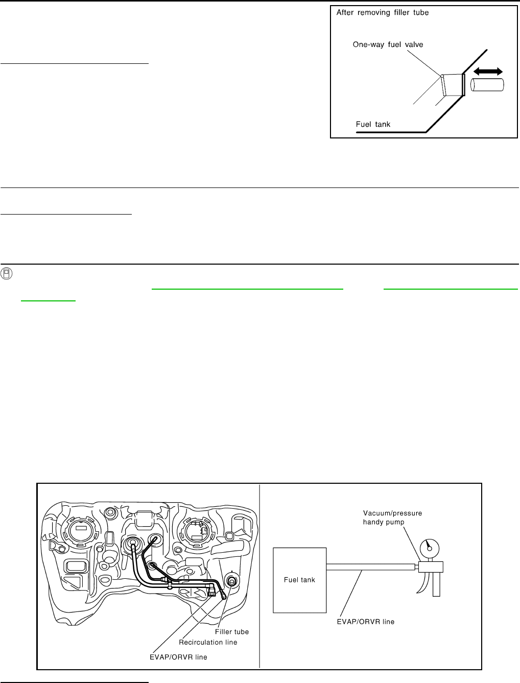
EC-434
< COMPONENT DIAGNOSIS > [FOR CALIFORNIA]
ON BOARD REFUELING VAPOR RECOVERY (ORVR)
3. Check one-way fuel valve for operation as follows.
When a stick is inserted, the valve should open, when removing
stick it should close.
Do not drop any material into the tank.
Is the inspection result normal?
YES >> INSPECTION END
NO >> Replace fuel filler tube or replace one-way fuel valve
with fuel tank.
Component Inspection INFOID:0000000004493671
1.INSPECTION START
Do you have CONSULT-III?
Do you have CONSULT-III?
YES >> GO TO 2.
NO >> GO TO 3.
2.CHECK REFUELING EVAP VAPOR CUT VALVE
With CONSULT-III
1. Remove fuel tank. Refer to FL-15, "2WD : Removal and Installation" (2WD), FL-18, "AWD : Removal and
Installation" (AWD).
2. Drain fuel from the tank as follows:
- Remove fuel feed hose located on the fuel gauge retainer.
- Connect a spare fuel hose, one side to fuel gauge retainer where the hose was removed and the other
side to a fuel container.
- Drain fuel using “FUEL PUMP RELAY” in “ACTIVE TEST” mode with CONSULT-III.
3. Check refueling EVAP vapor cut valve for being stuck to close as follows.
Blow air into the refueling EVAP vapor cut valve (from the end of EVAP/ORVR line hose), and check that
the air flows freely into the tank.
4. Check refueling EVAP vapor cut valve for being stuck to open as follows.
- Connect vacuum pump to hose end.
- Remove fuel gauge retainer with fuel gauge unit.
Always replace O-ring with new one.
- Turn fuel tank upside down.
- Apply vacuum pressure to hose end [−13.3 kPa (−0.136 kg/cm3, −1.93 psi)] with fuel gauge retainer
remaining open and check that the pressure is applicable.
Is the inspection result normal?
YES >> INSPECTION END
NO >> Replace refueling EVAP vapor cut valve with fuel tank.
SEF665U
JMBIA0907G
B
Revision: 2008 August 2009 Rogue
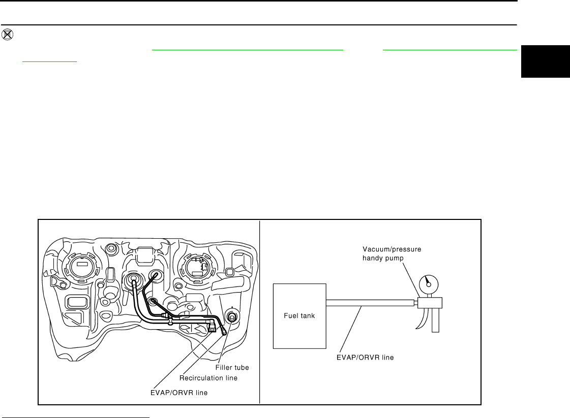
ON BOARD REFUELING VAPOR RECOVERY (ORVR)
EC-435
< COMPONENT DIAGNOSIS > [FOR CALIFORNIA]
C
D
E
F
G
H
I
J
K
L
M
A
EC
N
P
O
3.CHECK REFUELING EVAP VAPOR CUT VALVE
Without CONSULT-III
1. Remove fuel tank. Refer to FL-15, "2WD : Removal and Installation" (2WD), FL-18, "AWD : Removal and
Installation" (AWD).
2. Drain fuel from the tank as follows:
- Remove fuel gauge retainer.
- Drain fuel from the tank using a handy pump into a fuel container.
3. Check refueling EVAP vapor cut valve for being stuck to close as follows.
Blow air into the refueling EVAP vapor cut valve (from the end of EVAP/ORVR line hose), and check that
the air flows freely into the tank.
4. Check refueling EVAP vapor cut valve for being stuck to open as follows.
- Connect vacuum pump to hose end.
- Remove fuel gauge retainer with fuel gauge unit.
Always replace O-ring with new one.
- Turn fuel tank upside down.
- Apply vacuum pressure to hose end [−13.3 kPa (−0.136 kg/cm3, −1.93 psi)] with fuel gauge retainer
remaining open and check that the pressure is applicable.
Is the inspection result normal?
YES >> INSPECTION END
NO >> Replace refueling EVAP vapor cut valve with fuel tank.
JMBIA0907G
B
Revision: 2008 August 2009 Rogue

EC-436
< COMPONENT DIAGNOSIS > [FOR CALIFORNIA]
POSITIVE CRANKCASE VENTILATION
POSITIVE CRANKCASE VENTILATION
Description INFOID:0000000004493672
This system returns blow-by gas to the intake manifold.
The positive crankcase ventilation (PCV) valve is provided to conduct crankcase blow-by gas to the intake
manifold.
During partial throttle operation of the engine, the intake manifold sucks the blow-by gas through the PCV
valve.
Normally, the capacity of the valve is sufficient to handle any blow-by and a small amount of ventilating air.
The ventilating air is drawn from the air inlet tubes into the crankcase. In this process the air passes through
the hose connecting air inlet tubes to rocker cover.
Under full-throttle condition, the manifold vacuum is insufficient to draw the blow-by flow through the valve.
The flow goes through the hose connection in the reverse direction.
On vehicles with an excessively high blow-by, the valve does not
meet the requirement. This is because some of the flow will go
through the hose connection to the air inlet tubes under all condi-
tions.
Component Inspection INFOID:0000000004493673
1.CHECK PCV VALVE
With engine running at idle, remove PCV valve from rocker cover. A
properly working valve makes a hissing noise as air passes through
it. A strong vacuum should be felt immediately when a finger is
placed over valve inlet.
Is the inspection result normal?
YES >> INSPECTION END
NO >> Replace PCV valve.
PBIB0492E
PBIB1588E
PBIB1589E
Revision: 2008 August 2009 Rogue

REFRIGERANT PRESSURE SENSOR
EC-437
< COMPONENT DIAGNOSIS > [FOR CALIFORNIA]
C
D
E
F
G
H
I
J
K
L
M
A
EC
N
P
O
REFRIGERANT PRESSURE SENSOR
Description INFOID:0000000004493674
The refrigerant pressure sensor is installed at the condenser of the air conditioner system. The sensor uses an
electrostatic volume pressure transducer to convert refrigerant pressure to voltage. The voltage signal is sent
to ECM, and ECM controls cooling fan system.
Component Function Check INFOID:0000000004493675
1.CHECK REFRIGERANT PRESSURE SENSOR OVERALL FUNCTION
1. Start engine and warm it up to normal operating temperature.
2. Turn A/C switch and blower fan switch ON.
3. Check the voltage between ECM harness connector terminals.
Is the inspection result normal?
YES >> INSPECTION END
NO >> Go to EC-437, "Diagnosis Procedure".
Diagnosis Procedure INFOID:0000000004493676
1.CHECK GROUND CONNECTION
1. Turn A/C switch and blower fan switch OFF.
2. Stop engine.
3. Turn ignition switch OFF.
4. Check ground connection E21. Refer to Ground Inspection in GI-44, "Circuit Inspection".
Is the inspection result normal?
YES >> GO TO 2.
NO >> Repair or replace ground connection.
2.CHECK REFRIGERANT PRESSURE SENSOR POWER SUPPLY CIRCUIT
1. Disconnect refrigerant pressure sensor harness connector.
2. Turn ignition switch ON.
3. Check the voltage between refrigerant pressure sensor harness connector and ground.
Is the inspection result normal?
YES >> GO TO 4.
PBIB2657E
ECM
Voltage+−
Connector Terminal Terminal
F8 39
(Refrigerant pressure sensor signal)
40
(Sensor ground) 1.0 - 4.0 V
Refrigerant pressure sensor Ground Voltage
Connector Terminal
E49 3 Ground Approx. 5 V
Revision: 2008 August 2009 Rogue
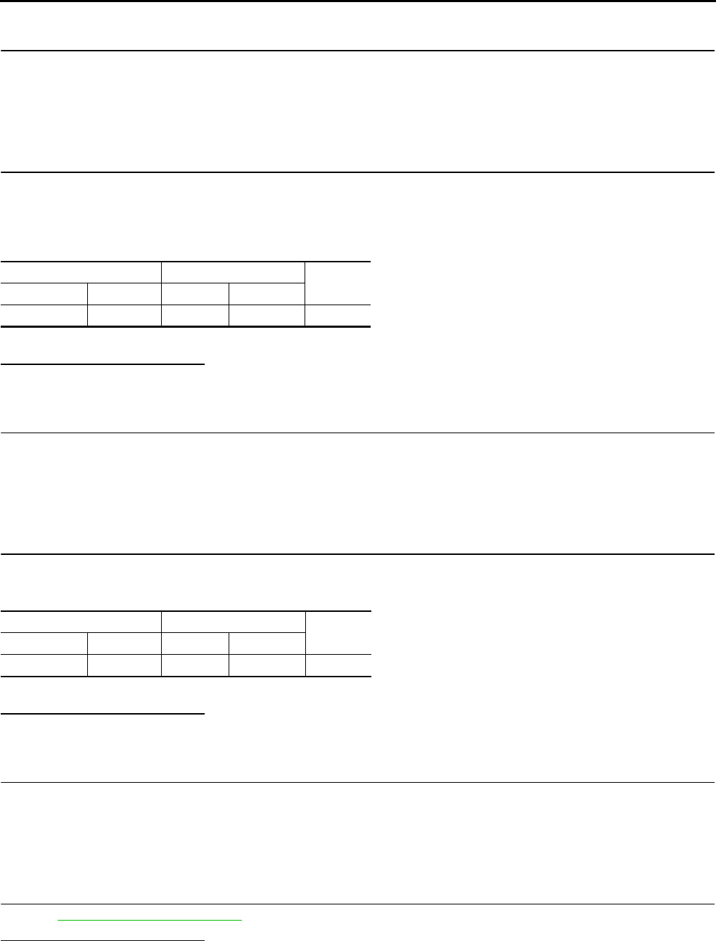
EC-438
< COMPONENT DIAGNOSIS > [FOR CALIFORNIA]
REFRIGERANT PRESSURE SENSOR
NO >> GO TO 3.
3.DETECT MALFUNCTIONING PART
Check the following.
• Harness connectors F123, E6
• Harness for open or short between ECM and refrigerant pressure sensor
>> Repair open circuit or short to ground or short to power in harness or connectors.
4.CHECK REFRIGERANT PRESSURE SENSOR GROUND CIRCUIT FOR OPEN AND SHORT
1. Turn ignition switch OFF.
2. Disconnect ECM harness connector.
3. Check the continuity between refrigerant pressure sensor harness connector and ECM harness connec-
tor.
4. Also check harness for short to ground and short to power.
Is the inspection result normal?
YES >> GO TO 6.
NO >> GO TO 5.
5.DETECT MALFUNCTIONING PART
Check the following.
• Harness connectors F123, E6
• Harness for open or short between ECM and refrigerant pressure sensor
>> Repair open circuit or short to ground or short to power in harness or connectors.
6.CHECK REFRIGERANT PRESSURE SENSOR INPUT SIGNAL CIRCUIT FOR OPEN AND SHORT
1. Check the continuity between ECM harness connector and refrigerant pressure sensor harness connec-
tor.
2. Also check harness for short to ground and short to power.
Is the inspection result normal?
YES >> GO TO 8.
NO >> GO TO 7.
7.DETECT MALFUNCTIONING PART
Check the following.
• Harness connectors F123, E6
• Harness for open or short between ECM and refrigerant pressure sensor
>> Repair open circuit or short to ground or short to power in harness or connectors.
8.CHECK INTERMITTENT INCIDENT
Refer to GI-41, "Intermittent Incident".
Is the inspection result normal?
YES >> Replace refrigerant pressure sensor.
NO >> Repair or replace.
Refrigerant pressure sensor ECM Continuity
Connector Terminal Connector Terminal
E49 1 F8 40 Existed
Refrigerant pressure sensor ECM Continuity
Connector Terminal Connector Terminal
E49 2 F8 39 Existed
Revision: 2008 August 2009 Rogue
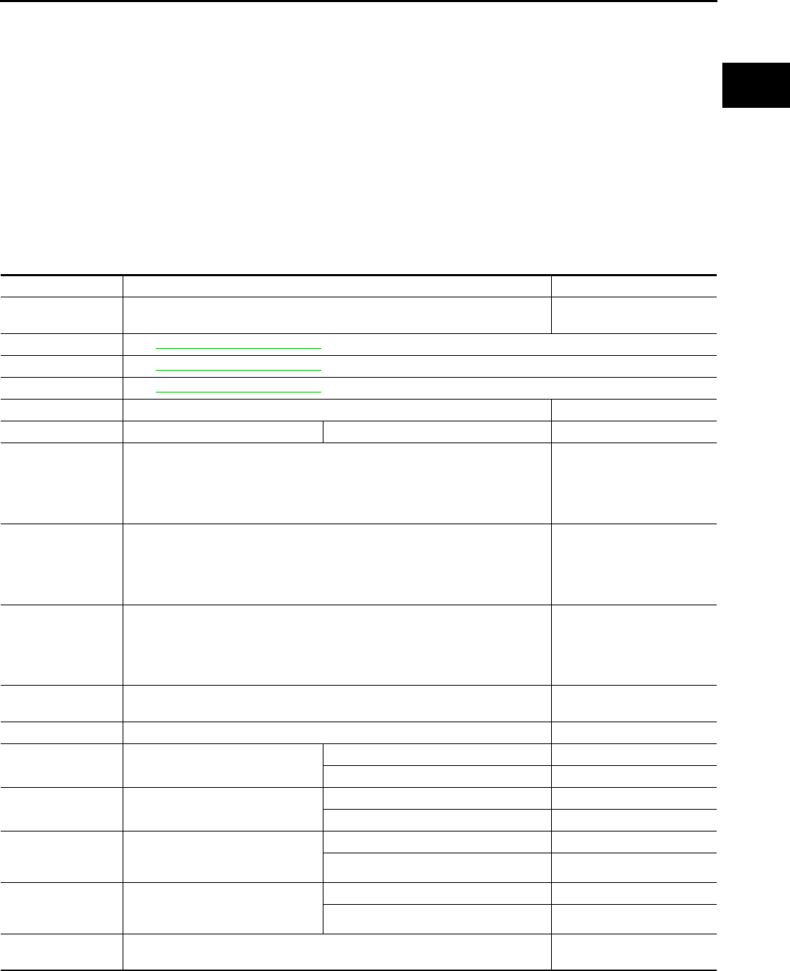
ECM
EC-439
< ECU DIAGNOSIS > [FOR CALIFORNIA]
C
D
E
F
G
H
I
J
K
L
M
A
EC
N
P
O
ECU DIAGNOSIS
ECM
Reference Value INFOID:0000000004493677
VALUES ON THE DIAGNOSIS TOOL
Remarks:
z Specification data are reference values.
z Specification data are output/input values which are detected or supplied by the ECM at the connector.
* Specification data may not be directly related to their components signals/values/operations.
I.e. Adjust ignition timing with a timing light before monitoring IGN TIMING, because the monitor may show
the specification data in spite of the ignition timing not being adjusted to the specification data. this IGN TIM-
ING monitors the data calculated by the ECM according to the signals input from the camshaft position sensor
and other ignition timing related sensors.
Monitor Item Condition Values/Status
ENG SPEED • Run engine and compare CONSULT-III value with the tachometer indication. Almost the same speed as
the tachometer indication.
MAS A/F SE-B1 See EC-117, "Diagnosis Procedure".
B/FUEL SCHDL See EC-117, "Diagnosis Procedure".
A/F ALPHA-B1 See EC-117, "Diagnosis Procedure".
COOLAN TEMP/S • Engine: After warming up More than 70°C (158°F)
A/F SEN1 (B1) • Engine: After warming up Maintaining engine speed at 2,000 rpm Fluctuates around 2.2 V
HO2S2 (B1)
• Revving engine from idle up to 3,000 rpm quickly after the following conditions
are met.
- Engine: After warming up
- After keeping engine speed between 3,500 and 4,000 rpm for 1 minute and at
idle for 1 minute under no load
0 - 0.3V ←→ Approx. 0.6 -
1.0V
HO2S3 (B1)
• Revving engine from idle up to 3,000 rpm quickly after the following conditions
are met.
- Engine: After warming up
- Driving for 3 minutes at a speed of 80 km/h (50 MPH) or more
(Keep the vehicle speed as steady as possible during the cruising.)
0 - 0.3V ←→ Approx. 0.6 -
1.0V
HO2S2 MNTR (B1)
• Revving engine from idle up to 3,000 rpm quickly after the following conditions
are met.
- Engine: After warming up
- After keeping engine speed between 3,500 and 4,000 rpm for 1 minute and at
idle for 1 minute under no load
LEAN ←→ RICH
VHCL SPEED SE • Turn drive wheels and compare CONSULT-III value with the speedometer in-
dication.
Almost the same speed as
speedometer indication
BATTERY VOLT • Ignition switch: ON (Engine stopped) 11 - 14V
ACCEL SEN 1 • Ignition switch: ON
(Engine stopped)
Accelerator pedal: Fully released 0.6 - 0.9 V
Accelerator pedal: Fully depressed 4.0 - 4.8V
ACCEL SEN 2*1• Ignition switch: ON
(Engine stopped)
Accelerator pedal: Fully released 0.6 - 0.9V
Accelerator pedal: Fully depressed 3.9 - 4.8V
TP SEN 1-B1
• Ignition switch: ON
(Engine stopped)
• Selector lever: D
Accelerator pedal: Fully released More than 0.36V
Accelerator pedal: Fully depressed Less than 4.75V
TP SEN 2-B1*1• Ignition switch: ON
(Engine stopped)
• Selector lever: D
Accelerator pedal: Fully released More than 0.36V
Accelerator pedal: Fully depressed Less than 4.75V
FUEL T/TMP SE • Ignition switch: ON Indicates fuel tank tempera-
ture
Revision: 2008 August 2009 Rogue

EC-440
< ECU DIAGNOSIS > [FOR CALIFORNIA]
ECM
INT/A TEMP SE • Ignition switch: ON Indicates intake air tempera-
ture
EVAP SYS PRES • Ignition switch: ON Approx. 1.8 - 4.8V
FUEL LEVEL SE • Ignition switch: ON Depending on fuel level of
fuel tank
START SIGNAL • Ignition switch: ON → START → ON OFF → ON → OFF
CLSD THL POS • Ignition switch: ON
(Engine stopped)
Accelerator pedal: Fully released ON
Accelerator pedal: Slightly depressed OFF
AIR COND SIG • Engine: After warming up, idle the
engine
Air conditioner switch: OFF OFF
Air conditioner switch: ON
(Compressor operates.) ON
P/N POSI SW • Ignition switch: ON Selector lever: P or N ON
Selector lever: Except above OFF
PW/ST SIGNAL • Engine: After warming up, idle the
engine
Steering wheel: Not being turned OFF
Steering wheel: Being turned ON
LOAD SIGNAL • Ignition switch: ON
Rear window defogger switch: ON
and/or Lighting switch: 2nd position ON
Rear window defogger switch and lighting
switch: OFF OFF
IGNITION SW • Ignition switch: ON → OFF → ON ON → OFF → ON
HEATER FAN SW • Engine: After warming up, idle the
engine
Heater fan switch: ON ON
Heater fan switch: OFF OFF
BRAKE SW • Ignition switch: ON Brake pedal: Fully released OFF
Brake pedal: Slightly depressed ON
INJ PULSE-B1
• Engine: After warming up
• Selector lever: P or N
• Air conditioner switch: OFF
•No load
Idle 2.0 - 3.0 msec
2,000 rpm 1.9 - 2.9 msec
IGN TIMING
• Engine: After warming up
• Selector lever: P or N
• Air conditioner switch: OFF
•No load
Idle 10° - 20° BTDC
2,000 rpm 25° - 45° BTDC
CAL/LD VALUE
• Engine: After warming up
• Selector lever: P or N
• Air conditioner switch: OFF
•No load
Idle 10% - 35%
2,500 rpm 10% - 35%
MASS AIRFLOW
• Engine: After warming up
• Selector lever: P or N
• Air conditioner switch: OFF
•No load
Idle 1.0 - 4.0 g·m/s
2,500 rpm 4.0 - 10.0 g·m/s
PURG VOL C/V
• Engine: After warming up
• Selector lever: P or N
• Air conditioner switch: OFF
•No load
Idle
(Accelerator pedal: Not depressed even
slightly, after engine starting.)
0%
2,000 rpm 20% - 90%
INT/V TIM (B1)
• Engine: After warming up
• Selector lever: P or N
• Air conditioner switch: OFF
•No load
Idle −5° - 5°CA
2,000 rpm Approx. 0° - 20°CA
INT/V SOL (B1)
• Engine: After warming up
• Selector lever: P or N
• Air conditioner switch: OFF
•No load
Idle 0%
2,000 rpm Approx. 0% - 60%
Monitor Item Condition Values/Status
Revision: 2008 August 2009 Rogue

ECM
EC-441
< ECU DIAGNOSIS > [FOR CALIFORNIA]
C
D
E
F
G
H
I
J
K
L
M
A
EC
N
P
O
SWRL CONT S/V
• Ignition switch: ON
• Engine coolant temperature: Be-
tween 5°C (41°F) and 40°C
(104°F)
Accelerator pedal: Fully released ON
Accelerator pedal: Slightly depressed OFF
AIR COND RLY • Engine: After warming up, idle the
engine
Air conditioner switch: OFF OFF
Air conditioner switch: ON
(Compressor operates) ON
FUEL PUMP RLY
• For 1 second after turning ignition switch: ON
• Engine running or cranking ON
• Except above OFF
VENT CONT/V • Ignition switch: ON OFF
THRTL RELAY • Ignition switch: ON ON
HO2S2 HTR (B1)
• Engine speed: Below 3,600 rpm after the following conditions are met.
- Engine: After warming up
- Keeping the engine speed between 3,500 and 4,000 rpm for 1 minute and at
idle for 1 minute under no load
ON
• Engine speed: Above 3,600 rpm OFF
HO2S3 HTR (B1)
• Engine speed: Below 3,600 rpm after the following conditions are met.
- Engine: After warming up
- Driving for 3 minutes at a speed of 80 km/h (50 MPH) or more
(Keep the vehicle speed as steady as possible during the cruising.)
ON
• Engine speed: Above 3,600 rpm OFF
I/P PULLY SPD • Vehicle speed: More than 20 km/h (12 MPH) Almost the same speed as
the tachometer indication
VEHICLE SPEED • Turn drive wheels and compare CONSULT-III value with the speedometer in-
dication. Almost the same speed as
the speedometer indication
IDL A/V LEARN • Engine: running
Idle air volume learning has not been per-
formed yet. YET
Idle air volume learning has already been
performed successfully. CMPLT
TRVL AFTER MIL • Ignition switch: ON Vehicle has traveled after MIL has turned
ON. 0 - 65,535 km
(0 - 40,723 miles)
A/F S1 HTR (B1) • Engine: After warming up, idle the engine
(More than 140 seconds after starting engine.) 4 - 100%
AC PRESS SEN • Engine: Idle
• Both A/C switch and blower fan switch: ON (Compressor operates) 1.0 - 4.0V
VHCL SPEED SE • Turn drive wheels and compare CONSULT-III value with the speedometer in-
dication.
Almost the same speed as
the speedometer indication
SET VHCL SPD • Engine: Running ASCD: Operating The preset vehicle speed is
displayed
MAIN SW • Ignition switch: ON MAIN switch: Pressed ON
MAIN switch: Released OFF
CANCEL SW • Ignition switch: ON CANCEL switch: Pressed ON
CANCEL switch: Released OFF
RESUME/ACC SW • Ignition switch: ON
RESUME/ACCELERATE switch:
Pressed ON
RESUME/ACCELERATE switch: Re-
leased OFF
SET SW • Ignition switch: ON SET/COAST switch: Pressed ON
SET/COAST switch: Released OFF
Monitor Item Condition Values/Status
Revision: 2008 August 2009 Rogue
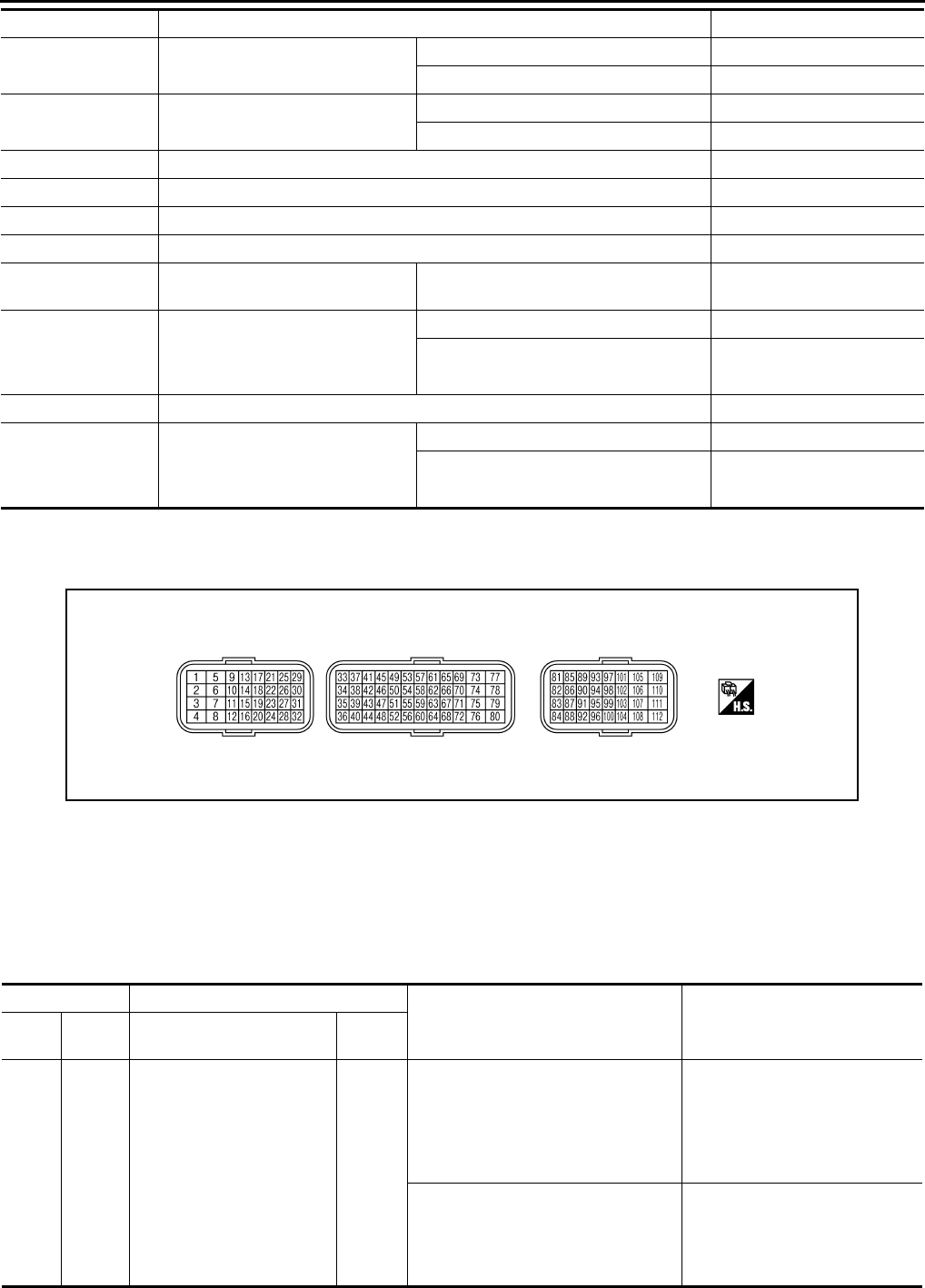
EC-442
< ECU DIAGNOSIS > [FOR CALIFORNIA]
ECM
*1: Accelerator pedal position sensor 2 signal and throttle position sensor 2 signal are converted by ECM internally. Thus, they differ
from ECM terminals voltage signal.
TERMINAL LAYOUT
PHYSICAL VALUES
NOTE:
• ECM is located behind the passenger side instrument lower panel. For this inspection, remove passenger
side instrument lower panel.
• Specification data are reference values and are measured between each terminal and ground.
• Pulse signal is measured by CONSULT-III.
BRAKE SW1
(ASCD brake switch) • Ignition switch: ON Brake pedal: Fully released ON
Brake pedal: Slightly depressed OFF
BRAKE SW2
(Stop lamp switch) • Ignition switch: ON Brake pedal: Fully released OFF
Brake pedal: Slightly depressed ON
VHCL SPD CUT • Ignition switch: ON NON
LO SPEED CUT • Ignition switch: ON NON
AT OD MONITOR • Ignition switch: ON OFF
AT OD CANCEL • Ignition switch: ON OFF
CRUISE LAMP • Ignition switch: ON MAIN switch: Pressed at the 1st time →
at the 2nd time ON → OFF
SET LAMP
• MAIN switch: ON
• When vehicle speed: Between 38
km/h (24 MPH) and 144 km/h (89
MPH)
ASCD: Operating ON
ASCD: Not operating OFF
A/F ADJ-B1 • Engine: running –0.330 - 0.330
TMBL POS SEN
• Ignition switch: ON
• Engine coolant temperature: Be-
tween 5°C (41°F) and 60°C
(140°F)
Accelerator pedal: Fully released Less than 1.2V
Accelerator pedal: Slightly depressed More than 2.9V
Monitor Item Condition Values/Status
PBIA9221J
Terminal No. Description
Condition Value
(Approx.)
+ – Signal name Input/
Output
1
(V)
112
(B)
Tumble control valve motor
(Close) Output
[Ignition switch OFF → ON]
• For a few seconds after turning igni-
tion switch ON
0 V
↓
BATTERY VOLTAGE
(11 - 14 V)
↓
0 V
[Ignition switch ON → OFF]
• For a few seconds after turning igni-
tion switch OFF
0 V
↓
1.5 - 2.0 V
↓
0 V
Revision: 2008 August 2009 Rogue
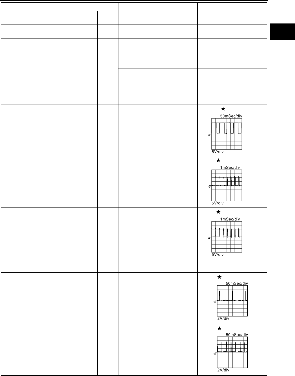
ECM
EC-443
< ECU DIAGNOSIS > [FOR CALIFORNIA]
C
D
E
F
G
H
I
J
K
L
M
A
EC
N
P
O
2
(P)
112
(B)
Throttle control motor power
supply Input [Ignition switch: ON] BATTERY VOLTAGE
(11 - 14 V)
3
(LG) 112
(B) Tumble control valve motor
(Open) Output
[Ignition switch OFF → ON]
• For a few seconds after turning igni-
tion switch ON
0 V
↓
Approx. 0.5 V
↓
0 V
[Ignition switch ON → OFF]
• For a few seconds after turning igni-
tion switch OFF
0 V
↓
BATTERY VOLTAGE
(11 - 14 V)
↓
0 V
4
(R) 112
(B) A/F sensor 1 heater Output
[Engine is running]
• Warm-up condition
• Idle speed
2.9 - 8.8 V
5
(GR)
6
(L)
Throttle control motor 1
(Open) Output
[Ignition switch: ON]
• Engine stopped
• Selector lever: D
• Accelerator pedal: Fully depressed
0 - 14 V
6
(L)
5
(GR)
Throttle control motor 2
(Close) Output
[Ignition switch: ON]
• Engine stopped
• Selector lever: D
• Accelerator pedal: Fully released
0 - 14 V
7
(BR)
112
(B)
Tumble control valve motor
power supply Input [Ignition switch: ON] BATTERY VOLTAGE
(11 - 14 V)
9
(R)
112
(B)
Ignition signal No. 3
Output
[Engine is running]
• Warm-up condition
• Idle speed
NOTE:
The pulse cycle changes depending
on rpm at idle
0 - 0.1 V
10
(W) Ignition signal No. 2
11
(SB) Ignition signal No. 1
[Engine is running]
• Warm-up condition
• Engine speed: 2,000 rpm
0 - 0.2 V
21
(G) Ignition signal No. 4
Terminal No. Description
Condition Value
(Approx.)
+ – Signal name Input/
Output
JMBIA0082G
B
JMBIA0083G
B
JMBIA0084G
B
JMBIA0900G
B
JMBIA0901G
B
Revision: 2008 August 2009 Rogue
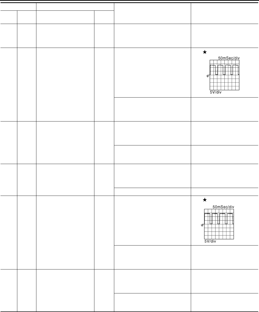
EC-444
< ECU DIAGNOSIS > [FOR CALIFORNIA]
ECM
12
(B)
16
(B)
— ECM ground — — —
13
(Y)
112
(B)
Heated oxygen sensor 2
heater Output
[Engine is running]
• Engine speed: Below 3,600 rpm af-
ter the following conditions are met
- Engine: After warming up
- Keeping the engine speed between
3,500 and 4,000 rpm for 1 minute
and at idle for 1 minute under no
load
10 V
[Ignition switch: ON]
• Engine stopped
[Engine is running]
• Engine speed: Above 3,600 rpm
BATTERY VOLTAGE
(11 - 14 V)
14
(GR)
112
(B) Fuel pump relay Output
[Ignition switch: ON]
• For 1 second after turning ignition
switch ON
[Engine is running]
0 - 1.0 V
[Ignition switch: ON]
• More than 1 second after turning ig-
nition switch ON
BATTERY VOLTAGE
(11 - 14 V)
15
(V)
112
(B) Throttle control motor relay Output [Ignition switch: ON → OFF]
0 - 1.0 V
↓
BATTERY VOLTAGE
(11 - 14 V)
[Ignition switch: ON] 0 - 1.0 V
17
(SB)
112
(B)
Heated oxygen sensor 3
heater Output
[Engine is running]
• Engine speed: Below 3,600 rpm af-
ter the following conditions are met
- Engine: After warming up
- Driving for 3 minutes at a speed of
80 km/h (50 MPH) or more
(Keep the vehicle speed as steady
as possible during the cruising.)
10 V
[Ignition switch: ON]
• Engine stopped
[Engine is running]
• Engine speed: Above 3,600 rpm
BATTERY VOLTAGE
(11 - 14 V)
24
(L) 112
(B) ECM relay
(Self shut-off) Output
[Engine is running]
[Ignition switch: OFF]
• A few seconds after turning ignition
switch OFF
0 - 1.0 V
[Ignition switch: OFF]
• More than a few seconds after turn-
ing ignition switch OFF
BATTERY VOLTAGE
(11 - 14 V)
Terminal No. Description
Condition Value
(Approx.)
+ – Signal name Input/
Output
JMBIA0902G
B
JMBIA0037G
B
Revision: 2008 August 2009 Rogue
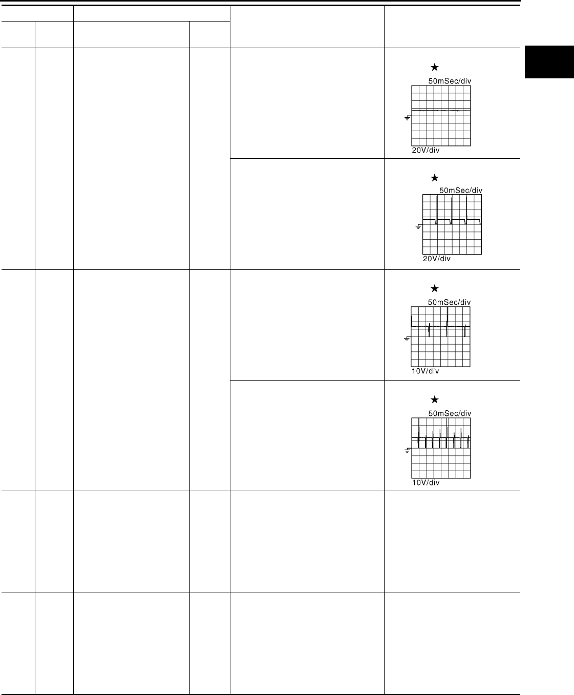
ECM
EC-445
< ECU DIAGNOSIS > [FOR CALIFORNIA]
C
D
E
F
G
H
I
J
K
L
M
A
EC
N
P
O
25
(Y)
112
(B)
EVAP canister purge vol-
ume control solenoid valve Output
[Engine is running]
• Idle speed
• Accelerator pedal: Not depressed
even slightly, after engine starting
BATTERY VOLTAGE
(11 - 14 V)
[Engine is running]
• Engine speed: Approx. 2,000 rpm
(More than 100 seconds after start-
ing engine.)
BATTERY VOLTAGE
(11 - 14 V)
29
(P)
112
(B)
Fuel injector No. 4
Output
[Engine is running]
• Warm-up condition
• Idle speed
NOTE:
The pulse cycle changes depending
on rpm at idle
BATTERY VOLTAGE
(11 - 14 V)
30
(LG) Fuel injector No. 3
31
(BR) Fuel injector No. 2
[Engine is running]
• Warm-up condition
• Engine speed: 2,000 rpm
BATTERY VOLTAGE
(11 - 14 V)
32
(GR) Fuel injector No. 1
33
(P) 35
(L) Heated oxygen sensor 2 Input
[Engine is running]
• Revving engine from idle to 3,000
rpm quickly after the following con-
ditions are met
- Engine: After warming up
- Keeping the engine speed between
3,500 and 4,000 rpm for 1 minute
and at idle for 1 minute under no
load
0 - 1.0 V
34
(V)
35
(L) Heated oxygen sensor 3 Input
[Engine is running]
• Revving engine from idle to 3,000
rpm quickly after the following con-
ditions are met
- Engine: After warming up
- Driving for 3 minutes at a speed of
80 km/h (50 MPH) or more
(Keep the vehicle speed as steady
as possible during the cruising.)
0 - 1.0 V
Terminal No. Description
Condition Value
(Approx.)
+ – Signal name Input/
Output
JMBIA0087G
B
JMBIA0903G
B
JMBIA0089G
B
JMBIA0090G
B
Revision: 2008 August 2009 Rogue

EC-446
< ECU DIAGNOSIS > [FOR CALIFORNIA]
ECM
35
(L) —
Sensor ground
(Heated oxygen sensor 2,
Heated oxygen sensor 3)
—— —
36
(R) —Sensor ground
(Throttle position sensor) —— —
37
(W)
36
(R) Throttle position sensor 1 Input
[Ignition switch: ON]
• Engine stopped
• Selector lever: D
• Accelerator pedal: Fully released
More than 0.36 V
[Ignition switch: ON]
• Engine stopped
• Selector lever: D
• Accelerator pedal: Fully depressed
Less than 4.75 V
38
(G)
36
(R) Throttle position sensor 2 Input
[Ignition switch: ON]
• Engine stopped
• Selector lever: D
• Accelerator pedal: Fully released
Less than 4.75 V
[Ignition switch: ON]
• Engine stopped
• Selector lever: D
• Accelerator pedal: Fully depressed
More than 0.36 V
39
(Y)
40
(W) Refrigerant pressure sensor Input
[Engine is running]
• Warm-up condition
• Both A/C switch and blower fan mo-
tor switch: ON (Compressor oper-
ates)
1.0 - 4.0 V
40
(W) —
Sensor ground
(Refrigerant pressure sen-
sor) —— —
45
(V)
49
(LG) A/F sensor 1 (bank 1) Input [Ignition switch: ON] 2.2 V
46
(P)
52
(O)
Engine coolant temperature
sensor Input [Engine is running]
0 - 4.8 V
Output voltage varies with engine
coolant temperature.
47
(B) 36
(R) Sensor power supply
(Throttle position sensor) — [Ignition switch: ON] 5 V
49
(LG) 112
(B) A/F sensor 1 Input
[Engine is running]
• Warm-up condition
• Engine speed: 2,000 rpm
1.8 V
Output voltage varies with air fuel
ratio.
50
(BR)
56
(R)
Intake air temperature sen-
sor Input [Engine is running] 0 - 4.8 V
Output voltage varies with intake
air temperature.
52
(O) —
Sensor ground
(Tumble control valve posi-
tion sensor, Engine coolant
temperature sensor)
—— —
54
(W) 52
(O) Tumble control valve posi-
tion sensor Input
[Ignition switch OFF → ON]
• For a few seconds after turning igni-
tion switch ON
0 V
↓
0.7 V
[Ignition switch ON → OFF]
• For a few seconds after turning igni-
tion switch OFF
0.7 V
↓
3.5 V
↓
0 V
Terminal No. Description
Condition Value
(Approx.)
+ – Signal name Input/
Output
Revision: 2008 August 2009 Rogue
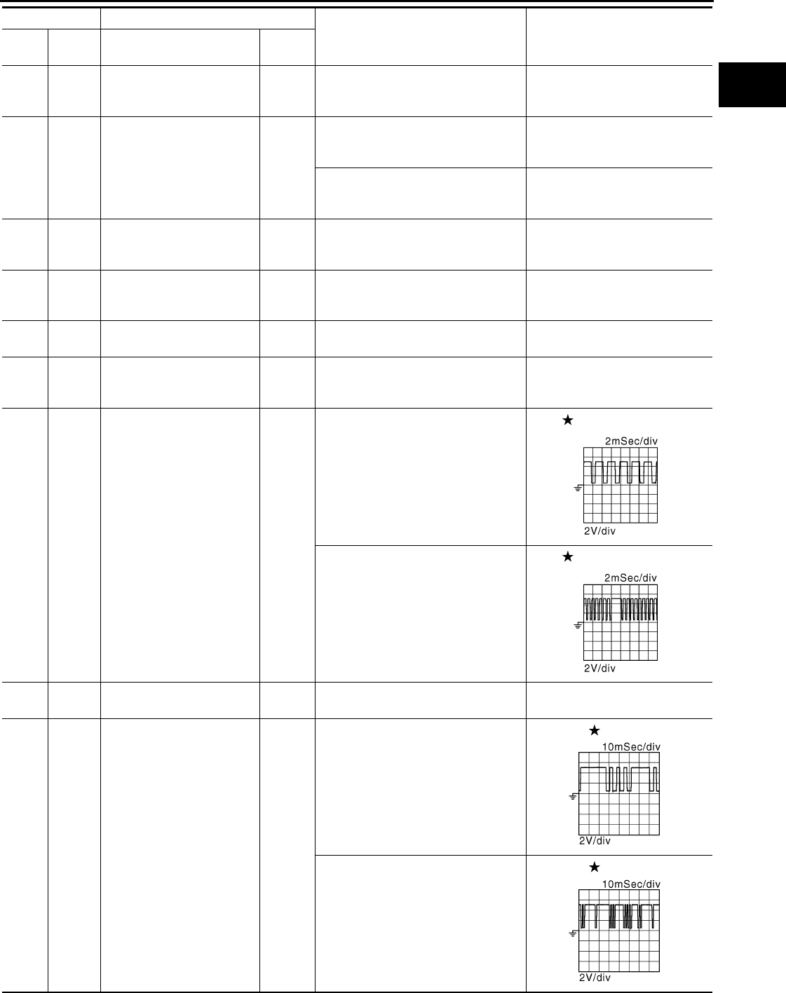
ECM
EC-447
< ECU DIAGNOSIS > [FOR CALIFORNIA]
C
D
E
F
G
H
I
J
K
L
M
A
EC
N
P
O
56
(R) —
Sensor ground
(Mass air flow sensor, Intake
air temperature sensor)
—— —
58
(L) 56
(R) Mass air flow sensor Input
[Engine is running]
• Warm-up condition
• Idle speed
0.8 - 1.2 V
[Engine is running]
• Warm-up condition
• Engine speed: 2,500 rpm 1.4 - 1.8 V
59
(V) 64
(Y)
Sensor power supply
[Camshaft position sensor
(PHASE)]
— [Ignition switch: ON] 5 V
60
(B) —Sensor ground
[Crankshaft position sensor
(POS)]
—— —
61
(W)
67
(— Knock sensor Input [Engine is running]
• Idle speed 2.5 V
64
(Y) —Sensor ground
[Camshaft position sensor
(PHASE)]
—— —
65
(W) 60
(B) Crankshaft position sensor
(POS) Input
[Engine is running]
• Warm-up condition
• Idle speed
NOTE:
The pulse cycle changes depending
on rpm at idle
3.0 V
[Engine is running]
• Engine speed: 2,000 rpm
3.0 V
67
(—) —Sensor ground
(Knock sensor) —— —
69
(G)
64
(Y)
Camshaft position sensor
(PHASE) Input
[Engine is running]
• Warm-up condition
• Idle speed
NOTE:
The pulse cycle changes depending
on rpm at idle
1.0 - 4.0 V
[Engine is running]
• Engine speed is 2,000 rpm
1.0 - 4.0 V
Terminal No. Description
Condition Value
(Approx.)
+ – Signal name Input/
Output
JMBIA0514G
B
JMBIA0515G
B
JMBIA0904G
B
JMBIA0905G
B
Revision: 2008 August 2009 Rogue
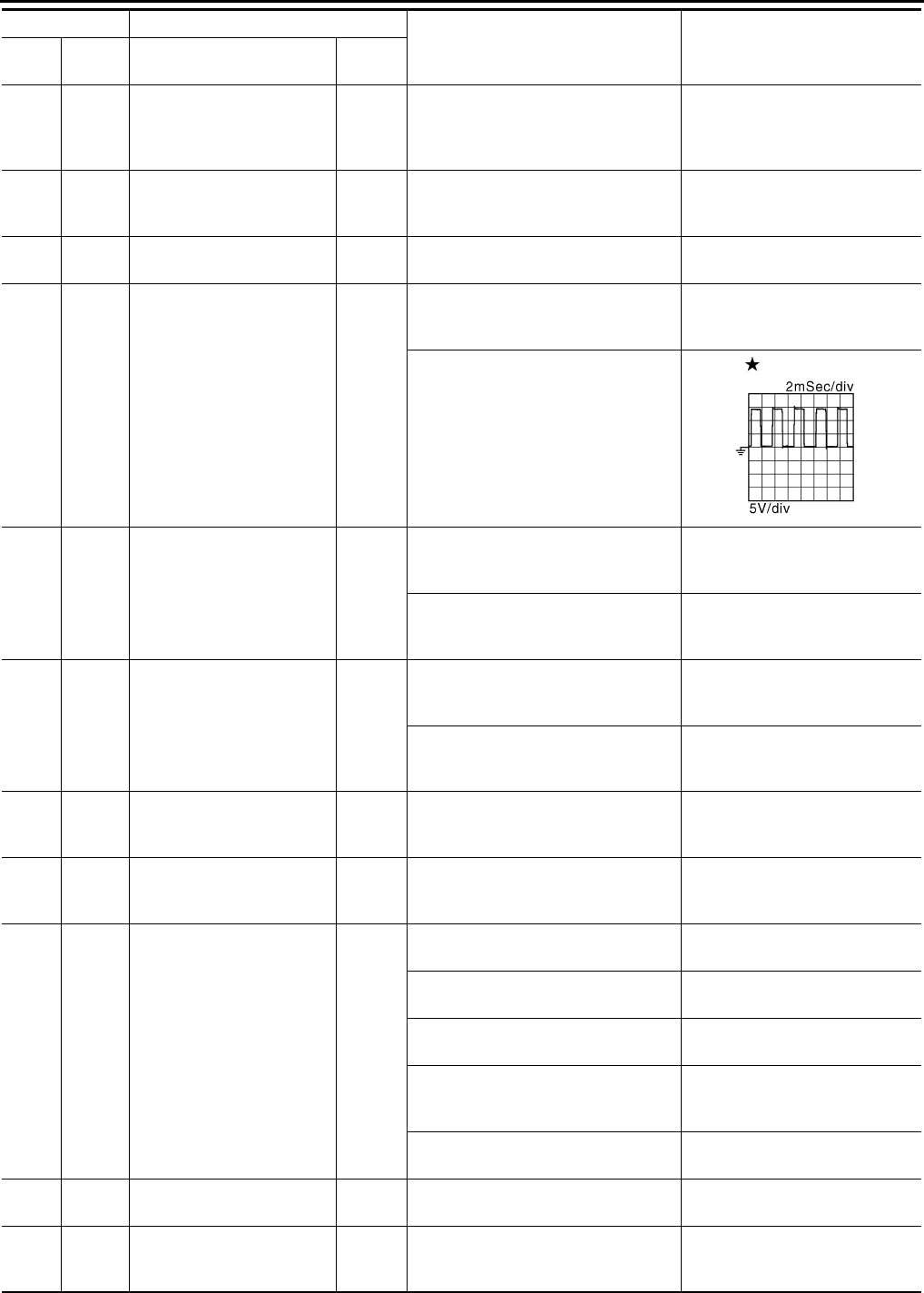
EC-448
< ECU DIAGNOSIS > [FOR CALIFORNIA]
ECM
72
(L)
40
(W)
Sensor power supply
(Tumble control valve posi-
tion sensor, Refrigerant
pressure sensor)
— [Ignition switch: ON] 5 V
76
(P) 60
(B)
Sensor power supply
[Crankshaft position sensor
(POS)]
— [Ignition switch: ON] 5 V
77
(R) 112
(B) Power supply for ECM
(Back-up) Input [Ignition switch: OFF] BATTERY VOLTAGE
(11 - 14 V)
78
(O) 112
(B) Intake valve timing control
solenoid valve Output
[Engine is running]
• Warm-up condition
• Idle speed
0 V
[Engine is running]
• Warm-up condition
• Engine speed: 2,000rpm
7 - 10 V
81
(SB) 84
(Y) Accelerator pedal position
sensor 1 Input
[Ignition switch: ON]
• Engine stopped
• Accelerator pedal: Fully released
0.6 - 0.9 V
[Ignition switch: ON]
• Engine stopped
• Accelerator pedal: Fully depressed 4.0 - 4.8 V
82
(G)
100
(W)
Accelerator pedal position
sensor 2 Input
[Ignition switch: ON]
• Engine stopped
• Accelerator pedal: Fully released
0.6 - 0.9 V
[Ignition switch: ON]
• Engine stopped
• Accelerator pedal: Fully depressed
3.9 - 4.8 V
83
(R)
84
(Y)
Sensor power supply
(Accelerator pedal position
sensor 1) — [Ignition switch: ON] 5 V
84
(Y) —
Sensor ground
(Accelerator pedal position
sensor 1)
—— —
85
(R)
92
(W) ASCD steering switch Input
[Ignition switch: ON]
• ASCD steering switch: OFF 4 V
[Ignition switch: ON]
• MAIN switch: Pressed 0 V
[Ignition switch: ON]
• CANCEL switch: Pressed 1 V
[Ignition switch: ON]
• RESUME/ACCELERATE switch:
Pressed
3 V
[Ignition switch: ON]
• SET/COAST switch: Pressed 2 V
86
(BR) 96
(P) EVAP control system pres-
sure sensor Input [Ignition switch: ON] 1.8 - 4.8 V
87
(V) 100
(W)
Sensor power supply
(Accelerator pedal position
sensor 2)
— [Ignition switch: ON] 5 V
Terminal No. Description
Condition Value
(Approx.)
+ – Signal name Input/
Output
JMBIA0906G
B
Revision: 2008 August 2009 Rogue

ECM
EC-449
< ECU DIAGNOSIS > [FOR CALIFORNIA]
C
D
E
F
G
H
I
J
K
L
M
A
EC
N
P
O
: Average voltage for pulse signal (Actual pulse signal can be confirmed by oscilloscope.)
88
(L)
112
(B) Data link connector Input/
Output
[Ignition switch: ON]
• GST: Disconnected
BATTERY VOLTAGE
(11 - 14 V)
91
(Y)
96
(P)
Sensor power supply
(EVAP control system pres-
sure sensor) — [Ignition switch: ON] 5 V
92
(W) —Sensor ground
(ASCD steering switch) —— —
93
(O)
112
(B) Ignition switch Input
[Ignition switch: OFF] 0 V
[Ignition switch: ON] BATTERY VOLTAGE
(11 - 14 V)
95
(O)
104
(B)
Fuel tank temperature sen-
sor Input [Engine is running] 0 - 4.8 V
Output voltage varies with fuel
tank temperature.
96
(P) —
Sensor ground
(EVAP control system pres-
sure sensor) —— —
97
(P) — CAN communication line — — —
98
(L) — CAN communication line — — —
100
(W) —Sensor ground
(Accelerator pedal position
sensor 2)
—— —
102
(LG)
112
(B) PNP switch Input
[Ignition switch: ON]
• Selector lever: P or N
BATTERY VOLTAGE
(11 - 14 V)
[Ignition switch: ON]
• Selector lever: Except above 0 V
104
(B) —
Sensor ground
(Fuel tank temperature sen-
sor)
—— —
105
(R) 112
(B) Power supply for ECM Input [Ignition switch: ON] BATTERY VOLTAGE
(11 - 14 V)
106
(Y)
112
(B) Stop lamp switch Input
[Ignition switch: OFF]
• Brake pedal: Fully released 0 V
[Ignition switch: OFF]
• Brake pedal: Slightly depressed
BATTERY VOLTAGE
(11 - 14 V)
107
(B)
108
(B)
— ECM ground — — —
109
(W)
112
(B)
EVAP canister vent control
valve Output [Ignition switch: ON] BATTERY VOLTAGE
(11 - 14 V)
110
(GR)
112
(B) ASCD brake switch Input
[Ignition switch: ON]
• Brake pedal: Slightly depressed 0 V
[Ignition switch: ON]
• Brake pedal: Fully released
BATTERY VOLTAGE
(11 - 14 V)
111
(B)
112
(B)
— ECM ground — — —
Terminal No. Description
Condition Value
(Approx.)
+ – Signal name Input/
Output
Revision: 2008 August 2009 Rogue
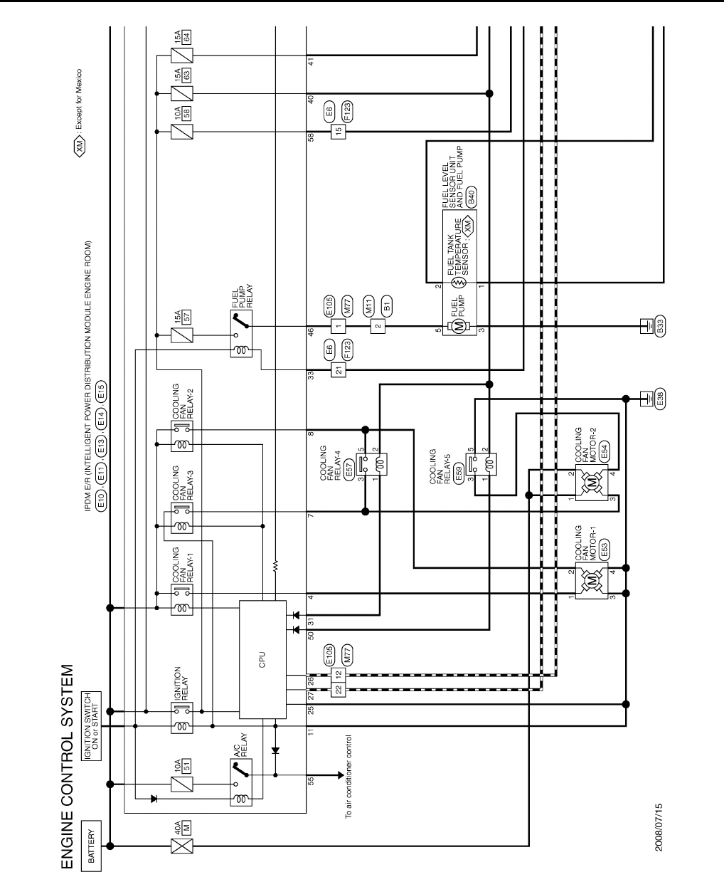
EC-450
< ECU DIAGNOSIS > [FOR CALIFORNIA]
ECM
Wiring Diagram — ENGINE CONTROL SYSTEM — INFOID:0000000004493678
JCBWM0957
GB
Revision: 2008 August 2009 Rogue
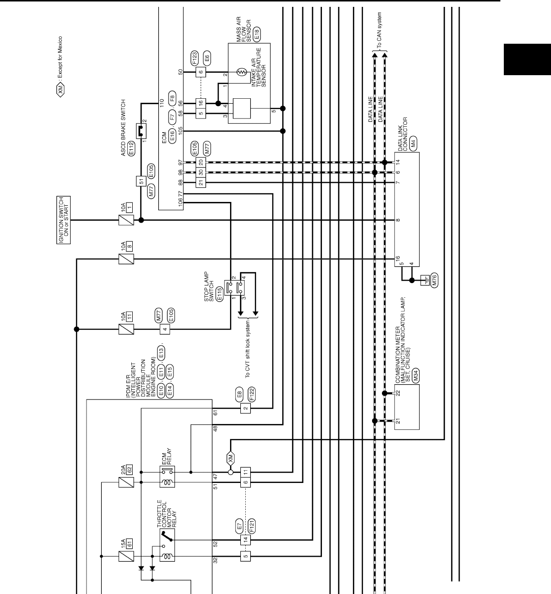
ECM
EC-451
< ECU DIAGNOSIS > [FOR CALIFORNIA]
C
D
E
F
G
H
I
J
K
L
M
A
EC
N
P
O
JCBWM0958
GB
Revision: 2008 August 2009 Rogue

EC-452
< ECU DIAGNOSIS > [FOR CALIFORNIA]
ECM
JCBWM0959
GB
Revision: 2008 August 2009 Rogue
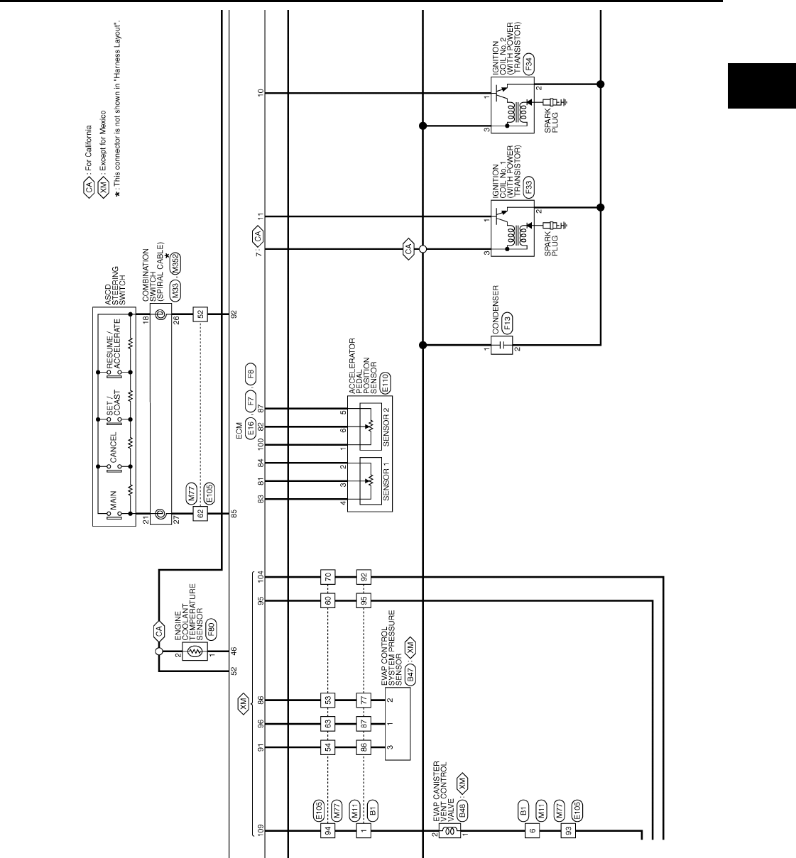
ECM
EC-453
< ECU DIAGNOSIS > [FOR CALIFORNIA]
C
D
E
F
G
H
I
J
K
L
M
A
EC
N
P
O
JCBWM0960
GB
Revision: 2008 August 2009 Rogue
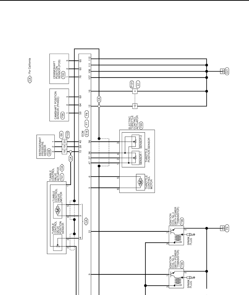
EC-454
< ECU DIAGNOSIS > [FOR CALIFORNIA]
ECM
JCBWM0961
GB
Revision: 2008 August 2009 Rogue

ECM
EC-455
< ECU DIAGNOSIS > [FOR CALIFORNIA]
C
D
E
F
G
H
I
J
K
L
M
A
EC
N
P
O
JCBWM0962
GB
Revision: 2008 August 2009 Rogue

EC-456
< ECU DIAGNOSIS > [FOR CALIFORNIA]
ECM
JCBWM0963
GB
Revision: 2008 August 2009 Rogue
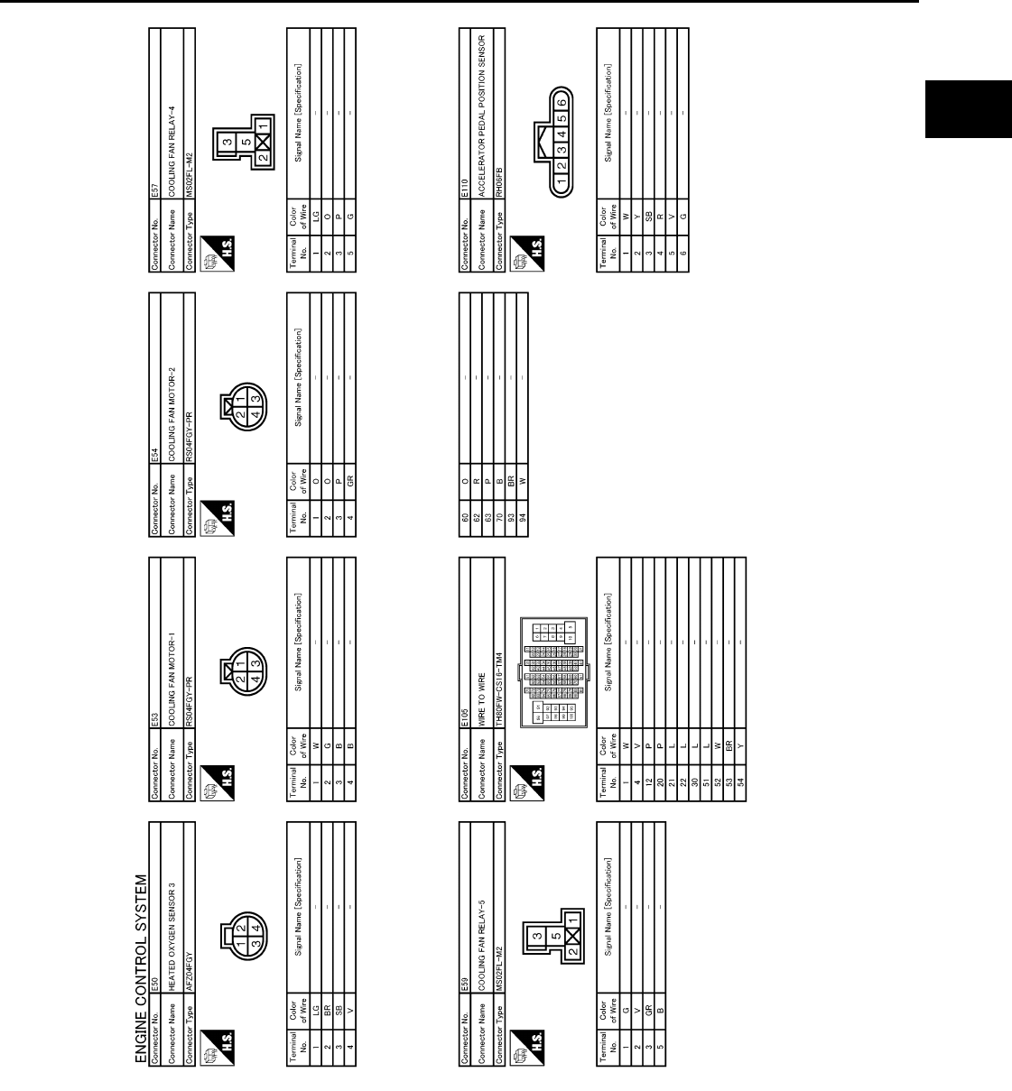
ECM
EC-457
< ECU DIAGNOSIS > [FOR CALIFORNIA]
C
D
E
F
G
H
I
J
K
L
M
A
EC
N
P
O
JCBWM0964
GB
Revision: 2008 August 2009 Rogue

EC-458
< ECU DIAGNOSIS > [FOR CALIFORNIA]
ECM
JCBWM0965
GB
Revision: 2008 August 2009 Rogue
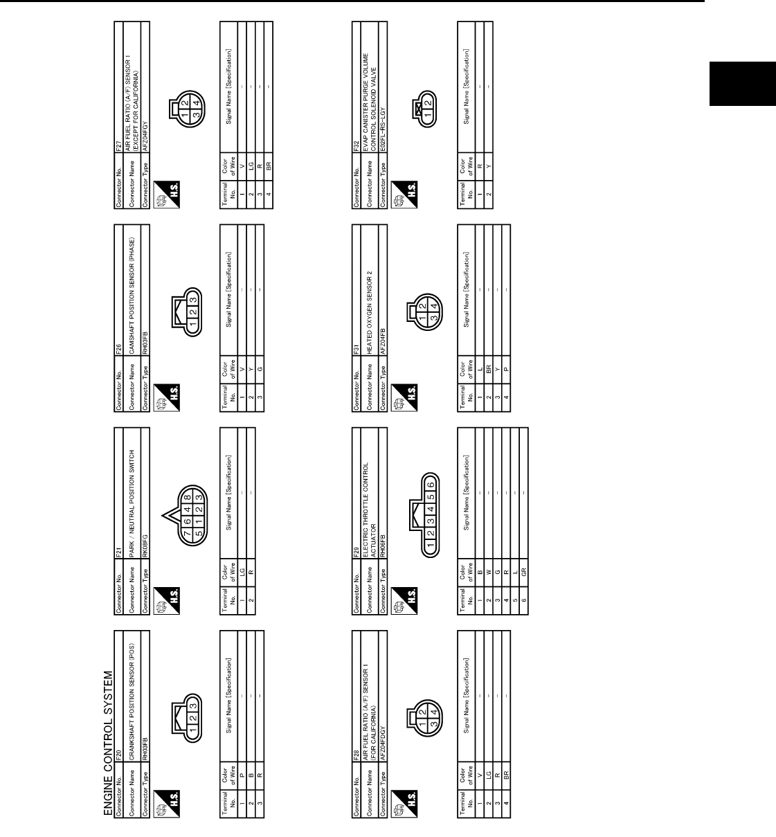
ECM
EC-459
< ECU DIAGNOSIS > [FOR CALIFORNIA]
C
D
E
F
G
H
I
J
K
L
M
A
EC
N
P
O
JCBWM0966
GB
Revision: 2008 August 2009 Rogue
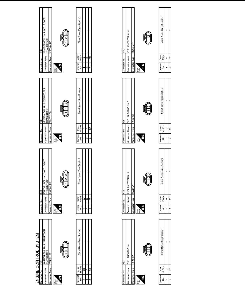
EC-460
< ECU DIAGNOSIS > [FOR CALIFORNIA]
ECM
JCBWM0967
GB
Revision: 2008 August 2009 Rogue
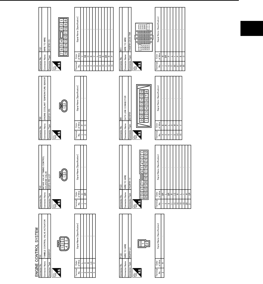
ECM
EC-461
< ECU DIAGNOSIS > [FOR CALIFORNIA]
C
D
E
F
G
H
I
J
K
L
M
A
EC
N
P
O
JCBWM0968
GB
Revision: 2008 August 2009 Rogue

EC-462
< ECU DIAGNOSIS > [FOR CALIFORNIA]
ECM
Fail safe INFOID:0000000004493679
NON DTC RELATED ITEM
JCBWM0969
GB
Revision: 2008 August 2009 Rogue

ECM
EC-463
< ECU DIAGNOSIS > [FOR CALIFORNIA]
C
D
E
F
G
H
I
J
K
L
M
A
EC
N
P
O
DTC RELATED ITEM
Engine operating condi-
tion in fail-safe mode Detected items Remarks Reference
page
Engine speed will not
rise more than 2,500 rpm
due to the fuel cut
Malfunction indicator
lamp circuit When there is an open circuit on MIL circuit, the ECM cannot warn the
driver by illuminating MIL when there is malfunction on engine control
system.
Therefore, when electrical controlled throttle and part of ECM related
diagnoses are continuously detected as NG for 5 trips, ECM warns the
driver that engine control system malfunctions and MIL circuit is open
by means of operating the fail-safe function.
The fail-safe function also operates when above diagnoses except MIL
circuit are detected and demands the driver to repair the malfunction.
EC-430
DTC No. Detected items Engine operating condition in fail-safe mode
P0011 Intake valve timing control The signal is not energized to the intake valve timing control solenoid valve and the valve
control does not function.
P0102
P0103
Mass air flow sensor circuit Engine speed will not rise more than 2,400 rpm due to the fuel cut.
P0117
P0118 Engine coolant tempera-
ture sensor circuit Engine coolant temperature will be determined by ECM based on the following conditions.
CONSULT-III displays the engine coolant temperature decided by ECM.
Condition Engine coolant temperature decided
(CONSULT-III display)
Just as ignition switch is turned ON
or START 40°C (104°F)
Approx. 4 minutes or more after
starting engine 80°C (176°F)
Except as shown above 40 - 80°C (104 - 176°F)
(Depends on the time)
When the fail-safe system for engine coolant temperature sensor is activated, the cooling
fan operates while engine is running.
P0122
P0123
P0222
P0223
P2132
P2133
P2135
Throttle position sensor The ECM controls the electric throttle control actuator in regulating the throttle opening in
order for the idle position to be within +10 degrees.
The ECM regulates the opening speed of the throttle valve to be slower than the normal
condition.
Therefore, the acceleration will be poor.
P0500 Vehicle speed sensor When the fail-safe system for vehicle speed sensor is activated, the cooling fan operates
(Highest) while engine is running.
P0643 Sensor power supply ECM stops the electric throttle control actuator control, throttle valve is maintained at a
fixed opening (approx. 5 degrees) by the return spring.
P0605 ECM (When ECM calculation function is malfunctioning:)
ECM stops the electric throttle control actuator control, throttle valve is maintained at a
fixed opening (approx. 5 degrees) by the return spring.
ECM deactivates ASCD operation.
P1805 Brake switch ECM controls the electric throttle control actuator by regulating the throttle opening to a
small range.
Therefore, acceleration will be poor.
Vehicle condition Driving condition
When engine is idling Normal
When accelerating Poor acceleration
P2100
P2103 Throttle control motor relay ECM stops the electric throttle control actuator control, throttle valve is maintained at a
fixed opening (approx. 5 degrees) by the return spring.
P2101 Electric throttle control
function
ECM stops the electric throttle control actuator control, throttle valve is maintained at a
fixed opening (approx. 5 degrees) by the return spring.
Revision: 2008 August 2009 Rogue

EC-464
< ECU DIAGNOSIS > [FOR CALIFORNIA]
ECM
DTC Inspection Priority Chart INFOID:0000000004493680
If some DTCs are displayed at the same time, perform inspections one by one based on the following priority
chart.
P2118 Throttle control motor ECM stops the electric throttle control actuator control, throttle valve is maintained at a
fixed opening (approx. 5 degrees) by the return spring.
P2119 Electric throttle control ac-
tuator
(When electric throttle control actuator does not function properly due to the return spring
malfunction:)
ECM controls the electric throttle actuator by regulating the throttle opening around the
idle position. The engine speed will not rise more than 2,000 rpm.
(When throttle valve opening angle in fail-safe mode is not in specified range:)
ECM controls the electric throttle control actuator by regulating the throttle opening to 20
degrees or less.
(When ECM detects the throttle valve is stuck open:)
While the vehicle being driven, it slows down gradually because of fuel cut. After the ve-
hicle stops, the engine stalls.
The engine can restart in N or P position, and engine speed will not exceed 1,000 rpm or
more.
P2122
P2123
P2127
P2128
P2138
Accelerator pedal position
sensor
The ECM controls the electric throttle control actuator in regulating the throttle opening in
order for the idle position to be within +10 degrees.
The ECM regulates the opening speed of the throttle valve to be slower than the normal
condition.
Therefore, the acceleration will be poor.
DTC No. Detected items Engine operating condition in fail-safe mode
Revision: 2008 August 2009 Rogue

ECM
EC-465
< ECU DIAGNOSIS > [FOR CALIFORNIA]
C
D
E
F
G
H
I
J
K
L
M
A
EC
N
P
O
Priority Detected items (DTC)
1 • U0101 U0140 U1001 CAN communication line
• P0101 P0102 P0103 Mass air flow sensor
• P0112 P0113 P0127 Intake air temperature sensor
• P0116 P0117 P0118 P0125 Engine coolant temperature sensor
• P0122 P0123 P0222 P0223 P1225 P1226 P2135 Throttle position sensor
• P0128 Thermostat function
• P0181 P0182 P0183 Fuel tank temperature sensor
• P0327 P0328 Knock sensor
• P0335 Crankshaft position sensor (POS)
• P0340 Camshaft position sensor (PHASE)
• P0460 P0461 P0462 P0463 Fuel level sensor
• P0500 Vehicle speed sensor
• P0605 P0607 ECM
• P0643 Sensor power supply
• P0705 P0850 Park/neutral position (PNP) switch
• P1610 - P1615 NATS
• P2122 P2123 P2127 P2128 P2138 Accelerator pedal position sensor
2 • P0031 P0032 Air fuel ratio (A/F) sensor 1 heater
• P0037 P0038 Heated oxygen sensor 2 heater
• P0043 P0044 Heated oxygen sensor 3 heater
• P0075 Intake valve timing control solenoid valve
• P0130 P0131 P0132 P0133 P2A00 Air fuel ratio (A/F) sensor 1
• P0137 P0138 P0139 Heated oxygen sensor 2
• P0143 P0144 P0145 P0146 Heated oxygen sensor 3
• P0441 EVAP control system purge flow monitoring
• P0443 P0444 P0445 EVAP canister purge volume control solenoid valve
• P0447 P0448 EVAP canister vent control valve
• P0451 P0452 P0453 EVAP control system pressure sensor
• P0603 ECM power supply
• P0710 P0715 P0720 P0740 P0744 P0745 P0746 P0776 P0778 P0840 P1740 P1777 P1778 CVT related sensors, solenoid
valves and switches
• P1217 Engine over temperature (OVERHEAT)
• P1805 Brake switch
• P2004 Tumble control valve motor
• P2014 Tumble control valve position sensor
• P2100 P2103 Throttle control motor relay
• P2101 Electric throttle control function
• P2118 Throttle control motor
3 • P0011 Intake valve timing control
• P0171 P0172 Fuel injection system function
• P0300 - P0304 Misfire
• P0420 Three way catalyst function
• P0442 P0456 EVAP control system (SMALL LEAK, VERY SMALL LEAK)
• P0455 EVAP control system (GROSS LEAK)
• P0506 P0507 Idle speed control system
• P1148 Closed loop control
• P1212 TCS communication line
• P1421 Cold start control
• P1564 ASCD steering switch
• P1572 ASCD brake switch
• P1574 ASCD vehicle speed sensor
• P1715 Primary speed sensor
• P2119 Electric throttle control actuator
• P2423 HC adsorption catalyst
Revision: 2008 August 2009 Rogue

EC-466
< ECU DIAGNOSIS > [FOR CALIFORNIA]
ECM
DTC Index INFOID:0000000004493681
×:Applicable —: Not applicable
Items
(CONSULT-III screen terms)
DTC*1
SRT code Trip MIL Reference
page
CONSULT-III
GST*2ECM*3
LOST COMM (TCM) U0101 0101*4—1 ×EC-128
LOST COMM (BCM) U0140 0140*4—1 ×EC-129
CAN COMM CIRCUIT U1001 1001*4—2 —EC-130
NO DTC IS DETECTED.
FURTHER TESTING
MAY BE REQUIRED. P0000 0000 ——
Flashing*7—
INT/V TIM CONT-B1 P0011 0011 — 2 ×EC-131
A/F SEN1 HTR (B1) P0031 0031 — 2 ×EC-135
A/F SEN1 HTR (B1) P0032 0032 — 2 ×EC-135
HO2S2 HTR (B1) P0037 0037 — 2 ×EC-138
HO2S2 HTR (B1) P0038 0038 — 2 ×EC-138
HO2S3 HTR (B1) P0043 0043 — 2 ×EC-141
HO2S3 HTR (B1) P0044 0044 — 2 ×EC-141
INT/V TIM V/CIR-B1 P0075 0075 — 2 ×EC-144
MAF SEN/CIRCUIT-B1 P0101 0101 — 2 ×EC-147
MAF SEN/CIRCUIT-B1 P0102 0102 — 1 ×EC-154
MAF SEN/CIRCUIT-B1 P0103 0103 — 1 ×EC-154
IAT SEN/CIRCUIT-B1 P0112 0112 — 2 ×EC-159
IAT SEN/CIRCUIT-B1 P0113 0113 — 2 ×EC-159
ECT SEN/CIRC P0116 0116 — 2 ×EC-164
ECT SEN/CIRC P0117 0117 — 1 ×EC-164
ECT SEN/CIRC P0118 0118 — 1 ×EC-164
TP SEN 2/CIRC-B1 P0122 0122 — 1 ×EC-167
TP SEN 2/CIRC-B1 P0123 0123 — 1 ×EC-167
ECT SENSOR P0125 0125 — 2 ×EC-170
IAT SENSOR-B1 P0127 0127 — 2 ×EC-173
THERMSTAT FNCTN P0128 0128 — 2 ×EC-175
A/F SENSOR1 (B1) P0130 0130 — 2 ×EC-177
A/F SENSOR1 (B1) P0131 0131 — 2 ×EC-181
A/F SENSOR1 (B1) P0132 0132 — 2 ×EC-184
A/F SENSOR1 (B1) P0133 0133 ×2×EC-187
HO2S2 (B1) P0137 0137 ×2×EC-192
HO2S2 (B1) P0138 0138 ×2×EC-198
HO2S2 (B1) P0139 0139 ×2×EC-205
HO2S3 (B1) P0143 0143 ×2×EC-211
HO2S3 (B1) P0144 0144 ×2×EC-216
HO2S3 (B1) P0145 0145 ×2×EC-221
HO2S3 (B1) P0146 0146 — 2 ×EC-226
FUEL SYS-LEAN-B1 P0171 0171 — 2 ×EC-231
FUEL SYS-RICH-B1 P0172 0172 — 2 ×EC-235
Revision: 2008 August 2009 Rogue

ECM
EC-467
< ECU DIAGNOSIS > [FOR CALIFORNIA]
C
D
E
F
G
H
I
J
K
L
M
A
EC
N
P
O
FTT SENSOR P0181 0181 — 2 ×EC-239
FTT SEN/CIRCUIT P0182 0182 — 2 ×EC-242
FTT SEN/CIRCUIT P0183 0183 — 2 ×EC-242
TP SEN 1/CIRC-B1 P0222 0222 — 1 ×EC-245
TP SEN 1/CIRC-B1 P0223 0223 — 1 ×EC-245
MULTI CYL MISFIRE P0300 0300 — 2 ×EC-248
CYL 1 MISFIRE P0301 0301 — 2 ×EC-248
CYL 2 MISFIRE P0302 0302 — 2 ×EC-248
CYL 3 MISFIRE P0303 0303 — 2 ×EC-248
CYL 4 MISFIRE P0304 0304 — 2 ×EC-248
KNOCK SEN/CIRC-B1 P0327 0327 — 2 — EC-254
KNOCK SEN/CIRC-B1 P0328 0328 — 2 — EC-254
CKP SEN/CIRCUIT P0335 0335 — 2 ×EC-256
CMP SEN/CIRC-B1 P0340 0340 — 2 ×EC-260
TW CATALYST SYS-B1 P0420 0420 ×2×EC-264
EVAP PURG FLOW/MON P0441 0441 ×2×EC-268
EVAP SMALL LEAK P0442 0442 ×2×EC-273
PURG VOLUME CONT/V P0443 0443 — 2 ×EC-279
PURG VOLUME CONT/V P0444 0444 — 2 ×EC-283
PURG VOLUME CONT/V P0445 0445 — 2 ×EC-283
VENT CONTROL VALVE P0447 0447 — 2 ×EC-286
VENT CONTROL VALVE P0448 0448 — 2 ×EC-290
EVAP SYS PRES SEN P0451 0451 — 2 ×EC-294
EVAP SYS PRES SEN P0452 0452 — 2 ×EC-297
EVAP SYS PRES SEN P0453 0453 — 2 ×EC-302
EVAP GROSS LEAK P0455 0455 — 2 ×EC-308
EVAP VERY SML LEAK P0456 0456 ×*62×EC-314
FUEL LEV SEN SLOSH P0460 0460 — 2 ×EC-321
FUEL LEVEL SENSOR P0461 0461 — 2 ×EC-322
FUEL LEVL SEN/CIRC P0462 0462 — 2 ×EC-324
FUEL LEVL SEN/CIRC P0463 0463 — 2 ×EC-324
VEH SPEED SEN/CIRC*5P0500 0500 — 2 ×EC-325
ISC SYSTEM P0506 0506 — 2 ×EC-327
ISC SYSTEM P0507 0507 — 2 ×EC-329
ECM BACK UP/CIRCUIT P0603 0603 — 2 ×EC-331
ECM P0605 0605 — 1 or 2 × or — EC-333
ECM P0607 0607 — 1 ×EC-335
SENSOR POWER/CIRC P0643 0643 — 1 ×EC-336
PNP SW/CIRC P0705 0705 — 2 ×TM-53
ATF TEMP SEN/CIRC P0710 0710 — 1 ×TM-56
INPUT SPD SEN/CIRC P0715 0715 — 2 ×TM-59
VEH SPD SEN/CIR AT*5P0720 0720 — 2 ×TM-63
Items
(CONSULT-III screen terms)
DTC*1
SRT code Trip MIL Reference
page
CONSULT-III
GST*2ECM*3
Revision: 2008 August 2009 Rogue

EC-468
< ECU DIAGNOSIS > [FOR CALIFORNIA]
ECM
TCC SOLENOID/CIRC P0740 0740 — 2 ×TM-69
A/T TCC S/V FNCTN P0744 0744 — 2 ×TM-71
L/PRESS SOL/CIRC P0745 0745 — 2 ×TM-73
PRS CNT SOL/A FCTN P0746 0746 — 1 ×TM-75
PRS CNT SOL/B FCTN P0776 0776 — 2 ×TM-77
PRS CNT SOL/B CIRC P0778 0778 — 2 ×TM-80
TR PRS SENS/A CIRC P0840 0840 — 2 ×TM-87
P-N POS SW/CIRCUIT P0850 0850 — 2 ×EC-338
CLOSED LOOP-B1 P1148 1148 — 1 ×EC-341
TCS/CIRC P1212 1212 — 2 — EC-342
ENG OVER TEMP P1217 1217 — 1 ×EC-343
CTP LEARNING-B1 P1225 1225 — 2 — EC-347
CTP LEARNING-B1 P1226 1226 — 2 — EC-349
COLD START CONTROL P1421 1421 — 2 ×EC-351
ASCD SW P1564 1564 — 1 — EC-353
ASCD BRAKE SW P1572 1572 — 1 — EC-356
ASCD VHL SPD SEN P1574 1574 — 1 — EC-361
LOCK MODE P1610 1610 — 2 — SEC-34*8
SEC-168*9
ID DISCORD,IMMU-ECM P1611 1611 — 2 — SEC-35*8
SEC-169*9
CHAIN OF ECM-IMMU P1612 1612 — 2 — SEC-37*8
SEC-171*9
CHAIN OF IMMU-KEY P1614 1614 — 2 — SEC-38*8
SEC-172*9
DIFFERENCE OF KEY P1615 1615 — 2 — SEC-40*8
SEC-174*9
IN PULY SPEED P1715 1715 — 2 — EC-363
LU-SLCT SOL/CIRC P1740 1740 — 2 ×TM-104
STEP MOTOR CIRC P1777 1777 — 1 ×TM-107
STEP MOTOR FNCT P1778 1778 — 2 ×TM-110
BRAKE SW/CIRCUIT P1805 1805 — 2 — EC-365
TUMBLE CONT/V P2004 2004 — 2 ×EC-367
TUMBLE POS SEN P2014 2014 — 2 — EC-372
ETC MOT PWR-B1 P2100 2100 — 1 ×EC-375
ETC FNCTN/CIRC-B1 P2101 2101 — 1 ×EC-377
ETC MOT PWR P2103 2103 — 1 ×EC-375
ETC MOT-B1 P2118 2118 — 1 ×EC-381
ETC ACTR-B1 P2119 2119 — 1 ×EC-383
APP SEN 1/CIRC P2122 2122 — 1 ×EC-385
APP SEN 1/CIRC P2123 2123 — 1 ×EC-385
APP SEN 2/CIRC P2127 2127 — 1 ×EC-388
Items
(CONSULT-III screen terms)
DTC*1
SRT code Trip MIL Reference
page
CONSULT-III
GST*2ECM*3
Revision: 2008 August 2009 Rogue
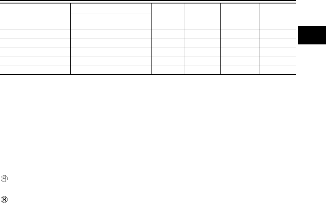
ECM
EC-469
< ECU DIAGNOSIS > [FOR CALIFORNIA]
C
D
E
F
G
H
I
J
K
L
M
A
EC
N
P
O
*1: 1st trip DTC No. is the same as DTC No.
*2: This number is prescribed by SAE J2012.
*3: In Diagnostic Test Mode II (Self-diagnostic results), this number is controlled by NISSAN.
*4: The troubleshooting for this DTC needs CONSULT-III.
*5: When the fail-safe operations for both self-diagnosis occur, the MIL illuminates.
*6: SRT code will not be set if the self-diagnostic result is NG.
*7: When the ECM is in the mode that displays SRT status, MIL may flash. For the details, refer to “How to Display SRT Status”.
*8: Models with intelligent key system
*9: Models without intelligent key system
How to Set SRT Code INFOID:0000000004493682
To set all SRT codes, self-diagnosis for the items indicated above must be performed one or more times. Each
diagnosis may require a long period of actual driving under various conditions.
WITH CONSULT-III
Perform corresponding DTC CONFIRMATION PROCEDURE one by one based on Performance Priority in
the table on “SRT Item”.
WITHOUT CONSULT-III
The most efficient driving pattern in which SRT codes can be properly set is explained below. The driving pat-
tern should be performed one or more times to set all SRT codes.
APP SEN 2/CIRC P2128 2128 — 1 ×EC-388
TP SENSOR-B1 P2135 2135 — 1 ×EC-392
APP SENSOR P2138 2138 — 1 ×EC-396
HC ADS CATALYST-B1 P2423 2423 ×2×EC-400
A/F SENSOR1 (B1) P2A00 2A00 — 2 ×EC-404
Items
(CONSULT-III screen terms)
DTC*1
SRT code Trip MIL Reference
page
CONSULT-III
GST*2ECM*3
Revision: 2008 August 2009 Rogue
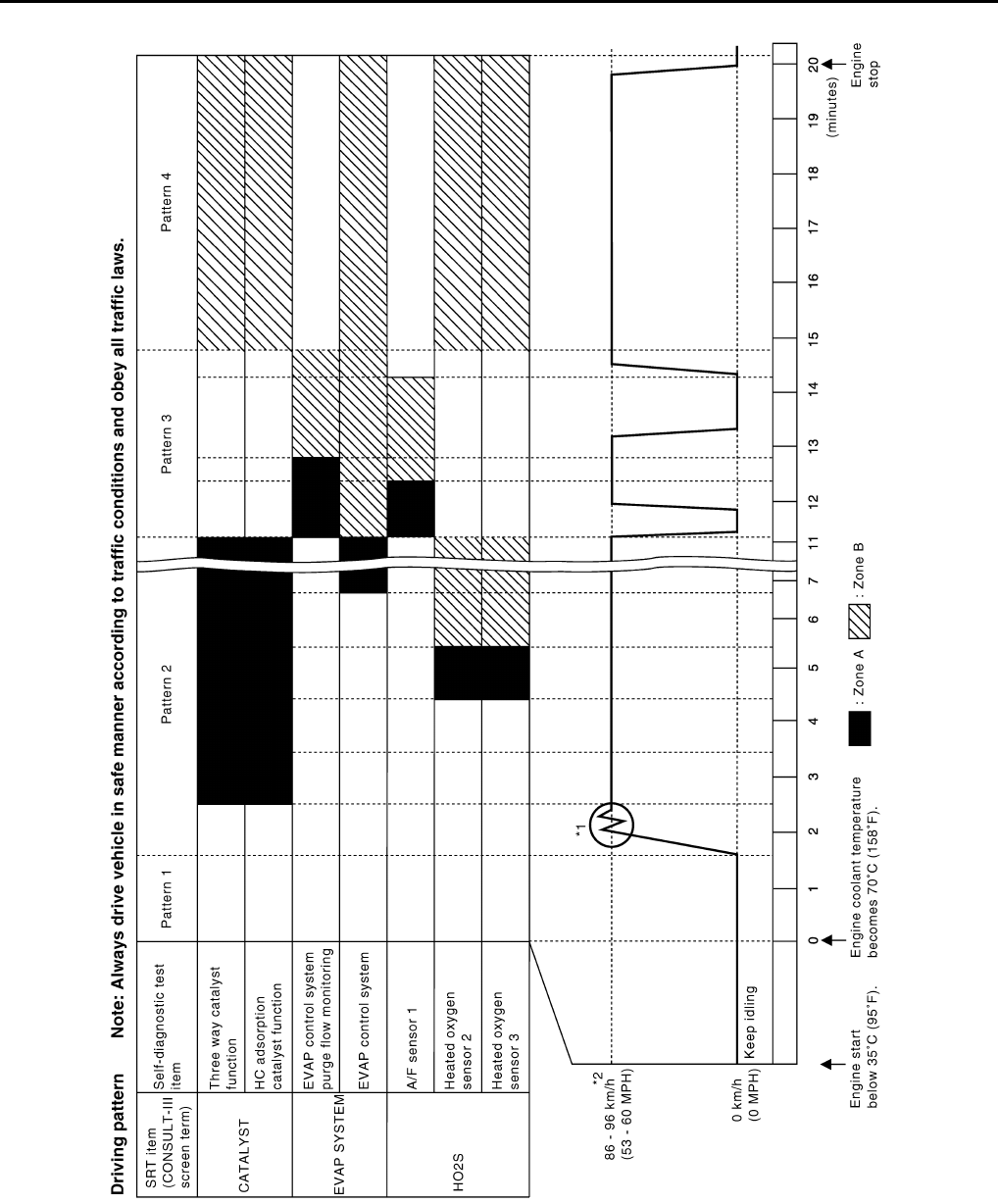
EC-470
< ECU DIAGNOSIS > [FOR CALIFORNIA]
ECM
DRIVING PATTERN
• The time required for each diagnosis varies with road surface conditions, weather, altitude, individual driving
habits, etc.
Zone A refers to the range where the time, required for the diagnosis under normal conditions*, is the short-
est.
Zone B refers to the range where the diagnosis can still be performed if the diagnosis is not completed within
zone A.
*: Normal conditions refer to the following:
JMBIA1020G
B
Revision: 2008 August 2009 Rogue
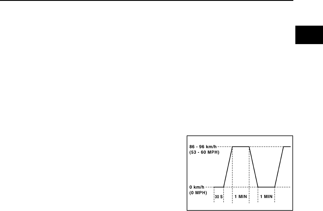
ECM
EC-471
< ECU DIAGNOSIS > [FOR CALIFORNIA]
C
D
E
F
G
H
I
J
K
L
M
A
EC
N
P
O
• Sea level
• Flat road
• Ambient air temperature: 20 - 30°C (68 - 86°F)
• Diagnosis is performed as quickly as possible under normal conditions.
Under different conditions [For example: ambient air temperature other than 20 - 30°C (68 - 86°F)], diagno-
sis may also be performed.
Pattern 1:
•The engine is started at the engine coolant temperature of −10 to 35°C (14 to 95°F)
[where the voltage between the ECM terminals 46 (Engine coolant temperature sensor signal) and 52
(Sensor ground) is 3.0 - 4.3V].
•The engine must be operated at idle speed until the engine coolant temperature is greater than 70°C
(158°F) [where the voltage between the ECM terminals 46 (Engine coolant temperature sensor sig-
nal) and 52 (Sensor ground) is lower than 1.4V].
•The engine is started at the fuel tank temperature of warmer than 0°C (32°F) [where the voltage
between the ECM terminal 95 (Fuel tank temperature sensor signal) and 104 (Sensor ground) is less
than 4.1V].
Pattern 2:
• When steady-state driving is performed again even after it is interrupted, each diagnosis can be conducted.
In this case, the time required for diagnosis may be extended.
Pattern 3:
• Operate vehicle following the driving pattern shown in the figure.
• Release the accelerator pedal during decelerating vehicle speed
from 90 km/h (56 MPH) to 0 km/h (0 MPH).
Pattern 4:
• The accelerator pedal must be held very steady during steady-
state driving.
• If the accelerator pedal is moved, the test must be conducted all
over again.
*1: Depress the accelerator pedal until vehicle speed is 90 km/h (56
MPH), then release the accelerator pedal and keep it released for
more than 10 seconds. Depress the accelerator pedal until vehicle
speed is 90 km/h (56 MPH) again.
*2: Checking the vehicle speed with GST is advised.
Suggested Transmission Gear Position for CVT Models
Set the selector lever in the D position.
Test Value and Test Limit INFOID:0000000004503765
The following is the information specified in Service $06 of SAE J1979.
The test value is a parameter used to determine whether a system/circuit diagnostic test is OK or NG while
being monitored by the ECM during self-diagnosis. The test limit is a reference value which is specified as the
maximum or minimum value and is compared with the test value being monitored.
These data (test value and test limit) are specified by On Board Monitor ID(OBDMID), Test ID (TID), Unit and
Scaling ID and can be displayed on the GST screen.
The items of the test value and test limit will be displayed with GST screen which items are provided by the
ECM. (eg., if bank 2 is not applied on this vehicle, only the items of bank 1 are displayed)
PBIB2244E
Revision: 2008 August 2009 Rogue

EC-472
< ECU DIAGNOSIS > [FOR CALIFORNIA]
ECM
Item OBD-
MID Self-diagnostic test item DTC
Test value and Test
limit
(GST display) Description
TID
Unit and
Scaling
ID
HO2S
01H Air fuel ratio (A/F) sensor 1
(Bank 1)
P0131 83H 0BH Minimum sensor output voltage for test
cycle
P0131 84H 0BH Maximum sensor output voltage for test
cycle
P0130 85H 0BH Minimum sensor output voltage for test
cycle
P0130 86H 0BH Maximum sensor output voltage for test
cycle
P0133 87H 04H Response rate: Response ratio (Lean to
Rich)
P0133 88H 04H Response rate: Response ratio (Rich to
Lean)
P2A00 89H 84H The amount of shift in air fuel ratio
P2A00 8AH 84H The amount of shift in air fuel ratio
P0130 8BH 0BH Difference in sensor output voltage
P0133 8CH 83H Response gain at the limited frequency
02H Heated oxygen sensor 2
(Bank 1)
P0138 07H 0CH Minimum sensor output voltage for test
cycle
P0137 08H 0CH Maximum sensor output voltage for test
cycle
P0138 80H 0CH Sensor output voltage
P0139 81H 0CH Difference in sensor output voltage
03H Heated oxygen sensor 3
(Bank 1)
P0143 07H 0CH Minimum sensor output voltage for test
cycle
P0144 08H 0CH Maximum sensor output voltage for test
cycle
P0146 80H 0CH Sensor output voltage
P0145 81H 0CH Difference in sensor output voltage
Revision: 2008 August 2009 Rogue

ECM
EC-473
< ECU DIAGNOSIS > [FOR CALIFORNIA]
C
D
E
F
G
H
I
J
K
L
M
A
EC
N
P
O
HO2S
05H Air fuel ratio (A/F) sensor 1
(Bank 2)
P0151 83H 0BH Minimum sensor output voltage for test
cycle
P0151 84H 0BH Maximum sensor output voltage for test
cycle
P0150 85H 0BH Minimum sensor output voltage for test
cycle
P0150 86H 0BH Maximum sensor output voltage for test
cycle
P0153 87H 04H Response rate: Response ratio (Lean to
Rich)
P0153 88H 04H Response rate: Response ratio (Rich to
Lean)
P2A03 89H 84H The amount of shift in air fuel ratio
P2A03 8AH 84H The amount of shift in air fuel ratio
P0150 8BH 0BH Difference in sensor output voltage
P0153 8CH 83H Response gain at the limited frequency
06H Heated oxygen sensor 2
(Bank 2)
P0158 07H 0CH Minimum sensor output voltage for test
cycle
P0157 08H 0CH Maximum sensor output voltage for test
cycle
P0158 80H 0CH Sensor output voltage
P0159 81H 0CH Difference in sensor output voltage
07H Heated oxygen sensor 3
(Bank2)
P0163 07H 0CH Minimum sensor output voltage for test
cycle
P0164 08H 0CH Maximum sensor output voltage for test
cycle
P0166 80H 0CH Sensor output voltage
P0165 81H 0CH Difference in sensor output voltage
CATA-
LYST
21H Three way catalyst function
(Bank1)
P0420 80H 01H O2 storage index
P0420 82H 01H Switching time lag engine exhaust index
value
P2423 83H 0CH Difference in 3rd O2 sensor output volt-
age
P2423 84H 84H O2 storage index in HC trap catalyst
22H Three way catalyst function
(Bank2)
P0430 80H 01H O2 storage index
P0430 82H 01H Switching time lag engine exhaust index
value
P2424 83H 0CH Difference in 3rd O2 sensor output volt-
age
P2424 84H 84H O2 storage index in HC trap catalyst
Item OBD-
MID Self-diagnostic test item DTC
Test value and Test
limit
(GST display) Description
TID
Unit and
Scaling
ID
Revision: 2008 August 2009 Rogue

EC-474
< ECU DIAGNOSIS > [FOR CALIFORNIA]
ECM
EGR
SYSTEM 31H EGR function
P0400 80H 96H Low Flow Faults: EGR temp change
rate (short term)
P0400 81H 96H Low Flow Faults: EGR temp change
rate (long term)
P0400 82H 96H Low Flow Faults: Difference between
max EGR temp and EGR temp under
idling condition
P0400 83H 96H Low Flow Faults: Max EGR temp
P1402 84H 96H High Flow Faults: EGR temp increase
rate
VVT
SYSTEM
35H VVT Monitor (Bank1)
P0011 80H 9DH VTC intake function diagnosis (VTC
alignment check diagnosis)
P0014 81H 9DH VTC exhaust function diagnosis (VTC
alignment check diagnosis)
P0011 82H 9DH VTC intake function diagnosis (VTC
drive failure diagnosis)
P0014 83H 9DH VTC exhaust function diagnosis (VTC
drive failure diagnosis)
36H VVT Monitor (Bank2)
P0021 80H 9DH VTC intake function diagnosis (VTC
alignment check diagnosis)
P0024 81H 9DH VTC exhaust function diagnosis (VTC
alignment check diagnosis)
P0021 82H 9DH VTC intake function diagnosis (VTC
drive failure diagnosis)
P0024 83H 9DH VTC exhaust function diagnosis (VTC
drive failure diagnosis)
EVAP
SYSTEM
39H EVAP control system leak
(Cap Off) P0455 80H 0CH Difference in pressure sensor output
voltage before and after pull down
3BH EVAP control system leak
(Small leak) P0442 80H 05H Leak area index (for more than 0.04
inch)
3CH EVAP control system leak
(Very small leak)
P0456 80H 05H Leak area index (for more than 0.02
inch)
P0456 81H FDH Maximum internal pressure of EVAP
system during monitoring
3DH Purge flow system P0441 83H 0CH
Difference in pressure sensor output
voltage before and after vent control
valve close
O2 SEN-
SOR
HEATER
41H A/F sensor 1 heater
(Bank 1)
Low Input:P0031
High Input:P0032 81H 0BH Converted value of Heater electric cur-
rent to voltage
42H Heated oxygen sensor 2 heat-
er (Bank 1)
Low Input:P0037
High Input:P0038 80H 0CH Converted value of Heater electric cur-
rent to voltage
43H Heated oxygen sensor 3 heat-
er (Bank 1) P0043 80H 0CH Converted value of Heater electric cur-
rent to voltage
45H A/F sensor 1 heater
(Bank 2)
Low Input:P0051
High Input:P0052 81H 0BH Converted value of Heater electric cur-
rent to voltage
46H Heated oxygen sensor 2 heat-
er (Bank 2)
Low Input:P0057
High Input:P0058 80H 0CH Converted value of Heater electric cur-
rent to voltage
47H Heated oxygen sensor 3 heat-
er (Bank 2) P0063 80H 0CH Converted value of Heater electric cur-
rent to voltage
Item OBD-
MID Self-diagnostic test item DTC
Test value and Test
limit
(GST display) Description
TID
Unit and
Scaling
ID
Revision: 2008 August 2009 Rogue

ECM
EC-475
< ECU DIAGNOSIS > [FOR CALIFORNIA]
C
D
E
F
G
H
I
J
K
L
M
A
EC
N
P
O
SEC-
OND-
ARY AIR 71H Secondary Air system
P0411 80H 01H Secondary Air Injection System Incor-
rect Flow Detected
Bank1: P0491
Bank2: P0492 81H 01H Secondary Air Injection System Insuffi-
cient Flow
P2445 82H 01H Secondary Air Injection System Pump
Stuck Off
P2448 83H 01H Secondary Air Injection System High
Airflow
Bank1: P2440
Bank2: P2442 84H 01H Secondary Air Injection System Switch-
ing Valve Stuck Open
P2440 85H 01H Secondary Air Injection System Switch-
ing Valve Stuck Open
P2444 86H 01H Secondary Air Injection System Pump
Stuck On
FUEL
SYSTEM
81H Fuel injection system function
(Bank 1)
P0171 or P0172 80H 2FH Long term fuel trim
P0171 or P0172 81H 24H The number of lambda control clamped
82H Fuel injection system function
(Bank 2)
P0174 or P0175 80H 2FH Long term fuel trim
P0174 or P0175 81H 24H The number of lambda control clamped
Item OBD-
MID Self-diagnostic test item DTC
Test value and Test
limit
(GST display) Description
TID
Unit and
Scaling
ID
Revision: 2008 August 2009 Rogue

EC-476
< ECU DIAGNOSIS > [FOR CALIFORNIA]
ECM
MISFIRE A1H Multiple Cylinder Misfires
P0301 80H 24H Misfiring counter at 1000 revolution of
the first cylinder
P0302 81H 24H Misfiring counter at 1000 revolution of
the second cylinder
P0303 82H 24H Misfiring counter at 1000 revolution of
the third cylinder
P0304 83H 24H Misfiring counter at 1000 revolution of
the fourth cylinder
P0305 84H 24H Misfiring counter at 1000 revolution of
the fifth cylinder
P0306 85H 24H Misfiring counter at 1000 revolution of
the sixth cylinder
P0307 86H 24H Misfiring counter at 1000 revolution of
the seventh cylinder
P0308 87H 24H Misfiring counter at 1000 revolution of
the eighth cylinder
P0300 88H 24H Misfiring counter at 1000 revolution of
the multiple cylinders
P0301 89H 24H Misfiring counter at 200 revolution of the
first cylinder
P0302 8AH 24H Misfiring counter at 200 revolution of the
second cylinder
P0303 8BH 24H Misfiring counter at 200 revolution of the
third cylinder
P0304 8CH 24H Misfiring counter at 200 revolution of the
fourth cylinder
P0305 8DH 24H Misfiring counter at 200 revolution of the
fifth cylinder
P0306 8EH 24H Misfiring counter at 200 revolution of the
sixth cylinder
P0307 8FH 24H Misfiring counter at 200 revolution of the
seventh cylinder
P0308 90H 24H Misfiring counter at 200 revolution of the
eighth cylinder
P0300 91H 24H Misfiring counter at 1000 revolution of
the single cylinder
P0300 92H 24H Misfiring counter at 200 revolution of the
single cylinder
P0300 93H 24H Misfiring counter at 200 revolution of the
multiple cylinders
Item OBD-
MID Self-diagnostic test item DTC
Test value and Test
limit
(GST display) Description
TID
Unit and
Scaling
ID
Revision: 2008 August 2009 Rogue

ECM
EC-477
< ECU DIAGNOSIS > [FOR CALIFORNIA]
C
D
E
F
G
H
I
J
K
L
M
A
EC
N
P
O
MISFIRE
A2H No. 1 Cylinder Misfire
P0301 0BH 24H
EWMA (Exponential Weighted Moving
Average) misfire counts for last 10 driv-
ing cycles
P0301 0CH 24H Misfire counts for last/current driving cy-
cles
A3H No. 2 Cylinder Misfire
P0302 0BH 24H
EWMA (Exponential Weighted Moving
Average) misfire counts for last 10 driv-
ing cycles
P0302 0CH 24H Misfire counts for last/current driving cy-
cles
A4H No. 3 Cylinder Misfire
P0303 0BH 24H
EWMA (Exponential Weighted Moving
Average) misfire counts for last 10 driv-
ing cycles
P0303 0CH 24H Misfire counts for last/current driving cy-
cles
A5H No. 4 Cylinder Misfire
P0304 0BH 24H
EWMA (Exponential Weighted Moving
Average) misfire counts for last 10 driv-
ing cycles
P0304 0CH 24H Misfire counts for last/current driving cy-
cles
A6H No. 5 Cylinder Misfire
P0305 0BH 24H
EWMA (Exponential Weighted Moving
Average) misfire counts for last 10 driv-
ing cycles
P0305 0CH 24H Misfire counts for last/current driving cy-
cles
A7H No. 6 Cylinder Misfire
P0306 0BH 24H
EWMA (Exponential Weighted Moving
Average) misfire counts for last 10 driv-
ing cycles
P0306 0CH 24H Misfire counts for last/current driving cy-
cles
A8H No. 7 Cylinder Misfire
P0307 0BH 24H EWMA (Exponential Weighted Moving
Average) misfire counts for last 10 driv-
ing cycles
P0307 0CH 24H Misfire counts for last/current driving cy-
cles
A9H No. 8 Cylinder Misfire
P0308 0BH 24H EWMA (Exponential Weighted Moving
Average) misfire counts for last 10 driv-
ing cycles
P0308 0CH 24H Misfire counts for last/current driving cy-
cles
Item OBD-
MID Self-diagnostic test item DTC
Test value and Test
limit
(GST display) Description
TID
Unit and
Scaling
ID
Revision: 2008 August 2009 Rogue

EC-478
< SYMPTOM DIAGNOSIS > [FOR CALIFORNIA]
ENGINE CONTROL SYSTEM SYMPTOMS
SYMPTOM DIAGNOSIS
ENGINE CONTROL SYSTEM SYMPTOMS
Symptom Table INFOID:0000000004493684
SYSTEM — BASIC ENGINE CONTROL SYSTEM
SYMPTOM
Reference
page
HARD/NO START/RESTART (EXCP. HA)
ENGINE STALL
HESITATION/SURGING/FLAT SPOT
SPARK KNOCK/DETONATION
LACK OF POWER/POOR ACCELERATION
HIGH IDLE/LOW IDLE
ROUGH IDLE/HUNTING
IDLING VIBRATION
SLOW/NO RETURN TO IDLE
OVERHEATS/WATER TEMPERATURE HIGH
EXCESSIVE FUEL CONSUMPTION
EXCESSIVE OIL CONSUMPTION
BATTERY DEAD (UNDER CHARGE)
Warranty symptom code AA AB AC AD AE AF AG AH AJ AK AL AM HA
Fuel Fuel pump circuit 11232 22 3 2EC-422
Fuel pressure regulator system 334444444 4 EC-489
Fuel injector circuit 11232 22 2 EC-419
Evaporative emission system 334444444 4 EC-72
Air Positive crankcase ventilation sys-
tem 334444444 41 EC-436
Incorrect idle speed adjustment 1 1 1 1 1 EC-26
Electric throttle control actuator 112332222 2 2
EC-377
EC-383
IgnitionIncorrect ignition timing adjustment33111 11 1 EC-26
Ignition circuit 11222 22 2 EC-425
Main power supply and ground circuit 22333 33 23 EC-124
Mass air flow sensor circuit
1
12
2
222 2
EC-147
EC-154
Engine coolant temperature sensor circuit
3
33 EC-164
EC-170
Air fuel ratio (A/F) sensor 1 circuit
EC-177
EC-181
EC-184
EC-187
EC-404
Throttle position sensor circuit
22
EC-167
EC-245
EC-347
EC-349
EC-392
Accelerator pedal position sensor circuit 3 2 1 EC-385
EC-388
EC-396
Knock sensor circuit 2 3 EC-254
Revision: 2008 August 2009 Rogue
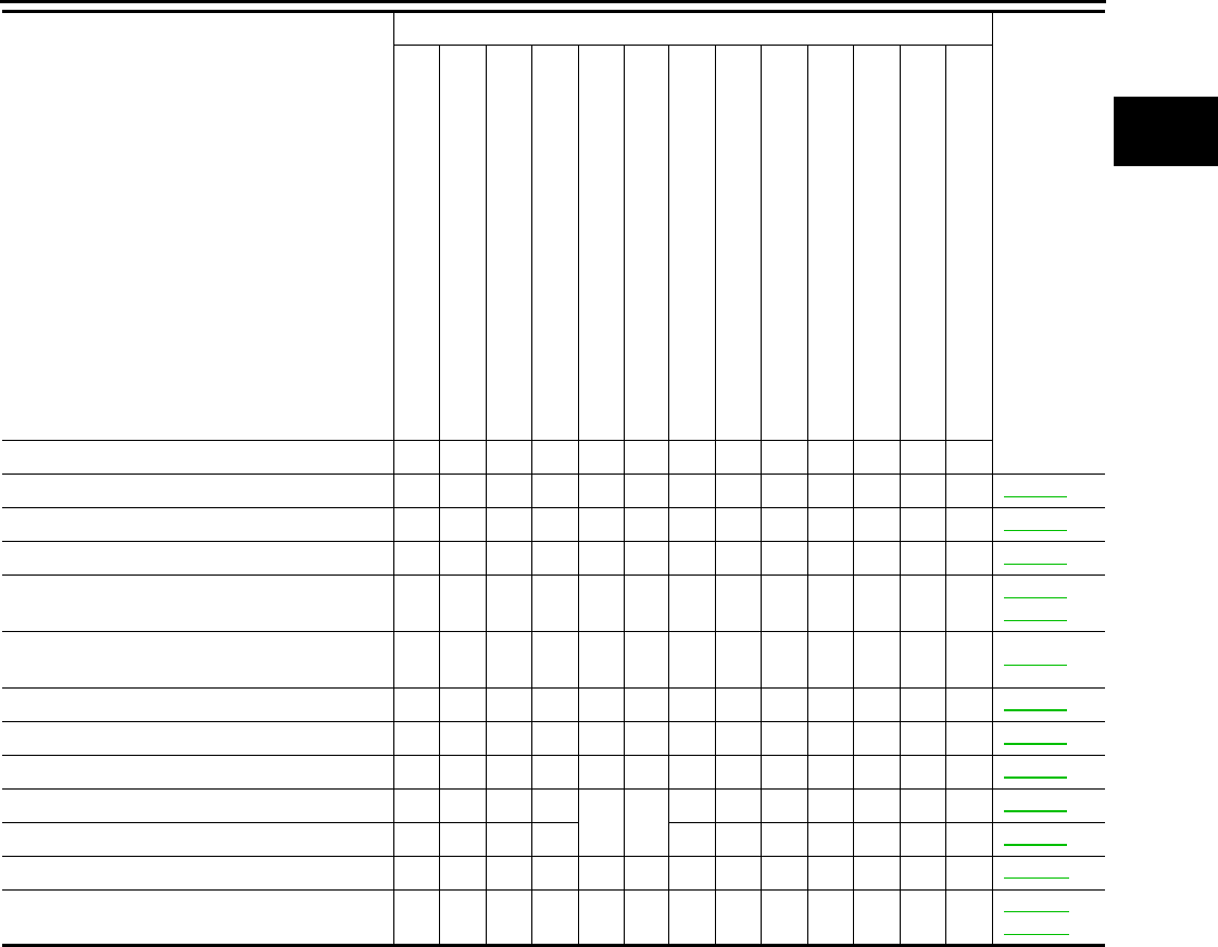
ENGINE CONTROL SYSTEM SYMPTOMS
EC-479
< SYMPTOM DIAGNOSIS > [FOR CALIFORNIA]
C
D
E
F
G
H
I
J
K
L
M
A
EC
N
P
O
1 - 6: The numbers refer to the order of inspection.
SYSTEM — ENGINE MECHANICAL & OTHER
Crankshaft position sensor (POS) circuit 2 2 EC-256
Camshaft position sensor (PHASE) circuit 3 2 EC-260
Vehicle speed signal circuit 2 3 3 3 EC-325
ECM 22333333333 EC-331
EC-333
Intake valve timing control solenoid valve cir-
cuit 32 13223 3 EC-144
PNP switch circuit 3 3 3 3 3 EC-338
Refrigerant pressure sensor circuit 2 3 3 4 EC-437
Electrical load signal circuit 3 EC-417
Tumble control valve motor 44 EC-368
Tumble control valve position sensor EC-372
Air conditioner circuit 223333333 3 2HAC-20
ABS actuator and electric unit (control unit) 4 BRC-15
BRC-93
SYMPTOM
Reference
page
HARD/NO START/RESTART (EXCP. HA)
ENGINE STALL
HESITATION/SURGING/FLAT SPOT
SPARK KNOCK/DETONATION
LACK OF POWER/POOR ACCELERATION
HIGH IDLE/LOW IDLE
ROUGH IDLE/HUNTING
IDLING VIBRATION
SLOW/NO RETURN TO IDLE
OVERHEATS/WATER TEMPERATURE HIGH
EXCESSIVE FUEL CONSUMPTION
EXCESSIVE OIL CONSUMPTION
BATTERY DEAD (UNDER CHARGE)
Warranty symptom code AA AB AC AD AE AF AG AH AJ AK AL AM HA
Revision: 2008 August 2009 Rogue

EC-480
< SYMPTOM DIAGNOSIS > [FOR CALIFORNIA]
ENGINE CONTROL SYSTEM SYMPTOMS
SYMPTOM
Reference
page
HARD/NO START/RESTART (EXCP. HA)
ENGINE STALL
HESITATION/SURGING/FLAT SPOT
SPARK KNOCK/DETONATION
LACK OF POWER/POOR ACCELERATION
HIGH IDLE/LOW IDLE
ROUGH IDLE/HUNTING
IDLING VIBRATION
SLOW/NO RETURN TO IDLE
OVERHEATS/WATER TEMPERATURE HIGH
EXCESSIVE FUEL CONSUMPTION
EXCESSIVE OIL CONSUMPTION
BATTERY DEAD (UNDER CHARGE)
Warranty symptom code AA AB AC AD AE AF AG AH AJ AK AL AM HA
Fuel Fuel tank 5
5
FL-17
FL-20
Fuel piping 5 5 5 5 5 5 FL-6
Vapor lock —
Valve deposit
5 555 55 5
—
Poor fuel (Heavy weight gasoline,
Low octane) —
Air Air duct
55555 5
EM-28
Air cleaner EM-28
Air leakage from air duct
(Mass air flow sensor — electric
throttle control actuator) 5555
EM-28
Electric throttle control actuator EM-29
Air leakage from intake manifold/
Collector/Gasket EM-31
Cranking Battery 111111
1
1PG-92
Generator circuit CHG-18
Starter circuit 3 STR-5
Signal plate 6 EM-96
PNP switch 4 TM-54
Engine Cylinder head 55555 55 5 EM-85
Cylinder head gasket 4 3
Cylinder block
66666 66 6
4
EM-96
Piston
Piston ring
Connecting rod
Bearing
Crankshaft
Valve
mecha-
nism
Timing chain
55555 55 5
EM-77
Camshaft EM-53
Intake valve timing control EM-77
Intake valve 3EM-85
Exhaust valve
Revision: 2008 August 2009 Rogue
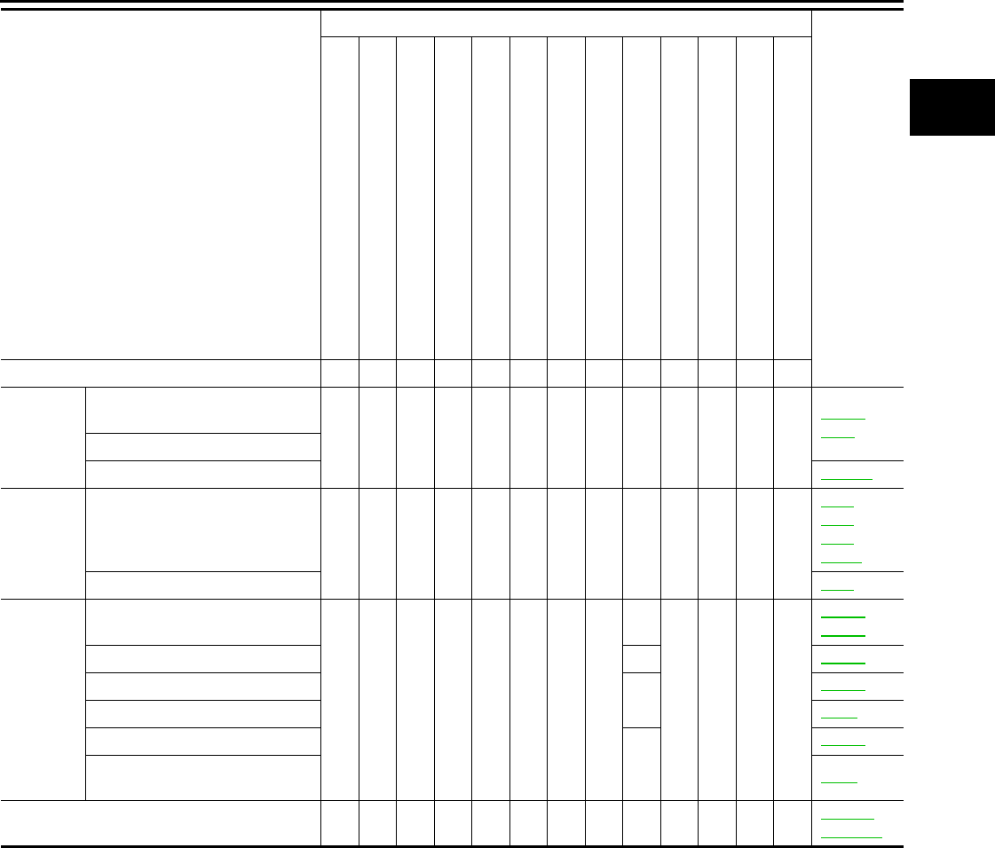
ENGINE CONTROL SYSTEM SYMPTOMS
EC-481
< SYMPTOM DIAGNOSIS > [FOR CALIFORNIA]
C
D
E
F
G
H
I
J
K
L
M
A
EC
N
P
O
1 - 6: The numbers refer to the order of inspection.
Exhaust Exhaust manifold/Tube/Muffler/
Gasket 55555 55 5
EM-33
EX-4
Three way catalyst
HC adsorption catalyst EC-400
Lubrica-
tion Oil pan/Oil strainer/Oil pump/Oil
filter/Oil gallery/Oil cooler 55555 55 5
LU-5
LU-8
LU-9
LU-12
Oil level (Low)/Filthy oil LU-5
Cooling Radiator/Hose/Radiator filler cap
55555 55 45
CO-13
CO-13
Thermostat 5 CO-26
Water pump CO-24
Water gallery CO-2
Cooling fan
5
CO-22
Coolant level (Low)/Contaminat-
ed coolant CO-9
NVIS (NISSAN Vehicle Immobilizer System —
NATS) 11 SEC-15
SEC-155
SYMPTOM
Reference
page
HARD/NO START/RESTART (EXCP. HA)
ENGINE STALL
HESITATION/SURGING/FLAT SPOT
SPARK KNOCK/DETONATION
LACK OF POWER/POOR ACCELERATION
HIGH IDLE/LOW IDLE
ROUGH IDLE/HUNTING
IDLING VIBRATION
SLOW/NO RETURN TO IDLE
OVERHEATS/WATER TEMPERATURE HIGH
EXCESSIVE FUEL CONSUMPTION
EXCESSIVE OIL CONSUMPTION
BATTERY DEAD (UNDER CHARGE)
Warranty symptom code AA AB AC AD AE AF AG AH AJ AK AL AM HA
Revision: 2008 August 2009 Rogue

EC-482
< SYMPTOM DIAGNOSIS > [FOR CALIFORNIA]
NORMAL OPERATING CONDITION
NORMAL OPERATING CONDITION
Description INFOID:0000000004493685
FUEL CUT CONTROL (AT NO LOAD AND HIGH ENGINE SPEED)
If the engine speed is above 1,800 rpm under no load (for example, the selector lever position is neutral and
engine speed is over 1,800 rpm) fuel will be cut off after some time. The exact time when the fuel is cut off var-
ies based on engine speed.
Fuel cut will be operated until the engine speed reaches 1,500 rpm, then fuel cut will be cancelled.
NOTE:
This function is different from deceleration control listed under Multiport Fuel Injection (MFI) System, EC-38,
"System Description".
Revision: 2008 August 2009 Rogue

PRECAUTIONS
EC-483
< PRECAUTION > [FOR CALIFORNIA]
C
D
E
F
G
H
I
J
K
L
M
A
EC
N
P
O
PRECAUTION
PRECAUTIONS
Precaution for Supplemental Restraint System (SRS) "AIR BAG" and "SEAT BELT
PRE-TENSIONER" INFOID:0000000004541611
The Supplemental Restraint System such as “AIR BAG” and “SEAT BELT PRE-TENSIONER”, used along
with a front seat belt, helps to reduce the risk or severity of injury to the driver and front passenger for certain
types of collision. This system includes seat belt switch inputs and dual stage front air bag modules. The SRS
system uses the seat belt switches to determine the front air bag deployment, and may only deploy one front
air bag, depending on the severity of a collision and whether the front occupants are belted or unbelted.
Information necessary to service the system safely is included in the “SRS AIRBAG” and “SEAT BELT” of this
Service Manual.
WARNING:
• To avoid rendering the SRS inoperative, which could increase the risk of personal injury or death in
the event of a collision which would result in air bag inflation, all maintenance must be performed by
an authorized NISSAN/INFINITI dealer.
• Improper maintenance, including incorrect removal and installation of the SRS, can lead to personal
injury caused by unintentional activation of the system. For removal of Spiral Cable and Air Bag
Module, see the “SRS AIRBAG”.
• Never use electrical test equipment on any circuit related to the SRS unless instructed to in this Ser-
vice Manual. SRS wiring harnesses can be identified by yellow and/or orange harnesses or harness
connectors.
Precaution for Procedure without Cowl Top Cover INFOID:0000000004541612
When performing the procedure after removing cowl top cover, cover
the lower end of windshield with urethane, etc.
Precautions For Xenon Headlamp Service INFOID:0000000004541613
WARNING:
Comply with the following warnings to prevent any serious accident.
• Disconnect the battery cable (negative terminal) or the power supply fuse before installing, remov-
ing, or touching the xenon headlamp (bulb included). The xenon headlamp contains high-voltage
generated parts.
• Never work with wet hands.
• Check the xenon headlamp ON-OFF status after assembling it to the vehicle. Never turn the xenon
headlamp ON in other conditions. Connect the power supply to the vehicle-side connector.
(Turning it ON outside the lamp case may cause fire or visual impairments.)
• Never touch the bulb glass immediately after turning it OFF. It is extremely hot.
CAUTION:
Comply with the following cautions to prevent any error and malfunction.
• Install the xenon bulb securely. (Insufficient bulb socket installation may melt the bulb, the connec-
tor, the housing, etc. by high-voltage leakage or corona discharge.)
• Never perform HID circuit inspection with a tester.
• Never touch the xenon bulb glass with hands. Never put oil and grease on it.
• Dispose of the used xenon bulb after packing it in thick vinyl without breaking it.
• Never wipe out dirt and contamination with organic solvent (thinner, gasoline, etc.).
PIIB3706J
Revision: 2008 August 2009 Rogue

EC-484
< PRECAUTION > [FOR CALIFORNIA]
PRECAUTIONS
On Board Diagnostic (OBD) System of Engine and CVT INFOID:0000000004493689
The ECM has an on board diagnostic system. It will illuminate the malfunction indicator lamp (MIL) to warn the
driver of a malfunction causing emission deterioration.
CAUTION:
• Always turn the ignition switch OFF and disconnect the negative battery cable before any repair or
inspection work. The open/short circuit of related switches, sensors, solenoid valves, etc. will cause
the MIL to illuminate.
• Always connect and lock the connectors securely after work. A loose (unlocked) connector will
cause the MIL to illuminate due to the open circuit. (Be sure the connector is free from water, grease,
dirt, bent terminals, etc.)
• Certain systems and components, especially those related to OBD, may use a new style slide-lock-
ing type harness connector. For description and how to disconnect, refer to PG-82, "Description".
• Always route and secure the harnesses properly after work. The interference of the harness with a
bracket, etc. may cause the MIL to illuminate due to the short circuit.
• Always connect rubber tubes properly after work. A misconnected or disconnected rubber tube may
cause the MIL to illuminate due to the malfunction of the EVAP system or fuel injection system, etc.
• Always erase the unnecessary malfunction information (repairs completed) from the ECM and TCM
(Transmission control module) before returning the vehicle to the customer.
General Precautions INFOID:0000000004493690
•Always use a 12 volt battery as power source.
•Never attempt to disconnect battery cables while engine is
running.
•Before connecting or disconnecting the ECM harness con-
nector, turn ignition switch OFF and disconnect negative bat-
tery cable. Failure to do so may damage the ECM because
battery voltage is applied to ECM even if ignition switch is
turned OFF.
•Before removing parts, turn ignition switch OFF and then dis-
connect negative battery cable.
•Never disassemble ECM.
•If a battery cable is disconnected, the memory will return to
the ECM value.
The ECM will now start to self-control at its initial value. Thus
engine operation can vary slightly in this case. However, this
is not an indication of a malfunction. Never replace parts
because of a slight variation.
•If the battery is disconnected, the following emission-related
diagnostic information will be cleared within 24 hours.
-Diagnostic trouble codes
-1st trip diagnostic trouble codes
-Freeze frame data
-1st trip freeze frame data
-System readiness test (SRT) codes
-Test values
•When connecting ECM harness connector (1), fasten (B) it
securely with a lever as far as it will go as shown in the figure.
SEF289H
2. ECM
A. Loosen
PBIA9222J
PBIB2947E
Revision: 2008 August 2009 Rogue

PRECAUTIONS
EC-485
< PRECAUTION > [FOR CALIFORNIA]
C
D
E
F
G
H
I
J
K
L
M
A
EC
N
P
O
•When connecting or disconnecting pin connectors into or
from ECM, never damage pin terminals (berds or breaks).
Check that there are not any bends or breaks on ECM pin ter-
minal, when connecting pin connectors.
•Securely connect ECM harness connectors.
A poor connection can cause an extremely high (surge) volt-
age to develop in coil and condenser, thus resulting in dam-
age to ICs.
•Keep engine control system harness at least 10 cm (4 in) away
from adjacent harness, to prevent engine control system mal-
functions due to receiving external noise, degraded operation
of ICs, etc.
•Keep engine control system parts and harness dry.
•Before replacing ECM, perform ECM Terminals and Reference
Value inspection and check that ECM functions properly.
Refer to EC-439, "Reference Value".
•Handle mass air flow sensor carefully to avoid damage.
•Never clean mass air flow sensor with any type of detergent.
•Never disassemble electric throttle control actuator.
•Even a slight leak in the air intake system can cause serious
incidents.
•Never shock or jar the camshaft position sensor (PHASE),
crankshaft position sensor (POS).
•After performing each TROUBLE DIAGNOSIS, perform DTC
CONFIRMATION PROCEDURE or Component Function
Check. The DTC should not be displayed in the DTC CONFIRMA-
TION PROCEDURE if the repair is completed. The Component
Function Check should be a good result if the repair is completed.
PBIB0090E
MEF040D
SEF217U
Revision: 2008 August 2009 Rogue

EC-486
< PRECAUTION > [FOR CALIFORNIA]
PRECAUTIONS
•When measuring ECM signals with a circuit tester, never allow
the two tester probes to contact.
Accidental contact of probes will cause a short circuit and
damage the ECM power transistor.
•Never operate fuel pump when there is no fuel in lines.
•Tighten fuel hose clamps to the specified torque.
•Never depress accelerator pedal when starting.
•Immediately after starting, never rev up engine unnecessarily.
•Never rev up engine just prior to shutdown.
•When installing C.B. ham radio or a mobile phone, always
observe the following as it may adversely affect electronic
control systems depending on installation location.
-Keep the antenna as far as possible from the electronic con-
trol units.
-Keep the antenna feeder line more than 20 cm (8 in) away
from the harness of electronic controls.
Never let them run parallel for a long distance.
-Adjust the antenna and feeder line so that the standing-wave
ratio can be kept smaller.
-Always ground the radio to vehicle body.
SEF348N
SEF709Y
SEF708Y
Revision: 2008 August 2009 Rogue
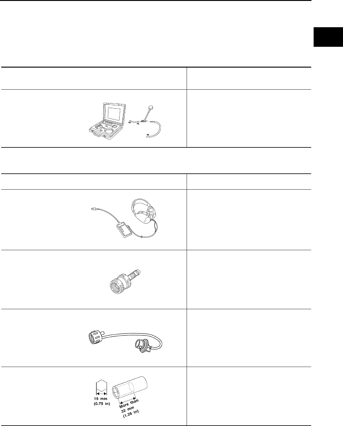
PREPARATION
EC-487
< PREPARATION > [FOR CALIFORNIA]
C
D
E
F
G
H
I
J
K
L
M
A
EC
N
P
O
PREPARATION
PREPARATION
Special Service Tools INFOID:0000000004493691
NOTE:
The actual shapes of Kent-Moore tools may differ from those of special service tools illustrated here.
Commercial Service Tools INFOID:0000000004493692
Tool number
(Kent-Moore No.)
Tool name
Description
(J-44321)
Fuel pressure gauge
kit
Checks fuel pressure
LEC642
Tool name
(Kent-Moore No.) Description
Leak detector
i.e.: (J-41416)
Locates the EVAP leak
EVAP service port
adapter
i.e.: (J-41413-OBD)
Applies positive pressure through EVAP service
port
Fuel filler cap adapter
i.e.: (MLR-8382) Checks fuel tank vacuum relief valve opening
pressure
Socket wrench Removes and installs engine coolant temperature
sensor
S-NT703
S-NT704
S-NT815
S-NT705
Revision: 2008 August 2009 Rogue

EC-488
< PREPARATION > [FOR CALIFORNIA]
PREPARATION
Oxygen sensor thread
cleaner
i.e.: (J-43897-18)
(J-43897-12)
Reconditions the exhaust system threads before
installing a new oxygen sensor. Use with anti-
seize lubricant shown below.
a: 18 mm diameter with pitch 1.5 mm for Zirco-
nia Oxygen Sensor
b: 12 mm diameter with pitch 1.25 mm for Tita-
nia Oxygen Sensor
Anti-seize lubricant
i.e.: (PermatexTM
133AR or equivalent
meeting MIL specifica-
tion MIL-A-907)
Lubricates oxygen sensor thread cleaning tool
when reconditioning exhaust system threads.
Tool name
(Kent-Moore No.) Description
AEM488
S-NT779
Revision: 2008 August 2009 Rogue
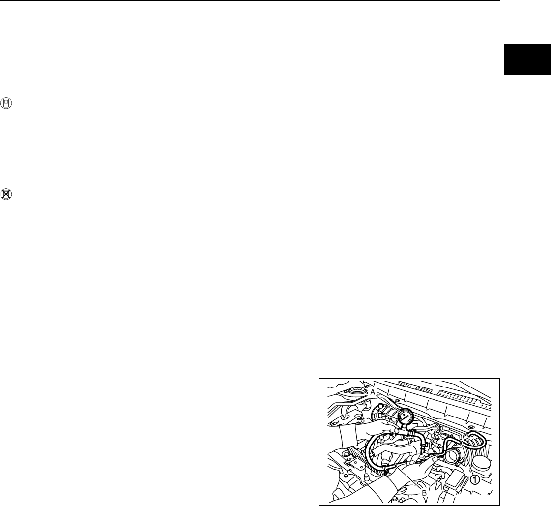
FUEL PRESSURE
EC-489
< ON-VEHICLE MAINTENANCE > [FOR CALIFORNIA]
C
D
E
F
G
H
I
J
K
L
M
A
EC
N
P
O
ON-VEHICLE MAINTENANCE
FUEL PRESSURE
Inspection INFOID:0000000004493693
FUEL PRESSURE RELEASE
With CONSULT-III
1. Turn ignition switch ON.
2. Perform “FUEL PRESSURE RELEASE” in “WORK SUPPORT” mode with CONSULT-III.
3. Start engine.
4. After engine stalls, crank it two or three times to release all fuel pressure.
5. Turn ignition switch OFF.
With CONSULT-III
1. Remove fuel pump fuse located in IPDM E/R.
2. Start engine.
3. After engine stalls, crank it two or three times to release all fuel pressure.
4. Turn ignition switch OFF.
5. Reinstall fuel pump fuse after servicing fuel system.
FUEL PRESSURE CHECK
CAUTION:
Before disconnecting fuel line, release fuel pressure from fuel line to eliminate danger.
NOTE:
•Prepare pans or saucers under the disconnected fuel line because the fuel may spill out. The fuel
pressure cannot be completely released because S35 models do not have fuel return system.
•Use Fuel Pressure Gauge Kit [SST (J-44321)] to check fuel pressure.
1. Release fuel pressure to zero.
2. Install fuel pressure gauge adapter [SST (J-44321-6)] (B) with
fuel pressure gauge (A).
• Fuel feed hose (1)
3. Turn ignition switch ON and check for fuel leakage.
4. Start engine and check for fuel leakage.
5. Read the indication of fuel pressure gauge.
6. If result is unsatisfactory, check fuel hoses and fuel tubes for
clogging.
If OK, Replace “fuel filter and fuel pump assembly”.
If NG, Repair or replace.
At idling : Approximately 350 kPa (3.57 kg/cm2, 51 psi)
JMBIA0930ZZ
Revision: 2008 August 2009 Rogue
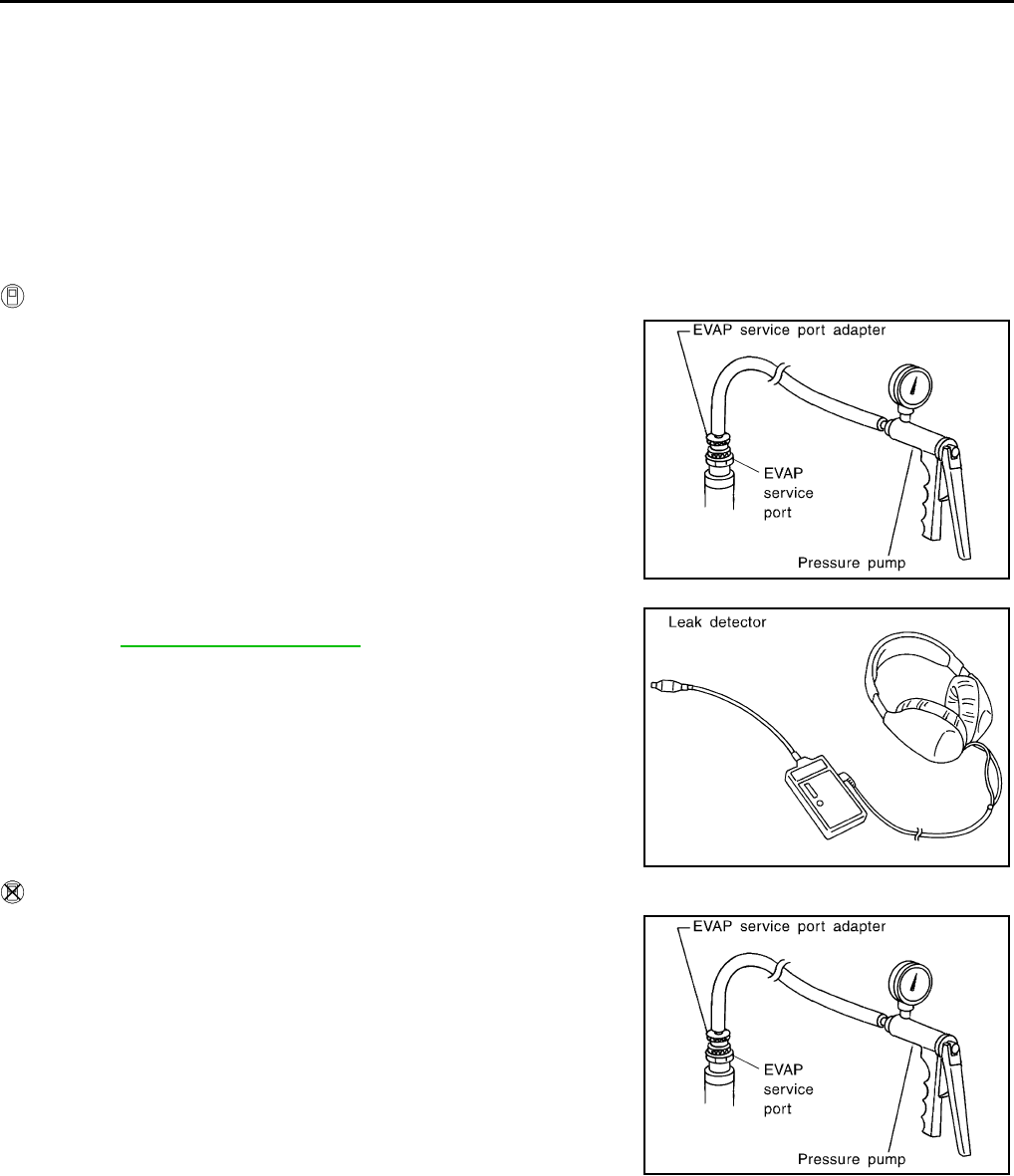
EC-490
< ON-VEHICLE MAINTENANCE > [FOR CALIFORNIA]
EVAP LEAK CHECK
EVAP LEAK CHECK
Inspection INFOID:0000000004493694
CAUTION:
• Never use compressed air or a high pressure pump.
• Never exceed 4.12 kPa (0.042 kg/cm2, 0.6 psi) of pressure in EVAP system.
NOTE:
• Do not start engine.
• Improper installation of EVAP service port adapter (commercial service tool) to the EVAP service port may
cause a leak.
WITH CONSULT-III
1. To locate the EVAP leak, install EVAP service port adapter (com-
mercial service tool) and pressure pump to EVAP service port.
2. Turn ignition switch ON.
3. Select the “EVAP SYSTEM CLOSE” of “WORK SUPPORT”
mode with CONSULT-III.
4. Touch “START”. A bar graph (Pressure indicating display) will
appear on the screen.
5. Apply positive pressure to the EVAP system until the pressure
indicator reaches the middle of the bar graph.
6. Remove EVAP service port adapter (commercial service tool)
and hose with pressure pump.
7. Locate the leak using a leak detector (commercial service tool).
Refer to EC-72, "System Diagram".
WITHOUT CONSULT-III
1. To locate the EVAP leak, install EVAP service port adapter (com-
mercial service tool) and pressure pump to EVAP service port.
2. Apply battery voltage between the terminals of EVAP canister
vent control valve to make a closed EVAP system.
3. To locate the leak, deliver positive pressure to the EVAP system
until pressure gauge points reach 1.38 to 2.76 kPa (0.014 to
0.028 kg/cm2, 0.2 to 0.4 psi).
4. Remove EVAP service port adapter (commercial service tool)
and hose with pressure pump.
SEF462UA
SEF200U
SEF462UA
Revision: 2008 August 2009 Rogue

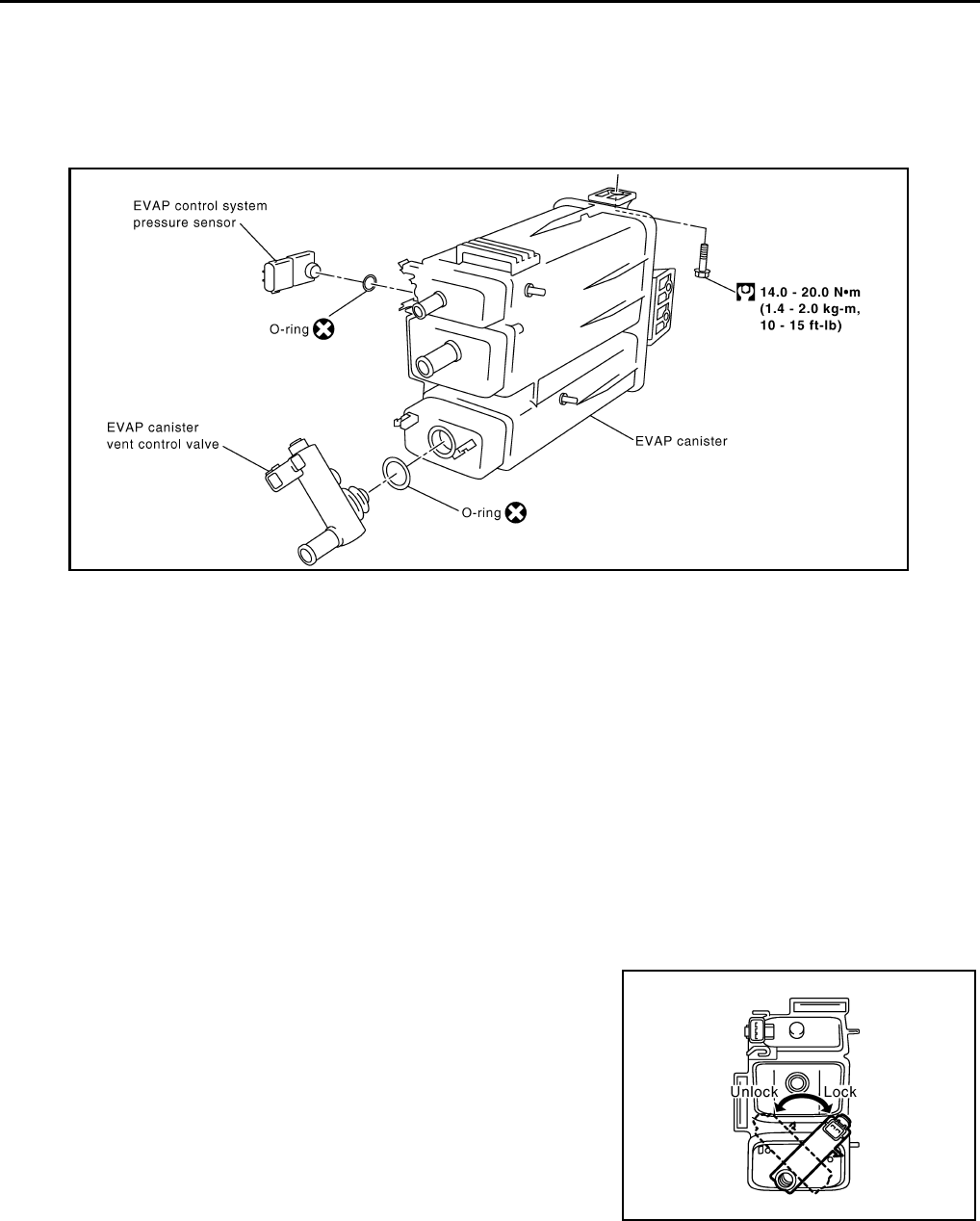
EC-492
< ON-VEHICLE REPAIR > [FOR CALIFORNIA]
EVAP CANISTER
ON-VEHICLE REPAIR
EVAP CANISTER
Exploded View INFOID:0000000004493695
Removal and Installation INFOID:0000000004493696
REMOVAL
1. Lift up the vehicle.
2. Remove EVAP canister fixing bolt.
3. Remove EVAP canister.
NOTE:
The EVAP canister vent control valve and EVAP canister system pressure sensor can be removed without
removing the EVAP canister.
INSTALLATION
Install in the reverse order of removal.
NOTE:
Tighten EVAP canister fixing bolt to the specified torque.
DISASSEMBLY
1. Turn EVAP canister vent control valve counterclockwise.
2. Remove the EVAP canister vent control valve.
ASSEMBLY
Assemble in the reverse order of disassembly.
CAUTION:
Always replace O-ring with a new one.
PBIB1383E
PBIB1384E
Revision: 2008 August 2009 Rogue

EVAP CANISTER
EC-493
< ON-VEHICLE REPAIR > [FOR CALIFORNIA]
C
D
E
F
G
H
I
J
K
L
M
A
EC
N
P
O
Inspection INFOID:0000000004493697
Check EVAP canister as follows:
1. Block port (B).
2. Blow air into port (A) and check that it flows freely out of port (C).
3. Release blocked port (B).
4. Apply vacuum pressure to port (B) and check that vacuum pres-
sure exists at the ports (A) and (C).
5. Block port (A) and (B).
6. Apply pressure to port (C) and check that there is no leakage.
JMBIA0961ZZ
Revision: 2008 August 2009 Rogue

EC-494
< SERVICE DATA AND SPECIFICATIONS (SDS) [FOR CALIFORNIA]
SERVICE DATA AND SPECIFICATIONS (SDS)
SERVICE DATA AND SPECIFICATIONS (SDS)
SERVICE DATA AND SPECIFICATIONS (SDS)
Idle Speed INFOID:0000000004493698
*: Under the following conditions
• A/C switch: OFF
• Electric load: OFF (Lights, heater fan & rear window defogger)
• Steering wheel: Kept in straight-ahead position
Ignition Timing INFOID:0000000004493699
*: Under the following conditions
• A/C switch: OFF
• Electric load: OFF (Lights, heater fan & rear window defogger)
• Steering wheel: Kept in straight-ahead position
Calculated Load Value INFOID:0000000004672486
Mass Air Flow Sensor INFOID:0000000004672487
*: Engine is warmed up to normal operating temperature and running under no load.
Transmission Condition Specification
CVT No load* (in P or N position) 700 ± 50 rpm
Transmission Condition Specification
CVT No load* (in P or N position) 15 ± 5° BTDC
Condition Specification (Using CONSULT-III or GST)
At idle 10 – 35 %
At 2,500 rpm 10 – 35 %
Supply voltage Battery voltage (11 – 14 V)
Output voltage at idle 0.8 – 1.2V*
Mass air flow (Using CONSULT-III or GST) 1.0 – 4.0 g·m/sec at idle*
4.0 – 10.0 g·m/sec at 2,500 rpm*
Revision: 2008 August 2009 Rogue
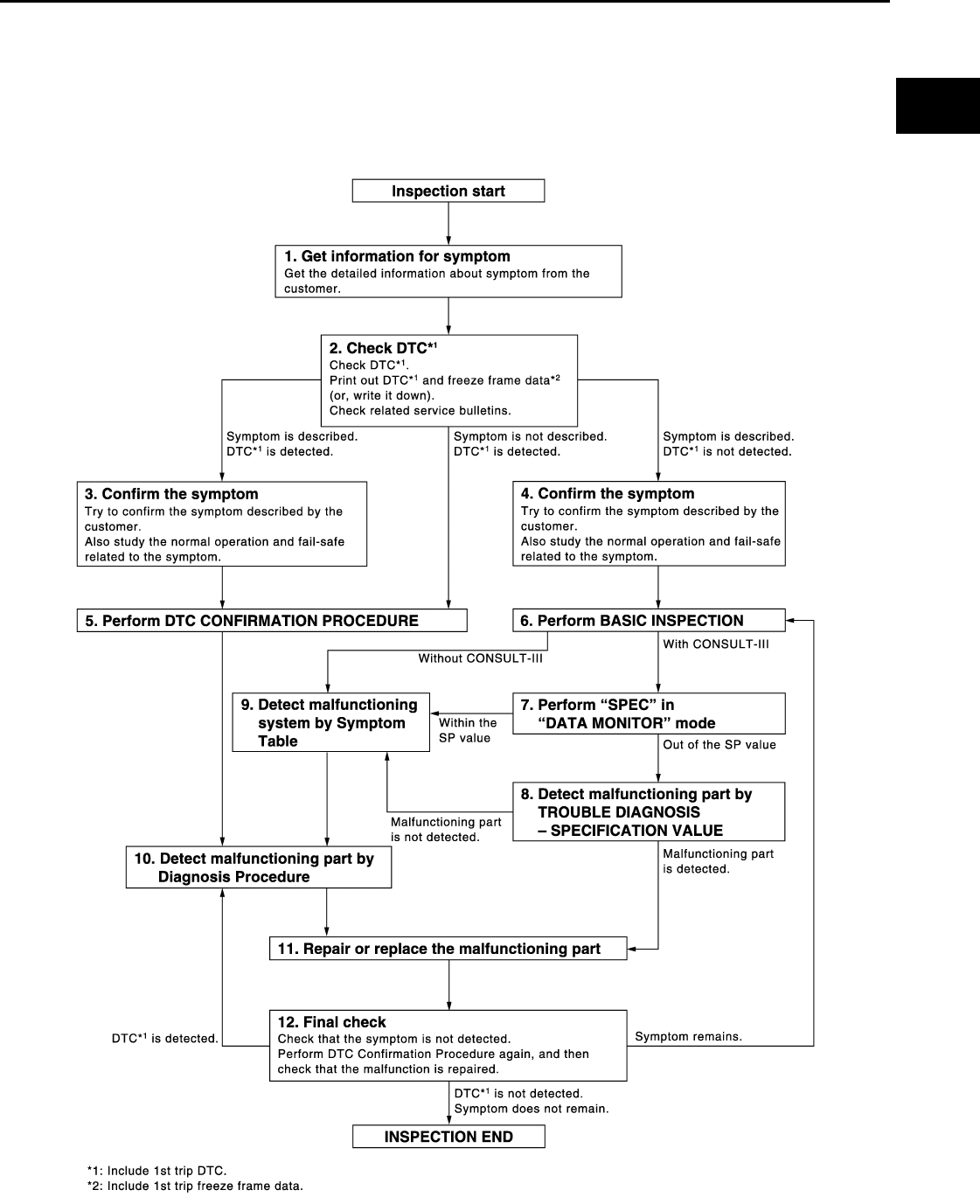
DIAGNOSIS AND REPAIR WORKFLOW
EC-495
< BASIC INSPECTION > [FOR USA (FEDERAL) AND CANADA]
C
D
E
F
G
H
I
J
K
L
M
A
EC
N
P
O
BASIC INSPECTION
DIAGNOSIS AND REPAIR WORKFLOW
Work Flow INFOID:0000000004529408
OVERALL SEQUENCE
DETAILED FLOW
JMBIA1416G
B
Revision: 2008 August 2009 Rogue

EC-496
< BASIC INSPECTION > [FOR USA (FEDERAL) AND CANADA]
DIAGNOSIS AND REPAIR WORKFLOW
1.GET INFORMATION FOR SYMPTOM
Get the detailed information from the customer about the symptom (the condition and the environment when
the incident/malfunction occurred) using the “Diagnostic Work Sheet”. (Refer to EC-498, "Diagnostic Work
Sheet".)
>> GO TO 2.
2.CHECK DTC
1. Check DTC.
2. Perform the following procedure if DTC is displayed.
- Record DTC and freeze frame data. (Print them out with CONSULT-III or GST.)
- Erase DTC. (Refer to “” in EC-563, "Diagnosis Description".)
- Study the relationship between the cause detected by DTC and the symptom described by the customer.
(Symptom Table is useful. Refer to EC-912, "Symptom Table".)
3. Check related service bulletins for information.
Are any symptoms described and is any DTCs detected?
Symptom is described, DTC is detected>>GO TO 3.
Symptom is described, DTC is not detected>>GO TO 4.
Symptom is not described, DTC is detected>>GO TO 5.
3.CONFIRM THE SYMPTOM
Try to confirm the symptom described by the customer (except MIL ON).
Also study the normal operation and fail-safe related to the symptom. Refer to EC-916, "Description" and EC-
897, "Fail Safe".
Diagnosis Work Sheet is useful to verify the incident.
Verify relation between the symptom and the condition when the symptom is detected.
>> GO TO 5.
4.CONFIRM THE SYMPTOM
Try to confirm the symptom described by the customer.
Also study the normal operation and fail-safe related to the symptom. Refer to EC-916, "Description" and EC-
897, "Fail Safe".
Diagnosis Work Sheet is useful to verify the incident.
Verify relation between the symptom and the condition when the symptom is detected.
>> GO TO 6.
5.PERFORM DTC CONFIRMATION PROCEDURE
Perform DTC CONFIRMATION PROCEDURE for the displayed DTC, and then check that DTC is detected
again.
If two or more DTCs are detected, refer to EC-899, "DTC Inspection Priority Chart" and determine trouble
diagnosis order.
NOTE:
• Freeze frame data is useful if the DTC is not detected.
• Perform Component Function Check if DTC CONFIRMATION PROCEDURE is not included on Service
Manual. This simplified check procedure is an effective alternative though DTC cannot be detected during
this check.
If the result of Component Function Check is NG, it is the same as the detection of DTC by DTC CONFIR-
MATION PROCEDURE.
Is DTC detected?
YES >> GO TO 10.
NO >> Check according to GI-41, "Intermittent Incident".
6.PERFORM BASIC INSPECTION
Perform EC-499, "BASIC INSPECTION : Special Repair Requirement".
Do you have CONSULT-III?
Revision: 2008 August 2009 Rogue

DIAGNOSIS AND REPAIR WORKFLOW
EC-497
< BASIC INSPECTION > [FOR USA (FEDERAL) AND CANADA]
C
D
E
F
G
H
I
J
K
L
M
A
EC
N
P
O
YES >> GO TO 7.
NO >> GO TO 9.
7.PERFORM SPEC IN DATA MONITOR MODE
With CONSULT-III
Check that “MAS A/F SE-B1”, “B/FUEL SCHDL” and “A/F ALPHA-B1” are within the SP value using CON-
SULT-III in “SPEC” of “DATA MONITOR” mode with CONSULT-III. Refer to EC-587, "Component Function
Check".
Is the measurement value within the SP value?
YES >> GO TO 9.
NO >> GO TO 8.
8.DETECT MALFUNCTIONING PART BY TROUBLE DIAGNOSIS - SPECIFICATION VALUE
Detect malfunctioning part according to EC-588, "Diagnosis Procedure".
Is a malfunctioning part detected?
YES >> GO TO 11.
NO >> GO TO 9.
9.DETECT MALFUNCTIONING SYSTEM BY SYMPTOM TABLE
Detect malfunctioning system according to EC-912, "Symptom Table" based on the confirmed symptom in
step 4, and determine the trouble diagnosis order based on possible causes and symptoms.
>> GO TO 10.
10.DETECT MALFUNCTIONING PART BY DIAGNOSIS PROCEDURE
Inspect according to Diagnosis Procedure of the system.
NOTE:
The Diagnosis Procedure in EC section described based on open circuit inspection. A short circuit inspection
is also required for the circuit check in the Diagnosis Procedure. For details, refer to “Circuit Inspection” in GI-
44, "Circuit Inspection".
Is a malfunctioning part detected?
YES >> GO TO 11.
NO >> Monitor input data from related sensors or check the voltage of related ECM terminals using CON-
SULT-III. Refer to EC-875, "Reference Value".
11.REPAIR OR REPLACE THE MALFUNCTIONING PART
1. Repair or replace the malfunctioning part.
2. Reconnect parts or connectors disconnected during Diagnosis Procedure again after repair and replace-
ment.
3. Check DTC. If DTC is displayed, erase it. (Refer to “” in EC-563, "Diagnosis Description".)
>> GO TO 12.
12.FINAL CHECK
When DTC was detected in step 2, perform DTC CONFIRMATION PROCEDURE or Component Function
Check again, and then check that the malfunction have been completely repaired.
When symptom was described from the customer, refer to confirmed symptom in step 3 or 4, and check that
the symptom is not detected.
Is DTC detected and does symptom remain?
YES-1 >> DTC is detected: GO TO 10.
YES-2 >> Symptom remains: GO TO 6.
NO >> Before returning the vehicle to the customer, check to always erase unnecessary DTC in ECM
and TCM (Transmission Control Module). (Refer to “” in EC-563, "Diagnosis Description".) If the
completion of SRT is needed, drive vehicle under the specific DRIVING PATTERN in EC-903,
"How to Set SRT Code".
Revision: 2008 August 2009 Rogue
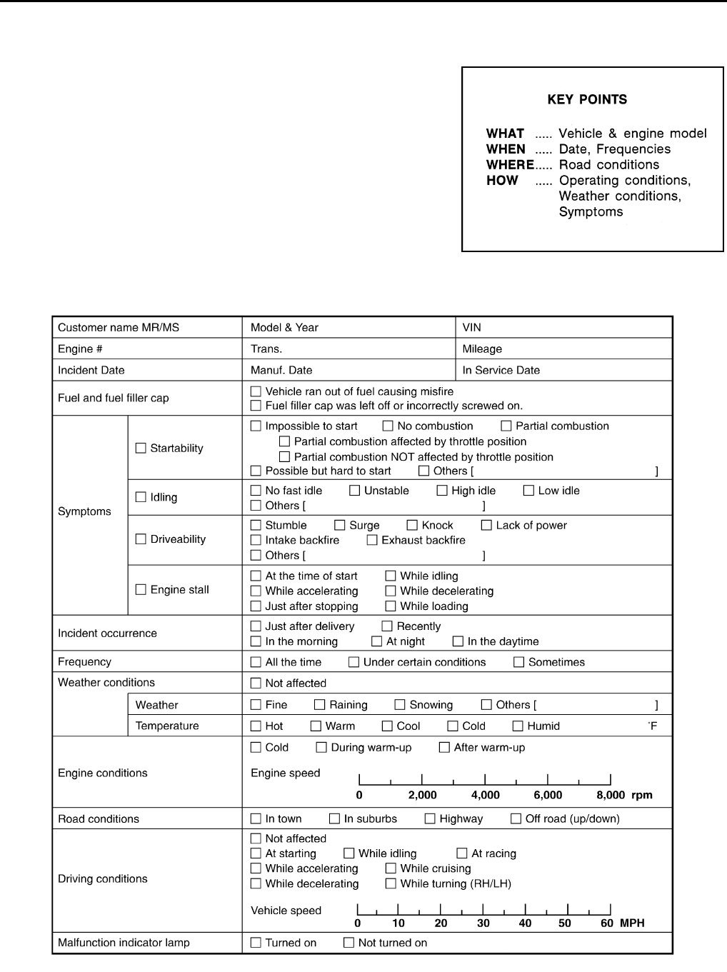
EC-498
< BASIC INSPECTION > [FOR USA (FEDERAL) AND CANADA]
DIAGNOSIS AND REPAIR WORKFLOW
Diagnostic Work Sheet INFOID:0000000004529409
DESCRIPTION
There are many operating conditions that lead to the malfunction of
engine components. A good grasp of such conditions can make trou-
bleshooting faster and more accurate.
In general, each customer feels differently about symptoms. It is
important to fully understand the symptoms or conditions for a cus-
tomer complaint.
Utilize a diagnostic worksheet like WORKSHEET SAMPLE below in
order to organize all the information for troubleshooting.
Some conditions may cause the MIL to illuminate or blink, and DTC
to be detected. Examples:
• Vehicle ran out of fuel, which caused the engine to misfire.
• Fuel filler cap was left off or incorrectly screwed on, allowing fuel to
evaporate into the atmosphere.
WORKSHEET SAMPLE
SEF907L
MTBL0017
Revision: 2008 August 2009 Rogue
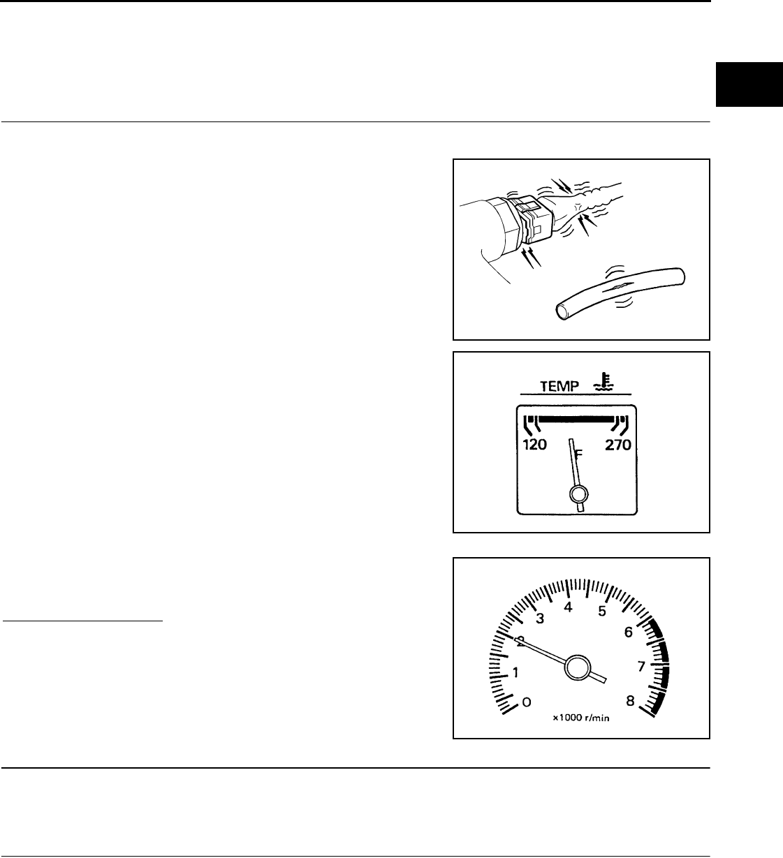
INSPECTION AND ADJUSTMENT
EC-499
< BASIC INSPECTION > [FOR USA (FEDERAL) AND CANADA]
C
D
E
F
G
H
I
J
K
L
M
A
EC
N
P
O
INSPECTION AND ADJUSTMENT
BASIC INSPECTION
BASIC INSPECTION : Special Repair Requirement INFOID:0000000004529410
1.INSPECTION START
1. Check service records for any recent repairs that may indicate a related malfunction, or a current need for
scheduled maintenance.
2. Open engine hood and check the following:
- Harness connectors for improper connections
- Wiring harness for improper connections, pinches and cut
- Vacuum hoses for splits, kinks and improper connections
- Hoses and ducts for leakage
- Air cleaner clogging
- Gasket
3. Check that electrical or mechanical loads are not applied.
- Headlamp switch is OFF.
- Air conditioner switch is OFF.
- Rear window defogger switch is OFF.
- Steering wheel is in the straight-ahead position, etc.
4. Start engine and warm it up until engine coolant temperature
indicator points to the middle of gauge.
Check that engine stays below 1,000 rpm.
5. Run engine at approximately 2,000 rpm for approximately 2 min-
utes under no load.
6. Check that no DTC is displayed with CONSULT-III or GST.
Are any DTCs detected?
YES >> GO TO 2.
NO >> GO TO 3.
2.REPAIR OR REPLACE
Repair or replace components as necessary according to corresponding Diagnosis Procedure.
>> GO TO 3
3.CHECK IDLE SPEED
1. Run engine at approximately 2,000 rpm for approximately 2 minutes under no load.
SEF983U
SEF976U
SEF977U
Revision: 2008 August 2009 Rogue
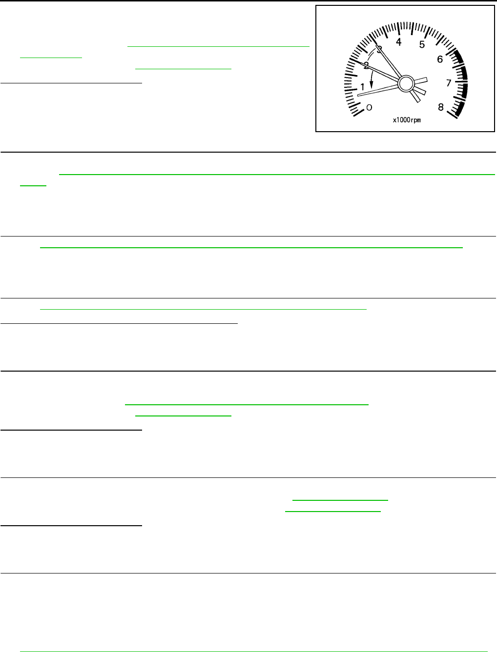
EC-500
< BASIC INSPECTION > [FOR USA (FEDERAL) AND CANADA]
INSPECTION AND ADJUSTMENT
2. Rev engine (2,000 to 3,000 rpm) two or three times under no
load, then run engine at idle speed for approximately 1 minute.
3. Check idle speed.
For procedure, refer to EC-503, "IDLE SPEED : Special Repair
Requirement".
For specification, refer to EC-928, "Idle Speed".
Is the inspection result normal?
YES >> GO TO 10.
NO >> GO TO 4.
4.PERFORM ACCELERATOR PEDAL RELEASED POSITION LEARNING
1. Stop engine.
2. Perform EC-504, "ACCELERATOR PEDAL RELEASED POSITION LEARNING : Special Repair Require-
ment".
>> GO TO 5.
5.PERFORM THROTTLE VALVE CLOSED POSITION LEARNING
Perform EC-504, "THROTTLE VALVE CLOSED POSITION LEARNING : Special Repair Requirement".
>> GO TO 6.
6.PERFORM IDLE AIR VOLUME LEARNING
Perform EC-505, "IDLE AIR VOLUME LEARNING : Special Repair Requirement".
Is Idle Air Volume Learning carried out successfully?
YES >> GO TO 7.
NO >> Follow the instruction of Idle Air Volume Learning. Then GO TO 4.
7.CHECK IDLE SPEED AGAIN
1. Start engine and warm it up to normal operating temperature.
2. Check idle speed.
For procedure, refer to EC-503, "IDLE SPEED : Special Repair Requirement".
For specification, refer to EC-928, "Idle Speed".
Is the inspection result normal?
YES >> GO TO 10.
NO >> GO TO 8.
8.DETECT MALFUNCTIONING PART
Check the Following.
• Check camshaft position sensor (PHASE) and circuit. Refer to EC-707, "DTC Logic".
• Check crankshaft position sensor (POS) and circuit. Refer to EC-703, "DTC Logic".
Is the inspection result normal?
YES >> GO TO 9.
NO >> Repair or replace. Then GO TO 4.
9.CHECK ECM FUNCTION
1. Substitute another with a non-malfunctioning ECM to check ECM function. (ECM may be the cause of an
incident, although this is rare.)
NOTE:
Use the specified bolts described in parts information certainly when installing the ECM, or violates the
Canada law.
2. Perform initialization of NVIS (NATS) system and registration of all NVIS (NATS) ignition key IDs. Refer to
EC-502, "ADDITIONAL SERVICE WHEN REPLACING CONTROL UNIT : Special Repair Requirement".
>> GO TO 4.
PBIA8513J
Revision: 2008 August 2009 Rogue

INSPECTION AND ADJUSTMENT
EC-501
< BASIC INSPECTION > [FOR USA (FEDERAL) AND CANADA]
C
D
E
F
G
H
I
J
K
L
M
A
EC
N
P
O
10.CHECK IGNITION TIMING
1. Run engine at idle.
2. Check ignition timing with a timing light.
For procedure, refer to EC-503, "IGNITION TIMING : Special Repair Requirement".
For specification, refer to EC-928, "Ignition Timing".
Is the inspection result normal?
YES >> GO TO 19.
NO >> GO TO 11.
11.PERFORM ACCELERATOR PEDAL RELEASED POSITION LEARNING
1. Stop engine.
2. Perform EC-504, "ACCELERATOR PEDAL RELEASED POSITION LEARNING : Special Repair Require-
ment".
>> GO TO 12.
12.PERFORM THROTTLE VALVE CLOSED POSITION LEARNING
Perform EC-504, "THROTTLE VALVE CLOSED POSITION LEARNING : Special Repair Requirement".
>> GO TO 13.
13.PERFORM IDLE AIR VOLUME LEARNING
Perform EC-505, "IDLE AIR VOLUME LEARNING : Special Repair Requirement".
Is Idle Air Volume Learning carried out successfully?
YES >> GO TO 14.
NO >> Follow the instruction of Idle Air Volume Learning. Then GO TO 4.
14.CHECK IDLE SPEED AGAIN
1. Start engine and warm it up to normal operating temperature.
2. Check idle speed.
For procedure, refer to EC-503, "IDLE SPEED : Special Repair Requirement".
For specification, refer to EC-928, "Idle Speed".
Is the inspection result normal?
YES >> GO TO 15.
NO >> GO TO 17.
15.CHECK IGNITION TIMING AGAIN
1. Run engine at idle.
2. Check ignition timing with a timing light.
For procedure, refer to EC-503, "IGNITION TIMING : Special Repair Requirement".
For specification, refer to EC-928, "Ignition Timing".
Is the inspection result normal?
YES >> GO TO 19.
NO >> GO TO 16.
16.CHECK TIMING CHAIN INSTALLATION
Check timing chain installation. Refer to EM-70, "Removal and Installation".
Is the inspection result normal?
YES >> GO TO 17.
NO >> Repair the timing chain installation. Then GO TO 4.
17.DETECT MALFUNCTIONING PART
Check the following.
• Check camshaft position sensor (PHASE) and circuit. Refer to EC-707, "DTC Logic".
• Check crankshaft position sensor (POS) and circuit. Refer to EC-703, "DTC Logic".
Is the inspection result normal?
Revision: 2008 August 2009 Rogue

EC-502
< BASIC INSPECTION > [FOR USA (FEDERAL) AND CANADA]
INSPECTION AND ADJUSTMENT
YES >> GO TO 18.
NO >> Repair or replace. Then GO TO 4.
18.CHECK ECM FUNCTION
1. Substitute with a non-malfunctioning ECM to check ECM function. (ECM may be the cause of a incident,
although this is rare.)
NOTE:
Use the specified bolts described in parts information certainly when installing the ECM, or violates the
Canada law.
2. Perform initialization of NVIS (NATS) system and registration of all NVIS (NATS) ignition key IDs. Refer to
EC-502, "ADDITIONAL SERVICE WHEN REPLACING CONTROL UNIT : Special Repair Requirement".
>> GO TO 4.
19.INSPECTION END
If ECM is replaced during this BASIC INSPECTION procedure, go to EC-502, "ADDITIONAL SERVICE
WHEN REPLACING CONTROL UNIT : Special Repair Requirement".
>> INSPECTION END
ADDITIONAL SERVICE WHEN REPLACING CONTROL UNIT
ADDITIONAL SERVICE WHEN REPLACING CONTROL UNIT : Description
INFOID:0000000004529411
When replacing ECM, the following procedure must be performed.
ADDITIONAL SERVICE WHEN REPLACING CONTROL UNIT : Special Repair Re-
quirement INFOID:0000000004529412
1.PERFORM INITIALIZATION OF NVIS (NATS) SYSTEM AND REGISTRATION OF ALL NATS IGNITION
KEY IDS
Refer to SEC-9, "ECM RE-COMMUNICATING FUNCTION : Special Repair Requirement" (With Intelligent key
system), SEC-154, "ECM RE-COMMUNICATING FUNCTION : Special Repair Requirement" (Without Intelli-
gent key system).
>> GO TO 2.
2.PERFORM VIN REGISTRATION
Refer to EC-504, "VIN REGISTRATION : Special Repair Requirement".
>> GO TO 3.
3.PERFORM ACCELERATOR PEDAL RELEASED POSITION LEARNING
Refer to EC-504, "ACCELERATOR PEDAL RELEASED POSITION LEARNING : Special Repair Require-
ment".
>> GO TO 4.
4.PERFORM THROTTLE VALVE CLOSED POSITION LEARNING
Refer to EC-504, "THROTTLE VALVE CLOSED POSITION LEARNING : Special Repair Requirement".
>> GO TO 5.
5.PERFORM IDLE AIR VOLUME LEARNING
Refer to EC-505, "IDLE AIR VOLUME LEARNING : Special Repair Requirement".
>> END
Revision: 2008 August 2009 Rogue
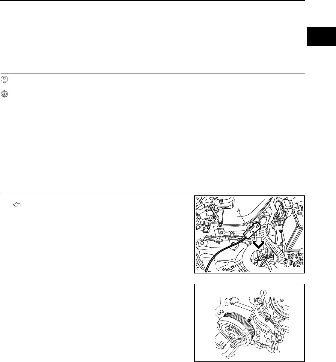
INSPECTION AND ADJUSTMENT
EC-503
< BASIC INSPECTION > [FOR USA (FEDERAL) AND CANADA]
C
D
E
F
G
H
I
J
K
L
M
A
EC
N
P
O
IDLE SPEED
IDLE SPEED : Description INFOID:0000000004529413
This describes how to check the idle speed. For the actual procedure, follow the instructions in “BASIC
INSPECTION”.
IDLE SPEED : Special Repair Requirement INFOID:0000000004529414
1.CHECK IDLE SPEED
With CONSULT-III
Check idle speed in “DATA MONITOR” mode with CONSULT-III.
With GST
Check idle speed with Service $01 of GST.
>> INSPECTION END
IGNITION TIMING
IGNITION TIMING : Description INFOID:0000000004529415
This describes how to check the ignition timing. For the actual procedure, follow the instructions in “BASIC
INSPECTION”.
IGNITION TIMING : Special Repair Requirement INFOID:0000000004529416
1.CHECK IGNITION TIMING
1. Attach timing light (A) to No. 1 ignition coil wire as shown.
- : Vehicle front
2. Check ignition timing.
- Timing indicator (1)
>> INSPECTION END
VIN REGISTRATION
VIN REGISTRATION : Description INFOID:0000000004529417
VIN Registration is an operation to register VIN in ECM. It must be performed each time ECM is replaced.
NOTE:
Accurate VIN which is registered in ECM may be required for Inspection & Maintenance (I/M).
JMBIA0928ZZ
ALBIA0048ZZ
Revision: 2008 August 2009 Rogue

EC-504
< BASIC INSPECTION > [FOR USA (FEDERAL) AND CANADA]
INSPECTION AND ADJUSTMENT
VIN REGISTRATION : Special Repair Requirement INFOID:0000000004529418
1.CHECK VIN
Check the VIN of the vehicle and note it. Refer to GI-22, "Information About Identification or Model Code".
>> GO TO 2.
2.PERFORM VIN REGISTRATION
With CONSULT-III
1. Turn ignition switch ON with engine stopped.
2. Select “VIN REGISTRATION” in “WORK SUPPORT” mode.
3. Follow the instructions on the CONSULT-III display.
>> END
ACCELERATOR PEDAL RELEASED POSITION LEARNING
ACCELERATOR PEDAL RELEASED POSITION LEARNING : Description INFOID:0000000004529419
Accelerator Pedal Released Position Learning is a function of ECM to learn the fully released position of the
accelerator pedal by monitoring the accelerator pedal position sensor output signal. It must be performed each
time harness connector of accelerator pedal position sensor or ECM is disconnected.
ACCELERATOR PEDAL RELEASED POSITION LEARNING : Special Repair Re-
quirement INFOID:0000000004529420
1.START
1. Check that accelerator pedal is fully released.
2. Turn ignition switch ON and wait at least 2 seconds.
3. Turn ignition switch OFF and wait at least 10 seconds.
4. Turn ignition switch ON and wait at least 2 seconds.
5. Turn ignition switch OFF and wait at least 10 seconds.
>> END
THROTTLE VALVE CLOSED POSITION LEARNING
THROTTLE VALVE CLOSED POSITION LEARNING : Description INFOID:0000000004529421
Throttle Valve Closed Position Learning is a function of ECM to learn the fully closed position of the throttle
valve by monitoring the throttle position sensor output signal. It must be performed each time harness connec-
tor of electric throttle control actuator or ECM is disconnected.
THROTTLE VALVE CLOSED POSITION LEARNING : Special Repair Requirement
INFOID:0000000004529422
1.START
1. Check that accelerator pedal is fully released.
2. Turn ignition switch ON.
3. Turn ignition switch OFF and wait at least 10 seconds.
Check that throttle valve moves during the above 10 seconds by confirming the operating sound.
>> END
IDLE AIR VOLUME LEARNING
IDLE AIR VOLUME LEARNING : Description INFOID:0000000004529423
Idle Air Volume Learning is a function of ECM to learn the idle air volume that keeps each engine idle speed
within the specific range. It must be performed under the following conditions:
Revision: 2008 August 2009 Rogue

INSPECTION AND ADJUSTMENT
EC-505
< BASIC INSPECTION > [FOR USA (FEDERAL) AND CANADA]
C
D
E
F
G
H
I
J
K
L
M
A
EC
N
P
O
• Each time the electric throttle control actuator or ECM is replaced.
• Idle speed or ignition timing is out of the specification.
IDLE AIR VOLUME LEARNING : Special Repair Requirement INFOID:0000000004529424
1.PRECONDITIONING
Check that all of the following conditions are satisfied.
Learning will be cancelled if any of the following conditions are missed for even a moment.
• Battery voltage: More than 12.9V (At idle)
• Engine coolant temperature: 70 - 100°C (158 - 212°F)
• PNP switch: ON
• Electric load switch: OFF
(Air conditioner, headlamp, rear window defogger)
On vehicles equipped with daytime light systems, if the parking brake is applied before the engine is
started the headlamp will not illuminate.
• Steering wheel: Neutral (Straight-ahead position)
• Vehicle speed: Stopped
• Transmission: Warmed-up
- With CONSULT-III: Drive vehicle until “ATF TENP SEN” in “DATA MONITOR” mode of “CVT” system indi-
cates less than 0.9V.
- Without CONSULT-III: Drive vehicle for 10 minutes.
Do you have CONSULT-III?
YES >> GO TO 2.
NO >> GO TO 3.
2.IDLE AIR VOLUME LEARNING
With CONSULT-III
1. Perform Accelerator Pedal Released Position Learning. Refer to EC-504, "ACCELERATOR PEDAL
RELEASED POSITION LEARNING : Special Repair Requirement".
2. Perform Throttle Valve Closed Position Learning. Refer to EC-504, "THROTTLE VALVE CLOSED POSI-
TION LEARNING : Special Repair Requirement".
3. Start engine and warm it up to normal operating temperature.
4. Select “IDLE AIR VOL LEARN” in “WORK SUPPORT” mode.
5. Touch “START” and wait 20 seconds.
Is “CMPLT” displayed on CONSULT-III screen?
YES >> GO TO 4.
NO >> GO TO 5.
3.IDLE AIR VOLUME LEARNING
Without CONSULT-III
NOTE:
•It is better to count the time accurately with a clock.
•It is impossible to switch the diagnostic mode when an accelerator pedal position sensor circuit has
a malfunction.
1. Perform Accelerator Pedal Released Position Learning. Refer to EC-504, "ACCELERATOR PEDAL
RELEASED POSITION LEARNING : Special Repair Requirement".
2. Perform Throttle Valve Closed Position Learning. Refer to EC-504, "THROTTLE VALVE CLOSED POSI-
TION LEARNING : Special Repair Requirement".
3. Start engine and warm it up to normal operating temperature.
4. Turn ignition switch OFF and wait at least 10 seconds.
5. Confirm that accelerator pedal is fully released, turn ignition switch ON and wait 3 seconds.
6. Repeat the following procedure quickly five times within 5 seconds.
- Fully depress the accelerator pedal.
- Fully release the accelerator pedal.
7. Wait 7 seconds, fully depress the accelerator pedal for approx. 20 seconds until the MIL stops blinking
and turned ON.
8. Fully release the accelerator pedal within 3 seconds after the MIL turns ON.
9. Start engine and let it idle.
Revision: 2008 August 2009 Rogue
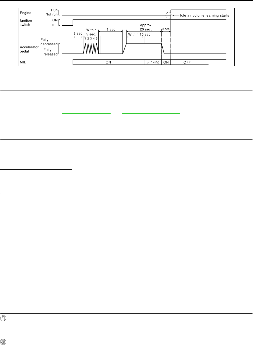
EC-506
< BASIC INSPECTION > [FOR USA (FEDERAL) AND CANADA]
INSPECTION AND ADJUSTMENT
10. Wait 20 seconds.
>> GO TO 4.
4.CHECK IDLE SPEED AND IGNITION TIMING
Rev up the engine two or three times and check that idle speed and ignition timing are within the specifica-
tions.
For procedure, refer to EC-928, "Idle Speed" and EC-928, "Ignition Timing".
For specifications, refer to EC-928, "Idle Speed" and EC-928, "Ignition Timing".
Is the inspection result normal?
YES >> INSPECTION END
5.DETECT MALFUNCTIONING PART
Check the following
• Check that throttle valve is fully closed.
• Check PCV valve operation.
• Check that downstream of throttle valve is free from air leakage.
Is the inspection result normal?
YES >> GO TO 6.
NO >> Repair or replace malfunctioning part.
6.DETECT MALFUNCTIONING PART
Engine component parts and their installation condition are questionable. Check and eliminate the cause of
the incident.
It is useful to perform “TROUBLE DIAGNOSIS - SPECIFICATION VALUE”. Refer to EC-587, "Description".
If any of the following conditions occur after the engine has started, eliminate the cause of the incident and
perform Idle Air Volume Learning again:
• Engine stalls.
• Incorrect idle.
>> INSPECTION END
MIXTURE RATIO SELF-LEARNING VALUE CLEAR
MIXTURE RATIO SELF-LEARNING VALUE CLEAR : Description INFOID:0000000004529425
This describes how to erase the mixture ratio self-learning value. For the actual procedure, follow the instruc-
tions in “Diagnosis Procedure”.
MIXTURE RATIO SELF-LEARNING VALUE CLEAR : Special Repair Requirement
INFOID:0000000004529426
1.START
With CONSULT-III
1. Start engine and warm it up to normal operating temperature.
2. Select “SELF-LEARNING CONT” in “WORK SUPPORT” mode with CONSULT-III.
3. Clear mixture ratio self-learning value by touching “CLEAR”.
With GST
1. Start engine and warm it up to normal operating temperature.
SEC897C
Revision: 2008 August 2009 Rogue

INSPECTION AND ADJUSTMENT
EC-507
< BASIC INSPECTION > [FOR USA (FEDERAL) AND CANADA]
C
D
E
F
G
H
I
J
K
L
M
A
EC
N
P
O
2. Turn ignition switch OFF.
3. Disconnect mass air flow sensor harness connector.
4. Restart engine and let it idle for at least 5 seconds.
5. Stop engine and reconnect mass air flow sensor harness connector.
6. Select Service $03 with GST. Check DTC P0102 is detected.
7. Select Service $04 with GST to erase the DTC P0102.
>> END
Revision: 2008 August 2009 Rogue
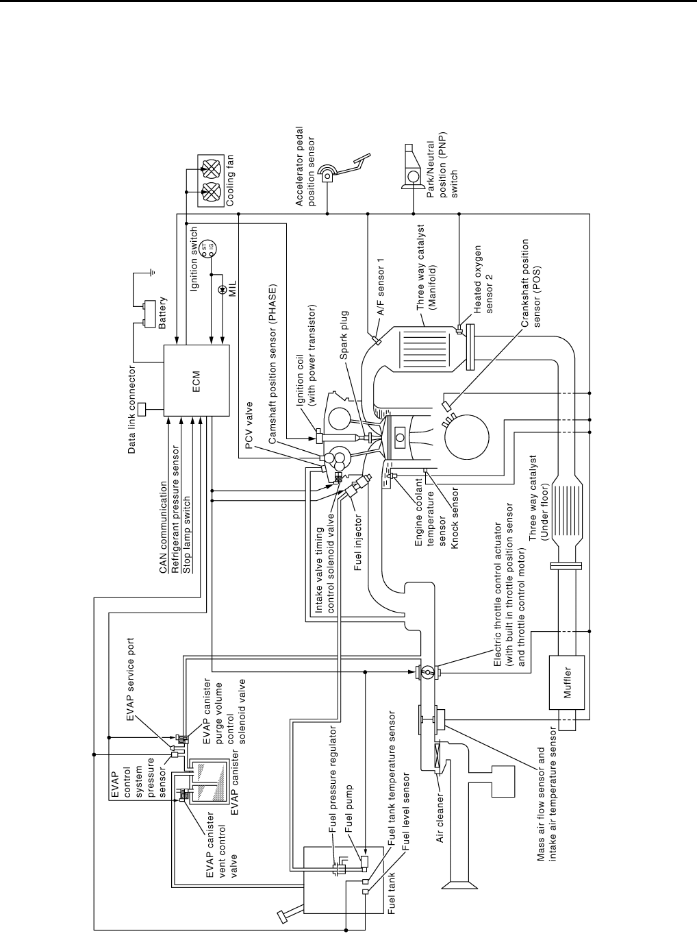
EC-508
< FUNCTION DIAGNOSIS > [FOR USA (FEDERAL) AND CANADA]
ENGINE CONTROL SYSTEM
FUNCTION DIAGNOSIS
ENGINE CONTROL SYSTEM
System Diagram INFOID:0000000004529427
JMBIA0934G
B
Revision: 2008 August 2009 Rogue
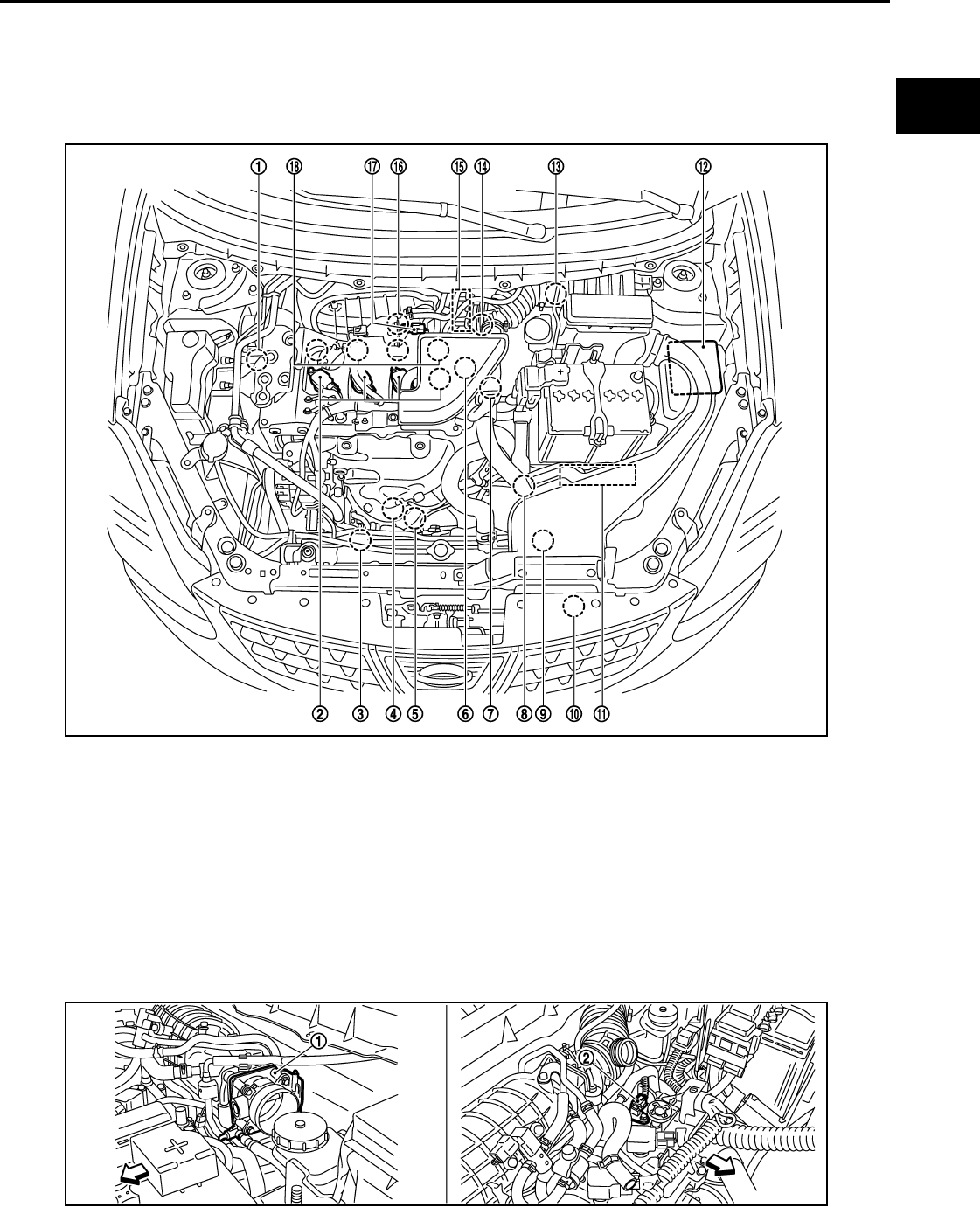
ENGINE CONTROL SYSTEM
EC-509
< FUNCTION DIAGNOSIS > [FOR USA (FEDERAL) AND CANADA]
C
D
E
F
G
H
I
J
K
L
M
A
EC
N
P
O
System Description INFOID:0000000004529428
ECM performs various controls such as fuel injection control and ignition timing control.
Component Parts Location INFOID:0000000004529429
1. Intake valve timing control solenoid
valve
2. Ignition coil (with power transistor)
and spark plug
3. Cooling fan motor-2
4. Air fuel ratio (A/F) sensor 1 5. Heated oxygen sensor 2 6. Camshaft position sensor (PHASE)
7. Engine coolant temperature sensor 8. Park/neutral position (PNP) switch 9. Cooling fan motor-1
10. Refrigerant pressure sensor 11. ECM 12. IPDM E/R
13. Mass air flow sensor (with intake air
temperature sensor) 14. Crankshaft position sensor (POS) 15. Electric throttle control actuator
(with built in throttle position sensor
and throttle control motor)
16. Knock sensor 17. EVAP canister purge volume control
solenoid valve
18. Fuel injector
JMBIA0916ZZ
JMBIA0917ZZ
Revision: 2008 August 2009 Rogue

EC-510
< FUNCTION DIAGNOSIS > [FOR USA (FEDERAL) AND CANADA]
ENGINE CONTROL SYSTEM
1. Electric throttle control actuator 2. Camshaft position sensor (PHASE)
Vehicle front
1. Mass air flow sensor (with intake air
temperature sensor)
2. Engine coolant temperature sensor
Vehicle front
1. Cooling fan motor-1 harness con-
nector
2. Cooling fan motor-1 3. Cooling fan motor-2 harness con-
nector
4. Cooling fan motor-2 5. Crankshaft position sensor (POS)
Vehicle front
1. Fuel injector 2. Ignition coil (with power transistor)
and spark plug
3. EVAP canister purge volume control
solenoid valve
4. EVAP service port
Vehicle front
JMBIA0918ZZ
JMBIA0919ZZ
JMBIA0921ZZ
Revision: 2008 August 2009 Rogue
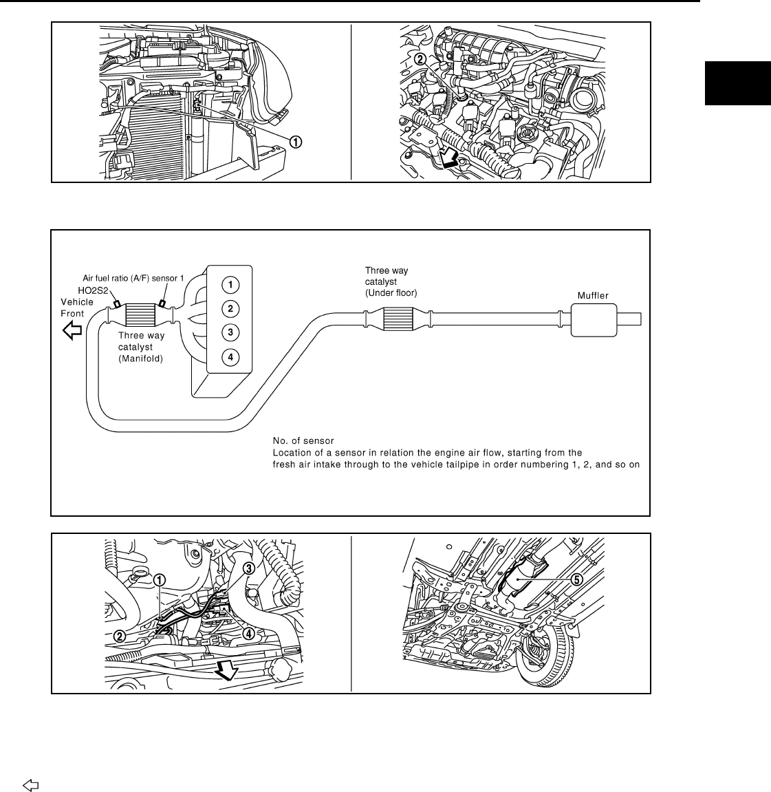
ENGINE CONTROL SYSTEM
EC-511
< FUNCTION DIAGNOSIS > [FOR USA (FEDERAL) AND CANADA]
C
D
E
F
G
H
I
J
K
L
M
A
EC
N
P
O
1. Refrigerant pressure sensor 2. PCV valve
JMBIA0922ZZ
JMBIA0502G
B
1. Air fuel ratio (A/F) sensor 1 2. Heated oxygen sensor 2 3. Air fuel ratio (A/F) sensor 1 harness
connector
4. Heated oxygen sensor 2 harness
connector
5. Three way catalyst (Under floor)
Vehicle front
JMBIA0920ZZ
Revision: 2008 August 2009 Rogue
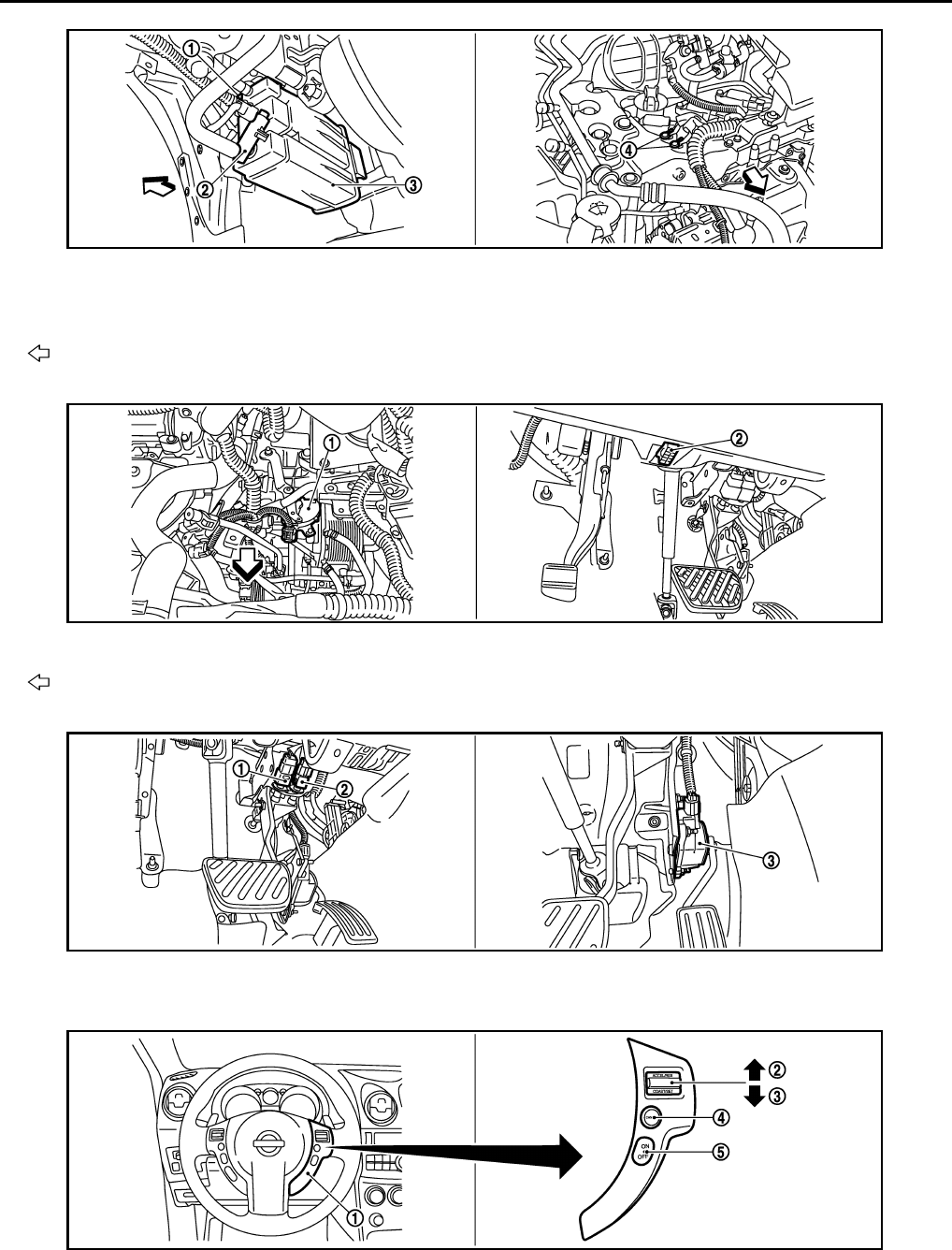
EC-512
< FUNCTION DIAGNOSIS > [FOR USA (FEDERAL) AND CANADA]
ENGINE CONTROL SYSTEM
1. EVAP control system pressure sen-
sor
2. EVAP canister vent control valve 3. EVAP canister
4. Body ground
Vehicle front
1. Park/neutral position (PNP) switch 2. Data link connector
Vehicle front
1. Stop lamp switch 2. ASCD brake switch 3. Accelerator pedal position sensor
1. ASCD steering switch 2. RESUME/ACCERELATE switch 3. SET/COAST switch
4. CANSEL switch 5. MAIN switch
JMBIA0923ZZ
JMBIA0927ZZ
JMBIA0924ZZ
JMBIA0925ZZ
Revision: 2008 August 2009 Rogue
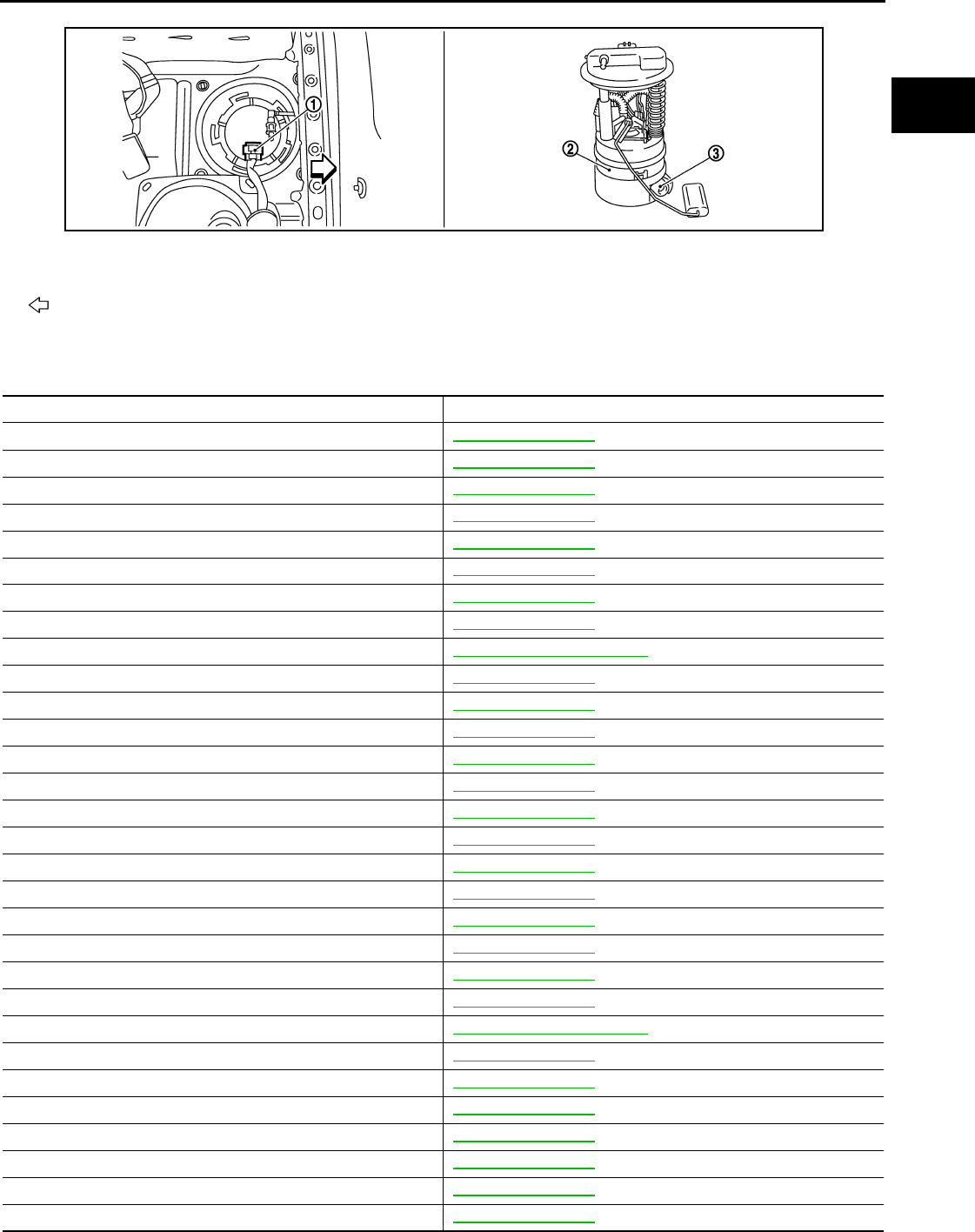
ENGINE CONTROL SYSTEM
EC-513
< FUNCTION DIAGNOSIS > [FOR USA (FEDERAL) AND CANADA]
C
D
E
F
G
H
I
J
K
L
M
A
EC
N
P
O
Component Description INFOID:0000000004529430
1. Fuel level sensor unit and fuel pump
harness connector
2. Fuel level sensor unit and fuel pump 3. Fuel pressure regulator
Vehicle front
JMBIA0926ZZ
Component Reference
A/F sensor 1 EC-645, "Description"
A/F sensor 1 heater EC-606, "Description"
Accelerator pedal position sensor EC-825, "Description"
ASCD brake switch EC-804, "Description"
ASCD steering switch EC-801, "Description"
ASCD vehicle speed sensor EC-809, "Description"
Camshaft position sensor (PHASE) EC-707, "Description"
Crankshaft position sensor (POS) EC-703, "Description"
Cooling fan motor EC-542, "System Description"
Electric throttle control actuator EC-823, "Description"
Engine coolant temperature sensor EC-632, "Description"
EVAP canister purge volume control solenoid valve EC-727, "Description"
EVAP canister vent control valve EC-734, "Description"
EVAP control system pressure sensor EC-742, "Description"
Fuel injector EC-855, "Description"
Fuel level sensor EC-768, "Description"
Fuel pump EC-858, "Description"
Fuel tank temperature sensor EC-687, "Description"
Heated oxygen sensor 2 EC-660, "Description"
Heated oxygen sensor 2 heater EC-609, "Description"
Ignition signal EC-861, "Description"
Intake air temperature sensor EC-627, "Description"
Intake valve timing control solenoid valve EC-557, "System Description"
Knock sensor EC-701, "Description"
Mass air flow sensor EC-615, "Description"
Park/neutral position switch EC-786, "Description"
PCV valve EC-872, "Description"
Refrigerant pressure sensor EC-873, "Description"
Stop lamp switch EC-813, "Description"
Throttle control motor EC-821, "Description"
Revision: 2008 August 2009 Rogue


MULTIPORT FUEL INJECTION SYSTEM
EC-515
< FUNCTION DIAGNOSIS > [FOR USA (FEDERAL) AND CANADA]
C
D
E
F
G
H
I
J
K
L
M
A
EC
N
P
O
MULTIPORT FUEL INJECTION SYSTEM
System Diagram INFOID:0000000004529431
System Description INFOID:0000000004529432
INPUT/OUTPUT SIGNAL CHART
*1: This sensor is not used to control the engine system under normal conditions.
*2: This signal is sent to the ECM through CAN communication line.
JMBIA1014G
B
Sensor Input signal to ECM ECM function Actuator
Crankshaft position sensor (POS) Engine speed*3
Piston position
Fuel injection
& mixture ratio
control Fuel injector
Camshaft position sensor (PHASE)
Mass air flow sensor Amount of intake air
Intake air temperature sensor Intake air temperature
Engine coolant temperature sensor Engine coolant temperature
Air fuel ratio (A/F) sensor 1 Density of oxygen in exhaust gas
Throttle position sensor Throttle position
Accelerator pedal position sensor Accelerator pedal position
Park/neutral position (PNP) switch Gear position
Battery Battery voltage*3
Knock sensor Engine knocking condition
Heated oxygen sensor 2*1Density of oxygen in exhaust gas
EPS control unit Power steering operation*2
ABS actuator and electric unit (control unit) ABS operation command*2
Combination meter Vehicle speed*2
BCM Air conditioner operation*2
Revision: 2008 August 2009 Rogue

EC-516
< FUNCTION DIAGNOSIS > [FOR USA (FEDERAL) AND CANADA]
MULTIPORT FUEL INJECTION SYSTEM
*3: ECM determines the start signal status by the signals of engine speed and battery voltage.
SYSTEM DESCRIPTION
The amount of fuel injected from the fuel injector is determined by the ECM. The ECM controls the length of
time the valve remains open (injection pulse duration). The amount of fuel injected is a program value in the
ECM memory. The program value is preset by engine operating conditions. These conditions are determined
by input signals (for engine speed and intake air) from the crankshaft position sensor (POS), camshaft position
sensor (PHASE) and the mass air flow sensor.
VARIOUS FUEL INJECTION INCREASE/DECREASE COMPENSATION
In addition, the amount of fuel injected is compensated to improve engine performance under various operat-
ing conditions as listed below.
<Fuel increase>
• During warm-up
• When starting the engine
• During acceleration
• Hot-engine operation
• When selector lever is changed from N to D
• High-load, high-speed operation
<Fuel decrease>
• During deceleration
• During high engine speed operation
MIXTURE RATIO FEEDBACK CONTROL (CLOSED LOOP CONTROL)
The mixture ratio feedback system provides the best air-fuel mixture ratio for driveability and emission control.
The three way catalyst (manifold) can better reduce CO, HC and NOx emissions. This system uses A/F sen-
sor 1 in the exhaust manifold to monitor whether the engine operation is rich or lean. The ECM adjusts the
injection pulse width according to the sensor voltage signal. For more information about A/F sensor 1, refer to
EC-645, "DTC Logic". This maintains the mixture ratio within the range of stoichiometric (ideal air-fuel mix-
ture).
This stage is referred to as the closed loop control condition.
Heated oxygen sensor 2 is located downstream of the three way catalyst (manifold). Even if the switching
characteristics of A/F sensor 1 shift, the air-fuel ratio is controlled to stoichiometric by the signal from heated
oxygen sensor 2.
• Open Loop Control
The open loop system condition refers to when the ECM detects any of the following conditions. Feedback
control stops in order to maintain stabilized fuel combustion.
- Deceleration and acceleration
- High-load, high-speed operation
- Malfunction of A/F sensor 1 or its circuit
- Insufficient activation of A/F sensor 1 at low engine coolant temperature
- High engine coolant temperature
- During warm-up
- After shifting from N to D
- When starting the engine
MIXTURE RATIO SELF-LEARNING CONTROL
The mixture ratio feedback control system monitors the mixture ratio signal transmitted from A/F sensor 1.
This feedback signal is then sent to the ECM. The ECM controls the basic mixture ratio as close to the theoret-
ical mixture ratio as possible. However, the basic mixture ratio is not necessarily controlled as originally
PBIB2793E
Revision: 2008 August 2009 Rogue

MULTIPORT FUEL INJECTION SYSTEM
EC-517
< FUNCTION DIAGNOSIS > [FOR USA (FEDERAL) AND CANADA]
C
D
E
F
G
H
I
J
K
L
M
A
EC
N
P
O
designed. Both manufacturing differences (i.e., mass air flow sensor hot wire) and characteristic changes dur-
ing operation (i.e., fuel injector clogging) directly affect mixture ratio.
Accordingly, the difference between the basic and theoretical mixture ratios is monitored in this system. This is
then computed in terms of “injection pulse duration” to automatically compensate for the difference between
the two ratios.
“Fuel trim” refers to the feedback compensation value compared against the basic injection duration. Fuel trim
includes short-term fuel trim and long-term fuel trim.
“Short-term fuel trim” is the short-term fuel compensation used to maintain the mixture ratio at its theoretical
value. The signal from A/F sensor 1 indicates whether the mixture ratio is RICH or LEAN compared to the the-
oretical value. The signal then triggers a reduction in fuel volume if the mixture ratio is rich, and an increase in
fuel volume if it is lean.
“Long-term fuel trim” is overall fuel compensation carried out long-term to compensate for continual deviation
of the short-term fuel trim from the central value. Such deviation will occur due to individual engine differences,
wear over time and changes in the usage environment.
FUEL INJECTION TIMING
Two types of systems are used.
• Sequential Multiport Fuel Injection System
Fuel is injected into each cylinder during each engine cycle according to the firing order. This system is used
when the engine is running.
• Simultaneous Multiport Fuel Injection System
Fuel is injected simultaneously into all four cylinders twice each engine cycle. In other words, pulse signals
of the same width are simultaneously transmitted from the ECM.
The four injectors will then receive the signals two times for each engine cycle.
This system is used when the engine is being started and/or if the fail-safe system (CPU) is operating.
FUEL SHUT-OFF
Fuel to each cylinder is cut off during deceleration, operation of the engine at excessively high speeds or oper-
ation of the vehicle at excessively high speeds.
SEF337W
Revision: 2008 August 2009 Rogue

EC-518
< FUNCTION DIAGNOSIS > [FOR USA (FEDERAL) AND CANADA]
MULTIPORT FUEL INJECTION SYSTEM
Component Parts Location INFOID:0000000004533667
1. Intake valve timing control solenoid
valve
2. Ignition coil (with power transistor)
and spark plug
3. Cooling fan motor-2
4. Air fuel ratio (A/F) sensor 1 5. Heated oxygen sensor 2 6. Camshaft position sensor (PHASE)
7. Engine coolant temperature sensor 8. Park/neutral position (PNP) switch 9. Cooling fan motor-1
10. Refrigerant pressure sensor 11. ECM 12. IPDM E/R
13. Mass air flow sensor (with intake air
temperature sensor)
14. Crankshaft position sensor (POS) 15. Electric throttle control actuator
(with built in throttle position sensor
and throttle control motor)
16. Knock sensor 17. EVAP canister purge volume control
solenoid valve
18. Fuel injector
1. Electric throttle control actuator 2. Camshaft position sensor (PHASE)
Vehicle front
JMBIA0916ZZ
JMBIA0917ZZ
Revision: 2008 August 2009 Rogue

MULTIPORT FUEL INJECTION SYSTEM
EC-519
< FUNCTION DIAGNOSIS > [FOR USA (FEDERAL) AND CANADA]
C
D
E
F
G
H
I
J
K
L
M
A
EC
N
P
O
1. Mass air flow sensor (with intake air
temperature sensor)
2. Engine coolant temperature sensor
Vehicle front
1. Cooling fan motor-1 harness con-
nector
2. Cooling fan motor-1 3. Cooling fan motor-2 harness con-
nector
4. Cooling fan motor-2 5. Crankshaft position sensor (POS)
Vehicle front
1. Fuel injector 2. Ignition coil (with power transistor)
and spark plug 3. EVAP canister purge volume control
solenoid valve
4. EVAP service port
Vehicle front
JMBIA0918ZZ
JMBIA0919ZZ
JMBIA0921ZZ
Revision: 2008 August 2009 Rogue

EC-520
< FUNCTION DIAGNOSIS > [FOR USA (FEDERAL) AND CANADA]
MULTIPORT FUEL INJECTION SYSTEM
1. Refrigerant pressure sensor 2. PCV valve
JMBIA0922ZZ
JMBIA0502G
B
1. Air fuel ratio (A/F) sensor 1 2. Heated oxygen sensor 2 3. Air fuel ratio (A/F) sensor 1 harness
connector
4. Heated oxygen sensor 2 harness
connector
5. Three way catalyst (Under floor)
Vehicle front
JMBIA0920ZZ
Revision: 2008 August 2009 Rogue

MULTIPORT FUEL INJECTION SYSTEM
EC-521
< FUNCTION DIAGNOSIS > [FOR USA (FEDERAL) AND CANADA]
C
D
E
F
G
H
I
J
K
L
M
A
EC
N
P
O
1. EVAP control system pressure sen-
sor
2. EVAP canister vent control valve 3. EVAP canister
4. Body ground
Vehicle front
1. Park/neutral position (PNP) switch 2. Data link connector
Vehicle front
1. Stop lamp switch 2. ASCD brake switch 3. Accelerator pedal position sensor
1. ASCD steering switch 2. RESUME/ACCERELATE switch 3. SET/COAST switch
4. CANSEL switch 5. MAIN switch
JMBIA0923ZZ
JMBIA0927ZZ
JMBIA0924ZZ
JMBIA0925ZZ
Revision: 2008 August 2009 Rogue
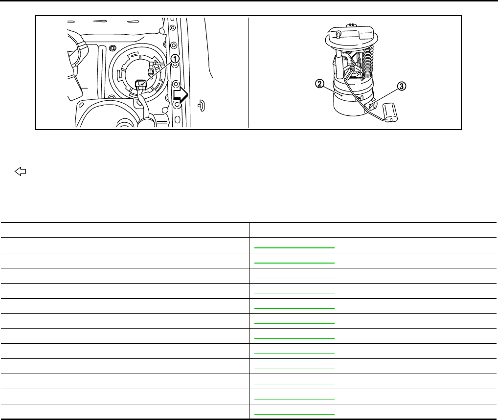
EC-522
< FUNCTION DIAGNOSIS > [FOR USA (FEDERAL) AND CANADA]
MULTIPORT FUEL INJECTION SYSTEM
Component Description INFOID:0000000004529434
1. Fuel level sensor unit and fuel pump
harness connector
2. Fuel level sensor unit and fuel pump 3. Fuel pressure regulator
Vehicle front
JMBIA0926ZZ
Component Reference
A/F sensor 1 EC-645, "Description"
Accelerator pedal position sensor EC-825, "Description"
Camshaft position sensor (PHASE) EC-707, "Description"
Crankshaft position sensor (POS) EC-703, "Description"
Engine coolant temperature sensor EC-632, "Description"
Fuel injector EC-855, "Description"
Heated oxygen sensor 2 EC-609, "Description"
Intake air temperature sensor EC-627, "Description"
Knock sensor EC-701, "Description"
Mass air flow sensor EC-615, "Description"
Park/neutral position switch EC-786, "Description"
Throttle position sensor EC-635, "Description"
Revision: 2008 August 2009 Rogue

ELECTRIC IGNITION SYSTEM
EC-523
< FUNCTION DIAGNOSIS > [FOR USA (FEDERAL) AND CANADA]
C
D
E
F
G
H
I
J
K
L
M
A
EC
N
P
O
ELECTRIC IGNITION SYSTEM
System Diagram INFOID:0000000004529435
System Description INFOID:0000000004529436
INPUT/OUTPUT SIGNAL CHART
*1: This signal is sent to the ECM through CAN communication line.
*2: ECM determines the start signal status by the signals of engine speed and battery voltage.
SYSTEM DESCRIPTION
Firing order: 1 - 3 - 4 - 2
The ignition timing is controlled by the ECM to maintain the best air-fuel ratio for every running condition of the
engine. The ignition timing data is stored in the ECM.
The ECM receives information such as the injection pulse width and camshaft position sensor (PHASE) sig-
nal. Computing this information, ignition signals are transmitted to the power transistor.
During the following conditions, the ignition timing is revised by the ECM according to the other data stored in
the ECM.
• At starting
• During warm-up
•At idle
• At low battery voltage
• During acceleration
The knock sensor retard system is designed only for emergencies. The basic ignition timing is programmed
within the anti-knocking zone, if recommended fuel is used under dry conditions. The retard system does not
JMBIA0174G
B
Sensor Input signal to ECM ECM function Actuator
Crankshaft position sensor (POS) Engine speed*2
Piston position
Ignition timing
control
Ignition coil (with power transis-
tor)
Camshaft position sensor (PHASE)
Mass air flow sensor Amount of intake air
Engine coolant temperature sensor Engine coolant temperature
Throttle position sensor Throttle position
Accelerator pedal position sensor Accelerator pedal position
Battery Battery voltage*2
Knock sensor Engine knocking
Park/neutral position (PNP) switch Gear position
Combination meter Vehicle speed*1
Revision: 2008 August 2009 Rogue
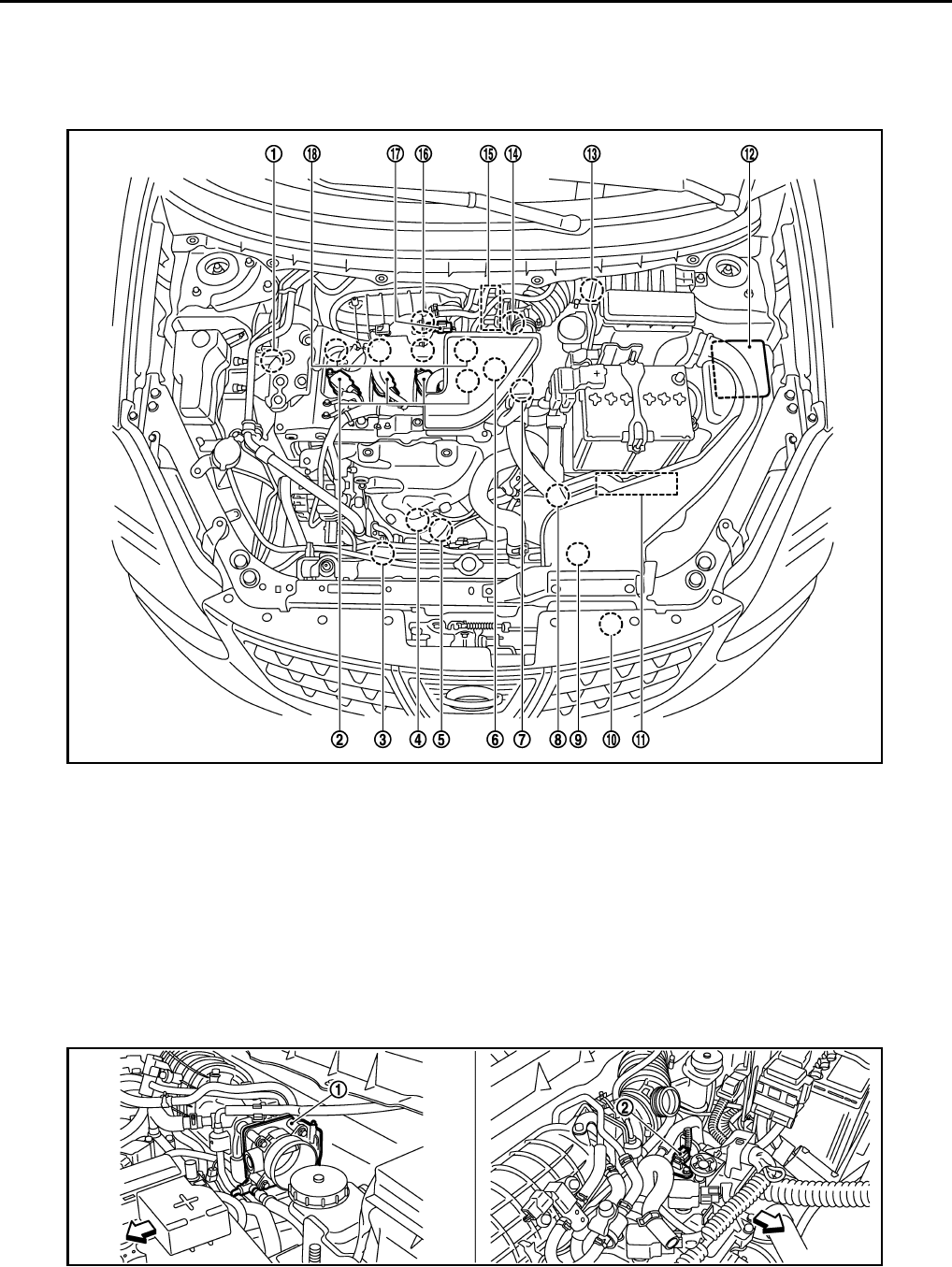
EC-524
< FUNCTION DIAGNOSIS > [FOR USA (FEDERAL) AND CANADA]
ELECTRIC IGNITION SYSTEM
operate under normal driving conditions. If engine knocking occurs, the knock sensor monitors the condition.
The signal is transmitted to the ECM. The ECM retards the ignition timing to eliminate the knocking condition.
Component Parts Location INFOID:0000000004533668
1. Intake valve timing control solenoid
valve
2. Ignition coil (with power transistor)
and spark plug
3. Cooling fan motor-2
4. Air fuel ratio (A/F) sensor 1 5. Heated oxygen sensor 2 6. Camshaft position sensor (PHASE)
7. Engine coolant temperature sensor 8. Park/neutral position (PNP) switch 9. Cooling fan motor-1
10. Refrigerant pressure sensor 11. ECM 12. IPDM E/R
13. Mass air flow sensor (with intake air
temperature sensor) 14. Crankshaft position sensor (POS) 15. Electric throttle control actuator
(with built in throttle position sensor
and throttle control motor)
16. Knock sensor 17. EVAP canister purge volume control
solenoid valve 18. Fuel injector
JMBIA0916ZZ
JMBIA0917ZZ
Revision: 2008 August 2009 Rogue
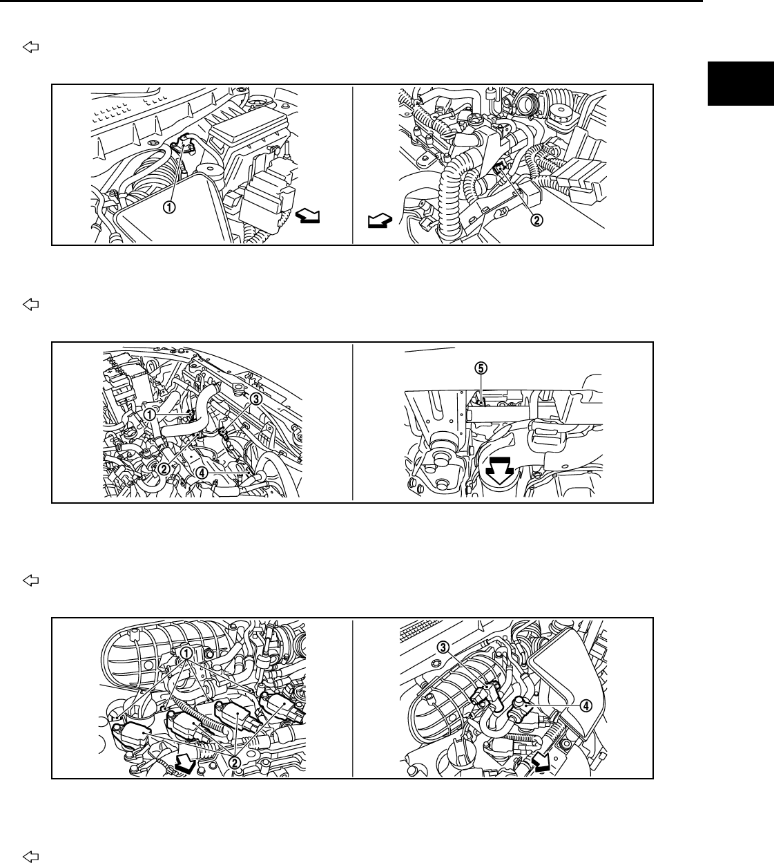
ELECTRIC IGNITION SYSTEM
EC-525
< FUNCTION DIAGNOSIS > [FOR USA (FEDERAL) AND CANADA]
C
D
E
F
G
H
I
J
K
L
M
A
EC
N
P
O
1. Electric throttle control actuator 2. Camshaft position sensor (PHASE)
Vehicle front
1. Mass air flow sensor (with intake air
temperature sensor)
2. Engine coolant temperature sensor
Vehicle front
1. Cooling fan motor-1 harness con-
nector
2. Cooling fan motor-1 3. Cooling fan motor-2 harness con-
nector
4. Cooling fan motor-2 5. Crankshaft position sensor (POS)
Vehicle front
1. Fuel injector 2. Ignition coil (with power transistor)
and spark plug
3. EVAP canister purge volume control
solenoid valve
4. EVAP service port
Vehicle front
JMBIA0918ZZ
JMBIA0919ZZ
JMBIA0921ZZ
Revision: 2008 August 2009 Rogue

EC-526
< FUNCTION DIAGNOSIS > [FOR USA (FEDERAL) AND CANADA]
ELECTRIC IGNITION SYSTEM
1. Refrigerant pressure sensor 2. PCV valve
JMBIA0922ZZ
JMBIA0502G
B
1. Air fuel ratio (A/F) sensor 1 2. Heated oxygen sensor 2 3. Air fuel ratio (A/F) sensor 1 harness
connector
4. Heated oxygen sensor 2 harness
connector
5. Three way catalyst (Under floor)
Vehicle front
JMBIA0920ZZ
Revision: 2008 August 2009 Rogue
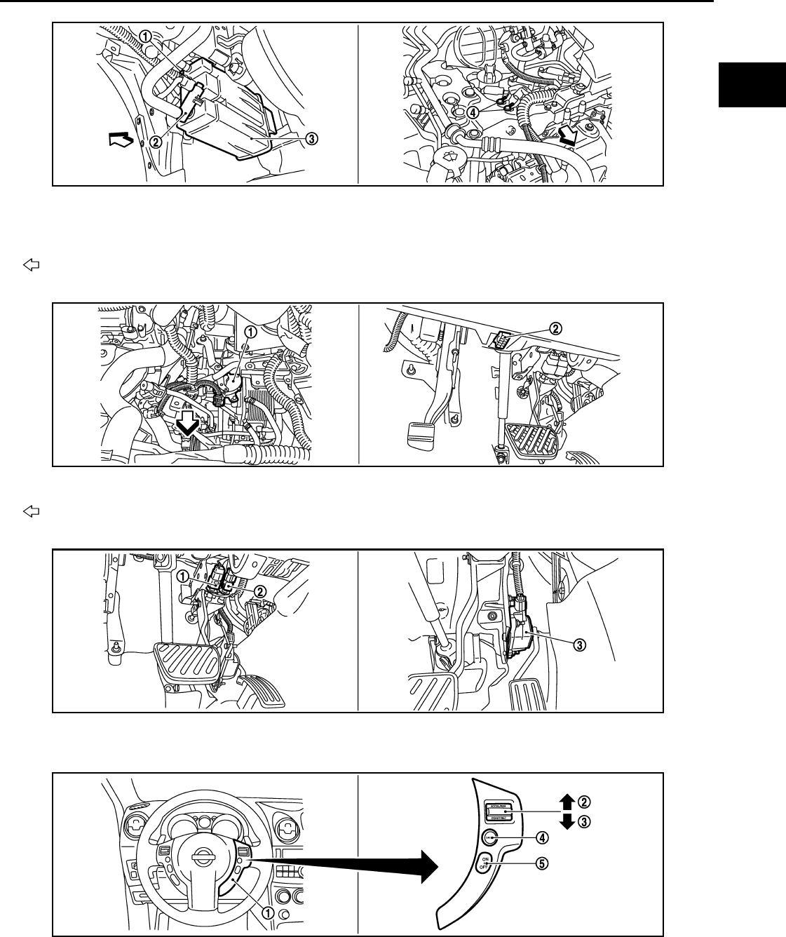
ELECTRIC IGNITION SYSTEM
EC-527
< FUNCTION DIAGNOSIS > [FOR USA (FEDERAL) AND CANADA]
C
D
E
F
G
H
I
J
K
L
M
A
EC
N
P
O
1. EVAP control system pressure sen-
sor
2. EVAP canister vent control valve 3. EVAP canister
4. Body ground
Vehicle front
1. Park/neutral position (PNP) switch 2. Data link connector
Vehicle front
1. Stop lamp switch 2. ASCD brake switch 3. Accelerator pedal position sensor
1. ASCD steering switch 2. RESUME/ACCERELATE switch 3. SET/COAST switch
4. CANSEL switch 5. MAIN switch
JMBIA0923ZZ
JMBIA0927ZZ
JMBIA0924ZZ
JMBIA0925ZZ
Revision: 2008 August 2009 Rogue
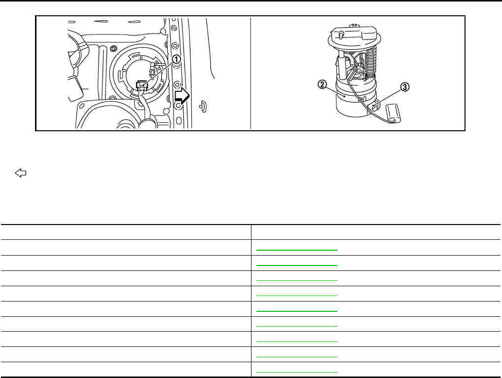
EC-528
< FUNCTION DIAGNOSIS > [FOR USA (FEDERAL) AND CANADA]
ELECTRIC IGNITION SYSTEM
Component Description INFOID:0000000004529438
1. Fuel level sensor unit and fuel pump
harness connector
2. Fuel level sensor unit and fuel pump 3. Fuel pressure regulator
Vehicle front
JMBIA0926ZZ
Component Reference
Accelerator pedal position sensor EC-825, "Description"
Camshaft position sensor (PHASE) EC-707, "Description"
Crankshaft position sensor (POS) EC-703, "Description"
Engine coolant temperature sensor EC-632, "Description"
Ignition signal EC-861, "Description"
Knock sensor EC-701, "Description"
Mass air flow sensor EC-615, "Description"
Park/neutral position switch EC-786, "Description"
Throttle position sensor EC-635, "Description"
Revision: 2008 August 2009 Rogue

AIR CONDITIONING CUT CONTROL
EC-529
< FUNCTION DIAGNOSIS > [FOR USA (FEDERAL) AND CANADA]
C
D
E
F
G
H
I
J
K
L
M
A
EC
N
P
O
AIR CONDITIONING CUT CONTROL
System Diagram INFOID:0000000004529439
System Description INFOID:0000000004529440
INPUT/OUTPUT SIGNAL CHART
*1: This signal is sent to the ECM through CAN communication line.
*2: ECM determines the start signal status by the signals of engine speed and battery voltage.
SYSTEM DESCRIPTION
This system improves engine operation when the air conditioner is used.
Under the following conditions, the air conditioner is turned off.
• When the accelerator pedal is fully depressed.
• When cranking the engine.
• At high engine speeds.
• When the engine coolant temperature becomes excessively high.
• When operating power steering during low engine speed or low vehicle speed.
• When engine speed is excessively low.
JMBIA1015G
B
Sensor Input signal to ECM ECM function Actuator
Accelerator pedal position sensor Accelerator pedal position
Air conditioner
cut control
IPDM E/R
↓
Air conditioner relay
↓
Compressor
Crankshaft position sensor (POS)
Camshaft position sensor (PHASE) Engine speed*2
Engine coolant temperature sensor Engine coolant temperature
Battery Battery voltage*2
Refrigerant pressure sensor Refrigerant pressure
EPS control unit Power steering operation*1
Combination meter Vehicle speed*1
BCM Air conditioner ON signal*1
Revision: 2008 August 2009 Rogue

EC-530
< FUNCTION DIAGNOSIS > [FOR USA (FEDERAL) AND CANADA]
AIR CONDITIONING CUT CONTROL
• When refrigerant pressure is excessively low or high.
Component Parts Location INFOID:0000000004533673
1. Intake valve timing control solenoid
valve 2. Ignition coil (with power transistor)
and spark plug 3. Cooling fan motor-2
4. Air fuel ratio (A/F) sensor 1 5. Heated oxygen sensor 2 6. Camshaft position sensor (PHASE)
7. Engine coolant temperature sensor 8. Park/neutral position (PNP) switch 9. Cooling fan motor-1
10. Refrigerant pressure sensor 11. ECM 12. IPDM E/R
13. Mass air flow sensor (with intake air
temperature sensor)
14. Crankshaft position sensor (POS) 15. Electric throttle control actuator
(with built in throttle position sensor
and throttle control motor)
16. Knock sensor 17. EVAP canister purge volume control
solenoid valve
18. Fuel injector
1. Electric throttle control actuator 2. Camshaft position sensor (PHASE)
Vehicle front
JMBIA0916ZZ
JMBIA0917ZZ
Revision: 2008 August 2009 Rogue

AIR CONDITIONING CUT CONTROL
EC-531
< FUNCTION DIAGNOSIS > [FOR USA (FEDERAL) AND CANADA]
C
D
E
F
G
H
I
J
K
L
M
A
EC
N
P
O
1. Mass air flow sensor (with intake air
temperature sensor)
2. Engine coolant temperature sensor
Vehicle front
1. Cooling fan motor-1 harness con-
nector
2. Cooling fan motor-1 3. Cooling fan motor-2 harness con-
nector
4. Cooling fan motor-2 5. Crankshaft position sensor (POS)
Vehicle front
1. Fuel injector 2. Ignition coil (with power transistor)
and spark plug 3. EVAP canister purge volume control
solenoid valve
4. EVAP service port
Vehicle front
JMBIA0918ZZ
JMBIA0919ZZ
JMBIA0921ZZ
Revision: 2008 August 2009 Rogue

EC-532
< FUNCTION DIAGNOSIS > [FOR USA (FEDERAL) AND CANADA]
AIR CONDITIONING CUT CONTROL
1. Refrigerant pressure sensor 2. PCV valve
JMBIA0922ZZ
JMBIA0502G
B
1. Air fuel ratio (A/F) sensor 1 2. Heated oxygen sensor 2 3. Air fuel ratio (A/F) sensor 1 harness
connector
4. Heated oxygen sensor 2 harness
connector
5. Three way catalyst (Under floor)
Vehicle front
JMBIA0920ZZ
Revision: 2008 August 2009 Rogue

AIR CONDITIONING CUT CONTROL
EC-533
< FUNCTION DIAGNOSIS > [FOR USA (FEDERAL) AND CANADA]
C
D
E
F
G
H
I
J
K
L
M
A
EC
N
P
O
1. EVAP control system pressure sen-
sor
2. EVAP canister vent control valve 3. EVAP canister
4. Body ground
Vehicle front
1. Park/neutral position (PNP) switch 2. Data link connector
Vehicle front
1. Stop lamp switch 2. ASCD brake switch 3. Accelerator pedal position sensor
1. ASCD steering switch 2. RESUME/ACCERELATE switch 3. SET/COAST switch
4. CANSEL switch 5. MAIN switch
JMBIA0923ZZ
JMBIA0927ZZ
JMBIA0924ZZ
JMBIA0925ZZ
Revision: 2008 August 2009 Rogue
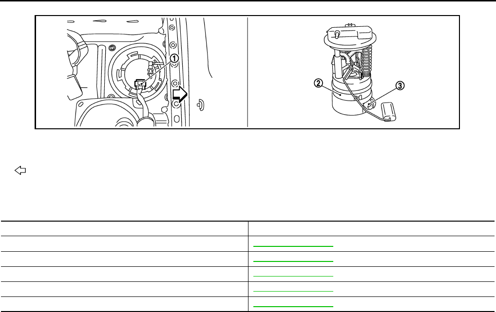
EC-534
< FUNCTION DIAGNOSIS > [FOR USA (FEDERAL) AND CANADA]
AIR CONDITIONING CUT CONTROL
Component Description INFOID:0000000004529442
1. Fuel level sensor unit and fuel pump
harness connector
2. Fuel level sensor unit and fuel pump 3. Fuel pressure regulator
Vehicle front
JMBIA0926ZZ
Component Reference
Accelerator pedal position sensor EC-825, "Description"
Camshaft position sensor (PHASE) EC-707, "Description"
Crankshaft position sensor (POS) EC-703, "Description"
Engine coolant temperature sensor EC-632, "Description"
Refrigerant pressure sensor EC-873, "Description"
Revision: 2008 August 2009 Rogue
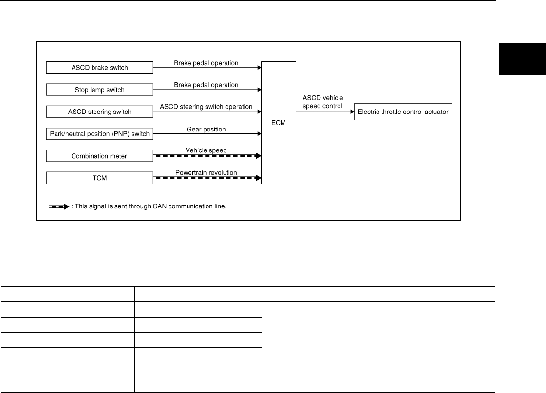
AUTOMATIC SPEED CONTROL DEVICE (ASCD)
EC-535
< FUNCTION DIAGNOSIS > [FOR USA (FEDERAL) AND CANADA]
C
D
E
F
G
H
I
J
K
L
M
A
EC
N
P
O
AUTOMATIC SPEED CONTROL DEVICE (ASCD)
System Diagram INFOID:0000000004529443
System Description INFOID:0000000004529444
INPUT/OUTPUT SIGNAL CHART
*: This signal is sent to the ECM via the CAN communication line
BASIC ASCD SYSTEM
Refer to Owner's Manual for ASCD operating instructions.
Automatic Speed Control Device (ASCD) allows a driver to keep vehicle at predetermined constant speed
without depressing accelerator pedal. Driver can set vehicle speed in advance between approximately 40 km/
h (25 MPH) and 144 km/h (89 MPH).
ECM controls throttle angle of electric throttle control actuator to regulate engine speed.
Operation status of ASCD is indicated by CRUISE lamp and SET lamp on combination meter. If any malfunc-
tion occurs in the ASCD system, it automatically deactivates control.
NOTE:
Always drive vehicle in a safe manner according to traffic conditions and obey all traffic laws.
SET OPERATION
Press MAIN switch. (The CRUISE lamp on combination meter illuminates.)
When vehicle speed reaches a desired speed between approximately 38 km/h (24 MPH) and 144 km/h (89
MPH), press SET/COAST switch. (Then SET lamp on combination meter illuminates.)
ACCELERATE OPERATION
If the RESUME/ACCELERATE switch is pressed during cruise control driving, increase the vehicle speed until
the switch is released or vehicle speed reaches maximum speed controlled by the system.
And then ASCD will maintain the new set speed.
CANCEL OPERATION
When any of following conditions exist, cruise operation will be canceled.
• CANCEL switch is pressed
• More than 2 switches on ASCD steering switch are pressed at the same time (Set speed will be cleared)
• Brake pedal is depressed
JMBIA0935G
B
Sensor Input signal to ECM ECM function Actuator
ASCD brake switch Brake pedal operation
ASCD vehicle speed control Electric throttle control
actuator
Stop lamp switch Brake pedal operation
ASCD steering switch ASCD steering switch operation
Park/neutral position (PNP) switch Gear position
Combination meter Vehicle speed*
TCM Powertrain revolution*
Revision: 2008 August 2009 Rogue
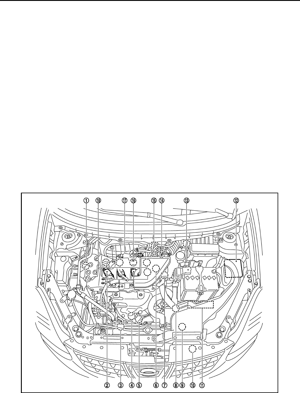
EC-536
< FUNCTION DIAGNOSIS > [FOR USA (FEDERAL) AND CANADA]
AUTOMATIC SPEED CONTROL DEVICE (ASCD)
• Selector lever position is changed to N, P or R
• Vehicle speed decreased to 13 km/h (8 MPH) lower than the set speed
• TCS system is operated
When the ECM detects any of the following conditions, the ECM will cancel the cruise operation and inform
the driver by blinking indicator lamp.
• Engine coolant temperature is slightly higher than the normal operating temperature, CRUISE lamp may
blink slowly.
When the engine coolant temperature decreases to the normal operating temperature, CRUISE lamp will
stop blinking and the cruise operation will be able to work by pressing SET/COAST switch or RESUME/
ACCELERATE switch.
• Malfunction for some self-diagnoses regarding ASCD control: SET lamp will blink quickly.
If MAIN switch is turned to OFF while ASCD is activated, all of ASCD operations will be canceled and vehicle
speed memory will be erased.
COAST OPERATION
When the SET/COAST switch is pressed during cruise control driving, decrease vehicle set speed until the
switch is released. And then ASCD will maintain the new set speed.
RESUME OPERATION
When the RESUME/ACCELERATE switch is pressed after canceling operation other than pressing the MAIN
switch, vehicle speed will return to last set speed. To resume vehicle set speed, vehicle condition must meet
following conditions.
• Brake pedal is released
• Selector lever is in a position other than P and N
• Vehicle speed is greater than 38 km/h (24 MPH) and less than 144 km/h (89 MPH)
Component Parts Location INFOID:0000000004533674
JMBIA0916ZZ
1. Intake valve timing control solenoid
valve
2. Ignition coil (with power transistor)
and spark plug
3. Cooling fan motor-2
4. Air fuel ratio (A/F) sensor 1 5. Heated oxygen sensor 2 6. Camshaft position sensor (PHASE)
Revision: 2008 August 2009 Rogue
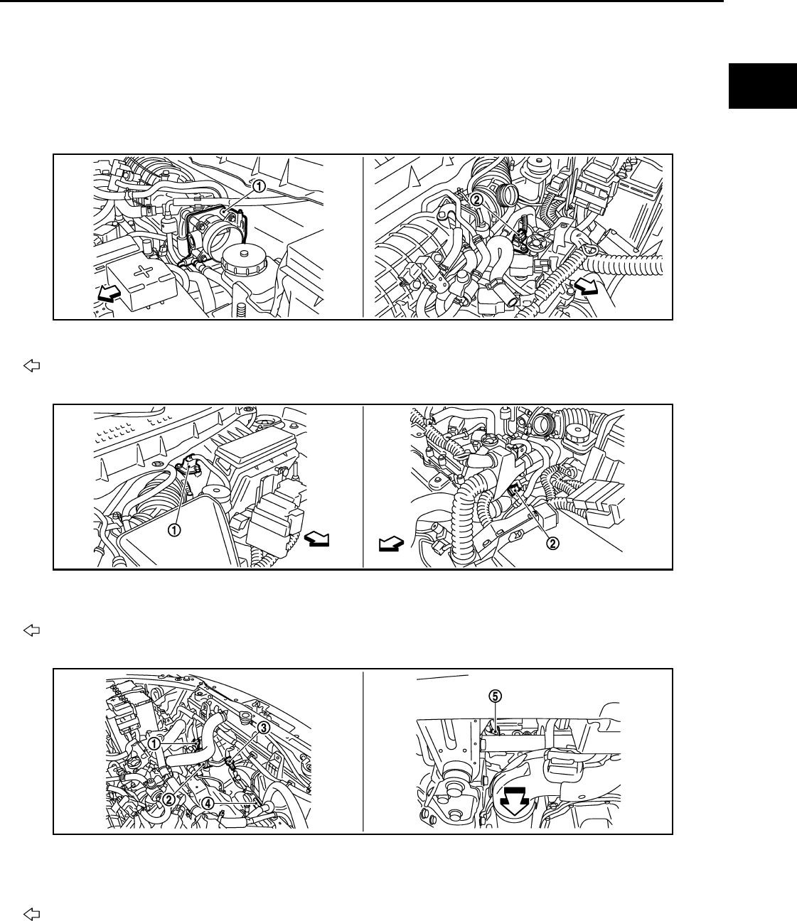
AUTOMATIC SPEED CONTROL DEVICE (ASCD)
EC-537
< FUNCTION DIAGNOSIS > [FOR USA (FEDERAL) AND CANADA]
C
D
E
F
G
H
I
J
K
L
M
A
EC
N
P
O
7. Engine coolant temperature sensor 8. Park/neutral position (PNP) switch 9. Cooling fan motor-1
10. Refrigerant pressure sensor 11. ECM 12. IPDM E/R
13. Mass air flow sensor (with intake air
temperature sensor)
14. Crankshaft position sensor (POS) 15. Electric throttle control actuator
(with built in throttle position sensor
and throttle control motor)
16. Knock sensor 17. EVAP canister purge volume control
solenoid valve
18. Fuel injector
1. Electric throttle control actuator 2. Camshaft position sensor (PHASE)
Vehicle front
1. Mass air flow sensor (with intake air
temperature sensor)
2. Engine coolant temperature sensor
Vehicle front
1. Cooling fan motor-1 harness con-
nector 2. Cooling fan motor-1 3. Cooling fan motor-2 harness con-
nector
4. Cooling fan motor-2 5. Crankshaft position sensor (POS)
Vehicle front
JMBIA0917ZZ
JMBIA0918ZZ
JMBIA0919ZZ
Revision: 2008 August 2009 Rogue
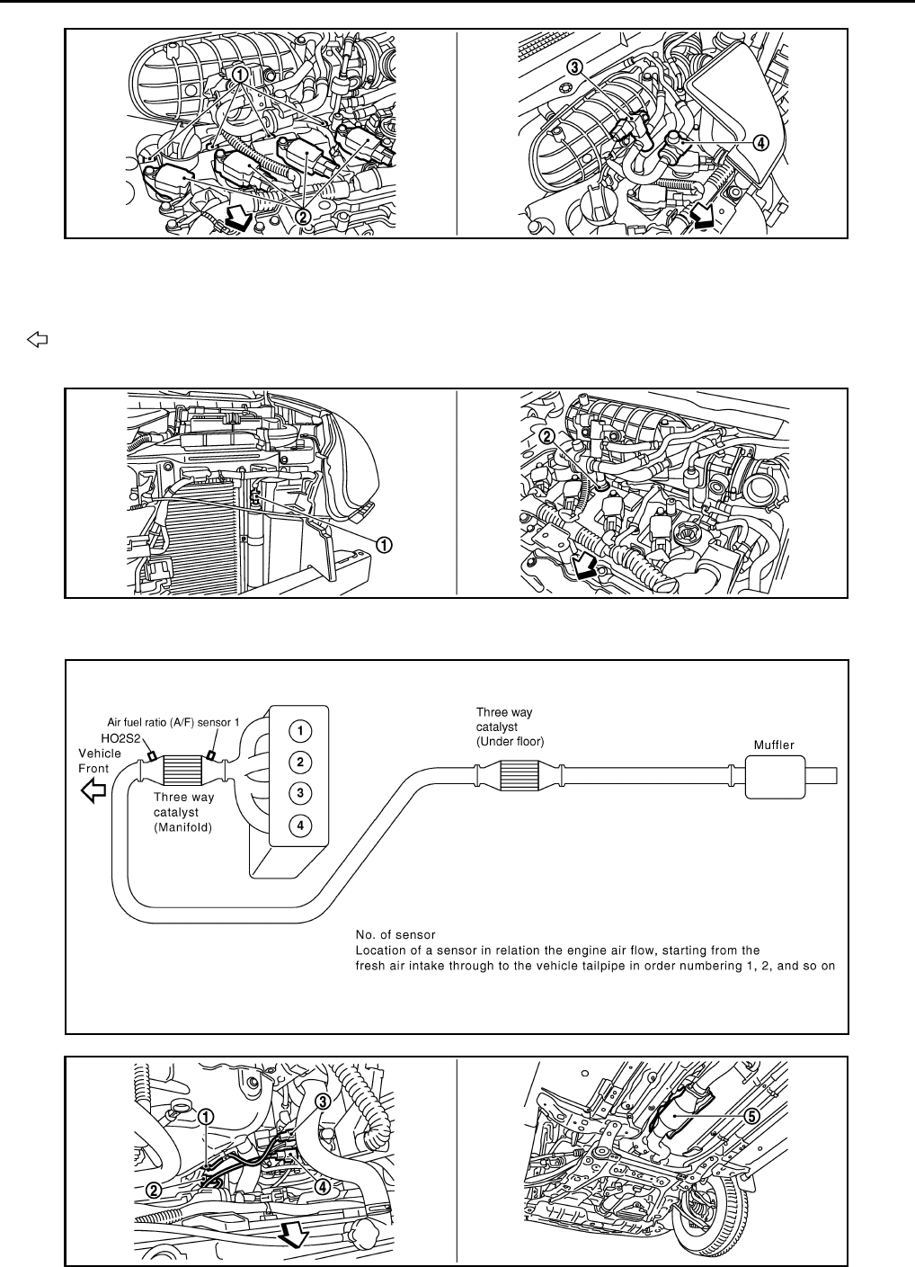
EC-538
< FUNCTION DIAGNOSIS > [FOR USA (FEDERAL) AND CANADA]
AUTOMATIC SPEED CONTROL DEVICE (ASCD)
1. Fuel injector 2. Ignition coil (with power transistor)
and spark plug
3. EVAP canister purge volume control
solenoid valve
4. EVAP service port
Vehicle front
1. Refrigerant pressure sensor 2. PCV valve
JMBIA0921ZZ
JMBIA0922ZZ
JMBIA0502G
B
JMBIA0920ZZ
Revision: 2008 August 2009 Rogue
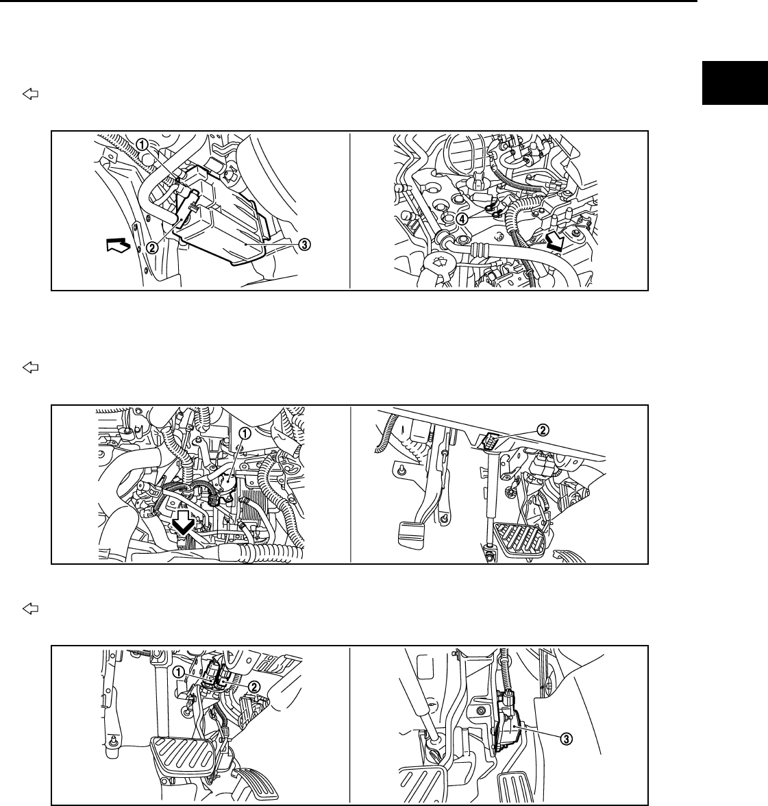
AUTOMATIC SPEED CONTROL DEVICE (ASCD)
EC-539
< FUNCTION DIAGNOSIS > [FOR USA (FEDERAL) AND CANADA]
C
D
E
F
G
H
I
J
K
L
M
A
EC
N
P
O
1. Air fuel ratio (A/F) sensor 1 2. Heated oxygen sensor 2 3. Air fuel ratio (A/F) sensor 1 harness
connector
4. Heated oxygen sensor 2 harness
connector 5. Three way catalyst (Under floor)
Vehicle front
1. EVAP control system pressure sen-
sor
2. EVAP canister vent control valve 3. EVAP canister
4. Body ground
Vehicle front
1. Park/neutral position (PNP) switch 2. Data link connector
Vehicle front
1. Stop lamp switch 2. ASCD brake switch 3. Accelerator pedal position sensor
JMBIA0923ZZ
JMBIA0927ZZ
JMBIA0924ZZ
Revision: 2008 August 2009 Rogue
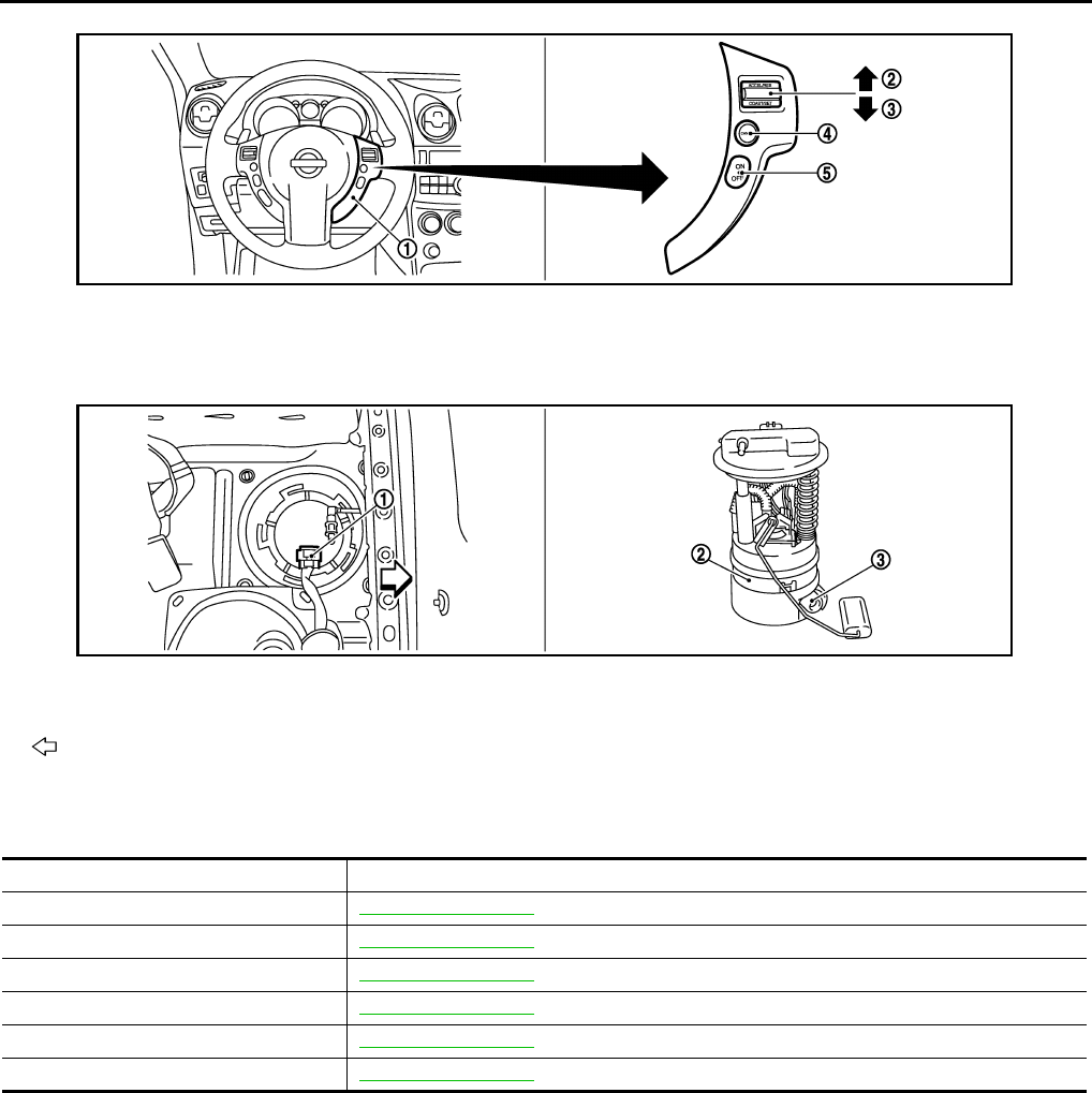
EC-540
< FUNCTION DIAGNOSIS > [FOR USA (FEDERAL) AND CANADA]
AUTOMATIC SPEED CONTROL DEVICE (ASCD)
Component Description INFOID:0000000004529446
1. ASCD steering switch 2. RESUME/ACCERELATE switch 3. SET/COAST switch
4. CANSEL switch 5. MAIN switch
1. Fuel level sensor unit and fuel pump
harness connector 2. Fuel level sensor unit and fuel pump 3. Fuel pressure regulator
Vehicle front
JMBIA0925ZZ
JMBIA0926ZZ
Component Reference
ASCD steering switch EC-801, "Description"
ASCD clutch switch EC-804, "Description"
ASCD brake switch EC-804, "Description"
Stop lamp switch EC-813, "Description"
Electric throttle control actuator EC-823, "Description"
ASCD indicator EC-846, "Description"
Revision: 2008 August 2009 Rogue

CAN COMMUNICATION
EC-541
< FUNCTION DIAGNOSIS > [FOR USA (FEDERAL) AND CANADA]
C
D
E
F
G
H
I
J
K
L
M
A
EC
N
P
O
CAN COMMUNICATION
System Description INFOID:0000000004529447
CAN (Controller Area Network) is a serial communication line for real time application. It is an on-vehicle mul-
tiplex communication line with high data communication speed and excellent error detection ability. Many elec-
tronic control units are equipped onto a vehicle, and each control unit shares information and links with other
control units during operation (not independent). In CAN communication, control units are connected with 2
communication lines (CAN H line, CAN L line) allowing a high rate of information transmission with less wiring.
Each control unit transmits/receives data but selectively reads required data only.
Refer to LAN-24, "CAN Communication Signal Chart", about CAN communication for detail..
Revision: 2008 August 2009 Rogue
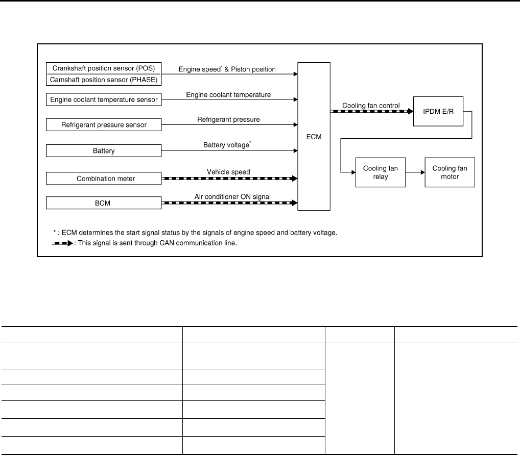
EC-542
< FUNCTION DIAGNOSIS > [FOR USA (FEDERAL) AND CANADA]
COOLING FAN CONTROL
COOLING FAN CONTROL
System Diagram INFOID:0000000004529448
System Description INFOID:0000000004529449
INPUT/OUTPUT SIGNAL CHART
*1: The ECM determines the start signal status by the signals of engine speed and battery voltage.
*2: This signal is sent to ECM via the CAN communication line.
SYSTEM DESCRIPTION
ECM controls cooling fan speed corresponding to vehicle speed, engine coolant temperature, refrigerant pres-
sure, air conditioner ON signal. Then control system has 3-step control [HIGH/LOW/OFF].
JMBIA0177G
B
Sensor Input signal to ECM ECM function Actuator
Crankshaft position sensor (POS)
Camshaft position sensor (PHASE) Engine speed*1
Cooling fan
control
IPDM E/R
↓
Cooling fan relay
↓
Cooling fan motor
Engine coolant temperature sensor Engine coolant temperature
Refrigerant pressure sensor Refrigerant pressure
Battery Battery voltage*1
Combination meter Vehicle speed*2
BCM Air conditioner ON signal*2
Revision: 2008 August 2009 Rogue
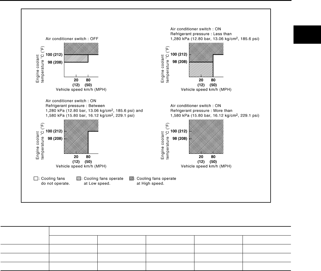
COOLING FAN CONTROL
EC-543
< FUNCTION DIAGNOSIS > [FOR USA (FEDERAL) AND CANADA]
C
D
E
F
G
H
I
J
K
L
M
A
EC
N
P
O
Cooling Fan Operation
Cooling Fan Relay Operation
The ECM controls cooling fan relays through CAN communication line.
JMBIA0936G
B
Cooling fan speed Cooling fan relay
12345
Stop (OFF) OFF OFF OFF OFF OFF
Low (LOW) OFF OFF OFF ON OFF
High (HI) ON ON ON OFF ON
Revision: 2008 August 2009 Rogue

EC-544
< FUNCTION DIAGNOSIS > [FOR USA (FEDERAL) AND CANADA]
COOLING FAN CONTROL
Component Parts Location INFOID:0000000004533675
1. Intake valve timing control solenoid
valve
2. Ignition coil (with power transistor)
and spark plug
3. Cooling fan motor-2
4. Air fuel ratio (A/F) sensor 1 5. Heated oxygen sensor 2 6. Camshaft position sensor (PHASE)
7. Engine coolant temperature sensor 8. Park/neutral position (PNP) switch 9. Cooling fan motor-1
10. Refrigerant pressure sensor 11. ECM 12. IPDM E/R
13. Mass air flow sensor (with intake air
temperature sensor)
14. Crankshaft position sensor (POS) 15. Electric throttle control actuator
(with built in throttle position sensor
and throttle control motor)
16. Knock sensor 17. EVAP canister purge volume control
solenoid valve
18. Fuel injector
1. Electric throttle control actuator 2. Camshaft position sensor (PHASE)
Vehicle front
JMBIA0916ZZ
JMBIA0917ZZ
Revision: 2008 August 2009 Rogue
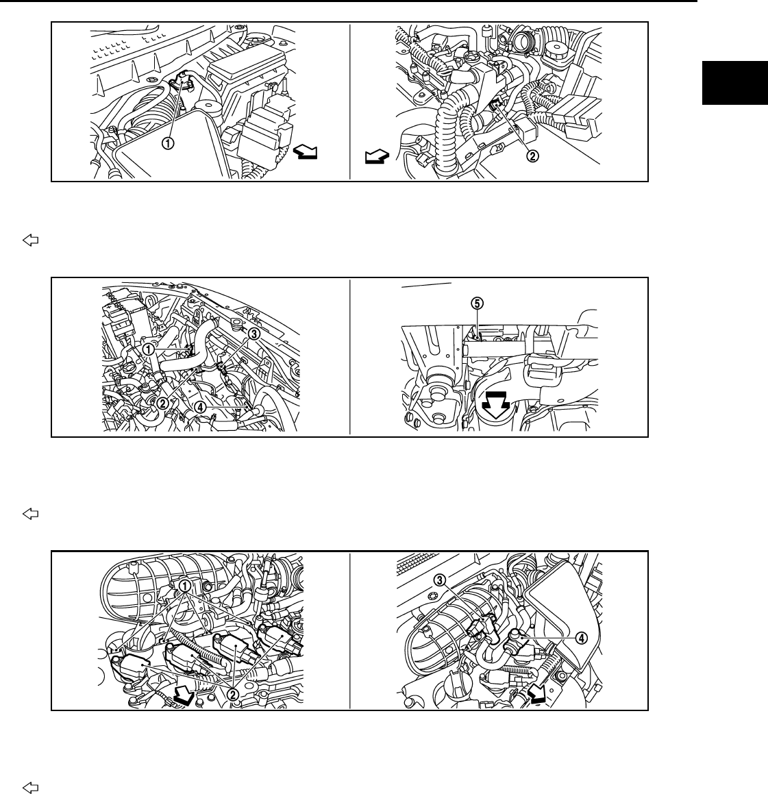
COOLING FAN CONTROL
EC-545
< FUNCTION DIAGNOSIS > [FOR USA (FEDERAL) AND CANADA]
C
D
E
F
G
H
I
J
K
L
M
A
EC
N
P
O
1. Mass air flow sensor (with intake air
temperature sensor)
2. Engine coolant temperature sensor
Vehicle front
1. Cooling fan motor-1 harness con-
nector
2. Cooling fan motor-1 3. Cooling fan motor-2 harness con-
nector
4. Cooling fan motor-2 5. Crankshaft position sensor (POS)
Vehicle front
1. Fuel injector 2. Ignition coil (with power transistor)
and spark plug 3. EVAP canister purge volume control
solenoid valve
4. EVAP service port
Vehicle front
JMBIA0918ZZ
JMBIA0919ZZ
JMBIA0921ZZ
Revision: 2008 August 2009 Rogue

EC-546
< FUNCTION DIAGNOSIS > [FOR USA (FEDERAL) AND CANADA]
COOLING FAN CONTROL
1. Refrigerant pressure sensor 2. PCV valve
JMBIA0922ZZ
JMBIA0502G
B
1. Air fuel ratio (A/F) sensor 1 2. Heated oxygen sensor 2 3. Air fuel ratio (A/F) sensor 1 harness
connector
4. Heated oxygen sensor 2 harness
connector
5. Three way catalyst (Under floor)
Vehicle front
JMBIA0920ZZ
Revision: 2008 August 2009 Rogue

COOLING FAN CONTROL
EC-547
< FUNCTION DIAGNOSIS > [FOR USA (FEDERAL) AND CANADA]
C
D
E
F
G
H
I
J
K
L
M
A
EC
N
P
O
1. EVAP control system pressure sen-
sor
2. EVAP canister vent control valve 3. EVAP canister
4. Body ground
Vehicle front
1. Park/neutral position (PNP) switch 2. Data link connector
Vehicle front
1. Stop lamp switch 2. ASCD brake switch 3. Accelerator pedal position sensor
1. ASCD steering switch 2. RESUME/ACCERELATE switch 3. SET/COAST switch
4. CANSEL switch 5. MAIN switch
JMBIA0923ZZ
JMBIA0927ZZ
JMBIA0924ZZ
JMBIA0925ZZ
Revision: 2008 August 2009 Rogue

EC-548
< FUNCTION DIAGNOSIS > [FOR USA (FEDERAL) AND CANADA]
COOLING FAN CONTROL
Component Description INFOID:0000000004529451
1. Fuel level sensor unit and fuel pump
harness connector
2. Fuel level sensor unit and fuel pump 3. Fuel pressure regulator
Vehicle front
JMBIA0926ZZ
Component Reference
Camshaft position sensor (PHASE) EC-707, "Description"
Crankshaft position sensor (POS) EC-703, "Description"
Cooling fan motor EC-542, "System Description"
Engine coolant temperature sensor EC-632, "Description"
Refrigerant pressure sensor EC-873, "Description"
Revision: 2008 August 2009 Rogue
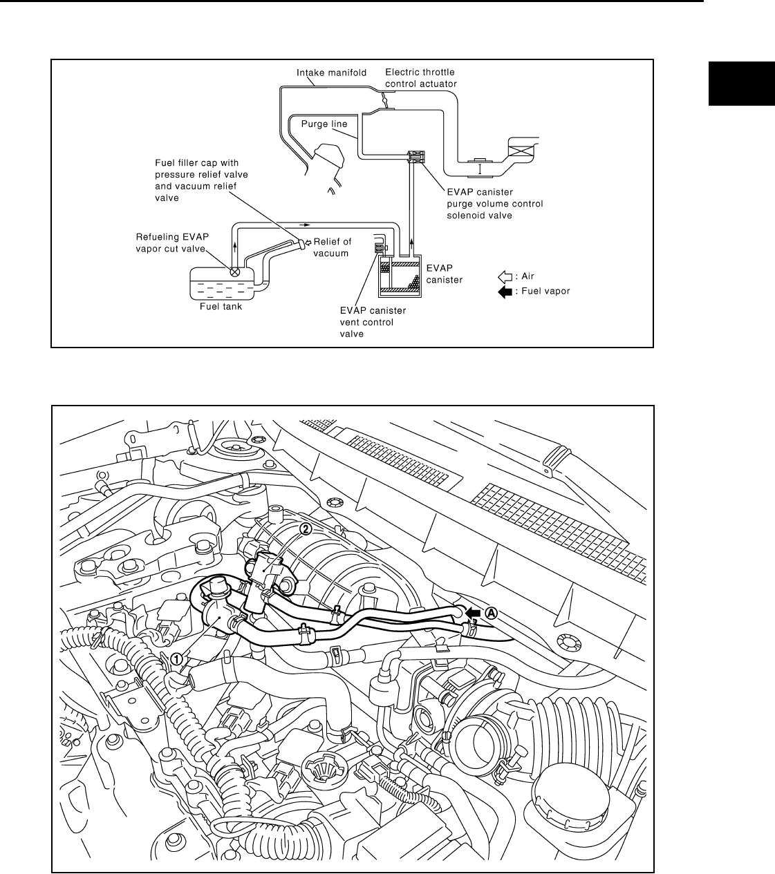
EVAPORATIVE EMISSION SYSTEM
EC-549
< FUNCTION DIAGNOSIS > [FOR USA (FEDERAL) AND CANADA]
C
D
E
F
G
H
I
J
K
L
M
A
EC
N
P
O
EVAPORATIVE EMISSION SYSTEM
System Diagram INFOID:0000000004529452
EVAPORATIVE EMISSION LINE DRAWING
PBIB1631E
1. EVAP service port 2. EVAP canister purge volume control
solenoid valve
A. From next figure
JMBIA0909ZZ
Revision: 2008 August 2009 Rogue
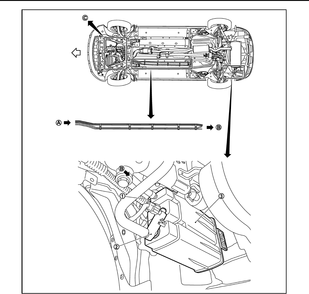
EC-550
< FUNCTION DIAGNOSIS > [FOR USA (FEDERAL) AND CANADA]
EVAPORATIVE EMISSION SYSTEM
NOTE:
Do not use soapy water or any type of solvent while installing vacuum hose or purge hoses.
System Description INFOID:0000000004529453
INPUT/OUTPUT SIGNAL CHART
1. EVAP control system pressure sensor 2. EVAP canister vent control valve 3. EVAP canister
A. To previous figure B. To/From B in this figure
JMBIA0908ZZ
Revision: 2008 August 2009 Rogue

EVAPORATIVE EMISSION SYSTEM
EC-551
< FUNCTION DIAGNOSIS > [FOR USA (FEDERAL) AND CANADA]
C
D
E
F
G
H
I
J
K
L
M
A
EC
N
P
O
*1: ECM determines the start signal status by the signals of engine speed and battery voltage.
*2: This signal is sent to the ECM through CAN communication line.
SYSTEM DESCRIPTION
The evaporative emission system is used to reduce hydrocarbons emitted into the atmosphere from the fuel
system. This reduction of hydrocarbons is accomplished by activated charcoals in the EVAP canister.
The fuel vapor in the sealed fuel tank is led into the EVAP canister which contains activated carbon and the
vapor is stored there when the engine is not operating or when refueling to the fuel tank.
The vapor in the EVAP canister is purged by the air through the purge line to the intake manifold when the
engine is operating. EVAP canister purge volume control solenoid valve is controlled by ECM. When the
engine operates, the flow rate of vapor controlled by EVAP canister purge volume control solenoid valve is
proportionally regulated as the air flow increases.
EVAP canister purge volume control solenoid valve also shuts off the vapor purge line during decelerating.
Sensor Input signal to ECM ECM function Actuator
Crankshaft position sensor (POS)
Camshaft position sensor (PHASE) Engine speed*1
EVAP canister
purge flow control
EVAP canister purge vol-
ume control solenoid valve
Mass air flow sensor Amount of intake air
Engine coolant temperature sensor Engine coolant temperature
Battery Battery voltage*1
Throttle position sensor Throttle position
Accelerator pedal position sensor Accelerator pedal position
Air fuel ratio (A/F) sensor 1 Density of oxygen in exhaust gas
(Mixture ratio feedback signal)
Fuel tank temperature sensor Fuel temperature in fuel tank
EVAP control system pressure sensor Pressure in purge line
Combination meter Vehicle speed*2
Revision: 2008 August 2009 Rogue

EC-552
< FUNCTION DIAGNOSIS > [FOR USA (FEDERAL) AND CANADA]
EVAPORATIVE EMISSION SYSTEM
Component Parts Location INFOID:0000000004533676
1. Intake valve timing control solenoid
valve
2. Ignition coil (with power transistor)
and spark plug
3. Cooling fan motor-2
4. Air fuel ratio (A/F) sensor 1 5. Heated oxygen sensor 2 6. Camshaft position sensor (PHASE)
7. Engine coolant temperature sensor 8. Park/neutral position (PNP) switch 9. Cooling fan motor-1
10. Refrigerant pressure sensor 11. ECM 12. IPDM E/R
13. Mass air flow sensor (with intake air
temperature sensor)
14. Crankshaft position sensor (POS) 15. Electric throttle control actuator
(with built in throttle position sensor
and throttle control motor)
16. Knock sensor 17. EVAP canister purge volume control
solenoid valve
18. Fuel injector
1. Electric throttle control actuator 2. Camshaft position sensor (PHASE)
Vehicle front
JMBIA0916ZZ
JMBIA0917ZZ
Revision: 2008 August 2009 Rogue

EVAPORATIVE EMISSION SYSTEM
EC-553
< FUNCTION DIAGNOSIS > [FOR USA (FEDERAL) AND CANADA]
C
D
E
F
G
H
I
J
K
L
M
A
EC
N
P
O
1. Mass air flow sensor (with intake air
temperature sensor)
2. Engine coolant temperature sensor
Vehicle front
1. Cooling fan motor-1 harness con-
nector
2. Cooling fan motor-1 3. Cooling fan motor-2 harness con-
nector
4. Cooling fan motor-2 5. Crankshaft position sensor (POS)
Vehicle front
1. Fuel injector 2. Ignition coil (with power transistor)
and spark plug 3. EVAP canister purge volume control
solenoid valve
4. EVAP service port
Vehicle front
JMBIA0918ZZ
JMBIA0919ZZ
JMBIA0921ZZ
Revision: 2008 August 2009 Rogue

EC-554
< FUNCTION DIAGNOSIS > [FOR USA (FEDERAL) AND CANADA]
EVAPORATIVE EMISSION SYSTEM
1. Refrigerant pressure sensor 2. PCV valve
JMBIA0922ZZ
JMBIA0502G
B
1. Air fuel ratio (A/F) sensor 1 2. Heated oxygen sensor 2 3. Air fuel ratio (A/F) sensor 1 harness
connector
4. Heated oxygen sensor 2 harness
connector
5. Three way catalyst (Under floor)
Vehicle front
JMBIA0920ZZ
Revision: 2008 August 2009 Rogue

EVAPORATIVE EMISSION SYSTEM
EC-555
< FUNCTION DIAGNOSIS > [FOR USA (FEDERAL) AND CANADA]
C
D
E
F
G
H
I
J
K
L
M
A
EC
N
P
O
1. EVAP control system pressure sen-
sor
2. EVAP canister vent control valve 3. EVAP canister
4. Body ground
Vehicle front
1. Park/neutral position (PNP) switch 2. Data link connector
Vehicle front
1. Stop lamp switch 2. ASCD brake switch 3. Accelerator pedal position sensor
1. ASCD steering switch 2. RESUME/ACCERELATE switch 3. SET/COAST switch
4. CANSEL switch 5. MAIN switch
JMBIA0923ZZ
JMBIA0927ZZ
JMBIA0924ZZ
JMBIA0925ZZ
Revision: 2008 August 2009 Rogue
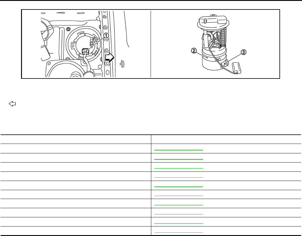
EC-556
< FUNCTION DIAGNOSIS > [FOR USA (FEDERAL) AND CANADA]
EVAPORATIVE EMISSION SYSTEM
Component Description INFOID:0000000004529455
1. Fuel level sensor unit and fuel pump
harness connector
2. Fuel level sensor unit and fuel pump 3. Fuel pressure regulator
Vehicle front
JMBIA0926ZZ
Component Reference
A/F sensor 1 EC-645, "Description"
Accelerator pedal position sensor EC-825, "Description"
Camshaft position sensor (PHASE) EC-707, "Description"
Crankshaft position sensor (POS) EC-703, "Description"
Engine coolant temperature sensor EC-632, "Description"
EVAP canister purge volume control solenoid valve EC-727, "Description"
EVAP control system pressure sensor EC-742, "Description"
Fuel tank temperature sensor EC-687, "Description"
Mass air flow sensor EC-615, "Description"
Throttle position sensor EC-635, "Description"
Revision: 2008 August 2009 Rogue
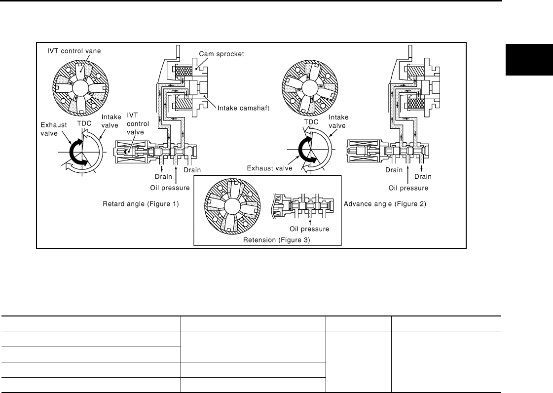
INTAKE VALVE TIMING CONTROL
EC-557
< FUNCTION DIAGNOSIS > [FOR USA (FEDERAL) AND CANADA]
C
D
E
F
G
H
I
J
K
L
M
A
EC
N
P
O
INTAKE VALVE TIMING CONTROL
System Diagram INFOID:0000000004529456
System Description INFOID:0000000004529457
INPUT/OUTPUT SIGNAL CHART
*: This signal is sent to the ECM through CAN communication line
SYSTEM DESCRIPTION
This mechanism hydraulically controls cam phases continuously with the fixed operating angle of the intake
valve.
The ECM receives signals such as crankshaft position, camshaft position, engine speed, and engine coolant
temperature. Then, the ECM sends ON/OFF pulse duty signals to the intake valve timing (IVT) control sole-
noid valve depending on driving status. This makes it possible to control the shut/open timing of the intake
valve to increase engine torque in low/mid speed range and output in high-speed range.
JMBIA0060G
B
Sensor Input signal to ECM ECM function Actuator
Crankshaft position sensor (POS) Engine speed and piston position Intake valve
timing control Intake valve timing control
solenoid valve
Camshaft position sensor (PHASE)
Engine coolant temperature sensor Engine coolant temperature
Combination meter Vehicle speed*
Revision: 2008 August 2009 Rogue

EC-558
< FUNCTION DIAGNOSIS > [FOR USA (FEDERAL) AND CANADA]
INTAKE VALVE TIMING CONTROL
Component Parts Location INFOID:0000000004533677
1. Intake valve timing control solenoid
valve
2. Ignition coil (with power transistor)
and spark plug
3. Cooling fan motor-2
4. Air fuel ratio (A/F) sensor 1 5. Heated oxygen sensor 2 6. Camshaft position sensor (PHASE)
7. Engine coolant temperature sensor 8. Park/neutral position (PNP) switch 9. Cooling fan motor-1
10. Refrigerant pressure sensor 11. ECM 12. IPDM E/R
13. Mass air flow sensor (with intake air
temperature sensor)
14. Crankshaft position sensor (POS) 15. Electric throttle control actuator
(with built in throttle position sensor
and throttle control motor)
16. Knock sensor 17. EVAP canister purge volume control
solenoid valve
18. Fuel injector
1. Electric throttle control actuator 2. Camshaft position sensor (PHASE)
Vehicle front
JMBIA0916ZZ
JMBIA0917ZZ
Revision: 2008 August 2009 Rogue

INTAKE VALVE TIMING CONTROL
EC-559
< FUNCTION DIAGNOSIS > [FOR USA (FEDERAL) AND CANADA]
C
D
E
F
G
H
I
J
K
L
M
A
EC
N
P
O
1. Mass air flow sensor (with intake air
temperature sensor)
2. Engine coolant temperature sensor
Vehicle front
1. Cooling fan motor-1 harness con-
nector
2. Cooling fan motor-1 3. Cooling fan motor-2 harness con-
nector
4. Cooling fan motor-2 5. Crankshaft position sensor (POS)
Vehicle front
1. Fuel injector 2. Ignition coil (with power transistor)
and spark plug 3. EVAP canister purge volume control
solenoid valve
4. EVAP service port
Vehicle front
JMBIA0918ZZ
JMBIA0919ZZ
JMBIA0921ZZ
Revision: 2008 August 2009 Rogue

EC-560
< FUNCTION DIAGNOSIS > [FOR USA (FEDERAL) AND CANADA]
INTAKE VALVE TIMING CONTROL
1. Refrigerant pressure sensor 2. PCV valve
JMBIA0922ZZ
JMBIA0502G
B
1. Air fuel ratio (A/F) sensor 1 2. Heated oxygen sensor 2 3. Air fuel ratio (A/F) sensor 1 harness
connector
4. Heated oxygen sensor 2 harness
connector
5. Three way catalyst (Under floor)
Vehicle front
JMBIA0920ZZ
Revision: 2008 August 2009 Rogue

INTAKE VALVE TIMING CONTROL
EC-561
< FUNCTION DIAGNOSIS > [FOR USA (FEDERAL) AND CANADA]
C
D
E
F
G
H
I
J
K
L
M
A
EC
N
P
O
1. EVAP control system pressure sen-
sor
2. EVAP canister vent control valve 3. EVAP canister
4. Body ground
Vehicle front
1. Park/neutral position (PNP) switch 2. Data link connector
Vehicle front
1. Stop lamp switch 2. ASCD brake switch 3. Accelerator pedal position sensor
1. ASCD steering switch 2. RESUME/ACCERELATE switch 3. SET/COAST switch
4. CANSEL switch 5. MAIN switch
JMBIA0923ZZ
JMBIA0927ZZ
JMBIA0924ZZ
JMBIA0925ZZ
Revision: 2008 August 2009 Rogue
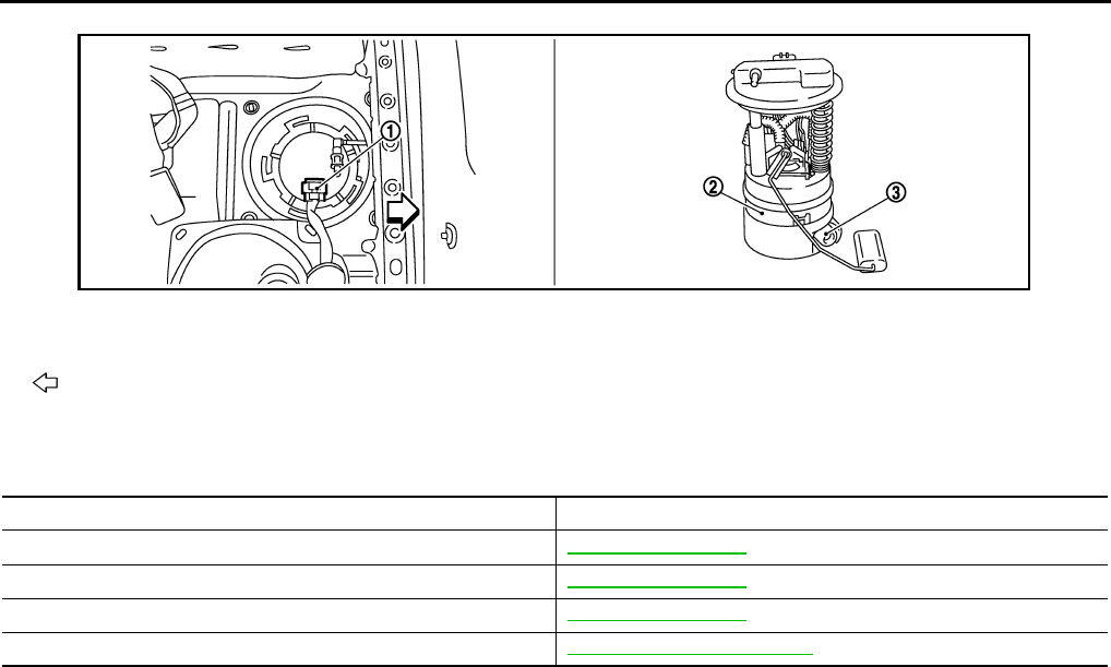
EC-562
< FUNCTION DIAGNOSIS > [FOR USA (FEDERAL) AND CANADA]
INTAKE VALVE TIMING CONTROL
Component Description INFOID:0000000004529459
1. Fuel level sensor unit and fuel pump
harness connector
2. Fuel level sensor unit and fuel pump 3. Fuel pressure regulator
Vehicle front
JMBIA0926ZZ
Component Reference
Camshaft position sensor (PHASE) EC-707, "Description"
Crankshaft position sensor (POS) EC-703, "Description"
Engine coolant temperature sensor EC-632, "Description"
Intake valve timing control solenoid valve EC-557, "System Description"
Revision: 2008 August 2009 Rogue

ON BOARD DIAGNOSTIC (OBD) SYSTEM
EC-563
< FUNCTION DIAGNOSIS > [FOR USA (FEDERAL) AND CANADA]
C
D
E
F
G
H
I
J
K
L
M
A
EC
N
P
O
ON BOARD DIAGNOSTIC (OBD) SYSTEM
Diagnosis Description INFOID:0000000004529460
INTRODUCTION
The ECM has an on board diagnostic system, which detects malfunctions related to engine sensors or actua-
tors. The ECM also records various emission-related diagnostic information including:
The above information can be checked using procedures listed in the table below.
×: Applicable —: Not applicable
*: When DTC and 1st trip DTC simultaneously appear on the display, they cannot be clearly distinguished from each other.
The malfunction indicator lamp (MIL) on the instrument panel illuminates when the same malfunction is
detected in two consecutive trips (Two trip detection logic), or when the ECM enters fail-safe mode. (Refer to
EC-897, "Fail Safe".)
TWO TRIP DETECTION LOGIC
When a malfunction is detected for the first time, 1st trip DTC and 1st trip Freeze Frame data are stored in the
ECM memory. The MIL will not illuminate at this stage. <1st trip>
If the same malfunction is detected again during the next drive, the DTC and Freeze Frame data are stored in
the ECM memory, and the MIL illuminates. The MIL illuminates at the same time when the DTC is stored.
<2nd trip> The “trip” in the “Two Trip Detection Logic” means a driving mode in which self-diagnosis is per-
formed during vehicle operation. Specific on board diagnostic items will cause the ECM to illuminate or blink
the MIL, and store DTC and Freeze Frame data, even in the 1st trip, as shown below.
×: Applicable —: Not applicable
Emission-related diagnostic information Diagnostic service
Diagnostic Trouble Code (DTC) Service $03 of SAE J1979
Freeze Frame data Service $02 of SAE J1979
System Readiness Test (SRT) code Service $01 of SAE J1979
1st Trip Diagnostic Trouble Code (1st Trip DTC) Service $07 of SAE J1979
1st Trip Freeze Frame data
Test values and Test limits Service $06 of SAE J1979
Calibration ID Service $09 of SAE J1979
DTC 1st trip DTC Freeze
Frame data 1st trip Freeze
Frame data SRT code SRT status Test value
CONSULT-III ××× × ××—
GST ××× —×××
ECM ××*— — — ×—
Items
MIL DTC 1st trip DTC
1st trip 2nd trip 1st trip
displaying 2nd trip
displaying 1st trip dis-
playing 2nd trip
displaying
Blinking illuminate Blinking illuminate
Misfire (Possible
three way catalyst
damage) — DTC:
P0300 - P0304 is
being detected
×—————×—
Misfire (Possible
three way catalyst
damage) — DTC:
P0300 - P0304 is
being detected
——×——×——
Revision: 2008 August 2009 Rogue

EC-564
< FUNCTION DIAGNOSIS > [FOR USA (FEDERAL) AND CANADA]
ON BOARD DIAGNOSTIC (OBD) SYSTEM
DTC AND FREEZE FRAME DATA
DTC and 1st Trip DTC
The 1st trip DTC (whose number is the same as the DTC number) is displayed for the latest self-diagnostic
result obtained. If the ECM memory was cleared previously, and the 1st trip DTC did not recur, the 1st trip DTC
will not be displayed.
If a malfunction is detected during the 1st trip, the 1st trip DTC is saved in the ECM memory. The MIL will not
illuminate (two trip detection logic). If the same malfunction is not detected in the 2nd trip (meeting the required
driving pattern), the 1st trip DTC is cleared from the ECM memory. If the same malfunction is detected in the
2nd trip, both the 1st trip DTC and DTC are stored in the ECM memory and the MIL illuminates. In other
words, the DTC is stored in the ECM memory and the MIL illuminates when the same malfunction occurs in
two consecutive trips. If a 1st trip DTC is saved and a non-diagnostic operation is performed between the 1st
and 2nd trips, only the 1st trip DTC will continue to be stored. For malfunctions that blink or illuminate the MIL
during the 1st trip, the DTC and 1st trip DTC are stored in the ECM memory.
Procedures for clearing the DTC and the 1st trip DTC from the ECM memory are described in “How to Erase
DTC and 1st Trip DTC”.
For malfunctions in which 1st trip DTCs are displayed, refer to EC-900, "DTC Index". These items are
required by legal regulations to continuously monitor the system/component. In addition, the items monitored
non-continuously are also displayed on CONSULT-III.
1st trip DTC is specified in Service $07 of SAE J1979. 1st trip DTC detection occurs without illuminating the
MIL and therefore does not warn the driver of a malfunction. However, 1st trip DTC detection will not prevent
the vehicle from being tested, for example during Inspection/Maintenance (I/M) tests.
When a 1st trip DTC is detected, check, print out or write down and erase (1st trip) DTC and Freeze Frame
data as specified in Work Flow procedure Step 2, refer to EC-495, "Work Flow". Then perform DTC CONFIR-
MATION PROCEDURE or Component Function Check to try to duplicate the malfunction. If the malfunction is
duplicated, the item requires repair.
Freeze Frame Data and 1st Trip Freeze Frame Data
The ECM records the driving conditions such as fuel system status, calculated load value, engine coolant tem-
perature, short term fuel trim, long term fuel trim, engine speed, vehicle speed, absolute throttle position, base
fuel schedule and intake air temperature at the moment a malfunction is detected.
Data which are stored in the ECM memory, along with the 1st trip DTC, are called 1st trip freeze frame data.
The data, stored together with the DTC data, are called freeze frame data and displayed on CONSULT-III or
GST. The 1st trip freeze frame data can only be displayed on the CONSULT-III screen, not on the GST.
Only one set of freeze frame data (either 1st trip freeze frame data or freeze frame data) can be stored in the
ECM. 1st trip freeze frame data is stored in the ECM memory along with the 1st trip DTC. There is no priority
for 1st trip freeze frame data and it is updated each time a different 1st trip DTC is detected. However, once
freeze frame data (2nd trip detection/MIL on) is stored in the ECM memory, 1st trip freeze frame data is no
longer stored. Remember, only one set of freeze frame data can be stored in the ECM. The ECM has the fol-
lowing priorities to update the data.
For example, the EGR malfunction (Priority: 2) was detected and the freeze frame data was saved in the 2nd
trip. After that when the misfire (Priority: 1) is detected in another trip, the freeze frame data will be updated
from the EGR malfunction to the misfire. The 1st trip freeze frame data is updated each time a different mal-
function is detected. There is no priority for 1st trip freeze frame data. However, once freeze frame data is
One trip detection
diagnoses (Refer to
EC-900,
"DTC Index".)
—×——×—— —
Except above — — — ×—××—
Items
MIL DTC 1st trip DTC
1st trip 2nd trip 1st trip
displaying
2nd trip
displaying
1st trip dis-
playing
2nd trip
displaying
Blinking illuminate Blinking illuminate
Priority Items
1Freeze frame data Misfire — DTC: P0300 - P0304
Fuel Injection System Function — DTC: P0171, P0172
2 Except the above items (Includes CVT related items)
3 1st trip freeze frame data
Revision: 2008 August 2009 Rogue

ON BOARD DIAGNOSTIC (OBD) SYSTEM
EC-565
< FUNCTION DIAGNOSIS > [FOR USA (FEDERAL) AND CANADA]
C
D
E
F
G
H
I
J
K
L
M
A
EC
N
P
O
stored in the ECM memory, 1st trip freeze data is no longer stored (because only one freeze frame data or 1st
trip freeze frame data can be stored in the ECM). If freeze frame data is stored in the ECM memory and freeze
frame data with the same priority occurs later, the first (original) freeze frame data remains unchanged in the
ECM memory.
Both 1st trip freeze frame data and freeze frame data (along with the DTCs) are cleared when the ECM mem-
ory is erased. Procedures for clearing the ECM memory are described in “How to Erase DTC and 1st Trip
DTC”.
How to Read DTC and 1st Trip DTC
With CONSULT-III
With GST
CONSULT-III or GST (Generic Scan Tool) Examples: P0340, P0850, P1148, etc.
These DTCs are prescribed by SAE J2012.
(CONSULT-III also displays the malfunctioning component or system.)
No Tools
The number of blinks of the MIL in the Diagnostic Test Mode II (Self-Diagnostic Results) indicates the DTC.
Example: 0340, 0850, 1148, etc.
These DTCs are controlled by NISSAN.
•1st trip DTC No. is the same as DTC No.
•Output of a DTC indicates a malfunction. However, GST and the Diagnostic Test Mode II do not indi-
cate whether the malfunction is still occurring or has occurred in the past and has returned to nor-
mal. CONSULT-III can identify malfunction status as shown below. Therefore, using CONSULT-III (if
available) is recommended.
DTC or 1st trip DTC of a malfunction is displayed in “SELF-DIAGNOSTIC RESULTS” mode of CONSULT-III.
Time data indicates how many times the vehicle was driven after the last detection of a DTC.
If the DTC is being detected currently, the time data will be [0].
If a 1st trip DTC is stored in the ECM, the time data will be [1t].
How to Erase DTC and 1st Trip DTC
With CONSULT-III
NOTE:
•If the ignition switch stays ON after repair work, be sure to turn ignition switch OFF once.
Wait at least 10 seconds and then turn it ON (engine stopped) again.
• If the DTC is not for CVT related items (see EC-900, "DTC Index"), skip step 1.
1. Erase DTC in TCM. Refer to TM-42, "Diagnosis Description".
2. Select “ENGINE” with CONSULT-III.
3. Select “SELFDIAGNOSTIC RESULT”.
4. Touch “ERASE”. (DTC in ECM will be erased.)
With GST
NOTE:
•If the ignition switch stays ON after repair work, be sure to turn ignition switch OFF once.
Wait at least 10 seconds and then turn it ON (engine stopped) again.
1. Select Service $04 with GST (Generic Scan Tool).
No Tools
NOTE:
•If the ignition switch stays ON after repair work, be sure to turn ignition switch OFF once.
Wait at least 10 seconds and then turn it ON (engine stopped) again.
1. Erase DTC in ECM. Refer to How to Erase Diagnostic Test Mode II (Self-diagnostic Results).
•If the battery is disconnected, the emission-related diagnostic information will be cleared within 24
hours.
•The following data are cleared when the ECM memory is erased.
- Diagnostic trouble codes
- 1st trip diagnostic trouble codes
- Freeze frame data
- 1st trip freeze frame data
- System readiness test (SRT) codes
- Test values
Actual work procedures are explained using a DTC as an example. Be careful so that not only the DTC, but all
of the data listed above, are cleared from the ECM memory during work procedures.
SYSTEM READINESS TEST (SRT) CODE
System Readiness Test (SRT) code is specified in Service $01 of SAE J1979.
Revision: 2008 August 2009 Rogue
EC-566
< FUNCTION DIAGNOSIS > [FOR USA (FEDERAL) AND CANADA]
ON BOARD DIAGNOSTIC (OBD) SYSTEM
As part of an enhanced emissions test for Inspection & Maintenance (I/M), certain states require the status of
SRT be used to indicate whether the ECM has completed self-diagnosis of major emission systems and com-
ponents. Completion must be verified in order for the emissions inspection to proceed.
If a vehicle is rejected for a State emissions inspection due to one or more SRT items indicating “INCMP”, use
the information in this Service Manual to set the SRT to “CMPLT”.
In most cases the ECM will automatically complete its self-diagnosis cycle during normal usage, and the SRT
status will indicate “CMPLT” for each application system. Once set as “CMPLT”, the SRT status remains
“CMPLT” until the self-diagnosis memory is erased.
Occasionally, certain portions of the self-diagnostic test may not be completed as a result of the customer's
normal driving pattern; the SRT will indicate “INCMP” for these items.
NOTE:
The SRT will also indicate “INCMP” if the self-diagnosis memory is erased for any reason or if the ECM mem-
ory power supply is interrupted for several hours.
If, during the state emissions inspection, the SRT indicates “CMPLT” for all test items, the inspector will con-
tinue with the emissions test. However, if the SRT indicates “INCMP” for one or more of the SRT items the
vehicle is returned to the customer untested.
NOTE:
If MIL is ON during the state emissions inspection, the vehicle is also returned to the customer untested even
though the SRT indicates “CMPLT” for all test items. Therefore, it is important to check SRT (“CMPLT”) and
DTC (No DTCs) before the inspection.
SRT Item
The table below shows required self-diagnostic items to set the SRT to “CMPLT”.
*: If completion of several SRTs is required, perform driving patterns (DTC CONFIRMATION PROCEDURE), one by one based on the
priority for models with CONSULT-III.
SRT Set Timing
SRT is set as “CMPLT” after self-diagnosis has been performed one or more times. Completion of SRT is
done regardless of whether the result is OK or NG. The set timing is different between OK and NG results and
is shown in the table below.
SRT item
(CONSULT-III indication)
Performance
Priority* Required self-diagnostic items to set the SRT to “CMPLT” Corresponding
DTC No.
CATALYST 2 Three way catalyst function P0420
EVAP SYSTEM 2 EVAP control system purge flow monitoring P0441
1 EVAP control system P0442
2 EVAP control system P0456
HO2S 2 Air fuel ratio (A/F) sensor 1 P0133
Heated oxygen sensor 2 P0137
Heated oxygen sensor 2 P0138
Heated oxygen sensor 2 P0139
Self-diagnosis result
Example
Diagnosis Ignition cycle
← ON →OFF ← ON →OFF ← ON →OFF ← ON →
All OK Case 1 P0400 OK (1) — (1) OK (2) — (2)
P0402 OK (1) — (1) — (1) OK (2)
P1402 OK (1) OK (2) — (2) — (2)
SRT of EGR “CMPLT” “CMPLT” “CMPLT” “CMPLT”
Case 2 P0400 OK (1) — (1) — (1) — (1)
P0402 — (0) — (0) OK (1) — (1)
P1402 OK (1) OK (2) — (2) — (2)
SRT of EGR “INCMP” “INCMP” “CMPLT” “CMPLT”
Revision: 2008 August 2009 Rogue

ON BOARD DIAGNOSTIC (OBD) SYSTEM
EC-567
< FUNCTION DIAGNOSIS > [FOR USA (FEDERAL) AND CANADA]
C
D
E
F
G
H
I
J
K
L
M
A
EC
N
P
O
OK: Self-diagnosis is carried out and the result is OK.
NG: Self-diagnosis is carried out and the result is NG.
—: Self-diagnosis is not carried out.
When all SRT related self-diagnoses show OK results in a single cycle (Ignition OFF-ON-OFF), the SRT will
indicate “CMPLT”. → Case 1 above
When all SRT related self-diagnoses show OK results through several different cycles, the SRT will indicate
“CMPLT” at the time the respective self-diagnoses have at least one OK result. → Case 2 above
If one or more SRT related self-diagnoses show NG results in 2 consecutive cycles, the SRT will also indicate
“CMPLT”. → Case 3 above
The table above shows that the minimum number of cycles for setting SRT as “INCMP” is the number one (1)
for each self-diagnosis (Case 1 & 2) or the number two (2) for one of self-diagnoses (Case 3). However, in
preparation for the state emissions inspection, it is unnecessary for each self-diagnosis to be executed twice
(Case 3) for the following reasons:
• The SRT will indicate “CMPLT” at the time the respective self-diagnoses have one (1) OK result.
• The emissions inspection requires “CMPLT” of the SRT only with OK self-diagnosis results.
• During SRT driving pattern, the 1st trip DTC (NG) is detected prior to “CMPLT” of SRT and the self-diagnosis
memory must be erased from the ECM after repair.
• If the 1st trip DTC is erased, all the SRT will indicate “INCMP”.
NOTE:
SRT can be set as “CMPLT” together with the DTC(s). Therefore, DTC check must always be carried out
prior to the state emission inspection even though the SRT indicates “CMPLT”.
SRT Service Procedure
If a vehicle has failed the state emissions inspection due to one or more SRT items indicating “INCMP”, review
the flowchart diagnostic sequence on the next page.
NG exists Case 3 P0400 OK OK — —
P0402 — — — —
P1402 NG — NG NG
(Consecutive
NG)
(1st trip)
DTC 1st trip DTC — 1st trip DTC DTC
(= MIL ON)
SRT of EGR “INCMP” “INCMP” “INCMP” “CMPLT”
Revision: 2008 August 2009 Rogue
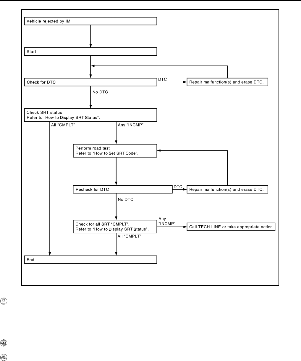
EC-568
< FUNCTION DIAGNOSIS > [FOR USA (FEDERAL) AND CANADA]
ON BOARD DIAGNOSTIC (OBD) SYSTEM
How to Display SRT Status
WITH CONSULT-III
Selecting “SRT STATUS” in “DTC CONFIRMATION” mode with CONSULT-III.
For items whose SRT codes are set “CMPLT” is displayed on the CONSULT-III screen; for items whose SRT
codes are not set, “INCMP” is displayed.
NOTE:
Though displayed on the CONSULT-III screen, “HO2S HTR” is not SRT item.
WITH GST
Selecting Service $01 with GST (Generic Scan Tool)
NO TOOLS
A SRT code itself cannot be displayed, however SRT status can.
1. Turn ignition switch ON and wait 20 seconds.
2. SRT status is indicated as shown below.
• When all SRT codes are set, MIL illuminates continuously.
JMBIA1574G
B
Revision: 2008 August 2009 Rogue
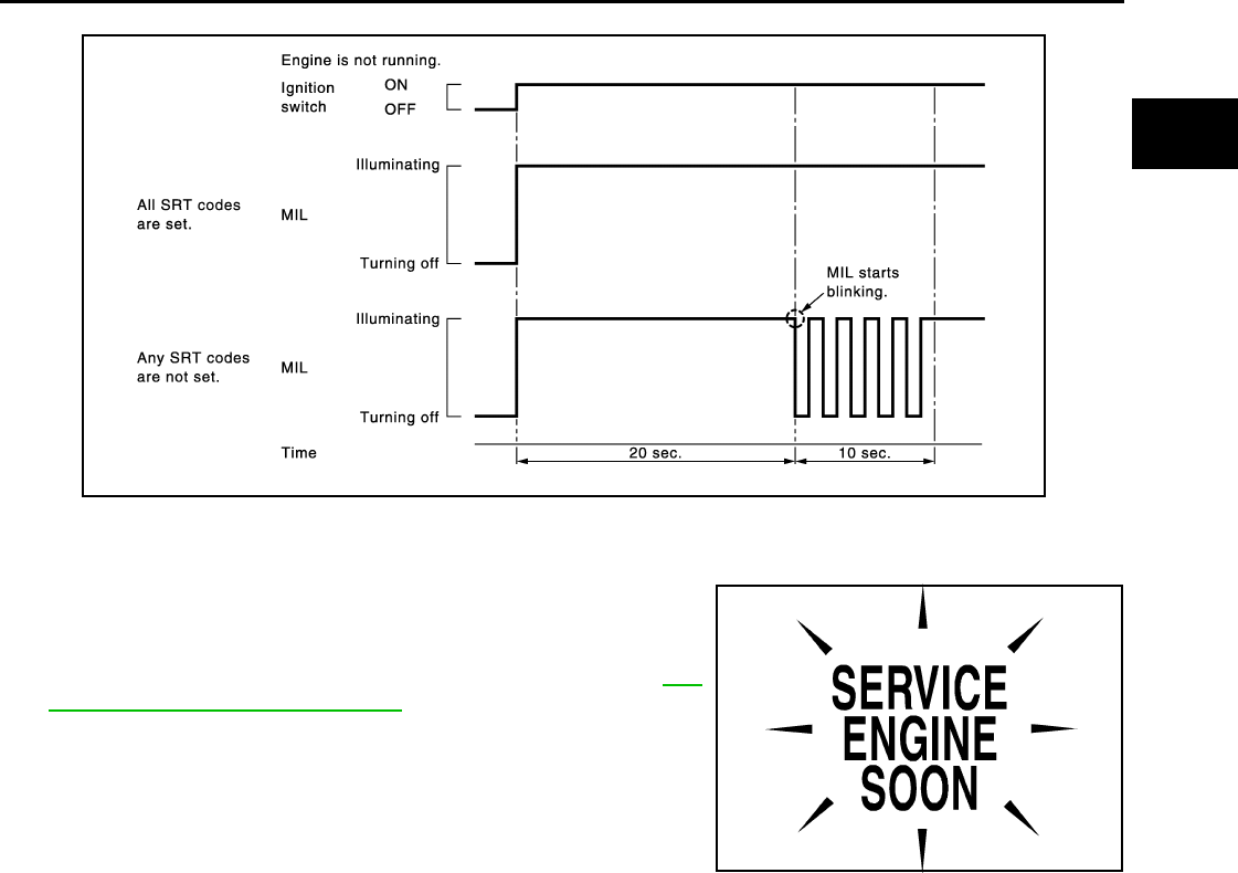
ON BOARD DIAGNOSTIC (OBD) SYSTEM
EC-569
< FUNCTION DIAGNOSIS > [FOR USA (FEDERAL) AND CANADA]
C
D
E
F
G
H
I
J
K
L
M
A
EC
N
P
O
• When any SRT codes are not set, MIL will flash periodically for 10 seconds.
MALFUNCTION INDICATOR LAMP (MIL)
Description
The MIL is located on the instrument panel.
1. The MIL will illuminate when the ignition switch is turned ON
without the engine running. This is a bulb check.
If the MIL does not illuminate, check MIL circuit. Refer to EC-
866, "Component Function Check".
2. When the engine is started, the MIL should turn off.
If the MIL remains on, the on board diagnostic system has
detected an engine system malfunction.
On Board Diagnostic System Function
The on board diagnostic system has the following three functions.
JMBIA1515G
B
SEF217U
Revision: 2008 August 2009 Rogue
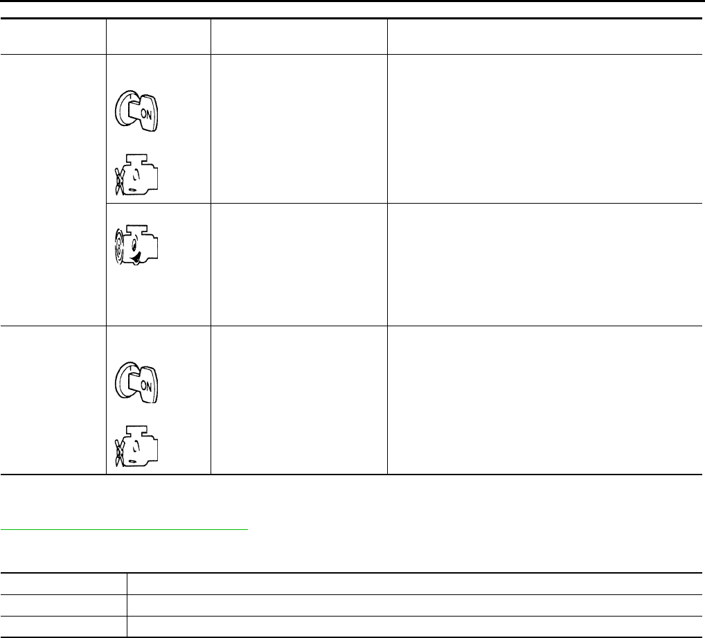
EC-570
< FUNCTION DIAGNOSIS > [FOR USA (FEDERAL) AND CANADA]
ON BOARD DIAGNOSTIC (OBD) SYSTEM
Diagnostic Test Mode I — Bulb Check
In this mode, the MIL on the instrument panel should stay ON. If it remains OFF, check MIL circuit. Refer to
EC-866, "Component Function Check".
Diagnostic Test Mode I — Malfunction Warning
This DTC number is clarified in Diagnostic Test Mode II (SELF-DIAGNOSTIC RESULTS)
Diagnostic Test Mode II — Self-diagnostic Results
In this mode, the DTC and 1st trip DTC are indicated by the number of blinks of the MIL as shown below.
The DTC and 1st trip DTC are displayed at the same time. If the MIL does not illuminate in diagnostic test
mode I (Malfunction warning), all displayed items are 1st trip DTCs. If only one code is displayed when the MIL
illuminates in diagnostic test mode II (SELF-DIAGNOSTIC RESULTS), it is a DTC; if two or more codes are
displayed, they may be either DTCs or 1st trip DTCs. DTC No. is same as that of 1st trip DTC. These uniden-
tified codes can be identified by using the CONSULT-III or GST. A DTC will be used as an example for how to
read a code.
Diagnostic Test
Mode
KEY and ENG.
Status
Function Explanation of Function
Mode I Ignition switch in
ON position
Engine stopped
BULB CHECK This function checks the MIL bulb for damage (blown, open
circuit, etc.).
If the MIL does not come on, check MIL circuit.
Engine running MALFUNCTION
WARNING
When a malfunction is detected twice in two consecutive
driving cycles (two trip detection logic), the MIL will illumi-
nate to inform the driver that a malfunction has been detect-
ed.
The following malfunctions will illuminate or blink the MIL in
the 1st trip.
• Misfire (Possible three way catalyst damage)
• One trip detection diagnoses
Mode II Ignition switch in
ON position
Engine stopped
SELF-DIAGNOSTIC
RESULTS This function allows DTCs and 1st trip DTCs to be read.
MIL Condition
ON When the malfunction is detected.
OFF No malfunction.
Revision: 2008 August 2009 Rogue
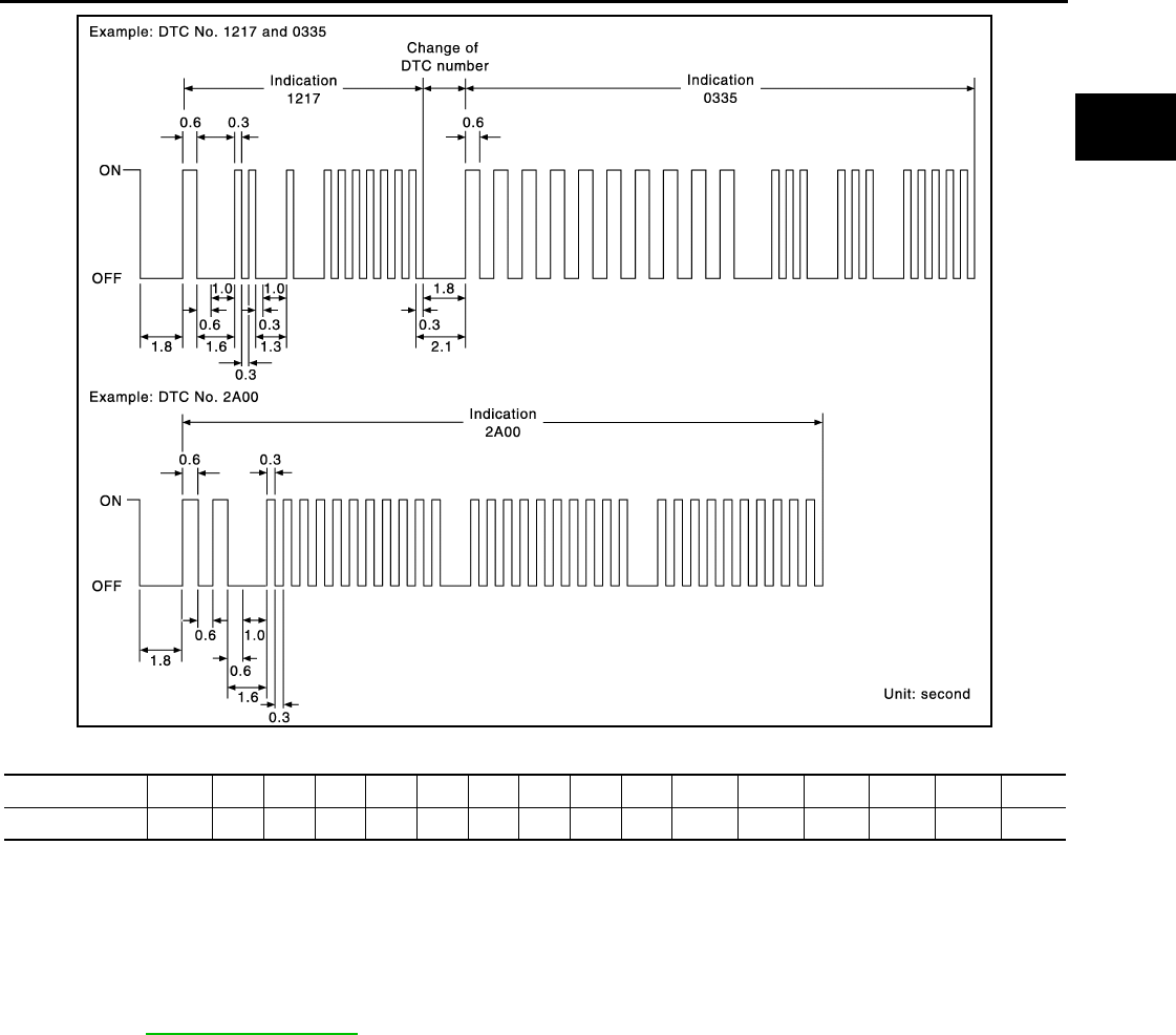
ON BOARD DIAGNOSTIC (OBD) SYSTEM
EC-571
< FUNCTION DIAGNOSIS > [FOR USA (FEDERAL) AND CANADA]
C
D
E
F
G
H
I
J
K
L
M
A
EC
N
P
O
A particular trouble code can be identified by the number of four-digit numeral flashes as per the following.
The length of time the 1,000th-digit numeral flashes on and off is 1.2 seconds consisting of an ON (0.6-sec-
onds) - OFF (0.6-seconds) cycle.
The 100th-digit numeral and lower digit numerals consist of a 0.3-seconds ON and 0.3-seconds OFF cycle.
A change from one digit numeral to another occurs at an interval of 1.0-second OFF. In other words, the later
numeral appears on the display 1.3 seconds after the former numeral has disappeared.
A change from one trouble code to another occurs at an interval of 1.8-seconds OFF.
In this way, all the detected malfunctions are classified by their DTC numbers. The DTC 0000 refers to no mal-
function. (See EC-900, "DTC Index")
How to Switch Diagnostic Test Mode
NOTE:
•It is better to count the time accurately with a clock.
•It is impossible to switch the diagnostic mode when an accelerator pedal position sensor circuit has
a malfunction.
•Always ECM returns to Diagnostic Test Mode I after the ignition switch is turned OFF.
HOW TO SET DIAGNOSTIC TEST MODE II (SELF-DIAGNOSTIC RESULTS)
1. Confirm that accelerator pedal is fully released, turn ignition switch ON and wait 3 seconds.
2. Repeat the following procedure quickly five times within 5 seconds.
- Fully depress the accelerator pedal.
- Fully release the accelerator pedal.
3. Wait 7 seconds, fully depress the accelerator pedal and keep it for depressed approx. 10 seconds until the
MIL starts blinking.
NOTE:
Do not release the accelerator pedal for 10 seconds if MIL starts blinking during this period. 10
seconds. This blinking is displaying SRT status and is continued for another 10 seconds.
4. Fully release the accelerator pedal.
ECM has entered to Diagnostic Test Mode II (Self-diagnostic results).
JMBIA1140G
B
Number 0 123456789 A B C D E F
Flashes 10123456789 11 12 13 14 15 16
Revision: 2008 August 2009 Rogue
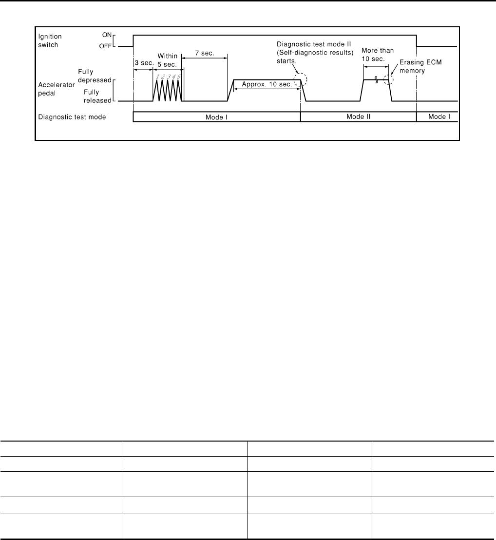
EC-572
< FUNCTION DIAGNOSIS > [FOR USA (FEDERAL) AND CANADA]
ON BOARD DIAGNOSTIC (OBD) SYSTEM
NOTE:
Wait until the same DTC (or 1st trip DTC) appears to completely confirm all DTCs certainly.
HOW TO ERASE DIAGNOSTIC TEST MODE II (SELF-DIAGNOSTIC RESULTS)
1. Set ECM in Diagnostic Test Mode II (Self-diagnostic results). Refer to “How to Set Diagnostic Test Mode II
(Self-diagnostic Results)”.
2. Fully depress the accelerator pedal and keep it depressed for more than 10 seconds.
The emission-related diagnostic information has been erased from the backup memory in the ECM.
3. Fully release the accelerator pedal, and confirm the DTC 0000 is displayed.
•If the battery is disconnected, the DTC will be lost from the backup memory within 24 hours.
•Do not erase the stored memory before starting trouble diagnoses.
OBD System Operation Chart
Relationship Between MIL, 1st Trip DTC, DTC and Detectable Items
• When a malfunction is detected for the first time, the 1st trip DTC and the 1st trip freeze frame data are
stored in the ECM memory.
• When the same malfunction is detected in two consecutive trips, the DTC and the freeze frame data are
stored in the ECM memory, and the MIL will come on.
• The MIL will turn off after the vehicle is driven 3 times (driving pattern B) with no malfunction. A is counted
only when the recorded driving pattern is met (as stored in the ECM). If another malfunction occurs while
counting, the counter will reset.
• The DTC and the freeze frame data will be stored until the vehicle is driven 40 times (driving pattern A) with-
out the same malfunction recurring (except for Misfire and Fuel Injection System). For Misfire and Fuel Injec-
tion System, the DTC and freeze frame data will be stored until the vehicle is driven 80 times (driving pattern
C) without the same malfunction recurring. The “TIME” in “SELF-DIAGNOSTIC RESULTS” mode of CON-
SULT-III will count the number of times the vehicle is driven.
• The 1st trip DTC is not displayed when the self-diagnosis results in OK for the 2nd trip.
Summary Chart
For details about patterns B and C under “Fuel Injection System” and “Misfire”, see “EXPLANATION FOR DRIVING PATTERNS FOR
“MISFIRE <EXHAUST QUALITY DETERIORATION>”, “FUEL INJECTION SYSTEM”.
For details about patterns A and B under Other, see “EXPLANATION FOR DRIVING PATTERNS FOR “MISFIRE <EXHAUST QUALITY
DETERIORATION>”, “FUEL INJECTION SYSTEM”.
*1: Clear timing is at the moment OK is detected.
*2: Clear timing is when the same malfunction is detected in the 2nd trip.
Relationship Between MIL, DTC, 1st Trip DTC and Driving Patterns for “Misfire <Exhaust Quality Deterioration>”,
“Fuel Injection System”
PBIB0092E
Items Fuel Injection System Misfire Other
MIL (turns off) 3 (pattern B) 3 (pattern B) 3 (pattern B)
DTC, Freeze Frame Data (no
display) 80 (pattern C) 80 (pattern C) 40 (pattern A)
1st Trip DTC (clear) 1 (pattern C), *11 (pattern C), *11 (pattern B)
1st Trip Freeze Frame Data
(clear) *1, *2 *1, *2 1 (pattern B)
Revision: 2008 August 2009 Rogue
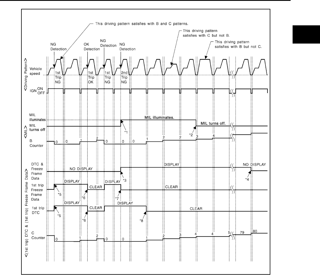
ON BOARD DIAGNOSTIC (OBD) SYSTEM
EC-573
< FUNCTION DIAGNOSIS > [FOR USA (FEDERAL) AND CANADA]
C
D
E
F
G
H
I
J
K
L
M
A
EC
N
P
O
Explanation for Driving Patterns for “Misfire <Exhaust Quality Deterioration>”, “Fuel Injection System”
<Driving Pattern B>
Driving pattern B means the vehicle operation as per the following.
All components and systems should be monitored at least once by the OBD system.
*1: When the same malfunction is de-
tected in two consecutive trips, MIL
will illuminate.
*2: MIL will turn off after vehicle is driven
3 times (pattern B) without any mal-
functions.
*3: When the same malfunction is de-
tected in two consecutive trips, the
DTC and the freeze frame data will be
stored in ECM.
*4: The DTC and the freeze frame data
will not be displayed any longer after
vehicle is driven 80 times (pattern C)
without the same malfunction. (The
DTC and the freeze frame data still
remain in ECM.)
*5: When a malfunction is detected for
the first time, the 1st trip DTC and the
1st trip freeze frame data will be
stored in ECM.
*6: The 1st trip DTC and the 1st trip
freeze frame data will be cleared at
the moment OK is detected.
*7: When the same malfunction is de-
tected in the 2nd trip, the 1st trip
freeze frame data will be cleared.
*8: 1st trip DTC will be cleared when ve-
hicle is driven once (pattern C) with-
out the same malfunction after DTC
is stored in ECM.
JMBIA1417G
B
Revision: 2008 August 2009 Rogue

EC-574
< FUNCTION DIAGNOSIS > [FOR USA (FEDERAL) AND CANADA]
ON BOARD DIAGNOSTIC (OBD) SYSTEM
• The B counter will be cleared when the malfunction is detected once regardless of the driving pattern.
• The B counter will be counted up when driving pattern B is satisfied without any malfunction.
• The MIL will turn off when the B counter reaches 3. (*2 in “OBD SYSTEM OPERATION CHART”)
<Driving Pattern C>
Driving pattern C means oprating vehicle as per the following:
The following conditions should be satisfied at the same time:
Engine speed: (Engine speed in the freeze frame data) ± 375 rpm
Calculated load value: (Calculated load value in the freeze frame data) × (1 ±0.1) [%]
Engine coolant temperature (T) condition:
• When the freeze frame data shows lower than 70°C (158°F), T should be lower than 70°C (158°F).
• When the freeze frame data shows higher than or equal to 70°C (158°F), T should be higher than or equal to
70°C (158°F).
Example:
If the stored freeze frame data is as per the following:
Engine speed: 850 rpm, Calculated load value: 30%, Engine coolant temperature: 80°C (176°F)
To be satisfied with driving pattern C, the vehicle should run under the following conditions:
Engine speed: 475 - 1,225 rpm, Calculated load value: 27 - 33%, Engine coolant temperature: more than 70°C
(158°F)
• The C counter will be cleared when the malfunction is detected regardless of vehicle conditions above.
• The C counter will be counted up when vehicle conditions above are satisfied without the same malfunction.
• The DTC will not be displayed after C counter reaches 80.
• The 1st trip DTC will be cleared when C counter is counted once without the same malfunction after DTC is
stored in ECM.
Relationship Between MIL, DTC, 1st Trip DTC and Driving Patterns Except For “Misfire <Exhaust Quality Deteriora-
tion>”, “Fuel Injection System”
Revision: 2008 August 2009 Rogue
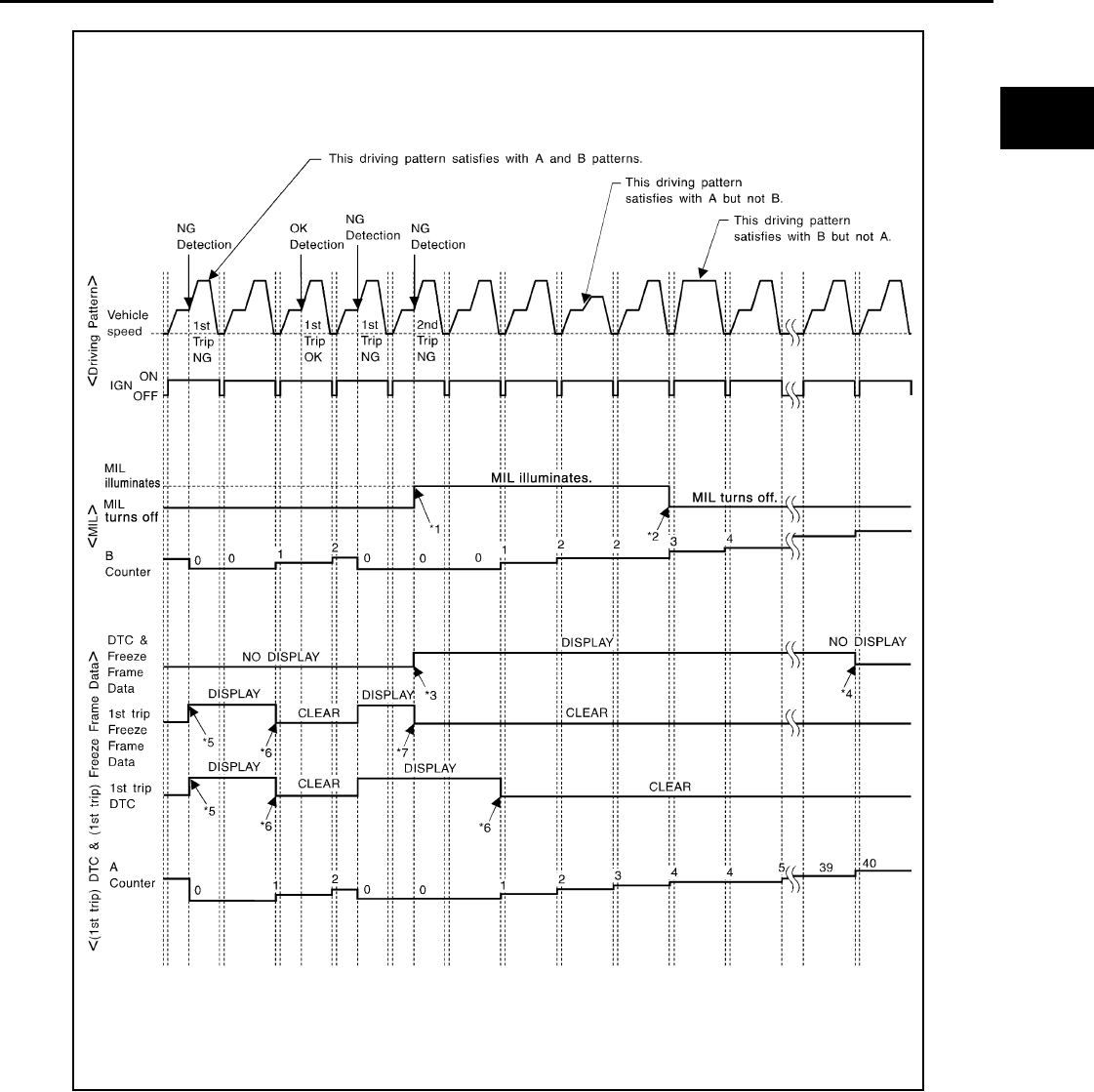
ON BOARD DIAGNOSTIC (OBD) SYSTEM
EC-575
< FUNCTION DIAGNOSIS > [FOR USA (FEDERAL) AND CANADA]
C
D
E
F
G
H
I
J
K
L
M
A
EC
N
P
O
*1: When the same malfunction is de-
tected in two consecutive trips, MIL
will illuminate.
*2: MIL will go off after vehicle is driven 3
times (pattern B) without any mal-
functions.
*3: When the same malfunction is de-
tected in two consecutive trips, the
DTC and the freeze frame data will be
stored in ECM.
JMBIA1418G
B
Revision: 2008 August 2009 Rogue
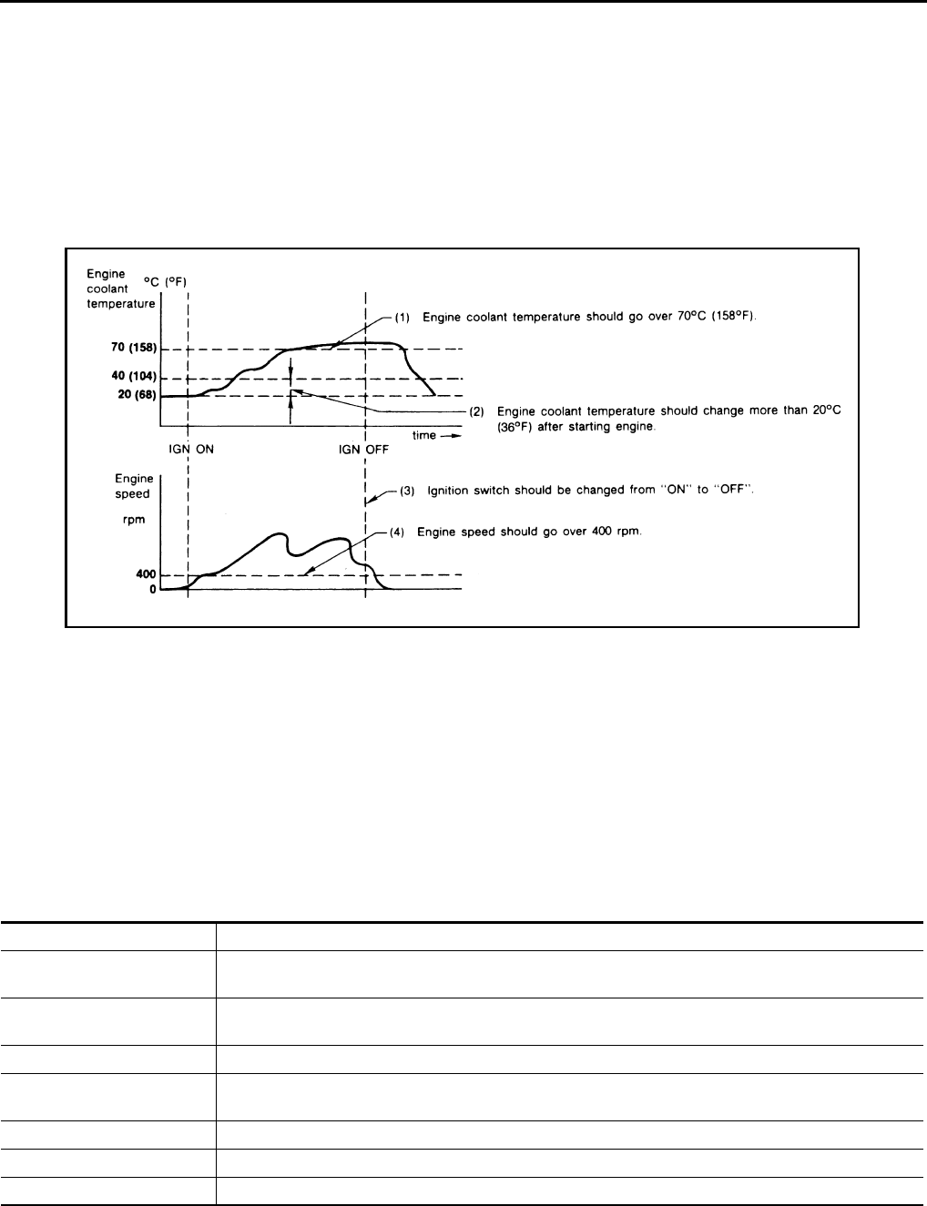
EC-576
< FUNCTION DIAGNOSIS > [FOR USA (FEDERAL) AND CANADA]
ON BOARD DIAGNOSTIC (OBD) SYSTEM
Explanation for Driving Patterns Except for “Misfire <Exhaust Quality Deterioration>”, “Fuel Injection System”
<Driving Pattern A>
• The A counter will be cleared when the malfunction is detected regardless of (1) - (4).
• The A counter will be counted up when (1) - (4) are satisfied without the same malfunction.
• The DTC will not be displayed after the A counter reaches 40.
<Driving Pattern B>
Driving pattern B means operating vehicle as per the following:
All components and systems should be monitored at least once by the OBD system.
• The B counter will be cleared when the malfunction is detected once regardless of the driving pattern.
• The B counter will be counted up when driving pattern B is satisfied without any malfunctions.
• The MIL will turn off when the B counter reaches 3 (*2 in OBD SYSTEM OPERATION CHART).
CONSULT-III Function INFOID:0000000004529461
FUNCTION
*: The following emission-related diagnostic information is cleared when the ECM memory is erased.
• Diagnostic trouble codes
• 1st trip diagnostic trouble codes
• Freeze frame data
*4: The DTC and the freeze frame data
will not be displayed any longer after
vehicle is driven 40 times (pattern A)
without the same malfunction.
(The DTC and the freeze frame data
still remain in ECM.)
*5: When a malfunction is detected for
the first time, the 1st trip DTC and the
1st trip freeze frame data will be
stored in ECM.
*6: 1st trip DTC will be cleared after vehi-
cle is driven once (pattern B) without
the same malfunction.
*7: When the same malfunction is de-
tected in the 2nd trip, the 1st trip
freeze frame data will be cleared.
JMBIA1920G
B
Diagnostic test mode Function
Work Support This mode enables a technician to adjust some devices faster and more accurately by following the in-
dications on the CONSULT-III screen.
Self Diagnostic Result Self-diagnostic results such as 1st trip DTC, DTC and 1st trip freeze frame data or freeze frame data
can be read and erased quickly.*
Data Monitor Input/Output data in the ECM can be read.
Active Test Diagnostic Test Mode in which CONSULT-III drives some actuators apart from the ECMs and also shifts
some parameters in a specified range.
DTC & SRT Confirmation The status of system monitoring tests and the self-diagnosis status/results can be confirmed.
Function Test This mode is used to inform customers when their vehicle requires periodic maintenance.
ECU Part Number ECM part number can be read.
Revision: 2008 August 2009 Rogue
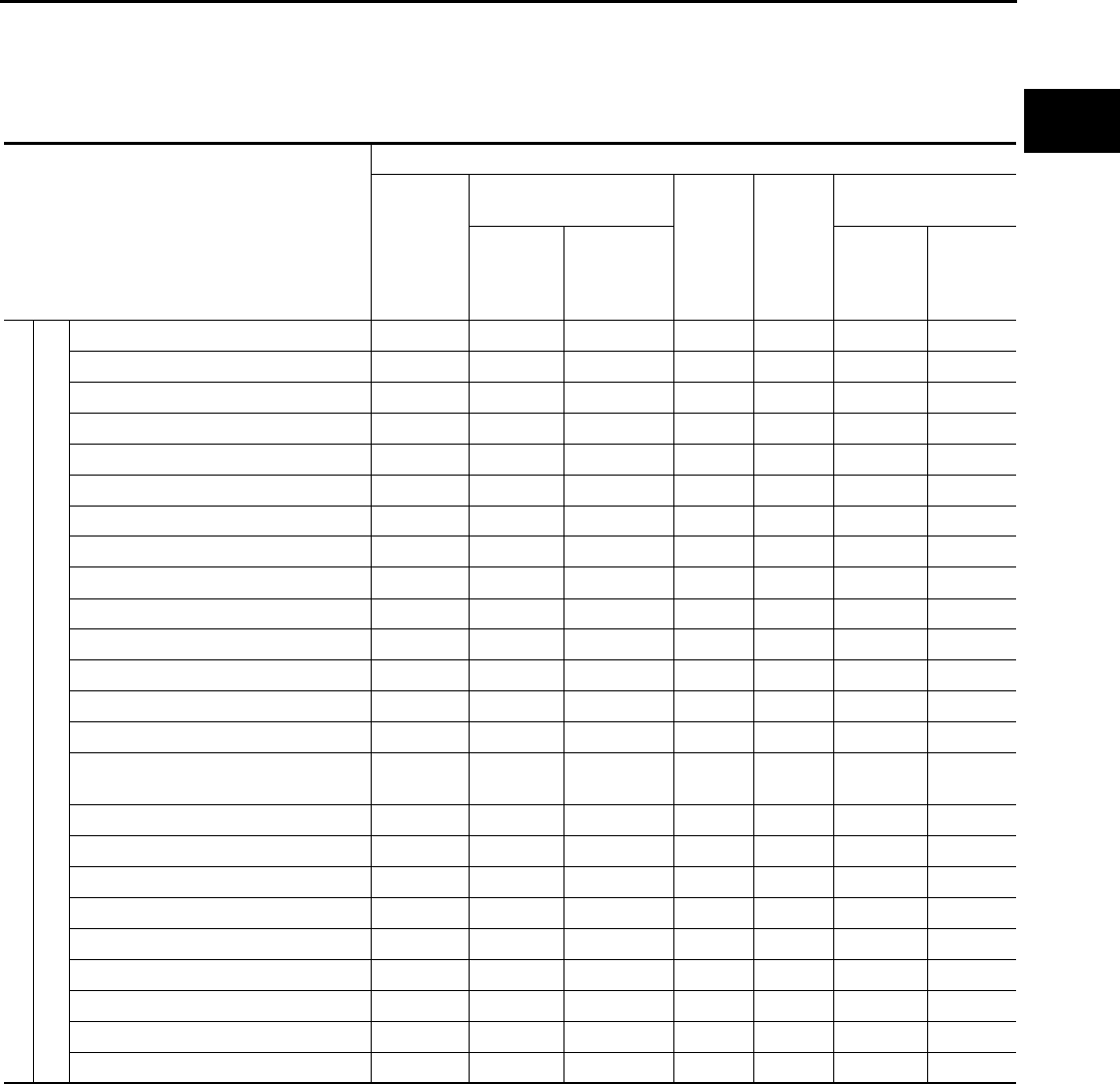
ON BOARD DIAGNOSTIC (OBD) SYSTEM
EC-577
< FUNCTION DIAGNOSIS > [FOR USA (FEDERAL) AND CANADA]
C
D
E
F
G
H
I
J
K
L
M
A
EC
N
P
O
• 1st trip freeze frame data
• System readiness test (SRT) codes
•Test values
ENGINE CONTROL COMPONENT PARTS/CONTROL SYSTEMS APPLICATION
Item
Direct Diagnostic Mode
Work
Support
Self Diagnostic Result
Data
Monitor Active
Test
DTC & SRT Confir-
mation
DTC*1 FREEZE
FRAME
DATA*2
SRT STA-
TUS
DTC
WORK
SUP-
PORT
ENGINE CONTROL COMPONENT PARTS
INPUT
Crankshaft position sensor (POS) ×××
Camshaft position sensor (PHASE) ×××
Mass air flow sensor ××
Engine coolant temperature sensor ××××
Air fuel ratio (A/F) sensor 1 ××××
Heated oxygen sensor 2 ××××
Vehicle speed signal ×××
Accelerator pedal position sensor ××
Throttle position sensor ×××
Fuel tank temperature sensor ×××
EVAP control system pressure sensor ××
Intake air temperature sensor ×××
Knock sensor ×
Refrigerant pressure sensor ×
Closed throttle position switch (accel-
erator pedal position sensor signal) ×
Air conditioner switch ×
Park/neutral position (PNP) switch ××
Stop lamp switch ××
Battery voltage ×
Load signal ×
Primary speed sensor ××
Fuel level sensor ××
ASCD steering switch ××
ASCD brake switch ××
Revision: 2008 August 2009 Rogue

EC-578
< FUNCTION DIAGNOSIS > [FOR USA (FEDERAL) AND CANADA]
ON BOARD DIAGNOSTIC (OBD) SYSTEM
X: Applicable
*1: This item includes 1st trip DTCs.
*2: This mode includes 1st trip freeze frame data or freeze frame data. The items appear on CONSULT-III screen in freeze frame data
mode only if a 1st trip DTC or DTC is detected. For details, refer to EC-563, "Diagnosis Description".
*3: Always “CMPLT” is displayed.
WORK SUPPORT MODE
Work Item
ENGINE COTNROL COMPONENT PARTS
OUTPUT
Fuel injector ××
Power transistor (Ignition timing) ××
Throttle control motor relay ××
Throttle control motor ×
EVAP canister purge volume control
solenoid valve ××××
Air conditioner relay ×
Fuel pump relay ×××
Cooling fan relay ×××
Air fuel ratio (A/F) sensor 1 heater ××
×*3
Heated oxygen sensor 2 heater ××
×*3
EVAP canister vent control valve ×× ××
Intake valve timing control solenoid
valve ×××
Calculated load value ××
Item
Direct Diagnostic Mode
Work
Support
Self Diagnostic Result
Data
Monitor Active
Test
DTC & SRT Confir-
mation
DTC*1 FREEZE
FRAME
DATA*2
SRT STA-
TUS
DTC
WORK
SUP-
PORT
WORK ITEM CONDITION USAGE
FUEL PRESSURE RELEASE • FUEL PUMP WILL STOP BY TOUCHING “START” DUR-
ING IDLING.
CRANK A FEW TIMES AFTER ENGINE STALLS.
When releasing fuel pressure from
fuel line
IDLE AIR VOL LEARN • THE IDLE AIR VOLUME THAT KEEPS THE ENGINE
WITHIN THE SPECIFIED RANGE IS MEMORIZED IN
ECM.
When learning the idle air volume
SELF-LEARNING CONT • THE COEFFICIENT OF SELF-LEARNING CONTROL
MIXTURE RATIO RETURNS TO THE ORIGINAL COEF-
FICIENT.
When clearing mixture ratio self-
learning value
Revision: 2008 August 2009 Rogue

ON BOARD DIAGNOSTIC (OBD) SYSTEM
EC-579
< FUNCTION DIAGNOSIS > [FOR USA (FEDERAL) AND CANADA]
C
D
E
F
G
H
I
J
K
L
M
A
EC
N
P
O
*: This function is not necessary in the usual service procedure.
SELF-DIAGNOSTIC RESULT MODE
Self Diagnostic Item
Regarding items of DTC and 1st trip DTC, refer to EC-900, "DTC Index".)
Freeze Frame Data and 1st Trip Freeze Frame Data
EVAP SYSTEM CLOSE CLOSE THE EVAP CANISTER VENT CONTROL VALVE IN
ORDER TO MAKE EVAP SYSTEM CLOSE UNDER THE
FOLLOWING CONDITIONS.
•IGN SW ON
• ENGINE NOT RUNNING
• AMBIENT TEMPERATURE IS ABOVE 0°C (32°F).
• NO VACUUM AND NO HIGH PRESSURE IN EVAP SYS-
TEM
• FUEL TANK TEMP. IS MORE THAN 0°C (32°F).
• WITHIN 10 MINUTES AFTER STARTING “EVAP SYS-
TEM CLOSE”
• WHEN TRYING TO EXECUTE “EVAP SYSTEM CLOSE”
UNDER THE CONDITION EXCEPT ABOVE, CONSULT-
III WILL DISCONTINUE IT AND DISPLAY APPROPRI-
ATE INSTRUCTION.
NOTE:
WHEN STARTING ENGINE, CONSULT-III MAY DIS-
PLAY “BATTERY VOLTAGE IS LOW. CHARGE BAT-
TERY”, EVEN IN WHEN USING A CHARGED BATTERY.
When detecting EVAP vapor leak
in the EVAP system
VIN REGISTRATION • IN THIS MODE, VIN IS REGISTERED IN ECM. When registering VIN in ECM
TARGET IDLE RPM ADJ* • IDLE CONDITION When setting target idle speed
TARGET IGN TIM ADJ* • IDLE CONDITION When adjusting target ignition tim-
ing
WORK ITEM CONDITION USAGE
Freeze frame data item* Description
DIAG TROUBLE CODE
[PXXXX]
• The engine control component part/control system has a trouble code that is displayed as PXXXX. (Re-
fer to EC-900, "DTC Index".)
FUEL SYS-B1
• “Fuel injection system status” at the moment a malfunction is detected is displayed.
• One of the following mode is displayed.
Mode2: Open loop due to detected system malfunction
Mode3: Open loop due to driving conditions (power enrichment, deceleration enleanment)
Mode4: Closed loop - using oxygen sensor(s) as feedback for fuel control
Mode5: Open loop - has not yet satisfied condition to go to closed loop
CAL/LD VALUE [%] • The calculated load value at the moment a malfunction is detected is displayed.
COOLANT TEMP
[°C] or [°F] • The engine coolant temperature at the moment a malfunction is detected is displayed.
L-FUEL TRM-B1 [%]
• “Long-term fuel trim” at the moment a malfunction is detected is displayed.
• The long-term fuel trim indicates much more gradual feedback compensation to the base fuel schedule
than short-term fuel trim.
S-FUEL TRM-B1 [%]
• “Short-term fuel trim” at the moment a malfunction is detected is displayed.
• The short-term fuel trim indicates dynamic or instantaneous feedback compensation to the base fuel
schedule.
ENGINE SPEED [rpm] • The engine speed at the moment a malfunction is detected is displayed.
VEHICL SPEED
[km/h] or [mph] • The vehicle speed at the moment a malfunction is detected is displayed.
ABSOL TH·P/S [%] • The throttle valve opening angle at the moment a malfunction is detected is displayed.
B/FUEL SCHDL [msec] • The base fuel schedule at the moment a malfunction is detected is displayed.
INT/A TEMP SE
[°C] or [°F] • The intake air temperature at the moment a malfunction is detected is displayed.
Revision: 2008 August 2009 Rogue

EC-580
< FUNCTION DIAGNOSIS > [FOR USA (FEDERAL) AND CANADA]
ON BOARD DIAGNOSTIC (OBD) SYSTEM
*: The items are the same as those of 1st trip freeze frame data.
DATA MONITOR MODE
Monitored Item
FUEL SYS-B2
• There items are displayed but are not applicable to this model.
L-FUEL TRM-B2 [%]
S-FUEL TRM-B2 [%]
INT MANI PRES [kPa]
COMBUST CONDITION
Freeze frame data item* Description
Monitored item Unit Description Remarks
ENG SPEED rpm • Indicates the engine speed computed from the
signal of the crankshaft position sensor (POS)
and camshaft position sensor (PHASE).
• Accuracy becomes poor if engine
speed drops below the idle rpm.
• If the signal is interrupted while the
engine is running, an abnormal value
may be indicated.
MAS A/F SE-B1 V • The signal voltage of the mass air flow sensor is
displayed.
• When the engine is stopped, a certain
value is indicated.
• When engine is running, specification
range is indicated in “SPEC”.
B/FUEL SCHDL msec • “Base fuel schedule” indicates the fuel injection
pulse width programmed into ECM, prior to any
learned on board correction.
• When engine is running, specification
range is indicated in “SPEC”.
A/F ALPHA-B1 % • The mean value of the air-fuel ratio feedback cor-
rection factor per cycle is indicated.
• When the engine is stopped, a certain
value is indicated.
• When engine is running, specification
range is indicated in “SPEC”.
• This data also includes the data for
the air-fuel ratio learning control.
COOLAN TEMP/S °C or °F
• The engine coolant temperature (determined by
the signal voltage of the engine coolant tempera-
ture sensor) is displayed.
• When the engine coolant temperature
sensor is open or short-circuited,
ECM enters fail-safe mode. The en-
gine coolant temperature determined
by the ECM is displayed.
A/F SEN1 (B1) V • The A/F signal computed from the input signal of
the air fuel ratio (A/F) sensor 1 is displayed.
HO2S2 (B1) V • The signal voltage of the heated oxygen sensor 2
is displayed.
HO2S2 MNTR(B1) RICH/LEAN
• Display of heated oxygen sensor 2 signal:
RICH: means the amount of oxygen after three
way catalyst is relatively small.
LEAN: means the amount of oxygen after three
way catalyst is relatively large.
• When the engine is stopped, a certain
value is indicated.
VHCL SPEED SE km/h or mph
• The vehicle speed computed from the vehicle
speed signal sent from combination meter is dis-
played.
BATTERY VOLT V • The power supply voltage of ECM is displayed.
ACCEL SEN 1 V• The accelerator pedal position sensor signal volt-
age is displayed.
• ACCEL SEN 2 signal is converted by
ECM internally. Thus, it differs from
ECM terminal voltage signal.
ACCEL SEN 2
TP SEN 1-B1
V• The throttle position sensor signal voltage is dis-
played.
• TP SEN 2-B1 signal is converted by
ECM internally. Thus, it differs from
ECM terminal voltage signal.
TP SEN 2-B1
FUEL T/TMP SE °C or °F
• The fuel temperature (determined by the signal
voltage of the fuel tank temperature sensor) is
displayed.
Revision: 2008 August 2009 Rogue

ON BOARD DIAGNOSTIC (OBD) SYSTEM
EC-581
< FUNCTION DIAGNOSIS > [FOR USA (FEDERAL) AND CANADA]
C
D
E
F
G
H
I
J
K
L
M
A
EC
N
P
O
INT/A TEMP SE °C or °F• The intake air temperature (determined by the
signal voltage of the intake air temperature sen-
sor) is indicated.
EVAP SYS PRES V • The signal voltage of EVAP control system pres-
sure sensor is displayed.
FUEL LEVEL SE V • The signal voltage of the fuel level sensor is dis-
played.
START SIGNAL ON/OFF
• Indicates start signal status [ON/OFF] computed
by the ECM according to the signals of engine
speed and battery voltage.
• After starting the engine, [OFF] is dis-
played regardless of the starter sig-
nal.
CLSD THL POS ON/OFF • Indicates idle position [ON/OFF] computed by
ECM according to the accelerator pedal position
sensor signal.
AIR COND SIG ON/OFF
• Indicates [ON/OFF] condition of the air condition-
er switch as determined by the air conditioner sig-
nal.
P/N POSI SW ON/OFF • Indicates [ON/OFF] condition from the park/neu-
tral position (PNP) switch signal.
PW/ST SIGNAL ON/OFF
• [ON/OFF] condition of the power steering system
(determined by the signal sent from EPS control
unit) is indicated.
LOAD SIGNAL ON/OFF
• Indicates [ON/OFF] condition from the electrical
load signal.
ON: Rear window defogger switch is ON and/or
lighting switch is in 2nd position.
OFF: Both rear window defogger switch and light-
ing switch are OFF.
IGNITION SW ON/OFF • Indicates [ON/OFF] condition from ignition switch
signal.
HEATER FAN SW ON/OFF • Indicates [ON/OFF] condition from the heater fan
switch signal.
BRAKE SW ON/OFF • Indicates [ON/OFF] condition from the stop lamp
switch signal.
INJ PULSE-B1 msec • Indicates the actual fuel injection pulse width
compensated by ECM according to the input sig-
nals.
• When the engine is stopped, a certain
computed value is indicated.
IGN TIMING BTDC • Indicates the ignition timing computed by ECM
according to the input signals.
• When the engine is stopped, a certain
value is indicated.
CAL/LD VALUE % • “Calculated load value” indicates the value of the
current air flow divided by peak air flow.
MASS AIRFLOW g·m/s • Indicates the mass air flow computed by ECM ac-
cording to the signal voltage of the mass air flow
sensor.
PURG VOL C/V %
• Indicates the EVAP canister purge volume con-
trol solenoid valve control value computed by the
ECM according to the input signals.
• The opening becomes larger as the value in-
creases.
INT/V TIM (B1) °CA • Indicates [°CA] of intake camshaft advance an-
gle.
INT/V SOL(B1) %
• The control value of the intake valve timing con-
trol solenoid valve (determined by ECM accord-
ing to the input signals) is indicated.
• The advance angle becomes larger as the value
increases.
Monitored item Unit Description Remarks
Revision: 2008 August 2009 Rogue

EC-582
< FUNCTION DIAGNOSIS > [FOR USA (FEDERAL) AND CANADA]
ON BOARD DIAGNOSTIC (OBD) SYSTEM
AIR COND RLY ON/OFF • The air conditioner relay control condition (deter-
mined by ECM according to the input signals) is
indicated.
FUEL PUMP RLY ON/OFF
• Indicates the fuel pump relay control condition
determined by ECM according to the input sig-
nals.
VENT CONT/V ON/OFF
• The control condition of the EVAP canister vent
control valve (determined by ECM according to
the input signals) is indicated.
ON: Closed
OFF: Open
THRTL RELAY ON/OFF
• Indicates the throttle control motor relay control
condition determined by the ECM according to
the input signals.
COOLING FAN HI/LOW/OFF
• Indicates the condition of the cooling fan (deter-
mined by ECM according to the input signals).
HI: High speed operation
LOW: Low speed operation
OFF: Stop
HO2S2 HTR (B1) ON/OFF
• Indicates [ON/OFF] condition of heated oxygen
sensor 2 heater determined by ECM according to
the input signals.
I/P PULLY SPD rpm • Indicates the engine speed computed from the
turbine revolution sensor signal.
VEHICLE SPEED km/h or mph • The vehicle speed computed from the vehicle
speed signal sent from TCM is displayed.
IDL A/V LEARN YET/CMPLT
• Displays the condition of Idle Air Volume Learn-
ing
YET: Idle air volume learning has not been per-
formed yet.
CMPLT: Idle air volume learning has already
been performed successfully.
TRVL AFTER MIL km or mile • Distance traveled while MIL is activated.
A/F S1 HTR(B1) %
• Air fuel ratio (A/F) sensor 1 heater control value
computed by ECM according to the input signals.
• The current flow to the heater becomes larger as
the value increases.
AC PRESS SEN V • The signal voltage from the refrigerant pressure
sensor is displayed.
VHCL SPEED SE km/h or mph
• The vehicle speed computed from the vehicle
speed signal sent from combination meter is dis-
played.
SET VHCL SPD km/h or mph • The preset vehicle speed is displayed.
MAIN SW ON/OFF • Indicates [ON/OFF] condition from MAIN switch
signal.
CANCEL SW ON/OFF • Indicates [ON/OFF] condition from CANCEL
switch signal.
RESUME/ACC SW ON/OFF • Indicates [ON/OFF] condition from RESUME/AC-
CELERATE switch signal.
SET SW ON/OFF • Indicates [ON/OFF] condition from SET/COAST
switch signal.
BRAKE SW1 ON/OFF • Indicates [ON/OFF] condition from ASCD brake
switch signal.
BRAKE SW2 ON/OFF • Indicates [ON/OFF] condition of stop lamp switch
signal.
Monitored item Unit Description Remarks
Revision: 2008 August 2009 Rogue

ON BOARD DIAGNOSTIC (OBD) SYSTEM
EC-583
< FUNCTION DIAGNOSIS > [FOR USA (FEDERAL) AND CANADA]
C
D
E
F
G
H
I
J
K
L
M
A
EC
N
P
O
NOTE:
Any monitored item that does not match the vehicle being diagnosed is deleted from the display automatically.
ACTIVE TEST MODE
Test Item
VHCL SPD CUT NON/CUT
• Indicates the vehicle cruise condition.
NON: Vehicle speed is maintained at the ASCD
set speed.
CUT: Vehicle speed decreased to excessively
low compared with the ASCD set speed, and
ASCD operation is cut off.
LO SPEED CUT NON/CUT
• Indicates the vehicle cruise condition.
NON: Vehicle speed is maintained at the ASCD
set speed.
CUT: Vehicle speed decreased to excessively
low, and ASCD operation is cut off.
AT OD MONITOR ON/OFF • Indicates [ON/OFF] condition of A/T O/D accord-
ing to the input signal from the TCM.
AT OD CANCEL ON/OFF • Indicates [ON/OFF] condition of A/T O/D cancel
request signal.
CRUISE LAMP ON/OFF
• Indicates [ON/OFF] condition of CRUISE lamp
determined by the ECM according to the input
signals.
SET LAMP ON/OFF • Indicates [ON/OFF] condition of SET lamp deter-
mined by the ECM according to the input signals.
A/F ADJ-B1 —
• Indicates the correction of factor stored in ECM.
The factor is calculated from the difference be-
tween the target air-fuel ratio stored in ECM and
the air-fuel ratio calculated from A/F sensor 1 sig-
nal.
Monitored item Unit Description Remarks
TEST ITEM CONDITION JUDGMENT CHECK ITEM (REMEDY)
FUEL INJECTION
• Engine: Return to the original
trouble condition
• Change the amount of fuel injec-
tion using CONSULT-III.
If trouble symptom disappears, see
CHECK ITEM.
• Harness and connectors
• Fuel injector
• Air fuel ratio (A/F) sensor 1
IGNITION TIMING
• Engine: Return to the original
trouble condition
• Timing light: Set
• Retard the ignition timing using
CONSULT-III.
If trouble symptom disappears, see
CHECK ITEM.
• Perform Idle Air Volume Learn-
ing.
POWER BALANCE
• Engine: After warming up, idle the
engine.
• A/C switch OFF
• Selector lever: P or N
• Cut off each fuel injector signal
one at a time using CONSULT-III.
Engine runs rough or stops.
• Harness and connectors
• Compression
• Fuel injector
• Power transistor
•Spark plug
•Ignition coil
COOLING FAN*
• Ignition switch: ON
• Turn the cooling fan “LOW”, “HI”
and “OFF” using CONSULT-III. Cooling fan moves and stops.
• Harness and connectors
• IPDM E/R (Cooling fan relay)
• Cooling fan motor
ENG COOLANT
TEMP
• Engine: Return to the original
trouble condition
• Change the engine coolant tem-
perature using CONSULT-III.
If trouble symptom disappears, see
CHECK ITEM.
• Harness and connectors
• Engine coolant temperature
sensor
• Fuel injector
Revision: 2008 August 2009 Rogue

EC-584
< FUNCTION DIAGNOSIS > [FOR USA (FEDERAL) AND CANADA]
ON BOARD DIAGNOSTIC (OBD) SYSTEM
*: Leaving cooling fan OFF with CONSULT-III while engine is running may cause the engine to overheat.
DTC & SRT CONFIRMATION MODE
SRT STATUS Mode
For details, refer to EC-563, "Diagnosis Description".
SRT WORK SUPPORT Mode
This mode enables a technician to drive a vehicle to set the SRT while monitoring the SRT status.
DTC WORK SUPPORT Mode
*: DTC P1442 and P1456 does not apply to S35 models but appears in DTC Work Support Mode screens.
Diagnosis Tool Function INFOID:0000000004529462
DESCRIPTION
FUEL PUMP RELAY
• Ignition switch: ON (Engine
stopped)
• Turn the fuel pump relay “ON”
and “OFF” using CONSULT-III
and listen to operating sound.
Fuel pump relay makes the operat-
ing sound. • Harness and connectors
• Fuel pump relay
PURG VOL CONT/V
• Engine: After warming up, run en-
gine at 1,500 rpm.
• Change the EVAP canister purge
volume control solenoid valve
opening percent using CON-
SULT-III.
Engine speed changes according
to the opening percent. • Harness and connectors
• Solenoid valve
FUEL/T TEMP SEN • Change the fuel tank temperature using CONSULT-III.
VENT CONTROL/V
• Ignition switch: ON (Engine
stopped)
• Turn solenoid valve “ON” and
“OFF” using CONSULT-III and lis-
ten to operating sound.
Solenoid valve makes an operating
sound. • Harness and connectors
• Solenoid valve
V/T ASSIGN ANGLE
• Engine: Return to the original
trouble condition
• Change intake valve timing using
CONSULT-III.
If trouble symptom disappears, see
CHECK ITEM.
• Harness and connectors
• Intake valve timing control sole-
noid valve
TEST ITEM CONDITION JUDGMENT CHECK ITEM (REMEDY)
Test mode Test item Corresponding DTC No. Reference page
EVAPORATIVE SYSTEM
EVP SML LEAK P0442/P1442* P0442 EC-721
P0455 EC-755
EVP V/S LEAK P0456/P1456* P0456 EC-761
PURG VOL CN/V P1444 P0443 EC-727
PURG FLOW P0441 P0441 EC-716
A/F SEN1 A/F SEN1(B1) P1278/P1279 P0133 EC-655
A/F SEN1(B1) P1276 P0130 EC-645
HO2S2
HO2S2(B1) P1146 P0138 EC-666
HO2S2(B1) P1147 P0137 EC-660
HO2S2(B1) P0139 P0139 EC-673
Revision: 2008 August 2009 Rogue
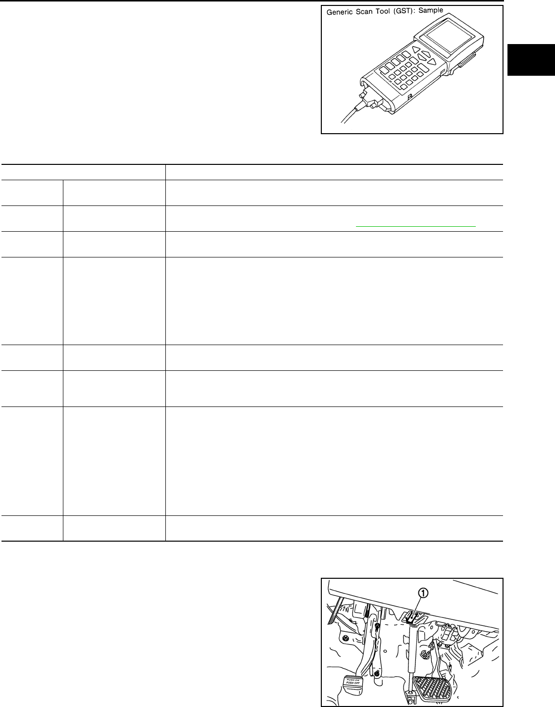
ON BOARD DIAGNOSTIC (OBD) SYSTEM
EC-585
< FUNCTION DIAGNOSIS > [FOR USA (FEDERAL) AND CANADA]
C
D
E
F
G
H
I
J
K
L
M
A
EC
N
P
O
Generic Scan Tool (OBD II scan tool) complying with SAE J1978 has
several functions explained below.
ISO 15765-4 is used as the protocol.
The name “GST” or “Generic Scan Tool” is used in this service man-
ual.
FUNCTION
INSPECTION PROCEDURE
1. Turn ignition switch OFF.
2. Connect “GST” to data link connector (1), which is located under
LH dash panel.
3. Turn ignition switch ON.
SEF139P
Diagnostic Service Function
Service $01 READINESS TESTS This diagnostic service gains access to current emission-related data values, including an-
alog inputs and outputs, digital inputs and outputs, and system status information.
Service $02 (FREEZE DATA) This diagnostic service gains access to emission-related data value that were stored by
ECM during the freeze frame. For details, refer to EC-563, "Diagnosis Description".
Service $03 DTCs This diagnostic service gains access to emission-related power train trouble codes which
were stored by ECM.
Service $04 CLEAR DIAG INFO
This diagnostic service can clear all emission-related diagnostic information. This in-
cludes:
• Clear number of diagnostic trouble codes (Service $01)
• Clear diagnostic trouble codes (Service $03)
• Clear trouble code for freeze frame data (Service $01)
• Clear freeze frame data (Service $02)
• Reset status of system monitoring test (Service $01)
• Clear on board monitoring test results (Service $06 and $07)
Service $06 (ON BOARD TESTS) This diagnostic service accesses the results of on board diagnostic monitoring tests of
specific components/systems that are not continuously monitored.
Service $07 (ON BOARD TESTS) This diagnostic service enables the off board test drive to obtain test results for emission-
related powertrain components/systems that are continuously monitored during normal
driving conditions.
Service $08 —
This diagnostic service can close EVAP system in ignition switch ON position (Engine
stopped). When this diagnostic service is performed, EVAP canister vent control valve can
be closed.
In the following conditions, this diagnostic service cannot function.
• Low ambient temperature
• Low battery voltage
• Engine running
• Ignition switch OFF
• Low fuel temperature
• Too much pressure is applied to EVAP system
Service $09 (CALIBRATION ID) This diagnostic service enables the off-board test device to request specific vehicle infor-
mation such as Vehicle Identification Number (VIN) and Calibration IDs.
JMBIA1073ZZ
Revision: 2008 August 2009 Rogue
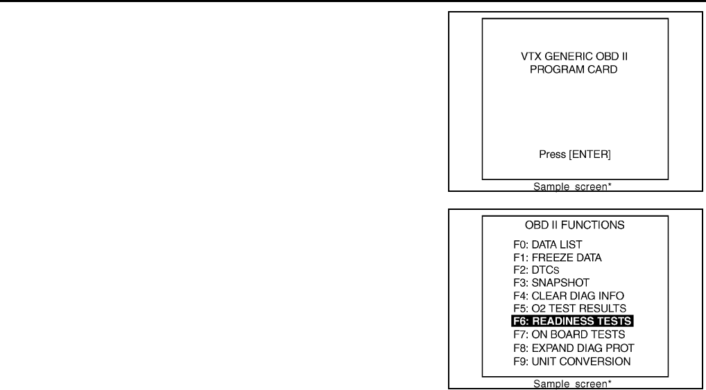
EC-586
< FUNCTION DIAGNOSIS > [FOR USA (FEDERAL) AND CANADA]
ON BOARD DIAGNOSTIC (OBD) SYSTEM
4. Enter the program according to instruction on the screen or in
the operation manual.
(*: Regarding GST screens in this section, sample screens are
shown.)
5. Perform each diagnostic mode according to each service proce-
dure.
For further information, see the GST Operation Manual of
the tool maker.
SEF398S
SEF416S
Revision: 2008 August 2009 Rogue

TROUBLE DIAGNOSIS - SPECIFICATION VALUE
EC-587
< COMPONENT DIAGNOSIS > [FOR USA (FEDERAL) AND CANADA]
C
D
E
F
G
H
I
J
K
L
M
A
EC
N
P
O
COMPONENT DIAGNOSIS
TROUBLE DIAGNOSIS - SPECIFICATION VALUE
Description INFOID:0000000004529463
The specification (SP) value indicates the tolerance of the value that is displayed in “SPEC” of “DATA MONI-
TOR” mode of CONSULT-III during normal operation of the Engine Control System. When the value in “SPEC”
of “DATA MONITOR” mode is within the SP value, the Engine Control System is confirmed OK. When the
value in “SPEC” of “DATA MONITOR” mode is NOT within the SP value, the Engine Control System may have
one or more malfunctions.
The SP value is used to detect malfunctions that may affect the Engine Control System, but will not illuminate
the MIL.
The SP value will be displayed for the following three items:
• B/FUEL SCHDL (The fuel injection pulse width programmed into ECM prior to any learned on board correc-
tion)
• A/F ALPHA-B1 (The mean value of air-fuel ratio feedback correction factor per cycle)
• MAS A/F SE-B1 (The signal voltage of the mass air flow sensor)
Component Function Check INFOID:0000000004529464
1.START
Check that all of the following conditions are satisfied.
• Vehicle driven distance: More than 5,000 km (3,107 miles)
• Barometric pressure: 98.3 - 104.3 kPa (1.003 - 1.064 kg/cm2, 14.25 - 15.12 psi)
• Atmospheric temperature: 20 - 30°C (68 - 86°F)
• Engine coolant temperature: 75 - 95°C (167 - 203°F)
• Engine speed: Idle
• Transmission: Warmed-up
- After the engine is warmed up to normal operating temperature, drive vehicle until “FLUID TEMP SE” (CVT
fluid temperature sensor signal) indicates more than 60°C (140°F).
• Electrical load: Not applied
- Rear window defogger switch and air conditioner switch lighting switch are OFF. Steering wheel is straight
ahead.
>> GO TO 2.
2.PERFORM “SPEC” OF “DATA MONITOR” MODE
With CONSULT-III
NOTE:
Perform “SPEC” in “DATA MONITOR” mode in maximum scale display.
1. Perform EC-499, "BASIC INSPECTION : Special Repair Requirement".
2. Select “B/FUEL SCHDL”, “A/F ALPHA-B1” and “MAS A/F SE-B1” in “SPEC” of “DATA MONITOR” mode
with CONSULT-III.
3. Check that monitor items are within the SP value.
Is the inspection result normal?
YES >> END
NO >> Go to EC-588, "Diagnosis Procedure".
Revision: 2008 August 2009 Rogue
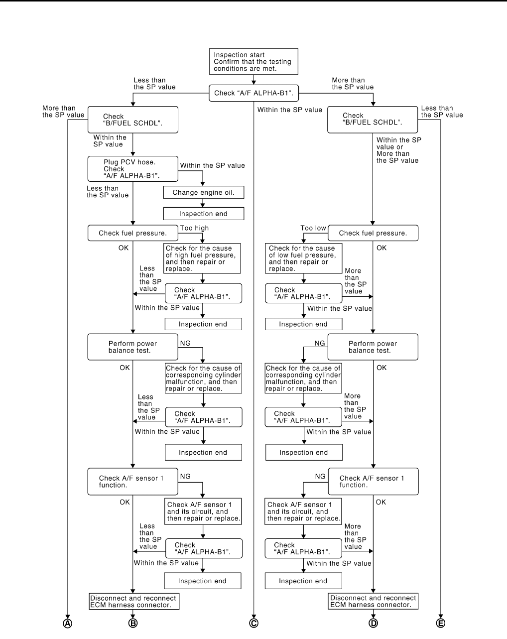
EC-588
< COMPONENT DIAGNOSIS > [FOR USA (FEDERAL) AND CANADA]
TROUBLE DIAGNOSIS - SPECIFICATION VALUE
Diagnosis Procedure INFOID:0000000004529465
OVERALL SEQUENCE
PBIB2318E
Revision: 2008 August 2009 Rogue
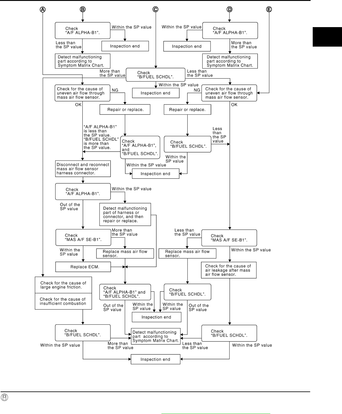
TROUBLE DIAGNOSIS - SPECIFICATION VALUE
EC-589
< COMPONENT DIAGNOSIS > [FOR USA (FEDERAL) AND CANADA]
C
D
E
F
G
H
I
J
K
L
M
A
EC
N
P
O
DETAILED PROCEDURE
1.CHECK “A/F ALPHA-B1”
With CONSULT-III
1. Start engine.
2. Confirm that the testing conditions are met. Refer to EC-587, "Component Function Check".
3. Select “A/F ALPHA-B1” in “SPEC” of “DATA MONITOR” mode, and check that each indication is within
the SP value.
PBIB3213E
Revision: 2008 August 2009 Rogue

EC-590
< COMPONENT DIAGNOSIS > [FOR USA (FEDERAL) AND CANADA]
TROUBLE DIAGNOSIS - SPECIFICATION VALUE
NOTE:
Check “A/F ALPHA-B1” for approximately 1 minute because they may fluctuate. It is NG if the indication is
out of the SP value even a little.
Is the measurement value within the SP value?
YES >> GO TO 17.
NO-1 >> Less than the SP value: GO TO 2.
NO-2 >> More than the SP value: GO TO 3.
2.CHECK “B/FUEL SCHDL”
Select “B/FUEL SCHDL” in “SPEC” of “DATA MONITOR” mode, and check that the indication is within the SP
value.
Is the measurement value within the SP value?
YES >> GO TO 4.
NO >> More than the SP value: GO TO 19.
3.CHECK “B/FUEL SCHDL”
Select “B/FUEL SCHDL” in “SPEC” of “DATA MONITOR” mode, and check that the indication is within the SP
value.
Is the measurement value within the SP value?
YES >> GO TO 6.
NO-1 >> More than the SP value: GO TO 6.
NO-2 >> Less than the SP value: GO TO 25.
4.CHECK “A/F ALPHA-B1”
1. Stop the engine.
2. Disconnect PCV hose, and then plug it.
3. Start engine.
4. Select “A/F ALPHA-B1” in “SPEC” of “DATA MONITOR” mode, and check that the indication is within the
SP value.
Is the measurement value within the SP value?
YES >> GO TO 5.
NO >> GO TO 6.
5.CHANGE ENGINE OIL
1. Stop the engine.
2. Change engine oil.
NOTE:
This symptom may occur when a large amount of gasoline is mixed with engine oil because of driving
conditions (such as when engine oil temperature does not rise enough since a journey distance is too
short during winter). The symptom will not be detected after changing engine oil or changing driving con-
ditions.
>> INSPECTION END
6.CHECK FUEL PRESSURE
Check fuel pressure. (Refer to EC-923, "Inspection".)
Is the inspection result normal?
YES >> GO TO 9.
NO-1 >> Fuel pressure is too high: Replace “fuel filter and fuel pump assembly” and then GO TO 8.
NO-2 >> Fuel pressure is too low: GO TO 7.
7.DETECT MALFUNCTIONING PART
Check fuel hoses and fuel tubes for clogging
Is the inspection result normal?
YES >> Replace “fuel filter and fuel pump assembly” and then GO TO 8.
NO >> Repair or replace and then GO TO 8.
8.CHECK “A/F ALPHA-B1”
Revision: 2008 August 2009 Rogue

TROUBLE DIAGNOSIS - SPECIFICATION VALUE
EC-591
< COMPONENT DIAGNOSIS > [FOR USA (FEDERAL) AND CANADA]
C
D
E
F
G
H
I
J
K
L
M
A
EC
N
P
O
1. Start engine.
2. Select “A/F ALPHA-B1” in “SPEC” of “DATA MONITOR” mode, and check that the indication is within the
SP value.
Is the measurement value within the SP value?
YES >> INSPECTION END
NO >> GO TO 9.
9.PERFORM POWER BALANCE TEST
1. Perform “POWER BALANCE” in “ACTIVE TEST” mode.
2. Check that the each cylinder produces a momentary engine speed drop.
Is the inspection result normal?
YES >> GO TO 12.
NO >> GO TO 10.
10.DETECT MALFUNCTIONING PART
Check the following below.
1. Ignition coil and its circuit (Refer to EC-861, "Component Function Check".)
2. Fuel injector and its circuit (Refer to EC-855, "Component Function Check".)
3. Intake air leakage
4. Low compression pressure (Refer to EM-23, "Inspection".)
Is the inspection result normal?
YES >> Replace fuel injector and then GO TO 11.
NO >> Repair or replace malfunctioning part and then GO TO 11.
11.CHECK “A/F ALPHA-B1”
1. Start engine.
2. Select “A/F ALPHA-B1” in “SPEC” of “DATA MONITOR” mode, and check that each indication is within
the SP value.
Is the measurement value within the SP value?
YES >> INSPECTION END
NO >> GO TO 12.
12.CHECK A/F SENSOR 1 FUNCTION
Perform all DTC CONFIRMATION PROCEDURE related with A/F sensor 1.
• For DTC P0130, refer to EC-645, "DTC Logic".
• For DTC P0131, refer to EC-649, "DTC Logic".
• For DTC P0132, refer to EC-652, "DTC Logic".
• For DTC P0133, refer to EC-655, "DTC Logic".
• For DTC P2A00, refer to EC-840, "DTC Logic".
Are any DTC detected?
YES >> GO TO 15.
NO >> GO TO 13.
13.CHECK A/F SENSOR 1 CIRCUIT
Perform DIAGNOSTIC PROCEDURE according to corresponding DTC.
>> GO TO 14.
14.CHECK “A/F ALPHA-B1”
1. Start engine.
2. Select “A/F ALPHA-B1” in “SPEC” of “DATA MONITOR” mode, and check that each indication is within
the SP value.
Is the measurement value within the SP value?
YES >> INSPECTION END
NO >> GO TO 15.
15.DISCONNECT AND RECONNECT ECM HARNESS CONNECTOR
1. Stop the engine.
Revision: 2008 August 2009 Rogue

EC-592
< COMPONENT DIAGNOSIS > [FOR USA (FEDERAL) AND CANADA]
TROUBLE DIAGNOSIS - SPECIFICATION VALUE
2. Disconnect ECM harness connector. Check pin terminal and connector for damage, and then reconnect it.
>> GO TO 16.
16.CHECK “A/F ALPHA-B1”
1. Start engine.
2. Select “A/F ALPHA-B1” in “SPEC” of “DATA MONITOR” mode, and check that each indication is within
the SP value.
Is the measurement value within the SP value?
YES >> INSPECTION END
NO >> Detect malfunctioning part according to EC-912, "Symptom Table".
17.CHECK “B/FUEL SCHDL”
Select “B/FUEL SCHDL” in “SPEC” of “DATA MONITOR” mode, and check that each indication is within the
SP value.
Is the measurement value within the SP value?
YES >> INSPECTION END
NO-1 >> More than the SP value: GO TO 18.
NO-2 >> Less than the SP value: GO TO 25.
18.DETECT MALFUNCTIONING PART
1. Check for the cause of large engine friction. Refer to the following.
- Engine oil level is too high
- Engine oil viscosity
- Belt tension of power steering, alternator, A/C compressor, etc. is excessive
- Noise from engine
- Noise from transmission, etc.
2. Check for the cause of insufficient combustion. Refer to the following.
- Valve clearance malfunction
- Intake valve timing control function malfunction
- Camshaft sprocket installation malfunction, etc.
>> Repair or replace malfunctioning part, and then GO TO 30.
19.CHECK INTAKE SYSTEM
Check for the cause of uneven air flow through mass air flow sensor. Refer to the following.
• Crushed air ducts
• Malfunctioning seal of air cleaner element
• Uneven dirt of air cleaner element
• Improper specification of intake air system
Is the inspection result normal?
YES >> GO TO 21.
NO >> Repair or replace malfunctioning part, and then GO TO 20.
20.CHECK “A/F ALPHA-B1”, AND “B/FUEL SCHDL”
Select “A/F ALPHA-B1” and “B/FUEL SCHDL” in “SPEC” of “DATA MONITOR” mode, and check that the each
indication is within the SP value.
Is the measurement value within the SP value?
YES >> INSPECTION END
NO >> “B/FUEL SCHDL” is more, “A/F ALPHA-B1” is less than the SP value: GO TO 21.
21.DISCONNECT AND RECONNECT MASS AIR FLOW SENSOR HARNESS CONNECTOR
1. Stop the engine.
2. Disconnect mass air flow sensor harness connector. Check pin terminal and connector for damage and
then reconnect it again.
>> GO TO 22.
Revision: 2008 August 2009 Rogue

TROUBLE DIAGNOSIS - SPECIFICATION VALUE
EC-593
< COMPONENT DIAGNOSIS > [FOR USA (FEDERAL) AND CANADA]
C
D
E
F
G
H
I
J
K
L
M
A
EC
N
P
O
22.CHECK “A/F ALPHA-B1”
1. Start engine.
2. Select “A/F ALPHA-B1” in “SPEC” of “DATA MONITOR” mode, and check that each indication is within
the SP value.
Is the measurement value within the SP value?
YES >> Detect malfunctioning part of mass air flow sensor circuit and repair it. Refer to EC-615, "DTC
Logic". Then GO TO 29.
NO >> GO TO 23.
23.CHECK “MAS A/F SE-B1”
Select “MAS A/F SE-B1” in “SPEC” of “DATA MONITOR” mode, and check that the indication is within the SP
value.
Is the measurement value within the SP value?
YES >> GO TO 24.
NO >> More than the SP value: Replace mass air flow sensor, and then GO TO 29.
24.REPLACE ECM
1. Replace ECM.
NOTE:
Use the specified bolts described in parts information certainly when installing the ECM, or violates the
Canada law.
2. Go to EC-502, "ADDITIONAL SERVICE WHEN REPLACING CONTROL UNIT : Special Repair Require-
ment".
>> GO TO 29.
25.CHECK INTAKE SYSTEM
Check for the cause of uneven air flow through mass air flow sensor. Refer to the following.
• Crushed air ducts
• Malfunctioning seal in air cleaner element
• Uneven dirt in air cleaner element
• Improper specification in intake air system
Is the inspection result normal?
YES >> GO TO 27.
NO >> Repair or replace malfunctioning part, and then GO TO 26.
26.CHECK “B/FUEL SCHDL”
Select “B/FUEL SCHDL” in “SPEC” of “DATA MONITOR” mode, and check that the indication is within the SP
value.
Is the measurement value within the SP value?
YES >> INSPECTION END
NO >> Less than the SP value: GO TO 27.
27.CHECK “MAS A/F SE-B1”
Select “MAS A/F SE-B1” in “SPEC” of “DATA MONITOR” mode, and check that the indication is within the SP
value.
Is the measurement value within the SP value?
YES >> GO TO 28.
NO >> Less than the SP value: Replace mass air flow sensor, and then GO TO 30.
28.CHECK INTAKE SYSTEM
Check for the cause of air leak after the mass air flow sensor. Refer to the following.
• Disconnection, looseness, and cracks in air duct
• Looseness of oil filler cap
• Disconnection of oil level gauge
• Open stuck, breakage, hose disconnection, or cracks in PCV valve
Revision: 2008 August 2009 Rogue

EC-594
< COMPONENT DIAGNOSIS > [FOR USA (FEDERAL) AND CANADA]
TROUBLE DIAGNOSIS - SPECIFICATION VALUE
• Disconnection or cracks in EVAP purge hose, stuck open of EVAP canister purge volume control solenoid
valve
• Malfunctioning seal in rocker cover gasket
• Disconnection, looseness, or cracks in hoses, such as a vacuum hose, connecting to intake air system parts
• Malfunctioning seal in intake air system, etc.
>> GO TO 30.
29.CHECK “A/F ALPHA-B1” AND “B/FUEL SCHDL”
Select “A/F ALPHA-B1” and “B/FUEL SCHDL” in “SPEC” of “DATA MONITOR” mode, and check that each
indication is within the SP value.
Is the measurement value within the SP value?
YES >> INSPECTION END
NO >> Detect malfunctioning part according to EC-912, "Symptom Table".
30.CHECK “B/FUEL SCHDL”
Select “B/FUEL SCHDL” in “SPEC” of “DATA MONITOR” mode, and then check that the indication is within
the SP value.
Is the measurement value within the SP value?
YES >> INSPECTION END
NO >> Detect malfunctioning part according to EC-912, "Symptom Table".
Revision: 2008 August 2009 Rogue

POWER SUPPLY AND GROUND CIRCUIT
EC-595
< COMPONENT DIAGNOSIS > [FOR USA (FEDERAL) AND CANADA]
C
D
E
F
G
H
I
J
K
L
M
A
EC
N
P
O
POWER SUPPLY AND GROUND CIRCUIT
Diagnosis Procedure INFOID:0000000004529466
1.INSPECTION START
Start engine.
Is engine running?
YES >> GO TO 8.
NO >> GO TO 2.
2.CHECK ECM POWER SUPPLY CIRCUIT-I
1. Turn ignition switch OFF and then ON.
2. Check the voltage between ECM harness connector and ground.
Is the inspection result normal?
YES >> GO TO 4.
NO >> GO TO 3.
3.DETECT MALFUNCTIONING PART
Check the following.
• IPDM E/R harness connector E14
• 15A fuse (No. 64)
• Harness for open or short between ECM and fuse
>> Repair open circuit or short to ground or short to power in harness or connectors.
4.CHECK GROUND CONNECTION-I
1. Turn ignition switch OFF.
2. Check ground connection E21. Refer to Ground Inspection in GI-44, "Circuit Inspection".
Is the inspection result normal?
YES >> GO TO 5.
NO >> Repair or replace ground connection.
5.CHECK ECM GROUND CIRCUIT FOR OPEN AND SHORT-I
1. Disconnect ECM harness connectors.
2. Check the continuity between ECM harness connector and ground.
3. Also check harness for short to power.
Is the inspection result normal?
YES >> GO TO 7.
NO >> GO TO 6.
ECM Ground Voltage
Connector Terminal
E16 93 Ground Battery voltage
ECM Ground Continuity
Connector Terminal
F7 12
Ground Existed
16
E16
107
108
111
112
Revision: 2008 August 2009 Rogue

EC-596
< COMPONENT DIAGNOSIS > [FOR USA (FEDERAL) AND CANADA]
POWER SUPPLY AND GROUND CIRCUIT
6.DETECT MALFUNCTIONING PART
Check the following.
• Harness connectors F121, E7
• Harness for open or short between ECM and ground
>> Repair open circuit or short to power in harness or connectors.
7.CHECK ECM POWER SUPPLY CIRCUIT-II
1. Reconnect ECM harness connectors.
2. Turn ignition switch ON.
3. Check the voltage between IPDM E/R harness connector and ground.
Is the inspection result normal?
YES >> Go to EC-861, "Diagnosis Procedure".
NO >> GO TO 8.
8.CHECK ECM POWER SUPPLY CIRCUIT-III
1. Turn ignition switch OFF and wait at least 10 seconds.
2. Check the voltage between ECM harness connector and ground.
Is the inspection result normal?
YES >> GO TO 14.
NO-1 >> Battery voltage does not exist: GO TO 9.
NO-2 >> Battery voltage exists for more than a few seconds: GO TO 11.
9.CHECK ECM POWER SUPPLY CIRCUIT-IV
1. Turn ignition switch OFF and wait at least 10 seconds.
2. Check the voltage between ECM harness connector and ground.
Is the inspection result normal?
YES >> GO TO 10.
NO >> GO TO 11.
10.CHECK ECM POWER SUPPLY CIRCUIT-V
1. Disconnect ECM harness connector.
2. Disconnect IPDM E/R harness connector E15.
3. Check the continuity between ECM harness connector and IPDM E/R harness connector.
4. Also check harness for short to ground and short to power.
IPDM E/R Ground Voltage
Connector Terminal
E15 47 Ground Battery voltage
ECM Ground Voltage
Connector Terminal
E16 105 Ground After turning ignition switch OFF, battery voltage will ex-
ist for a few seconds, then drop to approximately 0V.
ECM Ground Voltage
Connector Terminal
F7 24 Ground Battery voltage
ECM IPDM E/R Continuity
Connector Terminal Connector Terminal
E16 105 E15 48 Existed
Revision: 2008 August 2009 Rogue

POWER SUPPLY AND GROUND CIRCUIT
EC-597
< COMPONENT DIAGNOSIS > [FOR USA (FEDERAL) AND CANADA]
C
D
E
F
G
H
I
J
K
L
M
A
EC
N
P
O
Is the inspection result normal?
YES >> GO TO 17.
NO >> Repair open circuit or short to ground or short to power in harness or connectors.
11.CHECK ECM POWER SUPPLY CIRCUIT-VI
1. Disconnect ECM harness connector.
2. Disconnect IPDM E/R harness connector E15.
3. Check the continuity between ECM harness connector and IPDM E/R harness connector.
4. Also check harness for short to ground and short to power.
Is the inspection result normal?
YES >> GO TO 13.
NO >> GO TO 12.
12.DETECT MALFUNCTIONING PART
Check the following.
• Harness or connectors F121, E7
• Harness for open or short between ECM and IPDM E/R
>> Repair open circuit or short to ground or short power in harness or connectors.
13.CHECK 20A FUSE
1. Disconnect 20A fuse (No. 62) from IPDM E/R.
2. Check 20A fuse.
Is the inspection result normal?
YES >> GO TO 17.
NO >> Replace 20A fuse.
14.CHECK GROUND CONNECTION-II
1. Turn ignition switch OFF.
2. Check ground connection E21. Refer to Ground Inspection in GI-44, "Circuit Inspection".
Is the inspection result normal?
YES >> GO TO 15.
NO >> Repair or replace ground connection.
15.CHECK ECM GROUND CIRCUIT FOR OPEN AND SHORT-II
1. Disconnect ECM harness connector.
2. Check the continuity between ECM harness connector and ground.
3. Also check harness for short to power.
Is the inspection result normal?
YES >> GO TO 17.
ECM IPDM E/R Continuity
Connector Terminal Connector Terminal
F7 24 E15 51 Existed
ECM Ground Continuity
Connector Terminal
F7 12
Ground Existed
16
E16
107
108
111
112
Revision: 2008 August 2009 Rogue

EC-598
< COMPONENT DIAGNOSIS > [FOR USA (FEDERAL) AND CANADA]
POWER SUPPLY AND GROUND CIRCUIT
NO >> GO TO 16.
16.DETECT MALFUNCTIONING PART
Check the following.
• Harness or connectors F121, E7
• Harness for open or short between ECM and ground
>> Repair open circuit or short to power in harness or connectors.
17.CHECK INTERMITTENT INCIDENT
Refer to GI-41, "Intermittent Incident".
Is the inspection result normal?
YES >> Replace IPDM E/R.
NO >> Repair open circuit or short to power in harness or connectors.
Revision: 2008 August 2009 Rogue

U0101 CAN COMM CIRCUIT
EC-599
< COMPONENT DIAGNOSIS > [FOR USA (FEDERAL) AND CANADA]
C
D
E
F
G
H
I
J
K
L
M
A
EC
N
P
O
U0101 CAN COMM CIRCUIT
Description INFOID:0000000004533678
CAN (Controller Area Network) is a serial communication line for real time application. It is an on-vehicle mul-
tiplex communication line with high data communication speed and excellent error detection ability. Many elec-
tronic control units are equipped onto a vehicle, and each control unit shares information and links with other
control units during operation (not independent). In CAN communication, control units are connected with 2
communication lines (CAN H line, CAN L line) allowing a high rate of information transmission with less wiring.
Each control unit transmits/receives data but selectively reads required data only.
DTC Logic INFOID:0000000004533679
DTC DETECTION LOGIC
DTC CONFIRMATION PROCEDURE
1.PERFORM DTC CONFIRMATION PROCEDURE
1. Turn ignition switch ON and wait at least 3 seconds.
2. Check DTC.
Is DTC detected?
YES >> EC-599, "Diagnosis Procedure".
NO >> INSPECTION END
Diagnosis Procedure INFOID:0000000004533680
Go to LAN-15, "Trouble Diagnosis Flow Chart"
DTC No. Trouble diagnosis
name DTC detecting condition Possible cause
U0101 Lost communication
with TCM
When ECM is not transmitting or receiving CAN com-
munication signal of OBD (emission-related diagno-
sis) with TCM for 2 seconds or more.
• CAN communication line between
TCM and ECM
(CAN communication line is open or
shorted)
Revision: 2008 August 2009 Rogue

EC-600
< COMPONENT DIAGNOSIS > [FOR USA (FEDERAL) AND CANADA]
U0140 CAN COMM CIRCUIT
U0140 CAN COMM CIRCUIT
Description INFOID:0000000004533681
CAN (Controller Area Network) is a serial communication line for real time application. It is an on-vehicle mul-
tiplex communication line with high data communication speed and excellent error detection ability. Many elec-
tronic control units are equipped onto a vehicle, and each control unit shares information and links with other
control units during operation (not independent). In CAN communication, control units are connected with 2
communication lines (CAN H line, CAN L line) allowing a high rate of information transmission with less wiring.
Each control unit transmits/receives data but selectively reads required data only.
DTC Logic INFOID:0000000004533682
DTC DETECTION LOGIC
DTC CONFIRMATION PROCEDURE
1.PERFORM DTC CONFIRMATION PROCEDURE
1. Turn ignition switch ON and wait at least 3 seconds.
2. Check DTC.
Is DTC detected?
YES >> EC-600, "Diagnosis Procedure".
NO >> INSPECTION END
Diagnosis Procedure INFOID:0000000004533683
Go to LAN-15, "Trouble Diagnosis Flow Chart"
DTC No. Trouble diagnosis
name DTC detecting condition Possible cause
U0140 Lost communication
with BCM
When ECM is not transmitting or receiving CAN com-
munication signal of OBD (emission-related diagno-
sis) with BCM for 2 seconds or more.
• CAN communication line between
BCM and ECM
(CAN communication line is open or
shorted)
Revision: 2008 August 2009 Rogue

U1001 CAN COMM CIRCUIT
EC-601
< COMPONENT DIAGNOSIS > [FOR USA (FEDERAL) AND CANADA]
C
D
E
F
G
H
I
J
K
L
M
A
EC
N
P
O
U1001 CAN COMM CIRCUIT
Description INFOID:0000000004533684
CAN (Controller Area Network) is a serial communication line for real time application. It is an on-vehicle mul-
tiplex communication line with high data communication speed and excellent error detection ability. Many elec-
tronic control units are equipped onto a vehicle, and each control unit shares information and links with other
control units during operation (not independent). In CAN communication, control units are connected with 2
communication lines (CAN H line, CAN L line) allowing a high rate of information transmission with less wiring.
Each control unit transmits/receives data but selectively reads required data only.
DTC Logic INFOID:0000000004529468
DTC DETECTION LOGIC
DTC CONFIRMATION PROCEDURE
1.PERFORM DTC CONFIRMATION PROCEDURE
1. Turn ignition switch ON and wait at least 3 seconds.
2. Check DTC.
Is DTC detected?
YES >> EC-601, "Diagnosis Procedure".
NO >> INSPECTION END
Diagnosis Procedure INFOID:0000000004533685
Go to LAN-15, "Trouble Diagnosis Flow Chart"
DTC No. Trouble diagnosis
name DTC detecting condition Possible cause
U1001 CAN communication
line
When ECM is not transmitting or receiving CAN com-
munication signal other than OBD (emission-related
diagnosis) for 2 seconds or more.
• Harness or connectors
(CAN communication line is open or
shorted)
Revision: 2008 August 2009 Rogue
EC-602
< COMPONENT DIAGNOSIS > [FOR USA (FEDERAL) AND CANADA]
P0011 IVT CONTROL
P0011 IVT CONTROL
DTC Logic INFOID:0000000004529470
DTC DETECTION LOGIC
NOTE:
If DTC P0011 is displayed with DTC P0075, first perform the trouble diagnosis for EC-784, "DTC Logic".
DTC CONFIRMATION PROCEDURE
1.PRECONDITIONING
If DTC CONFIRMATION PROCEDURE has been previously conducted, always turn ignition switch OFF and
wait at least 10 seconds before conducting the next test.
TESTING CONDITION:
Before performing the following procedure, confirm that battery voltage is between 10V and 16V at
idle.
>> GO TO 2.
2.PERFORM DTC CONFIRMATION PROCEDURE-I
With CONSULT-III
1. Turn ignition switch ON and select “DATA MONITOR” mode with CONSULT-III.
2. Start engine and warm it up to the normal operating temperature.
3. Maintain the following conditions for at least 6 consecutive seconds. Hold the accelerator pedal as steady
as possible.
CAUTION:
Always drive at a safe speed.
4. Stop vehicle with engine running and let engine idle for 10 seconds.
5. Check 1st trip DTC.
With GST
Follow the procedure “With CONSULT-III” above.
Is 1st trip DTC detected?
YES >> Go to EC-603, "Diagnosis Procedure"
NO >> GO TO 3.
3.PERFORM DTC CONFIRMATION PROCEDURE-II
With CONSULT-III
1. Maintain the following conditions for at least 20 consecutive seconds.
DTC No. Trouble diagnosis
name Detecting condition Possible cause
P0011 Intake valve timing
control performance
There is a gap between angle of target and
phase-control angle degree.
• Crankshaft position sensor (POS)
• Camshaft position sensor (PHASE)
• Intake valve control solenoid valve
• Accumulation of debris to the signal pick-up
portion of the camshaft
• Timing chain installation
• Foreign matter caught in the oil groove for in-
take valve timing control
VHCL SPEED SE 100 - 120 km/h (63 - 75 mph)
ENG SPEED 1,200 - 2,000 rpm
COOLAN TEMP/S More than 60°C (140°F)
B/FUEL SCHDL More than 3.5 msec
Selectort lever D position
Revision: 2008 August 2009 Rogue
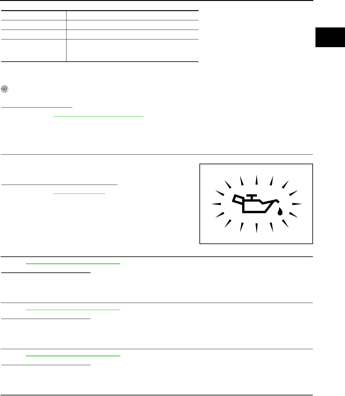
P0011 IVT CONTROL
EC-603
< COMPONENT DIAGNOSIS > [FOR USA (FEDERAL) AND CANADA]
C
D
E
F
G
H
I
J
K
L
M
A
EC
N
P
O
CAUTION:
Always drive at a safe speed.
2. Check 1st trip DTC.
With GST
Follow the procedure “With CONSULT-III” above.
Is 1st trip DTC detected?
YES >> Go to EC-603, "Diagnosis Procedure"
NO >> INSPECTION END
Diagnosis Procedure INFOID:0000000004529471
1.CHECK OIL PRESSURE WARNING LAMP
1. Start engine.
2. Check oil pressure warning lamp and confirm it is not illumi-
nated.
Is oil pressure warning lamp illuminated?
YES >> Go to LU-5, "Inspection".
NO >> GO TO 2.
2.CHECK INTAKE VALVE TIMING CONTROL SOLENOID VALVE
Refer to EC-604, "Component Inspection".
Is the inspection result normal?
YES >> GO TO 3.
NO >> Replace intake valve timing control solenoid valve.
3.CHECK CRANKSHAFT POSITION SENSOR (POS)
Refer to EC-706, "Component Inspection".
Is the inspection result normal?
YES >> GO TO 4.
NO >> Replace crankshaft position sensor (POS).
4.CHECK CAMSHAFT POSITION SENSOR (PHASE)
Refer to EC-709, "Component Inspection".
Is the inspection result normal?
YES >> GO TO 5.
NO >> Replace camshaft position sensor (PHASE).
5.CHECK CAMSHAFT (INTAKE)
Check the following.
ENG SPEED 1,200 - 3,175 rpm (A constant rotation is maintained.)
COOLAN TEMP/S More than 70°C (221°F)
Selector lever 1st or 2nd position
Driving location uphill Driving vehicle uphill
(Increased engine load will help maintain the driving
conditions required for this test.)
PBIA8559J
Revision: 2008 August 2009 Rogue
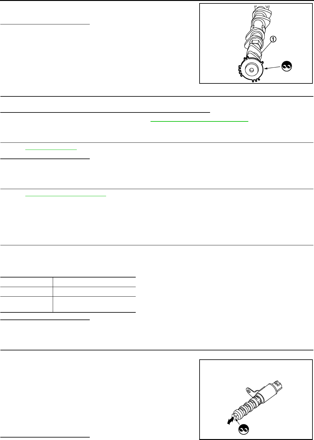
EC-604
< COMPONENT DIAGNOSIS > [FOR USA (FEDERAL) AND CANADA]
P0011 IVT CONTROL
• Accumulation of debris on the signal plate of camshaft (1) rear end
• Chipping signal plate of camshaft rear end
Is the inspection result normal?
YES >> GO TO 6.
NO >> Remove debris and clean the signal plate of camshaft
rear end or replace camshaft.
6.CHECK TIMING CHAIN INSTALLATION
Check service records for any recent repairs that may cause timing chain misalignment.
Are there any service records that may cause timing chain misalignment?
YES >> Check timing chain installation. Refer to EM-70, "Removal and Installation".
NO >> GO TO 7.
7.CHECK LUBRICATION CIRCUIT
Refer to LU-5, "Inspection".
Is the inspection result normal?
YES >> GO TO 8.
NO >> Clean lubrication line.
8.CHECK INTERMITTENT INCIDENT
Refer to GI-41, "Intermittent Incident".
>> INSPECTION END
Component Inspection INFOID:0000000004529472
1.CHECK INTAKE VALVE TIMING CONTROL SOLENOID VALVE-I
1. Turn ignition switch OFF.
2. Disconnect intake valve timing control solenoid valve harness connector.
3. Check resistance between intake valve timing control solenoid valve terminals as follows.
Is the inspection result normal?
YES >> GO TO 2.
NO >> Replace intake valve timing control solenoid valve.
2.CHECK INTAKE VALVE TIMING CONTROL SOLENOID VALVE-II
1. Remove intake valve timing control solenoid valve.
2. Provide 12V DC between intake valve timing control solenoid
valve terminals 1 and 2, and then interrupt it. Check that the
plunger moves as shown in the figure.
CAUTION:
Never apply 12V DC continuously for 5 seconds or more.
Doing so may result in damage to the coil in intake valve
timing control solenoid valve.
NOTE:
Always replace O-ring when intake valve timing control
solenoid valve is removed.
Is the inspection result normal?
JMBIA0096ZZ
Terminals Resistance
1 and 2 7.0 - 7.5 Ω [at 20°C (68°F)]
1 or 2 and ground ∞ Ω
(Continuity should not exist)
JMBIA0097ZZ
Revision: 2008 August 2009 Rogue

P0011 IVT CONTROL
EC-605
< COMPONENT DIAGNOSIS > [FOR USA (FEDERAL) AND CANADA]
C
D
E
F
G
H
I
J
K
L
M
A
EC
N
P
O
YES >> INSPECTION END
NO >> Replace intake valve timing control solenoid valve.
Revision: 2008 August 2009 Rogue

EC-606
< COMPONENT DIAGNOSIS > [FOR USA (FEDERAL) AND CANADA]
P0031, P0032 A/F SENSOR 1 HEATER
P0031, P0032 A/F SENSOR 1 HEATER
Description INFOID:0000000004529473
SYSTEM DESCRIPTION
The ECM performs ON/OFF duty control of the A/F sensor 1 heater corresponding to the engine operating
condition to keep the temperature of A/F sensor 1 element within the specified range.
DTC Logic INFOID:0000000004529474
DTC DETECTION LOGIC
DTC CONFIRMATION PROCEDURE
1.PRECONDITIONING
If DTC CONFIRMATION PROCEDURE has been previously conducted, always turn ignition switch OFF and
wait at least 10 seconds before conducting the next test.
TESTING CONDITION:
Before performing the following procedure, confirm that battery voltage is more than between 11V at
idle.
>> GO TO 2.
2.PERFORM DTC CONFIRMATION PROCEDURE
1. Start engine and let it idle for at least 10 seconds.
2. Check 1st trip DTC.
Is 1st trip DTC detected?
YES >> Go to EC-606, "Diagnosis Procedure".
NO >> INSPECTION END
Diagnosis Procedure INFOID:0000000004529475
1.CHECK GROUND CONNECTION
1. Turn ignition switch OFF.
2. Check ground connection E21. Refer to Ground Inspection in GI-44, "Circuit Inspection".
Is the inspection result normal?
YES >> GO TO 2.
NO >> Repair or replace ground connection.
2.CHECK AIR FUEL RATIO (A/F) SENSOR 1 POWER SUPPLY CIRCUIT
1. Disconnect air fuel ratio (A/F) sensor 1 harness connector.
2. Turn ignition switch ON.
Sensor Input signal to ECM ECM function Actuator
Camshaft position sensor (PHASE)
Crankshaft position sensor (POS) Engine speed Air fuel ratio (A/F) sensor 1
heater control Air fuel ratio (A/F) sensor 1
heater
Mass air flow sensor Amount of intake air
DTC No. Trouble diagnosis name DTC detecting condition Possible cause
P0031 Air fuel ratio (A/F) sensor
1 heater control circuit low
The current amperage in the A/F sensor 1 heater
circuit is out of the normal range.
(An excessively low voltage signal is sent to ECM
through the A/F sensor 1 heater.)
• Harness or connectors
(The A/F sensor 1 heater circuit is
open or shorted.)
• A/F sensor 1 heater
P0032
Air fuel ratio (A/F) sensor
1 heater control circuit
high
The current amperage in the A/F sensor 1 heater
circuit is out of the normal range.
(An excessively high voltage signal is sent to ECM
through the A/F sensor 1 heater.)
• Harness or connectors
(The A/F sensor 1 heater circuit is
shorted.)
• A/F sensor 1 heater
Revision: 2008 August 2009 Rogue

P0031, P0032 A/F SENSOR 1 HEATER
EC-607
< COMPONENT DIAGNOSIS > [FOR USA (FEDERAL) AND CANADA]
C
D
E
F
G
H
I
J
K
L
M
A
EC
N
P
O
3. Check the voltage between A/F sensor 1 harness connector and ground.
Is the inspection result normal?
YES >> GO TO 4.
NO >> GO TO 3.
3.DETECT MALFUNCTIONING PART
Check the following.
• Harness connectors F123, E6
• IPDM E/R harness connector E14
• 15A fuse (No. 63)
• Harness for open or short between A/F sensor 1 and fuse
>> Repair or replace harness or connectors.
4.CHECK A/F SENSOR 1 HEATER OUTPUT SIGNAL CIRCUIT
1. Turn ignition switch OFF.
2. Disconnect ECM harness connector.
3. Check the continuity between A/F sensor 1 harness connector and ECM harness connector.
4. Also check harness for short to ground and short to power.
Is the inspection result normal?
YES >> GO TO 5.
NO >> Repair open circuit or short to ground or short to power in harness or connectors.
5.CHECK A/F SENSOR 1 HEATER
Refer to EC-608, "Component Inspection".
Is the inspection result normal?
YES >> GO TO 7.
NO >> GO TO 6.
6.REPLACE AIR FUEL RATIO (A/F) SENSOR 1
Replace air fuel ratio (A/F) sensor 1.
CAUTION:
• Discard any A/F sensor which has been dropped from a height of more than 0.5 m (19.7 in) onto a
hard surface such as a concrete floor; use a new one.
• Before installing new A/F sensor, clean exhaust system threads using oxygen sensor thread cleaner
[commercial service tool (J-43897-18 or J-43897-12)] and approved anti-seize lubricant (commercial
service tool).
>> INSPECTION END
7.CHECK INTERMITTENT INCIDENT
Perform GI-41, "Intermittent Incident".
>> INSPECTION END
A/F sensor 1 Ground Voltage
Connector Terminal
F27 4 Ground Battery voltage
A/F sensor 1 ECM Continuity
Connector Terminal Connector Terminal
F27 3 F7 4 Existed
Revision: 2008 August 2009 Rogue

EC-608
< COMPONENT DIAGNOSIS > [FOR USA (FEDERAL) AND CANADA]
P0031, P0032 A/F SENSOR 1 HEATER
Component Inspection INFOID:0000000004529476
1.CHECK AIR FUEL RATIO (A/F) SENSOR 1
1. Turn ignition switch OFF.
2. Disconnect A/F sensor 1 harness connector.
3. Check resistance between A/F sensor 1 terminals as follows.
Is the inspection result normal?
YES >> INSPECTION END
NO >> GO TO 2.
2.REPLACE AIR FUEL RATIO (A/F) SENSOR 1
Replace air fuel ratio (A/F) sensor 1.
CAUTION:
• Discard any A/F sensor which has been dropped from a height of more than 0.5 m (19.7 in) onto a
hard surface such as a concrete floor; use a new one.
• Before installing new A/F sensor, clean exhaust system threads using Heated oxygen sensor thread
cleaner [commercial service tool (J-43897-18 or J-43897-12)] and approved anti-seize lubricant (com-
mercial service tool).
>> INSPECTION END
Terminals Resistance
3 and 4 1.80 - 2.44 Ω [at 25°C (77°F)]
3 and 1, 2 ∞ Ω
(Continuity should not exist)
4 and 1, 2
Revision: 2008 August 2009 Rogue

P0037, P0038 HO2S2 HEATER
EC-609
< COMPONENT DIAGNOSIS > [FOR USA (FEDERAL) AND CANADA]
C
D
E
F
G
H
I
J
K
L
M
A
EC
N
P
O
P0037, P0038 HO2S2 HEATER
Description INFOID:0000000004529477
SYSTEM DESCRIPTION
The ECM performs ON/OFF control of the heated oxygen sensor 2 heater corresponding to the engine speed,
amount of intake air and engine coolant temperature.
OPERATION
DTC Logic INFOID:0000000004529478
DTC DETECTION LOGIC
DTC CONFIRMATION PROCEDURE
1.PRECONDITIONING
If DTC CONFIRMATION PROCEDURE has been previously conducted, always turn ignition switch OFF and
wait at least 10 seconds before conducting the next test.
TESTING CONDITION:
Before performing the following procedure, confirm that battery voltage is more than 11V at idle.
>> GO TO 2.
2.PERFORM DTC CONFIRMATION PROCEDURE
1. Start engine and warm it up to the normal operating temperature.
2. Turn ignition switch OFF and wait at least 10 seconds.
3. Start engine and keep engine speed between 3,500 and 4,000 rpm for at least 1 minute under no load.
4. Let engine idle for 1 minute.
5. Check 1st trip DTC.
Is 1st tip DTC detected?
YES >> Go to EC-610, "Diagnosis Procedure".
NO >> INSPECTION END
Sensor Input signal to ECM ECM function Actuator
Camshaft position sensor (PHASE)
Crankshaft position sensor (POS) Engine speed Heated oxygen sensor 2
heater control Heated oxygen sensor 2 heater
Engine coolant temperature sensor Engine coolant temperature
Mass air flow sensor Amount of intake air
Engine speed Heated oxygen sensor 2 heater
Above 3,600 rpm OFF
Below 3,600 rpm after the following conditions are met.
• Engine: After warming up
• Keeping the engine speed between 3,500 and 4,000 rpm for 1
minute and at idle for 1 minute under no load
ON
DTC No. Trouble diagnosis
name DTC detecting condition Possible cause
P0037
Heated oxygen
sensor 2 heater
control circuit low
The current amperage in the heated oxygen sensor
2 heater circuit is out of the normal range.
(An excessively low voltage signal is sent to ECM
through the heated oxygen sensor 2 heater.)
• Harness or connectors
(The heated oxygen sensor 2 heater circuit
is open or shorted.)
• Heated oxygen sensor 2 heater
P0038
Heated oxygen
sensor 2 heater
control circuit high
The current amperage in the heated oxygen sensor
2 heater circuit is out of the normal range.
(An excessively high voltage signal is sent to ECM
through the heated oxygen sensor 2 heater.)
• Harness or connectors
(The heated oxygen sensor 2 heater circuit
is shorted.)
• Heated oxygen sensor 2 heater
Revision: 2008 August 2009 Rogue

EC-610
< COMPONENT DIAGNOSIS > [FOR USA (FEDERAL) AND CANADA]
P0037, P0038 HO2S2 HEATER
Diagnosis Procedure INFOID:0000000004529479
1.CHECK GROUND CONNECTION
1. Turn ignition switch OFF.
2. Check ground connection E21. Refer to Ground Inspection in GI-44, "Circuit Inspection".
Is the inspection result normal?
YES >> GO TO 2.
NO >> Repair or replace ground connection.
2.CHECK HO2S2 POWER SUPPLY CIRCUIT
1. Disconnect heated oxygen sensor 2 (HO2S2) harness connector.
2. Turn ignition switch ON.
3. Check the voltage between HO2S2 harness connector and ground.
Is the inspection result normal?
YES >> GO TO 4.
NO >> GO TO 3.
3.DETECT MALFUNCTIONING PART
Check the following.
• Harness connectors F123, E6
• IPDM E/R connector E14
• 15A fuse (No. 63)
• Harness for open or short between heated oxygen sensor 2 and fuse
>> Repair open circuit or short to ground or short to power in harness or connectors.
4.CHECK HO2S2 OUTPUT SIGNAL CIRCUIT FOR OPEN AND SHORT
1. Turn ignition switch OFF.
2. Disconnect ECM harness connector.
3. Check the continuity between HO2S2 harness connector and ECM harness connector.
4. Also check harness for short to ground and short to power.
Is the inspection result normal?
YES >> GO TO 5.
NO >> Repair open circuit or short to ground or short to power in harness or connectors.
5.CHECK HEATED OXYGEN SENSOR 2 HEATER
Refer to EC-611, "Component Inspection".
Is the inspection result normal?
YES >> GO TO 7.
NO >> GO TO 6.
6.REPLACE HEATED OXYGEN SENSOR 2
Replace heated oxygen sensor 2.
CAUTION:
• Discard any heated oxygen sensor which has been dropped from a height of more than 0.5 m (19.7
in) onto a hard surface such as a concrete floor; use a new one.
HO2S2 Ground Voltage
Connector Terminal
F31 2 Ground Battery voltage
HO2S2 ECM Continuity
Connector Terminal Connector Terminal
F31 3 F7 13 Existed
Revision: 2008 August 2009 Rogue

P0037, P0038 HO2S2 HEATER
EC-611
< COMPONENT DIAGNOSIS > [FOR USA (FEDERAL) AND CANADA]
C
D
E
F
G
H
I
J
K
L
M
A
EC
N
P
O
• Before installing new heated oxygen sensor, clean exhaust system threads using oxygen sensor
thread cleaner [commercial service tool (J-43897-18 or J-43897-12)] and approved anti-seize lubri-
cant (commercial service tool).
>> INSPECTION END
7.CHECK INTERMITTENT INCIDENT
Refer to GI-41, "Intermittent Incident".
>> INSPECTION END
Component Inspection INFOID:0000000004529480
1.CHECK HEATED OXYGEN SENSOR 2 HEATER
1. Turn ignition switch OFF.
2. Disconnect heated oxygen sensor 2 harness connector.
3. Check resistance between HO2S2 terminals as follows.
Is the inspection result normal?
YES >> INSPECTION END
NO >> GO TO 2.
2.REPLACE HEATED OXYGEN SENSOR 2
Replace heated oxygen sensor 2.
CAUTION:
• Discard any heated oxygen sensor which has been dropped from a height of more than 0.5 m (19.7
in) onto a hard surface such as a concrete floor; use a new one.
• Before installing new heated oxygen sensor, clean exhaust system threads using oxygen sensor
thread cleaner [commercial service tool (J-43897-18 or J-43897-12)] and approved anti-seize lubri-
cant (commercial service tool).
>> INSPECTION END
Terminals Resistance
2 and 3 3.3 - 4.4 Ω [at 25°C (77°F)]
1 and 2, 3, 4 ∞ Ω
(Continuity should not exist)
4 and 1, 2, 3
Revision: 2008 August 2009 Rogue
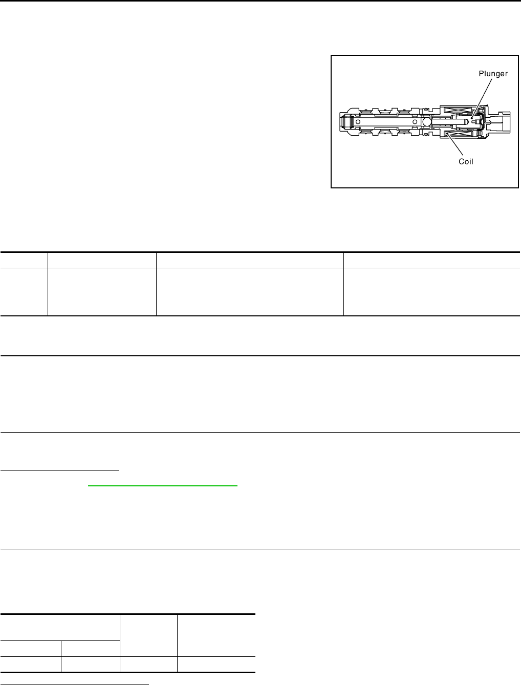
EC-612
< COMPONENT DIAGNOSIS > [FOR USA (FEDERAL) AND CANADA]
P0075 IVT CONTROL SOLENOID VALVE
P0075 IVT CONTROL SOLENOID VALVE
Description INFOID:0000000004529481
Intake valve timing control solenoid valve is activated by ON/OFF
pulse duty (ratio) signals from the ECM.
The intake valve timing control solenoid valve changes the oil
amount and direction of flow through intake valve timing control unit
or stops oil flow.
The longer pulse width advances valve timing.
The shorter pulse width retards valve timing.
When ON and OFF pulse widths become equal, the solenoid valve
stops oil pressure flow to fix the intake valve angle at the control
position.
DTC Logic INFOID:0000000004529482
DTC DETECTION LOGIC
DTC CONFIRMATION PROCEDURE
1.PRECONDITIONING
If DTC CONFIRMATION PROCEDURE has been previously conducted, always turn ignition switch OFF and
wait at least 10 seconds before conducting the next test.
>> GO TO2.
2.PERFORM DTC CONFIRMATION PROCEDURE
1. Start engine and let it idle for 5 seconds.
2. Check 1st trip DTC.
Is 1st trip DTC detected?
YES >> Go to EC-612, "Diagnosis Procedure".
NO >> INSPECTION END
Diagnosis Procedure INFOID:0000000004529483
1.CHECK INTAKE VALVE TIMING CONTROL SOLENOID VALVE POWER SUPPLY CIRCUIT
1. Turn ignition switch OFF.
2. Disconnect intake valve timing control solenoid valve harness connector.
3. Turn ignition switch ON.
4. Check the voltage between intake valve timing control solenoid valve harness connector and ground.
Is the inspection result normal?
YES >> GO TO 3.
NO >> GO TO 2.
JMBIA0098G
B
DTC No. Trouble diagnosis name DTC detecting condition Possible cause
P0075 Intake valve timing control
solenoid valve circuit
An improper voltage is sent to the ECM through
intake valve timing control solenoid valve.
• Harness or connectors
(Intake valve timing control solenoid valve
circuit is open or shorted.)
• Intake valve timing control solenoid valve
Intake valve timing control
solenoid valve Ground Voltage
Connector Terminal
F45 2 Ground Battery voltage
Revision: 2008 August 2009 Rogue

P0075 IVT CONTROL SOLENOID VALVE
EC-613
< COMPONENT DIAGNOSIS > [FOR USA (FEDERAL) AND CANADA]
C
D
E
F
G
H
I
J
K
L
M
A
EC
N
P
O
2.DETECT MALFUNCTIONING PART
Check the following.
• Harness connectors E7, F121
• Harness for open or short between intake valve timing control solenoid valve and IPDM E/R
>> Repair open circuit or short to ground or short to power in harness or connectors.
3.CHECK INTAKE VALVE TIMING CONTROL SOLENOID VALVE OUTPUT SIGNAL CIRCUIT FOR OPEN
AND SHORT
1. Turn ignition switch OFF.
2. Disconnect ECM harness connector.
3. Check the continuity between intake valve timing control solenoid valve harness connector and ECM har-
ness connector.
4. Also check harness for short to ground and short to power.
Is the inspection result normal?
YES >> GO TO 4.
NO >> Repair open circuit or short to ground or short to power in harness or connectors.
4.CHECK INTAKE VALVE TIMING CONTROL SOLENOID VALVE
Refer to EC-613, "Component Inspection".
Is the inspection result normal?
YES >> GO TO 5.
NO >> Replace intake valve timing control solenoid valve.
5.CHECK INTERMITTENT INCIDENT
Refer to GI-41, "Intermittent Incident".
>> INSPECTION END
Component Inspection INFOID:0000000004533686
1.CHECK INTAKE VALVE TIMING CONTROL SOLENOID VALVE-I
1. Turn ignition switch OFF.
2. Disconnect intake valve timing control solenoid valve harness connector.
3. Check resistance between intake valve timing control solenoid valve terminals as follows.
Is the inspection result normal?
YES >> GO TO 2.
NO >> Replace intake valve timing control solenoid valve.
2.CHECK INTAKE VALVE TIMING CONTROL SOLENOID VALVE-II
1. Remove intake valve timing control solenoid valve.
Intake valve timing control
solenoid valve ECM Continuity
Connector Terminal Connector Terminal
F45 1 F8 78 Existed
Terminals Resistance
1 and 2 7.0 - 7.5 Ω [at 20°C (68°F)]
1 or 2 and ground ∞ Ω
(Continuity should not exist)
Revision: 2008 August 2009 Rogue

EC-614
< COMPONENT DIAGNOSIS > [FOR USA (FEDERAL) AND CANADA]
P0075 IVT CONTROL SOLENOID VALVE
2. Provide 12V DC between intake valve timing control solenoid
valve terminals 1 and 2, and then interrupt it. Check that the
plunger moves as shown in the figure.
CAUTION:
Never apply 12V DC continuously for 5 seconds or more.
Doing so may result in damage to the coil in intake valve
timing control solenoid valve.
NOTE:
Always replace O-ring when intake valve timing control
solenoid valve is removed.
Is the inspection result normal?
YES >> INSPECTION END
NO >> Replace intake valve timing control solenoid valve.
JMBIA0097ZZ
Revision: 2008 August 2009 Rogue
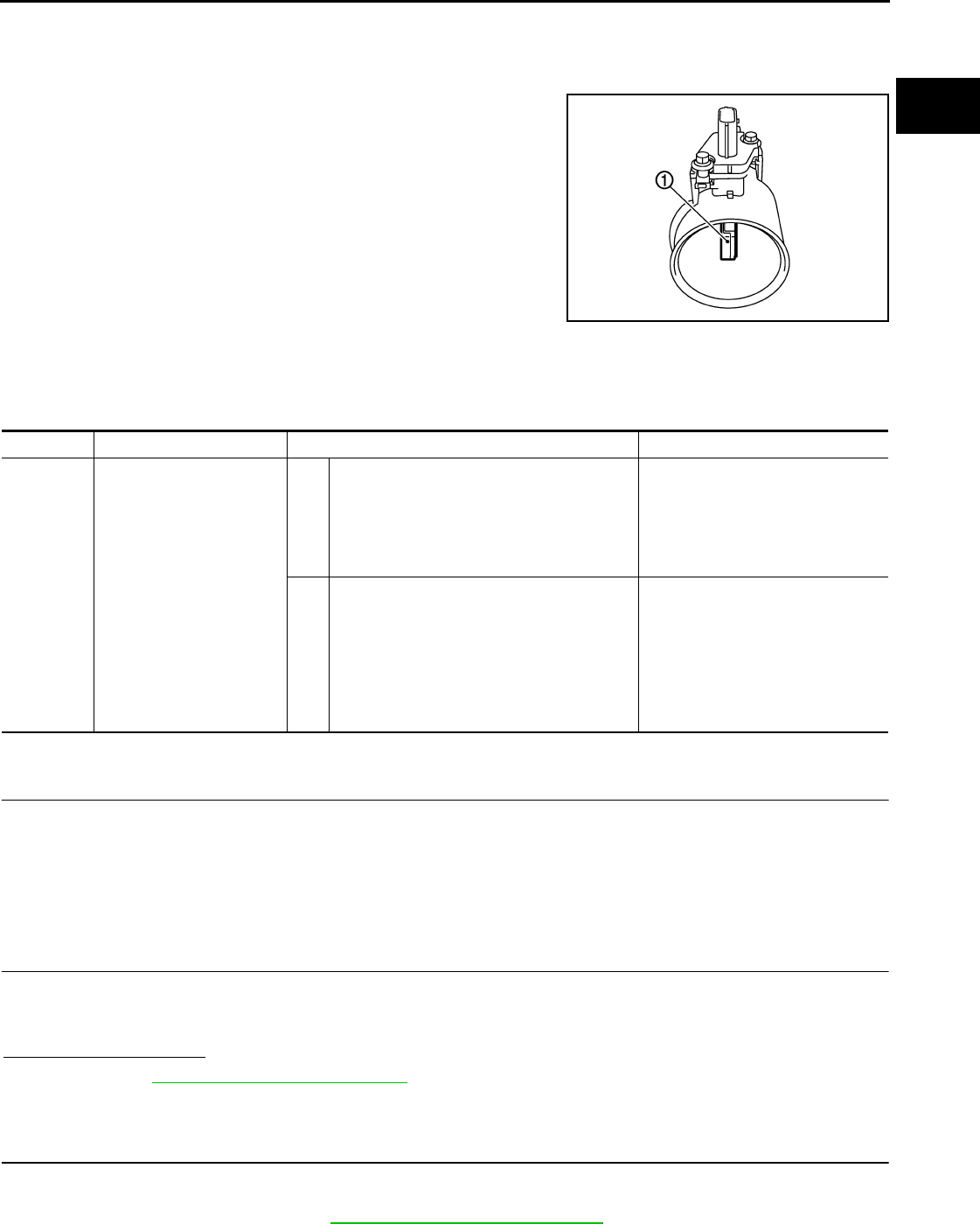
P0101 MAF SENSOR
EC-615
< COMPONENT DIAGNOSIS > [FOR USA (FEDERAL) AND CANADA]
C
D
E
F
G
H
I
J
K
L
M
A
EC
N
P
O
P0101 MAF SENSOR
Description INFOID:0000000004529485
The mass air flow sensor (1) is placed in the stream of intake air. It
measures the intake flow rate by measuring a part of the entire
intake flow. The mass air flow sensor controls the temperature of the
hot wire to a certain amount. The heat generated by the hot wire is
reduced as the intake air flows around it. The greater air flow, the
greater the heat loss.
Therefore, the electric current supplied to hot wire is changed to
maintain the temperature of the hot wire as air flow increases. The
ECM detects the air flow by means of this current change.
DTC Logic INFOID:0000000004529486
DTC DETECTION LOGIC
DTC CONFIRMATION PROCEDURE
1.PRECONDITIONING
If DTC CONFIRMATION PROCEDURE has been previously conducted, always turn ignition switch OFF and
wait at least 10 seconds before conducting the next test.
If engine will not start or stops soon, wait at least 10 seconds with engine stopped (Ignition switch ON) instead
of running engine at idle speed.
>> GO TO 2.
2.PERFORM DTC CONFIRMATION PROCEDURE FOR MALFUNCTION A
1. Start engine and warm it up to normal operating temperature.
2. Run engine for at least 10 seconds at idle speed.
3. Check 1st trip DTC.
Is 1st trip DTC detected?
YES >> Go to EC-617, "Diagnosis Procedure".
NO-1 >> With CONSULT-III: GO TO 3.
NO-2 >> Without CONSULT-III: GO TO 5.
3.CHECK MASS AIR FLOW SENSOR FUNCTION
1. Turn ignition switch ON.
2. Start engine and warm it up to normal operating temperature.
If engine cannot be started, go to EC-617, "Diagnosis Procedure".
PBIA9559J
DTC No. Trouble diagnosis name DTC detecting condition Possible cause
P0101 Mass air flow sensor circuit
range/performance
A) A high voltage from the sensor is sent to ECM
under light load driving condition.
• Harness or connectors
(The sensor circuit is open or
shorted.)
• Mass air flow sensor
• EVAP control system pressure
sensor
B) A low voltage from the sensor is sent to ECM
under heavy load driving condition.
• Harness or connectors
(The sensor circuit is open or
shorted.)
• Intake air leaks
• Mass air flow sensor
• EVAP control system pressure
sensor
• Intake air temperature sensor
Revision: 2008 August 2009 Rogue
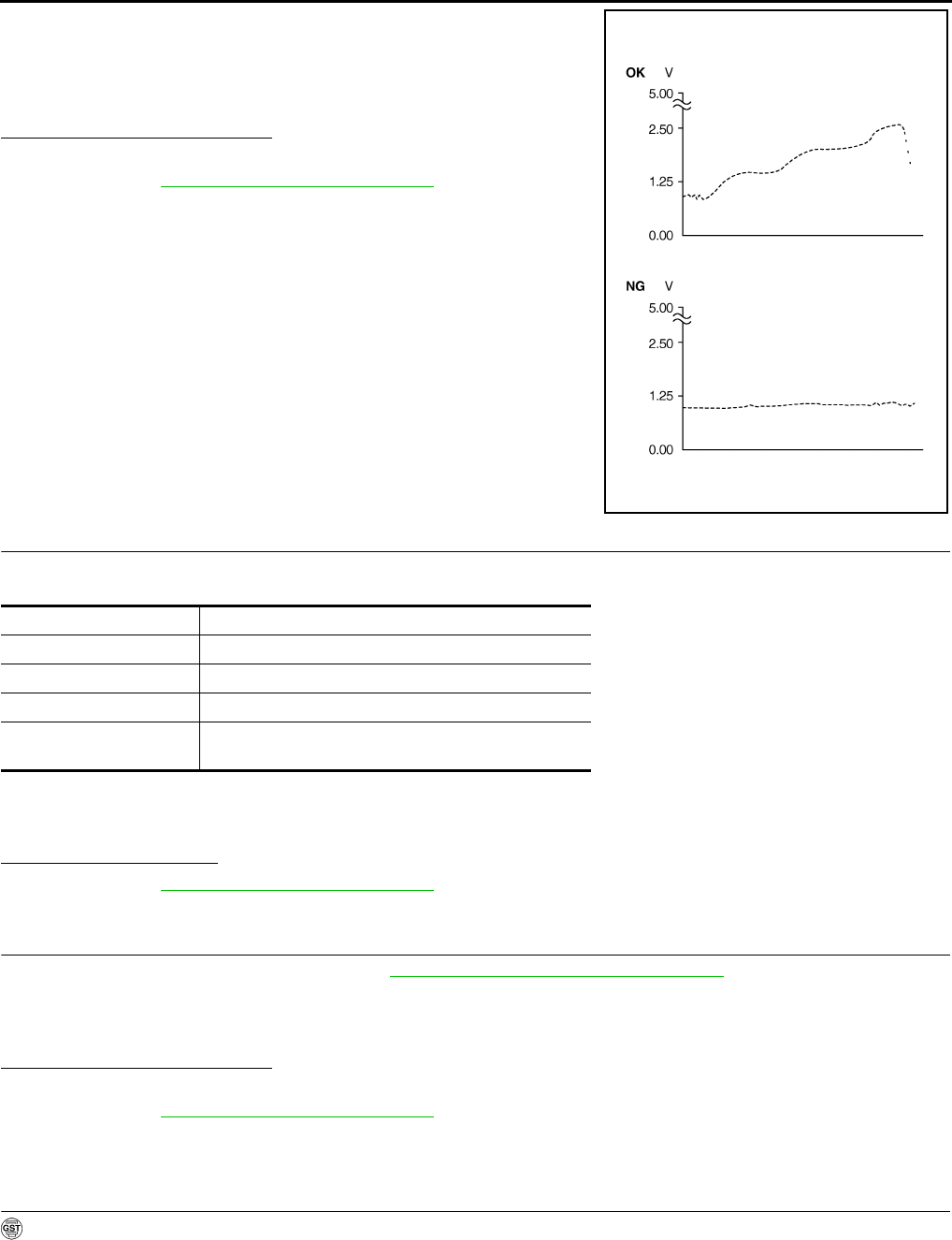
EC-616
< COMPONENT DIAGNOSIS > [FOR USA (FEDERAL) AND CANADA]
P0101 MAF SENSOR
3. Select “DATA MONITOR” mode with CONSULT-III.
4. Check the voltage of “MAS A/F SE-B1” with “DATA MONITOR”.
5. Increases engine speed to approximately 4,000 rpm.
6. Monitor the linear voltage rise in response to engine speed
increases.
Is the inspection result normal?
YES >> GO TO 4.
NO >> Go to EC-617, "Diagnosis Procedure".
4.PERFORM DTC CONFIRMATION PROCEDURE FOR MALFUNCTION B
1. Maintain the following conditions for at least 10 consecutive seconds.
CAUTION:
Always drive vehicle at a safe speed.
2. Check 1st trip DTC.
Is 1st trip DTC detected?
YES >> Go to EC-617, "Diagnosis Procedure".
NO >> INSPECTION END
5.PERFORM COMPONENT FUNCTION CHECK FOR MALFUNCTION B
Perform component function check. Refer to EC-616, "Component Function Check".
NOTE:
Use component function check to check the overall function of the mass air flow sensor circuit. During this
check, a 1st trip DTC might not be confirmed.
Is the inspection result normal?
YES >> INSPECTION END
NO >> Go to EC-617, "Diagnosis Procedure".
Component Function Check INFOID:0000000004529487
1.PERFORM COMPONENT FUNCTION CHECK FOR MALFUNCTION B
With GST
1. Start engine and warm it up to normal operating temperature.
2. Select Service $01 with GST.
PBIB3457E
ENG SPEED More than 2,000 rpm
THRTL SEN 1-B1 More than 1.5V
THRTL SEN 2-B1 More than 1.5V
Selector lever Suitable position
Driving location Driving vehicle uphill (Increased engine load) will help
maintain the driving conditions required for this test.
Revision: 2008 August 2009 Rogue
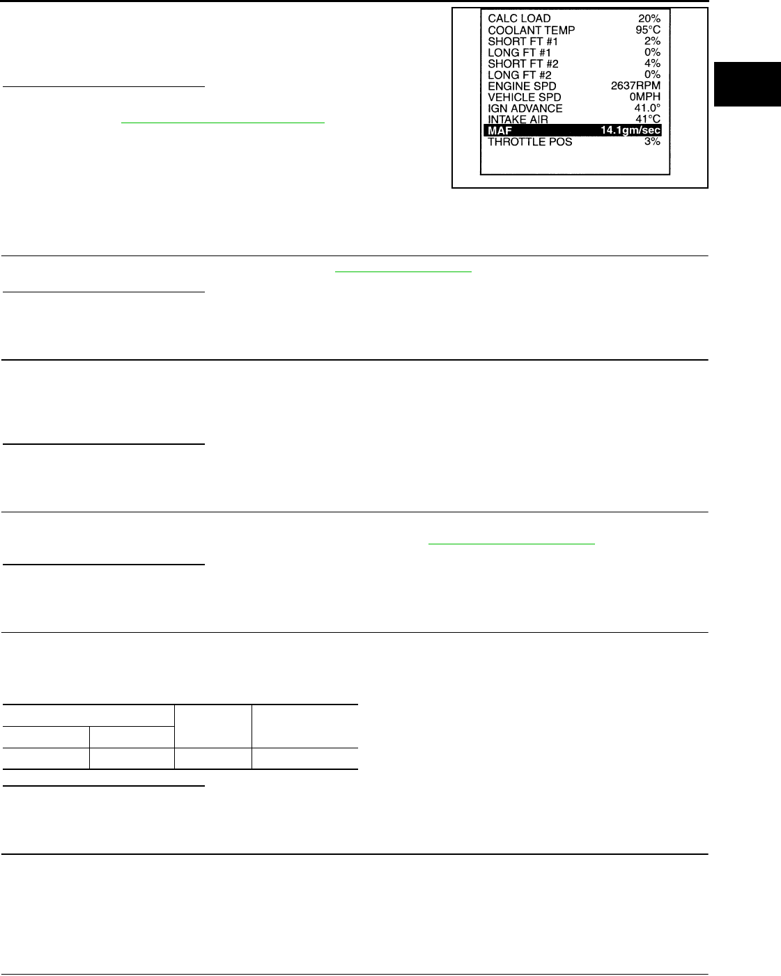
P0101 MAF SENSOR
EC-617
< COMPONENT DIAGNOSIS > [FOR USA (FEDERAL) AND CANADA]
C
D
E
F
G
H
I
J
K
L
M
A
EC
N
P
O
3. Check the mass air flow sensor signal with Service $01.
4. Check for linear mass air flow sensor signal value rise in
response to increases to approximately 4,000 rpm in engine
speed.
Is the inspection result normal?
YES >> INSPECTION END
NO >> Go to EC-617, "Diagnosis Procedure".
Diagnosis Procedure INFOID:0000000004529488
1.INSPECTION START
Confirm the detected malfunction (A or B). Refer to EC-615, "DTC Logic".
Which malfunction is detected?
A >> GO TO 3.
B >> GO TO 2.
2.CHECK INTAKE SYSTEM
Check the following for connection.
• Air duct
• Vacuum hoses
• Intake air passage between air duct and intake manifold
Is the inspection result normal?
YES >> GO TO 3.
NO >> Reconnect the parts.
3.CHECK GROUND CONNECTION
1. Turn ignition switch OFF.
2. Check ground connection E21. Refer to Ground Inspection in GI-44, "Circuit Inspection".
Is the inspection result normal?
YES >> GO TO 4.
NO >> Repair or replace ground connection.
4.CHECK MAF SENSOR POWER SUPPLY CIRCUIT
1. Disconnect mass air flow (MAF) sensor harness connector.
2. Turn ignition switch ON.
3. Check the voltage between MAF sensor harness connector and ground.
Is the inspection result normal?
YES >> GO TO 6.
NO >> GO TO 5.
5.DETECT MALFUNCTIONING PART
Check the following.
• Harness for open or short between mass air flow sensor and ECM
• Harness for open or short between mass air flow sensor and IPDM E/R
>> Repair open circuit or short to ground or short to power in harness or connectors.
6.CHECK MAF SENSOR GROUND CIRCUIT FOR OPEN AND SHORT
1. Turn ignition switch OFF.
SEF534P
MAF sensor Ground Voltage
Connector Terminal
E18 5 Ground Battery voltage
Revision: 2008 August 2009 Rogue

EC-618
< COMPONENT DIAGNOSIS > [FOR USA (FEDERAL) AND CANADA]
P0101 MAF SENSOR
2. Disconnect ECM harness connector.
3. Check the continuity between MAF sensor harness connector and ECM harness connector.
4. Also check harness for short to ground and short to power.
Is the inspection result normal?
YES >> GO TO 8.
NO >> GO TO 7.
7.DETECT MALFUNCTIONING PART
Check the following.
• Harness connectors E6, F123
• Harness for open or short between mass air flow sensor and ECM
>> Repair open circuit or short to ground or short to power in harness or connectors.
8.CHECK MAF SENSOR INPUT SIGNAL CIRCUIT FOR OPEN AND SHORT
1. Check the continuity between MAF sensor harness connector and ECM harness connector.
2. Also check harness for short to ground and short to power.
Is the inspection result normal?
YES >> GO TO 10.
NO >> GO TO 9.
9.DETECT MALFUNCTIONING PART
Check the following.
• Harness connectors E6, F123
• Harness for open or short between mass air flow sensor and ECM
>> Repair open circuit or short to ground or short to power in harness or connectors.
10.CHECK INTAKE AIR TEMPERATURE SENSOR
Refer to EC-629, "Component Inspection".
Is the inspection result normal?
YES >> GO TO 11.
NO >> Replace mass air flow sensor (with intake air temperature sensor).
11.CHECK EVAP CONTROL SYSTEM PRESSURE SENSOR
Refer to EC-744, "Component Inspection".
Is the inspection result normal?
YES >> GO TO 12.
NO >> Replace EVAP control system pressure sensor.
12.CHECK MASS AIR FLOW SENSOR
Refer to EC-619, "Component Inspection".
Is the inspection result normal?
YES >> GO TO 13.
NO >> Replace mass air flow sensor.
13.CHECK INTERMITTENT INCIDENT
MAF sensor ECM Continuity
Connector Terminal Connector Terminal
E18 4 F7 56 Existed
MAF sensor ECM Continuity
Connector Terminal Connector Terminal
E18 3 F8 58 Existed
Revision: 2008 August 2009 Rogue
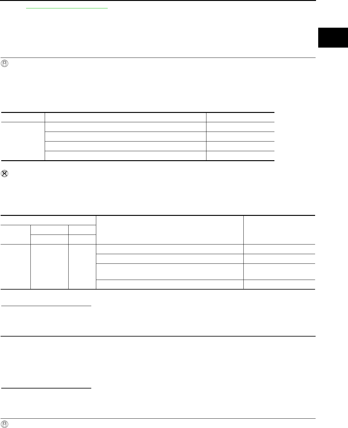
P0101 MAF SENSOR
EC-619
< COMPONENT DIAGNOSIS > [FOR USA (FEDERAL) AND CANADA]
C
D
E
F
G
H
I
J
K
L
M
A
EC
N
P
O
Refer to GI-41, "Intermittent Incident".
>> INSPECTION END
Component Inspection INFOID:0000000004529489
1.CHECK MASS AIR FLOW SENSOR-I
With CONSULT-III
1. Turn ignition switch OFF.
2. Reconnect all harness connectors disconnected.
3. Start engine and warm it up to normal operating temperature.
4. Connect CONSULT-III and select “DATA MONITOR” mode.
5. Select “MAS A/F SE-B1” and check indication.
*: Check for linear voltage rise in response to engine being increased to approx 4,000 rpm.
Without CONSULT-III
1. Turn ignition switch OFF.
2. Reconnect all harness connectors disconnected.
3. Start engine and warm it up to normal operating temperature.
4. Check the voltage between ECM harness connector terminals under the following conditions.
*: Check for linear voltage rise in response to engine being increased to approx 4,000 rpm.
Is the inspection result normal?
YES >> INSPECTION END
NO >> GO TO 2.
2.CHECK FOR THE CAUSE OF UNEVEN AIR FLOW THROUGH MASS AIR FLOW SENSOR
1. Turn ignition switch OFF.
2. Check for the cause of uneven air flow through mass air flow sensor. Refer to the following.
- Crushed air ducts
- Malfunctioning seal of air cleaner element
- Uneven dirt of air cleaner element
- Improper specification of intake air system parts
Is the inspection result normal?
YES >> GO TO 4.
NO >> GO TO 3.
3.CHECK MASS AIR FLOW SENSOR-II
With CONSULT-III
1. Repair or replace malfunctioning part.
2. Start engine and warm it up to normal operating temperature.
Monitor item Condition MAS A/F SE-B1
MAS A/F SE-B1
Ignition switch ON (Engine stopped.) Approx. 0.4 V
Idle (Engine is warmed-up to normal operating temperature.) 0.8 - 1.2 V
2,500 rpm (Engine is warmed-up to normal operating temperature.) 1.4 - 1.8 V
Idle to approx. 4,000 rpm 0.8 - 1.2 V to Approx. 2.4 V*
ECM
Condition Voltage
Connector +−
Terminal Terminal
F8 58
(MAF sensor
signal)
56
(Sensor
gound)
Ignition switch ON (Engine stopped.) Approx. 0.4 V
Idle (Engine is warmed-up to normal operating temperature.) 0.8 - 1.2 V
2,500 rpm (Engine is warmed-up to normal operating temper-
ature.) 1.4 - 1.8 V
Idle to approx. 4,000 rpm 0.8 - 1.2 V to Approx. 2.4 V*
Revision: 2008 August 2009 Rogue

EC-620
< COMPONENT DIAGNOSIS > [FOR USA (FEDERAL) AND CANADA]
P0101 MAF SENSOR
3. Connect CONSULT-III and select “DATA MONITOR” mode.
4. Select “MAS A/F SE-B1” and check indication.
*: Check for linear voltage rise in response to engine being increased to approx 4,000 rpm.
Without CONSULT-III
1. Repair or replace malfunctioning part.
2. Start engine and warm it up to normal operating temperature.
3. Check the voltage between ECM harness connector terminals under the following conditions.
*: Check for linear voltage rise in response to engine being increased to approx 4,000 rpm.
Is the inspection result normal?
YES >> INSPECTION END
NO >> GO TO 4.
4.CHECK MASS AIR FLOW SENSOR-III
With CONSULT-III
1. Turn ignition switch OFF.
2. Disconnect mass air flow sensor harness connector and reconnect it again.
3. Start engine and warm it up to normal operating temperature.
4. Connect CONSULT-III and select “DATA MONITOR” mode.
5. Select “MAS A/F SE-B1” and check indication.
*: Check for linear voltage rise in response to engine being increased to approx 4,000 rpm.
Without CONSULT-III
1. Turn ignition switch OFF.
2. Disconnect mass air flow sensor harness connector and reconnect it again.
3. Start engine and warm it up to normal operating temperature.
4. Check the voltage between ECM harness connector terminals under the following conditions.
Monitor item Condition MAS A/F SE-B1
MAS A/F SE-B1
Ignition switch ON (Engine stopped.) Approx. 0.4 V
Idle (Engine is warmed-up to normal operating temperature.) 0.8 - 1.2 V
2,500 rpm (Engine is warmed-up to normal operating temperature.) 1.4 - 1.8 V
Idle to approx. 4,000 rpm 0.8 - 1.2 V to Approx. 2.4 V*
ECM
Condition Voltage
Connector +−
Terminal Terminal
F8
58
(MAF sensor
signal)
56
(Sensor
gound)
Ignition switch ON (Engine stopped.) Approx. 0.4 V
Idle (Engine is warmed-up to normal operating temperature.) 0.8 - 1.2 V
2,500 rpm (Engine is warmed-up to normal operating temper-
ature.) 1.4 - 1.8 V
Idle to approx. 4,000 rpm 0.8 - 1.2 V to Approx. 2.4 V*
Monitor item Condition MAS A/F SE-B1
MAS A/F SE-B1
Ignition switch ON (Engine stopped.) Approx. 0.4 V
Idle (Engine is warmed-up to normal operating temperature.) 0.8 - 1.2 V
2,500 rpm (Engine is warmed-up to normal operating temperature.) 1.4 - 1.8 V
Idle to approx. 4,000 rpm 0.8 - 1.2 V to Approx. 2.4 V*
Revision: 2008 August 2009 Rogue

P0101 MAF SENSOR
EC-621
< COMPONENT DIAGNOSIS > [FOR USA (FEDERAL) AND CANADA]
C
D
E
F
G
H
I
J
K
L
M
A
EC
N
P
O
*: Check for linear voltage rise in response to engine being increased to approx 4,000 rpm.
Is the inspection result normal?
YES >> INSPECTION END
NO >> Clean or replace mass air flow sensor.
ECM
Condition Voltage
Connector +−
Terminal Terminal
F8
58
(MAF sensor
signal)
56
(Sensor
gound)
Ignition switch ON (Engine stopped.) Approx. 0.4 V
Idle (Engine is warmed-up to normal operating temperature.) 0.8 - 1.2 V
2,500 rpm (Engine is warmed-up to normal operating temper-
ature.) 1.4 - 1.8 V
Idle to approx. 4,000 rpm 0.8 - 1.2 V to Approx. 2.4 V*
Revision: 2008 August 2009 Rogue

EC-622
< COMPONENT DIAGNOSIS > [FOR USA (FEDERAL) AND CANADA]
P0102, P0103 MAF SENSOR
P0102, P0103 MAF SENSOR
Description INFOID:0000000004533687
The mass air flow sensor (1) is placed in the stream of intake air. It
measures the intake flow rate by measuring a part of the entire
intake flow. The mass air flow sensor controls the temperature of the
hot wire to a certain amount. The heat generated by the hot wire is
reduced as the intake air flows around it. The greater air flow, the
greater the heat loss.
Therefore, the electric current supplied to hot wire is changed to
maintain the temperature of the hot wire as air flow increases. The
ECM detects the air flow by means of this current change.
DTC Logic INFOID:0000000004529491
DTC DETECTION LOGIC
DTC CONFIRMATION PROCEDURE
1.PRECONDITIONING
If DTC CONFIRMATION PROCEDURE has been previously conducted, always turn ignition switch OFF and
wait at least 10 seconds before conducting the next test.
Which DTC is detected?
P0102 >> GO TO 2.
P0103 >> GO TO 3.
2.PERFORM DTC CONFIRMATION PROCEDURE FOR DTC P0102
1. Start engine and wait at least 5 seconds.
2. Check DTC.
Is DTC detected?
YES >> Go to EC-623, "Diagnosis Procedure".
NO >> INSPECTION END
3.PERFORM DTC CONFIRMATION PROCEDURE FOR DTC P0103-I
1. Turn ignition switch ON and wait at least 5 seconds.
2. Check DTC.
Is DTC detected?
YES >> Go to EC-623, "Diagnosis Procedure".
NO >> GO TO 4.
4.PERFORM DTC CONFIRMATION PROCEDURE FOR DTC P0103-II
1. Start engine and wait at least 5 seconds.
2. Check DTC.
Is DTC detected?
YES >> Go to EC-623, "Diagnosis Procedure".
NO >> INSPECTION END
PBIA9559J
DTC No. Trouble diagnosis name DTC detecting condition Possible cause
P0102 Mass air flow sensor circuit
low input An excessively low voltage from the sensor is
sent to ECM.
• Harness or connectors
(The sensor circuit is open or shorted.)
• Intake air leaks
• Mass air flow sensor
P0103 Mass air flow sensor circuit
high input
An excessively high voltage from the sensor is
sent to ECM.
• Harness or connectors
(The sensor circuit is open or shorted.)
• Mass air flow sensor
Revision: 2008 August 2009 Rogue

P0102, P0103 MAF SENSOR
EC-623
< COMPONENT DIAGNOSIS > [FOR USA (FEDERAL) AND CANADA]
C
D
E
F
G
H
I
J
K
L
M
A
EC
N
P
O
Diagnosis Procedure INFOID:0000000004529492
1.INSPECTION START
Confirm the detected DTC.
Which DTC is detected?
P0102 >> GO TO 2.
P0103 >> GO TO 3.
2.CHECK INTAKE SYSTEM
Check the following for connection.
• Air duct
• Vacuum hoses
• Intake air passage between air duct to intake manifold
Is the inspection result normal?
YES >> GO TO 3.
NO >> Reconnect the parts.
3.CHECK GROUND CONNECTION
1. Turn ignition switch OFF.
2. Check ground connection E21. Refer to Ground Inspection in GI-44, "Circuit Inspection".
Is the inspection result normal?
YES >> GO TO 4.
NO >> Repair or replace ground connection.
4.CHECK MAF SENSOR POWER SUPPLY CIRCUIT
1. Disconnect mass air flow (MAF) sensor harness connector.
2. Turn ignition switch ON.
3. Check the voltage between MAF sensor harness connector and ground.
Is the inspection result normal?
YES >> GO TO 6.
NO >> GO TO 5.
5.DETECT MALFUNCTIONING PART
Check the following.
• Harness for open or short between mass air flow sensor and ECM
• Harness for open or short between mass air flow sensor and IPDM E/R
>> Repair open circuit or short to ground or short to power in harness or connectors.
6.CHECK MAF SENSOR GROUND CIRCUIT FOR OPEN AND SHORT
1. Turn ignition switch OFF.
2. Disconnect ECM harness connector.
3. Check the continuity between MAF sensor harness connector and ECM harness connector.
4. Also check harness for short to ground and short to power.
Is the inspection result normal?
YES >> GO TO 8.
MAF sensor Ground Voltage
Connector Terminal
E18 5 Ground Battery voltage
MAF sensor ECM Continuity
Connector Terminal Connector Terminal
E18 4 F8 56 Existed
Revision: 2008 August 2009 Rogue

EC-624
< COMPONENT DIAGNOSIS > [FOR USA (FEDERAL) AND CANADA]
P0102, P0103 MAF SENSOR
NO >> GO TO 7.
7.DETECT MALFUNCTIONING PART
Check the following.
• Harness connectors E6, F123
• Harness for open or short between mass air flow sensor and ECM
>> Repair open circuit or short to ground or short to power in harness or connectors.
8.CHECK MAF SENSOR INPUT SIGNAL CIRCUIT FOR OPEN AND SHORT
1. Check the continuity between MAF sensor harness connector and ECM harness connector.
2. Also check harness for short to ground and short to power.
Is the inspection result normal?
YES >> GO TO 10.
NO >> GO TO 9.
9.DETECT MALFUNCTIONING PART
Check the following.
• Harness connectors E6, F123
• Harness for open or short between mass air flow sensor and ECM
>> Repair open circuit or short to ground or short to power in harness or connectors.
10.CHECK MASS AIR FLOW SENSOR
Refer to EC-624, "Component Inspection".
Is the inspection result normal?
YES >> GO TO 11.
NO >> Replace mass air flow sensor.
11.CHECK INTERMITTENT INCIDENT
Refer to GI-41, "Intermittent Incident".
>> INSPECTION END
Component Inspection INFOID:0000000004533688
1.CHECK MASS AIR FLOW SENSOR-I
With CONSULT-III
1. Turn ignition switch OFF.
2. Reconnect all harness connectors disconnected.
3. Start engine and warm it up to normal operating temperature.
4. Connect CONSULT-III and select “DATA MONITOR” mode.
5. Select “MAS A/F SE-B1” and check indication.
*: Check for linear voltage rise in response to engine being increased to approx 4,000 rpm.
MAF sensor ECM Continuity
Connector Terminal Connector Terminal
E18 3 F8 58 Existed
Monitor item Condition MAS A/F SE-B1
MAS A/F SE-B1
Ignition switch ON (Engine stopped.) Approx. 0.4 V
Idle (Engine is warmed-up to normal operating temperature.) 0.8 - 1.2 V
2,500 rpm (Engine is warmed-up to normal operating temperature.) 1.4 - 1.8 V
Idle to approx. 4,000 rpm 0.8 - 1.2 V to Approx. 2.4 V*
Revision: 2008 August 2009 Rogue
P0102, P0103 MAF SENSOR
EC-625
< COMPONENT DIAGNOSIS > [FOR USA (FEDERAL) AND CANADA]
C
D
E
F
G
H
I
J
K
L
M
A
EC
N
P
O
Without CONSULT-III
1. Turn ignition switch OFF.
2. Reconnect all harness connectors disconnected.
3. Start engine and warm it up to normal operating temperature.
4. Check the voltage between ECM harness connector terminals under the following conditions.
*: Check for linear voltage rise in response to engine being increased to approx 4,000 rpm.
Is the inspection result normal?
YES >> INSPECTION END
NO >> GO TO 2.
2.CHECK FOR THE CAUSE OF UNEVEN AIR FLOW THROUGH MASS AIR FLOW SENSOR
1. Turn ignition switch OFF.
2. Check for the cause of uneven air flow through mass air flow sensor. Refer to the following.
- Crushed air ducts
- Malfunctioning seal of air cleaner element
- Uneven dirt of air cleaner element
- Improper specification of intake air system parts
Is the inspection result normal?
YES >> GO TO 4.
NO >> GO TO 3.
3.CHECK MASS AIR FLOW SENSOR-II
With CONSULT-III
1. Repair or replace malfunctioning part.
2. Start engine and warm it up to normal operating temperature.
3. Connect CONSULT-III and select “DATA MONITOR” mode.
4. Select “MAS A/F SE-B1” and check indication.
*: Check for linear voltage rise in response to engine being increased to approx 4,000 rpm.
Without CONSULT-III
1. Repair or replace malfunctioning part.
2. Start engine and warm it up to normal operating temperature.
3. Check the voltage between ECM harness connector terminals under the following conditions.
ECM
Condition Voltage
Connector +−
Terminal Terminal
F8
58
(MAF sensor
signal)
56
(Sensor
gound)
Ignition switch ON (Engine stopped.) Approx. 0.4 V
Idle (Engine is warmed-up to normal operating temperature.) 0.8 - 1.2 V
2,500 rpm (Engine is warmed-up to normal operating temper-
ature.) 1.4 - 1.8 V
Idle to approx. 4,000 rpm 0.8 - 1.2 V to Approx. 2.4 V*
Monitor item Condition MAS A/F SE-B1
MAS A/F SE-B1
Ignition switch ON (Engine stopped.) Approx. 0.4 V
Idle (Engine is warmed-up to normal operating temperature.) 0.8 - 1.2 V
2,500 rpm (Engine is warmed-up to normal operating temperature.) 1.4 - 1.8 V
Idle to approx. 4,000 rpm 0.8 - 1.2 V to Approx. 2.4 V*
Revision: 2008 August 2009 Rogue

EC-626
< COMPONENT DIAGNOSIS > [FOR USA (FEDERAL) AND CANADA]
P0102, P0103 MAF SENSOR
*: Check for linear voltage rise in response to engine being increased to approx 4,000 rpm.
Is the inspection result normal?
YES >> INSPECTION END
NO >> GO TO 4.
4.CHECK MASS AIR FLOW SENSOR-III
With CONSULT-III
1. Turn ignition switch OFF.
2. Disconnect mass air flow sensor harness connector and reconnect it again.
3. Start engine and warm it up to normal operating temperature.
4. Connect CONSULT-III and select “DATA MONITOR” mode.
5. Select “MAS A/F SE-B1” and check indication.
*: Check for linear voltage rise in response to engine being increased to approx 4,000 rpm.
Without CONSULT-III
1. Turn ignition switch OFF.
2. Disconnect mass air flow sensor harness connector and reconnect it again.
3. Start engine and warm it up to normal operating temperature.
4. Check the voltage between ECM harness connector terminals under the following conditions.
*: Check for linear voltage rise in response to engine being increased to approx 4,000 rpm.
Is the inspection result normal?
YES >> INSPECTION END
NO >> Clean or replace mass air flow sensor.
ECM
Condition Voltage
Connector +−
Terminal Terminal
F8
58
(MAF sensor
signal)
56
(Sensor
gound)
Ignition switch ON (Engine stopped.) Approx. 0.4 V
Idle (Engine is warmed-up to normal operating temperature.) 0.8 - 1.2 V
2,500 rpm (Engine is warmed-up to normal operating temper-
ature.) 1.4 - 1.8 V
Idle to approx. 4,000 rpm 0.8 - 1.2 V to Approx. 2.4 V*
Monitor item Condition MAS A/F SE-B1
MAS A/F SE-B1
Ignition switch ON (Engine stopped.) Approx. 0.4 V
Idle (Engine is warmed-up to normal operating temperature.) 0.8 - 1.2 V
2,500 rpm (Engine is warmed-up to normal operating temperature.) 1.4 - 1.8 V
Idle to approx. 4,000 rpm 0.8 - 1.2 V to Approx. 2.4 V*
ECM
Condition Voltage
Connector +−
Terminal Terminal
F8
58
(MAF sensor
signal)
56
(Sensor
gound)
Ignition switch ON (Engine stopped.) Approx. 0.4 V
Idle (Engine is warmed-up to normal operating temperature.) 0.8 - 1.2 V
2,500 rpm (Engine is warmed-up to normal operating temper-
ature.) 1.4 - 1.8 V
Idle to approx. 4,000 rpm 0.8 - 1.2 V to Approx. 2.4 V*
Revision: 2008 August 2009 Rogue
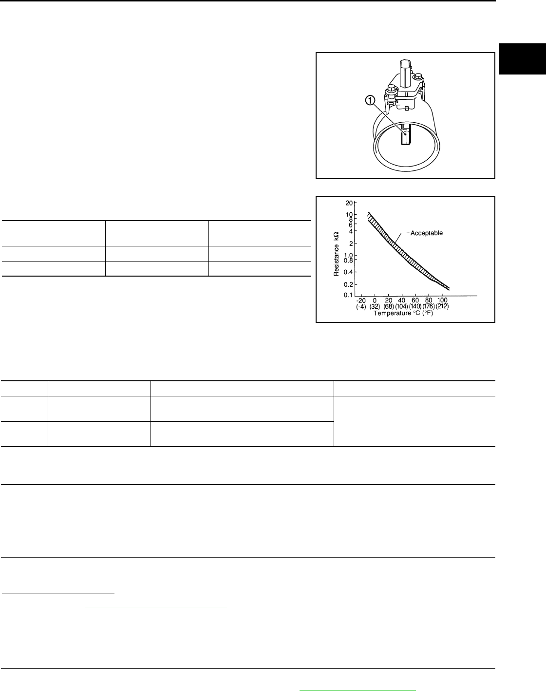
P0112, P0113 IAT SENSOR
EC-627
< COMPONENT DIAGNOSIS > [FOR USA (FEDERAL) AND CANADA]
C
D
E
F
G
H
I
J
K
L
M
A
EC
N
P
O
P0112, P0113 IAT SENSOR
Description INFOID:0000000004529494
The intake air temperature sensor is built-into the mass air flow sen-
sor (1). The sensor detects intake air temperature and transmits a
signal to the ECM.
The temperature sensing unit uses a thermistor which is sensitive to
the change in temperature. Electrical resistance of the thermistor
decreases in response to the rise in temperature.
<Reference data>
*: These data are reference values and are measured between ECM terminals 50
(Intake air temperature sensor) and 58 (Sensor ground).
DTC Logic INFOID:0000000004529495
DTC DETECTION LOGIC
DTC CONFIRMATION PROCEDURE
1.PRECONDITIONING
If DTC CONFIRMATION PROCEDURE has been previously conducted, always turn ignition switch OFF and
wait at least 10 seconds before conducting the next test.
>> GO TO 2.
2.PERFORM DTC CONFIRMATION PROCEDURE
1. Turn ignition switch ON and wait at least 5 seconds.
2. Check 1st trip DTC.
Is 1st trip DTC detected?
YES >> Go to EC-627, "Diagnosis Procedure".
NO >> INSPECTION END
Diagnosis Procedure INFOID:0000000004529496
1.CHECK GROUND CONNECTION
1. Turn ignition switch OFF.
2. Check ground connection E21. Refer to Ground Inspection in GI-44, "Circuit Inspection".
PBIA9559J
Intake air temperature
[°C (°F)] Voltage* (V) Resistance (kΩ)
25 (77) 3.3 1.800 - 2.200
80 (176) 1.2 0.283 - 0.359
SEF012P
DTC No. Trouble diagnosis name DTC detecting condition Possible cause
P0112 Intake air temperature
sensor circuit low input An excessively low voltage from the sensor is
sent to ECM. • Harness or connectors
(The sensor circuit is open or shorted.)
• Intake air temperature sensor
P0113 Intake air temperature
sensor circuit high input
An excessively high voltage from the sensor is
sent to ECM.
Revision: 2008 August 2009 Rogue
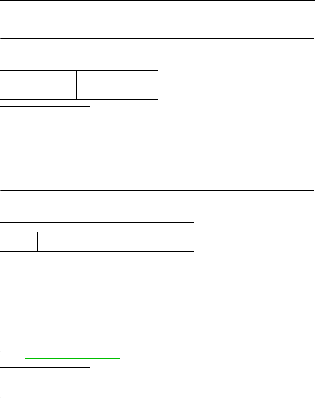
EC-628
< COMPONENT DIAGNOSIS > [FOR USA (FEDERAL) AND CANADA]
P0112, P0113 IAT SENSOR
Is the inspection result normal?
YES >> GO TO 2.
NO >> Repair or replace ground connection.
2.CHECK INTAKE AIR TEMPERATURE SENSOR POWER SUPPLY CIRCUIT
1. Disconnect mass air flow sensor (with intake air temperature sensor) harness connector.
2. Turn ignition switch ON.
3. Check the voltage between mass air flow sensor harness connector and ground.
Is the inspection result normal?
YES >> GO TO 4.
NO >> GO TO 3.
3.DETECT MALFUNCTIONING PART
Check the following.
• Harness connectors E6, F123
• Harness for open or short between mass air flow sensor and ECM
>> Repair open circuit or short to ground or short to power in harness or connectors.
4.CHECK INTAKE AIR TEMPERATURE SENSOR GROUND CIRCUIT FOR OPEN AND SHORT
1. Turn ignition switch OFF.
2. Disconnect ECM harness connector.
3. Check the continuity between mass air flow sensor harness connector and ECM harness connector.
4. Also check harness for short to ground and short to power.
Is the inspection result normal?
YES >> GO TO 6.
NO >> GO TO 5.
5.DETECT MALFUNCTIONING PART
Check the following.
• Harness connectors E6, F123
• Harness for open or short between mass air flow sensor and ECM
>> Repair open circuit or short to ground or short to power in harness or connectors.
6.CHECK INTAKE AIR TEMPERATURE SENSOR
Refer to EC-629, "Component Inspection".
Is the inspection result normal?
YES >> GO TO 7.
NO >> Replace mass air flow sensor (with intake air temperature sensor).
7.CHECK INTERMITTENT INCIDENT
Refer to GI-41, "Intermittent Incident".
>> INSPECTION END
MAF sensor Ground Voltage
Connector Terminal
E18 2 Ground Approx. 5 V
MAF sensor ECM Continuity
Connector Terminal Connector Terminal
E18 1 F8 56 Existed
Revision: 2008 August 2009 Rogue

P0112, P0113 IAT SENSOR
EC-629
< COMPONENT DIAGNOSIS > [FOR USA (FEDERAL) AND CANADA]
C
D
E
F
G
H
I
J
K
L
M
A
EC
N
P
O
Component Inspection INFOID:0000000004529497
1.CHECK INTAKE AIR TEMPERATURE SENSOR
1. Turn ignition switch OFF.
2. Disconnect mass air flow sensor harness connector.
3. Check resistance between mass air flow sensor terminals as follows.
Is the inspection result normal?
YES >> INSPECTION END
NO >> Replace mass air flow sensor (with intake air temperature sensor).
Terminals Condition Resistance (kΩ)
1 and 2 Intake air temperature [°C (°F)] 25 (77) 1.800 - 2.200
Revision: 2008 August 2009 Rogue

EC-630
< COMPONENT DIAGNOSIS > [FOR USA (FEDERAL) AND CANADA]
P0116 ECT SENSOR
P0116 ECT SENSOR
Description INFOID:0000000004541995
The engine coolant temperature sensor is used to detect the engine
coolant temperature. The sensor modifies a voltage signal from the
ECM. The modified signal returns to the ECM as the engine coolant
temperature input. The sensor uses a thermistor which is sensitive to
the change in temperature. The electrical resistance of the ther-
mistor decreases as temperature increases.
<Reference data>
*: These data are reference values and are measured between ECM terminals 46
(Engine coolant temperature sensor) and 52 (Sensor ground).
DTC Logic INFOID:0000000004541698
DTC DETECTION LOGIC
NOTE:
If DTC P0116 is displayed with P0117 or P0118, first perform the trouble diagnosis for DTC P0117,
P0118. Refer to EC-164, "DTC Logic".
DTC CONFIRMATION PROCEDURE
1.PRECONDITIONING
If DTC confirmation procedure has been previously conducted, always turn ignition switch OFF and wait at
least 10 seconds before conducting the next test.
>> GO TO 2.
2.PERFORM DTC CONFIRMATION PROCEDURE
1. Start engine and warm it up to normal operating temperature.
2. Rev engine up to 2,000 rpm for more than 10 minutes.
3. Move the vehicle to a cool place, then stop engine and turn ignition switch OFF.
4. Check resistance between “fuel level sensor unit and fuel pump” terminals 1 and 2.
5. Soak the vehicle until the resistance between “fuel level sensor unit and fuel pump” terminals 1 and 2
becomes 0.5 kΩ higher than the value measured before soaking.
CAUTION:
Never turn ignition switch ON during soaking.
SEF594K
Engine coolant temperature
[°C (°F)] Voltage* (V) Resistance (kΩ)
–10 (14) 4.4 7.0 - 11.4
20 (68) 3.5 2.10 - 2.90
50 (122) 2.2 0.68 - 1.00
90 (194) 0.9 0.236 - 0.260
SEF012P
DTC No. Trouble diagnosis name DTC detecting condition Possible cause
P0116 Engine coolant tempera-
ture sensor circuit range/
performance
Engine coolant temperature signal from engine
coolant temperature sensor does not fluctuate,
even when some time has passed after starting
the engine with pre-warming up condition.
• Harness or connectors
(High or low resistance in the circuit)
• Engine coolant temperature sensor
Revision: 2008 August 2009 Rogue

P0116 ECT SENSOR
EC-631
< COMPONENT DIAGNOSIS > [FOR USA (FEDERAL) AND CANADA]
C
D
E
F
G
H
I
J
K
L
M
A
EC
N
P
O
NOTE:
Soak time changes depending on ambient air temperature. It may take several hours.
6. Start engine and let it idle for 5 minutes.
7. Check 1st trip DTC.
Is 1st trip DTC detected?
YES >> EC-631, "Diagnosis Procedure".
NO >> INSPECTION END
Diagnosis Procedure INFOID:0000000004541699
1.CHECK GROUND CONNECTION
1. Turn ignition switch OFF.
2. Check ground connection E9. Refer to GROUND INSPECTION in GI-44, "Circuit Inspection".
Is the inspection result normal?
YES >> GO TO 2.
NO >> Repair or replace ground connection.
2.CHECK ENGINE COOLANT TEMPERATURE SENSOR
Refer to EC-631, "Component Inspection".
Is the inspection result normal?
YES >> GO TO 3.
NO >> Replace engine coolant temperature sensor.
3.CHECK INTERMITTENT INCIDENT
Refer to GI-41, "Intermittent Incident".
>> INSPECTION END
Component Inspection INFOID:0000000004541996
1.CHECK ENGINE COOLANT TEMPERATURE SENSOR
1. Turn ignition switch OFF.
2. Disconnect engine coolant temperature sensor harness connector.
3. Remove engine coolant temperature sensor.
4. Check resistance between engine coolant temperature sensor
terminals by heating with hot water as shown in the figure.
Is the inspection result normal?
YES >> INSPECTION END
NO >> Replace engine coolant temperature sensor.
Terminals Condition Resistance (kΩ)
1 and 2 Temperature [°C (°F)]
20 (68) 2.10 - 2.90
50 (122) 0.68 - 1.00
90 (194) 0.236 - 0.260
JMBIA0080ZZ
Revision: 2008 August 2009 Rogue
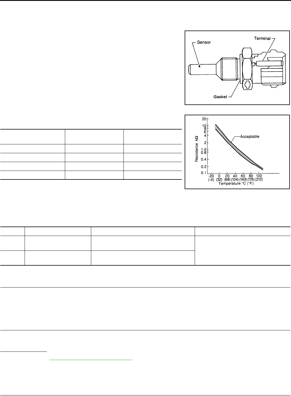
EC-632
< COMPONENT DIAGNOSIS > [FOR USA (FEDERAL) AND CANADA]
P0117, P0118 ECT SENSOR
P0117, P0118 ECT SENSOR
Description INFOID:0000000004529498
The engine coolant temperature sensor is used to detect the engine
coolant temperature. The sensor modifies a voltage signal from the
ECM. The modified signal returns to the ECM as the engine coolant
temperature input. The sensor uses a thermistor which is sensitive to
the change in temperature. The electrical resistance of the ther-
mistor decreases as temperature increases.
<Reference data>
*: These data are reference values and are measured between ECM terminals 46
(Engine coolant temperature sensor) and 52 (Sensor ground).
DTC Logic INFOID:0000000004529499
DTC DETECTION LOGIC
DTC CONFIRMATION PROCEDURE
1.PRECONDITIONING
If DTC CONFIRMATION PROCEDURE has been previously conducted, always turn ignition switch OFF and
wait at least 10 seconds before conducting the next test.
>> GO TO 2.
2.PERFORM DTC CONFIRMATION PROCEDURE
1. Turn ignition switch ON and wait at least 5 seconds.
2. Check DTC.
Is DTC detected?
YES >> Go to EC-632, "Diagnosis Procedure".
NO >> INSPECTION END
Diagnosis Procedure INFOID:0000000004529500
1.CHECK GROUND CONNECTION
1. Turn ignition switch OFF.
SEF594K
Engine coolant temperature
[°C (°F)] Voltage* (V) Resistance (kΩ)
–10 (14) 4.4 7.0 - 11.4
20 (68) 3.5 2.10 - 2.90
50 (122) 2.2 0.68 - 1.00
90 (194) 0.9 0.236 - 0.260
SEF012P
DTC No. Trouble Diagnosis Name DTC Detecting Condition Possible Cause
P0117 Engine coolant temperature
sensor circuit low input An excessively low voltage from the sensor is
sent to ECM. • Harness or connectors
(The sensor circuit is open or shorted.)
• Engine coolant temperature sensor
P0118 Engine coolant temperature
sensor circuit high input
An excessively high voltage from the sensor is
sent to ECM.
Revision: 2008 August 2009 Rogue

P0117, P0118 ECT SENSOR
EC-633
< COMPONENT DIAGNOSIS > [FOR USA (FEDERAL) AND CANADA]
C
D
E
F
G
H
I
J
K
L
M
A
EC
N
P
O
2. Check ground connection E21. Refer to Ground Inspection in GI-44, "Circuit Inspection".
Is the inspection result normal?
YES >> GO TO 2.
NO >> Repair or replace ground connection.
2.CHECK ECT SENSOR POWER SUPPLY CIRCUIT
1. Disconnect engine coolant temperature (ECT) sensor harness connector.
2. Turn ignition switch ON.
3. Check the voltage between ECT sensor harness connector and ground.
Is the inspection result normal?
YES >> GO TO 3.
NO >> Repair open circuit or short to ground or short to power in harness or connectors.
3.CHECK ECT SENSOR GROUND CIRCUIT FOR OPEN AND SHORT
1. Turn ignition switch OFF.
2. Disconnect ECM harness connector.
3. Check the continuity between ECT sensor harness connector and ECM harness connector.
4. Also check harness for short to ground and short to power.
Is the inspection result normal?
YES >> GO TO 4.
NO >> Repair open circuit or short to ground or short to power in harness or connectors.
4.CHECK ENGINE COOLANT TEMPERATURE SENSOR
Refer to EC-633, "Component Inspection".
Is the inspection result normal?
YES >> GO TO 5.
NO >> Replace engine coolant temperature sensor.
5.CHECK INTERMITTENT INCIDENT
Refer to GI-41, "Intermittent Incident".
>> INSPECTION END
Component Inspection INFOID:0000000004529501
1.CHECK ENGINE COOLANT TEMPERATURE SENSOR
1. Turn ignition switch OFF.
2. Disconnect engine coolant temperature sensor harness connector.
3. Remove engine coolant temperature sensor.
ECT sensor Ground Voltage
Connector Terminal
F80 1 Ground Approx. 5 V
ECT sensor ECM Continuity
Connector Terminal Connector Terminal
F80 2 F8 52 Existed
Revision: 2008 August 2009 Rogue

EC-634
< COMPONENT DIAGNOSIS > [FOR USA (FEDERAL) AND CANADA]
P0117, P0118 ECT SENSOR
4. Check resistance between engine coolant temperature sensor
terminals by heating with hot water as shown in the figure.
Is the inspection result normal?
YES >> INSPECTION END
NO >> Replace engine coolant temperature sensor.
Terminals Condition Resistance (kΩ)
1 and 2 Temperature [°C (°F)]
20 (68) 2.10 - 2.90
50 (122) 0.68 - 1.00
90 (194) 0.236 - 0.260
JMBIA0080ZZ
Revision: 2008 August 2009 Rogue
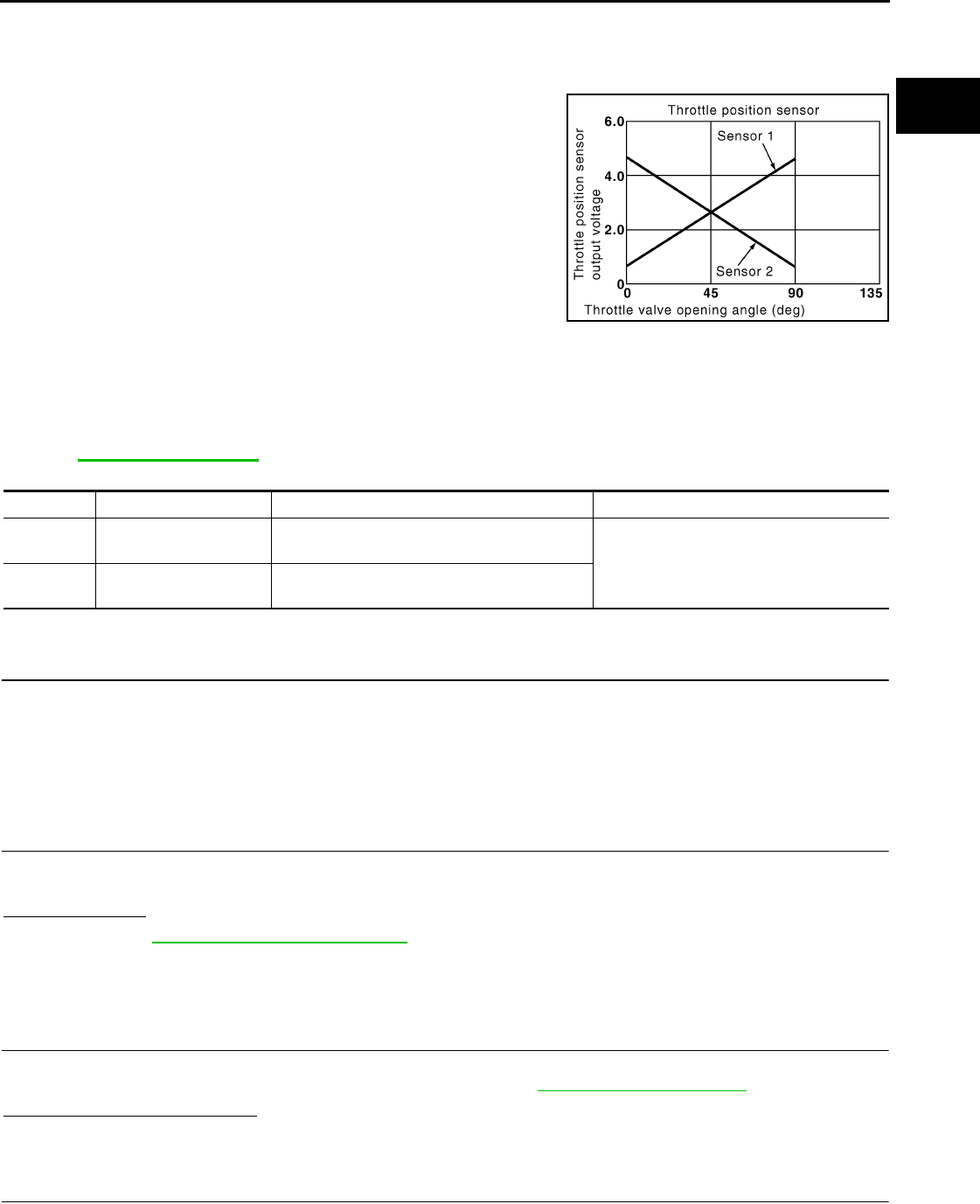
P0122, P0123 TP SENSOR
EC-635
< COMPONENT DIAGNOSIS > [FOR USA (FEDERAL) AND CANADA]
C
D
E
F
G
H
I
J
K
L
M
A
EC
N
P
O
P0122, P0123 TP SENSOR
Description INFOID:0000000004529502
Electric throttle control actuator consists of throttle control motor,
throttle position sensor, etc. The throttle position sensor responds to
the throttle valve movement.
The throttle position sensor has two sensors. These sensors are a
kind of potentiometer which transform the throttle valve position into
output voltage, and emit the voltage signals to the ECM. The ECM
judges the current opening angle of the throttle valve from these sig-
nals and contols the throttle valve opening angle in response to driv-
ing conditions via the throttle contorol motor.
DTC Logic INFOID:0000000004529503
DTC DETECTION LOGIC
NOTE:
If DTC P0122 or P0123 is displayed with DTC P0643, first perform the trouble diagnosis for DTC P0643.
Refer to EC-784, "DTC Logic".
DTC CONFIRMATION PROCEDURE
1.PRECONDITIONING
If DTC CONFIRMATION PROCEDURE has been previously conducted, always turn ignition switch OFF and
wait at least 10 seconds before conducting the next test.
TESTING CONDITION:
Before performing the following procedure, confirm that battery voltage is more than 8V at idle.
>> GO TO 2.
2.PERFORM DTC CONFIRMATION PROCEDURE
1. Start engine and let it idle for 1 second.
2. Check DTC.
Is DTC detected?
YES >> Go to EC-635, "Diagnosis Procedure".
NO >> INSPECTION END
Diagnosis Procedure INFOID:0000000004529504
1.CHECK GROUND CONNECTION
1. Turn ignition switch OFF.
2. Check ground connection E21. Refer to Ground Inspection in GI-44, "Circuit Inspection".
Is the inspection result normal?
YES >> GO TO 2.
NO >> Repair or replace ground connection.
2.CHECK THROTTLE POSITION SENSOR 2 POWER SUPPLY CIRCUIT
1. Disconnect electric throttle control actuator harness connector.
2. Turn ignition switch ON.
PBIB0145E
DTC No. Trouble diagnosis name DTC detecting condition Possible cause
P0122 Throttle position sensor
2 circuit low input An excessively low voltage from the TP sensor
2 is sent to ECM. • Harness or connectors
(TP sensor 2 circuit is open or shorted.)
• Electric throttle control actuator
(TP sensor 2)
P0123 Throttle position sensor
2 circuit high input
An excessively high voltage from the TP sensor
2 is sent to ECM.
Revision: 2008 August 2009 Rogue

EC-636
< COMPONENT DIAGNOSIS > [FOR USA (FEDERAL) AND CANADA]
P0122, P0123 TP SENSOR
3. Check the voltage between electric throttle control actuator harness connector and ground.
Is the inspection result normal?
YES >> GO TO 3.
NO >> Repair open circuit or short to ground or short to power in harness or connectors.
3.CHECK THROTTLE POSITION SENSOR 2 GROUND CIRCUIT FOR OPEN AND SHORT
1. Turn ignition switch OFF.
2. Disconnect ECM harness connector.
3. Check the continuity between electric throttle control actuator harness connector and ECM harness con-
nector.
4. Also check harness for short to ground and short to power.
Is the inspection result normal?
YES >> GO TO 4.
NO >> Repair open circuit or short to ground or short to power in harness or connectors.
4.CHECK THROTTLE POSITION SENSOR 2 INPUT SIGNAL CIRCUIT FOR OPEN AND SHORT
1. Check the continuity between electric throttle control actuator harness connector and ECM harness con-
nector.
2. Also check harness for short to ground and short to power.
Is the inspection result normal?
YES >> GO TO 5.
NO >> Repair open circuit or short to ground or short to power in harness or connectors.
5.CHECK THROTTLE POSITION SENSOR
Refer to EC-637, "Component Inspection".
Is the inspection result normal?
YES >> GO TO 7.
NO >> GO TO 6.
6.REPLACE ELECTRIC THROTTLE CONTROL ACTUATOR
1. Replace electric throttle control actuator.
2. Perform EC-637, "Special Repair Requirement".
>> INSPECTION END
7.CHECK INTERMITTENT INCIDENT
Refer to GI-41, "Intermittent Incident".
>> INSPECTION END
Electric throttle control actuator Ground Voltage
Connector Terminal
F29 1 Ground Approx. 5 V
Electric throttle control actuator ECM Continuity
Connector Terminal Connector Terminal
F29 4 F8 36 Existed
Electric throttle control actuator ECM Continuity
Connector Terminal Connector Terminal
F29 3 F8 38 Existed
Revision: 2008 August 2009 Rogue

P0122, P0123 TP SENSOR
EC-637
< COMPONENT DIAGNOSIS > [FOR USA (FEDERAL) AND CANADA]
C
D
E
F
G
H
I
J
K
L
M
A
EC
N
P
O
Component Inspection INFOID:0000000004529505
1.CHECK THROTTLE POSITION SENSOR
1. Turn ignition switch OFF.
2. Reconnect all harness connectors disconnected.
3. Perform EC-504, "THROTTLE VALVE CLOSED POSITION LEARNING : Special Repair Requirement".
4. Turn ignition switch ON.
5. Set selector lever to the D position.
6. Check the voltage between ECM harness connector terminals.
Is the inspection result normal?
YES >> INSPECTION END
NO >> GO TO 2.
2.REPLACE ELECTRIC THROTTLE CONTROL ACTUATOR
1. Replace electric throttle control actuator.
2. Perform EC-637, "Special Repair Requirement".
>> INSPECTION END
Special Repair Requirement INFOID:0000000004529506
1.PERFORM THROTTLE VALVE CLOSED POSITION LEARNING
Refer to EC-504, "THROTTLE VALVE CLOSED POSITION LEARNING : Special Repair Requirement"
>> GO TO 2.
2.PERFORM IDLE AIR VOLUME LEARNING
Refer to EC-505, "IDLE AIR VOLUME LEARNING : Special Repair Requirement"
>> END
ECM
Condition Voltage+−
Connector Terminal Connector Terminal
F8
37
(TP sensor 1
signal) F8
36
(Sensor
ground) Accelerator pedal
Fully released More than 0.36 V
Fully depressed Less than 4.75 V
38
(TP sensor 2
signal)
Fully released Less than 4.75 V
Fully depressed More than 0.36 V
Revision: 2008 August 2009 Rogue
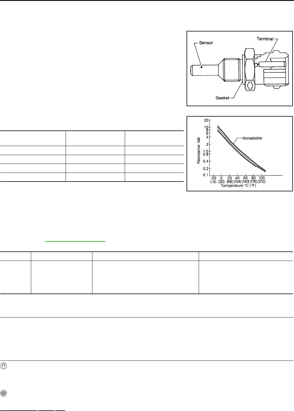
EC-638
< COMPONENT DIAGNOSIS > [FOR USA (FEDERAL) AND CANADA]
P0125 ECT SENSOR
P0125 ECT SENSOR
Description INFOID:0000000004533691
The engine coolant temperature sensor is used to detect the engine
coolant temperature. The sensor modifies a voltage signal from the
ECM. The modified signal returns to the ECM as the engine coolant
temperature input. The sensor uses a thermistor which is sensitive to
the change in temperature. The electrical resistance of the ther-
mistor decreases as temperature increases.
<Reference data>
*: These data are reference values and are measured between ECM terminals 46
(Engine coolant temperature sensor) and 52 (Sensor ground).
DTC Logic INFOID:0000000004529508
DTC DETECTION LOGIC
NOTE:
If DTC P0125 is displayed with P0117 or P0118, first perform the trouble diagnosis for DTC P0117 or
P0118. Refer to EC-632, "DTC Logic".
DTC CONFIRMATION PROCEDURE
1.PRECONDITIONING
If DTC CONFIRMATION PROCEDURE has been previously conducted, always turn ignition switch OFF and
wait at least 10 seconds before conducting the next test.
>> GO TO 2.
2.CHECK ENGINE COOLANT TEMPERATURE SENSOR FUNCTION
With CONSULT-III
1. Turn ignition switch ON.
2. Select “DATA MONITOR” mode with CONSULT-III.
3. Check that “COOLAN TEMP/S” indication is above 5°C (41°F).
With GST
Follow the procedure “With CONSULT-III” above.
Is it above 10°C (50°F)?
SEF594K
Engine coolant temperature
[°C (°F)] Voltage* (V) Resistance (kΩ)
–10 (14) 4.4 7.0 - 11.4
20 (68) 3.5 2.10 - 2.90
50 (122) 2.2 0.68 - 1.00
90 (194) 0.9 0.236 - 0.260
SEF012P
DTC No. Trouble diagnosis name DTC detecting condition Possible cause
P0125
Insufficient engine coolant
temperature for closed
loop fuel control
• Voltage sent to ECM from the sensor is not
practical, even when some time has passed
after starting the engine.
• Engine coolant temperature is insufficient for
closed loop fuel control.
• Harness or connectors
(High resistance in the circuit)
• Engine coolant temperature sensor
•Thermostat
Revision: 2008 August 2009 Rogue

P0125 ECT SENSOR
EC-639
< COMPONENT DIAGNOSIS > [FOR USA (FEDERAL) AND CANADA]
C
D
E
F
G
H
I
J
K
L
M
A
EC
N
P
O
YES >> INSPECTION END
NO >> GO TO 3.
3.PERFORM DTC CONFIRMATION PROCEDURE
With CONSULT-III
1. Start engine and run it for 65 minutes at idle speed.
2. Check 1st tip DTC.
If “COOLAN TEMP/S” indication increases to more than 5°C (41°F) within 65 minutes, stop engine
because the test result will be OK.
CAUTION:
Never overheat engine.
With GST
Follow the procedure “With CONSULT-III” above.
Is 1st trip DTC detected?
YES >> EC-639, "Diagnosis Procedure"
NO >> INSPECTION END
Diagnosis Procedure INFOID:0000000004529509
1.CHECK GROUND CONNECTION
1. Turn ignition switch OFF.
2. Check ground connection E21. Refer to Ground Inspection in GI-44, "Circuit Inspection".
Is the inspection result normal?
YES >> GO TO 2.
NO >> Repair or replace ground connection.
2.CHECK ENGINE COOLANT TEMPERATURE SENSOR
Refer to EC-639, "Component Inspection".
Is the inspection result normal?
YES >> GO TO 3.
NO >> Replace engine coolant temperature sensor.
3.CHECK THERMOSTAT OPERATION
When the engine is cold [lower than 70°C (158°F)] condition, grasp lower radiator hose and confirm the engine
coolant does not flow.
Is the inspection result normal?
YES >> GO TO 4.
NO >> Repair or replace thermostat. Refer to CO-25, "Removal and Installation".
4.CHECK INTERMITTENT INCIDENT
Refer to GI-41, "Intermittent Incident".
>> INSPECTION END
Component Inspection INFOID:0000000004533692
1.CHECK ENGINE COOLANT TEMPERATURE SENSOR
1. Turn ignition switch OFF.
2. Disconnect engine coolant temperature sensor harness connector.
3. Remove engine coolant temperature sensor.
Revision: 2008 August 2009 Rogue

EC-640
< COMPONENT DIAGNOSIS > [FOR USA (FEDERAL) AND CANADA]
P0125 ECT SENSOR
4. Check resistance between engine coolant temperature sensor
terminals by heating with hot water as shown in the figure.
Is the inspection result normal?
YES >> INSPECTION END
NO >> Replace engine coolant temperature sensor.
Terminals Condition Resistance (kΩ)
1 and 2 Temperature [°C (°F)]
20 (68) 2.10 - 2.90
50 (122) 0.68 - 1.00
90 (194) 0.236 - 0.260
JMBIA0080ZZ
Revision: 2008 August 2009 Rogue
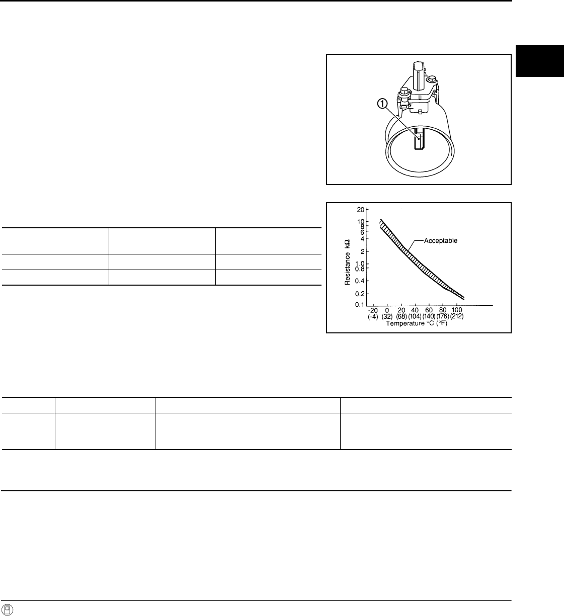
P0127 IAT SENSOR
EC-641
< COMPONENT DIAGNOSIS > [FOR USA (FEDERAL) AND CANADA]
C
D
E
F
G
H
I
J
K
L
M
A
EC
N
P
O
P0127 IAT SENSOR
Description INFOID:0000000004533689
The intake air temperature sensor is built-into the mass air flow sen-
sor (1). The sensor detects intake air temperature and transmits a
signal to the ECM.
The temperature sensing unit uses a thermistor which is sensitive to
the change in temperature. Electrical resistance of the thermistor
decreases in response to the rise in temperature.
<Reference data>
*: These data are reference values and are measured between ECM terminals 50
(Intake air temperature sensor) and 58 (Sensor ground).
DTC Logic INFOID:0000000004529512
DTC DETECTION LOGIC
DTC CONFIRMATION PROCEDURE
1.PRECONDITIONING
If DTC CONFIRMATION PROCEDURE has been previously conducted, always turn ignition switch OFF and
wait at least 10 seconds before conducting the next test.
TESTING CONDITION:
This test may be conducted with the drive wheels lifted in the shop or by driving the vehicle. If a road
test is expected to be easier, it is unnecessary to lift the vehicle.
>> GO TO 2.
2.PERFORM DTC CONFIRMATION PROCEDURE
With CONSULT-III
1. Wait until engine coolant temperature is less than 90°C (194°F)
- Turn ignition switch ON.
- Select “DATA MONITOR” mode with CONSULT-III.
- Check the engine coolant temperature.
- If the engine coolant temperature is not less than 90°C (194°F), turn ignition switch OFF and cool down
engine.
NOTE:
Perform the following steps before engine coolant temperature is above 90°C (194°F).
PBIA9559J
Intake air temperature
[°C (°F)] Voltage* (V) Resistance (kΩ)
25 (77) 3.3 1.800 - 2.200
80 (176) 1.2 0.283 - 0.359
SEF012P
DTC No. Trouble diagnosis name DTC detecting condition Possible cause
P0127 Intake air temperature
too high
Rationally incorrect voltage from the sensor is
sent to ECM, compared with the voltage signal
from engine coolant temperature sensor.
• Harness or connectors
(The sensor circuit is open or shorted)
• Intake air temperature sensor
Revision: 2008 August 2009 Rogue

EC-642
< COMPONENT DIAGNOSIS > [FOR USA (FEDERAL) AND CANADA]
P0127 IAT SENSOR
2. Start engine.
3. Hold vehicle speed at more than 70 km/h (43 MPH) for 100 consecutive seconds.
CAUTION:
Always drive vehicle at a safe speed.
4. Check 1st trip DTC.
With GST
Follow the procedure “With CONSULT-III” above.
Is 1st trip DTC detected?
YES >> Go to EC-642, "Diagnosis Procedure".
NO >> INSPECTION END
Diagnosis Procedure INFOID:0000000004529513
1.CHECK GROUND CONNECTION
1. Turn ignition switch OFF.
2. Check ground connection E21. Refer to Ground Inspection in GI-44, "Circuit Inspection".
Is the inspection result normal?
YES >> GO TO 2.
NO >> Repair or replace ground connection.
2.CHECK INTAKE AIR TEMPERATURE SENSOR
Refer to EC-642, "Component Inspection".
Is the inspection result normal?
YES >> GO TO 3.
NO >> Replace mass air flow sensor (with intake air temperature sensor).
3.CHECK INTERMITTENT INCIDENT
Refer to GI-41, "Intermittent Incident".
>> INSPECTION END
Component Inspection INFOID:0000000004533690
1.CHECK INTAKE AIR TEMPERATURE SENSOR
1. Turn ignition switch OFF.
2. Disconnect mass air flow sensor harness connector.
3. Check resistance between mass air flow sensor terminals as follows.
Is the inspection result normal?
YES >> INSPECTION END
NO >> Replace mass air flow sensor (with intake air temperature sensor).
Terminals Condition Resistance (kΩ)
1 and 2 Intake air temperature [°C (°F)] 25 (77) 1.800 - 2.200
Revision: 2008 August 2009 Rogue
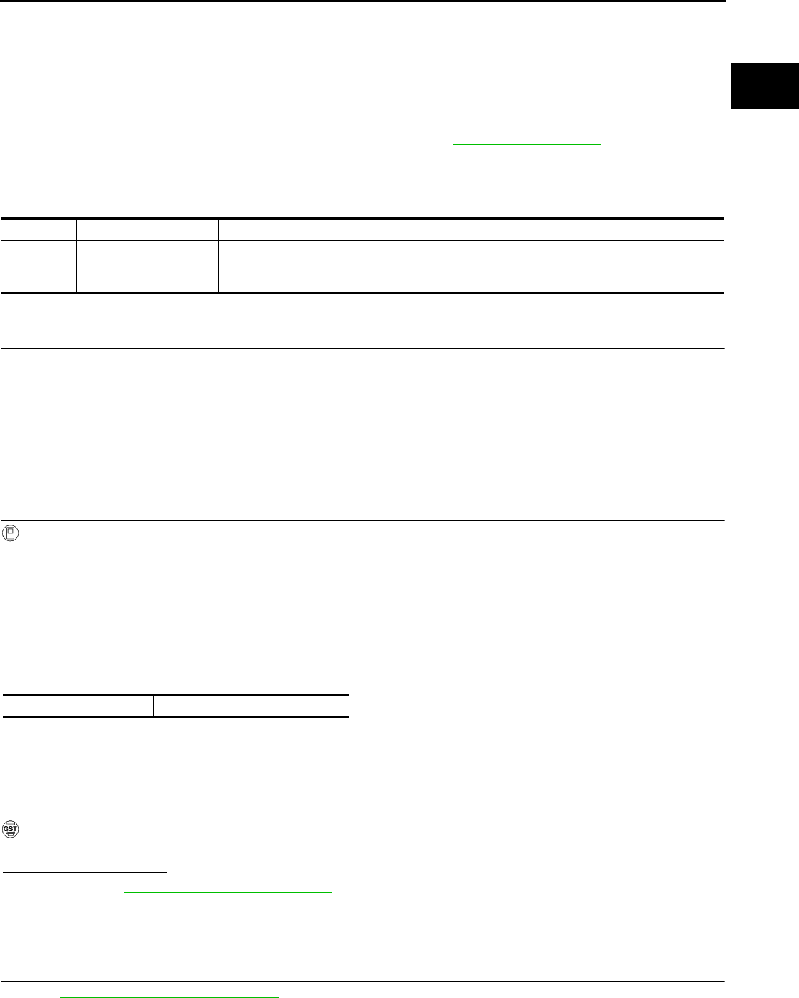
P0128 THERMOSTAT FUNCTION
EC-643
< COMPONENT DIAGNOSIS > [FOR USA (FEDERAL) AND CANADA]
C
D
E
F
G
H
I
J
K
L
M
A
EC
N
P
O
P0128 THERMOSTAT FUNCTION
DTC Logic INFOID:0000000004529515
DTC DETECTION LOGIC
NOTE:
If DTC P0128 is displayed with DTC PP0300, P0301, P0302, P0303 or P0304, first perform the trouble
diagnosis for DTC P0300, P0301, P0302, P0303, P0304. Refer to EC-696, "DTC Logic".
Engine coolant temperature has not risen enough to open the thermostat even though the engine has run long
enough.
This is due to a leak in the seal or the thermostat stuck being open.
DTC CONFIRMATION PROCEDURE
1.PRECONDITIONING
If DTC CONFIRMATION PROCEDURE has been previously conducted, always turn ignition switch OFF and
wait at least 10 seconds before conducting the next test.
TESTING CONDITION:
•For best results, perform at ambient temperature of –10°C (14°F) or higher.
•For best results, perform at engine coolant temperature of –10°C (14°F) to 56°C (133°F).
•Before performing the following procedure, do not add fuel.
>> GO TO 2.
2.PERFORM DTC CONFIRMATION PROCEDURE
With CONSULT-III
1. Turn A/C switch OFF.
2. Turn blower fan switch OFF.
3. Turn ignition switch ON.
4. Select “COOLAN TEMP/S” in “DATA MONITOR” mode with CONSULT-III.
5. Check the indication of “COOLAN TEMP/S”
If it is below 56°C (126°F), go to next step.
If it is above 56°C (126°F), cool down the engine to less than 56°C (126°F). Then go to next steps.
6. Start engine drive vehicle for 10 consecutive minutes under the following conditions.
CAUTION:
Always drive vehicle at a safe speed.
NOTE:
If “COOLAN TEMP/S” increases to more than 75°C (160°F) within 10 minutes, turn ignition switch
OFF because the test result will be OK.
7. Check 1st trip DTC.
With GST
Follow the procedure “With CONSULT-III” above.
Is 1st trip DTC detected?
YES >> Go to EC-643, "Diagnosis Procedure".
NO >> INSPECTION END
Diagnosis Procedure INFOID:0000000004529516
1.CHECK ENGINE COOLANT TEMPERATURE SENSOR
Refer to EC-644, "Component Inspection".
DTC No. Trouble diagnosis name DTC detecting condition Possible cause
P0128 Thermostat function
The engine coolant temperature does not
reach to specified temperature even though
the engine has run long enough.
•Thermostat
• Leakage from sealing portion of thermostat
• Engine coolant temperature sensor
VHCL SPEED SE More than 56 km/h (35 MPH)
Revision: 2008 August 2009 Rogue
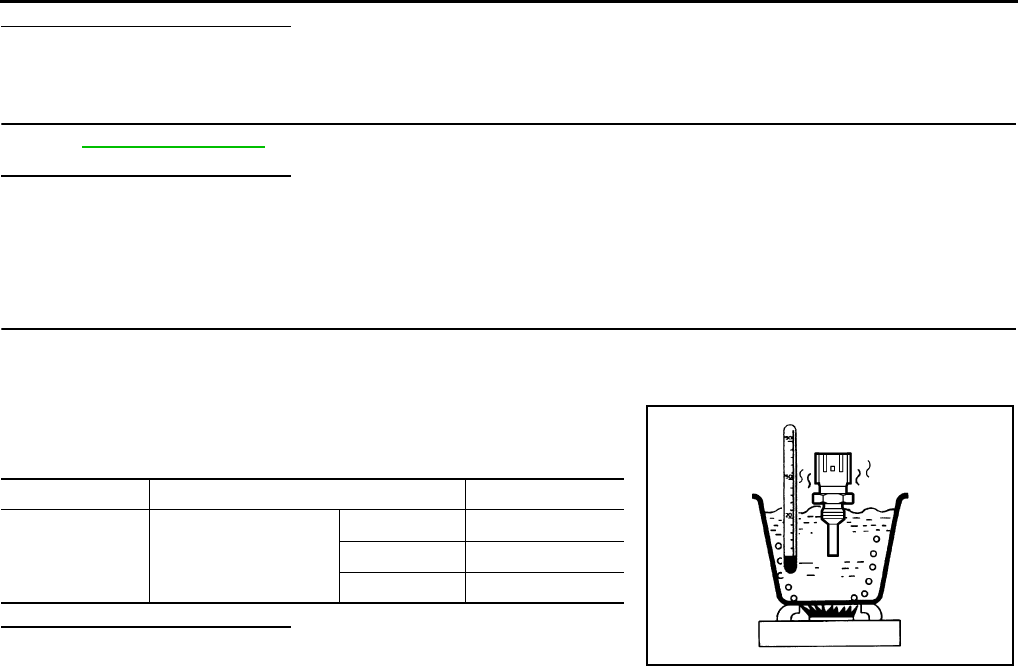
EC-644
< COMPONENT DIAGNOSIS > [FOR USA (FEDERAL) AND CANADA]
P0128 THERMOSTAT FUNCTION
Is the inspection result normal?
YES >> GO TO 2.
NO >> Replace engine coolant temperature sensor.
2.CHECK THERMOSTAT
Refer to CO-26, "Inspection".
Is the inspection result normal?
YES >> INSPECTION END
NO >> Replace thermostat.
Component Inspection INFOID:0000000004533693
1.CHECK ENGINE COOLANT TEMPERATURE SENSOR
1. Turn ignition switch OFF.
2. Disconnect engine coolant temperature sensor harness connector.
3. Remove engine coolant temperature sensor.
4. Check resistance between engine coolant temperature sensor
terminals by heating with hot water as shown in the figure.
Is the inspection result normal?
YES >> INSPECTION END
NO >> Replace engine coolant temperature sensor.
Terminals Condition Resistance (kΩ)
1 and 2 Temperature [°C (°F)]
20 (68) 2.10 - 2.90
50 (122) 0.68 - 1.00
90 (194) 0.236 - 0.260
JMBIA0080ZZ
Revision: 2008 August 2009 Rogue
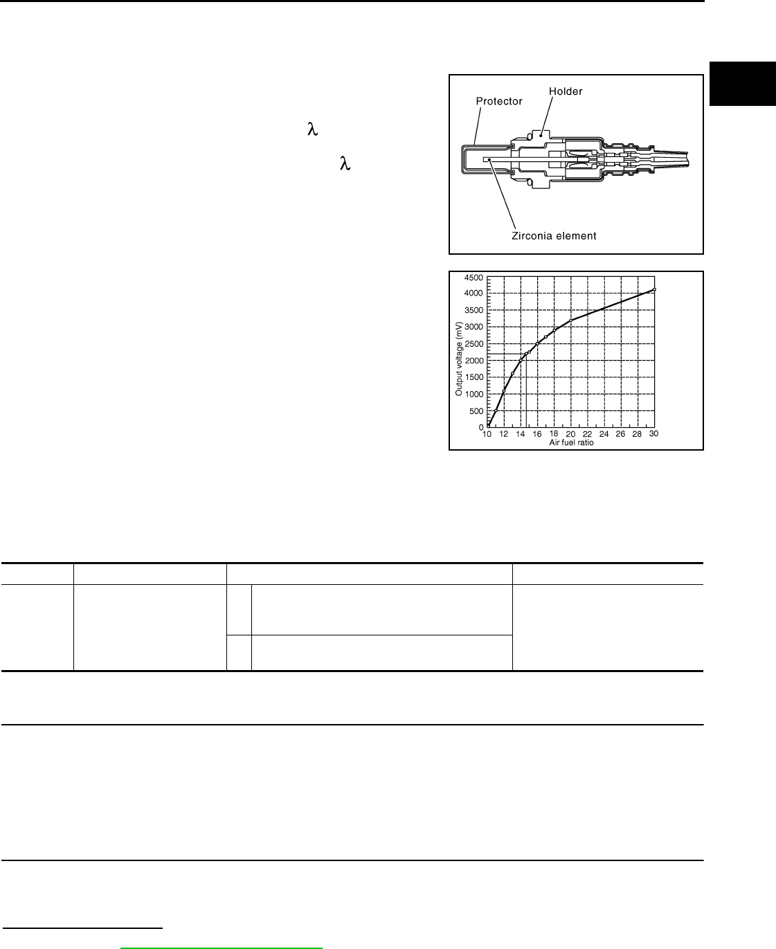
P0130 A/F SENSOR 1
EC-645
< COMPONENT DIAGNOSIS > [FOR USA (FEDERAL) AND CANADA]
C
D
E
F
G
H
I
J
K
L
M
A
EC
N
P
O
P0130 A/F SENSOR 1
Description INFOID:0000000004529518
The air fuel ratio (A/F) sensor 1 is a planar one-cell limit current sen-
sor. The sensor element of the A/F sensor 1 is composed an elec-
trode layer, which transports ions. It has a heater in the element.
The sensor is capable of precise measurement = 1, but also in the
lean and rich range. Together with its control electronics, the sensor
outputs a clear, continuous signal throughout a wide range.
The exhaust gas components diffuse through the diffusion layer at
the sensor cell. An electrode layer is applied voltage, and this current
relative oxygen density in lean. Also this current relative hydrocar-
bon density in rich.
Therefore, the A/F sensor 1 is able to indicate air fuel ratio by this
electrode layer of current. In addition, a heater is integrated in the
sensor to ensure the required operating temperature of approxi-
mately 800°C (1,472°F).
DTC Logic INFOID:0000000004529519
DTC DETECTION LOGIC
To judge malfunctions, the diagnosis checks that the A/F signal computed by ECM from the A/F sensor 1 sig-
nal fluctuates according to fuel feedback control.
DTC CONFIRMATION PROCEDURE
1.PRECONDITIONING
If DTC CONFIRMATION PROCEDURE has been previously conducted, always turn ignition switch OFF and
wait at least 10 seconds before conducting the next test.
TESTING CONDITION:
Before performing the following procedure, confirm that battery voltage is more than 11V at idle.
>> GO TO 2.
2.PERFORM DTC CONFIRMATION PROCEDURE FOR MALFUNCTION A
1. Start engine and warm it up to normal operating temperature.
2. Let it idle for 2 minutes.
3. Check 1st trip DTC.
Is 1st trip DTC detected?
YES >> Go to EC-647, "Diagnosis Procedure".
NO-1 >> With CONSULT-III: GO TO 3.
NO-2 >> Without CONSULT-III: GO TO 7.
JMBIA0112GB
PBIB3354E
DTC No. Trouble diagnosis name DTC detecting condition Possible Cause
P0130 Air fuel ratio (A/F) sensor 1
circuit
A)
The A/F signal computed by ECM from the A/F
sensor 1 signal is constantly in the range other
than approx. 2.2V.
• Harness or connectors
(The A/F sensor 1 circuit is open
or shorted.)
• A/F sensor 1
B) The A/F signal computed by ECM from the A/F
sensor 1 signal is constantly approx. 2.2V.
Revision: 2008 August 2009 Rogue
EC-646
< COMPONENT DIAGNOSIS > [FOR USA (FEDERAL) AND CANADA]
P0130 A/F SENSOR 1
3.CHECK AIR FUEL RATIO (A/F) SENSOR 1 FUNCTION
1. Select “A/F SEN1 (B1)” in “DATA MONITOR” mode with CONSULT-III.
2. Check “A/F SEN1 (B1)” indication.
Does the indication fluctuates around 2.2 V?
YES >> GO TO 4.
NO >> Go to EC-647, "Diagnosis Procedure".
4.PERFORM DTC CONFIRMATION PROCEDURE FOR MALFUNCTION B-I
1. Select “A/F SEN1 (B1) P1276” of “A/F SEN1” in “DTC WORK SUPPORT” mode with CONSULT-III.
2. Touch “START”.
3. When the following conditions are met, “TESTING” will be displayed on the CONSULT-III screen.
If “TESTING” is not displayed after 20 seconds, retry from step 2.
CAUTION:
Always drive vehicle at a safe speed.
Is “TESTING” displayed on CONSULT-III screen?
YES >> GO TO 5.
NO >> Check A/F sensor 1 function again. GO TO 3.
5.PERFORM DTC CONFIRMATION PROCEDURE FOR MALFUNCTION B-II
Release accelerator pedal fully.
NOTE:
Never apply brake when releasing the accelerator pedal.
Which does “TESTING” change to?
COMPLETED>>GO TO 6.
OUT OF CONDITION>>Retry DTC CONFIRMATION PROCEDURE. GO TO 4.
6.PERFORM DTC CONFIRMATION PROCEDURE FOR MALFUNCTION B-III
Touch “SELF-DIAG RESULT”
Which is displayed on CONSULT-III screen?
OK >> INSPECTION END
NG >> Go to EC-647, "Diagnosis Procedure".
7.PERFORM COMPONENT FUNCTION CHECK FOR MALFUNCTION B
Perform Component Function Check. Refer to EC-646, "Component Function Check".
NOTE:
Use component function check to check the overall function of the A/F sensor 1 circuit. During this check, a
1st trip DTC might not be confirmed.
Is the inspection result normal?
YES >> INSPECTION END
NO >> Go to EC-647, "Diagnosis Procedure".
Component Function Check INFOID:0000000004529520
1.PERFORM COMPONENT FUNCTION CHECK
With GST
1. Start engine and warm it up to normal operating temperature.
2. Drive the vehicle at a speed of 80 km/h (50 MPH) for a few minutes in the suitable gear position.
3. Sheft the selector lever to the D position, then release the accelerator pedal fully until the vehicle speed
decreases to 50 km/h (31 MPH).
CAUTION:
ENG SPEED 1,000 - 3,200 rpm
VHCL SPEED SE More than 64 km/h (40 mph)
B/FUEL SCHDL 1.0 - 11.5 msec
Selector lever D position
Revision: 2008 August 2009 Rogue

P0130 A/F SENSOR 1
EC-647
< COMPONENT DIAGNOSIS > [FOR USA (FEDERAL) AND CANADA]
C
D
E
F
G
H
I
J
K
L
M
A
EC
N
P
O
Always drive vehicle at a safe speed.
NOTE:
Never apply brake when releasing the accelerator pedal.
4. Repeat steps 2 and 3 for five times.
5. Stop the vehicle and turn ignition switch OFF.
6. Wait at least 10 seconds and restart engine.
7. Repeat steps 2 and 3 for five times.
8. Stop the vehicle and connect GST to the vehicle.
9. Check 1st trip DTC.
Is 1st trip DTC detected?
YES >> Go to EC-647, "Diagnosis Procedure".
NO >> INSPECTION END
Diagnosis Procedure INFOID:0000000004529521
1.CHECK GROUND CONNECTION
1. Turn ignition switch OFF.
2. Check ground connection E21. Refer to Ground Inspection in GI-44, "Circuit Inspection".
Is the inspection result normal?
YES >> GO TO 2.
NO >> Repair or replace ground connection.
2.CHECK AIR FUEL RATIO (A/F) SENSOR 1 POWER SUPPLY CIRCUIT
1. Disconnect A/F sensor 1 harness connector.
2. Turn ignition switch ON.
3. Check the voltage between A/F sensor 1 harness connector and ground.
Is the inspection result normal?
YES >> GO TO 4.
NO >> GO TO 3.
3.DETECT MALFUNCTIONING PART
Check the following.
• Harness connectors E6, F123
• IPDM E/R harness connector E14
• 15A fuse (No. 63)
• Harness for open or short between A/F sensor 1 and fuse
>> Repair or replace harness or connectors.
4.CHECK A/F SENSOR 1 INPUT SIGNAL CIRCUIT FOR OPEN AND SHORT
1. Turn ignition switch OFF.
2. Disconnect ECM harness connector.
3. Check the continuity between A/F sensor 1 harness connector and ECM harness connector.
4. Check the continuity between A/F sensor 1 harness connector or ECM harness connector and ground.
A/F sensor 1 Ground Voltage
Connector Terminal
F27 4 Ground Battery voltage
A/F sensor 1 ECM Continuity
Connector Terminal Connector Terminal
F27 1F8 45 Existed
249
Revision: 2008 August 2009 Rogue

EC-648
< COMPONENT DIAGNOSIS > [FOR USA (FEDERAL) AND CANADA]
P0130 A/F SENSOR 1
5. Also check harness for short to power.
Is the inspection result normal?
YES >> GO TO 5.
NO >> Repair open circuit or short to ground or short to power in harness or connectors.
5.CHECK INTERMITTENT INCIDENT
Perform GI-41, "Intermittent Incident".
Is the inspection result normal?
YES >> GO TO 6.
NO >> Repair or replace.
6.REPLACE AIR FUEL RATIO (A/F) SENSOR 1
Replace air fuel ratio (A/F) sensor 1.
CAUTION:
• Discard any A/F sensor which has been dropped from a height of more than 0.5 m (19.7 in) onto a
hard surface such as a concrete floor; use a new one.
• Before installing new A/F sensor, clean exhaust system threads using oxygen sensor thread cleaner
[commercial service tool (J-43897-18 or J-43897-12)] and approved anti-seize lubricant (commercial
service tool).
>> INSPECTION END
A/F sensor 1 ECM Ground Continuity
Connector Terminal Connector Terminal
F27 1F8 45 Ground Not existed
249
Revision: 2008 August 2009 Rogue
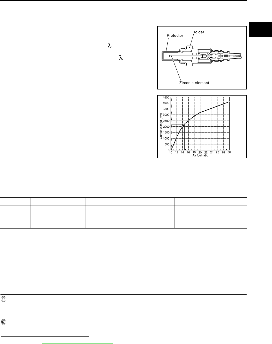
P0131 A/F SENSOR 1
EC-649
< COMPONENT DIAGNOSIS > [FOR USA (FEDERAL) AND CANADA]
C
D
E
F
G
H
I
J
K
L
M
A
EC
N
P
O
P0131 A/F SENSOR 1
Description INFOID:0000000004533854
The air fuel ratio (A/F) sensor 1 is a planar one-cell limit current sen-
sor. The sensor element of the A/F sensor 1 is composed an elec-
trode layer, which transports ions. It has a heater in the element.
The sensor is capable of precise measurement = 1, but also in the
lean and rich range. Together with its control electronics, the sensor
outputs a clear, continuous signal throughout a wide range.
The exhaust gas components diffuse through the diffusion layer at
the sensor cell. An electrode layer is applied voltage, and this current
relative oxygen density in lean. Also this current relative hydrocar-
bon density in rich.
Therefore, the A/F sensor 1 is able to indicate air fuel ratio by this
electrode layer of current. In addition, a heater is integrated in the
sensor to ensure the required operating temperature of approxi-
mately 800°C (1,472°F).
DTC Logic INFOID:0000000004529523
DTC DETECTION LOGIC
To judge the malfunction, the diagnosis checks that the A/F signal computed by ECM from the A/F sensor 1
signal is not inordinately low.
DTC CONFIRMATION PROCEDURE
1.PRECONDITIONING
If DTC CONFIRMATION PROCEDURE has been previously conducted, always turn ignition switch OFF and
wait at least 10 seconds before conducting the next test.
TESTING CONDITION:
Before performing the following procedure, confirm that battery voltage is more than 10.5V at idle.
>> GO TO 2.
2.CHECK A/F SENSOR FUNCTION
With CONSULT-III
1. Start engine and warm it up to normal operating temperature.
2. Select “A/F SEN1 (B1)” in “DATA MONITOR” mode with CONSULT-III.
3. Check “A/F SEN1 (B1)” indication.
With GST
Follow the procedure “With CONSULT-III” above.
Is the indication constantly approx. 0V?
YES >> Go to EC-650, "Diagnosis Procedure".
JMBIA0112GB
PBIB3354E
DTC No. Trouble diagnosis name DTC detecting condition Possible Cause
P0131 Air fuel ratio (A/F) sensor 1
circuit low voltage
• The A/F signal computed by ECM from the A/
F sensor 1 signal is constantly approx. 0V.
• Harness or connectors
(The A/F sensor 1 circuit is open or
shorted.)
• A/F sensor 1
Revision: 2008 August 2009 Rogue

EC-650
< COMPONENT DIAGNOSIS > [FOR USA (FEDERAL) AND CANADA]
P0131 A/F SENSOR 1
NO >> GO TO 3.
3.PERFORM DTC CONFIRMATION PROCEDURE
With CONSULT-III
1. Turn ignition switch OFF, wait at least 10 seconds and then restart engine.
2. Drive and accelerate vehicle to more than 40 km/h (25 MPH) within 20 seconds after restarting engine.
CAUTION:
Always drive vehicle at a safe speed.
3. Maintain the following conditions for approximately 20 consecutive seconds.
NOTE:
•Keep the accelerator pedal as steady as possible during the cruising.
•If this procedure is not completed within 1 minute after restarting engine at step 1, return to step
1.
4. Check 1st trip DTC.
With GST
Follow the procedure “With CONSULT-III” above.
Is 1st trip DTC detected?
YES >> Go to EC-650, "Diagnosis Procedure".
NO >> INSPECTION END
Diagnosis Procedure INFOID:0000000004529524
1.CHECK GROUND CONNECTION
1. Turn ignition switch OFF.
2. Check ground connection E21. Refer to Ground Inspection in GI-44, "Circuit Inspection".
Is the inspection result normal?
YES >> GO TO 2.
NO >> Repair or replace ground connection.
2.CHECK AIR FUEL RATIO (A/F) SENSOR 1 POWER SUPPLY CIRCUIT
1. Disconnect A/F sensor 1 harness connector.
2. Turn ignition switch ON.
3. Check the voltage between A/F sensor 1 harness connector and ground.
Is the inspection result normal?
YES >> GO TO 4.
NO >> GO TO 3.
3.DETECT MALFUNCTIONING PART
Check the following.
• Harness connectors E6, F123
• IPDM E/R harness connector E14
• 15A fuse (No. 63)
• Harness for open or short between A/F sensor 1 and fuse
>> Repair or replace harness or connectors.
ENG SPEED 1,000 - 3,200 rpm
VHCL SPEED SE More than 40 km/h (25 mph)
B/FUEL SCHDL 1.5 - 9.0 msec
Selector lever Suitable position
A/F sensor 1 Ground Voltage
Connector Terminal
F27 4 Ground Battery voltage
Revision: 2008 August 2009 Rogue

P0131 A/F SENSOR 1
EC-651
< COMPONENT DIAGNOSIS > [FOR USA (FEDERAL) AND CANADA]
C
D
E
F
G
H
I
J
K
L
M
A
EC
N
P
O
4.CHECK A/F SENSOR 1 INPUT SIGNAL CIRCUIT FOR OPEN AND SHORT
1. Turn ignition switch OFF.
2. Disconnect ECM harness connector.
3. Check the continuity between A/F sensor 1 harness connector and ECM harness connector.
4. Check the continuity between A/F sensor 1 harness connector or ECM harness connector and ground.
5. Also check harness for short to power.
Is the inspection result normal?
YES >> GO TO 5.
NO >> Repair open circuit or short to ground or short to power in harness or connectors.
5.CHECK INTERMITTENT INCIDENT
Perform GI-41, "Intermittent Incident".
Is the inspection result normal?
YES >> GO TO 6.
NO >> Repair or replace.
6.REPLACE AIR FUEL RATIO (A/F) SENSOR 1
Replace air fuel ratio (A/F) sensor 1.
CAUTION:
• Discard any A/F sensor which has been dropped from a height of more than 0.5 m (19.7 in) onto a
hard surface such as a concrete floor; use a new one.
• Before installing new A/F sensor, clean exhaust system threads using oxygen sensor thread cleaner
[commercial service tool (J-43897-18 or J-43897-12)] and approved anti-seize lubricant (commercial
service tool).
>> INSPECTION END
A/F sensor 1 ECM Continuity
Connector Terminal Connector Terminal
F27 1F8 45 Existed
249
A/F sensor 1 ECM Ground Continuity
Connector Terminal Connector Terminal
F27 1F8 45 Ground Not existed
249
Revision: 2008 August 2009 Rogue

EC-652
< COMPONENT DIAGNOSIS > [FOR USA (FEDERAL) AND CANADA]
P0132 A/F SENSOR 1
P0132 A/F SENSOR 1
Description INFOID:0000000004533855
The air fuel ratio (A/F) sensor 1 is a planar one-cell limit current sen-
sor. The sensor element of the A/F sensor 1 is composed an elec-
trode layer, which transports ions. It has a heater in the element.
The sensor is capable of precise measurement = 1, but also in the
lean and rich range. Together with its control electronics, the sensor
outputs a clear, continuous signal throughout a wide range.
The exhaust gas components diffuse through the diffusion layer at
the sensor cell. An electrode layer is applied voltage, and this current
relative oxygen density in lean. Also this current relative hydrocar-
bon density in rich.
Therefore, the A/F sensor 1 is able to indicate air fuel ratio by this
electrode layer of current. In addition, a heater is integrated in the
sensor to ensure the required operating temperature of approxi-
mately 800°C (1,472°F).
DTC Logic INFOID:0000000004529526
DTC DETECTION LOGIC
To judge the malfunction, the diagnosis checks that the A/F signal computed by ECM from the A/F sensor 1
signal is not inordinately high.
DTC CONFIRMATION PROCEDURE
1.PRECONDITIONING
If DTC CONFIRMATION PROCEDURE has been previously conducted, always turn ignition switch OFF and
wait at least 10 seconds before conducting the next test.
TESTING CONDITION:
Before performing the following procedure, confirm that battery voltage is more than 10.5V at idle.
>> GO TO 2.
2.CHECK A/F SENSOR FUNCTION
With CONSULT-III
1. Start engine and warm it up to normal operating temperature.
2. Select “A/F SEN1 (B1)” in “DATA MONITOR” mode with CONSULT-III.
3. Check “A/F SEN1 (B1)” indication.
With GST
Follow the procedure “With CONSULT-III” above.
Is the indication constantly approx. 5 V?
YES >> Go to EC-653, "Diagnosis Procedure".
JMBIA0112GB
PBIB3354E
DTC No. Trouble diagnosis name DTC detecting condition Possible Cause
P0132 Air fuel ratio (A/F) sensor 1
circuit high voltage
• The A/F signal computed by ECM from the A/F
sensor 1 signal is constantly approx. 5V.
• Harness or connectors
(The A/F sensor 1 circuit is open or
shorted.)
• A/F sensor 1
Revision: 2008 August 2009 Rogue

P0132 A/F SENSOR 1
EC-653
< COMPONENT DIAGNOSIS > [FOR USA (FEDERAL) AND CANADA]
C
D
E
F
G
H
I
J
K
L
M
A
EC
N
P
O
NO >> GO TO 3.
3.PERFORM DTC CONFIRMATION PROCEDURE
With CONSULT-III
1. Turn ignition switch OFF, wait at least 10 seconds and then restart engine.
2. Drive and accelerate vehicle to more than 40 km/h (25 MPH) within 20 seconds after restarting engine.
CAUTION:
Always drive vehicle at a safe speed.
3. Maintain the following conditions for approximately 20 consecutive seconds.
NOTE:
•Keep the accelerator pedal as steady as possible during the cruising.
•If this procedure is not completed within 1 minute after restarting engine at step 1, return to step
1.
4. Check 1st trip DTC.
With GST
Follow the procedure “With CONSULT-III” above.
Is 1st trip DTC detected?
YES >> Go to EC-653, "Diagnosis Procedure".
NO >> INSPECTION END
Diagnosis Procedure INFOID:0000000004529527
1.CHECK GROUND CONNECTION
1. Turn ignition switch OFF.
2. Check ground connection E21. Refer to Ground Inspection in GI-44, "Circuit Inspection".
Is the inspection result normal?
YES >> GO TO 2.
NO >> Repair or replace ground connection.
2.CHECK AIR FUEL RATIO (A/F) SENSOR 1 POWER SUPPLY CIRCUIT
1. Disconnect A/F sensor 1 harness connector.
2. Turn ignition switch ON.
3. Check the voltage between A/F sensor 1 harness connector and ground.
Is the inspection result normal?
YES >> GO TO 4.
NO >> GO TO 3.
3.DETECT MALFUNCTIONING PART
Check the following.
• Harness connectors E6, F123
• IPDM E/R harness connector E14
• 15A fuse (No. 63)
• Harness for open or short between A/F sensor 1 and fuse
>> Repair or replace harness or connectors.
ENG SPEED 1,000 - 3,200 rpm
VHCL SPEED SE More than 40 km/h (25 mph)
B/FUEL SCHDL 1.5 - 9.0 msec
Selector lever Suitable position
A/F sensor 1 Ground Voltage
Connector Terminal
F27 4 Ground Battery voltage
Revision: 2008 August 2009 Rogue
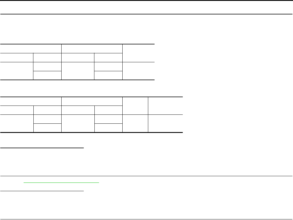
EC-654
< COMPONENT DIAGNOSIS > [FOR USA (FEDERAL) AND CANADA]
P0132 A/F SENSOR 1
4.CHECK A/F SENSOR 1 INPUT SIGNAL CIRCUIT FOR OPEN AND SHORT
1. Turn ignition switch OFF.
2. Disconnect ECM harness connector.
3. Check the continuity between A/F sensor 1 harness connector and ECM harness connector.
4. Check the continuity between A/F sensor 1 harness connector or ECM harness connector and ground.
5. Also check harness for short to power.
Is the inspection result normal?
YES >> GO TO 5.
NO >> Repair open circuit or short to ground or short to power in harness or connectors.
5.CHECK INTERMITTENT INCIDENT
Perform GI-41, "Intermittent Incident".
Is the inspection result normal?
YES >> GO TO 6.
NO >> Repair or replace.
6.REPLACE AIR FUEL RATIO (A/F) SENSOR 1
Replace air fuel ratio (A/F) sensor 1.
CAUTION:
• Discard any A/F sensor which has been dropped from a height of more than 0.5 m (19.7 in) onto a
hard surface such as a concrete floor; use a new one.
• Before installing new A/F sensor, clean exhaust system threads using oxygen sensor thread cleaner
[commercial service tool (J-43897-18 or J-43897-12)] and approved anti-seize lubricant (commercial
service tool).
>> INSPECTION END
A/F sensor 1 ECM Continuity
Connector Terminal Connector Terminal
F27 1F8 45 Existed
249
A/F sensor 1 ECM Ground Continuity
Connector Terminal Connector Terminal
F27 1F8 45 Ground Not existed
249
Revision: 2008 August 2009 Rogue
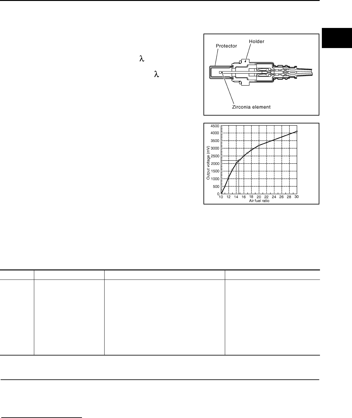
P0133 A/F SENSOR 1
EC-655
< COMPONENT DIAGNOSIS > [FOR USA (FEDERAL) AND CANADA]
C
D
E
F
G
H
I
J
K
L
M
A
EC
N
P
O
P0133 A/F SENSOR 1
Description INFOID:0000000004533856
The air fuel ratio (A/F) sensor 1 is a planar one-cell limit current sen-
sor. The sensor element of the A/F sensor 1 is composed an elec-
trode layer, which transports ions. It has a heater in the element.
The sensor is capable of precise measurement = 1, but also in the
lean and rich range. Together with its control electronics, the sensor
outputs a clear, continuous signal throughout a wide range.
The exhaust gas components diffuse through the diffusion layer at
the sensor cell. An electrode layer is applied voltage, and this current
relative oxygen density in lean. Also this current relative hydrocar-
bon density in rich.
Therefore, the A/F sensor 1 is able to indicate air fuel ratio by this
electrode layer of current. In addition, a heater is integrated in the
sensor to ensure the required operating temperature of approxi-
mately 800°C (1,472°F).
DTC Logic INFOID:0000000004529529
DTC DETECTION LOGIC
To judge the malfunction of A/F sensor 1, this diagnosis measures response time of the A/F signal computed
by ECM from the A/F sensor 1 signal. The time is compensated by engine operating (speed and load), fuel
feedback control constant, and the A/F sensor 1 temperature index. Judgment is based on whether the com-
pensated time (the A/F signal cycling time index) is inordinately long or not.
DTC CONFIRMATION PROCEDURE
1.PRECONDITIONING
If DTC CONFIRMATION PROCEDURE has been previously conducted, always turn ignition switch OFF and
wait at least 10 seconds before conducting the next test.
TESTING CONDITION:
Before performing the following procedure, confirm that battery voltage is more than 11V at idle.
Do you have CONSULT-III?
YES >> GO TO 2.
NO >> GO TO 5.
JMBIA0112GB
PBIB3354E
DTC No. Trouble diagnosis name DTC detecting condition Possible Cause
P0133 Air fuel ratio (A/F) sensor 1
circuit slow response
• The response of the A/F signal computed by
ECM from A/F sensor 1 signal takes more than
the specified time.
• Harness or connectors
(The A/F sensor 1 circuit is open or
shorted.)
• A/F sensor 1
• A/F sensor 1 heater
• Fuel pressure
• Fuel injector
• Intake air leaks
• Exhaust gas leaks
•PCV
• Mass air flow sensor
Revision: 2008 August 2009 Rogue

EC-656
< COMPONENT DIAGNOSIS > [FOR USA (FEDERAL) AND CANADA]
P0133 A/F SENSOR 1
2.PERFORM DTC CONFIRMATION PROCEDURE-I
With CONSULT-III
1. Start engine and warm it up to normal operating temperature.
2. Turn ignition switch OFF and wait at least 10 seconds.
3. Start engine and keep the engine speed between 3,500 and 4,000 rpm for at least 1minute under no load.
4. Let engine idle for 1 minute.
5. Select “A/F SEN1(B1) P1278/P1279” of “A/F SEN1” in “DTC WORK SUPPORT” mode with CONSULT-III.
6. Touch “START”.
Is “COMPLETED” displayed on COUSULT-III?
YES >> GO TO 3
NO >> GO TO 4.
3.PERFORM DTC CONFIRMATION PROCEDURE-II
Touch “SELF-DIAG RESULT”.
Which is displayed on CONSULT-III?
OK >> INSPECTION END
NG >> Go to EC-657, "Diagnosis Procedure".
4.PERFORM DTC CONFIRMATION PROCEDURE
1. After perform the following procedure, “TESTING” will be displayed on the CONSULT-III screen.
- Increase the engine speed between 4,000 and 5,000 rpm and maintain that speed for 10 seconds.
- Fully release accelerator pedal and then let engine idle for approximately 10 seconds.
If “TESTING” is not displayed after 10 seconds, refer to EC-587, "Component Function Check".
2. Wait for approximately 20 seconds at idle under the condition that “TESTING” is displayed on the CON-
SULT-III screen.
3. Check that “TESTING” changes to “COMPLETED”.
If “TESTING” changed to “OUT OF CONDITION”, refer to EC-587, "Component Function Check".
4. Touch “SELF-DIAG RESULT”.
Which is displayed on CONSULT-III?
OK >> INSPECTION END
NG >> Go to EC-657, "Diagnosis Procedure".
5.CHECK AIR-FUEL RATIO SELF-LEARNING VALUE
With GST
1. Start engine and warm it up to normal operating temperature.
2. Select Service $01 with GST.
3. Calculate the total value of “Short-term fuel trim” and “Long-term fuel trim” indications.
Is the total percentage within ±15%?
YES >> GO TO 7.
NO >> GO TO 6.
6.DETECT MALFUNCTIONING PART
Check the following.
• Intake air leaks
• Exhaust gas leaks
• Incorrect fuel pressure
• Lack of fuel
• Fuel injector
• Incorrect PCV hose connection
• PCV valve
• Mass air flow sensor
>> Repair or replace malfunctioning part.
7.PERFORM DTC CONFIRMATION PROCEDURE
1. Turn ignition switch OFF and wait at least 10 seconds.
2. Start engine and keep the engine speed between 3,500 and 4,000 rpm for at least 1minute under no load.
Revision: 2008 August 2009 Rogue
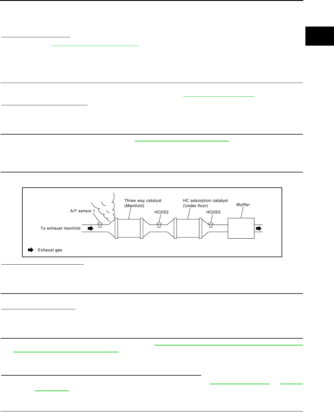
P0133 A/F SENSOR 1
EC-657
< COMPONENT DIAGNOSIS > [FOR USA (FEDERAL) AND CANADA]
C
D
E
F
G
H
I
J
K
L
M
A
EC
N
P
O
3. Let engine idle for 1 minute.
4. Increase the engine speed between 4,000 and 5,000 rpm and keep it for 10 seconds.
5. Fully release accelerator pedal and then let engine idle for approximately 1 minute.
6. Check 1st trip DTC detected?.
Is 1st trip DTC detected?
YES >> Go to EC-657, "Diagnosis Procedure".
NO >> INSPECTION END
Diagnosis Procedure INFOID:0000000004529530
1.CHECK GROUND CONNECTION
1. Turn ignition switch OFF.
2. Check ground connection E21. Refer to Ground Inspection in GI-44, "Circuit Inspection".
Is the inspection result normal?
YES >> GO TO 2.
NO >> Repair or replace ground connection.
2.RETIGHTEN A/F SENSOR 1
Loosen and retighten the A/F sensor 1. Refer to EM-32, "Removal and Installation".
>> GO TO 3.
3.CHECK EXHAUST GAS LEAK
1. Start engine and run it at idle.
2. Listen for an exhaust gas leak before three way catalyst (manifold).
Is exhaust gas leak detected?
YES >> Repair or replace.
NO >> GO TO 4.
4.CHECK FOR INTAKE AIR LEAK
Listen for an intake air leak after the mass air flow sensor.
Is intake air leak detected?
YES >> Repair or replace.
NO >> GO TO 5.
5.CLEAR THE MIXTURE RATIO SELF-LEARNING VALUE
1. Clear the mixture ratio self-learning value. Refer to EC-506, "MIXTURE RATIO SELF-LEARNING VALUE
CLEAR : Special Repair Requirement".
2. Run engine for at least 10 minutes at idle speed.
Is the 1st trip DTC P0171 or P172 detected? Is it difficult to start engine?
YES >> Perform trouble diagnosis for DTC P0171 or P0172. Refer to EC-679, "DTC Logic" or EC-683,
"DTC Logic".
NO >> GO TO 6.
6.CHECK AIR FUEL RATIO (A/F) SENSOR 1 POWER SUPPLY CIRCUIT
1. Disconnect A/F sensor 1 harness connector.
JMBIA0163G
B
Revision: 2008 August 2009 Rogue

EC-658
< COMPONENT DIAGNOSIS > [FOR USA (FEDERAL) AND CANADA]
P0133 A/F SENSOR 1
2. Turn ignition switch ON.
3. Check the voltage between A/F sensor 1 harness connector and ground.
Is the inspection result normal?
YES >> GO TO 8.
NO >> GO TO 7.
7.DETECT MALFUNCTIONING PART
Check the following.
• Harness connectors E6, F123
• IPDM E/R harness connector E14
• 15A fuse (No. 63)
• Harness for open or short between A/F sensor 1 and fuse
>> Repair or replace harness or connectors.
8.CHECK A/F SENSOR 1 INPUT SIGNAL CIRCUIT FOR OPEN AND SHORT
1. Turn ignition switch OFF.
2. Disconnect ECM harness connector.
3. Check the continuity between A/F sensor 1 harness connector and ECM harness connector.
4. Check the continuity between A/F sensor 1 harness connector or ECM harness connector and ground.
5. Also check harness for short to power.
Is the inspection result normal?
YES >> GO TO 9.
NO >> Repair open circuit or short to ground or short to power in harness or connectors.
9.CHECK AIR FUEL RATIO (A/F) SENSOR 1 HEATER
Refer to EC-608, "Component Inspection".
Is the inspection result normal?
YES >> GO TO 10.
NO >> GO TO 13.
10.CHECK MASS AIR FLOW SENSOR
Check mass air flow sensor.
Refer to EC-619, "Component Inspection".
Is the inspection result normal?
YES >> GO TO 11.
NO >> Replace mass air flow sensor.
11.CHECK PCV VALVE
A/F sensor 1 Ground Voltage
Connector Terminal
F27 4 Ground Battery voltage
A/F sensor 1 ECM Continuity
Connector Terminal Connector Terminal
F27 1F8 45 Existed
249
A/F sensor 1 ECM Ground Continuity
Connector Terminal Connector Terminal
F27 1F8 45 Ground Not existed
249
Revision: 2008 August 2009 Rogue

P0133 A/F SENSOR 1
EC-659
< COMPONENT DIAGNOSIS > [FOR USA (FEDERAL) AND CANADA]
C
D
E
F
G
H
I
J
K
L
M
A
EC
N
P
O
Refer to EC-872, "Component Inspection".
Is the inspection result normal?
YES >> GO TO 12.
NO >> Repair or replace PCV valve.
12.CHECK INTERMITTENT INCIDENT
Perform GI-41, "Intermittent Incident".
Is the inspection result normal?
YES >> GO TO 13.
NO >> Repair or replace.
13.REPLACE AIR FUEL RATIO (A/F) SENSOR 1
Replace air fuel ratio (A/F) sensor 1.
CAUTION:
• Discard any A/F sensor which has been dropped from a height of more than 0.5 m (19.7 in) onto a
hard surface such as a concrete floor; use a new one.
• Before installing new A/F sensor, clean exhaust system threads using oxygen sensor thread cleaner
[commercial service tool (J-43897-18 or J-43897-12)] and approved anti-seize lubricant (commercial
service tool).
>> INSPECTION END
Revision: 2008 August 2009 Rogue
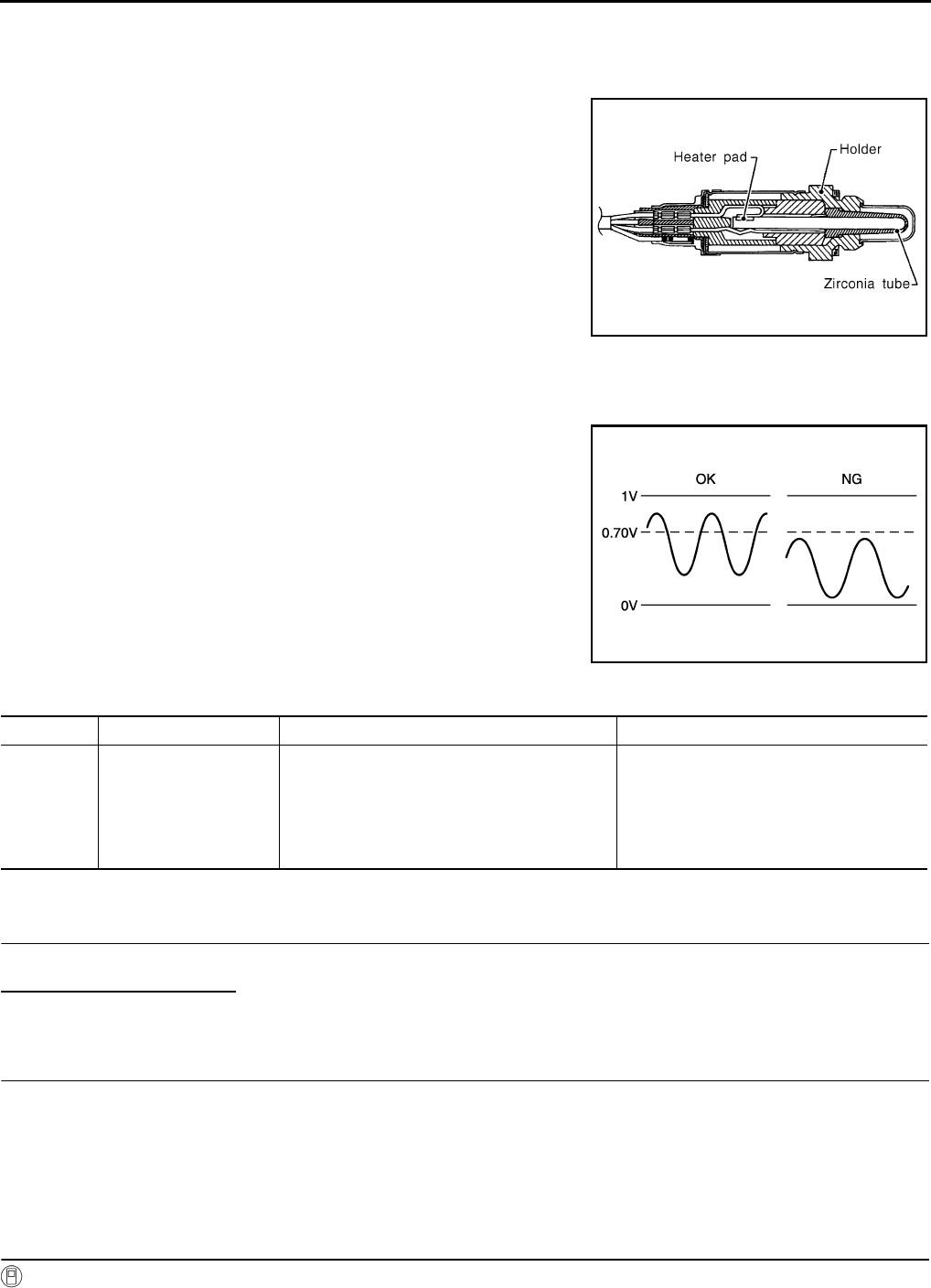
EC-660
< COMPONENT DIAGNOSIS > [FOR USA (FEDERAL) AND CANADA]
P0137 HO2S2
P0137 HO2S2
Description INFOID:0000000004529531
The heated oxygen sensor 2, after three way catalyst (manifold),
monitors the oxygen level in the exhaust gas.
Even if switching characteristics of the air fuel ratio (A/F) sensor 1
are shifted, the air-fuel ratio is controlled to stoichiometric, by the sig-
nal from the heated oxygen sensor 2.
This sensor is made of ceramic zirconia. The zirconia generates volt-
age from approximately 1V in richer conditions to 0V in leaner condi-
tions.
Under normal conditions the heated oxygen sensor 2 is not used for
engine control operation.
DTC Logic INFOID:0000000004529532
DTC DETECTION LOGIC
The heated oxygen sensor 2 has a much longer switching time
between rich and lean than the air fuel ratio (A/F) sensor 1. The oxy-
gen storage capacity of the three way catalyst (manifold) causes the
longer switching time. To judge the malfunctions of heated oxygen
sensor 2, ECM monitors whether the maximum voltage of the sensor
is sufficiently high during various driving conditions such as fuel cut.
DTC CONFIRMATION PROCEDURE
1.INSPECTION START
Do you have CONSULT-III?
Do you have CONSULT-III?
YES >> GO TO 2.
NO >> GO TO 5.
2.PRECONDITIONING
If DTC CONFIRMATION PROCEDURE has been previously conducted, always turn ignition switch OFF and
wait at least 10 seconds before conducting the next test.
TESTING CONDITION:
For better results, perform “DTC WORK SUPPORT” at a temperature of 0 to 30 °C (32 to 86 °F).
>> GO TO 3.
3.PERFORM DTC CONFIRMATION PROCEDURE
With CONSULT-III
SEF327R
JMBIA1669G
B
DTC No. Trouble diagnosis name DTC detecting condition Possible cause
P0137 Heated oxygen sensor 2
circuit low voltage
The maximum voltage from the sensor does not
reach the specified voltage.
• Harness or connectors
(The sensor circuit is open or shorted)
• Heated oxygen sensor 2
• Fuel pressure
• Fuel injector
• Intake air leaks
Revision: 2008 August 2009 Rogue
P0137 HO2S2
EC-661
< COMPONENT DIAGNOSIS > [FOR USA (FEDERAL) AND CANADA]
C
D
E
F
G
H
I
J
K
L
M
A
EC
N
P
O
1. Turn ignition switch ON and select “DATA MONITOR” mode with CONSULT-III.
2. Start engine and warm it up to the normal operating temperature.
3. Turn ignition switch OFF and wait at least 10 seconds.
4. Start engine and keep the engine speed between 3,500 and 4,000 rpm for at least 1 minute under no load.
5. Let engine idle for 1 minute.
6. Check that “COOLAN TEMP/S” indicates more than 70°C (158°F).
If not, warm up engine and go to next step when “COOLAN TEMP/S” indication reaches 70°C (158°F).
7. Open engine hood.
8. Select “HO2S2 (B1) P1147” of “HO2S2” in “DTC WORK SUPPORT” mode with CONSULT-III.
9. Follow the instruction of CONSULT-III display.
NOTE:
It will take at most 10 minutes until “COMPLETED” is displayed.
10. Touch “SELF-DIAG RESULT”.
Which is displayed on CONSULT-III screen?
OK >> INSPECTION END
NG >> Go to EC-662, "Diagnosis Procedure".
CAN NOT BE DIAGNOSED>>GO TO 4.
4.PERFORM DTC CONFIRMATION PROCEDURE AGAIN
1. Turn ignition switch OFF and leave the vehicle in a cool place (soak the vehicle).
2. Perform DTC CONFIRMATION PROCEDURE again.
>> GO TO 3.
5.PERFORM COMPONENT FUNCTION CHECK
Perform Component Function Check. Refer to EC-661, "Component Function Check".
NOTE:
Use component function check to check the overall function of the heated oxygen sensor 2 circuit. During this
check, a 1st trip DTC might not be confirmed.
Is the inspection result normal?
YES >> INSPECTION END
NO >> Go to EC-662, "Diagnosis Procedure".
Component Function Check INFOID:0000000004529533
1.PERFORM COMPONENT FUNCTION CHECK-I
Without CONSULT-III
1. Start engine and warm it up to the normal operating temperature.
2. Turn ignition switch OFF and wait at least 10 seconds.
3. Start engine and keep the engine speed between 3,500 and 4,000 rpm for at least 1 minute under no load.
4. Let engine idle for 1 minute.
5. Check the voltage between ECM harness connector terminals under the following condition.
Is the inspection result normal?
YES >> INSPECTION END
NO >> GO TO 2.
2.PERFORM COMPONENT FUNCTION CHECK-II
Check the voltage between ECM harness connectors under the following condition.
ECM ECM Condition Voltage
Connector Terminal Connector Terminal
F8 33
(HO2S2 signal) F8 35
(Sensor
ground)
Revving up to 4,000 rpm under
no load at least 10 times
The voltage should be above 0.70V
at least once during this procedure.
Revision: 2008 August 2009 Rogue

EC-662
< COMPONENT DIAGNOSIS > [FOR USA (FEDERAL) AND CANADA]
P0137 HO2S2
Is the inspection result normal?
YES >> INSPECTION END
NO >> GO TO 3.
3.PERFORM COMPONENT FUNCTION CHECK-III
Check the voltage between ECM harness connector and ground under the following condition.
Is the inspection result normal?
YES >> INSPECTION END
NO >> Go to EC-662, "Diagnosis Procedure".
Diagnosis Procedure INFOID:0000000004529534
1.CHECK GROUND CONNECTION
1. Turn ignition switch OFF.
2. Check ground connection E21. Refer to Ground Inspection in GI-44, "Circuit Inspection".
Is the inspection result normal?
YES >> GO TO 2.
NO >> Repair or replace ground connection.
2.CLEAR THE MIXTURE RATIO SELF-LEARNING VALUE
1. Clear the mixture ratio self-learning value. Refer to EC-506, "MIXTURE RATIO SELF-LEARNING VALUE
CLEAR : Special Repair Requirement".
2. Run engine for at least 10 minutes at idle speed.
Is the 1st trip DTC P0171 detected? Is it difficult to start engine?
YES >> Perform trouble diagnosis for DTC P0171. Refer to EC-679, "DTC Logic".
NO >> GO TO 3.
3.CHECK HO2S2 GROUND CIRCUIT FOR OPEN AND SHORT
1. Turn ignition switch OFF.
2. Disconnect heated oxygen sensor 2 (HO2S2) harness connector.
3. Disconnect ECM harness connector.
4. Check the continuity between HO2S2 harness connector and ECM harness connector.
5. Also check harness for short to ground and short to power.
Is the inspection result normal?
YES >> GO TO 4.
NO >> Repair open circuit or short to ground or short to power in harness or connectors.
4.CHECK HO2S2 INPUT SIGNAL CIRCUIT FOR OPEN AND SHORT
1. Check the continuity between HO2S2 harness connector and ECM harness connector.
ECM ECM Condition Voltage
Connector Terminal Connector Terminal
F8 33
(HO2S2 signal) F8 35
(Sensor
ground)
Keeping engine speed at idle for
10 minutes
The voltage should be above 0.70V
at least once during this procedure.
ECM ECM Condition Voltage
Connector Terminal Connector Terminal
F8 33
(HO2S2 signal) F8
35
(Sensor
ground)
Coasting from 80 km/h (50 MPH)
in D position The voltage should be above 0.70V
at least once during this procedure.
HO2S2 ECM Continuity
Connector Terminal Connector Terminal
F31 1 F8 35 Existed
Revision: 2008 August 2009 Rogue

P0137 HO2S2
EC-663
< COMPONENT DIAGNOSIS > [FOR USA (FEDERAL) AND CANADA]
C
D
E
F
G
H
I
J
K
L
M
A
EC
N
P
O
2. Check the continuity between HO2S2 harness connector or ECM harness connector and ground.
3. Also check harness for short to power.
Is the inspection result normal?
YES >> GO TO 5.
NO >> Repair open circuit or short to ground or short to power in harness or connectors.
5.CHECK HEATED OXYGEN SENSOR 2
Refer to EC-663, "Component Inspection".
Is the inspection result normal?
YES >> GO TO 7.
NO >> GO TO 6.
6.REPLACE HEATED OXYGEN SENSOR 2
Replace heated oxygen sensor 2.
CAUTION:
• Discard any heated oxygen sensor which has been dropped from a height of more than 0.5 m (19.7
in) onto a hard surface such as a concrete floor; use a new one.
• Before installing new heated oxygen sensor, clean exhaust system threads using oxygen sensor
thread cleaner [commercial service tool (J-43897-18 or J-43897-12)] and approved anti-seize lubri-
cant (commercial service tool).
>> INSPECTION END
7.CHECK INTERMITTENT INCIDENT
Refer to GI-41, "Intermittent Incident".
>> INSPECTION END
Component Inspection INFOID:0000000004529535
1.INSPECTION START
Do you have CONSULT-III?
Do you have CONSULT-III?
YES >> GO TO 2.
NO >> GO TO 3.
2.CHECK HEATED OXYGEN SENSOR 2
With CONSULT-III
1. Turn ignition switch ON and select “DATA MONITOR” mode with CONSULT-III.
2. Start engine and warm it up to the normal operating temperature.
3. Turn ignition switch OFF and wait at least 10 seconds.
4. Start engine and keep the engine speed between 3,500 and 4,000 rpm for at least 1 minute under no load.
5. Let engine idle for 1 minute.
6. Select “FUEL INJECTION” in “ACTIVE TEST” mode, and select “HO2S2 (B1)” as the monitor item with
CONSULT-III.
HO2S2 ECM Continuity
Connector Terminal Connector Terminal
F31 4 F8 33 Existed
HO2S2 ECM Ground Continuity
Connector Terminal Connector Terminal
F31 4 F8 33 Ground Not existed
Revision: 2008 August 2009 Rogue

EC-664
< COMPONENT DIAGNOSIS > [FOR USA (FEDERAL) AND CANADA]
P0137 HO2S2
7. Check “HO2S2 (B1)” at idle speed when adjusting “FUEL INJECTION” to ±25%.
“HO2S2 (B1)” should be above 0.70V at least once when the “FUEL INJECTION” is +25%.
“HO2S2 (B1)” should be below 0.18V at least once when the “FUEL INJECTION” is −25%.
Is the inspection result normal?
YES >> INSPECTION END
NO >> GO TO 6.
3.CHECK HEATED OXYGEN SENSOR 2-I
Without CONSULT-III
1. Start engine and warm it up to the normal operating temperature.
2. Turn ignition switch OFF and wait at least 10 seconds.
3. Start engine and keep the engine speed between 3,500 and 4,000 rpm for at least 1 minute under no load.
4. Let engine idle for 1 minute.
5. Check the voltage between ECM harness connector and ground under the following condition.
Is the inspection result normal?
YES >> INSPECTION END
NO >> GO TO 4.
4.CHECK HEATED OXYGEN SENSOR 2-II
Check the voltage between ECM harness connector and ground under the following condition.
Is the inspection result normal?
YES >> INSPECTION END
NO >> GO TO 5.
5.CHECK HEATED OXYGEN SENSOR 2-III
Check the voltage between ECM harness connector and ground under the following condition.
JMBIA1670G
B
ECM
Condition Voltage
Connector +−
Terminal Terminal
F8
33
(HO2S2
signal)
35
(Sensor
ground)
Revving up to 4,000 rpm under no load
at least 10 times
The voltage should be above 0.70V at
least once during this procedure.
The voltage should be below 0.18V at
least once during this procedure.
ECM
Condition Voltage
Connector +−
Terminal Terminal
F8 33
(HO2S2
signal)
35
(Sensor
ground)
Keeping engine speed at idle for 10
minutes
The voltage should be above 0.70V at
least once during this procedure.
The voltage should be below 0.18V at
least once during this procedure.
Revision: 2008 August 2009 Rogue

P0137 HO2S2
EC-665
< COMPONENT DIAGNOSIS > [FOR USA (FEDERAL) AND CANADA]
C
D
E
F
G
H
I
J
K
L
M
A
EC
N
P
O
Is the inspection result normal?
YES >> INSPECTION END
NO >> GO TO 6.
6.REPLACE HEATED OXYGEN SENSOR 2
Replace heated oxygen sensor 2.
CAUTION:
• Discard any heated oxygen sensor which has been dropped from a height of more than 0.5 m (19.7
in) onto a hard surface such as a concrete floor; use a new one.
• Before installing new heated oxygen sensor, clean exhaust system threads using oxygen sensor
thread cleaner [commercial service tool (J-43897-18 or J-43897-12)] and approved anti-seize lubri-
cant (commercial service tool).
>> INSPECTION END
ECM
Condition Voltage
Connector +−
Terminal Terminal
F8
33
(HO2S2
signal)
35
(Sensor
ground)
Coasting from 80 km/h (50 MPH) in D
position
The voltage should be above 0.70V at
least once during this procedure.
The voltage should be below 0.18V at
least once during this procedure.
Revision: 2008 August 2009 Rogue

EC-666
< COMPONENT DIAGNOSIS > [FOR USA (FEDERAL) AND CANADA]
P0138 HO2S2
P0138 HO2S2
Description INFOID:0000000004533858
The heated oxygen sensor 2, after three way catalyst (manifold),
monitors the oxygen level in the exhaust gas.
Even if switching characteristics of the air fuel ratio (A/F) sensor 1
are shifted, the air-fuel ratio is controlled to stoichiometric, by the sig-
nal from the heated oxygen sensor 2.
This sensor is made of ceramic zirconia. The zirconia generates volt-
age from approximately 1V in richer conditions to 0V in leaner condi-
tions.
Under normal conditions the heated oxygen sensor 2 is not used for
engine control operation.
DTC Logic INFOID:0000000004529537
DTC DETECTION LOGIC
The heated oxygen sensor 2 has a much longer switching time between rich and lean than the air fuel ratio (A/
F) sensor 1. The oxygen storage capacity of the three way catalyst (manifold) causes the longer switching
time.
MALFUNCTION A
To judge the malfunctions of heated oxygen sensor 2, ECM monitors
whether the voltage is unusually high during various driving condi-
tions such as fuel cut.
MALFUNCTION B
To judge the malfunctions of heated oxygen sensor 2, ECM monitors
whether the minimum voltage of sensor is sufficiently low during var-
ious driving conditions such as fuel cut.
DTC CONFIRMATION PROCEDURE
SEF327R
PBIB1848E
PBIB2376E
DTC No. Trouble diagnosis name DTC detecting condition Possible cause
P0138 Heated oxygen sensor 2
circuit high voltage
A) An excessively high voltage from the sen-
sor is sent to ECM.
• Harness or connectors
(The sensor circuit is open or shorted)
• Heated oxygen sensor 2
B) The minimum voltage from the sensor is
not reached to the specified voltage.
• Harness or connectors
(The sensor circuit is open or shorted)
• Heated oxygen sensor 2
• Fuel pressure
• Fuel injector
Revision: 2008 August 2009 Rogue

P0138 HO2S2
EC-667
< COMPONENT DIAGNOSIS > [FOR USA (FEDERAL) AND CANADA]
C
D
E
F
G
H
I
J
K
L
M
A
EC
N
P
O
1.PRECONDITIONING
If DTC CONFIRMATION PROCEDURE has been previously conducted, always turn ignition switch OFF and
wait at least 10 seconds before conducting the next test.
>> GO TO 2.
2.PERFORM DTC CONFIRMATION PROCEDURE FOR MALFUNCTION A
1. Start engine and warm it up to the normal operating temperature.
2. Turn ignition switch OFF and wait at least 10 seconds.
3. Start engine and keep the engine speed between 3,500 and 4,000 rpm for at least 1 minute under no load.
4. Check 1st trip DTC.
Is 1st trip DTC detected?
YES >> Go to EC-668, "Diagnosis Procedure".
NO-1 >> With CONSULT-III: GO TO 3.
NO-2 >> Without CONSULT-III: GO TO 5.
3.PERFORM DTC CONFIRMATION PROCEDURE FOR MALFUNCTION B
NOTE:
For better results, perform “DTC WORK SUPPORT” at a temperature of 0 to 30 °C (32 to 86 °F).
1. Turn ignition switch ON and select “DATA MONITOR” mode with CONSULT-III.
2. Start engine and warm it up to the normal operating temperature.
3. Turn ignition switch OFF and wait at least 10 seconds.
4. Start engine and keep the engine speed between 3,500 and 4,000 rpm for at least 1 minute under no load.
5. Let engine idle for 1 minute.
6. Check that “COOLAN TEMP/S” indicates more than 70°C (158°F).
If not, warm up engine and go to next step when “COOLAN TEMP/S” indication reaches 70°C (158°F).
7. Open engine hood.
8. Select “HO2S2 (B1) P1146” of “HO2S2” in “DTC WORK SUPPORT” mode with CONSULT-III.
9. Follow the instruction of CONSULT-III display.
NOTE:
It will take at most 10 minutes until “COMPLETED” is displayed.
10. Touch “SELF-DIAG RESULT”.
Which is displayed on CONSULT-III
OK >> INSPECTION END
NG >> Go to EC-668, "Diagnosis Procedure".
CAN NOT BE DIAGNOSED>>GO TO 4.
4.PERFORM DTC CONFIRMATION PROCEDURE FOR MALUNCTION B AGAIN
1. Turn ignition switch OFF and leave the vehicle in a cool place (soak the vehicle).
2. Perform DTC CONFIRMATION PROCEDURE again.
>> GO TO 3.
5.PERFORM COMPONENT FUNCTION CHECK FOR MALFUNCTION B
Perform component function check. Refer to EC-668, "Diagnosis Procedure".
NOTE:
Use component function check to check the overall function of the heated oxygen sensor 2 circuit. During this
check, a 1st trip DTC might not be confirmed.
Is the inspection result normal?
YES >> INSPECTION END
NO >> Go to EC-668, "Diagnosis Procedure".
Component Function Check INFOID:0000000004529538
1.PERFORM COMPONENT FUNCTION CHECK-I
Without CONSULT-III
1. Start engine and warm it up to the normal operating temperature.
Revision: 2008 August 2009 Rogue

EC-668
< COMPONENT DIAGNOSIS > [FOR USA (FEDERAL) AND CANADA]
P0138 HO2S2
2. Turn ignition switch OFF and wait at least 10 seconds.
3. Start engine and keep the engine speed between 3,500 and 4,000 rpm for at least 1 minute under no load.
4. Let engine idle for 1 minute.
5. Check the voltage between ECM harness connector terminals under the following condition.
Is the inspection result normal?
YES >> INSPECTION END
NO >> GO TO 2.
2.PERFORM COMPONENT FUNCTION CHECK-II
Check the voltage between ECM harness connectors under the following condition.
Is the inspection result normal?
YES >> INSPECTION END
NO >> GO TO 3.
3.PERFORM COMPONENT FUNCTION CHECK-III
Check the voltage between ECM harness connector and ground under the following condition.
Is the inspection result normal?
YES >> INSPECTION END
NO >> Go to EC-668, "Diagnosis Procedure".
Diagnosis Procedure INFOID:0000000004529539
1.INSPECTION START
Confirm the detected malfunction (A or B). Refer to EC-666, "DTC Logic".
Which malfunction is detected?
A>>GO TO 2.
B>>GO TO 9.
2.CHECK GROUND CONNECTION
1. Turn ignition switch OFF.
2. Check ground connection E21. Refer to Ground Inspection in GI-44, "Circuit Inspection".
Is the inspection result normal?
YES >> GO TO 3.
NO >> Repair or replace ground connection.
3.CHECK HO2S2 GROUND CIRCUIT FOR OPEN AND SHORT
1. Disconnect heated oxygen sensor 2 harness connector.
ECM ECM Condition Voltage
Connector Terminal Connector Terminal
F8 33
(HO2S2 signal) F8 35
(Sensor
ground)
Revving up to 4,000 rpm under
no load at least 10 times
The voltage should be below 0.18V
at least once during this procedure.
ECM ECM Condition Voltage
Connector Terminal Connector Terminal
F8 33
(HO2S2 signal) F8
35
(Sensor
ground)
Keeping engine speed at idle for
10 minutes The voltage should be below 0.18V
at least once during this procedure.
ECM ECM Condition Voltage
Connector Terminal Connector Terminal
F8 33
(HO2S2 signal) F8
35
(Sensor
ground)
Coasting from 80 km/h (50 MPH)
in D position
The voltage should be below 0.18V
at least once during this procedure.
Revision: 2008 August 2009 Rogue

P0138 HO2S2
EC-669
< COMPONENT DIAGNOSIS > [FOR USA (FEDERAL) AND CANADA]
C
D
E
F
G
H
I
J
K
L
M
A
EC
N
P
O
2. Disconnect ECM harness connector.
3. Check the continuity between HO2S2 harness connector and ECM harness connector.
4. Also check harness for short to ground and short to power.
Is the inspection result normal?
YES >> GO TO 4.
NO >> Repair open circuit or short to ground or short to power in harness or connectors.
4.CHECK HO2S2 INPUT SIGNAL CIRCUIT FOR OPEN AND SHORT
1. Check the continuity between HO2S2 harness connector and ECM harness connector.
2. Check the continuity between HO2S2 harness connector or ECM harness connector and ground.
3. Also check harness for short to power.
Is the inspection result normal?
YES >> GO TO 5.
NO >> Repair open circuit or short to ground or short to power in harness or connectors.
5.CHECK HO2S2 CONNECTOR FOR WATER
Check connectors for water.
Is the inspection result normal?
YES >> GO TO 6.
NO >> Repair or replace harness or connectors.
6.CHECK HEATED OXYGEN SENSOR 2
Refer to EC-671, "Component Inspection".
Is the inspection result normal?
YES >> GO TO 8.
NO >> GO TO 7.
7.REPLACE HEATED OXYGEN SENSOR 2
Replace heated oxygen sensor 2.
CAUTION:
• Discard any heated oxygen sensor which has been dropped from a height of more than 0.5 m (19.7
in) onto a hard surface such as a concrete floor; use a new one.
• Before installing new heated oxygen sensor, clean exhaust system threads using oxygen sensor
thread cleaner [commercial service tool (J-43897-18 or J-43897-12)] and approved anti-seize lubri-
cant (commercial service tool).
>> INSPECTION END
8.CHECK INTERMITTENT INCIDENT
HO2S2 ECM Continuity
Connector Terminal Connector Terminal
F31 1 F8 35 Existed
HO2S2 ECM Continuity
Connector Terminal Connector Terminal
F31 4 F8 33 Existed
HO2S2 ECM Ground Continuity
Connector Terminal Connector Terminal
F31 4 F8 33 Ground Not existed
Water should not exist.
Revision: 2008 August 2009 Rogue

EC-670
< COMPONENT DIAGNOSIS > [FOR USA (FEDERAL) AND CANADA]
P0138 HO2S2
Refer to GI-41, "Intermittent Incident".
>> INSPECTION END
9.CHECK GROUND CONNECTION
1. Turn ignition switch OFF.
2. Check ground connection E21. Refer to Ground Inspection in GI-44, "Circuit Inspection".
Is the inspection result normal?
YES >> GO TO 10.
NO >> Repair or replace ground connection.
10.CLEAR THE MIXTURE RATIO SELF-LEARNING VALUE
1. Clear the mixture ratio self-learning value. Refer to EC-506, "MIXTURE RATIO SELF-LEARNING VALUE
CLEAR : Special Repair Requirement".
2. Run engine for at least 10 minutes at idle speed.
Is the 1st trip DTC P0172 detected? Is it difficult to start engine?
YES >> Perform trouble diagnosis for DTC P0172. Refer to EC-683, "DTC Logic".
NO >> GO TO 11.
11.CHECK HO2S2 GROUND CIRCUIT FOR OPEN AND SHORT
1. Turn ignition switch OFF.
2. Disconnect heated oxygen sensor 2 harness connector.
3. Disconnect ECM harness connector.
4. Check the continuity between HO2S2 harness connector and ECM harness connector.
5. Also check harness for short to ground and short to power.
Is the inspection result normal?
YES >> GO TO 12.
NO >> Repair open circuit or short to ground or short to power in harness or connectors.
12.CHECK HO2S2 INPUT SIGNAL CIRCUIT FOR OPEN AND SHORT
1. Check the continuity between HO2S2 harness connector and ECM harness connector.
2. Check the continuity between HO2S2 harness connector or ECM harness connector and ground.
3. Also check harness for short to power.
Is the inspection result normal?
YES >> GO TO 13.
NO >> Repair open circuit or short to ground or short to power in harness or connectors.
13.CHECK HEATED OXYGEN SENSOR 2
Refer to EC-671, "Component Inspection".
Is the inspection result normal?
YES >> GO TO 15.
HO2S2 ECM Continuity
Connector Terminal Connector Terminal
F31 1 F8 35 Existed
HO2S2 ECM Continuity
Connector Terminal Connector Terminal
F31 4 F8 33 Existed
HO2S2 ECM Ground Continuity
Connector Terminal Connector Terminal
F31 4 F8 33 Ground Not existed
Revision: 2008 August 2009 Rogue

P0138 HO2S2
EC-671
< COMPONENT DIAGNOSIS > [FOR USA (FEDERAL) AND CANADA]
C
D
E
F
G
H
I
J
K
L
M
A
EC
N
P
O
NO >> GO TO 14.
14.REPLACE HEATED OXYGEN SENSOR 2
Replace heated oxygen sensor 2.
CAUTION:
• Discard any heated oxygen sensor which has been dropped from a height of more than 0.5 m (19.7
in) onto a hard surface such as a concrete floor; use a new one.
• Before installing new oxygen sensor, clean exhaust system threads using oxygen sensor thread
cleaner tool (J-43897-18 or J-43897-12) and approved anti-seize lubricant.
>> INSPECTION END
15.CHECK INTERMITTENT INCIDENT
Refer to GI-41, "Intermittent Incident".
>> INSPECTION END
Component Inspection INFOID:0000000004533859
1.INSPECTION START
Do you have CONSULT-III?
Do you have CONSULT-III?
YES >> GO TO 2.
NO >> GO TO 3.
2.CHECK HEATED OXYGEN SENSOR 2
With CONSULT-III
1. Turn ignition switch ON and select “DATA MONITOR” mode with CONSULT-III.
2. Start engine and warm it up to the normal operating temperature.
3. Turn ignition switch OFF and wait at least 10 seconds.
4. Start engine and keep the engine speed between 3,500 and 4,000 rpm for at least 1 minute under no load.
5. Let engine idle for 1 minute.
6. Select “FUEL INJECTION” in “ACTIVE TEST” mode, and select “HO2S2 (B1)” as the monitor item with
CONSULT-III.
7. Check “HO2S2 (B1)” at idle speed when adjusting “FUEL INJECTION” to ±25%.
“HO2S2 (B1)” should be above 0.70V at least once when the “FUEL INJECTION” is +25%.
“HO2S2 (B1)” should be below 0.18V at least once when the “FUEL INJECTION” is −25%.
Is the inspection result normal?
YES >> INSPECTION END
NO >> GO TO 6.
3.CHECK HEATED OXYGEN SENSOR 2-I
Without CONSULT-III
1. Start engine and warm it up to the normal operating temperature.
2. Turn ignition switch OFF and wait at least 10 seconds.
3. Start engine and keep the engine speed between 3,500 and 4,000 rpm for at least 1 minute under no load.
4. Let engine idle for 1 minute.
5. Check the voltage between ECM harness connector and ground under the following condition.
JMBIA1670G
B
Revision: 2008 August 2009 Rogue

EC-672
< COMPONENT DIAGNOSIS > [FOR USA (FEDERAL) AND CANADA]
P0138 HO2S2
Is the inspection result normal?
YES >> INSPECTION END
NO >> GO TO 4.
4.CHECK HEATED OXYGEN SENSOR 2-II
Check the voltage between ECM harness connector and ground under the following condition.
Is the inspection result normal?
YES >> INSPECTION END
NO >> GO TO 5.
5.CHECK HEATED OXYGEN SENSOR 2-III
Check the voltage between ECM harness connector and ground under the following condition.
Is the inspection result normal?
YES >> INSPECTION END
NO >> GO TO 6.
6.REPLACE HEATED OXYGEN SENSOR 2
Replace heated oxygen sensor 2.
CAUTION:
• Discard any heated oxygen sensor which has been dropped from a height of more than 0.5 m (19.7
in) onto a hard surface such as a concrete floor; use a new one.
• Before installing new heated oxygen sensor, clean exhaust system threads using oxygen sensor
thread cleaner [commercial service tool (J-43897-18 or J-43897-12)] and approved anti-seize lubri-
cant (commercial service tool).
>> INSPECTION END
ECM
Condition Voltage
Connector +−
Terminal Terminal
F8
33
(HO2S2
signal)
35
(Sensor
ground)
Revving up to 4,000 rpm under no load
at least 10 times
The voltage should be above 0.70V at
least once during this procedure.
The voltage should be below 0.18V at
least once during this procedure.
ECM
Condition Voltage
Connector +−
Terminal Terminal
F8
33
(HO2S2
signal)
35
(Sensor
ground)
Keeping engine speed at idle for 10
minutes
The voltage should be above 0.70V at
least once during this procedure.
The voltage should be below 0.18V at
least once during this procedure.
ECM
Condition Voltage
Connector +−
Terminal Terminal
F8 33
(HO2S2
signal)
35
(Sensor
ground)
Coasting from 80 km/h (50 MPH) in D
position
The voltage should be above 0.70V at
least once during this procedure.
The voltage should be below 0.18V at
least once during this procedure.
Revision: 2008 August 2009 Rogue

P0139 HO2S2
EC-673
< COMPONENT DIAGNOSIS > [FOR USA (FEDERAL) AND CANADA]
C
D
E
F
G
H
I
J
K
L
M
A
EC
N
P
O
P0139 HO2S2
Description INFOID:0000000004533860
The heated oxygen sensor 2, after three way catalyst (manifold),
monitors the oxygen level in the exhaust gas.
Even if switching characteristics of the air fuel ratio (A/F) sensor 1
are shifted, the air-fuel ratio is controlled to stoichiometric, by the sig-
nal from the heated oxygen sensor 2.
This sensor is made of ceramic zirconia. The zirconia generates volt-
age from approximately 1V in richer conditions to 0V in leaner condi-
tions.
Under normal conditions the heated oxygen sensor 2 is not used for
engine control operation.
DTC Logic INFOID:0000000004529542
DTC DETECTION LOGIC
The heated oxygen sensor 2 has a much longer switching time
between rich and lean than the air fuel ratio (A/F) sensor 1. The oxy-
gen storage capacity of the three way catalyst (mamifold) causes the
longer switching time. To judge the malfunctions of heated oxygen
sensor 2, ECM monitors whether the switching response of the sen-
sor's voltage is faster than specified during various driving conditions
such as fuel cut.
DTC CONFIRMATION PROCEDURE
1.INSPECTION START
Do you have CONSULT-III?
Do you have CONSULT-III?
YES >> GO TO 2.
NO >> GO TO 5.
2.PRECONDITIONING
If DTC CONFIRMATION PROCEDURE has been previously conducted, always turn ignition switch OFF and
wait at least 10 seconds before conducting the next test.
>> GO TO 3.
3.PERFORM DTC CONFIRMATION PROCEDURE
With CONSULT-III
1. Turn ignition switch ON and select “DATA MONITOR” mode with CONSULT-III.
2. Start engine and warm it up to the normal operating temperature.
SEF327R
SEF302U
DTC No. Trouble diagnosis name DTC detecting condition Possible cause
P0139 Heated oxygen sensor 2
circuit slow response
It takes more time for the sensor to respond be-
tween rich and lean than the specified time.
• Harness or connectors
(The sensor circuit is open or shorted)
• Heated oxygen sensor 2
• Fuel pressure
• Fuel injector
• Intake air leaks
Revision: 2008 August 2009 Rogue
EC-674
< COMPONENT DIAGNOSIS > [FOR USA (FEDERAL) AND CANADA]
P0139 HO2S2
3. Start engine and warm it up to the normal operating temperature.
4. Start engine and keep the engine speed between 3,500 and 4,000 rpm for at least 1 minute under no load.
5. Let engine idle for 1 minute.
6. Open engine hood.
7. Select “HO2S2 (B1) P0139” of “HO2S2” in “DTC WORK SUPPORT” mode with CONSULT-III.
8. Start engine and following the instruction of CONSULT-III.
NOTE:
It will take at most 10 minutes until “COMPLETED” is displayed.
9. Touch “SELF-DIAG RESULT”.
Which is displayed on CONSULT-III?
OK >> INSPECTION END
NG >> GO TO 4.
CAN NOT BE DIAGNOSED>>GO TO 4.
4.PERFORM THE RESULT OF DTC CONFIRMATION PROCEDURE
1. Turn ignition switch OFF and leave the vehicle in a cool place (soak the vehicle).
2. Perform DTC CONFIRMATION PROCEDURE again.
>> GO TO 3.
5.PERFORM COMPONENT FUNCTION CHECK
Perform Component Function Check. Refer to EC-674, "Component Function Check".
NOTE:
Use Component Function Check to check the overall function of the heated oxygen sensor 2 circuit. During
this check, a 1st trip DTC might not be confirmed.
Is the inspection result normal?
YES >> INSPECTION END
NO >> Go to EC-675, "Diagnosis Procedure".
Component Function Check INFOID:0000000004529543
1.PERFORM COMPONENT FUNCTION CHECK-I
Without CONSULT-III
1. Start engine and warm it up to the normal operating temperature.
2. Turn ignition switch OFF and wait at least 10 seconds.
3. Start engine and keep the engine speed between 3,500 and 4,000 rpm for at least 1 minute under no load.
4. Let engine idle for 1 minute.
5. Check the voltage between ECM harness connector terminals under the following condition.
Is the inspection result normal?
YES >> INSPECTION END
NO >> GO TO 2.
2.PERFORM COMPONENT FUNCTION CHECK-II
Check the voltage between ECM harness connectors under the following condition.
ECM ECM Condition Voltage
Connector Terminal Connector Terminal
F8
33
(HO2S2
signal) F8
35
(Sensor
ground)
Revving up to 4,000 rpm under
no load at least 10 times
A change of voltage should be more than
0.80V for 1 second during this procedure.
ECM ECM Condition Voltage
Connector Terminal Connector Terminal
F8 33
(HO2S2
signal)
F8 35
(Sensor
ground)
Keeping engine speed at idle for
10 minutes
A change of voltage should be more than
0.80V for 1 second during this procedure.
Revision: 2008 August 2009 Rogue

P0139 HO2S2
EC-675
< COMPONENT DIAGNOSIS > [FOR USA (FEDERAL) AND CANADA]
C
D
E
F
G
H
I
J
K
L
M
A
EC
N
P
O
Is the inspection result normal?
YES >> INSPECTION END
NO >> GO TO 3.
3.PERFORM COMPONENT FUNCTION CHECK-III
Check the voltage between ECM harness connector and ground under the following condition.
Is the inspection result normal?
YES >> INSPECTION END
NO >> Go to EC-675, "Diagnosis Procedure".
Diagnosis Procedure INFOID:0000000004529544
1.CHECK GROUND CONNECTION
1. Turn ignition switch OFF.
2. Check ground connection E21. Refer to Ground Inspection in GI-44, "Circuit Inspection".
Is the inspection result normal?
YES >> GO TO 2.
NO >> Repair or replace ground connection.
2.CLEAR THE MIXTURE RATIO SELF-LEARNING VALUE
1. Clear the mixture ratio self-learning value. Refer to EC-506, "MIXTURE RATIO SELF-LEARNING VALUE
CLEAR : Special Repair Requirement".
2. Run engine for at least 10 minutes at idle speed.
Is the 1st trip DTC P0171 or P0172 detected? Is it difficult to start engine?
YES >> Perform trouble diagnosis for DTC P0171 or P0172. Refer to EC-679, "DTC Logic" or EC-683,
"DTC Logic".
NO >> GO TO 3.
3.CHECK HO2S2 GROUND CIRCUIT FOR OPEN AND SHORT
1. Turn ignition switch OFF.
2. Disconnect heated oxygen sensor 2 harness connector.
3. Disconnect ECM harness connector.
4. Check the continuity between HO2S2 harness connector and ECM harness connector.
5. Also check harness for short to ground and short to power.
Is the inspection result normal?
YES >> GO TO 4.
NO >> Repair open circuit or short to ground or short to power in harness or connectors.
4.CHECK HO2S2 INPUT SIGNAL CIRCUIT FOR OPEN AND SHORT
1. Check the continuity between HO2S2 harness connector and ECM harness connector.
ECM ECM Condition Voltage
Connector Terminal Connector Terminal
F8
33
(HO2S2
signal)
F8
35
(Sensor
ground)
Coasting from 80 km/h (50 MPH)
in D position A change of voltage should be more than
0.80V for 1 second during this procedure.
HO2S2 ECM Continuity
Connector Terminal Connector Terminal
F31 1 F8 35 Existed
HO2S2 ECM Continuity
Connector Terminal Connector Terminal
F31 4 F8 33 Existed
Revision: 2008 August 2009 Rogue

EC-676
< COMPONENT DIAGNOSIS > [FOR USA (FEDERAL) AND CANADA]
P0139 HO2S2
2. Check the continuity between HO2S2 harness connector or ECM harness connector and ground.
3. Also check harness for short to power.
Is the inspection result normal?
YES >> GO TO 5.
NO >> Repair open circuit or short to ground or short to power in harness or connectors.
5.CHECK HEATED OXYGEN SENSOR 2
Refer to EC-676, "Component Inspection".
Is the inspection result normal?
YES >> GO TO 7.
NO >> GO TO 6.
6.REPLACE HEATED OXYGEN SENSOR 2
Replace heated oxygen sensor 2.
CAUTION:
• Discard any heated oxygen sensor which has been dropped from a height of more than 0.5 m (19.7
in) onto a hard surface such as a concrete floor; use a new one.
• Before installing new heated oxygen sensor, clean exhaust system threads using oxygen sensor
thread cleaner [commercial service tool (J-43897-18 or J-43897-12)] and approved anti-seize lubri-
cant (commercial service tool).
>> INSPECTION END
7.CHECK INTERMITTENT INCIDENT
Refer to GI-41, "Intermittent Incident".
>> INSPECTION END
Component Inspection INFOID:0000000004533861
1.INSPECTION START
Do you have CONSULT-III?
Do you have CONSULT-III?
YES >> GO TO 2.
NO >> GO TO 3.
2.CHECK HEATED OXYGEN SENSOR 2
With CONSULT-III
1. Turn ignition switch ON and select “DATA MONITOR” mode with CONSULT-III.
2. Start engine and warm it up to the normal operating temperature.
3. Turn ignition switch OFF and wait at least 10 seconds.
4. Start engine and keep the engine speed between 3,500 and 4,000 rpm for at least 1 minute under no load.
5. Let engine idle for 1 minute.
6. Select “FUEL INJECTION” in “ACTIVE TEST” mode, and select “HO2S2 (B1)” as the monitor item with
CONSULT-III.
HO2S2 ECM Ground Continuity
Connector Terminal Connector Terminal
F31 4 F8 33 Ground Not existed
Revision: 2008 August 2009 Rogue

P0139 HO2S2
EC-677
< COMPONENT DIAGNOSIS > [FOR USA (FEDERAL) AND CANADA]
C
D
E
F
G
H
I
J
K
L
M
A
EC
N
P
O
7. Check “HO2S2 (B1)” at idle speed when adjusting “FUEL INJECTION” to ±25%.
“HO2S2 (B1)” should be above 0.70V at least once when the “FUEL INJECTION” is +25%.
“HO2S2 (B1)” should be below 0.18V at least once when the “FUEL INJECTION” is −25%.
Is the inspection result normal?
YES >> INSPECTION END
NO >> GO TO 6.
3.CHECK HEATED OXYGEN SENSOR 2-I
Without CONSULT-III
1. Start engine and warm it up to the normal operating temperature.
2. Turn ignition switch OFF and wait at least 10 seconds.
3. Start engine and keep the engine speed between 3,500 and 4,000 rpm for at least 1 minute under no load.
4. Let engine idle for 1 minute.
5. Check the voltage between ECM harness connector and ground under the following condition.
Is the inspection result normal?
YES >> INSPECTION END
NO >> GO TO 4.
4.CHECK HEATED OXYGEN SENSOR 2-II
Check the voltage between ECM harness connector and ground under the following condition.
Is the inspection result normal?
YES >> INSPECTION END
NO >> GO TO 5.
5.CHECK HEATED OXYGEN SENSOR 2-III
Check the voltage between ECM harness connector and ground under the following condition.
JMBIA1670G
B
ECM
Condition Voltage
Connector +−
Terminal Terminal
F8
33
(HO2S2
signal)
35
(Sensor
ground)
Revving up to 4,000 rpm under no load
at least 10 times
The voltage should be above 0.70V at
least once during this procedure.
The voltage should be below 0.18V at
least once during this procedure.
ECM
Condition Voltage
Connector +−
Terminal Terminal
F8 33
(HO2S2
signal)
35
(Sensor
ground)
Keeping engine speed at idle for 10
minutes
The voltage should be above 0.70V at
least once during this procedure.
The voltage should be below 0.18V at
least once during this procedure.
Revision: 2008 August 2009 Rogue

EC-678
< COMPONENT DIAGNOSIS > [FOR USA (FEDERAL) AND CANADA]
P0139 HO2S2
Is the inspection result normal?
YES >> INSPECTION END
NO >> GO TO 6.
6.REPLACE HEATED OXYGEN SENSOR 2
Replace heated oxygen sensor 2.
CAUTION:
• Discard any heated oxygen sensor which has been dropped from a height of more than 0.5 m (19.7
in) onto a hard surface such as a concrete floor; use a new one.
• Before installing new heated oxygen sensor, clean exhaust system threads using oxygen sensor
thread cleaner [commercial service tool (J-43897-18 or J-43897-12)] and approved anti-seize lubri-
cant (commercial service tool).
>> INSPECTION END
ECM
Condition Voltage
Connector +−
Terminal Terminal
F8
33
(HO2S2
signal)
35
(Sensor
ground)
Coasting from 80 km/h (50 MPH) in D
position
The voltage should be above 0.70V at
least once during this procedure.
The voltage should be below 0.18V at
least once during this procedure.
Revision: 2008 August 2009 Rogue

P0171 FUEL INJECTION SYSTEM FUNCTION
EC-679
< COMPONENT DIAGNOSIS > [FOR USA (FEDERAL) AND CANADA]
C
D
E
F
G
H
I
J
K
L
M
A
EC
N
P
O
P0171 FUEL INJECTION SYSTEM FUNCTION
DTC Logic INFOID:0000000004529546
DTC DETECTION LOGIC
With the Air/Fuel Mixture Ratio Self-Learning Control, the actual mixture ratio can be brought closely to the
theoretical mixture ratio based on the mixture ratio feedback signal from A/F sensor 1. The ECM calculates
the necessary compensation to correct the offset between the actual and the theoretical ratios.
In case the amount of the compensation value is extremely large (the actual mixture ratio is too lean.), the
ECM judges the condition as the fuel injection system malfunction and illuminates the MIL (2 trip detection
logic).
DTC CONFIRMATION PROCEDURE
1.PRECONDITIONING
If DTC CONFIRMATION PROCEDURE has been previously conducted, always turn ignition switch OFF and
wait at least 10 seconds before conducting the next test.
>> GO TO 2.
2.PERFORM DTC CONFIRMATION PROCEDURE-I
1. Clear the mixture ratio self-learning value. Refer to EC-506, "MIXTURE RATIO SELF-LEARNING VALUE
CLEAR : Special Repair Requirement".
2. Start engine.
Is it difficult to start engine?
YES >> GO TO 3.
NO >> GO TO 4.
3.RESTART ENGINE
If it is difficult to start engine, the fuel injection system has a malfunction, too.
Crank engine while depressing accelerator pedal.
NOTE:
When depressing accelerator pedal three-fourths (3/4) or more, the control system does not start the
engine. Do not depress accelerator pedal too much.
Does engine start?
YES >> Go to EC-680, "Diagnosis Procedure".
NO >> Check exhaust and intake air leak visually.
4.PERFORM DTC CONFIRMATION PROCEDURE-II
1. Start engine and let it idle for at least 5 minutes.
2. Check 1st trip DTC.
Is 1st trip DTC detected?
YES >> Go to EC-680, "Diagnosis Procedure".
NO >> GO TO 5.
Sensor Input signal to ECM ECM function Actuator
A/F sensor 1 Density of oxygen in exhaust gas
(Mixture ratio feedback signal) Fuel injection control Fuel injector
DTC No. Trouble diagnosis name DTC detecting condition Possible cause
P0171 Fuel injection system too
lean
• Fuel injection system does not operate properly.
• The amount of mixture ratio compensation is too
large. (The mixture ratio is too lean.)
• Intake air leaks
• A/F sensor 1
• Fuel injector
• Exhaust gas leaks
• Incorrect fuel pressure
• Lack of fuel
• Mass air flow sensor
• Incorrect PCV hose connection
Revision: 2008 August 2009 Rogue
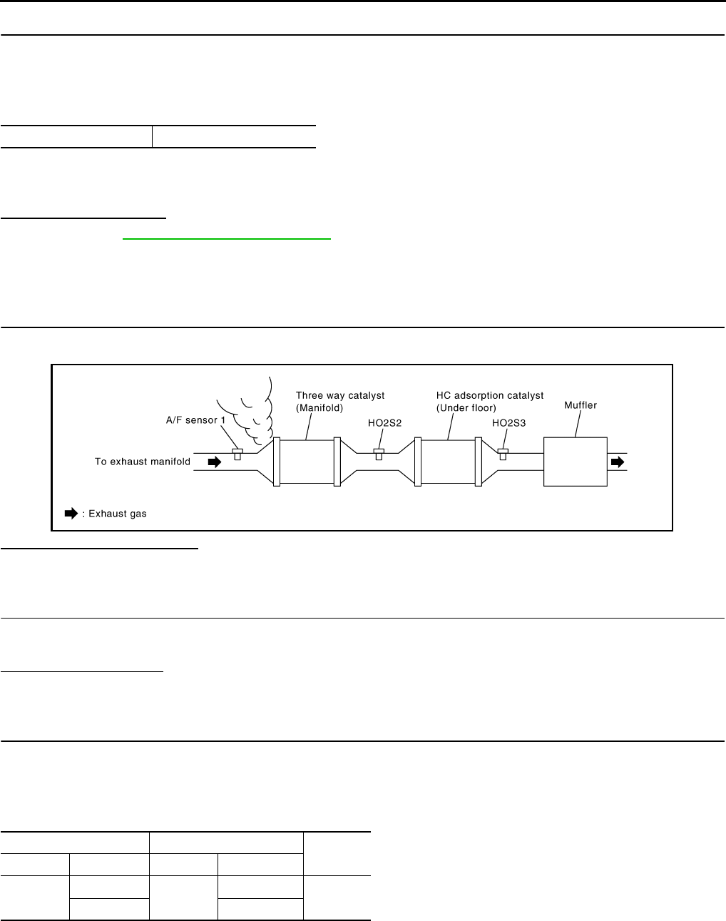
EC-680
< COMPONENT DIAGNOSIS > [FOR USA (FEDERAL) AND CANADA]
P0171 FUEL INJECTION SYSTEM FUNCTION
5.PERFORM DTC CONFIRMATION PROCEDURE-III
1. Turn ignition switch OFF and wait at least 10 seconds.
2. Start engine
3. Maintain the following conditions for at least 10 consecutive minutes.
Hold the accelerator pedal as steady as possible.
CAUTION:
Always drive vehicle at a safe speed.
4. Check 1st trip DTC.
Is 1st trip DTC detected?
YES >> Go to EC-680, "Diagnosis Procedure".
NO >> INSPECTION END
Diagnosis Procedure INFOID:0000000004529547
1.CHECK EXHAUST GAS LEAK
1. Start engine and run it at idle.
2. Listen for an exhaust gas leak before three way catalyst (manifold).
Is exhaust gas leak detected?
YES >> Repair or replace.
NO >> GO TO 2.
2.CHECK FOR INTAKE AIR LEAK
1. Listen for an intake air leak after the mass air flow sensor.
2. Check PCV hose connection.
Intake air leak detected?
YES >> Repair or replace.
NO >> GO TO 3.
3.CHECK A/F SENSOR 1 INPUT SIGNAL CIRCUIT
1. Turn ignition switch OFF.
2. Disconnect corresponding A/F sensor 1 harness connector.
3. Disconnect ECM harness connector.
4. Check the continuity between A/F sensor 1 harness connector and ECM harness connector.
5. Check the continuity between A/F sensor 1 harness connector or ECM harness connector and ground.
VHCL SPEED SE 50 - 120 km/h (31 - 75 MPH)
JMBIA0163G
B
A/F sensor 1 ECM Continuity
Connector Terminal Connector Terminal
F27 1F8 45 Existed
249
Revision: 2008 August 2009 Rogue
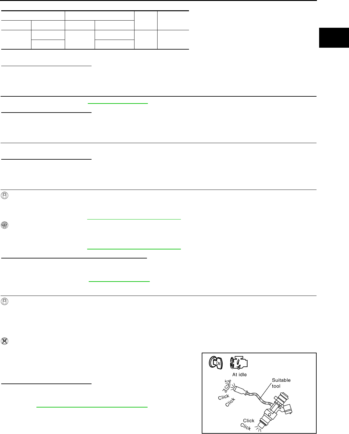
P0171 FUEL INJECTION SYSTEM FUNCTION
EC-681
< COMPONENT DIAGNOSIS > [FOR USA (FEDERAL) AND CANADA]
C
D
E
F
G
H
I
J
K
L
M
A
EC
N
P
O
6. Also check harness for short to power.
Is the inspection result normal?
YES >> GO TO 4.
NO >> Repair open circuit or short to ground or short to power in harness or connectors.
4.CHECK FUEL PRESSURE
Check fuel pressure. Refer to EC-923, "Inspection".
Is the inspection result normal?
YES >> GO TO 6.
NO >> GO TO 5.
5. DETECT MALFUNCTIONING PART
Check fuel hoses and fuel tubes for clogging.
Is the inspection result normal?
YES >> Replace “fuel filter and fuel pump assembly”.
NO >> Repair or replace
6.CHECK MASS AIR FLOW SENSOR
With CONSULT-III
1. Install all removed parts.
2. Check “MASS AIR FLOW” in “DATA MONITOR” mode with CONSULT-III.
For specification, refer to EC-928, "Mass Air Flow Sensor".
With GST
1. Install all removed parts.
2. Check mass air flow sensor signal in Service $01 with GST.
For specification, refer to EC-928, "Mass Air Flow Sensor".
Is the measurement value within the specification?
YES >> GO TO 7.
NO >> Check connectors for rusted terminals or loose connections in the mass air flow sensor circuit or
grounds. Refer to EC-615, "DTC Logic".
7.CHECK FUNCTION OF FUEL INJECTOR
With CONSULT-III
1. Start engine.
2. Perform “POWER BALANCE” in “ACTIVE TEST” mode with CONSULT-III.
3. Check that each circuit produces a momentary engine speed drop.
Without CONSULT-III
1. Let engine idle.
2. Listen to each fuel injector operating sound.
Is the inspection result normal?
YES >> GO TO 8.
NO >> Perform trouble diagnosis for FUEL INJECTOR, refer to
EC-855, "Component Function Check".
A/F sensor 1 ECM Ground Continuity
Connector Terminal Connector Terminal
F27 1F8 45 Ground Not existed
249
Clicking noise should be heard.
PBIB3332E
Revision: 2008 August 2009 Rogue
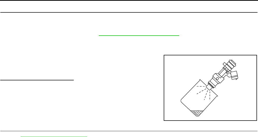
EC-682
< COMPONENT DIAGNOSIS > [FOR USA (FEDERAL) AND CANADA]
P0171 FUEL INJECTION SYSTEM FUNCTION
8.CHECK FUEL INJECTOR
1. Turn ignition switch OFF.
2. Confirm that the engine is cooled down and there are no fire hazards near the vehicle.
3. Disconnect all fuel injector harness connectors.
4. Remove fuel tube assembly. Refer to EM-43, "Removal and Installation".
Keep fuel hose and all fuel injectors connected to fuel tube.
5. Disconnect all ignition coil harness connectors.
6. Prepare pans or saucers under each fuel injector.
7. Crank engine for approximately 3 seconds.
Is the inspection result normal?
YES >> GO TO 9.
NO >> Replace fuel injectors from which fuel does not spray
out. Always replace O-ring with new ones.
9.CHECK INTERMITTENT INCIDENT
Refer to GI-41, "Intermittent Incident".
>> INSPECTION END
Fuel should be sprayed evenly for each fuel injector.
PBIA9666J
Revision: 2008 August 2009 Rogue

P0172 FUEL INJECTION SYSTEM FUNCTION
EC-683
< COMPONENT DIAGNOSIS > [FOR USA (FEDERAL) AND CANADA]
C
D
E
F
G
H
I
J
K
L
M
A
EC
N
P
O
P0172 FUEL INJECTION SYSTEM FUNCTION
DTC Logic INFOID:0000000004529548
DTC DETECTION LOGIC
With the Air/Fuel Mixture Ratio Self-Learning Control, the actual mixture ratio can be brought closely to the
theoretical mixture ratio based on the mixture ratio feedback signal from A/F sensor 1. The ECM calculates
the necessary compensation to correct the offset between the actual and the theoretical ratios.
In case the amount of the compensation value is extremely large (the actual mixture ratio is too rich.), the
ECM judges the condition as the fuel injection system malfunction and illuminates the MIL (2 trip detection
logic).
DTC CONFIRMATION PROCEDURE
1.PRECONDITIONING
If DTC CONFIRMATION PROCEDURE has been previously conducted, always turn ignition switch OFF and
wait at least 10 seconds before conducting the next test.
>> GO TO 2.
2.PERFORM DTC CONFIRMATION PROCEDURE-I
1. Clear the mixture ratio self-learning value. Refer to EC-506, "MIXTURE RATIO SELF-LEARNING VALUE
CLEAR : Special Repair Requirement".
2. Start engine.
Is it difficult to start engine?
YES >> GO TO 3.
NO >> GO TO 4.
3.RESTART ENGINE
If it is difficult to start engine, the fuel injection system has a malfunction, too.
Crank engine while depressing accelerator pedal.
NOTE:
When depressing accelerator pedal three-fourths (3/4) or more, the control system does not start the
engine. Do not depress accelerator pedal.
Does engine start?
YES >> Go to EC-684, "Diagnosis Procedure".
NO >> Remove spark plugs and check for fouling, etc.
4.PERFORM DTC CONFIRMATION PROCEDURE-II
1. Start engine and let it idle for at least 5 minutes.
2. Check 1st trip DTC.
Is 1st trip DTC detected?
YES >> Go to EC-684, "Diagnosis Procedure".
NO >> GO TO 5.
5.PERFORM DTC CONFIRMATION PROCEDURE-III
1. Turn ignition switch OFF and wait at least 10 seconds.
Sensor Input signal to ECM ECM function Actuator
A/F sensor 1 Density of oxygen in exhaust gas
(Mixture ratio feedback signal) Fuel injection control Fuel injector
DTC No. Trouble diagnosis name DTC detecting condition Possible cause
P0172 Fuel injection system too
rich
• Fuel injection system does not operate properly.
• The amount of mixture ratio compensation is too
large. (The mixture ratio is too rich.)
• A/F sensor 1
• Fuel injector
• Exhaust gas leaks
• Incorrect fuel pressure
• Mass air flow sensor
Revision: 2008 August 2009 Rogue
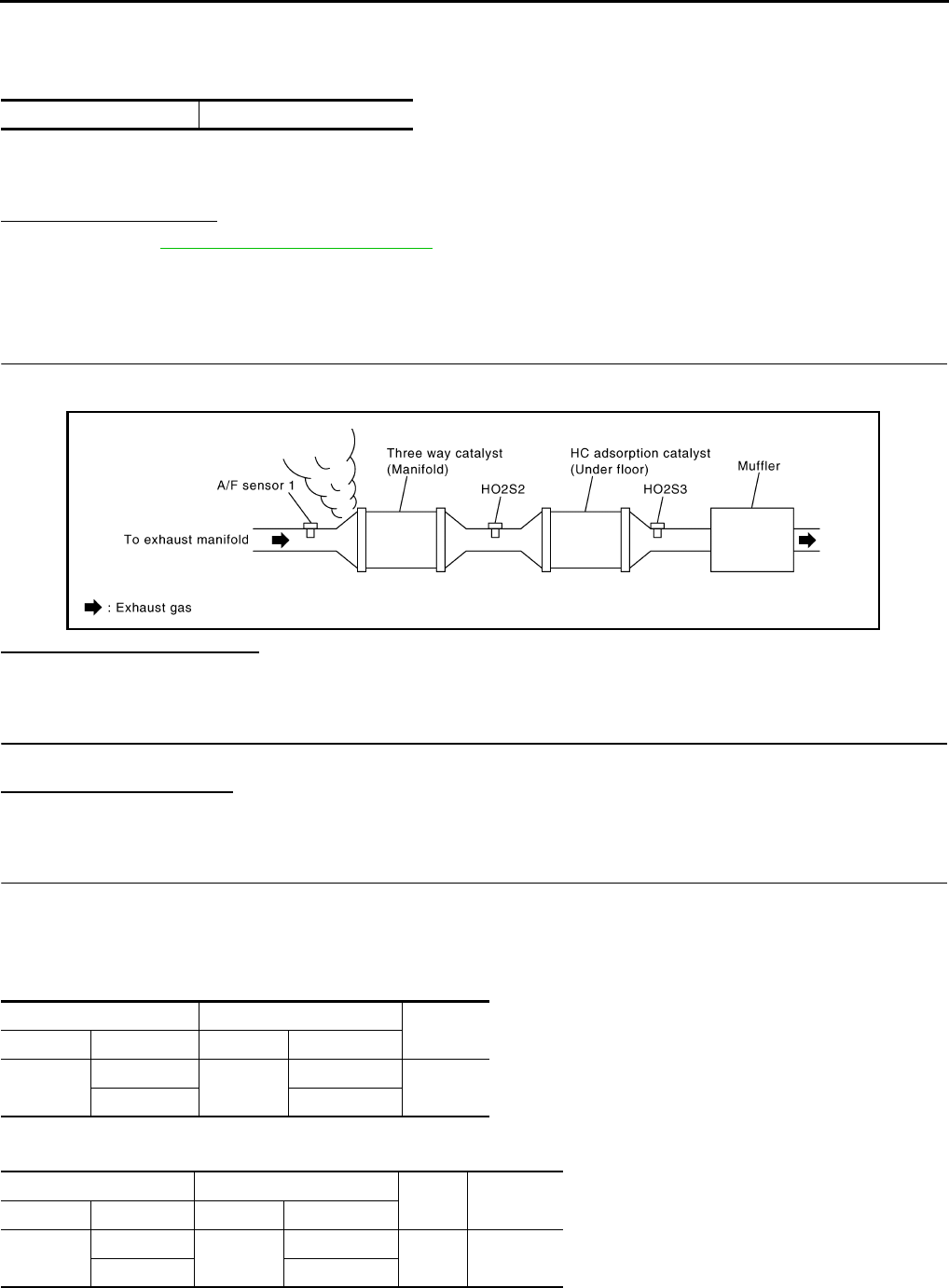
EC-684
< COMPONENT DIAGNOSIS > [FOR USA (FEDERAL) AND CANADA]
P0172 FUEL INJECTION SYSTEM FUNCTION
2. Start engine
3. Maintain the following conditions for at least 10 consecutive minutes.
Hold the accelerator pedal as steady as possible.
CAUTION:
Always drive vehicle at a safe speed.
4. Check 1st trip DTC.
Is 1st trip DTC detected?
YES >> Go to EC-684, "Diagnosis Procedure".
NO >> INSPECTION END
Diagnosis Procedure INFOID:0000000004529549
1.CHECK EXHAUST GAS LEAK
1. Start engine and run it at idle.
2. Listen for an exhaust gas leak before three way catalyst (manifold).
Is exhaust gas leak detected?
YES >> Repair or replace.
NO >> GO TO 2.
2.CHECK FOR INTAKE AIR LEAK
Listen for an intake air leak after the mass air flow sensor.
Is intake air leak detected?
YES >> Repair or replace.
NO >> GO TO 3.
3.CHECK A/F SENSOR 1 INPUT SIGNAL CIRCUIT
1. Turn ignition switch OFF.
2. Disconnect corresponding A/F sensor 1 harness connector.
3. Disconnect ECM harness connector.
4. Check the continuity between A/F sensor 1 harness connector and ECM harness connector.
5. Check the continuity between A/F sensor 1 harness connector or ECM harness connector and ground.
6. Also check harness for short to power.
VHCL SPEED SE 50 - 120 km/h (31 - 75 MPH)
JMBIA0163G
B
A/F sensor 1 ECM Continuity
Connector Terminal Connector Terminal
F28 1F8 45 Existed
249
A/F sensor 1 ECM Ground Continuity
Connector Terminal Connector Terminal
F28 1F8 45 Ground Not existed
249
Revision: 2008 August 2009 Rogue

P0172 FUEL INJECTION SYSTEM FUNCTION
EC-685
< COMPONENT DIAGNOSIS > [FOR USA (FEDERAL) AND CANADA]
C
D
E
F
G
H
I
J
K
L
M
A
EC
N
P
O
Is the inspection result normal?
YES >> GO TO 4.
NO >> Repair open circuit or short to ground or short to power in harness or connectors.
4.CHECK FUEL PRESSURE
1. Check fuel pressure. Refer to EC-923, "Inspection".
Is the inspection result normal?
YES >> GO TO 6.
NO >> GO TO 5.
5. DETECT MALFUNCTIONING PART
Check fuel hoses and fuel tubes for clogging.
Is the inspection result normal?
YES >> Replace “fuel filter and fuel pump assembly”.
NO >> Repair or replace
6.CHECK MASS AIR FLOW SENSOR
With CONSULT-III
1. Install all removed parts.
2. Check “MASS AIR FLOW” in “DATA MONITOR” mode with CONSULT-III.
For specification, refer to EC-928, "Mass Air Flow Sensor"
With GST
1. Install all removed parts.
2. Check mass air flow sensor signal in “Service $01” with GST.
For specification, refer to EC-928, "Mass Air Flow Sensor"
Is the measurement value within the specification?
YES >> GO TO 7.
NO >> Check connectors for rusted terminals or loose connections in the mass air flow sensor circuit or
grounds. Refer to EC-615, "DTC Logic".
7.CHECK FUNCTION OF FUEL INJECTOR
With CONSULT-III
1. Start engine.
2. Perform “POWER BALANCE” in “ACTIVE TEST” mode with CONSULT-III.
3. Check that each circuit produces a momentary engine speed drop.
Without CONSULT-III
1. Let engine idle.
2. Listen to each fuel injector operating sound.
Is the inspection result normal?
YES >> GO TO 8.
NO >> Perform trouble diagnosis for FUEL INJECTOR, refer to
EC-855, "Component Function Check".
8.CHECK FUEL INJECTOR
1. Remove fuel injector assembly. Refer to EM-43, "Removal and Installation".
Keep fuel hose and all fuel injectors connected to fuel tube.
2. Confirm that the engine is cooled down and there are no fire hazards near the vehicle.
3. Disconnect all fuel injector harness connectors.
4. Disconnect all ignition coil harness connectors.
5. Prepare pans or saucers under each fuel injector.
6. Crank engine for approximately 3 seconds.
Clicking noise should be heard.
PBIB3332E
Revision: 2008 August 2009 Rogue

EC-686
< COMPONENT DIAGNOSIS > [FOR USA (FEDERAL) AND CANADA]
P0172 FUEL INJECTION SYSTEM FUNCTION
Check that fuel does not drip from fuel injector.
Is the inspection result normal?
YES >> GO TO 9.
NO >> Replace the fuel injectors from which fuel is dripping. Always replace O-ring with new one.
9.CHECK INTERMITTENT INCIDENT
Refer to GI-41, "Intermittent Incident".
>> INSPECTION END
Revision: 2008 August 2009 Rogue

P0181 FTT SENSOR
EC-687
< COMPONENT DIAGNOSIS > [FOR USA (FEDERAL) AND CANADA]
C
D
E
F
G
H
I
J
K
L
M
A
EC
N
P
O
P0181 FTT SENSOR
Description INFOID:0000000004529550
The fuel tank temperature sensor is used to detect the fuel tempera-
ture inside the fuel tank. The sensor modifies a voltage signal from
the ECM. The modified signal returns to the ECM as the fuel temper-
ature input. The sensor uses a thermistor which is sensitive to the
change in temperature. The electrical resistance of the thermistor
decreases as temperature increases.
<Reference data>
*: These data are reference values and are measured between ECM terminals 95 (Fuel tank temperature sensor) and 104 (Sensor
ground).
DTC Logic INFOID:0000000004529551
DTC DETECTION LOGIC
DTC CONFIRMATION PROCEDURE
1.PRECONDITIONING
If DTC CONFIRMATION PROCEDURE has been previously conducted, always turn ignition switch OFF and
wait at least 10 seconds before conducting the next test.
>> GO TO 2.
2.PERFORM DTC CONFIRMATION PROCEDURE-I
1. Turn ignition switch and wait at least 10 seconds.
2. Check 1st trip DTC.
Is 1st trip DTC detected?
YES >> Go to EC-688, "Diagnosis Procedure".
NO >> GO TO 3.
3.CHECK ENGINE COOLANT TEMPERATURE
With CONSULT-III
1. Select “COOLAN TEMP/S” in “DATA MONITOR” mode with CONSULT-III.
2. Check “COOLAN TEMP/S” indication.
With GST
Follow the procedure “With CONSULT-III” above.
Is “COOLAN TEMP/S” indication less than 60°C (140°F)?
YES >> INSPECTION END
NO >> GO TO 4.
4.PERFORM DTC CONFIRMATION PROCEDURE-II
With CONSULT-III
1. Cool engine down until “COOLAN TEMP/S” indication is less than 60°C (140°F).
Fluid temperature
[°C (°F)]
Voltage*
(V)
Resistance
(kΩ)
20 (68) 3.5 2.3 - 2.7
50 (122) 2.2 0.79 - 0.90
SEF012P
DTC No. Trouble diagnosis name DTC detecting condition Possible cause
P0181 Fuel tank temperature
sensor circuit range/per-
formance
Rationally incorrect voltage from the sensor is
sent to ECM, compared with the voltage signals
from engine coolant temperature sensor and in-
take air temperature sensor.
• Harness or connectors
(The sensor circuit is open or shorted)
• Fuel tank temperature sensor
Revision: 2008 August 2009 Rogue

EC-688
< COMPONENT DIAGNOSIS > [FOR USA (FEDERAL) AND CANADA]
P0181 FTT SENSOR
2. Wait at least 10 seconds.
3. Check 1st trip DTC.
With GST
Follow the procedure “With CONSULT-III” above.
Is 1st trip DTC detected?
YES >> Go to EC-688, "Diagnosis Procedure".
NO >> INSPECTION END
Diagnosis Procedure INFOID:0000000004529552
1.CHECK GROUND CONNECTION
1. Turn ignition switch OFF.
2. Check ground connection E21. Refer to Ground Inspection in GI-44, "Circuit Inspection".
Is the inspection result normal?
YES >> GO TO 2.
NO >> Repair or replace ground connection.
2.CHECK FUEL TANK TEMPERATURE SENSOR POWER SUPPLY CIRCUIT
1. Turn ignition switch OFF.
2. Disconnect “fuel level sensor unit and fuel pump” harness connector.
3. Turn ignition switch ON.
4. Check the voltage between “fuel level sensor unit and fuel pump” harness connector and ground.
Is the inspection result normal?
YES >> GO TO 4.
NO >> GO TO 3.
3.DETECT MALFUNCTIONING PART
Check the following.
• Harness connectors M11, B1
• Harness connectors M77, E105
• Harness for open or short between ECM and “fuel level sensor unit and fuel pump”
>> Repair open circuit or short to ground or short to power in harness or connector.
4.CHECK FUEL TANK TEMPERATURE SENSOR GROUND CIRCUIT FOR OPEN AND SHORT
1. Turn ignition switch OFF.
2. Check the continuity between “fuel level sensor unit and fuel pump” harness connector and ECM harness
connector.
3. Also check harness for short to ground and short to power.
Is the inspection result normal?
YES >> GO TO 6.
NO >> GO TO 5.
5.DETECT MALFUNCTIONING PART
Check the following.
• Harness connectors B1, M11
• Harness connectors M77, E105
Fuel level sensor unit and fuel pump Ground Voltage
Connector Terminal
B40 2 Ground Approx. 5V
Fuel level sensor unit and fuel pump ECM Continuity
Connector Terminal Connector Terminal
B40 1 E16 104 Existed
Revision: 2008 August 2009 Rogue

P0181 FTT SENSOR
EC-689
< COMPONENT DIAGNOSIS > [FOR USA (FEDERAL) AND CANADA]
C
D
E
F
G
H
I
J
K
L
M
A
EC
N
P
O
• Harness for open or short between “fuel level sensor unit and fuel pump” and ECM
>> Repair open circuit or short to ground or short to power in harness or connector.
6.CHECK FUEL TANK TEMPERATURE SENSOR
Refer to EC-689, "Component Inspection".
Is the inspection result normal?
YES >> GO TO 7.
NO >> Replace “fuel level sensor unit and fuel pump”.
7.CHECK INTERMITTENT INCIDENT
Refer to GI-41, "Intermittent Incident".
>> INSPECTION END
Component Inspection INFOID:0000000004529553
1.CHECK FUEL TANK TEMPERATURE SENSOR
1. Turn ignition switch OFF.
2. Disconnect “fuel level sensor unit and fuel pump” harness connector.
3. Remove fuel level sensor unit.
4. Check resistance between “fuel level sensor unit and fuel pump”
terminals by heating with hot water as shown in the figure.
Is the inspection result normal?
YES >> INSPECTION END
NO >> Replace “fuel level sensor unit and fuel pump”.
Terminals Condition Resistance (kΩ)
1 and 2 Temperature [°C (°F)] 20 (68) 2.3 - 2.7
50 (122) 0.79 - 0.90
JMBIA0167ZZ
Revision: 2008 August 2009 Rogue
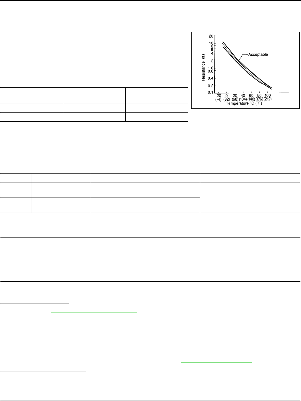
EC-690
< COMPONENT DIAGNOSIS > [FOR USA (FEDERAL) AND CANADA]
P0182, P0183 FTT SENSOR
P0182, P0183 FTT SENSOR
Description INFOID:0000000004533862
The fuel tank temperature sensor is used to detect the fuel tempera-
ture inside the fuel tank. The sensor modifies a voltage signal from
the ECM. The modified signal returns to the ECM as the fuel temper-
ature input. The sensor uses a thermistor which is sensitive to the
change in temperature. The electrical resistance of the thermistor
decreases as temperature increases.
<Reference data>
*: These data are reference values and are measured between ECM terminals 95 (Fuel tank temperature sensor) and 104 (Sensor
ground).
DTC Logic INFOID:0000000004529555
DTC DETECTION LOGIC
DTC CONFIRMATION PROCEDURE
1.PRECONDITIONING
If DTC CONFIRMATION PROCEDURE has been previously conducted, always turn ignition switch OFF and
wait at least 10 seconds before conducting the next test.
>> GO TO 2.
2.PERFORM DTC CONFIRMATION PROCEDURE
1. Turn ignition switch ON and wait at least 5 seconds.
2. Check 1st trip DTC.
Is 1st trip DTC detected?
YES >> Go to EC-690, "Diagnosis Procedure".
NO >> INSPECTION END
Diagnosis Procedure INFOID:0000000004533863
1.CHECK GROUND CONNECTION
1. Turn ignition switch OFF.
2. Check ground connection E21. Refer to Ground Inspection in GI-44, "Circuit Inspection".
Is the inspection result normal?
YES >> GO TO 2.
NO >> Repair or replace ground connection.
2.CHECK FUEL TANK TEMPERATURE SENSOR POWER SUPPLY CIRCUIT
1. Turn ignition switch OFF.
2. Disconnect “fuel level sensor unit and fuel pump” harness connector.
3. Turn ignition switch ON.
Fluid temperature
[°C (°F)]
Voltage*
(V)
Resistance
(kΩ)
20 (68) 3.5 2.3 - 2.7
50 (122) 2.2 0.79 - 0.90
SEF012P
DTC No. Trouble diagnosis name DTC detecting condition Possible cause
P0182 Fuel tank temperature
sensor circuit low input
An excessively low voltage from the sensor is
sent to ECM. • Harness or connectors
(The sensor circuit is open or shorted.)
• Fuel tank temperature sensor
P0183 Fuel tank temperature
sensor circuit high input
An excessively high voltage from the sensor is
sent to ECM.
Revision: 2008 August 2009 Rogue

P0182, P0183 FTT SENSOR
EC-691
< COMPONENT DIAGNOSIS > [FOR USA (FEDERAL) AND CANADA]
C
D
E
F
G
H
I
J
K
L
M
A
EC
N
P
O
4. Check the voltage between “fuel level sensor unit and fuel pump” harness connector and ground.
Is the inspection result normal?
YES >> GO TO 4.
NO >> GO TO 3.
3.DETECT MALFUNCTIONING PART
Check the following.
• Harness connectors M11, B1
• Harness connectors M77, E105
• Harness for open or short between ECM and “fuel level sensor unit and fuel pump”
>> Repair open circuit or short to ground or short to power in harness or connector.
4.CHECK FUEL TANK TEMPERATURE SENSOR GROUND CIRCUIT FOR OPEN AND SHORT
1. Turn ignition switch OFF.
2. Check the continuity between “fuel level sensor unit and fuel pump” harness connector and ECM harness
connector.
3. Also check harness for short to ground and short to power.
Is the inspection result normal?
YES >> GO TO 6.
NO >> GO TO 5.
5.DETECT MALFUNCTIONING PART
Check the following.
• Harness connectors B1, M11
• Harness connectors M77, E105
• Harness for open or short between “fuel level sensor unit and fuel pump” and ECM
>> Repair open circuit or short to ground or short to power in harness or connector.
6.CHECK FUEL TANK TEMPERATURE SENSOR
Refer to EC-691, "Component Inspection".
Is the inspection result normal?
YES >> GO TO 7.
NO >> Replace “fuel level sensor unit and fuel pump”.
7.CHECK INTERMITTENT INCIDENT
Refer to GI-41, "Intermittent Incident".
>> INSPECTION END
Component Inspection INFOID:0000000004533864
1.CHECK FUEL TANK TEMPERATURE SENSOR
1. Turn ignition switch OFF.
2. Disconnect “fuel level sensor unit and fuel pump” harness connector.
3. Remove fuel level sensor unit.
Fuel level sensor unit and fuel pump Ground Voltage
Connector Terminal
B40 2 Ground Approx. 5V
Fuel level sensor unit and fuel pump ECM Continuity
Connector Terminal Connector Terminal
B40 1 E16 104 Existed
Revision: 2008 August 2009 Rogue
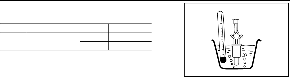
EC-692
< COMPONENT DIAGNOSIS > [FOR USA (FEDERAL) AND CANADA]
P0182, P0183 FTT SENSOR
4. Check resistance between “fuel level sensor unit and fuel pump”
terminals by heating with hot water as shown in the figure.
Is the inspection result normal?
YES >> INSPECTION END
NO >> Replace “fuel level sensor unit and fuel pump”.
Terminals Condition Resistance (kΩ)
1 and 2 Temperature [°C (°F)] 20 (68) 2.3 - 2.7
50 (122) 0.79 - 0.90
JMBIA0167ZZ
Revision: 2008 August 2009 Rogue

P0222, P0223 TP SENSOR
EC-693
< COMPONENT DIAGNOSIS > [FOR USA (FEDERAL) AND CANADA]
C
D
E
F
G
H
I
J
K
L
M
A
EC
N
P
O
P0222, P0223 TP SENSOR
Description INFOID:0000000004533694
Electric throttle control actuator consists of throttle control motor,
throttle position sensor, etc. The throttle position sensor responds to
the throttle valve movement.
The throttle position sensor has two sensors. These sensors are a
kind of potentiometer which transform the throttle valve position into
output voltage, and emit the voltage signals to the ECM. The ECM
judges the current opening angle of the throttle valve from these sig-
nals and contols the throttle valve opening angle in response to driv-
ing conditions via the throttle contorol motor.
DTC Logic INFOID:0000000004529559
DTC DETECTION LOGIC
DTC CONFIRMATION PROCEDURE
1.PRECONDITIONING
If DTC CONFIRMATION PROCEDURE has been previously conducted, always turn ignition switch OFF and
wait at least 10 seconds before conducting the next test.
TESTING CONDITION:
Before performing the following procedure, confirm that battery voltage is more than 8V at idle.
>> GO TO 2.
2.PERFORM DTC CONFIRMATION PROCEDURE
1. Start engine and let it idle for 1 second.
2. Check DTC.
Is DTC detected?
YES >> Go to EC-693, "Diagnosis Procedure".
NO >> INSPECTION END
Diagnosis Procedure INFOID:0000000004529560
1.CHECK GROUND CONNECTION
1. Turn ignition switch OFF.
2. Check ground connection E21. Refer to Ground Inspection in GI-44, "Circuit Inspection".
Is the inspection result normal?
YES >> GO TO 2.
NO >> Repair or replace ground connection.
2.CHECK THROTTLE POSITION SENSOR 1 POWER SUPPLY CIRCUIT
1. Disconnect electric throttle control actuator harness connector.
2. Turn ignition switch ON.
3. Check the voltage between electric throttle control actuator harness connector and ground.
PBIB0145E
DTC No. Trouble diagnosis name DTC detecting condition Possible cause
P0222 Throttle position sensor
1 circuit low input An excessively low voltage from the TP sensor
1 is sent to ECM. • Harness or connectors
(TP sensor 1 circuit is open or shorted.)
• Electric throttle control actuator
(TP sensor 1)
P0223 Throttle position sensor
1 circuit high input
An excessively high voltage from the TP sensor
1 is sent to ECM.
Revision: 2008 August 2009 Rogue

EC-694
< COMPONENT DIAGNOSIS > [FOR USA (FEDERAL) AND CANADA]
P0222, P0223 TP SENSOR
Is the inspection result normal?
YES >> GO TO 3.
NO >> Repair open circuit or short to ground or short to power in harness or connectors.
3.CHECK THROTTLE POSITION SENSOR 1 GROUND CIRCUIT FOR OPEN AND SHORT
1. Turn ignition switch OFF.
2. Disconnect ECM harness connector.
3. Check the continuity between electric throttle control actuator harness connector and ECM harness con-
nector.
4. Also check harness for short to ground and short to power.
Is the inspection result normal?
YES >> GO TO 4.
NO >> Repair open circuit or short to ground or short to power in harness or connectors.
4.CHECK THROTTLE POSITION SENSOR 1 INPUT SIGNAL CIRCUIT FOR OPEN AND SHORT
1. Check the continuity between electric throttle control actuator harness connector and ECM harness con-
nector.
2. Also check harness for short to ground and short to power.
Is the inspection result normal?
YES >> GO TO 5.
NO >> Repair open circuit or short to ground or short to power in harness or connectors.
5.CHECK THROTTLE POSITION SENSOR
Refer to EC-695, "Component Inspection".
Is the inspection result normal?
YES >> GO TO 7.
NO >> GO TO 6.
6.REPLACE ELECTRIC THROTTLE CONTROL ACTUATOR
1. Replace electric throttle control actuator.
2. Go to EC-695, "Special Repair Requirement".
>> INSPECTION END
7.CHECK INTERMITTENT INCIDENT
Refer to GI-41, "Intermittent Incident".
>> INSPECTION END
Electric throttle control actuator Ground Voltage
Connector Terminal
F29 1 Ground Approx. 5V
Electric throttle control actuator ECM Continuity
Connector Terminal Connector Terminal
F29 4 F8 36 Existed
Electric throttle control actuator ECM Continuity
Connector Terminal Connector Terminal
F29 2 F8 37 Existed
Revision: 2008 August 2009 Rogue

P0222, P0223 TP SENSOR
EC-695
< COMPONENT DIAGNOSIS > [FOR USA (FEDERAL) AND CANADA]
C
D
E
F
G
H
I
J
K
L
M
A
EC
N
P
O
Component Inspection INFOID:0000000004533695
1.CHECK THROTTLE POSITION SENSOR
1. Turn ignition switch OFF.
2. Reconnect all harness connectors disconnected.
3. Perform EC-504, "THROTTLE VALVE CLOSED POSITION LEARNING : Special Repair Requirement".
4. Turn ignition switch ON.
5. Set selector lever to the D position.
6. Check the voltage between ECM harness connector terminals.
Is the inspection result normal?
YES >> INSPECTION END
NO >> GO TO 2.
2.REPLACE ELECTRIC THROTTLE CONTROL ACTUATOR
1. Replace electric throttle control actuator.
2. Perform EC-695, "Special Repair Requirement".
>> INSPECTION END
Special Repair Requirement INFOID:0000000004533696
1.PERFORM THROTTLE VALVE CLOSED POSITION LEARNING
Refer to EC-504, "THROTTLE VALVE CLOSED POSITION LEARNING : Special Repair Requirement"
>> GO TO 2.
2.PERFORM IDLE AIR VOLUME LEARNING
Refer to EC-505, "IDLE AIR VOLUME LEARNING : Special Repair Requirement"
>> END
ECM
Condition Voltage+−
Connector Terminal Connector Terminal
F8
37
(TP sensor 1
signal) F8
36
(Sensor
ground) Accelerator pedal
Fully released More than 0.36 V
Fully depressed Less than 4.75 V
38
(TP sensor 2
signal)
Fully released Less than 4.75 V
Fully depressed More than 0.36 V
Revision: 2008 August 2009 Rogue

EC-696
< COMPONENT DIAGNOSIS > [FOR USA (FEDERAL) AND CANADA]
P0300, P0301, P0302, P0303, P0304 MISFIRE
P0300, P0301, P0302, P0303, P0304 MISFIRE
DTC Logic INFOID:0000000004529563
DTC DETECTION LOGIC
When a misfire occurs, engine speed will fluctuate. If the engine speed fluctuates enough to cause the crank-
shaft position (CKP) sensor (POS) signal to vary, ECM can determine that a misfire is occurring.
The misfire detection logic consists of the following two conditions.
1. One Trip Detection Logic (Three Way Catalyst Damage)
On the 1st trip, when that a misfire condition occurs that can damage the three way catalyst (TWC) due to
overheating, the MIL will blink.
When a misfire condition occurs, the ECM monitors the CKP sensor signal every 200 engine revolutions
for a change.
When the misfire condition decreases to a level that will not damage the TWC, the MIL will turn off.
If another misfire condition occurs that can damage the TWC on a second trip, the MIL will blink.
When the misfire condition decreases to a level that will not damage the TWC, the MIL will remain on.
If another misfire condition occurs that can damage the TWC, the MIL will begin to blink again.
2. Two Trip Detection Logic (Exhaust quality deterioration)
For misfire conditions that will not damage the TWC (but will affect vehicle emissions), the MIL will only
light when the misfire is detected on a second trip. During this condition, the ECM monitors the CKP sen-
sor signal every 1,000 engine revolutions.
A misfire malfunction can be detected in any one cylinder or in multiple cylinders.
DTC CONFIRMATION PROCEDURE
1.PRECONDITIONING
If DTC CONFIRMATION PROCEDURE has been previously conducted, always turn ignition switch OFF and
wait at least 10 seconds before conducting the next test.
>> GO TO 2.
2.PERFORM DTC CONFIRMATION PROCEDURE-I
1. Start engine and warm it up to normal operating temperature.
2. Turn ignition switch OFF and wait at least 10 seconds.
3. Restart engine and let it idle for approximately 15 minutes.
4. Check 1st trip DTC.
Is 1st trip DTC detected?
YES >> Go to EC-697, "Diagnosis Procedure".
NO >> GO TO 3.
3.PERFORM DTC CONFIRMATION PROCEDURE-II
1. Turn ignition switch OFF and wait at least 10 seconds.
Sensor Input signal to ECM ECM function
Crankshaft position sensor (POS) Engine speed On board diagnosis of misfire
DTC No. Trouble diagnosis name DTC detecting condition Possible cause
P0300 Multiple cylinder misfires detected Multiple cylinder misfire. • Improper spark plug
• Insufficient compression
• Incorrect fuel pressure
• The fuel injector circuit is open or shorted
• Fuel injector
• Intake air leak
• The ignition signal circuit is open or shorted
• Lack of fuel
• Signal plate
• A/F sensor 1
• Incorrect PCV hose connection
P0301 No.1 cylinder misfire detected No. 1 cylinder misfires.
P0302 No. 2 cylinder misfire detected No. 2 cylinder misfires.
P0303 No. 3 cylinder misfire detected No. 3 cylinder misfires.
P0304 No. 4 cylinder misfire detected No. 4 cylinder misfires.
Revision: 2008 August 2009 Rogue

P0300, P0301, P0302, P0303, P0304 MISFIRE
EC-697
< COMPONENT DIAGNOSIS > [FOR USA (FEDERAL) AND CANADA]
C
D
E
F
G
H
I
J
K
L
M
A
EC
N
P
O
2. Start engine and drive the vehicle under similar conditions to (1st trip) Freeze Frame Data for a certain
time. Refer to the table below.
Hold the accelerator pedal as steady as possible.
Similar conditions to (1st trip) Freeze Frame Data mean that the following conditions should be satisfied at
the same time.
CAUTION:
Always drive vehicle in safe manner according to traffic conditions and obey all traffic laws when
driving.
Driving timevaries according to the engine speed in the freeze frame data.
3. Check 1st trip DTC.
Is 1st trip DTC detected?
YES >> Go to EC-697, "Diagnosis Procedure".
NO >> INSPECTION END
Diagnosis Procedure INFOID:0000000004529564
1.CHECK FOR INTAKE AIR LEAK AND PCV HOSE
1. Start engine and run it at idle speed.
2. Listen for the sound of the intake air leak.
3. Check PCV hose connection.
Is intake air leak detected?
YES >> Discover air leak location and repair.
NO >> GO TO 2.
2.CHECK FOR EXHAUST SYSTEM CLOGGING
Stop engine and visually check exhaust tube, three way catalyst and muffler for dents.
Is the inspection result normal?
YES-1 >> With CONSULT-III: GO TO 3.
YES-2 >> Without CONSULT-III: GO TO 4.
NO >> Repair or replace malfunctioning part.
3.PERFORM POWER BALANCE TEST
With CONSULT-III
1. Start engine.
2. Perform “POWER BALANCE” in “ACTIVE TEST” mode with CONSULT-III.
3. Check that each circuit produces a momentary engine speed drop.
Is the inspection result normal?
YES >> GO TO 9.
NO >> GO TO 4.
4.CHECK FUNCTION OF FUEL INJECTOR
1. Start engine and let engine idle.
Engine speed Engine speed in the freeze frame data ± 400 rpm
Vehicle speed Vehicle speed in the freeze frame data ± 10 km/h (6 MPH)
Base fuel schedule Base fuel schedule in freeze frame data × (1 ± 0.1)
Engine coolant temperature (T)
condition
When the freeze frame data shows lower than 70 °C (158 °F),
T should be lower than 70 °C (158 °F).
When the freeze frame data shows higher than or equal to 70 °C (158 °F),
T should be higher than or equal to 70 °C (158 °F).
Engine speed Time
Around 1,000 rpm Approximately 10 minutes
Around 2,000 rpm Approximately 5 minutes
More than 3,000 rpm Approximately 3.5 minutes
Revision: 2008 August 2009 Rogue
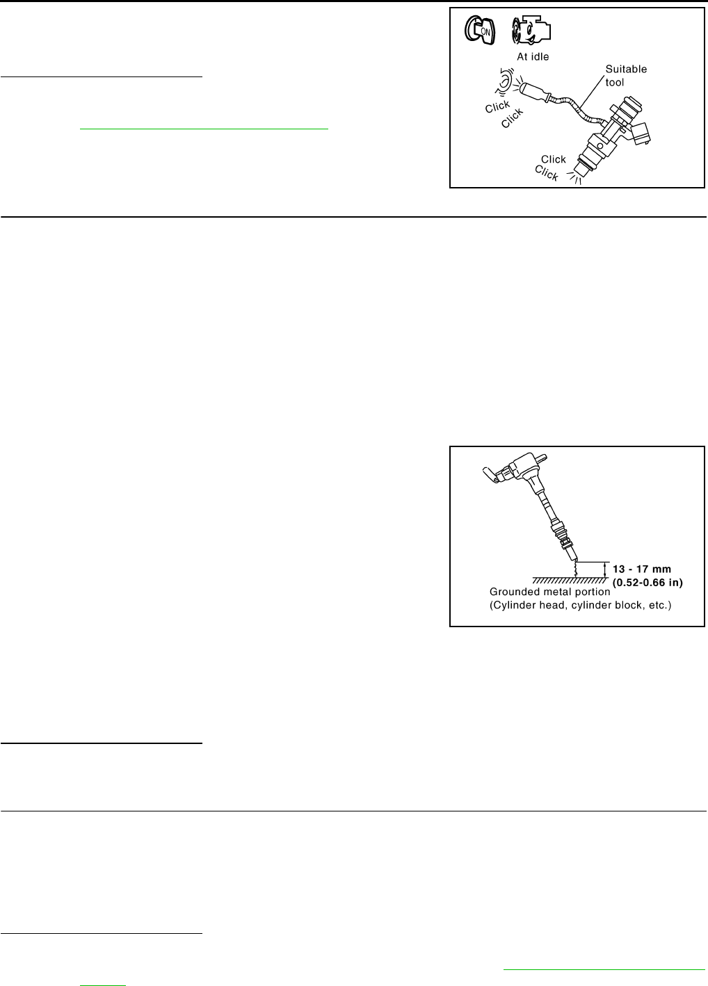
EC-698
< COMPONENT DIAGNOSIS > [FOR USA (FEDERAL) AND CANADA]
P0300, P0301, P0302, P0303, P0304 MISFIRE
2. Listen to each fuel injector operation.
Is the inspection result normal?
YES >> GO TO 5.
NO >> Perform trouble diagnosis for FUEL INJECTOR, refer to
EC-855, "Component Function Check".
5.CHECK FUNCTION OF IGNITION COIL-I
CAUTION:
Perform the following procedure in a place with no combustible objects and good ventilation.
1. Turn ignition switch OFF.
2. Remove fuel pump fuse in IPDM E/R to release fuel pressure.
NOTE:
Do not use CONSULT-III to release fuel pressure, or fuel pressure applies again during the following pro-
cedure.
3. Start engine.
4. After engine stalls, crank it two or three times to release all fuel pressure.
5. Turn ignition switch OFF.
6. Remove all ignition coil harness connectors to avoid the electrical discharge from the ignition coils.
7. Remove ignition coil and spark plug of the cylinder to be checked.
8. Crank engine for 5 seconds or more to remove combustion gas in the cylinder.
9. Connect spark plug and harness connector to ignition coil.
10. Fix ignition coil using a rope etc. with gap of 13 - 17 mm (0.52 -
0.66 in) between the edge of the spark plug and grounded metal
portion as shown in the figure.
11. Crank engine for approximately 3 seconds, and check whether
spark is generated between the spark plug and the grounded
metal portion.
CAUTION:
• Never place the spark plug and the ignition coil within 50
cm (19.7 in) each other. Be careful not to get an electrical
shock while checking, because the electrical discharge
voltage becomes 20kV or more.
• It might damage the ignition coil if the gap of more than 17 mm (0.66 in) is made.
NOTE:
When the gap is less than 13 mm (0.52 in), a spark might be generated even if the coil is malfunc-
tioning.
Is the inspection result normal?
YES >> GO TO 9.
NO >> GO TO 6.
6.CHECK FUNCTION OF IGNITION COIL-II
1. Turn ignition switch OFF.
2. Disconnect spark plug and connect a non-malfunctioning spark plug.
3. Crank engine for approximately 3 seconds, and recheck whether spark is generated between the spark
plug and the grounded metal portion.
Is the inspection result normal?
YES >> GO TO 7.
NO >> Check ignition coil, power transistor and their circuits. Refer to EC-861, "Component Function
Check".
Clicking noise should be heard.
PBIB3332E
Spark should be generated.
JMBIA0066G
B
Spark should be generated.
Revision: 2008 August 2009 Rogue
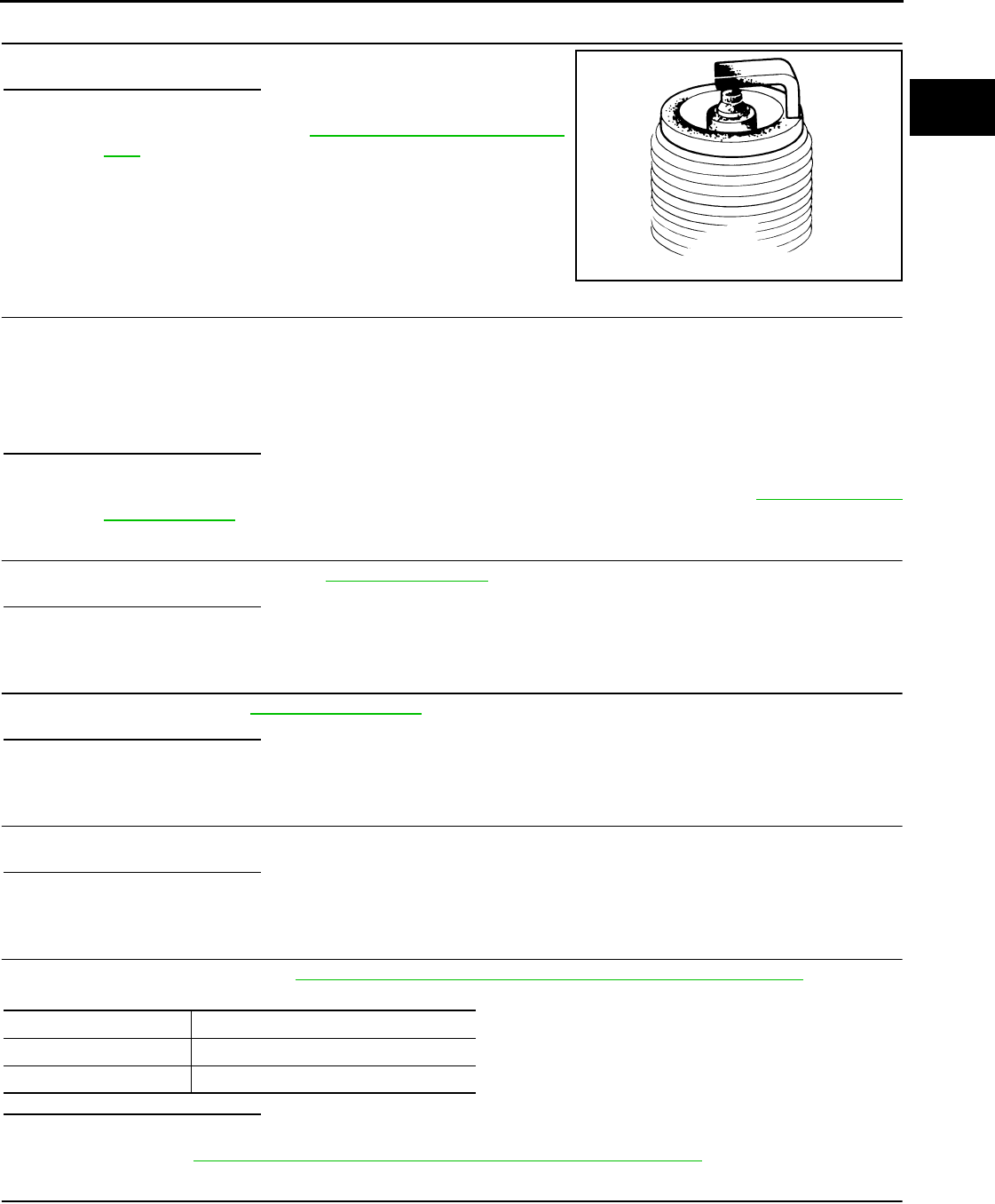
P0300, P0301, P0302, P0303, P0304 MISFIRE
EC-699
< COMPONENT DIAGNOSIS > [FOR USA (FEDERAL) AND CANADA]
C
D
E
F
G
H
I
J
K
L
M
A
EC
N
P
O
7.CHECK SPARK PLUG
Check the initial spark plug for fouling, etc.
Is the inspection result normal?
YES >> Replace spark plug(s) with standard type one(s). For
spark plug type, refer to EM-40, "Removal and Installa-
tion".
NO >> Repair or clean spark plug. Then GO TO 8.
8.CHECK FUNCTION OF IGNITION COIL-III
1. Reconnect the initial spark plugs.
2. Crank engine for approximately 3 seconds, and recheck whether spark is generated between the spark
plug and the grounded portion.
Is the inspection result normal?
YES >> INSPECTION END
NO >> Replace spark plug(s) with standard type one(s). For spark plug type, refer to EM-40, "Removal
and Installation".
9.CHECK COMPRESSION PRESSURE
Check compression pressure. Refer to EM-23, "Inspection".
Is the inspection result normal?
YES >> GO TO 10.
NO >> Check pistons, piston rings, valves, valve seats and cylinder head gaskets.
10.CHECK FUEL PRESSURE
Check fuel pressure. Refer to EC-923, "Inspection".
Is the inspection result normal?
YES >> GO TO 12.
NO >> GO TO 11.
11.DETECT MALFUNCTIONING PART
Check fuel hoses and fuel tubes for clogging.
Is the inspection result normal?
YES >> Replace “fuel filter and fuel pump assembly”.
NO >> Repair or replace.
12.CHECK IGNITION TIMING
Check the following items. Refer to EC-499, "BASIC INSPECTION : Special Repair Requirement".
Is the inspection result normal?
YES >> GO TO 13.
NO >> Follow the EC-499, "BASIC INSPECTION : Special Repair Requirement".
13.CHECK A/F SENSOR 1 INPUT SIGNAL CIRCUIT
1. Turn ignition switch OFF.
2. Disconnect corresponding A/F sensor 1 harness connector.
3. Disconnect ECM harness connector.
SEF156I
Spark should be generated.
Items Specifications
idle speed 700 ± 50 rpm (in P or N position)
Ignition timing 15 ± 5°BTDC (in P or N position)
Revision: 2008 August 2009 Rogue
EC-700
< COMPONENT DIAGNOSIS > [FOR USA (FEDERAL) AND CANADA]
P0300, P0301, P0302, P0303, P0304 MISFIRE
4. Check the continuity between A/F sensor 1 harness connector and ECM harness connector.
5. Check the continuity between A/F sensor 1 harness connector or ECM harness connector and ground.
6. Also check harness for short to power.
Is the inspection result normal?
YES >> GO TO 14.
NO >> Repair open circuit or short to ground or short to power in harness or connectors.
14.CHECK A/F SENSOR 1 HEATER
Refer to EC-608, "Component Inspection".
Is the inspection result normal?
YES >> GO TO 15.
NO >> Replace A/F sensor 1.
15.CHECK MASS AIR FLOW SENSOR
With CONSULT-III
1. Install all removed parts.
2. Check “MASS AIR FLOW” in “DATA MONITOR” mode with CONSULT-III.
For specification, refer to EC-928, "Mass Air Flow Sensor".
With GST
1. Install all removed parts.
2. Check mass air flow sensor signal in Service $01 with GST.
For specification, refer to EC-928, "Mass Air Flow Sensor".
Is the measurement value within the specification?
YES >> GO TO 16.
NO >> Check connectors for rusted terminals or loose connections in the mass air flow sensor circuit or
ground. Refer to EC-615, "DTC Logic".
16.CHECK SYMPTOM TABLE
Check items on the rough idle symptom in EC-912, "Symptom Table".
Is the inspection result normal?
YES >> GO TO 17.
NO >> Repair or replace.
17.ERASE THE 1ST TRIP DTC
Some tests may cause a 1st trip DTC to be set.
Erase the 1st trip DTC from the ECM memory after performing the tests. Refer to EC-563, "Diagnosis Descrip-
tion".
>> GO TO 18.
18.CHECK INTERMITTENT INCIDENT
Refer to GI-41, "Intermittent Incident".
>> INSPECTION END
A/F sensor 1 ECM Continuity
Connector Terminal Connector Terminal
F28 1F8 45 Existed
249
A/F sensor 1 ECM Ground Continuity
Connector Terminal Connector Terminal
F28 1F8 45 Ground Not existed
249
Revision: 2008 August 2009 Rogue

P0327, P0328 KS
EC-701
< COMPONENT DIAGNOSIS > [FOR USA (FEDERAL) AND CANADA]
C
D
E
F
G
H
I
J
K
L
M
A
EC
N
P
O
P0327, P0328 KS
Description INFOID:0000000004529565
The knock sensor is attached to the cylinder block. It senses engine knocking using a piezoelectric element. A
knocking vibration from the cylinder block is sensed as vibrational pressure. This pressure is converted into a
voltage signal and sent to the ECM.
DTC Logic INFOID:0000000004529566
DTC DETECTION LOGIC
DTC CONFIRMATION PROCEDURE
1.PRECONDITIONING
If DTC CONFIRMATION PROCEDURE has been previously conducted, always turn ignition switch OFF and
wait at least 10 seconds before conducting the next test.
TESTING CONDITION:
Before performing the following procedure, confirm that battery voltage is more than 10V at idle.
>> GO TO 2.
2.PERFORM DTC CONFIRMATION PROCEDURE
1. Start engine and run it for at least 5 seconds at idle speed.
2. Check 1st trip DTC.
Is 1st trip DTC detected?
YES >> Go to EC-701, "Diagnosis Procedure".
NO >> INSPECTION END
Diagnosis Procedure INFOID:0000000004529567
1.CHECK GROUND CONNECTION
1. Turn ignition switch OFF.
2. Check ground connection E21. Refer to Ground Inspection in GI-44, "Circuit Inspection".
Is the inspection result normal?
YES >> GO TO 2.
NO >> Repair or replace ground connection.
2.CHECK KNOCK SENSOR GROUND CIRCUIT FOR OPEN AND SHORT
1. Disconnect knock sensor harness connector and disconnect ECM harness connector.
2. Check the continuity between knock sensor harness connector and ECM harness connector.
3. Also check harness for short to ground and short to power.
Is the inspection result normal?
YES >> GO TO 3.
NO >> Repair open circuit or short to ground or short to power in harness or connectors.
DTC No. Trouble diagnosis
name DTC detected condition Possible cause
P0327 Knock sensor circuit
low input
An excessively low voltage from the sensor is
sent to ECM. • Harness or connectors
(The sensor circuit is open or shorted.)
• Knock sensor
P0328 Knock sensor circuit
high input
An excessively high voltage from the sensor is
sent to ECM.
Knock sensor ECM Continuity
Connector Terminal Connector Terminal
F16 2 F8 67 Existed
Revision: 2008 August 2009 Rogue
EC-702
< COMPONENT DIAGNOSIS > [FOR USA (FEDERAL) AND CANADA]
P0327, P0328 KS
3.CHECK KNOCK SENSOR INPUT SIGNAL CIRCUIT FOR OPEN AND SHORT
1. Check the continuity between knock sensor harness connector and ECM harness connector.
2. Also check harness for short to ground and short to power.
Is the inspection result normal?
YES >> GO TO 4.
NO >> Repair open circuit or short to ground or short to power in harness or connectors.
4.CHECK KNOCK SENSOR
Refer to EC-702, "Component Inspection".
Is the inspection result normal?
YES >> GO TO 5.
NO >> Replace knock sensor.
5.CHECK INTERMITTENT INCIDENT
Refer to GI-41, "Intermittent Incident".
>> INSPECTION END
Component Inspection INFOID:0000000004529568
1.CHECK KNOCK SENSOR
1. Turn ignition switch OFF.
2. Disconnect knock sensor harness connector.
3. Check resistance between knock sensor terminals as follows.
NOTE:
It is necessary to use an ohmmeter which can measure more than 10 MΩ.
CAUTION:
Never use any knock sensors that have been dropped or physically damaged. Use only new ones.
Is the inspection result normal?
YES >> INSPECTION END
NO >> Replace knock sensor.
Knock sensor ECM Continuity
Connector Terminal Connector Terminal
F16 1 F8 61 Existed
Terminals Resistance
1 and 2 Approx. 532 - 588 kΩ [at 20°C (68°F)]
Revision: 2008 August 2009 Rogue
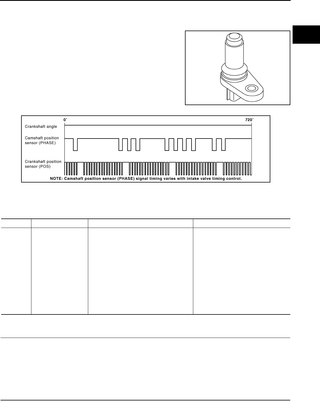
P0335 CKP SENSOR (POS)
EC-703
< COMPONENT DIAGNOSIS > [FOR USA (FEDERAL) AND CANADA]
C
D
E
F
G
H
I
J
K
L
M
A
EC
N
P
O
P0335 CKP SENSOR (POS)
Description INFOID:0000000004529569
The crankshaft position sensor (POS) is located on the oil pan facing
the gear teeth (cogs) of the signal plate. It detects the fluctuation of
the engine revolution.
The sensor consists of a permanent magnet and Hall IC.
When the engine is running, the high and low parts of the teeth
cause the gap with the sensor to change.
The changing gap causes the magnetic field near the sensor to
change.
Due to the changing magnetic field, the voltage from the sensor
changes.
The ECM receives the voltage signal and detects the fluctuation of
the engine revolution.
ECM receives the signals as shown in the figure.
DTC Logic INFOID:0000000004529570
DTC DETECTION LOGIC
DTC CONFIRMATION PROCEDURE
1.PRECONDITIONING
If DTC Confirmation Procedure has been previously conducted, always turn ignition switch OFF and wait at
least 10 seconds before conducting the next test.
TESTING CONDITION:
Before performing the following procedure, confirm that battery voltage is more than 10.5V with igni-
tion switch ON.
>> GO TO 2.
2.PERFORM DTC CONFIRMATION PROCEDURE
JMBIA0062ZZ
JMBIA0714G
B
DTC No. Trouble diagnosis name DTC detecting condition Possible cause
P0335 Crankshaft position sen-
sor (POS) circuit
• The crankshaft position sensor (POS) signal
is not detected by the ECM during the first
few seconds of engine cranking.
• The proper pulse signal from the crankshaft
position sensor (POS) is not sent to ECM
while the engine is running.
• The crankshaft position sensor (POS) signal
is not in the normal pattern during engine run-
ning.
• Harness or connectors
[Crankshaft position sensor (POS) circuit
is open or shorted.]
(Refrigerant pressure sensor circuit is
shorted.)
(Accelerator pedal position sensor circuit
is shorted.)
(EVAP control system pressure sensor
circuit is shorted.)
• Crankshaft position sensor (POS)
• Refrigerant pressure sensor
• Accelerator pedal position sensor
• EVAP control system pressure sensor
• Signal plate
Revision: 2008 August 2009 Rogue

EC-704
< COMPONENT DIAGNOSIS > [FOR USA (FEDERAL) AND CANADA]
P0335 CKP SENSOR (POS)
1. Start engine and let it idle for at least 5 seconds.
If engine does not start, crank engine for at least 2 seconds.
2. Check 1st trip DTC.
Is 1st trip DTC detected?
YES >> Go to EC-704, "Diagnosis Procedure".
NO >> INSPECTION END
Diagnosis Procedure INFOID:0000000004529571
1.CHECK GROUND CONNECTION
1. Turn ignition switch OFF.
2. Check ground connection E21. Refer to Ground Inspection in GI-44, "Circuit Inspection".
Is the inspection result normal?
YES >> GO TO 2.
NO >> Repair or replace ground connection.
2.CHECK CRANKSHAFT POSITION (CKP) SENSOR (POS) POWER SUPPLY CIRCUIT-I
1. Disconnect crankshaft position (CKP) sensor (POS) harness connector.
2. Turn ignition switch ON.
3. Check the voltage between CKP sensor (POS) harness connector and ground.
Is the inspection result normal?
YES >> GO TO 8.
NO >> GO TO 3.
3.CHECK CRANKSHAFT POSITION (CKP) SENSOR (POS) POWER SUPPLY CIRCUIT-II
1. Turn ignition switch ON.
2. Disconnect ECM harness connector.
3. Check the continuity between CKP sensor (POS) harness connector and ECM harness connector.
Is the inspection result normal?
YES >> GO TO 4.
NO >> Repair open circuit.
4.CHECK SENSOR POWER SUPPLY CIRCUIT
Check harness for short to power and short to ground, between the following terminals.
Is the inspection result normal?
YES >> GO TO 5.
NO >> Repair short to ground or short to power in harness or connectors.
CKP sensor (POS) Ground Voltage
Connector Terminal
F20 1 Ground Approx. 5 V
CKP sensor (POS) ECM Continuity
Connector Terminal Connector Terminal
F20 1 F8 76 Existed
ECM Sensor
Connector Terminal Name Connector Terminal
F8 72 Refrigerant pressure sensor E49 3
76 CKP sensor (POS) F20 1
E16 87 APP sensor E110 5
91 EVAP control system pressure sensor B47 3
Revision: 2008 August 2009 Rogue

P0335 CKP SENSOR (POS)
EC-705
< COMPONENT DIAGNOSIS > [FOR USA (FEDERAL) AND CANADA]
C
D
E
F
G
H
I
J
K
L
M
A
EC
N
P
O
5.CHECK COMPONENTS
Check the following.
• Refrigerant pressure sensor (Refer to EC-873, "Diagnosis Procedure".)
• EVAP control system pressure sensor (Refer to EC-744, "Component Inspection".)
Is the inspection result normal?
YES >> GO TO 6.
NO >> Replace malfunctioning components.
6.CHECK APP SENSOR
Refer to EC-839, "Component Inspection".
Is the inspection result normal?
YES >> GO TO 12.
NO >> GO TO 7.
7.REPLACE ACCELERATOR PEDAL ASSEMBLY
1. Replace accelerator pedal assembly. Refer to ACC-3, "Removal and Installation".
2. Go to EC-839, "Special Repair Requirement".
>> INSPECTION END
8.CHECK CKP SENSOR (POS) GROUND CIRCUIT FOR OPEN AND SHORT
1. Turn ignition switch OFF.
2. Check the continuity between CKP sensor (POS) harness connector and ECM harness connector.
3. Also check harness for short to ground and short to power.
Is the inspection result normal?
YES >> GO TO 9.
NO >> Repair open circuit or short to ground or short to power in harness or connectors.
9.CHECK CKP SENSOR (POS) INPUT SIGNAL CIRCUIT FOR OPEN AND SHORT
1. Disconnect ECM harness connector.
2. Check the continuity between CKP sensor (POS) harness connector and ECM harness connector.
3. Also check harness for short to ground and short to power.
Is the inspection result normal?
YES >> GO TO 10.
NO >> Repair open circuit or short to ground or short to power in harness or connectors.
10.CHECK CRANKSHAFT POSITION SENSOR (POS)
Refer to EC-706, "Component Inspection".
Is the inspection result normal?
YES >> GO TO 11.
NO >> Replace crankshaft position sensor (POS).
11.CHECK GEAR TOOTH
Visually check for chipping signal plate gear tooth.
Is the inspection result normal?
CKP sensor (POS) ECM Continuity
Connector Terminal Connector Terminal
F20 2 F8 60 Existed
CKP sensor (POS) ECM Continuity
Connector Terminal Connector Terminal
F20 3 F8 65 Existed
Revision: 2008 August 2009 Rogue
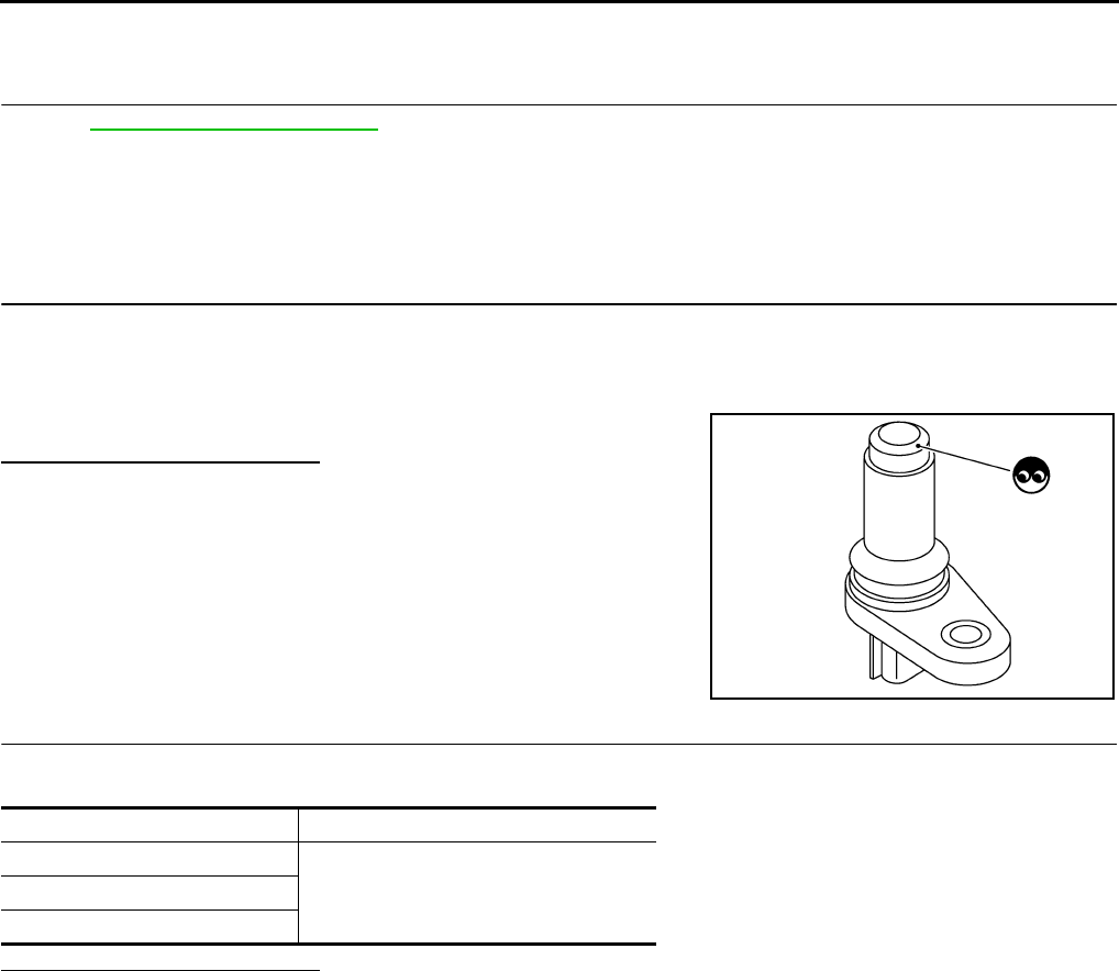
EC-706
< COMPONENT DIAGNOSIS > [FOR USA (FEDERAL) AND CANADA]
P0335 CKP SENSOR (POS)
YES >> GO TO 12.
NO >> Replace the signal plate.
12.CHECK INTERMITTENT INCIDENT
Refer to GI-41, "Intermittent Incident".
>> INSPECTION END
Component Inspection INFOID:0000000004529572
1.CHECK CRANKSHAFT POSITION SENSOR (POS)-I
1. Turn ignition switch OFF.
2. Loosen the fixing bolt of the sensor.
3. Disconnect crankshaft position sensor (POS) harness connector.
4. Remove the sensor.
5. Visually check the sensor for chipping.
Is the inspection result normal?
YES >> GO TO 2.
NO >> Replace crankshaft position sensor (POS).
2.CHECK CRANKSHAFT POSITION SENSOR (POS)-II
Check resistance between crankshaft position sensor (POS) terminals as follows.
Is the inspection result normal?
YES >> INSPECTION END
NO >> Replace crankshaft position sensor (POS).
JMBIA0063ZZ
Terminals (Polarity) Resistance [Ω at 25°C (77°F)]
1 (+) - 2 (-)
Except 0 or ∞1 (+) - 3 (-)
2 (+) - 3 (-)
Revision: 2008 August 2009 Rogue
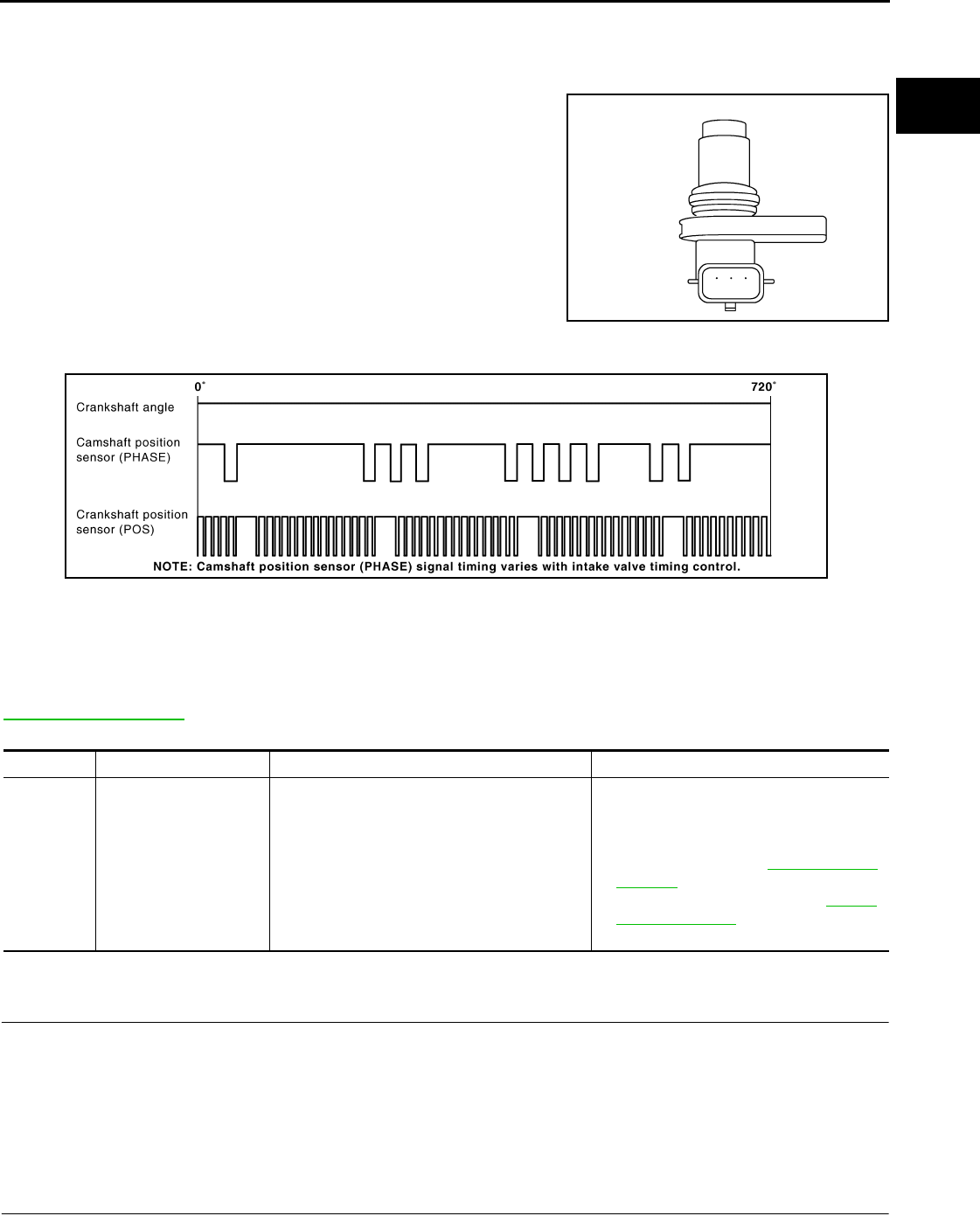
P0340 CMP SENSOR (PHASE)
EC-707
< COMPONENT DIAGNOSIS > [FOR USA (FEDERAL) AND CANADA]
C
D
E
F
G
H
I
J
K
L
M
A
EC
N
P
O
P0340 CMP SENSOR (PHASE)
Description INFOID:0000000004529573
The camshaft position sensor (PHASE) senses the retraction of
camshaft (INT) to identify a particular cylinder. The camshaft position
sensor (PHASE) senses the piston position.
When the crankshaft position sensor (POS) system becomes inoper-
ative, the camshaft position sensor (PHASE) provides various con-
trols of engine parts instead, utilizing timing of cylinder identification
signals.
The sensor consists of a permanent magnet and Hall IC.
When engine is running, the high and low parts of the teeth cause
the gap with the sensor to change.
The changing gap causes the magnetic field near the sensor to
change.
Due to the changing magnetic field, the voltage from the sensor changes.
ECM receives the signals as shown in the figure.
DTC Logic INFOID:0000000004529574
DTC DETECTION LOGIC
NOTE:
If DTC P0340 is displayed with DTC P0643, first perform the trouble diagnosis for DTC P0643. Refer to
EC-784, "DTC Logic".
DTC CONFIRMATION PROCEDURE
1.PRECONDITIONING
If DTC CONFIRMATION PROCEDURE has been previously conducted, always turn ignition switch OFF and
wait at least 10 seconds before conducting the next test.
TESTING CONDITION:
Before performing the following procedure, confirm that battery voltage is more than 10.5V with igni-
tion switch ON.
>> GO TO 2.
2.PERFORM DTC CONFIRMATION PROCEDURE-II
1. Start engine and let it idle for at least 5 seconds.
JMBIA0064ZZ
JMBIA0714G
B
DTC No. Trouble diagnosis name DTC detecting condition Possible cause
P0340 Camshaft position sen-
sor (PHASE) circuit
• The cylinder No. signal is not sent to ECM for
the first few seconds during engine cranking.
• The cylinder No. signal is not sent to ECM
during engine running.
• The cylinder No. signal is not in the normal
pattern during engine running.
• Harness or connectors
(The sensor circuit is open or shorted)
• Camshaft position sensor (PHASE)
•Camshaft (INT)
• Starter motor (Refer to STR-5, "System
Diagram".)
• Starting system circuit (Refer to STR-5,
"System Diagram".)
• Dead (Weak) battery
Revision: 2008 August 2009 Rogue

EC-708
< COMPONENT DIAGNOSIS > [FOR USA (FEDERAL) AND CANADA]
P0340 CMP SENSOR (PHASE)
If engine does not start, crank engine for at least 2 seconds.
2. Check 1st trip DTC.
Is 1st trip DTC detected?
YES >> Go to EC-708, "Diagnosis Procedure".
NO >> GO TO 3.
3.PERFORM DTC CONFIRMATION PROCEDURE-I
1. Maintaining engine speed at more than 800 rpm for at least 5 seconds.
2. Check 1st trip DTC.
Is 1st trip DTC detected?
YES >> Go to EC-708, "Diagnosis Procedure".
NO >> INSPECTION END
Diagnosis Procedure INFOID:0000000004529575
1.CHECK STARTING SYSTEM
Turn ignition switch to START position.
Does the engine turn over? Does the starter motor operate?
YES >> GO TO 2.
NO >> Check starting system.
2.CHECK GROUND CONNECTION
1. Turn ignition switch OFF.
2. Check ground connection E21. Refer to Ground Inspection in GI-44, "Circuit Inspection".
Is the inspection result normal?
YES >> GO TO 3.
NO >> Repair or replace ground connection.
3.CHECK CAMSHAFT POSITION (CMP) SENSOR (PHASE) POWER SUPPLY CIRCUIT
1. Disconnect camshaft position (CMP) sensor (PHASE) harness connector.
2. Turn ignition switch ON.
3. Check the voltage between CMP sensor (PHASE) harness connector and ground.
Is the inspection result normal?
YES >> GO TO 4.
NO >> Repair open circuit or short to ground or short to power in harness or connectors.
4.CHECK CMP SENSOR (PHASE) GROUND CIRCUIT FOR OPEN AND SHORT
1. Turn ignition switch OFF.
2. Check the continuity between CMP sensor (PHASE) harness connector and ECM harness connector.
3. Also check harness for short to power.
Is the inspection result normal?
YES >> GO TO 5.
NO >> Repair open circuit or short to ground or short to power in harness or connectors.
5.CHECK CMP SENSOR (PHASE) INPUT SIGNAL CIRCUIT FOR OPEN AND SHORT
1. Disconnect ECM harness connector.
2. Check the continuity between CMP sensor (PHASE) harness connector and ECM harness connector.
CMP sensor (PHASE) Ground Voltage
Connector Terminal
F26 1 Ground Approx. 5 V
CMP sensor (PHASE) ECM Continuity
Connector Terminal Connector Terminal
F26 2 F8 64 Existed
Revision: 2008 August 2009 Rogue
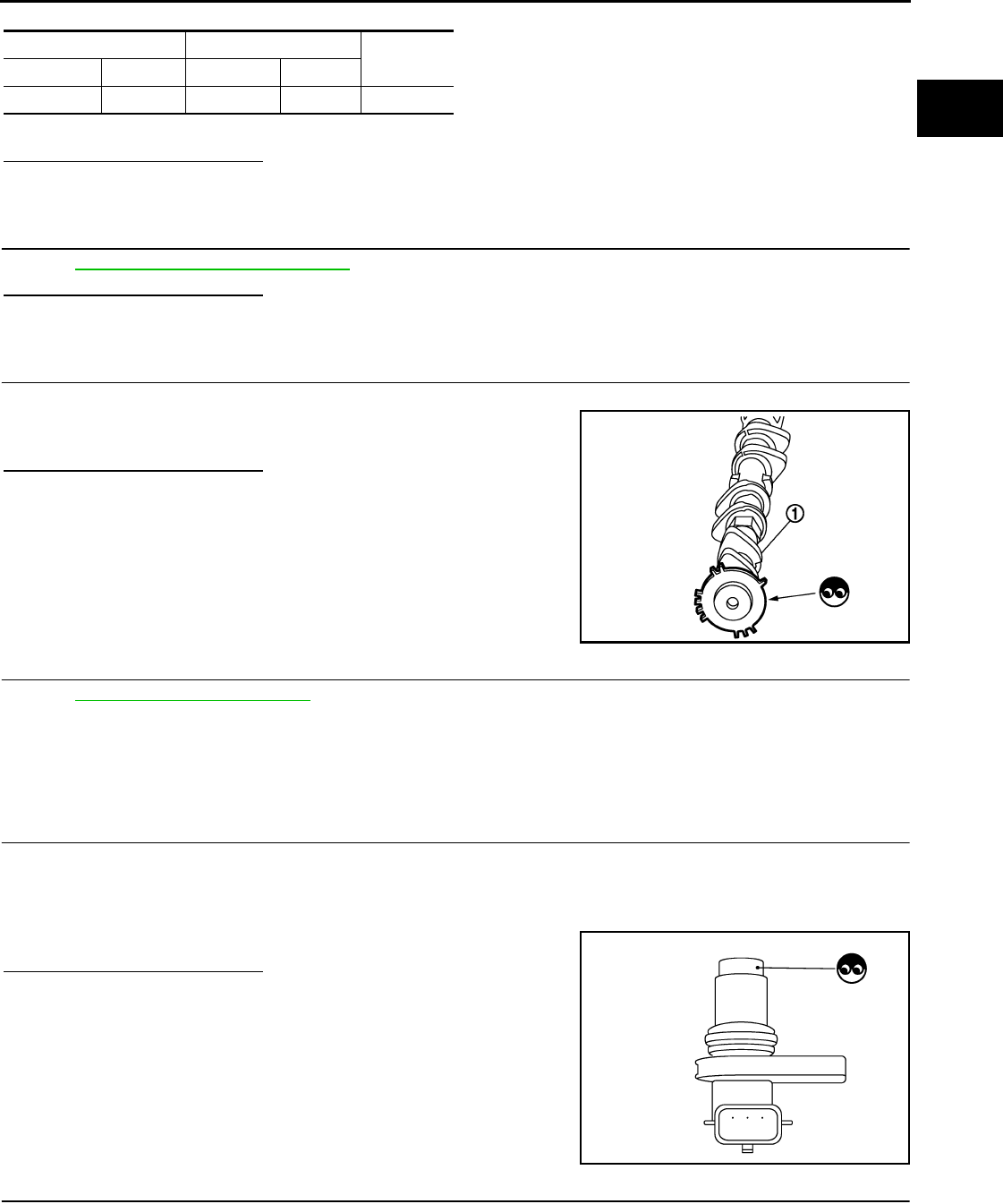
P0340 CMP SENSOR (PHASE)
EC-709
< COMPONENT DIAGNOSIS > [FOR USA (FEDERAL) AND CANADA]
C
D
E
F
G
H
I
J
K
L
M
A
EC
N
P
O
3. Also check harness for short to ground and short to power.
Is the inspection result normal?
YES >> GO TO 6.
NO >> Repair open circuit or short to ground or short to power in harness or connectors.
6.CHECK CAMSHAFT POSITION SENSOR (PHASE)
Refer to EC-709, "Component Inspection".
Is the inspection result normal?
YES >> GO TO 7.
NO >> Replace camshaft position sensor (PHASE).
7.CHECK CAMSHAFT (INT)
Check the following.
• Accumulation of debris to the signal plate of camshaft (1) rear end
• Chipping signal plate of camshaft rear end
Is the inspection result normal?
YES >> GO TO 8.
NO >> Remove debris and clean the signal plate of camshaft
rear end or replace camshaft.
8.CHECK INTERMITTENT INCIDENT
Refer to GI-41, "Intermittent Incident".
>> INSPECTION END
Component Inspection INFOID:0000000004529576
1.CHECK CAMSHAFT POSITION SENSOR (PHASE)-I
1. Turn ignition switch OFF.
2. Loosen the fixing bolt of the sensor.
3. Disconnect camshaft position sensor (PHASE) harness connector.
4. Remove the sensor.
5. Visually check the sensor for chipping.
Is the inspection result normal?
YES >> GO TO 2.
NO >> Replace camshaft position sensor (PHASE).
2.CHECK CAMSHAFT POSITION SENSOR (PHASE)-II
Check resistance camshaft position sensor (PHASE) terminals as follows.
CMP sensor (PHASE) ECM Continuity
Connector Terminal Connector Terminal
F26 3 F8 69 Existed
JMBIA0096ZZ
JMBIA0065ZZ
Revision: 2008 August 2009 Rogue

EC-710
< COMPONENT DIAGNOSIS > [FOR USA (FEDERAL) AND CANADA]
P0340 CMP SENSOR (PHASE)
Is the inspection result normal?
YES >> INSPECTION END
NO >> Replace camshaft position sensor (PHASE).
Terminals (Polarity) Resistance
1 (+) - 2 (-)
Except 0 or ∞Ω [at 25°C (77°F)]1 (+) - 3 (-)
2 (+) - 3 (-)
Revision: 2008 August 2009 Rogue
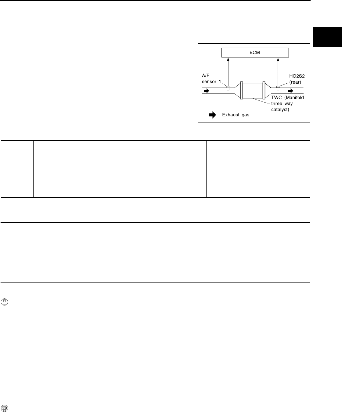
P0420 THREE WAY CATALYST FUNCTION
EC-711
< COMPONENT DIAGNOSIS > [FOR USA (FEDERAL) AND CANADA]
C
D
E
F
G
H
I
J
K
L
M
A
EC
N
P
O
P0420 THREE WAY CATALYST FUNCTION
DTC Logic INFOID:0000000004529577
DTC DETECTION LOGIC
The ECM monitors the switching frequency ratio of air fuel ratio (A/F)
sensor 1 and heated oxygen sensor 2.
A three way catalyst (manifold) with high oxygen storage capacity
will indicate a low switching frequency of heated oxygen sensor 2.
As oxygen storage capacity decreases, the heated oxygen sensor 2
switching frequency will increase.
When the frequency ratio of A/F sensor 1 and heated oxygen sensor
2 approaches a specified limit value, the three way catalyst (mani-
fold) malfunction is diagnosed.
DTC CONFIRMATION PROCEDURE
1.PRECONDITIONING
If DTC CONFIRMATION PROCEDURE has been previously conducted, always turn ignition switch OFF and
wait at least 10 seconds before conducting the next test.
TESTING CONDITION:
Do not hold engine speed for more than the specified minutes below.
>> GO TO 2.
2.PERFORM DTC CONFIRMATION PROCEDURE
CAUTION:
Always drive vehicle in safe manner according to traffic conditions and obey all traffic laws.
With CONSULT-III
1. Start engine and warm it up to the normal operating temperature.
2. Repeat the following procedure 3 times.
- Drive vehicle at a speed of 80 km/h (50 MPH) or more for at least 3 consecutive minutes.
NOTE:
Keep the vehicle speed as steady as possible during the cruising.
- Stop vehicle with engine running.
NOTE:
Never turn ignition switch OFF.
3. Select “DTC & SRT CONFIRMATION” then “SRT WORK SUPPORT” mode with CONSULT-III.
4. Drive vehicle at a speed of 80 km/h (50 MPH) or more until “INCMP” of “CATALYST” changes to “CMPLT”
NOTE:
•Keep the vehicle speed as steady as possible during the cruising.
•It will take at most 3 minutes until “INCMP” of “CATALYST” changes to “CMPLT”.
5. Check 1 st trip DTC.
With GST
1. Start engine and warm it up to the normal operating temperature.
2. Repeat the following procedure 3 times.
- Drive vehicle at a speed of 80 km/h (50 MPH) or more for at least 3 consecutive minutes.
SEF484YB
DTC No. Trouble diagnosis name DTC detecting condition Possible cause
P0420 Catalyst system efficien-
cy below threshold
• Three way catalyst (manifold) does not oper-
ate properly.
• Three way catalyst (manifold) does not have
enough oxygen storage capacity.
• Three way catalyst (manifold)
• Exhaust tube
• Intake air leaks
• Fuel injector
• Fuel injector leaks
• Spark plug
• Improper ignition timing
Revision: 2008 August 2009 Rogue
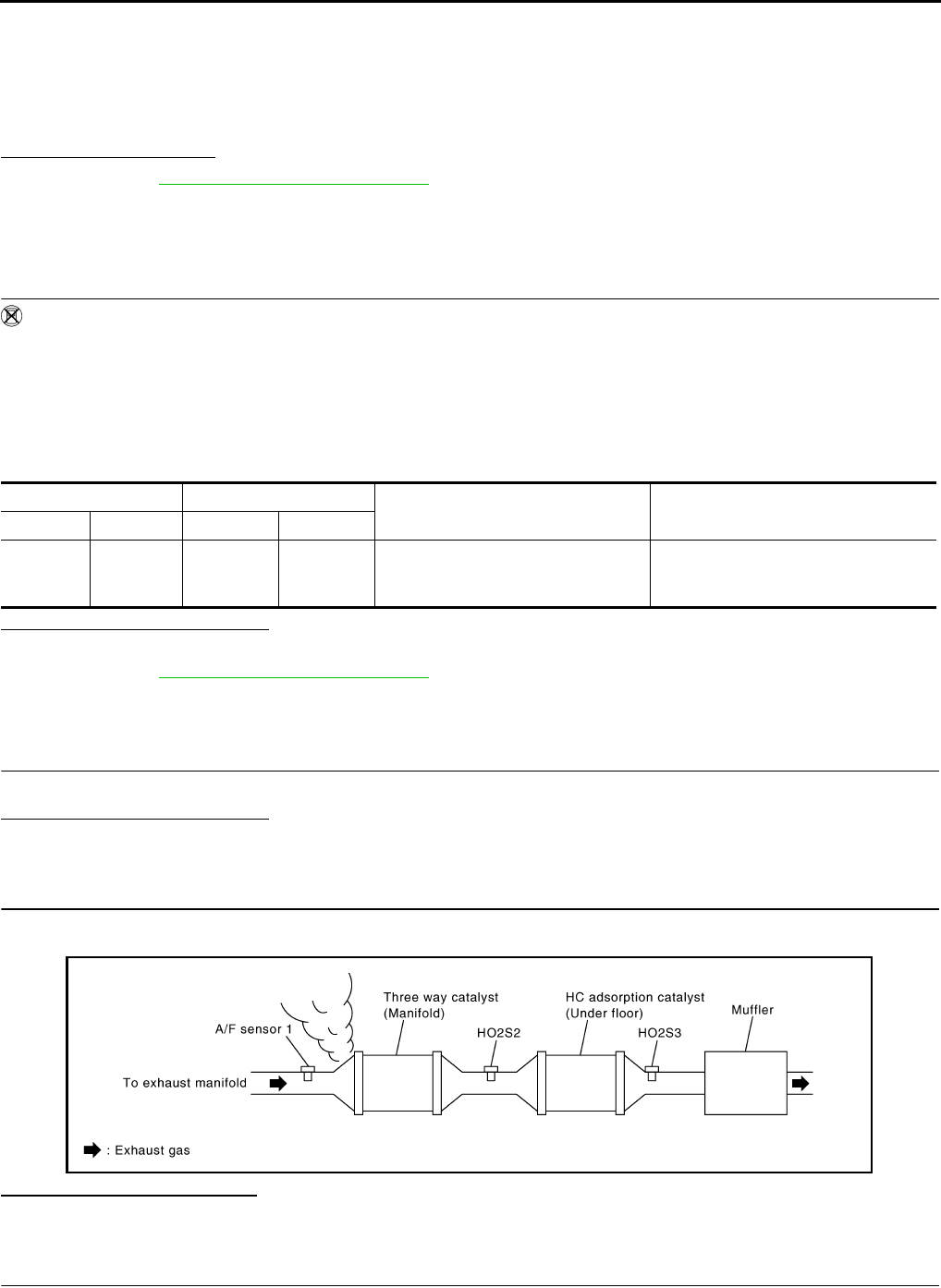
EC-712
< COMPONENT DIAGNOSIS > [FOR USA (FEDERAL) AND CANADA]
P0420 THREE WAY CATALYST FUNCTION
NOTE:
Keep the vehicle speed as steady as possible during the cruising.
- Stop vehicle with engine running.
NOTE:
Never turn ignition switch OFF.
3. Check 1 st trip DTC.
Is 1st trip DTC detected?
YES >> Go to EC-712, "Diagnosis Procedure".
NO >> INSPECTION END
Component Function Check INFOID:0000000004529578
1.PERFORM COMPONENT FUNCTION CHECK
Without CONSULT-III
1. Start engine and warm it up to the normal operating temperature.
2. Turn ignition switch OFF and wait at least 10 seconds.
3. Start engine and keep the engine speed between 3,500 and 4,000 rpm for at least 1 minute under no load.
4. Let engine idle for 1 minute.
5. Open engine hood.
6. Check the voltage between ECM harness connector terminals under the following condition.
Is the inspection result normal?
YES >> INSPECTION END
NO >> Go to EC-712, "Diagnosis Procedure".
Diagnosis Procedure INFOID:0000000004529579
1.CHECK EXHAUST SYSTEM
Visually check exhaust tubes and muffler for dents.
Is the inspection result normal?
YES >> GO TO 2.
NO >> Repair or replace.
2.CHECK EXHAUST GAS LEAK
1. Start engine and run it at idle.
2. Listen for an exhaust gas leak before the three way catalyst (manifold).
Is exhaust gas leak detected?
YES >> Repair or replace.
NO >> GO TO 3.
3.CHECK INTAKE AIR LEAK
Listen for an intake air leak after the mass air flow sensor.
ECM ECM Condition Voltage
Connector Terminal Connector Terminal
F8
33
(HO2S2
signal)
F8
35
(Sensor
ground)
Keeping engine speed at 2,500 rpm
constant under no load
The voltage fluctuation cycle takes
more than 5 seconds.
1 cycle: 0.6 - 1.0 → 0 - 0.3 → 0.6 - 1.0
JMBIA0163G
B
Revision: 2008 August 2009 Rogue
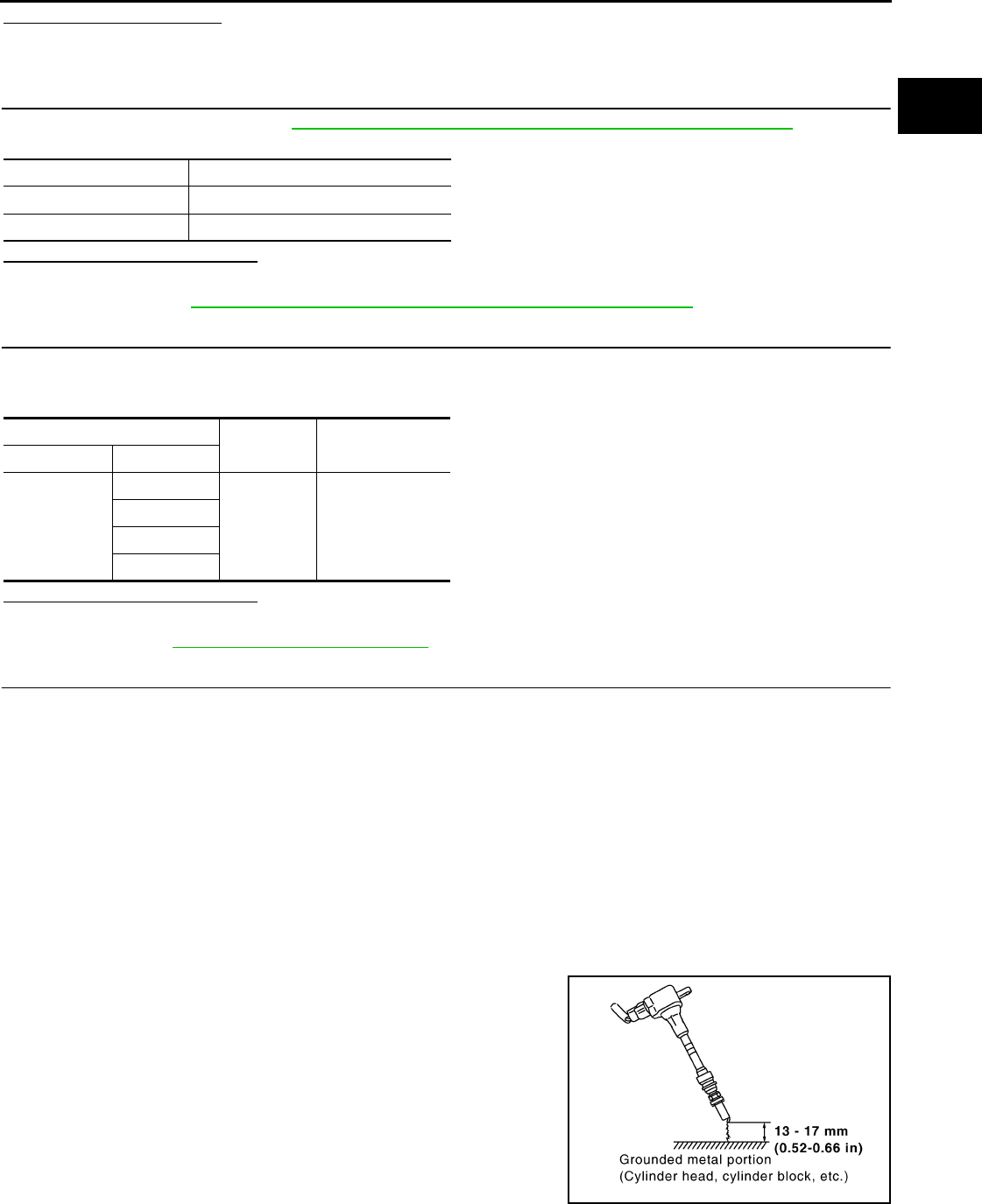
P0420 THREE WAY CATALYST FUNCTION
EC-713
< COMPONENT DIAGNOSIS > [FOR USA (FEDERAL) AND CANADA]
C
D
E
F
G
H
I
J
K
L
M
A
EC
N
P
O
Is intake air leak detected?
YES >> Repair or replace.
NO >> GO TO 4.
4.CHECK IGNITION TIMING
Check the following items. Refer to EC-499, "BASIC INSPECTION : Special Repair Requirement".
Is the inspection result normal?
YES >> GO TO 5.
NO >> Follow the EC-499, "BASIC INSPECTION : Special Repair Requirement".
5.CHECK FUEL INJECTOR
1. Stop engine and then turn ignition switch ON.
2. Check the voltage between ECM harness connector and ground.
Is the inspection result normal?
YES >> GO TO 6.
NO >> Perform EC-855, "Diagnosis Procedure".
6.CHECK FUNCTION OF IGNITION COIL-I
CAUTION:
Perform the following procedure in a place with no combustible objects and good ventilation.
1. Turn ignition switch OFF.
2. Remove fuel pump fuse in IPDM E/R to release fuel pressure.
NOTE:
Do not use CONSULT-III to release fuel pressure, or fuel pressure applies again during the following pro-
cedure.
3. Start engine.
4. After engine stalls, crank it two or three times to release all fuel pressure.
5. Turn ignition switch OFF.
6. Remove all ignition coil harness connectors to avoid the electrical discharge from the ignition coils.
7. Remove ignition coil and spark plug of the cylinder to be checked.
8. Crank engine for 5 seconds or more to remove combustion gas in the cylinder.
9. Connect spark plug and harness connector to ignition coil.
10. Fix ignition coil using a rope etc. with gap of 13 - 17 mm (0.52 -
0.66 in) between the edge of the spark plug and grounded metal
portion as shown in the figure.
11. Crank engine for approximately 3 seconds, and check whether
spark is generated between the spark plug and the grounded
metal portion.
CAUTION:
• Never place the spark plug and the ignition coil within 50
cm (19.7 in) each other. Be careful not to get an electrical
shock while checking, because the electrical discharge
voltage becomes 20kV or more.
Items Specifications
idle speed 700 ± 50 rpm (in P or N position)
Ignition timing 15 ± 5° BTDC (in P or N position)
ECM Ground Voltage
Connector Terminal
F7
29
Ground Battery voltage
30
31
32
Spark should be generated.
JMBIA0066G
B
Revision: 2008 August 2009 Rogue
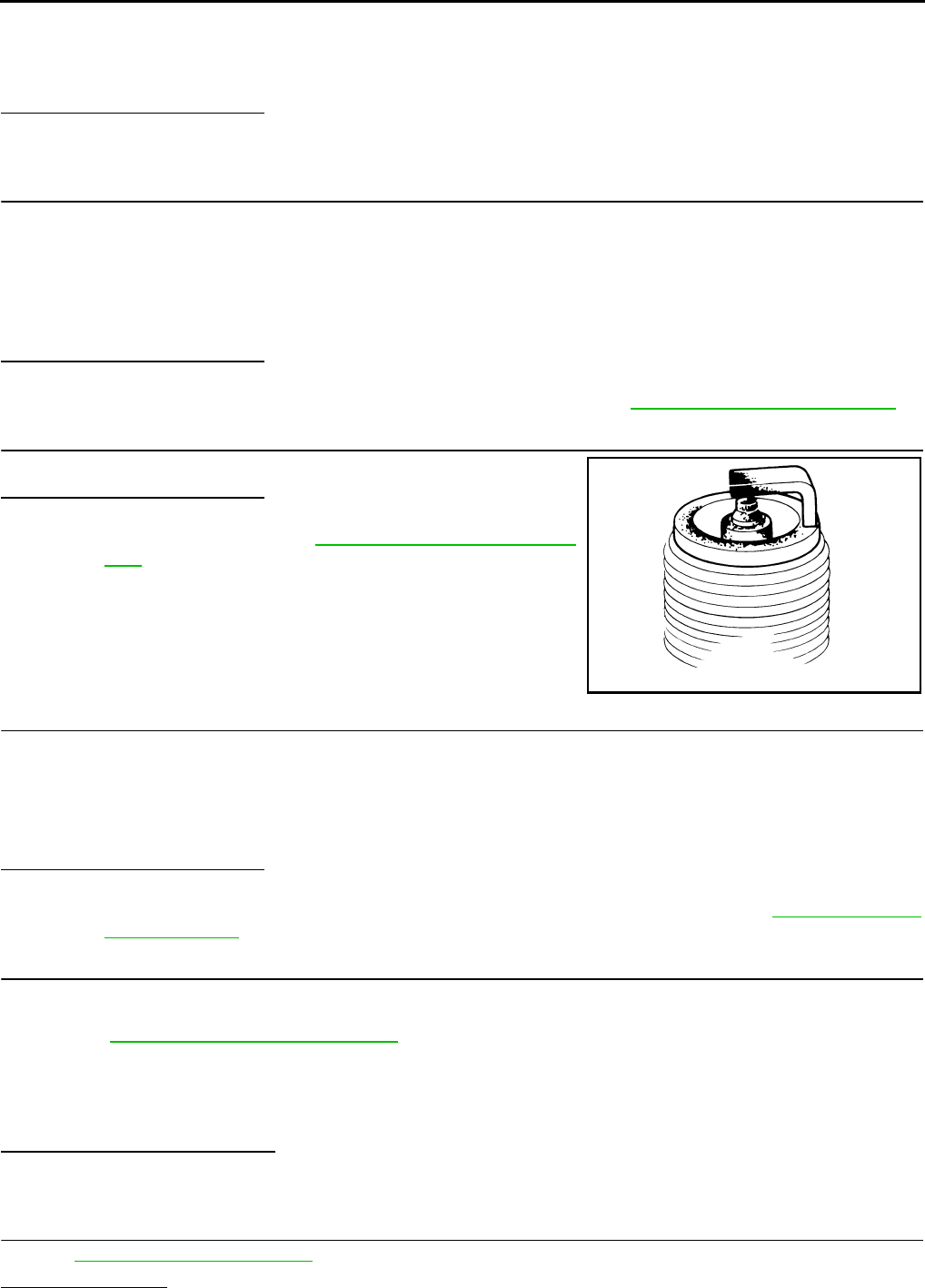
EC-714
< COMPONENT DIAGNOSIS > [FOR USA (FEDERAL) AND CANADA]
P0420 THREE WAY CATALYST FUNCTION
• It might damage the ignition coil if the gap of more than 17 mm (0.66 in) is mode.
NOTE:
When the gap is less than 13 mm (0.52 in), a spark might be generated even if the coil is malfunc-
tioning.
Is the inspection result normal?
YES >> GO TO 10.
NO >> GO TO 7.
7.CHECK FUNCTION OF IGNITION COIL-II
1. Turn ignition switch OFF.
2. Disconnect spark plug and connect a non-malfunctioning spark plug.
3. Crank engine for approximately 3 seconds, and recheck whether spark is generated between the spark
plug and the grounded metal portion.
Is the inspection result normal?
YES >> GO TO 8.
NO >> Check ignition coil, power transistor and their circuits. Refer to EC-861, "Diagnosis Procedure".
8.CHECK SPARK PLUG
Check the initial spark plug for fouling, etc.
Is the inspection result normal?
YES >> Replace spark plug(s) with standard type one(s). For
spark plug type, refer to EM-40, "Removal and Installa-
tion".
NO >> Repair or clean spark plug. Then GO TO 9.
9.CHECK FUNCTION OF IGNITION COIL-III
1. Reconnect the initial spark plugs.
2. Crank engine for approximately 3 seconds, and recheck whether spark is generated between the spark
plug and the grounded portion.
Is the inspection result normal?
YES >> INSPECTION END
NO >> Replace spark plug(s) with standard type one(s). For spark plug type, refer to EM-40, "Removal
and Installation".
10.CHECK FUEL INJECTOR
1. Turn ignition switch OFF.
2. Remove fuel injector assembly.
Refer to EM-43, "Removal and Installation".
Keep fuel hose and all fuel injectors connected to fuel tube.
3. Disconnect all ignition coil harness connectors.
4. Reconnect all fuel injector harness connectors disconnected.
5. Turn ignition switch ON.
Does fuel drip from fuel injector?
YES >> GO TO 11.
NO >> Replace the fuel injector(s) from which fuel is dripping.
11.CHECK INTERMITTENT INCIDENT
Refer to GI-41, "Intermittent Incident".
Is the trouble fixed?
Spark should be generated.
SEF156I
Spark should be generated.
Revision: 2008 August 2009 Rogue

P0420 THREE WAY CATALYST FUNCTION
EC-715
< COMPONENT DIAGNOSIS > [FOR USA (FEDERAL) AND CANADA]
C
D
E
F
G
H
I
J
K
L
M
A
EC
N
P
O
YES >> INSPECTION END
NO >> Replace three way catalyst assembly.
Revision: 2008 August 2009 Rogue

EC-716
< COMPONENT DIAGNOSIS > [FOR USA (FEDERAL) AND CANADA]
P0441 EVAP CONTROL SYSTEM
P0441 EVAP CONTROL SYSTEM
DTC Logic INFOID:0000000004529580
DTC DETECTION LOGIC
NOTE:
If DTC P0441 is displayed with other DTC such as P2122, P2123, P2127, P2128 or P2138, first perform
trouble diagnosis for other DTC.
In this evaporative emission (EVAP) control system, purge flow occurs during non-closed throttle conditions.
Purge volume is related to air intake volume. Under normal purge conditions (non-closed throttle), the EVAP
canister purge volume control solenoid valve is open to admit purge flow. Purge flow exposes the EVAP con-
trol system pressure sensor to intake manifold vacuum.
Under normal conditions (non-closed throttle), sensor output voltage indicates if pressure drop and purge flow
are adequate. If not, a malfunction is determined.
DTC CONFIRMATION PROCEDURE
1.INSPECTION START
Do you have CONSULT-III?
Do you have CONSULT-III?
YES >> GO TO 2.
NO >> GO TO 6.
2.PRECONDITIONING
If DTC CONFIRMATION PROCEDURE has been previously conducted, always turn ignition switch OFF and
wait at least 10 seconds before conducting the next test.
TESTING CONDITION:
DTC No. Trouble diagnosis name DTC detecting condition Possible cause
P0441 EVAP control system in-
correct purge flow
EVAP control system does not operate proper-
ly, EVAP control system has a leak between in-
take manifold and EVAP control system
pressure sensor.
• EVAP canister purge volume control so-
lenoid valve stuck closed
• EVAP control system pressure sensor
and the circuit
• Loose, disconnected or improper con-
nection of rubber tube
• Blocked rubber tube
• Cracked EVAP canister
• EVAP canister purge volume control so-
lenoid valve circuit
• Accelerator pedal position sensor
• Blocked purge port
• EVAP canister vent control valve
PBIB1026E
Revision: 2008 August 2009 Rogue
P0441 EVAP CONTROL SYSTEM
EC-717
< COMPONENT DIAGNOSIS > [FOR USA (FEDERAL) AND CANADA]
C
D
E
F
G
H
I
J
K
L
M
A
EC
N
P
O
Always perform test at a temperature of 5°C (41°F) or more.
>> GO TO 3.
3.PERFORM DTC CONFIRMATION PROCEDURE-I
With CONSULT-III
1. Start engine and warm it up to normal operating temperature.
2. Turn ignition switch OFF and wait at least 10 seconds.
3. Start engine and let it idle for at least 70 seconds.
4. Select “PURG FLOW P0441” of “EVAPORATIVE SYSTEM” in “DTC WORK SUPPORT” mode with CON-
SULT-III.
5. Touch “START”.
Is COMPLETED displayed on CONSULT-III screen?
YES >> GO TO 5.
NO >> GO TO 4.
4.PERFORM DTC CONFIRMATION PROCEDURE-II
When the following conditions are met, “TESTING” will be displayed on the CONSULT-III screen. Maintain the
conditions continuously until “TESTING” changes to “COMPLETED”. (It will take at least 35 seconds.)
CAUTION:
Always drive vehicle at a safe speed.
If “TESTING” does not change for a long time, retry from step 2.
Is “COMPLETED” displayed on CONSULT-III screen?
YES >> GO TO 5.
NO >> Perform DTC CONFIRMATION PROCEDURE again. GO TO 3.
5.PERFORM DTC CONFIRMATION PROCEDURE-III
Touch “SELF-DIAG RESULT”.
Which is displayed on CONSULT-III screen?
OK >> INSPECTION END
NG >> Go to EC-718, "Diagnosis Procedure".
6.PERFORM COMPONENT FUNCTION CHECK
Perform Component Function Check. Refer to EC-717, "Component Function Check".
NOTE:
Use Component Function Check to check the overall function of the EVAP control system purge flow monitor-
ing. During this check, a 1st trip DTC might not be confirmed.
Is the inspection result normal?
YES >> INSPECTION END
NO >> Go to EC-718, "Diagnosis Procedure".
Component Function Check INFOID:0000000004529581
1.PERFORM COMPONENT FUNCTION CHECK
Without CONSULT-III
1. Lift up drive wheels.
2. Start engine and warm it up to normal operating temperature.
3. Turn ignition switch OFF, wait at least 10 seconds.
4. Start engine and wait at least 70 seconds.
5. Set voltmeter probes to ECM harness connector terminals.
Selector lever Suitable position
VHCL SPEED SE 32 - 120 km/h (20 - 75 mph)
ENG SPEED 500 - 3,800 rpm
B/FUEL SCHDL 1.0 - 10.0 msec
COOLAN TEMP/S More than 0°C (32°F)
Revision: 2008 August 2009 Rogue
EC-718
< COMPONENT DIAGNOSIS > [FOR USA (FEDERAL) AND CANADA]
P0441 EVAP CONTROL SYSTEM
6. Check EVAP control system pressure sensor value at idle speed and note it.
7. Establish and maintain the following conditions for at least 1 minute.
8. Verify that EVAP control system pressure sensor value stays 0.1V less than the value at idle speed (mea-
sured at step 6) for at least 1 second.
Is the inspection result normal?
YES >> INSPECTION END
NO >> Go to EC-718, "Diagnosis Procedure".
Diagnosis Procedure INFOID:0000000004529582
1.CHECK EVAP CANISTER
1. Turn ignition switch OFF.
2. Check EVAP canister for cracks.
Is the inspection result normal?
YES-1 >> With CONSULT-III: GO TO 2.
YES-2 >> Without CONSULT-III: GO TO 3.
NO >> Replace EVAP canister.
2.CHECK PURGE FLOW
With CONSULT-III
1. Disconnect vacuum hose connected to EVAP canister purge volume control solenoid valve at EVAP ser-
vice port and install vacuum gauge. For the location of EVAP service port, refer to EC-549, "System Dia-
gram".
2. Start engine and let it idle.
3. Select “PURG VOL CONT/V” in “ACTIVE TEST” mode with CONSULT-III.
4. Rev engine up to 2,000 rpm.
5. Touch “Qd” and “Qu” on CONSULT-III screen to adjust “PURG VOL C/V” opening and check vacuum
existence.
Is the inspection result normal?
YES >> GO TO 7.
NO >> GO TO 4.
3.CHECK PURGE FLOW
Without CONSULT-III
1. Start engine and warm it up to normal operating temperature.
2. Stop engine.
ECM ECM
Connector Terminal Connector Terminal
E16 86
(EVAP control system
pressure sensor signal)
E16 96
(Sensor
ground)
Air conditioner switch ON
Headlamp switch ON
Rear window defogger switch ON
Engine speed Approx. 3,000 rpm
Selector lever Any position other than P, N or R
PURG VOL C/V Vacuum
100% Existed
0% Not existed
Revision: 2008 August 2009 Rogue
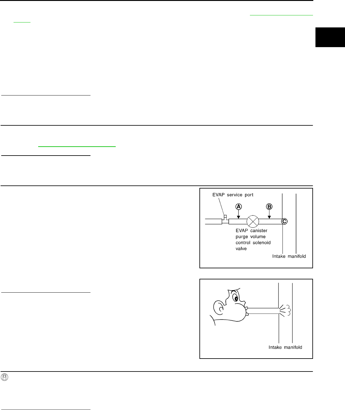
P0441 EVAP CONTROL SYSTEM
EC-719
< COMPONENT DIAGNOSIS > [FOR USA (FEDERAL) AND CANADA]
C
D
E
F
G
H
I
J
K
L
M
A
EC
N
P
O
3. Disconnect vacuum hose connected to EVAP canister purge volume control solenoid valve at EVAP ser-
vice port and install vacuum gauge. For the location of EVAP service port, refer to EC-549, "System Dia-
gram".
4. Start engine and let it idle.
Do not depress accelerator pedal even slightly.
5. Check vacuum gauge indication before 60 seconds pass after starting engine.
6. Rev engine up to 2,000rpm after 100 seconds pass after starting engine.
Is the inspection result normal?
YES >> GO TO 7.
NO >> GO TO 4.
4.CHECK EVAP PURGE LINE
1. Turn ignition switch OFF.
2. Check EVAP purge line for improper connection or disconnection.
Refer to EC-549, "System Diagram".
Is the inspection result normal?
YES >> GO TO 5.
NO >> Repair EVAP purge line.
5.CHECK EVAP PURGE HOSE AND PURGE PORT
1. Disconnect purge hoses connected to EVAP service port A and
EVAP canister purge volume control solenoid valve B.
2. Blow air into each hose and EVAP purge port C.
3. Check that air flows freely.
Is the inspection result normal?
YES-1 >> With CONSULT-III: GO TO 6.
YES-2 >> Without CONSULT-III: GO TO 7.
NO >> Repair or clean hoses and/or purge port.
6.CHECK EVAP CANISTER PURGE VOLUME CONTROL SOLENOID VALVE
With CONSULT-III
1. Start engine.
2. Perform “PURG VOL CONT/V” in “ACTIVE TEST” mode with CONSULT-III. Check that engine speed var-
ies according to the valve opening.
Is the inspection result normal?
YES >> GO TO 8.
NO >> GO TO 7.
Vacuum should not exist.
Vacuum should exist.
SEF367U
SEF368U
Revision: 2008 August 2009 Rogue

EC-720
< COMPONENT DIAGNOSIS > [FOR USA (FEDERAL) AND CANADA]
P0441 EVAP CONTROL SYSTEM
7.CHECK EVAP CANISTER PURGE VOLUME CONTROL SOLENOID VALVE
Refer to EC-730, "Component Inspection".
Is the inspection result normal?
YES >> GO TO 8.
NO >> Replace EVAP canister purge volume control solenoid valve.
8.CHECK EVAP CONTROL SYSTEM PRESSURE SENSOR CONNECTOR
1. Disconnect EVAP control system pressure sensor harness connector.
2. Check connectors for water.
Is the inspection result normal?
YES >> GO TO 9.
NO >> Replace EVAP control system pressure sensor.
9.CHECK EVAP CONTROL SYSTEM PRESSURE SENSOR FUNCTION
Refer to EC-745, "DTC Logic" for DTC P0452, EC-750, "DTC Logic" for DTC P0453.
Is the inspection result normal?
YES >> GO TO 10.
NO >> Replace EVAP control system pressure sensor.
10.CHECK RUBBER TUBE FOR CLOGGING
1. Disconnect rubber tube connected to EVAP canister vent control valve.
2. Check the rubber tube for clogging.
Is the inspection result normal?
YES >> GO TO 11.
NO >> Clean the rubber tube using an air blower.
11.CHECK EVAP CANISTER VENT CONTROL VALVE
Refer to EC-736, "Component Inspection".
Is the inspection result normal?
YES >> GO TO 12.
NO >> Replace EVAP canister vent control valve.
12.CHECK EVAP PURGE LINE
Inspect EVAP purge line (pipe and rubber tube). Check for evidence of leaks.
Refer to EC-924, "Inspection".
Is the inspection result normal?
YES >> GO TO 13.
NO >> Replace it.
13.CLEAN EVAP PURGE LINE
Clean EVAP purge line (pipe and rubber tube) using air blower.
>> GO TO 14.
14.CHECK INTERMITTENT INCIDENT
Refer to GI-41, "Intermittent Incident".
>> INSPECTION END
Water should not exist.
Revision: 2008 August 2009 Rogue

P0442 EVAP CONTROL SYSTEM
EC-721
< COMPONENT DIAGNOSIS > [FOR USA (FEDERAL) AND CANADA]
C
D
E
F
G
H
I
J
K
L
M
A
EC
N
P
O
P0442 EVAP CONTROL SYSTEM
DTC Logic INFOID:0000000004529583
DTC DETECTION LOGIC
NOTE:
If DTC P0442 is displayed with DTC P0456, first perform the trouble diagnosis for DTC P0456. Refer to
EC-761, "DTC Logic".
This diagnosis detects leaks in the EVAP purge line using engine intake manifold vacuum.
If pressure does not increase, the ECM will check for leaks in the line between the fuel tank and EVAP canister
purge volume control solenoid valve, under the following “Vacuum test” conditions.
The EVAP canister vent control valve is closed to shut the EVAP purge line off. The EVAP canister purge vol-
ume control solenoid valve will then be opened to depressurize the EVAP purge line using intake manifold
vacuum. After this occurs, the EVAP canister purge volume control solenoid valve will be closed.
CAUTION:
• Use only a genuine NISSAN fuel filler cap as a replacement. If an incorrect fuel filler cap is used, the
MIL may illuminate.
• If the fuel filler cap is not tightened properly, the MIL may illuminate.
DTC No. Trouble diagnosis name DTC detecting condition Possible cause
P0442
EVAP control system
small leak detected
(negative pressure)
EVAP control system has a leak, EVAP
control system does not operate prop-
erly.
• Incorrect fuel tank vacuum relief valve
• Incorrect fuel filler cap used
• Fuel filler cap remains open or fails to close.
• Foreign matter caught in fuel filler cap.
• Leak is in line between intake manifold and EVAP
canister purge volume control solenoid valve.
• Foreign matter caught in EVAP canister vent con-
trol valve.
• EVAP canister or fuel tank leaks
• EVAP purge line (pipe and rubber tube) leaks
• EVAP purge line rubber tube bent
• Loose or disconnected rubber tube
• EVAP canister vent control valve and the circuit
• EVAP canister purge volume control solenoid
valve and the circuit
• Fuel tank temperature sensor
• O-ring of EVAP canister vent control valve is
missing or damaged
• EVAP canister is saturated with water
• EVAP control system pressure sensor
• Fuel level sensor and the circuit
• Refueling EVAP vapor cut valve
• ORVR system leaks
PBIB1026E
Revision: 2008 August 2009 Rogue

EC-722
< COMPONENT DIAGNOSIS > [FOR USA (FEDERAL) AND CANADA]
P0442 EVAP CONTROL SYSTEM
• Use only a genuine NISSAN rubber tube as a replacement.
DTC CONFIRMATION PROCEDURE
1.PRECONDITIONING
If DTC CONFIRMATION PROCEDURE has been previously conducted, always turn ignition switch OFF and
wait at least 10 seconds before conducting the next test.
TESTING CONDITION:
•Perform “DTC WORK SUPPORT” when the fuel level is between 1/4 and 3/4 full, and vehicle is placed
on flat level surface.
•Always perform test at a temperature of 0 to 30°C (32 to 86°F).
NOTE:
Check that EVAP hoses are connected to EVAP canister purge volume control solenoid valve properly.
Do you have CONSULT-III?
YES >> GO TO 2.
NO >> GO TO 3.
2.PERFORM DTC CONFIRMATION PROCEDURE
With CONSULT-III
1. Turn ignition switch ON.
2. Turn ignition switch OFF and wait at least 10 seconds.
3. Turn ignition switch ON and select “DATA MONITOR” mode with CONSULT-III.
4. Check that the following conditions are met.
COOLAN TEMP/S: 0 - 70°C (32 - 158°F)
INT/A TEMP SE: 0 - 30°C (32 - 86°F)
5. Select “EVAP SML LEAK P0442/P1442” of “EVAPORATIVE SYSTEM” in “DTC WORK SUPPORT” mode
with CONSULT-III.
Follow the instructions displayed.
NOTE:
If the engine speed cannot be maintained within the range displayed on the CONSULT-III screen, go to
EC-499, "BASIC INSPECTION : Special Repair Requirement".
Which is displayed on CONSULT-III screen?
OK >> INSPECTION END
NG >> Go to EC-722, "Diagnosis Procedure".
3.PERFORM COMPONENT FUNCTION CHECK
With GST
NOTE:
Be sure to read the explanation of DRIVING PATTERN in EC-903, "How to Set SRT Code" before driving
vehicle.
1. Start engine.
2. Drive vehicle according to DRIVING PATTERN.
3. Stop vehicle.
4. Turn ignition switch OFF, wait at least 10 seconds and then turn ON.
5. Select Service $07 with GST.
Is 1st trip DTC displayed?
YES-1 >> P0441: Go to EC-718, "Diagnosis Procedure".
YES-2 >> P0442: Go to EC-722, "Diagnosis Procedure".
NO >> INSPECTION END
Diagnosis Procedure INFOID:0000000004529584
1.CHECK FUEL FILLER CAP DESIGN
1. Turn ignition switch OFF.
Revision: 2008 August 2009 Rogue
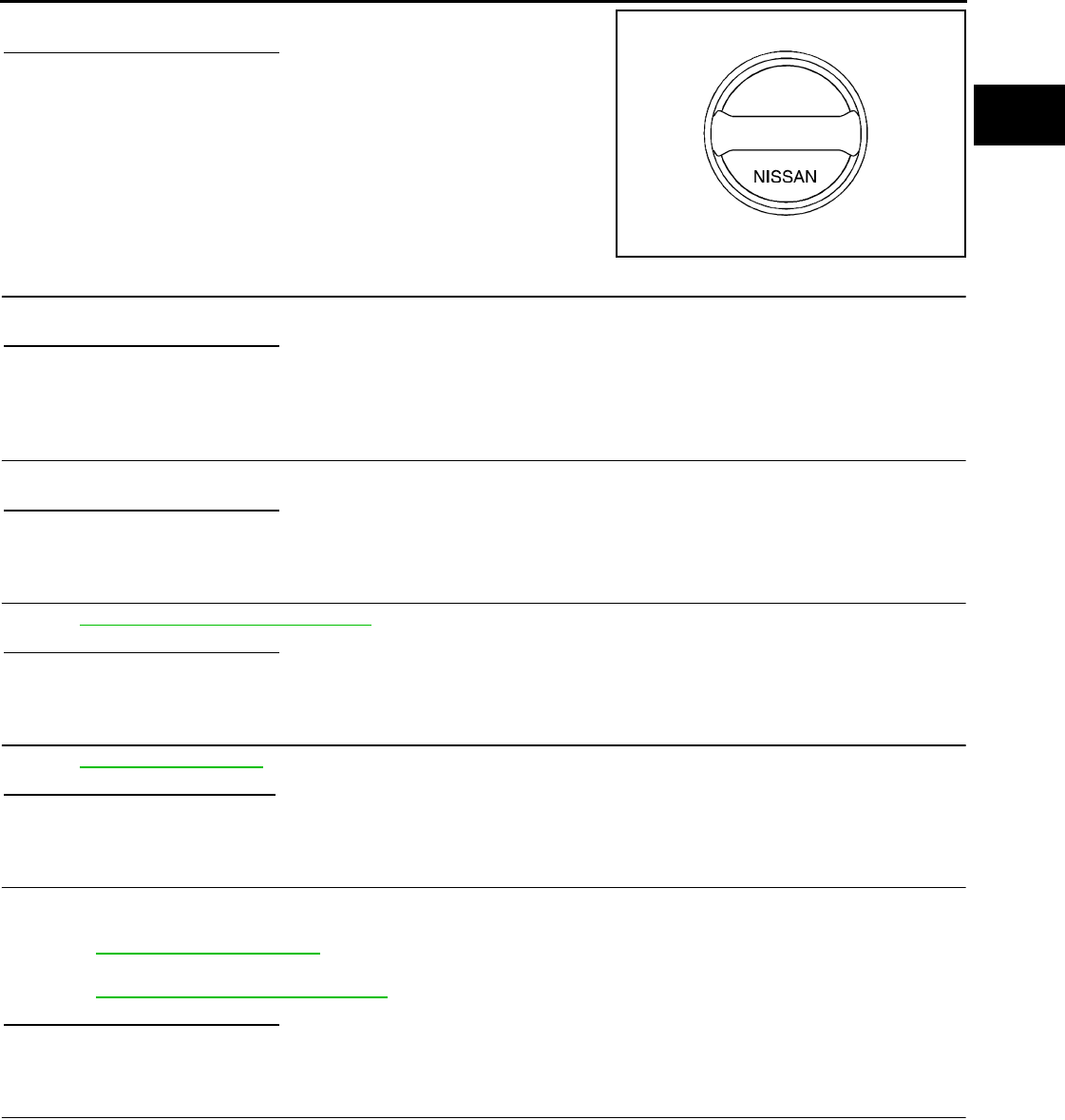
P0442 EVAP CONTROL SYSTEM
EC-723
< COMPONENT DIAGNOSIS > [FOR USA (FEDERAL) AND CANADA]
C
D
E
F
G
H
I
J
K
L
M
A
EC
N
P
O
2. Check for genuine NISSAN fuel filler cap design.
Is the inspection result normal?
YES >> GO TO 2.
NO >> Replace with genuine NISSAN fuel filler cap.
2.CHECK FUEL FILLER CAP INSTALLATION
Check that the cap is tightened properly by rotating the cap clockwise.
Is the inspection result normal?
YES >> GO TO 3.
NO >> Open fuel filler cap, then clean cap and fuel filler neck threads using air blower. Then retighten
until ratcheting sound is heard.
3.CHECK FUEL FILLER CAP FUNCTION
Check for air releasing sound while opening the fuel filler cap.
Is the inspection result normal?
YES >> GO TO 5.
NO >> GO TO 4.
4.CHECK FUEL TANK VACUUM RELIEF VALVE
Refer to EC-726, "Component Inspection".
Is the inspection result normal?
YES >> GO TO 5.
NO >> Replace fuel filler cap with a genuine one.
5.CHECK FOR EVAP LEAK
Refer to EC-924, "Inspection".
Is there any leak in EVAP line?
YES >> Repair or replace.
NO >> GO TO 6.
6.CHECK EVAP CANISTER VENT CONTROL VALVE
Check the following.
• EVAP canister vent control valve is installed properly.
Refer to EC-926, "Exploded View".
• EVAP canister vent control valve.
Refer to EC-736, "Component Inspection".
Is the inspection result normal?
YES >> GO TO 7.
NO >> Repair or replace EVAP canister vent control valve and O-ring.
7.CHECK IF EVAP CANISTER IS SATURATED WITH WATER
1. Remove EVAP canister with EVAP canister vent control valve and EVAP control system pressure sensor
attached.
SEF915U
Revision: 2008 August 2009 Rogue
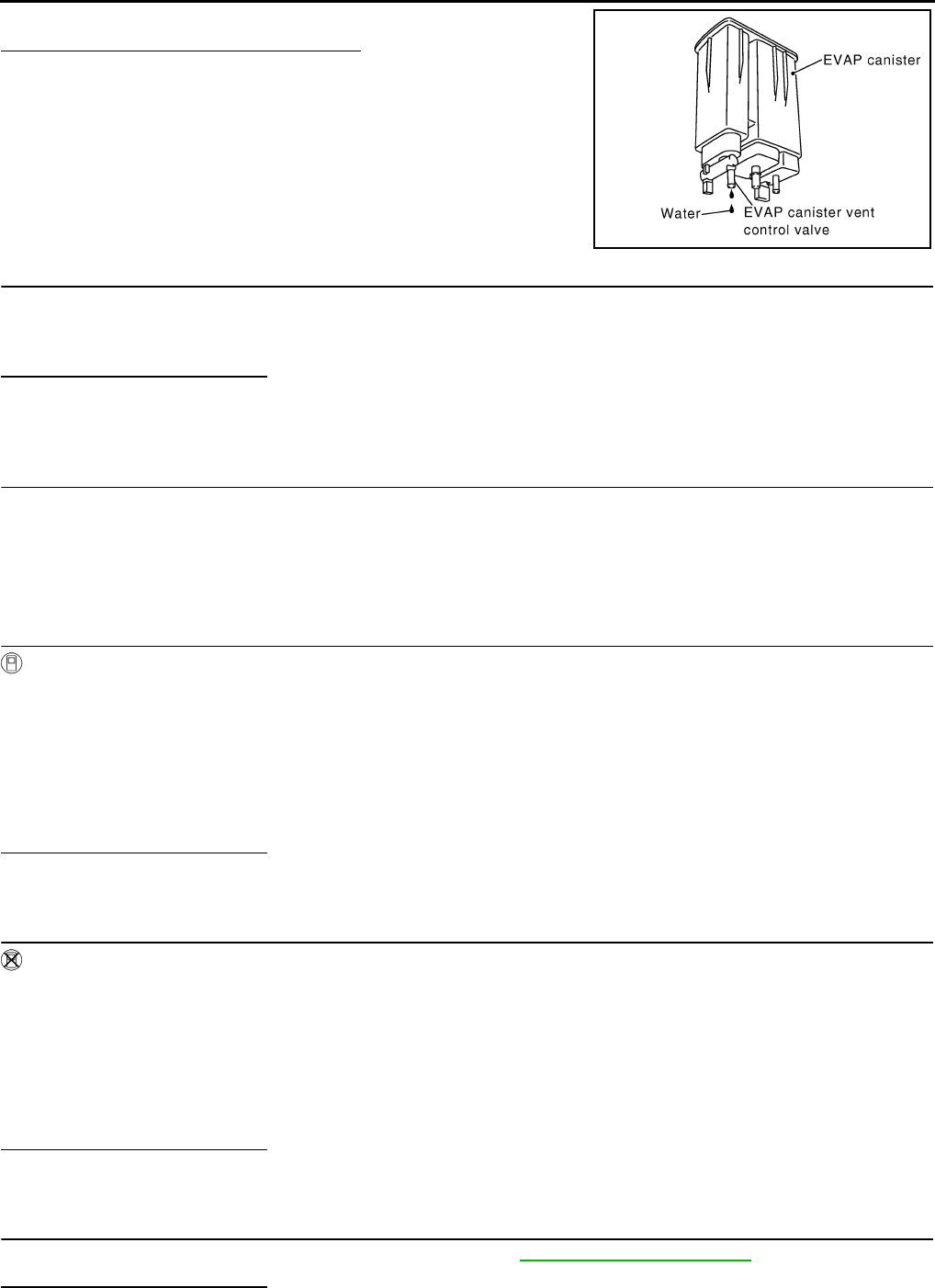
EC-724
< COMPONENT DIAGNOSIS > [FOR USA (FEDERAL) AND CANADA]
P0442 EVAP CONTROL SYSTEM
2. Does water drain from the EVAP canister?
Does water drain from the EVAP canister?
YES >> GO TO 8.
NO-1 >> With CONSULT-III: GO TO 10.
NO-2 >> Without CONSULT-III: GO TO 11.
8.CHECK EVAP CANISTER
Weigh the EVAP canister with the EVAP canister vent control valve and EVAP control system pressure sensor
attached.
The weight should be less than 2.1 kg (4.6 lb).
Is the inspection result normal?
YES-1 >> With CONSULT-III: GO TO 10.
YES-2 >> Without CONSULT-III: GO TO 11.
NO >> GO TO 9.
9.DETECT MALFUNCTIONING PART
Check the following.
• EVAP canister for damage
• EVAP hose between EVAP canister and vehicle frame for clogging or poor connection
>> Repair hose or replace EVAP canister.
10.CHECK EVAP CANISTER PURGE VOLUME CONTROL SOLENOID VALVE OPERATION
With CONSULT-III
1. Disconnect vacuum hose from EVAP canister purge volume control solenoid valve at EVAP service port.
2. Start engine.
3. Perform “PURG VOL CONT/V” in “ACTIVE TEST” mode.
4. Touch “Qu” on CONSULT-III screen to increase “PURG VOL C/V” opening to 100%.
5. Check vacuum hose for vacuum.
Is the inspection result normal?
YES >> GO TO 13.
NO >> GO TO 12.
11.CHECK EVAP CANISTER PURGE VOLUME CONTROL SOLENOID VALVE OPERATION
Without CONSULT-III
1. Start engine and warm it up to normal operating temperature.
2. Stop engine.
3. Disconnect vacuum hose from EVAP canister purge volume control solenoid valve at EVAP service port.
4. Start engine and let it idle for at least 80 seconds.
5. Check vacuum hose for vacuum when revving engine up to 2,000 rpm.
Is the inspection result normal?
YES >> GO TO 13.
NO >> GO TO 12.
12.CHECK VACUUM HOSE
Check vacuum hoses for clogging or disconnection. Refer to EC-549, "System Diagram".
Is the inspection result normal?
PBIB1213E
Vacuum should exist.
Vacuum should exist.
Revision: 2008 August 2009 Rogue

P0442 EVAP CONTROL SYSTEM
EC-725
< COMPONENT DIAGNOSIS > [FOR USA (FEDERAL) AND CANADA]
C
D
E
F
G
H
I
J
K
L
M
A
EC
N
P
O
YES >> GO TO 13.
NO >> Repair or reconnect the hose.
13.CHECK EVAP CANISTER PURGE VOLUME CONTROL SOLENOID VALVE
Refer to EC-730, "Component Inspection".
Is the inspection result normal?
YES >> GO TO 14.
NO >> Replace EVAP canister purge volume control solenoid valve.
14.CHECK FUEL TANK TEMPERATURE SENSOR
Refer to EC-689, "Component Inspection".
Is the inspection result normal?
YES >> GO TO 15.
NO >> Replace fuel level sensor unit.
15.CHECK EVAP CONTROL SYSTEM PRESSURE SENSOR
Refer to EC-742, "DTC Logic".
Is the inspection result normal?
YES >> GO TO 16.
NO >> Replace EVAP control system pressure sensor.
16.CHECK EVAP PURGE LINE
Check EVAP purge line (pipe, rubber tube, fuel tank and EVAP canister) for cracks or improper connection.
Refer to EC-549, "System Diagram".
Is the inspection result normal?
YES >> GO TO 17.
NO >> Repair or reconnect the hose.
17.CLEAN EVAP PURGE LINE
Clean EVAP purge line (pipe and rubber tube) using air blower.
>> GO TO 18.
18.CHECK EVAP/ORVR LINE
Check EVAP/ORVR line between EVAP canister and fuel tank for clogging, kinks, looseness and improper
connection. For location, refer to EC-867, "Description".
Is the inspection result normal?
YES >> GO TO 19.
NO >> Repair or replace hoses and tubes.
19.CHECK RECIRCULATION LINE
Check recirculation line between filler neck tube and fuel tank for clogging, kinks, cracks, looseness and
improper connection.
Is the inspection result normal?
YES >> GO TO 20.
NO >> Repair or replace hose, tube or filler neck tube.
20.CHECK REFUELING EVAP VAPOR CUT VALVE
Refer to EC-870, "Component Inspection".
Is the inspection result normal?
YES >> GO TO 21.
NO >> Replace refueling EVAP vapor cut valve with fuel tank.
21.CHECK FUEL LEVEL SENSOR
Refer to MWI-43, "Component Function Check".
Is the inspection result normal?
YES >> GO TO 22.
Revision: 2008 August 2009 Rogue
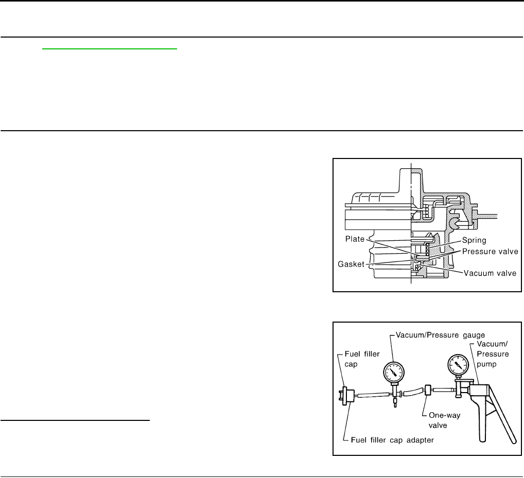
EC-726
< COMPONENT DIAGNOSIS > [FOR USA (FEDERAL) AND CANADA]
P0442 EVAP CONTROL SYSTEM
NO >> Replace fuel level sensor unit.
22.CHECK INTERMITTENT INCIDENT
Refer to GI-41, "Intermittent Incident".
>> INSPECTION END
Component Inspection INFOID:0000000004529585
1.CHECK FUEL FILLER CAP
1. Turn ignition switch OFF.
2. Remove fuel filler cap.
3. Wipe clean valve housing.
4. Install fuel filler cap adapter (commercial service tool) to fuel filler cap.
5. Check valve opening pressure and vacuum.
Is the inspection result normal?
YES >> INSPECTION END
NO >> GO TO 2.
2.REPLACE FUEL FILLER CAP
Replace fuel filler cap.
CAUTION:
Use only a genuine fuel filler cap as a replacement. If an incorrect fuel filler cap is used, the MIL may
illuminate.
>> INSPECTION END
SEF445Y
Pressure: 15.3 - 20.0 kPa (0.156 - 0.204 kg/cm2, 2.22 -
2.90 psi)
Vacuum: −6.0 to −3.3 kPa (−0.061 to −0.034 kg/cm2,
−0.87 to −0.48 psi)
SEF943S
Revision: 2008 August 2009 Rogue
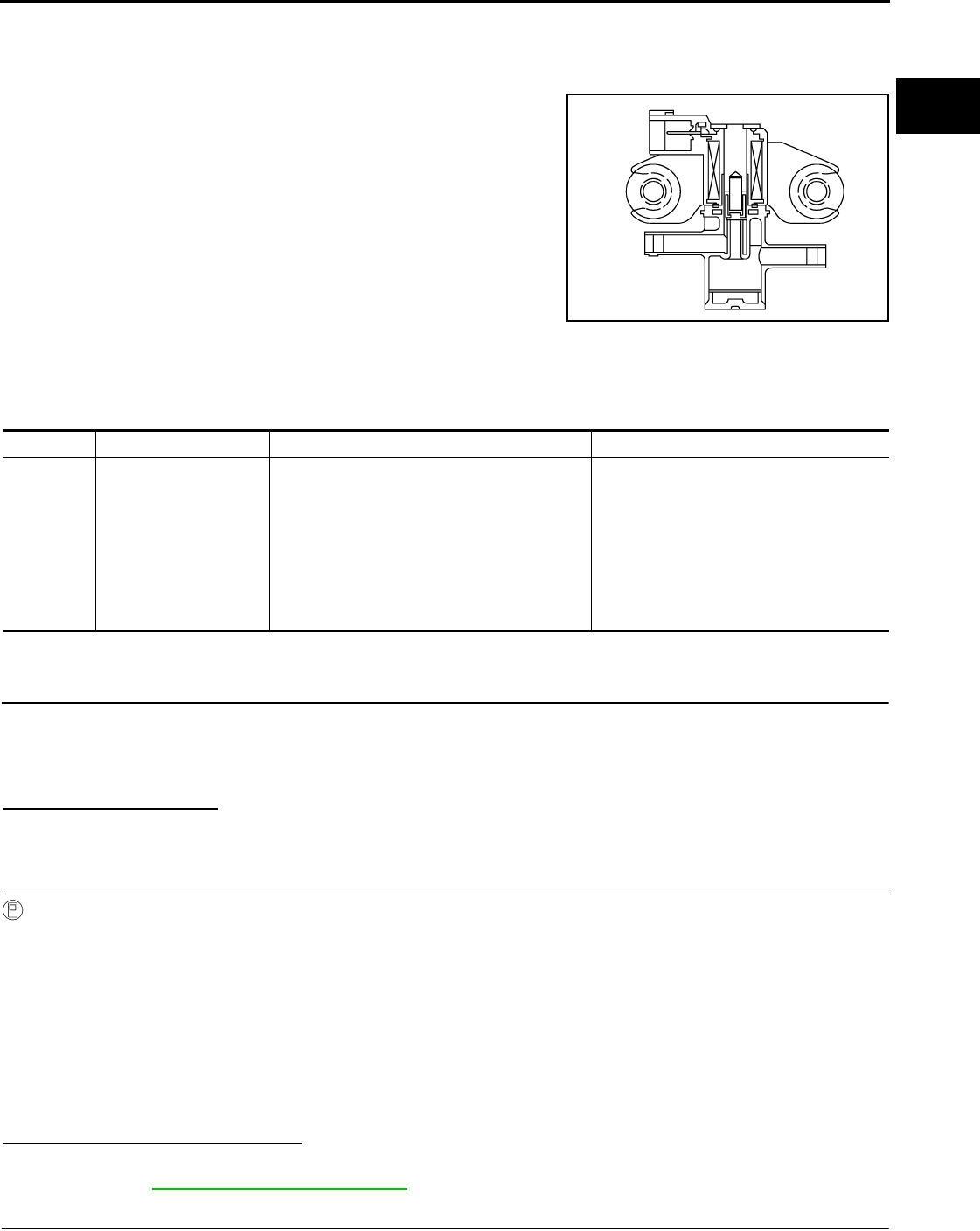
P0443 EVAP CANISTER PURGE VOLUME CONTROL SOLENOID VALVE
EC-727
< COMPONENT DIAGNOSIS > [FOR USA (FEDERAL) AND CANADA]
C
D
E
F
G
H
I
J
K
L
M
A
EC
N
P
O
P0443 EVAP CANISTER PURGE VOLUME CONTROL SOLENOID VALVE
Description INFOID:0000000004529586
The EVAP canister purge volume control solenoid valve is used to
control the flow rate of fuel vapor from the EVAP canister. The EVAP
canister purge volume control solenoid valve is moved by ON/OFF
pulses from the ECM. The longer the ON pulse, the greater the
amount of fuel vapor that will flow through the valve.
DTC Logic INFOID:0000000004529587
DTC DETECTION LOGIC
DTC CONFIRMATION PROCEDURE
1.PRECONDITIONING
If DTC CONFIRMATION PROCEDURE has been previously conducted, always turn ignition switch OFF and
wait at least 10 seconds before conducting the next test.
TESTING CONDITION:
Always perform test at a temperature of 5°C (41°F) or more.
Do you have CONSULT-III
YES >> GO TO 2.
NO >> GO TO 3.
2.PERFORM DTC CONFIRMATION PROCEDURE
With CONSULT-III
1. Start engine and warm it up to normal operating temperature.
2. Turn ignition switch OFF and wait at least 10 seconds.
3. Turn ignition switch ON.
4. Select “PURG VOL CN/V P1444” of “EVAPORATIVE SYSTEM” in “DTC WORK SUPPORT” mode with
CONSULT-III.
5. Touch “START”.
6. Start engine and let it idle until “TESTING” on CONSULT-III changes to “COMPLETED”. (It will take
approximately 10 seconds.)
If “TESTING” is not displayed after 5 minutes, retry from step 2.
7. Touch “SELF-DIAG RESULT”.
Which is displayed on CONSULT-III?
OK >> INSPECTION END
NG >> Go to EC-728, "Diagnosis Procedure".
3.PERFORM DTC CONFIRMATION PROCEDURE
JMBIA0069ZZ
DTC No. Trouble diagnosis name DTC detecting condition Possible cause
P0443 EVAP canister purge
volume control solenoid
valve
The canister purge flow is detected during the
specified driving conditions, even when EVAP
canister purge volume control solenoid valve is
completely closed.
• EVAP control system pressure sensor
• EVAP canister purge volume control so-
lenoid valve
(The valve is stuck open.)
• EVAP canister vent control valve
• EVAP canister
•Hoses
(Hoses are connected incorrectly or
clogged.)
Revision: 2008 August 2009 Rogue
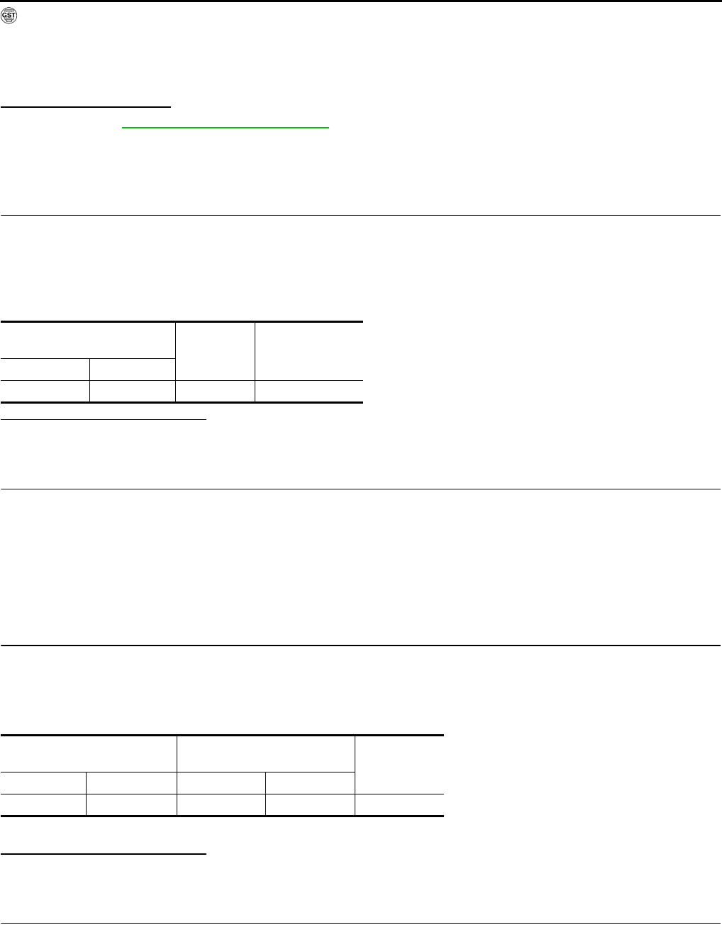
EC-728
< COMPONENT DIAGNOSIS > [FOR USA (FEDERAL) AND CANADA]
P0443 EVAP CANISTER PURGE VOLUME CONTROL SOLENOID VALVE
With GST
1. Start engine and warm it up to normal operating temperature.
2. Turn ignition switch OFF and wait at least 10 seconds.
3. Start engine and let it idle for at least 20 seconds.
4. Check 1st trip DTC.
Is 1st trip DTC displayed?
YES >> Go to EC-728, "Diagnosis Procedure".
NO >> INSPECTION END
Diagnosis Procedure INFOID:0000000004529588
1.CHECK EVAP CANISTER PURGE VOLUME CONTROL SOLENOID VALVE POWER SUPPLY CIRCUIT
1. Turn ignition switch OFF.
2. Disconnect EVAP canister purge volume control solenoid valve harness connector.
3. Turn ignition switch ON.
4. Check the voltage between EVAP canister purge volume control solenoid valve harness connector and
ground.
Is the inspection result normal?
YES >> GO TO 3.
NO >> GO TO 2.
2.DETECT MALFUNCTIONING PART
Check the following.
• Harness connectors E7, F121
• Harness for open or short between EVAP canister purge volume control solenoid valve and IPDM E/R
• Harness for open or short between EVAP canister purge volume control solenoid valve and ECM
>> Repair open circuit or short to ground or short to power in harness or connectors.
3.CHECK EVAP CANISTER PURGE VOLUME CONTROL SOLENOID VALVE OUTPUT SIGNAL CIRCUIT
FOR OPEN AND SHORT
1. Turn ignition switch OFF.
2. Disconnect ECM harness connector.
3. Check the continuity between EVAP canister purge volume control solenoid valve harness connector and
ECM harness connector.
4. Also check harness for short to ground and short to power.
Is the inspection result normal?
YES >> GO TO 4.
NO >> Repair open circuit or short to ground or short to power in harness or connectors.
4.CHECK EVAP CONTROL SYSTEM PRESSURE SENSOR CONNECTOR
1. Disconnect EVAP control system pressure sensor harness connector.
2. Check connectors for water.
EVAP canister purge volume
control solenoid valve Ground Voltage
Connector Terminal
F32 1 Ground Battery voltage
EVAP canister purge volume
control solenoid valve ECM Continuity
Connector Terminal Connector Terminal
F32 2 F7 25 Existed
Water should not exist.
Revision: 2008 August 2009 Rogue
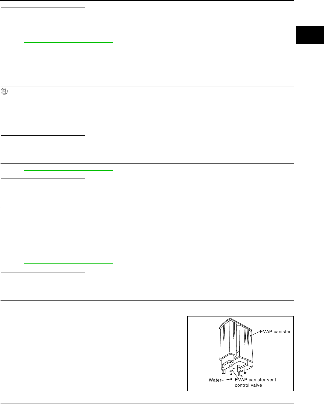
P0443 EVAP CANISTER PURGE VOLUME CONTROL SOLENOID VALVE
EC-729
< COMPONENT DIAGNOSIS > [FOR USA (FEDERAL) AND CANADA]
C
D
E
F
G
H
I
J
K
L
M
A
EC
N
P
O
Is the inspection result normal?
YES >> GO TO 5.
NO >> Replace EVAP control system pressure sensor.
5.CHECK EVAP CONTROL SYSTEM PRESSURE SENSOR
Refer to EC-744, "Component Inspection".
Is the inspection result normal?
YES-1 >> With CONSULT-III: GO TO 6.
YES-2 >> Without CONSULT-III: GO TO 7.
NO >> Replace EVAP control system pressure sensor.
6.CHECK EVAP CANISTER PURGE VOLUME CONTROL SOLENOID VALVE
With CONSULT-III
1. Turn ignition switch OFF.
2. Reconnect harness connectors disconnected.
3. Start engine.
4. Perform “PURG VOL CONT/V” in “ACTIVE TEST” mode with CONSULT-III. Check that engine speed var-
ies according to the valve opening.
Is the inspection result normal?
YES >> GO TO 8.
NO >> GO TO 7.
7.CHECK EVAP CANISTER PURGE VOLUME CONTROL SOLENOID VALVE
Refer to EC-730, "Component Inspection".
Is the inspection result normal?
YES >> GO TO 8.
NO >> Replace EVAP canister purge volume control solenoid valve.
8.CHECK RUBBER TUBE FOR CLOGGING
1. Disconnect rubber tube connected to EVAP canister vent control valve.
2. Check the rubber tube for clogging.
Is the inspection result normal?
YES >> GO TO 9.
NO >> Clean the rubber tube using an air blower.
9.CHECK EVAP CANISTER VENT CONTROL VALVE
Refer to EC-736, "Component Inspection".
Is the inspection result normal?
YES >> GO TO 10.
NO >> Replace EVAP canister vent control valve.
10.CHECK IF EVAP CANISTER IS SATURATED WITH WATER
1. Remove EVAP canister with EVAP canister vent control valve and EVAP control system pressure sensor
attached.
2. Check if water will drain from EVAP canister.
Does water drain from the EVAP canister?
YES >> GO TO 11.
NO >> GO TO 13.
11.CHECK EVAP CANISTER
PBIB1213E
Revision: 2008 August 2009 Rogue

EC-730
< COMPONENT DIAGNOSIS > [FOR USA (FEDERAL) AND CANADA]
P0443 EVAP CANISTER PURGE VOLUME CONTROL SOLENOID VALVE
Weigh the EVAP canister with the EVAP canister vent control valve and EVAP control system pressure sensor
attached.
The weight should be less than 2.1 kg (4.6 lb).
Is the inspection result normal?
YES >> GO TO 13.
NO >> GO TO 12.
12.DETECT MALFUNCTIONING PART
Check the following.
• EVAP canister for damage
• EVAP hose between EVAP canister and vehicle frame for clogging or poor connection
>> Repair hose or replace EVAP canister.
13.CHECK INTERMITTENT INCIDENT
Refer to GI-41, "Intermittent Incident".
>> INSPECTION END
Component Inspection INFOID:0000000004529589
1.CHECK EVAP CANISTER PURGE VOLUME CONTROL SOLENOID VALVE
With CONSULT-III
1. Turn ignition switch OFF.
2. Reconnect all harness connectors disconnected.
3. Disconnect EVAP purge hoses connected to EVAP canister purge volume control solenoid valve.
4. Turn ignition switch ON.
5. Select “PURG VOL C/V” in “ACTIVE TEST” mode with CONSULT-III.
6. Touch “Qd” and “Qu” on CONSULT-III screen to adjust “PURG
VOL C/V” opening and check air passage continuity of EVAP
canister purge volume control solenoid valve under the following
conditions.
Without CONSULT-III
1. Turn ignition switch OFF.
2. Disconnect EVAP canister purge volume control solenoid valve harness connector.
3. Disconnect EVAP purge hoses connected to EVAP canister purge volume control solenoid valve.
4. Check air passage continuity of EVAP canister purge volume control solenoid valve under the following
conditions.
Is the inspection result normal?
YES >> INSPECTION END
NO >> Replace EVAP canister purge volume control solenoid valve
Condition
(PURG VOL C/V value)
Air passage continuity
between (A) and (B)
100% Existed
0% Not existed
JMBIA0068ZZ
Condition Air passage continuity
between (A) and (B)
12V direct current supply between
terminals 1 and 2 Existed
No supply Not existed
Revision: 2008 August 2009 Rogue
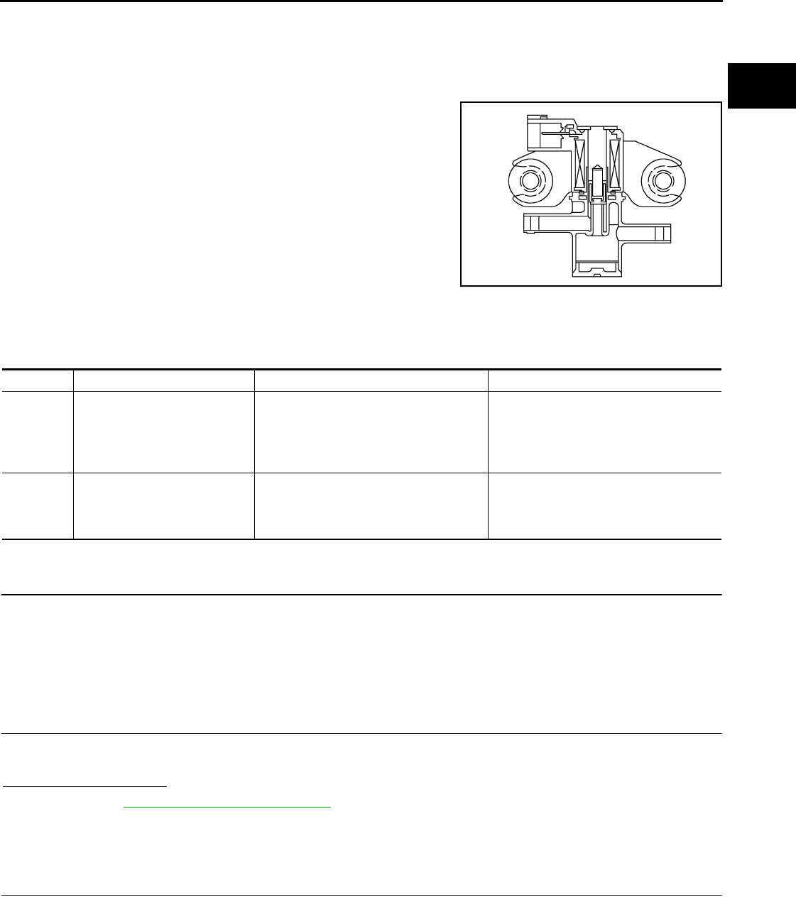
P0444, P0445 EVAP CANISTER PURGE VOLUME CONTROL SOLENOID
VALVE
EC-731
< COMPONENT DIAGNOSIS > [FOR USA (FEDERAL) AND CANADA]
C
D
E
F
G
H
I
J
K
L
M
A
EC
N
P
O
P0444, P0445 EVAP CANISTER PURGE VOLUME CONTROL SOLENOID
VALVE
Description INFOID:0000000004533980
The EVAP canister purge volume control solenoid valve is used to
control the flow rate of fuel vapor from the EVAP canister. The EVAP
canister purge volume control solenoid valve is moved by ON/OFF
pulses from the ECM. The longer the ON pulse, the greater the
amount of fuel vapor that will flow through the valve.
DTC Logic INFOID:0000000004529591
DTC DETECTION LOGIC
DTC CONFIRMATION PROCEDURE
1.CONDITIONING
If DTC CONFIRMATION PROCEDURE has been previously conducted, always turn ignition switch OFF and
wait at least 10 seconds before conducting the next test.
TESTING CONDITION:
Before performing the following procedure, confirm battery voltage is more than 11V at idle.
>> GO TO 2.
2.PERFORM DTC CONFIRMATION PROCEDURE
1. Start engine and let it idle for at least 13 seconds.
2. Check 1st trip DTC.
Is 1st trip DTC detected?
YES >> Go to EC-731, "Diagnosis Procedure".
NO >> INSPECTION END
Diagnosis Procedure INFOID:0000000004529592
1.CHECK EVAP CANISTER PURGE VOLUME CONTROL SOLENOID VALVE POWER SUPPLY CIRCUIT
1. Turn ignition switch OFF.
2. Disconnect EVAP canister purge volume control solenoid valve harness connector.
3. Turn ignition switch ON.
4. Check the voltage between EVAP canister purge volume control solenoid valve harness connector and
ground.
JMBIA0069ZZ
DTC No. Trouble diagnosis name DTC detecting condition Possible cause
P0444 EVAP canister purge volume
control solenoid valve circuit
open
An excessively low voltage signal is sent
to ECM through the valve
• Harness or connectors
(The solenoid valve circuit is open or
shorted.)
• EVAP canister purge volume control so-
lenoid valve
P0445
EVAP canister purge volume
control solenoid valve circuit
shorted
An excessively high voltage signal is sent
to ECM through the valve
• Harness or connectors
(The solenoid valve circuit is shorted.)
• EVAP canister purge volume control so-
lenoid valve
Revision: 2008 August 2009 Rogue
EC-732
< COMPONENT DIAGNOSIS > [FOR USA (FEDERAL) AND CANADA]
P0444, P0445 EVAP CANISTER PURGE VOLUME CONTROL SOLENOID
VALVE
Is the inspection result normal?
YES >> GO TO 3.
NO >> GO TO 2.
2.DETECT MALFUNCTIONING PART
Check the following.
• Harness connectors E7, F121
• Harness for open or short between EVAP canister purge volume control solenoid valve and IPDM E/R
• Harness for open or short between EVAP canister purge volume control solenoid valve and ECM
>> Repair open circuit or short to ground or short to power in harness or connectors.
3.CHECK EVAP CANISTER PURGE VOLUME CONTROL SOLENOID VALVE OUTPUT SIGNAL CIRCUIT
FOR OPEN AND SHORT
1. Turn ignition switch OFF.
2. Disconnect ECM harness connector.
3. Check the continuity between EVAP canister purge volume control solenoid valve harness connector and
ECM harness connector.
4. Also check harness for short to ground and short to power.
Is the inspection result normal?
YES-1 >> With CONSULT-III: GO TO 4.
YES-2 >> Without CONSULT-III: GO TO 5.
NO >> Repair open circuit or short to ground or short to power in harness or connectors.
4.CHECK EVAP CANISTER PURGE VOLUME CONTROL SOLENOID VALVE OPERATION
With CONSULT-III
1. Reconnect all harness connectors disconnected.
2. Start engine.
3. Perform “PURG VOL CONT/V” in “ACTIVE TEST” mode with CONSULT-III. Check that engine speed var-
ies according to the valve opening.
Is the inspection result normal?
YES >> GO TO 6.
NO >> GO TO 5.
5.CHECK EVAP CANISTER PURGE VOLUME CONTROL SOLENOID VALVE
Refer to EC-733, "Component Inspection".
Is the inspection result normal?
YES >> GO TO 6.
NO >> Replace EVAP canister purge volume control solenoid valve.
6.CHECK INTERMITTENT INCIDENT
Refer to GI-41, "Intermittent Incident".
>> INSPECTION END
EVAP canister purge volume
control solenoid valve Ground Voltage
Connector Terminal
F32 1 Ground Battery voltage
EVAP canister purge volume
control solenoid valve ECM Continuity
Connector Terminal Connector Terminal
F32 2 F7 25 Existed
Revision: 2008 August 2009 Rogue
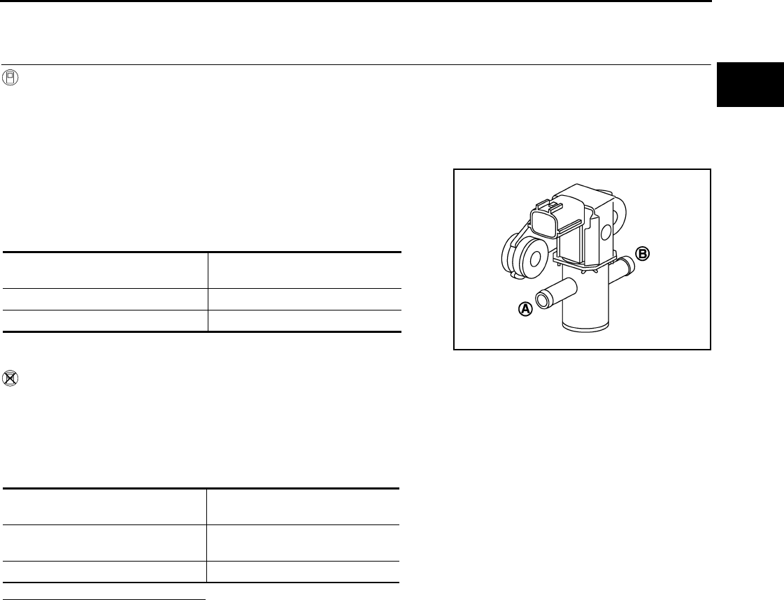
P0444, P0445 EVAP CANISTER PURGE VOLUME CONTROL SOLENOID
VALVE
EC-733
< COMPONENT DIAGNOSIS > [FOR USA (FEDERAL) AND CANADA]
C
D
E
F
G
H
I
J
K
L
M
A
EC
N
P
O
Component Inspection INFOID:0000000004533981
1.CHECK EVAP CANISTER PURGE VOLUME CONTROL SOLENOID VALVE
With CONSULT-III
1. Turn ignition switch OFF.
2. Reconnect all harness connectors disconnected.
3. Disconnect EVAP purge hoses connected to EVAP canister purge volume control solenoid valve.
4. Turn ignition switch ON.
5. Select “PURG VOL C/V” in “ACTIVE TEST” mode with CONSULT-III.
6. Touch “Qd” and “Qu” on CONSULT-III screen to adjust “PURG
VOL C/V” opening and check air passage continuity of EVAP
canister purge volume control solenoid valve under the following
conditions.
Without CONSULT-III
1. Turn ignition switch OFF.
2. Disconnect EVAP canister purge volume control solenoid valve harness connector.
3. Disconnect EVAP purge hoses connected to EVAP canister purge volume control solenoid valve.
4. Check air passage continuity of EVAP canister purge volume control solenoid valve under the following
conditions.
Is the inspection result normal?
YES >> INSPECTION END
NO >> Replace EVAP canister purge volume control solenoid valve
Condition
(PURG VOL C/V value)
Air passage continuity
between (A) and (B)
100% Existed
0% Not existed
JMBIA0068ZZ
Condition Air passage continuity
between (A) and (B)
12V direct current supply between
terminals 1 and 2 Existed
No supply Not existed
Revision: 2008 August 2009 Rogue

EC-734
< COMPONENT DIAGNOSIS > [FOR USA (FEDERAL) AND CANADA]
P0447 EVAP CANISTER VENT CONTROL VALVE
P0447 EVAP CANISTER VENT CONTROL VALVE
Description INFOID:0000000004529594
The EVAP canister vent control valve is located on the EVAP canis-
ter and is used to seal the canister vent.
This solenoid valve responds to signals from the ECM. When the
ECM sends an ON signal, the coil in the solenoid valve is energized.
A plunger will then move to seal the canister vent. The ability to seal
the vent is necessary for the on board diagnosis of other evaporative
emission control system components.
This solenoid valve is used only for diagnosis, and usually remains
opened.
When the vent is closed, under normal purge conditions, the evapo-
rative emission control system is depressurized and allows “EVAP
Control System” diagnosis.
DTC Logic INFOID:0000000004529595
DTC DETECTION LOGIC
DTC CONFIRMATION PROCEDURE
1.PRECONDITIONING
If DTC CONFIRMATION PROCEDURE has been previously conducted, always turn ignition switch OFF and
wait at least 10 seconds before conducting the next test.
TESTING CONDITION:
Before performing the following procedure, confirm battery voltage is more than 11V at idle.
>> GO TO 2.
2.PERFORM DTC CONFIRMATION PROCEDURE
1. Start engine and wait at least 8 seconds.
2. Check 1st trip DTC.
Is 1st trip DTC detected?
YES >> Go to EC-734, "Diagnosis Procedure".
NO >> INSPECTION END
Diagnosis Procedure INFOID:0000000004529596
1.INSPECTION START
Do you have CONSULT-III?
Do you have CONSULT-III?
YES >> GO TO 2.
NO >> GO TO 3.
2.CHECK EVAP CANISTER VENT CONTROL VALVE CIRCUIT
With CONSULT-III
1. Turn ignition switch OFF and then ON.
2. Select “VENT CONTROL/V” in “ACTIVE TEST” mode with CONSULT-III.
3. Touch “ON/OFF” on CONSULT-III screen.
4. Check for operating sound of the valve.
PBIB1263E
DTC No. Trouble diagnosis name DTC detecting condition Possible cause
P0447 EVAP canister vent con-
trol valve circuit open An improper voltage signal is sent to ECM
through EVAP canister vent control valve.
• Harness or connectors
(The valve circuit is open or shorted.)
• EVAP canister vent control valve
Revision: 2008 August 2009 Rogue

P0447 EVAP CANISTER VENT CONTROL VALVE
EC-735
< COMPONENT DIAGNOSIS > [FOR USA (FEDERAL) AND CANADA]
C
D
E
F
G
H
I
J
K
L
M
A
EC
N
P
O
Is the inspection result normal?
YES >> GO TO 7.
NO >> GO TO 3.
3.CHECK EVAP CANISTER VENT CONTROL VALVE POWER SUPPLY CIRCUIT
1. Turn ignition switch OFF.
2. Disconnect EVAP canister vent control valve harness connector.
3. Turn ignition switch ON.
4. Check the voltage between EVAP canister vent control valve harness connector and ground.
Is the inspection result normal?
YES >> GO TO 5.
NO >> GO TO 4.
4.DETECT MALFUNCTIONING PART
Check the following.
• Harness connectors E105, M77
• Harness connectors M11, B1
• Harness for open or short between EVAP canister vent control valve and IPDM E/R
>> Repair open circuit or short to ground or short to power in harness or connectors.
5.CHECK EVAP CANISTER VENT CONTROL VALVE OUTPUT SIGNAL CIRCUIT FOR OPEN AND SHORT
1. Turn ignition switch OFF.
2. Disconnect ECM harness connector.
3. Check the continuity between EVAP canister vent control valve harness connector and ECM harness con-
nector.
4. Also check harness for short to ground and short to power.
Is the inspection result normal?
YES >> GO TO 7.
NO >> GO TO 6.
6.DETECT MALFUNCTIONING PART
Check the following.
• Harness connectors E105, M77
• Harness connectors M11, B1
• Harness for open or short between EVAP canister vent control valve and ECM
>> Repair open circuit or short to ground or short to power in harness or connectors.
7.CHECK RUBBER TUBE FOR CLOGGING
1. Disconnect rubber tube connected to EVAP canister vent control valve.
2. Check the rubber tube for clogging.
Is the inspection result normal?
YES >> GO TO 8.
NO >> Clean the rubber tube using an air blower.
Clicking sound should be heard.
EVAP canister vent control valve Ground Voltage
Connector Terminal
B48 1 Ground Battery voltage
EVAP canister vent control valve ECM Continuity
Connector Terminal Connector Terminal
B48 2 E16 109 Existed
Revision: 2008 August 2009 Rogue
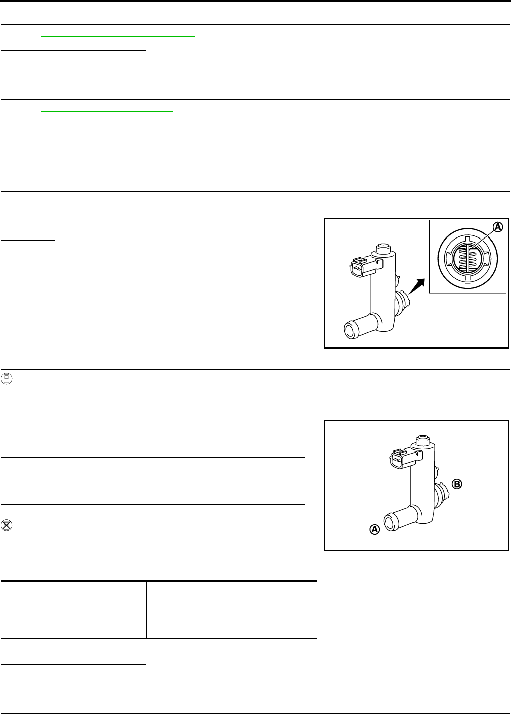
EC-736
< COMPONENT DIAGNOSIS > [FOR USA (FEDERAL) AND CANADA]
P0447 EVAP CANISTER VENT CONTROL VALVE
8.CHECK EVAP CANISTER VENT CONTROL VALVE
Refer to EC-736, "Component Inspection".
Is the inspection result normal?
YES >> GO TO 9.
NO >> Replace EVAP canister vent control valve.
9.CHECK INTERMITTENT INCIDENT
Refer to GI-41, "Intermittent Incident".
>> INSPECTION END
Component Inspection INFOID:0000000004529597
1.CHECK EVAP CANISTER VENT CONTROL VALVE-I
1. Turn ignition switch OFF.
2. Remove EVAP canister vent control valve from EVAP canister.
3. Check portion (A) of EVAP canister vent control valve for rust.
Is it rusted?
YES >> Replace EVAP canister vent control valve
NO >> GO TO 2.
2.CHECK EVAP CANISTER VENT CONTROL VALVE-II
With CONSULT-III
1. Reconnect harness connectors disconnected.
2. Turn ignition switch ON.
3. Perform “VENT CONTROL/V” in “ACTIVE TEST” mode.
4. Check air passage continuity and operation delay time.
Check that new O-ring is installed properly.
Operation takes less than 1 second.
Without CONSULT-III
Check air passage continuity and operation delay time under the fol-
lowing conditions.
Check that new O-ring is installed properly.
Operation takes less than 1 second.
Is the inspection result normal?
YES >> INSPECTION END
NO >> GO TO 3.
3.CHECK EVAP CANISTER VENT CONTROL VALVE-III
JMBIA0168ZZ
Condition (VENT CONT/V) Air passage continuity between (A) and (B)
ON Not existed
OFF Existed
Condition Air passage continuity between (A) and (B)
12V direct current supply between
terminals (1) and (2) Not existed
OFF Existed
JMBIA0169ZZ
Revision: 2008 August 2009 Rogue

P0447 EVAP CANISTER VENT CONTROL VALVE
EC-737
< COMPONENT DIAGNOSIS > [FOR USA (FEDERAL) AND CANADA]
C
D
E
F
G
H
I
J
K
L
M
A
EC
N
P
O
With CONSULT-III
1. Clean the air passage [portion (A) to (B)] of EVAP canister vent control valve using an air blower.
2. Perform “VENT CONTROL/V” in “ACTIVE TEST” mode.
3. Check air passage continuity and operation delay time.
Check that new O-ring is installed properly.
Operation takes less than 1 second.
Without CONSULT-III
1. Clean the air passage [portion (A) to (B)] of EVAP canister vent
control valve using an air blower.
2. Check air passage continuity and operation delay time under the
following conditions.
Check that new O-ring is installed properly.
Operation takes less than 1 second.
Is the inspection result normal?
YES >> INSPECTION END
NO >> Replace EVAP canister vent control valve
Condition (VENT CONT/V) Air passage continuity between (A) and (B)
ON Not existed
OFF Existed
Condition Air passage continuity between (A) and (B)
12V direct current supply between
terminals (1) and (2) Not existed
OFF Existed
JMBIA0169ZZ
Revision: 2008 August 2009 Rogue

EC-738
< COMPONENT DIAGNOSIS > [FOR USA (FEDERAL) AND CANADA]
P0448 EVAP CANISTER VENT CONTROL VALVE
P0448 EVAP CANISTER VENT CONTROL VALVE
Description INFOID:0000000004533982
The EVAP canister vent control valve is located on the EVAP canis-
ter and is used to seal the canister vent.
This solenoid valve responds to signals from the ECM. When the
ECM sends an ON signal, the coil in the solenoid valve is energized.
A plunger will then move to seal the canister vent. The ability to seal
the vent is necessary for the on board diagnosis of other evaporative
emission control system components.
This solenoid valve is used only for diagnosis, and usually remains
opened.
When the vent is closed, under normal purge conditions, the evapo-
rative emission control system is depressurized and allows “EVAP
Control System” diagnosis.
DTC Logic INFOID:0000000004529599
DTC DETECTION LOGIC
DTC CONFIRMATION PROCEDURE
1.PRECONDITIONING
If DTC CONFIRMATION PROCEDURE has been previously conducted, always turn ignition switch OFF and
wait at least 10 seconds before conducting the next test.
>> GO TO 2.
2.PERFORM DTC CONFIRMATION PROCEDURE
1. Turn ignition switch ON and wait at least 5 seconds.
2. Turn ignition switch OFF and wait at least 10 seconds.
3. Start engine and let it idle for at least 1 minute.
4. Repeat next procedures three times.
- Increase the engine speed between 3,000 to 3,500 rpm and maintain that speed for 2 minutes and 50
seconds to 3 minutes.
Do not exceed 3 minutes.
- Fully released accelerator pedal and keep engine idle for approximately 5 seconds.
5. Repeat next procedure 20 times.
- Quickly increase the engine speed between 4,000 to 4,500 rpm and maintain that speed for 25 to 30 sec-
onds.
- Fully released accelerator pedal and keep engine idle for at least 35 seconds.
PBIB1263E
DTC No. Trouble diagnosis name DTC detecting condition Possible cause
P0448 EVAP canister vent con-
trol valve close EVAP canister vent control valve remains
closed under specified driving conditions.
• EVAP canister vent control valve
• EVAP control system pressure sensor
and the circuit
• Blocked rubber tube to EVAP canister
vent control valve
• EVAP canister is saturated with water
JMBIA1516G
B
Revision: 2008 August 2009 Rogue

P0448 EVAP CANISTER VENT CONTROL VALVE
EC-739
< COMPONENT DIAGNOSIS > [FOR USA (FEDERAL) AND CANADA]
C
D
E
F
G
H
I
J
K
L
M
A
EC
N
P
O
6. Check 1st trip DTC.
Is 1st trip DTC detected?
YES >> Go to EC-739, "Diagnosis Procedure".
NO >> INSPECTION END
Diagnosis Procedure INFOID:0000000004529600
1.CHECK RUBBER TUBE
1. Turn ignition switch OFF.
2. Disconnect rubber tube connected to EVAP canister vent control valve.
3. Check the rubber tube for clogging.
Is the inspection result normal?
YES >> GO TO 2.
NO >> Clean rubber tube using an air blower.
2.CHECK EVAP CANISTER VENT CONTROL VALVE
Refer to EC-740, "Component Inspection".
Is the inspection result normal?
YES >> GO TO 3.
NO >> Replace EVAP canister vent control valve.
3.CHECK IF EVAP CANISTER IS SATURATED WITH WATER
1. Remove EVAP canister with EVAP canister vent control valve and EVAP control system pressure sensor
attached.
2. Check if water will drain from the EVAP canister.
Does water drain from EVAP canister?
YES >> GO TO 4.
NO >> GO TO 6.
4.CHECK EVAP CANISTER
Weigh the EVAP canister with the EVAP canister vent control valve and EVAP control system pressure sensor
attached.
The weight should be less than 2.1 kg (4.6 lb).
Is the inspection result normal?
YES >> GO TO 6.
NO >> GO TO 5.
5.DETECT MALFUNCTIONING PART
Check the following.
• EVAP canister for damage
• EVAP hose between EVAP canister and vehicle frame for clogging or poor connection
>> Repair hose or replace EVAP canister.
6.CHECK EVAP CONTROL SYSTEM PRESSURE SENSOR CONNECTOR
1. Disconnect EVAP control system pressure sensor harness connector.
2. Check connectors for water.
Is the inspection result normal?
PBIB1213E
Water should not exist.
Revision: 2008 August 2009 Rogue

EC-740
< COMPONENT DIAGNOSIS > [FOR USA (FEDERAL) AND CANADA]
P0448 EVAP CANISTER VENT CONTROL VALVE
YES >> GO TO 7.
NO >> Replace EVAP control system pressure sensor.
7.CHECK EVAP CONTROL SYSTEM PRESSURE SENSOR
Refer to EC-744, "Component Inspection".
Is the inspection result normal?
YES >> GO TO 8.
NO >> Replace EVAP control system pressure sensor.
8.CHECK INTERMITTENT INCIDENT
Refer to GI-41, "Intermittent Incident".
>> INSPECTION END
Component Inspection INFOID:0000000004533983
1.CHECK EVAP CANISTER VENT CONTROL VALVE-I
1. Turn ignition switch OFF.
2. Remove EVAP canister vent control valve from EVAP canister.
3. Check portion (A) of EVAP canister vent control valve for rust.
Is it rusted?
YES >> Replace EVAP canister vent control valve
NO >> GO TO 2.
2.CHECK EVAP CANISTER VENT CONTROL VALVE-II
With CONSULT-III
1. Reconnect harness connectors disconnected.
2. Turn ignition switch ON.
3. Perform “VENT CONTROL/V” in “ACTIVE TEST” mode.
4. Check air passage continuity and operation delay time.
Check that new O-ring is installed properly.
Operation takes less than 1 second.
Without CONSULT-III
Check air passage continuity and operation delay time under the fol-
lowing conditions.
Check that new O-ring is installed properly.
Operation takes less than 1 second.
Is the inspection result normal?
YES >> INSPECTION END
NO >> GO TO 3.
JMBIA0168ZZ
Condition (VENT CONT/V) Air passage continuity between (A) and (B)
ON Not existed
OFF Existed
Condition Air passage continuity between (A) and (B)
12V direct current supply between
terminals (1) and (2) Not existed
OFF Existed
JMBIA0169ZZ
Revision: 2008 August 2009 Rogue
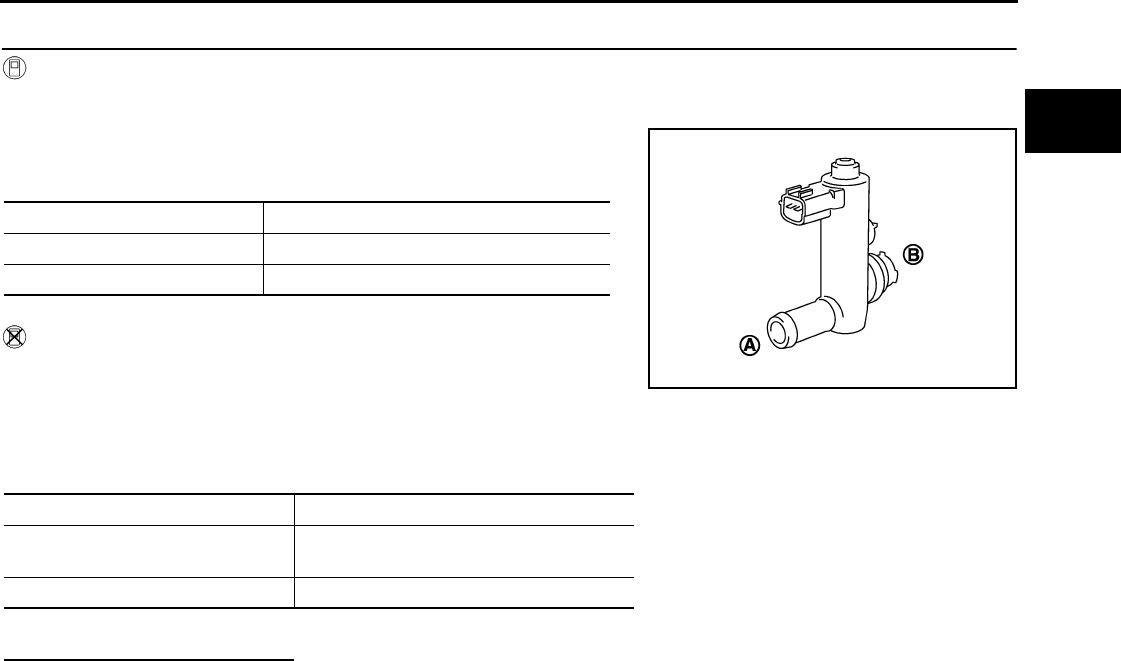
P0448 EVAP CANISTER VENT CONTROL VALVE
EC-741
< COMPONENT DIAGNOSIS > [FOR USA (FEDERAL) AND CANADA]
C
D
E
F
G
H
I
J
K
L
M
A
EC
N
P
O
3.CHECK EVAP CANISTER VENT CONTROL VALVE-III
With CONSULT-III
1. Clean the air passage [portion (A) to (B)] of EVAP canister vent control valve using an air blower.
2. Perform “VENT CONTROL/V” in “ACTIVE TEST” mode.
3. Check air passage continuity and operation delay time.
Check that new O-ring is installed properly.
Operation takes less than 1 second.
Without CONSULT-III
1. Clean the air passage [portion (A) to (B)] of EVAP canister vent
control valve using an air blower.
2. Check air passage continuity and operation delay time under the
following conditions.
Check that new O-ring is installed properly.
Operation takes less than 1 second.
Is the inspection result normal?
YES >> INSPECTION END
NO >> Replace EVAP canister vent control valve
Condition (VENT CONT/V) Air passage continuity between (A) and (B)
ON Not existed
OFF Existed
Condition Air passage continuity between (A) and (B)
12V direct current supply between
terminals (1) and (2) Not existed
OFF Existed
JMBIA0169ZZ
Revision: 2008 August 2009 Rogue
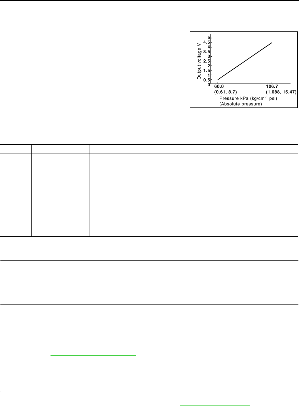
EC-742
< COMPONENT DIAGNOSIS > [FOR USA (FEDERAL) AND CANADA]
P0451 EVAP CONTROL SYSTEM PRESSURE SENSOR
P0451 EVAP CONTROL SYSTEM PRESSURE SENSOR
Description INFOID:0000000004529602
The EVAP control system pressure sensor detects pressure in the
purge line. The sensor output voltage to the ECM increases as pres-
sure increases.
DTC Logic INFOID:0000000004529603
DTC DETECTION LOGIC
DTC CONFIRMATION PROCEDURE
1.PRECONDITIONING
If DTC Confirmation Procedure has been previously conducted, always turn ignition switch OFF and wait at
least 10 seconds before conducting the next test.
>> GO TO 2.
2.PERFORM DTC CONFIRMATION PROCEDURE
1. Turn ignition switch OFF and wait at least 10 seconds.
2. Start engine and wait at least 40 seconds.
NOTE:
Do not depress accelerator pedal even slightly.
3. Check 1st trip DTC.
Is 1st trip DTC detected?
YES >> Go to EC-742, "Diagnosis Procedure".
NO >> INSPECTION END
Diagnosis Procedure INFOID:0000000004529604
1.CHECK GROUND CONNECTION
1. Turn ignition switch OFF.
2. Check ground connection E21. Refer to Ground Inspection in GI-44, "Circuit Inspection".
Is the inspection result normal?
PBIB3370E
DTC No. Trouble diagnosis name DTC detecting condition Possible cause
P0451
EVAP control system
pressure sensor perfor-
mance
ECM detects a sloshing signal from the EVAP
control system pressure sensor
• Harness or connectors
(EVAP control system pressure sensor
circuit is shorted.)
[Crankshaft position sensor (POS) circuit
is shorted.]
(Accelerator pedal position sensor circuit
is shorted.)
(Refrigerant pressure sensor circuit is
shorted.)
• EVAP control system pressure sensor
• Crankshaft position sensor (POS)
• Accelerator pedal position sensor
• Refrigerant pressure sensor
Revision: 2008 August 2009 Rogue

P0451 EVAP CONTROL SYSTEM PRESSURE SENSOR
EC-743
< COMPONENT DIAGNOSIS > [FOR USA (FEDERAL) AND CANADA]
C
D
E
F
G
H
I
J
K
L
M
A
EC
N
P
O
YES >> GO TO 2.
NO >> Repair or replace ground connection.
2.CHECK EVAP CONTROL SYSTEM PRESSURE SENSOR CONNECTOR FOR WATER
1. Disconnect EVAP control system pressure sensor harness connector.
2. Check sensor harness connector for water.
Is the inspection result normal?
YES >> GO TO 3.
NO >> Repair or replace harness connector.
3.CHECK EVAP CONTROL SYSTEM PRESSURE SENSOR POWER SUPPLY CIRCUIT
1. Turn ignition switch ON.
2. Check the voltage between EVAP control system pressure sensor harness connector and ground.
Is the inspection result normal?
YES >> GO TO 8.
NO >> GO TO 4.
4.CHECK SENSOR POWER SUPPLY CIRCUIT
Check harness for short to power and short to ground, between the following terminals.
Is the inspection result normal?
YES >> GO TO 5.
NO >> Repair short to ground or short to power in harness or connectors.
5.CHECK COMPONENT
Check the following.
• Crankshaft position sensor (POS) (Refer to EC-706, "Component Inspection".)
• Refrigerant pressure sensor (Refer to EC-873, "Diagnosis Procedure".)
Is the inspection result normal?
YES >> GO TO 6.
NO >> Replace malfunctioning component.
6.CHECK APP SENSOR
Refer to EC-839, "Component Inspection".
Is the inspection result normal?
YES >> GO TO 9.
NO >> GO TO 7.
7.REPLACE ACCELERATOR PEDAL ASSEMBLY
1. Replace accelerator pedal assembly. Refer to ACC-3, "Removal and Installation".
2. Go to EC-839, "Special Repair Requirement".
Water should not exist.
EVAP control system pressure sensor Ground Voltage
Connector Terminal
B47 3 Ground Approx. 5 V
ECM Sensor
Connector Terminal Name Connector Terminal
F8 72 Refrigerant pressure sensor E49 3
76 CKP sensor (POS) F20 1
E10 87 APP sensor E110 5
91 EVAP control system pressure sensor B47 3
Revision: 2008 August 2009 Rogue
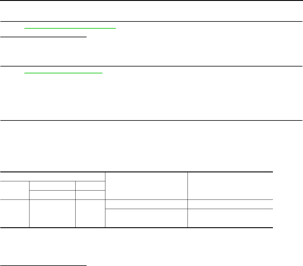
EC-744
< COMPONENT DIAGNOSIS > [FOR USA (FEDERAL) AND CANADA]
P0451 EVAP CONTROL SYSTEM PRESSURE SENSOR
>> INSPECTION END
8.CHECK EVAP CONTROL SYSTEM PRESSURE SENSOR
Refer to EC-744, "Component Inspection".
Is the inspection result normal?
YES >> GO TO 9.
NO >> Replace EVAP control system pressure sensor.
9.CHECK INTERMITTENT INCIDENT
Refer to GI-41, "Intermittent Incident".
>> INSPECTION END
Component Inspection INFOID:0000000004529605
1.CHECK EVAP CONTROL SYSTEM PRESSURE SENSOR
1. Turn ignition switch OFF.
2. Remove EVAP control system pressure sensor with its harness connector.
Always replace O-ring with a new one.
3. Install a vacuum pump to EVAP control system pressure sensor.
4. Turn ignition switch ON and check output voltage between ECM harness connector terminals under the
following conditions.
CAUTION:
• Always calibrate the vacuum pump gauge when using it.
• Never apply below -93.3 kPa (-0.952 kg/cm2, -13.53 psi) or pressure over 101.3 kPa (1.033 kg/cm2,
14.69 psi).
Is the inspection result normal?
YES >> INSPECTION END
NO >> Replace EVAP control system pressure sensor
ECM Condition
[Applied vacuum kPa (kg/cm2, psi)] Voltage (V)
Connector +−
Terminal Terminal
E16
86
(EVAP control
system pressure
sensor signal)
96
(Sensor
ground)
Not applied 1.8 - 4.8
-26.7 (-0.272, -3.87) 2.1 to 2.5 lower than above value
Revision: 2008 August 2009 Rogue
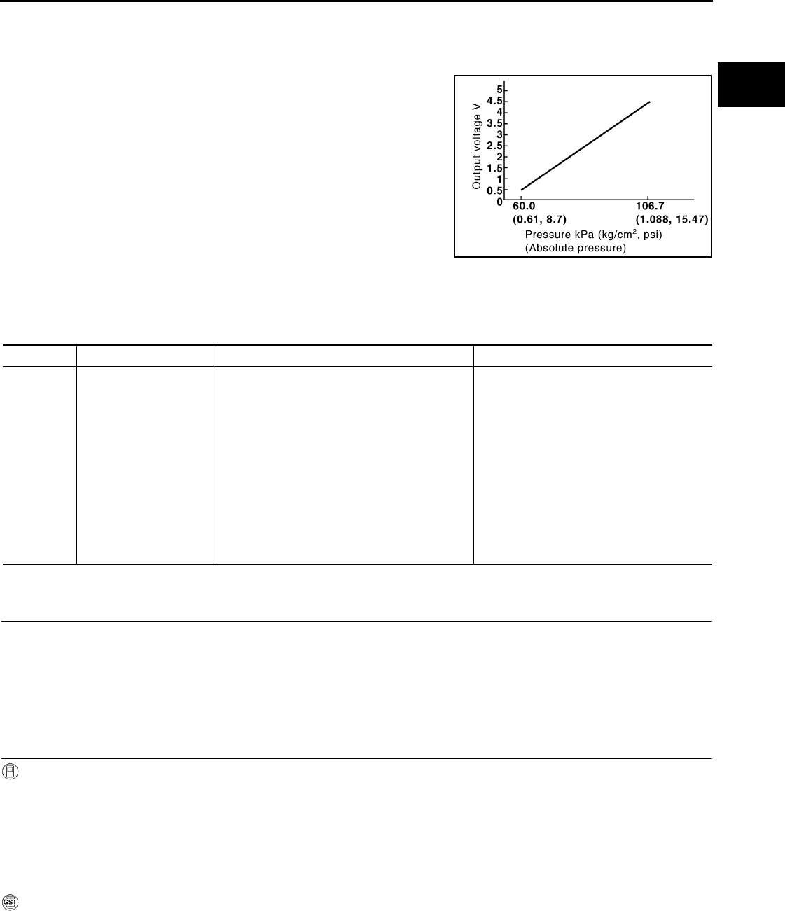
P0452 EVAP CONTROL SYSTEM PRESSURE SENSOR
EC-745
< COMPONENT DIAGNOSIS > [FOR USA (FEDERAL) AND CANADA]
C
D
E
F
G
H
I
J
K
L
M
A
EC
N
P
O
P0452 EVAP CONTROL SYSTEM PRESSURE SENSOR
Description INFOID:0000000004533991
The EVAP control system pressure sensor detects pressure in the
purge line. The sensor output voltage to the ECM increases as pres-
sure increases.
DTC Logic INFOID:0000000004529607
DTC DETECTION LOGIC
DTC CONFIRMATION PROCEDURE
1.PRECONDITIONING
If DTC Confirmation Procedure has been previously conducted, always turn ignition switch OFF and wait at
least 10 seconds before conducting the next test.
TESTING CONDITION:
Always perform test at a temperature of 5°C (41°F) or more.
>> GO TO 2.
2.PERFORM DTC CONFIRMATION PROCEDURE
With CONSULT-III
1. Start engine and warm it up to normal operating temperature.
2. Turn ignition switch OFF and wait at least 10 seconds.
3. Turn ignition switch ON.
4. Select “DATA MONITOR” mode with CONSULT-III.
5. Check that “FUEL T/TMP SE” is more than 0°C (32°F).
6. Start engine and wait at least 20 seconds.
7. Check 1st trip DTC.
With GST
1. Start engine and warm it up to normal operating temperature.
2. Set voltmeter probes to ECM harness connector and ground as follows.
PBIB3370E
DTC No. Trouble diagnosis name DTC detecting condition Possible cause
P0452
EVAP control system
pressure sensor low in-
put
An excessively low voltage from the sensor is
sent to ECM.
• Harness or connectors
(EVAP control system pressure sensor
circuit is open or shorted.)
[Crankshaft position sensor (POS) circuit
is shorted.)
(Accelerator pedal position sensor circuit
is shorted.)
(Refrigerant pressure sensor circuit is
shorted.)
• EVAP control system pressure sensor
• Crankshaft position sensor (POS)
• Accelerator pedal position sensor
• Refrigerant pressure sensor
Revision: 2008 August 2009 Rogue

EC-746
< COMPONENT DIAGNOSIS > [FOR USA (FEDERAL) AND CANADA]
P0452 EVAP CONTROL SYSTEM PRESSURE SENSOR
3. Check that the voltage is less than 4.2V.
4. Turn ignition switch OFF and wait at least 10 seconds.
5. Start engine and wait at least 20 seconds.
6. Check 1st trip DTC.
Is 1st trip DTC detected?
YES >> Go to EC-746, "Diagnosis Procedure".
NO >> INSPECTION END
Diagnosis Procedure INFOID:0000000004529608
1.CHECK GROUND CONNECTION
1. Turn ignition switch OFF.
2. Check ground connection E21. Refer to Ground Inspection in GI-44, "Circuit Inspection".
Is the inspection result normal?
YES >> GO TO 2.
NO >> Repair or replace ground connection.
2.CHECK CONNECTOR
1. Disconnect EVAP control system pressure sensor harness connector.
2. Check sensor harness connector for water.
Is the inspection result normal?
YES >> GO TO 3.
NO >> Repair or replace harness connector.
3.CHECK EVAP CONTROL SYSTEM PRESSURE SENSOR POWER SUPPLY CIRCUIT-I
1. Turn ignition switch ON.
2. Check the voltage between EVAP control system pressure sensor harness connector and ground.
Is the inspection result normal?
YES >> GO TO 10.
NO >> GO TO 4.
4.CHECK EVAP CONTROL SYSTEM PRESSURE SENSOR POWER SUPPLY CIRCUIT-II
1. Turn ignition switch OFF.
2. Disconnect ECM harness connector.
3. Check the continuity between EVAP control system pressure sensor harness connector and ECM har-
ness connector.
Is the inspection result normal?
YES >> GO TO 6.
ECM ECM
Connector Terminal Connector Terminal
E16 95
(Fuel tank temperature sensor signal) E16 104
(Sensor ground)
Water should not exist.
EVAP control system pressure sensor Ground Voltage
Connector Terminal
B47 3 Ground Approx. 5 V
EVAP control system pressure
sensor ECM Continuity
Connector Terminal Connector Terminal
B47 3 E16 91 Existed
Revision: 2008 August 2009 Rogue

P0452 EVAP CONTROL SYSTEM PRESSURE SENSOR
EC-747
< COMPONENT DIAGNOSIS > [FOR USA (FEDERAL) AND CANADA]
C
D
E
F
G
H
I
J
K
L
M
A
EC
N
P
O
NO >> GO TO 5.
5.DETECT MALFUNCTIONING PART
Check the following.
• Harness connectors B1, M11
• Harness connectors M77, E105
• Harness for open or short between EVAP control system pressure sensor and ECM
>> Repair open circuit or short to ground or short to power in harness or connectors.
6.CHECK SENSOR POWER SUPPLY CIRCUIT
Check harness for short to power and short to ground, between the following terminals.
Is the inspection result normal?
YES >> GO TO 7.
NO >> Repair short to ground or short to power in harness or connectors.
7.CHECK COMPONENT
Check the following.
• Crankshaft position sensor (POS) (Refer to EC-706, "Component Inspection".)
• Refrigerant pressure sensor (Refer to EC-873, "Diagnosis Procedure".)
Is the inspection result normal?
YES >> GO TO 8.
NO >> Replace malfunctioning component.
8.CHECK APP SENSOR
Refer to EC-839, "Component Inspection".
Is the inspection result normal?
YES >> GO TO 10.
NO >> GO TO 9.
9.REPLACE ACCELERATOR PEDAL ASSEMBLY
1. Replace accelerator pedal assembly. Refer to ACC-3, "Removal and Installation".
2. Go to EC-839, "Special Repair Requirement".
>> INSPECTION END
10.CHECK EVAP CONTROL SYSTEM PRESSURE SENSOR GROUND CIRCUIT FOR OPEN AND
SHORT
1. Turn ignition switch OFF.
2. Disconnect ECM harness connector.
3. Check the continuity between EVAP control system pressure sensor harness connector and ECM har-
ness connector.
4. Also check harness for short to ground and short to power.
ECM Sensor
Connector Terminal Name Connector Terminal
F8 72 Refrigerant pressure sensor E49 3
76 CKP sensor (POS) F20 1
E10 87 APP sensor E110 5
91 EVAP control system pressure sensor B47 3
EVAP control system pressure
sensor ECM Continuity
Connector Terminal Connector Terminal
B47 1 E16 96 Existed
Revision: 2008 August 2009 Rogue

EC-748
< COMPONENT DIAGNOSIS > [FOR USA (FEDERAL) AND CANADA]
P0452 EVAP CONTROL SYSTEM PRESSURE SENSOR
Is the inspection result normal?
YES >> GO TO 12.
NO >> GO TO 11.
11.DETECT MALFUNCTIONING PART
Check the following.
• Harness connectors B1, M11
• Harness connectors M77, E105
• Harness for open or short between EVAP control system pressure sensor and ECM
>> Repair open circuit or short to ground or short to power in harness or connectors.
12.CHECK EVAP CONTROL SYSTEM PRESSURE SENSOR INPUT SIGNAL CIRCUIT FOR OPEN AND
SHORT
1. Check the continuity between EVAP control system pressure sensor harness connector and ECM har-
ness connector.
2. Also check harness for short to ground and short to power.
Is the inspection result normal?
YES >> GO TO 14.
NO >> GO TO 13.
13.DETECT MALFUNCTIONING PART
Check the following.
• Harness connectors B1, M11
• Harness connectors B10, E29
• Harness for open or short between EVAP control system pressure sensor and ECM
>> Repair open circuit or short to ground or short to power in harness or connectors.
14.CHECK EVAP CONTROL SYSTEM PRESSURE SENSOR
Refer to EC-748, "Component Inspection".
Is the inspection result normal?
YES >> GO TO 15.
NO >> Replace EVAP control system pressure sensor.
15.CHECK INTERMITTENT INCIDENT
Refer to GI-41, "Intermittent Incident".
>> INSPECTION END
Component Inspection INFOID:0000000004529609
1.CHECK EVAP CONTROL SYSTEM PRESSURE SENSOR
1. Turn ignition switch OFF.
2. Remove EVAP control system pressure sensor with its harness connector connected from EVAP canister.
Always replace O-ring with a new one.
3. Install a vacuum pump to EVAP control system pressure sensor.
4. Turn ignition switch ON and check output voltage between ECM harness connector terminals under the
following conditions.
EVAP control system pressure
sensor ECM Continuity
Connector Terminal Connector Terminal
B47 2 E16 86 Existed
Revision: 2008 August 2009 Rogue

P0452 EVAP CONTROL SYSTEM PRESSURE SENSOR
EC-749
< COMPONENT DIAGNOSIS > [FOR USA (FEDERAL) AND CANADA]
C
D
E
F
G
H
I
J
K
L
M
A
EC
N
P
O
CAUTION:
• Always calibrate the vacuum pump gauge when using it.
• Never apply below -93.3 kPa (-0.952 kg/cm2, -13.53 psi) or pressure over 101.3 kPa (1.033 kg/cm2,
14.69 psi).
Is the inspection result normal?
YES >> INSPECTION END
NO >> Replace EVAP control system pressure sensor
ECM Condition
[Applied vacuum kPa (kg/cm2, psi)] Voltage (V)
Connector +−
Terminal Terminal
E16
86
(EVAP control
system pressure
sensor signal)
96
(Sensor
ground)
Not applied 1.8 - 4.8
-26.7 (-0.272, -3.87) 2.1 to 2.5 lower than above value
Revision: 2008 August 2009 Rogue

EC-750
< COMPONENT DIAGNOSIS > [FOR USA (FEDERAL) AND CANADA]
P0453 EVAP CONTROL SYSTEM PRESSURE SENSOR
P0453 EVAP CONTROL SYSTEM PRESSURE SENSOR
Description INFOID:0000000004534025
The EVAP control system pressure sensor detects pressure in the
purge line. The sensor output voltage to the ECM increases as pres-
sure increases.
DTC Logic INFOID:0000000004529611
DTC DETECTION LOGIC
DTC CONFIRMATION PROCEDURE
1.PRECONDITIONING
If DTC Confirmation Procedure has been previously conducted, always turn ignition switch OFF and wait at
least 10 seconds before conducting the next test.
TESTING CONDITION:
Always perform test at a temperature of 5°C (41°F) or more.
>> GO TO 2.
2.PERFORM DTC CONFIRMATION PROCEDURE
With CONSULT-III
1. Start engine and warm it up to normal operating temperature.
2. Turn ignition switch OFF and wait at least 10 seconds.
3. Turn ignition switch ON.
4. Select “DATA MONITOR” mode with CONSULT-III.
5. Check that “FUEL T/TMP SE” is more than 0°C (32°F).
6. Start engine and wait at least 20 seconds.
7. Check 1st trip DTC.
With GST
1. Start engine and warm it up to normal operating temperature.
2. Set voltmeter probes to ECM harness connector and ground as follows.
PBIB3370E
DTC No. Trouble diagnosis name DTC detecting condition Possible cause
P0453
EVAP control system
pressure sensor high in-
put
An excessively high voltage from the sensor is
sent to ECM.
• Harness or connectors
(EVAP control system pressure sensor
circuit is open or shorted.)
[Crankshaft position sensor (POS) circuit
is shorted.]
(Accelerator pedal circuit is shorted.)
(Refrigerant pressure sensor circuit is
shorted.)
• EVAP control system pressure sensor
• Crankshaft position sensor (POS)
• Accelerator pedal position sensor
• Refrigerant pressure sensor
• EVAP canister vent control valve
• EVAP canister
• Rubber hose from EVAP canister vent
control valve to vehicle frame
Revision: 2008 August 2009 Rogue

P0453 EVAP CONTROL SYSTEM PRESSURE SENSOR
EC-751
< COMPONENT DIAGNOSIS > [FOR USA (FEDERAL) AND CANADA]
C
D
E
F
G
H
I
J
K
L
M
A
EC
N
P
O
3. Check that the voltage is less than 4.2V.
4. Turn ignition switch OFF and wait at least 10 seconds.
5. Start engine and wait at least 20 seconds.
6. Check 1st trip DTC.
Is 1st trip DTC detected?
YES >> Go to EC-751, "Diagnosis Procedure".
NO >> INSPECTION END
Diagnosis Procedure INFOID:0000000004529612
1.CHECK GROUND CONNECTION
1. Turn ignition switch OFF.
2. Check ground connection E21. Refer to Ground Inspection in GI-44, "Circuit Inspection".
Is the inspection result normal?
YES >> GO TO 2.
NO >> Repair or replace ground connection.
2.CHECK CONNECTOR
1. Disconnect EVAP control system pressure sensor harness connector.
2. Check sensor harness connector for water.
Is the inspection result normal?
YES >> GO TO 3.
NO >> Repair or replace harness connector.
3.CHECK EVAP CONTROL SYSTEM PRESSURE SENSOR POWER SUPPLY CIRCUIT
1. Turn ignition switch ON.
2. Check the voltage between EVAP control system pressure sensor harness connector and ground.
Is the inspection result normal?
YES >> GO TO 10.
NO >> GO TO 4.
4.CHECK EVAP CONTROL SYSTEM PRESSURE SENSOR POWER SUPPLY CIRCUIT-II
1. Turn ignition switch OFF.
2. Disconnect ECM harness connector.
3. Check the continuity between EVAP control system pressure sensor harness connector and ECM har-
ness connector.
Is the inspection result normal?
YES >> GO TO 6.
ECM ECM
Connector Terminal Connector Terminal
E16 95
(Fuel tank temperature sensor signal) E16 104
(Sensor ground)
Water should not exist.
EVAP control system pressure sensor Ground Voltage
Connector Terminal
B47 3 Ground Approx. 5 V
EVAP control system pressure
sensor ECM Continuity
Connector Terminal Connector Terminal
B47 3 E16 91 Existed
Revision: 2008 August 2009 Rogue
EC-752
< COMPONENT DIAGNOSIS > [FOR USA (FEDERAL) AND CANADA]
P0453 EVAP CONTROL SYSTEM PRESSURE SENSOR
NO >> GO TO 5.
5.DETECT MALFUNCTIONING PART
Check the following.
• Harness connectors B1, M11
• Harness connectors M77, E105
• Harness for open or short between EVAP control system pressure sensor and ECM
>> Repair open circuit or short to ground or short to power in harness or connectors.
6.CHECK SENSOR POWER SUPPLY CIRCUIT
Check harness for short to power and short to ground, between the following terminals.
Is the inspection result normal?
YES >> GO TO 7.
NO >> Repair short to ground or short to power in harness or connectors.
7.CHECK COMPONENT
Check the following.
• Crankshaft position sensor (POS) (Refer to EC-706, "Component Inspection".)
• Refrigerant pressure sensor (Refer to EC-873, "Diagnosis Procedure".)
Is the inspection result normal?
YES >> GO TO 8.
NO >> Replace malfunctioning component.
8.CHECK APP SENSOR
Refer to EC-839, "Component Inspection".
Is the inspection result normal?
YES >> GO TO 10.
NO >> GO TO 9.
9.REPLACE ACCELERATOR PEDAL ASSEMBLY
1. Replace accelerator pedal assembly. Refer to ACC-3, "Removal and Installation".
2. Go to EC-839, "Special Repair Requirement".
>> INSPECTION END
10.CHECK EVAP CONTROL SYSTEM PRESSURE SENSOR GROUND CIRCUIT FOR OPEN AND
SHORT
1. Turn ignition switch OFF.
2. Disconnect ECM harness connector.
3. Check the continuity between EVAP control system pressure sensor harness connector and ECM har-
ness connector.
4. Also check harness for short to ground and short to power.
ECM Sensor
Connector Terminal Name Connector Terminal
F8 72 Refrigerant pressure sensor E49 3
76 CKP sensor (POS) F20 1
E10 87 APP sensor E110 5
91 EVAP control system pressure sensor B47 3
EVAP control system pressure
sensor ECM Continuity
Connector Terminal Connector Terminal
B47 1 E16 96 Existed
Revision: 2008 August 2009 Rogue

P0453 EVAP CONTROL SYSTEM PRESSURE SENSOR
EC-753
< COMPONENT DIAGNOSIS > [FOR USA (FEDERAL) AND CANADA]
C
D
E
F
G
H
I
J
K
L
M
A
EC
N
P
O
Is the inspection result normal?
YES >> GO TO 12.
NO >> GO TO 11.
11.DETECT MALFUNCTIONING PART
Check the following.
• Harness connectors B1, M11
• Harness connectors M77, E105
• Harness for open or short between EVAP control system pressure sensor and ECM
>> Repair open circuit or short to ground or short to power in harness or connectors.
12.CHECK EVAP CONTROL SYSTEM PRESSURE SENSOR INPUT SIGNAL CIRCUIT FOR OPEN AND
SHORT
1. Check the continuity between EVAP control system pressure sensor harness connector and ECM har-
ness connector.
2. Also check harness for short to ground and short to power.
Is the inspection result normal?
YES >> GO TO 14.
NO >> GO TO 13.
13.DETECT MALFUNCTIONING PART
Check the following.
• Harness connectors B1, M11
• Harness connectors M77, E105
• Harness for open or short between EVAP control system pressure sensor and ECM
>> Repair open circuit or short to ground or short to power in harness or connectors.
14.CHECK RUBBER TUBE
1. Disconnect rubber tube connected to EVAP canister vent control valve.
2. Check the rubber tube for clogging.
Is the inspection result normal?
YES >> GO TO 15.
NO >> Clean the rubber tube using an air blower, repair or replace rubber tube.
15.CHECK EVAP CANISTER VENT CONTROL VALVE
Refer to EC-736, "Component Inspection".
Is the inspection result normal?
YES >> GO TO 16.
NO >> Replace EVAP canister vent control valve.
16.CHECK EVAP CONTROL SYSTEM PRESSURE SENSOR
Refer to EC-754, "Component Inspection".
Is the inspection result normal?
YES >> GO TO 17.
NO >> Replace EVAP control system pressure sensor.
17.CHECK IF EVAP CANISTER IS SATURATED WITH WATER
1. Remove EVAP canister with EVAP canister vent control valve and EVAP control system pressure sensor
attached.
EVAP control system pressure
sensor ECM Continuity
Connector Terminal Connector Terminal
B47 2 E16 86 Existed
Revision: 2008 August 2009 Rogue
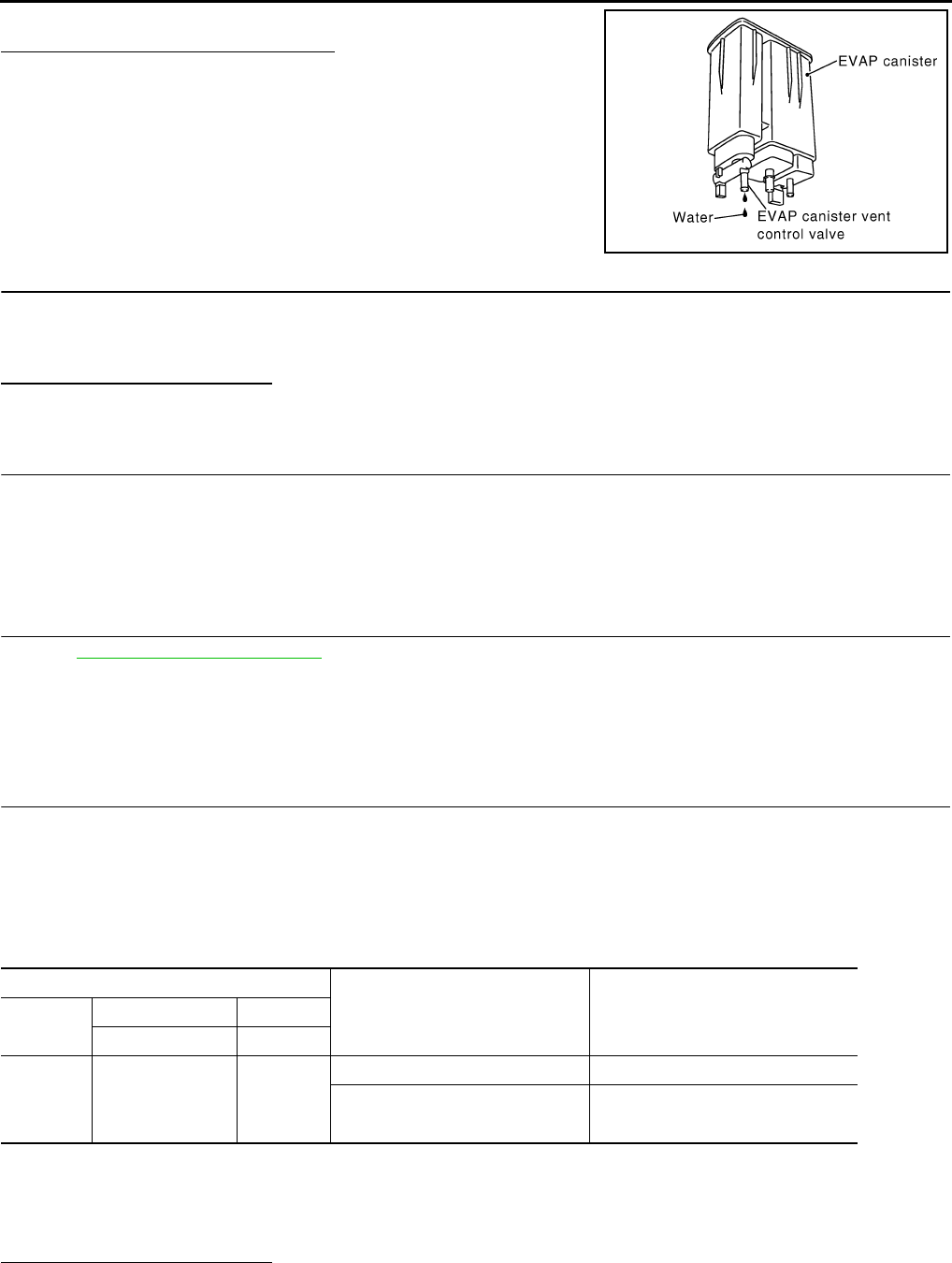
EC-754
< COMPONENT DIAGNOSIS > [FOR USA (FEDERAL) AND CANADA]
P0453 EVAP CONTROL SYSTEM PRESSURE SENSOR
2. Check if water will drain from the EVAP canister.
Does water drain from EVAP canister?
YES >> GO TO 18.
NO >> GO TO 20.
18.CHECK EVAP CANISTER
Weigh the EVAP canister with the EVAP canister vent control valve and EVAP control system pressure sensor
attached.
The weight should be less than 2.1 kg (4.6 lb).
Is the inspection result normal?
YES >> GO TO 20.
NO >> GO TO 19.
19.DETECT MALFUNCTIONING PART
Check the following.
• EVAP canister for damage
• EVAP hose between EVAP canister and vehicle frame for clogging or poor connection
>> Repair hose or replace EVAP canister.
20.CHECK INTERMITTENT INCIDENT
Refer to GI-41, "Intermittent Incident".
>> INSPECTION END
Component Inspection INFOID:0000000004529613
1.CHECK EVAP CONTROL SYSTEM PRESSURE SENSOR
1. Turn ignition switch OFF.
2. Remove EVAP control system pressure sensor with its harness connector connected from EVAP canister.
Always replace O-ring with a new one.
3. Install a vacuum pump to EVAP control system pressure sensor.
4. Turn ignition switch ON and check output voltage between ECM harness connector terminals under the
following conditions.
CAUTION:
• Always calibrate the vacuum pump gauge when using it.
• Never apply below -93.3 kPa (-0.952 kg/cm2, -13.53 psi) or pressure over 101.3 kPa (1.033 kg/cm2,
14.69 psi).
Is the inspection result normal?
YES >> INSPECTION END
NO >> Replace EVAP control system pressure sensor
PBIB1213E
ECM Condition
[Applied vacuum kPa (kg/cm2, psi)] Voltage (V)
Connector +−
Terminal Terminal
E16
86
(EVAP control
system pressure
sensor signal)
96
(Sensor
ground)
Not applied 1.8 - 4.8
-26.7 (-0.272, -3.87) 2.1 to 2.5 lower than above value
Revision: 2008 August 2009 Rogue
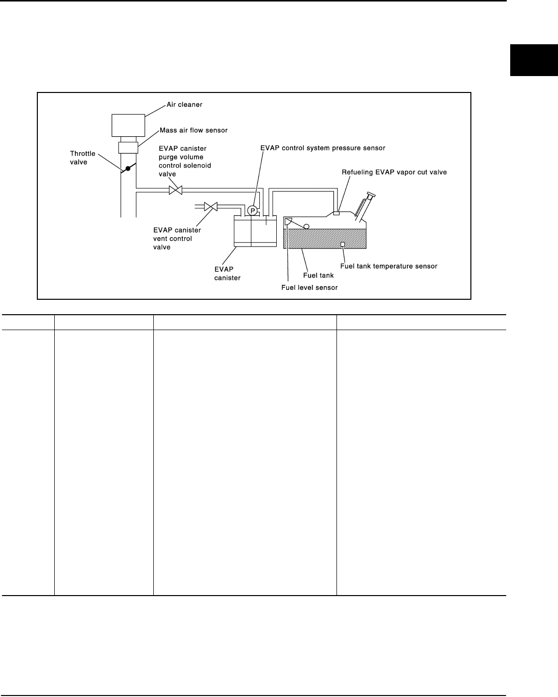
P0455 EVAP CONTROL SYSTEM
EC-755
< COMPONENT DIAGNOSIS > [FOR USA (FEDERAL) AND CANADA]
C
D
E
F
G
H
I
J
K
L
M
A
EC
N
P
O
P0455 EVAP CONTROL SYSTEM
DTC Logic INFOID:0000000004529614
DTC DETECTION LOGIC
This diagnosis detects a very large leak (fuel filler cap fell off etc.) in EVAP system between the fuel tank and
EVAP canister purge volume control solenoid valve.
CAUTION:
• Use only a genuine NISSAN fuel filler cap as a replacement. If an incorrect fuel filler cap is used, the
MIL may illuminate.
• If the fuel filler cap is not tightened properly, the MIL may illuminate.
• Use only a genuine NISSAN rubber tube as a replacement.
DTC CONFIRMATION PROCEDURE
1.PRECONDITIONING
CAUTION:
DTC No. Trouble diagnosis name DTC detecting condition Possible cause
P0455 EVAP control system
gross leak detected
EVAP control system has a very large leak such
as fuel filler cap fell off, EVAP control system
does not operate properly.
• Fuel filler cap remains open or fails to
close.
• Incorrect fuel tank vacuum relief valve
• Incorrect fuel filler cap used
• Foreign matter caught in fuel filler cap.
• Leak is in line between intake manifold
and EVAP canister purge volume control
solenoid valve.
• Foreign matter caught in EVAP canister
vent control valve.
• EVAP canister or fuel tank leaks
• EVAP purge line (pipe and rubber tube)
leaks
• EVAP purge line rubber tube bent.
• Loose or disconnected rubber tube
• EVAP canister vent control valve and the
circuit
• EVAP canister purge volume control so-
lenoid valve and the circuit
• Fuel tank temperature sensor
• O-ring of EVAP canister vent control
valve is missing or damaged.
• EVAP control system pressure sensor
• Refueling EVAP vapor cut valve
• ORVR system leaks
PBIB1026E
Revision: 2008 August 2009 Rogue

EC-756
< COMPONENT DIAGNOSIS > [FOR USA (FEDERAL) AND CANADA]
P0455 EVAP CONTROL SYSTEM
Never remove fuel filler cap during the DTC CONFIRMATION PROCEDURE.
If DTC CONFIRMATION PROCEDURE has been previously conducted, always turn ignition switch OFF and
wait at least 10 seconds before conducting the next test.
NOTE:
Check that EVAP hoses are connected to EVAP canister purge volume control solenoid valve properly.
TESTING CONDITION:
•Perform “DTC WORK SUPPORT” when the fuel level is between 1/4 and 3/4 full, and vehicle is placed
on flat level surface.
•Open engine hood before conducting the following procedures.
Do you have CONSULT-III?
YES >> GO TO 2.
NO >> GO TO 4.
2.PERFORM DTC CONFIRMATION PROCEDURE
With CONSULT-III
1. Tighten fuel filler cap securely until ratcheting sound is heard.
2. Turn ignition switch ON.
3. Turn ignition switch OFF and wait at least 10 seconds.
4. Turn ignition switch ON and select “DATA MONITOR” mode with CONSULT-III.
5. Check that the following conditions are met.
COOLAN TEMP/S: 0 - 70°C (32 - 158°F)
INT/A TEMP SE: 0 - 60°C (32 - 140°F)
6. Select “EVAP SML LEAK P0442/P1442” of “EVAPORATIVE SYSTEM” in “DTC WORK SUPPORT” mode
with CONSULT-III.
Follow the instructions displayed.
NOTE:
If the engine speed cannot be maintained within the range displayed on the CONSULT-III screen, go to
EC-499, "BASIC INSPECTION : Special Repair Requirement".
Which is displayed on CONSULT-III screen?
OK >> INSPECTION END.
NG >> GO TO 3.
3.CHECK DTC
Check DTC.
Which DTC is detected?
P0455 >> Go to EC-756, "Diagnosis Procedure".
P0442 >> Go to EC-722, "Diagnosis Procedure".
4.PERFORM DTC CONFIRMATION PROCEDURE
With GST
NOTE:
Be sure to read the explanation of DIRVING PATTERN in EC-903, "How to Set SRT Code" before driving
vehicle.
1. Start engine.
2. Drive vehicle according to DRIVING PATTERN.
3. Stop vehicle.
4. Turn ignition switch OFF, wait at least 10 seconds and then turn ON.
5. Check 1st trip DTC.
Is 1st trip DTC detected?
YES-1 >> P0455: Go to EC-756, "Diagnosis Procedure".
YES-2 >> P0442: Go to EC-722, "Diagnosis Procedure".
YES-3 >> P0441: Go to EC-718, "Diagnosis Procedure".
NO >> INSPECTION END
Diagnosis Procedure INFOID:0000000004529615
1.CHECK FUEL FILLER CAP DESIGN
1. Turn ignition switch OFF.
Revision: 2008 August 2009 Rogue

P0455 EVAP CONTROL SYSTEM
EC-757
< COMPONENT DIAGNOSIS > [FOR USA (FEDERAL) AND CANADA]
C
D
E
F
G
H
I
J
K
L
M
A
EC
N
P
O
2. Check for genuine NISSAN fuel filler cap design.
Is the inspection result normal?
YES >> GO TO 2.
NO >> Replace with genuine NISSAN fuel filler cap.
2.CHECK FUEL FILLER CAP INSTALLATION
Check that the cap is tightened properly by rotating the cap clockwise.
Is the inspection result normal?
YES >> GO TO 3.
NO >> Open fuel filler cap, then clean cap and fuel filler neck threads using air blower. Then retighten
until ratcheting sound is heard.
3.CHECK FUEL FILLER CAP FUNCTION
Check for air releasing sound while opening the fuel filler cap.
Is the inspection result normal?
YES >> GO TO 5.
NO >> GO TO 4.
4.CHECK FUEL TANK VACUUM RELIEF VALVE
Refer to EC-759, "Component Inspection".
Is the inspection result normal?
YES >> GO TO 5.
NO >> Replace fuel filler cap with a genuine one.
5.CHECK EVAP PURGE LINE
Check EVAP purge line (pipe, rubber tube, fuel tank and EVAP canister) for cracks, improper connection or
disconnection.
Refer to EC-549, "System Diagram".
Is the inspection result normal?
YES >> GO TO 6.
NO >> Repair or reconnect the hose.
6.CLEAN EVAP PURGE LINE
Clean EVAP purge line (pipe and rubber tube) using air blower.
>> GO TO 7.
7.CHECK EVAP CANISTER VENT CONTROL VALVE
Check the following.
• EVAP canister vent control valve is installed properly.
Refer to EC-926, "Exploded View".
• EVAP canister vent control valve.
Refer to EC-736, "Component Inspection".
Is the inspection result normal?
YES >> GO TO 8.
NO >> Repair or replace EVAP canister vent control valve and O-ring.
8.CHECK FOR EVAP LEAK
Refer to EC-924, "Inspection".
Is there any leak in EVAP line?
SEF915U
Revision: 2008 August 2009 Rogue

EC-758
< COMPONENT DIAGNOSIS > [FOR USA (FEDERAL) AND CANADA]
P0455 EVAP CONTROL SYSTEM
YES >> Repair or replace.
NO-1 >> With CONSULT-III: GO TO 9.
NO-2 >> Without CONSULT-III: GO TO 10.
9.CHECK EVAP CANISTER PURGE VOLUME CONTROL SOLENOID VALVE OPERATION
With CONSULT-III
1. Disconnect vacuum hose from EVAP canister purge volume control solenoid valve at EVAP service port.
2. Start engine.
3. Perform “PURG VOL CONT/V” in “ACTIVE TEST” mode.
4. Touch “Qu” on CONSULT-III screen to increase “PURG VOL C/V” opening to 100%.
5. Check vacuum hose for vacuum.
Is the inspection result normal?
YES >> GO TO 12.
NO >> GO TO 11.
10.CHECK EVAP CANISTER PURGE VOLUME CONTROL SOLENOID VALVE OPERATION
Without CONSULT-III
1. Start engine and warm it up to normal operating temperature.
2. Stop engine.
3. Disconnect vacuum hose from EVAP canister purge volume control solenoid valve at EVAP service port.
4. Start engine and let it idle for at least 80 seconds.
5. Check vacuum hose for vacuum when revving engine up to 2,000 rpm.
Is the inspection result normal?
YES >> GO TO 13.
NO >> GO TO 11.
11.CHECK VACUUM HOSE
Check vacuum hoses for clogging or disconnection. Refer to EC-549, "System Diagram".
Is the inspection result normal?
YES-1 >> With CONSULT-III: GO TO 12.
YES-2 >> Without CONSULT-III: GO TO 13.
NO >> Repair or reconnect the hose.
12.CHECK EVAP CANISTER PURGE VOLUME CONTROL SOLENOID VALVE
With CONSULT-III
1. Start engine.
2. Perform “PURG VOL CONT/V” in “ACTIVE TEST” mode with CONSULT-III. Check that engine speed var-
ies according to the valve opening.
Does engine speed vary according to the valve opening?
YES >> GO TO 14.
NO >> GO TO 13.
13.CHECK EVAP CANISTER PURGE VOLUME CONTROL SOLENOID VALVE
Refer to EC-730, "Component Inspection".
Is the inspection result normal?
YES >> GO TO 14.
NO >> Replace EVAP canister purge volume control solenoid valve.
14.CHECK FUEL TANK TEMPERATURE SENSOR
Refer to EC-689, "Component Inspection".
Is the inspection result normal?
YES >> GO TO 15.
NO >> Replace fuel level sensor unit.
Vacuum should exist.
Vacuum should exist.
Revision: 2008 August 2009 Rogue
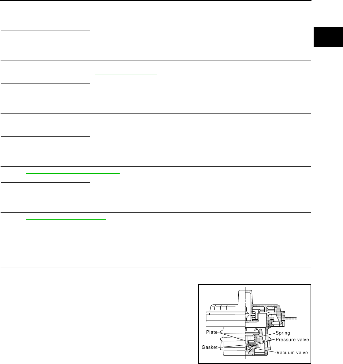
P0455 EVAP CONTROL SYSTEM
EC-759
< COMPONENT DIAGNOSIS > [FOR USA (FEDERAL) AND CANADA]
C
D
E
F
G
H
I
J
K
L
M
A
EC
N
P
O
15.CHECK EVAP CONTROL SYSTEM PRESSURE SENSOR
Refer to EC-744, "Component Inspection".
Is the inspection result normal?
YES >> GO TO 16.
NO >> Replace EVAP control system pressure sensor.
16.CHECK EVAP/ORVR LINE
Check EVAP/ORVR line between EVAP canister and fuel tank for clogging, kinks, looseness and improper
connection. For location, refer to EC-867, "Description".
Is the inspection result normal?
YES >> GO TO 17.
NO >> Repair or replace hoses and tubes.
17.CHECK RECIRCULATION LINE
Check recirculation line between filler neck tube and fuel tank for clogging, kinks, cracks, looseness and
improper connection.
Is the inspection result normal?
YES >> GO TO 18.
NO >> Repair or replace hose, tube or filler neck tube.
18.CHECK REFUELING EVAP VAPOR CUT VALVE
Refer to EC-870, "Component Inspection".
Is the inspection result normal?
YES >> GO TO 19.
NO >> Replace refueling EVAP vapor cut valve with fuel tank.
19.CHECK INTERMITTENT INCIDENT
Refer to GI-41, "Intermittent Incident".
>> INSPECTION END
Component Inspection INFOID:0000000004533865
1.CHECK FUEL FILLER CAP
1. Turn ignition switch OFF.
2. Remove fuel filler cap.
3. Wipe clean valve housing.
4. Install fuel filler cap adapter (commercial service tool) to fuel filler cap.
SEF445Y
Revision: 2008 August 2009 Rogue
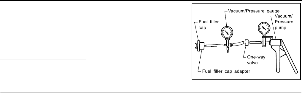
EC-760
< COMPONENT DIAGNOSIS > [FOR USA (FEDERAL) AND CANADA]
P0455 EVAP CONTROL SYSTEM
5. Check valve opening pressure and vacuum.
Is the inspection result normal?
YES >> INSPECTION END
NO >> GO TO 2.
2.REPLACE FUEL FILLER CAP
Replace fuel filler cap.
CAUTION:
Use only a genuine fuel filler cap as a replacement. If an incorrect fuel filler cap is used, the MIL may
illuminate.
>> INSPECTION END
Pressure: 15.3 - 20.0 kPa (0.156 - 0.204 kg/cm2, 2.22 -
2.90 psi)
Vacuum: −6.0 to −3.3 kPa (−0.061 to −0.034 kg/cm2,
−0.87 to −0.48 psi)
SEF943S
Revision: 2008 August 2009 Rogue
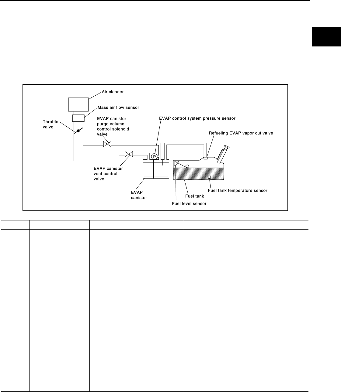
P0456 EVAP CONTROL SYSTEM
EC-761
< COMPONENT DIAGNOSIS > [FOR USA (FEDERAL) AND CANADA]
C
D
E
F
G
H
I
J
K
L
M
A
EC
N
P
O
P0456 EVAP CONTROL SYSTEM
DTC Logic INFOID:0000000004529617
DTC DETECTION LOGIC
This diagnosis detects very small leaks in the EVAP line between fuel tank and EVAP canister purge volume
control solenoid valve, using the intake manifold vacuum in the same way as conventional EVAP small leak
diagnosis.
If ECM judges a leak which corresponds to a very small leak, the very small leak P0456 will be detected.
If ECM judges a leak equivalent to a small leak, EVAP small leak P0442 will be detected.
If ECM judges that there are no leaks, the diagnosis will be OK.
CAUTION:
• Use only a genuine NISSAN fuel filler cap as a replacement. If an incorrect fuel filler cap is used, the
MIL may illuminate.
• If the fuel filler cap is not tightened properly, the MIL may illuminate.
• Use only a genuine NISSAN rubber tube as a replacement.
DTC No. Trouble diagnosis name DTC detecting condition Possible cause
P0456
Evaporative emission
control system very
small leak (negative
pressure check)
• EVAP system has a very small leak.
• EVAP system does not operate prop-
erly.
• Incorrect fuel tank vacuum relief valve
• Incorrect fuel filler cap used
• Fuel filler cap remains open or fails to close.
• Foreign matter caught in fuel filler cap.
• Leak is in line between intake manifold and EVAP
canister purge volume control solenoid valve.
• Foreign matter caught in EVAP canister vent con-
trol valve.
• EVAP canister or fuel tank leaks
• EVAP purge line (pipe and rubber tube) leaks
• EVAP purge line rubber tube bent
• Loose or disconnected rubber tube
• EVAP canister vent control valve and the circuit
• EVAP canister purge volume control solenoid
valve and the circuit
• Fuel tank temperature sensor
• O-ring of EVAP canister vent control valve is miss-
ing or damaged
• EVAP canister is saturated with water
• EVAP control system pressure sensor
• Refueling EVAP vapor cut valve
• ORVR system leaks
• Fuel level sensor and the circuit
• Foreign matter caught in EVAP canister purge vol-
ume control solenoid valve
PBIB1026E
Revision: 2008 August 2009 Rogue

EC-762
< COMPONENT DIAGNOSIS > [FOR USA (FEDERAL) AND CANADA]
P0456 EVAP CONTROL SYSTEM
DTC CONFIRMATION PROCEDURE
1.INSPECTION START
Do you have CONSULT-III?
Do you have CONSULT-III?
YES >> GO TO 2.
NO >> GO TO 4.
2.PRECONDITIONING
If DTC CONFIRMATION PROCEDURE has been previously conducted, always turn ignition switch OFF and
wait at least 10 seconds before conducting the next test.
NOTE:
•If DTC P0456 is displayed with P0442, first perform trouble diagnosis for DTC P0456.
•After repair, check that the hoses and clips are installed properly.
•Check that EVAP hoses are connected to EVAP canister purge volume control solenoid valve prop-
erly.
TESTING CONDITION:
•Open engine hood before conducting the following procedure.
•If any of following conditions are met just before the DTC CONFIRMATION PROCEDURE, leave the
vehicle for more than 1 hour.
-Fuel filler cap is removed.
-Fuel is refilled or drained.
-EVAP component part/parts is/are removed.
•Before performing the following procedure, confirm that battery voltage is more than 11V at idle.
>> GO TO 3.
3.PERFORM DTC CONFIRMATION PROCEDURE
With CONSULT-III
1. Turn ignition switch ON and select “DATA MONITOR” mode with CONSULT-III.
2. Check that the following conditions are met.
FUEL LEVEL SE: 0.25 - 1.4V
COOLAN TEMP/S: 0 - 32°C (32 - 90°F)
FUEL T/TMP SE: 0 - 35°C (32 - 95°F)
INT A/TEMP SE: More than 0°C (32°F)
If NG, turn ignition switch OFF and leave the vehicle in a cool place (soak the vehicle), or refill/drain fuel
until the output voltage the “FUEL LEVEL SE” meets within the range above and leave the vehicle for
more than 1 hour. Then start from step 1.
3. Turn ignition switch OFF and wait at least 10 seconds.
4. Turn ignition switch ON.
5. Select “EVAP V/S LEAK P0456/P1456” of “EVAPORATIVE SYSTEM” in “DTC WORK SUPPORT” mode
with CONSULT-III.
Follow the instructions displayed.
NOTE:
If the engine speed cannot be maintained within the range displayed on CONSULT-III screen, go to
EC-499, "BASIC INSPECTION : Special Repair Requirement".
Which is displayed on CONSULT-III?
OK >> INSPECTION END
NG >> Go to EC-763, "Diagnosis Procedure".
4.PERFORM COMPONENT FUNCTION CHECK
Perform Component Function Check. Refer to EC-763, "Component Function Check".
NOTE:
Use Component Function Check to check the overall function of the EVAP very small leak function. During this
check, a 1st trip DTC might not be confirmed.
Is the inspection result normal?
YES >> INSPECTION END
NO >> Go to EC-763, "Diagnosis Procedure".
Revision: 2008 August 2009 Rogue
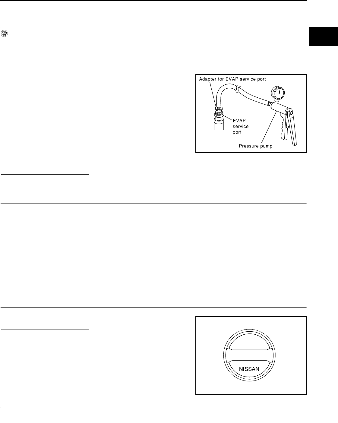
P0456 EVAP CONTROL SYSTEM
EC-763
< COMPONENT DIAGNOSIS > [FOR USA (FEDERAL) AND CANADA]
C
D
E
F
G
H
I
J
K
L
M
A
EC
N
P
O
Component Function Check INFOID:0000000004529618
1.PERFORM COMPONENT FUNCTION CHECK
With GST
CAUTION:
• Never use compressed air, doing so may damage the EVAP system.
• Never start engine.
• Never exceeded 4.12 kPa (0.042 kg/cm2, 0.6 psi).
1. Attach the EVAP service port adapter (commercial service tool) securely to the EVAP service port.
2. Set the pressure pump and a hose.
3. Also set a vacuum gauge via 3-way connector and a hose.
4. Turn ignition switch ON.
5. Connect GST and select Service $08.
6. Using Service $08 control the EVAP canister vent control valve
(close).
7. Apply pressure and check that the following conditions are satis-
fied.
Pressure to be applied: 2.7 kPa (0.028 kg/cm2, 0.39 psi)
Time to be waited after the pressure drawn in to the EVAP
system and the pressure to be dropped: 60 seconds and
the pressure should not be dropped more than 0.4 kPa
(0.004 kg/cm2, 0.06 psi).
Is the inspection result normal?
YES >> GO TO 2.
NO >> Go to EC-763, "Diagnosis Procedure".
2.RELEASE PRESSURE
1. Disconnect GST.
2. Start engine and warm it up to normal operating temperature.
3. Turn ignition switch OFF and wait at least 10 seconds.
4. Restart engine and let it idle for 90 seconds.
5. Keep engine speed at 2,000 rpm for 30 seconds.
6. Turn ignition switch OFF.
NOTE:
For more information, refer to GST Instruction Manual.
>> INSPECTION END
Diagnosis Procedure INFOID:0000000004529619
1.CHECK FUEL FILLER CAP DESIGN
1. Turn ignition switch OFF.
2. Check for genuine NISSAN fuel filler cap design.
Is the inspection result normal?
YES >> GO TO 2.
NO >> Replace with genuine NISSAN fuel filler cap.
2.CHECK FUEL FILLER CAP INSTALLATION
Check that the cap is tightened properly by rotating the cap clockwise.
Is the inspection result normal?
SEF462UI
SEF915U
Revision: 2008 August 2009 Rogue
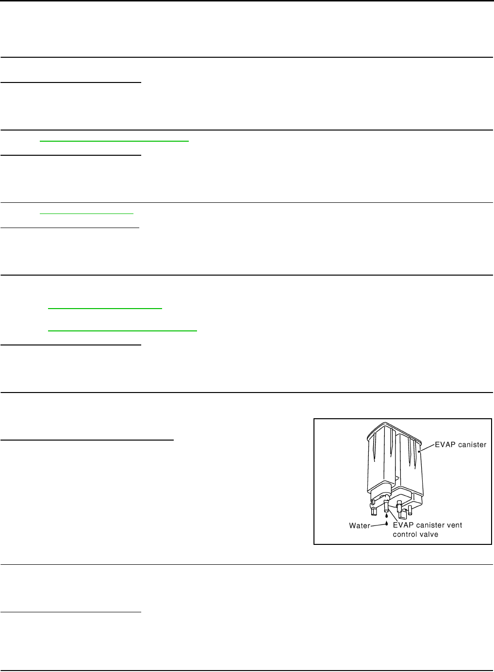
EC-764
< COMPONENT DIAGNOSIS > [FOR USA (FEDERAL) AND CANADA]
P0456 EVAP CONTROL SYSTEM
YES >> GO TO 3.
NO >> Open fuel filler cap, then clean cap and fuel filler neck threads using air blower. Then retighten
until ratcheting sound is heard.
3.CHECK FUEL FILLER CAP FUNCTION
Check for air releasing sound while opening the fuel filler cap.
Is the inspection result normal?
YES >> GO TO 5.
NO >> GO TO 4.
4.CHECK FUEL TANK VACUUM RELIEF VALVE
Refer to EC-766, "Component Inspection".
Is the inspection result normal?
YES >> GO TO 5.
NO >> Replace fuel filler cap with a genuine one.
5.CHECK FOR EVAP LEAK
Refer to EC-924, "Inspection".
Is there any leak in EVAP line?
YES >> Repair or replace.
NO >> GO TO 6.
6.CHECK EVAP CANISTER VENT CONTROL VALVE
Check the following.
• EVAP canister vent control valve is installed properly.
Refer to EC-926, "Exploded View".
• EVAP canister vent control valve.
Refer to EC-736, "Component Inspection".
Is the inspection result normal?
YES >> GO TO 7.
NO >> Repair or replace EVAP canister vent control valve and O-ring.
7.CHECK IF EVAP CANISTER IS SATURATED WITH WATER
1. Remove EVAP canister with EVAP canister vent control valve and EVAP control system pressure sensor
attached.
2. Check if water will drain from the EVAP canister.
Does water drain from EVAP canister?
YES >> GO TO 8.
NO-1 >> With CONSULT-III: GO TO 10.
NO-2 >> Without CONSULT-III: GO TO 11.
8.CHECK EVAP CANISTER
Weigh the EVAP canister with the EVAP canister vent control valve and EVAP control system pressure sensor
attached.
The weight should be less than 2.1 kg (4.6 lb).
Is the inspection result normal?
YES-1 >> With CONSULT-III: GO TO 10.
YES-2 >> Without CONSULT-III: GO TO 11.
NO >> GO TO 9.
9.DETECT MALFUNCTIONING PART
Check the following.
PBIB1213E
Revision: 2008 August 2009 Rogue

P0456 EVAP CONTROL SYSTEM
EC-765
< COMPONENT DIAGNOSIS > [FOR USA (FEDERAL) AND CANADA]
C
D
E
F
G
H
I
J
K
L
M
A
EC
N
P
O
• EVAP canister for damage
• EVAP hose between EVAP canister and vehicle frame for clogging or poor connection
>> Repair hose or replace EVAP canister.
10.CHECK EVAP CANISTER PURGE VOLUME CONTROL SOLENOID VALVE OPERATION
With CONSULT-III
1. Disconnect vacuum hose connected to EVAP service port and EVAP canister purge volume control sole-
noid valve at from EVAP service port.
2. Start engine.
3. Perform “PURG VOL CONT/V” in “ACTIVE TEST” mode.
4. Touch “Qu” on CONSULT-III screen to increase “PURG VOL C/V” opening to 100%.
5. Check vacuum hose for vacuum.
Is the inspection result normal?
YES >> GO TO 13.
NO >> GO TO 12.
11.CHECK EVAP CANISTER PURGE VOLUME CONTROL SOLENOID VALVE OPERATION
Without CONSULT-III
1. Start engine and warm it up to normal operating temperature.
2. Stop engine.
3. Disconnect vacuum hose connected to EVAP service port and EVAP canister purge volume control sole-
noid valve at from EVAP service port.
4. Start engine and let it idle for at least 80 seconds.
5. Check vacuum hose for vacuum when revving engine up to 2,000 rpm.
Is the inspection result normal?
YES >> GO TO 14.
NO >> GO TO 12.
12.CHECK VACUUM HOSE
Check vacuum hoses for clogging or disconnection. Refer to EC-549, "System Diagram".
Is the inspection result normal?
YES >> GO TO 13.
NO >> Repair or reconnect the hose.
13.CHECK EVAP CANISTER PURGE VOLUME CONTROL SOLENOID VALVE
Refer to EC-728, "Diagnosis Procedure".
Is the inspection result normal?
YES >> GO TO 14.
NO >> Replace EVAP canister purge volume control solenoid valve.
14.CHECK FUEL TANK TEMPERATURE SENSOR
Refer to EC-689, "Component Inspection".
Is the inspection result normal?
YES >> GO TO 15.
NO >> Replace fuel level sensor unit.
15.CHECK EVAP CONTROL SYSTEM PRESSURE SENSOR
Refer to EC-744, "Component Inspection".
Is the inspection result normal?
YES >> GO TO 16.
NO >> Replace EVAP control system pressure sensor.
Vacuum should exist.
Vacuum should exist.
Revision: 2008 August 2009 Rogue

EC-766
< COMPONENT DIAGNOSIS > [FOR USA (FEDERAL) AND CANADA]
P0456 EVAP CONTROL SYSTEM
16.CHECK EVAP PURGE LINE
Check EVAP purge line (pipe, rubber tube, fuel tank and EVAP canister) for cracks or improper connection.
Refer to EC-549, "System Diagram".
Is the inspection result normal?
YES >> GO TO 17.
NO >> Repair or reconnect the hose.
17.CLEAN EVAP PURGE LINE
Clean EVAP purge line (pipe and rubber tube) using air blower.
>> GO TO 18.
18.CHECK EVAP/ORVR LINE
Check EVAP/ORVR line between EVAP canister and fuel tank for clogging, kinks, looseness and improper
connection. For location, refer to EC-867, "Description".
Is the inspection result normal?
YES >> GO TO 19.
NO >> Repair or replace hoses and tubes.
19.CHECK RECIRCULATION LINE
Check recirculation line between filler neck tube and fuel tank for clogging, kinks, cracks, looseness and
improper connection.
Is the inspection result normal?
YES >> GO TO 20.
NO >> Repair or replace hose, tube or filler neck tube.
20.CHECK REFUELING EVAP VAPOR CUT VALVE
Refer to EC-870, "Component Inspection".
Is the inspection result normal?
YES >> GO TO 21.
NO >> Replace refueling EVAP vapor cut valve with fuel tank.
21.CHECK FUEL LEVEL SENSOR
Refer to MWI-43, "Component Function Check".
Is the inspection result normal?
YES >> GO TO 22.
NO >> Replace fuel level sensor unit.
22.CHECK INTERMITTENT INCIDENT
Refer to GI-41, "Intermittent Incident".
>> INSPECTION END
Component Inspection INFOID:0000000004533907
1.CHECK FUEL FILLER CAP
1. Turn ignition switch OFF.
2. Remove fuel filler cap.
Revision: 2008 August 2009 Rogue
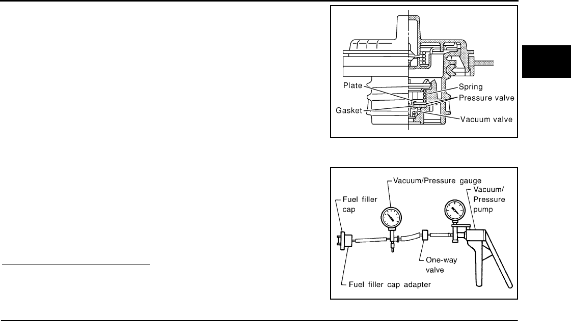
P0456 EVAP CONTROL SYSTEM
EC-767
< COMPONENT DIAGNOSIS > [FOR USA (FEDERAL) AND CANADA]
C
D
E
F
G
H
I
J
K
L
M
A
EC
N
P
O
3. Wipe clean valve housing.
4. Install fuel filler cap adapter (commercial service tool) to fuel filler cap.
5. Check valve opening pressure and vacuum.
Is the inspection result normal?
YES >> INSPECTION END
NO >> GO TO 2.
2.REPLACE FUEL FILLER CAP
Replace fuel filler cap.
CAUTION:
Use only a genuine fuel filler cap as a replacement. If an incorrect fuel filler cap is used, the MIL may
illuminate.
>> INSPECTION END
SEF445Y
Pressure: 15.3 - 20.0 kPa (0.156 - 0.204 kg/cm2, 2.22 -
2.90 psi)
Vacuum: −6.0 to −3.3 kPa (−0.061 to −0.034 kg/cm2,
−0.87 to −0.48 psi)
SEF943S
Revision: 2008 August 2009 Rogue

EC-768
< COMPONENT DIAGNOSIS > [FOR USA (FEDERAL) AND CANADA]
P0460 FUEL LEVEL SENSOR
P0460 FUEL LEVEL SENSOR
Description INFOID:0000000004529621
The fuel level sensor is mounted in the fuel level sensor unit.
The sensor detects a fuel level in the fuel tank and transmits a signal to the combination meter. The combina-
tion meter sends the fuel level sensor signal to the ECM through the CAN communication line.
It consists of two parts, one is mechanical float and the other is variable resistor. Fuel level sensor output volt-
age changes depending on the movement of the fuel mechanical float.
DTC Logic INFOID:0000000004529622
DTC DETECTION LOGIC
NOTE:
•If DTC P0460 is displayed with DTC UXXXX, first perform the trouble diagnosis for DTC UXXXX.
Refer to EC-601, "DTC Logic".
•If DTC P0460 is displayed with DTC P0607, first perform the trouble diagnosis for DTC P0607. Refer
to EC-601, "DTC Logic".
When the vehicle is parked, the fuel level in the fuel tank is naturally stable. It means that output signal of the
fuel level sensor does not change. If ECM senses sloshing signal from the sensor, fuel level sensor malfunc-
tion is detected.
DTC CONFIRMATION PROCEDURE
1.PRECONDITIONING
If DTC CONFIRMATION PROCEDURE has been previously conducted, always turn ignition switch OFF and
wait at least 10 seconds before conducting the next test.
>> GO TO 2.
2.PERFORM DTC CONFIRMATION PROCEDURE
1. Start engine and wait maximum of 2 consecutive minutes.
2. Check 1st trip DTC.
Is 1st trip DTC detected?
YES >> Go to EC-768, "Diagnosis Procedure".
NO >> INSPECTION END
Diagnosis Procedure INFOID:0000000004529623
1.CHECK COMBINATION METER FUNCTION
Refer to MWI-43, "Component Function Check".
Is the inspection result normal?
YES >> GO TO 2.
NO >> Go to MWI-43, "Diagnosis Procedure".
2.CHECK INTERMITTENT INCIDENT
Refer to GI-41, "Intermittent Incident".
>> INSPECTION END
DTC No. Trouble diagnosis name DTC detecting condition Possible cause
P0460 Fuel level sensor circuit
noise
Even though the vehicle is parked, a signal be-
ing varied is sent from the fuel level sensor to
ECM.
• Harness or connectors
(The CAN communication line is open or
shorted)
• Harness or connectors
(The sensor circuit is open or shorted)
• Combination meter
• Fuel level sensor
Revision: 2008 August 2009 Rogue

P0461 FUEL LEVEL SENSOR
EC-769
< COMPONENT DIAGNOSIS > [FOR USA (FEDERAL) AND CANADA]
C
D
E
F
G
H
I
J
K
L
M
A
EC
N
P
O
P0461 FUEL LEVEL SENSOR
Description INFOID:0000000004534058
The fuel level sensor is mounted in the fuel level sensor unit.
The sensor detects a fuel level in the fuel tank and transmits a signal to the combination meter. The combina-
tion meter sends the fuel level sensor signal to the ECM through the CAN communication line.
It consists of two parts, one is mechanical float and the other is variable resistor. Fuel level sensor output volt-
age changes depending on the movement of the fuel mechanical float.
DTC Logic INFOID:0000000004529625
DTC DETECTION LOGIC
NOTE:
•If DTC P0461 is displayed with DTC UXXXX, first perform the trouble diagnosis for DTC UXXXX.
•If DTC P0461 is displayed with DTC P0607, first perform the trouble diagnosis for DTC P0607. Refer
to EC-783, "DTC Logic".
Driving long distances naturally affect fuel gauge level.
This diagnosis detects the fuel gauge malfunction of the gauge not moving even after a long distance has
been driven.
DTC CONFIRMATION PROCEDURE
1.PERFORM COMPONENT FUNCTION CHECK
Perform Component Function Check. Refer to EC-769, "Component Function Check".
Use Component Function Check to check the overall function of the fuel level sensor. During this check, a 1st
trip DTC might not be confirmed.
Is the inspection result normal?
YES >> INSPECTION END
NO >> Go to EC-770, "Diagnosis Procedure".
Component Function Check INFOID:0000000004529626
1.PRECONDITIONING
WARNING:
When performing the following procedure, always observe the handling of the fuel. Refer to FL-7,
"2WD : Removal and Installation" (2WD), FL-11, "AWD : Removal and Installation" (AWD).
TESTING CONDITION:
Before starting component function check, preparation of draining fuel and refilling fuel is required.
Do you have CONSULT-III?
YES >> GO TO 2.
NO >> GO TO 3.
2.PERFORM COMPONENT FUNCTION CHECK
With CONSULT-III
NOTE:
Start from step 10, if it is possible to confirm that the fuel cannot be drained by 30 (7-7/8 US gal, 6-5/
8 Imp gal) in advance.
1. Prepare a fuel container and a spare hose.
DTC No. Trouble diagnosis name DTC detecting condition Possible cause
P0461 Fuel level sensor circuit
range/performance
The output signal of the fuel level sensor does
not change within the specified range even
though the vehicle has been driven a long dis-
tance.
• Harness or connectors
(The CAN communication line is open or
shorted)
• Harness or connectors
(The sensor circuit is open or shorted)
• Combination meter
• Fuel level sensor
Revision: 2008 August 2009 Rogue

EC-770
< COMPONENT DIAGNOSIS > [FOR USA (FEDERAL) AND CANADA]
P0461 FUEL LEVEL SENSOR
2. Release fuel pressure from fuel line, refer to EC-923, "Inspection".
3. Remove the fuel feed hose on the fuel level sensor unit.
4. Connect a spare fuel hose where the fuel feed hose was removed.
5. Turn ignition switch OFF and wait at least 10 seconds then turn ON.
6. Select “FUEL LEVEL SE” in “DATA MONITOR” mode with CONSULT-III.
7. Check “FUEL LEVEL SE” output voltage and note it.
8. Select “FUEL PUMP RELAY” in “ACTIVE TEST” mode with CONSULT-III.
9. Touch “ON” and drain fuel approximately 30 (7-7/8 US gal, 6-5/8 Imp gal) and stop it.
10. Check “FUEL LEVEL SE” output voltage and note it.
11. Fill fuel into the fuel tank for 30 (7-7/8 US gal, 6-5/8 Imp gal).
12. Check “FUEL LEVEL SE” output voltage and note it.
13. Confirm whether the voltage changes more than 0.03V during step 7 to 10 and 10 to 12.
Is the inspection result normal?
YES >> INSPECTION END
NO >> Go to EC-770, "Diagnosis Procedure".
3.PERFORM COMPONENT FUNCTION CHECK
Without CONSULT-III
NOTE:
Start from step 8, if it is possible to confirm that the fuel cannot be drained by 30 (7-7/8 US gal, 6-5/8
Imp gal) in advance.
1. Prepare a fuel container and a spare hose.
2. Release fuel pressure from fuel line. Refer to EC-923, "Inspection".
3. Remove the fuel feed hose on the fuel level sensor unit.
4. Connect a spare fuel hose where the fuel feed hose was removed.
5. Turn ignition switch ON.
6. Drain fuel by 30 (7-7/8 US gal, 6-5/8 Imp gal) from the fuel tank using proper equipment.
7. Confirm that the fuel gauge indication varies.
8. Fill fuel into the fuel tank for 30 (7-7/8 US gal, 6-5/8 Imp gal).
9. Confirm that the fuel gauge indication varies.
Is the inspection result normal?
YES >> INSPECTION END
NO >> Go to EC-770, "Diagnosis Procedure".
Diagnosis Procedure INFOID:0000000004534079
1.CHECK COMBINATION METER FUNCTION
Refer to MWI-43, "Component Function Check".
Is the inspection result normal?
YES >> GO TO 2.
NO >> Go to MWI-43, "Diagnosis Procedure".
2.CHECK INTERMITTENT INCIDENT
Refer to GI-41, "Intermittent Incident".
>> INSPECTION END
Revision: 2008 August 2009 Rogue

P0462, P0463 FUEL LEVEL SENSOR
EC-771
< COMPONENT DIAGNOSIS > [FOR USA (FEDERAL) AND CANADA]
C
D
E
F
G
H
I
J
K
L
M
A
EC
N
P
O
P0462, P0463 FUEL LEVEL SENSOR
Description INFOID:0000000004534061
The fuel level sensor is mounted in the fuel level sensor unit.
The sensor detects a fuel level in the fuel tank and transmits a signal to the combination meter. The combina-
tion meter sends the fuel level sensor signal to the ECM through the CAN communication line.
It consists of two parts, one is mechanical float and the other is variable resistor. Fuel level sensor output volt-
age changes depending on the movement of the fuel mechanical float.
DTC Logic INFOID:0000000004529629
DTC DETECTION LOGIC
NOTE:
•If DTC P0462 or P0463 is displayed with DTC UXXXX, first perform the trouble diagnosis for DTC
UXXXX.
•If DTC P0462 or P0463 is displayed with DTC P0607, first perform the trouble diagnosis for DTC
P0607. Refer to EC-783, "DTC Logic".
DTC CONFIRMATION PROCEDURE
1.PRECONDITIONING
If DTC CONFIRMATION PROCEDURE has been previously conducted, always turn ignition switch OFF and
wait at least 10 seconds before conducting the next test.
TESTING CONDITION:
Before performing the following procedure, confirm that battery voltage is between 11V and 16V at
ignition switch ON.
>> GO TO 2.
2.PERFORM DTC CONFIRMATION PROCEDURE
1. Turn ignition switch ON and wait at least 5 seconds.
2. Check 1st trip DTC.
Is 1st trip DTC detected?
YES >> Go to EC-771, "Diagnosis Procedure".
NO >> INSPECTION END
Diagnosis Procedure INFOID:0000000004534064
1.CHECK COMBINATION METER FUNCTION
Refer to MWI-43, "Component Function Check".
Is the inspection result normal?
YES >> GO TO 2.
NO >> Go to MWI-43, "Diagnosis Procedure".
2.CHECK INTERMITTENT INCIDENT
Refer to GI-41, "Intermittent Incident".
DTC No. Trouble diagnosis name DTC detecting condition Possible cause
P0462 Fuel level sensor circuit
low input An excessively low voltage from the sensor is
sent to ECM. • Harness or connectors
(The CAN communication line is open or
shorted)
• Harness or connectors
(The sensor circuit is open or shorted)
• Combination meter
• Fuel level sensor
P0463 Fuel level sensor circuit
high input An excessively high voltage from the sensor is
sent to ECM.
Revision: 2008 August 2009 Rogue

EC-772
< COMPONENT DIAGNOSIS > [FOR USA (FEDERAL) AND CANADA]
P0462, P0463 FUEL LEVEL SENSOR
>> INSPECTION END
Revision: 2008 August 2009 Rogue

P0500 VSS
EC-773
< COMPONENT DIAGNOSIS > [FOR USA (FEDERAL) AND CANADA]
C
D
E
F
G
H
I
J
K
L
M
A
EC
N
P
O
P0500 VSS
Description INFOID:0000000004529631
The vehicle speed signal is sent to the combination meter from the “ABS actuator and electric unit (control
unit)” by CAN communication line. The combination meter then sends a signal to the ECM by CAN communi-
cation line.
DTC Logic INFOID:0000000004529632
DTC DETECTION LOGIC
NOTE:
•If DTC P0500 is displayed with DTC UXXXX, first perform the trouble diagnosis for DTC UXXXX. .
•If DTC P0500 is displayed with DTC P0607, first perform the trouble diagnosis for DTC P0607. Refer
to EC-783, "DTC Logic".
DTC CONFIRMATION PROCEDURE
1.INSPECTION START
Do you have CONSULT-III?
Do you have CONSULT-III?
YES >> GO TO 2.
NO >> GO TO 5.
2.PRECONDITIONING
If DTC CONFIRMATION PROCEDURE has been previously conducted, always turn ignition switch OFF and
wait at least 10 seconds before conducting the next test.
>> GO TO 3.
3.CHECK VEHICLE SPEED SENSOR FUNCTION
NOTE:
This procedure may be conducted with the drive wheels lifted in the shop or by driving the vehicle. If a
road test is expected to be easier, it is unnecessary to lift the vehicle.
With CONSULT-III
1. Start engine.
2. Read “VHCL SPEED SE” in “DATA MONITOR” mode with CONSULT-III. The vehicle speed on CON-
SULT-III should exceed 10 km/h (6 mph) when rotating wheels with suitable gear position.
Is the inspection result normal?
YES >> GO TO 4.
NO >> Go to EC-774, "Diagnosis Procedure".
4.PERFORM DTC CONFIRMATION PROCEDURE
1. Select “DATA MONITOR” mode with CONSULT-III.
2. Warm engine up to normal operating temperature.
3. Maintain the following conditions for at least 50 consecutive seconds.
CAUTION:
Always drive vehicle at a safe speed.
DTC No. Trouble diagnosis name DTC detecting condition Possible cause
P0500 Vehicle speed sensor
The almost 0 km/h (0 MPH) signal from
vehicle speed sensor is sent to ECM even
when vehicle is being driven.
• Harness or connectors
(The CAN communication line is open or short-
ed)
• Harness or connectors
(The vehicle speed signal circuit is open or
shorted)
• Vehicle speed sensor
• Combination meter
• ABS actuator and electric unit (control unit)
Revision: 2008 August 2009 Rogue

EC-774
< COMPONENT DIAGNOSIS > [FOR USA (FEDERAL) AND CANADA]
P0500 VSS
4. Check 1st trip DTC.
Is 1st trip DTC detected?
YES >> Go to EC-774, "Diagnosis Procedure".
NO >> INSPECTION END
5.PERFORM COMPONENT FUNCTION CHECK
Perform Component Function Check. Refer to EC-774, "Component Function Check".
Use Component Function Check to check the overall function of the vehicle speed sensor circuit. During this
check, a 1st trip DTC might not be confirmed.
Is the inspection result normal?
YES >> INSPECTION END
NO >> Go to EC-774, "Diagnosis Procedure".
Component Function Check INFOID:0000000004529633
1.PERFORM COMPONENT FUNCTION CHECK
With GST
1. Lift up drive wheels.
2. Start engine.
3. Read vehicle speed sensor signal in Service $01 with GST.
The vehicle speed sensor on GST should be able to exceed 10 km/h (6 MPH) when rotating wheels with
suitable gear position.
Is the inspection result normal?
YES >> INSPECTION END
NO >> Go to EC-774, "Diagnosis Procedure".
Diagnosis Procedure INFOID:0000000004529634
1.CHECK DTC WITH “ABS ACTUATOR AND ELECTRIC UNIT (CONTROL UNIT)”
Refer to BRC-15, "CONSULT-III Function" (ABS models), BRC-93, "CONSULT-III Function" (VDC models).
Is the inspection result normal?
YES >> GO TO 2.
NO >> Repair or replace.
2.CHECK COMBINATION METER
Refer to MWI-33, "CONSULT-III Function (METER/M&A)".
>> INSPECTION END
ENG SPEED 1,350 - 6,000 rpm
COOLAN TEMP/S More than 70°C (158°F)
B/FUEL SCHDL 5.5 - 31.8 msec
Selector lever Except P or N position
PW/ST SIGNAL OFF
Revision: 2008 August 2009 Rogue

P0506 ISC SYSTEM
EC-775
< COMPONENT DIAGNOSIS > [FOR USA (FEDERAL) AND CANADA]
C
D
E
F
G
H
I
J
K
L
M
A
EC
N
P
O
P0506 ISC SYSTEM
Description INFOID:0000000004529635
The ECM controls the engine idle speed to a specified level through the fine adjustment of the air, which is let
into the intake manifold, by operating the electric throttle control actuator. The operating of the throttle valve is
varied to allow for optimum control of the engine idling speed. The crankshaft position sensor (POS) detects
the actual engine speed and sends a signal to the ECM.
The ECM controls the electric throttle control actuator so that the engine speed coincides with the target value
memorized in the ECM. The target engine speed is the lowest speed at which the engine can operate steadily.
The optimum value stored in the ECM is determined by taking into consideration various engine conditions,
such as during warming up, deceleration and engine load (air conditioner, power steering and cooling fan
operation, etc.).
DTC Logic INFOID:0000000004529636
DTC DETECTION LOGIC
NOTE:
If DTC P0506 is displayed with other DTC, first perform the trouble diagnosis for the other DTC.
DTC CONFIRMATION PROCEDURE
1.PRECONDITIONING
If DTC CONFIRMATION PROCEDURE has been previously conducted, always turn ignition switch OFF and
wait at least 10 seconds before conducting the next test.
If the target idle speed is out of the specified value, perform EC-505, "IDLE AIR VOLUME LEARNING :
Special Repair Requirement", before conducting DTC CONFIRMATION PROCEDURE.
TESTING CONDITION:
•Before performing the following procedure, confirm that battery voltage is more than 11V at idle.
•Always perform the test at a temperature above −10°C (14°F).
>> GO TO 2.
2.PERFORM DTC CONFIRMATION PROCEDURE
1. Start engine and warm it up to normal operating temperature.
2. Turn ignition switch OFF and wait at least 10 seconds.
3. Start engine and run it for at least 1 minute at idle speed.
4. Check 1st trip DTC.
Is 1st trip DTC detected?
YES >> Go to EC-775, "Diagnosis Procedure".
NO >> INSPECTION END
Diagnosis Procedure INFOID:0000000004529637
1.CHECK INTAKE AIR LEAK
1. Start engine and let it idle.
2. Listen for an intake air leak after the mass air flow sensor.
Is intake air leak detected?
YES >> Discover air leak location and repair.
NO >> GO TO 2.
2.REPLACE ECM
1. Stop engine.
2. Replace ECM.
DTC No. Trouble diagnosis name DTC detecting condition Possible cause
P0506 Idle speed control system
RPM lower than expected The idle speed is less than the target idle
speed by 100 rpm or more. • Electric throttle control actuator
• Intake air leak
Revision: 2008 August 2009 Rogue

EC-776
< COMPONENT DIAGNOSIS > [FOR USA (FEDERAL) AND CANADA]
P0506 ISC SYSTEM
NOTE:
Use the specified bolts described in parts information certainly when installing the ECM, or violates the
Canada law.
3. Go to EC-502, "ADDITIONAL SERVICE WHEN REPLACING CONTROL UNIT : Special Repair Require-
ment".
>> INSPECTION END
Revision: 2008 August 2009 Rogue

P0507 ISC SYSTEM
EC-777
< COMPONENT DIAGNOSIS > [FOR USA (FEDERAL) AND CANADA]
C
D
E
F
G
H
I
J
K
L
M
A
EC
N
P
O
P0507 ISC SYSTEM
Description INFOID:0000000004534080
The ECM controls the engine idle speed to a specified level through the fine adjustment of the air, which is let
into the intake manifold, by operating the electric throttle control actuator. The operating of the throttle valve is
varied to allow for optimum control of the engine idling speed. The crankshaft position sensor (POS) detects
the actual engine speed and sends a signal to the ECM.
The ECM controls the electric throttle control actuator so that the engine speed coincides with the target value
memorized in the ECM. The target engine speed is the lowest speed at which the engine can operate steadily.
The optimum value stored in the ECM is determined by taking into consideration various engine conditions,
such as during warming up, deceleration and engine load (air conditioner, power steering and cooling fan
operation, etc.).
DTC Logic INFOID:0000000004529639
DTC DETECTION LOGIC
NOTE:
If DTC P0507 is displayed with other DTC, first perform the trouble diagnosis for the other DTC.
DTC CONFIRMATION PROCEDURE
1.PRECONDITIONING
If DTC CONFIRMATION PROCEDURE has been previously conducted, always turn ignition switch OFF and
wait at least 10 seconds before conducting the next test.
If the target idle speed is out of the specified value, perform EC-505, "IDLE AIR VOLUME LEARNING :
Special Repair Requirement", before conducting DTC CONFIRMATION PROCEDURE.
TESTING CONDITION:
•Before performing the following procedure, confirm that battery voltage is more than 11V at idle.
•Always perform the test at a temperature above −10°C (14°F).
>> GO TO 2.
2.PERFORM DTC CONFIRMATION PROCEDURE
1. Start engine and warm it up to normal operating temperature.
2. Turn ignition switch OFF and wait at least 10 seconds.
3. Start engine and run it for at least 1 minute at idle speed.
4. Check 1st trip DTC.
Is 1st trip DTC detected?
YES >> Go to EC-777, "Diagnosis Procedure".
NO >> INSPECTION END
Diagnosis Procedure INFOID:0000000004529640
1.CHECK PCV HOSE CONNECTION
Confirm that PCV hose is connected correctly.
Is the inspection result normal?
YES >> GO TO 2.
NO >> Repair or replace.
2.CHECK INTAKE AIR LEAK
1. Start engine and let it idle.
2. Listen for an intake air leak after the mass air flow sensor.
DTC No. Trouble diagnosis name DTC detecting condition Possible cause
P0507 Idle speed control sys-
tem RPM higher than
expected
The idle speed is more than the target idle
speed by 200 rpm or more.
• Electric throttle control actuator
• Intake air leak
• PCV system
Revision: 2008 August 2009 Rogue

EC-778
< COMPONENT DIAGNOSIS > [FOR USA (FEDERAL) AND CANADA]
P0507 ISC SYSTEM
Is intake air leak detected?
YES >> Discover air leak location and repair.
NO >> GO TO 3.
3.REPLACE ECM
1. Stop engine.
2. Replace ECM.
NOTE:
Use the specified bolts described in parts information certainly when installing the ECM, or violates the
Canada law.
3. Go to EC-502, "ADDITIONAL SERVICE WHEN REPLACING CONTROL UNIT : Special Repair Require-
ment".
>> INSPECTION END
Revision: 2008 August 2009 Rogue
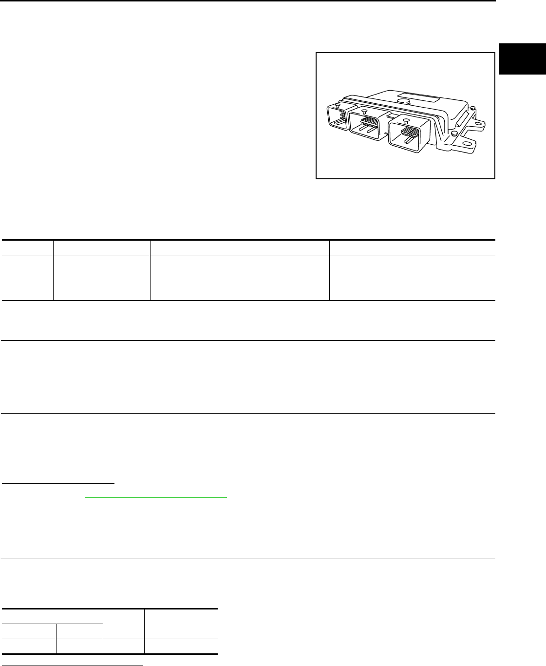
P0603 ECM POWER SUPPLY
EC-779
< COMPONENT DIAGNOSIS > [FOR USA (FEDERAL) AND CANADA]
C
D
E
F
G
H
I
J
K
L
M
A
EC
N
P
O
P0603 ECM POWER SUPPLY
Description INFOID:0000000004529641
Battery voltage is supplied to the ECM even when the ignition switch
is turned OFF for the ECM memory function of the DTC memory, the
air-fuel ratio feedback compensation value memory, the idle air vol-
ume learning value memory, etc.
DTC Logic INFOID:0000000004529642
DTC DETECTION LOGIC
DTC CONFIRMATION PROCEDURE
1.PRECONDITIONING
If DTC CONFIRMATION PROCEDURE has been previously conducted, always turn ignition switch OFF and
wait at least 10 seconds before conducting the next test.
>> GO TO 2.
2.PERFORM DTC CONFIRMATION PROCEDURE
1. Turn ignition switch ON and wait at least 1 second.
2. Start engine and let it idle for 1 second.
3. Turn ignition switch OFF, wait at least 10 seconds, and then turn it ON.
4. Repeat steps 2 and 3 for four times.
5. Check 1st trip DTC.
Is 1st trip DTC detected?
YES >> Go to EC-779, "Diagnosis Procedure".
NO >> INSPECTION END
Diagnosis Procedure INFOID:0000000004529643
1.CHECK ECM POWER SUPPLY
1. Turn ignition switch OFF.
2. Disconnect ECM harness connector.
3. Check the voltage between ECM harness connector and ground.
Is the inspection result normal?
YES >> GO TO 3.
NO >> GO TO 2.
PBIA9222J
DTC No. Trouble diagnosis name DTC detecting condition Possible cause
P0603 ECM power supply cir-
cuit
ECM back-up RAM system does not function
properly.
• Harness or connectors
[ECM power supply (back-up) circuit is
open or shorted.]
•ECM
ECM Ground Voltage
Connector Terminal
F8 77 Ground Battery voltage
Revision: 2008 August 2009 Rogue

EC-780
< COMPONENT DIAGNOSIS > [FOR USA (FEDERAL) AND CANADA]
P0603 ECM POWER SUPPLY
2.DETECT MALFUNCTIONING PART
Check the following.
• Harness connectors E8, F122
• 20A fuse (No. 62)
• IPDM E/R harness connector E15
• Harness for open or short between ECM and battery
>> Repair or replace harness or connectors.
3.CHECK INTERMITTENT INCIDENT
Refer to GI-41, "Intermittent Incident".
Is the inspection result normal?
YES >> GO TO 4.
NO >> Repair or replace harness or connectors.
4.PERFORM DTC CONFIRMATION PROCEDURE
1. Erase DTC.
2. Perform DTC CONFIRMATION PROCEDURE.
See EC-779, "DTC Logic".
Is the 1st trip DTC P0603 displayed again?
YES >> GO TO 5.
NO >> INSPECTION END
5.REPLACE ECM
1. Replace ECM.
NOTE:
Use the specified bolts described in parts information certainly when installing the ECM, or violates the
Canada law.
2. Go to EC-502, "ADDITIONAL SERVICE WHEN REPLACING CONTROL UNIT : Special Repair Require-
ment".
>> INSPECTION END
Revision: 2008 August 2009 Rogue

P0605 ECM
EC-781
< COMPONENT DIAGNOSIS > [FOR USA (FEDERAL) AND CANADA]
C
D
E
F
G
H
I
J
K
L
M
A
EC
N
P
O
P0605 ECM
Description INFOID:0000000004529644
The ECM consists of a microcomputer and connectors for signal
input and output and for power supply. The ECM controls the engine.
DTC Logic INFOID:0000000004529645
DTC DETECTION LOGIC
DTC CONFIRMATION PROCEDURE
1.PRECONDITIONING
If DTC CONFIRMATION PROCEDURE has been previously conducted, always turn ignition switch OFF and
wait at least 10 seconds before conducting the next test.
>> GO TO 2.
2.PERFORM DTC CONFIRMATION PROCEDURE FOR MALFUNCTION A
1. Turn ignition switch ON.
2. Check 1st trip DTC.
Is 1st trip DTC detected?
YES >> Go to EC-782, "Diagnosis Procedure".
NO >> GO TO 3.
3.PERFORM DTC CONFIRMATION PROCEDURE FOR MALFUNCTION B
1. wait at least 1 second.
2. Turn ignition switch OFF, wait at least 10 seconds, and then turn it ON.
3. Check 1st trip DTC.
Is 1st trip DTC detected?
YES >> Go to EC-782, "Diagnosis Procedure".
NO >> GO TO 4.
4.PERFORM DTC CONFIRMATION PROCEDURE FOR MALFUNCTION C
1. wait at least 1 second.
2. Turn ignition switch OFF, wait at least 10 seconds, and then turn it ON.
3. Repeat step 2 for 32 times.
4. Check 1st trip DTC.
Is 1st trip DTC detected?
YES >> Go to EC-782, "Diagnosis Procedure".
NO >> INSPECTION END
PBIA9222J
DTC No. Trouble diagnosis name DTC detecting condition Possible cause
P0605 Engine control module
A) ECM calculation function is malfunctioning.
•ECMB) ECM EEP-ROM system is malfunctioning.
C) ECM self shut-off function is malfunctioning.
Revision: 2008 August 2009 Rogue

EC-782
< COMPONENT DIAGNOSIS > [FOR USA (FEDERAL) AND CANADA]
P0605 ECM
Diagnosis Procedure INFOID:0000000004529646
1.INSPECTION START
1. Erase DTC.
2. Perform DTC CONFIRMATION PROCEDURE.
See EC-781, "DTC Logic".
Is the 1st trip DTC P0605 displayed again?
YES >> GO TO 2.
NO >> INSPECTION END
2.REPLACE ECM
1. Replace ECM.
NOTE:
Use the specified bolts described in parts information certainly when installing the ECM, or violates the
Canada law.
2. Go to EC-502, "ADDITIONAL SERVICE WHEN REPLACING CONTROL UNIT : Special Repair Require-
ment".
>> INSPECTION END
Revision: 2008 August 2009 Rogue

P0607 ECM
EC-783
< COMPONENT DIAGNOSIS > [FOR USA (FEDERAL) AND CANADA]
C
D
E
F
G
H
I
J
K
L
M
A
EC
N
P
O
P0607 ECM
Description INFOID:0000000004529647
CAN (Controller Area Network) is a serial communication line for real time application. It is an on-vehicle mul-
tiplex communication line with high data communication speed and excellent error detection ability. Many elec-
tronic control units are equipped onto a vehicle, and each control unit shares information and links with other
control units during operation (not independent). In CAN communication, control units are connected with 2
communication lines (CAN H line, CAN L line) allowing a high rate of information transmission with less wiring.
Each control unit transmits/receives data but selectively reads required data only.
DTC Logic INFOID:0000000004529648
DTC DETECTION LOGIC
DTC CONFIRMATION PROCEDURE
1.PRECONDITIONING
If DTC CONFIRMATION PROCEDURE has been previously conducted, always turn ignition switch OFF and
wait at least 10 seconds before conducting the next test.
>> GO TO 2.
2.PERFORM DTC CONFIRMATION PROCEDURE
1. Turn ignition switch ON.
2. Check DTC.
Is DTC detected?
YES >> Go to EC-783, "Diagnosis Procedure".
NO >> INSPECTION END
Diagnosis Procedure INFOID:0000000004529649
1.INSPECTION START
1. Erase DTC.
2. Perform DTC CONFIRMATION PROCEDURE.
See EC-783, "DTC Logic".
Is the DTC P0607 displayed again?
YES >> GO TO 2.
NO >> INSPECTION END
2.REPLACE ECM
1. Replace ECM.
NOTE:
Use the specified bolts described in parts information certainly when installing the ECM, or violates the
Canada law.
2. Go to EC-502, "ADDITIONAL SERVICE WHEN REPLACING CONTROL UNIT : Special Repair Require-
ment".
>> INSPECTION END
DTC No. Trouble diagnosis name DTC detecting condition Possible cause
P0607 CAN communication bus When detecting error during the initial diagno-
sis of CAN controller of ECM. •ECM
Revision: 2008 August 2009 Rogue

EC-784
< COMPONENT DIAGNOSIS > [FOR USA (FEDERAL) AND CANADA]
P0643 SENSOR POWER SUPPLY
P0643 SENSOR POWER SUPPLY
DTC Logic INFOID:0000000004529650
DTC DETECTION LOGIC
DTC CONFIRMATION PROCEDURE
1.PRECONDITIONING
If DTC CONFIRMATION PROCEDURE has been previously conducted, always turn ignition switch OFF and
wait at least 10 seconds before conducting the next test.
TESTING CONDITION:
Before performing the following procedure, confirm that battery voltage is more than 8V at idle.
>> GO TO 2.
2.PERFORM DTC CONFIRMATION PROCEDURE
1. Start engine and let it idle for 1 second.
2. Check DTC.
Is DTC detected?
YES >> Go to EC-784, "Diagnosis Procedure".
NO >> INSPECTION END
Diagnosis Procedure INFOID:0000000004529651
1.CHECK GROUND CONNECTION
1. Turn ignition switch OFF.
2. Check ground connection E21. Refer to Ground Inspection in GI-44, "Circuit Inspection".
Is the inspection result normal?
YES >> GO TO 2.
NO >> Repair or replace ground connection.
2.CHECK ACCELERATOR PEDAL POSITION SENSOR 1 POWER SUPPLY CIRCUIT
1. Disconnect accelerator pedal position (APP) sensor harness connector.
2. Turn ignition switch ON.
3. Check the voltage between APP sensor harness connector and ground.
Is the inspection result normal?
YES >> GO TO 7.
NO >> GO TO 3.
3.CHECK SENSOR POWER SUPPLY CIRCUIT
Check harness for short to power and short to ground, between the following terminals.
DTC No. Trouble diagnosis
name DTC detecting condition Possible cause
P0643 Sensor power supply
circuit short
ECM detects that the voltage of power
source for sensor is excessively low or high.
• Harness or connectors
(APP sensor 1 circuit is shorted.)
(TP sensor circuit is shorted.)
[Camshaft position sensor (PHASE) circuit is
shorted.]
• Accelerator pedal position sensor
• Throttle position sensor
• Camshaft position sensor (PHASE)
APP sensor Ground Voltage
Connector Terminal
E110 4 Ground Approx. 5 V
Revision: 2008 August 2009 Rogue
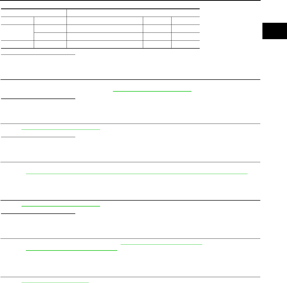
P0643 SENSOR POWER SUPPLY
EC-785
< COMPONENT DIAGNOSIS > [FOR USA (FEDERAL) AND CANADA]
C
D
E
F
G
H
I
J
K
L
M
A
EC
N
P
O
Is the inspection result normal?
YES >> GO TO 4.
NO >> Repair short to ground or short to power in harness or connectors.
4.CHECK COMPONENT
Check the following.
• Camshaft position sensor (PHASE) (Refer to EC-709, "Component Inspection".)
Is the inspection result normal?
YES >> GO TO 5.
NO >> Replace malfunctioning component.
5.CHECK TP SENSOR
Refer to EC-637, "Component Inspection".
Is the inspection result normal?
YES >> GO TO 9.
NO >> GO TO 6.
6.REPLACE ELECTRIC THROTTLE CONTROL ACTUATOR
1. Replace electric throttle control actuator.
2. Go to EC-504, "THROTTLE VALVE CLOSED POSITION LEARNING : Special Repair Requirement".
>> INSPECTION END
7.CHECK APP SENSOR
Refer to EC-839, "Component Inspection".
Is the inspection result normal?
YES >> GO TO 9.
NO >> GO TO 8.
8.REPLACE ACCELERATOR PEDAL ASSEMBLY
1. Replace accelerator pedal assembly. Refer to ACC-3, "Removal and Installation".
2. Go to EC-839, "Special Repair Requirement".
>> INSPECTION END
9.CHECK INTERMITTENT INCIDENT
Refer to GI-41, "Intermittent Incident".
>> INSPECTION END
ECM Sensor
Connector Terminal Name Connector Terminal
F8 47 Electric throttle control actuator F29 1
59 CMP sensor (PHASE) F26 1
E16 83 APP sensor E110 4
Revision: 2008 August 2009 Rogue
EC-786
< COMPONENT DIAGNOSIS > [FOR USA (FEDERAL) AND CANADA]
P0850 PNP SWITCH
P0850 PNP SWITCH
Description INFOID:0000000004529652
When the selector lever position is P or N, park/neutral position (PNP) switch is ON.
ECM detects the position because the continuity of the line (the ON signal) exists.
DTC Logic INFOID:0000000004529653
DTC DETECTION LOGIC
DTC CONFIRMATION PROCEDURE
1.INSPECTION START
Do you have CONSULT-III?
Do you have CONSULT-III?
YES >> GO TO 2.
NO >> GO TO 5.
2.PRECONDITIONING
If DTC CONFIRMATION PROCEDURE has been previously conducted, always turn ignition switch OFF and
wait at least 10 seconds before conducting the next test.
>> GO TO 3.
3.CHECK PNP SWITCH FUNCTION
With CONSULT-III
1. Turn ignition switch ON.
2. Select “P/N POSI SW” in “DATA MONITOR” mode with CONSULT-III. Then check the “P/N POSI SW” sig-
nal under the following conditions.
Is the inspection result normal?
YES >> GO TO 4.
NO >> Go to EC-787, "Diagnosis Procedure".
4.PERFORM DTC CONFIRMATION PROCEDURE
1. Select “DATA MONITOR” mode with CONSULT-III.
2. Start engine and warm it up to normal operating temperature.
3. Maintain the following conditions for at least 50 consecutive seconds.
CAUTION:
Always drive vehicle at a safe speed.
DTC No. Trouble diagnosis name DTC detecting condition Possible cause
P0850 Park/neutral position
switch
The signal of the park/neutral position (PNP)
signal does not change during driving after the
engine is started.
• Harness or connectors
[The park/neutral position (PNP) switch
circuit is open or shorted.]
• Park/neutral position (PNP) switch
Position (Selector lever) Known-good signal
N or P position ON
Except above position OFF
ENG SPEED 1,300 - 6,375 rpm
COOLAN TEMP/S More than 70°C (158°F)
B/FUEL SCHDL 3.0 - 31.8 msec
Revision: 2008 August 2009 Rogue

P0850 PNP SWITCH
EC-787
< COMPONENT DIAGNOSIS > [FOR USA (FEDERAL) AND CANADA]
C
D
E
F
G
H
I
J
K
L
M
A
EC
N
P
O
4. Check 1st trip DTC.
Is 1st trip DTC detected?
YES >> Go to EC-787, "Diagnosis Procedure".
NO >> INSPECTION END
5.PERFORM COMPONENT FUNCTION CHECK
Perform Component Function Check. Refer to EC-787, "Component Function Check".
NOTE:
Use Component Function Check to check the overall function of the park/neutral position (PNP) switch circuit.
During this check, a 1st trip DTC might not be confirmed.
Is the inspection result normal?
YES >> INSPECTION END
NO >> Go to EC-787, "Diagnosis Procedure".
Component Function Check INFOID:0000000004529654
1.PERFORM COMPONENT FUNCTION CHECK
1. Turn ignition switch ON.
2. Check the voltage between ECM harness connector and ground.
Is the inspection result normal?
YES >> INSPECTION END
NO >> Go to EC-787, "Diagnosis Procedure".
Diagnosis Procedure INFOID:0000000004529655
1.CHECK PNP SWITCH POWER SUPPLY CIRCUIT
1. Turn ignition switch OFF.
2. Disconnect Park/neutral position (PNP) switch harness connector.
3. Turn ignition switch ON.
4. Check the voltage between PNP switch harness connector and ground.
Is the inspection result normal?
YES >> GO TO 3.
NO >> GO TO 2.
2.DETECT MALFUNCTIONING PART
Check the following.
• Harness connectors E6, F123
• IPDM E/R harness connector E15
• 10A fuse (No. 58)
• Harness for open or short between PNP switch and IPDM E/R
>> Repair open circuit or short to ground or short to power in harness or connectors.
VHCL SPEED SE More than 64 km/h (40 mph)
Selector lever Suitable position
ECM Ground Condition Voltage (V)
Connector Terminal
E16 102
(PNP switch signal) Ground Selector lever P or N BATTERY VOLTAGE
Except above Approx. 0
PNP switch Ground Voltage
Connector Terminal
F21 1 Ground Battery voltage
Revision: 2008 August 2009 Rogue

EC-788
< COMPONENT DIAGNOSIS > [FOR USA (FEDERAL) AND CANADA]
P0850 PNP SWITCH
3.CHECK PNP SWITCH INPUT SIGNAL CIRCUIT FOR OPEN AND SHORT-I
1. Turn ignition switch OFF.
2. Disconnect ECM harness connector.
3. Check the continuity between PNP switch harness connector and ECM harness connector.
4. Also check harness for short to ground and short to power.
Is the inspection result normal?
YES >> GO TO 5.
NO >> GO TO 4.
4.DETECT MALFUNCTIONING PART
Check the following.
• Harness for open or short between PNP switch and ECM
>> Repair open circuit or short to ground or short to power in harness or connectors.
5.CHECK PNP SWITCH
Refer to TM-54, "Component Inspection (Park/Neutral Position Switch)".
Is the inspection result normal?
YES >> GO TO 6.
NO >> Replace PNP switch.
6.CHECK INTERMITTENT INCIDENT
Refer to GI-41, "Intermittent Incident".
>> INSPECTION END
PNP switch ECM Continuity
Connector Terminal Connector Terminal
F21 2 E16 102 Existed
Revision: 2008 August 2009 Rogue

P1148 CLOSED LOOP CONTROL
EC-789
< COMPONENT DIAGNOSIS > [FOR USA (FEDERAL) AND CANADA]
C
D
E
F
G
H
I
J
K
L
M
A
EC
N
P
O
P1148 CLOSED LOOP CONTROL
DTC Logic INFOID:0000000004529656
DTC DETECTION LOGIC
NOTE:
DTC P1148 is displayed with another DTC for A/F sensor 1.
Perform the trouble diagnosis for the corresponding DTC.
DTC No. Trouble diagnosis name DTC detecting condition Possible cause
P1148 Closed loop control
function
The closed loop control function for bank 1 does
not operate even when vehicle is being driven
in the specified condition.
• Harness or connectors
(The A/F sensor 1 circuit is open or short-
ed.)
• A/F sensor 1
• A/F sensor 1 heater
The closed loop control function for bank 2 does
not operate even when vehicle is driving in the
specified condition.
Revision: 2008 August 2009 Rogue

EC-790
< COMPONENT DIAGNOSIS > [FOR USA (FEDERAL) AND CANADA]
P1212 TCS COMMUNICATION LINE
P1212 TCS COMMUNICATION LINE
Description INFOID:0000000004529657
This CAN communication line is used to control the smooth engine operation during the TCS operation. Pulse
signals are exchanged between ECM and “ABS actuator and electric unit (control unit)”.
DTC Logic INFOID:0000000004529658
DTC DETECTION LOGIC
NOTE:
•If DTC P1212 is displayed with DTC UXXXX, first perform the trouble diagnosis for DTC UXXXX.
•If DTC P1212 is displayed with DTC P0607, first perform the trouble diagnosis for DTC P0607. Refer
to EC-783, "DTC Logic".
•Be sure to erase the malfunction information such as DTC not only for “ABS actuator and electric
unit (control unit)” but also for ECM after TCS related repair.
Freeze frame data is not stored in the ECM for this self-diagnosis.
DTC CONFIRMATION PROCEDURE
1.PRECONDITIONING
TESTING CONDITION:
Before performing the following procedure, confirm that battery voltage is more than 10.5V at idle.
>> GO TO 2.
2.PERFORM DTC CONFIRMATION PROCEDURE
1. Start engine and let it idle for at least 10 seconds.
2. Check 1st trip DTC.
Is 1st trip DTC detected?
YES >> Go to EC-790, "Diagnosis Procedure".
NO >> INSPECTION END
Diagnosis Procedure INFOID:0000000004529659
Go to BRC-71, "Work Flow".
DTC No. Trouble diagnosis name DTC detecting condition Possible cause
P1212 TCS communication line
ECM cannot receive the information from
“ABS actuator and electric unit (control
unit)” continuously.
• Harness or connectors
(The CAN communication line is open or short-
ed.)
• ABS actuator and electric unit (control unit)
• Dead (Weak) battery
Revision: 2008 August 2009 Rogue

P1217 ENGINE OVER TEMPERATURE
EC-791
< COMPONENT DIAGNOSIS > [FOR USA (FEDERAL) AND CANADA]
C
D
E
F
G
H
I
J
K
L
M
A
EC
N
P
O
P1217 ENGINE OVER TEMPERATURE
DTC Logic INFOID:0000000004529660
DTC DETECTION LOGIC
NOTE:
•If DTC P1217 is displayed with DTC UXXXX, first perform the trouble diagnosis for DTC UXXXX.
•If DTC P1217 is displayed with DTC P0607, first perform the trouble diagnosis for DTC P0607. Refer
to EC-783, "DTC Logic".
If the cooling fan or another component in the cooling system malfunctions, engine coolant temperature will
rise.
When the engine coolant temperature reaches an abnormally high temperature condition, a malfunction is
indicated.
CAUTION:
When a malfunction is indicated, always replace the coolant. Refer to CO-9, "Draining" and CO-10,
"Refilling". Also, replace the engine oil. Refer to LU-6, "Draining" and LU-7, "Refilling".
1. Fill radiator with coolant up to specified level with a filling speed of 2 liters per minute. Always use
coolant with the proper mixture ratio. Refer to MA-18, "FOR NORTH AMERICA : Anti-Freeze Cool-
ant Mixture Ratio".
2. After refilling coolant, run engine to ensure that no water-flow noise is emitted.
DTC CONFIRMATION PROCEDURE
1.PERFORM COMPONENT FUNCTION CHECK
Perform Component Function Check. Refer to EC-791, "Component Function Check".
NOTE:
Use Component Function Check to check the overall function of the cooling fan. During this check, a DTC
might not be confirmed.
Is the inspection result normal?
YES >> INSPECTION END
NO >> Go to EC-792, "Diagnosis Procedure".
Component Function Check INFOID:0000000004529661
1.PERFORM COMPONENT FUNCTION CHECK-I
WARNING:
Never remove the radiator cap when the engine is hot. Serious burns could be caused by high pres-
sure fluid escaping from the radiator.
Wrap a thick cloth around cap. Carefully remove the cap by turning it a quarter turn to allow built-up
pressure to escape. Then turn the cap all the way off.
DTC No. Trouble diagnosis name DTC detecting condition Possible cause
P1217 Engine over tempera-
ture (Overheat)
• Cooling fan does not operate properly (Over-
heat).
• Cooling fan system does not operate proper-
ly (Overheat).
• Engine coolant was not added to the system
using the proper filling method.
• Engine coolant is not within the specified
range.
• Harness or connectors
(The cooling fan circuit is open or short-
ed.)
• IPDM E/R (Cooling fan relay-1)
• Cooling fan relays-2 and -3
• Cooling fan motor
• Radiator hose
•Radiator
•Radiator cap
• Reservoir tank
• Water pump
•Thermostat
• Water control valve
Revision: 2008 August 2009 Rogue
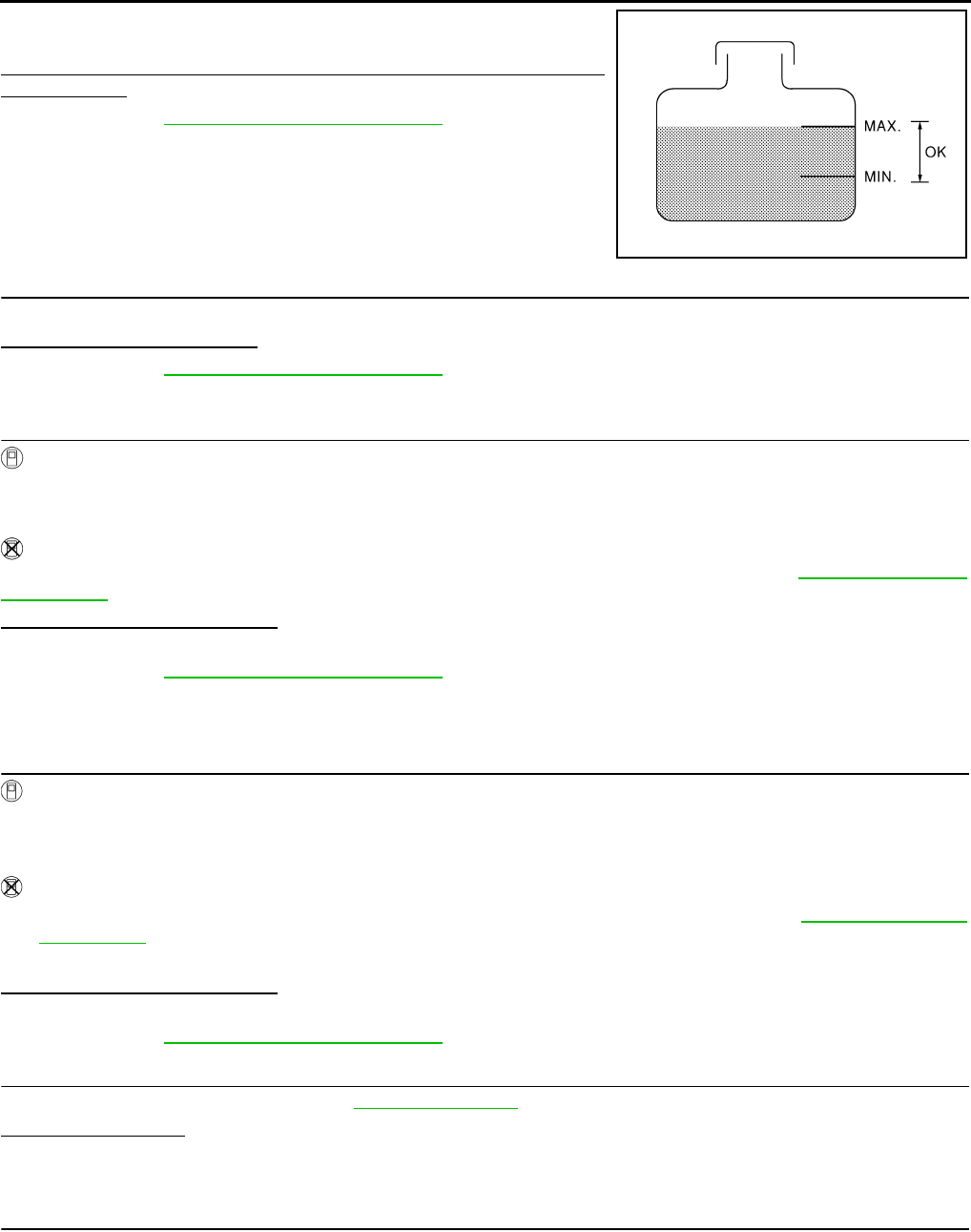
EC-792
< COMPONENT DIAGNOSIS > [FOR USA (FEDERAL) AND CANADA]
P1217 ENGINE OVER TEMPERATURE
Check the coolant level in the reservoir tank and radiator.
Allow engine to cool before checking coolant level.
Is the coolant level in the reservoir tank and/or radiator below the
proper range?
YES >> Go to EC-792, "Diagnosis Procedure".
NO >> GO TO 2.
2.PERFORM COMPONENT FUNCTION CHECK-II
Confirm whether customer filled the coolant or not.
Did customer fill the coolant?
YES >> Go to EC-792, "Diagnosis Procedure".
NO >> GO TO 3.
3.PERFORM COMPONENT FUNCTION CHECK-III
With CONSULT-III
1. Turn ignition switch ON.
2. Perform “COOLING FAN” in “ACTIVE TEST” mode with CONSULT-III.
3. Check that cooling fan motors-1 and -2 operate at each speed (LOW/HI).
Without CONSULT-III
Perform IPDM E/R auto active test and check cooling fan motors operation, refer to PCS-8, "Diagnosis
Description".
Is the inspection result normal?
YES >> INSPECTION END
NO >> Go to EC-792, "Diagnosis Procedure".
Diagnosis Procedure INFOID:0000000004529662
1.CHECK COOLING FAN OPERATION
With CONSULT-III
1. Turn ignition switch ON.
2. Perform “COOLING FAN” in “ACTIVE TEST” mode with CONSULT-III.
3. Check that cooling fan motors-1 and -2 operate at each speed (LOW/HI).
Without CONSULT-III
1. Perform IPDM E/R auto active test and check cooling fan motors operation, refer to PCS-8, "Diagnosis
Description".
2. Check that cooling fan motors-1 and -2 operate at each speed (Low/High).
Is the inspection result normal?
YES >> GO TO 2.
NO >> Go to EC-848, "Diagnosis Procedure".
2.CHECK COOLING SYSTEM FOR LEAK-I
Check cooling system for leak. Refer to CO-9, "Inspection".
Is leakage detected?
YES >> GO TO 3.
NO >> GO TO 4.
3.CHECK COOLING SYSTEM FOR LEAK-II
Check the following for leak.
•Hose
• Radiator
• Water pump
SEF621W
Revision: 2008 August 2009 Rogue
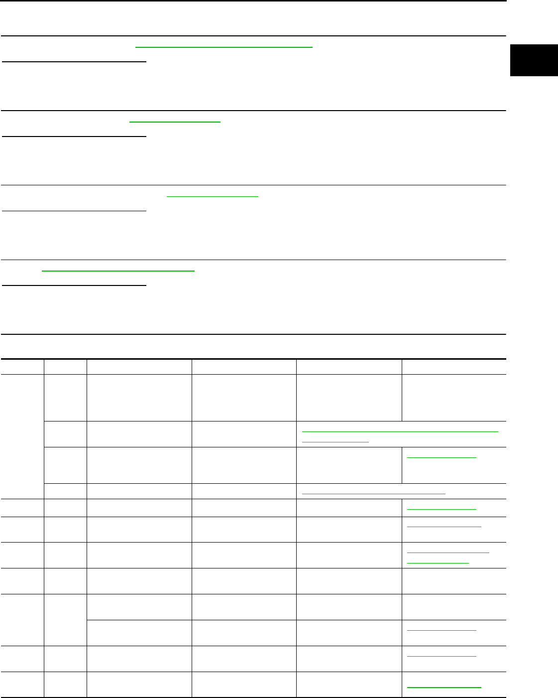
P1217 ENGINE OVER TEMPERATURE
EC-793
< COMPONENT DIAGNOSIS > [FOR USA (FEDERAL) AND CANADA]
C
D
E
F
G
H
I
J
K
L
M
A
EC
N
P
O
>> Repair or replace malfunctioning part.
4.CHECK RADIATOR CAP
Check radiator cap. Refer to CO-13, "RADIATOR CAP : Inspection".
Is the inspection result normal?
YES >> GO TO 5.
NO >> Replace radiator cap.
5.CHECK THERMOSTAT
Check thermostat. Refer to CO-26, "Inspection".
Is the inspection result normal?
YES >> GO TO 6.
NO >> Replace thermostat.
6.CHECK WATER CONTROL VALVE
Check water control valve. Refer to CO-26, "Inspection".
Is the inspection result normal?
YES >> GO TO 7.
NO >> Replace water control valve
7.CHECK ENGINE COOLANT TEMPERATURE SENSOR
Refer to EC-633, "Component Inspection".
Is the inspection result normal?
YES >> GO TO 8.
NO >> Replace engine coolant temperature sensor.
8.CHECK MAIN 13 CAUSES
If the cause cannot be isolated, check the following.
Engine Step Inspection item Equipment Standard Reference page
OFF 1 • Blocked radiator
• Blocked condenser
• Blocked radiator grille
• Blocked bumper
• Visual No blocking —
2 • Coolant mixture • Coolant tester MA-18, "FOR NORTH AMERICA : Anti-Freeze Cool-
ant Mixture Ratio"
3 • Coolant level • Visual Coolant up to MAX level in
reservoir tank and radiator
filler neck
CO-9, "Inspection"
4 • Radiator cap • Pressure tester CO-13, "RADIATOR CAP : Inspection"
ON*25 • Coolant leaks • Visual No leaks CO-9, "Inspection"
ON*26 • Thermostat • Touch the upper and
lower radiator hoses
Both hoses should be hot CO-26, "Inspection"
ON*17 • Cooling fan motor • CONSULT-III Operating EC-847, "Component
Function Check"
OFF 8 • Combustion gas leak • Color checker chemical
tester 4 Gas analyzer
Negative —
ON*39 • Coolant temperature
gauge
• Visual Gauge less than 3/4 when
driving
—
• Coolant overflow to res-
ervoir tank
• Visual No overflow during driving
and idling
CO-9, "Inspection"
OFF*410 • Coolant return from res-
ervoir tank to radiator • Visual Should be initial level in
reservoir tank CO-9, "Inspection"
OFF 11 • Water control valve • Remove and inspect
the valve Within the specified value CO-26, "Inspection"
Revision: 2008 August 2009 Rogue

EC-794
< COMPONENT DIAGNOSIS > [FOR USA (FEDERAL) AND CANADA]
P1217 ENGINE OVER TEMPERATURE
*1: Turn the ignition switch ON.
*2: Engine running at 3,000 rpm for 10 minutes.
*3: Drive at 90 km/h (56 MPH) for 30 minutes and then let idle for 10 minutes.
*4: After 60 minutes of cool down time.
For more information, refer to CO-4, "Troubleshooting Chart".
>> INSPECTION END
OFF 12 • Cylinder head • Straight gauge feeler
gauge 0.1 mm (0.004 in) Maxi-
mum distortion (warping) EM-85, "Inspection"
13 • Cylinder block and pis-
tons
• Visual No scuffing on cylinder
walls or piston
EM-96, "Inspection"
Engine Step Inspection item Equipment Standard Reference page
Revision: 2008 August 2009 Rogue
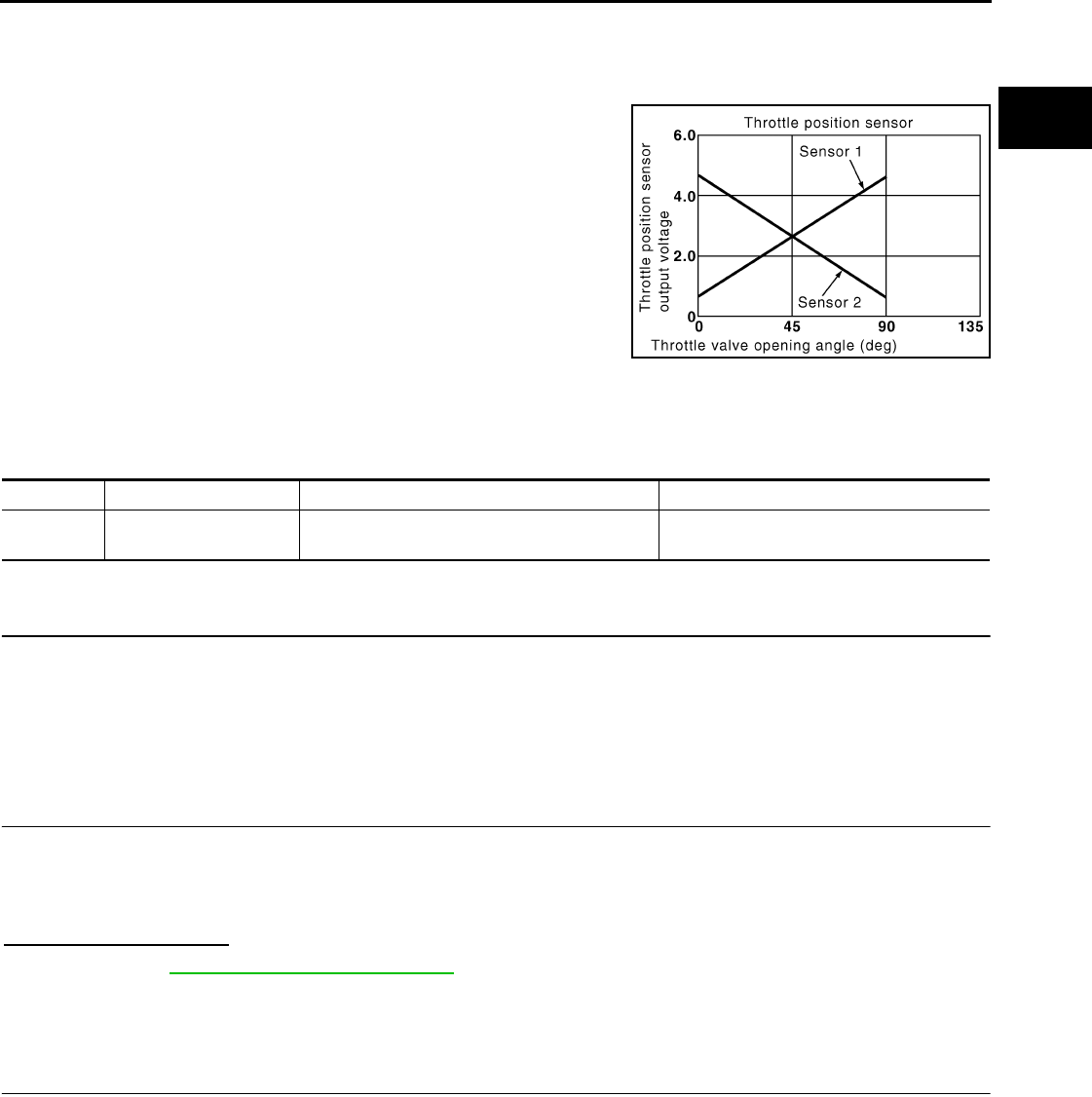
P1225 TP SENSOR
EC-795
< COMPONENT DIAGNOSIS > [FOR USA (FEDERAL) AND CANADA]
C
D
E
F
G
H
I
J
K
L
M
A
EC
N
P
O
P1225 TP SENSOR
Description INFOID:0000000004533697
Electric throttle control actuator consists of throttle control motor,
throttle position sensor, etc. The throttle position sensor responds to
the throttle valve movement.
The throttle position sensor has two sensors. These sensors are a
kind of potentiometer which transform the throttle valve position into
output voltage, and emit the voltage signals to the ECM. The ECM
judges the current opening angle of the throttle valve from these sig-
nals and contols the throttle valve opening angle in response to driv-
ing conditions via the throttle contorol motor.
DTC Logic INFOID:0000000004529664
DTC DETECTION LOGIC
DTC CONFIRMATION PROCEDURE
1.PRECONDITIONING
If DTC CONFIRMATION PROCEDURE has been previously conducted, always turn ignition switch OFF and
wait at least 10 seconds before conducting the next test.
TESTING CONDITION:
Before performing the following procedure, confirm that battery voltage is more than 10V at idle.
>> GO TO 2.
2.PERFORM DTC CONFIRMATION PROCEDURE
1. Turn ignition switch ON.
2. Turn ignition switch OFF and wait at least 10 seconds.
3. Turn ignition switch ON.
4. Check 1st trip DTC.
Is 1st trip DTC detected?
YES >> Go to EC-795, "Diagnosis Procedure".
NO >> INSPECTION END
Diagnosis Procedure INFOID:0000000004529665
1.CHECK ELECTRIC THROTTLE CONTROL ACTUATOR VISUALLY
1. Turn ignition switch OFF.
2. Remove the intake air duct.
PBIB0145E
DTC No. Trouble diagnosis name DTC detecting condition Possible cause
P1225 Closed throttle position
learning performance Closed throttle position learning value is exces-
sively low. • Electric throttle control actuator
(TP sensor 1 and 2)
Revision: 2008 August 2009 Rogue

EC-796
< COMPONENT DIAGNOSIS > [FOR USA (FEDERAL) AND CANADA]
P1225 TP SENSOR
3. Check if foreign matter is caught between the throttle valve (1)
and the housing.
Is the inspection result normal?
YES >> GO TO 2.
NO >> Remove the foreign matter and clean the electric throttle
control actuator inside.
2.REPLACE ELECTRIC THROTTLE CONTROL ACTUATOR
1. Replace electric throttle control actuator.
2. Go to EC-796, "Special Repair Requirement".
>> INSPECTION END
Special Repair Requirement INFOID:0000000004533698
1.PERFORM THROTTLE VALVE CLOSED POSITION LEARNING
Refer to EC-504, "THROTTLE VALVE CLOSED POSITION LEARNING : Special Repair Requirement"
>> GO TO 2.
2.PERFORM IDLE AIR VOLUME LEARNING
Refer to EC-505, "IDLE AIR VOLUME LEARNING : Special Repair Requirement"
>> END
2. Electric throttle control actuator
: Vehicle front
ALBIA0061ZZ
Revision: 2008 August 2009 Rogue

P1226 TP SENSOR
EC-797
< COMPONENT DIAGNOSIS > [FOR USA (FEDERAL) AND CANADA]
C
D
E
F
G
H
I
J
K
L
M
A
EC
N
P
O
P1226 TP SENSOR
Description INFOID:0000000004533786
Electric throttle control actuator consists of throttle control motor,
throttle position sensor, etc. The throttle position sensor responds to
the throttle valve movement.
The throttle position sensor has two sensors. These sensors are a
kind of potentiometer which transform the throttle valve position into
output voltage, and emit the voltage signals to the ECM. The ECM
judges the current opening angle of the throttle valve from these sig-
nals and contols the throttle valve opening angle in response to driv-
ing conditions via the throttle contorol motor.
DTC Logic INFOID:0000000004529668
DTC DETECTION LOGIC
DTC CONFIRMATION PROCEDURE
1.PRECONDITIONING
If DTC CONFIRMATION PROCEDURE has been previously conducted, always turn ignition switch OFF and
wait at least 10 seconds before conducting the next test.
TESTING CONDITION:
Before performing the following procedure, confirm that battery voltage is more than 10V at idle.
>> GO TO 2.
2.PERFORM DTC CONFIRMATION PROCEDURE
1. Turn ignition switch ON.
2. Turn ignition switch OFF, wait at least 10 seconds.
3. Turn ignition switch ON.
4. Repeat steps 2 and 3 for 32 times.
5. Check 1st trip DTC.
Is 1st trip DTC detected?
YES >> Go to EC-797, "Diagnosis Procedure".
NO >> INSPECTION END
Diagnosis Procedure INFOID:0000000004534081
1.CHECK ELECTRIC THROTTLE CONTROL ACTUATOR VISUALLY
1. Turn ignition switch OFF.
2. Remove the intake air duct.
PBIB0145E
DTC No. Trouble diagnosis name DTC detecting condition Possible cause
P1226 Closed throttle position
learning performance Closed throttle position learning is not per-
formed successfully, repeatedly. • Electric throttle control actuator
(TP sensor 1 and 2)
Revision: 2008 August 2009 Rogue

EC-798
< COMPONENT DIAGNOSIS > [FOR USA (FEDERAL) AND CANADA]
P1226 TP SENSOR
3. Check if foreign matter is caught between the throttle valve (1)
and the housing.
Is the inspection result normal?
YES >> GO TO 2.
NO >> Remove the foreign matter and clean the electric throttle
control actuator inside.
2.REPLACE ELECTRIC THROTTLE CONTROL ACTUATOR
1. Replace electric throttle control actuator.
2. Go to EC-798, "Special Repair Requirement".
>> INSPECTION END
Special Repair Requirement INFOID:0000000004533787
1.PERFORM THROTTLE VALVE CLOSED POSITION LEARNING
Refer to EC-504, "THROTTLE VALVE CLOSED POSITION LEARNING : Special Repair Requirement"
>> GO TO 2.
2.PERFORM IDLE AIR VOLUME LEARNING
Refer to EC-505, "IDLE AIR VOLUME LEARNING : Special Repair Requirement"
>> END
2. Electric throttle control actuator
: Vehicle front
ALBIA0061ZZ
Revision: 2008 August 2009 Rogue

P1421 COLD START CONTROL
EC-799
< COMPONENT DIAGNOSIS > [FOR USA (FEDERAL) AND CANADA]
C
D
E
F
G
H
I
J
K
L
M
A
EC
N
P
O
P1421 COLD START CONTROL
Description INFOID:0000000004529671
ECM controls ignition timing and engine idle speed when engine is started with prewarming up condition.
This control promotes the activation of three way catalyst by heating the catalyst and reduces emissions.
DTC Logic INFOID:0000000004529672
DTC DETECTION LOGIC
NOTE:
If DTC P1421 is displayed with other DTC, first perform the trouble diagnosis for other DTC.
DTC CONFIRMATION PROCEDURE
1.PRECONDITIONING
If DTC CONFIRMATION PROCEDURE has been previously conducted, always turn ignition switch OFF and
wait at least 10 seconds before conducting the next test.
TESTING CONDITION:
Before performing the following procedure, confirm that battery voltage is more than 11V at idle.
>> GO TO 2.
2.PERFORM DTC CONFIRMATION PROCEDURE
With CONSULT-III
1. Turn ignition switch OFF and wait at least 10 seconds.
2. Turn ignition switch ON.
3. Select “DATA MONITOR” mode with CONSULT-III.
4. Check that the “COOLAN TEMP/S” indication is between 4°C (39°F) and 36°C (97°F).
If “COOLAN TEMP/S” indication is within the specified value, go to the following step.
If “COOLANT TEMP/S” indication is out of the specified value, cool engine down or warm engine up and
go to step 1.
5. Start engine and let it idle for 5 minutes.
6. Check 1st trip DTC.
With GST
Follow the procedure “With CONSULT-III” above.
Is 1st trip DTC detected?
YES >> Go to EC-799, "Diagnosis Procedure".
NO >> INSPECTION END
Diagnosis Procedure INFOID:0000000004529673
1.PERFORM IDLE AIR VOLUME LEARNING
Perform EC-505, "IDLE AIR VOLUME LEARNING : Special Repair Requirement".
Is Idle Air Volume Learning carried out successfully?
YES >> GO TO 2.
NO >> Follow the instruction of Idle Air Volume Learning.
2.CHECK INTAKE SYSTEM
Check for the cause of intake air volume lacking. Refer to the following.
• Crushed intake air passage
• Intake air passage clogging
DTC No. Trouble diagnosis name DTC detecting condition Possible cause
P1421 Cold start emission reduction
strategy monitoring
ECM does not control ignition timing and engine
idle speed properly when engine is started with
prewarming up condition.
• Lack of intake air volume
• Fuel injection system
•ECM
Revision: 2008 August 2009 Rogue

EC-800
< COMPONENT DIAGNOSIS > [FOR USA (FEDERAL) AND CANADA]
P1421 COLD START CONTROL
Is the inspection result normal?
YES >> GO TO 3.
NO >> Repair or replace malfunctioning part
3.CHECK FUEL INJECTION SYSTEM FUNCTION
Perform DTC CONFIRMATION PROCEDURE for DTC P0171. Refer to EC-679, "DTC Logic".
Is the inspection result normal?
YES >> GO TO 4.
NO >> Go to EC-680, "Diagnosis Procedure" for DTC P0171.
4.PERFORM DTC CONFIRMATION PROCEDURE
1. Turn ignition switch ON.
2. Erase DTC.
3. Perform DTC CONFIRMATION PROCEDURE.
See EC-799, "DTC Logic".
Is the 1st trip DTC P1421 displayed again?
YES >> GO TO 5.
NO >> INSPECTION END
5.REPLACE ECM
1. Replace ECM.
NOTE:
Use the specified bolts described in parts information certainly when installing the ECM, or violates the
Canada law.
2. Go to EC-502, "ADDITIONAL SERVICE WHEN REPLACING CONTROL UNIT : Special Repair Require-
ment".
>> INSPECTION END
Revision: 2008 August 2009 Rogue

P1564 ASCD STEERING SWITCH
EC-801
< COMPONENT DIAGNOSIS > [FOR USA (FEDERAL) AND CANADA]
C
D
E
F
G
H
I
J
K
L
M
A
EC
N
P
O
P1564 ASCD STEERING SWITCH
Description INFOID:0000000004529674
ASCD steering switch has variant values of electrical resistance for each button. ECM reads voltage variation
of switch, and determines which button is operated.
Refer to EC-535, "System Description" for the ASCD function.
DTC Logic INFOID:0000000004529675
DTC DETECTION LOGIC
NOTE:
If DTC P1564 is displayed with DTC P0605, first perform the trouble diagnosis for DTC P0605. Refer to
EC-781, "DTC Logic".
DTC CONFIRMATION PROCEDURE
1.PRECONDITIONING
If DTC CONFIRMATION PROCEDURE has been previously conducted, always turn ignition switch OFF and
wait at least 10 seconds before conducting the next test.
>> GO TO 2.
2.PERFORM DTC CONFIRMATION PROCEDURE
1. Turn ignition switch ON.
2. Wait at least 10 seconds.
3. Press MAIN switch for at least 10 seconds, then release it and wait at least 10 seconds.
4. Press CANCEL switch for at least 10 seconds, then release it and wait at least 10 seconds.
5. Press RESUME/ACCELERATE switch for at least 10 seconds, then release it and wait at least 10 sec-
onds.
6. Press SET/COAST switch for at least 10 seconds, then release it and wait at least 10 seconds.
7. Check DTC.
Is DTC detected?
YES >> Go to EC-801, "Diagnosis Procedure".
NO >> INSPECTION END
Diagnosis Procedure INFOID:0000000004529676
1.CHECK GROUND CONNECTION
1. Turn ignition switch OFF.
2. Check ground connection E21. Refer to Ground Inspection in GI-44, "Circuit Inspection".
Is the inspection result normal?
YS >> GO TO 2.
NO >> Repair or replace ground connection.
2.CHECK ASCD STEERING SWITCH CIRCUIT
With CONSULT-III
1. Turn ignition switch ON.
DTC No. Trouble diagnosis
name DTC detecting condition Possible cause
P1564 ASCD steering switch
• An excessively high voltage signal from the
ASCD steering switch is sent to ECM.
• ECM detects that input signal from the
ASCD steering switch is out of the specified
range.
• ECM detects that the ASCD steering switch
is stuck ON.
• Harness or connectors
(The switch circuit is open or shorted.)
• ASCD steering switch
•ECM
Revision: 2008 August 2009 Rogue
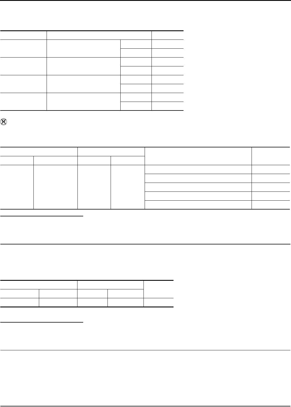
EC-802
< COMPONENT DIAGNOSIS > [FOR USA (FEDERAL) AND CANADA]
P1564 ASCD STEERING SWITCH
2. Select “MAIN SW”, “CANCEL SW”, “RESUME/ACC SW” and “SET SW” in “DATA MONITOR” mode with
CONSULT-III.
3. Check each item indication under the following conditions.
Without CONSULT-III
1. Turn ignition switch ON.
2. Check the voltage between ECM harness connectors.
Is the inspection result normal?
YES >> GO TO 8.
NO >> GO TO 3.
3.CHECK ASCD STEERING SWITCH GROUND CIRCUIT FOR OPEN AND SHORT
1. Turn ignition switch OFF.
2. Disconnect ECM harness connector.
3. Disconnect combination switch harness connector M352.
4. Check the continuity between combination switch and ECM harness connector.
5. Also check harness for short to ground and short to power.
Is the inspection result normal?
YES >> GO TO 5.
NO >> GO TO 4.
4.DETECT MALFUNCTIONING PART
Check the following.
• Harness connectors M77, E105
• Combination switch (spiral cable)
• Harness for open and short between ECM and combination switch
>> Repair open circuit or short to ground or short to power in harness or connectors.
5.CHECK ASCD STEERING SWITCH INPUT SIGNAL CIRCUIT FOR OPEN AND SHORT
Monitor item Condition Indication
MAIN SW MAIN switch Pressed ON
Released OFF
CANCEL SW CANCEL switch Pressed ON
Released OFF
RESUME/ACC SW RESUME/ACCELERATE switch Pressed ON
Released OFF
SET SW SET/COAST switch Pressed ON
Released OFF
ECM ECM Condition Voltage
Connector Terminal Connector Terminal
E16
85
(ASCD steering
switch signal)
E16
92
(Switch
ground)
MAIN switch: Pressed Approx. 0 V
CANSEL switch: Pressed Approx. 1 V
SET/COAST switch: Pressed Approx. 2 V
RESUME/ACCELERATE switch: Pressed Approx. 3 V
All ASCD steering switches: Released Approx. 4 V
Combination switch ECM Continuity
Connector Terminal Connector Terminal
—18E1692Existed
Revision: 2008 August 2009 Rogue

P1564 ASCD STEERING SWITCH
EC-803
< COMPONENT DIAGNOSIS > [FOR USA (FEDERAL) AND CANADA]
C
D
E
F
G
H
I
J
K
L
M
A
EC
N
P
O
1. Check the continuity between ECM harness connector and combination switch.
2. Also check harness for short to ground and short to power.
Is the inspection result normal?
YES >> GO TO 7.
NO >> GO TO 6.
6.DETECT MALFUNCTIONING PART
Check the following.
• Harness connectors M77, E105
• Combination switch (spiral cable)
• Harness for open and short between ECM and combination switch
>> Repair open circuit or short to ground or short to power in harness or connectors.
7.CHECK ASCD STEERING SWITCH
Refer to EC-803, "Component Inspection".
Is the inspection result normal?
YES >> GO TO 8.
NO >> Replace ASCD steering switch.
8.CHECK INTERMITTENT INCIDENT
Refer to GI-41, "Intermittent Incident".
>> INSPECTION END
Component Inspection INFOID:0000000004529677
1.CHECK ASCD STEERING SWITCH
1. Disconnect combination switch (spiral cable) harness connector M352.
2. Check the continuity between combination switch harness connector terminals under following conditions.
Is the inspection result normal?
YES >> INSPECTION END
NO >> Replace ASCD steering switch
Combination switch ECM Continuity
Connector Terminal Connector Terminal
— 21 E10 85 Existed
Combination meter Condition Resistance
Connector Terminals
M352 18 and 21
MAIN switch: Pressed Approx. 0 Ω
CANCEL switch: Pressed Approx. 250 Ω
SET/COAST switch: Pressed Approx. 660 Ω
RESUME/ACCELERATE switch: Pressed Approx. 1,480 Ω
All ASCD steering switches: Released Approx. 4,000 Ω
Revision: 2008 August 2009 Rogue

EC-804
< COMPONENT DIAGNOSIS > [FOR USA (FEDERAL) AND CANADA]
P1572 ASCD BRAKE SWITCH
P1572 ASCD BRAKE SWITCH
Description INFOID:0000000004529678
When the brake pedal is depressed, ASCD brake switch is turned OFF and stop lamp switch is turned ON.
ECM detects the state of the brake pedal by those two types of input (ON/OFF signal).
Refer to EC-535, "System Description" for the ASCD function.
DTC Logic INFOID:0000000004529679
DTC DETECTION LOGIC
NOTE:
•If DTC P1572 is displayed with DTC P0605, first perform the trouble diagnosis for DTC P0605. Refer
to EC-781, "DTC Logic".
•This self-diagnosis has the one trip detection logic. When malfunction A is detected, DTC is not
stored in ECM memory. And in that case, 1st trip DTC and 1st trip freeze frame data are displayed.
1st trip DTC is erased when ignition switch is turned OFF. And even when malfunction A is detected
in two consecutive trips, DTC is not stored in ECM memory.
DTC CONFIRMATION PROCEDURE
1.PRECONDITIONING
If DTC CONFIRMATION PROCEDURE has been previously conducted, always turn ignition switch OFF and
wait at least 10 seconds before conducting the next test.
NOTE:
The procedure for malfunction B is not described. It takes an extremely long time to complete the procedure
for malfunction B. By performing the procedure for malfunction A, the condition that causes malfunction B can
be detected.
>> GO TO 2.
2.PERFORM DTC CONFIRMATION PROCEDURE FOR MALFUNCTION A - I
1. Start engine.
2. Press MAIN switch and check that CRUISE indicator is displayed in combination meter.
3. Drive the vehicle for at least 5 consecutive seconds under the following conditions.
CAUTION:
Always drive vehicle at a safe speed.
NOTE:
This procedure may be conducted with the drive wheels lifted in the shop or by driving the vehicle.
If a road test is expected to be easier, it is unnecessary to lift the vehicle.
4. Check 1st trip DTC.
Is 1st trip DTC detected?
YES >> Go to EC-805, "Diagnosis Procedure".
NO >> GO TO 3.
DTC No. Trouble diagnosis
name DTC detecting condition Possible cause
P1572 ASCD brake switch
A)
When the vehicle speed is above 30 km/h
(19 MPH), ON signals from the stop lamp
switch and the ASCD brake switch are sent
to the ECM at the same time.
• Harness or connectors
(The stop lamp switch circuit is shorted.)
• Harness or connectors
(The ASCD brake switch circuit is shorted.)
• Stop lamp switch
• ASCD brake switch
• Incorrect stop lamp switch installation
• Incorrect ASCD brake switch installation
•ECM
B)
ASCD brake switch signal is not sent to
ECM for extremely long time while the ve-
hicle is being driven.
Vehicle speed More than 30 km/h (19 mph)
Selector lever Suitable position
Revision: 2008 August 2009 Rogue

P1572 ASCD BRAKE SWITCH
EC-805
< COMPONENT DIAGNOSIS > [FOR USA (FEDERAL) AND CANADA]
C
D
E
F
G
H
I
J
K
L
M
A
EC
N
P
O
3.PERFORM DTC CONFIRMATION PROCEDURE FOR MALFUNCTION A - II
1. Drive the vehicle for at least 5 consecutive seconds under the following conditions.
CAUTION:
Always drive vehicle at a safe speed.
NOTE:
This procedure may be conducted with the drive wheels lifted in the shop or by driving the vehicle.
If a road test is expected to be easier, it is unnecessary to lift the vehicle.
2. Check 1st trip DTC.
Is 1st trip DTC detected?
YES >> Go to EC-805, "Diagnosis Procedure".
NO >> INSPECTION END
Diagnosis Procedure INFOID:0000000004529680
1.CHECK OVERALL FUNCTION-I
With CONSULT-III
1. Turn ignition switch ON.
2. Select “BRAKE SW1” in “DATA MONITOR” mode with CONSULT-III.
3. Check “BRAKE SW1” indication under the following conditions.
Without CONSULT-III
1. Turn ignition switch ON.
2. Check the voltage between ECM harness connector and ground.
Is the inspection result normal?
YES >> GO TO 2.
NO >> GO TO 3.
2.CHECK OVERALL FUNCTION-II
With CONSULT-III
Select “BRAKE SW2” and check indication in “DATA MONITOR” mode.
Without CONSULT-III
Check the voltage between ECM harness connector and ground.
Vehicle speed More than 30 km/h (19 mph)
Selector lever Suitable position
Driving location Depress the brake pedal for more than five seconds so as
not to come off from the above-mentioned vehicle speed.
Monitor item Condition Indication
BRAKE SW1 Brake pedal Slightly depressed OFF
Fully released ON
ECM Ground Condition Voltage
Connector Terminal
E16 110
(ASCD brake switch signal) Ground Brake pedal Slightly depressed Approx. 0V
Fully released Battery voltage
Monitor item Condition Indication
BRAKE SW2 Brake pedal Slightly depressed ON
Fully released OFF
Revision: 2008 August 2009 Rogue

EC-806
< COMPONENT DIAGNOSIS > [FOR USA (FEDERAL) AND CANADA]
P1572 ASCD BRAKE SWITCH
Is the inspection result normal?
YES >> GO TO 11.
NO >> GO TO 7.
3.CHECK ASCD BRAKE SWITCH POWER SUPPLY CIRCUIT
1. Turn ignition switch OFF.
2. Disconnect ASCD brake switch harness connector.
3. Turn ignition switch ON.
4. Check the voltage between ASCD brake switch harness connector and ground.
Is the inspection result normal?
YES >> GO TO 5.
NO >> GO TO 4.
4.DETECT MALFUNCTIONING PART
Check the following.
• Junction block connector E105, M77
• 10A fuse (No.1)
• Harness for open or short between ASCD brake switch and fuse
>> Repair open circuit or short to ground or short to power in harness or connectors.
5.CHECK ASCD BRAKE SWITCH INPUT SIGNAL CIRCUIT FOR OPEN AND SHORT
1. Turn ignition switch OFF.
2. Disconnect ECM harness connector.
3. Check the continuity between ASCD brake switch harness connector and ECM harness connector.
4. Also check harness for short to ground and short to power.
Is the inspection result normal?
YES >> GO TO 6.
NO >> Repair open circuit or short to ground or short to power in harness or connectors.
6.CHECK ASCD BRAKE SWITCH
Refer to EC-807, "Component Inspection (ASCD Brake Switch)".
Is the inspection result normal?
YES >> GO TO 11.
NO >> Replace ASCD brake switch.
7.CHECK STOP LAMP SWITCH POWER SUPPLY CIRCUIT
1. Turn ignition switch OFF.
2. Disconnect stop lamp switch harness connector.
3. Check the voltage between stop lamp switch harness connector and ground.
ECM Ground Condition Voltage
Connector Terminal
E16 106
(Stop lamp switch signal) Ground Brake pedal Slightly depressed Battery voltage
Fully released Approx. 0V
ASCD brake switch Ground Voltage
Connector Terminal
E112 1 Ground Battery voltage
ASCD brake switch ECM Continuity
Connector Terminal Connector Terminal
E112 2 E16 110 Existed
Revision: 2008 August 2009 Rogue

P1572 ASCD BRAKE SWITCH
EC-807
< COMPONENT DIAGNOSIS > [FOR USA (FEDERAL) AND CANADA]
C
D
E
F
G
H
I
J
K
L
M
A
EC
N
P
O
Is the inspection result normal?
YES >> GO TO 9.
NO >> GO TO 8.
8.DETECT MALFUNCTIONING PART
Check the following.
• Harness connectors E105, M77
• 10A fuse (No.11)
• Harness for open or short between stop lamp switch and battery
>> Repair open circuit or short to ground or short to power in harness or connectors.
9.CHECK STOP LAMP SWITCH INPUT SIGNAL CIRCUIT FOR OPEN AND SHORT
1. Disconnect ECM harness connector.
2. Check the continuity between ECM harness connector and stop lamp switch harness connector.
3. Also check harness for short to ground and short to power.
Is the inspection result normal?
YES >> GO TO 10.
NO >> Repair open circuit or short to ground or short to power in harness or connectors.
10.CHECK STOP LAMP SWITCH
Refer to EC-808, "Component Inspection (Stop Lamp Switch)".
Is the inspection result normal?
YES >> GO TO 11.
NO >> Replace stop lamp switch.
11.CHECK INTERMITTENT INCIDENT
Refer to GI-41, "Intermittent Incident".
>> INSPECTION END
Component Inspection (ASCD Brake Switch) INFOID:0000000004529681
1.CHECK ASCD BRAKE SWITCH-I
1. Turn ignition switch OFF.
2. Disconnect ASCD brake switch harness connector.
3. Check the continuity between ASCD brake switch terminals under the following conditions.
Is the inspection result normal?
YES >> INSPECTION END
NO >> GO TO 2.
2.CHECK ASCD BRAKE SWITCH-II
Stop lamp switch Ground Voltage
Connector Terminal
E115 1 Ground Battery voltage
ECM Stop lamp switch Continuity
Connector Terminal Connector Terminal
E16 106 E115 2 Existed
Terminals Condition Continuity
1 and 2 Brake pedal Fully released Existed
Slightly depressed Not existed
Revision: 2008 August 2009 Rogue

EC-808
< COMPONENT DIAGNOSIS > [FOR USA (FEDERAL) AND CANADA]
P1572 ASCD BRAKE SWITCH
1. Adjust ASCD brake switch installation. Refer to BR-19, "Inspection and Adjustment".
2. Check the continuity between ASCD brake switch terminals under the following conditions.
Is the inspection result normal?
YES >> INSPECTION END
NO >> Replace ASCD brake switch.
Component Inspection (Stop Lamp Switch) INFOID:0000000004529682
1.CHECK STOP LAMP SWITCH-I
1. Turn ignition switch OFF.
2. Disconnect stop lamp switch harness connector.
3. Check the continuity between stop lamp switch terminals under the following conditions.
Is the inspection result normal?
YES >> INSPECTION END
NO >> GO TO 2.
2.CHECK STOP LAMP SWITCH-II
1. Adjust stop lamp switch installation. Refer to BR-19, "Inspection and Adjustment".
2. Check the continuity between stop lamp switch terminals under the following conditions.
Is the inspection result normal?
YES >> INSPECTION END
NO >> Replace stop lamp switch.
Terminals Condition Continuity
1 and 2 Brake pedal Fully released Existed
Slightly depressed Not existed
Terminals Condition Continuity
1 and 2 Brake pedal Fully released Not existed
Slightly depressed Existed
Terminals Condition Continuity
1 and 2 Brake pedal Fully released Not existed
Slightly depressed Existed
Revision: 2008 August 2009 Rogue

P1574 ASCD VEHICLE SPEED SENSOR
EC-809
< COMPONENT DIAGNOSIS > [FOR USA (FEDERAL) AND CANADA]
C
D
E
F
G
H
I
J
K
L
M
A
EC
N
P
O
P1574 ASCD VEHICLE SPEED SENSOR
Description INFOID:0000000004529683
The ECM receives two vehicle speed sensor signals via CAN communication line. One is sent from combina-
tion meter, and the other is from TCM (Transmission control module). The ECM uses these signals for ASCD
control. Refer to EC-535, "System Description" for ASCD functions.
DTC Logic INFOID:0000000004529684
DTC DETECTION LOGIC
NOTE:
•If DTC P1574 is displayed with DTC UXXXX, first perform the trouble diagnosis for DTC UXXXX.
•If DTC P1574 is displayed with DTC P0500, first perform the trouble diagnosis for DTC P0500. Refer
to EC-773, "DTC Logic"
•If DTC P1574 is displayed with DTC P0605, first perform the trouble diagnosis for DTC P0605. Refer
to EC-781, "DTC Logic"
•If DTC P1574 is displayed with DTC P0607, first perform the trouble diagnosis for DTC P0607. Refer
to EC-783, "DTC Logic".
DTC CONFIRMATION PROCEDURE
1.PRECONDITIONING
If DTC CONFIRMATION PROCEDURE has been previously conducted, always turn ignition switch OFF and
wait at least 10 seconds before conducting the next test.
>> GO TO 2.
2.PERFORM DTC CONFIRMATION PROCEDURE
1. Start engine.
2. Drive the vehicle at more than 40 km/h (25 MPH).
CAUTION:
Always drive vehicle at a safe speed.
NOTE:
This procedure may be conducted with the drive wheels lifted in the shop or by driving the vehicle.
If a road test is expected to be easier, it is unnecessary to lift the vehicle.
3. Check DTC.
Is DTC detected?
YES >> Go to EC-809, "Diagnosis Procedure".
NO >> INSPECTION END
Diagnosis Procedure INFOID:0000000004529685
1.CHECK DTC WITH TCM
Check DTC with TCM. Refer to TM-44, "CONSULT-III Function (TRANSMISSION)".
Is the inspection result normal?
YES >> GO TO 2.
NO >> Perform trouble shooting relevant to DTC indicated.
DTC No. Trouble diagnosis
name DTC detecting condition Possible cause
P1574 ASCD vehicle speed
sensor
The difference between the two vehicle speed
signals is out of the specified range.
• Harness or connectors
(The CAN communication line is open or
shorted.)
(Combination meter circuit is open or shorted.)
• Combination meter
• ABS actuator and electric unit (control unit)
• Wheel sensor
•TCM
•ECM
Revision: 2008 August 2009 Rogue

EC-810
< COMPONENT DIAGNOSIS > [FOR USA (FEDERAL) AND CANADA]
P1574 ASCD VEHICLE SPEED SENSOR
2.CHECK DTC WITH “ABS ACTUATOR AND ELECTRIC UNIT (CONTROL UNIT)”
Refer to BRC-15, "CONSULT-III Function" (ABS models), BRC-93, "CONSULT-III Function" (VDC models).
Is the inspection result normal?
YES >> GO TO 3.
NO >> Repair or replace.
3.CHECK COMBINATION METER
Check combination meter function.
Refer to MWI-33, "CONSULT-III Function (METER/M&A)".
>> INSPECTION END
Revision: 2008 August 2009 Rogue

P1715 INPUT SPEED SENSOR (PRIMARY SPEED SENSOR)
EC-811
< COMPONENT DIAGNOSIS > [FOR USA (FEDERAL) AND CANADA]
C
D
E
F
G
H
I
J
K
L
M
A
EC
N
P
O
P1715 INPUT SPEED SENSOR (PRIMARY SPEED SENSOR)
Description INFOID:0000000004529686
ECM receives primary speed sensor signal from TCM through CAN communication line. ECM uses this signal
for engine control.
DTC Logic INFOID:0000000004529687
DTC DETECTION LOGIC
NOTE:
•If DTC P1715 is displayed with DTC UXXXX, first perform the trouble diagnosis for DTC UXXXX.
•If DTC P1715 is displayed with DTC P0335, first perform the trouble diagnosis for DTC P0335. Refer
to EC-703, "DTC Logic".
•If DTC P1715 is displayed with DTC P0340, first perform the trouble diagnosis for DTC P0340. Refer
to EC-707, "DTC Logic".
•If DTC P1715 is displayed with DTC P0605, first perform the trouble diagnosis for DTC P0605. Refer
to EC-781, "DTC Logic".
•If DTC P1715 is displayed with DTC P0607, first perform the trouble diagnosis for DTC P0607. Refer
to EC-783, "DTC Logic".
DTC CONFIRMATION PROCEDURE
1.PRECONDITIONING
If DTC CONFIRMATION PROCEDURE has been previously conducted, always turn ignition switch OFF and
wait at least 10 seconds before conducting the next test.
>> GO TO 2.
2.PERFORM DTC CONFIRMATION PROCEDURE
1. Start engine and drive the vehicle at more than 50 km/h (31 MPH) for at least 5 seconds.
CAUTION:
Always drive vehicle at a safe speed.
2. Check 1st trip DTC.
Is 1st trip DTC detected?
YES >> Go to EC-811, "Diagnosis Procedure".
NO >> INSPECTION END
Diagnosis Procedure INFOID:0000000004529688
1.CHECK DTC WITH TCM
Check DTC with TCM. Refer to TM-44, "CONSULT-III Function (TRANSMISSION)".
Is the inspection result normal?
YES >> GO TO 2.
NO >> Perform trouble shooting relevant to DTC indicated.
2.REPLACE TCM
Replace TCM.
DTC No. Trouble diagnosis name DTC detecting condition Possible cause
P1715 Input speed sensor
(Primary speed sensor)
(TCM output)
Primary speed sensor signal is different
from the theoretical value calculated by
ECM from secondary speed sensor signal
and engine rpm signal.
• Harness or connectors
(The CAN communication line is open or short-
ed)
• Harness or connectors
(Primary speed sensor circuit is open or short-
ed)
•TCM
Revision: 2008 August 2009 Rogue

EC-812
< COMPONENT DIAGNOSIS > [FOR USA (FEDERAL) AND CANADA]
P1715 INPUT SPEED SENSOR (PRIMARY SPEED SENSOR)
>> INSPECTION END
Revision: 2008 August 2009 Rogue

P1805 BRAKE SWITCH
EC-813
< COMPONENT DIAGNOSIS > [FOR USA (FEDERAL) AND CANADA]
C
D
E
F
G
H
I
J
K
L
M
A
EC
N
P
O
P1805 BRAKE SWITCH
Description INFOID:0000000004529689
Brake switch signal is applied to the ECM through the stop lamp switch when the brake pedal is depressed.
This signal is used mainly to decrease the engine speed when the vehicle is being driven.
DTC Logic INFOID:0000000004529690
DTC DETECTION LOGIC
DTC CONFIRMATION PROCEDURE
1.PERFORM DTC CONFIRMATION PROCEDURE
1. Turn ignition switch ON.
2. Fully depress the brake pedal for at least 5 seconds.
3. Erase the DTC with CONSULT-III.
4. Check 1st trip DTC.
Is 1st trip DTC detected?
YES >> Go to EC-813, "Diagnosis Procedure".
NO >> INSPECTION END
Diagnosis Procedure INFOID:0000000004529691
1.CHECK STOP LAMP SWITCH CIRCUIT
1. Turn ignition switch OFF.
2. Check the stop lamp when depressing and releasing the brake pedal.
Is 1st trip DTC detected?
YES >> GO TO 4.
NO >> GO TO 2.
2.CHECK STOP LAMP SWITCH POWER SUPPLY CIRCUIT
1. Turn ignition switch OFF.
2. Disconnect stop lamp switch harness connector.
3. Check the voltage between stop lamp switch harness connector and ground.
Is the inspection result normal?
YES >> GO TO 4.
NO >> GO TO 3.
3.DETECT MALFUNCTIONING PART
Check the following.
• Harness connectors E105, M77
DTC No. Trouble diagnosis name DTC detecting condition Possible cause
P1805 Brake switch
A brake switch signal is not sent to ECM for ex-
tremely long time while the vehicle is being driv-
en.
• Harness or connectors
(Stop lamp switch circuit is open or short-
ed.)
• Stop lamp switch
Brake pedal Stop lamp
Fully released Not illuminated
Slightly depressed Illuminated
Stop lamp switch Ground Voltage
Connector Terminal
E115 1 Ground Battery voltage
Revision: 2008 August 2009 Rogue

EC-814
< COMPONENT DIAGNOSIS > [FOR USA (FEDERAL) AND CANADA]
P1805 BRAKE SWITCH
• 10A fuse (No. 11)
• Harness for open or short between stop lamp switch and battery
>> Repair open circuit or short to ground or short to power in harness or connectors.
4.CHECK STOP LAMP SWITCH INPUT SIGNAL CIRCUIT FOR OPEN AND SHORT
1. Disconnect ECM harness connector.
2. Check the continuity between ECM harness connector and stop lamp switch harness connector.
3. Also check harness for short to ground and short to power.
Is the inspection result normal?
YES >> GO TO 5.
NO >> Repair open circuit or short to ground or short to power in harness or connectors.
5.CHECK STOP LAMP SWITCH
Refer to EC-814, "Component Inspection (Stop Lamp Switch)".
Is the inspection result normal?
YES >> GO TO 6.
NO >> Replace stop lamp switch.
6.CHECK INTERMITTENT INCIDENT
Refer to GI-41, "Intermittent Incident".
>> INSPECTION END
Component Inspection (Stop Lamp Switch) INFOID:0000000004534151
1.CHECK STOP LAMP SWITCH-I
1. Turn ignition switch OFF.
2. Disconnect stop lamp switch harness connector.
3. Check the continuity between stop lamp switch terminals under the following conditions.
Is the inspection result normal?
YES >> INSPECTION END
NO >> GO TO 2.
2.CHECK STOP LAMP SWITCH-II
1. Adjust stop lamp switch installation. Refer to BR-19, "Inspection and Adjustment".
2. Check the continuity between stop lamp switch terminals under the following conditions.
Is the inspection result normal?
YES >> INSPECTION END
NO >> Replace stop lamp switch.
ECM Stop lamp switch Continuity
Connector Terminal Connector Terminal
E16 106 E115 2 Existed
Terminals Condition Continuity
1 and 2 Brake pedal Fully released Not existed
Slightly depressed Existed
Terminals Condition Continuity
1 and 2 Brake pedal Fully released Not existed
Slightly depressed Existed
Revision: 2008 August 2009 Rogue

P2100, P2103 THROTTLE CONTROL MOTOR RELAY
EC-815
< COMPONENT DIAGNOSIS > [FOR USA (FEDERAL) AND CANADA]
C
D
E
F
G
H
I
J
K
L
M
A
EC
N
P
O
P2100, P2103 THROTTLE CONTROL MOTOR RELAY
Description INFOID:0000000004529693
Power supply for the throttle control motor is provided to the ECM via throttle control motor relay. The throttle
control motor relay is controlled ON/OFF by the ECM. When the ignition switch is turned ON, the ECM sends
an ON signal to throttle control motor relay and battery voltage is provided to the ECM. When the ignition
switch is turned OFF, the ECM sends an OFF signal to throttle control motor relay and battery voltage is not
provided to the ECM.
DTC Logic INFOID:0000000004529694
DTC DETECTION LOGIC
DTC CONFIRMATION PROCEDURE
1.PRECONDITIONING
If DTC CONFIRMATION PROCEDURE has been previously conducted, always turn ignition switch OFF and
wait at least 10 seconds before conducting the next test.
TESTING CONDITION:
Before performing the following procedure, confirm that battery voltage is more than 8V.
Witch DTC is detected?
P2100 >> GO TO 2.
P2103 >> GO TO 3.
2.PERFORM DTC CONFIRMATION PROCEDURE FOR DTC P2100
1. Turn ignition switch ON and wait at least 2 seconds.
2. Start engine and let it idle for 5 seconds.
3. Check DTC.
Is DTC detected?
YES >> Go to EC-815, "Diagnosis Procedure".
NO >> INSPECTION END
3.PERFORM DTC CONFIRMATION PROCEDURE FOR DTC P2103
1. Turn ignition switch ON and wait at least 1 second.
2. Check DTC.
Is DTC detected?
YES >> Go to EC-815, "Diagnosis Procedure".
NO >> INSPECTION END
Diagnosis Procedure INFOID:0000000004529695
1.CHECK THROTTLE CONTROL MOTOR RELAY POWER SUPPLY CIRCUIT
1. Turn ignition switch OFF.
2. Disconnect ECM harness connector.
3. Disconnect IPDM E/R harness connector.
4. Check the continuity between ECM harness connector and IPDM E/R harness connector.
DTC No. Trouble diagnosis name DTC detecting condition Possible cause
P2100 Throttle control motor
relay circuit open
ECM detects that the voltage of power source
for throttle control motor is excessively low.
• Harness or connectors
(Throttle control motor relay circuit is
open)
• Throttle control motor relay
P2103 Throttle control motor
relay circuit short
ECM detects that the throttle control motor relay
is stuck ON.
• Harness or connectors
(Throttle control motor relay circuit is
shorted)
• Throttle control motor relay
Revision: 2008 August 2009 Rogue

EC-816
< COMPONENT DIAGNOSIS > [FOR USA (FEDERAL) AND CANADA]
P2100, P2103 THROTTLE CONTROL MOTOR RELAY
5. Also check harness for short to ground and short to power.
Is the inspection result normal?
YES >> GO TO 3.
NO >> GO TO 2.
2.DETECT MALFUNCTION PART
Check the following.
• Harness connectors E7, F121
• Harness for open or short between ECM and IPDM E/R
>> Repair open circuit or short to ground or short to power in harness or connectors.
3.CHECK THROTTLE CONTROL MOTOR RELAY INPUT SIGNAL CIRCUIT
1. Check the continuity between ECM harness connector and IPDM E/R harness connector.
2. Also check harness for short to ground and short to power.
Is the inspection result normal?
YES >> GO TO 5.
NO >> GO TO 4.
4.DETECT MALFUNCTION PART
Check the following.
• Harness connectors E7, F121
• Harness for open or short between ECM and IPDM E/R
>> Repair open circuit or short to ground or short to power in harness or connectors.
5.CHECK FUSE
1. Disconnect 15A fuse (No. 61) from IPDM E/R.
2. Check it 15A fuse is blown.
Is the inspection result normal?
YES >> GO TO 6.
NO >> Replace 15A fuse.
6.CHECK INTERMITTENT INCIDENT
Refer to GI-41, "Intermittent Incident".
Is the inspection result normal?
YES >> Replace IPDM E/R.
NO >> Repair or replace harness or connectors.
ECM IPDM E/R Continuity
Connector Terminal Connector Terminal
F7 15 E13 32 Existed
ECM IPDM E/R Continuity
Connector Terminal Connector Terminal
F7 2 E15 52 Existed
Revision: 2008 August 2009 Rogue

P2101 ELECTRIC THROTTLE CONTROL FUNCTION
EC-817
< COMPONENT DIAGNOSIS > [FOR USA (FEDERAL) AND CANADA]
C
D
E
F
G
H
I
J
K
L
M
A
EC
N
P
O
P2101 ELECTRIC THROTTLE CONTROL FUNCTION
Description INFOID:0000000004529696
Electric throttle control actuator consists of throttle control motor, throttle position sensor, etc.
The throttle control motor is operated by the ECM and it opens and closes the throttle valve.
The current opening angle of the throttle valve is detected by the throttle position sensor. The throttle position
sensor and it provides feedback to the ECM, when open/closes the throttle valve in response to driving condi-
tions via the throttle control motor.
DTC Logic INFOID:0000000004529697
DTC DETECTION LOGIC
NOTE:
If DTC P2101 is displayed with DTC P2100 or P2119, first perform the trouble diagnosis for DTC P2100
or P2119. Refer to EC-815, "DTC Logic" or EC-823, "DTC Logic".
DTC CONFIRMATION PROCEDURE
1.PRECONDITIONING
If DTC CONFIRMATION PROCEDURE has been previously conducted, always turn ignition switch OFF and
wait at least 10 seconds before conducting the next test.
TESTING CONDITION:
Before performing the following procedure, confirm that battery voltage is more than 11V when engine
is running.
>> GO TO 2.
2.PERFORM DTC CONFIRMATION PROCEDURE
1. Turn ignition switch ON and wait at least 2 seconds.
2. Start engine and let it idle for 5 seconds.
3. Check DTC.
Is DTC detected?
YES >> Go to EC-817, "Diagnosis Procedure".
NO >> INSPECTION END
Diagnosis Procedure INFOID:0000000004529698
1.CHECK GROUND CONNECTION
1. Turn ignition switch OFF.
2. Check ground connection E21. Refer to Ground Inspection in GI-44, "Circuit Inspection".
Is the inspection result normal?
YES >> GO TO 2.
NO >> Repair or replace ground connection.
2.CHECK THROTTLE CONTROL MOTOR RELAY INPUT SIGNAL CIRCUIT-I
1. Check the voltage between ECM harness connector and ground.
DTC No. Trouble diagnosis name DTC detecting condition Possible cause
P2101 Electric throttle control
performance
Electric throttle control function does not oper-
ate properly.
• Harness or connectors
(Throttle control motor circuit is open or
shorted)
• Electric throttle control actuator
Revision: 2008 August 2009 Rogue

EC-818
< COMPONENT DIAGNOSIS > [FOR USA (FEDERAL) AND CANADA]
P2101 ELECTRIC THROTTLE CONTROL FUNCTION
Is the inspection result normal?
YES >> GO TO 9.
NO >> GO TO 3.
3.CHECK THROTTLE CONTROL MOTOR RELAY POWER SUPPLY CIRCUIT
1. Disconnect ECM harness connector.
2. Disconnect IPDM E/R harness connector.
3. Check the continuity between ECM harness connector and IPDM E/R harness connector.
4. Also check harness for short to ground and short to power.
Is the inspection result normal?
YES >> GO TO 5.
NO >> GO TO 4.
4.DETECT MALFUNCTION PART
Check the following.
• Harness connectors E7, F121
• Harness for open or short between ECM and IPDM E/R
>> Repair open circuit or short to ground or short to power in harness or connectors.
5.CHECK THROTTLE CONTROL MOTOR RELAY INPUT SIGNAL CIRCUIT-II
1. Check the continuity between ECM harness connector and IPDM E/R harness connector.
2. Also check harness for short to ground and short to power.
Is the inspection result normal?
YES >> GO TO 7.
NO >> GO TO 6.
6.DETECT MALFUNCTION PART
Check the following.
• Harness connectors E7, F121
• Harness for open or short between ECM and IPDM E/R
>> Repair open circuit or short to ground or short to power in harness or connectors.
7.CHECK FUSE
1. Disconnect 15A fuse (No. 61) from IPDM E/R.
2. Check it 15A fuse is blown.
Is the inspection result normal?
YES >> GO TO 8.
NO >> Replace 15A fuse.
ECM Ground Condition Voltage (V)
Connector Terminal
F7 2 Ground Ignition switch OFF Approx. 0
Ignition switch ON Battery voltage
IPDM E/R ECM Continuity
Connector Terminal Connector Terminal
E13 32 F7 15 Existed
IPDM E/R ECM Continuity
Connector Terminal Connector Terminal
E15 52 F7 2 Existed
Revision: 2008 August 2009 Rogue
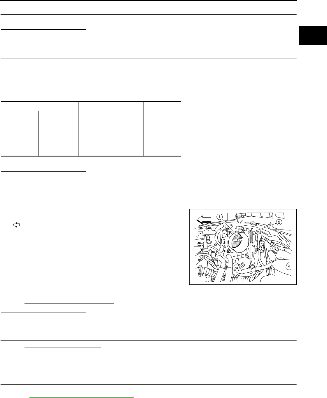
P2101 ELECTRIC THROTTLE CONTROL FUNCTION
EC-819
< COMPONENT DIAGNOSIS > [FOR USA (FEDERAL) AND CANADA]
C
D
E
F
G
H
I
J
K
L
M
A
EC
N
P
O
8.CHECK INTERMITTENT INCIDENT
Refer to GI-41, "Intermittent Incident".
Is the inspection result normal?
YES >> Replace IPDM E/R.
NO >> Repair or replace harness or connectors.
9.CHECK THROTTLE CONTROL MOTOR OUTPUT SIGNAL CIRCUIT FOR OPEN OR SHORT
1. Turn ignition switch OFF.
2. Disconnect electric throttle control actuator harness connector.
3. Disconnect ECM harness connector.
4. Check the continuity between electric throttle control actuator harness connector and ECM harness con-
nector.
5. Also check harness for short to ground and short to power.
Is the inspection result normal?
YES >> GO TO 10.
NO >> Repair or replace.
10.CHECK ELECTRIC THROTTLE CONTROL ACTUATOR VISUALLY
1. Remove the intake air duct.
2. Check if foreign matter is caught between the throttle valve (1)
and the housing.
- : Vehicle front
- Electric throttle control actuator (2)
Is the inspection result normal?
YES >> GO TO 11.
NO >> Remove the foreign matter and clean the electric throttle
control actuator inside.
11.CHECK THROTTLE CONTROL MOTOR
Refer to EC-820, "Component Inspection".
Is the inspection result normal?
YES >> GO TO 12.
NO >> GO TO 13.
12.CHECK INTERMITTENT INCIDENT
Refer to GI-41, "Intermittent Incident".
Is the inspection result normal?
YES >> GO TO 13.
NO >> Repair or replace harness or connectors.
13.REPLACE ELECTRIC THROTTLE CONTROL ACTUATOR
1. Replace malfunction electric throttle control actuator.
2. Go to EC-820, "Special Repair Requirement".
>> INSPECTION END
Electric throttle control actuator ECM Continuity
Connector Terminal Connector Terminal
F29
5
F7
5 Not existed
6 Existed
65 Existed
6 Not existed
ALBIA0061ZZ
Revision: 2008 August 2009 Rogue
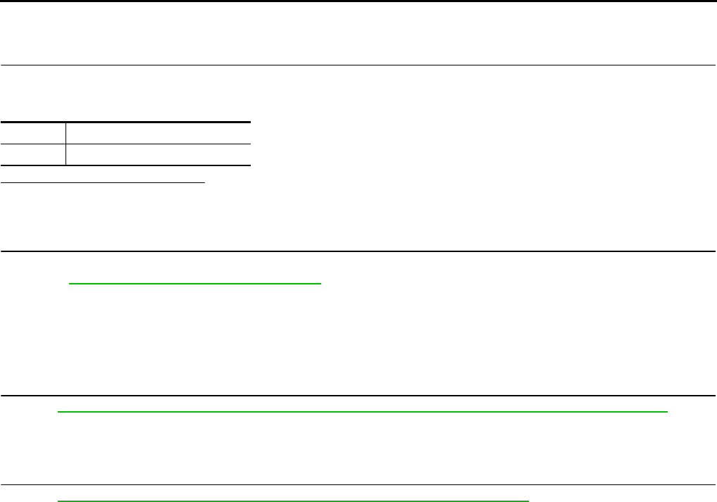
EC-820
< COMPONENT DIAGNOSIS > [FOR USA (FEDERAL) AND CANADA]
P2101 ELECTRIC THROTTLE CONTROL FUNCTION
Component Inspection INFOID:0000000004529699
1.CHECK THROTTLE CONTROL MOTOR
1. Disconnect electric throttle control actuator harness connector.
2. Check resistance between electric throttle control actuator terminals as follows.
Is the inspection result normal?
YES >> INSPECTION END
NO >> GO TO 2.
2.REPLACE ELECTRIC THROTTLE CONTROL ACTUATOR
1. Replace electric throttle control actuator.
2. Go to EC-820, "Special Repair Requirement".
>> INSPECTION END
Special Repair Requirement INFOID:0000000004533851
1.PERFORM THROTTLE VALVE CLOSED POSITION LEARNING
Refer to EC-504, "THROTTLE VALVE CLOSED POSITION LEARNING : Special Repair Requirement"
>> GO TO 2.
2.PERFORM IDLE AIR VOLUME LEARNING
Refer to EC-505, "IDLE AIR VOLUME LEARNING : Special Repair Requirement"
>> END
Terminals Resistance
5 and 6 Approx. 1 - 15 Ω [at 25 °C (77°F)]
Revision: 2008 August 2009 Rogue

P2118 THROTTLE CONTROL MOTOR
EC-821
< COMPONENT DIAGNOSIS > [FOR USA (FEDERAL) AND CANADA]
C
D
E
F
G
H
I
J
K
L
M
A
EC
N
P
O
P2118 THROTTLE CONTROL MOTOR
Description INFOID:0000000004529701
The throttle control motor is operated by the ECM and it opens and closes the throttle valve.
The current opening angle of the throttle valve is detected by the throttle position sensor. The throttle position
sensor and it provides feedback to the ECM, when open/closes the throttle valve in response to driving condi-
tions via the throttle control motor.
DTC Logic INFOID:0000000004529702
DTC DETECTION LOGIC
DTC CONFIRMATION PROCEDURE
1.PRECONDITIONING
If DTC CONFIRMATION PROCEDURE has been previously conducted, always turn ignition switch OFF and
wait at least 10 seconds before conducting the next test.
>> GO TO 2.
2.PERFORM DTC CONFIRMATION PROCEDURE
1. Turn ignition switch ON and wait at least 2 seconds.
2. Start engine and let it idle for 5 seconds.
3. Check DTC.
Is DTC detected?
YES >> Go to EC-821, "Diagnosis Procedure".
NO >> INSPECTION END
Diagnosis Procedure INFOID:0000000004529703
1.CHECK GROUND CONNECTION
1. Turn ignition switch OFF.
2. Check ground connection E21. Refer to Ground Inspection in GI-44, "Circuit Inspection".
Is the inspection result normal?
YES >> GO TO 2.
NO >> Repair or replace ground connection.
2.CHECK THROTTLE CONTROL MOTOR OUTPUT SIGNAL CIRCUIT FOR OPEN AND SHORT
1. Disconnect electric throttle control actuator harness connector.
2. Disconnect ECM harness connector.
3. Check the continuity between electric throttle control actuator harness connector and ECM harness con-
nector.
DTC No. Trouble diagnosis name DTC detecting condition Possible cause
P2118 Throttle control motor
circuit short ECM detects short in both circuits between
ECM and throttle control motor.
• Harness or connectors
(Throttle control motor circuit is shorted.)
• Electric throttle control actuator
(Throttle control motor)
Electric throttle control actuator ECM Continuity
Connector Terminal Connector Terminal
F29
5
F7
5 Not existed
6 Existed
65 Existed
6 Not existed
Revision: 2008 August 2009 Rogue

EC-822
< COMPONENT DIAGNOSIS > [FOR USA (FEDERAL) AND CANADA]
P2118 THROTTLE CONTROL MOTOR
4. Also check harness for short to ground and short to power.
Is the inspection result normal?
YES >> GO TO 3.
NO >> Repair or replace.
3.CHECK THROTTLE CONTROL MOTOR
Refer to EC-822, "Component Inspection".
Is the inspection result normal?
YES >> GO TO 4.
NO >> GO TO 5.
4.CHECK INTERMITTENT INCIDENT
Refer to GI-41, "Intermittent Incident".
Is the inspection result normal?
YES >> GO TO 5.
NO >> Repair or replace harness or connectors.
5.REPLACE ELECTRIC THROTTLE CONTROL ACTUATOR
1. Replace electric throttle control actuator.
2. Go to EC-822, "Special Repair Requirement".
>> INSPECTION END
Component Inspection INFOID:0000000004534083
1.CHECK THROTTLE CONTROL MOTOR
1. Disconnect electric throttle control actuator harness connector.
2. Check resistance between electric throttle control actuator terminals as follows.
Is the inspection result normal?
YES >> INSPECTION END
NO >> GO TO 2.
2.REPLACE ELECTRIC THROTTLE CONTROL ACTUATOR
1. Replace electric throttle control actuator.
2. Go to EC-822, "Special Repair Requirement".
>> INSPECTION END
Special Repair Requirement INFOID:0000000004533852
1.PERFORM THROTTLE VALVE CLOSED POSITION LEARNING
Refer to EC-504, "THROTTLE VALVE CLOSED POSITION LEARNING : Special Repair Requirement"
>> GO TO 2.
2.PERFORM IDLE AIR VOLUME LEARNING
Refer to EC-505, "IDLE AIR VOLUME LEARNING : Special Repair Requirement"
>> END
Terminals Resistance
5 and 6 Approx. 1 - 15 Ω [at 25 °C (77°F)]
Revision: 2008 August 2009 Rogue

P2119 ELECTRIC THROTTLE CONTROL ACTUATOR
EC-823
< COMPONENT DIAGNOSIS > [FOR USA (FEDERAL) AND CANADA]
C
D
E
F
G
H
I
J
K
L
M
A
EC
N
P
O
P2119 ELECTRIC THROTTLE CONTROL ACTUATOR
Description INFOID:0000000004529706
Electric throttle control actuator consists of throttle control motor, throttle position sensor, etc.
The throttle control motor is operated by the ECM and it opens and closes the throttle valve.
The throttle position sensor detects the throttle valve position, and sends the voltage signals to the ECM. The
ECM judges the current opening angle of the throttle valve from these signals and open/closes The throttle
valve in response to driving conditions via the throttle control motor.
DTC Logic INFOID:0000000004529707
DTC DETECTION LOGIC
DTC CONFIRMATION PROCEDURE
1.PRECONDITIONING
If DTC CONFIRMATION PROCEDURE has been previously conducted, always turn ignition switch OFF and
wait at least 10 seconds before conducting the next test.
>> GO TO 2.
2.PERFORM DTC CONFIRMATION PROCEDURE FOR MALFUNCTION A AND B
1. Turn ignition switch ON and wait at least 1 second.
2. Set selector lever to D position and wait at least 3 seconds.
3. Set selector lever to P position.
4. Turn ignition switch OFF and wait at least 10 seconds.
5. Turn ignition switch ON and wait at least 1 second.
6. Set selector lever to D position and wait at least 3 seconds.
7. Set selector lever to P position.
8. Turn ignition switch OFF, wait at least 10 seconds, and then turn ON.
9. Check DTC.
Is DTC detected?
YES >> Go to EC-823, "Diagnosis Procedure".
NO >> GO TO 3.
3.PERFORM DTC CONFIRMATION PROCEDURE FOR MALFUNCTION C
1. Turn ignition switch ON and wait at least 1 second.
2. Set selector lever to D position and wait at least 3 seconds.
3. Set selector lever to N or P position.
4. Start engine and let it idle for 3 seconds.
5. Check DTC.
Is DTC detected?
YES >> Go to EC-823, "Diagnosis Procedure".
NO >> INSPECTION END
Diagnosis Procedure INFOID:0000000004534082
1.CHECK ELECTRIC THROTTLE CONTROL ACTUATOR VISUALLY
1. Turn ignition switch OFF.
2. Remove the intake air duct.
DTC No. Trouble diagnosis name DTC detecting condition Possible cause
P2119 Electric throttle control
actuator
A) Electric throttle control actuator does not function
properly due to the return spring malfunction.
• Electric throttle control actuator
B) Throttle valve opening angle in fail-safe mode is
not in specified range.
C) ECM detects that the throttle valve is stuck open.
Revision: 2008 August 2009 Rogue
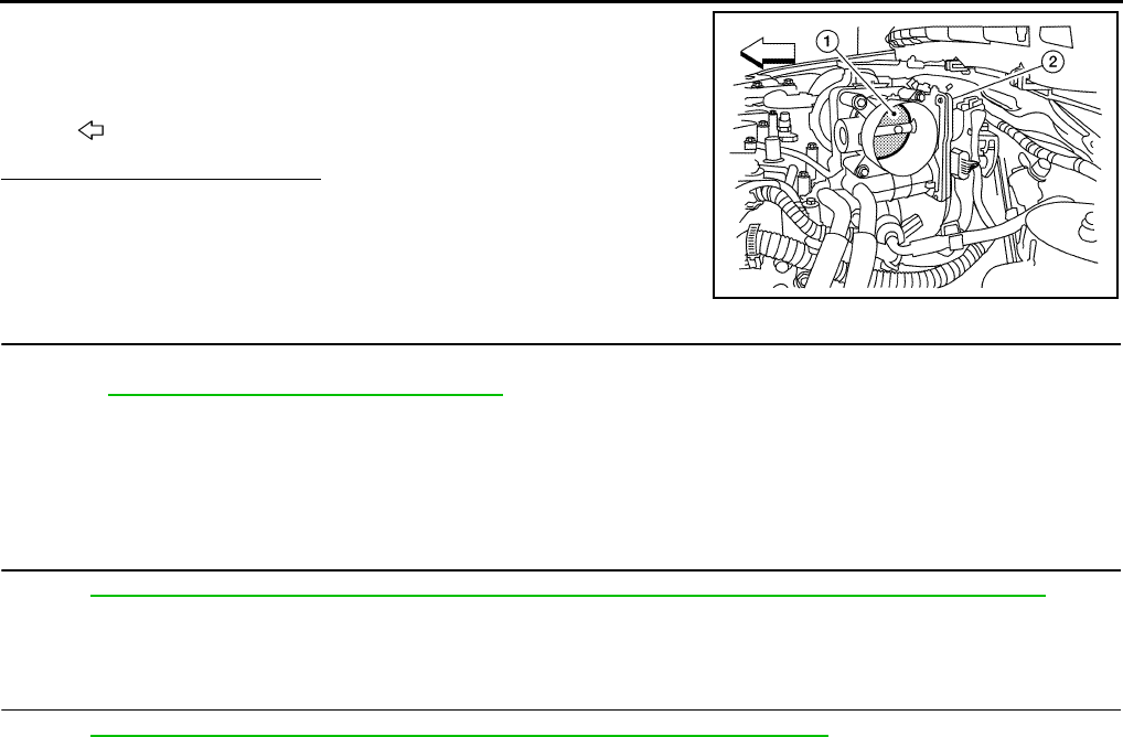
EC-824
< COMPONENT DIAGNOSIS > [FOR USA (FEDERAL) AND CANADA]
P2119 ELECTRIC THROTTLE CONTROL ACTUATOR
3. Check if foreign matter is caught between the throttle valve (1)
and the housing.
Is the inspection result normal?
YES >> GO TO 2.
NO >> Remove the foreign matter and clean the electric throttle
control actuator inside.
2.REPLACE ELECTRIC THROTTLE CONTROL ACTUATOR
1. Replace electric throttle control actuator.
2. Go to EC-824, "Special Repair Requirement".
>> INSPECTION END
Special Repair Requirement INFOID:0000000004533853
1.PERFORM THROTTLE VALVE CLOSED POSITION LEARNING
Refer to EC-504, "THROTTLE VALVE CLOSED POSITION LEARNING : Special Repair Requirement"
>> GO TO 2.
2.PERFORM IDLE AIR VOLUME LEARNING
Refer to EC-505, "IDLE AIR VOLUME LEARNING : Special Repair Requirement"
>> END
2. Electric throttle control actuator
: Vehicle front
ALBIA0061ZZ
Revision: 2008 August 2009 Rogue
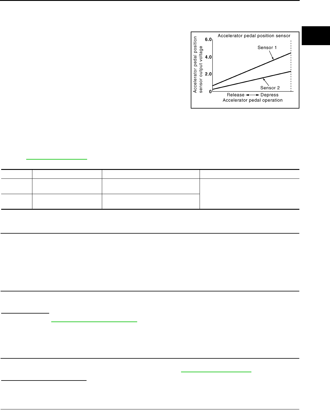
P2122, P2123 APP SENSOR
EC-825
< COMPONENT DIAGNOSIS > [FOR USA (FEDERAL) AND CANADA]
C
D
E
F
G
H
I
J
K
L
M
A
EC
N
P
O
P2122, P2123 APP SENSOR
Description INFOID:0000000004529710
The accelerator pedal position sensor is installed on the upper end
of the accelerator pedal assembly. The sensor detects the accelera-
tor position and sends a signal to the ECM.
Accelerator pedal position sensor has two sensors. These sensors
are a kind of potentiometer which transform the accelerator pedal
position into output voltage, and emit the voltage signals to the ECM.
The ECM judges the current opening angle of the accelerator pedal
from these signals and controls the throttle control motor based on
these signals.
Idle position of the accelerator pedal is determined by the ECM
receiving the signal from the accelerator pedal position sensor. The
ECM uses this signal for engine operations such as fuel cut.
DTC Logic INFOID:0000000004529711
DTC DETECTION LOGIC
NOTE:
If DTC P2122 or P2123 is displayed with DTC P0643, first perform the trouble diagnosis for DTC P0643.
Refer to EC-784, "DTC Logic".
DTC CONFIRMATION PROCEDURE
1.PRECONDITIONING
If DTC CONFIRMATION PROCEDURE has been previously conducted, always turn ignition switch OFF and
wait at least 10 seconds before conducting the next test.
TESTING CONDITION:
Before performing the following procedure, confirm that battery voltage is more than 8V at idle.
>> GO TO 2.
2.PERFORM DTC CONFIRMATION PROCEDURE
1. Start engine and let it idle for 1 second.
2. Check DTC.
Is DTC detected?
YES >> Go to EC-825, "Diagnosis Procedure".
NO >> INSPECTION END
Diagnosis Procedure INFOID:0000000004529712
1.CHECK GROUND CONNECTION
1. Turn ignition switch OFF.
2. Check ground connection E21. Refer to Ground Inspection in GI-44, "Circuit Inspection".
Is the inspection result normal?
YES >> GO TO 2.
NO >> Repair or replace ground connection.
2.CHECK APP SENSOR 1 POWER SUPPLY CIRCUIT
1. Disconnect accelerator pedal position (APP) sensor harness connector.
PBIB1741E
DTC No. Trouble diagnosis name DTC detecting condition Possible cause
P2122 Accelerator pedal position
sensor 1 circuit low input
An excessively low voltage from the APP
sensor 1 is sent to ECM. • Harness or connectors
(APP sensor 1 circuit is open or shorted.)
• Accelerator pedal position sensor
(APP sensor 1)
P2123 Accelerator pedal position
sensor 1 circuit high input
An excessively high voltage from the APP
sensor 1 is sent to ECM.
Revision: 2008 August 2009 Rogue

EC-826
< COMPONENT DIAGNOSIS > [FOR USA (FEDERAL) AND CANADA]
P2122, P2123 APP SENSOR
2. Turn ignition switch ON.
3. Check the voltage between APP sensor harness connector and ground.
Is the inspection result normal?
YES >> GO TO 3.
NO >> Repair open circuit or short to ground or short to power in harness or connectors.
3.CHECK APP SENSOR 1 GROUND CIRCUIT FOR OPEN AND SHORT
1. Turn ignition switch OFF.
2. Disconnect ECM harness connector.
3. Check the continuity between APP sensor harness connector and ECM harness connector.
4. Also check harness for short to ground and short to power.
Is the inspection result normal?
YES >> GO TO 4.
NO >> Repair open circuit or short to ground or short to power in harness or connectors.
4.CHECK APP SENSOR INPUT SIGNAL CIRCUIT FOR OPEN AND SHORT
1. Check the continuity between APP sensor harness connector and ECM harness connector.
2. Also check harness for short to ground and short to power.
Is the inspection result normal?
YES >> GO TO 5.
NO >> Repair open circuit or short to ground or short to power in harness or connectors.
5.CHECK APP SENSOR
Refer to EC-827, "Component Inspection".
Is the inspection result normal?
YES >> GO TO 7.
NO >> GO TO 6.
6.REPLACE ACCELERATOR PEDAL ASSEMBLY
1. Replace accelerator pedal assembly. Refer to ACC-3, "Removal and Installation".
2. Go to EC-827, "Special Repair Requirement".
>> INSPECTION END
7.CHECK INTERMITTENT INCIDENT
Refer to GI-41, "Intermittent Incident".
>> INSPECTION END
APP sensor Ground Voltage
Connector Terminal
E110 4 Ground Approx. 5 V
APP sensor ECM Continuity
Connector Terminal Connector Terminal
E110 2 E16 84 Existed
APP sensor ECM Continuity
Connector Terminal Connector Terminal
E110 3 E16 81 Existed
Revision: 2008 August 2009 Rogue

P2122, P2123 APP SENSOR
EC-827
< COMPONENT DIAGNOSIS > [FOR USA (FEDERAL) AND CANADA]
C
D
E
F
G
H
I
J
K
L
M
A
EC
N
P
O
Component Inspection INFOID:0000000004529713
1.CHECK ACCELERATOR PEDAL POSITION SENSOR
1. Reconnect all harness connectors disconnected.
2. Turn ignition switch ON.
3. Check the voltage between ECM harness connector terminals.
Is the inspection result normal?
YES >> INSPECTION END
NO >> GO TO 2.
2.REPLACE ACCELERATOR PEDAL ASSEMBLY
1. Replace accelerator pedal assembly.
2. Go to EC-827, "Special Repair Requirement".
>> INSPECTION END
Special Repair Requirement INFOID:0000000004529714
1.PERFORM ACCELERATOR PEDAL RELEASED POSITION LEARNING
Refer to EC-504, "ACCELERATOR PEDAL RELEASED POSITION LEARNING : Special Repair Require-
ment".
>> GO TO 2.
2.PERFORM THROTTLE VALVE CLOSED POSITION LEARNING
Refer to EC-504, "THROTTLE VALVE CLOSED POSITION LEARNING : Special Repair Requirement".
>> GO TO 3.
3.PERFORM IDLE AIR VOLUME LEARNING
Refer to EC-505, "IDLE AIR VOLUME LEARNING : Special Repair Requirement".
>> END
ECM
Condition Voltage+−
Connector Terminal Connector Terminal
E16
81
(APP sensor 1 signal) E16
84
(Sensor ground) Accelerator pedal
Fully released 0.6 - 0.9 V
Fully depressed 3.9 - 4.7 V
82
(APP sensor 2 signal)
100
(Sensor ground)
Fully released 0.3 - 0.6 V
Fully depressed 1.95 - 2.4 V
Revision: 2008 August 2009 Rogue
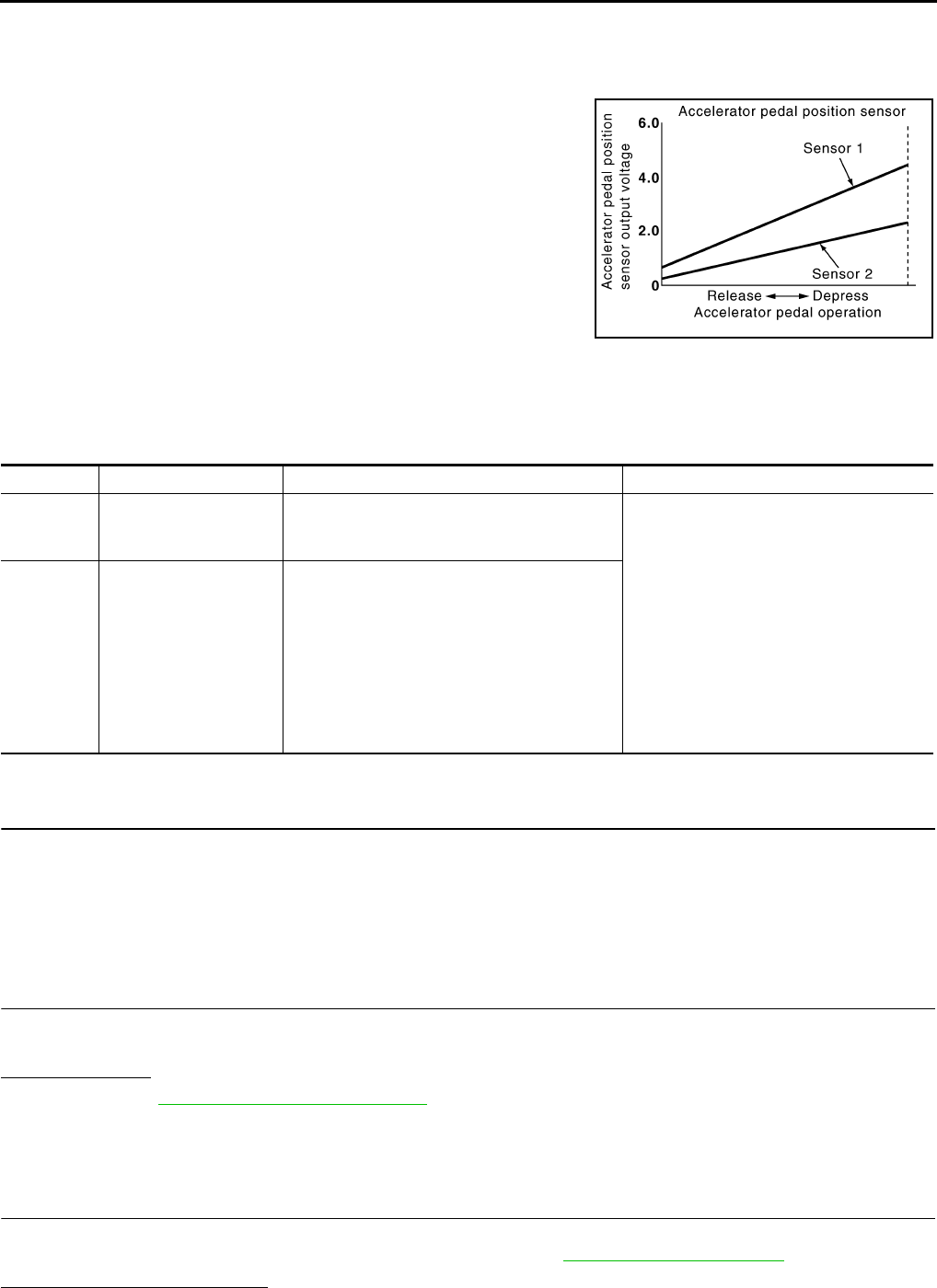
EC-828
< COMPONENT DIAGNOSIS > [FOR USA (FEDERAL) AND CANADA]
P2127, P2128 APP SENSOR
P2127, P2128 APP SENSOR
Description INFOID:0000000004534152
The accelerator pedal position sensor is installed on the upper end
of the accelerator pedal assembly. The sensor detects the accelera-
tor position and sends a signal to the ECM.
Accelerator pedal position sensor has two sensors. These sensors
are a kind of potentiometer which transform the accelerator pedal
position into output voltage, and emit the voltage signals to the ECM.
The ECM judges the current opening angle of the accelerator pedal
from these signals and controls the throttle control motor based on
these signals.
Idle position of the accelerator pedal is determined by the ECM
receiving the signal from the accelerator pedal position sensor. The
ECM uses this signal for engine operations such as fuel cut.
DTC Logic INFOID:0000000004529716
DTC DETECTION LOGIC
DTC CONFIRMATION PROCEDURE
1.PRECONDITIONING
If DTC CONFIRMATION PROCEDURE has been previously conducted, always turn ignition switch OFF and
wait at least 10 seconds before conducting the next test.
TESTING CONDITION:
Before performing the following procedure, confirm that battery voltage is more than 8V at idle.
>> GO TO 2.
2.PERFORM DTC CONFIRMATION PROCEDURE
1. Start engine and let it idle for 1 second.
2. Check DTC.
Is DTC detected?
YES >> Go to EC-828, "Diagnosis Procedure".
NO >> INSPECTION END
Diagnosis Procedure INFOID:0000000004529717
1.CHECK GROUND CONNECTION
1. Turn ignition switch OFF.
2. Check ground connection E21. Refer to Ground Inspection in GI-44, "Circuit Inspection".
Is the inspection result normal?
PBIB1741E
DTC No. Trouble diagnosis name DTC detecting condition Possible cause
P2127
Accelerator pedal posi-
tion sensor 2 circuit low
input
An excessively low voltage from the APP sen-
sor 2 is sent to ECM.
• Harness or connectors
(APP sensor 2 circuit is open or shorted.)
[Crankshaft position sensor (POS) circuit
is shorted.]
(Refrigerant pressure sensor circuit is
shorted.)
(EVAP control system pressure sensor
circuit is shorted.)
• Accelerator pedal position sensor
(APP sensor 2)
• Crankshaft position sensor (POS)
• Refrigerant pressure sensor
• EVAP control system pressure sensor
P2128
Accelerator pedal posi-
tion sensor 2 circuit high
input
An excessively high voltage from the APP sen-
sor 2 is sent to ECM.
Revision: 2008 August 2009 Rogue

P2127, P2128 APP SENSOR
EC-829
< COMPONENT DIAGNOSIS > [FOR USA (FEDERAL) AND CANADA]
C
D
E
F
G
H
I
J
K
L
M
A
EC
N
P
O
YES >> GO TO 2.
NO >> Repair or replace ground connection.
2.CHECK APP SENSOR 2 POWER SUPPLY CIRCUIT-I
1. Disconnect accelerator pedal position (APP) sensor harness connector.
2. Turn ignition switch ON.
3. Check the voltage between APP sensor harness connector and ground.
Is the inspection result normal?
YES >> GO TO 6.
NO >> GO TO 3.
3.CHECK APP SENSOR 2 POWER SUPPLY CIRCUIT-II
1. Turn ignition switch OFF.
2. Disconnect ECM harness connector.
3. Check the continuity between APP sensor harness connector and ECM harness connector.
Is the inspection result normal?
YES >> GO TO 4.
NO >> Repair open circuit.
4.CHECK SENSOR POWER SUPPLY CIRCUIT
Check harness for short to power and short to ground, between the following terminals.
Is the inspection result normal?
YES >> GO TO 5.
NO >> Repair short to ground or short to power in harness or connectors.
5.CHECK COMPONENT
Check the following.
• Crankshaft position sensor (POS) (Refer to EC-706, "Component Inspection".)
• EVAP control system pressure sensor (Refer to EC-744, "Component Inspection".)
• Refrigerant pressure sensor (Refer to EC-873, "Diagnosis Procedure".)
Is the inspection result normal?
YES >> GO TO 10.
NO >> Replace malfunctioning component.
6.CHECK APP SENSOR 2 GROUND CIRCUIT FOR OPEN AND SHORT
1. Turn ignition switch OFF.
2. Disconnect ECM harness connector.
3. Check the continuity between APP sensor harness connector and ECM harness connector.
APP sensor Ground Voltage
Connector Terminal
E110 5 Ground Approx. 5 V
APP sensor ECM Continuity
Connector Terminal Connector Terminal
E110 5 E16 87 Existed
ECM Sensor
Connector Terminal Name Connector Terminal
F8 72 Refrigerant pressure sensor E49 3
76 CKP sensor (POS) F20 1
E16 87 APP sensor E110 5
91 EVAP control system pressure sensor B47 3
Revision: 2008 August 2009 Rogue

EC-830
< COMPONENT DIAGNOSIS > [FOR USA (FEDERAL) AND CANADA]
P2127, P2128 APP SENSOR
4. Also check harness for short to ground and short to power.
Is the inspection result normal?
YES >> GO TO 7.
NO >> Repair open circuit or short to ground or short to power in harness or connectors.
7.CHECK APP SENSOR 2 INPUT SIGNAL CIRCUIT FOR OPEN AND SHORT
1. Check the continuity between APP sensor harness connector and ECM harness connector.
2. Also check harness for short to ground and short to power.
Is the inspection result normal?
YES >> GO TO 8.
NO >> Repair open circuit or short to ground or short to power in harness or connectors.
8.CHECK APP SENSOR
Refer to EC-830, "Component Inspection".
Is the inspection result normal?
YES >> GO TO 10.
NO >> GO TO 9.
9.REPLACE ACCELERATOR PEDAL ASSEMBLY
1. Replace accelerator pedal assembly. Refer to ACC-3, "Removal and Installation".
2. Go to EC-831, "Special Repair Requirement".
>> INSPECTION END
10.CHECK INTERMITTENT INCIDENT
Refer to GI-41, "Intermittent Incident".
>> INSPECTION END
Component Inspection INFOID:0000000004534153
1.CHECK ACCELERATOR PEDAL POSITION SENSOR
1. Reconnect all harness connectors disconnected.
2. Turn ignition switch ON.
3. Check the voltage between ECM harness connector terminals.
Is the inspection result normal?
APP sensor ECM Continuity
Connector Terminal Connector Terminal
E110 1 E16 100 Existed
APP sensor ECM Continuity
Connector Terminal Connector Terminal
E110 6 E16 82 Existed
ECM
Condition Voltage+−
Connector Terminal Connector Terminal
E16
81
(APP sensor 1 signal) E16
84
(Sensor ground) Accelerator pedal
Fully released 0.6 - 0.9 V
Fully depressed 3.9 - 4.7 V
82
(APP sensor 2 signal) 100
(Sensor ground)
Fully released 0.3 - 0.6 V
Fully depressed 1.95 - 2.4 V
Revision: 2008 August 2009 Rogue

P2127, P2128 APP SENSOR
EC-831
< COMPONENT DIAGNOSIS > [FOR USA (FEDERAL) AND CANADA]
C
D
E
F
G
H
I
J
K
L
M
A
EC
N
P
O
YES >> INSPECTION END
NO >> GO TO 2.
2.REPLACE ACCELERATOR PEDAL ASSEMBLY
1. Replace accelerator pedal assembly.
2. Go to EC-827, "Special Repair Requirement".
>> INSPECTION END
Special Repair Requirement INFOID:0000000004534157
1.PERFORM ACCELERATOR PEDAL RELEASED POSITION LEARNING
Refer to EC-504, "ACCELERATOR PEDAL RELEASED POSITION LEARNING : Special Repair Require-
ment".
>> GO TO 2.
2.PERFORM THROTTLE VALVE CLOSED POSITION LEARNING
Refer to EC-504, "THROTTLE VALVE CLOSED POSITION LEARNING : Special Repair Requirement".
>> GO TO 3.
3.PERFORM IDLE AIR VOLUME LEARNING
Refer to EC-505, "IDLE AIR VOLUME LEARNING : Special Repair Requirement".
>> END
Revision: 2008 August 2009 Rogue

EC-832
< COMPONENT DIAGNOSIS > [FOR USA (FEDERAL) AND CANADA]
P2135 TP SENSOR
P2135 TP SENSOR
Description INFOID:0000000004533788
Electric throttle control actuator consists of throttle control motor,
throttle position sensor, etc. The throttle position sensor responds to
the throttle valve movement.
The throttle position sensor has two sensors. These sensors are a
kind of potentiometer which transform the throttle valve position into
output voltage, and emit the voltage signals to the ECM. The ECM
judges the current opening angle of the throttle valve from these sig-
nals and contols the throttle valve opening angle in response to driv-
ing conditions via the throttle contorol motor.
DTC Logic INFOID:0000000004529721
DTC DETECTION LOGIC
NOTE:
If DTC P2135 is displayed with DTC P0643, first perform the trouble diagnosis for DTC P0643. Refer to
EC-784, "DTC Logic".
DTC CONFIRMATION PROCEDURE
1.PRECONDITIONING
If DTC CONFIRMATION PROCEDURE has been previously conducted, always turn ignition switch OFF and
wait at least 10 seconds before conducting the next test.
TESTING CONDITION:
Before performing the following procedure, confirm that battery voltage is more than 8V at idle.
>> GO TO 2.
2.PERFORM DTC CONFIRMATION PROCEDURE
1. Start engine and let it idle for 1 second.
2. Check DTC.
Is DTC detected?
YES >> Go to EC-832, "Diagnosis Procedure".
NO >> INSPECTION END
Diagnosis Procedure INFOID:0000000004529722
1.CHECK GROUND CONNECTION
1. Turn ignition switch OFF.
2. Check ground connection E21. Refer to Ground Inspection in GI-44, "Circuit Inspection".
Is the inspection result normal?
YES >> GO TO 2.
NO >> Repair or replace ground connection.
2.CHECK THROTTLE POSITION SENSOR POWER SUPPLY CIRCUIT-I
1. Disconnect electric throttle control actuator harness connector.
PBIB0145E
DTC No. Trouble diagnosis name DTC detecting condition Possible cause
P2135
Throttle position sensor
circuit range/perfor-
mance
Rationally incorrect voltage is sent to ECM
compared with the signals from TP sensor 1
and TP sensor 2.
• Harness or connector
(TP sensor 1 or 2 circuit is open or short-
ed.)
• Electric throttle control actuator
(TP sensor 1 or 2)
Revision: 2008 August 2009 Rogue

P2135 TP SENSOR
EC-833
< COMPONENT DIAGNOSIS > [FOR USA (FEDERAL) AND CANADA]
C
D
E
F
G
H
I
J
K
L
M
A
EC
N
P
O
2. Turn ignition switch ON.
3. Check the voltage between electric throttle control actuator harness connector and ground.
Is the inspection result normal?
YES >> GO TO 3.
NO >> Repair open circuit or short to ground or short to power in harness or connectors.
3.CHECK THROTTLE POSITION SENSOR POWER SUPPLY CIRCUIT-II
1. Turn ignition switch OFF.
2. Disconnect ECM harness connector.
3. Check the continuity between electric throttle control actuator harness connector and ground.
Is the inspection result normal?
YES >> GO TO 4.
NO >> Repair open circuit.
4.CHECK THROTTLE POSITION SENSOR GROUND CIRCUIT FOR OPEN AND SHORT
1. Turn ignition switch OFF.
2. Disconnect ECM harness connector.
3. Check the continuity between electric throttle control actuator harness connector and ground.
4. Also check harness for short to ground and short to power.
Is the inspection result normal?
YES >> GO TO 5.
NO >> Repair open circuit or short to ground or short to power in harness or connectors.
5.CHECK SENSOR POWER SUPPLY CIRCUIT
Check harness for short to power and short to ground, between the following terminals.
Is the inspection result normal?
YES >> GO TO 6.
NO >> Repair short to ground or short to power in harness or connectors.
6.CHECK THROTTLE POSITION SENSOR INPUT SIGNAL CIRCUIT FOR OPEN AND SHORT
1. Check the continuity between electric throttle control actuator harness connector and ground.
Electric throttle control actuator Ground Voltage (V)
Connector Terminal
F29 1 Ground Approx. 5
Electric throttle control actuator ECM Continuity
Connector Terminal Connector Terminal
F29 1 F8 47 Existed
Electric throttle control actuator ECM Continuity
Connector Terminal Connector Terminal
F29 4 F8 36 Existed
ECM Sensor
Connector Terminal Name Connector Terminal
F8 47 Electric throttle control actuator F29 1
59 CMP sensor (PHASE) F26 1
E16 83 APP sensor E110 4
Revision: 2008 August 2009 Rogue

EC-834
< COMPONENT DIAGNOSIS > [FOR USA (FEDERAL) AND CANADA]
P2135 TP SENSOR
2. Also check harness for short to ground and short to power.
Is the inspection result normal?
YES >> GO TO 7.
NO >> Repair open circuit or short to ground or short to power in harness or connectors.
7.CHECK THROTTLE POSITION SENSOR
Refer to EC-834, "Component Inspection".
Is the inspection result normal?
YES >> GO TO 9.
NO >> GO TO 8.
8.REPLACE ELECTRIC THROTTLE CONTROL ACTUATOR
1. Replace electric throttle control actuator.
2. Go to EC-835, "Special Repair Requirement".
>> INSPECTION END
9.CHECK INTERMITTENT INCIDENT
Refer to GI-41, "Intermittent Incident".
>> INSPECTION END
Component Inspection INFOID:0000000004533849
1.CHECK THROTTLE POSITION SENSOR
1. Turn ignition switch OFF.
2. Reconnect all harness connectors disconnected.
3. Perform EC-504, "THROTTLE VALVE CLOSED POSITION LEARNING : Special Repair Requirement".
4. Turn ignition switch ON.
5. Set selector lever to the D position.
6. Check the voltage between ECM harness connector terminals.
Is the inspection result normal?
YES >> INSPECTION END
NO >> GO TO 2.
2.REPLACE ELECTRIC THROTTLE CONTROL ACTUATOR
1. Replace electric throttle control actuator.
2. Perform EC-835, "Special Repair Requirement".
Electric throttle control actuator ECM Continuity
Connector Terminal Connector Terminal
F29 2F8 37 Existed
338
ECM
Condition Voltage+−
Connector Terminal Connector Terminal
F8
37
(TP sensor 1
signal) F8 36
(Sensor
ground)
Accelerator pedal
Fully released More than 0.36 V
Fully depressed Less than 4.75 V
38
(TP sensor 2
signal)
Fully released Less than 4.75 V
Fully depressed More than 0.36 V
Revision: 2008 August 2009 Rogue

P2135 TP SENSOR
EC-835
< COMPONENT DIAGNOSIS > [FOR USA (FEDERAL) AND CANADA]
C
D
E
F
G
H
I
J
K
L
M
A
EC
N
P
O
>> INSPECTION END
Special Repair Requirement INFOID:0000000004533850
1.PERFORM THROTTLE VALVE CLOSED POSITION LEARNING
Refer to EC-504, "THROTTLE VALVE CLOSED POSITION LEARNING : Special Repair Requirement"
>> GO TO 2.
2.PERFORM IDLE AIR VOLUME LEARNING
Refer to EC-505, "IDLE AIR VOLUME LEARNING : Special Repair Requirement"
>> END
Revision: 2008 August 2009 Rogue
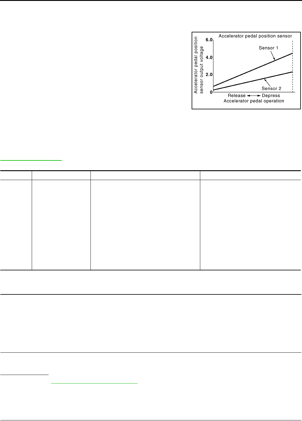
EC-836
< COMPONENT DIAGNOSIS > [FOR USA (FEDERAL) AND CANADA]
P2138 APP SENSOR
P2138 APP SENSOR
Description INFOID:0000000004534154
The accelerator pedal position sensor is installed on the upper end
of the accelerator pedal assembly. The sensor detects the accelera-
tor position and sends a signal to the ECM.
Accelerator pedal position sensor has two sensors. These sensors
are a kind of potentiometer which transform the accelerator pedal
position into output voltage, and emit the voltage signals to the ECM.
The ECM judges the current opening angle of the accelerator pedal
from these signals and controls the throttle control motor based on
these signals.
Idle position of the accelerator pedal is determined by the ECM
receiving the signal from the accelerator pedal position sensor. The
ECM uses this signal for engine operations such as fuel cut.
DTC Logic INFOID:0000000004529726
DTC DETECTION LOGIC
NOTE:
If DTC P2138 is displayed with DTC P0643, first perform the trouble diagnosis for DTC P0643. Refer to
EC-784, "DTC Logic".
DTC CONFIRMATION PROCEDURE
1.PRECONDITIONING
If DTC CONFIRMATION PROCEDURE has been previously conducted, always turn ignition switch OFF and
wait at least 10 seconds before conducting the next test.
TESTING CONDITION:
Before performing the following procedure, confirm that battery voltage is more than 8V at idle.
>> GO TO 2.
2.PERFORM DTC CONFIRMATION PROCEDURE
1. Start engine and let it idle for 1 second.
2. Check DTC.
Is DTC detected?
YES >> Go to EC-836, "Diagnosis Procedure".
NO >> INSPECTION END
Diagnosis Procedure INFOID:0000000004529727
1.CHECK GROUND CONNECTION
PBIB1741E
DTC No. Trouble diagnosis name DTC detecting condition Possible cause
P2138
Accelerator pedal posi-
tion sensor circuit range/
performance
Rationally incorrect voltage is sent to ECM
compared with the signals from APP sensor 1
and APP sensor 2.
• Harness or connector
(APP sensor 1 or 2 circuit is open or
shorted.)
[Crankshaft position sensor (POS) circuit
is shorted.)
(Refrigerant pressure sensor circuit is
shorted.)
(EVAP control system sensor circuit is
shorted.)
• Accelerator pedal position sensor
(APP sensor 1 or 2)
• Crankshaft position sensor (POS)
• Refrigerant pressure sensor
• EVAP control system pressure sensor
Revision: 2008 August 2009 Rogue

P2138 APP SENSOR
EC-837
< COMPONENT DIAGNOSIS > [FOR USA (FEDERAL) AND CANADA]
C
D
E
F
G
H
I
J
K
L
M
A
EC
N
P
O
1. Turn ignition switch OFF.
2. Check ground connection E21. Refer to Ground Inspection in GI-44, "Circuit Inspection".
Is the inspection result normal?
YES >> GO TO 2.
NO >> Repair or replace ground connection.
2.CHECK APP SENSOR 1 POWER SUPPLY CIRCUIT
1. Disconnect accelerator pedal position (APP) sensor harness connector.
2. Turn ignition switch ON.
3. Check the voltage between APP sensor harness connector and ground.
Is the inspection result normal?
YES >> GO TO 3.
NO >> Repair open circuit or short to ground or shot to power in harness or connectors.
3.CHECK APP SENSOR 2 POWER SUPPLY CIRCUIT-I
1. Turn ignition switch ON.
2. Check the voltage between APP sensor harness connector and ground.
Is the inspection result normal?
YES >> GO TO 7.
NO >> GO TO 4.
4.CHECK APP SENSOR 2 POWER SUPPLY CIRCUIT-II
1. Turn ignition switch OFF.
2. Disconnect ECM harness connector.
3. Check the continuity between APP sensor harness connector and ECM harness connector.
Is the inspection result normal?
YES >> GO TO 5.
NO >> Repair open circuit or short to ground or shot to power in harness or connectors.
5.CHECK SENSOR POWER SUPPLY CIRCUIT
Check harness for short to power and short to ground, between the following terminals.
Is the inspection result normal?
YES >> GO TO 6.
APP sensor Ground Voltage
Connector Terminal
E110 4 Ground Approx. 5 V
APP sensor Ground Voltage
Connector Terminal
E110 5 Ground Approx. 5 V
APP sensor ECM Continuity
Connector Terminal Connector Terminal
E110 5 E16 87 Existed
ECM Sensor
Connector Terminal Name Connector Terminal
F8 72 Refrigerant pressure sensor E49 3
76 CKP sensor (POS) F20 1
E16 87 APP sensor E110 5
91 EVAP control system pressure sensor B47 3
Revision: 2008 August 2009 Rogue
EC-838
< COMPONENT DIAGNOSIS > [FOR USA (FEDERAL) AND CANADA]
P2138 APP SENSOR
NO >> Repair short to ground or short to power in harness or connectors.
6.CHECK COMPONENT
Check the following.
• Crankshaft position sensor (POS) (Refer to EC-706, "Component Inspection".)
• EVAP control system pressure sensor (Refer to EC-744, "Component Inspection".)
• Refrigerant pressure sensor (Refer to EC-873, "Diagnosis Procedure".)
Is the inspection result normal?
YES >> GO TO 11.
NO >> Replace malfunctioning component.
7.CHECK APP SENSOR GROUND CIRCUIT FOR OPEN AND SHORT
1. Turn ignition switch OFF.
2. Disconnect ECM harness connector.
3. Check the continuity between APP sensor harness connector and ECM harness connector as follows.
4. Also check harness for short to ground and short to power.
Is the inspection result normal?
YES >> GO TO 8.
NO >> Repair open circuit or short to ground or shot to power in harness or connectors.
8.CHECK APP SENSOR INPUT SIGNAL CIRCUIT FOR OPEN AND SHORT
1. Check the continuity between APP sensor harness connector and ECM harness connector as follows.
2. Also check harness for short to ground and short to power.
Is the inspection result normal?
YES >> GO TO 9.
NO >> Repair open circuit or short to ground or shot to power in harness or connectors.
9.CHECK APP SENSOR
Refer to EC-839, "Component Inspection".
Is the inspection result normal?
YES >> GO TO 11.
NO >> GO TO 10.
10.REPLACE ACCELERATOR PEDAL ASSEMBLY
1. Replace accelerator pedal assembly. Refer to ACC-3, "Removal and Installation".
2. Go to EC-839, "Special Repair Requirement".
>> INSPECTION END
11.CHECK INTERMITTENT INCIDENT
Refer to GI-41, "Intermittent Incident".
>> INSPECTION END
APP sensor ECM Continuity
Connector Terminal Connector Terminal
E110 2E16 84 Existed
1100
APP sensor ECM Continuity
Connector Terminal Connector Terminal
E110 6E16 82 Existed
381
Revision: 2008 August 2009 Rogue

P2138 APP SENSOR
EC-839
< COMPONENT DIAGNOSIS > [FOR USA (FEDERAL) AND CANADA]
C
D
E
F
G
H
I
J
K
L
M
A
EC
N
P
O
Component Inspection INFOID:0000000004534155
1.CHECK ACCELERATOR PEDAL POSITION SENSOR
1. Reconnect all harness connectors disconnected.
2. Turn ignition switch ON.
3. Check the voltage between ECM harness connector terminals.
Is the inspection result normal?
YES >> INSPECTION END
NO >> GO TO 2.
2.REPLACE ACCELERATOR PEDAL ASSEMBLY
1. Replace accelerator pedal assembly.
2. Go to EC-839, "Special Repair Requirement".
>> INSPECTION END
Special Repair Requirement INFOID:0000000004534156
1.PERFORM ACCELERATOR PEDAL RELEASED POSITION LEARNING
Refer to EC-504, "ACCELERATOR PEDAL RELEASED POSITION LEARNING : Special Repair Require-
ment".
>> GO TO 2.
2.PERFORM THROTTLE VALVE CLOSED POSITION LEARNING
Refer to EC-504, "THROTTLE VALVE CLOSED POSITION LEARNING : Special Repair Requirement".
>> GO TO 3.
3.PERFORM IDLE AIR VOLUME LEARNING
Refer to EC-505, "IDLE AIR VOLUME LEARNING : Special Repair Requirement".
>> END
ECM
Condition Voltage+−
Connector Terminal Connector Terminal
E16
81
(APP sensor 1 signal) E16
84
(Sensor ground) Accelerator pedal
Fully released 0.6 - 0.9 V
Fully depressed 3.9 - 4.7 V
82
(APP sensor 2 signal)
100
(Sensor ground)
Fully released 0.3 - 0.6 V
Fully depressed 1.95 - 2.4 V
Revision: 2008 August 2009 Rogue
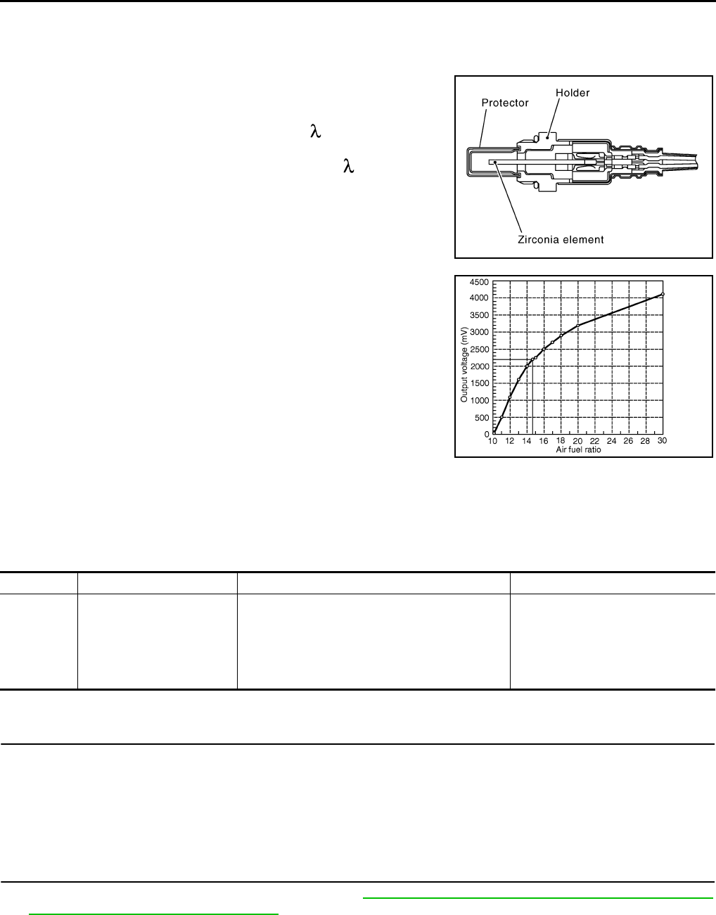
EC-840
< COMPONENT DIAGNOSIS > [FOR USA (FEDERAL) AND CANADA]
P2A00 A/F SENSOR 1
P2A00 A/F SENSOR 1
Description INFOID:0000000004533857
The air fuel ratio (A/F) sensor 1 is a planar one-cell limit current sen-
sor. The sensor element of the A/F sensor 1 is composed an elec-
trode layer, which transports ions. It has a heater in the element.
The sensor is capable of precise measurement = 1, but also in the
lean and rich range. Together with its control electronics, the sensor
outputs a clear, continuous signal throughout a wide range.
The exhaust gas components diffuse through the diffusion layer at
the sensor cell. An electrode layer is applied voltage, and this current
relative oxygen density in lean. Also this current relative hydrocar-
bon density in rich.
Therefore, the A/F sensor 1 is able to indicate air fuel ratio by this
electrode layer of current. In addition, a heater is integrated in the
sensor to ensure the required operating temperature of approxi-
mately 800°C (1,472°F).
DTC Logic INFOID:0000000004529731
DTC DETECTION LOGIC
To judge the malfunction, the A/F signal computed by ECM from the A/F sensor 1 signal is monitored so it will
not shift to LEAN side or RICH side.
DTC CONFIRMATION PROCEDURE
1.PRECONDITIONING
If DTC CONFIRMATION PROCEDURE has been previously conducted, always turn ignition switch OFF and
wait at least 10 seconds before conducting the next test.
TESTING CONDITION:
Before performing the following procedure, confirm that battery voltage is more than 11V at idle.
>> GO TO 2.
2.PERFORM DTC CONFIRMATION PROCEDURE
1. Clear the mixture ratio self-learning value. Refer to EC-506, "MIXTURE RATIO SELF-LEARNING VALUE
CLEAR : Special Repair Requirement".
2. Turn ignition switch OFF and wait at least 10 seconds.
3. Start engine and keep the engine speed between 3,500 and 4,000 rpm for 1 minute under no load.
4. Let engine idle for 1 minute.
5. Keep engine speed between 2,500 and 3,000 rpm for 20 minutes.
6. Check 1st trip DTC$.
JMBIA0112GB
PBIB3354E
DTC No. Trouble diagnosis name DTC detecting condition Possible Cause
P2A00 Air fuel ratio (A/F) sensor 1
circuit range/performance
• The output voltage computed by ECM from the
A/F sensor 1 signal is shifted to the lean side for
a specified period.
• The A/F signal computed by ECM from the A/F
sensor 1 signal shifts to the rich side for a spec-
ified period.
• A/F sensor 1
• A/F sensor 1 heater
• Fuel pressure
• Fuel injector
• Intake air leaks
Revision: 2008 August 2009 Rogue

P2A00 A/F SENSOR 1
EC-841
< COMPONENT DIAGNOSIS > [FOR USA (FEDERAL) AND CANADA]
C
D
E
F
G
H
I
J
K
L
M
A
EC
N
P
O
Is 1st trip DTC detected?
YES >> Go to EC-841, "Diagnosis Procedure".
NO >> INSPECTION END
Diagnosis Procedure INFOID:0000000004529732
1.CHECK GROUND CONNECTION
1. Turn ignition switch OFF.
2. Check ground connection E21. Refer to Ground Inspection in GI-44, "Circuit Inspection".
Is the inspection result normal?
YES >> GO TO 2.
NO >> Repair or replace ground connection.
2.RETIGHTEN A/F SENSOR 1
1. Loosen and retighten the A/F sensor 1. Refer to EM-32, "Removal and Installation".
>> GO TO 3.
3.CHECK FOR INTAKE AIR LEAK
1. Start engine and run it at idle.
2. Listen for an intake air leak after the mass air flow sensor.
Is intake air leak detected?
YES >> GO TO 4.
NO >> Repair or replace.
4.CLEAR THE MIXTURE RATIO SELF-LEARNING VALUE
1. Clear the mixture ratio self-learning value. Refer to EC-506, "MIXTURE RATIO SELF-LEARNING VALUE
CLEAR : Special Repair Requirement".
2. Run engine for at least 10 minutes at idle speed.
Is the 1st trip DTC P0171 or P0172 detected? Is it difficult to start engine?
YES >> Perform trouble diagnosis for DTC P0171or P0172. Refer to EC-679, "DTC Logic" or EC-683,
"DTC Logic".
NO >> GO TO 5.
5.CHECK HARNESS CONNECTOR
1. Turn ignition switch OFF.
2. Disconnect A/F sensor 1 harness connector.
3. Check harness connector for water.
Is the inspection result normal?
YES >> GO TO 6.
NO >> Repair or replace harness connector.
6.CHECK A/F SENSOR 1 POWER SUPPLY CIRCUIT
1. Turn ignition switch ON.
2. Check the voltage between A/F sensor 1 harness connector and ground.
Is the inspection result normal?
YES >> GO TO 8.
NO >> GO TO 7.
7.DETECT MALFUNCTIONING PART
Water should not exit.
A/F sensor 1 Ground Voltage
Connector Terminal
F27 4 Ground Battery voltage
Revision: 2008 August 2009 Rogue

EC-842
< COMPONENT DIAGNOSIS > [FOR USA (FEDERAL) AND CANADA]
P2A00 A/F SENSOR 1
Check the following.
• Harness connectors E6, F123
• IPDM E/R harness connector E14
• 15A fuse (No. 63)
• Harness for open or short between A/F sensor 1 and fuse
>> Repair or replace harness or connectors.
8.CHECK A/F SENSOR 1 INPUT SIGNAL CIRCUIT FOR OPEN AND SHORT
1. Turn ignition switch OFF.
2. Disconnect ECM harness connector.
3. Check the continuity between A/F sensor 1 harness connector and ECM harness connector.
4. Check the continuity between ECM harness connector or A/F sensor 1 harness connector and ground.
5. Also check harness for short to power.
Is the inspection result normal?
YES >> GO TO 9.
NO >> Repair open circuit or short to ground or short to power in harness or connectors.
9.CHECK A/F SENSOR 1 HEATER
Refer to EC-608, "Component Inspection".
Is the inspection result normal?
YES >> GO TO 10.
NO >> GO TO 11.
10.CHECK INTERMITTENT INCIDENT
Perform GI-41, "Intermittent Incident".
Is the inspection result normal?
YES >> GO TO 11.
NO >> Repair or replace.
11.REPLACE AIR FUEL RATIO (A/F) SENSOR 1
Replace air fuel ratio (A/F) sensor 1.
CAUTION:
• Discard any A/F sensor which has been dropped from a height of more than 0.5 m (19.7 in) onto a
hard surface such as a concrete floor; use a new one.
• Before installing new A/F sensor, clean exhaust system threads using oxygen sensor thread cleaner
[commercial service tool (J-43897-18 or J-43897-12)] and approved anti-seize lubricant (commercial
service tool).
Do you have CONSULT-III?
YES >> GO TO 12.
NO >> GO TO 13.
12.CONFIRM A/F ADJUSTMENT DATA
With CONSULT-III
1. Turn ignition switch ON.
A/F sensor 1 ECM Continuity
Connector Terminal Connector Terminal
F27 1F8 45 Existed
249
A/F sensor 1 ECM Ground Continuity
Connector Terminal Connector Terminal
F27 1F8 45 Ground Not existed
249
Revision: 2008 August 2009 Rogue

P2A00 A/F SENSOR 1
EC-843
< COMPONENT DIAGNOSIS > [FOR USA (FEDERAL) AND CANADA]
C
D
E
F
G
H
I
J
K
L
M
A
EC
N
P
O
2. Select “A/F ADJ-B1” in “DATA MONITOR” mode with CONSULT-III.
3. Check that “0.000” is displayed on CONSULT-III screen.
Is “0.000” displayed?
YES >> INSPECTION END
NO >> GO TO 13.
13.CLEAR THE MIXTURE RATIO SELF-LEARNING VALUE
Clear the mixture ratio self-learning value. Refer to EC-506, "MIXTURE RATIO SELF-LEARNING VALUE
CLEAR : Special Repair Requirement".
Do you have CONSULT-III?
YES >> GO TO 14.
NO >> INSPECTION END
14.CONFIRM A/F ADJUSTMENT DATA
With CONSULT-III
1. Turn ignition switch ON.
2. Select “A/F ADJ-B1” in “DATA MONITOR” mode with CONSULT-III.
3. Check that “0.000” is displayed on CONSULT-III screen.
>> INSPECTION END
Revision: 2008 August 2009 Rogue
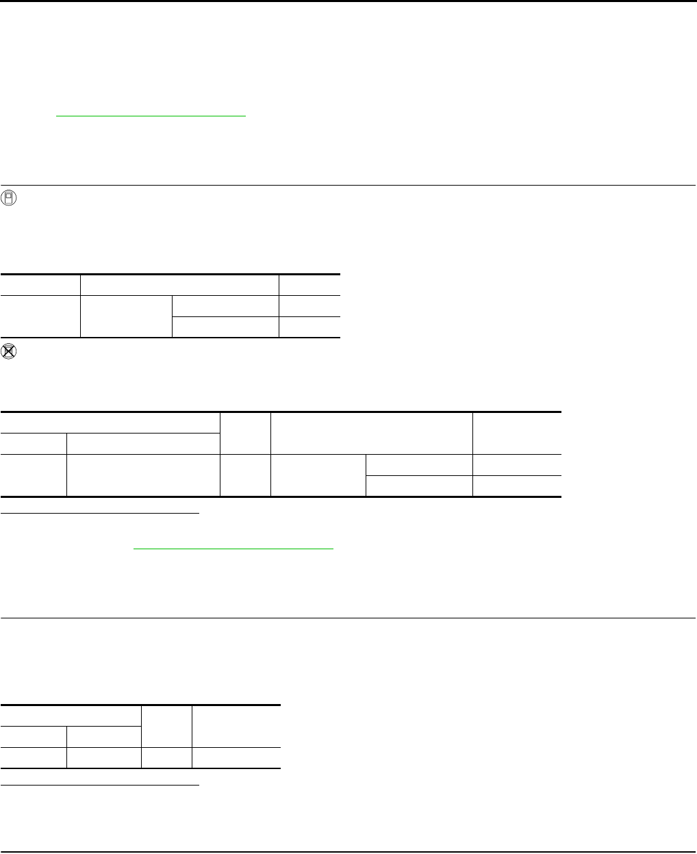
EC-844
< COMPONENT DIAGNOSIS > [FOR USA (FEDERAL) AND CANADA]
ASCD BRAKE SWITCH
ASCD BRAKE SWITCH
Description INFOID:0000000004534149
When the brake pedal is depressed, ASCD brake switch is turned OFF and stop lamp switch is turned ON.
ECM detects the state of the brake pedal by those two types of input (ON/OFF signal).
Refer to EC-535, "System Description" for the ASCD function.
Component Function Check INFOID:0000000004529734
1.CHECK FOR ASCD BRAKE SWITCH FUNCTION
With CONSULT-III
1. Turn ignition switch ON.
2. Select “BRAKE SW1” in “DATA MONITOR” mode with CONSULT-III.
3. Check “BRAKE SW1” indication under the following conditions.
Without CONSULT-III
1. Turn ignition switch ON.
2. Check the voltage between ECM harness connector and ground.
Is the inspection result normal?
YES >> INSPECTION END.
NO >> Refer to EC-844, "Diagnosis Procedure".
Diagnosis Procedure INFOID:0000000004529735
1.CHECK ASCD BRAKE SWITCH POWER SUPPLY CIRCUIT
1. Turn ignition switch OFF.
2. Disconnect ASCD brake switch harness connector.
3. Turn ignition switch ON.
4. Check the voltage between ASCD brake switch harness connector and ground.
Is the inspection result normal?
YES >> GO TO 3.
NO >> GO TO 2.
2.DETECT MALFUNCTIONING PART
Check the following.
• Harness connectors E105, M77
• 10A fuse (No. 1)
• Harness for open or short between ASCD brake switch and fuse
>> Repair open circuit or short to ground or short to power in harness or connectors.
Monitor item Condition Indication
BRAKE SW1 Brake pedal Slightly depressed OFF
Fully released ON
ECM Ground Condition Voltage (V)
Connector Terminal
E16 110
(ASCD brake switch signal) Ground Brake pedal Slightly depressed Approx. 0
Fully released Battery voltage
ASCD brake switch Ground Voltage
Connector Terminal
E112 1 Ground Battery voltage
Revision: 2008 August 2009 Rogue

ASCD BRAKE SWITCH
EC-845
< COMPONENT DIAGNOSIS > [FOR USA (FEDERAL) AND CANADA]
C
D
E
F
G
H
I
J
K
L
M
A
EC
N
P
O
3.CHECK ASCD BRAKE SWITCH INPUT SIGNAL CIRCUIT FOR OPEN AND SHORT
1. Turn ignition switch OFF.
2. Disconnect ECM harness connector.
3. Check the continuity between ASCD brake switch harness connector and ECM harness connector.
4. Also check harness for short to ground and short to power.
Is the inspection result normal?
YES >> GO TO 4.
NO >> Repair open circuit or short to ground or short to power in harness or connectors.
4.CHECK ASCD BRAKE SWITCH
Refer to EC-845, "Component Inspection (ASCD Brake Switch)".
Is the inspection result normal?
YES >> GO TO 5.
NO >> Replace ASCD brake switch.
5.CHECK INTERMITTENT INCIDENT
Refer to GI-41, "Intermittent Incident".
>> INSPECTION END
Component Inspection (ASCD Brake Switch) INFOID:0000000004534150
1.CHECK ASCD BRAKE SWITCH-I
1. Turn ignition switch OFF.
2. Disconnect ASCD brake switch harness connector.
3. Check the continuity between ASCD brake switch terminals under the following conditions.
Is the inspection result normal?
YES >> INSPECTION END
NO >> GO TO 2.
2.CHECK ASCD BRAKE SWITCH-II
1. Adjust ASCD brake switch installation. Refer to BR-19, "Inspection and Adjustment".
2. Check the continuity between ASCD brake switch terminals under the following conditions.
Is the inspection result normal?
YES >> INSPECTION END
NO >> Replace ASCD brake switch.
ASCD brake switch ECM Continuity
Connector Terminal Connector Terminal
E112 2 E16 110 Existed
Terminals Condition Continuity
1 and 2 Brake pedal Fully released Existed
Slightly depressed Not existed
Terminals Condition Continuity
1 and 2 Brake pedal Fully released Existed
Slightly depressed Not existed
Revision: 2008 August 2009 Rogue

EC-846
< COMPONENT DIAGNOSIS > [FOR USA (FEDERAL) AND CANADA]
ASCD INDICATOR
ASCD INDICATOR
Description INFOID:0000000004529737
ASCD indicator lamp illuminates to indicate ASCD operation status. Lamp has two indicators, CRUISE and
SET, and is integrated in combination meter.
CRUISE lamp illuminates when MAIN switch on ASCD steering switch is turned ON to indicated that ASCD
system is ready for operation.
SET lamp illuminates when the following conditions are met.
• CRUISE lamp is illuminated.
• SET/COAST switch on ASCD steering switch is turned ON while vehicle speed is within the range of the
ASCD setting.
SET lamp remains lit during ASCD control.
Refer to EC-535, "System Description" for the ASCD function.
Component Function Check INFOID:0000000004529738
1.ASCD INDICATOR FUNCTION
Check ASCD indicator under the following conditions.
Is the inspection result normal?
YES >> INSPECTION END
NO >> Go to EC-846, "Diagnosis Procedure".
Diagnosis Procedure INFOID:0000000004529739
1.CHECK DTC
Check that DTC UXXXX is not displayed.
Is the inspection result normal?
YES >> GO TO 2.
NO >> Perform trouble diagnosis for DTC UXXXX.
2.CHECK COMBINATION METER OPERATION
Refer to MWI-33, "CONSULT-III Function (METER/M&A)".
Is the inspection result normal?
YES >> GO TO 3.
NO >> Check combination meter circuit. Refer to MWI-9, "SPEEDOMETER : System Diagram".
3.CHECK INTERMITTENT INCIDENT
Refer to GI-41, "Intermittent Incident".
>> INSPECTION END
ASCD INDICATOR CONDITION SPECIFICATION
CRUISE LAMP • Ignition switch: ON • MAIN switch: Pressed at the
1st time →at the 2nd time ON → OFF
SET LAMP
•MAIN switch: ON
• When vehicle speed: Be-
tween 40 km/h (25 MPH) and
144 km/h (89 MPH)
• ASCD: Operating ON
• ASCD: Not operating OFF
Revision: 2008 August 2009 Rogue
COOLING FAN
EC-847
< COMPONENT DIAGNOSIS > [FOR USA (FEDERAL) AND CANADA]
C
D
E
F
G
H
I
J
K
L
M
A
EC
N
P
O
COOLING FAN
Description INFOID:0000000004529740
The ECM controls the cooling fan corresponding to the vehicle speed, engine coolant temperature, refrigerant
pressure, and air conditioner ON signal. The control system has 3-step control [HIGH/LOW/OFF].
COOLING FAN MOTOR
The cooling fan operates at each speed when the current flows in the cooling fan motor as follows.
The cooling fan operates at low (LOW) speed when cooling fan motors-1 and -2 are circuited in series under
the middle speed condition.
Refer to EC-542, "System Description".
Component Function Check INFOID:0000000004529741
1.CHECK COOLING FAN LOW SPEED FUNCTION
With CONSULT-III
1. Turn ignition switch ON.
2. Perform “COOLING FAN” in “ACTIVE TEST” mode with CONSULT-III and touch “LOW” on the CON-
SULT-III screen.
3. Check that cooling fans operates at low speed.
Without CONSULT-III
1. Start engine and let it idle.
2. Turn air conditioner switch and blower fan switch ON.
3. Check that cooling fan operates at low speed.
Is the inspection result normal?
YES >> GO TO 2.
NO >> Check cooling fan low speed control circuit. Refer to “PROCEDURE A” in EC-848, "Diagnosis
Procedure".
2.CHECK COOLING FAN HIGH SPEED FUNCTION
With CONSULT-III
1. Touch “HI” on the CONSULT-III screen.
2. Check that cooling fans operates at higher speed than low speed.
Without CONSULT-III
1. Turn ignition switch OFF.
2. Turn air conditioner switch and blower fan switch OFF.
3. Disconnect engine coolant temperature sensor harness connector.
4. Connect 150Ω resistor to engine coolant temperature sensor harness connector.
5. Restart engine and check that cooling fan operates at higher speed than low speed.
Is the inspection result normal?
YES >> INSPECTION END
NO >> Check cooling fan high speed control circuit. Refer to “PROCEDURE B” in EC-848, "Diagnosis
Procedure".
Cooling fan speed Cooling fan motor terminals
(+) (-)
Middle (MID)
1 3 and 4
2 3 and 4
1 and 2 3
1 and 2 4
High (HI) 1 and 2 3 and 4
Revision: 2008 August 2009 Rogue

EC-848
< COMPONENT DIAGNOSIS > [FOR USA (FEDERAL) AND CANADA]
COOLING FAN
Diagnosis Procedure INFOID:0000000004529742
PROCEDURE A
1.CHECK GROUND CONNECTION
1. Turn ignition switch OFF.
2. Check ground connection E38. Refer to Ground Inspection in GI-44, "Circuit Inspection".
Is the inspection result normal?
YES >> GO TO 2.
NO >> Repair or replace ground connection.
2.CHECK COOLING FAN MOTORS POWER SUPPLY CIRCUIT-I
1. Disconnect cooling fan motor-2 harness connector.
2. Check the voltage between cooling fan motor-2 harness connectors and ground.
3. Also check harness for short to ground or short to power.
Is the inspection result normal?
YES >> GO TO 4.
NO >> GO TO 3.
3.DETECT MALFUNCTIONING PART
Check the following.
• 40A fusible link (letter M)
• Harness for open or short between cooling fan motor-2 and battery
>> Repair open circuit or short to ground or short to power in harness or connectors.
4.CHECK COOLING FAN MOTORS POWER SUPPLY CIRCUIT-II
1. Disconnect cooling fan relay-4.
2. Turn ignition switch ON.
3. Check the voltage between cooling fan relay-4 harness connectors and ground.
4. Also check harness for short to ground or short to power.
Is the inspection result normal?
YES >> GO TO 6.
NO >> GO TO 5.
5.DETECT MALFUNCTIONING PART
Check the following.
• IPDM E/R harness connector E14
• 15A fuse (No. 63)
• Harness for open or short between cooling fan relay-4 and fuse
>> Repair open circuit or short to ground or short to power in harness or connectors.
6.CHECK COOLING FAN MOTORS GROUND CIRCUIT FOR OPEN AND SHORT
1. Turn ignition switch OFF.
2. Disconnect cooling fan motor-1 harness connector.
Cooling fan motor-2 Ground Voltage
Connector Terminal
E54 1Ground Battery voltage
2
Cooling fan relay-4 Ground Voltage
Connector Terminal
E57 2 Ground Battery voltage
Revision: 2008 August 2009 Rogue

COOLING FAN
EC-849
< COMPONENT DIAGNOSIS > [FOR USA (FEDERAL) AND CANADA]
C
D
E
F
G
H
I
J
K
L
M
A
EC
N
P
O
3. Check the continuity between cooling fan motor-1 harness connectors and ground.
4. Also check harness for short to ground or short to power.
Is the inspection result normal?
YES >> GO TO 7.
NO >> Repair open circuit or short to ground or short to power in harness or connectors.
7.CHECK COOLING FAN MOTORS CIRCUIT FOR OPEN AND SHORT
1. Disconnect IPDM E/R harness connector E13.
2. Check the continuity between cooling fan motor-2 harness connectors and cooling fan relay-4 harness
connectors.
3. Check the continuity between cooling fan relay-4 harness connectors and cooling fan motor-1 harness
connectors and ground.
4. Check the continuity between cooling fan relay-4 harness connectors and IPDM E/R harness connectors.
5. Also check harness for short to ground and short to power.
Is the inspection result normal?
YES >> GO TO 8.
NO >> Repair open circuit or short to ground or short to power in harness or connectors.
8.CHECK COOLING FAN RELAY-4
Refer to EC-852, "Component Inspection (Cooling Fan Relay)".
Is the inspection result normal?
YES >> GO TO 9.
NO >> Replace cooling fan relay.
9.CHECK COOLING FAN MOTORS
Refer to EC-852, "Component Inspection (Cooling Fan Motor)".
Is the inspection result normal?
YES >> GO TO 10.
NO >> Replace malfunctioning cooling fan motor.
10.CHECK INTERMITTENT INCIDENT
Perform GI-41, "Intermittent Incident".
Is the inspection result normal?
YES >> Replace IPDM E/R.
NO >> Repair or replace harness or connector.
Cooling fan motor-1 Ground Continuity
Connector Terminal
E53 3Ground Existed
4
Cooling fan motor-2 Cooling fan relay-4 Continuity
Connector Terminal Connector Terminal
E543E573Existed
Cooling fan relay-4 Cooling fan motor-1 Continuity
Connector Terminal Connector Terminal
E57 5 E53 2 Existed
Cooling fan relay-4 IPDM E/R Continuity
Connector Terminal Connector Terminal
E57 1 E13 31 Existed
Revision: 2008 August 2009 Rogue

EC-850
< COMPONENT DIAGNOSIS > [FOR USA (FEDERAL) AND CANADA]
COOLING FAN
PROCEDURE B
1.CHECK GROUND CONNECTION
1. Turn ignition switch OFF.
2. Check ground connection E21, E38. Refer to Ground Inspection in GI-44, "Circuit Inspection".
Is the inspection result normal?
YES >> GO TO 2.
NO >> Repair or replace ground connection.
2.CHECK IPDM E/R POWER SUPPLY AND GROUND CIRCUIT
Power supply and ground circuit. Refer to PCS-15, "Diagnosis Procedure".
Is the inspection result normal?
YES >> GO TO 3.
NO >> Repair or replace malfunctioning part.
3.CHECK COOLING FAN MOTORS POWER SUPPLY CIRCUIT-I
1. Disconnect cooling fan motor-2 harness connector.
2. Check the voltage between cooling fan motor-2 harness connector and ground.
3. Also check harness for short to ground or short to power.
Is the inspection result normal?
YES >> GO TO 5.
NO >> GO TO 4.
4.DETECT MALFUNCTIONING PART
Check the following.
• 40A fusible link (letter M)
• Harness for open or short between cooling fan motor-2 and battery
>> Repair open circuit or short to ground or short to power in harness or connectors.
5.CHECK COOLING FAN MOTORS POWER SUPPLY CIRCUIT-II
1. Disconnect cooling fan relay-5.
2. Turn ignition switch ON.
3. Check the voltage between cooling fan relay-5 harness connector and ground.
4. Also check harness for short to ground or short to power.
Is the inspection result normal?
YES >> GO TO 7.
NO >> GO TO 6.
6.DETECT MALFUNCTIONING PART
Check the following.
• IPDM E/R harness connector E14
• 15A fuse (No. 63)
• Harness for open or short between cooling fan relay-5 and fuse
Cooling fan motor-2 Ground Voltage
Connector Terminal
E54 1Ground Battery voltage
2
Cooling fan relay-5 Ground Voltage
Connector Terminal
E59 2 Ground Battery voltage
Revision: 2008 August 2009 Rogue

COOLING FAN
EC-851
< COMPONENT DIAGNOSIS > [FOR USA (FEDERAL) AND CANADA]
C
D
E
F
G
H
I
J
K
L
M
A
EC
N
P
O
>> Repair open circuit or short to ground or short to power in harness or connectors.
7.CHECK COOLING FAN MOTORS GROUND CIRCUIT FOR OPEN AND SHORT
1. Turn ignition switch OFF.
2. Disconnect cooling fan motor-1 harness connector.
3. Check the continuity between cooling fan motor-1 harness connector and ground.
4. Check the continuity between cooling fan relay-5 harness connector and ground.
5. Also check harness for short to ground or short to power.
Is the inspection result normal?
YES >> GO TO 8.
NO >> Repair open circuit or short to ground or short to power in harness or connectors.
8.CHECK COOLING FAN MOTORS CIRCUIT FOR OPEN AND SHORT
1. Disconnect IPDM E/R harness connector E15.
2. Check the continuity between cooling fan motor-2 harness connector and cooling fan relay-5 harness con-
nector.
3. Check the continuity between cooling fan motor-2 harness connectors and IPDM E/R harness connec-
tors.
4. Check the continuity between cooling fan relay-5 harness connectors and IPDM E/R harness connectors.
5. Check the continuity between cooling fan motor-1 harness connectors and IPDM E/R harness connec-
tors.
6. Also check harness for short to ground and short to power.
Is the inspection result normal?
YES >> GO TO 9.
Cooling fan motor-1 Ground Continuity
Connector Terminal
E53 3Ground Existed
4
Cooling fan relay-5 Ground Continuity
Connector Terminal
E59 5 Ground Existed
Cooling fan motor-2 Cooling fan relay-5 Continuity
Connector Terminal Connector Terminal
E54 4 E59 3 Existed
Cooling fan motor-2 IPDM E/R Continuity
Connector Terminal Connector Terminal
E54 3 E10 7 Existed
Cooling fan relay-5 IPDM E/R Continuity
Connector Terminal Connector Terminal
E59 1 E15 50 Existed
Cooling fan motor-1 IPDM E/R Continuity
Connector Terminal Connector Terminal
E53 1E10 4Existed
28
Revision: 2008 August 2009 Rogue
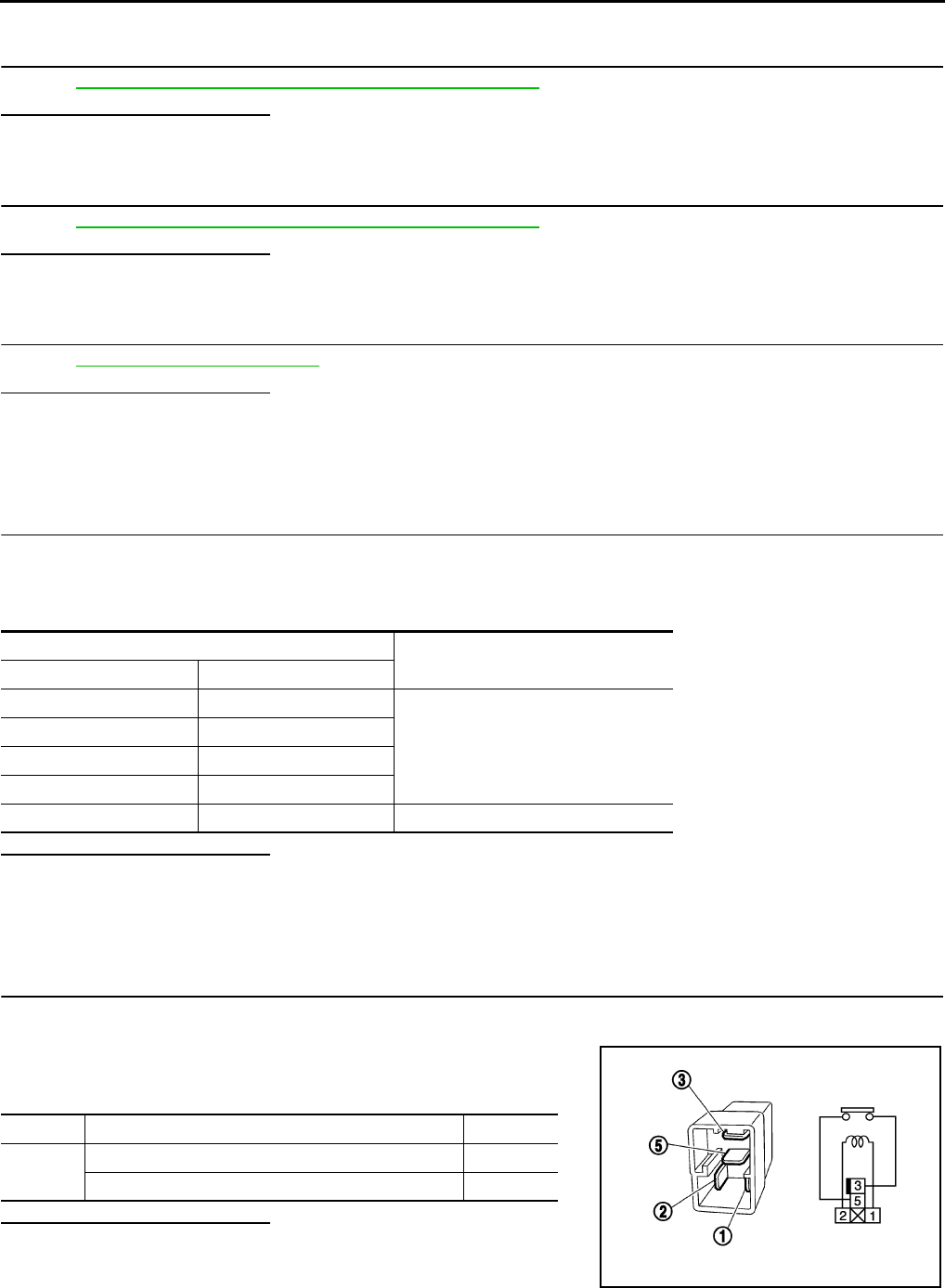
EC-852
< COMPONENT DIAGNOSIS > [FOR USA (FEDERAL) AND CANADA]
COOLING FAN
NO >> Repair open circuit or short to ground or short to power in harness or connectors.
9.CHECK COOLING FAN RELAY-5
Refer to EC-852, "Component Inspection (Cooling Fan Relay)".
Is the inspection result normal?
YES >> GO TO 10.
NO >> Replace cooling fan relay.
10.CHECK COOLING FAN MOTORS
Refer to EC-852, "Component Inspection (Cooling Fan Motor)".
Is the inspection result normal?
YES >> GO TO 11.
NO >> Replace malfunctioning cooling fan motor.
11.CHECK INTERMITTENT INCIDENT
Perform GI-41, "Intermittent Incident".
Is the inspection result normal?
YES >> Replace IPDM E/R.
NO >> Repair or replace harness or connector.
Component Inspection (Cooling Fan Motor) INFOID:0000000004529743
1.CHECK COOLING FAN MOTORS
1. Turn ignition switch OFF.
2. Disconnect cooling fan motor-1 and -2 harness connectors E53, E54.
3. Supply cooling fan motor terminals with battery voltage and check operation.
Is the inspection result normal?
YES >> INSPECTION END
NO >> Replace cooling fan motor.
Component Inspection (Cooling Fan Relay) INFOID:0000000004529744
1.CHECK COOLING FAN RELAYS
1. Turn ignition switch OFF.
2. Remove cooling fan relay.
3. Check the continuity between cooling fan relay terminals under
the following conditions.
Is the inspection result normal?
YES >> INSPECTION END
NO >> Replace cooling fan relay.
Cooling fan motor terminals Operation
(+) (-)
1 3 and 4
Cooling fans operates at low speed.
2 3 and 4
1 and 2 3
1 and 2 4
1 and 2 3 and 4 Cooling fans operates at high speed.
Terminals Conditions Continuity
3 and 5 12V direct current supply between terminals 1 and 2 Existed
No current supply Not existed
PBIB0098E
Revision: 2008 August 2009 Rogue

ELECTRICAL LOAD SIGNAL
EC-853
< COMPONENT DIAGNOSIS > [FOR USA (FEDERAL) AND CANADA]
C
D
E
F
G
H
I
J
K
L
M
A
EC
N
P
O
ELECTRICAL LOAD SIGNAL
Description INFOID:0000000004529745
The electrical load signal (Headlamp switch signal, rear window defogger switch signal, etc.) is transferred
through the CAN communication line from BCM to ECM via IPDM E/R.
Component Function Check INFOID:0000000004529746
1.CHECK REAR WINDOW DEFOGGER SWITCH FUNCTION
1. Turn ignition switch ON.
2. Connect CONSULT-III and select “DATA MONITOR” mode.
3. Select “LOAD SIGNAL” and check indication under the following conditions.
Is the inspection result normal?
YES >> GO TO 2.
NO >> Go to EC-853, "Diagnosis Procedure".
2.CHECK LIGHTING SWITCH FUNCTION
Check “LOAD SIGNAL” indication under the following conditions.
Is the inspection result normal?
YES >> GO TO 3.
NO >> Go to EC-853, "Diagnosis Procedure".
3.CHECK HEATER FAN CONTROL SWITCH FUNCTION
Select “HEATER FAN SW” and check indication under the following conditions.
Is the inspection result normal?
YES >> INSPECTION END
NO >> Go to EC-853, "Diagnosis Procedure".
Diagnosis Procedure INFOID:0000000004529747
1.INSPECTION START
Confirm the malfunctioning circuit (rear window defogger, headlamp or heater fan). Refer to EC-853, "Compo-
nent Function Check".
Which circuit is related to the incident?
Rear window defogger>>GO TO 2.
Headlamp>>GO TO 3.
Heater fan>>GO TO 4.
2.CHECK REAR WINDOW DEFOGGER SYSTEM
Refer to DEF-4, "System Diagram".
Monitor item Condition Indication
LOAD SIGNAL Rear window defogger switch ON ON
OFF OFF
Monitor item Condition Indication
LOAD SIGNAL Lighting switch ON at 2nd position ON
OFF OFF
Monitor item Condition Indication
HEATER FAN SW Heater fan control switch ON ON
OFF OFF
Revision: 2008 August 2009 Rogue

EC-854
< COMPONENT DIAGNOSIS > [FOR USA (FEDERAL) AND CANADA]
ELECTRICAL LOAD SIGNAL
>> INSPECTION END
3.CHECK HEADLAMP SYSTEM
Refer to EXL-8, "System Diagram" (XENON TYPE) or EXL-136, "System Diagram" (HALOGEN TYPE).
>> INSPECTION END
4.CHECK HEATER FAN CONTROL SYSTEM
Refer to VTL-3, "System Description".
>> INSPECTION END
Revision: 2008 August 2009 Rogue
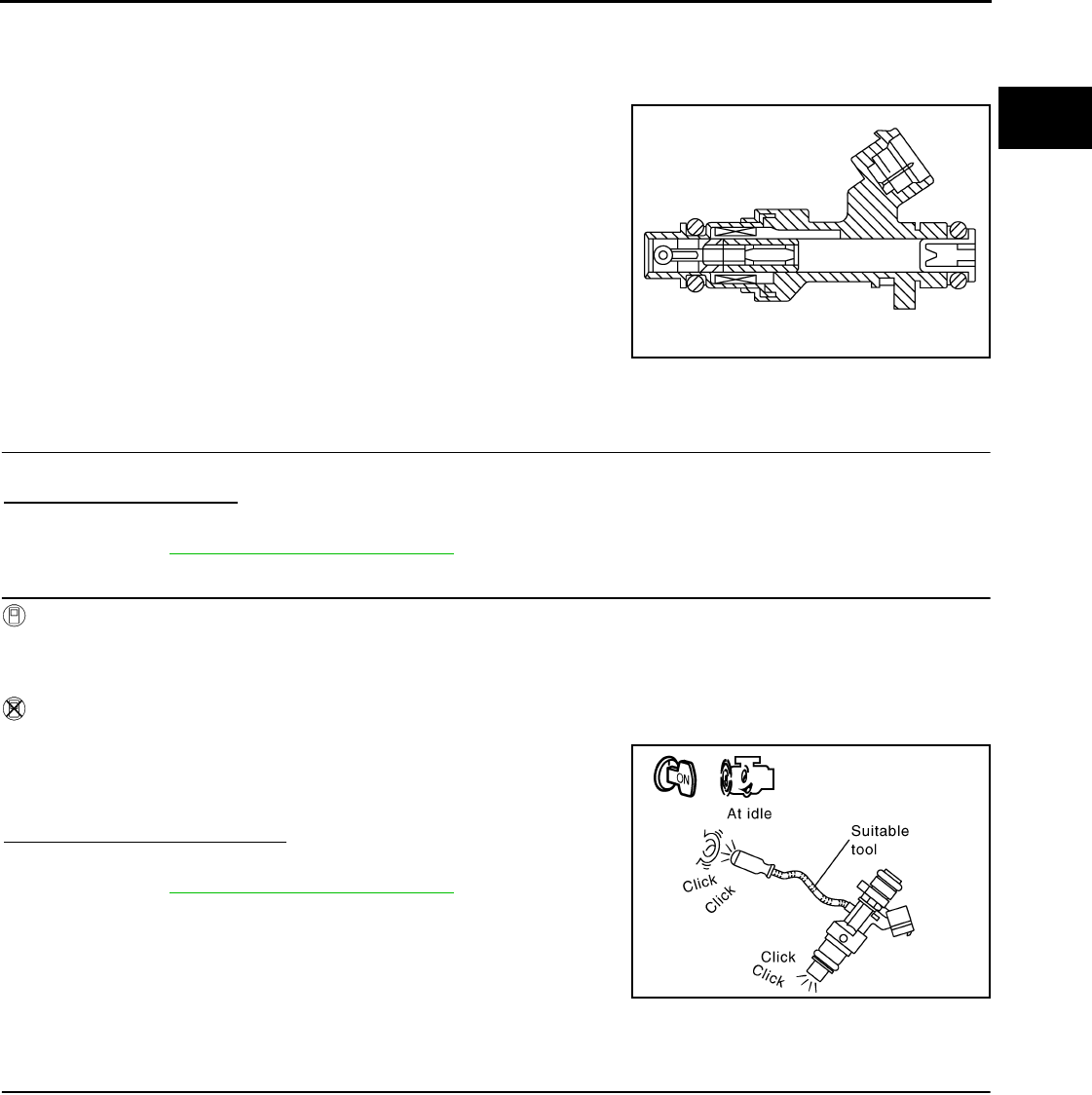
FUEL INJECTOR
EC-855
< COMPONENT DIAGNOSIS > [FOR USA (FEDERAL) AND CANADA]
C
D
E
F
G
H
I
J
K
L
M
A
EC
N
P
O
FUEL INJECTOR
Description INFOID:0000000004529748
The fuel injector is a small, precise solenoid valve. When the ECM
supplies a ground to the fuel injector circuit, the coil in the fuel injec-
tor is energized. The energized coil pulls the ball valve back and
allows fuel to flow through the fuel injector into the intake manifold.
The amount of fuel injected depends upon the injection pulse dura-
tion. Pulse duration is the length of time the fuel injector remains
open. The ECM controls the injection pulse duration based on
engine fuel needs.
Component Function Check INFOID:0000000004529749
1.INSPECTION START
Turn ignition switch to START.
Are any cylinders ignited?
YES >> GO TO 2.
NO >> Go to EC-855, "Diagnosis Procedure".
2.CHECK FUEL INJECTOR FUNCTION
With CONSULT-III
1. Start engine.
2. Perform “POWER BALANCE” in “ACTIVE TEST” mode with CONSULT-III.
3. Check that each circuit produces a momentary engine speed drop.
Without CONSULT-III
1. Let engine idle.
2. Listen to each fuel injector operating sound.
Is the inspection result normal?
YES >> INSPECTION END
NO >> Go to EC-855, "Diagnosis Procedure".
Diagnosis Procedure INFOID:0000000004529750
1.CHECK FUEL INJECTOR POWER SUPPLY CIRCUIT
1. Turn ignition switch OFF.
2. Disconnect fuel injector harness connector.
3. Turn ignition switch ON.
4. Check the voltage between fuel injector harness connector and ground.
PBIA9664J
Clicking noise should be heard.
PBIB3332E
Revision: 2008 August 2009 Rogue

EC-856
< COMPONENT DIAGNOSIS > [FOR USA (FEDERAL) AND CANADA]
FUEL INJECTOR
Is the inspection result normal?
YES >> GO TO 3.
NO >> GO TO 2.
2.DETECT MALFUNCTIONING PART
Check the following.
• Harness connectors E7, F121
• IPDM E/R harness connector E14
• 15A fuse (No. 64)
• Harness for open or short between fuel injector and fuse
>> Repair open circuit or short to ground or short to power in harness or connectors.
3.CHECK FUEL INJECTOR OUTPUT SIGNAL CIRCUIT FOR OPEN AND SHORT
1. Turn ignition switch OFF.
2. Disconnect ECM harness connector.
3. Check the continuity between fuel injector harness connector and ECM harness connector.
4. Also check harness for short to ground and short to power.
Is the inspection result normal?
YES >> GO TO 4.
NO >> Repair open circuit or short to ground or short to power in harness or connectors.
4.CHECK FUEL INJECTOR
Refer to EC-856, "Component Inspection".
Is the inspection result normal?
YES >> GO TO 5.
NO >> Replace malfunctioning fuel injector.
5.CHECK INTERMITTENT INCIDENT
Refer to GI-41, "Intermittent Incident".
Is the inspection result normal?
YES >> Replace IPDM E/R.
NO >> Repair open circuit or short to ground or short to power in harness or connectors.
Component Inspection INFOID:0000000004529751
1.CHECK FUEL INJECTOR
1. Turn ignition switch OFF.
2. Disconnect fuel injector harness connector.
Fuel injector Ground Voltage
Cylinder Connector Terminal
1F37 1
Ground Battery voltage
2F38 1
3F39 1
4F40 1
Fuel injector ECM Continuity
Cylinder Connector Terminal Connector Terminal
1F372
F7
32
Existed
2F382 31
3F392 30
4F402 29
Revision: 2008 August 2009 Rogue

FUEL INJECTOR
EC-857
< COMPONENT DIAGNOSIS > [FOR USA (FEDERAL) AND CANADA]
C
D
E
F
G
H
I
J
K
L
M
A
EC
N
P
O
3. Check resistance between fuel injector terminals as follows.
Is the inspection result normal?
YES >> INSPECTION END
NO >> Replace malfunctioning fuel injector.
Terminals Resistance
1 and 2 10.4 - 15.3 Ω [at 10 -60°C (50 - 140°F)]
Revision: 2008 August 2009 Rogue
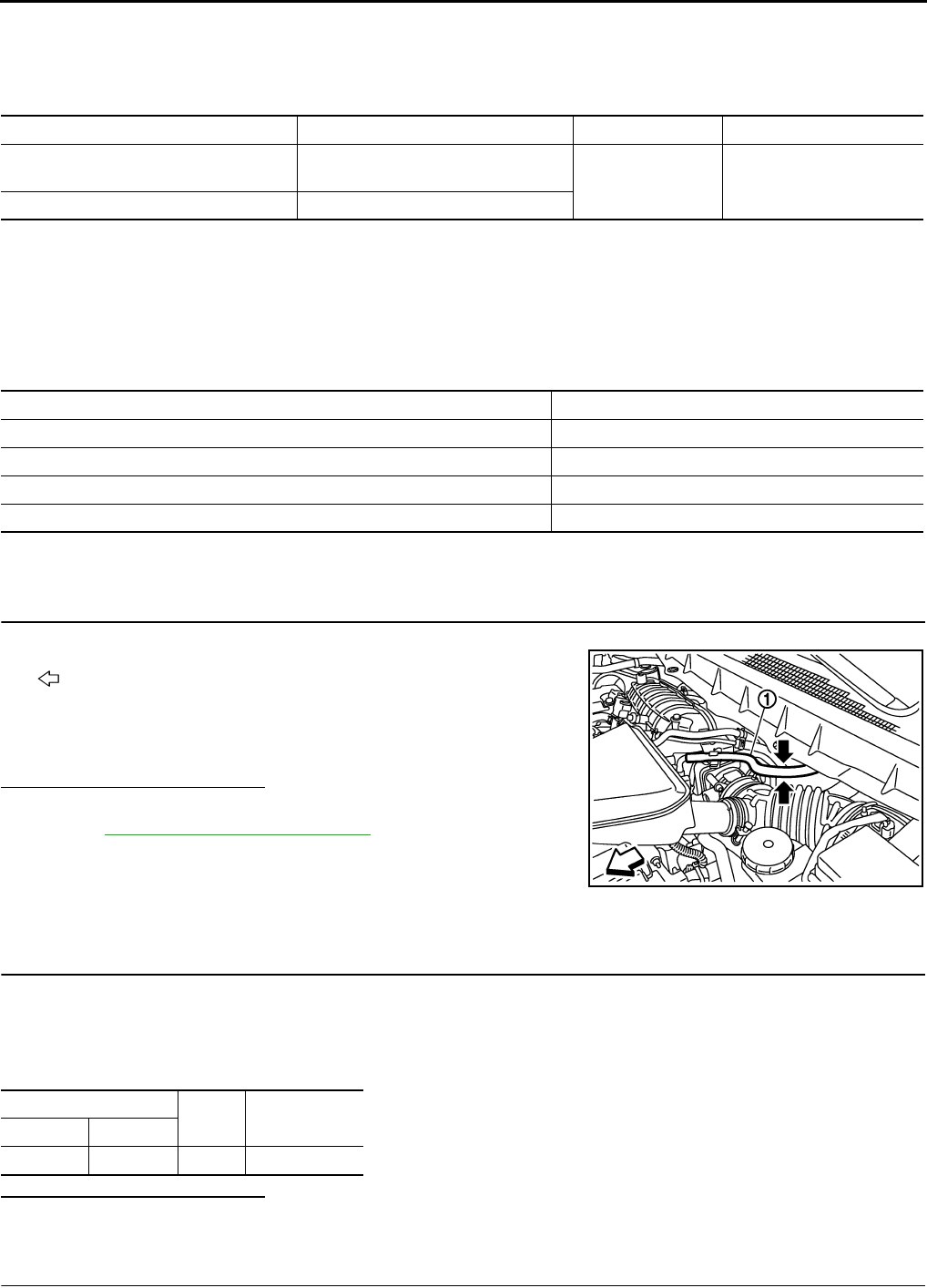
EC-858
< COMPONENT DIAGNOSIS > [FOR USA (FEDERAL) AND CANADA]
FUEL PUMP
FUEL PUMP
Description INFOID:0000000004529752
*: ECM determines the start signal status by the signals of engine speed and battery voltage.
The ECM activates the fuel pump for several seconds after the ignition switch is turned ON to improve engine
startability. If the ECM receives a engine speed signal from the camshaft position sensor (PHASE), it knows
that the engine is rotating, and causes the pump to operate. If the engine speed signal is not received when
the ignition switch is ON, the engine stalls. The ECM stops pump operation and prevents battery discharging,
thereby improving safety. The ECM does not directly drive the fuel pump. It controls the ON/OFF fuel pump
relay, which in turn controls the fuel pump.
Component Function Check INFOID:0000000004529753
1.CHECK FUEL PUMP FUNCTION
1. Turn ignition switch ON.
2. Pinch fuel feed hose (1) with two fingers.
- : Vehicle front
Is the inspection result normal?
YES >> INSPECTION END
NO >> EC-858, "Diagnosis Procedure".
Diagnosis Procedure INFOID:0000000004529754
1.CHECK FUEL PUMP POWER SUPPLY CIRCUIT-I
1. Turn ignition switch OFF.
2. Disconnect ECM harness connector.
3. Turn ignition switch ON.
4. Check the voltage between ECM harness connector and ground.
Is the inspection result normal?
YES >> GO TO 4.
NO >> GO TO 2.
2.CHECK FUEL PUMP POWER SUPPLY CIRCUIT-II
Sensor Input signal to ECM ECM function Actuator
Crankshaft position sensor (POS)
Camshaft position sensor (PHASE) Engine speed* Fuel pump control Fuel pump relay
↓
Fuel pump
Battery Battery voltage*
Condition Fuel pump operation
Ignition switch is turned to ON. Operates for 1 second.
Engine running and cranking Operates.
When engine is stopped Stops in 1.5 seconds.
Except as shown above Stops.
Fuel pressure pulsation should be felt on the fuel feed
hose for 1 second after ignition switch is turned ON.
JMBIA0929ZZ
ECM Ground Voltage
Connector Terminal
F7 14 Ground Battery voltage
Revision: 2008 August 2009 Rogue

FUEL PUMP
EC-859
< COMPONENT DIAGNOSIS > [FOR USA (FEDERAL) AND CANADA]
C
D
E
F
G
H
I
J
K
L
M
A
EC
N
P
O
1. Turn ignition switch OFF.
2. Disconnect IDPDM E/R harness connector E13.
3. Check the continuity between IPDM E/R harness connector and ECM harness connector.
Is the inspection result normal?
YES >> GO TO 9.
NO >> GO TO 3.
3.DETECT MALFUNCTIONING PART
Check the following.
• Harness connectors E6, F123
• IPDM E/R connector E13
• Harness for open or short between ECM and IPDM E/R
>> Repair open circuit or short to ground or short to power in harness or connectors.
4.CHECK 15A FUSE
1. Disconnect 15A fuse (No. 57) from IPDM E/R.
2. Check 15A fuse.
Is the inspection result normal?
YES >> GO TO 5.
NO >> Replace fuse.
5.CHECK FUEL PUMP POWER SUPPLY CIRCUIT-III
1. Disconnect “fuel level sensor unit and fuel pump” harness connector.
2. Check the continuity between IPDM E/R harness connector and “fuel level sensor unit and fuel pump” and
ground.
Is the inspection result normal?
YES >> GO TO 7.
NO >> GO TO 6.
6.DETECT MALFUNCTIONING PART
Check the following.
• Harness connectors E105, M77
• Harness connectors M11, B1
• Harness for open or short between “fuel level sensor unit and fuel pump” and IPDM E/R
>> Repair open circuit or short to ground or short to power in harness or connectors.
7.CHECK FUEL PUMP GROUND CIRCUIT
1. Check the continuity between “fuel level sensor unit and fuel pump” and ground.
2. Also heck harness for short to power.
ECM IPDM E/R Continuity
Connector Terminal Connector Terminal
F7 14 E13 33 Existed
IPDM E/R Fuel level sensor unit
and fuel pump Continuity
Connector Terminal Connector Terminal
E14 46 B40 5 Existed
Fuel level sensor unit
and fuel pump Ground Continuity
Connector Terminal
B40 3 Ground Existed
Revision: 2008 August 2009 Rogue

EC-860
< COMPONENT DIAGNOSIS > [FOR USA (FEDERAL) AND CANADA]
FUEL PUMP
Is the inspection result normal?
YES >> GO TO 8.
NO >> Repair open circuit or short to power in harness or connectors.
8.CHECK FUEL PUMP
Refer to EC-860, "Component Inspection".
Is the inspection result normal?
YES >> GO TO 9.
NO >> Replace fuel pump.
9.CHECK INTERMITTENT INCIDENT
Refer to GI-41, "Intermittent Incident".
Is the inspection result normal?
YES >> Replace IPDM E/R.
NO >> Repair or replace harness or connectors.
Component Inspection INFOID:0000000004529755
1.CHECK FUEL PUMP
1. Turn ignition switch OFF.
2. Disconnect “fuel level sensor unit and fuel pump” harness connector.
3. Check resistance between “fuel level sensor unit and fuel pump” terminals as follows.
Is the inspection result normal?
YES >> INSPECTION END
NO >> Replace “fuel level sensor unit and fuel pump”.
Terminals Resistance
3 and 5 0.2 - 5.0 Ω [at 25°C (77°F)]
Revision: 2008 August 2009 Rogue

IGNITION SIGNAL
EC-861
< COMPONENT DIAGNOSIS > [FOR USA (FEDERAL) AND CANADA]
C
D
E
F
G
H
I
J
K
L
M
A
EC
N
P
O
IGNITION SIGNAL
Description INFOID:0000000004529756
The ignition signal from the ECM is sent to and amplified by the power transistor. The power transistor turns
ON and OFF the ignition coil primary circuit. This ON/OFF operation induces the proper high voltage in the coil
secondary circuit.
Component Function Check INFOID:0000000004529757
1.INSPECTION START
Turn ignition switch OFF, and restart engine.
Does the engine start?
YES-1 >> With CONSULT-III: GO TO 2.
YES-2 >> Without CONSULT-III: GO TO 3.
NO >> Go to EC-861, "Diagnosis Procedure".
2.IGNITION SIGNAL FUNCTION
With CONSULT-III
1. Perform “POWER BALANCE” in “ACTIVE TEST” mode with CONSULT-III.
2. Check that each circuit produces a momentary engine speed drop.
Is the inspection result normal?
YES >> INSPECTION END
NO >> Go to EC-861, "Diagnosis Procedure".
3.IGNITION SIGNAL FUNCTION
Without CONSULT-III
1. Let engine idle.
2. Read the voltage signal between ECM harness connector and ground.
NOTE:
The pulse cycle changes depending on rpm at idle.
Is the inspection result normal?
YES >> INSPECTION END
NO >> Go to EC-861, "Diagnosis Procedure".
Diagnosis Procedure INFOID:0000000004529758
1.CHECK IGNITION COIL POWER SUPPLY CIRCUIT-I
1. Turn ignition switch OFF, wait at least 10 seconds and then turn it ON.
2. Check the voltage between ECM harness connector and ground.
ECM Ground Voltage signal
Connector Terminal
F7
9
Ground
10
11
21
JMBIA0900G
B
ECM Ground Voltage
Connector Terminal
E16 105 Ground Battery voltage
Revision: 2008 August 2009 Rogue

EC-862
< COMPONENT DIAGNOSIS > [FOR USA (FEDERAL) AND CANADA]
IGNITION SIGNAL
Is the inspection result normal?
YES >> GO TO 2.
NO >> Go to EC-595, "Diagnosis Procedure".
2.CHECK IGNITION COIL POWER SUPPLY CIRCUIT-II
1. Turn ignition switch OFF.
2. Disconnect condenser-1 harness connector.
3. Turn ignition switch ON.
4. Check the voltage between condenser-1 harness connector and ground.
Is the inspection result normal?
YES >> GO TO 5.
NO >> GO TO 3.
3.CHECK IGNITION COIL POWER SUPPLY CIRCUIT-III
1. Turn ignition switch OFF.
2. Disconnect IPDM E/R harness connector E15.
3. Check the continuity between IPDM E/R harness connector and condenser-1 harness connector.
4. Also check harness for short to ground and short to power.
Is the inspection result normal?
YES >> Go to EC-595, "Diagnosis Procedure".
NO >> GO TO 4.
4.DETECT MALFUNCTIONING PART
Check the following.
• Harness connectors E7, F121
• Harness for open or short between IPDM E/R and condenser-1
>> Repair open circuit or short to ground or short to power in harness or connectors.
5.CHECK CONDENSER-1 GROUND CIRCUIT FOR OPEN AND SHORT
1. Turn ignition switch OFF.
2. Check the continuity between condenser-1 harness connector and ground.
3. Also check harness for short to power.
Is the inspection result normal?
YES >> GO TO 6.
NO >> Repair open circuit or short to ground or short to power in harness or connectors.
6.CHECK CONDENSER
Refer to EC-865, "Component Inspection (Condenser-1)"
Is the inspection result normal?
YES >> GO TO 7.
NO >> Replace condenser.
Condenser Ground Voltage
Connector Terminal
F13 1 Ground Battery voltage
IPDM E/R Condenser-1 Continuity
Connector Terminal Connector Terminal
E15 47 F13 1 Existed
Condenser-1 Ground Continuity
Connector Terminal
F13 2 Ground Existed
Revision: 2008 August 2009 Rogue

IGNITION SIGNAL
EC-863
< COMPONENT DIAGNOSIS > [FOR USA (FEDERAL) AND CANADA]
C
D
E
F
G
H
I
J
K
L
M
A
EC
N
P
O
7.CHECK IGNITION COIL POWER SUPPLY CIRCUIT-IV
1. Reconnect all harness connectors disconnected.
2. Disconnect ignition coil harness connector.
3. Turn ignition switch ON.
4. Check the voltage between ignition coil harness connector and ground.
Is the inspection result normal?
YES >> GO TO 8.
NO >> Repair open circuit or short to ground or short to power in harness or connectors.
8.CHECK IGNITION COIL GROUND CIRCUIT FOR OPEN AND SHORT
1. Turn ignition switch OFF.
2. Check the continuity between ignition coil harness connector and ground.
3. Also check harness for short to power.
Is the inspection result normal?
YES >> GO TO 9.
NO >> Repair open circuit or short to ground or short to power in harness or connectors.
9.CHECK IGNITION COIL OUTPUT SIGNAL CIRCUIT FOR OPEN AND SHORT
1. Disconnect ECM harness connector.
2. Check the continuity between ECM harness connector and ignition coil harness connector.
3. Also check harness for short to ground and short to power.
Is the inspection result normal?
YES >> GO TO 10.
NO >> Repair open circuit or short to ground or short to power in harness or connectors.
10.CHECK IGNITION COIL WITH POWER TRANSISTOR
Refer to EC-864, "Component Inspection (Ignition Coil with Power Transistor)".
Is the inspection result normal?
YES >> GO TO 11.
NO >> Replace malfunctioning ignition coil with power transistor.
Ignition coil Ground Voltage
Cylinder Connector Terminal
1F33 3
Ground Battery voltage
2F34 3
3F35 3
4F36 3
Ignition coil Ground Continuity
Cylinder Connector Terminal
1F33 2
Ground Existed
2F34 2
3F35 2
4F36 2
Ignition coil ECM Continuity
Cylinder Connector Terminal Connector Terminal
1F33 1
F7
11
Existed
2F34 1 10
3F35 1 9
4F36 1 21
Revision: 2008 August 2009 Rogue

EC-864
< COMPONENT DIAGNOSIS > [FOR USA (FEDERAL) AND CANADA]
IGNITION SIGNAL
11.CHECK INTERMITTENT INCIDENT
Refer to GI-41, "Intermittent Incident".
>> INSPECTION END
Component Inspection (Ignition Coil with Power Transistor) INFOID:0000000004529759
1.CHECK IGNITION COIL WITH POWER TRANSISTOR-I
1. Turn ignition switch OFF.
2. Disconnect ignition coil harness connector.
3. Check resistance between ignition coil terminals as follows.
Is the inspection result normal?
YES >> GO TO 2.
NO >> Replace malfunctioning ignition coil with power transistor.
2.CHECK IGNITION COIL WITH POWER TRANSISTOR-II
CAUTION:
Perform the following procedure in a place with no combustible objects and good ventilation.
1. Turn ignition switch OFF.
2. Reconnect all harness connectors disconnected.
3. Remove fuel pump fuse in IPDM E/R to release fuel pressure.
NOTE:
Do not use CONSULT-III to release fuel pressure, or fuel pressure applies again during the following pro-
cedure.
4. Start engine.
5. After engine stalls, crank it two or three times to release all fuel pressure.
6. Turn ignition switch OFF.
7. Remove all ignition coil harness connectors to avoid the electrical discharge from the ignition coils.
8. Remove ignition coil and spark plug of the cylinder to be checked.
9. Crank engine for 5 seconds or more to remove combustion gas in the cylinder.
10. Connect spark plug and harness connector to ignition coil.
11. Fix ignition coil using a rope etc. with gap of 13 - 17 mm (0.52 -
0.66 in) between the edge of the spark plug and grounded metal
portion as shown in the figure.
12. Crank engine for approximately 3 seconds, and check whether
spark is generated between the spark plug and the grounded
metal portion.
CAUTION:
• Never place the spark plug and the ignition coil within 50
cm (19.7 in) each other. Be careful not to get an electrical
shock while checking, because the electrical discharge
voltage becomes 20kV or more.
• It might damage the ignition coil if the gap of more than 17 mm (0.66 in) is made.
NOTE:
When the gap is less than 13 mm (0.52 in), a spark might be generated even if the coil is malfunc-
tioning.
Is the inspection result normal?
YES >> INSPECTION END
NO >> Replace malfunctioning ignition coil with power transistor.
Terminals Resistance [Ωat 25°C (77°F)]
1 and 2 Except 0 or ∞
1 and 3 Except 0
2 and 3
Spark should be generated.
JMBIA0066G
B
Revision: 2008 August 2009 Rogue

IGNITION SIGNAL
EC-865
< COMPONENT DIAGNOSIS > [FOR USA (FEDERAL) AND CANADA]
C
D
E
F
G
H
I
J
K
L
M
A
EC
N
P
O
Component Inspection (Condenser-1) INFOID:0000000004529760
1.CHECK CONDENSER-1
1. Turn ignition switch OFF.
2. Disconnect condenser-1 harness connector.
3. Check resistance between condenser-1 terminals as follows.
Is the inspection result normal?
YES >> INSPECTION END
NO >> Replace condenser-1.
Terminals Resistance
1 and 2 Above 1 MΩ [at 25°C (77°F)]
Revision: 2008 August 2009 Rogue

EC-866
< COMPONENT DIAGNOSIS > [FOR USA (FEDERAL) AND CANADA]
MALFUNCTION INDICATOR LAMP
MALFUNCTION INDICATOR LAMP
Description INFOID:0000000004529761
The Malfunction Indicator Lamp (MIL) is located on the combination
meter.
The MIL will illuminate when the ignition switch is turned ON without
the engine running. This is a bulb check.
When the engine is started, the MIL should turn off. If the MIL
remains illuminated, the on board diagnostic system has detected an
engine system malfunction.
For details, refer to EC-866, "Diagnosis Procedure".
Component Function Check INFOID:0000000004529762
1.CHECK MIL FUNCTION
1. Turn ignition switch ON.
2. Check that MIL illuminate.
Is the inspection result normal?
YES >> INSPECTION END
NO >> Go to EC-866, "Diagnosis Procedure".
Diagnosis Procedure INFOID:0000000004529763
1.CHECK DTC
Check that DTC UXXXX is not displayed.
Is the inspection result normal?
YES >> GO TO 2.
NO >> Perform trouble diagnosis for DTC UXXXX.
2.CHECK DTC WITH METER
Refer to MWI-33, "CONSULT-III Function (METER/M&A)".
Is the inspection result normal?
YES >> GO TO 3.
NO >> Repair or replace.
3.CHECK INTERMITTENT INCIDENT
Refer to GI-41, "Intermittent Incident".
Is the inspection result normal?
YES >> Replace combination meter.
NO >> Repair or replace.
SEF217U
Revision: 2008 August 2009 Rogue
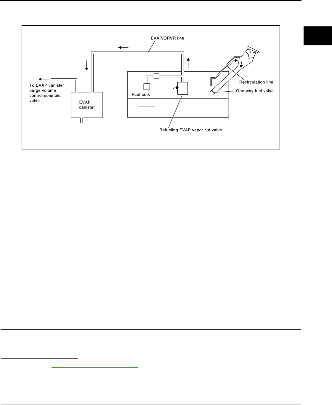
ON BOARD REFUELING VAPOR RECOVERY (ORVR)
EC-867
< COMPONENT DIAGNOSIS > [FOR USA (FEDERAL) AND CANADA]
C
D
E
F
G
H
I
J
K
L
M
A
EC
N
P
O
ON BOARD REFUELING VAPOR RECOVERY (ORVR)
Description INFOID:0000000004529764
From the beginning of refueling, the air and vapor inside the fuel tank go through refueling EVAP vapor cut
valve and EVAP/ORVR line to the EVAP canister. The vapor is absorbed by the EVAP canister and the air is
released to the atmosphere.
When the refueling has reached the full level of the fuel tank, the refueling EVAP vapor cut valve is closed and
refueling is stopped because of auto shut-off. The vapor which was absorbed by the EVAP canister is purged
during driving.
WARNING:
When conducting inspections below, be sure to observe the following:
• Put a “CAUTION: FLAMMABLE” sign in workshop.
• Never smoke while servicing fuel system. Keep open flames and sparks away from work area.
• Always furnish the workshop with a CO2 fire extinguisher.
CAUTION:
• Before removing fuel line parts, carry out the following procedures:
- Put drained fuel in an explosion-proof container and put lid on securely.
- Release fuel pressure from fuel line. Refer to EC-923, "Inspection".
- Disconnect battery ground cable.
• Always replace O-ring when the fuel gauge retainer is removed.
• Never kink or twist hose and tube when they are installed.
• Never tighten hose and clamps excessively to avoid damaging hoses.
• After installation, run engine and check for fuel leaks at connections.
• Never attempt to top off the fuel tank after the fuel pump nozzle shuts off automatically.
Continued refueling may cause fuel overflow, resulting in fuel spray and possibly a fire.
Component Function Check INFOID:0000000004529765
1.CHECK ORVR FUNCTION
Check whether the following symptoms are present.
• Fuel odor from EVAP canister is strong.
• Cannot refuel/Fuel odor from the fuel filler opening is strong while refueling.
Are any symptoms present?
YES >> Go to EC-867, "Diagnosis Procedure".
NO >> INSPECTION END
Diagnosis Procedure INFOID:0000000004529766
1.INSPECTION START
Check whether the following symptoms are present.
A: Fuel odor from EVAP canister is strong.
PBIB1068E
Revision: 2008 August 2009 Rogue

EC-868
< COMPONENT DIAGNOSIS > [FOR USA (FEDERAL) AND CANADA]
ON BOARD REFUELING VAPOR RECOVERY (ORVR)
B: Cannot refuel/Fuel odor from the fuel filler opening is strong while refueling.
Which symptom is present?
A>>GO TO 2.
B>>GO TO 7.
2.CHECK EVAP CANISTER
1. Remove EVAP canister with EVAP canister vent control valve and EVAP control system pressure sensor
attached.
2. Weigh the EVAP canister with EVAP canister vent control valve and EVAP control system pressure sensor
attached.
The weight should be less than 2.1 kg (4.6 lb).
Is the inspection result normal?
YES >> GO TO 3.
NO >> GO TO 4.
3.CHECK IF EVAP CANISTER IS SATURATED WITH WATER
Check if water will drain from EVAP canister.
Does water drain from the EVAP canister?
YES >> GO TO 4.
NO >> GO TO 6.
4.REPLACE EVAP CANISTER
Replace EVAP canister with a new one.
>> GO TO 5.
5.DETECT MALFUNCTIONING PART
Check the EVAP hose between EVAP canister and vehicle frame for clogging or poor connection.
>> Repair or replace EVAP hose.
6.CHECK REFUELING EVAP VAPOR CUT VALVE
Refer to EC-870, "Component Inspection".
Is the inspection result normal?
YES >> INSPECTION END
NO >> Replace refueling EVAP vapor cut valve with fuel tank.
7.CHECK EVAP CANISTER
1. Remove EVAP canister with EVAP canister vent control valve and EVAP control system pressure sensor
attached.
2. Weigh the EVAP canister with EVAP canister vent control valve and EVAP control system pressure sensor
attached.
The weight should be less than 2.1 kg (4.6 lb).
Is the inspection result normal?
YES >> GO TO 8.
NO >> GO TO 9.
8.CHECK IF EVAP CANISTER IS SATURATED WITH WATER
PBIB1213E
Revision: 2008 August 2009 Rogue
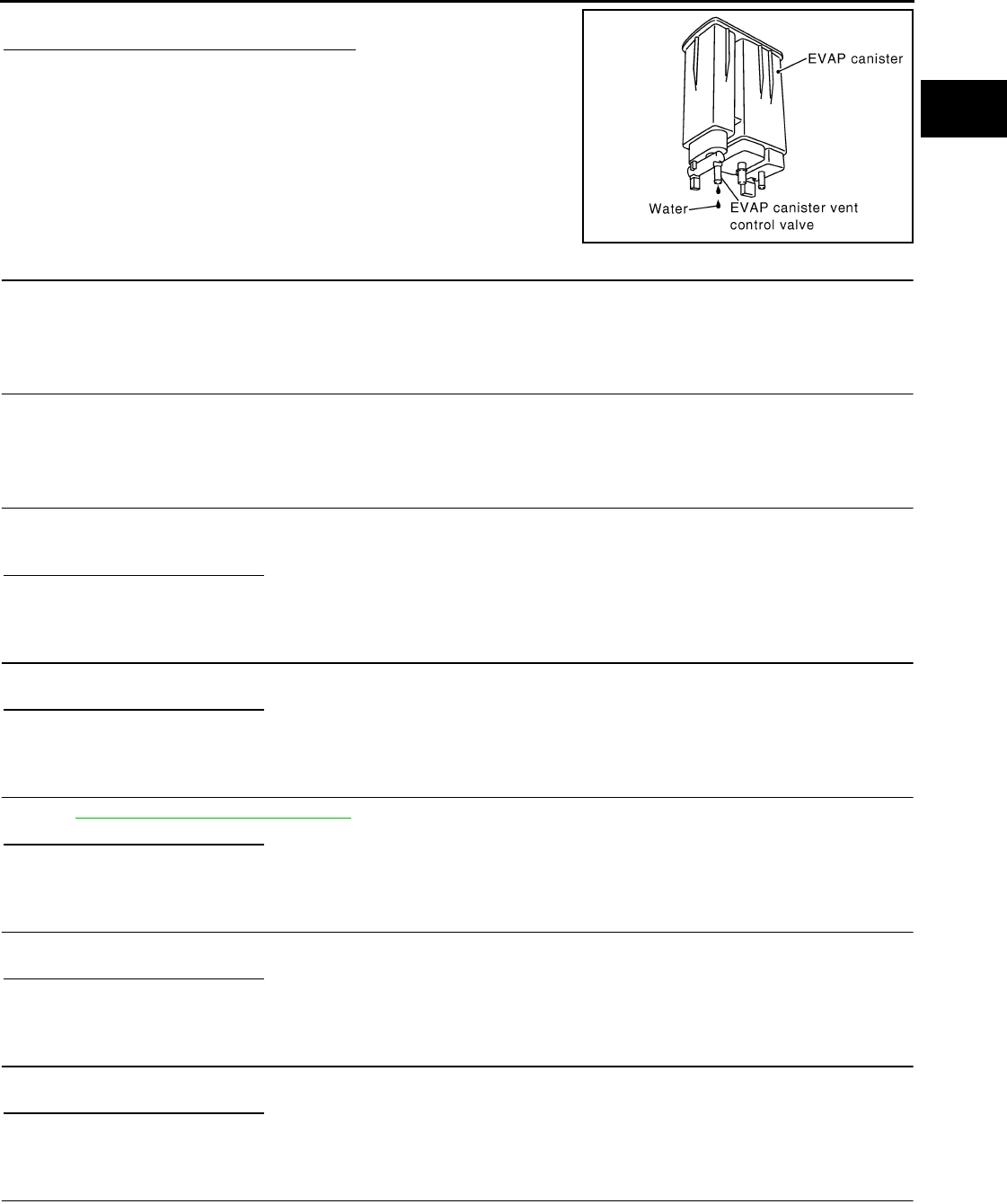
ON BOARD REFUELING VAPOR RECOVERY (ORVR)
EC-869
< COMPONENT DIAGNOSIS > [FOR USA (FEDERAL) AND CANADA]
C
D
E
F
G
H
I
J
K
L
M
A
EC
N
P
O
Check if water will drain from EVAP canister.
Does water drain from the EVAP canister?
YES >> GO TO 9.
NO >> GO TO 11.
9.REPLACE EVAP CANISTER
Replace EVAP canister with a new one.
>> GO TO 10.
10.DETECT MALFUNCTIONING PART
Check the EVAP hose between EVAP canister and vehicle frame for clogging or poor connection.
>> Repair or replace EVAP hose.
11.CHECK VENT HOSES AND VENT TUBES
Check hoses and tubes between EVAP canister and refueling control valve for clogging, kinks, looseness and
improper connection.
Is the inspection result normal?
YES >> GO TO 12.
NO >> Repair or replace hoses and tubes.
12.CHECK FILLER NECK TUBE
Check recirculation line for clogging, dents and cracks.
Is the inspection result normal?
YES >> GO TO 13.
NO >> Replace filler neck tube.
13.CHECK REFUELING EVAP VAPOR CUT VALVE
Refer to EC-870, "Component Inspection".
Is the inspection result normal?
YES >> GO TO 14.
NO >> Replace refueling EVAP vapor cut valve with fuel tank.
14.CHECK FUEL FILLER TUBE
Check filler neck tube and hose connected to the fuel tank for clogging, dents and cracks.
Is the inspection result normal?
YES >> GO TO 15.
NO >> Replace fuel filler tube.
15.CHECK ONE-WAY FUEL VALVE-I
Check one-way valve for clogging.
Is the inspection result normal?
YES >> GO TO 16.
NO >> Repair or replace one-way fuel valve with fuel tank.
16.CHECK ONE-WAY FUEL VALVE-II
1. Check that fuel is drained from the tank.
2. Remove fuel filler tube and hose.
PBIB1213E
Revision: 2008 August 2009 Rogue

EC-870
< COMPONENT DIAGNOSIS > [FOR USA (FEDERAL) AND CANADA]
ON BOARD REFUELING VAPOR RECOVERY (ORVR)
3. Check one-way fuel valve for operation as follows.
When a stick is inserted, the valve should open, when removing
stick it should close.
Do not drop any material into the tank.
Is the inspection result normal?
YES >> INSPECTION END
NO >> Replace fuel filler tube or replace one-way fuel valve
with fuel tank.
Component Inspection INFOID:0000000004529767
1.INSPECTION START
Do you have CONSULT-III?
Do you have CONSULT-III?
YES >> GO TO 2.
NO >> GO TO 3.
2.CHECK REFUELING EVAP VAPOR CUT VALVE
With CONSULT-III
1. Remove fuel tank. Refer to FL-15, "2WD : Removal and Installation" (2WD), FL-18, "AWD : Removal and
Installation" (AWD).
2. Drain fuel from the tank as follows:
- Remove fuel feed hose located on the fuel gauge retainer.
- Connect a spare fuel hose, one side to fuel gauge retainer where the hose was removed and the other
side to a fuel container.
- Drain fuel using “FUEL PUMP RELAY” in “ACTIVE TEST” mode with CONSULT-III.
3. Check refueling EVAP vapor cut valve for being stuck to close as follows.
Blow air into the refueling EVAP vapor cut valve (from the end of EVAP/ORVR line hose), and check that
the air flows freely into the tank.
4. Check refueling EVAP vapor cut valve for being stuck to open as follows.
- Connect vacuum pump to hose end.
- Remove fuel gauge retainer with fuel gauge unit.
Always replace O-ring with new one.
- Turn fuel tank upside down.
- Apply vacuum pressure to hose end [−13.3 kPa (−0.136 kg/cm3, −1.93 psi)] with fuel gauge retainer
remaining open and check that the pressure is applicable.
Is the inspection result normal?
YES >> INSPECTION END
NO >> Replace refueling EVAP vapor cut valve with fuel tank.
SEF665U
JMBIA0907G
B
Revision: 2008 August 2009 Rogue

ON BOARD REFUELING VAPOR RECOVERY (ORVR)
EC-871
< COMPONENT DIAGNOSIS > [FOR USA (FEDERAL) AND CANADA]
C
D
E
F
G
H
I
J
K
L
M
A
EC
N
P
O
3.CHECK REFUELING EVAP VAPOR CUT VALVE
Without CONSULT-III
1. Remove fuel tank. Refer to FL-15, "2WD : Removal and Installation" (2WD), FL-18, "AWD : Removal and
Installation" (AWD).
2. Drain fuel from the tank as follows:
- Remove fuel gauge retainer.
- Drain fuel from the tank using a handy pump into a fuel container.
3. Check refueling EVAP vapor cut valve for being stuck to close as follows.
Blow air into the refueling EVAP vapor cut valve (from the end of EVAP/ORVR line hose), and check that
the air flows freely into the tank.
4. Check refueling EVAP vapor cut valve for being stuck to open as follows.
- Connect vacuum pump to hose end.
- Remove fuel gauge retainer with fuel gauge unit.
Always replace O-ring with new one.
- Turn fuel tank upside down.
- Apply vacuum pressure to hose end [−13.3 kPa (−0.136 kg/cm3, −1.93 psi)] with fuel gauge retainer
remaining open and check that the pressure is applicable.
Is the inspection result normal?
YES >> INSPECTION END
NO >> Replace refueling EVAP vapor cut valve with fuel tank.
JMBIA0907G
B
Revision: 2008 August 2009 Rogue
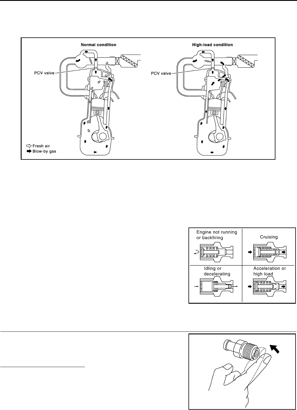
EC-872
< COMPONENT DIAGNOSIS > [FOR USA (FEDERAL) AND CANADA]
POSITIVE CRANKCASE VENTILATION
POSITIVE CRANKCASE VENTILATION
Description INFOID:0000000004529768
This system returns blow-by gas to the intake manifold.
The positive crankcase ventilation (PCV) valve is provided to conduct crankcase blow-by gas to the intake
manifold.
During partial throttle operation of the engine, the intake manifold sucks the blow-by gas through the PCV
valve.
Normally, the capacity of the valve is sufficient to handle any blow-by and a small amount of ventilating air.
The ventilating air is drawn from the air inlet tubes into the crankcase. In this process the air passes through
the hose connecting air inlet tubes to rocker cover.
Under full-throttle condition, the manifold vacuum is insufficient to draw the blow-by flow through the valve.
The flow goes through the hose connection in the reverse direction.
On vehicles with an excessively high blow-by, the valve does not
meet the requirement. This is because some of the flow will go
through the hose connection to the air inlet tubes under all condi-
tions.
Component Inspection INFOID:0000000004529769
1.CHECK PCV VALVE
With engine running at idle, remove PCV valve from rocker cover. A
properly working valve makes a hissing noise as air passes through
it. A strong vacuum should be felt immediately when a finger is
placed over valve inlet.
Is the inspection result normal?
YES >> INSPECTION END
NO >> Replace PCV valve.
PBIB0492E
PBIB1588E
PBIB1589E
Revision: 2008 August 2009 Rogue
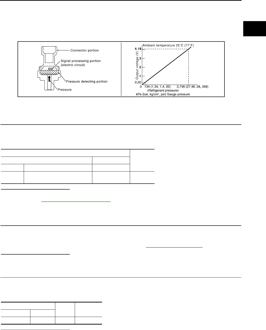
REFRIGERANT PRESSURE SENSOR
EC-873
< COMPONENT DIAGNOSIS > [FOR USA (FEDERAL) AND CANADA]
C
D
E
F
G
H
I
J
K
L
M
A
EC
N
P
O
REFRIGERANT PRESSURE SENSOR
Description INFOID:0000000004529770
The refrigerant pressure sensor is installed at the condenser of the air conditioner system. The sensor uses an
electrostatic volume pressure transducer to convert refrigerant pressure to voltage. The voltage signal is sent
to ECM, and ECM controls cooling fan system.
Component Function Check INFOID:0000000004529771
1.CHECK REFRIGERANT PRESSURE SENSOR OVERALL FUNCTION
1. Start engine and warm it up to normal operating temperature.
2. Turn A/C switch and blower fan switch ON.
3. Check the voltage between ECM harness connector terminals.
Is the inspection result normal?
YES >> INSPECTION END
NO >> Go to EC-873, "Diagnosis Procedure".
Diagnosis Procedure INFOID:0000000004529772
1.CHECK GROUND CONNECTION
1. Turn A/C switch and blower fan switch OFF.
2. Stop engine.
3. Turn ignition switch OFF.
4. Check ground connection E21. Refer to Ground Inspection in GI-44, "Circuit Inspection".
Is the inspection result normal?
YES >> GO TO 2.
NO >> Repair or replace ground connection.
2.CHECK REFRIGERANT PRESSURE SENSOR POWER SUPPLY CIRCUIT
1. Disconnect refrigerant pressure sensor harness connector.
2. Turn ignition switch ON.
3. Check the voltage between refrigerant pressure sensor harness connector and ground.
Is the inspection result normal?
YES >> GO TO 4.
PBIB2657E
ECM
Voltage (V)+−
Connector Terminal Terminal
F8 39
(Refrigerant pressure sensor signal)
40
(Sensor ground) 1.0 - 4.0
Refrigerant pressure sensor Ground Voltage
Connector Terminal
E49 3 Ground Approx. 5 V
Revision: 2008 August 2009 Rogue

EC-874
< COMPONENT DIAGNOSIS > [FOR USA (FEDERAL) AND CANADA]
REFRIGERANT PRESSURE SENSOR
NO >> GO TO 3.
3.DETECT MALFUNCTIONING PART
Check the following.
• Harness connectors F123, E6
• Harness for open or short between ECM and refrigerant pressure sensor
>> Repair open circuit or short to ground or short to power in harness or connectors.
4.CHECK REFRIGERANT PRESSURE SENSOR GROUND CIRCUIT FOR OPEN AND SHORT
1. Turn ignition switch OFF.
2. Disconnect ECM harness connector.
3. Check the continuity between refrigerant pressure sensor harness connector and ECM harness connec-
tor.
4. Also check harness for short to ground and short to power.
Is the inspection result normal?
YES >> GO TO 6.
NO >> GO TO 5.
5.DETECT MALFUNCTIONING PART
Check the following.
• Harness connectors F123, E6
• Harness for open or short between ECM and refrigerant pressure sensor
>> Repair open circuit or short to ground or short to power in harness or connectors.
6.CHECK REFRIGERANT PRESSURE SENSOR INPUT SIGNAL CIRCUIT FOR OPEN AND SHORT
1. Check the continuity between ECM harness connector and refrigerant pressure sensor harness connec-
tor.
2. Also check harness for short to ground and short to power.
Is the inspection result normal?
YES >> GO TO 8.
NO >> GO TO 7.
7.DETECT MALFUNCTIONING PART
Check the following.
• Harness connectors F123, E6
• Harness for open or short between ECM and refrigerant pressure sensor
>> Repair open circuit or short to ground or short to power in harness or connectors.
8.CHECK INTERMITTENT INCIDENT
Refer to GI-41, "Intermittent Incident".
Is the inspection result normal?
YES >> Replace refrigerant pressure sensor.
NO >> Repair or replace.
Refrigerant pressure sensor ECM Continuity
Connector Terminal Connector Terminal
E49 1 F8 40 Existed
Refrigerant pressure sensor ECM Continuity
Connector Terminal Connector Terminal
E49 2 F8 39 Existed
Revision: 2008 August 2009 Rogue
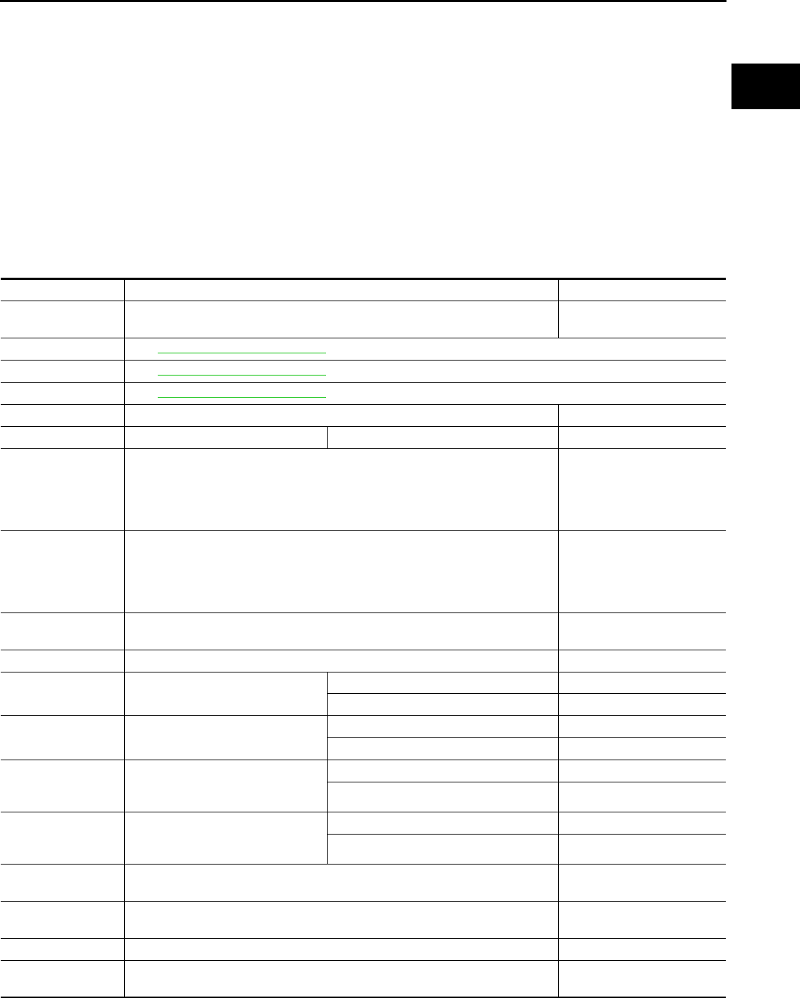
ECM
EC-875
< ECU DIAGNOSIS > [FOR USA (FEDERAL) AND CANADA]
C
D
E
F
G
H
I
J
K
L
M
A
EC
N
P
O
ECU DIAGNOSIS
ECM
Reference Value INFOID:0000000004529773
VALUES ON THE DIAGNOSIS TOOL
Remarks:
z Specification data are reference values.
z Specification data are output/input values which are detected or supplied by the ECM at the connector.
* Specification data may not be directly related to their components signals/values/operations.
I.e. Adjust ignition timing with a timing light before monitoring IGN TIMING, because the monitor may show
the specification data in spite of the ignition timing not being adjusted to the specification data. this IGN TIM-
ING monitors the data calculated by the ECM according to the signals input from the camshaft position sensor
and other ignition timing related sensors.
Monitor Item Condition Values/Status
ENG SPEED • Run engine and compare CONSULT-III value with the tachometer indication. Almost the same speed as
the tachometer indication.
MAS A/F SE-B1 See EC-588, "Diagnosis Procedure".
B/FUEL SCHDL See EC-588, "Diagnosis Procedure".
A/F ALPHA-B1 See EC-588, "Diagnosis Procedure".
COOLAN TEMP/S • Engine: After warming up More than 70°C (158°F)
A/F SEN1 (B1) • Engine: After warming up Maintaining engine speed at 2,000 rpm Fluctuates around 2.2 V
HO2S2 (B1)
• Revving engine from idle up to 3,000 rpm quickly after the following conditions
are met.
- Engine: After warming up
- After keeping engine speed between 3,500 and 4,000 rpm for 1 minute and at
idle for 1 minute under no load
0 - 0.3 V ←→ Approx. 0.6 -
1.0 V
HO2S2 MNTR (B1)
• Revving engine from idle up to 3,000 rpm quickly after the following conditions
are met.
- Engine: After warming up
- After keeping engine speed between 3,500 and 4,000 rpm for 1 minute and at
idle for 1 minute under no load
LEAN ←→ RICH
VHCL SPEED SE • Turn drive wheels and compare CONSULT-III value with the speedometer in-
dication. Almost the same speed as
speedometer indication
BATTERY VOLT • Ignition switch: ON (Engine stopped) 11 - 14 V
ACCEL SEN 1 • Ignition switch: ON
(Engine stopped)
Accelerator pedal: Fully released 0.6 - 0.9 V
Accelerator pedal: Fully depressed 4.0 - 4.8 V
ACCEL SEN 2*1• Ignition switch: ON
(Engine stopped)
Accelerator pedal: Fully released 0.6 - 0.9 V
Accelerator pedal: Fully depressed 3.9 - 4.8 V
TP SEN 1-B1
• Ignition switch: ON
(Engine stopped)
• Selector lever: D
Accelerator pedal: Fully released More than 0.36 V
Accelerator pedal: Fully depressed Less than 4.75 V
TP SEN 2-B1*1• Ignition switch: ON
(Engine stopped)
• Selector lever: D
Accelerator pedal: Fully released More than 0.36 V
Accelerator pedal: Fully depressed Less than 4.75 V
FUEL T/TMP SE • Ignition switch: ON Indicates fuel tank tempera-
ture
INT/A TEMP SE • Ignition switch: ON Indicates intake air tempera-
ture
EVAP SYS PRES • Ignition switch: ON Approx. 1.8 - 4.8 V
FUEL LEVEL SE • Ignition switch: ON Depending on fuel level of
fuel tank
Revision: 2008 August 2009 Rogue

EC-876
< ECU DIAGNOSIS > [FOR USA (FEDERAL) AND CANADA]
ECM
START SIGNAL • Ignition switch: ON → START → ON OFF → ON → OFF
CLSD THL POS • Ignition switch: ON
(Engine stopped)
Accelerator pedal: Fully released ON
Accelerator pedal: Slightly depressed OFF
AIR COND SIG • Engine: After warming up, idle the
engine
Air conditioner switch: OFF OFF
Air conditioner switch: ON
(Compressor operates.) ON
P/N POSI SW • Ignition switch: ON Selector lever: P or N ON
Selector lever: Except above OFF
PW/ST SIGNAL • Engine: After warming up, idle the
engine
Steering wheel: Not being turned OFF
Steering wheel: Being turned ON
LOAD SIGNAL • Ignition switch: ON
Rear window defogger switch: ON
and/or Lighting switch: 2nd position ON
Rear window defogger switch and lighting
switch: OFF OFF
IGNITION SW • Ignition switch: ON → OFF → ON ON → OFF → ON
HEATER FAN SW • Engine: After warming up, idle the
engine
Heater fan switch: ON ON
Heater fan switch: OFF OFF
BRAKE SW • Ignition switch: ON Brake pedal: Fully released OFF
Brake pedal: Slightly depressed ON
INJ PULSE-B1
• Engine: After warming up
• Selector lever: P or N
• Air conditioner switch: OFF
•No load
Idle 2.0 - 3.0 msec
2,000 rpm 1.9 - 2.9 msec
IGN TIMING
• Engine: After warming up
• Selector lever: P or N
• Air conditioner switch: OFF
•No load
Idle 10° - 20° BTDC
2,000 rpm 25° - 45° BTDC
CAL/LD VALUE
• Engine: After warming up
• Selector lever: P or N
• Air conditioner switch: OFF
•No load
Idle 10% - 35%
2,500 rpm 10% - 35%
MASS AIRFLOW
• Engine: After warming up
• Selector lever: P or N
• Air conditioner switch: OFF
•No load
Idle 1.0 - 4.0 g·m/s
2,500 rpm 4.0 - 10.0 g·m/s
PURG VOL C/V
• Engine: After warming up
• Selector lever: P or N
• Air conditioner switch: OFF
•No load
Idle
(Accelerator pedal: Not depressed even
slightly, after engine starting.) 0%
2,000 rpm 20% - 90%
INT/V TIM (B1)
• Engine: After warming up
• Selector lever: P or N
• Air conditioner switch: OFF
•No load
Idle −5° - 5°CA
2,000 rpm Approx. 0° - 20°CA
INT/V SOL (B1)
• Engine: After warming up
• Selector lever: P or N
• Air conditioner switch: OFF
•No load
Idle 0%
2,000 rpm Approx. 0% - 60%
AIR COND RLY • Engine: After warming up, idle the
engine
Air conditioner switch: OFF OFF
Air conditioner switch: ON
(Compressor operates) ON
Monitor Item Condition Values/Status
Revision: 2008 August 2009 Rogue

ECM
EC-877
< ECU DIAGNOSIS > [FOR USA (FEDERAL) AND CANADA]
C
D
E
F
G
H
I
J
K
L
M
A
EC
N
P
O
FUEL PUMP RLY
• For 1 second after turning ignition switch: ON
• Engine running or cranking ON
• Except above OFF
VENT CONT/V • Ignition switch: ON OFF
THRTL RELAY • Ignition switch: ON ON
HO2S2 HTR (B1)
• Engine speed: Below 3,600 rpm after the following conditions are met.
- Engine: After warming up
- Keeping the engine speed between 3,500 and 4,000 rpm for 1 minute and at
idle for 1 minute under no load
ON
• Engine speed: Above 3,600 rpm OFF
I/P PULLY SPD • Vehicle speed: More than 20 km/h (12 MPH) Almost the same speed as
the tachometer indication
VEHICLE SPEED • Turn drive wheels and compare CONSULT-III value with the speedometer in-
dication.
Almost the same speed as
the speedometer indication
IDL A/V LEARN • Engine: running
Idle air volume learning has not been per-
formed yet. YET
Idle air volume learning has already been
performed successfully. CMPLT
TRVL AFTER MIL • Ignition switch: ON Vehicle has traveled after MIL has turned
ON.
0 - 65,535 km
(0 - 40,723 miles)
A/F S1 HTR (B1) • Engine: After warming up, idle the engine
(More than 140 seconds after starting engine.) 4 - 100%
AC PRESS SEN • Engine: Idle
• Both A/C switch and blower fan switch: ON (Compressor operates) 1.0 - 4.0 V
VHCL SPEED SE • Turn drive wheels and compare CONSULT-III value with the speedometer in-
dication.
Almost the same speed as
the speedometer indication
SET VHCL SPD • Engine: Running ASCD: Operating The preset vehicle speed is
displayed
MAIN SW • Ignition switch: ON MAIN switch: Pressed ON
MAIN switch: Released OFF
CANCEL SW • Ignition switch: ON CANCEL switch: Pressed ON
CANCEL switch: Released OFF
RESUME/ACC SW • Ignition switch: ON
RESUME/ACCELERATE switch:
Pressed ON
RESUME/ACCELERATE switch: Re-
leased OFF
SET SW • Ignition switch: ON SET/COAST switch: Pressed ON
SET/COAST switch: Released OFF
BRAKE SW1
(ASCD brake switch) • Ignition switch: ON Brake pedal: Fully released ON
Brake pedal: Slightly depressed OFF
BRAKE SW2
(Stop lamp switch) • Ignition switch: ON Brake pedal: Fully released OFF
Brake pedal: Slightly depressed ON
VHCL SPD CUT • Ignition switch: ON NON
LO SPEED CUT • Ignition switch: ON NON
AT OD MONITOR • Ignition switch: ON OFF
AT OD CANCEL • Ignition switch: ON OFF
CRUISE LAMP • Ignition switch: ON MAIN switch: Pressed at the 1st time →
at the 2nd time ON → OFF
Monitor Item Condition Values/Status
Revision: 2008 August 2009 Rogue
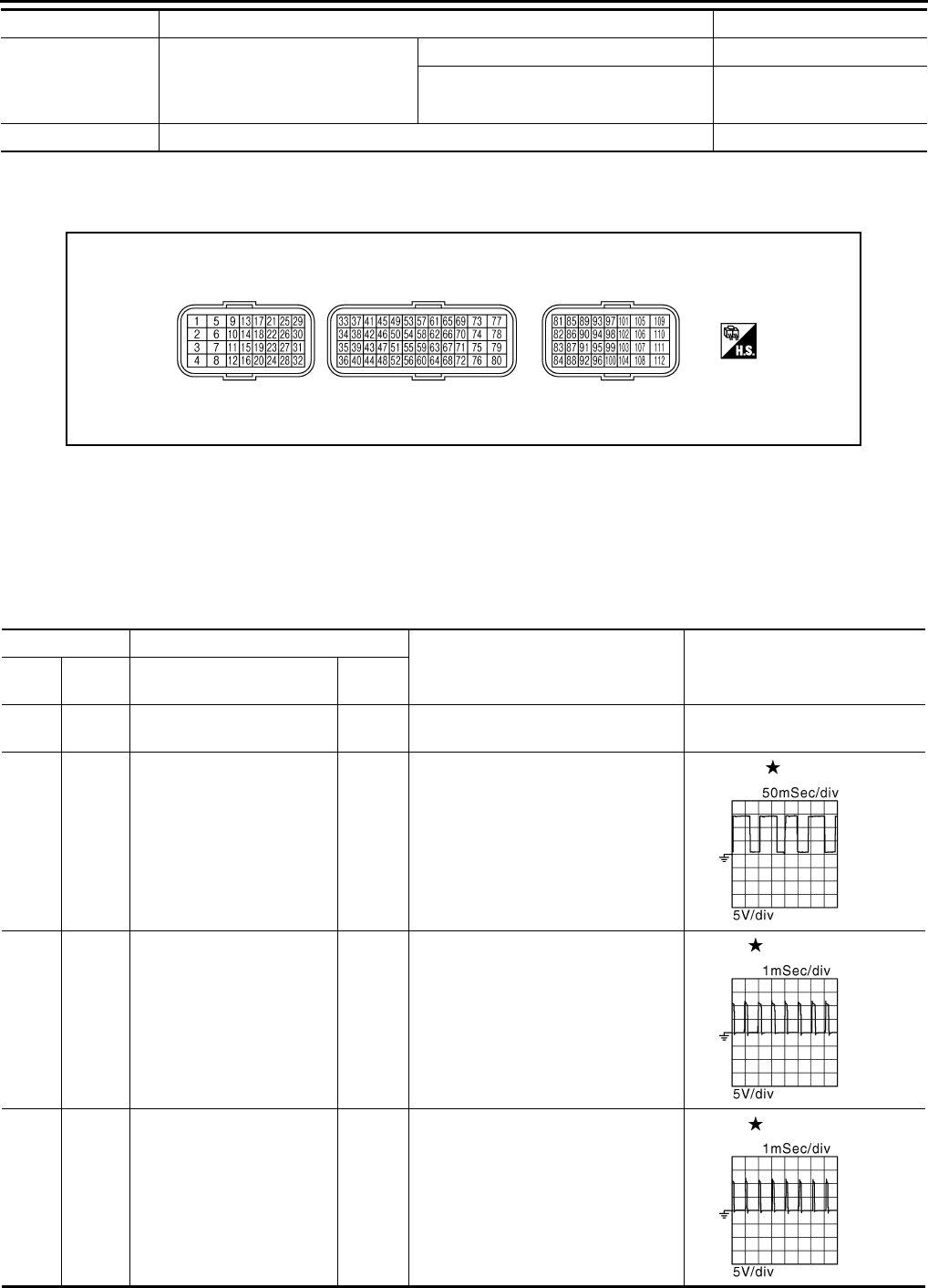
EC-878
< ECU DIAGNOSIS > [FOR USA (FEDERAL) AND CANADA]
ECM
*1: Accelerator pedal position sensor 2 signal and throttle position sensor 2 signal are converted by ECM internally. Thus, they differ
from ECM terminals voltage signal.
TERMINAL LAYOUT
PHYSICAL VALUES
NOTE:
• ECM is located behind the passenger side instrument lower panel. For this inspection, remove passenger
side instrument lower panel.
• Specification data are reference values and are measured between each terminal and ground.
• Pulse signal is measured by CONSULT-III.
SET LAMP
• MAIN switch: ON
• When vehicle speed: Between 40
km/h (25 MPH) and 144 km/h (89
MPH)
ASCD: Operating ON
ASCD: Not operating OFF
A/F ADJ-B1 • Engine: running –0.330 - 0.330
Monitor Item Condition Values/Status
PBIA9221J
Terminal No. Description
Condition Value
(Approx.)
+ – Signal name Input/
Output
2
(P)
112
(B)
Throttle control motor power
supply Input [Ignition switch: ON] BATTERY VOLTAGE
(11 - 14 V)
4
(R) 112
(B) A/F sensor 1 heater Output
[Engine is running]
• Warm-up condition
• Idle speed
2.9 - 8.8 V
5
(GR) 6
(L) Throttle control motor 1
(Open) Output
[Ignition switch: ON]
• Engine stopped
• Selector lever: D
• Accelerator pedal: Fully depressed
0 - 14 V
6
(L)
5
(GR)
Throttle control motor 2
(Close) Output
[Ignition switch: ON]
• Engine stopped
• Selector lever: D
• Accelerator pedal: Fully released
0 - 14 V
JMBIA0082G
B
JMBIA0083G
B
JMBIA0084G
B
Revision: 2008 August 2009 Rogue
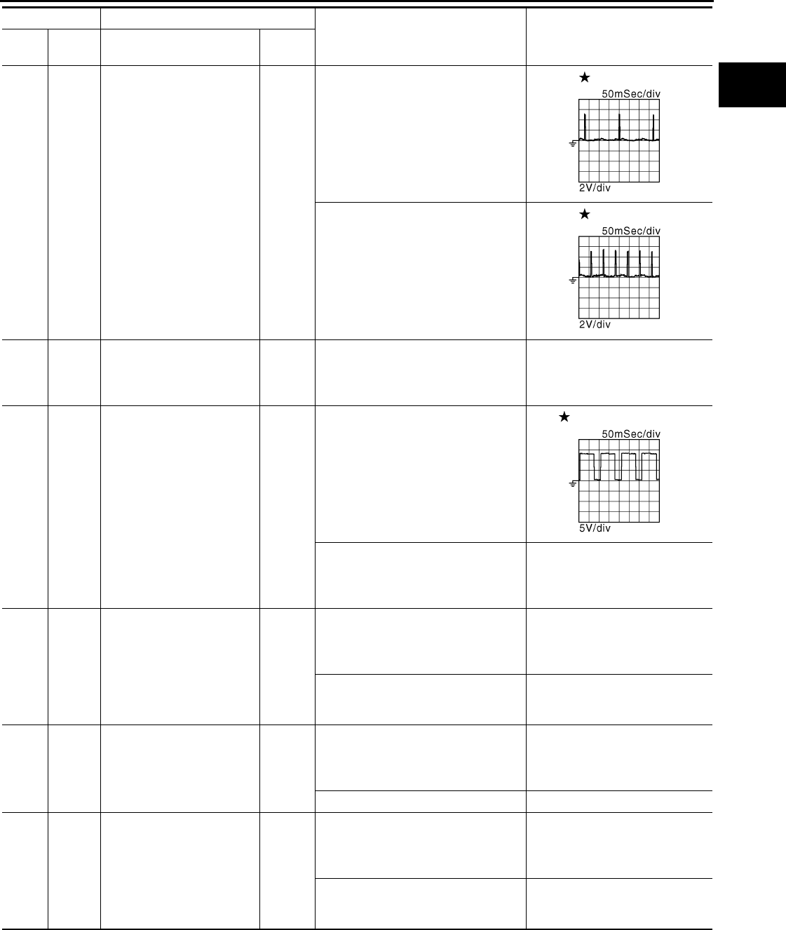
ECM
EC-879
< ECU DIAGNOSIS > [FOR USA (FEDERAL) AND CANADA]
C
D
E
F
G
H
I
J
K
L
M
A
EC
N
P
O
9
(R)
112
(B)
Ignition signal No. 3
Output
[Engine is running]
• Warm-up condition
• Idle speed
NOTE:
The pulse cycle changes depending
on rpm at idle
0 - 0.1 V
10
(W) Ignition signal No. 2
11
(SB) Ignition signal No. 1
[Engine is running]
• Warm-up condition
• Engine speed: 2,000 rpm
0 - 0.2 V
21
(G) Ignition signal No. 4
12
(B)
16
(B)
— ECM ground — — —
13
(Y) 112
(B) Heated oxygen sensor 2
heater Output
[Engine is running]
• Engine speed: Below 3,600 rpm af-
ter the following conditions are met
- Engine: After warming up
- Keeping the engine speed between
3,500 and 4,000 rpm for 1 minute
and at idle for 1 minute under no
load
10 V
[Ignition switch: ON]
• Engine stopped
[Engine is running]
• Engine speed: Above 3,600 rpm
BATTERY VOLTAGE
(11 - 14 V)
14
(GR)
112
(B) Fuel pump relay Output
[Ignition switch: ON]
• For 1 second after turning ignition
switch ON
[Engine is running]
0 - 1.0 V
[Ignition switch: ON]
• More than 1 second after turning ig-
nition switch ON
BATTERY VOLTAGE
(11 - 14 V)
15
(V)
112
(B) Throttle control motor relay Output [Ignition switch: ON → OFF]
0 - 1.0 V
↓
BATTERY VOLTAGE
(11 - 14 V)
[Ignition switch: ON] 0 - 1.0 V
24
(L) 112
(B) ECM relay
(Self shut-off) Output
[Engine is running]
[Ignition switch: OFF]
• A few seconds after turning ignition
switch OFF
0 - 1.0 V
[Ignition switch: OFF]
• More than a few seconds after turn-
ing ignition switch OFF
BATTERY VOLTAGE
(11 - 14 V)
Terminal No. Description
Condition Value
(Approx.)
+ – Signal name Input/
Output
JMBIA0900G
B
JMBIA0901G
B
JMBIA0902G
B
Revision: 2008 August 2009 Rogue
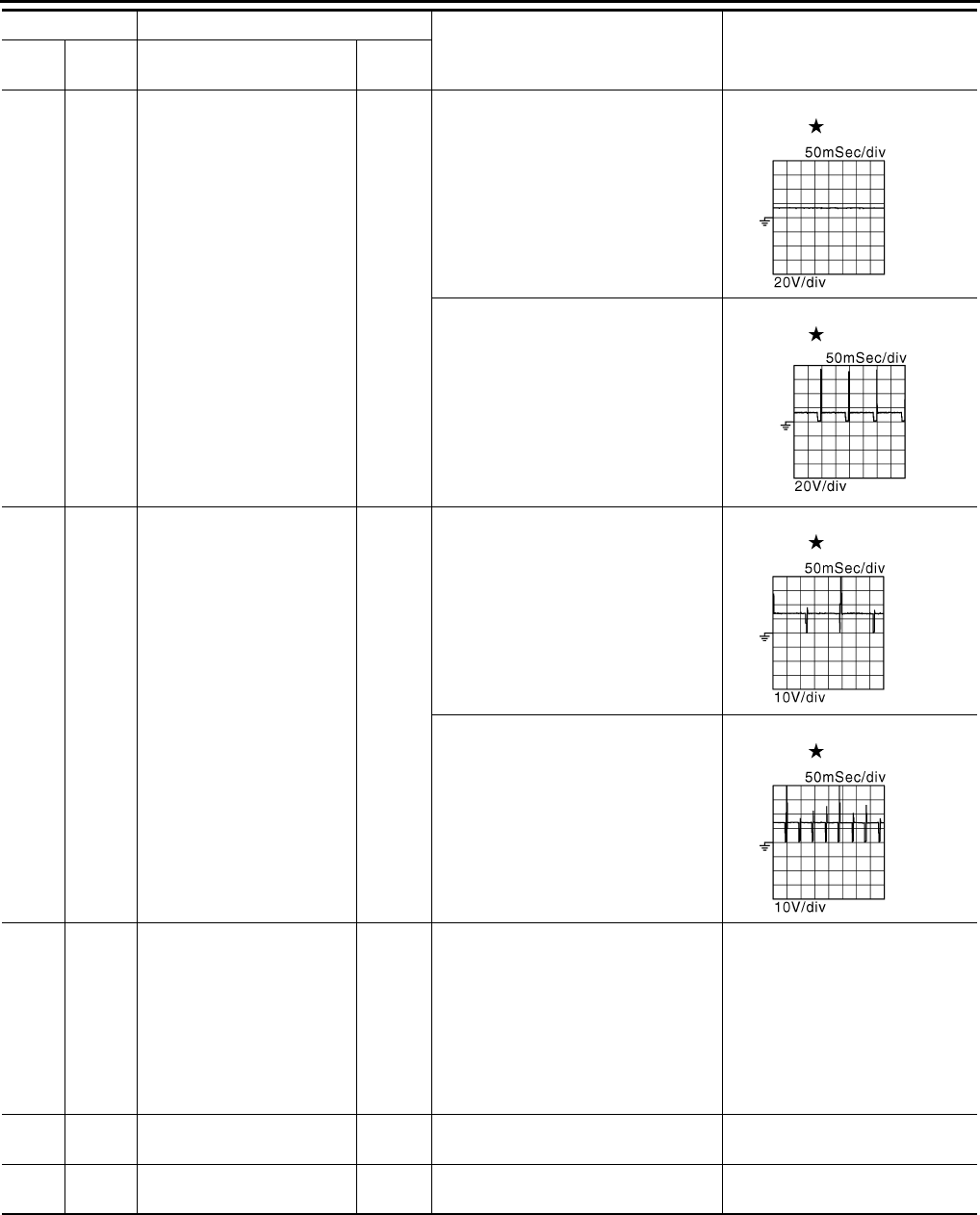
EC-880
< ECU DIAGNOSIS > [FOR USA (FEDERAL) AND CANADA]
ECM
25
(Y)
112
(B)
EVAP canister purge vol-
ume control solenoid valve Output
[Engine is running]
• Idle speed
• Accelerator pedal: Not depressed
even slightly, after engine starting
BATTERY VOLTAGE
(11 - 14 V)
[Engine is running]
• Engine speed: Approx. 2,000 rpm
(More than 100 seconds after start-
ing engine.)
BATTERY VOLTAGE
(11 - 14 V)
29
(P)
112
(B)
Fuel injector No. 4
Output
[Engine is running]
• Warm-up condition
• Idle speed
NOTE:
The pulse cycle changes depending
on rpm at idle
BATTERY VOLTAGE
(11 - 14 V)
30
(LG) Fuel injector No. 3
31
(BR) Fuel injector No. 2
[Engine is running]
• Warm-up condition
• Engine speed: 2,000 rpm
BATTERY VOLTAGE
(11 - 14 V)
32
(GR) Fuel injector No. 1
33
(P) 35
(L) Heated oxygen sensor 2 Input
[Engine is running]
• Revving engine from idle to 3,000
rpm quickly after the following con-
ditions are met
- Engine: After warming up
- Keeping the engine speed between
3,500 and 4,000 rpm for 1 minute
and at idle for 1 minute under no
load
0 - 1.0 V
35
(L) —Sensor ground
(Heated oxygen sensor 2) —— —
36
(R) —Sensor ground
(Throttle position sensor) —— —
Terminal No. Description
Condition Value
(Approx.)
+ – Signal name Input/
Output
JMBIA0087G
B
JMBIA0903G
B
JMBIA0089G
B
JMBIA0090G
B
Revision: 2008 August 2009 Rogue

ECM
EC-881
< ECU DIAGNOSIS > [FOR USA (FEDERAL) AND CANADA]
C
D
E
F
G
H
I
J
K
L
M
A
EC
N
P
O
37
(W)
36
(R) Throttle position sensor 1 Input
[Ignition switch: ON]
• Engine stopped
• Selector lever: D
• Accelerator pedal: Fully released
More than 0.36 V
[Ignition switch: ON]
• Engine stopped
• Selector lever: D
• Accelerator pedal: Fully depressed
Less than 4.75 V
38
(G)
36
(R) Throttle position sensor 2 Input
[Ignition switch: ON]
• Engine stopped
• Selector lever: D
• Accelerator pedal: Fully released
Less than 4.75 V
[Ignition switch: ON]
• Engine stopped
• Selector lever: D
• Accelerator pedal: Fully depressed
More than 0.36 V
39
(Y)
40
(W) Refrigerant pressure sensor Input
[Engine is running]
• Warm-up condition
• Both A/C switch and blower fan mo-
tor switch: ON (Compressor oper-
ates)
1.0 - 4.0 V
40
(W) —
Sensor ground
(Refrigerant pressure sen-
sor) —— —
45
(V)
49
(LG) A/F sensor 1 (bank 1) Input [Ignition switch: ON] 2.2 V
46
(P)
52
(O)
Engine coolant temperature
sensor Input [Engine is running]
0 - 4.8 V
Output voltage varies with engine
coolant temperature.
47
(B)
36
(R)
Sensor power supply
(Throttle position sensor) — [Ignition switch: ON] 5 V
49
(LG)
112
(B) A/F sensor 1 Input
[Engine is running]
• Warm-up condition
• Engine speed: 2,000 rpm
1.8 V
Output voltage varies with air fuel
ratio.
50
(BR)
56
(R)
Intake air temperature sen-
sor Input [Engine is running] 0 - 4.8 V
Output voltage varies with intake
air temperature.
52
(O) —
Sensor ground
(Engine coolant tempera-
ture sensor) —— —
56
(R) —
Sensor ground
(Mass air flow sensor, Intake
air temperature sensor)
—— —
58
(L) 56
(R) Mass air flow sensor Input
[Engine is running]
• Warm-up condition
• Idle speed
0.8 - 1.2 V
[Engine is running]
• Warm-up condition
• Engine speed: 2,500 rpm 1.4 - 1.8 V
59
(V) 64
(Y)
Sensor power supply
[Camshaft position sensor
(PHASE)]
— [Ignition switch: ON] 5 V
60
(B) —Sensor ground
[Crankshaft position sensor
(POS)]
—— —
Terminal No. Description
Condition Value
(Approx.)
+ – Signal name Input/
Output
Revision: 2008 August 2009 Rogue
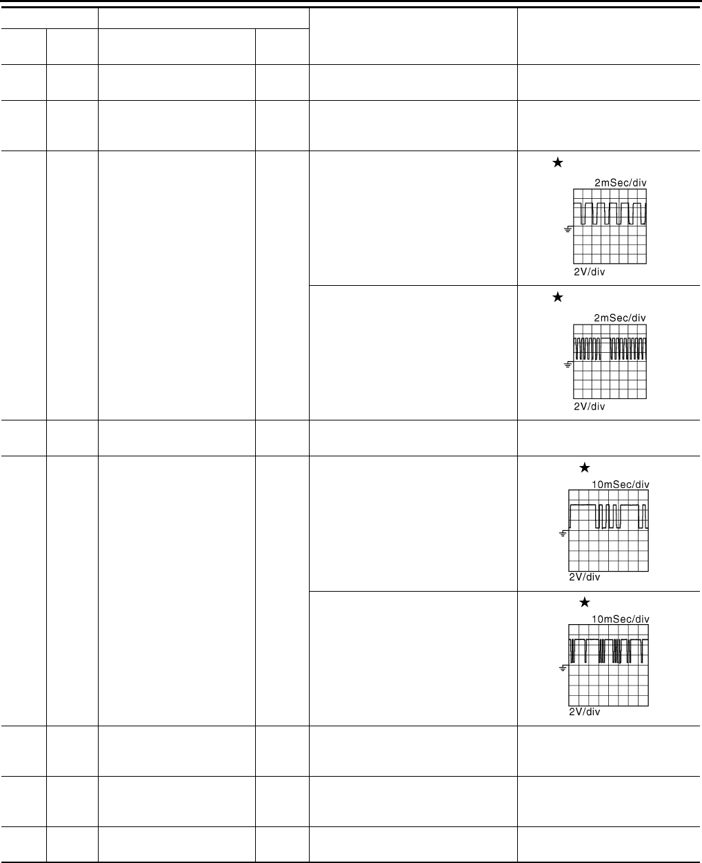
EC-882
< ECU DIAGNOSIS > [FOR USA (FEDERAL) AND CANADA]
ECM
61
(W)
67
(—) Knock sensor Input [Engine is running]
• Idle speed 2.5 V
64
(Y) —
Sensor ground
[Camshaft position sensor
(PHASE)] —— —
65
(W) 60
(B) Crankshaft position sensor
(POS) Input
[Engine is running]
• Warm-up condition
• Idle speed
NOTE:
The pulse cycle changes depending
on rpm at idle
3.0 V
[Engine is running]
• Engine speed: 2,000 rpm
3.0 V
67
(—) —Sensor ground
(Knock sensor) —— —
69
(G)
64
(Y)
Camshaft position sensor
(PHASE) Input
[Engine is running]
• Warm-up condition
• Idle speed
NOTE:
The pulse cycle changes depending
on rpm at idle
1.0 - 4.0 V
[Engine is running]
• Engine speed is 2,000 rpm
1.0 - 4.0 V
72
(L) 40
(W)
Sensor power supply
(Refrigerant pressure sen-
sor)
— [Ignition switch: ON] 5 V
76
(P)
60
(B)
Sensor power supply
[Crankshaft position sensor
(POS)]
— [Ignition switch: ON] 5 V
77
(R)
112
(B)
Power supply for ECM
(Back-up) Input [Ignition switch: OFF] BATTERY VOLTAGE
(11 - 14 V)
Terminal No. Description
Condition Value
(Approx.)
+ – Signal name Input/
Output
JMBIA0514G
B
JMBIA0515G
B
JMBIA0904G
B
JMBIA0905G
B
Revision: 2008 August 2009 Rogue

ECM
EC-883
< ECU DIAGNOSIS > [FOR USA (FEDERAL) AND CANADA]
C
D
E
F
G
H
I
J
K
L
M
A
EC
N
P
O
78
(O)
112
(B)
Intake valve timing control
solenoid valve Output
[Engine is running]
• Warm-up condition
• Idle speed
0 V
[Engine is running]
• Warm-up condition
• Engine speed: 2,000rpm
7 - 10 V
81
(SB)
84
(Y)
Accelerator pedal position
sensor 1 Input
[Ignition switch: ON]
• Engine stopped
• Accelerator pedal: Fully released
0.6 - 0.9 V
[Ignition switch: ON]
• Engine stopped
• Accelerator pedal: Fully depressed
4.0 - 4.8 V
82
(G)
100
(W)
Accelerator pedal position
sensor 2 Input
[Ignition switch: ON]
• Engine stopped
• Accelerator pedal: Fully released 0.6 - 0.9 V
[Ignition switch: ON]
• Engine stopped
• Accelerator pedal: Fully depressed
3.9 - 4.8 V
83
(R)
84
(Y)
Sensor power supply
(Accelerator pedal position
sensor 1) — [Ignition switch: ON] 5 V
84
(Y) —
Sensor ground
(Accelerator pedal position
sensor 1)
—— —
85
(R)
92
(W) ASCD steering switch Input
[Ignition switch: ON]
• ASCD steering switch: OFF 4 V
[Ignition switch: ON]
• MAIN switch: Pressed 0 V
[Ignition switch: ON]
• CANCEL switch: Pressed 1 V
[Ignition switch: ON]
• RESUME/ACCELERATE switch:
Pressed
3 V
[Ignition switch: ON]
• SET/COAST switch: Pressed 2 V
86
(BR) 96
(P) EVAP control system pres-
sure sensor Input [Ignition switch: ON] 1.8 - 4.8 V
87
(V) 100
(W)
Sensor power supply
(Accelerator pedal position
sensor 2)
— [Ignition switch: ON] 5 V
88
(L) 112
(B) Data link connector Input/
Output [Ignition switch: ON]
• GST: Disconnected BATTERY VOLTAGE
(11 - 14 V)
91
(Y) 96
(P)
Sensor power supply
(EVAP control system pres-
sure sensor)
— [Ignition switch: ON] 5 V
92
(W) —Sensor ground
(ASCD steering switch) —— —
Terminal No. Description
Condition Value
(Approx.)
+ – Signal name Input/
Output
JMBIA0906G
B
Revision: 2008 August 2009 Rogue

EC-884
< ECU DIAGNOSIS > [FOR USA (FEDERAL) AND CANADA]
ECM
: Average voltage for pulse signal (Actual pulse signal can be confirmed by oscilloscope.)
93
(O)
112
(B) Ignition switch Input
[Ignition switch: OFF] 0 V
[Ignition switch: ON] BATTERY VOLTAGE
(11 - 14 V)
95
(O)
104
(B)
Fuel tank temperature sen-
sor Input [Engine is running]
0 - 4.8 V
Output voltage varies with fuel
tank temperature.
96
(P) —
Sensor ground
(EVAP control system pres-
sure sensor)
—— —
97
(P) — CAN communication line — — —
98
(L) — CAN communication line — — —
100
(W) —
Sensor ground
(Accelerator pedal position
sensor 2) —— —
102
(LG) 112
(B) PNP switch Input
[Ignition switch: ON]
• Selector lever: P or N
BATTERY VOLTAGE
(11 - 14 V)
[Ignition switch: ON]
• Selector lever: Except above 0 V
104
(B) —Sensor ground
(Fuel tank temperature sen-
sor)
—— —
105
(R)
112
(B) Power supply for ECM Input [Ignition switch: ON] BATTERY VOLTAGE
(11 - 14 V)
106
(Y)
112
(B) Stop lamp switch Input
[Ignition switch: OFF]
• Brake pedal: Fully released 0 V
[Ignition switch: OFF]
• Brake pedal: Slightly depressed
BATTERY VOLTAGE
(11 - 14 V)
107
(B)
108
(B)
— ECM ground — — —
109
(W)
112
(B)
EVAP canister vent control
valve Output [Ignition switch: ON] BATTERY VOLTAGE
(11 - 14 V)
110
(GR)
112
(B) ASCD brake switch Input
[Ignition switch: ON]
• Brake pedal: Slightly depressed 0 V
[Ignition switch: ON]
• Brake pedal: Fully released BATTERY VOLTAGE
(11 - 14 V)
111
(B)
112
(B)
— ECM ground — — —
Terminal No. Description
Condition Value
(Approx.)
+ – Signal name Input/
Output
Revision: 2008 August 2009 Rogue
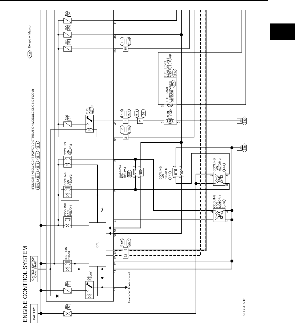
ECM
EC-885
< ECU DIAGNOSIS > [FOR USA (FEDERAL) AND CANADA]
C
D
E
F
G
H
I
J
K
L
M
A
EC
N
P
O
Wiring Diagram — ENGINE CONTROL SYSTEM — INFOID:0000000004529774
JCBWM0957
GB
Revision: 2008 August 2009 Rogue
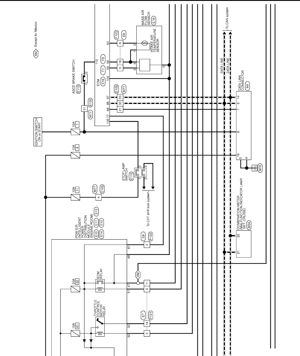
EC-886
< ECU DIAGNOSIS > [FOR USA (FEDERAL) AND CANADA]
ECM
JCBWM0958
GB
Revision: 2008 August 2009 Rogue
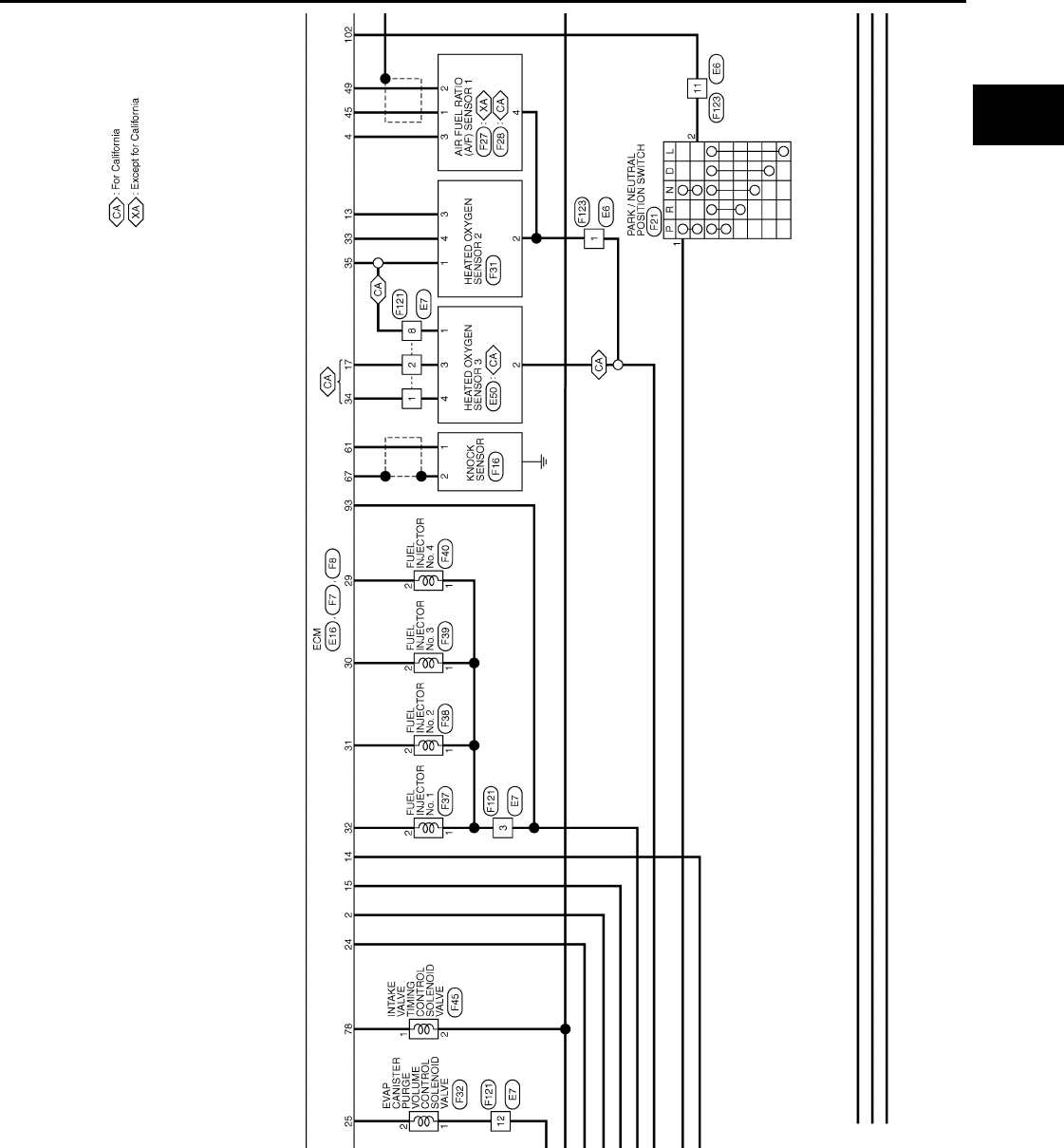
ECM
EC-887
< ECU DIAGNOSIS > [FOR USA (FEDERAL) AND CANADA]
C
D
E
F
G
H
I
J
K
L
M
A
EC
N
P
O
JCBWM0959
GB
Revision: 2008 August 2009 Rogue
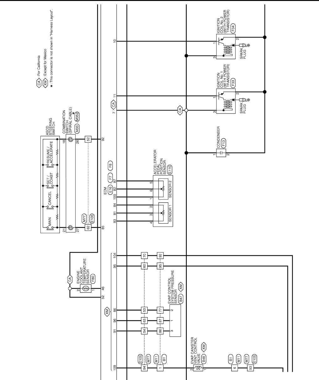
EC-888
< ECU DIAGNOSIS > [FOR USA (FEDERAL) AND CANADA]
ECM
JCBWM0960
GB
Revision: 2008 August 2009 Rogue
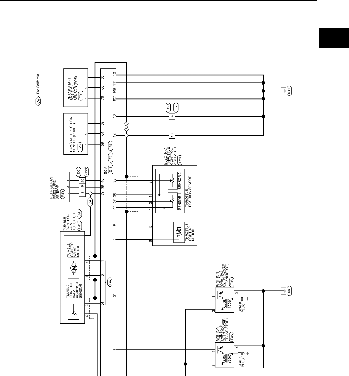
ECM
EC-889
< ECU DIAGNOSIS > [FOR USA (FEDERAL) AND CANADA]
C
D
E
F
G
H
I
J
K
L
M
A
EC
N
P
O
JCBWM0961
GB
Revision: 2008 August 2009 Rogue
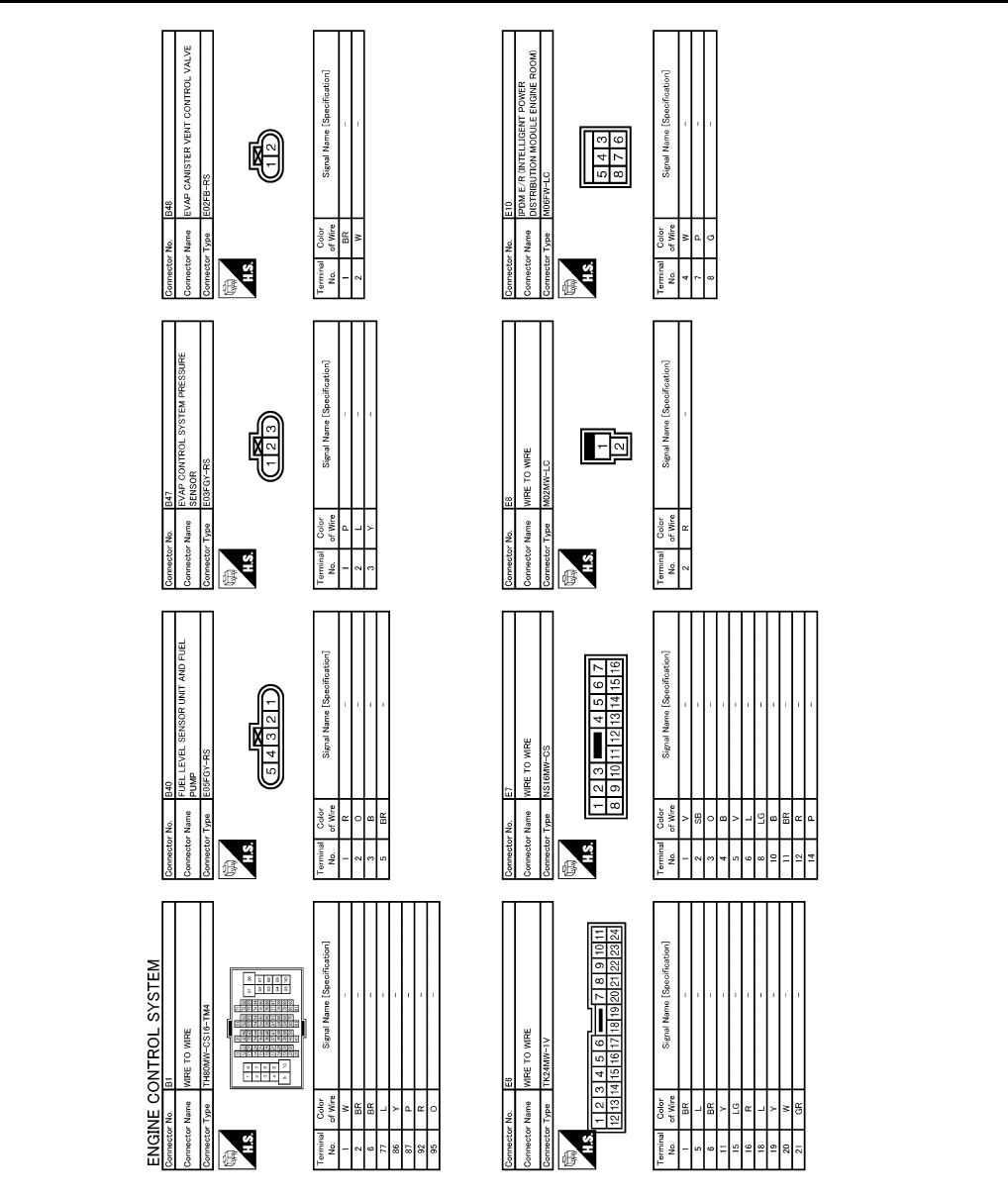
EC-890
< ECU DIAGNOSIS > [FOR USA (FEDERAL) AND CANADA]
ECM
JCBWM0962
GB
Revision: 2008 August 2009 Rogue
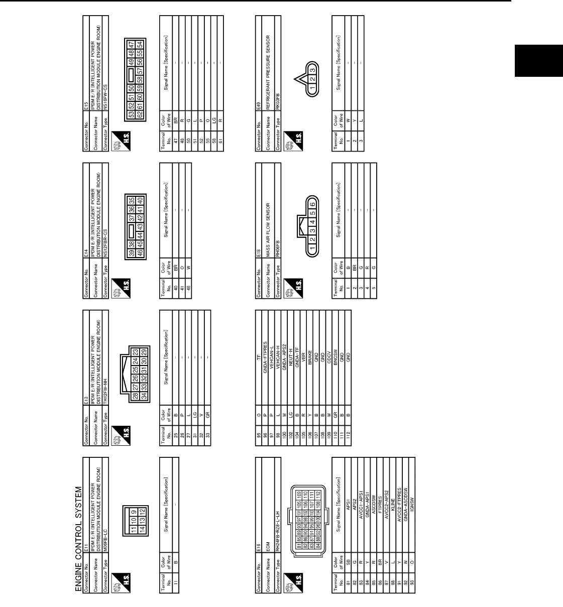
ECM
EC-891
< ECU DIAGNOSIS > [FOR USA (FEDERAL) AND CANADA]
C
D
E
F
G
H
I
J
K
L
M
A
EC
N
P
O
JCBWM0963
GB
Revision: 2008 August 2009 Rogue
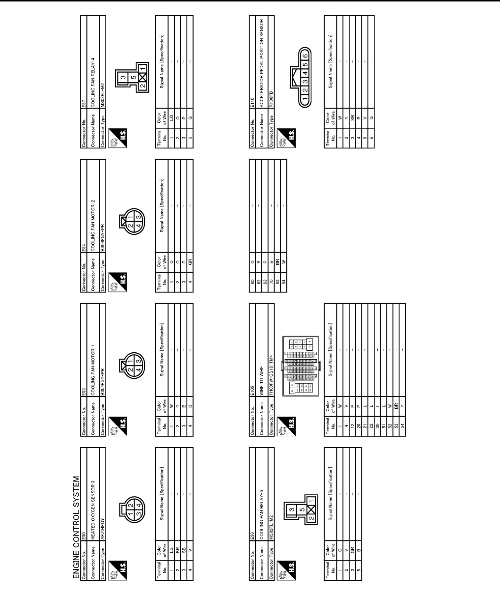
EC-892
< ECU DIAGNOSIS > [FOR USA (FEDERAL) AND CANADA]
ECM
JCBWM0964
GB
Revision: 2008 August 2009 Rogue
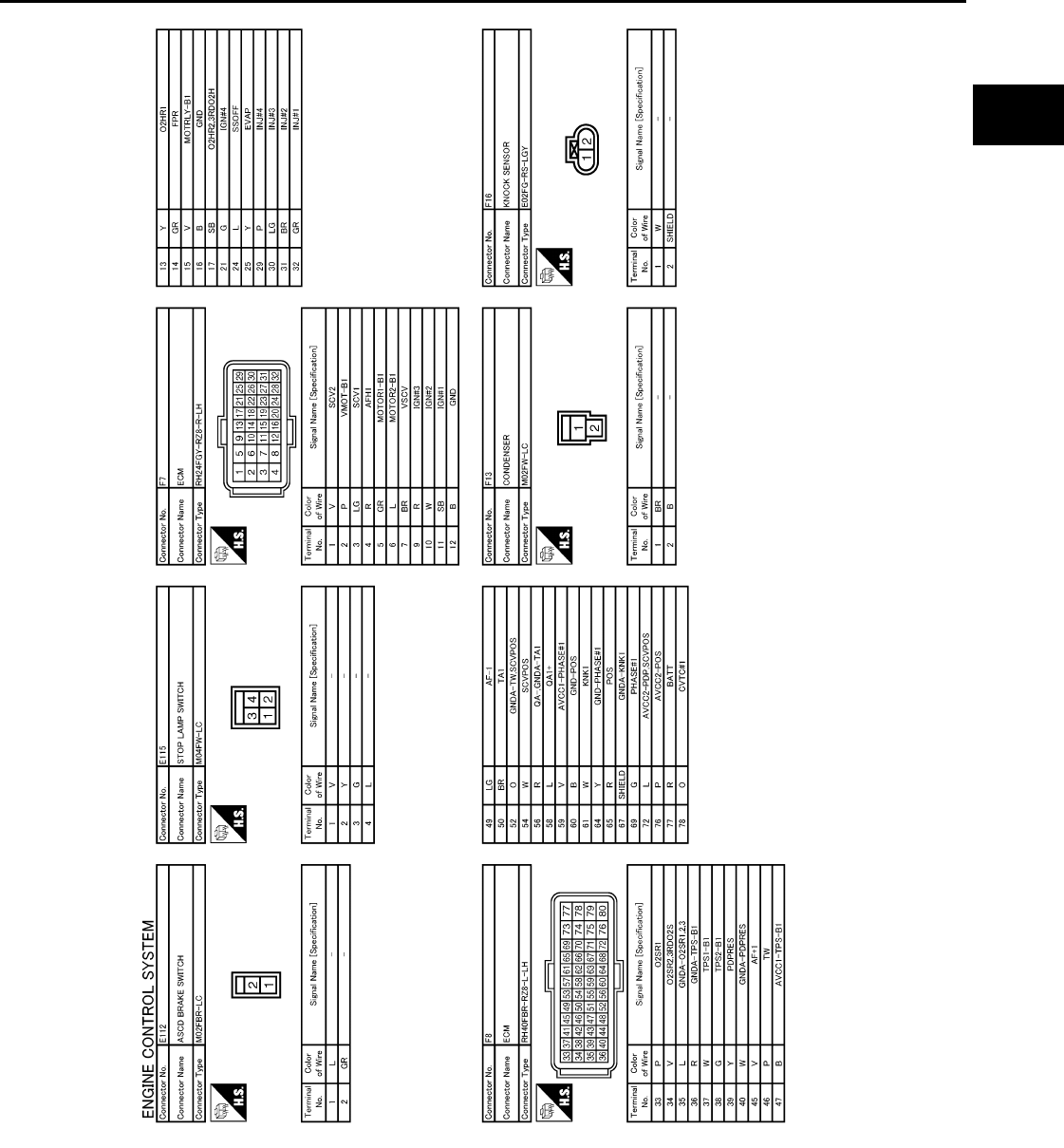
ECM
EC-893
< ECU DIAGNOSIS > [FOR USA (FEDERAL) AND CANADA]
C
D
E
F
G
H
I
J
K
L
M
A
EC
N
P
O
JCBWM0965
GB
Revision: 2008 August 2009 Rogue
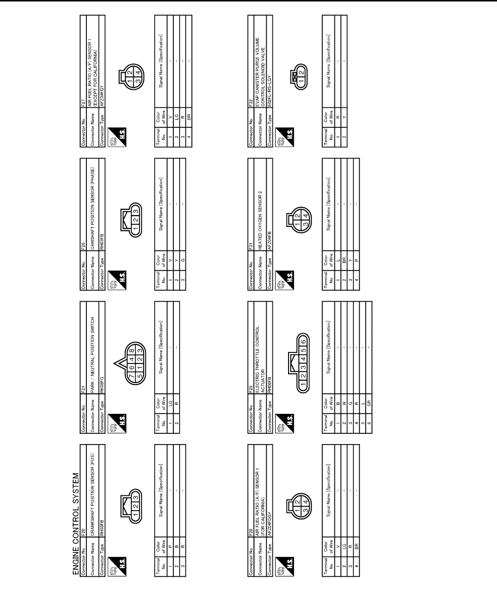
EC-894
< ECU DIAGNOSIS > [FOR USA (FEDERAL) AND CANADA]
ECM
JCBWM0966
GB
Revision: 2008 August 2009 Rogue

ECM
EC-895
< ECU DIAGNOSIS > [FOR USA (FEDERAL) AND CANADA]
C
D
E
F
G
H
I
J
K
L
M
A
EC
N
P
O
JCBWM0967
GB
Revision: 2008 August 2009 Rogue
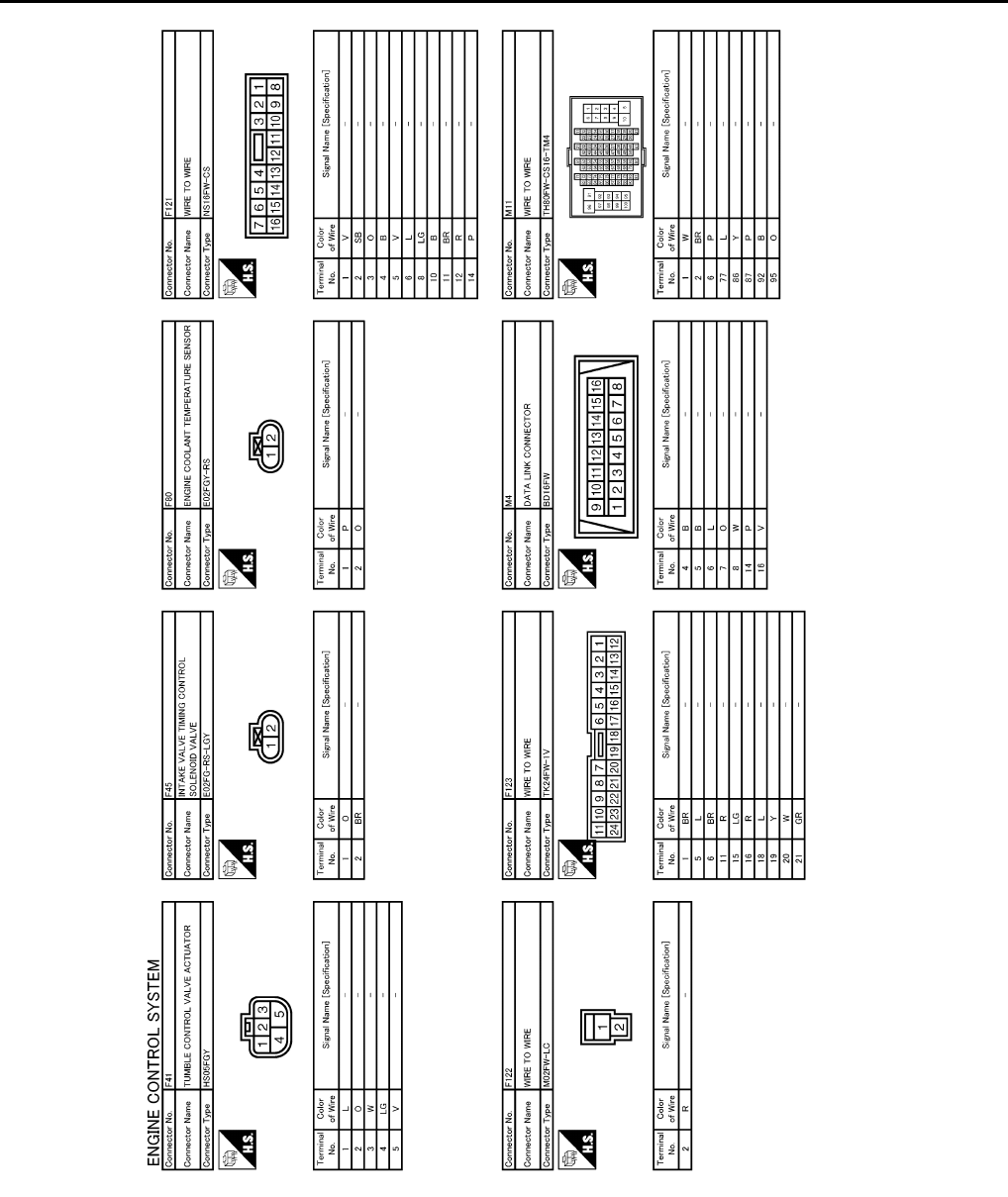
EC-896
< ECU DIAGNOSIS > [FOR USA (FEDERAL) AND CANADA]
ECM
JCBWM0968
GB
Revision: 2008 August 2009 Rogue
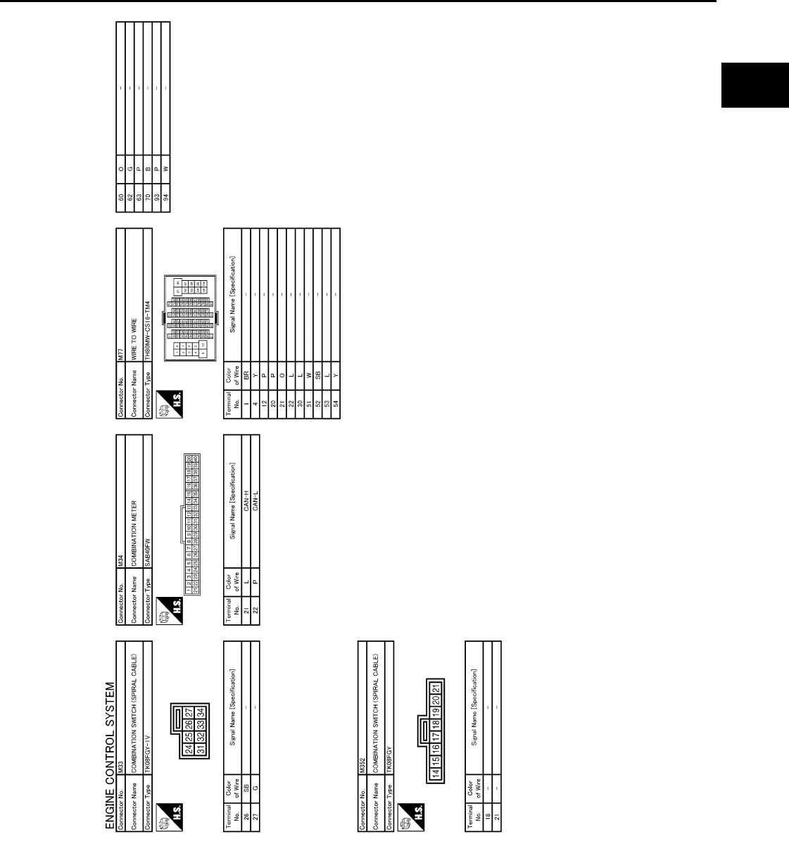
ECM
EC-897
< ECU DIAGNOSIS > [FOR USA (FEDERAL) AND CANADA]
C
D
E
F
G
H
I
J
K
L
M
A
EC
N
P
O
Fail Safe INFOID:0000000004529775
NON DTC RELATED ITEM
JCBWM0969
GB
Revision: 2008 August 2009 Rogue

EC-898
< ECU DIAGNOSIS > [FOR USA (FEDERAL) AND CANADA]
ECM
DTC RELATED ITEM
Engine operating condi-
tion in fail-safe mode Detected items Remarks Reference
page
Engine speed will not
rise more than 2,500 rpm
due to the fuel cut
Malfunction indicator
lamp circuit When there is an open circuit on MIL circuit, the ECM cannot warn the
driver by illuminating MIL when there is malfunction on engine control
system.
Therefore, when electrical controlled throttle and part of ECM related
diagnoses are continuously detected as NG for 5 trips, ECM warns the
driver that engine control system malfunctions and MIL circuit is open
by means of operating the fail-safe function.
The fail-safe function also operates when above diagnoses except MIL
circuit are detected and demands the driver to repair the malfunction.
EC-866
DTC No. Detected items Engine operating condition in fail-safe mode
P0011 Intake valve timing control The signal is not energized to the intake valve timing control solenoid valve and the valve
control does not function.
P0102
P0103
Mass air flow sensor circuit Engine speed will not rise more than 2,400 rpm due to the fuel cut.
P0117
P0118 Engine coolant tempera-
ture sensor circuit Engine coolant temperature will be determined by ECM based on the following conditions.
CONSULT-III displays the engine coolant temperature decided by ECM.
Condition Engine coolant temperature decided
(CONSULT-III display)
Just as ignition switch is turned ON
or START 40°C (104°F)
Approx. 4 minutes or more after
starting engine 80°C (176°F)
Except as shown above 40 - 80°C (104 - 176°F)
(Depends on the time)
When the fail-safe system for engine coolant temperature sensor is activated, the cooling
fan operates while engine is running.
P0122
P0123
P0222
P0223
P2132
P2133
P2135
Throttle position sensor The ECM controls the electric throttle control actuator in regulating the throttle opening in
order for the idle position to be within +10 degrees.
The ECM regulates the opening speed of the throttle valve to be slower than the normal
condition.
Therefore, the acceleration will be poor.
P0500 Vehicle speed sensor When the fail-safe system for vehicle speed sensor is activated, the cooling fan operates
(Highest) while engine is running.
P0643 Sensor power supply ECM stops the electric throttle control actuator control, throttle valve is maintained at a
fixed opening (approx. 5 degrees) by the return spring.
P0605 ECM (When ECM calculation function is malfunctioning:)
ECM stops the electric throttle control actuator control, throttle valve is maintained at a
fixed opening (approx. 5 degrees) by the return spring.
ECM deactivates ASCD operation.
P1805 Brake switch ECM controls the electric throttle control actuator by regulating the throttle opening to a
small range.
Therefore, acceleration will be poor.
Vehicle condition Driving condition
When engine is idling Normal
When accelerating Poor acceleration
P2100
P2103 Throttle control motor relay ECM stops the electric throttle control actuator control, throttle valve is maintained at a
fixed opening (approx. 5 degrees) by the return spring.
P2101 Electric throttle control
function
ECM stops the electric throttle control actuator control, throttle valve is maintained at a
fixed opening (approx. 5 degrees) by the return spring.
Revision: 2008 August 2009 Rogue
ECM
EC-899
< ECU DIAGNOSIS > [FOR USA (FEDERAL) AND CANADA]
C
D
E
F
G
H
I
J
K
L
M
A
EC
N
P
O
DTC Inspection Priority Chart INFOID:0000000004529776
If some DTCs are displayed at the same time, perform inspections one by one based on the following priority
chart.
P2118 Throttle control motor ECM stops the electric throttle control actuator control, throttle valve is maintained at a
fixed opening (approx. 5 degrees) by the return spring.
P2119 Electric throttle control ac-
tuator
(When electric throttle control actuator does not function properly due to the return spring
malfunction:)
ECM controls the electric throttle actuator by regulating the throttle opening around the
idle position. The engine speed will not rise more than 2,000 rpm.
(When throttle valve opening angle in fail-safe mode is not in specified range:)
ECM controls the electric throttle control actuator by regulating the throttle opening to 20
degrees or less.
(When ECM detects the throttle valve is stuck open:)
While the vehicle being driven, it slows down gradually because of fuel cut. After the ve-
hicle stops, the engine stalls.
The engine can restart in N or P position, and engine speed will not exceed 1,000 rpm or
more.
P2122
P2123
P2127
P2128
P2138
Accelerator pedal position
sensor
The ECM controls the electric throttle control actuator in regulating the throttle opening in
order for the idle position to be within +10 degrees.
The ECM regulates the opening speed of the throttle valve to be slower than the normal
condition.
Therefore, the acceleration will be poor.
DTC No. Detected items Engine operating condition in fail-safe mode
Priority Detected items (DTC)
1 • U0101 U0140 U1001 CAN communication line
• P0101 P0102 P0103 Mass air flow sensor
• P0112 P0113 P0127 Intake air temperature sensor
• P0116 P0117 P0118 P0125 Engine coolant temperature sensor
• P0122 P0123 P0222 P0223 P1225 P1226 P2135 Throttle position sensor
• P0128 Thermostat function
• P0181 P0182 P0183 Fuel tank temperature sensor
• P0327 P0328 Knock sensor
• P0335 Crankshaft position sensor (POS)
• P0340 Camshaft position sensor (PHASE)
• P0460 P0461 P0462 P0463 Fuel level sensor
• P0500 Vehicle speed sensor
• P0605 P0607 ECM
• P0643 Sensor power supply
• P0705 P0850 Park/neutral position (PNP) switch
• P1610 - P1615 NATS
• P2122 P2123 P2127 P2128 P2138 Accelerator pedal position sensor
Revision: 2008 August 2009 Rogue
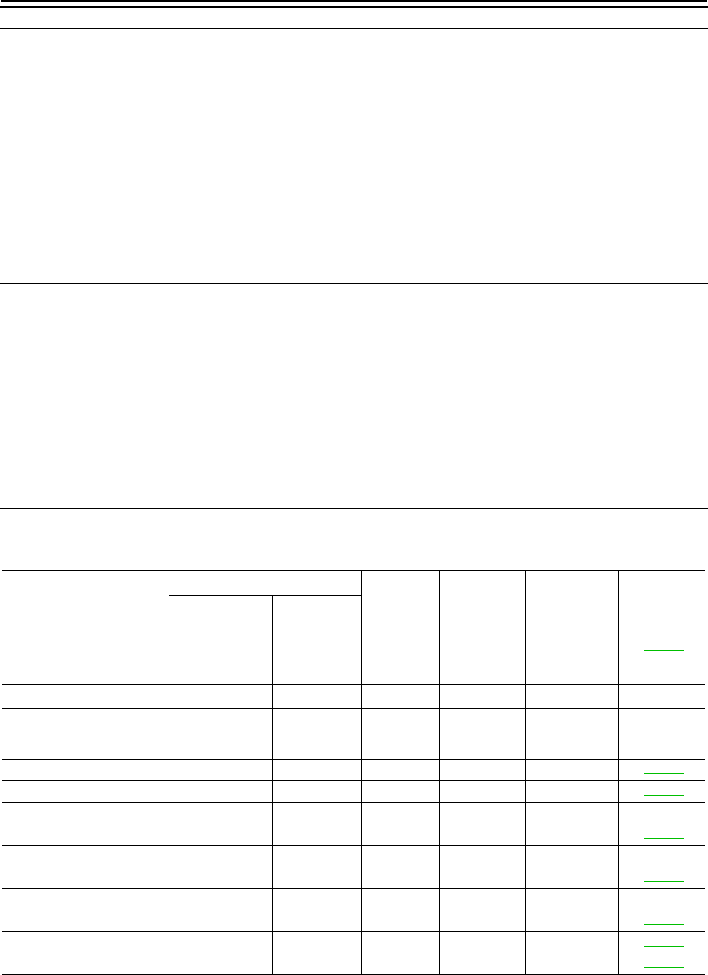
EC-900
< ECU DIAGNOSIS > [FOR USA (FEDERAL) AND CANADA]
ECM
DTC Index INFOID:0000000004529777
×:Applicable —: Not applicable
2 • P0031 P0032 Air fuel ratio (A/F) sensor 1 heater
• P0037 P0038 Heated oxygen sensor 2 heater
• P0075 Intake valve timing control solenoid valve
• P0130 P0131 P0132 P0133 P2A00 Air fuel ratio (A/F) sensor 1
• P0137 P0138 P0139 Heated oxygen sensor 2
• P0441 EVAP control system purge flow monitoring
• P0443 P0444 P0445 EVAP canister purge volume control solenoid valve
• P0447 P0448 EVAP canister vent control valve
• P0451 P0452 P0453 EVAP control system pressure sensor
• P0603 ECM power supply
• P0710 P0715 P0720 P0740 P0744 P0745 P0746 P0776 P0778 P0840 P1740 P1777 P1778 CVT related sensors, solenoid
valves and switches
• P1217 Engine over temperature (OVERHEAT)
• P1805 Brake switch
• P2100 P2103 Throttle control motor relay
• P2101 Electric throttle control function
• P2118 Throttle control motor
3 • P0011 Intake valve timing control
• P0171 P0172 Fuel injection system function
• P0300 - P0304 Misfire
• P0420 Three way catalyst function
• P0442 P0456 EVAP control system (SMALL LEAK, VERY SMALL LEAK)
• P0455 EVAP control system (GROSS LEAK)
• P0506 P0507 Idle speed control system
• P1148 Closed loop control
• P1212 TCS communication line
• P1421 Cold start control
• P1564 ASCD steering switch
• P1572 ASCD brake switch
• P1574 ASCD vehicle speed sensor
• P1715 Primary speed sensor
• P2119 Electric throttle control actuator
Priority Detected items (DTC)
Items
(CONSULT-III screen terms)
DTC*1
SRT code Trip MIL Reference
page
CONSULT-III
GST*2ECM*3
CAN COMM CIRCUIT U0101 0101*4—1 ×EC-599
CAN COMM CIRCUIT U0140 0140*4—1 ×EC-600
CAN COMM CIRCUIT U1001 1001*4—2 —EC-601
NO DTC IS DETECTED.
FURTHER TESTING
MAY BE REQUIRED. P0000 0000 ——
Flashing*7—
INT/V TIM CONT-B1 P0011 0011 — 2 ×EC-602
A/F SEN1 HTR (B1) P0031 0031 — 2 ×EC-606
A/F SEN1 HTR (B1) P0032 0032 — 2 ×EC-606
HO2S2 HTR (B1) P0037 0037 — 2 ×EC-609
HO2S2 HTR (B1) P0038 0038 — 2 ×EC-609
INT/V TIM V/CIR-B1 P0075 0075 — 2 ×EC-612
MAF SEN/CIRCUIT-B1 P0101 0101 — 2 ×EC-615
MAF SEN/CIRCUIT-B1 P0102 0102 — 1 ×EC-622
MAF SEN/CIRCUIT-B1 P0103 0103 — 1 ×EC-622
IAT SEN/CIRCUIT-B1 P0112 0112 — 2 ×EC-627
Revision: 2008 August 2009 Rogue

ECM
EC-901
< ECU DIAGNOSIS > [FOR USA (FEDERAL) AND CANADA]
C
D
E
F
G
H
I
J
K
L
M
A
EC
N
P
O
IAT SEN/CIRCUIT-B1 P0113 0113 — 2 ×EC-627
ECT SEN/CIRC P0116 0116 — 2 ×EC-630
ECT SEN/CIRC P0117 0117 — 1 ×EC-632
ECT SEN/CIRC P0118 0118 — 1 ×EC-632
TP SEN 2/CIRC-B1 P0122 0122 — 1 ×EC-635
TP SEN 2/CIRC-B1 P0123 0123 — 1 ×EC-635
ECT SENSOR P0125 0125 — 2 ×EC-638
IAT SENSOR-B1 P0127 0127 — 2 ×EC-641
THERMSTAT FNCTN P0128 0128 — 2 ×EC-643
A/F SENSOR1 (B1) P0130 0130 — 2 ×EC-645
A/F SENSOR1 (B1) P0131 0131 — 2 ×EC-649
A/F SENSOR1 (B1) P0132 0132 — 2 ×EC-652
A/F SENSOR1 (B1) P0133 0133 ×2×EC-655
HO2S2 (B1) P0137 0137 ×2×EC-660
HO2S2 (B1) P0138 0138 ×2×EC-666
HO2S2 (B1) P0139 0139 ×2×EC-673
FUEL SYS-LEAN-B1 P0171 0171 — 2 ×EC-679
FUEL SYS-RICH-B1 P0172 0172 — 2 ×EC-683
FTT SENSOR P0181 0181 — 2 ×EC-687
FTT SEN/CIRCUIT P0182 0182 — 2 ×EC-690
FTT SEN/CIRCUIT P0183 0183 — 2 ×EC-690
TP SEN 1/CIRC-B1 P0222 0222 — 1 ×EC-693
TP SEN 1/CIRC-B1 P0223 0223 — 1 ×EC-693
MULTI CYL MISFIRE P0300 0300 — 2 ×EC-696
CYL 1 MISFIRE P0301 0301 — 2 ×EC-696
CYL 2 MISFIRE P0302 0302 — 2 ×EC-696
CYL 3 MISFIRE P0303 0303 — 2 ×EC-696
CYL 4 MISFIRE P0304 0304 — 2 ×EC-696
KNOCK SEN/CIRC-B1 P0327 0327 — 2 — EC-701
KNOCK SEN/CIRC-B1 P0328 0328 — 2 — EC-701
CKP SEN/CIRCUIT P0335 0335 — 2 ×EC-703
CMP SEN/CIRC-B1 P0340 0340 — 2 ×EC-707
TW CATALYST SYS-B1 P0420 0420 ×2×EC-711
EVAP PURG FLOW/MON P0441 0441 ×2×EC-716
EVAP SMALL LEAK P0442 0442 ×2×EC-721
PURG VOLUME CONT/V P0443 0443 — 2 ×EC-727
PURG VOLUME CONT/V P0444 0444 — 2 ×EC-731
PURG VOLUME CONT/V P0445 0445 — 2 ×EC-731
VENT CONTROL VALVE P0447 0447 — 2 ×EC-734
VENT CONTROL VALVE P0448 0448 — 2 ×EC-738
EVAP SYS PRES SEN P0451 0451 — 2 ×EC-742
EVAP SYS PRES SEN P0452 0452 — 2 ×EC-745
Items
(CONSULT-III screen terms)
DTC*1
SRT code Trip MIL Reference
page
CONSULT-III
GST*2ECM*3
Revision: 2008 August 2009 Rogue

EC-902
< ECU DIAGNOSIS > [FOR USA (FEDERAL) AND CANADA]
ECM
EVAP SYS PRES SEN P0453 0453 — 2 ×EC-750
EVAP GROSS LEAK P0455 0455 — 2 ×EC-755
EVAP VERY SML LEAK P0456 0456 ×*62×EC-761
FUEL LEV SEN SLOSH P0460 0460 — 2 ×EC-768
FUEL LEVEL SENSOR P0461 0461 — 2 ×EC-769
FUEL LEVL SEN/CIRC P0462 0462 — 2 ×EC-771
FUEL LEVL SEN/CIRC P0463 0463 — 2 ×EC-771
VEH SPEED SEN/CIRC*5P0500 0500 — 2 ×EC-773
ISC SYSTEM P0506 0506 — 2 ×EC-775
ISC SYSTEM P0507 0507 — 2 ×EC-777
ECM BACK UP/CIRCUIT P0603 0603 — 2 ×EC-779
ECM P0605 0605 — 1 or 2 × or — EC-781
ECM P0607 0607 — 1 ×EC-783
SENSOR POWER/CIRC P0643 0643 — 1 ×EC-784
PNP SW/CIRC P0705 0705 — 2 ×TM-53
ATF TEMP SEN/CIRC P0710 0710 — 1 ×TM-56
INPUT SPD SEN/CIRC P0715 0715 — 2 ×TM-59
VEH SPD SEN/CIR AT*5P0720 0720 — 2 ×TM-63
TCC SOLENOID/CIRC P0740 0740 — 2 ×TM-69
A/T TCC S/V FNCTN P0744 0744 — 2 ×TM-71
L/PRESS SOL/CIRC P0745 0745 — 2 ×TM-73
PRS CNT SOL/A FCTN P0746 0746 — 1 ×TM-75
PRS CNT SOL/B FCTN P0776 0776 — 2 ×TM-77
PRS CNT SOL/B CIRC P0778 0778 — 2 ×TM-80
TR PRS SENS/A CIRC P0840 0840 — 2 ×TM-87
P-N POS SW/CIRCUIT P0850 0850 — 2 ×EC-786
CLOSED LOOP-B1 P1148 1148 — 1 ×EC-789
TCS/CIRC P1212 1212 — 2 — EC-790
ENG OVER TEMP P1217 1217 — 1 ×EC-791
CTP LEARNING-B1 P1225 1225 — 2 — EC-795
CTP LEARNING-B1 P1226 1226 — 2 — EC-797
COLD START CONTROL P1421 1421 — 2 ×EC-799
ASCD SW P1564 1564 — 1 — EC-801
ASCD BRAKE SW P1572 1572 — 1 — EC-804
ASCD VHL SPD SEN P1574 1574 — 1 — EC-809
LOCK MODE P1610 1610 — 2 — SEC-34*8
SEC-168*9
ID DISCORD,IMMU-ECM P1611 1611 — 2 — SEC-35*8
SEC-169*9
CHAIN OF ECM-IMMU P1612 1612 — 2 — SEC-37*8
SEC-171*9
Items
(CONSULT-III screen terms)
DTC*1
SRT code Trip MIL Reference
page
CONSULT-III
GST*2ECM*3
Revision: 2008 August 2009 Rogue
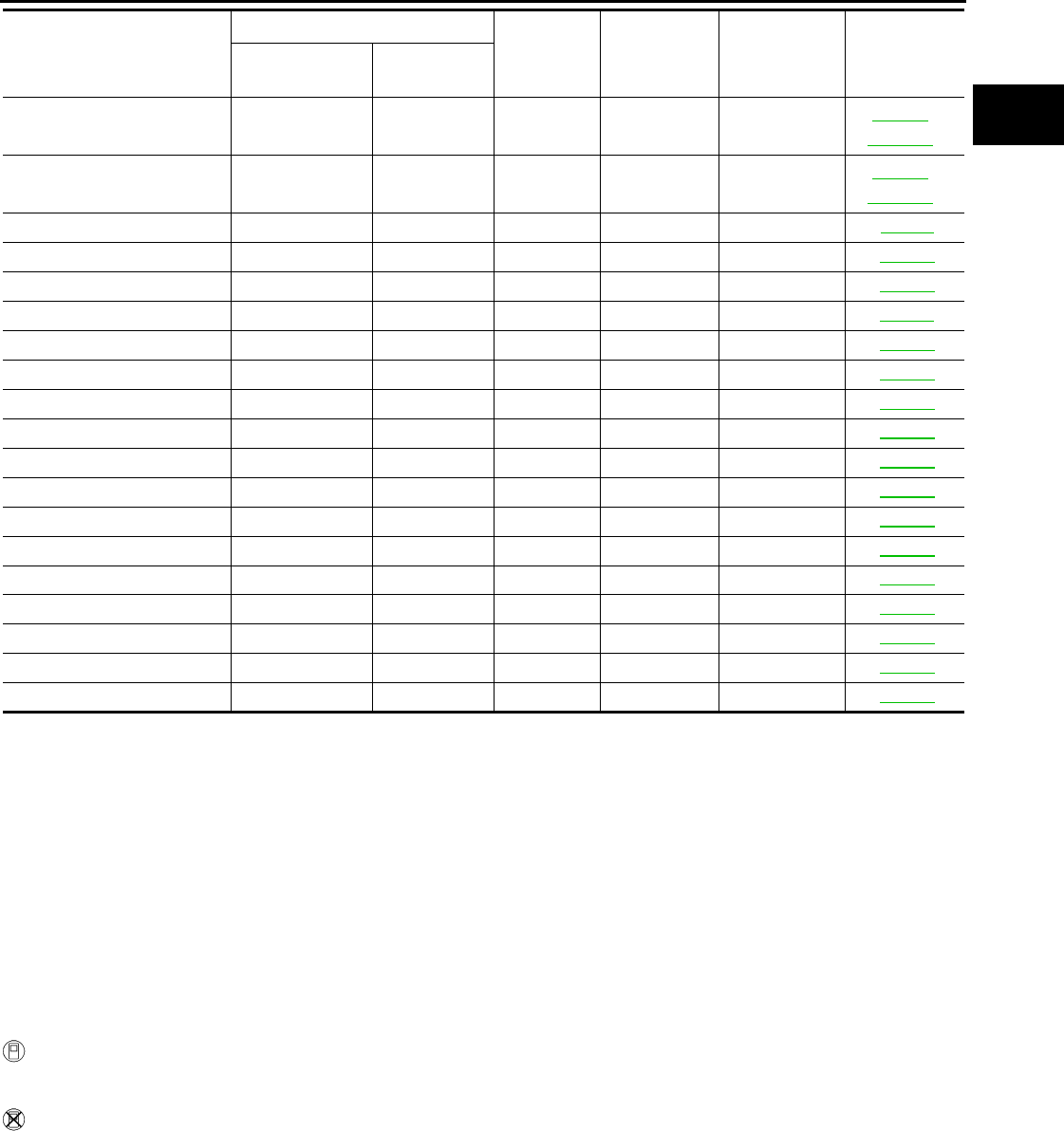
ECM
EC-903
< ECU DIAGNOSIS > [FOR USA (FEDERAL) AND CANADA]
C
D
E
F
G
H
I
J
K
L
M
A
EC
N
P
O
*1: 1st trip DTC No. is the same as DTC No.
*2: This number is prescribed by SAE J2012.
*3: In Diagnostic Test Mode II (Self-diagnostic results), this number is controlled by NISSAN.
*4: The troubleshooting for this DTC needs CONSULT-III.
*5: When the fail-safe operations for both self-diagnoses occur, the MIL illuminates.
*6: SRT code will not be set if the self-diagnostic result is NG.
*7: When the ECM is in the mode that displays SRT status, MIL may flash. For the details, refer to “How to Display SRT Status”.
*8: Models with intelligent system
*9: Models without intelligent system
How to Set SRT Code INFOID:0000000004529778
To set all SRT codes, self-diagnosis for the items indicated above must be performed one or more times. Each
diagnosis may require a long period of actual driving under various conditions.
WITH CONSULT-III
Perform corresponding DTC CONFIRMATION PROCEDURE one by one based on Performance Priority in
the table on “SRT Item”.
WITHOUT CONSULT-III
The most efficient driving pattern in which SRT codes can be properly set is explained below. The driving pat-
tern should be performed one or more times to set all SRT codes.
CHAIN OF IMMU-KEY P1614 1614 — 2 — SEC-38*8
SEC-172*9
DIFFERENCE OF KEY P1615 1615 — 2 — SEC-40*8
SEC-174*9
IN PULY SPEED P1715 1715 — 2 — EC-811
LU-SLCT SOL/CIRC P1740 1740 — 2 ×TM-104
STEP MOTOR CIRC P1777 1777 — 1 ×TM-107
STEP MOTOR FNCT P1778 1778 — 2 ×TM-110
BRAKE SW/CIRCUIT P1805 1805 — 2 — EC-813
ETC MOT PWR-B1 P2100 2100 — 1 ×EC-815
ETC FNCTN/CIRC-B1 P2101 2101 — 1 ×EC-817
ETC MOT PWR P2103 2103 — 1 ×EC-815
ETC MOT-B1 P2118 2118 — 1 ×EC-821
ETC ACTR-B1 P2119 2119 — 1 ×EC-823
APP SEN 1/CIRC P2122 2122 — 1 ×EC-825
APP SEN 1/CIRC P2123 2123 — 1 ×EC-825
APP SEN 2/CIRC P2127 2127 — 1 ×EC-828
APP SEN 2/CIRC P2128 2128 — 1 ×EC-828
TP SENSOR-B1 P2135 2135 — 1 ×EC-832
APP SENSOR P2138 2138 — 1 ×EC-836
A/F SENSOR1 (B1) P2A00 2A00 — 2 ×EC-840
Items
(CONSULT-III screen terms)
DTC*1
SRT code Trip MIL Reference
page
CONSULT-III
GST*2ECM*3
Revision: 2008 August 2009 Rogue
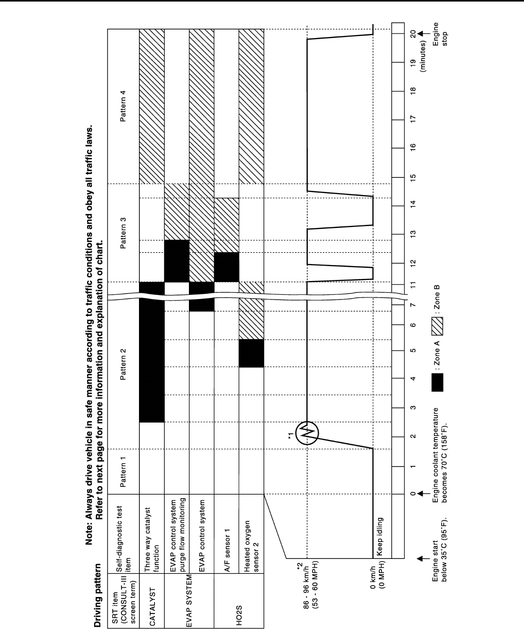
EC-904
< ECU DIAGNOSIS > [FOR USA (FEDERAL) AND CANADA]
ECM
DRIVING PATTERN
• The time required for each diagnosis varies with road surface conditions, weather, altitude, individual driving
habits, etc.
Zone A refers to the range where the time, required for the diagnosis under normal conditions*, is the short-
est.
Zone B refers to the range where the diagnosis can still be performed if the diagnosis is not completed within
zone A.
*: Normal conditions refer to the following:
PBIB3622E
Revision: 2008 August 2009 Rogue

ECM
EC-905
< ECU DIAGNOSIS > [FOR USA (FEDERAL) AND CANADA]
C
D
E
F
G
H
I
J
K
L
M
A
EC
N
P
O
• Sea level
• Flat road
• Ambient air temperature: 20 - 30°C (68 - 86°F)
• Diagnosis is performed as quickly as possible under normal conditions.
Under different conditions [For example: ambient air temperature other than 20 - 30°C (68 - 86°F)], diagno-
sis may also be performed.
Pattern 1:
•The engine is started at the engine coolant temperature of −10 to 35°C (14 to 95°F)
[where the voltage between the ECM terminals 46 (Engine coolant temperature sensor signal) and 52
(Sensor ground) is 3.0 - 4.3V].
•The engine must be operated at idle speed until the engine coolant temperature is greater than 70°C
(158°F) [where the voltage between the ECM terminals 46 (Engine coolant temperature sensor sig-
nal) and 52 (Sensor ground) is lower than 1.4V].
•The engine is started at the fuel tank temperature of warmer than 0°C (32°F) [where the voltage
between the ECM terminal 95 (Fuel tank temperature sensor signal) and 104 (Sensor ground) is less
than 4.1V].
Pattern 2:
• When steady-state driving is performed again even after it is interrupted, each diagnosis can be conducted.
In this case, the time required for diagnosis may be extended.
Pattern 3:
• Operate vehicle following the driving pattern shown in the figure.
• Release the accelerator pedal during decelerating vehicle speed
from 90 km/h (56 MPH) to 0 km/h (0 MPH).
Pattern 4:
• The accelerator pedal must be held very steady during steady-
state driving.
• If the accelerator pedal is moved, the test must be conducted all
over again.
*1: Depress the accelerator pedal until vehicle speed is 90 km/h (56
MPH), then release the accelerator pedal and keep it released for
more than 10 seconds. Depress the accelerator pedal until vehicle
speed is 90 km/h (56 MPH) again.
*2: Checking the vehicle speed with GST is advised.
Suggested Transmission Gear Position for CVT Models
Set the selector lever in the D position.
Test Value and Test Limit INFOID:0000000004534166
The following is the information specified in Service $06 of SAE J1979.
The test value is a parameter used to determine whether a system/circuit diagnostic test is OK or NG while
being monitored by the ECM during self-diagnosis. The test limit is a reference value which is specified as the
maximum or minimum value and is compared with the test value being monitored.
These data (test value and test limit) are specified by On Board Monitor ID(OBDMID), Test ID (TID), Unit and
Scaling ID and can be displayed on the GST screen.
The items of the test value and test limit will be displayed with GST screen which items are provided by the
ECM. (eg., if bank 2 is not applied on this vehicle, only the items of bank 1 are displayed)
PBIB2244E
Revision: 2008 August 2009 Rogue

EC-906
< ECU DIAGNOSIS > [FOR USA (FEDERAL) AND CANADA]
ECM
Item OBD-
MID Self-diagnostic test item DTC
Test value and Test
limit
(GST display) Description
TID
Unit and
Scaling
ID
HO2S
01H Air fuel ratio (A/F) sensor 1
(Bank 1)
P0131 83H 0BH Minimum sensor output voltage for test
cycle
P0131 84H 0BH Maximum sensor output voltage for test
cycle
P0130 85H 0BH Minimum sensor output voltage for test
cycle
P0130 86H 0BH Maximum sensor output voltage for test
cycle
P0133 87H 04H Response rate: Response ratio (Lean to
Rich)
P0133 88H 04H Response rate: Response ratio (Rich to
Lean)
P2A00 89H 84H The amount of shift in air fuel ratio
P2A00 8AH 84H The amount of shift in air fuel ratio
P0130 8BH 0BH Difference in sensor output voltage
P0133 8CH 83H Response gain at the limited frequency
02H Heated oxygen sensor 2
(Bank 1)
P0138 07H 0CH Minimum sensor output voltage for test
cycle
P0137 08H 0CH Maximum sensor output voltage for test
cycle
P0138 80H 0CH Sensor output voltage
P0139 81H 0CH Difference in sensor output voltage
03H Heated oxygen sensor 3
(Bank 1)
P0143 07H 0CH Minimum sensor output voltage for test
cycle
P0144 08H 0CH Maximum sensor output voltage for test
cycle
P0146 80H 0CH Sensor output voltage
P0145 81H 0CH Difference in sensor output voltage
Revision: 2008 August 2009 Rogue

ECM
EC-907
< ECU DIAGNOSIS > [FOR USA (FEDERAL) AND CANADA]
C
D
E
F
G
H
I
J
K
L
M
A
EC
N
P
O
HO2S
05H Air fuel ratio (A/F) sensor 1
(Bank 2)
P0151 83H 0BH Minimum sensor output voltage for test
cycle
P0151 84H 0BH Maximum sensor output voltage for test
cycle
P0150 85H 0BH Minimum sensor output voltage for test
cycle
P0150 86H 0BH Maximum sensor output voltage for test
cycle
P0153 87H 04H Response rate: Response ratio (Lean to
Rich)
P0153 88H 04H Response rate: Response ratio (Rich to
Lean)
P2A03 89H 84H The amount of shift in air fuel ratio
P2A03 8AH 84H The amount of shift in air fuel ratio
P0150 8BH 0BH Difference in sensor output voltage
P0153 8CH 83H Response gain at the limited frequency
06H Heated oxygen sensor 2
(Bank 2)
P0158 07H 0CH Minimum sensor output voltage for test
cycle
P0157 08H 0CH Maximum sensor output voltage for test
cycle
P0158 80H 0CH Sensor output voltage
P0159 81H 0CH Difference in sensor output voltage
07H Heated oxygen sensor 3
(Bank2)
P0163 07H 0CH Minimum sensor output voltage for test
cycle
P0164 08H 0CH Maximum sensor output voltage for test
cycle
P0166 80H 0CH Sensor output voltage
P0165 81H 0CH Difference in sensor output voltage
CATA-
LYST
21H Three way catalyst function
(Bank1)
P0420 80H 01H O2 storage index
P0420 82H 01H Switching time lag engine exhaust index
value
P2423 83H 0CH Difference in 3rd O2 sensor output volt-
age
P2423 84H 84H O2 storage index in HC trap catalyst
22H Three way catalyst function
(Bank2)
P0430 80H 01H O2 storage index
P0430 82H 01H Switching time lag engine exhaust index
value
P2424 83H 0CH Difference in 3rd O2 sensor output volt-
age
P2424 84H 84H O2 storage index in HC trap catalyst
Item OBD-
MID Self-diagnostic test item DTC
Test value and Test
limit
(GST display) Description
TID
Unit and
Scaling
ID
Revision: 2008 August 2009 Rogue

EC-908
< ECU DIAGNOSIS > [FOR USA (FEDERAL) AND CANADA]
ECM
EGR
SYSTEM 31H EGR function
P0400 80H 96H Low Flow Faults: EGR temp change
rate (short term)
P0400 81H 96H Low Flow Faults: EGR temp change
rate (long term)
P0400 82H 96H Low Flow Faults: Difference between
max EGR temp and EGR temp under
idling condition
P0400 83H 96H Low Flow Faults: Max EGR temp
P1402 84H 96H High Flow Faults: EGR temp increase
rate
VVT
SYSTEM
35H VVT Monitor (Bank1)
P0011 80H 9DH VTC intake function diagnosis (VTC
alignment check diagnosis)
P0014 81H 9DH VTC exhaust function diagnosis (VTC
alignment check diagnosis)
P0011 82H 9DH VTC intake function diagnosis (VTC
drive failure diagnosis)
P0014 83H 9DH VTC exhaust function diagnosis (VTC
drive failure diagnosis)
36H VVT Monitor (Bank2)
P0021 80H 9DH VTC intake function diagnosis (VTC
alignment check diagnosis)
P0024 81H 9DH VTC exhaust function diagnosis (VTC
alignment check diagnosis)
P0021 82H 9DH VTC intake function diagnosis (VTC
drive failure diagnosis)
P0024 83H 9DH VTC exhaust function diagnosis (VTC
drive failure diagnosis)
EVAP
SYSTEM
39H EVAP control system leak
(Cap Off) P0455 80H 0CH Difference in pressure sensor output
voltage before and after pull down
3BH EVAP control system leak
(Small leak) P0442 80H 05H Leak area index (for more than 0.04
inch)
3CH EVAP control system leak
(Very small leak)
P0456 80H 05H Leak area index (for more than 0.02
inch)
P0456 81H FDH Maximum internal pressure of EVAP
system during monitoring
3DH Purge flow system P0441 83H 0CH
Difference in pressure sensor output
voltage before and after vent control
valve close
O2 SEN-
SOR
HEATER
41H A/F sensor 1 heater
(Bank 1)
Low Input:P0031
High Input:P0032 81H 0BH Converted value of Heater electric cur-
rent to voltage
42H Heated oxygen sensor 2 heat-
er (Bank 1)
Low Input:P0037
High Input:P0038 80H 0CH Converted value of Heater electric cur-
rent to voltage
43H Heated oxygen sensor 3 heat-
er (Bank 1) P0043 80H 0CH Converted value of Heater electric cur-
rent to voltage
45H A/F sensor 1 heater
(Bank 2)
Low Input:P0051
High Input:P0052 81H 0BH Converted value of Heater electric cur-
rent to voltage
46H Heated oxygen sensor 2 heat-
er (Bank 2)
Low Input:P0057
High Input:P0058 80H 0CH Converted value of Heater electric cur-
rent to voltage
47H Heated oxygen sensor 3 heat-
er (Bank 2) P0063 80H 0CH Converted value of Heater electric cur-
rent to voltage
Item OBD-
MID Self-diagnostic test item DTC
Test value and Test
limit
(GST display) Description
TID
Unit and
Scaling
ID
Revision: 2008 August 2009 Rogue

ECM
EC-909
< ECU DIAGNOSIS > [FOR USA (FEDERAL) AND CANADA]
C
D
E
F
G
H
I
J
K
L
M
A
EC
N
P
O
SEC-
OND-
ARY AIR 71H Secondary Air system
P0411 80H 01H Secondary Air Injection System Incor-
rect Flow Detected
Bank1: P0491
Bank2: P0492 81H 01H Secondary Air Injection System Insuffi-
cient Flow
P2445 82H 01H Secondary Air Injection System Pump
Stuck Off
P2448 83H 01H Secondary Air Injection System High
Airflow
Bank1: P2440
Bank2: P2442 84H 01H Secondary Air Injection System Switch-
ing Valve Stuck Open
P2440 85H 01H Secondary Air Injection System Switch-
ing Valve Stuck Open
P2444 86H 01H Secondary Air Injection System Pump
Stuck On
FUEL
SYSTEM
81H Fuel injection system function
(Bank 1)
P0171 or P0172 80H 2FH Long term fuel trim
P0171 or P0172 81H 24H The number of lambda control clamped
82H Fuel injection system function
(Bank 2)
P0174 or P0175 80H 2FH Long term fuel trim
P0174 or P0175 81H 24H The number of lambda control clamped
Item OBD-
MID Self-diagnostic test item DTC
Test value and Test
limit
(GST display) Description
TID
Unit and
Scaling
ID
Revision: 2008 August 2009 Rogue

EC-910
< ECU DIAGNOSIS > [FOR USA (FEDERAL) AND CANADA]
ECM
MISFIRE A1H Multiple Cylinder Misfires
P0301 80H 24H Misfiring counter at 1000 revolution of
the first cylinder
P0302 81H 24H Misfiring counter at 1000 revolution of
the second cylinder
P0303 82H 24H Misfiring counter at 1000 revolution of
the third cylinder
P0304 83H 24H Misfiring counter at 1000 revolution of
the fourth cylinder
P0305 84H 24H Misfiring counter at 1000 revolution of
the fifth cylinder
P0306 85H 24H Misfiring counter at 1000 revolution of
the sixth cylinder
P0307 86H 24H Misfiring counter at 1000 revolution of
the seventh cylinder
P0308 87H 24H Misfiring counter at 1000 revolution of
the eighth cylinder
P0300 88H 24H Misfiring counter at 1000 revolution of
the multiple cylinders
P0301 89H 24H Misfiring counter at 200 revolution of the
first cylinder
P0302 8AH 24H Misfiring counter at 200 revolution of the
second cylinder
P0303 8BH 24H Misfiring counter at 200 revolution of the
third cylinder
P0304 8CH 24H Misfiring counter at 200 revolution of the
fourth cylinder
P0305 8DH 24H Misfiring counter at 200 revolution of the
fifth cylinder
P0306 8EH 24H Misfiring counter at 200 revolution of the
sixth cylinder
P0307 8FH 24H Misfiring counter at 200 revolution of the
seventh cylinder
P0308 90H 24H Misfiring counter at 200 revolution of the
eighth cylinder
P0300 91H 24H Misfiring counter at 1000 revolution of
the single cylinder
P0300 92H 24H Misfiring counter at 200 revolution of the
single cylinder
P0300 93H 24H Misfiring counter at 200 revolution of the
multiple cylinders
Item OBD-
MID Self-diagnostic test item DTC
Test value and Test
limit
(GST display) Description
TID
Unit and
Scaling
ID
Revision: 2008 August 2009 Rogue

ECM
EC-911
< ECU DIAGNOSIS > [FOR USA (FEDERAL) AND CANADA]
C
D
E
F
G
H
I
J
K
L
M
A
EC
N
P
O
MISFIRE
A2H No. 1 Cylinder Misfire
P0301 0BH 24H
EWMA (Exponential Weighted Moving
Average) misfire counts for last 10 driv-
ing cycles
P0301 0CH 24H Misfire counts for last/current driving cy-
cles
A3H No. 2 Cylinder Misfire
P0302 0BH 24H
EWMA (Exponential Weighted Moving
Average) misfire counts for last 10 driv-
ing cycles
P0302 0CH 24H Misfire counts for last/current driving cy-
cles
A4H No. 3 Cylinder Misfire
P0303 0BH 24H
EWMA (Exponential Weighted Moving
Average) misfire counts for last 10 driv-
ing cycles
P0303 0CH 24H Misfire counts for last/current driving cy-
cles
A5H No. 4 Cylinder Misfire
P0304 0BH 24H
EWMA (Exponential Weighted Moving
Average) misfire counts for last 10 driv-
ing cycles
P0304 0CH 24H Misfire counts for last/current driving cy-
cles
A6H No. 5 Cylinder Misfire
P0305 0BH 24H
EWMA (Exponential Weighted Moving
Average) misfire counts for last 10 driv-
ing cycles
P0305 0CH 24H Misfire counts for last/current driving cy-
cles
A7H No. 6 Cylinder Misfire
P0306 0BH 24H
EWMA (Exponential Weighted Moving
Average) misfire counts for last 10 driv-
ing cycles
P0306 0CH 24H Misfire counts for last/current driving cy-
cles
A8H No. 7 Cylinder Misfire
P0307 0BH 24H EWMA (Exponential Weighted Moving
Average) misfire counts for last 10 driv-
ing cycles
P0307 0CH 24H Misfire counts for last/current driving cy-
cles
A9H No. 8 Cylinder Misfire
P0308 0BH 24H EWMA (Exponential Weighted Moving
Average) misfire counts for last 10 driv-
ing cycles
P0308 0CH 24H Misfire counts for last/current driving cy-
cles
Item OBD-
MID Self-diagnostic test item DTC
Test value and Test
limit
(GST display) Description
TID
Unit and
Scaling
ID
Revision: 2008 August 2009 Rogue

EC-912
< SYMPTOM DIAGNOSIS > [FOR USA (FEDERAL) AND CANADA]
ENGINE CONTROL SYSTEM SYMPTOMS
SYMPTOM DIAGNOSIS
ENGINE CONTROL SYSTEM SYMPTOMS
Symptom Table INFOID:0000000004529780
SYSTEM — BASIC ENGINE CONTROL SYSTEM
SYMPTOM
Reference
page
HARD/NO START/RESTART (EXCP. HA)
ENGINE STALL
HESITATION/SURGING/FLAT SPOT
SPARK KNOCK/DETONATION
LACK OF POWER/POOR ACCELERATION
HIGH IDLE/LOW IDLE
ROUGH IDLE/HUNTING
IDLING VIBRATION
SLOW/NO RETURN TO IDLE
OVERHEATS/WATER TEMPERATURE HIGH
EXCESSIVE FUEL CONSUMPTION
EXCESSIVE OIL CONSUMPTION
BATTERY DEAD (UNDER CHARGE)
Warranty symptom code AA AB AC AD AE AF AG AH AJ AK AL AM HA
Fuel Fuel pump circuit 11232 22 3 2EC-858
Fuel pressure regulator system 334444444 4 EC-923
Fuel injector circuit 11232 22 2 EC-855
Evaporative emission system 334444444 4 EC-550
Air Positive crankcase ventilation sys-
tem 334444444 41 EC-872
Incorrect idle speed adjustment 1 1 1 1 1 EC-503
Electric throttle control actuator 112332222 2 2
EC-817
EC-823
IgnitionIncorrect ignition timing adjustment33111 11 1 EC-503
Ignition circuit 11222 22 2 EC-861
Main power supply and ground circuit 22333 33 23 EC-595
Mass air flow sensor circuit
1
12
2
222 2
EC-615
EC-622
Engine coolant temperature sensor circuit
3
33 EC-632
EC-638
Air fuel ratio (A/F) sensor 1 circuit
EC-645
EC-649
EC-652
EC-655
EC-840
Throttle position sensor circuit
22
EC-635
EC-693
EC-795
EC-797
EC-832
Accelerator pedal position sensor circuit 3 2 1 EC-825
EC-828
EC-836
Knock sensor circuit 2 3 EC-701
Revision: 2008 August 2009 Rogue
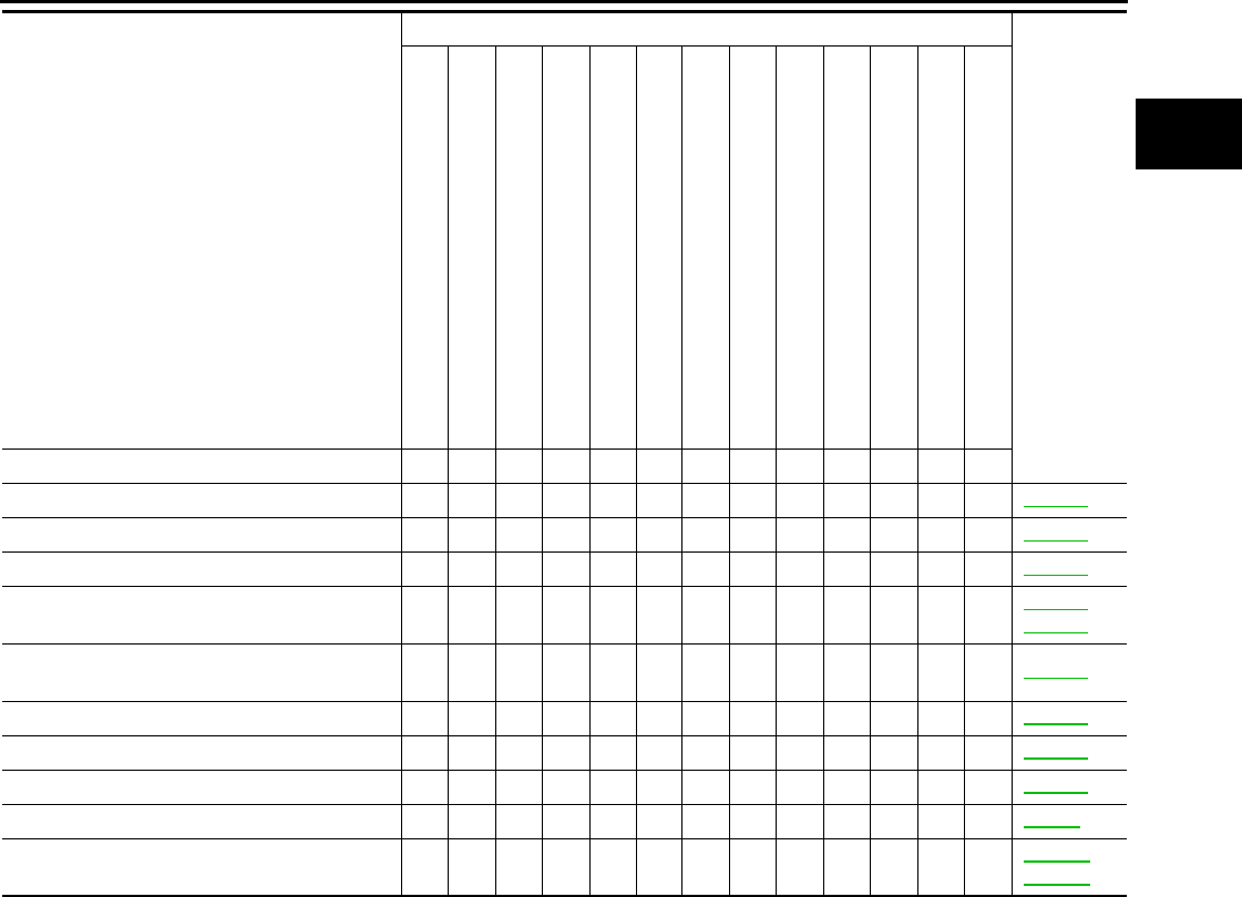
ENGINE CONTROL SYSTEM SYMPTOMS
EC-913
< SYMPTOM DIAGNOSIS > [FOR USA (FEDERAL) AND CANADA]
C
D
E
F
G
H
I
J
K
L
M
A
EC
N
P
O
1 - 6: The numbers refer to the order of inspection.
SYSTEM — ENGINE MECHANICAL & OTHER
Crankshaft position sensor (POS) circuit 2 2 EC-703
Camshaft position sensor (PHASE) circuit 3 2 EC-707
Vehicle speed signal circuit 2 3 3 3 EC-773
ECM 22333333333 EC-779
EC-781
Intake valve timing control solenoid valve cir-
cuit 32 13223 3 EC-612
PNP switch circuit 3 3 3 3 3 EC-786
Refrigerant pressure sensor circuit 2 3 3 4 EC-873
Electrical load signal circuit 3 EC-853
Air conditioner circuit 223333333 3 2HAC-9
ABS actuator and electric unit (control unit) 4 BRC-15
BRC-93
SYMPTOM
Reference
page
HARD/NO START/RESTART (EXCP. HA)
ENGINE STALL
HESITATION/SURGING/FLAT SPOT
SPARK KNOCK/DETONATION
LACK OF POWER/POOR ACCELERATION
HIGH IDLE/LOW IDLE
ROUGH IDLE/HUNTING
IDLING VIBRATION
SLOW/NO RETURN TO IDLE
OVERHEATS/WATER TEMPERATURE HIGH
EXCESSIVE FUEL CONSUMPTION
EXCESSIVE OIL CONSUMPTION
BATTERY DEAD (UNDER CHARGE)
Warranty symptom code AA AB AC AD AE AF AG AH AJ AK AL AM HA
Revision: 2008 August 2009 Rogue

EC-914
< SYMPTOM DIAGNOSIS > [FOR USA (FEDERAL) AND CANADA]
ENGINE CONTROL SYSTEM SYMPTOMS
SYMPTOM
Reference
page
HARD/NO START/RESTART (EXCP. HA)
ENGINE STALL
HESITATION/SURGING/FLAT SPOT
SPARK KNOCK/DETONATION
LACK OF POWER/POOR ACCELERATION
HIGH IDLE/LOW IDLE
ROUGH IDLE/HUNTING
IDLING VIBRATION
SLOW/NO RETURN TO IDLE
OVERHEATS/WATER TEMPERATURE HIGH
EXCESSIVE FUEL CONSUMPTION
EXCESSIVE OIL CONSUMPTION
BATTERY DEAD (UNDER CHARGE)
Warranty symptom code AA AB AC AD AE AF AG AH AJ AK AL AM HA
Fuel Fuel tank 5
5
FL-17
FL-20
Fuel piping 5 5 5 5 5 5 FL-6
Vapor lock —
Valve deposit
5 555 55 5
—
Poor fuel (Heavy weight gasoline,
Low octane) —
Air Air duct
55555 5
EM-28
Air cleaner EM-28
Air leakage from air duct
(Mass air flow sensor — electric
throttle control actuator) 5555
EM-28
Electric throttle control actuator EM-31
Air leakage from intake manifold/
Collector/Gasket EM-31
Cranking Battery 111111
1
1PG-92
Generator circuit CHG-18
Starter circuit 3 STR-5
Signal plate 6 EM-53
PNP switch 4 TM-54
Engine Cylinder head 55555 55 5 EM-85
Cylinder head gasket 4 3
Cylinder block
66666 66 6
4
EM-96
Piston
Piston ring
Connecting rod
Bearing
Crankshaft
Valve
mecha-
nism
Timing chain
55555 55 5
EM-77
Camshaft EM-53
Intake valve timing control EM-31
Intake valve 3EM-77
Exhaust valve
Revision: 2008 August 2009 Rogue
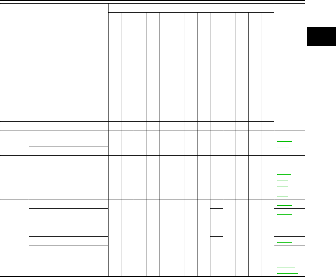
ENGINE CONTROL SYSTEM SYMPTOMS
EC-915
< SYMPTOM DIAGNOSIS > [FOR USA (FEDERAL) AND CANADA]
C
D
E
F
G
H
I
J
K
L
M
A
EC
N
P
O
1 - 6: The numbers refer to the order of inspection.
Exhaust Exhaust manifold/Tube/Muffler/
Gasket 55555 55 5 EM-33
EX-4
Three way catalyst
Lubrica-
tion Oil pan/Oil strainer/Oil pump/Oil
filter/Oil gallery/Oil cooler 55555 55 5
EM-36
EM-39
LU-12
LU-8
LU-9
Oil level (Low)/Filthy oil LU-5
Cooling Radiator/Hose/Radiator filler cap
55555 55 45
CO-20
Thermostat 5 CO-26
Water pump CO-24
Water gallery CO-9
Cooling fan
5
CO-22
Coolant level (Low)/Contaminat-
ed coolant CO-9
NVIS (NISSAN Vehicle Immobilizer System —
NATS) 11 SEC-15
SEC-155
SYMPTOM
Reference
page
HARD/NO START/RESTART (EXCP. HA)
ENGINE STALL
HESITATION/SURGING/FLAT SPOT
SPARK KNOCK/DETONATION
LACK OF POWER/POOR ACCELERATION
HIGH IDLE/LOW IDLE
ROUGH IDLE/HUNTING
IDLING VIBRATION
SLOW/NO RETURN TO IDLE
OVERHEATS/WATER TEMPERATURE HIGH
EXCESSIVE FUEL CONSUMPTION
EXCESSIVE OIL CONSUMPTION
BATTERY DEAD (UNDER CHARGE)
Warranty symptom code AA AB AC AD AE AF AG AH AJ AK AL AM HA
Revision: 2008 August 2009 Rogue

EC-916
< SYMPTOM DIAGNOSIS > [FOR USA (FEDERAL) AND CANADA]
NORMAL OPERATING CONDITION
NORMAL OPERATING CONDITION
Description INFOID:0000000004529781
FUEL CUT CONTROL (AT NO LOAD AND HIGH ENGINE SPEED)
If the engine speed is above 1,800 rpm under no load (for example, the selector lever position is neutral and
engine speed is over 1,800 rpm) fuel will be cut off after some time. The exact time when the fuel is cut off var-
ies based on engine speed.
Fuel cut will be operated until the engine speed reaches 1,500 rpm, then fuel cut will be cancelled.
NOTE:
This function is different from deceleration control listed under Multiport Fuel Injection (MFI) System, EC-515,
"System Description".
Revision: 2008 August 2009 Rogue
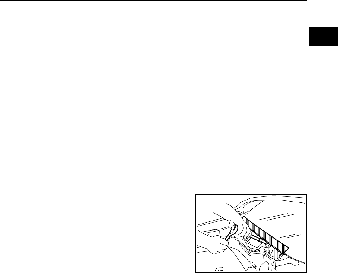
PRECAUTIONS
EC-917
< PRECAUTION > [FOR USA (FEDERAL) AND CANADA]
C
D
E
F
G
H
I
J
K
L
M
A
EC
N
P
O
PRECAUTION
PRECAUTIONS
Precaution for Supplemental Restraint System (SRS) "AIR BAG" and "SEAT BELT
PRE-TENSIONER" INFOID:0000000004539399
The Supplemental Restraint System such as “AIR BAG” and “SEAT BELT PRE-TENSIONER”, used along
with a front seat belt, helps to reduce the risk or severity of injury to the driver and front passenger for certain
types of collision. This system includes seat belt switch inputs and dual stage front air bag modules. The SRS
system uses the seat belt switches to determine the front air bag deployment, and may only deploy one front
air bag, depending on the severity of a collision and whether the front occupants are belted or unbelted.
Information necessary to service the system safely is included in the “SRS AIRBAG” and “SEAT BELT” of this
Service Manual.
WARNING:
• To avoid rendering the SRS inoperative, which could increase the risk of personal injury or death in
the event of a collision which would result in air bag inflation, all maintenance must be performed by
an authorized NISSAN/INFINITI dealer.
• Improper maintenance, including incorrect removal and installation of the SRS, can lead to personal
injury caused by unintentional activation of the system. For removal of Spiral Cable and Air Bag
Module, see the “SRS AIRBAG”.
• Never use electrical test equipment on any circuit related to the SRS unless instructed to in this Ser-
vice Manual. SRS wiring harnesses can be identified by yellow and/or orange harnesses or harness
connectors.
Precaution for Procedure without Cowl Top Cover INFOID:0000000004539392
When performing the procedure after removing cowl top cover, cover
the lower end of windshield with urethane, etc.
Precautions For Xenon Headlamp Service INFOID:0000000004541615
WARNING:
Comply with the following warnings to prevent any serious accident.
• Disconnect the battery cable (negative terminal) or the power supply fuse before installing, remov-
ing, or touching the xenon headlamp (bulb included). The xenon headlamp contains high-voltage
generated parts.
• Never work with wet hands.
• Check the xenon headlamp ON-OFF status after assembling it to the vehicle. Never turn the xenon
headlamp ON in other conditions. Connect the power supply to the vehicle-side connector.
(Turning it ON outside the lamp case may cause fire or visual impairments.)
• Never touch the bulb glass immediately after turning it OFF. It is extremely hot.
CAUTION:
Comply with the following cautions to prevent any error and malfunction.
• Install the xenon bulb securely. (Insufficient bulb socket installation may melt the bulb, the connec-
tor, the housing, etc. by high-voltage leakage or corona discharge.)
• Never perform HID circuit inspection with a tester.
• Never touch the xenon bulb glass with hands. Never put oil and grease on it.
• Dispose of the used xenon bulb after packing it in thick vinyl without breaking it.
• Never wipe out dirt and contamination with organic solvent (thinner, gasoline, etc.).
PIIB3706J
Revision: 2008 August 2009 Rogue
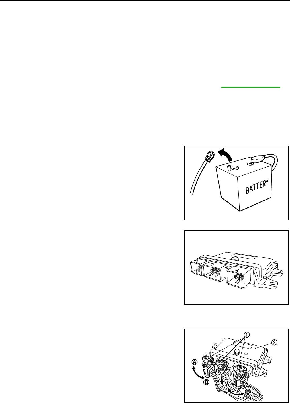
EC-918
< PRECAUTION > [FOR USA (FEDERAL) AND CANADA]
PRECAUTIONS
On Board Diagnostic (OBD) System of Engine and CVT INFOID:0000000004529785
The ECM has an on board diagnostic system. It will illuminate the malfunction indicator lamp (MIL) to warn the
driver of a malfunction causing emission deterioration.
CAUTION:
• Always turn the ignition switch OFF and disconnect the negative battery cable before any repair or
inspection work. The open/short circuit of related switches, sensors, solenoid valves, etc. will cause
the MIL to illuminate.
• Always connect and lock the connectors securely after work. A loose (unlocked) connector will
cause the MIL to illuminate due to the open circuit. (Be sure the connector is free from water, grease,
dirt, bent terminals, etc.)
• Certain systems and components, especially those related to OBD, may use a new style slide-lock-
ing type harness connector. For description and how to disconnect, refer to PG-82, "Description".
• Always route and secure the harnesses properly after work. The interference of the harness with a
bracket, etc. may cause the MIL to illuminate due to the short circuit.
• Always connect rubber tubes properly after work. A misconnected or disconnected rubber tube may
cause the MIL to illuminate due to the malfunction of the EVAP system or fuel injection system, etc.
• Always erase the unnecessary malfunction information (repairs completed) from the ECM and TCM
(Transmission control module) before returning the vehicle to the customer.
General Precautions INFOID:0000000004529786
•Always use a 12 volt battery as power source.
•Never attempt to disconnect battery cables while engine is
running.
•Before connecting or disconnecting the ECM harness con-
nector, turn ignition switch OFF and disconnect negative bat-
tery cable. Failure to do so may damage the ECM because
battery voltage is applied to ECM even if ignition switch is
turned OFF.
•Before removing parts, turn ignition switch OFF and then dis-
connect negative battery cable.
•Never disassemble ECM.
•If a battery cable is disconnected, the memory will return to
the ECM value.
The ECM will now start to self-control at its initial value. Thus
engine operation can vary slightly in this case. However, this
is not an indication of a malfunction. Never replace parts
because of a slight variation.
•If the battery is disconnected, the following emission-related
diagnostic information will be cleared within 24 hours.
-Diagnostic trouble codes
-1st trip diagnostic trouble codes
-Freeze frame data
-1st trip freeze frame data
-System readiness test (SRT) codes
-Test values
•When connecting ECM harness connector (1), fasten (B) it
securely with a lever as far as it will go as shown in the figure.
SEF289H
2. ECM
A. Loosen
PBIA9222J
PBIB2947E
Revision: 2008 August 2009 Rogue

PRECAUTIONS
EC-919
< PRECAUTION > [FOR USA (FEDERAL) AND CANADA]
C
D
E
F
G
H
I
J
K
L
M
A
EC
N
P
O
•When connecting or disconnecting pin connectors into or
from ECM, Never damage pin terminals (berds or breaks).
Check that there are not any bends or breaks on ECM pin ter-
minal, when connecting pin connectors.
•Securely connect ECM harness connectors.
A poor connection can cause an extremely high (surge) volt-
age to develop in coil and condenser, thus resulting in dam-
age to ICs.
•Keep engine control system harness at least 10 cm (4 in) away
from adjacent harness, to prevent engine control system mal-
functions due to receiving external noise, degraded operation
of ICs, etc.
•Keep engine control system parts and harness dry.
•Before replacing ECM, perform ECM Terminals and Reference
Value inspection and Check that ECM functions properly.
Refer to EC-875, "Reference Value".
•Handle mass air flow sensor carefully to avoid damage.
•Never clean mass air flow sensor with any type of detergent.
•Never disassemble electric throttle control actuator.
•Even a slight leak in the air intake system can cause serious
incidents.
•Never shock or jar the camshaft position sensor (PHASE),
crankshaft position sensor (POS).
•After performing each TROUBLE DIAGNOSIS, perform DTC
CONFIRMATION PROCEDURE or Component Function
Check. The DTC should not be displayed in the DTC CONFIRMA-
TION PROCEDURE if the repair is completed. The Component
Function Check should be a good result if the repair is completed.
PBIB0090E
MEF040D
SEF217U
Revision: 2008 August 2009 Rogue

EC-920
< PRECAUTION > [FOR USA (FEDERAL) AND CANADA]
PRECAUTIONS
•When measuring ECM signals with a circuit tester, never allow
the two tester probes to contact.
Accidental contact of probes will cause a short circuit and
damage the ECM power transistor.
•Never operate fuel pump when there is no fuel in lines.
•Tighten fuel hose clamps to the specified torque.
•Never depress accelerator pedal when starting.
•Immediately after starting, Never rev up engine unnecessarily.
•Never rev up engine just prior to shutdown.
•When installing C.B. ham radio or a mobile phone, always
observe the following as it may adversely affect electronic
control systems depending on installation location.
-Keep the antenna as far as possible from the electronic con-
trol units.
-Keep the antenna feeder line more than 20 cm (8 in) away
from the harness of electronic controls.
Never let them run parallel for a long distance.
-Adjust the antenna and feeder line so that the standing-wave
ratio can be kept smaller.
-Always ground the radio to vehicle body.
SEF348N
SEF709Y
SEF708Y
Revision: 2008 August 2009 Rogue

PREPARATION
EC-921
< PREPARATION > [FOR USA (FEDERAL) AND CANADA]
C
D
E
F
G
H
I
J
K
L
M
A
EC
N
P
O
PREPARATION
PREPARATION
Special Service Tools INFOID:0000000004529787
NOTE:
The actual shapes of Kent-Moore tools may differ from those of special service tools illustrated here.
Commercial Service Tools INFOID:0000000004529788
Tool number
(Kent-Moore No.)
Tool name
Description
(J-44321)
Fuel pressure gauge
kit
Checks fuel pressure
LEC642
Tool name
(Kent-Moore No.) Description
Leak detector
i.e.: (J-41416)
Locates the EVAP leak
EVAP service port
adapter
i.e.: (J-41413-OBD)
Applies positive pressure through EVAP service
port
Fuel filler cap adapter
i.e.: (MLR-8382) Checks fuel tank vacuum relief valve opening
pressure
Socket wrench Removes and installs engine coolant temperature
sensor
S-NT703
S-NT704
S-NT815
S-NT705
Revision: 2008 August 2009 Rogue
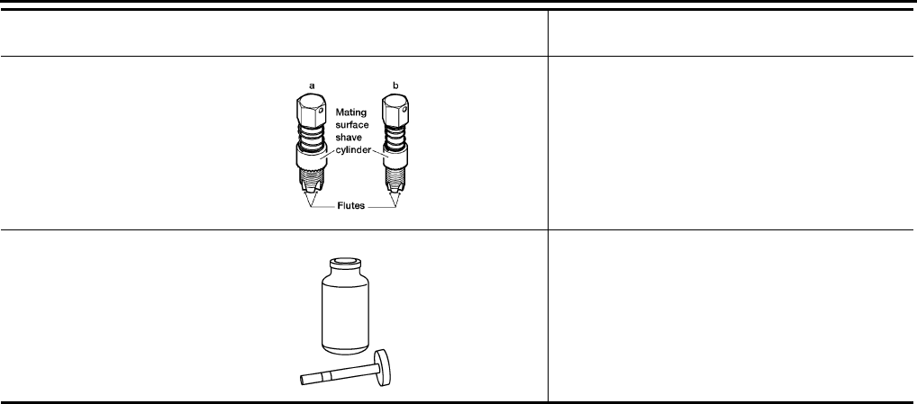
EC-922
< PREPARATION > [FOR USA (FEDERAL) AND CANADA]
PREPARATION
Oxygen sensor thread
cleaner
i.e.: (J-43897-18)
(J-43897-12)
Reconditions the exhaust system threads before
installing a new oxygen sensor. Use with anti-
seize lubricant shown below.
a: 18 mm diameter with pitch 1.5 mm for Zirco-
nia Oxygen Sensor
b: 12 mm diameter with pitch 1.25 mm for Tita-
nia Oxygen Sensor
Anti-seize lubricant
i.e.: (PermatexTM
133AR or equivalent
meeting MIL specifica-
tion MIL-A-907)
Lubricantes oxygen sensor thread cleaning tool
when reconditioning exhaust system threads.
Tool name
(Kent-Moore No.) Description
AEM488
S-NT779
Revision: 2008 August 2009 Rogue

FUEL PRESSURE
EC-923
< ON-VEHICLE MAINTENANCE > [FOR USA (FEDERAL) AND CANADA]
C
D
E
F
G
H
I
J
K
L
M
A
EC
N
P
O
ON-VEHICLE MAINTENANCE
FUEL PRESSURE
Inspection INFOID:0000000004529789
FUEL PRESSURE RELEASE
With CONSULT-III
1. Turn ignition switch ON.
2. Perform “FUEL PRESSURE RELEASE” in “WORK SUPPORT” mode with CONSULT-III.
3. Start engine.
4. After engine stalls, crank it two or three times to release all fuel pressure.
5. Turn ignition switch OFF.
With CONSULT-III
1. Remove fuel pump fuse located in IPDM E/R.
2. Start engine.
3. After engine stalls, crank it two or three times to release all fuel pressure.
4. Turn ignition switch OFF.
5. Reinstall fuel pump fuse after servicing fuel system.
FUEL PRESSURE CHECK
CAUTION:
Before disconnecting fuel line, release fuel pressure from fuel line to eliminate danger.
NOTE:
•Prepare pans or saucers under the disconnected fuel line because the fuel may spill out. The fuel
pressure cannot be completely released because S35 models do not have fuel return system.
•Use Fuel Pressure Gauge Kit [SST (J-44321)] to check fuel pressure.
1. Release fuel pressure to zero.
2. Install fuel pressure gauge adapter [SST (J-44321-6)] (B) with
fuel pressure gauge (A).
• Fuel feed hose (1)
3. Turn ignition switch ON and check for fuel leakage.
4. Start engine and check for fuel leakage.
5. Read the indication of fuel pressure gauge.
6. If result is unsatisfactory, check fuel hoses and fuel tubes for
clogging.
If OK, Replace “fuel filter and fuel pump assembly”.
If NG, Repair or replace.
At idling : Approximately 350 kPa (3.57 kg/cm2, 51 psi)
JMBIA0930ZZ
Revision: 2008 August 2009 Rogue
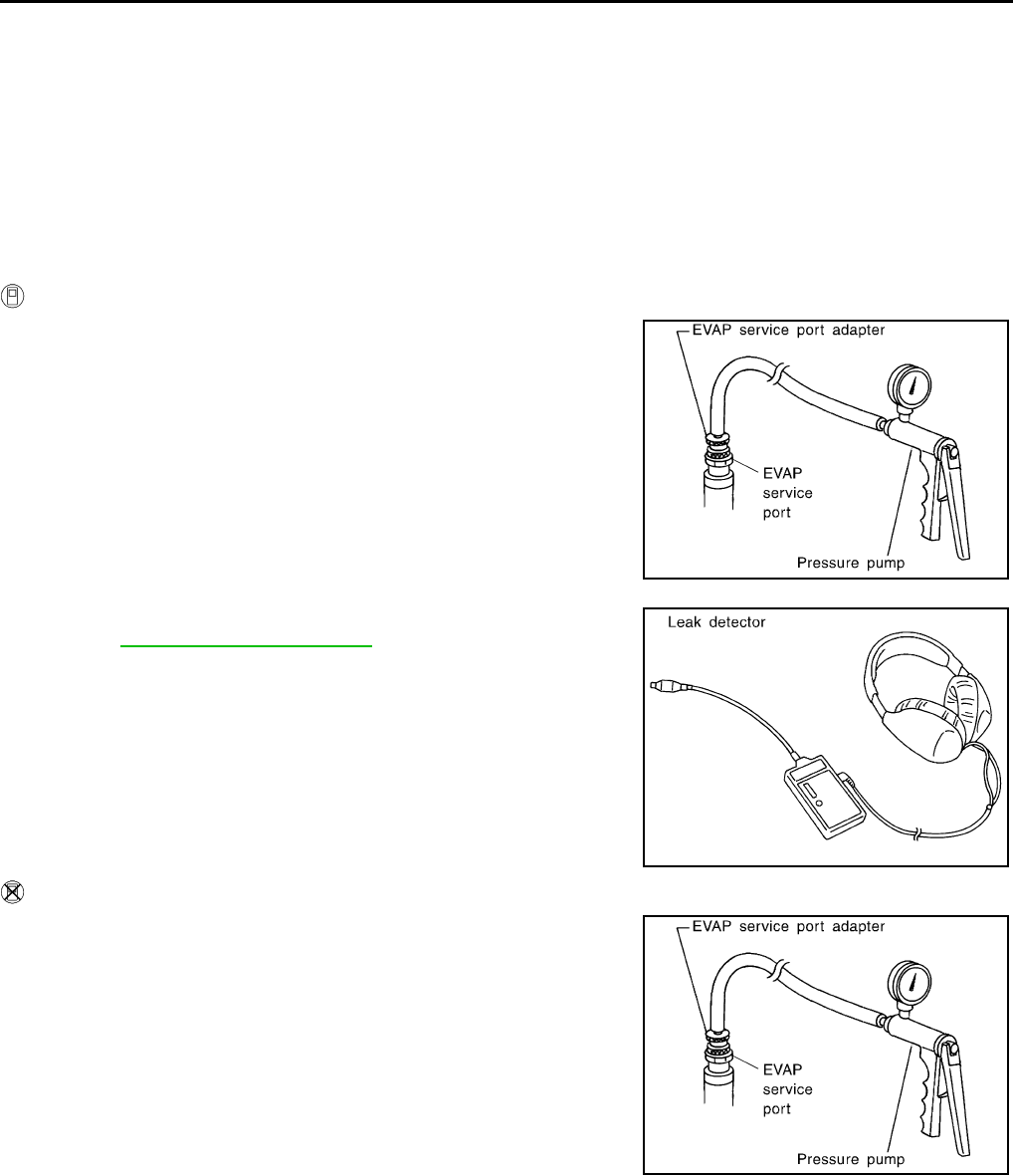
EC-924
< ON-VEHICLE MAINTENANCE > [FOR USA (FEDERAL) AND CANADA]
EVAP LEAK CHECK
EVAP LEAK CHECK
Inspection INFOID:0000000004529790
CAUTION:
• Never use compressed air or a high pressure pump.
• Never exceed 4.12 kPa (0.042 kg/cm2, 0.6 psi) of pressure in EVAP system.
NOTE:
• Do not start engine.
• Improper installation of EVAP service port adapter (commercial service tool) to the EVAP service port may
cause a leak.
WITH CONSULT-III
1. To locate the EVAP leak, install EVAP service port adapter (com-
mercial service tool) and pressure pump to EVAP service port.
2. Turn ignition switch ON.
3. Select the “EVAP SYSTEM CLOSE” of “WORK SUPPORT”
mode with CONSULT-III.
4. Touch “START”. A bar graph (Pressure indicating display) will
appear on the screen.
5. Apply positive pressure to the EVAP system until the pressure
indicator reaches the middle of the bar graph.
6. Remove EVAP service port adapter (commercial service tool)
and hose with pressure pump.
7. Locate the leak using a leak detector (commercial service tool).
Refer to EC-549, "System Diagram".
WITHOUT CONSULT-III
1. To locate the EVAP leak, install EVAP service port adapter (com-
mercial service tool) and pressure pump to EVAP service port.
2. Apply battery voltage between the terminals of EVAP canister
vent control valve to make a closed EVAP system.
3. To locate the leak, deliver positive pressure to the EVAP system
until pressure gauge points reach 1.38 to 2.76 kPa (0.014 to
0.028 kg/cm2, 0.2 to 0.4 psi).
4. Remove EVAP service port adapter (commercial service tool)
and hose with pressure pump.
SEF462UA
SEF200U
SEF462UA
Revision: 2008 August 2009 Rogue
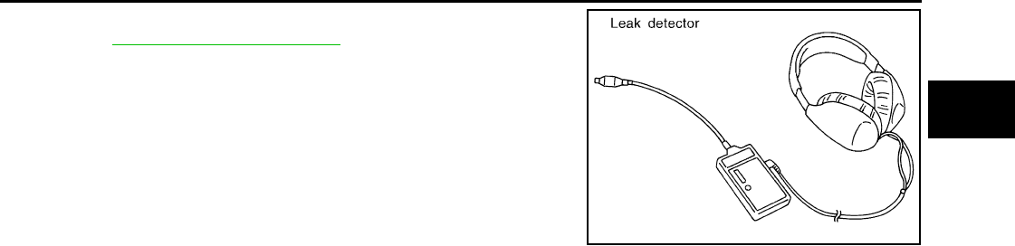

EC-926
< ON-VEHICLE REPAIR > [FOR USA (FEDERAL) AND CANADA]
EVAP CANISTER
ON-VEHICLE REPAIR
EVAP CANISTER
Exploded View INFOID:0000000004529791
Removal and Installation INFOID:0000000004529792
REMOVAL
1. Lift up the vehicle.
2. Remove EVAP canister fixing bolt.
3. Remove EVAP canister.
NOTE:
The EVAP canister vent control valve and EVAP canister system pressure sensor can be removed without
removing the EVAP canister.
INSTALLATION
Install in the reverse order of removal.
NOTE:
Tighten EVAP canister fixing bolt to the specified torque.
DISASSEMBLY
1. Turn EVAP canister vent control valve counterclockwise.
2. Remove the EVAP canister vent control valve.
ASSEMBLY
Assemble in the reverse order of disassembly.
CAUTION:
Always replace O-ring with a new one.
PBIB1383E
PBIB1384E
Revision: 2008 August 2009 Rogue
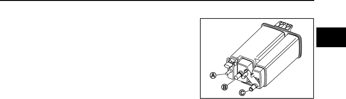
EVAP CANISTER
EC-927
< ON-VEHICLE REPAIR > [FOR USA (FEDERAL) AND CANADA]
C
D
E
F
G
H
I
J
K
L
M
A
EC
N
P
O
Inspection INFOID:0000000004529793
Check EVAP canister as follows:
1. Block port (B).
2. Blow air into port (A) and check that it flows freely out of port (C).
3. Release blocked port (B).
4. Apply vacuum pressure to port (B) and check that vacuum pres-
sure exists at the ports (A) and (C).
5. Block port (A) and (B).
6. Apply pressure to port (C) and check that there is no leakage.
JMBIA0961ZZ
Revision: 2008 August 2009 Rogue
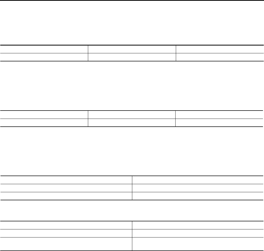
EC-928
< SERVICE DATA AND SPECIFICATIONS (SDS) [FOR USA (FEDERAL) AND CANADA]
SERVICE DATA AND SPECIFICATIONS (SDS)
SERVICE DATA AND SPECIFICATIONS (SDS)
SERVICE DATA AND SPECIFICATIONS (SDS)
Idle Speed INFOID:0000000004672618
*: Under the following conditions
• A/C switch: OFF
• Electric load: OFF (Lights, heater fan & rear window defogger)
• Steering wheel: Kept in straight-ahead position
Ignition Timing INFOID:0000000004672619
*: Under the following conditions
• A/C switch: OFF
• Electric load: OFF (Lights, heater fan & rear window defogger)
• Steering wheel: Kept in straight-ahead position
Calculated Load Value INFOID:0000000004672620
Mass Air Flow Sensor INFOID:0000000004672621
*: Engine is warmed up to normal operating temperature and running under no load.
Transmission Condition Specification
CVT No load* (in P or N position) 700 ± 50 rpm
Transmission Condition Specification
CVT No load* (in P or N position) 15 ± 5° BTDC
Condition Specification (Using CONSULT-III or GST)
At idle 10 – 35 %
At 2,500 rpm 10 – 35 %
Supply voltage Battery voltage (11 – 14 V)
Output voltage at idle 0.8 – 1.2V*
Mass air flow (Using CONSULT-III or GST) 1.0 – 4.0 g·m/sec at idle*
4.0 – 10.0 g·m/sec at 2,500 rpm*
Revision: 2008 August 2009 Rogue

DIAGNOSIS AND REPAIR WORKFLOW
EC-929
< BASIC INSPECTION > [FOR MEXICO]
C
D
E
F
G
H
I
J
K
L
M
A
EC
N
P
O
BASIC INSPECTION
DIAGNOSIS AND REPAIR WORKFLOW
Work Flow INFOID:0000000004494106
OVERALL SEQUENCE
DETAILED FLOW
JMBIA1416G
B
Revision: 2008 August 2009 Rogue

EC-930
< BASIC INSPECTION > [FOR MEXICO]
DIAGNOSIS AND REPAIR WORKFLOW
1.GET INFORMATION FOR SYMPTOM
Get the detailed information from the customer about the symptom (the condition and the environment when
the incident/malfunction occurred) using the “Diagnostic Work Sheet”. (Refer to EC-932, "Diagnostic Work
Sheet".)
>> GO TO 2.
2.CHECK DTC
1. Check DTC.
2. Perform the following procedure if DTC is displayed.
- Record DTC and freeze frame data. (Print them out with CONSULT-III or GST.)
- Erase DTC. (Refer to “”EC-990, "Diagnosis Description".)
- Study the relationship between the cause detected by DTC and the symptom described by the customer.
(Symptom Table is useful. Refer to EC-1268, "Symptom Table".)
3. Check related service bulletins for information.
Are any symptoms described and is any DTCs detected?
Symptom is described, DTC is detected>>GO TO 3.
Symptom is described, DTC is not detected>>GO TO 4.
Symptom is not described, DTC is detected>>GO TO 5.
3.CONFIRM THE SYMPTOM
Try to confirm the symptom described by the customer (except MIL ON).
Also study the normal operation and fail-safe related to the symptom. Refer to EC-1272, "Description" and EC-
1254, "Fail Safe".
Diagnosis Work Sheet is useful to verify the incident.
Verify relation between the symptom and the condition when the symptom is detected.
>> GO TO 5.
4.CONFIRM THE SYMPTOM
Try to confirm the symptom described by the customer.
Also study the normal operation and fail-safe related to the symptom. Refer to EC-1272, "Description" and EC-
1254, "Fail Safe".
Diagnosis Work Sheet is useful to verify the incident.
Verify relation between the symptom and the condition when the symptom is detected.
>> GO TO 6.
5.PERFORM DTC CONFIRMATION PROCEDURE
Perform DTC CONFIRMATION PROCEDURE for the displayed DTC, and then check that DTC is detected
again.
If two or more DTCs are detected, refer to EC-1256, "DTC Inspection Priority Chart" and determine trouble
diagnosis order.
NOTE:
• Freeze frame data is useful if the DTC is not detected.
• Perform Component Function Check if DTC CONFIRMATION PROCEDURE is not included on Service
Manual. This simplified check procedure is an effective alternative though DTC cannot be detected during
this check.
If the result of Component Function Check is NG, it is the same as the detection of DTC by DTC CONFIR-
MATION PROCEDURE.
Is DTC detected?
YES >> GO TO 10.
NO >> Check according to GI-41, "Intermittent Incident".
6.PERFORM BASIC INSPECTION
Perform EC-933, "BASIC INSPECTION : Special Repair Requirement".
Do you have CONSULT-III?
Revision: 2008 August 2009 Rogue

DIAGNOSIS AND REPAIR WORKFLOW
EC-931
< BASIC INSPECTION > [FOR MEXICO]
C
D
E
F
G
H
I
J
K
L
M
A
EC
N
P
O
YES >> GO TO 7.
NO >> GO TO 9.
7.PERFORM SPEC IN DATA MONITOR MODE
With CONSULT-III
Check that “MAS A/F SE-B1”, “B/FUEL SCHDL” and “A/F ALPHA-B1” are within the SP value using CON-
SULT-III in “SPEC” of “DATA MONITOR” mode with CONSULT-III. Refer to EC-1012, "Component Function
Check".
Is the measurement value within the SP value?
YES >> GO TO 9.
NO >> GO TO 8.
8.DETECT MALFUNCTIONING PART BY TROUBLE DIAGNOSIS - SPECIFICATION VALUE
Detect malfunctioning part according to EC-1013, "Diagnosis Procedure".
Is a malfunctioning part detected?
YES >> GO TO 11.
NO >> GO TO 9.
9.DETECT MALFUNCTIONING SYSTEM BY SYMPTOM TABLE
Detect malfunctioning system according to EC-1268, "Symptom Table" based on the confirmed symptom in
step 4, and determine the trouble diagnosis order based on possible causes and symptoms.
>> GO TO 10.
10.DETECT MALFUNCTIONING PART BY DIAGNOSIS PROCEDURE
Inspect according to Diagnosis Procedure of the system.
NOTE:
The Diagnosis Procedure in EC section described based on open circuit inspection. A short circuit inspection
is also required for the circuit check in the Diagnosis Procedure. For details, refer to “Circuit Inspection” in GI-
44, "Circuit Inspection".
Is a malfunctioning part detected?
YES >> GO TO 11.
NO >> Monitor input data from related sensors or check the voltage of related ECM terminals using CON-
SULT-III. Refer to EC-1232, "Reference Value".
11.REPAIR OR REPLACE THE MALFUNCTIONING PART
1. Repair or replace the malfunctioning part.
2. Reconnect parts or connectors disconnected during Diagnosis Procedure again after repair and replace-
ment.
3. Check DTC. If DTC is displayed, erase it. (Refer to “”EC-990, "Diagnosis Description".)
>> GO TO 12.
12.FINAL CHECK
When DTC was detected in step 2, perform DTC CONFIRMATION PROCEDURE or Component Function
Check again, and then check that the malfunction have been completely repaired.
When symptom was described from the customer, refer to confirmed symptom in step 3 or 4, and check that
the symptom is not detected.
Is DTC detected and does symptom remain?
YES-1 >> DTC is detected: GO TO 10.
YES-2 >> Symptom remains: GO TO 6.
NO >> Before returning the vehicle to the customer, check to always erase unnecessary DTC in ECM
and TCM (Transmission Control Module). (Refer to “”EC-990, "Diagnosis Description".) If the
completion of SRT is needed, drive vehicle under the specific DRIVING PATTERN in EC-1260,
"How to Set SRT Code".
Revision: 2008 August 2009 Rogue
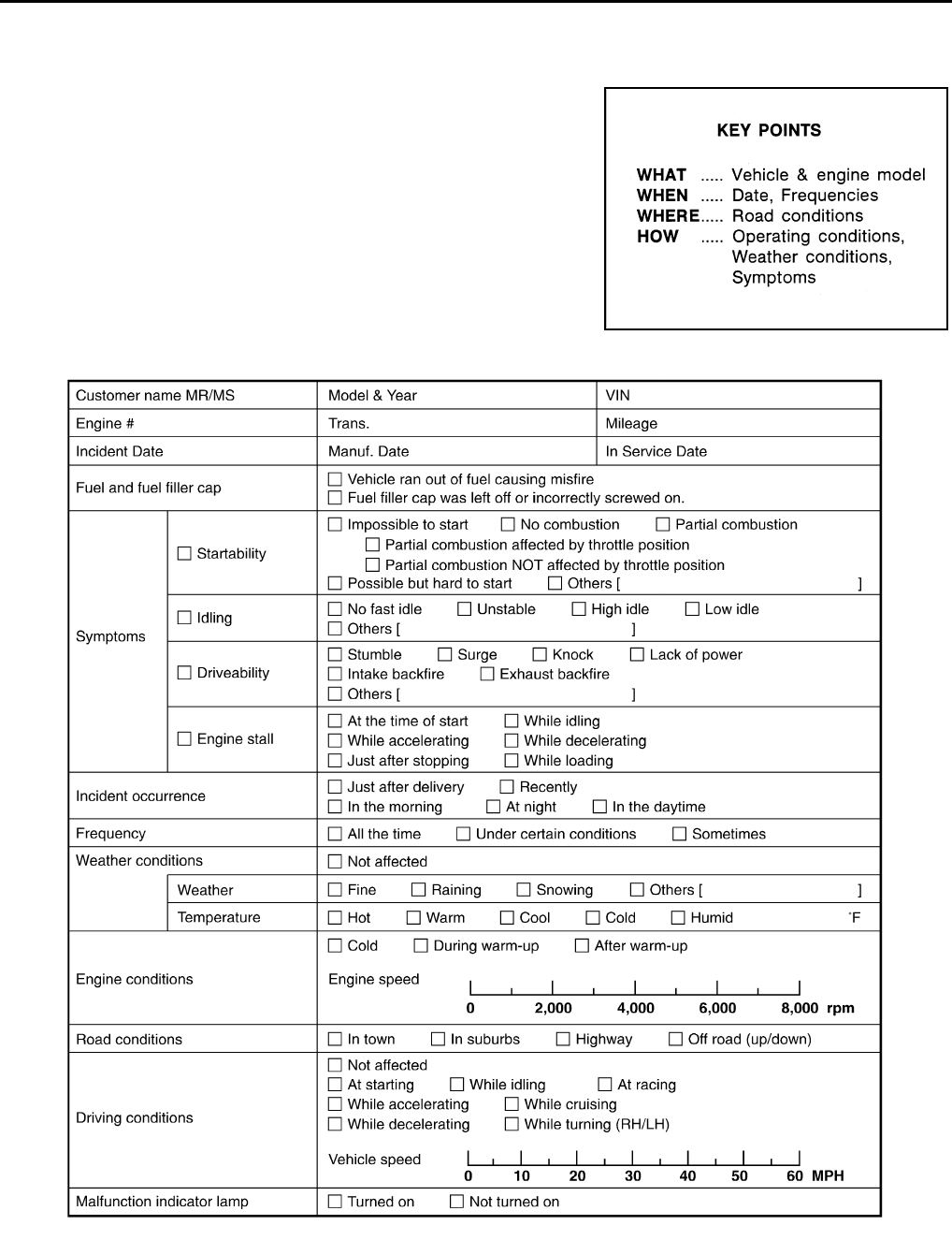
EC-932
< BASIC INSPECTION > [FOR MEXICO]
DIAGNOSIS AND REPAIR WORKFLOW
Diagnostic Work Sheet INFOID:0000000004494107
DESCRIPTION
There are many operating conditions that lead to the malfunction of
engine components. A good grasp of such conditions can make trou-
bleshooting faster and more accurate.
In general, each customer feels differently about symptoms. It is
important to fully understand the symptoms or conditions for a cus-
tomer complaint.
Utilize a diagnostic worksheet like WORKSHEET SAMPLE below in
order to organize all the information for troubleshooting.
Some conditions may cause the MIL to illuminate or blink, and DTC
to be detected. Examples:
• Vehicle ran out of fuel, which caused the engine to misfire.
WORKSHEET SAMPLE
SEF907L
MTBL0017
Revision: 2008 August 2009 Rogue

INSPECTION AND ADJUSTMENT
EC-933
< BASIC INSPECTION > [FOR MEXICO]
C
D
E
F
G
H
I
J
K
L
M
A
EC
N
P
O
INSPECTION AND ADJUSTMENT
BASIC INSPECTION
BASIC INSPECTION : Special Repair Requirement INFOID:0000000004494108
1.INSPECTION START
1. Check service records for any recent repairs that may indicate a related malfunction, or a current need for
scheduled maintenance.
2. Open engine hood and check the following:
- Harness connectors for improper connections
- Wiring harness for improper connections, pinches and cut
- Vacuum hoses for splits, kinks and improper connections
- Hoses and ducts for leakage
- Air cleaner clogging
- Gasket
3. Check that electrical or mechanical loads are not applied.
- Headlamp switch is OFF.
- Air conditioner switch is OFF.
- Rear window defogger switch is OFF.
- Steering wheel is in the straight-ahead position, etc.
4. Start engine and warm it up until engine coolant temperature
indicator points to the middle of gauge.
Check that engine stays below 1,000 rpm.
5. Run engine at approximately 2,000 rpm for approximately 2 min-
utes under no load.
6. Check that no DTC is displayed with CONSULT-III or GST.
Are any DTCs detected?
YES >> GO TO 2.
NO >> GO TO 3.
2.REPAIR OR REPLACE
Repair or replace components as necessary according to corresponding Diagnosis Procedure.
>> GO TO 3
3.CHECK IDLE SPEED
1. Run engine at approximately 2,000 rpm for approximately 2 minutes under no load.
SEF983U
SEF976U
SEF977U
Revision: 2008 August 2009 Rogue
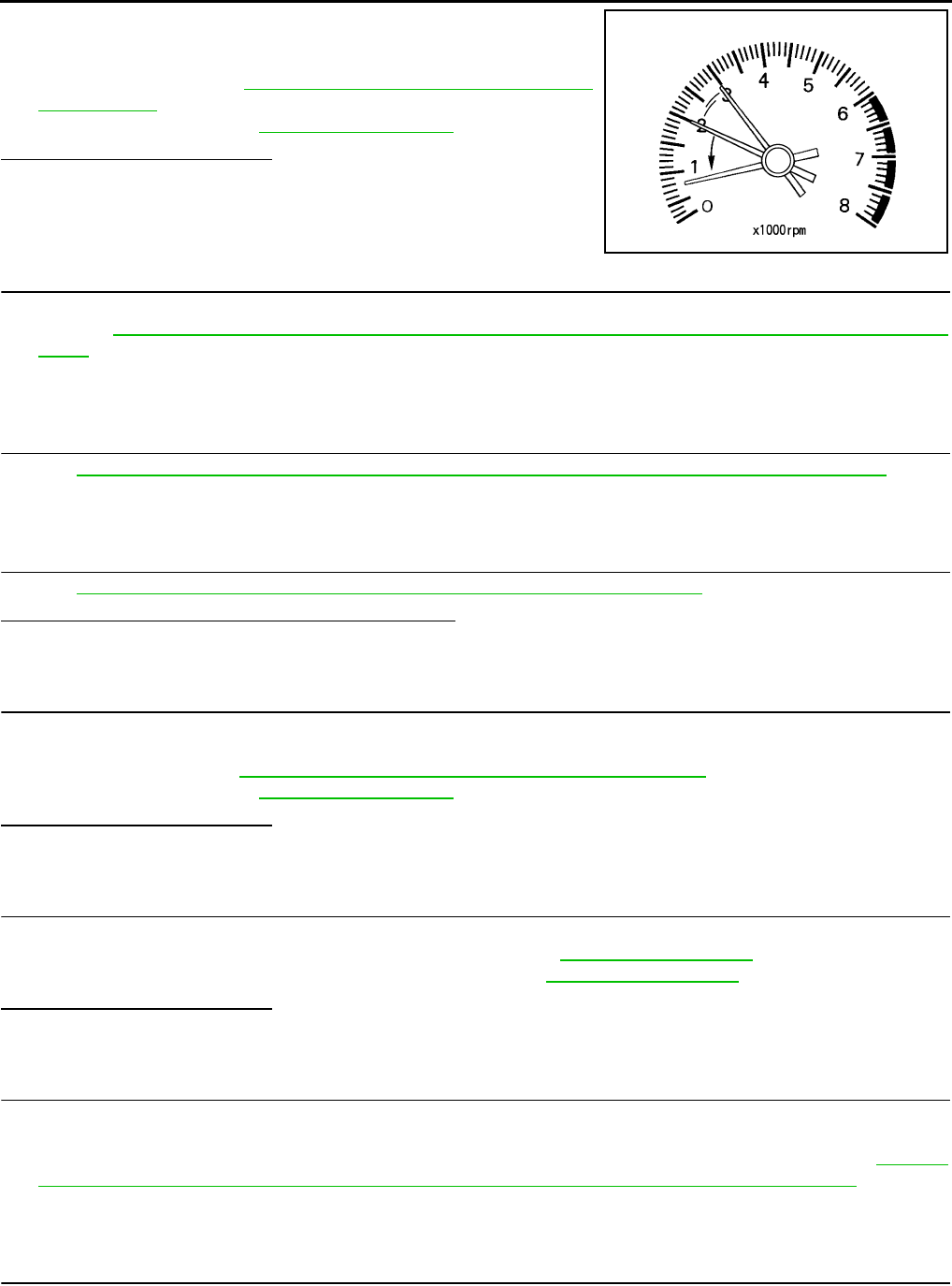
EC-934
< BASIC INSPECTION > [FOR MEXICO]
INSPECTION AND ADJUSTMENT
2. Rev engine (2,000 to 3,000 rpm) two or three times under no
load, then run engine at idle speed for approximately 1 minute.
3. Check idle speed.
For procedure, refer to EC-936, "IDLE SPEED : Special Repair
Requirement".
For specification, refer to EC-1281, "Idle Speed".
Is the inspection result normal?
YES >> GO TO 10.
NO >> GO TO 4.
4.PERFORM ACCELERATOR PEDAL RELEASED POSITION LEARNING
1. Stop engine.
2. Perform EC-937, "ACCELERATOR PEDAL RELEASED POSITION LEARNING : Special Repair Require-
ment".
>> GO TO 5.
5.PERFORM THROTTLE VALVE CLOSED POSITION LEARNING
Perform EC-938, "THROTTLE VALVE CLOSED POSITION LEARNING : Special Repair Requirement".
>> GO TO 6.
6.PERFORM IDLE AIR VOLUME LEARNING
Perform EC-938, "IDLE AIR VOLUME LEARNING : Special Repair Requirement".
Is Idle Air Volume Learning carried out successfully?
YES >> GO TO 7.
NO >> Follow the instruction of Idle Air Volume Learning. Then GO TO 4.
7.CHECK IDLE SPEED AGAIN
1. Start engine and warm it up to normal operating temperature.
2. Check idle speed.
For procedure, refer to EC-936, "IDLE SPEED : Special Repair Requirement".
For specification, refer to EC-1281, "Idle Speed".
Is the inspection result normal?
YES >> GO TO 10.
NO >> GO TO 8.
8.DETECT MALFUNCTIONING PART
Check the Following.
• Check camshaft position sensor (PHASE) and circuit. Refer to EC-1124, "DTC Logic".
• Check crankshaft position sensor (POS) and circuit. Refer to EC-1120, "DTC Logic".
Is the inspection result normal?
YES >> GO TO 9.
NO >> Repair or replace. Then GO TO 4.
9.CHECK ECM FUNCTION
1. Substitute with a non-malfunctioning ECM to check ECM function. (ECM may be the cause of a incident,
although this is rare.)
2. Perform initialization of NATS system and registration of all NATS ignition key IDs. Refer to EC-936,
"ADDITIONAL SERVICE WHEN REPLACING CONTROL UNIT : Special Repair Requirement".
>> GO TO 4.
10.CHECK IGNITION TIMING
1. Run engine at idle.
2. Check ignition timing with a timing light.
PBIA8513J
Revision: 2008 August 2009 Rogue

INSPECTION AND ADJUSTMENT
EC-935
< BASIC INSPECTION > [FOR MEXICO]
C
D
E
F
G
H
I
J
K
L
M
A
EC
N
P
O
For procedure, refer to EC-937, "IGNITION TIMING : Special Repair Requirement".
For specification, refer to EC-1281, "Ignition Timing".
Is the inspection result normal?
YES >> GO TO 19.
NO >> GO TO 11.
11.PERFORM ACCELERATOR PEDAL RELEASED POSITION LEARNING
1. Stop engine.
2. Perform EC-937, "ACCELERATOR PEDAL RELEASED POSITION LEARNING : Special Repair Require-
ment".
>> GO TO 12.
12.PERFORM THROTTLE VALVE CLOSED POSITION LEARNING
Perform EC-938, "THROTTLE VALVE CLOSED POSITION LEARNING : Special Repair Requirement".
>> GO TO 13.
13.PERFORM IDLE AIR VOLUME LEARNING
Perform EC-938, "IDLE AIR VOLUME LEARNING : Special Repair Requirement".
Is Idle Air Volume Learning carried out successfully?
YES >> GO TO 14.
NO >> Follow the instruction of Idle Air Volume Learning. Then GO TO 4.
14.CHECK IDLE SPEED AGAIN
1. Start engine and warm it up to normal operating temperature.
2. Check idle speed.
For procedure, refer to EC-936, "IDLE SPEED : Special Repair Requirement".
For specification, refer to EC-1281, "Idle Speed".
Is the inspection result normal?
YES >> GO TO 15.
NO >> GO TO 17.
15.CHECK IGNITION TIMING AGAIN
1. Run engine at idle.
2. Check ignition timing with a timing light.
For procedure, refer to EC-937, "IGNITION TIMING : Special Repair Requirement".
For specification, refer to EC-1281, "Ignition Timing".
Is the inspection result normal?
YES >> GO TO 19.
NO >> GO TO 16.
16.CHECK TIMING CHAIN INSTALLATION
Check timing chain installation. Refer to EM-70, "Removal and Installation".
Is the inspection result normal?
YES >> GO TO 17.
NO >> Repair the timing chain installation. Then GO TO 4.
17.DETECT MALFUNCTIONING PART
Check the following.
• Check camshaft position sensor (PHASE) and circuit. Refer to EC-1124, "DTC Logic".
• Check crankshaft position sensor (POS) and circuit. Refer to EC-1120, "DTC Logic".
Is the inspection result normal?
YES >> GO TO 18.
NO >> Repair or replace. Then GO TO 4.
18.CHECK ECM FUNCTION
Revision: 2008 August 2009 Rogue

EC-936
< BASIC INSPECTION > [FOR MEXICO]
INSPECTION AND ADJUSTMENT
1. Substitute with a non-malfunctioning ECM to check ECM function. (ECM may be the cause of a incident,
although this is rare.)
2. Perform initialization of NATS system and registration of all NATS ignition key IDs. Refer to EC-936,
"ADDITIONAL SERVICE WHEN REPLACING CONTROL UNIT : Special Repair Requirement".
>> GO TO 4.
19.INSPECTION END
If ECM is replaced during this BASIC INSPECTION procedure, go to EC-936, "ADDITIONAL SERVICE
WHEN REPLACING CONTROL UNIT : Special Repair Requirement".
>> INSPECTION END
ADDITIONAL SERVICE WHEN REPLACING CONTROL UNIT
ADDITIONAL SERVICE WHEN REPLACING CONTROL UNIT : Description
INFOID:0000000004494109
When replacing ECM, the following procedure must be performed.
ADDITIONAL SERVICE WHEN REPLACING CONTROL UNIT : Special Repair Re-
quirement INFOID:0000000004494110
1.PERFORM INITIALIZATION OF NVIS (NATS) SYSTEM AND REGISTRATION OF ALL NATS IGNITION
KEY IDS
Refer to EC-936, "ADDITIONAL SERVICE WHEN REPLACING CONTROL UNIT : Special Repair Require-
ment" (With Intelligent key system), EC-936, "ADDITIONAL SERVICE WHEN REPLACING CONTROL UNIT :
Special Repair Requirement" (Without Intelligent key system).
>> GO TO 2.
2.PERFORM ACCELERATOR PEDAL RELEASED POSITION LEARNING
Refer to EC-937, "ACCELERATOR PEDAL RELEASED POSITION LEARNING : Special Repair Require-
ment".
>> GO TO 3.
3.PERFORM THROTTLE VALVE CLOSED POSITION LEARNING
Refer to EC-938, "THROTTLE VALVE CLOSED POSITION LEARNING : Special Repair Requirement".
>> GO TO 4.
4.PERFORM IDLE AIR VOLUME LEARNING
Refer to EC-938, "IDLE AIR VOLUME LEARNING : Special Repair Requirement".
>> END
IDLE SPEED
IDLE SPEED : Description INFOID:0000000004494111
This describes how to check the idle speed. For the actual procedure, follow the instructions in “BASIC
INSPECTION”.
IDLE SPEED : Special Repair Requirement INFOID:0000000004494112
1.CHECK IDLE SPEED
With CONSULT-III
Check idle speed in “DATA MONITOR” mode with CONSULT-III.
Revision: 2008 August 2009 Rogue
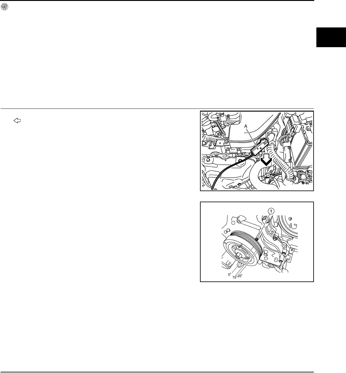
INSPECTION AND ADJUSTMENT
EC-937
< BASIC INSPECTION > [FOR MEXICO]
C
D
E
F
G
H
I
J
K
L
M
A
EC
N
P
O
With GST
Check idle speed with Service $01 of GST.
>> INSPECTION END
IGNITION TIMING
IGNITION TIMING : Description INFOID:0000000004494113
This describes how to check the ignition timing. For the actual procedure, follow the instructions in “BASIC
INSPECTION”.
IGNITION TIMING : Special Repair Requirement INFOID:0000000004494114
1.CHECK IGNITION TIMING
1. Attach timing light (A) to No. 1 ignition coil wire as shown.
- : Vehicle front
2. Check ignition timing.
- Timing indicator (1)
>> INSPECTION END
ACCELERATOR PEDAL RELEASED POSITION LEARNING
ACCELERATOR PEDAL RELEASED POSITION LEARNING : Description INFOID:0000000004494115
Accelerator Pedal Released Position Learning is a function of ECM to learn the fully released position of the
accelerator pedal by monitoring the accelerator pedal position sensor output signal. It must be performed each
time harness connector of accelerator pedal position sensor or ECM is disconnected.
ACCELERATOR PEDAL RELEASED POSITION LEARNING : Special Repair Re-
quirement INFOID:0000000004494116
1.START
1. Check that accelerator pedal is fully released.
2. Turn ignition switch ON and wait at least 2 seconds.
3. Turn ignition switch OFF and wait at least 10 seconds.
4. Turn ignition switch ON and wait at least 2 seconds.
5. Turn ignition switch OFF and wait at least 10 seconds.
>> END
THROTTLE VALVE CLOSED POSITION LEARNING
JMBIA0928ZZ
ALBIA0048ZZ
Revision: 2008 August 2009 Rogue

EC-938
< BASIC INSPECTION > [FOR MEXICO]
INSPECTION AND ADJUSTMENT
THROTTLE VALVE CLOSED POSITION LEARNING : Description INFOID:0000000004494117
Throttle Valve Closed Position Learning is a function of ECM to learn the fully closed position of the throttle
valve by monitoring the throttle position sensor output signal. It must be performed each time harness connec-
tor of electric throttle control actuator or ECM is disconnected.
THROTTLE VALVE CLOSED POSITION LEARNING : Special Repair Requirement
INFOID:0000000004494118
1.START
1. Check that accelerator pedal is fully released.
2. Turn ignition switch ON.
3. Turn ignition switch OFF and wait at least 10 seconds.
Check that throttle valve moves during the above 10 seconds by confirming the operating sound.
>> END
IDLE AIR VOLUME LEARNING
IDLE AIR VOLUME LEARNING : Description INFOID:0000000004494119
Idle Air Volume Learning is a function of ECM to learn the idle air volume that keeps each engine idle speed
within the specific range. It must be performed under the following conditions:
• Each time the electric throttle control actuator or ECM is replaced.
• Idle speed or ignition timing is out of the specification.
IDLE AIR VOLUME LEARNING : Special Repair Requirement INFOID:0000000004494120
1.PRECONDITIONING
Check that all of the following conditions are satisfied.
Learning will be cancelled if any of the following conditions are missed for even a moment.
• Battery voltage: More than 12.9V (At idle)
• Engine coolant temperature: 70 - 100°C (158 - 212°F)
• PNP switch: ON
• Electric load switch: OFF
(Air conditioner, headlamp, rear window defogger)
On vehicles equipped with daytime light systems, if the parking brake is applied before the engine is
started the headlamp will not illuminate.
• Steering wheel: Neutral (Straight-ahead position)
• Vehicle speed: Stopped
• Transmission: Warmed-up
- With CONSULT-III: Drive vehicle until “ATF TENP SEN” in “DATA MONITOR” mode of “CVT” system indi-
cates less than 0.9V.
- Without CONSULT-III: Drive vehicle for 10 minutes.
Do you have CONSULT-III?
YES >> GO TO 2.
NO >> GO TO 3.
2.IDLE AIR VOLUME LEARNING
With CONSULT-III
1. Perform Accelerator Pedal Released Position Learning. Refer to EC-937, "ACCELERATOR PEDAL
RELEASED POSITION LEARNING : Special Repair Requirement".
2. Perform Throttle Valve Closed Position Learning. Refer to EC-938, "THROTTLE VALVE CLOSED POSI-
TION LEARNING : Special Repair Requirement".
3. Start engine and warm it up to normal operating temperature.
4. Select “IDLE AIR VOL LEARN” in “WORK SUPPORT” mode.
5. Touch “START” and wait 20 seconds.
Is “CMPLT” displayed on CONSULT-III screen?
YES >> GO TO 4.
NO >> GO TO 5.
Revision: 2008 August 2009 Rogue
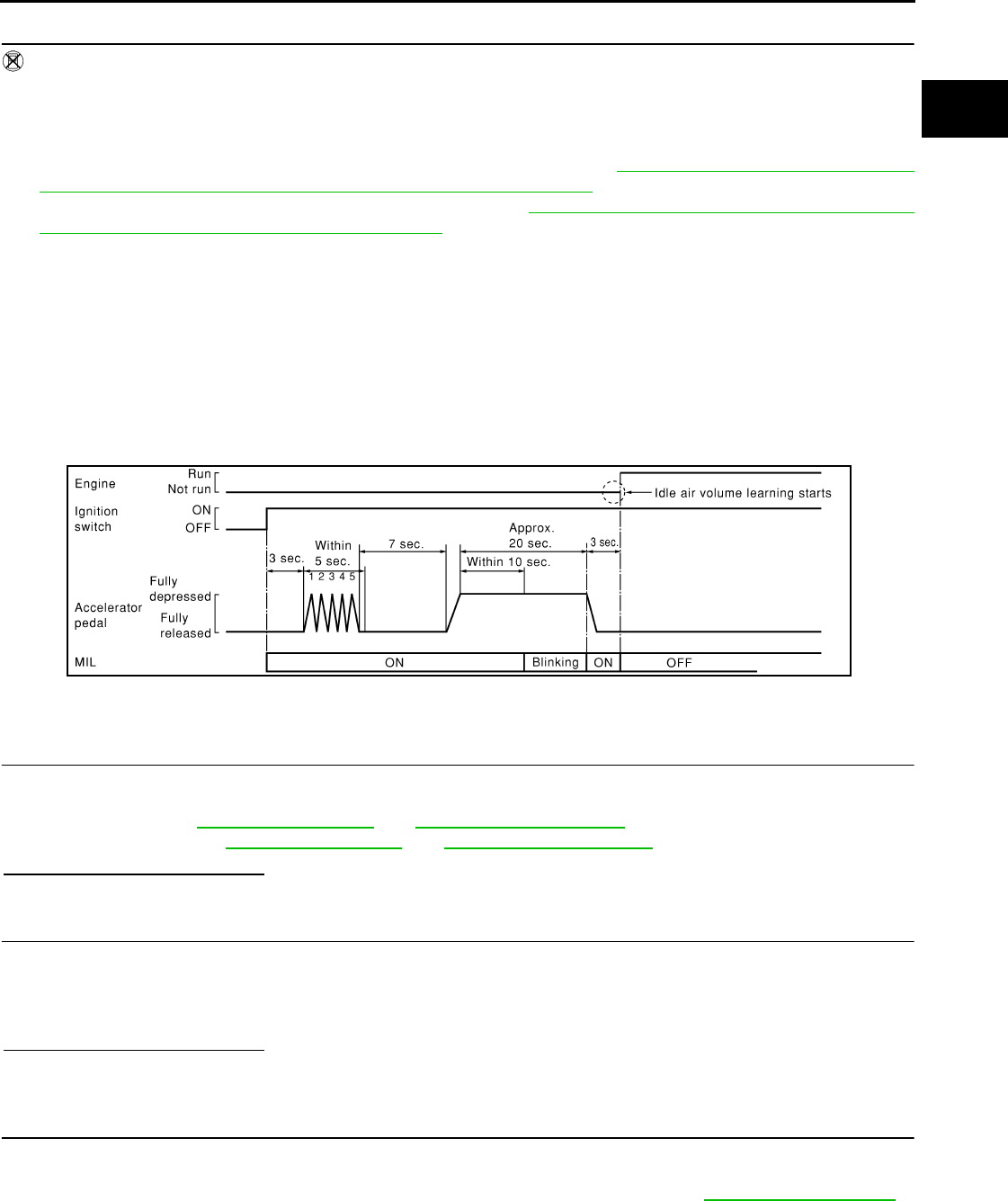
INSPECTION AND ADJUSTMENT
EC-939
< BASIC INSPECTION > [FOR MEXICO]
C
D
E
F
G
H
I
J
K
L
M
A
EC
N
P
O
3.IDLE AIR VOLUME LEARNING
Without CONSULT-III
NOTE:
•It is better to count the time accurately with a clock.
•It is impossible to switch the diagnostic mode when an accelerator pedal position sensor circuit has
a malfunction.
1. Perform Accelerator Pedal Released Position Learning. Refer to EC-937, "ACCELERATOR PEDAL
RELEASED POSITION LEARNING : Special Repair Requirement".
2. Perform Throttle Valve Closed Position Learning. Refer to EC-938, "THROTTLE VALVE CLOSED POSI-
TION LEARNING : Special Repair Requirement".
3. Start engine and warm it up to normal operating temperature.
4. Turn ignition switch OFF and wait at least 10 seconds.
5. Confirm that accelerator pedal is fully released, turn ignition switch ON and wait 3 seconds.
6. Repeat the following procedure quickly five times within 5 seconds.
- Fully depress the accelerator pedal.
- Fully release the accelerator pedal.
7. Wait 7 seconds, fully depress the accelerator pedal for approx. 20 seconds until the MIL stops blinking
and turns ON.
8. Fully release the accelerator pedal within 3 seconds after the MIL turns ON.
9. Start engine and let it idle.
10. Wait 20 seconds.
>> GO TO 4.
4.CHECK IDLE SPEED AND IGNITION TIMING
Rev up the engine two or three times and check that idle speed and ignition timing are within the specifica-
tions.
For procedure, refer to EC-494, "Idle Speed" and EC-494, "Ignition Timing".
For specifications, refer to EC-494, "Idle Speed" and EC-494, "Ignition Timing".
Is the inspection result normal?
YES >> INSPECTION END
5.DETECT MALFUNCTIONING PART
Check the following
• Check that throttle valve is fully closed.
• Check PCV valve operation.
• Check that downstream of throttle valve is free from air leakage.
Is the inspection result normal?
YES >> GO TO 6.
NO >> Repair or replace malfunctioning part.
6.DETECT MALFUNCTIONING PART
Engine component parts and their installation condition are questionable. Check and eliminate the cause of
the incident.
It is useful to perform “TROUBLE DIAGNOSIS - SPECIFICATION VALUE”. Refer to EC-1012, "Description".
If any of the following conditions occur after the engine has started, eliminate the cause of the incident and
perform Idle Air Volume Learning again:
• Engine stalls.
SEC897C
Revision: 2008 August 2009 Rogue

EC-940
< BASIC INSPECTION > [FOR MEXICO]
INSPECTION AND ADJUSTMENT
• Incorrect idle.
>> INSPECTION END
MIXTURE RATIO SELF-LEARNING VALUE CLEAR
MIXTURE RATIO SELF-LEARNING VALUE CLEAR : Description INFOID:0000000004494121
This describes how to erase the mixture ratio self-learning value. For the actual procedure, follow the instruc-
tions in “Diagnosis Procedure”.
MIXTURE RATIO SELF-LEARNING VALUE CLEAR : Special Repair Requirement
INFOID:0000000004494122
1.START
With CONSULT-III
1. Start engine and warm it up to normal operating temperature.
2. Select “SELF-LEARNING CONT” in “WORK SUPPORT” mode with CONSULT-III.
3. Clear mixture ratio self-learning value by touching “CLEAR”.
With GST
1. Start engine and warm it up to normal operating temperature.
2. Turn ignition switch OFF.
3. Disconnect mass air flow sensor harness connector.
4. Restart engine and let it idle for at least 5 seconds.
5. Stop engine and reconnect mass air flow sensor harness connector.
6. Select Service $03 with GST. Check that DTC P0102 is detected.
7. Select Service $04 with GST to erase the DTC P0102.
>> END
Revision: 2008 August 2009 Rogue
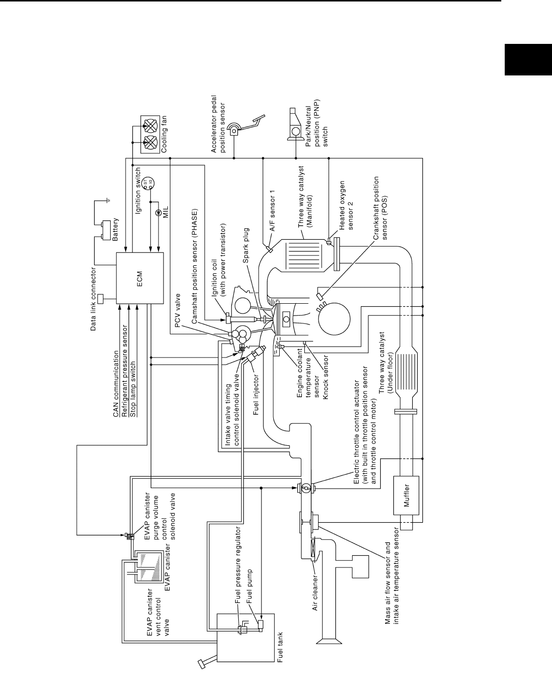
ENGINE CONTROL SYSTEM
EC-941
< FUNCTION DIAGNOSIS > [FOR MEXICO]
C
D
E
F
G
H
I
J
K
L
M
A
EC
N
P
O
FUNCTION DIAGNOSIS
ENGINE CONTROL SYSTEM
System Diagram INFOID:0000000004494123
JMBIA1032G
B
Revision: 2008 August 2009 Rogue
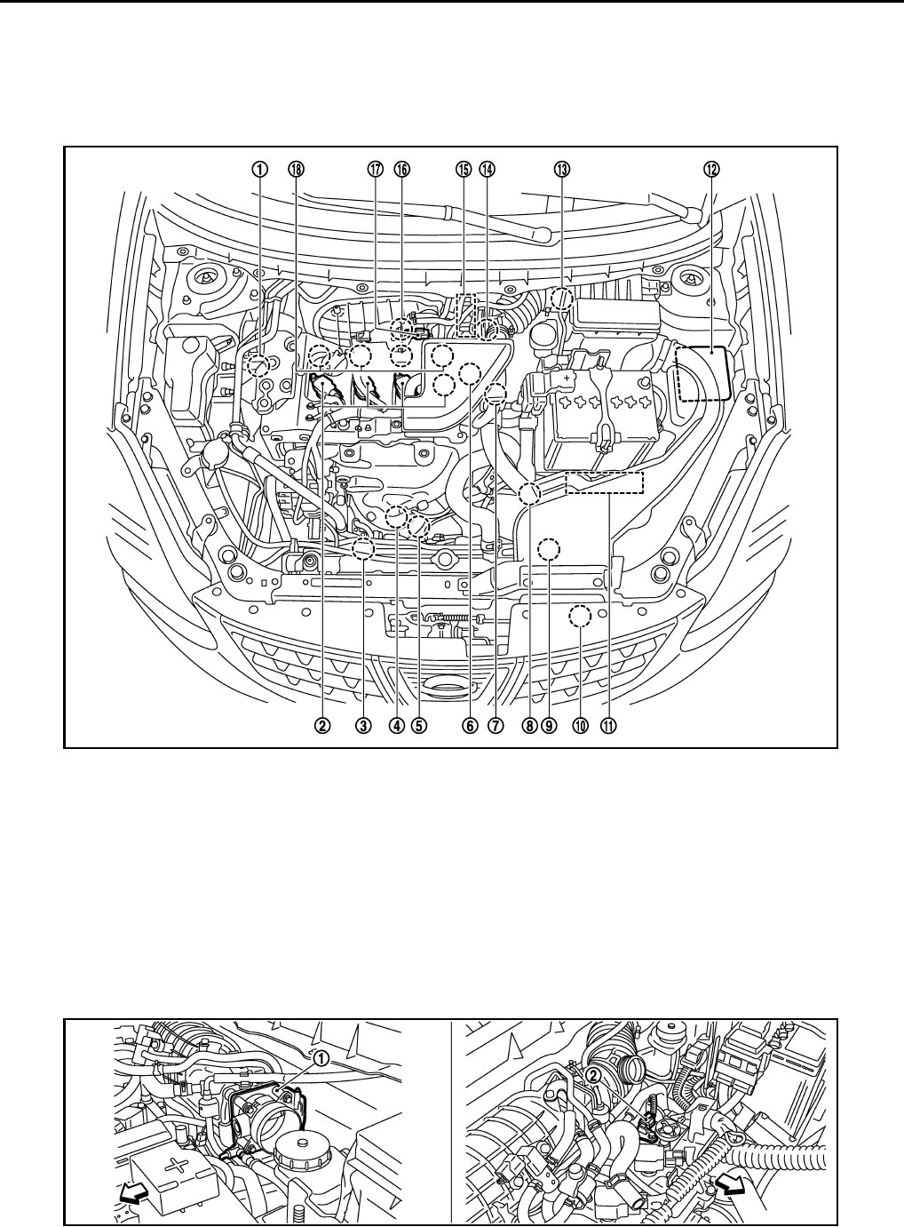
EC-942
< FUNCTION DIAGNOSIS > [FOR MEXICO]
ENGINE CONTROL SYSTEM
System Description INFOID:0000000004494124
ECM performs various controls such as fuel injection control and ignition timing control.
Component Parts Location INFOID:0000000004494125
1. Intake valve timing control solenoid
valve
2. Ignition coil (with power transistor)
and spark plug
3. Cooling fan motor-2
4. Air fuel ratio (A/F) sensor 1 5. Heated oxygen sensor 2 6. Camshaft position sensor (PHASE)
7. Engine coolant temperature sensor 8. Park/neutral position (PNP) switch 9. Cooling fan motor-1
10. Refrigerant pressure sensor 11. ECM 12. IPDM E/R
13. Mass air flow sensor (with intake air
temperature sensor) 14. Crankshaft position sensor (POS) 15. Electric throttle control actuator
(with built in throttle position sensor
and throttle control motor)
16. Knock sensor 17. EVAP canister purge volume control
solenoid valve
18. Fuel injector
JMBIA0916ZZ
JMBIA0917ZZ
Revision: 2008 August 2009 Rogue

ENGINE CONTROL SYSTEM
EC-943
< FUNCTION DIAGNOSIS > [FOR MEXICO]
C
D
E
F
G
H
I
J
K
L
M
A
EC
N
P
O
1. Electric throttle control actuator 2. Camshaft position sensor (PHASE)
Vehicle front
1. Mass air flow sensor (with intake air
temperature sensor)
2. Engine coolant temperature sensor
Vehicle front
1. Cooling fan motor-1 harness con-
nector
2. Cooling fan motor-1 3. Cooling fan motor-2 harness con-
nector
4. Cooling fan motor-2 5. Crankshaft position sensor (POS)
Vehicle front
1. Fuel injector 2. Ignition coil (with power transistor)
and spark plug
3. EVAP canister purge volume control
solenoid valve
Vehicle front
JMBIA0918ZZ
JMBIA0919ZZ
JMBIA1069ZZ
Revision: 2008 August 2009 Rogue

EC-944
< FUNCTION DIAGNOSIS > [FOR MEXICO]
ENGINE CONTROL SYSTEM
1. Refrigerant pressure sensor 2. PCV valve
JMBIA0922ZZ
JMBIA0502G
B
1. Air fuel ratio (A/F) sensor 1 2. Heated oxygen sensor 2 3. Air fuel ratio (A/F) sensor 1 harness
connector
4. Heated oxygen sensor 2 harness
connector
5. Three way catalyst (Under floor)
Vehicle front
JMBIA0920ZZ
Revision: 2008 August 2009 Rogue
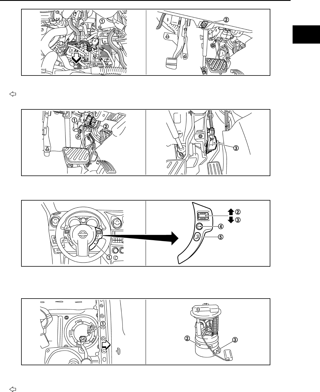
ENGINE CONTROL SYSTEM
EC-945
< FUNCTION DIAGNOSIS > [FOR MEXICO]
C
D
E
F
G
H
I
J
K
L
M
A
EC
N
P
O
1. Park/neutral position (PNP) switch 2. Data link connector
Vehicle front
1. Stop lamp switch 2. ASCD brake switch 3. Accelerator pedal position sensor
1. ASCD steering switch 2. RESUME/ACCERELATE switch 3. SET/COAST switch
4. CANSEL switch 5. MAIN switch
1. Fuel level sensor unit and fuel pump
harness connector 2. Fuel level sensor unit and fuel pump 3. Fuel pressure regulator
Vehicle front
JMBIA0927ZZ
JMBIA0924ZZ
JMBIA0925ZZ
JMBIA0926ZZ
Revision: 2008 August 2009 Rogue

EC-946
< FUNCTION DIAGNOSIS > [FOR MEXICO]
ENGINE CONTROL SYSTEM
Component Description INFOID:0000000004494126
Component Reference
A/F sensor 1 EC-1068, "Description"
A/F sensor 1 heater EC-1031, "Description"
Accelerator pedal position sensor EC-1187, "Description"
ASCD brake switch EC-1166, "Description"
ASCD steering switch EC-1163, "Description"
ASCD vehicle speed sensor EC-1171, "Description"
Camshaft position sensor (PHASE) EC-1124, "Description"
Crankshaft position sensor (POS) EC-1120, "Description"
Cooling fan motor EC-973, "System Description"
Electric throttle control actuator EC-1185, "Description"
Engine coolant temperature sensor EC-1055, "Description"
EVAP canister purge volume control solenoid valve EC-1133, "Description"
Fuel injector EC-1217, "Description"
Fuel pump EC-1220, "Description"
Heated oxygen sensor 2 EC-1083, "Description"
Heated oxygen sensor 2 heater EC-1034, "Description"
Ignition signal EC-1223, "Description"
Intake air temperature sensor EC-1052, "Description"
Intake valve timing control solenoid valve EC-985, "System Description"
Knock sensor EC-1118, "Description"
Mass air flow sensor EC-1040, "Description"
Park/neutral position switch EC-1149, "Description"
PCV valve EC-1229, "Description"
Refrigerant pressure sensor EC-1230, "Description"
Stop lamp switch EC-1175, "Description"
Throttle control motor EC-1183, "Description"
Throttle control motor relay EC-1177, "Description"
Throttle position sensor EC-1058, "Description"
Revision: 2008 August 2009 Rogue
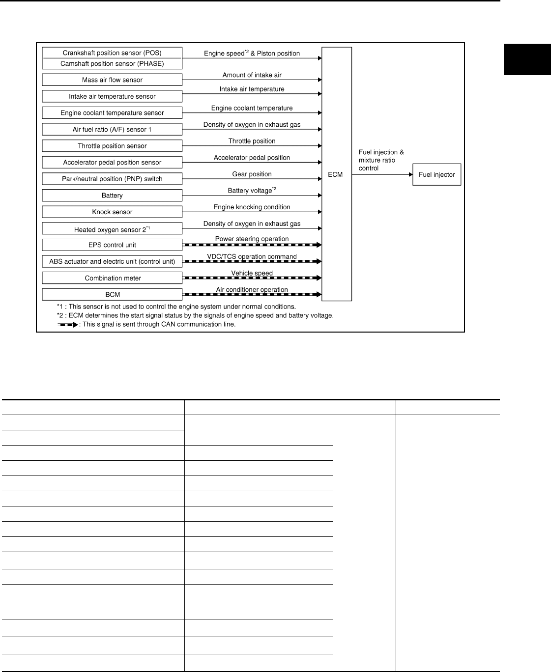
MULTIPORT FUEL INJECTION SYSTEM
EC-947
< FUNCTION DIAGNOSIS > [FOR MEXICO]
C
D
E
F
G
H
I
J
K
L
M
A
EC
N
P
O
MULTIPORT FUEL INJECTION SYSTEM
System Diagram INFOID:0000000004494127
System Description INFOID:0000000004494128
INPUT/OUTPUT SIGNAL CHART
*1: This sensor is not used to control the engine system under normal conditions.
*2: This signal is sent to the ECM through CAN communication line.
JMBIA1014G
B
Sensor Input signal to ECM ECM function Actuator
Crankshaft position sensor (POS) Engine speed*3
Piston position
Fuel injection
& mixture ratio
control Fuel injector
Camshaft position sensor (PHASE)
Mass air flow sensor Amount of intake air
Intake air temperature sensor Intake air temperature
Engine coolant temperature sensor Engine coolant temperature
Air fuel ratio (A/F) sensor 1 Density of oxygen in exhaust gas
Throttle position sensor Throttle position
Accelerator pedal position sensor Accelerator pedal position
Park/neutral position (PNP) switch Gear position
Battery Battery voltage*3
Knock sensor Engine knocking condition
Heated oxygen sensor 2*1Density of oxygen in exhaust gas
EPS control unit Power steering operation*2
ABS actuator and electric unit (control unit) ABS operation command*2
Combination meter Vehicle speed*2
BCM Air conditioner operation*2
Revision: 2008 August 2009 Rogue
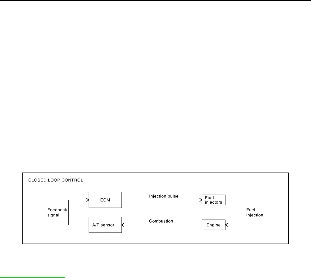
EC-948
< FUNCTION DIAGNOSIS > [FOR MEXICO]
MULTIPORT FUEL INJECTION SYSTEM
*3: ECM determines the start signal status by the signals of engine speed and battery voltage.
SYSTEM DESCRIPTION
The amount of fuel injected from the fuel injector is determined by the ECM. The ECM controls the length of
time the valve remains open (injection pulse duration). The amount of fuel injected is a program value in the
ECM memory. The program value is preset by engine operating conditions. These conditions are determined
by input signals (for engine speed and intake air) from the crankshaft position sensor (POS), camshaft position
sensor (PHASE) and the mass air flow sensor.
VARIOUS FUEL INJECTION INCREASE/DECREASE COMPENSATION
In addition, the amount of fuel injected is compensated to improve engine performance under various operat-
ing conditions as listed below.
<Fuel increase>
• During warm-up
• When starting the engine
• During acceleration
• Hot-engine operation
• When selector lever is changed from N to D
• High-load, high-speed operation
<Fuel decrease>
• During deceleration
• During high engine speed operation
MIXTURE RATIO FEEDBACK CONTROL (CLOSED LOOP CONTROL)
The mixture ratio feedback system provides the best air-fuel mixture ratio for driveability and emission control.
The three way catalyst (manifold) can better reduce CO, HC and NOx emissions. This system uses A/F sen-
sor 1 in the exhaust manifold to monitor whether the engine operation is rich or lean. The ECM adjusts the
injection pulse width according to the sensor voltage signal. For more information about A/F sensor 1, refer to
EC-1068, "DTC Logic". This maintains the mixture ratio within the range of stoichiometric (ideal air-fuel mix-
ture).
This stage is referred to as the closed loop control condition.
Heated oxygen sensor 2 is located downstream of the three way catalyst (manifold). Even if the switching
characteristics of A/F sensor 1 shift, the air-fuel ratio is controlled to stoichiometric by the signal from heated
oxygen sensor 2.
• Open Loop Control
The open loop system condition refers to when the ECM detects any of the following conditions. Feedback
control stops in order to maintain stabilized fuel combustion.
- Deceleration and acceleration
- High-load, high-speed operation
- Malfunction of A/F sensor 1 or its circuit
- Insufficient activation of A/F sensor 1 at low engine coolant temperature
- High engine coolant temperature
- During warm-up
- After shifting from N to D
- When starting the engine
MIXTURE RATIO SELF-LEARNING CONTROL
The mixture ratio feedback control system monitors the mixture ratio signal transmitted from A/F sensor 1.
This feedback signal is then sent to the ECM. The ECM controls the basic mixture ratio as close to the theoret-
ical mixture ratio as possible. However, the basic mixture ratio is not necessarily controlled as originally
PBIB2793E
Revision: 2008 August 2009 Rogue
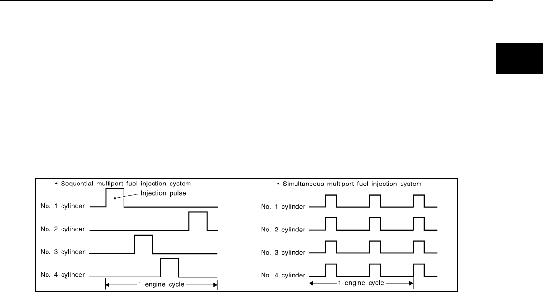
MULTIPORT FUEL INJECTION SYSTEM
EC-949
< FUNCTION DIAGNOSIS > [FOR MEXICO]
C
D
E
F
G
H
I
J
K
L
M
A
EC
N
P
O
designed. Both manufacturing differences (i.e., mass air flow sensor hot wire) and characteristic changes dur-
ing operation (i.e., fuel injector clogging) directly affect mixture ratio.
Accordingly, the difference between the basic and theoretical mixture ratios is monitored in this system. This is
then computed in terms of “injection pulse duration” to automatically compensate for the difference between
the two ratios.
“Fuel trim” refers to the feedback compensation value compared against the basic injection duration. Fuel trim
includes short-term fuel trim and long-term fuel trim.
“Short-term fuel trim” is the short-term fuel compensation used to maintain the mixture ratio at its theoretical
value. The signal from A/F sensor 1 indicates whether the mixture ratio is RICH or LEAN compared to the the-
oretical value. The signal then triggers a reduction in fuel volume if the mixture ratio is rich, and an increase in
fuel volume if it is lean.
“Long-term fuel trim” is overall fuel compensation carried out over time to compensate for continual deviation
of the short-term fuel trim from the central value. Continual deviation will occur due to individual engine differ-
ences, wear over time and changes in the usage environment.
FUEL INJECTION TIMING
Two types of systems are used.
• Sequential Multiport Fuel Injection System
Fuel is injected into each cylinder during each engine cycle according to the firing order. This system is used
when the engine is running.
• Simultaneous Multiport Fuel Injection System
Fuel is injected simultaneously into all four cylinders twice each engine cycle. In other words, pulse signals
of the same width are simultaneously transmitted from the ECM.
The four injectors will then receive the signals two times for each engine cycle.
This system is used when the engine is being started and/or if the fail-safe system (CPU) is operating.
FUEL SHUT-OFF
Fuel to each cylinder is cut off during deceleration, operation of the engine at excessively high speeds or oper-
ation of the vehicle at excessively high speeds.
SEF337W
Revision: 2008 August 2009 Rogue
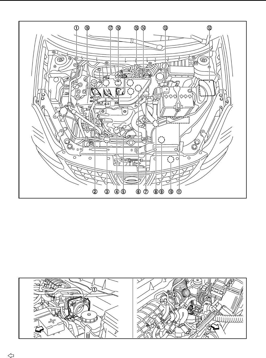
EC-950
< FUNCTION DIAGNOSIS > [FOR MEXICO]
MULTIPORT FUEL INJECTION SYSTEM
Component Parts Location INFOID:0000000004534174
1. Intake valve timing control solenoid
valve
2. Ignition coil (with power transistor)
and spark plug
3. Cooling fan motor-2
4. Air fuel ratio (A/F) sensor 1 5. Heated oxygen sensor 2 6. Camshaft position sensor (PHASE)
7. Engine coolant temperature sensor 8. Park/neutral position (PNP) switch 9. Cooling fan motor-1
10. Refrigerant pressure sensor 11. ECM 12. IPDM E/R
13. Mass air flow sensor (with intake air
temperature sensor)
14. Crankshaft position sensor (POS) 15. Electric throttle control actuator
(with built in throttle position sensor
and throttle control motor)
16. Knock sensor 17. EVAP canister purge volume control
solenoid valve
18. Fuel injector
1. Electric throttle control actuator 2. Camshaft position sensor (PHASE)
Vehicle front
JMBIA0916ZZ
JMBIA0917ZZ
Revision: 2008 August 2009 Rogue
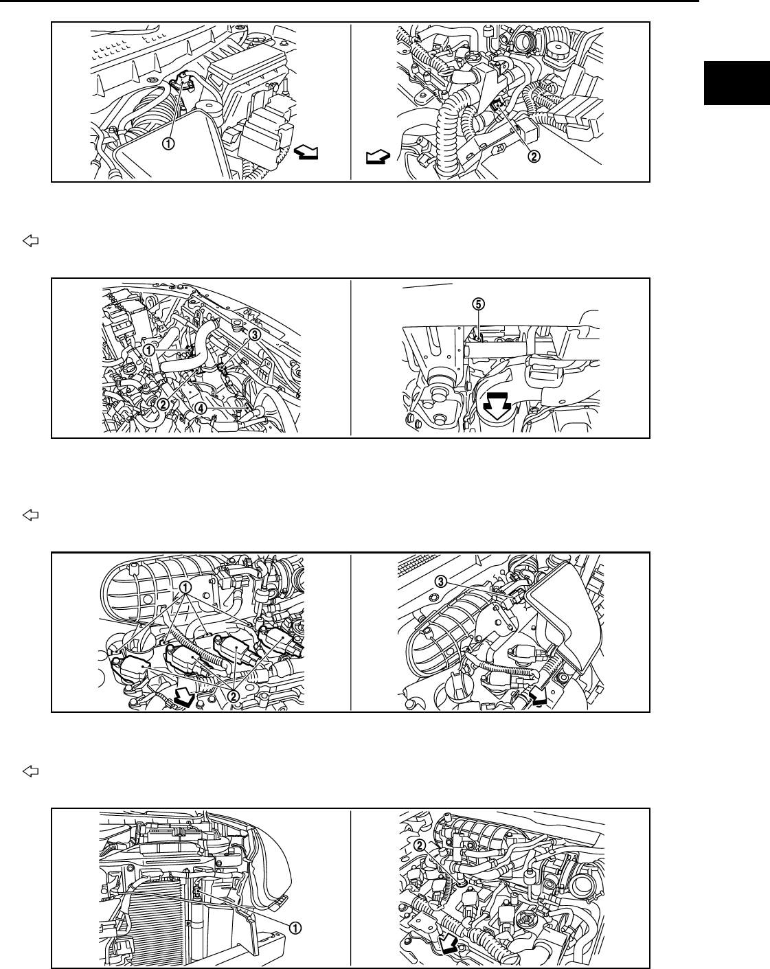
MULTIPORT FUEL INJECTION SYSTEM
EC-951
< FUNCTION DIAGNOSIS > [FOR MEXICO]
C
D
E
F
G
H
I
J
K
L
M
A
EC
N
P
O
1. Mass air flow sensor (with intake air
temperature sensor)
2. Engine coolant temperature sensor
Vehicle front
1. Cooling fan motor-1 harness con-
nector
2. Cooling fan motor-1 3. Cooling fan motor-2 harness con-
nector
4. Cooling fan motor-2 5. Crankshaft position sensor (POS)
Vehicle front
1. Fuel injector 2. Ignition coil (with power transistor)
and spark plug 3. EVAP canister purge volume control
solenoid valve
Vehicle front
JMBIA0918ZZ
JMBIA0919ZZ
JMBIA1069ZZ
JMBIA0922ZZ
Revision: 2008 August 2009 Rogue

EC-952
< FUNCTION DIAGNOSIS > [FOR MEXICO]
MULTIPORT FUEL INJECTION SYSTEM
1. Refrigerant pressure sensor 2. PCV valve
JMBIA0502G
B
1. Air fuel ratio (A/F) sensor 1 2. Heated oxygen sensor 2 3. Air fuel ratio (A/F) sensor 1 harness
connector
4. Heated oxygen sensor 2 harness
connector 5. Three way catalyst (Under floor)
Vehicle front
1. Park/neutral position (PNP) switch 2. Data link connector
Vehicle front
JMBIA0920ZZ
JMBIA0927ZZ
Revision: 2008 August 2009 Rogue
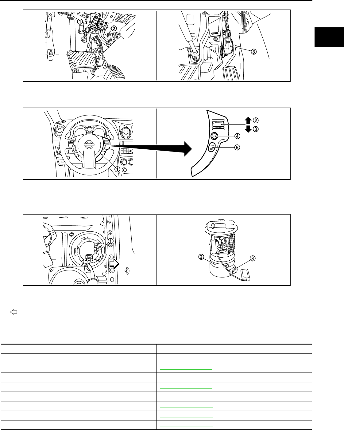
MULTIPORT FUEL INJECTION SYSTEM
EC-953
< FUNCTION DIAGNOSIS > [FOR MEXICO]
C
D
E
F
G
H
I
J
K
L
M
A
EC
N
P
O
Component Description INFOID:0000000004494130
1. Stop lamp switch 2. ASCD brake switch 3. Accelerator pedal position sensor
1. ASCD steering switch 2. RESUME/ACCERELATE switch 3. SET/COAST switch
4. CANSEL switch 5. MAIN switch
1. Fuel level sensor unit and fuel pump
harness connector
2. Fuel level sensor unit and fuel pump 3. Fuel pressure regulator
Vehicle front
JMBIA0924ZZ
JMBIA0925ZZ
JMBIA0926ZZ
Component Reference
A/F sensor 1 EC-1068, "Description"
Accelerator pedal position sensor EC-1187, "Description"
Camshaft position sensor (PHASE) EC-1124, "Description"
Crankshaft position sensor (POS) EC-1120, "Description"
Engine coolant temperature sensor EC-1055, "Description"
Fuel injector EC-1217, "Description"
Heated oxygen sensor 2 EC-1034, "Description"
Intake air temperature sensor EC-1052, "Description"
Revision: 2008 August 2009 Rogue

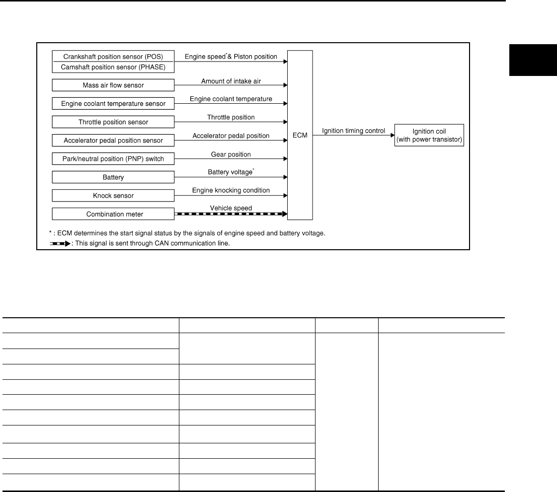
ELECTRIC IGNITION SYSTEM
EC-955
< FUNCTION DIAGNOSIS > [FOR MEXICO]
C
D
E
F
G
H
I
J
K
L
M
A
EC
N
P
O
ELECTRIC IGNITION SYSTEM
System Diagram INFOID:0000000004494131
System Description INFOID:0000000004494132
INPUT/OUTPUT SIGNAL CHART
*1: This signal is sent to the ECM through CAN communication line.
*2: ECM determines the start signal status by the signals of engine speed and battery voltage.
SYSTEM DESCRIPTION
Ignition order: 1 - 3 - 4 - 2
The ignition timing is controlled by the ECM to maintain the best air-fuel ratio for every running condition of the
engine. The ignition timing data is stored in the ECM.
The ECM receives information such as the injection pulse width and camshaft position sensor (PHASE) sig-
nal. Computing this information, ignition signals are transmitted to the power transistor.
During the following conditions, the ignition timing is revised by the ECM according to the other data stored in
the ECM.
• At starting
• During warm-up
•At idle
• At low battery voltage
• During acceleration
The knock sensor retard system is designed only for emergencies. The basic ignition timing is programmed
within the anti-knocking zone, if recommended fuel is used under dry conditions. The retard system does not
JMBIA0174G
B
Sensor Input signal to ECM ECM function Actuator
Crankshaft position sensor (POS) Engine speed*2
Piston position
Ignition timing
control
Ignition coil (with power transis-
tor)
Camshaft position sensor (PHASE)
Mass air flow sensor Amount of intake air
Engine coolant temperature sensor Engine coolant temperature
Throttle position sensor Throttle position
Accelerator pedal position sensor Accelerator pedal position
Battery Battery voltage*2
Knock sensor Engine knocking
Park/neutral position (PNP) switch Gear position
Combination meter Vehicle speed*1
Revision: 2008 August 2009 Rogue

EC-956
< FUNCTION DIAGNOSIS > [FOR MEXICO]
ELECTRIC IGNITION SYSTEM
operate under normal driving conditions. If engine knocking occurs, the knock sensor monitors the condition.
The signal is transmitted to the ECM. The ECM retards the ignition timing to eliminate the knocking condition.
Component Parts Location INFOID:0000000004534175
1. Intake valve timing control solenoid
valve
2. Ignition coil (with power transistor)
and spark plug
3. Cooling fan motor-2
4. Air fuel ratio (A/F) sensor 1 5. Heated oxygen sensor 2 6. Camshaft position sensor (PHASE)
7. Engine coolant temperature sensor 8. Park/neutral position (PNP) switch 9. Cooling fan motor-1
10. Refrigerant pressure sensor 11. ECM 12. IPDM E/R
13. Mass air flow sensor (with intake air
temperature sensor) 14. Crankshaft position sensor (POS) 15. Electric throttle control actuator
(with built in throttle position sensor
and throttle control motor)
16. Knock sensor 17. EVAP canister purge volume control
solenoid valve 18. Fuel injector
JMBIA0916ZZ
JMBIA0917ZZ
Revision: 2008 August 2009 Rogue
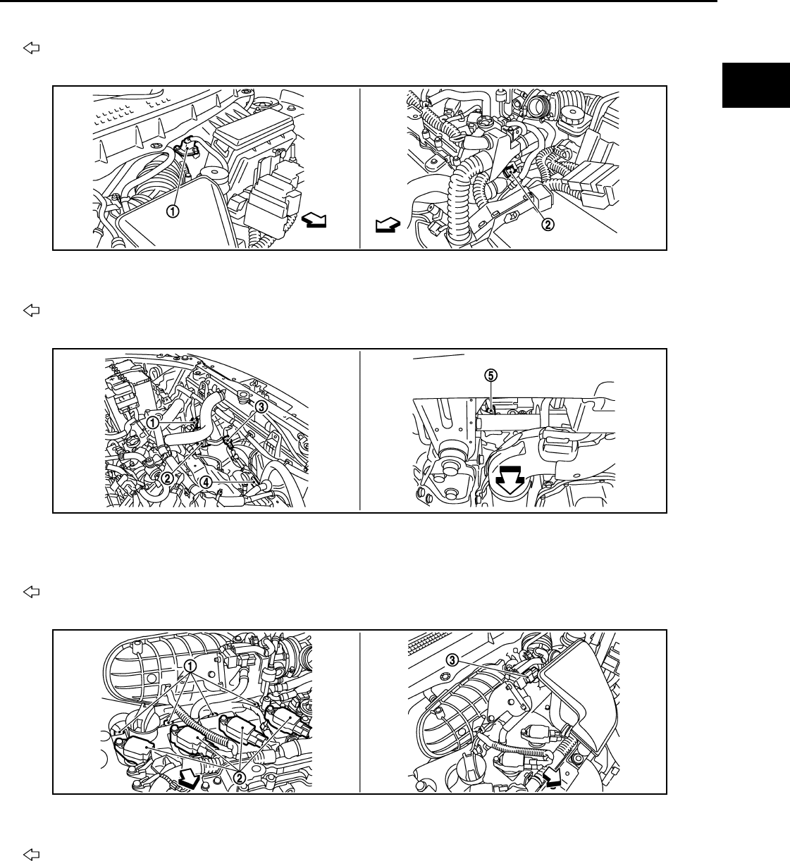
ELECTRIC IGNITION SYSTEM
EC-957
< FUNCTION DIAGNOSIS > [FOR MEXICO]
C
D
E
F
G
H
I
J
K
L
M
A
EC
N
P
O
1. Electric throttle control actuator 2. Camshaft position sensor (PHASE)
Vehicle front
1. Mass air flow sensor (with intake air
temperature sensor)
2. Engine coolant temperature sensor
Vehicle front
1. Cooling fan motor-1 harness con-
nector
2. Cooling fan motor-1 3. Cooling fan motor-2 harness con-
nector
4. Cooling fan motor-2 5. Crankshaft position sensor (POS)
Vehicle front
1. Fuel injector 2. Ignition coil (with power transistor)
and spark plug
3. EVAP canister purge volume control
solenoid valve
Vehicle front
JMBIA0918ZZ
JMBIA0919ZZ
JMBIA1069ZZ
Revision: 2008 August 2009 Rogue
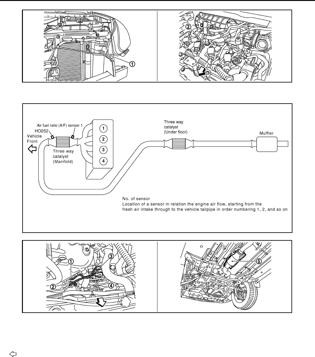
EC-958
< FUNCTION DIAGNOSIS > [FOR MEXICO]
ELECTRIC IGNITION SYSTEM
1. Refrigerant pressure sensor 2. PCV valve
JMBIA0922ZZ
JMBIA0502G
B
1. Air fuel ratio (A/F) sensor 1 2. Heated oxygen sensor 2 3. Air fuel ratio (A/F) sensor 1 harness
connector
4. Heated oxygen sensor 2 harness
connector
5. Three way catalyst (Under floor)
Vehicle front
JMBIA0920ZZ
Revision: 2008 August 2009 Rogue

ELECTRIC IGNITION SYSTEM
EC-959
< FUNCTION DIAGNOSIS > [FOR MEXICO]
C
D
E
F
G
H
I
J
K
L
M
A
EC
N
P
O
1. Park/neutral position (PNP) switch 2. Data link connector
Vehicle front
1. Stop lamp switch 2. ASCD brake switch 3. Accelerator pedal position sensor
1. ASCD steering switch 2. RESUME/ACCERELATE switch 3. SET/COAST switch
4. CANSEL switch 5. MAIN switch
1. Fuel level sensor unit and fuel pump
harness connector 2. Fuel level sensor unit and fuel pump 3. Fuel pressure regulator
Vehicle front
JMBIA0927ZZ
JMBIA0924ZZ
JMBIA0925ZZ
JMBIA0926ZZ
Revision: 2008 August 2009 Rogue

EC-960
< FUNCTION DIAGNOSIS > [FOR MEXICO]
ELECTRIC IGNITION SYSTEM
Component Description INFOID:0000000004494134
Component Reference
Accelerator pedal position sensor EC-1187, "Description"
Camshaft position sensor (PHASE) EC-1124, "Description"
Crankshaft position sensor (POS) EC-1120, "Description"
Engine coolant temperature sensor EC-1055, "Description"
Ignition signal EC-1223, "Description"
Knock sensor EC-1118, "Description"
Mass air flow sensor EC-1040, "Description"
Park/neutral position switch EC-1149, "Description"
Throttle position sensor EC-1058, "Description"
Revision: 2008 August 2009 Rogue
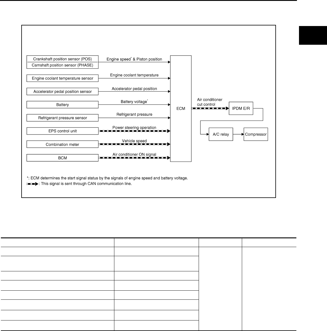
AIR CONDITIONING CUT CONTROL
EC-961
< FUNCTION DIAGNOSIS > [FOR MEXICO]
C
D
E
F
G
H
I
J
K
L
M
A
EC
N
P
O
AIR CONDITIONING CUT CONTROL
System Diagram INFOID:0000000004494135
System Description INFOID:0000000004494136
INPUT/OUTPUT SIGNAL CHART
*1: This signal is sent to the ECM through CAN communication line.
*2: ECM determines the start signal status by the signals of engine speed and battery voltage.
SYSTEM DESCRIPTION
This system improves engine operation when the air conditioner is used.
Under the following conditions, the air conditioner is turned off.
• When the accelerator pedal is fully depressed.
• When cranking the engine.
• At high engine speeds.
• When the engine coolant temperature becomes excessively high.
• When operating power steering during low engine speed or low vehicle speed.
• When engine speed is excessively low.
JMBIA1015G
B
Sensor Input signal to ECM ECM function Actuator
Accelerator pedal position sensor Accelerator pedal position
Air conditioner
cut control
IPDM E/R
↓
Air conditioner relay
↓
Compressor
Crankshaft position sensor (POS)
Camshaft position sensor (PHASE) Engine speed*2
Engine coolant temperature sensor Engine coolant temperature
Battery Battery voltage*2
Refrigerant pressure sensor Refrigerant pressure
EPS control unit Power steering operation*1
Combination meter Vehicle speed*1
BCM Air conditioner ON signal*1
Revision: 2008 August 2009 Rogue
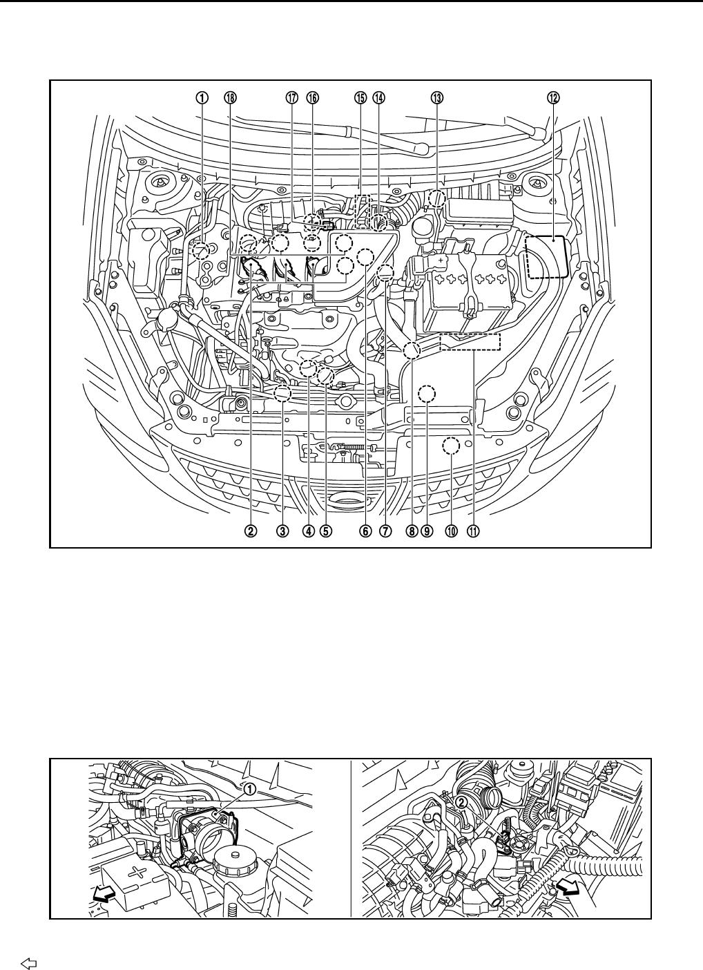
EC-962
< FUNCTION DIAGNOSIS > [FOR MEXICO]
AIR CONDITIONING CUT CONTROL
• When refrigerant pressure is excessively low or high.
Component Parts Location INFOID:0000000004534289
1. Intake valve timing control solenoid
valve 2. Ignition coil (with power transistor)
and spark plug 3. Cooling fan motor-2
4. Air fuel ratio (A/F) sensor 1 5. Heated oxygen sensor 2 6. Camshaft position sensor (PHASE)
7. Engine coolant temperature sensor 8. Park/neutral position (PNP) switch 9. Cooling fan motor-1
10. Refrigerant pressure sensor 11. ECM 12. IPDM E/R
13. Mass air flow sensor (with intake air
temperature sensor)
14. Crankshaft position sensor (POS) 15. Electric throttle control actuator
(with built in throttle position sensor
and throttle control motor)
16. Knock sensor 17. EVAP canister purge volume control
solenoid valve
18. Fuel injector
1. Electric throttle control actuator 2. Camshaft position sensor (PHASE)
Vehicle front
JMBIA0916ZZ
JMBIA0917ZZ
Revision: 2008 August 2009 Rogue

AIR CONDITIONING CUT CONTROL
EC-963
< FUNCTION DIAGNOSIS > [FOR MEXICO]
C
D
E
F
G
H
I
J
K
L
M
A
EC
N
P
O
1. Mass air flow sensor (with intake air
temperature sensor)
2. Engine coolant temperature sensor
Vehicle front
1. Cooling fan motor-1 harness con-
nector
2. Cooling fan motor-1 3. Cooling fan motor-2 harness con-
nector
4. Cooling fan motor-2 5. Crankshaft position sensor (POS)
Vehicle front
1. Fuel injector 2. Ignition coil (with power transistor)
and spark plug 3. EVAP canister purge volume control
solenoid valve
Vehicle front
JMBIA0918ZZ
JMBIA0919ZZ
JMBIA1069ZZ
JMBIA0922ZZ
Revision: 2008 August 2009 Rogue

EC-964
< FUNCTION DIAGNOSIS > [FOR MEXICO]
AIR CONDITIONING CUT CONTROL
1. Refrigerant pressure sensor 2. PCV valve
JMBIA0502G
B
1. Air fuel ratio (A/F) sensor 1 2. Heated oxygen sensor 2 3. Air fuel ratio (A/F) sensor 1 harness
connector
4. Heated oxygen sensor 2 harness
connector 5. Three way catalyst (Under floor)
Vehicle front
1. Park/neutral position (PNP) switch 2. Data link connector
Vehicle front
JMBIA0920ZZ
JMBIA0927ZZ
Revision: 2008 August 2009 Rogue
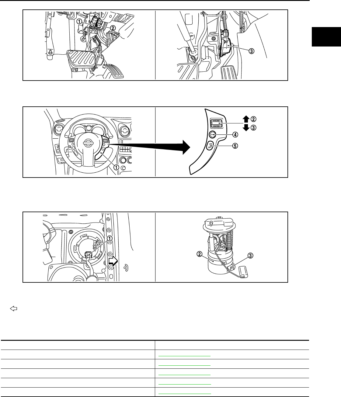
AIR CONDITIONING CUT CONTROL
EC-965
< FUNCTION DIAGNOSIS > [FOR MEXICO]
C
D
E
F
G
H
I
J
K
L
M
A
EC
N
P
O
Component Description INFOID:0000000004494138
1. Stop lamp switch 2. ASCD brake switch 3. Accelerator pedal position sensor
1. ASCD steering switch 2. RESUME/ACCERELATE switch 3. SET/COAST switch
4. CANSEL switch 5. MAIN switch
1. Fuel level sensor unit and fuel pump
harness connector
2. Fuel level sensor unit and fuel pump 3. Fuel pressure regulator
Vehicle front
JMBIA0924ZZ
JMBIA0925ZZ
JMBIA0926ZZ
Component Reference
Accelerator pedal position sensor EC-1187, "Description"
Camshaft position sensor (PHASE) EC-1124, "Description"
Crankshaft position sensor (POS) EC-1120, "Description"
Engine coolant temperature sensor EC-1055, "Description"
Refrigerant pressure sensor EC-1230, "Description"
Revision: 2008 August 2009 Rogue

EC-966
< FUNCTION DIAGNOSIS > [FOR MEXICO]
AUTOMATIC SPEED CONTROL DEVICE (ASCD)
AUTOMATIC SPEED CONTROL DEVICE (ASCD)
System Diagram INFOID:0000000004494139
System Description INFOID:0000000004494140
INPUT/OUTPUT SIGNAL CHART
*: This signal is sent to the ECM through CAN communication line
BASIC ASCD SYSTEM
Refer to Owner's Manual for ASCD operating instructions.
Automatic Speed Control Device (ASCD) allows a driver to keep vehicle at predetermined constant speed
without depressing accelerator pedal. Driver can set vehicle speed in advance between approximately 40 km/
h (25 MPH) and 144 km/h (89 MPH).
ECM controls throttle angle of electric throttle control actuator to regulate engine speed.
Operation status of ASCD is indicated by CRUISE lamp and SET lamp on combination meter. If any malfunc-
tion occurs in the ASCD system, it automatically deactivates control.
NOTE:
Always drive vehicle in a safe manner according to traffic conditions and obey all traffic laws.
SET OPERATION
Press MAIN switch. (The CRUISE lamp on combination meter illuminates.)
When vehicle speed reaches a desired speed between approximately 40 km/h (25 MPH) and 144 km/h (89
MPH), press SET/COAST switch. (Then SET lamp on combination meter illuminates.)
ACCELERATE OPERATION
If the RESUME/ACCELERATE switch is pressed during cruise control driving, increase the vehicle speed until
the switch is released or vehicle speed reaches maximum speed controlled by the system.
And then ASCD will maintain the new set speed.
CANCEL OPERATION
When any of following conditions exist, cruise operation will be canceled.
• CANCEL switch is pressed
• More than 2 switches on ASCD steering switch are pressed at the same time (Set speed will be cleared)
• Brake pedal is depressed
JMBIA0935G
B
Sensor Input signal to ECM ECM function Actuator
ASCD brake switch Brake pedal operation
ASCD vehicle speed control Electric throttle control
actuator
Stop lamp switch Brake pedal operation
ASCD steering switch ASCD steering switch operation
Park/neutral position (PNP) switch Gear position
Combination meter Vehicle speed*
TCM Powertrain revolution*
Revision: 2008 August 2009 Rogue
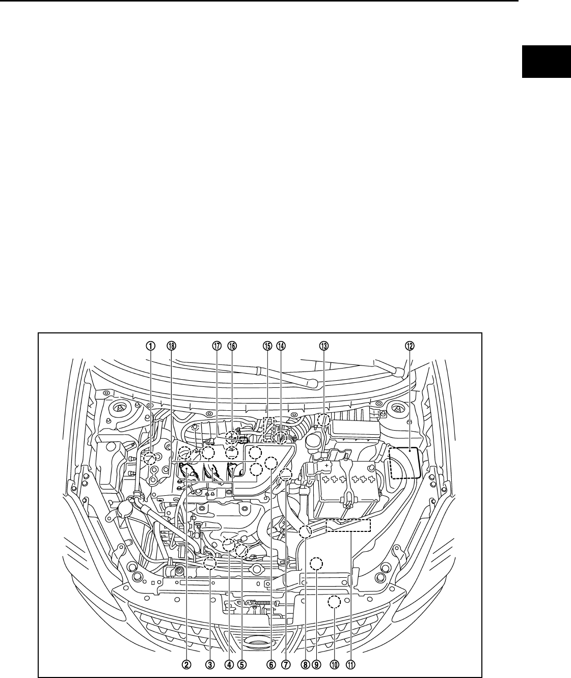
AUTOMATIC SPEED CONTROL DEVICE (ASCD)
EC-967
< FUNCTION DIAGNOSIS > [FOR MEXICO]
C
D
E
F
G
H
I
J
K
L
M
A
EC
N
P
O
• Selector lever position is changed to N, P or R
• Vehicle speed decreased to 13 km/h (8 MPH) lower than the set speed
• TCS system is operated
When the ECM detects any of the following conditions, the ECM will cancel the cruise operation and inform
the driver by blinking indicator lamp.
• Engine coolant temperature is slightly higher than the normal operating temperature, CRUISE lamp may
blink slowly.
When the engine coolant temperature decreases to the normal operating temperature, CRUISE lamp will
stop blinking and the cruise operation will be able to work by pressing SET/COAST switch or RESUME/
ACCELERATE switch.
• Malfunction for some self-diagnoses regarding ASCD control: SET lamp will blink quickly.
If MAIN switch is turned to OFF while ASCD is activated, all of ASCD operations will be canceled and vehicle
speed memory will be erased.
COAST OPERATION
When the SET/COAST switch is pressed during cruise control driving, decrease vehicle set speed until the
switch is released. And then ASCD will maintain the new set speed.
RESUME OPERATION
When the RESUME/ACCELERATE switch is pressed after canceling operation other than pressing the MAIN
switch, vehicle speed will return to last set speed. To resume vehicle set speed, vehicle condition must meet
following conditions.
• Brake pedal is released
• Selector lever is in a position other than P and N
• Vehicle speed is greater than 40 km/h (25 MPH) and less than 144 km/h (89 MPH)
Component Parts Location INFOID:0000000004534290
JMBIA0916ZZ
1. Intake valve timing control solenoid
valve
2. Ignition coil (with power transistor)
and spark plug
3. Cooling fan motor-2
4. Air fuel ratio (A/F) sensor 1 5. Heated oxygen sensor 2 6. Camshaft position sensor (PHASE)
Revision: 2008 August 2009 Rogue
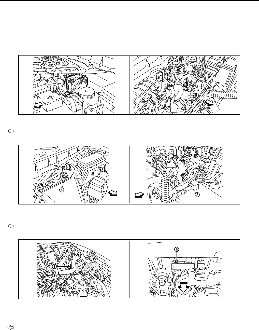
EC-968
< FUNCTION DIAGNOSIS > [FOR MEXICO]
AUTOMATIC SPEED CONTROL DEVICE (ASCD)
7. Engine coolant temperature sensor 8. Park/neutral position (PNP) switch 9. Cooling fan motor-1
10. Refrigerant pressure sensor 11. ECM 12. IPDM E/R
13. Mass air flow sensor (with intake air
temperature sensor)
14. Crankshaft position sensor (POS) 15. Electric throttle control actuator
(with built in throttle position sensor
and throttle control motor)
16. Knock sensor 17. EVAP canister purge volume control
solenoid valve
18. Fuel injector
1. Electric throttle control actuator 2. Camshaft position sensor (PHASE)
Vehicle front
1. Mass air flow sensor (with intake air
temperature sensor)
2. Engine coolant temperature sensor
Vehicle front
1. Cooling fan motor-1 harness con-
nector 2. Cooling fan motor-1 3. Cooling fan motor-2 harness con-
nector
4. Cooling fan motor-2 5. Crankshaft position sensor (POS)
Vehicle front
JMBIA0917ZZ
JMBIA0918ZZ
JMBIA0919ZZ
Revision: 2008 August 2009 Rogue
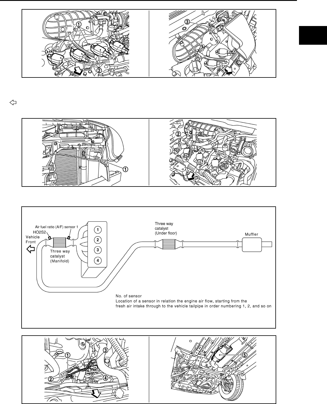
AUTOMATIC SPEED CONTROL DEVICE (ASCD)
EC-969
< FUNCTION DIAGNOSIS > [FOR MEXICO]
C
D
E
F
G
H
I
J
K
L
M
A
EC
N
P
O
1. Fuel injector 2. Ignition coil (with power transistor)
and spark plug
3. EVAP canister purge volume control
solenoid valve
Vehicle front
1. Refrigerant pressure sensor 2. PCV valve
JMBIA1069ZZ
JMBIA0922ZZ
JMBIA0502G
B
JMBIA0920ZZ
Revision: 2008 August 2009 Rogue
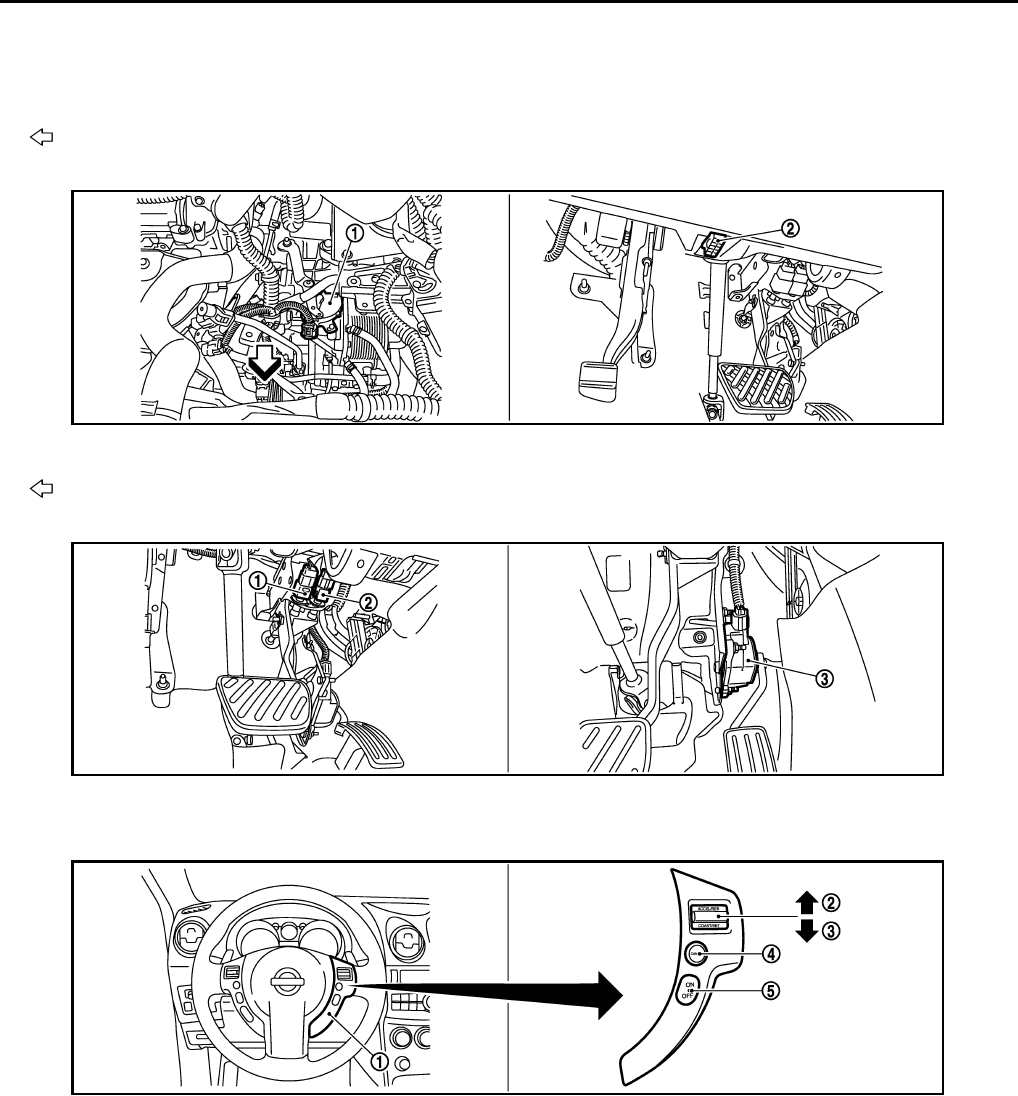
EC-970
< FUNCTION DIAGNOSIS > [FOR MEXICO]
AUTOMATIC SPEED CONTROL DEVICE (ASCD)
1. Air fuel ratio (A/F) sensor 1 2. Heated oxygen sensor 2 3. Air fuel ratio (A/F) sensor 1 harness
connector
4. Heated oxygen sensor 2 harness
connector 5. Three way catalyst (Under floor)
Vehicle front
1. Park/neutral position (PNP) switch 2. Data link connector
Vehicle front
1. Stop lamp switch 2. ASCD brake switch 3. Accelerator pedal position sensor
1. ASCD steering switch 2. RESUME/ACCERELATE switch 3. SET/COAST switch
4. CANSEL switch 5. MAIN switch
JMBIA0927ZZ
JMBIA0924ZZ
JMBIA0925ZZ
Revision: 2008 August 2009 Rogue
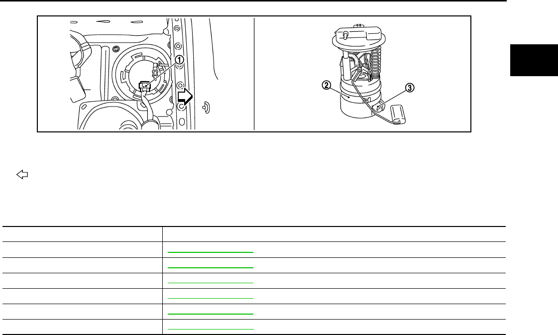
AUTOMATIC SPEED CONTROL DEVICE (ASCD)
EC-971
< FUNCTION DIAGNOSIS > [FOR MEXICO]
C
D
E
F
G
H
I
J
K
L
M
A
EC
N
P
O
Component Description INFOID:0000000004494142
1. Fuel level sensor unit and fuel pump
harness connector
2. Fuel level sensor unit and fuel pump 3. Fuel pressure regulator
Vehicle front
JMBIA0926ZZ
Component Reference
ASCD steering switch EC-1163, "Description"
ASCD clutch switch EC-1166, "Description"
ASCD brake switch EC-1166, "Description"
Stop lamp switch EC-1175, "Description"
Electric throttle control actuator EC-1185, "Description"
ASCD indicator EC-1208, "Description"
Revision: 2008 August 2009 Rogue

EC-972
< FUNCTION DIAGNOSIS > [FOR MEXICO]
CAN COMMUNICATION
CAN COMMUNICATION
System Description INFOID:0000000004494143
CAN (Controller Area Network) is a serial communication line for real time application. It is an on-vehicle mul-
tiplex communication line with high data communication speed and excellent error detection ability. Many elec-
tronic control units are equipped onto a vehicle, and each control unit shares information and links with other
control units during operation (not independent). In CAN communication, control units are connected with 2
communication lines (CAN H line, CAN L line) allowing a high rate of information transmission with less wiring.
Each control unit transmits/receives data but selectively reads required data only.
Refer to LAN-24, "CAN Communication Signal Chart", about CAN communication for detail..
Revision: 2008 August 2009 Rogue
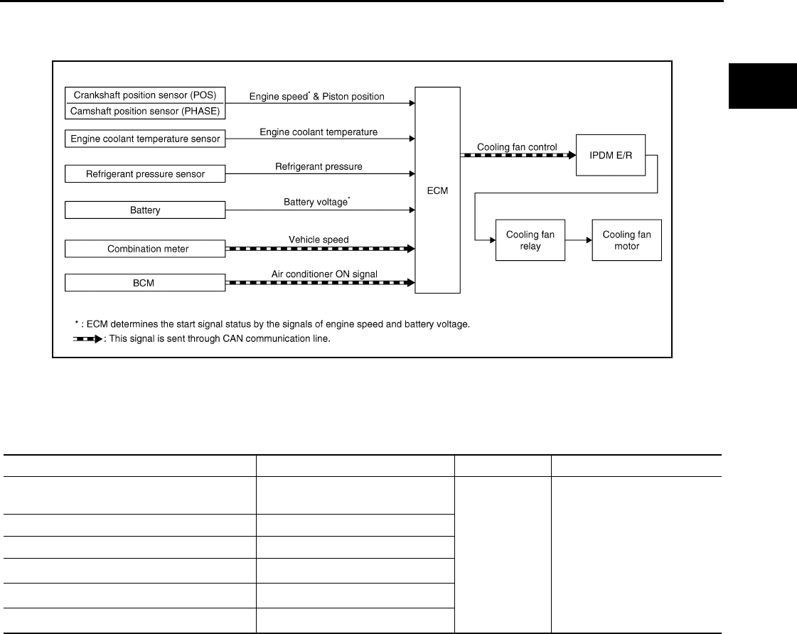
COOLING FAN CONTROL
EC-973
< FUNCTION DIAGNOSIS > [FOR MEXICO]
C
D
E
F
G
H
I
J
K
L
M
A
EC
N
P
O
COOLING FAN CONTROL
System Diagram INFOID:0000000004494144
System Description INFOID:0000000004494145
INPUT/OUTPUT SIGNAL CHART
*1: The ECM determines the start signal status by the signals of engine speed and battery voltage.
*2: This signal is sent to ECM through CAN communication line.
SYSTEM DESCRIPTION
ECM controls cooling fan speed corresponding to vehicle speed, engine coolant temperature, refrigerant pres-
sure, air conditioner ON signal. Then control system has 3-step control [HIGH/LOW/OFF].
JMBIA0177G
B
Sensor Input signal to ECM ECM function Actuator
Crankshaft position sensor (POS)
Camshaft position sensor (PHASE) Engine speed*1
Cooling fan
control
IPDM E/R
↓
Cooling fan relay
↓
Cooling fan motor
Engine coolant temperature sensor Engine coolant temperature
Refrigerant pressure sensor Refrigerant pressure
Battery Battery voltage*1
Combination meter Vehicle speed*2
BCM Air conditioner ON signal*2
Revision: 2008 August 2009 Rogue

EC-974
< FUNCTION DIAGNOSIS > [FOR MEXICO]
COOLING FAN CONTROL
Cooling Fan Operation
Cooling Fan Relay Operation
The ECM controls cooling fan relays through CAN communication line.
JMBIA0936G
B
Cooling fan speed Cooling fan relay
12345
Stop (OFF) OFF OFF OFF OFF OFF
Low (LOW) OFF OFF OFF ON OFF
High (HI) ON ON ON OFF ON
Revision: 2008 August 2009 Rogue
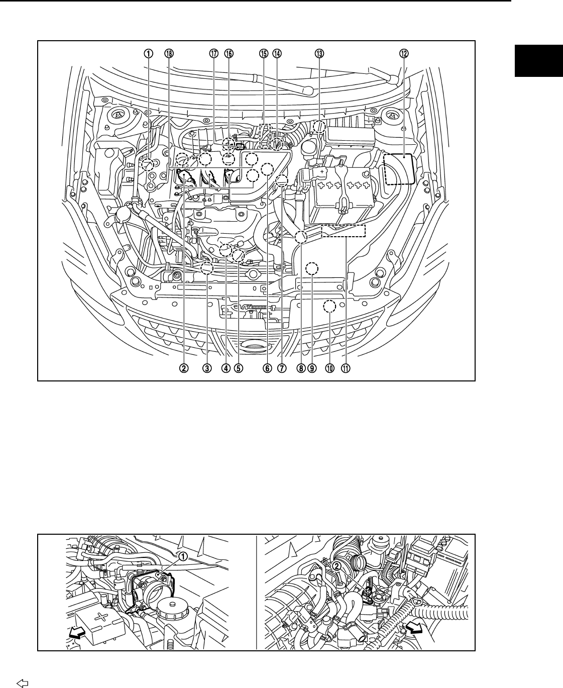
COOLING FAN CONTROL
EC-975
< FUNCTION DIAGNOSIS > [FOR MEXICO]
C
D
E
F
G
H
I
J
K
L
M
A
EC
N
P
O
Component Parts Location INFOID:0000000004534291
1. Intake valve timing control solenoid
valve
2. Ignition coil (with power transistor)
and spark plug
3. Cooling fan motor-2
4. Air fuel ratio (A/F) sensor 1 5. Heated oxygen sensor 2 6. Camshaft position sensor (PHASE)
7. Engine coolant temperature sensor 8. Park/neutral position (PNP) switch 9. Cooling fan motor-1
10. Refrigerant pressure sensor 11. ECM 12. IPDM E/R
13. Mass air flow sensor (with intake air
temperature sensor)
14. Crankshaft position sensor (POS) 15. Electric throttle control actuator
(with built in throttle position sensor
and throttle control motor)
16. Knock sensor 17. EVAP canister purge volume control
solenoid valve
18. Fuel injector
1. Electric throttle control actuator 2. Camshaft position sensor (PHASE)
Vehicle front
JMBIA0916ZZ
JMBIA0917ZZ
Revision: 2008 August 2009 Rogue
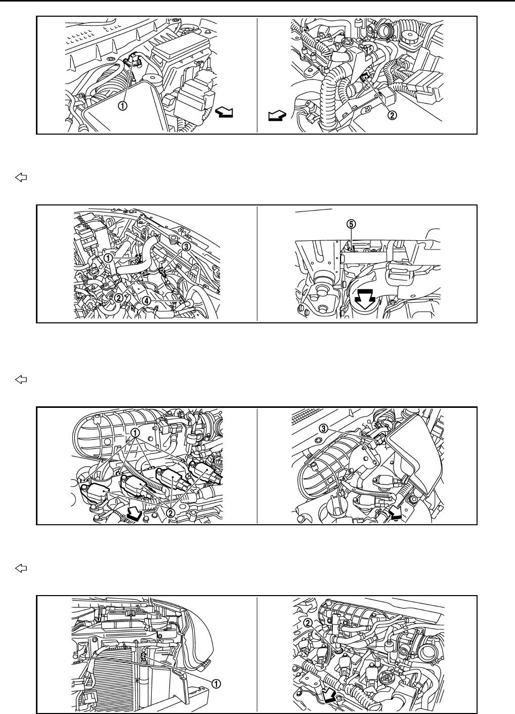
EC-976
< FUNCTION DIAGNOSIS > [FOR MEXICO]
COOLING FAN CONTROL
1. Mass air flow sensor (with intake air
temperature sensor)
2. Engine coolant temperature sensor
Vehicle front
1. Cooling fan motor-1 harness con-
nector
2. Cooling fan motor-1 3. Cooling fan motor-2 harness con-
nector
4. Cooling fan motor-2 5. Crankshaft position sensor (POS)
Vehicle front
1. Fuel injector 2. Ignition coil (with power transistor)
and spark plug 3. EVAP canister purge volume control
solenoid valve
Vehicle front
JMBIA0918ZZ
JMBIA0919ZZ
JMBIA1069ZZ
JMBIA0922ZZ
Revision: 2008 August 2009 Rogue
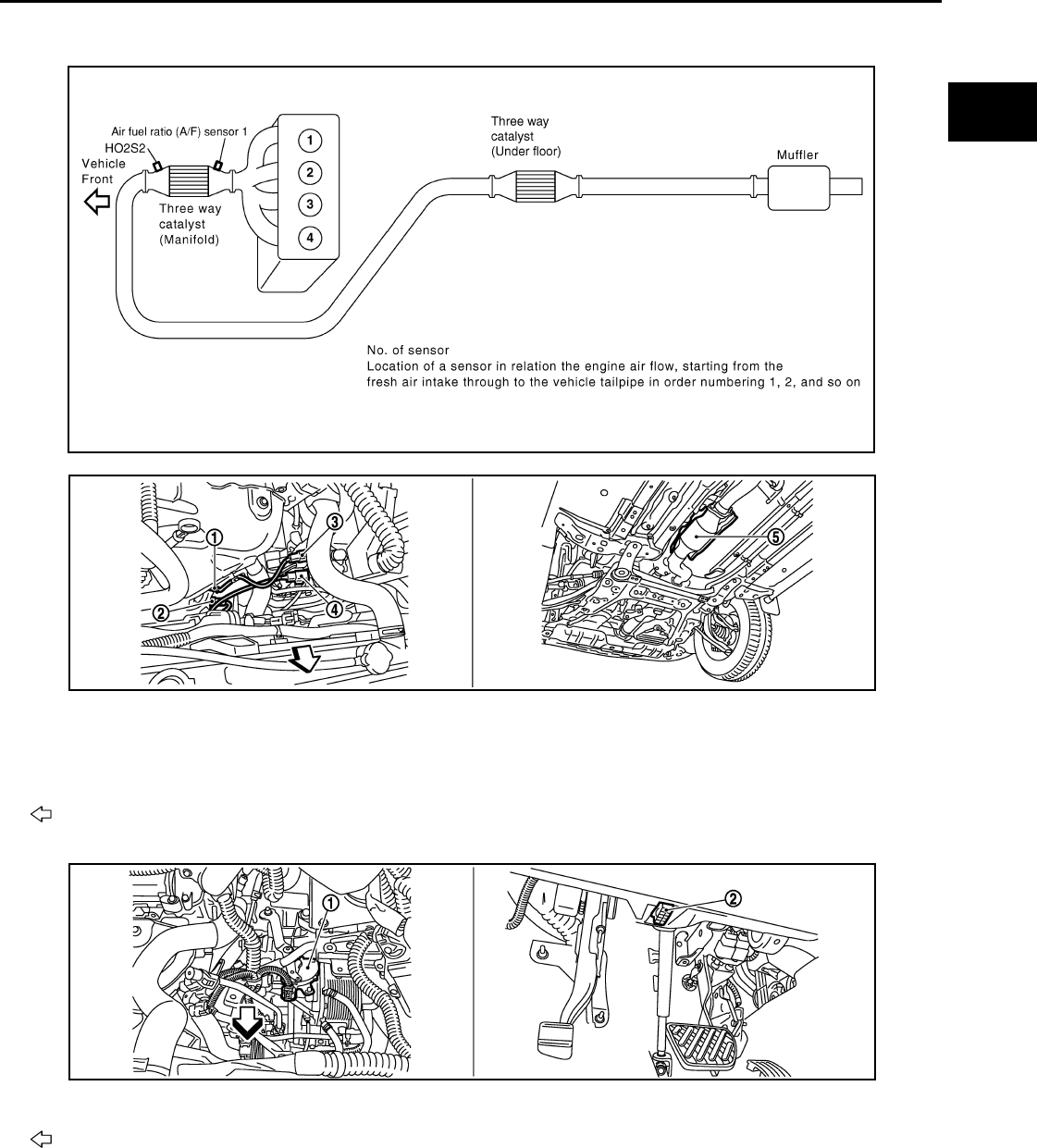
COOLING FAN CONTROL
EC-977
< FUNCTION DIAGNOSIS > [FOR MEXICO]
C
D
E
F
G
H
I
J
K
L
M
A
EC
N
P
O
1. Refrigerant pressure sensor 2. PCV valve
JMBIA0502G
B
1. Air fuel ratio (A/F) sensor 1 2. Heated oxygen sensor 2 3. Air fuel ratio (A/F) sensor 1 harness
connector
4. Heated oxygen sensor 2 harness
connector 5. Three way catalyst (Under floor)
Vehicle front
1. Park/neutral position (PNP) switch 2. Data link connector
Vehicle front
JMBIA0920ZZ
JMBIA0927ZZ
Revision: 2008 August 2009 Rogue
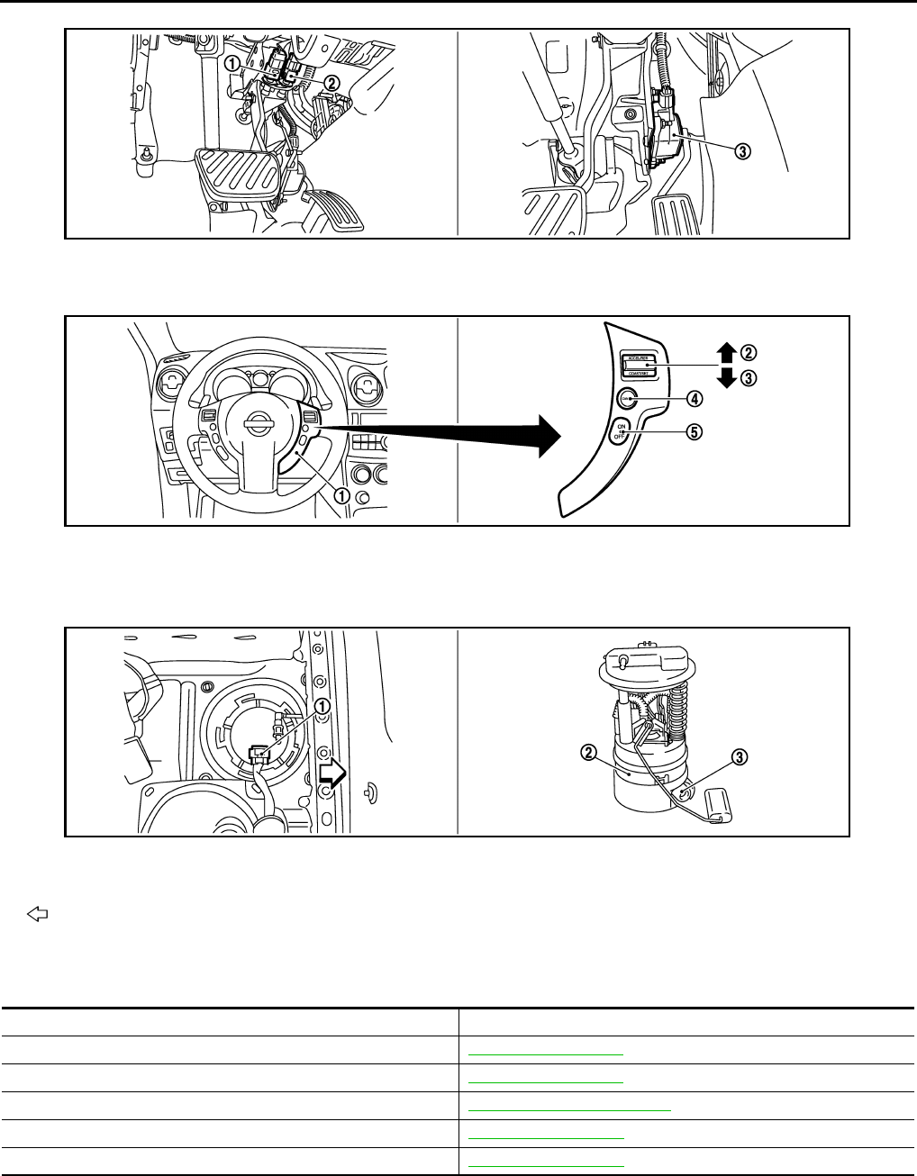
EC-978
< FUNCTION DIAGNOSIS > [FOR MEXICO]
COOLING FAN CONTROL
Component Description INFOID:0000000004494147
1. Stop lamp switch 2. ASCD brake switch 3. Accelerator pedal position sensor
1. ASCD steering switch 2. RESUME/ACCERELATE switch 3. SET/COAST switch
4. CANSEL switch 5. MAIN switch
1. Fuel level sensor unit and fuel pump
harness connector
2. Fuel level sensor unit and fuel pump 3. Fuel pressure regulator
Vehicle front
JMBIA0924ZZ
JMBIA0925ZZ
JMBIA0926ZZ
Component Reference
Camshaft position sensor (PHASE) EC-1124, "Description"
Crankshaft position sensor (POS) EC-1120, "Description"
Cooling fan motor EC-973, "System Description"
Engine coolant temperature sensor EC-1055, "Description"
Refrigerant pressure sensor EC-1230, "Description"
Revision: 2008 August 2009 Rogue
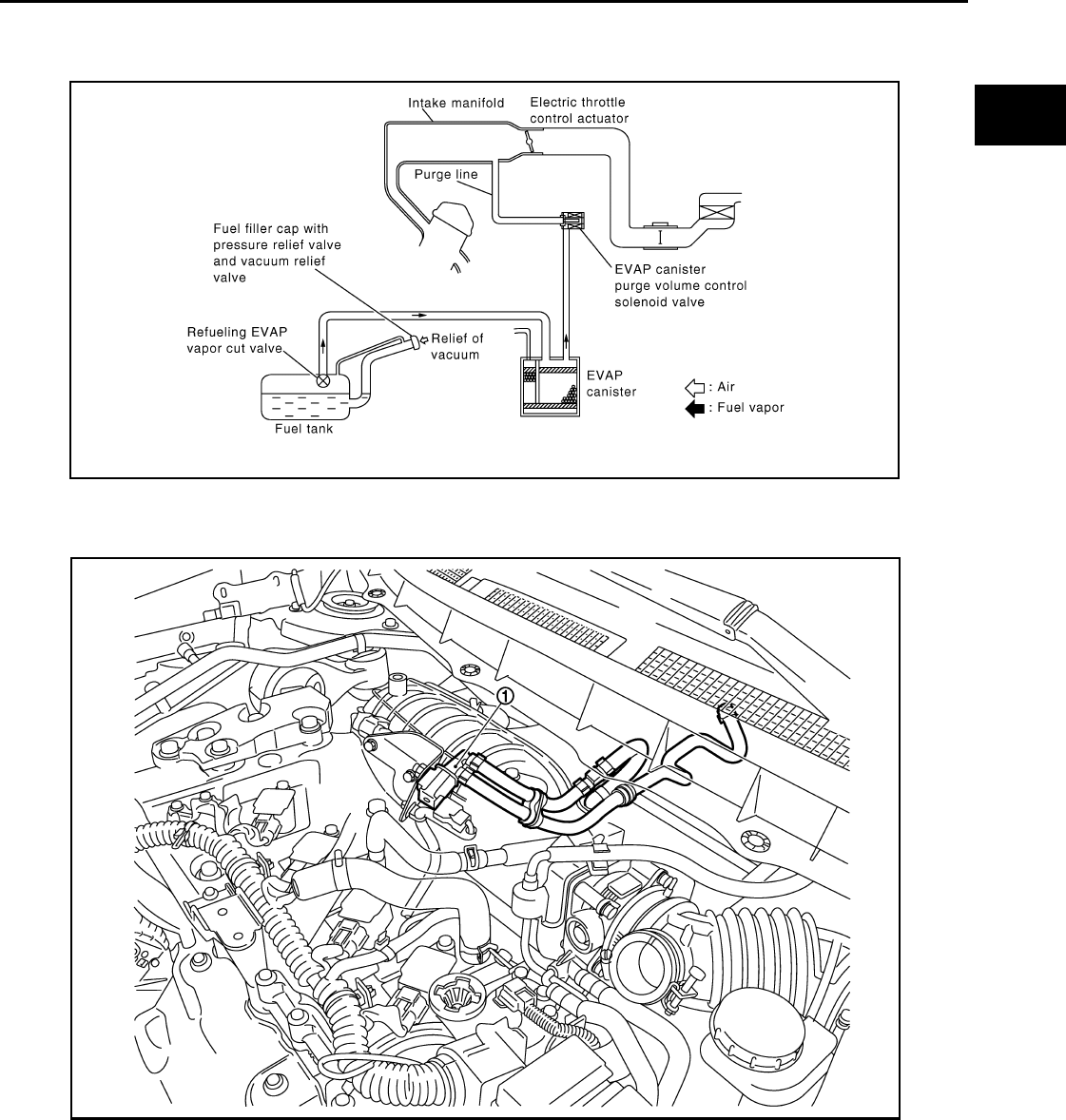
EVAPORATIVE EMISSION SYSTEM
EC-979
< FUNCTION DIAGNOSIS > [FOR MEXICO]
C
D
E
F
G
H
I
J
K
L
M
A
EC
N
P
O
EVAPORATIVE EMISSION SYSTEM
System Diagram INFOID:0000000004494148
EVAPORATIVE EMISSION LINE DRAWING
NOTE:
Do not use soapy water or any type of solvent while installing vacuum hose or purge hoses.
System Description INFOID:0000000004494149
INPUT/OUTPUT SIGNAL CHART
JMBIA1070ZZ
1. EVAP canister purge volume control
solenoid valve
A. From fuel tank
JMBIA1071ZZ
Revision: 2008 August 2009 Rogue
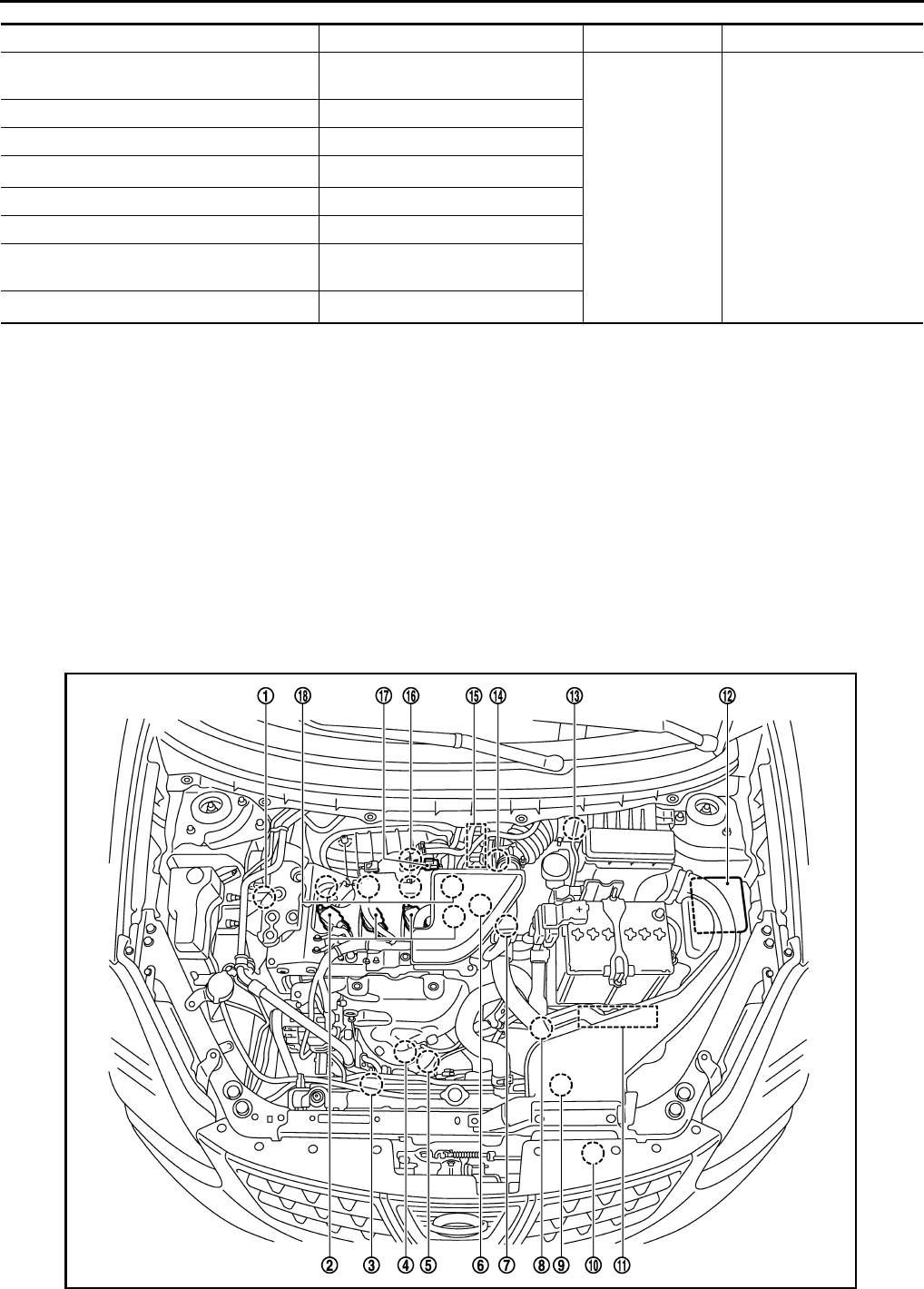
EC-980
< FUNCTION DIAGNOSIS > [FOR MEXICO]
EVAPORATIVE EMISSION SYSTEM
*1: ECM determines the start signal status by the signals of engine speed and battery voltage.
*2: This signal is sent to the ECM through CAN communication line.
SYSTEM DESCRIPTION
The evaporative emission system is used to reduce hydrocarbons emitted into the atmosphere from the fuel
system. This reduction of hydrocarbons is accomplished by activated charcoals in the EVAP canister.
The fuel vapor in the sealed fuel tank is led into the EVAP canister which contains activated carbon and the
vapor is stored there when the engine is not operating or when refueling to the fuel tank.
The vapor in the EVAP canister is purged by the air through the purge line to the intake manifold when the
engine is operating. EVAP canister purge volume control solenoid valve is controlled by ECM. When the
engine operates, the flow rate of vapor controlled by EVAP canister purge volume control solenoid valve is
proportionally regulated as the air flow increases.
EVAP canister purge volume control solenoid valve also shuts off the vapor purge line during decelerating.
Component Parts Location INFOID:0000000004534293
Sensor Input signal to ECM ECM function Actuator
Crankshaft position sensor (POS)
Camshaft position sensor (PHASE) Engine speed*1
EVAP canister
purge flow control
EVAP canister purge vol-
ume control solenoid valve
Mass air flow sensor Amount of intake air
Engine coolant temperature sensor Engine coolant temperature
Battery Battery voltage*1
Throttle position sensor Throttle position
Accelerator pedal position sensor Accelerator pedal position
Air fuel ratio (A/F) sensor 1 Density of oxygen in exhaust gas
(Mixture ratio feedback signal)
Combination meter Vehicle speed*2
JMBIA0916ZZ
Revision: 2008 August 2009 Rogue
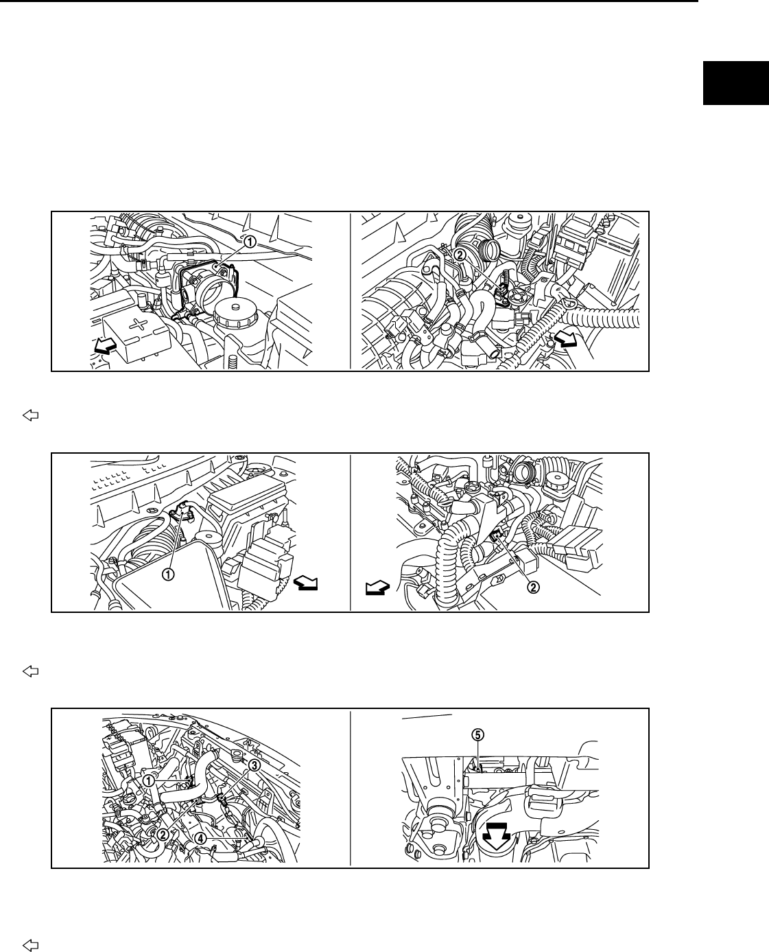
EVAPORATIVE EMISSION SYSTEM
EC-981
< FUNCTION DIAGNOSIS > [FOR MEXICO]
C
D
E
F
G
H
I
J
K
L
M
A
EC
N
P
O
1. Intake valve timing control solenoid
valve
2. Ignition coil (with power transistor)
and spark plug
3. Cooling fan motor-2
4. Air fuel ratio (A/F) sensor 1 5. Heated oxygen sensor 2 6. Camshaft position sensor (PHASE)
7. Engine coolant temperature sensor 8. Park/neutral position (PNP) switch 9. Cooling fan motor-1
10. Refrigerant pressure sensor 11. ECM 12. IPDM E/R
13. Mass air flow sensor (with intake air
temperature sensor) 14. Crankshaft position sensor (POS) 15. Electric throttle control actuator
(with built in throttle position sensor
and throttle control motor)
16. Knock sensor 17. EVAP canister purge volume control
solenoid valve 18. Fuel injector
1. Electric throttle control actuator 2. Camshaft position sensor (PHASE)
Vehicle front
1. Mass air flow sensor (with intake air
temperature sensor)
2. Engine coolant temperature sensor
Vehicle front
1. Cooling fan motor-1 harness con-
nector
2. Cooling fan motor-1 3. Cooling fan motor-2 harness con-
nector
4. Cooling fan motor-2 5. Crankshaft position sensor (POS)
Vehicle front
JMBIA0917ZZ
JMBIA0918ZZ
JMBIA0919ZZ
Revision: 2008 August 2009 Rogue
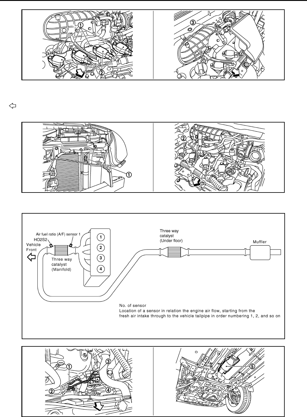
EC-982
< FUNCTION DIAGNOSIS > [FOR MEXICO]
EVAPORATIVE EMISSION SYSTEM
1. Fuel injector 2. Ignition coil (with power transistor)
and spark plug
3. EVAP canister purge volume control
solenoid valve
Vehicle front
1. Refrigerant pressure sensor 2. PCV valve
JMBIA1069ZZ
JMBIA0922ZZ
JMBIA0502G
B
JMBIA0920ZZ
Revision: 2008 August 2009 Rogue
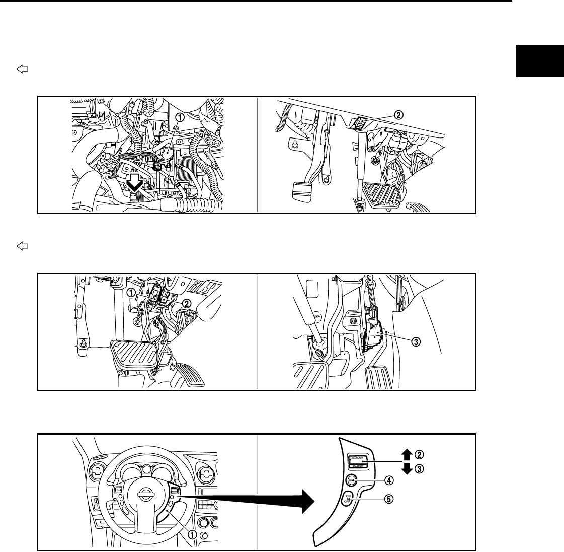
EVAPORATIVE EMISSION SYSTEM
EC-983
< FUNCTION DIAGNOSIS > [FOR MEXICO]
C
D
E
F
G
H
I
J
K
L
M
A
EC
N
P
O
1. Air fuel ratio (A/F) sensor 1 2. Heated oxygen sensor 2 3. Air fuel ratio (A/F) sensor 1 harness
connector
4. Heated oxygen sensor 2 harness
connector 5. Three way catalyst (Under floor)
Vehicle front
1. Park/neutral position (PNP) switch 2. Data link connector
Vehicle front
1. Stop lamp switch 2. ASCD brake switch 3. Accelerator pedal position sensor
1. ASCD steering switch 2. RESUME/ACCERELATE switch 3. SET/COAST switch
4. CANSEL switch 5. MAIN switch
JMBIA0927ZZ
JMBIA0924ZZ
JMBIA0925ZZ
Revision: 2008 August 2009 Rogue
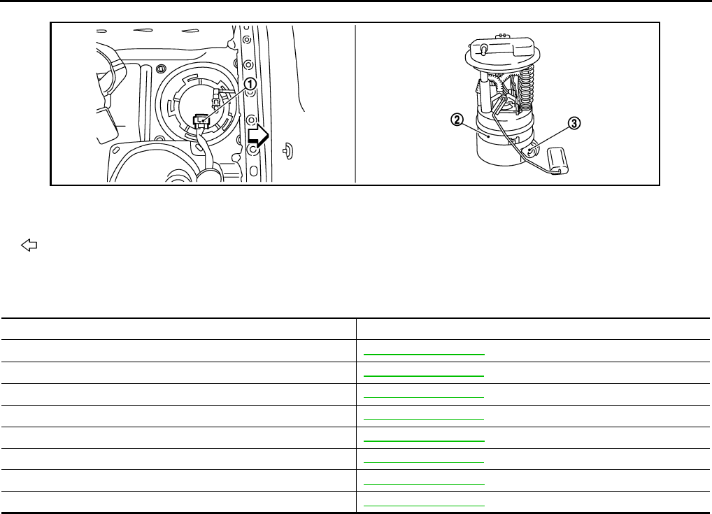
EC-984
< FUNCTION DIAGNOSIS > [FOR MEXICO]
EVAPORATIVE EMISSION SYSTEM
Component Description INFOID:0000000004494151
1. Fuel level sensor unit and fuel pump
harness connector
2. Fuel level sensor unit and fuel pump 3. Fuel pressure regulator
Vehicle front
JMBIA0926ZZ
Component Reference
A/F sensor 1 EC-1068, "Description"
Accelerator pedal position sensor EC-1187, "Description"
Camshaft position sensor (PHASE) EC-1124, "Description"
Crankshaft position sensor (POS) EC-1120, "Description"
Engine coolant temperature sensor EC-1055, "Description"
EVAP canister purge volume control solenoid valve EC-1133, "Description"
Mass air flow sensor EC-1040, "Description"
Throttle position sensor EC-1058, "Description"
Revision: 2008 August 2009 Rogue

INTAKE VALVE TIMING CONTROL
EC-985
< FUNCTION DIAGNOSIS > [FOR MEXICO]
C
D
E
F
G
H
I
J
K
L
M
A
EC
N
P
O
INTAKE VALVE TIMING CONTROL
System Diagram INFOID:0000000004494152
System Description INFOID:0000000004494153
INPUT/OUTPUT SIGNAL CHART
*: This signal is sent to the ECM through CAN communication line
SYSTEM DESCRIPTION
This mechanism hydraulically controls cam phases continuously with the fixed operating angle of the intake
valve.
The ECM receives signals such as crankshaft position, camshaft position, engine speed, and engine coolant
temperature. Then, the ECM sends ON/OFF pulse duty signals to the intake valve timing (IVT) control sole-
noid valve depending on driving status. This makes it possible to control the shut/open timing of the intake
valve to increase engine torque in low/mid speed range and output in high-speed range.
JMBIA0060G
B
Sensor Input signal to ECM ECM function Actuator
Crankshaft position sensor (POS) Engine speed and piston position Intake valve
timing control Intake valve timing control
solenoid valve
Camshaft position sensor (PHASE)
Engine coolant temperature sensor Engine coolant temperature
Combination meter Vehicle speed*
Revision: 2008 August 2009 Rogue

EC-986
< FUNCTION DIAGNOSIS > [FOR MEXICO]
INTAKE VALVE TIMING CONTROL
Component Parts Location INFOID:0000000004534294
1. Intake valve timing control solenoid
valve
2. Ignition coil (with power transistor)
and spark plug
3. Cooling fan motor-2
4. Air fuel ratio (A/F) sensor 1 5. Heated oxygen sensor 2 6. Camshaft position sensor (PHASE)
7. Engine coolant temperature sensor 8. Park/neutral position (PNP) switch 9. Cooling fan motor-1
10. Refrigerant pressure sensor 11. ECM 12. IPDM E/R
13. Mass air flow sensor (with intake air
temperature sensor)
14. Crankshaft position sensor (POS) 15. Electric throttle control actuator
(with built in throttle position sensor
and throttle control motor)
16. Knock sensor 17. EVAP canister purge volume control
solenoid valve
18. Fuel injector
1. Electric throttle control actuator 2. Camshaft position sensor (PHASE)
Vehicle front
JMBIA0916ZZ
JMBIA0917ZZ
Revision: 2008 August 2009 Rogue

INTAKE VALVE TIMING CONTROL
EC-987
< FUNCTION DIAGNOSIS > [FOR MEXICO]
C
D
E
F
G
H
I
J
K
L
M
A
EC
N
P
O
1. Mass air flow sensor (with intake air
temperature sensor)
2. Engine coolant temperature sensor
Vehicle front
1. Cooling fan motor-1 harness con-
nector
2. Cooling fan motor-1 3. Cooling fan motor-2 harness con-
nector
4. Cooling fan motor-2 5. Crankshaft position sensor (POS)
Vehicle front
1. Fuel injector 2. Ignition coil (with power transistor)
and spark plug 3. EVAP canister purge volume control
solenoid valve
Vehicle front
JMBIA0918ZZ
JMBIA0919ZZ
JMBIA1069ZZ
JMBIA0922ZZ
Revision: 2008 August 2009 Rogue
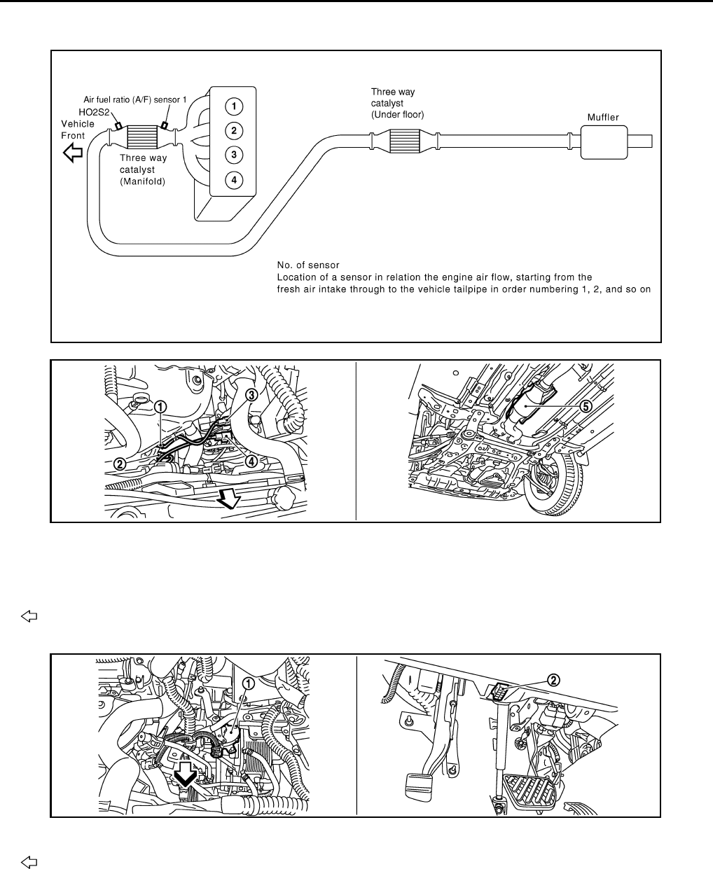
EC-988
< FUNCTION DIAGNOSIS > [FOR MEXICO]
INTAKE VALVE TIMING CONTROL
1. Refrigerant pressure sensor 2. PCV valve
JMBIA0502G
B
1. Air fuel ratio (A/F) sensor 1 2. Heated oxygen sensor 2 3. Air fuel ratio (A/F) sensor 1 harness
connector
4. Heated oxygen sensor 2 harness
connector 5. Three way catalyst (Under floor)
Vehicle front
1. Park/neutral position (PNP) switch 2. Data link connector
Vehicle front
JMBIA0920ZZ
JMBIA0927ZZ
Revision: 2008 August 2009 Rogue
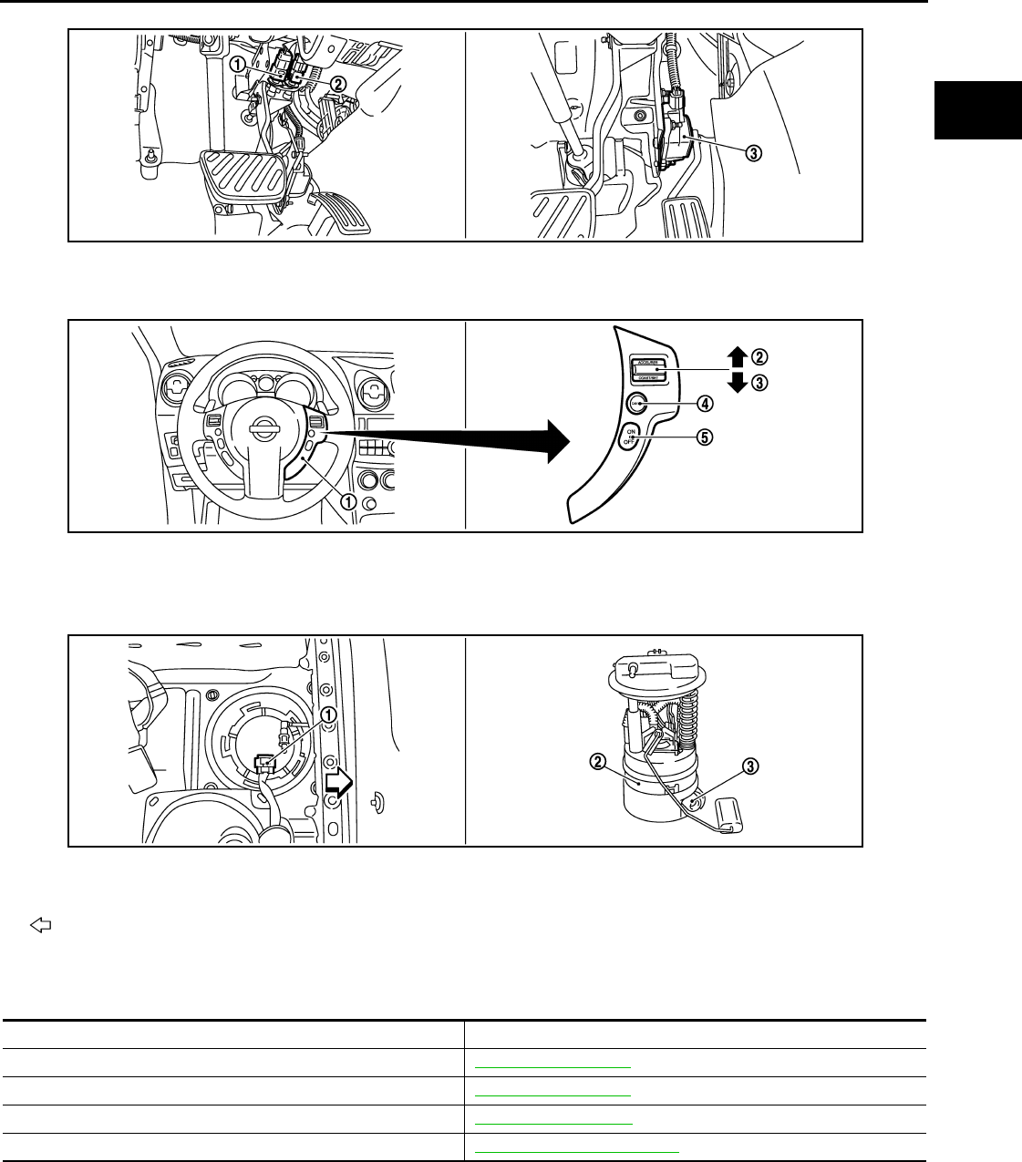
INTAKE VALVE TIMING CONTROL
EC-989
< FUNCTION DIAGNOSIS > [FOR MEXICO]
C
D
E
F
G
H
I
J
K
L
M
A
EC
N
P
O
Component Description INFOID:0000000004494155
1. Stop lamp switch 2. ASCD brake switch 3. Accelerator pedal position sensor
1. ASCD steering switch 2. RESUME/ACCERELATE switch 3. SET/COAST switch
4. CANSEL switch 5. MAIN switch
1. Fuel level sensor unit and fuel pump
harness connector
2. Fuel level sensor unit and fuel pump 3. Fuel pressure regulator
Vehicle front
JMBIA0924ZZ
JMBIA0925ZZ
JMBIA0926ZZ
Component Reference
Camshaft position sensor (PHASE) EC-1124, "Description"
Crankshaft position sensor (POS) EC-1120, "Description"
Engine coolant temperature sensor EC-1055, "Description"
Intake valve timing control solenoid valve EC-985, "System Description"
Revision: 2008 August 2009 Rogue
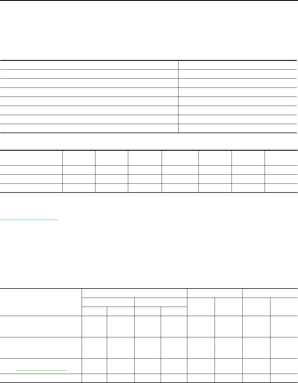
EC-990
< FUNCTION DIAGNOSIS > [FOR MEXICO]
ON BOARD DIAGNOSTIC (OBD) SYSTEM
ON BOARD DIAGNOSTIC (OBD) SYSTEM
Diagnosis Description INFOID:0000000004494156
INTRODUCTION
The ECM has an on board diagnostic system, which detects malfunctions related to engine sensors or actua-
tors. The ECM also records various emission-related diagnostic information including:
The above information can be checked using procedures listed in the table below.
×: Applicable —: Not applicable
*: When DTC and 1st trip DTC simultaneously appear on the display, they cannot be clearly distinguished from each other.
The malfunction indicator lamp (MIL) on the instrument panel illuminates when the same malfunction is
detected in two consecutive trips (Two trip detection logic), or when the ECM enters fail-safe mode. (Refer to
EC-1254, "Fail Safe".)
TWO TRIP DETECTION LOGIC
When a malfunction is detected for the first time, 1st trip DTC and 1st trip Freeze Frame data are stored in the
ECM memory. The MIL will not illuminate at this stage. <1st trip>
If the same malfunction is detected again during the next drive, the DTC and Freeze Frame data are stored in
the ECM memory, and the MIL illuminates. The MIL illuminates at the same time the DTC is stored. <2nd trip>
The “trip” in the “Two Trip Detection Logic” means a driving mode in which self-diagnosis is performed during
vehicle operation. Specific on board diagnostic items will cause the ECM to illuminate or blink the MIL, and
store DTC and Freeze Frame data, even in the 1st trip, as shown below.
×: Applicable —: Not applicable
DTC AND FREEZE FRAME DATA
DTC and 1st Trip DTC
Emission-related diagnostic information Diagnostic service
Diagnostic Trouble Code (DTC) Service $03 of ISO 15031-5
Freeze Frame data Service $02 of ISO 15031-5
System Readiness Test (SRT) code Service $01 of ISO 15031-5
1st Trip Diagnostic Trouble Code (1st Trip DTC) Service $07 of ISO 15031-5
1st Trip Freeze Frame data
Test values and Test limits Service $06 of ISO 15031-5
Calibration ID Service $09 of ISO 15031-5
DTC 1st trip DTC Freeze
Frame data 1st trip Freeze
Frame data SRT code SRT status Test value
CONSULT-III ××× × ××—
GST ××× —×××
ECM ××*— — — ×—
Items
MIL DTC 1st trip DTC
1st trip 2nd trip 1st trip
displaying 2nd trip
displaying 1st trip
displaying 2nd trip
displaying
Blinking illuminate Blinking illuminate
Misfire (Possible three way catalyst
damage) — DTC: P0300 - P0304 is
being detected
×————— ×—
Misfire (Possible three way catalyst
damage) — DTC: P0300 - P0304 is
being detected
—— ×—— ×——
One trip detection diagnoses (Re-
fer to EC-1257, "DTC Index".) —×—— ×———
Except above — — — ×—××—
Revision: 2008 August 2009 Rogue

ON BOARD DIAGNOSTIC (OBD) SYSTEM
EC-991
< FUNCTION DIAGNOSIS > [FOR MEXICO]
C
D
E
F
G
H
I
J
K
L
M
A
EC
N
P
O
The 1st trip DTC (whose number is the same as the DTC number) is displayed for the latest self-diagnostic
result obtained. If the ECM memory was cleared previously, and the 1st trip DTC did not recur, the 1st trip DTC
will not be displayed.
If a malfunction is detected during the 1st trip, the 1st trip DTC is saved in the ECM memory. The MIL will not
illuminate (two trip detection logic). If the same malfunction is not detected in the 2nd trip (meeting the required
driving pattern), the 1st trip DTC is cleared from the ECM memory. If the same malfunction is detected in the
2nd trip, both the 1st trip DTC and DTC are stored in the ECM memory and the MIL illuminates. In other
words, the DTC is stored in the ECM memory and the MIL illuminates when the same malfunction occurs in
two consecutive trips. If a 1st trip DTC is saved and a non-diagnostic operation is performed between the 1st
and 2nd trips, only the 1st trip DTC will continue to be stored. For malfunctions that blink or illuminate the MIL
during the 1st trip, the DTC and 1st trip DTC are stored in the ECM memory.
Procedures for clearing the DTC and the 1st trip DTC from the ECM memory are described in “How to Erase
DTC and 1st Trip DTC”.
For malfunctions in which 1st trip DTCs are displayed, refer to EC-1257, "DTC Index". These items are
required by legal regulations to continuously monitor the system/component. In addition, the items monitored
non-continuously are also displayed on CONSULT-III.
1st trip DTC is specified in Service $07 of ISO 15031-5. 1st trip DTC detection occurs without illuminating the
MIL and therefore does not warn the driver of a malfunction. However, 1st trip DTC detection will not prevent
the vehicle from being tested, for example during Inspection/Maintenance (I/M) tests.
When a 1st trip DTC is detected, check, print out or write down and erase (1st trip) DTC and Freeze Frame
data as specified in Work Flow procedure Step 2, refer to EC-929, "Work Flow". Then perform DTC CONFIR-
MATION PROCEDURE or Component Function Check to try to duplicate the malfunction. If the malfunction is
duplicated, the item requires repair.
Freeze Frame Data and 1st Trip Freeze Frame Data
The ECM records the driving conditions such as fuel system status, calculated load value, engine coolant tem-
perature, short-term fuel trim, long-term fuel trim, engine speed, vehicle speed, absolute throttle position, base
fuel schedule and intake air temperature at the moment a malfunction is detected.
Data which are stored in the ECM memory, along with the 1st trip DTC, are called 1st trip freeze frame data.
The data, stored together with the DTC data, are called freeze frame data and displayed on CONSULT-III or
GST. The 1st trip freeze frame data can only be displayed on the CONSULT-III screen, not on the GST.
Only one set of freeze frame data (either 1st trip freeze frame data or freeze frame data) can be stored in the
ECM. 1st trip freeze frame data is stored in the ECM memory along with the 1st trip DTC. There is no priority
for 1st trip freeze frame data and it is updated each time a different 1st trip DTC is detected. However, once
freeze frame data (2nd trip detection/MIL on) is stored in the ECM memory, 1st trip freeze frame data is no
longer stored. Remember, only one set of freeze frame data can be stored in the ECM. The ECM has the fol-
lowing priorities to update the data.
For example, the EGR malfunction (Priority: 2) was detected and the freeze frame data was saved in the 2nd
trip. After that when the misfire (Priority: 1) is detected in another trip, the freeze frame data will be updated
from the EGR malfunction to the misfire. The 1st trip freeze frame data is updated each time a different mal-
function is detected. There is no priority for 1st trip freeze frame data. However, once freeze frame data is
stored in the ECM memory, 1st trip freeze data is no longer stored (because only one freeze frame data or 1st
trip freeze frame data can be stored in the ECM). If freeze frame data is stored in the ECM memory and freeze
frame data with the same priority occurs later, the first (original) freeze frame data remains unchanged in the
ECM memory.
Both 1st trip freeze frame data and freeze frame data (along with the DTCs) are cleared when the ECM mem-
ory is erased. Procedures for clearing the ECM memory are described in “How to Erase DTC and 1st Trip
DTC”.
How to Read DTC and 1st Trip DTC
With CONSULT-III
With GST
CONSULT-III or GST (Generic Scan Tool) Examples: P0340, P0850, P1148, etc.
These DTCs are prescribed by SAE J2012.
Priority Items
1Freeze frame data Misfire — DTC: P0300 - P0304
Fuel Injection System Function — DTC: P0171, P0172
2 Except the above items (Includes CVT related items)
3 1st trip freeze frame data
Revision: 2008 August 2009 Rogue

EC-992
< FUNCTION DIAGNOSIS > [FOR MEXICO]
ON BOARD DIAGNOSTIC (OBD) SYSTEM
(CONSULT-III also displays the malfunctioning component or system.)
No Tools
The number of blinks of the MIL in the Diagnostic Test Mode II (Self-Diagnostic Results) indicates the DTC.
Example: 0340, 0850, 1148, etc.
These DTCs are controlled by NISSAN.
•1st trip DTC No. is the same as DTC No.
•Output of a DTC indicates a malfunction. However, GST and the Diagnostic Test Mode II do not indi-
cate whether the malfunction is still occurring or has occurred in the past and has returned to nor-
mal. CONSULT-III can identify malfunction status as shown below. Therefore, using CONSULT-III (if
available) is recommended.
DTC or 1st trip DTC of a malfunction is displayed in “SELF-DIAGNOSTIC RESULTS” mode of CONSULT-III.
Time data indicates how many times the vehicle was driven after the last detection of a DTC.
If the DTC is being detected currently, the time data will be [0].
If a 1st trip DTC is stored in the ECM, the time data will be [1t].
How to Erase DTC and 1st Trip DTC
With CONSULT-III
NOTE:
•If the ignition switch stays ON after repair work, be sure to turn ignition switch OFF once.
Wait at least 10 seconds and then turn it ON (engine stopped) again.
•If the DTC is not for CVT related items (see EC-1257, "DTC Index"), skip step 1.
1. Erase DTC in TCM. Refer to TM-42, "Diagnosis Description".
2. Select “ENGINE” with CONSULT-III.
3. Select “SELFDIAGNOSTIC RESULT”.
4. Touch “ERASE”. (DTC in ECM will be erased.)
With GST
NOTE:
•If the ignition switch stays ON after repair work, be sure to turn ignition switch OFF once.
Wait at least 10 seconds and then turn it ON (engine stopped) again.
1. Select Service $04 with GST (Generic Scan Tool).
No Tools
NOTE:
•If the ignition switch stays ON after repair work, be sure to turn ignition switch OFF once.
Wait at least 10 seconds and then turn it ON (engine stopped) again.
1. Erase DTC in ECM. Refer to How to Erase Diagnostic Test Mode II (Self-diagnostic Results).
•If the battery is disconnected, the emission-related diagnostic information will be cleared within 24
hours.
•The following data are cleared when the ECM memory is erased.
- Diagnostic trouble codes
- 1st trip diagnostic trouble codes
- Freeze frame data
- 1st trip freeze frame data
- System readiness test (SRT) codes
- Test values
Actual work procedures are explained using a DTC as an example. Be careful so that not only the DTC, but all
of the data listed above, are cleared from the ECM memory during work procedures.
SYSTEM READINESS TEST (SRT) CODE
System Readiness Test (SRT) code is specified in Service $01 of ISO 15031-5.
As part of an enhanced emissions test for Inspection & Maintenance (I/M), certain states require the status of
SRT be used to indicate whether the ECM has completed self-diagnosis of major emission systems and com-
ponents. Completion must be verified in order for the emissions inspection to proceed.
If a vehicle is rejected for a State emissions inspection due to one or more SRT items indicating “INCMP”, use
the information in this Service Manual to set the SRT to “CMPLT”.
In most cases the ECM will automatically complete its self-diagnosis cycle during normal usage, and the SRT
status will indicate “CMPLT” for each application system. Once set as “CMPLT”, the SRT status remains
“CMPLT” until the self-diagnosis memory is erased.
Occasionally, certain portions of the self-diagnostic test may not be completed as a result of the customer's
normal driving pattern; the SRT will indicate “INCMP” for these items.
NOTE:
Revision: 2008 August 2009 Rogue

ON BOARD DIAGNOSTIC (OBD) SYSTEM
EC-993
< FUNCTION DIAGNOSIS > [FOR MEXICO]
C
D
E
F
G
H
I
J
K
L
M
A
EC
N
P
O
The SRT will also indicate “INCMP” if the self-diagnosis memory is erased for any reason or if the ECM mem-
ory power supply is interrupted for several hours.
If, during the state emissions inspection, the SRT indicates “CMPLT” for all test items, the inspector will con-
tinue with the emissions test. However, if the SRT indicates “INCMP” for one or more of the SRT items the
vehicle is returned to the customer untested.
NOTE:
If MIL is ON during the state emissions inspection, the vehicle is also returned to the customer untested even
though the SRT indicates “CMPLT” for all test items. Therefore, it is important to check SRT (“CMPLT”) and
DTC (No DTCs) before the inspection.
SRT Item
The table below shows required self-diagnostic items to set the SRT to “CMPLT”.
*: If completion of several SRTs is required, perform driving patterns (DTC CONFIRMATION PROCEDURE), one by one based on the
priority for models with CONSULT-III.
SRT Set Timing
SRT is set as “CMPLT” after self-diagnosis has been performed one or more times. Completion of SRT is
done regardless of whether the result is OK or NG. The set timing is different between OK and NG results and
is shown in the table below.
OK: Self-diagnosis is carried out and the result is OK.
NG: Self-diagnosis is carried out and the result is NG.
—: Self-diagnosis is not carried out.
SRT item
(CONSULT-III indication)
Performance
Priority* Required self-diagnostic items to set the SRT to “CMPLT” Corresponding
DTC No.
CATALYST 2 Three way catalyst function P0420
EVAP SYSTEM 2 EVAP control system purge flow monitoring P0441
1 EVAP control system P0442
2 EVAP control system P0456
HO2S 2 Air fuel ratio (A/F) sensor 1 P0133
Heated oxygen sensor 2 P0137
Heated oxygen sensor 2 P0138
Heated oxygen sensor 2 P0139
Self-diagnosis result
Example
Diagnosis Ignition cycle
← ON →OFF ← ON →OFF ← ON →OFF ← ON →
All OK Case 1 P0400 OK (1) — (1) OK (2) — (2)
P0402 OK (1) — (1) — (1) OK (2)
P1402 OK (1) OK (2) — (2) — (2)
SRT of EGR “CMPLT” “CMPLT” “CMPLT” “CMPLT”
Case 2 P0400 OK (1) — (1) — (1) — (1)
P0402 — (0) — (0) OK (1) — (1)
P1402 OK (1) OK (2) — (2) — (2)
SRT of EGR “INCMP” “INCMP” “CMPLT” “CMPLT”
NG exists Case 3 P0400 OK OK — —
P0402 — — — —
P1402 NG — NG NG
(Consecutive
NG)
(1st trip)
DTC 1st trip DTC — 1st trip DTC DTC
(= MIL ON)
SRT of EGR “INCMP” “INCMP” “INCMP” “CMPLT”
Revision: 2008 August 2009 Rogue

EC-994
< FUNCTION DIAGNOSIS > [FOR MEXICO]
ON BOARD DIAGNOSTIC (OBD) SYSTEM
When all SRT related self-diagnoses show OK results in a single cycle (Ignition OFF-ON-OFF), the SRT will
indicate “CMPLT”. → Case 1 above
When all SRT related self-diagnoses show OK results through several different cycles, the SRT will indicate
“CMPLT” at the time the respective self-diagnoses have at least one OK result. → Case 2 above
If one or more SRT related self-diagnoses show NG results in 2 consecutive cycles, the SRT will also indicate
“CMPLT”. → Case 3 above
The table above shows that the minimum number of cycles for setting SRT as “INCMP” is the number one (1)
for each self-diagnosis (Case 1 & 2) or the number two (2) for one of self-diagnoses (Case 3). However, in
preparation for the state emissions inspection, it is unnecessary for each self-diagnosis to be executed twice
(Case 3) for the following reasons:
• The SRT will indicate “CMPLT” at the time the respective self-diagnoses have one (1) OK result.
• The emissions inspection requires “CMPLT” of the SRT only with OK self-diagnosis results.
• During SRT driving pattern, the 1st trip DTC (NG) is detected prior to “CMPLT” of SRT and the self-diagnosis
memory must be erased from the ECM after repair.
• If the 1st trip DTC is erased, all the SRT will indicate “INCMP”.
NOTE:
SRT can be set as “CMPLT” together with the DTC(s). Therefore, DTC check must always be carried out
prior to the state emission inspection even though the SRT indicates “CMPLT”.
SRT Service Procedure
If a vehicle has failed the state emissions inspection due to one or more SRT items indicating “INCMP”, review
the flowchart diagnostic sequence on the next page.
Revision: 2008 August 2009 Rogue
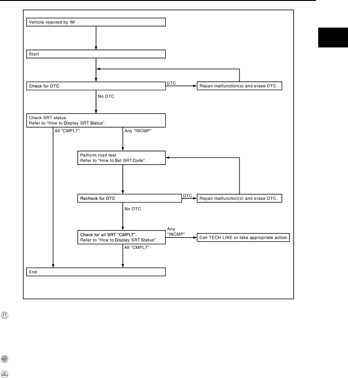
ON BOARD DIAGNOSTIC (OBD) SYSTEM
EC-995
< FUNCTION DIAGNOSIS > [FOR MEXICO]
C
D
E
F
G
H
I
J
K
L
M
A
EC
N
P
O
How to Display SRT Status
WITH CONSULT-III
Selecting “SRT STATUS” in “DTC CONFIRMATION” mode with CONSULT-III.
For items whose SRT codes are set “CMPLT” is displayed on the CONSULT-III screen; for items whose SRT
codes are not set, “INCMP” is displayed.
NOTE:
Though displayed on the CONSULT-III screen, “HO2S HTR” is not SRT item.
WITH GST
Selecting Service $01 with GST (Generic Scan Tool)
NO TOOLS
A SRT code itself cannot be displayed, however SRT status can.
1. Turn ignition switch ON and wait 20 seconds.
2. SRT status is indicated as shown below.
• When all SRT codes are set, MIL illuminates continuously.
JMBIA1574G
B
Revision: 2008 August 2009 Rogue
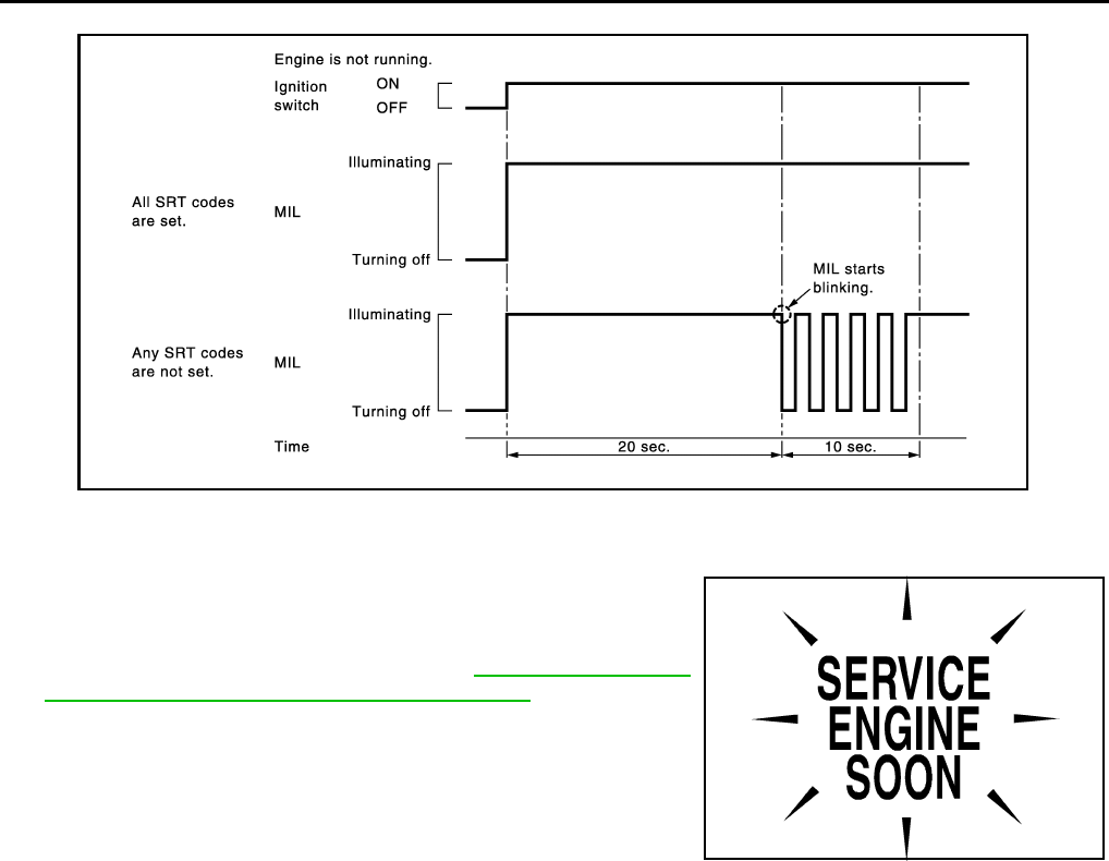
EC-996
< FUNCTION DIAGNOSIS > [FOR MEXICO]
ON BOARD DIAGNOSTIC (OBD) SYSTEM
• When any SRT codes are not set, MIL will flash periodically for 10 seconds.
MALFUNCTION INDICATOR LAMP (MIL)
Description
The MIL is located on the instrument panel.
1. The MIL will illuminate when the ignition switch is turned ON
without the engine running. This is a bulb check.
If the MIL does not illuminate, refer to MWI-22, "WARNING
LAMPS/INDICATOR LAMPS : System Diagram".
2. When the engine is started, the MIL should turn off.
If the MIL remains on, the on board diagnostic system has
detected an engine system malfunction.
On Board Diagnostic System Function
The on board diagnostic system has the following three functions.
JMBIA1515G
B
SEF217U
Revision: 2008 August 2009 Rogue
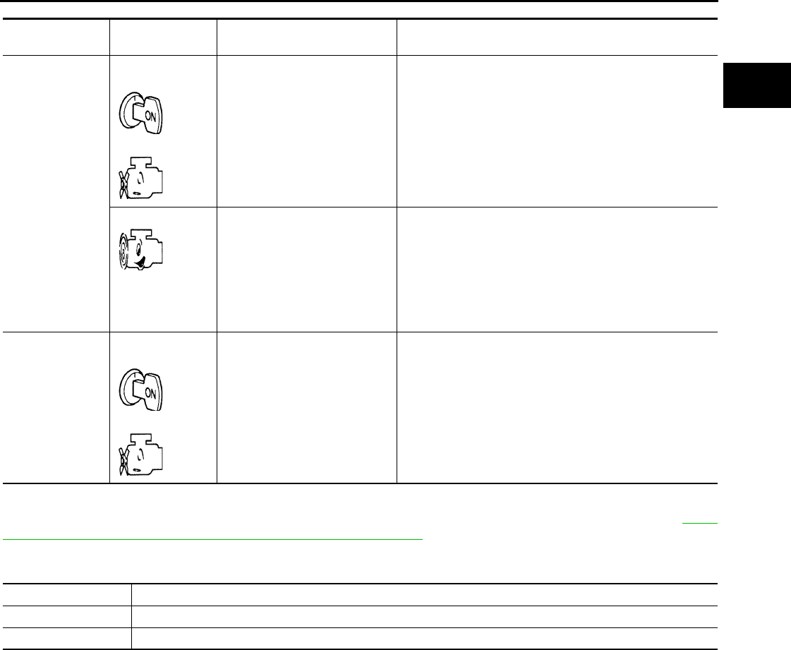
ON BOARD DIAGNOSTIC (OBD) SYSTEM
EC-997
< FUNCTION DIAGNOSIS > [FOR MEXICO]
C
D
E
F
G
H
I
J
K
L
M
A
EC
N
P
O
Diagnostic Test Mode I — Bulb Check
In this mode, the MIL on the instrument panel should stay ON. If it remains OFF, check the bulb. Refer to MWI-
22, "WARNING LAMPS/INDICATOR LAMPS : System Diagram".
Diagnostic Test Mode I — Malfunction Warning
This DTC number is clarified in Diagnostic Test Mode II (SELF-DIAGNOSTIC RESULTS)
Diagnostic Test Mode II — Self-diagnostic Results
In this mode, the DTC and 1st trip DTC are indicated by the number of blinks of the MIL as shown below.
The DTC and 1st trip DTC are displayed at the same time. If the MIL does not illuminate in diagnostic test
mode I (Malfunction warning), all displayed items are 1st trip DTCs. If only one code is displayed when the MIL
illuminates in diagnostic test mode II (SELF-DIAGNOSTIC RESULTS), it is a DTC; if two or more codes are
displayed, they may be either DTCs or 1st trip DTCs. DTC No. is same as that of 1st trip DTC. These uniden-
tified codes can be identified by using the CONSULT-III or GST. A DTC will be used as an example for how to
read a code.
Diagnostic Test
Mode
KEY and ENG.
Status
Function Explanation of Function
Mode I Ignition switch in
ON position
Engine stopped
BULB CHECK This function checks the MIL bulb for damage (blown, open
circuit, etc.).
If the MIL does not come on, check MIL circuit.
Engine running MALFUNCTION
WARNING
When a malfunction is detected twice in two consecutive
driving cycles (two trip detection logic), the MIL will illumi-
nate to inform the driver that a malfunction has been detect-
ed.
The following malfunctions will illuminate or blink the MIL in
the 1st trip.
• Misfire (Possible three way catalyst damage)
• One trip detection diagnoses
Mode II Ignition switch in
ON position
Engine stopped
SELF-DIAGNOSTIC
RESULTS This function allows DTCs and 1st trip DTCs to be read.
MIL Condition
ON When the malfunction is detected.
OFF No malfunction.
Revision: 2008 August 2009 Rogue
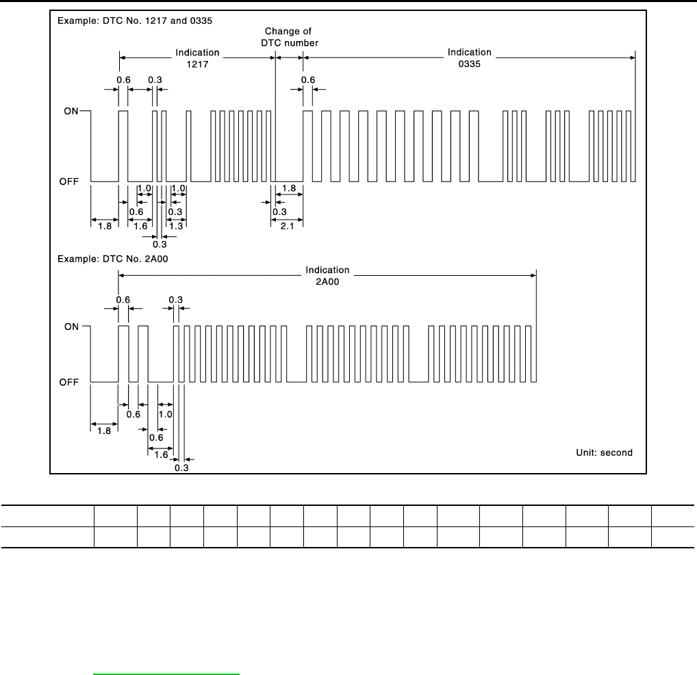
EC-998
< FUNCTION DIAGNOSIS > [FOR MEXICO]
ON BOARD DIAGNOSTIC (OBD) SYSTEM
A particular trouble code can be identified by the number of four-digit numeral flashes as per the following.
The length of time the 1,000th-digit numeral flashes on and off is 1.2 seconds consisting of an ON (0.6-sec-
onds) - OFF (0.6-seconds) cycle.
The 100th-digit numeral and lower digit numerals consist of a 0.3-seconds ON and 0.3-seconds OFF cycle.
A change from one digit numeral to another occurs at an interval of 1.0-second OFF. In other words, the later
numeral appears on the display 1.3 seconds after the former numeral has disappeared.
A change from one trouble code to another occurs at an interval of 1.8-seconds OFF.
In this way, all the detected malfunctions are classified by their DTC numbers. The DTC 0000 refers to no mal-
function. (See EC-1257, "DTC Index")
How to Switch Diagnostic Test Mode
NOTE:
•It is better to count the time accurately with a clock.
•It is impossible to switch the diagnostic mode when an accelerator pedal position sensor circuit has
a malfunction.
•Always ECM returns to Diagnostic Test Mode I after the ignition switch is turned OFF.
HOW TO SET DIAGNOSTIC TEST MODE II (SELF-DIAGNOSTIC RESULTS)
1. Confirm that accelerator pedal is fully released, turn ignition switch ON and wait 3 seconds.
2. Repeat the following procedure quickly five times within 5 seconds.
- Fully depress the accelerator pedal.
- Fully release the accelerator pedal.
3. Wait 7 seconds, fully depress the accelerator pedal and keep it for depressed approx. 10 seconds until the
MIL starts blinking.
NOTE:
Do not release the accelerator pedal for 10 seconds if MIL starts blinking during this period. 10
seconds. This blinking is displaying SRT status and is continued for another 10 seconds.
4. Fully release the accelerator pedal.
ECM has entered to Diagnostic Test Mode II (Self-diagnostic results).
JMBIA1140G
B
Number 0 123456789 A B C D E F
Flashes 10 1 2 3 4 5 6 7 8 9 11 12 13 14 15 16
Revision: 2008 August 2009 Rogue
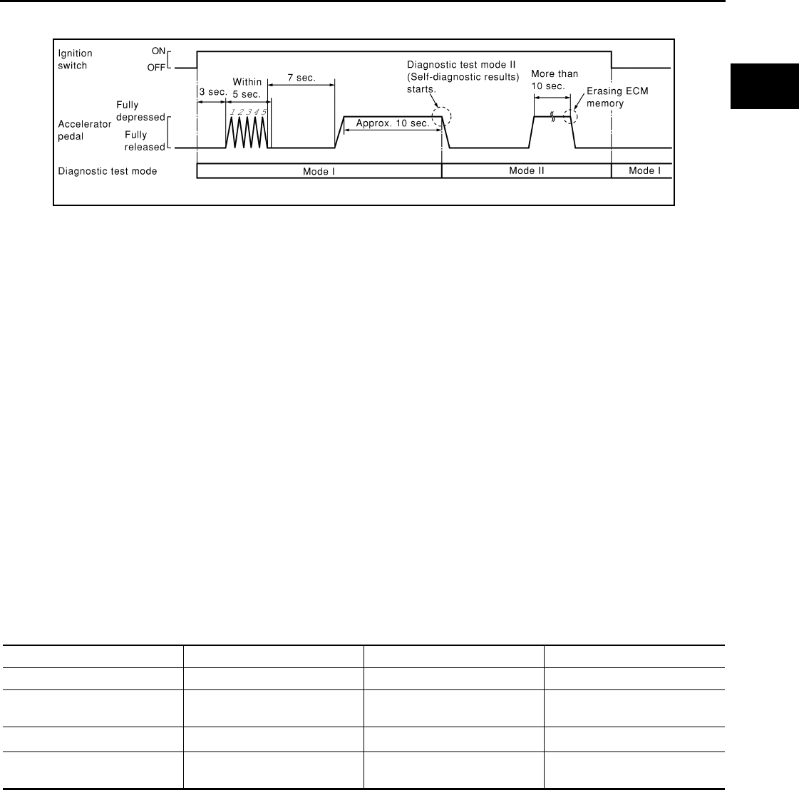
ON BOARD DIAGNOSTIC (OBD) SYSTEM
EC-999
< FUNCTION DIAGNOSIS > [FOR MEXICO]
C
D
E
F
G
H
I
J
K
L
M
A
EC
N
P
O
NOTE:
Wait until the same DTC (or 1st trip DTC) appears to completely confirm all DTCs.
HOW TO ERASE DIAGNOSTIC TEST MODE II (SELF-DIAGNOSTIC RESULTS)
1. Set ECM in Diagnostic Test Mode II (Self-diagnostic results). Refer to “How to Set Diagnostic Test Mode II
(Self-diagnostic Results)”.
2. Fully depress the accelerator pedal and keep it depressed for more than 10 seconds.
The emission-related diagnostic information has been erased from the backup memory in the ECM.
3. Fully release the accelerator pedal, and confirm the DTC 0000 is displayed.
•If the battery is disconnected, the DTC will be lost from the backup memory within 24 hours.
•Do not erase the stored memory before starting trouble diagnoses.
OBD System Operation Chart
Relationship Between MIL, 1st Trip DTC, DTC and Detectable Items
• When a malfunction is detected for the first time, the 1st trip DTC and the 1st trip freeze frame data are
stored in the ECM memory.
• When the same malfunction is detected in two consecutive trips, the DTC and the freeze frame data are
stored in the ECM memory, and the MIL will come on.
• The MIL will turn off after the vehicle is driven 3 times (driving pattern B) with no malfunction. A is counted
only when the recorded driving pattern is met (as stored in the ECM). If another malfunction occurs while
counting, the counter will reset.
• The DTC and the freeze frame data will be stored until the vehicle is driven 40 times (driving pattern A) with-
out the same malfunction recurring (except for Misfire and Fuel Injection System). For Misfire and Fuel Injec-
tion System, the DTC and freeze frame data will be stored until the vehicle is driven 80 times (driving pattern
C) without the same malfunction recurring. The “TIME” in “SELF-DIAGNOSTIC RESULTS” mode of CON-
SULT-III will count the number of times the vehicle is driven.
• The 1st trip DTC is not displayed when the self-diagnosis results in OK for the 2nd trip.
Summary Chart
For details about patterns B and C under “Fuel Injection System” and “Misfire”, see “EXPLANATION FOR DRIVING PATTERNS FOR
“MISFIRE <EXHAUST QUALITY DETERIORATION>”, “FUEL INJECTION SYSTEM”.
For details about patterns A and B under Other, see “EXPLANATION FOR DRIVING PATTERNS FOR “MISFIRE <EXHAUST QUALITY
DETERIORATION>”, “FUEL INJECTION SYSTEM”.
*1: Clear timing is at the moment OK is detected.
*2: Clear timing is when the same malfunction is detected in the 2nd trip.
Relationship Between MIL, DTC, 1st Trip DTC and Driving Patterns for “Misfire <Exhaust Quality Deterioration>”,
“Fuel Injection System”
PBIB0092E
Items Fuel Injection System Misfire Other
MIL (turns off) 3 (pattern B) 3 (pattern B) 3 (pattern B)
DTC, Freeze Frame Data (no
display) 80 (pattern C) 80 (pattern C) 40 (pattern A)
1st Trip DTC (clear) 1 (pattern C), *11 (pattern C), *11 (pattern B)
1st Trip Freeze Frame Data
(clear) *1, *2 *1, *2 1 (pattern B)
Revision: 2008 August 2009 Rogue
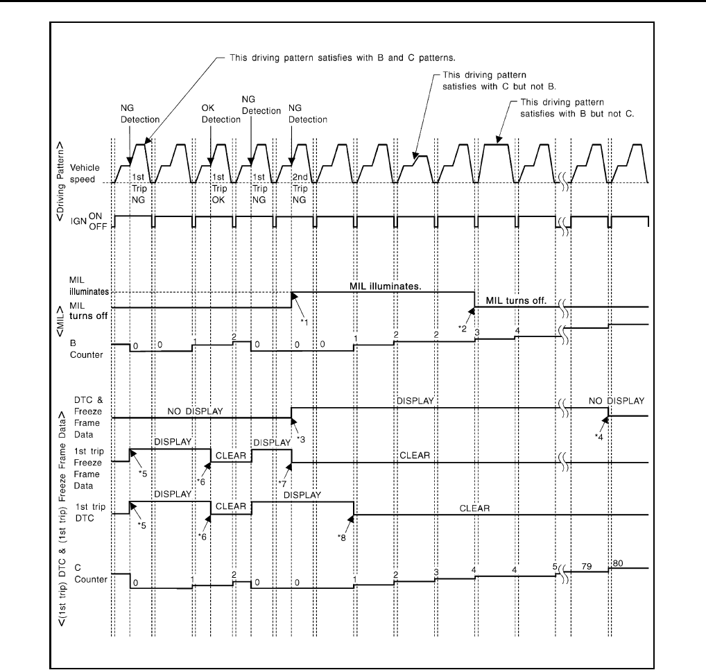
EC-1000
< FUNCTION DIAGNOSIS > [FOR MEXICO]
ON BOARD DIAGNOSTIC (OBD) SYSTEM
Explanation for Driving Patterns for “Misfire <Exhaust Quality Deterioration>”, “Fuel Injection System”
<Driving Pattern B>
Driving pattern B means the vehicle operation as per the following:
All components and systems should be monitored at least once by the OBD system.
*1: When the same malfunction is de-
tected in two consecutive trips, MIL
will illuminate.
*2: MIL will turn off after vehicle is driven
3 times (pattern B) without any mal-
functions.
*3: When the same malfunction is de-
tected in two consecutive trips, the
DTC and the freeze frame data will be
stored in ECM.
*4: The DTC and the freeze frame data
will not be displayed any longer after
vehicle is driven 80 times (pattern C)
without the same malfunction. (The
DTC and the freeze frame data still
remain in ECM.)
*5: When a malfunction is detected for
the first time, the 1st trip DTC and the
1st trip freeze frame data will be
stored in ECM.
*6: The 1st trip DTC and the 1st trip
freeze frame data will be cleared at
the moment OK is detected.
*7: When the same malfunction is de-
tected in the 2nd trip, the 1st trip
freeze frame data will be cleared.
*8: 1st trip DTC will be cleared when ve-
hicle is driven once (pattern C) with-
out the same malfunction after DTC
is stored in ECM.
JMBIA1417G
B
Revision: 2008 August 2009 Rogue

ON BOARD DIAGNOSTIC (OBD) SYSTEM
EC-1001
< FUNCTION DIAGNOSIS > [FOR MEXICO]
C
D
E
F
G
H
I
J
K
L
M
A
EC
N
P
O
• The B counter will be cleared when the malfunction is detected once regardless of the driving pattern.
• The B counter will be counted up when driving pattern B is satisfied without any malfunction.
• The MIL will go off when the B counter reaches 3. (*2 in “OBD SYSTEM OPERATION CHART”)
<Driving Pattern C>
Driving pattern C means the vehicle operation as follows:
The following conditions should be satisfied at the same time:
Engine speed: (Engine speed in the freeze frame data) ± 375 rpm
Calculated load value: (Calculated load value in the freeze frame data) × (1 ±0.1) [%]
Engine coolant temperature (T) condition:
• When the freeze frame data shows lower than 70°C (158°F), T should be lower than 70°C (158°F).
• When the freeze frame data shows higher than or equal to 70°C (158°F), T should be higher than or equal to
70°C (158°F).
Example:
If the stored freeze frame data is as follows:
Engine speed: 850 rpm, Calculated load value: 30%, Engine coolant temperature: 80°C (176°F)
To be satisfied with driving pattern C, the vehicle should run under the following conditions:
Engine speed: 475 - 1,225 rpm, Calculated load value: 27 - 33%, Engine coolant temperature: more than 70°C
(158°F)
• The C counter will be cleared when the malfunction is detected regardless of vehicle conditions above.
• The C counter will be counted up when vehicle conditions above is satisfied without the same malfunction.
• The DTC will not be displayed after C counter reaches 80.
• The 1st trip DTC will be cleared when C counter is counted once without the same malfunction after DTC is
stored in ECM.
Relationship Between MIL, DTC, 1st Trip DTC and Driving Patterns Except For “Misfire <Exhaust Quality Deteriora-
tion>”, “Fuel Injection System”
Revision: 2008 August 2009 Rogue
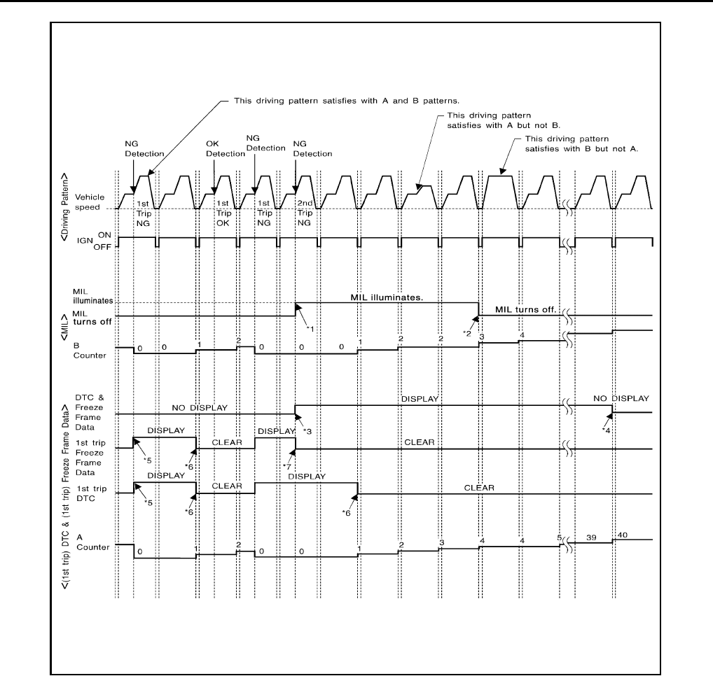
EC-1002
< FUNCTION DIAGNOSIS > [FOR MEXICO]
ON BOARD DIAGNOSTIC (OBD) SYSTEM
Explanation for Driving Patterns Except for “Misfire <Exhaust Quality Deterioration>”, “Fuel Injection System”
*1: When the same malfunction is de-
tected in two consecutive trips, MIL
will illuminate.
*2: MIL will turn off after vehicle is driven
3 times (pattern B) without any mal-
functions.
*3: When the same malfunction is de-
tected in two consecutive trips, the
DTC and the freeze frame data will be
stored in ECM.
*4: The DTC and the freeze frame data
will not be displayed any longer after
vehicle is driven 40 times (pattern A)
without the same malfunction.
(The DTC and the freeze frame data
still remain in ECM.)
*5: When a malfunction is detected for
the first time, the 1st trip DTC and the
1st trip freeze frame data will be
stored in ECM.
*6: 1st trip DTC will be cleared after vehi-
cle is driven once (pattern B) without
the same malfunction.
*7: When the same malfunction is de-
tected in the 2nd trip, the 1st trip
freeze frame data will be cleared.
JMBIA1418G
B
Revision: 2008 August 2009 Rogue
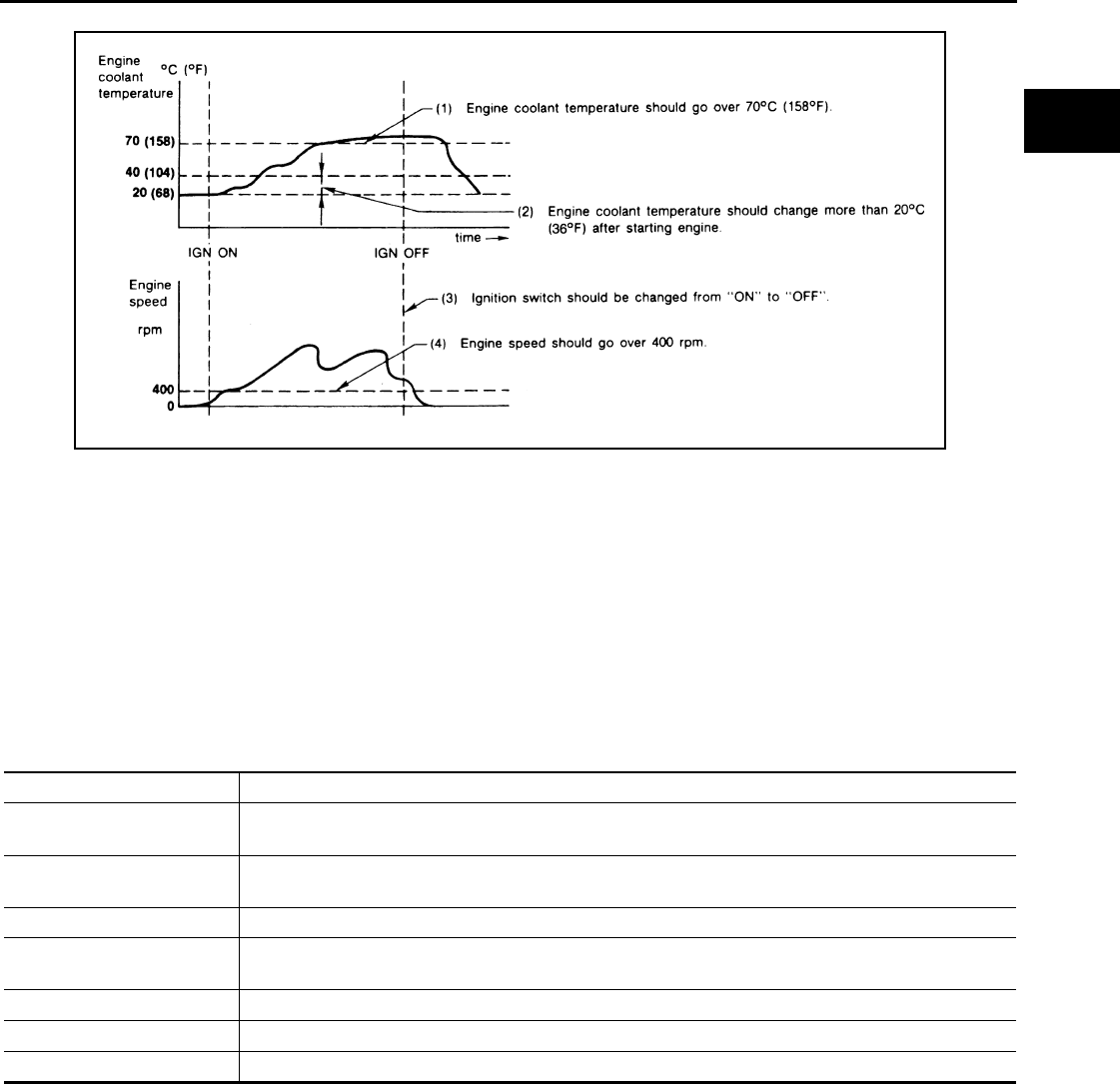
ON BOARD DIAGNOSTIC (OBD) SYSTEM
EC-1003
< FUNCTION DIAGNOSIS > [FOR MEXICO]
C
D
E
F
G
H
I
J
K
L
M
A
EC
N
P
O
<Driving Pattern A>
• The A counter will be cleared when the malfunction is detected regardless of (1) - (4).
• The A counter will be counted up when (1) - (4) are satisfied without the same malfunction.
• The DTC will not be displayed after the A counter reaches 40.
<Driving Pattern B>
Driving pattern B means operating vehicle as per the following:
All components and systems should be monitored at least once by the OBD system.
• The B counter will be cleared when the malfunction is detected once regardless of the driving pattern.
• The B counter will be counted up when driving pattern B is satisfied without any malfunctions.
• The MIL will turn off when the B counter reaches 3 (*2 in OBD SYSTEM OPERATION CHART).
CONSULT-III Function INFOID:0000000004494157
FUNCTION
*: The following emission-related diagnostic information is cleared when the ECM memory is erased.
• Diagnostic trouble codes
• 1st trip diagnostic trouble codes
• Freeze frame data
• 1st trip freeze frame data
• System readiness test (SRT) codes
•Test values
ENGINE CONTROL COMPONENT PARTS/CONTROL SYSTEMS APPLICATION
JMBIA1920G
B
Diagnostic test mode Function
Work Support This mode enables a technician to adjust some devices faster and more accurately by following the in-
dications on the CONSULT-III screen.
Self Diagnostic Result Self-diagnostic results such as 1st trip DTC, DTC and 1st trip freeze frame data or freeze frame data
can be read and erased quickly.*
Data Monitor Input/Output data in the ECM can be read.
Active Test Diagnostic Test Mode in which CONSULT-III drives some actuators apart from the ECMs and also shifts
some parameters in a specified range.
DTC & SRT Confirmation The status of system monitoring tests and the self-diagnosis status/results can be confirmed.
Function Test This mode is used to inform customers when their vehicle requires periodic maintenance.
ECU Part Number ECM part number can be read.
Revision: 2008 August 2009 Rogue
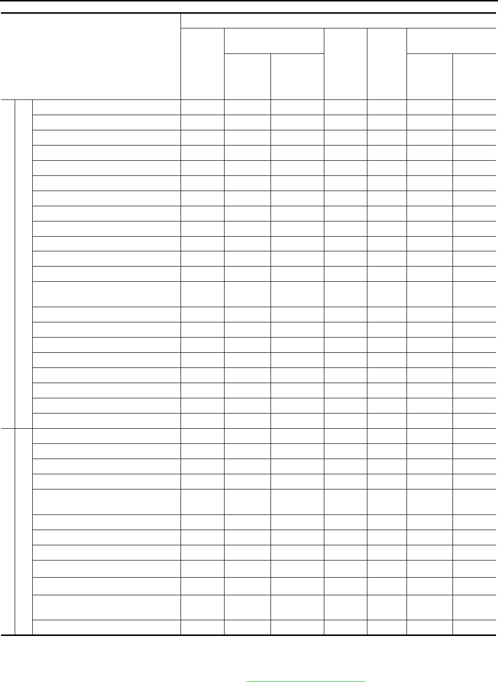
EC-1004
< FUNCTION DIAGNOSIS > [FOR MEXICO]
ON BOARD DIAGNOSTIC (OBD) SYSTEM
X: Applicable
*1: This item includes 1st trip DTCs.
*2: This mode includes 1st trip freeze frame data or freeze frame data. The items appear on CONSULT-III screen in freeze frame data
mode only if a 1st trip DTC or DTC is detected. For details, refer to EC-990, "Diagnosis Description".
*3: Always “CMPLT” is displayed.
Item
DIAGNOSTIC TEST MODE
Work
Support
Self Diagnostic Result
Data
Monitor Active
Test
DTC & SRT Confir-
mation
DTC*1 FREEZE
FRAME
DATA*2
SRT STA-
TUS
DTC
WORK
SUP-
PORT
ENGINE CONTROL COMPONENT PARTS
INPUT
Crankshaft position sensor (POS) ×××
Camshaft position sensor (PHASE) ×××
Mass air flow sensor ××
Engine coolant temperature sensor ××××
Air fuel ratio (A/F) sensor 1 ××××
Heated oxygen sensor 2 ××××
Vehicle speed signal ×××
Accelerator pedal position sensor ××
Throttle position sensor ×××
Intake air temperature sensor ××
Knock sensor ×
Refrigerant pressure sensor ×
Closed throttle position switch (accel-
erator pedal position sensor signal) ×
Air conditioner switch ×
Park/neutral position (PNP) switch ××
Stop lamp switch ××
Battery voltage ×
Load signal ×
Primary speed sensor ××
ASCD steering switch ××
ASCD brake switch ××
ENGINE COTNROL COMPONENT PARTS
OUTPUT
Fuel injector ××
Power transistor (Ignition timing) ××
Throttle control motor relay ××
Throttle control motor ×
EVAP canister purge volume control
solenoid valve ××××
Air conditioner relay ×
Fuel pump relay ×××
Cooling fan relay ×××
Air fuel ratio (A/F) sensor 1 heater ××
×*3
Heated oxygen sensor 2 heater ××
×*3
Intake valve timing control solenoid
valve ×××
Calculated load value ××
Revision: 2008 August 2009 Rogue

ON BOARD DIAGNOSTIC (OBD) SYSTEM
EC-1005
< FUNCTION DIAGNOSIS > [FOR MEXICO]
C
D
E
F
G
H
I
J
K
L
M
A
EC
N
P
O
WORK SUPPORT MODE
Work Item
*: This function is not necessary in the usual service procedure.
SELF-DIAGNOSTIC RESULT MODE
Self Diagnostic Item
Regarding items of DTC and 1st trip DTC, refer to EC-1257, "DTC Index".)
Freeze Frame Data and 1st Trip Freeze Frame Data
WORK ITEM CONDITION USAGE
FUEL PRESSURE RELEASE • FUEL PUMP WILL STOP BY TOUCHING “START” DUR-
ING IDLING.
CRANK A FEW TIMES AFTER ENGINE STALLS.
When releasing fuel pressure from
fuel line
IDLE AIR VOL LEARN • THE IDLE AIR VOLUME THAT KEEPS THE ENGINE
WITHIN THE SPECIFIED RANGE IS MEMORIZED IN
ECM.
When learning the idle air volume
SELF-LEARNING CONT • THE COEFFICIENT OF SELF-LEARNING CONTROL
MIXTURE RATIO RETURNS TO THE ORIGINAL COEF-
FICIENT.
When clearing mixture ratio self-
learning value
VIN REGISTRATION • IN THIS MODE, VIN IS REGISTERED IN ECM. When registering VIN in ECM
TARGET IDLE RPM ADJ* • IDLE CONDITION When setting target idle speed
TARGET IGN TIM ADJ* • IDLE CONDITION When adjusting target ignition tim-
ing
Freeze frame data item* Description
DIAG TROUBLE CODE
[PXXXX]
• The engine control component part/control system has a trouble code, it is displayed as PXXXX. (Refer
to EC-1257, "DTC Index".)
FUEL SYS-B1
• “Fuel injection system status” at the moment a malfunction is detected is displayed.
• One mode the following mode is displayed.
Mode2: Open loop due to detected system malfunction
Mode3: Open loop due to driving conditions (power enrichment, deceleration enleanment)
Mode4: Closed loop - using oxygen sensor(s) as feedback for fuel control
Mode5: Open loop - has not yet satisfied condition to go to closed loop
CAL/LD VALUE [%] • The calculated load value at the moment a malfunction is detected is displayed.
COOLANT TEMP
[°C] or [°F] • The engine coolant temperature at the moment a malfunction is detected is displayed.
L-FUEL TRM-B1 [%]
• “Long-term fuel trim” at the moment a malfunction is detected is displayed.
• The long-term fuel trim indicates much more gradual feedback compensation to the base fuel schedule
than short-term fuel trim.
S-FUEL TRM-B1 [%] • “Short-term fuel trim” at the moment a malfunction is detected is displayed.
• The short-term fuel trim indicates dynamic or instantaneous feedback compensation to the base fuel
schedule.
ENGINE SPEED [rpm] • The engine speed at the moment a malfunction is detected is displayed.
VEHICL SPEED
[km/h] or [mph] • The vehicle speed at the moment a malfunction is detected is displayed.
ABSOL TH·P/S [%] • The throttle valve opening angle at the moment a malfunction is detected is displayed.
B/FUEL SCHDL [msec] • The base fuel schedule at the moment a malfunction is detected is displayed.
INT/A TEMP SE
[°C] or [°F] • The intake air temperature at the moment a malfunction is detected is displayed.
Revision: 2008 August 2009 Rogue

EC-1006
< FUNCTION DIAGNOSIS > [FOR MEXICO]
ON BOARD DIAGNOSTIC (OBD) SYSTEM
*: The items are the same as those of 1st trip freeze frame data.
DATA MONITOR MODE
Monitored Item
FUEL SYS-B2
• These items are displayed but are not applicable to this model.
L-FUEL TRM-B2 [%]
S-FUEL TRM-B2 [%]
INT MANI PRES [kPa]
COMBUST CONDITION
Freeze frame data item* Description
Monitored item Unit Description Remarks
ENG SPEED rpm
• Indicates the engine speed computed from the
signal of the crankshaft position sensor (POS)
and camshaft position sensor (PHASE).
• Accuracy becomes poor if engine
speed drops below the idle rpm.
• If the signal is interrupted while the
engine is running, an abnormal value
may be indicated.
MAS A/F SE-B1 V • The signal voltage of the mass air flow sensor is
displayed.
• When the engine is stopped, a certain
value is indicated.
• When engine is running specification
range is indicated in “SPEC”.
B/FUEL SCHDL msec
• “Base fuel schedule” indicates the fuel injection
pulse width programmed into ECM, prior to any
learned on board correction.
• When engine is running specification
range is indicated in “SPEC”.
A/F ALPHA-B1 % • The mean value of the air-fuel ratio feedback cor-
rection factor per cycle is indicated.
• When the engine is stopped, a certain
value is indicated.
• When engine is running specification
range is indicated in “SPEC”.
• This data also includes the data for
the air-fuel ratio learning control.
COOLAN TEMP/S °C or °F• The engine coolant temperature (determined by
the signal voltage of the engine coolant tempera-
ture sensor) is displayed.
• When the engine coolant temperature
sensor is open or short-circuited,
ECM enters fail-safe mode. The en-
gine coolant temperature determined
by the ECM is displayed.
A/F SEN1 (B1) V • The A/F signal computed from the input signal of
the air fuel ratio (A/F) sensor 1 is displayed.
HO2S2 (B1) V • The signal voltage of the heated oxygen sensor 2
is displayed.
HO2S2 MNTR(B1) RICH/LEAN
• Display of heated oxygen sensor 2 signal:
RICH: means the amount of oxygen after three
way catalyst is relatively small.
LEAN: means the amount of oxygen after three
way catalyst is relatively large.
• When the engine is stopped, a certain
value is indicated.
VHCL SPEED SE km/h or mph
• The vehicle speed computed from the vehicle
speed signal sent from combination meter is dis-
played.
BATTERY VOLT V • The power supply voltage of ECM is displayed.
ACCEL SEN 1
V• The accelerator pedal position sensor signal volt-
age is displayed.
• ACCEL SEN 2 signal is converted by
ECM internally. Thus, it differs from
ECM terminal voltage signal.
ACCEL SEN 2
TP SEN 1-B1 V• The throttle position sensor signal voltage is dis-
played.
• TP SEN 2-B1 signal is converted by
ECM internally. Thus, it differs from
ECM terminal voltage signal.
TP SEN 2-B1
INT/A TEMP SE °C or °F
• The intake air temperature (determined by the
signal voltage of the intake air temperature sen-
sor) is indicated.
Revision: 2008 August 2009 Rogue

ON BOARD DIAGNOSTIC (OBD) SYSTEM
EC-1007
< FUNCTION DIAGNOSIS > [FOR MEXICO]
C
D
E
F
G
H
I
J
K
L
M
A
EC
N
P
O
START SIGNAL ON/OFF • Indicates start signal status [ON/OFF] computed
by the ECM according to the signals of engine
speed and battery voltage.
• After starting the engine, [OFF] is dis-
played regardless of the starter sig-
nal.
CLSD THL POS ON/OFF
• Indicates idle position [ON/OFF] computed by
ECM according to the accelerator pedal position
sensor signal.
AIR COND SIG ON/OFF
• Indicates [ON/OFF] condition of the air condition-
er switch as determined by the air conditioner sig-
nal.
P/N POSI SW ON/OFF • Indicates [ON/OFF] condition from the park/neu-
tral position (PNP) switch signal.
PW/ST SIGNAL ON/OFF
• [ON/OFF] condition of the power steering system
(determined by the signal sent from EPS control
unit) is indicated.
LOAD SIGNAL ON/OFF
• Indicates [ON/OFF] condition from the electrical
load signal.
ON: Rear window defogger switch is ON and/or
lighting switch is in 2nd position.
OFF: Both rear window defogger switch and light-
ing switch are OFF.
IGNITION SW ON/OFF • Indicates [ON/OFF] condition from ignition switch
signal.
HEATER FAN SW ON/OFF • Indicates [ON/OFF] condition from the heater fan
switch signal.
BRAKE SW ON/OFF • Indicates [ON/OFF] condition from the stop lamp
switch signal.
INJ PULSE-B1 msec
• Indicates the actual fuel injection pulse width
compensated by ECM according to the input sig-
nals.
• When the engine is stopped, a certain
computed value is indicated.
IGN TIMING BTDC • Indicates the ignition timing computed by ECM
according to the input signals.
• When the engine is stopped, a certain
value is indicated.
CAL/LD VALUE % • “Calculated load value” indicates the value of the
current air flow divided by peak air flow.
MASS AIRFLOW g·m/s • Indicates the mass air flow computed by ECM ac-
cording to the signal voltage of the mass air flow
sensor.
PURG VOL C/V %
• Indicates the EVAP canister purge volume con-
trol solenoid valve control value computed by the
ECM according to the input signals.
• The opening becomes larger as the value in-
creases.
INT/V TIM (B1) °CA • Indicates [°CA] of intake camshaft advance an-
gle.
INT/V SOL(B1) %
• The control value of the intake valve timing con-
trol solenoid valve (determined by ECM accord-
ing to the input signals) is indicated.
• The advance angle becomes larger as the value
increases.
AIR COND RLY ON/OFF
• The air conditioner relay control condition (deter-
mined by ECM according to the input signals) is
indicated.
FUEL PUMP RLY ON/OFF • Indicates the fuel pump relay control condition
determined by ECM according to the input sig-
nals.
THRTL RELAY ON/OFF
• Indicates the throttle control motor relay control
condition determined by the ECM according to
the input signals.
Monitored item Unit Description Remarks
Revision: 2008 August 2009 Rogue

EC-1008
< FUNCTION DIAGNOSIS > [FOR MEXICO]
ON BOARD DIAGNOSTIC (OBD) SYSTEM
COOLING FAN HI/LOW/OFF
• Indicates the condition of the cooling fan (deter-
mined by ECM according to the input signals).
HI: High speed operation
LOW: Low speed operation
OFF: Stop
HO2S2 HTR (B1) ON/OFF
• Indicates [ON/OFF] condition of heated oxygen
sensor 2 heater determined by ECM according to
the input signals.
I/P PULLY SPD rpm • Indicates the engine speed computed from the
turbine revolution sensor signal.
VEHICLE SPEED km/h or mph • The vehicle speed computed from the vehicle
speed signal sent from TCM is displayed.
IDL A/V LEARN YET/CMPLT
• Display the condition of Idle Air Volume Learning
YET: Idle air volume learning has not been per-
formed yet.
CMPLT: Idle air volume learning has already
been performed successfully.
TRVL AFTER MIL km or mile • Distance traveled while MIL is activated.
A/F S1 HTR(B1) %
• Air fuel ratio (A/F) sensor 1 heater control value
computed by ECM according to the input signals.
• The current flow to the heater becomes larger as
the value increases.
AC PRESS SEN V • The signal voltage from the refrigerant pressure
sensor is displayed.
VHCL SPEED SE km/h or mph
• The vehicle speed computed from the vehicle
speed signal sent from combination meter is dis-
played.
SET VHCL SPD km/h or mph • The preset vehicle speed is displayed.
MAIN SW ON/OFF • Indicates [ON/OFF] condition from MAIN switch
signal.
CANCEL SW ON/OFF • Indicates [ON/OFF] condition from CANCEL
switch signal.
RESUME/ACC SW ON/OFF • Indicates [ON/OFF] condition from RESUME/AC-
CELERATE switch signal.
SET SW ON/OFF • Indicates [ON/OFF] condition from SET/COAST
switch signal.
BRAKE SW1 ON/OFF • Indicates [ON/OFF] condition from ASCD brake
switch signal.
BRAKE SW2 ON/OFF • Indicates [ON/OFF] condition of stop lamp switch
signal.
VHCL SPD CUT NON/CUT
• Indicates the vehicle cruise condition.
NON: Vehicle speed is maintained at the ASCD
set speed.
CUT: Vehicle speed decreased to excessively
low compared with the ASCD set speed, and
ASCD operation is cut off.
LO SPEED CUT NON/CUT
• Indicates the vehicle cruise condition.
NON: Vehicle speed is maintained at the ASCD
set speed.
CUT: Vehicle speed decreased to excessively
low, and ASCD operation is cut off.
AT OD MONITOR ON/OFF • Indicates [ON/OFF] condition of A/T O/D accord-
ing to the input signal from the TCM.
AT OD CANCEL ON/OFF • Indicates [ON/OFF] condition of A/T O/D cancel
request signal.
Monitored item Unit Description Remarks
Revision: 2008 August 2009 Rogue

ON BOARD DIAGNOSTIC (OBD) SYSTEM
EC-1009
< FUNCTION DIAGNOSIS > [FOR MEXICO]
C
D
E
F
G
H
I
J
K
L
M
A
EC
N
P
O
NOTE:
Any monitored item that does not match the vehicle being diagnosed is deleted from the display automatically.
ACTIVE TEST MODE
Test Item
*: Leaving cooling fan OFF with CONSULT-III while engine is running may cause the engine to overheat.
DTC & SRT CONFIRMATION MODE
SRT STATUS Mode
CRUISE LAMP ON/OFF • Indicates [ON/OFF] condition of CRUISE lamp
determined by the ECM according to the input
signals.
SET LAMP ON/OFF • Indicates [ON/OFF] condition of SET lamp deter-
mined by the ECM according to the input signals.
A/F ADJ-B1 —
• Indicates the correction of factor stored in ECM.
The factor is calculated from the difference be-
tween the target air-fuel ratio stored in ECM and
the air-fuel ratio calculated from A/F sensor 1 sig-
nal.
Monitored item Unit Description Remarks
TEST ITEM CONDITION JUDGMENT CHECK ITEM (REMEDY)
FUEL INJECTION
• Engine: Return to the original
trouble condition
• Change the amount of fuel injec-
tion using CONSULT-III.
If trouble symptom disappears, see
CHECK ITEM.
• Harness and connectors
• Fuel injector
• Air fuel ratio (A/F) sensor 1
IGNITION TIMING
• Engine: Return to the original
trouble condition
• Timing light: Set
• Retard the ignition timing using
CONSULT-III.
If trouble symptom disappears, see
CHECK ITEM.
• Perform Idle Air Volume Learn-
ing.
POWER BALANCE
• Engine: After warming up, idle the
engine.
• A/C switch OFF
• Selector lever position: P or N
• Cut off each fuel injector signal
one at a time using CONSULT-III.
Engine runs rough or stops.
• Harness and connectors
• Compression
• Fuel injector
• Power transistor
•Spark plug
•Ignition coil
COOLING FAN*
• Ignition switch: ON
• Turn the cooling fan “LOW”, “HI”
and “OFF” using CONSULT-III.
Cooling fan moves and stops.
• Harness and connectors
• IPDM E/R (Cooling fan relay)
• Cooling fan motor
ENG COOLANT
TEMP
• Engine: Return to the original
trouble condition
• Change the engine coolant tem-
perature using CONSULT-III.
If trouble symptom disappears, see
CHECK ITEM.
• Harness and connectors
• Engine coolant temperature
sensor
• Fuel injector
FUEL PUMP RELAY
• Ignition switch: ON (Engine
stopped)
• Turn the fuel pump relay “ON”
and “OFF” using CONSULT-III
and listen to operating sound.
Fuel pump relay makes the operat-
ing sound.
• Harness and connectors
•Fuel pump relay
PURG VOL CONT/V
• Engine: After warming up, run en-
gine at 1,500 rpm.
• Change the EVAP canister purge
volume control solenoid valve
opening percent using CON-
SULT-III.
Engine speed changes according
to the opening percent.
• Harness and connectors
• Solenoid valve
V/T ASSIGN ANGLE
• Engine: Return to the original
trouble condition
• Change intake valve timing using
CONSULT-III.
If trouble symptom disappears, see
CHECK ITEM.
• Harness and connectors
• Intake valve timing control sole-
noid valve
Revision: 2008 August 2009 Rogue
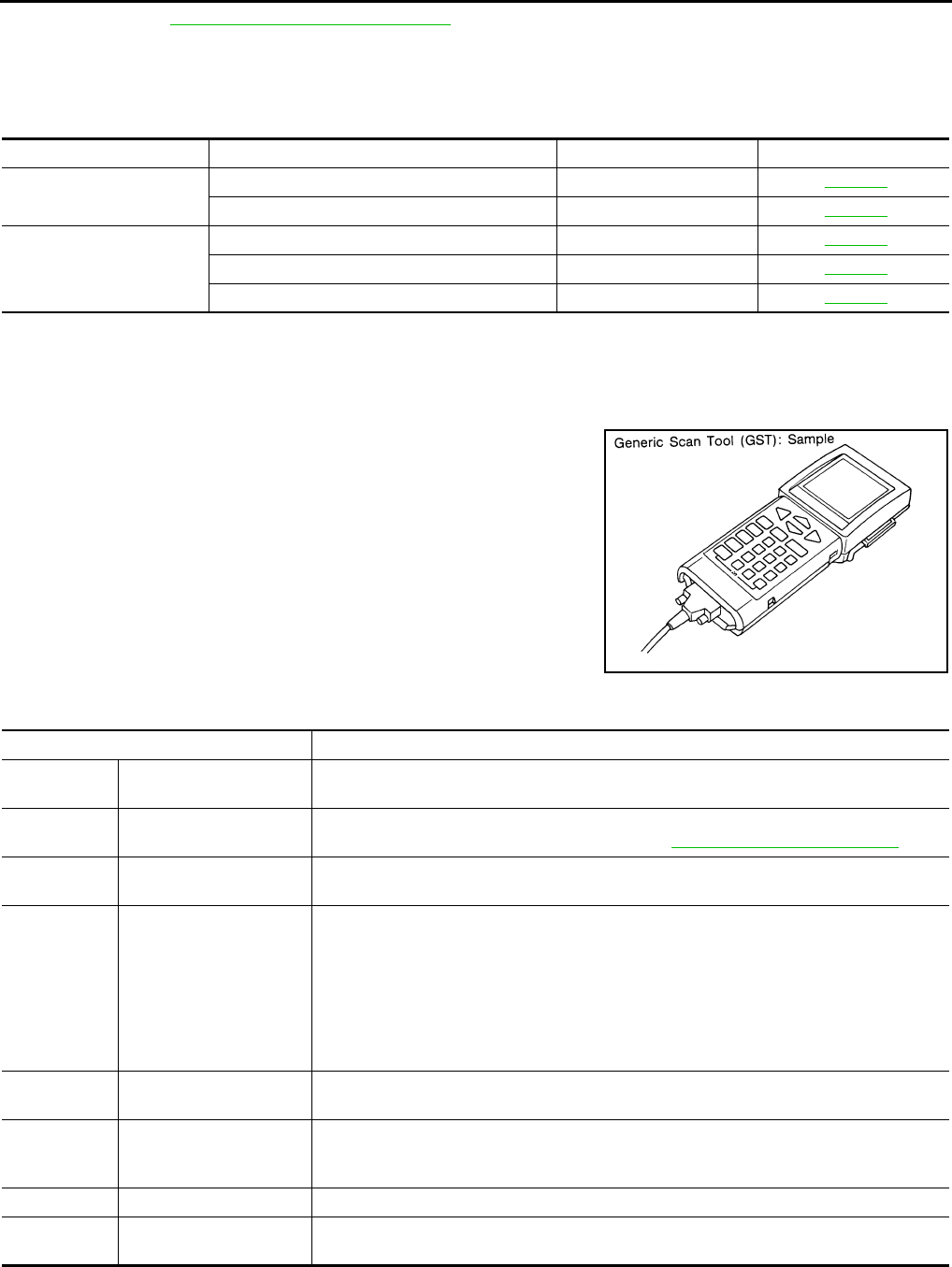
EC-1010
< FUNCTION DIAGNOSIS > [FOR MEXICO]
ON BOARD DIAGNOSTIC (OBD) SYSTEM
For details, refer to EC-990, "Diagnosis Description".
SRT WORK SUPPORT Mode
This mode enables a technician to drive a vehicle to set the SRT while monitoring the SRT status.
DTC WORK SUPPORT Mode
*: DTC P1442 and P1456 does not apply to S35 models but appears in DTC Work Support Mode screens.
Diagnosis Tool Function INFOID:0000000004494158
DESCRIPTION
Generic Scan Tool (OBD II scan tool) complying with ISO 15031-4
has several functions explained below.
ISO 15765-4 is used as the protocol.
The name “GST” or “Generic Scan Tool” is used in this service man-
ual.
FUNCTION
INSPECTION PROCEDURE
1. Turn ignition switch OFF.
Test mode Test item Corresponding DTC No. Reference page
A/F SEN1 A/F SEN1(B1) P1278/P1279 P0133 EC-1078
A/F SEN1(B1) P1276 P0130 EC-1068
HO2S2
HO2S2(B1) P1146 P0138 EC-1089
HO2S2(B1) P1147 P0137 EC-1083
HO2S2(B1) P0139 P0139 EC-1096
SEF139P
Diagnostic Service Function
Service $01 READINESS TESTS This diagnostic service gains access to current emission-related data values, including an-
alog inputs and outputs, digital inputs and outputs, and system status information.
Service $02 (FREEZE DATA) This diagnostic service gains access to emission-related data value that were stored by
ECM during the freeze frame. For details, refer to EC-990, "Diagnosis Description".
Service $03 DTCs This diagnostic service gains access to emission-related power train trouble codes which
were stored by ECM.
Service $04 CLEAR DIAG INFO
This diagnostic service can clear all emission-related diagnostic information. This in-
cludes:
• Clear number of diagnostic trouble codes (Service $01)
• Clear diagnostic trouble codes (Service $03)
• Clear trouble code for freeze frame data (Service $01)
• Clear freeze frame data (Service $02)
• Reset status of system monitoring test (Service $01)
• Clear on board monitoring test results (Service $06 and $07)
Service $06 (ON BOARD TESTS) This diagnostic service accesses the results of on board diagnostic monitoring tests of
specific components/systems that are not continuously monitored.
Service $07 (ON BOARD TESTS)
This diagnostic service enables the off board test drive to obtain test results for emission-
related powertrain components/systems that are continuously monitored during normal
driving conditions.
Service $08 — This diagnostic service is not applicable on this vehicle.
Service $09 (CALIBRATION ID) This diagnostic service enables the off-board test device to request specific vehicle infor-
mation such as Vehicle Identification Number (VIN) and Calibration IDs.
Revision: 2008 August 2009 Rogue

ON BOARD DIAGNOSTIC (OBD) SYSTEM
EC-1011
< FUNCTION DIAGNOSIS > [FOR MEXICO]
C
D
E
F
G
H
I
J
K
L
M
A
EC
N
P
O
2. Connect “GST” to data link connector (1), which is located under
LH dash panel.
3. Turn ignition switch ON.
4. Enter the program according to instruction on the screen or in
the operation manual.
(*: Regarding GST screens in this section, sample screens are
shown.)
5. Perform each diagnostic mode according to each service proce-
dure.
For further information, see the GST Operation Manual of
the tool maker.
JMBIA1073ZZ
SEF398S
SEF416S
Revision: 2008 August 2009 Rogue

EC-1012
< COMPONENT DIAGNOSIS > [FOR MEXICO]
TROUBLE DIAGNOSIS - SPECIFICATION VALUE
COMPONENT DIAGNOSIS
TROUBLE DIAGNOSIS - SPECIFICATION VALUE
Description INFOID:0000000004494159
The specification (SP) value indicates the tolerance of the value that is displayed in “SPEC” of “DATA MONI-
TOR” mode of CONSULT-III during normal operation of the Engine Control System. When the value in “SPEC”
of “DATA MONITOR” mode is within the SP value, the Engine Control System is confirmed OK. When the
value in “SPEC” of “DATA MONITOR” mode is NOT within the SP value, the Engine Control System may have
one or more malfunctions.
The SP value is used to detect malfunctions that may affect the Engine Control System, but will not illuminate
the MIL.
The SP value will be displayed for the following three items:
• B/FUEL SCHDL (The fuel injection pulse width programmed into ECM prior to any learned on board correc-
tion)
• A/F ALPHA-B1 (The mean value of air-fuel ratio feedback correction factor per cycle)
• MAS A/F SE-B1 (The signal voltage of the mass air flow sensor)
Component Function Check INFOID:0000000004494160
1.START
Check that all of the following conditions are satisfied.
• Vehicle driven distance: More than 5,000 km (3,107 miles)
• Barometric pressure: 98.3 - 104.3 kPa (1.003 - 1.064 kg/cm2, 14.25 - 15.12 psi)
• Atmospheric temperature: 20 - 30°C (68 - 86°F)
• Engine coolant temperature: 75 - 95°C (167 - 203°F)
• Engine speed: Idle
• Transmission: Warmed-up
- After the engine is warmed up to normal operating temperature, drive vehicle until “FLUID TEMP SE” (CVT
fluid temperature sensor signal) indicates more than 60°C (140°F).
• Electrical load: Not applied
- Rear window defogger switch and air conditioner switch lighting switch are OFF. Steering wheel is straight
ahead.
>> GO TO 2.
2.PERFORM “SPEC” OF “DATA MONITOR” MODE
With CONSULT-III
NOTE:
Perform “SPEC” in “DATA MONITOR” mode in maximum scale display.
1. Perform EC-933, "BASIC INSPECTION : Special Repair Requirement".
2. Select “B/FUEL SCHDL”, “A/F ALPHA-B1” and “MAS A/F SE-B1” in “SPEC” of “DATA MONITOR” mode
with CONSULT-III.
3. Check that monitor items are within the SP value.
Is the inspection result normal?
YES >> END
NO >> Go to EC-1013, "Diagnosis Procedure".
Revision: 2008 August 2009 Rogue
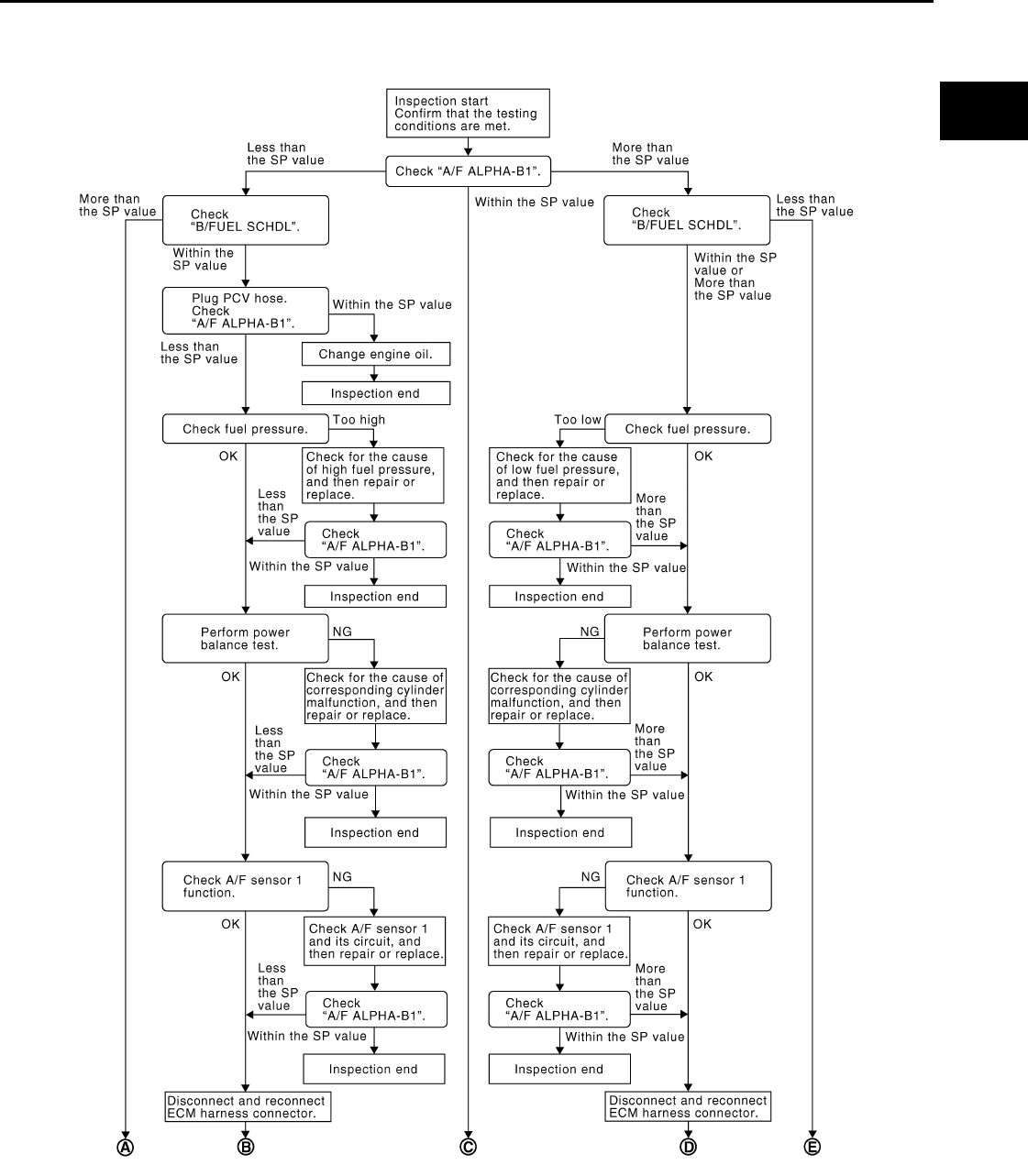
TROUBLE DIAGNOSIS - SPECIFICATION VALUE
EC-1013
< COMPONENT DIAGNOSIS > [FOR MEXICO]
C
D
E
F
G
H
I
J
K
L
M
A
EC
N
P
O
Diagnosis Procedure INFOID:0000000004494161
OVERALL SEQUENCE
PBIB2318E
Revision: 2008 August 2009 Rogue

EC-1014
< COMPONENT DIAGNOSIS > [FOR MEXICO]
TROUBLE DIAGNOSIS - SPECIFICATION VALUE
DETAILED PROCEDURE
1.CHECK “A/F ALPHA-B1”
With CONSULT-III
1. Start engine.
2. Confirm that the testing conditions are met. Refer to EC-1012, "Component Function Check".
3. Select “A/F ALPHA-B1” in “SPEC” of “DATA MONITOR” mode, and check that the each indication is
within the SP value.
PBIB3213E
Revision: 2008 August 2009 Rogue

TROUBLE DIAGNOSIS - SPECIFICATION VALUE
EC-1015
< COMPONENT DIAGNOSIS > [FOR MEXICO]
C
D
E
F
G
H
I
J
K
L
M
A
EC
N
P
O
NOTE:
Check “A/F ALPHA-B1” for approximately 1 minute because they may fluctuate. It is NG if the indication is
out of the SP value even a little.
Is the measurement value within the SP value?
YES >> GO TO 17.
NO-1 >> Less than the SP value: GO TO 2.
NO-2 >> More than the SP value: GO TO 3.
2.CHECK “B/FUEL SCHDL”
Select “B/FUEL SCHDL” in “SPEC” of “DATA MONITOR” mode, and check that the indication is within the SP
value.
Is the measurement value within the SP value?
YES >> GO TO 4.
NO >> More than the SP value: GO TO 19.
3.CHECK “B/FUEL SCHDL”
Select “B/FUEL SCHDL” in “SPEC” of “DATA MONITOR” mode, and check that the indication is within the SP
value.
Is the measurement value within the SP value?
YES >> GO TO 6.
NO-1 >> More than the SP value: GO TO 6.
NO-2 >> Less than the SP value: GO TO 25.
4.CHECK “A/F ALPHA-B1”
1. Stop the engine.
2. Disconnect PCV hose, and then plug it.
3. Start engine.
4. Select “A/F ALPHA-B1” in “SPEC” of “DATA MONITOR” mode, and check that the indication is within the
SP value.
Is the measurement value within the SP value?
YES >> GO TO 5.
NO >> GO TO 6.
5.CHANGE ENGINE OIL
1. Stop the engine.
2. Change engine oil.
NOTE:
This symptom may occur when a large amount of gasoline is mixed with engine oil because of driving
conditions (such as when engine oil temperature does not rise enough since a journey distance is too
short during winter). The symptom will not be detected after changing engine oil or changing driving con-
ditions.
>> INSPECTION END
6.CHECK FUEL PRESSURE
Check fuel pressure. (Refer to EC-1279, "Inspection".)
Is the inspection result normal?
YES >> GO TO 9.
NO-1 >> Fuel pressure is too high: Replace “fuel filter and fuel pump assembly” and then GO TO 8.
NO-2 >> Fuel pressure is too low: GO TO 7.
7.DETECT MALFUNCTIONING PART
Check fuel hoses and fuel tubes for clogging
Is the inspection result normal?
YES >> Replace “fuel filter and fuel pump assembly” and then GO TO 8.
NO >> Repair or replace and then GO TO 8.
8.CHECK “A/F ALPHA-B1”
Revision: 2008 August 2009 Rogue

EC-1016
< COMPONENT DIAGNOSIS > [FOR MEXICO]
TROUBLE DIAGNOSIS - SPECIFICATION VALUE
1. Start engine.
2. Select “A/F ALPHA-B1” in “SPEC” of “DATA MONITOR” mode, and check that the indication is within the
SP value.
Is the measurement value within the SP value?
YES >> INSPECTION END
NO >> GO TO 9.
9.PERFORM POWER BALANCE TEST
1. Perform “POWER BALANCE” in “ACTIVE TEST” mode.
2. Check that the each cylinder produces a momentary engine speed drop.
Is the inspection result normal?
YES >> GO TO 12.
NO >> GO TO 10.
10.DETECT MALFUNCTIONING PART
Check the following below.
1. Ignition coil and its circuit (Refer to EC-1223, "Component Function Check".)
2. Fuel injector and its circuit (Refer to EC-1217, "Component Function Check".)
3. Intake air leakage
4. Low compression pressure (Refer to EM-23, "Inspection".)
Is the inspection result normal?
YES >> Replace fuel injector and then GO TO 11.
NO >> Repair or replace malfunctioning part and then GO TO 11.
11.CHECK “A/F ALPHA-B1”
1. Start engine.
2. Select “A/F ALPHA-B1” in “SPEC” of “DATA MONITOR” mode, and check that each indication is within
the SP value.
Is the measurement value within the SP value?
YES >> INSPECTION END
NO >> GO TO 12.
12.CHECK A/F SENSOR 1 FUNCTION
Perform all DTC CONFIRMATION PROCEDURE related with A/F sensor 1.
• For DTC P0130, refer to EC-1068, "DTC Logic".
• For DTC P0131, refer to EC-1072, "DTC Logic".
• For DTC P0132, refer to EC-1075, "DTC Logic".
• For DTC P0133, refer to EC-1078, "DTC Logic".
• For DTC P2A00, refer to EC-1202, "DTC Logic".
Are any DTC detected?
YES >> GO TO 15.
NO >> GO TO 13.
13.CHECK A/F SENSOR 1 CIRCUIT
Perform DIAGNOSTIC PROCEDURE according to corresponding DTC.
>> GO TO 14.
14.CHECK “A/F ALPHA-B1”
1. Start engine.
2. Select “A/F ALPHA-B1” in “SPEC” of “DATA MONITOR” mode, and check that each indication is within
the SP value.
Is the measurement value within the SP value?
YES >> INSPECTION END
NO >> GO TO 15.
15.DISCONNECT AND RECONNECT ECM HARNESS CONNECTOR
1. Stop the engine.
Revision: 2008 August 2009 Rogue

TROUBLE DIAGNOSIS - SPECIFICATION VALUE
EC-1017
< COMPONENT DIAGNOSIS > [FOR MEXICO]
C
D
E
F
G
H
I
J
K
L
M
A
EC
N
P
O
2. Disconnect ECM harness connector. Check pin terminal and connector for damage, and then reconnect it.
>> GO TO 16.
16.CHECK “A/F ALPHA-B1”
1. Start engine.
2. Select “A/F ALPHA-B1” in “SPEC” of “DATA MONITOR” mode, and check that each indication is within
the SP value.
Is the measurement value within the SP value?
YES >> INSPECTION END
NO >> Detect malfunctioning part according to EC-1268, "Symptom Table".
17.CHECK “B/FUEL SCHDL”
Select “B/FUEL SCHDL” in “SPEC” of “DATA MONITOR” mode, and check that each indication is within the
SP value.
Is the measurement value within the SP value?
YES >> INSPECTION END
NO-1 >> More than the SP value: GO TO 18.
NO-2 >> Less than the SP value: GO TO 25.
18.DETECT MALFUNCTIONING PART
1. Check for the cause of large engine friction. Refer to the following.
- Engine oil level is too high
- Engine oil viscosity
- Belt tension of power steering, alternator, A/C compressor, etc. is excessive
- Noise from engine
- Noise from transmission, etc.
2. Check for the cause of insufficient combustion. Refer to the following.
- Valve clearance malfunction
- Intake valve timing control function malfunction
- Camshaft sprocket installation malfunction, etc.
>> Repair or replace malfunctioning part, and then GO TO 30.
19.CHECK INTAKE SYSTEM
Check for the cause of uneven air flow through mass air flow sensor. Refer to the following.
• Crushed air ducts
• Malfunctioning seal of air cleaner element
• Uneven dirt of air cleaner element
• Improper specification of intake air system
Is the inspection result normal?
YES >> GO TO 21.
NO >> Repair or replace malfunctioning part, and then GO TO 20.
20.CHECK “A/F ALPHA-B1”, AND “B/FUEL SCHDL”
Select “A/F ALPHA-B1” and “B/FUEL SCHDL” in “SPEC” of “DATA MONITOR” mode, and check that each
indication is within the SP value.
Is the measurement value within the SP value?
YES >> INSPECTION END
NO >> “B/FUEL SCHDL” is more, “A/F ALPHA-B1” is less than the SP value: GO TO 21.
21.DISCONNECT AND RECONNECT MASS AIR FLOW SENSOR HARNESS CONNECTOR
1. Stop the engine.
2. Disconnect mass air flow sensor harness connector. Check pin terminal and connector for damage and
then reconnect it again.
>> GO TO 22.
Revision: 2008 August 2009 Rogue

EC-1018
< COMPONENT DIAGNOSIS > [FOR MEXICO]
TROUBLE DIAGNOSIS - SPECIFICATION VALUE
22.CHECK “A/F ALPHA-B1”
1. Start engine.
2. Select “A/F ALPHA-B1” in “SPEC” of “DATA MONITOR” mode, and check that each indication is within
the SP value.
Is the measurement value within the SP value?
YES >> Detect malfunctioning part of mass air flow sensor circuit and repair it. Refer to EC-1040, "DTC
Logic". Then GO TO 29.
NO >> GO TO 23.
23.CHECK “MAS A/F SE-B1”
Select “MAS A/F SE-B1” in “SPEC” of “DATA MONITOR” mode, and check that each indication is within the
SP value.
Is the measurement value within the SP value?
YES >> GO TO 24.
NO >> More than the SP value: Replace mass air flow sensor, and then GO TO 29.
24.REPLACE ECM
1. Replace ECM.
2. Go to EC-936, "ADDITIONAL SERVICE WHEN REPLACING CONTROL UNIT : Special Repair Require-
ment".
>> GO TO 29.
25.CHECK INTAKE SYSTEM
Check for the cause of uneven air flow through mass air flow sensor. Refer to the following.
• Crushed air ducts
• Malfunctioning seal in air cleaner element
• Uneven dirt in air cleaner element
• Improper specification in intake air system
Is the inspection result normal?
YES >> GO TO 27.
NO >> Repair or replace malfunctioning part, and then GO TO 26.
26.CHECK “B/FUEL SCHDL”
Select “B/FUEL SCHDL” in “SPEC” of “DATA MONITOR” mode, and check that each indication is within the
SP value.
Is the measurement value within the SP value?
YES >> INSPECTION END
NO >> Less than the SP value: GO TO 27.
27.CHECK “MAS A/F SE-B1”
Select “MAS A/F SE-B1” in “SPEC” of “DATA MONITOR” mode, and check that each indication is within the
SP value.
Is the measurement value within the SP value?
YES >> GO TO 28.
NO >> Less than the SP value: Replace mass air flow sensor, and then GO TO 30.
28.CHECK INTAKE SYSTEM
Check for the cause of air leak after the mass air flow sensor. Refer to the following.
• Disconnection, looseness, and cracks in air duct
• Looseness of oil filler cap
• Disconnection of oil level gauge
• Open stuck, breakage, hose disconnection, or cracks in PCV valve
• Disconnection or cracks in EVAP purge hose, open stuck of EVAP canister purge volume control solenoid
valve
• Malfunctioning seal in rocker cover gasket
• Disconnection, looseness, or cracks in hoses, such as vacuum hose, connecting to intake air system parts
Revision: 2008 August 2009 Rogue

TROUBLE DIAGNOSIS - SPECIFICATION VALUE
EC-1019
< COMPONENT DIAGNOSIS > [FOR MEXICO]
C
D
E
F
G
H
I
J
K
L
M
A
EC
N
P
O
• Malfunctioning seal in intake air system, etc.
>> GO TO 30.
29.CHECK “A/F ALPHA-B1” AND “B/FUEL SCHDL”
Select “A/F ALPHA-B1” and “B/FUEL SCHDL” in “SPEC” of “DATA MONITOR” mode, and check that each
indication is within the SP value.
Is the measurement value within the SP value?
YES >> INSPECTION END
NO >> Detect malfunctioning part according to EC-1268, "Symptom Table".
30.CHECK “B/FUEL SCHDL”
Select “B/FUEL SCHDL” in “SPEC” of “DATA MONITOR” mode, and then check that each indication is within
the SP value.
Is the measurement value within the SP value?
YES >> INSPECTION END
NO >> Detect malfunctioning part according to EC-1268, "Symptom Table".
Revision: 2008 August 2009 Rogue

EC-1020
< COMPONENT DIAGNOSIS > [FOR MEXICO]
POWER SUPPLY AND GROUND CIRCUIT
POWER SUPPLY AND GROUND CIRCUIT
Diagnosis Procedure INFOID:0000000004494162
1.INSPECTION START
Start engine.
Is engine running?
YES >> GO TO 8.
NO >> GO TO 2.
2.CHECK ECM POWER SUPPLY CIRCUIT-I
1. Turn ignition switch OFF and then ON.
2. Check the voltage between ECM harness connector and ground.
Is the inspection result normal?
YES >> GO TO 4.
NO >> GO TO 3.
3.DETECT MALFUNCTIONING PART
Check the following.
• IPDM E/R harness connector E14
• 15A fuse (No. 64)
• Harness for open or short between ECM and fuse
>> Repair open circuit or short to ground or short to power in harness or connectors.
4.CHECK GROUND CONNECTION-I
1. Turn ignition switch OFF.
2. Check ground connection E21. Refer to Ground Inspection in GI-44, "Circuit Inspection".
Is the inspection result normal?
YES >> GO TO 5.
NO >> Repair or replace ground connection.
5.CHECK ECM GROUND CIRCUIT FOR OPEN AND SHORT-I
1. Disconnect ECM harness connectors.
2. Check the continuity between ECM harness connector and ground.
3. Also check harness for short to power.
Is the inspection result normal?
YES >> GO TO 7.
NO >> GO TO 6.
ECM Ground Voltage
Connector Terminal
E16 93 Ground Battery voltage
ECM Ground Continuity
Connector Terminal
F7 12
Ground Existed
16
E16
107
108
111
112
Revision: 2008 August 2009 Rogue

POWER SUPPLY AND GROUND CIRCUIT
EC-1021
< COMPONENT DIAGNOSIS > [FOR MEXICO]
C
D
E
F
G
H
I
J
K
L
M
A
EC
N
P
O
6.DETECT MALFUNCTIONING PART
Check the following.
• Harness connectors F121, E7
• Harness for open or short between ECM and ground
>> Repair open circuit or short to power in harness or connectors.
7.CHECK ECM POWER SUPPLY CIRCUIT-II
1. Reconnect ECM harness connectors.
2. Turn ignition switch ON.
3. Check the voltage between IPDM E/R harness connector and ground.
Is the inspection result normal?
YES >> Go to EC-1223, "Diagnosis Procedure".
NO >> GO TO 8.
8.CHECK ECM POWER SUPPLY CIRCUIT-III
1. Turn ignition switch OFF and wait at least 10 seconds.
2. Check the voltage between ECM harness connector and ground.
Is the inspection result normal?
YES >> GO TO 14.
NO-1 >> Battery voltage does not exist: GO TO 9.
NO-2 >> Battery voltage exists for more than a few seconds: GO TO 11.
9.CHECK ECM POWER SUPPLY CIRCUIT-IV
1. Turn ignition switch OFF and wait at least 10 seconds.
2. Check the voltage between ECM harness connector and ground.
Is the inspection result normal?
YES >> GO TO 10.
NO >> GO TO 11.
10.CHECK ECM POWER SUPPLY CIRCUIT-V
1. Disconnect ECM harness connector.
2. Disconnect IPDM E/R harness connector E15.
3. Check the continuity between ECM harness connector and IPDM E/R harness connector.
4. Also check harness for short to ground and short to power.
IPDM E/R Ground Voltage
Connector Terminal
E15 47 Ground Battery voltage
ECM Ground Voltage
Connector Terminal
E16 105 Ground After turning ignition switch OFF, battery voltage will ex-
ist for a few seconds, then drop to approximately 0V.
ECM Ground Voltage
Connector Terminal
F7 24 Ground Battery voltage
ECM IPDM E/R Continuity
Connector Terminal Connector Terminal
E16 105 E15 48 Existed
Revision: 2008 August 2009 Rogue

EC-1022
< COMPONENT DIAGNOSIS > [FOR MEXICO]
POWER SUPPLY AND GROUND CIRCUIT
Is the inspection result normal?
YES >> GO TO 17.
NO >> Repair open circuit or short to ground or short to power in harness or connectors.
11.CHECK ECM POWER SUPPLY CIRCUIT-VI
1. Disconnect ECM harness connector.
2. Disconnect IPDM E/R harness connector E15.
3. Check the continuity between ECM harness connector and IPDM E/R harness connector.
4. Also check harness for short to ground and short to power.
Is the inspection result normal?
YES >> GO TO 13.
NO >> GO TO 12.
12.DETECT MALFUNCTIONING PART
Check the following.
• Harness or connectors F121, E7
• Harness for open or short between ECM and IPDM E/R
>> Repair open circuit or short to ground or short power in harness or connectors.
13.CHECK 20A FUSE
1. Disconnect 20A fuse (No. 62) from IPDM E/R.
2. Check 20A fuse.
Is the inspection result normal?
YES >> GO TO 17.
NO >> Replace 20A fuse.
14.CHECK GROUND CONNECTION-II
1. Turn ignition switch OFF.
2. Check ground connection E21. Refer to Ground Inspection in GI-44, "Circuit Inspection".
Is the inspection result normal?
YES >> GO TO 15.
NO >> Repair or replace ground connection.
15.CHECK ECM GROUND CIRCUIT FOR OPEN AND SHORT-II
1. Disconnect ECM harness connector.
2. Check the continuity between ECM harness connector and ground.
3. Also check harness for short to power.
Is the inspection result normal?
YES >> GO TO 17.
ECM IPDM E/R Continuity
Connector Terminal Connector Terminal
F7 24 E15 51 Existed
ECM Ground Continuity
Connector Terminal
F7 12
Ground Existed
16
E16
107
108
111
112
Revision: 2008 August 2009 Rogue

POWER SUPPLY AND GROUND CIRCUIT
EC-1023
< COMPONENT DIAGNOSIS > [FOR MEXICO]
C
D
E
F
G
H
I
J
K
L
M
A
EC
N
P
O
NO >> GO TO 16.
16.DETECT MALFUNCTIONING PART
Check the following.
• Harness or connectors F121, E7
• Harness for open or short between ECM and ground
>> Repair open circuit or short to power in harness or connectors.
17.CHECK INTERMITTENT INCIDENT
Refer to GI-41, "Intermittent Incident".
Is the inspection result normal?
YES >> Replace IPDM E/R.
NO >> Repair open circuit or short to power in harness or connectors.
Revision: 2008 August 2009 Rogue

EC-1024
< COMPONENT DIAGNOSIS > [FOR MEXICO]
U0101 CAN COMM CIRCUIT
U0101 CAN COMM CIRCUIT
Description INFOID:0000000004534295
CAN (Controller Area Network) is a serial communication line for real time application. It is an on-vehicle mul-
tiplex communication line with high data communication speed and excellent error detection ability. Many elec-
tronic control units are equipped onto a vehicle, and each control unit shares information and links with other
control units during operation (not independent). In CAN communication, control units are connected with 2
communication lines (CAN H line, CAN L line) allowing a high rate of information transmission with less wiring.
Each control unit transmits/receives data but selectively reads required data only.
DTC Logic INFOID:0000000004534296
DTC DETECTION LOGIC
DTC CONFIRMATION PROCEDURE
1.PERFORM DTC CONFIRMATION PROCEDURE
1. Turn ignition switch ON and wait at least 3 seconds.
2. Check DTC.
Is DTC detected?
YES >> EC-1026, "Diagnosis Procedure".
NO >> INSPECTION END
Diagnosis Procedure INFOID:0000000004534297
Go to LAN-15, "Trouble Diagnosis Flow Chart".
DTC No. Trouble diagnosis
name DTC detecting condition Possible cause
U0101 Lost communication
with TCM
When ECM is not transmitting or receiving CAN com-
munication signal of OBD (emission-related diagno-
sis) with TCM for 2 seconds or more.
• CAN communication line between
TCM and ECM
(CAN communication line is open or
shorted)
Revision: 2008 August 2009 Rogue

U0140 CAN COMM CIRCUIT
EC-1025
< COMPONENT DIAGNOSIS > [FOR MEXICO]
C
D
E
F
G
H
I
J
K
L
M
A
EC
N
P
O
U0140 CAN COMM CIRCUIT
Description INFOID:0000000004534298
CAN (Controller Area Network) is a serial communication line for real time application. It is an on-vehicle mul-
tiplex communication line with high data communication speed and excellent error detection ability. Many elec-
tronic control units are equipped onto a vehicle, and each control unit shares information and links with other
control units during operation (not independent). In CAN communication, control units are connected with 2
communication lines (CAN H line, CAN L line) allowing a high rate of information transmission with less wiring.
Each control unit transmits/receives data but selectively reads required data only.
DTC Logic INFOID:0000000004534299
DTC DETECTION LOGIC
DTC CONFIRMATION PROCEDURE
1.PERFORM DTC CONFIRMATION PROCEDURE
1. Turn ignition switch ON and wait at least 3 seconds.
2. Check DTC.
Is DTC detected?
YES >> EC-1025, "Diagnosis Procedure".
NO >> INSPECTION END
Diagnosis Procedure INFOID:0000000004534300
Go to LAN-15, "Trouble Diagnosis Flow Chart".
DTC No. Trouble diagnosis
name DTC detecting condition Possible cause
U0140 Lost communication
with BCM
When ECM is not transmitting or receiving CAN com-
munication signal of OBD (emission-related diagno-
sis) with BCM for 2 seconds or more.
• CAN communication line between
BCM and ECM
(CAN communication line is open or
shorted)
Revision: 2008 August 2009 Rogue

EC-1026
< COMPONENT DIAGNOSIS > [FOR MEXICO]
U1001 CAN COMM CIRCUIT
U1001 CAN COMM CIRCUIT
Description INFOID:0000000004534301
CAN (Controller Area Network) is a serial communication line for real time application. It is an on-vehicle mul-
tiplex communication line with high data communication speed and excellent error detection ability. Many elec-
tronic control units are equipped onto a vehicle, and each control unit shares information and links with other
control units during operation (not independent). In CAN communication, control units are connected with 2
communication lines (CAN H line, CAN L line) allowing a high rate of information transmission with less wiring.
Each control unit transmits/receives data but selectively reads required data only.
DTC Logic INFOID:0000000004494164
DTC DETECTION LOGIC
DTC CONFIRMATION PROCEDURE
1.PERFORM DTC CONFIRMATION PROCEDURE
1. Turn ignition switch ON and wait at least 3 seconds.
2. Check DTC.
Is DTC detected?
YES >> EC-1026, "Diagnosis Procedure".
NO >> INSPECTION END
Diagnosis Procedure INFOID:0000000004534302
Go to LAN-15, "Trouble Diagnosis Flow Chart".
DTC No. Trouble diagnosis
name DTC detecting condition Possible cause
U1001 CAN communication
line
When ECM is not transmitting or receiving CAN com-
munication signal of OBD (emission-related diagno-
sis) for 2 seconds or more.
• Harness or connectors
(CAN communication line is open or
shorted)
Revision: 2008 August 2009 Rogue
P0011 IVT CONTROL
EC-1027
< COMPONENT DIAGNOSIS > [FOR MEXICO]
C
D
E
F
G
H
I
J
K
L
M
A
EC
N
P
O
P0011 IVT CONTROL
DTC Logic INFOID:0000000004494166
DTC DETECTION LOGIC
NOTE:
If DTC P0011 is displayed with DTC P0075, first perform the trouble diagnosis for EC-1147, "DTC
Logic".
DTC CONFIRMATION PROCEDURE
1.PRECONDITIONING
If DTC CONFIRMATION PROCEDURE has been previously conducted, always turn ignition switch OFF and
wait at least 10 seconds before conducting the next test.
TESTING CONDITION:
Before performing the following procedure, confirm that battery voltage is between 10V and 16V at
idle.
>> GO TO 2.
2.PERFORM DTC CONFIRMATION PROCEDURE-I
With CONSULT-III
1. Turn ignition switch ON and select “DATA MONITOR” mode with CONSULT-III.
2. Start engine and warm it up to the normal operating temperature.
3. Maintain the following conditions for at least 6 consecutive seconds. Hold the accelerator pedal as steady
as possible.
CAUTION:
Always drive at a safe speed.
4. Stop vehicle with engine running and let engine idle for 10 seconds.
5. Check 1st trip DTC.
With GST
Follow the procedure “With CONSULT-III” above.
Is 1st trip DTC detected?
YES >> Go to EC-1028, "Diagnosis Procedure"
NO >> GO TO 3.
3.PERFORM DTC CONFIRMATION PROCEDURE-II
With CONSULT-III
1. Maintain the following conditions for at least 20 consecutive seconds.
DTC No. Trouble diagnosis
name Detecting condition Possible cause
P0011 Intake valve timing
control performance
There is a gap between angle of target and
phase-control angle degree.
• Crankshaft position sensor (POS)
• Camshaft position sensor (PHASE)
• Intake valve control solenoid valve
• Accumulation of debris to the signal pick-up
portion of the camshaft
• Timing chain installation
• Foreign matter caught in the oil groove for in-
take valve timing control
VHCL SPEED SE 100 - 120 km/h (63 - 75 mph)
ENG SPEED 1,200 - 2,000 rpm
COOLAN TEMP/S More than 60°C (140°F)
B/FUEL SCHDL More than 3.5 msec
Selector lever D position
Revision: 2008 August 2009 Rogue
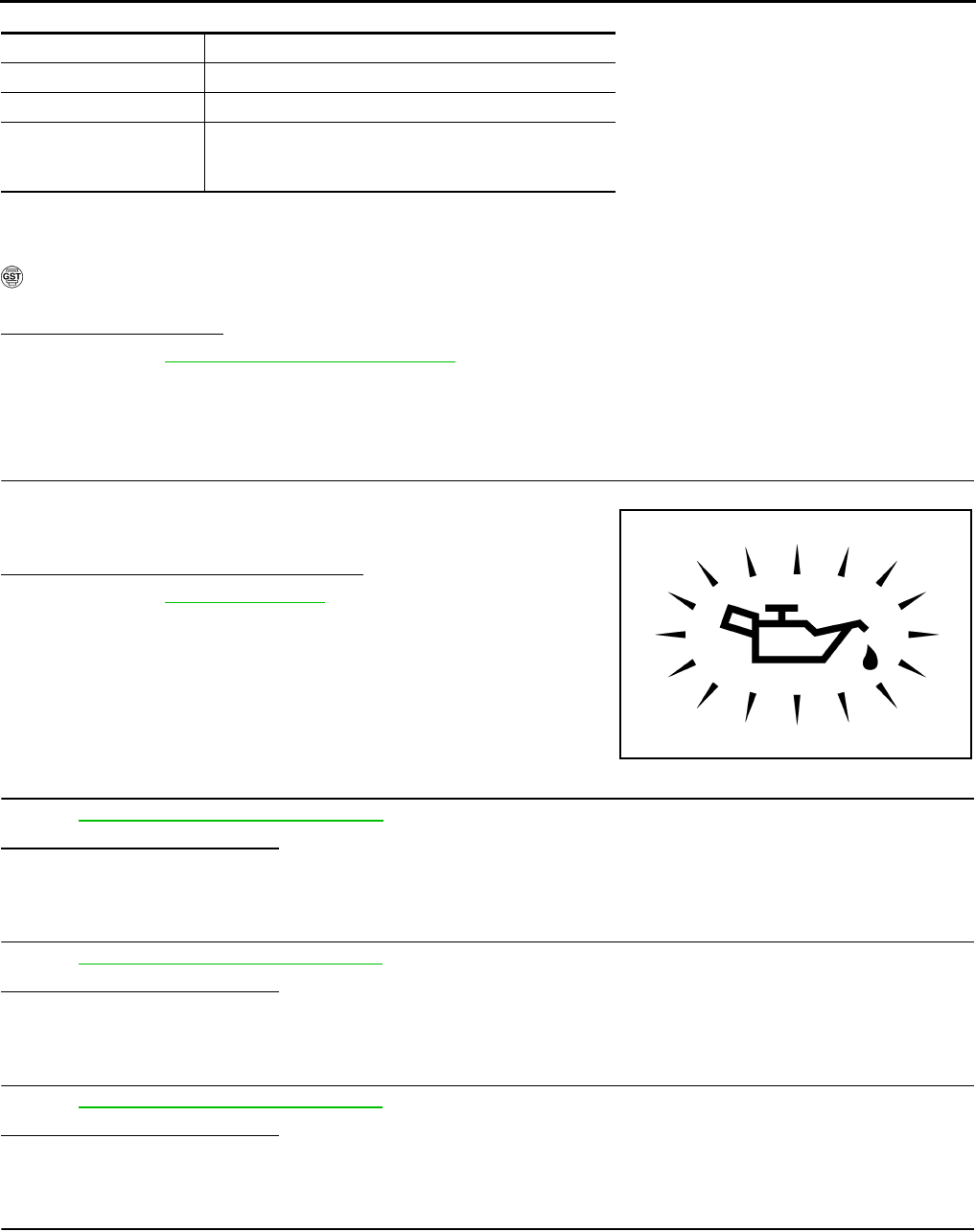
EC-1028
< COMPONENT DIAGNOSIS > [FOR MEXICO]
P0011 IVT CONTROL
CAUTION:
Always drive at a safe speed.
2. Check 1st trip DTC.
With GST
Follow the procedure “With CONSULT-III” above.
Is 1st trip DTC detected?
YES >> Go to EC-1028, "Diagnosis Procedure"
NO >> INSPECTION END
Diagnosis Procedure INFOID:0000000004494167
1.CHECK OIL PRESSURE WARNING LAMP
1. Start engine.
2. Check oil pressure warning lamp and confirm it is not illumi-
nated.
Is oil pressure warning lamp illuminated?
YES >> Go to LU-5, "Inspection".
NO >> GO TO 2.
2.CHECK INTAKE VALVE TIMING CONTROL SOLENOID VALVE
Refer to EC-1029, "Component Inspection".
Is the inspection result normal?
YES >> GO TO 3.
NO >> Replace intake valve timing control solenoid valve.
3.CHECK CRANKSHAFT POSITION SENSOR (POS)
Refer to EC-1123, "Component Inspection".
Is the inspection result normal?
YES >> GO TO 4.
NO >> Replace crankshaft position sensor (POS).
4.CHECK CAMSHAFT POSITION SENSOR (PHASE)
Refer to EC-1126, "Component Inspection".
Is the inspection result normal?
YES >> GO TO 5.
NO >> Replace camshaft position sensor (PHASE).
5.CHECK CAMSHAFT (INTAKE)
Check the following.
ENG SPEED 1,200 - 3,175 rpm (A constant rotation is maintained.)
COOLAN TEMP/S More than 70°C (221°F)
Selector lever 1st or 2nd position
Driving location Driving vehicle uphill
(Increased engine load will help maintain the driving
conditions required for this test.)
PBIA8559J
Revision: 2008 August 2009 Rogue

P0011 IVT CONTROL
EC-1029
< COMPONENT DIAGNOSIS > [FOR MEXICO]
C
D
E
F
G
H
I
J
K
L
M
A
EC
N
P
O
• Accumulation of debris on the signal plate of camshaft (1) rear end
• Chipping signal plate of camshaft rear end
Is the inspection result normal?
YES >> GO TO 6.
NO >> Remove debris and clean the signal plate of camshaft
rear end or replace camshaft.
6.CHECK TIMING CHAIN INSTALLATION
Check service records for any recent repairs that may cause timing chain misalignment.
Are there any service records that may cause timing chain misalignment?
YES >> Check timing chain installation. Refer to EM-70, "Removal and Installation".
NO >> GO TO 7.
7.CHECK LUBRICATION CIRCUIT
Refer to EM-53, "Inspection".
Is the inspection result normal?
YES >> GO TO 8.
NO >> Clean lubrication line.
8.CHECK INTERMITTENT INCIDENT
Refer to GI-41, "Intermittent Incident".
>> INSPECTION END
Component Inspection INFOID:0000000004494168
1.CHECK INTAKE VALVE TIMING CONTROL SOLENOID VALVE-I
1. Turn ignition switch OFF.
2. Disconnect intake valve timing control solenoid valve harness connector.
3. Check resistance between intake valve timing control solenoid valve terminals as follows.
Is the inspection result normal?
YES >> GO TO 2.
NO >> Replace intake valve timing control solenoid valve.
2.CHECK INTAKE VALVE TIMING CONTROL SOLENOID VALVE-II
1. Remove intake valve timing control solenoid valve.
2. Provide 12V DC between intake valve timing control solenoid
valve terminals 1 and 2, and then interrupt it. Check that the
plunger moves as shown in the figure.
CAUTION:
Never apply 12V DC continuously for 5 seconds or more.
Doing so may result in damage to the coil in intake valve
timing control solenoid valve.
NOTE:
Always replace O-ring when intake valve timing control
solenoid valve is removed.
Is the inspection result normal?
JMBIA0096ZZ
Terminals Resistance
1 and 2 7.0 - 7.5 Ω [at 20°C (68°F)]
1 or 2 and ground ∞ Ω
(Continuity should not exist)
JMBIA0097ZZ
Revision: 2008 August 2009 Rogue

EC-1030
< COMPONENT DIAGNOSIS > [FOR MEXICO]
P0011 IVT CONTROL
YES >> INSPECTION END
NO >> Replace intake valve timing control solenoid valve.
Revision: 2008 August 2009 Rogue

P0031, P0032 A/F SENSOR 1 HEATER
EC-1031
< COMPONENT DIAGNOSIS > [FOR MEXICO]
C
D
E
F
G
H
I
J
K
L
M
A
EC
N
P
O
P0031, P0032 A/F SENSOR 1 HEATER
Description INFOID:0000000004494169
SYSTEM DESCRIPTION
The ECM performs ON/OFF duty control of the A/F sensor 1 heater corresponding to the engine operating
condition to keep the temperature of A/F sensor 1 element within the specified range.
DTC Logic INFOID:0000000004494170
DTC DETECTION LOGIC
DTC CONFIRMATION PROCEDURE
1.PRECONDITIONING
If DTC CONFIRMATION PROCEDURE has been previously conducted, always turn ignition switch OFF and
wait at least 10 seconds before conducting the next test.
TESTING CONDITION:
Before performing the following procedure, confirm that battery voltage is more than between 11V at
idle.
>> GO TO 2.
2.PERFORM DTC CONFIRMATION PROCEDURE
1. Start engine and let it idle for at least 10 seconds.
2. Check 1st trip DTC.
Is 1st trip DTC detected?
YES >> Go to EC-1031, "Diagnosis Procedure".
NO >> INSPECTION END
Diagnosis Procedure INFOID:0000000004494171
1.CHECK GROUND CONNECTION
1. Turn ignition switch OFF.
2. Check ground connection E21. Refer to Ground Inspection in GI-44, "Circuit Inspection".
Is the inspection result normal?
YES >> GO TO 2.
NO >> Repair or replace ground connection.
2.CHECK AIR FUEL RATIO (A/F) SENSOR 1 POWER SUPPLY CIRCUIT
1. Disconnect air fuel ratio (A/F) sensor 1 harness connector.
2. Turn ignition switch ON.
Sensor Input signal to ECM ECM function Actuator
Camshaft position sensor (PHASE)
Crankshaft position sensor (POS) Engine speed Air fuel ratio (A/F) sensor 1
heater control Air fuel ratio (A/F) sensor 1
heater
Mass air flow sensor Amount of intake air
DTC No. Trouble diagnosis name DTC detecting condition Possible cause
P0031 Air fuel ratio (A/F) sensor
1 heater control circuit low
The current amperage in the A/F sensor 1 heater
circuit is out of the normal range.
(An excessively low voltage signal is sent to ECM
through the A/F sensor 1 heater.)
• Harness or connectors
(The A/F sensor 1 heater circuit is
open or shorted.)
• A/F sensor 1 heater
P0032
Air fuel ratio (A/F) sensor
1 heater control circuit
high
The current amperage in the A/F sensor 1 heater
circuit is out of the normal range.
(An excessively high voltage signal is sent to ECM
through the A/F sensor 1 heater.)
• Harness or connectors
(The A/F sensor 1 heater circuit is
shorted.)
• A/F sensor 1 heater
Revision: 2008 August 2009 Rogue

EC-1032
< COMPONENT DIAGNOSIS > [FOR MEXICO]
P0031, P0032 A/F SENSOR 1 HEATER
3. Check the voltage between A/F sensor 1 harness connector and ground.
Is the inspection result normal?
YES >> GO TO 4.
NO >> GO TO 3.
3.DETECT MALFUNCTIONING PART
Check the following.
• Harness connectors F123, E6
• IPDM E/R harness connector E14
• 15A fuse (No. 63)
• Harness for open or short between A/F sensor 1 and fuse
>> Repair or replace harness or connectors.
4.CHECK A/F SENSOR 1 HEATER OUTPUT SIGNAL CIRCUIT
1. Turn ignition switch OFF.
2. Disconnect ECM harness connector.
3. Check the continuity between A/F sensor 1 harness connector and ECM harness connector.
4. Also check harness for short to ground and short to power.
Is the inspection result normal?
YES >> GO TO 5.
NO >> Repair open circuit or short to ground or short to power in harness or connectors.
5.CHECK A/F SENSOR 1 HEATER
Refer to EC-1033, "Component Inspection".
Is the inspection result normal?
YES >> GO TO 7.
NO >> GO TO 6.
6.REPLACE AIR FUEL RATIO (A/F) SENSOR 1
Replace air fuel ratio (A/F) sensor 1.
CAUTION:
• Discard any A/F sensor which has been dropped from a height of more than 0.5 m (19.7 in) onto a
hard surface such as a concrete floor; use a new one.
• Before installing new A/F sensor, clean exhaust system threads using oxygen sensor thread cleaner
[commercial service tool (J-43897-18 or J-43897-12)] and approved anti-seize lubricant (commercial
service tool).
>> INSPECTION END
7.CHECK INTERMITTENT INCIDENT
Perform GI-41, "Intermittent Incident".
>> INSPECTION END
A/F sensor 1 Ground Voltage
Connector Terminal
F27 4 Ground Battery voltage
A/F sensor 1 ECM Continuity
Connector Terminal Connector Terminal
F27 3 F7 4 Existed
Revision: 2008 August 2009 Rogue

P0031, P0032 A/F SENSOR 1 HEATER
EC-1033
< COMPONENT DIAGNOSIS > [FOR MEXICO]
C
D
E
F
G
H
I
J
K
L
M
A
EC
N
P
O
Component Inspection INFOID:0000000004494172
1.CHECK AIR FUEL RATIO (A/F) SENSOR 1
1. Turn ignition switch OFF.
2. Disconnect A/F sensor 1 harness connector.
3. Check resistance between A/F sensor 1 terminals as follows.
Is the inspection result normal?
YES >> INSPECTION END
NO >> GO TO 2.
2.REPLACE AIR FUEL RATIO (A/F) SENSOR 1
Replace air fuel ratio (A/F) sensor 1.
CAUTION:
• Discard any A/F sensor which has been dropped from a height of more than 0.5 m (19.7 in) onto a
hard surface such as a concrete floor; use a new one.
• Before installing new A/F sensor, clean exhaust system threads using Heated oxygen sensor thread
cleaner [commercial service tool (J-43897-18 or J-43897-12)] and approved anti-seize lubricant (com-
mercial service tool).
>> INSPECTION END
Terminals Resistance
3 and 4 1.80 - 2.44 Ω [at 25°C (77°F)]
3 and 1, 2 ∞ Ω
(Continuity should not exist)
4 and 1, 2
Revision: 2008 August 2009 Rogue

EC-1034
< COMPONENT DIAGNOSIS > [FOR MEXICO]
P0037, P0038 HO2S2 HEATER
P0037, P0038 HO2S2 HEATER
Description INFOID:0000000004494173
SYSTEM DESCRIPTION
The ECM performs ON/OFF control of the heated oxygen sensor 2 heater corresponding to the engine speed,
amount of intake air and engine coolant temperature.
OPERATION
DTC Logic INFOID:0000000004494174
DTC DETECTION LOGIC
DTC CONFIRMATION PROCEDURE
1.PRECONDITIONING
If DTC CONFIRMATION PROCEDURE has been previously conducted, always turn ignition switch OFF and
wait at least 10 seconds before conducting the next test.
TESTING CONDITION:
Before performing the following procedure, confirm that battery voltage is more than 11V at idle.
>> GO TO 2.
2.PERFORM DTC CONFIRMATION PROCEDURE
1. Start engine and warm it up to the normal operating temperature.
2. Turn ignition switch OFF and wait at least 10 seconds.
3. Start engine and keep engine speed between 3,500 and 4,000 rpm for at least 1 minute under no load.
4. Let engine idle for 1 minute.
5. Check 1st trip DTC.
Is 1st tip DTC detected?
YES >> Go to EC-1035, "Diagnosis Procedure".
NO >> INSPECTION END
Sensor Input signal to ECM ECM function Actuator
Camshaft position sensor (PHASE)
Crankshaft position sensor (POS) Engine speed Heated oxygen sensor 2
heater control Heated oxygen sensor 2 heater
Engine coolant temperature sensor Engine coolant temperature
Mass air flow sensor Amount of intake air
Engine speed Heated oxygen sensor 2 heater
Above 3,600 rpm OFF
Below 3,600 rpm after the following conditions are met.
• Engine: After warming up
• Keeping the engine speed between 3,500 and 4,000 rpm for 1
minute and at idle for 1 minute under no load
ON
DTC No. Trouble diagnosis
name DTC detecting condition Possible cause
P0037
Heated oxygen
sensor 2 heater
control circuit low
The current amperage in the heated oxygen sensor
2 heater circuit is out of the normal range.
(An excessively low voltage signal is sent to ECM
through the heated oxygen sensor 2 heater.)
• Harness or connectors
(The heated oxygen sensor 2 heater circuit
is open or shorted.)
• Heated oxygen sensor 2 heater
P0038
Heated oxygen
sensor 2 heater
control circuit high
The current amperage in the heated oxygen sensor
2 heater circuit is out of the normal range.
(An excessively high voltage signal is sent to ECM
through the heated oxygen sensor 2 heater.)
• Harness or connectors
(The heated oxygen sensor 2 heater circuit
is shorted.)
• Heated oxygen sensor 2 heater
Revision: 2008 August 2009 Rogue

P0037, P0038 HO2S2 HEATER
EC-1035
< COMPONENT DIAGNOSIS > [FOR MEXICO]
C
D
E
F
G
H
I
J
K
L
M
A
EC
N
P
O
Diagnosis Procedure INFOID:0000000004494175
1.CHECK GROUND CONNECTION
1. Turn ignition switch OFF.
2. Check ground connection E21. Refer to Ground Inspection in GI-44, "Circuit Inspection".
Is the inspection result normal?
YES >> GO TO 2.
NO >> Repair or replace ground connection.
2.CHECK HO2S2 POWER SUPPLY CIRCUIT
1. Disconnect heated oxygen sensor 2 (HO2S2) harness connector.
2. Turn ignition switch ON.
3. Check the voltage between HO2S2 harness connector and ground.
Is the inspection result normal?
YES >> GO TO 4.
NO >> GO TO 3.
3.DETECT MALFUNCTIONING PART
Check the following.
• Harness connectors F123, E6
• IPDM E/R connector E14
• 15A fuse (No. 63)
• Harness for open or short between heated oxygen sensor 2 and fuse
>> Repair open circuit or short to ground or short to power in harness or connectors.
4.CHECK HO2S2 OUTPUT SIGNAL CIRCUIT FOR OPEN AND SHORT
1. Turn ignition switch OFF.
2. Disconnect ECM harness connector.
3. Check the continuity between HO2S2 harness connector and ECM harness connector.
4. Also check harness for short to ground and short to power.
Is the inspection result normal?
YES >> GO TO 5.
NO >> Repair open circuit or short to ground or short to power in harness or connectors.
5.CHECK HEATED OXYGEN SENSOR 2 HEATER
Refer to EC-1036, "Component Inspection".
Is the inspection result normal?
YES >> GO TO 7.
NO >> GO TO 6.
6.REPLACE HEATED OXYGEN SENSOR 2
Replace heated oxygen sensor 2.
CAUTION:
• Discard any heated oxygen sensor which has been dropped from a height of more than 0.5 m (19.7
in) onto a hard surface such as a concrete floor; use a new one.
HO2S2 Ground Voltage
Connector Terminal
F31 2 Ground Battery voltage
HO2S2 ECM Continuity
Connector Terminal Connector Terminal
F31 3 F7 13 Existed
Revision: 2008 August 2009 Rogue
EC-1036
< COMPONENT DIAGNOSIS > [FOR MEXICO]
P0037, P0038 HO2S2 HEATER
• Before installing new heated oxygen sensor, clean exhaust system threads using oxygen sensor
thread cleaner [commercial service tool (J-43897-18 or J-43897-12)] and approved anti-seize lubri-
cant (commercial service tool).
>> INSPECTION END
7.CHECK INTERMITTENT INCIDENT
Refer to GI-41, "Intermittent Incident".
>> INSPECTION END
Component Inspection INFOID:0000000004494176
1.CHECK HEATED OXYGEN SENSOR 2 HEATER
1. Turn ignition switch OFF.
2. Disconnect heated oxygen sensor 2 (HO2S2) harness connector.
3. Check resistance between HO2S2 terminals as follows.
Is the inspection result normal?
YES >> INSPECTION END
NO >> GO TO 2.
2.REPLACE HEATED OXYGEN SENSOR 2
Replace heated oxygen sensor 2.
CAUTION:
• Discard any heated oxygen sensor which has been dropped from a height of more than 0.5 m (19.7
in) onto a hard surface such as a concrete floor; use a new one.
• Before installing new heated oxygen sensor, clean exhaust system threads using oxygen sensor
thread cleaner [commercial service tool (J-43897-18 or J-43897-12)] and approved anti-seize lubri-
cant (commercial service tool).
>> INSPECTION END
Terminals Resistance
2 and 3 3.3 - 4.4 Ω [at 25°C (77°F)]
1 and 2, 3, 4 ∞ Ω
(Continuity should not exist)
4 and 1, 2, 3
Revision: 2008 August 2009 Rogue
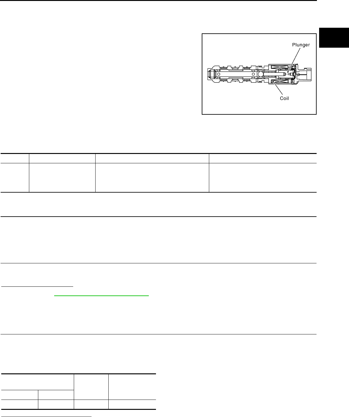
P0075 IVT CONTROL SOLENOID VALVE
EC-1037
< COMPONENT DIAGNOSIS > [FOR MEXICO]
C
D
E
F
G
H
I
J
K
L
M
A
EC
N
P
O
P0075 IVT CONTROL SOLENOID VALVE
Description INFOID:0000000004494177
Intake valve timing control solenoid valve is activated by ON/OFF
pulse duty (ratio) signals from the ECM.
The intake valve timing control solenoid valve changes the oil
amount and direction of flow through intake valve timing control unit
or stops oil flow.
The longer pulse width advances valve timing.
The shorter pulse width retards valve timing.
When ON and OFF pulse widths become equal, the solenoid valve
stops oil pressure flow to fix the intake valve angle at the control
position.
DTC Logic INFOID:0000000004494178
DTC DETECTION LOGIC
DTC CONFIRMATION PROCEDURE
1.PRECONDITIONING
If DTC CONFIRMATION PROCEDURE has been previously conducted, always turn ignition switch OFF and
wait at least 10 seconds before conducting the next test.
>> GO TO2.
2.PERFORM DTC CONFIRMATION PROCEDURE
1. Start engine and let it idle for 5 seconds.
2. Check 1st trip DTC.
Is 1st trip DTC detected?
YES >> Go to EC-1037, "Diagnosis Procedure".
NO >> INSPECTION END
Diagnosis Procedure INFOID:0000000004494179
1.CHECK INTAKE VALVE TIMING CONTROL SOLENOID VALVE POWER SUPPLY CIRCUIT
1. Turn ignition switch OFF.
2. Disconnect intake valve timing control solenoid valve harness connector.
3. Turn ignition switch ON.
4. Check the voltage between intake valve timing control solenoid valve harness connector and ground.
Is the inspection result normal?
YES >> GO TO 3.
NO >> GO TO 2.
JMBIA0098G
B
DTC No. Trouble diagnosis name DTC detecting condition Possible cause
P0075 Intake valve timing control
solenoid valve circuit
An improper voltage is sent to the ECM through
intake valve timing control solenoid valve.
• Harness or connectors
(Intake valve timing control solenoid valve
circuit is open or shorted.)
• Intake valve timing control solenoid valve
Intake valve timing control
solenoid valve Ground Voltage
Connector Terminal
F45 2 Ground Battery voltage
Revision: 2008 August 2009 Rogue

EC-1038
< COMPONENT DIAGNOSIS > [FOR MEXICO]
P0075 IVT CONTROL SOLENOID VALVE
2.DETECT MALFUNCTIONING PART
Check the following.
• Harness connectors E7, F121
• Harness for open or short between intake valve timing control solenoid valve and IPDM E/R
>> Repair open circuit or short to ground or short to power in harness or connectors.
3.CHECK INTAKE VALVE TIMING CONTROL SOLENOID VALVE OUTPUT SIGNAL CIRCUIT FOR OPEN
AND SHORT
1. Turn ignition switch OFF.
2. Disconnect ECM harness connector.
3. Check the continuity between intake valve timing control solenoid valve harness connector and ECM har-
ness connector.
4. Also check harness for short to ground and short to power.
Is the inspection result normal?
YES >> GO TO 4.
NO >> Repair open circuit or short to ground or short to power in harness or connectors.
4.CHECK INTAKE VALVE TIMING CONTROL SOLENOID VALVE
Refer to EC-1038, "Component Inspection".
Is the inspection result normal?
YES >> GO TO 5.
NO >> Replace intake valve timing control solenoid valve.
5.CHECK INTERMITTENT INCIDENT
Refer to GI-41, "Intermittent Incident".
>> INSPECTION END
Component Inspection INFOID:0000000004534361
1.CHECK INTAKE VALVE TIMING CONTROL SOLENOID VALVE-I
1. Turn ignition switch OFF.
2. Disconnect intake valve timing control solenoid valve harness connector.
3. Check resistance between intake valve timing control solenoid valve terminals as follows.
Is the inspection result normal?
YES >> GO TO 2.
NO >> Replace intake valve timing control solenoid valve.
2.CHECK INTAKE VALVE TIMING CONTROL SOLENOID VALVE-II
1. Remove intake valve timing control solenoid valve.
Intake valve timing control
solenoid valve ECM Continuity
Connector Terminal Connector Terminal
F45 1 F8 78 Existed
Terminals Resistance
1 and 2 7.0 - 7.5 Ω [at 20°C (68°F)]
1 or 2 and ground ∞ Ω
(Continuity should not exist)
Revision: 2008 August 2009 Rogue
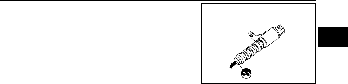
P0075 IVT CONTROL SOLENOID VALVE
EC-1039
< COMPONENT DIAGNOSIS > [FOR MEXICO]
C
D
E
F
G
H
I
J
K
L
M
A
EC
N
P
O
2. Provide 12V DC between intake valve timing control solenoid
valve terminals 1 and 2, and then interrupt it. Check that the
plunger moves as shown in the figure.
CAUTION:
Never apply 12V DC continuously for 5 seconds or more.
Doing so may result in damage to the coil in intake valve
timing control solenoid valve.
NOTE:
Always replace O-ring when intake valve timing control
solenoid valve is removed.
Is the inspection result normal?
YES >> INSPECTION END
NO >> Replace intake valve timing control solenoid valve.
JMBIA0097ZZ
Revision: 2008 August 2009 Rogue
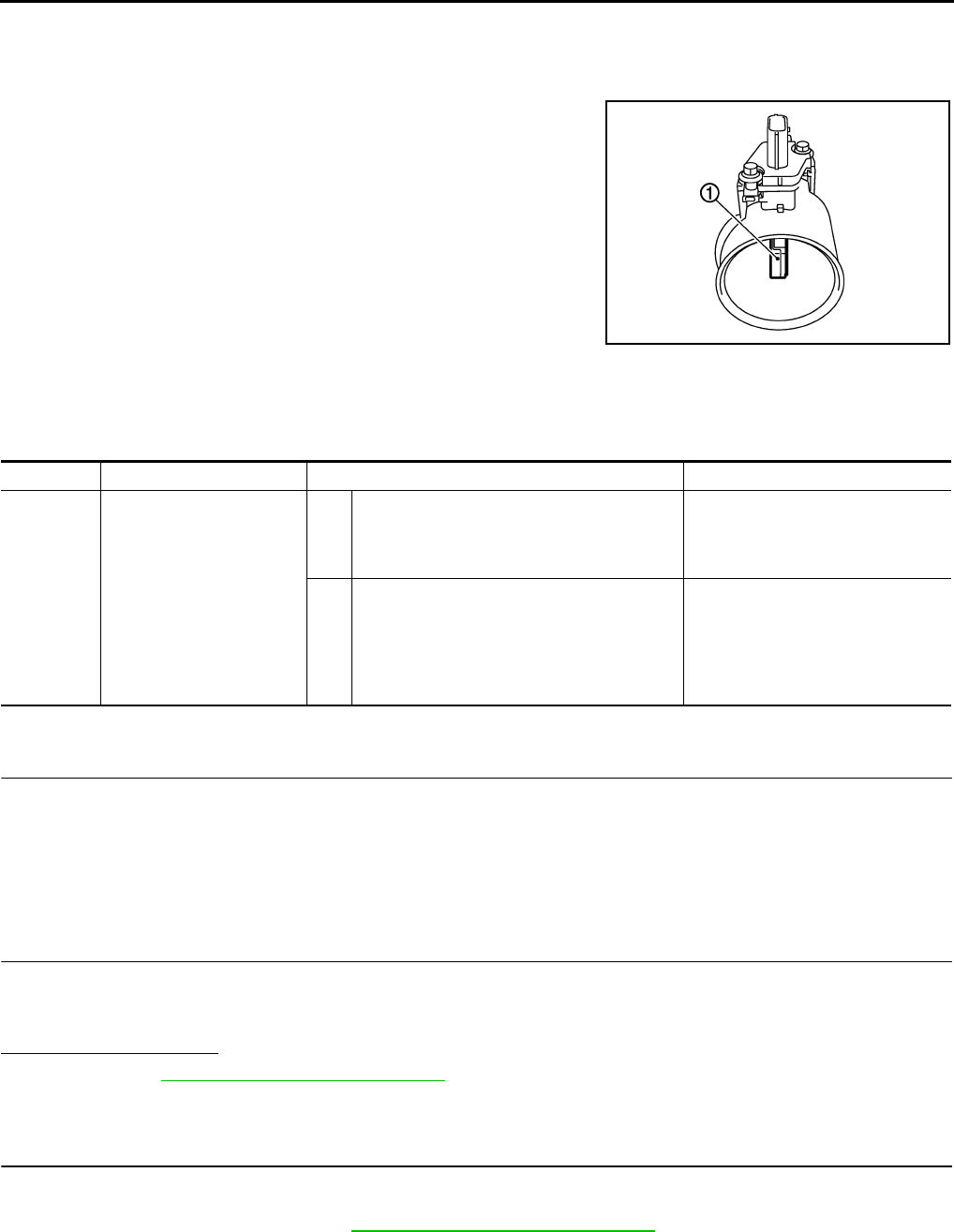
EC-1040
< COMPONENT DIAGNOSIS > [FOR MEXICO]
P0101 MAF SENSOR
P0101 MAF SENSOR
Description INFOID:0000000004494181
The mass air flow sensor (1) is placed in the stream of intake air. It
measures the intake flow rate by measuring a part of the entire
intake flow. The mass air flow sensor controls the temperature of the
hot wire to a certain amount. The heat generated by the hot wire is
reduced as the intake air flows around it. The greater air flow, the
greater the heat loss.
Therefore, the electric current supplied to hot wire is changed to
maintain the temperature of the hot wire as air flow increases. The
ECM detects the air flow by means of this current change.
DTC Logic INFOID:0000000004494182
DTC DETECTION LOGIC
DTC CONFIRMATION PROCEDURE
1.PRECONDITIONING
If DTC CONFIRMATION PROCEDURE has been previously conducted, always turn ignition switch OFF and
wait at least 10 seconds before conducting the next test.
If engine will not start or stops soon, wait at least 10 seconds with engine stopped (Ignition switch ON) instead
of running engine at idle speed.
>> GO TO 2.
2.PERFORM DTC CONFIRMATION PROCEDURE FOR MALFUNCTION A
1. Start engine and warm it up to normal operating temperature.
2. Run engine for at least 10 seconds at idle speed.
3. Check 1st trip DTC.
Is 1st trip DTC detected?
YES >> Go to EC-1042, "Diagnosis Procedure".
NO-1 >> With CONSULT-III: GO TO 3.
NO-2 >> Without CONSULT-III: GO TO 5.
3.CHECK MASS AIR FLOW SENSOR FUNCTION
1. Turn ignition switch ON.
2. Start engine and warm it up to normal operating temperature.
If engine cannot be started, go to EC-1042, "Diagnosis Procedure".
PBIA9559J
DTC No. Trouble diagnosis name DTC detecting condition Possible cause
P0101 Mass air flow sensor circuit
range/performance
A) A high voltage from the sensor is sent to ECM
under light load driving condition.
• Harness or connectors
(The sensor circuit is open or
shorted.)
• Mass air flow sensor
B) A low voltage from the sensor is sent to ECM
under heavy load driving condition.
• Harness or connectors
(The sensor circuit is open or
shorted.)
• Intake air leaks
• Mass air flow sensor
• Intake air temperature sensor
Revision: 2008 August 2009 Rogue
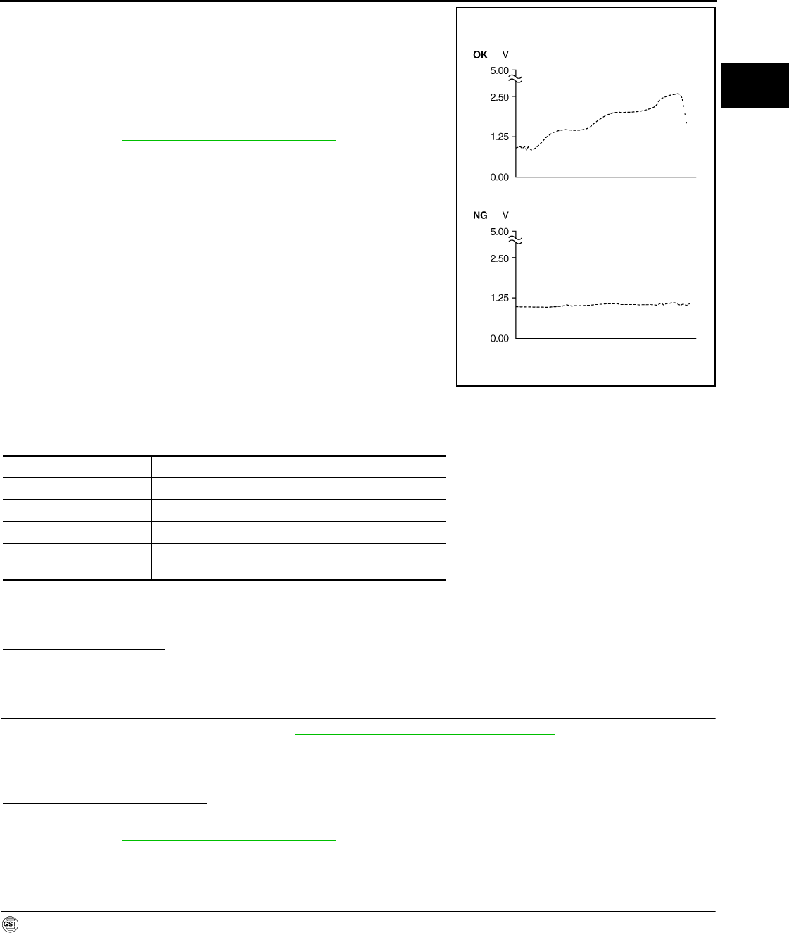
P0101 MAF SENSOR
EC-1041
< COMPONENT DIAGNOSIS > [FOR MEXICO]
C
D
E
F
G
H
I
J
K
L
M
A
EC
N
P
O
3. Select “DATA MONITOR” mode with CONSULT-III.
4. Check the voltage of “MAS A/F SE-B1” with “DATA MONITOR”.
5. Increases engine speed to approximately 4,000 rpm.
6. Monitor the linear voltage rise in response to engine speed
increases.
Is the inspection result normal?
YES >> GO TO 4.
NO >> Go to EC-1042, "Diagnosis Procedure".
4.PERFORM DTC CONFIRMATION PROCEDURE FOR MALFUNCTION B
1. Maintain the following conditions for at least 10 consecutive seconds.
CAUTION:
Always drive vehicle at a safe speed.
2. Check 1st trip DTC.
Is 1st trip DTC detected?
YES >> Go to EC-1042, "Diagnosis Procedure".
NO >> INSPECTION END
5.PERFORM COMPONENT FUNCTION CHECK FOR MALFUNCTION B
Perform component function check. Refer to EC-1041, "Component Function Check".
NOTE:
Use component function check to check the overall function of the mass air flow sensor circuit. During this
check, a 1st trip DTC might not be confirmed.
Is the inspection result normal?
YES >> INSPECTION END
NO >> Go to EC-1042, "Diagnosis Procedure".
Component Function Check INFOID:0000000004494183
1.PERFORM COMPONENT FUNCTION CHECK FOR MALFUNCTION B
With GST
1. Start engine and warm it up to normal operating temperature.
2. Select Service $01 with GST.
PBIB3457E
ENG SPEED More than 2,000 rpm
THRTL SEN 1-B1 More than 1.5V
THRTL SEN 2-B1 More than 1.5V
Selector lever Suitable position
Driving location Driving vehicle uphill (Increased engine load) will help
maintain the driving conditions required for this test.
Revision: 2008 August 2009 Rogue
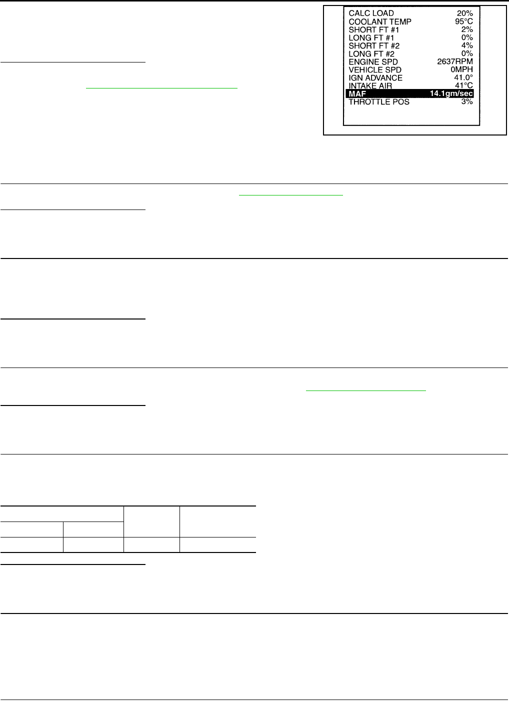
EC-1042
< COMPONENT DIAGNOSIS > [FOR MEXICO]
P0101 MAF SENSOR
3. Check the mass air flow sensor signal with Service $01.
4. Check for linear mass air flow sensor signal value rise in
response to increases to approximately 4,000 rpm in engine
speed.
Is the inspection result normal?
YES >> INSPECTION END
NO >> Go to EC-1042, "Diagnosis Procedure".
Diagnosis Procedure INFOID:0000000004494184
1.INSPECTION START
Confirm the detected malfunction (A or B). Refer to EC-1040, "DTC Logic".
Which malfunction is detected?
A>>GO TO 3.
B>>GO TO 2.
2.CHECK INTAKE SYSTEM
Check the following for connection.
• Air duct
• Vacuum hoses
• Intake air passage between air duct and intake manifold
Is the inspection result normal?
YES >> GO TO 3.
NO >> Reconnect the parts.
3.CHECK GROUND CONNECTION
1. Turn ignition switch OFF.
2. Check ground connection E21. Refer to Ground Inspection in GI-44, "Circuit Inspection".
Is the inspection result normal?
YES >> GO TO 4.
NO >> Repair or replace ground connection.
4.CHECK MAF SENSOR POWER SUPPLY CIRCUIT
1. Disconnect mass air flow (MAF) sensor harness connector.
2. Turn ignition switch ON.
3. Check the voltage between MAF sensor harness connector and ground.
Is the inspection result normal?
YES >> GO TO 6.
NO >> GO TO 5.
5.DETECT MALFUNCTIONING PART
Check the following.
• Harness for open or short between mass air flow sensor and ECM
• Harness for open or short between mass air flow sensor and IPDM E/R
>> Repair open circuit or short to ground or short to power in harness or connectors.
6.CHECK MAF SENSOR GROUND CIRCUIT FOR OPEN AND SHORT
1. Turn ignition switch OFF.
SEF534P
MAF sensor Ground Voltage
Connector Terminal
E18 5 Ground Battery voltage
Revision: 2008 August 2009 Rogue

P0101 MAF SENSOR
EC-1043
< COMPONENT DIAGNOSIS > [FOR MEXICO]
C
D
E
F
G
H
I
J
K
L
M
A
EC
N
P
O
2. Disconnect ECM harness connector.
3. Check the continuity between MAF sensor harness connector and ECM harness connector.
4. Also check harness for short to ground and short to power.
Is the inspection result normal?
YES >> GO TO 8.
NO >> GO TO 7.
7.DETECT MALFUNCTIONING PART
Check the following.
• Harness connectors E6, F123
• Harness for open or short between mass air flow sensor and ECM
>> Repair open circuit or short to ground or short to power in harness or connectors.
8.CHECK MAF SENSOR INPUT SIGNAL CIRCUIT FOR OPEN AND SHORT
1. Check the continuity between MAF sensor harness connector and ECM harness connector.
2. Also check harness for short to ground and short to power.
Is the inspection result normal?
YES >> GO TO 10.
NO >> GO TO 9.
9.DETECT MALFUNCTIONING PART
Check the following.
• Harness connectors E6, F123
• Harness for open or short between mass air flow sensor and ECM
>> Repair open circuit or short to ground or short to power in harness or connectors.
10.CHECK INTAKE AIR TEMPERATURE SENSOR
Refer to EC-1054, "Component Inspection".
Is the inspection result normal?
YES >> GO TO 11.
NO >> Replace mass air flow sensor (with intake air temperature sensor).
11.CHECK MASS AIR FLOW SENSOR
Refer to EC-1044, "Component Inspection".
Is the inspection result normal?
YES >> GO TO 12.
NO >> Replace mass air flow sensor.
12.CHECK INTERMITTENT INCIDENT
Refer to GI-41, "Intermittent Incident".
>> INSPECTION END
MAF sensor ECM Continuity
Connector Terminal Connector Terminal
E18 4 F7 56 Existed
MAF sensor ECM Continuity
Connector Terminal Connector Terminal
E18 3 F8 58 Existed
Revision: 2008 August 2009 Rogue
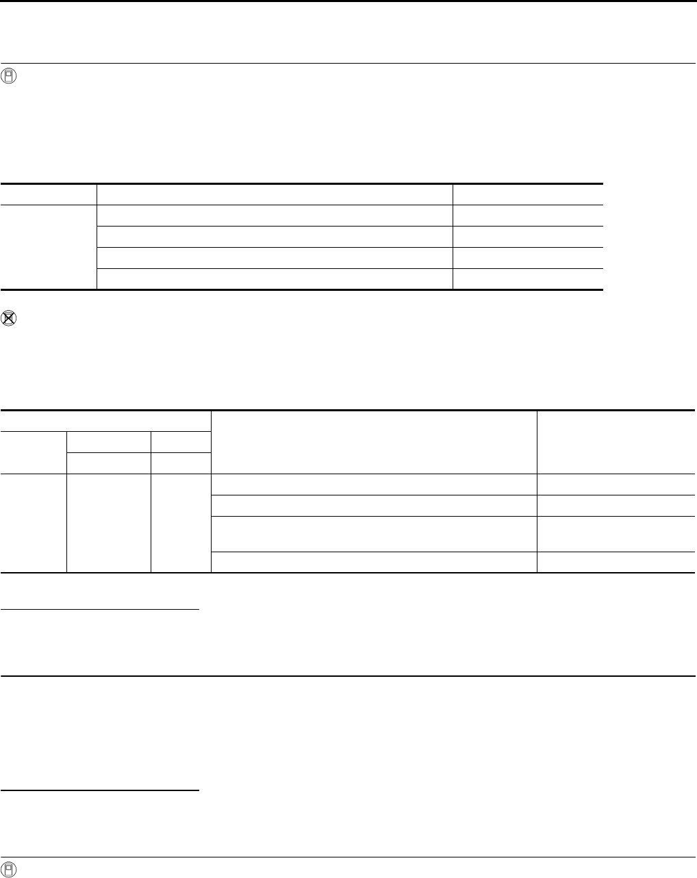
EC-1044
< COMPONENT DIAGNOSIS > [FOR MEXICO]
P0101 MAF SENSOR
Component Inspection INFOID:0000000004494185
1.CHECK MASS AIR FLOW SENSOR-I
With CONSULT-III
1. Turn ignition switch OFF.
2. Reconnect all harness connectors disconnected.
3. Start engine and warm it up to normal operating temperature.
4. Connect CONSULT-III and select “DATA MONITOR” mode.
5. Select “MAS A/F SE-B1” and check indication.
*: Check for linear voltage rise in response to engine being increased to approximately 4,000 rpm.
Without CONSULT-III
1. Turn ignition switch OFF.
2. Reconnect all harness connectors disconnected.
3. Start engine and warm it up to normal operating temperature.
4. Check the voltage between ECM harness connector terminals under the following conditions.
*: Check for linear voltage rise in response to engine being increased to approximately 4,000 rpm.
Is the inspection result normal?
YES >> INSPECTION END
NO >> GO TO 2.
2.CHECK FOR THE CAUSE OF UNEVEN AIR FLOW THROUGH MASS AIR FLOW SENSOR
1. Turn ignition switch OFF.
2. Check for the cause of uneven air flow through mass air flow sensor. Refer to the following.
- Crushed air ducts
- Malfunctioning seal of air cleaner element
- Uneven dirt of air cleaner element
- Improper specification of intake air system parts
Is the inspection result normal?
YES >> GO TO 4.
NO >> GO TO 3.
3.CHECK MASS AIR FLOW SENSOR-II
With CONSULT-III
1. Repair or replace malfunctioning part.
2. Start engine and warm it up to normal operating temperature.
3. Connect CONSULT-III and select “DATA MONITOR” mode.
4. Select “MAS A/F SE-B1” and check indication.
Monitor item Condition MAS A/F SE-B1
MAS A/F SE-B1
Ignition switch ON (Engine stopped.) Approx. 0.4V
Idle (Engine is warmed-up to normal operating temperature.) 0.8 - 1.2V
2,500 rpm (Engine is warmed-up to normal operating temperature.) 1.4 - 1.8V
Idle to approx. 4,000 rpm 0.8 - 1.2V to Approx. 2.4V*
ECM
Condition Voltage
Connector +−
Terminal Terminal
F8 58
(MAF sensor
signal)
56
(Sensor
gound)
Ignition switch ON (Engine stopped.) Approx. 0.4V
Idle (Engine is warmed-up to normal operating temperature.) 0.8 - 1.2V
2,500 rpm (Engine is warmed-up to normal operating temper-
ature.) 1.4 - 1.8V
Idle to approx. 4,000 rpm 0.8 - 1.2V to Approx. 2.4V*
Revision: 2008 August 2009 Rogue
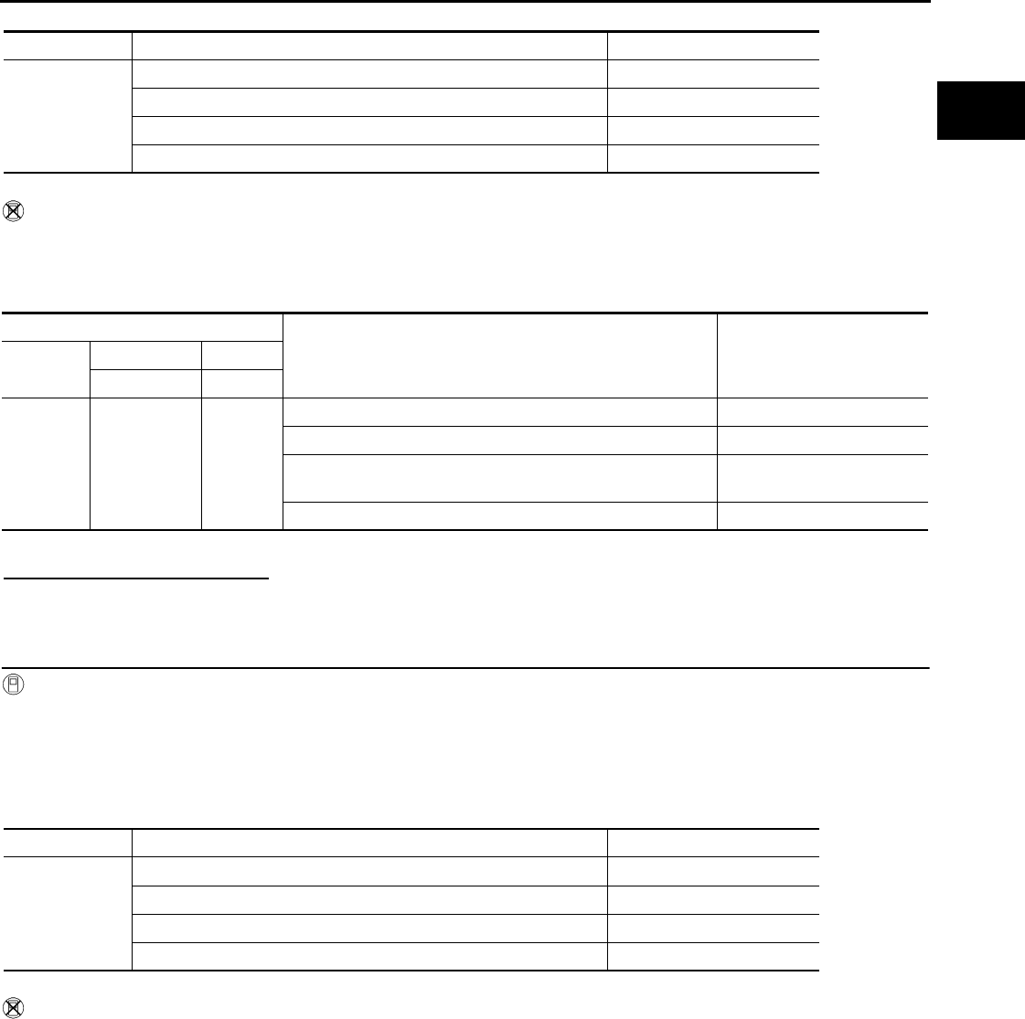
P0101 MAF SENSOR
EC-1045
< COMPONENT DIAGNOSIS > [FOR MEXICO]
C
D
E
F
G
H
I
J
K
L
M
A
EC
N
P
O
*: Check for linear voltage rise in response to engine being increased to approximately 4,000 rpm.
Without CONSULT-III
1. Repair or replace malfunctioning part.
2. Start engine and warm it up to normal operating temperature.
3. Check the voltage between ECM harness connector terminals under the following conditions.
*: Check for linear voltage rise in response to engine being increased to approximately 4,000 rpm.
Is the inspection result normal?
YES >> INSPECTION END
NO >> GO TO 4.
4.CHECK MASS AIR FLOW SENSOR-III
With CONSULT-III
1. Turn ignition switch OFF.
2. Disconnect mass air flow sensor harness connector and reconnect it again.
3. Start engine and warm it up to normal operating temperature.
4. Connect CONSULT-III and select “DATA MONITOR” mode.
5. Select “MAS A/F SE-B1” and check indication.
*: Check for linear voltage rise in response to engine being increased to approximately 4,000 rpm.
Without CONSULT-III
1. Turn ignition switch OFF.
2. Disconnect mass air flow sensor harness connector and reconnect it again.
3. Start engine and warm it up to normal operating temperature.
4. Check the voltage between ECM harness connector terminals under the following conditions.
Monitor item Condition MAS A/F SE-B1
MAS A/F SE-B1
Ignition switch ON (Engine stopped.) Approx. 0.4V
Idle (Engine is warmed-up to normal operating temperature.) 0.8 - 1.2V
2,500 rpm (Engine is warmed-up to normal operating temperature.) 1.4 - 1.8V
Idle to approx. 4,000 rpm 0.8 - 1.2V to Approx. 2.4V*
ECM
Condition Voltage
Connector +−
Terminal Terminal
F8 58
(MAF sensor
signal)
56
(Sensor
gound)
Ignition switch ON (Engine stopped.) Approx. 0.4V
Idle (Engine is warmed-up to normal operating temperature.) 0.8 - 1.2V
2,500 rpm (Engine is warmed-up to normal operating temper-
ature.) 1.4 - 1.8V
Idle to approx. 4,000 rpm 0.8 - 1.2V to Approx. 2.4V*
Monitor item Condition MAS A/F SE-B1
MAS A/F SE-B1
Ignition switch ON (Engine stopped.) Approx. 0.4V
Idle (Engine is warmed-up to normal operating temperature.) 0.8 - 1.2V
2,500 rpm (Engine is warmed-up to normal operating temperature.) 1.4 - 1.8V
Idle to approx. 4,000 rpm 0.8 - 1.2V to Approx. 2.4V*
Revision: 2008 August 2009 Rogue
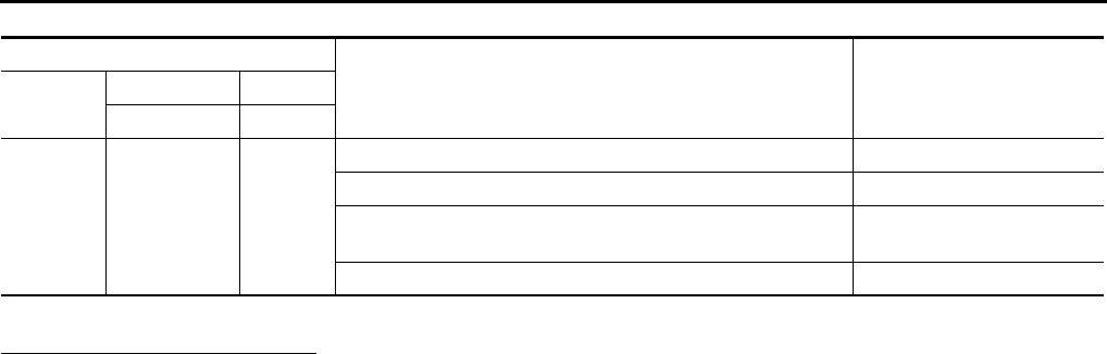
EC-1046
< COMPONENT DIAGNOSIS > [FOR MEXICO]
P0101 MAF SENSOR
*: Check for linear voltage rise in response to engine being increased to approximately 4,000 rpm.
Is the inspection result normal?
YES >> INSPECTION END
NO >> Clean or replace mass air flow sensor.
ECM
Condition Voltage
Connector +−
Terminal Terminal
F8
58
(MAF sensor
signal)
56
(Sensor
gound)
Ignition switch ON (Engine stopped.) Approx. 0.4V
Idle (Engine is warmed-up to normal operating temperature.) 0.8 - 1.2V
2,500 rpm (Engine is warmed-up to normal operating temper-
ature.) 1.4 - 1.8V
Idle to approx. 4,000 rpm 0.8 - 1.2V to Approx. 2.4V*
Revision: 2008 August 2009 Rogue
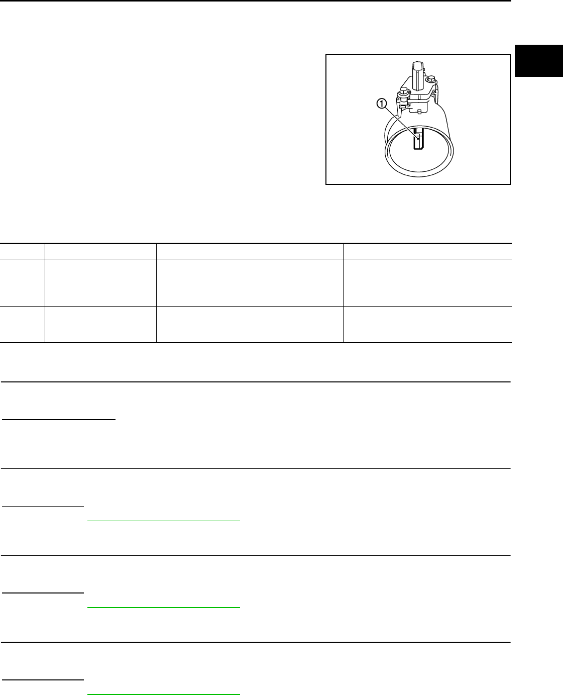
P0102, P0103 MAF SENSOR
EC-1047
< COMPONENT DIAGNOSIS > [FOR MEXICO]
C
D
E
F
G
H
I
J
K
L
M
A
EC
N
P
O
P0102, P0103 MAF SENSOR
Description INFOID:0000000004534362
The mass air flow sensor (1) is placed in the stream of intake air. It
measures the intake flow rate by measuring a part of the entire
intake flow. The mass air flow sensor controls the temperature of the
hot wire to a certain amount. The heat generated by the hot wire is
reduced as the intake air flows around it. The greater air flow, the
greater the heat loss.
Therefore, the electric current supplied to hot wire is changed to
maintain the temperature of the hot wire as air flow increases. The
ECM detects the air flow by means of this current change.
DTC Logic INFOID:0000000004494187
DTC DETECTION LOGIC
DTC CONFIRMATION PROCEDURE
1.PRECONDITIONING
If DTC CONFIRMATION PROCEDURE has been previously conducted, always turn ignition switch OFF and
wait at least 10 seconds before conducting the next test.
Which DTC is detected?
P0102 >> GO TO 2.
P0103 >> GO TO 3.
2.PERFORM DTC CONFIRMATION PROCEDURE FOR DTC P0102
1. Start engine and wait at least 5 seconds.
2. Check DTC.
Is DTC detected?
YES >> Go to EC-1048, "Diagnosis Procedure".
NO >> INSPECTION END
3.PERFORM DTC CONFIRMATION PROCEDURE FOR DTC P0103-I
1. Turn ignition switch ON and wait at least 5 seconds.
2. Check DTC.
Is DTC detected?
YES >> Go to EC-1048, "Diagnosis Procedure".
NO >> GO TO 4.
4.PERFORM DTC CONFIRMATION PROCEDURE FOR DTC P0103-II
1. Start engine and wait at least 5 seconds.
2. Check DTC.
Is DTC detected?
YES >> Go to EC-1048, "Diagnosis Procedure".
NO >> INSPECTION END
PBIA9559J
DTC No. Trouble diagnosis name DTC detecting condition Possible cause
P0102 Mass air flow sensor circuit
low input An excessively low voltage from the sensor is
sent to ECM.
• Harness or connectors
(The sensor circuit is open or shorted.)
• Intake air leaks
• Mass air flow sensor
P0103 Mass air flow sensor circuit
high input
An excessively high voltage from the sensor is
sent to ECM.
• Harness or connectors
(The sensor circuit is open or shorted.)
• Mass air flow sensor
Revision: 2008 August 2009 Rogue

EC-1048
< COMPONENT DIAGNOSIS > [FOR MEXICO]
P0102, P0103 MAF SENSOR
Diagnosis Procedure INFOID:0000000004494188
1.INSPECTION START
Confirm the detected DTC.
Which DTC is detected?
P0102 >> GO TO 2.
P0103 >> GO TO 3.
2.CHECK INTAKE SYSTEM
Check the following for connection.
• Air duct
• Vacuum hoses
• Intake air passage between air duct to intake manifold
Is the inspection result normal?
YES >> GO TO 3.
NO >> Reconnect the parts.
3.CHECK GROUND CONNECTION
1. Turn ignition switch OFF.
2. Check ground connection E21. Refer to Ground Inspection in GI-44, "Circuit Inspection".
Is the inspection result normal?
YES >> GO TO 4.
NO >> Repair or replace ground connection.
4.CHECK MAF SENSOR POWER SUPPLY CIRCUIT
1. Disconnect mass air flow (MAF) sensor harness connector.
2. Turn ignition switch ON.
3. Check the voltage between MAF sensor harness connector and ground.
Is the inspection result normal?
YES >> GO TO 6.
NO >> GO TO 5.
5.DETECT MALFUNCTIONING PART
Check the following.
• Harness for open or short between mass air flow sensor and ECM
• Harness for open or short between mass air flow sensor and IPDM E/R
>> Repair open circuit or short to ground or short to power in harness or connectors.
6.CHECK MAF SENSOR GROUND CIRCUIT FOR OPEN AND SHORT
1. Turn ignition switch OFF.
2. Disconnect ECM harness connector.
3. Check the continuity between MAF sensor harness connector and ECM harness connector.
4. Also check harness for short to ground and short to power.
Is the inspection result normal?
YES >> GO TO 8.
MAF sensor Ground Voltage
Connector Terminal
E18 5 Ground Battery voltage
MAF sensor ECM Continuity
Connector Terminal Connector Terminal
E18 4 F8 56 Existed
Revision: 2008 August 2009 Rogue
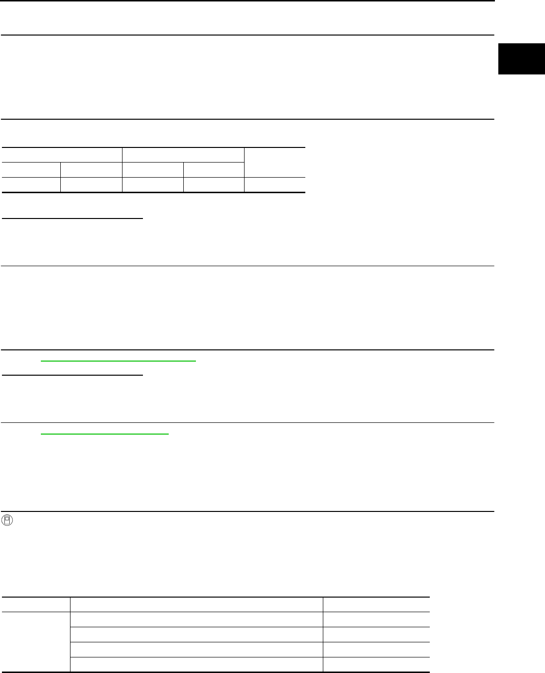
P0102, P0103 MAF SENSOR
EC-1049
< COMPONENT DIAGNOSIS > [FOR MEXICO]
C
D
E
F
G
H
I
J
K
L
M
A
EC
N
P
O
NO >> GO TO 7.
7.DETECT MALFUNCTIONING PART
Check the following.
• Harness connectors E6, F123
• Harness for open or short between mass air flow sensor and ECM
>> Repair open circuit or short to ground or short to power in harness or connectors.
8.CHECK MAF SENSOR INPUT SIGNAL CIRCUIT FOR OPEN AND SHORT
1. Check the continuity between MAF sensor harness connector and ECM harness connector.
2. Also check harness for short to ground and short to power.
Is the inspection result normal?
YES >> GO TO 10.
NO >> GO TO 9.
9.DETECT MALFUNCTIONING PART
Check the following.
• Harness connectors E6, F123
• Harness for open or short between mass air flow sensor and ECM
>> Repair open circuit or short to ground or short to power in harness or connectors.
10.CHECK MASS AIR FLOW SENSOR
Refer to EC-1049, "Component Inspection".
Is the inspection result normal?
YES >> GO TO 11.
NO >> Replace mass air flow sensor.
11.CHECK INTERMITTENT INCIDENT
Refer to GI-41, "Intermittent Incident".
>> INSPECTION END
Component Inspection INFOID:0000000004534364
1.CHECK MASS AIR FLOW SENSOR-I
With CONSULT-III
1. Turn ignition switch OFF.
2. Reconnect all harness connectors disconnected.
3. Start engine and warm it up to normal operating temperature.
4. Connect CONSULT-III and select “DATA MONITOR” mode.
5. Select “MAS A/F SE-B1” and check indication.
*: Check for linear voltage rise in response to engine being increased to approximately 4,000 rpm.
MAF sensor ECM Continuity
Connector Terminal Connector Terminal
E18 3 F8 58 Existed
Monitor item Condition MAS A/F SE-B1
MAS A/F SE-B1
Ignition switch ON (Engine stopped.) Approx. 0.4V
Idle (Engine is warmed-up to normal operating temperature.) 0.8 - 1.2V
2,500 rpm (Engine is warmed-up to normal operating temperature.) 1.4 - 1.8V
Idle to approx. 4,000 rpm 0.8 - 1.2V to Approx. 2.4V*
Revision: 2008 August 2009 Rogue
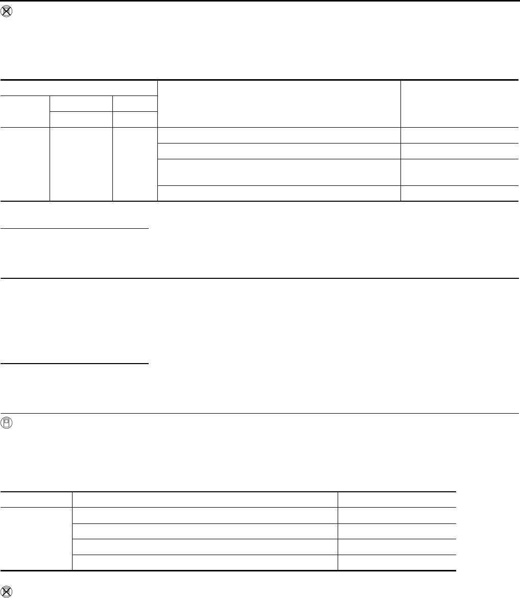
EC-1050
< COMPONENT DIAGNOSIS > [FOR MEXICO]
P0102, P0103 MAF SENSOR
Without CONSULT-III
1. Turn ignition switch OFF.
2. Reconnect all harness connectors disconnected.
3. Start engine and warm it up to normal operating temperature.
4. Check the voltage between ECM harness connector terminals under the following conditions.
*: Check for linear voltage rise in response to engine being increased to approximately 4,000 rpm.
Is the inspection result normal?
YES >> INSPECTION END
NO >> GO TO 2.
2.CHECK FOR THE CAUSE OF UNEVEN AIR FLOW THROUGH MASS AIR FLOW SENSOR
1. Turn ignition switch OFF.
2. Check for the cause of uneven air flow through mass air flow sensor. Refer to the following.
- Crushed air ducts
- Malfunctioning seal of air cleaner element
- Uneven dirt of air cleaner element
- Improper specification of intake air system parts
Is the inspection result normal?
YES >> GO TO 4.
NO >> GO TO 3.
3.CHECK MASS AIR FLOW SENSOR-II
With CONSULT-III
1. Repair or replace malfunctioning part.
2. Start engine and warm it up to normal operating temperature.
3. Connect CONSULT-III and select “DATA MONITOR” mode.
4. Select “MAS A/F SE-B1” and check indication.
*: Check for linear voltage rise in response to engine being increased to approximately 4,000 rpm.
Without CONSULT-III
1. Repair or replace malfunctioning part.
2. Start engine and warm it up to normal operating temperature.
3. Check the voltage between ECM harness connector terminals under the following conditions.
ECM
Condition Voltage
Connector +−
Terminal Terminal
F8
58
(MAF sensor
signal)
56
(Sensor
gound)
Ignition switch ON (Engine stopped.) Approx. 0.4V
Idle (Engine is warmed-up to normal operating temperature.) 0.8 - 1.2V
2,500 rpm (Engine is warmed-up to normal operating temper-
ature.) 1.4 - 1.8V
Idle to approx. 4,000 rpm 0.8 - 1.2V to Approx. 2.4V*
Monitor item Condition MAS A/F SE-B1
MAS A/F SE-B1
Ignition switch ON (Engine stopped.) Approx. 0.4V
Idle (Engine is warmed-up to normal operating temperature.) 0.8 - 1.2V
2,500 rpm (Engine is warmed-up to normal operating temperature.) 1.4 - 1.8V
Idle to approx. 4,000 rpm 0.8 - 1.2V to Approx. 2.4V*
Revision: 2008 August 2009 Rogue
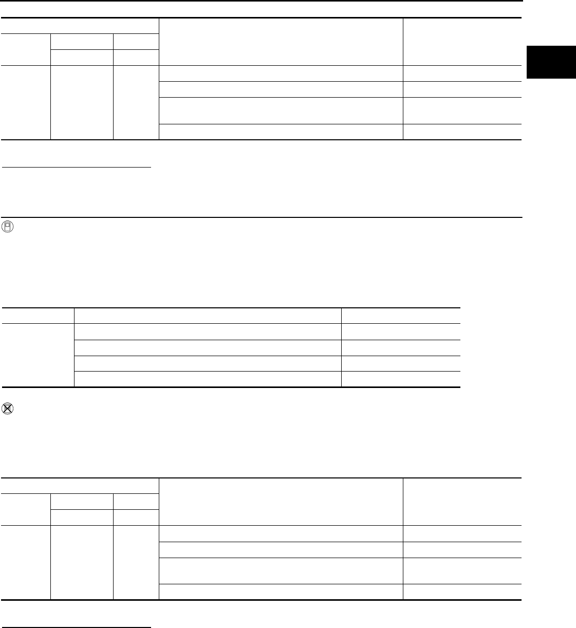
P0102, P0103 MAF SENSOR
EC-1051
< COMPONENT DIAGNOSIS > [FOR MEXICO]
C
D
E
F
G
H
I
J
K
L
M
A
EC
N
P
O
*: Check for linear voltage rise in response to engine being increased to approximately 4,000 rpm.
Is the inspection result normal?
YES >> INSPECTION END
NO >> GO TO 4.
4.CHECK MASS AIR FLOW SENSOR-III
With CONSULT-III
1. Turn ignition switch OFF.
2. Disconnect mass air flow sensor harness connector and reconnect it again.
3. Start engine and warm it up to normal operating temperature.
4. Connect CONSULT-III and select “DATA MONITOR” mode.
5. Select “MAS A/F SE-B1” and check indication.
*: Check for linear voltage rise in response to engine being increased to approximately 4,000 rpm.
Without CONSULT-III
1. Turn ignition switch OFF.
2. Disconnect mass air flow sensor harness connector and reconnect it again.
3. Start engine and warm it up to normal operating temperature.
4. Check the voltage between ECM harness connector terminals under the following conditions.
*: Check for linear voltage rise in response to engine being increased to approximately 4,000 rpm.
Is the inspection result normal?
YES >> INSPECTION END
NO >> Clean or replace mass air flow sensor.
ECM
Condition Voltage
Connector +−
Terminal Terminal
F8
58
(MAF sensor
signal)
56
(Sensor
gound)
Ignition switch ON (Engine stopped.) Approx. 0.4V
Idle (Engine is warmed-up to normal operating temperature.) 0.8 - 1.2V
2,500 rpm (Engine is warmed-up to normal operating temper-
ature.) 1.4 - 1.8V
Idle to approx. 4,000 rpm 0.8 - 1.2V to Approx. 2.4V*
Monitor item Condition MAS A/F SE-B1
MAS A/F SE-B1
Ignition switch ON (Engine stopped.) Approx. 0.4V
Idle (Engine is warmed-up to normal operating temperature.) 0.8 - 1.2V
2,500 rpm (Engine is warmed-up to normal operating temperature.) 1.4 - 1.8V
Idle to approx. 4,000 rpm 0.8 - 1.2V to Approx. 2.4V*
ECM
Condition Voltage
Connector +−
Terminal Terminal
F8
58
(MAF sensor
signal)
56
(Sensor
gound)
Ignition switch ON (Engine stopped.) Approx. 0.4V
Idle (Engine is warmed-up to normal operating temperature.) 0.8 - 1.2V
2,500 rpm (Engine is warmed-up to normal operating temper-
ature.) 1.4 - 1.8V
Idle to approx. 4,000 rpm 0.8 - 1.2V to Approx. 2.4V*
Revision: 2008 August 2009 Rogue
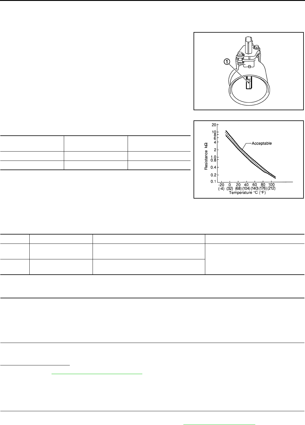
EC-1052
< COMPONENT DIAGNOSIS > [FOR MEXICO]
P0112, P0113 IAT SENSOR
P0112, P0113 IAT SENSOR
Description INFOID:0000000004494190
The intake air temperature sensor is built-into the mass air flow sen-
sor (1). The sensor detects intake air temperature and transmits a
signal to the ECM.
The temperature sensing unit uses a thermistor which is sensitive to
the change in temperature. Electrical resistance of the thermistor
decreases in response to the rise in temperature.
<Reference data>
*: These data are reference values and are measured between ECM terminals 50
(Intake air temperature sensor) and 58 (Sensor ground).
DTC Logic INFOID:0000000004494191
DTC DETECTION LOGIC
DTC CONFIRMATION PROCEDURE
1.PRECONDITIONING
If DTC CONFIRMATION PROCEDURE has been previously conducted, always turn ignition switch OFF and
wait at least 10 seconds before conducting the next test.
>> GO TO 2.
2.PERFORM DTC CONFIRMATION PROCEDURE
1. Turn ignition switch ON and wait at least 5 seconds.
2. Check 1st trip DTC.
Is 1st trip DTC detected?
YES >> Go to EC-1052, "Diagnosis Procedure".
NO >> INSPECTION END
Diagnosis Procedure INFOID:0000000004494192
1.CHECK GROUND CONNECTION
1. Turn ignition switch OFF.
2. Check ground connection E21. Refer to Ground Inspection in GI-44, "Circuit Inspection".
PBIA9559J
Intake air temperature
[°C (°F)] Voltage* (V) Resistance (kΩ)
25 (77) 3.3 1.800 - 2.200
80 (176) 1.2 0.283 - 0.359
SEF012P
DTC No. Trouble diagnosis name DTC detecting condition Possible cause
P0112 Intake air temperature
sensor circuit low input An excessively low voltage from the sensor is
sent to ECM. • Harness or connectors
(The sensor circuit is open or shorted.)
• Intake air temperature sensor
P0113 Intake air temperature
sensor circuit high input
An excessively high voltage from the sensor is
sent to ECM.
Revision: 2008 August 2009 Rogue

P0112, P0113 IAT SENSOR
EC-1053
< COMPONENT DIAGNOSIS > [FOR MEXICO]
C
D
E
F
G
H
I
J
K
L
M
A
EC
N
P
O
Is the inspection result normal?
YES >> GO TO 2.
NO >> Repair or replace ground connection.
2.CHECK INTAKE AIR TEMPERATURE SENSOR POWER SUPPLY CIRCUIT
1. Disconnect mass air flow sensor (with intake air temperature sensor) harness connector.
2. Turn ignition switch ON.
3. Check the voltage between mass air flow sensor harness connector and ground.
Is the inspection result normal?
YES >> GO TO 4.
NO >> GO TO 3.
3.DETECT MALFUNCTIONING PART
Check the following.
• Harness connectors E6, F123
• Harness for open or short between mass air flow sensor and ECM
>> Repair open circuit or short to ground or short to power in harness or connectors.
4.CHECK INTAKE AIR TEMPERATURE SENSOR GROUND CIRCUIT FOR OPEN AND SHORT
1. Turn ignition switch OFF.
2. Disconnect ECM harness connector.
3. Check the continuity between mass air flow sensor harness connector and ECM harness connector.
4. Also check harness for short to ground and short to power.
Is the inspection result normal?
YES >> GO TO 6.
NO >> GO TO 5.
5.DETECT MALFUNCTIONING PART
Check the following.
• Harness connectors E6, F123
• Harness for open or short between mass air flow sensor and ECM
>> Repair open circuit or short to ground or short to power in harness or connectors.
6.CHECK INTAKE AIR TEMPERATURE SENSOR
Refer to EC-1054, "Component Inspection".
Is the inspection result normal?
YES >> GO TO 7.
NO >> Replace mass air flow sensor (with intake air temperature sensor).
7.CHECK INTERMITTENT INCIDENT
Refer to GI-41, "Intermittent Incident".
>> INSPECTION END
MAF sensor Ground Voltage
Connector Terminal
E18 2 Ground Approx. 5V
MAF sensor ECM Continuity
Connector Terminal Connector Terminal
E18 1 F8 56 Existed
Revision: 2008 August 2009 Rogue

EC-1054
< COMPONENT DIAGNOSIS > [FOR MEXICO]
P0112, P0113 IAT SENSOR
Component Inspection INFOID:0000000004494193
1.CHECK INTAKE AIR TEMPERATURE SENSOR
1. Turn ignition switch OFF.
2. Disconnect mass air flow sensor harness connector.
3. Check resistance between mass air flow sensor terminals as follows.
Is the inspection result normal?
YES >> INSPECTION END
NO >> Replace mass air flow sensor (with intake air temperature sensor).
Terminals Condition Resistance (kΩ)
1 and 2 Intake air temperature [°C (°F)] 25 (77) 1.800 - 2.200
Revision: 2008 August 2009 Rogue
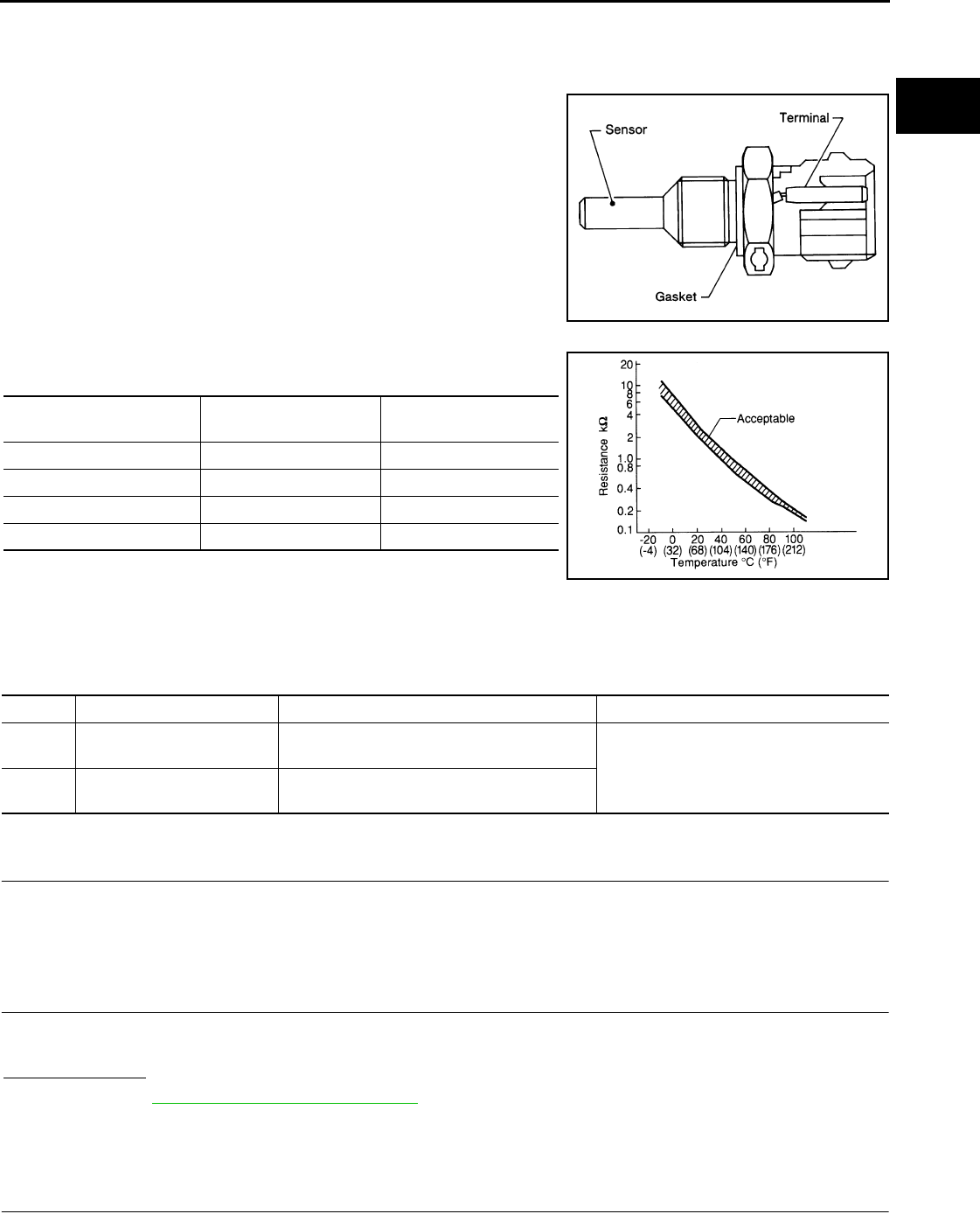
P0117, P0118 ECT SENSOR
EC-1055
< COMPONENT DIAGNOSIS > [FOR MEXICO]
C
D
E
F
G
H
I
J
K
L
M
A
EC
N
P
O
P0117, P0118 ECT SENSOR
Description INFOID:0000000004494194
The engine coolant temperature sensor is used to detect the engine
coolant temperature. The sensor modifies a voltage signal from the
ECM. The modified signal returns to the ECM as the engine coolant
temperature input. The sensor uses a thermistor which is sensitive to
the change in temperature. The electrical resistance of the ther-
mistor decreases as temperature increases.
<Reference data>
*: These data are reference values and are measured between ECM terminals 46
(Engine coolant temperature sensor) and 52 (Sensor ground).
DTC Logic INFOID:0000000004494195
DTC DETECTION LOGIC
DTC CONFIRMATION PROCEDURE
1.PRECONDITIONING
If DTC CONFIRMATION PROCEDURE has been previously conducted, always turn ignition switch OFF and
wait at least 10 seconds before conducting the next test.
>> GO TO 2.
2.PERFORM DTC CONFIRMATION PROCEDURE
1. Turn ignition switch ON and wait at least 5 seconds.
2. Check DTC.
Is DTC detected?
YES >> Go to EC-1055, "Diagnosis Procedure".
NO >> INSPECTION END
Diagnosis Procedure INFOID:0000000004494196
1.CHECK GROUND CONNECTION
1. Turn ignition switch OFF.
SEF594K
Engine coolant temperature
[°C (°F)] Voltage* (V) Resistance (kΩ)
–10 (14) 4.4 7.0 - 11.4
20 (68) 3.5 2.10 - 2.90
50 (122) 2.2 0.68 - 1.00
90 (194) 0.9 0.236 - 0.260
SEF012P
DTC No. Trouble Diagnosis Name DTC Detecting Condition Possible Cause
P0117 Engine coolant temperature
sensor circuit low input An excessively low voltage from the sensor is
sent to ECM. • Harness or connectors
(The sensor circuit is open or shorted.)
• Engine coolant temperature sensor
P0118 Engine coolant temperature
sensor circuit high input
An excessively high voltage from the sensor is
sent to ECM.
Revision: 2008 August 2009 Rogue

EC-1056
< COMPONENT DIAGNOSIS > [FOR MEXICO]
P0117, P0118 ECT SENSOR
2. Check ground connection E21. Refer to Ground Inspection in GI-44, "Circuit Inspection".
Is the inspection result normal?
YES >> GO TO 2.
NO >> Repair or replace ground connection.
2.CHECK ECT SENSOR POWER SUPPLY CIRCUIT
1. Disconnect engine coolant temperature (ECT) sensor harness connector.
2. Turn ignition switch ON.
3. Check the voltage between ECT sensor harness connector and ground.
Is the inspection result normal?
YES >> GO TO 3.
NO >> Repair open circuit or short to ground or short to power in harness or connectors.
3.CHECK ECT SENSOR GROUND CIRCUIT FOR OPEN AND SHORT
1. Turn ignition switch OFF.
2. Disconnect ECM harness connector.
3. Check the continuity between ECT sensor harness connector and ECM harness connector.
4. Also check harness for short to ground and short to power.
Is the inspection result normal?
YES >> GO TO 4.
NO >> Repair open circuit or short to ground or short to power in harness or connectors.
4.CHECK ENGINE COOLANT TEMPERATURE SENSOR
Refer to EC-1056, "Component Inspection".
Is the inspection result normal?
YES >> GO TO 5.
NO >> Replace engine coolant temperature sensor.
5.CHECK INTERMITTENT INCIDENT
Refer to GI-41, "Intermittent Incident".
>> INSPECTION END
Component Inspection INFOID:0000000004494197
1.CHECK ENGINE COOLANT TEMPERATURE SENSOR
1. Turn ignition switch OFF.
2. Disconnect engine coolant temperature sensor harness connector.
3. Remove engine coolant temperature sensor.
ECT sensor Ground Voltage
Connector Terminal
F80 1 Ground Approx. 5V
ECT sensor ECM Continuity
Connector Terminal Connector Terminal
F80 2 F8 52 Existed
Revision: 2008 August 2009 Rogue

P0117, P0118 ECT SENSOR
EC-1057
< COMPONENT DIAGNOSIS > [FOR MEXICO]
C
D
E
F
G
H
I
J
K
L
M
A
EC
N
P
O
4. Check resistance between engine coolant temperature sensor
terminals by heating with hot water as shown in the figure.
Is the inspection result normal?
YES >> INSPECTION END
NO >> Replace engine coolant temperature sensor.
Terminals Condition Resistance
1 and 2 Temperature [°C (°F)]
20 (68) 2.10 - 2.90 kΩ
50 (122) 0.68 - 1.00 kΩ
90 (194) 0.236 - 0.260 kΩ
JMBIA0080ZZ
Revision: 2008 August 2009 Rogue
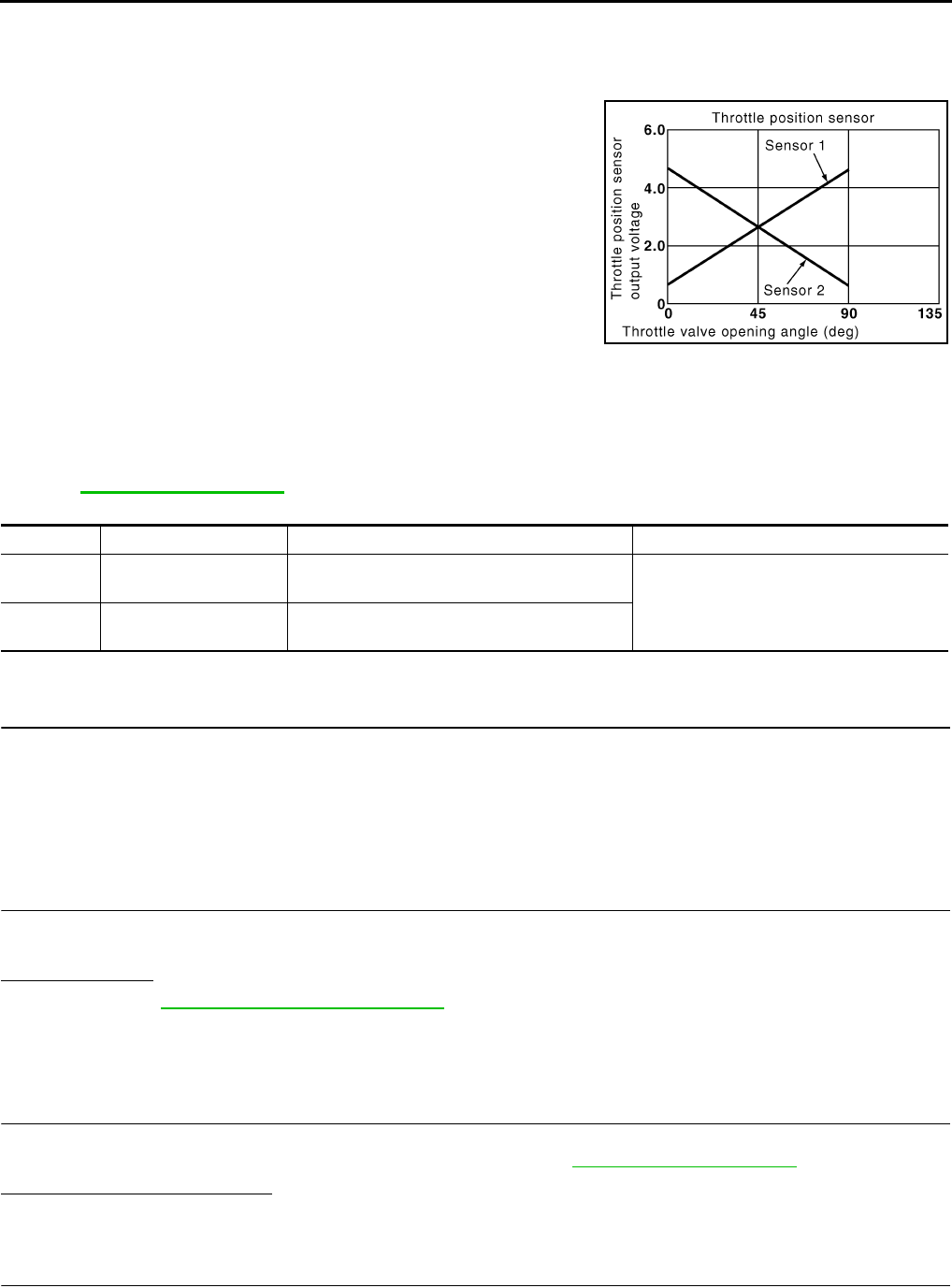
EC-1058
< COMPONENT DIAGNOSIS > [FOR MEXICO]
P0122, P0123 TP SENSOR
P0122, P0123 TP SENSOR
Description INFOID:0000000004494198
Electric throttle control actuator consists of throttle control motor,
throttle position sensor, etc. The throttle position sensor responds to
the throttle valve movement.
The throttle position sensor has two sensors. These sensors are a
kind of potentiometer which transform the throttle valve position into
output voltage, and emit the voltage signals to the ECM. The ECM
judges the current opening angle of the throttle valve from these sig-
nals and controls the throttle valve opening angle in response to
driving conditions via the throttle control motor.
DTC Logic INFOID:0000000004494199
DTC DETECTION LOGIC
NOTE:
If DTC P0122 or P0123 is displayed with DTC P0643, first perform the trouble diagnosis for DTC P0643.
Refer to EC-1147, "DTC Logic".
DTC CONFIRMATION PROCEDURE
1.PRECONDITIONING
If DTC CONFIRMATION PROCEDURE has been previously conducted, always turn ignition switch OFF and
wait at least 10 seconds before conducting the next test.
TESTING CONDITION:
Before performing the following procedure, confirm that battery voltage is more than 8V at idle.
>> GO TO 2.
2.PERFORM DTC CONFIRMATION PROCEDURE
1. Start engine and let it idle for 1 second.
2. Check DTC.
Is DTC detected?
YES >> Go to EC-1058, "Diagnosis Procedure".
NO >> INSPECTION END
Diagnosis Procedure INFOID:0000000004494200
1.CHECK GROUND CONNECTION
1. Turn ignition switch OFF.
2. Check ground connection E21. Refer to Ground Inspection in GI-44, "Circuit Inspection".
Is the inspection result normal?
YES >> GO TO 2.
NO >> Repair or replace ground connection.
2.CHECK THROTTLE POSITION SENSOR 2 POWER SUPPLY CIRCUIT
1. Disconnect electric throttle control actuator harness connector.
2. Turn ignition switch ON.
PBIB0145E
DTC No. Trouble diagnosis name DTC detecting condition Possible cause
P0122 Throttle position sensor
2 circuit low input An excessively low voltage from the TP sensor
2 is sent to ECM. • Harness or connectors
(TP sensor 2 circuit is open or shorted.)
• Electric throttle control actuator
(TP sensor 2)
P0123 Throttle position sensor
2 circuit high input
An excessively high voltage from the TP sensor
2 is sent to ECM.
Revision: 2008 August 2009 Rogue

P0122, P0123 TP SENSOR
EC-1059
< COMPONENT DIAGNOSIS > [FOR MEXICO]
C
D
E
F
G
H
I
J
K
L
M
A
EC
N
P
O
3. Check the voltage between electric throttle control actuator harness connector and ground.
Is the inspection result normal?
YES >> GO TO 3.
NO >> Repair open circuit or short to ground or short to power in harness or connectors.
3.CHECK THROTTLE POSITION SENSOR 2 GROUND CIRCUIT FOR OPEN AND SHORT
1. Turn ignition switch OFF.
2. Disconnect ECM harness connector.
3. Check the continuity between electric throttle control actuator harness connector and ECM harness con-
nector.
4. Also check harness for short to ground and short to power.
Is the inspection result normal?
YES >> GO TO 4.
NO >> Repair open circuit or short to ground or short to power in harness or connectors.
4.CHECK THROTTLE POSITION SENSOR 2 INPUT SIGNAL CIRCUIT FOR OPEN AND SHORT
1. Check the continuity between electric throttle control actuator harness connector and ECM harness con-
nector.
2. Also check harness for short to ground and short to power.
Is the inspection result normal?
YES >> GO TO 5.
NO >> Repair open circuit or short to ground or short to power in harness or connectors.
5.CHECK THROTTLE POSITION SENSOR
Refer to EC-1060, "Component Inspection".
Is the inspection result normal?
YES >> GO TO 7.
NO >> GO TO 6.
6.REPLACE ELECTRIC THROTTLE CONTROL ACTUATOR
1. Replace electric throttle control actuator.
2. Perform EC-1060, "Special Repair Requirement".
>> INSPECTION END
7.CHECK INTERMITTENT INCIDENT
Refer to GI-41, "Intermittent Incident".
>> INSPECTION END
Electric throttle control actuator Ground Voltage
Connector Terminal
F29 1 Ground Approx. 5V
Electric throttle control actuator ECM Continuity
Connector Terminal Connector Terminal
F29 4 F8 36 Existed
Electric throttle control actuator ECM Continuity
Connector Terminal Connector Terminal
F29 3 F8 38 Existed
Revision: 2008 August 2009 Rogue
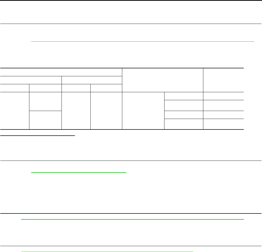
EC-1060
< COMPONENT DIAGNOSIS > [FOR MEXICO]
P0122, P0123 TP SENSOR
Component Inspection INFOID:0000000004494201
1.CHECK THROTTLE POSITION SENSOR
1. Turn ignition switch OFF.
2. Reconnect all harness connectors disconnected.
3. Perform EC-938, "THROTTLE VALVE CLOSED POSITION LEARNING : Special Repair Requirement".
4. Turn ignition switch ON.
5. Set selector lever to the D position.
6. Check the voltage between ECM harness connector terminals.
Is the inspection result normal?
YES >> INSPECTION END
NO >> GO TO 2.
2.REPLACE ELECTRIC THROTTLE CONTROL ACTUATOR
1. Replace electric throttle control actuator.
2. Perform EC-1060, "Special Repair Requirement".
>> INSPECTION END
Special Repair Requirement INFOID:0000000004494202
1.PERFORM THROTTLE VALVE CLOSED POSITION LEARNING
Refer to EC-938, "THROTTLE VALVE CLOSED POSITION LEARNING : Special Repair Requirement"
>> GO TO 2.
2.PERFORM IDLE AIR VOLUME LEARNING
Refer to EC-938, "IDLE AIR VOLUME LEARNING : Special Repair Requirement"
>> END
ECM
Condition Voltage+−
Connector Terminal Connector Terminal
F8
37
(TP sensor 1
signal) F8
36
(Sensor
ground) Accelerator pedal
Fully released More than 0.36 V
Fully depressed Less than 4.75 V
38
(TP sensor 2
signal)
Fully released Less than 4.75 V
Fully depressed More than 0.36 V
Revision: 2008 August 2009 Rogue
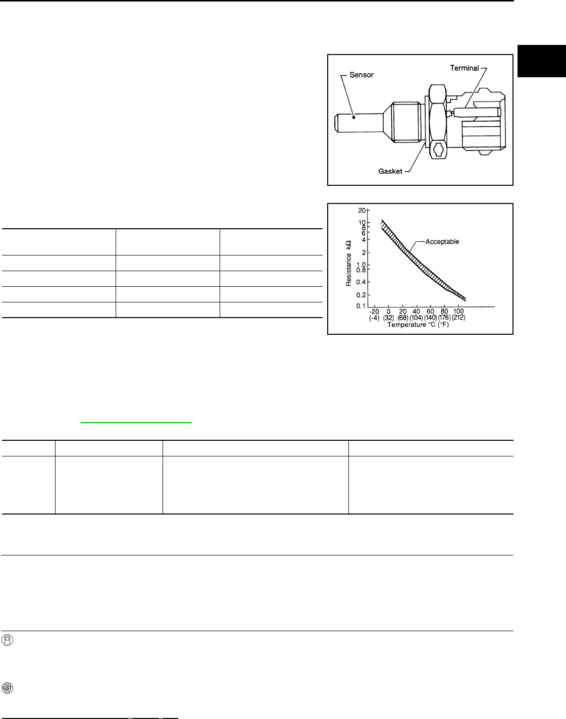
P0125 ECT SENSOR
EC-1061
< COMPONENT DIAGNOSIS > [FOR MEXICO]
C
D
E
F
G
H
I
J
K
L
M
A
EC
N
P
O
P0125 ECT SENSOR
Description INFOID:0000000004534365
The engine coolant temperature sensor is used to detect the engine
coolant temperature. The sensor modifies a voltage signal from the
ECM. The modified signal returns to the ECM as the engine coolant
temperature input. The sensor uses a thermistor which is sensitive to
the change in temperature. The electrical resistance of the ther-
mistor decreases as temperature increases.
<Reference data>
*: These data are reference values and are measured between ECM terminals 46
(Engine coolant temperature sensor) and 52 (Sensor ground).
DTC Logic INFOID:0000000004494204
DTC DETECTION LOGIC
NOTE:
If DTC P0125 is displayed with P0117 or P0118, first perform the trouble diagnosis for DTC P0117 or
P0118. Refer to EC-1055, "DTC Logic".
DTC CONFIRMATION PROCEDURE
1.PRECONDITIONING
If DTC CONFIRMATION PROCEDURE has been previously conducted, always turn ignition switch OFF and
wait at least 10 seconds before conducting the next test.
>> GO TO 2.
2.CHECK ENGINE COOLANT TEMPERATURE SENSOR FUNCTION
With CONSULT-III
1. Turn ignition switch ON.
2. Select “DATA MONITOR” mode with CONSULT-III.
3. Check that “COOLAN TEMP/S” indication is above 5°C (41°F).
With GST
Follow the procedure “With CONSULT-III” above.
Is the temperature above 5°C (41°F)?
SEF594K
Engine coolant temperature
[°C (°F)] Voltage* (V) Resistance (kΩ)
–10 (14) 4.4 7.0 - 11.4
20 (68) 3.5 2.10 - 2.90
50 (122) 2.2 0.68 - 1.00
90 (194) 0.9 0.236 - 0.260
SEF012P
DTC No. Trouble diagnosis name DTC detecting condition Possible cause
P0125
Insufficient engine coolant
temperature for closed
loop fuel control
• Voltage sent to ECM from the sensor is not
practical, even when some time has passed
after starting the engine.
• Engine coolant temperature is insufficient for
closed loop fuel control.
• Harness or connectors
(High resistance in the circuit)
• Engine coolant temperature sensor
•Thermostat
Revision: 2008 August 2009 Rogue

EC-1062
< COMPONENT DIAGNOSIS > [FOR MEXICO]
P0125 ECT SENSOR
YES >> INSPECTION END
NO >> GO TO 3.
3.PERFORM DTC CONFIRMATION PROCEDURE
With CONSULT-III
1. Start engine and run it for 65 minutes at idle speed.
2. Check 1st tip DTC.
If “COOLAN TEMP/S” indication increases to more than 5°C (41°F) within 65 minutes, stop engine
because the test result will be OK.
CAUTION:
Never overheat engine.
With GST
Follow the procedure “With CONSULT-III” above.
Is 1st trip DTC detected?
YES >> EC-1062, "Diagnosis Procedure"
NO >> INSPECTION END
Diagnosis Procedure INFOID:0000000004494205
1.CHECK GROUND CONNECTION
1. Turn ignition switch OFF.
2. Check ground connection E21. Refer to Ground Inspection in GI-44, "Circuit Inspection".
Is the inspection result normal?
YES >> GO TO 2.
NO >> Repair or replace ground connection.
2.CHECK ENGINE COOLANT TEMPERATURE SENSORCO-25, "REMOVAL AND INSTALLATION"
Refer to EC-1062, "Component Inspection".
Is the inspection result normal?
YES >> GO TO 3.
NO >> Replace engine coolant temperature sensor.
3.CHECK THERMOSTAT OPERATION
When the engine is cold [lower than 70°C (158°F)] condition, grasp lower radiator hose and confirm that the
engine coolant does not flow.
Is the inspection result normal?
YES >> GO TO 4.
NO >> Repair or replace thermostat. Refer to CO-25, "Removal and Installation".
4.CHECK INTERMITTENT INCIDENT
Refer to GI-41, "Intermittent Incident".
>> INSPECTION END
Component Inspection INFOID:0000000004534366
1.CHECK ENGINE COOLANT TEMPERATURE SENSOR
1. Turn ignition switch OFF.
2. Disconnect engine coolant temperature sensor harness connector.
3. Remove engine coolant temperature sensor.
Revision: 2008 August 2009 Rogue
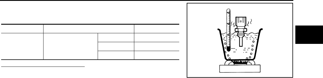
P0125 ECT SENSOR
EC-1063
< COMPONENT DIAGNOSIS > [FOR MEXICO]
C
D
E
F
G
H
I
J
K
L
M
A
EC
N
P
O
4. Check resistance between engine coolant temperature sensor
terminals by heating with hot water as shown in the figure.
Is the inspection result normal?
YES >> INSPECTION END
NO >> Replace engine coolant temperature sensor.
Terminals Condition Resistance
1 and 2 Temperature [°C (°F)]
20 (68) 2.10 - 2.90 kΩ
50 (122) 0.68 - 1.00 kΩ
90 (194) 0.236 - 0.260 kΩ
JMBIA0080ZZ
Revision: 2008 August 2009 Rogue
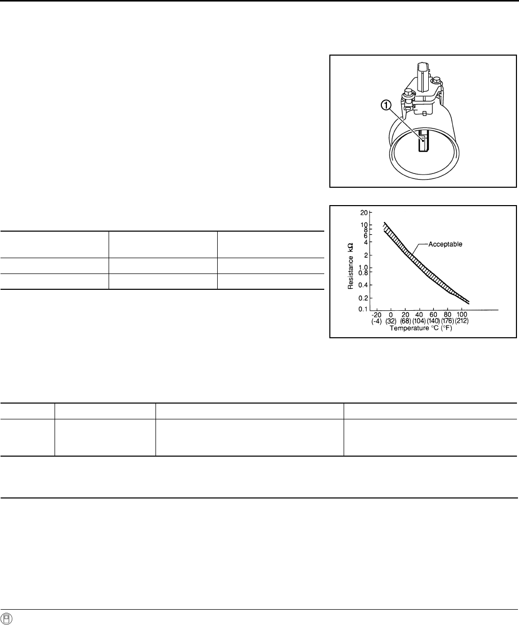
EC-1064
< COMPONENT DIAGNOSIS > [FOR MEXICO]
P0127 IAT SENSOR
P0127 IAT SENSOR
Description INFOID:0000000004534370
The intake air temperature sensor is built-into the mass air flow sen-
sor (1). The sensor detects intake air temperature and transmits a
signal to the ECM.
The temperature sensing unit uses a thermistor which is sensitive to
the change in temperature. Electrical resistance of the thermistor
decreases in response to the rise in temperature.
<Reference data>
*: These data are reference values and are measured between ECM terminals 50
(Intake air temperature sensor) and 58 (Sensor ground).
DTC Logic INFOID:0000000004494208
DTC DETECTION LOGIC
DTC CONFIRMATION PROCEDURE
1.PRECONDITIONING
If DTC CONFIRMATION PROCEDURE has been previously conducted, always turn ignition switch OFF and
wait at least 10 seconds before conducting the next test.
TESTING CONDITION:
This test may be conducted with the drive wheels lifted in the shop or by driving the vehicle. If a road
test is expected to be easier, it is unnecessary to lift the vehicle.
>> GO TO 2.
2.PERFORM DTC CONFIRMATION PROCEDURE
With CONSULT-III
1. Wait until engine coolant temperature is less than 90°C (194°F)
- Turn ignition switch ON.
- Select “DATA MONITOR” mode with CONSULT-III.
- Check the engine coolant temperature.
- If the engine coolant temperature is not less than 90°C (194°F), turn ignition switch OFF and cool down
engine.
NOTE:
Perform the following steps before engine coolant temperature is above 90°C (194°F).
PBIA9559J
Intake air temperature
[°C (°F)] Voltage* (V) Resistance (kΩ)
25 (77) 3.3 1.800 - 2.200
80 (176) 1.2 0.283 - 0.359
SEF012P
DTC No. Trouble diagnosis name DTC detecting condition Possible cause
P0127 Intake air temperature
too high
Rationally incorrect voltage from the sensor is
sent to ECM, compared with the voltage signal
from engine coolant temperature sensor.
• Harness or connectors
(The sensor circuit is open or shorted)
• Intake air temperature sensor
Revision: 2008 August 2009 Rogue
P0127 IAT SENSOR
EC-1065
< COMPONENT DIAGNOSIS > [FOR MEXICO]
C
D
E
F
G
H
I
J
K
L
M
A
EC
N
P
O
2. Start engine.
3. Hold vehicle speed at more than 70 km/h (43 MPH) for 100 consecutive seconds.
CAUTION:
Always drive vehicle at a safe speed.
4. Check 1st trip DTC.
With GST
Follow the procedure “With CONSULT-III” above.
Is 1st trip DTC detected?
YES >> Go to EC-1065, "Diagnosis Procedure".
NO >> INSPECTION END
Diagnosis Procedure INFOID:0000000004494209
1.CHECK GROUND CONNECTION
1. Turn ignition switch OFF.
2. Check ground connection E21. Refer to Ground Inspection in GI-44, "Circuit Inspection".
Is the inspection result normal?
YES >> GO TO 2.
NO >> Repair or replace ground connection.
2.CHECK INTAKE AIR TEMPERATURE SENSOR
Refer to EC-1065, "Component Inspection".
Is the inspection result normal?
YES >> GO TO 3.
NO >> Replace mass air flow sensor (with intake air temperature sensor).
3.CHECK INTERMITTENT INCIDENT
Refer to GI-41, "Intermittent Incident".
>> INSPECTION END
Component Inspection INFOID:0000000004534371
1.CHECK INTAKE AIR TEMPERATURE SENSOR
1. Turn ignition switch OFF.
2. Disconnect mass air flow sensor harness connector.
3. Check resistance between mass air flow sensor terminals as follows.
Is the inspection result normal?
YES >> INSPECTION END
NO >> Replace mass air flow sensor (with intake air temperature sensor).
Terminals Condition Resistance (kΩ)
1 and 2 Intake air temperature [°C (°F)] 25 (77) 1.800 - 2.200
Revision: 2008 August 2009 Rogue
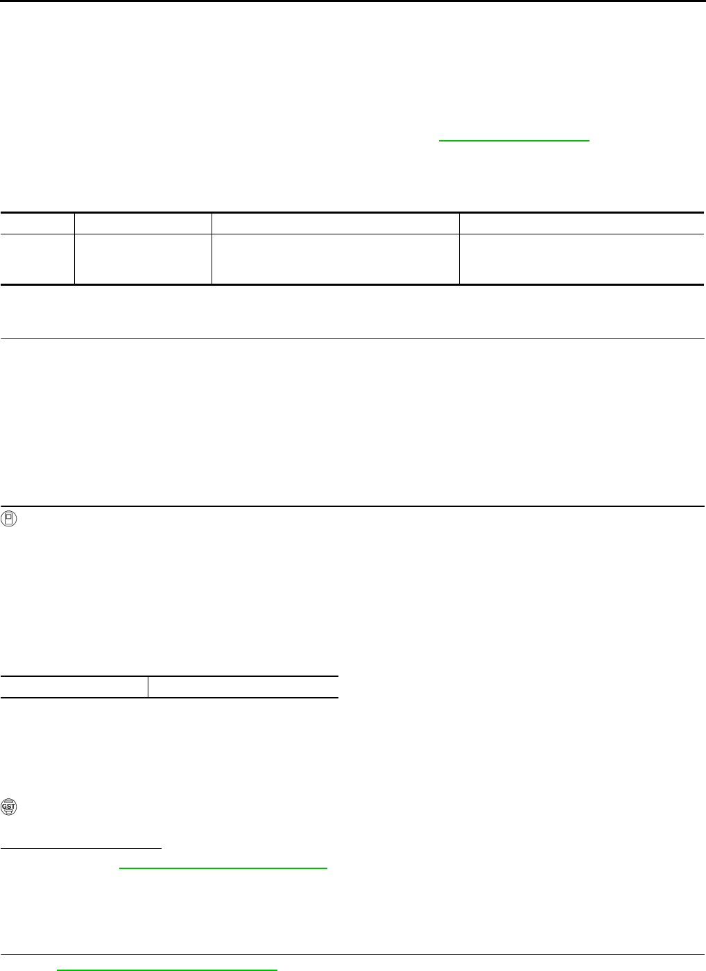
EC-1066
< COMPONENT DIAGNOSIS > [FOR MEXICO]
P0128 THERMOSTAT FUNCTION
P0128 THERMOSTAT FUNCTION
DTC Logic INFOID:0000000004494211
DTC DETECTION LOGIC
NOTE:
If DTC P0128 is displayed with DTC PP0300, P0301, P0302, P0303 or P0304, first perform the trouble
diagnosis for DTC P0300, P0301, P0302, P0303, P0304. Refer to EC-1113, "DTC Logic".
Engine coolant temperature has not risen enough to open the thermostat even though the engine has run long
enough.
This is due to a leak in the seal or the thermostat stuck being open.
DTC CONFIRMATION PROCEDURE
1.PRECONDITIONING
If DTC CONFIRMATION PROCEDURE has been previously conducted, always turn ignition switch OFF and
wait at least 10 seconds before conducting the next test.
TESTING CONDITION:
•For best results, perform at ambient temperature of –10°C (14°F) or higher.
•For best results, perform at engine coolant temperature of –10°C (14°F) to 56°C (133°F).
•Before performing the following procedure, do not add fuel.
>> GO TO 2.
2.PERFORM DTC CONFIRMATION PROCEDURE
With CONSULT-III
1. Turn A/C switch OFF.
2. Turn blower fan switch OFF.
3. Turn ignition switch ON.
4. Select “COOLAN TEMP/S” in “DATA MONITOR” mode with CONSULT-III.
5. Check the indication of “COOLAN TEMP/S”
If it is below 56°C (133°F), go to next step.
If it is above 56°C (133°F), cool down the engine to less than 56°C (133°F). Then go to next steps.
6. Start engine drive vehicle for 10 consecutive minutes under the following conditions.
CAUTION:
Always drive vehicle at a safe speed.
NOTE:
If “COOLAN TEMP/S” increases to more than 75°C (160°F) within 10 minutes, turn ignition switch
OFF because the test result will be OK.
7. Check 1st trip DTC.
With GST
Follow the procedure “With CONSULT-III” above.
Is 1st trip DTC detected?
YES >> Go to EC-1114, "Diagnosis Procedure".
NO >> INSPECTION END
Diagnosis Procedure INFOID:0000000004494212
1.CHECK ENGINE COOLANT TEMPERATURE SENSOR
Refer to EC-1067, "Component Inspection".
DTC No. Trouble diagnosis name DTC detecting condition Possible cause
P0128 Thermostat function
The engine coolant temperature does not
reach to specified temperature even though
the engine has run long enough.
•Thermostat
• Leakage from sealing portion of thermostat
• Engine coolant temperature sensor
VHCL SPEED SE More than 56 km/h (35 MPH)
Revision: 2008 August 2009 Rogue
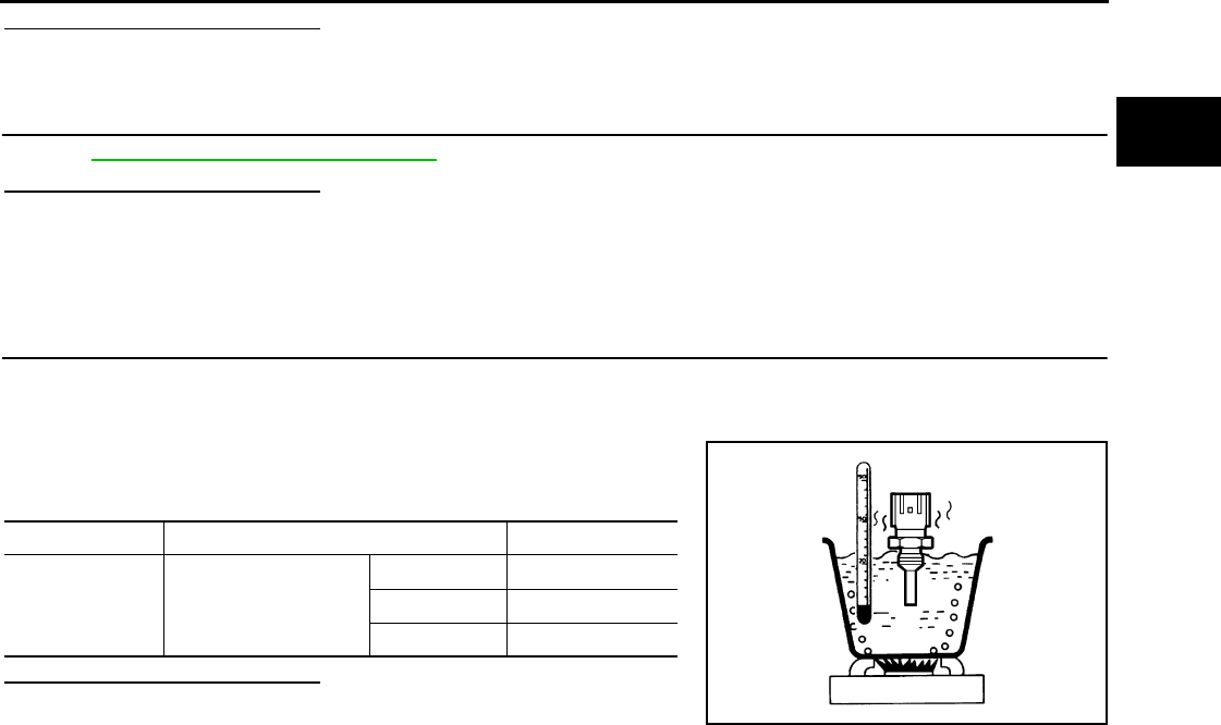
P0128 THERMOSTAT FUNCTION
EC-1067
< COMPONENT DIAGNOSIS > [FOR MEXICO]
C
D
E
F
G
H
I
J
K
L
M
A
EC
N
P
O
Is the inspection result normal?
YES >> GO TO 2.
NO >> Replace engine coolant temperature sensor.
2.CHECK THERMOSTAT
Refer to CO-25, "Removal and Installation".
Is the inspection result normal?
YES >> INSPECTION END
NO >> Replace thermostat.
Component Inspection INFOID:0000000004534372
1.CHECK ENGINE COOLANT TEMPERATURE SENSOR
1. Turn ignition switch OFF.
2. Disconnect engine coolant temperature sensor harness connector.
3. Remove engine coolant temperature sensor.
4. Check resistance between engine coolant temperature sensor
terminals by heating with hot water as shown in the figure.
Is the inspection result normal?
YES >> INSPECTION END
NO >> Replace engine coolant temperature sensor.
Terminals Condition Resistance
1 and 2 Temperature [°C (°F)]
20 (68) 2.10 - 2.90 kΩ
50 (122) 0.68 - 1.00 kΩ
90 (194) 0.236 - 0.260 kΩ
JMBIA0080ZZ
Revision: 2008 August 2009 Rogue
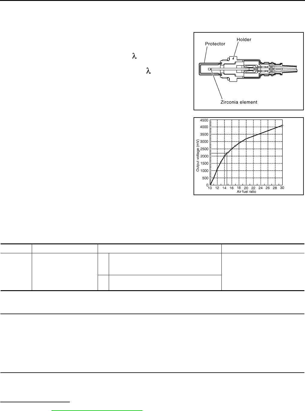
EC-1068
< COMPONENT DIAGNOSIS > [FOR MEXICO]
P0130 A/F SENSOR 1
P0130 A/F SENSOR 1
Description INFOID:0000000004494214
The air fuel ratio (A/F) sensor 1 is a planar one-cell limit current sen-
sor. The sensor element of the A/F sensor 1 is composed an elec-
trode layer, which transports ions. It has a heater in the element.
The sensor is capable of precise measurement = 1, but also in the
lean and rich range. Together with its control electronics, the sensor
outputs a clear, continuous signal throughout a wide range.
The exhaust gas components diffuse through the diffusion layer at
the sensor cell. An electrode layer is applied voltage, and this current
relative oxygen density in lean. Also this current relative hydrocar-
bon density in rich.
Therefore, the A/F sensor 1 is able to indicate air fuel ratio by this
electrode layer of current. In addition, a heater is integrated in the
sensor to ensure the required operating temperature of approxi-
mately 800°C (1,472°F).
DTC Logic INFOID:0000000004494215
DTC DETECTION LOGIC
To judge malfunctions, the diagnosis checks that the A/F signal computed by ECM from the A/F sensor 1 sig-
nal fluctuates according to fuel feedback control.
DTC CONFIRMATION PROCEDURE
1.PRECONDITIONING
If DTC CONFIRMATION PROCEDURE has been previously conducted, always turn ignition switch OFF and
wait at least 10 seconds before conducting the next test.
TESTING CONDITION:
Before performing the following procedure, confirm that battery voltage is more than 11V at idle.
>> GO TO 2.
2.PERFORM DTC CONFIRMATION PROCEDURE FOR MALFUNCTION A
1. Start engine and warm it up to normal operating temperature.
2. Let it idle for 2 minutes.
3. Check 1st trip DTC.
Is 1st trip DTC detected?
YES >> Go to EC-1070, "Diagnosis Procedure".
NO-1 >> With CONSULT-III: GO TO 3.
NO-2 >> Without CONSULT-III: GO TO 7.
JMBIA0112GB
PBIB3354E
DTC No. Trouble diagnosis name DTC detecting condition Possible Cause
P0130 Air fuel ratio (A/F) sensor 1
circuit
A)
The A/F signal computed by ECM from the A/F
sensor 1 signal is constantly in the range other
than approx. 2.2V.
• Harness or connectors
(The A/F sensor 1 circuit is open
or shorted.)
• A/F sensor 1
B) The A/F signal computed by ECM from the A/F
sensor 1 signal is constantly approx. 2.2V.
Revision: 2008 August 2009 Rogue

P0130 A/F SENSOR 1
EC-1069
< COMPONENT DIAGNOSIS > [FOR MEXICO]
C
D
E
F
G
H
I
J
K
L
M
A
EC
N
P
O
3.CHECK AIR FUEL RATIO (A/F) SENSOR 1 FUNCTION
1. Select “A/F SEN1 (B1)” in “DATA MONITOR” mode with CONSULT-III.
2. Check “A/F SEN1 (B1)” indication.
Does the indication fluctuate around 2.2 V?
YES >> GO TO 4.
NO >> Go to EC-1070, "Diagnosis Procedure".
4.PERFORM DTC CONFIRMATION PROCEDURE FOR MALFUNCTION B-I
1. Select “A/F SEN1 (B1) P1276” of “A/F SEN1” in “DTC WORK SUPPORT” mode with CONSULT-III.
2. Touch “START”.
3. When the following conditions are met, “TESTING” will be displayed on the CONSULT-III screen.
If “TESTING” is not displayed after 20 seconds, retry from step 2.
CAUTION:
Always drive vehicle at a safe speed.
Is “TESTING” displayed on CONSULT-III screen?
YES >> GO TO 5.
NO >> Check A/F sensor 1 function again. GO TO 3.
5.PERFORM DTC CONFIRMATION PROCEDURE FOR MALFUNCTION B-II
Release accelerator pedal fully.
NOTE:
Never apply brake when releasing the accelerator pedal.
Which does “TESTING” change to?
COMPLETED>>GO TO 6.
OUT OF CONDITION>>Retry DTC CONFIRMATION PROCEDURE. GO TO 4.
6.PERFORM DTC CONFIRMATION PROCEDURE FOR MALFUNCTION B-III
Touch “SELF-DIAG RESULT”
Which is displayed on CONSULT-III screen?
OK >> INSPECTION END
NG >> Go to EC-1070, "Diagnosis Procedure".
7.PERFORM COMPONENT FUNCTION CHECK FOR MALFUNCTION B
Perform Component Function Check. Refer to EC-1069, "Component Function Check".
NOTE:
Use component function check to check the overall function of the A/F sensor 1 circuit. During this check, a
1st trip DTC might not be confirmed.
Is the inspection result normal?
YES >> INSPECTION END
NO >> Go to EC-1070, "Diagnosis Procedure".
Component Function Check INFOID:0000000004494216
1.PERFORM COMPONENT FUNCTION CHECK
With GST
1. Start engine and warm it up to normal operating temperature.
2. Drive the vehicle at a speed of 80 km/h (50 MPH) for a few minutes in the suitable gear position.
3. Shift the selector lever to the D position, then release the accelerator pedal fully until the vehicle speed
decreases to 50 km/h (31 MPH).
CAUTION:
ENG SPEED 1,100 - 3,200 rpm
VHCL SPEED SE More than 64 km/h (40 mph)
B/FUEL SCHDL 1.0 - 11.5 msec
Selector lever D position
Revision: 2008 August 2009 Rogue

EC-1070
< COMPONENT DIAGNOSIS > [FOR MEXICO]
P0130 A/F SENSOR 1
Always drive vehicle at a safe speed.
NOTE:
Never apply brake when releasing the accelerator pedal.
4. Repeat steps 2 and 3 for five times.
5. Stop the vehicle and turn ignition switch OFF.
6. Wait at least 10 seconds and restart engine.
7. Repeat steps 2 and 3 for five times.
8. Stop the vehicle and connect GST to the vehicle.
9. Check 1st trip DTC.
Is 1st trip DTC detected?
YES >> Go to EC-1070, "Diagnosis Procedure".
NO >> INSPECTION END
Diagnosis Procedure INFOID:0000000004494217
1.CHECK GROUND CONNECTION
1. Turn ignition switch OFF.
2. Check ground connection E21. Refer to Ground Inspection in GI-44, "Circuit Inspection".
Is the inspection result normal?
YES >> GO TO 2.
NO >> Repair or replace ground connection.
2.CHECK AIR FUEL RATIO (A/F) SENSOR 1 POWER SUPPLY CIRCUIT
1. Disconnect A/F sensor 1 harness connector.
2. Turn ignition switch ON.
3. Check the voltage between A/F sensor 1 harness connector and ground.
Is the inspection result normal?
YES >> GO TO 4.
NO >> GO TO 3.
3.DETECT MALFUNCTIONING PART
Check the following.
• Harness connectors E6, F123
• IPDM E/R harness connector E14
• 15A fuse (No. 63)
• Harness for open or short between A/F sensor 1 and fuse
>> Repair or replace harness or connectors.
4.CHECK A/F SENSOR 1 INPUT SIGNAL CIRCUIT FOR OPEN AND SHORT
1. Turn ignition switch OFF.
2. Disconnect ECM harness connector.
3. Check the continuity between A/F sensor 1 harness connector and ECM harness connector.
4. Check the continuity between A/F sensor 1 harness connector or ECM harness connector and ground.
A/F sensor 1 Ground Voltage
Connector Terminal
F27 4 Ground Battery voltage
A/F sensor 1 ECM Continuity
Connector Terminal Connector Terminal
F27 1F8 45 Existed
249
Revision: 2008 August 2009 Rogue

P0130 A/F SENSOR 1
EC-1071
< COMPONENT DIAGNOSIS > [FOR MEXICO]
C
D
E
F
G
H
I
J
K
L
M
A
EC
N
P
O
5. Also check harness for short to power.
Is the inspection result normal?
YES >> GO TO 5.
NO >> Repair open circuit or short to ground or short to power in harness or connectors.
5.CHECK INTERMITTENT INCIDENT
Perform GI-41, "Intermittent Incident".
Is the inspection result normal?
YES >> GO TO 6.
NO >> Repair or replace.
6.REPLACE AIR FUEL RATIO (A/F) SENSOR 1
Replace air fuel ratio (A/F) sensor 1.
CAUTION:
• Discard any A/F sensor which has been dropped from a height of more than 0.5 m (19.7 in) onto a
hard surface such as a concrete floor; use a new one.
• Before installing new A/F sensor, clean exhaust system threads using oxygen sensor thread cleaner
[commercial service tool (J-43897-18 or J-43897-12)] and approved anti-seize lubricant (commercial
service tool).
>> INSPECTION END
A/F sensor 1 ECM Ground Continuity
Connector Terminal Connector Terminal
F27 1F8 45 Ground Not existed
249
Revision: 2008 August 2009 Rogue
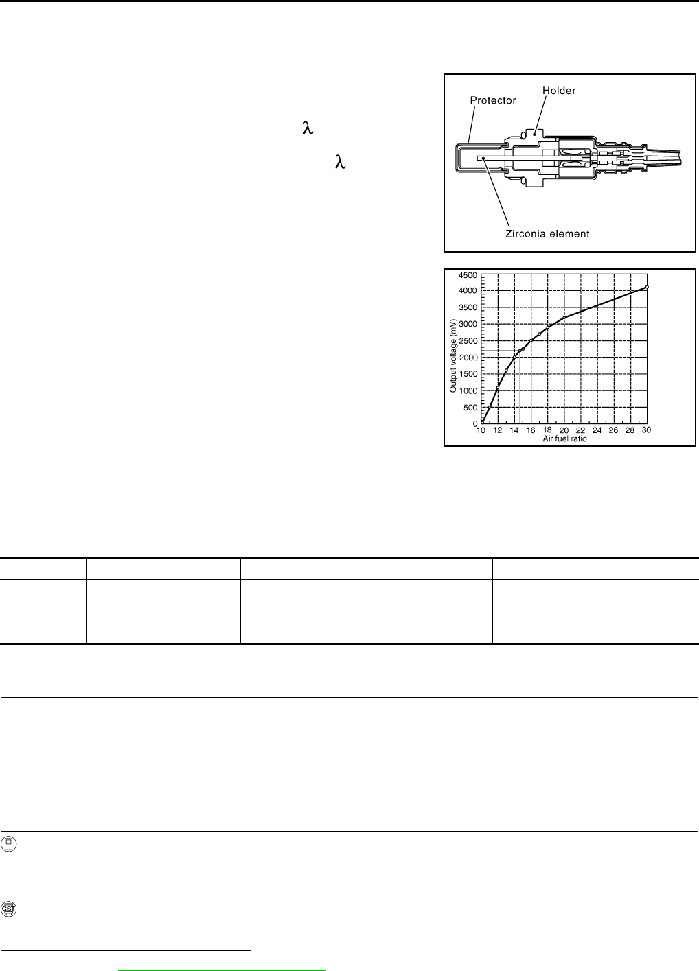
EC-1072
< COMPONENT DIAGNOSIS > [FOR MEXICO]
P0131 A/F SENSOR 1
P0131 A/F SENSOR 1
Description INFOID:0000000004534590
The air fuel ratio (A/F) sensor 1 is a planar one-cell limit current sen-
sor. The sensor element of the A/F sensor 1 is composed an elec-
trode layer, which transports ions. It has a heater in the element.
The sensor is capable of precise measurement = 1, but also in the
lean and rich range. Together with its control electronics, the sensor
outputs a clear, continuous signal throughout a wide range.
The exhaust gas components diffuse through the diffusion layer at
the sensor cell. An electrode layer is applied voltage, and this current
relative oxygen density in lean. Also this current relative hydrocar-
bon density in rich.
Therefore, the A/F sensor 1 is able to indicate air fuel ratio by this
electrode layer of current. In addition, a heater is integrated in the
sensor to ensure the required operating temperature of approxi-
mately 800°C (1,472°F).
DTC Logic INFOID:0000000004494219
DTC DETECTION LOGIC
To judge the malfunction, the diagnosis checks that the A/F signal computed by ECM from the A/F sensor 1
signal is not inordinately low.
DTC CONFIRMATION PROCEDURE
1.PRECONDITIONING
If DTC CONFIRMATION PROCEDURE has been previously conducted, always turn ignition switch OFF and
wait at least 10 seconds before conducting the next test.
TESTING CONDITION:
Before performing the following procedure, confirm that battery voltage is more than 10.5V at idle.
>> GO TO 2.
2.CHECK A/F SENSOR FUNCTION
With CONSULT-III
1. Start engine and warm it up to normal operating temperature.
2. Select “A/F SEN1 (B1)” in “DATA MONITOR” mode with CONSULT-III.
3. Check “A/F SEN1 (B1)” indication.
With GST
Follow the procedure “With CONSULT-III” above.
Is the indication constantly approx. 0V?
YES >> Go to EC-1073, "Diagnosis Procedure".
JMBIA0112GB
PBIB3354E
DTC No. Trouble diagnosis name DTC detecting condition Possible Cause
P0131 Air fuel ratio (A/F) sensor 1
circuit low voltage
• The A/F signal computed by ECM from the A/
F sensor 1 signal is constantly approx. 0V.
• Harness or connectors
(The A/F sensor 1 circuit is open or
shorted.)
• A/F sensor 1
Revision: 2008 August 2009 Rogue

P0131 A/F SENSOR 1
EC-1073
< COMPONENT DIAGNOSIS > [FOR MEXICO]
C
D
E
F
G
H
I
J
K
L
M
A
EC
N
P
O
NO >> GO TO 3.
3.PERFORM DTC CONFIRMATION PROCEDURE
With CONSULT-III
1. Turn ignition switch OFF, wait at least 10 seconds and then restart engine.
2. Drive and accelerate vehicle to more than 40 km/h (25 MPH) within 20 seconds after restarting engine.
CAUTION:
Always drive vehicle at a safe speed.
3. Maintain the following conditions for approximately 20 consecutive seconds.
NOTE:
•Keep the accelerator pedal as steady as possible during cruising.
•If this procedure is not completed within 1 minute after restarting engine at step 1, return to step
1.
4. Check 1st trip DTC.
With GST
Follow the procedure “With CONSULT-III” above.
Is 1st trip DTC detected?
YES >> Go to EC-1073, "Diagnosis Procedure".
NO >> INSPECTION END
Diagnosis Procedure INFOID:0000000004494220
1.CHECK GROUND CONNECTION
1. Turn ignition switch OFF.
2. Check ground connection E21. Refer to Ground Inspection in GI-44, "Circuit Inspection".
Is the inspection result normal?
YES >> GO TO 2.
NO >> Repair or replace ground connection.
2.CHECK AIR FUEL RATIO (A/F) SENSOR 1 POWER SUPPLY CIRCUIT
1. Disconnect A/F sensor 1 harness connector.
2. Turn ignition switch ON.
3. Check the voltage between A/F sensor 1 harness connector and ground.
Is the inspection result normal?
YES >> GO TO 4.
NO >> GO TO 3.
3.DETECT MALFUNCTIONING PART
Check the following.
• Harness connectors E6, F123
• IPDM E/R harness connector E14
• 15A fuse (No. 63)
• Harness for open or short between A/F sensor 1 and fuse
>> Repair or replace harness or connectors.
ENG SPEED 1,000 - 3,200 rpm
VHCL SPEED SE More than 40 km/h (25 mph)
B/FUEL SCHDL 1.5 - 9.0 msec
Selector lever Suitable position
A/F sensor 1 Ground Voltage
Connector Terminal
F27 4 Ground Battery voltage
Revision: 2008 August 2009 Rogue

EC-1074
< COMPONENT DIAGNOSIS > [FOR MEXICO]
P0131 A/F SENSOR 1
4.CHECK A/F SENSOR 1 INPUT SIGNAL CIRCUIT FOR OPEN AND SHORT
1. Turn ignition switch OFF.
2. Disconnect ECM harness connector.
3. Check the continuity between A/F sensor 1 harness connector and ECM harness connector.
4. Check the continuity between A/F sensor 1 harness connector or ECM harness connector and ground.
5. Also check harness for short to power.
Is the inspection result normal?
YES >> GO TO 5.
NO >> Repair open circuit or short to ground or short to power in harness or connectors.
5.CHECK INTERMITTENT INCIDENT
Perform GI-41, "Intermittent Incident".
Is the inspection result normal?
YES >> GO TO 6.
NO >> Repair or replace.
6.REPLACE AIR FUEL RATIO (A/F) SENSOR 1
Replace air fuel ratio (A/F) sensor 1.
CAUTION:
• Discard any A/F sensor which has been dropped from a height of more than 0.5 m (19.7 in) onto a
hard surface such as a concrete floor; use a new one.
• Before installing new A/F sensor, clean exhaust system threads using oxygen sensor thread cleaner
[commercial service tool (J-43897-18 or J-43897-12)] and approved anti-seize lubricant (commercial
service tool).
>> INSPECTION END
A/F sensor 1 ECM Continuity
Connector Terminal Connector Terminal
F27 1F8 45 Existed
249
A/F sensor 1 ECM Ground Continuity
Connector Terminal Connector Terminal
F27 1F8 45 Ground Not existed
249
Revision: 2008 August 2009 Rogue

P0132 A/F SENSOR 1
EC-1075
< COMPONENT DIAGNOSIS > [FOR MEXICO]
C
D
E
F
G
H
I
J
K
L
M
A
EC
N
P
O
P0132 A/F SENSOR 1
Description INFOID:0000000004534598
The air fuel ratio (A/F) sensor 1 is a planar one-cell limit current sen-
sor. The sensor element of the A/F sensor 1 is composed an elec-
trode layer, which transports ions. It has a heater in the element.
The sensor is capable of precise measurement = 1, but also in the
lean and rich range. Together with its control electronics, the sensor
outputs a clear, continuous signal throughout a wide range.
The exhaust gas components diffuse through the diffusion layer at
the sensor cell. An electrode layer is applied voltage, and this current
relative oxygen density in lean. Also this current relative hydrocar-
bon density in rich.
Therefore, the A/F sensor 1 is able to indicate air fuel ratio by this
electrode layer of current. In addition, a heater is integrated in the
sensor to ensure the required operating temperature of approxi-
mately 800°C (1,472°F).
DTC Logic INFOID:0000000004494222
DTC DETECTION LOGIC
To judge the malfunction, the diagnosis checks that the A/F signal computed by ECM from the A/F sensor 1
signal is not inordinately high.
DTC CONFIRMATION PROCEDURE
1.PRECONDITIONING
If DTC CONFIRMATION PROCEDURE has been previously conducted, always turn ignition switch OFF and
wait at least 10 seconds before conducting the next test.
TESTING CONDITION:
Before performing the following procedure, confirm that battery voltage is more than 10.5V at idle.
>> GO TO 2.
2.CHECK A/F SENSOR FUNCTION
With CONSULT-III
1. Start engine and warm it up to normal operating temperature.
2. Select “A/F SEN1 (B1)” in “DATA MONITOR” mode with CONSULT-III.
3. Check “A/F SEN1 (B1)” indication.
With GST
Follow the procedure “With CONSULT-III” above.
Is the indication constantly approx. 5 V?
YES >> Go to EC-1076, "Diagnosis Procedure".
JMBIA0112GB
PBIB3354E
DTC No. Trouble diagnosis name DTC detecting condition Possible Cause
P0132 Air fuel ratio (A/F) sensor 1
circuit high voltage
• The A/F signal computed by ECM from the A/F
sensor 1 signal is constantly approx. 5V.
• Harness or connectors
(The A/F sensor 1 circuit is open or
shorted.)
• A/F sensor 1
Revision: 2008 August 2009 Rogue
EC-1076
< COMPONENT DIAGNOSIS > [FOR MEXICO]
P0132 A/F SENSOR 1
NO >> GO TO 3.
3.PERFORM DTC CONFIRMATION PROCEDURE
With CONSULT-III
1. Turn ignition switch OFF, wait at least 10 seconds and then restart engine.
2. Drive and accelerate vehicle to more than 40 km/h (25 MPH) within 20 seconds after restarting engine.
CAUTION:
Always drive vehicle at a safe speed.
3. Maintain the following conditions for approximately 20 consecutive seconds.
NOTE:
•Keep the accelerator pedal as steady as possible during the cruising.
•If this procedure is not completed within 1 minute after restarting engine at step 1, return to step
1.
4. Check 1st trip DTC.
With GST
Follow the procedure “With CONSULT-III” above.
Is 1st trip DTC detected?
YES >> Go to EC-1076, "Diagnosis Procedure".
NO >> INSPECTION END
Diagnosis Procedure INFOID:0000000004494223
1.CHECK GROUND CONNECTION
1. Turn ignition switch OFF.
2. Check ground connection E21. Refer to Ground Inspection in GI-44, "Circuit Inspection".
Is the inspection result normal?
YES >> GO TO 2.
NO >> Repair or replace ground connection.
2.CHECK AIR FUEL RATIO (A/F) SENSOR 1 POWER SUPPLY CIRCUIT
1. Disconnect A/F sensor 1 harness connector.
2. Turn ignition switch ON.
3. Check the voltage between A/F sensor 1 harness connector and ground.
Is the inspection result normal?
YES >> GO TO 4.
NO >> GO TO 3.
3.DETECT MALFUNCTIONING PART
Check the following.
• Harness connectors E6, F123
• IPDM E/R harness connector E14
• 15A fuse (No. 63)
• Harness for open or short between A/F sensor 1 and fuse
>> Repair or replace harness or connectors.
ENG SPEED 1,000 - 3,200 rpm
VHCL SPEED SE More than 40 km/h (25 mph)
B/FUEL SCHDL 1.5 - 9.0 msec
Selector lever Suitable position
A/F sensor 1 Ground Voltage
Connector Terminal
F27 4 Ground Battery voltage
Revision: 2008 August 2009 Rogue
P0132 A/F SENSOR 1
EC-1077
< COMPONENT DIAGNOSIS > [FOR MEXICO]
C
D
E
F
G
H
I
J
K
L
M
A
EC
N
P
O
4.CHECK A/F SENSOR 1 INPUT SIGNAL CIRCUIT FOR OPEN AND SHORT
1. Turn ignition switch OFF.
2. Disconnect ECM harness connector.
3. Check the continuity between A/F sensor 1 harness connector and ECM harness connector.
4. Check the continuity between A/F sensor 1 harness connector or ECM harness connector and ground.
5. Also check harness for short to power.
Is the inspection result normal?
YES >> GO TO 5.
NO >> Repair open circuit or short to ground or short to power in harness or connectors.
5.CHECK INTERMITTENT INCIDENT
Perform GI-41, "Intermittent Incident".
Is the inspection result normal?
YES >> GO TO 6.
NO >> Repair or replace.
6.REPLACE AIR FUEL RATIO (A/F) SENSOR 1
Replace air fuel ratio (A/F) sensor 1.
CAUTION:
• Discard any A/F sensor which has been dropped from a height of more than 0.5 m (19.7 in) onto a
hard surface such as a concrete floor; use a new one.
• Before installing new A/F sensor, clean exhaust system threads using oxygen sensor thread cleaner
[commercial service tool (J-43897-18 or J-43897-12)] and approved anti-seize lubricant (commercial
service tool).
>> INSPECTION END
A/F sensor 1 ECM Continuity
Connector Terminal Connector Terminal
F27 1F8 45 Existed
249
A/F sensor 1 ECM Ground Continuity
Connector Terminal Connector Terminal
F27 1F8 45 Ground Not existed
249
Revision: 2008 August 2009 Rogue
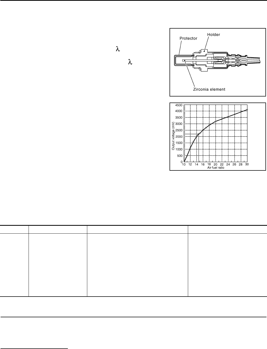
EC-1078
< COMPONENT DIAGNOSIS > [FOR MEXICO]
P0133 A/F SENSOR 1
P0133 A/F SENSOR 1
Description INFOID:0000000004534603
The air fuel ratio (A/F) sensor 1 is a planar one-cell limit current sen-
sor. The sensor element of the A/F sensor 1 is composed an elec-
trode layer, which transports ions. It has a heater in the element.
The sensor is capable of precise measurement = 1, but also in the
lean and rich range. Together with its control electronics, the sensor
outputs a clear, continuous signal throughout a wide range.
The exhaust gas components diffuse through the diffusion layer at
the sensor cell. An electrode layer is applied voltage, and this current
relative oxygen density in lean. Also this current relative hydrocar-
bon density in rich.
Therefore, the A/F sensor 1 is able to indicate air fuel ratio by this
electrode layer of current. In addition, a heater is integrated in the
sensor to ensure the required operating temperature of approxi-
mately 800°C (1,472°F).
DTC Logic INFOID:0000000004494225
DTC DETECTION LOGIC
To judge the malfunction of A/F sensor 1, this diagnosis measures response time of the A/F signal computed
by ECM from the A/F sensor 1 signal. The time is compensated by engine operating (speed and load), fuel
feedback control constant, and the A/F sensor 1 temperature index. Judgment is based on whether the com-
pensated time (the A/F signal cycling time index) is inordinately long or not.
DTC CONFIRMATION PROCEDURE
1.PRECONDITIONING
If DTC CONFIRMATION PROCEDURE has been previously conducted, always turn ignition switch OFF and
wait at least 10 seconds before conducting the next test.
TESTING CONDITION:
Before performing the following procedure, confirm that battery voltage is more than 11V at idle.
Do you have CONSULT-III?
YES >> GO TO 2.
NO >> GO TO 5.
JMBIA0112GB
PBIB3354E
DTC No. Trouble diagnosis name DTC detecting condition Possible Cause
P0133 Air fuel ratio (A/F) sensor 1
circuit slow response
• The response of the A/F signal computed by
ECM from A/F sensor 1 signal takes more than
the specified time.
• Harness or connectors
(The A/F sensor 1 circuit is open or
shorted.)
• A/F sensor 1
• A/F sensor 1 heater
• Fuel pressure
• Fuel injector
• Intake air leaks
• Exhaust gas leaks
•PCV
• Mass air flow sensor
Revision: 2008 August 2009 Rogue

P0133 A/F SENSOR 1
EC-1079
< COMPONENT DIAGNOSIS > [FOR MEXICO]
C
D
E
F
G
H
I
J
K
L
M
A
EC
N
P
O
2.PERFORM DTC CONFIRMATION PROCEDURE-I
With CONSULT-III
1. Start engine and warm it up to normal operating temperature.
2. Turn ignition switch OFF and wait at least 10 seconds.
3. Start engine and keep the engine speed between 3,500 and 4,000 rpm for at least 1minute under no load.
4. Let engine idle for 1 minute.
5. Select “A/F SEN1(B1) P1278/P1279” of “A/F SEN1” in “DTC WORK SUPPORT” mode with CONSULT-III.
6. Touch “START”.
Is “COMPLETED” displayed on COUSULT-III?
YES >> GO TO 3
NO >> GO TO 4.
3.PERFORM DTC CONFIRMATION PROCEDURE-II
Touch “SELF-DIAG RESULT”.
Which is displayed on CONSULT-III?
OK >> INSPECTION END
NG >> Go to EC-1080, "Diagnosis Procedure".
4.PERFORM DTC CONFIRMATION PROCEDURE
1. After perform the following procedure, “TESTING” will be displayed on the CONSULT-III screen.
- Increase the engine speed up to between 4,000 and 5,000 rpm and maintain that speed for 10 seconds.
- Fully release accelerator pedal and then let engine idle for approximately 10 seconds.
If “TESTING” is not displayed after 10 seconds, refer to EC-1012, "Component Function Check".
2. Wait for approximately 20 seconds at idle under the condition that “TESTING” is displayed on the CON-
SULT-III screen.
3. Check that “TESTING” changes to “COMPLETED”.
If “TESTING” changed to “OUT OF CONDITION”, refer to EC-1012, "Component Function Check".
4. Touch “SELF-DIAG RESULT”.
Which is displayed on CONSULT-III?
OK >> INSPECTION END
NG >> Go to EC-1080, "Diagnosis Procedure".
5.CHECK AIR-FUEL RATIO SELF-LEARNING VALUE
With GST
1. Start engine and warm it up to normal operating temperature.
2. Select Service $01 with GST.
3. Calculate the total value of “Short-term fuel trim” and “Long-term fuel trim” indications.
Is the total percentage within ±15%?
YES >> GO TO 7.
NO >> GO TO 6.
6.DETECT MALFUNCTIONING PART
Check the following.
• Intake air leaks
• Exhaust gas leaks
• Incorrect fuel pressure
• Lack of fuel
• Fuel injector
• Incorrect PCV hose connection
•PCV valve
• Mass air flow sensor
>> Repair or replace malfunctioning part.
7.PERFORM DTC CONFIRMATION PROCEDURE
1. Turn ignition switch OFF and wait at least 10 seconds.
2. Start engine and keep the engine speed between 3,500 and 4,000 rpm for at least 1minute under no load.
Revision: 2008 August 2009 Rogue
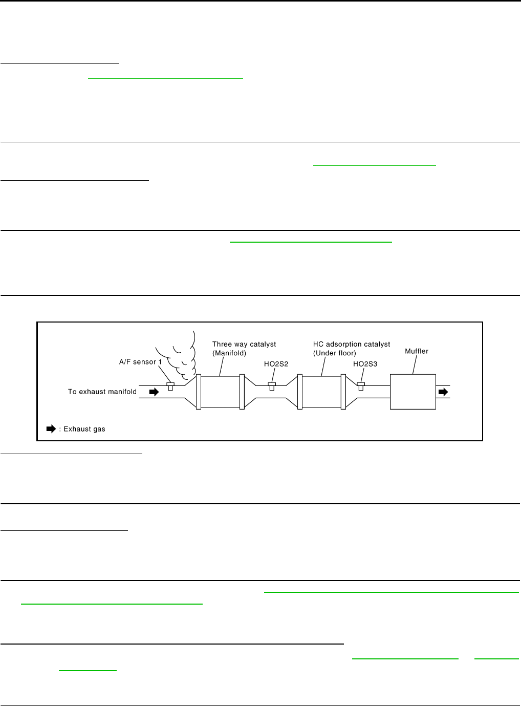
EC-1080
< COMPONENT DIAGNOSIS > [FOR MEXICO]
P0133 A/F SENSOR 1
3. Let engine idle for 1 minute.
4. Increase the engine speed up to between 4,000 and 5,000 rpm and maintain that speed for 10 seconds.
5. Fully release accelerator pedal and then let engine idle for approximately 1 minute.
6. Check 1st trip DTC detected?.
Is 1st trip DTC detected?
YES >> Go to EC-1080, "Diagnosis Procedure".
NO >> INSPECTION END
Diagnosis Procedure INFOID:0000000004494226
1.CHECK GROUND CONNECTION
1. Turn ignition switch OFF.
2. Check ground connection E21. Refer to Ground Inspection in GI-44, "Circuit Inspection".
Is the inspection result normal?
YES >> GO TO 2.
NO >> Repair or replace ground connection.
2.RETIGHTEN A/F SENSOR 1
Loosen and retighten the A/F sensor 1. Refer to EM-32, "Removal and Installation".
>> GO TO 3.
3.CHECK EXHAUST GAS LEAK
1. Start engine and run it at idle.
2. Listen for an exhaust gas leak before three way catalyst (manifold).
Is exhaust gas leak detected?
YES >> Repair or replace.
NO >> GO TO 4.
4.CHECK FOR INTAKE AIR LEAK
Listen for an intake air leak after the mass air flow sensor.
Is intake air leak detected?
YES >> Repair or replace.
NO >> GO TO 5.
5.CLEAR THE MIXTURE RATIO SELF-LEARNING VALUE
1. Clear the mixture ratio self-learning value. Refer to EC-940, "MIXTURE RATIO SELF-LEARNING VALUE
CLEAR : Special Repair Requirement".
2. Run engine for at least 10 minutes at idle speed.
Is the 1st trip DTC P0171 or P172 detected? Is it difficult to start engine?
YES >> Perform trouble diagnosis for DTC P0171 or P0172. Refer to EC-1102, "DTC Logic" or EC-1106,
"DTC Logic".
NO >> GO TO 6.
6.CHECK AIR FUEL RATIO (A/F) SENSOR 1 POWER SUPPLY CIRCUIT
1. Disconnect A/F sensor 1 harness connector.
JMBIA0163G
B
Revision: 2008 August 2009 Rogue

P0133 A/F SENSOR 1
EC-1081
< COMPONENT DIAGNOSIS > [FOR MEXICO]
C
D
E
F
G
H
I
J
K
L
M
A
EC
N
P
O
2. Turn ignition switch ON.
3. Check the voltage between A/F sensor 1 harness connector and ground.
Is the inspection result normal?
YES >> GO TO 8.
NO >> GO TO 7.
7.DETECT MALFUNCTIONING PART
Check the following.
• Harness connectors E6, F123
• IPDM E/R harness connector E14
• 15A fuse (No. 63)
• Harness for open or short between A/F sensor 1 and fuse
>> Repair or replace harness or connectors.
8.CHECK A/F SENSOR 1 INPUT SIGNAL CIRCUIT FOR OPEN AND SHORT
1. Turn ignition switch OFF.
2. Disconnect ECM harness connector.
3. Check the continuity between A/F sensor 1 harness connector and ECM harness connector.
4. Check the continuity between A/F sensor 1 harness connector or ECM harness connector and ground.
5. Also check harness for short to power.
Is the inspection result normal?
YES >> GO TO 9.
NO >> Repair open circuit or short to ground or short to power in harness or connectors.
9.CHECK AIR FUEL RATIO (A/F) SENSOR 1 HEATER
Refer to EC-1033, "Component Inspection".
Is the inspection result normal?
YES >> GO TO 10.
NO >> GO TO 13.
10.CHECK MASS AIR FLOW SENSOR
Check mass air flow sensor.
Refer to EC-1044, "Component Inspection".
Is the inspection result normal?
YES >> GO TO 11.
NO >> Replace mass air flow sensor.
11.CHECK PCV VALVE
A/F sensor 1 Ground Voltage
Connector Terminal
F27 4 Ground Battery voltage
A/F sensor 1 ECM Continuity
Connector Terminal Connector Terminal
F27 1F8 45 Existed
249
A/F sensor 1 ECM Ground Continuity
Connector Terminal Connector Terminal
F27 1F8 45 Ground Not existed
249
Revision: 2008 August 2009 Rogue

EC-1082
< COMPONENT DIAGNOSIS > [FOR MEXICO]
P0133 A/F SENSOR 1
Refer to EC-1229, "Component Inspection".
Is the inspection result normal?
YES >> GO TO 12.
NO >> Repair or replace PCV valve.
12.CHECK INTERMITTENT INCIDENT
Perform GI-41, "Intermittent Incident".
Is the inspection result normal?
YES >> GO TO 13.
NO >> Repair or replace.
13.REPLACE AIR FUEL RATIO (A/F) SENSOR 1
Replace air fuel ratio (A/F) sensor 1.
CAUTION:
• Discard any A/F sensor which has been dropped from a height of more than 0.5 m (19.7 in) onto a
hard surface such as a concrete floor; use a new one.
• Before installing new A/F sensor, clean exhaust system threads using oxygen sensor thread cleaner
[commercial service tool (J-43897-18 or J-43897-12)] and approved anti-seize lubricant (commercial
service tool).
>> INSPECTION END
Revision: 2008 August 2009 Rogue

P0137 HO2S2
EC-1083
< COMPONENT DIAGNOSIS > [FOR MEXICO]
C
D
E
F
G
H
I
J
K
L
M
A
EC
N
P
O
P0137 HO2S2
Description INFOID:0000000004494227
The heated oxygen sensor 2, after three way catalyst (manifold),
monitors the oxygen level in the exhaust gas.
Even if switching characteristics of the air fuel ratio (A/F) sensor 1
are shifted, the air-fuel ratio is controlled to stoichiometric, by the sig-
nal from the heated oxygen sensor 2.
This sensor is made of ceramic zirconia. The zirconia generates volt-
age from approximately 1V in richer conditions to 0V in leaner condi-
tions.
Under normal conditions the heated oxygen sensor 2 is not used for
engine control operation.
DTC Logic INFOID:0000000004494228
DTC DETECTION LOGIC
The heated oxygen sensor 2 has a much longer switching time
between rich and lean than the air fuel ratio (A/F) sensor 1. The oxy-
gen storage capacity of the three way catalyst (manifold) causes the
longer switching time. To judge the malfunctions of heated oxygen
sensor 2, ECM monitors whether the maximum voltage of the sensor
is sufficiently high during various driving conditions such as fuel cut.
DTC CONFIRMATION PROCEDURE
1.INSPECTION START
Do you have CONSULT-III?
Do you have CONSULT-III?
YES >> GO TO 2.
NO >> GO TO 5.
2.PRECONDITIONING
If DTC CONFIRMATION PROCEDURE has been previously conducted, always turn ignition switch OFF and
wait at least 10 seconds before conducting the next test.
TESTING CONDITION:
For better results, perform “DTC WORK SUPPORT” at a temperature of 0 to 30 °C (32 to 86 °F).
>> GO TO 3.
3.PERFORM DTC CONFIRMATION PROCEDURE
With CONSULT-III
SEF327R
JMBIA1669G
B
DTC No. Trouble diagnosis name DTC detecting condition Possible cause
P0137 Heated oxygen sensor 2
circuit low voltage
The maximum voltage from the sensor does not
reach the specified voltage.
• Harness or connectors
(The sensor circuit is open or shorted)
• Heated oxygen sensor 2
• Fuel pressure
• Fuel injector
• Intake air leaks
Revision: 2008 August 2009 Rogue
EC-1084
< COMPONENT DIAGNOSIS > [FOR MEXICO]
P0137 HO2S2
1. Turn ignition switch ON and select “DATA MONITOR” mode with CONSULT-III.
2. Start engine and warm it up to the normal operating temperature.
3. Turn ignition switch OFF and wait at least 10 seconds.
4. Start engine and keep the engine speed between 3,500 and 4,000 rpm for at least 1 minute under no load.
5. Let engine idle for 1 minute.
6. Check that “COOLAN TEMP/S” indicates more than 70°C (158°F).
If not, warm up engine and go to next step when “COOLAN TEMP/S” indication reaches 70°C (158°F).
7. Open engine hood.
8. Select “HO2S2 (B1) P1147” of “HO2S2” in “DTC WORK SUPPORT” mode with CONSULT-III.
9. Follow the instruction of CONSULT-III display.
NOTE:
It will take at most 10 minutes until “COMPLETED” is displayed.
10. Touch “SELF-DIAG RESULT”.
Which is displayed on CONSULT-III screen?
OK >> INSPECTION END
NG >> Go to EC-1085, "Diagnosis Procedure".
CAN NOT BE DIAGNOSED>>GO TO 4.
4.PERFORM DTC CONFIRMATION PROCEDURE AGAIN
1. Turn ignition switch OFF and leave the vehicle in a cool place (soak the vehicle).
2. Perform DTC CONFIRMATION PROCEDURE again.
>> GO TO 3.
5.PERFORM COMPONENT FUNCTION CHECK
Perform Component Function Check. Refer to EC-1084, "Component Function Check".
NOTE:
Use component function check to check the overall function of the heated oxygen sensor 2 circuit. During this
check, a 1st trip DTC might not be confirmed.
Is the inspection result normal?
YES >> INSPECTION END
NO >> Go to EC-1085, "Diagnosis Procedure".
Component Function Check INFOID:0000000004494229
1.PERFORM COMPONENT FUNCTION CHECK-I
Without CONSULT-III
1. Start engine and warm it up to the normal operating temperature.
2. Turn ignition switch OFF and wait at least 10 seconds.
3. Start engine and keep the engine speed between 3,500 and 4,000 rpm for at least 1 minute under no load.
4. Let engine idle for 1 minute.
5. Check the voltage between ECM harness connector terminals under the following condition.
Is the inspection result normal?
YES >> INSPECTION END
NO >> GO TO 2.
2.PERFORM COMPONENT FUNCTION CHECK-II
Check the voltage between ECM harness connectors under the following condition.
ECM ECM Condition Voltage
Connector Terminal Connector Terminal
F8 33
(HO2S2 signal) F8 35
(Sensor
ground)
Revving up to 4,000 rpm under
no load at least 10 times
The voltage should be above 0.70V
at least once during this procedure.
Revision: 2008 August 2009 Rogue

P0137 HO2S2
EC-1085
< COMPONENT DIAGNOSIS > [FOR MEXICO]
C
D
E
F
G
H
I
J
K
L
M
A
EC
N
P
O
Is the inspection result normal?
YES >> INSPECTION END
NO >> GO TO 3.
3.PERFORM COMPONENT FUNCTION CHECK-III
Check the voltage between ECM harness connector and ground under the following condition.
Is the inspection result normal?
YES >> INSPECTION END
NO >> Go to EC-1085, "Diagnosis Procedure".
Diagnosis Procedure INFOID:0000000004494230
1.CHECK GROUND CONNECTION
1. Turn ignition switch OFF.
2. Check ground connection E21. Refer to Ground Inspection in GI-44, "Circuit Inspection".
Is the inspection result normal?
YES >> GO TO 2.
NO >> Repair or replace ground connection.
2.CLEAR THE MIXTURE RATIO SELF-LEARNING VALUE
1. Clear the mixture ratio self-learning value. Refer to EC-940, "MIXTURE RATIO SELF-LEARNING VALUE
CLEAR : Special Repair Requirement".
2. Run engine for at least 10 minutes at idle speed.
Is the 1st trip DTC P0171 detected? Is it difficult to start engine?
YES >> Perform trouble diagnosis for DTC P0171. Refer to EC-1102, "DTC Logic".
NO >> GO TO 3.
3.CHECK HO2S2 GROUND CIRCUIT FOR OPEN AND SHORT
1. Turn ignition switch OFF.
2. Disconnect heated oxygen sensor 2 (HO2S2) harness connector.
3. Disconnect ECM harness connector.
4. Check the continuity between HO2S2 harness connector and ECM harness connector.
5. Also check harness for short to ground and short to power.
Is the inspection result normal?
YES >> GO TO 4.
NO >> Repair open circuit or short to ground or short to power in harness or connectors.
4.CHECK HO2S2 INPUT SIGNAL CIRCUIT FOR OPEN AND SHORT
1. Check the continuity between HO2S2 harness connector and ECM harness connector.
ECM ECM Condition Voltage
Connector Terminal Connector Terminal
F8 33
(HO2S2 signal) F8 35
(Sensor
ground)
Keeping engine speed at idle for
10 minutes
The voltage should be above 0.70V
at least once during this procedure.
ECM ECM Condition Voltage
Connector Terminal Connector Terminal
F8 33
(HO2S2 signal) F8
35
(Sensor
ground)
Coasting from 80 km/h (50 MPH)
in D position The voltage should be above 0.70V
at least once during this procedure.
HO2S2 ECM Continuity
Connector Terminal Connector Terminal
F31 1 F8 35 Existed
Revision: 2008 August 2009 Rogue
EC-1086
< COMPONENT DIAGNOSIS > [FOR MEXICO]
P0137 HO2S2
2. Check the continuity between HO2S2 harness connector or ECM harness connector and ground.
3. Also check harness for short to power.
Is the inspection result normal?
YES >> GO TO 5.
NO >> Repair open circuit or short to ground or short to power in harness or connectors.
5.CHECK HEATED OXYGEN SENSOR 2
Refer to EC-1086, "Component Inspection".
Is the inspection result normal?
YES >> GO TO 7.
NO >> GO TO 6.
6.REPLACE HEATED OXYGEN SENSOR 2
Replace heated oxygen sensor 2.
CAUTION:
• Discard any heated oxygen sensor which has been dropped from a height of more than 0.5 m (19.7
in) onto a hard surface such as a concrete floor; use a new one.
• Before installing new heated oxygen sensor, clean exhaust system threads using oxygen sensor
thread cleaner [commercial service tool (J-43897-18 or J-43897-12)] and approved anti-seize lubri-
cant (commercial service tool).
>> INSPECTION END
7.CHECK INTERMITTENT INCIDENT
Refer to GI-41, "Intermittent Incident".
>> INSPECTION END
Component Inspection INFOID:0000000004494231
1.INSPECTION START
Do you have CONSULT-III?
Do you have CONSULT-III?
YES >> GO TO 2.
NO >> GO TO 3.
2.CHECK HEATED OXYGEN SENSOR 2
With CONSULT-III
1. Turn ignition switch ON and select “DATA MONITOR” mode with CONSULT-III.
2. Start engine and warm it up to the normal operating temperature.
3. Turn ignition switch OFF and wait at least 10 seconds.
4. Start engine and keep the engine speed between 3,500 and 4,000 rpm for at least 1 minute under no load.
5. Let engine idle for 1 minute.
6. Select “FUEL INJECTION” in “ACTIVE TEST” mode, and select “HO2S2 (B1)” as the monitor item with
CONSULT-III.
HO2S2 ECM Continuity
Connector Terminal Connector Terminal
F31 4 F8 33 Existed
HO2S2 ECM Ground Continuity
Connector Terminal Connector Terminal
F31 4 F8 33 Ground Not existed
Revision: 2008 August 2009 Rogue
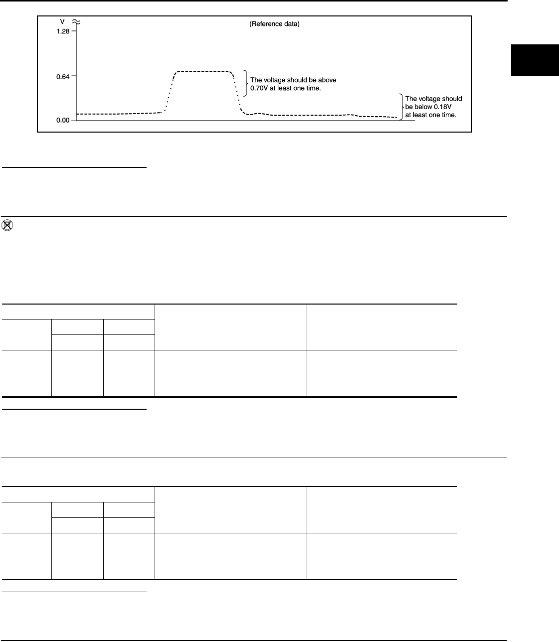
P0137 HO2S2
EC-1087
< COMPONENT DIAGNOSIS > [FOR MEXICO]
C
D
E
F
G
H
I
J
K
L
M
A
EC
N
P
O
7. Check “HO2S2 (B1)” at idle speed when adjusting “FUEL INJECTION” to ±25%.
“HO2S2 (B1)” should be above 0.70V at least once when the “FUEL INJECTION” is +25%.
“HO2S2 (B1)” should be below 0.18V at least once when the “FUEL INJECTION” is −25%.
Is the inspection result normal?
YES >> INSPECTION END
NO >> GO TO 6.
3.CHECK HEATED OXYGEN SENSOR 2-I
Without CONSULT-III
1. Start engine and warm it up to the normal operating temperature.
2. Turn ignition switch OFF and wait at least 10 seconds.
3. Start engine and keep the engine speed between 3,500 and 4,000 rpm for at least 1 minute under no load.
4. Let engine idle for 1 minute.
5. Check the voltage between ECM harness connector and ground under the following condition.
Is the inspection result normal?
YES >> INSPECTION END
NO >> GO TO 4.
4.CHECK HEATED OXYGEN SENSOR 2-II
Check the voltage between ECM harness connector and ground under the following condition.
Is the inspection result normal?
YES >> INSPECTION END
NO >> GO TO 5.
5.CHECK HEATED OXYGEN SENSOR 2-III
Check the voltage between ECM harness connector and ground under the following condition.
JMBIA1670G
B
ECM
Condition Voltage
Connector +−
Terminal Terminal
F8
33
(HO2S2
signal)
35
(Sensor
ground)
Revving up to 4,000 rpm under no load
at least 10 times
The voltage should be above 0.70V at
least once during this procedure.
The voltage should be below 0.18V at
least once during this procedure.
ECM
Condition Voltage
Connector +−
Terminal Terminal
F8 33
(HO2S2
signal)
35
(Sensor
ground)
Keeping engine speed at idle for 10
minutes
The voltage should be above 0.70V at
least once during this procedure.
The voltage should be below 0.18V at
least once during this procedure.
Revision: 2008 August 2009 Rogue

EC-1088
< COMPONENT DIAGNOSIS > [FOR MEXICO]
P0137 HO2S2
Is the inspection result normal?
YES >> INSPECTION END
NO >> GO TO 6.
6.REPLACE HEATED OXYGEN SENSOR 2
Replace heated oxygen sensor 2.
CAUTION:
• Discard any heated oxygen sensor which has been dropped from a height of more than 0.5 m (19.7
in) onto a hard surface such as a concrete floor; use a new one.
• Before installing new heated oxygen sensor, clean exhaust system threads using oxygen sensor
thread cleaner [commercial service tool (J-43897-18 or J-43897-12)] and approved anti-seize lubri-
cant (commercial service tool).
>> INSPECTION END
ECM
Condition Voltage
Connector +−
Terminal Terminal
F8
33
(HO2S2
signal)
35
(Sensor
ground)
Coasting from 80 km/h (50 MPH) in D
position
The voltage should be above 0.70V at
least once during this procedure.
The voltage should be below 0.18V at
least once during this procedure.
Revision: 2008 August 2009 Rogue
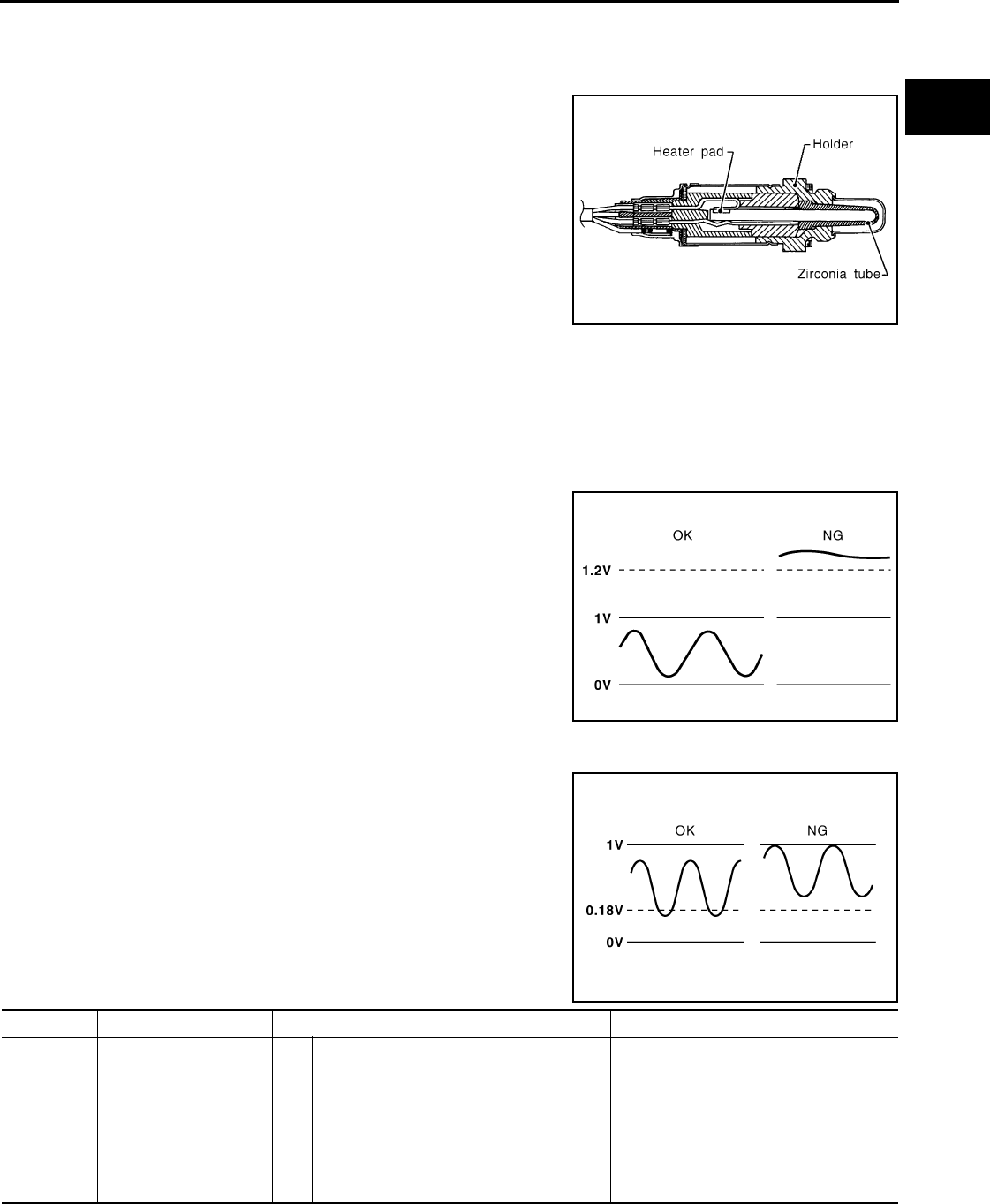
P0138 HO2S2
EC-1089
< COMPONENT DIAGNOSIS > [FOR MEXICO]
C
D
E
F
G
H
I
J
K
L
M
A
EC
N
P
O
P0138 HO2S2
Description INFOID:0000000004534626
The heated oxygen sensor 2, after three way catalyst (manifold),
monitors the oxygen level in the exhaust gas.
Even if switching characteristics of the air fuel ratio (A/F) sensor 1
are shifted, the air-fuel ratio is controlled to stoichiometric, by the sig-
nal from the heated oxygen sensor 2.
This sensor is made of ceramic zirconia. The zirconia generates volt-
age from approximately 1V in richer conditions to 0V in leaner condi-
tions.
Under normal conditions the heated oxygen sensor 2 is not used for
engine control operation.
DTC Logic INFOID:0000000004494233
DTC DETECTION LOGIC
The heated oxygen sensor 2 has a much longer switching time between rich and lean than the air fuel ratio (A/
F) sensor 1. The oxygen storage capacity of the three way catalyst (manifold) causes the longer switching
time.
MALFUNCTION A
To judge the malfunctions of heated oxygen sensor 2, ECM monitors
whether the voltage is unusually high during various driving condi-
tions such as fuel cut.
MALFUNCTION B
To judge the malfunctions of heated oxygen sensor 2, ECM monitors
whether the minimum voltage of sensor is sufficiently low during var-
ious driving conditions such as fuel cut.
DTC CONFIRMATION PROCEDURE
SEF327R
PBIB1848E
PBIB2376E
DTC No. Trouble diagnosis name DTC detecting condition Possible cause
P0138 Heated oxygen sensor 2
circuit high voltage
A) An excessively high voltage from the sen-
sor is sent to ECM.
• Harness or connectors
(The sensor circuit is open or shorted)
• Heated oxygen sensor 2
B) The minimum voltage from the sensor is
not reached to the specified voltage.
• Harness or connectors
(The sensor circuit is open or shorted)
• Heated oxygen sensor 2
• Fuel pressure
• Fuel injector
Revision: 2008 August 2009 Rogue

EC-1090
< COMPONENT DIAGNOSIS > [FOR MEXICO]
P0138 HO2S2
1.PRECONDITIONING
If DTC CONFIRMATION PROCEDURE has been previously conducted, always turn ignition switch OFF and
wait at least 10 seconds before conducting the next test.
>> GO TO 2.
2.PERFORM DTC CONFIRMATION PROCEDURE FOR MALFUNCTION A
1. Start engine and warm it up to the normal operating temperature.
2. Turn ignition switch OFF and wait at least 10 seconds.
3. Start engine and keep the engine speed between 3,500 and 4,000 rpm for at least 1 minute under no load.
4. Check 1st trip DTC.
Is 1st trip DTC detected?
YES >> Go to EC-1091, "Diagnosis Procedure".
NO-1 >> With CONSULT-III: GO TO 3.
NO-2 >> Without CONSULT-III: GO TO 5.
3.PERFORM DTC CONFIRMATION PROCEDURE FOR MALFUNCTION B
NOTE:
For better results, perform “DTC WORK SUPPORT” at a temperature of 0 to 30 °C (32 to 86 °F).
1. Turn ignition switch ON and select “DATA MONITOR” mode with CONSULT-III.
2. Start engine and warm it up to the normal operating temperature.
3. Turn ignition switch OFF and wait at least 10 seconds.
4. Start engine and keep the engine speed between 3,500 and 4,000 rpm for at least 1 minute under no load.
5. Let engine idle for 1 minute.
6. Check that “COOLAN TEMP/S” indicates more than 70°C (158°F).
If not, warm up engine and go to next step when “COOLAN TEMP/S” indication reaches 70°C (158°F).
7. Open engine hood.
8. Select “HO2S2 (B1) P1146” of “HO2S2” in “DTC WORK SUPPORT” mode with CONSULT-III.
9. Follow the instruction of CONSULT-III display.
NOTE:
It will take at most 10 minutes until “COMPLETED” is displayed.
10. Touch “SELF-DIAG RESULT”.
Which is displayed on CONSULT-III
OK >> INSPECTION END
NG >> Go to EC-1091, "Diagnosis Procedure".
CAN NOT BE DIAGNOSED>>GO TO 4.
4.PERFORM DTC CONFIRMATION PROCEDURE FOR MALUNCTION B AGAIN
1. Turn ignition switch OFF and leave the vehicle in a cool place (soak the vehicle).
2. Perform DTC CONFIRMATION PROCEDURE again.
>> GO TO 3.
5.PERFORM COMPONENT FUNCTION CHECK FOR MALFUNCTION B
Perform component function check. Refer to EC-1091, "Diagnosis Procedure".
NOTE:
Use component function check to check the overall function of the heated oxygen sensor 2 circuit. During this
check, a 1st trip DTC might not be confirmed.
Is the inspection result normal?
YES >> INSPECTION END
NO >> Go to EC-1091, "Diagnosis Procedure".
Component Function Check INFOID:0000000004494234
1.PERFORM COMPONENT FUNCTION CHECK-I
Without CONSULT-III
1. Start engine and warm it up to the normal operating temperature.
Revision: 2008 August 2009 Rogue

P0138 HO2S2
EC-1091
< COMPONENT DIAGNOSIS > [FOR MEXICO]
C
D
E
F
G
H
I
J
K
L
M
A
EC
N
P
O
2. Turn ignition switch OFF and wait at least 10 seconds.
3. Start engine and keep the engine speed between 3,500 and 4,000 rpm for at least 1 minute under no load.
4. Let engine idle for 1 minute.
5. Check the voltage between ECM harness connector terminals under the following condition.
Is the inspection result normal?
YES >> INSPECTION END
NO >> GO TO 2.
2.PERFORM COMPONENT FUNCTION CHECK-II
Check the voltage between ECM harness connectors under the following condition.
Is the inspection result normal?
YES >> INSPECTION END
NO >> GO TO 3.
3.PERFORM COMPONENT FUNCTION CHECK-III
Check the voltage between ECM harness connector and ground under the following condition.
Is the inspection result normal?
YES >> INSPECTION END
NO >> Go to EC-1091, "Diagnosis Procedure".
Diagnosis Procedure INFOID:0000000004494235
1.INSPECTION START
Confirm the detected malfunction (A or B). Refer to EC-1089, "DTC Logic".
Which malfunction is detected?
A >> GO TO 2.
B >> GO TO 9.
2.CHECK GROUND CONNECTION
1. Turn ignition switch OFF.
2. Check ground connection E21. Refer to Ground Inspection in GI-44, "Circuit Inspection".
Is the inspection result normal?
YES >> GO TO 3.
NO >> Repair or replace ground connection.
3.CHECK HO2S2 GROUND CIRCUIT FOR OPEN AND SHORT
1. Disconnect heated oxygen sensor 2 harness connector.
ECM ECM Condition Voltage
Connector Terminal Connector Terminal
F8 33
(HO2S2 signal) F8 35
(Sensor
ground)
Revving up to 4,000 rpm under
no load at least 10 times
The voltage should be below 0.18V
at least once during this procedure.
ECM ECM Condition Voltage
Connector Terminal Connector Terminal
F8 33
(HO2S2 signal) F8
35
(Sensor
ground)
Keeping engine speed at idle for
10 minutes The voltage should be below 0.18V
at least once during this procedure.
ECM ECM Condition Voltage
Connector Terminal Connector Terminal
F8 33
(HO2S2 signal) F8
35
(Sensor
ground)
Coasting from 80 km/h (50 MPH)
in D position
The voltage should be below 0.18V
at least once during this procedure.
Revision: 2008 August 2009 Rogue

EC-1092
< COMPONENT DIAGNOSIS > [FOR MEXICO]
P0138 HO2S2
2. Disconnect ECM harness connector.
3. Check the continuity between HO2S2 harness connector and ECM harness connector.
4. Also check harness for short to ground and short to power.
Is the inspection result normal?
YES >> GO TO 4.
NO >> Repair open circuit or short to ground or short to power in harness or connectors.
4.CHECK HO2S2 INPUT SIGNAL CIRCUIT FOR OPEN AND SHORT
1. Check the continuity between HO2S2 harness connector and ECM harness connector.
2. Check the continuity between HO2S2 harness connector or ECM harness connector and ground.
3. Also check harness for short to power.
Is the inspection result normal?
YES >> GO TO 5.
NO >> Repair open circuit or short to ground or short to power in harness or connectors.
5.CHECK HO2S2 CONNECTOR FOR WATER
Check connectors for water.
Is the inspection result normal?
YES >> GO TO 6.
NO >> Repair or replace harness or connectors.
6.CHECK HEATED OXYGEN SENSOR 2
Refer to EC-1094, "Component Inspection".
Is the inspection result normal?
YES >> GO TO 8.
NO >> GO TO 7.
7.REPLACE HEATED OXYGEN SENSOR 2
Replace heated oxygen sensor 2.
CAUTION:
• Discard any heated oxygen sensor which has been dropped from a height of more than 0.5 m (19.7
in) onto a hard surface such as a concrete floor; use a new one.
• Before installing new heated oxygen sensor, clean exhaust system threads using oxygen sensor
thread cleaner [commercial service tool (J-43897-18 or J-43897-12)] and approved anti-seize lubri-
cant (commercial service tool).
>> INSPECTION END
8.CHECK INTERMITTENT INCIDENT
HO2S2 ECM Continuity
Connector Terminal Connector Terminal
F31 1 F8 35 Existed
HO2S2 ECM Continuity
Connector Terminal Connector Terminal
F31 4 F8 33 Existed
HO2S2 ECM Ground Continuity
Connector Terminal Connector Terminal
F31 4 F8 33 Ground Not existed
Water should not exist.
Revision: 2008 August 2009 Rogue

P0138 HO2S2
EC-1093
< COMPONENT DIAGNOSIS > [FOR MEXICO]
C
D
E
F
G
H
I
J
K
L
M
A
EC
N
P
O
Refer to GI-44, "Circuit Inspection".
>> INSPECTION END
9.CHECK GROUND CONNECTION
1. Turn ignition switch OFF.
2. Check ground connection E21. Refer to Ground Inspection in GI-44, "Circuit Inspection".
Is the inspection result normal?
YES >> GO TO 10.
NO >> Repair or replace ground connection.
10.CLEAR THE MIXTURE RATIO SELF-LEARNING VALUE
1. Clear the mixture ratio self-learning value. Refer to EC-940, "MIXTURE RATIO SELF-LEARNING VALUE
CLEAR : Special Repair Requirement".
2. Run engine for at least 10 minutes at idle speed.
Is the 1st trip DTC P0172 detected? Is it difficult to start engine?
YES >> Perform trouble diagnosis for DTC P0172. Refer to EC-1106, "DTC Logic".
NO >> GO TO 11.
11.CHECK HO2S2 GROUND CIRCUIT FOR OPEN AND SHORT
1. Turn ignition switch OFF.
2. Disconnect heated oxygen sensor 2 harness connector.
3. Disconnect ECM harness connector.
4. Check the continuity between HO2S2 harness connector and ECM harness connector.
5. Also check harness for short to ground and short to power.
Is the inspection result normal?
YES >> GO TO 12.
NO >> Repair open circuit or short to ground or short to power in harness or connectors.
12.CHECK HO2S2 INPUT SIGNAL CIRCUIT FOR OPEN AND SHORT
1. Check the continuity between HO2S2 harness connector and ECM harness connector.
2. Check the continuity between HO2S2 harness connector or ECM harness connector and ground.
3. Also check harness for short to power.
Is the inspection result normal?
YES >> GO TO 13.
NO >> Repair open circuit or short to ground or short to power in harness or connectors.
13.CHECK HEATED OXYGEN SENSOR 2
Refer to EC-1094, "Component Inspection".
Is the inspection result normal?
YES >> GO TO 15.
HO2S2 ECM Continuity
Connector Terminal Connector Terminal
F31 1 F8 35 Existed
HO2S2 ECM Continuity
Connector Terminal Connector Terminal
F31 4 F8 33 Existed
HO2S2 ECM Ground Continuity
Connector Terminal Connector Terminal
F31 4 F8 33 Ground Not existed
Revision: 2008 August 2009 Rogue
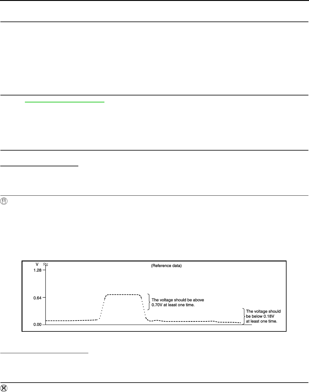
EC-1094
< COMPONENT DIAGNOSIS > [FOR MEXICO]
P0138 HO2S2
NO >> GO TO 14.
14.REPLACE HEATED OXYGEN SENSOR 2
Replace heated oxygen sensor 2.
CAUTION:
• Discard any heated oxygen sensor which has been dropped from a height of more than 0.5 m (19.7
in) onto a hard surface such as a concrete floor; use a new one.
• Before installing new oxygen sensor, clean exhaust system threads using oxygen sensor thread
cleaner tool J-43897-18 or J-43897-12 and approved anti-seize lubricant.
>> INSPECTION END
15.CHECK INTERMITTENT INCIDENT
Refer to GI-41, "Intermittent Incident".
>> INSPECTION END
Component Inspection INFOID:0000000004534627
1.INSPECTION START
Do you have CONSULT-III?
Do you have CONSULT-III?
YES >> GO TO 2.
NO >> GO TO 3.
2.CHECK HEATED OXYGEN SENSOR 2
With CONSULT-III
1. Turn ignition switch ON and select “DATA MONITOR” mode with CONSULT-III.
2. Start engine and warm it up to the normal operating temperature.
3. Turn ignition switch OFF and wait at least 10 seconds.
4. Start engine and keep the engine speed between 3,500 and 4,000 rpm for at least 1 minute under no load.
5. Let engine idle for 1 minute.
6. Select “FUEL INJECTION” in “ACTIVE TEST” mode, and select “HO2S2 (B1)” as the monitor item with
CONSULT-III.
7. Check “HO2S2 (B1)” at idle speed when adjusting “FUEL INJECTION” to ±25%.
“HO2S2 (B1)” should be above 0.70V at least once when the “FUEL INJECTION” is +25%.
“HO2S2 (B1)” should be below 0.18V at least once when the “FUEL INJECTION” is −25%.
Is the inspection result normal?
YES >> INSPECTION END
NO >> GO TO 6.
3.CHECK HEATED OXYGEN SENSOR 2-I
Without CONSULT-III
1. Start engine and warm it up to the normal operating temperature.
2. Turn ignition switch OFF and wait at least 10 seconds.
3. Start engine and keep the engine speed between 3,500 and 4,000 rpm for at least 1 minute under no load.
4. Let engine idle for 1 minute.
5. Check the voltage between ECM harness connector and ground under the following condition.
JMBIA1670G
B
Revision: 2008 August 2009 Rogue
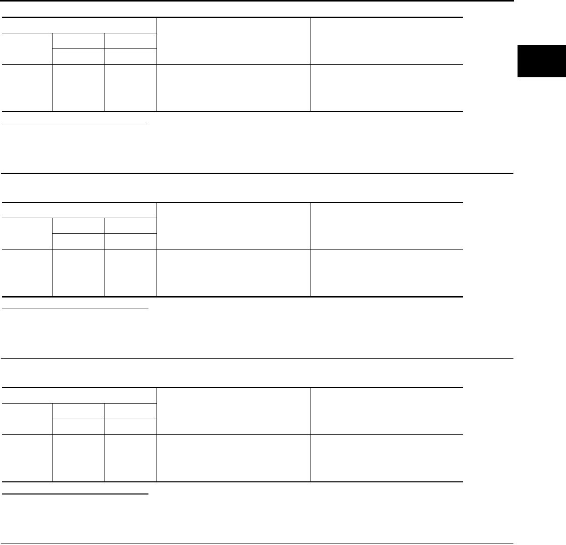
P0138 HO2S2
EC-1095
< COMPONENT DIAGNOSIS > [FOR MEXICO]
C
D
E
F
G
H
I
J
K
L
M
A
EC
N
P
O
Is the inspection result normal?
YES >> INSPECTION END
NO >> GO TO 4.
4.CHECK HEATED OXYGEN SENSOR 2-II
Check the voltage between ECM harness connector and ground under the following condition.
Is the inspection result normal?
YES >> INSPECTION END
NO >> GO TO 5.
5.CHECK HEATED OXYGEN SENSOR 2-III
Check the voltage between ECM harness connector and ground under the following condition.
Is the inspection result normal?
YES >> INSPECTION END
NO >> GO TO 6.
6.REPLACE HEATED OXYGEN SENSOR 2
Replace heated oxygen sensor 2.
CAUTION:
• Discard any heated oxygen sensor which has been dropped from a height of more than 0.5 m (19.7
in) onto a hard surface such as a concrete floor; use a new one.
• Before installing new heated oxygen sensor, clean exhaust system threads using oxygen sensor
thread cleaner [commercial service tool (J-43897-18 or J-43897-12)] and approved anti-seize lubri-
cant (commercial service tool).
>> INSPECTION END
ECM
Condition Voltage
Connector +−
Terminal Terminal
F8
33
(HO2S2
signal)
35
(Sensor
ground)
Revving up to 4,000 rpm under no load
at least 10 times
The voltage should be above 0.70V at
least once during this procedure.
The voltage should be below 0.18V at
least once during this procedure.
ECM
Condition Voltage
Connector +−
Terminal Terminal
F8
33
(HO2S2
signal)
35
(Sensor
ground)
Keeping engine speed at idle for 10
minutes
The voltage should be above 0.70V at
least once during this procedure.
The voltage should be below 0.18V at
least once during this procedure.
ECM
Condition Voltage
Connector +−
Terminal Terminal
F8 33
(HO2S2
signal)
35
(Sensor
ground)
Coasting from 80 km/h (50 MPH) in D
position
The voltage should be above 0.70V at
least once during this procedure.
The voltage should be below 0.18V at
least once during this procedure.
Revision: 2008 August 2009 Rogue
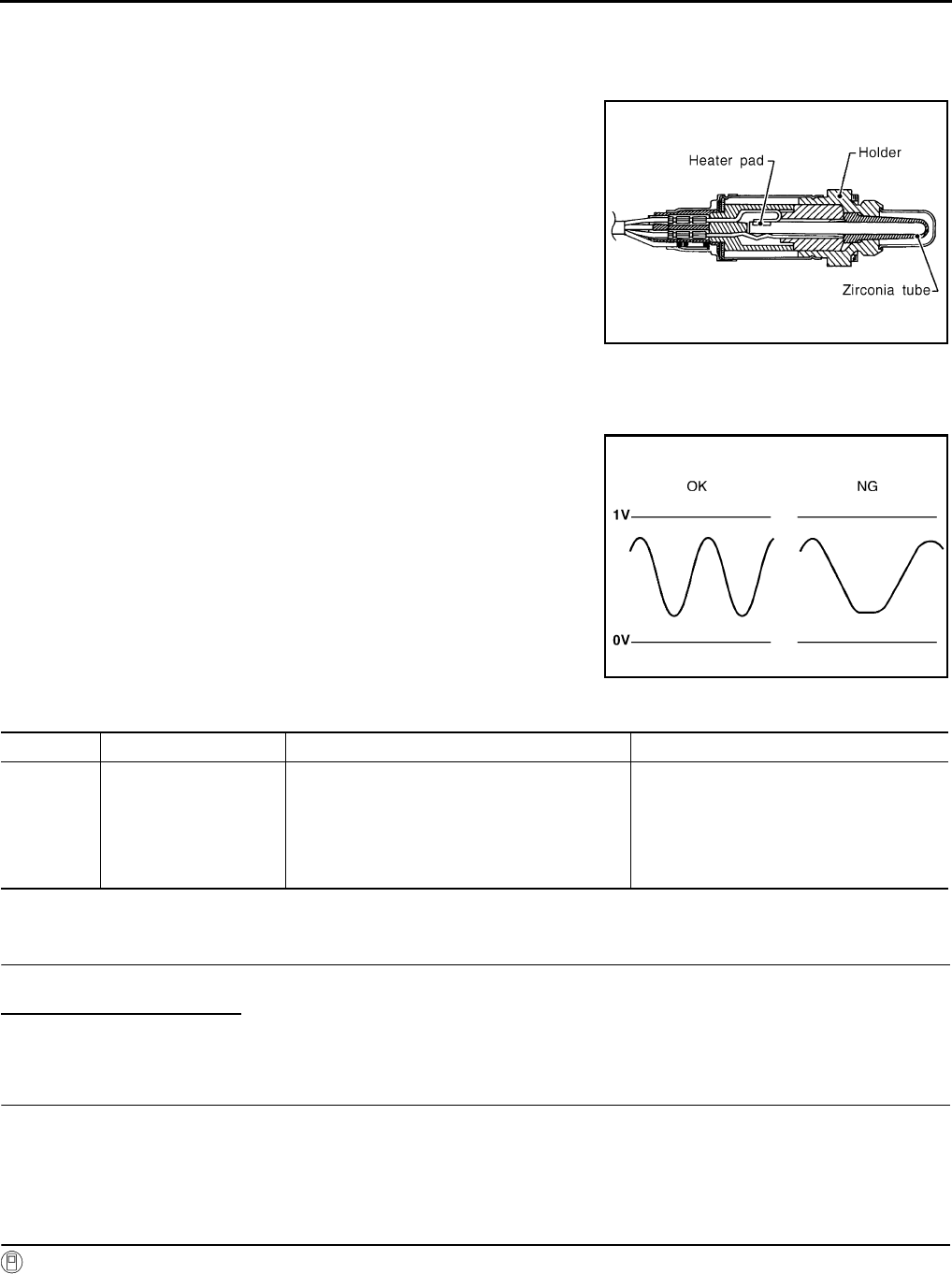
EC-1096
< COMPONENT DIAGNOSIS > [FOR MEXICO]
P0139 HO2S2
P0139 HO2S2
Description INFOID:0000000004534633
The heated oxygen sensor 2, after three way catalyst (manifold),
monitors the oxygen level in the exhaust gas.
Even if switching characteristics of the air fuel ratio (A/F) sensor 1
are shifted, the air-fuel ratio is controlled to stoichiometric, by the sig-
nal from the heated oxygen sensor 2.
This sensor is made of ceramic zirconia. The zirconia generates volt-
age from approximately 1V in richer conditions to 0V in leaner condi-
tions.
Under normal conditions the heated oxygen sensor 2 is not used for
engine control operation.
DTC Logic INFOID:0000000004494238
DTC DETECTION LOGIC
The heated oxygen sensor 2 has a much longer switching time
between rich and lean than the air fuel ratio (A/F) sensor 1. The oxy-
gen storage capacity of the three way catalyst (mamifold) causes the
longer switching time. To judge the malfunctions of heated oxygen
sensor 2, ECM monitors whether the switching response of the sen-
sor's voltage is faster than specified during various driving conditions
such as fuel cut.
DTC CONFIRMATION PROCEDURE
1.INSPECTION START
Do you have CONSULT-III?
Do you have CONSULT-III?
YES >> GO TO 2.
NO >> GO TO 5.
2.PRECONDITIONING
If DTC CONFIRMATION PROCEDURE has been previously conducted, always turn ignition switch OFF and
wait at least 10 seconds before conducting the next test.
>> GO TO 3.
3.PERFORM DTC CONFIRMATION PROCEDURE
With CONSULT-III
1. Turn ignition switch ON and select “DATA MONITOR” mode with CONSULT-III.
2. Start engine and warm it up to the normal operating temperature.
SEF327R
SEF302U
DTC No. Trouble diagnosis name DTC detecting condition Possible cause
P0139 Heated oxygen sensor 2
circuit slow response
It takes more time for the sensor to respond be-
tween rich and lean than the specified time.
• Harness or connectors
(The sensor circuit is open or shorted)
• Heated oxygen sensor 2
• Fuel pressure
• Fuel injector
• Intake air leaks
Revision: 2008 August 2009 Rogue
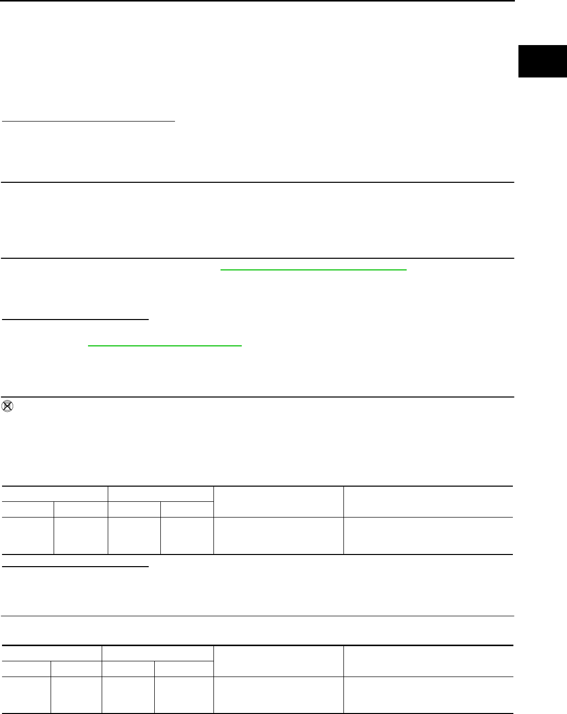
P0139 HO2S2
EC-1097
< COMPONENT DIAGNOSIS > [FOR MEXICO]
C
D
E
F
G
H
I
J
K
L
M
A
EC
N
P
O
3. Start engine and warm it up to the normal operating temperature.
4. Start engine and keep the engine speed between 3,500 and 4,000 rpm for at least 1 minute under no load.
5. Let engine idle for 1 minute.
6. Open engine hood.
7. Select “HO2S2 (B1) P0139” of “HO2S2” in “DTC WORK SUPPORT” mode with CONSULT-III.
8. Follow the instruction of CONSULT-III diaplay.
NOTE:
It will take at most 10 minutes until “COMPLETED” is displayed.
9. Touch “SELF-DIAG RESULT”.
Which is displayed on CONSULT-III?
OK >> INSPECTION END
NG >> GO TO 4.
CAN NOT BE DIAGNOSED>>GO TO 4.
4.PERFORM THE RESULT OF DTC CONFIRMATION PROCEDURE
1. Turn ignition switch OFF and leave the vehicle in a cool place (soak the vehicle).
2. Perform DTC CONFIRMATION PROCEDURE again.
>> GO TO 3.
5.PERFORM COMPONENT FUNCTION CHECK
Perform Component Function Check. Refer to EC-1097, "Component Function Check".
NOTE:
Use Component Function Check to check the overall function of the heated oxygen sensor 2 circuit. During
this check, a 1st trip DTC might not be confirmed.
Is the inspection result normal?
YES >> INSPECTION END
NO >> Go to EC-1098, "Diagnosis Procedure".
Component Function Check INFOID:0000000004494239
1.PERFORM COMPONENT FUNCTION CHECK-I
Without CONSULT-III
1. Start engine and warm it up to the normal operating temperature.
2. Turn ignition switch OFF and wait at least 10 seconds.
3. Start engine and keep the engine speed between 3,500 and 4,000 rpm for at least 1 minute under no load.
4. Let engine idle for 1 minute.
5. Check the voltage between ECM harness connector terminals under the following condition.
Is the inspection result normal?
YES >> INSPECTION END
NO >> GO TO 2.
2.PERFORM COMPONENT FUNCTION CHECK-II
Check the voltage between ECM harness connectors under the following condition.
ECM ECM Condition Voltage
Connector Terminal Connector Terminal
F8
33
(HO2S2
signal) F8
35
(Sensor
ground)
Revving up to 4,000 rpm under
no load at least 10 times
A change of voltage should be more than
0.80V for 1 second during this procedure.
ECM ECM Condition Voltage
Connector Terminal Connector Terminal
F8 33
(HO2S2
signal)
F8 35
(Sensor
ground)
Keeping engine speed at idle for
10 minutes
A change of voltage should be more than
0.80V for 1 second during this procedure.
Revision: 2008 August 2009 Rogue

EC-1098
< COMPONENT DIAGNOSIS > [FOR MEXICO]
P0139 HO2S2
Is the inspection result normal?
YES >> INSPECTION END
NO >> GO TO 3.
3.PERFORM COMPONENT FUNCTION CHECK-III
Check the voltage between ECM harness connector and ground under the following condition.
Is the inspection result normal?
YES >> INSPECTION END
NO >> Go to EC-1098, "Diagnosis Procedure".
Diagnosis Procedure INFOID:0000000004494240
1.CHECK GROUND CONNECTION
1. Turn ignition switch OFF.
2. Check ground connection E21. Refer to Ground Inspection in GI-44, "Circuit Inspection".
Is the inspection result normal?
YES >> GO TO 2.
NO >> Repair or replace ground connection.
2.CLEAR THE MIXTURE RATIO SELF-LEARNING VALUE
1. Clear the mixture ratio self-learning value. Refer to EC-940, "MIXTURE RATIO SELF-LEARNING VALUE
CLEAR : Special Repair Requirement".
2. Run engine for at least 10 minutes at idle speed.
Is the 1st trip DTC P0171 or P0172 detected? Is it difficult to start engine?
YES >> Perform trouble diagnosis for DTC P0171 or P0172. Refer to EC-1102, "DTC Logic" or EC-1106,
"DTC Logic".
NO >> GO TO 3.
3.CHECK HO2S2 GROUND CIRCUIT FOR OPEN AND SHORT
1. Turn ignition switch OFF.
2. Disconnect heated oxygen sensor 2 harness connector.
3. Disconnect ECM harness connector.
4. Check the continuity between HO2S2 harness connector and ECM harness connector.
5. Also check harness for short to ground and short to power.
Is the inspection result normal?
YES >> GO TO 4.
NO >> Repair open circuit or short to ground or short to power in harness or connectors.
4.CHECK HO2S2 INPUT SIGNAL CIRCUIT FOR OPEN AND SHORT
1. Check the continuity between HO2S2 harness connector and ECM harness connector.
ECM ECM Condition Voltage
Connector Terminal Connector Terminal
F8
33
(HO2S2
signal)
F8
35
(Sensor
ground)
Coasting from 80 km/h (50 MPH)
in D position A change of voltage should be more than
0.80V for 1 second during this procedure.
HO2S2 ECM Continuity
Connector Terminal Connector Terminal
F31 1 F8 35 Existed
HO2S2 ECM Continuity
Connector Terminal Connector Terminal
F31 4 F8 33 Existed
Revision: 2008 August 2009 Rogue
P0139 HO2S2
EC-1099
< COMPONENT DIAGNOSIS > [FOR MEXICO]
C
D
E
F
G
H
I
J
K
L
M
A
EC
N
P
O
2. Check the continuity between HO2S2 harness connector or ECM harness connector and ground.
3. Also check harness for short to power.
Is the inspection result normal?
YES >> GO TO 5.
NO >> Repair open circuit or short to ground or short to power in harness or connectors.
5.CHECK HEATED OXYGEN SENSOR 2
Refer to EC-1099, "Component Inspection".
Is the inspection result normal?
YES >> GO TO 7.
NO >> GO TO 6.
6.REPLACE HEATED OXYGEN SENSOR 2
Replace heated oxygen sensor 2.
CAUTION:
• Discard any heated oxygen sensor which has been dropped from a height of more than 0.5 m (19.7
in) onto a hard surface such as a concrete floor; use a new one.
• Before installing new heated oxygen sensor, clean exhaust system threads using oxygen sensor
thread cleaner [commercial service tool (J-43897-18 or J-43897-12)] and approved anti-seize lubri-
cant (commercial service tool).
>> INSPECTION END
7.CHECK INTERMITTENT INCIDENT
Refer to GI-41, "Intermittent Incident".
>> INSPECTION END
Component Inspection INFOID:0000000004534634
1.INSPECTION START
Do you have CONSULT-III?
Do you have CONSULT-III?
YES >> GO TO 2.
NO >> GO TO 3.
2.CHECK HEATED OXYGEN SENSOR 2
With CONSULT-III
1. Turn ignition switch ON and select “DATA MONITOR” mode with CONSULT-III.
2. Start engine and warm it up to the normal operating temperature.
3. Turn ignition switch OFF and wait at least 10 seconds.
4. Start engine and keep the engine speed between 3,500 and 4,000 rpm for at least 1 minute under no load.
5. Let engine idle for 1 minute.
6. Select “FUEL INJECTION” in “ACTIVE TEST” mode, and select “HO2S2 (B1)” as the monitor item with
CONSULT-III.
HO2S2 ECM Ground Continuity
Connector Terminal Connector Terminal
F31 4 F8 33 Ground Not existed
Revision: 2008 August 2009 Rogue

EC-1100
< COMPONENT DIAGNOSIS > [FOR MEXICO]
P0139 HO2S2
7. Check “HO2S2 (B1)” at idle speed when adjusting “FUEL INJECTION” to ±25%.
“HO2S2 (B1)” should be above 0.70V at least once when the “FUEL INJECTION” is +25%.
“HO2S2 (B1)” should be below 0.18V at least once when the “FUEL INJECTION” is −25%.
Is the inspection result normal?
YES >> INSPECTION END
NO >> GO TO 6.
3.CHECK HEATED OXYGEN SENSOR 2-I
Without CONSULT-III
1. Start engine and warm it up to the normal operating temperature.
2. Turn ignition switch OFF and wait at least 10 seconds.
3. Start engine and keep the engine speed between 3,500 and 4,000 rpm for at least 1 minute under no load.
4. Let engine idle for 1 minute.
5. Check the voltage between ECM harness connector and ground under the following condition.
Is the inspection result normal?
YES >> INSPECTION END
NO >> GO TO 4.
4.CHECK HEATED OXYGEN SENSOR 2-II
Check the voltage between ECM harness connector and ground under the following condition.
Is the inspection result normal?
YES >> INSPECTION END
NO >> GO TO 5.
5.CHECK HEATED OXYGEN SENSOR 2-III
Check the voltage between ECM harness connector and ground under the following condition.
JMBIA1670G
B
ECM
Condition Voltage
Connector +−
Terminal Terminal
F8
33
(HO2S2
signal)
35
(Sensor
ground)
Revving up to 4,000 rpm under no load
at least 10 times
The voltage should be above 0.70V at
least once during this procedure.
The voltage should be below 0.18V at
least once during this procedure.
ECM
Condition Voltage
Connector +−
Terminal Terminal
F8 33
(HO2S2
signal)
35
(Sensor
ground)
Keeping engine speed at idle for 10
minutes
The voltage should be above 0.70V at
least once during this procedure.
The voltage should be below 0.18V at
least once during this procedure.
Revision: 2008 August 2009 Rogue

P0139 HO2S2
EC-1101
< COMPONENT DIAGNOSIS > [FOR MEXICO]
C
D
E
F
G
H
I
J
K
L
M
A
EC
N
P
O
Is the inspection result normal?
YES >> INSPECTION END
NO >> GO TO 6.
6.REPLACE HEATED OXYGEN SENSOR 2
Replace heated oxygen sensor 2.
CAUTION:
• Discard any heated oxygen sensor which has been dropped from a height of more than 0.5 m (19.7
in) onto a hard surface such as a concrete floor; use a new one.
• Before installing new heated oxygen sensor, clean exhaust system threads using oxygen sensor
thread cleaner [commercial service tool (J-43897-18 or J-43897-12)] and approved anti-seize lubri-
cant (commercial service tool).
>> INSPECTION END
ECM
Condition Voltage
Connector +−
Terminal Terminal
F8
33
(HO2S2
signal)
35
(Sensor
ground)
Coasting from 80 km/h (50 MPH) in D
position
The voltage should be above 0.70V at
least once during this procedure.
The voltage should be below 0.18V at
least once during this procedure.
Revision: 2008 August 2009 Rogue

EC-1102
< COMPONENT DIAGNOSIS > [FOR MEXICO]
P0171 FUEL INJECTION SYSTEM FUNCTION
P0171 FUEL INJECTION SYSTEM FUNCTION
DTC Logic INFOID:0000000004494242
DTC DETECTION LOGIC
With the Air/Fuel Mixture Ratio Self-Learning Control, the actual mixture ratio can be brought closely to the
theoretical mixture ratio based on the mixture ratio feedback signal from A/F sensor 1. The ECM calculates
the necessary compensation to correct the offset between the actual and the theoretical ratios.
In case the amount of the compensation value is extremely large (the actual mixture ratio is too lean.), the
ECM judges the condition as the fuel injection system malfunction and illuminates the MIL (2 trip detection
logic).
DTC CONFIRMATION PROCEDURE
1.PRECONDITIONING
If DTC CONFIRMATION PROCEDURE has been previously conducted, always turn ignition switch OFF and
wait at least 10 seconds before conducting the next test.
>> GO TO 2.
2.PERFORM DTC CONFIRMATION PROCEDURE-I
1. Clear the mixture ratio self-learning value. Refer to EC-940, "MIXTURE RATIO SELF-LEARNING VALUE
CLEAR : Special Repair Requirement".
2. Start engine.
Is it difficult to start engine?
YES >> GO TO 3.
NO >> GO TO 4.
3.RESTART ENGINE
If it is difficult to start engine, the fuel injection system has a malfunction, too.
Crank engine while depressing accelerator pedal.
NOTE:
When depressing accelerator pedal three-fourths (3/4) or more, the control system does not start the
engine. Do not depress accelerator pedal too much.
Does engine start?
YES >> Go to EC-1103, "Diagnosis Procedure".
NO >> Check exhaust and intake air leak visually.
4.PERFORM DTC CONFIRMATION PROCEDURE-II
1. Start engine and let it idle for at least 5 minutes.
2. Check 1st trip DTC.
Is 1st trip DTC detected?
YES >> Go to EC-1103, "Diagnosis Procedure".
NO >> GO TO 5.
Sensor Input signal to ECM ECM function Actuator
A/F sensor 1 Density of oxygen in exhaust gas
(Mixture ratio feedback signal) Fuel injection control Fuel injector
DTC No. Trouble diagnosis name DTC detecting condition Possible cause
P0171 Fuel injection system too
lean
• Fuel injection system does not operate properly.
• The amount of mixture ratio compensation is too
large. (The mixture ratio is too lean.)
• Intake air leaks
• A/F sensor 1
• Fuel injector
• Exhaust gas leaks
• Incorrect fuel pressure
• Lack of fuel
• Mass air flow sensor
• Incorrect PCV hose connection
Revision: 2008 August 2009 Rogue
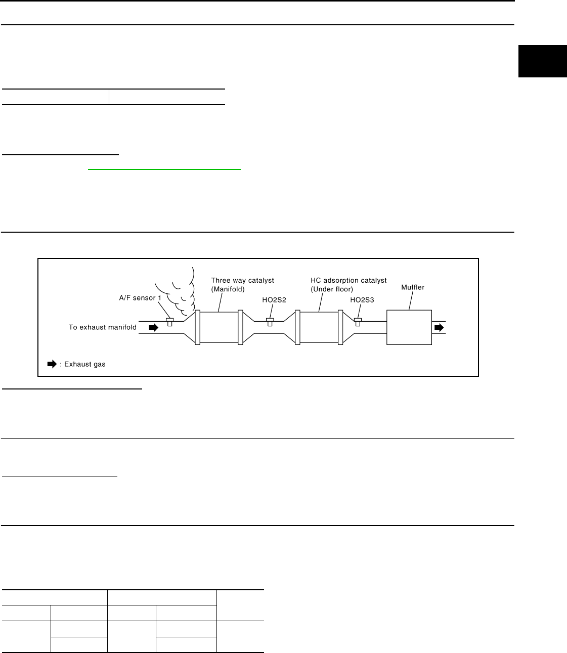
P0171 FUEL INJECTION SYSTEM FUNCTION
EC-1103
< COMPONENT DIAGNOSIS > [FOR MEXICO]
C
D
E
F
G
H
I
J
K
L
M
A
EC
N
P
O
5.PERFORM DTC CONFIRMATION PROCEDURE-III
1. Turn ignition switch OFF and wait at least 10 seconds.
2. Start engine
3. Maintain the following conditions for at least 10 consecutive minutes.
Hold the accelerator pedal as steady as possible.
CAUTION:
Always drive vehicle at a safe speed.
4. Check 1st trip DTC.
Is 1st trip DTC detected?
YES >> Go to EC-1103, "Diagnosis Procedure".
NO >> INSPECTION END
Diagnosis Procedure INFOID:0000000004494243
1.CHECK EXHAUST GAS LEAK
1. Start engine and run it at idle.
2. Listen for an exhaust gas leak before three way catalyst (manifold).
Is exhaust gas leak detected?
YES >> Repair or replace.
NO >> GO TO 2.
2.CHECK FOR INTAKE AIR LEAK
1. Listen for an intake air leak after the mass air flow sensor.
2. Check PCV hose connection.
Intake air leak detected?
YES >> Repair or replace.
NO >> GO TO 3.
3.CHECK A/F SENSOR 1 INPUT SIGNAL CIRCUIT
1. Turn ignition switch OFF.
2. Disconnect corresponding A/F sensor 1 harness connector.
3. Disconnect ECM harness connector.
4. Check the continuity between A/F sensor 1 harness connector and ECM harness connector.
5. Check the continuity between A/F sensor 1 harness connector or ECM harness connector and ground.
VHCL SPEED SE 50 - 120 km/h (31 - 75 MPH)
JMBIA0163G
B
A/F sensor 1 ECM Continuity
Connector Terminal Connector Terminal
F28 1F8 45 Existed
249
Revision: 2008 August 2009 Rogue
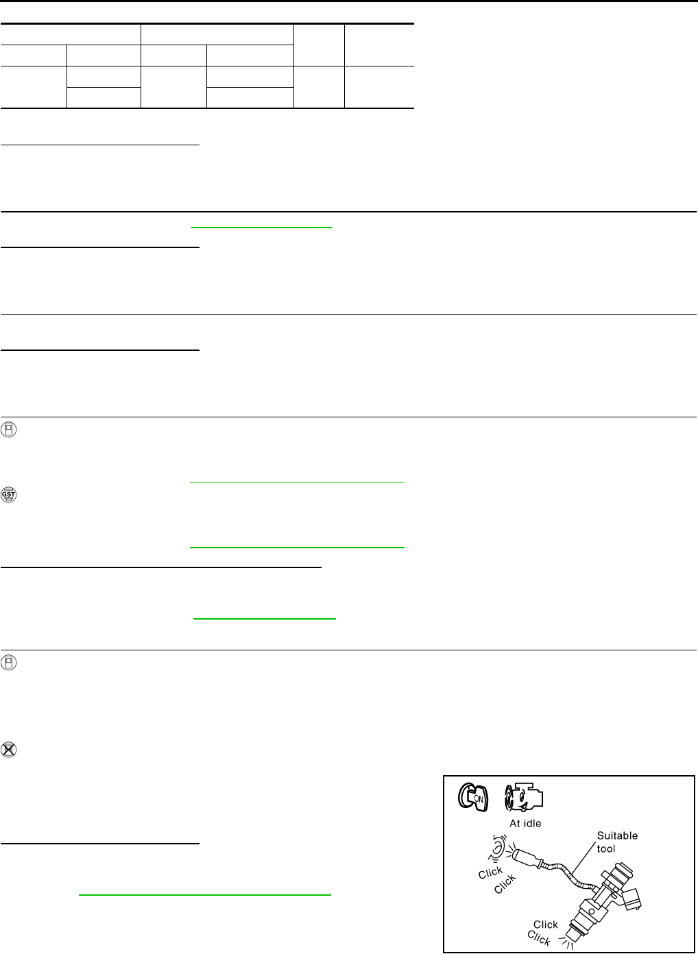
EC-1104
< COMPONENT DIAGNOSIS > [FOR MEXICO]
P0171 FUEL INJECTION SYSTEM FUNCTION
6. Also check harness for short to power.
Is the inspection result normal?
YES >> GO TO 4.
NO >> Repair open circuit or short to ground or short to power in harness or connectors.
4.CHECK FUEL PRESSURE
Check fuel pressure. Refer to EC-1279, "Inspection".
Is the inspection result normal?
YES >> GO TO 6.
NO >> GO TO 5.
5. DETECT MALFUNCTIONING PART
Check fuel hoses and fuel tubes for clogging.
Is the inspection result normal?
YES >> Replace “fuel filter and fuel pump assembly”.
NO >> Repair or replace
6.CHECK MASS AIR FLOW SENSOR
With CONSULT-III
1. Install all removed parts.
2. Check “MASS AIR FLOW” in “DATA MONITOR” mode with CONSULT-III.
For specification, refer to EC-1281, "Mass Air Flow Sensor".
With GST
1. Install all removed parts.
2. Check mass air flow sensor signal in Service $01 with GST.
For specification, refer to EC-1281, "Mass Air Flow Sensor".
Is the measurement value within the specification?
YES >> GO TO 7.
NO >> Check connectors for rusted terminals or loose connections in the mass air flow sensor circuit or
grounds. Refer to EC-1040, "DTC Logic".
7.CHECK FUNCTION OF FUEL INJECTOR
With CONSULT-III
1. Start engine.
2. Perform “POWER BALANCE” in “ACTIVE TEST” mode with CONSULT-III.
3. Check that each circuit produces a momentary engine speed drop.
Without CONSULT-III
1. Let engine idle.
2. Listen to each fuel injector operating sound.
Is the inspection result normal?
YES >> GO TO 8.
NO >> Perform trouble diagnosis for FUEL INJECTOR, refer to
EC-1217, "Component Function Check".
A/F sensor 1 ECM Ground Continuity
Connector Terminal Connector Terminal
F28 1F8 45 Ground Not existed
249
Clicking noise should be heard.
PBIB3332E
Revision: 2008 August 2009 Rogue
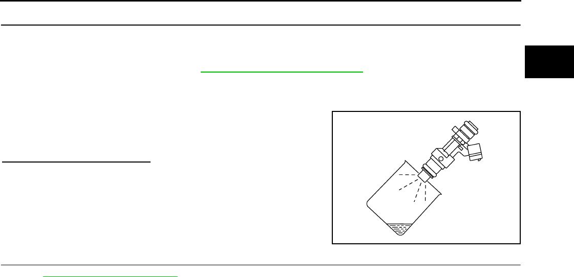
P0171 FUEL INJECTION SYSTEM FUNCTION
EC-1105
< COMPONENT DIAGNOSIS > [FOR MEXICO]
C
D
E
F
G
H
I
J
K
L
M
A
EC
N
P
O
8.CHECK FUEL INJECTOR
1. Turn ignition switch OFF.
2. Confirm that the engine is cooled down and there are no fire hazards near the vehicle.
3. Disconnect all fuel injector harness connectors.
4. Remove fuel tube assembly. Refer to EM-43, "Removal and Installation".
Keep fuel hose and all fuel injectors connected to fuel tube.
5. Disconnect all ignition coil harness connectors.
6. Prepare pans or saucers under each fuel injector.
7. Crank engine for approximately 3 seconds.
Is the inspection result normal?
YES >> GO TO 9.
NO >> Replace fuel injectors from which fuel does not spray
out. Always replace O-ring with new ones.
9.CHECK INTERMITTENT INCIDENT
Refer to GI-41, "Intermittent Incident".
>> INSPECTION END
Fuel should be sprayed evenly for each fuel injector.
PBIA9666J
Revision: 2008 August 2009 Rogue

EC-1106
< COMPONENT DIAGNOSIS > [FOR MEXICO]
P0172 FUEL INJECTION SYSTEM FUNCTION
P0172 FUEL INJECTION SYSTEM FUNCTION
DTC Logic INFOID:0000000004494244
DTC DETECTION LOGIC
With the Air/Fuel Mixture Ratio Self-Learning Control, the actual mixture ratio can be brought closely to the
theoretical mixture ratio based on the mixture ratio feedback signal from the A/F sensors 1. The ECM calcu-
lates the necessary compensation to correct the offset between the actual and the theoretical ratios.
In case the amount of the compensation value is extremely large (The actual mixture ratio is too rich.), the
ECM judges the condition as the fuel injection system malfunction and illuminates the MIL (2 trip detection
logic).
DTC CONFIRMATION PROCEDURE
1.PRECONDITIONING
If DTC CONFIRMATION PROCEDURE has been previously conducted, always turn ignition switch OFF and
wait at least 10 seconds before conducting the next test.
>> GO TO 2.
2.PERFORM DTC CONFIRMATION PROCEDURE-I
1. Clear the mixture ratio self-learning value. Refer to EC-940, "MIXTURE RATIO SELF-LEARNING VALUE
CLEAR : Special Repair Requirement".
2. Start engine.
Is it difficult to start engine?
YES >> GO TO 3.
NO >> GO TO 4.
3.RESTART ENGINE
If it is difficult to start engine, the fuel injection system has a malfunction, too.
Crank engine while depressing accelerator pedal.
NOTE:
When depressing accelerator pedal three-fourths (3/4) or more, the control system does not start the
engine. Do not depress accelerator pedal.
Does engine start?
YES >> Go to EC-1107, "Diagnosis Procedure".
NO >> Remove spark plugs and check for fouling, etc.
4.PERFORM DTC CONFIRMATION PROCEDURE-II
1. Start engine and let it idle for at least 10 minutes.
2. Check 1st trip DTC.
Is 1st trip DTC detected?
YES >> Go to EC-1107, "Diagnosis Procedure".
NO >> GO TO 5.
5.PERFORM DTC CONFIRMATION PROCEDURE-III
1. Turn ignition switch OFF and wait at least 10 seconds.
Sensor Input signal to ECM ECM function Actuator
A/F sensor 1 Density of oxygen in exhaust gas
(Mixture ratio feedback signal) Fuel injection control Fuel injector
DTC No. Trouble diagnosis name DTC detecting condition Possible cause
P0172 Fuel injection system too
rich
• Fuel injection system does not operate properly.
• The amount of mixture ratio compensation is too
large. (The mixture ratio is too rich.)
• A/F sensor 1
• Fuel injector
• Exhaust gas leaks
• Incorrect fuel pressure
• Mass air flow sensor
Revision: 2008 August 2009 Rogue
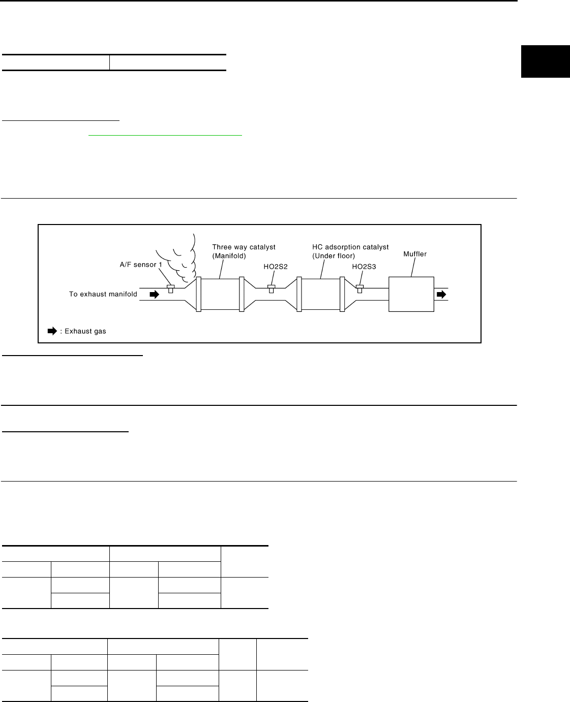
P0172 FUEL INJECTION SYSTEM FUNCTION
EC-1107
< COMPONENT DIAGNOSIS > [FOR MEXICO]
C
D
E
F
G
H
I
J
K
L
M
A
EC
N
P
O
2. Start engine
3. Maintain the following conditions for at least 10 consecutive minutes.
Hold the accelerator pedal as steady as possible.
CAUTION:
Always drive vehicle at a safe speed.
4. Check 1st trip DTC.
Is 1st trip DTC detected?
YES >> Go to EC-1107, "Diagnosis Procedure".
NO >> INSPECTION END
Diagnosis Procedure INFOID:0000000004494245
1.CHECK EXHAUST GAS LEAK
1. Start engine and run it at idle.
2. Listen for an exhaust gas leak before three way catalyst (manifold).
Is exhaust gas leak detected?
YES >> Repair or replace.
NO >> GO TO 2.
2.CHECK FOR INTAKE AIR LEAK
Listen for an intake air leak after the mass air flow sensor.
Is intake air leak detected?
YES >> Repair or replace.
NO >> GO TO 3.
3.CHECK A/F SENSOR 1 INPUT SIGNAL CIRCUIT
1. Turn ignition switch OFF.
2. Disconnect corresponding A/F sensor 1 harness connector.
3. Disconnect ECM harness connector.
4. Check the continuity between A/F sensor 1 harness connector and ECM harness connector.
5. Check the continuity between A/F sensor 1 harness connector or ECM harness connector and ground.
6. Also check harness for short to power.
VHCL SPEED SE 50 - 120 km/h (31 - 75 MPH)
JMBIA0163G
B
A/F sensor 1 ECM Continuity
Connector Terminal Connector Terminal
F28 1F8 45 Existed
249
A/F sensor 1 ECM Ground Continuity
Connector Terminal Connector Terminal
F28 1F8 45 Ground Not existed
249
Revision: 2008 August 2009 Rogue
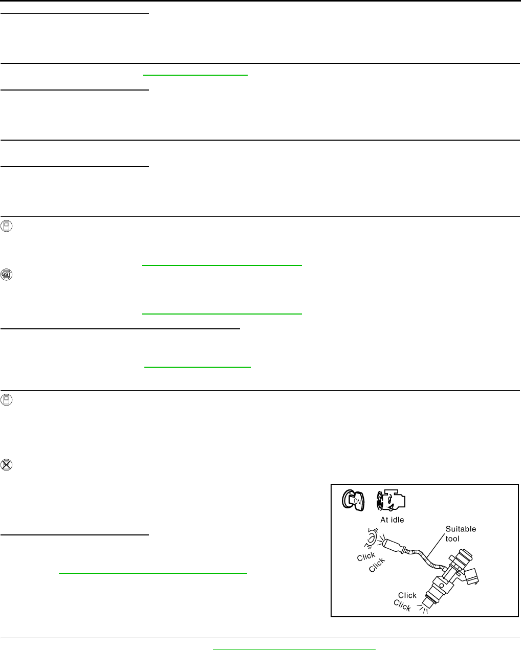
EC-1108
< COMPONENT DIAGNOSIS > [FOR MEXICO]
P0172 FUEL INJECTION SYSTEM FUNCTION
Is the inspection result normal?
YES >> GO TO 4.
NO >> Repair open circuit or short to ground or short to power in harness or connectors.
4.CHECK FUEL PRESSURE
Check fuel pressure. Refer to EC-1279, "Inspection".
Is the inspection result normal?
YES >> GO TO 6.
NO >> GO TO 5.
5. DETECT MALFUNCTIONING PART
Check fuel hoses and fuel tubes for clogging.
Is the inspection result normal?
YES >> Replace “fuel filter and fuel pump assembly”.
NO >> Repair or replace
6.CHECK MASS AIR FLOW SENSOR
With CONSULT-III
1. Install all removed parts.
2. Check “MASS AIR FLOW” in “DATA MONITOR” mode with CONSULT-III.
For specification, refer to EC-1281, "Mass Air Flow Sensor".
With GST
1. Install all removed parts.
2. Check mass air flow sensor signal in “Service $01” with GST.
For specification, refer to EC-1281, "Mass Air Flow Sensor".
Is the measurement value within the specification?
YES >> GO TO 7.
NO >> Check connectors for rusted terminals or loose connections in the mass air flow sensor circuit or
grounds. Refer to EC-1040, "DTC Logic".
7.CHECK FUNCTION OF FUEL INJECTOR
With CONSULT-III
1. Start engine.
2. Perform “POWER BALANCE” in “ACTIVE TEST” mode with CONSULT-III.
3. Check that each circuit produces a momentary engine speed drop.
Without CONSULT-III
1. Let engine idle.
2. Listen to each fuel injector operating sound.
Is the inspection result normal?
YES >> GO TO 8.
NO >> Perform trouble diagnosis for FUEL INJECTOR, refer to
EC-1217, "Component Function Check".
8.CHECK FUEL INJECTOR
1. Remove fuel injector assembly. Refer to EM-43, "Removal and Installation".
Keep fuel hose and all fuel injectors connected to fuel tube.
2. Confirm that the engine is cooled down and there are no fire hazards near the vehicle.
3. Disconnect all fuel injector harness connectors.
4. Disconnect all ignition coil harness connectors.
5. Prepare pans or saucers under each fuel injector.
6. Crank engine for approximately 3 seconds.
Clicking noise should be heard.
PBIB3332E
Revision: 2008 August 2009 Rogue

P0172 FUEL INJECTION SYSTEM FUNCTION
EC-1109
< COMPONENT DIAGNOSIS > [FOR MEXICO]
C
D
E
F
G
H
I
J
K
L
M
A
EC
N
P
O
Check that fuel does not drip from fuel injector.
Is the inspection result normal?
YES >> GO TO 9.
NO >> Replace the fuel injectors from which fuel is dripping. Always replace O-ring with new one.
9.CHECK INTERMITTENT INCIDENT
Refer to GI-41, "Intermittent Incident".
>> INSPECTION END
Revision: 2008 August 2009 Rogue
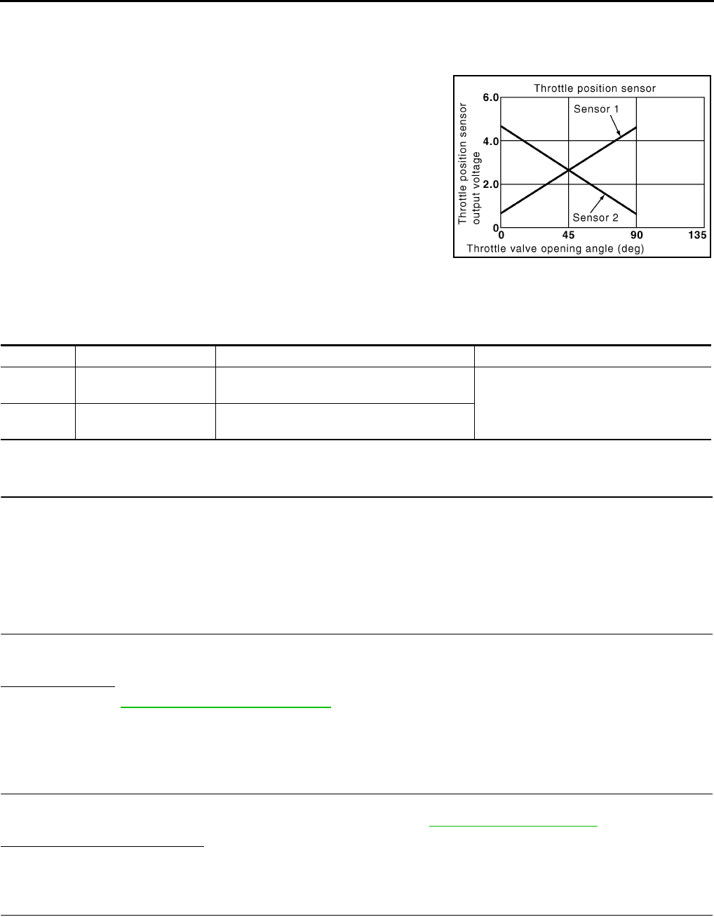
EC-1110
< COMPONENT DIAGNOSIS > [FOR MEXICO]
P0222, P0223 TP SENSOR
P0222, P0223 TP SENSOR
Description INFOID:0000000004534374
Electric throttle control actuator consists of throttle control motor,
throttle position sensor, etc. The throttle position sensor responds to
the throttle valve movement.
The throttle position sensor has two sensors. These sensors are a
kind of potentiometer which transform the throttle valve position into
output voltage, and emit the voltage signals to the ECM. The ECM
judges the current opening angle of the throttle valve from these sig-
nals and controls the throttle valve opening angle in response to
driving conditions via the throttle control motor.
DTC Logic INFOID:0000000004494247
DTC DETECTION LOGIC
DTC CONFIRMATION PROCEDURE
1.PRECONDITIONING
If DTC CONFIRMATION PROCEDURE has been previously conducted, always turn ignition switch OFF and
wait at least 10 seconds before conducting the next test.
TESTING CONDITION:
Before performing the following procedure, confirm that battery voltage is more than 8V at idle.
>> GO TO 2.
2.PERFORM DTC CONFIRMATION PROCEDURE
1. Start engine and let it idle for 1 second.
2. Check DTC.
Is DTC detected?
YES >> Go to EC-1110, "Diagnosis Procedure".
NO >> INSPECTION END
Diagnosis Procedure INFOID:0000000004494248
1.CHECK GROUND CONNECTION
1. Turn ignition switch OFF.
2. Check ground connection E21. Refer to Ground Inspection in GI-44, "Circuit Inspection".
Is the inspection result normal?
YES >> GO TO 2.
NO >> Repair or replace ground connection.
2.CHECK THROTTLE POSITION SENSOR 1 POWER SUPPLY CIRCUIT
1. Disconnect electric throttle control actuator harness connector.
2. Turn ignition switch ON.
3. Check the voltage between electric throttle control actuator harness connector and ground.
PBIB0145E
DTC No. Trouble diagnosis name DTC detecting condition Possible cause
P0222 Throttle position sensor
1 circuit low input An excessively low voltage from the TP sensor
1 is sent to ECM. • Harness or connectors
(TP sensor 1 circuit is open or shorted.)
• Electric throttle control actuator
(TP sensor 1)
P0223 Throttle position sensor
1 circuit high input
An excessively high voltage from the TP sensor
1 is sent to ECM.
Revision: 2008 August 2009 Rogue

P0222, P0223 TP SENSOR
EC-1111
< COMPONENT DIAGNOSIS > [FOR MEXICO]
C
D
E
F
G
H
I
J
K
L
M
A
EC
N
P
O
Is the inspection result normal?
YES >> GO TO 3.
NO >> Repair open circuit or short to ground or short to power in harness or connectors.
3.CHECK THROTTLE POSITION SENSOR 1 GROUND CIRCUIT FOR OPEN AND SHORT
1. Turn ignition switch OFF.
2. Disconnect ECM harness connector.
3. Check the continuity between electric throttle control actuator harness connector and ECM harness con-
nector.
4. Also check harness for short to ground and short to power.
Is the inspection result normal?
YES >> GO TO 4.
NO >> Repair open circuit or short to ground or short to power in harness or connectors.
4.CHECK THROTTLE POSITION SENSOR 1 INPUT SIGNAL CIRCUIT FOR OPEN AND SHORT
1. Check the continuity between electric throttle control actuator harness connector and ECM harness con-
nector.
2. Also check harness for short to ground and short to power.
Is the inspection result normal?
YES >> GO TO 5.
NO >> Repair open circuit or short to ground or short to power in harness or connectors.
5.CHECK THROTTLE POSITION SENSOR
Refer to EC-1112, "Component Inspection".
Is the inspection result normal?
YES >> GO TO 7.
NO >> GO TO 6.
6.REPLACE ELECTRIC THROTTLE CONTROL ACTUATOR
1. Replace electric throttle control actuator.
2. Go to EC-1060, "Special Repair Requirement".
>> INSPECTION END
7.CHECK INTERMITTENT INCIDENT
Refer to GI-41, "Intermittent Incident".
>> INSPECTION END
Electric throttle control actuator Ground Voltage
Connector Terminal
F29 1 Ground Approx. 5 V
Electric throttle control actuator ECM Continuity
Connector Terminal Connector Terminal
F29 4 F8 36 Existed
Electric throttle control actuator ECM Continuity
Connector Terminal Connector Terminal
F29 2 F8 37 Existed
Revision: 2008 August 2009 Rogue

EC-1112
< COMPONENT DIAGNOSIS > [FOR MEXICO]
P0222, P0223 TP SENSOR
Component Inspection INFOID:0000000004534375
1.CHECK THROTTLE POSITION SENSOR
1. Turn ignition switch OFF.
2. Reconnect all harness connectors disconnected.
3. Perform EC-938, "THROTTLE VALVE CLOSED POSITION LEARNING : Special Repair Requirement".
4. Turn ignition switch ON.
5. Set selector lever to the D position.
6. Check the voltage between ECM harness connector terminals.
Is the inspection result normal?
YES >> INSPECTION END
NO >> GO TO 2.
2.REPLACE ELECTRIC THROTTLE CONTROL ACTUATOR
1. Replace electric throttle control actuator.
2. Perform EC-1112, "Special Repair Requirement".
>> INSPECTION END
Special Repair Requirement INFOID:0000000004534376
1.PERFORM THROTTLE VALVE CLOSED POSITION LEARNING
Refer to EC-938, "THROTTLE VALVE CLOSED POSITION LEARNING : Special Repair Requirement"
>> GO TO 2.
2.PERFORM IDLE AIR VOLUME LEARNING
Refer to EC-938, "IDLE AIR VOLUME LEARNING : Special Repair Requirement"
>> END
ECM
Condition Voltage+−
Connector Terminal Connector Terminal
F8
37
(TP sensor 1
signal) F8
36
(Sensor
ground) Accelerator pedal
Fully released More than 0.36 V
Fully depressed Less than 4.75 V
38
(TP sensor 2
signal)
Fully released Less than 4.75 V
Fully depressed More than 0.36 V
Revision: 2008 August 2009 Rogue
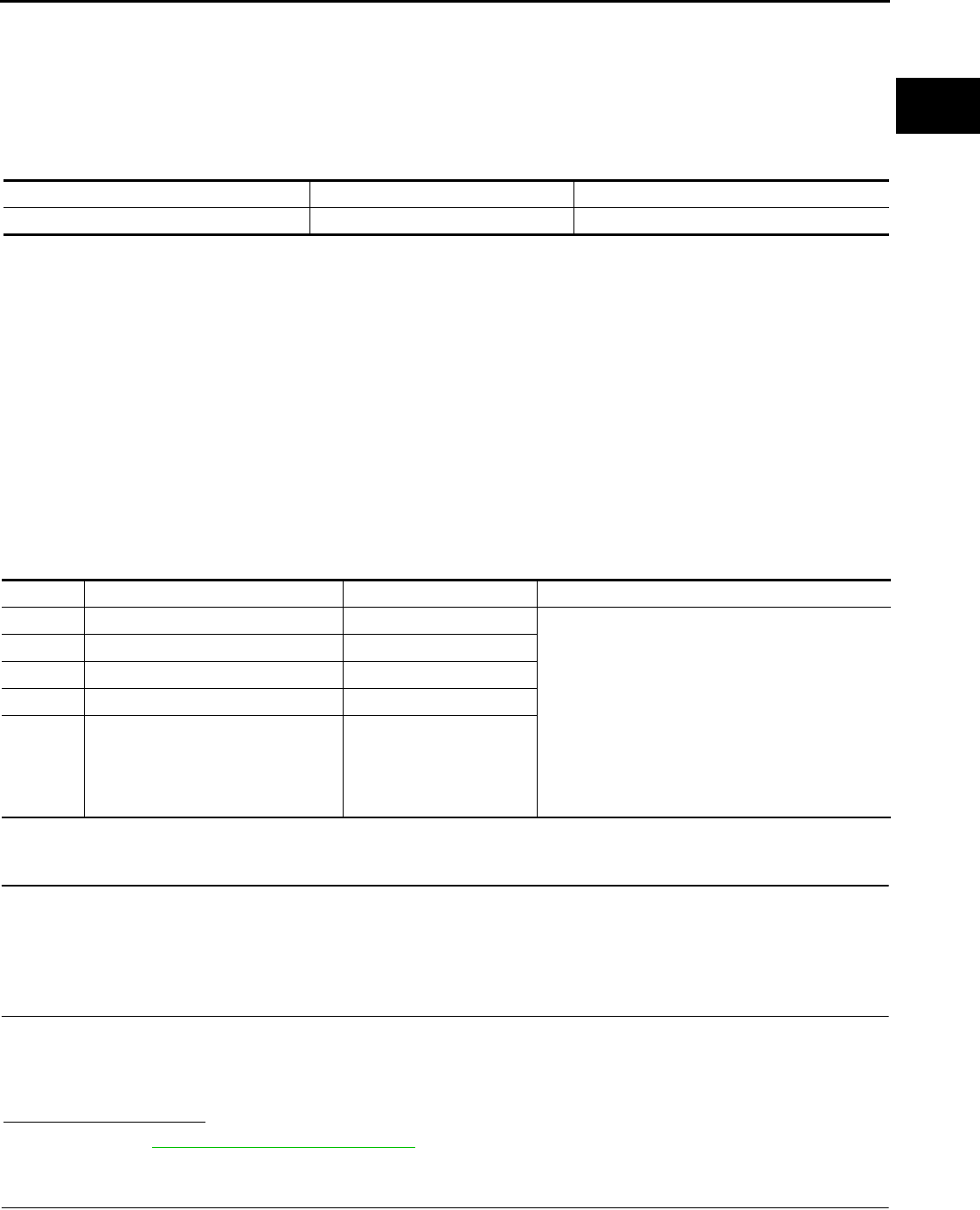
P0300, P0301, P0302, P0303, P0304 MISFIRE
EC-1113
< COMPONENT DIAGNOSIS > [FOR MEXICO]
C
D
E
F
G
H
I
J
K
L
M
A
EC
N
P
O
P0300, P0301, P0302, P0303, P0304 MISFIRE
DTC Logic INFOID:0000000004494251
DTC DETECTION LOGIC
When a misfire occurs, engine speed will fluctuate. If the engine speed fluctuates enough to cause the crank-
shaft position (CKP) sensor (POS) signal to vary, ECM can determine that a misfire is occurring.
The misfire detection logic consists of the following two conditions.
1. One Trip Detection Logic (Three Way Catalyst Damage)
On the 1st trip, when a misfire condition occurs that can damage the three way catalyst (TWC) due to
overheating, the MIL will blink.
When a misfire condition occurs, the ECM monitors the CKP sensor signal every 200 engine revolutions
for a change.
When the misfire condition decreases to a level that will not damage the TWC, the MIL will turn off.
If another misfire condition occurs that can damage the TWC on a second trip, the MIL will blink.
When the misfire condition decreases to a level that will not damage the TWC, the MIL will remain on.
If another misfire condition occurs that can damage the TWC, the MIL will begin to blink again.
2. Two Trip Detection Logic (Exhaust quality deterioration)
For misfire conditions that will not damage the TWC (but will affect vehicle emissions), the MIL will only
light when the misfire is detected on a second trip. During this condition, the ECM monitors the CKP sen-
sor signal every 1,000 engine revolutions.
A misfire malfunction can be detected in any one cylinder or in multiple cylinders.
DTC CONFIRMATION PROCEDURE
1.PRECONDITIONING
If DTC CONFIRMATION PROCEDURE has been previously conducted, always turn ignition switch OFF and
wait at least 10 seconds before conducting the next test.
>> GO TO 2.
2.PERFORM DTC CONFIRMATION PROCEDURE-I
1. Start engine and warm it up to normal operating temperature.
2. Turn ignition switch OFF and wait at least 10 seconds.
3. Restart engine and let it idle for approximately 15 minutes.
4. Check 1st trip DTC.
Is 1st trip DTC detected?
YES >> Go to EC-1114, "Diagnosis Procedure".
NO >> GO TO 3.
3.PERFORM DTC CONFIRMATION PROCEDURE-II
1. Turn ignition switch OFF and wait at least 10 seconds.
Sensor Input signal to ECM ECM function
Crankshaft position sensor (POS) Engine speed On board diagnosis of misfire
DTC No. Trouble diagnosis name DTC detecting condition Possible cause
P0300 Multiple cylinder misfires detected Multiple cylinder misfire. • Improper spark plug
• Insufficient compression
• Incorrect fuel pressure
• The fuel injector circuit is open or shorted
• Fuel injector
• Intake air leak
• The ignition signal circuit is open or shorted
• Lack of fuel
• Signal plate
• A/F sensor 1
• Incorrect PCV hose connection
P0301 No.1 cylinder misfire detected No. 1 cylinder misfires.
P0302 No. 2 cylinder misfire detected No. 2 cylinder misfires.
P0303 No. 3 cylinder misfire detected No. 3 cylinder misfires.
P0304 No. 4 cylinder misfire detected No. 4 cylinder misfires.
Revision: 2008 August 2009 Rogue
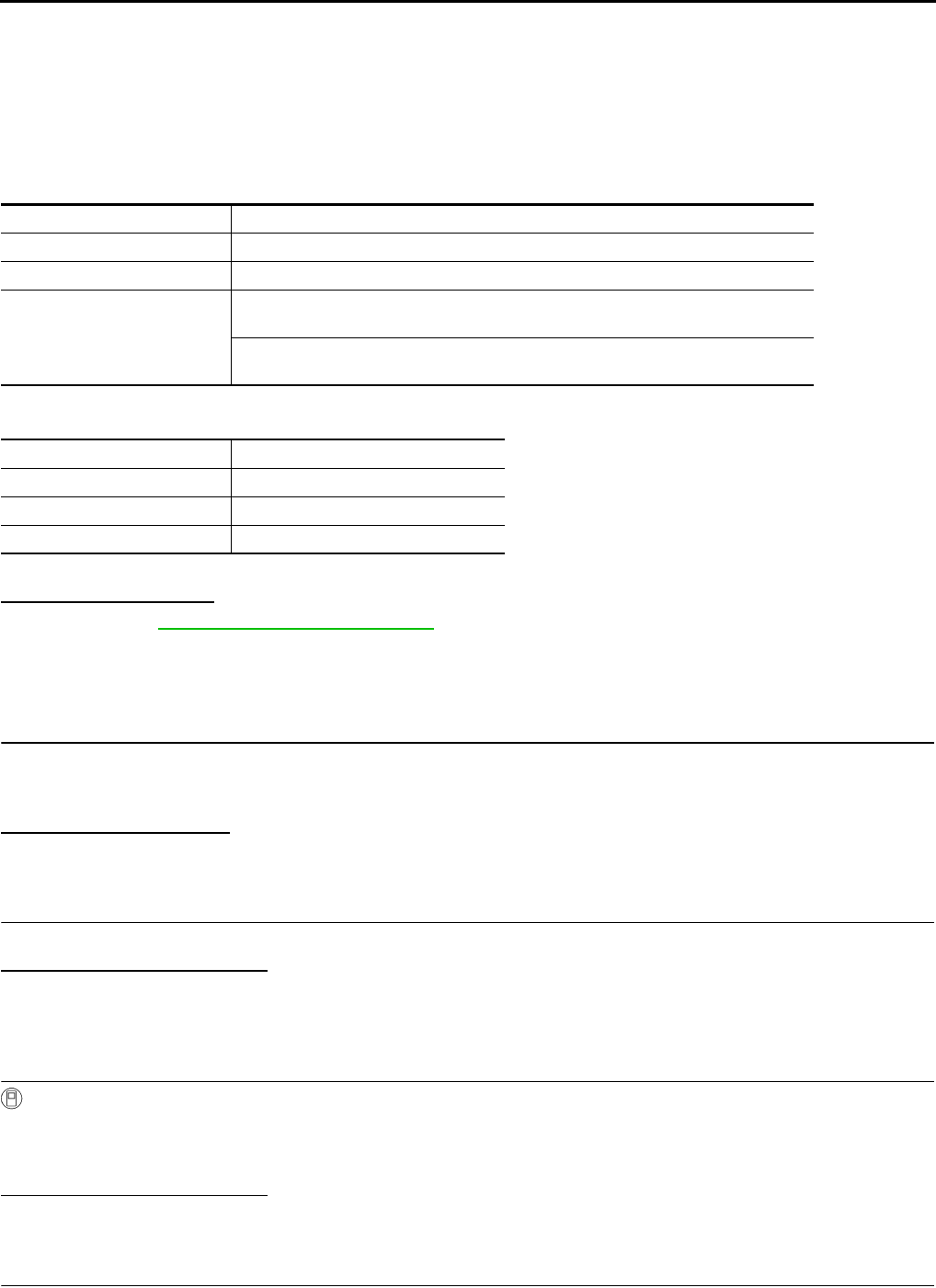
EC-1114
< COMPONENT DIAGNOSIS > [FOR MEXICO]
P0300, P0301, P0302, P0303, P0304 MISFIRE
2. Start engine and drive the vehicle under similar conditions to (1st trip) Freeze Frame Data for a certain
time. Refer to the table below.
Hold the accelerator pedal as steady as possible.
Similar conditions to (1st trip) Freeze Frame Data mean that the following conditions should be satisfied at
the same time.
CAUTION:
Always drive vehicle in safe manner according to traffic conditions and obey all traffic laws when
driving.
Driving time varies according to the engine speed in the freeze frame data.
3. Check 1st trip DTC.
Is 1st trip DTC detected?
YES >> Go to EC-1114, "Diagnosis Procedure".
NO >> INSPECTION END
Diagnosis Procedure INFOID:0000000004494252
1.CHECK FOR INTAKE AIR LEAK AND PCV HOSE
1. Start engine and run it at idle speed.
2. Listen for the sound of the intake air leak.
3. Check PCV hose connection.
Is intake air leak detected?
YES >> Discover air leak location and repair.
NO >> GO TO 2.
2.CHECK FOR EXHAUST SYSTEM CLOGGING
Stop engine and visually check exhaust tube, three way catalyst and muffler for dents.
Is the inspection result normal?
YES-1 >> With CONSULT-III: GO TO 3.
YES-2 >> Without CONSULT-III: GO TO 4.
NO >> Repair or replace malfunctioning part.
3.PERFORM POWER BALANCE TEST
With CONSULT-III
1. Start engine.
2. Perform “POWER BALANCE” in “ACTIVE TEST” mode with CONSULT-III.
3. Check that each circuit produces a momentary engine speed drop.
Is the inspection result normal?
YES >> GO TO 9.
NO >> GO TO 4.
4.CHECK FUNCTION OF FUEL INJECTOR
1. Start engine and let engine idle.
Engine speed Engine speed in the freeze frame data ± 400 rpm
Vehicle speed Vehicle speed in the freeze frame data ± 10 km/h (6 MPH)
Base fuel schedule Base fuel schedule in freeze frame data × (1 ± 0.1)
Engine coolant temperature (T)
condition
When the freeze frame data shows lower than 70 °C (158 °F),
T should be lower than 70 °C (158 °F).
When the freeze frame data shows higher than or equal to 70 °C (158 °F),
T should be higher than or equal to 70 °C (158 °F).
Engine speed Time
Around 1,000 rpm Approximately 10 minutes
Around 2,000 rpm Approximately 5 minutes
More than 3,000 rpm Approximately 3.5 minutes
Revision: 2008 August 2009 Rogue
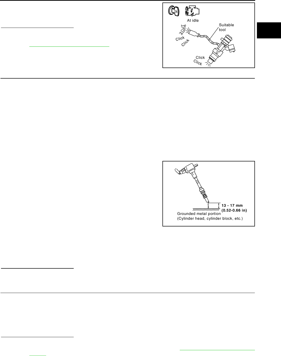
P0300, P0301, P0302, P0303, P0304 MISFIRE
EC-1115
< COMPONENT DIAGNOSIS > [FOR MEXICO]
C
D
E
F
G
H
I
J
K
L
M
A
EC
N
P
O
2. Listen to each fuel injector operation.
Is the inspection result normal?
YES >> GO TO 5.
NO >> Perform trouble diagnosis for FUEL INJECTOR, refer to
EC-1218, "Component Inspection".
5.CHECK FUNCTION OF IGNITION COIL-I
CAUTION:
Perform the following procedure in a place with no combustible objects and good ventilation.
1. Turn ignition switch OFF.
2. Remove fuel pump fuse in IPDM E/R to release fuel pressure.
NOTE:
Do not use CONSULT-III to release fuel pressure, or fuel pressure applies again during the following pro-
cedure.
3. Start engine.
4. After engine stalls, crank it two or three times to release all fuel pressure.
5. Turn ignition switch OFF.
6. Remove all ignition coil harness connectors to avoid the electrical discharge from the ignition coils.
7. Remove ignition coil and spark plug of the cylinder to be checked.
8. Crank engine for 5 seconds or more to remove combustion gas in the cylinder.
9. Connect spark plug and harness connector to ignition coil.
10. Fix ignition coil using a rope etc. with gap of 13 - 17 mm (0.52 -
0.66 in) between the edge of the spark plug and grounded metal
portion as shown in the figure.
11. Crank engine for approximately 3 seconds, and check whether
spark is generated between the spark plug and the grounded
metal portion.
CAUTION:
• Never place the spark plug and the ignition coil within 50
cm (19.7 in) each other . Be careful not to get an electrical
shock while checking, because the electrical discharge
voltage becomes 20kV or more.
• It might damage the ignition coil if the gap of more than 17 mm (0.66 in) is made.
NOTE:
When the gap is less than 13 mm (0.52 in), a spark might be generated even if the coil is malfunc-
tioning.
Is the inspection result normal?
YES >> GO TO 9.
NO >> GO TO 6.
6.CHECK FUNCTION OF IGNITION COIL-II
1. Turn ignition switch OFF.
2. Disconnect spark plug and connect a non-malfunctioning spark plug.
3. Crank engine for approximately 3 seconds, and recheck whether spark is generated between the spark
plug and the grounded metal portion.
Is the inspection result normal?
YES >> GO TO 7.
NO >> Check ignition coil, power transistor and their circuits. Refer to EC-1223, "Component Function
Check".
Clicking noise should be heard.
PBIB3332E
Spark should be generated.
JMBIA0066G
B
Spark should be generated.
Revision: 2008 August 2009 Rogue
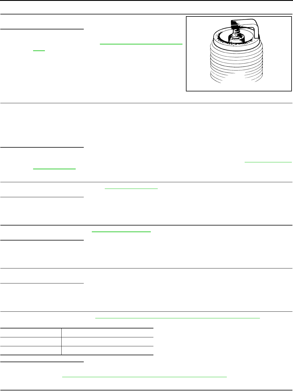
EC-1116
< COMPONENT DIAGNOSIS > [FOR MEXICO]
P0300, P0301, P0302, P0303, P0304 MISFIRE
7.CHECK SPARK PLUG
Check the initial spark plug for fouling, etc.
Is the inspection result normal?
YES >> Replace spark plug(s) with standard type one(s). For
spark plug type, refer to EM-18, "Removal and Installa-
tion".
NO >> Repair or clean spark plug. Then GO TO 8.
8.CHECK FUNCTION OF IGNITION COIL-III
1. Reconnect the initial spark plugs.
2. Crank engine for approximately 3 seconds, and recheck whether spark is generated between the spark
plug and the grounded portion.
Is the inspection result normal?
YES >> INSPECTION END
NO >> Replace spark plug(s) with standard type one(s). For spark plug type, refer to EM-18, "Removal
and Installation".
9.CHECK COMPRESSION PRESSURE
Check compression pressure. Refer to EM-23, "Inspection".
Is the inspection result normal?
YES >> GO TO 10.
NO >> Check pistons, piston rings, valves, valve seats and cylinder head gaskets.
10.CHECK FUEL PRESSURE
1. Check fuel pressure. Refer to EC-1279, "Inspection".
Is the inspection result normal?
YES >> GO TO 12.
NO >> GO TO 11.
11.DETECT MALFUNCTIONING PART
Check fuel hoses and fuel tubes for clogging.
Is the inspection result normal?
YES >> Replace “fuel filter and fuel pump assembly”.
NO >> Repair or replace.
12.CHECK IGNITION TIMING
Check the following items. Refer to EC-933, "BASIC INSPECTION : Special Repair Requirement".
Is the inspection result normal?
YES >> GO TO 13.
NO >> Follow the EC-933, "BASIC INSPECTION : Special Repair Requirement".
13.CHECK A/F SENSOR 1 INPUT SIGNAL CIRCUIT
1. Turn ignition switch OFF.
2. Disconnect corresponding A/F sensor 1 harness connector.
3. Disconnect ECM harness connector.
SEF156I
Spark should be generated.
Items Specifications
idle speed 700 ± 50 rpm (in P or N position)
Ignition timing 15 ± 5°BTDC (in P or N position)
Revision: 2008 August 2009 Rogue
P0300, P0301, P0302, P0303, P0304 MISFIRE
EC-1117
< COMPONENT DIAGNOSIS > [FOR MEXICO]
C
D
E
F
G
H
I
J
K
L
M
A
EC
N
P
O
4. Check the continuity between A/F sensor 1 harness connector and ECM harness connector.
5. Check the continuity between A/F sensor 1 harness connector or ECM harness connector and ground.
6. Also check harness for short to power.
Is the inspection result normal?
YES >> GO TO 14.
NO >> Repair open circuit or short to ground or short to power in harness or connectors.
14.CHECK A/F SENSOR 1 HEATER
Refer to EC-1033, "Component Inspection".
Is the inspection result normal?
YES >> GO TO 15.
NO >> Replace A/F sensor 1.
15.CHECK MASS AIR FLOW SENSOR
With CONSULT-III
1. Install all removed parts.
2. Check “MASS AIR FLOW” in “DATA MONITOR” mode with CONSULT-III.
For specification, refer to EC-1281, "Mass Air Flow Sensor".
With GST
1. Install all removed parts.
2. Check mass air flow sensor signal in Service $01 with GST.
For specification, refer to EC-1281, "Mass Air Flow Sensor".
Is the measurement value within the specification?
YES >> GO TO 16.
NO >> Check connectors for rusted terminals or loose connections in the mass air flow sensor circuit or
ground. Refer to EC-1040, "DTC Logic".
16.CHECK SYMPTOM TABLE
Check items on the rough idle symptom in EC-1268, "Symptom Table".
Is the inspection result normal?
YES >> GO TO 17.
NO >> Repair or replace.
17.ERASE THE 1ST TRIP DTC
Some tests may cause a 1st trip DTC to be set.
Erase the 1st trip DTC from the ECM memory after performing the tests. Refer to EC-990, "Diagnosis Descrip-
tion".
>> GO TO 18.
18.CHECK INTERMITTENT INCIDENT
Refer to GI-41, "Intermittent Incident".
>> INSPECTION END
A/F sensor 1 ECM Continuity
Connector Terminal Connector Terminal
F28 1F8 45 Existed
249
A/F sensor 1 ECM Ground Continuity
Connector Terminal Connector Terminal
F28 1F8 45 Ground Not existed
249
Revision: 2008 August 2009 Rogue

EC-1118
< COMPONENT DIAGNOSIS > [FOR MEXICO]
P0327, P0328 KS
P0327, P0328 KS
Description INFOID:0000000004494253
The knock sensor is attached to the cylinder block. It senses engine knocking using a piezoelectric element. A
knocking vibration from the cylinder block is sensed as vibrational pressure. This pressure is converted into a
voltage signal and sent to the ECM.
DTC Logic INFOID:0000000004494254
DTC DETECTION LOGIC
DTC CONFIRMATION PROCEDURE
1.PRECONDITIONING
If DTC CONFIRMATION PROCEDURE has been previously conducted, always turn ignition switch OFF and
wait at least 10 seconds before conducting the next test.
TESTING CONDITION:
Before performing the following procedure, confirm that battery voltage is more than 10V at idle.
>> GO TO 2.
2.PERFORM DTC CONFIRMATION PROCEDURE
1. Start engine and run it for at least 5 seconds at idle speed.
2. Check 1st trip DTC.
Is 1st trip DTC detected?
YES >> Go to EC-1118, "Diagnosis Procedure".
NO >> INSPECTION END
Diagnosis Procedure INFOID:0000000004494255
1.CHECK GROUND CONNECTION
1. Turn ignition switch OFF.
2. Check ground connection E21. Refer to Ground Inspection in GI-44, "Circuit Inspection".
Is the inspection result normal?
YES >> GO TO 2.
NO >> Repair or replace ground connection.
2.CHECK KNOCK SENSOR GROUND CIRCUIT FOR OPEN AND SHORT
1. Disconnect knock sensor harness connector and disconnect ECM harness connector.
2. Check the continuity between knock sensor harness connector and ECM harness connector.
3. Also check harness for short to ground and short to power.
Is the inspection result normal?
YES >> GO TO 3.
NO >> Repair open circuit or short to ground or short to power in harness or connectors.
DTC No. Trouble diagnosis
name DTC detected condition Possible cause
P0327 Knock sensor circuit
low input
An excessively low voltage from the sensor is
sent to ECM. • Harness or connectors
(The sensor circuit is open or shorted.)
• Knock sensor
P0328 Knock sensor circuit
high input
An excessively high voltage from the sensor is
sent to ECM.
Knock sensor ECM Continuity
Connector Terminal Connector Terminal
F16 2 F8 67 Existed
Revision: 2008 August 2009 Rogue
P0327, P0328 KS
EC-1119
< COMPONENT DIAGNOSIS > [FOR MEXICO]
C
D
E
F
G
H
I
J
K
L
M
A
EC
N
P
O
3.CHECK KNOCK SENSOR INPUT SIGNAL CIRCUIT FOR OPEN AND SHORT
1. Check the continuity between knock sensor harness connector and ECM harness connector.
2. Also check harness for short to ground and short to power.
Is the inspection result normal?
YES >> GO TO 4.
NO >> Repair open circuit or short to ground or short to power in harness or connectors.
4.CHECK KNOCK SENSOR
Refer to EC-1119, "Component Inspection".
Is the inspection result normal?
YES >> GO TO 5.
NO >> Replace knock sensor.
5.CHECK INTERMITTENT INCIDENT
Refer to GI-41, "Intermittent Incident".
>> INSPECTION END
Component Inspection INFOID:0000000004494256
1.CHECK KNOCK SENSOR
1. Turn ignition switch OFF.
2. Disconnect knock sensor harness connector.
3. Check resistance between knock sensor terminals as follows.
NOTE:
It is necessary to use an ohmmeter which can measure more than 10 MΩ.
CAUTION:
Never use any knock sensors that have been dropped or physically damaged. Use only new ones.
Is the inspection result normal?
YES >> INSPECTION END
NO >> Replace knock sensor.
Knock sensor ECM Continuity
Connector Terminal Connector Terminal
F16 1 F8 61 Existed
Terminals Resistance
1 and 2 Approx. 532 - 588 kΩ [at 20°C (68°F)]
Revision: 2008 August 2009 Rogue
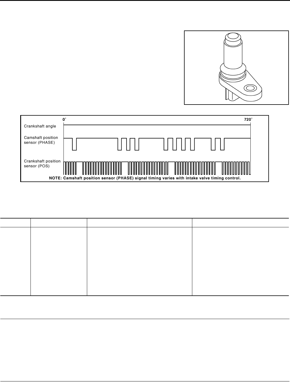
EC-1120
< COMPONENT DIAGNOSIS > [FOR MEXICO]
P0335 CKP SENSOR (POS)
P0335 CKP SENSOR (POS)
Description INFOID:0000000004494257
The crankshaft position sensor (POS) is located on the oil pan facing
the gear teeth (cogs) of the signal plate. It detects the fluctuation of
the engine revolution.
The sensor consists of a permanent magnet and Hall IC.
When the engine is running, the high and low parts of the teeth
cause the gap with the sensor to change.
The changing gap causes the magnetic field near the sensor to
change.
Due to the changing magnetic field, the voltage from the sensor
changes.
The ECM receives the voltage signal and detects the fluctuation of
the engine revolution.
ECM receives the signals as shown in the figure.
DTC Logic INFOID:0000000004494258
DTC DETECTION LOGIC
DTC CONFIRMATION PROCEDURE
1.PRECONDITIONING
If DTC Confirmation Procedure has been previously conducted, always turn ignition switch OFF and wait at
least 10 seconds before conducting the next test.
TESTING CONDITION:
Before performing the following procedure, confirm that battery voltage is more than 10.5V with igni-
tion switch ON.
>> GO TO 2.
2.PERFORM DTC CONFIRMATION PROCEDURE
1. Start engine and let it idle for at least 5 seconds.
If engine does not start, crank engine for at least 2 seconds.
2. Check 1st trip DTC.
JMBIA0062ZZ
JMBIA0714G
B
DTC No. Trouble diagnosis name DTC detecting condition Possible cause
P0335 Crankshaft position sen-
sor (POS) circuit
• The crankshaft position sensor (POS) signal
is not detected by the ECM during the first
few seconds of engine cranking.
• The proper pulse signal from the crankshaft
position sensor (POS) is not sent to ECM
while the engine is running.
• The crankshaft position sensor (POS) signal
is not in the normal pattern during engine run-
ning.
• Harness or connectors
[Crankshaft position sensor (POS) circuit
is open or shorted.]
(Refrigerant pressure sensor circuit is
shorted.)
(Accelerator pedal position sensor circuit
is shorted.)
• Crankshaft position sensor (POS)
• Refrigerant pressure sensor
• Accelerator pedal position sensor
• Signal plate
Revision: 2008 August 2009 Rogue

P0335 CKP SENSOR (POS)
EC-1121
< COMPONENT DIAGNOSIS > [FOR MEXICO]
C
D
E
F
G
H
I
J
K
L
M
A
EC
N
P
O
Is 1st trip DTC detected?
YES >> Go to EC-1121, "Diagnosis Procedure".
NO >> INSPECTION END
Diagnosis Procedure INFOID:0000000004494259
1.CHECK GROUND CONNECTION
1. Turn ignition switch OFF.
2. Check ground connection E21. Refer to Ground Inspection in GI-44, "Circuit Inspection".
Is the inspection result normal?
YES >> GO TO 2.
NO >> Repair or replace ground connection.
2.CHECK CRANKSHAFT POSITION (CKP) SENSOR (POS) POWER SUPPLY CIRCUIT-I
1. Disconnect crankshaft position (CKP) sensor (POS) harness connector.
2. Turn ignition switch ON.
3. Check the voltage between CKP sensor (POS) harness connector and ground.
Is the inspection result normal?
YES >> GO TO 8.
NO >> GO TO 3.
3.CHECK CRANKSHAFT POSITION (CKP) SENSOR (POS) POWER SUPPLY CIRCUIT-II
1. Turn ignition switch ON.
2. Disconnect ECM harness connector.
3. Check the continuity between CKP sensor (POS) harness connector and ECM harness connector.
Is the inspection result normal?
YES >> GO TO 4.
NO >> Repair open circuit.
4.CHECK SENSOR POWER SUPPLY CIRCUIT
Check harness for short to power and short to ground, between the following terminals.
Is the inspection result normal?
YES >> GO TO 5.
NO >> Repair short to ground or short to power in harness or connectors.
5.CHECK REFRIGERANT PRESSURE SENSOR
Refer to EC-873, "Diagnosis Procedure".
Is the inspection result normal?
YES >> GO TO 6.
CKP sensor (POS) Ground Voltage
Connector Terminal
F20 1 Ground Approx. 5V
CKP sensor (POS) ECM Continuity
Connector Terminal Connector Terminal
F20 1 F8 76 Existed
ECM Sensor
Connector Terminal Name Connector Terminal
F8 72 Refrigerant pressure sensor E49 3
76 CKP sensor (POS) F20 1
E16 87 APP sensor E110 5
Revision: 2008 August 2009 Rogue
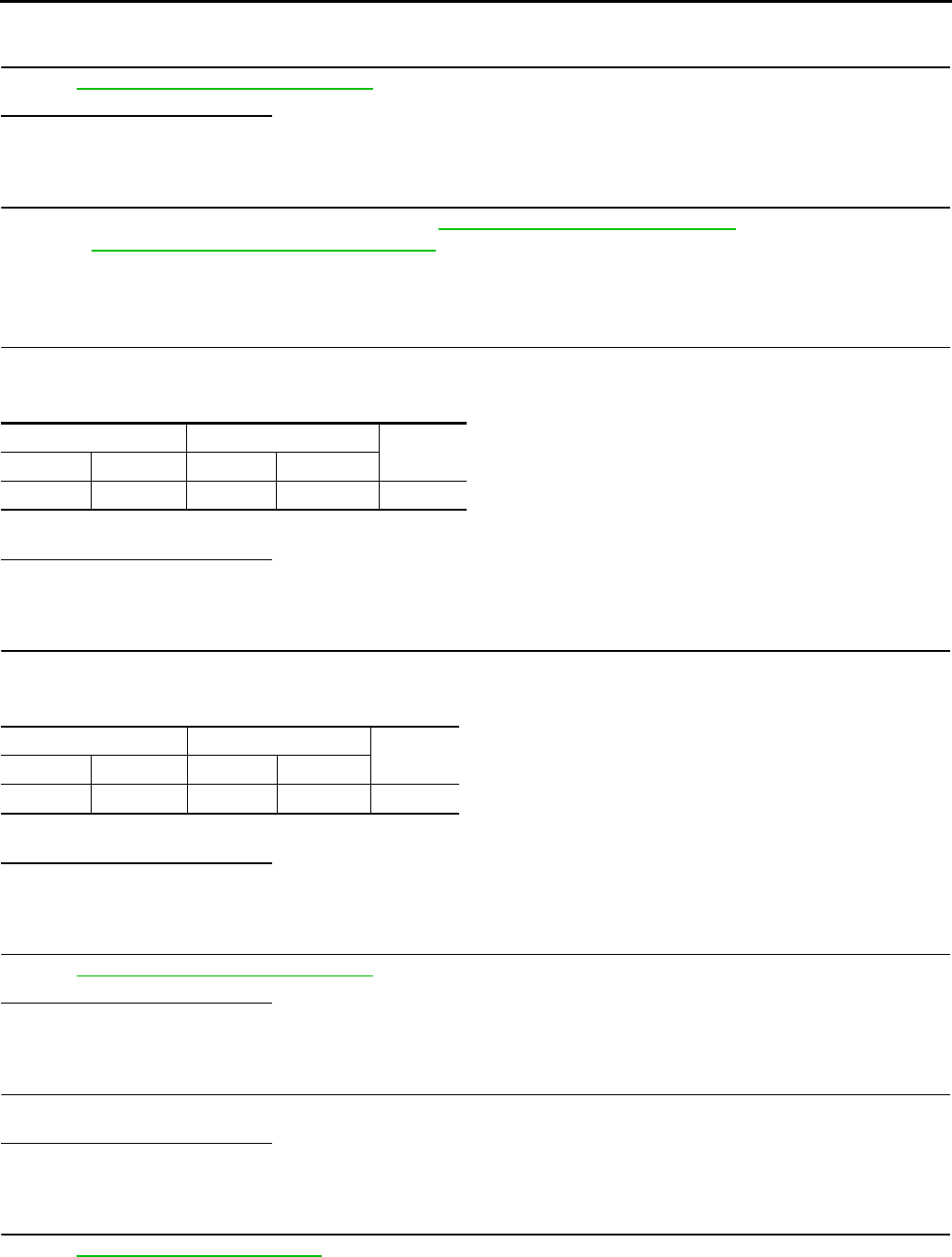
EC-1122
< COMPONENT DIAGNOSIS > [FOR MEXICO]
P0335 CKP SENSOR (POS)
NO >> Replace malfunctioning components.
6.CHECK APP SENSOR
Refer to EC-1189, "Component Inspection".
Is the inspection result normal?
YES >> GO TO 12.
NO >> GO TO 7.
7.REPLACE ACCELERATOR PEDAL ASSEMBLY
1. Replace accelerator pedal assembly. Refer to ACC-3, "Removal and Installation".
2. Go to EC-1189, "Special Repair Requirement".
>> INSPECTION END
8.CHECK CKP SENSOR (POS) GROUND CIRCUIT FOR OPEN AND SHORT
1. Turn ignition switch OFF.
2. Check the continuity between CKP sensor (POS) harness connector and ECM harness connector.
3. Also check harness for short to ground and short to power.
Is the inspection result normal?
YES >> GO TO 9.
NO >> Repair open circuit or short to ground or short to power in harness or connectors.
9.CHECK CKP SENSOR (POS) INPUT SIGNAL CIRCUIT FOR OPEN AND SHORT
1. Disconnect ECM harness connector.
2. Check the continuity between CKP sensor (POS) harness connector and ECM harness connector.
3. Also check harness for short to ground and short to power.
Is the inspection result normal?
YES >> GO TO 10.
NO >> Repair open circuit or short to ground or short to power in harness or connectors.
10.CHECK CRANKSHAFT POSITION SENSOR (POS)
Refer to EC-1123, "Component Inspection".
Is the inspection result normal?
YES >> GO TO 11.
NO >> Replace crankshaft position sensor (POS).
11.CHECK GEAR TOOTH
Visually check for chipping signal plate gear tooth.
Is the inspection result normal?
YES >> GO TO 12.
NO >> Replace the signal plate.
12.CHECK INTERMITTENT INCIDENT
Refer to GI-41, "Intermittent Incident".
>> INSPECTION END
CKP sensor (POS) ECM Continuity
Connector Terminal Connector Terminal
F20 2 F8 60 Existed
CKP sensor (POS) ECM Continuity
Connector Terminal Connector Terminal
F20 3 F8 65 Existed
Revision: 2008 August 2009 Rogue
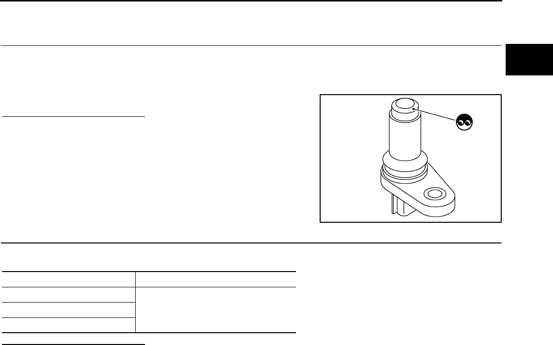
P0335 CKP SENSOR (POS)
EC-1123
< COMPONENT DIAGNOSIS > [FOR MEXICO]
C
D
E
F
G
H
I
J
K
L
M
A
EC
N
P
O
Component Inspection INFOID:0000000004494260
1.CHECK CRANKSHAFT POSITION SENSOR (POS)-I
1. Turn ignition switch OFF.
2. Loosen the fixing bolt of the sensor.
3. Disconnect crankshaft position sensor (POS) harness connector.
4. Remove the sensor.
5. Visually check the sensor for chipping.
Is the inspection result normal?
YES >> GO TO 2.
NO >> Replace crankshaft position sensor (POS).
2.CHECK CRANKSHAFT POSITION SENSOR (POS)-II
Check resistance between crankshaft position sensor (POS) terminals as follows.
Is the inspection result normal?
YES >> INSPECTION END
NO >> Replace crankshaft position sensor (POS).
JMBIA0063ZZ
Terminals (Polarity) Resistance [Ω at 25°C (77°F)]
1 (+) - 2 (-)
Except 0 or ∞1 (+) - 3 (-)
2 (+) - 3 (-)
Revision: 2008 August 2009 Rogue
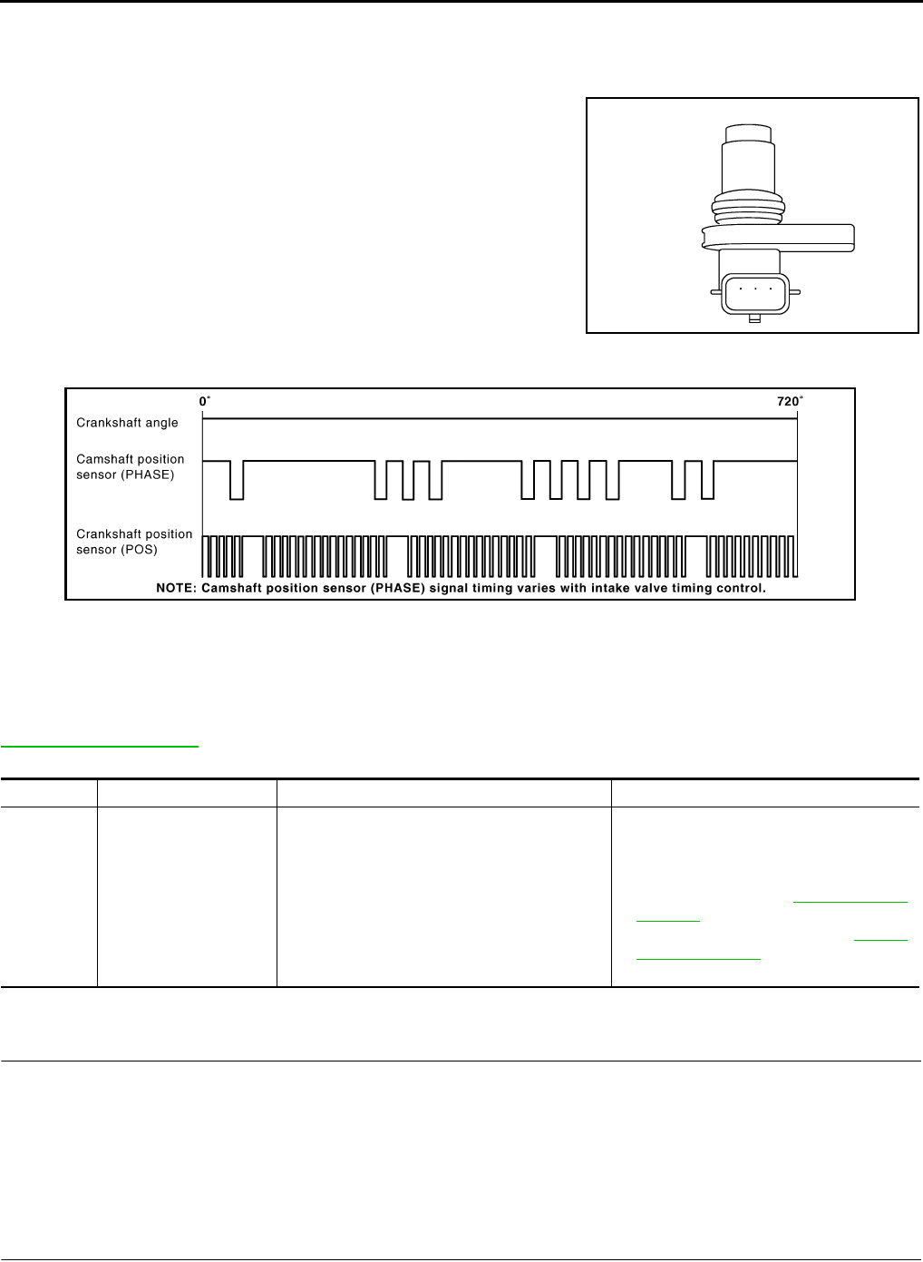
EC-1124
< COMPONENT DIAGNOSIS > [FOR MEXICO]
P0340 CMP SENSOR (PHASE)
P0340 CMP SENSOR (PHASE)
Description INFOID:0000000004494261
The camshaft position sensor (PHASE) senses the retraction of
camshaft (INT) to identify a particular cylinder. The camshaft position
sensor (PHASE) senses the piston position.
When the crankshaft position sensor (POS) system becomes inoper-
ative, the camshaft position sensor (PHASE) provides various con-
trols of engine parts instead, utilizing timing of cylinder identification
signals.
The sensor consists of a permanent magnet and Hall IC.
When engine is running, the high and low parts of the teeth cause
the gap with the sensor to change.
The changing gap causes the magnetic field near the sensor to
change.
Due to the changing magnetic field, the voltage from the sensor changes.
ECM receives the signals as shown in the figure.
DTC Logic INFOID:0000000004494262
DTC DETECTION LOGIC
NOTE:
If DTC P0340 is displayed with DTC P0643, first perform the trouble diagnosis for DTC P0643. Refer to
EC-1147, "DTC Logic".
DTC CONFIRMATION PROCEDURE
1.PRECONDITIONING
If DTC CONFIRMATION PROCEDURE has been previously conducted, always turn ignition switch OFF and
wait at least 10 seconds before conducting the next test.
TESTING CONDITION:
Before performing the following procedure, confirm that battery voltage is more than 10.5V with igni-
tion switch ON.
>> GO TO 2.
2.PERFORM DTC CONFIRMATION PROCEDURE-I
1. Start engine and let it idle for at least 5 seconds.
JMBIA0064ZZ
JMBIA0714G
B
DTC No. Trouble diagnosis name DTC detecting condition Possible cause
P0340 Camshaft position sen-
sor (PHASE) circuit
• The cylinder No. signal is not sent to ECM for
the first few seconds during engine cranking.
• The cylinder No. signal is not sent to ECM
during engine running.
• The cylinder No. signal is not in the normal
pattern during engine running.
• Harness or connectors
(The sensor circuit is open or shorted)
• Camshaft position sensor (PHASE)
• Camshaft (INT)
• Starter motor (Refer to STR-5, "System
Diagram".)
• Starting system circuit (Refer to STR-5,
"System Diagram".)
• Dead (Weak) battery
Revision: 2008 August 2009 Rogue

P0340 CMP SENSOR (PHASE)
EC-1125
< COMPONENT DIAGNOSIS > [FOR MEXICO]
C
D
E
F
G
H
I
J
K
L
M
A
EC
N
P
O
If engine does not start, crank engine for at least 2 seconds.
2. Check 1st trip DTC.
Is 1st trip DTC detected?
YES >> Go to EC-1125, "Diagnosis Procedure".
NO >> GO TO 3.
3.PERFORM DTC CONFIRMATION PROCEDURE-II
1. Maintaining engine speed at more than 800 rpm for at least 5 seconds.
2. Check 1st trip DTC.
Is 1st trip DTC detected?
YES >> Go to EC-1125, "Diagnosis Procedure".
NO >> INSPECTION END
Diagnosis Procedure INFOID:0000000004494263
1.CHECK STARTING SYSTEM
Turn ignition switch to START position.
Does the engine turn over? Does the starter motor operate?
YES >> GO TO 2.
NO >> Check starting system.
2.CHECK GROUND CONNECTION
1. Turn ignition switch OFF.
2. Check ground connection E21. Refer to Ground Inspection in GI-44, "Circuit Inspection".
Is the inspection result normal?
YES >> GO TO 3.
NO >> Repair or replace ground connection.
3.CHECK CAMSHAFT POSITION (CMP) SENSOR (PHASE) POWER SUPPLY CIRCUIT
1. Disconnect camshaft position (CMP) sensor (PHASE) harness connector.
2. Turn ignition switch ON.
3. Check the voltage between CMP sensor (PHASE) harness connector and ground.
Is the inspection result normal?
YES >> GO TO 4.
NO >> Repair open circuit or short to ground or short to power in harness or connectors.
4.CHECK CMP SENSOR (PHASE) GROUND CIRCUIT FOR OPEN AND SHORT
1. Turn ignition switch OFF.
2. Check the continuity between CMP sensor (PHASE) harness connector and ECM harness connector.
3. Also check harness for short to power.
Is the inspection result normal?
YES >> GO TO 5.
NO >> Repair open circuit or short to ground or short to power in harness or connectors.
5.CHECK CMP SENSOR (PHASE) INPUT SIGNAL CIRCUIT FOR OPEN AND SHORT
1. Disconnect ECM harness connector.
2. Check the continuity between CMP sensor (PHASE) harness connector and ECM harness connector.
CMP sensor (PHASE) Ground Voltage
Connector Terminal
F26 1 Ground Approx. 5V
CMP sensor (PHASE) ECM Continuity
Connector Terminal Connector Terminal
F26 2 F8 64 Existed
Revision: 2008 August 2009 Rogue

EC-1126
< COMPONENT DIAGNOSIS > [FOR MEXICO]
P0340 CMP SENSOR (PHASE)
3. Also check harness for short to ground and short to power.
Is the inspection result normal?
YES >> GO TO 6.
NO >> Repair open circuit or short to ground or short to power in harness or connectors.
6.CHECK CAMSHAFT POSITION SENSOR (PHASE)
Refer to EC-1126, "Component Inspection".
Is the inspection result normal?
YES >> GO TO 7.
NO >> Replace camshaft position sensor (PHASE).
7.CHECK CAMSHAFT (INT)
Check the following.
• Accumulation of debris to the signal plate of camshaft (1) rear end
• Chipping signal plate of camshaft rear end
Is the inspection result normal?
YES >> GO TO 8.
NO >> Remove debris and clean the signal plate of camshaft
rear end or replace camshaft.
8.CHECK INTERMITTENT INCIDENT
Refer to GI-41, "Intermittent Incident".
>> INSPECTION END
Component Inspection INFOID:0000000004494264
1.CHECK CAMSHAFT POSITION SENSOR (PHASE)-I
1. Turn ignition switch OFF.
2. Loosen the fixing bolt of the sensor.
3. Disconnect camshaft position sensor (PHASE) harness connector.
4. Remove the sensor.
5. Visually check the sensor for chipping.
Is the inspection result normal?
YES >> GO TO 2.
NO >> Replace camshaft position sensor (PHASE).
2.CHECK CAMSHAFT POSITION SENSOR (PHASE)-II
Check resistance camshaft position sensor (PHASE) terminals as follows.
CMP sensor (PHASE) ECM Continuity
Connector Terminal Connector Terminal
F26 3 F8 69 Existed
JMBIA0096ZZ
JMBIA0065ZZ
Revision: 2008 August 2009 Rogue

P0340 CMP SENSOR (PHASE)
EC-1127
< COMPONENT DIAGNOSIS > [FOR MEXICO]
C
D
E
F
G
H
I
J
K
L
M
A
EC
N
P
O
Is the inspection result normal?
YES >> INSPECTION END
NO >> Replace camshaft position sensor (PHASE).
Terminals (Polarity) Resistance
1 (+) - 2 (-)
Except 0 or ∞ Ω [at 25°C (77°F)]1 (+) - 3 (-)
2 (+) - 3 (-)
Revision: 2008 August 2009 Rogue

EC-1128
< COMPONENT DIAGNOSIS > [FOR MEXICO]
P0420 THREE WAY CATALYST FUNCTION
P0420 THREE WAY CATALYST FUNCTION
DTC Logic INFOID:0000000004494265
DTC DETECTION LOGIC
The ECM monitors the switching frequency ratio of air fuel ratio (A/F)
sensor 1 and heated oxygen sensor 2.
A three way catalyst (manifold) with high oxygen storage capacity
will indicate a low switching frequency of heated oxygen sensor 2.
As oxygen storage capacity decreases, the heated oxygen sensor 2
switching frequency will increase.
When the frequency ratio of A/F sensor 1 and heated oxygen sensor
2 approaches a specified limit value, the three way catalyst (mani-
fold) malfunction is diagnosed.
DTC CONFIRMATION PROCEDURE
1.PRECONDITIONING
If DTC CONFIRMATION PROCEDURE has been previously conducted, always turn ignition switch OFF and
wait at least 10 seconds before conducting the next test.
TESTING CONDITION:
Do not maintain engine speed for more than the specified minutes below.
>> GO TO 2.
2.PERFORM DTC CONFIRMATION PROCEDURE
CAUTION:
Always drive vehicle in safe manner according to traffic conditions and obey all traffic laws.
With CONSULT-III
1. Start engine and warm it up to the normal operating temperature.
2. Repeat the following procedure 3 times.
- Drive vehicle at a speed of 80 km/h (50 MPH) or more for at least 3 consecutive minutes.
NOTE:
Keep the vehicle speed as steady as possible during the cruising.
- Stop vehicle with engine running.
NOTE:
Never turn ignition switch OFF.
3. Select “DTC & SRT CONFIRMATION” then “SRT WORK SUPPORT” mode with CONSULT-III.
4. Drive vehicle at a speed of 80 km/h (50 MPH) or more until “INCMP” of “CATALYST” changes to “CMPLT”
NOTE:
•Keep the vehicle speed as steady as possible during the cruising.
•It will take at most 3 minutes until “INCMP” of “CATALYST” changes to “CMPLT”.
5. Check 1 st trip DTC.
With GST
1. Start engine and warm it up to the normal operating temperature.
2. Repeat the following procedure 3 times.
- Drive vehicle at a speed of 80 km/h (50 MPH) or more for at least 3 consecutive minutes.
SEF484YB
DTC No. Trouble diagnosis name DTC detecting condition Possible cause
P0420 Catalyst system efficien-
cy below threshold
• Three way catalyst (manifold) does not oper-
ate properly.
• Three way catalyst (manifold) does not have
enough oxygen storage capacity.
• Three way catalyst (manifold)
• Exhaust tube
• Intake air leaks
• Fuel injector
• Fuel injector leaks
• Spark plug
• Improper ignition timing
Revision: 2008 August 2009 Rogue
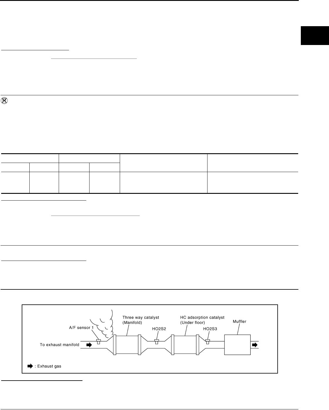
P0420 THREE WAY CATALYST FUNCTION
EC-1129
< COMPONENT DIAGNOSIS > [FOR MEXICO]
C
D
E
F
G
H
I
J
K
L
M
A
EC
N
P
O
NOTE:
Keep the vehicle speed as steady as possible during the cruising.
- Stop vehicle with engine running.
NOTE:
Never turn ignition switch OFF.
3. Check 1 st trip DTC.
Is 1st trip DTC detected?
YES >> Go to EC-265, "Diagnosis Procedure".
NO >> INSPECTION END
Component Function Check INFOID:0000000004494266
1.PERFORM COMPONENT FUNCTION CHECK
Without CONSULT-III
1. Start engine and warm it up to the normal operating temperature.
2. Turn ignition switch OFF and wait at least 10 seconds.
3. Start engine and keep the engine speed between 3,500 and 4,000 rpm for at least 1 minute under no load.
4. Let engine idle for 1 minute.
5. Open engine hood.
6. Check the voltage between ECM harness connector terminals under the following condition.
Is the inspection result normal?
YES >> INSPECTION END
NO >> Go to EC-1129, "Diagnosis Procedure".
Diagnosis Procedure INFOID:0000000004494267
1.CHECK EXHAUST SYSTEM
Visually check exhaust tubes and muffler for dents.
Is the inspection result normal?
YES >> GO TO 2.
NO >> Repair or replace.
2.CHECK EXHAUST GAS LEAK
1. Start engine and run it at idle.
2. Listen for an exhaust gas leak before the three way catalyst (manifold).
Is exhaust gas leak detected?
YES >> Repair or replace.
NO >> GO TO 3.
3.CHECK INTAKE AIR LEAK
Listen for an intake air leak after the mass air flow sensor.
ECM ECM Condition Voltage
Connector Terminal Connector Terminal
F8
33
(HO2S2
signal)
F8
35
(Sensor
ground)
Keeping engine speed at 2,500 rpm
constant under no load
The voltage fluctuation cycle takes
more than 5 seconds.
1 cycle: 0.6 - 1.0 → 0 - 0.3 → 0.6 - 1.0
JMBIA0163G
B
Revision: 2008 August 2009 Rogue
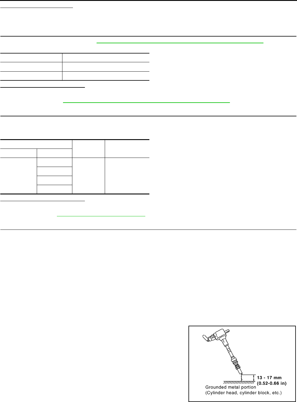
EC-1130
< COMPONENT DIAGNOSIS > [FOR MEXICO]
P0420 THREE WAY CATALYST FUNCTION
Is intake air leak detected?
YES >> Repair or replace.
NO >> GO TO 4.
4.CHECK IGNITION TIMING
Check the following items. Refer to EC-933, "BASIC INSPECTION : Special Repair Requirement".
Is the inspection result normal?
YES >> GO TO 5.
NO >> Follow the EC-933, "BASIC INSPECTION : Special Repair Requirement".
5.CHECK FUEL INJECTOR
1. Stop engine and then turn ignition switch ON.
2. Check the voltage between ECM harness connector and ground.
Is the inspection result normal?
YES >> GO TO 6.
NO >> Perform EC-1217, "Diagnosis Procedure".
6.CHECK FUNCTION OF IGNITION COIL-I
CAUTION:
Perform the following procedure in a place with no combustible objects and good ventilation.
1. Turn ignition switch OFF.
2. Remove fuel pump fuse in IPDM E/R to release fuel pressure.
NOTE:
Do not use CONSULT-III to release fuel pressure, or fuel pressure applies again during the following pro-
cedure.
3. Start engine.
4. After engine stalls, crank it two or three times to release all fuel pressure.
5. Turn ignition switch OFF.
6. Remove all ignition coil harness connectors to avoid the electrical discharge from the ignition coils.
7. Remove ignition coil and spark plug of the cylinder to be checked.
8. Crank engine for 5 seconds or more to remove combustion gas in the cylinder.
9. Connect spark plug and harness connector to ignition coil.
10. Fix ignition coil using a rope etc. with gap of 13 - 17 mm (0.52 -
0.66 in) between the edge of the spark plug and grounded metal
portion as shown in the figure.
11. Crank engine for approximately 3 seconds, and check whether
spark is generated between the spark plug and the grounded
metal portion.
CAUTION:
• Never place the spark plug and the ignition coil within 50
cm (19.7 in) each other. Be careful not to get an electrical
shock while checking, because the electrical discharge
voltage becomes 20kV or more.
Items Specifications
idle speed 700 ± 50 rpm (in P or N position)
Ignition timing 15 ± 5° BTDC (in P or N position)
ECM Ground Voltage
Connector Terminal
F7
29
Ground Battery voltage
30
31
32
Spark should be generated.
JMBIA0066G
B
Revision: 2008 August 2009 Rogue
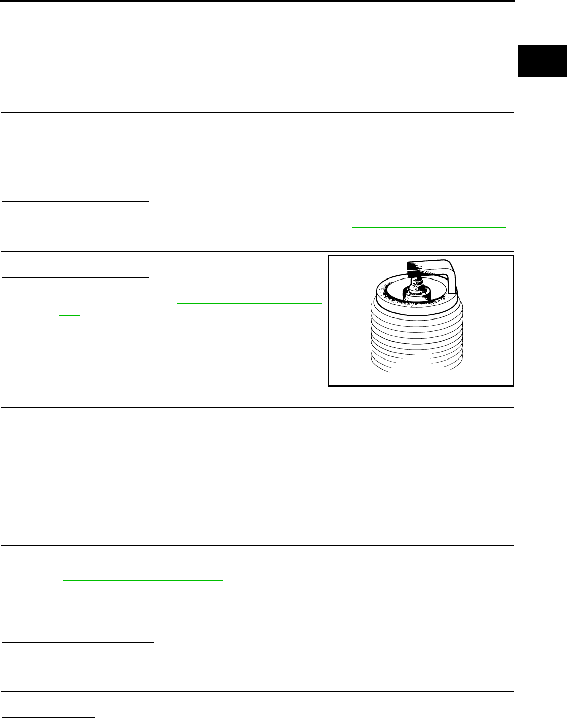
P0420 THREE WAY CATALYST FUNCTION
EC-1131
< COMPONENT DIAGNOSIS > [FOR MEXICO]
C
D
E
F
G
H
I
J
K
L
M
A
EC
N
P
O
• It might damage the ignition coil if the gap of more than 17 mm (0.66 in) is made.
NOTE:
When the gap is less than 13 mm (0.52 in), a spark might be generated even if the coil is malfunc-
tioning.
Is the inspection result normal?
YES >> GO TO 10.
NO >> GO TO 7.
7.CHECK FUNCTION OF IGNITION COIL-II
1. Turn ignition switch OFF.
2. Disconnect spark plug and connect a non-malfunctioning spark plug.
3. Crank engine for approximately 3 seconds, and recheck whether spark is generated between the spark
plug and the grounded metal portion.
Is the inspection result normal?
YES >> GO TO 8.
NO >> Check ignition coil, power transistor and their circuits. Refer to EC-1223, "Diagnosis Procedure".
8.CHECK SPARK PLUG
Check the initial spark plug for fouling, etc.
Is the inspection result normal?
YES >> Replace spark plug(s) with standard type one(s). For
spark plug type, refer to EM-18, "Removal and Installa-
tion".
NO >> Repair or clean spark plug. Then GO TO 9.
9.CHECK FUNCTION OF IGNITION COIL-III
1. Reconnect the initial spark plugs.
2. Crank engine for approximately 3 seconds, and recheck whether spark is generated between the spark
plug and the grounded portion.
Is the inspection result normal?
YES >> INSPECTION END
NO >> Replace spark plug(s) with standard type one(s). For spark plug type, refer to EM-18, "Removal
and Installation".
10.CHECK FUEL INJECTOR
1. Turn ignition switch OFF.
2. Remove fuel injector assembly.
Refer to EM-43, "Removal and Installation".
Keep fuel hose and all fuel injectors connected to fuel tube.
3. Disconnect all ignition coil harness connectors.
4. Reconnect all fuel injector harness connectors disconnected.
5. Turn ignition switch ON.
Does fuel drip from fuel injector?
YES >> GO TO 11.
NO >> Replace the fuel injector(s) from which fuel is dripping.
11.CHECK INTERMITTENT INCIDENT
Refer to GI-41, "Intermittent Incident".
Is the trouble fixed?
Spark should be generated.
SEF156I
Spark should be generated.
Revision: 2008 August 2009 Rogue

EC-1132
< COMPONENT DIAGNOSIS > [FOR MEXICO]
P0420 THREE WAY CATALYST FUNCTION
YES >> INSPECTION END
NO >> Replace three way catalyst assembly.
Revision: 2008 August 2009 Rogue
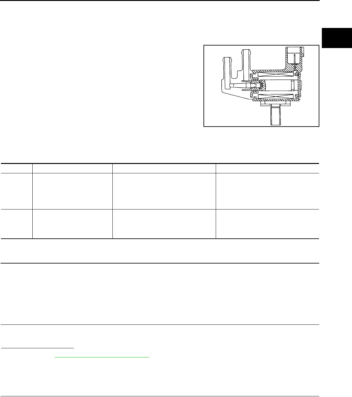
P0444, P0445 EVAP CANISTER PURGE VOLUME CONTROL SOLENOID
VALVE
EC-1133
< COMPONENT DIAGNOSIS > [FOR MEXICO]
C
D
E
F
G
H
I
J
K
L
M
A
EC
N
P
O
P0444, P0445 EVAP CANISTER PURGE VOLUME CONTROL SOLENOID
VALVE
Description INFOID:0000000004494268
The EVAP canister purge volume control solenoid valve uses a ON/
OFF duty to control the flow rate of fuel vapor from the EVAP canis-
ter. The EVAP canister purge volume control solenoid valve is
moved by ON/OFF pulses from the ECM. The longer the ON pulse,
the greater the amount of fuel vapor that will flow through the valve.
DTC Logic INFOID:0000000004494269
DTC DETECTION LOGIC
DTC CONFIRMATION PROCEDURE
1.CONDITIONING
If DTC CONFIRMATION PROCEDURE has been previously conducted, always turn ignition switch OFF and
wait at least 10 seconds before conducting the next test.
TESTING CONDITION:
Before performing the following procedure, confirm battery voltage is more than 11V at idle.
>> GO TO 2.
2.PERFORM DTC CONFIRMATION PROCEDURE
1. Start engine and let it idle for at least 13 seconds.
2. Check 1st trip DTC.
Is 1st trip DTC detected?
YES >> Go to EC-1133, "Diagnosis Procedure".
NO >> INSPECTION END
Diagnosis Procedure INFOID:0000000004494270
1.CHECK EVAP CANISTER PURGE VOLUME CONTROL SOLENOID VALVE POWER SUPPLY CIRCUIT
1. Turn ignition switch OFF.
2. Disconnect EVAP canister purge volume control solenoid valve harness connector.
3. Turn ignition switch ON.
4. Check the voltage between EVAP canister purge volume control solenoid valve harness connector and
ground.
SEF337U
DTC No. Trouble diagnosis name DTC detecting condition Possible cause
P0444 EVAP canister purge volume
control solenoid valve circuit
open
An excessively low voltage signal is sent
to ECM through the valve
• Harness or connectors
(The solenoid valve circuit is open or
shorted.)
• EVAP canister purge volume control so-
lenoid valve
P0445
EVAP canister purge volume
control solenoid valve circuit
shorted
An excessively high voltage signal is sent
to ECM through the valve
• Harness or connectors
(The solenoid valve circuit is shorted.)
• EVAP canister purge volume control so-
lenoid valve
Revision: 2008 August 2009 Rogue

EC-1134
< COMPONENT DIAGNOSIS > [FOR MEXICO]
P0444, P0445 EVAP CANISTER PURGE VOLUME CONTROL SOLENOID
VALVE
Is the inspection result normal?
YES >> GO TO 3.
NO >> GO TO 2.
2.DETECT MALFUNCTIONING PART
Check the following.
• Harness connectors E7, F121
• Harness for open or short between EVAP canister purge volume control solenoid valve and IPDM E/R
• Harness for open or short between EVAP canister purge volume control solenoid valve and ECM
>> Repair open circuit or short to ground or short to power in harness or connectors.
3.CHECK EVAP CANISTER PURGE VOLUME CONTROL SOLENOID VALVE OUTPUT SIGNAL CIRCUIT
FOR OPEN AND SHORT
1. Turn ignition switch OFF.
2. Disconnect ECM harness connector.
3. Check the continuity between EVAP canister purge volume control solenoid valve harness connector and
ECM harness connector.
4. Also check harness for short to ground and short to power.
Is the inspection result normal?
YES-1 >> With CONSULT-III: GO TO 4.
YES-2 >> Without CONSULT-III: GO TO 5.
NO >> Repair open circuit or short to ground or short to power in harness or connectors.
4.CHECK EVAP CANISTER PURGE VOLUME CONTROL SOLENOID VALVE OPERATION
With CONSULT-III
1. Reconnect all harness connectors disconnected.
2. Start engine.
3. Perform “PURG VOL CONT/V” in “ACTIVE TEST” mode with CONSULT-III. Check that engine speed var-
ies according to the valve opening.
Is the inspection result normal?
YES >> GO TO 6.
NO >> GO TO 5.
5.CHECK EVAP CANISTER PURGE VOLUME CONTROL SOLENOID VALVE
Refer to EC-1135, "Component Inspection".
Is the inspection result normal?
YES >> GO TO 6.
NO >> Replace EVAP canister purge volume control solenoid valve.
6.CHECK INTERMITTENT INCIDENT
Refer to GI-41, "Intermittent Incident".
>> INSPECTION END
EVAP canister purge volume
control solenoid valve Ground Voltage
Connector Terminal
F32 1 Ground Battery voltage
EVAP canister purge volume
control solenoid valve ECM Continuity
Connector Terminal Connector Terminal
F32 2 F7 25 Existed
Revision: 2008 August 2009 Rogue

P0444, P0445 EVAP CANISTER PURGE VOLUME CONTROL SOLENOID
VALVE
EC-1135
< COMPONENT DIAGNOSIS > [FOR MEXICO]
C
D
E
F
G
H
I
J
K
L
M
A
EC
N
P
O
Component Inspection INFOID:0000000004494271
1.CHECK EVAP CANISTER PURGE VOLUME CONTROL SOLENOID VALVE
With CONSULT-III
1. Turn ignition switch OFF.
2. Reconnect all harness connectors disconnected.
3. Disconnect EVAP purge hoses connected to EVAP canister purge volume control solenoid valve.
4. Turn ignition switch ON.
5. Select “PURG VOL CONT/V” in “ACTIVE TEST” mode with CONSULT-III.
6. Touch “Qd” and “Qu” on CONSULT-III screen to adjust “PURG
VOL C/V” opening and check air passage continuity of EVAP
canister purge volume control solenoid valve under the following
conditions.
Without CONSULT-III
1. Turn ignition switch OFF.
2. Disconnect EVAP canister purge volume control solenoid valve harness connector.
3. Disconnect EVAP purge hoses connected to EVAP canister purge volume control solenoid valve.
4. Check air passage continuity of EVAP canister purge volume control solenoid valve under the following
conditions.
Is the inspection result normal?
YES >> INSPECTION END
NO >> Replace EVAP canister purge volume control solenoid valve
Condition
(PURG VOL C/V value)
Air passage continuity
between (A) and (B)
100% Existed
0% Not existed
JMBIA0068ZZ
Condition Air passage continuity
between (A) and (B)
12V direct current supply between
terminals 1 and 2 Existed
No supply Not existed
Revision: 2008 August 2009 Rogue

EC-1136
< COMPONENT DIAGNOSIS > [FOR MEXICO]
P0500 VSS
P0500 VSS
Description INFOID:0000000004494272
The vehicle speed signal is sent to the combination meter from the “ABS actuator and electric unit (control
unit)” by CAN communication line. The combination meter then sends a signal to the ECM by CAN communi-
cation line.
DTC Logic INFOID:0000000004494273
DTC DETECTION LOGIC
NOTE:
•If DTC P500 is displayed with DTC UXXXX, first perform the trouble diagnosis for DTC UXXXX.
•If DTC P0500 is displayed with DTC P0607, first perform the trouble diagnosis for DTC P0607. Refer
to EC-1146, "DTC Logic".
DTC CONFIRMATION PROCEDURE
1.INSPECTION START
Do you have CONSULT-III?
Do you have CONSULT-III?
YES >> GO TO 2.
NO >> GO TO 5.
2.PRECONDITIONING
If DTC CONFIRMATION PROCEDURE has been previously conducted, always turn ignition switch OFF and
wait at least 10 seconds before conducting the next test.
>> GO TO 3.
3.CHECK VEHICLE SPEED SENSOR FUNCTION
NOTE:
This procedure may be conducted with the drive wheels lifted in the shop or by driving the vehicle. If a
road test is expected to be easier, it is unnecessary to lift the vehicle.
With CONSULT-III
1. Start engine.
2. Read “VHCL SPEED SE” in “DATA MONITOR” mode with CONSULT-III. The vehicle speed on CON-
SULT-III should exceed 10 km/h (6 mph) when rotating wheels with suitable gear position.
Is the inspection result normal?
YES >> GO TO 4.
NO >> Go to EC-1137, "Diagnosis Procedure".
4.PERFORM DTC CONFIRMATION PROCEDURE
1. Select “DATA MONITOR” mode with CONSULT-III.
2. Warm engine up to normal operating temperature.
3. Maintain the following conditions for at least 50 consecutive seconds.
CAUTION:
Always drive vehicle at a safe speed.
DTC No. Trouble diagnosis name DTC detecting condition Possible cause
P0500 Vehicle speed sensor
The almost 0 km/h (0 MPH) signal from
vehicle speed sensor is sent to ECM even
when vehicle is being driven.
• Harness or connectors
(The CAN communication line is open or short-
ed)
• Harness or connectors
(The vehicle speed signal circuit is open or
shorted)
• Vehicle speed sensor
• Combination meter
• ABS actuator and electric unit (control unit)
Revision: 2008 August 2009 Rogue
P0500 VSS
EC-1137
< COMPONENT DIAGNOSIS > [FOR MEXICO]
C
D
E
F
G
H
I
J
K
L
M
A
EC
N
P
O
4. Check 1st trip DTC.
Is 1st trip DTC detected?
YES >> Go to EC-1137, "Diagnosis Procedure".
NO >> INSPECTION END
5.PERFORM COMPONENT FUNCTION CHECK
Perform Component Function Check. Refer to EC-1137, "Component Function Check".
Use Component Function Check to check the overall function of the vehicle speed sensor circuit. During this
check, a 1st trip DTC might not be confirmed.
Is the inspection result normal?
YES >> INSPECTION END
NO >> Go to EC-1137, "Diagnosis Procedure".
Component Function Check INFOID:0000000004494274
1.PERFORM COMPONENT FUNCTION CHECK
With GST
1. Lift up drive wheels.
2. Start engine.
3. Read vehicle speed sensor signal in Service $01 with GST.
The vehicle speed sensor on GST should be able to exceed 10 km/h (6 MPH) when rotating wheels with
suitable gear position.
Is the inspection result normal?
YES >> INSPECTION END
NO >> Go to EC-1137, "Diagnosis Procedure".
Diagnosis Procedure INFOID:0000000004494275
1.CHECK DTC WITH “ABS ACTUATOR AND ELECTRIC UNIT (CONTROL UNIT)”
Refer to BRC-15, "CONSULT-III Function" (ABS models), BRC-93, "CONSULT-III Function" (VDC models).
Is the inspection result normal?
YES >> GO TO 2.
NO >> Repair or replace.
2.CHECK COMBINATION METER
Refer to MWI-33, "CONSULT-III Function (METER/M&A)".
>> INSPECTION END
ENG SPEED 1,350 - 6,000 rpm
COOLAN TEMP/S More than 70°C (158°F)
B/FUEL SCHDL 5.5 - 31.8 msec
Selector lever Except P or N position
PW/ST SIGNAL OFF
Revision: 2008 August 2009 Rogue
EC-1138
< COMPONENT DIAGNOSIS > [FOR MEXICO]
P0506 ISC SYSTEM
P0506 ISC SYSTEM
Description INFOID:0000000004494276
The ECM controls the engine idle speed to a specified level through the fine adjustment of the air, which is let
into the intake manifold, by operating the electric throttle control actuator. The operating of the throttle valve is
varied to allow for optimum control of the engine idling speed. The crankshaft position sensor (POS) detects
the actual engine speed and sends a signal to the ECM.
The ECM controls the electric throttle control actuator so that the engine speed coincides with the target value
memorized in the ECM. The target engine speed is the lowest speed at which the engine can operate steadily.
The optimum value stored in the ECM is determined by taking into consideration various engine conditions,
such as during warming up, deceleration and engine load (air conditioner, power steering and cooling fan
operation, etc.).
DTC Logic INFOID:0000000004494277
DTC DETECTION LOGIC
NOTE:
If DTC P0506 is displayed with other DTC, first perform the trouble diagnosis for the other DTC.
DTC CONFIRMATION PROCEDURE
1.PRECONDITIONING
If DTC CONFIRMATION PROCEDURE has been previously conducted, always turn ignition switch OFF and
wait at least 10 seconds before conducting the next test.
If the target idle speed is out of the specified value, perform EC-938, "IDLE AIR VOLUME LEARNING :
Special Repair Requirement", before conducting DTC CONFIRMATION PROCEDURE.
TESTING CONDITION:
•Before performing the following procedure, confirm that battery voltage is more than 11V at idle.
•Always perform the test at a temperature above −10°C (14°F).
>> GO TO 2.
2.PERFORM DTC CONFIRMATION PROCEDURE
1. Start engine and warm it up to normal operating temperature.
2. Turn ignition switch OFF and wait at least 10 seconds.
3. Start engine and run it for at least 1 minute at idle speed.
4. Check 1st trip DTC.
Is 1st trip DTC detected?
YES >> Go to EC-1138, "Diagnosis Procedure".
NO >> INSPECTION END
Diagnosis Procedure INFOID:0000000004494278
1.CHECK INTAKE AIR LEAK
1. Start engine and let it idle.
2. Listen for an intake air leak after the mass air flow sensor.
Is intake air leak detected?
YES >> Discover air leak location and repair.
NO >> GO TO 2.
2.REPLACE ECM
1. Stop engine.
2. Replace ECM.
DTC No. Trouble diagnosis name DTC detecting condition Possible cause
P0506 Idle speed control system
RPM lower than expected The idle speed is less than the target idle
speed by 100 rpm or more. • Electric throttle control actuator
• Intake air leak
Revision: 2008 August 2009 Rogue


EC-1140
< COMPONENT DIAGNOSIS > [FOR MEXICO]
P0507 ISC SYSTEM
P0507 ISC SYSTEM
Description INFOID:0000000004534638
The ECM controls the engine idle speed to a specified level through the fine adjustment of the air, which is let
into the intake manifold, by operating the electric throttle control actuator. The operating of the throttle valve is
varied to allow for optimum control of the engine idling speed. The crankshaft position sensor (POS) detects
the actual engine speed and sends a signal to the ECM.
The ECM controls the electric throttle control actuator so that the engine speed coincides with the target value
memorized in the ECM. The target engine speed is the lowest speed at which the engine can operate steadily.
The optimum value stored in the ECM is determined by taking into consideration various engine conditions,
such as during warming up, deceleration and engine load (air conditioner, power steering and cooling fan
operation, etc.).
DTC Logic INFOID:0000000004494280
DTC DETECTION LOGIC
NOTE:
If DTC P0507 is displayed with other DTC, first perform the trouble diagnosis for the other DTC.
DTC CONFIRMATION PROCEDURE
1.PRECONDITIONING
If DTC CONFIRMATION PROCEDURE has been previously conducted, always turn ignition switch OFF and
wait at least 10 seconds before conducting the next test.
If the target idle speed is out of the specified value, perform EC-938, "IDLE AIR VOLUME LEARNING :
Special Repair Requirement", before conducting DTC CONFIRMATION PROCEDURE.
TESTING CONDITION:
•Before performing the following procedure, confirm that battery voltage is more than 11V at idle.
•Always perform the test at a temperature above −10°C (14°F).
>> GO TO 2.
2.PERFORM DTC CONFIRMATION PROCEDURE
1. Start engine and warm it up to normal operating temperature.
2. Turn ignition switch OFF and wait at least 10 seconds.
3. Start engine and run it for at least 1 minute at idle speed.
4. Check 1st trip DTC.
Is 1st trip DTC detected?
YES >> Go to EC-1140, "Diagnosis Procedure".
NO >> INSPECTION END
Diagnosis Procedure INFOID:0000000004494281
1.CHECK PCV HOSE CONNECTION
Confirm that PCV hose is connected correctly.
Is the inspection result normal?
YES >> GO TO 2.
NO >> Repair or replace.
2.CHECK INTAKE AIR LEAK
1. Start engine and let it idle.
2. Listen for an intake air leak after the mass air flow sensor.
DTC No. Trouble diagnosis name DTC detecting condition Possible cause
P0507 Idle speed control sys-
tem RPM higher than
expected
The idle speed is more than the target idle
speed by 200 rpm or more.
• Electric throttle control actuator
• Intake air leak
• PCV system
Revision: 2008 August 2009 Rogue

P0507 ISC SYSTEM
EC-1141
< COMPONENT DIAGNOSIS > [FOR MEXICO]
C
D
E
F
G
H
I
J
K
L
M
A
EC
N
P
O
Is intake air leak detected?
YES >> Discover air leak location and repair.
NO >> GO TO 3.
3.REPLACE ECM
1. Stop engine.
2. Replace ECM.
3. Go to EC-936, "ADDITIONAL SERVICE WHEN REPLACING CONTROL UNIT : Special Repair Require-
ment".
>> INSPECTION END
Revision: 2008 August 2009 Rogue
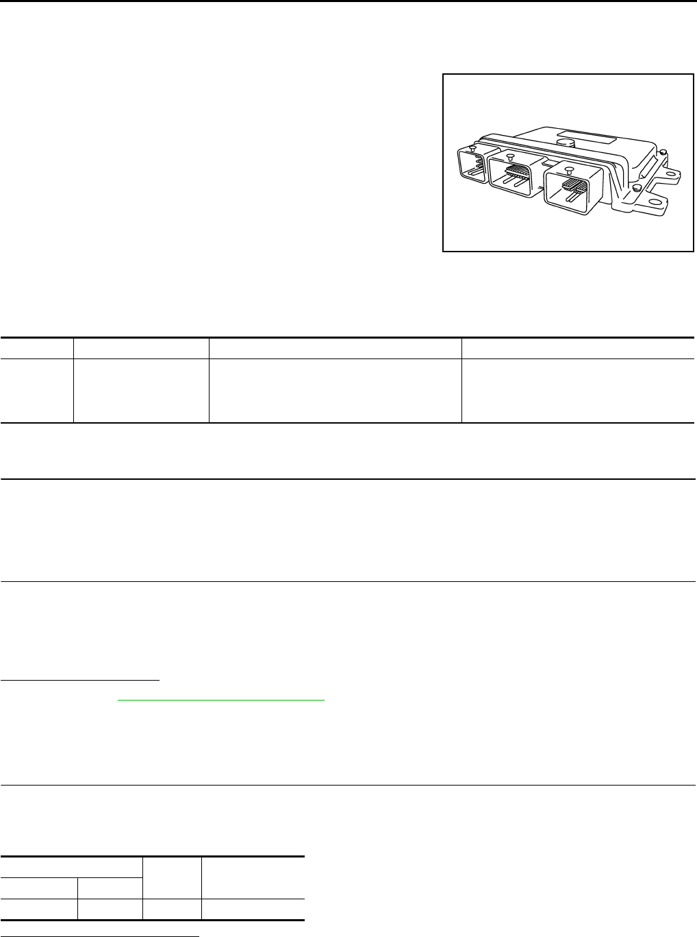
EC-1142
< COMPONENT DIAGNOSIS > [FOR MEXICO]
P0603 ECM POWER SUPPLY
P0603 ECM POWER SUPPLY
Description INFOID:0000000004494282
Battery voltage is supplied to the ECM even when the ignition switch
is turned OFF for the ECM memory function of the DTC memory, the
air-fuel ratio feedback compensation value memory, the idle air vol-
ume learning value memory, etc.
DTC Logic INFOID:0000000004494283
DTC DETECTION LOGIC
DTC CONFIRMATION PROCEDURE
1.PRECONDITIONING
If DTC CONFIRMATION PROCEDURE has been previously conducted, always turn ignition switch OFF and
wait at least 10 seconds before conducting the next test.
>> GO TO 2.
2.PERFORM DTC CONFIRMATION PROCEDURE
1. Turn ignition switch ON and wait at least 1 second.
2. Start engine and let it idle for 1 second.
3. Turn ignition switch OFF, wait at least 10 seconds, and then turn it ON.
4. Repeat steps 2 and 3 for four times.
5. Check 1st trip DTC.
Is 1st trip DTC detected?
YES >> Go to EC-1142, "Diagnosis Procedure".
NO >> INSPECTION END
Diagnosis Procedure INFOID:0000000004494284
1.CHECK ECM POWER SUPPLY
1. Turn ignition switch OFF.
2. Disconnect ECM harness connector.
3. Check the voltage between ECM harness connector and ground.
Is the inspection result normal?
YES >> GO TO 3.
NO >> GO TO 2.
PBIA9222J
DTC No. Trouble diagnosis name DTC detecting condition Possible cause
P0603 ECM power supply cir-
cuit
ECM back-up RAM system does not function
properly.
• Harness or connectors
[ECM power supply (back-up) circuit is
open or shorted.]
•ECM
ECM Ground Voltage
Connector Terminal
F8 77 Ground Battery voltage
Revision: 2008 August 2009 Rogue

P0603 ECM POWER SUPPLY
EC-1143
< COMPONENT DIAGNOSIS > [FOR MEXICO]
C
D
E
F
G
H
I
J
K
L
M
A
EC
N
P
O
2.DETECT MALFUNCTIONING PART
Check the following.
• Harness connectors E8, F122
• 20A fuse (No. 62)
• IPDM E/R harness connector E15
• Harness for open or short between ECM and battery
>> Repair or replace harness or connectors.
3.CHECK INTERMITTENT INCIDENT
Refer to GI-41, "Intermittent Incident".
Is the inspection result normal?
YES >> GO TO 4.
NO >> Repair or replace harness or connectors.
4.PERFORM DTC CONFIRMATION PROCEDURE
1. Erase DTC.
2. Perform DTC CONFIRMATION PROCEDURE.
See EC-1142, "DTC Logic".
Is the 1st trip DTC P0603 displayed again?
YES >> GO TO 5.
NO >> INSPECTION END
5.REPLACE ECM
1. Replace ECM.
2. Go to EC-936, "ADDITIONAL SERVICE WHEN REPLACING CONTROL UNIT : Special Repair Require-
ment".
>> INSPECTION END
Revision: 2008 August 2009 Rogue
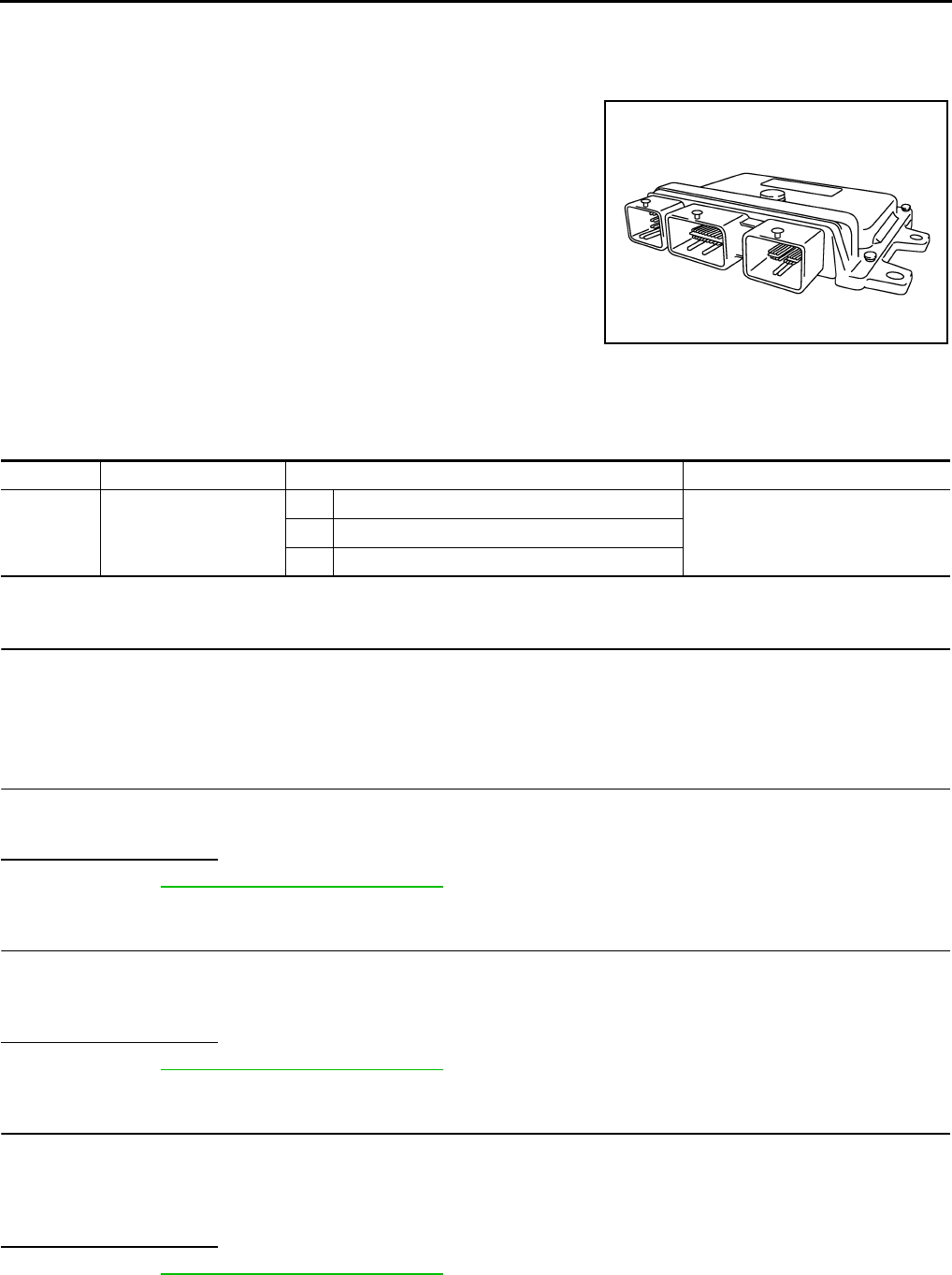
EC-1144
< COMPONENT DIAGNOSIS > [FOR MEXICO]
P0605 ECM
P0605 ECM
Description INFOID:0000000004494285
The ECM consists of a microcomputer and connectors for signal
input and output and for power supply. The ECM controls the engine.
DTC Logic INFOID:0000000004494286
DTC DETECTION LOGIC
DTC CONFIRMATION PROCEDURE
1.PRECONDITIONING
If DTC CONFIRMATION PROCEDURE has been previously conducted, always turn ignition switch OFF and
wait at least 10 seconds before conducting the next test.
>> GO TO 2.
2.PERFORM DTC CONFIRMATION PROCEDURE FOR MALFUNCTION A
1. Turn ignition switch ON.
2. Check 1st trip DTC.
Is 1st trip DTC detected?
YES >> Go to EC-1145, "Diagnosis Procedure".
NO >> GO TO 3.
3.PERFORM DTC CONFIRMATION PROCEDURE FOR MALFUNCTION B
1. wait at least 1 second.
2. Turn ignition switch OFF, wait at least 10 seconds, and then turn it ON.
3. Check 1st trip DTC.
Is 1st trip DTC detected?
YES >> Go to EC-1145, "Diagnosis Procedure".
NO >> GO TO 4.
4.PERFORM DTC CONFIRMATION PROCEDURE FOR MALFUNCTION C
1. wait at least 1 second.
2. Turn ignition switch OFF, wait at least 10 seconds, and then turn it ON.
3. Repeat step 2 for 32 times.
4. Check 1st trip DTC.
Is 1st trip DTC detected?
YES >> Go to EC-1145, "Diagnosis Procedure".
NO >> INSPECTION END
PBIA9222J
DTC No. Trouble diagnosis name DTC detecting condition Possible cause
P0605 Engine control module
A) ECM calculation function is malfunctioning.
•ECMB) ECM EEP-ROM system is malfunctioning.
C) ECM self shut-off function is malfunctioning.
Revision: 2008 August 2009 Rogue

P0605 ECM
EC-1145
< COMPONENT DIAGNOSIS > [FOR MEXICO]
C
D
E
F
G
H
I
J
K
L
M
A
EC
N
P
O
Diagnosis Procedure INFOID:0000000004494287
1.INSPECTION START
1. Erase DTC.
2. Perform DTC CONFIRMATION PROCEDURE.
See EC-1144, "DTC Logic".
Is the 1st trip DTC P0605 displayed again?
YES >> GO TO 2.
NO >> INSPECTION END
2.REPLACE ECM
1. Replace ECM.
2. Go to EC-936, "ADDITIONAL SERVICE WHEN REPLACING CONTROL UNIT : Special Repair Require-
ment".
>> INSPECTION END
Revision: 2008 August 2009 Rogue

EC-1146
< COMPONENT DIAGNOSIS > [FOR MEXICO]
P0607 ECM
P0607 ECM
Description INFOID:0000000004494288
CAN (Controller Area Network) is a serial communication line for real time application. It is an on-vehicle mul-
tiplex communication line with high data communication speed and excellent error detection ability. Many elec-
tronic control units are equipped onto a vehicle, and each control unit shares information and links with other
control units during operation (not independent). In CAN communication, control units are connected with 2
communication lines (CAN H line, CAN L line) allowing a high rate of information transmission with less wiring.
Each control unit transmits/receives data but selectively reads required data only.
DTC Logic INFOID:0000000004494289
DTC DETECTION LOGIC
DTC CONFIRMATION PROCEDURE
1.PRECONDITIONING
If DTC CONFIRMATION PROCEDURE has been previously conducted, always turn ignition switch OFF and
wait at least 10 seconds before conducting the next test.
>> GO TO 2.
2.PERFORM DTC CONFIRMATION PROCEDURE
1. Turn ignition switch ON.
2. Check DTC.
Is DTC detected?
YES >> Go to EC-1146, "Diagnosis Procedure".
NO >> INSPECTION END
Diagnosis Procedure INFOID:0000000004494290
1.INSPECTION START
1. Erase DTC.
2. Perform DTC CONFIRMATION PROCEDURE.
See EC-1146, "DTC Logic".
Is the DTC P0607 displayed again?
YES >> GO TO 2.
NO >> INSPECTION END
2.REPLACE ECM
1. Replace ECM.
2. Go to EC-936, "ADDITIONAL SERVICE WHEN REPLACING CONTROL UNIT : Special Repair Require-
ment".
>> INSPECTION END
DTC No. Trouble diagnosis name DTC detecting condition Possible cause
P0607 CAN communication bus When detecting error during the initial diagno-
sis of CAN controller of ECM. •ECM
Revision: 2008 August 2009 Rogue

P0643 SENSOR POWER SUPPLY
EC-1147
< COMPONENT DIAGNOSIS > [FOR MEXICO]
C
D
E
F
G
H
I
J
K
L
M
A
EC
N
P
O
P0643 SENSOR POWER SUPPLY
DTC Logic INFOID:0000000004494291
DTC DETECTION LOGIC
DTC CONFIRMATION PROCEDURE
1.PRECONDITIONING
If DTC CONFIRMATION PROCEDURE has been previously conducted, always turn ignition switch OFF and
wait at least 10 seconds before conducting the next test.
TESTING CONDITION:
Before performing the following procedure, confirm that battery voltage is more than 8V at idle.
>> GO TO 2.
2.PERFORM DTC CONFIRMATION PROCEDURE
1. Start engine and let it idle for 1 second.
2. Check DTC.
Is DTC detected?
YES >> Go to EC-1147, "Diagnosis Procedure".
NO >> INSPECTION END
Diagnosis Procedure INFOID:0000000004494292
1.CHECK GROUND CONNECTION
1. Turn ignition switch OFF.
2. Check ground connection E21. Refer to Ground Inspection in GI-44, "Circuit Inspection".
Is the inspection result normal?
YES >> GO TO 2.
NO >> Repair or replace ground connection.
2.CHECK ACCELERATOR PEDAL POSITION SENSOR 1 POWER SUPPLY CIRCUIT
1. Disconnect accelerator pedal position (APP) sensor harness connector.
2. Turn ignition switch ON.
3. Check the voltage between APP sensor harness connector and ground.
Is the inspection result normal?
YES >> GO TO 7.
NO >> GO TO 3.
3.CHECK SENSOR POWER SUPPLY CIRCUIT
Check harness for short to power and short to ground, between the following terminals.
DTC No. Trouble diagnosis
name DTC detecting condition Possible cause
P0643 Sensor power supply
circuit short
ECM detects that the voltage of power
source for sensor is excessively low or high.
• Harness or connectors
(APP sensor 1 circuit is shorted.)
(TP sensor circuit is shorted.)
[Camshaft position sensor (PHASE) circuit is
shorted.]
• Accelerator pedal position sensor
• Throttle position sensor
• Camshaft position sensor (PHASE)
APP sensor Ground Voltage
Connector Terminal
E110 4 Ground Approx. 5V
Revision: 2008 August 2009 Rogue

EC-1148
< COMPONENT DIAGNOSIS > [FOR MEXICO]
P0643 SENSOR POWER SUPPLY
Is the inspection result normal?
YES >> GO TO 4.
NO >> Repair short to ground or short to power in harness or connectors.
4.CHECK COMPONENT
Check the following.
• Camshaft position sensor (PHASE) (Refer to EC-1126, "Component Inspection".)
Is the inspection result normal?
YES >> GO TO 5.
NO >> Replace malfunctioning component.
5.CHECK TP SENSOR
Refer to EC-1060, "Component Inspection".
Is the inspection result normal?
YES >> GO TO 9.
NO >> GO TO 6.
6.REPLACE ELECTRIC THROTTLE CONTROL ACTUATOR
1. Replace electric throttle control actuator.
2. Go to EC-937, "ACCELERATOR PEDAL RELEASED POSITION LEARNING : Special Repair Require-
ment".
>> INSPECTION END
7.CHECK APP SENSOR
Refer to EC-1189, "Component Inspection".
Is the inspection result normal?
YES >> GO TO 9.
NO >> GO TO 8.
8.REPLACE ACCELERATOR PEDAL ASSEMBLY
1. Replace accelerator pedal assembly. Refer to ACC-3, "Removal and Installation".
2. Go to EC-1189, "Special Repair Requirement".
>> INSPECTION END
9.CHECK INTERMITTENT INCIDENT
Refer to GI-41, "Intermittent Incident".
>> INSPECTION END
ECM Sensor
Connector Terminal Name Connector Terminal
F8 47 Electric throttle control actuator F29 1
59 CMP sensor (PHASE) F26 1
E16 83 APP sensor E110 4
Revision: 2008 August 2009 Rogue

P0850 PNP SWITCH
EC-1149
< COMPONENT DIAGNOSIS > [FOR MEXICO]
C
D
E
F
G
H
I
J
K
L
M
A
EC
N
P
O
P0850 PNP SWITCH
Description INFOID:0000000004494293
When the selector lever position is P or N, park/neutral position (PNP) switch is ON.
ECM detects the position because the continuity of the line (the ON signal) exists.
DTC Logic INFOID:0000000004494294
DTC DETECTION LOGIC
DTC CONFIRMATION PROCEDURE
1.INSPECTION START
Do you have CONSULT-III?
Do you have CONSULT-III?
YES >> GO TO 2.
NO >> GO TO 5.
2.PRECONDITIONING
If DTC CONFIRMATION PROCEDURE has been previously conducted, always turn ignition switch OFF and
wait at least 10 seconds before conducting the next test.
>> GO TO 3.
3.CHECK PNP SWITCH FUNCTION
With CONSULT-III
1. Turn ignition switch ON.
2. Select “P/N POSI SW” in “DATA MONITOR” mode with CONSULT-III. Then check the “P/N POSI SW” sig-
nal under the following conditions.
Is the inspection result normal?
YES >> GO TO 4.
NO >> Go to EC-1150, "Diagnosis Procedure".
4.PERFORM DTC CONFIRMATION PROCEDURE
1. Select “DATA MONITOR” mode with CONSULT-III.
2. Start engine and warm it up to normal operating temperature.
3. Maintain the following conditions for at least 50 consecutive seconds.
CAUTION:
Always drive vehicle at a safe speed.
DTC No. Trouble diagnosis name DTC detecting condition Possible cause
P0850 Park/neutral position
switch
The signal of the park/neutral position (PNP)
switch does not change during driving after the
engine is started.
• Harness or connectors
[The park/neutral position (PNP) switch
circuit is open or shorted.]
• Park/neutral position (PNP) switch
Position (Selector lever) Known-good signal
N or P position ON
Except above position OFF
ENG SPEED 1,300 - 6,375 rpm
COOLAN TEMP/S More than 70°C (158°F)
B/FUEL SCHDL 3.0 - 31.8 msec
Revision: 2008 August 2009 Rogue

EC-1150
< COMPONENT DIAGNOSIS > [FOR MEXICO]
P0850 PNP SWITCH
4. Check 1st trip DTC.
Is 1st trip DTC detected?
YES >> Go to EC-1150, "Diagnosis Procedure".
NO >> INSPECTION END
5.PERFORM COMPONENT FUNCTION CHECK
Perform Component Function Check. Refer to EC-1150, "Component Function Check".
NOTE:
Use Component Function Check to check the overall function of the park/neutral position (PNP) switch circuit.
During this check, a 1st trip DTC might not be confirmed.
Is the inspection result normal?
YES >> INSPECTION END
NO >> Go to EC-1150, "Diagnosis Procedure".
Component Function Check INFOID:0000000004494295
1.PERFORM COMPONENT FUNCTION CHECK
1. Turn ignition switch ON.
2. Check the voltage between ECM harness connector and ground.
Is the inspection result normal?
YES >> INSPECTION END
NO >> Go to EC-1150, "Diagnosis Procedure".
Diagnosis Procedure INFOID:0000000004494296
1.CHECK PNP SWITCH POWER SUPPLY CIRCUIT
1. Turn ignition switch OFF.
2. Disconnect Park/neutral position (PNP) switch harness connector.
3. Turn ignition switch ON.
4. Check the voltage between PNP switch harness connector and ground.
Is the inspection result normal?
YES >> GO TO 3.
NO >> GO TO 2.
2.DETECT MALFUNCTIONING PART
Check the following.
• Harness connectors E6, F123
• IPDM E/R harness connector E15
• 10A fuse (No. 58)
• Harness for open or short between PNP switch and IPDM E/R
>> Repair open circuit or short to ground or short to power in harness or connectors.
VHCL SPEED SE More than 64 km/h (40 mph)
Selector lever Suitable position
ECM Ground Condition Voltage
Connector Terminal
E16 102
(PNP switch signal) Ground Selector lever P or N BATTERY VOLTAGE
Except above Approx. 0V
PNP switch Ground Voltage
Connector Terminal
F21 1 Ground Battery voltage
Revision: 2008 August 2009 Rogue
P0850 PNP SWITCH
EC-1151
< COMPONENT DIAGNOSIS > [FOR MEXICO]
C
D
E
F
G
H
I
J
K
L
M
A
EC
N
P
O
3.CHECK PNP SWITCH INPUT SIGNAL CIRCUIT FOR OPEN AND SHORT-I
1. Turn ignition switch OFF.
2. Disconnect ECM harness connector.
3. Check the continuity between PNP switch harness connector and ECM harness connector.
4. Also check harness for short to ground and short to power.
Is the inspection result normal?
YES >> GO TO 5.
NO >> GO TO 4.
4.DETECT MALFUNCTIONING PART
Check the following.
• Harness connectors E6, F123
• Harness for open or short between PNP switch and ECM
>> Repair open circuit or short to ground or short to power in harness or connectors.
5.CHECK PNP SWITCH
Refer to .TM-58, "Component Inspection (CVT Fluid Temperature Sensor)"
Is the inspection result normal?
YES >> GO TO 6.
NO >> Replace PNP switch.
6.CHECK INTERMITTENT INCIDENT
Refer to GI-41, "Intermittent Incident".
>> INSPECTION END
PNP switch ECM Continuity
Connector Terminal Connector Terminal
F21 2 E16 102 Existed
Revision: 2008 August 2009 Rogue

EC-1152
< COMPONENT DIAGNOSIS > [FOR MEXICO]
P1148 CLOSED LOOP CONTROL
P1148 CLOSED LOOP CONTROL
DTC Logic INFOID:0000000004494297
DTC DETECTION LOGIC
NOTE:
DTC P1148 is displayed with another DTC for A/F sensor 1.
Perform the trouble diagnosis for the corresponding DTC.
DTC No. Trouble diagnosis name DTC detecting condition Possible cause
P1148 Closed loop control
function
The closed loop control function for bank 1 does
not operate even when vehicle is being driven
in the specified condition.
• Harness or connectors
(The A/F sensor 1 circuit is open or short-
ed.)
• A/F sensor 1
• A/F sensor 1 heater
The closed loop control function for bank 2 does
not operate even when vehicle is being driven
in the specified condition.
Revision: 2008 August 2009 Rogue

P1217 ENGINE OVER TEMPERATURE
EC-1153
< COMPONENT DIAGNOSIS > [FOR MEXICO]
C
D
E
F
G
H
I
J
K
L
M
A
EC
N
P
O
P1217 ENGINE OVER TEMPERATURE
DTC Logic INFOID:0000000004494298
DTC DETECTION LOGIC
NOTE:
•If DTC P1217 is displayed with DTC UXXXX, first perform the trouble diagnosis for DTC UXXXX.
•If DTC P1217 is displayed with DTC P0607, first perform the trouble diagnosis for DTC P0607. Refer
to EC-1146, "DTC Logic".
If the cooling fan or another component in the cooling system malfunctions, engine coolant temperature will
rise.
When the engine coolant temperature reaches an abnormally high temperature condition, a malfunction is
indicated.
CAUTION:
When a malfunction is indicated, always replace the coolant. Refer to CO-9, "Draining" and CO-10,
"Refilling". Also, replace the engine oil. Refer to LU-6, "Draining" and LU-7, "Refilling".
1. Fill radiator with coolant up to specified level with a filling speed of 2 liters per minute. Always use
coolant with the proper mixture ratio. Refer to MA-19, "FOR MEXICO : Engine Coolant Mixture
Ratio".
2. After refilling coolant, run engine to ensure that no water-flow noise is emitted.
DTC CONFIRMATION PROCEDURE
1.PERFORM COMPONENT FUNCTION CHECK
Perform Component Function Check. Refer to EC-1153, "Component Function Check".
NOTE:
Use Component Function Check to check the overall function of the cooling fan. During this check, a DTC
might not be confirmed.
Is the inspection result normal?
YES >> INSPECTION END
NO >> Go to EC-1154, "Diagnosis Procedure".
Component Function Check INFOID:0000000004494299
1.PERFORM COMPONENT FUNCTION CHECK-I
WARNING:
Never remove the radiator cap when the engine is hot. Serious burns could be caused by high pres-
sure fluid escaping from the radiator.
Wrap a thick cloth around cap. Carefully remove the cap by turning it a quarter turn to allow built-up
pressure to escape. Then turn the cap all the way off.
DTC No. Trouble diagnosis name DTC detecting condition Possible cause
P1217 Engine over tempera-
ture (Overheat)
• Cooling fan does not operate properly (Over-
heat).
• Cooling fan system does not operate proper-
ly (Overheat).
• Engine coolant was not added to the system
using the proper filling method.
• Engine coolant is not within the specified
range.
• Harness or connectors
(The cooling fan circuit is open or short-
ed.)
• IPDM E/R (Cooling fan relay-1)
• Cooling fan relays-2 and -3
• Cooling fan motor
• Radiator hose
•Radiator
•Radiator cap
• Reservoir tank
• Water pump
•Thermostat
• Water control valve
Revision: 2008 August 2009 Rogue
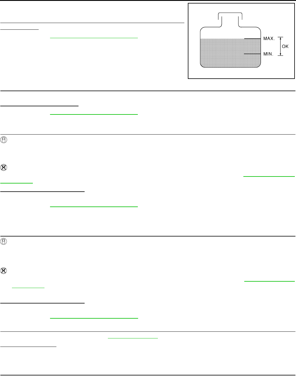
EC-1154
< COMPONENT DIAGNOSIS > [FOR MEXICO]
P1217 ENGINE OVER TEMPERATURE
Check the coolant level in the reservoir tank and radiator.
Allow engine to cool before checking coolant level.
Is the coolant level in the reservoir tank and/or radiator below the
proper range?
YES >> Go to EC-1154, "Diagnosis Procedure".
NO >> GO TO 2.
2.PERFORM COMPONENT FUNCTION CHECK-II
Confirm whether customer filled the coolant or not.
Did customer fill the coolant?
YES >> Go to EC-1154, "Diagnosis Procedure".
NO >> GO TO 3.
3.PERFORM COMPONENT FUNCTION CHECK-III
With CONSULT-III
1. Turn ignition switch ON.
2. Perform “COOLING FAN” in “ACTIVE TEST” mode with CONSULT-III.
3. Check that cooling fan motors-1 and -2 operate at each speed (LOW/HI).
Without CONSULT-III
Perform IPDM E/R auto active test and check cooling fan motors operation, refer to PCS-8, "Diagnosis
Description".
Is the inspection result normal?
YES >> INSPECTION END
NO >> Go to EC-1154, "Diagnosis Procedure".
Diagnosis Procedure INFOID:0000000004494300
1.CHECK COOLING FAN OPERATION
With CONSULT-III
1. Turn ignition switch ON.
2. Perform “COOLING FAN” in “ACTIVE TEST” mode with CONSULT-III.
3. Check that cooling fan motors-1 and -2 operate at each speed (LOW/HI).
Without CONSULT-III
1. Perform IPDM E/R auto active test and check cooling fan motors operation, refer to PCS-8, "Diagnosis
Description".
2. Check that cooling fan motors-1 and -2 operate at each speed (Low/High).
Is the inspection result normal?
YES >> GO TO 2.
NO >> Go to EC-1210, "Diagnosis Procedure".
2.CHECK COOLING SYSTEM FOR LEAK-I
Check cooling system for leak. Refer to CO-9, "Inspection".
Is leakage detected?
YES >> GO TO 3.
NO >> GO TO 4.
3.CHECK COOLING SYSTEM FOR LEAK-II
Check the following for leak.
•Hose
• Radiator
• Water pump
SEF621W
Revision: 2008 August 2009 Rogue
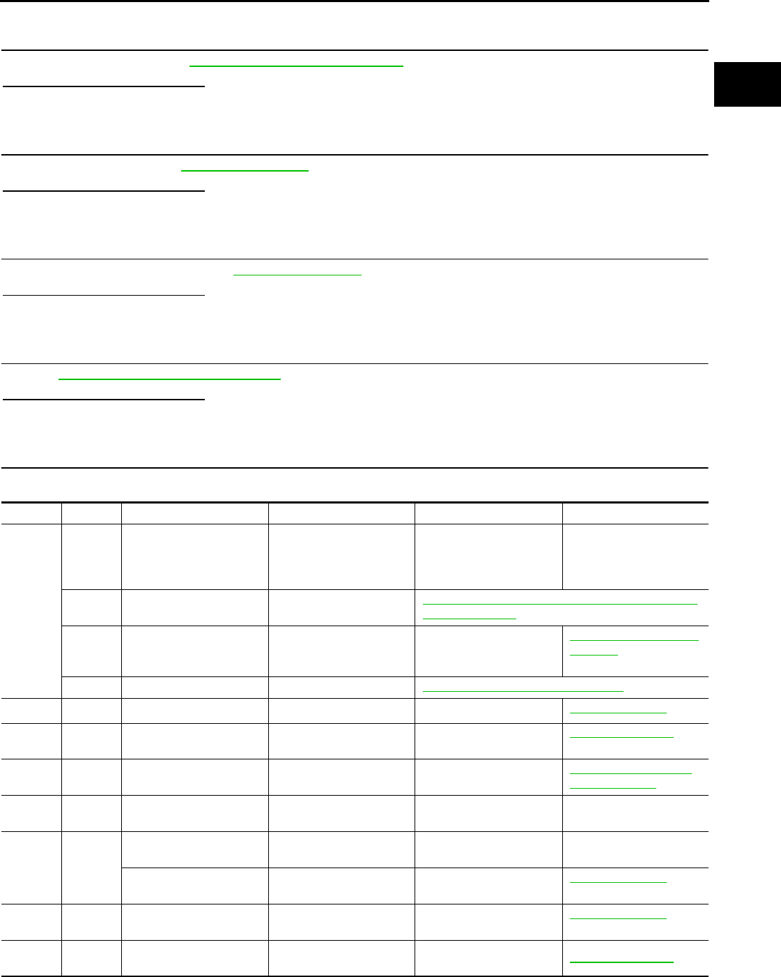
P1217 ENGINE OVER TEMPERATURE
EC-1155
< COMPONENT DIAGNOSIS > [FOR MEXICO]
C
D
E
F
G
H
I
J
K
L
M
A
EC
N
P
O
>> Repair or replace malfunctioning part.
4.CHECK RADIATOR CAP
Check radiator cap. Refer to CO-13, "RADIATOR : Inspection".
Is the inspection result normal?
YES >> GO TO 5.
NO >> Replace radiator cap.
5.CHECK THERMOSTAT
Check thermostat. Refer to CO-26, "Inspection".
Is the inspection result normal?
YES >> GO TO 6.
NO >> Replace thermostat.
6.CHECK WATER CONTROL VALVE
Check water control valve. Refer to CO-26, "Inspection".
Is the inspection result normal?
YES >> GO TO 7.
NO >> Replace water control valve
7.CHECK ENGINE COOLANT TEMPERATURE SENSOR
Refer to EC-1056, "Component Inspection".
Is the inspection result normal?
YES >> GO TO 8.
NO >> Replace engine coolant temperature sensor.
8.CHECK MAIN 13 CAUSES
If the cause cannot be isolated, check the following.
Engine Step Inspection item Equipment Standard Reference page
OFF 1 • Blocked radiator
• Blocked condenser
• Blocked radiator grille
• Blocked bumper
• Visual No blocking —
2 • Coolant mixture • Coolant tester MA-18, "FOR NORTH AMERICA : Anti-Freeze Cool-
ant Mixture Ratio"
3 • Coolant level • Visual Coolant up to MAX level in
reservoir tank and radiator
filler neck
CO-13, "RADIATOR : In-
spection"
4 • Radiator cap • Pressure tester CO-13, "RADIATOR CAP : Inspection"
ON*25 • Coolant leaks • Visual No leaks CO-9, "Inspection"
ON*26 • Thermostat • Touch the upper and
lower radiator hoses
Both hoses should be hot CO-26, "Inspection"
ON*17 • Cooling fan motor • CONSULT-III Operating EC-1209, "Component
Function Check"
OFF 8 • Combustion gas leak • Color checker chemical
tester 4 Gas analyzer
Negative —
ON*39 • Coolant temperature
gauge
• Visual Gauge less than 3/4 when
driving
—
• Coolant overflow to res-
ervoir tank
• Visual No overflow during driving
and idling
CO-9, "Inspection"
OFF*410 • Coolant return from res-
ervoir tank to radiator • Visual Should be initial level in
reservoir tank CO-9, "Inspection"
OFF 11 • Water control valve • Remove and inspect
the valve Within the specified value CO-26, "Inspection"
Revision: 2008 August 2009 Rogue

EC-1156
< COMPONENT DIAGNOSIS > [FOR MEXICO]
P1217 ENGINE OVER TEMPERATURE
*1: Turn the ignition switch ON.
*2: Engine running at 3,000 rpm for 10 minutes.
*3: Drive at 90 km/h (56 MPH) for 30 minutes and then let idle for 10 minutes.
*4: After 60 minutes of cool down time.
For more information, refer to CO-4, "Troubleshooting Chart".
>> INSPECTION END
OFF 12 • Cylinder head • Straight gauge feeler
gauge 0.1 mm (0.004 in) Maxi-
mum distortion (warping) EM-85, "Inspection"
13 • Cylinder block and pis-
tons
• Visual No scuffing on cylinder
walls or piston
EM-96, "Inspection"
Engine Step Inspection item Equipment Standard Reference page
Revision: 2008 August 2009 Rogue

P1225 TP SENSOR
EC-1157
< COMPONENT DIAGNOSIS > [FOR MEXICO]
C
D
E
F
G
H
I
J
K
L
M
A
EC
N
P
O
P1225 TP SENSOR
Description INFOID:0000000004534377
Electric throttle control actuator consists of throttle control motor,
throttle position sensor, etc. The throttle position sensor responds to
the throttle valve movement.
The throttle position sensor has two sensors. These sensors are a
kind of potentiometer which transform the throttle valve position into
output voltage, and emit the voltage signals to the ECM. The ECM
judges the current opening angle of the throttle valve from these sig-
nals and controls the throttle valve opening angle in response to
driving conditions via the throttle control motor.
DTC Logic INFOID:0000000004494302
DTC DETECTION LOGIC
DTC CONFIRMATION PROCEDURE
1.PRECONDITIONING
If DTC CONFIRMATION PROCEDURE has been previously conducted, always turn ignition switch OFF and
wait at least 10 seconds before conducting the next test.
TESTING CONDITION:
Before performing the following procedure, confirm that battery voltage is more than 10V at idle.
>> GO TO 2.
2.PERFORM DTC CONFIRMATION PROCEDURE
1. Turn ignition switch ON.
2. Turn ignition switch OFF and wait at least 10 seconds.
3. Turn ignition switch ON.
4. Check 1st trip DTC.
Is 1st trip DTC detected?
YES >> Go to EC-1157, "Diagnosis Procedure".
NO >> INSPECTION END
Diagnosis Procedure INFOID:0000000004494303
1.CHECK ELECTRIC THROTTLE CONTROL ACTUATOR VISUALLY
1. Turn ignition switch OFF.
2. Remove the intake air duct.
PBIB0145E
DTC No. Trouble diagnosis name DTC detecting condition Possible cause
P1225 Closed throttle position
learning performance Closed throttle position learning value is exces-
sively low. • Electric throttle control actuator
(TP sensor 1 and 2)
Revision: 2008 August 2009 Rogue
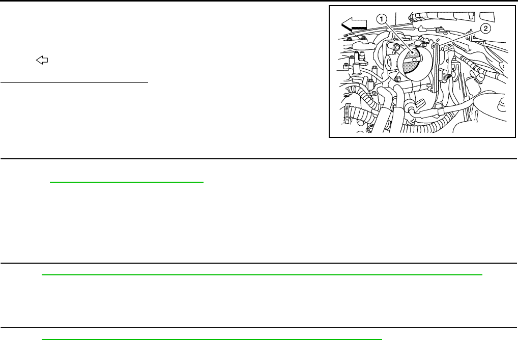
EC-1158
< COMPONENT DIAGNOSIS > [FOR MEXICO]
P1225 TP SENSOR
3. Check if foreign matter is caught between the throttle valve (1)
and the housing.
Is the inspection result normal?
YES >> GO TO 2.
NO >> Remove the foreign matter and clean the electric throttle
control actuator inside.
2.REPLACE ELECTRIC THROTTLE CONTROL ACTUATOR
1. Replace electric throttle control actuator.
2. Go to EC-1157, "Diagnosis Procedure".
>> INSPECTION END
Special Repair Requirement INFOID:0000000004534381
1.PERFORM THROTTLE VALVE CLOSED POSITION LEARNING
Refer to EC-938, "THROTTLE VALVE CLOSED POSITION LEARNING : Special Repair Requirement"
>> GO TO 2.
2.PERFORM IDLE AIR VOLUME LEARNING
Refer to EC-938, "IDLE AIR VOLUME LEARNING : Special Repair Requirement"
>> END
2. Electric throttle control actuator
: Vehicle front
ALBIA0061ZZ
Revision: 2008 August 2009 Rogue
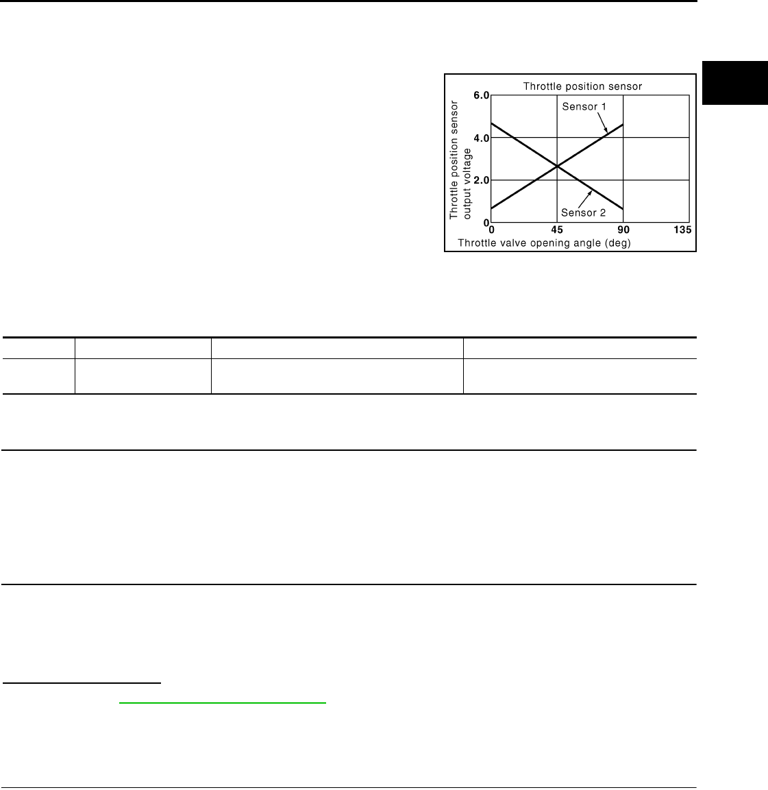
P1226 TP SENSOR
EC-1159
< COMPONENT DIAGNOSIS > [FOR MEXICO]
C
D
E
F
G
H
I
J
K
L
M
A
EC
N
P
O
P1226 TP SENSOR
Description INFOID:0000000004534410
Electric throttle control actuator consists of throttle control motor,
throttle position sensor, etc. The throttle position sensor responds to
the throttle valve movement.
The throttle position sensor has two sensors. These sensors are a
kind of potentiometer which transform the throttle valve position into
output voltage, and emit the voltage signals to the ECM. The ECM
judges the current opening angle of the throttle valve from these sig-
nals and controls the throttle valve opening angle in response to
driving conditions via the throttle control motor.
DTC Logic INFOID:0000000004494306
DTC DETECTION LOGIC
DTC CONFIRMATION PROCEDURE
1.PRECONDITIONING
If DTC CONFIRMATION PROCEDURE has been previously conducted, always turn ignition switch OFF and
wait at least 10 seconds before conducting the next test.
TESTING CONDITION:
Before performing the following procedure, confirm that battery voltage is more than 10V at idle.
>> GO TO 2.
2.PERFORM DTC CONFIRMATION PROCEDURE
1. Turn ignition switch ON.
2. Turn ignition switch OFF, wait at least 10 seconds.
3. Turn ignition switch ON.
4. Repeat steps 2 and 3 for 32 times.
5. Check 1st trip DTC.
Is 1st trip DTC detected?
YES >> Go to EC-1159, "Diagnosis Procedure".
NO >> INSPECTION END
Diagnosis Procedure INFOID:0000000004534643
1.CHECK ELECTRIC THROTTLE CONTROL ACTUATOR VISUALLY
1. Turn ignition switch OFF.
2. Remove the intake air duct.
PBIB0145E
DTC No. Trouble diagnosis name DTC detecting condition Possible cause
P1226 Closed throttle position
learning performance Closed throttle position learning is not per-
formed successfully, repeatedly. • Electric throttle control actuator
(TP sensor 1 and 2)
Revision: 2008 August 2009 Rogue

EC-1160
< COMPONENT DIAGNOSIS > [FOR MEXICO]
P1226 TP SENSOR
3. Check if foreign matter is caught between the throttle valve (1)
and the housing.
Is the inspection result normal?
YES >> GO TO 2.
NO >> Remove the foreign matter and clean the electric throttle
control actuator inside.
2.REPLACE ELECTRIC THROTTLE CONTROL ACTUATOR
1. Replace electric throttle control actuator.
2. Go to EC-1157, "Diagnosis Procedure".
>> INSPECTION END
Special Repair Requirement INFOID:0000000004534411
1.PERFORM THROTTLE VALVE CLOSED POSITION LEARNING
Refer to EC-938, "THROTTLE VALVE CLOSED POSITION LEARNING : Special Repair Requirement"
>> GO TO 2.
2.PERFORM IDLE AIR VOLUME LEARNING
Refer to EC-938, "IDLE AIR VOLUME LEARNING : Special Repair Requirement"
>> END
2. Electric throttle control actuator
: Vehicle front
ALBIA0061ZZ
Revision: 2008 August 2009 Rogue

P1421 COLD START CONTROL
EC-1161
< COMPONENT DIAGNOSIS > [FOR MEXICO]
C
D
E
F
G
H
I
J
K
L
M
A
EC
N
P
O
P1421 COLD START CONTROL
Description INFOID:0000000004494309
ECM controls ignition timing and engine idle speed when engine is started with prewarming up condition.
This control promotes the activation of three way catalyst by heating the catalyst and reduces emissions.
DTC Logic INFOID:0000000004494310
DTC DETECTION LOGIC
NOTE:
If DTC P1421 is displayed with other DTC, first perform the trouble diagnosis for other DTC.
DTC CONFIRMATION PROCEDURE
1.PRECONDITIONING
If DTC CONFIRMATION PROCEDURE has been previously conducted, always turn ignition switch OFF and
wait at least 10 seconds before conducting the next test.
TESTING CONDITION:
Before performing the following procedure, confirm that battery voltage is more than 11V at idle.
>> GO TO 2.
2.PERFORM DTC CONFIRMATION PROCEDURE
With CONSULT-III
1. Turn ignition switch OFF and wait at least 10 seconds.
2. Turn ignition switch ON.
3. Select “DATA MONITOR” mode with CONSULT-III.
4. Check that the “COOLAN TEMP/S” indication is between 4°C (39°F) and 36°C (97°F).
If “COOLAN TEMP/S” indication is within the specified value, go to the following step.
If “COOLANT TEMP/S” indication is out of the specified value, cool engine down or warm engine up and
go to step 1.
5. Start engine and let it idle for 5 minutes.
6. Check 1st trip DTC.
With GST
Follow the procedure “With CONSULT-III” above.
Is 1st trip DTC detected?
YES >> Go to EC-1161, "Diagnosis Procedure".
NO >> INSPECTION END
Diagnosis Procedure INFOID:0000000004494311
1.PERFORM IDLE AIR VOLUME LEARNING
Perform EC-938, "IDLE AIR VOLUME LEARNING : Special Repair Requirement".
Is Idle Air Volume Learning carried out successfully?
YES >> GO TO 2.
NO >> Follow the instruction of Idle Air Volume Learning.
2.CHECK INTAKE SYSTEM
Check for the cause of intake air volume lacking. Refer to the following.
• Crushed intake air passage
• Intake air passage clogging
DTC No. Trouble diagnosis name DTC detecting condition Possible cause
P1421 Cold start emission reduction
strategy monitoring
ECM does not control ignition timing and engine
idle speed properly when engine is started with
prewarming up condition.
• Lack of intake air volume
• Fuel injection system
•ECM
Revision: 2008 August 2009 Rogue

EC-1162
< COMPONENT DIAGNOSIS > [FOR MEXICO]
P1421 COLD START CONTROL
Is the inspection result normal?
YES >> GO TO 3.
NO >> Repair or replace malfunctioning part
3.CHECK FUEL INJECTION SYSTEM FUNCTION
Perform DTC CONFIRMATION PROCEDURE for DTC P0171. Refer to EC-1102, "DTC Logic".
Is the inspection result normal?
YES >> GO TO 4.
NO >> Go to EC-1103, "Diagnosis Procedure" for DTC P0171.
4.PERFORM DTC CONFIRMATION PROCEDURE
1. Turn ignition switch ON.
2. Erase DTC.
3. Perform DTC CONFIRMATION PROCEDURE.
See EC-1161, "DTC Logic".
Is the 1st trip DTC P1421 displayed again?
YES >> GO TO 5.
NO >> INSPECTION END
5.REPLACE ECM
1. Replace ECM.
2. Go to EC-936, "ADDITIONAL SERVICE WHEN REPLACING CONTROL UNIT : Special Repair Require-
ment".
>> INSPECTION END
Revision: 2008 August 2009 Rogue

P1564 ASCD STEERING SWITCH
EC-1163
< COMPONENT DIAGNOSIS > [FOR MEXICO]
C
D
E
F
G
H
I
J
K
L
M
A
EC
N
P
O
P1564 ASCD STEERING SWITCH
Description INFOID:0000000004494312
ASCD steering switch has variant values of electrical resistance for each button. ECM reads voltage variation
of switch, and determines which button is operated.
Refer to EC-966, "System Description" for the ASCD function.
DTC Logic INFOID:0000000004494313
DTC DETECTION LOGIC
NOTE:
If DTC P1564 is displayed with DTC P0605, first perform the trouble diagnosis for DTC P0605. Refer to
EC-1144, "DTC Logic".
DTC CONFIRMATION PROCEDURE
1.PRECONDITIONING
If DTC CONFIRMATION PROCEDURE has been previously conducted, always turn ignition switch OFF and
wait at least 10 seconds before conducting the next test.
>> GO TO 2.
2.PERFORM DTC CONFIRMATION PROCEDURE
1. Turn ignition switch ON.
2. Wait at least 10 seconds.
3. Press MAIN switch for at least 10 seconds, then release it and wait at least 10 seconds.
4. Press CANCEL switch for at least 10 seconds, then release it and wait at least 10 seconds.
5. Press RESUME/ACCELERATE switch for at least 10 seconds, then release it and wait at least 10 sec-
onds.
6. Press SET/COAST switch for at least 10 seconds, then release it and wait at least 10 seconds.
7. Check DTC.
Is DTC detected?
YES >> Go to EC-1163, "Diagnosis Procedure".
NO >> INSPECTION END
Diagnosis Procedure INFOID:0000000004494314
1.CHECK GROUND CONNECTION
1. Turn ignition switch OFF.
2. Check ground connection E21. Refer to Ground Inspection in GI-44, "Circuit Inspection".
Is the inspection result normal?
YS >> GO TO 2.
NO >> Repair or replace ground connection.
2.CHECK ASCD STEERING SWITCH CIRCUIT
With CONSULT-III
1. Turn ignition switch ON.
DTC No. Trouble diagnosis
name DTC detecting condition Possible cause
P1564 ASCD steering switch
• An excessively high voltage signal from the
ASCD steering switch is sent to ECM.
• ECM detects that input signal from the
ASCD steering switch is out of the specified
range.
• ECM detects that the ASCD steering switch
is stuck ON.
• Harness or connectors
(The switch circuit is open or shorted.)
• ASCD steering switch
•ECM
Revision: 2008 August 2009 Rogue

EC-1164
< COMPONENT DIAGNOSIS > [FOR MEXICO]
P1564 ASCD STEERING SWITCH
2. Select “MAIN SW”, “CANCEL SW”, “RESUME/ACC SW” and “SET SW” in “DATA MONITOR” mode with
CONSULT-III.
3. Check each item indication under the following conditions.
Without CONSULT-III
1. Turn ignition switch ON.
2. Check the voltage between ECM harness connectors.
Is the inspection result normal?
YES >> GO TO 8.
NO >> GO TO 3.
3.CHECK ASCD STEERING SWITCH GROUND CIRCUIT FOR OPEN AND SHORT
1. Turn ignition switch OFF.
2. Disconnect ECM harness connector.
3. Disconnect combination switch harness connector M352.
4. Check the continuity between combination switch and ECM harness connector.
5. Also check harness for short to ground and short to power.
Is the inspection result normal?
YES >> GO TO 5.
NO >> GO TO 4.
4.DETECT MALFUNCTIONING PART
Check the following.
• Harness connectors M77, E105
• Combination switch (spiral cable)
• Harness for open and short between ECM and combination switch
>> Repair open circuit or short to ground or short to power in harness or connectors.
5.CHECK ASCD STEERING SWITCH INPUT SIGNAL CIRCUIT FOR OPEN AND SHORT
Monitor item Condition Indication
MAIN SW MAIN switch Pressed ON
Released OFF
CANCEL SW CANCEL switch Pressed ON
Released OFF
RESUME/ACC SW RESUME/ACCELERATE switch Pressed ON
Released OFF
SET SW SET/COAST switch Pressed ON
Released OFF
ECM ECM Condition Voltage
Connector Terminal Connector Terminal
E16
85
(ASCD steering
switch signal)
E16
92
(Switch
ground)
MAIN switch: Pressed Approx. 0 V
CANSEL switch: Pressed Approx. 1 V
SET/COAST switch: Pressed Approx. 2 V
RESUME/ACCELERATE switch: Pressed Approx. 3 V
All ASCD steering switches: Released Approx. 4 V
Combination switch ECM Continuity
Connector Terminal Connector Terminal
—18E1692Existed
Revision: 2008 August 2009 Rogue

P1564 ASCD STEERING SWITCH
EC-1165
< COMPONENT DIAGNOSIS > [FOR MEXICO]
C
D
E
F
G
H
I
J
K
L
M
A
EC
N
P
O
1. Check the continuity between ECM harness connector and combination switch.
2. Also check harness for short to ground and short to power.
Is the inspection result normal?
YES >> GO TO 7.
NO >> GO TO 6.
6.DETECT MALFUNCTIONING PART
Check the following.
• Harness connectors M77, E105
• Combination switch (spiral cable)
• Harness for open and short between ECM and combination switch
>> Repair open circuit or short to ground or short to power in harness or connectors.
7.CHECK ASCD STEERING SWITCH
Refer to EC-1165, "Component Inspection".
Is the inspection result normal?
YES >> GO TO 8.
NO >> Replace ASCD steering switch.
8.CHECK INTERMITTENT INCIDENT
Refer to GI-41, "Intermittent Incident".
>> INSPECTION END
Component Inspection INFOID:0000000004494315
1.CHECK ASCD STEERING SWITCH
1. Disconnect combination switch (spiral cable) harness connector M352.
2. Check the continuity between combination switch harness connector terminals under following conditions.
Is the inspection result normal?
YES >> INSPECTION END
NO >> Replace ASCD steering switch
Combination switch ECM Continuity
Connector Terminal Connector Terminal
— 21 E10 85 Existed
Combination meter Condition Resistance
Connector Terminals
M352 18 and 21
MAIN switch: Pressed Approx. 0 Ω
CANCEL switch: Pressed Approx. 250 Ω
SET/COAST switch: Pressed Approx. 660 Ω
RESUME/ACCELERATE switch: Pressed Approx. 1,480 Ω
All ASCD steering switches: Released Approx. 4,000 Ω
Revision: 2008 August 2009 Rogue

EC-1166
< COMPONENT DIAGNOSIS > [FOR MEXICO]
P1572 ASCD BRAKE SWITCH
P1572 ASCD BRAKE SWITCH
Description INFOID:0000000004494316
When the brake pedal is depressed, ASCD brake switch is turned OFF and stop lamp switch is turned ON.
ECM detects the state of the brake pedal by those two types of input (ON/OFF signal).
Refer to EC-966, "System Description" for the ASCD function.
DTC Logic INFOID:0000000004494317
DTC DETECTION LOGIC
NOTE:
•If DTC P1572 is displayed with DTC P0605, first perform the trouble diagnosis for DTC P0605. Refer
to EC-1144, "DTC Logic".
•This self-diagnosis has the one trip detection logic. When malfunction A is detected, DTC is not
stored in ECM memory. And in that case, 1st trip DTC and 1st trip freeze frame data are displayed.
1st trip DTC is erased when ignition switch is turned OFF. And even when malfunction A is detected
in two consecutive trips, DTC is not stored in ECM memory.
DTC CONFIRMATION PROCEDURE
1.PRECONDITIONING
If DTC CONFIRMATION PROCEDURE has been previously conducted, always turn ignition switch OFF and
wait at least 10 seconds before conducting the next test.
NOTE:
The procedure for malfunction B is not described. It takes an extremely long time to complete the procedure
for malfunction B. By performing the procedure for malfunction A, the condition that causes malfunction B can
be detected.
>> GO TO 2.
2.PERFORM DTC CONFIRMATION PROCEDURE FOR MALFUNCTION A -I
1. Start engine.
2. Press MAIN switch and check that CRUISE indicator is displayed in combination meter.
3. Drive the vehicle for at least 5 consecutive seconds under the following conditions.
CAUTION:
Always drive vehicle at a safe speed.
NOTE:
This procedure may be conducted with the drive wheels lifted in the shop or by driving the vehicle.
If a road test is expected to be easier, it is unnecessary to lift the vehicle.
4. Check 1st trip DTC.
Is 1st trip DTC detected?
YES >> Go to EC-1167, "Diagnosis Procedure".
NO >> GO TO 3.
DTC No. Trouble diagnosis
name DTC detecting condition Possible cause
P1572 ASCD brake switch
A)
When the vehicle speed is above 30 km/h
(19 MPH), ON signals from the stop lamp
switch and the ASCD brake switch are sent
to the ECM at the same time.
• Harness or connectors
(The stop lamp switch circuit is shorted.)
• Harness or connectors
(The ASCD brake switch circuit is shorted.)
• Stop lamp switch
• ASCD brake switch
• Incorrect stop lamp switch installation
• Incorrect ASCD brake switch installation
•ECM
B)
ASCD brake switch signal is not sent to
ECM for extremely long time while the ve-
hicle is being driven.
Vehicle speed More than 30 km/h (19 mph)
Selector lever Suitable position
Revision: 2008 August 2009 Rogue
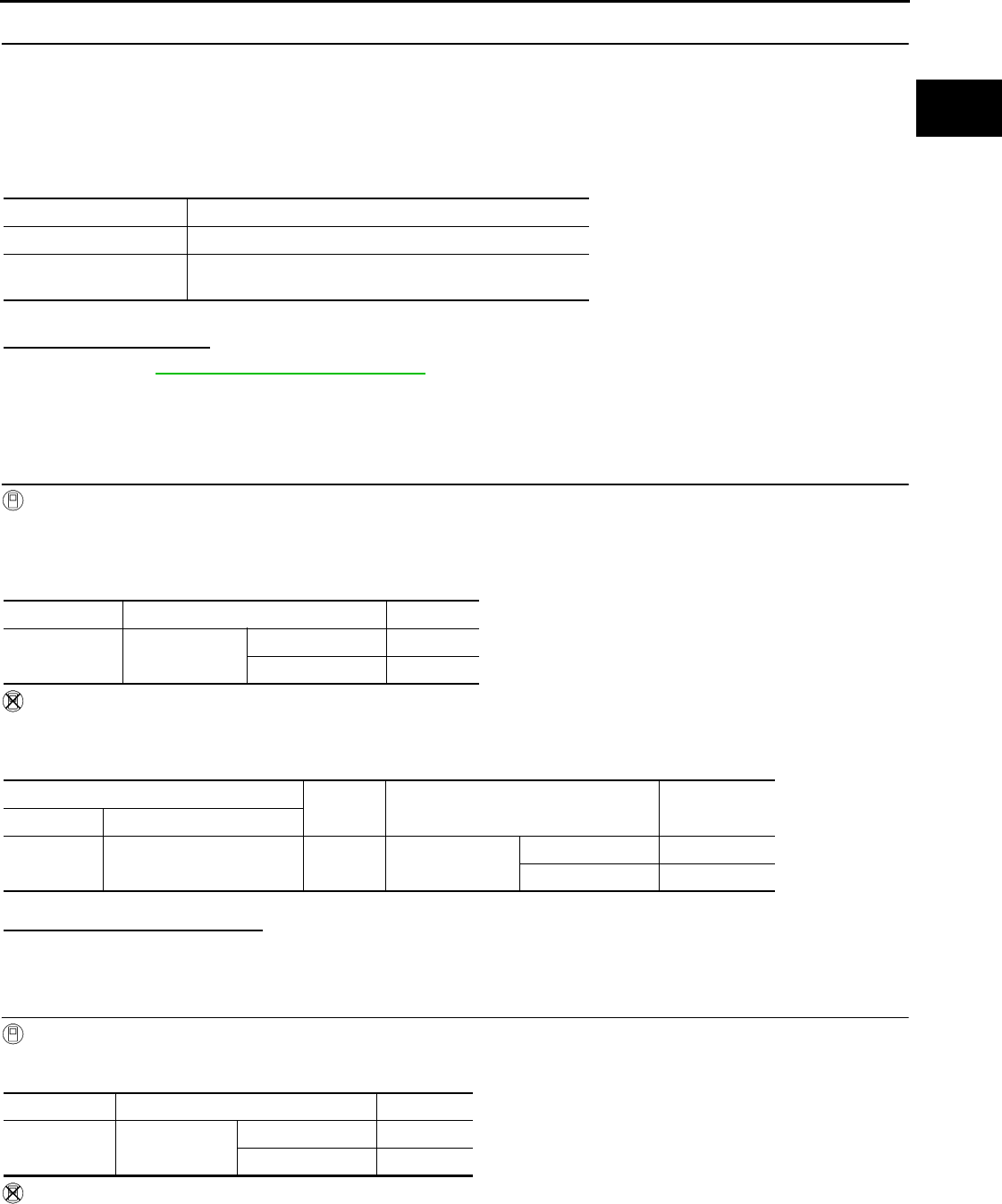
P1572 ASCD BRAKE SWITCH
EC-1167
< COMPONENT DIAGNOSIS > [FOR MEXICO]
C
D
E
F
G
H
I
J
K
L
M
A
EC
N
P
O
3.PERFORM DTC CONFIRMATION PROCEDURE FOR MALFUNCTION A -II
1. Drive the vehicle for at least 5 consecutive seconds under the following conditions.
CAUTION:
Always drive vehicle at a safe speed.
NOTE:
This procedure may be conducted with the drive wheels lifted in the shop or by driving the vehicle.
If a road test is expected to be easier, it is unnecessary to lift the vehicle.
2. Check 1st trip DTC.
Is 1st trip DTC detected?
YES >> Go to EC-1167, "Diagnosis Procedure".
NO >> INSPECTION END
Diagnosis Procedure INFOID:0000000004494318
1.CHECK OVERALL FUNCTION-I
With CONSULT-III
1. Turn ignition switch ON.
2. Select “BRAKE SW1” in “DATA MONITOR” mode with CONSULT-III.
3. Check “BRAKE SW1” indication under the following conditions.
Without CONSULT-III
1. Turn ignition switch ON.
2. Check the voltage between ECM harness connector and ground.
Is the inspection result normal?
YES >> GO TO 2.
NO >> GO TO 3.
2.CHECK OVERALL FUNCTION-II
With CONSULT-III
Select “BRAKE SW2” and check indication in “DATA MONITOR” mode.
Without CONSULT-III
Check the voltage between ECM harness connector and ground.
Vehicle speed More than 30 km/h (19 mph)
Selector lever Suitable position
Driving location Depress the brake pedal for more than five seconds so as
not to come off from the above-mentioned vehicle speed.
Monitor item Condition Indication
BRAKE SW1 Brake pedal Slightly depressed OFF
Fully released ON
ECM Ground Condition Voltage
Connector Terminal
E16 110
(ASCD brake switch signal) Ground Brake pedal Slightly depressed Approx. 0V
Fully released Battery voltage
Monitor item Condition Indication
BRAKE SW2 Brake pedal Slightly depressed ON
Fully released OFF
Revision: 2008 August 2009 Rogue

EC-1168
< COMPONENT DIAGNOSIS > [FOR MEXICO]
P1572 ASCD BRAKE SWITCH
Is the inspection result normal?
YES >> GO TO 11.
NO >> GO TO 7.
3.CHECK ASCD BRAKE SWITCH POWER SUPPLY CIRCUIT
1. Turn ignition switch OFF.
2. Disconnect ASCD brake switch harness connector.
3. Turn ignition switch ON.
4. Check the voltage between ASCD brake switch harness connector and ground.
Is the inspection result normal?
YES >> GO TO 5.
NO >> GO TO 4.
4.DETECT MALFUNCTIONING PART
Check the following.
• Junction block connector E105, M77
• 10A fuse (No.1)
• Harness for open or short between ASCD brake switch and fuse
>> Repair open circuit or short to ground or short to power in harness or connectors.
5.CHECK ASCD BRAKE SWITCH INPUT SIGNAL CIRCUIT FOR OPEN AND SHORT
1. Turn ignition switch OFF.
2. Disconnect ECM harness connector.
3. Check the continuity between ASCD brake switch harness connector and ECM harness connector.
4. Also check harness for short to ground and short to power.
Is the inspection result normal?
YES >> GO TO 6.
NO >> Repair open circuit or short to ground or short to power in harness or connectors.
6.CHECK ASCD BRAKE SWITCH
Refer to EC-1169, "Component Inspection (ASCD Brake Switch)".
Is the inspection result normal?
YES >> GO TO 11.
NO >> Replace ASCD brake switch.
7.CHECK STOP LAMP SWITCH POWER SUPPLY CIRCUIT
1. Turn ignition switch OFF.
2. Disconnect stop lamp switch harness connector.
3. Check the voltage between stop lamp switch harness connector and ground.
ECM Ground Condition Voltage
Connector Terminal
E16 106
(Stop lamp switch signal) Ground Brake pedal Slightly depressed Battery voltage
Fully released Approx. 0V
ASCD brake switch Ground Voltage
Connector Terminal
E112 1 Ground Battery voltage
ASCD brake switch ECM Continuity
Connector Terminal Connector Terminal
E112 2 E16 110 Existed
Revision: 2008 August 2009 Rogue

P1572 ASCD BRAKE SWITCH
EC-1169
< COMPONENT DIAGNOSIS > [FOR MEXICO]
C
D
E
F
G
H
I
J
K
L
M
A
EC
N
P
O
Is the inspection result normal?
YES >> GO TO 9.
NO >> GO TO 8.
8.DETECT MALFUNCTIONING PART
Check the following.
• Harness connectors E105, M77
• 10A fuse (No.11)
• Harness for open or short between stop lamp switch and battery
>> Repair open circuit or short to ground or short to power in harness or connectors.
9.CHECK STOP LAMP SWITCH INPUT SIGNAL CIRCUIT FOR OPEN AND SHORT
1. Disconnect ECM harness connector.
2. Check the continuity between ECM harness connector and stop lamp switch harness connector.
3. Also check harness for short to ground and short to power.
Is the inspection result normal?
YES >> GO TO 10.
NO >> Repair open circuit or short to ground or short to power in harness or connectors.
10.CHECK STOP LAMP SWITCH
Refer to EC-1170, "Component Inspection (Stop Lamp Switch)".
Is the inspection result normal?
YES >> GO TO 11.
NO >> Replace stop lamp switch.
11.CHECK INTERMITTENT INCIDENT
Refer to GI-41, "Intermittent Incident".
>> INSPECTION END
Component Inspection (ASCD Brake Switch) INFOID:0000000004494319
1.CHECK ASCD BRAKE SWITCH-I
1. Turn ignition switch OFF.
2. Disconnect ASCD brake switch harness connector.
3. Check the continuity between ASCD brake switch terminals under the following conditions.
Is the inspection result normal?
YES >> INSPECTION END
NO >> GO TO 2.
2.CHECK ASCD BRAKE SWITCH-II
Stop lamp switch Ground Voltage
Connector Terminal
E115 1 Ground Battery voltage
ECM Stop lamp switch Continuity
Connector Terminal Connector Terminal
E16 106 E115 2 Existed
Terminals Condition Continuity
1 and 2 Brake pedal Fully released Existed
Slightly depressed Not existed
Revision: 2008 August 2009 Rogue

EC-1170
< COMPONENT DIAGNOSIS > [FOR MEXICO]
P1572 ASCD BRAKE SWITCH
1. Adjust ASCD brake switch installation. Refer to BR-9, "Inspection and Adjustment".
2. Check the continuity between ASCD brake switch terminals under the following conditions.
Is the inspection result normal?
YES >> INSPECTION END
NO >> Replace ASCD brake switch.
Component Inspection (Stop Lamp Switch) INFOID:0000000004494320
1.CHECK STOP LAMP SWITCH-I
1. Turn ignition switch OFF.
2. Disconnect stop lamp switch harness connector.
3. Check the continuity between stop lamp switch terminals under the following conditions.
Is the inspection result normal?
YES >> INSPECTION END
NO >> GO TO 2.
2.CHECK STOP LAMP SWITCH-II
1. Adjust stop lamp switch installation. Refer to BR-9, "Inspection and Adjustment".
2. Check the continuity between stop lamp switch terminals under the following conditions.
Is the inspection result normal?
YES >> INSPECTION END
NO >> Replace stop lamp switch.
Terminals Condition Continuity
1 and 2 Brake pedal Fully released Existed
Slightly depressed Not existed
Terminals Condition Continuity
1 and 2 Brake pedal Fully released Not existed
Slightly depressed Existed
Terminals Condition Continuity
1 and 2 Brake pedal Fully released Not existed
Slightly depressed Existed
Revision: 2008 August 2009 Rogue

P1574 ASCD VEHICLE SPEED SENSOR
EC-1171
< COMPONENT DIAGNOSIS > [FOR MEXICO]
C
D
E
F
G
H
I
J
K
L
M
A
EC
N
P
O
P1574 ASCD VEHICLE SPEED SENSOR
Description INFOID:0000000004494321
The ECM receives two vehicle speed sensor signals via CAN communication line. One is sent from combina-
tion meter, and the other is from TCM (Transmission control module). The ECM uses these signals for ASCD
control. Refer to EC-966, "System Description" for ASCD functions.
DTC Logic INFOID:0000000004494322
DTC DETECTION LOGIC
NOTE:
•If DTC P1574 is displayed with DTC UXXXX, first perform the trouble diagnosis for DTC UXXXX.
•If DTC P1574 is displayed with DTC P0500, first perform the trouble diagnosis for DTC P0500. Refer
to EC-1136, "DTC Logic"
•If DTC P1574 is displayed with DTC P0605, first perform the trouble diagnosis for DTC P0605. Refer
to EC-1144, "DTC Logic"
•If DTC P1574 is displayed with DTC P0607, first perform the trouble diagnosis for DTC P0607. Refer
to EC-1146, "DTC Logic".
DTC CONFIRMATION PROCEDURE
1.PRECONDITIONING
If DTC CONFIRMATION PROCEDURE has been previously conducted, always turn ignition switch OFF and
wait at least 10 seconds before conducting the next test.
>> GO TO 2.
2.PERFORM DTC CONFIRMATION PROCEDURE
1. Start engine.
2. Drive the vehicle at more than 40 km/h (25 MPH).
CAUTION:
Always drive vehicle at a safe speed.
NOTE:
This procedure may be conducted with the drive wheels lifted in the shop or by driving the vehicle.
If a road test is expected to be easier, it is unnecessary to lift the vehicle.
3. Check DTC.
Is DTC detected?
YES >> Go to EC-1171, "Diagnosis Procedure".
NO >> INSPECTION END
Diagnosis Procedure INFOID:0000000004494323
1.CHECK DTC WITH TCM
Check DTC with TCM. Refer to TM-44, "CONSULT-III Function (TRANSMISSION)".
Is the inspection result normal?
YES >> GO TO 2.
NO >> Perform trouble shooting relevant to DTC indicated.
DTC No. Trouble diagnosis
name DTC detecting condition Possible cause
P1574 ASCD vehicle speed
sensor
The difference between the two vehicle speed
signals is out of the specified range.
• Harness or connectors
(The CAN communication line is open or
shorted.)
(Combination meter circuit is open or shorted.)
• Combination meter
• ABS actuator and electric unit (control unit)
• Wheel sensor
•TCM
•ECM
Revision: 2008 August 2009 Rogue

EC-1172
< COMPONENT DIAGNOSIS > [FOR MEXICO]
P1574 ASCD VEHICLE SPEED SENSOR
2.CHECK DTC WITH “ABS ACTUATOR AND ELECTRIC UNIT (CONTROL UNIT)”
Refer to BRC-15, "CONSULT-III Function" (ABS models), BRC-93, "CONSULT-III Function" (VDC models).
Is the inspection result normal?
YES >> GO TO 3.
NO >> Repair or replace.
3.CHECK COMBINATION METER
Check combination meter function.
Refer to MWI-33, "CONSULT-III Function (METER/M&A)".
>> INSPECTION END
Revision: 2008 August 2009 Rogue

P1715 INPUT SPEED SENSOR (PRIMARY SPEED SENSOR)
EC-1173
< COMPONENT DIAGNOSIS > [FOR MEXICO]
C
D
E
F
G
H
I
J
K
L
M
A
EC
N
P
O
P1715 INPUT SPEED SENSOR (PRIMARY SPEED SENSOR)
Description INFOID:0000000004494324
ECM receives primary speed sensor signal from TCM through CAN communication line. ECM uses this signal
for engine control.
DTC Logic INFOID:0000000004494325
DTC DETECTION LOGIC
NOTE:
•If DTC P1715 is displayed with DTC UXXXX, first perform the trouble diagnosis for DTC UXXXX.
•If DTC P1715 is displayed with DTC P0335, first perform the trouble diagnosis for DTC P0335. Refer
to EC-1120, "DTC Logic".
•If DTC P1715 is displayed with DTC P0340, first perform the trouble diagnosis for DTC P0340. Refer
to EC-1124, "DTC Logic".
•If DTC P1715 is displayed with DTC P0605, first perform the trouble diagnosis for DTC P0605. Refer
to EC-1144, "DTC Logic".
•If DTC P1715 is displayed with DTC P0607, first perform the trouble diagnosis for DTC P0607. Refer
to EC-1146, "DTC Logic".
DTC CONFIRMATION PROCEDURE
1.PRECONDITIONING
If DTC CONFIRMATION PROCEDURE has been previously conducted, always turn ignition switch OFF and
wait at least 10 seconds before conducting the next test.
>> GO TO 2.
2.PERFORM DTC CONFIRMATION PROCEDURE
1. Start engine and drive the vehicle at more than 50 km/h (31 MPH) for at least 5 seconds.
CAUTION:
Always drive vehicle at a safe speed.
2. Check 1st trip DTC.
Is 1st trip DTC detected?
YES >> Go to EC-1173, "Diagnosis Procedure".
NO >> INSPECTION END
Diagnosis Procedure INFOID:0000000004494326
1.CHECK DTC WITH TCM
Check DTC with TCM. Refer to TM-44, "CONSULT-III Function (TRANSMISSION)".
Is the inspection result normal?
YES >> GO TO 2.
NO >> Perform trouble shooting relevant to DTC indicated.
2.REPLACE TCM
Replace TCM.
DTC No. Trouble diagnosis name DTC detecting condition Possible cause
P1715 Input speed sensor
(Primary speed sensor)
(TCM output)
Primary speed sensor signal is different
from the theoretical value calculated by
ECM from secondary speed sensor signal
and engine rpm signal.
• Harness or connectors
(The CAN communication line is open or short-
ed)
• Harness or connectors
(Primary speed sensor circuit is open or short-
ed)
•TCM
Revision: 2008 August 2009 Rogue

EC-1174
< COMPONENT DIAGNOSIS > [FOR MEXICO]
P1715 INPUT SPEED SENSOR (PRIMARY SPEED SENSOR)
>> INSPECTION END
Revision: 2008 August 2009 Rogue

P1805 BRAKE SWITCH
EC-1175
< COMPONENT DIAGNOSIS > [FOR MEXICO]
C
D
E
F
G
H
I
J
K
L
M
A
EC
N
P
O
P1805 BRAKE SWITCH
Description INFOID:0000000004494327
Brake switch signal is applied to the ECM through the stop lamp switch when the brake pedal is depressed.
This signal is used mainly to decrease the engine speed when the vehicle is being driven.
DTC Logic INFOID:0000000004494328
DTC DETECTION LOGIC
DTC CONFIRMATION PROCEDURE
1.PERFORM DTC CONFIRMATION PROCEDURE
1. Turn ignition switch ON.
2. Fully depress the brake pedal for at least 5 seconds.
3. Erase the DTC with CONSULT-III.
4. Check 1st trip DTC.
Is 1st trip DTC detected?
YES >> Go to EC-1175, "Diagnosis Procedure".
NO >> INSPECTION END
Diagnosis Procedure INFOID:0000000004494329
1.CHECK STOP LAMP SWITCH CIRCUIT
1. Turn ignition switch OFF.
2. Check the stop lamp when depressing and releasing the brake pedal.
Is 1st trip DTC detected?
YES >> GO TO 4.
NO >> GO TO 2.
2.CHECK STOP LAMP SWITCH POWER SUPPLY CIRCUIT
1. Turn ignition switch OFF.
2. Disconnect stop lamp switch harness connector.
3. Check the voltage between stop lamp switch harness connector and ground.
Is the inspection result normal?
YES >> GO TO 4.
NO >> GO TO 3.
3.DETECT MALFUNCTIONING PART
Check the following.
• Harness connectors E105, M77
DTC No. Trouble diagnosis name DTC detecting condition Possible cause
P1805 Brake switch
A brake switch signal is not sent to ECM for ex-
tremely long time while the vehicle is being driv-
en.
• Harness or connectors
(Stop lamp switch circuit is open or short-
ed.)
• Stop lamp switch
Brake pedal Stop lamp
Fully released Not illuminated
Slightly depressed Illuminated
Stop lamp switch Ground Voltage
Connector Terminal
E115 1 Ground Battery voltage
Revision: 2008 August 2009 Rogue

EC-1176
< COMPONENT DIAGNOSIS > [FOR MEXICO]
P1805 BRAKE SWITCH
• 10A fuse (No. 11)
• Harness for open or short between stop lamp switch and battery
>> Repair open circuit or short to ground or short to power in harness or connectors.
4.CHECK STOP LAMP SWITCH INPUT SIGNAL CIRCUIT FOR OPEN AND SHORT
1. Disconnect ECM harness connector.
2. Check the continuity between ECM harness connector and stop lamp switch harness connector.
3. Also check harness for short to ground and short to power.
Is the inspection result normal?
YES >> GO TO 5.
NO >> Repair open circuit or short to ground or short to power in harness or connectors.
5.CHECK STOP LAMP SWITCH
Refer to EC-1176, "Component Inspection (Stop Lamp Switch)".
Is the inspection result normal?
YES >> GO TO 6.
NO >> Replace stop lamp switch.
6.CHECK INTERMITTENT INCIDENT
Refer to GI-41, "Intermittent Incident".
>> INSPECTION END
Component Inspection (Stop Lamp Switch) INFOID:0000000004534680
1.CHECK STOP LAMP SWITCH-I
1. Turn ignition switch OFF.
2. Disconnect stop lamp switch harness connector.
3. Check the continuity between stop lamp switch terminals under the following conditions.
Is the inspection result normal?
YES >> INSPECTION END
NO >> GO TO 2.
2.CHECK STOP LAMP SWITCH-II
1. Adjust stop lamp switch installation. Refer to BR-9, "Inspection and Adjustment".
2. Check the continuity between stop lamp switch terminals under the following conditions.
Is the inspection result normal?
YES >> INSPECTION END
NO >> Replace stop lamp switch.
ECM Stop lamp switch Continuity
Connector Terminal Connector Terminal
E16 106 E115 2 Existed
Terminals Condition Continuity
1 and 2 Brake pedal Fully released Not existed
Slightly depressed Existed
Terminals Condition Continuity
1 and 2 Brake pedal Fully released Not existed
Slightly depressed Existed
Revision: 2008 August 2009 Rogue

P2100, P2103 THROTTLE CONTROL MOTOR RELAY
EC-1177
< COMPONENT DIAGNOSIS > [FOR MEXICO]
C
D
E
F
G
H
I
J
K
L
M
A
EC
N
P
O
P2100, P2103 THROTTLE CONTROL MOTOR RELAY
Description INFOID:0000000004494331
Power supply for the throttle control motor is provided to the ECM via throttle control motor relay. The throttle
control motor relay is controlled ON/OFF by the ECM. When the ignition switch is turned ON, the ECM sends
an ON signal to throttle control motor relay and battery voltage is provided to the ECM. When the ignition
switch is turned OFF, the ECM sends an OFF signal to throttle control motor relay and battery voltage is not
provided to the ECM.
DTC Logic INFOID:0000000004494332
DTC DETECTION LOGIC
DTC CONFIRMATION PROCEDURE
1.PRECONDITIONING
If DTC CONFIRMATION PROCEDURE has been previously conducted, always turn ignition switch OFF and
wait at least 10 seconds before conducting the next test.
TESTING CONDITION:
Before performing the following procedure, confirm that battery voltage is more than 8V.
Witch DTC is detected?
P2100 >> GO TO 2.
P2103 >> GO TO 3.
2.PERFORM DTC CONFIRMATION PROCEDURE FOR DTC P2100
1. Turn ignition switch ON and wait at least 2 seconds.
2. Start engine and let it idle for 5 seconds.
3. Check DTC.
Is DTC detected?
YES >> Go to EC-1177, "Diagnosis Procedure".
NO >> INSPECTION END
3.PERFORM DTC CONFIRMATION PROCEDURE FOR DTC P2103
1. Turn ignition switch ON and wait at least 1 second.
2. Check DTC.
Is DTC detected?
YES >> Go to EC-1177, "Diagnosis Procedure".
NO >> INSPECTION END
Diagnosis Procedure INFOID:0000000004494333
1.CHECK THROTTLE CONTROL MOTOR RELAY POWER SUPPLY CIRCUIT
1. Turn ignition switch OFF.
2. Disconnect ECM harness connector.
3. Disconnect IPDM E/R harness connector.
4. Check the continuity between ECM harness connector and IPDM E/R harness connector.
DTC No. Trouble diagnosis name DTC detecting condition Possible cause
P2100 Throttle control motor
relay circuit open
ECM detects that the voltage of power source
for throttle control motor is excessively low.
• Harness or connectors
(Throttle control motor relay circuit is
open)
• Throttle control motor relay
P2103 Throttle control motor
relay circuit short
ECM detects that the throttle control motor relay
is stuck ON.
• Harness or connectors
(Throttle control motor relay circuit is
shorted)
• Throttle control motor relay
Revision: 2008 August 2009 Rogue

EC-1178
< COMPONENT DIAGNOSIS > [FOR MEXICO]
P2100, P2103 THROTTLE CONTROL MOTOR RELAY
5. Also check harness for short to ground and short to power.
Is the inspection result normal?
YES >> GO TO 3.
NO >> GO TO 2.
2.DETECT MALFUNCTION PART
Check the following.
• Harness connectors E7, F121
• Harness for open or short between ECM and IPDM E/R
>> Repair open circuit or short to ground or short to power in harness or connectors.
3.CHECK THROTTLE CONTROL MOTOR RELAY INPUT SIGNAL CIRCUIT
1. Check the continuity between ECM harness connector and IPDM E/R harness connector.
2. Also check harness for short to ground and short to power.
Is the inspection result normal?
YES >> GO TO 5.
NO >> GO TO 4.
4.DETECT MALFUNCTION PART
Check the following.
• Harness connectors E7, F121
• Harness for open or short between ECM and IPDM E/R
>> Repair open circuit or short to ground or short to power in harness or connectors.
5.CHECK FUSE
1. Disconnect 15A fuse (No. 61) from IPDM E/R.
2. Check it 15A fuse is blown.
Is the inspection result normal?
YES >> GO TO 6.
NO >> Replace 15A fuse.
6.CHECK INTERMITTENT INCIDENT
Refer to GI-41, "Intermittent Incident".
Is the inspection result normal?
YES >> Replace IPDM E/R.
NO >> Repair or replace harness or connectors.
ECM IPDM E/R Continuity
Connector Terminal Connector Terminal
F7 15 E13 32 Existed
ECM IPDM E/R Continuity
Connector Terminal Connector Terminal
F7 2 E15 52 Existed
Revision: 2008 August 2009 Rogue

P2101 ELECTRIC THROTTLE CONTROL FUNCTION
EC-1179
< COMPONENT DIAGNOSIS > [FOR MEXICO]
C
D
E
F
G
H
I
J
K
L
M
A
EC
N
P
O
P2101 ELECTRIC THROTTLE CONTROL FUNCTION
Description INFOID:0000000004494334
Electric throttle control actuator consists of throttle control motor, throttle position sensor, etc.
The throttle control motor is operated by the ECM and it opens and closes the throttle valve.
The current opening angle of the throttle valve is detected by the throttle position sensor. The throttle position
sensor provides feedback to the ECM, when open/closes the throttle valve in response to driving conditions
via the throttle control motor.
DTC Logic INFOID:0000000004494335
DTC DETECTION LOGIC
NOTE:
If DTC P2101 is displayed with DTC P2100 or P2119, first perform the trouble diagnosis for DTC P2100
or P2119. Refer to EC-1177, "DTC Logic" or EC-1185, "DTC Logic".
DTC CONFIRMATION PROCEDURE
1.PRECONDITIONING
If DTC CONFIRMATION PROCEDURE has been previously conducted, always turn ignition switch OFF and
wait at least 10 seconds before conducting the next test.
TESTING CONDITION:
Before performing the following procedure, confirm that battery voltage is more than 11V when engine
is running.
>> GO TO 2.
2.PERFORM DTC CONFIRMATION PROCEDURE
1. Turn ignition switch ON and wait at least 2 seconds.
2. Start engine and let it idle for 5 seconds.
3. Check DTC.
Is DTC detected?
YES >> Go to EC-1179, "Diagnosis Procedure".
NO >> INSPECTION END
Diagnosis Procedure INFOID:0000000004494336
1.CHECK GROUND CONNECTION
1. Turn ignition switch OFF.
2. Check ground connection E21. Refer to Ground Inspection in GI-44, "Circuit Inspection".
Is the inspection result normal?
YES >> GO TO 2.
NO >> Repair or replace ground connection.
2.CHECK THROTTLE CONTROL MOTOR RELAY INPUT SIGNAL CIRCUIT-I
1. Check the voltage between ECM harness connector and ground.
DTC No. Trouble diagnosis name DTC detecting condition Possible cause
P2101 Electric throttle control
performance
Electric throttle control function does not oper-
ate properly.
• Harness or connectors
(Throttle control motor circuit is open or
shorted)
• Electric throttle control actuator
Revision: 2008 August 2009 Rogue

EC-1180
< COMPONENT DIAGNOSIS > [FOR MEXICO]
P2101 ELECTRIC THROTTLE CONTROL FUNCTION
Is the inspection result normal?
YES >> GO TO 9.
NO >> GO TO 3.
3.CHECK THROTTLE CONTROL MOTOR RELAY POWER SUPPLY CIRCUIT
1. Disconnect ECM harness connector.
2. Disconnect IPDM E/R harness connector.
3. Check the continuity between ECM harness connector and IPDM E/R harness connector.
4. Also check harness for short to ground and short to power.
Is the inspection result normal?
YES >> GO TO 5.
NO >> GO TO 4.
4.DETECT MALFUNCTION PART
Check the following.
• Harness connectors E7, F121
• Harness for open or short between ECM and IPDM E/R
>> Repair open circuit or short to ground or short to power in harness or connectors.
5.CHECK THROTTLE CONTROL MOTOR RELAY INPUT SIGNAL CIRCUIT-II
1. Check the continuity between ECM harness connector and IPDM E/R harness connector.
2. Also check harness for short to ground and short to power.
Is the inspection result normal?
YES >> GO TO 7.
NO >> GO TO 6.
6.DETECT MALFUNCTION PART
Check the following.
• Harness connectors E7, F121
• Harness for open or short between ECM and IPDM E/R
>> Repair open circuit or short to ground or short to power in harness or connectors.
7.CHECK FUSE
1. Disconnect 20A fuse (No. 61) from IPDM E/R.
2. Check it 20A fuse is blown.
Is the inspection result normal?
YES >> GO TO 8.
NO >> Replace 20A fuse.
ECM Ground Condition Voltage
Connector Terminal
F7 2 Ground Ignition switch OFF Approx. 0V
Ignition switch ON Battery voltage
IPDM E/R ECM Continuity
Connector Terminal Connector Terminal
E13 32 F7 15 Existed
IPDM E/R ECM Continuity
Connector Terminal Connector Terminal
E15 52 F7 2 Existed
Revision: 2008 August 2009 Rogue

P2101 ELECTRIC THROTTLE CONTROL FUNCTION
EC-1181
< COMPONENT DIAGNOSIS > [FOR MEXICO]
C
D
E
F
G
H
I
J
K
L
M
A
EC
N
P
O
8.CHECK INTERMITTENT INCIDENT
Refer to GI-41, "Intermittent Incident".
Is the inspection result normal?
YES >> Replace IPDM E/R.
NO >> Repair or replace harness or connectors.
9.CHECK THROTTLE CONTROL MOTOR OUTPUT SIGNAL CIRCUIT FOR OPEN OR SHORT
1. Turn ignition switch OFF.
2. Disconnect electric throttle control actuator harness connector.
3. Disconnect ECM harness connector.
4. Check the continuity between electric throttle control actuator harness connector and ECM harness con-
nector.
5. Also check harness for short to ground and short to power.
Is the inspection result normal?
YES >> GO TO 10.
NO >> Repair or replace.
10.CHECK ELECTRIC THROTTLE CONTROL ACTUATOR VISUALLY
1. Remove the intake air duct.
2. Check if foreign matter is caught between the throttle valve (1)
and the housing.
- : Vehicle front
- Electric throttle control actuator (2)
Is the inspection result normal?
YES >> GO TO 11.
NO >> Remove the foreign matter and clean the electric throttle
control actuator inside.
11.CHECK THROTTLE CONTROL MOTOR
Refer to EC-1182, "Component Inspection".
Is the inspection result normal?
YES >> GO TO 12.
NO >> GO TO 13.
12.CHECK INTERMITTENT INCIDENT
Refer to GI-41, "Intermittent Incident".
Is the inspection result normal?
YES >> GO TO 13.
NO >> Repair or replace harness or connectors.
13.REPLACE ELECTRIC THROTTLE CONTROL ACTUATOR
1. Replace malfunction electric throttle control actuator.
2. Go to EC-1182, "Special Repair Requirement".
>> INSPECTION END
Electric throttle control actuator ECM Continuity
Connector Terminal Connector Terminal
F29
5
F7
5 Not existed
6 Existed
65 Existed
6 Not existed
ALBIA0061ZZ
Revision: 2008 August 2009 Rogue
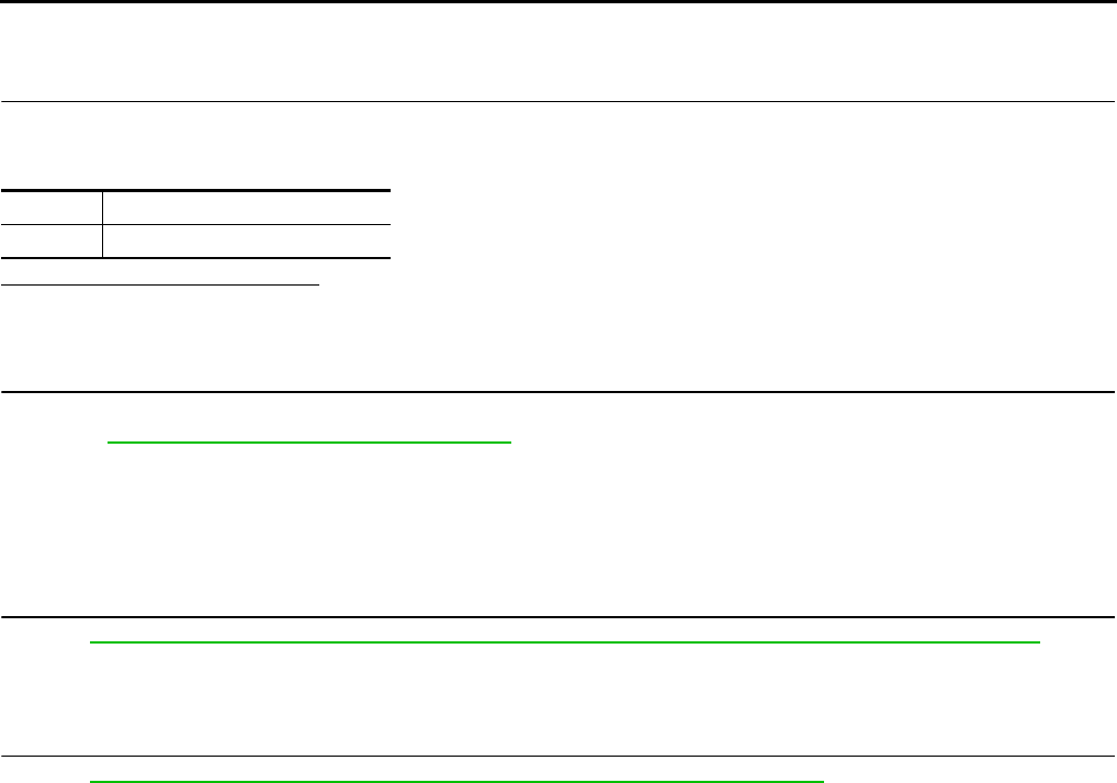
EC-1182
< COMPONENT DIAGNOSIS > [FOR MEXICO]
P2101 ELECTRIC THROTTLE CONTROL FUNCTION
Component Inspection INFOID:0000000004494337
1.CHECK THROTTLE CONTROL MOTOR
1. Disconnect electric throttle control actuator harness connector.
2. Check resistance between electric throttle control actuator terminals as follows.
Is the inspection result normal?
YES >> INSPECTION END
NO >> GO TO 2.
2.REPLACE ELECTRIC THROTTLE CONTROL ACTUATOR
1. Replace electric throttle control actuator.
2. Go to EC-1182, "Special Repair Requirement".
>> INSPECTION END
Special Repair Requirement INFOID:0000000004534428
1.PERFORM THROTTLE VALVE CLOSED POSITION LEARNING
Refer to EC-938, "THROTTLE VALVE CLOSED POSITION LEARNING : Special Repair Requirement"
>> GO TO 2.
2.PERFORM IDLE AIR VOLUME LEARNING
Refer to EC-938, "IDLE AIR VOLUME LEARNING : Special Repair Requirement"
>> END
Terminals Resistance
5 and 6 Approx. 1 - 15 Ω [at 25 °C (77°F)]
Revision: 2008 August 2009 Rogue

P2118 THROTTLE CONTROL MOTOR
EC-1183
< COMPONENT DIAGNOSIS > [FOR MEXICO]
C
D
E
F
G
H
I
J
K
L
M
A
EC
N
P
O
P2118 THROTTLE CONTROL MOTOR
Description INFOID:0000000004494339
The throttle control motor is operated by the ECM and it opens and closes the throttle valve.
The current opening angle of the throttle valve is detected by the throttle position sensor. The throttle position
sensor provides feedback to the ECM, when open/closes the throttle valve in response to driving conditions
via the throttle control motor.
DTC Logic INFOID:0000000004494340
DTC DETECTION LOGIC
DTC CONFIRMATION PROCEDURE
1.PRECONDITIONING
If DTC CONFIRMATION PROCEDURE has been previously conducted, always turn ignition switch OFF and
wait at least 10 seconds before conducting the next test.
>> GO TO 2.
2.PERFORM DTC CONFIRMATION PROCEDURE
1. Turn ignition switch ON and wait at least 2 seconds.
2. Start engine and let it idle for 5 seconds.
3. Check DTC.
Is DTC detected?
YES >> Go to EC-1183, "Diagnosis Procedure".
NO >> INSPECTION END
Diagnosis Procedure INFOID:0000000004494341
1.CHECK GROUND CONNECTION
1. Turn ignition switch OFF.
2. Check ground connection E21. Refer to Ground Inspection in GI-44, "Circuit Inspection".
Is the inspection result normal?
YES >> GO TO 2.
NO >> Repair or replace ground connection.
2.CHECK THROTTLE CONTROL MOTOR OUTPUT SIGNAL CIRCUIT FOR OPEN AND SHORT
1. Disconnect electric throttle control actuator harness connector.
2. Disconnect ECM harness connector.
3. Check the continuity between electric throttle control actuator harness connector and ECM harness con-
nector.
DTC No. Trouble diagnosis name DTC detecting condition Possible cause
P2118 Throttle control motor
circuit short ECM detects short in both circuits between
ECM and throttle control motor.
• Harness or connectors
(Throttle control motor circuit is shorted.)
• Electric throttle control actuator
(Throttle control motor)
Electric throttle control actuator ECM Continuity
Connector Terminal Connector Terminal
F29
5
F7
5 Not existed
6 Existed
65 Existed
6 Not existed
Revision: 2008 August 2009 Rogue

EC-1184
< COMPONENT DIAGNOSIS > [FOR MEXICO]
P2118 THROTTLE CONTROL MOTOR
4. Also check harness for short to ground and short to power.
Is the inspection result normal?
YES >> GO TO 3.
NO >> Repair or replace.
3.CHECK THROTTLE CONTROL MOTOR
Refer to EC-1184, "Component Inspection".
Is the inspection result normal?
YES >> GO TO 4.
NO >> GO TO 5.
4.CHECK INTERMITTENT INCIDENT
Refer to GI-41, "Intermittent Incident".
Is the inspection result normal?
YES >> GO TO 5.
NO >> Repair or replace harness or connectors.
5.REPLACE ELECTRIC THROTTLE CONTROL ACTUATOR
1. Replace electric throttle control actuator.
2. Go to EC-1184, "Special Repair Requirement".
>> INSPECTION END
Component Inspection INFOID:0000000004534646
1.CHECK THROTTLE CONTROL MOTOR
1. Disconnect electric throttle control actuator harness connector.
2. Check resistance between electric throttle control actuator terminals as follows.
Is the inspection result normal?
YES >> INSPECTION END
NO >> GO TO 2.
2.REPLACE ELECTRIC THROTTLE CONTROL ACTUATOR
1. Replace electric throttle control actuator.
2. Go to EC-1182, "Special Repair Requirement".
>> INSPECTION END
Special Repair Requirement INFOID:0000000004534444
1.PERFORM THROTTLE VALVE CLOSED POSITION LEARNING
Refer to EC-938, "THROTTLE VALVE CLOSED POSITION LEARNING : Special Repair Requirement"
>> GO TO 2.
2.PERFORM IDLE AIR VOLUME LEARNING
Refer to EC-938, "IDLE AIR VOLUME LEARNING : Special Repair Requirement"
>> END
Terminals Resistance
5 and 6 Approx. 1 - 15 Ω [at 25 °C (77°F)]
Revision: 2008 August 2009 Rogue

P2119 ELECTRIC THROTTLE CONTROL ACTUATOR
EC-1185
< COMPONENT DIAGNOSIS > [FOR MEXICO]
C
D
E
F
G
H
I
J
K
L
M
A
EC
N
P
O
P2119 ELECTRIC THROTTLE CONTROL ACTUATOR
Description INFOID:0000000004494344
Electric throttle control actuator consists of throttle control motor, throttle position sensor, etc.
The throttle control motor is operated by the ECM and it opens and closes the throttle valve.
The throttle position sensor detects the throttle valve position, and sends the voltage signals to the ECM. The
ECM judges the current opening angle of the throttle valve from these signals opens/closes the throttle valve
in response to driving conditions via the throttle control motor.
DTC Logic INFOID:0000000004494345
DTC DETECTION LOGIC
DTC CONFIRMATION PROCEDURE
1.PRECONDITIONING
If DTC CONFIRMATION PROCEDURE has been previously conducted, always turn ignition switch OFF and
wait at least 10 seconds before conducting the next test.
>> GO TO 2.
2.PERFORM DTC CONFIRMATION PROCEDURE FOR MALFUNCTION A AND B
1. Turn ignition switch ON and wait at least 1 second.
2. Set selector lever to D position and wait at least 3 seconds.
3. Set selector lever to P position.
4. Turn ignition switch OFF and wait at least 10 seconds.
5. Turn ignition switch ON and wait at least 1 second.
6. Set selector lever to D position and wait at least 3 seconds.
7. Set selector lever to P position.
8. Turn ignition switch OFF, wait at least 10 seconds, and then turn ON.
9. Check DTC.
Is DTC detected?
YES >> Go to EC-1185, "Diagnosis Procedure".
NO >> GO TO 3.
3.PERFORM DTC CONFIRMATION PROCEDURE FOR MALFUNCTION C
1. Turn ignition switch ON and wait at least 1 second.
2. Set selector lever to D position and wait at least 3 seconds.
3. Set selector lever to N or P position.
4. Start engine and let it idle for 3 seconds.
5. Check DTC.
Is DTC detected?
YES >> Go to EC-1185, "Diagnosis Procedure".
NO >> INSPECTION END
Diagnosis Procedure INFOID:0000000004534645
1.CHECK ELECTRIC THROTTLE CONTROL ACTUATOR VISUALLY
DTC No. Trouble diagnosis name DTC detecting condition Possible cause
P2119 Electric throttle control
actuator
A) Electric throttle control actuator does not func-
tion properly due to the return spring malfunc-
tion.
• Electric throttle control actuator
B) Throttle valve opening angle in fail-safe mode is
not in specified range.
C) ECM detects that the throttle valve is stuck
open.
Revision: 2008 August 2009 Rogue
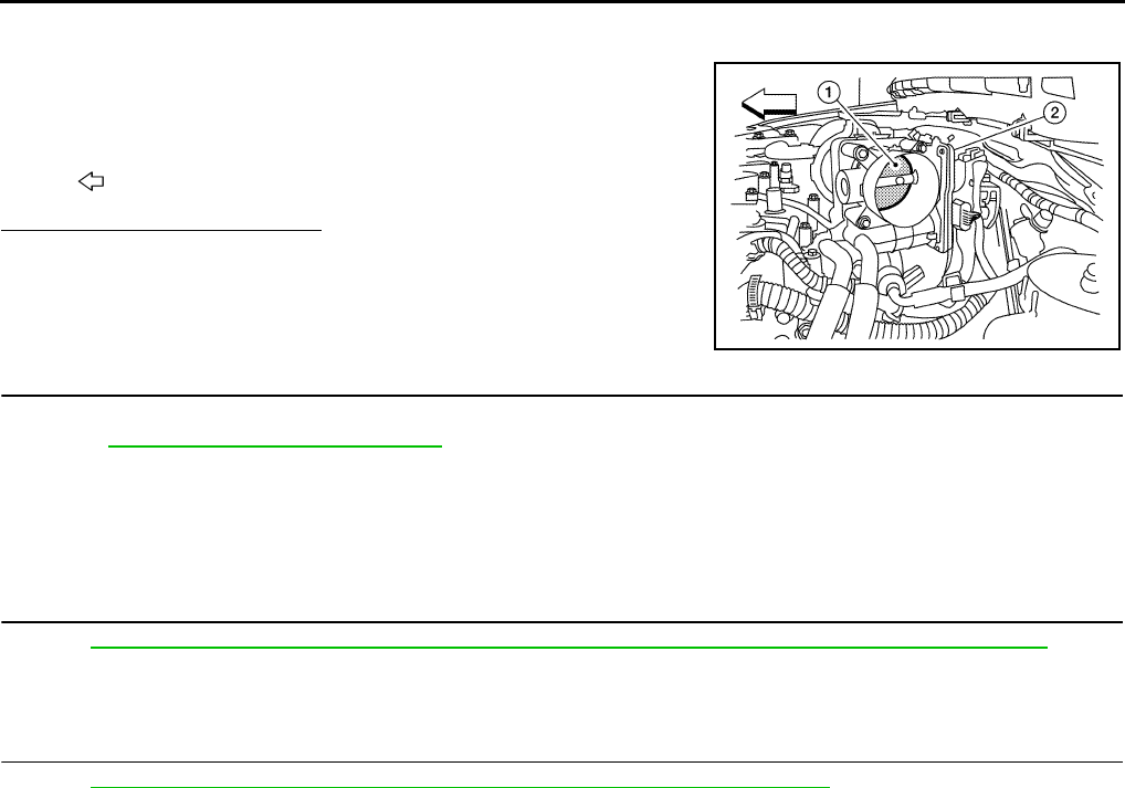
EC-1186
< COMPONENT DIAGNOSIS > [FOR MEXICO]
P2119 ELECTRIC THROTTLE CONTROL ACTUATOR
1. Turn ignition switch OFF.
2. Remove the intake air duct.
3. Check if foreign matter is caught between the throttle valve (1)
and the housing.
Is the inspection result normal?
YES >> GO TO 2.
NO >> Remove the foreign matter and clean the electric throttle
control actuator inside.
2.REPLACE ELECTRIC THROTTLE CONTROL ACTUATOR
1. Replace electric throttle control actuator.
2. Go to EC-1157, "Diagnosis Procedure".
>> INSPECTION END
Special Repair Requirement INFOID:0000000004534445
1.PERFORM THROTTLE VALVE CLOSED POSITION LEARNING
Refer to EC-938, "THROTTLE VALVE CLOSED POSITION LEARNING : Special Repair Requirement"
>> GO TO 2.
2.PERFORM IDLE AIR VOLUME LEARNING
Refer to EC-938, "IDLE AIR VOLUME LEARNING : Special Repair Requirement"
>> END
2. Electric throttle control actuator
: Vehicle front
ALBIA0061ZZ
Revision: 2008 August 2009 Rogue
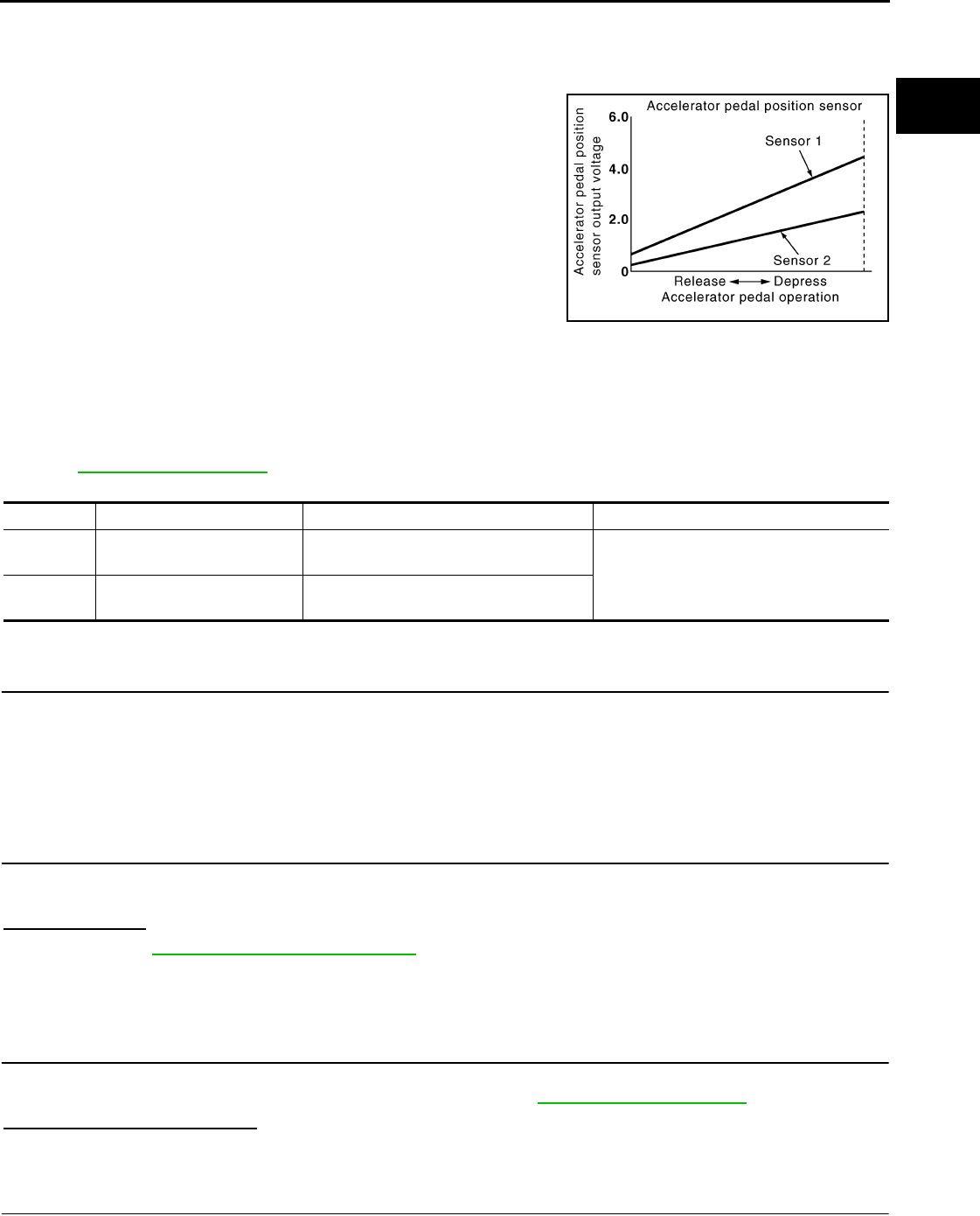
P2122, P2123 APP SENSOR
EC-1187
< COMPONENT DIAGNOSIS > [FOR MEXICO]
C
D
E
F
G
H
I
J
K
L
M
A
EC
N
P
O
P2122, P2123 APP SENSOR
Description INFOID:0000000004494348
The accelerator pedal position sensor is installed on the upper end
of the accelerator pedal assembly. The sensor detects the accelera-
tor position and sends a signal to the ECM.
Accelerator pedal position sensor has two sensors. These sensors
are a kind of potentiometer which transform the accelerator pedal
position into output voltage, and emit the voltage signals to the ECM.
The ECM judges the current opening angle of the accelerator pedal
from these signals and controls the throttle control motor based on
these signals.
Idle position of the accelerator pedal is determined by the ECM
receiving the signal from the accelerator pedal position sensor. The
ECM uses this signal for engine operations such as fuel cut.
DTC Logic INFOID:0000000004494349
DTC DETECTION LOGIC
NOTE:
If DTC P2122 or P2123 is displayed with DTC P0643, first perform the trouble diagnosis for DTC P0643.
Refer to EC-1147, "DTC Logic".
DTC CONFIRMATION PROCEDURE
1.PRECONDITIONING
If DTC CONFIRMATION PROCEDURE has been previously conducted, always turn ignition switch OFF and
wait at least 10 seconds before conducting the next test.
TESTING CONDITION:
Before performing the following procedure, confirm that battery voltage is more than 8V at idle.
>> GO TO 2.
2.PERFORM DTC CONFIRMATION PROCEDURE
1. Start engine and let it idle for 1 second.
2. Check DTC.
Is DTC detected?
YES >> Go to EC-1187, "Diagnosis Procedure".
NO >> INSPECTION END
Diagnosis Procedure INFOID:0000000004494350
1.CHECK GROUND CONNECTION
1. Turn ignition switch OFF.
2. Check ground connection E21. Refer to Ground Inspection in GI-44, "Circuit Inspection".
Is the inspection result normal?
YES >> GO TO 2.
NO >> Repair or replace ground connection.
2.CHECK APP SENSOR 1 POWER SUPPLY CIRCUIT
1. Disconnect accelerator pedal position (APP) sensor harness connector.
PBIB1741E
DTC No. Trouble diagnosis name DTC detecting condition Possible cause
P2122 Accelerator pedal position
sensor 1 circuit low input
An excessively low voltage from the APP
sensor 1 is sent to ECM. • Harness or connectors
(APP sensor 1 circuit is open or shorted.)
• Accelerator pedal position sensor
(APP sensor 1)
P2123 Accelerator pedal position
sensor 1 circuit high input
An excessively high voltage from the APP
sensor 1 is sent to ECM.
Revision: 2008 August 2009 Rogue

EC-1188
< COMPONENT DIAGNOSIS > [FOR MEXICO]
P2122, P2123 APP SENSOR
2. Turn ignition switch ON.
3. Check the voltage between APP sensor harness connector and ground.
Is the inspection result normal?
YES >> GO TO 3.
NO >> Repair open circuit or short to ground or short to power in harness or connectors.
3.CHECK APP SENSOR 1 GROUND CIRCUIT FOR OPEN AND SHORT
1. Turn ignition switch OFF.
2. Disconnect ECM harness connector.
3. Check the continuity between APP sensor harness connector and ECM harness connector.
4. Also check harness for short to ground and short to power.
Is the inspection result normal?
YES >> GO TO 4.
NO >> Repair open circuit or short to ground or short to power in harness or connectors.
4.CHECK APP SENSOR INPUT SIGNAL CIRCUIT FOR OPEN AND SHORT
1. Check the continuity between APP sensor harness connector and ECM harness connector.
2. Also check harness for short to ground and short to power.
Is the inspection result normal?
YES >> GO TO 5.
NO >> Repair open circuit or short to ground or short to power in harness or connectors.
5.CHECK APP SENSOR
Refer to EC-1189, "Component Inspection".
Is the inspection result normal?
YES >> GO TO 7.
NO >> GO TO 6.
6.REPLACE ACCELERATOR PEDAL ASSEMBLY
1. Replace accelerator pedal assembly.
2. Go to EC-1189, "Special Repair Requirement".
>> INSPECTION END
7.CHECK INTERMITTENT INCIDENT
Refer to GI-41, "Intermittent Incident".
>> INSPECTION END
APP sensor Ground Voltage
Connector Terminal
E110 4 Ground Approx. 5 V
APP sensor ECM Continuity
Connector Terminal Connector Terminal
E110 2 E16 84 Existed
APP sensor ECM Continuity
Connector Terminal Connector Terminal
E110 3 E16 81 Existed
Revision: 2008 August 2009 Rogue
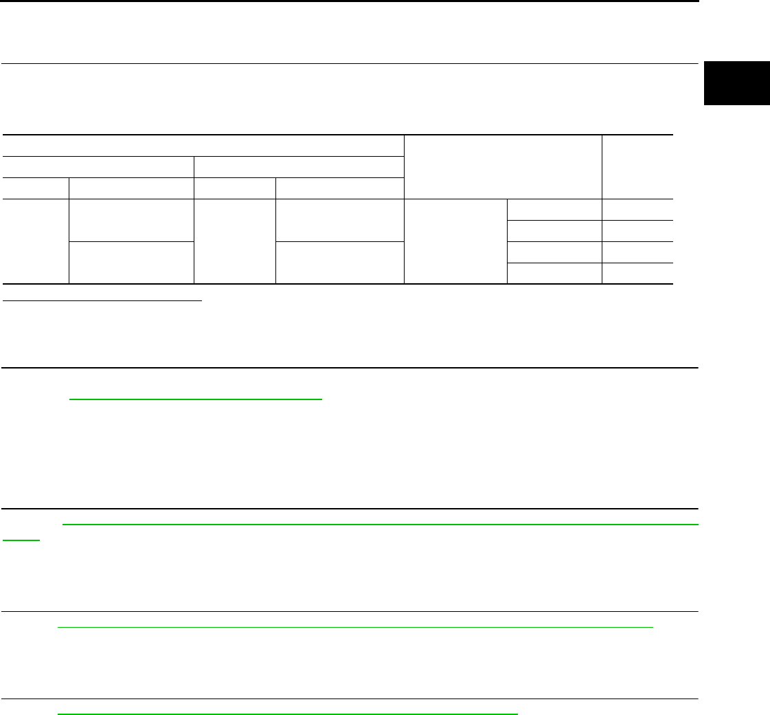
P2122, P2123 APP SENSOR
EC-1189
< COMPONENT DIAGNOSIS > [FOR MEXICO]
C
D
E
F
G
H
I
J
K
L
M
A
EC
N
P
O
Component Inspection INFOID:0000000004494351
1.CHECK ACCELERATOR PEDAL POSITION SENSOR
1. Reconnect all harness connectors disconnected.
2. Turn ignition switch ON.
3. Check the voltage between ECM harness connector terminals.
Is the inspection result normal?
YES >> INSPECTION END
NO >> GO TO 2.
2.REPLACE ACCELERATOR PEDAL ASSEMBLY
1. Replace accelerator pedal assembly.
2. Go to EC-1189, "Special Repair Requirement".
>> INSPECTION END
Special Repair Requirement INFOID:0000000004494352
1.PERFORM ACCELERATOR PEDAL RELEASED POSITION LEARNING
Refer to EC-937, "ACCELERATOR PEDAL RELEASED POSITION LEARNING : Special Repair Require-
ment".
>> GO TO 2.
2.PERFORM THROTTLE VALVE CLOSED POSITION LEARNING
Refer to EC-938, "THROTTLE VALVE CLOSED POSITION LEARNING : Special Repair Requirement".
>> GO TO 3.
3.PERFORM IDLE AIR VOLUME LEARNING
Refer to EC-938, "IDLE AIR VOLUME LEARNING : Special Repair Requirement".
>> END
ECM
Condition Voltage+−
Connector Terminal Connector Terminal
E16
81
(APP sensor 1 signal) E16
84
(Sensor ground) Accelerator pedal
Fully released 0.6 - 0.9 V
Fully depressed 3.9 - 4.7 V
82
(APP sensor 2 signal)
100
(Sensor ground)
Fully released 0.3 - 0.6 V
Fully depressed 1.95 - 2.4 V
Revision: 2008 August 2009 Rogue
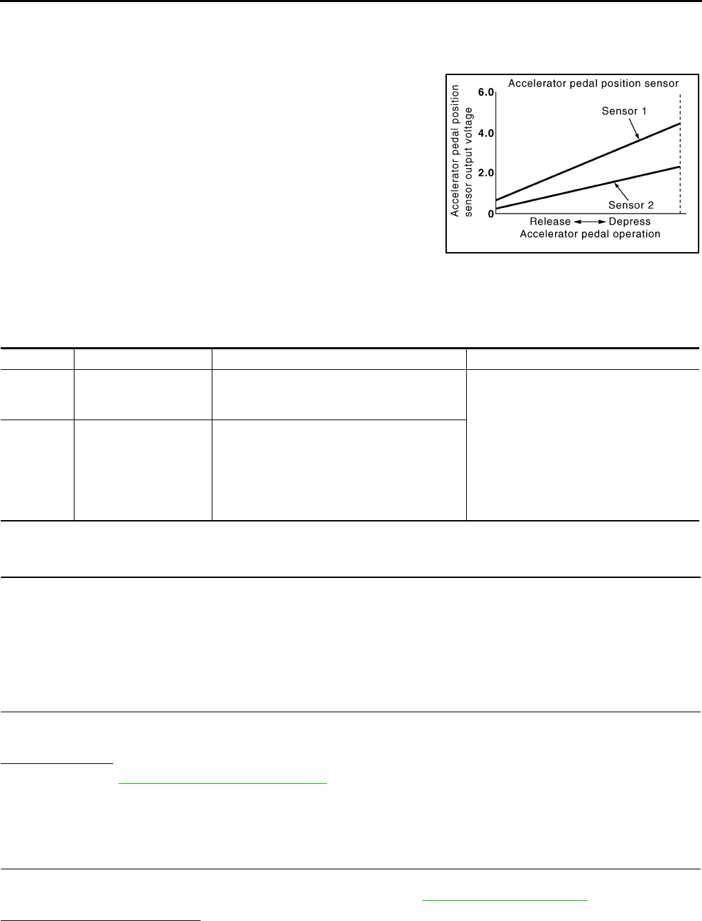
EC-1190
< COMPONENT DIAGNOSIS > [FOR MEXICO]
P2127, P2128 APP SENSOR
P2127, P2128 APP SENSOR
Description INFOID:0000000004534681
The accelerator pedal position sensor is installed on the upper end
of the accelerator pedal assembly. The sensor detects the accelera-
tor position and sends a signal to the ECM.
Accelerator pedal position sensor has two sensors. These sensors
are a kind of potentiometer which transform the accelerator pedal
position into output voltage, and emit the voltage signals to the ECM.
The ECM judges the current opening angle of the accelerator pedal
from these signals and controls the throttle control motor based on
these signals.
Idle position of the accelerator pedal is determined by the ECM
receiving the signal from the accelerator pedal position sensor. The
ECM uses this signal for engine operations such as fuel cut.
DTC Logic INFOID:0000000004494354
DTC DETECTION LOGIC
DTC CONFIRMATION PROCEDURE
1.PRECONDITIONING
If DTC CONFIRMATION PROCEDURE has been previously conducted, always turn ignition switch OFF and
wait at least 10 seconds before conducting the next test.
TESTING CONDITION:
Before performing the following procedure, confirm that battery voltage is more than 8V at idle.
>> GO TO 2.
2.PERFORM DTC CONFIRMATION PROCEDURE
1. Start engine and let it idle for 1 second.
2. Check DTC.
Is DTC detected?
YES >> Go to EC-1190, "Diagnosis Procedure".
NO >> INSPECTION END
Diagnosis Procedure INFOID:0000000004494355
1.CHECK GROUND CONNECTION
1. Turn ignition switch OFF.
2. Check ground connection E21. Refer to Ground Inspection in GI-44, "Circuit Inspection".
Is the inspection result normal?
YES >> GO TO 2.
NO >> Repair or replace ground connection.
PBIB1741E
DTC No. Trouble diagnosis name DTC detecting condition Possible cause
P2127
Accelerator pedal posi-
tion sensor 2 circuit low
input
An excessively low voltage from the APP sen-
sor 2 is sent to ECM.
• Harness or connectors
(APP sensor 2 circuit is open or shorted.)
[Crankshaft position sensor (POS) circuit
is shorted.]
(Refrigerant pressure sensor circuit is
shorted.)
• Accelerator pedal position sensor
(APP sensor 2)
• Crankshaft position sensor (POS)
• Refrigerant pressure sensor
P2128
Accelerator pedal posi-
tion sensor 2 circuit high
input
An excessively high voltage from the APP sen-
sor 2 is sent to ECM.
Revision: 2008 August 2009 Rogue

P2127, P2128 APP SENSOR
EC-1191
< COMPONENT DIAGNOSIS > [FOR MEXICO]
C
D
E
F
G
H
I
J
K
L
M
A
EC
N
P
O
2.CHECK APP SENSOR 2 POWER SUPPLY CIRCUIT-I
1. Disconnect accelerator pedal position (APP) sensor harness connector.
2. Turn ignition switch ON.
3. Check the voltage between APP sensor harness connector and ground.
Is the inspection result normal?
YES >> GO TO 6.
NO >> GO TO 3.
3.CHECK APP SENSOR 2 POWER SUPPLY CIRCUIT-II
1. Turn ignition switch OFF.
2. Disconnect ECM harness connector.
3. Check the continuity between APP sensor harness connector and ECM harness connector.
Is the inspection result normal?
YES >> GO TO 4.
NO >> Repair open circuit.
4.CHECK SENSOR POWER SUPPLY CIRCUIT
Check harness for short to power and short to ground, between the following terminals.
Is the inspection result normal?
YES >> GO TO 5.
NO >> Repair short to ground or short to power in harness or connectors.
5.CHECK COMPONENT
Check the following.
• Crankshaft position sensor (POS) (Refer to EC-1123, "Component Inspection".)
• Refrigerant pressure sensor (Refer to EC-873, "Diagnosis Procedure".)
Is the inspection result normal?
YES >> GO TO 10.
NO >> Replace malfunctioning component.
6.CHECK APP SENSOR 2 GROUND CIRCUIT FOR OPEN AND SHORT
1. Turn ignition switch OFF.
2. Disconnect ECM harness connector.
3. Check the continuity between APP sensor harness connector and ECM harness connector.
APP sensor Ground Voltage
Connector Terminal
E110 5 Ground Approx. 5 V
APP sensor ECM Continuity
Connector Terminal Connector Terminal
E110 5 E16 87 Existed
ECM Sensor
Connector Terminal Name Connector Terminal
F8 72 Refrigerant pressure sensor E49 3
76 CKP sensor (POS) F20 1
E16 87 APP sensor E110 5
APP sensor ECM Continuity
Connector Terminal Connector Terminal
E110 1 E16 100 Existed
Revision: 2008 August 2009 Rogue

EC-1192
< COMPONENT DIAGNOSIS > [FOR MEXICO]
P2127, P2128 APP SENSOR
4. Also check harness for short to ground and short to power.
Is the inspection result normal?
YES >> GO TO 7.
NO >> Repair open circuit or short to ground or short to power in harness or connectors.
7.CHECK APP SENSOR 2 INPUT SIGNAL CIRCUIT FOR OPEN AND SHORT
1. Check the continuity between APP sensor harness connector and ECM harness connector.
2. Also check harness for short to ground and short to power.
Is the inspection result normal?
YES >> GO TO 8.
NO >> Repair open circuit or short to ground or short to power in harness or connectors.
8.CHECK APP SENSOR
Refer to EC-1192, "Component Inspection".
Is the inspection result normal?
YES >> GO TO 10.
NO >> GO TO 9.
9.REPLACE ACCELERATOR PEDAL ASSEMBLY
1. Replace accelerator pedal assembly. Refer to ACC-3, "Removal and Installation".
2. Go to EC-1193, "Special Repair Requirement".
>> INSPECTION END
10.CHECK INTERMITTENT INCIDENT
Refer to GI-41, "Intermittent Incident".
>> INSPECTION END
Component Inspection INFOID:0000000004534682
1.CHECK ACCELERATOR PEDAL POSITION SENSOR
1. Reconnect all harness connectors disconnected.
2. Turn ignition switch ON.
3. Check the voltage between ECM harness connector terminals.
Is the inspection result normal?
YES >> INSPECTION END
NO >> GO TO 2.
2.REPLACE ACCELERATOR PEDAL ASSEMBLY
1. Replace accelerator pedal assembly.
APP sensor ECM Continuity
Connector Terminal Connector Terminal
E110 6 E16 82 Existed
ECM
Condition Voltage+−
Connector Terminal Connector Terminal
E16
81
(APP sensor 1 signal) E16
84
(Sensor ground) Accelerator pedal
Fully released 0.6 - 0.9 V
Fully depressed 3.9 - 4.7 V
82
(APP sensor 2 signal)
100
(Sensor ground)
Fully released 0.3 - 0.6 V
Fully depressed 1.95 - 2.4 V
Revision: 2008 August 2009 Rogue

P2127, P2128 APP SENSOR
EC-1193
< COMPONENT DIAGNOSIS > [FOR MEXICO]
C
D
E
F
G
H
I
J
K
L
M
A
EC
N
P
O
2. Go to EC-1193, "Special Repair Requirement".
>> INSPECTION END
Special Repair Requirement INFOID:0000000004534688
1.PERFORM ACCELERATOR PEDAL RELEASED POSITION LEARNING
Refer to EC-937, "ACCELERATOR PEDAL RELEASED POSITION LEARNING : Special Repair Require-
ment".
>> GO TO 2.
2.PERFORM THROTTLE VALVE CLOSED POSITION LEARNING
Refer to EC-938, "THROTTLE VALVE CLOSED POSITION LEARNING : Special Repair Requirement".
>> GO TO 3.
3.PERFORM IDLE AIR VOLUME LEARNING
Refer to EC-938, "IDLE AIR VOLUME LEARNING : Special Repair Requirement".
>> END
Revision: 2008 August 2009 Rogue

EC-1194
< COMPONENT DIAGNOSIS > [FOR MEXICO]
P2135 TP SENSOR
P2135 TP SENSOR
Description INFOID:0000000004534415
Electric throttle control actuator consists of throttle control motor,
throttle position sensor, etc. The throttle position sensor responds to
the throttle valve movement.
The throttle position sensor has two sensors. These sensors are a
kind of potentiometer which transform the throttle valve position into
output voltage, and emit the voltage signals to the ECM. The ECM
judges the current opening angle of the throttle valve from these sig-
nals and controls the throttle valve opening angle in response to
driving conditions via the throttle control motor.
DTC Logic INFOID:0000000004494359
DTC DETECTION LOGIC
NOTE:
If DTC P2135 is displayed with DTC P0643, first perform the trouble diagnosis for DTC P0643. Refer to
EC-1147, "DTC Logic".
DTC CONFIRMATION PROCEDURE
1.PRECONDITIONING
If DTC CONFIRMATION PROCEDURE has been previously conducted, always turn ignition switch OFF and
wait at least 10 seconds before conducting the next test.
TESTING CONDITION:
Before performing the following procedure, confirm that battery voltage is more than 8V at idle.
>> GO TO 2.
2.PERFORM DTC CONFIRMATION PROCEDURE
1. Start engine and let it idle for 1 second.
2. Check DTC.
Is DTC detected?
YES >> Go to EC-1194, "Diagnosis Procedure".
NO >> INSPECTION END
Diagnosis Procedure INFOID:0000000004494360
1.CHECK GROUND CONNECTION
1. Turn ignition switch OFF.
2. Check ground connection E21. Refer to Ground Inspection in GI-44, "Circuit Inspection".
Is the inspection result normal?
YES >> GO TO 2.
NO >> Repair or replace ground connection.
2.CHECK THROTTLE POSITION SENSOR POWER SUPPLY CIRCUIT-I
1. Disconnect electric throttle control actuator harness connector.
PBIB0145E
DTC No. Trouble diagnosis name DTC detecting condition Possible cause
P2135
Throttle position sensor
circuit range/perfor-
mance
Rationally incorrect voltage is sent to ECM
compared with the signals from TP sensor 1
and TP sensor 2.
• Harness or connector
(TP sensor 1 or 2 circuit is open or short-
ed.)
• Electric throttle control actuator
(TP sensor 1 or 2)
Revision: 2008 August 2009 Rogue

P2135 TP SENSOR
EC-1195
< COMPONENT DIAGNOSIS > [FOR MEXICO]
C
D
E
F
G
H
I
J
K
L
M
A
EC
N
P
O
2. Turn ignition switch ON.
3. Check the voltage between electric throttle control actuator harness connector and ground.
Is the inspection result normal?
YES >> GO TO 3.
NO >> Repair open circuit or short to ground or short to power in harness or connectors.
3.CHECK THROTTLE POSITION SENSOR POWER SUPPLY CIRCUIT-II
1. Turn ignition switch OFF.
2. Disconnect ECM harness connector.
3. Check the continuity between electric throttle control actuator harness connector and ground.
Is the inspection result normal?
YES >> GO TO 4.
NO >> Repair open circuit.
4.CHECK THROTTLE POSITION SENSOR GROUND CIRCUIT FOR OPEN AND SHORT
1. Turn ignition switch OFF.
2. Disconnect ECM harness connector.
3. Check the continuity between electric throttle control actuator harness connector and ground.
4. Also check harness for short to ground and short to power.
Is the inspection result normal?
YES >> GO TO 5.
NO >> Repair open circuit or short to ground or short to power in harness or connectors.
5.CHECK SENSOR POWER SUPPLY CIRCUIT
Check harness for short to power and short to ground, between the following terminals.
Is the inspection result normal?
YES >> GO TO 6.
NO >> Repair short to ground or short to power in harness or connectors.
6.CHECK THROTTLE POSITION SENSOR INPUT SIGNAL CIRCUIT FOR OPEN AND SHORT
1. Check the continuity between electric throttle control actuator harness connector and ground.
Electric throttle control actuator Ground Voltage
Connector Terminal
F29 1 Ground Approx. 5 V
Electric throttle control actuator ECM Continuity
Connector Terminal Connector Terminal
F29 1 F8 47 Existed
Electric throttle control actuator ECM Continuity
Connector Terminal Connector Terminal
F29 4 F8 36 Existed
ECM Sensor
Connector Terminal Name Connector Terminal
F8 47 Electric throttle control actuator F29 1
59 CMP sensor (PHASE) F26 1
E16 83 APP sensor E110 4
Revision: 2008 August 2009 Rogue

EC-1196
< COMPONENT DIAGNOSIS > [FOR MEXICO]
P2135 TP SENSOR
2. Also check harness for short to ground and short to power.
Is the inspection result normal?
YES >> GO TO 7.
NO >> Repair open circuit or short to ground or short to power in harness or connectors.
7.CHECK THROTTLE POSITION SENSOR
Refer to EC-1196, "Component Inspection".
Is the inspection result normal?
YES >> GO TO 9.
NO >> GO TO 8.
8.REPLACE ELECTRIC THROTTLE CONTROL ACTUATOR
1. Replace electric throttle control actuator.
2. Go to EC-1197, "Special Repair Requirement".
>> INSPECTION END
9.CHECK INTERMITTENT INCIDENT
Refer to GI-41, "Intermittent Incident".
>> INSPECTION END
Component Inspection INFOID:0000000004534416
1.CHECK THROTTLE POSITION SENSOR
1. Turn ignition switch OFF.
2. Reconnect all harness connectors disconnected.
3. Perform EC-938, "THROTTLE VALVE CLOSED POSITION LEARNING : Special Repair Requirement".
4. Turn ignition switch ON.
5. Set selector lever to the D position.
6. Check the voltage between ECM harness connector terminals.
Is the inspection result normal?
YES >> INSPECTION END
NO >> GO TO 2.
2.REPLACE ELECTRIC THROTTLE CONTROL ACTUATOR
1. Replace electric throttle control actuator.
2. Perform EC-1060, "Special Repair Requirement".
Electric throttle control actuator ECM Continuity
Connector Terminal Connector Terminal
F29 2F8 37 Existed
338
ECM
Condition Voltage+−
Connector Terminal Connector Terminal
F8
37
(TP sensor 1
signal) F8 36
(Sensor
ground)
Accelerator pedal
Fully released More than 0.36 V
Fully depressed Less than 4.75 V
38
(TP sensor 2
signal)
Fully released Less than 4.75 V
Fully depressed More than 0.36 V
Revision: 2008 August 2009 Rogue

P2135 TP SENSOR
EC-1197
< COMPONENT DIAGNOSIS > [FOR MEXICO]
C
D
E
F
G
H
I
J
K
L
M
A
EC
N
P
O
>> INSPECTION END
Special Repair Requirement INFOID:0000000004534422
1.PERFORM THROTTLE VALVE CLOSED POSITION LEARNING
Refer to EC-938, "THROTTLE VALVE CLOSED POSITION LEARNING : Special Repair Requirement"
>> GO TO 2.
2.PERFORM IDLE AIR VOLUME LEARNING
Refer to EC-938, "IDLE AIR VOLUME LEARNING : Special Repair Requirement"
>> END
Revision: 2008 August 2009 Rogue
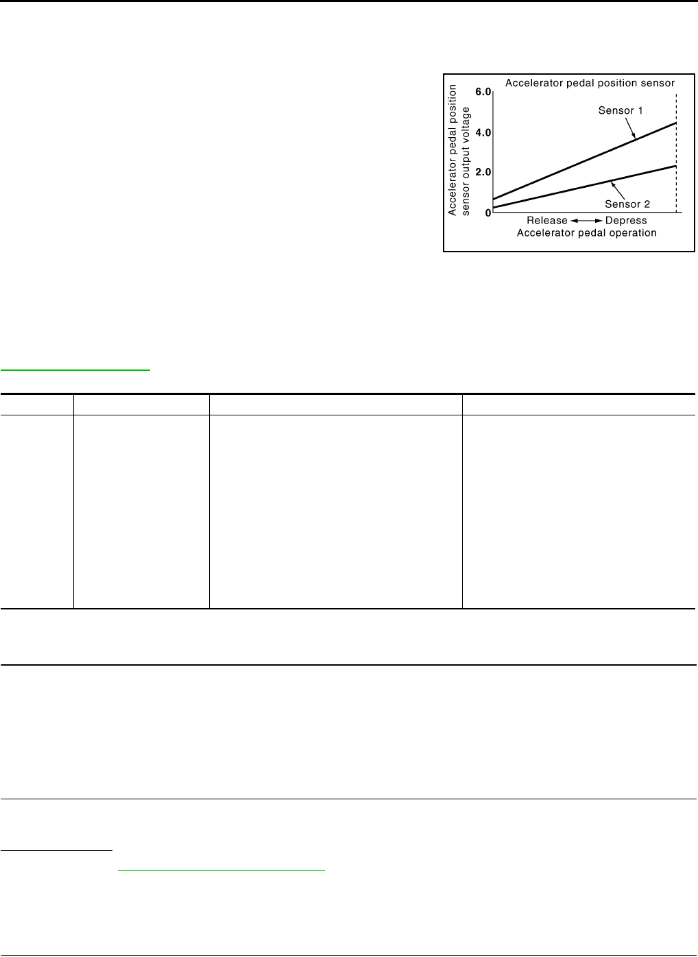
EC-1198
< COMPONENT DIAGNOSIS > [FOR MEXICO]
P2138 APP SENSOR
P2138 APP SENSOR
Description INFOID:0000000004534715
The accelerator pedal position sensor is installed on the upper end
of the accelerator pedal assembly. The sensor detects the accelera-
tor position and sends a signal to the ECM.
Accelerator pedal position sensor has two sensors. These sensors
are a kind of potentiometer which transform the accelerator pedal
position into output voltage, and emit the voltage signals to the ECM.
The ECM judges the current opening angle of the accelerator pedal
from these signals and controls the throttle control motor based on
these signals.
Idle position of the accelerator pedal is determined by the ECM
receiving the signal from the accelerator pedal position sensor. The
ECM uses this signal for engine operations such as fuel cut.
DTC Logic INFOID:0000000004494364
DTC DETECTION LOGIC
NOTE:
If DTC P2138 is displayed with DTC P0643, first perform the trouble diagnosis for DTC P0643. Refer to
EC-1147, "DTC Logic".
DTC CONFIRMATION PROCEDURE
1.PRECONDITIONING
If DTC CONFIRMATION PROCEDURE has been previously conducted, always turn ignition switch OFF and
wait at least 10 seconds before conducting the next test.
TESTING CONDITION:
Before performing the following procedure, confirm that battery voltage is more than 8V at idle.
>> GO TO 2.
2.PERFORM DTC CONFIRMATION PROCEDURE
1. Start engine and let it idle for 1 second.
2. Check DTC.
Is DTC detected?
YES >> Go to EC-1198, "Diagnosis Procedure".
NO >> INSPECTION END
Diagnosis Procedure INFOID:0000000004494365
1.CHECK GROUND CONNECTION
1. Turn ignition switch OFF.
PBIB1741E
DTC No. Trouble diagnosis name DTC detecting condition Possible cause
P2138 Accelerator pedal posi-
tion sensor circuit range/
performance
Rationally incorrect voltage is sent to ECM
compared with the signals from APP sensor 1
and APP sensor 2.
• Harness or connector
(APP sensor 1 or 2 circuit is open or
shorted.)
[Crankshaft position sensor (POS) circuit
is shorted.)
(Refrigerant pressure sensor circuit is
shorted.)
(Tumble control valve position sensor cir-
cuit is shorted.)
• Accelerator pedal position sensor
(APP sensor 1 or 2)
• Crankshaft position sensor (POS)
• Refrigerant pressure sensor
Revision: 2008 August 2009 Rogue

P2138 APP SENSOR
EC-1199
< COMPONENT DIAGNOSIS > [FOR MEXICO]
C
D
E
F
G
H
I
J
K
L
M
A
EC
N
P
O
2. Check ground connection E21. Refer to Ground Inspection in GI-44, "Circuit Inspection".
Is the inspection result normal?
YES >> GO TO 2.
NO >> Repair or replace ground connection.
2.CHECK APP SENSOR 1 POWER SUPPLY CIRCUIT
1. Disconnect accelerator pedal position (APP) sensor harness connector.
2. Turn ignition switch ON.
3. Check the voltage between APP sensor harness connector and ground.
Is the inspection result normal?
YES >> GO TO 3.
NO >> Repair open circuit or short to ground or shot to power in harness or connectors.
3.CHECK APP SENSOR 2 POWER SUPPLY CIRCUIT-I
1. Turn ignition switch ON.
2. Check the voltage between APP sensor harness connector and ground.
Is the inspection result normal?
YES >> GO TO 7.
NO >> GO TO 4.
4.CHECK APP SENSOR 2 POWER SUPPLY CIRCUIT-II
1. Turn ignition switch OFF.
2. Disconnect ECM harness connector.
3. Check the continuity between APP sensor harness connector and ECM harness connector.
Is the inspection result normal?
YES >> GO TO 5.
NO >> Repair open circuit or short to ground or shot to power in harness or connectors.
5.CHECK SENSOR POWER SUPPLY CIRCUIT
Check harness for short to power and short to ground, between the following terminals.
Is the inspection result normal?
YES >> GO TO 6.
NO >> Repair short to ground or short to power in harness or connectors.
6.CHECK COMPONENT
APP sensor Ground Voltage
Connector Terminal
E110 4 Ground Approx. 5 V
APP sensor Ground Voltage
Connector Terminal
E110 5 Ground Approx. 5V
APP sensor ECM Continuity
Connector Terminal Connector Terminal
E110 5 E16 87 Existed
ECM Sensor
Connector Terminal Name Connector Terminal
F8 72 Refrigerant pressure sensor E49 3
76 CKP sensor (POS) F20 1
E16 87 APP sensor E110 5
Revision: 2008 August 2009 Rogue

EC-1200
< COMPONENT DIAGNOSIS > [FOR MEXICO]
P2138 APP SENSOR
Check the following.
• Crankshaft position sensor (POS) (Refer to EC-1123, "Component Inspection".)
• Refrigerant pressure sensor (Refer to EC-1230, "Diagnosis Procedure".)
Is the inspection result normal?
YES >> GO TO 11.
NO >> Replace malfunctioning component.
7.CHECK APP SENSOR GROUND CIRCUIT FOR OPEN AND SHORT
1. Turn ignition switch OFF.
2. Disconnect ECM harness connector.
3. Check the continuity between APP sensor harness connector and ECM harness connector as follows.
4. Also check harness for short to ground and short to power.
Is the inspection result normal?
YES >> GO TO 8.
NO >> Repair open circuit or short to ground or shot to power in harness or connectors.
8.CHECK APP SENSOR INPUT SIGNAL CIRCUIT FOR OPEN AND SHORT
1. Check the continuity between APP sensor harness connector and ECM harness connector as follows.
2. Also check harness for short to ground and short to power.
Is the inspection result normal?
YES >> GO TO 9.
NO >> Repair open circuit or short to ground or shot to power in harness or connectors.
9.CHECK APP SENSOR
Refer to EC-1200, "Component Inspection".
Is the inspection result normal?
YES >> GO TO 11.
NO >> GO TO 10.
10.REPLACE ACCELERATOR PEDAL ASSEMBLY
1. Replace accelerator pedal assembly. Refer to ACC-3, "Removal and Installation".
2. Go to EC-1201, "Special Repair Requirement".
>> INSPECTION END
11.CHECK INTERMITTENT INCIDENT
Refer to GI-41, "Intermittent Incident".
>> INSPECTION END
Component Inspection INFOID:0000000004534716
1.CHECK ACCELERATOR PEDAL POSITION SENSOR
1. Reconnect all harness connectors disconnected.
APP sensor ECM Continuity
Connector Terminal Connector Terminal
E110 2E16 84 Existed
1100
APP sensor ECM Continuity
Connector Terminal Connector Terminal
E110 6E16 82 Existed
381
Revision: 2008 August 2009 Rogue
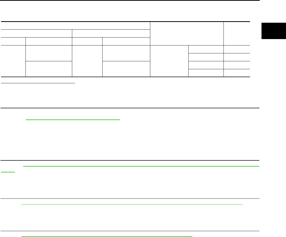
P2138 APP SENSOR
EC-1201
< COMPONENT DIAGNOSIS > [FOR MEXICO]
C
D
E
F
G
H
I
J
K
L
M
A
EC
N
P
O
2. Turn ignition switch ON.
3. Check the voltage between ECM harness connector terminals.
Is the inspection result normal?
YES >> INSPECTION END
NO >> GO TO 2.
2.REPLACE ACCELERATOR PEDAL ASSEMBLY
1. Replace accelerator pedal assembly.
2. Go to EC-1201, "Special Repair Requirement".
>> INSPECTION END
Special Repair Requirement INFOID:0000000004534717
1.PERFORM ACCELERATOR PEDAL RELEASED POSITION LEARNING
Refer to EC-937, "ACCELERATOR PEDAL RELEASED POSITION LEARNING : Special Repair Require-
ment".
>> GO TO 2.
2.PERFORM THROTTLE VALVE CLOSED POSITION LEARNING
Refer to EC-938, "THROTTLE VALVE CLOSED POSITION LEARNING : Special Repair Requirement".
>> GO TO 3.
3.PERFORM IDLE AIR VOLUME LEARNING
Refer to EC-938, "IDLE AIR VOLUME LEARNING : Special Repair Requirement".
>> END
ECM
Condition Voltage+−
Connector Terminal Connector Terminal
E16
81
(APP sensor 1 signal) E16
84
(Sensor ground) Accelerator pedal
Fully released 0.6 - 0.9 V
Fully depressed 3.9 - 4.7 V
82
(APP sensor 2 signal)
100
(Sensor ground)
Fully released 0.3 - 0.6 V
Fully depressed 1.95 - 2.4 V
Revision: 2008 August 2009 Rogue

EC-1202
< COMPONENT DIAGNOSIS > [FOR MEXICO]
P2A00 A/F SENSOR 1
P2A00 A/F SENSOR 1
Description INFOID:0000000004534623
The air fuel ratio (A/F) sensor 1 is a planar one-cell limit current sen-
sor. The sensor element of the A/F sensor 1 is composed an elec-
trode layer, which transports ions. It has a heater in the element.
The sensor is capable of precise measurement = 1, but also in the
lean and rich range. Together with its control electronics, the sensor
outputs a clear, continuous signal throughout a wide range.
The exhaust gas components diffuse through the diffusion layer at
the sensor cell. An electrode layer is applied voltage, and this current
relative oxygen density in lean. Also this current relative hydrocar-
bon density in rich.
Therefore, the A/F sensor 1 is able to indicate air fuel ratio by this
electrode layer of current. In addition, a heater is integrated in the
sensor to ensure the required operating temperature of approxi-
mately 800°C (1,472°F).
DTC Logic INFOID:0000000004494369
DTC DETECTION LOGIC
To judge the malfunction, the A/F signal computed by ECM from the A/F sensor 1 signal is monitored so it will
not shift to LEAN side or RICH side.
DTC CONFIRMATION PROCEDURE
1.PRECONDITIONING
If DTC CONFIRMATION PROCEDURE has been previously conducted, always turn ignition switch OFF and
wait at least 10 seconds before conducting the next test.
TESTING CONDITION:
Before performing the following procedure, confirm that battery voltage is more than 11V at idle.
>> GO TO 2.
2.PERFORM DTC CONFIRMATION PROCEDURE
1. Clear the mixture ratio self-learning value. Refer to EC-940, "MIXTURE RATIO SELF-LEARNING VALUE
CLEAR : Special Repair Requirement".
2. Turn ignition switch OFF and wait at least 10 seconds.
3. Start engine and keep the engine speed between 3,500 and 4,000 rpm for 1 minute under no load.
4. Let engine idle for 1 minute.
5. Keep engine speed between 2,500 and 3,000 rpm for 20 minutes.
6. Check 1st trip DTC$.
JMBIA0112GB
PBIB3354E
DTC No. Trouble diagnosis name DTC detecting condition Possible Cause
P2A00 Air fuel ratio (A/F) sensor 1
circuit range/performance
• The output voltage computed by ECM from the
A/F sensor 1 signal shifts to the lean side for a
specified period.
• The A/F signal computed by ECM from the A/F
sensor 1 signal shifts to the rich side for a spec-
ified period.
• A/F sensor 1
• A/F sensor 1 heater
• Fuel pressure
• Fuel injector
• Intake air leaks
Revision: 2008 August 2009 Rogue

P2A00 A/F SENSOR 1
EC-1203
< COMPONENT DIAGNOSIS > [FOR MEXICO]
C
D
E
F
G
H
I
J
K
L
M
A
EC
N
P
O
Is 1st trip DTC detected?
YES >> Go to EC-1203, "Diagnosis Procedure".
NO >> INSPECTION END
Diagnosis Procedure INFOID:0000000004494370
1.CHECK GROUND CONNECTION
1. Turn ignition switch OFF.
2. Check ground connection E21. Refer to Ground Inspection in GI-44, "Circuit Inspection".
Is the inspection result normal?
YES >> GO TO 2.
NO >> Repair or replace ground connection.
2.RETIGHTEN A/F SENSOR 1
1. Loosen and retighten the A/F sensor 1. Refer to EM-32, "Removal and Installation".
>> GO TO 3.
3.CHECK FOR INTAKE AIR LEAK
1. Start engine and run it at idle.
2. Listen for an intake air leak after the mass air flow sensor.
Is intake air leak detected?
YES >> GO TO 4.
NO >> Repair or replace.
4.CLEAR THE MIXTURE RATIO SELF-LEARNING VALUE
1. Clear the mixture ratio self-learning value. Refer to EC-940, "MIXTURE RATIO SELF-LEARNING VALUE
CLEAR : Special Repair Requirement".
2. Run engine for at least 10 minutes at idle speed.
Is the 1st trip DTC P0171 or P0172 detected? Is it difficult to start engine?
YES >> Perform trouble diagnosis for DTC P0171or P0172. Refer to EC-1102, "DTC Logic" or EC-1106,
"DTC Logic".
NO >> GO TO 5.
5.CHECK HARNESS CONNECTOR
1. Turn ignition switch OFF.
2. Disconnect A/F sensor 1 harness connector.
3. Check harness connector for water.
Is the inspection result normal?
YES >> GO TO 6.
NO >> Repair or replace harness connector.
6.CHECK A/F SENSOR 1 POWER SUPPLY CIRCUIT
1. Turn ignition switch ON.
2. Check the voltage between A/F sensor 1 harness connector and ground.
Is the inspection result normal?
YES >> GO TO 8.
NO >> GO TO 7.
7.DETECT MALFUNCTIONING PART
Water should not exit.
A/F sensor 1 Ground Voltage
Connector Terminal
F27 4 Ground Battery voltage
Revision: 2008 August 2009 Rogue

EC-1204
< COMPONENT DIAGNOSIS > [FOR MEXICO]
P2A00 A/F SENSOR 1
Check the following.
• Harness connectors E6, F123
• IPDM E/R harness connector E14
• 15A fuse (No. 63)
• Harness for open or short between A/F sensor 1 and fuse
>> Repair or replace harness or connectors.
8.CHECK A/F SENSOR 1 INPUT SIGNAL CIRCUIT FOR OPEN AND SHORT
1. Turn ignition switch OFF.
2. Disconnect ECM harness connector.
3. Check the continuity between A/F sensor 1 harness connector and ECM harness connector.
4. Check the continuity between ECM harness connector or A/F sensor 1 harness connector and ground.
5. Also check harness for short to power.
Is the inspection result normal?
YES >> GO TO 9.
NO >> Repair open circuit or short to ground or short to power in harness or connectors.
9.CHECK A/F SENSOR 1 HEATER
Refer to EC-1033, "Component Inspection".
Is the inspection result normal?
YES >> GO TO 10.
NO >> GO TO 11.
10.CHECK INTERMITTENT INCIDENT
Perform GI-41, "Intermittent Incident".
Is the inspection result normal?
YES >> GO TO 11.
NO >> Repair or replace.
11.REPLACE AIR FUEL RATIO (A/F) SENSOR 1
Replace air fuel ratio (A/F) sensor 1.
CAUTION:
• Discard any A/F sensor which has been dropped from a height of more than 0.5 m (19.7 in) onto a
hard surface such as a concrete floor; use a new one.
• Before installing new A/F sensor, clean exhaust system threads using oxygen sensor thread cleaner
[commercial service tool (J-43897-18 or J-43897-12)] and approved anti-seize lubricant (commercial
service tool).
Do you have CONSULT-III?
YES >> GO TO 12.
NO >> GO TO 13.
12.CONFIRM A/F ADJUSTMENT DATA
With CONSULT-III
1. Turn ignition switch ON.
A/F sensor 1 ECM Continuity
Connector Terminal Connector Terminal
F27 1F8 45 Existed
249
A/F sensor 1 ECM Ground Continuity
Connector Terminal Connector Terminal
F27 1F8 45 Ground Not existed
249
Revision: 2008 August 2009 Rogue

P2A00 A/F SENSOR 1
EC-1205
< COMPONENT DIAGNOSIS > [FOR MEXICO]
C
D
E
F
G
H
I
J
K
L
M
A
EC
N
P
O
2. Select “A/F ADJ-B1” in “DATA MONITOR” mode with CONSULT-III.
3. Check that “0.000” is displayed on CONSULT-III screen.
Is “0.000” displayed?
YES >> INSPECTION END
NO >> GO TO 13.
13.CLEAR THE MIXTURE RATIO SELF-LEARNING VALUE
Clear the mixture ratio self-learning value. Refer to EC-940, "MIXTURE RATIO SELF-LEARNING VALUE
CLEAR : Special Repair Requirement".
Do you have CONSULT-III?
YES >> GO TO 14.
NO >> INSPECTION END
14.CONFIRM A/F ADJUSTMENT DATA
With CONSULT-III
1. Turn ignition switch ON.
2. Select “A/F ADJ-B1” in “DATA MONITOR” mode with CONSULT-III.
3. Check that “0.000” is displayed on CONSULT-III screen.
>> INSPECTION END
Revision: 2008 August 2009 Rogue
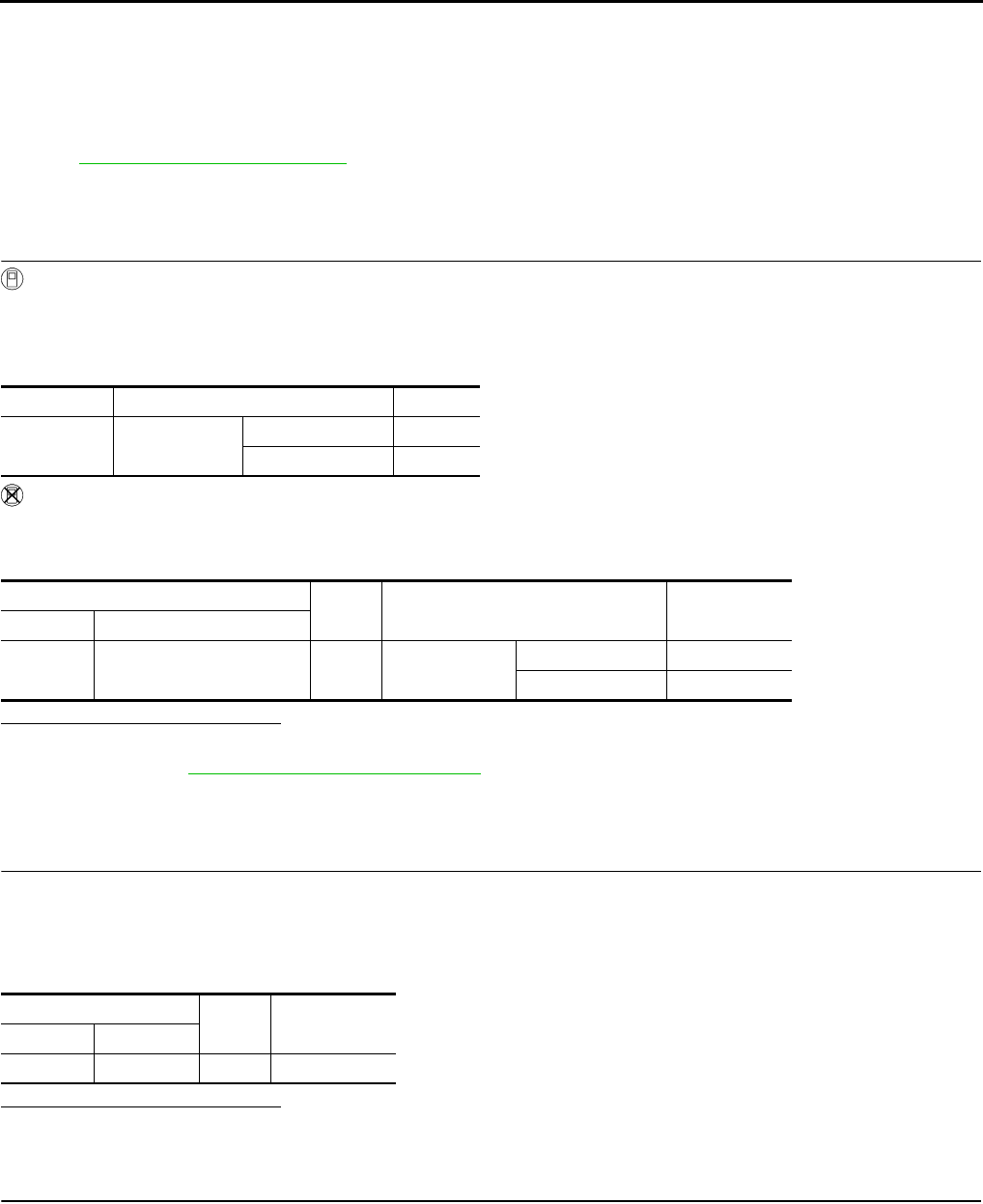
EC-1206
< COMPONENT DIAGNOSIS > [FOR MEXICO]
ASCD BRAKE SWITCH
ASCD BRAKE SWITCH
Description INFOID:0000000004534664
When the brake pedal is depressed, ASCD brake switch is turned OFF and stop lamp switch is turned ON.
ECM detects the state of the brake pedal by those two types of input (ON/OFF signal).
Refer to EC-966, "System Description" for the ASCD function.
Component Function Check INFOID:0000000004494372
1.CHECK FOR ASCD BRAKE SWITCH FUNCTION
With CONSULT-III
1. Turn ignition switch ON.
2. Select “BRAKE SW1” in “DATA MONITOR” mode with CONSULT-III.
3. Check “BRAKE SW1” indication under the following conditions.
Without CONSULT-III
1. Turn ignition switch ON.
2. Check the voltage between ECM harness connector and ground.
Is the inspection result normal?
YES >> INSPECTION END.
NO >> Refer to EC-1206, "Diagnosis Procedure".
Diagnosis Procedure INFOID:0000000004494373
1.CHECK ASCD BRAKE SWITCH POWER SUPPLY CIRCUIT
1. Turn ignition switch OFF.
2. Disconnect ASCD brake switch harness connector.
3. Turn ignition switch ON.
4. Check the voltage between ASCD brake switch harness connector and ground.
Is the inspection result normal?
YES >> GO TO 3.
NO >> GO TO 2.
2.DETECT MALFUNCTIONING PART
Check the following.
• Harness connectors E105, M77
• 10A fuse (No. 1)
• Harness for open or short between ASCD brake switch and fuse
>> Repair open circuit or short to ground or short to power in harness or connectors.
Monitor item Condition Indication
BRAKE SW1 Brake pedal Slightly depressed OFF
Fully released ON
ECM Ground Condition Voltage
Connector Terminal
E16 110
(ASCD brake switch signal) Ground Brake pedal Slightly depressed Approx. 0V
Fully released Battery voltage
ASCD brake switch Ground Voltage
Connector Terminal
E112 1 Ground Battery voltage
Revision: 2008 August 2009 Rogue

ASCD BRAKE SWITCH
EC-1207
< COMPONENT DIAGNOSIS > [FOR MEXICO]
C
D
E
F
G
H
I
J
K
L
M
A
EC
N
P
O
3.CHECK ASCD BRAKE SWITCH INPUT SIGNAL CIRCUIT FOR OPEN AND SHORT
1. Turn ignition switch OFF.
2. Disconnect ECM harness connector.
3. Check the continuity between ASCD brake switch harness connector and ECM harness connector.
4. Also check harness for short to ground and short to power.
Is the inspection result normal?
YES >> GO TO 4.
NO >> Repair open circuit or short to ground or short to power in harness or connectors.
4.CHECK ASCD BRAKE SWITCH
Refer to EC-1207, "Component Inspection (ASCD Brake Switch)".
Is the inspection result normal?
YES >> GO TO 5.
NO >> Replace ASCD brake switch.
5.CHECK INTERMITTENT INCIDENT
Refer to GI-41, "Intermittent Incident".
>> INSPECTION END
Component Inspection (ASCD Brake Switch) INFOID:0000000004534665
1.CHECK ASCD BRAKE SWITCH-I
1. Turn ignition switch OFF.
2. Disconnect ASCD brake switch harness connector.
3. Check the continuity between ASCD brake switch terminals under the following conditions.
Is the inspection result normal?
YES >> INSPECTION END
NO >> GO TO 2.
2.CHECK ASCD BRAKE SWITCH-II
1. Adjust ASCD brake switch installation. Refer to BR-9, "Inspection and Adjustment".
2. Check the continuity between ASCD brake switch terminals under the following conditions.
Is the inspection result normal?
YES >> INSPECTION END
NO >> Replace ASCD brake switch.
ASCD brake switch ECM Continuity
Connector Terminal Connector Terminal
E112 2 E16 110 Existed
Terminals Condition Continuity
1 and 2 Brake pedal Fully released Existed
Slightly depressed Not existed
Terminals Condition Continuity
1 and 2 Brake pedal Fully released Existed
Slightly depressed Not existed
Revision: 2008 August 2009 Rogue
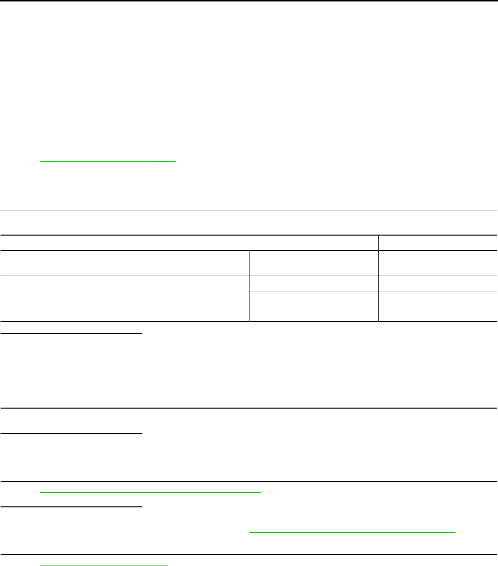
EC-1208
< COMPONENT DIAGNOSIS > [FOR MEXICO]
ASCD INDICATOR
ASCD INDICATOR
Description INFOID:0000000004494375
ASCD indicator lamp illuminates to indicate ASCD operation status. Lamp has two indicators, CRUISE and
SET, and is integrated in combination meter.
CRUISE lamp illuminates when MAIN switch on ASCD steering switch is turned ON to indicated that ASCD
system is ready for operation.
SET lamp illuminates when the following conditions are met.
• CRUISE lamp is illuminated.
• SET/COAST switch on ASCD steering switch is turned ON while vehicle speed is within the range of the
ASCD setting.
SET lamp remains lit during ASCD control.
Refer to EC-966, "System Description" for the ASCD function.
Component Function Check INFOID:0000000004494376
1.ASCD INDICATOR FUNCTION
Check ASCD indicator under the following conditions.
Is the inspection result normal?
YES >> INSPECTION END
NO >> Go to EC-1208, "Diagnosis Procedure".
Diagnosis Procedure INFOID:0000000004494377
1.CHECK DTC
Check that DTC UXXXX is not displayed.
Is the inspection result normal?
YES >> GO TO 2.
NO >> Perform trouble diagnosis for DTC UXXXX.
2.CHECK COMBINATION METER OPERATION
Refer to MWI-33, "CONSULT-III Function (METER/M&A)".
Is the inspection result normal?
YES >> GO TO 3.
NO >> Check combination meter circuit. Refer to MWI-9, "SPEEDOMETER : System Diagram".
3.CHECK INTERMITTENT INCIDENT
Refer to GI-41, "Intermittent Incident".
>> INSPECTION END
ASCD INDICATOR CONDITION SPECIFICATION
CRUISE LAMP • Ignition switch: ON • MAIN switch: Pressed at the
1st time →at the 2nd time ON → OFF
SET LAMP
•MAIN switch: ON
• When vehicle speed: Be-
tween 40 km/h (25 MPH) and
144 km/h (89 MPH)
• ASCD: Operating ON
• ASCD: Not operating OFF
Revision: 2008 August 2009 Rogue
COOLING FAN
EC-1209
< COMPONENT DIAGNOSIS > [FOR MEXICO]
C
D
E
F
G
H
I
J
K
L
M
A
EC
N
P
O
COOLING FAN
Description INFOID:0000000004494378
The ECM controls the cooling fan corresponding to the vehicle speed, engine coolant temperature, refrigerant
pressure, and air conditioner ON signal. The control system has 3-step control [HIGH/LOW/OFF].
COOLING FAN MOTOR
The cooling fan operates at each speed when the current flows in the cooling fan motor as follows.
The cooling fan operates at low (LOW) speed when cooling fan motors-1 and -2 are circuited in series under
middle speed condition.
Refer to EC-973, "System Description".
Component Function Check INFOID:0000000004494379
1.CHECK COOLING FAN LOW SPEED FUNCTION
With CONSULT-III
1. Turn ignition switch ON.
2. Perform “COOLING FAN” in “ACTIVE TEST” mode with CONSULT-III and touch “LOW” on the CON-
SULT-III screen.
3. Check that cooling fans operates at low speed.
Without CONSULT-III
1. Start engine and let it idle.
2. Turn air conditioner switch and blower fan switch ON.
3. Check that cooling fan operates at low speed.
Is the inspection result normal?
YES >> GO TO 2.
NO >> Check cooling fan low speed control circuit. Refer to “PROCEDURE A” in EC-1210, "Diagnosis
Procedure".
2.CHECK COOLING FAN HIGH SPEED FUNCTION
With CONSULT-III
1. Touch “HI” on the CONSULT-III screen.
2. Check that cooling fans operates at higher speed than low speed.
Without CONSULT-III
1. Turn ignition switch OFF.
2. Turn air conditioner switch and blower fan switch OFF.
3. Disconnect engine coolant temperature sensor harness connector.
4. Connect 150Ω resistor to engine coolant temperature sensor harness connector.
5. Restart engine and check that cooling fan operates at higher speed than low speed.
Is the inspection result normal?
YES >> INSPECTION END
NO >> Check cooling fan high speed control circuit. Refer to “PROCEDURE B” in EC-1210, "Diagnosis
Procedure".
Cooling fan speed Cooling fan motor terminals
(+) (-)
Middle (MID)
1 3 and 4
2 3 and 4
1 and 2 3
1 and 2 4
High (HI) 1 and 2 3 and 4
Revision: 2008 August 2009 Rogue

EC-1210
< COMPONENT DIAGNOSIS > [FOR MEXICO]
COOLING FAN
Diagnosis Procedure INFOID:0000000004494380
PROCEDURE A
1.CHECK GROUND CONNECTION
1. Turn ignition switch OFF.
2. Check ground connection E38. Refer to Ground Inspection in GI-44, "Circuit Inspection".
Is the inspection result normal?
YES >> GO TO 2.
NO >> Repair or replace ground connection.
2.CHECK COOLING FAN MOTORS POWER SUPPLY CIRCUIT-I
1. Disconnect cooling fan motor-2 harness connector.
2. Check the voltage between cooling fan motor-2 harness connectors and ground.
3. Also check harness for short to ground or short to power.
Is the inspection result normal?
YES >> GO TO 4.
NO >> GO TO 3.
3.DETECT MALFUNCTIONING PART
Check the following.
• 40A fusible link (letter M)
• Harness for open or short between cooling fan motor-2 and battery
>> Repair open circuit or short to ground or short to power in harness or connectors.
4.CHECK COOLING FAN MOTORS POWER SUPPLY CIRCUIT-II
1. Disconnect cooling fan relay-4.
2. Turn ignition switch ON.
3. Check the voltage between cooling fan relay-4 harness connectors and ground.
4. Also check harness for short to ground or short to power.
Is the inspection result normal?
YES >> GO TO 6.
NO >> GO TO 5.
5.DETECT MALFUNCTIONING PART
Check the following.
• IPDM E/R harness connector E14
• 15A fuse (No. 63)
• Harness for open or short between cooling fan relay-4 and fuse
>> Repair open circuit or short to ground or short to power in harness or connectors.
6.CHECK COOLING FAN MOTORS GROUND CIRCUIT FOR OPEN AND SHORT
1. Turn ignition switch OFF.
2. Disconnect cooling fan motor-1 harness connector.
Cooling fan motor-2 Ground Voltage
Connector Terminal
E54 1Ground Battery voltage
2
Cooling fan relay-4 Ground Voltage
Connector Terminal
E57 2 Ground Battery voltage
Revision: 2008 August 2009 Rogue

COOLING FAN
EC-1211
< COMPONENT DIAGNOSIS > [FOR MEXICO]
C
D
E
F
G
H
I
J
K
L
M
A
EC
N
P
O
3. Check the continuity between cooling fan motor-1 harness connectors and ground.
4. Also check harness for short to ground or short to power.
Is the inspection result normal?
YES >> GO TO 7.
NO >> Repair open circuit or short to ground or short to power in harness or connectors.
7.CHECK COOLING FAN MOTORS CIRCUIT FOR OPEN AND SHORT
1. Disconnect IPDM E/R harness connector E13.
2. Check the continuity between cooling fan motor-2 harness connectors and cooling fan relay-4 harness
connectors.
3. Check the continuity between cooling fan relay-4 harness connectors and cooling fan motor-1 harness
connectors and ground.
4. Check the continuity between cooling fan relay-4 harness connectors and IPDM E/R harness connectors.
5. Also check harness for short to ground and short to power.
Is the inspection result normal?
YES >> GO TO 8.
NO >> Repair open circuit or short to ground or short to power in harness or connectors.
8.CHECK COOLING FAN RELAY-4
Refer to EC-1214, "Component Inspection (Cooling Fan Relay)".
Is the inspection result normal?
YES >> GO TO 9.
NO >> Replace cooling fan relay.
9.CHECK COOLING FAN MOTORS
Refer to EC-1214, "Component Inspection (Cooling Fan Motor)".
Is the inspection result normal?
YES >> GO TO 10.
NO >> Replace malfunctioning cooling fan motor.
10.CHECK INTERMITTENT INCIDENT
Perform GI-41, "Intermittent Incident".
Is the inspection result normal?
YES >> Replace IPDM E/R.
NO >> Repair or replace harness or connector.
Cooling fan motor-1 Ground Continuity
Connector Terminal
E53 3Ground Existed
4
Cooling fan motor-2 Cooling fan relay-4 Continuity
Connector Terminal Connector Terminal
E543E573Existed
Cooling fan relay-4 Cooling fan motor-1 Continuity
Connector Terminal Connector Terminal
E57 5 E53 2 Existed
Cooling fan relay-4 IPDM E/R Continuity
Connector Terminal Connector Terminal
E57 1 E13 31 Existed
Revision: 2008 August 2009 Rogue

EC-1212
< COMPONENT DIAGNOSIS > [FOR MEXICO]
COOLING FAN
PROCEDURE B
1.CHECK GROUND CONNECTION
1. Turn ignition switch OFF.
2. Check ground connection E21, E38. Refer to Ground Inspection in GI-44, "Circuit Inspection".
Is the inspection result normal?
YES >> GO TO 2.
NO >> Repair or replace ground connection.
2.CHECK IPDM E/R POWER SUPPLY AND GROUND CIRCUIT
Power supply and ground circuit. Refer to PCS-15, "Diagnosis Procedure".
Is the inspection result normal?
YES >> GO TO 3.
NO >> Repair or replace malfunctioning part..
3.CHECK COOLING FAN MOTORS POWER SUPPLY CIRCUIT-I
1. Disconnect cooling fan motor-2 harness connector.
2. Check the voltage between cooling fan motor-2 harness connector and ground.
3. Also check harness for short to ground or short to power.
Is the inspection result normal?
YES >> GO TO 5.
NO >> GO TO 4.
4.DETECT MALFUNCTIONING PART
Check the following.
• 40A fusible link (letter M)
• Harness for open or short between cooling fan motor-2 and battery
>> Repair open circuit or short to ground or short to power in harness or connectors.
5.CHECK COOLING FAN MOTORS POWER SUPPLY CIRCUIT-II
1. Disconnect cooling fan relay-5.
2. Turn ignition switch ON.
3. Check the voltage between cooling fan relay-5 harness connector and ground.
4. Also check harness for short to ground or short to power.
Is the inspection result normal?
YES >> GO TO 7.
NO >> GO TO 6.
6.DETECT MALFUNCTIONING PART
Check the following.
• IPDM E/R harness connector E14
• 15A fuse (No. 63)
• Harness for open or short between cooling fan relay-5 and fuse
Cooling fan motor-2 Ground Voltage
Connector Terminal
E54 1Ground Battery voltage
2
Cooling fan relay-5 Ground Voltage
Connector Terminal
E59 2 Ground Battery voltage
Revision: 2008 August 2009 Rogue

COOLING FAN
EC-1213
< COMPONENT DIAGNOSIS > [FOR MEXICO]
C
D
E
F
G
H
I
J
K
L
M
A
EC
N
P
O
>> Repair open circuit or short to ground or short to power in harness or connectors.
7.CHECK COOLING FAN MOTORS GROUND CIRCUIT FOR OPEN AND SHORT
1. Turn ignition switch OFF.
2. Disconnect cooling fan motor-1 harness connector.
3. Check the continuity between cooling fan motor-1 harness connector and ground.
4. Check the continuity between cooling fan relay-5 harness connector and ground.
5. Also check harness for short to ground or short to power.
Is the inspection result normal?
YES >> GO TO 8.
NO >> Repair open circuit or short to ground or short to power in harness or connectors.
8.CHECK COOLING FAN MOTORS CIRCUIT FOR OPEN AND SHORT
1. Disconnect IPDM E/R harness connector E15.
2. Check the continuity between cooling fan motor-2 harness connector and cooling fan relay-5 harness con-
nector.
3. Check the continuity between cooling fan motor-2 harness connectors and IPDM E/R harness connec-
tors.
4. Check the continuity between cooling fan relay-5 harness connectors and IPDM E/R harness connectors.
5. Check the continuity between cooling fan motor-1 harness connectors and IPDM E/R harness connec-
tors.
6. Also check harness for short to ground and short to power.
Is the inspection result normal?
YES >> GO TO 9.
Cooling fan motor-1 Ground Continuity
Connector Terminal
E53 3Ground Existed
4
Cooling fan relay-5 Ground Continuity
Connector Terminal
E59 5 Ground Existed
Cooling fan motor-2 Cooling fan relay-5 Continuity
Connector Terminal Connector Terminal
E54 4 E59 3 Existed
Cooling fan motor-2 IPDM E/R Continuity
Connector Terminal Connector Terminal
E54 3 E10 7 Existed
Cooling fan relay-5 IPDM E/R Continuity
Connector Terminal Connector Terminal
E59 1 E15 50 Existed
Cooling fan motor-1 IPDM E/R Continuity
Connector Terminal Connector Terminal
E53 1E10 4Existed
28
Revision: 2008 August 2009 Rogue

EC-1214
< COMPONENT DIAGNOSIS > [FOR MEXICO]
COOLING FAN
NO >> Repair open circuit or short to ground or short to power in harness or connectors.
9.CHECK COOLING FAN RELAY-5
Refer to EC-1214, "Component Inspection (Cooling Fan Relay)".
Is the inspection result normal?
YES >> GO TO 10.
NO >> Replace cooling fan relay.
10.CHECK COOLING FAN MOTORS
Refer to EC-1214, "Component Inspection (Cooling Fan Motor)".
Is the inspection result normal?
YES >> GO TO 11.
NO >> Replace malfunctioning cooling fan motor.
11.CHECK INTERMITTENT INCIDENT
Perform GI-41, "Intermittent Incident".
Is the inspection result normal?
YES >> Replace IPDM E/R.
NO >> Repair or replace harness or connector.
Component Inspection (Cooling Fan Motor) INFOID:0000000004494381
1.CHECK COOLING FAN MOTORS
1. Turn ignition switch OFF.
2. Disconnect cooling fan motor-1 and -2 harness connectors E53, E54.
3. Supply cooling fan motor terminals with battery voltage and check operation.
Is the inspection result normal?
YES >> INSPECTION END
NO >> Replace cooling fan motor.
Component Inspection (Cooling Fan Relay) INFOID:0000000004494382
1.CHECK COOLING FAN RELAYS
1. Turn ignition switch OFF.
2. Remove cooling fan relay.
3. Check the continuity between cooling fan relay terminals under
the following conditions.
Is the inspection result normal?
YES >> INSPECTION END
NO >> Replace cooling fan relay.
Cooling fan motor terminals Operation
(+) (-)
1 3 and 4
Cooling fans operates at low speed.
2 3 and 4
1 and 2 3
1 and 2 4
1 and 2 3 and 4 Cooling fans operates at high speed.
Terminals Conditions Continuity
3 and 5 12V direct current supply between terminals 1 and 2 Existed
No current supply Not existed
PBIB0098E
Revision: 2008 August 2009 Rogue

ELECTRICAL LOAD SIGNAL
EC-1215
< COMPONENT DIAGNOSIS > [FOR MEXICO]
C
D
E
F
G
H
I
J
K
L
M
A
EC
N
P
O
ELECTRICAL LOAD SIGNAL
Description INFOID:0000000004494383
The electrical load signal (Headlamp switch signal, rear window defogger switch signal, etc.) is transferred
through the CAN communication line from BCM to ECM via IPDM E/R.
Component Function Check INFOID:0000000004494384
1.CHECK REAR WINDOW DEFOGGER SWITCH FUNCTION
1. Turn ignition switch ON.
2. Connect CONSULT-III and select “DATA MONITOR” mode.
3. Select “LOAD SIGNAL” and check indication under the following conditions.
Is the inspection result normal?
YES >> GO TO 2.
NO >> Go to EC-1215, "Diagnosis Procedure".
2.CHECK LIGHTING SWITCH FUNCTION
Check “LOAD SIGNAL” indication under the following conditions.
Is the inspection result normal?
YES >> GO TO 3.
NO >> Go to EC-1215, "Diagnosis Procedure".
3.CHECK HEATER FAN CONTROL SWITCH FUNCTION
Select “HEATER FAN SW” and check indication under the following conditions.
Is the inspection result normal?
YES >> INSPECTION END
NO >> Go to EC-1215, "Diagnosis Procedure".
Diagnosis Procedure INFOID:0000000004494385
1.INSPECTION START
Confirm the malfunctioning circuit (rear window defogger, headlamp or heater fan). Refer to EC-1215, "Com-
ponent Function Check".
Which circuit is related to the incident?
Rear window defogger>>GO TO 2.
Headlamp>>GO TO 3.
Heater fan>>GO TO 4.
2.CHECK REAR WINDOW DEFOGGER SYSTEM
Refer to DEF-4, "System Diagram".
Monitor item Condition Indication
LOAD SIGNAL Rear window defogger switch ON ON
OFF OFF
Monitor item Condition Indication
LOAD SIGNAL Lighting switch ON at 2nd position ON
OFF OFF
Monitor item Condition Indication
HEATER FAN SW Heater fan control switch ON ON
OFF OFF
Revision: 2008 August 2009 Rogue

EC-1216
< COMPONENT DIAGNOSIS > [FOR MEXICO]
ELECTRICAL LOAD SIGNAL
>> INSPECTION END
3.CHECK HEADLAMP SYSTEM
Refer to EXL-8, "System Diagram" (XENON TYPE) or EXL-136, "System Diagram" (HALOGEN TYPE).
>> INSPECTION END
4.CHECK HEATER FAN CONTROL SYSTEM
Refer to VTL-3, "System Description"
>> INSPECTION END
Revision: 2008 August 2009 Rogue
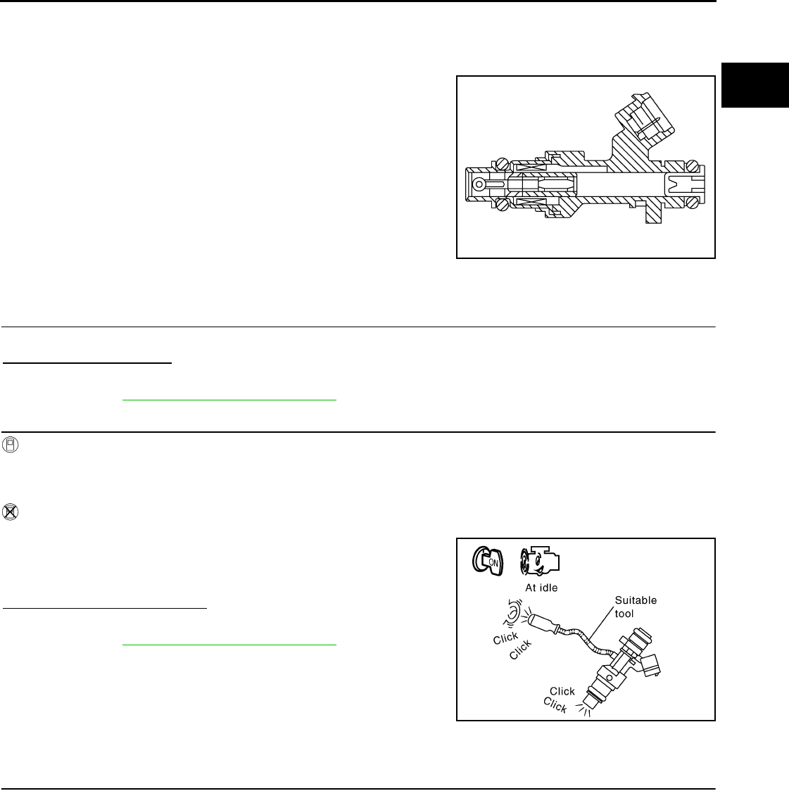
FUEL INJECTOR
EC-1217
< COMPONENT DIAGNOSIS > [FOR MEXICO]
C
D
E
F
G
H
I
J
K
L
M
A
EC
N
P
O
FUEL INJECTOR
Description INFOID:0000000004494386
The fuel injector is a small, precise solenoid valve. When the ECM
supplies a ground to the fuel injector circuit, the coil in the fuel injec-
tor is energized. The energized coil pulls the ball valve back and
allows fuel to flow through the fuel injector into the intake manifold.
The amount of fuel injected depends upon the injection pulse dura-
tion. Pulse duration is the length of time the fuel injector remains
open. The ECM controls the injection pulse duration based on
engine fuel needs.
Component Function Check INFOID:0000000004494387
1.INSPECTION START
Turn ignition switch to START.
Are any cylinders ignited?
YES >> GO TO 2.
NO >> Go to EC-1217, "Diagnosis Procedure".
2.CHECK FUEL INJECTOR FUNCTION
With CONSULT-III
1. Start engine.
2. Perform “POWER BALANCE” in “ACTIVE TEST” mode with CONSULT-III.
3. Check that each circuit produces a momentary engine speed drop.
Without CONSULT-III
1. Let engine idle.
2. Listen to each fuel injector operating sound.
Is the inspection result normal?
YES >> INSPECTION END
NO >> Go to EC-1217, "Diagnosis Procedure".
Diagnosis Procedure INFOID:0000000004494388
1.CHECK FUEL INJECTOR POWER SUPPLY CIRCUIT
1. Turn ignition switch OFF.
2. Disconnect fuel injector harness connector.
3. Turn ignition switch ON.
4. Check the voltage between fuel injector harness connector and ground.
PBIA9664J
Clicking noise should be heard.
PBIB3332E
Revision: 2008 August 2009 Rogue
EC-1218
< COMPONENT DIAGNOSIS > [FOR MEXICO]
FUEL INJECTOR
Is the inspection result normal?
YES >> GO TO 3.
NO >> GO TO 2.
2.DETECT MALFUNCTIONING PART
Check the following.
• Harness connectors E7, F121
• IPDM E/R harness connector E14
• 15A fuse (No. 64)
• Harness for open or short between fuel injector and fuse
>> Repair open circuit or short to ground or short to power in harness or connectors.
3.CHECK FUEL INJECTOR OUTPUT SIGNAL CIRCUIT FOR OPEN AND SHORT
1. Turn ignition switch OFF.
2. Disconnect ECM harness connector.
3. Check the continuity between fuel injector harness connector and ECM harness connector.
4. Also check harness for short to ground and short to power.
Is the inspection result normal?
YES >> GO TO 4.
NO >> Repair open circuit or short to ground or short to power in harness or connectors.
4.CHECK FUEL INJECTOR
Refer to EC-1218, "Component Inspection".
Is the inspection result normal?
YES >> GO TO 5.
NO >> Replace malfunctioning fuel injector.
5.CHECK INTERMITTENT INCIDENT
Refer to GI-41, "Intermittent Incident".
Is the inspection result normal?
YES >> Replace IPDM E/R.
NO >> Repair open circuit or short to ground or short to power in harness or connectors.
Component Inspection INFOID:0000000004494389
1.CHECK FUEL INJECTOR
1. Turn ignition switch OFF.
2. Disconnect fuel injector harness connector.
Fuel injector Ground Voltage
Cylinder Connector Terminal
1F37 1
Ground Battery voltage
2F38 1
3F39 1
4F40 1
Fuel injector ECM Continuity
Cylinder Connector Terminal Connector Terminal
1F372
F7
32
Existed
2F382 31
3F392 30
4F402 29
Revision: 2008 August 2009 Rogue

FUEL INJECTOR
EC-1219
< COMPONENT DIAGNOSIS > [FOR MEXICO]
C
D
E
F
G
H
I
J
K
L
M
A
EC
N
P
O
3. Check resistance between fuel injector terminals as follows.
Is the inspection result normal?
YES >> INSPECTION END
NO >> Replace malfunctioning fuel injector.
Terminals Resistance
1 and 2 10.4 - 15.3 Ω [at 10 -60°C (50 - 140°F)]
Revision: 2008 August 2009 Rogue
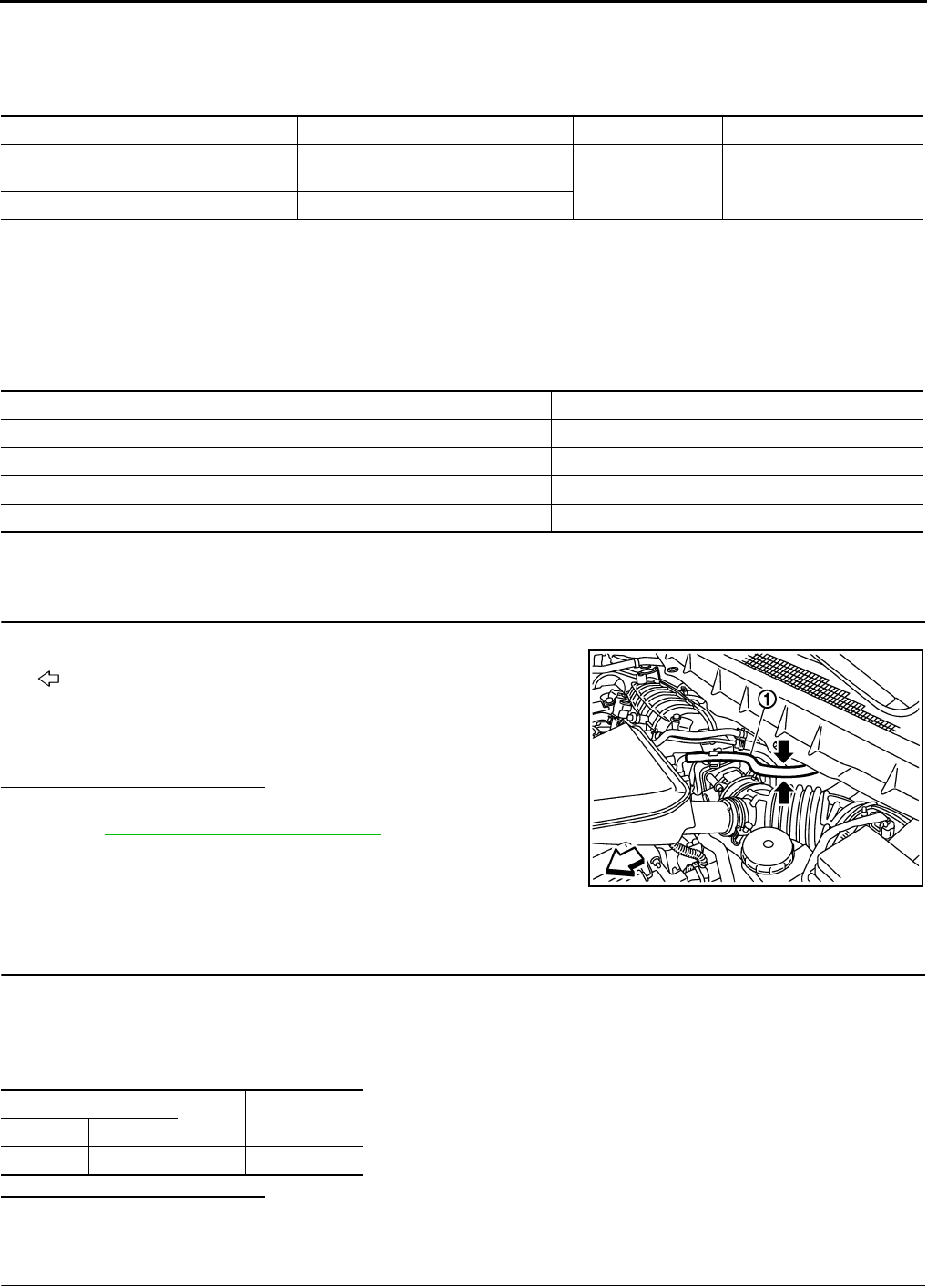
EC-1220
< COMPONENT DIAGNOSIS > [FOR MEXICO]
FUEL PUMP
FUEL PUMP
Description INFOID:0000000004494390
*: ECM determines the start signal status by the signals of engine speed and battery voltage.
The ECM activates the fuel pump for several seconds after the ignition switch is turned ON to improve engine
startability. If the ECM receives a engine speed signal from the camshaft position sensor (PHASE), it knows
that the engine is rotating, and causes the pump to operate. If the engine speed signal is not received when
the ignition switch is ON, the engine stalls. The ECM stops pump operation and prevents battery discharging,
thereby improving safety. The ECM does not directly drive the fuel pump. It controls the ON/OFF fuel pump
relay, which in turn controls the fuel pump.
Component Function Check INFOID:0000000004494391
1.CHECK FUEL PUMP FUNCTION
1. Turn ignition switch ON.
2. Pinch fuel feed hose (1) with two fingers.
- : Vehicle front
Is the inspection result normal?
YES >> INSPECTION END
NO >> EC-1220, "Diagnosis Procedure".
Diagnosis Procedure INFOID:0000000004494392
1.CHECK FUEL PUMP POWER SUPPLY CIRCUIT-I
1. Turn ignition switch OFF.
2. Disconnect ECM harness connector.
3. Turn ignition switch ON.
4. Check the voltage between ECM harness connector and ground.
Is the inspection result normal?
YES >> GO TO 4.
NO >> GO TO 2.
2.CHECK FUEL PUMP POWER SUPPLY CIRCUIT-II
Sensor Input signal to ECM ECM function Actuator
Crankshaft position sensor (POS)
Camshaft position sensor (PHASE) Engine speed* Fuel pump control Fuel pump relay
↓
Fuel pump
Battery Battery voltage*
Condition Fuel pump operation
Ignition switch is turned to ON. Operates for 1 second.
Engine running and cranking Operates.
When engine is stopped Stops in 1.5 seconds.
Except as shown above Stops.
Fuel pressure pulsation should be felt on the fuel feed
hose for 1 second after ignition switch is turned ON.
JMBIA0929ZZ
ECM Ground Voltage
Connector Terminal
F7 14 Ground Battery voltage
Revision: 2008 August 2009 Rogue

FUEL PUMP
EC-1221
< COMPONENT DIAGNOSIS > [FOR MEXICO]
C
D
E
F
G
H
I
J
K
L
M
A
EC
N
P
O
1. Turn ignition switch OFF.
2. Disconnect IDPDM E/R harness connector E13.
3. Check the continuity between IPDM E/R harness connector and ECM harness connector.
Is the inspection result normal?
YES >> GO TO 9.
NO >> GO TO 3.
3.DETECT MALFUNCTIONING PART
Check the following.
• Harness connectors E6, F123
• IPDM E/R connector E13
• Harness for open or short between ECM and IPDM E/R
>> Repair open circuit or short to ground or short to power in harness or connectors.
4.CHECK 15A FUSE
1. Disconnect 15A fuse (No. 57) from IPDM E/R.
2. Check 15A fuse.
Is the inspection result normal?
YES >> GO TO 5.
NO >> Replace fuse.
5.CHECK FUEL PUMP POWER SUPPLY CIRCUIT-III
1. Disconnect “fuel level sensor unit and fuel pump” harness connector.
2. Check the continuity between IPDM E/R harness connector and “fuel level sensor unit and fuel pump” and
ground.
Is the inspection result normal?
YES >> GO TO 7.
NO >> GO TO 6.
6.DETECT MALFUNCTIONING PART
Check the following.
• Harness connectors E105, M77
• Harness connectors M11, B1
• Harness for open or short between “fuel level sensor unit and fuel pump” and IPDM E/R
>> Repair open circuit or short to ground or short to power in harness or connectors.
7.CHECK FUEL PUMP GROUND CIRCUIT
1. Check the continuity between “fuel level sensor unit and fuel pump” and ground.
2. Also heck harness for short to power.
ECM IPDM E/R Continuity
Connector Terminal Connector Terminal
F7 14 E13 33 Existed
IPDM E/R Fuel level sensor unit
and fuel pump Continuity
Connector Terminal Connector Terminal
E14 46 B40 5 Existed
Fuel level sensor unit
and fuel pump Ground Continuity
Connector Terminal
B40 3 Ground Existed
Revision: 2008 August 2009 Rogue

EC-1222
< COMPONENT DIAGNOSIS > [FOR MEXICO]
FUEL PUMP
Is the inspection result normal?
YES >> GO TO 8.
NO >> Repair open circuit or short to power in harness or connectors.
8.CHECK FUEL PUMP
Refer to EC-1222, "Component Inspection".
Is the inspection result normal?
YES >> GO TO 9.
NO >> Replace fuel pump.
9.CHECK INTERMITTENT INCIDENT
Refer to GI-41, "Intermittent Incident".
Is the inspection result normal?
YES >> Replace IPDM E/R.
NO >> Repair or replace harness or connectors.
Component Inspection INFOID:0000000004494393
1.CHECK FUEL PUMP
1. Turn ignition switch OFF.
2. Disconnect “fuel level sensor unit and fuel pump” harness connector.
3. Check resistance between “fuel level sensor unit and fuel pump” terminals as follows.
Is the inspection result normal?
YES >> INSPECTION END
NO >> Replace “fuel level sensor unit and fuel pump”.
Terminals Resistance
3 and 5 0.2 - 5.0 Ω [at 25°C (77°F)]
Revision: 2008 August 2009 Rogue
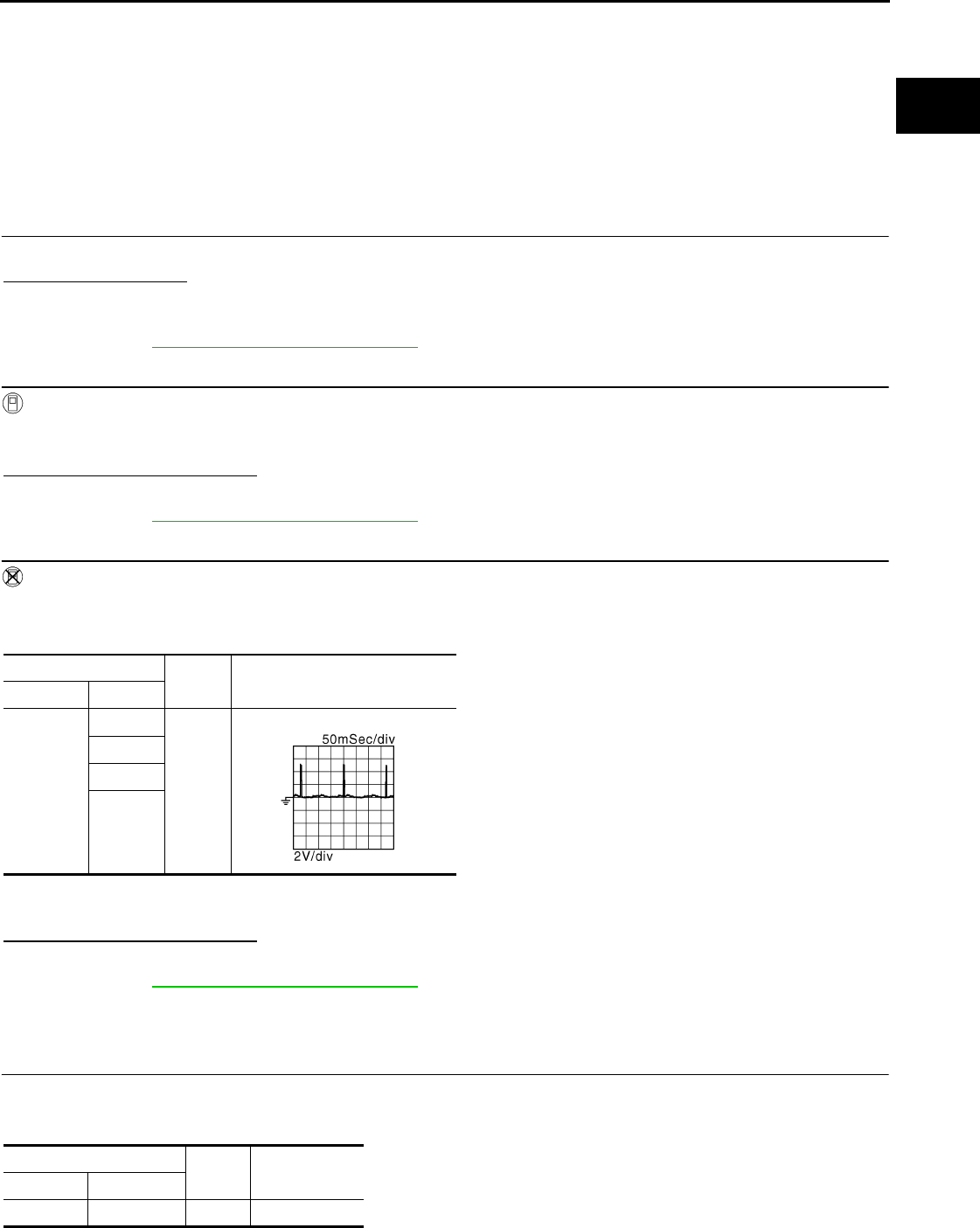
IGNITION SIGNAL
EC-1223
< COMPONENT DIAGNOSIS > [FOR MEXICO]
C
D
E
F
G
H
I
J
K
L
M
A
EC
N
P
O
IGNITION SIGNAL
Description INFOID:0000000004494394
The ignition signal from the ECM is sent to and amplified by the power transistor. The power transistor turns
ON and OFF the ignition coil primary circuit. This ON/OFF operation induces the proper high voltage in the coil
secondary circuit.
Component Function Check INFOID:0000000004494395
1.INSPECTION START
Turn ignition switch OFF, and restart engine.
Does the engine start?
YES-1 >> With CONSULT-III: GO TO 2.
YES-2 >> Without CONSULT-III: GO TO 3.
NO >> Go to EC-1223, "Diagnosis Procedure".
2.IGNITION SIGNAL FUNCTION
With CONSULT-III
1. Perform “POWER BALANCE” in “ACTIVE TEST” mode with CONSULT-III.
2. Check that each circuit produces a momentary engine speed drop.
Is the inspection result normal?
YES >> INSPECTION END
NO >> Go to EC-1223, "Diagnosis Procedure".
3.IGNITION SIGNAL FUNCTION
Without CONSULT-III
1. Let engine idle.
2. Read the voltage signal between ECM harness connector and ground.
NOTE:
The pulse cycle changes depending on rpm at idle.
Is the inspection result normal?
YES >> INSPECTION END
NO >> Go to EC-1223, "Diagnosis Procedure".
Diagnosis Procedure INFOID:0000000004494396
1.CHECK IGNITION COIL POWER SUPPLY CIRCUIT-I
1. Turn ignition switch OFF, wait at least 10 seconds and then turn ON.
2. Check the voltage between ECM harness connector and ground.
ECM Ground Voltage signal
Connector Terminal
F7
9
Ground
10
11
21
JMBIA0900G
B
ECM Ground Voltage
Connector Terminal
E16 105 Ground Battery voltage
Revision: 2008 August 2009 Rogue

EC-1224
< COMPONENT DIAGNOSIS > [FOR MEXICO]
IGNITION SIGNAL
Is the inspection result normal?
YES >> GO TO 2.
NO >> Go to EC-1020, "Diagnosis Procedure".
2.CHECK IGNITION COIL POWER SUPPLY CIRCUIT-II
1. Turn ignition switch OFF.
2. Disconnect condenser-1 harness connector.
3. Turn ignition switch ON.
4. Check the voltage between condenser-1 harness connector and ground.
Is the inspection result normal?
YES >> GO TO 5.
NO >> GO TO 3.
3.CHECK IGNITION COIL POWER SUPPLY CIRCUIT-III
1. Turn ignition switch OFF.
2. Disconnect IPDM E/R harness connector E15.
3. Check the continuity between IPDM E/R harness connector and condenser-1 harness connector.
4. Also check harness for short to ground and short to power.
Is the inspection result normal?
YES >> Go to EC-1020, "Diagnosis Procedure".
NO >> GO TO 4.
4.DETECT MALFUNCTIONING PART
Check the following.
• Harness connectors E7, F121
• Harness for open or short between IPDM E/R and condenser-1
>> Repair open circuit or short to ground or short to power in harness or connectors.
5.CHECK CONDENSER-1 GROUND CIRCUIT FOR OPEN AND SHORT
1. Turn ignition switch OFF.
2. Check the continuity between condenser-1 harness connector and ground.
3. Also check harness for short to power.
Is the inspection result normal?
YES >> GO TO 6.
NO >> Repair open circuit or short to ground or short to power in harness or connectors.
6.CHECK CONDENSER
Refer to EC-1227, "Component Inspection (Condenser-1)"
Is the inspection result normal?
YES >> GO TO 7.
NO >> Replace condenser.
Condenser Ground Voltage
Connector Terminal
F13 1 Ground Battery voltage
IPDM E/R Condenser-1 Continuity
Connector Terminal Connector Terminal
E15 47 F13 1 Existed
Condenser-1 Ground Continuity
Connector Terminal
F13 2 Ground Existed
Revision: 2008 August 2009 Rogue

IGNITION SIGNAL
EC-1225
< COMPONENT DIAGNOSIS > [FOR MEXICO]
C
D
E
F
G
H
I
J
K
L
M
A
EC
N
P
O
7.CHECK IGNITION COIL POWER SUPPLY CIRCUIT-IV
1. Reconnect all harness connectors disconnected.
2. Disconnect ignition coil harness connector.
3. Turn ignition switch ON.
4. Check the voltage between ignition coil harness connector and ground.
Is the inspection result normal?
YES >> GO TO 8.
NO >> Repair open circuit or short to ground or short to power in harness or connectors.
8.CHECK IGNITION COIL GROUND CIRCUIT FOR OPEN AND SHORT
1. Turn ignition switch OFF.
2. Check the continuity between ignition coil harness connector and ground.
3. Also check harness for short to power.
Is the inspection result normal?
YES >> GO TO 9.
NO >> Repair open circuit or short to ground or short to power in harness or connectors.
9.CHECK IGNITION COIL OUTPUT SIGNAL CIRCUIT FOR OPEN AND SHORT
1. Disconnect ECM harness connector.
2. Check the continuity between ECM harness connector and ignition coil harness connector.
3. Also check harness for short to ground and short to power.
Is the inspection result normal?
YES >> GO TO 10.
NO >> Repair open circuit or short to ground or short to power in harness or connectors.
10.CHECK IGNITION COIL WITH POWER TRANSISTOR
Refer to EC-1226, "Component Inspection (Ignition Coil with Power Transistor)".
Is the inspection result normal?
YES >> GO TO 11.
NO >> Replace malfunctioning ignition coil with power transistor.
Ignition coil Ground Voltage
Cylinder Connector Terminal
1F33 3
Ground Battery voltage
2F34 3
3F35 3
4F36 3
Ignition coil Ground Continuity
Cylinder Connector Terminal
1F33 2
Ground Existed
2F34 2
3F35 2
4F36 2
Ignition coil ECM Continuity
Cylinder Connector Terminal Connector Terminal
1F33 1
F7
11
Existed
2F34 1 10
3F35 1 9
4F36 1 21
Revision: 2008 August 2009 Rogue
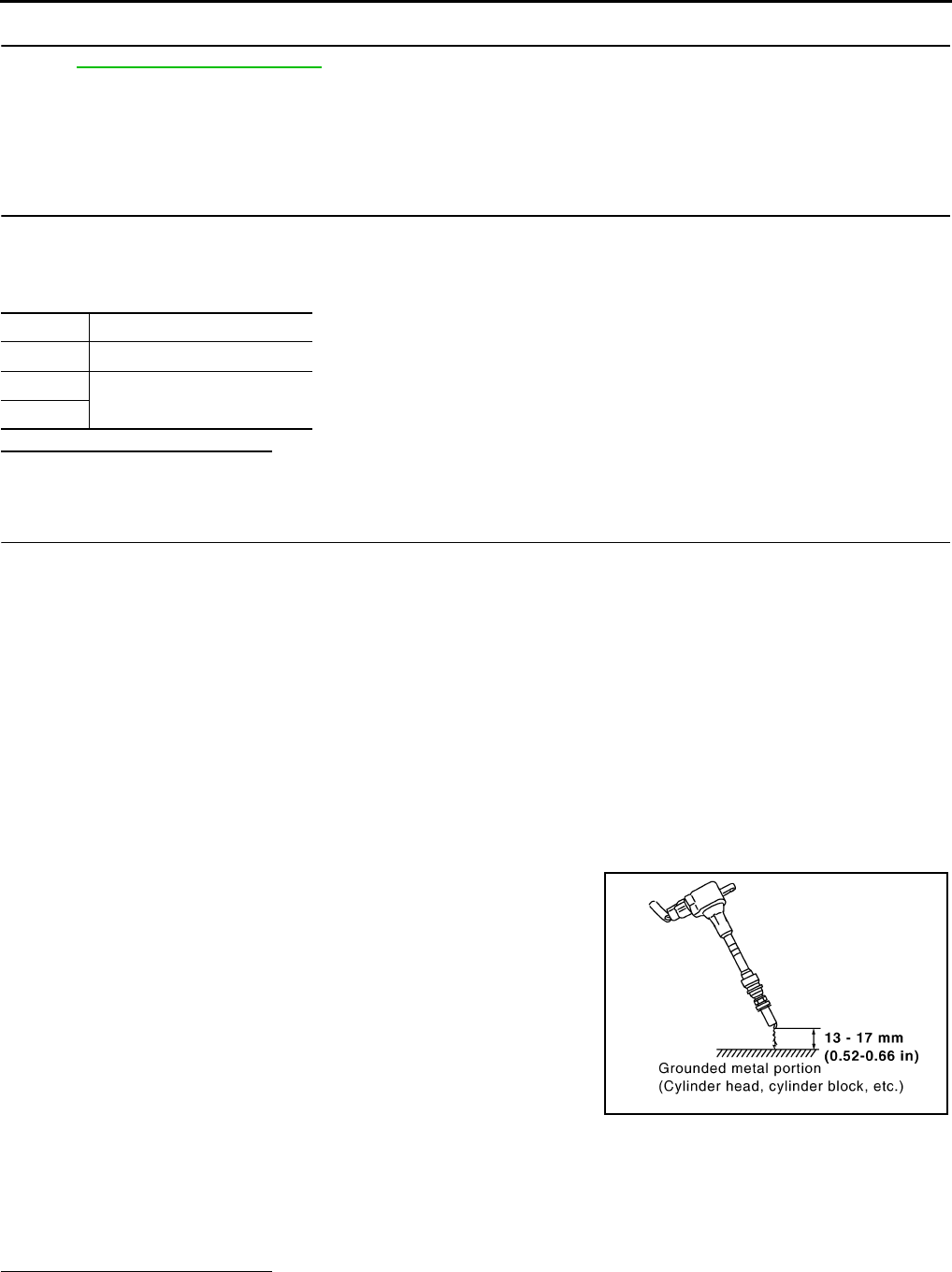
EC-1226
< COMPONENT DIAGNOSIS > [FOR MEXICO]
IGNITION SIGNAL
11.CHECK INTERMITTENT INCIDENT
Refer to GI-41, "Intermittent Incident".
>> INSPECTION END
Component Inspection (Ignition Coil with Power Transistor) INFOID:0000000004494397
1.CHECK IGNITION COIL WITH POWER TRANSISTOR-I
1. Turn ignition switch OFF.
2. Disconnect ignition coil harness connector.
3. Check resistance between ignition coil terminals as follows.
Is the inspection result normal?
YES >> GO TO 2.
NO >> Replace malfunctioning ignition coil with power transistor.
2.CHECK IGNITION COIL WITH POWER TRANSISTOR-II
CAUTION:
Perform the following procedure in a place with no combustible objects and good ventilation.
1. Turn ignition switch OFF.
2. Reconnect all harness connectors disconnected.
3. Remove fuel pump fuse in IPDM E/R to release fuel pressure.
NOTE:
Do not use CONSULT-III to release fuel pressure, or fuel pressure applies again during the following pro-
cedure.
4. Start engine.
5. After engine stalls, crank it two or three times to release all fuel pressure.
6. Turn ignition switch OFF.
7. Remove all ignition coil harness connectors to avoid the electrical discharge from the ignition coils.
8. Remove ignition coil and spark plug of the cylinder to be checked.
9. Crank engine for 5 seconds or more to remove combustion gas in the cylinder.
10. Connect spark plug and harness connector to ignition coil.
11. Fix ignition coil using a rope etc. with gap of 13 - 17 mm (0.52 -
0.66 in) between the edge of the spark plug and grounded metal
portion as shown in the figure.
12. Crank engine for approximately 3 seconds, and check whether
spark is generated between the spark plug and the grounded
metal portion.
CAUTION:
• Never place the spark plug and the ignition coil within 50
cm (19.7 in) each other. Be careful not to get an electrical
shock while checking, because the electrical discharge
voltage becomes 20kV or more.
• It might damage the ignition coil if the gap of more than 17 mm (0.66 in) is made.
NOTE:
When the gap is less than 13 mm (0.52 in), a spark might be generated even if the coil is malfunc-
tioning.
Is the inspection result normal?
YES >> INSPECTION END
NO >> Replace malfunctioning ignition coil with power transistor.
Terminals Resistance [Ω at 25°C (77°F)]
1 and 2 Except 0 or ∞
1 and 3 Except 0
2 and 3
Spark should be generated.
JMBIA0066G
B
Revision: 2008 August 2009 Rogue

IGNITION SIGNAL
EC-1227
< COMPONENT DIAGNOSIS > [FOR MEXICO]
C
D
E
F
G
H
I
J
K
L
M
A
EC
N
P
O
Component Inspection (Condenser-1) INFOID:0000000004494398
1.CHECK CONDENSER-1
1. Turn ignition switch OFF.
2. Disconnect condenser-1 harness connector.
3. Check resistance between condenser-1 terminals as follows.
Is the inspection result normal?
YES >> INSPECTION END
NO >> Replace condenser-1.
Terminals Resistance
1 and 2 Above 1 MΩ [at 25°C (77°F)]
Revision: 2008 August 2009 Rogue

EC-1228
< COMPONENT DIAGNOSIS > [FOR MEXICO]
MALFUNCTION INDICATOR LAMP
MALFUNCTION INDICATOR LAMP
Description INFOID:0000000004494399
The Malfunction Indicator Lamp (MIL) is located on the combination
meter.
The MIL will illuminate when the ignition switch is turned ON without
the engine running. This is a bulb check.
When the engine is started, the MIL should turn off. If the MIL
remains illuminated, the on board diagnostic system has detected an
engine system malfunction.
For details, refer to EC-1228, "Diagnosis Procedure".
Component Function Check INFOID:0000000004494400
1.CHECK MIL FUNCTION
1. Turn ignition switch ON.
2. Check that MIL illuminates.
Is the inspection result normal?
YES >> INSPECTION END
NO >> Go to EC-1228, "Diagnosis Procedure".
Diagnosis Procedure INFOID:0000000004494401
1.CHECK DTC
Check that DTC UXXXX is not displayed.
Is the inspection result normal?
YES >> GO TO 2.
NO >> Perform trouble diagnosis for DTC UXXXX.
2.CHECK DTC WITH METER
Refer to MWI-33, "CONSULT-III Function (METER/M&A)".
Is the inspection result normal?
YES >> GO TO 3.
NO >> Repair or replace.
3.CHECK INTERMITTENT INCIDENT
Refer to GI-41, "Intermittent Incident".
Is the inspection result normal?
YES >> Replace combination meter.
NO >> Repair or replace.
SEF217U
Revision: 2008 August 2009 Rogue
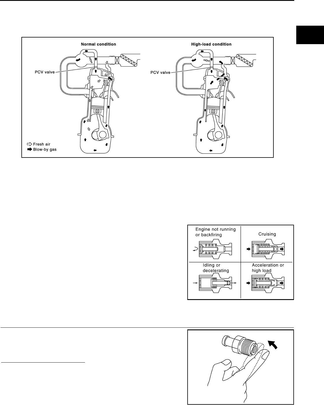
POSITIVE CRANKCASE VENTILATION
EC-1229
< COMPONENT DIAGNOSIS > [FOR MEXICO]
C
D
E
F
G
H
I
J
K
L
M
A
EC
N
P
O
POSITIVE CRANKCASE VENTILATION
Description INFOID:0000000004494402
This system returns blow-by gas to the intake manifold.
The positive crankcase ventilation (PCV) valve is provided to conduct crankcase blow-by gas to the intake
manifold.
During partial throttle operation of the engine, the intake manifold sucks the blow-by gas through the PCV
valve.
Normally, the capacity of the valve is sufficient to handle any blow-by and a small amount of ventilating air.
The ventilating air is drawn from the air inlet tubes into the crankcase. In this process the air passes through
the hose connecting air inlet tubes to rocker cover.
Under full-throttle condition, the manifold vacuum is insufficient to draw the blow-by flow through the valve.
The flow goes through the hose connection in the reverse direction.
On vehicles with an excessively high blow-by, the valve does not
meet the requirement. This is because some of the flow will go
through the hose connection to the air inlet tubes under all condi-
tions.
Component Inspection INFOID:0000000004494403
1.CHECK PCV VALVE
With engine running at idle, remove PCV valve from rocker cover. A
properly working valve makes a hissing noise as air passes through
it. A strong vacuum should be felt immediately when a finger is
placed over valve inlet.
Is the inspection result normal?
YES >> INSPECTION END
NO >> Replace PCV valve.
PBIB0492E
PBIB1588E
PBIB1589E
Revision: 2008 August 2009 Rogue
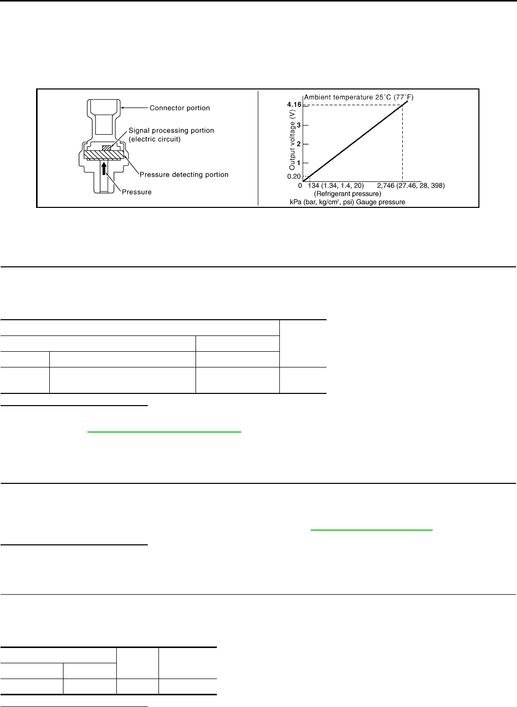
EC-1230
< COMPONENT DIAGNOSIS > [FOR MEXICO]
REFRIGERANT PRESSURE SENSOR
REFRIGERANT PRESSURE SENSOR
Description INFOID:0000000004494404
The refrigerant pressure sensor is installed at the condenser of the air conditioner system. The sensor uses an
electrostatic volume pressure transducer to convert refrigerant pressure to voltage. The voltage signal is sent
to ECM, and ECM controls cooling fan system.
Component Function Check INFOID:0000000004494405
1.CHECK REFRIGERANT PRESSURE SENSOR OVERALL FUNCTION
1. Start engine and warm it up to normal operating temperature.
2. Turn A/C switch and blower fan switch ON.
3. Check the voltage between ECM harness connector terminals.
Is the inspection result normal?
YES >> INSPECTION END
NO >> Go to EC-1230, "Diagnosis Procedure".
Diagnosis Procedure INFOID:0000000004494406
1.CHECK GROUND CONNECTION
1. Turn A/C switch and blower fan switch OFF.
2. Stop engine.
3. Turn ignition switch OFF.
4. Check ground connection E21. Refer to Ground Inspection in GI-44, "Circuit Inspection".
Is the inspection result normal?
YES >> GO TO 2.
NO >> Repair or replace ground connection.
2.CHECK REFRIGERANT PRESSURE SENSOR POWER SUPPLY CIRCUIT
1. Disconnect refrigerant pressure sensor harness connector.
2. Turn ignition switch ON.
3. Check the voltage between refrigerant pressure sensor harness connector and ground.
Is the inspection result normal?
YES >> GO TO 4.
PBIB2657E
ECM
Voltage+−
Connector Terminal Terminal
F8 39
(Refrigerant pressure sensor signal)
40
(Sensor ground) 1.0 - 4.0V
Refrigerant pressure sensor Ground Voltage
Connector Terminal
E49 3 Ground Approx. 5V
Revision: 2008 August 2009 Rogue

REFRIGERANT PRESSURE SENSOR
EC-1231
< COMPONENT DIAGNOSIS > [FOR MEXICO]
C
D
E
F
G
H
I
J
K
L
M
A
EC
N
P
O
NO >> GO TO 3.
3.DETECT MALFUNCTIONING PART
Check the following.
• Harness connectors F123, E6
• Harness for open or short between ECM and refrigerant pressure sensor
>> Repair open circuit or short to ground or short to power in harness or connectors.
4.CHECK REFRIGERANT PRESSURE SENSOR GROUND CIRCUIT FOR OPEN AND SHORT
1. Turn ignition switch OFF.
2. Disconnect ECM harness connector.
3. Check the continuity between refrigerant pressure sensor harness connector and ECM harness connec-
tor.
4. Also check harness for short to ground and short to power.
Is the inspection result normal?
YES >> GO TO 6.
NO >> GO TO 5.
5.DETECT MALFUNCTIONING PART
Check the following.
• Harness connectors F123, E6
• Harness for open or short between ECM and refrigerant pressure sensor
>> Repair open circuit or short to ground or short to power in harness or connectors.
6.CHECK REFRIGERANT PRESSURE SENSOR INPUT SIGNAL CIRCUIT FOR OPEN AND SHORT
1. Check the continuity between ECM harness connector and refrigerant pressure sensor harness connec-
tor.
2. Also check harness for short to ground and short to power.
Is the inspection result normal?
YES >> GO TO 8.
NO >> GO TO 7.
7.DETECT MALFUNCTIONING PART
Check the following.
• Harness connectors F123, E6
• Harness for open or short between ECM and refrigerant pressure sensor
>> Repair open circuit or short to ground or short to power in harness or connectors.
8.CHECK INTERMITTENT INCIDENT
Refer to GI-41, "Intermittent Incident".
Is the inspection result normal?
YES >> Replace refrigerant pressure sensor.
NO >> Repair or replace.
Refrigerant pressure sensor ECM Continuity
Connector Terminal Connector Terminal
E49 1 F8 40 Existed
Refrigerant pressure sensor ECM Continuity
Connector Terminal Connector Terminal
E49 2 F8 39 Existed
Revision: 2008 August 2009 Rogue
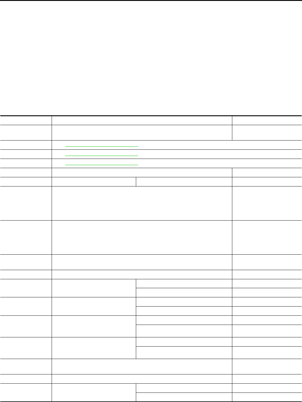
EC-1232
< ECU DIAGNOSIS > [FOR MEXICO]
ECM
ECU DIAGNOSIS
ECM
Reference Value INFOID:0000000004494407
VALUES ON THE DIAGNOSIS TOOL
Remarks:
z Specification data are reference values.
z Specification data are output/input values which are detected or supplied by the ECM at the connector.
* Specification data may not be directly related to their components signals/values/operations.
I.e. Adjust ignition timing with a timing light before monitoring IGN TIMING, because the monitor may show
the specification data in spite of the ignition timing not being adjusted to the specification data. this IGN TIM-
ING monitors the data calculated by the ECM according to the signals input from the camshaft position sensor
and other ignition timing related sensors.
Monitor Item Condition Values/Status
ENG SPEED • Run engine and compare CONSULT-III value with the tachometer indication. Almost the same speed as
the tachometer indication.
MAS A/F SE-B1 See EC-1013, "Diagnosis Procedure".
B/FUEL SCHDL See EC-1013, "Diagnosis Procedure".
A/F ALPHA-B1 See EC-1013, "Diagnosis Procedure".
COOLAN TEMP/S • Engine: After warming up More than 70°C (158°F)
A/F SEN1 (B1) • Engine: After warming up Maintaining engine speed at 2,000 rpm Fluctuates around 2.2 V
HO2S2 (B1)
• Revving engine from idle up to 3,000 rpm quickly after the following conditions
are met.
- Engine: After warming up
- After keeping engine speed between 3,500 and 4,000 rpm for 1 minute and at
idle for 1 minute under no load
0 - 0.3V ←→ Approx. 0.6 -
1.0V
HO2S2 MNTR (B1)
• Revving engine from idle up to 3,000 rpm quickly after the following conditions
are met.
- Engine: After warming up
- After keeping engine speed between 3,500 and 4,000 rpm for 1 minute and at
idle for 1 minute under no load
LEAN ←→ RICH
VHCL SPEED SE • Turn drive wheels and compare CONSULT-III value with the speedometer in-
dication. Almost the same speed as
speedometer indication
BATTERY VOLT • Ignition switch: ON (Engine stopped) 11 - 14V
ACCEL SEN 1 • Ignition switch: ON
(Engine stopped)
Accelerator pedal: Fully released 0.6 - 0.9V
Accelerator pedal: Fully depressed 4.0 - 4.8V
ACCEL SEN 2*1• Ignition switch: ON
(Engine stopped)
Accelerator pedal: Fully released 0.6 - 0.9V
Accelerator pedal: Fully depressed 3.9 - 4.8V
TP SEN 1-B1
• Ignition switch: ON
(Engine stopped)
• Selector lever: D
Accelerator pedal: Fully released More than 0.36V
Accelerator pedal: Fully depressed Less than 4.75V
TP SEN 2-B1*1• Ignition switch: ON
(Engine stopped)
• Selector lever: D
Accelerator pedal: Fully released More than 0.36V
Accelerator pedal: Fully depressed Less than 4.75V
INT/A TEMP SE • Ignition switch: ON Indicates intake air tempera-
ture
START SIGNAL • Ignition switch: ON → START → ON OFF → ON → OFF
CLSD THL POS • Ignition switch: ON
(Engine stopped)
Accelerator pedal: Fully released ON
Accelerator pedal: Slightly depressed OFF
Revision: 2008 August 2009 Rogue

ECM
EC-1233
< ECU DIAGNOSIS > [FOR MEXICO]
C
D
E
F
G
H
I
J
K
L
M
A
EC
N
P
O
AIR COND SIG • Engine: After warming up, idle the
engine
Air conditioner switch: OFF OFF
Air conditioner switch: ON
(Compressor operates.) ON
P/N POSI SW • Ignition switch: ON Selector lever: P or N ON
Selector lever: Except above OFF
PW/ST SIGNAL • Engine: After warming up, idle the
engine
Steering wheel: Not being turned OFF
Steering wheel: Being turned ON
LOAD SIGNAL • Ignition switch: ON
Rear window defogger switch: ON
and/or Lighting switch: 2nd position ON
Rear window defogger switch and lighting
switch: OFF OFF
IGNITION SW • Ignition switch: ON → OFF → ON ON → OFF → ON
HEATER FAN SW • Engine: After warming up, idle the
engine
Heater fan switch: ON ON
Heater fan switch: OFF OFF
BRAKE SW • Ignition switch: ON Brake pedal: Fully released OFF
Brake pedal: Slightly depressed ON
INJ PULSE-B1
• Engine: After warming up
• Selector lever: P or N
• Air conditioner switch: OFF
•No load
Idle 2.0 - 3.0 msec
2,000 rpm 1.9 - 2.9 msec
IGN TIMING
• Engine: After warming up
• Selector lever: P or N
• Air conditioner switch: OFF
•No load
Idle 10° - 20° BTDC
2,000 rpm 25° - 45° BTDC
CAL/LD VALUE
• Engine: After warming up
• Selector lever: P or N
• Air conditioner switch: OFF
•No load
Idle 10% - 35%
2,500 rpm 10% - 35%
MASS AIRFLOW
• Engine: After warming up
• Selector lever: P or N
• Air conditioner switch: OFF
•No load
Idle 1.0 - 4.0 g·m/s
2,500 rpm 4.0 - 10.0 g·m/s
PURG VOL C/V
• Engine: After warming up
• Selector lever: P or N
• Air conditioner switch: OFF
•No load
Idle
(Accelerator pedal: Not depressed even
slightly, after engine starting.) 0%
2,000 rpm 20% - 90%
INT/V TIM (B1)
• Engine: After warming up
• Selector lever: P or N
• Air conditioner switch: OFF
•No load
Idle −5° - 5°CA
2,000 rpm Approx. 0° - 20°CA
INT/V SOL (B1)
• Engine: After warming up
• Selector lever: P or N
• Air conditioner switch: OFF
•No load
Idle 0%
2,000 rpm Approx. 0% - 60%
AIR COND RLY • Engine: After warming up, idle the
engine
Air conditioner switch: OFF OFF
Air conditioner switch: ON
(Compressor operates) ON
FUEL PUMP RLY
• For 1 seconds after turning ignition switch: ON
• Engine running or cranking ON
• Except above OFF
THRTL RELAY • Ignition switch: ON ON
Monitor Item Condition Values/Status
Revision: 2008 August 2009 Rogue

EC-1234
< ECU DIAGNOSIS > [FOR MEXICO]
ECM
*1: Accelerator pedal position sensor 2 signal and throttle position sensor 2 signal are converted by ECM internally. Thus, they differ
from ECM terminals voltage signal.
HO2S2 HTR (B1)
• Engine speed: Below 3,600 rpm after the following conditions are met.
- Engine: After warming up
- Keeping the engine speed between 3,500 and 4,000 rpm for 1 minute and at
idle for 1 minute under no load
ON
• Engine speed: Above 3,600 rpm OFF
I/P PULLY SPD • Vehicle speed: More than 20 km/h (12 MPH) Almost the same speed as
the tachometer indication
VEHICLE SPEED • Turn drive wheels and compare CONSULT-III value with the speedometer in-
dication.
Almost the same speed as
the speedometer indication
IDL A/V LEARN • Engine: running
Idle air volume learning has not been per-
formed yet. YET
Idle air volume learning has already been
performed successfully. CMPLT
TRVL AFTER MIL • Ignition switch: ON Vehicle has traveled after MIL has turned
ON.
0 - 65,535 km
(0 - 40,723 miles)
A/F S1 HTR (B1) • Engine: After warming up, idle the engine
(More than 140 seconds after starting engine.) 4 - 100%
AC PRESS SEN • Engine: Idle
• Both A/C switch and blower fan switch: ON (Compressor operates) 1.0 - 4.0V
VHCL SPEED SE • Turn drive wheels and compare CONSULT-III value with the speedometer in-
dication.
Almost the same speed as
the speedometer indication
SET VHCL SPD • Engine: Running ASCD: Operating The preset vehicle speed is
displayed
MAIN SW • Ignition switch: ON MAIN switch: Pressed ON
MAIN switch: Released OFF
CANCEL SW • Ignition switch: ON CANCEL switch: Pressed ON
CANCEL switch: Released OFF
RESUME/ACC SW • Ignition switch: ON
RESUME/ACCELERATE switch:
Pressed ON
RESUME/ACCELERATE switch: Re-
leased OFF
SET SW • Ignition switch: ON SET/COAST switch: Pressed ON
SET/COAST switch: Released OFF
BRAKE SW1
(ASCD brake switch) • Ignition switch: ON Brake pedal: Fully released ON
Brake pedal: Slightly depressed OFF
BRAKE SW2
(Stop lamp switch) • Ignition switch: ON Brake pedal: Fully released OFF
Brake pedal: Slightly depressed ON
VHCL SPD CUT • Ignition switch: ON NON
LO SPEED CUT • Ignition switch: ON NON
AT OD MONITOR • Ignition switch: ON OFF
AT OD CANCEL • Ignition switch: ON OFF
CRUISE LAMP • Ignition switch: ON MAIN switch: Pressed at the 1st time →
at the 2nd time ON → OFF
SET LAMP
• MAIN switch: ON
• When vehicle speed: Between 40
km/h (25 MPH) and 144 km/h (89
MPH)
ASCD: Operating ON
ASCD: Not operating OFF
A/F ADJ-B1 • Engine: running –0.330 - 0.330
Monitor Item Condition Values/Status
Revision: 2008 August 2009 Rogue
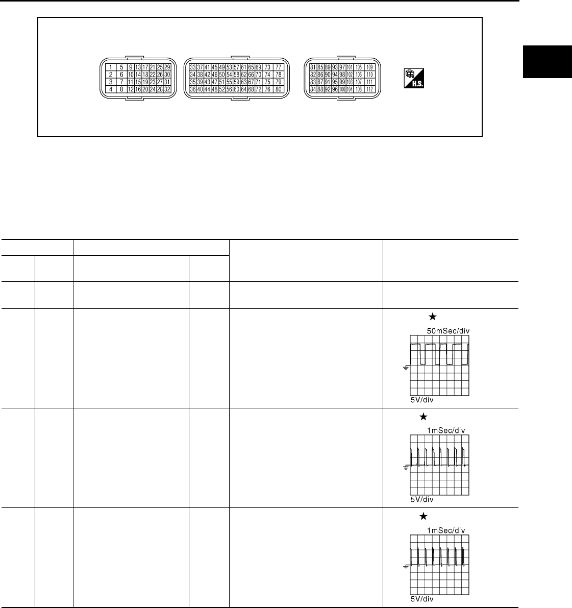
ECM
EC-1235
< ECU DIAGNOSIS > [FOR MEXICO]
C
D
E
F
G
H
I
J
K
L
M
A
EC
N
P
O
TERMINAL LAYOUT
PHYSICAL VALUES
NOTE:
• ECM is located behind the passenger side instrument lower panel. For this inspection, remove passenger
side instrument lower panel.
• Specification data are reference values and are measured between each terminal and ground.
• Pulse signal is measured by CONSULT-III.
PBIA9221J
Terminal No. Description
Condition Value
(Approx.)
+ – Signal name Input/
Output
2
(P)
112
(B)
Throttle control motor power
supply Input [Ignition switch: ON] BATTERY VOLTAGE
(11 - 14 V)
4
(R) 112
(B) A/F sensor 1 heater Output
[Engine is running]
• Warm-up condition
• Idle speed
2.9 - 8.8 V
5
(GR)
6
(L)
Throttle control motor 1
(Open) Output
[Ignition switch: ON]
• Engine stopped
• Selector lever: D
• Accelerator pedal: Fully depressed
0 - 14 V
6
(L)
5
(GR)
Throttle control motor 2
(Close) Output
[Ignition switch: ON]
• Engine stopped
• Selector lever: D
• Accelerator pedal: Fully released
0 - 14 V
JMBIA0082G
B
JMBIA0083G
B
JMBIA0084G
B
Revision: 2008 August 2009 Rogue
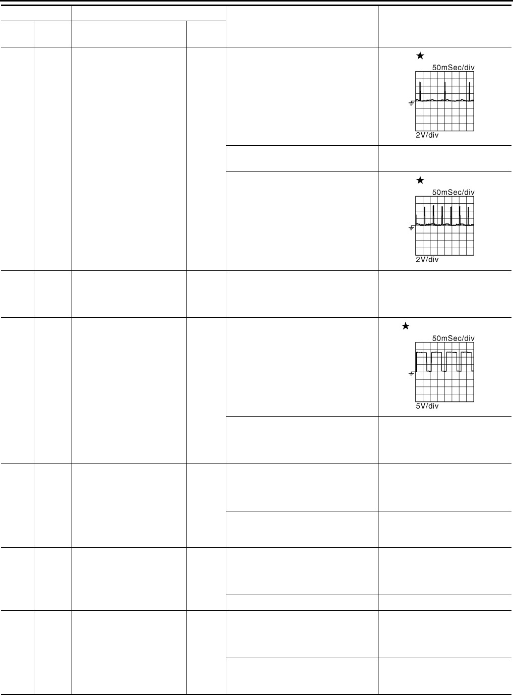
EC-1236
< ECU DIAGNOSIS > [FOR MEXICO]
ECM
9
(R)
112
(B)
Ignition signal No. 3
Output
[Engine is running]
• Warm-up condition
• Idle speed
NOTE:
The pulse cycle changes depending
on rpm at idle
0 - 0.1 V
10
(W) Ignition signal No. 2
11
(SB) Ignition signal No. 1
[Engine is running]
• Warm-up condition
• Engine speed: 2,000 rpm
0 - 0.2 V
21
(G) Ignition signal No. 4
12
(B)
16
(B)
— ECM ground — — —
13
(Y)
112
(B)
Heated oxygen sensor 2
heater Output
[Engine is running]
• Engine speed: Below 3,600 rpm af-
ter the following conditions are met
- Engine: After warming up
- Keeping the engine speed between
3,500 and 4,000 rpm for 1 minute
and at idle for 1 minute under no
load
10 V
[Ignition switch: ON]
• Engine stopped
[Engine is running]
• Engine speed: Above 3,600 rpm
BATTERY VOLTAGE
(11 - 14 V)
14
(GR) 112
(B) Fuel pump relay Output
[Ignition switch: ON]
• For 1 second after turning ignition
switch ON
[Engine is running]
0 - 1.0 V
[Ignition switch ON]
• More than 1 second after turning ig-
nition switch ON
BATTERY VOLTAGE
(11 - 14 V)
15
(V) 112
(B) Throttle control motor relay Output [Ignition switch: ON → OFF]
0 - 1.0 V
↓
BATTERY VOLTAGE
(11 - 14 V)
[Ignition switch: ON] 0 - 1.0 V
24
(L)
112
(B)
ECM relay
(Self shut-off) Output
[Engine is running]
[Ignition switch: OFF]
• A few seconds after turning ignition
switch OFF
0 - 1.0 V
[Ignition switch: OFF]
• More than a few seconds after turn-
ing ignition switch OFF
BATTERY VOLTAGE
(11 - 14 V)
Terminal No. Description
Condition Value
(Approx.)
+ – Signal name Input/
Output
JMBIA0900G
B
JMBIA0901G
B
JMBIA0902G
B
Revision: 2008 August 2009 Rogue

ECM
EC-1237
< ECU DIAGNOSIS > [FOR MEXICO]
C
D
E
F
G
H
I
J
K
L
M
A
EC
N
P
O
25
(Y)
112
(B)
EVAP canister purge vol-
ume control solenoid valve Output
[Engine is running]
• Idle speed
• Accelerator pedal: Not depressed
even slightly, after engine starting
BATTERY VOLTAGE
(11 - 14 V)
[Engine is running]
• Engine speed: Approx. 2,000 rpm
(More than 100 seconds after start-
ing engine.)
BATTERY VOLTAGE
(11 - 14 V)
29
(P)
112
(B)
Fuel injector No. 4
Output
[Engine is running]
• Warm-up condition
• Idle speed
NOTE:
The pulse cycle changes depending
on rpm at idle
BATTERY VOLTAGE
(11 - 14 V)
30
(LG) Fuel injector No. 3
31
(BR) Fuel injector No. 2
[Engine is running]
• Warm-up condition
• Engine speed: 2,000 rpm
BATTERY VOLTAGE
(11 - 14 V)
32
(GR) Fuel injector No. 1
33
(P) 35
(L) Heated oxygen sensor 2 Input
[Engine is running]
• Revving engine from idle to 3,000
rpm quickly after the following con-
ditions are met
- Engine: After warming up
- Keeping the engine speed between
3,500 and 4,000 rpm for 1 minute
and at idle for 1 minute under no
load
0 - 1.0 V
35
(L) —Sensor ground
(Heated oxygen sensor 2) —— —
36
(R) —Sensor ground
(Throttle position sensor) —— —
Terminal No. Description
Condition Value
(Approx.)
+ – Signal name Input/
Output
JMBIA0087G
B
JMBIA0903G
B
JMBIA0089G
B
JMBIA0090G
B
Revision: 2008 August 2009 Rogue

EC-1238
< ECU DIAGNOSIS > [FOR MEXICO]
ECM
37
(W)
36
(R) Throttle position sensor 1 Input
[Ignition switch: ON]
• Engine stopped
• Selector lever: D
• Accelerator pedal: Fully released
More than 0.36 V
[Ignition switch: ON]
• Engine stopped
• Selector lever: D
• Accelerator pedal: Fully depressed
Less than 4.75 V
38
(G)
36
(R) Throttle position sensor 2 Input
[Ignition switch: ON]
• Engine stopped
• Selector lever: D
• Accelerator pedal: Fully released
Less than 4.75 V
[Ignition switch: ON]
• Engine stopped
• Selector lever: D
• Accelerator pedal: Fully depressed
More than 0.36 V
39
(Y)
40
(W) Refrigerant pressure sensor Input
[Engine is running]
• Warm-up condition
• Both A/C switch and blower fan mo-
tor switch: ON (Compressor oper-
ates)
1.0 - 4.0 V
40
(W) —
Sensor ground
(Refrigerant pressure sen-
sor) —— —
45
(V)
49
(LG) A/F sensor 1 (bank 1) Input [Ignition switch: ON] 2.2 V
46
(P)
52
(O)
Engine coolant temperature
sensor Input [Engine is running]
0 - 4.8 V
Output voltage varies with engine
coolant temperature.
47
(B)
36
(R)
Sensor power supply
(Throttle position sensor) — [Ignition switch: ON] 5 V
49
(LG)
112
(B) A/F sensor 1 Input
[Engine is running]
• Warm-up condition
• Engine speed: 2,000 rpm
1.8 V
Output voltage varies with air fuel
ratio.
50
(BR)
56
(R)
Intake air temperature sen-
sor Input [Engine is running] 0 - 4.8 V
Output voltage varies with intake
air temperature.
52
(O) —
Sensor ground
(Engine coolant tempera-
ture sensor) —— —
56
(R) —
Sensor ground
(Mass air flow sensor, Intake
air temperature sensor)
—— —
58
(L) 56
(R) Mass air flow sensor Input
[Engine is running]
• Warm-up condition
• Idle speed
0.8 - 1.2 V
[Engine is running]
• Warm-up condition
• Engine speed: 2,500 rpm 1.4 - 1.8 V
59
(V) 64
(Y)
Sensor power supply
[Camshaft position sensor
(PHASE)]
— [Ignition switch: ON] 5 V
60
(B) —Sensor ground
[Crankshaft position sensor
(POS)]
—— —
Terminal No. Description
Condition Value
(Approx.)
+ – Signal name Input/
Output
Revision: 2008 August 2009 Rogue
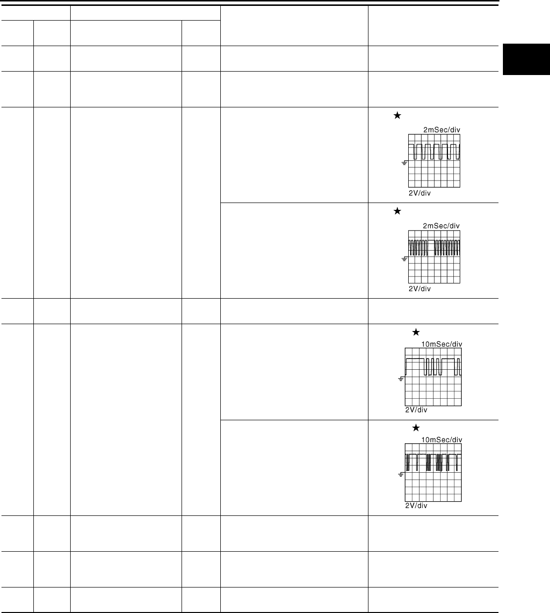
ECM
EC-1239
< ECU DIAGNOSIS > [FOR MEXICO]
C
D
E
F
G
H
I
J
K
L
M
A
EC
N
P
O
61
(W)
67
(—) Knock sensor Input [Engine is running]
• Idle speed 2.5 V
64
(Y) —
Sensor ground
[Camshaft position sensor
(PHASE)] —— —
65
(W) 60
(B) Crankshaft position sensor
(POS) Input
[Engine is running]
• Warm-up condition
• Idle speed
NOTE:
The pulse cycle changes depending
on rpm at idle
3.0 V
[Engine is running]
• Engine speed: 2,000 rpm
3.0 V
67
(—) —Sensor ground
(Knock sensor) —— —
69
(G)
64
(Y)
Camshaft position sensor
(PHASE) Input
[Engine is running]
• Warm-up condition
• Idle speed
NOTE:
The pulse cycle changes depending
on rpm at idle
1.0 - 4.0 V
[Engine is running]
• Engine speed is 2,000 rpm
1.0 - 4.0 V
72
(L) 40
(W)
Sensor power supply
(Refrigerant pressure sen-
sor)
— [Ignition switch: ON] 5 V
76
(P)
60
(B)
Sensor power supply
[Crankshaft position sensor
(POS)]
— [Ignition switch: ON] 5 V
77
(R)
112
(B)
Power supply for ECM
(Back-up) Input [Ignition switch: OFF] BATTERY VOLTAGE
(11 - 14 V)
Terminal No. Description
Condition Value
(Approx.)
+ – Signal name Input/
Output
JMBIA0514G
B
JMBIA0515G
B
JMBIA0904G
B
JMBIA0905G
B
Revision: 2008 August 2009 Rogue

EC-1240
< ECU DIAGNOSIS > [FOR MEXICO]
ECM
78
(O)
112
(B)
Intake valve timing control
solenoid valve Output
[Engine is running]
• Warm-up condition
• Idle speed
0 V
[Engine is running]
• Warm-up condition
• Engine speed: 2,000rpm
7 - 10 V
81
(SB)
84
(Y)
Accelerator pedal position
sensor 1 Input
[Ignition switch: ON]
• Engine stopped
• Accelerator pedal: Fully released
0.6 - 0.9 V
[Ignition switch: ON]
• Engine stopped
• Accelerator pedal: Fully depressed
4.0 - 4.8 V
82
(G)
100
(W)
Accelerator pedal position
sensor 2 Input
[Ignition switch: ON]
• Engine stopped
• Accelerator pedal: Fully released 0.6 - 0.9 V
[Ignition switch: ON]
• Engine stopped
• Accelerator pedal: Fully depressed
3.9 - 4.8 V
83
(R)
84
(Y)
Sensor power supply
(Accelerator pedal position
sensor 1) — [Ignition switch: ON] 5 V
84
(Y) —
Sensor ground
(Accelerator pedal position
sensor 1)
—— —
85
(R)
92
(W) ASCD steering switch Input
[Ignition switch: ON]
• ASCD steering switch: OFF 4 V
[Ignition switch: ON]
• MAIN switch: Pressed 0 V
[Ignition switch: ON]
• CANCEL switch: Pressed 1 V
[Ignition switch: ON]
• RESUME/ACCELERATE switch:
Pressed
3 V
[Ignition switch: ON]
• SET/COAST switch: Pressed 2 V
87
(V)
100
(W)
Sensor power supply
(Accelerator pedal position
sensor 2)
— [Ignition switch: ON] 5 V
88
(L)
112
(B) Data link connector Input/
Output
[Ignition switch: ON]
• GST: Disconnected
BATTERY VOLTAGE
(11 - 14 V)
92
(W) —Sensor ground
(ASCD steering switch) —— —
93
(O)
112
(B) Ignition switch Input
[Ignition switch: OFF] 0 V
[Ignition switch: ON] BATTERY VOLTAGE
(11 - 14 V)
97
(P) — CAN communication line — — —
Terminal No. Description
Condition Value
(Approx.)
+ – Signal name Input/
Output
JMBIA0906G
B
Revision: 2008 August 2009 Rogue

ECM
EC-1241
< ECU DIAGNOSIS > [FOR MEXICO]
C
D
E
F
G
H
I
J
K
L
M
A
EC
N
P
O
: Average voltage for pulse signal (Actual pulse signal can be confirmed by oscilloscope.)
98
(L) — CAN communication line — — —
100
(W) —
Sensor ground
(Accelerator pedal position
sensor 2) —— —
102
(LG) 112
(B) PNP switch Input
[Ignition switch: ON]
• Selector lever: P or N
BATTERY VOLTAGE
(11 - 14 V)
[Ignition switch: ON]
• Selector lever: Except above 0 V
105
(R) 112
(B) Power supply for ECM Input [Ignition switch: ON] BATTERY VOLTAGE
(11 - 14 V)
106
(Y) 112
(B) Stop lamp switch Input
[Ignition switch: OFF]
• Brake pedal: Fully released 0 V
[Ignition switch: OFF]
• Brake pedal: Slightly depressed
BATTERY VOLTAGE
(11 - 14 V)
107
(B)
108
(B)
— ECM ground — — —
110
(GR)
112
(B) ASCD brake switch Input
[Ignition switch: ON]
• Brake pedal: Slightly depressed 0 V
[Ignition switch: ON]
• Brake pedal: Fully released
BATTERY VOLTAGE
(11 - 14 V)
111
(B)
112
(B)
— ECM ground — — —
Terminal No. Description
Condition Value
(Approx.)
+ – Signal name Input/
Output
Revision: 2008 August 2009 Rogue

EC-1242
< ECU DIAGNOSIS > [FOR MEXICO]
ECM
Wiring Diagram — ENGINE CONTROL SYSTEM — INFOID:0000000004494408
JCBWM0957
GB
Revision: 2008 August 2009 Rogue

ECM
EC-1243
< ECU DIAGNOSIS > [FOR MEXICO]
C
D
E
F
G
H
I
J
K
L
M
A
EC
N
P
O
JCBWM0958
GB
Revision: 2008 August 2009 Rogue
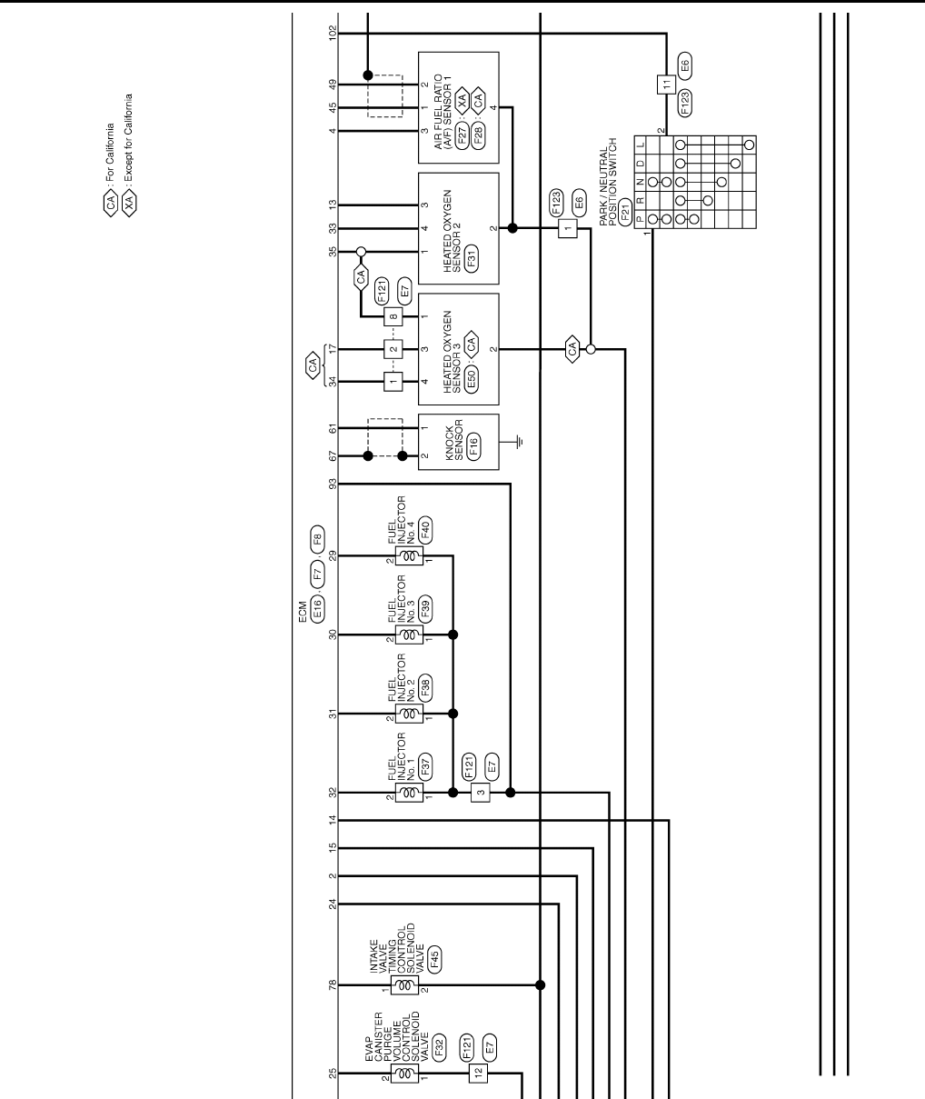
EC-1244
< ECU DIAGNOSIS > [FOR MEXICO]
ECM
JCBWM0959
GB
Revision: 2008 August 2009 Rogue

ECM
EC-1245
< ECU DIAGNOSIS > [FOR MEXICO]
C
D
E
F
G
H
I
J
K
L
M
A
EC
N
P
O
JCBWM0960
GB
Revision: 2008 August 2009 Rogue

EC-1246
< ECU DIAGNOSIS > [FOR MEXICO]
ECM
JCBWM0961
GB
Revision: 2008 August 2009 Rogue
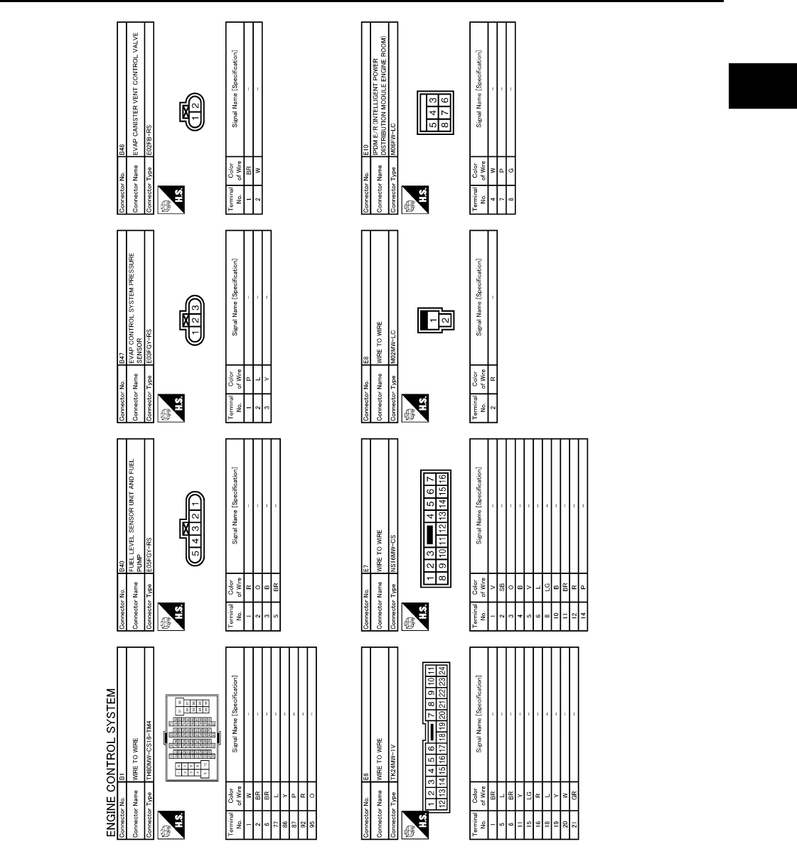
ECM
EC-1247
< ECU DIAGNOSIS > [FOR MEXICO]
C
D
E
F
G
H
I
J
K
L
M
A
EC
N
P
O
JCBWM0962
GB
Revision: 2008 August 2009 Rogue
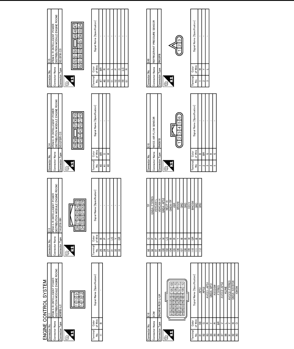
EC-1248
< ECU DIAGNOSIS > [FOR MEXICO]
ECM
JCBWM0963
GB
Revision: 2008 August 2009 Rogue

ECM
EC-1249
< ECU DIAGNOSIS > [FOR MEXICO]
C
D
E
F
G
H
I
J
K
L
M
A
EC
N
P
O
JCBWM0964
GB
Revision: 2008 August 2009 Rogue
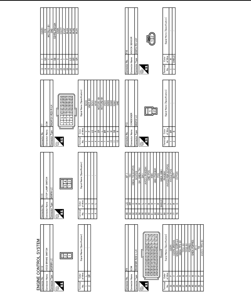
EC-1250
< ECU DIAGNOSIS > [FOR MEXICO]
ECM
JCBWM0965
GB
Revision: 2008 August 2009 Rogue

ECM
EC-1251
< ECU DIAGNOSIS > [FOR MEXICO]
C
D
E
F
G
H
I
J
K
L
M
A
EC
N
P
O
JCBWM0966
GB
Revision: 2008 August 2009 Rogue

EC-1252
< ECU DIAGNOSIS > [FOR MEXICO]
ECM
JCBWM0967
GB
Revision: 2008 August 2009 Rogue

ECM
EC-1253
< ECU DIAGNOSIS > [FOR MEXICO]
C
D
E
F
G
H
I
J
K
L
M
A
EC
N
P
O
JCBWM0968
GB
Revision: 2008 August 2009 Rogue
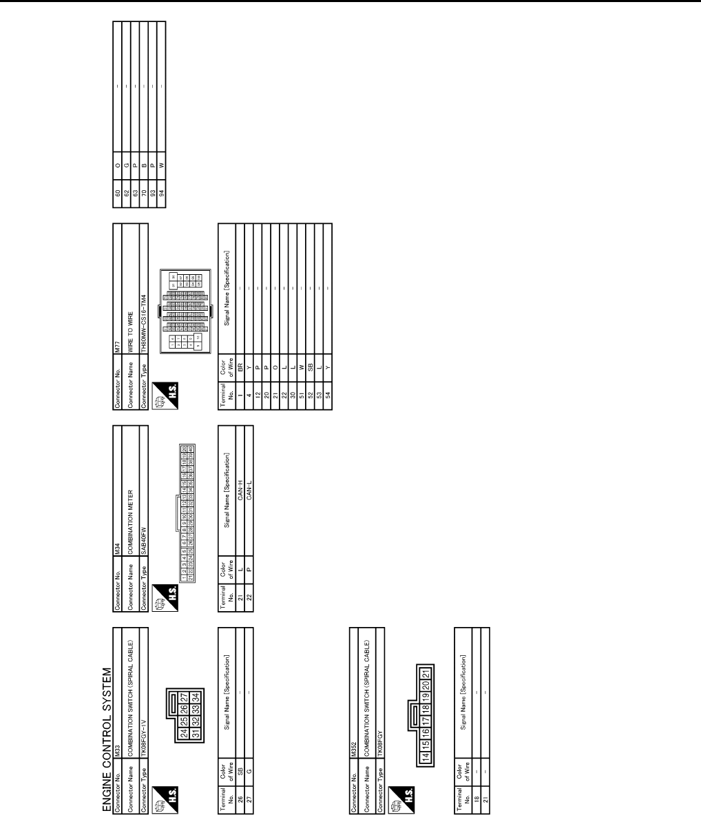
EC-1254
< ECU DIAGNOSIS > [FOR MEXICO]
ECM
Fail Safe INFOID:0000000004494409
NON DTC RELATED ITEM
JCBWM0969
GB
Revision: 2008 August 2009 Rogue

ECM
EC-1255
< ECU DIAGNOSIS > [FOR MEXICO]
C
D
E
F
G
H
I
J
K
L
M
A
EC
N
P
O
DTC RELATED ITEM
Engine operating condi-
tion in fail-safe mode Detected items Remarks Reference
page
Engine speed will not
rise more than 2,500 rpm
due to the fuel cut
Malfunction indicator
lamp circuit When there is an open circuit on MIL circuit, the ECM cannot warn the
driver by illuminating MIL when there is malfunction on engine control
system.
Therefore, when electrical controlled throttle and part of ECM related
diagnoses are continuously detected as NG for 5 trips, ECM warns the
driver that engine control system malfunctions and MIL circuit is open
by means of operating the fail-safe function.
The fail-safe function also operates when above diagnoses except MIL
circuit are detected and demands the driver to repair the malfunction.
EC-1228
DTC No. Detected items Engine operating condition in fail-safe mode
P0011 Intake valve timing control The signal is not energized to the intake valve timing control solenoid valve and the valve
control does not function.
P0102
P0103
Mass air flow sensor circuit Engine speed will not rise more than 2,400 rpm due to the fuel cut.
P0117
P0118 Engine coolant tempera-
ture sensor circuit Engine coolant temperature will be determined by ECM based on the following conditions.
CONSULT-III displays the engine coolant temperature decided by ECM.
Condition Engine coolant temperature decided
(CONSULT-III display)
Just as ignition switch is turned ON
or START 40°C (104°F)
Approx. 4 minutes or more after
starting engine 80°C (176°F)
Except as shown above 40 - 80°C (104 - 176°F)
(Depends on the time)
When the fail-safe system for engine coolant temperature sensor is activated, the cooling
fan operates while engine is running.
P0122
P0123
P0222
P0223
P2132
P2133
P2135
Throttle position sensor The ECM controls the electric throttle control actuator in regulating the throttle opening in
order for the idle position to be within +10 degrees.
The ECM regulates the opening speed of the throttle valve to be slower than the normal
condition.
Therefore, the acceleration will be poor.
P0500 Vehicle speed sensor When the fail-safe system for vehicle speed sensor is activated, the cooling fan operates
(Highest) while engine is running.
P0643 Sensor power supply ECM stops the electric throttle control actuator control, throttle valve is maintained at a
fixed opening (approx. 5 degrees) by the return spring.
P0605 ECM (When ECM calculation function is malfunctioning:)
ECM stops the electric throttle control actuator control, throttle valve is maintained at a
fixed opening (approx. 5 degrees) by the return spring.
ECM deactivates ASCD operation.
P1805 Brake switch ECM controls the electric throttle control actuator by regulating the throttle opening to a
small range.
Therefore, acceleration will be poor.
Vehicle condition Driving condition
When engine is idling Normal
When accelerating Poor acceleration
P2100
P2103 Throttle control motor relay ECM stops the electric throttle control actuator control, throttle valve is maintained at a
fixed opening (approx. 5 degrees) by the return spring.
P2101 Electric throttle control
function
ECM stops the electric throttle control actuator control, throttle valve is maintained at a
fixed opening (approx. 5 degrees) by the return spring.
Revision: 2008 August 2009 Rogue
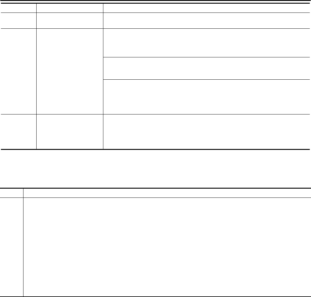
EC-1256
< ECU DIAGNOSIS > [FOR MEXICO]
ECM
DTC Inspection Priority Chart INFOID:0000000004494410
If some DTCs are displayed at the same time, perform inspections one by one based on the following priority
chart.
P2118 Throttle control motor ECM stops the electric throttle control actuator control, throttle valve is maintained at a
fixed opening (approx. 5 degrees) by the return spring.
P2119 Electric throttle control ac-
tuator
(When electric throttle control actuator does not function properly due to the return spring
malfunction:)
ECM controls the electric throttle actuator by regulating the throttle opening around the
idle position. The engine speed will not rise more than 2,000 rpm.
(When throttle valve opening angle in fail-safe mode is not in specified range:)
ECM controls the electric throttle control actuator by regulating the throttle opening to 20
degrees or less.
(When ECM detects the throttle valve is stuck open:)
While the vehicle being driven, it slows down gradually because of fuel cut. After the ve-
hicle stops, the engine stalls.
The engine can restart in N or P (CVT), Neutral (M/T) position, and engine speed will not
exceed 1,000 rpm or more.
P2122
P2123
P2127
P2128
P2138
Accelerator pedal position
sensor
The ECM controls the electric throttle control actuator in regulating the throttle opening in
order for the idle position to be within +10 degrees.
The ECM regulates the opening speed of the throttle valve to be slower than the normal
condition.
Therefore, the acceleration will be poor.
DTC No. Detected items Engine operating condition in fail-safe mode
Priority Detected items (DTC)
1 • U0101 U0140 U1001 CAN communication line
• P0101 P0102 P0103 Mass air flow sensor
• P0112 P0113 P0127 Intake air temperature sensor
• P0117 P0118 P0125 Engine coolant temperature sensor
• P0122 P0123 P0222 P0223 P1225 P1226 P2135 Throttle position sensor
• P0128 Thermostat function
• P0327 P0328 Knock sensor
• P0335 Crankshaft position sensor (POS)
• P0340 Camshaft position sensor (PHASE)
• P0500 Vehicle speed sensor
• P0605 P0607 ECM
• P0643 Sensor power supply
• P0705 P0850 Park/neutral position (PNP) switch
• P1610 - P1615 NATS
• P2122 P2123 P2127 P2128 P2138 Accelerator pedal position sensor
Revision: 2008 August 2009 Rogue
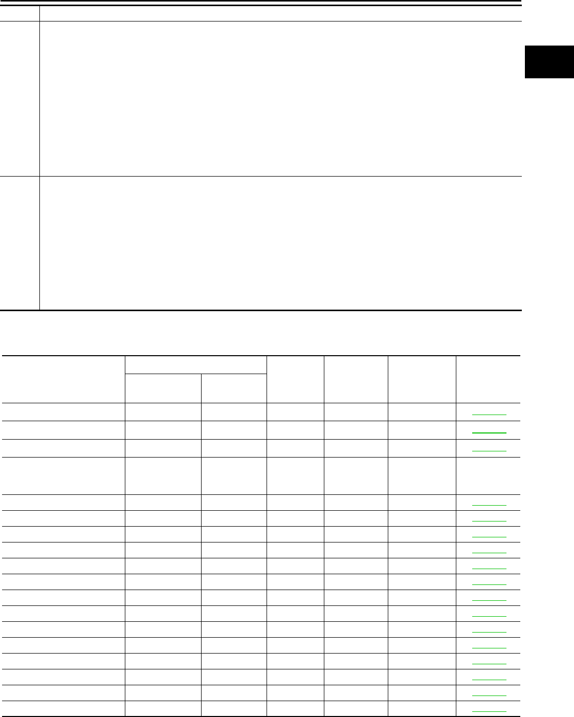
ECM
EC-1257
< ECU DIAGNOSIS > [FOR MEXICO]
C
D
E
F
G
H
I
J
K
L
M
A
EC
N
P
O
DTC Index INFOID:0000000004529135
×:Applicable —: Not applicable
2 • P0031 P0032 Air fuel ratio (A/F) sensor 1 heater
• P0037 P0038 Heated oxygen sensor 2 heater
• P0075 Intake valve timing control solenoid valve
• P0130 P0131 P0132 P0133 P2A00 Air fuel ratio (A/F) sensor 1
• P0137 P0138 P0139 Heated oxygen sensor 2
• P0444 P0445 EVAP canister purge volume control solenoid valve
• P0603 ECM power supply
• P0710 P0715 P0720 P0740 P0744 P0745 P0746 P0776 P0778 P0840 P1740 P1777 P1778 CVT related sensors, solenoid
valves and switches
• P1217 Engine over temperature (OVERHEAT)
• P1805 Brake switch
• P2100 P2103 Throttle control motor relay
• P2101 Electric throttle control function
• P2118 Throttle control motor
3 • P0011 Intake valve timing control
• P0171 P0172 Fuel injection system function
• P0300 - P0304 Misfire
• P0420 Three way catalyst function
• P0506 P0507 Idle speed control system
• P1148 Closed loop control
• P1421 Cold start control
• P1564 ASCD steering switch
• P1572 ASCD brake switch
• P1574 ASCD vehicle speed sensor
• P1715 Primary speed sensor
• P2119 Electric throttle control actuator
Priority Detected items (DTC)
Items
(CONSULT-III screen terms)
DTC*1
SRT code Trip MIL Reference
page
CONSULT-III
GST*2ECM*3
LOST COMM (TCM) U0101 0101*4—1 ×EC-1024
LOST COMM (BCM) U0140 0140*4—1 ×EC-1025
CAN COMM CIRCUIT U1001 1001*4—2 —EC-1026
NO DTC IS DETECTED.
FURTHER TESTING
MAY BE REQUIRED. P0000 0000 ——
Flashing*7—
INT/V TIM CONT-B1 P0011 0011 — 2 ×EC-1027
A/F SEN1 HTR (B1) P0031 0031 — 2 ×EC-1031
A/F SEN1 HTR (B1) P0032 0032 — 2 ×EC-1031
HO2S2 HTR (B1) P0037 0037 — 2 ×EC-1034
HO2S2 HTR (B1) P0038 0038 — 2 ×EC-1034
INT/V TIM V/CIR-B1 P0075 0075 — 2 ×EC-1037
MAF SEN/CIRCUIT-B1 P0101 0101 — 2 ×EC-1040
MAF SEN/CIRCUIT-B1 P0102 0102 — 1 ×EC-1047
MAF SEN/CIRCUIT-B1 P0103 0103 — 1 ×EC-1047
IAT SEN/CIRCUIT-B1 P0112 0112 — 2 ×EC-1052
IAT SEN/CIRCUIT-B1 P0113 0113 — 2 ×EC-1052
ECT SEN/CIRC P0117 0117 — 1 ×EC-1055
ECT SEN/CIRC P0118 0118 — 1 ×EC-1055
TP SEN 2/CIRC-B1 P0122 0122 — 1 ×EC-1058
Revision: 2008 August 2009 Rogue

EC-1258
< ECU DIAGNOSIS > [FOR MEXICO]
ECM
TP SEN 2/CIRC-B1 P0123 0123 — 1 ×EC-1058
ECT SENSOR P0125 0125 — 2 ×EC-1061
IAT SENSOR-B1 P0127 0127 — 2 ×EC-1064
THERMSTAT FNCTN P0128 0128 — 2 ×EC-1066
A/F SENSOR1 (B1) P0130 0130 — 2 ×EC-1068
A/F SENSOR1 (B1) P0131 0131 — 2 ×EC-1072
A/F SENSOR1 (B1) P0132 0132 — 2 ×EC-1075
A/F SENSOR1 (B1) P0133 0133 ×2×EC-1078
HO2S2 (B1) P0137 0137 ×2×EC-1083
HO2S2 (B1) P0138 0138 ×2×EC-1089
HO2S2 (B1) P0139 0139 ×2×EC-1096
FUEL SYS-LEAN-B1 P0171 0171 — 2 ×EC-1102
FUEL SYS-RICH-B1 P0172 0172 — 2 ×EC-1106
TP SEN 1/CIRC-B1 P0222 0222 — 1 ×EC-1110
TP SEN 1/CIRC-B1 P0223 0223 — 1 ×EC-1110
MULTI CYL MISFIRE P0300 0300 — 2 ×EC-1113
CYL 1 MISFIRE P0301 0301 — 2 ×EC-1113
CYL 2 MISFIRE P0302 0302 — 2 ×EC-1113
CYL 3 MISFIRE P0303 0303 — 2 ×EC-1113
CYL 4 MISFIRE P0304 0304 — 2 ×EC-1113
KNOCK SEN/CIRC-B1 P0327 0327 — 2 — EC-1118
KNOCK SEN/CIRC-B1 P0328 0328 — 2 — EC-1118
CKP SEN/CIRCUIT P0335 0335 — 2 ×EC-1120
CMP SEN/CIRC-B1 P0340 0340 — 2 ×EC-1124
TW CATALYST SYS-B1 P0420 0420 ×2×EC-1128
PURG VOLUME CONT/V P0444 0444 — 2 ×EC-1133
PURG VOLUME CONT/V P0445 0445 — 2 ×EC-1133
VEH SPEED SEN/CIRC*5P0500 0500 — 2 ×EC-1136
ISC SYSTEM P0506 0506 — 2 ×EC-1138
ISC SYSTEM P0507 0507 — 2 ×EC-1140
ECM BACK UP/CIRCUIT P0603 0603 — 2 ×EC-1142
ECM P0605 0605 — 1 or 2 × or — EC-1144
ECM P0607 0607 — 1 ×EC-1146
SENSOR POWER/CIRC P0643 0643 — 1 ×EC-1147
PNP SW/CIRC P0705 0705 — 2 ×TM-53
ATF TEMP SEN/CIRC P0710 0710 — 1 ×TM-56
INPUT SPD SEN/CIRC P0715 0715 — 2 ×TM-59
VEH SPD SEN/CIR AT*5P0720 0720 — 2 ×TM-63
TCC SOLENOID/CIRC P0740 0740 — 2 ×TM-69
A/T TCC S/V FNCTN P0744 0744 — 2 ×TM-71
L/PRESS SOL/CIRC P0745 0745 — 2 ×TM-73
PRS CNT SOL/A FCTN P0746 0746 — 1 ×TM-75
Items
(CONSULT-III screen terms)
DTC*1
SRT code Trip MIL Reference
page
CONSULT-III
GST*2ECM*3
Revision: 2008 August 2009 Rogue

ECM
EC-1259
< ECU DIAGNOSIS > [FOR MEXICO]
C
D
E
F
G
H
I
J
K
L
M
A
EC
N
P
O
*1: 1st trip DTC No. is the same as DTC No.
*2: This number is prescribed by SAE J2012.
*3: In Diagnostic Test Mode II (Self-diagnostic results), this number is controlled by NISSAN.
*4: The troubleshooting for this DTC needs CONSULT-III.
PRS CNT SOL/B FCTN P0776 0776 — 2 ×TM-77
PRS CNT SOL/B CIRC P0778 0778 — 2 ×TM-80
TR PRS SENS/A CIRC P0840 0840 — 2 ×TM-87
P-N POS SW/CIRCUIT P0850 0850 — 2 ×EC-1149
CLOSED LOOP-B1 P1148 1148 — 1 ×EC-1152
ENG OVER TEMP P1217 1217 — 1 ×EC-1153
CTP LEARNING-B1 P1225 1225 — 2 — EC-1157
CTP LEARNING-B1 P1226 1226 — 2 — EC-1159
COLD START CONTROL P1421 1421 — 2 ×EC-1161
ASCD SW P1564 1564 — 1 — EC-1163
ASCD BRAKE SW P1572 1572 — 1 — EC-1166
ASCD VHL SPD SEN P1574 1574 — 1 — EC-1171
LOCK MODE P1610 1610 — 2 — SEC-34*8
SEC-168*9
ID DISCORD,IMMU-ECM P1611 1611 — 2 — SEC-35*8
SEC-169*9
CHAIN OF ECM-IMMU P1612 1612 — 2 — SEC-37*8
SEC-171*9
CHAIN OF IMMU-KEY P1614 1614 — 2 — SEC-38*8
SEC-172*9
DIFFERENCE OF KEY P1615 1615 — 2 — SEC-40*8
SEC-174*9
IN PULY SPEED P1715 1715 — 2 — EC-1173
LU-SLCT SOL/CIRC P1740 1740 — 2 ×TM-104
STEP MOTOR CIRC P1777 1777 — 1 ×TM-107
STEP MOTOR FNCT P1778 1778 — 2 ×TM-110
BRAKE SW/CIRCUIT P1805 1805 — 2 — EC-1175
ETC MOT PWR-B1 P2100 2100 — 1 ×EC-1177
ETC FNCTN/CIRC-B1 P2101 2101 — 1 ×EC-1179
ETC MOT PWR P2103 2103 — 1 ×EC-1177
ETC MOT-B1 P2118 2118 — 1 ×EC-1183
ETC ACTR-B1 P2119 2119 — 1 ×EC-1185
APP SEN 1/CIRC P2122 2122 — 1 ×EC-1187
APP SEN 1/CIRC P2123 2123 — 1 ×EC-1187
APP SEN 2/CIRC P2127 2127 — 1 ×EC-1190
APP SEN 2/CIRC P2128 2128 — 1 ×EC-1190
TP SENSOR-B1 P2135 2135 — 1 ×EC-1194
APP SENSOR P2138 2138 — 1 ×EC-1198
A/F SENSOR1 (B1) P2A00 2A00 — 2 ×EC-1202
Items
(CONSULT-III screen terms)
DTC*1
SRT code Trip MIL Reference
page
CONSULT-III
GST*2ECM*3
Revision: 2008 August 2009 Rogue

EC-1260
< ECU DIAGNOSIS > [FOR MEXICO]
ECM
*5: When the fail-safe operations for both self-diagnoses occur, the MIL illuminates.
*6: SRT code will not be set if the self-diagnostic result is NG.
*7: When the ECM is in the mode that displays SRT status, MIL may flash. For the details, refer to “How to Display SRT Status”.
*8: Models with intelligent system
*9: Models without intelligent system
How to Set SRT Code INFOID:0000000004494412
To set all SRT codes, self-diagnosis for the items indicated above must be performed one or more times. Each
diagnosis may require a long period of actual driving under various conditions.
WITH CONSULT-III
Perform corresponding DTC CONFIRMATION PROCEDURE one by one based on Performance Priority in
the table on “SRT Item”.
WITHOUT CONSULT-III
The most efficient driving pattern in which SRT codes can be properly set is explained below. The driving pat-
tern should be performed one or more times to set all SRT codes.
Revision: 2008 August 2009 Rogue
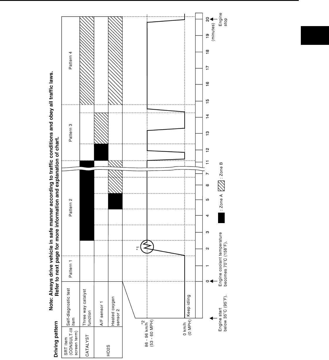
ECM
EC-1261
< ECU DIAGNOSIS > [FOR MEXICO]
C
D
E
F
G
H
I
J
K
L
M
A
EC
N
P
O
DRIVING PATTERN
• The time required for each diagnosis varies with road surface conditions, weather, altitude, individual driving
habits, etc.
Zone A refers to the range where the time, required for the diagnosis under normal conditions*, is the short-
est.
Zone B refers to the range where the diagnosis can still be performed if the diagnosis is not completed within
zone A.
*: Normal conditions refer to the following:
JMBIA0864G
B
Revision: 2008 August 2009 Rogue
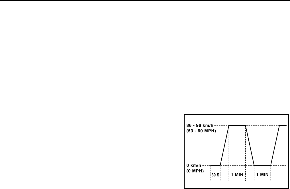
EC-1262
< ECU DIAGNOSIS > [FOR MEXICO]
ECM
• Sea level
• Flat road
• Ambient air temperature: 20 - 30°C (68 - 86°F)
• Diagnosis is performed as quickly as possible under normal conditions.
Under different conditions [For example: ambient air temperature other than 20 - 30°C (68 - 86°F)], diagno-
sis may also be performed.
Pattern 1:
•The engine is started at the engine coolant temperature of −10 to 35°C (14 to 95°F)
[where the voltage between the ECM terminals 46 (Engine coolant temperature sensor signal) and 52
(Sensor ground) is 3.0 - 4.3V].
•The engine must be operated at idle speed until the engine coolant temperature is greater than 70°C
(158°F) [where the voltage between the ECM terminals 46 (Engine coolant temperature sensor sig-
nal) and 52 (Sensor ground) is lower than 1.4V].
Pattern 2:
• When steady-state driving is performed again even after it is interrupted, each diagnosis can be conducted.
In this case, the time required for diagnosis may be extended.
Pattern 3:
• Operate vehicle following the driving pattern shown in the figure.
• Release the accelerator pedal during decelerating vehicle speed
from 90 km/h (56 MPH) to 0 km/h (0 MPH).
Pattern 4:
• The accelerator pedal must be held very steady during steady-
state driving.
• If the accelerator pedal is moved, the test must be conducted all
over again.
*1: Depress the accelerator pedal until vehicle speed is 90 km/h (56
MPH), then release the accelerator pedal and keep it released for
more than 10 seconds. Depress the accelerator pedal until vehicle
speed is 90 km/h (56 MPH) again.
*2: Checking the vehicle speed with GST is advised.
Suggested Transmission Gear Position for CVT Models
Set the selector lever in the D position.
Test Value and Test Limit INFOID:0000000004494413
The following is the information specified in Service $06 of SAE J1979.
The test value is a parameter used to determine whether a system/circuit diagnostic test is OK or NG while
being monitored by the ECM during self-diagnosis. The test limit is a reference value which is specified as the
maximum or minimum value and is compared with the test value being monitored.
These data (test value and test limit) are specified by On Board Monitor ID (OBDMID), Test ID (TID), Unit and
Scaling ID and can be displayed on the GST screen.
The items of the test value and test limit will be displayed with GST screen which items are provided by the
ECM. (e.g., if the bank 2 is not applied on this vehicle, only the items of the bank 1 is displayed)
PBIB2244E
Revision: 2008 August 2009 Rogue

ECM
EC-1263
< ECU DIAGNOSIS > [FOR MEXICO]
C
D
E
F
G
H
I
J
K
L
M
A
EC
N
P
O
Item OBD-
MID Self-diagnostic test item DTC
Test value and
Test limit
(GST display)
Description
TID
Unit
and
Scaling
ID
HO2S
01H Air fuel ratio (A/F) sensor 1
(Bank 1)
P0131 83H 0BH Minimum sensor output voltage for test cycle
P0131 84H 0BH Maximum sensor output voltage for test cycle
P0130 85H 0BH Minimum sensor output voltage for test cycle
P0130 86H 0BH Maximum sensor output voltage for test cycle
P0133 87H 04H Response rate: Response ratio (Lean to Rich)
P0133 88H 04H Response rate: Response ratio (Rich to Lean)
P2A00 89H 84H The amount of shift in air fuel ratio
P2A00 8AH 84H The amount of shift in air fuel ratio
P0130 8BH 0BH Difference in sensor output voltage
P0133 8CH 83H Response gain at the limited frequency
02H Heated oxygen sensor 2
(Bank 1)
P0138 07H 0CH Minimum sensor output voltage for test cycle
P0137 08H 0CH Maximum sensor output voltage for test cycle
P0138 80H 0CH Sensor output voltage
P0139 81H 0CH Difference in sensor output voltage
03H Heated oxygen sensor 3
(Bank 1)
P0143 07H 0CH Minimum sensor output voltage for test cycle
P0144 08H 0CH Maximum sensor output voltage for test cycle
P0146 80H 0CH Sensor output voltage
P0145 81H 0CH Difference in sensor output voltage
HO2S
05H Air fuel ratio (A/F) sensor 1
(Bank 2)
P0151 83H 0BH Minimum sensor output voltage for test cycle
P0151 84H 0BH Maximum sensor output voltage for test cycle
P0150 85H 0BH Minimum sensor output voltage for test cycle
P0150 86H 0BH Maximum sensor output voltage for test cycle
P0153 87H 04H Response rate: Response ratio (Lean to Rich)
P0153 88H 04H Response rate: Response ratio (Rich to Lean)
P2A03 89H 84H The amount of shift in air fuel ratio
P2A03 8AH 84H The amount of shift in air fuel ratio
P0150 8BH 0BH Difference in sensor output voltage
P0153 8CH 83H Response gain at the limited frequency
06H Heated oxygen sensor 2
(Bank 2)
P0158 07H 0CH Minimum sensor output voltage for test cycle
P0157 08H 0CH Maximum sensor output voltage for test cycle
P0158 80H 0CH Sensor output voltage
P0159 81H 0CH Difference in sensor output voltage
07H Heated oxygen sensor 3
(Bank2)
P0163 07H 0CH Minimum sensor output voltage for test cycle
P0164 08H 0CH Maximum sensor output voltage for test cycle
P0166 80H 0CH Sensor output voltage
P0165 81H 0CH Difference in sensor output voltage
Revision: 2008 August 2009 Rogue

EC-1264
< ECU DIAGNOSIS > [FOR MEXICO]
ECM
CATA-
LYST
21H Three way catalyst func-
tion (Bank1)
P0420 80H 01H O2 storage index
P0420 82H 01H Switching time lag engine exhaust index val-
ue
P2423 83H 0CH Difference in 3rd O2 sensor output voltage
P2423 84H 84H O2 storage index in HC trap catalyst
22H Three way catalyst func-
tion (Bank2)
P0430 80H 01H O2 storage index
P0430 82H 01H Switching time lag engine exhaust index val-
ue
P2424 83H 0CH Difference in 3rd O2 sensor output voltage
P2424 84H 84H O2 storage index in HC trap catalyst
EGR
SYSTEM 31H EGR function
P0400 80H 96H Low Flow Faults: EGR temp change rate
(short term)
P0400 81H 96H Low Flow Faults: EGR temp change rate
(long term)
P0400 82H 96H Low Flow Faults: Difference between max
EGR temp and EGR temp under idling condi-
tion
P0400 83H 96H Low Flow Faults: Max EGR temp
P1402 84H 96H High Flow Faults: EGR temp increase rate
EVAP
SYSTEM
39H EVAP control system leak
(Cap Off) P0455 80H 0CH Difference in pressure sensor output voltage
before and after pull down
3BH EVAP control system leak
(Small leak) P0442 80H 05H Leak area index (for more than 0.04inch)
3CH EVAP control system
(Very small leak)
P0456 80H 05H Leak area index (for more than 0.02inch)
P0456 81H FDH Maximum internal pressure of EVAP system
during monitoring
3DH Purge flow system P0441 83H 0CH Difference in pressure sensor output voltage
before and after vent control value close
O2 SEN-
SOR
HEATER
41H A/F sensor 1 heater
(Bank 1)
Low Input:P0031
High Input:P0032 81H 0BH Converted value of Heater electric current to
voltage
42H Heated oxygen sensor 2
(Bank 1) Low Input:P0037
High Input:P0038 80H 0CH Converted value of Heater electric current to
voltage
43H Heated oxygen sensor 3
(Bank 1) P0043 80H 0CH Converted value of Heater electric current to
voltage
45H A/F sensor 1 heater
(Bank 2)
Low Input:P0051
High Input:P0052 81H 0BH Converted value of Heater electric current to
voltage
46H Heated oxygen sensor 2
(Bank 2) Low Input:P0057
High Input:P0058 80H 0CH Converted value of Heater electric current to
voltage
47H Heated oxygen sensor 3
(Bank 2) P0063 80H 0CH Converted value of Heater electric current to
voltage
Item OBD-
MID Self-diagnostic test item DTC
Test value and
Test limit
(GST display)
Description
TID
Unit
and
Scaling
ID
Revision: 2008 August 2009 Rogue

ECM
EC-1265
< ECU DIAGNOSIS > [FOR MEXICO]
C
D
E
F
G
H
I
J
K
L
M
A
EC
N
P
O
SEC-
OND-
ARY AIR
71H Secondary Air system
P0411 80H 01H Secondary Air Injection System Incorrect
Flow Detected
Bank1: P0491
Bank2: P0492 81H 01H Secondary Air Injection System Insufficient
Flow
P2445 82H 01H Secondary Air Injection System Pump Stuck
Off
P2448 83H 01H Secondary Air Injection System High Airflow
Bank1: P2440
Bank2: P2442 84H 01H Secondary Air Injection System Switching
Valve Stuck Open
P2440 85H 01H Secondary Air Injection System Switching
Valve Stuck Open
P2444 86H 01H Secondary Air Injection System Pump Stuck
On
FUEL
SYSTEM
81H Fuel injection system
function (Bank 1)
P0171 or P0172 80H 2FH Long term fuel trim
P0171 or P0172 81H 24H The number of lambda control clamped
82H Fuel injection system
function (Bank 2)
P0174 or P0175 80H 2FH Long term fuel trim
P0174 or P0175 81H 24H The number of lambda control clamped
Item OBD-
MID Self-diagnostic test item DTC
Test value and
Test limit
(GST display)
Description
TID
Unit
and
Scaling
ID
Revision: 2008 August 2009 Rogue

EC-1266
< ECU DIAGNOSIS > [FOR MEXICO]
ECM
MISFIRE A1H Multiple Cylinder Misfire
P0301 80H 24H Misfiring counter at 1000rev of the first cylin-
der
P0302 81H 24H Misfiring counter at 1000rev of the second
cylinder
P0303 82H 24H Misfiring counter at 1000rev of the third cylin-
der
P0304 83H 24H Misfiring counter at 1000rev of the fourth cyl-
inder
P0305 84H 24H Misfiring counter at 1000rev of the fifth cylin-
der
P0306 85H 24H Misfiring counter at 1000rev of the sixth cylin-
der
P0307 86H 24H Misfiring counter at 1000rev of the seventh
cylinder
P0308 87H 24H Misfiring counter at 1000rev of the eighth cyl-
inder
P0300 88H 24H Misfiring counter at 1000rev of the multiple
cylinders
P0301 89H 24H Misfiring counter at 200rev of the first cylinder
P0302 8AH 24H Misfiring counter at 200rev of the second cyl-
inder
P0303 8BH 24H Misfiring counter at 200rev of the third cylin-
der
P0304 8CH 24H Misfiring counter at 200rev of the fourth cylin-
der
P0305 8DH 24H Misfiring counter at 200rev of the fifth cylinder
P0306 8EH 24H Misfiring counter at 200rev of the fifth cylinder
P0307 8FH 24H Misfiring counter at 200rev of the fifth cylinder
P0308 90H 24H Misfiring counter at 200rev of the fifth cylinder
P0300 91H 24H Misfiring counter at 1000rev of the single cyl-
inder
P0300 92H 24H Misfiring counter at 200rev of the single cylin-
der
P0300 93H 24H Misfiring counter at 200rev of the multiple cyl-
inders
Item OBD-
MID Self-diagnostic test item DTC
Test value and
Test limit
(GST display)
Description
TID
Unit
and
Scaling
ID
Revision: 2008 August 2009 Rogue

ECM
EC-1267
< ECU DIAGNOSIS > [FOR MEXICO]
C
D
E
F
G
H
I
J
K
L
M
A
EC
N
P
O
MISFIRE
A2H No.1 Cylinder Misfire P0301 0BH 24H EWMA (Exponential Weighted Moving Aver-
age) misfire counts for last 10 driving cycles
P0301 0CH 24H Misfire counts for last/current driving cycles
A3H No.2 Cylinder Misfire P0302 0BH 24H EWMA (Exponential Weighted Moving Aver-
age) misfire counts for last 10 driving cycles
P0302 0CH 24H Misfire counts for last/current driving cycles
A4H No.3 Cylinder Misfire P0303 0BH 24H EWMA (Exponential Weighted Moving Aver-
age) misfire counts for last 10 driving cycles
P0303 0CH 24H Misfire counts for last/current driving cycles
A5H No.4 Cylinder Misfire P0304 0BH 24H EWMA (Exponential Weighted Moving Aver-
age) misfire counts for last 10 driving cycles
P0304 0CH 24H Misfire counts for last/current driving cycles
A6H No.5 Cylinder Misfire P0305 0BH 24H EWMA (Exponential Weighted Moving Aver-
age) misfire counts for last 10 driving cycles
P0305 0CH 24H Misfire counts for last/current driving cycles
A7H No.6 Cylinder Misfire P0306 0BH 24H EWMA (Exponential Weighted Moving Aver-
age) misfire counts for last 10 driving cycles
P0306 0CH 24H Misfire counts for last/current driving cycles
A8H No.7 Cylinder Misfire P0307 0BH 24H EWMA (Exponential Weighted Moving Aver-
age) misfire counts for last 10 driving cycles
P0307 0CH 24H Misfire counts for last/current driving cycles
A9H No.8 Cylinder Misfire P0308 0BH 24H EWMA (Exponential Weighted Moving Aver-
age) misfire counts for last 10 driving cycles
P0308 0CH 24H Misfire counts for last/current driving cycles
Item OBD-
MID Self-diagnostic test item DTC
Test value and
Test limit
(GST display)
Description
TID
Unit
and
Scaling
ID
Revision: 2008 August 2009 Rogue

EC-1268
< SYMPTOM DIAGNOSIS > [FOR MEXICO]
ENGINE CONTROL SYSTEM SYMPTOMS
SYMPTOM DIAGNOSIS
ENGINE CONTROL SYSTEM SYMPTOMS
Symptom Table INFOID:0000000004494414
SYSTEM — BASIC ENGINE CONTROL SYSTEM
SYMPTOM
Reference
page
HARD/NO START/RESTART (EXCP. HA)
ENGINE STALL
HESITATION/SURGING/FLAT SPOT
SPARK KNOCK/DETONATION
LACK OF POWER/POOR ACCELERATION
HIGH IDLE/LOW IDLE
ROUGH IDLE/HUNTING
IDLING VIBRATION
SLOW/NO RETURN TO IDLE
OVERHEATS/WATER TEMPERATURE HIGH
EXCESSIVE FUEL CONSUMPTION
EXCESSIVE OIL CONSUMPTION
BATTERY DEAD (UNDER CHARGE)
Warranty symptom code AA AB AC AD AE AF AG AH AJ AK AL AM HA
Fuel Fuel pump circuit 11232 22 3 2EC-1220
Fuel pressure regulator system 334444444 4 EC-1279
Fuel injector circuit 11232 22 2 EC-1217
Evaporative emission system 334444444 4 EC-979
Air Positive crankcase ventilation sys-
tem 334444444 41 EC-1229
Incorrect idle speed adjustment 1 1 1 1 1 EC-936
Electric throttle control actuator 112332222 2 2
EC-1179
EC-1185
IgnitionIncorrect ignition timing adjustment33111 11 1 EC-937
Ignition circuit 11222 22 2 EC-1223
Main power supply and ground circuit 22333 33 23 EC-1020
Mass air flow sensor circuit
1
12
2
222 2
EC-1040
EC-1047
Engine coolant temperature sensor circuit
3
33 EC-1055
EC-1061
Air fuel ratio (A/F) sensor 1 circuit
EC-1068
EC-1072
EC-1075
EC-1078
EC-1202
Throttle position sensor circuit
22
EC-1058
EC-1110
EC-1157
EC-1159
EC-1194
Accelerator pedal position sensor circuit 3 2 1 EC-1187
EC-1190
EC-1198
Knock sensor circuit 2 3 EC-1118
Revision: 2008 August 2009 Rogue

ENGINE CONTROL SYSTEM SYMPTOMS
EC-1269
< SYMPTOM DIAGNOSIS > [FOR MEXICO]
C
D
E
F
G
H
I
J
K
L
M
A
EC
N
P
O
1 - 6: The numbers refer to the order of inspection.
SYSTEM — ENGINE MECHANICAL & OTHER
Crankshaft position sensor (POS) circuit 2 2 EC-1120
Camshaft position sensor (PHASE) circuit 3 2 EC-1124
Vehicle speed signal circuit 2 3 3 3 EC-1136
ECM 22333333333 EC-1142
EC-1144
Intake valve timing control solenoid valve cir-
cuit 32 13223 3 EC-1037
PNP switch circuit 3 3 3 3 3 EC-1149
Refrigerant pressure sensor circuit 2 3 3 4 EC-1230
Electrical load signal circuit 3 EC-1215
Air conditioner circuit 223333333 3 2HAC-20
ABS actuator and electric unit (control unit) 4 BRC-15
BRC-93
SYMPTOM
Reference
page
HARD/NO START/RESTART (EXCP. HA)
ENGINE STALL
HESITATION/SURGING/FLAT SPOT
SPARK KNOCK/DETONATION
LACK OF POWER/POOR ACCELERATION
HIGH IDLE/LOW IDLE
ROUGH IDLE/HUNTING
IDLING VIBRATION
SLOW/NO RETURN TO IDLE
OVERHEATS/WATER TEMPERATURE HIGH
EXCESSIVE FUEL CONSUMPTION
EXCESSIVE OIL CONSUMPTION
BATTERY DEAD (UNDER CHARGE)
Warranty symptom code AA AB AC AD AE AF AG AH AJ AK AL AM HA
Revision: 2008 August 2009 Rogue

EC-1270
< SYMPTOM DIAGNOSIS > [FOR MEXICO]
ENGINE CONTROL SYSTEM SYMPTOMS
SYMPTOM
Reference
page
HARD/NO START/RESTART (EXCP. HA)
ENGINE STALL
HESITATION/SURGING/FLAT SPOT
SPARK KNOCK/DETONATION
LACK OF POWER/POOR ACCELERATION
HIGH IDLE/LOW IDLE
ROUGH IDLE/HUNTING
IDLING VIBRATION
SLOW/NO RETURN TO IDLE
OVERHEATS/WATER TEMPERATURE HIGH
EXCESSIVE FUEL CONSUMPTION
EXCESSIVE OIL CONSUMPTION
BATTERY DEAD (UNDER CHARGE)
Warranty symptom code AA AB AC AD AE AF AG AH AJ AK AL AM HA
Fuel Fuel tank 5
5
FL-29
Fuel piping 5 5 5 5 5 5 EM-43
Vapor lock —
Valve deposit
5 555 55 5
—
Poor fuel (Heavy weight gasoline,
Low octane) —
Air Air duct
55555 5
EM-27
Air cleaner
Air leakage from air duct
(Mass air flow sensor — electric
throttle control actuator) 5555
Electric throttle control actuator
EM-29
Air leakage from intake manifold/
Collector/Gasket
Cranking Battery 111111
1
1PG-92
Generator circuit CHG-5
Starter circuit 3 STR-5
Signal plate 6 EM-88
PNP switch 4 TM-53
Engine Cylinder head 55555 55 5 EM-79
Cylinder head gasket 4 3
Cylinder block
66666 66 6
4
EM-88
Piston
Piston ring
Connecting rod
Bearing
Crankshaft
Valve
mecha-
nism
Timing chain
55555 55 5
EM-69
Camshaft EM-48
Intake valve timing control EM-69
Intake valve 3EM-79
Exhaust valve
Revision: 2008 August 2009 Rogue
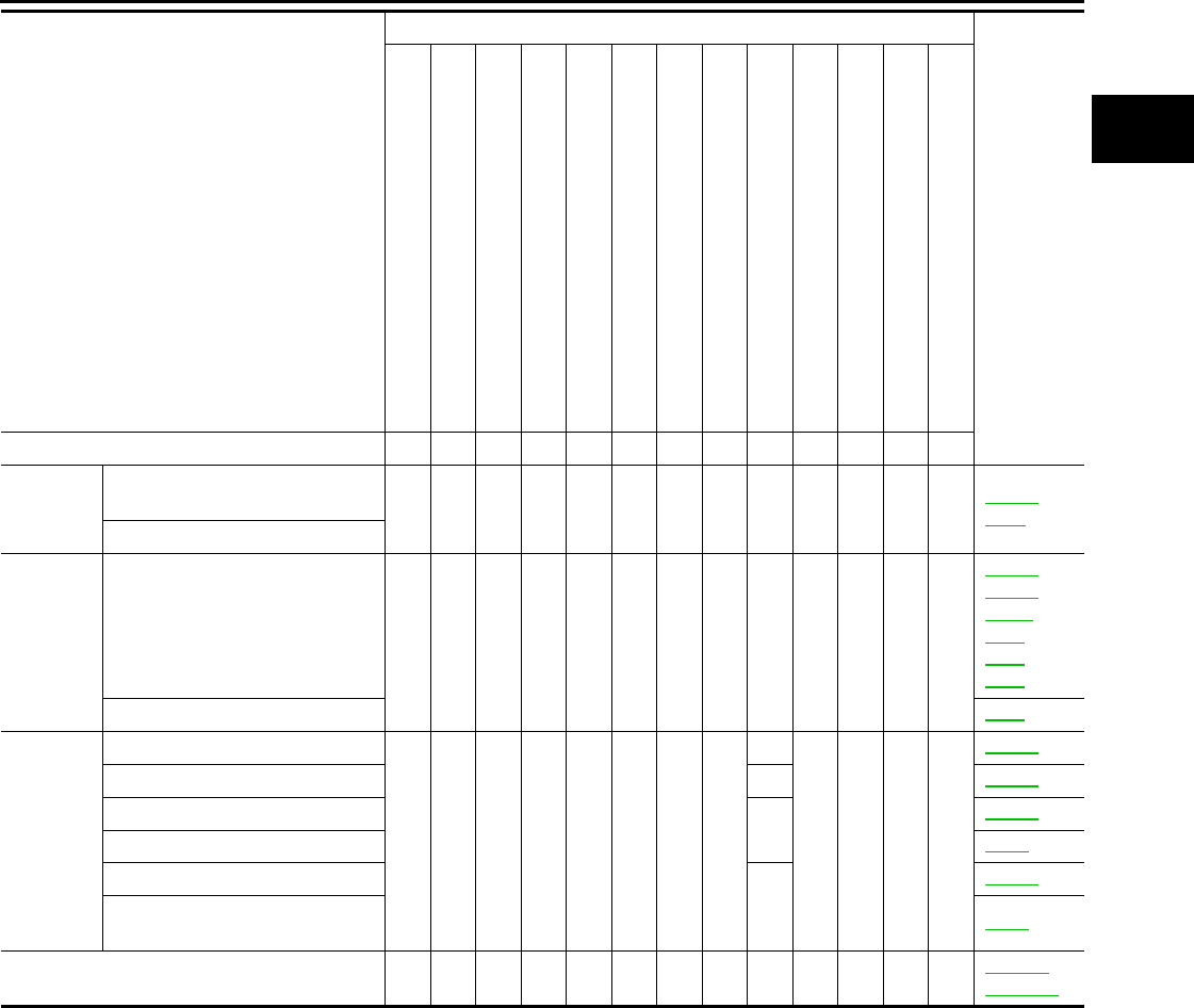
ENGINE CONTROL SYSTEM SYMPTOMS
EC-1271
< SYMPTOM DIAGNOSIS > [FOR MEXICO]
C
D
E
F
G
H
I
J
K
L
M
A
EC
N
P
O
1 - 6: The numbers refer to the order of inspection.
Exhaust Exhaust manifold/Tube/Muffler/
Gasket 55555 55 5 EM-32
EX-5
Three way catalyst
Lubrica-
tion
Oil pan/Oil strainer/Oil pump/Oil
filter/Oil gallery/Oil cooler 55555 55 5
EM-34
EM-37
LU-11
LU-8
LU-2
LU-9
Oil level (Low)/Filthy oil LU-5
Cooling Radiator/Hose/Radiator filler cap
55555 55 45
CO-15
Thermostat 5 CO-25
Water pump CO-23
Water gallery CO-2
Cooling fan
5
CO-21
Coolant level (Low)/Contaminat-
ed coolant CO-9
NVIS (NISSAN Vehicle Immobilizer System —
NATS) 11 SEC-15
SEC-155
SYMPTOM
Reference
page
HARD/NO START/RESTART (EXCP. HA)
ENGINE STALL
HESITATION/SURGING/FLAT SPOT
SPARK KNOCK/DETONATION
LACK OF POWER/POOR ACCELERATION
HIGH IDLE/LOW IDLE
ROUGH IDLE/HUNTING
IDLING VIBRATION
SLOW/NO RETURN TO IDLE
OVERHEATS/WATER TEMPERATURE HIGH
EXCESSIVE FUEL CONSUMPTION
EXCESSIVE OIL CONSUMPTION
BATTERY DEAD (UNDER CHARGE)
Warranty symptom code AA AB AC AD AE AF AG AH AJ AK AL AM HA
Revision: 2008 August 2009 Rogue

EC-1272
< SYMPTOM DIAGNOSIS > [FOR MEXICO]
NORMAL OPERATING CONDITION
NORMAL OPERATING CONDITION
Description INFOID:0000000004494415
FUEL CUT CONTROL (AT NO LOAD AND HIGH ENGINE SPEED)
If the engine speed is above 1,800 rpm under no load (for example, the selector lever position is neutral and
engine speed is over 1,800 rpm) fuel will be cut off after some time. The exact time when the fuel is cut off var-
ies based on engine speed.
Fuel cut will be operated until the engine speed reaches 1,500 rpm, then fuel cut will be cancelled.
NOTE:
This function is different from deceleration control listed under Multiport Fuel Injection (MFI) System, EC-947,
"System Description".
Revision: 2008 August 2009 Rogue

PRECAUTIONS
EC-1273
< PRECAUTION > [FOR MEXICO]
C
D
E
F
G
H
I
J
K
L
M
A
EC
N
P
O
PRECAUTION
PRECAUTIONS
Precaution for Supplemental Restraint System (SRS) "AIR BAG" and "SEAT BELT
PRE-TENSIONER" INFOID:0000000004536403
The Supplemental Restraint System such as “AIR BAG” and “SEAT BELT PRE-TENSIONER”, used along
with a front seat belt, helps to reduce the risk or severity of injury to the driver and front passenger for certain
types of collision. This system includes seat belt switch inputs and dual stage front air bag modules. The SRS
system uses the seat belt switches to determine the front air bag deployment, and may only deploy one front
air bag, depending on the severity of a collision and whether the front occupants are belted or unbelted.
Information necessary to service the system safely is included in the “SRS AIRBAG” and “SEAT BELT” of this
Service Manual.
WARNING:
• To avoid rendering the SRS inoperative, which could increase the risk of personal injury or death in
the event of a collision which would result in air bag inflation, all maintenance must be performed by
an authorized NISSAN/INFINITI dealer.
• Improper maintenance, including incorrect removal and installation of the SRS, can lead to personal
injury caused by unintentional activation of the system. For removal of Spiral Cable and Air Bag
Module, see the “SRS AIRBAG”.
• Never use electrical test equipment on any circuit related to the SRS unless instructed to in this Ser-
vice Manual. SRS wiring harnesses can be identified by yellow and/or orange harnesses or harness
connectors.
Precaution for Procedure without Cowl Top Cover INFOID:0000000004536349
When performing the procedure after removing cowl top cover, cover
the lower end of windshield with urethane, etc.
Precautions For Xenon Headlamp Service INFOID:0000000004543125
WARNING:
Comply with the following warnings to prevent any serious accident.
• Disconnect the battery cable (negative terminal) or the power supply fuse before installing, remov-
ing, or touching the xenon headlamp (bulb included). The xenon headlamp contains high-voltage
generated parts.
• Never work with wet hands.
• Check the xenon headlamp ON-OFF status after assembling it to the vehicle. Never turn the xenon
headlamp ON in other conditions. Connect the power supply to the vehicle-side connector.
(Turning it ON outside the lamp case may cause fire or visual impairments.)
• Never touch the bulb glass immediately after turning it OFF. It is extremely hot.
CAUTION:
Comply with the following cautions to prevent any error and malfunction.
• Install the xenon bulb securely. (Insufficient bulb socket installation may melt the bulb, the connec-
tor, the housing, etc. by high-voltage leakage or corona discharge.)
• Never perform HID circuit inspection with a tester.
• Never touch the xenon bulb glass with hands. Never put oil and grease on it.
• Dispose of the used xenon bulb after packing it in thick vinyl without breaking it.
• Never wipe out dirt and contamination with organic solvent (thinner, gasoline, etc.).
PIIB3706J
Revision: 2008 August 2009 Rogue

EC-1274
< PRECAUTION > [FOR MEXICO]
PRECAUTIONS
On Board Diagnostic (OBD) System of Engine and CVT INFOID:0000000004494419
The ECM has an on board diagnostic system. It will illuminate the malfunction indicator lamp (MIL) to warn the
driver of a malfunction causing emission deterioration.
CAUTION:
• Always turn the ignition switch OFF and disconnect the negative battery cable before any repair or
inspection work. The open/short circuit of related switches, sensors, solenoid valves, etc. will cause
the MIL to illuminate.
• Always connect and lock the connectors securely after work. A loose (unlocked) connector will
cause the MIL to illuminate due to the open circuit. (Be sure the connector is free from water, grease,
dirt, bent terminals, etc.)
• Certain systems and components, especially those related to OBD, may use a new style slide-lock-
ing type harness connector. For description and how to disconnect, refer to PG-82, "Description".
• Always route and secure the harnesses properly after work. The interference of the harness with a
bracket, etc. may cause the MIL to illuminate due to the short circuit.
• Always connect rubber tubes properly after work. A misconnected or disconnected rubber tube may
cause the MIL to illuminate due to the malfunction of the EVAP system or fuel injection system, etc.
• Always erase the unnecessary malfunction information (repairs completed) from the ECM and TCM
(Transmission control module) before returning the vehicle to the customer.
General Precautions INFOID:0000000004494420
•Always use a 12 volt battery as power source.
•Never attempt to disconnect battery cables while engine is
running.
•Before connecting or disconnecting the ECM harness con-
nector, turn ignition switch OFF and disconnect negative bat-
tery cable. Failure to do so may damage the ECM because
battery voltage is applied to ECM even if ignition switch is
turned OFF.
•Before removing parts, turn ignition switch OFF and then dis-
connect negative battery cable.
•Never disassemble ECM.
•If a battery cable is disconnected, the memory will return to
the ECM value.
The ECM will now start to self-control at its initial value. Thus
engine operation can vary slightly in this case. However, this
is not an indication of a malfunction. Never replace parts
because of a slight variation.
•If the battery is disconnected, the following emission-related
diagnostic information will be cleared within 24 hours.
-Diagnostic trouble codes
-1st trip diagnostic trouble codes
-Freeze frame data
-1st trip freeze frame data
-System readiness test (SRT) codes
-Test values
•When connecting ECM harness connector (1), fasten (B) it
securely with a lever as far as it will go as shown in the figure.
SEF289H
2. ECM
A. Loosen
PBIA9222J
PBIB2947E
Revision: 2008 August 2009 Rogue
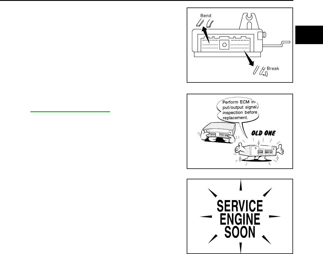
PRECAUTIONS
EC-1275
< PRECAUTION > [FOR MEXICO]
C
D
E
F
G
H
I
J
K
L
M
A
EC
N
P
O
•When connecting or disconnecting pin connectors into or
from ECM, never damage pin terminals (berds or breaks).
Check that there are not any bends or breaks on ECM pin ter-
minal, when connecting pin connectors.
•Securely connect ECM harness connectors.
A poor connection can cause an extremely high (surge) volt-
age to develop in coil and condenser, thus resulting in dam-
age to ICs.
•Keep engine control system harness at least 10 cm (4 in) away
from adjacent harness, to prevent engine control system mal-
functions due to receiving external noise, degraded operation
of ICs, etc.
•Keep engine control system parts and harness dry.
•Before replacing ECM, perform ECM Terminals and Reference
Value inspection and check that ECM functions properly.
Refer to EC-1232, "Reference Value".
•Handle mass air flow sensor carefully to avoid damage.
•Never clean mass air flow sensor with any type of detergent.
•Never disassemble electric throttle control actuator.
•Even a slight leak in the air intake system can cause serious
incidents.
•Never shock or jar the camshaft position sensor (PHASE),
crankshaft position sensor (POS).
•After performing each TROUBLE DIAGNOSIS, perform DTC
CONFIRMATION PROCEDURE or Component Function
Check. The DTC should not be displayed in the DTC CONFIRMA-
TION PROCEDURE if the repair is completed. The Component
Function Check should be a good result if the repair is completed.
PBIB0090E
MEF040D
SEF217U
Revision: 2008 August 2009 Rogue
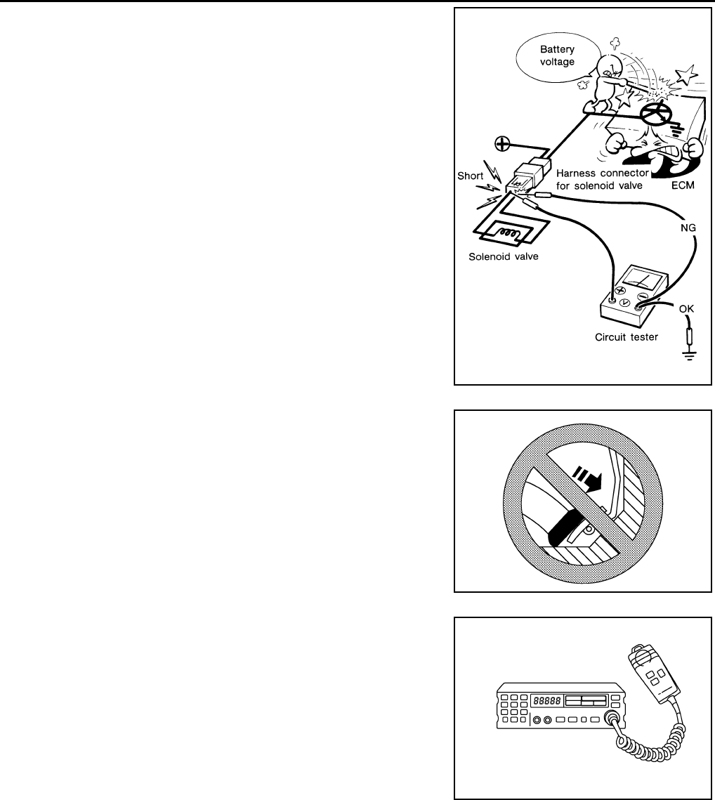
EC-1276
< PRECAUTION > [FOR MEXICO]
PRECAUTIONS
•When measuring ECM signals with a circuit tester, never allow
the two tester probes to contact.
Accidental contact of probes will cause a short circuit and
damage the ECM power transistor.
•Never operate fuel pump when there is no fuel in lines.
•Tighten fuel hose clamps to the specified torque.
•Never depress accelerator pedal when starting.
•Immediately after starting, never rev up engine unnecessarily.
•Never rev up engine just prior to shutdown.
•When installing C.B. ham radio or a mobile phone, always
observe the following as it may adversely affect electronic
control systems depending on installation location.
-Keep the antenna as far as possible from the electronic con-
trol units.
-Keep the antenna feeder line more than 20 cm (8 in) away
from the harness of electronic controls.
Never let them run parallel for a long distance.
-Adjust the antenna and feeder line so that the standing-wave
ratio can be kept smaller.
-Always ground the radio to vehicle body.
SEF348N
SEF709Y
SEF708Y
Revision: 2008 August 2009 Rogue

PREPARATION
EC-1277
< PREPARATION > [FOR MEXICO]
C
D
E
F
G
H
I
J
K
L
M
A
EC
N
P
O
PREPARATION
PREPARATION
Special Service Tools INFOID:0000000004494421
NOTE:
The actual shapes of Kent-Moore tools may differ from those of special service tools illustrated here.
Commercial Service Tools INFOID:0000000004494422
Tool number
(Kent-Moore No.)
Tool name
Description
(J-44321)
Fuel pressure gauge
kit
Checks fuel pressure
LEC642
Tool name
(Kent-Moore No.) Description
Leak detector
i.e.: (J-41416)
Locates the EVAP leak
EVAP service port
adapter
i.e.: (J-41413-OBD)
Applies positive pressure through EVAP service
port
Fuel filler cap adapter
i.e.: (MLR-8382) Checks fuel tank vacuum relief valve opening
pressure
Socket wrench Removes and installs engine coolant temperature
sensor
S-NT703
S-NT704
S-NT815
S-NT705
Revision: 2008 August 2009 Rogue

EC-1278
< PREPARATION > [FOR MEXICO]
PREPARATION
Oxygen sensor thread
cleaner
i.e.: (J-43897-18)
(J-43897-12)
Reconditions the exhaust system threads before
installing a new oxygen sensor. Use with anti-
seize lubricant shown below.
a: 18 mm diameter with pitch 1.5 mm for Zirco-
nia Oxygen Sensor
b: 12 mm diameter with pitch 1.25 mm for Tita-
nia Oxygen Sensor
Anti-seize lubricant
i.e.: (PermatexTM
133AR or equivalent
meeting MIL specifica-
tion MIL-A-907)
Lubricates oxygen sensor thread cleaning tool
when reconditioning exhaust system threads.
Tool name
(Kent-Moore No.) Description
AEM488
S-NT779
Revision: 2008 August 2009 Rogue

FUEL PRESSURE
EC-1279
< ON-VEHICLE MAINTENANCE > [FOR MEXICO]
C
D
E
F
G
H
I
J
K
L
M
A
EC
N
P
O
ON-VEHICLE MAINTENANCE
FUEL PRESSURE
Inspection INFOID:0000000004494423
FUEL PRESSURE RELEASE
With CONSULT-III
1. Turn ignition switch ON.
2. Perform “FUEL PRESSURE RELEASE” in “WORK SUPPORT” mode with CONSULT-III.
3. Start engine.
4. After engine stalls, crank it two or three times to release all fuel pressure.
5. Turn ignition switch OFF.
With CONSULT-III
1. Remove fuel pump fuse located in IPDM E/R.
2. Start engine.
3. After engine stalls, crank it two or three times to release all fuel pressure.
4. Turn ignition switch OFF.
5. Reinstall fuel pump fuse after servicing fuel system.
FUEL PRESSURE CHECK
CAUTION:
Before disconnecting fuel line, release fuel pressure from fuel line to eliminate danger.
NOTE:
•Prepare pans or saucers under the disconnected fuel line because the fuel may spill out. The fuel
pressure cannot be completely released because S35 models do not have fuel return system.
•Use Fuel Pressure Gauge Kit [SST (J-44321)] to check fuel pressure.
1. Release fuel pressure to zero.
2. Install fuel pressure gauge adapter [SST (J-44321-6)] (B) with
fuel pressure gauge (A).
• Fuel feed hose (1)
3. Turn ignition switch ON and check for fuel leakage.
4. Start engine and check for fuel leakage.
5. Read the indication of fuel pressure gauge.
6. If result is unsatisfactory, check fuel hoses and fuel tubes for
clogging.
If OK, Replace “fuel filter and fuel pump assembly”.
If NG, Repair or replace.
At idling : Approximately 350 kPa (3.57 kg/cm2, 51 psi)
JMBIA0930ZZ
Revision: 2008 August 2009 Rogue
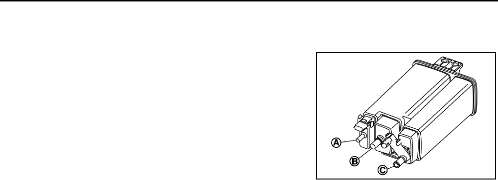
EC-1280
< ON-VEHICLE MAINTENANCE > [FOR MEXICO]
EVAP CANISTER
EVAP CANISTER
Inspection INFOID:0000000004494424
Check EVAP canister as follows:
1. Block port (B).
2. Blow air into port (A) and check that it flows freely out of port (C).
3. Release blocked port (B).
4. Apply vacuum pressure to port (B) and check that vacuum pres-
sure exists at the ports (A) and (C).
5. Block port (A) and (B).
6. Apply pressure to port (C) and check that there is no leakage.
JMBIA0961ZZ
Revision: 2008 August 2009 Rogue

SERVICE DATA AND SPECIFICATIONS (SDS)
EC-1281
< SERVICE DATA AND SPECIFICATIONS (SDS) [FOR MEXICO]
C
D
E
F
G
H
I
J
K
L
M
A
EC
N
P
O
SERVICE DATA AND SPECIFICATIONS (SDS)
SERVICE DATA AND SPECIFICATIONS (SDS)
Idle Speed INFOID:0000000004672614
*: Under the following conditions
• A/C switch: OFF
• Electric load: OFF (Lights, heater fan & rear window defogger)
• Steering wheel: Kept in straight-ahead position
Ignition Timing INFOID:0000000004672615
*: Under the following conditions
• A/C switch: OFF
• Electric load: OFF (Lights, heater fan & rear window defogger)
• Steering wheel: Kept in straight-ahead position
Calculated Load Value INFOID:0000000004672616
Mass Air Flow Sensor INFOID:0000000004672617
*: Engine is warmed up to normal operating temperature and running under no load.
Transmission Condition Specification
CVT No load* (in P or N position) 700 ± 50 rpm
Transmission Condition Specification
CVT No load* (in P or N position) 15 ± 5° BTDC
Condition Specification (Using CONSULT-III or GST)
At idle 10 – 35 %
At 2,500 rpm 10 – 35 %
Supply voltage Battery voltage (11 – 14 V)
Output voltage at idle 0.8 – 1.2V*
Mass air flow (Using CONSULT-III or GST) 1.0 – 4.0 g·m/sec at idle*
4.0 – 10.0 g·m/sec at 2,500 rpm*
Revision: 2008 August 2009 Rogue
