EE2024 Assignment 2 Manual 2016 2017 S1
User Manual:
Open the PDF directly: View PDF ![]() .
.
Page Count: 16

NATIONAL UNIVERSITY OF SINGAPORE
Department of Electrical and Computer Engineering
Scenario, Contents and Hidden Message by: Chris M. Shin
EE2024(E) – PROGRAMMING FOR COMPUTER INTERFACES
ASSIGNMENT 2
CARE
Semester 1, AY 2016/2017

SECTION 1: ASSIGNMENT DESCRIPTION
Page 2 of 16
SECTION 1: ASSIGNMENT DESCRIPTION
1.1 Objectives
After completing assignment 2, students will:
• be able to apply system design approaches, such as using flowcharts, to design embedded applications
• understand the interfaces between microcontrollers and peripherals
• have the ability to develop C embedded programming controller based applications
1.2 Overview
Taken for granted by many people, clean water is a valuable resource that can greatly enhance a country’s prosperity.
At the onset of the industrial age, and with a booming population growth throughout the world, clean water free from
excessive amounts of pollutants became more scare. As a result, communities from all parts of the globe have been
taking different approaches to safeguard this precious substance. Some have taken the approach of educating people
since young ages, while others believe that people can treasure water more when they enjoy activities related to it,
such as boating and fishing. For even more pristine water sources, law agencies, scientists and engineers have been
working together to prevent the human civilisation from destroying the biodiversity of such water sources. Vast water
sources can be quite difficult to secure, and monitoring them 24/7 used to be costly and unfeasible when they are
located in remote areas.
With the recent advances in sensor devices, the monitoring of water resources has been made easier. Whether it is to
monitor water quality for the strategic use of a country’s defence, or to detect and prevent the distribution of polluted
water in cases of accidents, or to prevent trespassers from exploiting certain water sources, electronic sensors have
made them all possible. While advanced analysis of the water quality is still costly and require human interventions in
certain cases, simpler analysis or monitoring of the water quality across vast areas of the water environment can be
done throughout the day by using embedded systems. At the core, all embedded systems require the programming of
computer interfaces to communicate with the multiple sensors and actuators.
For our EE2024(E) assignment, we will assume that a vast reservoir of clean and resource-rich water need to be
monitored for pollutants, trespassers and overgrowth of algae, with minimal impact to the ecosystem. As engineers, we
will be involved in the initiative meant to design a device to achieve the objective of safeguarding the water reservoir.
The initiative has the code name CARE, short for Caring for Aquatic Resources and Environments, while the device shall
be called CARES, short for CARE System.

SECTION 1: ASSIGNMENT DESCRIPTION
Page 3 of 16
In this assignment, it is assumed that the base board is a larger prototype version of CARES, with several output devices
to help in the debugging during development. The XBee RF module is assumed to a be a low powered wireless
communication device that sends collected data to a centralised water management organisation known as SAFE,
which is the short name for State Agency for Freshwater Ecosystems.
Students are required to interface with the various devices on the base board for data capture and data transmission.
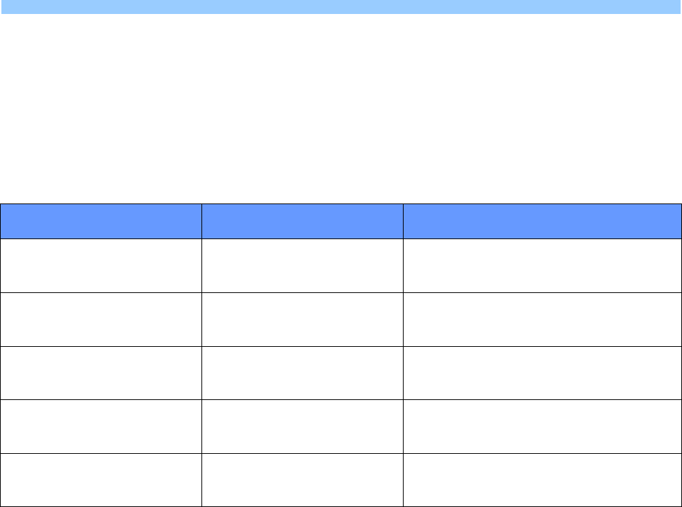
The reasons behind the use of the three main sensors are indicated in Table 1.
Sensor
Usage and Potential Implementations
Accelerometer
An accelerometer has an extremely varied range of applications. In a water environment, the
accelerometer can be used to detect turbulence. Turbulence can be caused by natural causes,
such as heavy rain or strong wind, or by artificial sources due to human activities. In CARES, the
accelerometer will be used to detect illegal activities caused by humans, including and not limited
to illegal dumping of wastes or prohibited activities like boating.
Light
Sensor
The light sensor on CARES is used as a preliminary detector of potential non-chemical based
pollution sources, before more advanced observations are made by other devices or human
beings. Whether it is to indicate clear water, water filled with sediments, or solid wastes and dead
fishes, the light sensor will provide initial clues.
Temperature
Sensor
The temperature module on CARES allows for the water temperature to be detected. When the
conditions are favourable, algae may grow rapidly and cause severe damage to the reservoir’s
ecosystem. Warm water, which is more common nowadays due to global warming, and sufficient
sunlight, can cause an overgrowth of algae. Using the light sensor and temperature sensor on
CARES, data can be collected over certain period of time to determine the possibility of algae
overgrowth, and to plan ahead for the latter’s removal.
Table 1: Usage and potential implementations for the three main sensors
CARES has two exclusive modes of operations: PASSIVE mode and DATE mode, and will be transmitting to SAFE if
certain conditions are met. Additionally, other device interfacing is required for CARES, and which shall be described in
the remaining sub-sections of section 1.
D A T E: Diagnostic, Analysis, and Telemetry Evaluations

SECTION 1: ASSIGNMENT DESCRIPTION
Page 4 of 16
L
1.3 Detailed Description and Specifications
CARES must be on a horizontal surface when powered on for the first time. Upon powering on, CARES must have the
following stable state behaviours:
• The SEGMENT_DISPLAY is off
• The GRAPHICS_DISPLAY is off
• The ENERGY_INDICATOR is off
• BLINK_RED is off
• BLINK_BLUE is off
• The TEMPERATURE_SENSOR, LIGHT_SENSOR and ACCELEROMETER are idle and not reading any data
• There are no transmissions to SAFE
If MODE_TOGGLE is pressed during the stable state, CARES goes into PASSIVE mode.
PASSIVE mode for CARES represents the situation when the latter is being deployed in a real environment for passive
monitoring of the quality of the water source. It is assumed that CARES consists of supercapacitors for energy storage
instead of potentially harmful chemical battery sources, and enough solar panels to ensure energy self-sufficiency
during both daytime and night time. In such situations, the amount of energy source is a limiting factor on how much
sensor data can be obtained. Reducing the rate at which sensors are read help in reducing power consumption and
processing workload, while frugally transmitting wireless data prevents energy from being used up too quickly. Sensors
and transmission devices are placed in sleep mode or low-power mode when not in use but for our case, it is not
required to put them in sleep mode or low-power mode when they are not being sampled or transmitting.
As soon as CARES enter PASSIVE mode, the TEMPERATURE_SENSOR, LIGHT_SENSOR, and ACCELEROMETER are
sampled. The following behaviour occurs in PASSIVE mode:
• The following message to SAFE is sent once each time PASSIVE mode is entered:
Entering PASSIVE Mode.\r\n
• The GRAPHICS_DISPLAY must include the following word throughout PASSIVE mode:
PASSIVE
• The SEGMENT_DISPLAY hexadecimal value increases by 1 for every second that passes by. After the
SEGMENT_DISPLAY shows the last value, it restarts with the first value of the hexadecimal system. The
sequence is as indicated below:
0 1 2 3 4 5 6 8 9 a 8 c 0 E F
• The TEMPERATURE_SENSOR, LIGHT_SENSOR, and ACCELEROMETER are sampled and the values are updated
on the GRAPHICS_DISPLAY when the SEGMENT_DISPLAY shows:
5 a F
PASSIVE mode

SECTION 1: ASSIGNMENT DESCRIPTION
Page 5 of 16
• Transmission of the currently sampled sensor values from the TEMPERATURE_SENSOR, LIGHT_SENSOR, and
ACCELEROMETER, to SAFE, occurs once each time the SEGMENT_DISPLAY shows:
F
The format of the transmitted data should be as follows:
NNN_-_T*****_L*****_AX*****_AY*****_AZ*****\r\n
where the temperature value, light value, and x-axis value, y-axis value, z-axis value of the accelerometer are
respectively preceded by T, L, AX, AY, and AZ. * is an optional numerical value, a decimal point, or a minus
sign. The special characters \r\n indicates that the next data transmission has a carriage return and is on a new
line. NNN represents a 3-digits value that starts from 000 and increments by 001 each time such set of sensor
data is transmitted to SAFE from CARES. NNN never resets itself to 000, unless CARES itself is powered on
from a power off state. It is assumed that 999 will never be reached.
• Any time between two data transmissions to SAFE, if the scheduled sample value from LIGHT_SENSOR is
between WARNING_LOWER and WARNING_UPPER, BLINK_BLUE should happen. If the scheduled sample value
from LIGHT_SENSOR is below WARNING_LOWER, BLINK_RED should happen. BLINK_BLUE and BLINK_RED
simulates the detection of algae and solid wastes respectively.
• BLINK_BLUE and BLINK_RED can happen at the same time. Both must be synchronised if they occur at the
same time. BLINK_BLUE and BLINK_RED must not be turned off and unless CARES goes into DATE mode.
• If BLINK_BLUE is happening at the instant a scheduled transmission to SAFE occurs, the following message
must also be sent before the usual sensor values from the TEMPERATURE_SENSOR, LIGHT_SENSOR, and
ACCELEROMETER:
Algae was Detected.\r\n
• If BLINK_RED is happening at the instant a scheduled transmission to SAFE is happening, the following message
must also be sent before the usual sensor values from the TEMPERATURE_SENSOR, LIGHT_SENSOR, and
ACCELEROMETER:
Solid Wastes was Detected.\r\n
• Messages due to BLINK_BLUE occurs before messages due to BLINK_RED.
• If MODE_TOGGLE is pressed any time in PASSIVE mode, CARES will go to DATE mode after the
SEGMENT_DISPLAY value reaches and shows the following for a minimum of 1 second:
F

SECTION 1: ASSIGNMENT DESCRIPTION
Page 6 of 16
DATE mode simulates the situation where by human interventions to deal with abnormal situations have been
completed, such as dealing with false alarms, or removal of wastes that triggered the warning messages. CARES will
undergo a few evaluations before going back to PASSIVE mode. In DATE mode, CARES run at full performance, where
the energy gets provided by a secondary supercapacitor, and the usage of the system becomes unrestricted for a short
duration. The energy source is divided into 16 units, as indicated by ENERGY_INDICATOR. Each INDICATOR_TIME_UNIT,
one unit of the energy source is depleted, regardless of the action taken. The characteristics of DATE mode are:
• The following message to SAFE is sent once each time DATE mode is entered:
Leaving PASSIVE Mode. Entering DATE Mode.\r\n
• The GRAPHICS_DISPLAY must include the following word throughout DATE mode:
DATE
• The energy source, as indicated by ENERGY_INDICATOR, is full each time CARES enter DATE mode
• The GRAPHICS_DISPLAY must not show the values obtained from the TEMPERATURE_SENSOR, LIGHT_SENSOR,
and ACCELEROMETER upon entering DATE mode. Instead, the values are replaced with the word:
DATE MODE
• BLINK_BLUE and BLINK_RED do not occur in DATE mode.
• Data is not obtained from the TEMPERATURE_SENSOR, LIGHT_SENSOR, and ACCELEROMETER, unless
GET_INFORMATION is pressed for the active capture of sensor data.
Pressing GET_INFORMATION can occur any time and multiple times during DATE mode. Each time, the press results in
the following at the next earliest instance (*See notes at the bottom of this page):
• Read the TEMPERATURE_SENSOR, LIGHT_SENSOR, and ACCELEROMETER values.
• Update GRAPHICS_DISPLAY to indicate the latest (values obtained within the last 1 second) temperature value
from the temperature sensor, sampled luminance value from the light sensor, and accelerometer values (5
values in all). These values are to remain unchanged on the GRAPHICS_DISPLAY, unless GET_INFORMATION is
pressed again or CARES goes to PASSIVE mode
• The latest (values obtained within the last 1 second) temperature value from the temperature sensor, sampled
luminance value from the light sensor, and accelerometer values (5 values in all) need to be sent to SAFE, in
the same format as described in PASSIVE mode.
MODE_TOGGLE is disabled in DATE mode. When the 16 LEDs of the ENERGY_INDICATOR are all off, CARES
automatically enters PASSIVE mode.
* Notes regarding “next earliest instance”: Depending on the way you have written your program, certain tasks may not
happen immediately. Furthermore, the processor is not natively parallel. “Next earliest instance” would mean that the
system is very responsive to the commands, such that it appears instantaneous to a user (For example, within a few
hundreds of milliseconds)
DATE mode

SECTION 1: ASSIGNMENT DESCRIPTION
Page 7 of 16
Specifications:
• WARNING_LOWER: 50 Lux
• WARNING_UPPER: 1000 Lux
• INDICATOR_TIME_UNIT: 208 milliseconds
Devices Used:
• ACCELEROMETER: MMA7455L
• LIGHT_SENSOR: ISL29003 with LIGHT_RANGE_4000
• TEMPERATURE_SENSOR: MAX6576
• SEGMENT_DISPLAY: 7-segment LED display
• GRAPHICS_DISPLAY: 96x64 White OLED
• BLINK_BLUE: Blue Light for RGB LED, alternating between ON and OFF every 333 milliseconds
• BLINK_RED: Red Light for RGB LED, alternating between ON and OFF every 333 milliseconds
• ENERGY_INDICATOR: LED4 (Energy is low) to LED19 (Maximum Energy) of the PCA9532
• MODE_TOGGLE: SW4
• GET_INFORMATION: SW3
• SAFE: UART terminal program (Tera Term) on a personal computer
D A T E : D i a g n o s t i c , A n a l y s i s a n d T e l e m e t r y E v a l u a t i o n s
S c e n a r i o , C o n t e n t s a n d H i d d e n M e s s a g e b y : C h r i s M . S h i n

SECTION 1: ASSIGNMENT DESCRIPTION
Page 8 of 16
1.4 CARES Enhancements
After all the requirements set out in the earlier sub-sections have been met, you are encouraged to use additional
peripherals or add features related to CARES, such as:
• SW2, SW5, etc.
• Other methods of interfacing such as Timer, ADC, etc.
• Interrupts for the different peripherals connected to the LPC1769
• More complex helper functions from the device libraries
With these additional peripherals, application logic enhancements can be implemented, including and not limited to
what is to be done with the values from the different sensors. This is an independent and self-learning task, for which
help will be limited in order to prevent such enhancements from becoming too common, and therefore worth less. The
more complex and rarer the enhancements, the more impressive your CARES will be. Peripherals whose usage and
codes have been discussed during the lab sessions will not be given extra credits.
Be aware that your application logic for CARES must be related to the given scenario, in order to score higher marks.
Furthermore, the enhancements carry limited amount of marks as compared to the basic requirements of the
assignment. In other words, a program with excellent enhancements, but poor completion of basic requirements, will
not score well. You are required to focus on one well-thought of application logic to showcase your enhancements,
instead of several smaller application logics. Marks are only given for one application logic.
During the assessment, you will be required to show all the tasks mentioned in sub-section 1.3 without your application
logic enhancements. The latter should only be shown after the basic requirements have been demonstrated. You are
not allowed to upload multiple programs to your LPC1769 to demonstrate your application logic enhancements. Only
one program will be allowed for upload to the LPC1769.
SECTION 2: UART CONNECTION
Page 9 of 16
SECTION 2: UART CONNECTION
2.1 Wired UART Communication
Students should establish a wired UART connection between the microcontroller and the PC first. Echo all introduced
characters on the terminal to make sure the connection is functioning correctly. Follow the steps below for UART set up
and programming:
1. The message from the microcontroller to the PC is sent through UART interface. Please read chapter 3.4 and 4.1 of
the document LPCXpresso Base Board Rev B User’s Guide carefully.
2. UART configuration example:
• BAUD RATE: 115 200
• DATA BITS: 8
• PARITY: none
• STOP BITS: 1
• FLOW CONTROL: none
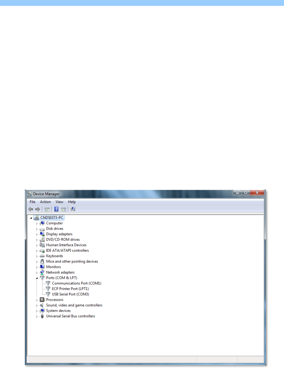
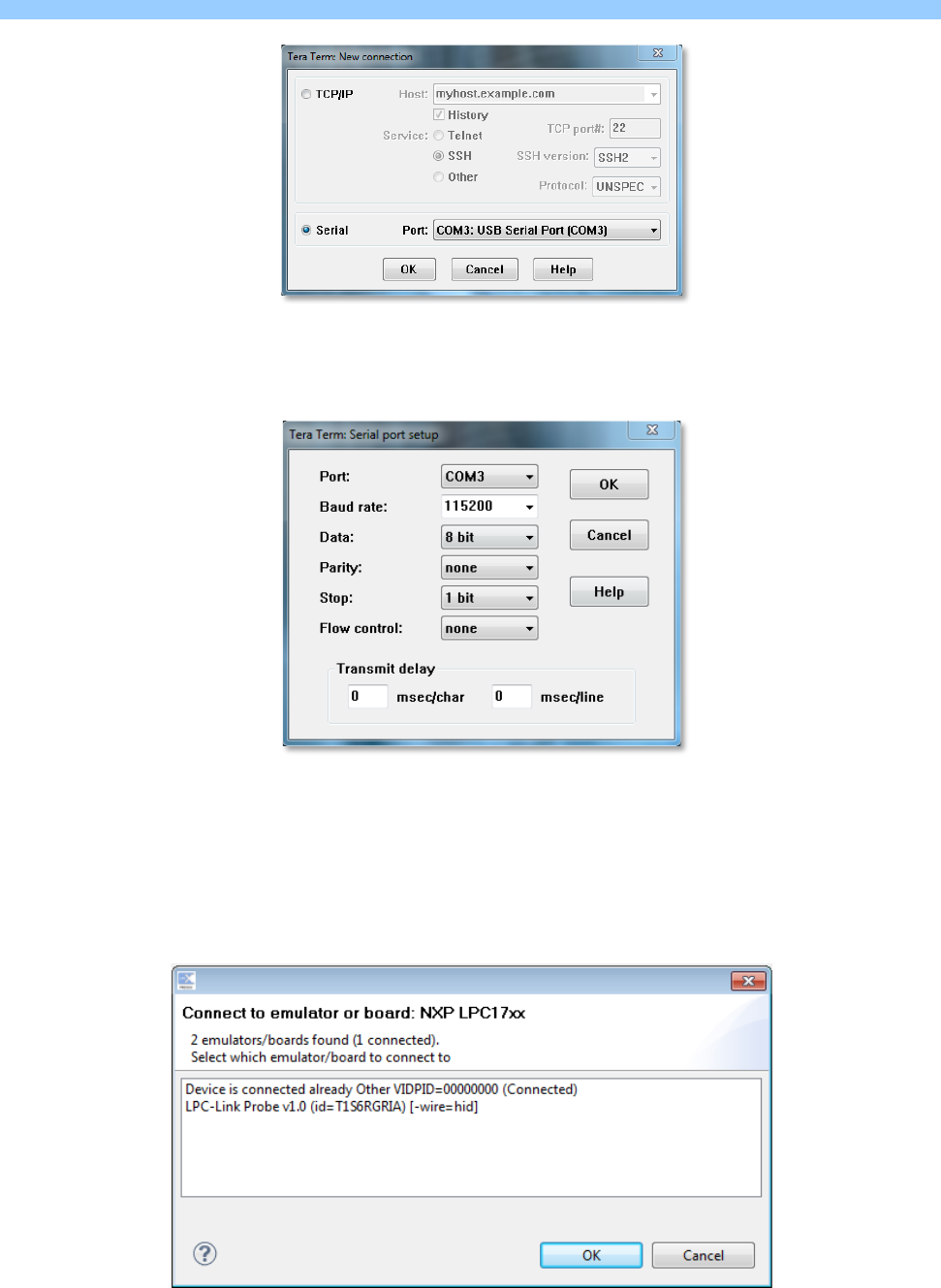
3. The recommended terminal is Tera Term. Select the corresponding UART port after opening Tera Term. Do not
forget to verify the UART configuration. The UART port may be determined through the computer’s device
manager by looking for the USB Serial Port as shown in Figure 1. The settings for the Tera Term program are as
depicted in Figure 2 and Figure 3.
Figure 1: Verify UART (USB serial) port
SECTION 2: UART CONNECTION
Page 10 of 16
Figure 2: Choose UART (USB serial) port in Tera Term
Figure 3: UART port setup in Tera Term
NOTE: If you debug a project when your terminal remains open, the window shown in Figure 4 may pop up. Click
on LPC-Link Probe v1.0 (id=T!S6RGRIA) [-wire=hid] and then press OK.
Figure 4: LPCXpresso IDE pop-up windows when having connection with Tera Term
SECTION 2: UART CONNECTION
Page 11 of 16
2.2 Wireless UART Communication
The objective is to simulate a scenario where CARES will communicate with SAFE (Tera Term) over-the-air via RF
communication. Prior to this, you should have successfully achieved the wired UART communication described in the
previous sub-section.
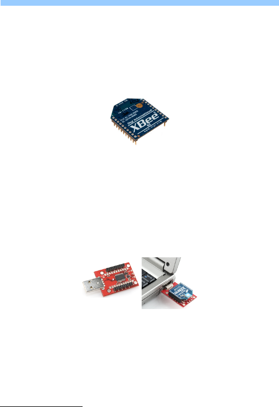
Students will be provided with two pieces of XBee RF modules. An XBee module is shown in Figure 5. XBee radios are
products from Digi International1 and are based on the IEEE 802.15.4 standard for physical layer and MAC control
specifications targeting low-cost, low-speed and low-power communication devices. XBee radios communicate with
each other within the ISM 2.4GHz frequency band at wireless data rate of 250kbps. The indoor communication range is
up to 100 ft. (30m). Detailed specifications and information on operation and configuration can be referenced from the
datasheet2.
Figure 5: An XBee Series 1 RF Module
An XBee module also includes an on-chip UART, hence it is fairly straightforward to communicate with an XBee module
from any micro-controller SOC that implements a UART such as the LPC1769. By default, an XBee module operates in
‘Transparent Mode’, i.e., acts as a serial line replacement – all data received on the UART is queued up for RF
transmission (RF data rate is 250kbps). Any RF data received is sent out over the UART. Both the XBee UART and the
host UART should be configured to the same settings. The default on XBee modules is 9600bps, 8N1. The baud rate and
parity settings are configurable.
One of the modules you issue out of the DE Lab is mounted on a USB-UART adapter dongle from Sparkfun Electronics3,
with examples shown in Figure 6. The dongle consists of the USB-UART adapter chip FT232R from FTDI International
Ltd.4, similar to the one on your LPC Xpresso Baseboard. This chip creates a virtual COM port on your PC that effectively
behaves as a UART.
Figure 6: (Left Picture) A Sparkfun XBee Explorer Dongle
(Right Picture) An Xbee module mounted on the dongle and plugged into a host PC USB port
1 http://www.digi.com/products/wireless-wired-embedded-solutions/zigbee-rf-modules/point-multipoint-rfmodules/xbee-series1-module
2 http://www.sparkfun.com/datasheets/Wireless/Zigbee/XBee-Datasheet.pdf
3 https://www.sparkfun.com/products/9819
4 http://www.ftdichip.com/Products/ICs/FT232R.htm
SECTION 2: UART CONNECTION
Page 12 of 16
2.3 Getting Started with the XBee Modules
Plug one of the XBee modules, mounted on the USB dongle, into your PC. The drivers should install automatically,
especially if previously your LPC Xpresso baseboard USB-UART adapter also installed successfully. If you run into
problems at this step, you can always download the device driver manually from FTDI5.
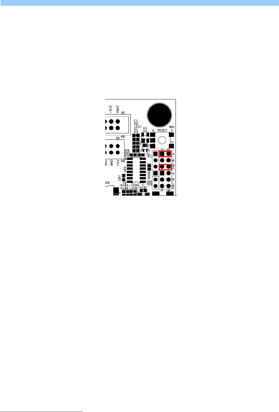
Now mount the other XBee module on to your LPC Xpresso Baseboard into the socket reserved for U236. Only one
jumper needs to be modified: remove the jumper B on J7 as shown in Figure 77. This disconnects the USB-UART bridge
on the baseboard that we have so far been using for UART communication with the PC, and alternatively routes all
UART signals from LPC1769 to and from the XBee module. If the UART data rate is below the XBee RF data rate
(250kbps), one needs not implement flow control and leave J59 in the default state.
Figure 7: Jumper configuration for XBee module mounted on the LPC Xpresso Baseboard
Configuring Tera Term on your PC and the LPC1769 UART to 9600bps 8N1 should allow them to communicate with each
other. Sub-section 5.5 describes how to configure XBee addresses to avoid interference with other XBees in the lab
during RF communication
5 http://www.ftdichip.com/Drivers/VCP.htm
6 http://www.ftdichip.LPC Xpresso Baseboard Schematics (LPCXpresso_Base_Board_revB.pdf), page 11./Drivers/VCP.htm
7 LPC Xpresso Baseboard User’s Guide (LPCXpresso_BaseBoard_rev_B_Users_Guide_Rev_PA18.pdf), page 31.
SECTION 2: UART CONNECTION
Page 13 of 16
2.4 Configuring the XBee UART Baud Rates
We require the LPC1769 and Tera Term to communicate with the XBee modules at their respective ends at a data rate
of 115.2kbps. We shall mount each XBee module one by one on to the USB dongle, plug it into the PC and configure
their baud via Tera Term.
Once an XBee module is plugged into your PC, set up Tera Term to connect to the appropriate COM port and configure
it to 9600bps, 8N1. Also turn on ‘Local echo’ by checking the option in Setup Terminal. This ensures whatever you
type into Tera Term console is also displayed on the console. Now follow the procedure outlined in Table 2:
AT COMMAND
(Tera Term Sends to XBee)
RESPONSE
(Tera Term Receives from XBee)
DESCRIPTION
+++ OK <CR> Commands XBee module to enter
the AT Command Mode
ATBD <Enter> {current value} <CR>
Commands XBee to return its current
UART baud rate
(3 indicates 9600 bps)
ATBD7 <Enter> OK <CR> Modifies XBee UART baud
(7 indicates 115200 bps)
ATWR <Enter> OK <CR> Write changes to XBee’s
non-volatile memory
ATCN <Enter> OK <CR> Exit AT Command Mode
Table 2: Configuring an XBee module to a UART baud rate of 115200bps
Ensure there is a 1s gap before and after you send the “+++” string to the XBee in order to successfully enter into AT
Command Mode of the XBee module. Pressing <Enter> into Tera Term sends a carriage return, i.e., ‘\r’. Similarly, on
successful execution of a command, the XBee returns a “OK\r” signal. Ensure you follow Table 2 carefully and only
send and expect carriage return characters where indicated. Also note if no commands are sent within 10s of the last
command sent the XBee automatically exits the AT Command Mode. You will need to re-enter Command Mode by
issuing “+++” again to issue more commands. Changes take effect soon as the XBee exits the command mode, whether
due to the 10s timeout, or by a response to “ATCN\r”. Changes not committed to non-volatile memory will only take
affect for current session and be lost once the power to the XBee is turned off.
Upon successful completion of the command sequence in Table 2, you should configure Tera Term to 115200 bps to
issue any further commands to this XBee module. Repeat the process with your other module.

SECTION 2: UART CONNECTION
Page 14 of 16
2.5 Configuring XBee Addresses
Conforming to the IEEE 802.15.4 specifications, each XBee RF packet contains a Source Address and Destination
Address besides the actual data (payload).
By default all XBee modules are configured to a source address of 0 and to transmit to a destination address of 0.
Effectively, this means all XBees transmit data to every other XBee module! If multiple XBees are transmitting within a
short range of each other, such as in the DE lab, RF interference is inevitable.
One method to avoid interference is to use the unique 64-bit IEEE source address assigned to each XBee module at the
factory which can be read using SH and SL commands in the AT Command mode. Another is to use short 16-bit
addresses. Note your XBee modules have been tagged by the DE lab with unique IDs corresponding to your boards. For
example, for a board asset tag ID 13, the XBees are tagged 13a and 13b. These are valid 16-bit hex addresses. Table 3
shows a command sequence to configure an Xbee to use a source address of 13a and a destination address of 13b.
Note that this process continues after sub-section 5.4, and is carried out with Tera Term configured at 115200 bps.
AT COMMAND
(Tera Term Sends to XBee)
RESPONSE
(Tera Term Receives from XBee)
DESCRIPTION
+++ OK <CR> Commands XBee module to enter
the AT Command Mode
ATMY <Enter> {current value} <CR>
Commands XBee to return its current
16-bit source address
(returns 0)
ATMY13A <Enter> OK <CR> Sets XBee 16-bit source address to 13a
ATDL <Enter> {current value} <CR>
Commands XBee to return its current
Destination Address Low (lower 32 bits).
(returns 0)
ATDL13B OK <CR> Sets XBee 16-bit destination address to 13b
ATDH <Enter> {current value} <CR>
Commands XBee to return its current
Destination Address High (higher 32 bits).
(returns 0)
ATDH0 OK <CR> To transmit using a 16-bit address, DH
parameter should be set to 0.
ATWR <Enter> OK <CR> Write changes to XBee’s non-volatile memory
ATCN <Enter> OK <CR> Exit AT Command Mode
Table 3: Configuring an XBee module’s source and destination addresses
Mount the other XBee module on to the USB dongle, and repeat the process configuring its source and destination
addresses to be 13b and 13a respectively. Now both your XBee modules should communicate only to each other and
not receive any data packets as interference from other XBee modules in the vicinity.

SECTION 3: ASSESSMENT
Page 15 of 16
SECTION 3: ASSESSMENT
3.1 Report
Each group is required to submit one report (at least 8 pages, including about 3 to 4 pages reserved for flowcharts). The
report should include at minimum the following information:
1. Names and matriculation numbers, Lab day on the first page. G.A. names are not needed.
2. Table of contents
3. Introduction and objectives
4. Flowcharts describing the system design and processes
5. Detailed implementation: Describe the detailed implementation steps, especially indicate and explain your
essential steps
6. Application logic enhancements: If you have application logic enhancements for CARES, carefully describe the
application logic and the enhancements with significant amounts of detail, especially technical details. You
might consider including several photos of your working board at some special steps. This will help to
distinguish your system and report from others
7. Significant problems encountered and solutions proposed: What did you learn? What are the significant
problems you encountered and how did you solve them in this assignment? If your code did not work in the
lab, explain why
8. Issues or suggestions: These feedbacks, whether positive or negative, will not affect your marks in any
circumstances, but will make the report more complete.
9. Conclusion
3.2 Assignment Demonstration and Submission
In the assessment week (Week 13), you need to present and demonstrate your designed system to an assessing G.A.
You are required to have a draft of your report (not the final one), and several basic flowcharts ready, in order to
explain your design. You can present to your G.A. through softcopies. Hardcopies of the report are not encouraged.
Students will be assessed as a group, but individual questions by the assessing G.A. will determine the marks to assign
to each student within the group. Both students need to be familiar with all aspects of the assignment, as the G.A. can
choose any one of you to explain any part of the assignment. The G.A. will also ask you additional questions to test your
understanding.
The workspace archive should be submitted during the assessment. Please do the following before going for the
assessment:
1. Finalise your program before the assessment day
2. In the LPCXpresso software, select File -> Export -> General -> Archive File. Click Next
3. Click on “Select All”. For options: Save in zip format, Create directory structure for files.
4. Save the archive file to your personal flash drive and bring it with you for the assessment
5. The archive file must follow this naming template:
Assignment2_Name of any one team member as indicated on the Matriculation Card_Matric Number of all
team members separated by an underscore_Workspace
Example:
Assignment2_Parker Gentry_A0131086Y_A0101010X_Workspace.zip
Marks will be lost if the workspace archive does not reasonably follow the above naming scheme
6. You will not be allowed to use your own notebook to upload your program to the LPC1769, nor allowed to use
Tera Term on your notebook. All these must be done using the desktop computer provided in the lab. You are
however allowed to use your notebook for presentation purposes (powerpoints, or to show your draft report)

SECTION 3: ASSESSMENT
Page 16 of 16
The softcopy of the final report should be uploaded to IVLE, as indicated in the instructions below:
1. Please upload to your assessing G.A. submission folder under "Assignment 2 Submission" within the stipulated
deadline in point number 4. Failure to do so will result in no marks being awarded for the report component,
forfeiting of the 10 marks for flowchart and the 10 marks reserved for the application logic enhancements
2. Only one uploaded report per team in common format (.pdf (preferred), .doc, .docx)
3. Naming of the report to follow this template:
Assignment2_Name of any one team member as indicated on the Matriculation Card_Matric Number of all
team members separated by an underscore_Report
Example:
Assignment2_Parker Gentry_A0131086Y_A0101010X_Report.pdf
Marks will be lost if the report does not reasonably follow the above naming scheme
4. The IVLE report upload must be completed by Saturday 12th November 2016
Reminder from the NUS Code of Student Conduct: http://www.nus.edu.sg/registrar/adminpolicy/acceptance.html
“Any student found to have committed or aided and abetted the offence of plagiarism may be subject to disciplinary
action.”
Both the source and recipient are equally responsible in cases of academic dishonesty.
3.3 Grading
Assignment 2 carries a maximum of 60 marks. It is equivalent to 30% of the marks for the EE2024(E) module. Students
will be marked based on a set of criteria that includes:
• Explanation, understanding and illustration (in the report) of basic flowcharts for the system design
(Worth 10 out of the 60 marks)
• Understanding of the devices that have been used for the assignment
• Ability to use device interrupts and their understanding
• Extent of UART implementation, such as whether wireless UART has been implemented
• Meeting the requirements of each mode: PASSIVE, DATE
• Responsiveness, performance and robustness of the system
(Focus and improve on these before working on the application logic enhancements)
• Meeting report and IVLE upload requirement. Marks are awarded for reports that are more complete
• Extent of the application logic enhancements as described in section 1.4, and several other factors that
demonstrate the ability to learn independently and program for computer interfaces (Worth 10 out of the 60
marks)
Overall, a good design with a full implementation of assignment 2, and a good understanding of the code will give you a
good mark. Poor design, lack of functionality, or poor understanding of the code during the assessment will lead to
deduction of marks. Failure to be present for the assessment without valid and genuine reasons will lead to zero marks
being awarded for assignment 2. There will not be make-up sessions after week 13.
3.4 Statement of Contribution
An online survey where you will need to indicate your contributions to assignment 2 will be made available on IVLE
before the assessment week. It is compulsory to fill in the online survey on time, as it considerably affects your final
assignment 2 marks. The IVLE survey must be completed by Sunday 13th November 2016. If any member of the team
does not fill in the online survey, the latter will be assumed to have made minimal contribution to assignment 2. If no
one from the team (applicable for individual member teams also) fill in the online survey, the assignment 2 marks will
be negatively affected.
Further details regarding the assessment and statement of
contribution will be communicated closer to the assessment week.
Caring for your learning experience through Assignment 2
