EF40 UM User Manual Current
User Manual:
Open the PDF directly: View PDF ![]() .
.
Page Count: 94

1
EnduroFlow™Series
EF40 Wall- Mount Ultrasonic Flowmeter
User’s Manual
Revision 1.1
February, 2019
2
STOP!
It is extremely important to enter the parameters properly
before installing the transducers. Incorrect parameters
result in operation errors and inaccurate measurements.
The following conventions are used in this manual:
For questions, please call us at +1 978 263 7100 or email us at support@spiremt.com.
WARNING!
Read the declaration carefully before starting any other action!
CAUTION!
Attention! Damage could occur to the device if handled inappropriately.

3
Table of Contents
1. Introduction ..................................................................................................................................... 6
§1.1 Preface ......................................................................................................................................... 6
§1.2 Features ....................................................................................................................................... 6
§1.3 Typical Applications .................................................................................................................... 7
§1.4 Principle of Measurement ............................................................................................................ 7
§1.5 Parts Identification ....................................................................................................................... 9
§1.6 Product Identification ................................................................................................................. 10
§1.7 Data Integrity and Built-in Time-Keeper .................................................................................... 10
§1.8 Technical Specifications ............................................................................................................ 11
§1.9 Wiring ....................................................................................................................................... 12
2. Flow Measurement ........................................................................................................................ 12
§2.1 Unpacking ................................................................................................................................. 13
§2.2 Installation Considerations ......................................................................................................... 13
§2.2.1 Mounting the Main Unit ...................................................................................................... 13
§2.2.2 Installing Transducers ......................................................................................................... 13
§2.2.3 Power Supply Wiring .......................................................................................................... 14
§2.2.4 Other Electrical Connections ............................................................................................... 14
§2.3 Power On ................................................................................................................................... 15
§2.4 Keypad ...................................................................................................................................... 15
§2.5 Display Windows ....................................................................................................................... 16
§2.6 Display Window List ................................................................................................................. 21
§2.7 Steps to Configure the Parameters .............................................................................................. 22
3. Installation ..................................................................................................................................... 24
§3.1 Mounting Allocation for Transducers ......................................................................................... 24
§3.2 Transducer Installation ............................................................................................................... 26
§3.3 Transducer Spacing .................................................................................................................... 28
§3.4 Installation Checkup .................................................................................................................. 30
§3.4.A Signal Strength ................................................................................................................... 30
§3.4.B Signal Quality ..................................................................................................................... 30
§3.4.C Total Transit Time and Delta Time ..................................................................................... 31
§3.4.D Transit Time Ratio ............................................................................................................. 31
4. How To ......................................................................................................................................... 33
§4.1 How to check if the instrument is working properly.................................................................... 33
§4.2 How to check the liquid flowing direction .................................................................................. 33

4
§4.3 How to change the unit’s measurement system ........................................................................... 33
§4.4 How to select a flow rate unit ..................................................................................................... 33
§4.5 How to use the totalizer multiplier.............................................................................................. 33
§4.6 How to turn on and off totalizers ................................................................................................ 34
§4.7 How to reset the totalizer ........................................................................................................... 34
§4.8 How to use the damping filter to stabilize the reading ................................................................. 34
§4.9 How to use the zero-cutoff function (Noise Filter) ...................................................................... 34
§4.10 How to set up the zero calibration ............................................................................................ 34
§4.11 How to change the flow rate scale factor .................................................................................. 34
§4.12 How to use the password lock .................................................................................................. 34
§4.13 How to use the built-in data logger ........................................................................................... 35
§4.14 How to use the Frequency Output ............................................................................................ 35
§4.15 How to use the Totalizer Pulse Output ...................................................................................... 35
§4.16 How to set up the alarm signal ................................................................................................. 36
§4.17 How to use the built-in Buzzer ................................................................................................. 37
§4.18 How to use the OCT output ...................................................................................................... 37
§4.19 How to use the relay output ...................................................................................................... 38
§4.20 How to use the 4-20mA output interface .................................................................................. 38
§4.21 How to use the analog input ..................................................................................................... 39
§4.22 How to view the Totalizers ....................................................................................................... 40
§4.23 How to use the Working Timer ................................................................................................ 40
§4.24 How to modify the built-in calendar ......................................................................................... 40
§4.25 How to use the manual totalizer ............................................................................................... 40
§4.26 How to check the ESN ............................................................................................................. 40
§4.27 How to adjust the LCD contrast ............................................................................................... 40
§4.28 What to do when the flow rate reading jumps abnormally ......................................................... 40
§4.29 How to calibrate the flow meter ............................................................................................... 41
5. Menu Window Details ................................................................................................................... 42
6. Troubleshooting ............................................................................................................................. 47
§6.1 Power-on Errors ......................................................................................................................... 47
§6.2 Working Status Errors ................................................................................................................ 47
§6.3 Other Problems and Solutions .................................................................................................... 48
7. Communication ............................................................................................................................. 49
§7.1 General ...................................................................................................................................... 50
§7.2 Connect the Flowmeter to a PC .................................................................................................. 50
§7.3 Check the Flowmeter COM Port Settings ................................................................................... 50
§7.4 Set up PC Software .................................................................................................................... 50

5
§7.5 Communication Protocol............................................................................................................ 51
§7.6 Protocol Prefix Usage ................................................................................................................ 52
8. Thermal Energy Measurement ....................................................................................................... 54
§8.1 Introduction ............................................................................................................................... 54
§8.2 Thermal Energy Measurement ................................................................................................... 54
§8.3 Calibration ................................................................................................................................. 55
9. Warranty and Service ..................................................................................................................... 57
§9.1 Warranty .................................................................................................................................... 57
§9.2 Service ....................................................................................................................................... 57
§9.3 Software Upgrade Service .......................................................................................................... 58
10. Appendix ................................................................................................................................... 59
§10.1 Wiring Diagram and Outline Drawings .................................................................................... 59
§10.2 Transducer Installation Guide................................................................................................... 61
§10.2.A Find the mounting site ...................................................................................................... 61
§10.2.B Prepare the Pipe Surface ................................................................................................... 62
§10.2.C Prepare the Transducer ..................................................................................................... 62
§10.2.D Install the Transducers ...................................................................................................... 62
§10.3 Pipe Size Tables ....................................................................................................................... 65

6
1. Introduction
§1.1 Preface
The EF40 Wall-mount Ultrasonic Flow Meter is a revolutionary Flow & BTU meter with rich functions.
It is designed to accommodate the challenge of onsite flow and energy measurements. The applications
range from almost all liquids that allow ultrasonic sound to propagate.
The EF40 uses the latest signal processing and ultrasonic measurement technologies. It offers highly
accurate and reliable measurements. The meter is self-explanatory and simple to follow. The EF40 is also
a thermal energy meter when it is equipped with a BTU measurement module.
The unique clamp-on fixture design, for both the flow transducers and temperature sensors, makes the
installation hassle-free. No special skills or tools are required.
The EF40 is the best choice for long term flow monitoring, HVAC energy balancing, facility
management, and other demanding flow and energy monitoring applications.
§1.2 Features
• Accurately measures energy and flow using non-intrusive technology
• Capability of measuring bi-directional flow and thermal energy (BTU)
• Ease of use and fast installation
• Able to measure on a very wide pipe size range, from 3/4” (DN20) up to 120” (DN3000)
• Signal quality tracking and self-adaptation for robust performance
• Suitable for pure liquids and liquids with some particles. No dependency on conductivity
• Suitable for all commonly used pipes
• Self-explanatory user interface. Step-by-step Quick Start guidance
• Built-in data logger
• PC software for data download and real-time data acquisition
• ±0.5% of linearity
• Accuracy: ±1% of reading in velocity plus ±0.03ft/s (10mm/s)

7
§1.3 Typical Applications
The EF40 wall-mount flow and BTU meter is a perfect fit for the following applications:
• Energy consumption supervision and water conservation management
• Cooling system and air conditioning/glycol solutions
• Water, including hot water, chilled water, city water, sea water, and more
• Sewage and drainage water with small particle concentration
• Oil, including crude oil, lubricating oil, diesel oil, fuel oil, and more
• Various chemicals, including alcohol, acids, and more
• Solvents
• Beverage and food processors
• Water and waste treatment
• Power plants (nuclear, thermal & hydropower) heat energy boiler feed water
• Metallurgy and mining applications (e.g., acid recovery)
• Marine operation and maintenance
• Pulp and paper
• Pipeline leak detection, inspection, tracking, and collection
• Water distribution network monitoring
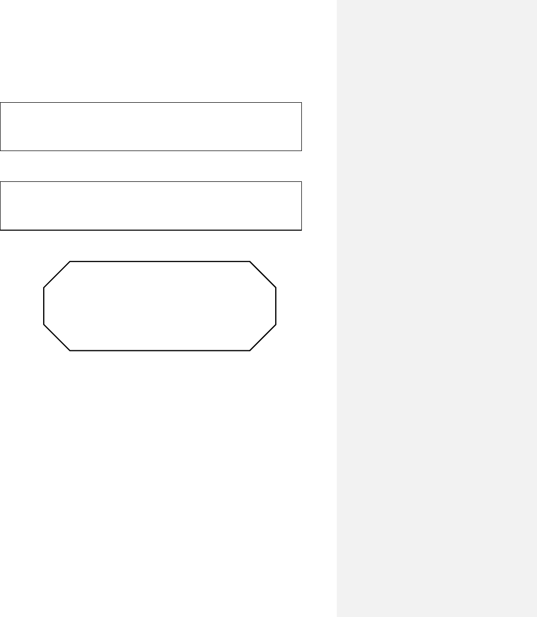
§1.4 Principle of Measurement
The EnduroFlowTM Series flow and energy meters are based on the transit-time measurement principle,
where the system utilizes a pair of sensors which function as both ultrasonic transmitter and receiver. The
sensors are installed on the pipe wall, either clamped on the outside of the pipe or inserted into the pipe at
a specific distance from each other. The flow meter operates by alternately transmitting and receiving a
coded burst of sound energy between the two sensors and measuring the transit time it takes for sound to
travel between the two sensors. The difference in the transit time is directly related to the velocity of the
liquid in the pipe. The flowrate is then calculated based on the transit-time difference, the geometry of the
pipe and the fluid dynamics formula.
The flow sensors, or transducers, are commonly mounted with the Z-method or the V-method. There are
several types of transducers you may choose for your application. Among them, RS2, RM1 and RL
transducers have mounting rails. They are, therefore, easy to install. You may need a clamping strap to
secure the mounting rail to the pipe if the magnet on the rail does not work with the pipe. See section §1.5
for details on the different types of transducers. All the other types of transducers do not have a mounting
rail. You can clamp them on to pipe using the supplied clamping strap. Installation using these clamping
straps is an easy, straight-forward process. The installation process is fully explained in chapter §3.
The EF40 operates by alternately transmitting and receiving a frequency-modulated burst of sound energy
between the two transducers and measuring the transit time that it takes for sound to travel between the
two transducers. The difference in the transit time measured is directly and exactly related to the velocity
of the liquid in the pipe, as shown in the following equation 1 and figure.
Carrying Case
8
Where
θ is the angle between the sound path and the flow direction
M is the number of times the sound traverses the flow
D is the pipe diameter
Tup is the time for the beam traveling from upstream the transducer to the downstream transducer
Tdown is the time for the beam traveling from the downstream transducer to the upstream transducer
ΔT = Tup – Tdown
The site of the transducer installation is very important. Here are some recommendations for selecting
the right site:
• In order to achieve high accuracy, we recommend using a pipe with at least a 15D straight-pipe
run: upstream 10D and downstream 5D, where D is pipe diameter. A longer, upstream straight-
pipe run is best. (Note 15D means 15 times the Diameter, 5D is 5 times the diameter)
• If there is a valve upstream and the valve is not fully open, it could generate flow disturbance.
• If there is a pump upstream, we recommend a pipe with at least a 30D straight pipe run.
• If the pipe is vertical, make sure the flow is going upward, not downward. Downward flow could
produce air gaps, if the flow is free fall.
• If the pipe is horizontal, make sure the pipe is FULL. The transducer needs to be installed on the
side of the pipe, not on the top or bottom of the pipe.
Equation 1
downup TT
TMD
V•
=
2sin
9
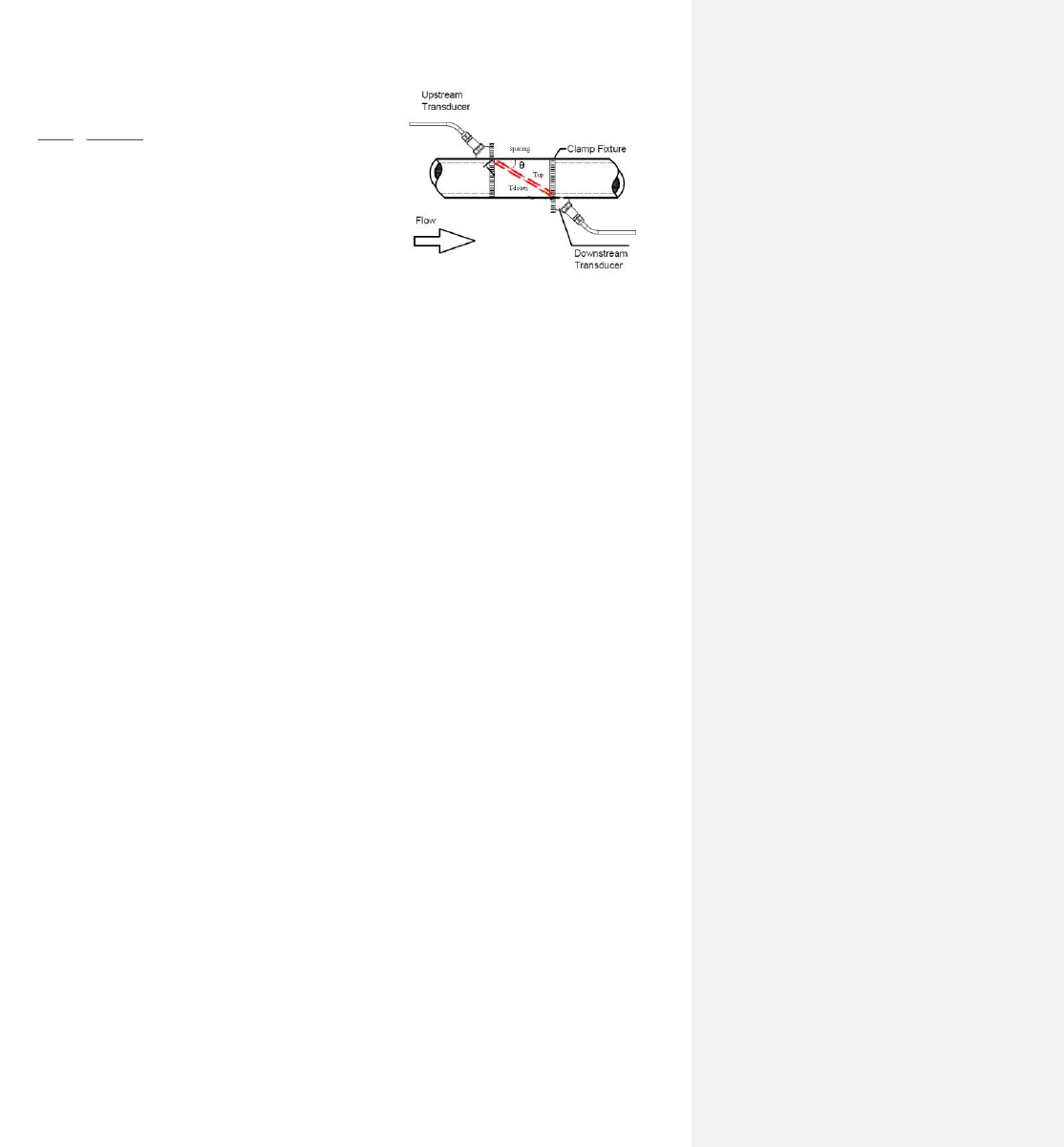
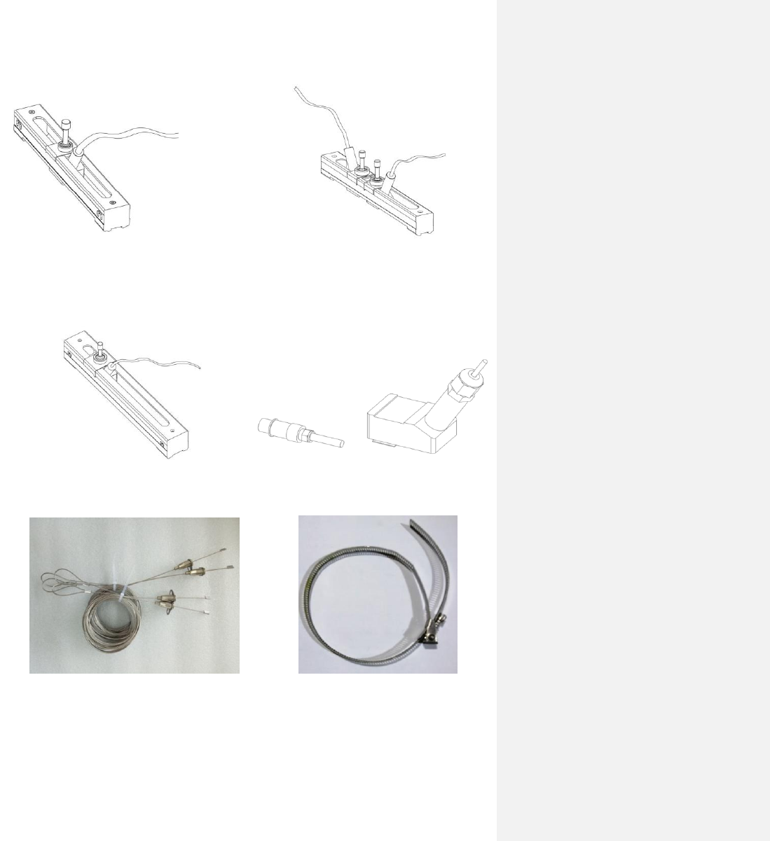
§1.5 Parts Identification
RM Transducer
Temperature Sensors
RL Transducer
(optional)
RS2 Transducer
Clamping Strap (optional)
Clamping Cable
10
§1.6 Product Identification
Every EF40 series flow meter has a unique product identification number, or ESN. This number is written
on the label inside of the meter enclosure. It is also displayed in Menu Window M55. The window can
be accessed by pressing the following series of keys:
M→ 5 (System) →5 (Version/SN#)
See section §2.4 for more information on display windows.
In the case of any hardware failure, please provide this number when contacting the manufacturer.
§1.7 Data Integrity and Built-in Time-Keeper
All user-entered configuration values are stored in the built-in, non-volatile flash memory that can retain
the data for over one hundred years. The memory integrity is retained even when the power is
disconnected or turned off. Password protection is provided to avoid inadvertent configuration changes or
totalizer resets.
A time-keeper is integrated in the flowmeter. It works as the time base for flow totalizing. The time-
keeper remains operational as long as the battery’s terminal voltage is over 1.5V. In the case of battery
failure, the time keeper will not keep running, and the time data will be lost. The user must re-enter
proper time values after the battery is restored. Improper time values will affect the totalizer as well as
many other functions. Re-entering the time value is a crucial step after battery failure because the
totalizer is a factor in accurate flow rate measurement.
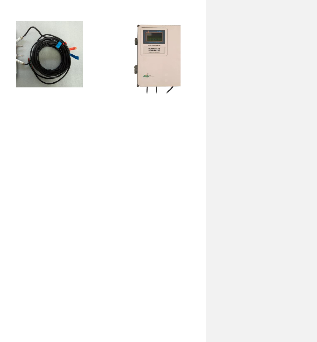
Transducer Cable 5m x 2
Main Unit

11
§1.8 Technical Specifications
Design
Wall-mount for permanently installation
Flow Measurement
Volumetric flow rate, total flow, velocity. Bi-directional
Energy
Measurement
Measure Energy rate and energy total. Dual PT100 RTD sensors
are required
Flow Velocity
± 10 m/s (± 32 ft/s), bi-directional.
Flow Accuracy
1% of reading 0.01m/s (0.03ft/s) in velocity*
Temperature
Accuracy
Within 0.1°C
Repeatability
0.5%
Response Time
0.5s. Configurable between 0.5s and 99s.
Display/Keypad
LCD with backlight. 4 x 16 letters. 5 x 4 tactile-feedback
membrane keypad plus 4 utility keys.
Displays instantaneous Energy rate/total, flow rate/total (positive,
negative and net), velocity.
Units
English (U.S.) or metric.
Totalizers
Positive totalizer, negative totalizer, net totalizer, manual
totalizer.
Output
4-20 mA
Optically isolated Open Collector Transistor output (OCT) for
frequency, pulse, or relay.
Recording
Automatically records the daily total of the last 64 days, the
monthly total of the last 64 months and the yearly total of
the last 5 years.
Data Logger
Optional. >150,000 measured values.
Communication
Interface
Default RS485. Supports the MODBUS protocol.
BACnet/MSTP and GPRS is available upon request.
Software
PC software for data logger download and real-time data
acquisition.
Pipe Size Range
3/4" - 120" (DN20mm - DN3000mm), depending on
transducer.
Pipe Material
All metals, most plastics, some lined pipes**
Liquid Type
Virtually all liquids (full pipe).
Liquid Temperature
32˚F - 176˚F (0˚C - 80˚C) or 32˚F - 312˚F (0˚C - 150˚C),
depending on transducer type
Environment Temp
32˚F - 140˚F (0˚C - 60˚C)
Enclosure
11” x 8.66” x 3.54” (280mm x 220mm x 90mm)
Aluminum, powder coated
Protection
IP65. Weather-proof
Weight
6.6 lbs (3kg) approximate
Power source
90-260VAC /50-60Hz/0.1A, or, 12-24VDC/1A (Fuse 0.5A)
*Note: This accuracy rate is only applicable under the reference conditions and with a velocity above
1ft/s. Flowrate is calculated by multiplying velocity with the inner cross-section area of the pipe.
12
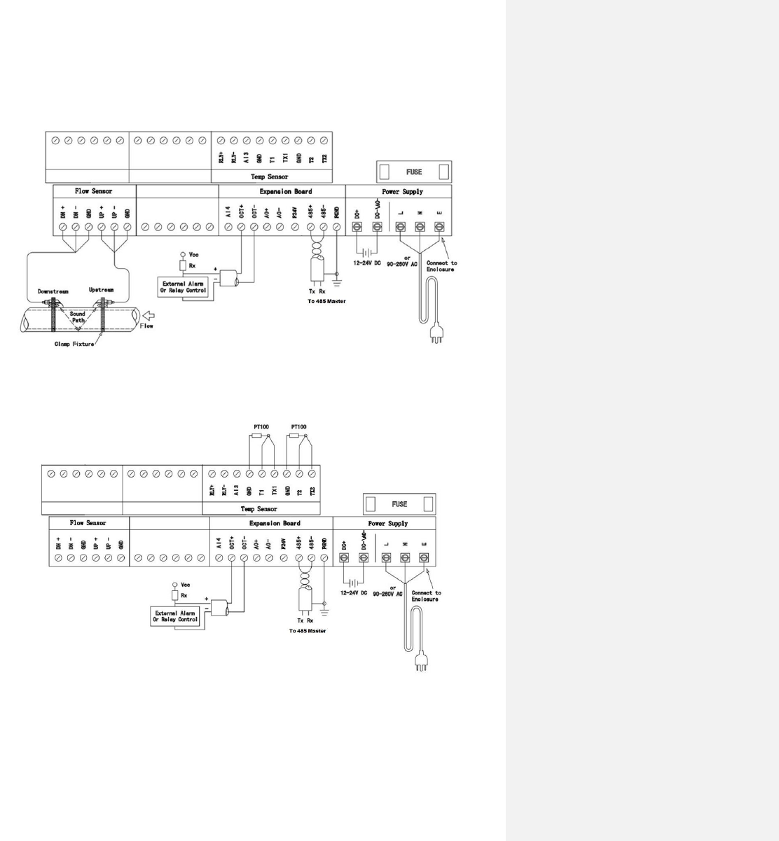
§1.9 Wiring
For flow measurement:
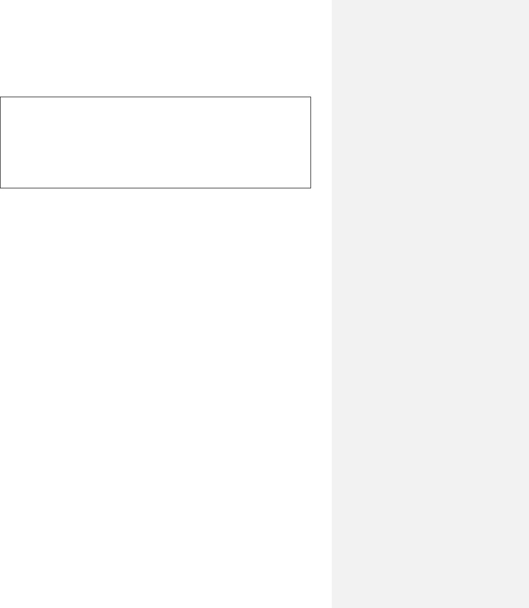
For thermal energy (BTU) measurement:
2. Flow Measurement
13
§2.1 Unpacking
Please unpack the shipping box and check the parts and documents against the packing slip. If there is
something missing, the device is damaged, or something is abnormal, please contact us immediately and
do not proceed with the installation.
§2.2 Installation Considerations
This section provides guidelines for installing the EnduroFlow TM EF40 main unit (the flow converter)
and its transducers.
§2.2.1 Mounting the Main Unit
The EnduroFlow TM EF40 main unit electronics are housed in an IP65 weather-proof and dust-tight metal
enclosure. Therefore, the main unit can be installed indoors or outdoors. Usually, it is mounted in a meter
shed or a location where one can easily access the meter for testing and servicing.
Note: because the unit is not water-proof, be sure it is not exposed to rain or water when it is installed
outdoors. Also avoid locations where there are strong sources of electrical interference and excessive
vibration.
§2.2.2 Installing Transducers
First, you need to select a proper installation site. For this, one usually needs to consider the accessibility
of the location, operating space needed for the installation, safety code compliance, etc. In addition, flow
and pipe conditions near the installation site are also very important. Please refer to section §3.1 for site
selection details.
Then, follow the installation guidelines given in Appendix §10.2 for installing clamp-on transducers.
If you ordered a wetted transducer, either insertion type or flow cell type, please refer to Section §3.2 and
§10.2 for installation instructions.
Distance from Main Unit to Transducers
In general, signal quality will improve based on the length of the transducer cable. Shorter cables will
result in better signal quality. Spire Metering Technology can supply up to 1000ft (300m) long transducer
cables.
Transducer Cables
EnduroFlow TM EF40 utilizes a double-balanced driving technique for high performance ultrasonic
transmission and receiving. It requires twisted shielded cables for the transducers. We recommend using
the cable supplied by the manufacturer. If you want to do the transducer cabling yourself, please consult
the manufacturer in advance.
Try not to route the transducer cable along with high current AC lines. Avoid strong interference sources.
Make sure the cables and cable connections are protected from weather and corrosive conditions.
WARNING!
The EF40 can be used to measure the flow of many kinds of liquids. Some of
the liquids may be hazardous. It is very important that you comply with local
safety codes and regulations in installing and using electronic devices in your
area. We do not accept returns on meters for service or refund if it has been
installed in a hazardous environment!
14
§2.2.3 Power Supply Wiring
Two types of power supplies can be used, 12-24VDC or 90~260VAC.
Note: Do not apply both power supplies (DC and AC) at the same time.
Please refer to Appendix §10.1 for wiring information.
Backup Battery
There is a 3V coin cell battery, CR2032, on the main board which is used to backup the calendar real-time
clock (RTC). When the main power is off, this battery will keep the RTC running. The battery lifetime is
normally about 3 years. Replace the battery with the same type when necessary. Please disconnect the
main power and wear an anti-static wrist straps to prevent electro-static damage to the main board
electronics.
If time stamping is not needed for data recording, you may remove this battery from the board.
§2.2.4 Other Electrical Connections
Wiring 0/4-20mA Output
Using standard twisted-pair wiring. Refer to section §4.20
Wiring analog Inputs
The analog input channels are wired to terminal block pins AI3(20), AI4(19) . Please refer to section
§4.21 for more information.
Wiring Alarms
You may use the OCT or Relay output to drive an alarm. The maximum electrical ratings for the OCT
and Relay are listed in the §4.18 and §4.19 Specifications. Use standard twisted-pair wiring.
Refer to section §4 for details.
WARNING!
The transducers may have static charges accumulated during
transportation. Before connecting the transducers to the main unit,
discharge the transducers by shorting the center conductor of the
transducer cable connectors to the metal shield of the connector.
WARNING!
There might be risk of explosion if the battery is replaced with an incorrect
type. Batteries should be recycled where possible. Disposal of used
batteries must comply with local environmental regulations.
15
§2.3 Power On
The EnduroFlow TM EF40 does not have a power ON/OFF switch. When connected to an external power
source, it will start to run automatically.
The flow meter will run a self-diagnostic program—checking the hardware first, and then, the software
integrity. If there are any abnormalities, corresponding error messages will be displayed. (See Section §6
for more information on error messages.) Under normal conditions, there should be no display of error
messages and the flowmeter will proceed to the main window. This menu can also be accessed at any
time by pressing the (“Ex”) key up to three times, depending on the menu window in use at the time.
The main menu will display the signal strength, signal quality, and transit-time ratio. These readings are
based on the most recent pipe parameters configured, or by the initial program.
The flow measurement will keep running in the background without change, regardless of any user
window browsing or viewing activities. Only when the user enters new pipe parameters will the
flowmeter change measurement to reflect these alterations.
When new pipe parameters are entered or when the power is turned on, the flowmeter will enter into a
self-adjusting mode. The device will account for the increase in receiving circuits so that the signal
strength will be within a proper range. Using this step, the flowmeter finds the best receiving signals. See
Section §2.7 for more information on configuring the pipe parameters.
When the user adjusts the position of the installed transducers, the flowmeter will re-adjust the signal gain
automatically. Any user-entered configuration value will be stored in the NVRAM (non-volatile
memory), until it is modified by the user.
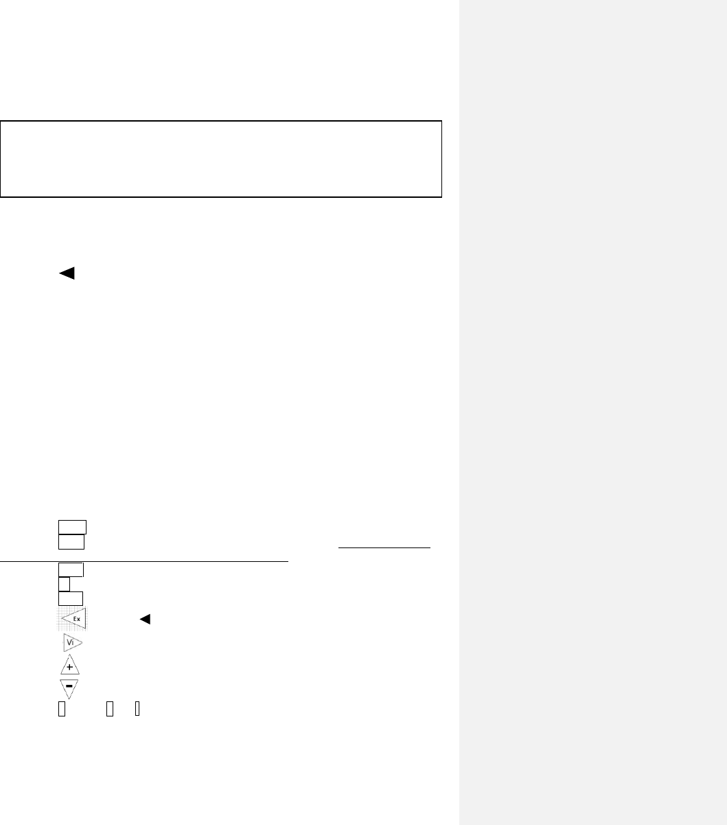
§2.4 Keypad
• The SET key is used to configure the pipe parameters.
• The LOG key is used to set up and view the built-in data-logger. Please note that you
need to choose the Data Logger option when placing the order.
• The CAL key is used to set up calibrations.
• The M key is used to access all the other menu functions.
• The ENT key is the enter key to confirm or acknowledge any input or selections.
• The (“Ex”) or key is the exit or backspace key.
• The (“Vi”) key is used to view measurements.
• The key is used to navigate up, or to add numbers together.
• The key is used to navigate down, or to subtract numbers.
• The 0 through 9 and .keys are used to enter numbers and values.
WARNING!
Before connecting the device to a power source, please do a final check to make
sure all the wiring is correct and all the local safety codes are followed.
16
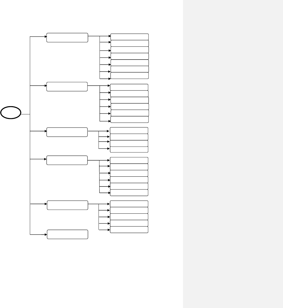
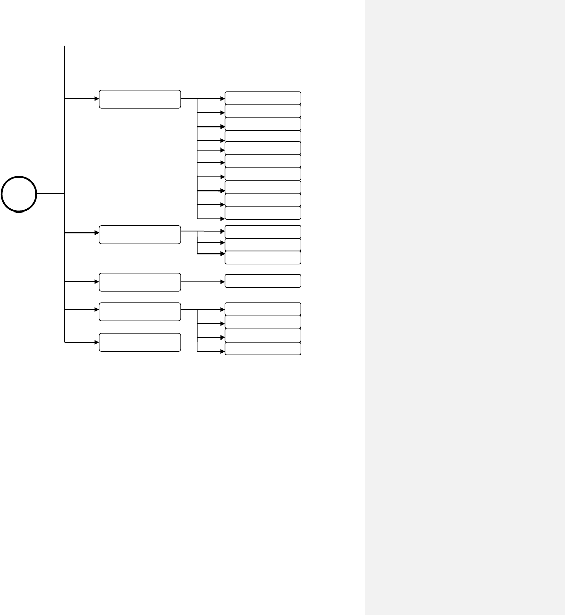
§2.5 Display Windows
1. Quick Start
S1. MOUNTING SITE
S2. PIPE PARAMETERS
2. Set Pipe
S3. FLUID PARAMETERS
S4. XDUCER
PARAMETERS
S5. INSTALL XDUCER
NnnNOW
S6. VERIFY S,Q&R
FS,Q,R
S7. DIAGNOSE Triplet
S21. Set OD
S22. Set Wall TH
S23. Set ID
ID
S24. Pipe Material
S25. Set Liner
Exit
S31. Fluid Type
Exit
S33. Viscosity
S32. Sound Speed
3. Set Fluid
S41. Xducer Type
S42. Mount Method
4. Set Xducer
S43. Mount Space
S44. Scale Factor
S45. MAT Correction
Exit
S51. Damping Filter
5. Set Filter
S52.LowFlow Cutoff
S53. PoorSig Filter
S54. Empty Pipe
Exit
6. Exit
SET
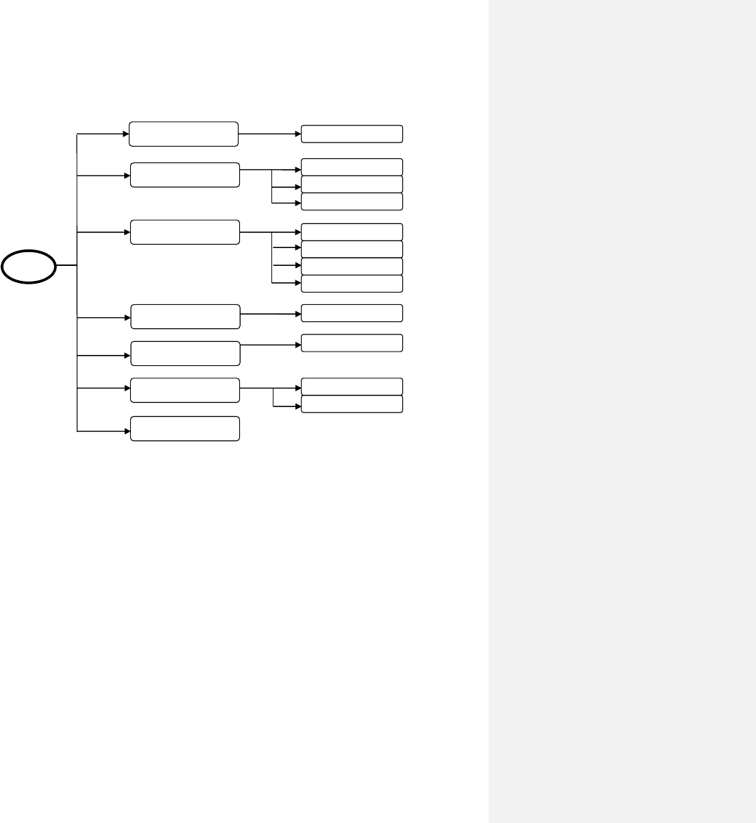
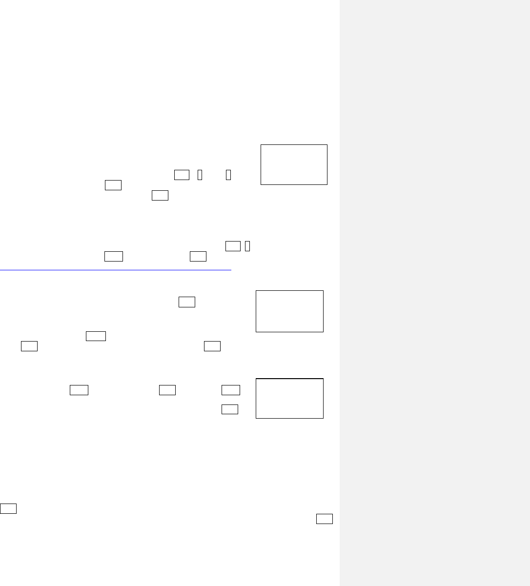
17
1. Basic 4 Items
2. All 16 Items
2. Start Time
1. Log Interval
3. Stop Time
L10. File Name:
1. Save to
2. Log Items
Exit
3. Schedule
Exit
4. View Log
Schedule
Displays log file
5. Clear Log
Schedule
Clears log file
6. Stp Collection
Schedule
1.YES
2.NO
7. Exit
LOG
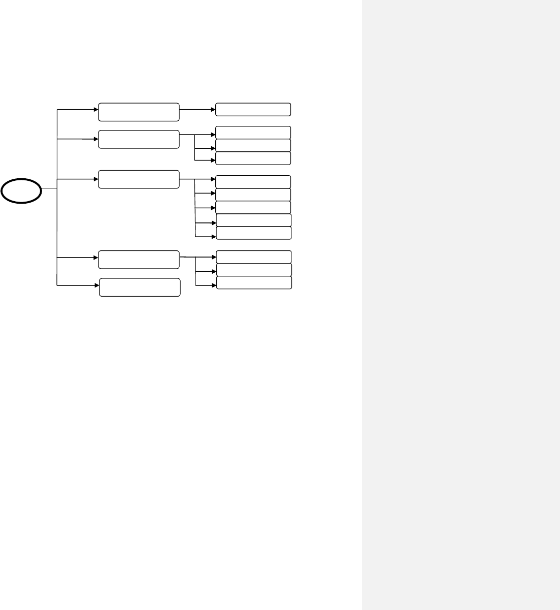
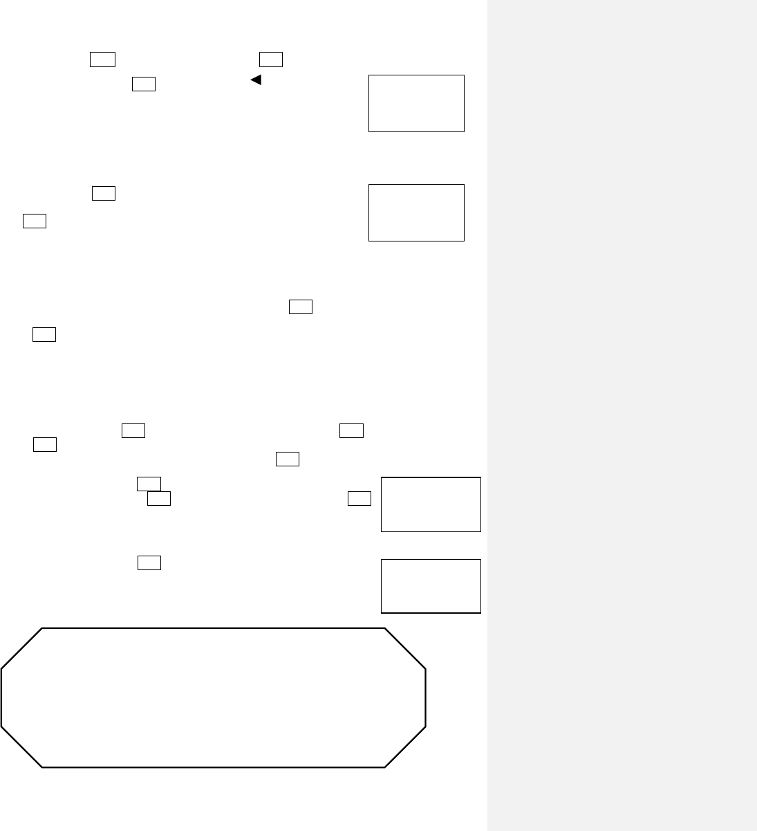
18
2.Close Sampling
1.T1/T2
1.Man Totalizer
C10:Zero Cal Instructions
1. Zero Cal
2. Linear Cal
2.Linear Table
3.Exit
3. 0/4-20mA Cal
4. Temp Cal
1.Start Sampling
3. Verify
2.Calibrate
3.Exit
5. Exit
CAL
4.Calibrate
5.Exit
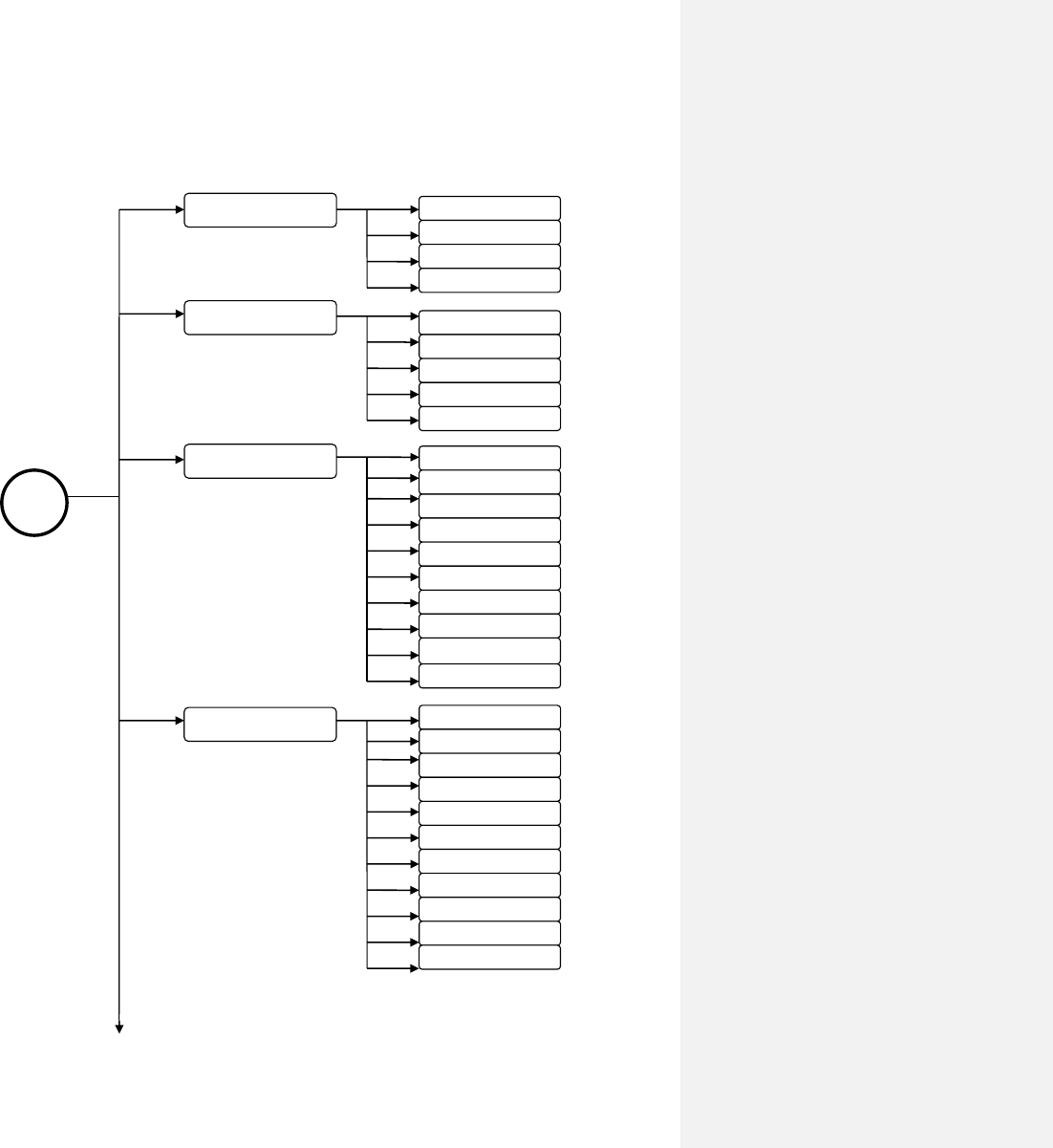
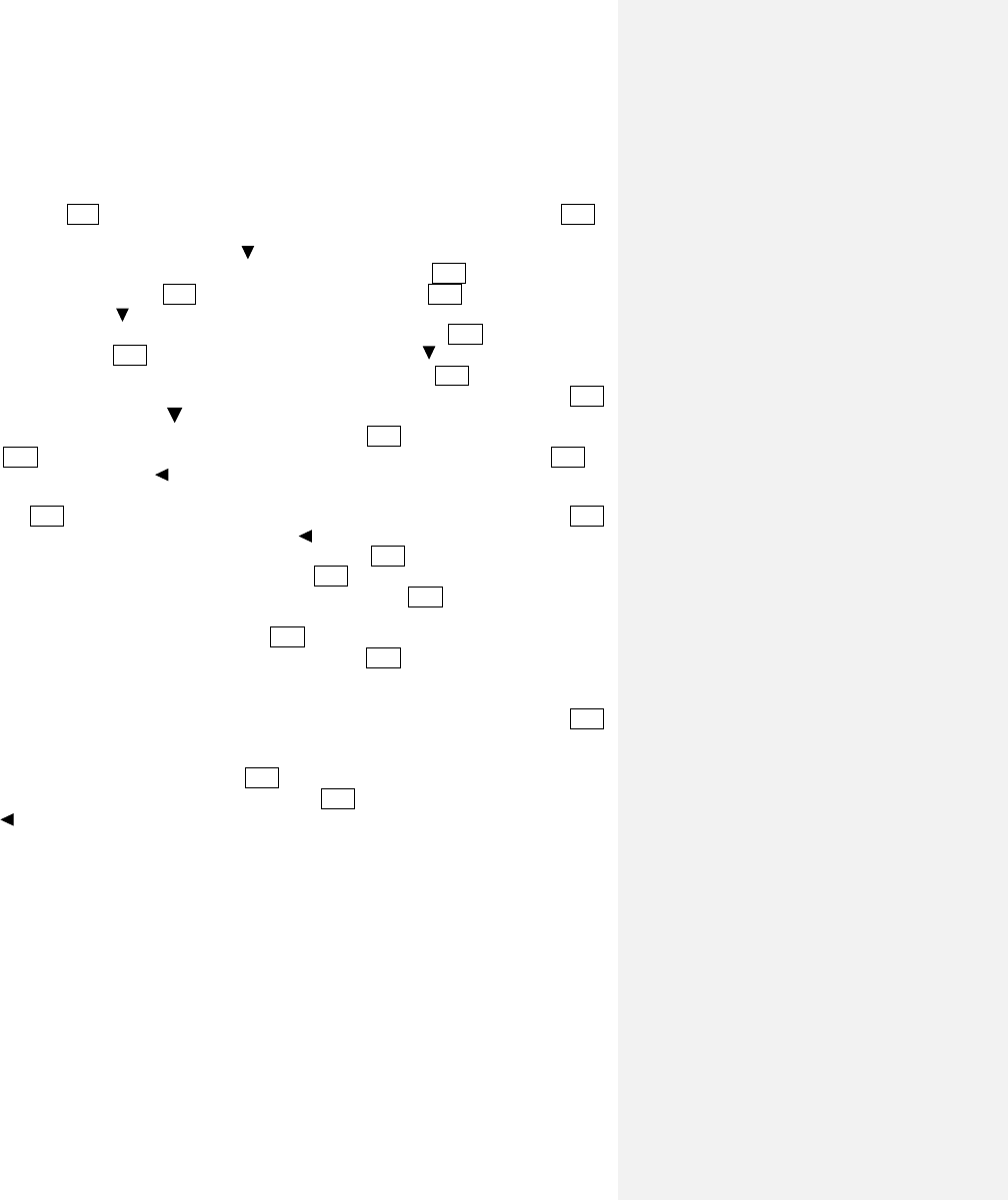
19
M
1. Site
4. Totalizer
2. Diagnosis
1.Save Site
2.Recall Site
3. Delete Site
4.Exit
1.Triplet
2. Sound speed
3.Transit-time
4.Reynolds
5.Exit
3. Input/Output
1.Display
2.0/4-20ma CL
-20ma CL
3.OCT Output
4.Relay Output
5.Freq Output
6.Buzzer
7.Alarm
8.Batch Control
9.A13/A14 Valu
10.Exit
1.Flo Multiplier
2.Flo NET ON/OFF
N
et
3.Flo POS ON/OFF
OFF
4.Flo NEG ON/OFF
N
EG
5.Flo TOT Reset
6.Eng Multiplier
7.Eng TOT Reset
8.Daily TOT
9.Monthly TOT
10.Yearly TOT
11.Exit
20
9. Exit
9.Clear Data
M
5. System
8. Misc
6. Heat Energy
1.Language
2.Unit
3.COMM
4.Date/Time
5.Version/SN#
6.Battery
7.System Lock
8.Work Timer
10.Exit
7. Calculator
1.Location
2.Temperature
-20ma CL
3.Exit
X= Y= Operator:
1.Max Flowrate
2. Last Pwr Off
3. Pwr On Time
4.Exit

21
§2.6 Display Window List
SET →Quick Start
To help the user get the flowmeter up and running as quickly as possible.
Includes instructions on preparing mounting site, setting pipe parameters,
setting fluid parameters, and setting transducer parameters, followed by
instructions on transducer installation, verification, and diagnosis.
SET → Set Pipe To set pipe parameters. This includes outer diameter, wall thickness,
inner diameter, pipe material, and pipe liner.
SET → Set Fluid To set fluid parameters. This includes fluid type, sound speed, and
viscosity.
SET → Set Transducer To set transducer parameters. This includes transducer type, mounting
method, transducer spacing, and scale factor.
SET → Set Filter To set up filter parameters. This includes average filter, noise filter, poor
signal filter, and empty pipe.
LOG → Save To To save logged data to a custom file name.
LOG → Log Items To set up data logging. This includes logging a basic set of 4 items or
logging all 16 items.
LOG → Schedule To set up a schedule for data logging. This includes logging interval,
start time, and stop time.
LOG → View Log To view any previously saved log.
LOG → Clear Log To delete a previously saved log.
CAL → Zero To set up zero calibration.
CAL → Linear To set up linear calibration. This includes manual totalizer and a linear
table.
CAL → 0/4 – 20mA To verify that the output of the 0/4 – 20mA is accurate.
CAL → Temp To set up temperature calibration
M11 – M13→Site To save, recall, and delete site parameters, respectively.
M21 – M24→ Diagnosis To display triplets, sound speed, transit time, and Reynolds time,
respectively.
M31 – M38→Input/output To change display settings, 0/4-20mA CL, OCT output, Relay output,
Frequency output, buzzer, alarm, batch control and A13/A14 value .
M41 – M410→ Totalizer To set up totalizer. Includes Flo multiplier, NET on/off, POS on/off,
NEG on/off, totalizer reset, Eng Multiplier, daily, monthly, and yearly
totalizer.
M51 – M59→ System To change and/or view the system settings. Includes language, system
units, COMM, date/time, ESN version, battery volts, set up system lock,
work timer, and Clear Data.
22
S44
Scale Factor
>= 1.01
1
=>0.951_
S2a:
Outer Diameter
2.375 in
M61 – M62→ Heat Energy To set up the heat energy. Includes location and temperature.
M70→ Calculator Option that features a scientific calculator.
M80→ Misc To set Max Flowrate, Last Pwr Off, and Pwr On Time.
§2.7 Steps to Configure the Parameters
You may use the built-in Quick Start by pressing SET and 1 keys to program the flow meter.
Alternatively, you may follow the following steps to program the flow meter.
Step 1: Enter transducer info
Change the Scale Factor: The scale factor can be found printed on the
transducer pair. Press keys S44 (e.g., press SET, 4 and 4 keys,
consecutively). Then, press the ENT key. Key in the new scale factor of the
transducer pair you are planning to use. Press ENT to confirm.
Step 2: Enter pipe info
All pipe parameters can be entered by pressing keys S1 (e.g., press SET, 1 consecutively) and then,
scroll down to Step 2 using the ▼/- key. Finally, press ENT. To find your pipe’s parameters, visit
http://www.engineeringtoolbox.com/pipes-tubes-dimensions-t_16.html. Select the type of pipe you
are using, and click the corresponding link. Once you have this information, proceed with the
following steps.
Pipe OD: Enter the pipe outer diameter, and press the ENT key to confirm.
Wall-thickness: Press the ▼/- key to scroll down to the next parameter.
Press ENT and enter the pipe wall-thickness value. Press ENT again to confirm. If pipe wall
thickness is unknown, Spire can provide a device to measure this value.
Pipe Material: Press ▼/- to scroll down. Press ENT and then use ▼/- to
select the material of the pipe you are using. If your pipe material is not
shown on the list (non-standard material), select Other. Press ENT to
confirm.
Sound Speed in Pipe Wall: If your pipe material is on the list in the previous step, the flow meter will
automatically skip this step and go to the next step. You do not have to enter in the Sound Speed
unless you have selected other as your pipe material.
If you selected other as your pipe material, you will have to enter the sound speed manually. Press
ENT which will prompt you to enter the correct sound speed for the pipe wall material you are using.
You can find this data in the Appendix §10.4 of the User’s Manual. When you are done, press ENT
to confirm.
S2c:
Select Pipe
1. Carbon Steel
1.StainlessSteel
23
STOP!
It is extremely important to enter the parameters properly before installing the
transducers. Incorrect parameters result in operation errors and inaccurate
measurements. Common parameter errors are incorrect wall thickness, usually
due to corrosion on the pipe. See Section §3 for more details on issues caused
by wall thickness problems.
S4a XDUCER TYPE:
1. THC-HS
2. THC-RS2
STEP5.
INSTALL XDUCER NOW
Dist= 113.41mm, V
Pipe lining: Press ▼/- to scroll down, and then, press ENT. If your pipe has lining inside, enter the
lining information. Press ENT to confirm. Press or (“Ex”) to go
back to the Quick Start menu.
Step 3: Enter fluid info
From the Quick Start menu, scroll down to Step 3.
Fluid Type: Press ENT and select the item that matches your fluid type. If
you do not find a match (non-standard fluid), select item 9 (Other). Press
the ENT key to confirm.
Sound Speed in Fluid: If you found your fluid type in the previous step, the flow meter already has
the sound speed data. Therefore, skip this step and go on to the next.
Otherwise, exit to the main screen and press keys S32. Press ENT and key in the sound speed of your
fluid. You can find this information in Appendix §10.4 of the User’s Manual. When you are done,
press ENT to confirm.
Step 4: Enter transducer installation info
From the Quick Start menu, scroll down to Step 4.
Transducer Type: Press ENT to edit the type of transducer. Use the ▼/- key to scroll down and
press ENT and select the proper transducer type from the list. Note: The type of transducer you are
using will be printed on the side of the transducers. Press ENT to confirm.
Mounting Method: Use the ▼/- key to scroll down to the mounting method
selection screen. Then, press ENT and select the proper method. Press ENT
to confirm. For pipes smaller than 1”, try the W-method. For pipes from 1” to
12”, use the V-method. For pipes larger than 12”, use the Z-method. See
Section §3.3 for more details on how to select the proper method.
Mounting Spacing: Use the ▼/- key to scroll down to Step 5. The displayed
value is the mounting spacing between the two transducers (see the image on
the right). Write down this number, as you will need it later when
installing the transducers.
S2d: Has Liner?
3. Rubber
S3a
Select Fluid
9. Other
1.StainlessSteel
24
Example:
For standard, or commonly-used, pipe materials and standard liquids, the parameter configuration
steps are as following:
a. Press the SET key. Make sure that the option “1. Quick Start” is highlighted. Press ENT.
b. You should see a “Select Mounting Site” window for information on ideal mounting
conditions. Press the down arrow to move on to the next step.
c. You should see the “Set Pipe Parameters” window. Press the ENT key to program the
pipe parameters. Press ENT to edit the outer diameter. Press ENT again to save. Press
the down arrow.
d. You should see the “S22: Set Wall-Thickness” window. Press ENT to edit the wall-
thickness. Press ENT again to save. Press the down arrow.
e. You should see the “S24: Select Material” window. Press ENT to select the pipe
material. Using the up and down arrows, select the appropriate pipe material. Press ENT
to save. Press the down arrow.
f. You should see the “S25: Set Liner?” window. Press ENT if the pipe has no liner. Press
ENT again, use the up and down arrows to select the appropriate liner. Press ENT to
save. Use the arrow to exit.
g. You should see a “Set Fluid” window. Press the down arrow to access this menu. Press
the ENT key. Use the up and down arrows to select the appropriate fluid. Press ENT
again to save information. Use the arrow to exit.
h. You should see a “Set Transducer” window. Press the ENT key. You should now see the
“S41: Transducer Type” window. Press the ENT key once again and use the up and
down arrows to select the appropriate transducer type. Press ENT to save.
i. Press the down button to access the transducer mounting method. You should see the
“S42: Mount Method” window. Press ENT to edit the mount method. Use the up and
down arrows to select your appropriate method. Press ENT again to save.
j. Press the down arrow to access this menu. You should see an “S43:Mount Space”
window. The number displayed on the screen represents the distance between the two
transducers (transducer spacing). For more information on installation press the ENT
key.
k. Use the down arrow button to edit the scale factor. You should see the “S44: Transducer
Scale Factor” window. Press the ENT key to edit. Enter in the scale factor of the
transducer pair you are planning to use. Press ENT key again to save. Use the arrow to
exit.
Refer to Quick Start for more information and diagrams.
3. Installation
§3.1 Mounting Allocation for Transducers
The first step in the installation process is to select an optimal location for installing the transducers in
order to make the measurements reliable and accurate. A basic knowledge about the piping and its
plumbing system is advised.

25
An optimal location is defined as a long, straight-pipe line filled with the liquid to be measured. This pipe
can either be in a vertical or horizontal position. However, on a vertical pipe, an upwards flow direction is
required. The following instructions will guide the user in finding an optimal location:
Principles to Select an Optimal Location:
1) The straight pipe should be long enough to eliminate any irregular-flow-induced errors.
Typically, the length of the straight pipe should be at least 15 times the pipe outer diameter
(represented as 15D). A run of over 15D, is more likely to yield a laminar, or undisturbed, flow.
This is an ideal condition for accurate measurement. As a general rule, the longer the straight run,
the higher the accuracy. The transducers should be installed at a pipe section where the length of
the straight pipe at the upstream side is at least 10D and the downstream is at least 5D. The
transducer installation site should be at least 30D away from the pump. Refer to Table A for
more details.
2) Make sure that the pipe is completely filled with liquid. It is impossible to take an accurate
measurement if there are any air bubbles. The equation used to calculate the flow rate assumes
the pipe is filled completely with the liquid being measured. For the best results, make sure the
pipe is under pressure. This way, it has to be full.
3) Make sure that the temperature on the mounting location does not exceed the range for the
transducers. Refer to the transducer specification chart in Appendix 10.2
4) If possible, select a relatively new straight-pipe line. Old pipes tend to have corrosions and
depositions, which could affect the results. If an old pipe is used, it is recommended that the
corrosions and depositions are treated as if they were a part of the pipe wall or as part of
the pipe liner (i.e. extra value is added to the pipe wall thickness or liner thickness
parameters to take into account the deposition).
5) Some pipes may have a type of plastic liner, which creates a certain amount of gap between liner
and inner pipe wall. These gaps could prevent the ultrasonic waves from direct travel. Such
conditions will make measurement very difficult. Whenever possible, try to avoid these kinds of
pipes. If lined pipes must be used, try our insertion transducers (PN#: TWI-V) that are
installed permanently in the pipe. The two transducers are installed by welding on a base
adding a ball valve, then drilling a hole in the pipe to install the transducer, even as liquid is
flowing inside.
26
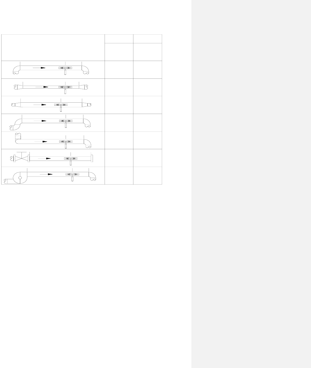
Table A
L up L dn
L up L dn
L up
L up
L up
L dn
L dn
L dn
Piping Configuration
and
Transducer Position
Upstream
Dimension
Downstream
Dimension
L dn
x Diameters
L up
x Diameters
10D 5D
10D
10D
12D
20D
20D 5D
5D
5D
5D
5D
L up L dn
30D 5D
L up L dn
§3.2 Transducer Installation
The transducers used by the EF40 Series Ultrasonic Flow Meter are made out of piezoelectric crystals for
both transmitting and receiving ultrasonic signals through the wall of a liquid-piping system. The
measurement is obtained by calculating the travel-time difference of the ultrasonic signals. Since the
difference is very small, the spacing and the alignment of the transducers are critical factors to the
accuracy of the measurement and to the performance of the system. Meticulous care should be used for
the installation of the transducers.
Steps to Install the Transducers:
1) Determine an optimal location. The straight pipe at both sides of the transducers needs to be of
sufficient length (See Section §3.1, #1). The pipes are required to be in favorable condition –
newer pipes with no rust are recommended (See Section §3.1, #4). Horizontal pipes typically
have gas bubbles inside, especially on the pipe ceiling. There also may be sediment on the pipe
base. As a result, it is recommended that the transducers are installed on the side of, rather than
the top or bottom of, a horizontal pipe. See Appendix §10.2 for more details.
27
2) Make sure the chosen location is safe for and compatible with the operation of the flowmeter.
The EF40 is not designed for contact with hazardous materials.
3) Clean any dust and/or rust off the spot where the transducers are to be installed. For better results,
polishing the pipe’s outer surface with a sander is strongly recommended.
4) Extra care should be taken to avoid any sand or dust particles left between the pipe surface and
the transducer surface. We recommend wiping the surface thoroughly with a damp towel or
sponge. Once the surface is completely clean, dry it with a towel for best results.
5) Apply adequate ultrasonic couplant (grease, gel, or Vaseline®)*. Couplant should be spread
over the entire transmitting surface on the transducer and the entire installation surface on
the pipe. Make sure there is no gap between the transducer transmitting surface and the pipe
surface. However, be careful not to apply too much couplant, especially for small pipes. See
figure below:
6) Consider the appropriate method for mounting the transducers on the pipe. There are 2 methods
of mounting:
o Magnetic fixture: If the pipe material is metal, the magnetic force will keep the transducers
on the pipe.
o Clamp-on fixture: We provide 2 types of clamp-on fixtures. The transducers may be
pressed tightly against the pipe with the metal straps or metal strings provided for permanent
28
installation. Turn the screws on the metal strips clockwise to tighten, using a screwdriver or a
wrench.
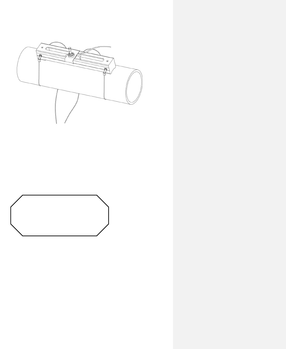
7) Install the transducers and space them carefully. See Appendix §10.2 for specifics on the RM1
and RS2 transducers. The spacing value shown on window S15 refers to the distance of inner
spacing between the two transducers. The actual distance of the two transducers should be as
close to this value as possible. Read Section §3.3 for more details on transducer spacing.
Please see Appendix §10.2 for more installation information.
*NOTE: As a safety precaution, it is recommended that the Sonotech Inc. SOUND SAFE® product be
used as the ultrasonic couplant. Other couplants such as grease, gel, or Vaseline® can be used as
alternatives – but please use at your own risk!
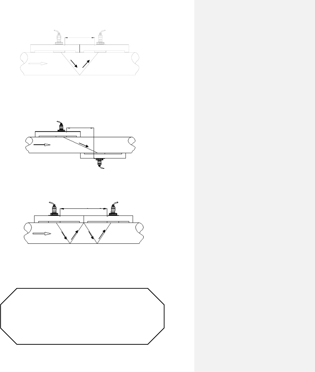
§3.3 Transducer Spacing
V-Method Installation
The V-method installation is the most widely used method for daily measurements. It is used when the
inner diameter of the pipe ranges from 20mm to 300mm. It is also known as the reflective method. The
small sound path of pipes in this range can interfere with accuracy. This method doubles the sound path,
thus, ensuring an accurate measurement.
STOP!
Before mounting, please read Section
§3.3! Transducer spacing is critical to
the accuracy of the meter readings.
29
Sensors Spacing
TOP VIEW OF PIPE
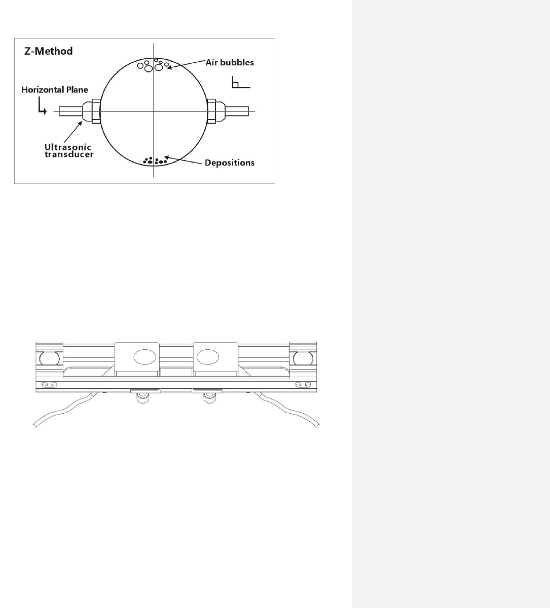
Z-Method Installation
The Z-method is commonly used for pipe diameters between 300mm and 5000mm. Signal strength is
increased with this method. However, occasionally the V-method does not work reliably; you can then try
the Z-method, even though the pipe is small. One example is RS2 transducer on a ¾” SS pipe.
W-Method Installation
The W-method can be used on pipes with diameters between 20mm and 40mm. This method is only
considered when V-method and Z-method do not work.
N-Method Installation (Spire Metering does not recommend this method)
The N-method is commonly used for pipe diameters between 10mm and 80mm and requires small
transducers. However, occasionally the N-method does not work reliably, if this is the case the Z-method
is recommend.
Liquid flow
Ultrasonic signal
Liquid flow
Ultrasonic signal
Ultrasonic signal
Liquid flow
STOP!
The meter readings WILL NOT be accurate unless the transducers
are installed properly. A critical value in determining proper
placement of transducers is the Transit Time Ratio. The ratio must
be in the range of 100±3. Please read Section §3.4 carefully to
ensure accurate measurement.
Ultrasonic signal
TOP VIEW OF PIPE
Sensors Spacing
TOP VIEW OF PIPE
Sensors Spacing

30
§3.4 Installation Checkup
After the completion of the transducer installation, the user should check the following items:
• The receiving signal strength (S value) and the degree of symmetricity ( value) between
upstream strength and downstream strength,
• The signal quality (Q value),
• The transit time ratio (R value).
• The delta time (travel time difference between the upstream and the downstream signals),
• The estimated liquid sound speed.
The S, Q and R values are displayed in the main window. You may press the View key to switch to the
main window in case your current window is not the main window. All the other information can be
viewed by pressing the + or – key.
This process will ensure that the flow meter is working properly for the most reliable and accurate results.
§3.4.A Signal Strength
Signal strength, represented as S, is a 5 bar of signal graphic that represents the amplitude of the receiving
ultrasonic signals. This value can be seen on the main menu. When all of the 5 bars are empty, it
indicates that there are no signals detected. When all of the 5 bars are full, it indicates that the received
signal is at its maximum strength.
The flow meter will operate well when the signal strength ranges from 4 to 5 full bars. Regardless of
the functioning range, higher signal strength is always desirable—the more bars, the more reliable and
accurate the results will be. The following methods are recommended to obtain strong signals:
1) Make sure the pipe is in excellent condition. Polish the outer surface of the pipe and apply more
couplant between the pipe and transducers.
2) Carefully adjust the position of the two transducers, both vertically and horizontally. Check the
signal strength after each movement. Stop at the position where the signal strength reaches a
maximum. Be sure to check the transducer spacing to make sure it is still the same or very close
to the figure displayed in S43 menu.
3) If the current location of the transducers provides a signal strength that is less than 4 full bars, try
relocating it to a location with a better signal.
The degree of symmetricity ( value) shows the difference between the upstream signal strength and the
downstream signal strength. Ideally, should be close to 0.0 or below 0.2. When the flow velocity in the
pipe is high, may increase to 0.5.
§3.4.B Signal Quality
Signal quality is indicated as the Q value for this instrument. This value can be seen on the main menu. A
higher Q value means a higher Signal to Noise Ratio (SNR). Higher signal quality yields a higher degree
of accuracy. Under normal pipe conditions, the Q value should be in the range of 4 to 5 full bars. A
higher quality is always more desirable.
Causes for a low Q value may be:
• Interference from other instruments and devices nearby, such as a power frequency converter or a
high-voltage AC power line, which could cause strong interference. If possible, relocate the flow
meter to a location where interference is minimal.

31
• Bad sonic coupling between the transducers and the pipe. If the Q value is not in the desired
range, we recommend polishing the pipe surface again. It is important to clean the surface after
polishing. We also recommend adding more couplant. Finally, the pipe needs to be in the best
condition possible.
• The selected pipe section is not conducive to accurate measurement. In some cases, the pipe
material causes this problem with signal quality. For example, carbon steel pipes frequently
feature corroded pipe sections, which would change pipe wall thickness values. In this case, we
recommend using the Z-method for transducer installation. Increase or decrease the spacing
between the transducers until the ratio is 100±3. See section §3.4.D for more details. The user
may also move the transducers to a pipe section that is in more favorable condition.
§3.4.C Total Transit Time and Delta Time
The total transit time (or traveling time) and the delta time are both displayed on menu window M23.
This window can be accessed by pressing the following series of keys:
M→(Diagnosis) →M23 (Transit Time)
See section §3.4.D for more details. These values are the primary data used by the instrument to calculate
the flow rate. They are the most important values calculated by the flow meter. The measured flow
rate will vary as the total transit time and delta time vary. Therefore, the total transit time should remain
stable or fluctuate only very slightly. The device will adjust for any variance on its own until it is
stable.
The delta time, or delta t, is the transit time difference between the upstream transit time and the
downstream transit time. It normally varies less than 20%. If the variation exceeds 20% in either
positive or negative direction, there may have been errors in the installation of the transducers.
The user should examine the installation site for any apparent problems. The following list shows some
common examples of installation errors that cause inaccuracies in measurement:
• There may be insufficient couplant between the transducers and the pipe surface.
• The transducers may not be spaced correctly or may have been placed in a non-favorable
location. Either of these issues will cause weak signal strength and quality.
• The pipe may be only partially full or there may be air bubbles. If this is the case, the logarithm
used to calculate the flow rate will not yield accurate readings. Make sure that the pipe is
completely full and that there are no air bubbles in the line.
• The wall thickness values may be incorrect. The error may have resulted from corrosion on the
pipe. Use the Z-method of installation or move to a more favorable location.
§3.4.D Transit Time Ratio
This ratio, R, is used to check the quality of the transducer installation. It also verifies whether the
entered pipe parameters are consistent to their actual values. If the pipe parameters are correct and the
transducers are installed properly, the transit time ratio should be in the range of 100±3.
If this range is not met, the user should verify the following:
• The entered pipe parameters are correct
• The actual spacing of the transducers is the same as or close to what is shown on window S1, Step 5
(see Section §3)
• The transducers are installed properly and are facing the right direction

32
• The mounting location is stable
• The pipe-run upstream and downstream of the transducers is straight
• The pipe is in adequate condition(the most common pipe quality issues are too much corrosion or too
much deposition inside the pipe)
• There are no interference sources inside the pipe
• For RS2 transducer, if you see the ratio is less than 90% and the pipe is DN20 or smaller, please try
to program the transducer as following:
1. Press S4 to enter into XDUCER TYPE menu.
2. Select User Defined, press ENT to modify
3. In 1/4 menu, enter 38
4. In 2/4 menu, enter 2267m/s or 7438ft/s
5. In 3/4 menu, no change
6. In 4/4 menu, enter 4.16us
7. Go back to the main window. You should see R has increase to somewhere in 100+/-3 range
Please refer to Appendix §10.2 for more installation details.

33
4. How To
§4.1 How to check if the instrument is working properly
The upper right hand corner of the LCD display features the symbol corresponding to the device’s current
level of functionality. The following list explains the most commonly-seen symbols:
1) Generally speaking, when “R” is displayed, the device is working properly.
2) If an “H” flashes, then the received signal may be poor. See Section §6 for more on troubleshooting.
3) If an “I” is displayed, then no signal was detected.
4) If a “J” is displayed, then the hardware of this instrument may be out of order. See Section §6 for
more details.
§4.2 How to check the liquid flowing direction
1) Make sure that the instrument is working properly. There should be an “R” displayed in the upper
right hand corner of the screen.
2) Check the flow rate display. If the value is positive, the direction of the flow will be from the
upstream transducer, which is connected to the upstream connector of the meter, to the
downstream transducer; if the value is negative, the direction will be from the downstream
transducer to the upstream transducer.
§4.3 How to change the unit’s measurement system
The device can operate in either the English or the Metric system. This option can be accessed using the
following series of keys:
M→System→Unit (M52) →Metric/English
§4.4 How to select a flow rate unit
Press keys M52, followed by the second sub-menu option “Flow Rate Unit” to select the flow rate unit as
well as the corresponding time unit. This can be accessed as follows:
M→System→Unit (M52) →Flow Rate Unit
§4.5 How to use the totalizer multiplier
The user must enter the proper multiplying factor for the totalizer Flo and Eng multiplier. This setting can
be accessed by pressing the following series of keys:
M→Totalizer→Flo Multiplier (M41)
There is also an Energy multiplier under Totalizer. This setting can be accessed by pressing the following
series of keys:
M→Totalizer→Eng Multiplier (M46)

34
The multiplying factor, which uses the method of scientific notation, is used for expressing the total
readings which are too large or too small.
To reset the totalizer use the following series of keys:
M→Totalizer→ TOT Reset (M45)
§4.6 How to turn on and off totalizers
Use menu window M42, M43, and M44 to turn on or turn off the NET, POS, and NEG totalizers,
respectively. These menus can be accessed as follows:
M→Totalizer→NET on/off (M42), POS on/off (M43), or NEG on/off (M44)
§4.7 How to reset the totalizer
Use menu window M45 to reset the flow rate totalizers. This can be accessed as follows:
M→4.Totalizer→5.Flo TOT Reset (M45)
§4.8 How to use the damping filter to stabilize the reading
The damper acts as a filter for a stable reading. This setting can be adjusted in the “Avg Filter” menu,
which can be accessed through the following series of keys:
SET→Set Filter→ENT.
If a “0” is entered, there is no damping. A bigger number generally brings a more stable effect. However,
a balance is required; bigger damping numbers will slow down the instrument’s response time.
§4.9 How to use the zero-cutoff function (Noise Filter)
This function can be accessed by pressing the following series of keys:
SET→5→2
§4.10 How to set up the zero calibration
Without a zero calibration, the flow meter may give a small non-zero flow rate reading even when the
flow in the pipe is not running. In order to make an accurate measurement, it is necessary to set the
correct zero calibration. While setting this data, the liquid flow should be completely turned off. If there
is any value besides zero at the time zero velocity is set, all future results will be skewed. This window
can be accessed by pressing the following series of keys:
CAL→Zero Cal. Press the ENT key to start the zero calibration.
§4.11 How to change the flow rate scale factor
The scale factor (SF) is the ratio between the “actual flow rate” and the flow rate measured by the
flowmeter. It can be determined with standard flow calibration equipment. This value can be adjusted by
pressing the following series of keys:
SET→Set Transducer →Scale Factor. S44 Press the ENT key to edit the scale factor.
§4.12 How to use the password lock
The password lock provides a means of preventing inadvertent configuration changes or totalizer resets.
When the system is locked, the user can still browse menu windows, but cannot make any modifications

35
to the windows.
The password locking/unlocking can be done in menu window M57, which can be accessed with the
following series of keys:
M→System→M57.
The system can be locked with or without a password. A password-free lock can be enabled by pressing
the ENT key while in menu window M57. A personalized password can also be set up. It must consist
of 1 to 4 digits.
§4.13 How to use the built-in data logger
When the flowmeter has the Data Logger option, you may follow these steps to use the data logger.
1) Data will be saved on the microSD card, and every file can hold about 2,000 lines of data.
2) Use window L10 to save the logged data. The data can be stored in a logger buffer. Alternatively,
the data can be directed to the RS-485 interface without being stored in the logger buffer. This
window can be accessed using the following series of keys: LOG→Save To.
3) Use window L20 to select items; this can be accessed using the following series of keys: LOG→Log
Items. This will select the items to be logged.
4) Use windows L31, L32, L33 to set up the time log interval, start time, and stop time, respectively.
Also pressing ‘9’ on “start time” interface will start data collection after one minute. All of these
windows can be accessed using the following series of keys: LOG→Schedule.
5) Use window L40 to view saved data in the logger buffer. This window can be accessed using the
following series of keys: LOG →View Log.
6) Use window L50 to clear any unwanted logging data remaining in the RS-485 interface and in the
logger buffer. This window can be accessed using the following series of keys: LOG →Clear Log.
7) Use Window L60 to stop the current collection. This window can be accessed using the following
series of keys: LOG →Stop Collection.
8) The data stored in the data logger can be downloaded to any PC with “RW.exe”. Please contact Spire
Metering for this software.
§4.14 How to use the Frequency Output
All EF40 Series Flowmeters have a Frequency Output functionality. The signal for each device represents
its flow rate for the purpose of communicating with other devices. The emitted frequency output signal is
designed to connect with other instruments.
The Frequency Output is completely user-configurable. Usually, three parameters are configured:
1) Enter the frequency range in the “Freq Range” window as follows:
M→Input/Output→Frequency Output→Freq Range
2) Enter the lower limit of flow rate in the “Freq Min” window as follows:
M→Input/Output→Frequency Output→Freq Min
3) Enter the higher limit of flow rate in the “Freq Max” window as follows:
M→Input/Output→Frequency Output→Freq Max
Example: Assume that the flow rate varies in a range from 0m3/h to 3000m3/h and the required output
signal frequency should be in the range 200Hz to 1000Hz. The user should enter 0 for the “Freq Min”
window, 3000 for the “Freq Max” window, and 200 followed by 1000 for the “Freq Range” windows.
***Please note that the user needs to select the frequency output option ***
§4.15 How to use the Totalizer Pulse Output
The flowmeter will produce a pulse output with every unit of liquid flow. This pulse could be used by an
external pulse counter to measure the accumulation of the flow rate. Refer to §4.4 and §4.5 for the set up
totalizer units and multiplier. The totalizer pulse output can only be connected to the OCT output
interface.

36
Example: Assume that the POS totalizer pulse output is needed and every pulse represents 0.1 cubic
meter of liquid flow. Assume also that the pulse output is connected to the OCT interface. With every 0.1
cubic meter of flow, we need the OCT to output a pulse for a while. In order to achieve this, the following
steps must be performed.
1) Select the Cubic Meter (m3) unit in window M52 → Flow Rate unit. This can be accessed as follows:
M→System→Unit (M 52) →Flow Rate Unit→Change Volume
2) Select the Multiplier factor as ‘2. X 0.1’ in menu window M41.
§4.16 How to set up the alarm signal
An alarm can be programmed to generate an ON and OFF signal on the OCT or Relay output interface,
which can be wired to an external alarm circuitry or valve circuitry to drive an external device.
The triggering sources of the alarming events for the ON/OFF alarm signal could be:
(0) No Signal - There is no receiving signal.
(1) Poor Signal - The signal received is too weak.
(2) Not Ready - The flowmeter is not in normal measurement mode.
(3) Reverse Flow - The flow direction is reversed.
(4) AO Over 100% - Overflow occurs at the analog outputs by 100% or more.
(5) FO Over 120% - Overflow occurs at the frequency output by 120% or more.
(6) Alarm #1 - The flow rate is out of the specified upper and lower limits specified in Alarm#1 settings
(7) Reverse Alarm #2 - The flow rate is out of the specified upper and lower limits specified in Alarm#2
settings.
(8) Batch Controller – Batching started.
(9) POS Int Pulse – Positive totalizer pulse output.
(10) NEG Int Pulse – Negative totalizer pulse output.
(11) NET Int Pulse – Net totalizer pulse output.
(12) Energy POS Pulse – Thermal energy positive totalizer pulse output.
(13) Energy NEG Pulse – Thermal energy negative totalizer pulse output.
(14) Energy NET Pulse – Thermal energy net totalizer pulse output.
(15) MediaVel => Thresh – Liquid sound speed becomes bigger, over the preset threshold.
(16) MediaVel < Thresh – Liquid sound speed becomes smaller, lower than the preset threshold.
(17) ON/OFF Via RS485 – RS485 is the trigger source, providing ON/OFF control.
(18) Timer (M51, Daily) –Daily scheduler programmed is the trigger source.
(19) Timed Alarm #1 – Alarm#1 is the trigger source during the time period.
(20) Timed Alarm #2 – Alarm#2 is the trigger source during the time period.
(21) Batch Total Full – The totalizer in the batch controller is full.
(22) Timer by M51
(23) Batch 90% Full-- The totalizer in the batch controller is 90%.
(24) Key Stroking ON – Key stroke is the trigger source.
37
(25) Disable BEEPER – the BEEPER will not be activated.
Example A: assume we need to drive an external Buzzer with the relay output interface to start beeping
when the flow rate is less than 300 m3/h and greater than 2000m3/h. This is how to set that up:
(1) Enter flow rate lower limit 300 in M371 for #1 alarm,
(2) Enter flow rate upper limit 2000 in M372 for #1 alarm,
(3) Select item ‘7. Alarm #1’ inM36
Example C: assume we need the OCT output to activate when flow rate exceeds 100~500m3/h and the
relay output to activate when flow rate exceeds 600~1000m3/h. The following setup steps would be
recommended:
(1) Enter flow rate lower limit 100 in M371
(2) Enter flow rate high limit 500 in M372
(3) Enter flow rate lower limit 600 in M373
(4) Enter flow rate high limit 1000 in M374
(5) Select item ‘7. Alarm #1’ in M33
(6) Select item ‘7. Alarm #1’ in M34
§4.17 How to use the built-in Buzzer
The built-in buzzer is for the keypad only.
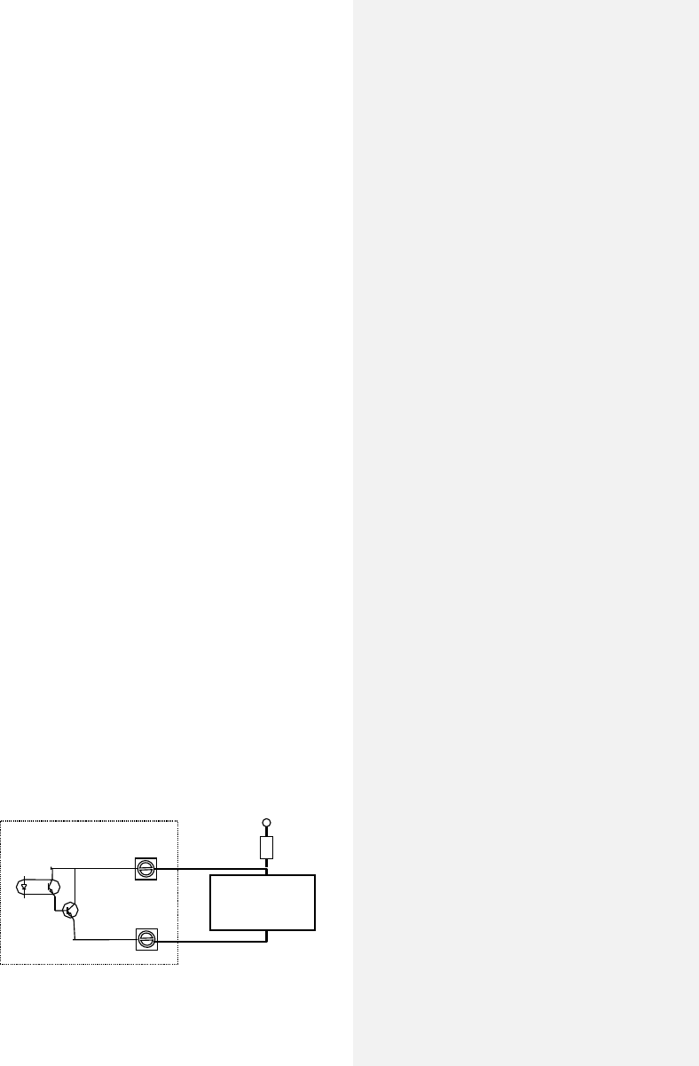
§4.18 How to use the OCT output
There is one OCT (Open Collector Transistor) output. It is a ON/OFF type and is electrically
isolated. One can program an OCT output to be an ON/OFF type alarm signal or a totalizer pulse
signal.
Notice that the Frequency Output shares the same OCT hardware. When used as Frequency
Output, the OCT cannot be used for another purpose (neither alarm signal nor totalizer pulse
signal).
The OCT has two wiring terminals, terminals OCT+ and OCT-. Terminal OCT+ is the collector and
terminal OCT- is the emitter. Be careful of the polarity. An external DC power supply Vcc and an
external pull-up resistor Rx are needed for using the OCT (see figure below). Vcc can be from
+12VDC to +24VDC. Rx can be from
1KOhm to 10KOhm. The maximum
current for the OCT is less than
0.2A. The OCT can drive an alarm,
pulse counter, frequency counter,
etc. It can also be used to drive a
relay, which operates a valve
system, for instance.
The triggering sources for OCT
output are similar to those listed in
the previous section for the Buzzer.
Terminals
Optocoupler
Isolation
OCT+
OCT-
External Alarm
Or Relay Control
Rx
Vcc
C
E
38
Refer to the next chapter on the menus.
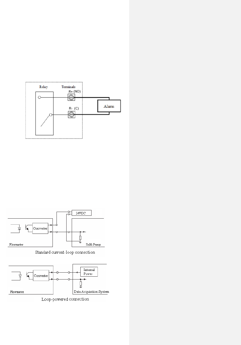
§4.19 How to use the relay output
The relay output is a single-pole single-throw (SPST). It has two terminals, R+ (normally open,
NO) and R- (common, C). Its maximum operating frequency is 1Hz. when the input power is
110VAC, Its load current is 1A at 125VAC, when the input power is 220V, Its load current is 1A
at 235VAC, or 2A at 30VDC.
The relay output is user-configurable
and can be configured as an ON/OFF
type signal to drive an alarm or a valve,
or, as a totalizer pulse signal to drive a
remote counter or totalizer.
When wiring the relay to an external
device, you can only wire it as normally
open (NO). The figure below illustrates
how to wire the relay to an external
alarm with a normally open
configuration.
§4.20 How to use the 4-20mA output interface
EnduroFlow TM EF40 has one channel of isolated 4-20mA analog output. The accuracy of this
output is better than 0.1%. It can be configured in different modes, such as 4-20mA mode and
0-20mA mode. Mode selection can be made in menu M32, refer to the next chapter for details.
In order to use the 4-20mA
output function, you need to
not only select the mode to be
4-20mA in M321, but also set
the flow rate values which
correspond to the minimum
current (4mA) and the
maximum current (20mA).
Enter the two values in M323
and M324.
Example A: flow rate range is 0-
500m3/h. Just enter 0 in M323
and 500 in M324.
If the differences are not within
tolerance, calibrate the current
loop.
The present current loop output
39
is displayed in Window M325. It changes along with flow rate change.
Wiring: There are two ways to wire this analog output to an external device: standard current-
loop connection and loop-powered connection. Which connection to use is totally dependent
on whether the external device provides 24VDC power to the current-loop. If yes, use the loop-
powered connection.
The 0/4-20mA current output actually does not output current. Instead, it sinks current. The
minimum sinking current is about 3mA.
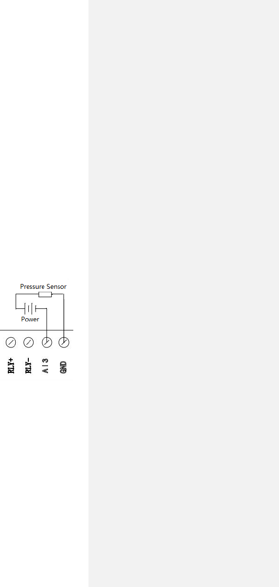
§4.21 How to use the analog input
The EnduroFlow TM EF40 flowmeter can be equipped with a maximum of two temperature
measurement channels and two analog input channels. The two temperature channels will be
explained in chapter 8.
The analog input channel, terminal AI3-GND or AI4-GND, can be connected to an analog sensor
where output is in standard 4-20mA current to measure physical quantity, such as temperature,
pressure, concentration, sulfa, etc. By combining the flow rate information, EnduroFlow TM EF40
can provide very valuable information for resources
management and process control.
All the results can be sent to a master computer through the
serial port (see chapter 7 for the communication). This means
that an EnduroFlow TM EF40 can be used as a RTU in a flow
monitoring network. It helps to reduce the cost and complexity
while improving the reliability of a monitoring network.
Note that the analog-to-digital conversion resolution of these
analog channels is 12-bit, and there is no electrical isolation for
those channels. If the working environment is subjected to
strong interference, it is recommended that external isolation is
added to protect the flowmeter circuitry.
The wiring diagram is shown in the figure to the right. The input
values can be viewed in the local LCD by using the browsing key.
The measurement range can be set in window M39. The second
option is the parameter minimum of the measurement range, corresponding to an analog input
of 4mA. The third option is the parameter maximum, corresponding to 20mA input current.
Example: assume a pressure transmitter outputs 4mA current at 0.98kg pressure and 20mA at
10.5kg pressure. The transmitter is connected to channel AI3. Then, you need to enter 0.98 and
10.5 in window M3912 AND M3913. The present values of input current and corresponding
temperature are shown in M393.

40
§4.22 How to view the Totalizers
Use menu windows M48, and M49 AND M410 to view the daily, monthly, and yearly totalizer,
respectively. These menu windows may be accessed as follows: M→Totalizer →M48: Daily TOT (or
M49: Monthly TOT or M410: Yearly TOT).
§4.23 How to use the Working Timer
Use the working timer to check the time that has passed with a certain kind of operation. For example, use
it as a timer to show how long a fully-charged battery will last. In menu window M58 press ENT key and
select YES to reset the working time. M58 may be accessed as follows: M→System→M58: Work
Timer.
§4.24 How to modify the built-in calendar
No modification on the built-in calendar will be needed in most cases. The calendar consumes an
insignificant amount of power. Modifications will only be needed when the battery has been totally
exhausted or when the replacement battery takes so long that the original time data is lost. Use window
menu M54 to change the time and date. This menu can be accessed as follows: M→System→Date/Time
(M54)
§4.25 How to use the manual totalizer
Use menu window C21, which can be accessed as follows: CAL→Linear Cal→C21: Man Totalizer.
Press any key to start and press the key again to stop the totalizer.
§4.26 How to check the ESN
Every EF40 Series Flow Meter utilizes a unique ESN to identify the meter—the ESN in an eight-digit
number that provides the product version and manufacturing date.
The user can also employ the ESN for instrumentation management.
The ESN is displayed in menu window M55, which can be accessed as follows: M→System
→Version/SN# (M55).
§4.27 How to adjust the LCD contrast
Use M312 to adjust the LCD contrast (backlight). The adjusted results will be stored in the EEPROM so
that the Clear Data option will not effect the contrast. M312 may be accessed as follows:
M→Input/output→M31: Display→M312: LCDBklt
§4.28 What to do when the flow rate reading jumps abnormally
In general the flow rate reading should be stable when the flow in the conduit is stable. If the reading
fluctuates a lot, you may try to increase the damping filter constant in the Damping Filter menu (SET->5)
to smooth out the fluctuation.
If the flow rate jumps to an abnormally big number, the flow meter is locked to a wrong pulse cycle. This
might happen when the signal is weak due to old pipe, entrained air or complicated pipe wall structure.
Sometimes RS2 transducers on a small pipe, such as DN20 or DN25, may show this problem. If this
happens, please try to install the transducers with a different installation configuration. For example, if a

41
big number jump happens when the transducers are installed with V-method, then, try to install the
transducers with Z-method.
§4.29 How to calibrate the flow meter
There are 4 calibration functions for the EF40: Zero Calibration, Linear Calibration, 0/4-20 mA loop
calibration, and temperature calibration. These can be found by pressing the CAL key on the device.
1) For Zero Calibration, refer to Section 4.10.
2) Linear and 0/4-20 mA loop calibration are unavailable at this time. For updates, please contact
Spire Metering at support@spiremt.com.
3) For Temperature Calibration, normally, there is no need for calibration, as the device is
calibrated at the factory. In case you need to re-calibrate the sensors, contact Spire Metering at
support@spiremt.com.

42
5. Menu Window Details
Key
Sub-Key
Window Number
Function
SET
Quick Start
Step 1: Select
Mounting Site
S1:Select Site
Window for providing instructions on selecting a mounting site:
- Pipe is full
- Straight pipe: 10D upstream, 5D downstream
- Vertical pipe: Flow must go up.
- Horizontal pipe: Transducers must be on the side of pipe.
Step 2: Set Pipe
Parameters
S2a: Enter
Outer
Diameter
Window for entering the outer diameter of the pipe
Valid range: 0 to 6000mm.
S2b
Window for entering pipe wall thickness
S2c
Window for selecting pipe material
Standard pipe materials (no need to enter the material sound speed)
include:
(1) carbon steel (2) stainless steel (3) cast iron (4) ductile iron
(5) copper (6) PVC (7) aluminum (8) asbestos
(9) fiberglass (10) other
S2d
Window for selecting the liner material. Select none
(1) For pipes without any liner. Standard liner materials (no need to
enter liner sound speed) include:
(2) Tar Epoxy (3) Rubber (4) Mortar (5) Polypropylene
(6) Polystryol (7)Polystyrene (8) Polyester (9) Polyethylene
(10) Ebonite (11) Teflon (12)other
Step3: Set Fluid
Parameters
S3a
Window for selecting fluid type
For standard liquids (no need to enter liquid sound speed) include:
(1) Water (2) Sea Water (3) Kerosene (4) Gasoline
(5) Fuel oil (6) Crude Oil (7) Propane at -45℃
(8) Butane at 0℃ (9)Other liquids (10) Diesel Oil (11)Castor Oil
(12)Peanut Oil (13) #90 Gasoline (14) #93 Gasoline (15) Alcohol
(16) Hot water at 125℃
Step4: Set
Transducer
Parameters
S4a
Window for selecting transducer type
There are 30 different types of transducers for selection.
The user needs to configure the 3 transducer parameters.
S4b
Window for selecting the transducer mounting methods
Four methods can be selected:
(0) V-method (1) Z-method (2) N-method (3) W-method
S4c
Window to set the flow rate scale factor. The factory default is ‘1’.
Keep this value as ‘1’ when no calibration has been made.
Step5: Install
Transducer Now
S5a
Window for transducer mount distance and installation:
a) Mark 2 spots of the same side on pipe surface, with the distance
equal to the number shown. b) Sand & clean the spots, make surface
smooth. c) Put compound on transducer surface. d) Clamp transducer
onto pipe. Cable towards outside. e) Finish wiring then power up.
Step6: Verify
Window to verify the signal strength, signal quality and transit time ratio shown
Step7: Diagnose
Window to Diagnose Triplet
S20:Set
Pipe
S21: Set OD
Window for entering the outer diameter of the pipe. Valid range: 0 to 6000mm.
S22: Set Wall
Thickness
Window for entering the pipe wall thickness.
S23: Set ID
Window for entering the inner diameter of the pipe. If pipe outer diameter and wall
thickness are entered correctly, the inner diameter will be calculated automatically,
thus no need to change anything in this window.
S24: Pipe
Material
Window for selecting pipe material
Standard pipe materials (no need to enter the material sound speed) include:
(1) carbon steel (2) stainless steel (3) cast iron (4) ductile iron
(5) copper (6) PVC (7) aluminum (8) asbestos
(9) fiberglass; (10)Other

43
S25: Set Liner
Window for selecting the liner material. Select none for pipes without any liner.
Standard liner materials (no need to enter liner sound speed) include:
(1) No Liner (2) Tar Epoxy (3) Rubber (4) Mortar (5) Polypropylene
(6) Polystryol (7)Polystyrene (8) Polyester (9) Polyethylene
(10) Ebonite (11) Teflon (12)other
S30:Set
Fluid
S31: Fluid Type
Window for selecting fluid type
For standard liquids (no need to enter liquid sound speed) include:
(1) Water (2) Sea Water (3) Kerosene (4) Gasoline
(5) Fuel oil (6) Crude Oil (7) Propane at -45℃
(8) Butane at 0℃ (9)Other liquids (10) Diesel Oil (11)Castor Oil
(11)Peanut Oil (12) #90 Gasoline (13) #93 Gasoline (14) Alcohol
(15) Hot water at 125℃
S32: Sound Speed
Window for entering the sound speed of non-standard liner materials
S33: Viscosity
Window for entering the viscosity of non-standard liquids
S40:Set
Transducer
S41:Transducer
Type
Window for selecting transducer type
There are 31 different types of transducers for selection. If the π type spool-piece
transducers are used, the user needs to configure the 3 transducer parameters.
Otherwise, the user needs to configure the 4 transducer parameters.
S42: Mount
Method
Window for selecting the transducer mounting methods
Four methods can be selected:
(1) V-method (2) Z-method (3) N-method (4) W-method
S43: Mount Space
Window to display the transducer mounting space or distance.
S44: Scale Factor
Window to set the flow rate scale factor. The factory default is ‘1’.
Keep this value as ‘1’ when no calibration has been made.
S45:Mat
correction
“Factory only” password protected input.
S50:Set
Filter
S51: Damping
Filter
Window to set the damping constant.
S52: Low Flow
Cutoff
Window to set the velocity cutoff for noise flow.
S53: PoorSig
Filter
Window to set the poor signal filter. If last reading was acceptable, select (1) Yes. If
last reading was not acceptable, select (2) No.
S54: Empty Pipe
Window to establish setting for an empty pipe. During normal operation, pipe should
be full.
L
O
G
L10: Save
To
Window to save recorded log to a customizable file name.
L20:Log
Items
L21: Basic 4
Items
Window to instruct device to log only basic information.
L22: All 16 Items
Window to instruct device to log all 16 items available on EF40
L30:
Schedule
L:31: Log interval
Window for entering the interval at which the flowmeter will log data.
L32: Start Time
Window for entering the start time of the logger. (Year-Month-Day and Hour-Minute-
Second) or directly press number ‘9’ to start collect data after one minute.
L33: Stop Time
Window for entering the end time of the logger. (Year-Month-Day and Hour-Minute-
Second)
L40: View
Log
Window to view a previously recorded log.
L50:Clear
Log
Window to clear a previously recorded log.
L60:Stop
Collection
Window to stop current collection.
C
A
L
C10:Zero
Cal
Window to set up the Zero point. Make sure the liquid in the pipe is not running during
setup.
C20:Linear
Cal
C21: Man
Totalizer
Window for manual totalizer used for calibration. Press any key to start and press the
key again to stop the totalizer.
C22: Linear Table
Window to view linear table. (1) Add data point. (2) View table.
C30:0/4 –
20 mA Cal
C31: Start
Sampling
start to sampling current flow value in every 4 seconds and outputing correspongding
4~20mA value.
C32: close
Sampling
close to sampling current flow value.
C33: Verify
Verify 0/4-20 mA loop.
C34: Calibrate
Currently unavailable for the EF40
C40:Temp
cal
C41: T1/T2
Window to display temperature for supply line and return line.
C42: Calibrate
Window to calibrate temperature sensors. User must enter password. Use resistors to

44
recalibrate sensors.
M
M10:Site
M11: Save Site
Window to store the pipe parameters into the internal NVRAM (non-volatile memory).
M12: Recall Site
Window to recall the previously saved pipe parameters
M13: Delete Site
Window to delete previously saved pipe parameters
M20:Diagn
osis
M21: Triplet
Window to display the signal strength, signal quality and transit time ratio.
M22: Sound
Speed
Window to display the estimated sound speed of the fluid in the pipe. If this value has
an obvious difference with the actual fluid sound speed, the user is recommended to
check if the pipe parameters are correct and if the transducer installation is good.
M23: Transit-time
Window to display the total transit time and delta time (transit time difference between
upstream and downstream traveling).
M24: Reynolds
Window to display the Reynolds number and the pipe factor used by the flow rate
measurement program. Note, the pipe factor is rarely used.
M30:Input/
Output
M31: Display
M311: Main
window
Window to control main window display. Choose between Flow Rate,
Velocity, Flow TOT, and ENERGY-RATE.
M312: LCD
Bklt
Window to control the LCD display backlight. The entered value
indicates how many seconds the backlight will be on with every key
pressing.
M313:
Buzzer
Window to turn buzzer on or off.
M32: 0/4-20 mA
CL
CL Mode
Select the current loop (CL) mode.
Output
Param
Enter flow rate.
Param Min
Enter minimum for 0/4 mA signal.
Param Max
Enter maximum for 20 mA signal.
CL Reading
Display present output of the current loop circuit.
M33: OCT output
Pulse Width
OCT (Open Collector Output) setup. By selecting a proper triggering
source, the OCT circuit will close when the trigger event occurs
Trigger
Source
Select the pulse type for the trigger source.
M34: Relay
Output
Window to select event for relay trigger source.
M35: Freq Output
Freq Range
Window to set up the frequency range (lower limit and upper limit) for
the frequency output. Valid values: 0Hz-9999Hz. Factory default is 1-
1001 Hz
Freq Min
Window to set up the minimum flow rate which corresponds to the
lower frequency limit of the frequency output.
Freq Max
Window to set up the maximum flow rate which corresponds to the
upper frequency limit of the frequency output.
M36: Buzzer
Window to set up the buzzer.
If a proper input source is selected, the buzzer will beep when the trigger event occurs
M37: Alarm
#1 Low
Limit
Alarm #1 lower threshold setup. Below this threshold the #1 Alarm
will be triggered. There are two alarming methods. User must select the
alarming output items from window M33 or M36
#1 High
Limit
Alarm #1 upper threshold setup.
#2 Low
Limit
Alarm #2 lower threshold setup.
#2 High
Limit
Alarm #2 lower upper threshold setup.
M38: Batch
Control
Window to access the built-in batch controller.
M40:Totali
zer
M41: Flo
Multiplier
Window to set the totalizer multiplying factor for the flow rate. The multiplying factor
ranges from 0.001 to 10000.
M42: Flo NET
ON/OFF
Window for turning on or off the NET totalizer
M43: Flo POS
ON/OFF
Window for turning on or off the POS totalizer.
M44: Flo NEG
ON/OFF
Window for turning on or off the NEG totalizer.
M45: Flo TOT
Reset
Window for:(1) None; (2)ALL TOTs
(3) Flow TOTs (4) Energy Net TOTs. Press the dot key followed by the backspace key.
Attention, it is recommended to make notes on the parameters before doing the

45
restoration.
M46:Eng
Multiplier
Window to set the multiplying factor for the Eng totalizer.
M47: Eng TOT
ON/OFF
Window to turn thermal energy totalizer on or off.
M48: Daily TOT
Window to set up for daily totalizer.
M49: Monthly
TOT
Window to set up for monthly totalizer.
M410: Yearly
TOT
Window to set up for yearly totalizer.
M50:Syste
m
M51: Language
Window to set up the language Selection – English or Chinese.
M52: Unit
Metric/
English
Window for selecting unit system. ‘Metric’ is the factory default. The
conversion from English to Metric or vice versa will not affect the unit for
totalizers.
Flow rate
unit
Change
Volume
Window for selecting flow rate unit system.
Flow rate can be in:
1. Cubic meter short for (m3)
2. Liter (l)
3. USA gallon (gal)
4. Imperial gallon (igl)
5. Million USA gallon (mgl)
6. Cubic feet (cf)
7. USA oil barrel (bal)
8. Imperial oil barrel (ib)
Change
Time
The flow unit in terms of time can be per day, per hour, per
minute or per second. So there are 36 different flow rate units
in total for selection.
Flow rate
TOT
Unit
Window for selecting flow rate totalizer unit system.
This can be in:
1. Cubic meter short for (m3)
2. Liter (l)
3. USA gallon (gal)
4. Imperial Gallon (igl)
5. Million USA gallon (mgl)
6. Cubic feet (cf)
7. USA oil barrel (bal)
8. Imperial oil barrel (ib)
M53: COMM
Port
Config
Window for RS-485 serial communication setup.
Protocol
Window for communication protocol selection.
Monitor
Window to verify the data being logged.
M54: Date/Time
M54
Window for setting the date and time.
M55: Version/
SN#
Displays version information and Electronic Serial Number (ESN) that are unique for
each EF40 series flowmeter. The user can use the ESN for instrumentation
management.
M56: Battery
Window that displays the current button cell battery voltage.
M57: System
Lock
Window to set up System lock to avoid modification of the system parameters.
M58: Work Timer
Work timer. It can be reset by pressing ENT key, Ok to Reset? select YES.
M59:Clear Data
Clears all stored Data. It can be reset by pressing ENT key, Are you sure?, select YES.
M60:Heat
Energy
M61: Location
Window to configure the location of the transducers. They can be placed on the supply
or the return line.
M62:
Temperature
Window to view the temperature of both transducers.
M63: EngTemp
Select
Window to temperature source selection:
0. temperature from input AI1 and AI2;
1. fixed difference.
When selecting fixed difference, enter the difference in this menu.
M64: Specific
Select
Window to specific heat (or thermal capacity coefficient) input
M70:Calcul
ator
Window which includes scientific calculator for the convenience of field applications.
All the mathematic operators are selected from a list.

46
M80:Misc.
M81: Max
Flowrate
Window to view maximum flow rate for the day and for the month.
M82: Last pwr off
Window to display the last recorded time the device was powered off.
M83: Pwr On
Time
Window to display the last recorded time the device was powered on.
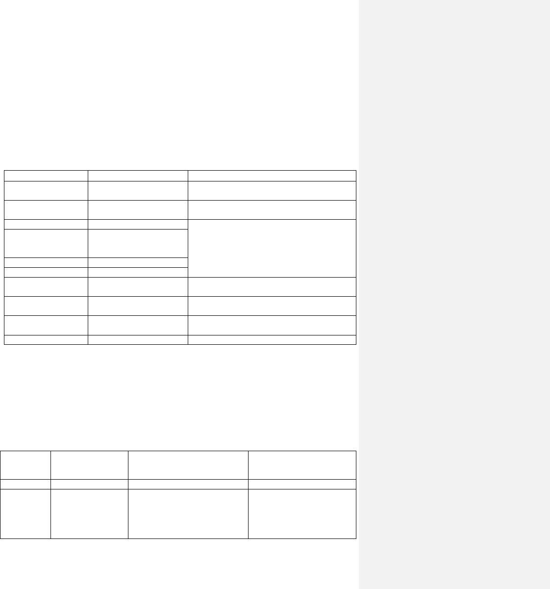
47
6. Troubleshooting
§6.1 Power-on Errors
When powered on, the EF40 series ultrasonic flowmeter will automatically start the self-diagnostic
process to determine if there are any hardware and/or software problems. If a problem is identified, an
error message will be displayed. The following table shows the possible error messages, the
corresponding causes, and their solutions.
Error Message
Causes
Solutions
ROM Parity Error
ROM operation illegal/error
1. Reboot the system
2. Contact the manufacturer
Stored Data Error
User entered parameters
were lost
Press ENT key to restore the default
configuration
SCPU Fatal Error
SCPU hardware fatal error
1. Reboot the system
2. Contact the manufacturer
System Clock Slow or
Fast Error
Problem with the system
clock or the crystal
oscillator
CPU or IRQ Error
Problem with RAM chip
System RAM error
Problem with RAM chip
Time Date Error
Problem with date/time
chip
1. Initialize the calendar in menu window M54
2. Contact the manufacturer
No Display, Erratic or
Abnormal Operation
Problem with wiring
Double-check wiring connections
No response to key
pressing
Keypad is locked; bad plug
connection
Press keys M, 5, and 7, consecutively (M57).
From there, unlock the keypad.
Reboot Repetitively
Hardware problems
Contact the manufacturer
§6.2 Working Status Errors
The EF40 series ultrasonic flowmeter will show an Error Code (i.e. a single letter, e.g. I, R, etc.) in the
upper right corner of the main menu window. When any abnormal error code shows, counter-measures
should be taken.
Error Code
Message Displayed
on main menu
window
Causes
Solutions
R
System Normal
No Error
I
No Signal
• Unable to receive signal
• Transducers installed
improperly
• Loose contact, or not
enough couplant between
1. Polish the pipe surface and
clean the spot. Remove paint.
2. Make sure there is adequate
couplant.
3. Make sure the transducer is

48
transducer and pipe
surface
• Pipe liners are too thick,
or the deposition inside
the pipe is too thick.
• 5. Transducer cables are
not properly connected.
in tight contact with pipe
surface
4. Check transducer cables
5. Check installation
parameter settings
6. Find a better measurement
site(newer pipe, no corrosion,
no deposition)
J
Hardware Error
Hardware problem
Contact the manufacturer
H
Poor Sig. Detected
Poor signal detected. Similar to
error code I.
Refer to error code I.
E
Current Loop Over
20mA
4-20mA loop output over 120%.
Improper settings for current loop
output
1. Ignore it if current loop
output is not used
2. Check current loop settings
in menu window M32
3. Confirm if the actual flow
rate is too high
Q
Frequency Output
Over
• The frequency output is
120% over
• 2. Improper settings for
frequency output.
3. The actual flow rate is
too high.
1. Ignore if frequency output
is not used
2. Check the values entered in
menu window M35
3. Use a larger value in M35
if needed
4. Confirm if the actual flow
rate is too high
F
System RAM Error
Date Time Error
CPU or IRQ Error
ROM Parity Error
• Temporary problems with
RAM, RTC
• 2. Permanent problems
with hardware
1. Reboot the system
2. Refer to Table 6.1, and
contact the manufacturer
G
Adjusting Gain > s1
Adjusting Gain > s2
Adjusting Gain > s3
Adjusting Gain > s4
Instrument is in progress of
adjusting the gain for the signal,
and the number indicates the
progressive steps.
No need for action
K
Empty Pipe
• No liquid inside the pipe
1. If the pipe is not full,
relocate the flowmeter to
where the pipe is full of
liquid.
§6.3 Other Problems and Solutions
Q: Why does the instrument display 0.0000 flow rate while the liquid in the pipe is actually flowing? The
signal strength, R, is in good range and the signal quality, Q, is a satisfactory value.
A: The problem is likely to be caused by an incorrect zero calibration. The user may have conducted the
zero point set up while the flow was not at a complete standstill. To solve this problem, press keys C, 1 to
enter window C10 and follow the directions given.
Q: Why is the displayed flow rate much lower or much higher than the actual flow rate in the pipe despite
being under normal working conditions?
A: There are three possible explanations for this error:
1) The entered offset value may be incorrect. Enter “0” offset in window S44. Please see Section

49
§4.11 for more information on changing the scale factor.
2) Incorrect transducer installation. Re-install the transducers carefully.
3) The zero calibration was set wrong. Press keys C, 1 to enter window C10 and redo the zero
calibration setup. The flow inside the pipe needs to be at a standstill. This menu can be accessed
as follows: CAL→Zero Cal
Q: Why is there no signal even when the installation requirements are met, pipe is new, and pipe material
is in good quality?
A: Check the following:
• Is the installation method suitable for the pipe size?
• Is the entered installation parameters correct?
• Is the wiring correct?
• Is there adequate couplant? Are the transducers in good contact with the pipe?
• Is the pipe full?
• Is the distance between the transducers true to the value shown in window S43? Accessed as
follows: SET→SetTransducer→Mount Space (S43). This should be the same figure from the
set-up process, which was accessed on Step 5 under the Quick Start menu window (S1, Step 5).
• Are the transducers facing in the right direction?
Q: If the pipe in use is heavily scaled inside, and/or poor or no signal is detected, is it possible to conduct
a measurement? Are there options for conducting a measurement on an old pipe?
A: Follow the instructions below:
• Check if the pipe is filled with liquid.
• Try the Z method. If the pipe is close to a wall, and it is hard to do the Z-method installation, the
user may use an inclined pipe or even vertical pipe with an upward flow direction.
• Carefully select a good pipe section and fully polish/clean the installation area of the pipe surface.
Apply a wide band of couplant on each transducer face. Install the transducers properly. See
Section §3 for more details on proper transducer installation.
• Slowly and carefully move each transducer with respect to each other around the installation
point until the maximum signal is found. Be sure that the new installation location is free of
scales inside the pipe and that the pipe is properly rounded (not distorted). This way, the sound
waves will not bounce outside of the intended area.
• For pipe with a thick scale inside or outside, try to clean the scale off – if accessible from the
inside. **Note: This method is not always successful. Therefore, in that case, adequate sound
wave transmission is not possible due to the layer of scale between the transducers and inside
pipe wall.**
Q: Can the flowmeter work normally for a few years without stop under harsh environment where power
supply voltage varies widely?
A: Yes, the EF40 flow meter employs intelligent signal processing algorithms to handle strong
interference coming from either power lines or radiation. It also automatically adjusts itself to the optimal
operation status when sound wave strength varies due to a changing environment.
For more tips, please visit http://www.spiremt.com/support.html.
7. Communication

50
M53: COMM
1. Port Config
2. Protocol
3. Monitor
§7.1 General
The EF40 series ultrasonic flowmeter uses a standard RS485/Modbus communication interface for access
to a variety of parameters and measurement results. It can be connected to a Modbus master such as a
PLC directly. Just connect the Tx and Rx terminals of the flowmeter to the Rx and Tx terminals of the
PLC device, respectively. You need to also make sure to set the flow meter serial port settings such as
Baud rate the same as that of your PLC. Please go to Menu->System->Communication window to change
the serial port settings if needed.
If your flowmeter comes with a RS485-BACnet/MSTP adapter, you may not need to change any COM
port settings in the flowmeter because they should have been already set. You just need to make sure the
Baud rate on the BACnet/MSTP adapter matches that on your BACnet/MSTP master. The Baud rate of
the BACnet/MSTP adapter can be modified by the DIP switches on the adapter.
If you want to connect to your computer which does not have RS48 bus, you need to use a RS485 to USB
adapter. Please refer to the next section for details.
§7.2 Connect the Flowmeter to a PC
You can connect the flowmeter to your PC through a RS485-USB adapter. First, you need to install the
driver for the RS485-USB adapter. The driver should be on the CD that comes with the RS485-USB
adapter, or, it can be downloaded from the manufacturer’s website.
Connect the Tx and Rx terminals of the RS485-USB adapter to the Rx and Tx terminals of the flowmeter.
Then, plug the adapter USB into the computer USB port. The computer should detect the adapter
automatically and assign a virtual COM port for this adapter.
At this point, you should be able to run Modbus software such as MODSCAN (free software) to get
information from the flowmeter.
§7.3 Check the Flowmeter COM Port Settings
Go to menu window M53 to check the COM port settings on your flow meter.
Baud rate is displayed under 1. Port Config. Write down the baud rate. It is
needed later in order to set up the computer’s COM port. If you want to change
the baud rate, press ENT key while in the Port Config window and select the
proper baud rate. Press ENT key again to confirm the change.
§7.4 Set up PC Software
Any PC software that supports standard Modbus protocol can be used. You may also make your own
software to communicate with the flowmeter by using the protocol described in the following section.
If you purchased Spire Metering’s StufManager PC software, you would need to install this software
now. After completion of the installation, launch the software, select the COM port which corresponds to
the RS485-USB adapter, make the COM port settings the same as those in the flowmeter, then, click the
Connect button on the StufManager software. The software will start to communicate with the flowmeter
and get basic information from the flowmeter. The rest of the software is self-explanatory.

51
Please visit the following technical support website for more information on PC software:
http://www.spiremt.com/support/rh20.html.
§7.5 Communication Protocol
The protocol is comprised of a set of basic commands that are strings in ASCII format, ending with a
carriage (CR) and line feed (LF). Commonly used commands are listed in the following table.
Command
Function
Data Format
DQD(CR)
Return flow rate per day
±d.ddddddE±dd (CR)
(LF)*
DQH(CR)
Return flow rate per hour
±d.ddddddE±dd (CR)
(LF)
DQM(CR)
Return flow rate per minute
±d.ddddddE±dd (CR)
(LF)
DQS(CR)
Return flow rate per second
±d.ddddddE±dd (CR)
(LF)
DV(CR)
Return instantaneous flow
velocity
±d.ddddddE±dd (CR)
(LF)
DI+(CR)
Return POS totalizer
±dddddddE±d (CR)
(LF)**
DI-(CR)
Return NEG totalizer
±dddddddE±d (CR)
(LF)
DIN(CR)
Return NET totalizer
±dddddddE±d (CR)
(LF)
DID(CR)
Return Identification Number
(IDN)
ddddd (CR)(LF)
DL(CR)
Return signal strength and
signal quality
S=ddd,ddd Q=dd
(CR)(LF)
DT(CR)
Return the current date and
time
yy-mm-ddhh:mm:ss
(CR)(LF)
M@(CR)***
Send a key value as if a key
is pressed
LCD(CR)
Return the current display
contents
FOdddd(CR)
Force the FO output to output
a frequency of dddd Hz
ESN(CR)
Return the ESN of the
flowmeter
Dddddddd (CR)(LF)
RING(CR)
Handshaking Request from a
MODEM
OK(CR)
Acknowledgement from a
MODEM
No action
52
GA
Command for GSM
messaging
Please contact the
manufacturer for
detail
GB
Command for GSM
messaging
GC
Command for GSM
messaging
DUMP(CR)
Return the print buffer
content
In ASCII string
format
DUMP0(CR)
Clear the whole print buffer
In ASCII string
format
DUMP1(CR)
Return the whole print buffer
content
In ASCII string
Format, 24KB in
length
W
Prefix of an IDN-addressing-
based networking command.
The IDN address is a word,
ranging 0-65534.
N
Prefix of an IDN-addressing-
based networking command.
The IDN address here is a
single byte value, ranging 00-
255.
Not recommend for
use.
P
Prefix of any command with
checksum
&
Command binder to make a
longer command by
combining up to 6 commands
Notes * CR stands for Carriage Return and LF for Line Feed.
** “d” stands for a digit number of 0~9.
*** @ stands for the key value, e.g., 30H for the value of ASCII key “0”.
§7.6 Protocol Prefix Usage
1) Prefix P
The prefix P can be added before any command in the above table to have the returning data followed
with two bytes of CRC check sum, which is the adding sum of the original character string.
Take the Return POS Totalizer Value command, DI+(CR), as an example. Assume that DI+(CR) would
return +1234567E+0m3(CR)(LF)( the string in hexadecimal is 2BH, 31H, 32H, 33H, 34H, 35H, 36H,
37H, 45H, 2BH, 30H, 6DH, 33H, 20H, 0DH, 0AH) , then PDI(CR) would return
+1234567E+0m3!F7(CR)(LF). The‘!’ acts as the starter of the check sum (F7) which is obtained by
adding up the string 2BH, 31H, 32H, 33H, 34H, 35H, 36H, 37H, 45H, 2BH, 30H, 6DH, 33H, 20H.
Please note that it is allowed to not have data entry or to have SPACES (20H) character before the ‘!’
character.
2) Prefix W
The prefix W is used for networking commands. The format of a networking command is:

53
W + IDN address string + basic command.
The IDN address should have a value between 0 and 65534, except 13(0DH), 10 (0AH), 42(2AH,*),
38(26H, &).
For example, if we want to visit the instantaneous flow velocity of device IDN=12345, the following
command should be sent to this device: W12345DV(CR). The corresponding binary code is 57H, 31H,
32H, 33H, 34H, 35H, 44H, 56H, 0DH.
3) Prefix N
The prefix N is a single byte IDN network address, not recommended in a new design.
4) Command binder &
The & command binder or connector can connect up to 6 basic commands to form a longer command so
that it will make the programming much easier.
For example, assume we want device IDN=4321 to return the flow rate, velocity and POS totalizer value
simultaneously. The combined command would be W4321DQD&DV&DI+(CR), and the result would be:
+1234567E+0m3(CR)
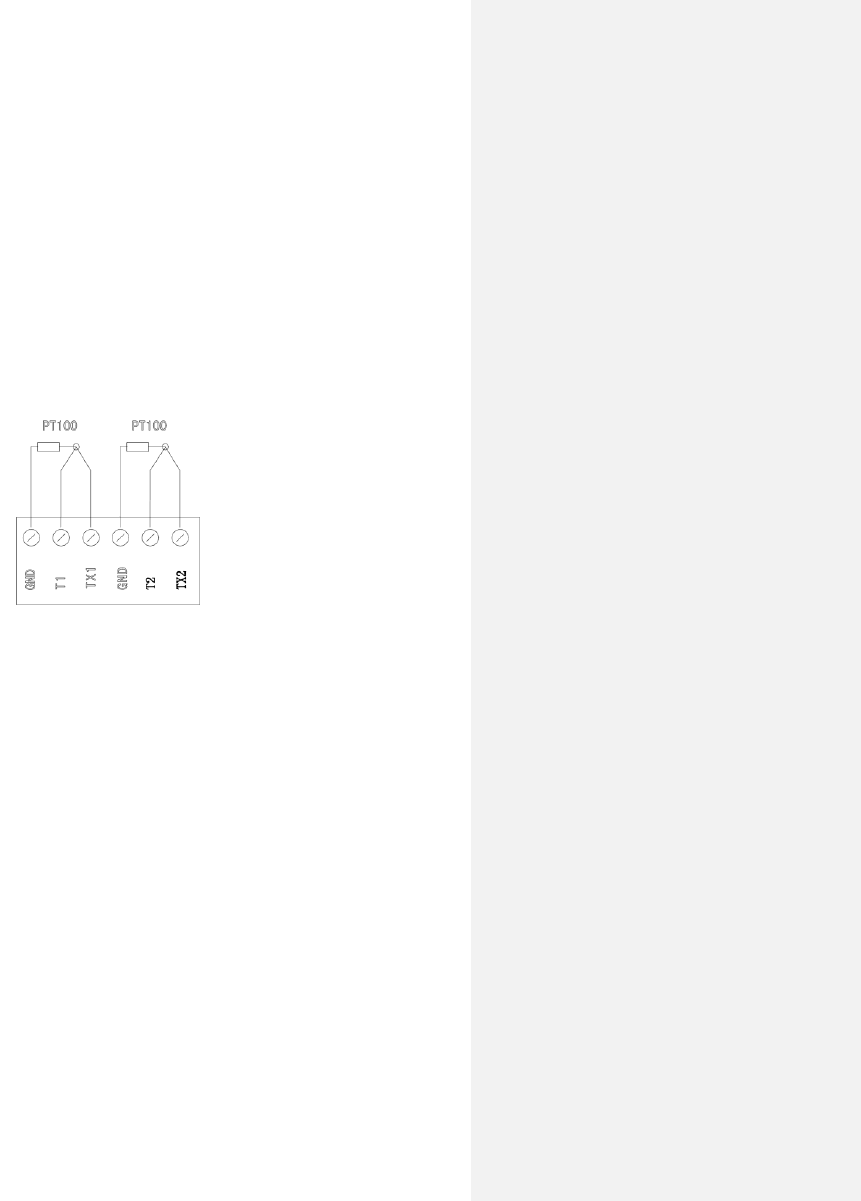
54
8. Thermal Energy Measurement
§8.1 Introduction
When the BTU Measurement option is selected, the EF40-Y flowmeter will be equipped with a thermal
energy measurement module and a pair of PT100 RTD sensors.
The two temperature channels designed for thermal measurement function are wired to terminal block
pins TX1, T1, TX2, T2 and GND. They can work with a 3-wire PT100 sensor without any extra parts. The
wiring diagram is shown in the figure below. The temperature and thermal energy values can be viewed
in the local LCD by using the browsing key. You may also view the data from an auxiliary interface.
§8.2 Thermal Energy Measurement
There are two methods for thermal energy calculation:
(1) Qt = Q x (T2 – T1) x Ct,
(2) Qt = Q x (TC2 – TC1)
Where Qt is the thermal energy (or caloric) consumed, Q is the flow rate, T1 and T2 are the temperature
at supply and return points, respectively. Ct is the specific heat (or the thermal capacity coefficient) of
the fluid, which can be entered in menu M64. For water, it is normally about 0.0041868GJ/m3C. TC1
and TC2 are the thermal capacities corresponding to temperature T1 and T2, which are calculated by the
flowmeter according to international standards and displayed in the main interface.
The following menu windows are used when performing thermal energy measurement:
Menu window M3114: choose energy rate, the energy rate will show in the main interface. Press the
button “up” or “down” to view the total energy and the two temperature measurement results
Menu window M39: display the values of input current AI3 and AI4 and their corresponding physical
values.

55
Menu window M524: thermal unit selection.
KCAL/s - Kilocalories/second, GJ/s – Giga Joules/second
Menu window M563: temperature source selection: 0. temperature from input AI1 and AI2; 1. fixed
difference. When selecting fixed difference, enter the difference in this menu.
Menu window M64: specific heat (or thermal capacity coefficient) input
Menu window M47: thermal totalizer on/off switch
Menu window M46: thermal totalizer multiplier factor
Menu window M45: thermal totalizer reset
Note that, if the fluid temperatures at both supply and return points are stable, you may choose not to
use temperature transmitters. Instead, you can directly enter the temperature difference of the two
points on menu window M63.
§8.3 Calibration
The temperature measurement accuracy of the EF40, under the un-calibrated condition, is
usually within the 1.0 ℃ range. That is, if the PT100 sensor was replaced, or if the temperature
measurement devices were replaced, it will produce errors of about 1.0 ℃.
In order to achieve the temperature measurement accuracy of 0.1 ℃, the temperature
measurement portion must be calibrated.
In general constant temperature baths are used for the calibration.
EF40 uses two reference temperature points of 50 ℃ and 84.5 ℃ for the calibration.
Two constant temperature baths are set, one at 50 ± 0.05 ℃, and the other at 84.5 ± 0.05 ℃,
use the following steps for the calibration:
(1) Immerse the two PT100 sensors into the 50 ℃ constant temperature bath.
(2) Key in 【C】【4】【2】for the “Temp Calibration” window, then press 【ENT】and
key in the Hardware Adjusting code 【4】【2】【1】【3】【0】【6】【8】【ENT】 to
start the hardware adjustments.
(3) Key in 【C】【4】【2】【1】for the “50°C Cal” window, which will display the current
un-calibrated T1 and T2 temperature values.
(4) After the PT100 sensors have reached temperature stabilization (about 2 minutes), press
the 【9】 key to confirm calibration at 50℃.
(5) Now immerse the two PT100 sensors into the 84.5 ℃ constant temperature bath.
(6) Key in 【C】【4】【2】【2】for the “84.5°C Cal” window, which will display the
current un-calibrated T1 and T2 temperature values.
(7) After the PT100 sensors have reached temperature stabilization (about 2 minutes), press
the 【9】 key to confirm calibration at 84.5℃.

56
(8) The temperature measurement calibration portion is now complete; you may now test
the calibration results.
During the above (4) or (7) steps, if the display window shows: "Temperature
Error? Press [ENT] to continue”, this indicates either a problem with your reference
temperature, or the temperature measurement circuit has a problem.
If constant temperature baths are not available, you may use decade resistor boxes to
achieve the temperature calibration. For calibrating the reference temperature of 50 ℃, you
can connect two equivalent resistances of 119.397 ohms to the TX1, T1, TX2, T2, and GND
terminals; likewise, for calibrating the reference temperature of 84.5 ℃, the equivalent
resistances will be 132.613 ohms.
If constant temperature baths and decade resistor boxes are not available, the EF40 has
a dual-channel PT100 sensors zero-set point function; this is to correct the dual-channel’s
temperature sensors’ matching errors. In order to match the full scale range of zero , EF40 has
two zero set points for both the low and high temperatures. “Low Temp Zero-Set” is in menu
C423, “High Temp Zero Set” is in menu C424.
When setting the temperature zero set points, it is best that the two PT100 sensors be
immersed into sufficient amount of water until they have reached temperature stabilization,
and then go to menu C423 or C424 to set their respective zero set points. Please note that the
temperature for setting the “Low Temp Zero-Set” cannot exceed 40 ℃, and the temperature of
the “High Temp Zero Set” must be at least 55 ℃.
Setting the temperature zero set points is only for correcting the initial two temperature
sensors’ inherited "zero" offsets. The best way is still to use constant temperature baths for the
temperature calibration.

57
9. Warranty and Service
§9.1 Warranty
The products manufactured by Spire Metering are warranted to be free from defects in materials and
workmanship for a period of one year from the date of shipment while under use of the original
purchaser. Spire Metering’s obligation shall be limited to restoring the meter to normal operation or
replacing the meter—at the company’s choice—and shall be conditioned upon receiving written notice of
any alleged defect within 10 days after its discovery. Spire Metering will make the determination if the
return of the meter is necessary. In the case that a full return is deemed required, the user will be
responsible for the one-way shipping fee from the customer to the manufacturer.
Spire Metering is not liable for any defects or damage attributable to misusage, improper installation,
operation outside of the recommended conditions, replacement of unauthorized parts, and acts of nature.
Fuses and batteries are not included under warranty.
THIS WARRANTY IS EXCLUSIVE AND IN LIEU OF ALL OTHER EXPRESS OR IMPLIED
WARRANTIES (INCLUDING BUT NOT LIMITED TO WARRANTIES OF MERCHANTABILITY
AND FITNESS FOR A PARTICULAR PURPOSE, AND WARRANTIES ARISING FROM DEALING,
TRADE OR USAGE.)
§9.2 Service
The manufacturer provides unit installation for its customers. The charge will depend on the complexity
of the installation.
The most important criteria that effects accurate measurement and proper functionality of the device is the
installation of the transducers. Section §3 and Appendix §10.2 provide in-depth information on transducer
installation. A checklist to ensure proper installation is located in Section §3.4. Additionally, information
on troubleshooting any issues that occur in powering on or operating the device can be found in Section
§6.
For operational problems, please contact the technical support department by telephone, fax, or email.
The user may contact Spire at support@spiremt.com or 978-263-7100, extension 612. In most cases,
problems can be resolved immediately.
For any hardware failures with the device, we recommend that our customers send the unit back to Spire
for servicing. Please contact the technical support department with the model number and the serial
number before returning the unit. Both numbers can be found on the product label.
For any service or calibration request, we will issue a Return Materials Authorization (RMA). Spire can
only determine the details of the repair (complexity of repair, timetable, cost) after receipt and inspection
of the instrument. A quote will be sent to the customer before proceeding with the service.
Important Notice for Product Return
Before returning the instrument for warranty repair or service, please read the following carefully:

58
1) If the return item has been exposed to nuclear or other radioactive environment and/or has been
in contact with hazardous materials, which could pose any sort of danger to our personnel, the
unit cannot be serviced.
2) If the return item has been exposed to or in contact with dangerous materials, but has been
recognized as a hazard-free device by a reputable organization, you are required to include the
certificate for service.
3) If the return item does not include the RMA number provided, it will be sent back without any
service conducted.
For more information, please see Spire’s RMA Policy and Procedure.
§9.3 Software Upgrade Service
Spire provides free software upgrade services. Please contact the manufacturer for software upgrade
information.
You may also visit our technical support website at http://www.spiremt.com/support/EF40.html for the
latest downloads.
Commented [RG1]:
Need to fix website to activate link.
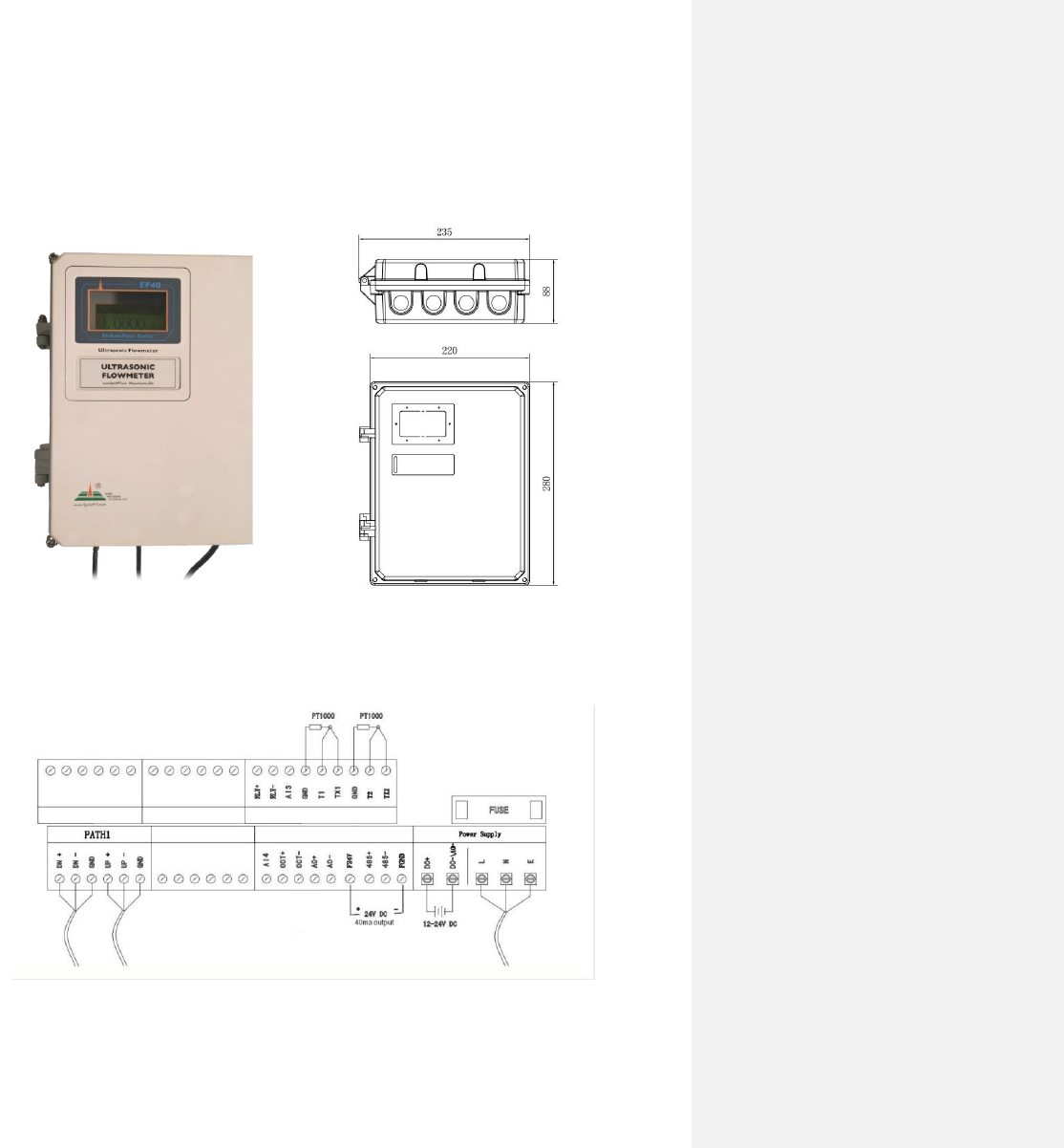
59
10. Appendix
§10.1 Wiring Diagram and Outline Drawings
Main Unit Outline Drawings:
Wiring Terminal Block
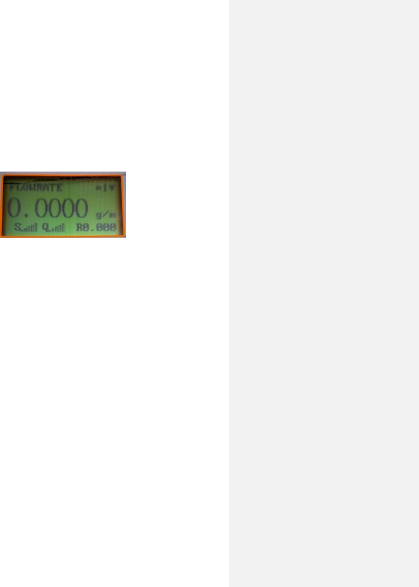
60
EF40 Startup
Open the main unit cover using the 5mm hex wrench (4 screws).
Wire the power supply cable and the transducer cables according the above wiring diagram. After
wiring is done, close the enclosure cover. Note, you can wire only one power source, either 24VDC or
90-260VAC. ( Note: The meter comes pre-wired in most cases.)
Connect to and turn on the power supply. The meter will start immediately. It goes through a self-
checking process to make sure everything is working properly. After a few seconds, the main unit will
enter into the normal working status.
Sample screen without transducer installed on the pipe
.
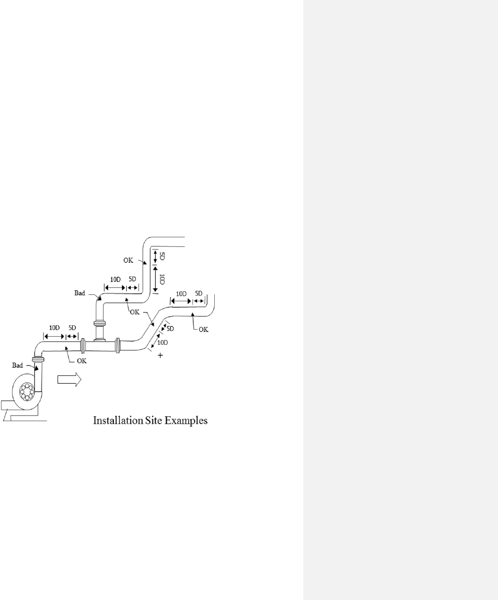
61
§10.2 Transducer Installation Guide
§10.2.A Find the mounting site
A) Pipe must be full of liquid at the measurement site.
B) No heavy corrosion of deposition inside the pipe.
C) Must be a safe location.
D) The straight run of the pipe must not be shorter than 15D as a general guideline, where Dis the
pipe diameter. Insufficient straight pipe length will degrade the accuracy of the results.
E) The transducer mounting site should be 10D straight run upstream and 5D straight run
downstream.
F) If there are flow disturbing parts such as pumps, valves, etc. on the upstream, the straight pipe
length should be increased. The disturbance strength of those flow conducting parts will be (from
low to high):
Single Bend
→
Pipe Reduction / Enlargement
→
Outflow Tee
→
Same Plane Multiple Bends
→
Inflow Tee
→
Out of Plane Multiple Bends
→
Valve
→
Pump
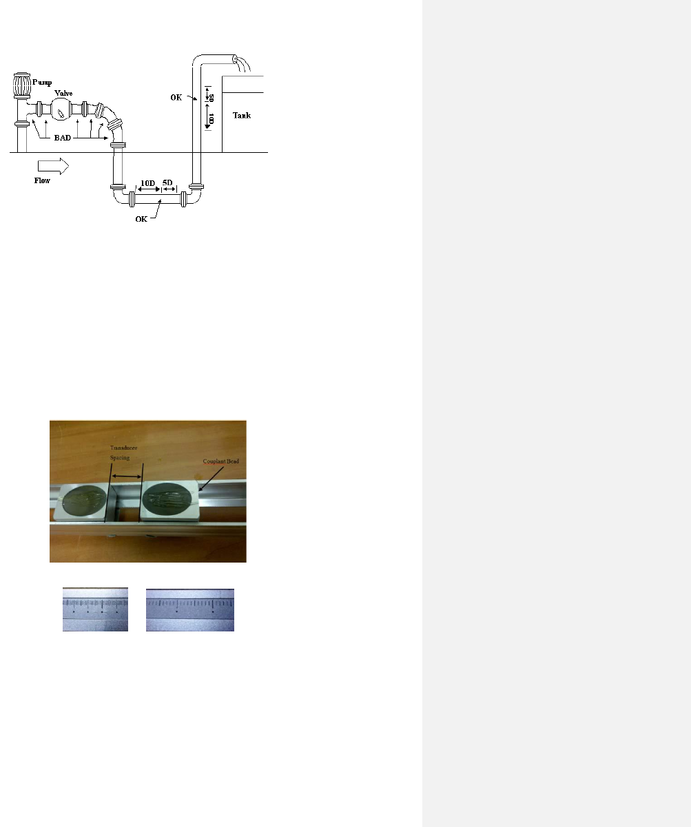
62
§10.2.B Prepare the Pipe Surface
Clean the pipe surface where the transducers will be mounted. Remove rust and paint. Sand the surface if
not smooth. Use a wet cloth to wipe off the powder after sanding. Dry up the surface. A dry, clean surface
will ensure a good acoustic bond between the transducer and the pipe.
§10.2.C Prepare the Transducer
Clean the transducer surface. Keep the surface dry. Put couplant on transducer surface as shown in the
figure on the right. Do not put more couplant than needed, especially for small pipes.
Note:
Some transducers have a mm ruler on one side and a inches ruler on the opposite side to help set spacing.
§10.2.D Install the Transducers
For horizontal pipe lines, it is recommended to install the transducers on the side instead of on the top or
bottom of the pipe. This is to avoid air bubbles on the top and sediments on the bottom of the pipe.
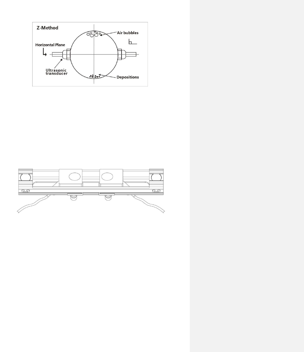
63
RS2-type transducer:
• Connect the transducer cables to the main unit.
• Move the transducer pair apart so that the mounting spacing between the two transducers is equal
to the one shown in window S43
• Apply a small amount of couplant in the prepared area of the pipe where transducers will be in
contact.
• Align the transducer mounting rack with the pipe axis.
• Release the transducer rack if magnetic force takes effect.
• If the pipe material is non-metal, push the transducer handle against the pipe and hold it during
the measurement. Clamps or metal strips may be used to mount the rack.
For pipe size 1”~1.5” metal pipe, we recommend a damping material to be used around the pipe surface,
such as “Grace Ice and Water Shield". (Note: The cables are labeled Up and Down for Upstream and
Downstream, see Chapter 1.9 for wiring and Flow).
If wrapping acoustic damping material is not an option, try to put some acoustic couplant around the pipe
to absorb the acoustic noise.
RM1/RL-type transducer:
Connect the transducer cables to the main unit. Move the transducer pair apart so that the mounting
spacing between the two transducers is equal to the one shown in menu window S43. Then, follow the
same steps as installing RS2 transducers, applying couplant as necessary.
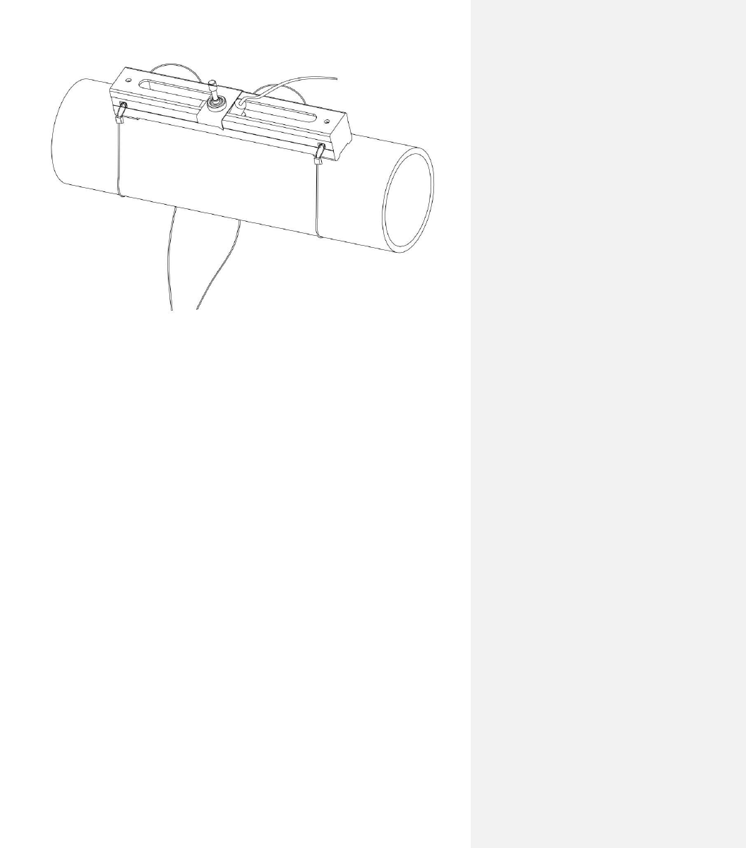
64
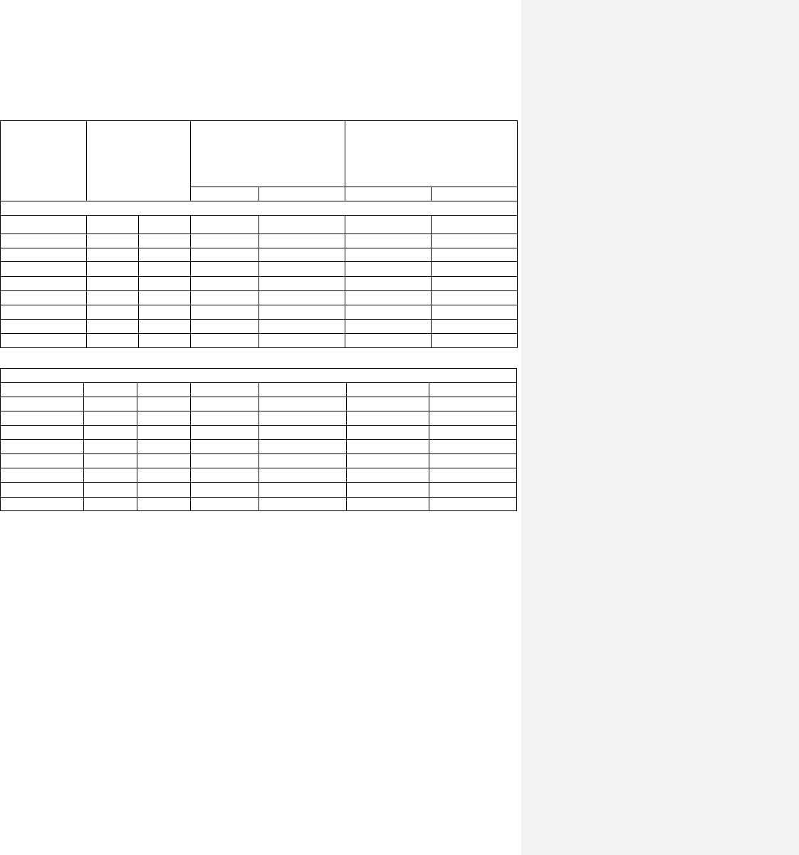
65
§10.3 Pipe Size Tables
Table A1: Standard copper tubes according ASTM B88.
Nominal Size
(Inches)
Actual Outside
Diameter (Inches)
Tolerance on Outside
Diameter (Inches)
Wall Thickness (Inches)
Annealed
Drawn
Nominal
Tolerance
Type K
¾
7/8
0.875
0.003
0.001
0.065
0.006
1
118
⁄
1.125
0.0035
0.0015
0.065
0.006
1 ¼
138
⁄
1.375
0.004
0.0015
0.065
0.006
1 ½
1 58
⁄
1.625
0.0045
0.002
0.072
0.007
2
218
⁄
2.125
0.005
0.002
0.083
0.008
2 ½
258
⁄
2.625
0.005
0.002
0.095
0.010
3
318
⁄
3.125
0.005
0.002
0.109
0.011
3 ½
358
⁄
3.625
0.005
0.002
0.120
0.012
4
418
⁄
4.125
0.005
0.002
0.134
0.013
Type L
¾
78
⁄
0.875
0.003
0.001
0.045
0.004
1
118
⁄
1.125
0.0035
0.0015
0.050
0.005
1 ¼
138
⁄
1.375
0.004
0.0015
0.055
0.006
1 ½
158
⁄
1.625
0.0045
0.002
0.060
0.006
2
218
⁄
2.215
0.005
0.002
0.070
0.007
2 ½
258
⁄
2.625
0.005
0.002
0.080
0.008
3
318
⁄
3.125
0.005
0.002
0.090
0.009
3 ½
358
⁄
3.625
0.005
0.002
0.100
0.010
4
418
⁄
4.125
0.005
0.002
0.114
0.011
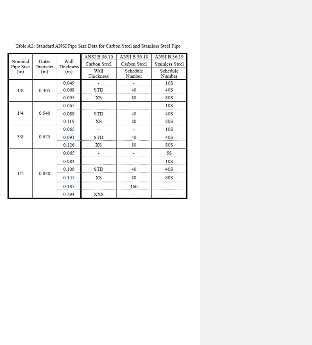
66
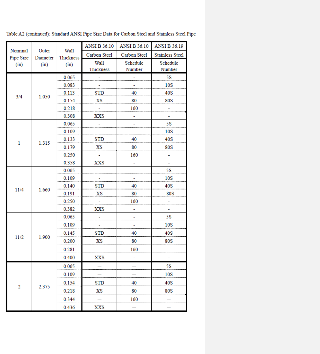
67
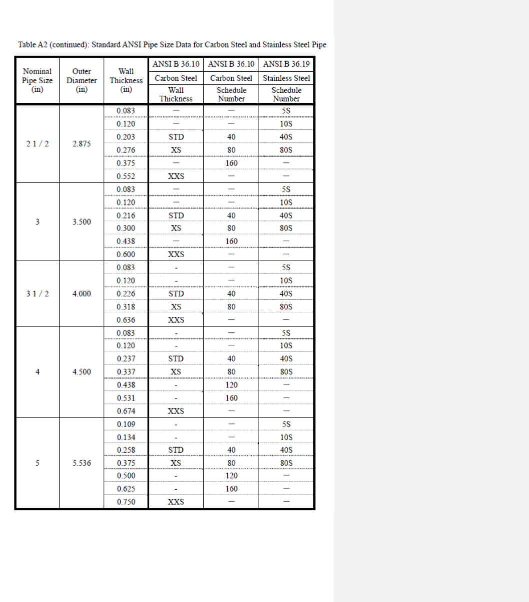
68
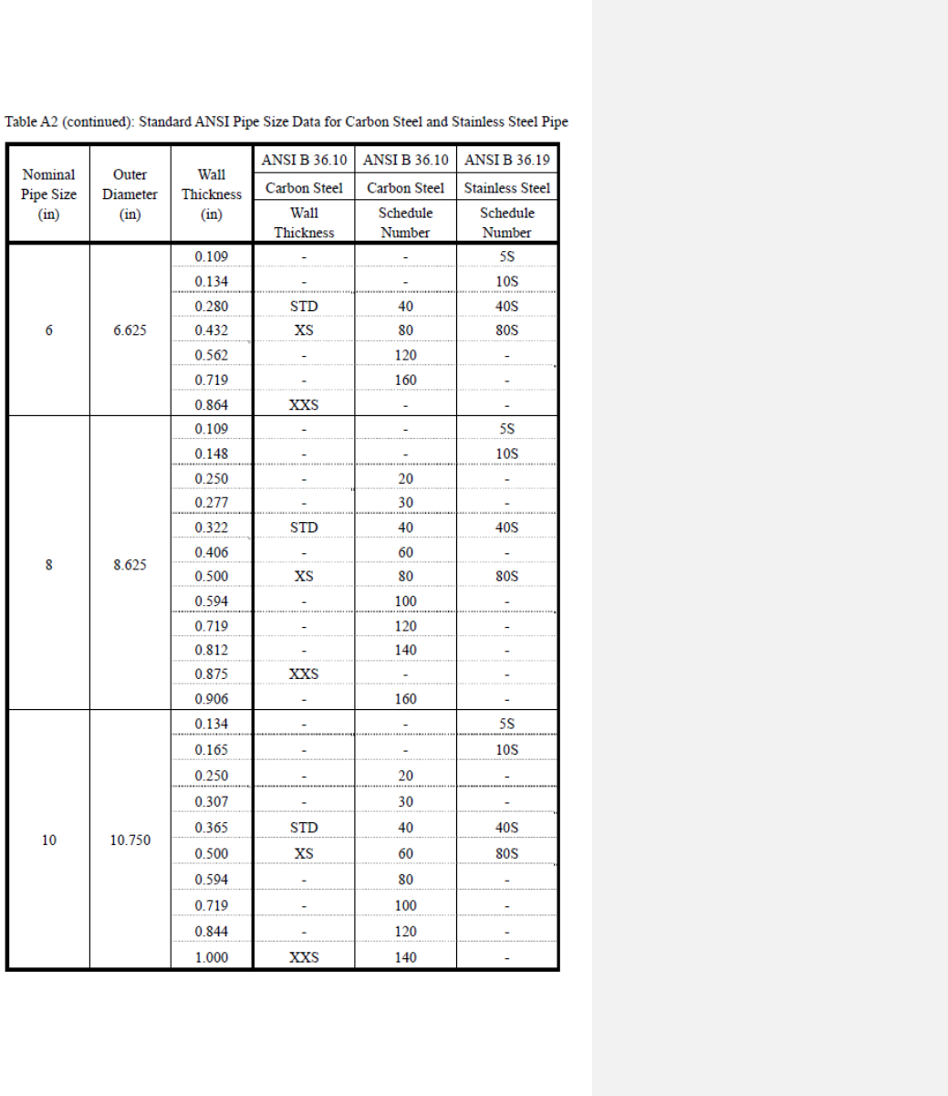
69
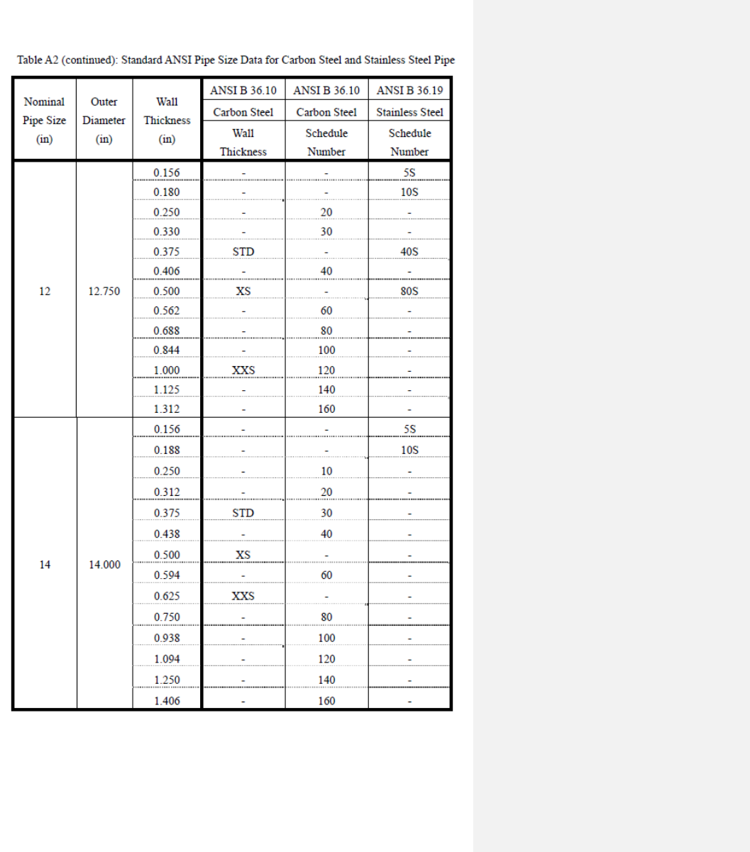
70
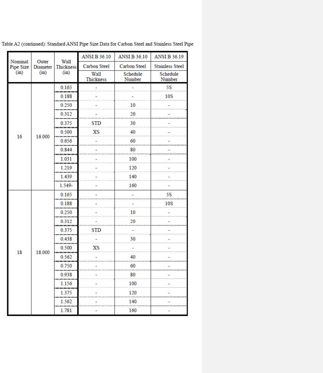
71
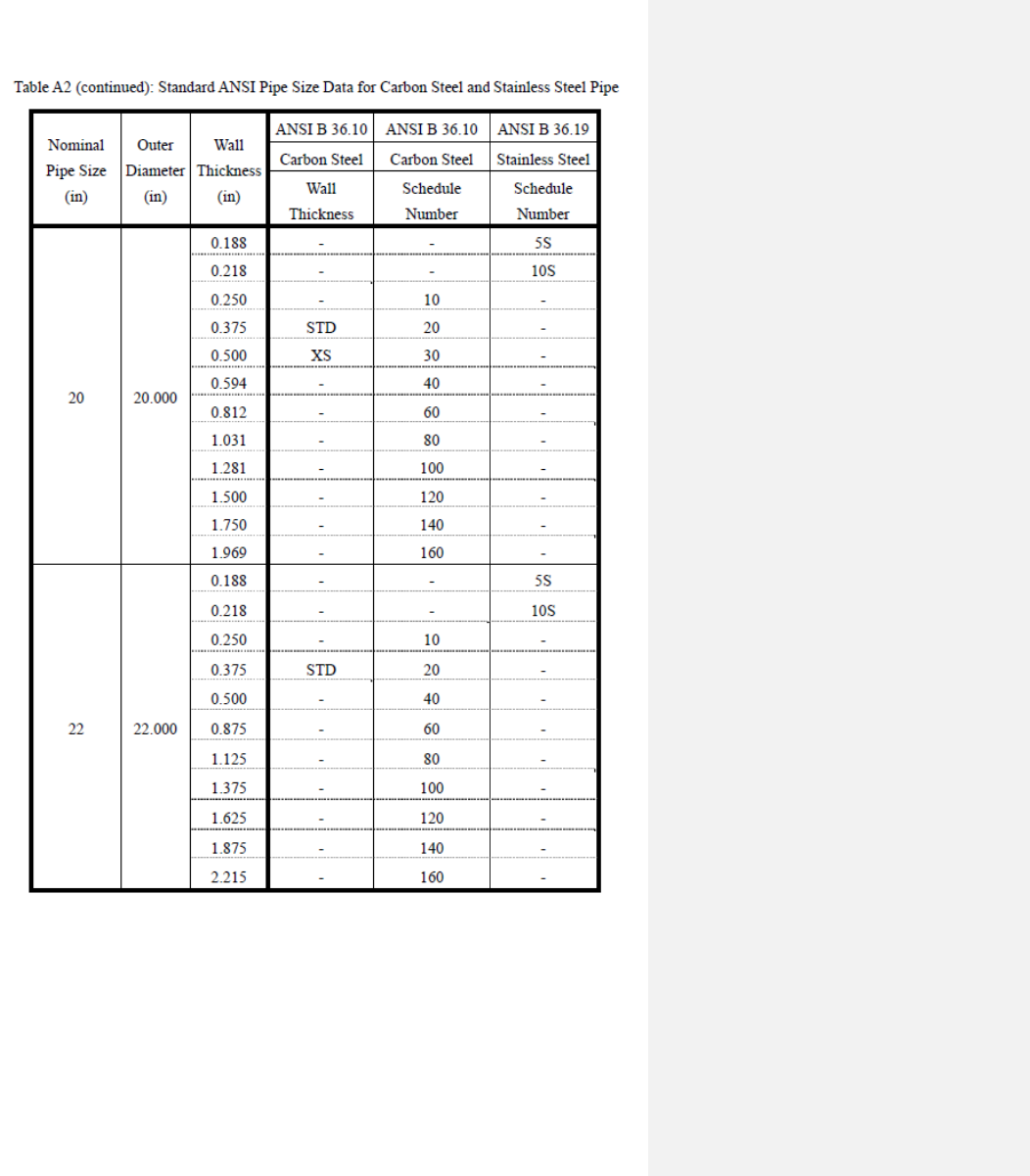
72
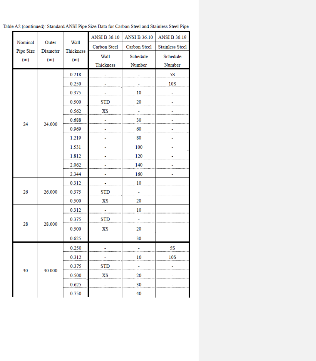
73
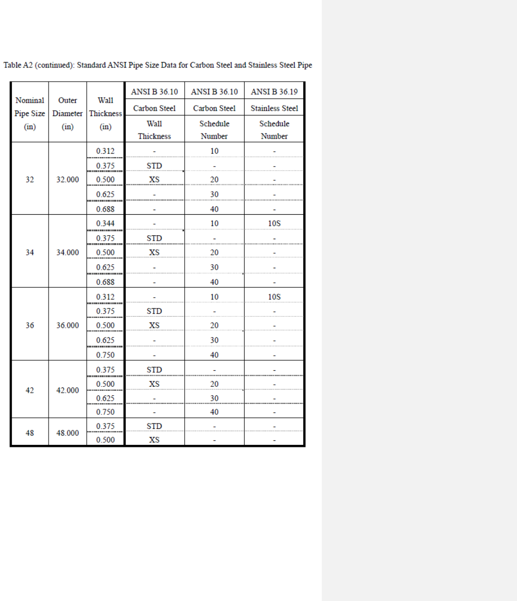
74
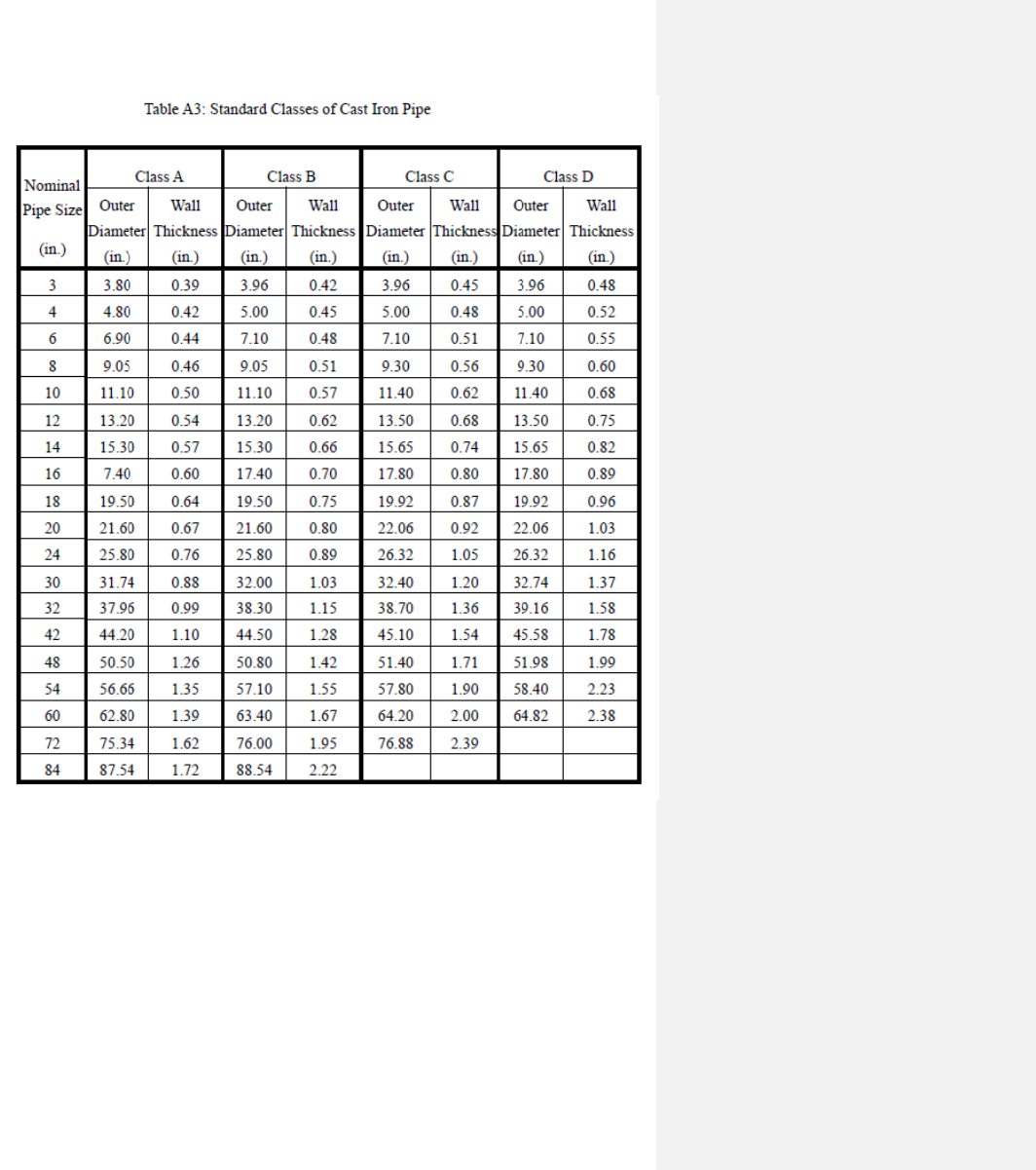
75
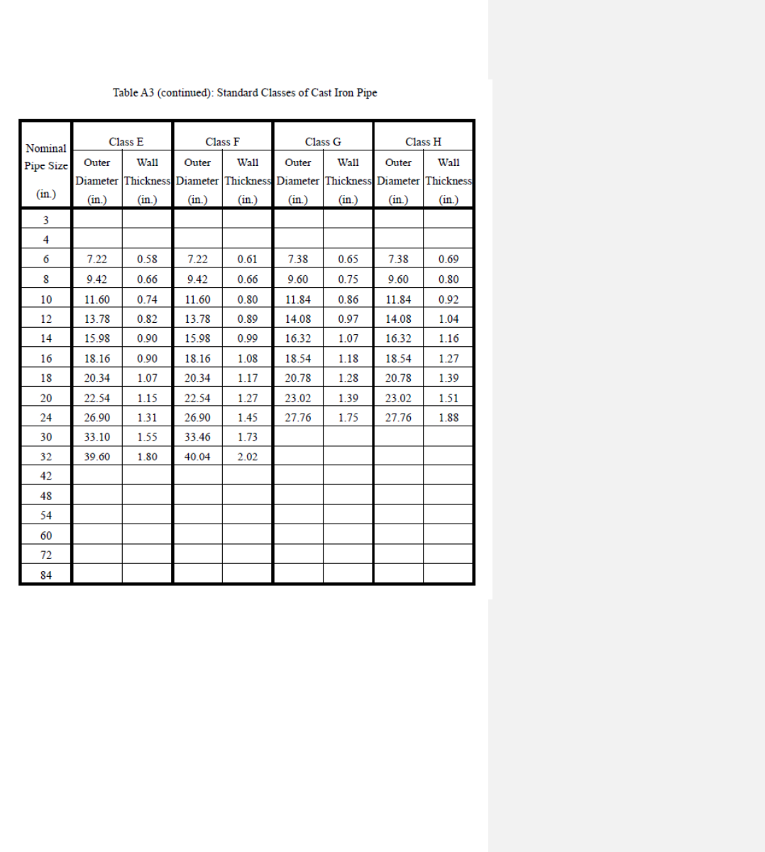
76
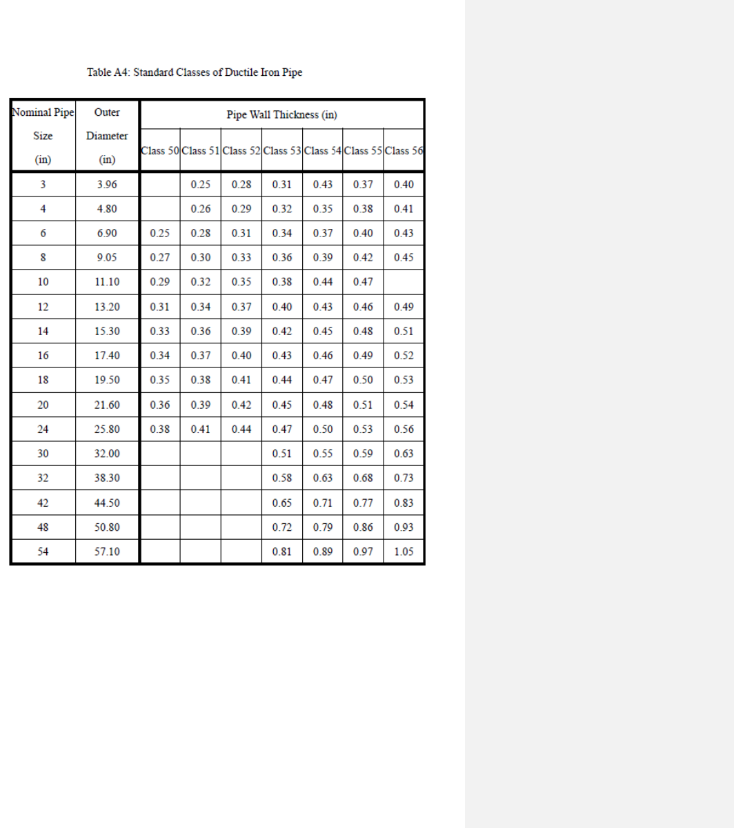
77
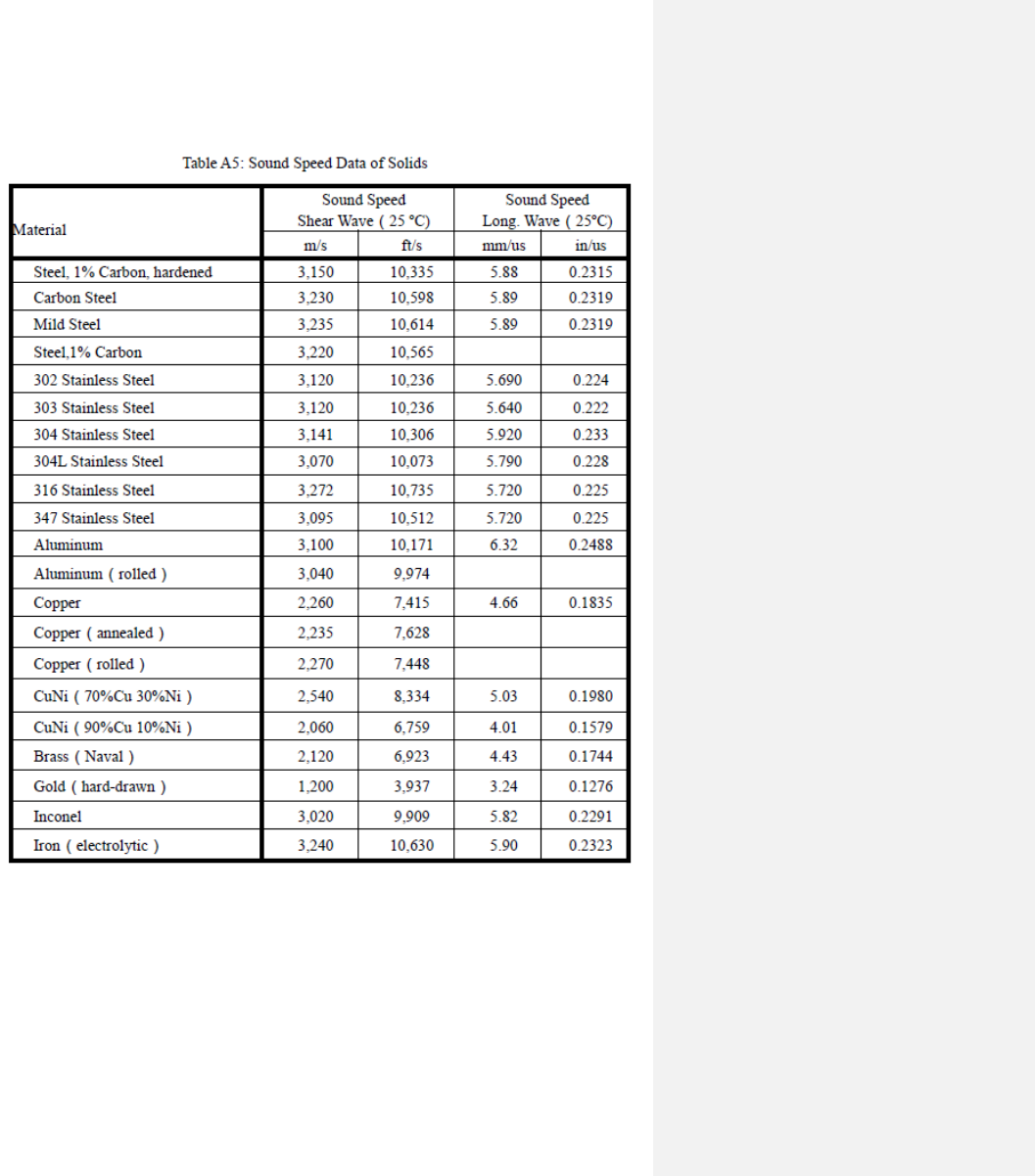
78
§10.4 Sound Speed Tables
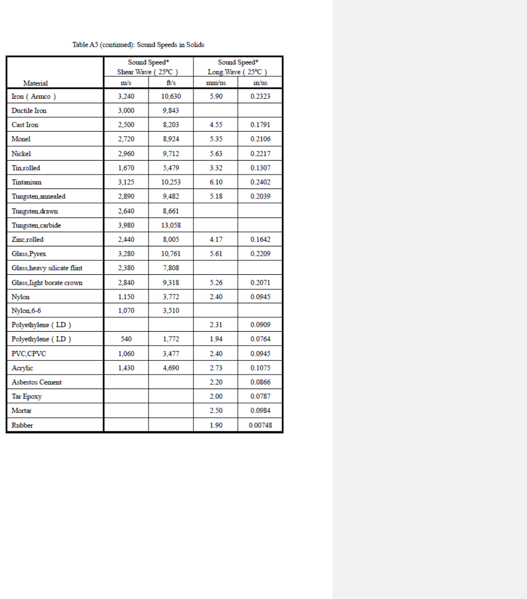
79
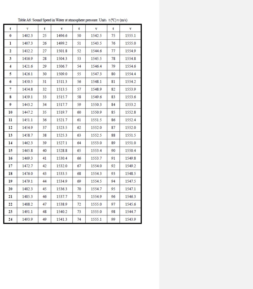
80
\
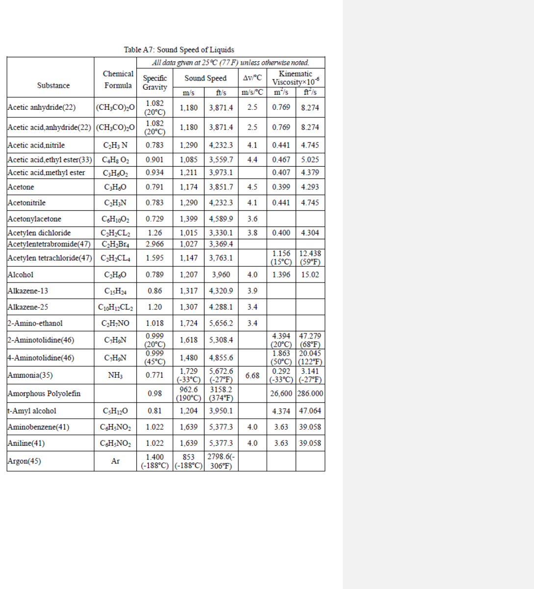
81
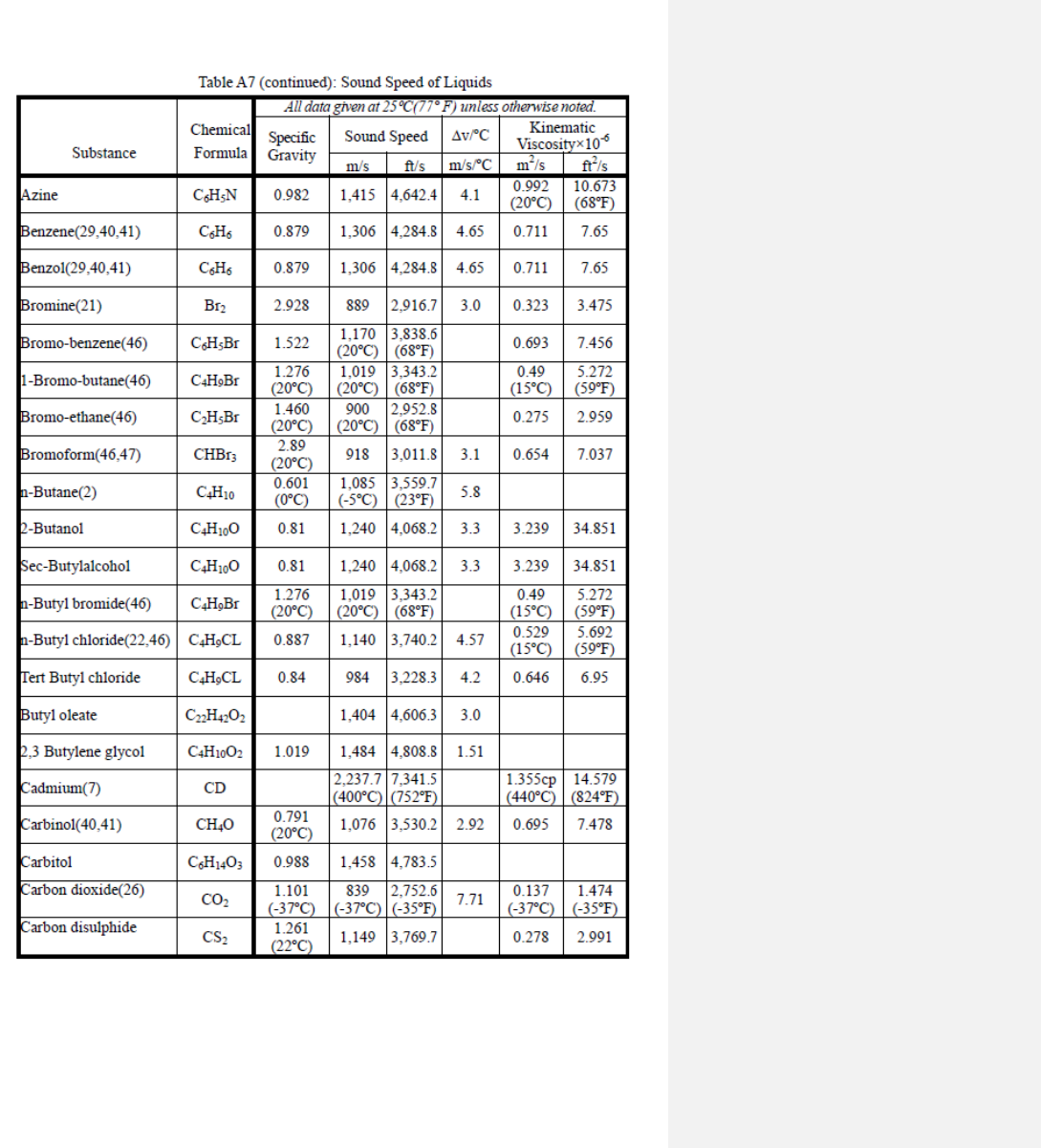
82
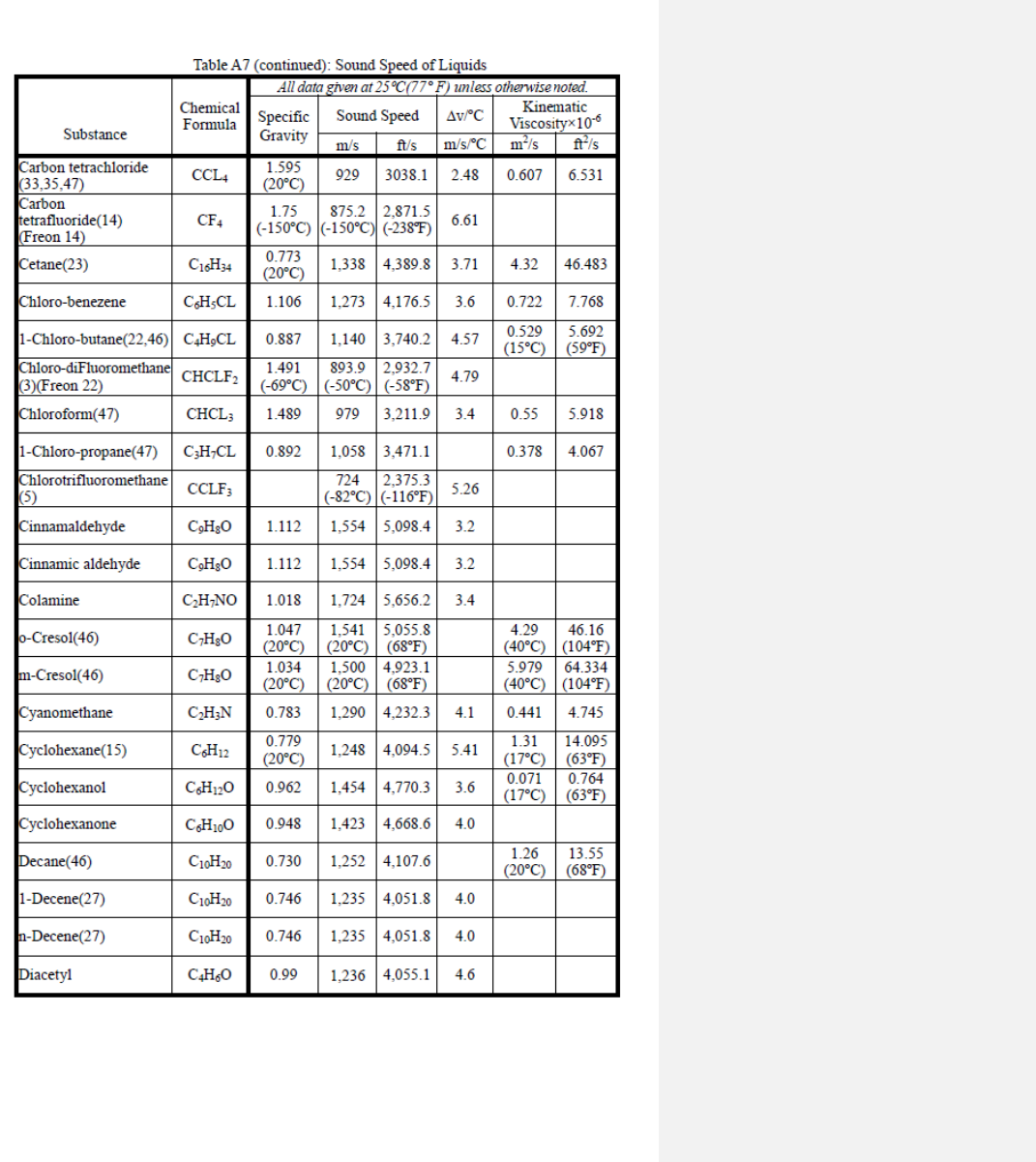
83
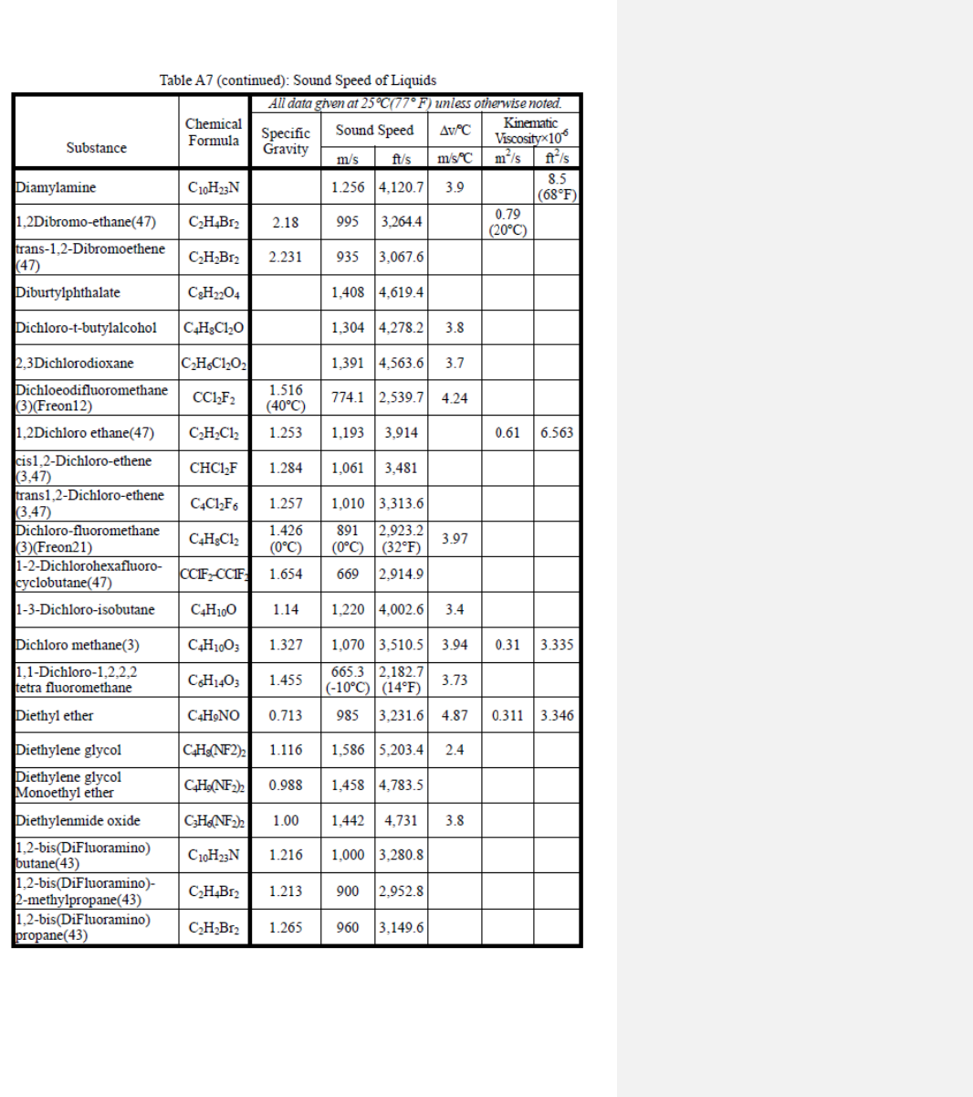
84
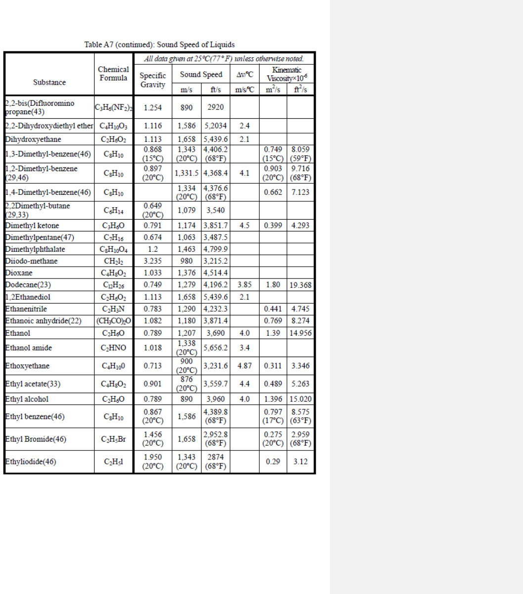
85
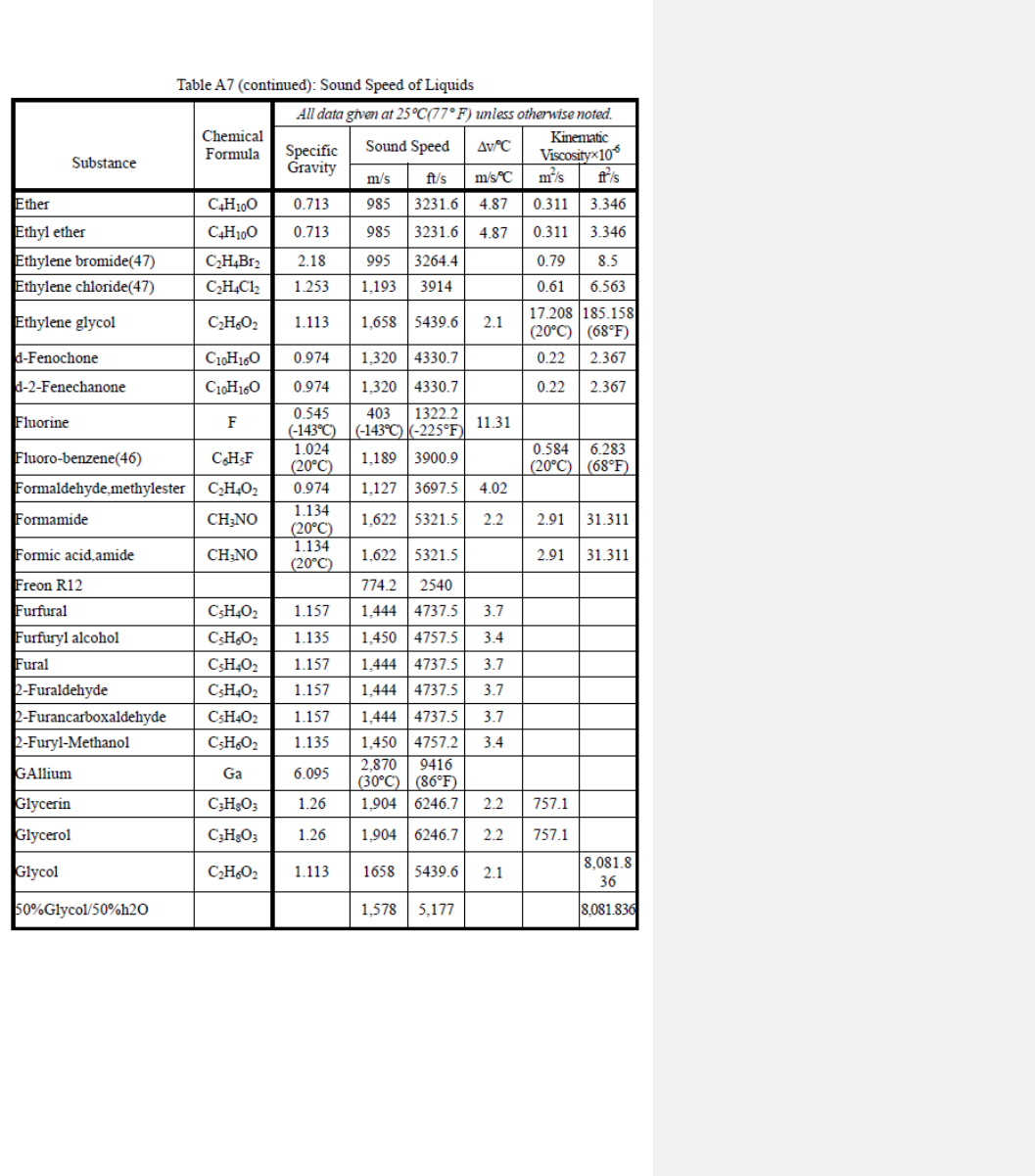
86
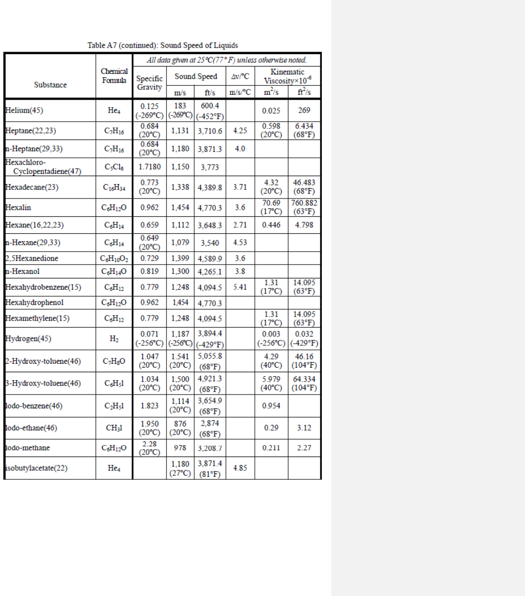
87
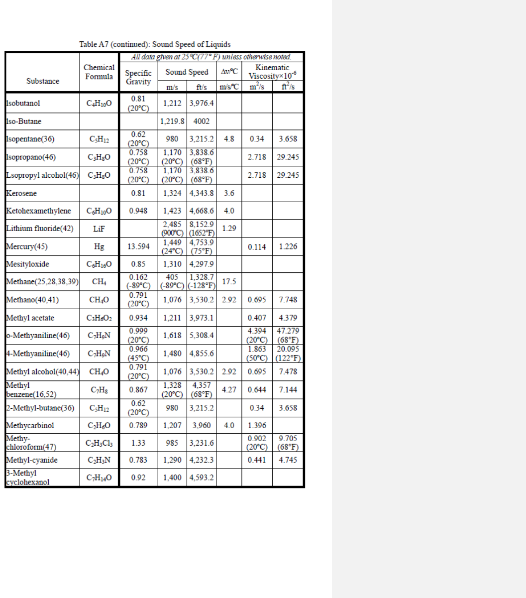
88
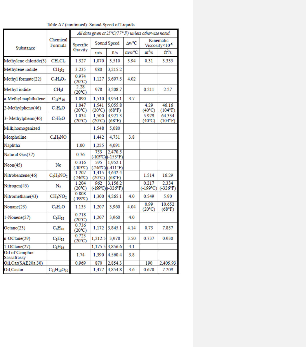
89
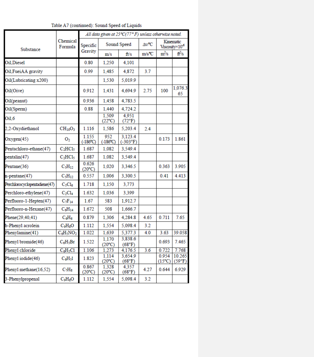
90
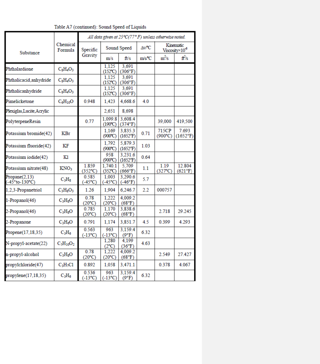
91
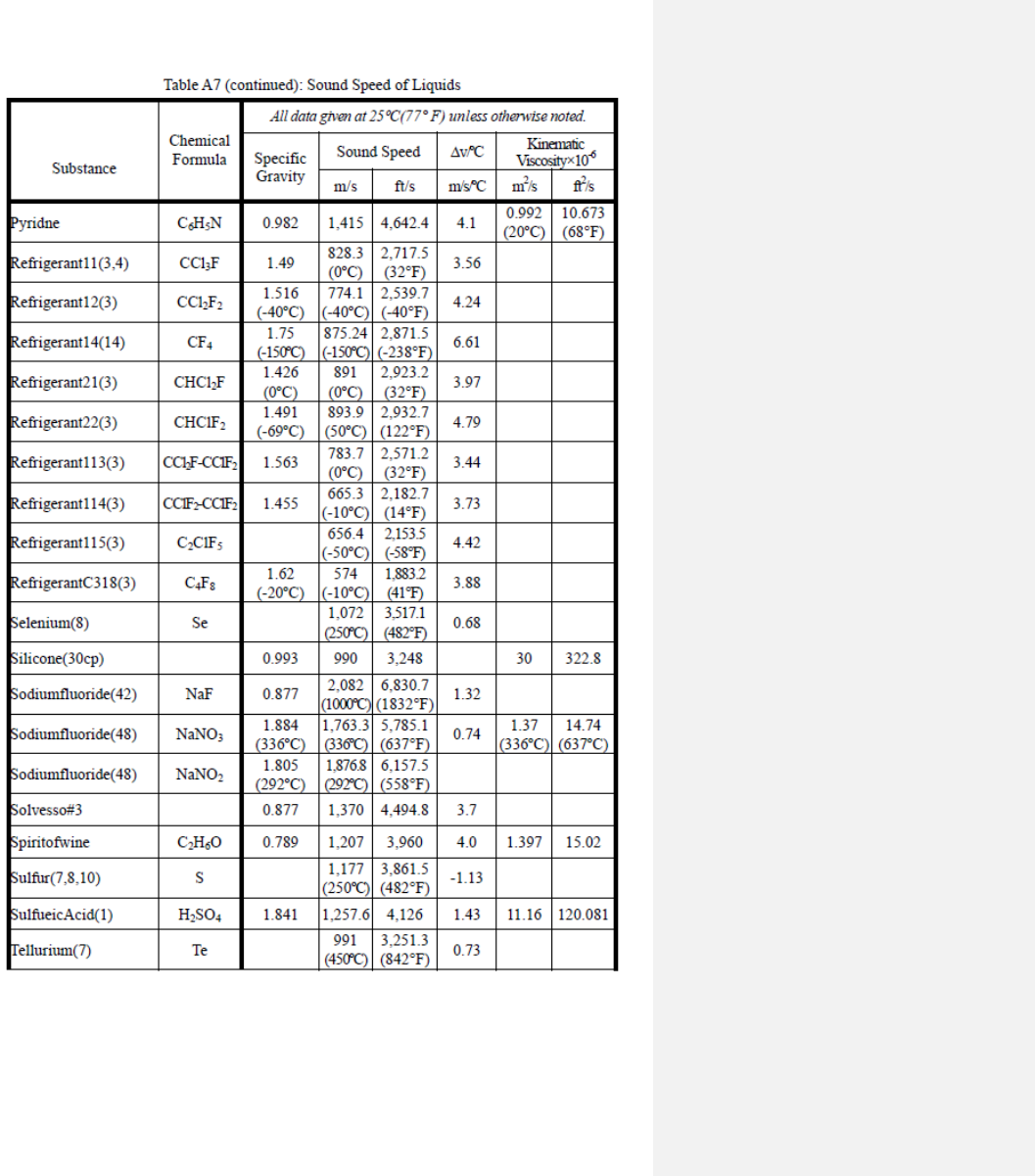
92
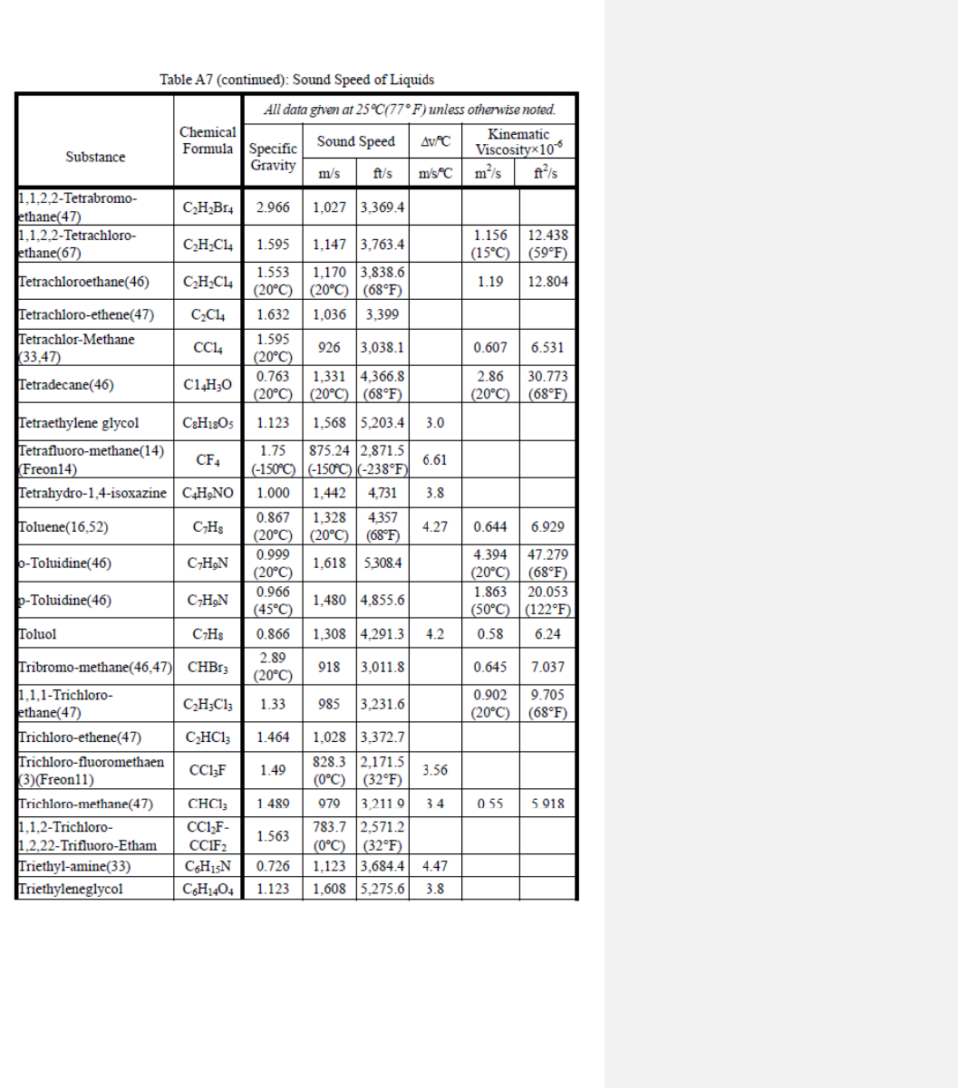
93
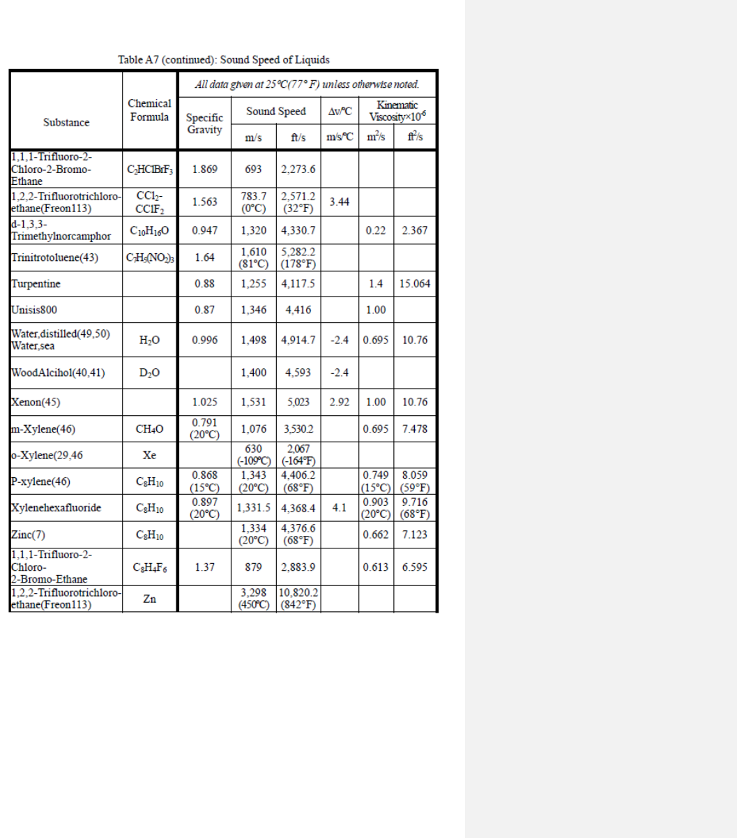
94
