IEEE Std 1609.0 2013, Guide For Wireless Access In Vehicular Environments (WAVE)—Architecture (2004)IEEE (WAVE) Architecture
User Manual:
Open the PDF directly: View PDF ![]() .
.
Page Count: 78
- IEEE Std 1609.0-2013 Front Cover
- Title page
- Important Notices and Disclaimers Concerning IEEE Standards Documents
- Participants
- Contents
- Important Notice
- 1. Overview
- 2. Normative references
- 3. Definitions, abbreviation, and acronyms
- 4. Relevant standards
- 5. WAVE system overview
- 5.1 General
- 5.2 System components and connectivity
- 5.3 Protocols
- 5.4 Interfaces
- 5.5 The 5.9 GHz spectrum allocation
- 5.6 Channel types
- 5.7 Communication services
- 5.8 WAVE Service Advertisement
- 5.9 Addresses and identifiers
- 5.10 Priorities
- 5.11 Channel coordination and time synchronization
- 5.12 Other features
- 5.13 Security considerations
- 5.13.1 Background
- 5.13.2 Communications security within WAVE standards
- 5.13.3 IEEE Std 1609.2 and WAVE Security Services
- 5.13.4 Security processing for applications
- 5.13.5 Security use cases for WSAs
- 5.13.6 Use of certificates for authentication
- 5.13.7 Certificate management
- 5.13.8 Privacy
- 5.13.9 Platform security considerations
- Annex A (informative) Example system configuration
- Annex B (informative) Certification
- Annex C (informative) Representative use cases
- Annex D (informative) International ITS documents
- Annex E (informative) Mapping PSID values to a contiguous set of integers
- Annex F (informative) Deployment history
- Annex G (informative) Bibliography

IEEE Guide for Wireless Access in
Vehicular Environments (WAVE)
Architecture
Sponsored by the
Intelligent Transportation Systems Committee
IEEE
3 Park Avenue
New York, NY 10016-5997
USA
IEEE Vehicular Technology Society
IEEE Std 1609.0™-2013
Authorized licensed use limited to: University Town Library of Shenzhen. Downloaded on January 04,2018 at 13:03:28 UTC from IEEE Xplore. Restrictions apply.
Authorized licensed use limited to: University Town Library of Shenzhen. Downloaded on January 04,2018 at 13:03:28 UTC from IEEE Xplore. Restrictions apply.
IEEE Std 1609.0™-2013
IEEE Guide for Wireless Access in
Vehicular Environments (WAVE)
Architecture
Sponsor
Intelligent Transportation Systems Committee
of the
IEEE Vehicular Technology Society
Approved 11 December 2013
IEEE-SA Standards Board
Authorized licensed use limited to: University Town Library of Shenzhen. Downloaded on January 04,2018 at 13:03:28 UTC from IEEE Xplore. Restrictions apply.

ii
Copyright © 2014 IEEE. All rights reserved.
Abstract: The wireless access in vehicular environments (WAVE) architecture and services
necessary for WAVE devices to communicate in a mobile vehicular environment are described in
this guide. It is meant to be used in conjunction with the family of IEEE 1609 standards as of its
publication date. These include IEEE Std 1609.2™, IEEE Standard Security Services for
Applications and Management Messages, IEEE Std 1609.3 Networking Services, IEEE Std
1609.4 Multi-Channel Operation, IEEE Std 1609.11 Over-the-Air Electronic Payment Data
Exchange Protocol for Intelligent Transportation Systems (ITS), IEEE Std 1609.12 Identifier
Allocations, and IEEE Std 802.11 in operation outside the context of a basic service set.
Keywords: dedicated short range communications, DSRC, IEEE 1609.0™, OBU, onboard unit,
Provider Service Identifier (PSID), roadside unit (RSU), WAVE, WAVE service advertisement,
WAVE Short Message, WAVE Short Message Protocol, wireless access in vehicular
environments, WSA, WSM, WSMP
•
The Institute of Electrical and Electronics Engineers, Inc.
3 Park Avenue, New York, NY 10016-5997, USA
Copyright © 2014 by the Institute of Electrical and Electronics Engineers, Inc.
All rights reserved. Published 5 March 2014. Printed in the United States of America.
IEEE is a registered trademark in the U.S. Patent & Trademark Office, owned by the Institute of Electrical and Electronics
Engineers, Incorporated.
PDF: ISBN 978-0-7381-8756-3 STD98459
Print: ISBN 978-0-7381-8757-0 STDPD98459
IEEE prohibits discrimination, harassment, and bullying.
For more information, visit http://www.ieee.org/web/aboutus/whatis/policies/p9-26.html.
No part of this publication may be reproduced in any form, in an electronic retrieval system or otherwise, without the prior written permission
of the publisher.
Authorized licensed use limited to: University Town Library of Shenzhen. Downloaded on January 04,2018 at 13:03:28 UTC from IEEE Xplore. Restrictions apply.
iii
Copyright © 2014 IEEE. All rights reserved.
Important Notices and Disclaimers Concerning IEEE Standards Documents
IEEE documents are made available for use subject to important notices and legal disclaimers. These
notices and disclaimers, or a reference to this page, appear in all standards and may be found under the
heading “Important Notice” or “Important Notices and Disclaimers Concerning IEEE Standards
Documents.”
Notice and Disclaimer of Liability Concerning the Use of IEEE Standards
Documents
IEEE Standards documents (standards, recommended practices, and guides), both full-use and trial-use, are
developed within IEEE Societies and the Standards Coordinating Committees of the IEEE Standards
Association (“IEEE-SA”) Standards Board. IEEE (“the Institute”) develops its standards through a
consensus development process, approved by the American National Standards Institute (“ANSI”), which
brings together volunteers representing varied viewpoints and interests to achieve the final product.
Volunteers are not necessarily members of the Institute and participate without compensation from IEEE.
While IEEE administers the process and establishes rules to promote fairness in the consensus development
process, IEEE does not independently evaluate, test, or verify the accuracy of any of the information or the
soundness of any judgments contained in its standards.
IEEE does not warrant or represent the accuracy or content of the material contained in its standards, and
expressly disclaims all warranties (express, implied and statutory) not included in this or any other
document relating to the standard, including, but not limited to, the warranties of: merchantability; fitness
for a particular purpose; non-infringement; and quality, accuracy, effectiveness, currency, or completeness
of material. In addition, IEEE disclaims any and all conditions relating to: results; and workmanlike effort.
IEEE standards documents are supplied “AS IS” and “WITH ALL FAULTS.”
Use of an IEEE standard is wholly voluntary. The existence of an IEEE standard does not imply that there
are no other ways to produce, test, measure, purchase, market, or provide other goods and services related
to the scope of the IEEE standard. Furthermore, the viewpoint expressed at the time a standard is approved
and issued is subject to change brought about through developments in the state of the art and comments
received from users of the standard.
In publishing and making its standards available, IEEE is not suggesting or rendering professional or other
services for, or on behalf of, any person or entity nor is IEEE undertaking to perform any duty owed by any
other person or entity to another. Any person utilizing any IEEE Standards document, should rely upon his
or her own independent judgment in the exercise of reasonable care in any given circumstances or, as
appropriate, seek the advice of a competent professional in determining the appropriateness of a given
IEEE standard.
IN NO EVENT SHALL IEEE BE LIABLE FOR ANY DIRECT, INDIRECT, INCIDENTAL, SPECIAL,
EXEMPLARY, OR CONSEQUENTIAL DAMAGES (INCLUDING, BUT NOT LIMITED TO:
PROCUREMENT OF SUBSTITUTE GOODS OR SERVICES; LOSS OF USE, DATA, OR PROFITS;
OR BUSINESS INTERRUPTION) HOWEVER CAUSED AND ON ANY THEORY OF LIABILITY,
WHETHER IN CONTRACT, STRICT LIABILITY, OR TORT (INCLUDING NEGLIGENCE OR
OTHERWISE) ARISING IN ANY WAY OUT OF THE PUBLICATION, USE OF, OR RELIANCE
UPON ANY STANDARD, EVEN IF ADVISED OF THE POSSIBILITY OF SUCH DAMAGE AND
REGARDLESS OF WHETHER SUCH DAMAGE WAS FORESEEABLE.
Translations
The IEEE consensus development process involves the review of documents in English only. In the event
that an IEEE standard is translated, only the English version published by IEEE should be considered the
approved IEEE standard.
Authorized licensed use limited to: University Town Library of Shenzhen. Downloaded on January 04,2018 at 13:03:28 UTC from IEEE Xplore. Restrictions apply.
iv
Copyright © 2014 IEEE. All rights reserved.
Official statements
A statement, written or oral, that is not processed in accordance with the IEEE-SA Standards Board
Operations Manual shall not be considered or inferred to be the official position of IEEE or any of its
committees and shall not be considered to be, or be relied upon as, a formal position of IEEE. At lectures,
symposia, seminars, or educational courses, an individual presenting information on IEEE standards shall
make it clear that his or her views should be considered the personal views of that individual rather than the
formal position of IEEE.
Comments on standards
Comments for revision of IEEE Standards documents are welcome from any interested party, regardless of
membership affiliation with IEEE. However, IEEE does not provide consulting information or advice
pertaining to IEEE Standards documents. Suggestions for changes in documents should be in the form of a
proposed change of text, together with appropriate supporting comments. Since IEEE standards represent a
consensus of concerned interests, it is important that any responses to comments and questions also receive
the concurrence of a balance of interests. For this reason, IEEE and the members of its societies and
Standards Coordinating Committees are not able to provide an instant response to comments or questions
except in those cases where the matter has previously been addressed. For the same reason, IEEE does not
respond to interpretation requests. Any person who would like to participate in revisions to an IEEE
standard is welcome to join the relevant IEEE working group.
Comments on standards should be submitted to the following address:
Secretary, IEEE-SA Standards Board
445 Hoes Lane
Piscataway, NJ 08854 USA
Laws and regulations
Users of IEEE Standards documents should consult all applicable laws and regulations. Compliance with
the provisions of any IEEE Standards document does not imply compliance to any applicable regulatory
requirements. Implementers of the standard are responsible for observing or referring to the applicable
regulatory requirements. IEEE does not, by the publication of its standards, intend to urge action that is not
in compliance with applicable laws, and these documents may not be construed as doing so.
Copyrights
IEEE draft and approved standards are copyrighted by IEEE under U. S. and international copyright laws.
They are made available by IEEE and are adopted for a wide variety of both public and private uses. These
include both use, by reference, in laws and regulations, and use in private self-regulation, standardization,
and the promotion of engineering practices and methods. By making these documents available for use and
adoption by public authorities and private users, IEEE does not waive any rights in copyright to the
documents.
Photocopies
Subject to payment of the appropriate fee, IEEE will grant users a limited, non-exclusive license to
photocopy portions of any individual standard for company or organizational internal use or individual,
non-commercial use only. To arrange for payment of licensing fees, please contact Copyright Clearance
Center, Customer Service, 222 Rosewood Drive, Danvers, MA 01923 USA; +1 978 750 8400. Permission
to photocopy portions of any individual standard for educational classroom use can also be obtained
through the Copyright Clearance Center.
Authorized licensed use limited to: University Town Library of Shenzhen. Downloaded on January 04,2018 at 13:03:28 UTC from IEEE Xplore. Restrictions apply.

v
Copyright © 2014 IEEE. All rights reserved.
Updating of IEEE Standards documents
Users of IEEE Standards documents should be aware that these documents may be superseded at any time
by the issuance of new editions or may be amended from time to time through the issuance of amendments,
corrigenda, or errata. An official IEEE document at any point in time consists of the current edition of the
document together with any amendments, corrigenda, or errata then in effect.
Every IEEE standard is subjected to review at least every ten years. When a document is more than ten
years old and has not undergone a revision process, it is reasonable to conclude that its contents, although
still of some value, do not wholly reflect the present state of the art. Users are cautioned to check to
determine that they have the latest edition of any IEEE standard.
In order to determine whether a given document is the current edition and whether it has been amended
through the issuance of amendments, corrigenda, or errata, visit the IEEE-SA Website at
http://ieeexplore.ieee.org/xpl/standards.jsp or contact IEEE at the address listed previously. For more
information about the IEEE SA or IEEE’s standards development process, visit the IEEE-SA Website at
http://standards.ieee.org.
Errata
Errata, if any, for all IEEE standards can be accessed on the IEEE-SA Website at the following URL:
http://standards.ieee.org/findstds/errata/index.html. Users are encouraged to check this URL for errata
periodically.
Patents
Attention is called to the possibility that implementation of this standard may require use of subject matter
covered by patent rights. By publication of this standard, no position is taken by the IEEE with respect to
the existence or validity of any patent rights in connection therewith. If a patent holder or patent applicant
has filed a statement of assurance via an Accepted Letter of Assurance, then the statement is listed on the
IEEE-SA Website at http://standards.ieee.org/about/sasb/patcom/patents.html. Letters of Assurance may
indicate whether the Submitter is willing or unwilling to grant licenses under patent rights without
compensation or under reasonable rates, with reasonable terms and conditions that are demonstrably free of
any unfair discrimination to applicants desiring to obtain such licenses.
Essential Patent Claims may exist for which a Letter of Assurance has not been received. The IEEE is not
responsible for identifying Essential Patent Claims for which a license may be required, for conducting
inquiries into the legal validity or scope of Patents Claims, or determining whether any licensing terms or
conditions provided in connection with submission of a Letter of Assurance, if any, or in any licensing
agreements are reasonable or non-discriminatory. Users of this standard are expressly advised that
determination of the validity of any patent rights, and the risk of infringement of such rights, is entirely
their own responsibility. Further information may be obtained from the IEEE Standards Association.
Authorized licensed use limited to: University Town Library of Shenzhen. Downloaded on January 04,2018 at 13:03:28 UTC from IEEE Xplore. Restrictions apply.
vi
Copyright © 2014 IEEE. All rights reserved.
Participants
At the time this guide was completed, the Wireless Access in Vehicular Environments (WAVE) Working
Group had the following membership:
Thomas M. Kurihara, Chair
John Moring, Vice Chair
William Whyte, Vice Chair
Scott Andrews
Lee Armstrong
Jerome Chiu
Hans-Joachim Fischer
Wayne Fisher
Ramez Gerges
Ali Ghandour
Refi-Tugrul Güner
Gloria Gwynne
Ron Hochnadel
Carl Kain
Doug Kavner
David Kelley
John Kenney
Jerry Landt
Mike Lin
Julius Madey
Alastair Malarky
Justin McNew
Gary Pruitt
Robert Rausch
Randy Roebuck
Richard Roy
Steve Sill
François Simon
Ramesh Siripurapu
Jason Tran
Huei-Ru Tseng
George Vlantis
The following members of the individual balloting committee voted on this guide. Balloters may have
voted for approval, disapproval, or abstention.
Lee Armstrong
Harry Bims
Bill Brown
William Byrd
Scott Cadzow
Keith Chow
Michael Coop
Patrick Diamond
Susan Dickey
Sourav Dutta
Richard Edgar
Marc Emmelmann
Andre Fournier
Avraham Freedman
H. Glickenstein
Randall Groves
Tugrul Guener
Gloria Gwynne
Ron Hochnadel
Werner Hoelzl
Chung-Hsien Hsu
Noriyuki Ikeuchi
Piotr Karocki
John Kenney
Stuart Kerry
Stanley Klein
Thomas M. Kurihara
Paul Lambert
Jeremy Landt
Hsia-Hsin Li
William Lumpkins
Julius Madey
Alastair Malarky
Justin McNew
John Moring
Ronald Murias
Michael Newman
Satoshi Obara
Satoshi Oyama
Markus Riederer
Robert Robinson
Jeff Rockower
Richard Roy
Randall Safier
Bartien Sayogo
Gil Shultz
Thomas Starai
Eugene Stoudenmire
Walter Struppler
Jasja Tijink
John Vergis
George Vlantis
Stephen Webb
Hung-Yu Wei
William Whyte
Oren Yuen
Daidi Zhong
Authorized licensed use limited to: University Town Library of Shenzhen. Downloaded on January 04,2018 at 13:03:28 UTC from IEEE Xplore. Restrictions apply.
vii
Copyright © 2014 IEEE. All rights reserved.
When the IEEE-SA Standards Board approved this guide on 11 December 2013 it had the following
membership:
John Kulick, Chair
David J. Law, Vice Chair
Richard H. Hulett, Past Chair
Konstantinos Karachalios, Secretary
Masayuki Ariyoshi
Peter Balma
Farooq Bari
Ted Burse
Stephen Dukes
Jean-Philippe Faure
Alexander Gelman
Mark Halpin
Gary Hoffman
Paul Houzé
Jim Hughes
Michael Janezic
Joseph L. Koepfinger*
Oleg Logvinov
Ron Petersen
Gary Robinson
Jon Walter Rosdahl
Adrian Stephens
Peter Sutherland
Yatin Trivedi
Phil Winston
Yu Yuan
*Member Emeritus
Also included are the following nonvoting IEEE-SA Standards Board liaisons:
Richard DeBlasio, DOE Representative
Michael Janezic, NIST Representative
Catherine Berger
Senior Program Manager, IEEE-SA Content Publishing
Michael Kipness
Program Manager, IEEE-SA Technical Community
Authorized licensed use limited to: University Town Library of Shenzhen. Downloaded on January 04,2018 at 13:03:28 UTC from IEEE Xplore. Restrictions apply.
viii
Copyright © 2014 IEEE. All rights reserved.
Contents
1. Overview .................................................................................................................................................... 1
1.1 Scope ................................................................................................................................................... 2
1.2 Aspects of a WAVE system ................................................................................................................ 2
2. Normative references .................................................................................................................................. 3
3. Definitions, abbreviation, and acronyms .................................................................................................... 3
3.1 Definitions ........................................................................................................................................... 3
3.2 Abbreviations and acronyms ............................................................................................................... 6
4. Relevant standards ...................................................................................................................................... 7
4.1 Overview of Intelligent Transportation Systems and the National ITS architecture ........................... 7
4.2 ASTM and the Federal Communications Commission (FCC) ............................................................ 8
4.3 IEEE standards .................................................................................................................................... 8
4.4 SAE DSRC standards ........................................................................................................................ 12
4.5 Related standards and organizations .................................................................................................. 13
5. WAVE system overview .......................................................................................................................... 15
5.1 General .............................................................................................................................................. 15
5.2 System components and connectivity ................................................................................................ 15
5.3 Protocols ............................................................................................................................................ 16
5.4 Interfaces ........................................................................................................................................... 18
5.5 The 5.9 GHz spectrum allocation ...................................................................................................... 19
5.6 Channel types .................................................................................................................................... 20
5.7 Communication services .................................................................................................................... 21
5.8 WAVE Service Advertisement .......................................................................................................... 25
5.9 Addresses and identifiers ................................................................................................................... 28
5.10 Priorities .......................................................................................................................................... 30
5.11 Channel coordination and time synchronization .............................................................................. 30
5.12 Other features .................................................................................................................................. 32
5.13 Security considerations .................................................................................................................... 34
Annex A (informative) Example system configuration ................................................................................ 53
Annex B (informative) Certification ............................................................................................................ 54
B.1 Scope ................................................................................................................................................. 54
B.2 Process .............................................................................................................................................. 55
Annex C (informative) Representative use cases ......................................................................................... 56
C.1 Vehicle communication for collision avoidance ............................................................................... 56
C.2 Electronic fee collection .................................................................................................................... 57
Annex D (informative) International ITS documents ................................................................................... 63
Annex E (informative) Mapping PSID values to a contiguous set of integers ............................................. 64
Annex F (informative) Deployment history ................................................................................................. 65
Annex G (informative) Bibliography ........................................................................................................... 67
Authorized licensed use limited to: University Town Library of Shenzhen. Downloaded on January 04,2018 at 13:03:28 UTC from IEEE Xplore. Restrictions apply.

1
Copyright © 2014 IEEE. All rights reserved.
IEEE Guide for Wireless Access in
Vehicular Environments (WAVE)
Architecture
IMPORTANT NOTICE: IEEE Standards documents are not intended to ensure safety, health, or
environmental protection, or ensure against interference with or from other devices or networks.
Implementers of IEEE Standards documents are responsible for determining and complying with all
appropriate safety, security, environmental, health, and interference protection practices and all
applicable laws and regulations.
This IEEE document is made available for use subject to important notices and legal disclaimers.
These notices and disclaimers appear in all publications containing this document and may
be found under the heading “Important Notice” or “Important Notices and Disclaimers
Concerning IEEE Documents.” They can also be obtained on request from IEEE or viewed at
http://standards.ieee.org/IPR/disclaimers.html.
1. Overview
A wireless access in vehicular environments (WAVE) system is a radio communication system intended to
provide seamless, interoperable services to transportation. These services include those recognized by the
U. S. National Intelligent Transportation Systems (ITS) architecture and many others contemplated by the
automotive and transportation infrastructure industries around the world, such as communications between
vehicles and infrastructure, and communications among vehicles. This guide provides an overview of the
system, its components, and its operation. It is intended to provide a context within which to better
understand the content of the related IEEE WAVE standards documents, which include IEEE Std
1609.2™-2013, IEEE Std 1609.3™-2010, IEEE Std 1609.4™-2010, IEEE P1609.6™ [B19],1, 2 IEEE Std
1609.11™-2010, and IEEE Std 1609.12™, as well as IEEE Std 802.11™-2012 [stations communicating
outside the context of a Basic Service Set (BSS), or OCB].3
The term dedicated short range communications (DSRC) is sometimes used in the U. S. to refer to radio
spectrum or technologies associated with WAVE. For example, U. S. Federal Communications
Commission (FCC) documents [B6] allocate spectrum to “mobile service for use by DSRC systems
operating in the Intelligent Transportation System (ITS) radio service,” and the Society of Automotive
Engineers (SAE) has specified messages in SAE J2735 “for use by applications intended to utilize the
5.9 GHz dedicated short range communications for wireless access in vehicular environments.” Outside the
1 The numbers in brackets correspond to those of the bibliography in Annex G.
2 Numbers preceded by P are IEEE authorized standards projects that were not approved by the IEEE-SA Standards Board at the time
this publication went to press.
3 Information on references can be found in Clause 2.
Authorized licensed use limited to: University Town Library of Shenzhen. Downloaded on January 04,2018 at 13:03:28 UTC from IEEE Xplore. Restrictions apply.
IEEE Std 1609.0-2013
IEEE Guide for Wireless Access in Vehicular Environments (WAVE) Architecture
2
Copyright © 2014 IEEE. All rights reserved.
U. S., DSRC may refer to a distinct radio technology operating at 5.8 GHz, used, e.g., for electronic fee
collection.
1.1 Scope
This guide describes the architecture and operation of a WAVE system based on IEEE 1609 standards and
IEEE Std 802.11-2012.
1.2 Aspects of a WAVE system
1.2.1 Introduction
ISO/IEC 42010:2007 [B28] is a recommended practice for architectural description of software-intensive
systems, and defines several aspects of any system: an environment or context, stakeholders who typically
have interest in or concerns relative to the system, and one or more missions. These aspects are addressed
in 1.2.2 through 1.2.5.
1.2.2 Environment
As its name suggests, the WAVE system as presently envisaged is designed to meet the communication
needs of mobile elements in the transportation sector. While in many of the usage scenarios at least one of
the devices engaged in WAVE communications is expected to be associated with a vehicle, other devices,
both fixed and portable (e.g., roadside and pedestrian) are envisaged as well.
1.2.3 Stakeholders
This document is intended to be a useful reference for any of the direct stakeholders including the
following:
⎯ Government agencies, e.g., national and state road operators.
⎯ Vehicle designers and original equipment manufacturers.
⎯ Aftermarket equipment makers.
⎯ Developers of applications and related standards.
Indirect stakeholders include anyone who uses or is otherwise affected by the intelligent transportation
systems built using the WAVE standards.
1.2.4 Mission
The WAVE standards enable the development of interoperable low-latency, low overhead WAVE devices
that can provide communications in support of transportation safety, efficiency and sustainability, and that
can enhance user comfort and convenience.
Authorized licensed use limited to: University Town Library of Shenzhen. Downloaded on January 04,2018 at 13:03:28 UTC from IEEE Xplore. Restrictions apply.

IEEE Std 1609.0-2013
IEEE Guide for Wireless Access in Vehicular Environments (WAVE) Architecture
3
Copyright © 2014 IEEE. All rights reserved.
1.2.5 Views
This document presents several architectural representations, or views. These include a device view (see,
e.g., 4.3.3.2 and 4.3.3.3), a protocol view (see, e.g., 5.3.1), and a standards view (see, e.g., 4.3.3.1).
2. Normative references
The following referenced documents are indispensable for the application of this document (i.e., they must
be understood and used, so each referenced document is cited in text and its relationship to this document is
explained). For dated references, only the edition cited applies. For undated references, the latest edition of
the referenced document (including any amendments or corrigenda) applies. Additional, non-essential
references may be found in the bibliography in Annex G.
IEEE Std 802.11-2012, IEEE Standard for Information technology—Telecommunications and information
exchange between systems—Local and metropolitan area networks—Specific requirements—Part 11:
Wireless LAN Medium Access Control (MAC) and Physical Layer (PHY) specifications.4, 5
IEEE Std 1609.2-2013, IEEE Standard for Wireless Access in Vehicular Environments (WAVE)—Security
Services for Applications and Management Messages.
IEEE Std 1609.3-2010, IEEE Standard for Wireless Access in Vehicular Environments (WAVE)—
Networking Services.
IEEE Std 1609.4-2010, IEEE Standard for Wireless Access in Vehicular Environments (WAVE)—Multi-
Channel Operation.
IEEE Std 1609.11-2010, IEEE Standard for Wireless Access in Vehicular Environments (WAVE)—Over-
the-Air Electronic Payment Data Exchange Protocol for Intelligent Transportation Systems (ITS).
IEEE Std 1609.12, IEEE Standard for Wireless Access in Vehicular Environments (WAVE)—Identifier
Allocations.
SAE J2735-2009, Dedicated Short Range Communications (DSRC) Message Set Dictionary.6
3. Definitions, abbreviation, and acronyms
3.1 Definitions
For the purposes of this document, the following terms and definitions apply. The IEEE Standards
Dictionary Online or IEEE Std 802.11-2012 should be consulted for terms not defined in this clause.7
advertised application-service opportunity: A resource consisting of a service channel (SCH) within
geographic and temporal bounds, intended for support of an application-service as indicated by the
4 IEEE publications are available from the Institute of Electrical and Electronics Engineers, Inc., 445 Hoes Lane, Piscataway, NJ
08854, USA (http://standards.ieee.org/).
5 The IEEE standards or products referred to in this clause are trademarks of the Institute of Electrical and Electronics Engineers, Inc.
6 SAE publications are available from the Society of Automotive Engineers, 400 Commonwealth Drive, Warrendale, PA 15096, USA
(http://www.sae.org/).
7IEEE Standards Dictionary Online subscription is available at:
http://www.ieee.org/portal/innovate/products/standard/standards_dictionary.html.
Authorized licensed use limited to: University Town Library of Shenzhen. Downloaded on January 04,2018 at 13:03:28 UTC from IEEE Xplore. Restrictions apply.
IEEE Std 1609.0-2013
IEEE Guide for Wireless Access in Vehicular Environments (WAVE) Architecture
4
Copyright © 2014 IEEE. All rights reserved.
transmission of a WAVE Service Advertisement (WSA) with Service Info and Channel Info referring to
that application-service and SCH.
application: A higher layer entity that may make use of WAVE communication facilities.
application-service: A service, involving an exchange of data, generally provided by a higher layer entity
on one WAVE device to a similar entity on another WAVE device, using WAVE communications.
certificate authority (CA): An authority trusted to issue digital certificates.
certificate chain: A top-to-bottom ordered list of digital certificates such that each certificate other than the
top one is issued by the one above it in the chain.
control channel (CCH): A radio channel limited by the WAVE standards to the exchange of management
frames and WAVE Short Messages.
cryptomaterial handle (CMH): A reference used by entities outside WAVE Security Services to refer to
private keys and associated public key material stored within WAVE Security Services.
data plane: A set of communication protocols defined to carry application and management data. The data
plane provides protocol stack(s) for the transfer of data through a device for transfer over-the-air.
digital certificate: An electronic document that binds information about an entity to a public key owned by
the entity (i.e., a key to which the entity knows the corresponding private key), along with a cryptographic
proof that the binding statement is made by a trusted authority (known as the issuer).
ethertype: The Ethernet Type field defined in IETF RFC 1042, used to identify the higher layer protocol
above logical link control.
higher layer entity: An entity, such as an application, that resides above the WAVE protocols in the
protocol stack and may make use of WAVE communication services.
management plane: A collection of functions performed in support of the communication functions
provided by the data plane, but not directly involved in passing application data. The management plane
may employ lower layers of the data plane to transfer management information between devices.
networking services: A collection of management plane and data plane functions at the network layer and
transport layer, as specified in IEEE Std 1609.3, supporting WAVE communications.
onboard equipment (OBE): A collection of vehicle-mounted equipment including an onboard unit
(OBU).
onboard unit (OBU): A WAVE device that can operate when in motion and supports the information
exchange with roadside units or other OBUs.
participant: A WAVE device that is tuned to a channel for the purpose accessing an (advertised or
unadvertised) application-service opportunity.
Provider: A WAVE device that transmits a WAVE Service Advertisement (WSA) containing Service Info
indicating an advertised application-service opportunity, and is a participant in that advertised application-
service opportunity. See also: User.
Provider Service Context (PSC): A field within the WAVE Service Advertisement (WSA), associated
with a Provider Service Identifier (PSID), containing supplementary information related to the application-
service. The internal format of the PSC is dependent on the PSID value with which it is associated.
Authorized licensed use limited to: University Town Library of Shenzhen. Downloaded on January 04,2018 at 13:03:28 UTC from IEEE Xplore. Restrictions apply.
IEEE Std 1609.0-2013
IEEE Guide for Wireless Access in Vehicular Environments (WAVE) Architecture
5
Copyright © 2014 IEEE. All rights reserved.
Provider Service Identifier (PSID): An identifier of an application-service provided by a higher layer
entity.
roadside equipment (RSE): A collection of roadside equipment including a roadside unit (RSU).
roadside unit (RSU): A WAVE device that operates only when stationary and supports information
exchange with onboard units (OBUs).
root certificate: A digital certificate that is issued by itself, i.e., that is verified using the public key
contained in the certificate rather than a public key contained in a different certificate.
root certificate authority: A certificate authority that holds a root certificate.
secure data exchange entity (SDEE): A higher layer entity, such as an application, that originates or
receives secured data-plane protocol data units (PDUs.)
service channel (SCH): Any channel that is not the control channel.
trust anchor: Any digital certificate which can be trusted on its own merits, i.e., without ensuring that it is
part of a certificate chain up to an already-trusted issuer.
unadvertised application-service opportunity: A resource consisting of a channel within geographic and
temporal bounds, intended for support of an application-service, where no WSA with Service Info and
Channel Info referring to that application-service and channel is transmitted.
User: A WAVE device that monitors received WAVE Service Advertisements (WSAs) for an advertised
application-service opportunity of interest. See also: Provider.
user priority: A priority level assigned to a packet that is ready for transmission, which determines its
treatment at the medium access control (MAC) layer.
WAVE device: A device that is compliant to IEEE Std 1609.3, IEEE Std 1609.4, and IEEE Std 802.11,
operating outside the context of a basic service set [outside the context of a(n IEEE 802.11) basic service
set (OCB)].
WAVE management entity (WME): A set of management functions providing WAVE Networking
Services.
WAVE Routing Advertisement (WRA): IPv6 network configuration information broadcast as part of a
WAVE Service Advertisement.
WAVE Service Advertisement (WSA): A management message type, containing information including
the announcement of the availability of an application-service.
WAVE Short Message (WSM): A packet consisting of WSM data and a WAVE Short Message Protocol
(WSMP) header.
WAVE Short Message Protocol (WSMP): A protocol for rapid exchange of messages in a rapidly
varying radio frequency (RF) environment where low latency may also be an important objective.
Authorized licensed use limited to: University Town Library of Shenzhen. Downloaded on January 04,2018 at 13:03:28 UTC from IEEE Xplore. Restrictions apply.
IEEE Std 1609.0-2013
IEEE Guide for Wireless Access in Vehicular Environments (WAVE) Architecture
6
Copyright © 2014 IEEE. All rights reserved.
3.2 Abbreviations and acronyms
AASHTO American Association of State Highway and Transportation Officials
AES Advanced Encryption Standard
BSS basic service set
CA certificate authority
CALM communications access for land mobiles
CCH control channel
CEN Comité Européen de Normalisation, European Committee for Standardization
CMH cryptomaterial handle
CRL certificate revocation list
CV connected vehicle
DNS domain name system
DOT Department of Transportation
DSRC dedicated short range communications
EDCA Enhanced Distributed Channel Access
ETSI European Telecommunications Standards Institute
FCC Federal Communications Commission
GPS Global Positioning System
ICMPv6 Internet Control Message Protocol for IPv6
IETF Internet Engineering Task Force
IP Internet Protocol
IPv6 Internet Protocol version 6
ISO International Organization for Standardization
ITS Intelligent Transportation Systems
LLC logical link control
LSAP link service access point
LSI-S local service indicator for security
MAC medium access control
MIB management information base
MLME MAC sublayer management entity
MLMEX MLME extension
MTU maximum transmission unit
OBE onboard equipment
OBU onboard unit
OCB outside the context of a(n IEEE 802.11) basic service set
OFDM orthogonal frequency division multiplexing
OID object identifier
OSI open systems interconnect
PDU protocol data unit
PHY physical layer
PLME physical layer management entity
PSC Provider Service Context
PSID Provider Service Identifier
PSSME Provider Service Security Management Entity
QC quality control
RF radio frequency
RFC Request for Comments
RSE roadside equipment
RSU roadside unit
Authorized licensed use limited to: University Town Library of Shenzhen. Downloaded on January 04,2018 at 13:03:28 UTC from IEEE Xplore. Restrictions apply.
IEEE Std 1609.0-2013
IEEE Guide for Wireless Access in Vehicular Environments (WAVE) Architecture
7
Copyright © 2014 IEEE. All rights reserved.
SAP service access point
SCH service channel
SDEE secure data exchange entity
SME Station Management Entity
SNAP Subnetwork Access Protocol
TCP Transmission Control Protocol
TLS Transport Layer Security
UDP User Datagram Protocol
U. S. United States of America
UTC Coordinated Universal Time
V2I vehicle-to-infrastructure
V2V vehicle-to-vehicle
VII vehicle infrastructure integration
WAVE Wireless Access in Vehicular Environments
WME WAVE Management Entity
WRA WAVE Routing Advertisement
WSA WAVE Service Advertisement
WSM WAVE Short Message
WSMP WAVE Short Message Protocol
4. Relevant standards
4.1 Overview of Intelligent Transportation Systems and the National ITS
architecture
This subclause provides a brief context for the WAVE standards, and includes information on related
activities.
Intelligent Transportation Systems (ITS) are being developed throughout the world. The United States ITS
program was created by Congress in the Intermodal Surface Transportation Efficiency Act of 1991, and is
administered by the U. S. Department of Transportation (DOT). The program uses advanced electronics to
improve traveler safety, decrease traffic congestion, facilitate the reduction of air pollution, and conserve
vital fossil fuels.
ITS improve transportation safety and mobility and enhances productivity through the use of advanced
communications and information systems technologies. ITS encompass a broad range of fixed and mobile
communications-based information and electronics technologies. When integrated into the transportation
system’s infrastructure, and into vehicles themselves, these technologies relieve congestion, improve
safety, and enhance productivity.
One of the key initiatives within the U. S. ITS program is the National ITS Architecture. The National ITS
Architecture is the definitive framework that will guide deployment of intelligent transportation systems in
the U.S. for the next 20 years or more. The latest version of the National ITS Architecture is Version 7, the
details of which can be found at: http://www.its.dot.gov/arch.
The National ITS Architecture provides a common framework for planning, defining, and integrating
intelligent transportation systems. The architecture defines the following:
⎯ Functions (e.g., gather traffic information or request a route) that are required for ITS.
⎯ Physical entities or subsystems where these functions reside (e.g., the field or the vehicle).
Authorized licensed use limited to: University Town Library of Shenzhen. Downloaded on January 04,2018 at 13:03:28 UTC from IEEE Xplore. Restrictions apply.
IEEE Std 1609.0-2013
IEEE Guide for Wireless Access in Vehicular Environments (WAVE) Architecture
8
Copyright © 2014 IEEE. All rights reserved.
⎯ Information flows and data flows that connect these functions and physical subsystems together
into an integrated subsystem.
This architecture guide focuses on the physical entities or subsystems of an ITS architecture, for example
the U. S. National ITS Architecture. The National ITS Architecture describes a physical representation
(though not a detailed design) of how the system provides the required functionality. Four categories of
subsystems are identified: Travelers (e.g., Remote Traveler Support, Personal Information Access), Centers
(e.g., Traffic Management, Emergency Management), Vehicles, and Field (e.g., Roadway Payment,
Parking Management). The roadside unit (RSU) exists in the “Field” area, and the onboard unit (OBU)
exists in the “Vehicle” area. The WAVE communications provide vehicle-vehicle communications and
field-vehicle communications.
4.2 ASTM and the Federal Communications Commission (FCC)
Pursuant to the Transportation Equity Act for the 21st Century, the U. S. FCC, in consultation with the
U. S. DOT, allocated the 5.850–5.925 GHz band to DSRC in October 1999. (See 5.6.) On November 7,
2002, the FCC adopted a Notice of Proposed Rule Making (NPRM) seeking comment on proposed DSRC
service rules in the 5.9 GHz band, and on December 17, 2003, it adopted the DSRC service rules.
To promote the widespread use and evaluation of intelligent vehicle-highway systems technology, the
Commission in the DSRC Report and Order FCC 03-0324 [B7] adopted the ASTM E2213-03 Standard
(ASTM-DSRC) [B1], which was supported by most commenters and which had been developed under an
accredited standard setting process. To achieve interoperability, allow open eligibility, and encourage the
development of a market for equipment that will meet the needs of public safety DSRC licensees, the rules
adopted by the FCC require all DSRC operations in the 5.9 GHz band to comply with the ASTM-DSRC
standard. DSRC Roadside Units (i.e., communication units that are fixed along the roadside) are licensed
under Part 90 Subpart M of the FCC rules (“Intelligent Transportation Systems Radio Service”). RSU
licensees receive non-exclusive geographic-area licenses authorizing operation on seventy of the seventy-
five megahertz of the 5.9 GHz band. OBUs are licensed by rule under new Subpart L of Part 95 of the FCC
rules; OBU operation is not geographically restricted by FCC license.
Since 2003, work has continued on IEEE standards for the 5.9 GHz band, making the FCC reference to the
ASTM-DSRC standard obsolete. It is currently expected that equipment deployed in the 5.9 GHz band in
the U. S. will be compliant to the IEEE 1609 family of standards and IEEE Std 802.11-2012.
4.3 IEEE standards
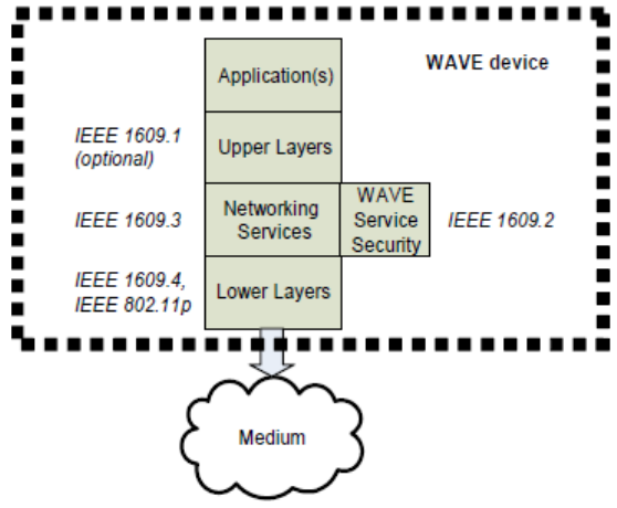
4.3.1 Trial-use WAVE standards—historical
In 2006 and 2007, a set of IEEE 1609 standards were adopted for trial-use. The trial-use standards were
used to demonstrate and prove the WAVE architecture and protocols, with the resulting lessons learned fed
back into full-use standards published in 2010 and beyond (see Annex F for an overview of field trials, and
4.3.3 for a description of subsequent standards). These IEEE 1609 trial-use standards, which were
developed for use with IEEE Std 802.11p (now IEEE Std 802.11-2012; see 4.3.2), are depicted in Figure 1
and described following.
Authorized licensed use limited to: University Town Library of Shenzhen. Downloaded on January 04,2018 at 13:03:28 UTC from IEEE Xplore. Restrictions apply.
IEEE Std 1609.0-2013
IEEE Guide for Wireless Access in Vehicular Environments (WAVE) Architecture
9
Copyright © 2014 IEEE. All rights reserved.
Figure 1 ―Trial-use standards
IEEE Std 1609.4-2006 [B18] specified extensions to the IEEE Std 802.11-2012 MAC layer for multi-
channel operations, e.g., operating alternately on the control channel and one of several service channels. It
has been superseded by IEEE Std 1609.4-2010.
IEEE Std 1609.3-2007 [B17] specified networking services required for operation of a WAVE system. It
employs the standard IPv6 protocol, introduces a WAVE Short Message Protocol (WSMP), and provides a
collection of management functions supporting WAVE services. It has been superseded by IEEE Std
1609.3-2010.
IEEE Std 1609.2-2006 [B16] collected the security processing requirements necessary for WAVE system
operation. It has been superseded by IEEE Std 1609.2-2013.
IEEE Std 1609.1-2006 [B15] was found unnecessary for WAVE system operation; it has been withdrawn
and no revision is planned.
4.3.2 IEEE Std 802.11
IEEE Std 802.11-2012 specifies one medium access control (MAC) sublayer and several physical layers
(PHYs) to provide wireless connectivity among fixed, portable, and moving stations (STAs) within a local
area. IEEE Std 802.11p-2010 [B12], now incorporated in IEEE Std 802.11-2012, standardized a small
number of extensions to IEEE Std 802.11-2012 for operating outside the context of a basic service set
(OCB, i.e., with the dot11OCBActivated parameter set to true), that is, supporting the types of vehicular
scenarios required for WAVE system operation. IEEE Std 802.11p-2010 [B12] also standardized the 5.9
GHz OFDM PHY (5.850–5.925 GHz in the U. S., 5.855–5.925 GHz in Europe), channel bandwidths,
operating classes, transmit power classification, transmission masks, and the alternate channel and alternate
adjacent channel rejection requirements.
Authorized licensed use limited to: University Town Library of Shenzhen. Downloaded on January 04,2018 at 13:03:28 UTC from IEEE Xplore. Restrictions apply.
IEEE Std 1609.0-2013
IEEE Guide for Wireless Access in Vehicular Environments (WAVE) Architecture
10
Copyright © 2014 IEEE. All rights reserved.
4.3.3 Full-use WAVE standards
4.3.3.1 IEEE 1609 standards
Full-use WAVE standards are in the process of being published as illustrated in Figure 2 and are described
in the following subclauses. These are the standards that are reflected in the descriptions throughout this
document. Differences between trial-use and full-use standards are summarized in Annex F.
1609.3
Management
Security
1609.4
802.11
Figure 2 ― Full-use standards
IEEE Std 1609.4-2010 (Multi-Channel Operations) specifies extensions to the IEEE 802.11 MAC layer
protocol and includes the following features:
⎯ Channel timing and switching
⎯ Use of IEEE 802.11 facilities [e.g., channel access, Enhanced Distributed Channel Access
(EDCA)] outside the context of a BSS
⎯ Use of IEEE 802.11 Vendor Specific Action and Timing Advertisement frames in a WAVE system
⎯ MAC-layer readdressing in support of pseudonymity
IEEE Std 1609.3-2010 (Networking Services) includes the following features:
⎯ WAVE Service Advertisements and channel scheduling
⎯ WAVE Short Message Protocol
Authorized licensed use limited to: University Town Library of Shenzhen. Downloaded on January 04,2018 at 13:03:28 UTC from IEEE Xplore. Restrictions apply.
IEEE Std 1609.0-2013
IEEE Guide for Wireless Access in Vehicular Environments (WAVE) Architecture
11
Copyright © 2014 IEEE. All rights reserved.
⎯ Use of existing protocols, e.g., LLC and IPv6, including streamlined IPv6 configuration
⎯ Delivery of general management information over the air interface
IEEE Std 1609.2-2013 (Security Services for Applications and Management Messages) specifies
communications security for WAVE Service Advertisements and WAVE Short Messages and additional
security services that may be provided to higher layers.
IEEE P1609.5 (Communication Manager) is an open project for addressing network management
requirements.
IEEE P1609.6 (Remote Management Services), in development, includes over-the-air management and
alias features.
IEEE Std 1609.11-2010 (Over-the-Air Electronic Payment Data Exchange Protocol for ITS) is the first
application-level IEEE 1609 standard and specifies a payment protocol referencing ISO standards. An
example use case illustrating electronic fee collection is provided in C.2.
IEEE Std 1609.12-2012 (Identifier Allocations) records the Provider Service Identifier (PSID) allocation
decisions made by the IEEE 1609 working group, and other identifiers used by the WAVE standards,
including Object Identifier (OID), Ethertype, and Management ID.
Other WAVE standards may be developed to specify higher layer, or application, features.
4.3.3.2 “WAVE device” and standards conformance
The IEEE 1609 standards include the concept of a WAVE device, which is defined as a device that is
conformant to the following:
⎯ IEEE Std 1609.3-2010.
⎯ IEEE Std 1609.4-2010.
⎯ IEEE Std 802.11-2012, operating outside the context of a basic service set.
For IEEE 1609.3 conformance, a device implements at least the following high-level features:
⎯ LLC and Subnetwork Access Protocol (SNAP)—see 5.3.
⎯ IPv6 or WSMP or both. A conformant device is able to at least send or receive over one of the
protocols.
For IEEE 1609.4 conformance, a device implements at least the following:
⎯ Transmit or receive or both.
⎯ EDCA and user priority when transmitting.
Each WAVE protocol standard (including IEEE Std 1609.3-2010, IEEE Std 1609.4-2010, and IEEE Std
1609.11-2010) includes an annex containing a Protocol Implementation Conformance Statement (PICS).
The PICS references each major feature specified in the standard, with an indication of whether the feature
is mandatory, optional, or conditional on the presence of some other feature. An implementer of WAVE
devices may use the PICS to indicate which features are supported by an implementation; a procurer of
WAVE devices may employ the PICS to indicate the features required for a particular deployment. A tester
Authorized licensed use limited to: University Town Library of Shenzhen. Downloaded on January 04,2018 at 13:03:28 UTC from IEEE Xplore. Restrictions apply.
IEEE Std 1609.0-2013
IEEE Guide for Wireless Access in Vehicular Environments (WAVE) Architecture
12
Copyright © 2014 IEEE. All rights reserved.
may use the PICS as a checklist against which to verify conformance. See Annex B for a discussion of
certification.
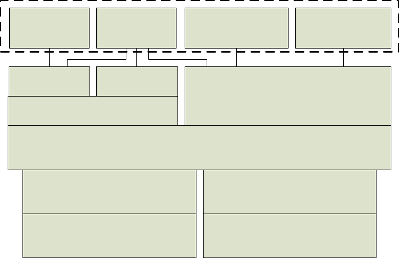
4.3.3.3 WAVE device configuration
Figure 3 illustrates an example of a device with two radios, running four applications operating above the
WAVE communication protocols.
UDP
LLC
PHY
MAC
IPv6
WSMP
Higher layer (four examples shown)
Fee Collection
using IEEE Std
1609.11
Safety
Applications
using SAE J2735
Proprietary
Application
PHY
MAC
Proprietary
Application
TCP
Figure 3 — Example WAVE device configuration
4.4 SAE DSRC standards
SAE J2735 Dedicated Short Range Communications (DSRC) Message Set Dictionary comprises a set of
messages, data frames, and data elements intended for both vehicle-to-vehicle (V2V) and vehicle-to-
infrastructure (the roadside) (V2I) safety exchanges. It includes specifications of each message, as well as
explanatory usage text required to properly understand and implement that message. Informative annexes
explain the operational concepts of several of the safety applications.
SAE is also developing J2945 DSRC Minimum Performance Standards to specify the minimum
communication performance requirements of the SAE J2735 DSRC message sets and associated data
frames and data elements.
IEEE 1609 WAVE and SAE DSRC standards are developed cooperatively; several PSID values have been
allocated for use with DSRC messages. WAVE systems deployed in the U. S. are expected to use the SAE
J2735 message set for safety applications. See C.1 for a use case for collision avoidance using this message
set.
Authorized licensed use limited to: University Town Library of Shenzhen. Downloaded on January 04,2018 at 13:03:28 UTC from IEEE Xplore. Restrictions apply.
IEEE Std 1609.0-2013
IEEE Guide for Wireless Access in Vehicular Environments (WAVE) Architecture
13
Copyright © 2014 IEEE. All rights reserved.
4.5 Related standards and organizations
4.5.1 Organizations and projects
Each organization listed below includes some aspect of ITS or communications in its charter, and may be
of interest to WAVE stakeholders. Annex D has a link to a list of international ITS standards.
American Association of State Highway and Transportation Officials (AASHTO). AASHTO is a
nonprofit, nonpartisan association representing highway and transportation departments in the 50 United
States, the District of Columbia, and Puerto Rico. It represents five transportation modes: air, highways,
public transportation, rail, and water. Its primary goal is to foster the development, operation, and
maintenance of an integrated national transportation system.
ASTM International. ASTM International, formerly the American Society for Testing and Materials,
develops and delivers test methods, specifications, guides, and practices that support industries and
governments worldwide.
European Committee for Standardization (CEN). CEN is a major provider of European Standards and
technical specifications. These standards have a unique status since they also are national standards in each
of its member countries.
European Telecommunications Standards Institute (ETSI). ETSI produces globally applicable
standards for information and communications technologies including fixed, mobile, radio, broadcast,
Internet, aeronautical, and other areas.
International Organization for Standardization (ISO). ISO is a network of the national standards
institutes of countries throughout the world, one member per country, with a Central Secretariat in Geneva,
Switzerland, that coordinates the system.
Internet Engineering Task Force (IETF). The IETF is an international group that develops and maintains
Internet-related standards, including those for IPv6, TCP, and UDP.
Institute of Transportation Engineers (ITE). The ITE is an international educational and scientific
association of transportation professionals who are responsible for meeting mobility and safety needs. ITE
facilitates the application of technology and scientific principles to research, planning, functional design,
implementation, operation, policy development, and management for any mode of ground transportation.
National Electrical Manufacturers Association (NEMA). NEMA is a trade association for the electrical
manufacturing industry. Its member companies manufacture products used in the generation, transmission
and distribution, control, and end-use of electricity.
SAE International. SAE International, formerly the Society of Automotive Engineers, is a global
association of more than 128,000 engineers and related technical experts in the aerospace, automotive and
commercial-vehicle industries. Among other publications, SAE generated the SAE J2735 message set
dictionary for use in WAVE systems, for which a usage case is presented in C.1.
National Transportation Communications for ITS Protocol (NTCIP). The NTCIP is a joint
standardization project of AASHTO, ITE, and NEMA.
OmniAir Consortium, Inc. OmniAir Consortium advances standards-based wireless ground transportation
systems through testing and certification programs.
Authorized licensed use limited to: University Town Library of Shenzhen. Downloaded on January 04,2018 at 13:03:28 UTC from IEEE Xplore. Restrictions apply.
IEEE Std 1609.0-2013
IEEE Guide for Wireless Access in Vehicular Environments (WAVE) Architecture
14
Copyright © 2014 IEEE. All rights reserved.
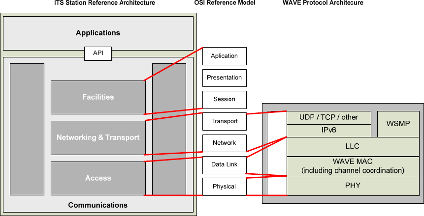
4.5.2 ITS station reference architecture in ETSI and ISO
International developments concerning communications in the area of ITS have centered on the concept of
abstracting applications from all of the lower OSI communication layers (Communications Access for Land
Mobiles, CALM). The CALM concept has been embodied in an architecture that allows ITS
communication devices to communicate on a peer-to-peer basis. One of the important developments was
the creation of the concept of an ITS station as a bounded secure managed domain. This has led to the
development of a large number of International Standards; see Annex D.
ISO 21217 (ETSI EN 302 665 [B5]) describes the ITS station reference architecture, which is derived from
the OSI layered model for communications. The ITS station reference architecture and its relationship to
the OSI Reference Model and to the IEEE 1609 protocol stack are shown in Figure 4. For example, in the
ITS station reference architecture, Road Safety is an application above the OSI Application layer; IPv6 and
messaging protocols reside in the Networking & Transport layer; and IEEE 802.x, 3G cellular, and
Bluetooth reside in the Access layer.
An example of a Facilities layer function is the Local Dynamic Map (LDM), which among other things
keeps track of nearby objects including vehicles. As a Facilities layer service, the LDM can accept
information from, and provide information to, both applications and other protocol entities.
Management
Security
Management
Security
Figure 4 ― Relationship among protocol models
One important difference between the ISO ITS station communication protocols and IEEE WAVE
protocols is that the ISO protocols specified in documents referenced in Annex D use port numbers for data
delivery to entities above the Networking & Transport layer. While WAVE communications use standard
port numbers for IPv6-based protocols (e.g., TCP, UDP), they use PSID as an identifier in the context of
WSMP as described in 5.9.4.
The Service Advertisement Message used in the ISO Fast Service Advertisement Protocol (FSAP)
specified in ISO 24102-5 is similar to the WSA, but designed to support advertising ITS services offered
over multiple media.
Authorized licensed use limited to: University Town Library of Shenzhen. Downloaded on January 04,2018 at 13:03:28 UTC from IEEE Xplore. Restrictions apply.
IEEE Std 1609.0-2013
IEEE Guide for Wireless Access in Vehicular Environments (WAVE) Architecture
15
Copyright © 2014 IEEE. All rights reserved.
An international harmonization effort in 2012 identified differences among ITS standards produced by
ETSI, IEEE, and ISO, and suggested actions to more closely align the standards. These differences and
suggested actions have been collected in a series of ITS Task Force reports [B9], [B10], and [B35].
5. WAVE system overview
5.1 General
A WAVE system provides connectivity in support of stationary and mobile (e.g., pedestrian and in-vehicle)
applications offering safety and convenience to their users, and provides confidentiality, authentication,
integrity, non-repudiation, and privacy features. (See 5.13.1 for definition of these terms.) A WAVE system
supports applications that offer vehicle systems and drivers greater situational awareness of events,
potential threats, and imminent hazards, toward the end of enhancing the safety, mobility, and convenience
of everyday transportation. Example use cases are described in Annex C.
WAVE standards (see 4.3) are intended to support a networked environment with low latency transactions
among vehicles (V2V), and between vehicles and infrastructure components (V2I) or hand-held devices
(V2D), to enable safety and mobility applications. In support of reliable low-latency communications,
dedicated spectrum has been allocated for this use (see 5.5) and a unique short message protocol has been
developed (see 5.3).
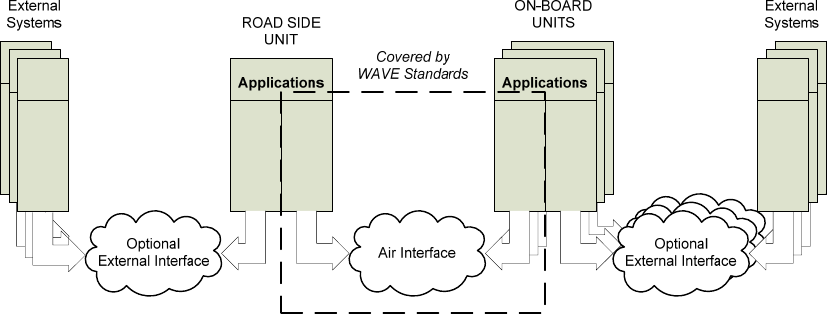
5.2 System components and connectivity
IEEE 1609 standards typically do not distinguish among different device types, but are flexible enough to
support multiple device types including the RSU and OBU as illustrated in Figure 5. An RSU is stationary
while in operation and is usually permanently mounted. An OBU may operate while mobile and is typically
mounted or installed in a vehicle. Other envisioned devices include portable units (e.g., smart safety cones)
and pedestrian units (e.g., for roadside workers).
An application-service is a service involving an exchange of data, generally provided by a higher layer
entity (e.g., an application) on one WAVE device to a similar entity on another WAVE device, using
WAVE communications. WAVE protocols are designed to allow applications to exchange data in a
consistent, interoperable, and timely manner. The WAVE standards specify the device role of Provider that
transmits advertisements of available application-services, and the device role of User that has the option to
participate in the advertised application-service opportunities. The Provider and User roles are not tied to
the RSU and OBU device types, though in many cases an RSU will be the Provider.
Communication security services may be accessed by the applications, or from within the data or
management plane. Subclause 5.13 describes the communications security services provided by the WAVE
protocol stack.
Authorized licensed use limited to: University Town Library of Shenzhen. Downloaded on January 04,2018 at 13:03:28 UTC from IEEE Xplore. Restrictions apply.
IEEE Std 1609.0-2013
IEEE Guide for Wireless Access in Vehicular Environments (WAVE) Architecture
16
Copyright © 2014 IEEE. All rights reserved.
WAVE Stack
Wireline Stack
WAVE Stack
Wireline Stack
WAVE
Protocols
WAVE
Protocols
Wireline Stack
Wireline Stack
Wireline Stack
Wireline Stack
Figure 5 ―Example WAVE system components
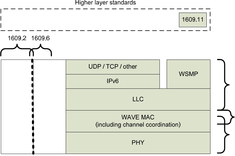
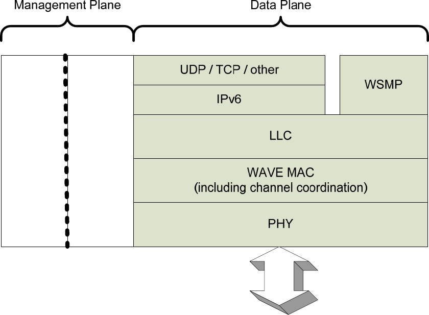
5.3 Protocols
5.3.1 General
The components of the WAVE protocol stack are illustrated in Figure 6. A data plane is defined for
protocols carrying higher layer information; a management plane is defined for security and management
functions that indirectly support information transfer. A common set of physical (PHY), medium access
control (MAC), and logical link control (LLC) layer protocols are specified. Above LLC, dual protocol
stacks are specified.
The mapping of these protocol elements to standards is described in 4.3.3.
IEEE Std 1609.3 specifies two data plane protocol stacks (sharing a common lower stack at the data link
and physical layers)—the standard Internet Protocol Version 6 (IPv6) and the WAVE Short Message
Protocol (WSMP) designed for optimized operation in a wireless vehicular environment (see Figure 6).
WAVE Short Messages (WSM) may be sent on any channel. IP traffic is only allowed on service channels
(SCHs), so as to offload high-volume IP traffic from the control channel (CCH).
The protocol stack distinguishes between the two upper stacks by the Ethertype field. Ethertype is a 2-octet
field in the LLC header, used to identify the networking protocol to be employed above the LLC protocol.
The Ethertype field is specified in IEEE Std 802.3 (as used in the Length/Type field) and its use in WAVE
devices is specified in IEEE Std 1609.3 and IETF RFC 1042 (cf., SNAP encoding). In particular, IEEE Std
1609.3 specifies the use of two Ethertype values (i.e., two networking protocols), IPv6 and WSMP. The
hexadecimal values indicating IPv6 and WSMP are 0x86DD and 0x88DC, respectively. A WAVE device
may support additional Ethertypes, but the WAVE standards do not describe the use of these Ethertypes
and their associated protocols.
Authorized licensed use limited to: University Town Library of Shenzhen. Downloaded on January 04,2018 at 13:03:28 UTC from IEEE Xplore. Restrictions apply.
IEEE Std 1609.0-2013
IEEE Guide for Wireless Access in Vehicular Environments (WAVE) Architecture
17
Copyright © 2014 IEEE. All rights reserved.
Air
Interface
Management
Security
Figure 6 —WAVE protocols
5.3.2 WAVE Short Message Protocol
WSMP allows applications to directly control physical characteristics, e.g., channel number and transmitter
power, used in transmitting the messages. The source application also provides a PSID and the MAC
address of the destination device, including the possibility of a group address. WSMs are delivered to the
correct receiving entity (e.g., an application or applications) at a destination based on the PSID. If the PSID
value in a received message header represents an application-service that is not of local interest, the
corresponding message can be ignored. WSMs are designed to consume minimal channel capacity; thus,
they are allowed on both CCH and SCHs.
An example of a WAVE short message exchange follows. A source application composes WSM data for
transmission, and addresses it to the broadcast MAC address. Based on its configuration, the application
selects appropriate radio channel information (power level, data rate) to control the transmission, and
invokes the resulting WSM request primitive (WSM-WaveShortMessage.request) to request that WSMP
delivers the data to the lower layers for subsequent transmission on the current channel of operation.
A receiving device accepts the packet and passes it up the communication stack. WSMP delivers it to
receiving entities based on PSID. At this point, the receiving application knows the existence and address
of the originating device, and can continue the exchange if desired, using either unicast or broadcast MAC
addresses as appropriate.
WSMP is well-suited to message-based applications, and applications subject to intermittent radio
connectivity. Examples of WSMP used in safety and fee collection scenarios are found in Annex C.
Authorized licensed use limited to: University Town Library of Shenzhen. Downloaded on January 04,2018 at 13:03:28 UTC from IEEE Xplore. Restrictions apply.
IEEE Std 1609.0-2013
IEEE Guide for Wireless Access in Vehicular Environments (WAVE) Architecture
18
Copyright © 2014 IEEE. All rights reserved.
5.3.3 Internet Protocol
The WAVE standards support Internet Protocol (IP) version 6 (v6) [B22]. IPv6 was selected over IPv4
because IPv6 is expected to be a viable protocol into the foreseeable future, whereas the long term future of
IPv4 is less certain. (Although not described in the WAVE standards, IPv4 has been tunneled over IPv6 in
WAVE trials.)
WAVE standards do not specify what transport and higher layer protocols may be used over IPv6. IP is
appropriate for applications requiring the features provided by the Internet protocol suite, such as routing
packets to a remote Internet host. IPv6 provides a fragmentation and reassembly feature. Two popular
transport protocols running over IP are the User Datagram Protocol (UDP) and the Transmission Control
Protocol (TCP). UDP [B20] provides port number addressing and a checksum not offered by WSMP. TCP
[B21] provides port number addressing and end-to-end reliability through acknowledgements and selective
retransmissions.
NOTE—TCP has been successfully used in field trials; however, in a WAVE scenario where packet losses/errors may
be high or connectivity durations may be short, the suitability of TCP should be considered.
IEEE Std 1609.3 specifies a feature of the WAVE Service Advertisement (WSA) to support IP-based
application-services. An RSU (for example) can broadcast all the information necessary for an OBU to
access an application-service available over IPv6 through the RSU router, in the WAVE Routing
Advertisement portion of its WSA. (See 5.8.)
5.3.4 Management plane
Management services are associated with the various data plane entities to provide layer-specific functions
necessary for system operation. These functions include time synchronization for channel coordination and
processing service requests and advertisements. In particular, IEEE Std 1609.4-2010 specifies extensions to
the IEEE 802.11 MAC sublayer management entity (MLME) and IEEE Std 1609.3-2010 specifies a
WAVE Management Entity (WME). The security services described in 5.13 also reside in the management
plane, and may be invoked by the WME or higher layer entities.
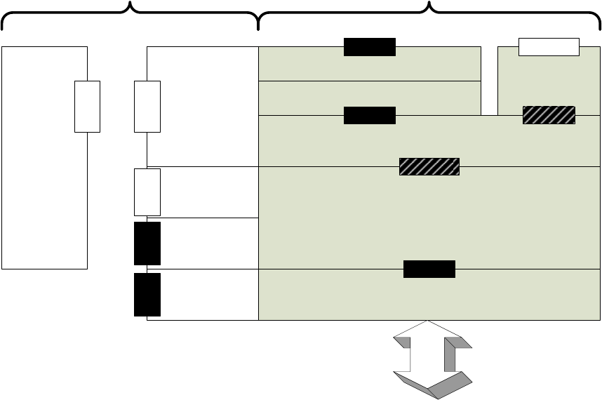
5.4 Interfaces
See Figure 5 for a device view of a WAVE system; see Figure 7 for a protocol view showing inter-layer
interfaces.
The air interface, specified in IEEE Std 802.11-2012, allows WAVE devices to communicate with each
other over the wireless medium.
Interfaces between protocol components are accomplished via service access points (SAPs). SAPs are
specified in the appropriate standards and are illustrated in Figure 7, where white shading indicates SAPs
specified in IEEE 1609 standards; black shading indicates SAPs specified elsewhere; hatched shading
indicates SAPs specified elsewhere but extended by IEEE Std 1609.3-2010. The details of the multiple
security SAPs are described in 5.13.3.
SAPs describe information exchanged, but do not specify the interface implementation. SAPs are
comprised of “primitives,” each of which is a logical message structure, generally containing a set of data
elements for accomplishing a particular function. Each SAP is defined and named by the layer or entity
providing the services. In the data plane SAPs are only accessible by adjacent entities. In the management
plane, layering is less structured, and SAPs may be accessible by other entities, whether or not they are
depicted as immediately adjacent.
Authorized licensed use limited to: University Town Library of Shenzhen. Downloaded on January 04,2018 at 13:03:28 UTC from IEEE Xplore. Restrictions apply.
IEEE Std 1609.0-2013
IEEE Guide for Wireless Access in Vehicular Environments (WAVE) Architecture
19
Copyright © 2014 IEEE. All rights reserved.
From the perspective of IEEE Std 802.11-2012, the WME and the MLME extension (MLMEX) specified
in IEEE 1609 standards may be considered aspects of the IEEE 802.11 station management entity (SME).
For example, the source of the MLME-TIMING_ADVERTISEMENT.request primitive delivered to the
MLME is described as the SME in IEEE Std 802.11-2012 and is described as the MLME Extension in
IEEE Std 1609.4-2010.
UDP / TCP / other
LLC
PHY
WAVE MAC
(including channel coordination)
Air
Interface
IPv6
WSMP
Data PlaneManagement Plane
TSAP
PHY SAP
MAC SAP
LSAP
WSM SAP
WAVE Management
Entity (WME)
WME
SAP
MLME Extension
PHY Sublayer
Management Entity
(PLME)
WAVE Security
Services
SEC
SAP
MAC Sublayer
Management Entity
(MLME)
LSAP
MLMEX
SAP
MLME
SAP
PLME
SAP
Figure 7 — Service access points
WAVE protocols support interfaces to higher layer entities, e.g., applications, which are considered for the
purposes of this discussion to be external to the WAVE protocols themselves. These applications may
interface with the WAVE protocol stack via the SAPs mentioned above, or via implementation-specific
mechanisms. There are no application program interfaces specified in the WAVE standards.
Other interfaces external to the WAVE device may be accommodated by a WAVE system, but are not
specified in the WAVE standards. For example, within a vehicle, an interface may provide vehicle-based
systems access to communications services provided by the WAVE device over a local communication
link. Likewise, an RSU may be connected to a wide area network to allow communications between
WAVE devices and systems such as application servers and management entities.
5.5 The 5.9 GHz spectrum allocation
Figure 8 shows the radio channels defined for use by DSRC in the U. S. by the FCC in [B6], [B7], and
[B8]. It is expected that WAVE systems deployed in the U. S. will use these channels, or a subset thereof.
(Other regions may have other channel plans that could be used for WAVE systems.)
⎯ 5.850 GHz to 5.855 GHz is held in reserve.
Authorized licensed use limited to: University Town Library of Shenzhen. Downloaded on January 04,2018 at 13:03:28 UTC from IEEE Xplore. Restrictions apply.
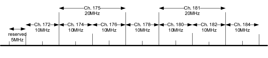
IEEE Std 1609.0-2013
IEEE Guide for Wireless Access in Vehicular Environments (WAVE) Architecture
20
Copyright © 2014 IEEE. All rights reserved.
⎯ Channel 178 is the control channel (CCH, see 5.6).
⎯ Channels 172, 174, 176, 180, 182, and 184 are service channels (SCH).
⎯ Channels 174 and 176 and channels 180 and 182 could be combined to produce two twenty-
megahertz channels, channels 175 and 181, respectively.
⎯ Channels 172 and 184 are designated for public safety applications involving safety of life and
property. Specifically, per FCC 06-110 [B8], channel 172 is for “vehicle-to-vehicle safety
communications for accident avoidance and mitigation, and safety of life and property
applications;” Channel 184 is for “high-power, longer distance communications to be used for
public safety applications involving safety of life and property, including road intersection collision
mitigation.”
5.850 GHz
5.910 GHz
5.900 GHz
5.890 GHz
5.880 GHz
5.870 GHz
5.860 GHz
5.920 GHz
5.855
5.865
5.875
5.885
5.895
5.905
5.915
5.925
Figure 8 — FCC channel allocation
The radio channels available for use by a WAVE device are set in its IEEE 1609.4 Management
Information Base (MIB). The WAVE protocols distinguish between control and service channels (see 5.6),
but do not enforce different rules on different service channels based on the FCC designations.
5.6 Channel types
WAVE standards specify two classes of radio channel: a single control channel, and multiple service
channels. The CCH is reserved for WSMP messages and for system management messages such as WSAs.
SCH use is intended for general-purpose application data transfers, and may be coordinated via a WSA as
described in 5.7.3.2. Alternately, SCH usage may be arranged through external means, e.g., regulation or
other standards, without advertisements (see 5.7.3.1). The WAVE standards allow IPv6 traffic, as well as
WSMP and management traffic, on SCHs.
WAVE standards specify use of the CCH for WSA broadcast, and preclude IP traffic on the CCH, but
otherwise do not specify how the various channels are used. For example, no separate “safety channel” is
specified in the IEEE 1609 standards; any of the control or service channels could be configured for use as
a safety channel.
Certain channels may be designated for safety use by regulations; see for example 5.5. As currently
envisioned, channel 172 will be treated as a dedicated safety channel in U. S. deployments; from the point
of view of the WAVE protocols, it is still a SCH. See C.1 for a use case description using this dedicated
safety channel.
Authorized licensed use limited to: University Town Library of Shenzhen. Downloaded on January 04,2018 at 13:03:28 UTC from IEEE Xplore. Restrictions apply.
IEEE Std 1609.0-2013
IEEE Guide for Wireless Access in Vehicular Environments (WAVE) Architecture
21
Copyright © 2014 IEEE. All rights reserved.
5.7 Communication services
5.7.1 General
WAVE communication services support the delivery of information from a higher layer entity (e.g., an
application) on one device to a higher layer entity on another device, using WAVE communication
protocols over the air interface.
Applications may request services from the WAVE protocol or management entities through service
primitives via Service Access Points (SAPs). Applications may provide application-services to other
applications over the WAVE communications, e.g., in the context of a client-server information exchange
of map information between WAVE devices.
Higher layer (e.g., application) information may be exchanged on either control or service channels.
WSMP traffic may use any channel, whereas IPv6 traffic is only allowed on SCHs. Three communication
scenarios are described in the following subclauses, one using the CCH and two using SCHs. SCH
application-service opportunities may be advertised or unadvertised. (Note the terms “unadvertised
application-service opportunity” and “advertised application-service opportunity” are defined for clarity of
discussion in this guide, but are not used in the published WAVE standards.)
5.7.2 CCH communications
The first scenario involves CCH communication. No over-the-air coordination is specified for this scenario.
Only WSMP and management traffic is allowed on the CCH. The WSMs may be unicast or
multicast/broadcast, and may be received by any nearby WAVE device tuned to the CCH at the time of
transmission. CCH communication could be used, for example, to solicit timing information from any
nearby WAVE device. In this example, the soliciting device would broadcast a request message via
WSMP, and a responding device would return timing information via a management frame, either unicast
or broadcast.
5.7.3 SCH communications
Multiple application-service opportunities, advertised or unadvertised, can use the same SCH in the same
area at the same time. Operation on one SCH consumes the resources of one device PHY, i.e., a radio PHY
operates on one radio channel at a time.
5.7.3.1 Unadvertised application-service opportunity
In the second communication scenario, an unadvertised application-service opportunity, applications may
communicate on a predefined SCH. The use of an SCH for a specific purpose may be pre-configured, or
determined through some other out-of-band mechanism. Any WAVE devices available for communications
(e.g., tuned to the correct channel) are participants in this unadvertised application-service opportunity. The
fact that a device is a participant does not imply any particular role (e.g., client, server, sender, receiver) on
the part of the application. Safety communications on channel 172 is an example of this type of exchange.
In this example, channel 172 is preconfigured as the safety channel in all participating devices. Application
protocols define what messages (e.g., Basic Safety Message) are broadcast periodically or on an event-
driven basis. See C.1 for a description of this use case.
Authorized licensed use limited to: University Town Library of Shenzhen. Downloaded on January 04,2018 at 13:03:28 UTC from IEEE Xplore. Restrictions apply.
IEEE Std 1609.0-2013
IEEE Guide for Wireless Access in Vehicular Environments (WAVE) Architecture
22
Copyright © 2014 IEEE. All rights reserved.
5.7.3.2 Advertised application-service opportunity
In the third communication scenario, WAVE provides the option for advertised application-service
opportunities. In this scenario, one WAVE device takes the role of Provider. The Provider transmits
WAVE Service Advertisement (WSA) messages identifying and describing the advertised application-
service and the SCH on which it is accessible, as described in 5.8. The Provider WAVE device is available
on the indicated SCH in support of information exchanges associated with the advertised application-
service and is by definition a participant in the advertised application-service opportunity. Other WAVE
devices may take the role of User and are potential participants in the advertised application-service
opportunity. Upon receipt of a WSA with an advertised application-service opportunity, Users may choose
to join the Provider on the indicated SCH, thus participating in the advertised application-service
opportunity. At this point, the Provider and Users may exchange communication traffic associated with the
application-service. See 5.7.3.3 for a more extensive discussion of the Provider and User roles.
An example of an advertised application-service opportunity is as follows. A fixed roadside Provider
device transmits a WSA containing Service Info with a PSID that has been allocated for a traffic advisory
application-service. The associated WSA Channel Info indicates SCH 182. The Provider traffic advisory
application broadcasts local traffic warnings over WSMP on channel 182, and also responds via IPv6 to
requests for more general traffic information. Vehicular User devices entering the coverage area of the
RSU receive and evaluate the WSA’s Service Info on the CCH. Those interested in travel advisory
recognize the broadcast PSID value and tune to channel 182, where they have access to the advertised
traffic advisory application-service.
Note that the message exchange used to establish an advertised application-service opportunity consists
only of the WSA; any other messages exchanged are the responsibility of the application.
The choice of data-plane protocol(s) to support a particular application-service is at the discretion of the
participants. The following describes a hierarchy of factors that may be used during operation to determine
the appropriate protocol.
a) There may be some knowledge of protocol, e.g., based on PSID or Provider Service Context (PSC)
(see 5.9.4).
b) An IP address in the WSA Service Info indicates an IP service. (The protocol above IP is not
indicated.)
c) Otherwise, WSMP may be assumed.
5.7.3.3 Device roles in an advertised application-service opportunity
In the context of an advertised application-service opportunity, a WAVE device may take on one of two
roles, Provider or User. As described in 5.7.3.2 and 5.8, a Provider transmits the WSA containing
information about the advertised application-service. The User monitors for the WSA, with the potential to
participate in the advertised application-service opportunity. This is illustrated in Figure 9.
To start, the support for the application-service has not been requested from the WAVE device. In step 1a,
the application at the Provider device sends a Provider Service request primitive to the WME. The request
indicates the characteristics of the services, such as the PSID to be advertised, the service priority, the
advertisement repetition rate, and the SCH to use. The WME could reject the request, e.g., if its radio
resources were consumed in servicing other requests. If not rejected, the WME proceeds to fulfill the
request. The service parameters are included in one of a variable number of Service Info segments in the
WSA; channel parameters are included in one of a variable number of Channel Info segments.
If indicated by the request, the WME will interact with Security Processing Services (not shown) to sign
the WSA at step 1b; see 5.13.5. Subsequently, the WME interacts with the MLME at step 1c to coordinate
the correct SCH access and the periodic transmission of the WSA on the CCH. The WSA is transmitted
Authorized licensed use limited to: University Town Library of Shenzhen. Downloaded on January 04,2018 at 13:03:28 UTC from IEEE Xplore. Restrictions apply.
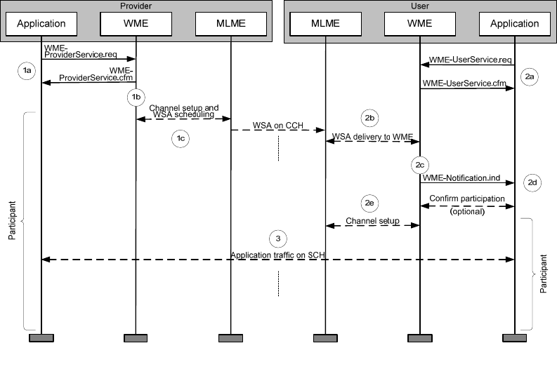
IEEE Std 1609.0-2013
IEEE Guide for Wireless Access in Vehicular Environments (WAVE) Architecture
23
Copyright © 2014 IEEE. All rights reserved.
within an IEEE 802.11 management frame as described in 5.8 and specified in IEEE Std 1609.4-2010.
Details of the WSA format are specified in IEEE Std 1609.3-2010.
In step 1c, the Provider device also tunes to the SCH, at which time it is a participant in the advertised
application-service opportunity.
Another WAVE device takes the role of User. An application sends a User service request to the WME in
step 2a. Upon successful processing of the request, the WAVE device awaits receipt of a WSA. In step 2b,
the User WME receives and processes a WSA. If the WSA is signed, and security validation is required per
the User service request, the WME interacts with Security Processing Services (not shown) in step 2c.
If the security check is successful (or not needed), the WME checks for an application-service, indicated by
the PSID value in the WSA’s Service Info, matching the one in the User service request. If no match is
found, or the security check fails, the WSA is ignored and the device continues to monitor the CCH.
If the check results in a match, the WME notifies the application in step 2d. At this point, assuming other
conditions such as radio resource availability are met, there are several options, described in detail in
Annex D of IEEE Std 1609.3-2010. Per the User service request, the WME may automatically begin
participation in the advertised application-service opportunity in step 2e, or may await confirmation by the
application before participation. Upon the decision to participate, the device begins accessing the correct
SCH (e.g., on a continuous or alternating basis). Now both devices are participants, accessing the same
SCH, and ready for application data transfer in support of the application-service.
Other WAVE devices may also participate in the advertised application-service opportunity as Users. A
WAVE device may accept multiple Provider and User service requests, thus simultaneously taking the
roles of Provider and User on multiple application-service opportunities.
Figure 9 — Device roles in an advertised application-service opportunity
Authorized licensed use limited to: University Town Library of Shenzhen. Downloaded on January 04,2018 at 13:03:28 UTC from IEEE Xplore. Restrictions apply.
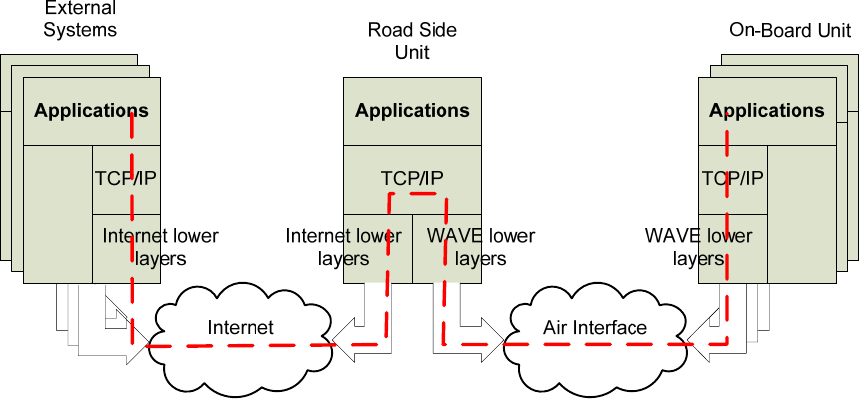
IEEE Std 1609.0-2013
IEEE Guide for Wireless Access in Vehicular Environments (WAVE) Architecture
24
Copyright © 2014 IEEE. All rights reserved.
5.7.3.4 Ending participation in an application-service opportunity
Once a device is a participant in an application-service opportunity, it remains so until participation is
locally terminated. WAVE standards specify no over-the-air message exchange to confirm this termination.
Within a device, the WME communicates the termination decision to the MLME so that it can take action,
e.g., stop channel access, stop advertising the application-service availability in the WSA. The WME also
notifies the affected applications. The WME terminates participation for any of several reasons. For
example, completion of the application activity could cause the application to request termination, or the
WME might need to reallocate local communication resources in the service of higher-priority requests.
5.7.3.5 IPv6 services
A WAVE system may support general IPv6-based applications as illustrated by the following example. An
RSU has a connection to the Internet. It is configured as a Provider to transmit a WSA advertising (via a
PSID value in the Service Info) a general Internet access service. The WSA optionally includes a WAVE
Routing Advertisement (WRA), as well as Service Info and Channel Info. The WRA contains the
information needed by an OBU to access the Internet, and removes the need for an ICMPv6 Router
Advertisement message.
Based on the information received in the WRA, the OBU configures its IPv6 stack and is capable of
accessing the Internet, using the RSU facilities as its gateway router as illustrated in Figure 10.
WAVE Stack
Wireline Stack
WAVE Stack
Wireline Stack
WAVE
Protocols
IPv6 protocols
WAVE
Protocols
Figure 10 — Internet access example
If the IPv6 application is hosted at the RSU, there is no need for Internet connectivity or the WRA. The
local Service Info and Channel Info are included in the RSU’s transmitted WSA.
WAVE devices, e.g., OBUs, may also participate in an IPv6 local network without an RSU. In this
scenario, an OBU could transmit the pertinent Service Info and Channel Info in a WSA.
IPv6 has provisions for neighbor discovery in which a Neighbor Cache is populated with IP addresses and
associated MAC addresses of devices within communications range. This is accomplished via a multicast-
response mechanism, as specified in RFC 2461, and generates a substantial amount of traffic on the
Authorized licensed use limited to: University Town Library of Shenzhen. Downloaded on January 04,2018 at 13:03:28 UTC from IEEE Xplore. Restrictions apply.
IEEE Std 1609.0-2013
IEEE Guide for Wireless Access in Vehicular Environments (WAVE) Architecture
25
Copyright © 2014 IEEE. All rights reserved.
channel. In some WAVE systems, it may be desirable to keep traffic on the channel to a minimum,
suggesting that the Neighbor Cache be populated via alternate methods such as passive monitoring of over-
the-air transmissions. Note that neighbor discovery per IETF RFC 2461 is not precluded by the IEEE 1609
standards.
In a WAVE system, the population of the Neighbor Cache may be accomplished based on the information
in received packets that contain both MAC and IP addresses. Upon accessing a service channel, a host
participating in non-routed communications (e.g., one where packets to the server do not transit a router)
adds an entry to its Neighbor Cache for the server, if possible. If the communications are routed, the client
host adds an entry to its Neighbor Cache for the gateway router, if possible. In addition, a WAVE device
learns Neighbor Cache associations from ICMPv6 and IPv6 PDUs received from a link-local IPv6 address
by associating the source IP address with the Source (MAC) Address from the MAC header.
5.8 WAVE Service Advertisement
5.8.1 General operation
Advertised application-service opportunities (see 5.7.3.2) are announced on the air interface via a WSA
inside an IEEE 802.11 management frame. The WSA is composed as shown in Figure 11 and described in
the following text.
Authorized licensed use limited to: University Town Library of Shenzhen. Downloaded on January 04,2018 at 13:03:28 UTC from IEEE Xplore. Restrictions apply.
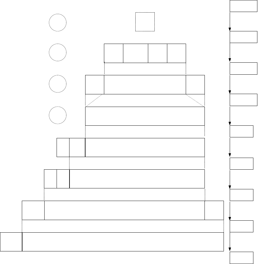
IEEE Std 1609.0-2013
IEEE Guide for Wireless Access in Vehicular Environments (WAVE) Architecture
26
Copyright © 2014 IEEE. All rights reserved.
MLME
PHY
Header
MAC
Header
MAC
Trailer
Unsecured WSA or
Secured WSA
PHY
Security
Header WaveService Advertisement Security
Trailer
WSA
Header Service Info
WAVE
Routing
Advert.
WME
Security
Services
WME
Vendor Specific Action frame
Air
interface
MAC
Vendor Specific Content
SEC-SignWSA.req
WME-
ProviderService.req
SEC-SignWSA.cfm
MLMEX-WSA.req
Higher layer
Service
request
MLME
extension
WSA MLME-
VSPECIFIC.req
OUI
Cont-
ent
descr.
Cate
gory OUI
Channel
Info
A
C
B
D
Figure 11 — Building the WSA
The process of creating a WSA and transmitting it is initiated when an application requests an advertised
application-service opportunity. On acceptance of the request from the higher layer entity, the Provider
WME builds a request to the MAC sublayer management entity (MLME) extension specified in IEEE Std
1609.4-2010, to start advertising the application-service. The information flow between layers is illustrated
in Figure 11 and described in this subclause. Additional details are found in IEEE Std 1609.3-2010, IEEE
Std 1609.4-2010, and IEEE Std 802.11-2012. A description of the Provider and User roles is found in
5.7.3.3.
Prior to operation (e.g., at network configuration), system parameters are loaded into the Provider MIB,
including operational channels and their characteristics, and (if applicable) a WAVE Routing Advertisement
(WRA) containing IP network configuration info.
Applications may request services through the WME (step A in the figure); the WME enters the parameters
into the WME MIB.
Authorized licensed use limited to: University Town Library of Shenzhen. Downloaded on January 04,2018 at 13:03:28 UTC from IEEE Xplore. Restrictions apply.
IEEE Std 1609.0-2013
IEEE Guide for Wireless Access in Vehicular Environments (WAVE) Architecture
27
Copyright © 2014 IEEE. All rights reserved.
The Provider WME generates a WSA, which will be transmitted to potential application-service Users. The
Provider WME collects the application information describing the application-services being offered,
previously registered in its MIB, and channel characteristics, also from the MIB, and inserts them into the
WSA as Service Info. In addition, if the application-service is IP-oriented the IP network configuration
information (WRA) from the MIB is included.
If any of the applications have requested it, the WSA is signed, indicating its authenticity, with security
header and trailer added, per IEEE Std 1609.2-2013 as described in 5.13.5. The result is a Secured WSA
(steps B and C in the figure).
The WSA is provided to Provider MLME (step D in the figure). Following this, over-the-air headers are
added by the lower layers and the frame is ready for transmission as a Vendor Specific Action management
frame specified in IEEE Std 802.11-2012.
It has been suggested that under certain conditions, a Provider might desire to concurrently transmit more
than one WSA. For example, as an alternative to including two different application-services in one WSA,
one application-service might be advertised in a WSA transmitted at a higher repetition rate with security
invoked, with a second application-service advertised in a WSA transmitted at a lower rate with no
security. The mechanisms for sending and receiving such multiple WSAs are neither described nor
precluded in IEEE Std 1609.3-2010.
5.8.2 WSA extensibility
Each section of the WSA (header, Service Info, Channel Info, WRA) optionally may be extended by
including predefined extension fields specified in IEEE Std 1609.3-2010. An example is the option to
include the transmitter’s location in the WSA header. Each extension field is preceded by an identifier
(WAVE Element ID) and length indicator. This allows additional extensions to be added in the future,
while maintaining compatibility between versions.
5.8.3 Other uses of the WSA
The WSA is not limited to carrying application-service information. Other information could include an
identification of the regulatory domain of operation and non-service-related channel parameters.
There is a WSA header extension field Country String that indicates the regulatory domain (e.g., country)
in which the system is operating. Since different channel characteristics may be associated with different
countries, as specified in IEEE Std 802.11-2012, this field could be used by the receiving device to
configure itself for operation in the correct domain. How this field would be processed has not been
specified.
The WSA associates channel information with each advertised application-service in the Channel Info.
Channel Info may include such parameters as DataRate and Transmit Power Level, and may include
EDCA parameters, in case non-default parameters are used on a particular service channel. (EDCA is the
priority-based channel access mechanism specified in IEEE Std 802.11-2012 and mandated by IEEE Std
1609.4-2010.) A separate instance of Channel Info could be included in the WSA and used to convey
parameters for the CCH.
5.8.4 Repeat rate considerations
IEEE Std 1609.3-2010 describes how each Provider service request includes a Repeat Rate requesting the
associated WSA to be transmitted at that rate. Rates that may be requested range from about 5
transmissions per 100 ms to 1 per 5 seconds. An implementation of the WME may be guided by the
requested repeat rates when selecting the transmission rate, but is not bound by them.
Authorized licensed use limited to: University Town Library of Shenzhen. Downloaded on January 04,2018 at 13:03:28 UTC from IEEE Xplore. Restrictions apply.
IEEE Std 1609.0-2013
IEEE Guide for Wireless Access in Vehicular Environments (WAVE) Architecture
28
Copyright © 2014 IEEE. All rights reserved.
Consider a WSA built in response to two Provider service requests with different latency requirements, and
therefore difference requested repeat rates. The WME could choose to transmit the WSA at the higher rate,
since this would satisfy both requests.
Though not described in the WAVE standards, a WME implementation might find it desirable to adapt the
WSA transmission rate to the current conditions. An example of a situation that would encourage this
adaptability is when the CCH becomes congested. In this case, the rate of WSAs could be reduced to allow
more of other traffic. The transmission of the Timing Advertisement described in 5.11 could likewise be
adapted.
5.8.5 Advertisement termination
Once a device is a participant in an advertised application-service opportunity, as either Provider or User, it
remains so until participation is locally terminated. WAVE standards specify no over-the-air message
exchange to confirm this termination. Within a device, the WME communicates the termination decision to
MLME so that it can take action, e.g., stop channel access, and also to the affected applications through a
notification. The WME terminates participation for any of several reasons. For example, completion of the
application activity could cause the application to request termination, or the WME might need to
reallocate local communication resources in the service of higher-priority requests.
5.8.6 Adding and subtracting applications from an advertisement
A Provider MLME extension typically generates regular WSA transmissions for the duration of an
advertised application-service opportunity. Different application-services may be advertised over time on
the same SCH, i.e., the contents of the Service Info may change in subsequent WSAs. To support this
feature, the WSA destination MAC address is defaulted to be the broadcast address. If the destination is a
unicast address, the advertisement is not repeated by the IEEE 1609 protocols, since lower-layer reliable
delivery is invoked.
The WSA header features a two-bit Change Count field that is incremented (modulo-4) when the contents
of the WSA change. The User can use the value in this field, compared to the value in the previous WSA,
to quickly determine if the WSA has changed.
The User WME will update the information in the MLME MIB when the received WSA information
changes (including when updated security credentials are generated), indicating a change in application-
service parameters. The WME ends participation in the advertised application-service opportunity under
the conditions described in 5.7.3.4.
5.9 Addresses and identifiers
5.9.1 MAC address
Each device operating in an IEEE 802® network, such as IEEE 802.11-2012, is assigned a MAC (layer 2)
address that is used in transferring packets across a data link. Distinct physical interfaces on a device have
distinct MAC addresses, e.g., a device with both WAVE and Ethernet physical interfaces will have a MAC
address for each. The MAC address is 48 bits. Per IEEE Std 802.11-2012, the source and destination MAC
addresses are included in the MAC header of each transmitted frame.
Besides unicast addresses, a broadcast MAC destination address is supported. Use of multicast MAC
addressing is permitted, but not required by IEEE 1609 standards.
Authorized licensed use limited to: University Town Library of Shenzhen. Downloaded on January 04,2018 at 13:03:28 UTC from IEEE Xplore. Restrictions apply.

IEEE Std 1609.0-2013
IEEE Guide for Wireless Access in Vehicular Environments (WAVE) Architecture
29
Copyright © 2014 IEEE. All rights reserved.
IEEE 1609 standards provide primitives to change local WAVE MAC addresses to protect the privacy of
the device operator. The process by which a decision is made to change the WAVE MAC address is not
addressed in the IEEE 1609 standards. See 5.13.8 for further discussion.
5.9.2 IPv6 address
Each device operating as an IP host or router has one or more IP (layer 3) addresses. IPv6 distinguishes
between the global address type and the link-local address type. A given device can have both. Global
addresses are assumed globally unique and share a prefix with the network to which they are attached, and
thus may be used to route packets across multiple interconnected networks. A link-local address is derived
by the device and is not assumed to be globally unique, and thus can only identify a host to other hosts on
the same network (i.e., is not routable). IPv6 also supports special multicast addresses.
The IP address of the service provider device may be included in the WSA if an application-service uses
IP-based communications.
5.9.3 Protocol/port
IEEE Std 1609.3-2010 supports the standard use of port numbers within protocols such as TCP and UDP.
When an IP packet is received with UDP or TCP as the transport layer protocol, the UDP or TCP
destination port number is used to deliver the packet payload to the appropriate higher layer entity.
The port number of the service provider application may be included in the WSA if the application-service
uses IP-based communications.
5.9.4 PSID and PSC
Unlike other identifiers described in 5.8, the PSID and PSC are defined in WAVE standards. From the
point of view of networking services, a PSID identifies an application service that may pertain to one or
more applications.
A PSID value is allocated to an organization that is expected to specify how the PSID is used, e.g., whether
the PSID is used in a WSMP or WSA context and what message set is to be employed for communications
associated with that PSID. Allocated PSID values are listed in IEEE Std 1609.12. The PSID may be from
one to four octets in length, with the leading bits indicating the length as specified in IEEE Std 1609.3-
2010, and further described in Annex E.
The PSID is allocated from the same numbering space as the ITS Application Identifier (ITS-AID)8 used in
other ITS standards. An eventual common registration service for the PSID and ITS-AID is foreseen.
In the context of WSMP, the PSID is used by the receiving device to deliver received WSMs to the
appropriate higher layer entity or entities.
In the context of service advertisements, the PSID, and optionally the PSC, of service provider applications
are included in the WSAs. PSID values received in a WSA at a User are compared by the WME to those
PSIDs previously received from local applications in User service requests, to determine whether one or
more of the represented application-services are of interest.
8 ITS-AID allocations are currently available at http://aid.its-standards.info/ITS-AID%20Registry/ITSaidRegistrationIndex.html.
Authorized licensed use limited to: University Town Library of Shenzhen. Downloaded on January 04,2018 at 13:03:28 UTC from IEEE Xplore. Restrictions apply.
IEEE Std 1609.0-2013
IEEE Guide for Wireless Access in Vehicular Environments (WAVE) Architecture
30
Copyright © 2014 IEEE. All rights reserved.
For both signed data (e.g., in WSMs) and signed WSAs, the PSID value is included in the accompanying
security certificate (see 5.13) to indicate that the sending entity has authorization to carry out activities
associated with that PSID value.
The PSC, if present in the WSA, contains supplementary information, e.g., version number, specific to the
advertised application-service. It may be used by the User application to determine if the application-
service is of interest. The PSC is up to 31 octets in length and could contain text or encoded information.
The PSC format is specific to the associated PSID value and is expected to be defined by the organization
to which the PSID value is allocated, so interpretation of the PSC by the receiving higher layer entity is
based on the associated PSID. For example, the PSC field associated with one PSID might be used to carry
an 8-bit version number identifying the latest data available.
5.10 Priorities
There are two types of priorities discussed in WAVE standards.
An IEEE 1609.3 “service priority” level may be associated with an application-service request; this may be
used by the WME to help decide which applications have first access to the communication services, e.g.,
which application-services to advertise in case of conflict at the Provider, or which advertised application-
service to participate in the case of conflict at the User. The Provider-assigned service priority is included
in the Service Info of the WSA, where it may be used by the User in deciding whether to participate in the
advertised application-service opportunity. (An example of a conflict at the Provider would be where
multiple applications request that their application-service access opportunities be offered on more
channels than can be accommodated by the WAVE device.)
The IEEE 802.11 lower layers use a separate MAC transmission “user priority” for packet transmission on
the wireless medium. An IP packet is assigned the user priority associated with the traffic class of the
generating application. A WSMP packet is assigned its user priority by the generating application on a
packet-by-packet basis. User priority is used by the EDCA mechanism specified in IEEE Std 802.11-2012.
5.11 Channel coordination and time synchronization
When using WAVE communications, time and frequency resources are segmented to provide a range of
communications options. CCH and SCH usage is described in 5.6.
WAVE devices may have the ability to access one or more channels on an alternating basis. An example
usage scenario is a single-radio device that is required to exchange information on an SCH while still
monitoring the CCH. To this end, channel intervals are specified, as illustrated in Figure 12. Other options
for channel coordination are described later in this subclause.
Alternating radio channel access is coordinated based on intervals that are synchronized relative to a
common time base. A sync interval is composed of a CCH interval followed by a SCH interval. During the
CCH interval, traffic is exchanged on the CCH. Single-radio devices participating in an application-service
opportunity may switch to the designated SCH during the SCH interval. A guard interval begins each CCH
interval and SCH interval; during a guard interval a device that is switching channels is assumed to be
unable to receive packets. IEEE Std 1609.4-2010 specifies channel intervals of 50 ms and a guard interval
of 4 ms.
Authorized licensed use limited to: University Town Library of Shenzhen. Downloaded on January 04,2018 at 13:03:28 UTC from IEEE Xplore. Restrictions apply.
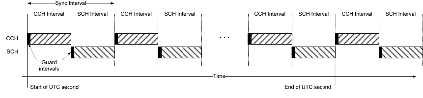
IEEE Std 1609.0-2013
IEEE Guide for Wireless Access in Vehicular Environments (WAVE) Architecture
31
Copyright © 2014 IEEE. All rights reserved.
Figure 12 ― Channel intervals
The standards accommodate the possibility of making the intervals of variable length, but do not specify a
mechanism for accomplishing this. Channel coordination is specified in IEEE Std 1609.4-2010.
A single-radio device using alternating channel access synchronizes to a standard time base. Channel
timing is defined such that a sync interval begins at the start of a second in Coordinated Universal Time
(UTC). UTC or an equivalent is commonly provided by GPS. Once synchronized, devices can tune to the
intended channel during the correct interval.
The Timing Advertisement frame specified in IEEE Std 802.11-2012 may also be used to convey an
estimate of absolute time from one device to another for the purpose of synchronization. Note that
synchronization is not required to make data exchanges except during alternating channel access. For the
purpose of channel coordination, only the one-second boundary is needed, but absolute timing may be
required for security purposes (see 5.13.6.3 and IEEE Std 1609.2-2013).
In addition to continuous (CCH or SCH) and alternating (CCH and SCH) channel access, WAVE standards
allow immediate and extended access as illustrated in Figure 13. Immediate access allows a User device to
switch to the SCH immediately on recognizing a desirable application-service in a WSA. Extended access
allows a User device, normally in alternating mode, to access the SCH for an extended period. Immediate
and extended access may be combined, and are provided to support a User device that needs to perform a
transaction during the limited time during which it is in range of a roadside service provider.
The device providing the service would be expected to have a radio in SCH continuous access to support
the extended transaction, as described in the use case in C.2. The Provider may indicate in the WSA
Channel Info whether it supports continuous or alternating access on the SCH, or this information could be
known a priori by the User.
Authorized licensed use limited to: University Town Library of Shenzhen. Downloaded on January 04,2018 at 13:03:28 UTC from IEEE Xplore. Restrictions apply.
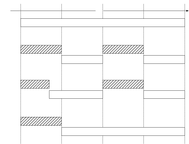
IEEE Std 1609.0-2013
IEEE Guide for Wireless Access in Vehicular Environments (WAVE) Architecture
32
Copyright © 2014 IEEE. All rights reserved.
CCH
SCH
CCH Interval SCH IntervalCCH IntervalSCH Interval
Time
(a)
(b)
CCH
SCH
(c)
CCH
SCH
(d)
CCH or
SCH
Figure 13 — Channel access options; (a) continuous, (b) alternating,
(c) immediate, and (d) extended
5.12 Other features
5.12.1 Delivery of management messages
WAVE standards provide for the delivery of general management information between WAVE devices
using the Vendor Specific Action management frame type (also used to deliver WSAs) specified in IEEE
Std 802.11-2012. The information flow supporting this service is illustrated in Figure 14 and Figure 15 and
described immediately below. Numbers in the text refer to those in the figures.
1) Except for the case where the management information is a WAVE Service Advertisement (see
5.8), a management entity – either IEEE 1609 or other – generates a request to the WME for
delivery of management information via the WME-ManagementDataService.request.
2) If appropriate, WME provides a supporting channel access assignment. WME generates an
MLMEX-VSA.request.
3) The MLME extension generates an MLME-VSPECIFIC.request…
4) … which results in queuing of the Action frame, and eventual transmission.
5) On receipt, the frame is processed by the MAC.
6) Vendor Specific Action frames with Organization Identifier values that do not indicate WAVE
data are passed to the appropriate entity directly.
7) Vendor Specific Action frames with Organization Identifier values that indicate WAVE data are
passed to the IEEE 1609 MLME extension.
Authorized licensed use limited to: University Town Library of Shenzhen. Downloaded on January 04,2018 at 13:03:28 UTC from IEEE Xplore. Restrictions apply.
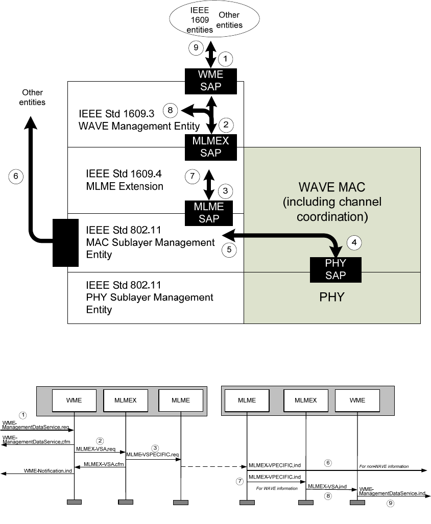
IEEE Std 1609.0-2013
IEEE Guide for Wireless Access in Vehicular Environments (WAVE) Architecture
33
Copyright © 2014 IEEE. All rights reserved.
8) The information is then passed to the WME, which proceeds based on the Management ID value.
One Management ID value indicates IEEE 1609.3, which indicates the presence of a WSA, and is
processed by the WME.
9) Other Management ID values may be allocated for use by other IEEE 1609 entities. (Allocated
Management ID values documented in IEEE Std 1609.12.) On receipt of information associated
with one of these Management ID values, the WME delivers the information to the appropriate
management entity.
MLME
SAP
Figure 14 — SAPs used for delivering general management information
Figure 15 —Information flow for management data distribution
Authorized licensed use limited to: University Town Library of Shenzhen. Downloaded on January 04,2018 at 13:03:28 UTC from IEEE Xplore. Restrictions apply.
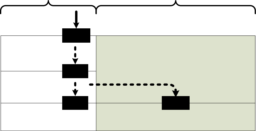
IEEE Std 1609.0-2013
IEEE Guide for Wireless Access in Vehicular Environments (WAVE) Architecture
34
Copyright © 2014 IEEE. All rights reserved.
5.12.2 Channel-specific IEEE 802.11 primitives
IEEE Std 802.11-2012 assumes single-channel operation. The WAVE standards add multi-channel
operation. There may be IEEE 802.11 features, accessible via primitives specified in that standard, that are
of interest to WAVE devices. These primitives may be ambiguous in a WAVE device because they do not
account for the possibility that the device may be operating on multiple channels. IEEE 1609.4 MLMEX-
SendPrimitive primitives extend the IEEE 802.11 primitives for multi-channel operation.
A management entity may invoke IEEE 802.11 via the MLME SAP. For channel-specific primitives, the
management entity would instead send the MLMEX-SendPrimitive request, containing an IEEE 802.11
MLME primitive plus a channel identifier. For primitives that entail transmissions, the management entity
may also indicate in which channel interval the transmission is to occur.
This feature is illustrated in Figure 16, where the dashed arrows represent IEEE 802.11 functionality and
the solid arrow represents IEEE 1609 functionality. No IEEE 802.11 primitives are currently identified as
candidates for this IEEE 1609 feature.
PHY
WAVE MAC
(including channel coordination)
Data Plane
PHY
SAP
IEEE Std 1609.4
MLME Extension
IEEE Std 802.11
MAC Sublayer Management Entity
MLMEX
SAP
Management Plane
IEEE Std 802.11
PHY Sublayer Management Entity
PLME
SAP
MLME
SAP
Figure 16 — Channel-specific primitives
5.13 Security considerations
5.13.1 Background
A communication system may provide the following generic security services to its users:
⎯ Confidentiality: Only legitimate entities can observe the contents of a communication.
⎯ Authenticity: The recipient of a communication can determine that it originated from a valid sender.
⎯ Integrity: The recipient of a communication can determine that it was not modified after generation.
Authorized licensed use limited to: University Town Library of Shenzhen. Downloaded on January 04,2018 at 13:03:28 UTC from IEEE Xplore. Restrictions apply.
IEEE Std 1609.0-2013
IEEE Guide for Wireless Access in Vehicular Environments (WAVE) Architecture
35
Copyright © 2014 IEEE. All rights reserved.
⎯ Non-Repudiation: The recipient of a communication can demonstrate to a third party that it
originated from a valid sender.
⎯ Replay Protection: A received communication is unique and not a copy of a previously received
communication.
⎯ Relevance Checking: A received communication is relevant to the receiver.
⎯ Privacy: The sender of a communication reveals only the information that they choose to reveal.
The main focus of this clause is on how the WAVE system can be used to provide communications security
services from the previous list that are appropriate to the needs of the sender and receiver.
A discussion of security services other than communications security services is provided in 5.13.9.
5.13.2 Communications security within WAVE standards
5.13.2.1 Data plane
This subclause describes options for security within the WAVE data plane.
Higher layer entities: IEEE Std 1609.2-2013 specifies security mechanisms that may be used by
applications or other higher layer entities communicating via the data plane. These mechanisms may be
used to provide confidentiality, authenticity, integrity, non-repudiation, replay protection, and relevance
checking. The mechanisms of IEEE Std 1609.2-2013 do not provide privacy on their own; a discussion of
privacy is given in 5.13.8.
Higher layer entities may use the mechanisms of IEEE Std 1609.2-2013, or they may use different
mechanisms. For example, Electronic Payment Systems as specified in IEEE Std 1609.11-2010 use their
own security mechanisms rather than those of IEEE Std 1609.2-2013.
Since the security mechanisms to be used are application-specific, a full specification of a higher layer
entity should also specify the security mechanisms to be used.
Protocol stack: The only security protocol supported within the IEEE 1609 data plane below the
application layer is Internet Protocol Security (IPSec), which is supported within the IP protocol stack.
IPSec may be used to provide confidentiality, authenticity, and integrity between two implementations of
the Internet Protocol.
No other mechanisms are specified within the data plane to provide confidentiality, authenticity, integrity,
or non-repudiation.
IEEE Std 1609.4-2010 provides primitives that may be used to change the MAC address of a WAVE
device. This may be used as part of an overall approach to provide privacy as discussed in 5.13.8.
5.13.2.2 Management plane
A WAVE device that sends secured WSAs is required by IEEE Std 1609.3-2010 to use mechanisms
defined in IEEE Std 1609.2-2013. No other security mechanisms are defined for use in the management
plane.
Authorized licensed use limited to: University Town Library of Shenzhen. Downloaded on January 04,2018 at 13:03:28 UTC from IEEE Xplore. Restrictions apply.
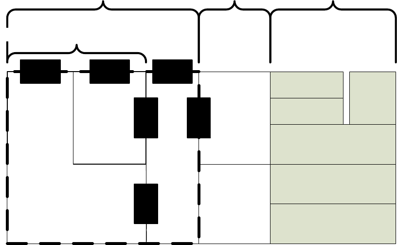
IEEE Std 1609.0-2013
IEEE Guide for Wireless Access in Vehicular Environments (WAVE) Architecture
36
Copyright © 2014 IEEE. All rights reserved.
5.13.3 IEEE Std 1609.2 and WAVE Security Services
WAVE Security Services are defined in IEEE Std 1609.2-2013. Figure 17 shows the services and entities
within WAVE Security Services as well as the SAPs that provide interfaces between WAVE Security
Services entities and other entities.
UDP / TCP
LLC
PHY
WAVE MAC
(including channel
coordination)
IPv6
WSMP
Data PlaneManagement Plane
Security Processing Services
WAVE
Management
Entity (WME)
Lower Layer
Management
Provider Service
Security Management
Entity (PSSME)
Certificate
Manage-
ment
Entity
(CME)
CME-
Sec-SAP
CME-
SAP
PSSME-
SAP
WAVE Security Services
Security Management Services
Sec-SAP
WME-
Sec-SAP
PSSME-
Sec-SAP
Figure 17 — WAVE protocol stack showing detail of WAVE Security Services
The Security Processing Services provide communications security services to outgoing and incoming
application and management PDUs.
The Security Management Services manage state and configuration information used by the Security
Processing Services. The Security Management Services consist of the following:
⎯ The Certificate Management Entity (CME) manages revocation and root certificate information
necessary to determine the validity of IEEE 1609.2 certificates.
⎯ The Provider Service Security Management Entity (PSSME) stores information necessary to obtain
certificates to be used when signing WSAs.
Use of Security Processing Services: Applications and other higher layer entities interact with the
Security Processing Services via the Sec-SAP as described in 5.13.4. Signed WSAs are generated and
validated via the WME-Sec-SAP as described in 5.13.5. In both these cases, when sending, the sender first
invokes the security services with a PDU and the security services return to the sender a secured PDU
which is then transmitted. Similarly, when a receiver receives data or WSAs that have been protected with
IEEE 1609.2 mechanisms, the receiver receives over the air interface the data, which is a secured PDU,
submits it to the Security Processing Services for processing, and is returned the original, unsecured PDU
from the peer sender. This is illustrated in Figure 18.
Authorized licensed use limited to: University Town Library of Shenzhen. Downloaded on January 04,2018 at 13:03:28 UTC from IEEE Xplore. Restrictions apply.
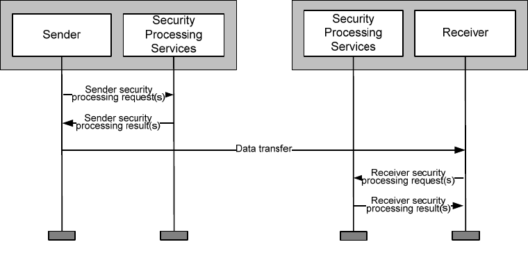
IEEE Std 1609.0-2013
IEEE Guide for Wireless Access in Vehicular Environments (WAVE) Architecture
37
Copyright © 2014 IEEE. All rights reserved.
Figure 18 — Process flow for use of IEEE 1609.2 Security Processing Services
Communications that are protected by WAVE Security Services are authenticated by use of digital
certificates and their associated private keys as discussed in 5.13.6. The Security Processing Services
provide an interface to key and certificate storage via the cryptomaterial handle (CMH). Certificates for
send-side operations are obtained via the certificate management processes described in 5.13.7.
Certificate Management Entity: The CME stores information about certificate validity for use by the
receive-side processing of the Security Processing Services: root certificate information, revocation
information, and other information about the trust status of individual certificates. Revocation information
is described in 5.13.6.4 and the process of obtaining revocation information is described in 5.13.7.5.
Provider service security management entity: The PSSME manages certificates that are used to sign
WSAs, as described in 5.13.7.4.
5.13.4 Security processing for applications
An application running on a WAVE device may use the Security Processing Services to provide
authentication, integrity, authorization, replay protection, relevance checking, and/or confidentiality to the
data that it exchanges. These are provided using primitives offered via the Sec-SAP illustrated in Figure 17.
An application may request the Security Processing Services to apply authentication, integrity,
authorization, replay protection, and relevance checking to outgoing data by signing the data via the signed
data signing primitives. An application may obtain assurance that incoming data has the required security
properties by requesting the Security Processing Services to verify the data via the signed data verification
primitives. Within the signed data primitives, the act of signing provides authentication and integrity; the
sender demonstrates authorization by attaching a digital certificate that authorizes the communication as
described in 5.13.6; and replay protection and relevance checking may be obtained by the use of optional
parameters in the primitive.
When signing data for sending, the Security Processing Services use a cryptographic private key and a
corresponding digital certificate that authorizes the data. (The “corresponding digital certificate” to a
private key that signs data is defined as the certificate that the recipient of the signed data may use to verify
its signature.)
When verifying signed data on receipt, the Security Processing Services use the signed data itself and the
following locally stored information:
Authorized licensed use limited to: University Town Library of Shenzhen. Downloaded on January 04,2018 at 13:03:28 UTC from IEEE Xplore. Restrictions apply.
IEEE Std 1609.0-2013
IEEE Guide for Wireless Access in Vehicular Environments (WAVE) Architecture
38
Copyright © 2014 IEEE. All rights reserved.
⎯ Known CA certificates, which are used to construct a certificate chain from the signer’s certificate
to a known trust anchor.
⎯ Revocation information about the signer’s certificate, which is used to determine whether the
certificate has been noted as untrusted.
This information is managed by the Certificate Management Entity (CME), and is made available to all
other entities on the WAVE device. See 5.13.6 or further description of root certificates, certificate chains,
and revocation.
The signed data structure includes a number of optional elements. For interoperability, the sending and
receiving entities use consistent options when signing and verifying. IEEE Std 1609.2-2013 provides the
security profile, which is a form to be filled in a priori specifying how different security options are to be
used, as a compact and standards-based way to specify those options. The IEEE 1609.2 security profile is
intended to be completed by the organization that specifies an over-the-air application-service, as part of
the specification of that application-service.
An application may request the Security Processing Services to apply confidentiality to outgoing data by
use of the encrypted data primitives. An application may request the Security Processing Services to
provide access to confidential data that is encrypted for that application by use of the encrypted data
decryption primitives.
To encrypt data, the Security Processing Services use an encryption public key contained in the intended
recipient’s certificate. In IEEE Std 1609.2-2013, responsibility for managing these certificates lies with the
application, which provides the appropriate certificate to the Security Processing Services via the
encryption primitives.
To decrypt encrypted data when so requested by an application, the Security Processing Services use the
application’s certificate and private key. These are managed via the CMH as described in 5.13.3.
IEEE Std 1609.2-2013 permits the use of the Elliptic Curve Digital Signature Algorithm (ECDSA) for
signing and the Elliptic Curve Integrated Encryption Scheme (ECIES) for encryption. ECDSA is specified
in IEEE Std 1363 [B13], and ECIES is specified in IEEE Std 1363a [B14].
5.13.5 Security use cases for WSAs
See 5.8 for a description of WAVE Service Advertisements. See Figure 17 for the services and entities
within WAVE Security Services and the SAPs that provide interfaces between WAVE Security Services
entities and other entities.
The WME on a WAVE device may request the Security Processing Services to sign a WSA. This provides
authentication, integrity, authorization, replay protection, and relevance checking to the WSA. WSA
signing is provided using primitives offered via the WME-Sec-SAP illustrated in Figure 17. The receiving
WME verifies the WSA also using primitives offered via the WME-Sec-SAP.
The WME will request the Security Processing Services to sign a WSA if so requested in a Provider service
request. See 5.13.6 for a description of how and why Provider applications might request inclusion in a
signed WSA.
To sign a WSA for transmission, the Security Processing Services uses a cryptographic private key and the
corresponding digital certificate that authorize the WSA. The WME communicates the required
authorizations to the Security Processing Services via the WME-Sec-SAP. The certificates that may be
used to sign WSAs are managed by the PSSME. When signing a WSA, the Security Processing Services
query the PSSME via the PSSME-Sec-SAP to determine whether a certificate is available that authorizes
Authorized licensed use limited to: University Town Library of Shenzhen. Downloaded on January 04,2018 at 13:03:28 UTC from IEEE Xplore. Restrictions apply.

IEEE Std 1609.0-2013
IEEE Guide for Wireless Access in Vehicular Environments (WAVE) Architecture
39
Copyright © 2014 IEEE. All rights reserved.
the requested signing operation, and, if so, to obtain the CMH that references the certificate and the
corresponding private key. See 5.13.7.4 for further description of the operations of the PSSME.
The WME will request the Security Processing Services to verify a WSA if so requested by a User service
request. When verifying signed data on receipt, the Security Processing Services use the signed data itself
and the following locally stored information:
⎯ Known CA certificates, which are used to construct a certificate chain from the signer’s certificate
to a known trust anchor.
⎯ Revocation information about the signer’s certificate, which is used to determine whether the
certificate has been noted as untrusted.
This information is managed by the Certificate Management Entity (CME), and is made available to all
other entities on the WAVE device via the CME-SAP. See 5.13.6.1 for further description of root
certificates, certificate chains, and revocation.
The receiving WME enters information derived from the signed WSA, including whether or not it was
signed and whether or not verification succeeded, into all the UserAvailableServiceTable entries that are
updated as a result of that WSA. This security information is then available to User applications to help
them determine whether to make use of an application-service advertised in the WSA. The specification of
a Provider application and the corresponding User application should include an indication of whether or
not the Provider requests, and the User expects, a signed WSA.
Signing a WSA provides authentication that the sending WME is authorized to advertise the signed
application-services. It does not provide a secure (encrypted, authenticated) connection between the User
and the Provider. This is the responsibility of the higher layer entities themselves.
The two following cases describe situations where use of an unsigned advertisement could pose a privacy
risk. In such cases, a Provider application should request that its WSAs are signed, and the corresponding
User application should only respond to advertisements in signed WSAs.
⎯ The application may cause a risk to the privacy of responders, i.e., if an application-service is
sufficiently rarely used then the fact that a given User participates in the application-service
opportunity can be used to distinguish or track the User.9
⎯ An unauthenticated application could cause a force-multiplied denial of service attack, i.e., that the
application-service is sufficiently widely used that, if it is advertised in an area of dense network
traffic, so many WAVE devices will respond as to cause significant channel congestion.
WSAs are not encrypted.
9 Consider a vehicular or personal WAVE device that hosts a rare user service, meaning a service that has only a relatively small
number of users out of the entire population of WAVE devices. (For example, there might be a special service offering added-value
information to Rotary Club members.) If this service was offered in almost every location, then since only a few WAVE devices will
respond to the service, an eavesdropper will with high probability be able to track those devices that respond to it. If the eavesdropper
can broadcast bogus WSAs advertising that service, the eavesdropper can in principle track the users of that service anywhere. There
are several mitigations for this; the one in scope for the IEEE 1609 standards is to allow User services to require that WSAs are signed
before responding.
Other possible responses include the following. First, since a large number of WSA-sending locations would be needed for tracking,
the attacker would be easy to detect. Second, WAVE devices could be programmed to emit bogus responses to services from time to
time, to confuse any attack based on traffic analysis.
Authorized licensed use limited to: University Town Library of Shenzhen. Downloaded on January 04,2018 at 13:03:28 UTC from IEEE Xplore. Restrictions apply.
IEEE Std 1609.0-2013
IEEE Guide for Wireless Access in Vehicular Environments (WAVE) Architecture
40
Copyright © 2014 IEEE. All rights reserved.
5.13.6 Use of certificates for authentication
5.13.6.1 General
In the IEEE 1609.2 model, a sending entity demonstrates authorization to send a communication (either
data or a WSA) by signing the communication and attaching a digital certificate.
A digital certificate is a document that contains a statement of the sending entity’s permissions, bound to a
public key for a public-key cryptographic algorithm, and authorized by a Certificate Authority (CA) which
is trusted only to issue certificates to entities that are entitled to them. The CA certificate may in turn be
issued by another CA, and so on, forming a certificate chain in which each certificate issues the following
one in the chain until the chain terminates at a root certificate, issued by a root CA, which is self-signed
(i.e., can be verified with the public key from the certificate itself, rather than the public key from a
different certificate). The entity that uses a certificate to authenticate an outgoing communication is referred
to as an “end-entity”.
Figure 19 illustrates a certificate chain, showing the fields that are used to indicate the issuer of each
certificate and to verify each certificate.
In order to trust a signed communication, the receiver must already know and trust at least one of the
certificates in the chain. The use of CAs simplifies the process of trusting incoming messages because once
a CA is trusted, all certificates that chain back to that CA can be trusted by assumption (unless specific
information to the contrary is received). A root certificate cannot be trusted because its issuer is trusted, as
it has no issuer. It must instead be trusted by out-of-band means, i.e., because the recipient is configured to
trust it by some means authenticated outside the certificate hierarchy. A certificate trusted by out-of-band
means is known as a trust anchor. Root certificates are automatically trust anchors, and other certificates
may be used as trust anchors to simplify processing (since the receiver can terminate certificate chain
construction when they reach any trust anchor)
Within WAVE Security Services, the Certificate Management Entity provides primitives to instruct the
Security Processing Services to trust certificates, i.e., to install them as trust anchors.
Authorized licensed use limited to: University Town Library of Shenzhen. Downloaded on January 04,2018 at 13:03:28 UTC from IEEE Xplore. Restrictions apply.
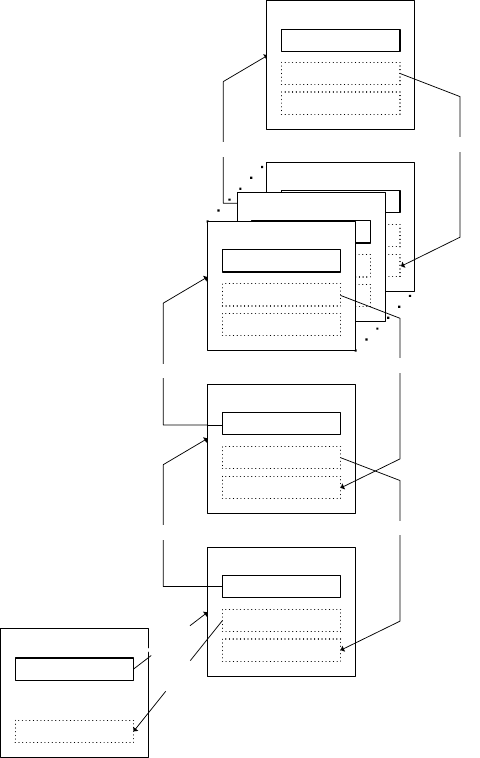
IEEE Std 1609.0-2013
IEEE Guide for Wireless Access in Vehicular Environments (WAVE) Architecture
41
Copyright © 2014 IEEE. All rights reserved.
CA Certificate
signer_id
public key
Issuer’s signature
Signed Data
signer
Issuer’s signature
End-Entity Certificate
signer_id
public key
Issuer’s signature
CA Certificate
signer_id
public key
Issuer’s signature
Root CA Certificate
signer_id
public key
Issuer’s signature
identifies
verifies
verifies
CA Certificate
signer_id
public key
Issuer’s signature
CA Certificate
signer_id
public key
Issuer’s signature
issuer ↑ ↓subordinate
issuer ↑ ↓subordinate
issuer ↑ ↓subordinate
↓trust anchor
identifies
verifies
identifies
verifies
identifies
Figure 19 — A certificate chain
To trust an incoming communication, the receiver of the communication may verify that the signature is
consistent with the public key obtained from the certificate, that the data is permitted by the permissions
contained in the certificate, that for each certificate in the chain the certificate was issued by a known CA
and is consistent with that CA’s permissions, and that the chain terminates at a known trust anchor.
5.13.6.2 Implicit and explicit certificates
IEEE Std 1609.2-2013 permits two types of certificates, known as implicit and explicit. If the public key is
explicitly included in the certificate, it is an explicit certificate. This is the type illustrated in Figure 19. If
the public key is not explicitly given in the certificate, but is obtained by performing additional processing,
the certificate is an implicit certificate. The difference between implicit and explicit certificates is
illustrated in Figure 20. Verifying a signed communication requires knowledge of all certificates in a chain,
regardless of whether the certificates are implicit or explicit. Implicit certificates are smaller than explicit
certificates and allow faster processing the first time a chain is constructed and verified, so they are optimal
for frequent messages on a congested channel or settings where a receiver will typically verify messages
from many different senders.
Authorized licensed use limited to: University Town Library of Shenzhen. Downloaded on January 04,2018 at 13:03:28 UTC from IEEE Xplore. Restrictions apply.
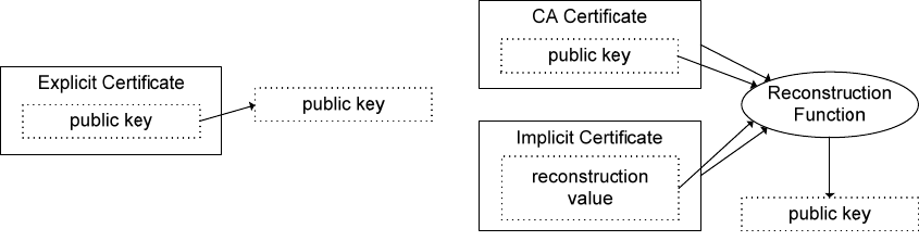
IEEE Std 1609.0-2013
IEEE Guide for Wireless Access in Vehicular Environments (WAVE) Architecture
42
Copyright © 2014 IEEE. All rights reserved.
Implicit certificates are specified in Standard #4 of the Standards for Efficient Cryptography Group [B34].
Figure 20 — Implicit and explicit certificates
5.13.6.3 Permission encoding
IEEE Std 1609.2-2013 encodes the permissions of senders directly in digital certificates. This allows the
receiver of a communication to determine the authorization of the sender to send that communication.
Permissions may include the following:
⎯ Temporal validity of the certificate: start time and end time. These are compared to the generation
time and expiry time of the associated signed communication. If generation and expiry time of the
communication are present, both lie between the generation and expiry times of the certificate.
⎯ Geographic validity of the certificate: from where its holder is entitled to send. This is compared to
the generation location of the associated signed communication. If generation location of the
communication is present, it lies within the geographic validity region of the certificate.
⎯ Operational permissions of the certificate: what actions its holder, i.e., the sender, is entitled to
take.
The operational permissions of a certificate used for signed data or signed WSAs are represented by a PSID
value, and may be further qualified by Service Specific Permissions (SSP). For signed WSAs, maximum
priority is also included. The PSID is defined in IEEE Std 1609.3-2010 and described in 5.9.4. The SSP is
an octet string of length no more than 31 octets. The SSP is application-specific: on receipt of signed data,
the application (not the Security Processing Services) verifies that the SSP is consistent with the application
payload in the signed data, and on receipt of a signed WSA the User application is responsible for
determining what use to make of the SSP in the appropriate field of the WSA certificate. The organization
that is allocated a PSID value is authorized to define the syntax and semantics of the SSP associated with
that PSID. The maximum priority for an application-service in a WSA certificate is the maximum priority
at which that application-service may be offered.
At the time of writing there are not yet any examples of organizations that have defined SSP semantics. The
following are hypothetical examples of how an SSP might be defined and used:
SSP in application: The SAE J2735 Basic Safety Message contains a LightbarInUse field. PSID value
0x20 has been allocated to SAE for applications employing the Basic Safety Message (see C.1 for a use
case description). Since not all vehicles are equipped with a light bar are permitted to use one, it may be
desirable to require that vehicles that set this field demonstrate that they are authorized to set it. This
requires the following steps:
Authorized licensed use limited to: University Town Library of Shenzhen. Downloaded on January 04,2018 at 13:03:28 UTC from IEEE Xplore. Restrictions apply.
IEEE Std 1609.0-2013
IEEE Guide for Wireless Access in Vehicular Environments (WAVE) Architecture
43
Copyright © 2014 IEEE. All rights reserved.
⎯ Standardization/Specification: SAE (or some other body directly or indirectly designated by
SAE) defines the syntax of the SSP so that it can encode the statements “entitled to set
LightbarInUse” and “not entitled to set LightbarInUse”.
⎯ Authorization: WAVE devices that emit the BSM in a WAVE Short Message with PSID 0x20
obtain certificates that contain the appropriate PSID and SSP, as described in 5.13.7. CAs use this
syntax to state the permissions of certificate holders
⎯ Operation: BSM-consuming applications on receiving WAVE devices check that, if the PSID
0x20 WSM with BSM data has set the LightbarInUse field, the SSP explicitly permits the inclusion
of this field. Any message that has set the LightbarInUse field in the payload but does not have the
corresponding permission in the SSP is rejected.
SSP in WSA: Two service providers might offer the same application, for example local point of interest
notification. If one service provider could masquerade as the other, this could allow attacks such as
phishing. To prevent masquerade, Providers could register for a unique identifier, such as a DNS name, and
demonstrate that they are authorized for the use of that name. This name could be provided to Users in the
appropriate SSP field of the WSA.
5.13.6.4 Revoked certificates
A signed communication may be rejected as invalid by a receiver if the signing certificate has been
revoked. A certificate is said to be revoked if an authorized entity distributes an authenticated message
stating that that certificate is no longer to be trusted. Such an authenticated message is known as a
Certificate Revocation List (CRL). If a certificate is revoked, all communications signed by that certificate
(for an end-entity certificate) or all certificates signed by that certificate (for a CA certificate) that are
received after the issue date of the revocation list are unauthorized and should be rejected. The CME within
WAVE Security Services stores revocation information. To save storage space, the CME may periodically
remove revocation information that applies only to certificates that would not be trusted anyway, such as
expired certificates.
CRLs will typically be issued by CAs. A CRL may be distributed to end-entities by WSMP using PSID
0x23, or by other means such as IPv6. IEEE Std 1609.2-2013 includes an informative description of a
“certificate management process”, which is a process resident on a WAVE device that carries out
communications operations necessary to support receiving CRLs. This may be restricted to receiving CRLs
broadcast over WSMP, or it may actively request CRLs that it has not yet received. When the certificate
management process receives a CRL, it verifies the CRL using the Security Processing Services and passes
the revocation information to the CME for storage and management.
5.13.7 Certificate management
5.13.7.1 General
“Certificate management” refers to the following:
⎯ Obtaining private keys and certificates that are used to sign and decrypt communications. These
keys are stored on a per-entity basis on the WAVE device.
⎯ Storing root certificates and other trust anchors, and maintaining information about revocation, to
allow verification of received signed communications. This information is stored by the CME on
the WAVE device.
Authorized licensed use limited to: University Town Library of Shenzhen. Downloaded on January 04,2018 at 13:03:28 UTC from IEEE Xplore. Restrictions apply.
IEEE Std 1609.0-2013
IEEE Guide for Wireless Access in Vehicular Environments (WAVE) Architecture
44
Copyright © 2014 IEEE. All rights reserved.
Both of these management functions require communicating with a Certificate Authority.
IEEE Std 1609.2-2013 provides support for certificate management by specifying data structures and the
processing necessary to carry out certificate management functions. However, IEEE Std 1609.2-2013 does
not specify exact communications procedures to be used to exchange these data structures. These are a
necessary part of a system specification and may be included in a future version of the standard. IEEE Std
1609.2-2013 also does not provide a full specification of when to request certificates and exactly what
permissions to include in a certificate request. These decisions are made by an entity out of the scope of
IEEE Std 1609.2-2013, which is referred to in IEEE Std 1609.2-2013 as a certificate management process.
Different WAVE devices, and different applications on WAVE devices, may support different certificate
management processes: for example, a certificate management process might support only manual
installation of certificates and private keys and only receive CRLs over WSMP, or it might support
certificate and CRL requests as and when needed over a data connection.
The certificate management process is to be distinguished from the certificate management entity. The
certificate management process manages communications with CAs. The certificate management entity
stores and manages the information once it has been received.
5.13.7.2 Obtaining certificates: general
In IEEE Std 1609.2-2013, a private key and the corresponding certificate are stored at a CMH, which is an
index to memory within the Security Processing Services. The private key and certificate may be stored by
the following methods:
⎯ The key and certificate may be generated outside the Security Processing Services and imported to
a CMH by the appropriate primitive defined in IEEE Std 1609.2-2013.
⎯ The private key and public key may be generated outside the Security Processing Services and
stored at a CMH. A certificate management process may then generate a certificate request
including the public key, send it to the CA to obtain a certificate, and store the resulting certificate
at the CMH.
⎯ The private key and public key may be generated on the device. A certificate management process
may then generate a certificate request including the public key, send it to the CA to obtain a
certificate, and store the resulting certificate at the CMH.
Possible operations of the certificate management process for signed data and signed WSAs are described
in 5.13.7.3 through 5.13.7.6 respectively.
5.13.7.3 Obtaining certificates for applications
An application that originates or receives secured messages is referred to in IEEE Std 1609.2-2013 as a
secure data exchange entity (SDEE).
Figure 21 illustrates the functional entities involved in requesting certificates for use by a message-
originating application. The heavy dashed lines indicate processing defined in the IEEE 1609 standards and
the dot-dashed arrow indicates data flows not defined in the IEEE 1609 standards. The functional entities
have the following responsibilities:
⎯ The SDEE provides the certificate management process with some or all of the information to be
included in the certificate request. Following successful completion of the certificate management
process, the SDEE possesses a CMH referencing a private key and the associated certificate.
Authorized licensed use limited to: University Town Library of Shenzhen. Downloaded on January 04,2018 at 13:03:28 UTC from IEEE Xplore. Restrictions apply.
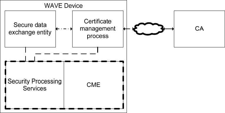
IEEE Std 1609.0-2013
IEEE Guide for Wireless Access in Vehicular Environments (WAVE) Architecture
45
Copyright © 2014 IEEE. All rights reserved.
⎯ The certificate management process is responsible for determining the information to be included
in a certificate request, determining the key and certificate to be used to sign the certificate request,
invoking the Security Processing Services to create the certificate request, sending the request to
the CA, invoking the Security Processing Services to process the response received from the CA
and making the returned certificates available to SDEE.
⎯ The CA is responsible for processing a received certificate request and returning the response to the
certificate management process.
⎯ The Security Processing Services create the certificate request and all associated keys, store the
certificate and keys and process the response from the CA when it is received by the certificate
management process.
IEEE Std 1609.2-2013 does not define the interface between the certificate management process and the
application. For an example of information that might pass across this interface, consider an application
that sends WSMs relating to two different PSIDs. The application may have a single certificate containing
both PSIDs, or two separate certificates each with one PSID. The trade-off is between packet size on the
channel and storage space on the device. Certificate management decisions such as this are made by entities
outside the scope of IEEE Std 1609.2-2013.
Figure 21 — Functional entities for certificate request for applications
Figure 22 shows the overall process flow for certificate request for applications. The heavy dashed box
shows functionality defined in the IEEE 1609 standards, specifically IEEE Std 1609.2-2013.
The “initialize keys” processing step refers to providing the certificate management process with a CMH
that references the keys needed to generate the certificate request. These keys may be generated on or off
the WAVE device as discussed in 5.13.7.2.
Authorized licensed use limited to: University Town Library of Shenzhen. Downloaded on January 04,2018 at 13:03:28 UTC from IEEE Xplore. Restrictions apply.
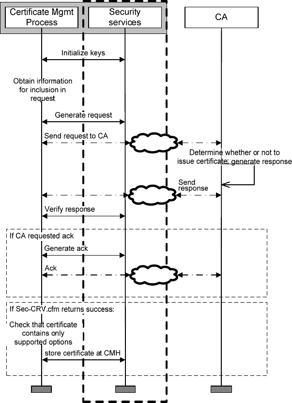
IEEE Std 1609.0-2013
IEEE Guide for Wireless Access in Vehicular Environments (WAVE) Architecture
46
Copyright © 2014 IEEE. All rights reserved.
Figure 22 — Process flow for certificate request for applications
5.13.7.4 Obtaining certificates for WSAs containing secure application-services
Private keys and certificates necessary to sign WSAs are stored and managed by the PSSME. Figure 23
illustrates the functional entities involved in requesting WSA certificates. The heavy dashed lines indicate
processing defined in IEEE Std 1609.2-2013, the dotted lines indicate data flows defined in IEEE Std
1609.3-2010, and the dot-dashed lines indicate data flows not defined in any IEEE standard. The functional
entities have the following responsibilities:
Authorized licensed use limited to: University Town Library of Shenzhen. Downloaded on January 04,2018 at 13:03:28 UTC from IEEE Xplore. Restrictions apply.
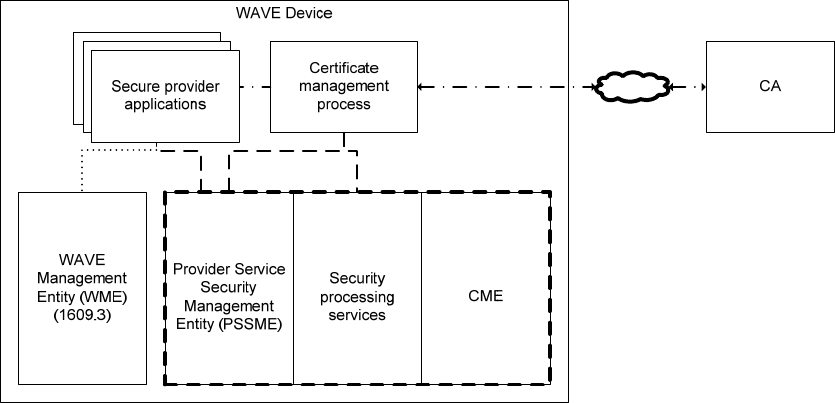
IEEE Std 1609.0-2013
IEEE Guide for Wireless Access in Vehicular Environments (WAVE) Architecture
47
Copyright © 2014 IEEE. All rights reserved.
Figure 23 — Functional entities for certificate request for WSA signing
⎯ The secure Provider applications provide the PSSME with information that may be included in the
certificate request.
⎯ The certificate management process is responsible for determining the information to be included
in certificate request, determining the key and certificate to be used to sign the certificate request,
invoking the Security Processing Services to create the certificate request, sending the request to
the CA, invoking the Security Processing Services to process the response received from the CA,
and making the returned certificates available to the secure data exchange entity.
⎯ The CA is responsible for processing a received certificate request and returning the response to
the certificate management process.
⎯ The PSSME provides the certificate management process with information that it may use in
generating the certificate request and stores the WSA certificates and private keys when the
certificate management process receives them from the CA.
⎯ The Security Processing Services create the certificate request and all associated keys and process
the response from the CA when it is received by the certificate management process.
First, a Provider application registers with the PSSME to obtain a Local Service Index for Security (LSI-S).
Then, the Provider application makes its request for a certificate known to the certificate management
process. These requests include the LSI-S, the PSID, and the SSP for which the provider application will
request inclusion in an advertisement, and the maximum priority at which the Provider will advertise the
application-service. The Provider application may request multiple sets of permissions for inclusion in a
certificate, for example, multiple PSIDs or multiple SSPs associated with a particular PSID. IEEE Std
1609.2-2013 provides mechanisms for the Provider application to make these requests using the PSSME
via the PSSME-SAP.
The certificate management process determines which requests to send to the CA, creates the requests
using the Security Processing Services, sends them, verifies the response using the Security Processing
Services, and processes the response contents. If a certificate is successfully received, the certificate
Authorized licensed use limited to: University Town Library of Shenzhen. Downloaded on January 04,2018 at 13:03:28 UTC from IEEE Xplore. Restrictions apply.
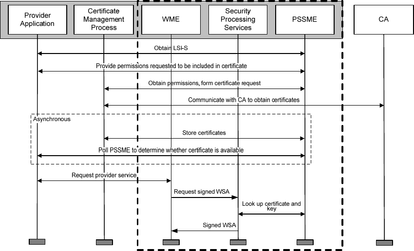
IEEE Std 1609.0-2013
IEEE Guide for Wireless Access in Vehicular Environments (WAVE) Architecture
48
Copyright © 2014 IEEE. All rights reserved.
management process stores the certificate and key at a CMH and makes this CMH available to the Provider
application and the WME via the PSSME-SAP.
The Provider application should not submit a Provider service request to the WME until it has been
informed that a certificate is available to authorize the associated secured application-service. The Provider
application can obtain this information using the mechanisms of IEEE Std 1609.2-2013 via the PSSME-
SAP, which allow the application to poll the PSSME until the certificate is present. Implementations may
provide a different mechanism to notify the application when the certificate is available.
Finally, the Provider application registers with the WME using WME-ProviderService.request, providing
the LSI-S. The LSI-S enables the WME to identify which application-services are being signed in the
WSA; this allows the WME to pass that identification to the Security Processing Services, which in turn
use the LSI-S to request a signing key and certificate from the PSSME that permits all the application-
services in the WSA.
Figure 24 — Process flow from newly installed Provider application to ability to send WSAs
securely advertising the associated application-service
WSA certificates with subsets of Provider applications. As discussed in 5.8, a WAVE Provider may
send WSAs containing only a subset of the registered application-services, for example so that the WSA
size remains within the IEEE 802.11 Maximum Transmission Unit (MTU). A WSA containing a subset of
application-services may be authorized using a certificate that contains a subset of authorized application-
services, so long as the subset of application-services in the certificate contains the subset of application-
services in the WSA. The certificate management process for WSAs may anticipate this use case and
prepare for it by applying for multiple certificates that contain selected subsets of the application-services.
For example, if ten Provider applications have registered with the PSSME, the certificate management
process may apply for one certificate for application-services 1–5 and a different certificate for application-
services 6–10. The IEEE 1609 standards permit this use case but do not provide all the functionality needed
to support it. For example, if there is no certificate that covers all application-services, neither IEEE Std
1609.2-2013 nor IEEE Std 1609.3-2010 specifies an interface to inform the WME as to which
Authorized licensed use limited to: University Town Library of Shenzhen. Downloaded on January 04,2018 at 13:03:28 UTC from IEEE Xplore. Restrictions apply.
IEEE Std 1609.0-2013
IEEE Guide for Wireless Access in Vehicular Environments (WAVE) Architecture
49
Copyright © 2014 IEEE. All rights reserved.
combinations of application-services may be advertised together. These use cases will need to be supported
by implementation-specific extensions.
5.13.7.5 Interactions with the CA: certificate request and revocation
IEEE Std 1609.2-2013 defines two types of information that originate at a CA: certificates themselves and
Certificate Revocation Lists (CRLs).
IEEE Std 1609.2-2013 specifies data structures and message flows that may be used to request signing and
decryption certificates interactively from the CA. Certificates may also be installed by other means. The
choice of what means to use to obtain certificates may vary from application to application. IEEE Std
1609.2-2013 does not specify a communications mechanism to be used to exchange messages with the CA.
IEEE Std 1609.2-2013 also specifies data structures that may be used to distribute CRLs. An application
might not use CRLs; for example, if the signing devices for that application have reliable connectivity to
the CA, the CA could instead issue the devices with short-lived certificates and decline to issue new
certificates to a compromised device. If an application uses CRLs, the distribution mechanism should be
agreed as part of the application specification. CRLs may be distributed using WSMP with the PSID field
in the WSMP header set to 0x23, or by other mechanisms not specified in IEEE Std 1609.2-2013.
Received revocation information is stored by the CME. An implementation may also provide other means
to enter revocation information into the CME.
5.13.7.6 Bootstrap
The IEEE 1609.2 Public Key Infrastructure (PKI) mechanisms assume that each WAVE device has the
information necessary to allow it to trust communications from a known CA, and that the CA has the
information necessary to allow it to trust certificate requests from the device; in other words, that the
WAVE device has access to a root certificate, and the CA has access to some public key belonging to the
device, and both the key and the certificate have been obtained in a trustworthy manner and not altered or
overwritten. The process that provides this initial cryptographic information to the device and the device’s
key to the CA is referred to as IEEE 1609.2 certificate bootstrap. IEEE Std 1609.2-2013 does not provide
mechanisms for bootstrap. See 5.13.9 for further discussion.
5.13.8 Privacy
5.13.8.1 General
The IEEE 1609 system is intended to be privacy protecting with respect to personal data. Broadly speaking,
“privacy” encompasses the concept that unauthorized parties should not be able to make use of my data,
authorized parties should only be able to make use of my data with my knowledge, and I should be able to
choose which of my data I reveal to which authorized party (for example, my credit card company does not
need to know my library card number, my library does not need to know my credit card number, and
someone I pay cash to does not even need to know my name). This means that personal (as opposed to
institutional) users of the system have a right to expect that their personal data remains under their control:
the originator of the data can prevent the data from being used in ways they do not approve.
Full privacy is not possible in an intelligent transportation system. Cars are large, visible objects, and can
be tracked. Many safety-of-life applications depend on devices frequently broadcasting their location and
other dynamic data. The privacy challenge within ITS is to ensure that only information necessary for
Authorized licensed use limited to: University Town Library of Shenzhen. Downloaded on January 04,2018 at 13:03:28 UTC from IEEE Xplore. Restrictions apply.
IEEE Std 1609.0-2013
IEEE Guide for Wireless Access in Vehicular Environments (WAVE) Architecture
50
Copyright © 2014 IEEE. All rights reserved.
particular uses is sent and that someone who wants to get a user’s private information (such as an address)
will not find that ITS are the cheapest source of that information.
However, the issue is complicated by considerations of traffic analysis and data mining: if someone can tell
that two messages come from me, they can potentially glean information from the combination of the
messages. This is often used for good purposes in legal investigations, where the pattern of a suspect’s
communication can reveal whether or not the suspect is part of a wider conspiracy. It is often a problem in,
for example, healthcare research, where the combination of medical condition, year of birth, and area of
residence can often identify a single person, making it difficult to provide appropriately anonymized data
sets to researchers.
Privacy also depends on the type of user. A person often has an expectation of privacy; a traffic signal does
not. An ambulance requesting a signal change is requesting a high level of privileges and so should have a
low expectation of privacy, because the claimer of a high level of privileges should be accountable for their
actions. On the other hand, the ambulance driver has an expectation of privacy.
Additionally, whatever privacy services are provided, there may be a legal right for appropriately
authorized parties to reverse that privacy for law enforcement or to ensure the correct operation of the
system.
5.13.8.2 Threats and mitigations
Threats to privacy within the WAVE system may be based on information from a number of different
sources.
⎯ Information from individual application messages.
⎯ Information from a collection of messages for a particular application.
⎯ Information from signalling data (source and destination addresses and other identifiers) for an
application.
⎯ Information from RF characteristics of a particular device.
⎯ The combination of application or signalling data from multiple applications. This compromises
privacy both because the combination of applications on a device is private (or, put more
informally, service provider A does not need to know that I am also using service provider B), and
because the exact combination of applications may be unique, or nearly unique, to a given WAVE
device and so act as a static identifier.
This information may compromise privacy as a result of being obtained by an unauthorized recipient (an
eavesdropper), or because it is misused by an authorized recipient. The situation is complicated in the case
of a WAVE system because many applications (such as those involving a broadcast Basic Safety Message)
have no concept of an authorized user, being intended for broadcast to any receiving WAVE device in the
vicinity.
The IEEE 1609 standards provide mechanisms that may be used to protect privacy. The following list
identifies mechanisms from within the IEEE 1609 standards that protect against particular threats to
privacy, as well as areas where mechanisms exist within other standards and areas where mechanisms have
not yet been standardized.
Information from individual application messages:
Authorized licensed use limited to: University Town Library of Shenzhen. Downloaded on January 04,2018 at 13:03:28 UTC from IEEE Xplore. Restrictions apply.
IEEE Std 1609.0-2013
IEEE Guide for Wireless Access in Vehicular Environments (WAVE) Architecture
51
Copyright © 2014 IEEE. All rights reserved.
⎯ For broadcast applications, privacy should be protected on a per-application basis.
Applications that broadcast information unencrypted should not include personally identifying
information.
⎯ For non-broadcast applications, IEEE Std 1609.2-2013 provides confidentiality services via
the encrypted message.
⎯ For non-broadcast applications, there are many application-layer protocols that can be used to
provide confidentiality for the contents of particular messages, for example the IETF
protocols Cryptographic Message Syntax (CMS) [B23], Transport Layer Security (TLS)
[B25] and Datagram Transport Layer Security (DTLS) [B24].
Information from a collection of messages for a particular application:
⎯ For broadcast applications, applications should avoid static fields within the application data
that would allow an eavesdropper to associate one message with another from the same
device.
⎯ For non-broadcast applications, this threat is also addressed by encrypting individual
messages, using either the mechanisms of IEEE Std 1609.2-2013 or other mechanisms.
Information from signaling data (source and destination addresses and other identifiers) for an application:
⎯ The MAC address, IP address (if applicable) and other addresses associated with a particular
application should change from time to time. These changes should all be synchronized with
each other and with the change of any broadcast identifier in the application data.
⎯ IEEE Std 1609.4-2010 provides the MLMEX-AddressChange primitive to trigger a MAC
address change.
⎯ Other protocol-level identifiers within the network stack (for example, IP addresses) may be
changed using the mechanisms defined for that protocol.
⎯ Application identifier change may be synched with network identifier change using
application-specific mechanisms.
⎯ Encryption at the MAC layer would help protect all signaling data on the first hop of an
application message. However, this is not possible for broadcast applications, and no
mechanisms are currently defined that are suitable for non-broadcast applications using
WAVE communications over IEEE Std 802.11-2012.
Information from RF characteristics of a particular device:
⎯ “RF Fingerprinting” (see, for example, Brik et. al [B2], Edman and Yener [B3]) may allow
attackers to distinguish one WAVE device from another by its RF transmission
characteristics. Currently there are no standards that address this type of attack.
The combination of application or signaling data from multiple applications:
⎯ To prevent an attacker from determining that PDUs from different applications come from the
same device, the applications may use entirely different sets of network stack identifiers, or
may use encryption at the MAC layer if a suitable mechanism is defined. This requires
functionality beyond the functionality specified in the IEEE 1609 standards.
Planned revisions to IEEE Std 1609.2-2013 include mechanisms to better protect the privacy of senders of
broadcast safety messages while allowing certificates of misbehaving units to be revoked.
5.13.9 Platform security considerations
Secure use of a WAVE device requires that the device protects access to its resources from attackers who
have access to the device. For example:
Authorized licensed use limited to: University Town Library of Shenzhen. Downloaded on January 04,2018 at 13:03:28 UTC from IEEE Xplore. Restrictions apply.
IEEE Std 1609.0-2013
IEEE Guide for Wireless Access in Vehicular Environments (WAVE) Architecture
52
Copyright © 2014 IEEE. All rights reserved.
⎯ Authorization and authentication are only provided by certificates if the certificates can only be
used by authorized entities on the transmitting WAVE device. (It should not be possible for
malware to get access to the signing keys used by a given application.)
⎯ Access to the safety channel should only be granted to authorized applications.
Therefore, before an application (running on a particular device) can apply for certificates, the device and
application should be in a state in that is known by the CA to be trustworthy. The CA can trust the device
and application if the following considerations hold:
⎯ The device is determined to be functioning correctly, i.e., it does not permit unauthorized access by
one process to another process’ keys.
⎯ The application is known to function correctly and use appropriate device and network resources.
⎯ The device has at least one symmetric or private cryptographic key that the CA trusts.
To obtain the first property, a device will probably need to undergo a process of certification by an
accredited certification program test lab. This certification process has not yet been defined but is discussed
in Annex B.
To obtain the second property, an application will probably need to undergo a process of certification. This
process has also not yet been defined.
One way of obtaining the third property is to have two states, an initialization state and an operational state.
In the initialization state the device may have keys and other certificate management information such as
the identity of trust anchors directly installed on it in a controlled way. Once the device is switched into the
operational state, updates to core security management information are only possible as a result of
authenticated communications. No mechanisms for this state change have yet been standardized in the ITS
setting, but the problem has been well studied in other settings (for example, SIM card initialization).
Authorized licensed use limited to: University Town Library of Shenzhen. Downloaded on January 04,2018 at 13:03:28 UTC from IEEE Xplore. Restrictions apply.
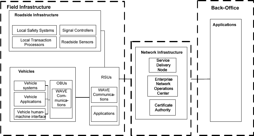
IEEE Std 1609.0-2013
IEEE Guide for Wireless Access in Vehicular Environments (WAVE) Architecture
53
Copyright © 2014 IEEE. All rights reserved.
Annex A
(informative)
Example system configuration
Figure A.1 illustrates one example of an operational system implemented using WAVE devices.
Figure A.1—Example system configuration
Authorized licensed use limited to: University Town Library of Shenzhen. Downloaded on January 04,2018 at 13:03:28 UTC from IEEE Xplore. Restrictions apply.
IEEE Std 1609.0-2013
IEEE Guide for Wireless Access in Vehicular Environments (WAVE) Architecture
54
Copyright © 2014 IEEE. All rights reserved.
Annex B
(informative)
Certification
B.1 Scope
In the context of this discussion, certification means validation, by testing, of conformance to a published
standard and possibly an accompanying defined set of performance requirements. In addition,
interoperability testing may be included.
Certification of devices to IEEE 1609 standards is not yet defined, but is necessary for successful
implementation, operation and maintenance of interoperable 5.9 GHz DSRC V2V and V2I subsystems of
the general connected vehicle architecture. The certification process encompasses both OBUs and RSUs.
While certification to the IEEE 1609 standards is a necessary condition, a sufficient certification process
would provide either proof of or testing of conformance to other physical and performance requirements of
devices implementing the IEEE 1609 standards such as FCC Parts 0, 1, 2 & 95, and SAE J551 [B31],
J1113 [B32], and J1211 [B33].
Requirement examples include the following:
⎯ Industry standard minimum form factors
⎯ Electrical power consumption
⎯ Local data interface and test ports
⎯ Onboard event logging
⎯ Connectors and cabling
⎯ Environmental conditions
⎯ Static and dynamic positional reporting accuracy
⎯ General documented industry “best practices”
From a practical perspective, for example, an IEEE 1609 compliant automotive grade device would be
useless if it failed to meet the maximum quiescent power consumption or operational temperature range in
an automotive environment.
The USDOT Connected Vehicle (CV) initiative is the principal customer for device certification at this
writing. A device certification process is needed that can accommodate all wireless modalities likely to be
included in the CV ecosystem and that should ultimately coordinate at some level with the CV Core
System, the entity that provides transactional trust for the system.
5.9 GHz DSRC, specifically designated for public safety applications in a transportation environment, is the
wireless medium for the USDOT Safety Pilot project. 5.9 GHz device certification is being piloted as an
integral part of the project.
Authorized licensed use limited to: University Town Library of Shenzhen. Downloaded on January 04,2018 at 13:03:28 UTC from IEEE Xplore. Restrictions apply.
IEEE Std 1609.0-2013
IEEE Guide for Wireless Access in Vehicular Environments (WAVE) Architecture
55
Copyright © 2014 IEEE. All rights reserved.
B.2 Process
The certification process addresses both technical and policy issues and provides governance for
implementation and enforcement and the maintenance of items such as a qualified products list.
Certification programs typically encompass a combination of compliance and interoperability testing.
In a full nationwide deployment scenario, the certification program serves multiple stakeholders including
technology vendors and end users. Convergence of multiple technologies with delivery of road safety
entails a high-risk potential for all participants, and an adequate, well-managed device certification program
can serve to mitigate risk in real world system deployment.
Program and process governance should be representative of all stakeholders including regulatory agencies,
application developers, system implementers and operators, manufacturers using certified devices, device
vendors, end users, and the security certificate entity.
In one possible hierarchy, the governance group would evaluate and approve processes submitted by a
technical certification process entity that would have membership from standards development groups,
commercial and government test houses, and specific end users such as auto manufacturers and device
vendors.
Certification and standards and requirements are iteratively linked and this structure facilitates the feedback
required for process refinement.
Certification may be performed entirely by an independent third party test house or in combination with a
vendor in-house quality control (QC) facility. The third party test house would be responsible for reviewing
the vendor’s submitted QC report as part of its certification procedure. The governance group would
establish contractual terms and responsibilities with test entities.
The “test stack” and any associated hardware and software tools necessary for performing tests may have
been developed by an independent third-party test house or under the aegis of a technical certification
process entity solely or in cooperation with one or more third-party test houses.
The tool set will include equipment such as spectrum analyzers, multiprotocol signal generators, and
standard antennas that are common equipment in wireless test facilities. Custom test tools and test tool
compliments will also be required and may be shared or leased at a nominal fee.
Authorized licensed use limited to: University Town Library of Shenzhen. Downloaded on January 04,2018 at 13:03:28 UTC from IEEE Xplore. Restrictions apply.

IEEE Std 1609.0-2013
IEEE Guide for Wireless Access in Vehicular Environments (WAVE) Architecture
56
Copyright © 2014 IEEE. All rights reserved.
Annex C
(informative)
Representative use cases
C.1 Vehicle communication for collision avoidance
One of the most important use cases for a WAVE system is communication to and from vehicles for the
purpose of enabling collision avoidance applications. Depending on the application, the communication can
be among neighboring vehicles and other mobile entities (V2V), between vehicles and roadside
infrastructure (V2I), or can include both V2V and V2I. Example applications include Forward Collision
Warning, Blind Spot Warning, Intersection Violation Warning, Icy Road Warning, and Longitudinal
Collision Risk Warning. These, and many others, are described more fully in other documents, e.g., from
SAE, ETSI, and the U. S. Department of Transportation (especially reports related to cooperative projects
between the U. S. DOT and the Vehicle Safety Communications [VSC] consortium). This section describes
a typical implementation supporting this use case.
The collision avoidance applications utilize messages exchanged between WAVE devices. For example,
vehicles that use SAE J2735 periodically send their basic state information using the Basic Safety Message
(BSM). The BSM conveys the sender’s position, speed, acceleration, heading, and other key information. A
vehicle-based application uses received BSMs to determine if a collision threat exists. These same
functions are supported in Europe by the ETSI Cooperative Awareness Message (CAM) and Decentralized
Environmental Notification Message (DENM). Additional collision avoidance applications can be provided
by an RSU, for instance by sending SAE J2735 Signal Phase and Timing (SPAT) and Map Data (MAP)
messages to convey the signal state and geographical description of an intersection. Figure C.1 shows the
usage of standards by collision avoidance applications. A sender (vehicle or infrastructure) will employ
IEEE Std 1609.2-2013 WAVE Security Services to sign and authenticate messages transmitted in support
of collision avoidance applications. These messages are most often broadcast, so encryption is not used.
The signed messages are sent using WSMP (see 5.3.2, defined in IEEE Std 1609.3-2010. This enables the
transmit power to be controlled on a message by message basis. WSMP also promotes bandwidth
efficiency, which is critical given that the channel used for safety broadcasts can experience congestion.
BSMs and SPAT messages are expected to be sent on pre-determined channels, so there is no need to
advertise their availability with the WSA. Their content may be updated as frequently as ten times per
second per transmitter. MAP messages might or might not be advertised. In the model considered most
likely for deployment in the United States, all three types of message (BSM, SPAT, and MAP) would be
sent on an SCH designated as the “safety channel,” which would be monitored continuously by devices
interested in receiving this data. Thus, no WSA would be needed for any of the messages. Similarly, the
channel switching function of IEEE Std 1609.4-2010 (see 5.11) would be unnecessary for the exchanges on
this SCH. A device participating on the “always-on” safety channel could be configured with a second
radio over which to participate in other CCH and/or SCH activities.
IEEE Std 1609.12 shows three PSID values for application areas related to the BSM. Two PSID values will
be used for vehicle BSMs, one of these intended for messages composed using vehicle sensor data that
meets defined high accuracy requirements.10 Devices that do not have data at the defined level of accuracy
will use the second PSID value. The third PSID value is used for messages composed by devices in tracked
vehicles (e.g., trains). The respective PSID value is carried in the WSMP header, which enables a receiver
to efficiently distinguish the three classes of BSM. A fourth PSID value has been allocated for an
application area associated with SAE J2735 intersection messages. This will be used in the header of a
10 At time of writing, the sensor requirements are under development by SAE DSRC Message Sets Technical Committee.
Authorized licensed use limited to: University Town Library of Shenzhen. Downloaded on January 04,2018 at 13:03:28 UTC from IEEE Xplore. Restrictions apply.
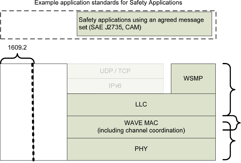
IEEE Std 1609.0-2013
IEEE Guide for Wireless Access in Vehicular Environments (WAVE) Architecture
57
Copyright © 2014 IEEE. All rights reserved.
WSM carrying a SPAT or MAP message. PSID values have also been allocated for other application areas
associated with SAE J2735 messages; a total of nine PSID values for SAE J2735 had been allocated at the
time this standard was being written.
1609.3
Management
Security
1609.4
802.11
Figure C.1—Standards used for collision avoidance
IEEE Std 1609.3-2010 includes the specification of the optional WSMP Safety Supplement (WSMP-S).
WSMP-S allows a sender of a safety message (e.g., BSM) to convey additional information about its
capabilities regarding multi-channel operation. This initial WSMP-S usage is not needed in an environment
with an “always-on” safety channel as described previously, but it provides flexibility for other channel
models. More importantly, the WSMP-S mechanism is extensible. Its definition can be expanded in future
revisions of IEEE Std 1609.3 to permit a sender to convey additional information in support of safety
applications. An example usage of an expanded WSMP-S is to advertise local channel load measurements
to enable fair allocation of channel resources in a distributed congestion control algorithm.
C.2 Electronic fee collection
C.2.1 Introduction
This use case description considers an electronic fee collection (EFC), specifically a toll collection,
transaction using technology as specified in the WAVE standards, including IEEE Std 1609.3-2010, IEEE
Authorized licensed use limited to: University Town Library of Shenzhen. Downloaded on January 04,2018 at 13:03:28 UTC from IEEE Xplore. Restrictions apply.
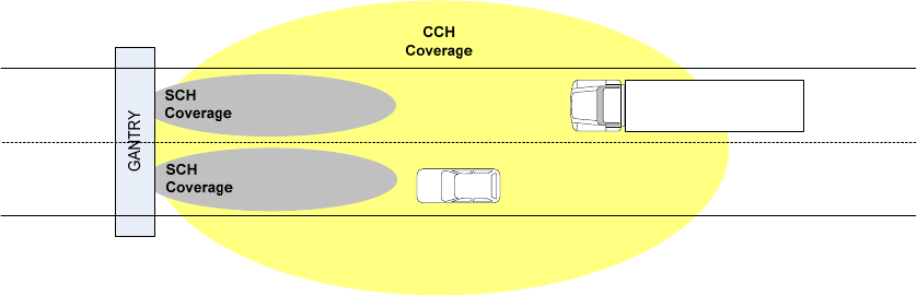
IEEE Std 1609.0-2013
IEEE Guide for Wireless Access in Vehicular Environments (WAVE) Architecture
58
Copyright © 2014 IEEE. All rights reserved.
Std 1609.4-2010, and IEEE Std 1609.11-2010 Annex A (Profile for Electronic Fee Collection systems per
ISO 14906 and ISO 15628:2007).
At a tolling gantry, an RSU acts as a Payee Unit (as defined in IEEE Std 1609.11-2010); vehicles carry
OBUs acting as Payer Units. The general objective is that the tolling transaction is accomplished reliably
and securely while the vehicle passes the tolling gantry at highway speeds. From a toll operator’s
perspective, the transaction should occur within a spatial/temporal frame that provides unambiguous
association of the logical payer with a physical vehicle (i.e., localization) for compatibility with revenue
protection violation detection and enforcement systems. In other words, if five vehicles drive through the
toll plaza, but only four electronic tolls are paid, the system determines which of the vehicles is the violator.
It may accomplish this by photographing each vehicle and matching each photo to a transaction. In doing
so, it determines the time and lane in which each vehicle performs its EFC transaction.
C.2.2 Example 1: localization via RF coverage
Figure C.2 illustrates a first example of such a system. Vehicles carrying battery-powered WAVE OBU toll
tags approach the tolling gantry from the right. A three-antenna RSU supports the operation. A first RSU
WAVE radio is tuned to the CCH and transmits a series of wake-up frames and WSAs that announce the
presence of the tolling service and deliver the particulars of the service, including the SCH to be used. Two
other RSU WAVE radios are tuned to the SCH and execute the exchange of messages that accomplish the
tolling transaction. These SCH radios transmit and receive through antennas configured for localization of
the specific vehicles/tags.
Figure C.2—Example toll collection setup, localization via RF coverage
C.2.3 OBU wake-up
If the OBU Payer units are battery powered, it is desirable to allow them to become dormant between
tolling exchanges to extend battery life, waking up just in time to accomplish each EFC transaction.
Receipt of a well-defined unique radio signal transmitted in an area just prior to the tolling gantry can serve
as the wake-up trigger. An example design for this feature is described following.
Repeated IEEE 802.11 QoS Null frames transmitted at 6Mbps on the CCH are used as a wake-up trigger.
Three such frames within a time window (2 ms) above a signal threshold (–44 dBm ±3 dB) cause the
receiving OBU to wake up. This unique pattern gives the wake-up mechanism certain robustness against
other strong radio signals but enables the battery powered OBU to wake-up within reasonable distance to
the service area to successfully accomplish a complete EFC transaction at maximum highway speeds.
Figure C.3 illustrates an example of such a wake-up pattern transmitted on the CCH.
Authorized licensed use limited to: University Town Library of Shenzhen. Downloaded on January 04,2018 at 13:03:28 UTC from IEEE Xplore. Restrictions apply.
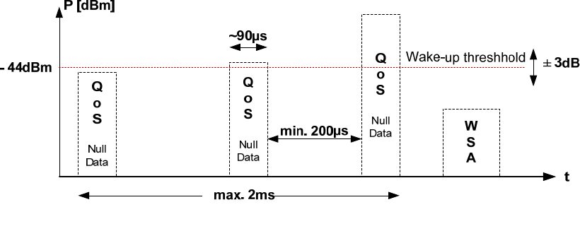
IEEE Std 1609.0-2013
IEEE Guide for Wireless Access in Vehicular Environments (WAVE) Architecture
59
Copyright © 2014 IEEE. All rights reserved.
Figure C.3—Wake-up pattern
C.2.4 Example 2: localization via GPS reports
In a second example, the tolling system relies on location reports from the OBUs to determine their lane.
As vehicles enter the CCH coverage zone, they receive the WSA with information about the upcoming
tolling service. As part of the message exchange with the RSU, each OBU provides precise location
information, e.g., derived from GPS. This scenario illustrates an example where the OBUs are powered
from the vehicle battery and therefore do not require the wake-up signal. (These location reports are not
included in the tolling exchange described in C.2.5. The vehicle location could be delivered over WSMP
during the message exchange of Figure C.5. Alternately, if the OBU is broadcasting its location, e.g., in a
Basic Safety Message as described in C.1, the RSU could derive its location via that means.)
This integrated OBU might include dual radios, so that one radio could continuously participate in safety
services via an “always-on” safety channel as described in C.1, while the other radio switches among
control and service channels to participate in other application-services, such as EFC.
In a deployment including tag-type OBUs of example 1 as well as integrated OBUs of example 2, the RSU
at the gantry illustrated in Figure C.2 could support both scenarios. The communication range of the
integrated OBU would be larger compared to example 1 as the OBU is continuously active and does not
need to go dormant to extend its battery life.
C.2.5 Message exchange
Refer to Figure C.4 and Figure C.5, adapted from IEEE Std 1609.11-2010 Annex A, that illustrate an
example message exchange occurring on the SCH, consistent with localization via RF coverage per
example 1 in C.2.2. IEEE Std 1609.11 identifies three elements within each of the Payer and Payee; here
the discussion is simplified by referring to the combination of the elements as “Payer application” and
“Payee application.”
Each device participates in an advertised application-service opportunity as specified in IEEE Std 1609.3-
2010 and described in 5.7. The OBU is configured as a User, which causes it to monitor received WSAs for
an application-service of interest, e.g., EFC. The RSU is configured as a Provider, with its first WAVE
radio to transmitting WSAs on the CCH, and the other WAVE radios monitoring the SCH for EFC activity,
i.e., waiting for Payers to arrive. The WSA has the following parameters of interest, shown in Table C.1.
Authorized licensed use limited to: University Town Library of Shenzhen. Downloaded on January 04,2018 at 13:03:28 UTC from IEEE Xplore. Restrictions apply.
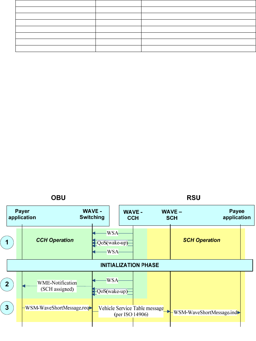
IEEE Std 1609.0-2013
IEEE Guide for Wireless Access in Vehicular Environments (WAVE) Architecture
60
Copyright © 2014 IEEE. All rights reserved.
Table C.1—Example Provider service request parameters
Parameter Value Notes
Destination MAC address broadcast WSA is broadcast
WSA type unsecured WSA is not signed
PSID 0x01 electronic fee collection
Channel number 182 SCH identifier
Channel access continuous User may switch to SCH immediately
Repeat rate 250 WSA transmitted 5 times per 100 ms
IP service false WSMP is used
The coverage areas of the RSU radios may be optimized by choosing the antenna characteristics and
configuring transmit power for each radio channel appropriately.
The OBU’s User service request has parameters matching those of the WSA Service Info, e.g., PSID 0x01.
The OBU Payer and RSU Payee applications also register with their local WAVE management entity as
recipients of received WAVE Short Messages on the EFC PSID (again, 0x01, per IEEE Std 1609.12).
1) When an OBU enters the CCH coverage zone, it recognizes the WSA transmissions on the CCH
as indicating the presence of an EFC service. Battery powered OBUs will first be awakened by
the wake-up signal pattern. The OBU receives and processes the WSA to determine the specifics
of the application-service.
2) The OBU WME switches its radio to the indicated SCH, with immediate and extended access,
and notifies the Payer application.
3) The Payer application constructs a Vehicle Service Table (VST) for delivery to the Payee
application via WSMP. The VST identifies the Payer device and provides pertinent information
to the Payee application.
Figure C.4—Example EFC message exchange, part 1
4) Next, as shown in Figure C.5 step 4, the roadside Payee application (still using WSMP for
transport) queries the vehicle Payer application for information, e.g., concerning the Payer’s
previous two tolling transactions, as well as information concerning the payment method. The
Authorized licensed use limited to: University Town Library of Shenzhen. Downloaded on January 04,2018 at 13:03:28 UTC from IEEE Xplore. Restrictions apply.
IEEE Std 1609.0-2013
IEEE Guide for Wireless Access in Vehicular Environments (WAVE) Architecture
61
Copyright © 2014 IEEE. All rights reserved.
Payer responds via WSMP. IEEE Std 1609.11-2010 specifies how the data is encoded and how
the sensitive data is encrypted.
The Payee requests additional vehicle data such as EquipmentOBUID and
VehicleLicencePlateNumber, perhaps using the same request, or a separate one as shown here.
5) The Payee application determines the appropriate toll to be charged, and delivers the
information to the Payer application over WSMP. The Payer may store this for later use, thus
completing the payment.
6) The Payee application (via WSMP) triggers a notification (e.g., an audible beep) to the operator
at the OBU.
7) The Payee application indicates to the Payer application that the transaction is complete. The
Payer application causes the User to stop participating in the application-service opportunity,
i.e., the OBU ceases operation on the SCH and returns to CCH monitoring.
8) If appropriate, the device is put back to sleep to conserve battery charge. A short-duration timer
may be used to prevent the device from reawakening on a trigger from the tolling station that it
is leaving.
Authorized licensed use limited to: University Town Library of Shenzhen. Downloaded on January 04,2018 at 13:03:28 UTC from IEEE Xplore. Restrictions apply.
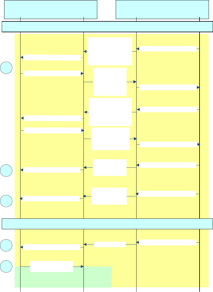
IEEE Std 1609.0-2013
IEEE Guide for Wireless Access in Vehicular Environments (WAVE) Architecture
62
Copyright © 2014 IEEE. All rights reserved.
SCH Operation
CCH Operation
Payer
application
Payee
application
Message with
ReceiptData1 and
ReceiptData2
WSM-WaveShortMessage.req
WSM-WaveShortMessage.ind
Closing message
WME-UserService.req
(Action = delete)
Message with
SET_MMI request WSM-WaveShortMessage.req
WSM-WaveShortMessage.ind
WSM-WaveShortMessage.req
WSM-WaveShortMessage.ind
WSM-WaveShortMessage.req Message with
ReceiptData1,
ReceiptData2 and
encrypted
PaymentMeans
WSM-WaveShortMessage.ind
WSM-WaveShortMessage.req
Message with requests
for ReceiptData1,
ReceiptData2 and
secured PaymentMeans
WSM-WaveShortMessage.ind
TRANSACTION PHASE
END OF TRANSACTION
4
8
7
6
5
OBU RSU
WAVE -
Switching WAVE –
SCH
WSM-WaveShortMessage.req Message with
EquipmentOBUID,
VehicleLicensePlate
Number, ... WSM-WaveShortMessage.ind
WSM-WaveShortMessage.req
Message with requests
for EquipmentOBUID,
VehicleLicensePlate
Number, ...
WSM-WaveShortMessage.ind
Figure C.5—Example EFC message exchange, part 2
Authorized licensed use limited to: University Town Library of Shenzhen. Downloaded on January 04,2018 at 13:03:28 UTC from IEEE Xplore. Restrictions apply.

IEEE Std 1609.0-2013
IEEE Guide for Wireless Access in Vehicular Environments (WAVE) Architecture
63
Copyright © 2014 IEEE. All rights reserved.
Annex D
(informative)
International ITS documents
At the time of the writing of this guide, the current status of CEN, ETSI, and ISO ITS standards has been
published at the following location.
http://www.imobilitysupport.eu/imobility-support/its-deployment/standardisation/library/reports-10
It is the stated intent of this document’s author to keep it up to date.
Authorized licensed use limited to: University Town Library of Shenzhen. Downloaded on January 04,2018 at 13:03:28 UTC from IEEE Xplore. Restrictions apply.

IEEE Std 1609.0-2013
IEEE Guide for Wireless Access in Vehicular Environments (WAVE) Architecture
64
Copyright © 2014 IEEE. All rights reserved.
Annex E
(informative)
Mapping PSID values to a contiguous set of integers
As specified in IEEE Std 1609.3-2010 and IEEE Std 1609.12, PSID values are allocated as unique variable-
length octet strings. However, there is a one-to-one mapping between these unique octet strings and the
contiguous set of integers (starting at zero) which is obtained by interpreting the “non-length” bits of the
PSID as integers with appropriate offsets added depending on the number of octets.
This one-to-one mapping may simplify the procedure by which an organization or individual requests an
assignment of PSID values from a registration authority, and is a means for ensuring harmonization with
international standards that define this identifier (e.g., ITS Application Identifier [ITS-AID]) as a variable
length integer.
Table E.1 below illustrates this mapping. Each PSID value has 1 to 4 bits [the most significant bit(s)] that
indicate the length of the field. Stripping these bits yields a range of values starting at zero, as shown in the
third and fourth columns. An appropriate integer offset may be determined chosen, as shown in the fifth
column. Adding this offset to the “stripped” values results in a contiguous set of unique integer values, as
shown in the final column.
Table E.1— A mapping from PSID value to integer
PSID
length
(octets)
PSID value (hex) Value with
MSBs stripped
(hex)
Value with MSBs
stripped
(decimal)
Integer
offset
Mapped integer value
1 00 – 7F 00 – 7F 0 – 127 0 0 – 127
2 80-00 – BF-FF 00-00 – 3F-FF 0 – 16,383 128 128 – 16,511
3 C0-00-00 –
DF-FF-FF
00-00-00 –
1F-FF-FF
0 –
2,097,151
16,512 16,512 –
2,113,663
4 E0-00-00-00 –
EF-FF-FF-FF
00-00-00-00 –
0F-FF-FF-FF
0 –
268,435,455
2,113,664 2,113,664 – 270,549,119
Authorized licensed use limited to: University Town Library of Shenzhen. Downloaded on January 04,2018 at 13:03:28 UTC from IEEE Xplore. Restrictions apply.
IEEE Std 1609.0-2013
IEEE Guide for Wireless Access in Vehicular Environments (WAVE) Architecture
65
Copyright © 2014 IEEE. All rights reserved.
Annex F
(informative)
Deployment history
During the time that the WAVE standards have been under development, there have been a number of field
trials to validate, and suggest improvements to, the technology.
In the U. S., the major deployments have been the Vehicle Infrastructure Integration Consortium (VIIC)
Proof of Concept (POC) project, and the Safety Pilot Model Deployment conducted by the University of
Michigan Technology Research Institute (UMTRI) for the U. S. Department of Transportation.
The VIIC Proof of Concept project was a field test run in the north-west suburbs of Detroit, Michigan
involving 27 vehicles and 55 roadside units. The project was announced in 2005, development and
integration work took place in 2006 and 2007, and the field trial itself ran from fall 2007 through 2008. The
technology was based on the 2006 trial-use versions of IEEE Std 1609.2, IEEE Std 1609.3, and IEEE Std
1609.4, along with the then-current draft of IEEE P802.11p.
Separate final reports were produced for the vehicle and infrastructure components and are available from
http://www.its.dot.gov/vii/.
Some modifications and extensions were made to the IEEE 1609 standards features to meet the
requirements of the POC. Specifically, IEEE Std 1609.2-2013 was extended to support anonymous
certificates that could not be linked to their holders and to support secure sessions via two novel
protocols—Vehicular Datagram Transport Layer Security (V-DTLS) and Vehicular Host Identity Protocols
(V-HIP).
Subsequently, the WAVE standards were updated to full-use as a result of recommendations and
observations made during POC. Changes included the following:
⎯ IEEE Std 1609.4-2010: Support MAC address change
⎯ IEEE Std 1609.3-2010:
⎯ Removed WSM forwarding
⎯ Made WSMP header extensible
⎯ Introduced the practice of describing IEEE 802.11p operations as “outside the context of a
basic service set”
⎯ Removed requirements for the WME or the WAVE protocol stack to maintain state
information on applications
⎯ Added indication of link quality to allow higher layers to use this to choose application-
services
⎯ Removed idle channel timeout
⎯ Changed from Application Class Identifier (single byte) to variable-length PSID
⎯ IEEE Std 1609.2-2013:
⎯ Introduced the ToBeEncrypted type
⎯ Removed SecuredWSM: secured data sent over WSMP is secured at the application layer, not
within the network stack
Authorized licensed use limited to: University Town Library of Shenzhen. Downloaded on January 04,2018 at 13:03:28 UTC from IEEE Xplore. Restrictions apply.
IEEE Std 1609.0-2013
IEEE Guide for Wireless Access in Vehicular Environments (WAVE) Architecture
66
Copyright © 2014 IEEE. All rights reserved.
⎯ Improved certificate management processes, including encrypting messages and introducing
error notifications and acknowledgements
The Safety Pilot Model Deployment was a field test run in Ann Arbor, Michigan, involving 2,564 cars, 169
trucks, 103 transit vehicles, and 29 roadside units. The selection of UMTRI as Test Conductor was
announced in August 2011, the first cars were driven as part of the Model Deployment on August 21, 2012,
and the project is scheduled at the time of writing to run through August 2013. The technology was based
on the 2010 versions of IEEE Std 1609.3 and IEEE Std 1609.4, along with draft 9.3 of IEEE P1609.2 and
the sections of IEEE Std 802.11-2012 referring to operation outside the context of a basic service set.
WAVE devices used in this program were conformant to these standards, with the exception that the
specific form of security certificate used in the program was not defined in draft 9.3 of IEEE P1609.2. This
certificate provides anonymity so it cannot easily be linked to a specific vehicle. The IEEE 1609 WG
expects to consider revising or amending IEEE 1609.2 to include a form of anonymous certificate, based on
experience obtained through the Model Deployment program. As part of the project, certification test
services were developed and provided by OmniAir and Booz Allen Hamilton. At the time of writing, up-to-
date information about the project is available from http://www.safetypilot.us.
Other ITS deployments in the U. S. include the following. Vehicle counts have been provided by
knowledgeable sources.
⎯ Scalability tests run by the Vehicle Safety Communications 3 (VSC3) consortium, which have
involved up to 200 vehicles in 2011–2013.
⎯ New York State Affiliated Test Bed fielded a demo system for the 2008 World Congress
Technology Showcase with 22 RSUs on I-495 corridor and in Manhattan. Later expanded with an
emphsis on commercial vehicles to include 20 aftermarket devices, 4 plow trucks, and 39 RSUs.
⎯ Michigan Affiliated Test Bed, on the same site as the VII POC.
⎯ Anthem, Arizona, with six pole mounted RSUs integrated with signal controllers, and OBUs
deployed in emergency response vehicles.
⎯ Palo Alto, California, with RSUs mounted along El Camino Real and OBUs in personal vehicles,
transit buses and commercial trucks. Applications include traveler information, electronic payment,
ramp metering and curve over-speed warning.
⎯ Orlando, Florida, demo system at the 18th World Congress Technology Showcase, with 24 RSUs.
⎯ Minnesota deployments including 500 volunteer vehicles and 80 snow plows.
⎯ Two testbeds in Virgina support a mix of vehicular types and dozens of RSUs.
European field tests have in general used a profile of IEEE Std 802.11p for PHY and lower MAC. Some
European field tests have used IEEE Std 1609.2-2013 for security services. In general, European field tests
have not used IEEE Std 1609.3-2010 or IEEE Std 1609.4-2010.
Authorized licensed use limited to: University Town Library of Shenzhen. Downloaded on January 04,2018 at 13:03:28 UTC from IEEE Xplore. Restrictions apply.

IEEE Std 1609.0-2013
IEEE Guide for Wireless Access in Vehicular Environments (WAVE) Architecture
67
Copyright © 2014 IEEE. All rights reserved.
Annex G
(informative)
Bibliography
[B1] ASTM E2213-03-2003, Standard Specification for Telecommunications and Information Exchange
Between Roadside and Vehicle Systems—5 GHz Band Dedicated Short Range Communications (DSRC)
Medium Access Control (MAC) and Physical Layer (PHY) Specifications.
[B2] Brik, V., Banerjee, S., Gruteser, M., and Oh, S. Wireless device identification with radiometric
signatures, Proceeding MobiCom '08MobiCom '08 Proceedings of the 14th ACM international conference
on Mobile computing and networking ACMACM New York, NY, USA 2008.
doi> 10.1145/1409944.140995910.1145/1409944.1409959.11
[B3] Current Status of Security Standards, Document #1-1, EU-US ITS Task Force, Standards
Harmonization Working Group.
[B4] Edman, M., Yener, B., Attacks against Modulation-based Radiometric Identification
http://ftp.cs.rpi.edu/research/pdf/09-02.pdf
[B5] ETSI EN 302 665, Intelligent Transport Systems (ITS); Communications Architecture.
[B6] Federal Communications Commission ET Docket No. 98-95, RM-9096, Amendment of Parts 2 and
90 of the Commission’s Rules to Allocate the 5.850–5.925 GHz Band to Mobile Service for Dedicated
Short Range Communications of Intelligent Transportation Services.
[B7] Federal Communications Commission FCC 03-324–2004, Amendment of the Commission’s Rules
Regarding Dedicated Short-Range Communication Services in the 5.850–5.925 GHz Band (5.9 GHz
Band).
[B8] Federal Communications Commission FCC 06-110 2006, Amendment of the Commission’s Rules
Regarding Dedicated Short-Range Communication Services in the 5.850–5.925 GHz Band (5.9 GHz
Band).
[B9] Feedback to Standards Development Organizations, Document #1-3, EU-US ITS Task Force,
Standards Harmonization Working Group.
[B10] Feedback to Standards Development Organizations—Communications, Document #3-3, EU-US ITS
Task Force, Standards Harmonization Working Group.
[B11] IEEE Std 802.2-1998 (ISO/IEC 8802-2:1994), IEEE Standard for Information technology—
Telecommunications and information exchange between systems—Local and metropolitan area
networks—Specific requirements—Part 2: Logical link control.
[B12] IEEE Std 802.11p-2010, IEEE Standard for Information technology—Telecommunications and
information exchange between systems—Specific Requirements—Part 11: Wireless LAN Medium Access
Control (MAC) and Physical Layer (PHY) Specifications: Amendment 6: Wireless Access in Vehicular
Environments.
[B13] IEEE Std 1363™-2000, IEEE Standard Specifications for Public Key Cryptography.
[B14] IEEE Std 1363a™-2004, IEEE Standard Specifications for Public Key Cryptography: Additional
Techniques.
[B15] IEEE Std 1609.1-2006, IEEE Trial-Use Standard for Wireless Access in Vehicular Environments
(WAVE)—Resource Manager [WITHDRAWN].
11 Available from www.winlab.rutgers.edu/~gruteser/papers/brik_paradis.pdf.
Authorized licensed use limited to: University Town Library of Shenzhen. Downloaded on January 04,2018 at 13:03:28 UTC from IEEE Xplore. Restrictions apply.

IEEE Std 1609.0-2013
IEEE Guide for Wireless Access in Vehicular Environments (WAVE) Architecture
68
Copyright © 2014 IEEE. All rights reserved.
[B16] IEEE Std 1609.2-2006, IEEE Trial-Use Standard for Wireless Access in Vehicular Environments
(WAVE)—Security Services for Applications and Management Messages [WITHDRAWN].
[B17] IEEE Std 1609.3-2007, IEEE Trial-Use Standard for Wireless Access in Vehicular Environments
(WAVE)—Networking Services [SUPERCEDED].
[B18] IEEE Std 1609.4-2006, IEEE Trial-Use Standard for Wireless Access in Vehicular Environments
(WAVE)—Multi-Channel Operation [WITHDRAWN].
[B19] IEEE P1609.6, Draft Standard for Wireless Access in Vehicular Environments (WAVE)—Remote
Management Services.12
[B20] IETF Request for Comments: RFC 768-1980, User Datagram Protocol.
[B21] IETF Request for Comments: RFC 793-1981, Transmission Control Protocol.
[B22] IETF Request for Comments: RFC 2460-1998, Internet Protocol, Version 6 (IPv6) Specification.
[B23] IETF Request for Comments: 3852, Cryptographic Message Syntax (CMS).
[B24] IETF Request for Comments: 4347, Datagram Transport Layer Security (DTLS).
[B25] IETF Request for Comments: 5246, The Transport Layer Security (TLS) Protocol Version 1.2.
[B26] IETF Request for Comments: 6071, IP Security (IPsec) and Internet Key Exchange (IKE) Document
Roadmap.
[B27] ISO/IEC 7498-1:1994, Information Technology—Open Systems Interconnection (OSI) 7 layer
reference model.
[B28] ISO/IEC 42010:2007 (IEEE Std 1471™-2000), Systems and software engineering—Recommended
practice for architectural description of software-intensive systems.
[B29] ISO 21217:2010, Intelligent transport systems—Communications access for land mobiles (CALM—
Architecture.
[B30] National ITS Architecture, Version 7.0, U. S. Department of Transportation, Research and
Innovative Technology Administration.
[B31] SAE J551/1, Performance Levels and Methods of Measurement of Electromagnetic Compatibility of
Vehicles, Boats (up to 15 m), and Machines (16.6 Hz to 18 GHz).
[B32] SAE J1113/1, Electromagnetic Compatibility Measurement Procedures and Limits for Components
of Vehicles, Boats (up to 15 m), and Machines (Except Aircraft) (16.6 Hz to 18 GHz).
[B33] SAE J1211, Handbook for Robustness Validation of Automotive Electrical/Electronic Modules.
[B34] Standards for Efficient Cryptography Group, “SEC 4: Elliptic Curve Qu-Vanstone Implicit
Certificate Scheme (ECQV)”, Working Draft Version 0.97, March 2011.
[B35] Status of Communication Standards, Document #3-1, EU-US ITS Task Force, Standards
Harmonization Working Group.
[B36] United States Code of Federal Regulations, Title 47 Telecommunication.
12 This IEEE standards project was not approved by the IEEE-SA Standards Board at the time this publication went to press. For
information about obtaining a draft, contact the IEEE.
Authorized licensed use limited to: University Town Library of Shenzhen. Downloaded on January 04,2018 at 13:03:28 UTC from IEEE Xplore. Restrictions apply.
