EL2901
User Manual: EL2901
Open the PDF directly: View PDF ![]() .
.
Page Count: 11
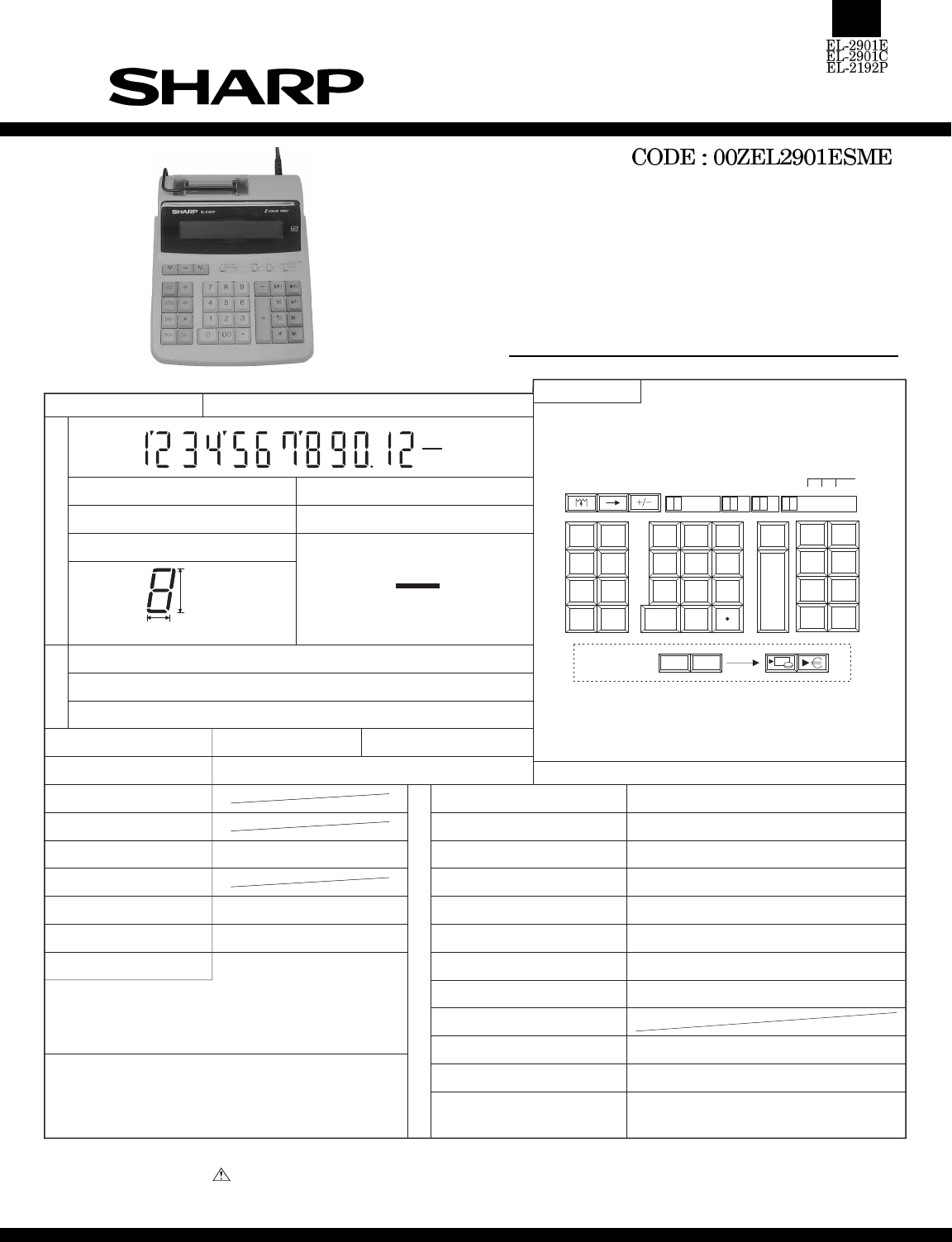
MODEL
EL-2901E
EL-2901C
EL-2192P
KEY LAYOUT
KEY SYSTEM : Plastic key + Key rubber
STANDARD FUNCTION
ELEMENT :
NUMERAL :
LCD
12
PARTS NAME :
SYMBOL :digits digit(s)2
Name
(mm)
Type
Pin
:
: 76 pins
: CHIP
u3866-015H
POWER SUPPLY AC : O DC : X
AC ADAPTER
DIMENSIONS (mm)
CALCULATIONS
RECHARGEABLE BATTERY
POWER CONSUMPTION
AUTO POWER OFF TIME
MEMORY PROTECT
Four arithmetic calculations, Constant calculation,
Power calculation, Reciprocal calculation, Chain
calculation, % calculation, Add-on (discount)
calculation,memory calculation, adding mode, etc.
L
S
I
D
I
S
P
L
A
Y
S
E
C
T
I
O
N
200 (D) x 251(W) x 60 (H) mm
12 digits 1M
P
R
I
N
T
E
R
S
E
C
T
I
O
N
MODEL NAME
PRINTING SYSTEM
PRINTING CAPACITY
CHARACTER DIMENSION
INPUT BUFFER
PRINTING SPEED
PAPER FEED SPEED
PAPER RELEASE MECHANISM
INK RIBBON
INK ROLLER
PAPER
PAPER SIZE (Roll Paper)
MFL87 (KI-OB1078CCZZ)
Serial print system
19 digits
1.6(W) 3.5 (H) mm
12 stages
Approx. 2.6 lines / sec.
Approx. 8.5 lines / sec.
Yes
Plain paper
58 mm (W), 80mm in diameter (max.)
(DPAPR1004CSZZ...5 rolls / pack)
+0
-1
BATTERY TYPE
Yes* (TAX / EURO only)
1
NOTE) *1 : This calculator operates only on AC power.
Further, the memory is retained only while the
AC cord is plugged in and clears when the AC
cord is disconnected.
30mA : AAC, ABC, AC7, TLC
5.2W, 47mA : UIC
AC only
CHARACTER PITCH : 9.0mm
9060ATRH
Black : EA-781R-BK, Red : EA-781R-RD
Parts marked with " " is important for maintaining the safety of the set. Be sure to replace these parts with specified
ones for maintaining the safety and performance of the set.
SHARP CORPORATION This document has been published to be used
for after sales service only.
The contents are subject to change without notice.
TAX+TAX-
for SEEG :
100
ON
OFF · P P·IC
5/4 ↓
210A
÷
×
=
C/CE
000
123
456
789
−
+
∗
M
∗
MU
%
M
−
M
+
M
◊
#/◊
TAX-
TAX+
STR
GT
F3GT ·
M
EG
18.75
6.9
M
EG
SERVICE MANUAL
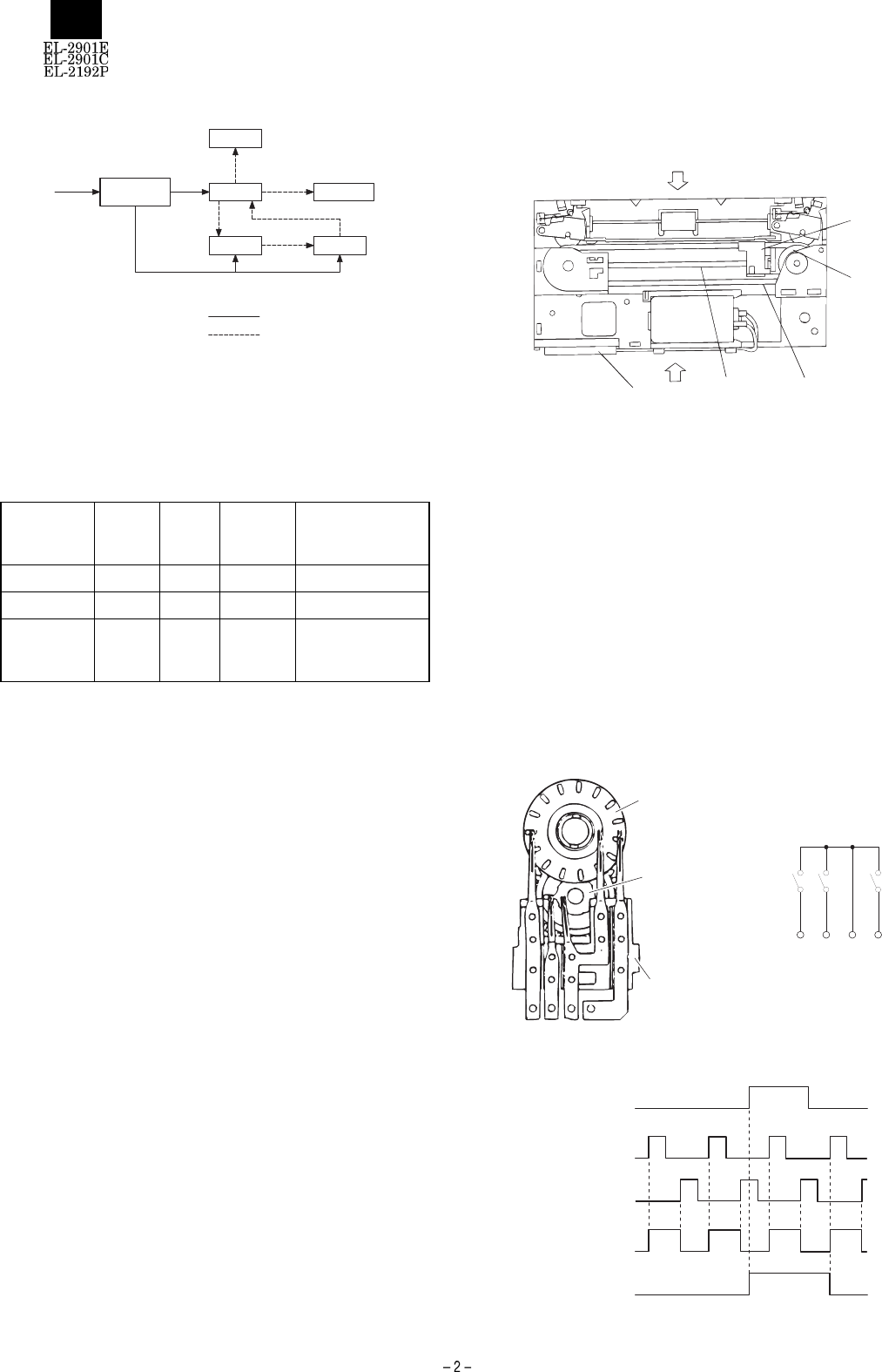
1. Block diagram
2. Tax/Euro exchange functions
LSI used for this machine has a tax function and a EURO exchange
function. Either function is selected depending on the destination of the
product.
Model name SPEC
CODE
Tax
function
EURO
exchange
function
Country
EL-2192P U1C O SECL
EL-2901E AC7 O SEEG
EL-2901C
AAC /
ABC /
TLC
O SUK, SCA, Agent
<Selecting between Tax/EURO exchange functions>
Either of the Tax and Euro exchange functions can be selected by
changing the signal with the jumper cables on the KEY PWB.
<Backup of Tax/EURO exchange functions>
This machine is an AC type which retains Tax data (tax rates and
others) and EURO exchange data in memory only while the AC cord is
plugged in. Therefore, data in memory cannot be retained if the AC
cord is disconnected.
3. PTMFL87 PRINTER CAUTION NOTES
3-1. Servicing
The printer model PTMFL87 (Ki-OB1078CCZZ) used for the EL-2192P
/ EL-2901C / 2901E is available for service by an entire unit and
therefore none of individual service parts is available for supply.
3-2. Cautions for handling
(1) Cautions for holding
Hold the sections shown with the arrows to carry the printer.
(2) Sections which a force must not be applied to :
1) PWB A
2) Do not turn the front belt B manually.
3) Do not turn the pulley C manually.
4) Do not apply a force to the hammer holder D.
(3) Sections which must not be touched :
1) Do not touch the shaft E with a bare hand.
2) Do not touch the font belt B with a bare hand.
3-3. Detecting Mechanism
The detector is of mechanical contact type and consists of the code
plate to output the character position detection signal to correspond to
each character on the character belt, sensor gear unit to output the
standard position signal, and fixed contact-piece unit.
: Power supply line
: Signal line
AC input LSI
LCD
Driver
Key,SL-SW
Printer
Power supply
circuit
D
C
BE
A
SCRSD
Code plate
Sensor gear unit
Fixed contact-piece unit
Fig. 1 Detecting Mechanism Fig. 2 Equivalent Circuit
S74S0S1
CP73 CP74 CP0 CP1
Standard signal(SD)
Reset signal( R)
Character position
signal(CP)
Standdard position
signal(SP)
Set signal(S)
Fig. 3 Time Chart
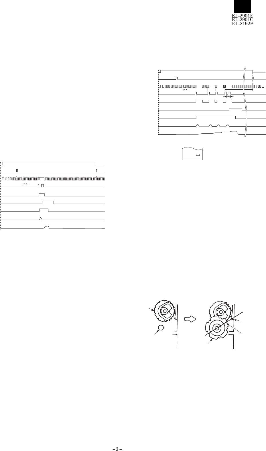
The character position detecting signal (CP) is to be made by the user
from the leading edges of the set signal and reset signal. This CP
corresponds to the character on the character belt. The standard sig-
nal (SD) is a signal output once to the 75CP pulse, and the signal to
be made by the user utilizing the leading edge of the second CP from
the leading edge of this signal is the standard position signal (SP).
The reason why CP and SP are made using the raw signals output
from the detector is that the effect of chattering is taken into considera-
tion.
The following will explain the basic operation.
3-4. Operation Sequence
The basic operation is explained
(1) Initialization
In order to make sure that the hammer holder is at its home position,
i.e. the first column, print the space after power is turned on, and after
the carry / return, do one-line paper feeding and set the hammer
holder at its home position. This completes the initialization.
(2) 1-line printing operation
1) The printing operation is started by setting the motor driving signal
(MT) ON.
2) Prior to 1-line printing, detect the standard position signal (SP)
once and make the time from the leading edge of the character
position detection signal CP8 to the leading edge of CP9 to and
make it standard pulse width. (This to setting must be done at the
initialization and prior to the 1-line printing. to is utilized for error
detection.)
3) The character belt rotates until the desired CP pulse is detected.
4) If the desired CP pulse is detected, power is supplied to the elec-
tromagnetic clutch unit, the character belt is stopped, and printing
operation / carry operation are done. In the meantime, the power to
the electromagnetic unit is cut off. (For the detail, see 1.3.2.Printing
/ Carry Mechanism.)
5) After completion of the printing / carry operation, the character belt
rotates again.
6) The operations 3) through 5) are repeated and 1-line printing is
completed.
7) After the most significant digit printing, the electromagnetic clutch-
signal TM becomes OFF, and then between T3 and T4, paper
feeding / column return operation is done by turning the electro-
magnetic clutch ON again.
T3 = 80 to 200 msec
T4 = (2.0 ~ 2.4) x Tcp
8) After paper feeding is started, it is completed when about 19CP is
counted.
9) The motor driving signal is turned OFF after 19CP counting after
the paper feeding is started. In case SP is not found within 19CP
after the paper feeding is started, it is turned OFF after SP is
detected.
Fig. 5 Time Chart for 1-Line Printing (0. |___| * printing)
(3) Continuous printing operation
1) After the 1-line printing operation in (2), the motor driving signal
(MT) is not turned OFF and the operations 2) through 8) are con-
tinuously done for the necessary number of columns while the
motor is run.
2) After the most significant digit of the last line is printed, the opera-
tions 7), 8) and 9) in (2) are done and the motor is stopped.
(4) Paper feeding operation
For the paper feeding operation, 1-line printing of space may be done
in the same way as for the printing operation sequence.
3-5. Troubleshooting dislocated print belt
Install the character belt on the drive pulley and driven pulley. When
installing the character belt, the following points must be considered.
1) If the driven pulley is removed and mismatched with the CC cam, it
should be aligned as follows.
2) The character belt should be positioned as follows.
Manually turn the motor to the position where the SD pulse ap-
pears.
089 21 0
Motor driving signal(MT)
Standard pisition
detection signal(SP)
Character position
detection signal(CP)
Electromagnetic
clutch signal(TM)
Carry gear operation
Paper reeding operation
Rack operation
Hammer operation
Carry operation
Fig. 4 Time Chart at Initialization
089 17 232528 0
16 22 24 27
19CP(mim)
T4
T3
t0
0. *
Motor driving signal(MT)
Standard pisition
detection signal(SP)
Character position
detection signal(CP)
Electromagnetic
clutch signal(TM)
Carry gear operation
Paper reeding operation
Rack operation
Hammer operation
Carry operation
Printing pattern through
the adove operation
Boss of
frame
Hole
Driven pulley
Frame hole
(Driven hole
inserting part)
CC cam
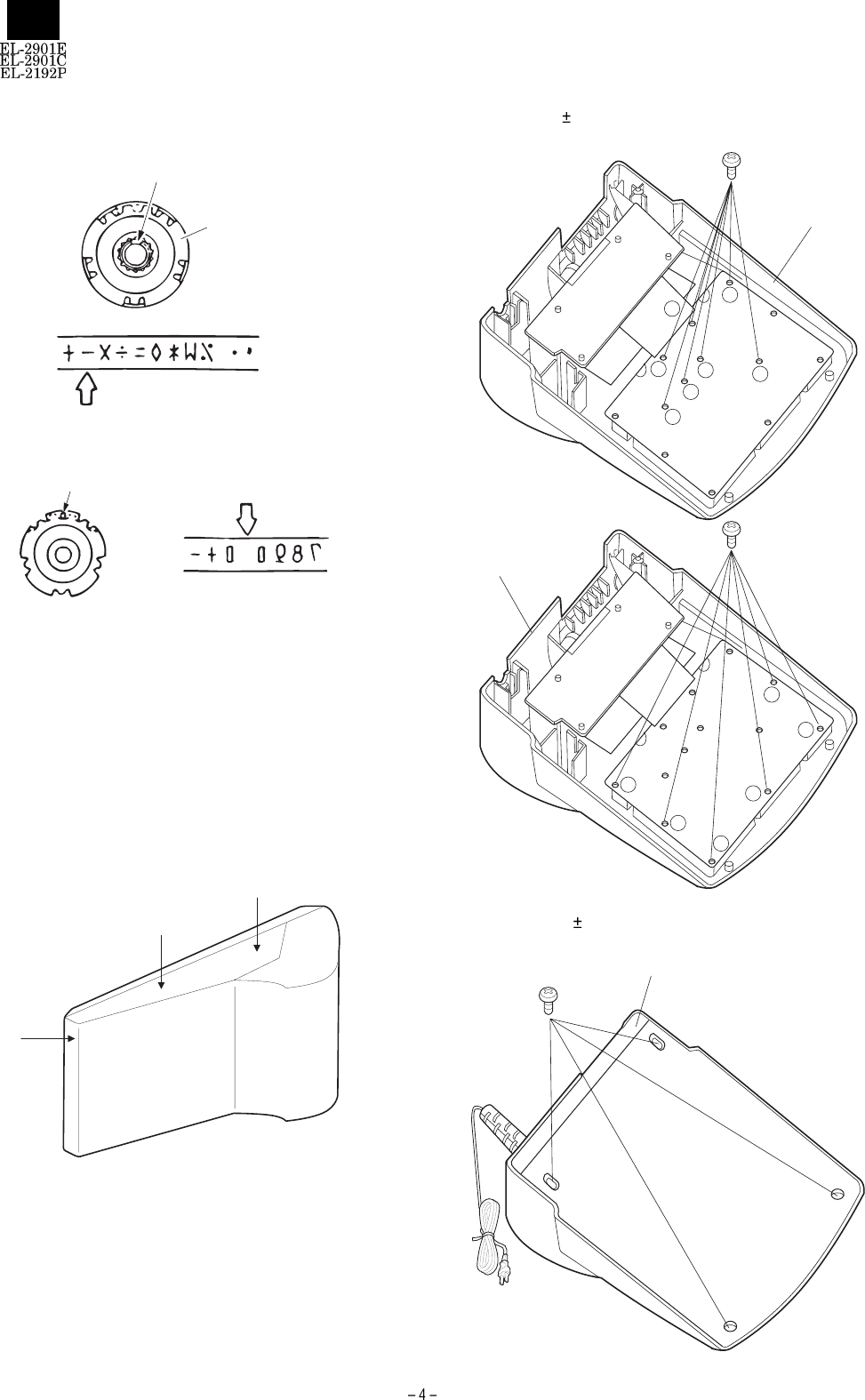
·A. Drive pulley side
Adjust the "–" of the character belt to the position of the hole (mark).
("–" shown in the above arrangement of characters)
·B. Driven pulley side
Adjust the center of the space of the character belt to the position of
hole (mark).
4. Note for disassembly and assembly
4-1. Disassembly of upper / lower cabinets
1) Hold the bottom housing and push down the upper housing at
circled 1 and slide the upper housing outwards.
2) Do the same at circled 2 and then 3.
4-2. Tightening torgue value
1) Key PWB : 1.5 0.2kg
2) Lower case : 2.5 0.5kg
Cutout
Driven pulley
Hole(mark)
1
2
3
1
2
24
5
6
3
1
2
4
5
63
UPPER CASE
UPPER CASE
LOWER CASE
3 x 8
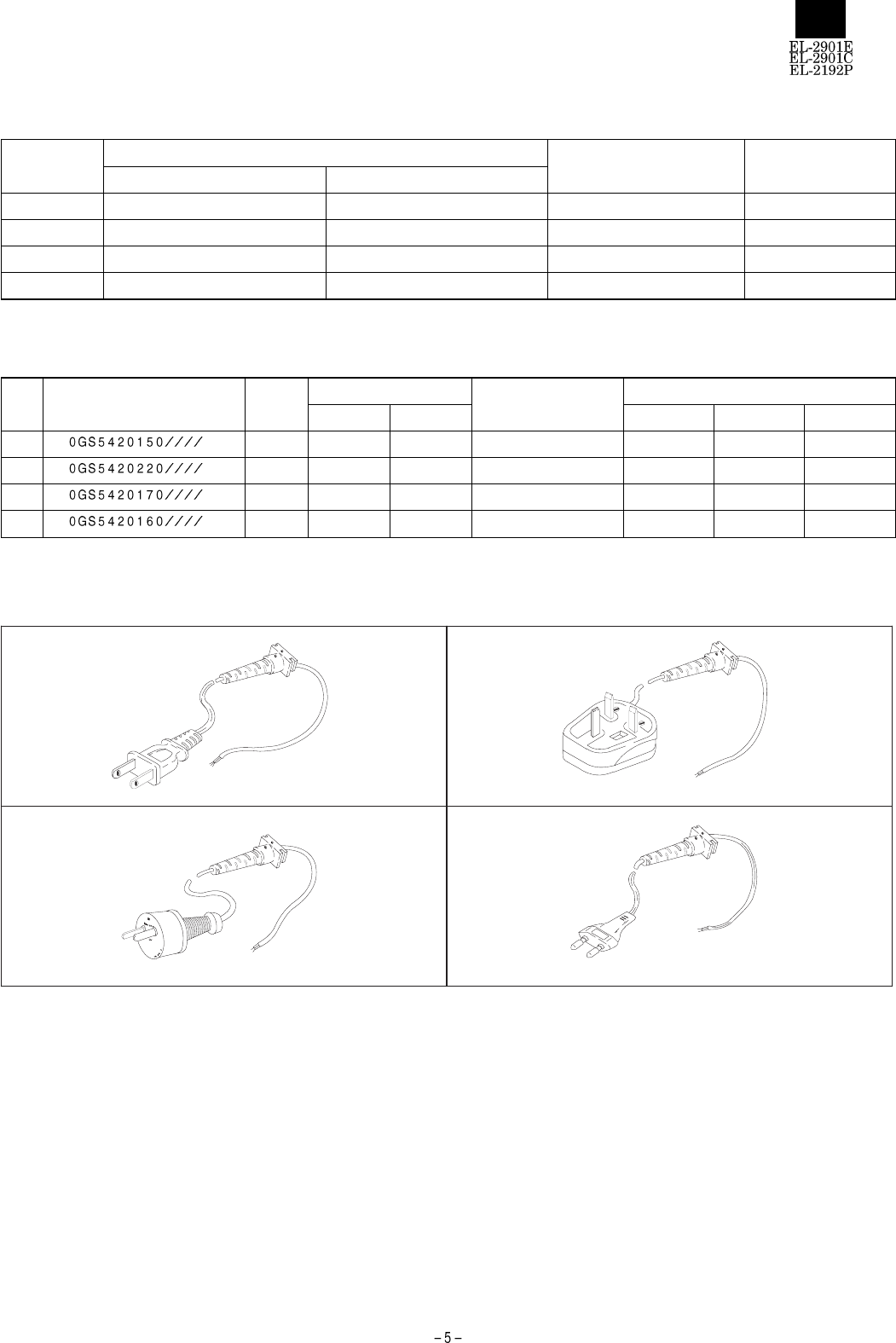
List of destinations (Destinations are determined
by the name plate voltage and the plug shape. )
Destination To identify destination Major shipping country Remarks
Name plate voltage Plug shape No.
U1C 120V 60Hz 1 Canada
AAC 220-230V 50Hz 2 U. Kingdom
ABC 230-240V 50Hz 3 Austraria
AC7, TLC 220-230 50Hz 4 Germany, Agent
AC cord
NO. PARTS CODE PRICE
RANK
TYPE OF LEAD DESCRIPTION MODEL NAME
2 LEAD 3 LEAD EL-2901C EL-2901E EL-2192P
1AP O AC cord U1C O
2AZ O AC cord AAC O
3AS O AC cord ABC O
4AP O AC cord AC7, TLC O O
Plug shape
0GS5420150////
(U1C)
12
34
(AAC)
(ABC)
(AC7,TLC)
0GS5420220////
0GS5420170//// 0GS5420160////
LCD unit
The S/L switch uses a key sheet (carbon printed)
Silver foil
Carbon printed
(Resistance: below 300Ω
8 7 6 5 4 32 1
A
B
C
D
12345678
D
C
B
A
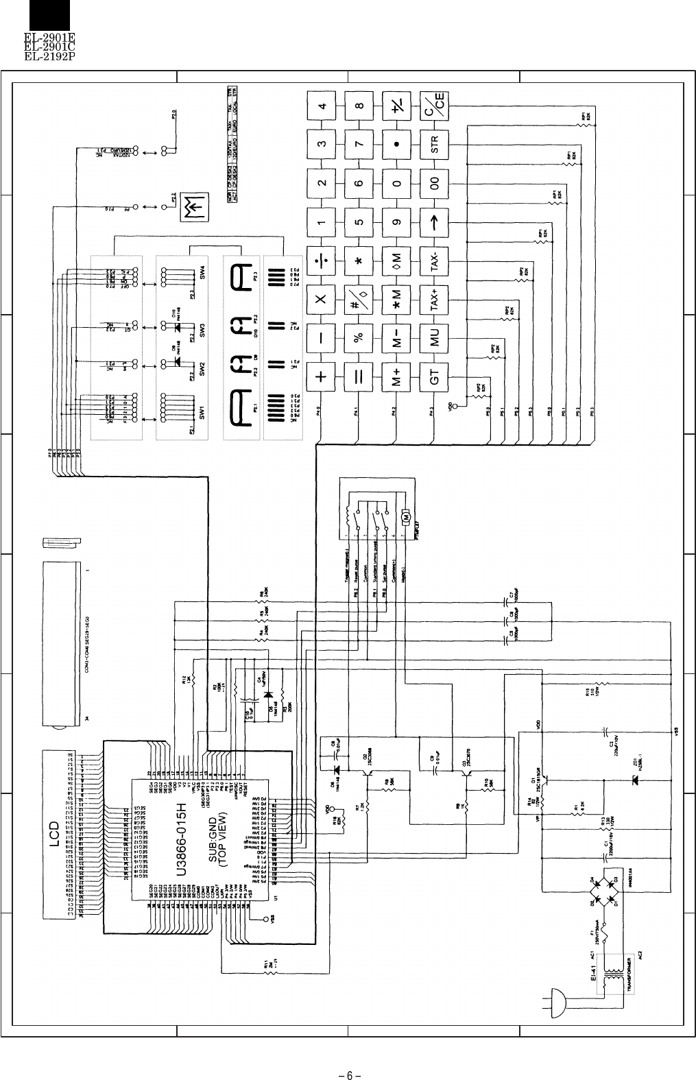
5. CIRCUIT DIAGRAM
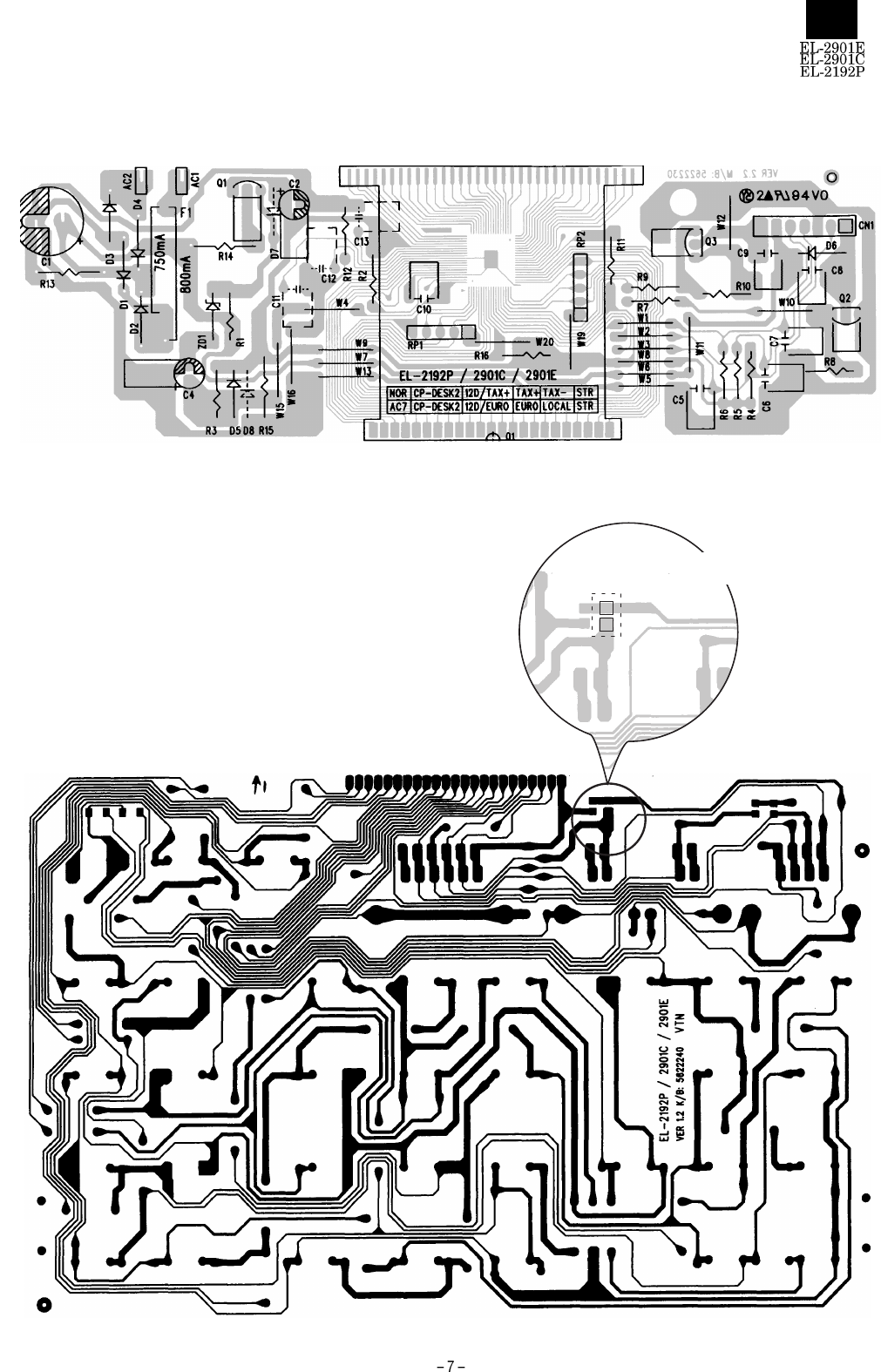
6. PWB LAYOUT
(1) MAIN PWB
(2) KEY PWB
(2) KEY PWB
(OPEN) TAX specifications
(SHORT) EURO specifications

■Parts guide
1Exteriors
NO. PARTS CODE PRICE
RANK NEW
MARK PART
RANK DESCRIPTION
10GS6177490//// AG C Paper cutter
20GS6345100//// AF D Paper holder
3
0GS6143250//// AS N D Display window (EL-2192P) [EL-2192P]
0GS6143260//// AS N D Display window (EL-2901E) [EL-2901E]
0GS6143270//// AS N D Display window (EL-2901C) [EL-2901C:AAC,ABC,TLC]
40GS6177860E/// AD N C Key top (HALF)(3KEY)
50GS6177860B/// AE N C Key top (MEMORY)(5KEY)
60GS6177860D/// AG N C Key top (FUNCTION)(9KEYS)
70GS6177860F/// AD N C Key top (TAX)(2KEY) [EL-2192P,EL-2901C]
0GS6177870F/// AD N C Key top (EURO)(2KEY) [EL-2901E]
80GS6177500A/// AH C Key top (NUMBER)
90GS6177500C/// AC C Key top (-)
10 0GS6177500G/// AC C Key top (+)
11 0GS6345120//// AC C Key top bar
12 0GS6116720//// AU N D Upper case
13 0GS6177540//// AD C SL-SW arm
14 0GS6177850//// AC N C SL-SW mask-L (BLINDER)
15 0GS6177840//// AC N C SL-SW knob-L
16 0GS6177521//// AC N C SL-SW mask-S (BLINDER)
17 0GS6177511//// AC N C SL-SW knob-S
18 0GS6345110//// AC C SL-SW contact
19 0GS6314420//// AF N C SL-SW sheet (SPACER)
20 0GS5533350//// AP N C Key rubber
21 XUBSD26P05000 AA C Screw (2.6´5) [for PWB,P/H]
22 KI-OB1078CCZZ BC E Printer unit (MFL87)
23 0GS5110270//// AD N C Flat cable (P/H,M/B)
24 0GS6314430//// AD N D Back-up tape (FOR H/SEAL)
25 0GS2192LCD//// AY N E LCD unit (LCD + H.M.F)
26 0GS6314470//// AE N C Insulation sheet (45´40´0.1)(FOR FLAT CABLE)
27 0GS5110260//// AF N C Flat cable (M/B,K/B)
28 0GS2192PWB//// BF N E PWB unit (PWB + LCD + H.M.F)
29
! 0GS3120060//// AX N B Transformer (120V)(for CANADA) [EL-2192P]
! 0GS3120070//// AZ N B Transformer (220-230V) [EL-2901E,EL-2901C:AAC,TLC]
! 0GS3120080//// AZ N B Transformer (230-240V)(for AUSTRALIA) [EL-2901C:ABC]
30 0GS6314250//// AD C LCD cushion
31 0GS6126550//// AU N D Lower case
32 XUPSN30P08000 AA CScrew (3´8) [for CABINET]
33 0GS6322000//// AC D Foot rubber
34
! 0GS5420150//// AP N B AC cord (for CANADA) [EL-2192P]
! 0GS5420160//// AP N B AC cord (for SEEG) [EL-2901C:AC7,TLC]
! 0GS5420220//// AZ N B AC cord (for ENGLAND) [EL-2901C:AAC]
! 0GS5420170//// AS N B AC cord (for AUSTRALIA) [EL-2901C:ABC]
35 PTUBU1004CCZZ AA C Protection tube (M4)
36
0GS9432130//// AD N D Rating label [EL-2192P]
0GS9432170//// AD N D Rating label [EL-2901E]
0GS9432140//// AD N D Rating label [EL-2901C:AAC]
0GS9432150//// AD N D Rating label [EL-2901C:ABC]
0GS9432160//// AD N D Rating label [EL-2901C:TLC]
EL-2901E/C
EL-2192P
– 1 –
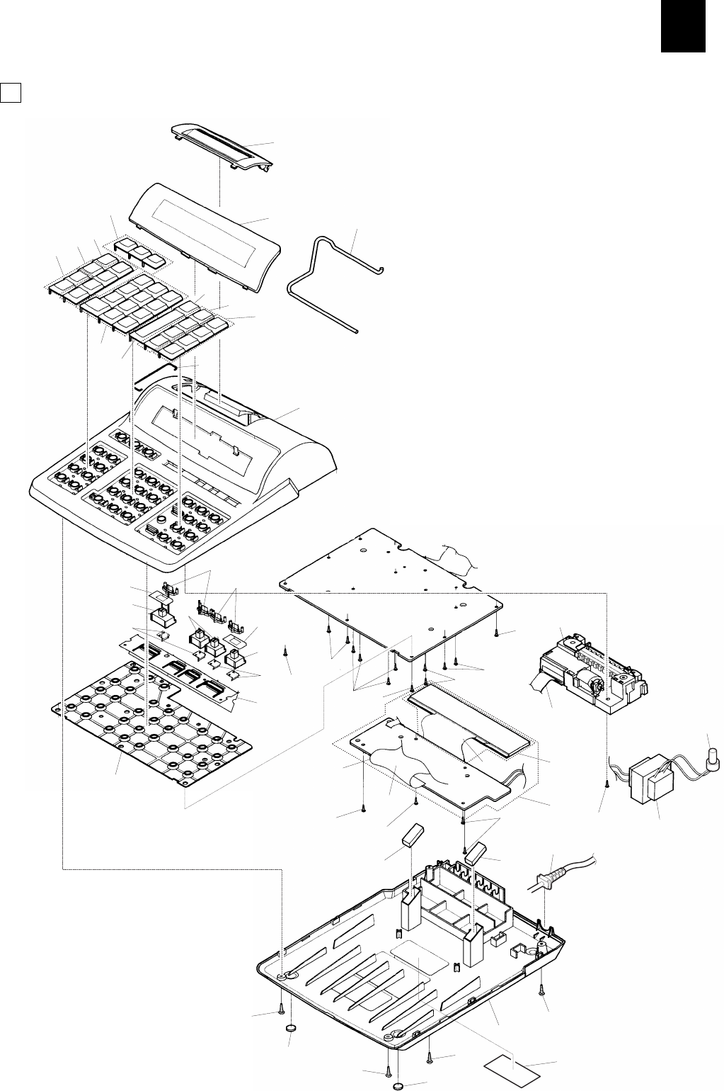
1Exteriors
CCP00076
1
32
4
5
6
7
9
10
65
8
12
13
14 13
15
18 17
19
16
17
18
20
21 21
21
21
21
21
21
22
23
25
26
21 27
21 21
24
28 21 29
35
34
30
30
31
32
33
33
32
32
32
36
11
EL-2901E/C
EL-2192P
– 2 –

2 Accessories
NO. PARTS CODE PRICE
RANK NEW
MARK PART
RANK DESCRIPTION
1
0GS9208860//// AD D Manual(E/F/S) [EL-2192P]
0GS9208920//// AP N D MANUALManual [EL-2901E]
0GS9208910//// AD N D Manual(E/F/S) [EL-2901C]
20GS9464640//// AC C Important label [EL-2901C:AAC]
3 PWB unit
NO. PARTS CODE PRICE
RANK NEW
MARK PART
RANK DESCRIPTION
1VRD-HT2EY822J AA C Resistor (1/4W 8.2KW ±5%) [R1]
2VRD-HT2EY104G AA C Resistor (1/4W 100KW ±2%) [R2]
3VRD-HT2EY204J AA C Resistor (1/4W 200KW ±5%) [R3]
4VRD-HT2EY244J AA C Resistor (1/4W 240KW ±5%) [R4,R5,R6]
5VRD-HT2EY122J AA C Resistor (1/4W 1.2KW ±5%) [R7]
6VRD-HT2EY563J AA C Resistor (1/4W 56KW ±5%) [R8,R10]
7VRD-HT2EY102J AA C Resistor (1/4W 1.0KW ±5%) [R9]
8VRD-HT2EY205G N C Resistor (1/4W 2MW ±2%) [R11]
9VRD-HT2EY133J AA C Resistor (1/4W 13KW ±5%) [R12]
10 VRD-HT2HY331J AA C Resistor (1/2W 330W ±5%) [R13]
11 VRD-HT2HY820J AA C Resistor (1/2W 82W ±5%) [R14]
12 VRD-HT2HY511J AA C Resistor (1/2W 510W ±5%) [R15]
13 VRD-HT2EY823J AA C Resistor (1/4W 82KW ±5%) [R16]
14 RMPTC5823QCKB AB B Block resistor (82KWX5 1/8W ±10%) [RP1,RP2]
15 VCEAGU1CW228M AE C Capacitor (16WV 2200mF) [C1]
16 VCEAGU1CW227M AB C Capacitor (16WV 220mF) [C2]
17 VCEAGU1HW105M AA C Capacitor (50WV 1mF) [C4]
18 VCKYPU1HB102K AA C Capacitor (50WV 0.001mF) [C5,C6,C7]
19 VCKYPU1HB103K AA C Capacitor (50WV 0.01mF) [C8,C9]
20 VCTYPU1EX104M AB C Capacitor (25WV 0.1mF) [C10]
21 VS2SC1815-GRC AB B Transistor (2SC1815-GRC) [Q1]
22 VS2SC3068-/-1 AD B Transistor (2SC3068) [Q2]
23 VS2SC3070-/-1 AE B Transistor (2SC3070) [Q3]
24 VHEHZ6B1L//-1 AA B Zener diode (HZ6BL1) [ZD1]
25 VHD10E1N///-1 AB B Diode (10E1N) [D1,D2,D3,D4]
26 VHDDSS131//-1 AA B Diode (DSS131) [D5,D6,D9,D10]
27
! 0GS3610330//// AE A Fuse (250V/750mA) (EL-2192P)[F1]
28
! 0GS3610350//// AF N A Fuse (250V/800mA) (EL-2901E/C)[F1]
101 0GS2192LCD//// AY N E LCD unit (LCD + H.M.F)
102 KI-OB1078CCZZ BC E Printer unit (MFL87)
(Unit)
901 0GS2192PWB//// BF N E PWB unit (PWB + LCD + H.M.F)
EL-2901E/C
EL-2192P
– 3 –

COPYRIGHT ã 1999 BY SHARP CORPORATION
All rights reserved.
Printed in Japan.
No part of this publication may be reproduced,
stored in a retrieval system, or transmitted.
In any form or by any means,
electronic, mechanical, photocopying, recording, or otherwise,
without prior written permission of the publisher.
SHARP CORPORATION
Information Systems Group
Quality & Reliability Control Center
Yamatokoriyama, Nara 639-1186, Japan
1999 July Printed in Japan
