ELX_33395_English ELX 33395 English
User Manual: ELX_33395_English
Open the PDF directly: View PDF ![]() .
.
Page Count: 20
ELX
Offset Cultivator
Instructions for use and maintenance
The following instructions must be read carefully prior to using the machine.
In accordance with article 2006/42/CE
and subsequent modifications
SERIAL
33395
In regards to safety and reliability this machine was designed in accordance with the provisions and subsequent
revisions set out in the EEC “machines article”.
The manufacturer therefore cannot be held responsible for machine use where modifications have been made without
prior manufacturer’s consent, replacement parts used are not those stated by the manufacturer and use by untrained
persons.
For safety issues not covered in this text please refer to general standards concerning the prevention of accidents.
Below is a list of definitions, descriptions and abbreviated terms most frequently used in the text.
Mass. = weight of object or machine
A.P.
B.P.
min.
max.
1'
h
L
P
H
Fig.
Pag.
Autom.
Man.
Rif.
Hp
°C
kg.
m.
cm.
mm.
CEE
high pressure
low pressure
Minimum
Maximum
minutes
hours
width
depth (length)
height
figure
page
Automatic
Manual
Reference
Horsepower
centigrade
kilograms
meters
centimeters
millimeters
European Economic Community

EC DECLARATION OF CONFORMITY
As stated by the EC directive 2006/42/CE and subsequent modifications
The undersigned
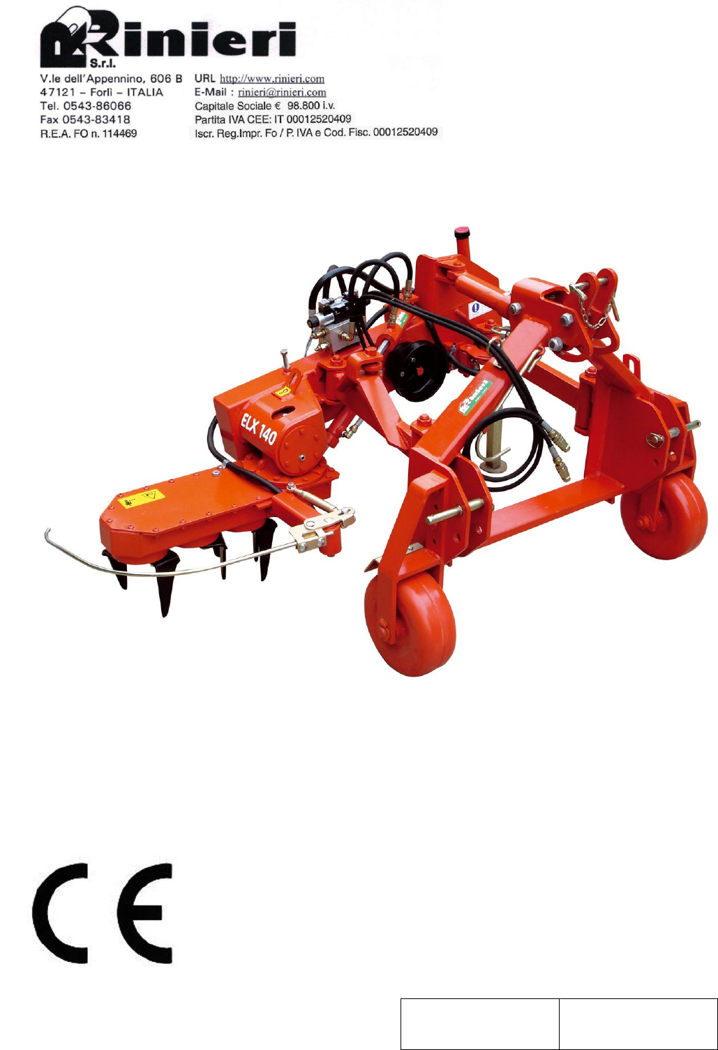
RINIERI S.r.l. - Forlì – Italia - Viale dell’Appennino 606 B
Declares under its responsability that the machine:
Hydraulic offset cultivator with vertical axles system, working size with 4 rotary tine sets, supporting wheels,
independent hydraulic kit, independent electro-hydraulic control block, hydraulic tilting with tubes linked to the
tractor, emergency control with proximity sensor to electro-hydraulic push button, complete with patented device
“RSA” for shifting mechanical control.
Model “ ELX 140-B “
Code no. 60790B
Serial no. 33395
Is in accordance with essential health and safety requirements of the machinery directive 2006/42/CE and its
subsequent modifications.
For the verification of conformity to the directive mentioned above, the following directives were respected:
UNI EN ISO 12100:2010 Safety of machinery - General principles for design - Risk assessment and risk reduction
UNI EN ISO 4254-1:2015 Agricultural machinery – Safety – Part 1: General requirements
UNI EN ISO 4254-5:2010 Agricultural machinery - Safety - Part 5: Power-driven soil-working machines
Forlì, 20 February 2017

ATTENTION
THE PURPOSE OF THIS TEXT IS TO INTRODUCE YOU TO THE
BASIC STANDARDS AND CRITERIA YOU HAVE TO FOLLOW IN
ORDER TO USE AND MAINTAIN THIS MACHINE AND THUS IT
HAS TO BE READ BEFORE USING THE MACHINE.
This manual has to be considered as an integral part of the machine and must be passed on with the machine if resold.
If you loose it or if it is not readable, it is important that you ask for a new copy to the producer, to the dealer or to the
importer.
If you think that some themes are not very good illustrated, return to the producer, the dealer or the importer to have
the needed informations.
INDEX
DESCRIPTION
DECLARATION OF CONFORMITY
INDEX
INTRODUCTION
GENERAL INFORMATION
RECOMMENDATIONS
DESCRIPTION OF THE MACHINE
USE
PRE-OPERATION
IDENTIFICATION DATA
ADHESIVES
SAFETY REGULATIONS
IMPROPER USE
INCORRECT USE
METHOD OF USE
REGISTRATION
MAINTENANCE
TRANSPORT HOISTING MOVEMENT
SPARE PARTS
CONDITIONS OF GUARANTEE
Page
3
6
7
7
7
8
9
9
10
10
11
13
13
13
14
16
18
19
20

INTRODUCTION
Dear Customer,
the purpose of this text is to introduce you to the basic standards and criteria you have to follow in order to use and
maintain this machine and thus it must be read before using the machine.
If any part of this publication is not understandable please consult your retailer as this is a necessary precondition to
using this machine safely.
Your safety depends on your careful and rational observation of the standards laid out in the text as well as the proper
functioning and durability of your machine.
This manual must be considered as an integral part of the machine and must be passed on with the machine if
resold.
This publication contains all the general specifications needed to have a working knowledge of the machine without
regards to specific types, models and the numerous characteristic modes and settings.
GENERAL INFORMATION
INSTRUCTION MANUAL
Verify that this manual is in good condition and all pages are readable.
If damaged or missing pages on receipt, please return to the retailer who will provide a replacement copy.
PRESERVATION AND CARE OF MANUAL
This manual must be kept for the entire life of the machine.
If lost of destroyed please ask the manufacturer for another copy quoting the type of machine, serial number and year
of production.
IN HOUSE TESTING
The machine has been tested on the manufacturer’s premises to verify that all components function correctly
according to standards laid out by the standards in force.
DELIVERY
Responsibility for goods in travel lie solely with the transporter and recipient.
In cases of delayed delivery or accident and the manufacturer cannot be held responsible.
Transportation of goods has to be carried out by suitable companies who comply to regulations in force and legislation
concerning weights and bulks.
INSPECTION
On receiving the machine check the condition.
Should you come across any damages don’t install the machine, instead inform the supplier and transporter
immediately.
Make sure the machine is in good condition.
Check you have all components, the overall condition of the machine is good and there are no breakage or dents.
In cases of damages or missing components inform the retailer immediately after taking legal proceedings against the
transporter, if necessary.
PACKAGING
Packaging material and maintenance waste must be disposed of separately at authorized depots and not left in reach of
children or animals or to litter the environment.
MACHINE DETAILS
An exact model description, identification code, serial number and any installed accessories will help the
manufacturer or call center deal with any enquiries quickly and efficiently.
Always refer to the machine model and production dates every time you contact the call center, retailer or
manufacturer.
For quick reference fill in your machine details in the box below
MODEL:
ELX 140-B
SERIAL NUMBER:
33395
CODE:
60790B
YEAR OF PRODUCTION:
2017
RECOMMENDATIONS
Before use please read the instructions carefully, in particular the RECOMMENDATIONS, SAFETY
REGULATIONS and PRECAUTIONS.

We remind you that some machines mechanical parts have linear or rotatory movement and can cause serious damage
or injury to people, animals and things.
It is forbidden to remove or tamper with the safeguards of the machine.
It is obligatory to wear the correct protective clothing and safety equipment.
It is necessary to keep the machine clean and in working order especially the nameplates, couplings and controls.
For the safety of you and others and the proper functioning of the machine don’t use the machine for uses other than
those specified or intended by the manufacturer.
Before using the machine make sure that any dangers to your safety or others have been removed. Pay attention to the
type of oil of used in cases where the equipment is used with different types of tractors.
VERY IMPORTANT
For all operations use proper working clothes and/or suitable safety apparel like glasses, shoes, gloves, and
working cloth in accordance with the safety standards in force in the working area.
The working area must be kept completely clear, so pay the utmost attention that there aren’t any people or
animals in the immediate area.
Nobody else apart from the operator must be within the working zone other than collaborators which for
safety should be no less that 50 mtrs.
Maintenance of the equipment must be carried out by only one operator with the machine off and tractor at a
standstill (off) with the ignition key removed.
DESCRIPTION OF THE MACHINE
The hydraulic offset cultivator with rotary tines (Fig.5) mounted on vertical axles, can be applied to three point
hoisters of ordinary 50-80 hp tractors, and is powered by the power takeoff through mechanical transmission.
The machine is built in a three working size with four rotary tine sets (Fig.4) that measure 65 cm., but with a single
extension length from the center of the tractor to the cultivator’s right-hand outer extremity (cm. 115 - 140 - 170).
The rotors are powered mechanically by a chain (Fig.15, Table 2) and gears (Fig.8 and 17, Table 2).
The in and out movement that allows for plant stocks to be avoided, works with a parallel arm system (Fig.2).
The arms are supported by ball bearings hinged to the hoister frame (Fig.1) and machine structure (Fig.3).
Additional balance is provided by a third arm, while the necessary drive is provided by an independent oil hydraulic
system (Fig. 8).
The distributor command (Fig.7) that allows for plant stocks to be avoided is automatically triggered by a sensor
(Fig.6).
The emergency control is electro-hydraulic with proximity fuses (Table 4).
The angle of the rotor head is adjustable by means of a hydraulic jack (Fig.9) operated directly from the driver’s seat.
Its outer extremity can be raised or lowered to match the ground’s inclination.
The hoister frame is provided with supporting wheels (Fig.10), and a gas spring damper on the third point (Fig.11) for
rocky terrain to cushion violent strokes.
A machine version with a patented device for automatic control of the shifting movement “RSA” is available upon
request.
Model
115
140
170
Code
60789M
60790M
60791M
A
m.
Min.
1,70
2,00
2,50
Max
2,30
3,00
3,80
B m.
1,15
1,40
1,70
C m.
0,65
0,65
0,65
D m.
0,50
0,50
0,55
Weight Kg.
370
390
410
Working
Depth m.
0,05
0,10
0,05
0,10
0,05
0,10
Maximum Speed Km/h
4,00
4,00
4,00
Tractor
Power
HP
50-80
50-80
50-80
KW
39-63
39-63
39-63
7
3
4
6
5
8
11
1
9
2
10
USING
The ELX is used for light tillage and weeding around vineyard and orchard rows and between plant stocks, even when
plants are grown as close as 40 cm from each other.
It is suitable for vineyards and orchards situated on slopes with loose, fine and medium soil, and on rocky terrain, but
the rocks must not exceed 12 cm.
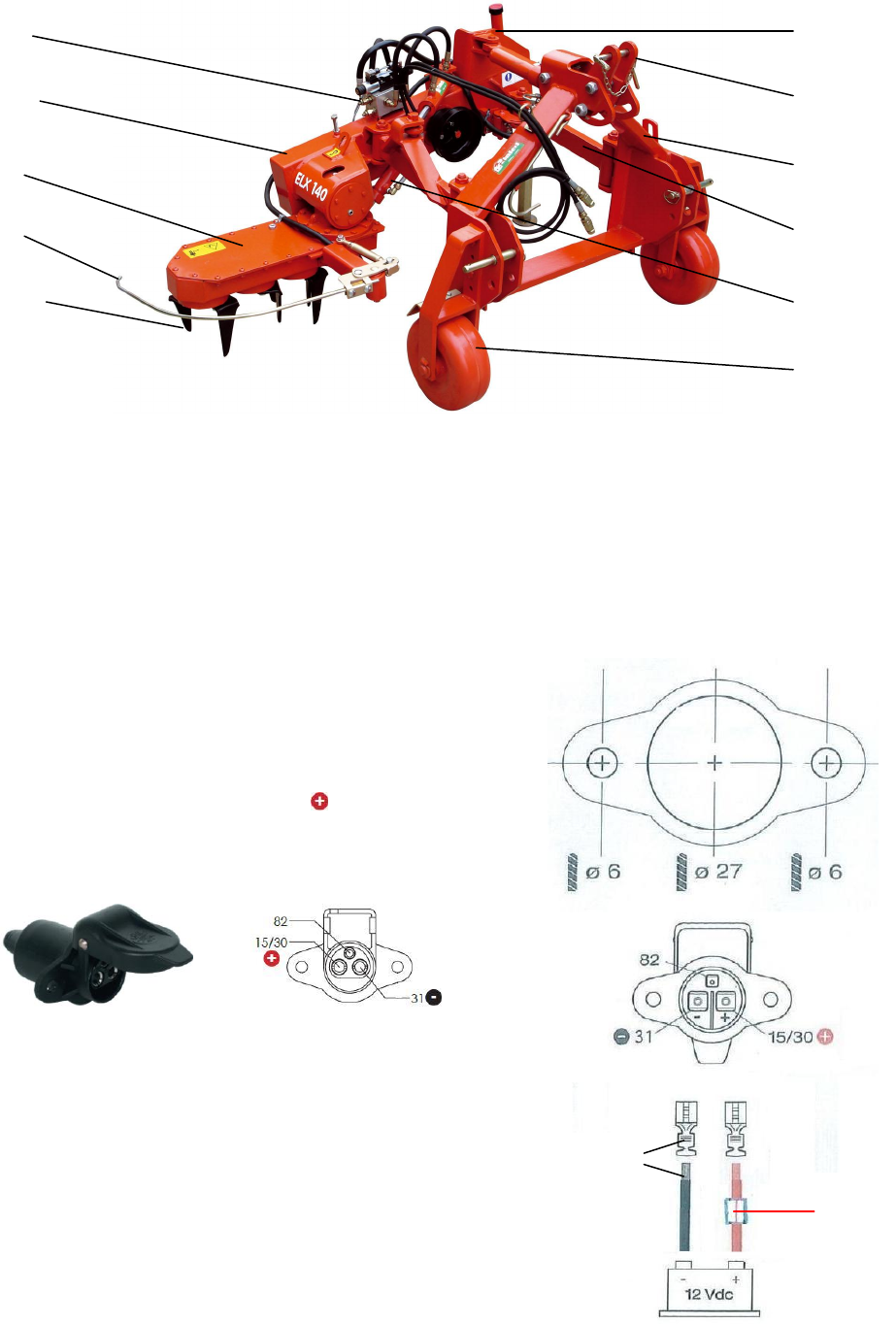
PRE-OPERATION
If the tractor does not have any 3-pin plug attachments, adapt its
system with the same 3-pin plugs that come with the machine
considering the scheme here above.
Connect the two 4mm2 diameter cable groups max. impedance 18A
directly to the 12V battery of the tractor, one group for every 3-pin
attachment to add to the existing system.
For every group insert on the red power cable a 10A fuse.
Connect the 3-pin plugs to the tractor using the piercing mask printed
on the blister, then connect the cables to the 3-pin plugs paying
attention to respecting polarity.
3-pin attachment
The “ELX” cultivators that we deliver personally or pack and ship
partially assembled are provided with grease in the hydraulic system,
bevel gears, and gearbox, unless directed otherwise.
They were fully tested after assembly by having them revolve at full
speed and the hydraulic ram end stops have been adjusted.
If the machine is delivered without hydraulic oil in the hydraulic
unit’s tank it is necessary to fill it before starting to use the machine.
Use a mineral oil grade ISO VG 46 for hydraulic units like, for
example, Mobil DTE 25 and an aspiration oil filter with metal net
of µ60 with a flow of 54 L/min.
Ensure that all levels are equal to those described in the
MAINTENANCE chapter.
Apply the machine to the tractor using appropriate pins and, if
necessary, use the adaptor bushings.
The tractor should be heavy enough to counterbalance the arm when it is fully hoisted so that the front tires do not
lose their grip.
If it is not included with the machine, connect an adequately powered cardan shaft making sure the side with the
picture of a tractor is inserted in the tractor’s power takeoff.
Safety devices, should be applied only on the machinery side.
Fuse
10 A
Crimp
or sold

Secure the shaft’s safety casing to the tractor and cultivator using the appropriate anti-rotational chains.
Never use the shaft without its safety casing and without having secured it with its respective chains.
Find the position in which it is retracted the most in the various shifting movements, making sure it can still be
shortened an extra 5 cm.
Before installing, using or performing maintenance operations on the transmission, read all the instructions
contained in its manual, as well as those provided by the tractor and equipment manufacturers.
Connect the 12V power plug to the tractor.
Set the emergency control box selector (Fig.9, Table 4) to the working position then start-up the power takeoff so that
the machinery will automatically shift to the right.
By pressing the red button adjacent to the selector on the emergency control box, machinery shifts back to the left
while the button remains pressed.
When the power takeoff is started-up with the machinery hoisted, make sure it is perfectly horizontal, or the
inclination may cause it to move at a much greater speed downward than when it is actually at work.
IDENTIFICATION DATA
ATTENTION
CHECK YOUR MACHINE: if you don't find an identification tag, ask immediately for it to your retailer.
Machines without identification tag mustn't be used. Our factory doesn't recognise them, so consider them as
anonymous and potentially dangerous.
Identification tag should always be attached on the machine and should be well readable, so, if it deteriorates or if you
loose it, please ask the manufacturer or your vendor buy a new one.
Identification tag of the machine
The identification tags are little plates fixed to the machine
frame and it supplies the following information:
A
Manufacturer
3
Serial
1
Model
4
Bulk
2
Code
5
Year of construction
ADHESIVES
The following safety adhesives are placed on the machine for your safety and the safety of others.
Go through the manual taking note of the meaning of every warning or danger sign.
This procedure has to be done together with your fellow operators and anyone using this equipment.
If in the event that one of these adhesives goes missing or becomes illegible you must get an immediate replacement
by contacting your retailer, or the manufacturer.
Indicates the equipment’s place of origin;
built or assembled in a country that belongs to the
European Economic Community
CAUTION
The power takeoff must be set to 540 rpm
with a working speed between 280 and 400 rpm
CAUTION
Read and refer to the “use and maintenance” instruction manual
carefully before using the equipment or performing any kind of work
on it.
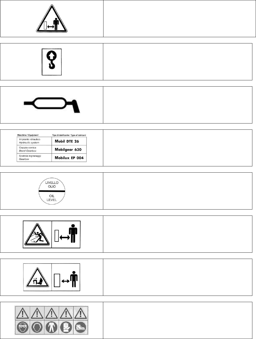
CAUTION
Danger: machinery may suddenly shift laterally.
Keep safety distance.
Hook for hoisting and handling the machinery.
Indicates the areas that require grease injections.
Indicates the different types of lubricant that must be used on the
various machinery components.
Indicates the ideal oil level in the hydraulic system’s
oil reservoir.
CAUTION
Danger: rocks or ground particles may be expelled from the
machinery while it is in use.
Keep safety distance.
CAUTION
The machinery contains sharp rotating tines;
Keep safety distance and wait for the components to stop rotating
before performing any work on them.
CAUTION
Suitable safety individual equipment must be worn.
SAFETY REGULATIONS
The use of this machine is for skilled and specialized persons with appropriate abilities and competence in carrying
out operations.
The must have a good knowledge of this manual and are informed in general safety procedures.
Follow with the utmost care and attention instructions for your safety, the safety of others and of environment.

SYMBOLS TO REMEMBER
Danger for people
Danger of serious damage to the machine
General danger
Protect the environment
The operator must always stay in the drivers seat and never abandon it when the equipment is on and
the engine is on.
The operator must never leave the drivers seat with the aim of making adjustments or other reasons
as it could create a dangerous situation.
The operator must always stay in the seat alone and not carry other people animals or things.
The operator must wear appropriate work overalls / clothes and not loose clothing which could get
caught in moving parts of the vehicle or equipment causing serious injury.
It’s necessary to wear personal protective devices for eyes (face mask, goggles) and protective
headphones for acoustic pressure in places of work it is greater than 85 db.
Don’t wear rings, wrist watches, loose articles of clothing or hanging things, torn clothes, shoes,
unbuttoned jackets or blouses which can get caught in moving parts. We advise you to use approved
articles of clothing for accident prevention for example sturdy gripped boots, safety goggles and face
mask, above all if the vehicle is automatic without a cabin.
We advise you to consult the appropriate public authority concerning the acquirement of accident
prevention devices and vineyard safety.
The operator must have suitable abilities and psychophysical conditions in order to understand how
to apply correctly all the instructions specified in this manual and all the symbols and captions on
the machine.
Do not use the machine if you are under the influence of medicines, alcohol, or other substances that
could compromise your normal level of attention, perception and reaction.
When on the streets, respect meticulously the provisions in force, in particular as far as lighting,
safety devices, maximum dimensions, juts etc are concerned.
Drive very carefully because the equipment limits visibility.
When you have to drive on streets to reach the work place, make sure that the machine is in line with
the moving vehicle and that it does not cover possible lighting and signaling systems; if this is not
possible, put the machine on a type-tested tow.
Before leaving the driver’s seat, disconnect the power source, switch off the engine, take out the
ignition key and put on the handbrake.
Do not allow the machine to be used by any operator ignoring the risks and instructions reported in
this manual.
Keep the equipment clean and in order.
Do not use any equipment with faulty components.
Additional safeguards have been placed by the manufacturer for the safety of the operator during his
work; their removal or tampering is therefore absolutely forbidden; instead, always make sure that
safeguards and safety devices are in place and work properly.
For the operator’s safety and the equipment’s integrity, do not modify anything without the written
authorization of the manufacturer.
Make sure that no one is in the working area of the machine when in use, (minimum distance to
respect: at least 50 meters), pay much attention to children and animals.
Verify the stability of the machine on a flat while the machine is working.
Do not work on soft ground, on too extreme slopes or that can compromise the machine’s stability.
Remove possible obstacles as wood, tree trunks , scraps which could damage the machine and its
stability.
Clean your shoes’ soles before getting up the machine and using the pedals.
Do not try to take out material with tools or with hands or feet while the machine is working: stop
the tractor, switch off the PTO, take off the key and wait some minutes that the machine stops before
repairing it.
If you have to stop while working, stop the machine on a flat with operated hand brake and first
speed, disconnect the PTO, turn off the motor and take out the key.
Be always sure that every part of the hydraulic kit is well closed.
Do not tamper the security system.
The security of your machine depends on its efficiency, so respect the instructions and the
maintenance, on its efficiency, so respect the instructions and the maintenance.
IMPROPER USE
By improper use we mean:
- using the machines for operations they were not designed for or for usages that do not appear in the chapter
“Machine’s Description and End Use” of this manual;
- use of the machine by people under the age of 18, and/or people not trained to use this kind of equipment.
INCORRECT USE
By incorrect use we mean using the machines without respecting the instructions of the manual.
Not respecting these instructions could risk injury to the operator or third parties, and cause damage to the machine.
Incorrect use can thus mean:
- incorrect installation and/or use of the components or optional accessories.
- incorrect preparation of the machine.
- not using the manufacturer’s spare parts.
- repairs by non-authorized people.
- maintenance by non-qualified people.
- uses the machine is not designed for (see above), lack of maintenance.
WARNING: the manufacturer cannot be held responsible for any injury to people, animals or damages to
things resulting from improper or irresponsible use, as mentioned above.
METHOD OF USE
Users
Users are divided into two categories:
- OPERATOR: a person without technical knowledge but trained to use the machine and carry out simple
maintenance and adjustments.
- QUALIFIED TECHNICIAN: a person who works on behalf of the manufacturer and/or retailer and can carry out
complex maintenance and repairs.
Indications before using
Before starting the machine, you should read this manual carefully.
Check that everything has been installed and checked by a qualified technician.
Send away everybody from the working area before starting work, than proceed slowly checking your machine.
Make sure there are no people standing in the vicinity of the machine and start up the power takeoff slowly until it
reaches a maximum of 400 rpm within the 540 rpm range.
Check that everything is functioning properly and that there are no vibrations.
Use a speed of advancement that does not exceed 3 Km/hr.
The cardan shaft’s actual speed of rotation should remain between 280 and 400 rpm to obtain optimal results.
Follow a straight line while moving forward and try to insert the outer extremity of the machine between the plant
stocks without going beyond 5 cm of the rows’ centerline.
When the machine is resting on its skids, adjust its working depth by regulating the threaded arm of the third point on
the tractor hoister.
Use the respective hydraulic jack to tilt the rotor head to the most appropriate angle in order to obtain an even working
depth.
Use the manual chord or electric button of the safety device to operate the equipment when plant stocks are bent or
feeble, since these may cause the feeler pin to perform inefficiently.
Work the same row on both sides; if it is on a slope, preferably work the side that is positioned uphill first.
The equipment should not absorb more than 25 hp from the power takeoff in normal working conditions.
If it is used with tractors that exceed 35 hp, immediately adjust the various settings and operating procedures before
the equipment show signs of excessive strain.
The machine was designed to operate at a maximum working depth of 10 cm. Increasing the depth does not improve
the weeding process; it would produce greater power absorption, ultimately causing the pieces to wear out
prematurely.
CORRECT USAGE: keep in mind that each time the machine operates in close proximity to plant stocks the cardan
shaft retracts and subsequently extends enduring torque strain.
While working, maintain the joints at the same angles and within the following parameters: max 25° for continuous
work, and max 45° for intermittent work (with up to 5 minutes of continuous work).
The cardan shaft will encounter greater resistance when the soil is hard or coarse, and when the working depth and
shifting movements are greater.
In these cases, the shaft will require more power from the hydraulic system, which may cause it to overheat.
Detach the equipment if you intend to perform maneuvers that would require greater angles than those indicated.

The hydraulic system was designed to operate for prolonged periods of time, and it is normal for the oil temperature to
rise to 60°C when the outside temperature is 30°C.
If the oil overheats excessively, check the telescopic cardan shafts and make sure they function properly and are
adequately greased.
Follow the directions in the CORRECT USAGE section of this chapter.
SAFETY MEASURES
Before working
Check the stratification, the ground type to work out the method of work, the adjustment and the speed of the
machine.
Always check that the safeguards are well installed and that no one is in the immediate area (10mtrs minimum).
Only use the machine if it is in perfect working order.
During work
Do not let anyone come within the working area; they must respect the minimum safe distance of 10 mtrs; cordon off
the working area and put warning signs up if necessary.
While working, keep other people far from the machine, and in particular from the sides of the machine NEVER
STAY BETWEEN TRACTOR AND MACHINE.
Use the tractor’s power take-off at 400 r.p.m. IN THE 540R.P.M. MODE, never for any reason whatsoever, set
it to a 1000 r.p.m
If you stop working; disconnect the power source, take out the ignition key and put on the handbrake before getting
out of the tractor.
Maintain an appropriate speed in order to avoid dangers to you, others and the equipment itself.
While working or during the machine’s moving, do not carry on the machine hanged or seated people.
When moving on inclined grounds avoid swerving which could cause sliding and overturning.
On uneven grounds or those with obstacles go as slow as possible.
When using the equipment after a long time of inactivity, we advise to check the functioning of the hydraulic system.
The way the equipment (when present) is used, must take into account the “equipment / vehicle” stability ratio; while
working continually check the stability.
During work always be alert.
When stopping or stationary pay attention to the ground where you have stopped making sure there are no bumps that
could compromise stability. Stop your vehicle and block the equipment in a way that it is secure and does not put you
or others at risk.
NOTE
Do not repair the machine with bad or improvised adjustment because it could cause a bad quality of the work For this
reason be sure that your tools are not consumed, pay attention to the working speed, elements which are linked
together.
RISKS
Every machine can cause a risks so this very dangerous let somebody be near the machine if not authorized.
In order to eliminate risks, REMEMBER to take of the key and to mount again the security devices in good and sure
position.
REGISTRATION
Every proximity sensor is activated by a cam. In order to guarantee correct functioning of the plant avoiding
movements of the working heads, every cam is registered during the assembly and the testing phase of the machine.
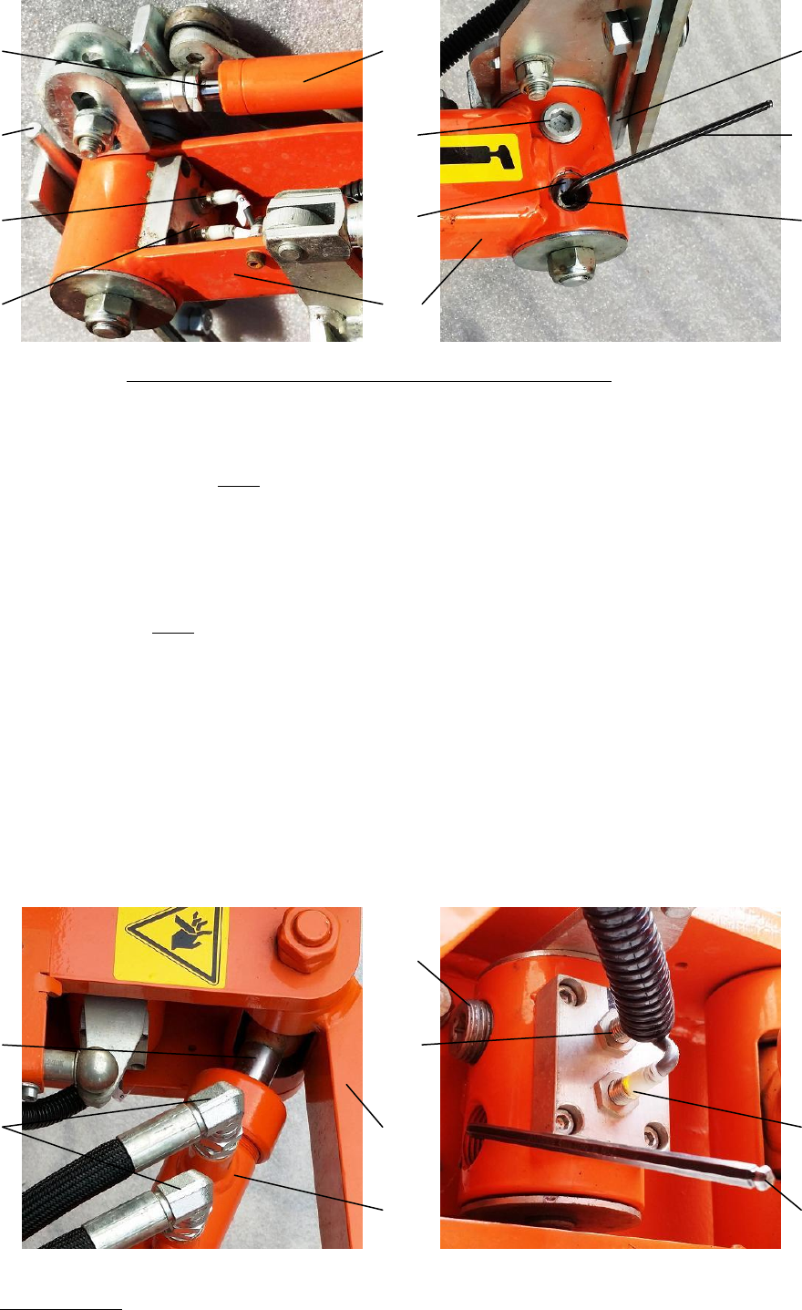
If necessary, register the cams again.
- for the cams of the sensor support (Fig.1) of the working heads, proceed as follows:
With the machine connected to the running tractor, with the working head in an open position and with its sensor
(Fig.2) in an open position (i.e. without touching any obstacle), push it until the rod of the gas spring for calling back
the sensor (Fig.3) is lengthened more than 1 cm., then insert between the head and the spring’s body a distance piece S
of 1cm. and let the sensor go.
Remove the stopper (Fig.4) of the lower cam (Fig.5), loosen the screw (Fig.6) and, using the key (Fig.7) that is still
inserted into the screw, turn the cam until the proximity sensor P2 results turned on, then retighten the screw of the
cam and put back the stopper.
Pay particular attention to stopping the rotation of the cam and tightening it with the screw the moment the light of the
sensor turns on.
In the same way, for the upper cam, insert between the head and the body of the spring a distance piece S of 2 cm.,
then turn the cam until the proximity sensor P1 results turned on.
Check the correct registration in relation to the lengthening of the gas spring’s rod.
From the resting position to 1 cm. the proximity sensor P2 has to result turned on, from 1 to 2 cm. the proximity
sensors P2 and P1 have to result turned off, from 2 cm. and more the proximity sensor P1 has to result turned on.
S
2
P1
P2
3
4
5
1
2
7
6
- in order to register the cams of maximum opening/closing of the hydraulic cylinder (Fig.8) of the plant avoiding
arms (Fig.9), proceed as follows:
With the machine connected or disconnected to the spent tractor, unscrew the tubes (Fig.10) of the hydraulic cylinder
on the side of the commando block and let the oil flow out into a collection tank.
Also empty the inside of the hydraulic cylinder by opening and closing it a few times manually by moving the arms.
Remove the stopper (Fig.4) of the lower cam (Fig.27, Table 2) and loosen the screw (Fig.26 Table 2).
With the head in an open position and the hydraulic cylinder completely closed mechanically, manually move the
plant avoiding arms in order to lengthen the cylinder’s piston rod S by 3 cm..
By using the key (Fig.7) that is still inserted into the screw, turn the cam until the proximity sensor P4 results turned
on, tighten the screw of the cam and put back into position the stopper, then let the sensor go.
Pay particular attention to stopping the rotation of the cam and tightening it with the screw the moment the light of the
sensor turns on.
In the same way, for the upper cam, with the head in a closed position and the hydraulic cylinder completely opened
mechanically, shorten the piston rod of the cylinder S by 3 cm., then turn the cam until the proximity sensor P3 results
turned on
Check the correct registration in relation to the lengthening of the cylinder’s piston rod.
From a closed position to -3 cm. the proximity sensor P4 has to result turned on.
From -3cm. in closing to -3 cm. in opening the proximity sensors P4 and P3 have to result turned off.
From -3 cm. to an opened position the proximity sensor P3 has to result turned on.
It is important that the proximity sensors of maximum opening/closing of the hydraulic cylinder are activated before
the cylinders arrive at their mechanical maximum position as, in the long run, the repeated stress might cause their
earlier deterioration.
Reconnect the cylinder’s tubes to the commando block and refill the hydraulic system with the collected oil.
With the machine connected to the running tractor, activate the movements of the hydraulic system in order to refill
the circuit of the cylinder.
S
10
4
P3
9
8
P4
7
The two independent commando blocks have a general maximum pressure valve (Fig.1) tared at 120 bar.
The movement speed can be modified proportionally by using the adjustable flow divider (Fig.2).
By increasing the speed of the plant avoiding movement made by the parallelogram group the speed of the lateral
extensions is reduced and the other way round.
There are a maximum pressure valve for the movements (Fig.3), and a shockproof maximum pressure valve only for
the parallelogram group (Fig.4).

The flow divider (Fig.5) can modify the speed of the tool’s motors.
PATENTED DEVICE “RSA” FOR AUTOMATIC SHIFTING MECHANICAL CONTROL
The patent device “RSA” controls the side shifting of the machine when it goes near the line of the trees.
The side shift is counted every time the sensor leave the trees. And the machine stop at the distance set.
In this way the position of the machine and in particular of the working head does not depend on the position of the
tractor in the row anymore.
In case that the tractor is too close at the row, the machine (if programmed following
our instructions) does not go too much into the row.
To modify the side shifting of the “RSA” press “set” on the box, then increase or
degrease the number of counting that appears on the small screen with the small arrow
form bottoms.
The best range of work is between 15 and 20 step.
Then press the bottom “F” to memorize the change or wait for 50 seconds for the
automatic memorizing.
In case the control device looses its program, this can be reprogrammed following the
schedule behind: press SET.
Part
Description
Definition
1
F1
Operation OUT 1
3
2
F2
Operation OUT 2
0
3
H1
Set for max computation
50
4
C
Computation
1
5
r
Restart time
10
6
H
Input max frequency
5
7
d
Time – sharing computation
1
8
B
Back-up
2
9
E
Input operation RES
1
10
t
Frontal key operation F
1
The safety zone around plant stocks is determined exclusively by the position of the sensor (Fig.14 Table 3); the are
two different setting of this part:
- the first is the angle of the sensor that can be changed by loosen the nut (Fig.3T, Table 3) and rotate the sensor
attachment brackets (Fig.13, 14 and 15, Table 3) to the desired position by letting the screw (Fig.8T, Table 3) slide
along the slot at the base of the sensor support (Fig.18, Table 3), when it is moved to the desired position tighten the
nut.
- the second is the distance between the external side of the working head and the sensor that can be changed by
loosen the nuts (Fig.16 Table 3) which hold the plate (Fig. 15 Table 3) and slides the sensor, then tighten again the
nuts.
It is important to respect a distance of 10 cm between the working head and the sensor at the turning on of the led P2
inside the sensor support arm (Fig. 9 Table 3).
MAINTENANCE
Maintaining the machine in a perfect condition means it has a longer life expectancy and retains optimum
performance; thus regular small checks are necessary.
This allows for a perfect working order and good reliability.
Cleaning, lubrication and adjustment of the machine must be carried out when it has been turned off.
General safety measures
Do not allow unauthorized people to interfere with the machine.
Before carrying out checks or maintenance, verify that the machine is completely off.
Never put your fingers in the machine openings without protection.
Never align holes or with your fingers but only with the appropriate centering tools.
Do not touch tools without wearing the correct protective gloves.
Never use petrol, solvents or other inflammable liquids as detergents but use recommended non-
flammable and non-toxic commercial detergents to clean the machine.
While using compressed air to clean and/or dry machine parts protect your eyes with goggles and

limit the pressure.
Keep the machine clean and in order.
Replace immediately any warning or instruction adhesives, which are no longer visible or missing.
Do not solder near the hydraulic tubes in order to prevent fires.
Pay close attention to losses from the hydraulic system; leakages from small holes can be almost
invisible but are able to penetrate beneath the skin: in these cases use face and hand protection.
Never carry out checks to identify leakages with bare hands..
CLEANING
Wash only with neutral products and water to remove traces of corrosive fluids; dry carefully making sure there are no
pockets of water.
If traces of dirt remain, we recommend using specific products following the instructions carefully.
WARNING: DO NOT USE products containing perfumed solvents, methanol or hydrocarbons to clean painted parts.
HYDRAULIC SYSTEM
Control regularly all the tubes of the hydraulic system are fitted properly and there are no leakages; verify that tubes
are intact.
Always take the necessary action, whether by repairing or replacing, every tube which is loose or which shows signs
of abrasion, tear, defective mounting, or oil loss even from the connections.
Check the connections and ensure that they have been properly joined in relation to each other before pressurising the
hydraulic circuits.
Avoid bending, or scratching tubes of the hydraulic system with sharp or abrasive objects.
Replace tubes which show any signs of damage caused by crushing, cracking, use, or with defective connections and
avoid using them again.
They could explode during use.
The hydraulic circuits are under pressure and therefore, before adding or removing hydraulic oil,
inspect the circuit, place the equipment on the ground and completely discharge the remaining
pressure in the system, operating the control lever several times, having first switched off the tractor
motor.
The hydraulic oil in the system is hot, even when use is no longer being made of the machine.
wait for the oil to cool down before carrying out any work on hydraulic lines.
The jet of oil which small losses from the tubes under pressure can generate is dangerous: it can
pierce the skin or damage the eyes.
Always wear thick gloves and safety goggles.
To avoid damage, always use the same oil.
The standard machine can work with the mineral oil of the tractor, like Mobil Multivariax/35 HP with viscosity grade
ISO VG 68, with the following limitations.
Remember that disposal and law regulates collection of used oil.
Take the aforementioned residues to the appropriate disposal center or keep them in tanks and call
specialized companies to dispose of them.
It’s absolutely forbidden to take them to illegal dumps or to dump them in rivers or sewers.
HYDRAULIC SYSTEM MAINTENANCE
If the machine has got an hydraulic kit, we are used to employ an hydraulic oil such as Mobil DTE 25 with viscosity
46 and a working duration of 5.000 hours in constant conditions, with hydraulic oil level at 3/4 of the tank capacity.
Variable working conditions, such as :variation in effort, heating/cooling of the daily temperature,(with the
consequent creation of condensation and pollution )decrease the working duration that we can evaluate in about
1200/1500 hours of work.
During this period you have to check periodically the oil level in the tank and if necessary fill it up with oil which
has the same viscosity.
When the oil has been completely replaced, we suggest to replace the filters at the inner of the tank too.
PERIODICALLY
Check the state of the tools; check they are not broken if there are any breakage replace immediately, using the
appropriate gloves for the job.
We recommend using the supplier’s replacement parts available from our company or authorized retailers.
Check the legibility of all adhesives and of the nameplates and, if need be, replace them with new ones.
Check the structure.
Remember that it is strictly forbidden to make holes or modify the structure.
WARNING: for the maintenance we recommend that the machine is disassembled from the tractor.
WARNING: we recommend to contact the retailer or authorized technician for specific maintenance, repairs
and/or setting up the machine.
Daily, carry out a general visual check, functional checks (lever, movements, etc.), and a check of the overall
condition of the rubber and metal tubing.
Check all the connections before applying pressure to any of the hydraulic circuits.
After the first two hours of work, tighten the tools and the tube connections of the hydraulic oil system and inject
thick grease semi fluid semi fluid at lithium for transmission gears, like Mobilux EP 004 with grade industrial NLGI
00, through the greasers.
The parts of the machine not reachable without oil feeder are greased when the machine is assembled and do not need
any further maintenance.
We recommend cleaning the greasers and the grease guns before carrying out the lubrication.
The lubrication points are indicated on the machine by adhesives.
Detach the cardan joint from the tractor’s side, slide out the inner rod and grease it using the appropriate grease semi
hard at calcium for transmission gears, like Stauffer/3 with grade industrial NLGI 3; repeat this operation every 4
working hours.
Every 8 working hours grease the rotating joints and the pivots.
Every 16 working hours grease the security devices and, if present, the spherical quick coupling.
Frequently check the oil levels inside the tank and if necessary fill up the oil; periodically clean the
discharge/aspiration oil filter.
Frequently change the mineral gear grease, like Mobilgear 600 XP ISO with viscosity grade VG 320, in the
bevel gears of the rotary set, keeping the level at about cm.3 from the bottom; replace it every 500 working
hours.
Check the wear status of the tools.
Verify that there are no broken cutters and if necessary, replace them immediately.
Replace the tines when they are worn down to 12 cm.
It is important to make sure the tines of each rotor are of equal length; it is also crucial to avoid using the equipment
with only one tine per rotor.
The tines have a right and left side version, and are lightly inclined to reduce friction with the ground.
Each rotor supports two tines of the same version, while the adjacent rotor supports tines of opposite versions.
To perform these operations only use heavy working gloves.
It is also recommended to use only original tools, requesting them from our Company or authorized Dealer.
Verify the existence and the readability of the plates and all stickers and, if necessary, replace them with new ones.
Weekly perform a visual inspection of all mechanism and possible loss of lubricant, of the movements and, if
necessary, grease the sliding surfaces of the moving parts to ensure functioning and reduce wear controlling also the
tubes in iron and plastic.
TRANSPORT - HOISTING - MOVEMENT
When transporting the machine be careful to block it with ropes, straps or anything suitable to keep the machine stable
and safe and to prevent accidental shifting that could cause injury or damage the machine.
If the machine has to be hoisted it must be hooked to the proper hoisting instruments by means of ropes or suitable
equipment to secure its integrity.
Before hoisting make sure that hoisting means are suitable in that they have a higher weight capacity than the weight
of the equipment.
The machine mounted on the centre of the tractor is not homologated for the transfers on common roads. So they have
to be disassemble and loaded on implements on issue and transfered by homologated trailers.
Also the machines which are more than 2.5 m. width have to be transfered by homologated trailers and longitudinal
positioned to avoid projecting parts.
The hoisting equipment must be adequate and comply with safety standards in effect at the time governing these
operations.
Verify that the instruments used are in sound condition and not worn or unsafe in anyway and above all the joints and
connections are robust, in good condition and can bear the estimated burden.
Remember that it is absolutely forbidden to remain under or in the immediate vicinity of the object whilst it is being
hoisted.
Always use thick protective gloves when carrying out these operations.
The points on the machine which are safe to attach the hoisting hooks to are indicated so by means of appropriate
adhesives.
UNISTALLATION OF MACHINE
Dismount the machine from the tractor and be careful to clean it well.
Park the vehicle on a level surface and in a safe stable way.
Store away from atmospheric agents (inside) and out of the reach of children.
DESTRUCTION AND DISPOSAL OF MACHINE
If you decide to destroy and dispose of the machine it’s recommended to render it inoperative by cutting the tubing,
disassembling knives and breaking the hydraulic motor.
Also remove identification nameplate of the machine.

Deliver the parts, packaging and replacement parts to the collection center.
It’s absolutely forbidden to leave any materials to litter the environment.
SPARE PARTS
When ordering spare parts, you only need to mention the code number of the part and, if desired, give a further
description.
If the part belongs to the gear-box, besides the part code and description, please mention the machine roll number,
which can be found on its small plate and on the first pages of this manual. Available on the market are parts such as
screws, bearings, cardans, washers, and so on, which, besides our factory, can be bought in specialized shops, just
using the same denomination found in this manual.
CONDITIONS OF GUARANTEE
This machine is guaranteed for 12 months from the date of purchase.
The guarantee covers the replacement of parts agreed as initially defective and for errant assembly operations.
The guarantee doesn’t cover:
breakage caused by negligence or non observance of the standards outlined in this manual.
Use or maintenance carried out by untrained or unskilled persons.
Pieces or parts which have been tampered with.
For damages sustained during transport, for incorrect installation, for carelessness or inability to use it.
The guarantee also doesn’t cover:
Everything considered materials of consumption.
As well as the necessary labour costs for repairs and the delivery expenses.
The parts which are deemed defective which must be repaired or replaced and are under guarantee will be returned to
the manufacturer free port and redelivered to you carriage on delivery with transportation costs and risks wholly with
the customer.
If the request is urgent the manufacturer will supply the parts with a standard invoice and reserving the acceptance of
the guarantee until after receiving the faulty part.
THE MANUFACTURER reserves the right to modify the machines for commercial or technical motives, therefore
descriptions and illustrations of this publication are up to date until printing.
If illustrations of tools or parts of the machine are different from this book, please refer to code number written in the
spare parts catalogue.
As above said, this machine was designed in accordance with the provisions and subsequent revisions set out in the
EEC “machines article”, therefore it is safe and reliable and the manufacturer cannot be held responsible for improper
use.
Where modifications have been made without prior written consent, replacement of used parts different from those
stated by the manufacturer and use of the machine by untrained persons, the manufacturer cannot be held responsible.
For safety issues not covered in this text please refer to general standards concerning the prevention of accidents.
All disputes and controversies lie exclusively with the territorial competence of the judicial authority of the place of
production.
Edited by the manufacturer
January 2014
