1984 Nissan 300ZX EM
User Manual: EM
Open the PDF directly: View PDF ![]() .
.
Page Count: 44
ENGINE MECHANICAL
I
E
SECTION
EM
CONTENTS
ENGINE COMPONENTS
-Outer
Parts-
COMPRESSION PRESSURE
.
..
TIMING BELT
CYLINDER HEAD
.
OIL PAN
OIL SEAL REPLACEMENT
ENGINE REMOVAL
ENGINE OVERHAUL
SERVICE DATA AND SPECIFICATIONS
(S
D
S)
...
SPECIAL SERVICE TOOLS
EM-
2
. .
EM- 4
EM- 5
EM-1 1
EM-23
EM-24
EM-25
EM-26
EM-35
EM43
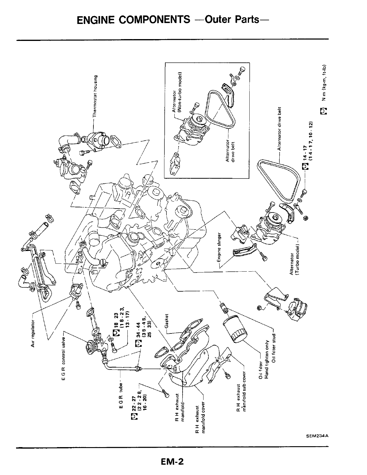
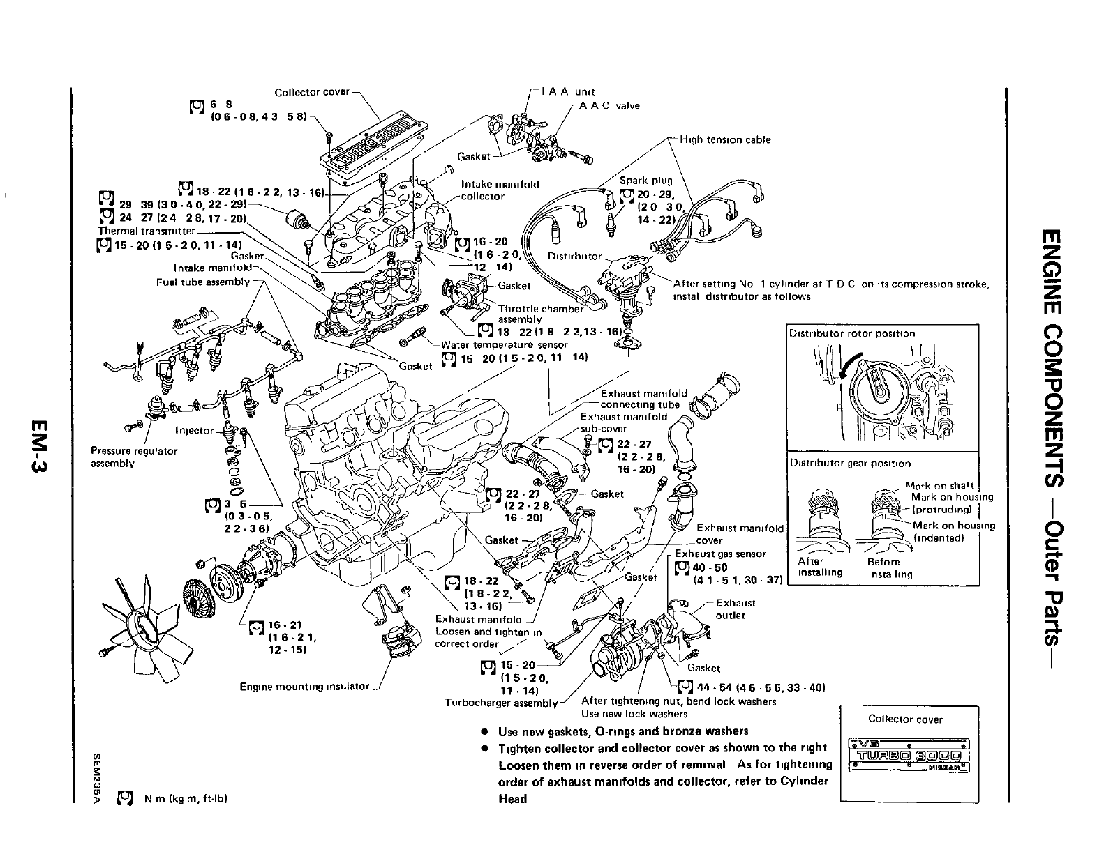
ENGINE COMPONENTS -Outer Parts-
SEM234A
EM-2
w
VI
P
0
N
rn
Ikgrn,ft-lbl
-DC
on
YL
I
I
istributar gear position
..
...
Turbocharger
assembly/
After twhtentng
nu;,
bend
lock
washers
Use
new
lack washers
0
Use new gaskets, O-rings and bronze washers
0
Tighten collector and collector cover as shown
to
the right
Loosen them in reverse order
of
removal
As
for tightening
order
of
exhaust manifolds and collector, refer to Cylinder
Head
I
Collector
cover
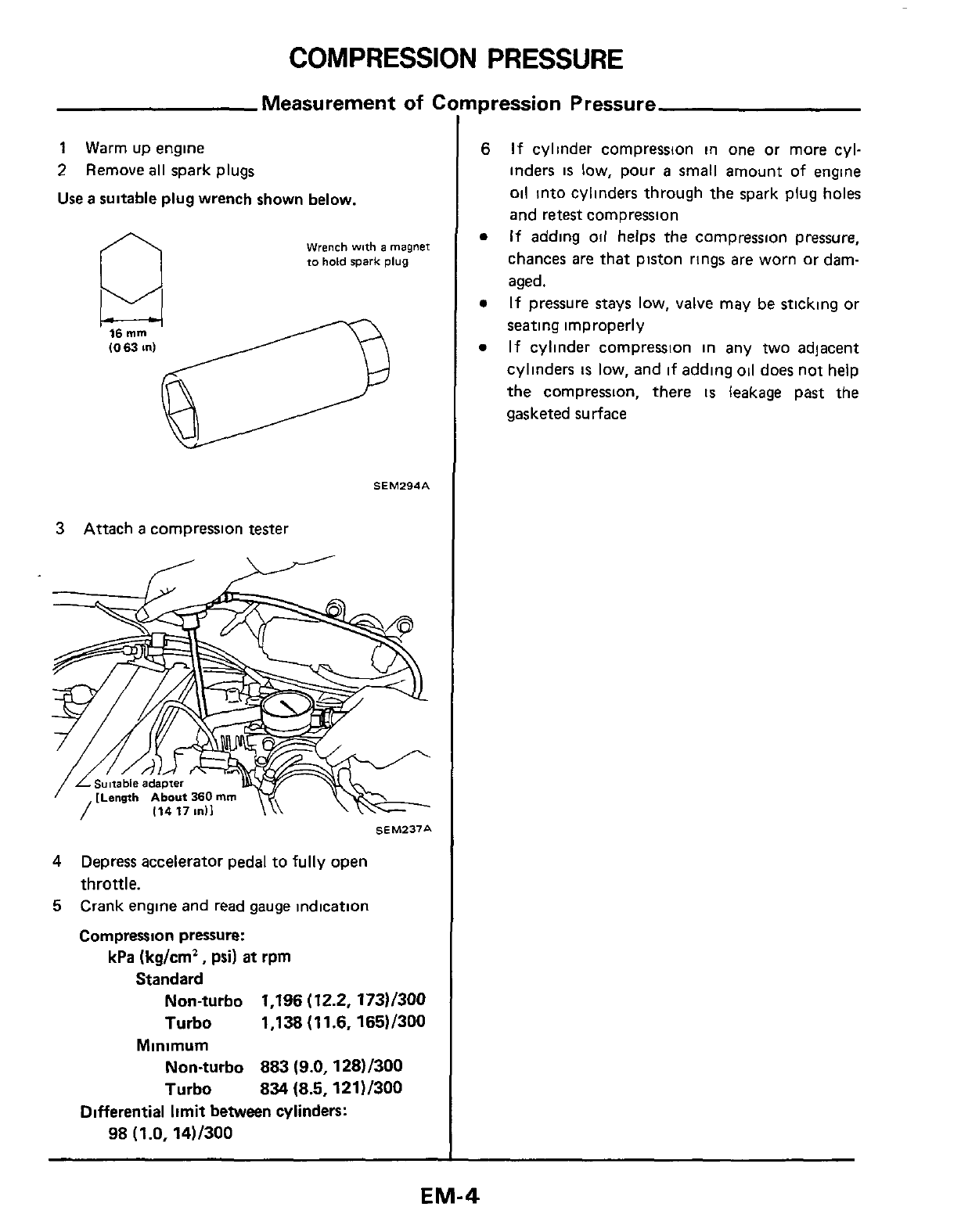
COMPRESSION
PRESSURE
Measurement
of
C
npression Pressure
1
Warm up engine
2
Remove
all
spark plugs
Use
a
suitable plug wrench shown below.
Wrench
with
a
magnet
to
hold
spark
plug
16
mm
(0
63
in)
/------
SEM294A
3
Attach
a
compression tester
SEM237A
4
5
Depress accelerator pedal to fully open
throttle.
Crank engine and read gauge indication
Compression
pressure:
kPa
(kg/cm*,
psi)
at
rpm
Standard
Non-turbo
1,196 (12.2, 173)/300
Turbo
1,138 (11.6, 16511300
Non-turbo
883 (9.0,128)/300
Turbo
834
(8.5,121)/300
Minimum
Differential
limit
between cylinders:
98 (1.0. 14)/300
If
cylinder compression in one or more cyl-
inders
is
low, pour
a
small amount
of
engine
oil
into cylinders through the spark plug holes
and retest cornpression
If
adding
oil
helps the compression pressure,
chances
are
that piston rings are worn or dam-
aged.
If
pressure stays
low,
valve may
be
sticking or
seating improperly
If
cylinder compression in any
two
adjacent
cylinders
is
low, and
if
adding
011
does not help
the compression, there
is
leakage past the
gasketed surface
EM-4
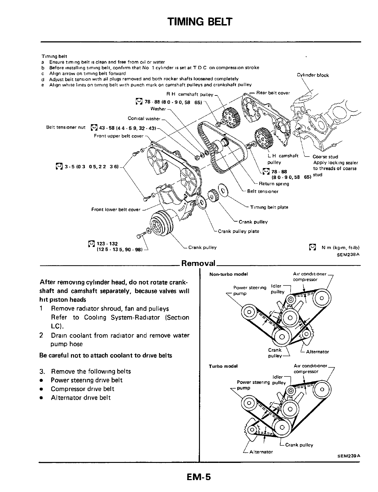
TIMING
BELT
Timing belt
a
b
c
d
e
Ensure timing belt
IS
clean and free from
011
or
water
Before installing timing belt, confirm that
No
1
cylinder
86
set
at
T
0
C
on
compression stroke
Align
arrow
on
timing belt forward
Adlust belt tenrian with
all
plugs removed
and
both rocker shafts loosened completely
Align white
lines
on
timing belt with punch mark
on
camshaft pulleys and crankshaft Pulley
Cylinder block
\
Belt
tensloner
nut
3 -5
10
3
m78-88180-90.58 65)
Conical washer
43-58 (44
-5
9.32- 431
Front
upper belt
cover
05.22
361
to threads of coma
Front
lower
belt
cover
-4
Rear belt
cover
,%
,
Belt tensioner
Timing belt plate
Crank pulley plate
123.132
\Crank pulley
m
N
m
(kg-m, ft-lbl
1125.135.90.98)
Ren
After removing cylinder head,
do
not rotate crank-
shaft and camshaft separately, because valves
will
hit
piston heads
1
Remove radiator shroud, fan and pulleys
Refer
to Cooling System-Radiator (Section
LC).
Drain coolant from radiator and remove water
pump hose
2
Be
careful not to attach coolant to
drive
belts
3.
Remove the following belts
Power steering drive
belt
Compressor drive belt
Alternator drive belt
SEM238A
Non-turbo
model
Air conditioner
cammessor
7
Turbo
model Air conditioner
comoressor
7
f-
Alternator
SEMZ39A
EM-5
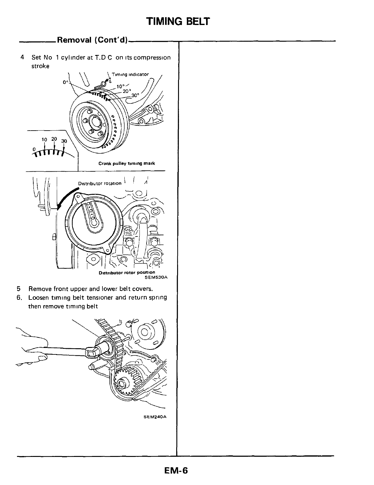
9-w3
ilaq
6uiuii
aAouai uaqi
Guilds uiniai pue lauoisuai ilaq
6uiluii
uasool
'9
'siaho3
ilaq lam01 pue laddn 1uoi4 anouau
5
1138
9NIWIl
TIMING
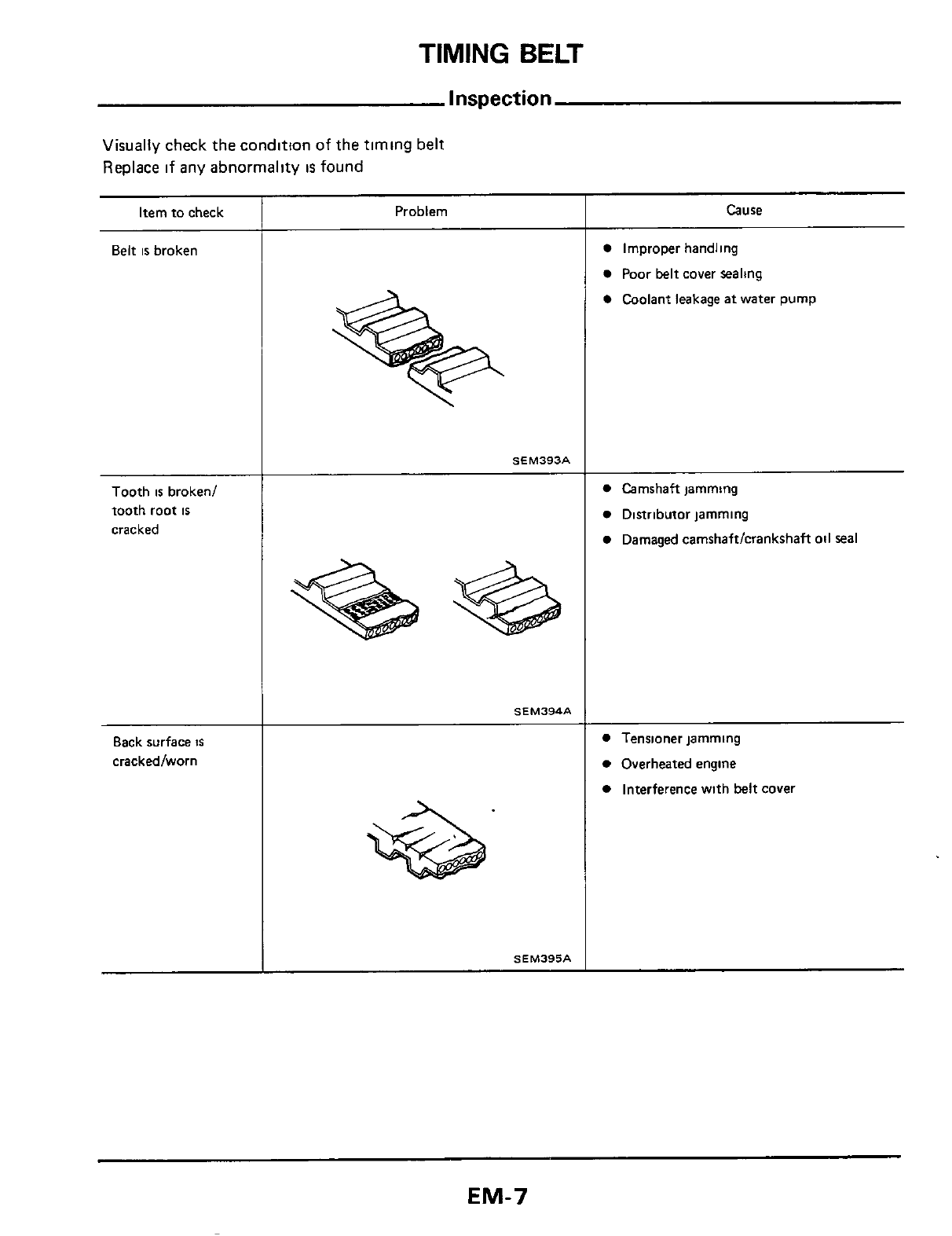
BELT
Inspection
Visually
check the
condition
of
the
timing
belt
Replace
if
any
abnormality
IS
found
Item to check
Belt
is
broken
Tooth
is
broken1
tooth root
is
cracked
Back surface
is
crackedlworn
Problem
SEM393A
SEM394A
SEM395A
Cause
Improper handling
Poor belt cover sealing
Coolant leakage
at
water pump
Camshaft jamming
Distributor jamming
Damaged camshaftlcrankshaft oil seal
Tensioner jamming
Overheated engine
Interference with belt covei
EM-7
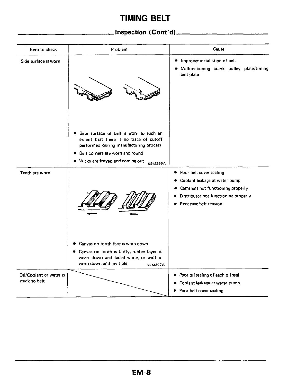
TIMING
BELT
inspection
(Cont'd
1
Item to check
Side surface
is
worn
Teeth
are
worn
OiVCoolant or water
is
stuck to belt
Problem
0
Side surface
of
belt
is
worn to such an
extent that there
is
no trace of cutoff
performed during manufacturing process
0
Belt corners are worn and round
0
Wicks are frayed and coming out
*~~~~~*
Canvas on tooth face
is
worn down
0
Canvas on tooth
is
fluffy, rubber layer
is
worn down and faded white, or weft
IS
worn down and invisible
SEM397A
Cause
Improper installation of belt
Malfunctioning crank pulley plateltiming
belt plate
Poor belt cover sealing
0
Coolant leakage
at
water pump
0
Camshaft not functioning properly
0
Distributor not functioning properly
0
Excessive belt tension
~~~
0
Poor oil sealing of each oil
seal
0
Coolant leakage
at
water pump
0
Poor belt cover sealing
EM-8
TIMING
BELT
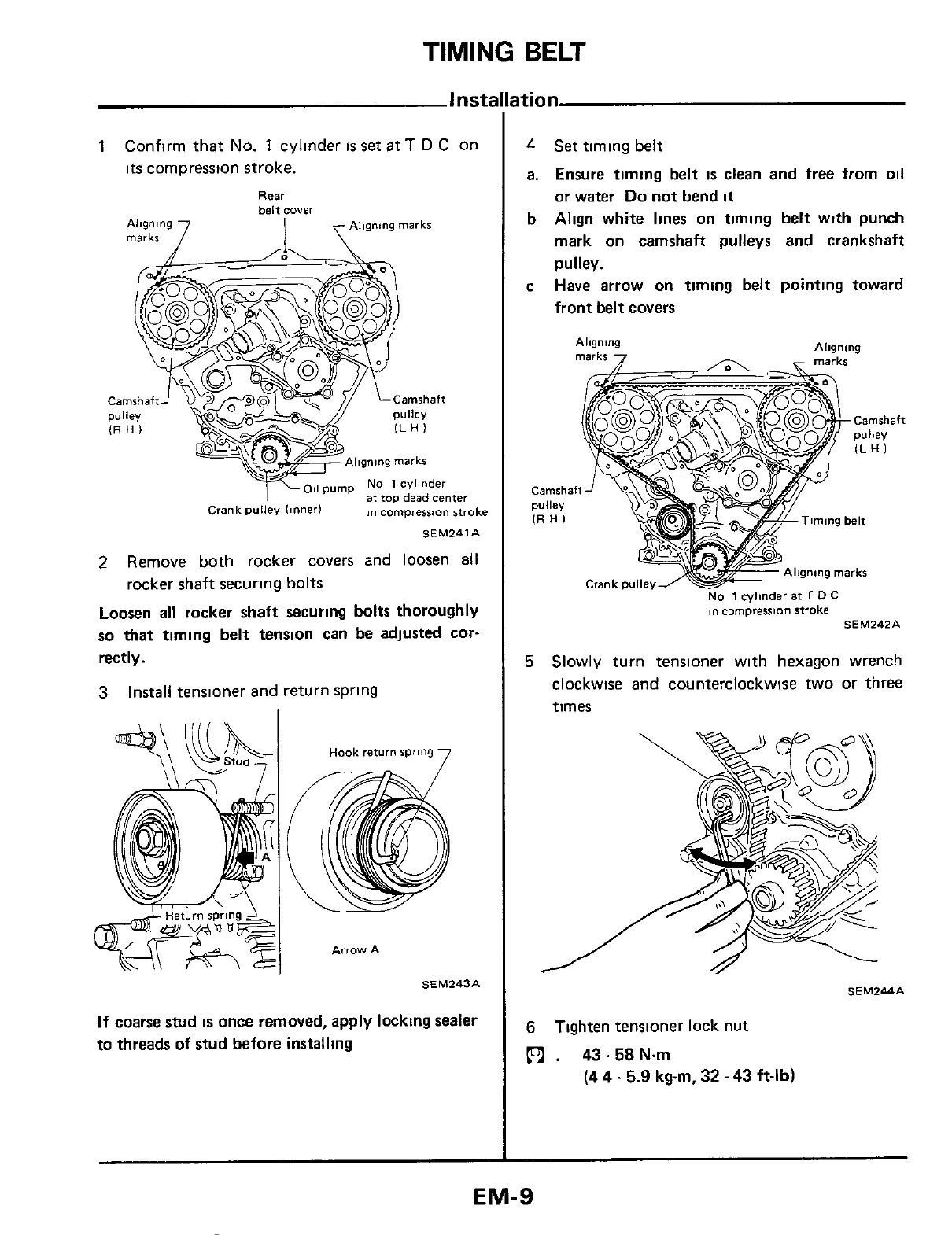
1
Confirm that
No.
1
cylinder
IS
set
at
T
D
C on
its
compression stroke.
Rear
..
belt
cover
Aligning
7
I
Al~gntng
marks
marks
/
I
\
=+==ii~$Altgn!ng
marks
o,i
pump
No
1
cylinder
at
IOP
dead
center
in
compression stroke
Crank
pulley
(Inner)
SEM241A
2
Remove both rocker covers and loosen all
Loosen
all
rocker shaft securing bolts thoroughly
so
that
timing belt tension can be adjusted
cor-
rectly.
3
rocker shaft securing bolts
Install tensloner
and
return spring
Arrow
A
SEM243A
If
coarse
stud
IS
once removed, apply locking sealer
to threads of stud before installing
4
a.
b
C
Set timing belt
Ensure timing belt
is
clean and free from oil
or water
Do
not bend
it
Align white lines on timing belt with punch
mark on camshaft pulleys and crankshaft
pulley.
Have arrow on timing belt pointing toward
front belt covers
Aligning
marks
7
Aligning
A
-
marks
~n
compression stroke SEM242A
5
Slowly turn tensioner with hexagon wrench
clockwise
and
counterclockwise
two
or three
times
SEM244A
6
Tighten tensioner lock nut
ps1
.
43-58N.m
(4
4
-
5.9
kgm,
32
-
43
ft-lb)
EM-9
TIMING
BELT
Installation (Cont'd)
7
Tighten rocker shaft securlng
bolts
in two or
three stages.
n
18-22N.m
(1.8-2.2kg-m, 13-16ft-lb)
R
H.
rocker
shafts
I
nta
ke
8
Install lower and umer
belt
covers
L
H
rocker
shafts
Intake manifold
ride
Exhaust manifold
side
SEM245A
Before
tightening,
be
sure
to set camshaft
lobe
at
the position
where
lobe
IS
not lifted.
Belt
cover
front (upper)
I
9
Belt
cover
(rear)
I
0
Belt
cover
front
(lower)
,
BOli
c
14
PSI
I
SEM:
.EA
EM-I
0
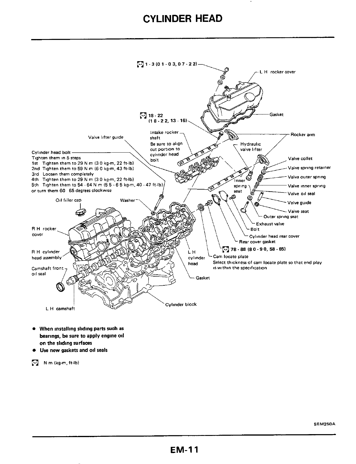
CYLINDER
HEAD
ml.
3
IO
1-0 3,O
7.2
2)-
L
H
rocker
cave!
(1
8
-2
2.13
-
161
Valve hfter guide
Cylinder head
bolt
Tbghten them
in
5
2nd Tighten them
to
59
N
m
16
0
kg-m.
43
ft-lbl
3rd
Loosen
them completely
Valve spring
retainer
Valve
outer
spnng
Valve
inner
spring
Valve
oil
seal
011
idler cap
Outer spring seat
Exhaust
valve
n
78
-
88
(8
0.9
0.58.65)
~swithin the specification
0
When installing sliding parts such
as
bearings, be sure to apply engine
oil
on
the sliding
surfaces
Use
new gaskets and
oil
seals
N
rn
lkgm,ft-lb)
SEM250A
EM-I
1
CYLINDER
HEAD
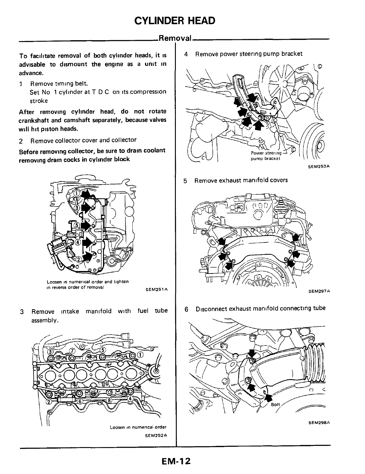
Rer
To
facilitate removal of both cylinder heads,
it
is
advisable to dismount the engine as a
unit
in
advance.
1
Remove timing belt.
Set
No
1
cylinder
at
T
D
C
on
its
compression
stroke
After removing cylinder head, do not rotate
crankshaft and camshaft separately, because valves
will hit piston heads.
2
Before removing collector, be sure
to
drain coolant
removing drain cocks
in
cylinder block
Remove collector cover and collector
Loosen
in
numerical
order
and
tighten
m
reverse
order
of
removal
SEM251A
3
Remove intake manifold with fuel tube
assembly.
I
II
Loosen
m
numerical
order
SEM252A
val
4
Remove power steering pump bracket
SEM253A
5
Remove exhaust manifold covers
SEM297A
6
Disconnect exhaust manifold connecting tube
SEM298A
EM-I
2
CYLINDER HEAD
Removal (Cont’d)
7.
Remove camshaft pulleys and rear timing cover
securing bolts.
8
Remove compressor and rocker covers
9.
Remove cylinder head with exhaust manifold
NO
1
NO
3
NO
5
SEM258A
1.
Remove exhaust manifold.
R.H
exhaust
manifold
L.H
exhaust
manifold
No
2
No4
No6
SEM536A
~aosen
an
numerical
order
2
The
bolts
should
be
loosened
in
two
or
three
Stages.
Remove rocker shafts with rocker arms.
EM-I
3
CYLINDER HEAD
Disassembly (Cont'd)
3
Remove hydraulic valve lifters and lifter guide
a.
Hold
hydraulic valve lifters with wire so that
they will not drop from lifter guide.
b.
Do
not put hydraulic valve lifters upside down,
otherwise air will enter valve lifter, causing
it
to
make
a
noise.
c.
Do
not
disassemble hydraulic valve lifter.
d.
Put identification mark
on
valve
lifters
not
to
avoid mixing them
up.
4.
Remove camshaft
SEM259A
Inspection
CAMSHAFT
END
PLAY
Camshaft end play
0
03
-
0.06
mm
(0.0012
-
0
0024
in)
End
~lav
,
Camshaft
Locate
plate
SEM260A
If
camshaft
end
play exceeds the specified
limit, select thickness of cam locate plate
so
that end play
is
within the specification.
Identjfication
No
A
mark
C
ldentification
Punched
mark
identif
cation
mark
SEM26lA
Unit
mm
im)
EM-I4
CYLINDER
HEAD
Inspection
(Cont'd)
Example
When camshaft end play
is
0
08
mm
(0
0031 in)
with shim
@
used, change shim
@
to shim
@
so
that camshaft end play
is
0
05
mm
(0
0020
in)
CYLINDER HEAD DISTORTION
Measuring
points
SEM262A
If
beyond the specified limit, resurface
it
Resurfacing limit.
The resurfacing limit of cylinder head
IS
deter-
mined by the cylinder block resurfacing in
an
engine
Amount
of
cylinder head resurfacing
is
"A'
Amount of cylinder block resurfacing
is
"B
The maximum limit
is
as
follows:
A
+
B
=
0.2
mm
(0.008
in)
VALVE GUIDE CLEARANCE
Valve guide clearance should be measured
parallel with rocker arm (Generally,
a
large
amount of wear occurs
in
this direction.)
Stem to guide clearance:
Maximum limit
Maximum allowable deflection
(Dial
indicator reading)
0
10
mm
(0.0039
in)
0.2
mm
(0
008
in)
SEMZ63A
Replacement
Replace valve and/or valve guide
1
To
remove valve guide heat cylinder head to
150 to 160°C (302 to 320°F) and drive out
valve guide with
a
press [under
a
20
kN
(2t, 2
2
US
ton, 2
0
Imp ton) pressure] or hammer,
and suitable tool
SEMOOBA
EM-I
5
CYLINDER
HEAD
4
Ream valve guide
Finished size:
Intake
Exhaust
7
000
-
7 018
mm
(0.2756
-
0.2763
in)
8.000
-
8.018
rnrn
(0.3150
-
0.3157
in)
SEM264A
2 Ream cylinder head valve guide hole
Valve
gwda
hole
inride
diameter
Intake-
11 175-11 196(04400-04408)
Exhaust
12175-12196(04793-04802~
,
,
3.
Heat cylinder head to
150
to
160°C
(302
to
320°F) and press service valve guide onto
cylinder head
SEMt71A
SEM272A
VALVE
INSERTS
Check valve inserts for any evidence of pitting
at
valve contact surface, and
reseat
or replace
if
worn
out excessively
When repairing valve inserts, check valve and
valve guide for wear beforehand.
If
worn,
replace them. Then correct valve seat.
The cutting should
be
done with both hands
for uniform cutting.
Replacement
If
necessary, replace valve inserts
as
follows.
1
After removing valve insert, ream the cylinder
head recess
2. Heat cylinder head to
a
temperature of
150
to
160°C
(302 to 320°F)
3
Press
fit
insert until
it
seats
on the bottom, and
caulk more than
4
points
4.
Cut or grind valve
inserts
using suitable tool
at
the soecified dimensions
as
shown in
S
D.S
EM-I
6
CYLINDER HEAD
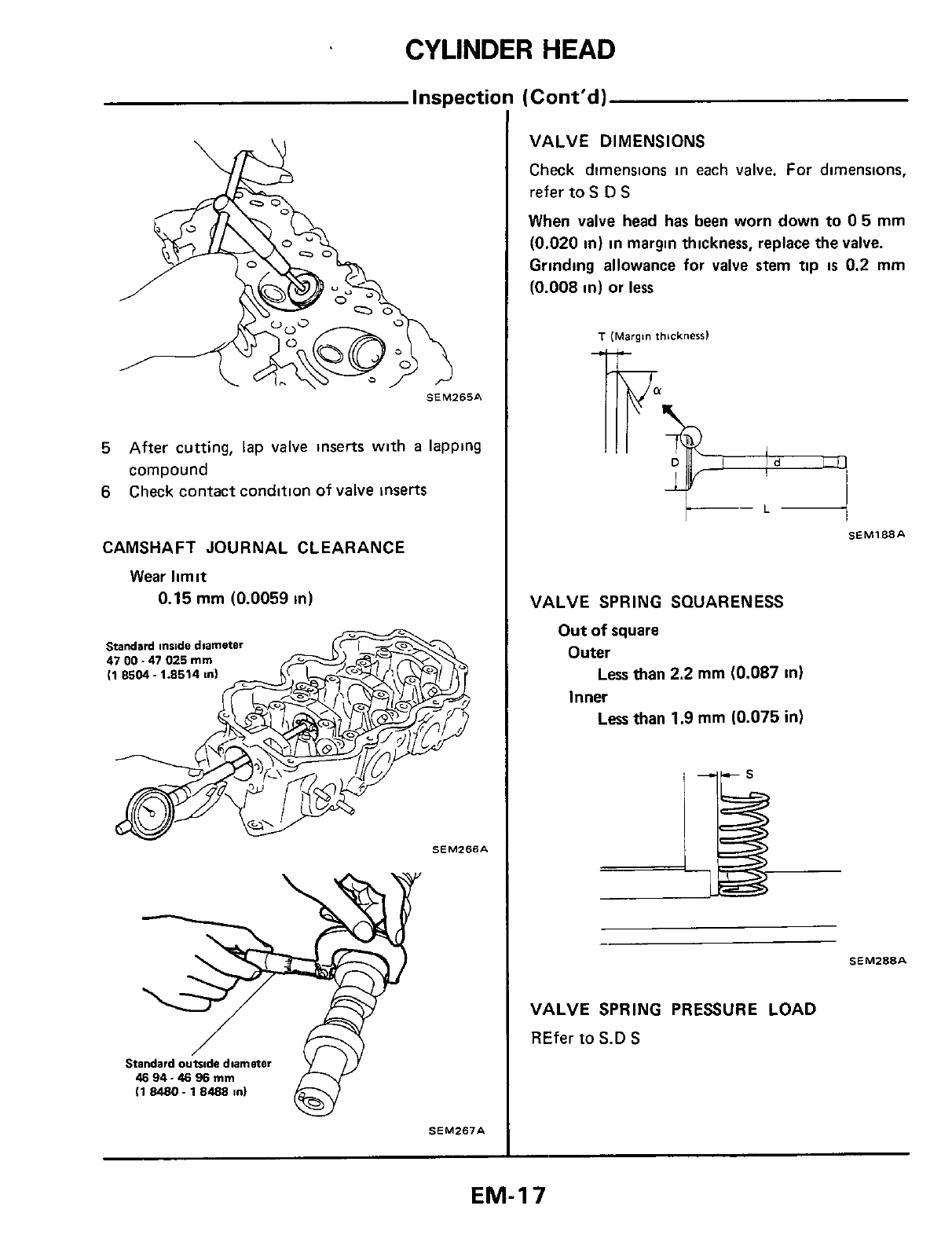
VALVE DIMENSIONS
Check dimensions in each valve.
For
dimensions,
refer
to
S
D
S
When valve head has been worn down
to
0
5
mm
(0.020
in)
in
margin thickness, replace
the
valve.
Grinding allowance for valve stem
tip
is
0.2
mm
(0.008
in)
or
less
SEM265A
5
6
After
cutting, lap valve inserts
with
a lapping
compound
Check contact condition
of
valve inserts
CAMSHAFT JOURNAL CLEARANCE
Wear
limit
0.15
mm
(0.0059
in)
Standard
mxde
diameter
47
00
-
47
025
rnrn
(1 8504. 1.8514
m)
SEMZ67A
T
(Margin
thickness1
4i-
SEM188A
F-
*
VALVE SPRING SQUARENESS
Out
of
square
Outer
Inner
Less
than
2.2
mm
(0.087
in)
Less
than
1.9
mm
(0.075
in)
SEM288A
VALVE
SPRING
PRESSURE LOAD
REfer
to
S.D
S
EM-I
7
CYLINDER
HEAD
Inspection
(Cont'd)
HYDRAULIC
VALVE
LIFTER
Check contact and sliding surfaces for wear or
scratches.
&+
SEMZBOA
If
valve
lifters
are noisy, check valve lifter
(1)
Depress plunger forcibly with your finger
If
it
moves about
1
mm
(0.04
in),
it
indicates
air
is
inside valve lifter
(2)
Re-install rocker arm and rocker cover.
(3)
Bleed
air
by running engine
at
1,000
rpm under
no-load for about
10
minutes.
(4)
Next, remove rocker cover and rocker arm and
check
to
ensure
all
air
IS
bled. (Refer to step
(1)
above)
(5)
If
there
is
still
air,
replace valve lifter.
1
Install valve component parts.
Install outer valve spring (uneven pitch type) with
its
narrow pitch side toward cylinder head side
#T
Wide
pitch
SEM052
2
Install camshaft
3
4
Apply engine oil to camshaft oil
seal
and install
it
in place
Adjust camshaft end play with locate
plate
in-
stalled
EM-I
8
CYLINDER HEAD
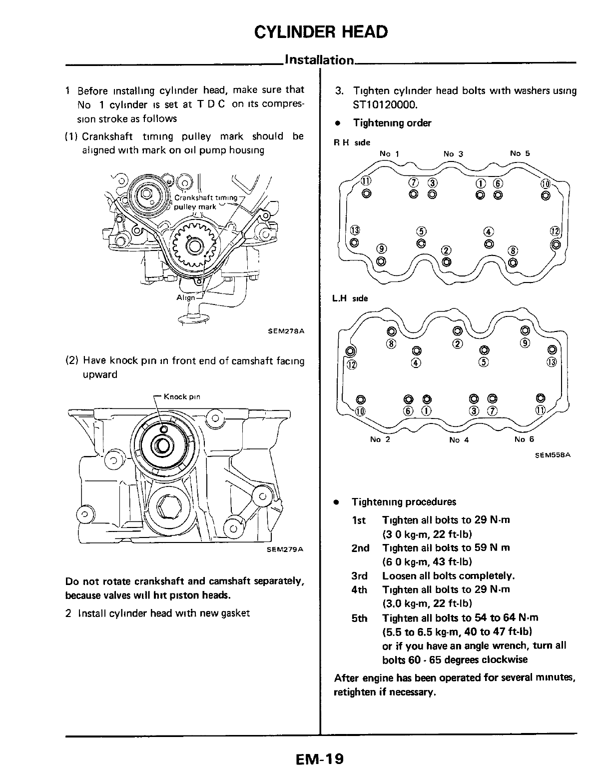
1 Before installing cyllnder head, make sure that
No
1
cylinder
is
set
at
T
D
C on
its
compres-
sion stroke
as
follows
(1) Crankshaft timing pulley mark should
be
aligned with mark on oil pump housing
SEM278A
CgF
(2)
Have knock pin in front end of camshaft facing
upward
Knock
pin
Do
not rotate crankshaft and camshaft separately,
because valves will
hit
piston heads.
2
Install cylinder head with new gasket
3. Tighten cylinder head
bolts
with washers using
ST1
01
20000.
Tightening order
R
H
side
No
1
No
3
NO
5
L.H
side
No
2
No
4
No
6
SEMSSSA
Tightening procedures
1st
2nd
3rd
Loosen
all
bolts completely.
4th
5th
Tighten all bolts to
29
N.m
(3
0
kg-m,
22
ft-lb)
Tighten all bolts to
59
N
m
(6
0
kgm,
43
ft-lb)
Tighten
all
bolts to
29
Nm
(3.0
kg-m,
22
ft-lb)
Tighten
all
bolts
to
54
to
64
Nm
(5.5
to
6.5
kg-m,
40
to
47
ft-lb)
or
if
you
have an angle wench,
turn
all
bolts
60.65
degrees clockwise
After engine has been operated
for
several minutes,
retighten
if
necessary.
EM-19
CYLINDER
HEAD
Installatic
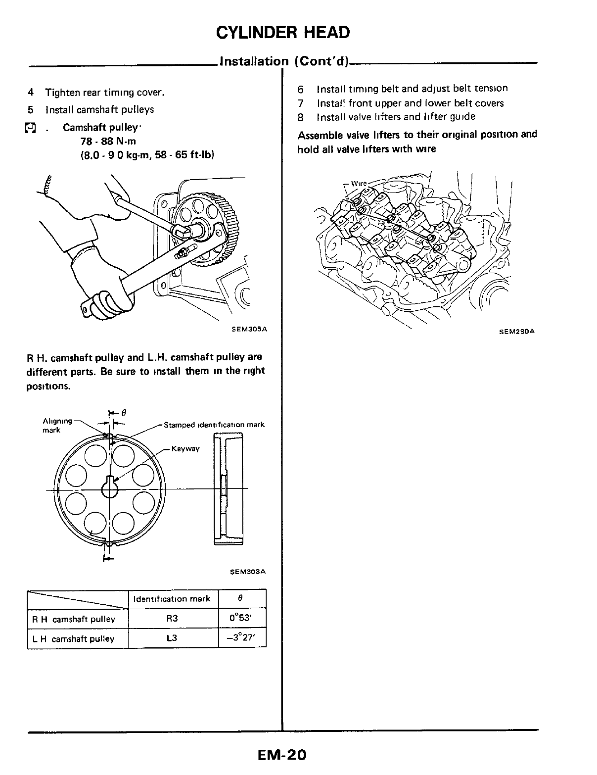
4
Tighten rear timing
cover.
5
Install camshaft pulleys
PJ)
.
Camshaftpulley.
78.88
Nm
(8.0
-
9
0
kgm,
58
-
65
ft-lb)
SEM305A
R
H.
camshaft pulley and
L.H.
camshaft
pulley
are
different
parts.
Be
sure to install them
in
the
right
positions.
LA
SEM303A
Identification mark
R
H
camshaft
pulley
0'53'
L
H
camshaft
pulley
-3'27'
(Cont'd)
6
7
8
Assemble valve lifters
to
their original position
and
hold
all valve lifters with wire
Install timing belt and adjust belt tension
Install front upper and lower belt
covers
Install
valve
lifters and
lifter
guide
SEM280A
-.
EM-20
CYLINDER
HEAD
Installation (Cont'd)
9
Install rocker shafts
with
rocker arms and tighten rocker shaft securmg bolts
in
two
or
three stages
R
H
rocker
shafts
Exhaust
manbfald
side
Rocker
shaft
direction
rn
iNo3
m
-@7lm-
~lla
HW7
@I
.
.
..
Intake
manifold
side
L
H
rocker
shafts
intake
manifold
ride
Exhaust
manifold
ride
SEM281A
10
Install rocker cover
Confirm rocker cover bolts, washers and trays are
free from
oil.
11
Install intake manifold and fuel
tube
Tighten in
two
or
three
stages.
.
Nut
1st
3-5N.m
2nd 24-27N.m
(0.3
-
0.5
kgm,
2.2
-
3.6 ft-lb)
(2.4
-
2.8
kgm,
17
-
20
ft-lb)
Bolt
1st 3-5N.m
2nd 24-27N.m
(0.3
-
0.5
kgm,
2.2
-
3.6 ft-lb)
(2.4
-
2.8 kgm, 17
-
20
ft-lb)
Tighten
In
numerical
order
SEM529A
EM-21
CYLINDER
MEAD
Installation (Cont'd)
12
Install exhaust manifolds and connecting tube
R
H
exhaust manlfold
No
5
No
3
No
1
L
H
exhaust manifold
No
2
NO
4
No
6
Tighren
m
numerical
order
SEM535A
13
After assembling
all
disassembled parts,
fill
radiator with coolant up to the specified
level
Refer
to Changing Engine Coolant (Sections
MA and LC)
EM-22
OIL
PAN
Ren
1 Drain engine
oil
2
Raise
vehicle and support
it
with safety stands
.
I
”
A\
3
Remove front stabilizer bar securing bolts and
nuts from suspension crossmember
4 Remove steering column shaft from gear
housing
5 Remove tension rod securing nuts from trans-
verse
link
6
Lift engine
7
Remove rear plate cover from transmission
case
8
Remove oil pan securing bolts
9 Remove suspension crossmember securing
bolts
10 Remove strut mounting insulator securing nuts
11 Remove screws securing refrigerant
lines
and
power steering tubes to suspension cross-
member
12 Lower suspension crossmember
13 Remove oil pan from
rear
side
14 Remove
oil
strainer
from
oil
pump assembly
and cylinder block.
15 Remove oil pump assembly
106-07.43
51
N
rn
Ikg-m,
ft-lbl
I1
2.16.
9-
121
SLC547
INSTALLATION
1 Apply sealant
011
Seal
reta,ner
7
SEM542A
Sealant
2 Install oil pan
m
5-7Nm
(0
5
-
0
7
kg-m,
3
6
-
5 1
ft-lb)
Tighten
!n
numerical
order
SEM543A
EM-23
OIL
SEAL REPLACEMENT
-Replacement
of
Camshaft
Oil
Seal-
1
Remove timing belt
2
Remove camshaft pulleys
3
Remove camshaft
oil
seal
4
Apply engine
oil
to
camshaft
oil
seal and install
it
in place
SEM284A
5
Install timing belt
-
Replacement of Valve
Oil
Seal
-
1
Remove collector and rocker cover
(L
H
only)
2
3
Remove rocker shaft assembly and valve lifters
with valve
guide
Remove valve springs, retainer and collets
SEM257A
4
Remove valve
oil
seals
SEM28SA
5
in
place.
Apply engine
oil
to
valve
oil
seal
and install
it
SEM286A
When installing valve oil seal
in
exhaust manifold
side,
tool
is
not necessary.
Valve
011
real-
Valve
rpr'ng
=at
1
pi
b+
(0.0391
SEM287A
EM-24
ENGINE
REMOVAL
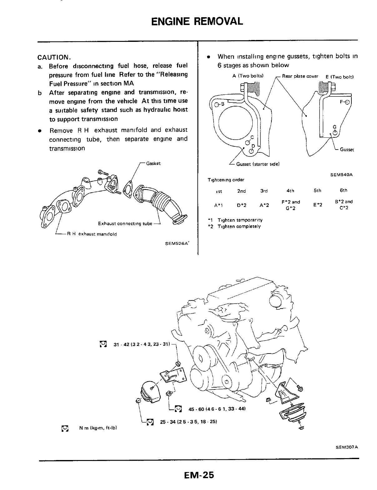
CAUTION.
a. Before disconnecting fuel hose, release fuel
pressure
from
fuel line Refer
to
the "Releasing
Fuel Pressure"
in
section
MA
After separating engine and transmission, re-
move engine
from
the vehicle
At
this
time
use
a suitable safety stand such as hydraulic hoist
to
support
transmission
Remove
R
H
exhaust manifold and exhaust
connecting
tube,
then separate engine and
transmission
b
,-Gasket
Exhaust
connecting
tube
LR
H
exhaust
manifold
SEM526A.
N
rn
(kg-m.
ft-lbl
When installing engine gussets, tighten
bolts
in
6
stages as
shown
below
A
(Two bolts)
Rear
plate
cover
E
(iw0
bolt)
1
Gusset
istarter
ridel
SEM54OA
Ttghtening
order
I
It
2nd
3rd
41
h
5th
61
h
F'Zand
E.2
8'2
and
C'2
A.1
D'2
A'2
G.2
'1
Toghien
temporarity
'2
Tqhfen
mrnplefely
.42 13 2.4 3,23- 311
45
-
60
(46-6 1,33.44)
25-
34
(25
-35.18-
25)
SEM307A
EM-25
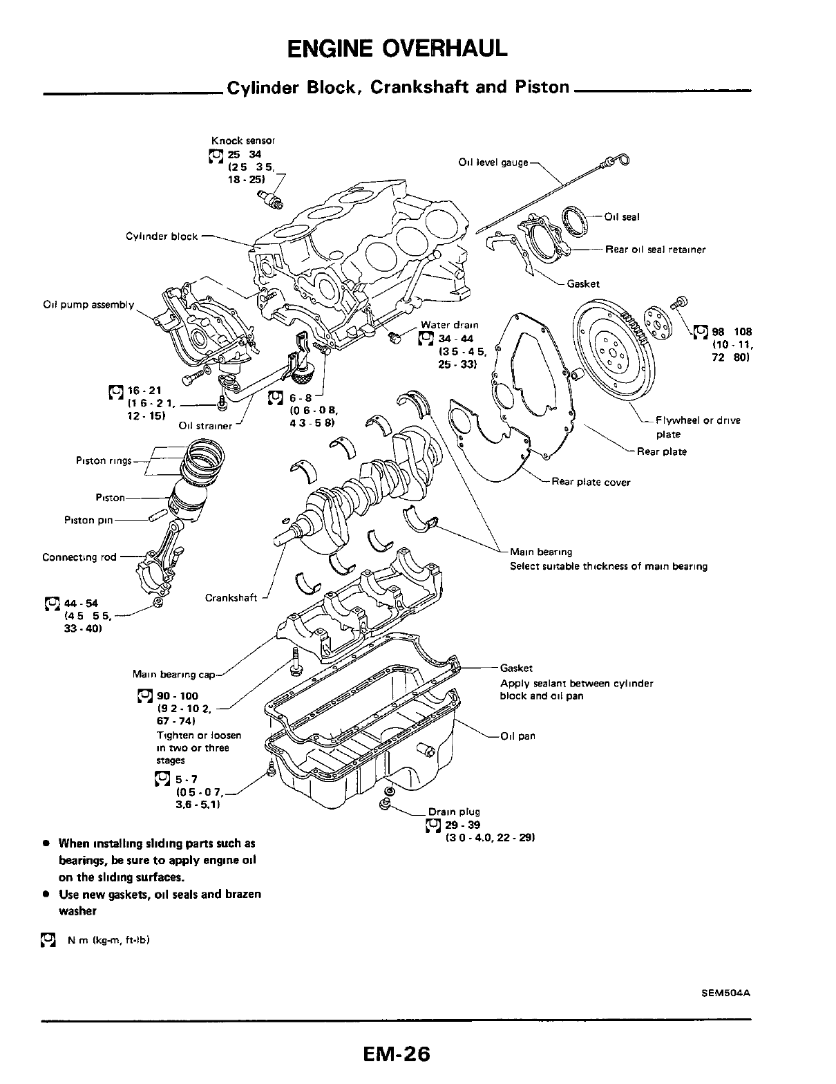
ENGINE OVERHAUL
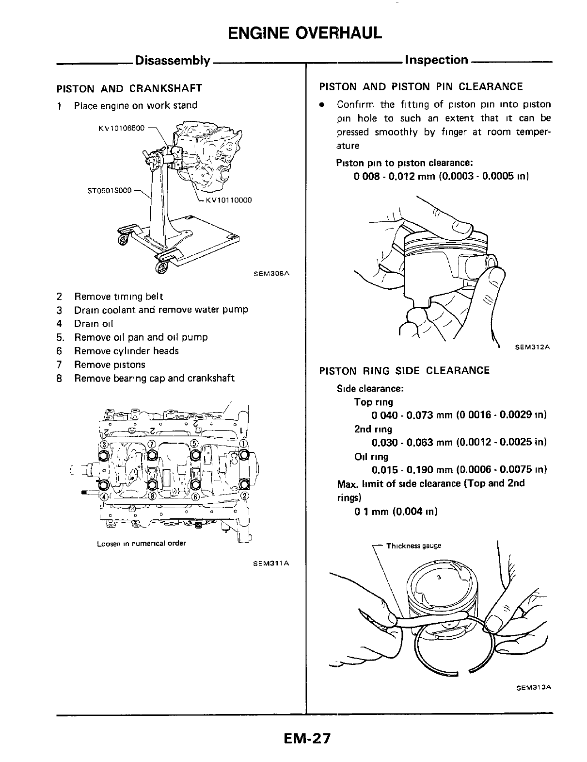
PISTON AND CRANKSHAFT
1
Place
engine
on
work stand
KL.
10106500
SEM308A
2
Remove timing belt
3 Drain coolant and remove water pump
4
Drain oil
5.
Remove oil pan and oil pump
6
Remove cylinder heads
7
Remove pistons
8
Remove bearing cap and crankshaft
Loosen
numerical order
SEM3llA
-
Inspection
PISTON AND PISTON PIN CLEARANCE
Confirm the fitting of piston pin into piston
pin hole to such an extent that
it
can be
pressed smoothly by finger
at
room temper-
ature
Piston pin to piston clearance:
0
008
-
0.012 mm
(0.0003
-
0.0005
in)
\
SEM312A
PISTON
RING
SIDE CLEARANCE
Side clearance:
Top
ring
2nd ring
Oil ring
0
040
-
0.073
mm
(0
0016.0.0029 in)
0.030
-
0.063
mm
(0.0012.0.0025
in)
0.015
-
0.190
mm
(0.0006.0.0075
in)
Max. limit of side clearance (Top and 2nd
rings)
0
1
mm
(0.004
in)
y-
Thickness
gauge
I
SEM313A
EM-27
ENGINE
OVERHAUL
Inspection
(Cont'd)
PISTON RING GAP
Ring gap:
Top
ring
2nd
ring
Oil
ring
0
21
-
0
44
mm
(0
0083
-
0.0173
in)
0.18
-
0.44
mm
(0.0071
-
0.0173
in)
0
20
-
0.76
mm
(0
0079
-
0.0299
in)
I
SEM314A
BEARING CLEARANCE
Bearing clearance:
Main bearing
0.028
-
0.055
mm
(0.0011
~
0.0022
in)
Limit
0.090
mm
(0.0035
in)
0.010 .0.052
mm
(0.0004
~
0.0020
in)
Limit
0.090
mm
(0.0035
in)
Connecting
rod
bearing
Method
A
CAUTl
ON
:
8
Do
not
turn
crankshaft or connecting rod
while the plastigage
is
being inserted.
When bearing clearance exceeds the specified
limit, ensure that the proper bearing has been
installed. Then
if
excessive bearing clearance
exists, use thicker main bearing or undersized
bearing
so
that the specified bearing clearance
is
obtained.
'
yic--J
/
EM142
Method
B
Main
bearing
1
Install main bearings
to
cylinder block and
2
Tighten
all
bolts
in correct order and in
two
or
three stages
main bearing cap
Install
main
bearing
cap
to
cylinder block
:
90-l00Nm
Measure inside diameter
"A"
of
main journal
(9.2
-
10
2
kg-m,
67.
74
ft-lb)
3
EM-28
ENGINE
OVERHAUL
Inspection
(Cont'd)
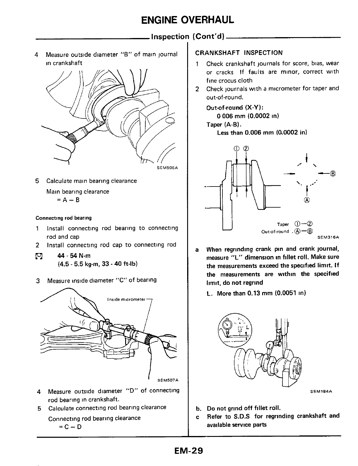
4
Measure outside diameter
"B"
of main journal
in crankshaft
SEM506A
5
Calculate main bearing clearance
Main bearing clearance
=A-B
Connecting
rod
bearing
1
Install connecting rod bearing to connecting
rod and cap
2
Install connecting rod cap to connecting rod
p-l
44-54N.m
(4.5
-
5.5
kg-m, 33
-
40
ft-lb)
3
Measure inside diameter "C" of bearing
A
I
SEM507A
4
5
Measure outside diameter "D"
of
connecting
rod bearing in crankshaft.
Calculate connecting rod bearing clearance
Connecting rod bearing clearance
=C-D
CRANKSHAFT INSPECTION
1
Check crankshaft journals for score, bias, wear
or cracks
If
faults
are
minor, correct wlth
fine crocus cloth
Check journals with
a
micrometer for taper and
out-of-round.
Out-of-round (X-Y):
Taper
(A-B).
2
0
006
mm
(0.0002
in)
Less than
0.006
mm
((LO002
in)
Taper
0
4
Outuf-round
.
@-@
SEM316A
U
a When regrinding crank pin and crank journal,
measure
"L"
dimension in fillet roll. Make sure
the
measurements exceed the specified limit.
If
the measurements are within the specified
limit, do not regrind
L.
More
than 0.13
mm
(0.0051
in)
SEMl84A
W
b.
Do
not
grind
off fillet roll.
c Refer
to
S.D.S
for
regrinding crankshaft and
available service parts
EM-29
ENGINE
OVERHAUL
Inspection
(Cont'd)
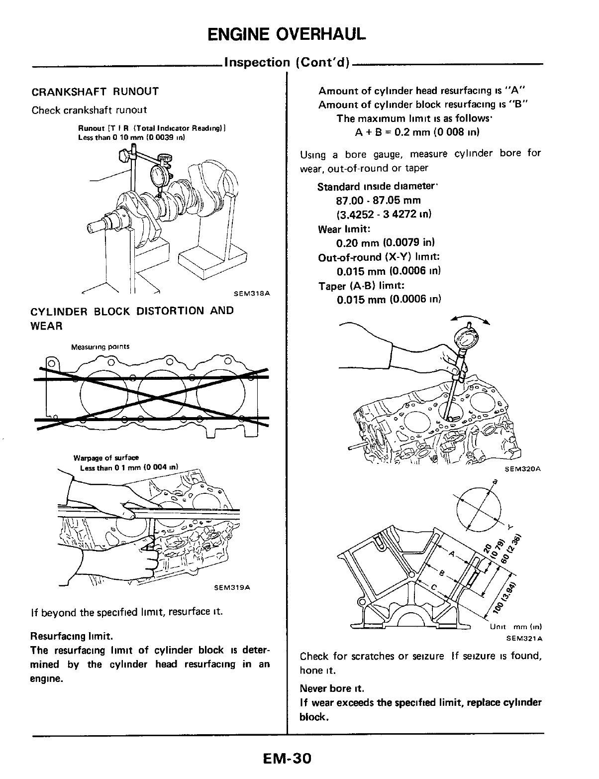
CRANKSHAFT RUNOUT
Check crankshaft runout
Runout
fT
I
R
(Total
indicator
Reading11
Less
than
0
10
rnrn
IO
0039
in1
SEM318A
CYLINDER BLOCK DISTORTION AND
WEAR
Warpage
of
plrfam
Less
than
0
1
rnm
(0
SEM3tSA
If beyond the specified limit, resurface
it.
Resurfacing limit.
The resurfacing limit of cylinder block
is
deter-
mined
by
the
cylinder head resurfacing
in
an
engine.
Amount of cylinder head resurfacing
is
"A"
Amount of cylinder block resurfacing
IS
"B"
The maximum limit
is
as
follows.
A
+
B
=
0.2
mm
(0
008
in)
Using
a
bore gauge, measure cylinder bore for
wear, out-of-round or taper
Standard inside diameter.
87.00
-
87.05
mm
(3.4252
-
3 4272
in)
Wear limit:
0.20
mm
(0.0079
in)
Out-of-round
(X-Y)
limit:
0.015
mm
(0.0006
in)
Taper (A-B) limit:
0.015
mm
(0.0006
in)
Unit
mrn
Id
SEM321A
Check for scratches or seizure If seizure
is
found,
hone
it.
Never bore
it.
If wear exceeds
the
specified limit, replace cylinder
block.
EM-30
ENGINE
OVERHAUL
Inspection
(Cont’d)
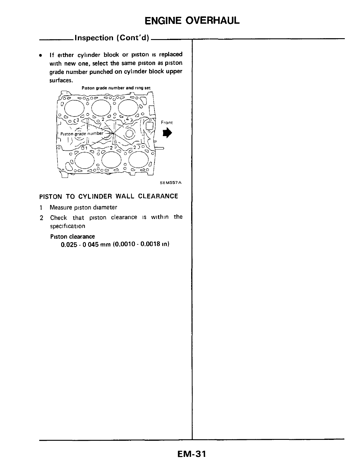
0
If
either cylmder block or plston
is
replaced
with new one, select the same piston as plston
grade number punched on cylinder block upper
surfaces.
Piston
orade
number
and
ring
set
SEM557A
PISTON
TO
CYLINDER WALL CLEARANCE
1
Measure piston diameter
2
Check that piston clearance
IS
withln the
specification
Piston clearance
0.025
-
0
045
mm
(0.0010
-
0.0018
in)
EM-31
ENGINE
OVERHAUL
Inspection (Cont'd)
PISTON-TO-CYLINDER CLEARANCE
(Using feeler gauge)
When pulling feeler gauge straight upward, measure
the
extracting force
It
IS
recommended that piston
and cylinder be heated
to
20°C (68°F)
Feeler gauge thickness:
Extracting force.
0.04
mm
(0.0016
in)
2.0
-
14.7
N
(0
2
-
1
5
kg,
0
4
-
3.3
Ib)
5EM324A
FLYWHEEL RUNOUT
Runout (Total indicator reading).
Less
than
0
15
mm
(0.0059
in)
Dial
gauge
A
Install ring on flywheel, heating ring gear to about
180
to
220°C
(356
to 428°F)
Assern
bly
PISTON
a. Numbers are stamped on the connecting rod
and cap corresponding to each cylinder'. Care
should be taken to avoid a wrong combination
including bearing.
b. When pressing piston pin
in
connecting rod,
apply engine oil to pin and small end
of
con-
necting rod.
n
10300
SEM32SA
CRANKSHAFT
1 Set main bearings in the proper position on
cylinder block
*
With
081
groove
No
1.
Upper
main
bearmg
Lower
main
bearing
No
4
SEM327A
EM-32
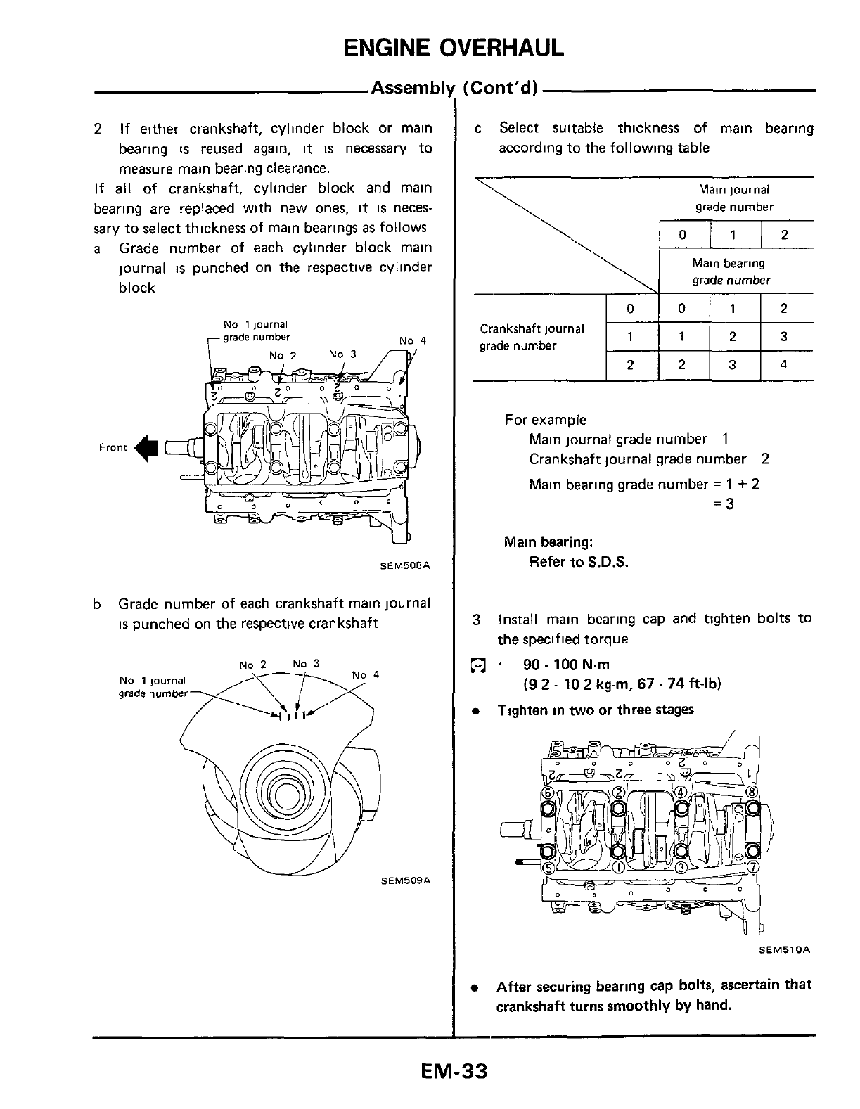
ENGINE OVERHAUL
2
2
If
either crankshaft, cylinder block or main
bearing
is
reused again,
it
IS
necessary to
measure main bearing clearance.
If
all
of crankshaft, cylinder block and main
bearing
are
replaced with new ones,
it
IS
neces-
sary to select thickness of main bearings
as
follows
a
Grade number of each cylinder block main
journal
is
punched on the respective cylinder
block
2
3
4
No
1
ioumal
No
4
No
2
NO
3
p/
W
SEM508A
b Grade number of each crankshaft main journal
is
punched on the respective crankshaft
:
Cont'd)
c Select suitable thickness of main bearing
according to the following table
Main journal
grade number
Main bearing
grade number
1 1
2
3
Crankshaft journal
grade number
For example
Main journal grade number
1
Crankshaft journal grade number
2
Main bearing grade number
=
1
+
2
=3
Main bearing:
Refer
to
S.D.S.
3
Install main bearing cap and tighten bolts to
the specified torque
.
90-
100N.m
(9
2
-
10
2
kg-m,
67
-
74
ft-lb)
Tighten in two or three stages
SEM510A
After securing bearing cap bolts, ascertain
that
crankshaft turns smoothly by hand.
EM-33
ENGINE
OVERHAUL
Assernbll
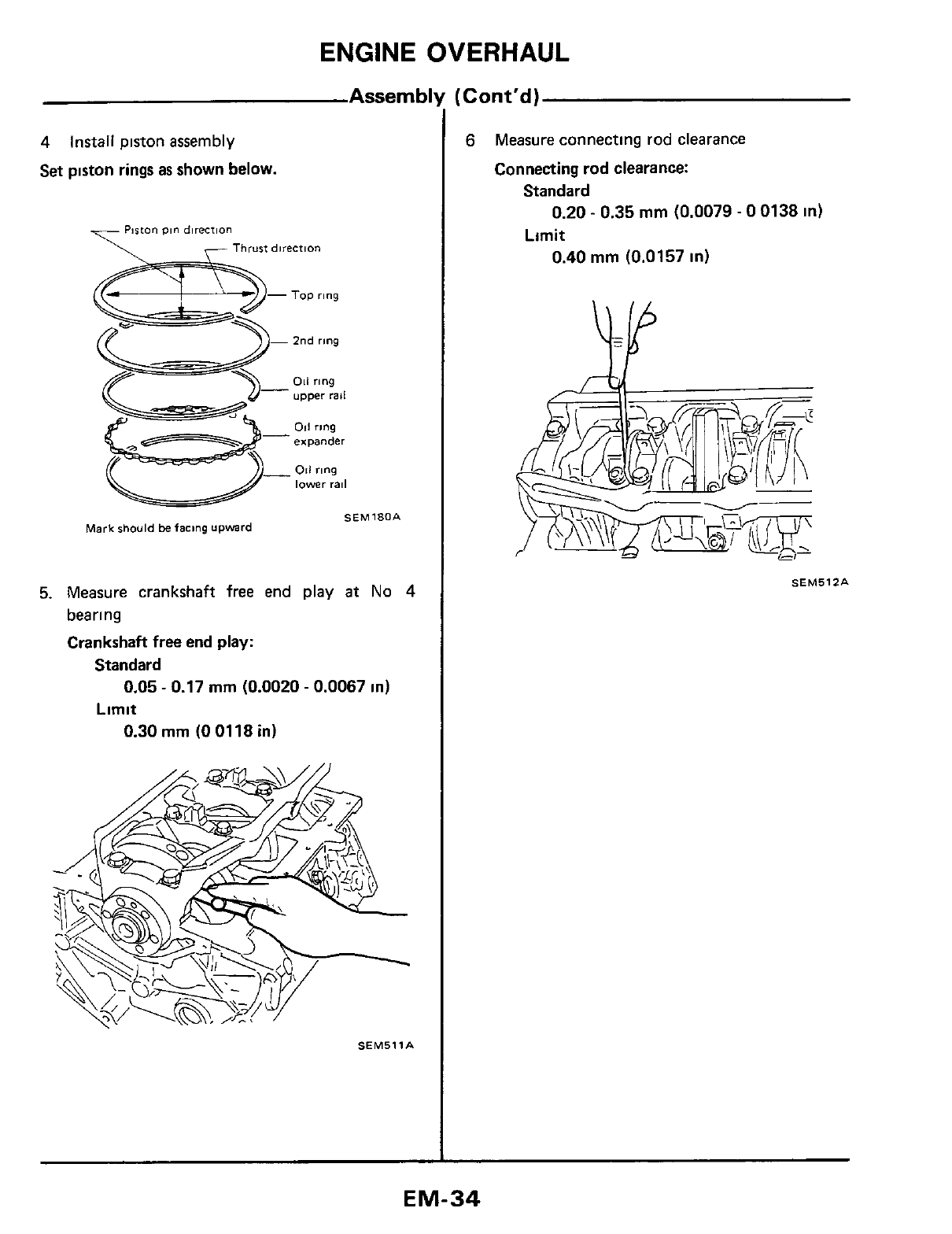
4
install piston assembly
Set piston rings
as
shown below.
ton
pin
direcrion
Thrust
direction
SEM180A
Mark
should
be
faclng
upward
5.
Measure crankshaft
free
end
play
at
No
4
bearing
Crankshaft free end play:
Standard
Limit
0.05
-
0.17
mm
(0.0020
-
0.0067 in)
0.30
mm
(0
0118 in)
SEMSllA
6
Measure connecting rod clearance
Connecting rod clearance:
Standard
Limit
0.20
-
0.35
mm
(0.0079
-
0
0138 in)
0.40
mm
(0.0157 in)
SEMSlZA
EM-34
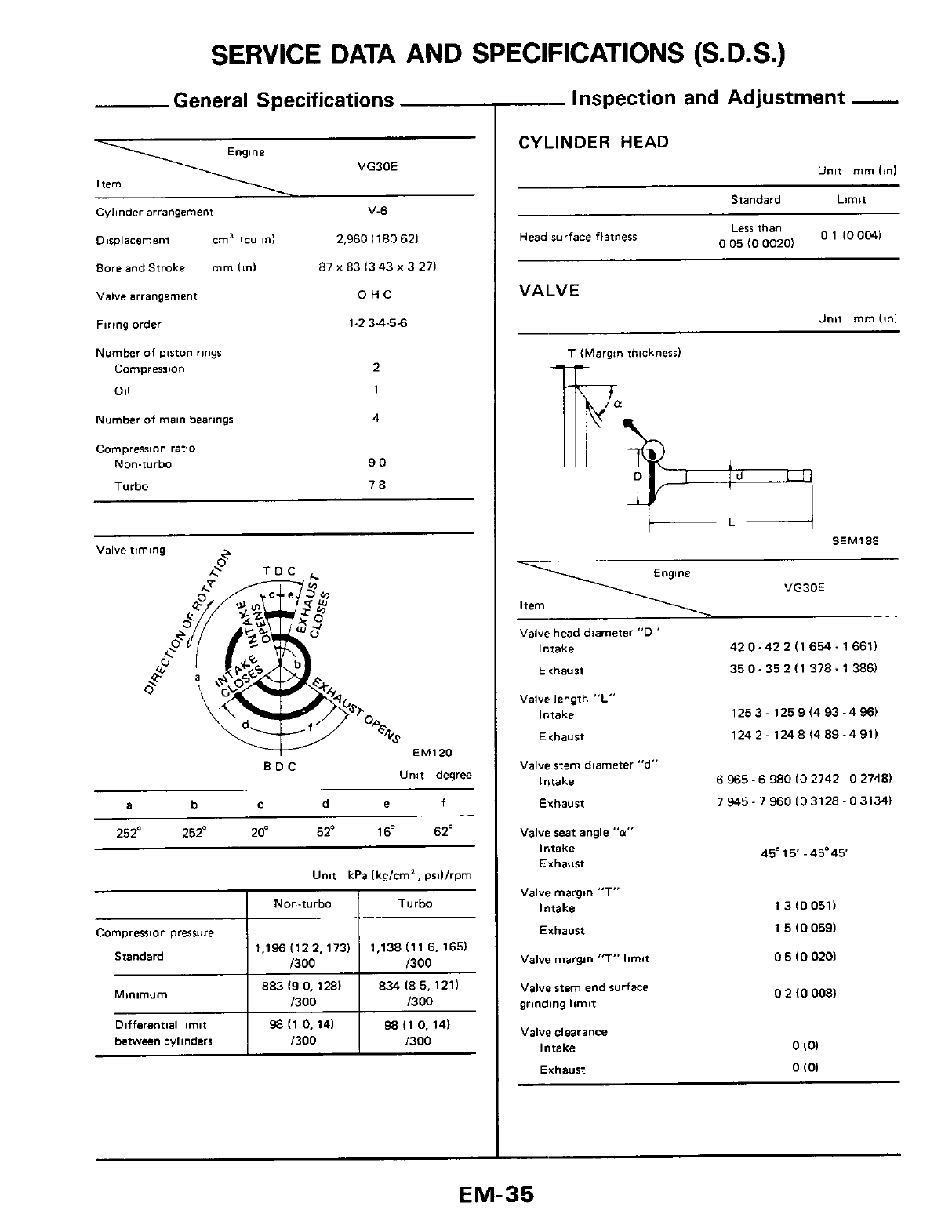
SERVICE DATA AND SPECIFICATIONS
(S.
D.S.)
Inspection and Adjustment
-
I
General Specifications
Non-turbo
VG30E
Turbo
Cylinder arrangement V-6
Displacement
cm'
lcu
in)
2.960 1180
621
8oreandStroke
mm
(In1
87
x
83 I343
x
3 271
~~~
Differential limit
between cylinders
Valve
arrangement
Firing order
Number
of piston rings
Compresston
011
98
I1
0.
141 98 (1
0.
14)
1300
1300
OHC
1-2
34-55
2
1
Number of
main
bearings 4
Camprerrion ratlo
Non-turbo
Tiirho
90
78
e
Valve timing
2
TDC
.
EM120
~~
Unit degree
BDC
a b
c
d
e
f
252'
252'
20"
52'
16"
62"
Unit kPa lkglcm2,
prd/rpm
1,1961122,173~ 1.138111 6,1651
Standard
I
/300
~
TO
883
I9
0,
1281
1300
Minimum
'
'
834
I8
5,121)
CYLINDER
HEAD
Unit
mrn
Id
Standard Limit
01
100041
Less
than
0
05
IO
00201
Head surface flatnerr
VALVE
T
IMargn
thtcknerrl
If
-1
Engine
VG30E
Item
-
Valve head diameter
"D
'
420-42
2
I1
654-
16611
35 0-35 2 I1 378.1 386)
Intake
Ethaust
Valve
length
"L'
Intake
Echaurt
1253
-
125 9 I4 93 -4 961
124 2
-
124
8
1489-4 911
Valve stem diameter '*d"
6
965
-
6
980
IO
2742
-
0
27481
Intake
Exhaust
7
945-
7
960
103128-031341
Valve seat angle
"a"
Intake
Exhaust
Valve margin "T"
Intake
Exhaust
13100511
1
5
(0
0591
Valve margin
'7"
limit
0
5
10
0201
Valve stem end
surface
grinding
limit
0
2
IO
008)
Valve clearance
Intake
0
101
Exhaust
0
I01
EM-35
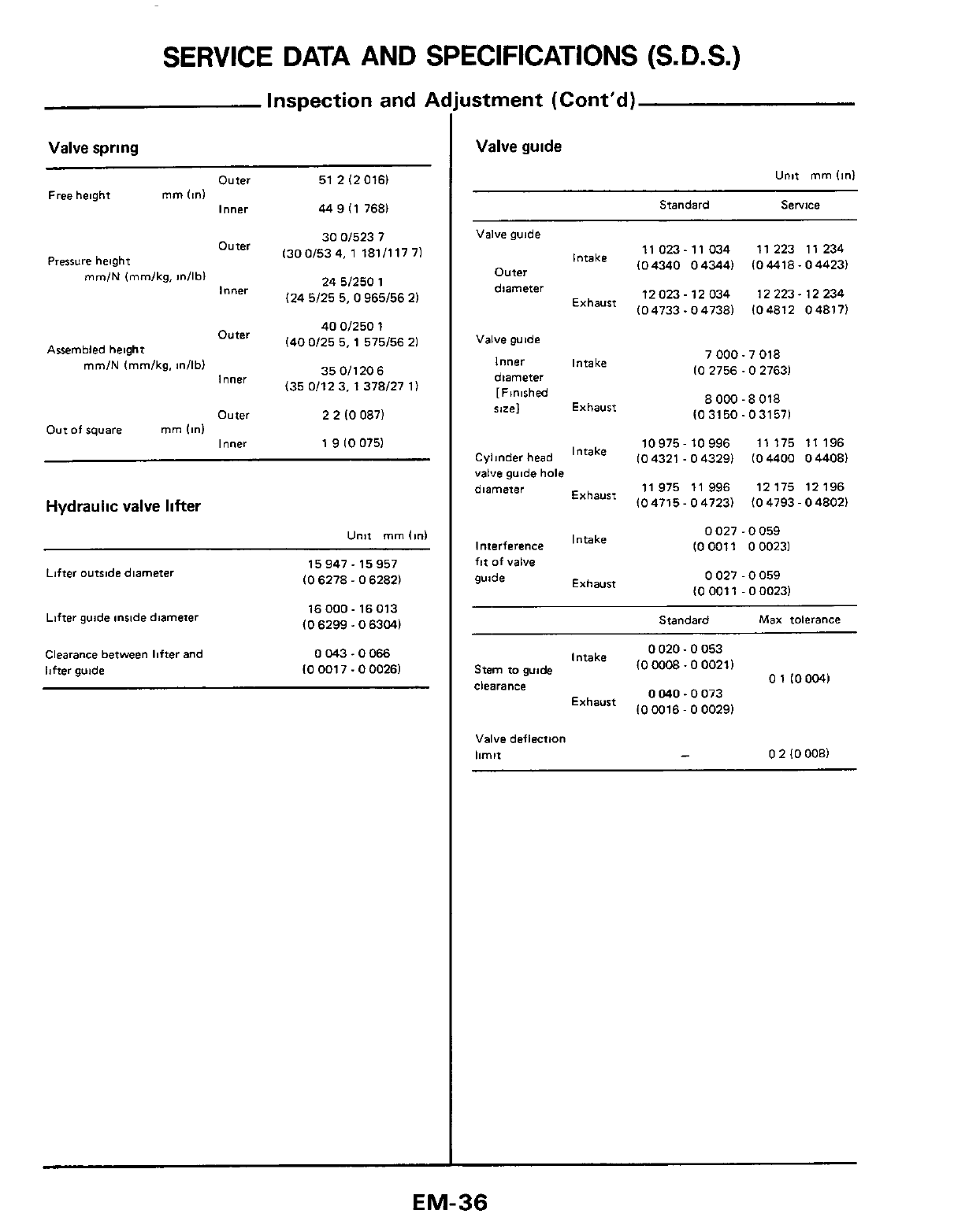
SERVICE DATA AND SPECIFICATIONS (S.D.S.)
Inspection and
A
Valve spring
Outer 51
2
I2
0161
l""W
44 9 (1 7681
Free
height mm
(ml
Pressure
height
30
01523 7
Outer 1300/534. 1 181111771
24
51250
1
(24
5/25
5,
0
965/56
21
mm/N
lmmlkg,
m/lb)
l""W
40
OD50
1
(40
0/25
5,
1
575/56
21
Outer
Assembled heioht
350/1206
135 0/12 3, 1 378/27
11
mm/N
lmm/kg,
dlbl
Inner
Outer
2
2
(0
0871
Inner
1
9
10
0751
Out of
square
mm
(in)
Hydraulic
valve lifter
Unit
mm
(in1
Lifter outride diameter
Lifter guide inside diameter
15947
-
15 957
IO
6278
-
0
62821
16
000
-
16 013
(0
6299
-
0
63041
Clearance
between lifter and
lifter guide
0
043.0066
10
001 7.0
00261
Jstment (Cont'd)
Valve guide
Standard Service
Valve guide
Intake
Outer
diameter
Exhaust
Valve guide
Inner Intake
diameter
[Finished
rml
Exhaust
Cylinder head Intake
valve gwde hole
diameter Exhaust
Interference Intake
ftt
of valve
guide Exhaust
11023-11034 11223 11234
104340 043441 (04418-04423)
12 223.12 234
(04733.04738) 104812 04817)
12 023
-
12 034
7
000-
7 018
10
2756.0 27631
8
000
-
8 018
(0
3150.031571
10975-10996 11 175 11 196
IO4321 -043291 104400 044081
11 975 11 996 12175 12196
104715-047231 (04793-04802)
0
027
-
0
059
IO
0011
0
00231
0
027
-
0
059
(0
001
1
-
0
00231
Standard
Max
tolerance
0
020.0
053
Intake
(0
0008~0
00211 01
(0004)
Stem to
gu&
clearance
OM0
-0073
(0
0016
-
0
0029)
Exhaust
Valve deflection
limn
-
0
2
10
0081
EM-36
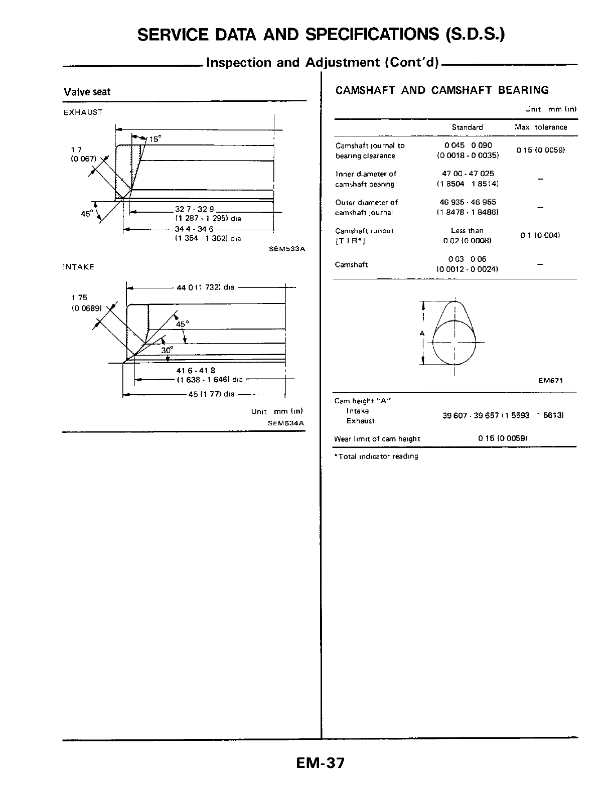
SERVICE DATA AND SPECIFICATIONS (S.D.S.)
Inspection and
P
Valve
seat
I
EXHAUST
344
-
34
6
I1 354. 1 3621
dia
SEM533A
INTAKE
I1 638. 1 6461
dia
45 I1 77)
dia
unit
mm
Iinl
SEM534A
ustment (Cont'd)
CAMSHAFT AND CAMSHAFT BEARING
Unit
mm
(in1
Standard Max tolerance
Camshaft Journal
to
bearing clearance
Inner diameter
of
cam,,haft bearing
Outer
diameter of
camshaft
ioumal
Camshaft
runout
LT
113.1
Camshaft
Ogo
0
15
IO
00591
IO
0018.0 00351
-
47 00.47 025
I1
8504 185141
46 935.46 955
I1
8478.1 84861
-
01
IOOMI
Less
than
0
02
IO
00081
003
006
IO
0012.0 00241
-
EM671
Cam height
"A"
Intake
Exhaust
39 607
-
39 657
I1
5593
1
56131
Wear
limit
of
cam
height
0
15
(0
00591
'Total
mdtcator reading
EM-37
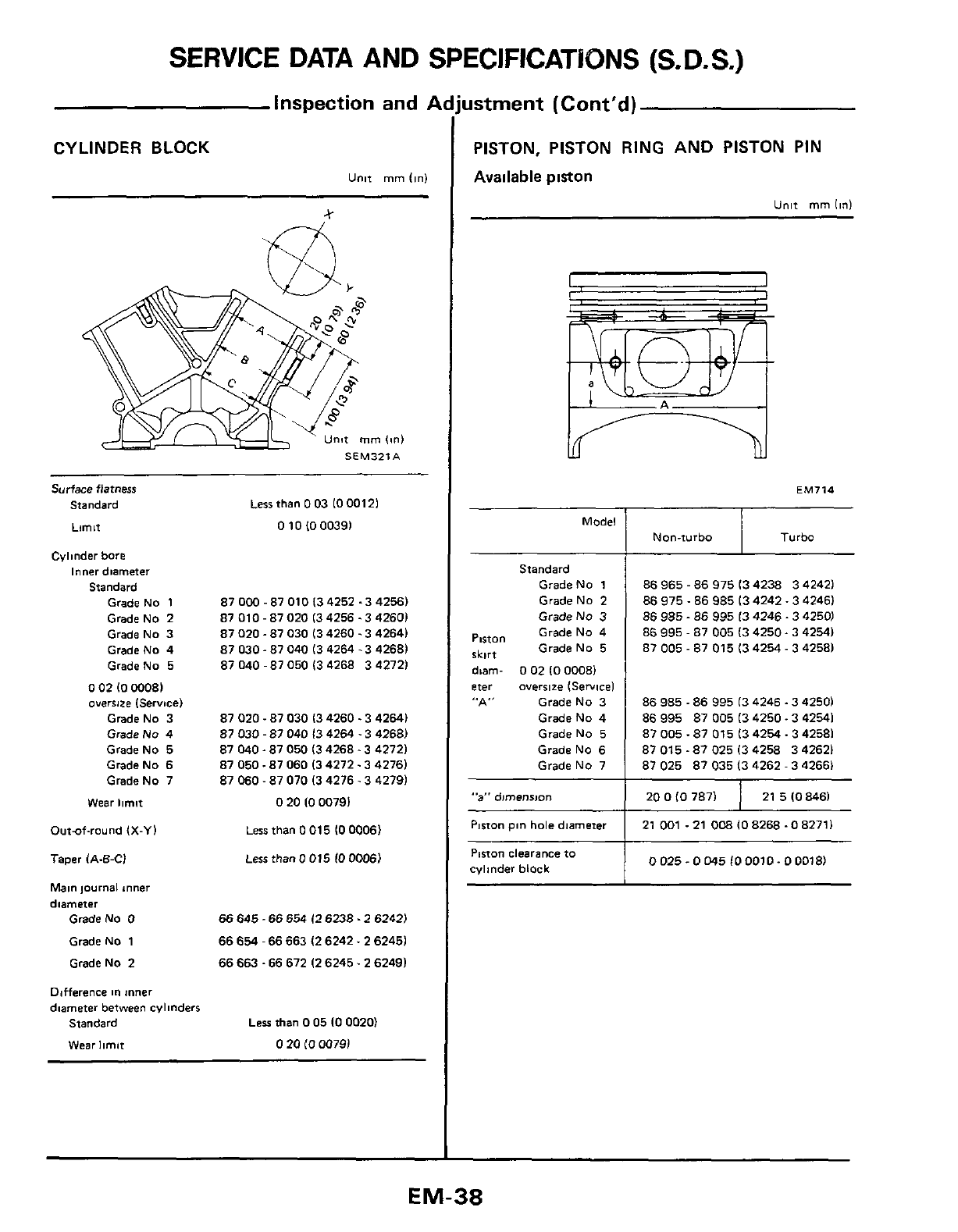
SERVICE DATA AND SPECIFICATiBNS
(S.
D.
S.)
Model
Non-turbo
inspection and
f
CYLINDER BLOCK
Unit
mm
Iinl
Turbo
%
Piston
pin
hole
diameter
Ptston
clearance
to
cylinder block
SEM321A
21
001 .21
008
IO
8268
.O
82711
0025-0045f00010-000181
Surface flatness
Standard
Limit
Cvlmder bore
Inner
diameter
Standard
Grade NO 1
Grade NO
2
Grade No 3
GradeNo 4
GradeNo
5
0
02
10
WO81
overs1ze
ISerwceI
GradeNo
3
GradeNo 4
GradeNo 5
GradeNo
6
GradeNo 7
Wear
limit
Outuf-round
IX-YI
Taper
IA-E-Cl
Main journal mner
diameter
GradeNo
0
GradeNo 1
GradeNo
2
Ddfference
in
inner
Less
than
0
03
10
00121
0
10
IO
00391
870W-87010(34252.342561
87 010
-
87
020
(3 4256.3 42601
87
020
-
87 030 13 4260.3 42641
87 030
-
87 040 13 4264.3 4268)
87 040 -87
050
13 4268 3 42721
87 020.87 030 13 4260.3 42641
87
030
-
87 040
13
4264
.3 42681
87 040.87
050
13 4268.3 42721
87 050.87
060
13 4272.3 42761
87
060
-
87
070
13 4276.3 4279)
0
20
10
00791
Less
than
0
015
10
00061
Less
than
0
015
IO
OOO6)
66
645
-66
654
(26238.2
62421
66
654
-
66
663
I2
6242.2 62451
66
663.66 672
12
6245.2 62491
dnameter
between
cylinders
Standard
Wear
limit
Less
than
0
05
10
0020)
0
20
(0
0079)
ustrnent (Cont'd)
PISTON, PISTON RING
AND
PISTON PIN
Available
piston
Unit
mm
(in)
Standard
GradeNo
1
GradeNo
2
Grade
NO
3
Grade No 4
Grade No
5
PlLtO"
skirt
dim-
0
02
IO
00081
eter oversize ISewiceI
',A"
GradeNo
3
Grade No 4
GradeNo
5
Grade NO
6
Grade NO 7
86 965
-
86 975 13 4238 3 42421
86
975.86 985 13 4242.3 42461
86 985
-
85 995
13
4246.3 4250)
86 995
-
87
005
13
4250.3 42541
87
005
-
87 015 13 4254
-
3 42581
86 985
-
86 995
13
4246.3
4250)
86 995 87
005
13 4250.3 42541
87 005.87 015 13 4254.3 42581
87 015.87
025
13
4258 3 42621
87
025
87 035 13 4262
-
3 42661
"a"
dimension
1
200f0787)
21
5108461
EM-38
SERVICE DATA AND SPEClfflCATlONS
(S.
D.S.)
Standard
Side clearance
0040
0073
IO
0016
-
0
0029)
0
030
-
0
063
IO
0012
0
0025)
0015 0190
100006
000751
TOP
2nd
081
Inspection and
A
Piston ring
Unit
mm
lid
Limit
0
1
10
004)
-
Ring gap 021 -044
IO
0083
-
0
01 731
TOP
I
1
2nd
0
20-
076
10
0079
0
0299)
041
Ira11
rlngl
Piston pin
Unit
mm
lid
Piston pin outer diameter
20
993
-
20
998
10
8265.0 82671
0008.0012
100003
00005)
Plrton pm to prston
clearance
Interference fit of piston
pin
0022
0040
to connecting rod
IO
009
-
0
00161
CONNECTING
ROD
Unit
mm
lid
Center distance 15410-15420
16
0669
-
6
07091
Bend. tonion [per 100 13 941
1
Limit
0
10
IO
00391
Piston pin
bore
dia
Big end play
Standard
Ltmit
20
958.20 971
(0
8251
-
0
82561
0
20.0
35
IO
0079
-
0
01381
0
6
IO
0241
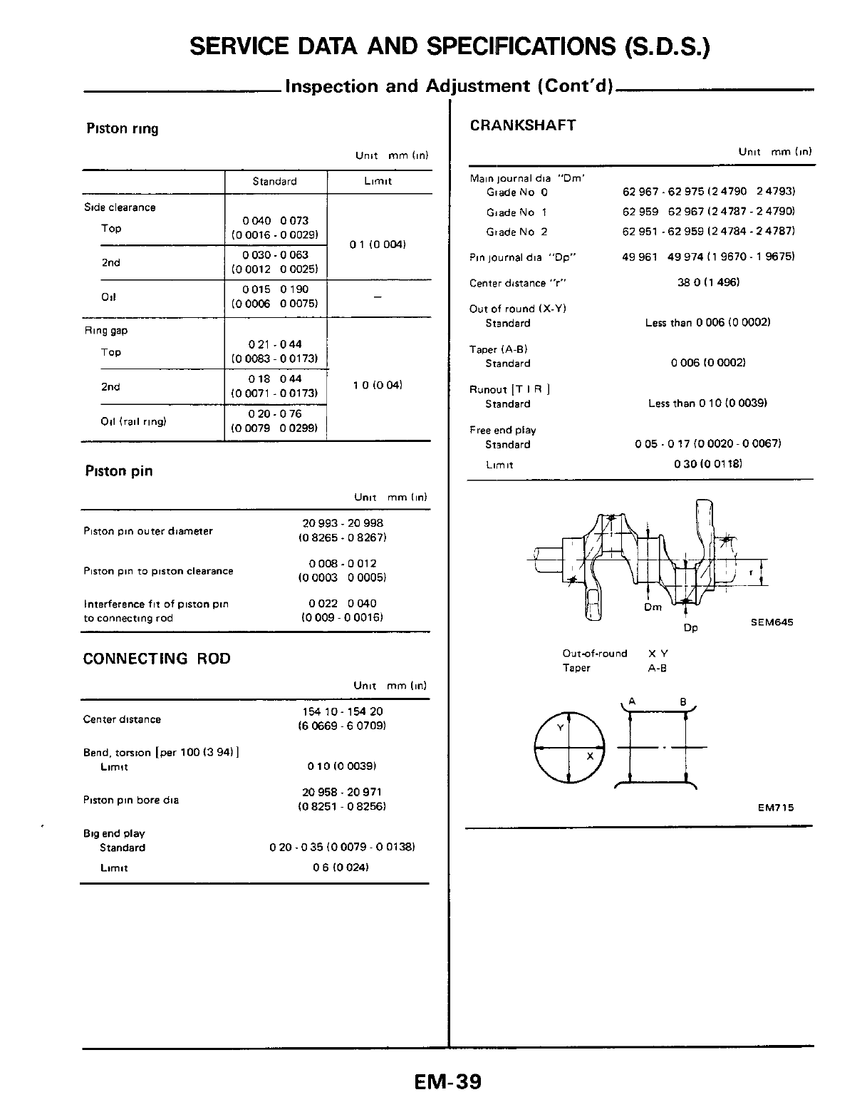
ustment (Cont'd)
CRANKSHAFT
Unit
mm
linl
Main
lournel
dia "Dm'
GiadeNo
0
GiadeNo 1
GiadeNo 2
P~niournal
dla
"DP"
Center distance
"r"
Out of round
(X-Yl
Standard
Taper
IA-Bl
Standard
Runout
IT
I
R
1
Standard
Free
end
play
Standard
Llrnlt
62
967.62 975
12
4790
2
4793)
62
959
62
967
(2
4787
-
2
47901
62
951
.62
959
12
4784.2 47871
49 961 49 974
(1
9670
-
1 96751
38
0
I1 4961
Less than
0
006
IO
0002)
0
006
IO
00021
Less than
0
10
10
00391
0
05.0
17
(0
0020
-
0
00671
0
30
10
01 181
n
SEM645
OP
Out-of-round
X
Y
Taper
A.B
EM715
EM-39
l&ZLO
0.
ZZLO
01
LE8
1
-
&E8
1
an18
WdZO-6EZZL
(ZZLO
0.
OZLO
01
&
&&8
1
-
628
L
(OZLO
0
-
6LLO
01
628
1
.928
L
(6LLOO-LLLO01
5Z8
L
-
17.8
1
~LLLOO-91LO01
128
L
-
LL8
L
Mollah
FOdZO 6CZZ1
18bL
01
uaaa
ZO~Z~SEZZL
6L
uMoJ8
LOdZO
GCZZL
3114M
OOdZO-6CZZ
L
(an0016
110
inoqiiM) 6ui~eaq
uiew
&
pue
z
'ON
(CZLO
0.
ZZLO
01
LE8
1
-
&&8
1
anis
wdzo-&zzzt
(ZZLO
0.
OZLO
0)
&
&E8
1
.628
I
MollaA
COdZO-EZZZL
(98801
lOZLOO-6LLOO)
uaw
ZOdZOEZZZL
pz2
628
Sz8,
(6LLOO-LLLO01
528
1. 128
L
(LLLOO 5LLOO)
UMoJ8
LOdZOEZZZL
WrlM
OOdZOEZZZL 128
1
L18L
(CZLOO ZZLO01
LE8
L
.
CE8
1
(ZZLO
0
-
OZLO
01
&E8
1
.628
L
anin
WdZoSLZZL
&
Mollah
COdZO-SLZZL
(98801
~OZLOO-6LLOOl
uaar3
ZOdZOSLZZL
z2
6z8
,
.
8z8
(6LLOO'LLLOOl
UMoJ8
LOdZO-51ZZ1 528
1.
128
L
allqM
OOdZO-81ZZL (LLLOO-91LOO~
128
L
-
L18
1
V'LZEW3S
b
ON
Z
ON
1
ON
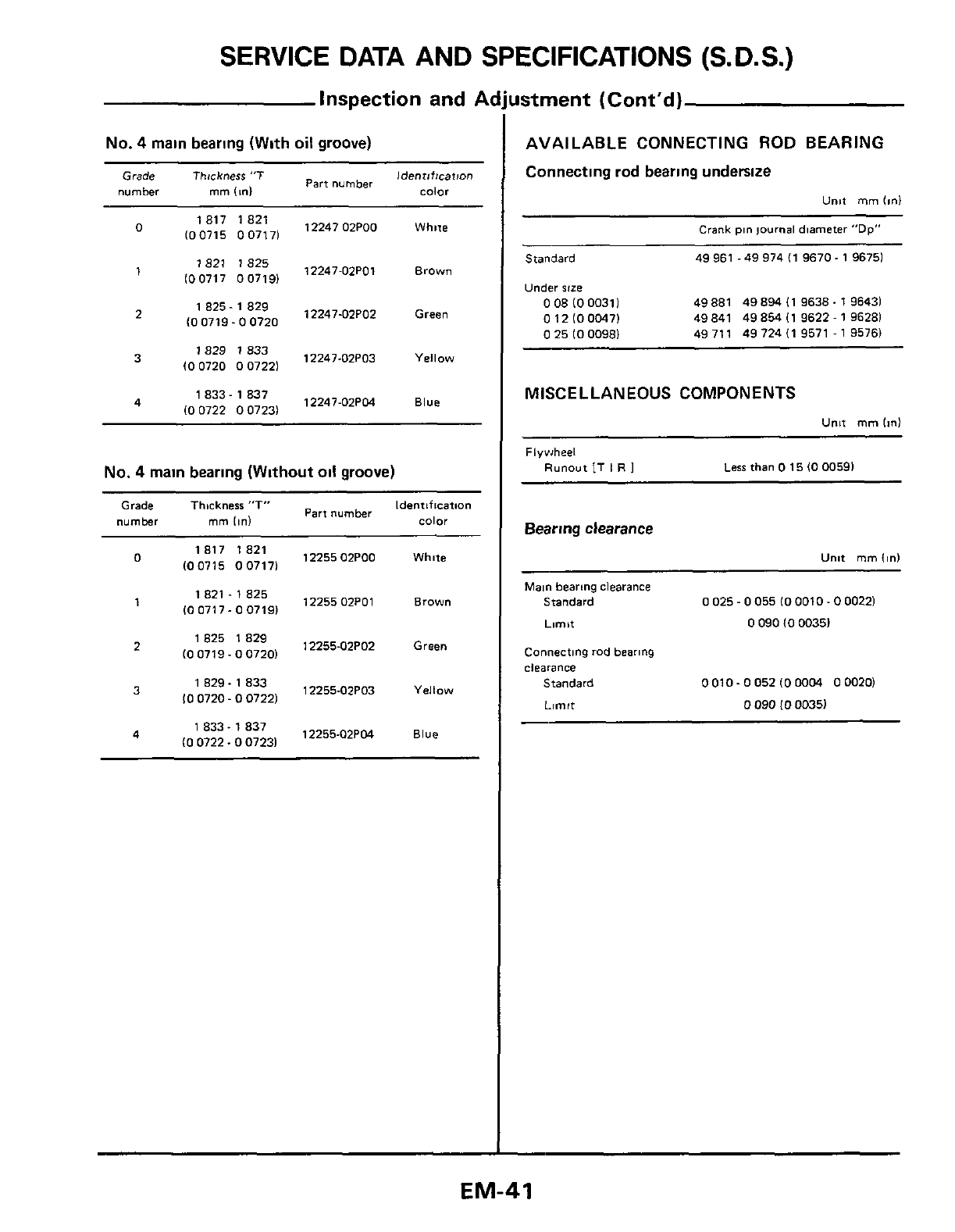
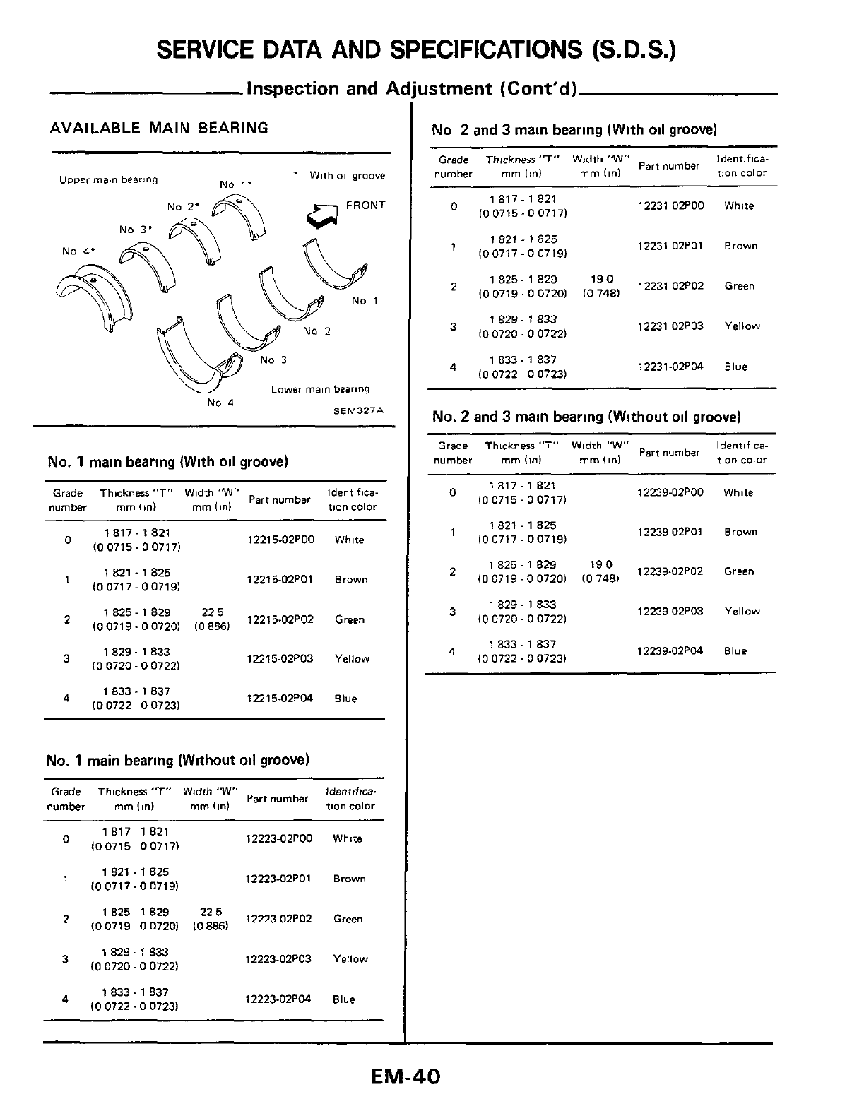
SERVICE
DATA
AND SPECIFICATIONS (S.D.S.)
Inspection and
A
No.
4
main bearing (With
oil
groove)
Thickness
'7
Identrf!catmn
Part
number
Grade
number
mm
Id
Color
12247
02POO
White
100715
007171
821
12247-02POl
Brown
IO0717 007191
1
829
12247-02PO2 Green
100719-00720
2
833
12247-02PO3 Yellow
100720 007221
833
837
12247-02PM Blue
100722 007231
No.
4
main bearing
(Without
oil groove)
Grade Thickness
"T"
Part
number
Identification
number mm
11nI
Color
821
1225502POO White
100715 007171
'
825
12255
02P01
Brown
100717-007191
12255-02P02 Green
IO
0719
-
0
07201
833
12255-02PO3 Yellow
10
0720
-
0
07221
833.
837
12255-02P04
Blue
IO
0722.0 07231
istrnent (Cont'd)
AVAILABLE CONNECTING
ROD
BEARING
Connecting rod bearing undersize
Unit
mm
Ion1
-
Crank
pin
journal
diameter
"Dp"
Standard
Under
size
49 961
-
49 974
(1
9670
-
1
96751
0
08
IO
0031
1
49 881 49
894
I1
9638.1 96431
0121000471 49 841 49 854
(1
9622
-
1
96281
0
25
(0
00981 49711 49724119571-195761
MISCELLANEOUS COMPONENTS
Unit
mm
Id
Flywheel
Runout
IT
I
R
1
Less
than
0
15
IO
00591
Bearing clearance
Unit
mm
11nI
-~~
~
Main
bearing clearance
Standard
Limit
0
090
IO
00351
0
025
-
0
055
(0
0010
-
0
00221
Connecting rod bearing
clearance
Standard
0
010.0
052
IO
0004
0
00201
Limit
0
090
IO
00351
EM-41
SERVICE DATA AND SPECIFICATIONS
(S.D.S.)
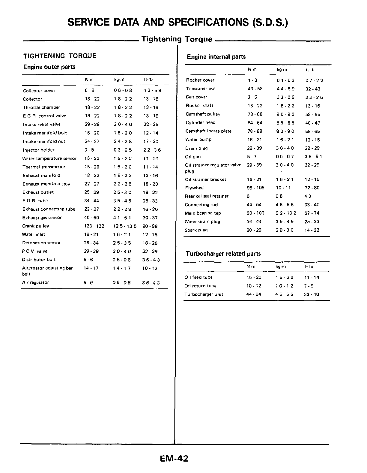
Tig
htenii
TIGHTENING
TORQUE
Engine outer parts
Nm kg-m ft-lb
Collector
cover
68
06-08 43-58
Collector
18-22 18-22 13-16
Throttle chamber
18.22 18-22 13-16
E
G
R
control
valve
18-22 18-22 13 16
Intake relief
valve
29.39 30-40 22-29
Intake manifold
bolt
16 20 16-20 12-14
Intake manifold
nut
24
-
27 24-28 17-20
Injector holder
3-5
03-05 22-36
Water temperature sensor
15
-
20 15-20 11 14
Thermal
transmltter
15-20 15-20 11-14
Exhaust manifold
18 22 18-22 13-16
Exhaust manifold
stay
22
-
27 22-28 16-20
Exhaust
outlet
25 29 25-30 18 22
E
G
R
tube
34 44 35-45 25-33
Exhaust connecting tube
22
-
27 22-28 16-20
Exhaust gas
sensor
40-50 41-51 30-37
Crank pulley
123 132 125-135 90-98
Water
mlet
16
-
21 16-21 12-15
Detowtion
sensor
25-34 25-35 18-25
P
c
v
WlYe
29-39 30-40 22 29
Dirtnbutor bolt
5-6
05-06
36-43
Alternator
adjusting
bar
14
-
17 14-17 10-12
bolt
Air
regulator
5-6
05-06
36-43
Torque
Engine internal
parts
Nm kq-m ft-lb
Rocker cover
Tenrmner nut
Belt cover
Rocker shaft
Camshaft pulley
Cyl~nder head
Camshaft
locate
plate
Water pump
Drain
plug
011
pan
011
strainer
regulator valve
Plug
011
strainer
bracket
Flywheel
Rear
011
seal retalner
Connecting rod
Main
bearing cap
Water
drain
plug
Spark plug
1-3
43
-
58
35
18 22
78.88
54.64
78
-
88
16
-
21
29.39
5-7
29.39
16.21
98
-
108
6
44
-
54
90
-
100
34
-
44
20.29
01-03
44-59
03-05
18-22
80-90
55-65
80-90
16-21
30-40
05-07
30-40
16-21
10-11
06
45-55
92-102
35-45
20-30
07-22
32.43
22-36
13
-
16
58.65
40
-
47
58.65
12-15
22.29
36-51
22.29
12-15
72
-
80
43
33
.40
67-74
25.33
14
-
22
Turbocharger related parts
Nm
kg-m
ft
Ib
011
feed tube
15.20 15-20 11-14
011
return
tube
10-12 10-12 7-9
Turbocharger
unlt
44.54 45
55
33-40
EM-42
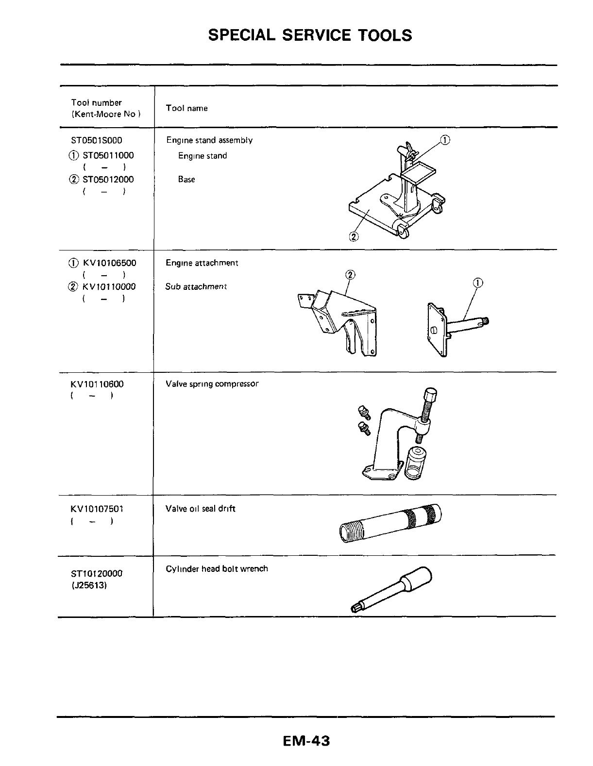
SPECIAL
SERVICE
TOOLS
Tool number
(Kent-Moore
No
I
ST0501S000
0
ST05011000
(-)
@
ST05012000
(-1
0
KV10106500
(-1
@
KVlOllOOOO
(-1
KV10110600
(-)
KV10107501
I-)
ST10120000
(J25613l
Tool name
Engine stand assembly
Engine stand
Base
Engine attachment
Sub attachment
P
Valve
oil
seal drift
Cylinder head
bolt
wrench
EM-43
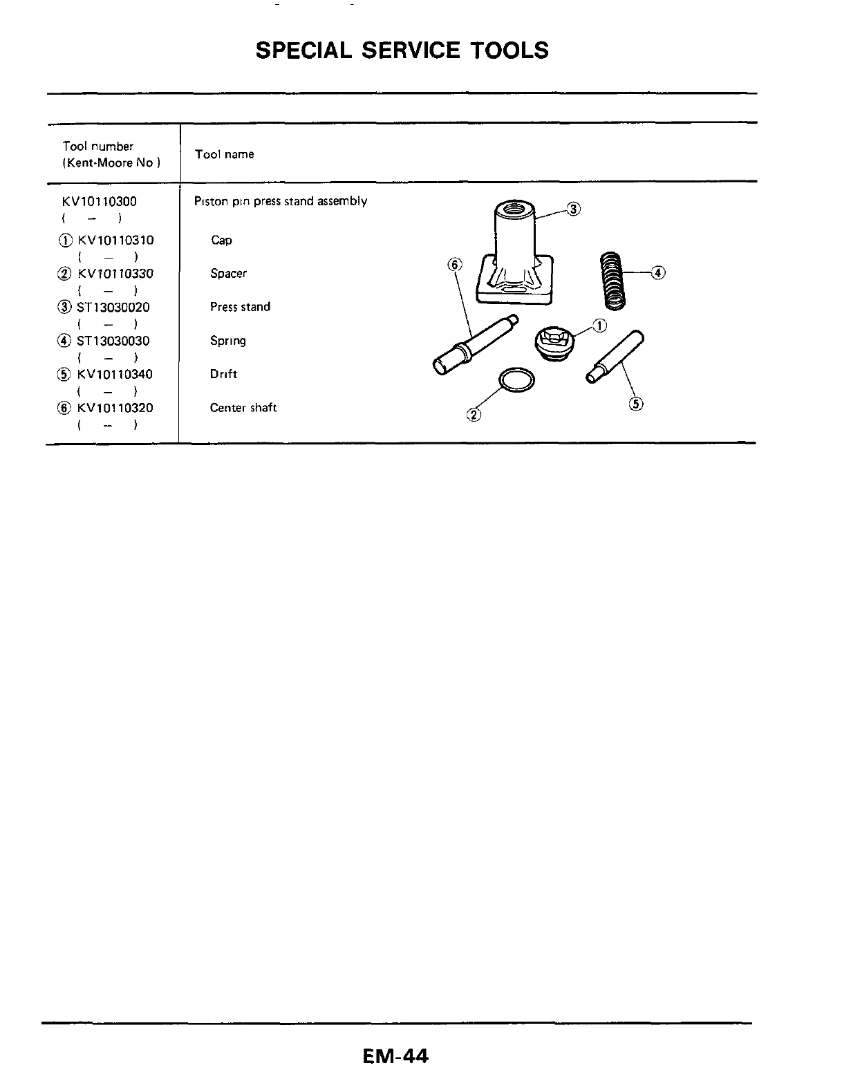
SPECIAL SERVICE TOOLS
Tool
number
(Kent-Moore
No
1
KVlOllO300
(-1
@
KV10110310
I-)
@
KVV0110330
(-)
@
ST13030020
(-1
@
ST13030030
(-)
@
KV10110340
(-)
@
KV10110320
(-)
Tool
name
Piston pin press stand assembly
Cap
Spacer
Press stand
Spring
Drift
Center shaft
EM-44
