EMS Bus Interface Board Manual V0.9
User Manual:
Open the PDF directly: View PDF ![]() .
.
Page Count: 4
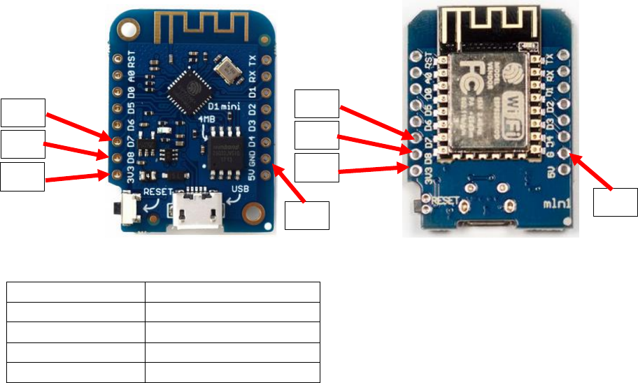
Wemos connections
The Wemos D1 Mini versions all have the same pinout, however the text on the
board may vary slightly. Below two examples.
Wemos D1 Mini V3 Wemos D1 Mini V2
Pin EMS board
Wemos pin
VC
3V3 (NOT 5V!!)
TX
D8
RX
D7
GD
G or GND
VC
TX
RX
GD
VC
TX
RX
GD
EMS bus interface board manual
Current board version: 0.9 - April 2018 – Last update 14 January 2019.
Please see the Github repository for all the details about working with the EMS bus.
https://github.com/bbqkees/Nefit-Buderus-EMS-bus-Arduino-Domoticz
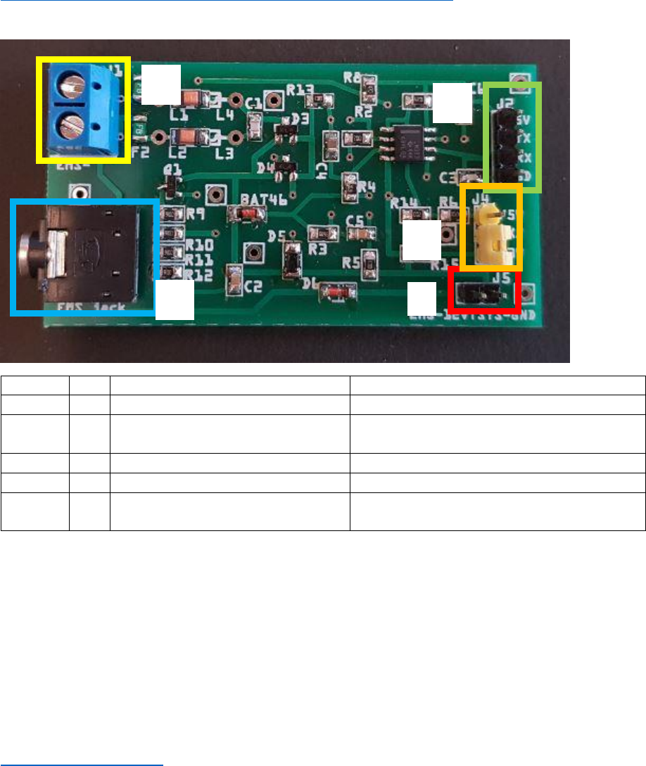
Connectors on the board
Number
J#
Header function
Remark
1
J1
EMS screw terminal
Polarity does not matter.
2
J2
Controller header
VCC/TX/RX/GND. Input 5V or 3.3V from
controller.
3
J3
EMS service jack plug
Only connect either J1 or J3.
4
J4
RX resistor selector jumper
Select either 4k7 or 100E resistor.
5
J5
8-12-16V pin from EMS service jack
Left pin EMS 8-16V. right pin GND. Max
power draw 200mA cont.
Before shipment, this board has been fully tested on my own boiler with an Arduino in RX and TX
mode on both 3.3V and 5V, and with both resistor settings. So the board you received works as
intended.
Keep this in mind when you created something with this board and it does not work. Do not
immediately assume the board is faulty. The most likely problems are in your own code or in the
connections to the microcontroller board. First try my Github examples to verify the board is working
in your setup and everything is wired up correctly.
If you have a persistent problem with the board you can always send an email to
bbqkees+pcb@gmail.com
In any case do not open a Paypal dispute.
1
2
4
3
5

Important note:
The board can be powered with either 5V or 3.3V. However, this is also the voltage for the signal
level on the UART. If you use 5V to power the board, 5V will also be your UART signal level and
this will potentially destroy f.i. an ESP8266.
So if you are using an Arduino, power the board with 5V and if you are using a Pi or an ESP chip
ONLY USE 3.3V to power the board. The yellow jumper setting J4 is an RX resistor selector. This
change was made in the last board revision to get an improved handling when using an ESP8266.
Furthermore R15 is no longer populated for the same reason, this is intentional.
The boards’ design has also been fully tested with the ESP8266 in both read and write mode.
See links on my Github to external ESP8266 code. (Like https://github.com/proddy/EMS-ESP-
Boiler)
Connecting to the controller
The controller needs to power the interface board. Connect GND as well. Do not supply the interface
board with more than 5V.
You can connect this board to any 5V or 3.3V compatible UART. This might be on an Arduino,
ESP8266 or f.i. a Raspberry Pi. Connect the header J2 to the controller. Keep in mind the remarks in
the red box above.
Use the jumper of J4 to select the correct RX UART resistor setting. For most Arduino’s and the Pi this
is setting 1. This setting provides a standard 4k7 Ohm resistor on the output. For the ESP8266 use
setting 2. Setting 2 provides a 100 Ohm resistor on the output, specifically intended for the ESP8266
and other similar chips. If one particular setting does not work, try the other setting too.
Connect RX to the RX UART serial port and TX to the TX UART serial port of your controller. If you do
not need TX you can just leave the pin unconnected.
On the Arduino Mega 2560 in combination with the Github sketch connect RX to RX1 (pin 19) and TX
to TX1 (pin 18).
If you use an Arduino UNO you have no choice other than RX on pin 0 and TX on pin 1. In case you
use the UNO do not connect the EMS board to the Arduino while you are programming the Arduino,
because the same serial pins are used for programming the Arduino.
On the Raspberry Pi connect RX to GPIO 15 (pin 10) and TX to GPIO 14 (pin 8).
Important:
The interface board also puts out the 8-16V pin of the EMS service jack via header 5. This can be used
to power small electronics. The interface board has 2 polyfuses that are rated for a continuous
current of 200mA and they trip at 400mA.
If you do draw power from the EMS service jack make sure the 3.5mm jack cable you use can handle
the current as most of these cables are meant for audio and therefore have very thin wires inside.
The best method to power external circuits from these pins is to use a buck converter. LDO's will
overheat pretty quickly due to the voltage difference.
Also take care you do not short circuit the board in any way or feed this board with incorrect voltages
as this may damage the board or the EMS bus. Also make sure the wires you connect the board to
are in fact EMS bus wires and NOT 24V or mains power lines!!!!!!!!!
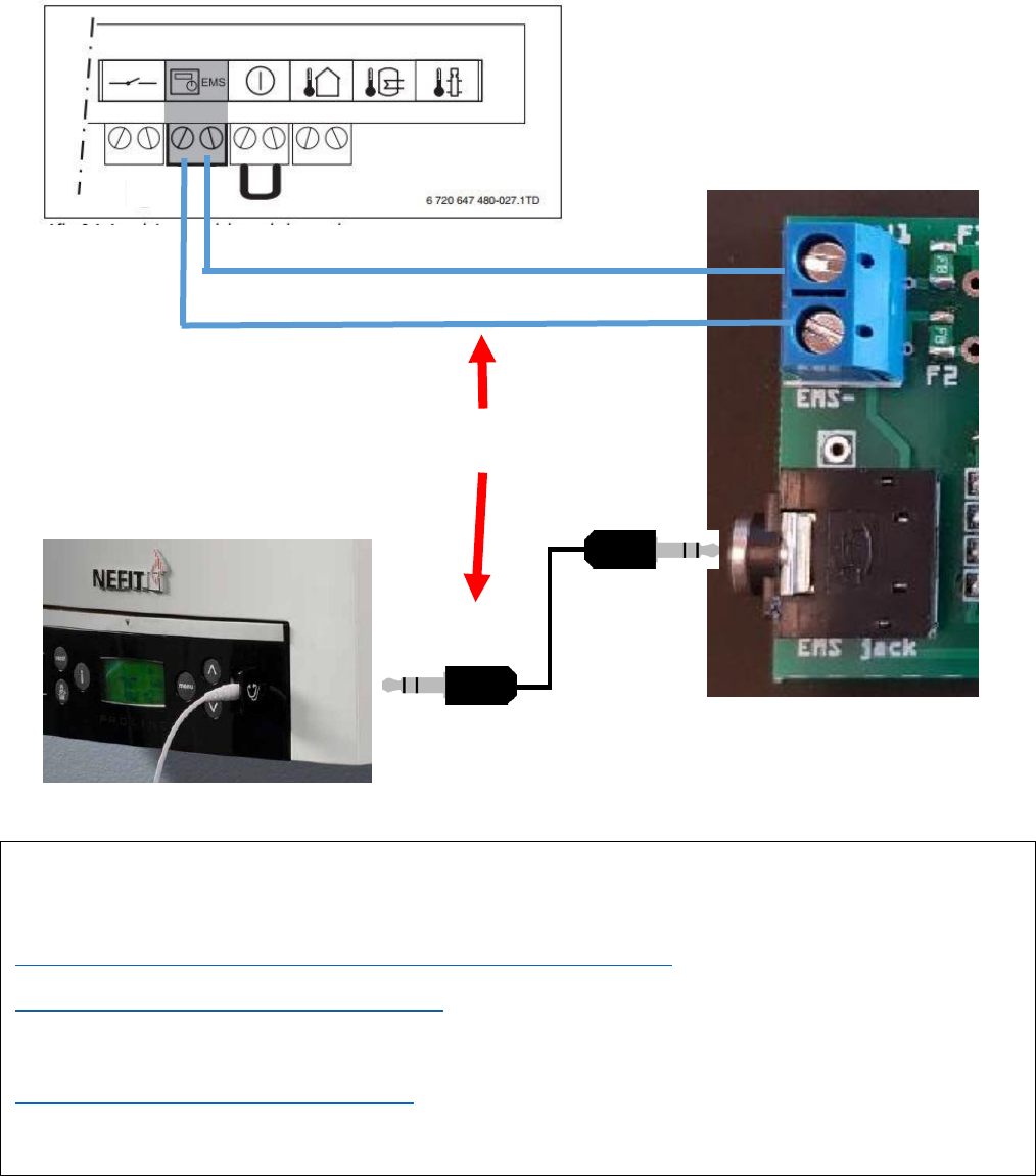
Connecting to the bus
You can use EITHER the EMS bus service jack OR the screw terminal.
Do not connect them at the same time, because you might short circuit the bus.
If you use the screw terminal, polarity does not matter because the circuit corrects both orientations.
OR
Below some code examples to get you started:
Arduino:
https://github.com/bbqkees/Nefit-Buderus-EMS-bus-Arduino-Domoticz
https://github.com/danimaciasperea/Calduino
ESP8266:
https://github.com/proddy/EMS-ESP-Boiler (Keep in mind this code uses the alternative RX and TX pins on
the Wemos!)
