EN Manual
User Manual:
Open the PDF directly: View PDF ![]() .
.
Page Count: 246 [warning: Documents this large are best viewed by clicking the View PDF Link!]
All contents are Copyright © 1992–2010 Cisco Systems, Inc. All rights reserved. This document is Cisco Public Information. Page 1 of 17
CCNPv6 ROUTE
Chapter 3 Lab 3-1, Single-Area OSPF Link Costs and Interface
Priorities Instructor Version
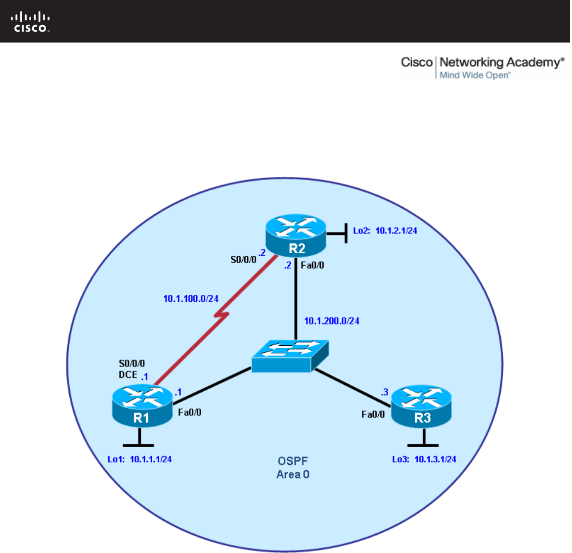
Topology
Objectives
• Configure single-area OSPF on a router.
• Advertise loopback interfaces into OSPF.
• Verify OSPF adjacencies.
• Verify OSPF routing information exchange.
• Modify OSPF link costs.
• Change interface priorities.
• Utilize debugging commands for troubleshooting OSPF.

CCNPv6 ROUTE
All contents are Copyright © 1992–2010 Cisco Systems, Inc. All rights reserved. This document is Cisco Public Information. Page 2 of 17
Background
You are responsible for configuring the new network to connect your company’s engineering, marketing, and
accounting departments, represented by the loopback interfaces on each of the three routers. The physical
devices have just been installed and connected by Fast Ethernet and serial cables. Configure OSPF to allow
full connectivity between all departments.
Note: This lab uses Cisco 1841 routers with Cisco IOS Release 12.4(24)T1 and the Advanced IP Services
image c1841-advipservicesk9-mz.124-24.T1.bin. The switch is a Cisco WS-C2960-24TT-L with the Cisco IOS
image c2960-lanbasek9-mz.122-46.SE.bin. You can use other routers (such as a 2801 or 2811), switches
(such as a 2950), and Cisco IOS Software versions if they have comparable capabilities and features.
Depending on the router or switch model and Cisco IOS Software version, the commands available and
output produced might vary from what is shown in this lab.
Required Resources
• 3 routers (Cisco 1841 with Cisco IOS Release 12.4(24)T1 Advanced IP Services or comparable)
• 1 switch (Cisco 2960 with the Cisco IOS Release 12.2(46)SE C2960-LANBASEK9-M image or
comparable)
• Serial and Ethernet cables
Step 1: Configure addressing and loopbacks.
a. Using the addressing scheme in the diagram, apply IP addresses to the Fast Ethernet interfaces on R1,
R2, and R3. Create Loopback1 on R1, Loopback2 on R2, and Loopback3 on R3, and address them
according to the diagram.
Note: Depending on the router models you have, you might need to add clock rates to the DCE end of
each connection (newer equipment adds this automatically). Verify connectivity across each serial link.
R1# configure terminal
R1(config)# interface Loopback1
R1(config-if)# description Engineering Department
R1(config-if)# ip address 10.1.1.1 255.255.255.0
R1(config-if)# exit
R1(config)# interface FastEthernet0/0
R1(config-if)# ip address 10.1.200.1 255.255.255.0
R1(config-if)# no shutdown
R2# configure terminal
R2(config)# interface Loopback2
R2(config-if)# description Marketing Department
R2(config-if)# ip address 10.1.2.1 255.255.255.0
R2(config-if)# exit
R2(config)# interface FastEthernet0/0
R2(config-if)# ip address 10.1.200.2 255.255.255.0
R2(config-if)# no shutdown
R3# configure terminal
R3(config)# interface Loopback3
R3(config-if)# description Accounting Department
R3(config-if)# ip address 10.1.3.1 255.255.255.0
R3(config-if)# exit
R3(config)# interface FastEthernet0/0
R3(config-if)# ip address 10.1.200.3 255.255.255.0
R3(config-if)# no shutdown

CCNPv6 ROUTE
All contents are Copyright © 1992–2010 Cisco Systems, Inc. All rights reserved. This document is Cisco Public Information. Page 3 of 17
Leave the switch in its default (blank) configuration. By default, all switch ports are in VLAN1 and are not
administratively down.
b. Configure the serial interfaces on R1 and R2 with the IP addresses shown in the diagram. Add the
clockrate command where needed.
R1(config)# interface Serial 0/0/0
R1(config-if)# ip address 10.1.100.1 255.255.255.0
R1(config-if)# clockrate 64000
R1(config-if)# bandwidth 64
R1(config-if)# no shutdown
R2(config)# interface Serial 0/0/0
R2(config-if)# ip address 10.1.100.2 255.255.255.0
R2(config-if)# bandwidth 64
R2(config-if)# no shutdown
Note: The bandwidth command on the serial interfaces is used to match the actual bandwidth of the link.
By default, OSPF calculates the cost of links based on the default interface bandwidth which may be
either 128 or 1544 Kb/s, depending on the WIC type. In this case the bandwidth 64 command is used
because the real bandwidth of the serial interfaces is set to 64 Kbps. Refer to Step 5 for information on
modifying OSPF link costs.
c. Verify that the appropriate interfaces are up and that you can ping across each link.
Step 2: Add physical interfaces to OSPF.
a. Enter the OSPF configuration prompt using the router ospf process_number command. The process
number is a locally significant number that does not affect how OSPF works. For this lab, use process
number 1 on all the routers.
b. Add interfaces with the network address wildcard_mask area area command. The address is an IP
address. The mask is an inverse mask, similar to the kind used in an access list. The area is the OSPF
area to put the interface. For this lab, use area 0, the backbone area, for all interfaces.
This command can be confusing at first. What it means is that any interface with an IP address that
matches the address and wildcard mask combination in the network statement is added to the OSPF
process in that area. The wildcard mask used in the network command has no influence on the actual IP
subnet mask that is advertised with a network on an interface. The network command selects interfaces
to be included into OSPF, but OSPF advertises the real subnet mask of the network attached to that
interface (with the only exception being loopback interfaces).
For example, the command network 10.1.200.1 0.0.0.0 area 0 adds the interface with the IP address of
10.1.200.1 and its network to the OSPF process into area 0. The wildcard mask of 0.0.0.0 means that all
32 bits of the IP address have to be an exact match. A 0 bit in the wildcard mask means that portion of
the interface IP must match the address. A 1 bit means that the bit in the interface IP does not have to
match that portion of the IP address.
The command network 10.1.100.0 0.0.0.255 area 0 means that any interface whose IP address matches
10.1.100.0 for the first 3 octets will match the command and add it to area 0. The last octet is all 1s,
because in the wildcard mask it is 255. This means that an interface with an IP of 10.1.100.1, 10.1.100.2,
or 10.1.100.250 would match this address and wildcard combination and get added to OSPF.
Instead of using wildcard masks in the network command, it is possible to use subnet masks. The router
converts the subnet masks to the wildcard format automatically. An easy way to calculate a wildcard

CCNPv6 ROUTE
All contents are Copyright © 1992–2010 Cisco Systems, Inc. All rights reserved. This document is Cisco Public Information. Page 4 of 17
mask from the subnet mask is to subtract the octet value for each octet from 255. For example, a subnet
mask of 255.255.255.252 (/30) becomes 0.0.0.3 to capture all interfaces on that subnet:
255.255.255.255
– 255.255.255.252
Note: Another option for adding individual directly connected networks into the OSPF process is to use
the ip ospf process-id area area-id interface command that is available with Cisco IOS version 12.3(11)T
and later.
= 0. 0. 0. 3
c. Enter the commands on R1. Exit to privileged EXEC mode and type debug ip ospf adj. The debug
command lets you watch OSPF neighbors come up and see neighbor relationships.
R1(config)# router ospf 1
R1(config-router)# network 10.1.100.0 0.0.0.255 area 0
R1(config-router)# network 10.1.200.0 0.0.0.255 area 0
R1(config-router)# end
R1#
R1# debug ip ospf adj
OSPF adjacency events debugging is on
d. Add network statements to the other two routers.
R2(config)# router ospf 1
R2(config-router)# network 10.1.100.0 0.0.0.255 area 0
R2(config-router)# network 10.1.200.0 0.0.0.255 area 0
R3(config)# router ospf 1
R3(config-router)# network 10.1.200.0 0.0.0.255 area 0
e. Observe the debug output on R1. When you are finished, turn off debugging on R1 with the undebug all
command.
f. What is the advantage of adding networks with a wildcard mask instead of using classful network
addresses?
_______________________________________________________________________________
_______________________________________________________________________________
_______________________________________________________________________________
_______________________________________________________________________________
_______________________________________________________________________________
_______________________________________________________________________________
_______________________________________________________________________________
Using wildcard masks to add network addresses provides more control in determining which interfaces
participate in the OSPF process.
In OSPF, interfaces can be assigned to different areas. Many times, a router is routing inside of a major
network, but different interfaces belong to different areas. You need the level of control given by wildcard
masks to assign different interfaces to their appropriate areas and not restrict an entire major network to
be in one area. There might be networks connected to a router that the administrator does not want to
advertise but which are in the same major network as the OSPF-enabled interface. Without using
wildcard masks, it would be practically impossible to implement this.

CCNPv6 ROUTE
All contents are Copyright © 1992–2010 Cisco Systems, Inc. All rights reserved. This document is Cisco Public Information. Page 5 of 17
Step 3: Use OSPF show commands.
a. The show ip protocols command displays basic high-level routing protocol information. The output lists
each OSPF process, the router ID, and which networks OSPF is routing for in each area. This information
can be useful in debugging routing operations.
R1# show ip protocols
Routing Protocol is "ospf 1"
Outgoing update filter list for all interfaces is not set
Incoming update filter list for all interfaces is not set
Router ID 10.1.1.1
Number of areas in this router is 1. 1 normal 0 stub 0 nssa
Maximum path: 4
Routing for Networks:
10.1.100.0 0.0.0.255 area 0
10.1.200.1 0.0.0.0 area 0
Reference bandwidth unit is 100 mbps
Routing Information Sources:
Gateway Distance Last Update
Distance: (default is 110)
b. The show ip ospf command displays the OSPF process ID and router ID.
R1# show ip ospf
Routing Process "ospf 1" with ID 10.1.1.1
Start time: 00:17:44.612, Time elapsed: 00:10:51.408
Supports only single TOS(TOS0) routes
Supports opaque LSA
Supports Link-local Signaling (LLS)
Supports area transit capability
Router is not originating router-LSAs with maximum metric
Initial SPF schedule delay 5000 msecs
Minimum hold time between two consecutive SPFs 10000 msecs
Maximum wait time between two consecutive SPFs 10000 msecs
Incremental-SPF disabled
Minimum LSA interval 5 secs
Minimum LSA arrival 1000 msecs
LSA group pacing timer 240 secs
Interface flood pacing timer 33 msecs
Retransmission pacing timer 66 msecs
Number of external LSA 0. Checksum Sum 0x000000
Number of opaque AS LSA 0. Checksum Sum 0x000000
Number of DCbitless external and opaque AS LSA 0
Number of DoNotAge external and opaque AS LSA 0
Number of areas in this router is 1. 1 normal 0 stub 0 nssa
Number of areas transit capable is 0
External flood list length 0
Area BACKBONE(0)
Number of interfaces in this area is 2
Area has no authentication
SPF algorithm last executed 00:03:21.132 ago
SPF algorithm executed 5 times
Area ranges are
Number of LSA 4. Checksum Sum 0x021A30
Number of opaque link LSA 0. Checksum Sum 0x000000
Number of DCbitless LSA 0
Number of indication LSA 0
Number of DoNotAge LSA 0
Flood list length 0

CCNPv6 ROUTE
All contents are Copyright © 1992–2010 Cisco Systems, Inc. All rights reserved. This document is Cisco Public Information. Page 6 of 17
Notice the router ID listed in the output. The R1 ID is 10.1.1.1, even though you have not added this
loopback into the OSPF process. The router chooses the router ID using the highest IP on a loopback
interface when OSPF is configured. If an additional loopback interface with a higher IP address is added
after OSPF is turned on, it does not become the router ID unless the router is reloaded, the OSPF
configuration is removed and reentered, or the OSPF-level command router-id is used to modify the RID
manually and the clear ip ospf process command is subsequently entered. If no loopback interfaces are
present on the router, the router selects the highest available IP address among interfaces that are
activated using the no shutdown command. If no IP addresses are assigned to interfaces, the OSPF
process does not start.
c. The show ip ospf neighbor command displays important neighbor status, including the adjacency state,
address, router ID, and connected interface.
R1# show ip ospf neighbor
Neighbor ID Pri State Dead Time Address Interface
10.1.2.1 1 FULL/BDR 00:00:36 10.1.200.2 FastEthernet0/0
10.1.3.1 1 FULL/DR 00:00:35 10.1.200.3 FastEthernet0/0
10.1.2.1 0 FULL/ - 00:00:36 10.1.100.2 Serial0/0/0
If you need more detail than the standard one-line summaries of neighbors, use the show ip ospf
neighbor detail command. However, generally, the regular command gives you all that you need.
d. The show ip ospf interface interface_type number command shows interface timers and network types.
R1# show ip ospf interface FastEthernet 0/0
FastEthernet0/0 is up, line protocol is up
Internet Address 10.1.200.1/24, Area 0
Process ID 1, Router ID 10.1.1.1, Network Type BROADCAST, Cost: 1
Transmit Delay is 1 sec, State DROTHER, Priority 1
Designated Router (ID) 10.1.3.1, Interface address 10.1.200.3
Backup Designated router (ID) 10.1.2.1, Interface address 10.1.200.2
Timer intervals configured, Hello 10, Dead 40, Wait 40, Retransmit 5
oob-resync timeout 40
Hello due in 00:00:09
Supports Link-local Signaling (LLS)
Cisco NSF helper support enabled
IETF NSF helper support enabled
Index 2/2, flood queue length 0
Next 0x0(0)/0x0(0)
Last flood scan length is 1, maximum is 1
Last flood scan time is 0 msec, maximum is 0 msec
Neighbor Count is 2, Adjacent neighbor count is 2
Adjacent with neighbor 10.1.3.1 (Designated Router)
Adjacent with neighbor 10.1.2.1
Suppress hello for 0 neighbor(s)
e. A variation of the previous command is the show ip ospf interface brief command, which displays each
interface that is participating in the OSPF process on the router, the area it is in, its IP address, cost,
state, and number of neighbors.
R1# show ip ospf interface brief
Interface PID Area IP Address/Mask Cost State Nbrs F/C
Fa0/0 1 0 10.1.200.1/24 1 DROTH 2/2
Se0/0/0 1 0 10.1.100.1/24 1 P2P 1/1
f. The show ip ospf database command displays the various LSAs in the OSPF database, organized by
area and type.

CCNPv6 ROUTE
All contents are Copyright © 1992–2010 Cisco Systems, Inc. All rights reserved. This document is Cisco Public Information. Page 7 of 17
R1# show ip ospf database
OSPF Router with ID (10.1.1.1) (Process ID 1)
Router Link States (Area 0)
Link ID ADV Router Age Seq# Checksum Link count
10.1.1.1 10.1.1.1 1782 0x80000002 0x001AC7 3
10.1.2.1 10.1.2.1 1783 0x80000001 0x001DC2 3
10.1.3.1 10.1.3.1 1720 0x80000002 0x00F077 1
Net Link States (Area 0)
Link ID ADV Router Age Seq# Checksum
10.1.200.1 10.1.1.1 1719 0x80000002 0x00EC3C
OSPF Router with ID (10.1.1.1) (Process ID 1)
Step 4: Add loopback interfaces to OSPF.
a. All three routers have loopback interfaces, but they are not yet advertised in the routing process. You can
verify this with the show ip route command on the three routers.
R1# show ip route
Codes: C - connected, S - static, R - RIP, M - mobile, B - BGP
D - EIGRP, EX - EIGRP external, O - OSPF, IA - OSPF inter area
N1 - OSPF NSSA external type 1, N2 - OSPF NSSA external type 2
E1 - OSPF external type 1, E2 - OSPF external type 2
i - IS-IS, su - IS-IS summary, L1 - IS-IS level-1, L2 - IS-IS level-2
ia - IS-IS inter area, * - candidate default, U - per-user static
route
o - ODR, P - periodic downloaded static route
Gateway of last resort is not set
10.0.0.0/24 is subnetted, 3 subnets
C 10.1.1.0 is directly connected, Loopback1
C 10.1.100.0 is directly connected, Serial0/0/0
C 10.1.200.0 is directly connected, FastEthernet0/0
R2# show ip route
Codes: C - connected, S - static, R - RIP, M - mobile, B - BGP
D - EIGRP, EX - EIGRP external, O - OSPF, IA - OSPF inter area
N1 - OSPF NSSA external type 1, N2 - OSPF NSSA external type 2
E1 - OSPF external type 1, E2 - OSPF external type 2
i - IS-IS, su - IS-IS summary, L1 - IS-IS level-1, L2 - IS-IS level-2
ia - IS-IS inter area, * - candidate default, U - per-user static
route
o - ODR, P - periodic downloaded static route
Gateway of last resort is not set
10.0.0.0/24 is subnetted, 3 subnets
C 10.1.2.0 is directly connected, Loopback2
C 10.1.100.0 is directly connected, Serial0/0/0
C 10.1.200.0 is directly connected, FastEthernet0/0
R3# show ip route

CCNPv6 ROUTE
All contents are Copyright © 1992–2010 Cisco Systems, Inc. All rights reserved. This document is Cisco Public Information. Page 8 of 17
Codes: C - connected, S - static, R - RIP, M - mobile, B - BGP
D - EIGRP, EX - EIGRP external, O - OSPF, IA - OSPF inter area
N1 - OSPF NSSA external type 1, N2 - OSPF NSSA external type 2
E1 - OSPF external type 1, E2 - OSPF external type 2
i - IS-IS, su - IS-IS summary, L1 - IS-IS level-1, L2 - IS-IS level-2
ia - IS-IS inter area, * - candidate default, U - per-user static
route
o - ODR, P - periodic downloaded static route
Gateway of last resort is not set
10.0.0.0/24 is subnetted, 3 subnets
C 10.1.3.0 is directly connected, Loopback3
O 10.1.100.0 [110/65] via 10.1.200.2, 00:06:39, FastEthernet0/0
[110/65] via 10.1.200.1, 00:06:39, FastEthernet0/0
C 10.1.200.0 is directly connected, FastEthernet0/0
b. For each router, the only loopback address displayed is the locally connected one. Add the loopbacks into
the routing process for each router using the same network command previously used to add the
physical interfaces.
R1(config)# router ospf 1
R1(config-router)# network 10.1.1.0 0.0.0.255 area 0
R2(config)# router ospf 1
R2(config-router)# network 10.1.2.0 0.0.0.255 area 0
R3(config)# router ospf 1
R3(config-router)# network 10.1.3.0 0.0.0.255 area 0
c. Verify that these networks have been added to the routing table using the show ip route command.
R1# show ip route
Codes: C - connected, S - static, R - RIP, M - mobile, B - BGP
D - EIGRP, EX - EIGRP external, O - OSPF, IA - OSPF inter area
N1 - OSPF NSSA external type 1, N2 - OSPF NSSA external type 2
E1 - OSPF external type 1, E2 - OSPF external type 2
i - IS-IS, su - IS-IS summary, L1 - IS-IS level-1, L2 - IS-IS level-2
ia - IS-IS inter area, * - candidate default, U - per-user static
route
o - ODR, P - periodic downloaded static route
Gateway of last resort is not set
10.0.0.0/8 is variably subnetted, 5 subnets, 2 masks
O 10.1.2.1/32 [110/2] via 10.1.200.2, 00:00:03, FastEthernet0/0
O 10.1.3.1/32 [110/2] via 10.1.200.3, 00:00:03, FastEthernet0/0
C 10.1.1.0/24 is directly connected, Loopback1
C 10.1.100.0/24 is directly connected, Serial0/0/0
C 10.1.200.0/24 is directly connected, FastEthernet0/0
Now you can see the loopbacks of the other routers, but their subnet mask is incorrect, because the
default network type on loopback interfaces advertises them as /32 (host) routes. As you can see in the
output of the show ip ospf interface Lo1 command, the default OSPF network type for a loopback
interface is LOOPBACK, causing the OSPF to advertise host routes instead of actual network masks.
R1# show ip ospf interface Lo1
Loopback1 is up, line protocol is up

CCNPv6 ROUTE
All contents are Copyright © 1992–2010 Cisco Systems, Inc. All rights reserved. This document is Cisco Public Information. Page 9 of 17
Internet Address 10.1.1.1/24, Area 0
Process ID 1, Router ID 10.1.1.1, Network Type LOOPBACK, Cost: 1
Loopback interface is treated as a stub Host
Note: The OSPF network type of LOOPBACK is a Cisco-proprietary extension that is not configurable but that
is present on loopback interfaces by default. In some applications such as MPLS, the possible discrepancy
between the real loopback interface mask and the advertised address/mask can lead to reachability or
functionality issues, and care must be taken to either use /32 mask on loopbacks, or whenever a different
mask is used, the OSPF network type must be changed to point-to-point.
d. To change this default behavior use the ip ospf network point-to-point command in interface
configuration mode for each loopback. After the routes propagate, you see the correct subnet masks
associated with those loopback interfaces.
R1(config)# interface loopback1
R1(config-if)# ip ospf network point-to-point
R2(config)# interface loopback2
R2(config-if)# ip ospf network point-to-point
R3(config)# interface loopback3
R3(config-if)# ip ospf network point-to-point
R1# show ip route
Codes: C - connected, S - static, R - RIP, M - mobile, B - BGP
D - EIGRP, EX - EIGRP external, O - OSPF, IA - OSPF inter area
N1 - OSPF NSSA external type 1, N2 - OSPF NSSA external type 2
E1 - OSPF external type 1, E2 - OSPF external type 2
i - IS-IS, su - IS-IS summary, L1 - IS-IS level-1, L2 - IS-IS level-2
ia - IS-IS inter area, * - candidate default, U - per-user static
route
o - ODR, P - periodic downloaded static route
Gateway of last resort is not set
10.0.0.0/24 is subnetted, 5 subnets
O 10.1.3.0 [110/2] via 10.1.200.3, 00:00:01, FastEthernet0/0
O 10.1.2.0 [110/2] via 10.1.200.2, 00:00:01, FastEthernet0/0
C 10.1.1.0 is directly connected, Loopback1
C 10.1.100.0 is directly connected, Serial0/0/0
C 10.1.200.0 is directly connected, FastEthernet0/0
e. Use the following Tcl script to verify connectivity to all addresses in the topology.
R1# tclsh
foreach address {
10.1.1.1
10.1.2.1
10.1.3.1
10.1.100.1
10.1.100.2
10.1.200.1
10.1.200.2
10.1.200.3
} {
ping $address }

CCNPv6 ROUTE
All contents are Copyright © 1992–2010 Cisco Systems, Inc. All rights reserved. This document is Cisco Public Information. Page 10 of 17
Step 5: Modify OSPF link costs.
When you use the show ip route command on R1, you see that the most direct route to the R2 loopback is
through its Ethernet connection. Next to this route is a pair in the form [administrative distance / metric ]. The
default administrative distance of OSPF on Cisco routers is 110. The metric depends on the link type. OSPF
always chooses the route with the lowest metric, which is a sum of all link costs.
You can modify a single link cost by using the interface command ip ospf cost cost. Use this command on
both ends of the link. In the following commands, the link cost of the Fast Ethernet connection between the
three routers is changed to a cost of 50. Notice the change in the metrics in the routing table.
R1(config)# interface FastEthernet 0/0
R1(config-if)# ip ospf cost 50
R2(config)# interface FastEthernet 0/0
R2(config-if)# ip ospf cost 50
R3(config)# interface FastEthernet 0/0
R3(config-if)# ip ospf cost 50
R1# show ip route
Codes: C - connected, S - static, R - RIP, M - mobile, B - BGP
D - EIGRP, EX - EIGRP external, O - OSPF, IA - OSPF inter area
N1 - OSPF NSSA external type 1, N2 - OSPF NSSA external type 2
E1 - OSPF external type 1, E2 - OSPF external type 2
i - IS-IS, su - IS-IS summary, L1 - IS-IS level-1, L2 - IS-IS level-2
ia - IS-IS inter area, * - candidate default, U - per-user static
route
o - ODR, P - periodic downloaded static route
Gateway of last resort is not set
10.0.0.0/24 is subnetted, 5 subnets
O 10.1.3.0 [110/51] via 10.1.200.3, 00:01:40, FastEthernet0/0
O 10.1.2.0 [110/51] via 10.1.200.2, 00:01:40, FastEthernet0/0
C 10.1.1.0 is directly connected, Loopback1
C 10.1.100.0 is directly connected, Serial0/0/0
C 10.1.200.0 is directly connected, FastEthernet0/0
For reference, here are some default link costs (taken from Cisco.com):
• 64-kb/s serial link: 1562
• T1 (1.544-Mb/s serial link): 64
• E1 (2.048-Mb/s serial link): 48
• Ethernet: 10
• Fast Ethernet: 1
• FDDI: 1
• X25: 5208
• ATM: 1
OSPF uses a reference bandwidth of 100 Mb/s for cost calculation. The formula to calculate the cost is the
reference bandwidth divided by the interface bandwidth. For example, in the case of Ethernet, is the cost is
100 Mb/s / 10 Mb/s = 10.
The above link costs do not include Gigabit Ethernet, which is significantly faster than Fast Ethernet, but
would still have a cost of 1 using the default reference bandwidth of 100 Mb/s.

CCNPv6 ROUTE
All contents are Copyright © 1992–2010 Cisco Systems, Inc. All rights reserved. This document is Cisco Public Information. Page 11 of 17
The cost calculation can be adjusted to account for network links that are faster than 100 Mb/s by using the
auto-cost reference-bandwidth command to change the reference bandwidth. For example, to change the
reference bandwidth to 1000 Mb/s (Gigabit Ethernet), use the following commands:
R1(config)# router ospf 1
R1(config-router)# auto-cost reference-bandwidth 1000
% OSPF: Reference bandwidth is changed.
Please ensure reference bandwidth is consistent across all routers.
Note: If the ip ospf cost cost command is used on the interface, as is the case here, it overrides this
formulated cost.
Note: The above example is for reference only and should not be entered on R1.
Step 6: Modify interface priorities to control the DR and BDR election.
If you use the show ip ospf neighbor detail command on any of the routers, you see that for the Ethernet
network, R3 is the DR (designated router) and R2 is the BDR (backup designated router). These designations
are determined by the interface priority for all routers in that network, which you see in the show output.
The default priority is 1. If all the priorities are the same (which happens by default), the DR election is then
based on router IDs. The highest router ID router becomes the DR, and the second highest becomes the
BDR. All other routers become DROTHERs.
Note: If your routers do not have this exact behavior, it might be because of the order in which the routers
came up. Sometimes a router does not leave the DR position unless its interface goes down and another
router takes over. Your routers might not behave exactly like the example.
Use the ip ospf priority number interface command to change the OSPF priorities on R1 and R2 to make R1
the DR and R2 the BDR. After changing the priority on both interfaces, look at the output of the show ip ospf
neighbor detail command. You can also see the change with the show ip ospf neighbor command, but it
requires more interpretation because it comes up with states per neighbor, rather than stating the DR and
BDR on a neighbor adjacency network.
R1(config)# interface FastEthernet 0/0
R1(config-if)# ip ospf priority 10
R2(config)# interface FastEthernet 0/0
R2(config-if)# ip ospf priority 5
R1# show ip ospf neighbor detail
Neighbor 10.1.2.1, interface address 10.1.200.2
In the area 0 via interface FastEthernet0/0
Neighbor priority is 5, State is FULL, 12 state changes
DR is 10.1.200.1 BDR is 10.1.200.2
Options is 0x52
LLS Options is 0x1 (LR)
Dead timer due in 00:00:37
Neighbor is up for 00:01:32
Index 3/3, retransmission queue length 0, number of retransmission 0
First 0x0(0)/0x0(0) Next 0x0(0)/0x0(0)
Last retransmission scan length is 0, maximum is 0
Last retransmission scan time is 0 msec, maximum is 0 msec
Neighbor 10.1.3.1, interface address 10.1.200.3
In the area 0 via interface FastEthernet0/0
Neighbor priority is 1, State is FULL, 12 state changes
DR is 10.1.200.1 BDR is 10.1.200.2
Options is 0x52

CCNPv6 ROUTE
All contents are Copyright © 1992–2010 Cisco Systems, Inc. All rights reserved. This document is Cisco Public Information. Page 12 of 17
LLS Options is 0x1 (LR)
Dead timer due in 00:00:30
Neighbor is up for 00:01:12
Index 1/1, retransmission queue length 0, number of retransmission 3
First 0x0(0)/0x0(0) Next 0x0(0)/0x0(0)
Last retransmission scan length is 1, maximum is 1
Last retransmission scan time is 0 msec, maximum is 0 msec
Neighbor 10.1.2.1, interface address 10.1.100.2
In the area 0 via interface Serial0/0/0
Neighbor priority is 0, State is FULL, 12 state changes
DR is 0.0.0.0 BDR is 0.0.0.0
Options is 0x52
LLS Options is 0x1 (LR)
Dead timer due in 00:00:35
Neighbor is up for 00:01:44
Index 2/2, retransmission queue length 0, number of retransmission 2
First 0x0(0)/0x0(0) Next 0x0(0)/0x0(0)
Last retransmission scan length is 2, maximum is 2
Last retransmission scan time is 0 msec, maximum is 0 msec
Note: To make a router take over as DR, use the clear ip ospf process command on all the routers after
changing the priorities. Another method of demonstrating the election process and priorities is to shutdown
and reactivate all ports on the switch simultaneously. The switch can be configured with spanning-tree
portfast default and all ports can be shutdown and reactivated using the following commands.
interface range fa0/1 - 24
shutdown
no shutdown
What is the purpose of a DR in OSPF?
__________________________________________________________________________________
__________________________________________________________________________________
__________________________________________________________________________________
__________________________________________________________________________________
__________________________________________________________________________________
__________________________________________________________________________________
__________________________________________________________________________________
__________________________________________________________________________________
__________________________________________________________________________________
The most important function of the DR is to represent the multi-access segment by generating the Type-2
LSA on behalf of that segment. Without the Type-2 LSA originated by the DR, on a multi-access segment with
n routers, each router would be required to generate its own Type-1 LSA containing n-1 entries (also called
links), one entry for each neighbor, to indicate a full reachability. The link-state database on each router would
then contain n(n-1) links collected from Type-1 LSAs originated by the n routers on this segment.
With the Type-2 LSA representing the multi-access segment itself, each of the n routers attached to the
segment inserts only one entry in their Type-1 LSAs, describing a connection to the multi-access segment
represented by the Type-2 LSA. The DR will, in addition to its own Type-1 LSA, generate a Type-2 LSA

CCNPv6 ROUTE
All contents are Copyright © 1992–2010 Cisco Systems, Inc. All rights reserved. This document is Cisco Public Information. Page 13 of 17
containing n entries, in turn indicating a connection from the multi-access segment to each of its attached
routers. Essentially, the multi-access segment will be described as each router having a link to the segment
and the segment in turn having a link to each router. The link-state database on each router will now contain
only n+1 links which is, for large n, significantly lower than the former count n(n-1).
What is the purpose of a BDR in OSPF?
__________________________________________________________________________________
__________________________________________________________________________________
__________________________________________________________________________________
__________________________________________________________________________________
__________________________________________________________________________________
A BDR is a backup designated router. Its purpose is to take over as the DR if the current DR goes down.
When the BDR becomes the DR, a new BDR election is held for the next BDR.
Challenge: Topology Change
OSPF, like many link-state routing protocols, is reasonably fast when it comes to convergence. To test this,
have R3 send a large number of pings to the R1 loopback. By default, the pings take the path from R3 to R1
over Fast Ethernet because it has the lowest total path cost.
a. Check the path from R3 to R1 by performing a traceroute on R3 to the loopback of R1.
R3# traceroute 10.1.1.1
Type escape sequence to abort.
Tracing the route to 10.1.1.1
1 10.1.200.1 0 msec 0 msec *
Note: Read the next substep carefully before trying out the commands on routers.
b. Initiate a ping from R3 to the R1 loopback with a high repeat number using the command ping ip repeat
number command. While this ping is going on, shut down the R1 Fa0/0 interface.
R3# ping 10.1.1.1 repeat 10000
R1(config)# interface FastEthernet 0/0
R1(config-if)# shutdown
Did you notice that some packets were dropped but then the pings started returning again?
_______________________________________________________________________________
_______________________________________________________________________________
_______________________________________________________________________________
Yes. Some pings were dropped because of the time it took for the OSPF adjacency to time out and for
the network topology to reconverge.
How do you think OSPF convergence compares to other routing protocols, such as RIP? What about
EIGRP?
_______________________________________________________________________________
_______________________________________________________________________________
_______________________________________________________________________________

CCNPv6 ROUTE
All contents are Copyright © 1992–2010 Cisco Systems, Inc. All rights reserved. This document is Cisco Public Information. Page 14 of 17
OSPF should perform better than RIP in this situation because it has a shorter dead time compared to the
RIP hold-down time. If you are using the default settings, OSPF might not perform as well as EIGRP,
which has a shorter dead time than OSPF. However, the hello and dead intervals for both protocols can
be adjusted to provide a fair comparison.
CCNPv6 ROUTE
All contents are Copyright © 1992–2010 Cisco Systems, Inc. All rights reserved. This document is Cisco Public Information. Page 15 of 17
Router Interface Summary Table
Router Interface Summary
Router Model Ethernet Interface
#1 Ethernet Interface
#2 Serial Interface
#1 Serial Interface
#2
1700 Fast Ethernet 0
(FA0) Fast Ethernet 1
(FA1) Serial 0 (S0) Serial 1 (S1)
1800 Fast Ethernet 0/0
(FA0/0) Fast Ethernet 0/1
(FA0/1) Serial 0/0/0
(S0/0/0) Serial 0/0/1
(S0/0/1)
2600 Fast Ethernet 0/0
(FA0/0) Fast Ethernet 0/1
(FA0/1) Serial 0/0 (S0/0) Serial 0/1 (S0/1)
2800 Fast Ethernet 0/0
(FA0/0) Fast Ethernet 0/1
(FA0/1) Serial 0/0/0
(S0/0/0) Serial 0/0/1
(S0/0/1)
Note: To find out how the router is configured, look at the interfaces to identify the type of router
and how many interfaces the router has. Rather than list all combinations of configurations for each
router class, this table includes identifiers for the possible combinations of Ethernet and serial
interfaces in the device. The table does not include any other type of interface, even though a
specific router might contain one. For example, for an ISDN BRI interface, the string in parenthesis
is the legal abbreviation that can be used in Cisco IOS commands to represent the interface.

CCNPv6 ROUTE
All contents are Copyright © 1992–2010 Cisco Systems, Inc. All rights reserved. This document is Cisco Public Information. Page 16 of 17
Device Configurations (Instructor version)
Router R1
hostname R1
!
interface Loopback1
description Engineering Department
ip address 10.1.1.1 255.255.255.0
!
interface FastEthernet0/0
ip address 10.1.200.1 255.255.255.0
ip ospf cost 50
ip ospf priority 10
no shutdown
!
interface Serial0/0/0
ip address 10.1.100.1 255.255.255.0
clock rate 64000
bandwidth 64
no shutdown
!
router ospf 1
network 10.1.1.0 0.0.0.255 area 0
network 10.1.100.0 0.0.0.255 area 0
network 10.1.200.0 0.0.0.255 area 0
!
end
Router R2
hostname R2
!
interface Loopback2
description Marketing Department
ip address 10.1.2.1 255.255.255.0
ip ospf network point-to-point
!
interface FastEthernet0/0
ip address 10.1.200.2 255.255.255.0
ip ospf cost 50
ip ospf priority 5
no shutdown
!
interface Serial0/0/0
ip address 10.1.100.2 255.255.255.0
bandwidth 64
no shutdown
!
router ospf 1
network 10.1.2.0 0.0.0.255 area 0
network 10.1.100.0 0.0.0.255 area 0
network 10.1.200.0 0.0.0.255 area 0
!
end

CCNPv6 ROUTE
All contents are Copyright © 1992–2010 Cisco Systems, Inc. All rights reserved. This document is Cisco Public Information. Page 17 of 17
Router R3
hostname R3
!
interface Loopback3
description Accounting Department
ip address 10.1.3.1 255.255.255.0
ip ospf network point-to-point
!
interface FastEthernet0/0
ip address 10.1.200.3 255.255.255.0
ip ospf cost 50
no shutdown
!
router ospf 1
network 10.1.3.0 0.0.0.255 area 0
network 10.1.200.0 0.0.0.255 area 0
!
end
All contents are Copyright © 1992–2010 Cisco Systems, Inc. All rights reserved. This document is Cisco Public Information. Page 1 of 18
CCNPv6 ROUTE
Chapter 3 Lab 3-2, Multi-Area OSPF with Stub Areas and
Authentication Instructor Version
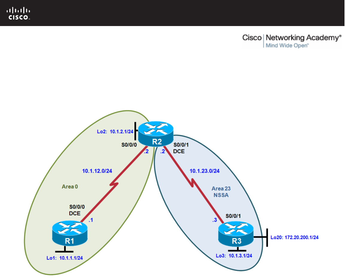
Topology
Objectives
• Configure multiple-area OSPF on a router.
• Verify multiple-area behavior.
• Configure OSPF stub, totally stubby, and not-so-stubby areas.
• Configure OSPF authentication.
Background
You are responsible for configuring the new network to connect your company’s engineering, marketing, and
accounting departments, represented by loopback interfaces on each of the three routers. The physical
devices have just been installed and connected by serial cables. Configure multiple-area OSPF to allow full
connectivity between all departments.
R3 also has a loopback representing a connection to another autonomous system that is not part of OSPF.
Note: This lab uses Cisco 1841 routers with Cisco IOS Release 12.4(24)T1 and the Advanced IP Services
image c1841-advipservicesk9-mz.124-24.T1.bin. You can use other routers (such as a 2801 or 2811) and
Cisco IOS Software versions if they have comparable capabilities and features. Depending on the router

CCNPv6 ROUTE
All contents are Copyright © 1992–2010 Cisco Systems, Inc. All rights reserved. This document is Cisco Public Information. Page 2 of 18
model and Cisco IOS Software version, the commands available and output produced might vary from what is
shown in this lab.
Required Resources
• 3 routers (Cisco 1841 with Cisco IOS Release 12.4(24)T1 Advanced IP Services or comparable)
• Serial and console cables
Step 1: Configure addressing and loopbacks.
a. Using the addressing scheme in the diagram, apply IP addresses to the serial interfaces on R1, R2, and
R3. Create loopbacks on R1, R2, and R3, and address them according to the diagram.
Note: Depending on the router models you have, you might need to add clock rates to the DCE end of
each connection (newer equipment adds this automatically). Verify connectivity across each serial link.
R1# configure terminal
Enter configuration commands, one per line. End with CNTL/Z.
R1(config)# interface loopback 1
R1(config-if)# description Engineering Department
R1(config-if)# ip address 10.1.1.1 255.255.255.0
R1(config-if)# interface serial 0/0/0
R1(config-if)# ip address 10.1.12.1 255.255.255.0
R1(config-if)# clockrate 64000
R1(config-if)# no shutdown
R2# configure terminal
Enter configuration commands, one per line. End with CNTL/Z.
R2(config)# interface loopback 2
R2(config-if)# description Marketing Department
R2(config-if)# ip address 10.1.2.1 255.255.255.0
R2(config-if)# interface serial 0/0/0
R2(config-if)# ip address 10.1.12.2 255.255.255.0
R2(config-if)# no shutdown
R2(config-if)# interface serial 0/0/1
R2(config-if)# ip address 10.1.23.2 255.255.255.0
R2(config-if)# clockrate 64000
R2(config-if)# no shutdown
R3# configure terminal
Enter configuration commands, one per line. End with CNTL/Z.
R3(config)# interface loopback 3
R3(config-if)# description Accounting Department
R3(config-if)# ip address 10.1.3.1 255.255.255.0
R3(config-if)# interface loopback 20
R3(config-if)# description Connection to another AS
R3(config-if)# ip address 172.20.200.1 255.255.255.0
R3(config-if)# interface serial 0/0/1
R3(config-if)# ip address 10.1.23.3 255.255.255.0
R3(config-if)# no shutdown
Step 2: Add interfaces into OSPF.
a. Create OSPF process 1 on routers R1 and R2. Configure the subnet of the serial link between R1 and R2
to be in OSPF area 0 using the network command. Add loopback 1 on R1 and loopback 2 on R2 into
OSPF area 0. Change the network type on the loopback interfaces so that they are advertised with the
correct subnet.

CCNPv6 ROUTE
All contents are Copyright © 1992–2010 Cisco Systems, Inc. All rights reserved. This document is Cisco Public Information. Page 3 of 18
R1(config)# router ospf 1
R1(config-router)# network 10.1.12.0 0.0.0.255 area 0
R1(config-router)# network 10.1.1.0 0.0.0.255 area 0
R1(config-router)# exit
R1(config)# interface loopback 1
R1(config-if)# ip ospf network point-to-point
R2(config)# router ospf 1
R2(config-router)# network 10.1.12.0 0.0.0.255 area 0
R2(config-router)# network 10.1.2.0 0.0.0.255 area 0
R2(config-router)# exit
R2(config)# interface loopback 2
R2(config-if)# ip ospf network point-to-point
Note: Another option for adding individual directly connected networks into the OSPF process is to use
the ip ospf process-id area area-id interface command that is available with Cisco IOS version 12.3(11)T
and later.
b. Verify that both routers have OSPF neighbors using the show ip ospf neighbors command.
R1# show ip ospf neighbor
Neighbor ID Pri State Dead Time Address Interface
10.1.2.1 0 FULL/ - 00:00:38 10.1.12.2 Serial0/0/0
R2# show ip ospf neighbor
Neighbor ID Pri State Dead Time Address Interface
10.1.1.1 0 FULL/ - 00:00:35 10.1.12.1 Serial0/0/0
c. Verify that the routers can see each other’s loopback with the show ip route command.
R1# show ip route
Codes: C - connected, S - static, R - RIP, M - mobile, B - BGP
D - EIGRP, EX - EIGRP external, O - OSPF, IA - OSPF inter area
N1 - OSPF NSSA external type 1, N2 - OSPF NSSA external type 2
E1 - OSPF external type 1, E2 - OSPF external type 2
i - IS-IS, su - IS-IS summary, L1 - IS-IS level-1, L2 - IS-IS level-2
ia - IS-IS inter area, * - candidate default, U - per-user static
route
o - ODR, P - periodic downloaded static route
Gateway of last resort is not set
10.0.0.0/24 is subnetted, 3 subnets
C 10.1.12.0 is directly connected, Serial0/0/0
O 10.1.2.0 [110/65] via 10.1.12.2, 00:00:10, Serial0/0/0
C 10.1.1.0 is directly connected, Loopback1
R2# show ip route
Codes: C - connected, S - static, R - RIP, M - mobile, B - BGP
D - EIGRP, EX - EIGRP external, O - OSPF, IA - OSPF inter area
N1 - OSPF NSSA external type 1, N2 - OSPF NSSA external type 2
E1 - OSPF external type 1, E2 - OSPF external type 2
i - IS-IS, su - IS-IS summary, L1 - IS-IS level-1, L2 - IS-IS level-2
ia - IS-IS inter area, * - candidate default, U - per-user static
route
o - ODR, P - periodic downloaded static route
Gateway of last resort is not set

CCNPv6 ROUTE
All contents are Copyright © 1992–2010 Cisco Systems, Inc. All rights reserved. This document is Cisco Public Information. Page 4 of 18
10.0.0.0/24 is subnetted, 4 subnets
C 10.1.12.0 is directly connected, Serial0/0/0
C 10.1.2.0 is directly connected, Loopback2
O 10.1.1.0 [110/65] via 10.1.12.1, 00:00:30, Serial0/0/0
C 10.1.23.0 is directly connected, Serial0/0/1
d. Add the subnet between R2 and R3 into OSPF area 23 using the network command. Add loopback 3 on
R3 into area 23.
R2(config)# router ospf 1
R2(config-router)# network 10.1.23.0 0.0.0.255 area 23
R3(config)# router ospf 1
R3(config-router)# network 10.1.23.0 0.0.0.255 area 23
R3(config-router)# network 10.1.3.0 0.0.0.255 area 23
R3(config-router)# exit
R3(config)# interface loopback 3
R3(config-if)# ip ospf network point-to-point
e. Verify that this neighbor relationship comes up using the show ip ospf neighbors command.
R2# show ip ospf neighbor
Neighbor ID Pri State Dead Time Address Interface
10.1.1.1 0 FULL/ - 00:00:36 10.1.12.1 Serial0/0/0
10.1.3.1 0 FULL/ - 00:00:36 10.1.23.3 Serial0/0/1
f. If you look at the output of the show ip route command on R1, you see a route to the R3 loopback.
Notice that it is identified as an inter-area route.
R1# show ip route
Codes: C - connected, S - static, R - RIP, M - mobile, B - BGP
D - EIGRP, EX - EIGRP external, O - OSPF, IA - OSPF inter area
N1 - OSPF NSSA external type 1, N2 - OSPF NSSA external type 2
E1 - OSPF external type 1, E2 - OSPF external type 2
i - IS-IS, su - IS-IS summary, L1 - IS-IS level-1, L2 - IS-IS level-2
ia - IS-IS inter area, * - candidate default, U - per-user static
route
o - ODR, P - periodic downloaded static route
Gateway of last resort is not set
10.0.0.0/24 is subnetted, 5 subnets
C 10.1.12.0 is directly connected, Serial0/0/0
O IA 10.1.3.0 [110/129] via 10.1.12.2, 00:00:28, Serial0/0/0
O 10.1.2.0 [110/65] via 10.1.12.2, 00:01:38, Serial0/0/0
C 10.1.1.0 is directly connected, Loopback1
O IA 10.1.23.0 [110/128] via 10.1.12.2, 00:01:38, Serial0/0/0
g. Issue the show ip route command on R2. Notice that R2 has no inter-area routes because R2 is in both
areas. It is an ABR, or area border router.
R2# show ip route
Codes: C - connected, S - static, R - RIP, M - mobile, B - BGP
D - EIGRP, EX - EIGRP external, O - OSPF, IA - OSPF inter area
N1 - OSPF NSSA external type 1, N2 - OSPF NSSA external type 2
E1 - OSPF external type 1, E2 - OSPF external type 2
i - IS-IS, su - IS-IS summary, L1 - IS-IS level-1, L2 - IS-IS level-2
ia - IS-IS inter area, * - candidate default, U - per-user static
route

CCNPv6 ROUTE
All contents are Copyright © 1992–2010 Cisco Systems, Inc. All rights reserved. This document is Cisco Public Information. Page 5 of 18
o - ODR, P - periodic downloaded static route
Gateway of last resort is not set
10.0.0.0/24 is subnetted, 5 subnets
C 10.1.12.0 is directly connected, Serial0/0/0
O 10.1.3.0 [110/65] via 10.1.23.3, 00:00:50, Serial0/0/1
C 10.1.2.0 is directly connected, Loopback2
O 10.1.1.0 [110/65] via 10.1.12.1, 00:02:00, Serial0/0/0
C 10.1.23.0 is directly connected, Serial0/0/1
h. Using a Tcl script, verify connectivity to all interfaces from any router, with the exception of loopback 20
on R3 (172.20.200.1), which has not yet been configured as part of OSPF.
i. Use the following Tcl script to verify that you can ping all addresses in the topology.
R1# tclsh
R1(tcl)#
foreach address {
10.1.1.1
10.1.2.1
10.1.3.1
10.1.12.1
10.1.12.2
10.1.23.2
10.1.23.3
172.20.200.1
} {
ping $address }
Step 3: Configure a stub area.
a. Under the OSPF process on R2 and R3, make area 23 the stub area using the area area stub command.
The adjacency between the two routers might go down during the transition period, but it should come
back up afterwards.
R2(config)# router ospf 1
R2(config-router)# area 23 stub
R3(config)# router ospf 1
R3(config-router)# area 23 stub
b. Confirm that it comes up by using the show ip ospf neighbors command.
R2# show ip ospf neighbor
Neighbor ID Pri State Dead Time Address Interface
10.1.1.1 0 FULL/ - 00:00:36 10.1.12.1 Serial0/0/0
10.1.3.1 0 FULL/ - 00:00:36 10.1.23.3 Serial0/0/1
R3# show ip ospf neighbor
Neighbor ID Pri State Dead Time Address Interface
10.1.2.1 0 FULL/ - 00:00:31 10.1.23.2 Serial0/0/1
c. Using the show ip route command, you can see that R3 now has a default route pointing toward R2. A
stub area does not receive any external routes. It receives a default route and OSPF inter-area routes.
R3# show ip route
Codes: C - connected, S - static, R - RIP, M - mobile, B - BGP

CCNPv6 ROUTE
All contents are Copyright © 1992–2010 Cisco Systems, Inc. All rights reserved. This document is Cisco Public Information. Page 6 of 18
D - EIGRP, EX - EIGRP external, O - OSPF, IA - OSPF inter area
N1 - OSPF NSSA external type 1, N2 - OSPF NSSA external type 2
E1 - OSPF external type 1, E2 - OSPF external type 2
i - IS-IS, su - IS-IS summary, L1 - IS-IS level-1, L2 - IS-IS level-2
ia - IS-IS inter area, * - candidate default, U - per-user static
route
o - ODR, P - periodic downloaded static route
Gateway of last resort is 10.1.23.2 to network 0.0.0.0
172.20.0.0/24 is subnetted, 1 subnets
C 172.20.200.0 is directly connected, Loopback20
10.0.0.0/24 is subnetted, 5 subnets
O IA 10.1.12.0 [110/128] via 10.1.23.2, 00:00:56, Serial0/0/1
C 10.1.3.0 is directly connected, Loopback3
O IA 10.1.2.0 [110/65] via 10.1.23.2, 00:00:56, Serial0/0/1
O IA 10.1.1.0 [110/129] via 10.1.23.2, 00:00:56, Serial0/0/1
C 10.1.23.0 is directly connected, Serial0/0/1
O*IA 0.0.0.0/0 [110/65] via 10.1.23.2, 00:00:56, Serial0/0/1
d. Look at the output of the show ip ospf command to see what type each area is.
R2# show ip ospf
Routing Process "ospf 1" with ID 10.1.2.1
Supports only single TOS(TOS0) routes
Supports opaque LSA
Supports Link-local Signaling (LLS)
Supports area transit capability
It is an area border router
Initial SPF schedule delay 5000 msecs
Minimum hold time between two consecutive SPFs 10000 msecs
Maximum wait time between two consecutive SPFs 10000 msecs
Incremental-SPF disabled
Minimum LSA interval 5 secs
Minimum LSA arrival 1000 msecs
LSA group pacing timer 240 secs
Interface flood pacing timer 33 msecs
Retransmission pacing timer 66 msecs
Number of external LSA 0. Checksum Sum 0x000000
Number of opaque AS LSA 0. Checksum Sum 0x000000
Number of DCbitless external and opaque AS LSA 0
Number of DoNotAge external and opaque AS LSA 0
Number of areas in this router is 2. 1 normal 1 stub 0 nssa
Number of areas transit capable is 0
External flood list length 0
Area BACKBONE(0)
Number of interfaces in this area is 2
Area has no authentication
SPF algorithm last executed 00:02:11.680 ago
SPF algorithm executed 5 times
Area ranges are
Number of LSA 4. Checksum Sum 0x01A85A
Number of opaque link LSA 0. Checksum Sum 0x000000
Number of DCbitless LSA 0
Number of indication LSA 0
Number of DoNotAge LSA 0
Flood list length 0
Area 23
Number of interfaces in this area is 1

CCNPv6 ROUTE
All contents are Copyright © 1992–2010 Cisco Systems, Inc. All rights reserved. This document is Cisco Public Information. Page 7 of 18
It is a stub area
generates stub default route with cost 1
Area has no authentication
SPF algorithm last executed 00:01:38.276 ago
SPF algorithm executed 8 times
Area ranges are
Number of LSA 6. Checksum Sum 0x027269
Number of opaque link LSA 0. Checksum Sum 0x000000
Number of DCbitless LSA 0
Number of indication LSA 0
Number of DoNotAge LSA 0
Flood list length 0
What are the advantages of having a router receive a default route rather than a more specific route?
_______________________________________________________________________________
_______________________________________________________________________________
Router memory and processing are conserved because the router has fewer routes to contend with.
Why do all routers in a stub area need to know that the area is a stub?
_______________________________________________________________________________
_______________________________________________________________________________
_______________________________________________________________________________
Routers need to know that an area is a stub for consistency so that no routers generate type 5 LSAs or
other OSPF features (such as virtual links) in an area in which they cannot exist.
Step 4: Configure a totally stubby area.
A modified version of a stubby area is a totally stubby area. A totally stubby area ABR only allows in a single,
default route from the backbone. To configure a totally stubby area, you only need to change a command at
the ABR, R2 in this scenario. Under the router OSPF process, you will enter the area 23 stub no-summary
command to replace the existing stub command for area 23. The no-summary option tells the router that this
area will not receive summary (inter-area) routes.
a. To see how this works, issue the show ip route command on R3. Notice the inter-area routes, in addition
to the default route generated by R2.
R3# show ip route
Codes: C - connected, S - static, R - RIP, M - mobile, B - BGP
D - EIGRP, EX - EIGRP external, O - OSPF, IA - OSPF inter area
N1 - OSPF NSSA external type 1, N2 - OSPF NSSA external type 2
E1 - OSPF external type 1, E2 - OSPF external type 2
i - IS-IS, su - IS-IS summary, L1 - IS-IS level-1, L2 - IS-IS level-2
ia - IS-IS inter area, * - candidate default, U - per-user static
route
o - ODR, P - periodic downloaded static route
Gateway of last resort is 10.1.23.2 to network 0.0.0.0
172.20.0.0/24 is subnetted, 1 subnets
C 172.20.200.0 is directly connected, Loopback20
10.0.0.0/24 is subnetted, 5 subnets
O IA 10.1.12.0 [110/128] via 10.1.23.2, 00:00:56, Serial0/0/1
C 10.1.3.0 is directly connected, Loopback3
O IA 10.1.2.0 [110/65] via 10.1.23.2, 00:00:56, Serial0/0/1

CCNPv6 ROUTE
All contents are Copyright © 1992–2010 Cisco Systems, Inc. All rights reserved. This document is Cisco Public Information. Page 8 of 18
O IA 10.1.1.0 [110/129] via 10.1.23.2, 00:00:56, Serial0/0/1
C 10.1.23.0 is directly connected, Serial0/0/1
O*IA 0.0.0.0/0 [110/65] via 10.1.23.2, 00:00:56, Serial0/0/1
b. Look at the output of the show ip ospf database command on R2 to see which LSAs are in its OSPF
database.
R2# show ip ospf database
OSPF Router with ID (10.1.2.1) (Process ID 1)
Router Link States (Area 0)
Link ID ADV Router Age Seq# Checksum Link count
10.1.1.1 10.1.1.1 435 0x80000004 0x0056D6 3
10.1.2.1 10.1.2.1 358 0x80000003 0x0057D2 3
Summary Net Link States (Area 0)
Link ID ADV Router Age Seq# Checksum
10.1.3.0 10.1.2.1 174 0x80000001 0x00EFEF
10.1.23.0 10.1.2.1 354 0x80000001 0x0009C3
Router Link States (Area 23)
Link ID ADV Router Age Seq# Checksum Link count
10.1.2.1 10.1.2.1 188 0x80000004 0x00298C 2
10.1.3.1 10.1.3.1 188 0x80000004 0x00B762 3
Summary Net Link States (Area 23)
Link ID ADV Router Age Seq# Checksum
0.0.0.0 10.1.2.1 207 0x80000001 0x003BF4
10.1.1.0 10.1.2.1 209 0x80000002 0x0022C0
10.1.2.0 10.1.2.1 209 0x80000002 0x00948D
10.1.12.0 10.1.2.1 209 0x80000002 0x009E3A
c. Enter the stub no-summary command on R2 (the ABR) under the OSPF process.
R2(config)# router ospf 1
R2(config-router)# area 23 stub no-summary
d. Go back to R3 and issue the show ip route command again. Notice that it shows only one incoming
route from OSPF.
R3# show ip route
Codes: C - connected, S - static, R - RIP, M - mobile, B - BGP
D - EIGRP, EX - EIGRP external, O - OSPF, IA - OSPF inter area
N1 - OSPF NSSA external type 1, N2 - OSPF NSSA external type 2
E1 - OSPF external type 1, E2 - OSPF external type 2
i - IS-IS, su - IS-IS summary, L1 - IS-IS level-1, L2 - IS-IS level-2
ia - IS-IS inter area, * - candidate default, U - per-user static
route
o - ODR, P - periodic downloaded static route
Gateway of last resort is 10.1.23.2 to network 0.0.0.0
172.20.0.0/24 is subnetted, 1 subnets
C 172.20.200.0 is directly connected, Loopback20
10.0.0.0/24 is subnetted, 2 subnets

CCNPv6 ROUTE
All contents are Copyright © 1992–2010 Cisco Systems, Inc. All rights reserved. This document is Cisco Public Information. Page 9 of 18
C 10.1.3.0 is directly connected, Loopback3
C 10.1.23.0 is directly connected, Serial0/0/1
O*IA 0.0.0.0/0 [110/65] via 10.1.23.2, 00:00:10, Serial0/0/1
e. Look at the show ip ospf database output to see which routes are in area 23.
R3# show ip ospf database
OSPF Router with ID (10.1.3.1) (Process ID 1)
Router Link States (Area 23)
Link ID ADV Router Age Seq# Checksum Link count
10.1.2.1 10.1.2.1 275 0x80000004 0x00298C 2
10.1.3.1 10.1.3.1 276 0x80000004 0x00B762 3
Summary Net Link States (Area 23)
Link ID ADV Router Age Seq# Checksum
0.0.0.0 10.1.2.1 68 0x80000002 0x0039F5
What are the advantages of making an area totally stubby instead of a regular stub area? What are the
disadvantages?
_______________________________________________________________________________
_______________________________________________________________________________
_______________________________________________________________________________
_______________________________________________________________________________
By making an area totally stubby, routers in the area only see intra-area routes and a default route. This
can save a lot of router memory and processor time. However, as with any type of route aggregation, the
loss of routing detail makes it possible for a non-optimal route to be chosen.
Why did only the ABR need to know that the area was totally stubby rather than all routers in the area?
_______________________________________________________________________________
_______________________________________________________________________________
_______________________________________________________________________________
The ABR is the gateway to the rest of the area and therefore is the boundary that all inter-area LSAs
need to pass through. Because of this, it only needs to filter out the type 3 LSAs and let the default route
through.
Step 5: Configure a not-so-stubby area.
Not-so-stubby areas (NSSAs) are similar to regular stub areas, except that they allow routes to be
redistributed from an ASBR into that area with a special LSA type, which gets converted to a normal external
route at the ABR.
a. Change area 23 into an NSSA. NSSAs are not compatible with stub areas, so the first thing to do is issue
the no area 23 stub command on routers R2 and R3. Next, issue the area area nssa command on
routers R2 and R3 to change area 23 to an NSSA. To generate an external route into the NSSA, use the
redistribute connected subnets command on R3. This adds the previously unreachable loopback 20
into OSPF. Be sure to include the subnets keyword; otherwise, only classful networks are redistributed.
R2(config)# router ospf 1

CCNPv6 ROUTE
All contents are Copyright © 1992–2010 Cisco Systems, Inc. All rights reserved. This document is Cisco Public Information. Page 10 of 18
R2(config-router)# no area 23 stub
R2(config-router)# area 23 nssa
R3(config)# router ospf 1
R3(config-router)# no area 23 stub
R3(config-router)# area 23 nssa
R3(config-router)# redistribute connected subnets
b. In the output of the show ip ospf command on R2, notice that area 23 is an NSSA and that R2 is
performing the LSA type 7 to type 5 translation. If there are multiple ABRs to an NSSA, the ABR with the
highest router ID performs the translation.
R2# show ip ospf
Routing Process "ospf 1" with ID 10.1.2.1
Supports only single TOS(TOS0) routes
Supports opaque LSA
Supports Link-local Signaling (LLS)
Supports area transit capability
It is an area border and autonomous system boundary router
Redistributing External Routes from,
Initial SPF schedule delay 5000 msecs
Minimum hold time between two consecutive SPFs 10000 msecs
Maximum wait time between two consecutive SPFs 10000 msecs
Incremental-SPF disabled
Minimum LSA interval 5 secs
Minimum LSA arrival 1000 msecs
LSA group pacing timer 240 secs
Interface flood pacing timer 33 msecs
Retransmission pacing timer 66 msecs
Number of external LSA 1. Checksum Sum 0x00CA2F
Number of opaque AS LSA 0. Checksum Sum 0x000000
Number of DCbitless external and opaque AS LSA 0
Number of DoNotAge external and opaque AS LSA 0
Number of areas in this router is 2. 1 normal 0 stub 1 nssa
Number of areas transit capable is 0
External flood list length 0
Area BACKBONE(0)
Number of interfaces in this area is 2
Area has no authentication
SPF algorithm last executed 00:03:11.636 ago
SPF algorithm executed 9 times
Area ranges are
Number of LSA 4. Checksum Sum 0x01AC53
Number of opaque link LSA 0. Checksum Sum 0x000000
Number of DCbitless LSA 0
Number of indication LSA 0
Number of DoNotAge LSA 0
Flood list length 0
Area 23
Number of interfaces in this area is 1
It is a NSSA area
Perform type-7/type-5 LSA translation
Area has no authentication
SPF algorithm last executed 00:00:16.408 ago
SPF algorithm executed 16 times
Area ranges are
Number of LSA 6. Checksum Sum 0x025498
Number of opaque link LSA 0. Checksum Sum 0x000000

CCNPv6 ROUTE
All contents are Copyright © 1992–2010 Cisco Systems, Inc. All rights reserved. This document is Cisco Public Information. Page 11 of 18
Number of DCbitless LSA 0
Number of indication LSA 0
Number of DoNotAge LSA 0
Flood list length 0
c. Look at the show ip route output on R2. Notice that the external route comes in as type N2 from R3. This
is because it is a special NSSA external route.
R2# show ip route
Codes: C - connected, S - static, R - RIP, M - mobile, B - BGP
D - EIGRP, EX - EIGRP external, O - OSPF, IA - OSPF inter area
N1 - OSPF NSSA external type 1, N2 - OSPF NSSA external type 2
E1 - OSPF external type 1, E2 - OSPF external type 2
i - IS-IS, su - IS-IS summary, L1 - IS-IS level-1, L2 - IS-IS level-2
ia - IS-IS inter area, * - candidate default, U - per-user static
route
o - ODR, P - periodic downloaded static route
Gateway of last resort is not set
172.20.0.0/24 is subnetted, 1 subnets
O N2 172.20.200.0 [110/20] via 10.1.23.3, 00:00:41, Serial0/0/1
10.0.0.0/24 is subnetted, 5 subnets
C 10.1.12.0 is directly connected, Serial0/0/0
O 10.1.3.0 [110/65] via 10.1.23.3, 00:00:47, Serial0/0/1
C 10.1.2.0 is directly connected, Loopback2
O 10.1.1.0 [110/65] via 10.1.12.1, 00:03:42, Serial0/0/0
C 10.1.23.0 is directly connected, Serial0/0/1
d. Look at the show ip route output on R1. Notice that the route is now a regular E2 external route,
because R2 has performed the type 7 to type 5 translation.
R1# show ip route
Codes: C - connected, S - static, R - RIP, M - mobile, B - BGP
D - EIGRP, EX - EIGRP external, O - OSPF, IA - OSPF inter area
N1 - OSPF NSSA external type 1, N2 - OSPF NSSA external type 2
E1 - OSPF external type 1, E2 - OSPF external type 2
i - IS-IS, su - IS-IS summary, L1 - IS-IS level-1, L2 - IS-IS level-2
ia - IS-IS inter area, * - candidate default, U - per-user static
route
o - ODR, P - periodic downloaded static route
Gateway of last resort is not set
172.20.0.0/24 is subnetted, 1 subnets
O E2 172.20.200.0 [110/20] via 10.1.12.2, 00:01:22, Serial0/0/0
10.0.0.0/24 is subnetted, 5 subnets
C 10.1.12.0 is directly connected, Serial0/0/0
O IA 10.1.3.0 [110/129] via 10.1.12.2, 00:02:06, Serial0/0/0
O 10.1.2.0 [110/65] via 10.1.12.2, 00:04:22, Serial0/0/0
C 10.1.1.0 is directly connected, Loopback1
O IA 10.1.23.0 [110/128] via 10.1.12.2, 00:04:22, Serial0/0/0
e. Look at the show ip route output on R3. Notice that it no longer has a default route in it, but inter-area
routes are coming in.
Note: An NSSA does not have the default route injected by the ABR (R2) automatically. It is possible to
make the ABR inject the default route into the NSSA using the area 23 nssa default-information-
originate command on R2.

CCNPv6 ROUTE
All contents are Copyright © 1992–2010 Cisco Systems, Inc. All rights reserved. This document is Cisco Public Information. Page 12 of 18
R3# show ip route
Codes: C - connected, S - static, R - RIP, M - mobile, B - BGP
D - EIGRP, EX - EIGRP external, O - OSPF, IA - OSPF inter area
N1 - OSPF NSSA external type 1, N2 - OSPF NSSA external type 2
E1 - OSPF external type 1, E2 - OSPF external type 2
i - IS-IS, su - IS-IS summary, L1 - IS-IS level-1, L2 - IS-IS level-2
ia - IS-IS inter area, * - candidate default, U - per-user static
route
o - ODR, P - periodic downloaded static route
Gateway of last resort is not set
172.20.0.0/24 is subnetted, 1 subnets
C 172.20.200.0 is directly connected, Loopback20
10.0.0.0/24 is subnetted, 5 subnets
O IA 10.1.12.0 [110/128] via 10.1.23.2, 00:02:11, Serial0/0/1
C 10.1.3.0 is directly connected, Loopback3
O IA 10.1.2.0 [110/65] via 10.1.23.2, 00:02:11, Serial0/0/1
O IA 10.1.1.0 [110/129] via 10.1.23.2, 00:02:11, Serial0/0/1
C 10.1.23.0 is directly connected, Serial0/0/1
f. Yet another type of area is a totally-stubby NSSA that combines the property of an NSSA area (injecting
external routing information into OSPF) with a totally stubby behavior (accepting only default route from
the backbone). Issue the area 23 nssa no-summary command on R2, similar to converting a stub area
into a totally stubby area.
R2(config)# router ospf 1
R2(config-router)# area 23 nssa no-summary
g. Check the routing table on R3. Notice that the inter-area routes have been replaced by a single default
route.
R3# show ip route
Codes: C - connected, S - static, R - RIP, M - mobile, B - BGP
D - EIGRP, EX - EIGRP external, O - OSPF, IA - OSPF inter area
N1 - OSPF NSSA external type 1, N2 - OSPF NSSA external type 2
E1 - OSPF external type 1, E2 - OSPF external type 2
i - IS-IS, su - IS-IS summary, L1 - IS-IS level-1, L2 - IS-IS level-2
ia - IS-IS inter area, * - candidate default, U - per-user static
route
o - ODR, P - periodic downloaded static route
Gateway of last resort is 10.1.23.2 to network 0.0.0.0
172.20.0.0/24 is subnetted, 1 subnets
C 172.20.200.0 is directly connected, Loopback20
10.0.0.0/24 is subnetted, 2 subnets
C 10.1.3.0 is directly connected, Loopback3
C 10.1.23.0 is directly connected, Serial0/0/1
O*IA 0.0.0.0/0 [110/65] via 10.1.23.2, 00:00:20, Serial0/0/1
h. On R2, look at the show ip ospf database output to see the various LSA types.
R2# show ip ospf database
OSPF Router with ID (10.1.2.1) (Process ID 1)
Router Link States (Area 0)
Link ID ADV Router Age Seq# Checksum Link count

CCNPv6 ROUTE
All contents are Copyright © 1992–2010 Cisco Systems, Inc. All rights reserved. This document is Cisco Public Information. Page 13 of 18
10.1.1.1 10.1.1.1 944 0x80000004 0x0056D6 3
10.1.2.1 10.1.2.1 383 0x80000004 0x005BCB 3
Summary Net Link States (Area 0)
Link ID ADV Router Age Seq# Checksum
10.1.3.0 10.1.2.1 242 0x80000001 0x00EFEF
10.1.23.0 10.1.2.1 862 0x80000001 0x0009C3
Router Link States (Area 23)
Link ID ADV Router Age Seq# Checksum Link count
10.1.2.1 10.1.2.1 257 0x80000007 0x00B0F7 2
10.1.3.1 10.1.3.1 209 0x80000007 0x003FCD 3
Summary Net Link States (Area 23)
Link ID ADV Router Age Seq# Checksum
0.0.0.0 10.1.2.1 34 0x80000001 0x00C265
Type-7 AS External Link States (Area 23)
Link ID ADV Router Age Seq# Checksum Tag
10.1.3.0 10.1.3.1 200 0x80000001 0x0076FC 0
Type-5 AS External Link States
Link ID ADV Router Age Seq# Checksum Tag
10.1.3.0 10.1.2.1 199 0x80000001 0x00CA2F 0
Where would it be useful to make an area into an NSSA?
_______________________________________________________________________________
_______________________________________________________________________________
_______________________________________________________________________________
An NSSA is useful if you want to allow an area to inject external routes into an OSPF domain while still
retaining some of the stub characteristics of the area such as not accepting external routes that are
originated in other areas.
Step 6: Configure OSPF interface authentication.
For security purposes, you can configure OSPF interfaces to use authentication.
a. Configure the link between R2 and R3 for plaintext authentication. To set up plaintext authentication on
an interface, type ip ospf authentication at the interface command prompt. Then set the password to
cisco with the ip ospf authentication-key key-string command.
R2(config)# interface serial 0/0/1
R2(config-if)# ip ospf authentication
R2(config-if)# ip ospf authentication-key cisco
R3(config)# interface serial 0/0/1
R3(config-if)# ip ospf authentication
R3(config-if)# ip ospf authentication-key cisco

CCNPv6 ROUTE
All contents are Copyright © 1992–2010 Cisco Systems, Inc. All rights reserved. This document is Cisco Public Information. Page 14 of 18
Note: While configuring the authentication, the adjacency might go down if the dead timer expires on one
of the routers. The relationship should be reestablished once authentication is configured on both sides.
b. Verify the authentication using the show ip ospf interface interface command.
R2# show ip ospf interface serial 0/0/1
Serial0/0/1 is up, line protocol is up
Internet Address 10.1.23.2/24, Area 23
Process ID 1, Router ID 10.1.2.1, Network Type POINT_TO_POINT, Cost: 64
Transmit Delay is 1 sec, State POINT_TO_POINT,
Timer intervals configured, Hello 10, Dead 40, Wait 40, Retransmit 5
oob-resync timeout 40
Hello due in 00:00:09
Supports Link-local Signaling (LLS)
Index 1/3, flood queue length 0
Next 0x0(0)/0x0(0)
Last flood scan length is 1, maximum is 4
Last flood scan time is 0 msec, maximum is 0 msec
Neighbor Count is 1, Adjacent neighbor count is 1
Adjacent with neighbor 10.1.3.1
Suppress hello for 0 neighbor(s)
Simple password authentication enabled
c. MD5 authentication encrypts the password for stronger security. Configure the link between R1 and R2
for MD5 authentication using the ip ospf authentication message-digest interface command. Then set
the password to cisco with the ip ospf message-digest-key key_number md5 key-string command.
Make sure that the key number is the same on both routers. In this case, use 1 for simplicity.
R1(config)# interface serial 0/0/0
R1(config-if)# ip ospf authentication message-digest
R1(config-if)# ip ospf message-digest-key 1 md5 cisco
R2(config)# interface serial 0/0/0
R2(config-if)# ip ospf authentication message-digest
R2(config-if)# ip ospf message-digest-key 1 md5 cisco
Note: The MD5 key number works differently than key chains. The router uses the most recently added
key for authenticating sent packets. The key number does not have a direct influence on this behavior,
that is, if the interface was configured with the MD5 key number 10 and later the key with number 5 was
added, the router would use the key number 5 to digitally sign outbound sent packets. If a router having
several MD5 keys on an interface detects that at least one of its neighbors has not yet started using the
most recently added key, it engages in a simple key migration procedure: it sends each OSPF packet
multiple times, with each instance of the packet authenticated by a particular MD5 key configured on the
interface, one instance for each key. This ensures a smooth, gradual migration.
d. Verify the configuration using the show ip ospf interface interface command.
R1# show ip ospf interface serial 0/0/0
Serial0/0/0 is up, line protocol is up
Internet Address 10.1.12.1/24, Area 0
Process ID 1, Router ID 10.1.1.1, Network Type POINT_TO_POINT, Cost: 64
Transmit Delay is 1 sec, State POINT_TO_POINT,
Timer intervals configured, Hello 10, Dead 40, Wait 40, Retransmit 5
oob-resync timeout 40
Hello due in 00:00:08
Supports Link-local Signaling (LLS)
Index 1/1, flood queue length 0
Next 0x0(0)/0x0(0)
Last flood scan length is 1, maximum is 1

CCNPv6 ROUTE
All contents are Copyright © 1992–2010 Cisco Systems, Inc. All rights reserved. This document is Cisco Public Information. Page 15 of 18
Last flood scan time is 0 msec, maximum is 0 msec
Neighbor Count is 0, Adjacent neighbor count is 0
Suppress hello for 0 neighbor(s)
Message digest authentication enabled
Youngest key id is 1
Why is configuring authentication for OSPF, or any routing protocol, a good idea?
_______________________________________________________________________________
_______________________________________________________________________________
_______________________________________________________________________________
Configuring routing protocol authentication is beneficial because without it, you could have a rogue router
on a subnet advertising false routes.
e. Use the following Tcl script to verify connectivity to all addresses in the topology.
R1# tclsh
R1(tcl)#
foreach address {
10.1.1.1
10.1.2.1
10.1.3.1
10.1.12.1
10.1.12.2
10.1.23.2
10.1.23.3
172.20.200.1
} {
ping $address }

CCNPv6 ROUTE
All contents are Copyright © 1992–2010 Cisco Systems, Inc. All rights reserved. This document is Cisco Public Information. Page 16 of 18
Router Interface Summary Table
Router Interface Summary
Router Model Ethernet Interface
#1 Ethernet Interface
#2 Serial Interface
#1 Serial Interface
#2
1700 Fast Ethernet 0
(FA0) Fast Ethernet 1
(FA1) Serial 0 (S0) Serial 1 (S1)
1800 Fast Ethernet 0/0
(FA0/0) Fast Ethernet 0/1
(FA0/1) Serial 0/0/0
(S0/0/0) Serial 0/0/1
(S0/0/1)
2600 Fast Ethernet 0/0
(FA0/0) Fast Ethernet 0/1
(FA0/1) Serial 0/0 (S0/0) Serial 0/1 (S0/1)
2800 Fast Ethernet 0/0
(FA0/0) Fast Ethernet 0/1
(FA0/1) Serial 0/0/0
(S0/0/0) Serial 0/0/1
(S0/0/1)
Note: To find out how the router is configured, look at the interfaces to identify the type of router
and how many interfaces the router has. Rather than list all combinations of configurations for each
router class, this table includes identifiers for the possible combinations of Ethernet and serial
interfaces in the device. The table does not include any other type of interface, even though a
specific router might contain one. For example, for an ISDN BRI interface, the string in parenthesis
is the legal abbreviation that can be used in Cisco IOS commands to represent the interface.

CCNPv6 ROUTE
All contents are Copyright © 1992–2010 Cisco Systems, Inc. All rights reserved. This document is Cisco Public Information. Page 17 of 18
Device Configurations (Instructor version)
Router R1
hostname R1
!
interface Loopback1
description Engineering Department
ip address 10.1.1.1 255.255.255.0
ip ospf network point-to-point
!
interface Serial0/0/0
ip address 10.1.12.1 255.255.255.0
ip ospf authentication message-digest
ip ospf message-digest-key 1 md5 cisco
clock rate 64000
no shutdown
!
router ospf 1
network 10.1.1.0 0.0.0.255 area 0
network 10.1.12.0 0.0.0.255 area 0
!
end
Router R2
hostname R2
!
interface Loopback2
description Marketing Department
ip address 10.1.2.1 255.255.255.0
ip ospf network point-to-point
!
interface Serial0/0/0
ip address 10.1.12.2 255.255.255.0
ip ospf authentication message-digest
ip ospf message-digest-key 1 md5 cisco
no shutdown
!
interface Serial0/0/1
ip address 10.1.23.2 255.255.255.0
ip ospf authentication
ip ospf authentication-key cisco
clock rate 64000
no shutdown
!
router ospf 1
area 23 nssa no-summary
network 10.1.2.0 0.0.0.255 area 0
network 10.1.12.0 0.0.0.255 area 0
network 10.1.23.0 0.0.0.255 area 23
!
end
Router R3
hostname R3
!

CCNPv6 ROUTE
All contents are Copyright © 1992–2010 Cisco Systems, Inc. All rights reserved. This document is Cisco Public Information. Page 18 of 18
interface Loopback3
description Accounting Department
ip address 10.1.3.1 255.255.255.0
ip ospf network point-to-point
!
interface Loopback20
description Connection to another AS
ip address 172.20.200.1 255.255.255.0
!
interface Serial0/0/1
ip address 10.1.23.3 255.255.255.0
ip ospf authentication
ip ospf authentication-key cisco
no shutdown
!
router ospf 1
area 23 nssa
redistribute connected subnets
network 10.1.3.0 0.0.0.255 area 23
network 10.1.23.0 0.0.0.255 area 23
!
end

All contents are Copyright © 1992–2010 Cisco Systems, Inc. All rights reserved. This document is Cisco Public Information. Page 1 of 14
CCNPv6 ROUTE
Chapter 3 Lab 3-3, OSPF Virtual Links and Area Summarization
Instructor Version
Topology
Objectives
• Configure multi-area OSPF on a router.
• Verify multi-area behavior.
• Create an OSPF virtual link.
• Summarize an area.
• Generate a default route into OSPF.
Background
You are responsible for configuring the new network to connect your company’s engineering, marketing, and
accounting departments, represented by loopback interfaces on each of the three routers. The physical
devices have just been installed and connected by serial cables. Configure multiple-area OSPF to allow full
connectivity between all departments.
In addition, R1 has a loopback interface representing a connection to the Internet. This connection will not be
added into OSPF. R3 will have four additional loopback interfaces representing connections to branch offices.

CCNPv6 ROUTE
All contents are Copyright © 1992–2010 Cisco Systems, Inc. All rights reserved. This document is Cisco Public Information. Page 2 of 14
Note: This lab uses Cisco 1841 routers with Cisco IOS Release 12.4(24)T1 and the Advanced IP Services
image c1841-advipservicesk9-mz.124-24.T1.bin. You can use other routers (such as a 2801 or 2811) and
Cisco IOS Software versions if they have comparable capabilities and features. Depending on the router
model and Cisco IOS Software version, the commands available and output produced might vary from what is
shown in this lab.
Required Resources
• 3 routers (Cisco 1841 with Cisco IOS Release 12.4(24)T1 Advanced IP Services or comparable)
• Serial and console cables
Step 1: Configure addressing and loopbacks.
Using the addressing scheme in the diagram, apply IP addresses to the serial interfaces on R1, R2, and R3.
Create loopbacks on R1, R2, and R3, and address them according to the diagram.
R1# configure terminal
Enter configuration commands, one per line. End with CNTL/Z.
R1(config)# interface loopback 1
R1(config-if)# description Engineering Department
R1(config-if)# ip address 10.1.1.1 255.255.255.0
R1(config-if)# interface loopback 30
R1(config-if)# ip address 172.30.30.1 255.255.255.252
R1(config-if)# interface serial 0/0/0
R1(config-if)# ip address 10.1.12.1 255.255.255.0
R1(config-if)# clockrate 64000
R1(config-if)# no shutdown
R2# configure terminal
Enter configuration commands, one per line. End with CNTL/Z.
R2(config)# interface loopback 2
R2(config-if)# description Marketing Department
R2(config-if)# ip address 10.1.2.1 255.255.255.0
R2(config-if)# interface serial 0/0/0
R2(config-if)# ip address 10.1.12.2 255.255.255.0
R2(config-if)# no shutdown
R2(config-if)# interface serial 0/0/1
R2(config-if)# ip address 10.1.23.2 255.255.255.0
R2(config-if)# clockrate 64000
R2(config-if)# no shutdown
R3# configure terminal
Enter configuration commands, one per line. End with CNTL/Z.
R3(config)# interface loopback 3
R3(config-if)# description Accounting Department
R3(config-if)# ip address 10.1.3.1 255.255.255.0
R3(config-if)# interface loopback 100
R3(config-if)# ip address 192.168.100.1 255.255.255.0
R3(config-if)# interface loopback 101
R3(config-if)# ip address 192.168.101.1 255.255.255.0
R3(config-if)# interface loopback 102
R3(config-if)# ip address 192.168.102.1 255.255.255.0
R3(config-if)# interface loopback 103
R3(config-if)# ip address 192.168.103.1 255.255.255.0
R3(config-if)# interface serial 0/0/1
R3(config-if)# ip address 10.1.23.3 255.255.255.0
R3(config-if)# no shutdown

CCNPv6 ROUTE
All contents are Copyright © 1992–2010 Cisco Systems, Inc. All rights reserved. This document is Cisco Public Information. Page 3 of 14
Step 2: Add interfaces into OSPF.
a. Create OSPF process 1 on all three routers. Using the network command, configure the subnet of the
serial link between R1 and R2 to be in OSPF area 0. Add loopback 1 on R1 and loopback 2 on R2 into
OSPF area 0.
Note: The default behavior of OSPF for loopback interfaces is to advertise a 32-bit host route. To ensure
that the full /24 network is advertised, use the ip ospf network point-to-point command. Change the
network type on the loopback interfaces so that they are advertised with the correct subnet.
R1(config)# router ospf 1
R1(config-router)# network 10.1.12.0 0.0.0.255 area 0
R1(config-router)# network 10.1.1.0 0.0.0.255 area 0
R1(config-router)# exit
R1(config)# interface loopback 1
R1(config-if)# ip ospf network point-to-point
R2(config)# router ospf 1
R2(config-router)# network 10.1.12.0 0.0.0.255 area 0
R2(config-router)# network 10.1.2.0 0.0.0.255 area 0
R2(config-router)# exit
R2(config)# interface loopback 2
R2(config-if)# ip ospf network point-to-point
b. Verify that you can see OSPF neighbors in the show ip ospf neighbors output on both routers. Verify
that the routers can see each other’s loopback with the show ip route command.
R1# show ip ospf neighbor
Neighbor ID Pri State Dead Time Address Interface
10.1.2.1 0 FULL/ - 00:00:38 10.1.12.2 Serial0/0/0
R1# show ip route
Codes: C - connected, S - static, R - RIP, M - mobile, B - BGP
D - EIGRP, EX - EIGRP external, O - OSPF, IA - OSPF inter area
N1 - OSPF NSSA external type 1, N2 - OSPF NSSA external type 2
E1 - OSPF external type 1, E2 - OSPF external type 2
i - IS-IS, su - IS-IS summary, L1 - IS-IS level-1, L2 - IS-IS level-2
ia - IS-IS inter area, * - candidate default, U - per-user static
route
o - ODR, P - periodic downloaded static route
Gateway of last resort is not set
10.0.0.0/24 is subnetted, 3 subnets
C 10.1.12.0 is directly connected, Serial0/0/0
O 10.1.2.0 [110/65] via 10.1.12.2, 00:00:10, Serial0/0/0
C 10.1.1.0 is directly connected, Loopback1
172.30.0.0/30 is subnetted, 1 subnets
C 172.30.30.0 is directly connected, Loopback30
R2# show ip ospf neighbor
Neighbor ID Pri State Dead Time Address Interface
172.30.30.1 0 FULL/ - 00:00:35 10.1.12.1 Serial0/0/0
R2# show ip route
Codes: C - connected, S - static, R - RIP, M - mobile, B - BGP
D - EIGRP, EX - EIGRP external, O - OSPF, IA - OSPF inter area

CCNPv6 ROUTE
All contents are Copyright © 1992–2010 Cisco Systems, Inc. All rights reserved. This document is Cisco Public Information. Page 4 of 14
N1 - OSPF NSSA external type 1, N2 - OSPF NSSA external type 2
E1 - OSPF external type 1, E2 - OSPF external type 2
i - IS-IS, su - IS-IS summary, L1 - IS-IS level-1, L2 - IS-IS level-2
ia - IS-IS inter area, * - candidate default, U - per-user static
route
o - ODR, P - periodic downloaded static route
Gateway of last resort is not set
10.0.0.0/24 is subnetted, 4 subnets
C 10.1.12.0 is directly connected, Serial0/0/0
C 10.1.2.0 is directly connected, Loopback2
O 10.1.1.0 [110/65] via 10.1.12.1, 00:00:30, Serial0/0/0
C 10.1.23.0 is directly connected, Serial0/0/1
c. Add the subnet between R2 and R3 into OSPF area 23 using the network command. Add loopback 3 on
R3 into area 23.
R2(config)# router ospf 1
R2(config-router)# network 10.1.23.0 0.0.0.255 area 23
R3(config)# router ospf 1
R3(config-router)# network 10.1.23.0 0.0.0.255 area 23
R3(config-router)# network 10.1.3.0 0.0.0.255 area 23
R3(config-router)# exit
R3(config)# interface loopback 3
R3(config-if)# ip ospf network point-to-point
d. Verify that this neighbor relationship comes up with the show ip ospf neighbors command.
R2# show ip ospf neighbor
Neighbor ID Pri State Dead Time Address Interface
172.30.30.1 0 FULL/ - 00:00:36 10.1.12.1 Serial0/0/0
192.168.103.1 0 FULL/ - 00:00:36 10.1.23.3 Serial0/0/1
e. Using a Tcl script, verify connectivity to all interfaces from any router, with the exception of loopback 30
on R1, and R3 loopbacks 100 through 103.
R1# tclsh
R1(tcl)#
foreach address {
10.1.1.1
10.1.2.1
10.1.3.1
10.1.12.1
10.1.12.2
10.1.23.2
10.1.23.3
172.30.30.1
192.168.100.1
192.168.101.1
192.168.102.1
192.168.103.1
Step 3: Create a virtual link.
a. Add loopbacks 100 through 103 on R3 to the OSPF process in area 100 using the network command.
Change the network type to advertise the correct subnet mask.

CCNPv6 ROUTE
All contents are Copyright © 1992–2010 Cisco Systems, Inc. All rights reserved. This document is Cisco Public Information. Page 5 of 14
R3(config)# router ospf 1
R3(config-router)# network 192.168.100.0 0.0.3.255 area 100
R3(config-router)# exit
R3(config)# interface loopback 100
R3(config-if)# ip ospf network point-to-point
R3(config-if)# interface loopback 101
R3(config-if)# ip ospf network point-to-point
R3(config-if)# interface loopback 102
R3(config-if)# ip ospf network point-to-point
R3(config-if)# interface loopback 103
R3(config-if)# ip ospf network point-to-point
b. Look at the output of the show ip route command on R2. Notice that the routes to those networks do not
appear. The reason for this behavior is that area 100 on R3 is not connected to the backbone. It is only
connected to area 23. If an area is not connected to the backbone, its routes are not advertised outside of
its area.
R2# show ip route
Codes: C - connected, S - static, R - RIP, M - mobile, B - BGP
D - EIGRP, EX - EIGRP external, O - OSPF, IA - OSPF inter area
N1 - OSPF NSSA external type 1, N2 - OSPF NSSA external type 2
E1 - OSPF external type 1, E2 - OSPF external type 2
i - IS-IS, su - IS-IS summary, L1 - IS-IS level-1, L2 - IS-IS level-2
ia - IS-IS inter area, * - candidate default, U - per-user static
route
o - ODR, P - periodic downloaded static route
Gateway of last resort is not set
10.0.0.0/24 is subnetted, 5 subnets
C 10.1.12.0 is directly connected, Serial0/0/0
O 10.1.3.0 [110/65] via 10.1.23.3, 00:01:00, Serial0/0/1
C 10.1.2.0 is directly connected, Loopback2
O 10.1.1.0 [110/65] via 10.1.12.1, 00:03:10, Serial0/0/0
C 10.1.23.0 is directly connected, Serial0/0/1
What would happen if routes could pass between areas without going through the backbone?
_______________________________________________________________________________
_______________________________________________________________________________
_______________________________________________________________________________
Routing loops might occur because any route could get advertised to different areas. By passing through
the backbone, type 3 LSAs are generated by their respective areas and not sent back in.
You can get around this situation by creating a virtual link. A virtual link is an OSPF feature that creates a
logical extension of the backbone area across a regular area, without actually adding any physical
interfaces into area 0.
Note: Prior to creating a virtual link you need to identify the OSPF router ID for the routers involved (R2
and R3), using a command such as show ip ospf, show ip protocols or show ip ospf interface. The
output for the show ip ospf command on R1 and R3 is shown below.
R2# show ip ospf
Routing Process "ospf 1" with ID 10.1.2.1
<output omitted>

CCNPv6 ROUTE
All contents are Copyright © 1992–2010 Cisco Systems, Inc. All rights reserved. This document is Cisco Public Information. Page 6 of 14
R3# show ip ospf
Routing Process "ospf 1" with ID 192.168.103.1
<output omitted>
c. Create a virtual link using the area transit_area virtual-link router-id OSPF configuration command on
both R2 and R3.
R2(config)# router ospf 1
R2(config-router)# area 23 virtual-link 192.168.103.1
R3(config)# router ospf 1
R3(config-router)# area 23 virtual-link 10.1.2.1
Note: To ensure that the router ID of the virtual link endpoints remains constant, you can statically
configure the OSPF router ID of the virtual link endpoints using the router-id command.
d. After you see the adjacency over the virtual interface come up, issue the show ip route command on R2
and see the routes from area 100. You can verify the virtual link with the show ip ospf neighbor and
show ip ospf interface commands.
R2# show ip route
Codes: C - connected, S - static, R - RIP, M - mobile, B - BGP
D - EIGRP, EX - EIGRP external, O - OSPF, IA - OSPF inter area
N1 - OSPF NSSA external type 1, N2 - OSPF NSSA external type 2
E1 - OSPF external type 1, E2 - OSPF external type 2
i - IS-IS, su - IS-IS summary, L1 - IS-IS level-1, L2 - IS-IS level-2
ia - IS-IS inter area, * - candidate default, U - per-user static
route
o - ODR, P - periodic downloaded static route
Gateway of last resort is not set
10.0.0.0/24 is subnetted, 5 subnets
C 10.1.12.0 is directly connected, Serial0/0/0
O 10.1.3.0 [110/65] via 10.1.23.3, 00:01:35, Serial0/0/1
C 10.1.2.0 is directly connected, Loopback2
O 10.1.1.0 [110/65] via 10.1.12.1, 00:01:35, Serial0/0/0
C 10.1.23.0 is directly connected, Serial0/0/1
O IA 192.168.102.0/24 [110/65] via 10.1.23.3, 00:00:05, Serial0/0/1
O IA 192.168.103.0/24 [110/65] via 10.1.23.3, 00:00:05, Serial0/0/1
O IA 192.168.100.0/24 [110/65] via 10.1.23.3, 00:00:57, Serial0/0/1
O IA 192.168.101.0/24 [110/65] via 10.1.23.3, 00:00:16, Serial0/0/1
R2# show ip ospf neighbor
Neighbor ID Pri State Dead Time Address Interface
192.168.103.1 0 FULL/ - - 10.1.23.3 OSPF_VL0
172.30.30.1 0 FULL/ - 00:00:30 10.1.12.1 Serial0/0/0
192.168.103.1 0 FULL/ - 00:00:30 10.1.23.3 Serial0/0/1
R2# show ip ospf interface
OSPF_VL0 is up, line protocol is up
Internet Address 10.1.23.2/24, Area 0
Process ID 1, Router ID 10.1.2.1, Network Type VIRTUAL_LINK, Cost: 64
Configured as demand circuit.
Run as demand circuit.
DoNotAge LSA allowed.
Transmit Delay is 1 sec, State POINT_TO_POINT,
Timer intervals configured, Hello 10, Dead 40, Wait 40, Retransmit 5

CCNPv6 ROUTE
All contents are Copyright © 1992–2010 Cisco Systems, Inc. All rights reserved. This document is Cisco Public Information. Page 7 of 14
oob-resync timeout 40
Hello due in 00:00:03
Supports Link-local Signaling (LLS)
Index 3/4, flood queue length 0
Next 0x0(0)/0x0(0)
Last flood scan length is 1, maximum is 1
Last flood scan time is 0 msec, maximum is 0 msec
Neighbor Count is 1, Adjacent neighbor count is 1
Adjacent with neighbor 192.168.103.1 (Hello suppressed)
Suppress hello for 1 neighbor(s)
<output omitted>
When are virtual links useful?
_______________________________________________________________________________
_______________________________________________________________________________
_______________________________________________________________________________
Virtual links are useful when there needs to be a temporary extension of the backbone, either because
the backbone became discontiguous or a new area got added onto an existing area.
Why are virtual links a poor long-term solution?
_______________________________________________________________________________
_______________________________________________________________________________
_______________________________________________________________________________
Virtual links are a poor long-term solution because they add processing overhead and basically extend
the backbone area onto routers where it might not belong. They can also add a lot of complexity to
troubleshooting.
Step 4: Summarize an area.
Loopbacks 100 through 103 can be summarized into one supernet of 192.168.100.0 /22. You can configure
area 100 to be represented by this single summary route.
a. Configure R3 (the ABR) to summarize this area using the area area range network mask command.
R3(config)# router ospf 1
R3(config-router)# area 100 range 192.168.100.0 255.255.252.0
b. You can see the summary route on R2 with the show ip route and show ip ospf database commands.
R2# show ip route
Codes: C - connected, S - static, R - RIP, M - mobile, B - BGP
D - EIGRP, EX - EIGRP external, O - OSPF, IA - OSPF inter area
N1 - OSPF NSSA external type 1, N2 - OSPF NSSA external type 2
E1 - OSPF external type 1, E2 - OSPF external type 2
i - IS-IS, su - IS-IS summary, L1 - IS-IS level-1, L2 - IS-IS level-2
ia - IS-IS inter area, * - candidate default, U - per-user static
route
o - ODR, P - periodic downloaded static route
Gateway of last resort is not set
10.0.0.0/24 is subnetted, 5 subnets
C 10.1.12.0 is directly connected, Serial0/0/0
O 10.1.3.0 [110/65] via 10.1.23.3, 00:07:25, Serial0/0/1

CCNPv6 ROUTE
All contents are Copyright © 1992–2010 Cisco Systems, Inc. All rights reserved. This document is Cisco Public Information. Page 8 of 14
C 10.1.2.0 is directly connected, Loopback2
O 10.1.1.0 [110/65] via 10.1.12.1, 00:07:25, Serial0/0/0
C 10.1.23.0 is directly connected, Serial0/0/1
O IA 192.168.100.0/22 [110/65] via 10.1.23.3, 00:00:01, Serial0/0/1
R2# show ip ospf database
OSPF Router with ID (10.1.2.1) (Process ID 1)
Router Link States (Area 0)
Link ID ADV Router Age Seq# Checksum Link count
10.1.2.1 10.1.2.1 341 0x80000003 0x0028DD 4
172.30.30.1 172.30.30.1 1665 0x80000002 0x000E67 3
192.168.103.1 192.168.103.1 1 (DNA) 0x80000003 0x00A374 1
Summary Net Link States (Area 0)
Link ID ADV Router Age Seq# Checksum
10.1.3.0 10.1.2.1 1268 0x80000001 0x00EFEF
10.1.3.0 192.168.103.1 6 (DNA) 0x80000001 0x00FD5E
10.1.23.0 10.1.2.1 1311 0x80000001 0x0009C3
10.1.23.0 192.168.103.1 6 (DNA) 0x80000001 0x00996F
192.168.100.0 192.168.103.1 1 (DNA) 0x80000002 0x009A04
Router Link States (Area 23)
Link ID ADV Router Age Seq# Checksum Link count
10.1.2.1 10.1.2.1 341 0x80000003 0x00DD8B 2
192.168.103.1 192.168.103.1 342 0x80000003 0x002E57 3
Summary Net Link States (Area 23)
Link ID ADV Router Age Seq# Checksum
10.1.1.0 10.1.2.1 1321 0x80000001 0x0006DB
10.1.2.0 10.1.2.1 1321 0x80000001 0x0078A8
10.1.12.0 10.1.2.1 1321 0x80000001 0x008255
192.168.100.0 192.168.103.1 157 0x80000002 0x009A04
c. Notice on R3 that OSPF has generated a summary route pointing toward Null0.
R3# show ip route
Codes: C - connected, S - static, R - RIP, M - mobile, B - BGP
D - EIGRP, EX - EIGRP external, O - OSPF, IA - OSPF inter area
N1 - OSPF NSSA external type 1, N2 - OSPF NSSA external type 2
E1 - OSPF external type 1, E2 - OSPF external type 2
i - IS-IS, su - IS-IS summary, L1 - IS-IS level-1, L2 - IS-IS level-2
ia - IS-IS inter area, * - candidate default, U - per-user static
route
o - ODR, P - periodic downloaded static route
Gateway of last resort is not set
10.0.0.0/24 is subnetted, 5 subnets
O 10.1.12.0 [110/128] via 10.1.23.2, 00:01:18, Serial0/0/1
C 10.1.3.0 is directly connected, Loopback3
O 10.1.2.0 [110/65] via 10.1.23.2, 00:01:18, Serial0/0/1
O 10.1.1.0 [110/129] via 10.1.23.2, 00:01:18, Serial0/0/1
C 10.1.23.0 is directly connected, Serial0/0/1

CCNPv6 ROUTE
All contents are Copyright © 1992–2010 Cisco Systems, Inc. All rights reserved. This document is Cisco Public Information. Page 9 of 14
C 192.168.102.0/24 is directly connected, Loopback102
C 192.168.103.0/24 is directly connected, Loopback103
C 192.168.100.0/24 is directly connected, Loopback100
C 192.168.101.0/24 is directly connected, Loopback101
O 192.168.100.0/22 is a summary, 00:01:19, Null0
This behavior is known as sending unknown traffic to the “bit bucket.” This means that if the router
advertising the summary route receives a packet destined for something covered by that summary but not
in the routing table, it drops it.
What is the reasoning behind this behavior?
_______________________________________________________________________________
_______________________________________________________________________________
_______________________________________________________________________________
_______________________________________________________________________________
_______________________________________________________________________________
_______________________________________________________________________________
The reason that summaries generate local routes to Null0 is that when a router creates a summary
address, it should have routes to all the existent more-specific routes. If the router lacks a more-specific
route for a prefix within the summary, it is assumed that the route does not exist, and packets destined for
that prefix should be dropped. If the route did not exist, bandwidth could be wasted if this router has a
less specific route (such as a default route) and forwards the packet to the route until it is dropped further
down the line.
The discard route also solves another problem. Depending on the contents of the routing table, a routing
loop can be formed between two routers, one receiving a summary route from the second one, while the
second one uses the first one as its default gateway. If a packet for a nonexistent component of the
summary route was received and there was no discard route installed in the second router, the packet
would loop between the routers until its TTL was decremented to 0.
Step 5: Generate a default route into OSPF.
You can simulate loopback 30 on R1 to be a connection to the Internet. You do not need to advertise this
specific network to the rest of the network. Instead, you can just have a default route for all unknown traffic to
go to R1.
a. To have R1 generate a default route, use the OSPF configuration command default-information
originate always. The always keyword is necessary for generating a default route in this scenario.
Without this keyword, a default route is generated only into OSPF if one exists in the routing table.
R1(config)# router ospf 1
R1(config-router)# default-information originate always
b. Verify that the default route appears on R2 and R3 with the show ip route command.
R2# show ip route
Codes: C - connected, S - static, R - RIP, M - mobile, B - BGP
D - EIGRP, EX - EIGRP external, O - OSPF, IA - OSPF inter area
N1 - OSPF NSSA external type 1, N2 - OSPF NSSA external type 2
E1 - OSPF external type 1, E2 - OSPF external type 2
i - IS-IS, su - IS-IS summary, L1 - IS-IS level-1, L2 - IS-IS level-2
ia - IS-IS inter area, * - candidate default, U - per-user static
route

CCNPv6 ROUTE
All contents are Copyright © 1992–2010 Cisco Systems, Inc. All rights reserved. This document is Cisco Public Information. Page 10 of 14
o - ODR, P - periodic downloaded static route
Gateway of last resort is 10.1.12.1 to network 0.0.0.0
10.0.0.0/24 is subnetted, 5 subnets
C 10.1.12.0 is directly connected, Serial0/0/0
O 10.1.3.0 [110/65] via 10.1.23.3, 00:10:36, Serial0/0/1
C 10.1.2.0 is directly connected, Loopback2
O 10.1.1.0 [110/65] via 10.1.12.1, 00:00:19, Serial0/0/0
C 10.1.23.0 is directly connected, Serial0/0/1
O*E2 0.0.0.0/0 [110/1] via 10.1.12.1, 00:00:09, Serial0/0/0
O IA 192.168.100.0/22 [110/65] via 10.1.23.3, 00:00:19, Serial0/0/1
R3# show ip route
Codes: C - connected, S - static, R - RIP, M - mobile, B - BGP
D - EIGRP, EX - EIGRP external, O - OSPF, IA - OSPF inter area
N1 - OSPF NSSA external type 1, N2 - OSPF NSSA external type 2
E1 - OSPF external type 1, E2 - OSPF external type 2
i - IS-IS, su - IS-IS summary, L1 - IS-IS level-1, L2 - IS-IS level-2
ia - IS-IS inter area, * - candidate default, U - per-user static
route
o - ODR, P - periodic downloaded static route
Gateway of last resort is 10.1.23.2 to network 0.0.0.0
10.0.0.0/24 is subnetted, 5 subnets
O 10.1.12.0 [110/128] via 10.1.23.2, 00:00:35, Serial0/0/1
C 10.1.3.0 is directly connected, Loopback3
O 10.1.2.0 [110/65] via 10.1.23.2, 00:00:35, Serial0/0/1
O 10.1.1.0 [110/129] via 10.1.23.2, 00:00:35, Serial0/0/1
C 10.1.23.0 is directly connected, Serial0/0/1
C 192.168.102.0/24 is directly connected, Loopback102
C 192.168.103.0/24 is directly connected, Loopback103
C 192.168.100.0/24 is directly connected, Loopback100
C 192.168.101.0/24 is directly connected, Loopback101
O*E2 0.0.0.0/0 [110/1] via 10.1.23.2, 00:00:26, Serial0/0/1
O 192.168.100.0/22 is a summary, 00:03:28, Null0
c. You should be able to ping the interface connecting to the Internet from R2 or R3, despite never being
advertised into OSPF.
R3# ping 172.30.30.1
Type escape sequence to abort.
Sending 5, 100-byte ICMP Echos to 172.30.30.1, timeout is 2 seconds:
!!!!!
Success rate is 100 percent (5/5), round-trip min/avg/max = 28/30/32 ms
d. Use the following Tcl script to verify connectivity to all addresses in the topology.
R1# tclsh
R1(tcl)#
foreach address {
10.1.1.1
10.1.2.1
10.1.3.1
10.1.12.1
10.1.12.2

CCNPv6 ROUTE
All contents are Copyright © 1992–2010 Cisco Systems, Inc. All rights reserved. This document is Cisco Public Information. Page 11 of 14
10.1.23.2
10.1.23.3
172.30.30.1
192.168.100.1
192.168.101.1
192.168.102.1
192.168.103.1
} {
ping $address }
Challenge: Configure OSPF Authentication
Configure OSPF MD5 authentication on the link between R2 and R3, using key ID 1 and the password cisco.
Record the commands used below.
__________________________________________________________________________________
__________________________________________________________________________________
__________________________________________________________________________________
Enter the following configuration commands on R2 and R3:
interface serial0/0/1
ip ospf authentication message-digest
ip ospf message-digest-key 1 md5 cisco

CCNPv6 ROUTE
All contents are Copyright © 1992–2010 Cisco Systems, Inc. All rights reserved. This document is Cisco Public Information. Page 12 of 14
Router Interface Summary Table
Router Interface Summary
Router Model Ethernet Interface
#1 Ethernet Interface
#2 Serial Interface
#1 Serial Interface
#2
1700 Fast Ethernet 0
(FA0) Fast Ethernet 1
(FA1) Serial 0 (S0) Serial 1 (S1)
1800 Fast Ethernet 0/0
(FA0/0) Fast Ethernet 0/1
(FA0/1) Serial 0/0/0
(S0/0/0) Serial 0/0/1
(S0/0/1)
2600 Fast Ethernet 0/0
(FA0/0) Fast Ethernet 0/1
(FA0/1) Serial 0/0 (S0/0) Serial 0/1 (S0/1)
2800 Fast Ethernet 0/0
(FA0/0) Fast Ethernet 0/1
(FA0/1) Serial 0/0/0
(S0/0/0) Serial 0/0/1
(S0/0/1)
Note: To find out how the router is configured, look at the interfaces to identify the type of router
and how many interfaces the router has. Rather than list all combinations of configurations for each
router class, this table includes identifiers for the possible combinations of Ethernet and serial
interfaces in the device. The table does not include any other type of interface, even though a
specific router might contain one. For example, for an ISDN BRI interface, the string in parenthesis
is the legal abbreviation that can be used in Cisco IOS commands to represent the interface.

CCNPv6 ROUTE
All contents are Copyright © 1992–2010 Cisco Systems, Inc. All rights reserved. This document is Cisco Public Information. Page 13 of 14
Device Configurations (Instructor version)
Router R1
hostname R1
!
interface Loopback1
description Engineering Department
ip address 10.1.1.1 255.255.255.0
ip ospf network point-to-point
!
interface Loopback30
ip address 172.30.30.1 255.255.255.252
!
interface Serial0/0/0
ip address 10.1.12.1 255.255.255.0
clock rate 64000
no shutdown
!
router ospf 1
network 10.1.1.0 0.0.0.255 area 0
network 10.1.12.0 0.0.0.255 area 0
default-information originate always
!
end
Router R2
hostname R2
!
interface Loopback2
description Marketing Department
ip address 10.1.2.1 255.255.255.0
ip ospf network point-to-point
!
interface Serial0/0/0
ip address 10.1.12.2 255.255.255.0
no shutdown
!
interface Serial0/0/1
ip address 10.1.23.2 255.255.255.0
clock rate 64000
no shutdown
!
router ospf 1
area 23 virtual-link 192.168.103.1
network 10.1.2.0 0.0.0.255 area 0
network 10.1.12.0 0.0.0.255 area 0
network 10.1.23.0 0.0.0.255 area 23
!
end

CCNPv6 ROUTE
All contents are Copyright © 1992–2010 Cisco Systems, Inc. All rights reserved. This document is Cisco Public Information. Page 14 of 14
Router R3
hostname R3
!
interface Loopback3
description Accounting Department
ip address 10.1.3.1 255.255.255.0
ip ospf network point-to-point
!
interface Loopback100
ip address 192.168.100.1 255.255.255.0
ip ospf network point-to-point
!
interface Loopback101
ip address 192.168.101.1 255.255.255.0
ip ospf network point-to-point
!
interface Loopback102
ip address 192.168.102.1 255.255.255.0
ip ospf network point-to-point
!
interface Loopback103
ip address 192.168.103.1 255.255.255.0
ip ospf network point-to-point
!
interface Serial0/0/1
ip address 10.1.23.3 255.255.255.0
no shutdown
!
router ospf 1
area 23 virtual-link 10.1.2.1
area 100 range 192.168.100.0 255.255.252.0
network 10.1.3.0 0.0.0.255 area 23
network 10.1.23.0 0.0.0.255 area 23
network 192.168.100.0 0.0.3.255 area 100
!
end

All contents are Copyright © 1992–2010 Cisco Systems, Inc. All rights reserved. This document is Cisco Public Information. Page 1 of 14
CCNPv6 ROUTE
Chapter 3 Lab 3-4, OSPF over Frame Relay Instructor Version
Topology
Objectives
• Configure OSPF over Frame Relay.
• Use non-broadcast and point-to-multipoint OSPF network types.
• Modify default OSPF timers.
Background
You are responsible for configuring the new network to connect your company’s East branch and West
branch through the company headquarters represented by loopback interfaces on each of the three routers.
The physical devices have just been installed and connected over Frame Relay hub-and-spoke topology.
Configure OSPF to allow full connectivity between all departments.

CCNPv6 ROUTE
All contents are Copyright © 1992–2010 Cisco Systems, Inc. All rights reserved. This document is Cisco Public Information. Page 2 of 14
To simulate the Frame Relay WAN connections, use a router with three serial ports to act as a Frame Relay
switch. The configuration of the router as a Frame Relay switch is described in Step 2. The Fast Ethernet
connection between router EAST and router WEST represents a backup link from a service provider.
In real-world Frame Relay deployments, a modem or CSU/DSU normally provides the clocking functions
(DCE) for each serial link. However, in this lab, R2 interface Serial0/0/1 is configured as the DCE for
compatibility with other labs. If you are uncertain which side of the connection is the DCE, use the show
controllers serial interface-number command:
FRS# show controllers serial0/0/0
Interface Serial0/0/0
Hardware is GT96K
DCE V.35, clock rate 64000
Note: In this lab, router R3 acts as the Frame Relay switch and requires two serial interface cards. If you are
using an Adtran as a Frame Relay switch, see Appendix A for the Adtran configuration. When using the
Adtran as the Frame Relay switch, the clock (DCE) is provided for each serial link.
Instructor note: You can also use Lab 3.4b from CCNP version 5 in the instructor lab manual, if available.
Note: This lab uses Cisco 1841 routers with Cisco IOS Release 12.4(24)T1 and the Advanced IP Services
image c1841-advipservicesk9-mz.124-24.T1.bin. The switch is a Cisco WS-C2960-24TT-L with the Cisco IOS
image c2960-lanbasek9-mz.122-46.SE.bin. You can use other routers (such as a 2801 or 2811) and Cisco
IOS Software versions if they have comparable capabilities and features. Depending on the router or switch
model and Cisco IOS Software version, the commands available and output produced might vary from what is
shown in this lab.
Required Resources
• 4 routers (Cisco 1841 with Cisco IOS Release 12.4(24)T1 Advanced IP Services or comparable)
• 1 switch (Cisco 2960 with the Cisco IOS Release 12.2(46)SE C2960-LANBASEK9-M image or
comparable)
• Serial and Ethernet cables
Step 1: Configure Frame Relay and addressing on the HQ, EAST, and WEST routers.
a. Configure the router physical interfaces with IP addresses. On the interfaces connected to the Frame
Relay switch, configure Frame Relay encapsulation with Inverse ARP disabled. Inverse ARP is disabled
in this lab so that you have exclusive control over the IP/DLCI mappings. Use frame relay map
statements to configure local Frame Relay maps so that you can ping the router’s interface. Also set up
the loopback interfaces.
Router R1 (Hostname HQ)
Router# configure terminal
Enter configuration commands, one per line. End with CNTL/Z.
Router(config)# hostname HQ
HQ(config)# interface loopback 1
HQ(config-if)# ip address 10.1.1.1 255.255.255.0
HQ(config-if)# interface serial 0/0/1
HQ(config-if)# ip address 10.1.123.1 255.255.255.0
HQ(config-if)# encapsulation frame-relay ietf
HQ(config-if)# no frame-relay inverse-arp
HQ(config-if)# frame-relay map ip 10.1.123.1 102
HQ(config-if)# frame-relay map ip 10.1.123.2 102
HQ(config-if)# frame-relay map ip 10.1.123.3 103

CCNPv6 ROUTE
All contents are Copyright © 1992–2010 Cisco Systems, Inc. All rights reserved. This document is Cisco Public Information. Page 3 of 14
HQ(config-if)# no shutdown
Router R2 (Hostname EAST)
Router# configure terminal
Enter configuration commands, one per line. End with CNTL/Z.
Router(config)# hostname EAST
EAST(config)# interface loopback 2
EAST(config-if)# ip address 10.1.2.1 255.255.255.0
EAST(config-if)# interface serial 0/0/1
EAST(config-if)# ip address 10.1.123.2 255.255.255.0
EAST(config-if)# clock rate 64000
EAST(config-if)# encapsulation frame-relay ietf
EAST(config-if)# no frame-relay inverse-arp
EAST(config-if)# frame-relay map ip 10.1.123.1 201
EAST(config-if)# frame-relay map ip 10.1.123.2 201
EAST(config-if)# frame-relay map ip 10.1.123.3 201
EAST(config-if)# no shutdown
EAST(config-if)# interface FastEthernet 0/0
EAST(config-if)# ip address 10.1.23.2 255.255.255.0
EAST(config-if)# no shutdown
Router R4 (Hostname WEST)
Router# configure terminal
Enter configuration commands, one per line. End with CNTL/Z.
Router(config)# hostname WEST
WEST(config)# interface loopback 3
WEST(config-if)# ip address 10.1.3.1 255.255.255.0
WEST(config-if)# interface serial 0/0/0
WEST(config-if)# ip address 10.1.123.3 255.255.255.0
WEST(config-if)# encapsulation frame-relay ietf
WEST(config-if)# no frame-relay inverse-arp
WEST(config-if)# frame-relay map ip 10.1.123.1 301
WEST(config-if)# frame-relay map ip 10.1.123.2 301
WEST(config-if)# frame-relay map ip 10.1.123.3 301
WEST(config-if)# no shutdown
WEST(config-if)# interface FastEthernet 0/0
WEST(config-if)# ip address 10.1.23.3 255.255.255.0
WEST(config-if)# no shutdown
b. Verify that you have local subnet connectivity with ping.
Step 2: Configure the Frame Relay switch.
Use a fourth Cisco router with three serial interfaces as a Frame Relay switch, and cable the routers
according to the diagram. Configure the Frame Relay switch to have the DLCIs indicated in the diagram
between HQ and EAST and HQ and WEST.
Router R3 (FRS)
hostname FRS
!
frame-relay switching
interface Serial0/0/0
no ip address
encapsulation frame-relay ietf
no ip route-cache

CCNPv6 ROUTE
All contents are Copyright © 1992–2010 Cisco Systems, Inc. All rights reserved. This document is Cisco Public Information. Page 4 of 14
clock rate 64000
frame-relay intf-type dce
frame-relay route 102 interface Serial0/0/1 201
frame-relay route 103 interface Serial0/1/0 301
no shutdown
!
interface Serial0/0/1
no ip address
encapsulation frame-relay ietf
frame-relay intf-type dce
frame-relay route 201 interface Serial0/0/0 102
no shutdown
!
interface Serial0/1/0
no ip address
encapsulation frame-relay ietf
no ip route-cache
frame-relay intf-type dce
clock rate 64000
frame-relay route 301 interface Serial0/0/0 103
no shutdown
Step 3: Configure OSPF network type NBMA.
Frame Relay is inherently a non-broadcast multi-access (NBMA) network. In this step, you configure OSPF
for hub-and-spoke over Frame Relay using the NBMA OSPF network type, which is the default for Frame
Relay physical interfaces and multipoint-type subinterfaces. HQ is the hub; EAST and WEST are the spokes.
a. Create OSPF process 1. Add the Frame Relay interfaces on each router into area 0 with the network
command. Add the loopback interfaces on each router into area 0, and then change the network type to
allow the correct subnet mask to be advertised.
HQ(config)# router ospf 1
HQ(config-router)# network 10.1.123.0 0.0.0.255 area 0
HQ(config-router)# network 10.1.1.0 0.0.0.255 area 0
HQ(config-router)# exit
HQ(config)# interface loopback 1
HQ(config-if)# ip ospf network point-to-point
EAST(config)# router ospf 1
EAST(config-router)# network 10.1.123.0 0.0.0.255 area 0
EAST(config-router)# network 10.1.2.0 0.0.0.255 area 0
EAST(config-router)# exit
EAST(config)# interface loopback 2
EAST(config-if)# ip ospf network point-to-point
WEST(config)# router ospf 1
WEST(config-router)# network 10.1.123.0 0.0.0.255 area 0
WEST(config-router)# network 10.1.3.0 0.0.0.255 area 0
WEST(config-router)# exit
WEST(config)# interface loopback 3
WEST(config-if)# ip ospf network point-to-point
b. On EAST and WEST, change the Frame Relay interfaces to have OSPF priority 0. This priority ensures
that HQ becomes the DR.
EAST(config)# interface serial 0/0/1
EAST(config-if)# ip ospf priority 0

CCNPv6 ROUTE
All contents are Copyright © 1992–2010 Cisco Systems, Inc. All rights reserved. This document is Cisco Public Information. Page 5 of 14
WEST(config)# interface serial 0/0/0
WEST(config-if)# ip ospf priority 0
c. No OSPF Frame Relay adjacencies will be established yet because the default network type is
nonbroadcast. You can change this by adding neighbor statements. Configure neighbor statements on
HQ pointing toward EAST and WEST. Only the router starting the exchange needs the statements (HQ in
this case). However, it is considered best practice to also specify HQ as a neighbor on the EAST and
WEST routers. Because the hello timers are longer on serial nonbroadcast links, the neighbor
adjacencies might take longer to come up.
HQ(config)# router ospf 1
HQ(config-router)# neighbor 10.1.123.2
HQ(config-router)# neighbor 10.1.123.3
EAST(config)# router ospf 1
EAST(config-router)# neighbor 10.1.123.1
WEST(config)# router ospf 1
WEST(config-router)# neighbor 10.1.123.1
Note: Neighbor commands shown for the EAST and WEST routers will not appear in the running config. This
is because the local router's OSPF priority has been set to 0 on the interface which would be used to
communicate with the designated neighbor.
d. You can verify adjacency states with the show ip ospf neighbor command.
HQ# show ip ospf neighbor
Neighbor ID Pri State Dead Time Address Interface
10.1.2.1 0 FULL/DROTHER 00:01:57 10.1.123.2 Serial0/0/1
10.1.3.1 0 FULL/DROTHER 00:01:57 10.1.123.3 Serial0/0/1
Step 4: Change the network type to point-to-multipoint.
Point-to-multipoint is an OSPF network type that lends itself well to a hub-and-spoke topology. Point-to-
multipoint does not elect DRs or BDRs, so it does not need interface priorities. Instead, it treats the network
as a collection of point-to-point networks and advertises host routes for any neighbors that it has.
a. To configure point-to-multipoint links, remove the previously configured neighbor statements and
interface priorities..
HQ(config)# router ospf 1
HQ(config-router)# no neighbor 10.1.123.2
HQ(config-router)# no neighbor 10.1.123.3
EAST(config)# interface serial 0/0/1
EAST(config-if)# no ip ospf priority 0
EAST(config-if)# exit
EAST(config)# router ospf 1
EAST(config-router)# no neighbor 10.1.123.1
WEST(config)# interface serial 0/0/0
WEST(config-if)# no ip ospf priority 0
WEST(config-if)# exit
WEST(config)# router ospf 1
WEST(config-router)# no neighbor 10.1.123.1

CCNPv6 ROUTE
All contents are Copyright © 1992–2010 Cisco Systems, Inc. All rights reserved. This document is Cisco Public Information. Page 6 of 14
b. Use the interface command ip ospf network point-to-multipoint and reapply the Frame Relay maps
using the broadcast option. Reset the OSPF process using the clear ip ospf process command. Verify
that the adjacencies are active with the show ip ospf neighbor command.
HQ(config)# interface serial 0/0/1
HQ(config-if)# ip ospf network point-to-multipoint
HQ(config-if)# frame-relay map ip 10.1.123.2 102 broadcast
HQ(config-if)# frame-relay map ip 10.1.123.3 103 broadcast
EAST(config)# interface serial 0/0/1
EAST(config-if)# ip ospf network point-to-multipoint
EAST(config-if)# frame-relay map ip 10.1.123.1 201 broadcast
EAST(config-if)# frame-relay map ip 10.1.123.3 201 broadcast
WEST(config)# interface serial 0/0/0
WEST(config-if)# ip ospf network point-to-multipoint
WEST(config-if)# frame-relay map ip 10.1.123.1 301 broadcast
WEST(config-if)# frame-relay map ip 10.1.123.2 301 broadcast
HQ# show ip ospf neighbor
Neighbor ID Pri State Dead Time Address Interface
10.1.3.1 0 FULL/ - 00:01:34 10.1.123.3 Serial0/0/1
10.1.2.1 0 FULL/ - 00:01:45 10.1.123.2 Serial0/0/1
c. Observe the routing table on one of the spoke routers. Notice how the routing table has host routes in it.
This is part of point-to-multipoint behavior.
EAST# show ip route
Codes: C - connected, S - static, R - RIP, M - mobile, B - BGP
D - EIGRP, EX - EIGRP external, O - OSPF, IA - OSPF inter area
N1 - OSPF NSSA external type 1, N2 - OSPF NSSA external type 2
E1 - OSPF external type 1, E2 - OSPF external type 2
i - IS-IS, su - IS-IS summary, L1 - IS-IS level-1, L2 - IS-IS level-2
ia - IS-IS inter area, * - candidate default, U - per-user static
route
o - ODR, P - periodic downloaded static route
Gateway of last resort is not set
10.0.0.0/8 is variably subnetted, 7 subnets, 2 masks
O 10.1.3.0/24 [110/129] via 10.1.123.1, 00:01:07, Serial0/0/1
C 10.1.2.0/24 is directly connected, Loopback2
O 10.1.1.0/24 [110/65] via 10.1.123.1, 00:01:07, Serial0/0/1
C 10.1.23.0/24 is directly connected, FastEthernet0/0
C 10.1.123.0/24 is directly connected, Serial0/0/1
O 10.1.123.1/32 [110/64] via 10.1.123.1, 00:01:07, Serial0/0/1
O 10.1.123.3/32 [110/128] via 10.1.123.1, 00:01:07, Serial0/0/1
d. Look at the output of the show ip ospf interface interface command on your routers. Notice that the
interface type is point-to-multipoint.
EAST# show ip ospf interface serial 0/0/1
Serial0/0/1 is up, line protocol is up
Internet Address 10.1.123.2/24, Area 0
Process ID 1, Router ID 10.1.2.1, Network Type POINT_TO_MULTIPOINT, Cost:
64
Transmit Delay is 1 sec, State POINT_TO_MULTIPOINT,
Timer intervals configured, Hello 30, Dead 120, Wait 120, Retransmit 5

CCNPv6 ROUTE
All contents are Copyright © 1992–2010 Cisco Systems, Inc. All rights reserved. This document is Cisco Public Information. Page 7 of 14
oob-resync timeout 120
Hello due in 00:00:16
Supports Link-local Signaling (LLS)
Index 1/1, flood queue length 0
Next 0x0(0)/0x0(0)
Last flood scan length is 1, maximum is 1
Last flood scan time is 0 msec, maximum is 0 msec
Neighbor Count is 1, Adjacent neighbor count is 1
Adjacent with neighbor 10.1.1.1
Suppress hello for 0 neighbor(s)
Step 5: Change OSPF timers.
a. Add the Ethernet link connecting EAST and WEST to the OSPF process using the network command.
EAST(config)# router ospf 1
EAST(config-router)# network 10.1.23.0 0.0.0.255 area 0
WEST(config)# router ospf 1
WEST(config-router)# network 10.1.23.0 0.0.0.255 area 0
b. Look at the interface OSPF properties with the show ip ospf interface interface command.
EAST# show ip ospf interface FastEthernet 0/0
FastEthernet0/0 is up, line protocol is up
Internet Address 10.1.23.2/24, Area 0
Process ID 1, Router ID 10.1.2.1, Network Type BROADCAST, Cost: 1
Transmit Delay is 1 sec, State BDR, Priority 1
Designated Router (ID) 10.1.3.1, Interface address 10.1.23.3
Backup Designated router (ID) 10.1.2.1, Interface address 10.1.23.2
Timer intervals configured, Hello 10, Dead 40, Wait 40, Retransmit 5
oob-resync timeout 40
Hello due in 00:00:00
Supports Link-local Signaling (LLS)
Index 3/3, flood queue length 0
Next 0x0(0)/0x0(0)
Last flood scan length is 1, maximum is 1
Last flood scan time is 0 msec, maximum is 0 msec
Neighbor Count is 1, Adjacent neighbor count is 1
Adjacent with neighbor 10.1.3.1 (Designated Router)
Suppress hello for 0 neighbor(s)
Because it is a Fast Ethernet link, the default network type is broadcast and the default network timers
are those associated with a broadcast network. You might want to change the default timers to allow for
better network convergence. Neighbors that go down are detected more quickly with lower dead timers.
The disadvantage of lower dead timers is higher router CPU utilization and more bandwidth being
consumed by hello packets.
c. Use the ip ospf hello-interval seconds command to change the default hello timer interval to 5 seconds
on both sides. Change the dead timer to 15 seconds with the ip ospf dead-interval seconds command.
EAST(config)# interface FastEthernet 0/0
EAST(config-if)# ip ospf hello-interval 5
EAST(config-if)# ip ospf dead-interval 15
WEST(config)# interface FastEthernet 0/0
WEST(config-if)# ip ospf hello-interval 5
WEST(config-if)# ip ospf dead-interval 15
d. Verify the changes with the show ip ospf interface interface command.

CCNPv6 ROUTE
All contents are Copyright © 1992–2010 Cisco Systems, Inc. All rights reserved. This document is Cisco Public Information. Page 8 of 14
EAST# show ip ospf int Fa0/0
FastEthernet0/0 is up, line protocol is up
Internet Address 10.1.23.2/24, Area 0
Process ID 1, Router ID 10.1.2.1, Network Type BROADCAST, Cost: 1
Transmit Delay is 1 sec, State BDR, Priority 1
Designated Router (ID) 10.1.3.1, Interface address 10.1.23.3
Backup Designated router (ID) 10.1.2.1, Interface address 10.1.23.2
Timer intervals configured, Hello 5, Dead 15, Wait 15, Retransmit 5
oob-resync timeout 40
Hello due in 00:00:01
Supports Link-local Signaling (LLS)
Index 3/3, flood queue length 0
Next 0x0(0)/0x0(0)
Last flood scan length is 1, maximum is 1
Last flood scan time is 0 msec, maximum is 0 msec
Neighbor Count is 1, Adjacent neighbor count is 1
Adjacent with neighbor 10.1.3.1 (Designated Router)
Suppress hello for 0 neighbor(s)
What are some disadvantages to changing the timers if they are not tuned correctly?
_______________________________________________________________________________
_______________________________________________________________________________
_______________________________________________________________________________
_______________________________________________________________________________
_______________________________________________________________________________
_______________________________________________________________________________
_______________________________________________________________________________
If timers are not tuned correctly, there are many negative side effects. Hello packets can saturate a
slower link or overload a slower router. Route instability and route flapping can occur from bad timers
having an adjacency come up and down. If timers are tuned to take too long, reconvergence of a network
after topology changes can be slower.
e. Use the following Tcl script to verify connectivity to all addresses in the topology.
HQ# tclsh
HQ(tcl)#
foreach address {
10.1.1.1
10.1.2.1
10.1.3.1
10.1.123.1
10.1.123.2
10.1.123.3
10.1.23.2
10.1.23.3
} {
ping $address }

CCNPv6 ROUTE
All contents are Copyright © 1992–2010 Cisco Systems, Inc. All rights reserved. This document is Cisco Public Information. Page 9 of 14
Challenge: Minimal Hello Intervals
Configure the Fast Ethernet link between EAST and WEST to lower the convergence time using the ip ospf
dead-interval minimal hello-multiplier multiplier command. This command sets the dead interval to 1
second. Hellos will be sent at the rate of multiplier per second.
Note: The use of this command overrides hello and dead intervals configured on EAST and WEST Fa0/0 in
Step 5.
a. Configure the routers to send five hellos a second.
__________________________________________________________________________________
__________________________________________________________________________________
EAST(config)# interface fastEthernet 0/0
EAST(config-if)# ip ospf dead-interval minimal hello-multiplier 5
WEST(config)# interface fastEthernet 0/0
WEST(config-if)# ip ospf dead-interval minimal hello-multiplier 5
Note: Although you could use this command on the serial links, it would create additional OSPF overhead on
these relatively slow (64 Kb/s) links and could result in flapping adjacencies if a link begins to experience
congestion. Using this command with high-speed serial links would be less of an issue.
b. Look at the dead time column of the show ip ospf neighbor command. Is it a different format than before
for that connection?
__________________________________________________________________________________
Now the dead timer is displayed in milliseconds, not seconds.
EAST# show ip ospf neighbor
Neighbor ID Pri State Dead Time Address Interface
10.1.1.1 0 FULL/ - 00:01:52 10.1.123.1 Serial0/0/1
10.1.3.1 1 FULL/DR 928 msec 10.1.23.3 FastEthernet0/0
c. Display the OSPF information for Fa0/0 on EAST or WEST using the show ip ospf interface
fastEthernet 0/0 command. What are the Hello and Dead intervals now?
__________________________________________________________________________________
The Hello interval is 200 msec (1/5 of a second) and the Dead interval is 1 second.
EAST# show ip ospf interface fastEthernet 0/0
FastEthernet0/0 is up, line protocol is up
Internet Address 10.1.23.2/24, Area 0
Process ID 1, Router ID 10.1.2.1, Network Type BROADCAST, Cost: 1
Transmit Delay is 1 sec, State BDR, Priority 1
Designated Router (ID) 10.1.3.1, Interface address 10.1.23.3
Backup Designated router (ID) 10.1.2.1, Interface address 10.1.23.2
Timer intervals configured, Hello 200 msec, Dead 1, Wait 1, Retransmit 5
oob-resync timeout 40
Hello due in 147 msec
Supports Link-local Signaling (LLS)
Cisco NSF helper support enabled
IETF NSF helper support enabled
Index 2/2, flood queue length 0
Next 0x0(0)/0x0(0)
Last flood scan length is 1, maximum is 1
Last flood scan time is 0 msec, maximum is 4 msec

CCNPv6 ROUTE
All contents are Copyright © 1992–2010 Cisco Systems, Inc. All rights reserved. This document is Cisco Public Information. Page 10 of 14
Neighbor Count is 1, Adjacent neighbor count is 1
Adjacent with neighbor 10.1.3.1 (Designated Router)
Suppress hello for 0 neighbor(s)
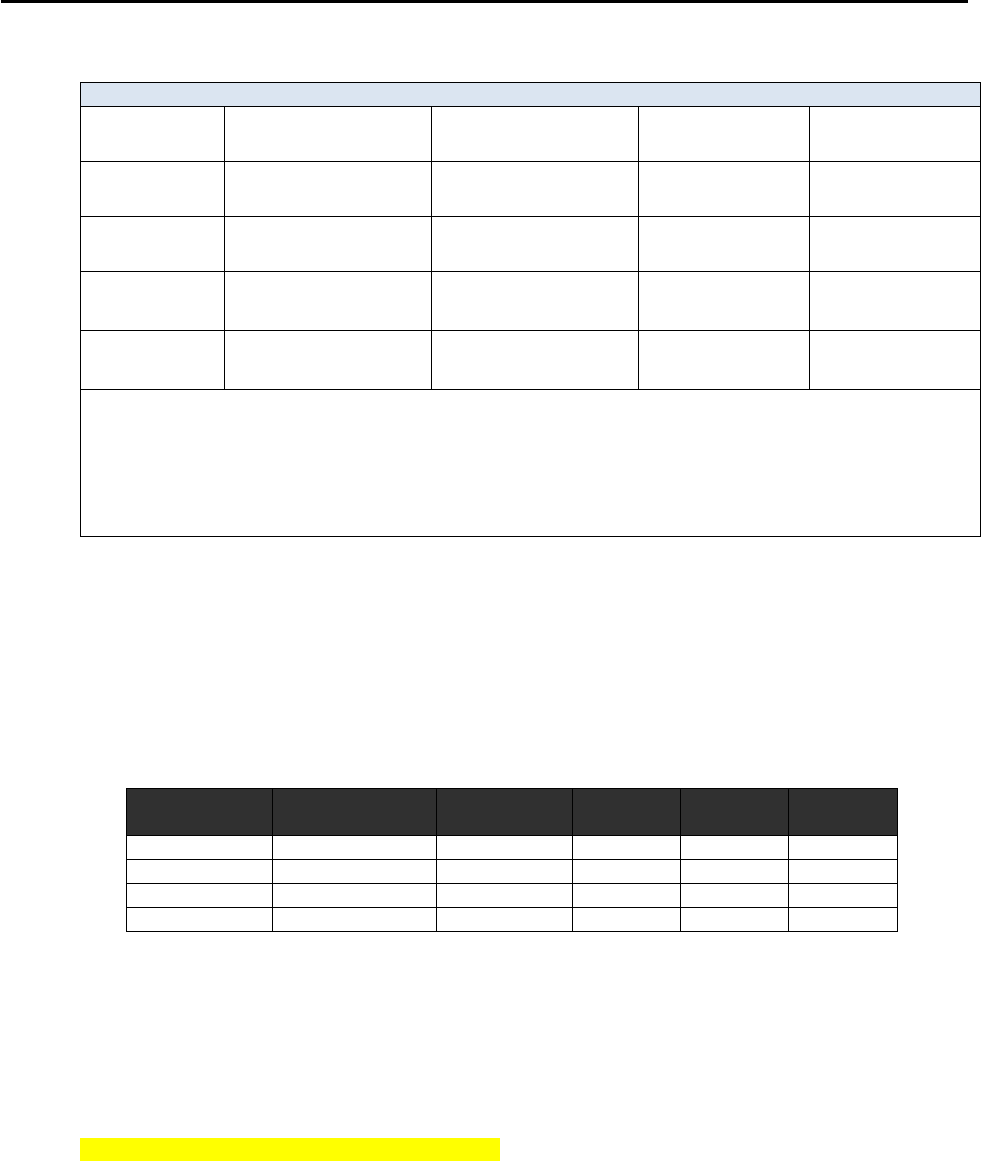
CCNPv6 ROUTE
All contents are Copyright © 1992–2010 Cisco Systems, Inc. All rights reserved. This document is Cisco Public Information. Page 11 of 14
Router Interface Summary Table
Router Interface Summary
Router Model Ethernet Interface
#1 Ethernet Interface
#2 Serial Interface
#1 Serial Interface
#2
1700 Fast Ethernet 0
(FA0) Fast Ethernet 1
(FA1) Serial 0 (S0) Serial 1 (S1)
1800 Fast Ethernet 0/0
(FA0/0) Fast Ethernet 0/1
(FA0/1) Serial 0/0/0
(S0/0/0) Serial 0/0/1
(S0/0/1)
2600 Fast Ethernet 0/0
(FA0/0)
Fast Ethernet 0/1
(FA0/1) Serial 0/0 (S0/0) Serial 0/1 (S0/1)
2800 Fast Ethernet 0/0
(FA0/0)
Fast Ethernet 0/1
(FA0/1) Serial 0/0/0
(S0/0/0) Serial 0/0/1
(S0/0/1)
Note: To find out how the router is configured, look at the interfaces to identify the type of router
and how many interfaces the router has. Rather than list all combinations of configurations for each
router class, this table includes identifiers for the possible combinations of Ethernet and serial
interfaces in the device. The table does not include any other type of interface, even though a
specific router might contain one. For example, for an ISDN BRI interface, the string in parenthesis
is the legal abbreviation that can be used in Cisco IOS commands to represent the interface.
Appendix A: Adtran Frame Relay Switch Configuration
If an Adtran Atlas 550 is used for the Frame Relay switch, connect the serial cable from each router interface
in the topology diagram to the Adtran interface indicated in the table below. The Adtran is preconfigured to
simulate a Frame Relay service that provides the following PVCs.
Frame Relay Switching Configuration
Connected
Router
Router
Interface
Adtran
Interface
Ingress
DLCI
Egress
DLCI
Egress
Router
HQ
S0/0/1 DTE
port 1/1
102
201
EAST
HQ
S0/0/1 DTE
port 1/1
103
301
WEST
EAST
S0/0/1 DTE
port 1/2
201
102
HQ
WEST
S0/0/0 DTE
port 2/1
301
103
HQ
The Adtran Frame Relay switch interfaces all provide the DCE clock. Be sure to use the appropriate cable
between each router and the Adtran. All the router interfaces are DTE, and the cable to the Adtran interface
should be serial to V.35 DCE. Use the show controllers command to verify which cable type is connected to a
given router interface.
HQ# show controllers s0/0/1
Interface Serial0/0/1
Hardware is GT96K
DTE V.35 TX and RX clocks detected.
<output omitted>

CCNPv6 ROUTE
All contents are Copyright © 1992–2010 Cisco Systems, Inc. All rights reserved. This document is Cisco Public Information. Page 12 of 14
Device Configurations (Instructor version)
Router HQ (R1)
hostname HQ
!
interface Loopback1
ip address 10.1.1.1 255.255.255.0
ip ospf network point-to-point
!
interface Serial0/0/1
ip address 10.1.123.1 255.255.255.0
encapsulation frame-relay ietf
ip ospf network point-to-multipoint
frame-relay map ip 10.1.123.1 102
frame-relay map ip 10.1.123.2 102 broadcast
frame-relay map ip 10.1.123.3 103 broadcast
no frame-relay inverse-arp
no shutdown
!
router ospf 1
network 10.1.1.0 0.0.0.255 area 0
network 10.1.123.0 0.0.0.255 area 0
!
end
Router EAST (R2)
hostname EAST
!
interface Loopback2
ip address 10.1.2.1 255.255.255.0
ip ospf network point-to-point
!
interface FastEthernet0/0
ip address 10.1.23.2 255.255.255.0
ip ospf dead-interval minimal hello-multiplier 5
no shutdown
!
interface Serial0/0/1
ip address 10.1.123.2 255.255.255.0
encapsulation frame-relay ietf
clock rate 64000
ip ospf network point-to-multipoint
frame-relay map ip 10.1.123.1 201 broadcast
frame-relay map ip 10.1.123.2 201
frame-relay map ip 10.1.123.3 201 broadcast
no frame-relay inverse-arp
no shutdown
!
router ospf 1
network 10.1.2.0 0.0.0.255 area 0
network 10.1.23.0 0.0.0.255 area 0
network 10.1.123.0 0.0.0.255 area 0
!
end

CCNPv6 ROUTE
All contents are Copyright © 1992–2010 Cisco Systems, Inc. All rights reserved. This document is Cisco Public Information. Page 13 of 14
Router WEST (R4)
hostname WEST
!
interface Loopback3
ip address 10.1.3.1 255.255.255.0
ip ospf network point-to-point
!
interface FastEthernet0/0
ip address 10.1.23.3 255.255.255.0
ip ospf dead-interval minimal hello-multiplier 5
no shutdown
!
interface Serial0/0/0
ip address 10.1.123.3 255.255.255.0
encapsulation frame-relay ietf
ip ospf network point-to-multipoint
frame-relay map ip 10.1.123.1 301 broadcast
frame-relay map ip 10.1.123.2 301 broadcast
frame-relay map ip 10.1.123.3 301
no frame-relay inverse-arp
no shutdown
!
router ospf 1
network 10.1.3.0 0.0.0.255 area 0
network 10.1.23.0 0.0.0.255 area 0
network 10.1.123.0 0.0.0.255 area 0
!
end
Router FRS (R3)
hostname FRS
!
frame-relay switching
!
interface Serial0/0/0
no ip address
encapsulation frame-relay ietf
no ip route-cache
clock rate 64000
frame-relay intf-type dce
frame-relay route 102 interface Serial0/0/1 201
frame-relay route 103 interface Serial0/1/0 301
no shutdown
!
interface Serial0/0/1
no ip address
encapsulation frame-relay ietf
frame-relay intf-type dce
frame-relay route 201 interface Serial0/0/0 102
no shutdown
!
interface Serial0/1/0
no ip address

CCNPv6 ROUTE
All contents are Copyright © 1992–2010 Cisco Systems, Inc. All rights reserved. This document is Cisco Public Information. Page 14 of 14
encapsulation frame-relay ietf
no ip route-cache
frame-relay intf-type dce
clock rate 64000
frame-relay route 301 interface Serial0/0/0 103
no shutdown
!
end
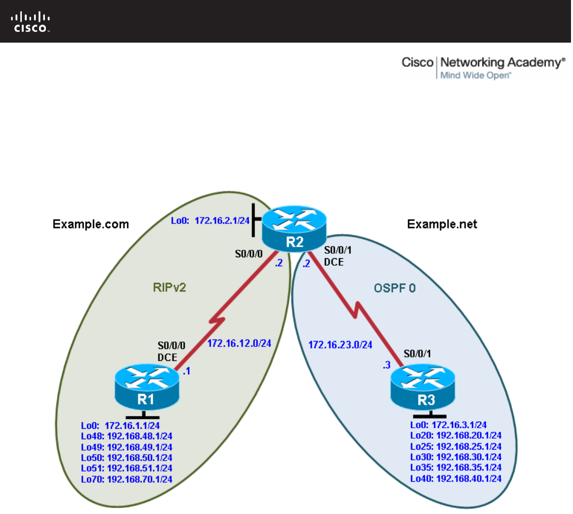
All contents are Copyright © 1992–2010 Cisco Systems, Inc. All rights reserved. This document is Cisco Public Information. Page 1 of 22
CCNPv6 ROUTE
Chapter 4 Lab 4-1, Redistribution Between RIP and OSPF Instructor
Version
Topology
Objectives
• Review configuration and verification of RIP and OSPF.
• Configure passive interfaces in both RIP and OSPF.
• Filter routing updates using distribute lists.
• Redistribute static routes into RIP.
• Redistribute RIP routes into OSPF.
• Redistribute OSPF routes into RIP.
• Originate a default route into OSPF.
• Set a default seed metric.
• Modify OSPF external network types.
• Configure summary addresses.

CCNPv6 ROUTE
All contents are Copyright © 1992–2010 Cisco Systems, Inc. All rights reserved. This document is Cisco Public Information. Page 2 of 22
Background
Two online booksellers, Example.com and Example.net, have merged and now need a short-term solution to
inter-domain routing. Since these companies provide client services to Internet users, it is essential to have
minimal downtime during the transition.
Example.com is a small firm running RIP, while Example.net has a somewhat larger network running OSPF.
The diagram identifies R2 as the router that will bridge the two networks. Because it is imperative that the two
booksellers continuously deliver Internet services, you should bridge these two routing domains without
interfering with each router’s path through its own routing domain to the Internet.
The CIO determines that it is preferable to keep the two protocol domains shown in the diagram during the
transition period, because the network engineers on each side need to understand the other’s network before
deploying a long-term solution. Redistribution will be a short-term solution.
In this scenario, R1 and R2 are running RIPv2, but the 172.16.23.0/24 network between R2 and R3 is running
OSPF. You need to configure R2 to enable these two routing protocols to interact to allow full connectivity
between all networks.
Note: This lab uses Cisco 1841 routers with Cisco IOS Release 12.4(24)T1 and the Advanced IP Services
image c1841-advipservicesk9-mz.124-24.T1.bin. You can use other routers (such as 2801 or 2811) and
Cisco IOS Software versions if they have comparable capabilities and features. Depending on the router
model and Cisco IOS Software version, the commands available and output produced might vary from what is
shown in this lab.
Required Resources
• 3 routers (Cisco 1841 with Cisco IOS Release 12.4(24)T1 Advanced IP Services or comparable)
• Serial and console cables
Step 1: Configure loopbacks and assign addresses.
a. Configure all loopback interfaces on the three routers in the diagram. Configure the serial interfaces with
the IP addresses, bring them up, and set a DCE clock rate where appropriate.
R1(config)# interface Loopback0
R1(config-if)# ip address 172.16.1.1 255.255.255.0
R1(config-if)# interface Loopback48
R1(config-if)# ip address 192.168.48.1 255.255.255.0
R1(config-if)# interface Loopback49
R1(config-if)# ip address 192.168.49.1 255.255.255.0
R1(config-if)# interface Loopback50
R1(config-if)# ip address 192.168.50.1 255.255.255.0
R1(config-if)# interface Loopback51
R1(config-if)# ip address 192.168.51.1 255.255.255.0
R1(config-if)# interface Loopback70
R1(config-if)# ip address 192.168.70.1 255.255.255.0
R1(config-if)# interface Serial0/0/0
R1(config-if)# ip address 172.16.12.1 255.255.255.0
R1(config-if)# clock rate 64000
R1(config-if)# bandwidth 64
R1(config-if)# no shutdown
R2(config)# interface Loopback0
R2(config-if)# ip address 172.16.2.1 255.255.255.0
R2(config-if)# interface Serial0/0/0
R2(config-if)# ip address 172.16.12.2 255.255.255.0

CCNPv6 ROUTE
All contents are Copyright © 1992–2010 Cisco Systems, Inc. All rights reserved. This document is Cisco Public Information. Page 3 of 22
R2(config-if)# bandwidth 64
R2(config-if)# no shutdown
R2(config-if)# interface Serial0/0/1
R2(config-if)# ip address 172.16.23.2 255.255.255.0
R2(config-if)# clock rate 64000
R2(config-if)# bandwidth 64
R2(config-if)# no shutdown
R3(config)# interface Loopback0
R3(config-if)# ip address 172.16.3.1 255.255.255.0
R3(config-if)# interface Loopback20
R3(config-if)# ip address 192.168.20.1 255.255.255.0
R3(config-if)# interface Loopback25
R3(config-if)# ip address 192.168.25.1 255.255.255.0
R3(config-if)# interface Loopback30
R3(config-if)# ip address 192.168.30.1 255.255.255.0
R3(config-if)# interface Loopback35
R3(config-if)# ip address 192.168.35.1 255.255.255.0
R3(config-if)# interface Loopback40
R3(config-if)# ip address 192.168.40.1 255.255.255.0
R3(config-if)# interface Serial0/0/1
R3(config-if)# ip address 172.16.23.3 255.255.255.0
R3(config-if)# bandwidth 64
R3(config-if)# no shutdown
b. (Optional) On each router, create an enable secret password. Configure the console line for synchronous
logging and no timeout. Configure the vty lines to allow Telnet to and remote configuration of network
devices.
R1 example:
R1(config)# enable secret cisco
R1(config)# line con 0
R1(config-line)# logging synchronous
R1(config-line)# exec-timeout 0 0
R1(config)# line vty 0 4
R1(config-line)# password cisco
R1(config-line)# login
c. Verify that you can ping across the serial links when you are finished. Use the following Tcl script to check
full and partial connectivity throughout this lab.
R1# tclsh
foreach address {
172.16.1.1
192.168.48.1
192.168.49.1
192.168.50.1
192.168.51.1
192.168.70.1
172.16.12.1
172.16.2.1
172.16.12.2
172.16.23.2
172.16.3.1
192.168.20.1

CCNPv6 ROUTE
All contents are Copyright © 1992–2010 Cisco Systems, Inc. All rights reserved. This document is Cisco Public Information. Page 4 of 22
192.168.25.1
192.168.30.1
192.168.35.1
192.168.40.1
172.16.23.3
} { ping $address }
At this point, the only pings that you should receive back are those of the connected networks of the
router from which you are pinging.
Step 2: Configure RIPv2.
Configuring RIPv2 on a router is fairly simple:
• Type the global configuration command router rip to enter RIP configuration mode.
• Enable RIPv2 with the version 2 command.
• Enter the no auto-summary command to disable automatic summarization at classful network
boundaries.
• Add the networks you want using the network network command.
Unlike EIGRP and OSPF, the RIP network command only requires the classful network address to be
entered and does not support a wildcard mask. This behavior is inherited from the classful RIPv1 protocol
configuration and is kept for backward compatibility with older Cisco IOS versions that would not otherwise be
able to process network commands with wildcard masks. Classful protocols do not support subnets;
therefore, subnet or wildcard masks are unnecessary.
Based on the topology diagram, which major networks need to be advertised into RIP for R1?
__________________________________________________________________________________
__________________________________________________________________________________
__________________________________________________________________________________
__________________________________________________________________________________
__________________________________________________________________________________
__________________________________________________________________________________
172.16.0.0/16
192.168.48.0/24
192.168.49.0/24
192.168.50.0/24
192.168.51.0/24
192.168.70.0/24
Which major networks need to be advertised into RIP for R2?
__________________________________________________________________________________
__________________________________________________________________________________
Only 172.16.0.0/16
a. Apply the following commands to R1 and R2.
R1(config)# router rip

CCNPv6 ROUTE
All contents are Copyright © 1992–2010 Cisco Systems, Inc. All rights reserved. This document is Cisco Public Information. Page 5 of 22
R1(config-router)# version 2
R1(config-router)# no auto-summary
R1(config-router)# network 172.16.0.0
R1(config-router)# network 192.168.48.0
R1(config-router)# network 192.168.49.0
R1(config-router)# network 192.168.50.0
R1(config-router)# network 192.168.51.0
R1(config-router)# network 192.168.70.0
R2(config)# router rip
R2(config-router)# version 2
R2(config-router)# no auto-summary
R2(config-router)# network 172.16.0.0
b. Verify that the RIP routes were learned from the other routers using the show ip route rip command on
each router.
R1# show ip route rip
172.16.0.0/24 is subnetted, 4 subnets
R 172.16.23.0 [120/1] via 172.16.12.2, 00:00:03, Serial0/0/0
R 172.16.2.0 [120/1] via 172.16.12.2, 00:00:03, Serial0/0/0
R2# show ip route rip
172.16.0.0/24 is subnetted, 4 subnets
R 172.16.1.0 [120/1] via 172.16.12.1, 00:00:29, Serial0/0/0
R 192.168.51.0/24 [120/1] via 172.16.12.1, 00:00:29, Serial0/0/0
R 192.168.50.0/24 [120/1] via 172.16.12.1, 00:00:29, Serial0/0/0
R 192.168.49.0/24 [120/1] via 172.16.12.1, 00:00:29, Serial0/0/0
R 192.168.70.0/24 [120/1] via 172.16.12.1, 00:00:29, Serial0/0/0
R 192.168.48.0/24 [120/1] via 172.16.12.1, 00:00:29, Serial0/0/0
c. You can also verify which routes are coming in from RIP advertisements with the show ip rip database
command.
R1# show ip rip database
172.16.0.0/16 auto-summary
172.16.1.0/24 directly connected, Loopback0
172.16.2.0/24
[1] via 172.16.12.2, 00:00:06, Serial0/0/0
172.16.12.0/24 directly connected, Serial0/0/0
172.16.23.0/24
[1] via 172.16.12.2, 00:00:06, Serial0/0/0
192.168.48.0/24 auto-summary
192.168.48.0/24 directly connected, Loopback48
192.168.49.0/24 auto-summary
192.168.49.0/24 directly connected, Loopback49
192.168.50.0/24 auto-summary
192.168.50.0/24 directly connected, Loopback50
192.168.51.0/24 auto-summary
192.168.51.0/24 directly connected, Loopback51
192.168.70.0/24 auto-summary
192.168.70.0/24 directly connected, Loopback70
R2# show ip rip database
172.16.0.0/16 auto-summary
172.16.1.0/24
[1] via 172.16.12.1, 00:00:10, Serial0/0/0
172.16.2.0/24 directly connected, Loopback0
172.16.12.0/24 directly connected, Serial0/0/0

CCNPv6 ROUTE
All contents are Copyright © 1992–2010 Cisco Systems, Inc. All rights reserved. This document is Cisco Public Information. Page 6 of 22
172.16.23.0/24 directly connected, Serial0/0/1
192.168.48.0/24 auto-summary
192.168.48.0/24
[1] via 172.16.12.1, 00:00:10, Serial0/0/0
192.168.49.0/24 auto-summary
192.168.49.0/24
[1] via 172.16.12.1, 00:00:10, Serial0/0/0
192.168.50.0/24 auto-summary
192.168.50.0/24
[1] via 172.16.12.1, 00:00:10, Serial0/0/0
192.168.51.0/24 auto-summary
192.168.51.0/24
[1] via 172.16.12.1, 00:00:10, Serial0/0/0
192.168.70.0/24 auto-summary
192.168.70.0/24
[1] via 172.16.12.1, 00:00:10, Serial0/0/0
Step 3: Configure passive interfaces in RIP.
a. On R1, use the show ip route rip command to view the RIP routes in the routing table. Notice that the
network for the serial interface of R2 that connects to R3 is present, even though you do not have a RIP
neighbor on that interface. This is because the entire class B network 172.16.0.0 /16 was added to RIP
on R2.
R1# show ip route rip
172.16.0.0/24 is subnetted, 4 subnets
R 172.16.23.0 [120/1] via 172.16.12.2, 00:00:03, Serial0/0/0
R 172.16.2.0 [120/1] via 172.16.12.2, 00:00:03, Serial0/0/0
b. Issue the show ip protocols command to verify that RIPv2 updates are being sent out both serial
interfaces.
R2# show ip protocols
Routing Protocol is "rip"
Outgoing update filter list for all interfaces is not set
Incoming update filter list for all interfaces is not set
Sending updates every 30 seconds, next due in 13 seconds
Invalid after 180 seconds, hold down 180, flushed after 240
Redistributing: rip
Default version control: send version 2, receive version 2
Interface Send Recv Triggered RIP Key-chain
Serial0/0/0 2 2
Serial0/0/1 2 2
Loopback0 2 2
Automatic network summarization is not in effect
Maximum path: 4
Routing for Networks:
172.16.0.0
Routing Information Sources:
Gateway Distance Last Update
172.16.12.1 120 00:00:26
Distance: (default is 120)
For security reasons and to reduce unnecessary traffic, RIP updates should not be propagated into the
OSPF domain. You can disable sending updates with the passive-interface interface_type
interface_number router configuration command
c. On R2, configure the serial interface connecting to R3 as passive. Notice that the interface is no longer
listed in the output of the show ip protocols command.

CCNPv6 ROUTE
All contents are Copyright © 1992–2010 Cisco Systems, Inc. All rights reserved. This document is Cisco Public Information. Page 7 of 22
R2(config)# router rip
R2(config-router)# passive-interface serial 0/0/1
R2# show ip protocols
Routing Protocol is "rip"
Outgoing update filter list for all interfaces is not set
Incoming update filter list for all interfaces is not set
Sending updates every 30 seconds, next due in 23 seconds
Invalid after 180 seconds, hold down 180, flushed after 240
Redistributing: rip
Default version control: send version 2, receive version 2
Interface Send Recv Triggered RIP Key-chain
Serial0/0/0 2 2
Loopback0 2 2
Automatic network summarization is not in effect
Maximum path: 4
Routing for Networks:
172.16.0.0
Passive Interface(s):
Serial0/0/1
Routing Information Sources:
Gateway Distance Last Update
172.16.12.1 120 00:00:17
Distance: (default is 120)
d. On R1, issue the show ip route rip command. Notice that the 172.16.23.0 network is still in the routing
table and being sourced from RIP.
R1# show ip route rip
172.16.0.0/24 is subnetted, 4 subnets
R 172.16.23.0 [120/1] via 172.16.12.2, 00:00:19, Serial0/0/0
R 172.16.2.0 [120/1] via 172.16.12.2, 00:00:19, Serial0/0/0
Making an interface in RIP passive only disables updates from being sent through RIP. It does not affect
routes being received through it.
What are some reasons to prevent RIP from sending updates out a particular interface?
_______________________________________________________________________________
_______________________________________________________________________________
_______________________________________________________________________________
_______________________________________________________________________________
_______________________________________________________________________________
_______________________________________________________________________________
_______________________________________________________________________________
_______________________________________________________________________________
RIPv2 does not use an adjacency system. Therefore, RIPv2 floods all of its routing updates out of its
interfaces rather than developing adjacencies with short hello packets like EIGRP and OSPF. Because
RIPv2 could flood packets out interfaces where there are no RIPv2 receivers, it is a best practice to
prevent RIP packets from being sent out these interfaces.
Putting a RIPv2 interface in passive mode saves the router from sending multicast RIP packets out an
interface that has no neighbors.

CCNPv6 ROUTE
All contents are Copyright © 1992–2010 Cisco Systems, Inc. All rights reserved. This document is Cisco Public Information. Page 8 of 22
Does RIPv2 send advertisements out loopback interfaces?
_______________________________________________________________________________
_______________________________________________________________________________
_______________________________________________________________________________
_______________________________________________________________________________
By default, loopback interfaces act like normal interfaces in RIPv2 when sending and receiving packets.
However, a router will never have RIPv2 neighbors out its loopback interface, so loopback interfaces can
always be configured as passive interfaces, thereby saving CPU resources.
e. If you are unsure, monitor the output of the debug ip rip command to verify your answer. On R1 and R2,
configure all loopbacks from which RIPv2 is sending advertisements in passive state with the passive-
interface command.
R1(config)# router rip
R1(config-router)# passive-interface loopback 0
R1(config-router)# passive-interface loopback 48
R1(config-router)# passive-interface loopback 49
R1(config-router)# passive-interface loopback 50
R1(config-router)# passive-interface loopback 51
R1(config-router)# passive-interface loopback 70
R2(config)# router rip
R2(config-router)# passive-interface loopback 0
When running RIPv2, implement passive interfaces as a common practice to save CPU processor cycles
and bandwidth on interfaces that do not have multicast RIPv2 neighbors.
Note: An alternative to making each loopback interface on R1 passive is to make all interfaces passive
with the passive-interface default command in router configuration mode. Then make any interfaces
that need to send updates, such as S0/0/0, nonpassive.
R1(config)# router rip
R1(config-router)# passive-interface default
R1(config-router)# no passive-interface Serial0/0/0
Step 4: Summarize a supernet with RIP.
a. On R2, issue the show ip route rip command. Notice that you can see all prefixes from R1 in the R2
routing table.
R2# show ip route rip
172.16.0.0/24 is subnetted, 4 subnets
R 172.16.1.0 [120/1] via 172.16.12.1, 00:00:29, Serial0/0/0
R 192.168.51.0/24 [120/1] via 172.16.12.1, 00:00:29, Serial0/0/0
R 192.168.50.0/24 [120/1] via 172.16.12.1, 00:00:29, Serial0/0/0
R 192.168.49.0/24 [120/1] via 172.16.12.1, 00:00:29, Serial0/0/0
R 192.168.70.0/24 [120/1] via 172.16.12.1, 00:00:29, Serial0/0/0
R 192.168.48.0/24 [120/1] via 172.16.12.1, 00:00:29, Serial0/0/0
In preparing for redistribution, you want to redistribute the minimum number of destination prefixes into
each of the routing protocols. Which RIP routes should you summarize because they are contiguous and
which mask should you use?
_______________________________________________________________________________
_______________________________________________________________________________

CCNPv6 ROUTE
All contents are Copyright © 1992–2010 Cisco Systems, Inc. All rights reserved. This document is Cisco Public Information. Page 9 of 22
Summarize 192.168.48.0/24 through 192.168.51.0/24. Use a 22-bit mask to create the supernet.
Under normal circumstances, you could simply summarize the four consecutive class-C networks with the
ip summary address rip command on the R1 serial 0/0/0 interface. However, the RIP implementation in
the Cisco IOS Software does not allow summarizing to a mask length that is less than the classful
network prefix (in this case, 24 bits). This limitation does not affect other routing protocols. If you do try,
you receive the following error message:
R1(config)# interface serial 0/0/0
R1(config-if)# ip summary-address rip 192.168.48.0 255.255.252.0
Summary mask must be greater or equal to major net
Recall from the EIGRP labs that summary routes display in the summarizing device’s routing table as
having the next hop being the Null0 interface. You can create an entry manually using the ip route
command and redistribute it into RIP, thereby emulating the approach of EIGRP to a certain extent.
b. To get around the ip summary-address rip message error, create a static route on R1 to summarize the
networks of loopbacks 48 through 51. Then redistribute the route on R1.
R1(config)# ip route 192.168.48.0 255.255.252.0 null0
R1(config)# router rip
R1(config-router)# redistribute static
This solution might seem unusual, but for RIPv2, it resembles many effects of summarization as
performed in other routing protocols like EIGRP or OSPF. Again, this is not a limitation of RIPv2, but
rather a Cisco IOS implementation issue.
c. On R1 and R2, verify that the RIP supernet has been added to the routing table with the show ip route
command.
R1# show ip route
<output omitted>
Gateway of last resort is not set
172.16.0.0/24 is subnetted, 4 subnets
R 172.16.23.0 [120/1] via 172.16.12.2, 00:00:27, Serial0/0/0
C 172.16.12.0 is directly connected, Serial0/0/0
C 172.16.1.0 is directly connected, Loopback0
R 172.16.2.0 [120/1] via 172.16.12.2, 00:00:27, Serial0/0/0
C 192.168.51.0/24 is directly connected, Loopback51
C 192.168.50.0/24 is directly connected, Loopback50
C 192.168.49.0/24 is directly connected, Loopback49
C 192.168.70.0/24 is directly connected, Loopback70
C 192.168.48.0/24 is directly connected, Loopback48
S 192.168.48.0/22 is directly connected, Null0
R2# show ip route
<output omitted>
Gateway of last resort is not set
172.16.0.0/24 is subnetted, 4 subnets
C 172.16.23.0 is directly connected, Serial0/0/1
C 172.16.12.0 is directly connected, Serial0/0/0
R 172.16.1.0 [120/1] via 172.16.12.1, 00:00:05, Serial0/0/0
C 172.16.2.0 is directly connected, Loopback0
R 192.168.51.0/24 [120/1] via 172.16.12.1, 00:00:05, Serial0/0/0
R 192.168.50.0/24 [120/1] via 172.16.12.1, 00:00:05, Serial0/0/0

CCNPv6 ROUTE
All contents are Copyright © 1992–2010 Cisco Systems, Inc. All rights reserved. This document is Cisco Public Information. Page 10 of 22
R 192.168.49.0/24 [120/1] via 172.16.12.1, 00:00:05, Serial0/0/0
R 192.168.70.0/24 [120/1] via 172.16.12.1, 00:00:07, Serial0/0/0
R 192.168.48.0/24 [120/1] via 172.16.12.1, 00:00:07, Serial0/0/0
R 192.168.48.0/22 [120/1] via 172.16.12.1, 00:00:07, Serial0/0/0
Will this route to Null0 affect routing to prefixes with longer addresses on R1? Explain.
_______________________________________________________________________________
_______________________________________________________________________________
_______________________________________________________________________________
_______________________________________________________________________________
_______________________________________________________________________________
The routing table first matches based on longest IP prefix. If any of the summarized networks are routable
on R1, as in this situation, R1 uses the connected route with the longer mask to reach those networks. If
one of those interfaces were to be shut down, R1 would send traffic for that network to its Null0 virtual
interface.
Step 5: Suppress routes using prefix lists.
Sometimes you might not want to advertise certain networks out a particular interface, or you might want to
filter updates as they come in. This is possible with distance-vector routing protocols, such as RIP or EIGRP.
However, link-state protocols are less flexible, because every router in an area is required to have a
synchronized database as a condition for full adjacency.
Distribute lists can be used with either access lists or prefix lists to filter routes by network address. With
prefix lists, they can also be configured to filter routes by subnet masks.
In this scenario, you want to filter updates from R1 to R2, allowing only the networks of Loopback 0 and
Loopback 70 and the summary route to be advertised. You want to suppress the more specific prefixes so
that routing tables are kept small, and CPU processor cycles on the routers are not wasted.
The 22-bit summary and the 24-bit major network address both have the same address, so access lists will
not accomplish the filtering correctly. Therefore, it is necessary to use prefix lists.
To create a prefix list or add a prefix list entry, use the ip prefix-list command in global configuration mode.
ip prefix-list {list-name | list-number} {deny network/length | permit
network/length} [ge ge-length] [le le-length]
The ge keyword represents the “greater than or equal to” operator. The le keyword represents the “less than
or equal to” operator. If both the ge and le keywords are omitted, the prefix list is processed using an exact
match.
a. On R1, use a prefix list as a distribution filter to prevent the more specific routes to loopbacks 48 through
51 from being advertised. Allow all other destination networks, including the summary route.
R1(config)# ip prefix-list RIP-OUT permit 192.168.48.0/22
R1(config)# ip prefix-list RIP-OUT deny 192.168.48.0/22 le 24
R1(config)# ip prefix-list RIP-OUT permit 0.0.0.0/0 le 32
Line 1 of the prefix list permits the summary route and nothing else, because no other route can match
that network address with a mask of exactly 22 bits.
Line 2 denies all prefixes with a network address in the 192.168.48.0/22 block of addresses that have
subnet masks from 22 bits to 24 bits. This removes exactly four network addresses matching the 22, 23,

CCNPv6 ROUTE
All contents are Copyright © 1992–2010 Cisco Systems, Inc. All rights reserved. This document is Cisco Public Information. Page 11 of 22
and 24 bits in length of the subnet mask. Line 2 would deny the 192.168.48.0/22 summary route you
created if Line 1 did not explicitly permit the summary route.
Line 3 allows all IPv4 prefixes that are not explicitly denied in previous statements of the prefix list.
b. From the RIP configuration prompt on R1, apply this access list with the distribute-list command.
R1(config)# router rip
R1(config-router)# distribute-list prefix RIP-OUT out serial0/0/0
c. On R2, verify that the filtering has taken place using the show ip route rip and show ip rip database
commands.
R2# show ip route rip
172.16.0.0/24 is subnetted, 4 subnets
R 172.16.1.0 [120/1] via 172.16.12.1, 00:00:12, Serial0/0/0
R 192.168.70.0/24 [120/1] via 172.16.12.1, 00:00:12, Serial0/0/0
R 192.168.48.0/22 [120/1] via 172.16.12.1, 00:00:12, Serial0/0/0
Note: You might need to issue the clear ip route * command on R2 to see the removal of the more
specific R1 prefixes. Also, if the network 192.168.48.0/22 does not appear on R2, this is incorrect
behavior and might be corrected in recent versions of Cisco IOS Software. A workaround is to remove the
network 192.168.48.0 command from RIP and issue the clear ip route * command on R1.
R2# show ip rip database
172.16.0.0/16 auto-summary
172.16.1.0/24
[1] via 172.16.12.1, 00:00:11, Serial0/0/0
172.16.2.0/24 directly connected, Loopback0
172.16.12.0/24 directly connected, Serial0/0/0
172.16.23.0/24 directly connected, Serial0/0/1
192.168.48.0/22
[1] via 172.16.12.1, 00:00:11, Serial0/0/0
192.168.70.0/24 auto-summary
192.168.70.0/24
[1] via 172.16.12.1, 00:00:11, Serial0/0/0
Why would you want to filter updates being sent out or coming in?
_______________________________________________________________________________
_______________________________________________________________________________
_______________________________________________________________________________
_______________________________________________________________________________
_______________________________________________________________________________
_______________________________________________________________________________
The intention is to summarize addresses at R1, achieving benefits such as smaller routing tables and the
prevention of route flapping disturbing network stability. By redistributing the static route into RIPv2, only
the summary route was added, but the more specific routes were not filtered. To achieve these benefits,
filter the outgoing routes to R2 by allowing all routes except the 24-bit routes.
Step 6: Configure OSPF.
a. Configure single-area OSPF between R2 and R3. On R2, include just the serial link connecting to R3. On
R3, include the serial link and all loopback interfaces.
R2(config)# router ospf 1

CCNPv6 ROUTE
All contents are Copyright © 1992–2010 Cisco Systems, Inc. All rights reserved. This document is Cisco Public Information. Page 12 of 22
R2(config-router)# network 172.16.23.0 0.0.0.255 area 0
R3(config)# router ospf 1
R3(config-router)# network 172.16.0.0 0.0.255.255 area 0
R3(config-router)# network 192.168.0.0 0.0.255.255 area 0
15:01:37.047: %OSPF-5-ADJCHG: Process 1, Nbr 172.16.2.1 on Serial0/0/1 from
LOADING to FULL, Loading Done
b. On R3, change the network type for the loopback interfaces to point-to-point so that they are advertised
with the correct subnet mask (/24 instead of /32).
R3(config)# interface Loopback0
R3(config-if)# ip ospf network point-to-point
R3(config-if)# interface Loopback20
R3(config-if)# ip ospf network point-to-point
R3(config-if)# interface Loopback25
R3(config-if)# ip ospf network point-to-point
R3(config-if)# interface Loopback30
R3(config-if)# ip ospf network point-to-point
R3(config-if)# interface Loopback35
R3(config-if)# ip ospf network point-to-point
R3(config-if)# interface Loopback40
R3(config-if)# ip ospf network point-to-point
c. Verify the OSPF adjacencies on R2 and R3 with the show ip ospf neighbors command. Also make sure
that you have routes from OSPF populating the routing tables with the show ip route ospf command.
R2# show ip ospf neighbor
Neighbor ID Pri State Dead Time Address Interface
192.168.40.1 0 FULL/ - 00:00:37 172.16.23.3 Serial0/0/1
R3# show ip ospf neighbor
Neighbor ID Pri State Dead Time Address Interface
172.16.2.1 0 FULL/ - 00:00:39 172.16.23.2 Serial0/0/1
R2# show ip route ospf
O 192.168.30.0/24 [110/1563] via 172.16.23.3, 00:01:23, Serial0/0/1
O 192.168.25.0/24 [110/1563] via 172.16.23.3, 00:01:23, Serial0/0/1
O 192.168.40.0/24 [110/1563] via 172.16.23.3, 00:01:23, Serial0/0/1
172.16.0.0/24 is subnetted, 5 subnets
O 172.16.3.0 [110/1563] via 172.16.23.3, 00:01:23, Serial0/0/1
O 192.168.20.0/24 [110/1563] via 172.16.23.3, 00:01:23, Serial0/0/1
O 192.168.35.0/24 [110/1563] via 172.16.23.3, 00:01:23, Serial0/0/1
R3# show ip route ospf
R3#
Note that output of the show ip route ospf command on R3 is blank.
The network 192.168.0.0 0.0.255.255 area 0 command allows OSPF to involve interfaces that have IP
addresses in that range.
A common misconception is that OSPF advertises the entire range of the network given in the router’s
network statement; it does not. However, it does advertise any connected subnets in that range of
addresses to adjacent routers. You can verify this by viewing the output of the show ip route command
on R2. Do you see a 192.168.0.0/16 supernet?

CCNPv6 ROUTE
All contents are Copyright © 1992–2010 Cisco Systems, Inc. All rights reserved. This document is Cisco Public Information. Page 13 of 22
_______________________________________________________________________________
_______________________________________________________________________________
_______________________________________________________________________________
No, because the network command selects interfaces by IP address. It does not set the exact prefix to
be advertised.
R2 is the only router with all routes in the topology (except for those that were filtered out), because it is
involved with both routing protocols.
Step 7: Configure passive interfaces in OSPF.
Passive interfaces save CPU cycles, router memory, and link bandwidth by preventing broadcast and
multicast routing updates on interfaces that have no neighbors. In link-state protocols, adjacencies must be
formed before routers exchange routing information. The passive-interface command in OSPF configuration
mode prevents an interface from sending or processing OSPF packets on that interface.
OSPF included the R3 loopback interfaces in its network statements shown in Step 6.
a. On R3, configure Loopback0 as a passive interface in OSPF. At the OSPF router configuration prompt,
use the passive-interface interface_type interface_number command.
R3(config-router)# passive-interface loopback 0
How is this different from the RIP version of this command?
_______________________________________________________________________________
_______________________________________________________________________________
_______________________________________________________________________________
_______________________________________________________________________________
_______________________________________________________________________________
_______________________________________________________________________________
_______________________________________________________________________________
_______________________________________________________________________________
_______________________________________________________________________________
_______________________________________________________________________________
Passive interfaces in RIPv2 prevent outgoing routing information via multicast.
Because OSPF must create an adjacency before sending routing updates, the OSPF version of the
passive-interface command prevents sending or processing OSPF packets and, therefore, prevents
adjacencies.
b. Cisco IOS Software provides a quick way of selecting interfaces for passive mode. Use the passive-
interface default command to make all interfaces passive. Then use the no passive-interface interface
interface_number command to bring the Serial0/0/1 interface out of passive mode.
R3(config)# router ospf 1
R3(config-router)# passive-interface default
R3(config-router)#
*Oct 15 01:49:44.174: %OSPF-5-ADJCHG: Process 1, Nbr 172.16.2.1 on
Serial0/0/1 from FULL to DOWN, Neighbor Down: Interface down or detached
R3(config-router)# no passive-interface serial 0/0/1

CCNPv6 ROUTE
All contents are Copyright © 1992–2010 Cisco Systems, Inc. All rights reserved. This document is Cisco Public Information. Page 14 of 22
R3(config-router)#
*Oct 15 01:49:55.438: %OSPF-5-ADJCHG: Process 1, Nbr 172.16.2.1 on
Serial0/0/1 from LOADING to FULL, Loading Done
c. You can verify the application of this command by issuing the show ip protocols command.
R3# show ip protocols
Routing Protocol is "ospf 1"
Outgoing update filter list for all interfaces is not set
Incoming update filter list for all interfaces is not set
Router ID 192.168.40.1
Number of areas in this router is 1. 1 normal 0 stub 0 nssa
Maximum path: 4
Routing for Networks:
172.16.0.0 0.0.255.255 area 0
192.168.0.0 0.0.255.255 area 0
Reference bandwidth unit is 100 mbps
Passive Interface(s):
FastEthernet0/0
FastEthernet0/1
Serial0/0/0
Serial0/1/0
Serial0/1/1
Loopback0
Loopback20
Loopback25
Loopback30
Loopback35
Loopback40
Routing Information Sources:
Gateway Distance Last Update
172.16.2.1 110 00:03:04
Distance: (default is 110)
Step 8: Allow one-way redistribution.
a. On R2, configure OSPF to redistribute into RIP under the RIP configuration prompt with the redistribute
ospf process metric metric command, where process is the OSPF process number, and metric is the
default metric with which you want to originate the routes into RIP. If you do not specify a default metric in
RIP, it gives routes an infinite metric and they are not advertised.
R2(config)# router rip
R2(config-router)# redistribute ospf 1 metric 4
b. Verify the redistribution with the show ip protocols command.
R2# show ip protocols
Routing Protocol is "rip"
Outgoing update filter list for all interfaces is not set
Incoming update filter list for all interfaces is not set
Sending updates every 30 seconds, next due in 24 seconds
Invalid after 180 seconds, hold down 180, flushed after 240
Redistributing: rip, ospf 1
Default version control: send version 2, receive version 2
Interface Send Recv Triggered RIP Key-chain
Serial0/0/0 2 2
Automatic network summarization is not in effect
Maximum path: 4
Routing for Networks:
172.16.0.0

CCNPv6 ROUTE
All contents are Copyright © 1992–2010 Cisco Systems, Inc. All rights reserved. This document is Cisco Public Information. Page 15 of 22
Passive Interface(s):
Serial0/0/1
Loopback0
Routing Information Sources:
Gateway Distance Last Update
172.16.12.1 120 00:00:19
Distance: (default is 120)
<output omitted>
c. On R1, look at the routing table with the show ip route rip command. It has all the routes in the topology.
R1# show ip route rip
R 192.168.30.0 [120/4] via 172.16.12.2, 00:00:11, Serial0/0/0
R 192.168.25.0 [120/4] via 172.16.12.2, 00:00:11, Serial0/0/0
R 192.168.40.0 [120/4] via 172.16.12.2, 00:00:11, Serial0/0/0
172.16.0.0/24 is subnetted, 5 subnets
R 172.16.23.0 [120/1] via 172.16.12.2, 00:00:11, Serial0/0/0
R 172.16.2.0 [120/1] via 172.16.12.2, 00:00:11, Serial0/0/0
R 172.16.3.0 [120/4] via 172.16.12.2, 00:00:11, Serial0/0/0
R 192.168.20.0 [120/4] via 172.16.12.2, 00:00:11, Serial0/0/0
R 192.168.35.0 [120/4] via 172.16.12.2, 00:00:11, Serial0/0/0
d. On R1, ping a loopback on R3. Notice that it shows that R1 has a route to R3, but R3 does not have a
route back to R1.
R1# ping 192.168.30.1
Type escape sequence to abort.
Sending 5, 100-byte ICMP Echos to 192.168.30.1, timeout is 2 seconds:
.....
Success rate is 0 percent (0/5)
e. On R1, verify that R3 does not have a route back with the traceroute command.
R1# traceroute 192.168.30.1
Type escape sequence to abort.
Tracing the route to 192.168.30.1
1 172.16.12.2 12 msec 12 msec 16 msec
2 * * *
3 * * *
4 * * *
<output omitted>
To address this problem, you can originate a default route into OSPF that points toward R2 so that the
pings are routed back toward R2. R2 uses its information from RIPv2 to send pings back to R1.
f. From the OSPF configuration prompt, issue the default-information originate always command to force
R2 to advertise a default route in OSPF.
R2(config)# router ospf 1
R2(config-router)# default-information originate always
g. Verify that this route is present in the R3 routing table.
R3# show ip route ospf
O*E2 0.0.0.0/0 [110/1] via 172.16.23.2, 00:05:13, Serial0/0/1
You should now have full connectivity between all networks in the diagram.

CCNPv6 ROUTE
All contents are Copyright © 1992–2010 Cisco Systems, Inc. All rights reserved. This document is Cisco Public Information. Page 16 of 22
h. Use the Tcl script from Step 1 to verify full connectivity.
Step 9: Redistribute between two routing protocols.
You can substitute this default route with actual, more specific routes.
a. On R2, under the OSPF router configuration prompt, remove the default route advertisement with the no
default-information originate always command. Next, use the redistribute rip command. You do not
need to specify a default metric in OSPF. Notice the warning.
R2(config)# router ospf 1
R2(config-router)# no default-information originate always
R2(config-router)# redistribute rip
% Only classful networks will be redistributed
b. If you display the routing table on R3, the external OSPF routes that were added are the 192.168.70.0/24
and 192.168.48.0/22 networks.
R3# show ip route ospf
O E2 192.168.70.0/24 [110/20] via 172.16.23.2, 00:00:51, Serial0/0/1
O E2 192.168.48.0/22 [110/20] via 172.16.23.2, 00:00:51, Serial0/0/1
This is because, by default, OSPF only accepts classful networks and supernets when redistributing into
it. The only classful network coming into R2 from RIP is the class C network 192.168.70.0, and the only
supernet is the 192.168.48.0/22.
c. You can modify this behavior by adding the subnets keyword to the redistribute command.
R2(config)# router ospf 1
R2(config-router)# redistribute rip subnets
d. On R3, verify the configuration with the show ip route ospf command.
R3# show ip route ospf
172.16.0.0/24 is subnetted, 5 subnets
O E2 172.16.12.0 [110/20] via 172.16.23.2, 00:00:01, Serial0/0/1
O E2 172.16.1.0 [110/20] via 172.16.23.2, 00:00:01, Serial0/0/1
O E2 172.16.2.0 [110/20] via 172.16.23.2, 00:00:01, Serial0/0/1
O E2 192.168.70.0/24 [110/20] via 172.16.23.2, 00:04:19, Serial0/0/1
O E2 192.168.48.0/22 [110/20] via 172.16.23.2, 00:04:19, Serial0/0/1
You should again have full connectivity between all networks in the diagram.
e. Run the Tcl script on each router to verify full connectivity.
Step 10: Set a default seed metric.
Under any routing protocol, you can specify a default seed metric to be used for redistribution instead of, or in
addition to, setting metrics on a per-protocol basis. A seed metric is a protocol-independent feature of the
Cisco IOS Software that is usually configured when redistributing into distance-vector protocols.
Notice that the metric listed in the R3 routing table is 20.
R3# show ip route ospf
172.16.0.0/24 is subnetted, 5 subnets
O E2 172.16.12.0 [110/20] via 172.16.23.2, 00:00:01, Serial0/0/1
O E2 172.16.1.0 [110/20] via 172.16.23.2, 00:00:01, Serial0/0/1
O E2 172.16.2.0 [110/20] via 172.16.23.2, 00:00:01, Serial0/0/1
O E2 192.168.70.0/24 [110/20] via 172.16.23.2, 00:04:19, Serial0/0/1
O E2 192.168.48.0/22 [110/20] via 172.16.23.2, 00:04:19, Serial0/0/1

CCNPv6 ROUTE
All contents are Copyright © 1992–2010 Cisco Systems, Inc. All rights reserved. This document is Cisco Public Information. Page 17 of 22
You can override the global creation of a default seed metric on a per-protocol basis by using the metric
argument in a redistribution command. You can also use the metric command under other routing protocols.
a. On R2, in OSPF configuration mode, issue the default-metric metric command to configure a default
metric for redistributed routes. The default metric for all OSPF redistributed routes is 20, except for BGP,
which is 1. Setting the metric for RIP to a higher number makes it less preferable to routes redistributed
from other routing protocols.
R2(config)# router ospf 1
R2(config-router)# default-metric 10000
b. Verify the new metric in the R3 routing table. It might take some time for the new metric to propagate.
R3# show ip route ospf
172.16.0.0/24 is subnetted, 5 subnets
O E2 172.16.12.0 [110/10000] via 172.16.23.2, 00:02:56, Serial0/0/1
O E2 172.16.1.0 [110/10000] via 172.16.23.2, 00:02:56, Serial0/0/1
O E2 172.16.2.0 [110/10000] via 172.16.23.2, 00:02:56, Serial0/0/1
O E2 192.168.70.0/24 [110/10000] via 172.16.23.2, 00:02:56, Serial0/0/1
O E2 192.168.48.0/22 [110/10000] via 172.16.23.2, 00:02:56, Serial0/0/1
Step 11: Change the OSPF external network type.
Look at the R3 routing table. Notice that the external (redistributed) routes have O E2 as their type. In the
output, O means OSPF, and E2 means external, type 2. OSPF has two external metric types, and E2 is the
default. External type 1 metrics increase like a usual route, whereas external type 2 metrics do not increase
as they get advertised through the OSPF domain. Also notice that the metric is exactly the same as the seed
metric in the previous step.
Where would an external type 1 metric be useful?
__________________________________________________________________________________
__________________________________________________________________________________
__________________________________________________________________________________
__________________________________________________________________________________
If there are multiple paths through an OSPF domain to an external destination network, use E1 routes so that
OSPF will evaluate the shortest cost path. Especially use this option if multiple ASBRs are advertising the
same destination network to prevent suboptimal routing.
Where would an external type 2 metric be useful?
__________________________________________________________________________________
__________________________________________________________________________________
__________________________________________________________________________________
If there is only one ASBR advertising an external route, use E2 routes. In this scenario, use the E1 type even
though only one ASBR is advertising the external routes.
a. You can change the external type using the metric-type argument with the redistribute command.
Change the type to E1 for RIP redistributed routes.
R2(config)# router ospf 1
R2(config-router)# redistribute rip subnets metric-type 1
b. Display the R3 routing table again.
R3# show ip route ospf

CCNPv6 ROUTE
All contents are Copyright © 1992–2010 Cisco Systems, Inc. All rights reserved. This document is Cisco Public Information. Page 18 of 22
172.16.0.0/24 is subnetted, 5 subnets
O E1 172.16.12.0 [110/11562] via 172.16.23.2, 00:03:05, Serial0/0/1
O E1 172.16.1.0 [110/11562] via 172.16.23.2, 00:03:05, Serial0/0/1
O E1 172.16.2.0 [110/11562] via 172.16.23.2, 00:03:05, Serial0/0/1
O E1 192.168.70.0/24 [110/11562] via 172.16.23.2, 00:03:05, Serial0/0/1
O E1 192.168.48.0/22 [110/11562] via 172.16.23.2, 00:03:05, Serial0/0/1
Which attributes of the routes changed?
_______________________________________________________________________________
_______________________________________________________________________________
_______________________________________________________________________________
The external route type has been changed from E2 to E1. The metric, previously 10000, has been
incremented to represent the path through the OSPF network to the ASBR.
Note: Be sure to save your final configurations through Step 11 for use in Lab 4-2, “Redistribution
Between EIGRP and OSPF.”
CCNPv6 ROUTE
All contents are Copyright © 1992–2010 Cisco Systems, Inc. All rights reserved. This document is Cisco Public Information. Page 19 of 22
Router Interface Summary Table
Router Interface Summary
Router Model Ethernet Interface
#1 Ethernet Interface
#2 Serial Interface
#1 Serial Interface
#2
1700 Fast Ethernet 0
(FA0) Fast Ethernet 1
(FA1) Serial 0 (S0) Serial 1 (S1)
1800 Fast Ethernet 0/0
(FA0/0) Fast Ethernet 0/1
(FA0/1) Serial 0/0/0
(S0/0/0) Serial 0/0/1
(S0/0/1)
2600 Fast Ethernet 0/0
(FA0/0) Fast Ethernet 0/1
(FA0/1) Serial 0/0 (S0/0) Serial 0/1 (S0/1)
2800 Fast Ethernet 0/0
(FA0/0) Fast Ethernet 0/1
(FA0/1) Serial 0/0/0
(S0/0/0) Serial 0/0/1
(S0/0/1)
Note: To find out how the router is configured, look at the interfaces to identify the type of router
and how many interfaces the router has. Rather than list all combinations of configurations for each
router class, this table includes identifiers for the possible combinations of Ethernet and serial
interfaces in the device. The table does not include any other type of interface, even though a
specific router might contain one. For example, for an ISDN BRI interface, the string in parenthesis
is the legal abbreviation that can be used in Cisco IOS commands to represent the interface.

CCNPv6 ROUTE
All contents are Copyright © 1992–2010 Cisco Systems, Inc. All rights reserved. This document is Cisco Public Information. Page 20 of 22
Device Configurations (Instructor version)
Router R1
hostname R1
!
interface Loopback0
ip address 172.16.1.1 255.255.255.0
!
interface Loopback48
ip address 192.168.48.1 255.255.255.0
!
interface Loopback49
ip address 192.168.49.1 255.255.255.0
!
interface Loopback50
ip address 192.168.50.1 255.255.255.0
!
interface Loopback51
ip address 192.168.51.1 255.255.255.0
!
interface Loopback70
ip address 192.168.70.1 255.255.255.0
!
interface Serial0/0/0
ip address 172.16.12.1 255.255.255.0
clock rate 64000
bandwidth 64
no shutdown
!
router rip
version 2
redistribute static
passive-interface Loopback0
passive-interface Loopback48
passive-interface Loopback49
passive-interface Loopback50
passive-interface Loopback51
passive-interface Loopback70
network 172.16.0.0
network 192.168.48.0
network 192.168.49.0
network 192.168.50.0
network 192.168.51.0
network 192.168.70.0
distribute-list prefix RIP-OUT out Serial0/0/0
no auto-summary
!
ip route 192.168.48.0 255.255.252.0 Null0
!
ip prefix-list RIP-OUT seq 5 permit 192.168.48.0/22
ip prefix-list RIP-OUT seq 10 deny 192.168.48.0/22 le 24
ip prefix-list RIP-OUT seq 15 permit 0.0.0.0/0 le 32
!
end

CCNPv6 ROUTE
All contents are Copyright © 1992–2010 Cisco Systems, Inc. All rights reserved. This document is Cisco Public Information. Page 21 of 22
Router R2
hostname R2
!
interface Loopback0
ip address 172.16.2.1 255.255.255.0
!
interface Serial0/0/0
ip address 172.16.12.2 255.255.255.0
bandwidth 64
no shutdown
!
interface Serial0/0/1
ip address 172.16.23.2 255.255.255.0
clock rate 64000
bandwidth 64
no shutdown
!
router ospf 1
redistribute rip metric-type 1 subnets
network 172.16.23.0 0.0.0.255 area 0
default-metric 10000
!
router rip
version 2
redistribute ospf 1 metric 4
passive-interface Serial0/0/1
passive-interface Loopback0
network 172.16.0.0
no auto-summary
!
end
Router R3
hostname R3
!
interface Loopback0
ip address 172.16.3.1 255.255.255.0
ip ospf network point-to-point
!
interface Loopback20
ip address 192.168.20.1 255.255.255.0
ip ospf network point-to-point
!
interface Loopback25
ip address 192.168.25.1 255.255.255.0
ip ospf network point-to-point
!
interface Loopback30
ip address 192.168.30.1 255.255.255.0
ip ospf network point-to-point
!
interface Loopback35
ip address 192.168.35.1 255.255.255.0
ip ospf network point-to-point
!

CCNPv6 ROUTE
All contents are Copyright © 1992–2010 Cisco Systems, Inc. All rights reserved. This document is Cisco Public Information. Page 22 of 22
interface Loopback40
ip address 192.168.40.1 255.255.255.0
ip ospf network point-to-point
!
interface Serial0/0/1
ip address 172.16.23.3 255.255.255.0
bandwidth 64
no shutdown
!
router ospf 1
passive-interface default
no passive-interface Serial0/0/1
network 172.16.0.0 0.0.255.255 area 0
network 192.168.0.0 0.0.255.255 area 0
!
end
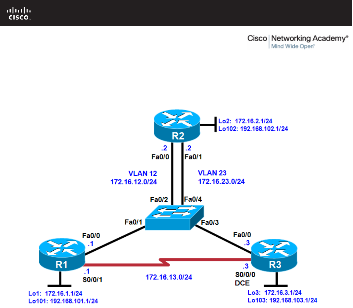
All contents are Copyright © 1992–2010 Cisco Systems, Inc. All rights reserved. This document is Cisco Public Information. Page 1 of 18
CCNPv6 ROUTE
Chapter 4 Lab 4-3, Manipulating Administrative Distances Instructor
Version
Topology
Objectives
• Configure RIP on a router.
• Configure OSPF on a router.
• Manipulate administrative distances.
• Compare routing protocol behavior.
Background
In this lab, you will compare the RIP and OSPF routing protocols based on how efficient they are at selecting
routes, as well as what happens when you manipulate administrative distances in the routing table.
Note: This lab uses Cisco 1841 routers with Cisco IOS Release 12.4(24)T1 and the Advanced IP Services
image c1841-advipservicesk9-mz.124-24.T1.bin. The switch is a Cisco WS-C2960-24TT-L with the Cisco IOS
image c2960-lanbasek9-mz.122-46.SE.bin. You can use other routers (such as a 2801 or 2811), switches
(such as 2950), and Cisco IOS Software versions if they have comparable capabilities and features.
CCNPv6 ROUTE
All contents are Copyright © 1992–2010 Cisco Systems, Inc. All rights reserved. This document is Cisco Public Information. Page 2 of 18
Depending on the router or switch model and Cisco IOS Software version, the commands available and
output produced might vary from what is shown in this lab.
Required Resources
• 3 routers (Cisco 1841 with Cisco IOS Release 12.4(24)T1 Advanced IP Services or comparable)
• 1 switch (Cisco 2960 with the Cisco IOS Release 12.2(46)SE C2960-LANBASEK9-M image or
comparable)
• Serial and Ethernet cables
Step 1: Review default administrative distances.
Fill in the following table with all the administrative distances you can recall from your reading.
Protocol Administrative Distance
Connected 0
Static 1
EIGRP Summary Route 5
External BGP 20
EIGRP 90
IGRP 100
OSPF 110
IS-IS 115
RIP 120
EGP 140
On-Demand Routing (ODR) 160
External EIGRP 170
Internal BGP 200
Unknown 255
Of the interior gateway protocols (IGPs) that you have studied, which one is considered the most trusted on a
Cisco router and why?
__________________________________________________________________________________
__________________________________________________________________________________
Currently, EIGRP is considered the most trusted IGP on Cisco routers with an administrative distance of 90.
Step 2: Configure router loopbacks and addressing.
Configure all loopback interfaces on the three routers in the diagram. Configure the serial interface with the IP
addresses, bring them up, and set a clock rate where appropriate.

CCNPv6 ROUTE
All contents are Copyright © 1992–2010 Cisco Systems, Inc. All rights reserved. This document is Cisco Public Information. Page 3 of 18
R1# conf t
R1(config)# interface loopback 1
R1(config-if)# ip address 172.16.1.1 255.255.255.0
R1(config-if)# interface loopback 101
R1(config-if)# ip address 192.168.101.1 255.255.255.0
R1(config-if)# interface fastethernet 0/0
R1(config-if)# ip address 172.16.12.1 255.255.255.0
R1(config-if)# no shutdown
R1(config-if)# interface serial 0/0/1
R1(config-if)# bandwidth 64
R1(config-if)# ip address 172.16.13.1 255.255.255.0
R1(config-if)# no shutdown
R2# conf t
R2(config)# interface loopback 2
R2(config-if)# ip address 172.16.2.1 255.255.255.0
R2(config-if)# interface loopback 102
R2(config-if)# ip address 192.168.102.1 255.255.255.0
R2(config-if)# interface fastethernet 0/0
R2(config-if)# ip address 172.16.12.2 255.255.255.0
R2(config-if)# no shutdown
R2(config-if)# interface fastethernet 0/1
R2(config-if)# ip address 172.16.23.2 255.255.255.0
R2(config-if)# no shutdown
R3# conf t
R3(config)# interface loopback 3
R3(config-if)# ip address 172.16.3.1 255.255.255.0
R3(config-if)# interface loopback 103
R3(config-if)# ip address 192.168.103.1 255.255.255.0
R3(config-if)# interface fastethernet 0/0
R3(config-if)# ip address 172.16.23.3 255.255.255.0
R3(config-if)# no shutdown
R3(config-if)# interface serial 0/0/0
R3(config-if)# bandwidth 64
R3(config-if)# ip address 172.16.13.3 255.255.255.0
R3(config-if)# clock rate 64000
R3(config-if)# no shutdown
Step 3: Configure switch VLANs.
a. Configure the switch VLANs, and place the correct access ports in each VLAN.
Note: The switch ports used are not important as long as the ports connecting to R1 Fa0/0 and R2 Fa0/0
are in VLAN 12 and the ports connecting to R3 Fa0/0 and R2 Fa0/1 are in VLAN 23.
Switch(config)# vlan 12
Switch(config-vlan)# name R1-R2
Switch(config-vlan)# vlan 23
Switch(config-vlan)# name R2-R3
Switch(config-vlan)# exit
Switch(config)# interface fastEthernet 0/1
Switch(config-if)# description To R1 Fa0/0
Switch(config-if)# switchport mode access
Switch(config-if)# switchport access vlan 12
Switch(config-if)# interface fastEthernet 0/2
Switch(config-if)# description To R2 Fa0/0

CCNPv6 ROUTE
All contents are Copyright © 1992–2010 Cisco Systems, Inc. All rights reserved. This document is Cisco Public Information. Page 4 of 18
Switch(config-if)# switchport mode access
Switch(config-if)# switchport access vlan 12
Switch(config-if)# interface fastEthernet 0/3
Switch(config-if)# description To R3 Fa0/0
Switch(config-if)# switchport mode access
Switch(config-if)# switchport access vlan 23
Switch(config-if)# interface fastEthernet 0/4
Switch(config-if)# description To R2 Fa0/1
Switch(config-if)# switchport mode access
Switch(config-if)# switchport access vlan 23
b. Verify that you can ping across the local subnets.
Step 4: Configure RIP.
a. Configure RIPv2 on all three routers for the major networks. Disable automatic summarization.
R1(config)# router rip
R1(config-router)# version 2
R1(config-router)# no auto-summary
R1(config-router)# network 172.16.0.0
R1(config-router)# network 192.168.101.0
R2(config)# router rip
R2(config-router)# version 2
R2(config-router)# no auto-summary
R2(config-router)# network 172.16.0.0
R2(config-router)# network 192.168.102.0
R3(config)# router rip
R3(config-router)# version 2
R3(config-router)# no auto-summary
R3(config-router)# network 172.16.0.0
R3(config-router)# network 192.168.103.0
b. Verify the configuration using the show ip route rip command on each router.
R1# show ip route rip
172.16.0.0/24 is subnetted, 6 subnets
R 172.16.23.0 [120/1] via 172.16.13.3, 00:02:29, Serial0/0/1
[120/1] via 172.16.12.2, 00:02:15, FastEthernet0/0
R 172.16.2.0 [120/1] via 172.16.12.2, 00:02:15, FastEthernet0/0
R 172.16.3.0 [120/1] via 172.16.13.3, 00:02:29, Serial0/0/1
R 192.168.102.0/24 [120/1] via 172.16.12.2, 00:02:15, FastEthernet0/0
R 192.168.103.0/24 [120/1] via 172.16.13.3, 00:02:29, Serial0/0/1
R2# show ip route rip
172.16.0.0/24 is subnetted, 6 subnets
R 172.16.13.0 [120/1] via 172.16.23.3, 00:02:18, FastEthernet0/1
[120/1] via 172.16.12.1, 00:02:20, FastEthernet0/0
R 172.16.1.0 [120/1] via 172.16.12.1, 00:02:20, FastEthernet0/0
R 172.16.3.0 [120/1] via 172.16.23.3, 00:02:18, FastEthernet0/1
R 192.168.103.0/24 [120/1] via 172.16.23.3, 00:02:18, FastEthernet0/1
R 192.168.101.0/24 [120/1] via 172.16.12.1, 00:02:20, FastEthernet0/0
R3# show ip route rip
172.16.0.0/24 is subnetted, 6 subnets
R 172.16.12.0 [120/1] via 172.16.23.2, 00:02:32, FastEthernet0/0

CCNPv6 ROUTE
All contents are Copyright © 1992–2010 Cisco Systems, Inc. All rights reserved. This document is Cisco Public Information. Page 5 of 18
[120/1] via 172.16.13.1, 00:02:47, Serial0/0/0
R 172.16.1.0 [120/1] via 172.16.13.1, 00:02:47, Serial0/0/0
R 172.16.2.0 [120/1] via 172.16.23.2, 00:02:32, FastEthernet0/0
R 192.168.102.0/24 [120/1] via 172.16.23.2, 00:02:32, FastEthernet0/0
R 192.168.101.0/24 [120/1] via 172.16.13.1, 00:02:47, Serial0/0/0
Notice that on R1, RIP chooses the serial interface as the best next hop for the R3 loopback interface.
c. Verify that each router is receiving RIP routes from other routers using the show ip protocols command.
R1# show ip protocols
Routing Protocol is "rip"
Outgoing update filter list for all interfaces is not set
Incoming update filter list for all interfaces is not set
Sending updates every 30 seconds, next due in 26 seconds
Invalid after 180 seconds, hold down 180, flushed after 240
Redistributing: rip
Default version control: send version 2, receive version 2
Interface Send Recv Triggered RIP Key-chain
FastEthernet0/0 2 2
Serial0/0/1 2 2
Loopback1 2 2
Loopback101 2 2
Automatic network summarization is not in effect
Maximum path: 4
Routing for Networks:
172.16.0.0
192.168.101.0
Routing Information Sources:
Gateway Distance Last Update
172.16.12.2 120 00:00:21
172.16.13.3 120 00:00:03
Distance: (default is 120)
R2# show ip protocols
Routing Protocol is "rip"
Outgoing update filter list for all interfaces is not set
Incoming update filter list for all interfaces is not set
Sending updates every 30 seconds, next due in 23 seconds
Invalid after 180 seconds, hold down 180, flushed after 240
Redistributing: rip
Default version control: send version 2, receive version 2
Interface Send Recv Triggered RIP Key-chain
FastEthernet0/0 2 2
FastEthernet0/1 2 2
Loopback2 2 2
Loopback102 2 2
Automatic network summarization is not in effect
Maximum path: 4
Routing for Networks:
172.16.0.0
192.168.102.0
Routing Information Sources:
Gateway Distance Last Update
172.16.23.3 120 00:00:02
172.16.12.1 120 00:00:24
Distance: (default is 120)

CCNPv6 ROUTE
All contents are Copyright © 1992–2010 Cisco Systems, Inc. All rights reserved. This document is Cisco Public Information. Page 6 of 18
R3# show ip protocols
Routing Protocol is "rip"
Outgoing update filter list for all interfaces is not set
Incoming update filter list for all interfaces is not set
Sending updates every 30 seconds, next due in 22 seconds
Invalid after 180 seconds, hold down 180, flushed after 240
Redistributing: rip
Default version control: send version 2, receive version 2
Interface Send Recv Triggered RIP Key-chain
FastEthernet0/0 2 2
Serial0/0/0 2 2
Loopback3 2 2
Loopback103 2 2
Automatic network summarization is not in effect
Maximum path: 4
Routing for Networks:
172.16.0.0
192.168.103.0
Routing Information Sources:
Gateway Distance Last Update
172.16.23.2 120 00:00:06
172.16.13.1 120 00:00:17
Distance: (default is 120)
Step 5: Configure OSPF.
a. Configure OSPF on all routers. Include the entire major network in area 0 on all three routers. Remember
to change the network type on the loopback interfaces.
R1(config)# interface loopback 1
R1(config-if)# ip ospf network point-to-point
R1(config-if)# interface loopback 101
R1(config-if)# ip ospf network point-to-point
R1(config-if)# router ospf 1
R1(config-router)# network 172.16.0.0 0.0.255.255 area 0
R1(config-router)# network 192.168.101.0 0.0.0.255 area 0
R2(config)# interface loopback 2
R2(config-if)# ip ospf network point-to-point
R2(config-if)# interface loopback 102
R2(config-if)# ip ospf network point-to-point
R2(config-if)# router ospf 1
R2(config-router)# network 172.16.0.0 0.0.255.255 area 0
R2(config-router)# network 192.168.102.0 0.0.0.255 area 0
R3(config)# interface loopback 3
R3(config-if)# ip ospf network point-to-point
R3(config-if)# interface loopback 103
R3(config-if)# ip ospf network point-to-point
R3(config-if)# router ospf 1
R3(config-router)# network 172.16.0.0 0.0.255.255 area 0
R3(config-router)# network 192.168.103.0 0.0.0.255 area 0
b. Verify the configuration using the show ip ospf neighbors and show ip route commands on each
router.
R1# show ip ospf neighbor
Neighbor ID Pri State Dead Time Address Interface

CCNPv6 ROUTE
All contents are Copyright © 1992–2010 Cisco Systems, Inc. All rights reserved. This document is Cisco Public Information. Page 7 of 18
192.168.103.1 0 FULL/ - 00:00:39 172.16.13.3 Serial0/0/1
192.168.102.1 1 FULL/DR 00:00:39 172.16.12.2 FastEthernet0/0
R1# show ip route
<output omitted>
172.16.0.0/24 is subnetted, 6 subnets
O 172.16.23.0 [110/2] via 172.16.12.2, 00:00:48, FastEthernet0/0
C 172.16.12.0 is directly connected, FastEthernet0/0
C 172.16.13.0 is directly connected, Serial0/0/1
C 172.16.1.0 is directly connected, Loopback1
O 172.16.2.0 [110/2] via 172.16.12.2, 00:00:48, FastEthernet0/0
O 172.16.3.0 [110/3] via 172.16.12.2, 00:00:48, FastEthernet0/0
O 192.168.102.0/24 [110/2] via 172.16.12.2, 00:00:48, FastEthernet0/0
O 192.168.103.0/24 [110/3] via 172.16.12.2, 00:00:49, FastEthernet0/0
C 192.168.101.0/24 is directly connected, Loopback101
R2# show ip ospf neighbor
Neighbor ID Pri State Dead Time Address Interface
192.168.103.1 1 FULL/DR 00:00:31 172.16.23.3 FastEthernet0/1
192.168.101.1 1 FULL/BDR 00:00:34 172.16.12.1 FastEthernet0/0
R2# show ip route
<output omitted>
172.16.0.0/24 is subnetted, 6 subnets
C 172.16.23.0 is directly connected, FastEthernet0/1
C 172.16.12.0 is directly connected, FastEthernet0/0
O 172.16.13.0 [110/1563] via 172.16.23.3, 00:01:19, FastEthernet0/1
[110/1563] via 172.16.12.1, 00:01:19, FastEthernet0/0
O 172.16.1.0 [110/2] via 172.16.12.1, 00:01:19, FastEthernet0/0
C 172.16.2.0 is directly connected, Loopback2
O 172.16.3.0 [110/2] via 172.16.23.3, 00:01:19, FastEthernet0/1
C 192.168.102.0/24 is directly connected, Loopback102
O 192.168.103.0/24 [110/2] via 172.16.23.3, 00:01:20, FastEthernet0/1
O 192.168.101.0/24 [110/2] via 172.16.12.1, 00:01:20, FastEthernet0/0
R3# show ip ospf neighbor
Neighbor ID Pri State Dead Time Address Interface
192.168.101.1 0 FULL/ - 00:00:36 172.16.13.1 Serial0/0/0
192.168.102.1 1 FULL/BDR 00:00:33 172.16.23.2 FastEthernet0/0
R3# show ip route
<output omitted>
172.16.0.0/24 is subnetted, 6 subnets
C 172.16.23.0 is directly connected, FastEthernet0/0
O 172.16.12.0 [110/2] via 172.16.23.2, 00:02:10, FastEthernet0/0
C 172.16.13.0 is directly connected, Serial0/0/0
O 172.16.1.0 [110/3] via 172.16.23.2, 00:02:10, FastEthernet0/0
O 172.16.2.0 [110/2] via 172.16.23.2, 00:02:10, FastEthernet0/0
C 172.16.3.0 is directly connected, Loopback3
O 192.168.102.0/24 [110/2] via 172.16.23.2, 00:02:10, FastEthernet0/0
C 192.168.103.0/24 is directly connected, Loopback103
O 192.168.101.0/24 [110/3] via 172.16.23.2, 00:02:11, FastEthernet0/0
Notice that all the OSPF routes have replaced the RIP routes in the routing table. This is because OSPF has
an administrative distance of 110, and RIP has an administrative distance of 120.

CCNPv6 ROUTE
All contents are Copyright © 1992–2010 Cisco Systems, Inc. All rights reserved. This document is Cisco Public Information. Page 8 of 18
What is the best next hop on R1 for 172.16.3.1 with only RIP running?
__________________________________________________________________________________
__________________________________________________________________________________
On R1, the best next hop to 172.16.3.1 is the R3 serial 0/0/0 interface with an IP address of 172.16.13.3.
What is the best next hop on R1 for 172.16.3.1 with OSPF running?
__________________________________________________________________________________
__________________________________________________________________________________
__________________________________________________________________________________
On R1, the best next hop to 172.16.3.1 is the R2 Fast Ethernet 0/0 interface with an IP address of
172.16.12.2.
On R1, the best next hop for the R3 loopback is now through the VLAN between R1 and R2. This is because
the sum of the costs for the two Ethernet links is still less than that of the single low-bandwidth (64 kb/s) serial
link. This is one of the reasons why RIP’s metric of a hop count is not very effective.
Which metric does R1 use to make routing decisions about whether to cross the serial link to R3 to reach
R3’s 172.16.3.1?
__________________________________________________________________________________
__________________________________________________________________________________
__________________________________________________________________________________
The metric R1 receives for the loopback 3 network on R3 via the serial link is 1562, which is not preferred by
R1.
Use the following information for your answer.
R1# show ip ospf database router adv-router 192.168.103.1
OSPF Router with ID (192.168.101.1) (Process ID 1)
Router Link States (Area 0)
LS age: 433
Options: (No TOS-capability, DC)
LS Type: Router Links
Link State ID: 192.168.103.1
Advertising Router: 192.168.103.1
LS Seq Number: 80000003
Checksum: 0xE87F
Length: 84
Number of Links: 5
Link connected to: a Stub Network
(Link ID) Network/subnet number: 192.168.103.0
(Link Data) Network Mask: 255.255.255.0
Number of TOS metrics: 0
TOS 0 Metrics: 1
Link connected to: a Stub Network
(Link ID) Network/subnet number: 172.16.3.0
(Link Data) Network Mask: 255.255.255.0

CCNPv6 ROUTE
All contents are Copyright © 1992–2010 Cisco Systems, Inc. All rights reserved. This document is Cisco Public Information. Page 9 of 18
Number of TOS metrics: 0
TOS 0 Metrics: 1
Link connected to: another Router (point-to-point)
(Link ID) Neighboring Router ID: 192.168.101.1
(Link Data) Router Interface address: 172.16.13.3
Number of TOS metrics: 0
TOS 0 Metrics: 1562
Link connected to: a Stub Network
(Link ID) Network/subnet number: 172.16.13.0
(Link Data) Network Mask: 255.255.255.0
Number of TOS metrics: 0
TOS 0 Metrics: 1562
Link connected to: a Transit Network
(Link ID) Designated Router address: 172.16.23.3
(Link Data) Router Interface address: 172.16.23.3
Number of TOS metrics: 0
TOS 0 Metrics: 1
Step 6: Modify the routing protocol distance.
The distance command is a protocol-independent way to manipulate routing protocol distances. This
command is different from the routing protocol-specific commands such as distance ospf and distance
eigrp. This command lets you globally change a routing protocol’s distances, change only routes from a
certain neighbor or those matching an access list, or a combination of any two of these three options.
Try applying the distance distance command, which changes the distance of every route. The previous
output of the show ip route command shows that OSPF marks routes it injects into the routing table with a
default administrative distance of 110. RIP injects routes into the routing table with a default administrative
distance of 120.
What would happen if the administrative distance on each router for RIP were set to 100?
__________________________________________________________________________________
__________________________________________________________________________________
All RIP routes would be preferred in the routing tables over OSPF routes.
a. On all three routers, change the distance of RIP to 100.
R1(config)# router rip
R1(config-router)# distance 100
R2(config)# router rip
R2(config-router)# distance 100
R3(config)# router rip
R3(config-router)# distance 100
b. Examine the output of the show ip route command. Notice that all the routes have become RIP routes
because RIP now has a lower distance than OSPF.
R1# show ip route
<output omitted>
172.16.0.0/24 is subnetted, 6 subnets
R 172.16.23.0 [100/1] via 172.16.13.3, 00:00:17, Serial0/0/1
[100/1] via 172.16.12.2, 00:00:09, FastEthernet0/0

CCNPv6 ROUTE
All contents are Copyright © 1992–2010 Cisco Systems, Inc. All rights reserved. This document is Cisco Public Information. Page 10 of 18
C 172.16.12.0 is directly connected, FastEthernet0/0
C 172.16.13.0 is directly connected, Serial0/0/1
C 172.16.1.0 is directly connected, Loopback1
R 172.16.2.0 [100/1] via 172.16.12.2, 00:00:09, FastEthernet0/0
R 172.16.3.0 [100/1] via 172.16.13.3, 00:00:17, Serial0/0/1
R 192.168.102.0/24 [100/1] via 172.16.12.2, 00:00:10, FastEthernet0/0
R 192.168.103.0/24 [100/1] via 172.16.13.3, 00:00:18, Serial0/0/1
C 192.168.101.0/24 is directly connected, Loopback101
R2# show ip route
<output omitted>
172.16.0.0/24 is subnetted, 6 subnets
C 172.16.23.0 is directly connected, FastEthernet0/1
C 172.16.12.0 is directly connected, FastEthernet0/0
R 172.16.13.0 [100/1] via 172.16.23.3, 00:00:07, FastEthernet0/1
[100/1] via 172.16.12.1, 00:00:07, FastEthernet0/0
R 172.16.1.0 [100/1] via 172.16.12.1, 00:00:07, FastEthernet0/0
C 172.16.2.0 is directly connected, Loopback2
R 172.16.3.0 [100/1] via 172.16.23.3, 00:00:07, FastEthernet0/1
C 192.168.102.0/24 is directly connected, Loopback102
R 192.168.103.0/24 [100/1] via 172.16.23.3, 00:00:08, FastEthernet0/1
R 192.168.101.0/24 [100/1] via 172.16.12.1, 00:00:08, FastEthernet0/0
R3# show ip route
<output omitted>
172.16.0.0/24 is subnetted, 6 subnets
C 172.16.23.0 is directly connected, FastEthernet0/0
R 172.16.12.0 [100/1] via 172.16.23.2, 00:00:07, FastEthernet0/0
[100/1] via 172.16.13.1, 00:00:02, Serial0/0/0
C 172.16.13.0 is directly connected, Serial0/0/0
R 172.16.1.0 [100/1] via 172.16.13.1, 00:00:02, Serial0/0/0
R 172.16.2.0 [100/1] via 172.16.23.2, 00:00:07, FastEthernet0/0
C 172.16.3.0 is directly connected, Loopback3
R 192.168.102.0/24 [100/1] via 172.16.23.2, 00:00:08, FastEthernet0/0
C 192.168.103.0/24 is directly connected, Loopback103
R 192.168.101.0/24 [100/1] via 172.16.13.1, 00:00:03, Serial0/0/0
c. You can display the new default distance for RIP using the show ip protocols command.
R1# show ip protocols
Routing Protocol is "rip"
Outgoing update filter list for all interfaces is not set
Incoming update filter list for all interfaces is not set
Sending updates every 30 seconds, next due in 11 seconds
Invalid after 180 seconds, hold down 180, flushed after 240
Redistributing: rip
Default version control: send version 2, receive version 2
Interface Send Recv Triggered RIP Key-chain
FastEthernet0/0 2 2
Serial0/0/1 2 2
Loopback1 2 2
Loopback101 2 2
Automatic network summarization is not in effect
Maximum path: 4
Routing for Networks:
172.16.0.0
192.168.101.0
Routing Information Sources:
Gateway Distance Last Update

CCNPv6 ROUTE
All contents are Copyright © 1992–2010 Cisco Systems, Inc. All rights reserved. This document is Cisco Public Information. Page 11 of 18
172.16.13.3 100 00:00:14
172.16.12.2 100 00:00:22
Distance: (default is 100)
<output omitted>
Step 7: Modify distance based on route source.
You can also modify administrative distance based on route source using the distance distance address
wildcard command, where address and wildcard represent the peer advertising the route. For OSPF, the
address is the router ID.
a. On all three routers, change the OSPF administrative distance to 85 for any routes being advertised from
routers with IDs in the range of 192.168.100.0/21.
R1(config)# router ospf 1
R1(config-router)# distance 85 192.168.100.0 0.0.3.255
R2(config)# router ospf 1
R2(config-router)# distance 85 192.168.100.0 0.0.3.255
R3(config)# router ospf 1
R3(config-router)# distance 85 192.168.100.0 0.0.3.255
b. Verify the change with the show ip protocols and show ip route commands.
R1# show ip route
<output omitted>
Gateway of last resort is not set
172.16.0.0/24 is subnetted, 6 subnets
O 172.16.23.0 [85/2] via 172.16.12.2, 00:00:31, FastEthernet0/0
C 172.16.12.0 is directly connected, FastEthernet0/0
C 172.16.13.0 is directly connected, Serial0/0/1
C 172.16.1.0 is directly connected, Loopback1
O 172.16.2.0 [85/2] via 172.16.12.2, 00:00:31, FastEthernet0/0
O 172.16.3.0 [85/3] via 172.16.12.2, 00:00:31, FastEthernet0/0
O 192.168.102.0/24 [85/2] via 172.16.12.2, 00:00:31, FastEthernet0/0
O 192.168.103.0/24 [85/3] via 172.16.12.2, 00:00:32, FastEthernet0/0
C 192.168.101.0/24 is directly connected, Loopback101
R2# show ip route
<output omitted>
Gateway of last resort is not set
172.16.0.0/24 is subnetted, 6 subnets
C 172.16.23.0 is directly connected, FastEthernet0/1
C 172.16.12.0 is directly connected, FastEthernet0/0
O 172.16.13.0 [85/1563] via 172.16.23.3, 00:00:53, FastEthernet0/1
[85/1563] via 172.16.12.1, 00:00:53, FastEthernet0/0
O 172.16.1.0 [85/2] via 172.16.12.1, 00:00:53, FastEthernet0/0
C 172.16.2.0 is directly connected, Loopback2
O 172.16.3.0 [85/2] via 172.16.23.3, 00:00:53, FastEthernet0/1
C 192.168.102.0/24 is directly connected, Loopback102
O 192.168.103.0/24 [85/2] via 172.16.23.3, 00:00:54, FastEthernet0/1
O 192.168.101.0/24 [85/2] via 172.16.12.1, 00:00:54, FastEthernet0/0

CCNPv6 ROUTE
All contents are Copyright © 1992–2010 Cisco Systems, Inc. All rights reserved. This document is Cisco Public Information. Page 12 of 18
R3# show ip route
<output omitted>
Gateway of last resort is not set
172.16.0.0/24 is subnetted, 6 subnets
C 172.16.23.0 is directly connected, FastEthernet0/0
O 172.16.12.0 [85/2] via 172.16.23.2, 00:01:15, FastEthernet0/0
C 172.16.13.0 is directly connected, Serial0/0/0
O 172.16.1.0 [85/3] via 172.16.23.2, 00:01:15, FastEthernet0/0
O 172.16.2.0 [85/2] via 172.16.23.2, 00:01:15, FastEthernet0/0
C 172.16.3.0 is directly connected, Loopback3
O 192.168.102.0/24 [85/2] via 172.16.23.2, 00:01:15, FastEthernet0/0
C 192.168.103.0/24 is directly connected, Loopback103
O 192.168.101.0/24 [85/3] via 172.16.23.2, 00:01:16, FastEthernet0/0
R1# show ip protocols
Routing Protocol is "ospf 1"
Outgoing update filter list for all interfaces is not set
Incoming update filter list for all interfaces is not set
Router ID 192.168.101.1
Number of areas in this router is 1. 1 normal 0 stub 0 nssa
Maximum path: 4
Routing for Networks:
172.16.0.0 0.0.255.255 area 0
192.168.101.0 0.0.0.255 area 0
Reference bandwidth unit is 100 mbps
Routing Information Sources:
Gateway Distance Last Update
192.168.103.1 85 00:05:47
192.168.102.1 85 00:05:47
Distance: (default is 110)
Address Wild mask Distance List
192.168.100.0 0.0.3.255 85
Each of the routers should have an entry similar to the one highlighted above.
Step 8: Modify distance based on an access list.
You can also modify administrative distance based on which routes match an access list using the distance
distance address wildcard acl command. The way you list routes in an access list which will be used to modify
distance is similar to how you list them when the access list is used to filter routes. For this lab, create an
access list containing all the subnets of 172.16.0.0/16. Then associate the access list with the distance
command, setting the address and wildcard to be any IP address (i.e., any route source).
a. On all three routers, change the distances of the affected routes to 65.
R1(config)# access-list 1 permit 172.16.0.0 0.0.255.255
R1(config)# router rip
R1(config-router)# distance 65 0.0.0.0 255.255.255.255 1
R2(config)# access-list 1 permit 172.16.0.0 0.0.255.255
R2(config)# router rip
R2(config-router)# distance 65 0.0.0.0 255.255.255.255 1
R3(config)# access-list 1 permit 172.16.0.0 0.0.255.255
R3(config)# router rip
R3(config-router)# distance 65 0.0.0.0 255.255.255.255 1

CCNPv6 ROUTE
All contents are Copyright © 1992–2010 Cisco Systems, Inc. All rights reserved. This document is Cisco Public Information. Page 13 of 18
b. Verify the change with the show ip protocols and show ip route commands.
R1# show ip protocols
<output omitted>
Routing Protocol is "rip"
Outgoing update filter list for all interfaces is not set
Incoming update filter list for all interfaces is not set
Sending updates every 30 seconds, next due in 22 seconds
Invalid after 180 seconds, hold down 180, flushed after 240
Redistributing: rip
Default version control: send version 2, receive version 2
Interface Send Recv Triggered RIP Key-chain
FastEthernet0/0 2 2
Serial0/0/1 2 2
Loopback1 2 2
Loopback101 2 2
Automatic network summarization is not in effect
Maximum path: 4
Routing for Networks:
172.16.0.0
192.168.101.0
Routing Information Sources:
Gateway Distance Last Update
172.16.12.2 64 00:00:11
172.16.13.3 64 00:00:12
Distance: (default is 100)
Address Wild mask Distance List
0.0.0.0 255.255.255.255 65 1
R1# show ip route
<output omitted>
172.16.0.0/24 is subnetted, 6 subnets
R 172.16.23.0 [65/1] via 172.16.13.3, 00:00:20, Serial0/0/1
[65/1] via 172.16.12.2, 00:00:19, FastEthernet0/0
C 172.16.12.0 is directly connected, FastEthernet0/0
C 172.16.13.0 is directly connected, Serial0/0/1
C 172.16.1.0 is directly connected, Loopback1
R 172.16.2.0 [65/1] via 172.16.12.2, 00:00:19, FastEthernet0/0
R 172.16.3.0 [65/1] via 172.16.13.3, 00:00:20, Serial0/0/1
O 192.168.102.0/24 [85/2] via 172.16.12.2, 00:09:09, FastEthernet0/0
O 192.168.103.0/24 [85/3] via 172.16.12.2, 00:09:09, FastEthernet0/0
C 192.168.101.0/24 is directly connected, Loopback101
R2# show ip protocols
<output omitted>
Routing Protocol is "rip"
Outgoing update filter list for all interfaces is not set
Incoming update filter list for all interfaces is not set
Sending updates every 30 seconds, next due in 27 seconds
Invalid after 180 seconds, hold down 180, flushed after 240
Redistributing: rip
Default version control: send version 2, receive version 2
Interface Send Recv Triggered RIP Key-chain
FastEthernet0/0 2 2
FastEthernet0/1 2 2
Loopback2 2 2
Loopback102 2 2

CCNPv6 ROUTE
All contents are Copyright © 1992–2010 Cisco Systems, Inc. All rights reserved. This document is Cisco Public Information. Page 14 of 18
Automatic network summarization is not in effect
Maximum path: 4
Routing for Networks:
172.16.0.0
192.168.102.0
Routing Information Sources:
Gateway Distance Last Update
172.16.23.3 65 00:00:06
172.16.12.1 65 00:00:22
Distance: (default is 100)
Address Wild mask Distance List
0.0.0.0 255.255.255.255 65 1
R2# show ip route
<output omitted>
172.16.0.0/24 is subnetted, 6 subnets
C 172.16.23.0 is directly connected, FastEthernet0/1
C 172.16.12.0 is directly connected, FastEthernet0/0
R 172.16.13.0 [65/1] via 172.16.23.3, 00:00:10, FastEthernet0/1
[65/1] via 172.16.12.1, 00:00:00, FastEthernet0/0
R 172.16.1.0 [65/1] via 172.16.12.1, 00:00:00, FastEthernet0/0
C 172.16.2.0 is directly connected, Loopback2
R 172.16.3.0 [65/1] via 172.16.23.3, 00:00:10, FastEthernet0/1
C 192.168.102.0/24 is directly connected, Loopback102
O 192.168.103.0/24 [85/2] via 172.16.23.3, 00:09:35, FastEthernet0/1
O 192.168.101.0/24 [85/2] via 172.16.12.1, 00:09:35, FastEthernet0/0
R3# show ip protocols
<output omitted>
Routing Protocol is "rip"
Outgoing update filter list for all interfaces is not set
Incoming update filter list for all interfaces is not set
Sending updates every 30 seconds, next due in 15 seconds
Invalid after 180 seconds, hold down 180, flushed after 240
Redistributing: rip
Default version control: send version 2, receive version 2
Interface Send Recv Triggered RIP Key-chain
FastEthernet0/0 2 2
Serial0/0/0 2 2
Loopback3 2 2
Loopback103 2 2
Automatic network summarization is not in effect
Maximum path: 4
Routing for Networks:
172.16.0.0
192.168.103.0
Routing Information Sources:
Gateway Distance Last Update
172.16.23.2 65 00:00:24
172.16.13.1 65 00:00:16
Distance: (default is 100)
Address Wild mask Distance List
0.0.0.0 255.255.255.255 65 1
R3# show ip route
<output omitted>
172.16.0.0/24 is subnetted, 6 subnets
C 172.16.23.0 is directly connected, FastEthernet0/1

CCNPv6 ROUTE
All contents are Copyright © 1992–2010 Cisco Systems, Inc. All rights reserved. This document is Cisco Public Information. Page 15 of 18
R 172.16.12.0 [65/1] via 172.16.23.2, 00:00:00, FastEthernet0/1
[65/1] via 172.16.13.1, 00:00:19, Serial0/0/0
C 172.16.13.0 is directly connected, Serial0/0/0
R 172.16.1.0 [65/1] via 172.16.13.1, 00:00:19, Serial0/0/0
R 172.16.2.0 [65/1] via 172.16.23.2, 00:00:00, FastEthernet0/1
C 172.16.3.0 is directly connected, Loopback3
O 192.168.102.0/24 [85/2] via 172.16.23.2, 00:09:43, FastEthernet0/1
C 192.168.103.0/24 is directly connected, Loopback103
O 192.168.101.0/24 [85/3] via 172.16.23.2, 00:09:43, FastEthernet0/1
c. Verify full connectivity with the following Tcl script.
R1# tclsh
foreach address {
172.16.1.1
172.16.2.1
172.16.3.1
172.16.12.1
172.16.12.2
172.16.13.1
172.16.13.3
172.16.23.2
172.16.23.3
192.168.101.1
192.168.102.1
192.168.103.1
} { ping $address }
Challenge
Attempt this exercise based on what you know about OSPF, Dijkstra’s algorithm, and the distance command.
Using only the distance command, write out the commands necessary to confuse the routers in this topology
so that packets destined for 172.16.3.1 would continually bounce between R1 to R2?
__________________________________________________________________________________
__________________________________________________________________________________
__________________________________________________________________________________
A permanent routing loop between R1 and R2 can be created by leaving the administrative distances at their
default values on R1 and, on R2, by setting the administrative distance of RIP-discovered routes from R1 to a
value lower than 110 to favor them more than OSPF-discovered routes.
Because it is possible to intentionally break routing in this way, what degree of caution should be exercised
when manipulating administrative distances in a production network?
__________________________________________________________________________________
__________________________________________________________________________________
__________________________________________________________________________________
Extreme caution should be used when manipulating administrative distances.

CCNPv6 ROUTE
All contents are Copyright © 1992–2010 Cisco Systems, Inc. All rights reserved. This document is Cisco Public Information. Page 16 of 18
Router Interface Summary Table
Router Interface Summary
Router Model Ethernet Interface
#1 Ethernet Interface
#2 Serial Interface
#1 Serial Interface
#2
1700 Fast Ethernet 0
(FA0) Fast Ethernet 1
(FA1) Serial 0 (S0) Serial 1 (S1)
1800 Fast Ethernet 0/0
(FA0/0) Fast Ethernet 0/1
(FA0/1) Serial 0/0/0
(S0/0/0) Serial 0/0/1
(S0/0/1)
2600 Fast Ethernet 0/0
(FA0/0) Fast Ethernet 0/1
(FA0/1) Serial 0/0 (S0/0) Serial 0/1 (S0/1)
2800 Fast Ethernet 0/0
(FA0/0) Fast Ethernet 0/1
(FA0/1) Serial 0/0/0
(S0/0/0) Serial 0/0/1
(S0/0/1)
Note: To find out how the router is configured, look at the interfaces to identify the type of router
and how many interfaces the router has. Rather than list all combinations of configurations for each
router class, this table includes identifiers for the possible combinations of Ethernet and serial
interfaces in the device. The table does not include any other type of interface, even though a
specific router might contain one. For example, for an ISDN BRI interface, the string in parenthesis
is the legal abbreviation that can be used in Cisco IOS commands to represent the interface.

CCNPv6 ROUTE
All contents are Copyright © 1992–2010 Cisco Systems, Inc. All rights reserved. This document is Cisco Public Information. Page 17 of 18
Device Configurations (Instructor version)
Router R1
hostname R1
!
interface Loopback1
ip address 172.16.1.1 255.255.255.0
ip ospf network point-to-point
!
interface Loopback101
ip address 192.168.101.1 255.255.255.0
ip ospf network point-to-point
!
interface FastEthernet0/0
ip address 172.16.12.1 255.255.255.0
no shutdown
!
interface Serial0/0/1
bandwidth 64
ip address 172.16.13.1 255.255.255.0
no shutdown
!
router ospf 1
network 172.16.0.0 0.0.255.255 area 0
network 192.168.101.0 0.0.0.255 area 0
distance 85 192.168.100.0 0.0.3.255
!
router rip
version 2
network 172.16.0.0
network 192.168.101.0
distance 100
distance 65 0.0.0.0 255.255.255.255 1
no auto-summary
!
access-list 1 permit 172.16.0.0 0.0.255.255
!
end
Router R2
hostname R2
!
interface Loopback2
ip address 172.16.2.1 255.255.255.0
ip ospf network point-to-point
!
interface Loopback102
ip address 192.168.102.1 255.255.255.0
ip ospf network point-to-point
!
interface FastEthernet0/0
ip address 172.16.12.2 255.255.255.0
no shutdown
!
interface FastEthernet0/1
ip address 172.16.23.2 255.255.255.0

CCNPv6 ROUTE
All contents are Copyright © 1992–2010 Cisco Systems, Inc. All rights reserved. This document is Cisco Public Information. Page 18 of 18
no shutdown
!
router ospf 1
network 172.16.0.0 0.0.255.255 area 0
network 192.168.102.0 0.0.0.255 area 0
distance 85 192.168.100.0 0.0.3.255
!
router rip
version 2
network 172.16.0.0
network 192.168.102.0
distance 100
distance 65 0.0.0.0 255.255.255.255 1
no auto-summary
!
access-list 1 permit 172.16.0.0 0.0.255.255
!
end
Router R3
hostname R3
!
interface Loopback3
ip address 172.16.3.1 255.255.255.0
ip ospf network point-to-point
!
interface Loopback103
ip address 192.168.103.1 255.255.255.0
ip ospf network point-to-point
!
interface FastEthernet0/0
ip address 172.16.23.3 255.255.255.0
no shutdown
!
interface Serial0/0/0
bandwidth 64
ip address 172.16.13.3 255.255.255.0
clock rate 64000
no shutdown
!
router ospf 1
network 172.16.0.0 0.0.255.255 area 0
network 192.168.103.0 0.0.0.255 area 0
distance 85 192.168.100.0 0.0.3.255
!
router rip
version 2
network 172.16.0.0
network 192.168.103.0
distance 100
distance 65 0.0.0.0 255.255.255.255 1
no auto-summary
!
access-list 1 permit 172.16.0.0 0.0.255.255
!
end
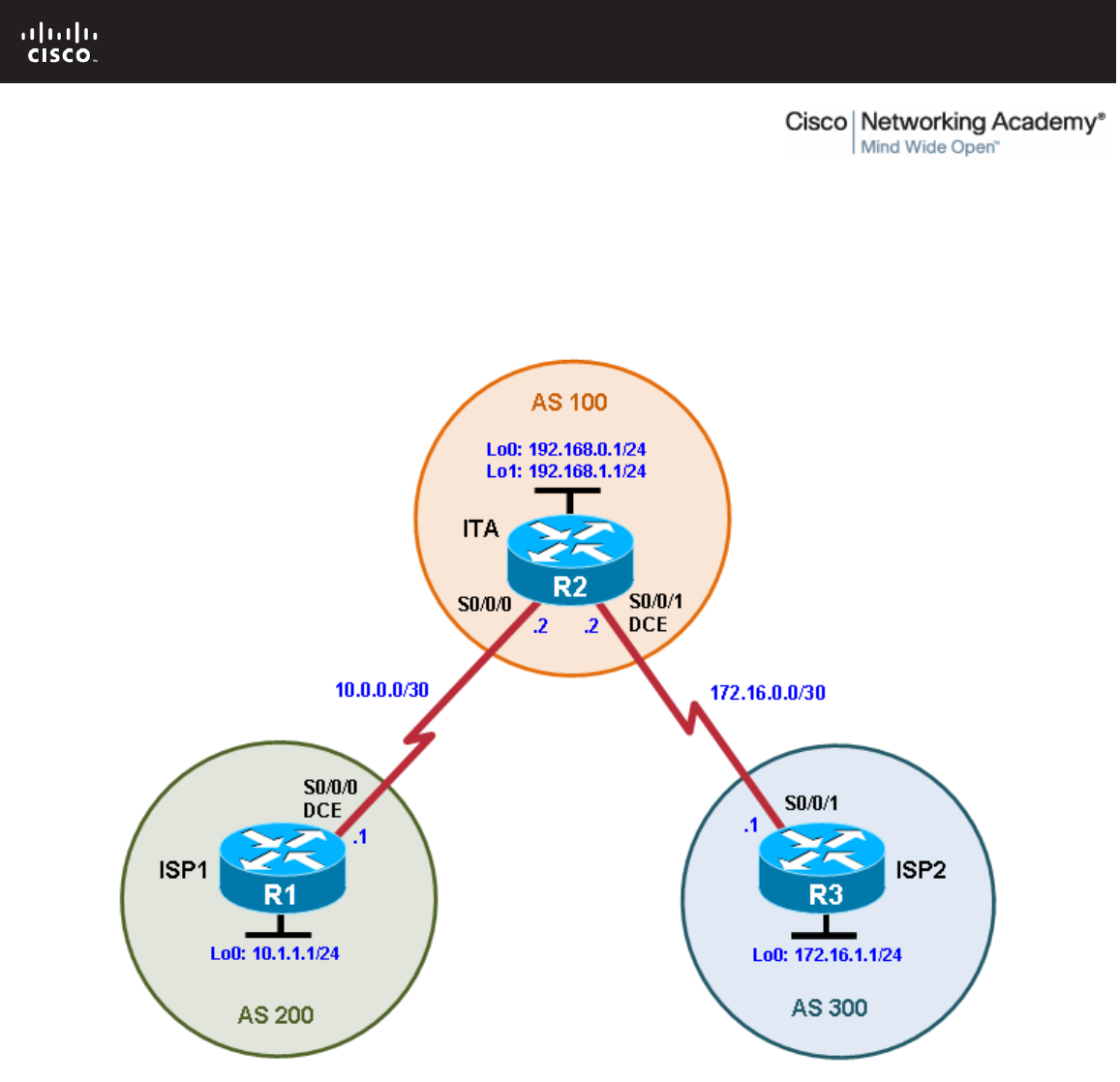
All contents are Copyright © 1992–2010 Cisco Systems, Inc. All rights reserved. This document is Cisco Public Information. Page 1 of 15
CCNPv6 ROUTE
Chapter 6 Lab 6-1, Configuring BGP with Default Routing Instructor
Version
Topology
Objectives
• Configure BGP to exchange routing information with two ISPs.
Background
The International Travel Agency (ITA) relies extensively on the Internet for sales. For this reason, the ITA has
decided to create a multihomed ISP connectivity solution and contracted with two ISPs for Internet
connectivity with fault tolerance. Because the ITA is connecting to two different service providers, you must
configure BGP, which runs between the ITA boundary router and the two ISP routers.

CCNPv6 ROUTE
All contents are Copyright © 1992–2010 Cisco Systems, Inc. All rights reserved. This document is Cisco Public Information. Page 2 of 15
Note: This lab uses Cisco 1841 routers with Cisco IOS Release 12.4(24)T1 and the Advanced IP Services
image c1841-advipservicesk9-mz.124-24.T1.bin. You can use other routers (such as a 2801 or 2811) and
Cisco IOS Software versions if they have comparable capabilities and features. Depending on the router or
switch model and Cisco IOS Software version, the commands available and output produced might vary from
what is shown in this lab.
Required Resources
• 3 routers (Cisco 1841 with Cisco IOS Release 12.4(24)T1 Advanced IP Services or comparable)
• Serial and console cables
Step 1: Prepare the routers for the lab.
Cable the network as shown in the topology diagram. Erase the startup configuration and reload each router
to clear previous configurations.
Step 2: Configure the hostname and interface addresses.
a. Assign the routers hostnames. Using the addressing scheme in the diagram, create the loopback
interfaces and apply IP addresses to these and the serial interfaces on ISP1 (R1), ISP2 (R3), and ITA
(R2). The ISP loopbacks simulate real networks that can be reached through the ISP. The two loopbacks
for the ITA router simulate the connections between the ITA boundary router and their core routers. Set a
clock rate on the DCE serial interfaces.
You can copy and paste the following configurations into your routers to begin.
Router R1 (hostname ISP1)
hostname ISP1
!
interface Lo0
description ISP1 Internet Network
ip address 10.1.1.1 255.255.255.0
!
interface Serial0/0/0
description ISP1 -> ITA
ip address 10.0.0.1 255.255.255.252
clock rate 128000
no shutdown
!
end
Router R2 (hostname ITA)
hostname ITA
!
interface Lo0
description Core router network link 1
ip address 192.168.0.1 255.255.255.0
!
interface Lo1
description Core router network link 2
ip address 192.168.1.1 255.255.255.0
!
interface Serial0/0/0
description ITA -> ISP1
ip address 10.0.0.2 255.255.255.252
no shutdown

CCNPv6 ROUTE
All contents are Copyright © 1992–2010 Cisco Systems, Inc. All rights reserved. This document is Cisco Public Information. Page 3 of 15
interface Serial0/0/1
description ITA -> ISP2
ip address 172.16.0.2 255.255.255.252
clock rate 128000
no shutdown
!
end
Router R3 (hostname ISP2)
hostname ISP2
!
interface Lo0
description ISP2 Internet Network
ip address 172.16.1.1 255.255.255.0
!
interface Serial0/0/1
description ISP2 -> ITA
ip address 172.16.0.1 255.255.255.252
no shutdown
!
end
b. Use ping to test the connectivity between the directly connected routers. Note that router ISP1 cannot
reach router ISP2.
Step 3: Configure BGP on the ISP routers.
On the ISP1 and ISP2 routers, configure BGP to peer with the ITA boundary router and advertise the ISP
loopback networks.
ISP1(config)# router bgp 200
ISP1(config-router)# neighbor 10.0.0.2 remote-as 100
ISP1(config-router)# network 10.1.1.0 mask 255.255.255.0
ISP2(config)# router bgp 300
ISP2(config-router)# neighbor 172.16.0.2 remote-as 100
ISP2(config-router)# network 172.16.1.0 mask 255.255.255.0
Step 4: Configure BGP on the ITA boundary router.
a. Configure the ITA router to run BGP with both Internet providers.
ITA(config)# router bgp 100
ITA(config-router)# neighbor 10.0.0.1 remote-as 200
ITA(config-router)# neighbor 172.16.0.1 remote-as 300
ITA(config-router)# network 192.168.0.0
ITA(config-router)# network 192.168.1.0
You should see BGP neighbor peering messages on the console similar to the following.
*Mar 4 14:07:38.667: %BGP-5-ADJCHANGE: neighbor 10.0.0.2 Up
b. To verify the configuration, check the ITA routing table with the show ip route command.
ITA# show ip route
<output omitted>
Gateway of last resort is not set

CCNPv6 ROUTE
All contents are Copyright © 1992–2010 Cisco Systems, Inc. All rights reserved. This document is Cisco Public Information. Page 4 of 15
172.16.0.0/16 is variably subnetted, 2 subnets, 2 masks
C 172.16.0.0/30 is directly connected, Serial0/0/1
B 172.16.1.0/24 [20/0] via 172.16.0.1, 00:00:32
10.0.0.0/8 is variably subnetted, 2 subnets, 2 masks
B 10.1.1.0/24 [20/0] via 10.0.0.1, 00:00:31
C 10.0.0.0/30 is directly connected, Serial0/0/0
C 192.168.0.0/24 is directly connected, Loopback0
C 192.168.1.0/24 is directly connected, Loopback1
ITA has routes to the loopback networks at each ISP router.
c. Run the following Tcl script on all routers to verify connectivity If these pings are not successful,
troubleshoot.
Note: The WAN subnets connecting ITA (R2) to the ISPs (R1 and R3) are not advertised in BGP, so the
ISPs will not be able to ping each other’s serial interface address.
ITA# tclsh
foreach address {
10.0.0.1
10.0.0.2
10.1.1.1
172.16.0.1
172.16.0.2
172.16.1.1
192.168.0.1
192.168.1.1
} {
ping $address }
Step 5: Verify BGP on the routers.
a. To verify the BGP operation on ITA, issue the show ip bgp command.
ITA# show ip bgp
BGP table version is 5, local router ID is 192.168.1.1
Status codes: s suppressed, d damped, h history, * valid, > best, i -
internal
Origin codes: i - IGP, e - EGP, ? - incomplete
Network Next Hop Metric LocPrf Weight Path
*> 10.1.1.0/24 10.0.0.1 0 0 200 i
*> 172.16.1.0/24 172.16.0.1 0 0 300 i
*> 192.168.0.0 0.0.0.0 0 32768 i
*> 192.168.1.0 0.0.0.0 0 32768 i
What is the local router ID?
_______________________________________________________________________________
The local router ID is 192.168.1.1.
Which table version is displayed?
_______________________________________________________________________________
The table version displayed is 5.
An asterisk (*) next to a route indicates that it is valid. An angle bracket (>) indicates that the route has
been selected as the best route.

CCNPv6 ROUTE
All contents are Copyright © 1992–2010 Cisco Systems, Inc. All rights reserved. This document is Cisco Public Information. Page 5 of 15
b. To verify the operation of ISP1, issue the show ip bgp command.
ISP1# show ip bgp
BGP table version is 5, local router ID is 10.1.1.1
Status codes: s suppressed, d damped, h history, * valid, > best, i -
internal,
r RIB-failure, S Stale
Origin codes: i - IGP, e - EGP, ? - incomplete
Network Next Hop Metric LocPrf Weight Path
*> 10.1.1.0/24 0.0.0.0 0 32768 i
*> 172.16.1.0/24 10.0.0.2 0 100 300 i
*> 192.168.0.0 10.0.0.2 0 0 100 i
*> 192.168.1.0 10.0.0.2 0 0 100 i
From ISP1, what is the path to network 172.16.1.0/24?
_______________________________________________________________________________
The path is through AS 100 (ITA) and AS 300 (ISP2).
c. On the ISP1 router, issue the shutdown command on Loopback0. Then on ITA, issue the show ip bgp
command again.
ITA# show ip bgp
BGP table version is 6, local router ID is 192.168.1.1
Status codes: s suppressed, d damped, h history, * valid, > best, i -
internal,
r RIB-failure, S Stale
Origin codes: i - IGP, e - EGP, ? - incomplete
Network Next Hop Metric LocPrf Weight Path
*> 172.16.1.0/24 172.16.0.1 0 0 300 i
*> 192.168.0.0 0.0.0.0 0 32768 i
*> 192.168.1.0 0.0.0.0 0 32768 i
Which table version is displayed? Why?
_______________________________________________________________________________
_______________________________________________________________________________
The table version displayed is an increment of the last one, which is 6 in the example. The shutdown
command causes a routing table update, so the version should be one higher than the last.
What happened to the route for network 10.1.1.0/24?
_______________________________________________________________________________
It is no longer in the BGP table because interface Lo0 on ISP1 is down.
d. Bring ISP1 router Loopback0 back up by issuing the no shutdown command.
e. On ITA, issue the show ip bgp neighbors command. The following is a partial sample output of the
command showing neighbor 172.16.0.1.
BGP neighbor is 172.16.0.1, remote AS 300, external link
BGP version 4, remote router ID 172.16.1.1
BGP state = Established, up for 00:16:00
Last read 00:00:54, last write 00:00:43, hold time is 180, keepalive
interval
is 60 seconds
Neighbor capabilities:

CCNPv6 ROUTE
All contents are Copyright © 1992–2010 Cisco Systems, Inc. All rights reserved. This document is Cisco Public Information. Page 6 of 15
Route refresh: advertised and received(new)
New ASN Capability: advertised and received
Address family IPv4 Unicast: advertised and received
Message statistics:
InQ depth is 0
OutQ depth is 0
Sent Rcvd
Opens: 1 1
Notifications: 0 0
Updates: 5 1
Keepalives: 15 17
Route Refresh: 0 0
Total: 21 19
Default minimum time between advertisement runs is 30 seconds
<output omitted>
Based on the output of this command, what is the BGP state between this router and ISP2?
_______________________________________________________________________________
_______________________________________________________________________________
The BGP state is established.
How long has this connection been up?
_______________________________________________________________________________
The connection has been up for 00:16:00.
Step 6: Configure route filters.
a. Check the ISP2 routing table using the show ip route command. ISP2 should have a route that belongs
to ISP1, network 10.1.1.0.
ISP2# show ip route
<output omitted>
172.16.0.0/16 is variably subnetted, 2 subnets, 2 masks
C 172.16.0.0/30 is directly connected, Serial0/0/1
C 172.16.1.0/24 is directly connected, Loopback0
10.0.0.0/24 is subnetted, 1 subnets
B 10.1.1.0 [20/0] via 172.16.0.2, 00:05:22
B 192.168.0.0/24 [20/0] via 172.16.0.2, 00:17:45
B 192.168.1.0/24 [20/0] via 172.16.0.2, 00:17:45
If ITA advertises a route belonging to ISP1, ISP2 installs that route in its table. ISP2 might then attempt to
route transit traffic through the ITA. Configure the ITA router so that it advertises only ITA networks
192.168.0.0 and 192.168.1.0 to both providers.
b. On the ITA router, configure the following access list.
ITA(config)# access-list 1 permit 192.168.0.0 0.0.1.255
c. Apply this access list as a route filter using the distribute-list keyword with the BGP neighbor statement.
ITA(config)# router bgp 100
ITA(config-router)# neighbor 10.0.0.1 distribute-list 1 out
ITA(config-router)# neighbor 172.16.0.1 distribute-list 1 out

CCNPv6 ROUTE
All contents are Copyright © 1992–2010 Cisco Systems, Inc. All rights reserved. This document is Cisco Public Information. Page 7 of 15
d. Check the routing table for ISP2 again. The route to 10.1.1.0, ISP1, should still be in the table.
e. Return to ITA and issue the clear ip bgp * command. Wait until the routers reach the established state,
which might take several seconds, and then recheck the ISP2 routing table. The route to ISP1, network
10.1.1.0, should no longer be in the routing table for ISP2, and the route to ISP2, network 172.16.1.0,
should not be in the routing table for ISP1.
ITA# clear ip bgp *
ITA#
*Mar 4 14:45:28.091: %BGP-5-ADJCHANGE: neighbor 10.0.0.1 Down User reset
*Mar 4 14:45:28.091: %BGP-5-ADJCHANGE: neighbor 172.16.0.1 Down User reset
*Mar 4 14:45:31.151: %BGP-5-ADJCHANGE: neighbor 172.16.0.1 Up
*Mar 4 14:45:47.095: %BGP-5-ADJCHANGE: neighbor 10.0.0.1 Up
Note: The clear ip bgp * command is disruptive because it completely resets all BGP adjacencies. This
is acceptable in a lab environment but could be problematic in a production network. Instead, if only a
change of inbound/outbound routing policies is to be performed, it is sufficient to issue the clear ip bgp *
in or clear ip bgp * out commands. These commands perform only a new BGP database
synchronization without the disruptive effects of a complete BGP adjacency reset. All current Cisco IOS
versions support the route refresh capability that replaces the inbound soft reconfiguration feature that
previously had to be configured on a per-neighbor basis.
ISP2# show ip route
<output omitted>
172.16.0.0/16 is variably subnetted, 2 subnets, 2 masks
C 172.16.0.0/30 is directly connected, Serial0/0/1
C 172.16.1.0/24 is directly connected, Loopback0
B 192.168.0.0/24 [20/0] via 172.16.0.2, 00:02:13
B 192.168.1.0/24 [20/0] via 172.16.0.2, 00:02:13
ISP1# show ip route
<output omitted>
10.0.0.0/8 is variably subnetted, 2 subnets, 2 masks
C 10.1.1.0/24 is directly connected, Loopback0
C 10.0.0.0/30 is directly connected, Serial0/0/0
B 192.168.0.0/24 [20/0] via 10.0.0.2, 00:05:06
B 192.168.1.0/24 [20/0] via 10.0.0.2, 00:05:06
Step 7: Configure primary and backup routes using floating static routes.
With bidirectional communication established with each ISP via BGP, configure the primary and backup
routes. This can be done with floating static routes or BGP.
a. Issue the show ip route command on the ITA router.
ITA# show ip route
<output omitted>
Gateway of last resort is not set
172.16.0.0/16 is variably subnetted, 2 subnets, 2 masks
C 172.16.0.0/30 is directly connected, Serial0/0/1
B 172.16.1.0/24 [20/0] via 172.16.0.1, 00:06:58
10.0.0.0/8 is variably subnetted, 2 subnets, 2 masks
B 10.1.1.0/24 [20/0] via 10.0.0.1, 00:06:58
C 10.0.0.0/30 is directly connected, Serial0/0/0
C 192.168.0.0/24 is directly connected, Loopback0

CCNPv6 ROUTE
All contents are Copyright © 1992–2010 Cisco Systems, Inc. All rights reserved. This document is Cisco Public Information. Page 8 of 15
C 192.168.1.0/24 is directly connected, Loopback1
Notice that there is no gateway of last resort defined. This is a problem because ITA is the border router
for the corporate network.
b. Configure static routes to reflect the policy that ISP1 is the primary provider and that ISP2 acts as the
backup by specifying a lower distance metric for the route to ISP1 (210) as compared to the backup route
to ISP2 (distance metric 220).
ITA(config)# ip route 0.0.0.0 0.0.0.0 10.0.0.1 210
ITA(config)# ip route 0.0.0.0 0.0.0.0 172.16.0.1 220
c. Verify that a default route is defined using the show ip route command.
ITA# show ip route
<output omitted>
Gateway of last resort is 10.0.0.1 to network 0.0.0.0
172.16.0.0/16 is variably subnetted, 2 subnets, 2 masks
C 172.16.0.0/30 is directly connected, Serial0/0/1
B 172.16.1.0/24 [20/0] via 172.16.0.1, 00:11:41
10.0.0.0/8 is variably subnetted, 2 subnets, 2 masks
B 10.1.1.0/24 [20/0] via 10.0.0.1, 00:11:41
C 10.0.0.0/30 is directly connected, Serial0/0/0
C 192.168.0.0/24 is directly connected, Loopback0
C 192.168.1.0/24 is directly connected, Loopback1
S* 0.0.0.0/0 [210/0] via 10.0.0.1
d. Test this default route by creating an unadvertised loopback on the router for ISP1.
ISP1# config t
ISP1(config)# interface loopback 100
ISP1(config-if)# ip address 192.168.100.1 255.255.255.0
e. Issue the show ip route command to ensure that the newly added 192.168.100.0 /24 network does not
appear in the routing table.
ITA# show ip route
<output omitted>
Gateway of last resort is 10.0.0.1 to network 0.0.0.0
172.16.0.0/16 is variably subnetted, 2 subnets, 2 masks
C 172.16.0.0/30 is directly connected, Serial0/0/1
B 172.16.1.0/24 [20/0] via 172.16.0.1, 00:16:24
10.0.0.0/8 is variably subnetted, 2 subnets, 2 masks
B 10.1.1.0/24 [20/0] via 10.0.0.1, 00:01:47
C 10.0.0.0/30 is directly connected, Serial0/0/0
C 192.168.0.0/24 is directly connected, Loopback0
C 192.168.1.0/24 is directly connected, Loopback1
S* 0.0.0.0/0 [210/0] via 10.0.0.1
f. In extended ping mode, ping the ISP1 loopback 1 interface 192.168.100.1 with the source originating
from the ITA loopback 1 interface 192.168.1.1.
ITA# ping
Protocol [ip]:
Target IP address: 192.168.100.1
Repeat count [5]:
Datagram size [100]:

CCNPv6 ROUTE
All contents are Copyright © 1992–2010 Cisco Systems, Inc. All rights reserved. This document is Cisco Public Information. Page 9 of 15
Timeout in seconds [2]:
Extended commands [n]: y
Source address or interface: 192.168.1.1
Type of service [0]:
Set DF bit in IP header? [no]:
Validate reply data? [no]:
Data pattern [0xABCD]:
Loose, Strict, Record, Timestamp, Verbose[none]:
Sweep range of sizes [n]:
Type escape sequence to abort.
Sending 5, 100-byte ICMP Echos to 192.168.100.1, timeout is 2 seconds:
!!!!!
Success rate is 100 percent (5/5), round-trip min/avg/max = 32/32/36 ms
Note: You can bypass extended ping prompted mode and ping while specifying a source address using
one of these abbreviated commands:
ITA# ping 192.168.100.1 source 192.168.1.1
or
ITA# ping 192.168.100.1 source Lo1
Note: Testing the default route by creating an unadvertised network on ISP1 and pinging it works only
because the default route also points toward ISP1. If the preferred default route pointed toward ISP2, the
ping to that unadvertised network on ISP1 would not succeed. If the link to ISP1 failed, the default route
to ISP2 would become active, but the pings would be successful only if ISP1 and ISP2 have another
working interconnection and appropriate BGP peering between them, which is currently not the case.
Step 8: Configure primary and backup routes using a default network and a static route.
Another method for configuring primary and backup routes is to use the ip default-network command instead
of a 0.0.0.0/0 route.
a. Remove the floating static routes configured in Step 7.
ITA(config)# no ip route 0.0.0.0 0.0.0.0 10.0.0.1 210
ITA(config)# no ip route 0.0.0.0 0.0.0.0 172.16.0.1 220
b. The network that was added in Step 7, 192.168.100.0/24, should now be advertised on the ISP1 router.
You might need to wait a few moments for BGP to advertise the new network.
ISP1(config)# router bgp 200
ISP1(config-router)# network 192.168.100.0
ISP1(config-router)# end
c. Make sure that the classful network 192.168.100.0 /24 appears in the ITA routing table.
ITA# show ip route
<output omitted>
Gateway of last resort is not set
172.16.0.0/16 is variably subnetted, 2 subnets, 2 masks
C 172.16.0.0/30 is directly connected, Serial0/0/1
B 172.16.1.0/24 [20/0] via 172.16.0.1, 00:30:10
10.0.0.0/8 is variably subnetted, 2 subnets, 2 masks
B 10.1.1.0/24 [20/0] via 10.0.0.1, 00:02:33
C 10.0.0.0/30 is directly connected, Serial0/0/0
C 192.168.0.0/24 is directly connected, Loopback0

CCNPv6 ROUTE
All contents are Copyright © 1992–2010 Cisco Systems, Inc. All rights reserved. This document is Cisco Public Information. Page 10 of 15
C 192.168.1.0/24 is directly connected, Loopback1
B 192.168.100.0/24 [20/0] via 10.0.0.1, 00:02:33
d. On the ITA router, configure the ip default-network statement to reestablish a gateway of last resort.
ITA(config)# ip default-network 192.168.100.0
Note: The behavior of this command is oriented toward legacy classful protocols and should be used only
with classful networks.
e. Wait a few moments and then reexamine the routing table on ITA.
ITA# show ip route
<output omitted>
Gateway of last resort is 10.0.0.1 to network 192.168.100.0
172.16.0.0/16 is variably subnetted, 2 subnets, 2 masks
C 172.16.0.0/30 is directly connected, Serial0/0/1
B 172.16.1.0/24 [20/0] via 172.16.0.1, 00:32:55
10.0.0.0/8 is variably subnetted, 2 subnets, 2 masks
B 10.1.1.0/24 [20/0] via 10.0.0.1, 00:05:19
C 10.0.0.0/30 is directly connected, Serial0/0/0
C 192.168.0.0/24 is directly connected, Loopback0
C 192.168.1.0/24 is directly connected, Loopback1
B* 192.168.100.0/24 [20/0] via 10.0.0.1, 00:05:19
This establishes ISP1 as the only default route.
f. Make ISP2 the backup ISP by adding a backup route on ITA to ISP2 serial 0/0/1 interface 172.16.0.1.
ITA(config)# ip route 0.0.0.0 0.0.0.0 172.16.0.1 220
EBGP learned routes have an administrative distance of 20 and are preferred over any routes with an
administrative distance greater than 20, such as the default route defined above with an administrative
distance of 220. The default route acts as a backup if the 192.168.100.0 /24 network is unavailable
because of a fault or misconfiguration, or during the short period after a clear ip bgp 10.0.0.1 command
is issued.
g. Verify that this newly added route establishes a consistent default route while the BGP conversation
between ITA and ISP1 reestablishes. Notice that the routing table includes two candidate default routes
(*), only one of which is used because of different administrative distances.
ITA# show ip route
<output omitted>
Gateway of last resort is 10.0.0.1 to network 192.168.100.0
172.16.0.0/16 is variably subnetted, 2 subnets, 2 masks
C 172.16.0.0/30 is directly connected, Serial0/0/1
B 172.16.1.0/24 [20/0] via 172.16.0.1, 00:35:42
10.0.0.0/8 is variably subnetted, 2 subnets, 2 masks
B 10.1.1.0/24 [20/0] via 10.0.0.1, 00:08:05
C 10.0.0.0/30 is directly connected, Serial0/0/0
C 192.168.0.0/24 is directly connected, Loopback0
C 192.168.1.0/24 is directly connected, Loopback1
B* 192.168.100.0/24 [20/0] via 10.0.0.1, 00:08:05
S* 0.0.0.0/0 [220/0] via 172.16.0.1
ITA# clear ip bgp 10.0.0.1
ITA# show ip route

CCNPv6 ROUTE
All contents are Copyright © 1992–2010 Cisco Systems, Inc. All rights reserved. This document is Cisco Public Information. Page 11 of 15
<output omitted>
Gateway of last resort is 172.16.0.1 to network 0.0.0.0
172.16.0.0/16 is variably subnetted, 2 subnets, 2 masks
C 172.16.0.0/30 is directly connected, Serial0/0/1
B 172.16.1.0/24 [20/0] via 172.16.0.1, 00:36:46
10.0.0.0/8 is variably subnetted, 2 subnets, 2 masks
B 10.1.1.0/24 [20/0] via 10.0.0.1, 00:00:00
C 10.0.0.0/30 is directly connected, Serial0/0/0
C 192.168.0.0/24 is directly connected, Loopback0
C 192.168.1.0/24 is directly connected, Loopback1
B 192.168.100.0/24 [20/0] via 10.0.0.1, 00:00:00
S* 0.0.0.0/0 [220/0] via 172.16.0.1
ITA# show ip route
<output omitted>
Gateway of last resort is 10.0.0.1 to network 192.168.100.0
172.16.0.0/16 is variably subnetted, 2 subnets, 2 masks
C 172.16.0.0/30 is directly connected, Serial0/0/1
B 172.16.1.0/24 [20/0] via 172.16.0.1, 00:38:05
10.0.0.0/8 is variably subnetted, 2 subnets, 2 masks
B 10.1.1.0/24 [20/0] via 10.0.0.1, 00:01:19
C 10.0.0.0/30 is directly connected, Serial0/0/0
C 192.168.0.0/24 is directly connected, Loopback0
C 192.168.1.0/24 is directly connected, Loopback1
B* 192.168.100.0/24 [20/0] via 10.0.0.1, 00:01:19
S* 0.0.0.0/0 [220/0] via 172.16.0.1
As expected, while the BGP conversation was down between ITA and ISP1, the route to ISP2 was added
as the gateway of last resort. However, when BGP reestablished the conversation between ITA and ISP1,
the default route of 192.168.100.0 was again set as the gateway of last resort on ITA.
h. Run the following Tcl script on router ITA to verify connectivity.
ITA# tclsh
foreach address {
10.0.0.1
10.0.0.2
10.1.1.1
172.16.0.1
172.16.0.2
172.16.1.1
192.168.0.1
192.168.1.1
192.168.100.1
} {
ping $address }
Should ISP1 and ISP2 be able to ping all networks in the topology?
_______________________________________________________________________________
_______________________________________________________________________________
_______________________________________________________________________________

CCNPv6 ROUTE
All contents are Copyright © 1992–2010 Cisco Systems, Inc. All rights reserved. This document is Cisco Public Information. Page 12 of 15
_______________________________________________________________________________
_______________________________________________________________________________
No. Router ITA has been configured with route filters and does not advertise the ISP1 networks to ISP2
and vice versa. The ITA router advertises only ITA networks 192.168.0.0 and 192.168.1.0 to both
providers. Pings from ISP1 to any of the ISP2 172.16.x.x networks will fail. Pings from ISP2 to any of the
ISP1 10.x.x.x networks will fail.
Note: Another option for setting up default routing is to inject a default route via BGP. The following
example configures the ISP1 router to inject a default route to itself that can be used by the ITA router:
ISP1(config)# router bgp 200
ISP1(config-router)# neighbor 10.0.0.2 default-originate
CCNPv6 ROUTE
All contents are Copyright © 1992–2010 Cisco Systems, Inc. All rights reserved. This document is Cisco Public Information. Page 13 of 15
Router Interface Summary Table
Router Interface Summary
Router Model Ethernet Interface
#1 Ethernet Interface
#2 Serial Interface
#1 Serial Interface
#2
1700 Fast Ethernet 0
(FA0) Fast Ethernet 1
(FA1) Serial 0 (S0) Serial 1 (S1)
1800 Fast Ethernet 0/0
(FA0/0) Fast Ethernet 0/1
(FA0/1) Serial 0/0/0
(S0/0/0) Serial 0/0/1
(S0/0/1)
2600 Fast Ethernet 0/0
(FA0/0) Fast Ethernet 0/1
(FA0/1) Serial 0/0 (S0/0) Serial 0/1 (S0/1)
2800 Fast Ethernet 0/0
(FA0/0) Fast Ethernet 0/1
(FA0/1) Serial 0/0/0
(S0/0/0) Serial 0/0/1
(S0/0/1)
Note: To find out how the router is configured, look at the interfaces to identify the type of router
and how many interfaces the router has. Rather than list all combinations of configurations for each
router class, this table includes identifiers for the possible combinations of Ethernet and serial
interfaces in the device. The table does not include any other type of interface, even though a
specific router might contain one. For example, for an ISDN BRI interface, the string in parenthesis
is the legal abbreviation that can be used in Cisco IOS commands to represent the interface.

CCNPv6 ROUTE
All contents are Copyright © 1992–2010 Cisco Systems, Inc. All rights reserved. This document is Cisco Public Information. Page 14 of 15
Device Configurations (Instructor version)
Router ISP1 (R1)
hostname ISP1
!
interface Loopback0
description ISP1 Internet network
ip address 10.1.1.1 255.255.255.0
!
interface Loopback100
ip address 192.168.100.1 255.255.255.0
!
interface Serial0/0/0
description ISP1 -> ITA
ip address 10.0.0.1 255.255.255.252
clock rate 128000
no shutdown
!
router bgp 200
no synchronization
network 10.1.1.0 mask 255.255.255.0
network 192.168.100.0
neighbor 10.0.0.2 remote-as 100
no auto-summary
!
end
Router ITA (R2)
hostname ITA
!
interface Loopback0
description Core router network link 1
ip address 192.168.0.1 255.255.255.0
!
interface Loopback1
description Core router network link 2
ip address 192.168.1.1 255.255.255.0
!
interface Serial0/0/0
description ITA -> ISP1
ip address 10.0.0.2 255.255.255.252
no shutdown
!
interface Serial0/0/1
description ITA -> ISP2
ip address 172.16.0.2 255.255.255.252
clock rate 128000
no shutdown
!
router bgp 100
no synchronization
network 192.168.0.0
network 192.168.1.0
neighbor 10.0.0.1 remote-as 200
neighbor 10.0.0.1 distribute-list 1 out

CCNPv6 ROUTE
All contents are Copyright © 1992–2010 Cisco Systems, Inc. All rights reserved. This document is Cisco Public Information. Page 15 of 15
neighbor 172.16.0.1 remote-as 300
neighbor 172.16.0.1 distribute-list 1 out
no auto-summary
!
ip default-network 192.168.100.0
ip route 0.0.0.0 0.0.0.0 172.16.0.1 220
!
access-list 1 permit 192.168.0.0 0.0.1.255
!
end
Router ISP2 (R3)
hostname ISP2
!
interface Loopback0
description ISP2 Internet Network
ip address 172.16.1.1 255.255.255.0
!
interface Serial0/0/1
description ISP2 -> ITA
ip address 172.16.0.1 255.255.255.252
no shutdown
!
router bgp 300
no synchronization
network 172.16.1.0 mask 255.255.255.0
neighbor 172.16.0.2 remote-as 100
no auto-summary
!
end

All contents are Copyright © 1992–2010 Cisco Systems, Inc. All rights reserved. This document is Cisco Public Information. Page 1 of 10
CCNPv6 ROUTE
Chapter 6 Lab 6-2, Using the AS_PATH Attribute Instructor Version
Topology
Objectives
• Use BGP commands to prevent private AS numbers from being advertised to the outside world.
• Use the AS_PATH attribute to filter BGP routes based on their source AS numbers.
Background
The International Travel Agency’s ISP has been assigned an AS number of 300. This provider uses BGP to
exchange routing information with several customer networks. Each customer network is assigned an AS
number from the private range, such as AS 65000. Configure the ISP router to remove the private AS
numbers from the AS Path information of CustRtr. In addition, the ISP would like to prevent its customer
networks from receiving route information from International Travel Agency’s AS 100. Use the AS_PATH
attribute to implement this policy.

CCNPv6 ROUTE
All contents are Copyright © 1992–2010 Cisco Systems, Inc. All rights reserved. This document is Cisco Public Information. Page 2 of 10
Note: This lab uses Cisco 1841 routers with Cisco IOS Release 12.4(24)T1 and the Advanced IP Services
image c1841-advipservicesk9-mz.124-24.T1.bin. You can use other routers (such as 2801 or 2811) and
Cisco IOS Software versions, if they have comparable capabilities and features. Depending on the router
model and Cisco IOS Software version, the commands available and output produced might vary from what is
shown in this lab.
Required Resources
• 3 routers (Cisco 1841 with Cisco IOS Release 12.4(24)T1 Advanced IP Services or comparable)
• Serial and console cables
Step 1: Prepare the routers for the lab.
Cable the network as shown in the topology diagram. Erase the startup configuration and reload each router
to clear previous configurations.
Step 2: Configure the hostname and interface addresses.
a. You can copy and paste the following configurations into your routers to begin.
Router R1 (hostname SanJose)
hostname SanJose
!
interface Loopback0
ip address 10.1.1.1 255.255.255.0
!
interface Serial0/0/0
ip address 192.168.1.5 255.255.255.252
clock rate 128000
no shutdown
Router R2 (hostname ISP)
hostname ISP
!
interface Loopback0
ip address 10.2.2.1 255.255.255.0
!
interface Serial0/0/0
ip address 192.168.1.6 255.255.255.252
no shutdown
!
interface Serial0/0/1
ip address 172.24.1.17 255.255.255.252
clock rate 128000
no shutdown
Router R3 (hostname CustRtr)
hostname CustRtr
!
interface Loopback0
ip address 10.3.3.1 255.255.255.0
!
interface Serial0/0/1
ip address 172.24.1.18 255.255.255.252
no shutdown

CCNPv6 ROUTE
All contents are Copyright © 1992–2010 Cisco Systems, Inc. All rights reserved. This document is Cisco Public Information. Page 3 of 10
b. Use ping to test the connectivity between the directly connected routers.
Note: SanJose will not be able to reach either ISP's loopback (10.2.2.1) or CustRtr's loopback (10.3.3.1),
nor will it be able to reach either end of the link joining ISP to CustRtr (172.24.1.17 and 172.24.1.18).
Step 3: Configure BGP.
a. Configure BGP for normal operation. Enter the appropriate BGP commands on each router so that they
identify their BGP neighbors and advertise their loopback networks.
SanJose(config)# router bgp 100
SanJose(config-router)# neighbor 192.168.1.6 remote-as 300
SanJose(config-router)# network 10.1.1.0 mask 255.255.255.0
ISP(config)# router bgp 300
ISP(config-router)# neighbor 192.168.1.5 remote-as 100
ISP(config-router)# neighbor 172.24.1.18 remote-as 65000
ISP(config-router)# network 10.2.2.0 mask 255.255.255.0
CustRtr(config)# router bgp 65000
CustRtr(config-router)# neighbor 172.24.1.17 remote-as 300
CustRtr(config-router)# network 10.3.3.0 mask 255.255.255.0
b. Verify that these routers have established the appropriate neighbor relationships by issuing the show ip
bgp neighbors command on each router.
ISP# show ip bgp neighbors
BGP neighbor is 172.24.1.18, remote AS 65000, external link
BGP version 4, remote router ID 10.3.3.1
BGP state = Established, up for 00:02:05
<output omitted>
BGP neighbor is 192.168.1.5, remote AS 100, external link
BGP version 4, remote router ID 10.1.1.1
BGP state = Established, up for 00:04:19
<output omitted>
Step 4: Remove the private AS.
a. Display the SanJose routing table using the show ip route command. SanJose should have a route to
both 10.2.2.0 and 10.3.3.0. Troubleshoot if necessary.
SanJose# show ip route
Codes: C - connected, S - static, R - RIP, M - mobile, B - BGP
D - EIGRP, EX - EIGRP external, O - OSPF, IA - OSPF inter area
N1 - OSPF NSSA external type 1, N2 - OSPF NSSA external type 2
E1 - OSPF external type 1, E2 - OSPF external type 2
i - IS-IS, su - IS-IS summary, L1 - IS-IS level-1, L2 - IS-IS level-2
ia - IS-IS inter area, * - candidate default, U - per-user static
route
o - ODR, P - periodic downloaded static route
Gateway of last resort is not set
10.0.0.0/24 is subnetted, 3 subnets
B 10.3.3.0 [20/0] via 192.168.1.6, 00:01:11
B 10.2.2.0 [20/0] via 192.168.1.6, 00:02:16
C 10.1.1.0 is directly connected, Loopback0
192.168.1.0/30 is subnetted, 1 subnets

CCNPv6 ROUTE
All contents are Copyright © 1992–2010 Cisco Systems, Inc. All rights reserved. This document is Cisco Public Information. Page 4 of 10
C 192.168.1.4 is directly connected, Serial0/0/0
b. Ping the 10.3.3.1 address from SanJose.
Why does this fail?
_______________________________________________________________________________
_______________________________________________________________________________
This fails because SanJose sources the ping with its closest connected interface s0/0/0 with IP address
192.168.1.5. CustRtr does not have a route back to that interface, so the ping replies cannot return to
SanJose.
c. Ping again, this time as an extended ping, sourcing from the Loopback0 interface address.
SanJose# ping
Protocol [ip]:
Target IP address: 10.3.3.1
Repeat count [5]:
Datagram size [100]:
Timeout in seconds [2]:
Extended commands [n]: y
Source address or interface: 10.1.1.1
Type of service [0]:
Set DF bit in IP header? [no]:
Validate reply data? [no]:
Data pattern [0xABCD]:
Loose, Strict, Record, Timestamp, Verbose[none]:
Sweep range of sizes [n]:
Type escape sequence to abort.
Sending 5, 100-byte ICMP Echos to 10.3.3.1, timeout is 2 seconds:
!!!!!
Success rate is 100 percent (5/5), round-trip min/avg/max = 64/64/68 ms
Note: You can bypass extended ping mode and specify a source address using one of these commands:
SanJose# ping 10.3.3.1 source 10.1.1.1
or
SanJose# ping 10.3.3.1 source Lo0
d. Check the BGP table from SanJose by using the show ip bgp command. Note the AS path for the
10.3.3.0 network. The AS 65000 should be listed in the path to 10.3.3.0.
SanJose# show ip bgp
BGP table version is 5, local router ID is 10.1.1.1
Status codes: s suppressed, d damped, h history, * valid, > best, i –
internal Origin codes: i - IGP, e - EGP, ? - incomplete
Network Next Hop Metric LocPrf Weight Path
*> 10.1.1.0 0.0.0.0 0 32768 i
*> 10.2.2.0 192.168.1.6 0 0 300 i
*> 10.3.3.0 192.168.1.6 0 300 65000 i
Why is this a problem?
_______________________________________________________________________________
_______________________________________________________________________________

CCNPv6 ROUTE
All contents are Copyright © 1992–2010 Cisco Systems, Inc. All rights reserved. This document is Cisco Public Information. Page 5 of 10
AS 65000 is a private AS, which should not be publicly advertised on the Internet. Otherwise, clients of
two interconnected ISPs having the same private AS number would see their own AS in the route
advertisements of each other. As a result, each client would incorrectly conclude that the advertisement
came from itself and it would ignore it.
e. Configure ISP to strip the private AS numbers from BGP routes exchanged with SanJose using the
following commands.
ISP(config)# router bgp 300
ISP(config-router)# neighbor 192.168.1.5 remove-private-as
f. After issuing these commands, use the clear ip bgp * command on ISP to reestablish the BGP
relationship between the three routers. Wait several seconds and then return to SanJose to check its
routing table.
Note: The clear ip bgp * soft command can also be used to force each router to resend its BGP table.
Does SanJose still have a route to 10.3.3.0?
_______________________________________________________________________________
Yes, learned via BGP from ISP 192.168.1.6.
SanJose should be able to ping 10.3.3.1 using its loopback 0 interface as the source of the ping.
SanJose# ping 10.3.3.1 source lo0
Type escape sequence to abort.
Sending 5, 100-byte ICMP Echos to 10.3.3.1, timeout is 2 seconds:
Packet sent with a source address of 10.1.1.1
!!!!!
Success rate is 100 percent (5/5), round-trip min/avg/max = 28/28/32 ms
g. Now check the BGP table on SanJose. The AS_ PATH to the 10.3.3.0 network should be AS 300. It no
longer has the private AS in the path.
SanJose# show ip bgp
BGP table version is 8, local router ID is 10.1.1.1
Status codes: s suppressed, d damped, h history, * valid, > best, i –
internal Origin codes: i - IGP, e - EGP, ? - incomplete
Network Next Hop Metric LocPrf Weight Path
*> 10.1.1.0 0.0.0.0 0 32768 i
*> 10.2.2.0 192.168.1.6 0 0 300 i
*> 10.3.3.0 192.168.1.6 0 300 i
Step 5: Use the AS_PATH attribute to filter routes.
As a final configuration, use the AS_PATH attribute to filter routes based on their origin. In a complex
environment, you can use this attribute to enforce routing policy. In this case, the provider router, ISP, must
be configured so that it does not propagate routes that originate from AS 100 to the customer router CustRtr.
AS-path access lists are read like regular access lists. The statements are read sequentially, and there is an
implicit deny at the end. Rather than matching an address in each statement like a conventional access list,
AS path access lists match on something called a regular expression. Regular expressions are a way of
matching text patterns and have many uses. In this case, you will be using them in the AS path access list to
match text patterns in AS paths.

CCNPv6 ROUTE
All contents are Copyright © 1992–2010 Cisco Systems, Inc. All rights reserved. This document is Cisco Public Information. Page 6 of 10
a. Configure a special kind of access list to match BGP routes with an AS_PATH attribute that both begins
and ends with the number 100. Enter the following commands on ISP.
ISP(config)# ip as-path access-list 1 deny ^100$
ISP(config)# ip as-path access-list 1 permit .*
The first command uses the ^ character to indicate that the AS path must begin with the given number
100. The $ character indicates that the AS_PATH attribute must also end with 100. Essentially, this
statement matches only paths that are sourced from AS 100. Other paths, which might include AS 100
along the way, will not match this list.
In the second statement, the . (period) is a wildcard, and the * (asterisk) stands for a repetition of the
wildcard. Together, .* matches any value of the AS_PATH attribute, which in effect permits any update
that has not been denied by the previous access-list statement.
For more details on configuring regular expressions on Cisco routers, see:
http://www.cisco.com/en/US/docs/ios/12_2/termserv/configuration/guide/tcfaapre_ps1835_TSD_Products
_Configuration_Guide_Chapter.html
b. Apply the configured access list using the neighbor command with the filter-list option.
ISP(config)# router bgp 300
ISP(config-router)# neighbor 172.24.1.18 filter-list 1 out
The out keyword specifies that the list is applied to routing information sent to this neighbor.
c. Use the clear ip bgp * command to reset the routing information. Wait several seconds and then check
the routing table for ISP. The route to 10.1.1.0 should be in the routing table.
Note: To force the local router to resend its BGP table, a less disruptive option is to use the clear ip bgp
* out or clear ip bgp * soft command (the second command performs both outgoing and incoming route
resync).
ISP# show ip route
<output omitted>
172.24.0.0/30 is subnetted, 1 subnets
C 172.24.1.16 is directly connected, Serial0/0/1
10.0.0.0/24 is subnetted, 3 subnets
B 10.3.3.0 [20/0] via 172.24.1.18, 00:07:34
C 10.2.2.0 is directly connected, Loopback0
B 10.1.1.0 [20/0] via 192.168.1.5, 00:10:53
192.168.1.0/30 is subnetted, 1 subnets
C 192.168.1.4 is directly connected, Serial0/0/0
d. Check the routing table for CustRtr. It should not have a route to 10.1.1.0 in its routing table.
CustRtr# show ip route
<output omitted>
172.24.0.0/30 is subnetted, 1 subnets
C 172.24.1.16 is directly connected, Serial0/0/1
10.0.0.0/24 is subnetted, 2 subnets
C 10.3.3.0 is directly connected, Loopback0
B 10.2.2.0 [20/0] via 172.24.1.17, 00:11:57
e. Return to ISP and verify that the filter is working as intended. Issue the show ip bgp regexp ^100$
command.
ISP# show ip bgp regexp ^100$
BGP table version is 4, local router ID is 10.2.2.1

CCNPv6 ROUTE
All contents are Copyright © 1992–2010 Cisco Systems, Inc. All rights reserved. This document is Cisco Public Information. Page 7 of 10
Status codes: s suppressed, d damped, h history, * valid, > best, i –
internal Origin codes: i - IGP, e - EGP, ? - incomplete
Network Next Hop Metric LocPrf Weight Path
*> 10.1.1.0 192.168.1.5 0 0 100 i
The output of this command shows all matches for the regular expressions that were used in the access
list. The path to 10.1.1.0 matches the access list and is filtered from updates to CustRtr.
f. Run the following Tcl script on all routers to verify whether there is connectivity. All pings from ISP should
be successful. SanJose should not be able to ping the CustRtr loopback 10.3.3.1 or the WAN link
172.24.1.16/30. CustRtr should not be able to ping the SanJose loopback 10.1.1.1 or the WAN link
192.168.1.4/30.
ISP# tclsh
foreach address {
10.1.1.1
10.2.2.1
10.3.3.1
192.168.1.5
192.168.1.6
172.24.1.17
172.24.1.18
} {
ping $address }
CCNPv6 ROUTE
All contents are Copyright © 1992–2010 Cisco Systems, Inc. All rights reserved. This document is Cisco Public Information. Page 8 of 10
Router Interface Summary Table
Router Interface Summary
Router Model Ethernet Interface
#1 Ethernet Interface
#2 Serial Interface
#1 Serial Interface
#2
1700 Fast Ethernet 0
(FA0) Fast Ethernet 1
(FA1) Serial 0 (S0) Serial 1 (S1)
1800 Fast Ethernet 0/0
(FA0/0) Fast Ethernet 0/1
(FA0/1) Serial 0/0/0
(S0/0/0) Serial 0/0/1
(S0/0/1)
2600 Fast Ethernet 0/0
(FA0/0) Fast Ethernet 0/1
(FA0/1) Serial 0/0 (S0/0) Serial 0/1 (S0/1)
2800 Fast Ethernet 0/0
(FA0/0) Fast Ethernet 0/1
(FA0/1) Serial 0/0/0
(S0/0/0) Serial 0/0/1
(S0/0/1)
Note: To find out how the router is configured, look at the interfaces to identify the type of router
and how many interfaces the router has. Rather than list all combinations of configurations for each
router class, this table includes identifiers for the possible combinations of Ethernet and serial
interfaces in the device. The table does not include any other type of interface, even though a
specific router might contain one. For example, for an ISDN BRI interface, the string in parenthesis
is the legal abbreviation that can be used in Cisco IOS commands to represent the interface.

CCNPv6 ROUTE
All contents are Copyright © 1992–2010 Cisco Systems, Inc. All rights reserved. This document is Cisco Public Information. Page 9 of 10
Device Configurations (Instructor version)
Router SanJose
hostname SanJose
!
interface Loopback0
ip address 10.1.1.1 255.255.255.0
!
!
interface Serial0/0/0
ip address 192.168.1.5 255.255.255.252
clock rate 128000
no shutdown
!
router bgp 100
no synchronization
network 10.1.1.0 mask 255.255.255.0
neighbor 192.168.1.6 remote-as 300
no auto-summary
!
end
Router ISP
hostname ISP
!
interface Loopback0
ip address 10.2.2.1 255.255.255.0
!
interface Serial0/0/0
ip address 192.168.1.6 255.255.255.252
no shutdown
!
interface Serial0/0/1
ip address 172.24.1.17 255.255.255.252
clock rate 128000
no shutdown
!
router bgp 300
no synchronization
network 10.2.2.0 mask 255.255.255.0
neighbor 172.24.1.18 remote-as 65000
neighbor 172.24.1.18 filter-list 1 out
neighbor 192.168.1.5 remote-as 100
neighbor 192.168.1.5 remove-private-as
no auto-summary
!
ip as-path access-list 1 deny ^100$
ip as-path access-list 1 permit .*
!
end
Router CustRtr
hostname CustRtr

CCNPv6 ROUTE
All contents are Copyright © 1992–2010 Cisco Systems, Inc. All rights reserved. This document is Cisco Public Information. Page 10 of 10
!
interface Loopback0
ip address 10.3.3.1 255.255.255.0
!
interface Serial0/0/1
ip address 172.24.1.18 255.255.255.252
no shutdown
!
router bgp 65000
no synchronization
network 10.3.3.0 mask 255.255.255.0
neighbor 172.24.1.17 remote-as 300
no auto-summary
!
end

All contents are Copyright © 1992–2010 Cisco Systems, Inc. All rights reserved. This document is Cisco Public Information. Page 1 of 12
CCNPv6 ROUTE
Chapter 6 Lab 6-4, BGP Route Reflectors and Route Filters Instructor
Version
Topology
Objectives
• Configure IBGP routers to use a route reflector and a simple route filter.
Background
The International Travel Agency maintains a full-mesh IBGP network that has quickly scaled beyond 100
routers. The company wants to implement route reflectors to work around the full-mesh IBGP requirement.
Configure a small cluster and observe how BGP operates in this configuration. Use IP prefix filters to control
the updates between IBGP peers.
Note: This lab uses Cisco 1841 routers with Cisco IOS Release 12.4(24)T1 and the Advanced IP Services
image c1841-advipservicesk9-mz.124-24.T1.bin. You can use other routers (such as a 2801 or 2811) and
Cisco IOS Software versions if they have comparable capabilities and features. Depending on the router or
switch model and Cisco IOS Software version, the commands available and output produced might vary from
what is shown in this lab.

CCNPv6 ROUTE
All contents are Copyright © 1992–2010 Cisco Systems, Inc. All rights reserved. This document is Cisco Public Information. Page 2 of 12
Required Resources
• 3 routers (Cisco 1841 with Cisco IOS Release 12.4(24)T1 Advanced IP Services or comparable)
• Serial and console cables
Step 1: Prepare the routers for the lab.
Cable the network as shown in the topology diagram. Erase the startup configuration and reload each router
to clear previous configurations. Do not configure Loopback 0 on SanJose3 at this time.
Step 2: Configure the hostname and interface addresses.
You can copy and paste the following configurations into your routers to begin.
Router R1 (hostname SanJose1)
hostname SanJose1
!
interface Serial0/0/0
ip address 192.168.1.5 255.255.255.252
clock rate 128000
no shutdown
Router R2 (hostname SanJose2)
hostname SanJose2
!
interface Loopback0
ip address 10.2.2.1 255.255.255.0
!
interface Serial0/0/0
ip address 192.168.1.6 255.255.255.252
no shutdown
!
interface Serial0/0/1
ip address 172.24.1.17 255.255.255.0
clock rate 128000
no shutdown
Router R3 (hostname SanJose3)
hostname SanJose3
!
interface Serial0/0/1
ip address 172.24.1.18 255.255.255.0
no shutdown
Note: Do not configure R3 (SanJose3) with loopback 0 at this time. That will be done in a later step.
Step 3: Configure RIPv2.
a. Build and configure the network according to the diagram. Use RIPv2 as the IGP. Do not configure the
198.133.219.0 network under the RIP process.
SanJose1(config)# router rip
SanJose1(config-router)# version 2
SanJose1(config-router)# no auto-summary
SanJose1(config-router)# network 192.168.1.0
SanJose2(config)# router rip
SanJose2(config-router)# version 2

CCNPv6 ROUTE
All contents are Copyright © 1992–2010 Cisco Systems, Inc. All rights reserved. This document is Cisco Public Information. Page 3 of 12
SanJose2(config-router)# no auto-summary
SanJose2(config-router)# network 172.24.0.0
SanJose2(config-router)# network 192.168.1.0
SanJose2(config-router)# network 10.0.0.0
SanJose3(config)# router rip
SanJose3(config-router)# version 2
SanJose3(config-router)# no auto-summary
SanJose3(config-router)# network 172.24.0.0
b. Issue the show ip route command on the routers to verify that each router has a complete routing table.
SanJose1# show ip route
Codes: C - connected, S - static, R - RIP, M - mobile, B - BGP
D - EIGRP, EX - EIGRP external, O - OSPF, IA - OSPF inter area
N1 - OSPF NSSA external type 1, N2 - OSPF NSSA external type 2
E1 - OSPF external type 1, E2 - OSPF external type 2
i - IS-IS, su - IS-IS summary, L1 - IS-IS level-1, L2 - IS-IS level-2
ia - IS-IS inter area, * - candidate default, U - per-user static
route
o - ODR, P - periodic downloaded static route
Gateway of last resort is not set
172.24.0.0/24 is subnetted, 1 subnets
R 172.24.1.0 [120/1] via 192.168.1.6, 00:00:21, Serial0/0/0
10.0.0.0/24 is subnetted, 1 subnets
R 10.2.2.0 [120/1] via 192.168.1.6, 00:00:21, Serial0/0/0
192.168.1.0/30 is subnetted, 1 subnets
C 192.168.1.4 is directly connected, Serial0/0/0
c. Run the following Tcl script on all routers to verify connectivity.
SanJose1# tclsh
foreach address {
10.2.2.1
192.168.1.5
192.168.1.6
172.24.1.17
172.24.1.18
} {
ping $address }
Step 4: Configure IBGP peers and route reflectors.
In this lab, you will configure a route reflector. By default, a router that receives an EBGP route advertises it to
its EBGP and IBGP peers. However, if it receives it through IBGP, it does not advertise it to its IBGP peers,
as a loop prevention mechanism. To maintain loop prevention, a route reflector adds two optional,
nontransitive BGP attributes to each reflected route, the ORIGINATOR_ID and CLUSTER_LIST. It uses these
attributes in a similar way to AS_PATH list to prevent routing loops from occurring. See
http://tools.ietf.org/html/rfc4456 for more information.
However, because of this behavior, the only way for all IBGP routers to receive a route after it is originated
into the AS is to have a full mesh of IBGP peers. This can get complex with a large number of peers. A route
reflector allows a topology to get around the IBGP limitation of having to have a full mesh. To do this, a route
reflector specifies some of its neighbors as route reflector clients. When a route reflector receives an update
from a route reflector client, it can pass it on to its other clients. The route reflector would also pass that client-

CCNPv6 ROUTE
All contents are Copyright © 1992–2010 Cisco Systems, Inc. All rights reserved. This document is Cisco Public Information. Page 4 of 12
learned route on to its other non-client peers (both IBGP and EBGP peers). Similarly, a route learned from a
non-client peer (again, from either an IBGP or EBGP peer) would be passed on to its client peers. This greatly
simplifies configuration because only the route reflector needs to know all the other peers. The clients do not
even know that they are clients. To them, it is just a normal IBGP peering relationship. You can even set up
multiple route reflectors in a more advanced configuration for redundancy.
a. Configure the IBGP peers for BGP. Later, you will configure SanJose2 as the route reflector. However,
first configure it to peer with both of the other routers.
SanJose2(config)# router bgp 100
SanJose2(config-router)# neighbor 192.168.1.5 remote-as 100
SanJose2(config-router)# neighbor 172.24.1.18 remote-as 100
After SanJose2 is configured, configure the other two routers as route reflector clients. Remember that to
set up clients simply, configure peering between the client and the server. IBGP does not need to be
configured in a full mesh.
b. Issue the following commands on SanJose1:
SanJose1(config)# router bgp 100
SanJose1(config-router)# neighbor 192.168.1.6 remote-as 100
c. Issue the following commands on SanJose3:
SanJose3(config)# router bgp 100
SanJose3(config-router)# neighbor 172.24.1.17 remote-as 100
d. Use the show ip bgp neighbors command to verify that SanJose2 has established a peering
relationship with both SanJose1 and SanJose3. Troubleshoot as necessary.
SanJose2# show ip bgp neighbors
BGP neighbor is 172.24.1.18, remote AS 100, internal link
BGP version 4, remote router ID 172.24.1.18
BGP state = Established, up for 00:02:10
<output omitted>
BGP neighbor is 192.168.1.5, remote AS 100, internal link
BGP version 4, remote router ID 192.168.1.5
BGP state = Established, up for 00:04:15
SanJose1 and SanJose3 should not have established a connection. Why?
_______________________________________________________________________________
_______________________________________________________________________________
No neighbor statements were created for that adjacency. Therefore, the routers will not attempt to bring
up that adjacency.
SanJose1 and SanJose3 were not configured with the appropriate BGP neighbor
Step 5: Inject a network into BGP.
command. As route
reflector clients, SanJose1 and SanJose3 do not need to reach an established state.
a. To observe the full effect of using a route reflector, configure SanJose3 to inject external routing
information into BGP.
SanJose3(config)# interface loopback 0
SanJose3(config-if)# ip address 198.133.219.1 255.255.255.0
SanJose3(config-if)# router bgp 100

CCNPv6 ROUTE
All contents are Copyright © 1992–2010 Cisco Systems, Inc. All rights reserved. This document is Cisco Public Information. Page 5 of 12
SanJose3(config-router)# network 198.133.219.0
This configuration forces SanJose3 to inject the external route 198.133.219.0 into BGP. Use the show ip
route
SanJose2# show ip route
command to check if SanJose2 has picked up this route through BGP. SanJose2 should have a
route to 198.133.219.0.
Codes: C - connected, S - static, R - RIP, M - mobile, B - BGP
D - EIGRP, EX - EIGRP external, O - OSPF, IA - OSPF inter area
N1 - OSPF NSSA external type 1, N2 - OSPF NSSA external type 2
E1 - OSPF external type 1, E2 - OSPF external type 2
i - IS-IS, su - IS-IS summary, L1 - IS-IS level-1, L2 - IS-IS level-2
ia - IS-IS inter area, * - candidate default, U - per-user static
route
o - ODR, P - periodic downloaded static route
Gateway of last resort is not set
172.24.0.0/24 is subnetted, 1 subnets
C 172.24.1.0 is directly connected, Serial0/0/1
10.0.0.0/24 is subnetted, 1 subnets
C 10.2.2.0 is directly connected, Loopback0
B 198.133.219.0/24 [200/0] via 172.24.1.18, 00:01:48
C 10.2.2.0 is directly connected, Loopback0
192.168.1.0/30 is subnetted, 1 subnets
C 192.168.1.4 is directly connected, Serial0/0/0
What is the next hop for this route? Explain.
_______________________________________________________________________________
_______________________________________________________________________________
The next hop is 172.24.1.18 because that is the source IP address used on SanJose3 to establish BGP
adjacency with SanJose2.
b. Verify that you can ping 198.133.219.1 from SanJose2. If not, troubleshoot.
c. Check the routing table of SanJose1. There should not be a route to 198.133.219.0. Why?
_______________________________________________________________________________
_______________________________________________________________________________
The default behavior of IBGP is to not advertise routes received through IBGP to other IBGP peers.
d. Remember that SanJose1 is not configured to peer with SanJose3. To eliminate the need for a full IBGP
mesh, SanJose2 must be configured as a route reflector. Issue the following commands on SanJose2:
SanJose2(config)# router bgp 100
SanJose2(config-router)# neighbor 192.168.1.5 route-reflector-client
SanJose2(config-router)# neighbor 172.24.1.18 route-reflector-client
*Mar 9 19:02:27.831: %BGP-5-ADJCHANGE: neighbor 192.168.1.5 Down RR client
conf
ig change
*Mar 9 19:02:27.931: %BGP-5-ADJCHANGE: neighbor 172.24.1.18 Down RR client
conf
ig change
*Mar 9 19:02:32.387: %BGP-5-ADJCHANGE: neighbor 172.24.1.18 Up
*Mar 9 19:02:37.507: %BGP-5-ADJCHANGE: neighbor 192.168.1.5 Up

CCNPv6 ROUTE
All contents are Copyright © 1992–2010 Cisco Systems, Inc. All rights reserved. This document is Cisco Public Information. Page 6 of 12
e. Verify that an IBGP cluster was successfully created by issuing the show ip protocols
SanJose2# show ip protocols
command on
SanJose2. The output of this command should indicate that SanJose2 is a route reflector.
Routing Protocol is "rip"
Outgoing update filter list for all interfaces is not set
Incoming update filter list for all interfaces is not set
Sending updates every 30 seconds, next due in 26 seconds
Invalid after 180 seconds, hold down 180, flushed after 240
Redistributing: rip
Default version control: send version 2, receive version 2
Interface Send Recv Triggered RIP Key-chain
Serial0/0/0 2 2
Serial0/0/1 2 2
Loopback0 2 2
Automatic network summarization is not in effect
Maximum path: 4
Routing for Networks:
10.0.0.0
172.24.0.0
192.168.1.0
Routing Information Sources:
Gateway Distance Last Update
Distance: (default is 120)
Routing Protocol is "bgp 100"
Outgoing update filter list for all interfaces is not set
Incoming update filter list for all interfaces is not set
Route Reflector for address family IPv4 Unicast, 2 clients
Route Reflector for address family IPv6 Unicast, 2 clients
Route Reflector for address family IPv4 MDT, 2 clients
Route Reflector for address family VPNv4 Unicast, 2 clients
Route Reflector for address family VPNv6 Unicast, 2 clients
Route Reflector for address family IPv4 Multicast, 2 clients
Route Reflector for address family IPv6 Multicast, 2 clients
Route Reflector for address family NSAP Unicast, 2 clients
IGP synchronization is disabled
Automatic route summarization is disabled
Neighbor(s):
Address FiltIn FiltOut DistIn DistOut Weight RouteMap
172.24.1.18
192.168.1.5
Maximum path: 1
Routing Information Sources:
Gateway Distance Last Update
172.24.1.18 200 00:01:43
Distance: external 20 internal 200 local 200
How many clients does SanJose2 have?
_______________________________________________________________________________
SanJose2 has two clients.
f. Issue the show ip protocols command on SanJose1. The output of this command does not include
information about route reflectors. Remember that SanJose1 is a client and not a route reflector server,
so it is unaware of route reflection.

CCNPv6 ROUTE
All contents are Copyright © 1992–2010 Cisco Systems, Inc. All rights reserved. This document is Cisco Public Information. Page 7 of 12
g. Finally, verify that route reflection is working by checking the routing table on SanJose1. SanJose1 will
have a route to network 198.133.219.0.
SanJose1# show ip route
Codes: C - connected, S - static, R - RIP, M - mobile, B - BGP
D - EIGRP, EX - EIGRP external, O - OSPF, IA - OSPF inter area
N1 - OSPF NSSA external type 1, N2 - OSPF NSSA external type 2
E1 - OSPF external type 1, E2 - OSPF external type 2
i - IS-IS, su - IS-IS summary, L1 - IS-IS level-1, L2 - IS-IS level-2
ia - IS-IS inter area, * - candidate default, U - per-user static
route
o - ODR, P - periodic downloaded static route
Gateway of last resort is not set
172.24.0.0/24 is subnetted, 1 subnets
R 172.24.1.0 [120/1] via 192.168.1.6, 00:00:08, Serial0/0/0
10.0.0.0/24 is subnetted, 1 subnets
R 10.2.2.0 [120/1] via 192.168.1.6, 00:00:08, Serial0/0/0
B 198.133.219.0/24 [200/0] via 172.24.1.18, 00:01:25
192.168.1.0/30 is subnetted, 1 subnets
C 192.168.1.4 is directly connected, Serial0/0/0
Is 172.24.1.18 the IP address of the next hop of this route on the SanJose1 table? Explain.
_______________________________________________________________________________
_______________________________________________________________________________
Yes, because the default behavior of IBGP is to not change the next-hop address.
Notice that SanJose1 is not directly connected to the IP network for the next hop. Why?
Hint: From which router did SanJose1 learn the route?
_______________________________________________________________________________
_______________________________________________________________________________
The default behavior of IBGP is to not change the next-hop address. The actual next hop is R2 S0/0/0
192.168.1.6.
h. Ping 198.133.219.1 from SanJose1. This ping should be successful.
Notice that SanJose1 pings to R3 198.133.219.1 are successful even though the next-hop address is not
on a directly-connected network. For example, the next-hop address could be 192.168.1.6 on R2 if it were
not for the behavior of IBGP.
Step 6: Inject a summary address into BGP.
a. For the purpose of this lab, configure SanJose3 to inject a summary address into BGP.
SanJose3(config)# router bgp 100
SanJose3(config-router)# aggregate-address 198.0.0.0 255.0.0.0
BGP should now send the supernet route 198.0.0.0.0/8 to SanJose2 with the attribute
ATOMIC_AGGREGATE set.
Note: By default, BGP on Cisco routers advertises both aggregate routes and the individual component
routes. If only the aggregate route is to be advertised, use the aggregate-address network mask
summary-only command.
b. On SanJose2, issue the following command:

CCNPv6 ROUTE
All contents are Copyright © 1992–2010 Cisco Systems, Inc. All rights reserved. This document is Cisco Public Information. Page 8 of 12
SanJose2# show ip bgp 198.0.0.0
BGP routing table entry for 198.0.0.0/8, version 8
Paths: (1 available, best #1, table Default-IP-Routing-Table)
Flag: 0x820
Advertised to update-groups:
1
Local, (aggregated by 100 172.24.1.18), (Received from a RR-client)
172.24.1.18 from 172.24.1.18 (172.24.1.18)
Origin IGP, metric 0, localpref 100, valid, internal, atomic-aggregate,
best
According to the output of this command, which address aggregated this route?
_______________________________________________________________________________
The address that aggregated the route is 172.24.1.18.
What indicates that route reflection is involved in this process?
_______________________________________________________________________________
The output states that it was received from a route reflector client.
Is there an indication that the ATOMIC_AGGREGATE attribute has been set?
_______________________________________________________________________________
Yes. In the list of attributes at the end of the output, the tag atomic-aggregate appears.
c. SanJose2 should, in turn, reflect this route to SanJose1. Check both the routing table and BGP table on
SanJose1 to be sure. Both the route to 198.133.219.0 and the supernet route 198.0.0.0 should be
installed in the SanJose1 routing table and the BGP table.
SanJose1# show ip route
Codes: C - connected, S - static, R - RIP, M - mobile, B - BGP
D - EIGRP, EX - EIGRP external, O - OSPF, IA - OSPF inter area
N1 - OSPF NSSA external type 1, N2 - OSPF NSSA external type 2
E1 - OSPF external type 1, E2 - OSPF external type 2
i - IS-IS, su - IS-IS summary, L1 - IS-IS level-1, L2 - IS-IS level-2
ia - IS-IS inter area, * - candidate default, U - per-user static
route
o - ODR, P - periodic downloaded static route
Gateway of last resort is not set
172.24.0.0/24 is subnetted, 1 subnets
R 172.24.1.0 [120/1] via 192.168.1.6, 00:00:20, Serial0/0/0
10.0.0.0/24 is subnetted, 1 subnets
R 10.2.2.0 [120/1] via 192.168.1.6, 00:00:20, Serial0/0/0
B 198.133.219.0/24 [200/0] via 172.24.1.18, 00:08:34
192.168.1.0/30 is subnetted, 1 subnets
C 192.168.1.4 is directly connected, Serial0/0/0
B 198.0.0.0/8 [200/0] via 172.24.1.18, 00:04:19
The International Travel Agency has decided to filter specific routes to the 198.0.0.0/8 address space.
Configure a route filter to prevent SanJose2 from sending the 198.133.219.0/24 route to its other clients,
in this case to SanJose1.
d. Issue the following commands on SanJose2:
SanJose2(config)# ip prefix-list SUPERNETONLY permit 198.0.0.0/8
SanJose2(config)# router bgp 100

CCNPv6 ROUTE
All contents are Copyright © 1992–2010 Cisco Systems, Inc. All rights reserved. This document is Cisco Public Information. Page 9 of 12
SanJose2(config-router)# neighbor 192.168.1.5 prefix-list SUPERNETONLY out
e. Return to SanJose1, issue the clear ip bgp * soft command, and verify that the prefix list has done its job
by issuing a show ip bgp
Unlike before, where routes to 198.133.219.0 and 198.0.0.0 were present, now only one route to
198.0.0.0 in the routing and BGP tables should be seen. Troubleshoot as necessary.
command. Troubleshoot as necessary.
SanJose1# show ip route
Codes: C - connected, S - static, R - RIP, M - mobile, B - BGP
D - EIGRP, EX - EIGRP external, O - OSPF, IA - OSPF inter area
N1 - OSPF NSSA external type 1, N2 - OSPF NSSA external type 2
E1 - OSPF external type 1, E2 - OSPF external type 2
i - IS-IS, su - IS-IS summary, L1 - IS-IS level-1, L2 - IS-IS level-2
ia - IS-IS inter area, * - candidate default, U - per-user static
route
o - ODR, P - periodic downloaded static route
Gateway of last resort is not set
172.24.0.0/24 is subnetted, 1 subnets
R 172.24.1.0 [120/1] via 192.168.1.6, 00:00:20, Serial0/0/0
10.0.0.0/24 is subnetted, 1 subnets
R 10.2.2.0 [120/1] via 192.168.1.6, 00:00:20, Serial0/0/0
192.168.1.0/30 is subnetted, 1 subnets
C 192.168.1.4 is directly connected, Serial0/0/0
B 198.0.0.0/8 [200/0] via 172.24.1.18, 00:04:19
f. Run the following Tcl script on all routers to verify full connectivity. All pings should be successful.
SanJose1# tclsh
foreach address {
10.2.2.1
198.133.219.1
192.168.1.5
192.168.1.6
172.24.1.17
172.24.1.18
} {
ping $address }
CCNPv6 ROUTE
All contents are Copyright © 1992–2010 Cisco Systems, Inc. All rights reserved. This document is Cisco Public Information. Page 10 of 12
Router Interface Summary Table
Router Interface Summary
Router Model Ethernet Interface
#1 Ethernet Interface
#2 Serial Interface
#1 Serial Interface
#2
1700 Fast Ethernet 0
(FA0) Fast Ethernet 1
(FA1) Serial 0 (S0) Serial 1 (S1)
1800 Fast Ethernet 0/0
(FA0/0) Fast Ethernet 0/1
(FA0/1) Serial 0/0/0
(S0/0/0) Serial 0/0/1
(S0/0/1)
2600 Fast Ethernet 0/0
(FA0/0) Fast Ethernet 0/1
(FA0/1) Serial 0/0 (S0/0) Serial 0/1 (S0/1)
2800 Fast Ethernet 0/0
(FA0/0) Fast Ethernet 0/1
(FA0/1) Serial 0/0/0
(S0/0/0) Serial 0/0/1
(S0/0/1)
Note: To find out how the router is configured, look at the interfaces to identify the type of router
and how many interfaces the router has. Rather than try to list all the combinations of
configurations for each router class, this table includes identifiers for the possible combinations of
Ethernet and serial interfaces in the device. The table does not include any other type of interface,
even though a specific router might contain one. An example of this is an ISDN BRI interface. The
string in parenthesis is the legal abbreviation that can be used in Cisco IOS commands to
represent the interface.

CCNPv6 ROUTE
All contents are Copyright © 1992–2010 Cisco Systems, Inc. All rights reserved. This document is Cisco Public Information. Page 11 of 12
Device Configurations (Instructor version)
Router SanJose1 (R1)
hostname SanJose1
!
interface Serial0/0/0
ip address 192.168.1.5 255.255.255.252
clock rate 128000
no shutdown
!
router rip
version 2
network 192.168.1.0
no auto-summary
!
router bgp 100
no synchronization
neighbor 192.168.1.6 remote-as 100
no auto-summary
!
end
Router SanJose2 (R2)
hostname SanJose2
!
interface Loopback0
ip address 10.2.2.1 255.255.255.0
!
interface Serial0/0/0
ip address 192.168.1.6 255.255.255.252
no shutdown
!
interface Serial0/0/1
ip address 172.24.1.17 255.255.255.0
clock rate 128000
no shutdown
!
router rip
version 2
network 172.24.0.0
network 192.168.1.0
network 10.0.0.0
no auto-summary
!
router bgp 100
no synchronization
neighbor 172.24.1.18 remote-as 100
neighbor 172.24.1.18 route-reflector-client
neighbor 192.168.1.5 remote-as 100
neighbor 192.168.1.5 route-reflector-client
neighbor 192.168.1.5 prefix-list SUPERNETONLY out
no auto-summary
!
ip prefix-list SUPERNETONLY seq 5 permit 198.0.0.0/8
ip prefix-list SUPERNETONLY seq 10 permit 172.24.1.0/24

CCNPv6 ROUTE
All contents are Copyright © 1992–2010 Cisco Systems, Inc. All rights reserved. This document is Cisco Public Information. Page 12 of 12
ip prefix-list SUPERNETONLY seq 15 permit 10.2.2.0/24
!
end
Router SanJose3 (R3)
hostname SanJose3
!
interface Loopback0
ip address 198.133.219.1 255.255.255.0
!
interface Serial0/0/1
ip address 172.24.1.18 255.255.255.0
no shutdown
!
router rip
version 2
network 172.24.0.0
no auto-summary
!
router bgp 100
no synchronization
network 198.133.219.0
aggregate-address 198.0.0.0 255.0.0.0
neighbor 172.24.1.17 remote-as 100
no auto-summary
end
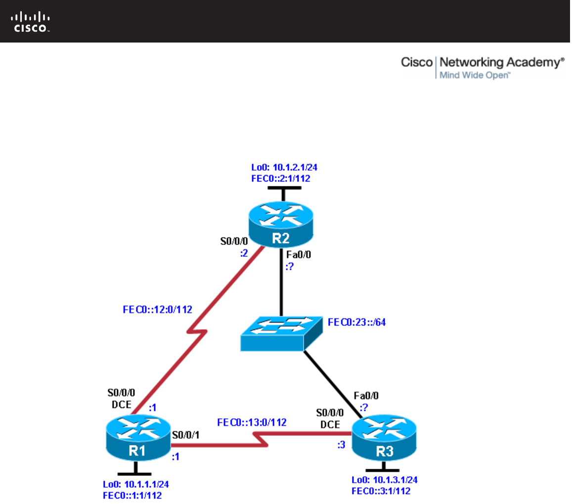
All contents are Copyright © 1992–2010 Cisco Systems, Inc. All rights reserved. This document is Cisco Public Information. Page 1 of 16
CCNPv6 ROUTE
Chapter 8 Lab 8-1, Configuring OSPF for IPv6 Instructor Version
Topology
Objectives
• Configure a static IPv6 address on an interface.
• Change the default link-local address on an interface.
• Configure an EUI-64 IPv6 address on an interface.
• Enable IPv6 routing and CEF.
• Configure and verify single-area OSPFv3 operation.
Background
In this lab, you configure static IPv6 addresses and EUI-64 IPv6 addresses on interfaces. You then configure
OSPFv3 to route between the IPv6 networks.
Note: This lab uses Cisco 1841 routers with Cisco IOS Release 12.4(24)T1 and the Advanced IP Services
Image c1841-advipservicesk9-mz.124-24.T1.bin. The switch is a Cisco WS-C2960-24TT-L with the Cisco IOS

CCNPv6 ROUTE
All contents are Copyright © 1992–2010 Cisco Systems, Inc. All rights reserved. This document is Cisco Public Information. Page 2 of 16
image c2960-lanbasek9-mz.122-46.SE.bin. You can use other routers (such as a 2801 or 2811), switches
(such as 2950), and Cisco IOS Software versions if they have comparable capabilities and features.
Depending on the router or switch model and Cisco IOS Software version, the commands available and
output produced might vary from what is shown in this lab.
Required Resources
• 3 routers (Cisco 1841 with Cisco IOS Release 12.4(24)T1 Advanced IP Services or comparable)
• 1 switch (Cisco 2960 with the Cisco IOS Release 12.2(46)SE C2960-LANBASEK9-M image or
comparable)
• Serial and Ethernet cables
Step 1: Prepare the routers for the lab.
Cable the network as shown in the topology diagram. Erase the startup configuration, and reload each router
to clear the previous configurations.
Step 2: Configuring the hostname and loopback interfaces.
Configure the loopback interface on each router with both the IPv4 address and IPv6 address shown in the
diagram. The IPv4 address is configured using the ip address address mask command. The IPv6 address
configuration is similar, using the ipv6 address address/mask command. With IPv6 addresses, you can enter
the mask length in bits with a decimal /mask, rather than entering the whole mask out in hexadecimal.
IPv6 addresses consist of eight groups of 16 bits (four hexadecimal characters) separated by colons. You can
also enter the IPv6 address in an abbreviated form. For example, you can abbreviate any continuous group of
zeros with two colons “::”. However, you can only use this abbreviation once per address. Also, leading zeros
in each group can be omitted. For example, FEC0:0:0:0:0:0:12:1 /112 can be shortened to FEC0::12:1 /112.
Router(config)# hostname R1
R1(config)# interface loopback0
R1(config-if)# ip address 10.1.1.1 255.255.255.0
R1(config-if)# ipv6 address FEC0::1:1/112
Router(config)# hostname R2
R2(config)# interface loopback0
R2(config-if)# ip address 10.1.2.1 255.255.255.0
R2(config-if)# ipv6 address FEC0::2:1/112
Router(config)# hostname R3
R3(config)# interface loopback0
R3(config-if)# ip address 10.1.3.1 255.255.255.0
R3(config-if)# ipv6 address FEC0::3:1/112
If you accidentally enter the wrong IPv6 address on an interface, make sure you remove it with the no version
of the command that you entered. Unlike IPv4 addresses, where the ip address command overwrites the
existing address, multiple IPv6 addresses can exist on an interface. Issuing the ipv6 address command
multiple times adds more addresses rather than replacing them.
Notice that both an IPv4 and an IPv6 address are on the same interface, and they do not conflict with each
other. This is because they are different Layer 3 protocols, and they run independently.

CCNPv6 ROUTE
All contents are Copyright © 1992–2010 Cisco Systems, Inc. All rights reserved. This document is Cisco Public Information. Page 3 of 16
Step 3: Configure static IPv6 addresses.
a. Configure the two serial links with IPv6 addresses. Use the ipv6 address address/mask command to
configure the interfaces with the addresses shown in the diagram. Set the clock rates where appropriate,
and bring up the interfaces.
R1(config)# interface serial0/0/0
R1(config-if)# ipv6 address FEC0::12:1/112
R1(config-if)# clockrate 64000
R1(config-if)# bandwidth 64
R1(config-if)# no shutdown
R1(config-if)# interface serial0/0/1
R1(config-if)# ipv6 address FEC0::13:1/112
R1(config-if)# bandwidth 64
R1(config-if)# no shutdown
R2(config)# interface serial0/0/0
R2(config-if)# ipv6 address FEC0::12:2/112
R2(config-if)# bandwidth 64
R2(config-if)# no shutdown
R3(config)# interface serial0/0/0
R3(config-if)# ipv6 address FEC0::13:3/112
R3(config-if)# clockrate 64000
R3(config-if)# bandwidth 64
R3(config-if)# no shutdown
b. Use ping to verify local subnet connectivity.
R1# ping FEC0::12:2
Type escape sequence to abort.
Sending 5, 100-byte ICMP Echos to FEC0::12:2, timeout is 2 seconds:
!!!!!
Success rate is 100 percent (5/5), round-trip min/avg/max = 28/28/28 ms
R1# ping FEC0::13:3
Type escape sequence to abort.
Sending 5, 100-byte ICMP Echos to FEC0::13:3, timeout is 2 seconds:
!!!!!
Success rate is 100 percent (5/5), round-trip min/avg/max = 28/28/28 ms
R2# ping FEC0::12:1
Type escape sequence to abort.
Sending 5, 100-byte ICMP Echos to FEC0::12:1, timeout is 2 seconds:
!!!!!
Success rate is 100 percent (5/5), round-trip min/avg/max = 28/28/28 ms
R3# ping FEC0::13:1
Type escape sequence to abort.
Sending 5, 100-byte ICMP Echos to FEC0::13:1, timeout is 2 seconds:
!!!!!
Success rate is 100 percent (5/5), round-trip min/avg/max = 28/28/28 ms

CCNPv6 ROUTE
All contents are Copyright © 1992–2010 Cisco Systems, Inc. All rights reserved. This document is Cisco Public Information. Page 4 of 16
Step 4: Change the link-local address on an interface.
a. Use the show ipv6 interface command to look at IPv6-related properties of the router interfaces. You
can also specify a type/number of an interface to see the output of that interface only.
R1# show ipv6 interface serial 0/0/0
Serial0/0/0 is up, line protocol is up
IPv6 is enabled, link-local address is FE80::219:6FF:FE23:4380
No Virtual link-local address(es):
Global unicast address(es):
FEC0::12:1, subnet is FEC0::12:0/112
Joined group address(es):
FF02::1
FF02::2
FF02::1:FF12:1
FF02::1:FF23:4380
MTU is 1500 bytes
ICMP error messages limited to one every 100 milliseconds
ICMP redirects are enabled
ICMP unreachables are sent
ND DAD is enabled, number of DAD attempts: 1
ND reachable time is 30000 milliseconds
R2# show ipv6 interface serial 0/0/0
Serial0/0/0 is up, line protocol is up
IPv6 is enabled, link-local address is FE80::218:B9FF:FE92:28D8
Global unicast address(es):
FEC0::12:2, subnet is FEC0::12:0/112
Joined group address(es):
FF02::1
FF02::2
FF02::1:FF12:2
FF02::1:FF92:28D8
MTU is 1500 bytes
ICMP error messages limited to one every 100 milliseconds
ICMP redirects are enabled
ND DAD is enabled, number of DAD attempts: 1
ND reachable time is 30000 milliseconds
Notice that in addition to the address that you already configured, there is a link-local address starting
with FE80 (your actual address will vary). You can change the addresses on the link between R1 and R2
by putting the link-local address FE80::1 on R1 and FE80::2 on R2. Link-local addresses do not have a
subnet mask because they are not routed, hence the term “link-local.”
b. To change the link-local address, use the ipv6 address address link-local command.
R1(config)# interface serial0/0/0
R1(config-if)# ipv6 address FE80::1 link-local
R2(config)# interface serial0/0/0
R2(config-if)# ipv6 address FE80::2 link-local
c. Verify that you can ping the link-local address on the other side. When pinging link-local addresses, you
must specify an outgoing interface because the addresses are not routed and not in the routing table.
Note: When prompted for the output interface with this command, you must use the full interface name
without spaces (for example, use serial0/0/0, not s0/0/0).
R1# ping FE80::2
Output Interface: Serial0/0/0

CCNPv6 ROUTE
All contents are Copyright © 1992–2010 Cisco Systems, Inc. All rights reserved. This document is Cisco Public Information. Page 5 of 16
Type escape sequence to abort.
Sending 5, 100-byte ICMP Echos to FE80::2, timeout is 2 seconds:
Packet sent with a source address of FE80::1
!!!!!
Success rate is 100 percent (5/5), round-trip min/avg/max = 28/28/28 ms
R2# ping FE80::1
Output Interface: Serial0/0/0
Type escape sequence to abort.
Sending 5, 100-byte ICMP Echos to FE80::1, timeout is 2 seconds:
Packet sent with a source address of FE80::2
!!!!!
Success rate is 100 percent (5/5), round-trip min/avg/max = 28/28/28 ms
d. Verify the link-local addresses with the show ipv6 interface command.
R1# show ipv6 interface serial 0/0/0
Serial0/0/0 is up, line protocol is up
IPv6 is enabled, link-local address is FE80::1
No Virtual link-local address(es):
Global unicast address(es):
FEC0::12:1, subnet is FEC0::12:0/112
Joined group address(es):
FF02::1
FF02::2
FF02::1:FF00:1
FF02::1:FF12:1
MTU is 1500 bytes
ICMP error messages limited to one every 100 milliseconds
ICMP redirects are enabled
ICMP unreachables are sent
ND DAD is enabled, number of DAD attempts: 1
ND reachable time is 30000 milliseconds
R2# show ipv6 interface serial 0/0/0
Serial0/0/0 is up, line protocol is up
IPv6 is enabled, link-local address is FE80::2
Global unicast address(es):
FEC0::12:2, subnet is FEC0::12:0/112
Joined group address(es):
FF02::1
FF02::2
FF02::1:FF00:2
FF02::1:FF12:2
MTU is 1500 bytes
ICMP error messages limited to one every 100 milliseconds
ICMP redirects are enabled
ND DAD is enabled, number of DAD attempts: 1
ND reachable time is 30000 milliseconds
Note: Manually modifying a link-local address is seldom needed. It is demonstrated here for the purpose
of this lab.
Step 5: Configure EUI-64 addresses.
EUI-64 IPv6 addresses are addresses where the first 64 bits are the network portion of the address and are
specified. The second 64 bits are the host portion of the address and are automatically generated by the
device. RFC 4921 splits the 48-bit MAC address into two 24-bit segments: the Organizational Unique
Identifier (OUI) and the NIC-specific component. The seventh bit of the OUI (bit 7 from the left) is inverted

CCNPv6 ROUTE
All contents are Copyright © 1992–2010 Cisco Systems, Inc. All rights reserved. This document is Cisco Public Information. Page 6 of 16
(changed from zero to one or vice versa). The 16-bit hex value 0xFFFE is then inserted between the modified
OUI and the NIC-specific component to create the modified EUI-64 address. This can be seen in the
highlighted EUI-64 address in Step 5b.
a. Configure IPv6 EUI-64 addresses on an interface using the ipv6 address address/mask eui-64
command. Configure the R2 and R3 Fast Ethernet interfaces with the subnet shown in the diagram, and
enable the interfaces.
R2(config)# interface fastEthernet 0/0
R2(config-if)# ipv6 address FEC0:23::/64 eui-64
R2(config-if)# no shutdown
R3(config)# interface fastEthernet 0/0
R3(config-if)# ipv6 address FEC0:23::/64 eui-64
R3(config-if)# no shutdown
b. Get the IPv6 addresses of the interfaces with the show ipv6 interface or show ipv6 interface brief
command, and then ping the other side of the link.
R2# show ipv6 interface fastEthernet 0/0
FastEthernet0/0 is up, line protocol is up
IPv6 is enabled, link-local address is FE80::218:B9FF:FE92:28D8
No Virtual link-local address(es):
Global unicast address(es):
FEC0:23::218:B9FF:FE92:28D8, subnet is FEC0:23::/64 [EUI]
Joined group address(es):
FF02::1
FF02::1:FF92:28D8
MTU is 1500 bytes
ICMP error messages limited to one every 100 milliseconds
ICMP redirects are enabled
ICMP unreachables are sent
ND DAD is enabled, number of DAD attempts: 1
ND reachable time is 30000 milliseconds (using 17162)
R2# show ipv6 interface brief
FastEthernet0/0 [up/up]
FE80::218:B9FF:FE92:28D8
FEC0:23::218:B9FF:FE92:28D8
FastEthernet0/1 [administratively down/down]
Serial0/0/0 [up/up]
FE80::2
FEC0::12:2
Serial0/0/1 [administratively down/down]
Serial0/1/0 [administratively down/down]
Serial0/1/1 [administratively down/down]
Loopback0 [up/up]
FE80::218:B9FF:FE92:28D8
FEC0::2:1
R3# show ipv6 interface brief
FastEthernet0/0 [up/up]
FE80::218:B9FF:FECD:BEF0
FEC0:23::218:B9FF:FECD:BEF0
FastEthernet0/1 [administratively down/down]
Serial0/0/0 [up/up]
FE80::218:B9FF:FECD:BEF0
FEC0::13:3
Serial0/0/1 [administratively down/down]

CCNPv6 ROUTE
All contents are Copyright © 1992–2010 Cisco Systems, Inc. All rights reserved. This document is Cisco Public Information. Page 7 of 16
Serial0/1/0 [administratively down/down]
Serial0/1/1 [administratively down/down]
Loopback0 [up/up]
FE80::218:B9FF:FECD:BEF0
FEC0::3:1
R2# ping FEC0:23::218:B9FF:FECD:BEF0
Type escape sequence to abort.
Sending 5, 100-byte ICMP Echos to FEC0:23::218:B9FF:FECD:BEF0, timeout is 2
seconds:
!!!!!
Success rate is 100 percent (5/5), round-trip min/avg/max = 0/0/4 ms
R3# ping FEC0:23::218:B9FF:FE92:28D8
Type escape sequence to abort.
Sending 5, 100-byte ICMP Echos to FEC0:23::218:B9FF:FE92:28D8, timeout is 2
seconds:
!!!!!
Success rate is 100 percent (5/5), round-trip min/avg/max = 0/0/0 ms
Note: Your addresses will be different from the addresses displayed in the example because EUI-64
addresses include the MAC address of the interface, which is unique per interface.
At this point, you should have local subnet connectivity.
Note: Although not configured in this lab, the ipv6 general-prefix command can simplify the
configuration of IPv6 addresses, including the EUI-64. You can use this command to assign a name to an
often-used IPv6 prefix and then use the name to configure interfaces.
Step 6: Enable IPv6 routing and CEF.
The Cisco IOS version used with the routers in this lab has IPv6 routing and IPv6 CEF disabled by default. To
enable IPv6 routing, use the ipv6 unicast-routing command in global configuration mode. To enable IPv6
CEF, use the ipv6 cef command. Enter these commands on all three routers.
R1(config)# ipv6 unicast-routing
R1(config)# ipv6 cef
R2(config)# ipv6 unicast-routing
R2(config)# ipv6 cef
R3(config)# ipv6 unicast-routing
R3(config)# ipv6 cef
Step 7: Configure OSPFv3.
Unlike IPv4 OSPF, where networks are added to the OSPF process using network statements under the
routing protocol configuration prompt, IPv6 OSPF uses the interface-level command ipv6 ospf process area
area-id to add an interface to an area.
a. Add all interfaces shown in the diagram into OSPF process 1, area 0. After you add the interfaces to the
OSPF process, the OSPF process starts automatically. If the adjacencies do not come up after a
reasonable period of time, troubleshoot using the debug ipv6 ospf adjacency and debug ipv6 packet
commands. Make sure that the packets are being sent to their destination and that adjacencies are
forming correctly.
R1(config)# interface loopback0

CCNPv6 ROUTE
All contents are Copyright © 1992–2010 Cisco Systems, Inc. All rights reserved. This document is Cisco Public Information. Page 8 of 16
R1(config-if)# ipv6 ospf 1 area 0
R1(config-if)# interface serial0/0/0
R1(config-if)# ipv6 ospf 1 area 0
R1(config-if)# interface serial0/0/1
R1(config-if)# ipv6 ospf 1 area 0
R2(config)# interface loopback0
R2(config-if)# ipv6 ospf 1 area 0
R2(config-if)# interface serial0/0/0
R2(config-if)# ipv6 ospf 1 area 0
R2(config-if)# interface fastEthernet 0/0
R2(config-if)# ipv6 ospf 1 area 0
R3(config)# interface loopback0
R3(config-if)# ipv6 ospf 1 area 0
R3(config-if)# interface serial0/0/0
R3(config-if)# ipv6 ospf 1 area 0
R3(config-if)# interface fastEthernet 0/0
R3(config-if)# ipv6 ospf 1 area 0
b. Verify that you have OSPFv3 neighbors with the show ipv6 ospf neighbor command.
R1# show ipv6 ospf neighbor
Neighbor ID Pri State Dead Time Interface ID Interface
10.1.3.1 1 FULL/ - 00:00:39 6 Serial0/0/1
10.1.2.1 1 FULL/ - 00:00:34 6 Serial0/0/0
R2# show ipv6 ospf neighbor
Neighbor ID Pri State Dead Time Interface ID Interface
10.1.3.1 1 FULL/DR 00:00:39 4 FastEthernet0/0
10.1.1.1 1 FULL/ - 00:00:32 6 Serial0/0/0
R3# show ipv6 ospf neighbor
Neighbor ID Pri State Dead Time Interface ID Interface
10.1.2.1 1 FULL/BDR 00:00:39 4 FastEthernet0/0
10.1.1.1 1 FULL/ - 00:00:39 7 Serial0/0/0
The router IDs for each router are created the same way that they are in OSPFv2 or BGP. Without any
IPv4 addresses on the router, the OSPFv3 process will not start unless you manually set the router IDs.
This is why the loopback interfaces have been configured with both IPv4 and IPv6 addresses.
c. View the routing table on all three routers with the show ipv6 route command.
R1# show ipv6 route
IPv6 Routing Table - 11 entries
Codes: C - Connected, L - Local, S - Static, R - RIP, B - BGP
U - Per-user Static route
I1 - ISIS L1, I2 - ISIS L2, IA - ISIS interarea, IS - ISIS summary
O - OSPF intra, OI - OSPF inter, OE1 - OSPF ext 1, OE2 - OSPF ext 2
ON1 - OSPF NSSA ext 1, ON2 - OSPF NSSA ext 2
D - EIGRP, EX - EIGRP external
L FE80::/10 [0/0]
via ::, Null0
C FEC0::1:0/112 [0/0]
via ::, Loopback0
L FEC0::1:1/128 [0/0]
via ::, Loopback0

CCNPv6 ROUTE
All contents are Copyright © 1992–2010 Cisco Systems, Inc. All rights reserved. This document is Cisco Public Information. Page 9 of 16
O FEC0::2:1/128 [110/1562]
via FE80::2, Serial0/0/0
O FEC0::3:1/128 [110/1562]
via FE80::218:B9FF:FECD:BEF0, Serial0/0/1
C FEC0::12:0/112 [0/0]
via ::, Serial0/0/0
L FEC0::12:1/128 [0/0]
via ::, Serial0/0/0
C FEC0::13:0/112 [0/0]
via ::, Serial0/0/1
L FEC0::13:1/128 [0/0]
via ::, Serial0/0/1
O FEC0:23::/64 [110/1563]
via FE80::2, Serial0/0/0
via FE80::218:B9FF:FECD:BEF0, Serial0/0/1
L FF00::/8 [0/0]
via ::, Null0
R2# show ipv6 route
IPv6 Routing Table - 11 entries
Codes: C - Connected, L - Local, S - Static, R - RIP, B - BGP
U - Per-user Static route
I1 - ISIS L1, I2 - ISIS L2, IA - ISIS interarea, IS - ISIS summary
O - OSPF intra, OI - OSPF inter, OE1 - OSPF ext 1, OE2 - OSPF ext 2
ON1 - OSPF NSSA ext 1, ON2 - OSPF NSSA ext 2
L FE80::/10 [0/0]
via ::, Null0
O FEC0::1:1/128 [110/1562]
via FE80::1, Serial0/0/0
C FEC0::2:0/112 [0/0]
via ::, Loopback0
L FEC0::2:1/128 [0/0]
via ::, Loopback0
O FEC0::3:1/128 [110/1]
via FE80::218:B9FF:FECD:BEF0, FastEthernet0/0
C FEC0::12:0/112 [0/0]
via ::, Serial0/0/0
L FEC0::12:2/128 [0/0]
via ::, Serial0/0/0
O FEC0::13:0/112 [110/1563]
via FE80::218:B9FF:FECD:BEF0, FastEthernet0/0
C FEC0:23::/64 [0/0]
via ::, FastEthernet0/0
L FEC0:23::218:B9FF:FE92:28D8/128 [0/0]
via ::, FastEthernet0/0
L FF00::/8 [0/0]
via ::, Null0
R3# show ipv6 route
IPv6 Routing Table - 11 entries
Codes: C - Connected, L - Local, S - Static, R - RIP, B - BGP
U - Per-user Static route
I1 - ISIS L1, I2 - ISIS L2, IA - ISIS interarea, IS - ISIS summary
O - OSPF intra, OI - OSPF inter, OE1 - OSPF ext 1, OE2 - OSPF ext 2
ON1 - OSPF NSSA ext 1, ON2 - OSPF NSSA ext 2
L FE80::/10 [0/0]
via ::, Null0
O FEC0::1:1/128 [110/1562]

CCNPv6 ROUTE
All contents are Copyright © 1992–2010 Cisco Systems, Inc. All rights reserved. This document is Cisco Public Information. Page 10 of 16
via FE80::219:6FF:FE23:4380, Serial0/0/0
O FEC0::2:1/128 [110/1]
via FE80::218:B9FF:FE92:28D8, FastEthernet0/0
C FEC0::3:0/112 [0/0]
via ::, Loopback0
L FEC0::3:1/128 [0/0]
via ::, Loopback0
O FEC0::12:0/112 [110/1563]
via FE80::218:B9FF:FE92:28D8, FastEthernet0/0
C FEC0::13:0/112 [0/0]
via ::, Serial0/0/0
L FEC0::13:3/128 [0/0]
via ::, Serial0/0/0
C FEC0:23::/64 [0/0]
via ::, FastEthernet0/0
L FEC0:23::218:B9FF:FECD:BEF0/128 [0/0]
via ::, FastEthernet0/0
L FF00::/8 [0/0]
via ::, Null0
d. You can also look at per-interface OSPF behavior with the show ipv6 ospf interface command.
R1# show ipv6 ospf interface
Serial0/0/1 is up, line protocol is up
Link Local Address FE80::219:6FF:FE23:4380, Interface ID 7
Area 0, Process ID 1, Instance ID 0, Router ID 10.1.1.1
Network Type POINT_TO_POINT, Cost: 1562
Transmit Delay is 1 sec, State POINT_TO_POINT,
Timer intervals configured, Hello 10, Dead 40, Wait 40, Retransmit 5
Hello due in 00:00:06
Index 1/3/3, flood queue length 0
Next 0x0(0)/0x0(0)/0x0(0)
Last flood scan length is 2, maximum is 2
Last flood scan time is 0 msec, maximum is 0 msec
Neighbor Count is 1, Adjacent neighbor count is 1
Adjacent with neighbor 10.1.3.1
Suppress hello for 0 neighbor(s)
Serial0/0/0 is up, line protocol is up
Link Local Address FE80::1, Interface ID 6
Area 0, Process ID 1, Instance ID 0, Router ID 10.1.1.1
Network Type POINT_TO_POINT, Cost: 1562
Transmit Delay is 1 sec, State POINT_TO_POINT,
Timer intervals configured, Hello 10, Dead 40, Wait 40, Retransmit 5
Hello due in 00:00:00
Index 1/2/2, flood queue length 0
Next 0x0(0)/0x0(0)/0x0(0)
Last flood scan length is 1, maximum is 4
Last flood scan time is 0 msec, maximum is 0 msec
Neighbor Count is 1, Adjacent neighbor count is 1
Adjacent with neighbor 10.1.2.1
Suppress hello for 0 neighbor(s)
Loopback0 is up, line protocol is up
Link Local Address FE80::219:6FF:FE23:4380, Interface ID 20
Area 0, Process ID 1, Instance ID 0, Router ID 10.1.1.1
Network Type LOOPBACK, Cost: 1
Loopback interface is treated as a stub Host
R2# show ipv6 ospf interface
FastEthernet0/0 is up, line protocol is up

CCNPv6 ROUTE
All contents are Copyright © 1992–2010 Cisco Systems, Inc. All rights reserved. This document is Cisco Public Information. Page 11 of 16
Link Local Address FE80::218:B9FF:FE92:28D8, Interface ID 4
Area 0, Process ID 1, Instance ID 0, Router ID 10.1.2.1
Network Type BROADCAST, Cost: 1
Transmit Delay is 1 sec, State BDR, Priority 1
Designated Router (ID) 10.1.3.1, local address FE80::218:B9FF:FECD:BEF0
Backup Designated router (ID) 10.1.2.1, local address
FE80::218:B9FF:FE92:28D8
Timer intervals configured, Hello 10, Dead 40, Wait 40, Retransmit 5
Hello due in 00:00:04
Index 1/3/3, flood queue length 0
Next 0x0(0)/0x0(0)/0x0(0)
Last flood scan length is 2, maximum is 2
Last flood scan time is 0 msec, maximum is 0 msec
Neighbor Count is 1, Adjacent neighbor count is 1
Adjacent with neighbor 10.1.3.1 (Designated Router)
Suppress hello for 0 neighbor(s)
Serial0/0/0 is up, line protocol is up
Link Local Address FE80::2, Interface ID 6
Area 0, Process ID 1, Instance ID 0, Router ID 10.1.2.1
Network Type POINT_TO_POINT, Cost: 1562
Transmit Delay is 1 sec, State POINT_TO_POINT,
Timer intervals configured, Hello 10, Dead 40, Wait 40, Retransmit 5
Hello due in 00:00:07
Index 1/2/2, flood queue length 0
Next 0x0(0)/0x0(0)/0x0(0)
Last flood scan length is 1, maximum is 4
Last flood scan time is 0 msec, maximum is 0 msec
Neighbor Count is 1, Adjacent neighbor count is 1
Adjacent with neighbor 10.1.1.1
Suppress hello for 0 neighbor(s)
Loopback0 is up, line protocol is up
Link Local Address FE80::218:B9FF:FE92:28D8, Interface ID 17
Area 0, Process ID 1, Instance ID 0, Router ID 10.1.2.1
Network Type LOOPBACK, Cost: 1
Loopback interface is treated as a stub Host
R3# show ipv6 ospf interface
FastEthernet0/0 is up, line protocol is up
Link Local Address FE80::218:B9FF:FECD:BEF0, Interface ID 4
Area 0, Process ID 1, Instance ID 0, Router ID 10.1.3.1
Network Type BROADCAST, Cost: 1
Transmit Delay is 1 sec, State DR, Priority 1
Designated Router (ID) 10.1.3.1, local address FE80::218:B9FF:FECD:BEF0
Backup Designated router (ID) 10.1.2.1, local address
FE80::218:B9FF:FE92:28D8
Timer intervals configured, Hello 10, Dead 40, Wait 40, Retransmit 5
Hello due in 00:00:09
Index 1/3/3, flood queue length 0
Next 0x0(0)/0x0(0)/0x0(0)
Last flood scan length is 1, maximum is 4
Last flood scan time is 0 msec, maximum is 0 msec
Neighbor Count is 1, Adjacent neighbor count is 1
Adjacent with neighbor 10.1.2.1 (Backup Designated Router)
Suppress hello for 0 neighbor(s)
Serial0/0/0 is up, line protocol is up
Link Local Address FE80::218:B9FF:FECD:BEF0, Interface ID 6
Area 0, Process ID 1, Instance ID 0, Router ID 10.1.3.1
Network Type POINT_TO_POINT, Cost: 1562

CCNPv6 ROUTE
All contents are Copyright © 1992–2010 Cisco Systems, Inc. All rights reserved. This document is Cisco Public Information. Page 12 of 16
Transmit Delay is 1 sec, State POINT_TO_POINT,
Timer intervals configured, Hello 10, Dead 40, Wait 40, Retransmit 5
Hello due in 00:00:07
Index 1/2/2, flood queue length 0
Next 0x0(0)/0x0(0)/0x0(0)
Last flood scan length is 1, maximum is 4
Last flood scan time is 0 msec, maximum is 0 msec
Neighbor Count is 1, Adjacent neighbor count is 1
Adjacent with neighbor 10.1.1.1
Suppress hello for 0 neighbor(s)
Loopback0 is up, line protocol is up
Link Local Address FE80::218:B9FF:FECD:BEF0, Interface ID 17
Area 0, Process ID 1, Instance ID 0, Router ID 10.1.3.1
Network Type LOOPBACK, Cost: 1
Loopback interface is treated as a stub Host
e. Run the following Tcl script on all routers to verify full connectivity. If these pings are not successful,
troubleshoot. Modify the script to include the correct EUI addresses on the FEC0:23:: /64 subnet. The
addresses for the router interfaces used in this lab are shown below.
tclsh
foreach address {
FEC0::1:1
FEC0::2:1
FEC0::3:1
FEC0::12:1
FEC0::12:2
FEC0::13:1
FEC0::13:3
FEC0:23::
FEC0:23::
} {
ping $address }
R1#tclsh
R1(tcl)#
R1(tcl)#foreach address {
+>(tcl)#FEC0::1:1
+>(tcl)#FEC0::2:1
+>(tcl)#FEC0::3:1
+>(tcl)#FEC0::12:1
+>(tcl)#FEC0::12:2
+>(tcl)#FEC0::13:1
+>(tcl)#FEC0::13:3
+>(tcl)#FEC0:23::218:B9FF:FE92:28D8
+>(tcl)#FEC0:23::218:B9FF:FECD:BEF0
+>(tcl)#} {
+>(tcl)#ping $address }
Challenge: Summarize OSPFv3 Areas
The commands available for OSPFv3 are similar to the commands available for OSPFv2. On R2, add in two
loopback interfaces, with the addresses FEC0:500::100:1 /112 and FEC0:500::200:1 /112. Add both of these
interfaces to the OSPF process in area 500. Summarize area 500 to FEC0:500:: /64. To enter the OSPF
configuration prompt, use the ipv6 router ospf process-id command. Unlike the IPv4 (config-router) prompt,
the IPv6 router prompt is (config-rtr). When in the IPv6 router prompt, use the area range command to
summarize the address. Use the question mark (?) if you need help.

CCNPv6 ROUTE
All contents are Copyright © 1992–2010 Cisco Systems, Inc. All rights reserved. This document is Cisco Public Information. Page 13 of 16
You would enter the following commands on R2:
interface loopback100
ipv6 address FEC0:500::100:1/112
ipv6 ospf 1 area 500
interface loopback200
ipv6 address FEC0:500::200:1/112
ipv6 ospf 1 area 500
ipv6 router ospf 1
area 500 range FEC0:500::/64

CCNPv6 ROUTE
All contents are Copyright © 1992–2010 Cisco Systems, Inc. All rights reserved. This document is Cisco Public Information. Page 14 of 16
Router Interface Summary Table
Router Interface Summary
Router Model Ethernet Interface
#1 Ethernet Interface
#2 Serial Interface
#1 Serial Interface
#2
1700 Fast Ethernet 0
(FA0) Fast Ethernet 1
(FA1) Serial 0 (S0) Serial 1 (S1)
1800 Fast Ethernet 0/0
(FA0/0) Fast Ethernet 0/1
(FA0/1) Serial 0/0/0
(S0/0/0) Serial 0/0/1
(S0/0/1)
2600 Fast Ethernet 0/0
(FA0/0) Fast Ethernet 0/1
(FA0/1) Serial 0/0 (S0/0) Serial 0/1 (S0/1)
2800 Fast Ethernet 0/0
(FA0/0) Fast Ethernet 0/1
(FA0/1) Serial 0/0/0
(S0/0/0) Serial 0/0/1
(S0/0/1)
Note: To find out how the router is configured, look at the interfaces to identify the type of router
and how many interfaces the router has. Rather than list all combinations of configurations for each
router class, this table includes identifiers for the possible combinations of Ethernet and serial
interfaces in the device. The table does not include any other type of interface, even though a
specific router might contain one. For example, for an ISDN BRI interface, the string in parenthesis
is the legal abbreviation that can be used in Cisco IOS commands to represent the interface.

CCNPv6 ROUTE
All contents are Copyright © 1992–2010 Cisco Systems, Inc. All rights reserved. This document is Cisco Public Information. Page 15 of 16
Device Configurations (Instructor version)
Router R1
hostname R1
!
ipv6 unicast-routing
ipv6 cef
!
interface Loopback0
ip address 10.1.1.1 255.255.255.0
ipv6 address FEC0::1:1/112
ipv6 ospf 1 area 0
!
interface Serial0/0/0
ipv6 address FE80::1 link-local
ipv6 address FEC0::12:1/112
ipv6 ospf 1 area 0
clock rate 64000
bandwidth 64
no shutdown
!
interface Serial0/0/1
ipv6 address FEC0::13:1/112
ipv6 ospf 1 area 0
bandwidth 64
no shutdown
!
end
Router R2
hostname R2
!
ipv6 unicast-routing
ipv6 cef
!
interface Loopback0
ip address 10.1.2.1 255.255.255.0
ipv6 address FEC0::2:1/112
ipv6 ospf 1 area 0
!
interface FastEthernet0/0
ipv6 address FEC0:23::/64 eui-64
ipv6 ospf 1 area 0
no shutdown
!
interface Serial0/0/0
ipv6 address FEC0::12:2/112
ipv6 address FE80::2 link-local
ipv6 ospf 1 area 0
bandwidth 64
no shutdown
!
end

CCNPv6 ROUTE
All contents are Copyright © 1992–2010 Cisco Systems, Inc. All rights reserved. This document is Cisco Public Information. Page 16 of 16
Router R3
hostname R3
!
ipv6 unicast-routing
ipv6 cef
!
interface Loopback0
ip address 10.1.3.1 255.255.255.0
ipv6 address FEC0::3:1/112
ipv6 ospf 1 area 0
!
interface FastEthernet0/0
ipv6 address FEC0:23::/64 eui-64
ipv6 ospf 1 area 0
no shutdown
!
interface Serial0/0/0
ipv6 address FEC0::13:3/112
ipv6 ospf 1 area 0
clock rate 64000
bandwidth 64
no shutdown
!
end
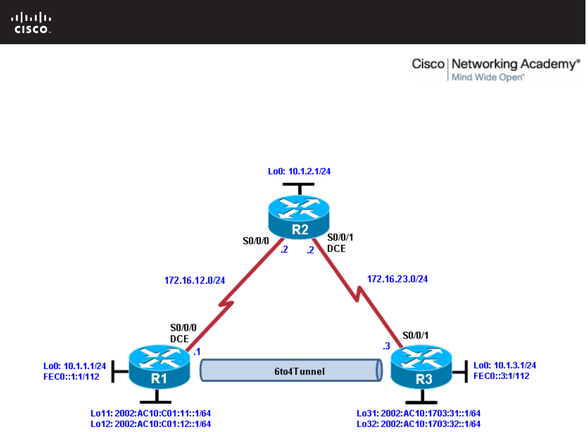
All contents are Copyright © 1992–2010 Cisco Systems, Inc. All rights reserved. This document is Cisco Public Information. Page 1 of 10
CCNPv6 ROUTE
Chapter 8 Lab 8-3, Configuring 6to4 Tunnels Instructor Version
Topology
Objectives
• Configure EIGRP for IPv4.
• Create a 6to4 tunnel.
• Configure static IPv6 routes.
Background
In this lab, you configure EIGRP for full connectivity between all IPv4 subnets. You then create a 6to4 tunnel
and create static routes over it.
Note: This lab uses Cisco 1841 routers with Cisco IOS Release 12.4(24)T1 and the Advanced IP Services
image c1841-advipservicesk9-mz.124-24.T1.bin. You can use other routers (such as a 2801 or 2811) and
Cisco IOS Software versions if they have comparable capabilities and features. Depending on the router
model and Cisco IOS Software version, the commands available and output produced might vary from what is
shown in this lab.
Required Resources
• 3 routers (Cisco 1841 with Cisco IOS Release 12.4(24)T1 Advanced IP Services or comparable)
• Serial and console cables

CCNPv6 ROUTE
All contents are Copyright © 1992–2010 Cisco Systems, Inc. All rights reserved. This document is Cisco Public Information. Page 2 of 10
Step 1: Prepare the routers for the lab.
Clear previous configurations by erasing the startup configuration and reloading the routers. After the routers
are reloaded, set up the appropriate hostnames.
Step 2: Configure loopbacks and physical interfaces.
a. Configure the loopback interfaces with IPv4 addresses and IPv6 addresses, where appropriate. Also
configure the serial interfaces with the IPv4 addresses shown in the diagram. Set the clock rates on the
appropriate interfaces and the bandwidth on all serial connections.
R1(config)# interface loopback0
R1(config-if)# ip address 10.1.1.1 255.255.255.0
R1(config-if)# ipv6 address FEC0::1:1/112
R1(config-if)# interface serial0/0/0
R1(config-if)# ip address 172.16.12.1 255.255.255.0
R1(config-if)# clockrate 64000
R1(config-if)# bandwidth 64
R1(config-if)# no shutdown
R2(config)# interface loopback0
R2(config-if)# ip address 10.1.2.1 255.255.255.0
R2(config-if)# interface serial0/0/0
R2(config-if)# ip address 172.16.12.2 255.255.255.0
R2(config-if)# bandwidth 64
R2(config-if)# no shutdown
R2(config-if)# interface serial0/0/1
R2(config-if)# ip address 172.16.23.2 255.255.255.0
R2(config-if)# clockrate 64000
R2(config-if)# bandwidth 64
R2(config-if)# no shutdown
R3(config)# interface loopback0
R3(config-if)# ip address 10.1.3.1 255.255.255.0
R3(config-if)# ipv6 address FEC0::3:1/112
R3(config-if)# interface serial0/0/1
R3(config-if)# ip address 172.16.23.3 255.255.255.0
R3(config-if)# bandwidth 64
R3(config-if)# no shutdown
b. Verify that you have local subnet connectivity with ping.
Step 3: Configure EIGRP.
Configure EIGRP for AS 1 for the major networks 172.16.0.0 and 10.0.0.0 on all three routers. You should
have full IPv4 connectivity.
R1(config)# router eigrp 1
R1(config-router)# no auto-summary
R1(config-router)# network 10.0.0.0
R1(config-router)# network 172.16.0.0
R2(config)# router eigrp 1
R2(config-router)# no auto-summary
R2(config-router)# network 10.0.0.0
R2(config-router)# network 172.16.0.0
R3(config)# router eigrp 1
R3(config-router)# no auto-summary

CCNPv6 ROUTE
All contents are Copyright © 1992–2010 Cisco Systems, Inc. All rights reserved. This document is Cisco Public Information. Page 3 of 10
R3(config-router)# network 10.0.0.0
R3(config-router)# network 172.16.0.0
Step 4: Configure a manual IPv6 6to4 tunnel.
A tunnel is a logical interface that acts as a logical connection between two endpoints. It is similar to a
loopback interface in that there is no corresponding physical interface, but it is different in that there is more
than one router involved. A 6to4 tunnel uses special IPv6 addresses in the 2002::/16 address space. The first
16 bits are the hexadecimal number 2002, and the next 32 bits are the original source IPv4 address in
hexadecimal form. The remaining bits can be specified as shown in Step 4c. A 6to4 tunnel does not require a
destination address because it is not a point-to-point link.
In this step, you configure additional 6to4 IPv6 loopback interfaces to represent LANs on R1 and R3, and then
configure a 6to4 tunnel to provide IPv6 connectivity between the loopback interfaces.
a. Add the following loopbacks to R1 and R3.
R1(config-if)# interface loopback11
R1(config-if)# ipv6 address 2002:AC10:0C01:11::1/64
R1(config-if)# interface loopback12
R1(config-if)# ipv6 address 2002:AC10:0C01:12::1/64
R3(config-if)# interface loopback31
R3(config-if)# ipv6 address 2002:AC10:1703:31::1/64
R3(config-if)# interface loopback32
R3(config-if)# ipv6 address 2002:AC10:1703:32::1/64
b. Configure a 6to4 tunnel using the interface tunnel number command to get to the tunnel interface
configuration prompt. For simplicity, use interface number 0.
R1(config)# interface tunnel 0
c. Set the tunnel mode with the tunnel mode ipv6ip 6to4 command. Then set up the IPv6 address with the
ipv6 address address/mask command. The R1 address is 2002:AC10:0C01:1::1/64, because
AC10:0C01 corresponds to 172.16.12.1, with 172 being AC, 16 being 10, 12 being C, and 1 being 1. The
1 after this address is just a more specific subnet, and the 1 at the end is the host address. The R3
address is 2002:AC10:1703:1::3/64. The two addresses are not in the same /64 subnet. After setting the
IPv6 addresses, set the source interface for the tunnel with the tunnel source type/number command.
R1(config-if)# tunnel mode ipv6ip 6to4
R1(config-if)# ipv6 address 2002:AC10:0C01:1::1/64
R1(config-if)# tunnel source serial0/0/0
d. Now that all the tunnel settings are set, enable IPv6 routing with the ipv6 unicast-routing command, and
set up an IPv6 static route for the whole 2002::/16 network with the global command ipv6 route
address/mask interface, with the interface being the tunnel you just created.
R1(config-if)# exit
R1(config)# ipv6 unicast-routing
R1(config)# ipv6 route 2002::/16 tunnel0
e. Enter the following commands on R3.
R3(config)# interface tunnel 0
R3(config-if)# tunnel mode ipv6ip 6to4
R3(config-if)# ipv6 address 2002:AC10:1703:1::3/64
R3(config-if)# tunnel source serial0/0/1
R3(config-if)# exit
R3(config)# ipv6 unicast-routing
R3(config)# ipv6 route 2002::/16 tunnel0

CCNPv6 ROUTE
All contents are Copyright © 1992–2010 Cisco Systems, Inc. All rights reserved. This document is Cisco Public Information. Page 4 of 10
f. Verify that you can ping the other side of the tunnel from R1 to R3, and ping the newly created loopback
interfaces from each router .
R1# ping 2002:AC10:1703:1::3
Type escape sequence to abort.
Sending 5, 100-byte ICMP Echos to 2002:AC10:1703:1::3, timeout is 2 seconds:
!!!!!
Success rate is 100 percent (5/5), round-trip min/avg/max = 64/67/68 ms
R1# ping 2002:AC10:1703:31::1
Type escape sequence to abort.
Sending 5, 100-byte ICMP Echos to 2002:AC10:1703:31::1, timeout is 2 seconds:
!!!!!
Success rate is 100 percent (5/5), round-trip min/avg/max = 64/65/68 ms
R1# ping 2002:AC10:1703:32::1
Type escape sequence to abort.
Sending 5, 100-byte ICMP Echos to 2002:AC10:1703:32::1, timeout is 2 seconds:
!!!!!
Success rate is 100 percent (5/5), round-trip min/avg/max = 64/65/68 ms
R3# ping 2002:AC10:C01:1::1
Type escape sequence to abort.
Sending 5, 100-byte ICMP Echos to 2002:AC10:C01:1::1, timeout is 2 seconds:
!!!!!
Success rate is 100 percent (5/5), round-trip min/avg/max = 64/66/68 ms
R3# ping 2002:AC10:0C01:11::1
Type escape sequence to abort.
Sending 5, 100-byte ICMP Echos to 2002:AC10:C01:11::1, timeout is 2 seconds:
!!!!!
Success rate is 100 percent (5/5), round-trip min/avg/max = 64/67/68 ms
R3# ping 2002:AC10:0C01:12::1
Type escape sequence to abort.
Sending 5, 100-byte ICMP Echos to 2002:AC10:C01:12::1, timeout is 2 seconds:
!!!!!
Success rate is 100 percent (5/5), round-trip min/avg/max = 64/65/68 ms
Step 5: Configure static IPv6 routes.
Just like IPv4, IPv6 can have static routes entered into its routing table. You already created one for the
2002::/16 network in Step 4. Now you will configure a static route on R1 telling it how to get to the R3
loopback 0 address. On R3, you will configure a static route pointing to R1.
a. Static routes with a next-hop IPv6 address are created with the ipv6 route address/mask next-hop
command. The next hop for both routers is the IPv6 address of the other end of the tunnel.
R1(config)# ipv6 route FEC0::3:0/112 2002:AC10:1703:1::3
R3(config)# ipv6 route FEC0::1:0/112 2002:AC10:C01:1::1

CCNPv6 ROUTE
All contents are Copyright © 1992–2010 Cisco Systems, Inc. All rights reserved. This document is Cisco Public Information. Page 5 of 10
b. Verify the IPv6 static routes using the show ipv6 route command or by pinging the remote loopback
address from each router.
R1# show ipv6 route
IPv6 Routing Table - Default - 11 entries
Codes: C - Connected, L - Local, S - Static, U - Per-user Static route
B - BGP, M - MIPv6, R - RIP, I1 - ISIS L1
I2 - ISIS L2, IA - ISIS interarea, IS - ISIS summary, D - EIGRP
EX - EIGRP external
O - OSPF Intra, OI - OSPF Inter, OE1 - OSPF ext 1, OE2 - OSPF ext 2
ON1 - OSPF NSSA ext 1, ON2 - OSPF NSSA ext 2
S 2002::/16 [1/0]
via Tunnel0, directly connected
C 2002:AC10:C01:1::/64 [0/0]
via Tunnel0, directly connected
L 2002:AC10:C01:1::1/128 [0/0]
via Tunnel0, receive
C 2002:AC10:C01:11::/64 [0/0]
via Loopback11, directly connected
L 2002:AC10:C01:11::1/128 [0/0]
via Loopback11, receive
C 2002:AC10:C01:12::/64 [0/0]
via Loopback12, directly connected
L 2002:AC10:C01:12::1/128 [0/0]
via Loopback12, receive
C FEC0::1:0/112 [0/0]
via Loopback0, directly connected
L FEC0::1:1/128 [0/0]
via Loopback0, receive
S FEC0::3:0/112 [1/0]
via 2002:AC10:1703:1::3
L FF00::/8 [0/0]
via Null0, receive
R3# show ipv6 route
IPv6 Routing Table - Default - 11 entries
Codes: C - Connected, L - Local, S - Static, U - Per-user Static route
B - BGP, M - MIPv6, R - RIP, I1 - ISIS L1
I2 - ISIS L2, IA - ISIS interarea, IS - ISIS summary, D - EIGRP
EX - EIGRP external
O - OSPF Intra, OI - OSPF Inter, OE1 - OSPF ext 1, OE2 - OSPF ext 2
ON1 - OSPF NSSA ext 1, ON2 - OSPF NSSA ext 2
S 2002::/16 [1/0]
via Tunnel0, directly connected
C 2002:AC10:1703:1::/64 [0/0]
via Tunnel0, directly connected
L 2002:AC10:1703:1::3/128 [0/0]
via Tunnel0, receive
C 2002:AC10:1703:31::/64 [0/0]
via Loopback31, directly connected
L 2002:AC10:1703:31::1/128 [0/0]
via Loopback31, receive
C 2002:AC10:1703:32::/64 [0/0]
via Loopback32, directly connected
L 2002:AC10:1703:32::1/128 [0/0]
via Loopback32, receive
S FEC0::1:0/112 [1/0]
via 2002:AC10:C01:1::1

CCNPv6 ROUTE
All contents are Copyright © 1992–2010 Cisco Systems, Inc. All rights reserved. This document is Cisco Public Information. Page 6 of 10
C FEC0::3:0/112 [0/0]
via Loopback0, directly connected
L FEC0::3:1/128 [0/0]
via Loopback0, receive
L FF00::/8 [0/0]
via Null0, receive
c. From R1 and R3, ping the loopback 0 IPv6 address of the opposite router.
R1# ping FEC0::3:1
Type escape sequence to abort.
Sending 5, 100-byte ICMP Echos to FEC0::3:1, timeout is 2 seconds:
!!!!!
Success rate is 100 percent (5/5), round-trip min/avg/max = 64/67/68 ms
R3# ping FEC0::1:1
Type escape sequence to abort.
Sending 5, 100-byte ICMP Echos to FEC0::1:1, timeout is 2 seconds:
!!!!!
Success rate is 100 percent (5/5), round-trip min/avg/max = 64/66/68 ms
d. Use the following Tcl script on R1 and R3 to verify network connectivity.
R1# tclsh
foreach address {
10.1.1.1
10.1.2.1
10.1.3.1
172.16.12.1
172.16.12.2
172.16.23.2
172.16.23.3
FEC0::1:1
FEC0::3:1
2002:AC10:C01:1::1
2002:AC10:1703:1::3
2002:AC10:1703:31::1
2002:AC10:1703:32::1
2002:AC10:0C01:11::1
2002:AC10:0C01:12::1
} {
ping $address }
Were all pings successful?
_______________________________________________________________________________
All pings should be successful for R1 and R3.
e. Run the Tcl script on R2. Were all IP addresses reachable? Explain.
_______________________________________________________________________________
_______________________________________________________________________________
_______________________________________________________________________________

CCNPv6 ROUTE
All contents are Copyright © 1992–2010 Cisco Systems, Inc. All rights reserved. This document is Cisco Public Information. Page 7 of 10
No. R2 cannot reach the R1 and R3 IPv6 loopback interface addresses or the IPv6 addresses for the
tunnel. R2 simply provides a physical path for the tunnel and has no knowledge of it or the R1 and R3
IPv6 loopback addresses.
Type escape sequence to abort.
Sending 5, 100-byte ICMP Echos to 10.1.1.1, timeout is 2 seconds:
!!!!!
Success rate is 100 percent (5/5), round-trip min/avg/max = 28/28/32 ms
Type escape sequence to abort.
Sending 5, 100-byte ICMP Echos to 10.1.2.1, timeout is 2 seconds:
!!!!!
Success rate is 100 percent (5/5), round-trip min/avg/max = 1/1/1 ms
Type escape sequence to abort.
Sending 5, 100-byte ICMP Echos to 10.1.3.1, timeout is 2 seconds:
!!!!!
Success rate is 100 percent (5/5), round-trip min/avg/max = 28/28/28 ms
Type escape sequence to abort.
Sending 5, 100-byte ICMP Echos to 172.16.12.1, timeout is 2 seconds:
!!!!!
Success rate is 100 percent (5/5), round-trip min/avg/max = 28/28/32 ms
Type escape sequence to abort.
Sending 5, 100-byte ICMP Echos to 172.16.12.2, timeout is 2 seconds:
!!!!!
Success rate is 100 percent (5/5), round-trip min/avg/max = 56/56/56 ms
Type escape sequence to abort.
Sending 5, 100-byte ICMP Echos to 172.16.23.2, timeout is 2 seconds:
!!!!!
Success rate is 100 percent (5/5), round-trip min/avg/max = 56/58/64 ms
Type escape sequence to abort.
Sending 5, 100-byte ICMP Echos to 172.16.23.3, timeout is 2 seconds:
!!!!!
Success rate is 100 percent (5/5), round-trip min/avg/max = 28/28/32 ms
% Unrecognized host or address, or protocol not running.
% Unrecognized host or address, or protocol not running.
% Unrecognized host or address, or protocol not running.
% Unrecognized host or address, or protocol not running.
% Unrecognized host or address, or protocol not running.
% Unrecognized host or address, or protocol not running.
% Unrecognized host or address, or protocol not running.
% Unrecognized host or address, or protocol not running.

CCNPv6 ROUTE
All contents are Copyright © 1992–2010 Cisco Systems, Inc. All rights reserved. This document is Cisco Public Information. Page 8 of 10
Router Interface Summary Table
Router Interface Summary
Router Model Ethernet Interface
#1 Ethernet Interface
#2 Serial Interface
#1 Serial Interface
#2
1700 Fast Ethernet 0
(FA0) Fast Ethernet 1
(FA1) Serial 0 (S0) Serial 1 (S1)
1800 Fast Ethernet 0/0
(FA0/0) Fast Ethernet 0/1
(FA0/1) Serial 0/0/0
(S0/0/0) Serial 0/0/1
(S0/0/1)
2600 Fast Ethernet 0/0
(FA0/0) Fast Ethernet 0/1
(FA0/1) Serial 0/0 (S0/0) Serial 0/1 (S0/1)
2800 Fast Ethernet 0/0
(FA0/0) Fast Ethernet 0/1
(FA0/1) Serial 0/0/0
(S0/0/0) Serial 0/0/1
(S0/0/1)
Note: To find out how the router is configured, look at the interfaces to identify the type of router
and how many interfaces the router has. Rather than list all combinations of configurations for each
router class, this table includes identifiers for the possible combinations of Ethernet and serial
interfaces in the device. The table does not include any other type of interface, even though a
specific router might contain one. For example, for an ISDN BRI interface, the string in parenthesis
is the legal abbreviation that can be used in Cisco IOS commands to represent the interface.

CCNPv6 ROUTE
All contents are Copyright © 1992–2010 Cisco Systems, Inc. All rights reserved. This document is Cisco Public Information. Page 9 of 10
Device Configurations (Instructor version)
Router R1
hostname R1
!
ipv6 unicast-routing
!
interface Loopback0
ip address 10.1.1.1 255.255.255.0
ipv6 address FEC0::1:1/112
!
interface Loopback11
no ip address
ipv6 address 2002:AC10:C01:11::1/64
!
interface Loopback12
no ip address
ipv6 address 2002:AC10:C01:12::1/64
!
interface Tunnel0
ipv6 address 2002:AC10:C01:1::1/64
tunnel source Serial0/0/0
tunnel mode ipv6ip 6to4
!
interface Serial0/0/0
ip address 172.16.12.1 255.255.255.0
clock rate 64000
bandwidth 64
no shutdown
!
router eigrp 1
network 10.0.0.0
network 172.16.0.0
no auto-summary
!
ipv6 route 2002::/16 Tunnel0
ipv6 route FEC0::3:0/112 2002:AC10:1703:1::3
end
Router R2
hostname R2
!
interface Loopback0
ip address 10.1.2.1 255.255.255.0
!
interface Serial0/0/0
ip address 172.16.12.2 255.255.255.0
bandwidth 64
no shutdown
!
interface Serial0/0/1
ip address 172.16.23.2 255.255.255.0
clock rate 64000
bandwidth 64
no shutdown

CCNPv6 ROUTE
All contents are Copyright © 1992–2010 Cisco Systems, Inc. All rights reserved. This document is Cisco Public Information. Page 10 of 10
!
router eigrp 1
network 10.0.0.0
network 172.16.0.0
no auto-summary
end
Router R3
hostname R3
!
ipv6 unicast-routing
!
interface Loopback0
ip address 10.1.3.1 255.255.255.0
ipv6 address FEC0::3:1/112
!
interface Loopback31
no ip address
ipv6 address 2002:AC10:1703:31::1/64
!
interface Loopback32
no ip address
ipv6 address 2002:AC10:1703:32::1/64
!
interface Tunnel0
no ip address
ipv6 address 2002:AC10:1703:1::3/64
tunnel source Serial0/0/1
tunnel mode ipv6ip 6to4
!
interface Serial0/0/1
ip address 172.16.23.3 255.255.255.0
bandwidth 64
no shutdown
!
router eigrp 1
network 10.0.0.0
network 172.16.0.0
no auto-summary
!
ipv6 route 2002::/16 Tunnel0
ipv6 route FEC0::1:0/112 2002:AC10:C01:1::1
end
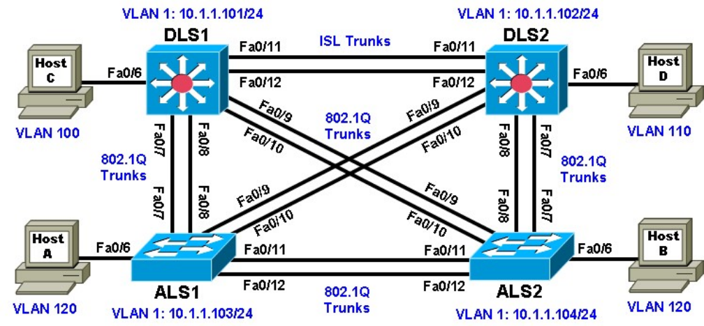
Practical 6, Static VLANS, VLAN Trunking, and VTP Domains and
Modes
Topology
Objectives
• Set up a VTP domain.
• Create and maintain VLANs.
• Configure ISL and 802.1Q trunking.
Background
VLANs logically segment a network by function, team, or application, regardless of the physical location of the
users. End stations in a particular IP subnet are often associated with a specific VLAN. VLAN membership on
a switch that is assigned manually for each interface is known as static VLAN membership.
Trunking, or connecting switches, and the VLAN Trunking Protocol (VTP) are technologies that support
VLANs. VTP manages the addition, deletion, and renaming of VLANs on the entire network from a single
central switch.
Note: This lab uses Cisco WS-C2960-24TT-L switches with the Cisco IOS image c2960-lanbasek9-
mz.12246.SE.bin, and Catalyst 3560-24PS with the Cisco IOS image c3560-advipservicesk9-mz.122-
46.SE.bin. You can use other switches (such as a 2950 or 3550) and Cisco IOS Software versions if they
have comparable capabilities and features. Depending on the switch model and Cisco IOS Software version,
the commands available and output produced might vary from what is shown in this lab.
Required Resources
• 2 switches (Cisco 2960 with the Cisco IOS Release 12.2(46)SE C2960-LANBASEK9-M image or
comparable)
• 2 switches (Cisco 3560 with the Cisco IOS Release 12.2(46)SE C3560-ADVIPSERVICESK9-M image
or comparable)
• 4 PCs (optional)
• Ethernet and console cables
Step 1: Prepare the switches for the lab.
Power up the switches and use the standard process for establishing a HyperTerminal console connection
from a workstation to each switch in your pod. If you are connecting remotely to the switches, follow the
instructions that have been supplied by your instructor.
Remove all VLAN information and configurations that may have been previously entered into the switches.
Refer to Lab 1-1, “Clearing a Switch,” and Lab 1-2, “Clearing a Switch Connected to a Larger Network.”
Step 2: Configure basic switch parameters.
Assign each switch a hostname and configure an IP address on the management VLAN according to the
diagram. By default, VLAN 1 is used as the management VLAN.
Enter basic configuration commands on each switch according to the diagram.
DLS1 example:
Switch# configure terminal
Enter configuration commands, one per line. End with CNTL/Z.
Switch(config)# hostname DLS1
DLS1(config)# interface vlan 1
DLS1(config-if)# ip address 10.1.1.101 255.255.255.0 DLS1(config-
if)# no shutdown
(Optional) On each switch, create an enable secret password and configure the vty lines to allow remote
access from other network devices. DLS1 example:
DLS1(config)# enable secret cisco
DLS1(config)# line vty 0 15
DLS1(config-line)# password cisco
DLS1(config-line)# login
Step 3: Display the switch default VLAN information.
Use the show vlan command in privileged mode on any switch. The following output is for a 2960 switch.
ALS1# show vlan
VLAN Name Status Ports
---- -------------------------------- --------- -------------------------------
1 default active Fa0/1, Fa0/2, Fa0/3, Fa0/4
Fa0/5, Fa0/6, Fa0/7, Fa0/8
Fa0/9, Fa0/10, Fa0/11, Fa0/12
Fa0/13, Fa0/14, Fa0/15, Fa0/16
Fa0/17, Fa0/18, Fa0/19, Fa0/20
Fa0/21, Fa0/22, Fa0/23, Fa0/24
Gi0/1, Gi0/2
1002 fddi-default act/unsup
1003 token-ring-default act/unsup
1004 fddinet-default act/unsup
1005 trnet-default act/unsup
VLAN Type SAID MTU Parent RingNo BridgeNo Stp BrdgMode Trans1
Trans2 ---- ----- ---------- ----- ------ ------ -------- ---- -------- -----
- ------ 1 enet 100001 1500 - - - - - 0
0 1002 fddi 101002 1500 - - - - - 0
0 1003 tr 101003 1500 - - - - - 0
0 1004 fdnet 101004 1500 - - - ieee - 0
0 1005 trnet 101005 1500 - - - ibm - 0
0
Remote SPAN VLANs
------------------------------------------------------------------------------
Primary Secondary Type Ports
------- --------- ----------------- ------------------------------------------
The following output is for a 3560 switch.
DLS1# show vlan
VLAN Name Status Ports
---- -------------------------------- --------- -------------------------------
1 default active Fa0/1, Fa0/2, Fa0/3, Fa0/4
Fa0/5, Fa0/6, Fa0/7, Fa0/8
Fa0/9, Fa0/10, Fa0/11, Fa0/12
Fa0/13, Fa0/14, Fa0/15, Fa0/16
Fa0/17, Fa0/18, Fa0/19, Fa0/20
Fa0/21, Fa0/22, Fa0/23, Fa0/24
Gi0/1, Gi0/2
1002 fddi-default act/unsup
1003 token-ring-default act/unsup
1004 fddinet-default act/unsup
1005 trnet-default act/unsup
VLAN Type SAID MTU Parent RingNo BridgeNo Stp BrdgMode Trans1 Trans2 -
--- ----- ---------- ----- ------ ------ -------- ---- -------- ------ ------ 1
enet 100001 1500 - - - - - 0 0 1002
fddi 101002 1500 - - - - - 0 0
1003 tr 101003 1500 - - - - - 0 0
1004 fdnet 101004 1500 - - - ieee - 0 0
1005 trnet 101005 1500 - - - ibm - 0 0
Remote SPAN VLANs
------------------------------------------------------------------------------
Primary Secondary Type Ports
------- --------- ----------------- ------------------------------------------
Note the default VLAN numbers, names, and associated types, and that all switch ports are automatically
assigned to VLAN 1.
You can use the show vlan command to determine the mode of a port. Ports configured for a particular VLAN
are shown in that VLAN. Ports configured for trunk mode are not associated with a specific VLAN, and so are
not included in the output.
Step 4: Examine VTP information.
A VTP domain, also called a VLAN management domain, consists of trunked switches that are under the
administrative responsibility of a switch or switches in server VTP mode. A switch can be in only one VTP
domain with the same VTP domain name. The default VTP mode for the 2960 and 3560 switches is server
mode. VLAN information is not propagated until a domain name is specified and trunks are set up between
the devices.
The following table describes the three VTP modes.

VTP Mode Description
VTP server You can create, modify, and delete VLANs and specify other
configuration parameters, such as VTP version and VTP
pruning, for the entire VTP domain. VTP servers advertise their
VLAN configuration to other switches in the same VTP domain
and synchronize their VLAN configuration with other switches
based on advertisements received over trunk links.
VTP server is the default mode.
VTP client
VTP clients behave the same way as VTP servers, but you
cannot create, change, or delete VLANs on a VTP client.
VTP transparent
VTP transparent switches do not participate in VTP. A VTP
transparent switch does not advertise its VLAN configuration nor
synchronize its VLAN configuration based on received
advertisements. Transparent switches do forward VTP
advertisements that they receive out their trunk ports in VTP
Version 2.
Use the show vtp status command on any switch. The output should be similar to the following sample for
DLS1.
DLS1# show vtp status
VTP Version : running VTP1 (VTP2 capable)
Configuration Revision : 0
Maximum VLANs supported locally : 1005
Number of existing VLANs : 5
VTP Operating Mode :
Server
VTP Domain Name :
VTP Pruning Mode : Disabled
VTP V2 Mode : Disabled
VTP Traps Generation : Disabled
MD5 digest : 0x57 0xCD 0x40 0x65 0x63 0x59 0x47 0xBD
Configuration last modified by 0.0.0.0 at 0-0-00 00:00:00
Local updater ID is 10.1.1.101 on interface Vl1 (lowest numbered VLAN interface
found)
Because no VLAN configurations were made, all settings are the defaults. Notice that the VTP mode is server
mode. The number of existing VLANs is the five built-in VLANs. The 3560 switch supports 1,005 maximum
VLANs locally. The 2960 switch supports 255 VLANs. The configuration revision is 0, and the default VTP
version is 1. All switches in the VTP domain must run the same VTP version.
The importance of the configuration revision number is that the switch with the highest revision number in VTP
server mode propagates VLAN information over trunked ports. Every time VLAN information is modified and
saved in the VLAN database or vlan.dat file, the revision number is increased by one when the user exits from
VLAN configuration mode.
Multiple switches in the VTP domain can be in VTP server mode. These switches can be used to manage all
other switches in the VTP domain. This is suitable for small-scale networks where the VLAN information is
small and easily stored in all switches. In a large network, the administrator must determine which switches
make the best VTP servers. The network administrator should select switches to function as VTP servers. The
other switches in the VTP domain can be configured as clients. The number of VTP servers should be
consistent based on the amount of redundancy desired in the network.
Step 5: Configure VTP on the switches.
Change the VTP domain name on DLS1 to SWLAB using the vtp domain command. If the VTP version
defaults to 1, set it manually to version 2 using the vtp version command.
DLS1(config)# vtp domain SWLAB
Changing VTP domain name from NULL to SWLAB
DLS1(config)# vtp version 2
Note: The newest VTP version, VTPv3, is not supported by the IOS used on the switches in this lab. However,
it is supported in IOS versions 12.2(52)SE and newer on all platforms eligible for this IOS (2960, 3560, 3750,
etc.). VTPv3 has improvements in three major areas.
Better administrative control over which device is allowed to update other devices’ view of the VLAN topology.
The chance of unintended and disruptive changes is significantly reduced, and availability is increased.
Functionality for the VLAN environment has been significantly expanded. In addition to supporting the earlier
ISL VLAN range from 1 to 1001, the new version supports the whole IEEE 802.1Q VLAN range up to 4095. In
addition to supporting the concept of normal VLANs, VTP version 3 can transfer information regarding Private
VLAN (PVLAN) structures.
The third area of major improvement is support for databases other than VLAN (for example, MST).
Set up the switches so that the distribution layer switches are in VTP server mode, and the access layer
switches are in VTP client mode. Set the version number to 2 on the DL switches.
DLS1(config)# vtp mode server Device
mode already VTP SERVER.
Because the default mode is server, you receive a message on DLS1 stating that the device mode is
already VTP server.
ALS1(config)# vtp mode client Setting
device to VTP CLIENT mode.
Note: You cannot modify the version in VTP client mode
Use the show vtp status command on either of the AL switches. The output should be similar to the following
sample for ALS1.
ALS1# show vtp status
VTP Version : running VTP1 (VTP2 capable)
Configuration Revision : 0
Maximum VLANs supported locally : 255
Number of existing VLANs : 5
VTP Operating Mode : Client
VTP Domain Name :
VTP Pruning Mode : Disabled
VTP V2 Mode : Disabled
VTP Traps Generation : Disabled
MD5 digest : 0x57 0xCD 0x40 0x65 0x63 0x59 0x47 0xBD
Configuration last modified by 0.0.0.0 at 0-0-00 00:00:00

Notice that you do not see the VTP domain name that you set up on DLS1. Because no trunks are set up
between the switches, they have not started to distribute any VLAN information. There is no IP address
(0.0.0.0) or time listed for the last configuration modification.
Step 6: Configure trunking.
The show interfaces switchport command lists the configured mode of each port in detail. The following
partial sample output is for a 2960 switch on Fa0/7.
ALS1# show interfaces fastEthernet 0/7 switchport
Name: Fa0/7
Switchport: Enabled
Administrative Mode: dynamic auto
Operational Mode: static access
Administrative Trunking Encapsulation: dot1q
Operational Trunking Encapsulation: native
Negotiation of Trunking: On
Access Mode VLAN: 1 (default)
Trunking Native Mode VLAN: 1 (default)
Administrative Native VLAN tagging: enabled
Voice VLAN: none
Administrative private-vlan host-association: none
Administrative private-vlan mapping: none
Administrative private-vlan trunk native VLAN: none
Administrative private-vlan trunk Native VLAN tagging: enabled
Administrative private-vlan trunk encapsulation: dot1q Administrative
private-vlan trunk normal VLANs: none
Administrative private-vlan trunk private VLANs: none
Operational private-vlan: none Trunking VLANs
Enabled: ALL
Pruning VLANs Enabled: 2-1001 Capture
Mode Disabled
Capture VLANs Allowed: ALL
Protected: false
Unknown unicast blocked: disabled
Unknown multicast blocked: disabled
Appliance trust: none
Ports on the 2960 and 3560 switches are set to dynamic auto by default. This means that they are willing
to negotiate a trunk with the neighbor; however, if both sides are set to dynamic auto, the link will remain
in access mode. This can be done by configuring one end of the trunk using the switchport mode trunk
command. On the 3560 switches, you also need to configure the trunk encapsulation with the switchport
trunk encapsulation command. The 3560 switch can use either Inter-Switch Link (ISL) or 802.1Q
encapsulation, whereas the 2960 switch only supports 802.1Q.
Refer to the lab diagram for which ports to set up as trunks and the type of encapsulation to use.
Configure only the interfaces on DLS1 and ALS1 with the switchport mode trunk command, and leave
DLS2 and ALS2 as the default port types for Fast Ethernet interfaces 0/9–0/12. Fast Ethernet 0/7 and 0/8 of
DLS2 also need to be configured with the switchport mode trunk command for the trunks connecting DLS2
and ALS2.
The 2960 and 3560 switches have a range command that you can use to designate multiple individual ports
or a continuous range of ports for an operation. Use the interface range command to configure all trunk ports
at once for trunking. The following is a sample configuration for the 802.1Q and ISL trunk ports on DLS1.
DLS1(config)# interface range fastEthernet 0/7 - 10

DLS1(config-if-range)# switchport trunk encapsulation dot1q
DLS1(config-if-range)# switchport mode trunk
DLS1(config)# interface range fastEthernet 0/11 - 12
DLS1(config-if-range)# switchport trunk encapsulation isl
DLS1(config-if-range)# switchport mode trunk
The following is a sample configuration for the trunk ports on ALS1.
ALS1(config)# interface range fastEthernet 0/7 – 12
ALS1(config-if)# switchport mode trunk
The following is a sample configuration for the trunk ports on DLS2.
DLS2(config)# interface range fastEthernet 0/7 - 8
DLS2(config-if-range)# switchport trunk encapsulation dot1q
DLS2(config-if-range)# switchport mode trunk
Note: This lab uses dynamic trunking protocol (DTP) to negotiate trunking, which can lead to security issues.
In general, when configuring trunks, it is a good practice to deactivate DTP using the switchport nonegotiate
command and configure all trunks statically.
Step 7: Verify trunk configuration. Use the show interfaces
fastEthernet 0/7 switchport command on ALS2.
ALS2# show interfaces fastEthernet 0/7 switchport
Name: Fa0/7
Switchport: Enabled
Operational Mode: trunk
Administrative Trunking Encapsulation: dot1q
Operational Trunking Encapsulation: dot1q
Negotiation of Trunking: On
Access Mode VLAN: 1 (default)
Trunking Native Mode VLAN: 1 (default)
Administrative Native VLAN tagging: enabled
Voice VLAN: none
Administrative private-vlan host-association: none
Administrative private-vlan mapping: none
Administrative private-vlan trunk native VLAN: none
Administrative private-vlan trunk Native VLAN tagging: enabled
Administrative private-vlan trunk encapsulation: dot1q Administrative
private-vlan trunk normal VLANs: none
Administrative private-vlan trunk private VLANs: none
Operational private-vlan: none Trunking
VLANs Enabled: ALL
Pruning VLANs Enabled: 2-1001 Capture
Mode Disabled
Capture VLANs Allowed: ALL
Protected: false
Unknown unicast blocked: disabled
Unknown multicast blocked: disabled
Appliance trust: none
Administrative Mode: dynamic auto

Notice that administrative mode on Fa0/7 is still the default dynamic auto. Fa0/7 on ALS2 is operating as a
trunk, because port Fa0/7 of DLS2 was configured using the switchport mode trunk command. Once this
command was issued, trunking was negotiated between the two switch ports. Use the show interfaces
trunk command on DLS1.
DLS1# show interfaces trunk
Port Mode Encapsulation Status Native vlan
Fa0/7 on 802.1q trunking 1
Fa0/8 on 802.1q trunking 1
Fa0/9 on 802.1q trunking 1
Fa0/10 on 802.1q trunking 1
Fa0/11 on isl trunking 1
Fa0/12 on isl trunking 1
Fa0/7 1-4094
Fa0/8 1-4094
Fa0/9 1-4094
Fa0/10 1-4094
Fa0/11 1-4094
Fa0/12 1-4094
Port Vlans allowed and active in management domain
Fa0/7 1
Fa0/8 1
Fa0/9 1
Fa0/10 1
Fa0/11 1
Port Vlans allowed and active in management domain
Fa0/12 1
Port Vlans in spanning tree forwarding state and not pruned
Fa0/7 1
Fa0/8 1
Fa0/9 1
Fa0/10 1
Fa0/11 1
Fa0/12 none
Note: By default, all VLANs are allowed on all trunks. You can explicitly control which VLANs are allowed on
a trunk by using the switchport trunk allowed vlan vlan-id command on the interface at each end of the
trunk. In addition, you can specify a native VLAN other than the default VLAN 1, using the switchport trunk
native vlan vlan-id command. These two measures can help reduce the possibility of VLAN attacks. Use
the show interfaces trunk command on DLS2.
DLS2# show interfaces trunk
Port Mode Encapsulation Status Native vlan
Fa0/7 on 802.1q trunking 1
Fa0/8 on 802.1q trunking 1
Fa0/9 auto n-802.1q trunking 1
Fa0/10 auto n-802.1q trunking 1
Fa0/11 auto n-isl trunking 1
Fa0/12 auto n-isl trunking 1
Port Vlans allowed on trunk
Port Vlans allowed on trunk
Fa0/7 1-4094
Fa0/8 1-4094
Fa0/9 1-4094
Fa0/10 1-4094
Fa0/11 1-4094
Fa0/12 1-4094
Port Vlans allowed and active in management domain
Fa0/7 1
Fa0/8 1
Fa0/9 1
Fa0/10 1
Fa0/11 1
Port Vlans allowed and active in management domain
Fa0/12 1
Port Vlans in spanning tree forwarding state and not pruned
Fa0/7 1
Fa0/8 1
Fa0/9 1
Fa0/10 1
Fa0/11 1
Fa0/12 1
Notice the highlighted portion of the above output from DLS2 where it indicates that these ports became
trunks by negotiation. For example, port Fa0/9 mode is Auto and encapsulation is n-802.1q. The “n”
indicates the 802.1q encapsulation was negotiated. The connected ports of the respective switches were
configured using the switchport mode trunk command.
Step 8: Configure access ports.
A port on the 2960 switch can operate in one of three modes, and a port on the 3560 switch can operate in
one of five modes. Use the switchport mode ? command for interface Fast Ethernet 0/6 in interface
configuration mode to view the modes. The following command output is for a 2960 switch.
ALS1(config)# interface fastEthernet 0/6
ALS1#(config-if)# switchport mode ? access Set
trunking mode to ACCESS unconditionally
dynamic Set trunking mode to dynamically negotiate access or trunk mode
trunk Set trunking mode to TRUNK unconditionally
The following command output is for a 3560 switch.
DLS1(config)# interface fastEthernet 0/6
DLS1(config-if)# switchport mode ? access Set
trunking mode to ACCESS unconditionally dot1q-tunnel
set trunking mode to TUNNEL unconditionally
dynamic Set trunking mode to dynamically negotiate access or trunk
mode
private-vlan Set the mode to private-vlan host or promiscuous
trunk Set trunking mode to TRUNK unconditionally
The Fast Ethernet ports connected to the hosts on the network can be set up as static access because they
are not to be used as trunk ports. Use the switchport mode access command to set the access mode on the

Fast Ethernet 0/6 port on all four switches in the pod. The following is a sample configuration for the access
port on ALS1.
ALS1(config)# interface fastEthernet 0/6 ALS1(config-if)#
switchport mode access
Use the show interfaces command for Fast Ethernet 0/6 to verify the configuration. The
following command is for a 3560 switch.
DLS1# show interfaces fastEthernet 0/6 switchport
Name: Fa0/6
Switchport: Enabled
Administrative Mode: static access
Operational Mode: down
Administrative Trunking Encapsulation: negotiate
Negotiation of Trunking: Off
Access Mode VLAN: 1 (default)
Trunking Native Mode VLAN: 1 (default)
Administrative Native VLAN tagging: enabled
Voice VLAN: none
Administrative private-vlan host-association: none
Administrative private-vlan mapping: none
Administrative private-vlan trunk native VLAN: none
Administrative private-vlan trunk Native VLAN tagging: enabled
Administrative private-vlan trunk encapsulation: dot1q Administrative
private-vlan trunk normal VLANs: none
Administrative private-vlan trunk private VLANs: none
Operational private-vlan: none Trunking VLANs
Enabled: ALL
Pruning VLANs Enabled: 2-1001 Capture
Mode Disabled
Capture VLANs Allowed: ALL
Protected: false
Unknown unicast blocked: disabled
Unknown multicast blocked: disabled Appliance
trust: none
Note that administrative mode has now changed to static access and that trunking negotiation is off. The
Fast Ethernet 0/6 ports on all four switches are now statically set to connect to a host device.
Step 9: Verify VTP configuration.
Before configuring the VLANs, verify the VTP configuration within the domain by using the show vtp status
command on ALS1 and ALS2. The following sample output is from ALS1.
ALS1# show vtp status
VTP Version : running VTP2
Configuration Revision : 1
Maximum VLANs supported locally : 255
Number of existing VLANs : 5
VTP Operating Mode : Client
VTP Domain Name : SWLAB
VTP Pruning Mode : Disabled
VTP V2 Mode : Enabled
VTP Traps Generation : Disabled
MD5 digest : 0xD1 0xC0 0x36 0xF9 0xC4 0x3E 0x73 0xA0
Configuration last modified by 10.1.1.101 at 3-1-93 00:12:43

The following sample output is from ALS2.
ALS2# show vtp status
VTP Version : running VTP2
Configuration Revision : 1
Maximum VLANs supported locally : 255
Number of existing VLANs : 5
VTP Operating Mode : Client
VTP Domain Name : SWLAB
VTP Pruning Mode : Disabled
VTP V2 Mode : Enabled
VTP Traps Generation : Disabled
MD5 digest : 0xD1 0xC0 0x36 0xF9 0xC4 0x3E 0x73 0xA0
Configuration last modified by 10.1.1.101 at 3-1-93 00:12:43
At this point, all switches in the lab are in VTP domain SWLAB and have five existing VLANs. All are running
VTP version 2. DLS1 and DLS2 are configured as VTP servers, and ALS1 and ALS2 are configured as
clients.
Note: You can limit the VLAN traffic passed between switches using VTP pruning. Pruning increases available
bandwidth by restricting flooded traffic to those trunk links that the traffic must use to access the destination
devices. You can enable VTP pruning on a switch in VTP server mode using the vtp pruning command. For
example, if a VLAN is not defined on access switch ALS1 but is defined on distribution switches DLS1 and
DLS2, the VLAN will be pruned from the trunk links between ALS1 and the distribution switches but not from
the link between the two distribution switches.
Step 10: Configure VLANs by assigning port membership.
VLANs can be configured on a switch in different ways, depending on the type of switch used and the Cisco
IOS version.
An older way to configure VLANs is to use the VLAN database. This method is being deprecated and is no
longer recommended. However, the VLAN database is still accessible for those who choose to use it. For
example, the following command is for a 3560 switch.
DLS1# vlan database
% Warning: It is recommended to configure VLAN from config mode,
as VLAN database mode is being deprecated. Please consult user
documentation for configuring VTP/VLAN in config mode.
A more current method to create a VLAN is to assign a port to a VLAN that does not yet exist. If the switch is
in VTP Server or Transparent mode, it automatically creates the VLAN to the port that it has been assigned to.
VLAN 1 is the management VLAN by default. By default, all ports are set to dynamic mode and their access
VLAN is set to 1. There is no need to create a VLAN 1, assign ports to it, or to set the mode of each port.
According to the lab diagram, VLANs 100, 110, and 120 must be created, and port 6 must be assigned to
each VLAN. You will create VLANs 100 and 110 on the distribution switches using the port assignment
method. You will create VLAN 120 for the access switches using global configuration commands and then
assign ports to those VLANs.
Use the switchport access vlan command to assign port 6 on DLS1 and DLS2, according to the diagram.
Port Fast Ethernet 0/6 of DLS1 will be assigned to VLAN 100, and Fast Ethernet 0/6 on DLS2 will be
assigned to VLAN 110. The following command is for the 3560 switches.
DLS1(config)# interface FastEthernet 0/6
DLS1(config-if-range)# switchport access vlan 100 %
Access VLAN does not exist. Creating vlan 100

VLAN 100 was created at the same time port 6 was assigned to it. Configure
DLS2 in the manner similar to DLS1, but this time use VLAN 110.
DLS2(config)# interface FastEthernet 0/6
DLS2(config-if-range)# switchport access vlan 110
% Access VLAN does not exist. Creating vlan 110
Issue the show vlan command on DLS1 to verify that VLANs 100 and 110 have been created. The output
should be similar to the following output.
DLS1# show vlan
VLAN Name Status Ports
---- -------------------------------- --------- -----------------------------
1 default active Fa0/1, Fa0/2, Fa0/3, Fa0/4
Fa0/5, Fa0/13, Fa0/14
Fa0/15, Fa0/16, Fa0/17,
Fa0/18
Fa0/19, Fa0/20, Fa0/21,
Fa0/22
Fa0/23, Fa0/24, Gi0/1, Gi0/2
100 VLAN0100 active Fa0/6
110 VLAN0110 active
1002 fddi-default act/unsup
1003 token-ring-default act/unsup
1004 fddinet-default act/unsup
1005 trnet-default act/unsup
VLAN Type SAID MTU Parent RingNo BridgeNo Stp BrdgMode Trans1
Trans2
---- ----- ---------- ----- ------ ------ -------- ---- -------- ------ -----
1 enet 100001 1500 - - - - - 0 0
100 enet 100100 1500 - - - - - 0 0
110 enet 100110 1500 - - - - - 0 0
1002 fddi 101002 1500 - - - - - 0 0
VLAN Type SAID MTU Parent RingNo BridgeNo Stp BrdgMode Trans1
Trans2
---- ----- ---------- ----- ------ ------ -------- ---- -------- ------ -----
1003 tr 101003 1500 - - - - - 0 0
1004 fdnet 101004 1500 - - - ieee - 0 0
1005 trnet 101005 1500 - - - ibm - 0 0
Remote SPAN VLANs
-----------------------------------------------------------------------------
Primary Secondary Type Ports
------- --------- ----------------- -----------------------------------------
Because VLAN 100 and 110 were not named, the switch automatically assigns default names, which are
VLAN0100 and VLAN0110.
Note that on DLS1, port Fa0/6 is active in VLAN 100. A show vlan command issued on DLS2 should
show port Fa0/6 active in VLAN 110.
Step 11: Configure VLANs in configuration mode.
Another way of creating VLANs is to create them in configuration mode without assigning port membership.
You can create a VLAN in global configuration mode using the vlan command. Because ALS1 and ALS2 are
configured for VTP client mode and it is not possible to create a VLAN when a switch is in client mode, you
must create the VLAN on the switch that is acting as a server for the network. The VLAN then propagates to
the other switches that are in client mode. Issue the vlan command in global configuration mode on DLS1.
DLS1(config)# vlan 120
Ports still need to be assigned to VLAN 120. Port assignment to a VLAN is an interface configuration
operation. Use the switchport access vlan command on Fast Ethernet 0/6 of ALS1 and ALS2 to configure
ports for VLAN 120.
ALS1(config)# interface fastEthernet 0/6
ALS1(config-if)# switchport access vlan 120
ALS2(config)# interface fastEthernet 0/6
ALS2(config-if)# switchport access vlan 120
Use the show vlan command to verify the creation of VLAN 120, with port Fa0/6 assigned to it. The output
should be similar to the following.
ALS1# show vlan
VLAN Name Status Ports
---- ------------------------------ --------- -----------------------------
1 default active Fa0/1, Fa0/2, Fa0/3, Fa0/4
Fa0/5, Fa0/13, Fa0/14, Fa0/15
Fa0/16, Fa0/17, Fa0/18, Fa0/19
Fa0/20, Fa0/21, Fa0/22, Fa0/23
Fa0/24, Gi0/1, Gi0/2
100 VLAN0100 active
110 VLAN0110 active
120 VLAN0120 active Fa0/6
1002 fddi-default act/unsup 1003
token-ring-default act/unsup 1004
fddinet-default act/unsup
1005 trnet-default act/unsup
VLAN Type SAID MTU Parent RingNo BridgeNo Stp BrdgMode Trans1
Trans2
---- ----- ---------- ----- ------ ------ -------- ---- -------- ------ -----
1 enet 100001 1500 - - - - - 0 0
100 enet 100100 1500 - - - - - 0 0
110 enet 100110 1500 - - - - - 0 0
120 enet 100120 1500 - - - - - 0 0
1002 fddi 101002 1500 - - - - - 0 0
VLAN Type SAID MTU Parent RingNo BridgeNo Stp BrdgMode Trans1
Trans2
---- ----- ---------- ----- ------ ------ -------- ---- -------- ------ -----
1003 tr 101003 1500 - - - - srb 0 0
1004 fdnet 101004 1500 - - - ieee - 0 0
1005 trnet 101005 1500 - - - ibm - 0 0
Remote SPAN VLANs
-----------------------------------------------------------------------------
Primary Secondary Type Ports

------- --------- ----------------- -----------------------------------------
Step 12: Change the VLAN names.
The VLANs have not been named yet. Naming VLANs can help network administrators identify the
functionality of those VLANs. To add names, use the name command in VLAN configuration mode. The
following is a sample configuration for naming the three VLANs created in the domain.
DLS1(config)# vlan 100
DLS1(config-vlan)# name Server-Farm-1
DLS1(config-vlan)# exit
DLS1(config)# vlan 110
DLS1(config-vlan)# name Server-Farm-2
DLS1(config-vlan)# exit
DLS1(config)# vlan 120
DLS1(config-vlan)# name Net-Eng DLS1(config-vlan)# exit Use the
show vlan command on DLS1 to verify that the new names have been added.
DLS1# show vlan
VLAN Name Status Ports
---- -------------------------------- --------- -------------------------------
1 default active Fa0/1, Fa0/2, Fa0/3, Fa0/4
Fa0/5, Fa0/7, Fa0/8, Fa0/9
Fa0/10, Fa0/11, Fa0/12, Fa0/13
Fa0/14, Fa0/15, Fa0/16, Fa0/17
Fa0/18, Fa0/19, Fa0/20, Fa0/21
Fa0/22, Fa0/23, Fa0/24, Gi0/1
Gi0/2
100 Server-Farm-1 active Fa0/6
110 Server-Farm-2 active
120 Net-Eng active
1002 fddi-default act/unsup
1003 token-ring-default act/unsup
1004 fddinet-default act/unsup
1005 trnet-default act/unsup
VLAN Type SAID MTU Parent RingNo BridgeNo Stp BrdgMode Trans1 Trans2
---- ----- ---------- ----- ------ ------ -------- ---- -------- ------ ------
1 enet 100001 1500 - - - - - 0 0 100
enet 100100 1500 - - - - - 0 0
110 enet 100110 1500 - - - - - 0 0
VLAN Type SAID MTU Parent RingNo BridgeNo Stp BrdgMode Trans1 Trans2
---- ----- ---------- ----- ------ ------ -------- ---- -------- ------ ------
120 enet 100120 1500 - - - - - 0 0
1002 fddi 101002 1500 - - - - - 0 0
1003 tr 101003 1500 - - - - - 0 0
1004 fdnet 101004 1500 - - - ieee - 0 0
1005 trnet 101005 1500 - - - ibm - 0 0
Remote SPAN VLANs
------------------------------------------------------------------------------
Primary Secondary Type Ports
------- --------- ----------------- ---------------------------------------

Step 13: Change the VLAN status to deactivate ports.
The default status of VLAN 1 and user-created VLANs is "active". A VLAN can be made locally inactive in the
VLAN configuration mode by entering the command shutdown for the particular VLAN (does not apply to an
SVI). This will cause all ports on a switch in a particular VLAN to stop transmitting data. Shutting down the
VLAN on a switch does not influence its state on other switches in a VTP domain.
Shutdown the Net-Eng VLAN 120 on ALS1, wait a few moments, exit vlan configuration mode and then issue
the show vlan brief command. The status should change to “act/lshut”.
ALS1(config)# vlan 120
ALS1(config-vlan)# shutdown
ALS1# show vlan brief
VLAN Name Status Ports
---- -------------------------------- --------- -------------------------------
1 default active Fa0/1, Fa0/2, Fa0/3, Fa0/4
Fa0/5, Fa0/7, Fa0/8, Fa0/9
Fa0/10, Fa0/11, Fa0/12, Fa0/13
Fa0/14, Fa0/15, Fa0/16, Fa0/17
Fa0/18, Fa0/19, Fa0/20, Fa0/21
Fa0/22, Fa0/23, Fa0/24, Gi0/1
Gi0/2
100 Server-Farm-1 active Fa0/6
110 Server-Farm-2 active
120 Net-Eng act/lshut
1002 fddi-default act/unsup
1003 token-ring-default act/unsup
1004 fddinet-default act/unsup
1005 trnet-default act/unsup
Reactivate all ports in ALS1 Net-Eng VLAN 120 using the no shutdown command in VLAN configuration
mode..
ALS1(config)# vlan 120
ALS1(config-vlan)# no shutdown
You can also put a VLAN into “suspend” status. The "suspend" state is configured in the VLAN configuration
mode using the command state suspend. Suspending a VLAN causes all ports in that VLAN throughout the
VTP domain to stop transferring data.
Suspend Net-Eng VLAN 120 on ALS1, wait a few moments, exit VLAN configuration mode and then issue the
show vlan brief command. The status should change to “suspended”.
ALS1(config)# vlan 120
ALS1(config-vlan)# state suspend
ALS1# show vlan brief
VLAN Name Status Ports
---- -------------------------------- --------- -------------------------------
1 default active Fa0/1, Fa0/2, Fa0/3, Fa0/4
Fa0/5, Fa0/7, Fa0/8, Fa0/9
Fa0/10, Fa0/11, Fa0/12, Fa0/13
Fa0/14, Fa0/15, Fa0/16, Fa0/17
Fa0/18, Fa0/19, Fa0/20, Fa0/21
Fa0/22, Fa0/23, Fa0/24, Gi0/1

Gi0/2
100 Server-Farm-1 active Fa0/6
110 Server-Farm-2 active
120 Net-Eng suspended
1002 fddi-default act/unsup
1003 token-ring-default act/unsup
1004 fddinet-default act/unsup
1005 trnet-default act/unsup
Reactivate VLAN 120 using the state active command in VLAN configuration mode..
ALS1(config)# vlan 120
ALS1(config-vlan)# state active
Note: The suspend state is advertised by VTP while the lshut state is not. The state suspend command can
be issued on any switch in the VTP domain. It does not have to be issued on the VTP server.
Both options can be used to temporarily take a particular VLAN out of operation which can be useful in certain
scenarios - especially for guests, infrequently used conference rooms and similar deployments.
Step 14: Prepare for the next lab.
Prepare for the next lab by removing all the VLAN information and configurations. The VLAN database and
startup configuration need to be deleted.

Practical 6b, Configuring EtherChannel
Topology
Objective
• Configure EtherChannel.
Background
Four switches have just been installed. The distribution layer switches are Catalyst 3560 switches, and the
access layer switches are Catalyst 2960 switches. There are redundant uplinks between the access layer and
distribution layer. Usually, only one of these links could be used; otherwise, a bridging loop might occur.
However, using only one link utilizes only half of the available bandwidth. EtherChannel allows up to eight
redundant links to be bundled together into one logical link. In this lab, you configure Port Aggregation
Protocol (PAgP), a Cisco EtherChannel protocol, and Link Aggregation Control Protocol (LACP), an IEEE
802.3ad open standard version of EtherChannel.
Note: This lab uses Cisco WS-C2960-24TT-L switches with the Cisco IOS image c2960-lanbasek9-
mz.12246.SE.bin, and Catalyst 3560-24PS with the Cisco IOS image c3560-advipservicesk9-mz.122-
46.SE.bin. You can use other switches (such as a 2950 or 3550) and Cisco IOS Software versions if they
have comparable capabilities and features. Depending on the switch model and Cisco IOS Software version,
the commands available and output produced might vary from what is shown in this lab.
Required Resources
• 2 switches (Cisco 2960 with the Cisco IOS Release 12.2(46)SE C2960-LANBASEK9-M image or
comparable)
• 2 switches (Cisco 3560 with the Cisco IOS Release 12.2(46)SE C3560- ADVIPSERVICESK9-M
image or comparable)
• Ethernet and console cables
Step 1: Prepare the switches for the lab.

Delete vlan.dat, erase the startup configuration, and reload all your switches. Refer to Lab 1-1, “Clearing a
Switch,” and Lab 1-2, “Clearing a Switch Connected to a Larger Network.” Step 2: Configure basic
switch parameters.
a. Assign each switch a hostname according to the topology diagram.
b. Configure ports Fa0/7 through Fa0/12 as trunks. On the 3560 switches, you must first set the trunk
encapsulation to 802.1Q. On the 2960s, only dot1q is supported, therefore the switchport trunk
encapsulation command is unavailable, but the mode still needs to be changed to trunk.
Note: If the ports are configured with dynamic auto mode and you do not set the mode of the ports to trunk,
the links do not form trunks and remain access ports. The default mode on a 3560 or 2960 switch is dynamic
auto. The default mode on a 3550 or 2950 switch is dynamic desirable. DLS1 example:
DLS1# configure terminal
Enter configuration commands, one per line. End with CNTL/Z.
DLS1(config)# interface range fastEthernet 0/7 - 12
DLS1(config-if-range)# switchport trunk encapsulation dot1q
DLS1(config-if-range)# switchport mode trunk
Step 3: Configure an EtherChannel with Cisco PAgP.
Note: When configuring EtherChannels, it is a recommended best practice to shutdown the physical ports
being grouped on both devices before configuring them into channel groups. Otherwise, the EtherChannel
Misconfig Guard may place these ports into err-disabled state. The ports and port channel can be re-enabled
after the EtherChannel is configured.
a. The first EtherChannel created for this lab aggregates ports Fa0/11 and Fa0/12 between ALS1 and ALS2.
Make sure that you have a trunk link active for those two links with the show interfaces trunk command.
ALS1# show interfaces trunk
Port Mode Encapsulation Status Native vlan
Fa0/7 on 802.1q trunking 1
Fa0/8 on 802.1q trunking 1
Fa0/9 on 802.1q trunking 1
Fa0/10 on 802.1q trunking 1
Fa0/11 on 802.1q trunking 1
Fa0/12 on 802.1q trunking 1
<output omitted>
b. On both switches, add ports Fa0/11 and Fa0/12 to port channel 1 with the channel-group 1 mode
desirable command. The mode desirable option indicates that you want the switch to actively negotiate
to form a PAgP link.
ALS1(config)# interface range fastEthernet 0/11 - 12
ALS1(config-if-range)# channel-group 1 mode desirable
Creating a port-channel interface Port-channel 1
c. Configure the logical interface to become a trunk by first entering the interface port-channel number
command and then the switchport mode trunk command. Add this configuration to both switches.
ALS1(config)# interface port-channel 1
ALS1(config-if)# switchport mode trunk
d. Verify that EtherChannel is working by issuing the show etherchannel summary command on both
switches. This command displays the type of EtherChannel, the ports utilized, and port states.

ALS1# show etherchannel summary
Flags: D - down P - in port-channel
I - stand-alone s - suspended H -
Hot-standby (LACP only) R - Layer3
S - Layer2
U - in use f - failed to allocate aggregator
u - unsuitable for bundling w - waiting to be
aggregated d - default port
Number of channel-groups in use: 1
Number of aggregators: 1
Group Port-channel Protocol Ports
------+-------------+-----------+---------------------------------------- 1
Po1(SU) PAgP Fa0/11(P) Fa0/12(P)
ALS2# show etherchannel summary
Flags: D - down P - in port-channel
I - stand-alone s - suspended H -
Hot-standby (LACP only) R - Layer3
S - Layer2
U - in use f - failed to allocate aggregator
u - unsuitable for bundling w - waiting to be
aggregated d - default port
Number of channel-groups in use: 1 Number
of aggregators: 1
Group Port-channel Protocol Ports
------+-------------+-----------+---------------------------------------- 1
Po1(SU) PAgP Fa0/11(P) Fa0/12(P)
e. If the EtherChannel does not come up, you might want to try “flapping” the physical interfaces on both
ends of the EtherChannel. This involves using the shut command on those interfaces, followed by a no
shut command a few seconds later.
The show interfaces trunk and show spanning-tree commands also show the port channel as one
logical link.
ALS1# show interfaces trunk
Port Mode Encapsulation Status Native vlan
Fa0/7 on 802.1q trunking 1
Fa0/8 on 802.1q trunking 1
Fa0/9 on 802.1q trunking 1 Fa0/10
on 802.1q trunking 1
Po1 on 802.1q trunking 1
<output omitted>
ALS1# show spanning-tree
VLAN0001
Spanning tree enabled protocol ieee
Root ID Priority 32769
Address 0017.5a53.a380

Cost 19
Port 9 (FastEthernet0/9)
Hello Time 2 sec Max Age 20 sec Forward Delay 15 sec
Bridge ID Priority 32769 (priority 32768 sys-id-ext 1)
Address 001d.4635.0c80
Hello Time 2 sec Max Age 20 sec Forward Delay 15 sec
Aging Time 300
Interface Role Sts Cost Prio.Nbr Type
------------------- ---- --- --------- -------- ----------------------------
Fa0/7 Altn BLK 19 128.7 P2p
Fa0/8 Altn BLK 19 128.8 P2p
Fa0/9 Root FWD 19 128.9 P2p
Fa0/10 Altn BLK 19 128.10 P2p
Po1 Desg FWD 12 128.56 P2p
Step 4: Configure an 802.3ad LACP EtherChannel.
a. In 2000, the IEEE passed 802.3ad, which is an open standard version of EtherChannel. Using the
previous commands, configure the link between DLS1 and ALS1 on ports Fa0/7 and Fa0/8 as an LACP
EtherChannel. You must use a different port channel number on ALS1 than 1, because you already used
that in the previous step. To configure a port channel as LACP, use the interface-level command
channel-group number mode active. Active mode indicates that the switch actively tries to negotiate
that link as LACP, as opposed to PAgP.
ALS1(config)# interface range fastEthernet 0/7 - 8
ALS1(config-if-range)# channel-group 2 mode active
Creating a port-channel interface Port-channel 2
ALS1(config-if-range)# interface port-channel 2
ALS1(config-if)# switchport mode trunk
b. Apply a similar configuration on DLS1. Verify the configuration with the show etherchannel summary
command.
ALS1# show etherchannel summary
Flags: D - down P - in port-channel
I - stand-alone s - suspended H -
Hot-standby (LACP only) R - Layer3
S - Layer2
U - in use f - failed to allocate aggregator
u - unsuitable for bundling w - waiting to be
aggregated d - default port
Number of channel-groups in use: 2 Number
of aggregators: 2
Group Port-channel Protocol Ports
------+-------------+-----------+----------------------------------------
1 Po1(SU) PAgP Fa0/11(P) Fa0/12(P)
2 Po2(SU) LACP Fa0/7(P) Fa0/8(P)
Step 5: Configure a Layer 3 EtherChannel.

In the previous steps, you configured EtherChannels as Layer 2 trunk connections between switches. You
can also configure EtherChannels as Layer 3 (routed) connections on switches that support routed ports.
Because DLS1 and DLS2 are both multilayer switches, they can support routed ports.
a. Use the no switchport command on Fa0/11 and Fa0/12 to make them Layer 3 ports, and then add them
to the channel group with the channel-group number mode desirable command. On the logical
interface, issue the no switchport command to make it a Layer 3 port. Add the IP address 10.0.0.1 for
DLS1 and 10.0.0.2 for DLS2. Configure both with a /24 subnet mask.
DLS1(config)# interface range fastEthernet 0/11 - 12
DLS1(config-if-range)# no switchport
DLS1(config-if-range)# channel-group 3 mode desirable
Creating a port-channel interface Port-channel 3 DLS1(config-if-range)#
interface port-channel 3
DLS1(config-if)# no switchport
DLS1(config-if)# ip address 10.0.0.1 255.255.255.0
b. Verify that you have Layer 3 connectivity by attempting to ping the other side of the link.
DLS1# ping 10.0.0.2
Type escape sequence to abort.
Sending 5, 100-byte ICMP Echos to 10.0.0.2, timeout is 2 seconds:
!!!!!
Success rate is 100 percent (5/5), round-trip min/avg/max = 1/1/1 ms
c. If you look at the output of the show etherchannel summary command, you see that it lists the port
channel as a routed port, not a switched port. The RU in parentheses next to the name means routed and
up, as opposed to switched and up (SU).
DLS1# show etherchannel summary
Flags: D - down P - in port-channel
I - stand-alone s - suspended H -
Hot-standby (LACP only) R - Layer3
S - Layer2
U - in use f - failed to allocate aggregator
u - unsuitable for bundling w - waiting to be
aggregated d - default port
Number of channel-groups in use: 2 Number
of aggregators: 2
Group Port-channel Protocol Ports
------+-------------+-----------+----------------------------------------
2 Po2(SU) LACP Fa0/7(P) Fa0/8(P)
3 Po3(RU) PAgP Fa0/11(P) Fa0/12(P)
Step 6: Configure load balancing.
The switches can use different methods to load-balance traffic going through a port channel. The available
methods as well as the default method used varies by hardware platform. By default, Cisco Catalyst 3560
and Catalyst 2960 switches load-balance using the source MAC address.
a. You can view the current load-balancing configuration with the show etherchannel load-balance
command.
DLS1# show etherchannel load-balance
EtherChannel Load-Balancing Operational State (src-mac):
Non-IP: Source MAC address
IPv4: Source MAC address
IPv6: Source IP address
Other methods of load balancing are based on the destination MAC address, both source and destination
MAC addresses, source IP address, destination IP address, and both source and destination IP
addresses. Some older platforms, such as the Cisco Catalyst 2950 and Catalyst 3550 switches, may not
support all of these methods.
b. For this scenario, configure ALS1 to load-balance by both source and destination MAC addresses using
the global configuration command port-channel load-balance method, where the method is src-
dstmac.
ALS1(config)# port-channel load-balance src-dst-mac
c. Verify the configuration with the show etherchannel load-balance command. ALS1# show
etherchannel load-balance
EtherChannel Load-Balancing Operational State (src-dst-mac):
Non-IP: Source XOR Destination MAC address
IPv4: Source XOR Destination MAC address
IPv6: Source XOR Destination IP address
Challenge
The topology still has redundant links that you can aggregate. Experiment with the other port channel modes
using the question mark on the interface-level command channel-group number mode ?. Look at the
descriptions and implement some port channels in different ways. If The port mode is set to desirable, auto,
active or passive (when PAgP or LACP are used), the command channel-protocol can be used. It cannot be
used with channel-group number mode on command. The “on” mode statically sets the EtherChannel
protocol without negotiation.

Practical 7a, Spanning Tree Protocol (STP) Default Behavior
Topology
Objective
• Observe the default behavior of STP.
Background
Four switches have just been installed. The distribution layer switches are Catalyst 3560s, and the access
layer switches are Catalyst 2960s. There are redundant uplinks between the access layer and distribution
layer. Because of the possibility of bridging loops, spanning tree logically removes any redundant links. In
this lab, you will observe what spanning tree does and why.
Note: This lab uses Cisco WS-C2960-24TT-L switches with the Cisco IOS image c2960-lanbasek9-mz.122-
46.SE.bin and Catalyst 3560-24PS switches with the Cisco IOS image c3560-advipservicesk9-
mz.12246.SE.bin. Other switches (such as a 2950 or 3550), and Cisco IOS Software versions can be used if
they have comparable capabilities and features. Depending on the switch model and Cisco IOS Software
version, the commands available and output produced might vary from what is shown in this lab.
Required Resources
• 2 switches (Cisco 2960 with the Cisco IOS Release 12.2(46)SE C2960-LANBASEK9-M image or
comparable)
• 2 switches (Cisco 3560 with the Cisco IOS Release 12.2(46)SE C3560-ADVIPSERVICESK9-M
image or comparable)
• Ethernet and console cables
Step 1: Prepare the switches for the lab.
Refer to Lab 1-1 Clearing a Switch and Lab 1-2 Clearing a Switch Connected to a Larger Network to prepare
all four switches for this lab. Cable the equipment as shown. If you are accessing your equipment remotely,
ask your instructor for instructions on how to do this.
Step 2: Configure basic switch parameters.

a. Configure the four switches as shown in the diagram with a hostname. ALS1 example:
Switch> enable
Switch# configure terminal
Switch(config)# hostname ALS1
b. Optionally, configure an enable secret password and console security. Configure the
console line with logging synchronous and no timeout. ALS1 example:
ALS1(config)# enable secret class
ALS1(config)# line console 0
ALS1(config-line)# logging synchronous
ALS1(config-line)# exec-timeout 0 0 ALS1(config-
line)# password cisco
ALS1(config-line)# login
Note: After the cables are connected spanning tree is initiated and the switch detects the redundant links.
By default, spanning tree runs on every port. When a new link becomes active, the port goes through the
IEEE 802.1D spanning tree listening and learning states before transitioning to forwarding state. During this
period, the switch discovers if it is connected to another switch or an end-user device.
One of the switches is elected as the root bridge for the tree. Then an agreement is established as to which
links to keep active and which links to logically remove from the spanning tree (disable) if multiple links exist.
What type of frame does STP use to communicate with other switches?
__________________________________________________________________________________
The results in this lab will vary. Spanning tree operation is based on the MAC addresses of the switches. c.
Observe the LEDs on the switch to check the status of the link. For access ports a bright green light
indicates an active link. An amber light indicates an inactive link.
Step 3: Display default spanning tree information for all switches.
a. Verify IEEE 802.1D STP with the show spanning-tree command on DLS1.
Note: Your output may differ, based on the root bridge selected in your topology. The sample output below
may also differ from those in your lab, because they were generated with a different set of switches.
DLS1# show spanning-tree
VLAN0001
Spanning tree enabled protocol ieee
Root ID Priority 32769
Address 000a.b8a9.d680
Cost 19
Port 13 (FastEthernet0/11)
Hello Time 2 sec Max Age 20 sec Forward Delay 15 sec
Bridge ID Priority 32769 (priority 32768 sys-id-ext 1)
Address 000a.b8b3.d780
Hello Time 2 sec Max Age 20 sec Forward Delay 15 sec
Aging Time 300
Interface Role Sts Cost Prio.Nbr Type
---------------- ---- --- --------- -------- ------------------------------

Fa0/7 Desg FWD 19 128.9 P2p
Fa0/8 Desg FWD 19 128.10 P2p
Fa0/9 Desg FWD 19 128.11 P2p
Fa0/10 Desg FWD 19 128.12 P2p
Fa0/11 Root FWD 19 128.13 P2p
Fa0/12 Altn BLK 19 128.14 P2p
b. Verify STP with the show spanning-tree command on DLS2. DLS2#
show spanning-tree
VLAN0001
Spanning tree enabled protocol ieee
Root ID Priority 32769
Address 000a.b8a9.d680
This bridge is the root
Hello Time 2 sec Max Age 20 sec Forward Delay 15 sec
Bridge ID Priority 32769 (priority 32768 sys-id-ext 1)
Address 000a.b8a9.d680
Hello Time 2 sec Max Age 20 sec Forward Delay 15 sec
Aging Time 300
Interface Role Sts Cost Prio.Nbr Type
---------------- ---- --- --------- -------- ------------------------------
Fa0/7 Desg FWD 19 128.9 P2p
Fa0/8 Desg FWD 19 128.10 P2p
Fa0/9 Desg FWD 19 128.11 P2p
Fa0/10 Desg FWD 19 128.12 P2p
Fa0/11 Desg FWD 19 128.13 P2p
Fa0/12 Desg FWD 19 128.14 P2p
c. Verify STP with the show spanning-tree command on ALS1. ALS1#
show spanning-tree
VLAN0001
Spanning tree enabled protocol ieee
Root ID Priority 32769
Address 000a.b8a9.d680
Cost 19
Port 11 (FastEthernet0/9)
Hello Time 2 sec Max Age 20 sec Forward Delay 15 sec
Bridge ID Priority 32769 (priority 32768 sys-id-ext 1)
Address 0019.0635.5780
Hello Time 2 sec Max Age 20 sec Forward Delay 15 sec
Aging Time 300
Interface Role Sts Cost Prio.Nbr Type
---------------- ---- --- --------- -------- ------------------------------
Fa0/7 Altn BLK 19 128.9 P2p
Fa0/8 Altn BLK 19 128.10 P2p

Fa0/9 Root FWD 19 128.11 P2p
Fa0/10 Altn BLK 19 128.12 P2p
Fa0/11 Desg FWD 19 128.13 P2p
Fa0/12 Desg FWD 19 128.14 P2p
Fa0/11 Altn BLK 19 128.11 P2p
Fa0/12 Altn BLK 19 128.12 P2p
d. Verify STP with the show spanning-tree command on ALS2. ALS2#
show spanning-tree
VLAN0001
Spanning tree enabled protocol ieee
Root ID Priority 32769
Address 000a.b8a9.d680
Cost 19
Port 9 (FastEthernet0/7)
Hello Time 2 sec Max Age 20 sec Forward Delay 15 sec
Bridge ID Priority 32769 (priority 32768 sys-id-ext 1)
Address 0019.068d.6980
Hello Time 2 sec Max Age 20 sec Forward Delay 15 sec
Aging Time 300
Interface Role Sts Cost Prio.Nbr Type
---------------- ---- --- --------- -------- ------------------------------
Fa0/7 Root FWD 19 128.9 P2p
Fa0/8 Altn BLK 19 128.10 P2p
Fa0/9 Altn BLK 19 128.11 P2p
Fa0/10 Altn BLK 19 128.12 P2p
Fa0/11 Altn BLK 19 128.13 P2p
Fa0/12 Altn BLK 19 128.14 P2p
Notice that between each pair of switches, at least one of the two ports is blocking. Blocking can occur on the
access layer switch or the distribution layer switch. If all ports have their default setting, the higher interface
number of the two ports will block.
A port is placed in the blocking state because the switch detects two links between the same switches. A
bridging loop would result if one of the switches did not logically disable a redundant link. e. Display the
spanning tree information for DLS2 again.
DLS2# show spanning-tree
VLAN0001
Spanning tree enabled protocol ieee
Root ID Priority 32769
Address 000a.b8a9.d680
This bridge is the root
Hello Time 2 sec Max Age 20 sec Forward Delay 15 sec
Bridge ID Priority 32769 (priority 32768 sys-id-ext 1)
Address 000a.b8a9.d680
Hello Time 2 sec Max Age 20 sec Forward Delay 15 sec
Aging Time 300
Interface Role Sts Cost Prio.Nbr Type
---------------- ---- --- --------- -------- ------------------------------
Fa0/7 Desg FWD 19 128.9 P2p
Fa0/8 Desg FWD 19 128.10 P2p
Fa0/9 Desg FWD 19 128.11 P2p
Fa0/10 Desg FWD 19 128.12 P2p
Fa0/11 Desg FWD 19 128.13 P2p
Fa0/12 Desg FWD 19 128.14 P2p
After reviewing the spanning tree output, answer the following questions.
Which switch is the root of the spanning tree?
__________________________________________________________________________________
How can the root switch be identified?
__________________________________________________________________________________
Why was that switch selected as the root?
__________________________________________________________________________________
What caused one port to be in blocking state over another?
__________________________________________________________________________________
__________________________________________________________________________________
What caused one link to be blocked over another?
__________________________________________________________________________________
__________________________________________________________________________________
f. Another useful STP command is show spanning-tree root. This command displays a summary listing of
the VLANs defined, the Root (bridge) ID for each one, the Root Cost and the Root Port that the switch
uses to reach the root bridge. In this lab the only active VLAN is default VLAN 1. Issue the show
spanning-tree root command on ALS1. The output shows the priority and MAC address of DLS2 as the
Root ID for VLAN 1. The Root Cost is 19 and ALS1 uses port Fa0/9 to reach DLS2.
ALS1# show spanning-tree root
Root Hello Max Fwd
Vlan Root ID Cost Time Age Dly Root Port
---------------- -------------------- --------- ----- --- --- ------------
VLAN0001 32769 0017.5a53.a380 19 2 20 15 Fa0/9
g. Issue the show spanning-tree root command on DLS2. The output shows the priority and MAC address
of DLS2 as the Root ID for VLAN 1. The Root Cost is 0 and there is no Root Port listed because DLS2 is
the root bridge.
DSL2# show spanning-tree root
Root Hello Max Fwd
Vlan Root ID Cost Time Age Dly Root Port
---------------- -------------------- --------- ----- --- --- -----------
- VLAN0001 32769 0017.5a53.a380 0 2 20 15 Step 4:
Diagram the STP topology for VLAN 1.
Diagram the spanning tree topology for VLAN 1. With Cisco Catalyst switches, there is a different spanning
tree state for each VLAN. Identify the root bridge, root forwarding ports, designated forwarding ports, and
alternate blocking ports.
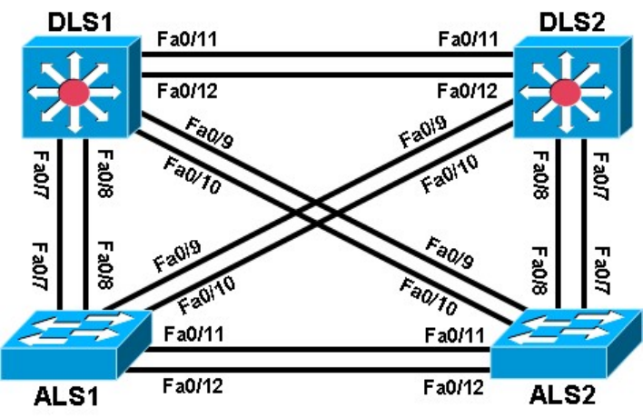
On the lab diagram provided below, indicate which switch is the root and the STP port role and state for the
switch ports. Place the letter R (Root FWD), D (Desg FWD) or A (Altn BLK) next to each port identified in the
topology.
In this lab, the default operation of IEEE 802.1D spanning tree was observed. Since no bridge priorities were
specified, the switch with the lowest MAC address was elected as the root. The link providing the lowest root
path cost was chosen as the active link. If costs were equal, the tie was broken first by the lowest sender BID
of the BPDU, then by the lowest sending port priority and last by the lowest sending port number.
In the next lab, the default STP behavior will be modified so that spanning tree works according to
specifications.
Challenge
Try to guess how your topology would look if you completely removed the root switch. Remember that the
switch with the lowest MAC address becomes the root.
a. Shut down all the ports on your current root switch.
Switch# conf t
Switch(config)# interface range fastEthernet 0/1-24
Switch(config-if-range)# shutdown
Note: If you are on a 48 port switch, use interface range Fa0/1 – 48. If there are Gigabit Ethernet ports on the
switch, they are not used with this lab, so it is not necessary to shut them down.
b. Issue the show spanning-tree command on the other switches. Did the topology converge the way you
thought it would?
__________________________________________________________________________________
__________________________________________________________________________________
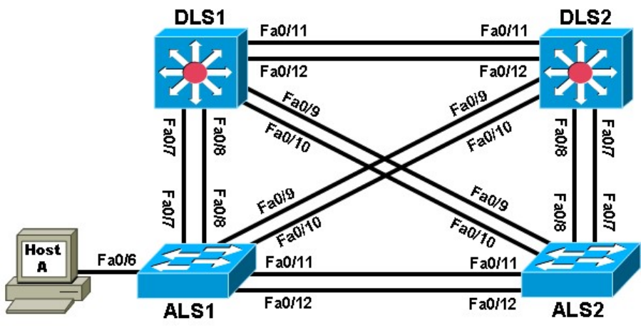
Practical 7b, Modifying Default Spanning Tree Behavior
Topology
Objective
• Observe what happens when the default spanning tree behavior is modified.
Background
Four switches have just been installed. The distribution layer switches are Catalyst 3560s, and the access
layer switches are Catalyst 2960s. There are redundant uplinks between the access layer and distribution
layer. Because of the possibility of bridging loops, spanning tree logically removes any redundant links. In this
lab, you will see what happens when the default spanning tree behavior is modified.
Note: This lab uses Cisco WS-C2960-24TT-L switches with the Cisco IOS image c2960-lanbasek9-mz.122-
46.SE.bin and Catalyst 3560-24PS switches with the Cisco IOS image c3560-advipservicesk9-
mz.12246.SE.bin. Other switches (such as a 2950 or 3550) and Cisco IOS Software versions can be used if
they have comparable capabilities and features. Depending on the switch model and Cisco IOS Software
version, the commands available and output produced might vary from what is shown in this lab.
Required Resources
• 2 switches (Cisco 2960 with the Cisco IOS Release 12.2(46)SE C2960-LANBASEK9-M image or
comparable)
• 2 switches (Cisco 3560 with the Cisco IOS Release 12.2(46)SE C3560-ADVIPSERVICESK9-M
image or comparable)
• 1 PC (optional) attached to switch ALS1.
• Ethernet and console cables
Note: Configuring PortFast in Step 5 requires a PC attached to one of the access switches.
Step 1: Prepare the switches for the lab.
a. Delete vlan.dat, erase the startup configuration, and reload all switches.

b. Give each switch a hostname according to the topology diagram.
c. Configure ports Fa0/7 through Fa0/12 on all switches to be trunks. On the 3560s, first set the trunk
encapsulation to dot1q. On the 2960s, only dot1q is supported, therefore the switchport trunk
encapsulation command is unavailable, but the mode still needs to be changed to trunk. If you do not set
the mode of the ports to trunk, they will negotiate the operational mode according to their default DTP
settings.
Note: The default mode on a 3560 or 2960 is dynamic auto; the default mode on a 3550 or 2950 is dynamic
desirable. DLS1 example:
DLS1(config)# interface range fastEthernet 0/7 - 12
DLS1(config-if-range)# switchport trunk encapsulation dot1q
DLS1(config-if-range)# switchport mode trunk
Step 2: Display default spanning tree information for all switches.
a. Use the show spanning-tree command to check how the non-configured switches created a spanning
tree. Verify which switch became the root bridge. In the topology used in this lab, DLS2 is the root bridge.
DLS1# show spanning-tree
VLAN0001
Spanning tree enabled protocol ieee
Root ID Priority 32769
Address 000a.b8a9.d680
Cost 19
Port 13 (FastEthernet0/11)
Hello Time 2 sec Max Age 20 sec Forward Delay 15 sec
Bridge ID Priority 32769 (priority 32768 sys-id-ext 1)
Address 000a.b8a9.d780
Hello Time 2 sec Max Age 20 sec Forward Delay 15 sec
Aging Time 300
Interface Role Sts Cost Prio.Nbr Type
---------------- ---- --- --------- -------- ----------------------------
Fa0/7 Desg FWD 19 128.9 P2p
Fa0/8 Desg FWD 19 128.10 P2p
Fa0/9 Desg FWD 19 128.11 P2p
Fa0/10 Desg FWD 19 128.12 P2p
Fa0/11 Root FWD 19 128.13 P2p
Fa0/12 Altn BLK 19 128.14 P2p
DLS2# show spanning-tree
VLAN0001
Spanning tree enabled protocol ieee
Root ID Priority 32769
Address 000a.b8a9.d680
This bridge is the root
Hello Time 2 sec Max Age 20 sec Forward Delay 15 sec
Bridge ID Priority 32769 (priority 32768 sys-id-ext 1)

Address 000a.b8a9.d680
Hello Time 2 sec Max Age 20 sec Forward Delay 15 sec
Aging Time 300
Interface Role Sts Cost Prio.Nbr Type
---------------- ---- --- --------- -------- ----------------------------
Fa0/7 Desg FWD 19 128.9 P2p
Fa0/8 Desg FWD 19 128.10 P2p
Fa0/9 Desg FWD 19 128.11 P2p
Fa0/10 Desg FWD 19 128.12 P2p
Fa0/11 Desg FWD 19 128.13 P2p
Fa0/12 Desg FWD 19 128.14 P2p
ALS1# show spanning-tree
VLAN0001
Spanning tree enabled protocol ieee
Root ID Priority 32769
Address 000a.b8a9.d680
Cost 19
Port 11 (FastEthernet0/9)
Hello Time 2 sec Max Age 20 sec Forward Delay 15 sec
Bridge ID Priority 32769 (priority 32768 sys-id-ext 1)
Address 0019.0635.5780
Hello Time 2 sec Max Age 20 sec Forward Delay 15 sec
Aging Time 300
Interface Role Sts Cost Prio.Nbr Type
---------------- ---- --- --------- -------- ----------------------------
Fa0/7 Altn BLK 19 128.9 P2p
Fa0/8 Altn BLK 19 128.10 P2p
Fa0/9 Root FWD 19 128.11 P2p
Fa0/10 Altn BLK 19 128.12 P2p
Fa0/11 Desg FWD 19 128.13 P2p
Fa0/12 Desg FWD 19 128.14 P2p
ALS2# show spanning-tree
VLAN0001
Spanning tree enabled protocol ieee
Root ID Priority 32769
Address 000a.b8a9.d680
Cost 19
Port 9 (FastEthernet0/7)
Hello Time 2 sec Max Age 20 sec Forward Delay 15 sec
Bridge ID Priority 32769 (priority 32768 sys-id-ext 1)
Address 0019.068d.6980
Hello Time 2 sec Max Age 20 sec Forward Delay 15 sec
Aging Time 300
Interface Role Sts Cost Prio.Nbr Type

---------------- ---- --- --------- -------- ----------------------------
Fa0/7 Root FWD 19 128.9 P2p
Fa0/8 Altn BLK 19 128.10 P2p
Fa0/9 Altn BLK 19 128.11 P2p
Fa0/10 Altn BLK 19 128.12 P2p
Fa0/11 Altn BLK 19 128.13 P2p
Fa0/12 Altn BLK 19 128.14 P2p
b. If you receive the following message “No spanning tree instance exists”, issue the no shutdown
command on all interfaces.
Switch# show spanning-tree
No spanning tree instance exists.
Switch# conf t
Switch(config)# interface range fastEthernet 0/1-24
Switch(config-if-range)# no shutdown
Switch(config-if-range)# end
Switch# show spanning-tree
Now that the switch is communicating with the other switches in the topology, you should receive spanning
tree output.
c. Issue the show interfaces trunk command on DLS1 to verify the trunking mode, encapsulation and
status for the trunk links.
DSL1# show interfaces trunk
Port Mode Encapsulation Status Native vlan Fa0/7
on 802.1q trunking 8
Fa0/8 on 802.1q trunking 8
Fa0/9 on 802.1q trunking 8
Fa0/10 on 802.1q trunking 8
Fa0/11 on 802.1q trunking 2
Fa0/12 on 802.1q trunking 2
Port Vlans allowed on trunk
Fa0/7 1-4094
Fa0/8 1-4094
Fa0/9 1-4094
Fa0/10 1-4094
Fa0/11 1-4094
Fa0/12 1-4094
<output omitted>
Are BPDUs propagated without trunk links?
__________________________________________________________________________________
__________________________________________________________________________________
Step 3: Configure specific switches to be primary and secondary root.
In this step you configure other switches to be the primary root and secondary root. Because DLS2 is the root
switch in this topology, this lab changes DLS1 to be the primary root and ALS1 to be the secondary. Do the

same in your topology, regardless of which switch is the initial root. On one of the switches that you are not
changing, you can use the debug spanning-tree events command to monitor topology changes. To change
the spanning tree root status, use the global configuration commands spanning-tree vlan vlan_number root
primary and spanning-tree vlan vlan_number root secondary. On a switch that you are not going to be
modifying, issue the debug command and then watch the output. a. Issue the debug command on DLS2.
DLS2# debug spanning-tree events
Spanning Tree event debugging is on
b. Change DLS1 to be the primary root switch.
DLS1(config)# spanning-tree vlan 1 root primary
c. Change ALS1 to the secondary root.
ALS1(config)# spanning-tree vlan 1 root secondary
You can see the topology changes on the switch that you enabled debugging on (your output may vary
depending on your initial topology):
DLS2#
00:10:43: STP: VLAN0001 heard root 24577-000a.b8a9.d780 on Fa0/11
00:10:43: supersedes 32769-000a.b8a9.d680
00:10:43: STP: VLAN0001 new root is 24577, 000a.b8a9.d780 on port Fa0/11, cost
19
00:10:43: STP: VLAN0001 sent Topology Change Notice on Fa0/11
00:10:43: STP: VLAN0001 Fa0/12 -> blocking
00:10:53: STP: VLAN0001 sent Topology Change Notice on Fa0/11
00:10:53: STP: VLAN0001 Fa0/9 -> blocking
00:10:53: STP: VLAN0001 Fa0/10 -> blocking
Notice the timestamps on the debugs to see the difference between changes caused by the commands done
in both steps.
d. Display the running config on the new root switches, DLS1 and ALS1.
DLS1# show run | include span spanning-tree mode pvst
spanning-tree extend system-id spanning-tree vlan 1
priority 24576
ALS1# show run | include span
spanning-tree mode pvst spanning-
tree extend system-id spanning-tree
vlan 1 priority 28672
Notice the spanning tree commands in the running configuration. You see a different command than the one
you entered. This is because spanning-tree vlan vlan_number root is a command that sets the priority
number on that VLAN automatically rather than typing in a specific priority number. The priority number of a
VLAN can be between 0 and 61440 in increments of 4096. To manually set the specific priority number, use
the spanning-tree vlan vlan_number priority priority_number command.
The command spanning-tree vlan vlan_number root primary sets the priority to 24576 instead of the
default (32768). The command spanning-tree vlan vlan_number root secondary sets the priority to 28672.
Given this information, would a lower or higher priority number result in a switch becoming the root bridge?

__________________________________________________________________________________
__________________________________________________________________________________
e. You can also view the priority modification with the show spanning-tree command: DLS1# show
spanning-tree
VLAN0001
Spanning tree enabled protocol ieee
Root ID Priority 24577
Address 000a.b8a9.d780
This bridge is the root
Hello Time 2 sec Max Age 20 sec Forward Delay 15 sec
Bridge ID Priority 24577 (priority 24576 sys-id-ext 1)
Address 000a.b8a9.d780
Hello Time 2 sec Max Age 20 sec Forward Delay 15 sec
Aging Time 15
Interface Role Sts Cost Prio.Nbr Type
---------------- ---- --- --------- -------- ----------------------------
Fa0/7 Desg FWD 19 128.9 P2p
Fa0/8 Desg FWD 19 128.10 P2p
Fa0/9 Desg FWD 19 128.11 P2p
Fa0/10 Desg FWD 19 128.12 P2p
Fa0/11 Desg FWD 19 128.13 P2p
Fa0/12 Desg FWD 19 128.14 P2p
Step 4: Change the root port using the spanning-tree port-priority command.
With spanning tree, you can also modify port priorities to determine which ports are forwarding and which are
blocking. To choose which port becomes the root on a non-root switch when faced with equal-cost redundant
root paths via the same neighbor, the switch looks at the port priorities first. If the sender port priorities are the
same, the switch picks the port that receives BPDUs with the lowest sender port number. On the link between
DLS1 and DLS2, the default forwarding port is Fa0/11 because it is lower, and the default blocking port is
Fa0/12 because it is higher. The two ports have equal costs because they have the same speed.
a. You can verify this using the show spanning-tree command on the non-root switch, which is DLS2. DLS2#
show spanning-tree
VLAN0001
Spanning tree enabled protocol ieee
Root ID Priority 24577
Address 000a.b8a9.d780
Cost 19
Port 13 (FastEthernet0/11)
Hello Time 2 sec Max Age 20 sec Forward Delay 15 sec
Bridge ID Priority 32769 (priority 32768 sys-id-ext 1)
Address 000a.b8a9.d680
Hello Time 2 sec Max Age 20 sec Forward Delay 15 sec
Aging Time 300

Interface Role Sts Cost Prio.Nbr Type
---------------- ---- --- --------- -------- ----------------------------
Fa0/7 Desg FWD 19 128.9 P2p
Fa0/8 Desg FWD 19 128.10 P2p
Fa0/9 Altn BLK 19 128.11 P2p
Fa0/10 Altn BLK 19 128.12 P2p
Fa0/11 Root FWD 19 128.13 P2p
Fa0/12 Altn BLK 19 128.14 P2p
b. For comparison, issue the show spanning-tree command on DLS1. Notice that all ports are forwarding
because it is the root switch.
DLS1# show spanning-tree
VLAN0001
Spanning tree enabled protocol ieee
Root ID Priority 24577
Address 000a.b8a9.d780
This bridge is the root
Hello Time 2 sec Max Age 20 sec Forward Delay 15 sec
Bridge ID Priority 24577 (priority 24576 sys-id-ext 1)
Address 000a.b8a9.d780
Hello Time 2 sec Max Age 20 sec Forward Delay 15 sec
Aging Time 15
Interface Role Sts Cost Prio.Nbr Type
---------------- ---- --- --------- -------- ----------------------------
Fa0/7 Desg FWD 19 128.9 P2p
Fa0/8 Desg FWD 19 128.10 P2p
Fa0/9 Desg FWD 19 128.11 P2p
Fa0/10 Desg FWD 19 128.12 P2p
Fa0/11 Desg FWD 19 128.13 P2p
Fa0/12 Desg FWD 19 128.14 P2p
Port priorities range from 0 to 240, in increments of 16. The default priority is 128, and a lower priority is
preferred. To change port priorities, change them on the switch closer to the root.
c. To make DLS2 Fa0/12 the root port, and Fa0/11 block, change the port priority on DLS1 with the
interface-level command spanning-tree port-priority priority.
DLS1(config)# int fastEthernet 0/12
DLS1(config-if)# spanning-tree port-priority 112
d. Issue the show spanning-tree command to verify which port is blocking on DLS2. DLS2# show
spanning-tree
VLAN0001
Spanning tree enabled protocol ieee
Root ID Priority 24577
Address 000a.b8a9.d780

Cost 19
Port 14 (FastEthernet0/12)
Hello Time 2 sec Max Age 20 sec Forward Delay 15 sec
Bridge ID Priority 32769 (priority 32768 sys-id-ext 1)
Address 000a.b8a9.d680
Hello Time 2 sec Max Age 20 sec Forward Delay 15 sec
Aging Time 15
Interface Role Sts Cost Prio.Nbr Type
---------------- ---- --- --------- -------- ----------------------------
Fa0/7 Desg FWD 19 128.9 P2p
Fa0/8 Desg FWD 19 128.10 P2p
Fa0/9 Altn BLK 19 128.11 P2p
Fa0/10 Altn BLK 19 128.12 P2p
Fa0/11 Altn BLK 19 128.13 P2p
Fa0/12 Root FWD 19 128.14 P2p
On DLS2, although the root port has changed, the port priorities have not. On DLS1, you can see the port
priorities have changed, although all ports are still forwarding (because it is the root switch).
DLS1# show spanning-tree
VLAN0001
Spanning tree enabled protocol ieee
Root ID Priority 24577
Address 000a.b8a9.d780
This bridge is the root
Hello Time 2 sec Max Age 20 sec Forward Delay 15 sec
Bridge ID Priority 24577 (priority 24576 sys-id-ext 1)
Address 000a.b8a9.d780
Hello Time 2 sec Max Age 20 sec Forward Delay 15 sec
Aging Time 15
Interface Role Sts Cost Prio.Nbr Type
---------------- ---- --- --------- -------- ----------------------------
Fa0/7 Desg FWD 19 128.9 P2p
Fa0/8 Desg FWD 19 128.10 P2p
Fa0/9 Desg FWD 19 128.11 P2p
Fa0/10 Desg FWD 19 128.12 P2p
Fa0/11 Desg FWD 19 128.13 P2p
Fa0/12 Desg FWD 19 112.14 P2p
Using the above output, how does DLS2 know which port to change to the root port, without changing the port
priorities on DLS2?
__________________________________________________________________________________
__________________________________________________________________________________
Step 5: Configure PortFast on an access port.
a. (Optional) If you have a host attached to ASL1 Fa0/6 you can perform this step. If not, read through the
following information to see how a port goes through the spanning tree states with and without PortFast
enabled.

Another feature of spanning tree is PortFast. PortFast allows you to bypass the normal states of IEEE 802.1D
spanning tree and move a port to the forwarding state as soon as it is turned on. This is useful when
connecting hosts to a switch, because they can start communicating on the VLAN instantly rather than waiting
for spanning tree. There is no danger of creating a spanning tree loop because you are not connecting
another switch. A client that runs DHCP as soon as it starts up benefits, because the DHCP requests could
be ignored if the port was not in the spanning tree forwarding state. PortFast must be used carefully to avoid
inadvertently creating spanning tree loops.
b. Ensure that the port to which the host is attached (Fa0/6) on ALS1 is shut down initially.
ALS1(config)# interface fastEthernet 0/6
ALS1(config-if)# shutdown
c. Enable spanning tree debugging on ALS1.
ALS1# debug spanning-tree events
Spanning Tree event debugging is on
d. Set port Fa0/6 switchport mode to access, enable the port and observe the debug output. Notice what
happens when the port is brought up. Your output may vary.
ALS1(config)# interface fastEthernet 0/6
ALS1(config-if)# switchport mode access
ALS1(config-if)# no shut
ALS1(config-if)# end
ALS1#
22:32:23: set portid: VLAN0001 Fa0/6: new port id 800D
22:32:23: STP: VLAN0001 Fa0/6 -> listening
22:32:25: %LINK-3-UPDOWN: Interface FastEthernet0/6, changed state to up
22:32:26: %LINEPROTO-5-UPDOWN: Line protocol on Interface FastEthernet0/6,
changed state to up
22:32:53: STP: VLAN0001 Fa0/6 ->
forwarding
22:32:53: STP: VLAN0001 sent Topology Change Notice on Fa0/7
e. Shut down the port for the next part.
ALS1(config)# interface fastEthernet 0/6
ALS1(config-if)# shutdown
f. Activate PortFast on the port with the interface-level command spanning-tree portfast. The switch warns
you about the possibility of creating switching loops.
ALS1(config)# interface fastEthernet 0/6
ALS1(config-if)# spanning-tree portfast
%Warning: portfast should only be enabled on ports connected to a single
host. Connecting hubs, concentrators, switches, bridges, etc... to this
interface when portfast is enabled, can cause temporary bridging loops. Use
with CAUTION
22:32:38: STP: VLAN0001 Fa0/6 -
>
learning

%Portfast has been configured on FastEthernet0/6 but will only
have effect when the interface is in a non-trunking mode.
g. Now, bring up the port by issuing the no shutdown command on the interface. ALS1(config-if)# no
shutdown
22:43:23: set portid: VLAN0001 Fa0/6: new port id 800D
22:43:23: STP: VLAN0001 Fa0/6 ->jump to forwarding from blocking
22:43:25: %LINK-3-UPDOWN: Interface FastEthernet0/6, changed state to up
22:43:26: %LINEPROTO-5-UPDOWN: Line protocol on Interface FastEthernet0/6,
changed state to up
h. Be sure to turn off debugging before continuing:
ALS1(config-if)# end
ALS1#
22:55:23: %SYS-5-CONFIG_I: Configured from console by console
ALS1# undebug all
All possible debugging has been turned off
Why could enabling portfast on redundant switch access links be a bad idea?
__________________________________________________________________________________
__________________________________________________________________________________
Note: The spanning-tree portfast trunk interface-level command can be useful if a trunk is being connected
to a router or a server. If RSTP is used, both trunk and access links can be moved to a forwarding state
rapidly. The spanning-tree portfast trunk command is to be used only on trunks connected to non-switching
devices.
Step 6: Change root port using the spanning-tree cost command.
Another way of changing which port becomes the root is to modify the port costs using the interface
command spanning-tree cost cost. The default cost is 4 for a gigabit Ethernet port, 19 for a Fast Ethernet
port, and 100 for a 10baseT Ethernet port. Lower cost is preferred.
Note: Each port has a default cost value based on a guideline established as part of IEEE 802.1d. In the
original specification, the cost of a port cost is calculated as 1,000 Mbps (1 gigabit per second) divided by the
bandwidth at which the port is functioning. A 10 Mbps connection have a cost of (1,000/10) or 100. As the
speed of networks has increased beyond gigabit, the standard cost has been modified somewhat. The new
cost values are:
Bandwidth STP Cost
4 Mbps 250
10 Mbps 100
16 Mbps 62
45 Mbps 39
100 Mbps 19

155 Mbps 14
622 Mbps 6
1 Gbps 4
10 Gbps 2
a. For this scenario, change the cost of port Fa0/10 on ALS2. First, look at the current port costs using the
show spanning-tree command.
Note: The cost shown here is for the port. The root bridge path cost is the sum of link port costs between a
switch and the root bridge. The cost of traversing this path is the sum of the costs of the segments on the
path. This determines how far away the root bridge is.
ALS2# show spanning-tree
VLAN0001
Spanning tree enabled protocol ieee
Root ID Priority 24577
Address 000a.b8a9.d780
Cost 19
Port 11 (FastEthernet0/9)
Hello Time 2 sec Max Age 20 sec Forward Delay 15 sec
Bridge ID Priority 32769 (priority 32768 sys-id-ext 1)
Address 0019.068d.6980
Hello Time 2 sec Max Age 20 sec Forward Delay 15 sec
Aging Time 300
Interface Role Sts Cost Prio.Nbr Type
---------------- ---- --- --------- -------- ----------------------------
Fa0/7 Altn BLK 19 128.9 P2p
Fa0/8 Altn BLK 19 128.10 P2p
Fa0/9 Root FWD 19 128.11 P2p
Fa0/10 Altn BLK 19 128.12 P2p
Fa0/11 Altn BLK 19 128.13 P2p
Fa0/12 Altn BLK 19 128.14 P2p
Note that Fa0/9 is currently the root port.
b. Change the port cost for Fa0/10 on ALS2 to 10 and then issue the show spanning-tree command.
ALS2(config)# interface fastEthernet 0/10
ALS2(config-if-range)# spanning-tree cost 10
ALS2# show spanning-tree
VLAN0001
Spanning tree enabled protocol ieee
Root ID Priority 24577
Address 000a.b8a9.d780

Cost 10
Port 12 (FastEthernet0/10)
Hello Time 2 sec Max Age 20 sec Forward Delay 15 sec
Bridge ID Priority 32769 (priority 32768 sys-id-ext 1)
Address 0019.068d.6980
Hello Time 2 sec Max Age 20 sec Forward Delay 15 sec
Aging Time 300
Interface Role Sts Cost Prio.Nbr Type
---------------- ---- --- --------- -------- ----------------------------
Fa0/7 Altn BLK 19 128.9 P2p
Fa0/8 Altn BLK 19 128.10 P2p
Fa0/9 Altn FWD 19 128.11 P2p
Fa0/10 Root FWD 10 128.12 P2p
Fa0/11 Altn BLK 19 128.13 P2p
Fa0/12 Altn BLK 19 128.14 P2p

Practical 8a, Per-VLAN Spanning Tree Behavior
Topology
Objectives
• Observe the behavior of a separate spanning tree instance per VLAN.
• Change spanning tree mode to rapid spanning tree.
Background
Four switches have just been installed. The distribution layer switches are Catalyst 3560s, and the access
layer switches are Catalyst 2960s. There are redundant uplinks between the access layer and distribution
layer. Because of the possibility of bridging loops, spanning tree logically removes any redundant links. In this
lab, you will see what happens when spanning tree is configured differently for different VLANs.
Note: This lab uses Cisco WS-C2960-24TT-L switches with the Cisco IOS image c2960-lanbasek9-
mz.12246.SE.bin and Catalyst 3560-24PS with the Cisco IOS image c3560-advipservicesk9-mz.122-
46.SE.bin. Other switches (such as a 2950 or 3550), and Cisco IOS Software versions can be used if they
have comparable capabilities and features. Depending on the switch model and Cisco IOS Software version,
the commands available and output produced might vary from what is shown in this lab.
Required Resources
• 2 switches (Cisco 2960 with the Cisco IOS Release 12.2(46)SE C2960-LANBASEK9-M image or
comparable)
• 2 switches (Cisco 3560 with the Cisco IOS Release 12.2(46)SE C3560-ADVIPSERVICESK9-M
image or comparable)
• Ethernet and console cables
Step 1: Prepare the switches for the lab.
a. Delete the vlan.dat file, erase the startup configuration, and reload the switches.
b. Give each switch a hostname according to the topology diagram.
c. Configure ports Fa0/7 through Fa0/12 on all switches to be trunks. On the 3560s, first set the trunk
encapsulation to dot1q. On the 2960s, only dot1q is supported, therefore the switchport trunk
encapsulation command is unavailable, but the mode still needs to be changed to trunk. If you do not
set the mode of the ports to trunk, they will negotiate the operational mode according to their default DTP
settings.
Note: The default mode on a 3560 or 2960 is dynamic auto; the default mode on a 3550 or 2950 is dynamic
desirable.
DLS1 example:
DLS1(config)# interface range fastEthernet 0/7 - 12
DLS1(config-if-range)# switchport trunk encapsulation dot1q
DLS1(config-if-range)# switchport mode trunk
Step 2: Configure VTP.
a. Configure all switches with VTP mode transparent and VTP domain CISCO. Add VLAN 10 and 20 to all of
them. Use the show vlan brief command to view the VLAN configurations. DLS1 example:
DLS1(config)# vtp mode transparent
Setting device to VTP TRANSPARENT mode.
DLS1(config)# vtp domain CISCO
Changing VTP domain name from NULL to CISCO
DLS1(config)# vlan 10,20
DLS1(config-vlan)# end
DLS1# show vlan brief
VLAN Name Status Ports
---- -------------------------------- --------- -------------------------
1 default active Fa0/1, Fa0/2, Fa0/3, Fa0/4
Fa0/5, Fa0/6, Fa0/9, Fa0/10
Fa0/13, Fa0/14, Fa0/15, Fa0/16
Fa0/17, Fa0/18, Fa0/19, Fa0/20
Fa0/21, Fa0/22, Fa0/23, Fa0/24
Gi0/1, Gi0/2
10 VLAN0010 active
20 VLAN0020 active
1002 fddi-default act/unsup
1003 token-ring-default act/unsup
1004 fddinet-default act/unsup
1005 trnet-default act/unsup
b. Issue the show spanning-tree command on any of the four switches. Notice that instead of just one VLAN
there are three non-reserved VLANs. VLANs 1002-1005 are reserved for internal switch usage. All other
VLANs shown are non-reserved.
Note: By default Cisco switches use PVST+, a Cisco-proprietary IEEE 802.1Q-compatible per-VLAN
spanning tree protocol.
DLS1# show spanning-tree

VLAN0001
Spanning tree enabled protocol ieee
Root ID Priority 32769
Address 000a.b8a9.d680
Cost 19
Port 13 (FastEthernet0/11)
Hello Time 2 sec Max Age 20 sec Forward Delay 15 sec
Bridge ID Priority 32769 (priority 32768 sys-id-ext 1)
Address 000a.b8a9.d780
Hello Time 2 sec Max Age 20 sec Forward Delay 15 sec
Aging Time 15
Interface Role Sts Cost Prio.Nbr Type
---------------- ---- --- --------- -------- ----------------------------
Fa0/7 Desg FWD 19 128.9 P2p
Fa0/8 Desg FWD 19 128.10 P2p
Fa0/9 Desg FWD 19 128.11 P2p
Fa0/10 Desg FWD 19 128.12 P2p
Fa0/11 Root FWD 19 128.13 P2p
Fa0/12 Altn BLK 19 128.14 P2p
VLAN0010
Spanning tree enabled protocol ieee
Root ID Priority 32778
Address 000a.b8a9.d680
Cost 19
Port 13 (FastEthernet0/11)
Hello Time 2 sec Max Age 20 sec Forward Delay 15 sec
Bridge ID Priority 32778 (priority 32768 sys-id-ext 10)
Address 000a.b8a9.d780
Hello Time 2 sec Max Age 20 sec Forward Delay 15 sec
Aging Time 15
Interface Role Sts Cost Prio.Nbr Type
---------------- ---- --- --------- -------- ----------------------------
Fa0/7 Desg FWD 19 128.9 P2p
Fa0/8 Desg FWD 19 128.10 P2p
Fa0/9 Desg FWD 19 128.11 P2p
Fa0/10 Desg FWD 19 128.12 P2p
Fa0/11 Root FWD 19 128.13 P2p
Fa0/12 Altn BLK 19 128.14 P2p
VLAN0020
Spanning tree
enabled protocol
ieee Root ID
Priority 32788
Address 000a.b8a9.d680
Cost 19
Port 13 (FastEthernet0/11)
Hello Time 2 sec Max Age 20 sec Forward Delay 15 sec
Bridge ID Priority 32788 (priority 32768 sys-id-ext 20)
Address 000a.b8a9.d780
Hello Time 2 sec Max Age 20 sec Forward Delay 15 sec
Aging Time 15
Interface Role Sts Cost Prio.Nbr Type
---------------- ---- --- --------- -------- ----------------------------
Fa0/7 Desg FWD 19 128.9 P2p
Fa0/8 Desg FWD 19 128.10 P2p
Fa0/9 Desg FWD 19 128.11 P2p
Fa0/10 Desg FWD 19 128.12 P2p
Fa0/11 Root FWD 19 128.13 P2p
Fa0/12 Altn BLK 19 128.14 P2p
Step 3: Assign a root switch for each VLAN.
Notice that all the ports have identical spanning tree behavior for each VLAN. This is because all VLANs are
running spanning tree with the default behavior. However, you can modify the default spanning tree behavior
on a per-VLAN basis. The default priority is 32768. Configuring a switch with a lower priority value for a given
VLAN makes it the root bridge for that VLAN. For this lab, we assign DLS1 as the root bridge for VLAN 10,
and DLS2 for VLAN 20.
a. To change the priority for a given VLAN, use the spanning-tree vlan number priority number command.
Configure DLS1 with priority 4096 for VLAN 10. Configure DLS2 similarly for VLAN 20.
DLS1(config)# spanning-tree vlan 10 priority 4096
DLS2(config)# spanning-tree vlan 20 priority 4096
b. If you look at the output of show spanning-tree on the four switches, you see that the port states and
root switches vary on a per VLAN basis.
DLS1# show spanning-tree
VLAN0001
Spanning tree enabled protocol ieee
Root ID Priority 32769
Address 000a.b8a9.d680
Cost 19
Port 13 (FastEthernet0/11)
Hello Time 2 sec Max Age 20 sec Forward Delay 15 sec
Bridge ID Priority 32769 (priority 32768 sys-id-ext 1)
Address 000a.b8a9.d780
Hello Time 2 sec Max Age 20 sec Forward Delay 15 sec
Aging Time 300
Interface Role Sts Cost Prio.Nbr Type
---------------- ---- --- --------- -------- ----------------------------
Fa0/7 Desg FWD 19 128.9 P2p
Fa0/8 Desg FWD 19 128.10 P2p
Fa0/9 Desg FWD 19 128.11 P2p
Fa0/10 Desg FWD 19 128.12 P2p
Fa0/11 Root FWD 19 128.13 P2p
Fa0/12 Altn BLK 19 128.14 P2p
VLAN0010

Spanning tree enabled protocol ieee
Root ID Priority 4106
Address 000a.b8a9.d780
This bridge is the root
Hello Time 2 sec Max Age 20 sec Forward Delay 15 sec
Bridge ID Priority 4106 (priority 4096 sys-id-ext 10)
Address 000a.b8a9.d780
Hello Time 2 sec Max Age 20 sec Forward Delay 15 sec
Aging Time 300
Interface Role Sts Cost Prio.Nbr Type
---------------- ---- --- --------- -------- ----------------------------
Fa0/7 Desg FWD 19 128.9 P2p
Fa0/8 Desg FWD 19 128.10 P2p
Fa0/9 Desg FWD 19 128.11 P2p
Fa0/10 Desg FWD 19 128.12 P2p
Fa0/11 Desg FWD 19 128.13 P2p
Fa0/12 Desg FWD 19 128.14 P2p
VLAN0020
Spanning tree enabled protocol ieee
Root ID Priority 4116
Address 000a.b8a9.d680
Cost 19
Port 13 (FastEthernet0/11)
Hello Time 2 sec Max Age 20 sec Forward Delay 15 sec
Bridge ID Priority 32788 (priority 32768 sys-id-ext 20)
Address 000a.b8a9.d780
Hello Time 2 sec Max Age 20 sec Forward Delay 15 sec
Aging Time 300
Interface Role Sts Cost Prio.Nbr Type
---------------- ---- --- --------- -------- ----------------------------
Fa0/7 Desg FWD 19 128.9 P2p
Fa0/8 Desg FWD 19 128.10 P2p
Fa0/9 Desg FWD 19 128.11 P2p
Fa0/10 Desg FWD 19 128.12 P2p
Fa0/11 Root FWD 19 128.13 P2p
Fa0/12 Altn BLK 19 128.14 P2p
DLS2# show spanning-tree
VLAN0001
Spanning tree enabled protocol ieee
Root ID Priority 32769
Address 000a.b8a9.d680
This bridge is the root
Hello Time 2 sec Max Age 20 sec Forward Delay 15 sec
Bridge ID Priority 32769 (priority 32768 sys-id-ext 1)
Address 000a.b8a9.d680

Hello Time 2 sec Max Age 20 sec Forward Delay 15 sec
Aging Time 300
Interface Role Sts Cost Prio.Nbr Type
---------------- ---- --- --------- -------- ----------------------------
Fa0/7 Desg FWD 19 128.9 P2p
Fa0/8 Desg FWD 19 128.10 P2p
Fa0/9 Desg FWD 19 128.11 P2p
Fa0/10 Desg FWD 19 128.12 P2p
Fa0/11 Desg FWD 19 128.13 P2p
Fa0/12 Desg FWD 19 128.14 P2p
VLAN0010
Spanning tree enabled protocol ieee
Root ID Priority 4106
Address 000a.b8a9.d780
Cost 19
Port 13 (FastEthernet0/11)
Hello Time 2 sec Max Age 20 sec Forward Delay 15 sec
Bridge ID Priority 32778 (priority 32768 sys-id-ext 10)
Address 000a.b8a9.d680
Hello Time 2 sec Max Age 20 sec Forward Delay 15 sec
Aging Time 300
Interface Role Sts Cost Prio.Nbr Type
---------------- ---- --- --------- -------- ----------------------------
Fa0/7 Desg FWD 19 128.9 P2p
Fa0/8 Desg FWD 19 128.10 P2p
Fa0/9 Desg FWD 19 128.11 P2p
Fa0/10 Desg FWD 19 128.12 P2p
Fa0/11 Root FWD 19 128.13 P2p
Fa0/12 Altn BLK 19 128.14 P2p
VLAN0020
Spanning tree enabled protocol ieee
Root ID Priority 4116
Address 000a.b8a9.d680
This bridge is the root
Hello Time 2 sec Max Age 20 sec Forward Delay 15 sec
Bridge ID Priority 4116 (priority 4096 sys-id-ext 20)
Address 000a.b8a9.d680
Hello Time 2 sec Max Age 20 sec Forward Delay 15 sec
Aging Time 300
Interface Role Sts Cost Prio.Nbr Type
---------------- ---- --- --------- -------- ----------------------------
Fa0/7 Desg FWD 19 128.9 P2p
Fa0/8 Desg FWD 19 128.10 P2p
Fa0/9 Desg FWD 19 128.11 P2p
Fa0/10 Desg FWD 19 128.12 P2p
Fa0/11 Desg FWD 19 128.13 P2p
Fa0/12 Desg FWD 19 128.14 P2p
ALS1# show spanning-tree
VLAN0001
Spanning tree enabled protocol ieee
Root ID Priority 32769
Address 000a.b8a9.d680
Cost 19
Port 11 (FastEthernet0/9)
Hello Time 2 sec Max Age 20 sec Forward Delay 15 sec
Bridge ID Priority 32769 (priority 32768 sys-id-ext 1)
Address 0019.0635.5780
Hello Time 2 sec Max Age 20 sec Forward Delay 15 sec
Aging Time 300
Interface Role Sts Cost Prio.Nbr Type
---------------- ---- --- --------- -------- ----------------------------
Fa0/7 Altn BLK 19 128.9 P2p
Fa0/8 Altn BLK 19 128.10 P2p
Fa0/9 Root FWD 19 128.11 P2p
Fa0/10 Altn BLK 19 128.12 P2p
Fa0/11 Desg FWD 19 128.13 P2p
Fa0/12 Desg FWD 19 128.14 P2p
VLAN0010
Spanning tree enabled protocol ieee
Root ID Priority 4106
Address 000a.b8a9.d780
Cost 19
Port 9 (FastEthernet0/7)
Hello Time 2 sec Max Age 20 sec Forward Delay 15 sec
Bridge ID Priority 32778 (priority 32768 sys-id-ext 10)
Address 0019.0635.5780
Hello Time 2 sec Max Age 20 sec Forward Delay 15 sec
Aging Time 15
Interface Role Sts Cost Prio.Nbr Type
---------------- ---- --- --------- -------- ----------------------------
Fa0/7 Root FWD 19 128.9 P2p
Fa0/8 Altn BLK 19 128.10 P2p
Fa0/9 Altn BLK 19 128.11 P2p
Fa0/10 Altn BLK 19 128.12 P2p
Fa0/11 Desg FWD 19 128.13 P2p
Fa0/12 Desg FWD 19 128.14 P2p
VLAN0020
Spanning tree enabled protocol ieee
Root ID Priority 4116
Address 000a.b8a9.d680
Cost 19
Port 11 (FastEthernet0/9)
Hello Time 2 sec Max Age 20 sec Forward Delay 15 sec
Bridge ID Priority 32788 (priority 32768 sys-id-ext 20)
Address 0019.0635.5780
Hello Time 2 sec Max Age 20 sec Forward Delay 15 sec
Aging Time 15
Interface Role Sts Cost Prio.Nbr Type
---------------- ---- --- --------- -------- ----------------------------
Fa0/7 Altn BLK 19 128.9 P2p
Fa0/8 Altn BLK 19 128.10 P2p
Fa0/9 Root FWD 19 128.11 P2p
Fa0/10 Altn BLK 19 128.12 P2p
Fa0/11 Desg FWD 19 128.13 P2p
Fa0/12 Desg FWD 19 128.14 P2p
ALS2# show spanning-tree
VLAN0001
Spanning tree enabled protocol ieee
Root ID Priority 32769
Address 000a.b8a9.d680
Cost 19
Port 9 (FastEthernet0/7)
Hello Time 2 sec Max Age 20 sec Forward Delay 15 sec
Bridge ID Priority 32769 (priority 32768 sys-id-ext 1)
Address 0019.068d.6980
Hello Time 2 sec Max Age 20 sec Forward Delay 15 sec
Aging Time 300
Interface Role Sts Cost Prio.Nbr Type
---------------- ---- --- --------- -------- ----------------------------
Fa0/7 Root FWD 19 128.9 P2p
Fa0/8 Altn BLK 19 128.10 P2p
Fa0/9 Altn BLK 19 128.11 P2p
Fa0/10 Altn BLK 19 128.12 P2p
Fa0/11 Altn BLK 19 128.13 P2p
Fa0/12 Altn BLK 19 128.14 P2p
VLAN0010
Spanning tree enabled protocol ieee
Root ID Priority 4106
Address 000a.b8a9.d780
Cost 19
Port 11 (FastEthernet0/9)
Hello Time 2 sec Max Age 20 sec Forward Delay 15 sec
Bridge ID Priority 32778 (priority 32768 sys-id-ext 10)
Address 0019.068d.6980
Hello Time 2 sec Max Age 20 sec Forward Delay 15 sec
Aging Time 15
Interface Role Sts Cost Prio.Nbr Type
---------------- ---- --- --------- -------- ----------------------------
F
a0/7
Altn BLK 19 128.9 P2p
Fa0/8 Altn BLK 19 128.10 P2p
Fa0/9 Root FWD 19 128.11 P2p
Fa0/10 Altn BLK 19 128.12 P2p
Fa0/11 Altn BLK 19 128.13 P2p
Fa0/12 Altn BLK 19 128.14 P2p
VLAN0020
Spanning tree enabled protocol ieee
Root ID Priority 4116
Address 000a.b8a9.d680
Cost 19
Port 9 (FastEthernet0/7)
Hello Time 2 sec Max Age 20 sec Forward Delay 15 sec
Bridge ID Priority 32788 (priority 32768 sys-id-ext 20)
Address 0019.068d.6980
Hello Time 2 sec Max Age 20 sec Forward Delay 15 sec
Aging Time 15
Interface Role Sts Cost Prio.Nbr Type
---------------- ---- --- --------- -------- ----------------------------
Fa0/7 Root FWD 19 128.9 P2p
Fa0/8 Altn BLK 19 128.10 P2p
Fa0/9 Altn BLK 19 128.11 P2p
Fa0/10 Altn BLK 19 128.12 P2p
Fa0/11 Altn BLK 19 128.13 P2p
Fa0/12 Altn BLK 19 128.14 P2p
Step 4: Configure RSTP.
Other spanning tree modes besides PVST+ are available. One of these is RSTP (rapid spanning tree
protocol), which greatly reduces the time for a port to transition to forwarding state while still preventing
bridging loops. Cisco-proprietary per-VLAN rapid spanning tree (PVRST+) combines the functionality of
RSTP and PVST.
Note: You can use the clear spanning-tree detected-protocols command after configuring different
spanning tree modes. This can avoid a mutual deadlock between two switches when they consider
themselves as 802.1D legacy bridges when in fact they were configured for RSTP.
a. To change the spanning tree mode to PVRST+, use the global configuration command spanning-tree
mode rapid-pvst. Configure this on all four switches. During the transition period, rapid spanning tree
falls back to 802.1D spanning tree on the links that have 802.1D spanning tree configured on one side.
DLS1(config)# spanning-tree mode rapid-pvst
b. After configuring all four switches with this command, use the show spanning-tree command to verify
the configuration:
DLS1# show spanning-tree

VLAN0001
Spanning tree enabled protocol rstp
Root ID Priority 32769
Address 000a.b8a9.d680
Cost 19
Port 13 (FastEthernet0/11)
Hello Time 2 sec Max Age 20 sec Forward Delay 15 sec
Bridge ID Priority 32769 (priority 32768 sys-id-ext 1)
Address 000a.b8a9.d780
Hello Time 2 sec Max Age 20 sec Forward Delay 15 sec
Aging Time 300
Interface Role Sts Cost Prio.Nbr Type
---------------- ---- --- --------- -------- ----------------------------
Fa0/7 Desg FWD 19 128.9 P2p
Fa0/8 Desg FWD 19 128.10 P2p
Fa0/9 Desg FWD 19 128.11 P2p
Fa0/10 Desg FWD 19 128.12 P2p
Fa0/11 Root FWD 19 128.13 P2p
Fa0/12 Altn BLK 19 128.14 P2p
VLAN0010
Spanning tree enabled protocol rstp
Root ID Priority 4106
Address 000a.b8a9.d780
This bridge is the root
Hello Time 2 sec Max Age 20 sec Forward Delay 15 sec
Bridge ID Priority 4106 (priority 4096 sys-id-ext 10)
Address 000a.b8a9.d780
Hello Time 2 sec Max Age 20 sec Forward Delay 15 sec
Aging Time 300
Interface Role Sts Cost Prio.Nbr Type
---------------- ---- --- --------- -------- ----------------------------
Fa0/7 Desg FWD 19 128.9 P2p
Fa0/8 Desg FWD 19 128.10 P2p
Fa0/9 Desg FWD 19 128.11 P2p
Fa0/10 Desg FWD 19 128.12 P2p
Fa0/11 Desg FWD 19 128.13 P2p
Fa0/12 Desg FWD 19 128.14 P2p
VLAN0020
Spanning tree enabled protocol rstp
Root ID Priority 4116
Address 000a.b8a9.d680
Cost 19
Port 13 (FastEthernet0/11)
Hello Time 2 sec Max Age 20 sec Forward Delay 15 sec
Bridge ID Priority 32788 (priority 32768 sys-id-ext 20)
Address 000a.b8a9.d780
Hello Time 2 sec Max Age 20 sec Forward Delay 15 sec
Aging Time 300
Interface Role Sts Cost Prio.Nbr Type
---------------- ---- --- --------- -------- ----------------------------
Fa0/7 Desg FWD 19 128.9 P2p
Fa0/8 Desg FWD 19 128.10 P2p
Fa0/9 Desg FWD 19 128.11 P2p
Fa0/10 Desg FWD 19 128.12 P2p
Fa0/11 Root FWD 19 128.13 P2p
Fa0/12 Altn BLK 19 128.14 P2p
Challenge
a. On each switch, add VLANs 50, 60, 70, 80, 90, and 100. Configure ALS1 to be the root bridge for VLANs
50, 60, and 70, and ALS2 to be the root bridge for VLANs 80, 90, and 100. Configure the root bridges
with a single line on each switch.
HINT: Use the question mark when you type the global configuration command spanning-tree vlan ?. Notice
that you can modify spanning tree attributes in ranges.
__________________________________________________________________________________
__________________________________________________________________________________
__________________________________________________________________________________
__________________________________________________________________________________
__________________________________________________________________________________
__________________________________________________________________________________ b.
Change the spanning tree cost of VLAN 20 on Fa0/11 and Fa0/12 between DLS1 and DLS2 to 15.
HINT: Use the question mark on the interface level command spanning-tree vlan number ?.
__________________________________________________________________________________
__________________________________________________________________________________
__________________________________________________________________________________
__________________________________________________________________________________
__________________________________________________________________________________
__________________________________________________________________________________

Practical 7b, Multiple Spanning Tree
Topology
Objective
• Observe the behavior of multiple spanning tree (MST).
Background
Four switches have just been installed. The distribution layer switches are Catalyst 3560s, and the access
layer switches are Catalyst 2960s. There are redundant uplinks between the access layer and distribution
layer. Because of the possibility of bridging loops, spanning tree logically removes any redundant links. In this
lab, we will group VLANs using MST so that we can have fewer spanning tree instances running at once to
minimize switch CPU load.
Note: This lab uses Cisco WS-C2960-24TT-L with the Cisco IOS image c2960-lanbasek9-mz.122-46.SE.bin
and Catalyst 3560-24PS switches with the Cisco IOS image c3560-advipservicesk9-mz.122-46.SE.bin. Other
switches (such as a 2950 or 3550), and Cisco IOS Software versions can be used if they have comparable
capabilities and features. Depending on the switch model and Cisco IOS Software version, the commands
available and output produced might vary from what is shown in this lab.
Note: VTP version 3, is not supported by the IOS used on the switches in this lab. However, it is supported in
IOS versions 12.2(52)SE and newer on all platforms eligible for this IOS (2960, 3560, 3750, etc.). VTPv3 has
improvements in three major areas.
• Better administrative control over which device is allowed to update other devices’ view of the VLAN
topology. The chance of unintended and disruptive changes is significantly reduced, and availability
is increased.
• Functionality for the VLAN environment has been significantly expanded. In addition to supporting the
earlier ISL VLAN range from 1 to 1001, the new version supports the whole IEEE 802.1Q VLAN
range up to 4095. In addition to supporting the concept of normal VLANs, VTP version 3 can transfer
information regarding Private VLAN (PVLAN) structures.

• The third area of major improvement is support for databases other than VLAN. For example, VTPv3
supports MST mapping propagation instances, can synchronize MST configuration and be very helpful in
maintaining the coherent MST configuration on all switches.
Required Resources
• 2 switch (Cisco 2960 with the Cisco IOS Release 12.2(46)SE C2960-LANBASEK9-M image or
comparable)
• 2 switches (Cisco 3560 with the Cisco IOS Release 12.2(46)SE C3560-ADVIPSERVICESK9-M
image or comparable)
• Ethernet and console cables
Step 1: Prepare the switches for the lab.
a. Delete vlan.dat file, erase the startup config, and reload the switches.
b. Give each switch a hostname according to the topology diagram.
c. Configure ports Fa0/7 through Fa0/12 on all switches to be trunks. On the 3560s, first set the trunk
encapsulation to dot1q. On the 2960s, only dot1q is supported, therefore the switchport trunk
encapsulation command is unavailable, but the mode still needs to be changed to trunk. If you do not set
the mode of the ports to trunk, they will negotiate the operational mode according to their default DTP
settings.
Note: The default mode on a 3560 or 2960 is dynamic auto; the default mode on a 3550 or 2950 is dynamic
desirable. DLS1 example:
DLS1(config)# interface range fastEthernet 0/7 - 12
DLS1(config-if-range)# switchport trunk encapsulation dot1q
DLS1(config-if-range)# switchport mode trunk
Step 2: Configure VTP and VLANs.
a. Configure all switches with VTP mode transparent and VTP domain CISCO. Add VLANs
10, 20, 30, 40, 50, 60, 70, 80, 90 and 100 to all of them. DLS1 example:
DLS1# configure terminal
Enter configuration commands, one per line. End with CNTL/Z.
DLS1(config)# vtp mode transparent
Setting device to VTP TRANSPARENT mode.
DLS1(config) #vtp domain CISCO
Changing VTP domain name from NULL to CISCO
DLS1(config)# vlan 10,20,30,40,50,60,70,80,90,100
DLS1(config-vlan)# end
b. Issue the show vlan brief command to view the VLAN configurations. DLS1# show
vlan brief
00:11:56: %SYS-5-CONFIG_I: Configured from console by console
VLAN Name Status Ports
---- -------------------------------- --------- -------------------------------
1 default active Fa0/1, Fa0/2, Fa0/3, Fa0/4
Fa0/5, Fa0/6, Fa0/7, Fa0/8

Fa0/9, Fa0/10, Fa0/11, Fa0/12
Fa0/13, Fa0/14, Fa0/15, Fa0/16
Fa0/17, Fa0/18, Fa0/19, Fa0/20
Fa0/21, Fa0/22, Fa0/23, Fa0/24
Gi0/1, Gi0/2
10 VLAN0010 active
20 VLAN0020 active
30 VLAN0030 active
40 VLAN0040 active
50 VLAN0050 active
60 VLAN0060 active
70 VLAN0070 active
80 VLAN0080 active
90 VLAN0090 active
100 VLAN0100 active
1002 fddi-default act/unsup
1003 token-ring-default act/unsup
1004 fddinet-default act/unsup
1005 trnet-default act/unsup
Step 3: Display spanning tree information.
Issue the show spanning-tree command on one of the switches. How many spanning tree instances are
running?
__________________________________________________________________________________
__________________________________________________________________________________
DLS1# show spanning-tree
VLAN0001
Spanning tree enabled protocol ieee
Root ID Priority 32769
Address 000a.b8a9.d680
Cost 19
Port 13 (FastEthernet0/11)
Hello Time 2 sec Max Age 20 sec Forward Delay 15 sec
Bridge ID Priority 32769 (priority 32768 sys-id-ext 1)
Address 000a.b8a9.d780
Hello Time 2 sec Max Age 20 sec Forward Delay 15 sec
Aging Time 300
Interface Role Sts Cost Prio.Nbr Type
---------------- ---- --- --------- -------- ----------------------------
Fa0/7 Desg FWD 19 128.9 P2p
Fa0/8 Desg FWD 19 128.10 P2p
Fa0/9 Desg FWD 19 128.11 P2p
Fa0/10 Desg FWD 19 128.12 P2p
Fa0/11 Root FWD 19 128.13 P2p
Fa0/12 Altn BLK 19 128.14 P2p
VLAN0010
Spanning tree enabled protocol ieee
Root ID Priority 32778
Address 000a.b8a9.d680

Cost 19
Port 13 (FastEthernet0/11)
Hello Time 2 sec Max Age 20 sec Forward Delay 15 sec
Bridge ID Priority 32778 (priority 32768 sys-id-ext 10)
Address 000a.b8a9.d780
Hello Time 2 sec Max Age 20 sec Forward Delay 15 sec
Aging Time 300
Interface Role Sts Cost Prio.Nbr Type
---------------- ---- --- --------- -------- ----------------------------
Fa0/7 Desg FWD 19 128.9 P2p
Fa0/8 Desg FWD 19 128.10 P2p
Fa0/9 Desg FWD 19 128.11 P2p
Fa0/10 Desg FWD 19 128.12 P2p
Fa0/11 Root FWD 19 128.13 P2p
Fa0/12 Altn BLK 19 128.14 P2p
VLAN0020
Spanning tree enabled protocol ieee
Root ID Priority 32788
Address 000a.b8a9.d680
Cost 19
Port 13 (FastEthernet0/11)
Hello Time 2 sec Max Age 20 sec Forward Delay 15 sec
Bridge ID Priority 32788 (priority 32768 sys-id-ext 20)
Address 000a.b8a9.d780
Hello Time 2 sec Max Age 20 sec Forward Delay 15 sec
Aging Time 300
Interface Role Sts Cost Prio.Nbr Type
---------------- ---- --- --------- -------- ----------------------------
Fa0/7 Desg FWD 19 128.9 P2p
Fa0/8 Desg FWD 19 128.10 P2p
Fa0/9 Desg FWD 19 128.11 P2p
Fa0/10 Desg FWD 19 128.12 P2p
Fa0/11 Root FWD 19 128.13 P2p
Fa0/12 Altn BLK 19 128.14 P2p
<output omitted>
VLAN0090
Spanning tree enabled protocol ieee
Root ID Priority 32858
Address 000a.b8a9.d680
Cost 19
Port 13 (FastEthernet0/11)
Hello Time 2 sec Max Age 20 sec Forward Delay 15 sec
Bridge ID Priority 32858 (priority 32768 sys-id-ext 90)
Address 000a.b8a9.d780
Hello Time 2 sec Max Age 20 sec Forward Delay 15 sec
Aging Time 300

Interface Role Sts Cost Prio.Nbr Type
---------------- ---- --- --------- -------- ----------------------------
Fa0/7 Desg FWD 19 128.9 P2p
Fa0/8 Desg FWD 19 128.10 P2p
Fa0/9 Desg FWD 19 128.11 P2p
Fa0/10 Desg FWD 19 128.12 P2p
Fa0/11 Root FWD 19 128.13 P2p
Fa0/12 Altn BLK 19 128.14 P2p
VLAN0100
Spanning tree enabled protocol ieee
Root ID Priority 32868
Address 000a.b8a9.d680
Cost 19
Port 13 (FastEthernet0/11)
Hello Time 2 sec Max Age 20 sec Forward Delay 15 sec
Bridge ID Priority 32868 (priority 32768 sys-id-ext 100)
Address 000a.b8a9.d780
Hello Time 2 sec Max Age 20 sec Forward Delay 15 sec
Aging Time 300
Interface Role Sts Cost Prio.Nbr Type
---------------- ---- --- --------- -------- ----------------------------
Fa0/7 Desg FWD 19 128.9 P2p
Fa0/8 Desg FWD 19 128.10 P2p
Fa0/9 Desg FWD 19 128.11 P2p
Fa0/10 Desg FWD 19 128.12 P2p
Fa0/11 Root FWD 19 128.13 P2p
Fa0/12 Altn BLK 19 128.14 P2p
Spanning tree is running a separate spanning tree instance for each VLAN created, plus VLAN 1. This
method assumes that each VLAN could be running on a differently shaped topology. However, in many
networks, multiple VLANs follow the same physical topology, so multiple spanning-tree calculations for the
same topologies can get redundant. MST lets you configure different spanning tree instances. Each instance
can hold a group of VLANs and manages its own spanning tree calculation.
MST is convenient in that it is backward compatible with PVST and RPVST+. Two switches only run MST
with each other if they are in the same MST region. An MST region is defined by switches having identical
region names, revision numbers, and VLAN-to-instance assignments. If they differ by any single attribute,
they are considered different MST regions and fall back to RPVST+.
Step 4: Configure MST globally.
a. To configure MST, first use the global configuration command spanning-tree mode mst on all four
switches. The command is shown for DLS1 only.
DLS1(config)# spanning-tree mode mst
By default, all VLANs are assigned to instance 0, but can be moved around to different instances when MST
is configured.
b. Issue the show spanning-tree command and observe that there is only one spanning tree (instance 0)
coming up. Also notice that the mode is listed as MSTP.

DLS1# show spanning-tree
Spanning tree enabled protocol mstp
Root ID Priority 32768
Address 000a.b8a9.d680
Cost 0
Port 13 (FastEthernet0/11)
Hello Time 2 sec Max Age 20 sec Forward Delay 15 sec
Bridge ID Priority 32768 (priority 32768 sys-id-ext 0)
Address 000a.b8a9.d780
Hello Time 2 sec Max Age 20 sec Forward Delay 15 sec
Interface Role Sts Cost Prio.Nbr Type
---------------- ---- --- --------- -------- ----------------------------
Fa0/7 Desg FWD 200000 128.9 P2p
Fa0/8 Desg BLK 200000 128.10 P2p
Fa0/9 Desg FWD 200000 128.11 P2p
Fa0/10 Desg FWD 200000 128.12 P2p
Fa0/11 Root FWD 200000 128.13 P2p
Fa0/12 Altn BLK 200000 128.14 P2p
c. If you use the show spanning-tree mst configuration command, you can see a switch’s current MST
configuration. Because you have not configured any MST region settings, the switch shows the default
settings.
DLS1# show spanning-tree mst configuration
Name []
Revision 0
Instance Vlans mapped
-------- ---------------------------------------------------------------
0 1-4094
-------------------------------------------------------------------------
Step 5: Configure the MST region and instances.
Now that MST has been enabled, we can configure the MST region settings to group VLANs. We use the
region name CISCO and a revision number of 1. We put VLANs 20 through 50 into instance 1, and 80 and
100 into instance 2. The rest of the VLANs remain in instance 0, the default.
a. To begin modifying the MST configuration, type the global configuration command spanning-tree mst
configuration. Configuring MST is different from other switch configurations, because changes are not
applied until you are finished (similar to the deprecated VLAN database mode), and you can abort
changes if you wish.
Note: You must apply identical configurations on each switch for MST to work properly. The commands are
shown for DLS1 only.
DLS1(config)# spanning-tree mst configuration
DLS1(config-mst)#
b. When you are in MST configuration mode, you can view the current configuration using the show
current command. You do not need to leave configuration mode to execute this command. Notice that
the output is identical to show spanning-tree mst configuration.
DLS1(config-mst)# show current
Current MST configuration
MST00
Name []
Revision 0
Instance Vlans mapped
-------- ---------------------------------------------------------------
0 1-4094
-------------------------------------------------------------------------
Change the region name by typing name name. Change the revision number by typing revision number.
DLS1(config-mst)# name CISCO
DLS1(config-mst)# revision 1
Note: The MST revision number is not like the configuration revision number used with VTP. It does not
increment when changes are made. Along with the region name, the revision number identifies the MST
domain and must be the same on all systems in the MST region.
c. The last configuration change you have to make is putting VLANs into instances. Use the command
instance number vlan vlan_range. The instance number can be between 0 and 15. Remember that 0 is
the default instance number.
DLS1(config-mst)# instance 1 vlan 20-50
DLS1(config-mst)# instance 2 vlan 80,100
d. You can verify the changes you are about to make with the show pending command. Remember that
the changes that you just entered are not committed until you type exit, end or Ctrl+C. If you do not like
the changes you made, you can leave the prompt without committing them by typing abort. In the output
below, notice the difference between show current and show pending.
DLS1(config-mst)# show current
Current MST configuration
Name []
Revision 0
Instance Vlans mapped
-------- ---------------------------------------------------------------
0 1-4094
-------------------------------------------------------------------------
DLS1(config-mst)# show pending
Pending MST configuration
Name [CISCO]
Revision 1
Instance Vlans mapped
-------- ---------------------------------------------------------------
0 1-19,51-79,81-99,101-4094
1 20-50
2 80,100
-------------------------------------------------------------------------
DLS1(config-mst)# exit
e. If you enter the show spanning-tree mst configuration command, you can see that the current
configuration reflects the changes you just committed. Remember to perform the same configuration on
all four switches.
DLS1# show span mst configuration

Name [CISCO]
Revision 1
Instance Vlans mapped
-------- ---------------------------------------------------------------
0 1-19,51-79,81-99,101-4094
1 20-50
2 80,100
-------------------------------------------------------------------------
Why do the switches wait until you are finished making changes to MST to commit them, rather than changing
MST as you enter commands (like most switch commands)?
__________________________________________________________________________________
__________________________________________________________________________________
__________________________________________________________________________________
f. Verify that separate instances of spanning tree are running.
DLS1# show spanning-tree
MST0
Spanning tree enabled protocol mstp
Root ID Priority 32768
Address 000a.b8a9.d680
Cost 0
Port 13 (FastEthernet0/11)
Hello Time 2 sec Max Age 20 sec Forward Delay 15 sec
Bridge ID Priority 32768 (priority 32768 sys-id-ext 0)
Address 000a.b8a9.d780
Hello Time 2 sec Max Age 20 sec Forward Delay 15 sec
Interface Role Sts Cost Prio.Nbr Type
---------------- ---- --- --------- -------- ----------------------------
Fa0/7 Desg FWD 200000 128.9 P2p
Fa0/8 Desg FWD 200000 128.10 P2p
Fa0/9 Desg FWD 200000 128.11 P2p
Fa0/10 Desg FWD 200000 128.12 P2p
Fa0/11 Root FWD 200000 128.13 P2p
Fa0/12 Altn BLK 200000 128.14 P2p
MST1
Spanning tree enabled protocol mstp
Root ID Priority 32769
Address 000a.b8a9.d680
Cost 200000
Port 13 (FastEthernet0/11)
Hello Time 2 sec Max Age 20 sec Forward Delay 15 sec
Bridge ID Priority 32769 (priority 32768 sys-id-ext 1)
Address 000a.b8a9.d780
Hello Time 2 sec Max Age 20 sec Forward Delay 15 sec
Interface Role Sts Cost Prio.Nbr Type
---------------- ---- --- --------- -------- ----------------------------
Fa0/7 Desg FWD 200000 128.9 P2p
Fa0/8 Desg FWD 200000 128.10 P2p
Fa0/9 Desg FWD 200000 128.11 P2p
Fa0/10 Desg FWD 200000 128.12 P2p

Fa0/11 Root FWD 200000 128.13 P2p
Fa0/12 Altn BLK 200000 128.14 P2p
MST2
Spanning tree enabled protocol mstp
Root ID Priority 32770
Address 000a.b8a9.d680
Cost 200000
Port 13 (FastEthernet0/11)
Hello Time 2 sec Max Age 20 sec Forward Delay 15 sec
Bridge ID Priority 32770 (priority 32768 sys-id-ext 2)
Address 000a.b8a9.d780
Hello Time 2 sec Max Age 20 sec Forward Delay 15 sec
Interface Role Sts Cost Prio.Nbr Type
---------------- ---- --- --------- -------- ----------------------------
Fa0/7 Desg FWD 200000 128.9 P2p
Fa0/8 Desg FWD 200000 128.10 P2p
Fa0/9 Desg FWD 200000 128.11 P2p
Fa0/10 Desg FWD 200000 128.12 P2p
Fa0/11 Root FWD 200000 128.13 P2p
Fa0/12 Altn BLK 200000 128.14 P2p
Challenge
You can modify per-instance MST spanning tree attributes the same way you can modify per-VLAN attributes.
Make DLS1 the root of instance 1 and DLS2 the root of instance 2.
HINT: Use a question mark on the global configuration command spanning-tree mst ?.
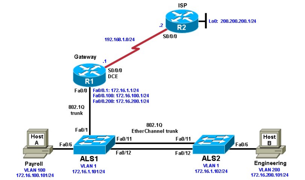
Practical 9a, Inter-VLAN Routing with an External Router
Topology
Objective
• Configure inter-VLAN routing using an external router, also known as a router on a stick.
Background
Inter-VLAN routing using an external router can be a cost-effective solution when it is necessary to segment a
network into multiple broadcast domains. In this lab, you split an existing network into two separate VLANs on
the access layer switches, and use an external router to route between the VLANs. An 802.1Q trunk connects
the switch and the Fast Ethernet interface of the router for routing and management. Static routes are used
between the gateway router and the ISP router. The switches are connected via an 802.1Q EtherChannel link.
Note: This lab uses Cisco 1841 routers with Cisco IOS Release 12.4(24)T1 and the Advanced IP Services
image c1841-advipservicesk9-mz.124-24.T1.bin. The switches are Cisco WS-C2960-24TT-L with the Cisco
IOS image c2960-lanbasek9-mz.122-46.SE.bin. You can use other routers (such as 2801 or 2811), switches
(such as 2950), and Cisco IOS Software versions if they have comparable capabilities and features.
Depending on the router or switch model and Cisco IOS Software version, the commands available and output
produced might vary from what is shown in this lab.
Required Resources
• 2 routers (Cisco 1841 with Cisco IOS Release 12.4(24)T1 Advanced IP Services or comparable)
• 2 switches (Cisco 2960 with the Cisco IOS Release 12.2(46)SE C2960-LANBASEK9-M image or
comparable)
• Serial and Ethernet cables
Step 1: Prepare the switches and routers for the lab.
a. Cable the network as shown in the topology diagram. On each switch, erase the startup configuration,
delete the vlan.dat file, and reload the switches. Refer to Lab 1-1, “Clearing a Switch” and Lab 1-2,
“Clearing a Switch Connected to a Larger Network” to prepare the switches for this lab.
b. Erase the startup configuration and reload the routers.
Step 2: Configure the hosts.
Configure PC hosts A and B with the IP address, subnet mask (/24), and default gateway shown in the
topology.
Step 3: Configure the routers.
a. Configure the ISP router for communication with your gateway router. The static route used for the internal
networks provides a path for the local network from the ISP. In addition, configure a loopback interface on
the ISP router to simulate an external network.
Router(config)# hostname ISP
ISP(config)# interface Loopback0
ISP(config-if)# ip address 200.200.200.1 255.255.255.0
ISP(config-if)# interface Serial0/0/0
ISP(config-if)# ip address 192.168.1.2 255.255.255.0 ISP(config-
if)# no shutdown
ISP(config-if)# exit
ISP(config)# ip route 172.16.0.0 255.255.0.0 192.168.1.1
b. Configure the Gateway router to communicate with the ISP router. Notice the use of a static default route.
The default route tells the router to send any traffic with an unknown destination network to the ISP router.
Router(config)# hostname Gateway
Gateway(config)# interface Serial0/0/0
Gateway(config-if)# ip address 192.168.1.1 255.255.255.0
Gateway(config-if)# clockrate 64000
Gateway(config-if)# no shutdown
Gateway(config-if)# exit
Gateway(config)# ip route 0.0.0.0 0.0.0.0 192.168.1.2
c. Verify connectivity from the Gateway router using the ping command.
Was this ping successful?
_______________________________________________________________________________
Step 4: Configure the switches.
a. Configure the switch hostnames and IP addresses on the management VLAN according to the diagram.
By default, VLAN 1 is used as the management VLAN. Create a default gateway on both access layer
switches using the ip default-gateway ip_address command. The following is a sample configuration
for switch ALS1.
Switch(config)# hostname ALS1
ALS1(config)# interface vlan 1
ALS1(config-if)# ip address 172.16.1.101 255.255.255.0
ALS1(config-if)# no shutdown
ALS1(config-if)# exit
ALS1(config)# ip default-gateway 172.16.1.1

The following is a sample configuration for switch ALS2.
Switch(config)# hostname ALS2
ALS2(config)# interface vlan 1
ALS2(config-if)# ip address 172.16.1.102 255.255.255.0
ALS2(config-if)# no shutdown
ALS2(config-if)# exit
ALS2(config)# ip default-gateway 172.16.1.1
b. (Optional) Set an enable secret password and configure the vty lines for Telnet access to the switch.
ALS1(config)# enable secret cisco
ALS1(config)# line vty 0 15
ALS1(config-line)# password cisco
ALS1(config-line)# login
ALS1(config-line)# end
ALS2(config)# enable secret cisco
ALS2(config)# line vty 0 15
ALS2(config-line)# password cisco
ALS2(config-line)# login ALS2(config-line)#
end
c. By default, how many lines are available for Telnet on the access switches?
_______________________________________________________________________________
Step 5: Confirm the VLANs.
a. Verify that the only existing VLANs are the built-in VLANs. Issue the show vlan command from privileged
mode on both access layer switches. ALS1# show vlan
VLAN Name Status Ports
---- -------------------------------- --------- -----------------------------
1 default active Fa0/1, Fa0/2, Fa0/3, Fa0/4
Fa0/5, Fa0/6, Fa0/7, Fa0/8
Fa0/9, Fa0/10, Fa0/11, Fa0/12
Fa0/13, Fa0/14, Fa0/15,
Fa0/16
Fa0/17, Fa0/18, Fa0/19,
Fa0/20
Fa0/21, Fa0/22, Fa0/23,
Fa0/24
Gi0/1, Gi0/2
1002 fddi-default act/unsup 1003 token-
ring-default act/unsup 1004 fddinet-default
act/unsup 1005 trnet-default act/unsup
VLAN Type SAID MTU Parent RingNo BridgeNo Stp BrdgMode Trans1
Trans2
---- ----- ---------- ----- ------ ------ -------- ---- -------- ------ -----
1 enet 100001 1500 - - - - - 0 0
1002 fddi 101002 1500 - - - - - 0 0
1003 tr 101003 1500 - - - - -
0 0 1004 fdnet 101004 1500 - - -
ieee - 0 0 1005 trnet 101005 1500 - -
- ibm - 0 0
Remote SPAN VLANs
-----------------------------------------------------------------------------
Primary Secondary Type Ports
------- --------- ----------------- -----------------------------------------
Which VLAN is the default management VLAN for Ethernet? What types of traffic are carried on this VLAN?
__________________________________________________________________________________
__________________________________________________________________________________
__________________________________________________________________________________
__________________________________________________________________________________
Step 6: Configure trunk links and EtherChannel on switches.
a. Use the Fast Ethernet 0/11 and 0/12 ports of ALS1 and ALS2 to create an EtherChannel trunk between the
switches.
ALS1# configure terminal
Enter configuration commands, one per line. End with CNTL/Z.
ALS1(config)# interface range fastEthernet 0/11 - 12
ALS1(config-if-range)# switchport mode trunk
ALS1(config-if-range)# channel-group 1 mode desirable
ALS1(config-if-range)# end
ALS2# configure terminal
Enter configuration commands, one per line. End with CNTL/Z.
ALS2(config)# interface range fastEthernet 0/11 - 12
ALS2(config-if-range)# switchport mode trunk
ALS2(config-if-range)# channel-group 1 mode desirable ALS2(config-if-range)#
end
b. Verify the EtherChannel configuration using the show etherchannel command. ALS1#
show etherchannel 1 summary
Flags: D - down P - in port-channel
I - stand-alone s - suspended H -
Hot-standby (LACP only) R - Layer3
S - Layer2
U - in use f - failed to allocate aggregator
u - unsuitable for bundling w - waiting to be
aggregated d - default port
Number of channel-groups in use: 1 Number
of aggregators: 1
Group Port-channel Protocol Ports
------+-------------+-----------+--------------------------------------------
1 Po1(SU) PAgP Fa0/11(P) Fa0/12(P)
Step 7: Configure VTP.
a. Set up the VTP domain for the access layer switches in global configuration mode. The default VTP mode
is server for both switches. Configure ALS2 as a VTP client, and leave ALS1 as a server. Configure the
VTP domain name and version on VTP server ALS1.

ALS2(config)# vtp mode client
Setting device to VTP CLIENT mode.
ALS1(config)# vtp domain SWLAB
Changing VTP domain name from NULL to SWLAB
%SW_VLAN-6-VTP_DOMAIN_NAME_CHG: VTP domain name changed to SWLAB.
ALS1(config)# vtp version 2
b. Use the show vtp status command to verify the ALS1 VTP configuration and that client ALS2 has
learned the new VTP domain information from ALS1.
ALS1# show vtp status
VTP Version : running VTP2
Configuration Revision : 1
Maximum VLANs supported locally : 255 Number
of existing VLANs : 5
VTP Operating Mode : Server VTP
Domain Name : SWLAB
VTP Pruning Mode : Disabled
VTP V2 Mode : Enabled
VTP Traps Generation : Disabled
MD5 digest : 0x6A 0x1A 0x90 0xA3 0x10 0xCE 0x86 0xFA
Configuration last modified by 172.16.1.101 at 2-28-10 00:36:24 Local
updater ID is 172.16.1.101 on interface Vl1 (lowest numbered VLAN
interface found)
ALS2# show vtp status
VTP Version : running VTP2
Configuration Revision : 1
Maximum VLANs supported locally : 255 Number
of existing VLANs : 5
VTP Operating Mode : Client
VTP Domain Name : SWLAB
VTP Pruning Mode : Disabled
VTP V2 Mode : Enabled
VTP Traps Generation : Disabled
MD5 digest : 0x6A 0x1A 0x90 0xA3 0x10 0xCE 0x86 0xFA
Configuration last modified by 172.16.1.101 at 2-28-10 00:36:24 Step 8: Configure
VLANs and switch access ports.
a. Configure the VLAN 100 named Payroll and VLAN 200 named Engineering on VTP server ALS1.
ALS1(config)# vlan 100
ALS1(config-vlan)# name Payroll ALS1(config-vlan)#
vlan 200
ALS1(config-vlan)# name Engineering
b. Use the show vlan brief command on ALS2 to verify that ALS2 has learned the new VLANs from ALS1.
ALS2# show vlan brief
VLAN Name Status Ports
---- -------------------------------- --------- -----------------------------
1 default active Fa0/1, Fa0/2, Fa0/3, Fa0/4
Fa0/5, Fa0/6, Fa0/7, Fa0/8
Fa0/9, Fa0/10, Fa0/13, Fa0/14

Fa0/15, Fa0/16, Fa0/17,
Fa0/18
Fa0/19, Fa0/20, Fa0/21,
Fa0/22
Fa0/23, Fa0/24, Gi0/1, Gi0/2
100 Payroll active
200 Engineering active
1002 fddi-default act/unsup
1003 trcrf-default act/unsup 1004 fddinet-
default act/unsup 1005 trbrf-default
act/unsup
c. Configure the switch access ports for the hosts according to the diagram. Statically set the switch port mode
to access, and use Spanning Tree PortFast on the interfaces. Assign the host attached to ALS1 Fast
Ethernet 0/6 to VLAN 100, and the host attached to ALS2 Fast Ethernet 0/6 to VLAN 200.
ALS1(config)# interface fastEthernet 0/6 ALS1(config-if)#
switchport mode access
ALS1(config-if)# switchport access vlan 100
ALS1(config-if)# spanning-tree portfast
%Warning: portfast should only be enabled on ports connected to a single
host. Connecting hubs, concentrators, switches, bridges, etc... to this
interface when portfast is enabled, can cause temporary bridging loops.
Use with CAUTION
%Portfast has been configured on FastEthernet0/6 but will only
have effect when the interface is in a non-trunking mode.
ALS2(config)# interface fastEthernet 0/6 ALS2(config-if)#
switchport mode access
ALS2(config-if)# switchport access vlan 200
ALS2(config-if)# spanning-tree portfast
%Warning: portfast should only be enabled on ports connected to a single
host. Connecting hubs, concentrators, switches, bridges, etc... to this
interface when portfast is enabled, can cause temporary bridging loops.
Use with CAUTION
%Portfast has been configured on FastEthernet0/6 but will only
have effect when the interface is in a non-trunking mode.
d. Use the show vlan brief command to verify that Fa0/6 is in VLAN 100 on ALS1 and in VLAN 200 on ALS2.
ALS1# show vlan brief
VLAN Name Status Ports
---- -------------------------------- --------- -----------------------------
1 default active Fa0/1, Fa0/2, Fa0/3, Fa0/4
Fa0/5, Fa0/7, Fa0/8, Fa0/9
Fa0/10, Fa0/13, Fa0/14,
Fa0/15
Fa0/16, Fa0/17, Fa0/18,
Fa0/19
Fa0/20, Fa0/21, Fa0/22,
Fa0/23
Fa0/24, Gi0/1, Gi0/2
100 Payroll active Fa0/6
200 Engineering active
1002 fddi-default act/unsup

1003 trcrf-default act/unsup 1004 fddinet-
default act/unsup 1005 trbrf-default
act/unsup
ALS2# show vlan brief
VLAN Name Status Ports
---- -------------------------------- --------- -----------------------------
1 default active Fa0/1, Fa0/2, Fa0/3, Fa0/4
Fa0/5, Fa0/7, Fa0/8, Fa0/9
Fa0/10, Fa0/13, Fa0/14,
Fa0/15
Fa0/16, Fa0/17, Fa0/18,
Fa0/19
Fa0/20, Fa0/21, Fa0/22,
Fa0/23
Fa0/24, Gi0/1, Gi0/2
100 Payroll active
200 Engineering active Fa0/6
1002 fddi-default act/unsup
1003 trcrf-default act/unsup 1004 fddinet-
default act/unsup
1005 trbrf-default act/unsup Step
9: Configure ALS1 trunking to the Gateway router.
Configure switch ALS1 interface Fast Ethernet 0/1 for trunking with the Gateway router Fast Ethernet
interface, according to the topology diagram.
ALS1(config)# interface fastEthernet 0/1
ALS1(config-if)# switchport mode trunk
ALS1(config-if)# end
Note: Optionally, you can apply the spanning-tree portfast trunk command to interface Fa0/1 of switch
ALS1. This allows the link to the router to rapidly transition to the forwarding state despite being a trunk.
Step 10: Configure the Gateway router Fast Ethernet interface for VLAN trunking.
The native VLAN cannot be configured on a subinterface for Cisco IOS releases earlier than 12.1(3)T. The
native VLAN IP address must be configured on the physical interface. Other VLAN traffic is configured on
subinterfaces. Cisco IOS release 12.1(3)T and later support native VLAN configuration on a subinterface with
the encapsulation dot1q native command. If a subinterface is configured using the encapsulation dot1q
native command, the configuration on the physical interface is ignored. This technique is used in the lab
configuration.
a. Create a subinterface for each VLAN. Enable each subinterface with the proper trunking protocol, and
configure it for a particular VLAN with the encapsulation command. Assign an IP address to each
subinterface, which hosts on the VLAN can use as their default gateway. The following is a sample
configuration for the Fast Ethernet 0/0 interface.
Gateway(config)# interface fastEthernet 0/0 Gateway(config-if)#
no shut
The following is a sample configuration for the VLAN 1 subinterface.
Gateway(config)# interface fastEthernet 0/0.1
Gateway(config-subif)# description Management VLAN 1
Gateway(config-subif)# encapsulation dot1q 1 native

Gateway(config-subif)# ip address 172.16.1.1 255.255.255.0
Note: For enhanced switch security, it is considered best practice to use independent unused VLANs
for native and management VLANs. The following is a sample configuration for the VLAN 100
subinterface.
Gateway(config-subif)# interface fastEthernet 0/0.100
Gateway(config-subif)# description Payroll VLAN 100
Gateway(config-subif)# encapsulation dot1q 100
Gateway(config-subif)# ip address 172.16.100.1 255.255.255.0
The following is a sample configuration for the VLAN 200 subinterface.
Gateway(config-subif)# interface fastEthernet 0/0.200
Gateway(config-subif)# description Engineering VLAN 200
Gateway(config-subif)# encapsulation dot1q 200
Gateway(config-subif)# ip address 172.16.200.1 255.255.255.0 Gateway(config-
subif)# end
b. Use the show ip interface brief command to verify the interface configuration and status.
Gateway# show ip interface brief
Interface IP-Address OK? Method Status
Protocol
FastEthernet0/0 unassigned YES unset up up
FastEthernet0/1.1 172.16.1.1 YES manual up up
FastEthernet0/1.100 172.16.100.1 YES manual up up
FastEthernet0/1.200 172.16.200.1 YES manual up up
FastEthernet0/1 unassigned YES unset administratively down down
Serial0/0/0 192.168.1.1 YES manual up up
Serial0/0/1 unassigned YES unset administratively down down
c. Use the show interfaces description command to verify the interface status and description assigned.
Gateway# show interfaces description
Interface Status Protocol Description
Fa0/0 up up
Fa0/0.1 up up Management VLAN 1
Fa0/0.100 up up Payroll VLAN 100
Fa0/0.200 up up Engineering VLAN 200
Fa0/1 admin down down
Se0/0/0 up up
Se0/0/1 admin down down
d. Use the show vlans command on the Gateway router. Gateway# show vlans
Virtual LAN ID: 1 (IEEE 802.1Q Encapsulation)
vLAN Trunk Interface: FastEthernet0/1.1
This is configured as native Vlan for the following interface(s) :
FastEthernet0/1
Protocols Configured: Address: Received: Transmitted:
IP 172.16.1.1 198 54
Other 0 29
277 packets, 91551 bytes input
83 packets, 15446 bytes output

Virtual LAN ID: 100 (IEEE 802.1Q Encapsulation)
vLAN Trunk Interface: FastEthernet0/1.100
Protocols Configured: Address: Received: Transmitted:
IP 172.16.100.1 1 25
0 packets, 0 bytes input
25 packets, 2350 bytes output
Virtual LAN ID: 200 (IEEE 802.1Q Encapsulation)
vLAN Trunk Interface: FastEthernet0/1.200
Protocols Configured: Address: Received: Transmitted:
IP 172.16.200.1 1 25
0 packets, 0 bytes input
25 packets, 2350 bytes output
e. Use the show cdp neighbor detail command on the Gateway router to verify that ALS1 is a neighbor.
Telnet to the IP address given in the CDP information.
Gateway# show cdp neighbor detail
-------------------------
Device ID: ISP
Entry address(es):
IP address: 192.168.1.2
Platform: Cisco 1841, Capabilities: Router Switch IGMP
Interface: Serial0/0/0, Port ID (outgoing port): Serial0/0/0
Holdtime : 174 sec
Version :
Cisco IOS Software, 1841 Software (C1841-ADVIPSERVICESK9-M), Version
12.4(24)T1,
RELEASE SOFTWARE (fc3)
Technical Support: http://www.cisco.com/techsupport
Copyright (c) 1986-2009 by Cisco Systems, Inc.
Compiled Fri 19-Jun-09 13:56 by prod_rel_team
advertisement version: 2 VTP
Management Domain: ''
-------------------------
Device ID: ALS1
Entry address(es):
IP address: 172.16.1.101
Platform: cisco WS-C2960-24TT-L, Capabilities: Switch IGMP
Interface: FastEthernet0/0.1, Port ID (outgoing port): FastEthernet0/1
Holdtime : 118 sec
Version :
Cisco IOS Software, C2960 Software (C2960-LANBASEK9-M), Version 12.2(46)SE,
RELE
ASE SOFTWARE (fc2)
Copyright (c) 1986-2008 by Cisco Systems, Inc.
Compiled Thu 21-Aug-08 15:59 by nachen

advertisement version: 2
Protocol Hello: OUI=0x00000C, Protocol ID=0x0112; payload len=27,
value=0000000
0FFFFFFFF010221FF000000000000001D46350C80FF0000
VTP Management Domain: 'SWLAB'
Native VLAN: 1 Duplex:
full
Was the Telnet successful?
_______________________________________________________________________________
Step 11: Verify inter-VLAN routing on the Gateway router and the host devices.
a. Ping to the 200.200.200.1 ISP loopback interface from either host. Was this ping successful?
_______________________________________________________________________________
_______________________________________________________________________________
b. Ping from Host A to Host B. Was this ping successful?
_______________________________________________________________________________
_______________________________________________________________________________
c. Telnet to the ALS2 VLAN 1 management IP address from the Engineering host. Was this Telnet
successful?
_______________________________________________________________________________
_______________________________________________________________________________
If any of the tests failed, make the necessary corrections to the configurations for the router and switches.
Router Interface Summary Table
Router Interface Summary
Router Model Ethernet Interface
#1
Ethernet Interface
#2
Serial Interface
#1
Serial Interface
#2
1700 Fast Ethernet 0
(FA0)
Fast Ethernet 1
(FA1)
Serial 0 (S0) Serial 1 (S1)
1800 Fast Ethernet 0/0
(FA0/0)
Fast Ethernet 0/1
(FA0/1)
Serial 0/0/0
(S0/0/0)
Serial 0/0/1
(S0/0/1)
2600 Fast Ethernet 0/0
(FA0/0)
Fast Ethernet 0/1
(FA0/1)
Serial 0/0 (S0/0) Serial 0/1 (S0/1)
2800 Fast Ethernet 0/0
(FA0/0)
Fast Ethernet 0/1
(FA0/1)
Serial 0/0/0
(S0/0/0)
Serial 0/0/1
(S0/0/1)
Note: To find out how the router is configured, look at the interfaces to identify the type of router
and how many interfaces the router has. Rather than list all combinations of configurations for each
router class, this table includes identifiers for the possible combinations of Ethernet and serial
interfaces in the device. The table does not include any other type of interface, even though a
specific router might contain one. For example, for an ISDN BRI interface, the string in parenthesis
is the legal abbreviation that can be used in Cisco IOS commands to represent the interface.
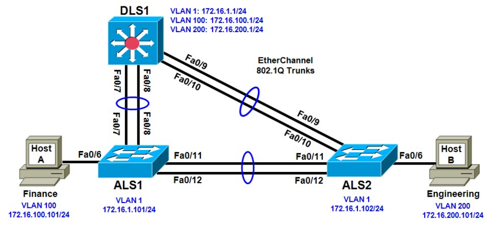
Practical 9b, Inter-VLAN Routing with an Internal Route
Processor and Monitoring CEF Functions
Topology
Objective
• Route between VLANs using a 3560 switch with an internal route processor using Cisco Express
Forwarding (CEF).
Background
The current network equipment includes a 3560 distribution layer switch and two 2960 access layer switches.
The network is segmented into three functional subnets using VLANs for better network management. The
VLANs include Finance, Engineering, and a subnet for equipment management, which is the default
management VLAN, VLAN 1. After VTP and trunking have been configured for the switches, switched virtual
interfaces (SVI) are configured on the distribution layer switch to route between these VLANs, providing full
connectivity to the internal network.
Note: This lab uses Cisco WS-C2960-24TT-L switches with the Cisco IOS image c2960-lanbasek9-
mz.12246.SE.bin and Catalyst 3560-24PS with the Cisco IOS image c3560-advipservicesk9-mz.122-
46.SE.bin. You can use other switches (such as 2950 or 3550) and Cisco IOS Software versions if they have
comparable capabilities and features. Depending on the switch model and Cisco IOS Software version, the
commands available and output produced might vary from what is shown in this lab.
Required Resources
• 2 switches (Cisco 2960 with the Cisco IOS Release 12.2(46)SE C2960-LANBASEK9-M image or
comparable)
• 1 switch (Cisco 3560 with the Cisco IOS Release 12.2(46)SE C3560-ADVIPSERVICESK9-mz image
or comparable)
• Ethernet and console cables
Step 1: Prepare the switches for the lab.
Erase the startup configuration, delete the vlan.dat file, and reload the switches.
Step 2: Configure basic switch parameters.
a. Configure the hostname, password, and optionally, Telnet access on each switch.
Switch(config)# hostname ALS1
ALS1(config)# enable secret cisco
ALS1(config)# line vty 0 15
ALS1(config-line)# password cisco
ALS1(config-line)# login
Switch(config)# hostname ALS2
ALS2(config)# enable secret cisco
ALS2(config)# line vty 0 15
ALS2(config-line)# password cisco
ALS2(config-line)# login
Switch(config)# hostname DLS1
DLS1(config)# enable secret cisco
DLS1(config)# line vty 0 15
DLS1(config-line)#password cisco DLS1(config-line)#
login
b. Configure management IP addresses on VLAN 1 for all three switches according to the diagram.
ALS1(config)# interface vlan 1
ALS1(config-if)# ip address 172.16.1.101 255.255.255.0
ALS1(config-if)# no shutdown
ALS2(config)# interface vlan 1
ALS2(config-if)# ip address 172.16.1.102 255.255.255.0
ALS2(config-if)# no shutdown
DLS1(config)# interface vlan 1
DLS1(config-if)# ip address 172.16.1.1 255.255.255.0 DLS1(config-
if)# no shutdown
c. Configure default gateways on the access layer switches. The distribution layer switch will not use a
default gateway, because it acts as a Layer 3 device. The access layer switches act as Layer 2 devices
and need a default gateway to send management VLAN traffic off of the local subnet.
ALS1(config)# ip default-gateway 172.16.1.1
ALS2(config)# ip default-gateway 172.16.1.1
Step 3: Configure trunks and EtherChannels between switches.
To distribute VLAN and VTP information between the switches, trunks are needed between the three
switches. Configure these trunks according to the diagram. EtherChannel is used for these trunks.
EtherChannel allows you to utilize both Fast Ethernet interfaces that are available between each device,
thereby doubling the bandwidth.
a. Configure the trunks and EtherChannel from DLS1 to ALS1. The switchport trunk encapsulation [isl |
dot1q] command is used because this switch also supports ISL encapsulation.
DLS1(config)# interface range fastEthernet 0/7 - 8

DLS1(config-if-range)# switchport trunk encapsulation dot1q
DLS1(config-if-range)# switchport mode trunk
DLS1(config-if-range)# channel-group 1 mode desirable
Creating a port-channel interface Port-channel 1
b. Configure the trunks and EtherChannel from DLS1 to ALS2.
DLS1(config)# interface range fastEthernet 0/9 - 10
DLS1(config-if-range)# switchport trunk encapsulation dot1q
DLS1(config-if-range)# switchport mode trunk
DLS1(config-if-range)# channel-group 2 mode desirable
Creating a port-channel interface Port-channel 2
c. Configure the trunks and EtherChannel between ALS1 and DLS1, and for the trunks and EtherChannel
between ALS1 and ALS2.
ALS1(config)# interface range fastEthernet 0/11 - 12
ALS1(config-if-range)# switchport mode trunk
ALS1(config-if-range)# channel-group 1 mode desirable
Creating a port-channel interface Port-channel 1
ALS1(config-if-range)# exit
ALS1(config)# interface range fastEthernet 0/7 - 8
ALS1(config-if-range)# switchport mode trunk
ALS1(config-if-range)# channel-group 2 mode desirable
Creating a port-channel interface Port-channel 2
d. Configure the trunks and EtherChannel between ALS2 and DLS1, and for the trunks and EtherChannel
between ALS2 and ALS1.
ALS2(config)# interface range fastEthernet 0/11 - 12
ALS2(config-if-range)# switchport mode trunk
ALS2(config-if-range)# channel-group 1 mode desirable
Creating a port-channel interface Port-channel 1
ALS2(config-if-range)# exit
ALS2(config)# interface range fastEthernet 0/9 - 10
ALS2(config-if-range)# switchport mode trunk
ALS2(config-if-range)# channel-group 2 mode desirable
Creating a port-channel interface Port-channel 2
e. Verify trunking between DLS1, ALS1, and ALS2 using the show interface trunk command on all
switches.
DLS1# show interface trunk
Port Mode Encapsulation Status Native vlan
Po1 on 802.1q trunking 1
Po2 on 802.1q trunking 1
Port Vlans allowed on trunk
Po1 1-4094
Po2 1-4094
Port Vlans allowed and active in management domain
Po1 1
Po2 1
Port Vlans in spanning tree forwarding state and not pruned
Po1 1
Po2 1
f. Use the show etherchannel summary command on each switch to verify the EtherChannels. The
following is sample output from ALS1. Notice the two EtherChannels on the access layer switches.
ALS1# show etherchannel summary
Flags: D - down P - in port-channel
I - stand-alone s - suspended H -
Hot-standby (LACP only) R - Layer3
S - Layer2
U - in use f - failed to allocate aggregator
u - unsuitable for bundling w - waiting to be
aggregated d - default port
Number of channel-groups in use: 2 Number
of aggregators: 2
Group Port-channel Protocol Ports
------+-------------+-----------+--------------------------------------------
1 Po1(SU) PAgP Fa0/11(P) Fa0/12(P)
2 Po2(SU) PAgP Fa0/7(P) Fa0/8(P)
On ALS1, which ports are used for channel group 2?
_______________________________________________________________________________
Step 4: Configure VTP on ALS1 and ALS2.
a. Change the VTP mode of ALS1 and ALS2 to client.
ALS1(config)# vtp mode client
Setting device to VTP CLIENT mode.
ALS2(config)# vtp mode client
Setting device to VTP CLIENT mode.
b. Verify the VTP changes with the show vtp status command. The output on ALS2 is similar to that of
ALS1.
ALS2# show vtp status
VTP Version : running VTP1 (VTP2 capable)
Configuration Revision : 0
Maximum VLANs supported locally : 255
Number of existing VLANs : 5
VTP Operating Mode : Client
VTP Domain Name :
VTP Pruning Mode : Disabled
VTP V2 Mode : Disabled
VTP Traps Generation : Disabled
MD5 digest : 0xC8 0xAB 0x3C 0x3B 0xAB 0xDD 0x34 0xCF
Configuration last modified by 0.0.0.0 at 3-1-93 15:47:34
How many VLANs can be supported locally on the 2960 switch?
_______________________________________________________________________________
Step 5: Configure VTP on DLS1.
a. Create the VTP domain on DLS1 and create VLANs 100 and 200 for the domain.
DLS1(config)# vtp domain SWPOD
DLS1(config)# vtp version 2
DLS1(config)# vlan 100
DLS1(config-vlan)# name Finance DLS1(config-vlan)#
vlan 200
DLS1(config-vlan)# name Engineering
b. Verify VTP information throughout the domain using the show vlan and show vtp status commands.
How many existing VLANs are in the VTP domain?
_______________________________________________________________________________
Step 6: Configure ports.
Configure the host ports for the appropriate VLANs according to the diagram.
ALS1(config)# interface fastEthernet 0/6 ALS1(config-if)#
switchport mode access
ALS1(config-if)# switchport access vlan 100
ALS2(config)# interface fastEthernet 0/6 ALS2(config-if)#
switchport mode access
ALS2(config-if)# switchport access vlan 200
Ping from the host on VLAN 100 to the host on VLAN 200. Was the ping successful? Why do you think
this is the case?
_______________________________________________________________________________
_______________________________________________________________________________
_______________________________________________________________________________
Ping from a host to the VLAN 1 management IP address of DLS1. Was the ping successful? Why do you
think this is the case?
_______________________________________________________________________________
_______________________________________________________________________________
_______________________________________________________________________________
Step 7: Configure VLAN interfaces and enable routing.
a. On DLS1, create the Layer 3 VLAN interfaces to route between VLANs using the interface vlan vlan-id
command. These are known as SVIs. You do not need to set up VLAN 1, because this was done in Step
2.
DLS1(config)# interface vlan 100
DLS1(config-if)# ip add 172.16.100.1 255.255.255.0
DLS1(config-if)# no shut
DLS1(config-if)# interface vlan 200
DLS1(config-if)# ip address 172.16.200.1 255.255.255.0
DLS1(config-if)# no shutdown
b. The ip routing command is also needed to allow the switch to act as a Layer 3 device to route between
these VLANs. Because the VLANs are all considered directly connected, a routing protocol is not needed
at this time.
DLS1(config)# ip routing
c. Verify the configuration using the show ip route command on DLS1.
DLS1# show ip route
Codes: C - connected, S - static, R - RIP, M - mobile, B - BGP
D - EIGRP, EX - EIGRP external, O - OSPF, IA - OSPF inter area
N1 - OSPF NSSA external type 1, N2 - OSPF NSSA external type 2 E1 -
OSPF external type 1, E2 - OSPF external type 2, E - EGP i - IS-IS,
su - IS-IS summary, L1 - IS-IS level-1, L2 - IS-IS level-2 ia - IS-IS
inter area, * - candidate default, U - per-user static route
o - ODR, P - periodic downloaded static route
Gateway of last resort is not set
172.16.0.0/24 is subnetted, 3 subnets
C 172.16.200.0 is directly connected, Vlan200
C 172.16.1.0 is directly connected, Vlan1
C 172.16.100.0 is directly connected, Vlan100
Step 8: Verify inter-VLAN routing by the internal route processor.
a. Ping from the Engineering host to the Finance host. Was the ping successful this time?
__________________________________________________________________________________
b. Telnet from one of the hosts to the VLAN 1 IP address of DLS1. Can this switch be remotely accessed
from this host?
__________________________________________________________________________________
Step 9: Examine the CEF configuration.
CEF implements an advanced IP lookup and forwarding algorithm to deliver maximum Layer 3 switching
performance. CEF is less CPU-intensive than route caching.
In dynamic networks, fast-switching cache entries are frequently invalidated because of routing changes. This
can cause traffic to be process-switched using the routing table, instead of fast-switched using the route
cache. CEF uses the Forwarding Information Base (FIB) lookup table to perform destination-based switching
of IP packets.
CEF is enabled by default on the 3560 switch.
a. Use the show ip cef command to display the CEF FIB.
DLS1# show ip cef
Prefix Next Hop Interface 0.0.0.0/32
receive
172.16.1.0/24 attached Vlan1
172.16.1.0/32 receive

172.16.1.1/32 receive
172.16.1.101/32 attached Vlan1
172.16.1.102/32 attached Vlan1
172.16.1.255/32 receive
172.16.100.0/24 attached Vlan100
172.16.100.0/32 receive
172.16.100.1/32 receive
172.16.100.255/32 receive
172.16.200.0/24 attached Vlan200
172.16.200.0/32 receive
172.16.200.1/32 receive
172.16.200.255/32 receive
224.0.0.0/4 drop
224.0.0.0/24 receive
255.255.255.255/32 receive
b. Use the show ip interface command to verify that CEF is enabled on an interface. The following output
shows that CEF is enabled on VLAN 100.
DLS1# show ip interface vlan 100
Vlan100 is up, line protocol is up
Internet address is 172.16.100.1/24
Broadcast address is 255.255.255.255
Address determined by setup command
MTU is 1500 bytes
Helper address is not set
Directed broadcast forwarding is disabled
Outgoing access list is not set
Inbound access list is not set
Proxy ARP is enabled
Local Proxy ARP is disabled
Security level is default
Split horizon is enabled
ICMP redirects are always sent
ICMP unreachables are always sent
ICMP mask replies are never sent
IP fast switching is enabled
IP CEF switching turbo vector
IP multicast fast switching is disabled
IP multicast distributed fast switching is
disabled
IP route-cache flags are Fast, CEF
Router Discovery is disabled
IP output packet accounting is disabled
IP access violation accounting is disabled
TCP/IP header compression is disabled
RTP/IP header compression is disabled
Probe proxy name replies are disabled
Policy routing is disabled
Network address translation is disabled
WCCP Redirect outbound is disabled
WCCP Redirect inbound is disabled
WCCP Redirect exclude is disabled
BGP Policy Mapping is disabled
c. Use the show ip cef summary command to display the CEF table summary.
IP CEF switching is
enabled
DLS1# show ip cef summary
IPv4 CEF is enabled for distributed and running
VRF Default:
18 prefixes (18/0 fwd/non-fwd)
Table id 0, 0 resets
Database epoch: 1 (18 entries at this epoch)
d. The show ip cef detail command shows CEF operation in detail for the switch.
DLS1# show ip cef detail
IPv4 CEF is enabled for distributed and running
VRF Default:
18 prefixes (18/0 fwd/non-fwd)
Table id 0, 0 resets
Database epoch: 1 (18 entries at this epoch)
0.0.0.0/32, epoch 1, flags receive
Special source: receive receive
172.16.1.0/24, epoch 1, flags attached, connected
attached to Vlan1
172.16.1.0/32, epoch 1, flags receive
receive
172.16.1.1/32, epoch 1, flags receive
receive
172.16.1.101/32, epoch 1
Adj source: IP adj out of Vlan1, addr 172.16.1.101
attached to Vlan1 172.16.1.102/32, epoch 1
Adj source: IP adj out of Vlan1, addr 172.16.1.102
attached to Vlan1
172.16.1.255/32, epoch 1, flags receive
receive
172.16.100.0/24, epoch 1, flags attached, connected
attached to Vlan100
172.16.100.0/32, epoch 1, flags receive
receive
172.16.100.1/32, epoch 1, flags receive
receive
172.16.100.255/32, epoch 1, flags receive
receive
172.16.200.0/24, epoch 1, flags attached, connected
attached to Vlan200
172.16.200.0/32, epoch 1, flags receive
receive
172.16.200.1/32, epoch 1, flags receive
receive
172.16.200.255/32, epoch 1, flags receive
receive 224.0.0.0/4, epoch 1 Special
source: drop drop
224.0.0.0/24, epoch 1, flags receive
Special source: receive receive
255.255.255.255/32, epoch 1, flags receive
Special source: receive
Receive
