EN:ICRA 2018 DJI Robo Master AI Robot User Manual
User Manual:
Open the PDF directly: View PDF ![]() .
.
Page Count: 27
ICRA 2018 DJI RoboMaster
AI Robot
User Manual
V1.0 2018.03
1
Contents
Using this manual ............................................................................................................................. 3
Warnings & Disclaimers .................................................................................................................... 4
Precautions ....................................................................................................................................... 4
Introduction ....................................................................................................................................... 5
Hardware Modules Introduction ........................................................................................................ 5
Complete Overview of Hardware Functions .................................................................................. 5
Chassis ......................................................................................................................................... 6
Customization ............................................................................................................................... 7
2-Axis Servo .................................................................................................................................. 8
Projectile Feeding System ............................................................................................................. 9
Launching Mechanism .................................................................................................................. 9
Referee System .......................................................................................................................... 10
Hardware Circuit System ............................................................................................................. 10
Software System ............................................................................................................................. 13
Intelligent Battery ............................................................................................................................ 14
Turning On/Off ............................................................................................................................ 14
Checking the Charge................................................................................................................... 14
Charging ..................................................................................................................................... 15
2
Charge Protection Indicator ......................................................................................................... 15
Remote Control Kit ......................................................................................................................... 17
Kit Overview ................................................................................................................................ 17
Remote Control ........................................................................................................................... 17
Turning On/Off ......................................................................................................................... 18
Charging .................................................................................................................................. 18
Receiver ...................................................................................................................................... 18
Pairing the Remote Control and Receiver ................................................................................ 19
Powering On and Controlling the Robot .......................................................................................... 20
Battery Installation/Removal ........................................................................................................ 20
Powering On/Off .......................................................................................................................... 20
Control Modes ............................................................................................................................. 20
Controlling with Remote Control .............................................................................................. 20
Controlling with Remote Control + PC ..................................................................................... 22
Appendix......................................................................................................................................... 23
Specifications .............................................................................................................................. 23
Parts List......................................................................................................................................... 25

3
Using this manual
Legends
Warning
Important
Hints and Tips
Reference
Agreement
ICRA 2018 DJI RoboMaster™ AI Robot does not include RoboMaster UWB positioning module and laser radar.
If you require these components, please purchase them separately. Additionally, the DR16 receiver is installed
on lower part of the AI Robot’s launching mechanism and will not be provided separately.
Recommended
RoboMaster provides the following documentation:
1. ICRA 2018 DJI RoboMaster Items List for AI Robots
2. ICRA 2018 DJI RoboMaster AI Robot User Manual
3. DJI Matrice 100 Intelligent Flight Battery Safety Guidelines
RoboMaster also provides a compressed file (ICRA 2018 DJI RoboMaster AI Robot Supplementary Materials)
containing the instructions for the various components (including the motor, ESC, etc.) used on AI Robots.
We recommend users first to verify that all the items listed in the ICRA 2018 DJI RoboMaster Items List for AI
Robots are in place. Then, read through the ICRA 2018 DJI RoboMaster AI Robot User Manual to gain an
understanding of the entire usage process. If you require further developer materials, please check the contents
of the ICRA 2018 DJI RoboMaster AI Robot Supplementary Materials compressed file. Before using the M100
intelligent flight battery, please carefully read through the DJI Matrice 100 Intelligent Flight Battery Safety
Guidelines. If you require futher technical instructions, please log in to https://robomaster.com and download
the relevant materials or contact RoboMaster.
4
Warnings & Disclaimers
Thank you for using the ICRA 2018 DJI RoboMaster AI Robot. Before use, please carefully read through the
warnings and disclaimers contained in this section. By using the product, you are considered have understood
and accepted the warnings and disclaimers contained herein. Please strictly follow the manual, product
description, and the relevant laws and regulations, policies, and guidelines when assembling and using the
product. When using the product, the user bears full responsibility for his or her own actions and all
consequences arising therefrom. DJI™ will not be liable for any loss caused by improper usage, assembly, or
modification of the user.
DJI and RoboMaster are trademarks of Da-Jiang Innovation (Shenzhen) Science and Technology Co., Ltd. and
its affiliated companies. The product names, brands, and so on that appear in this article are all the trademarks
of the company to which they belong. This product and manual are copyright of DJI. Any form of reproduction
without the expressed written consent of DJI is strictly prohibited.
DJI reserves the right of final interpretation of the disclaimers contained herein.
Precautions
The chassis, friction wheel, and launched projectiles move at rapid speeds and may damage assets or cause
bodily harm. Ensure that safety measures are taken during use.
Please pay careful attention to the “Important” items contained in the manual.
1. AI Robots are not waterproof. Avoid getting it wet or exposing it to any liquids.
2. Once turned on, an AI Robot will perform a self-test. It can then be operated if the self-test is passed.
3. When engaging in high speed maneuvers, ensure that the AI Robot is in a wide open environment free of
people and obstacles. Do not crash it into large and hard objects, such as walls, at full speed.
4. Do not fire projectiles at people. After adjusting projectile speeds, the best testing environment firing
projectiles a cloth bag or other shock absorbing materials.
5. When not in use or when there are people around, ensure the friction wheels are turned of to prevent
misfiring.
6. When engaging in robot battles, the battle must be carried out in an area completely enclosed by a 2 m tall
fence and in the presence of a skilled operator.
7. After each use, be sure to empty the projectile in the cartridge, to prevent misfires.
8. When no using the robot for an extended period, remove the battery and store it according to the storage
method described in the DJI Matrice 100 Intelligent Flight Battery Safety Guidelines.
9. Be sure to use the standard battery (model: tb47d/tb48d).
10. When assembling and disassembling the robot, tighten screws by applying an appropriate amount force.
The blue colored glue used on the screws is screw glue. After repeated disassembly, use a proper amount
of screw glue to fix the screws.
11. When transporting the robot, fix the servo and the four wheels of the chassis in place, remove the battery,
empty the projectile cartridge.
For any unresolved problems during use, please contact RoboMaster for assistance.
5
Introduction
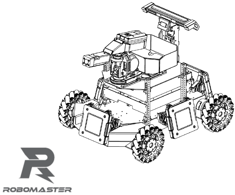
The ICRA 2018 DJI RoboMaster AI Robot ("AI Robot" or "robot") consists of a chassis, 2-axis servo, launching
mechanism, referee system, and intelligent battery. The chassis uses Mecanum wheels to achieve multi-
directional movement. The robot's 2-axis servo is capable of panning and tilting, enhancing the robot's dexterity
and the combat capability. The launching mechanism launches RoboMaster 17mm projectiles. The referee
system features built-in sensors that evaluates the amount of damage taken by the robot. When the robot’s HP
reaches 0, the referee system automatically cuts off the power supply, deactivating the robot. Multiple AI Robots
can engage in battles in specialized battle fields. All hardware debugging interfaces of AI Robots are open
except the referee system. You can use it to create a unique robot automation schemes.
Hardware Modules Introduction
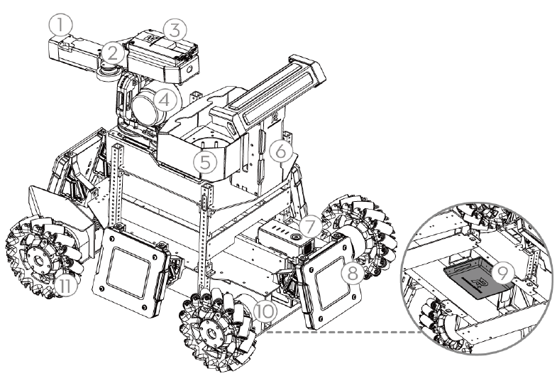
Complete Overview of Hardware Functions
1. Referee System - Speed Measurement Module
2. Launching Mechanism
3. Referee System - Camera Transmission Module
(transmit-end)
4. 2-Axis Servo
5. Projectile Feeding System
6. Referee System - Main Control Module
7. Intelligent Battery
8. Referee System - Armor Module
9. Referee System - RFID Interaction Module
10. Chassis Motor
11. Mecanum Wheels
6
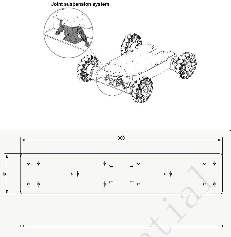
Chassis
The chassis of AI Robots features Mecanum wheels, which allows it to move in multiple directions, including
forwards, sideways, diagonally, and rotate in place. The chassis is equipped with a front-wheel joint suspension
system, which enables it to move within standard competition venues.
With the Robomaster EC60 Brushless Motor for four-wheel drive, the ESC is integrated into the tail of the motor.
For the technical specifications of the ESC, please refer to the Robomaster EC60 Brushless Motor User Manual.
Reminder:
7
Change the parts as shown in the figure to a 5mm thick carbon fiber plate, or attach an identical plate onto the
current design, can increase the rigidity of the front bridge and effectively mitigate the infantry front bridge
shaking problem.
A DXF drawing of the plate is in the attachment.
Customization
Upper layer functional modules (2-axis servo and projectile feeding system) are attached to the chassis by four
support columns. The center area is reserved for sensor installation, for example, you can install the laser radar
in this area. The support columns are aluminum alloy pipes that measure 15 mm x 1 5 mm x 2 mm and
features φ 3 mm through holes spaced 8mm apart. You can adjust the height of the boards and install other
sensors as needed.
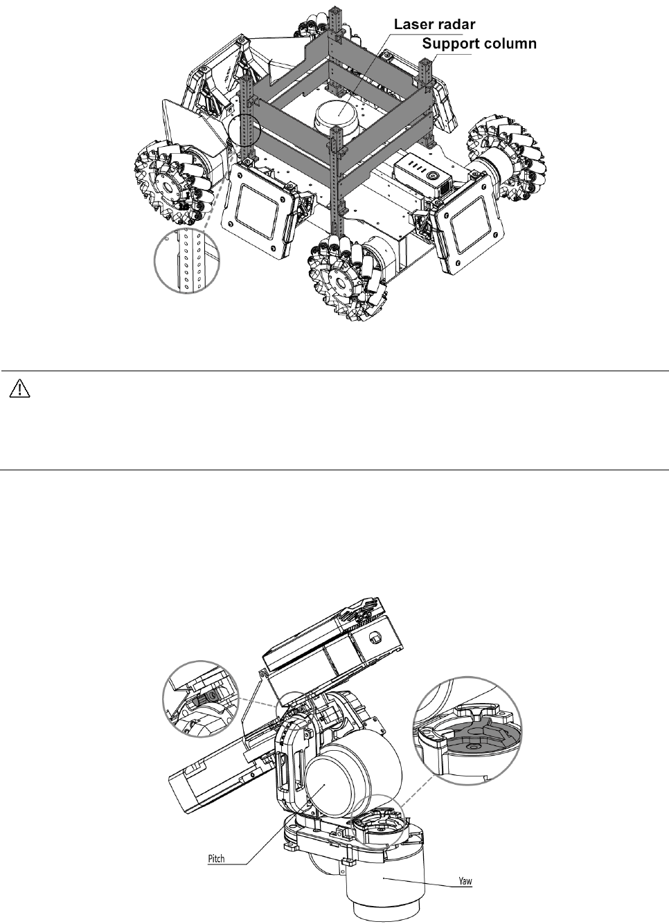
8
Install the C610 ESC on the backside of the board between the support column and the servo,
and ensure that the Set button faces downward. When making modifications, be sure not to press
the Set button on the ESC to avoid reseting the ID. If the ID is reset, refer to the RoboMaster
C610 Brushless Motor Speed Controller Manual to restore the ID.
The 8-pin line, which connects the servo to the chassis, passes through the rear left support
column. Ensure not to damage the 8-pin line when making modifications.
2-Axis Servo
A 2-axis servo is installed between the chassis and the launching mechanism. The pitch axis controls the tilt
motion and the yaw axis controls the pan motion. Pitch range: - 38° to +24°, yaw range: ±110°. The 2-axis servo
adopts mechanical limit switches to control the range of motion, as shown in the following figure:
The servo is driven by a synchronous belt connected to the RoboMaster 6623 Brushless DC Motor with an
integrated ESC at the tail of the motor. For the technical specifications of the motor and ESC, please refer to
φ 3 mm through holes spaced 8mm apart

9
the RoboMaster 6623 ESC User Manual and the RoboMaster 6623 Brushless Motor User Manual.
Projectile Feeding System
The projectile feeding system of AI Robots is located lower part of the robot. The cartridge and launching
mechanism are separated to increase the flexibility of the launching mechanism and the capacity of the cartridge.
The cartridge can hold over 200 projectiles, fully meeting competition needs. After loading the cartridge, wait for
the feeding wheel fill the chamber. Once the chamber is full, projectiles can be launched through the barrel.
Projectile loading is driven by the RoboMaster M2006 P36 DC Brushless DC Gear Motor with the RoboMaster
C610 Brushless Motor Speed Controller. For the technical specifications of the motor and ESC, please refer to
the RoboMaster M2006 P36 Brushless DC Gear Motor User Manual and the RoboMaster C610 Brushless Motor
Speed Controller User Manual.
Launching Mechanism
The launching mechanism lunches projectiles using the friction wheel. The friction wheels are driven by two
brushless DC motors rotating in opposite directions. When spinning, projectiles receive kinetic energy when
they are squeezed passed the two rotating friction wheels and are launched out the barrel.
Do not aim the barrel at people or animals to avoid injuries caused by misfired projectiles or the laser
(if installed).
The friction wheels are driven by the DJI Snail 2305 Racing Motor with the Snail 430-R Racing ESC. For the
technical specifications of the motor and ESC, please refer to the DJI Snail Racing Propulsion System User
Manual.
10
Referee System
The referee system is an electronic penalty system that integrates computing, communication, and control used
in robot competitions. The referee system consists of a robot mounted terminal and a server and client software
installed on a physical PC. The on-board terminal includes the main control module, armor module, speed
measurement module, RFID interaction module, camera transmission module, and positioning module (if
installed). The modules form a system that can assess the damage taken by the robot over the course of battle,
detect the velocity and frequency of projectiles, and transmit the robot's first person view to the client. The server
and client software checks the robot’s status in real time and automatically determines the outcome of the battle
according to competition rules. The server and client software is also responsible for sending control commands
to the robot to complete the corresponding operation.
The server (RoboMaster Server) is the service center of the referee system. During the competition, it collects
data from all robots, battlefield mechanisms, and the clients, and presents it to the referee in a visualized manner,
and automatically handles he results logic of the competition.
The client (RoboMaster client) provides the player with a first person view from the robot. A data collection
card is installed on the PC that connects to a private server or the competition server. From the first person view,
you can check the robots data uploaded by the referee system, including the current HP of the robot, real-time
projectile launch speeds and launch rate, battlefield map, real-time power output of the chassis, teammate
information, etc.
For guidelines on the usage of the referee system, please refer to the ICRA 2018 DJI RoboMaster AI Challenge
Referee System Specification Manual. For client installation, server setup, and other details of the referee
system, refer to the RoboMaster 2018 Referee System User Manual.
To download the latest version of the Referee System installation package, please visit the following link:
https://www.robomaster.com/zh-CN/products/components/referee
For materials related to the referee system, please visit the following link:
https://www.robomaster.com/en-US/resource/pages/834?type=announcementSub
Information regarding the speed measurement module can be found in the ICRA 2018 DJI
RoboMaster AI Challenge Referee System Specification Manual.
The client and server installation packages will be released on the RoboMaster website in early
March:
https://www.robomaster.com/zh-CN/products/components/referee
. Please look out for release notifications.
Hardware Circuit System
The robot’s hardware circuit system uses standard CAN bus communications. Main control board resource
allocation and circuit topology diagram are as follows:

11

12
The RoboMaster Main Control Board is an open source control board specially designed for RoboMaster robots.
It enables control of the entire robot and provides an open interface to help you customize and develop new
functions. For detailed technical information on the RoboMaster Main Control Board, please see the
RoboMaster Main Control Board User Manual.
Connector Specification:
Teams are recommended to purchase corresponding cables according to the following connector
specification. The pinout of the referee system can be found in the RoboMaster Referee System User
Manual (https://www.robomaster.com/en-US/resource/pages/834?type=announcementSub ), and the
pinout for infantry robot MCU can be found in RoboMaster Main Control Board User Manual..
1. Referee system firmware update connector/port: SM04B-GHS-TB (JST 4pin)
2. Referee system and MCU communication:
2.1. Referee system side connector: SM04B-GHS-TB (JST 4pin)
2.2. MCU side connector corresponds to USART3 on the above diagram. The connector is: MOLEX
53261-0571
3. MCU and the miniPC communication port is USART6 on the above diagram. The connector is: SM04B-
GHS-TB (JST 4pin)
4. MCU program download port is the SWD connector on the above diagram. The connector is: MOLEX
53261-047


14
Intelligent Battery
The battery of AI Robots (tb48d/tb47d) is the same intelligent battery that is used in the DJI Matrice 100 aircraft.
The tb48d model has a capacity of 5700 mAh and the tb47d model has a 4500 mAh capacity. Both models are
22.2 V and feature charge-discharge management. The battery uses high-energy cells and features an
advanced battery management system to provide the robot with ample power. Charge the battery only with the
official charger provided by RoboMaster. Before using the M100 intelligent flight battery, please carefully read
through the DJI Matrice 100 Intelligent Flight Battery Safety Guidelines.
Turning On/Off
Short press the battery button once and then press and hold the battery button for 2 seconds to turn the battery
on or off. When the battery is on, the battery level indicator indicates the battery’s charge, and the battery level
indicators are off when the battery is turned off.
Checking the Charge
When the battery is turned off, short press the power button once, to view the charge.
The battery level indicator shows the battery’s charge when it is charging or discharging as follows:
The LED indicator is on
The LED indicator is blinking
The LED indicator is off
Battery level indicator
LED1
LED2
LED3
LED4
Battery charge
87.5%~100%
75%~87.5%
62.5%~75%
15
50%~62.5%
37.5%~50%
25%~37.5%
12.5%~25%
0%~12.5%
= 0%
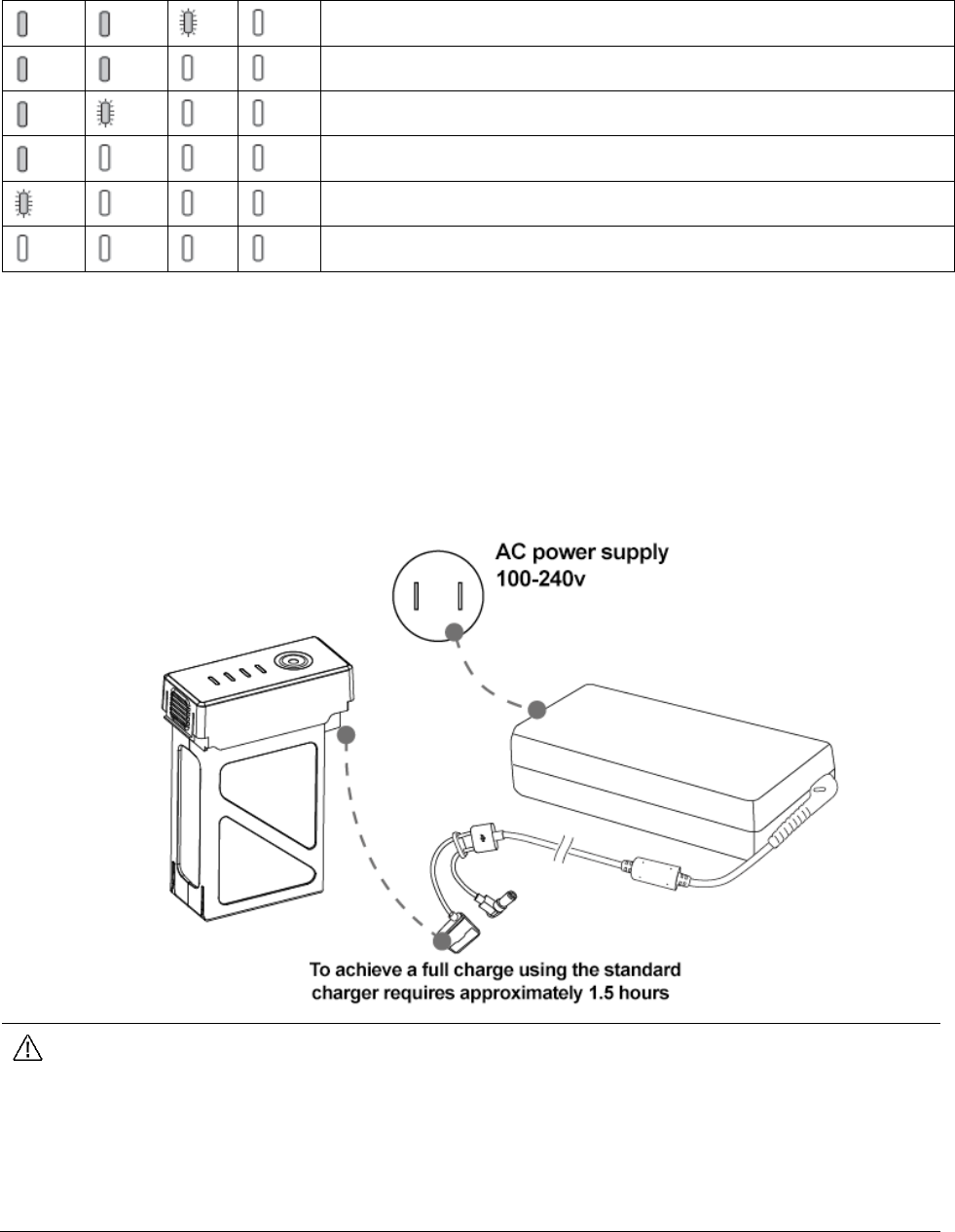
Charging
Before using the battery for the first time, ensure that it is fully charged.
1. Connect the charger to AC adapter (100-240 v, 50/60 hz; use a power converter if necessary).
2. Connect the battery to the charger when the battery is turned on or off. If the current battery charge is higher
than 95%, you need to turn on the battery to charge it further.
3. The battery level indicator will flash when the battery is charging and will indicate charge.
4. When the battery level indicator is completely off, the battery is fully charged. Remove the battery and
charger.
The designated charger is the A14-100P1A. Only use the designated charger from RoboMaster
to charge the battery.
The battery’s temperature is high after use. Wait for the battery to cool down to room temperature
before charging.
The best temperature range for charging the battery is between 0 ℃ to 40 ℃. If the temperature
of the cells is not within this range, the battery management system will prohibit charging.
Charge Protection Indicator
Battery level indicators will indicate when battery protection has been triggered due to a charge exception.
16
Battery level indicators
LED1
LED2
LED3
LED4
Behavior
Exception
LED 2 blinks twice
each second
The electric current is too high
LED 2 blinks three
times each second
Short circuit
LED 3 blinks twice
each second
Overcharging has caused the battery voltage
to be too high
LED 3 blinks three
times each second
Charger voltage is too high
LED 4 blinks twice
each second
The battery’s temperature is too low for
charging
LED 4 blinks three
times each second
The battery’s temperature is too high for
charging
After you discover the cause of the exception (the current is too large, short circuit, overcharge, charger voltage
too high), press the battery button to clear indicators, unplug and replug the charger, and resume charging. If
the battery’s temperature is beyond the acceptable range for charging, it will automatically resume charging
when the temperature to returns to normal.
17
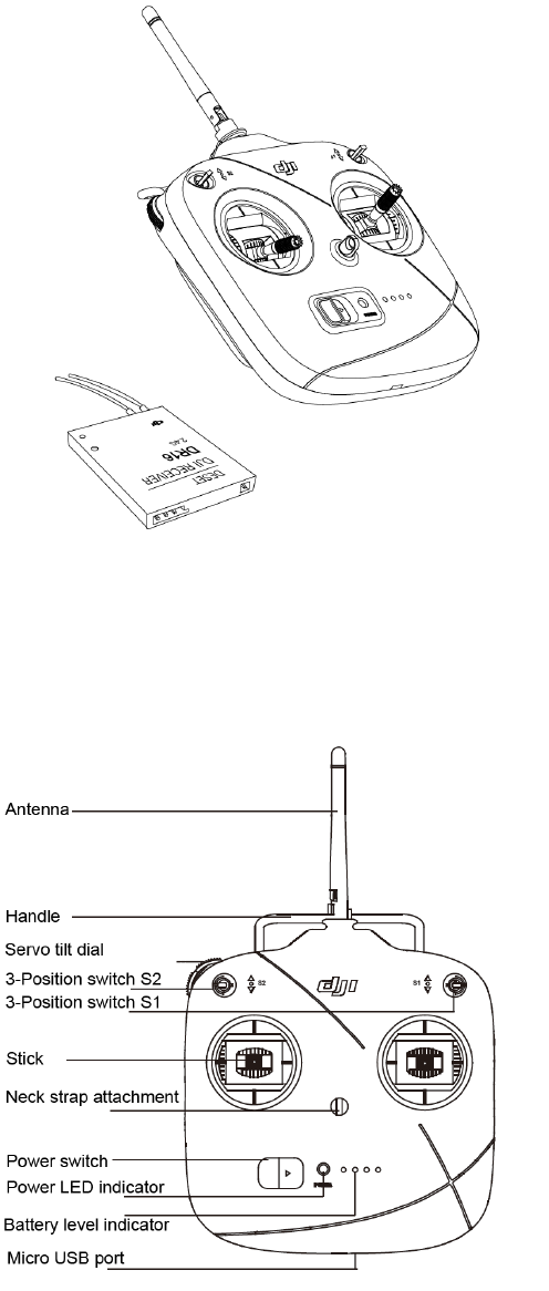
Remote Control Kit
Kit Overview
The kit includes a remote control and a receiver that is mounted below the launching mechanism of the AI Robot.
The frequency configuration of the remote control and receiver have already been completed.
Remote Control
The AI Robot’s remote control is the DJI DT7. DT7 is a radio communication device that operates in the 2.4GHz
band. The device can only be used with the DR16 receiver. In an open outdoor environment, the maximum
range of DT7 is 1000 m (you can control AI Robots on the ground from a maximum distance of 100 m). It has a
built-in lithium battery with a battery life of up to 12 hours.
18
Turning On/Off
1. Toggle the S1 switch to the top setting and confirm that the two rockers are in neutral position.
2. Toggle the power switch to the right to turn on the remote. Slide the power switch to the left to turn off the
remote.
3. When the remote control is turned on, the power LED indicator is green and the buzzer beeps.
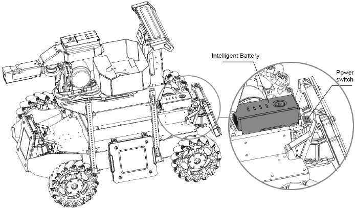
Charging
To charge the DT7, use the micro USB cable to connect the USB charger with the parameter adjustment
interface at the lower end of the device. When charging, the power indicator is solid red and the battery level
indicator is blinking green. When the charge is complete, the power LED indicator and the battery level
indicator are both solid green.
Receiver
The DR16 Receiver is a 2.4 GHz 16-channel receiver that can be used with DT7 remote control.

19
Pairing the Remote Control and Receiver
The receiver is installed below the launching mechanism of the robot (above). Before leaving the factory, the
frequency of the remote control and receiver have already been paired and can be used out of box. To pair the
remote control and receiver, follow the steps below:
1. The pairing button for the receiver is located in a hole under the main control board on the launching
mechanism.
2. Open the AI Robot and ensure that the receiver is being powered. If there are no nearby remote controls,
the receiver indicator will be solid red.
3. Turn on the remote control to be paired with the receiver. At this time, the receiver indicator will blink green.
4. Press the receiver pairing button for 2 seconds, and the receiver indicator will blink red while pairing.
5. Release the pairing button to complete pairing. At this time, the receiver indicator is solid green.
Keep the distance between the remote control and the receiver as close as possible and ensure that
there are no other remote controls in the vicinity.
For the communication protocol between the DT47 remote control and DR16 receiver, please refer to the
RoboMaster Robot Remote Control (Receiver) User Manual.
20
Powering On and Controlling the Robot
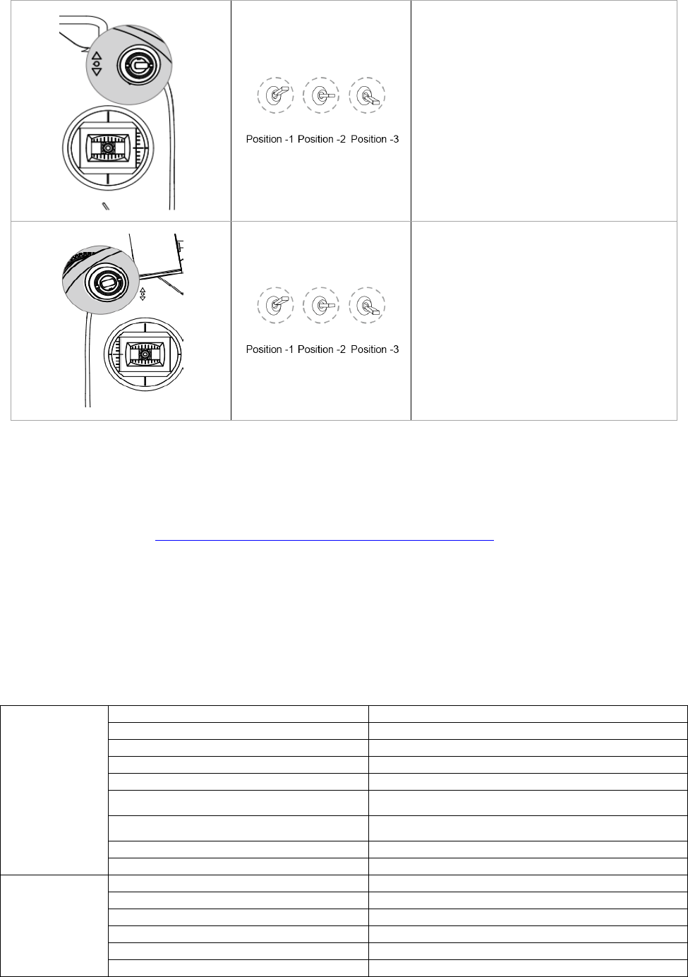
Battery Installation/Removal
The battery rack is located in front of the AI Robot's rear armor plate. During use, install the battery vertically in
the battery rack. Battery rack location:
Powering On/Off
After the battery is installed into the battery rack, turn on the intelligent battery and the press the power switch
of the AI Robot (as shown above). The power switch is located between the battery rack and rear armor plate
and is fixed on the battery rack. After the AI Robot is powered on, it will perform a self-test, during which the
referee system will increase the HP on the main control display from 0 to 90%. Once the self-test successfully
completes, the HP on the main control display will be at 100%. During the self-test, remote control operations
are invalid.
Control Modes
Mecanum wheels enable AI Robots to move in any direction. In fixed servo control mode, the chassis and servo
move in unison. AI Robots have two control modes:
1. Remote control only: Simple and convenient, ready to use, suitable for demonstration and debugging.
2. Remote control + PC: Controlling the robot based on the first person view from the robot on the PC screen,
which is suitable for competition.
Select the control mode by toggling the S2 switch on the remote control. The remote control can be used in any
control mode.
Controlling with Remote Control
Turn on the remote control and set the S1 switch on the top right side of the remote control to -1 (up) and the
S2 switch to -2 (center) to control the robot via remote control. Each function is implemented as follows:

21
Remote Control
Robot
Control
Moving the stick up tilts the robot’s head
up (+); moving the stick down tilts the
robot’s head down (-);
Servo pan range: -38°~24°
Moving the stick left rotates the servo
and chassis counterclockwise
Moving the stick right rotates the servo
and chassis clockwise
When the stick is in neutral position, the
robot does not move
Moving the stick up moves the robot
forward
Moving the stick down moves the robot
backwards
When the stick is in neutral position, the
robot does not move
Moving the stick left makes the robot
strafe left
Moving the stick right makes the robot
strafe right
When the stick is in neutral position, the
robot does not move
22
S1 switch is the software switch button:
When S1 is toggled to -1, the robot’s
servo and chassis are powered on.
When S1 is toggled to -2 or -3, the
robot’s servo and chassis are powered
off*. The referee system is always
powered on.
When S2 is toggled from -2 to -1, the
launching mechanism’s friction wheels
start to spin. Once the friction wheels are
spinning, toggling S2 from -2 to -3 and
then quickly back to -2 will launch a
projectile. If S2 stays on -3, the robot
continuously launches projectiles.
When S2 is toggled to -2, the robot can
be controlled via the PC.
When the miniPC/TX1/TX2 is not connected to the MCU, both tap positions on S1 will power-off chassis
and gimbal motors. Otherwise, the robot will operate under automatic mode. Check the Operation
Instructions on GitHub (https://github.com/RoboMaster/RoboRTS-Firmware ) for more details.
Controlling with Remote Control + PC
Connect the parameter adjustment port at the lower part of the remote control to the USB port of a computer
using a Micro USB cable and dial the switch in the upper-left corner of the remote control to 2 (medium). Launch
RoboMaster_Client from the PC and you will have a first person view from the robot. Now, you can control the
AI Robot via keyboard and mouse. For details about RoboMaster_Client, see the “Referee System” section of
this manual.
Controls:
Keyboard
W
Move forwards
S
Move backwards
A
Strafe left
D
Strafe right
E
Tactical evasive maneuver
Shift+W、A、S、D
Move quickly
Ctrl+W、A、S、D
Move slowly
Q
Turn on the friction wheel
Shift+Q
Turn off the friction wheel
Mouse
Pan left
Rotate the servo and chassis counterclockwise
Pan right
Rotate the servo and chassis clockwise
Zoom in
Tilt servo up (+)
Pan right
Tilt servo down (-)
Single left click
Launch projectiles (single shot)
Hold the left mouse button (2 seconds)
Launch projectiles (rapid fire)

23
The above default controls may be customized according to your requirements.
Appendix
Specifications
Structure
Dimensions
650 × 450 × 460 mm
Weight (with battery)
16.6 Kg
Performance
Maximum Forward Velocity
3 m/s
Maximum Transverse Velocity
2 m/s
Servo Pitch Range
-38° ~ 24°
Servo Yaw Range
-110° ~ 110°
Projectile Launch Frequency
10 shots/s
Projectile Launch Speed
25 m/s
Projectile Capacity
200
Drive System
Chassis Motor Model
RoboMaster EC60 Brushless Motor
Servo Motor Model
RoboMaster 6623 Servo Motor
Launch Motor Model
DJI Snail 2305 Racing Motor
Launcher Motor ESC
DJI Snail 430-R Racing ESC
Loader Motor Model
RoboMaster M2006 P36 Brushless DC Gear Motor
Loader Motor ESC
RoboMaster C610 Brushless Motor Speed Controller
Battery
Model
TB48D/TB47D
Type
LiPo 6S
Voltage
22.8 V
Capacity
TB48D:5700 mAh/TB47D:4500mAh
Remote Control
Model
DT7
Working Frequency
2.4 GHz
Communication Range
1000 m
Power Supply Mode
Built-in Lithium Battery
Interface
Micro USB
Batter Capacity
2600 mAh
Charger
Model
A14-100P1A
Input
100-240 V 50-60 Hz
Output
26.3 V
Projectile
Model
RoboMaster 17 mm Projectile
Color
White

24
Size
17 mm
Weight
2.5g

25
Parts List
Module
Part
Amount
Chassis
RoboMaster EC60 Brushless Motor-01
1
RoboMaster EC60 Brushless Motor-02
1
RoboMaster EC60 Brushless Motor-03
1
RoboMaster EC60 Brushless Motor-04
1
RoboMaster Mecanum Wheel (left)
2
RoboMaster Mecanum Wheel (right)
2
2-Axis Servo and
Launching
Mechanism
RoboMaster M2006 P36 Brushless DC Gear Motor
1
RoboMaster C610 Brushless Motor Speed Controller
1
RoboMaster 6623 Brushless Motor (with speed controller)
2
RoboMaster Main Control Board
1
DJI Snail 2305 Racing Motor
2
DJI Snail 430-R Racing ESC
2
Referee system
Armor Module
4
Main Control Module
1
Speed Measurement Module
1
Camera Transmission Module (transmit-end)
1
RFID Interaction Module
1
RFID Interaction Card
2
Camera Transmission Module (receive-end)
1
Remote Control
Remote Control
1
Remote Control Receiver
1
Battery
Intelligent Battery
1
Charger (wired)
1

Contact Us
RoboMaster Official Website: www.robomaster.com
RoboMaster Official Message Board: bbs.robomaster.com
RoboMaster Office Email: robomaster@dji.com
