ENGINE BOX 3 NO.1208 1351 REV E1.0
User Manual: ENGINE BOX 3 NO.1208-1351 REV E1.0
Open the PDF directly: View PDF ![]() .
.
Page Count: 20
These instructions are for all models
of 120” or 131” Alpha, Beta Engines
(Including Kits)

555 Dawson Drive, Camarillo, CA 93012 Phone 805-482-6913 • Fax 805-482-7422
1
Rev F
03/08
No.1208-1353
ADivision of Thiessen Products, INC
IInnssttrruuccttiioonn SShheeeett FFoorr BBooxx 33 112200”” OOrr 113311””
EEnnggiinnee AAsssseemmbblliieess OOrr EEnnggiinnee RRaaccee KKiittss
Box Three Installation Instructions
IInnttrroodduuccttiioonn ttoo BBooxx 33::
Congratulations! You have almost finished assembly of your JIMS 120 or 131 Race Kit engine.
You'll soon be ready for chassis installation, break-in and a trip to the track.
As we explained back in Box One, there is nothing particularly difficult about assembly of the JIMS
120 or 131. That remains true in Box 3. All of the parts and assemblies are either stock or
Screamin' Eagle items. Only the rocker covers have been modified to clear the roller rocker arms
and special valve springs. If you are familiar with normal TWIN CAM top-end assembly proce
dures, then you already know how to finish your JIMS 120 or 131 Race Kit engine.
Use these instructions for general assembly procedures and torque specifications.
Follow the instructions packaged with the enclosed Screamin' Eagle kits to install those parts.
These kits include the pushrods.
Notes and reminders:
Cleanliness:
• Remember to maintain your work area's cleanliness.
• Inspect all parts for burrs and machining chips before beginning assembly.
• Pay particular attention to the threaded holes in the lower rocker covers where they have
been modified to clear the valve springs.
• Be sure that all threaded holes are clear and clean.
Lock patches:
• Bolts used to assemble the lower rocker cover, rocker support plates and the breather assem-
blies have "lock patches" on their threads. Blue LOCTITE #243 will be needed for the regular
cover screws.
• These patches release a thread-locking compound when they are installed.
• No additional locking compound is needed and none should be used.
• Do not lubricate the bolts before installation.
STEP 1: Lower Rocker Housings - Installation
Note: Ensure that all mating surfaces are clean, flat and smooth. Be sure the threaded holes
are clear of chips or other debris.
Important: The rocker housing gaskets must be installed correctly.
• While they fit either of two ways, only one is right.
• Incorrect installation results in a major oil leak.
• Obtain:
• A modified lower rocker housing 1208-1319.
• A rocker-housing gasket 16719-99.
• Six rocker housing bolts. (Two of the bolts are longer than the other four)

555 Dawson Drive, Camarillo, CA 93012 Phone 805-482-6913 • Fax 805-482-7422
2
Rev F
03/08
No.1208-1353
A Division of Thiessen Products, INC
IInnssttrruuccttiioonn SShheeeett FFoorr BBooxx 33 112200”” OOrr 113311””
EEnnggiinnee AAsssseemmbblliieess OOrr EEnnggiinnee RRaaccee KKiittss
Note: Each bolt has a lock patch on its threads and additional Loctite is not required.
• Place the lower rocker-housing gasket onto the cylinder head (clean & burr-free).
• Make sure you install the gasket so it covers the breather channel.
• If the channel not covered, turn the gasket over.
• Place the rocker housing on the gasket (clean & burr-free).
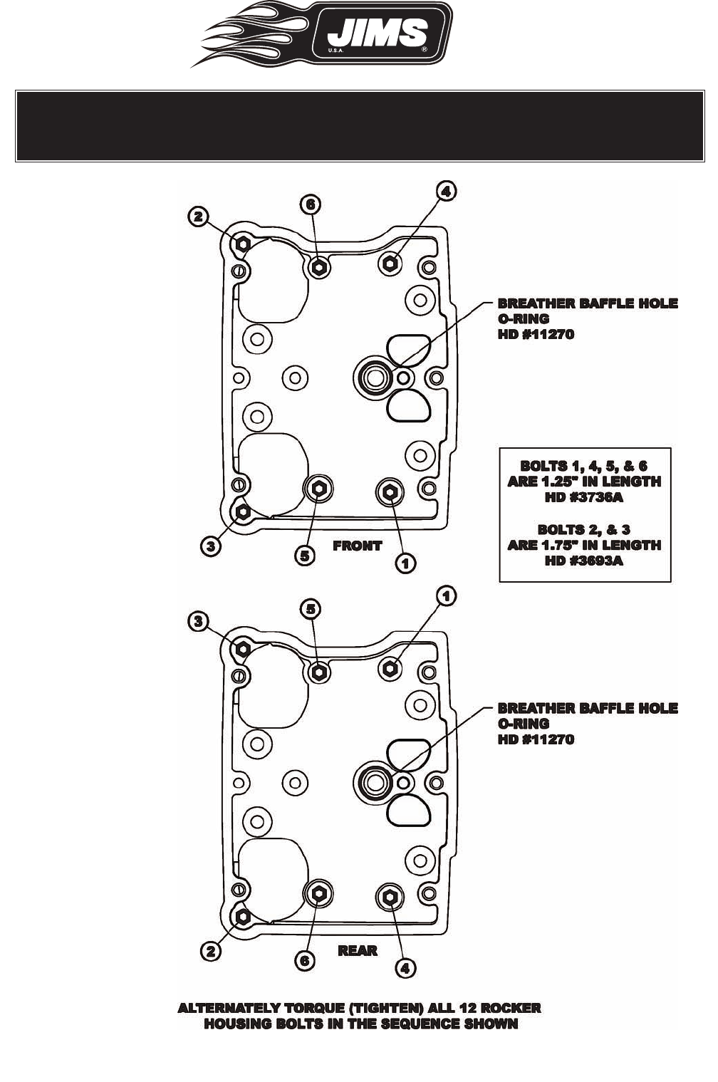
• Thread the two longer bolts H.D. 3693A through the left side of the lower rocker housing,
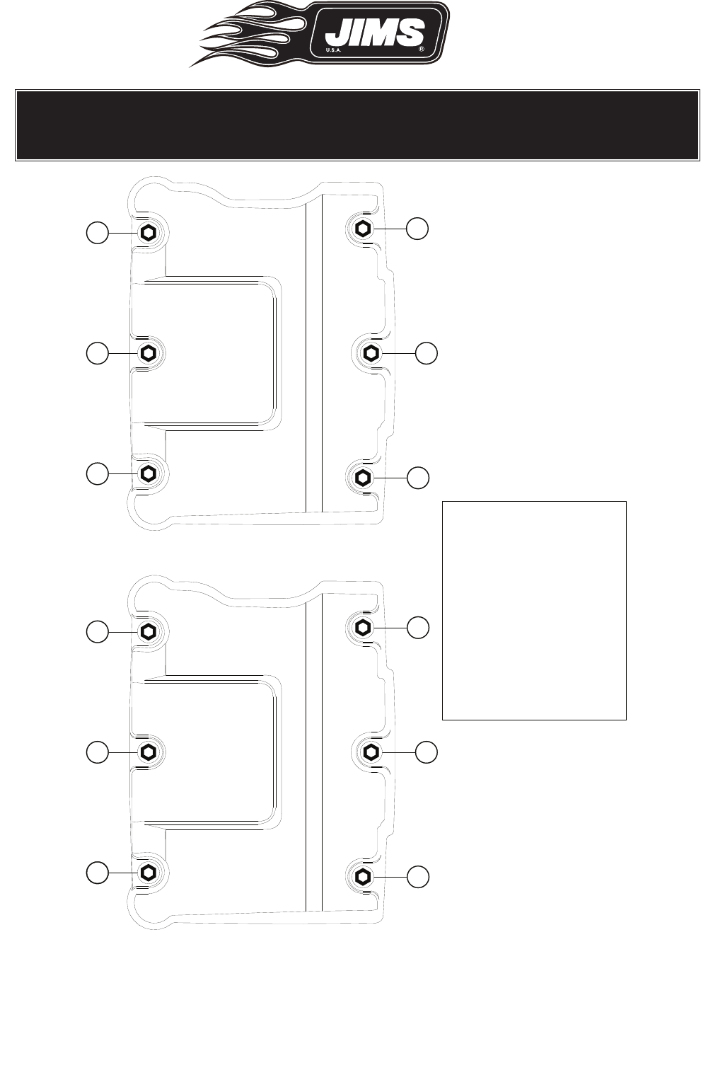
nearest the valve springs, and into the head. (See Fig. 1, bolts 2 & 3).
• Thread the remaining bolts H.D. 3736A through the lower rocker housing and into the head.
• Torque the bolts to 10 - 14 ft-lbs (120 - 168 in-lbs, 13.6 - 19.0 Nm) See Fig.1
• Follow the pattern shown in Fig. 1.
• Torque in two stages using about half the final torque the first time.
• Repeat these steps for the second lower rocker housing.
555 Dawson Drive, Camarillo, CA 93012 Phone 805-482-6913 • Fax 805-482-7422
3
Rev F
03/08
No.1208-1353
A Division of Thiessen Products, INC
IInnssttrruuccttiioonn SShheeeett FFoorr BBooxx 33 112200”” OOrr 113311””
EEnnggiinnee AAsssseemmbblliieess OOrr EEnnggiinnee RRaaccee KKiittss
Figure 1
555 Dawson Drive, Camarillo, CA 93012 Phone 805-482-6913 • Fax 805-482-7422
4
Rev F
03/08
No.1208-1353
A Division of Thiessen Products, INC
IInnssttrruuccttiioonn SShheeeett FFoorr BBooxx 33 112200”” OOrr 113311””
EEnnggiinnee AAsssseemmbblliieess OOrr EEnnggiinnee RRaaccee KKiittss
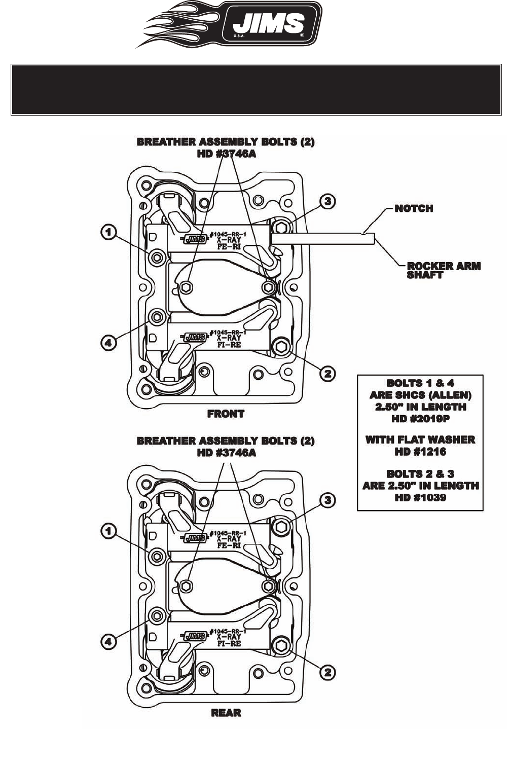
Figure 2

555 Dawson Drive, Camarillo, CA 93012 Phone 805-482-6913 • Fax 805-482-7422
5
Rev F
03/08
No.1208-1353
A Division of Thiessen Products, INC
IInnssttrruuccttiioonn SShheeeett FFoorr BBooxx 33 112200”” OOrr 113311””
EEnnggiinnee AAsssseemmbblliieess OOrr EEnnggiinnee RRaaccee KKiittss
STEP 2: Rocker Arms - Installation
• Obtain:
• The O-ring for the breather baffle hole in the lower rocker housing No.11270.
• A rocker arm support plate No.1208-1303.
• One intake and one exhaust rocker arm. They are different from one another. Their part num-
bers are laser-marked on each rocker arm for easy identification. See Fig. 2.
• Two rocker arm shafts No.17611-83.
• Two (Allen head) and two (flanged hex head) rocker arm support plate bolts.
• Lubricate the rocker arm bushing with the supplied assembly lube.
• Lubricate the rocker shafts with the supplied assembly lube.
• Lubricate the O-ring with a thin film of clean Harley-Davidson 20W-50 engine oil and install
it into its groove in the lower rocker housing. See Fig. 1 & 3
• Lay the rocker arm support plate in position on the head.
• Position the exhaust and intake rocker arms. See Fig. 2
• Slide the rocker shafts into the rocker arm support plate, capturing the rockers. See Fig. 2.
• Be sure that the notched-end of each shaft is toward the right side of the engine. See Fig. 2.
• Thread the two Allen head bolts (2019P with washer 1216) through the left hand side of the
support plate and into the head. (screws and washers supplied with rocker support) See Fig.
2.
• Thread the two remaining hex head bolts No.1286-1310 through the right side mounting
holes of the plate and into the head.
Fig.3 Install O-ring

555 Dawson Drive, Camarillo, CA 93012 Phone 805-482-6913 • Fax 805-482-7422
6
Rev F
03/08
No.1208-1353
A Division of Thiessen Products, INC
IInnssttrruuccttiioonn SShheeeett FFoorr BBooxx 33 112200”” OOrr 113311””
EEnnggiinnee AAsssseemmbblliieess OOrr EEnnggiinnee RRaaccee KKiittss
• You may need to move the rocker shafts slightly to allow passage of the bolts through the
notch in the shaft.
• Torque the bolts to 18-22 ft-lbs (20.3 - 24.4 Nm).
• Follow the pattern shown in Fig. 2.
• Torque in 1/4-turn stages using about half the final torque the first time.
Note: To avoid contact between the pushrods and the upper pushrod covers, you may need to
shift the rocker supports toward the engine cam side. To check the clearance between
the pushrods and covers, rotate the engine until both valves are closed in the cylinder you
are checking.
• Repeat these steps to install the second rocker arm support.
STEP 3: Breather - Pre-Assembly
• Obtain the bags containing breather parts No.17650-02.
• Install the Umbrella Valves:
• Locate the side of the breather baffle plate with the cast-in alignment pin.
• Lube the stem of an umbrella valve with denatured alcohol or glass cleaner.
• Insert the valve stem into the breather baffle plate, from the alignment pin side. See Fig. 4A
• Gently pull the stem from the other side of the plate. See Fig 4B.
• Verify that the lock nub on stem is completely through the hole in the plate. See Fig. 4C
• Repeat this procedure for the remaining umbrella valve and breather baffle plate.
• Install the filter elements into the plates.
• Press the filters into the plates until they are flush with the bottoms of the plates. See Fig. 5.
Fig.4 Fig.5
Umbrella Valve Installation Proper Filter Installation
AB C
555 Dawson Drive, Camarillo, CA 93012 Phone 805-482-6913 • Fax 805-482-7422
7
Rev F
03/08
No.1208-1353
A Division of Thiessen Products, INC
IInnssttrruuccttiioonn SShheeeett FFoorr BBooxx 33 112200”” OOrr 113311””
EEnnggiinnee AAsssseemmbblliieess OOrr EEnnggiinnee RRaaccee KKiittss
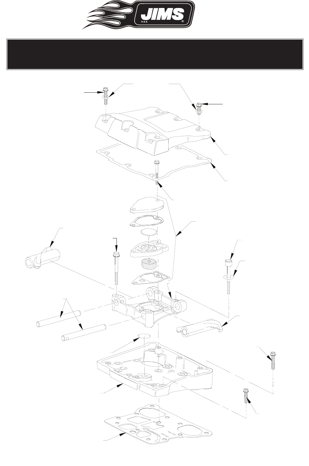
1286-1367
1286-1397
(WASHER)
1208-1318
1286-1308
1286-1341
2019P
1216
(WASHER)
1208-1303
1045RR
1286-1333
1286-1334
1286-1373
1208-1319
1286-1372
17611-83
1286-1310
1286-1374
1286-1352
1045RR
Figure 6
555 Dawson Drive, Camarillo, CA 93012 Phone 805-482-6913 • Fax 805-482-7422
8
Rev F
03/08
No.1208-1353
A Division of Thiessen Products, INC
IInnssttrruuccttiioonn SShheeeett FFoorr BBooxx 33 112200”” OOrr 113311””
EEnnggiinnee AAsssseemmbblliieess OOrr EEnnggiinnee RRaaccee KKiittss
ALTERNATELY TORQUE (TIGHTEN) ALL 12 ROCKER
COVER BOLTS IN THE SEQUENCE SHOWN
BOLTS 1, 3, & 5
ARE 1.00" IN LENGTH
HD #94334-91TS
AND
FLAT WASHER
HD #94064-03
BOLTS 2, 4, & 6
ARE 1.75" IN LENGTH
HD #94337-91TS
1
5
3
4
6
2
FRONT
REAR
36
12
54
Figure 7

555 Dawson Drive, Camarillo, CA 93012 Phone 805-482-6913 • Fax 805-482-7422
9
Rev F
03/08
No.1208-1353
A Division of Thiessen Products, INC
IInnssttrruuccttiioonn SShheeeett FFoorr BBooxx 33 112200”” OOrr 113311””
EEnnggiinnee AAsssseemmbblliieess OOrr EEnnggiinnee RRaaccee KKiittss
STEP 4: Breather - Main Assembly
• Assemble: See Fig. 6
• Baffle base gaskets.
• Breather baffle plate assemblies (with umbrella valves & filter elements).
• Cover gaskets.
• Breather covers.
STEP 5: Breather - Installation
• Obtain:
• The breather baffle assembly.
• Baffle cover.
• Two bolts No.3746A. (all have lock patches)
• Install the breather baffle assembly into the support plate. See Fig. 6, page 7
• Fit the breather cover with the two bolts.
• Torque the bolts, in two stages, to 90 - 120 in-lbs (7.5 - 10 ft-lbs, 10.2 - 13.6 Nm).
• Repeat this procedure for the second cylinder.
• Pour approximately one ounce of clean 20W50 H-D engine oil over the roller-end of each
rocker arm.
Note: Be careful to keep the oil off the gasket surface.
STEP 6: Top Cover - Installation See Fig. 6 & 7
• Obtain:
• A top rocker cover No.1208-1318.
• A top rocker cover gasket No.17386-99.
• Six chrome rocker cover bolts (three short three long) and six chrome washers.
• Make sure the gasket sealing surfaces are clean, smooth and dry.
• Place the gasket in position on the lower rocker cover.
• Place the top rocker cover in position over the gasket.
• Apply a drop of blue LOCTITE #243 to the first few threads of the 3 long bolts (1286-1367)
and 3 short bolts (1286-1352).
• Thread three short bolts with one flat washer (1286-1397) through the left side of the top
cover and into the lower cover.
• Thread the remaining three longer bolts, including the washers, into the right side of the top
cover and into the lower cover.
• Snug the two short bolts while holding the top rocker cover in alignment with the lower
rocker cover.
• Torque the bolts to 9 -12 ft-lbs (108 - 144 in-lbs, 12.2 - 16.3 Nm) See Fig. 7
• Torque in two stages, the first being about half the final torque.
• Follow the torque sequence shown in the illustration.
• Repeat these steps to install the second rocker cover.
555 Dawson Drive, Camarillo, CA 93012 Phone 805-482-6913 • Fax 805-482-7422
10
Rev F
03/08
No.1208-1353
A Division of Thiessen Products, INC
IInnssttrruuccttiioonn SShheeeett FFoorr BBooxx 33 112200”” OOrr 113311””
EEnnggiinnee AAsssseemmbblliieess OOrr EEnnggiinnee RRaaccee KKiittss
STEP 7: Pushrods - Installation
Use the instructions in the supplied Screamin' Eagle pushrod and pushrod cover kit (H-D
No.17997-99A).
Note: Pour approximately two ounces of clean 20W50 H-D engine oil into each tappet bore
cover to ensure initial lubrication of the tappets.
STEP 8: Pushrod Covers - Final Assembly
• Make sure that the top and bottom O-rings are fully seated.
• Slide the top & bottom pushrod covers apart.
• Gently push the bottom cover into its O-ring.
• Hold the bottom cover in place while you push the top cover into its O-ring.
• Make sure the spring cap is down against the spring.
• Install the lock clips – See Fig. 8
• Tilt and fit a lock clip up against the lip at the top of a pushrod cover.
• Use a round-shank standard screw driver as a lever to depress the spring cap as you slide the
clip along the screw driver shank and into position.
• Wiggle the clip to make sure it is fully seated.
STEP 9: Touch-up Paint Procedure
Note: Only apply touch-up paint when the parts to be painted and the room temperature are
between 75 and 90 degrees Fahrenheit.
• Black wrinkle paint is sensitive to the temperature at which it is applied.
• If it is too cold when applied, the "wrinkles" may be too fine and not match the factory
finish.
• Shake the bottle vigorously for a full two to three minutes to completely mix the paint.
• Apply paint only to bare metal surfaces as necessary to blend with the undamaged
paint.
• Heat freshly painted area to between 100 and 130 degrees to obtain the correct wrinkle ef-
fect.
• 100 degrees feels warm
• 130 is too hot to touch for more than a few seconds.
• Hot tap water typically does not exceed 120 degrees.
• Let paint then set for one hour or until dry to a light touch.
• The paint will be dry enough to sand in 24 to 48 hours if needed.
Fig.8
555 Dawson Drive, Camarillo, CA 93012 Phone 805-482-6913 • Fax 805-482-7422
11
Rev F
03/08
No.1208-1353
A Division of Thiessen Products, INC
IInnssttrruuccttiioonn SShheeeett FFoorr BBooxx 33 112200”” OOrr 113311””
EEnnggiinnee AAsssseemmbblliieess OOrr EEnnggiinnee RRaaccee KKiittss
STEP 10: Carburetor & Manifold - Installation
Follow the manufactures instructions from your choice of fuel system you have chosen. See JIMS
Sales Dept. for either carburetor,or fuel injection, recommended for your engine.
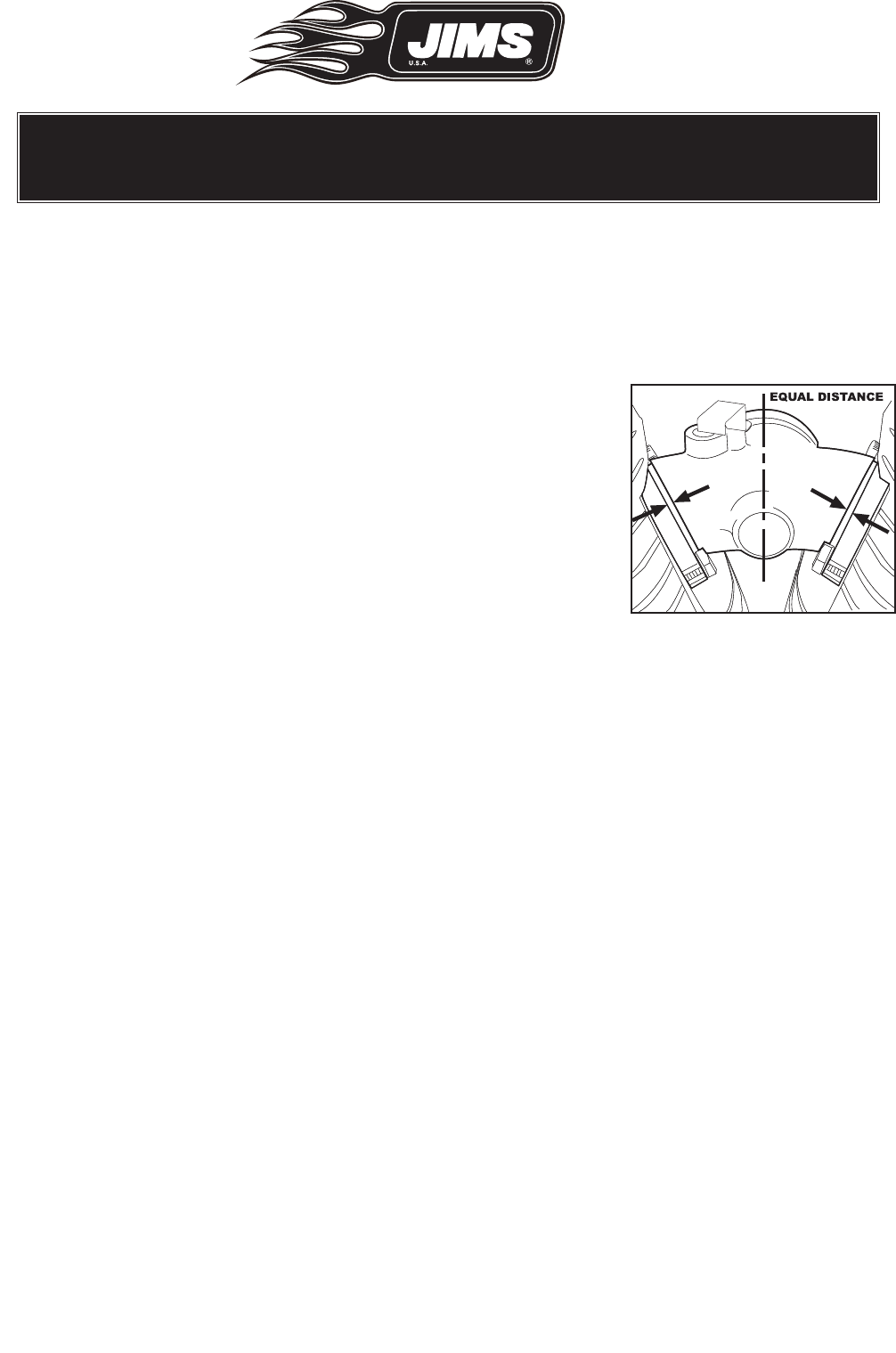
Note: Center the intake manifold in-between the two intake flange mounts during in-
stallation. See Fig. 9
STEP 11: Installing Primaries, and Clutch
Follow installation instructions for inner and outer primary, clutch
assembly, sprockets, primary chain, adjustment and alignment, per
Harley-Davidson’s service manual for the year and model you will
be working with.
Clutch Recommendation:
The high torque output of the JIMS 120 or 131 Race Kit engine re
quires increased clutch torque capacity. The Screamin’ Eagle®
No.37969-03 clutch is one example.
Pre-Start Settings, Procedures and Recommendations:
Note: If installing JIMS 120” or 131” in a 2008 FL or later read the following:
Harley-Davidson®made changes on the 2008 to H-D®motor mount using a new number 16321-
08, installed on the front head.
JIMS 120” and 131” Twin Cam®Engines being installed in a 2008 FL have been designed with
a new machined pad on the front head.
Each engine requires two spacers and each one of the spacers needs to be installed on the in-
side of the head mount between the front motor mount and head.
In other words the spacers will be sandwiched between the front and the chrome motor mount.
One spacer will be needed for the pushrod side of the head mount; it will be the thicker of the
two at .300” thickness, JIMS part number 1708-1550.
The other spacer is .250” thick, JIMS part number 1708-1551 and will need to be installed on
the primary side of the head mount.
After installing both spacers between head and motor mount, and after bolts are torqued to 10
ft-lb, check for rocker box to motor mount clearance, which needs to be at least 1/16”.
Use stock bolt H-D number 4721 with stock washer H-D number 6127.
Follow the H-D Service Manuel for installation and torquing information.
Fig. 9
- Proper manifold alignment

555 Dawson Drive, Camarillo, CA 93012 Phone 805-482-6913 • Fax 805-482-7422
12
Rev F
03/08
No.1208-1353
A Division of Thiessen Products, INC
IInnssttrruuccttiioonn SShheeeett FFoorr BBooxx 33 112200”” OOrr 113311””
EEnnggiinnee AAsssseemmbblliieess OOrr EEnnggiinnee RRaaccee KKiittss
STEP 12: Ignition - Installation all Engines
Follow the ignition manufactures instruction when installing per application.
Jims offers two carbureted only Screamin Eagle Select ignition systems that can be order
sepeately.
Jims No.1286-1379, H-D 32704-01 Use on 1999 - 2003 Alpha carburated only models:
Use on 2000 - 2003 Beta carburated only models
Jims No.1286-1376, H-D 32124-04 Use on 2004 - 2006 Alpha or Beta carburated only models.
If you are using one of these follow the instructions supplied by Harley-Davidson with the sup-
plied Screamin' Eagle ignition system for your model year motorcycle.
Screamin Eagle Ignition Settings: (SETTINGS ARE NOT FOR E.F.I .SYSTEMS)
1999 - 2003 carburated only models:
• Set the "CS" Curve Selection Mode at "3"
• Set the "SA" Spark Advance to "+2"
• Set the "ES" Engine Speed to 6000 rpm Max.
2004 and 2006 carburated only models:
• Set calibration to: HMCD1340, HEX (32124-04.134) hmed 1340. See Fig. 10
• Select all and +2 across the board on both spark table maps.
• Rev limiter at 6000 rpm Max.
Note: The following carb settings in Step 13, only
apply to the Screamin' Eagle "Super Bore
51mm CV Carburator Kit Jims No. 1286-
1378, H-D No. 27926-02. You will also
need to order 2-JIMS No 1286-1400, H-D
No. 26993-06 in take mounting flanges.
These items must be ordered sepa-
rately.
Fig.10 Calibration

555 Dawson Drive, Camarillo, CA 93012 Phone 805-482-6913 • Fax 805-482-7422
13
Rev F
03/08
No.1208-1353
A Division of Thiessen Products, INC
IInnssttrruuccttiioonn SShheeeett FFoorr BBooxx 33 112200”” OOrr 113311””
EEnnggiinnee AAsssseemmbblliieess OOrr EEnnggiinnee RRaaccee KKiittss
STEP 13: Carburetor Settings:
1. The standard (furnished) settings are normally correct when used with 2-into-1exhaust sys-
tems.
Note: Alternate exhaust systems may require different settings.
2. If carburetor tuning is required, use the Screamin' Eagle "Super Bore 51mm CV Tuner's Kit" H-
D No.27432-02. Order separately from a H-D dealer.
3. The standard (furnished) settings are normally correct for a "standard day" such as is common
near sea level in the summer.
• 70 degrees Fahrenheit.
• 29.9 Hg pressure
• 50% humidity
4. The Screamin' Eagle 51mm carburetor's standard settings are:
• Main Jet: 230
• Slow Jet: 48
• Jet Needle: NDKS (JET settings may need to be changed for peak H.P.)
STEP 14: Oil Flow, Oil Pressure And Gasket Seating, All Engines:
Important Notes:
• Before you install your new JIMS 120 Race Kit engine in its chassis, thoroughly flush the mo-
torcycle's complete oiling system.
• Be very careful that you do not tear small slivers of rubber off the edges of the oil lines as you
fit them to the engine's oil fittings.
• Do not connect the oil return line from the engine to the oil tank. Fit a hose from the engine's
oil return fitting and run the hose into a large catch-pan.
• Note: Remove the spark plugs from the engine. Attach the plug wires to the spark plugs and
lay them on the cylinder heads to prevent damage to the coils.
• Be sure the oil tank is properly filled with the correct oil. Use the electric starter to turn the en-
gine until the oil pressure light goes out or until the pressure gage reads 10 -15 psi.
• Re-install the spark plugs, torque to 12 to 18 ft lbs., and plug wires. Depress both compres-
sion release plungers.
• Start the engine using the normal procedure outlined in the owner's manual. Allow the return
oil to run into the catch pan.
• Run the JIMS 120 or 131 between 900 and 1500 rpm until the tops of the cylinders have
reached 200 degrees Fahrenheit (too hot to touch). This normally takes between one and two
minutes. Note: Do not allow the oil level in the tank to get too low while the engine is run-
ning. Stop the engine and letit cool to room temperature. Inspect the installation for any oil
or gasoline leaks. Top – off the oil tank. Repeat the warm-up and cool-down procedure three
additional times.
Note: Watch and maintain the oil level in the tank. You may reconnect the oil return line to the
oil tank after at least two Quarts of oil have been pumped into the catch pan. Discard the oil
in the pan.

555 Dawson Drive, Camarillo, CA 93012 Phone 805-482-6913 • Fax 805-482-7422
14
Rev F
03/08
No.1208-1353
A Division of Thiessen Products, INC
IInnssttrruuccttiioonn SShheeeett FFoorr BBooxx 33 112200”” OOrr 113311””
EEnnggiinnee AAsssseemmbblliieess OOrr EEnnggiinnee RRaaccee KKiittss
Oil Cooler Recommendation:
The JIMS 120 or 131 should be fitted with an effective oil cooler. The Harley No.62895-03B is
an example of such a cooler.
Chassis Oiling System:
Make sure that the entire oiling system is clean. If you are fitting your new JIMS 120 or 131 Race
Kit engine into a chassis that has been used, be sure to completely clean the oil tank together
with all lines and fittings leading to and away from the engine. If the old engine has more than
20,000 miles of use, or, if it has suffered any unusual wear, dismantle the oil pan and hoses and
thoroughly clean them.
Break In Procedure:
Note: Follow the engine break-in procedures outlined in the Harley-Davidson owner’s manual per
your application.
1. Allow the engine to warm-up before riding.
2. Do not use full throttle.
3. Do not idle the engine for more than two minutes. Note: Even less if the air temperature is
above 80-degrees Fahrenheit.
4. Do not load the engine at low rpm.
Note: All engine loads must be moderate.
5. Vary the rpm frequently.
Note: Do not hold a steady speed.
6. First 50 miles:
• Do not let the engine rpm exceed 2500.
• Do not exceed 50mph.
7. Next 500 miles:
• Do not let the engine rpm exceed 3000.
• Do not exceed 55 mph.
Oil Change Intervals:
Break in:
• At 50 miles
• 500 miles
• 1000 miles
Normal Oil change intervals:
• 1500 to 2000 miles, depending upon usage.
• Change the oil filter every oil change.
Torque Checks:
• Re-check the torque of all accessible engine and chassis fasteners at all oil changes. (Do not re-
torque the head bolts)

555 Dawson Drive, Camarillo, CA 93012 Phone 805-482-6913 • Fax 805-482-7422
15
Rev F
03/08
No.1208-1353
A Division of Thiessen Products, INC
IInnssttrruuccttiioonn SShheeeett FFoorr BBooxx 33 112200”” OOrr 113311””
EEnnggiinnee AAsssseemmbblliieess OOrr EEnnggiinnee RRaaccee KKiittss
Tuning Factors:
The Air:
As with any other normally aspirated engine, the JIMS 120 or 131 Race Kit engine is affected
by atmospheric conditions. Changes in air pressure, temperature and humidity all have their
effects on air/fuel mixtures, power output, engine temperature and rideability. At a constant
altitude, most such changes are small, not very important in day-to-day operation and can
generally be ignored. Altitude changes have a more dramatic effect. As a rule-of-thumb, you
can expect a pressure loss of three percent for each 1,000 feet of altitude gain. This means
that at 10,000 feet an engine is going to lose almost 30-percent of its power, at best.
The loss is normally even greater because air/fuel mixtures also richen. Carburetor settings can
become too rich for either smooth operation or maximum power production. If you are going
to operate your JIMS 120 or 131 above about 3,000 feet, you may find it necessary to alter
the jetting. In Denver, at one mile above sea level, you may need to install the next leaner nee-
dle, next leaner slow jet and go a couple of sizes down on the main jet. A highly experienced
engine tuner should make such changes.Atmospheric conditions are much more important
when racing where small differences can determine whether you go on to the next round or
go onto the trailer. Races are often won or lost on a tuner's ability to get the jetting (among
other things) "right" as the atmospheric conditions change during the day. If you do not un-
derstand jetting, if you cannot 'read' the air, you are in for some hard lessons at the track.
Ask questions. The great majority of race tuners are more than willing to share much of what
they know. Do not expect to get all the details - it is racing after all. But expect to get more
information than you can probably use right away. Drag racers are a congenial group and they
want you to be there, racing with them, and enjoying it.
More Power Air Flow Volume:
Ultimately, the amount of power your JIMS 120 or 131 Race Kit can produce is going to be
determined by two factors: How much air it can process in a given time, and, how efficiently
it uses that air to supply useful power to its crankshaft. The JIMS 120 Race Kit delivers about
121 and the 131 at about 130 horsepower. It is very possible to increase that output by 20%
or more. It is also possible to reduce it by a similar percentage. It is much easier to lose power
than to gain it. Each and every part of this engine and its accessories are in balance. Each has
been designed and developed or selected to work together for maximum airflow, power out-
put and drivability. If, for instance, you fit a larger air cleaner or carburetor that flows more air,
the result may not match your expectations. A bigger carburetor does little to improve power
if the total airflow is limited in some other part of the engine system. Substantial power gains
require substantial modifications.
Increased airflow through the cylinder heads of your JIMS 120 or 131 Race Kit engine requires
that the manifold and both intake and exhaust ports be carefully and skillfully modified. Cylin-
der head porting continues to be an art form and should not be attempted without guidance
from a practiced porting expert. Better yet, contract such an expert to do the work for you.

555 Dawson Drive, Camarillo, CA 93012 Phone 805-482-6913 • Fax 805-482-7422
16
Rev F
03/08
No.1208-1353
A Division of Thiessen Products, INC
IInnssttrruuccttiioonn SShheeeett FFoorr BBooxx 33 112200”” OOrr 113311””
EEnnggiinnee AAsssseemmbblliieess OOrr EEnnggiinnee RRaaccee KKiittss
While the Screamin' Eagle air cleaner element is one of the highest flowing units commonly
available, air cleaner flow can be increased. Several larger filters may flow more air volume than
the supplied filter. However, they are also likely to interfere with riding comfort.
Combustion Chamber Pressure:
Power output and combustion chamber pressure are directly related. The higher the pres-
sure, the more efficient and more powerful the engine becomes, within limits. That is, until
the onset of detonation. A racing engine, one that is carefully and constantly looked after by
an expert, can run with very high compression pressures. In the case of the Twin Cam cham-
ber design, these pressures can exceed 210 psi.
An engine that operates under a variety of conditions must have its compression pressure
compromised so that it is not damaged under the worst of those conditions. For this reason,
your JIMS 120 or 131 Race Kit engine does not develop the very highest possible compres-
sion pressure.
Compression pressure is found by performing a common compression test as outlined in
Harley's shop manuals. In this test, the mechanic removes both spark plugs and fits a com-
pression tester to one of the plug holes. He then opens the throttle fully, lifts the CV slide, and
turns the engine through five to seven compression cycles or until the pressure reading on the
tester stops rising. The measured pressure is the compression pressure for that cylinder.
The common method used to raise compression pressure is to remove material from the heads
on a milling machine. This decreases combustion chamber volume, raises the compression
ratio and, in turn, raises the cranking pressure.
Detonation:
Detonation must be avoided. A detonation event is literally an explosion. Most of the time
these explosions are so small that they do not immediately damage the engine. However, if
they are energetic or frequent enough, things break. A piston can be destroyed in a few en-
gine revolutions from the effects of severe detonation.
Detonation can be brought on by a variety of conditions including, incorrect ignition timing,
poor quality gasoline, overly lean air/fuel mixtures, and too much cranking pressure for the
particular combustion chamber or engine overheating.
If you choose to alter the cranking pressure, ignition timing or carburetor settings of your
JIMS 120 or 131 Race Kit engine, please be aware that any of these alterations, improperly
done, can result in engine damage. You should only consider such modifications if competi-
tion pressure demands them. And, make them only if you have the experience or expert as-
sistance to deal with the possibility of detonation.
Performance Tuning:
As you can see, performance tuning is complex. One change often creates the need for other
compensating or complimentary alterations. If raising the compression pressure makes the
chamber more turbulent, a likely thing, it may be necessary to back-off ignition timing to
compensate for the increased flame-front speed across the chamber. If moist air rolls across
the track late in the afternoon, a leaner main jet may be needed to compensate for the reduced
oxygen in the more moist air. If that air is also cooler and more dense, no change may be
needed at all.

555 Dawson Drive, Camarillo, CA 93012 Phone 805-482-6913 • Fax 805-482-7422
17
Rev F
03/08
No.1208-1353
A Division of Thiessen Products, INC
IInnssttrruuccttiioonn SShheeeett FFoorr BBooxx 33 112200”” OOrr 113311””
EEnnggiinnee AAsssseemmbblliieess OOrr EEnnggiinnee RRaaccee KKiittss
The possibilities are almost endless. However, exploring those possibilities can be great fun.
If drag racing and performance tuning in general were "Cut-And-Dried", they would be bor-
ing. The stands would not fill and pits would be empty. There would be no friendly argu-
ments about 'which cam' or 'what exhaust' works best.
Drag racing is one of the most popular participating motor sports in America. The fans are
often racers themselves, have been racers, want to be racers or know a lot about the nuts and
bolts of drag racing.
We at JIMS have spent years developing the JIMS 120 and 131 Race Kit engine for drag rac-
ers and those who want to become drag racers. The 120 or 131 engine is a strong, ground
pounding and reliable base for your exploration into the complex and fascinating sport of
drag racing. We hope you enjoy your new 120,or 131, as much we are pleased to bring it to
you.
Inspection and Service Wear information for Valve Train Components used in
Performance Twin Cam Engines.
Valve Train Components should be inspected each 5000 miles of service. More often if an
engine is used under severe riding condition, i.e. full throttle race operation, in city, dusty, low
octane usage, trailer and two up riding. As with all high performance engines, components
are under or subject to more stress in one-way or another, many times more then a stock
engine. The following engine components will need to be inspected and or replaced each
5000 miles or more often as needed.
1. Rocker arm / Rocker arm ShaftReplace if more then
Shaft fit in bushing .0035
End play, side clearance .025
Shaft fit in support plate .003
2. Cam support plate Replace if more then
Cam chain tensioner shoe wear .090 or 1/2 thickness of shoe
Crankcase bushing press fit
in cam support plate .0008
Crankshaft bushing maximum I.D. .8545
3. Hydraulic Lifter Replace if more then
Fit in crankcase .003
Roller fit on axel .0015 or any rough area or tight spot
Roller end clearance .015
4. Cylinder Head Replace if more then
Valve guide, press fit in head .002
Valve seat, press fit in head .002
Head warpage .006
5. Cylinder, Replace if more then
Taper .002
Out of round .002
Warpage at gasket surfaces .006

555 Dawson Drive, Camarillo, CA 93012 Phone 805-482-6913 • Fax 805-482-7422
18
Rev F
03/08
No.1208-1353
A Division of Thiessen Products, INC
IInnssttrruuccttiioonn SShheeeett FFoorr BBooxx 33 112200”” OOrr 113311””
EEnnggiinnee AAsssseemmbblliieess OOrr EEnnggiinnee RRaaccee KKiittss
6. Piston Replace if more then
Fit in cylinder .006
Piston pin fit (wrist pin) .0012
Compression rings .030
Oil control rings .070
Ring side clearance compression rings .004
Ring side clearance oil control rings .008
7. Connecting rod Replace if more then
Piston pin fit (wrist pin) .0012
Side play between flywheels
(female rod end play) .024
Fit on crank pin (up and down play) .002
8. Flywheel assembly Replace if more then
End play ( F/W in left bearing) .006
Inspect shaft bearing journals for scoring,
galling or wear, not to exceed .0005
9. Balancer components Replace if more then
Balance chain guides (front & rear) .060 to .070
Balance chain guides (lower) .060 to .070
Inspect other balancer components using H/D services
manual)

555 Dawson Drive, Camarillo, CA 93012 Phone 805-482-6913 • Fax 805-482-7422
19
Rev F
03/08
No.1208-1353
A Division of Thiessen Products, INC
IInnssttrruuccttiioonn SShheeeett FFoorr BBooxx 33 112200”” OOrr 113311””
EEnnggiinnee AAsssseemmbblliieess OOrr EEnnggiinnee RRaaccee KKiittss
BOX 3 Materials Check-Off Sheet
Part No. H-D® No. Description Qty.
1286-1380 11289A O-ring, Crank Position Sensor 1
1286-1373 16719-99 Gasket, Rocker Housing 2
1286-1374 17386-99 Gasket, Rocker Cover 2
1286-1372 11270 O-ring, Breather Assy 2
1208-1318 Rocker Cover, Modified 2
1208-1319 Rocker Housing, Modified 2
1045RR 1045RR Roller Rockers, T/C, 1.625 ratio 1 set
17611-83 17611-83 Rocker Arm Shaft, T/C 4
1208-1303 Rocker Support Kit 1 set
1286-1310 1039 Screw, Rocker Support 4
1286-1308 3746 A Screw, Breather 4
1286-1333 3693A Screw, Rocker Housing, Long 4
1286-1334 3736A Screw, Rocker Housing, Short 8
1286-1367 Screw, Rocker Cover, Chrome 1.750 6
1286-1352 Screw, Rocker Cover, Chrome 1.00 6
1286-1397 Washer, Flat, Chrome 12
1286-1341 17650-02 Breather Assy W/Gaskets 2
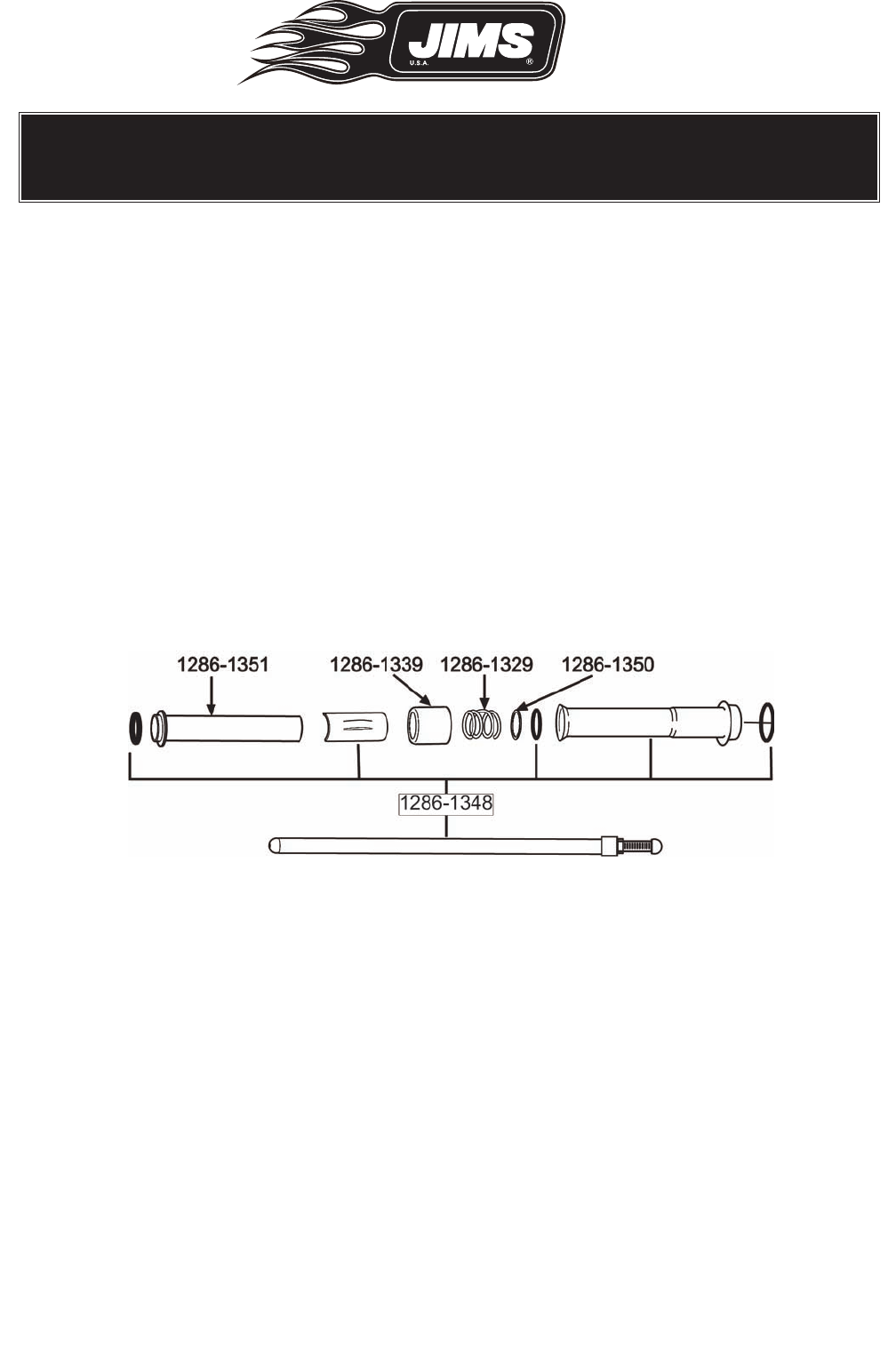
1286-1348 17997-99A Pushrod set 1 set
1286-1350 6762B Washer, Push Rod Tube Cover 4
1286-1351 17948-99 Cover, Upper Pushrod Tube 4
1286-1339 17945-36B Cap, Cover Spring 4
1286-1329 17947-36 Spring, Push Rod Tube 4
1286-1367 Screw, Valve Cover, Chrome 6
1286-1397 Washer, Valve Cover, Chrome 6
1286-1399 Thread Locker, #243, .0502 Loctitie 6
1286-1327 63798-99 Oil Filter, Chrome 1
1708-1550 Spacer, 08’ FL, Head Motor Mount (.300”) 1
1708-1551 Spacer, 08’ FL, Head Motor Mount (.250”) 1
1206-1353 IS, Instruction Sheet Box 3 1
