653 082 EP1653082A1
User Manual: 653-082
Open the PDF directly: View PDF ![]() .
.
Page Count: 9
Printed by Jouve, 75001 PARIS (FR)
Europäisches Patentamt
European Patent Office
Office européen des brevets
(19)
EP 1 653 082 A1
&
(11) EP 1 653 082 A1
(12) EUROPEAN PATENT APPLICATION
(43) Date of publication:
03.05.2006 Bulletin 2006/18
(21) Application number: 05022235.5
(22) Date of filing: 12.10.2005
(51) Int Cl.:
F04C 2/344
(2006.01)
F04C 15/00
(2006.01)
(84) Designated Contracting States:
AT BE BG CH CY CZ DE DK EE ES FI FR GB GR
HU IE IS IT LI LT LU LV MC NL PL PT RO SE SI
SK TR
Designated Extension States:
AL BA HR MK YU
(30) Priority: 26.10.2004 JP 2004310723
(71) Applicants:
• KAYABA INDUSTRY CO., LTD.
Minato-ku,
Tokyo 105-6190 (JP)
• JATCO Ltd
Fuji-shi,
Shizuoka 417-8585 (JP)
(72) Inventors:
• Fujita, Tomoyuki
Kabaya Industry Co. Ltd.
Minato-ku
Tokyo 105-6190 (JP)
• Sugihara, Masamichi
Kabaya Industry Co. Ltd.
Minato-ku
Tokyo 105-6190 (JP)
• Yasue, Yoshinobu
Kabaya Industry Co. Ltd.
Minato-ku
Tokyo 105-6190 (JP)
• Nishiyama, Hiroyuki
Shizuoka 417-8585 (JP)
• Hirotsu, Shingo
Shizuoka 417-8585 (JP)
• Amano, Katsutoshi
Shizuoka 417-8585 (JP)
(74) Representative: Grünecker, Kinkeldey,
Stockmair & Schwanhäusser
Anwaltssozietät
Maximilianstrasse 58
80538 München (DE)
(54) Vane pump for continuously variable transmission
(57) A vane pump disposed inside a transmission
case of a continuously variable transmission comprises
a pump case (20), a pump drive shaft (8) rotatably sup-
ported by a shaft bore (9) of the pump case (20) to rotate
a rotor (5), and a drain port (17), one end thereof being
opened to a shaft bore (9) of the pump drive shaft (8) and
the other end being opened to an outside of the pump
case (20). A leaked oil flown via the drain port (17) from
a pump discharge side is discharged to an outside of the
pump case (20).

EP 1 653 082 A1
2
5
10
15
20
25
30
35
40
45
50
55
Description
BACKGROUND OF THE INVENTION
Field of the Invention
[0001] The present invention relates to a vane pump
which is incorporated in a transmission case of a contin-
uously variable transmission.
Description of Related Art
[0002] A continuously variable transmission (hereinaf-
ter referred to as CVT) has a transmission case equipped
with a gear pump therein, and an operating oil supplied
from the gear pump operates each part of the CVT. Since
a pump efficiency of the gear pump, however, is not so
good, use of a vane pump having better pump efficiency
as compared to the gear pump has started to be re-
viewed. The vane pump is incorporated in the transmis-
sion case for use in the same way with a general gear
pump, and an inside of the transmission case is filled with
the operating oil. Accordingly, the vane pump is in a state
to be submerged in the operating oil by more than the
half thereof.
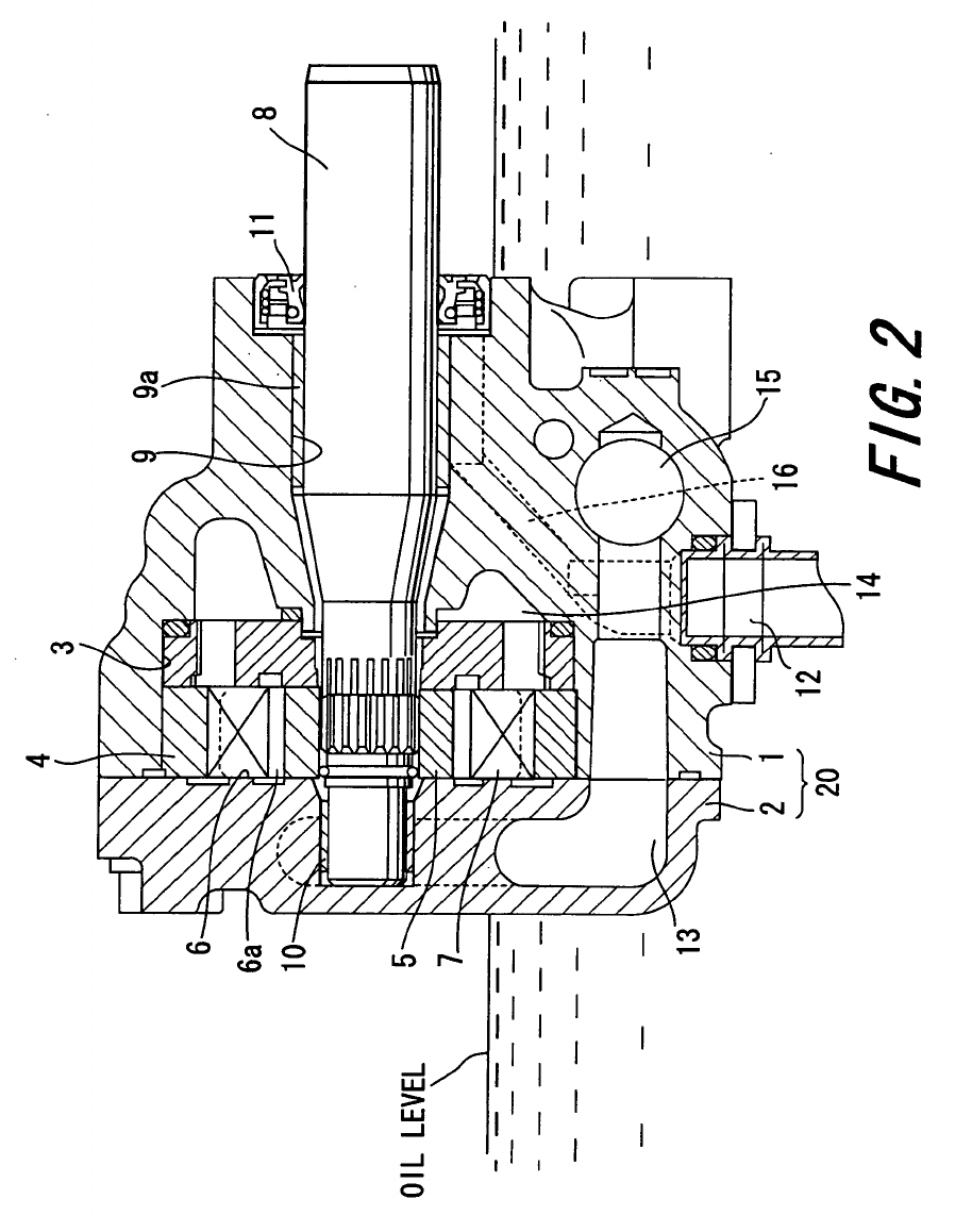
[0003] FIG. 2 shows a vane pump used under such a
condition (refer to Japanese Patent Publication JP8 -
291793A).
[0004] The CVT includes a pump case 20 constructed
of a body 1 and a cover 2. A cam ring 4 is incorporated
in a body bore 3 formed in the body 1. A rotor 5 is disposed
inside the cam ring 4. A plurality of vane grooves 6 are
radially formed in the rotor 5, and a vane 7 is incorporated
in each vane groove 6 in such a way to freely retract into
or move out of the vane groove 6. A pump discharge
pressure is introduced to a backpressure groove 6a as
the bottom of the vane groove 6.
[0005] A drive shaft 8 is inserted in the pump case 20.
The drive shaft 8 is rotatably supported by a bearing 9a
in the body 1, as well as penetrates through the rotor 5
and is rotatably supported at the penetrating end by a
bearing 10 disposed in the cover 2. The drive shaft 8 is
arranged to be engaged to the rotor 5 via serration for
rotation integral therewith.
[0006] Further, as an example, a base end of a drive
shaft 8, i. e. an opposing side thereof to the side of the
cover 2 extends into the transmission case (not shown).
A driving mechanism is disposed in the transmission
case and the drive shaft 8 is associated with the drive
mechanism. The vane pump is, as described above, bur-
ied in the operating oil and therefore, a seal member 11
is not necessarily required, but may be disposed for seal-
ing the circumference of the drive shaft 8.
[0007] Under the above structure, when the driving
mechanism is rotated in the transmission case to rotate
the drive shaft 8, the vanes 7 retract into or move out of
the vane grooves 6, while rotating along an inner periph-
eral surface of the cam ring 4 together with the rotor 5.
During this rotating process of the vanes 7, the chambers
defined between the plurality of the vanes expand or con-
tract to suck in or discharge the operating oil, i.e. provide
a pumping action.
[0008] When the pumping action is provided as de-
scribed above, the operating oil is drawn from a suction
port 12 disposed in the body 1. The suction port 12 is
arranged to have a suction opening positioned lower than
the oil level in the transmission case and also oriented
directly below. As a result, the operating oil in the trans-
mission case is drawn directly from the suction port 12.
[0009] The operating oil drawn from the suction port
12 is drawn via a suction flow passage 13 formed in the
side of the cover 2 into chambers defined by the vanes
7 during an expansion stroke and is then discharged from
the same chambers during a contraction stroke. The
high-pressure operating oil discharged from the cham-
bers defined by the vanes 7 is introduced from a high-
pressure chamber 14 via a passage (not shown) into a
flow control valve 15.
[0010] The flow control valve 15 to which the high-pres-
sure operating oil is introduced supplies a predetermined
flow quantity thereof to a piston activating a pulley of the
CVT (not shown) or a CVT drive mechanism such as a
forward/backward changing apparatus and returns an
excessive flow quantity of the operating oil exceeding the
predetermined flow quantity back to the suction flow pas-
sage 13. The necessary flow quantity of the operating oil
other than the excessive flow quantity is supplementary
from the suction port 12.
[0011] In addition, the high-pressure operating oil dis-
charged into the high-pressure camber 14 is also intro-
duced to the backpressure grooves 6a of the vane
grooves 6 and with action of the high-pressure oil intro-
duced to the backpressure grooves 6a, the vanes 7 are
pushed out of the vane grooves 6 to contact the vanes
7 with the inner peripheral surface of the cam ring 4.
[0012] When the vane pump is driven to generate a
high pressure in a discharge path side, the operating oil
is leaked from a clearance between each member. The
high-pressure operating oil discharge to the high-pres-
sure chamber 14 is, for example, introduced into the flow
control valve 15 via a passage (not shown), and during
the communicating process, a leaked oil flows into a
clearance between a shaft bore 9 of the body 1 and the
drive shaft 8. The leaked oil flown between the shaft bore
9 and the drive shaft 8 is returned back to the side of the
suction flow passage 13 via a drain passage 16. Accord-
ingly, the leaked oil is arranged to be again drawn in the
pump via the drain passage 16.
SUMMARY OF THE INVENTION
[0013] As described above, the conventional vane
pump for the CVT is used in such a state as to be sub-
merged in an operating oil inside the transmission case
by more than the half thereof and provides a pumping
action in use of the operating oil inside the transmission
1 2

EP 1 653 082 A1
3
5
10
15
20
25
30
35
40
45
50
55
case. However, for example, a chain for driving-force
transmission or the like moves inside the transmission
case without any protection or cover, and therefore, the
operating oil inside the transmission case is in such a
state as to be always stirred. Accordingly, the operating
oil inside the transmission case contains a lot of air bub-
bles.
[0014] For example, when an operation of the pump
stops for a long time in the event of using the operating
oil containing a lot of air bubbles, the air bubbles con-
tained in the operating oil go up due to a difference in
specific gravity between the air bubble and the operating
oil. During the going-up process, air bubbles get together
to form each of the air bubbles to be larger. And when
the operation of the pump stops for a long time, the oil
temperature resultantly goes down to increase oil viscos-
ity of the operating oil.
[0015] As described above, when the pump starts with
the state it has stopped for a long time, in the event the
larger air bubbles exist inside the transmission case, they
are difficult to go out. Since in particular, the leaked oil
in the pump case 20 is recirculated to the side of the
suction flow passage 13 inside the pump case 20 via the
drain passage 16, almost all of the air bubbles contained
in the leaked oil remain inside the pump case 20.
[0016] As the air bubbles thus remaining in the pump
case 20 enter into the backpressure grooves 6a, the air
bubbles prevent generation of force to push up the vanes
7. If the force to push up the vanes 7 is not generated,
the vanes 7 do not contact with the inner peripheral sur-
face of the cam ring 4. Since in particular, in the conven-
tional vane pump, the suction opening of the suction port
12 positioned lower than the oil level of the pump case
20 is oriented directly below, almost all of the air bubbles
do not go out from the suction opening.
[0017] In addition, since rotation of the rotor 5 at the
pump starting time causes centrifugal force to act on the
vanes 7, the centrifugal force acts on the vanes 7 as force
to move them out of the vane grooves 6. However, as
described above, when the pump stops for a long time,
the oil temperature goes down to increase the viscosity
of the operating oil. As the viscosity of the operating oil
gets the higher, the vanes 7 are the more difficult to go
out from the vane grooves 6. Therefore, the vanes 7 can
not go out from the vane grooves 6 only with the centrif-
ugal force and as a result, the vanes 7 do not get in contact
with the inner peripheral surface of the cam ring 4.
[0018] In this way, when the air bubbles are entered
into the backpressure grooves 6a or the viscosity of the
operating oil is high at a low oil temperature, even if the
rotor 5 rotates, in the event the vanes 7 do not get in
contact with the inner peripheral surface of the cam ring
4 easily, the vane pump can not perform the pumping
action sufficiently. As a result, there is a problem with
taking the more time to discharge the operating oil for
activating the CVT.
[0019] When the vane pump, however, continues to
operate for a little while, the temperature of the operating
oil increases to reduce the viscosity thereof correspond-
ingly. Finally the vanes 7 are projected from the vane
grooves 6 due to centrifugal action of the rotor 5. When
the pump continues to operate, the operating oil is suffi-
ciently stirred to produce the smaller air bubbles in size,
which are dispersed. When the air bubbles become
smaller and dispersed, even if the air bubbles enter into
the backpressure grooves 6a, they do not affect the
pumping action so much.
[0020] In view of the above, there exists a need for a
vane pump for a CVT which overcomes the above-men-
tioned problems in the related art. The present invention
addresses this need in the related art as well as other
needs, which will become apparent to those skilled in the
art from this disclosure.
[0021] It is an object of the present invention to provide
a vane pump for a CVT, which can sufficiently discharge
an operating oil immediately after pump starting.
[0022] In order to achieve above object the invention
provides A vane pump disposed inside a transmission
case of a continuously variable transmission. The vane
pump comprises a pump case, a pump drive shaft rotat-
ably supported by a shaft bore of the pump case to rotate
a rotor, and a drain port, one end thereof being opened
to the shaft bore of the pump drive shaft and the other
end being opened to an outside of the pump case, where-
in a leaked oil flown via the drain port from a pump dis-
charge side is discharged to the outside of the pump
case.
[0023] These and other objects, features, aspects and
advantages of the present invention will be become ap-
parent to those skilled in the art from the following detailed
description, which, taken in conjunction with the annexed
drawings, discloses a preferred embodiment of the
present invention.
BRIEF DESCRIPTION OF THE DRAWINGS
[0024] A preferred embodiment according to the inven-
tion will be explained below referring to the drawings,
wherein:
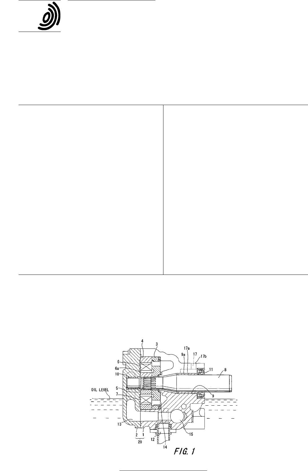
FIG. 1 is a cross-sectional view showing a vane
pump for a CVT in a preferred embodiment of the
present invention; and
FIG. 2 is a cross-sectional view showing a conven-
tional vane pump for a power steering.
DETAILED DESCRIPTION OF PREFERRED EMBOD-
IMENT
[0025] FIG. 1 is a vane pump for a CVT in a preferred
embodiment of the present invention in which compo-
nents identical to those in the conventional example in
FIG. 2 are referred to as identical numerals.
[0026] A vane pump for a continuously variable trans-
mission (referred to as CVT) of the preferred embodiment
supplies an operating oil to a cylinder receiving a piston
3 4

EP 1 653 082 A1
4
5
10
15
20
25
30
35
40
45
50
55
therein for moving a primary pulley or a secondary pulley
of the CVT and a CVT drive mechanism including a for-
ward/backward changing apparatus or the like and is dis-
posed inside a transmission case of the CVT and is sub-
merged in the operating oil in the transmission case by
at least a part of the vane pump.
[0027] The CVT includes a pump case 20 constructed
of a body 1 and a cover 2. A cam ring 4 is incorporated
in a body bore 3 formed in the body 1. A rotor 5 is disposed
inside the cam ring 4. A plurality of vane grooves 6 are
radially formed in the rotor 5, and a vane 7 is incorporated
in each vane groove 6 in such a way to freely retract into
or move out of the vane groove 6. A bottom of the vane
groove 6 is defined as a backpressure groove 6a.
[0028] A drive shaft 8 is inserted in the pump case 20.
The drive shaft 8 is rotatably supported by a bearing 9a
engaged to a shaft bore 9 in the body 1, as well as pen-
etrates through the rotor 5 and is rotatably supported at
the penetrating end by a bearing 10 disposed in the cover
2. The drive shaft 8 is arranged to be engaged to the
rotor 5 via serration for rotation integral therewith.
[0029] A base end of a drive shaft 8, i. e. an opposing
side thereof to the side of the cover 2 extends from the
pump case 20 and is positioned in the transmission case
(not shown). A driving mechanism including a gear mech-
anism or the like is disposed in the transmission case
and the drive shaft 8 is associated with the drive mech-
anism. A seal member 11 is not necessarily required sim-
ilarly to the conventional vane pump, but is disposed for
sealing an end of the drive shaft 8.
[0030] When the drive shaft 8 is rotated by the driving
mechanism disposed in the transmission case, the vanes
7 retract into or move out of the vane grooves 6 and rotate
along an inner peripheral surface of the cam ring 4 to-
gether with the rotor 5. During this rotating process of the
vanes 7, a chamber defined between a pair of the vanes
7 expands or contracts to suck in or discharge the oper-
ating oil, i.e. provides a pumping action.
[0031] With this pumping action, the operating oil is
drawn from a suction port 12 disposed in the body 1. The
suction port 12 is arranged to have a suction opening
positioned lower than the oil level in the transmission
case and also oriented directly below. As a result, the
operating oil in the transmission case is drawn directly
from the suction port 12 thus formed.
[0032] The operating oil drawn from the suction port
12 is drawn via a suction flow passage 13 formed in the
side of the cover 2 into chambers defined by the vanes
7 during an expansion stroke and is then discharged from
the same chambers during a contraction stroke. The
high-pressure operating oil discharged from the cham-
bers defined between the vanes 7 is introduced from a
high-pressure chamber 14 via a passage (not shown)
into a flow control valve 15.
[0033] The flow control valve 15 to which the high-pres-
sure operating oil is introduced supplies a predetermined
flow quantity thereof to a piston activating a pulley of the
CVT (not shown) or a CVT drive mechanism such as a
forward/backward changing apparatus and returns an
excessive flow quantity of the operating oil exceeding the
predetermined flow quantity back to the suction flow pas-
sage 13. Accordingly, the necessary flow quantity of the
operating oil other than the excessive flow quantity is
supplementary from the suction port 12.
[0034] A part of the high-pressure operating oil dis-
charged into the high-pressure camber 14 is also intro-
duced to the backpressure grooves 6a of the vane
grooves 6 and with action of the high-pressure oil intro-
duced to the backpressure grooves 6a, the vanes 7 are
pushed out of the vane grooves 6 to contact top ends of
the vanes 7 with the inner peripheral surface of the cam
ring 4.
[0035] When the vane pump is driven to generate a
high pressure in a discharge path side, the operating oil
is leaked from a clearance between each member simi-
larly to the conventional vane pump. The high-pressure
operating oil discharged to the high-pressure chamber
14 is, for example, introduced into flow control valve 15
via a passage (not shown), and during the communicat-
ing process, a leaked oil flows into a clearance between
a shaft bore 9 of the body 1 and the drive shaft 8.
[0036] A drain port 17 is provided in the body 1 to dis-
charge the leaked oil to an outside. One end 17a of the
drain port 17 is connected to the circumference of the
shaft bore 9 of the drive shaft 8 and the other end 17b
thereof is opened to an outside at the upper side of the
body 1.
[0037] The drain port 17 is positioned at an opposite
side to the suction port 12, having the drive shaft 8 placed
therebetween. One end (opening) 17a of the drain port
17 opened to the shaft bore 9 is positioned above the
drive shaft 8 and the other end (opening) 17b of the drain
port 17 is opened to an upper surface of the pump case
20, providing such a relationship that the opening 17b is
positioned at a side higher than the oil level in the trans-
mission case. In addition, the drain port 17 is arranged
to form a flow passage that elevates continuously from
one end 17a opened to the shaft bore 9 to the other end
17b opened to the outside of the pump case 20, so that
the leaked oil containing the air bubbles is not trapped in
the mid course and discharged to the outside of the pump
case 20.
[0038] Opening the drain port 17 to an inside of the
transmission case allows the leaked oil from the dis-
charge side to be positively released to the outside of the
pump case 20, i.e. the inside of the transmission case.
Since the leaked oil is thus released positively, the air
bubbles contained in the leaked oil are less likely to re-
main inside the pump case 20. Further, even if the vane
pump stops for a long time, thereby to largely expand the
air bubbles in size, since the drain port 17 acts as a con-
tinuously elevating flow passage, release of the air bub-
bles is certainly performed.
[0039] This construction thus prevents the state
where, for example, at the pump starting time, the air
bubbles remain in the backpressure grooves 6a of the
5 6

EP 1 653 082 A1
5
5
10
15
20
25
30
35
40
45
50
55
vane pump so that the vanes 7 are difficult to move out
of the vane grooves 6. As a result, discharge delay in
time from a point when the vane pump starts to rotate to
a point when the vane pump starts to discharge the op-
erating oil is prevented, thus securely activating the CVT
from an initial time of the vane pump starting without de-
lay.
[0040] Yet, according to the preferred embodiment,
since the drain port 17 is opened to the upper surface of
the pump case 20 and the opening is positioned above
the oil level in the transmission case. Therefore, the air
bubble lighter in specific gravity than the operating oil
passes through the drain port 17 and is released above
the oil level.
[0041] Note that if the rotor 5 rotates swiftly at the pump
starting time, the vanes 7 are projected out of the vane
grooves 6 due to centrifugal force in any way. Accord-
ingly, even if all the vanes 7 are not in contact with the
inner peripheral surface of the cam ring 4, flow of the
operating oil is generated in the pump case 20. This flow
of the operating oil thus produces the leaked oil, which
is discharged from the drain port 17 to the outside of the
pump case 20 together with the air bubbles.
[0042] A plurality of drain ports may be naturally dis-
posed. In the preferred embodiment, as shown in FIG.
1, the drain port 17 is opened to a side as opposed to
the suction port 12, but may be opened to any direction
only if opened to an inside of the transmission case at
an outward of the pump case 20.
[0043] This application claims priority to Japanese Pat-
ent Application No. 2004-310723. The entire disclosure
of Japanese Patent Application No. 2004-310723 is here-
by incorporated herein by reference.
[0044] While only the selected preferred embodiment
has been chosen to illustrate the present invention, it will
be apparent to those skilled in the art from this disclosure
that various changes and modifications can be made
therein without departing from the scope of the invention
as defined in the appended claims. Furthermore, the fore-
going description of the preferred embodiment according
to the present invention is provided for illustration only,
and not for the purpose of limiting the invention as defined
by the appended claims and their equivalents.
Claims
1. A vane pump disposed inside a transmission case
of a continuously variable transmission, comprising:
a pump case;
a pump drive shaft rotatably supported by a shaft
bore of the pump case to rotate a rotor; and
a drain port, one end thereof being opened to
the shaft bore of the pump drive shaft and the
other end being opened to an outside of the
pump case, wherein:
a leaked oil flown via the drain port from a
pump discharge side is discharged to the
outside of the pump case.
2. The vane pump according to claim 1, wherein:
the drain port is so formed that an opening there-
of to the outside of the pump case is disposed
at a higher position than an opening thereof to
the shaft bore.
3. The vane pump according to claim 2, wherein:
the drain port is so formed to continuously ele-
vate from the opening to the shaft bore to the
opening to the outside of the pump case.
4. The vane pump according to claim 1, wherein:
the drain port is so constructed that an opening
thereof to the outside of the pump case is dis-
posed at a higher position than an oil level in the
transmission case.
7 8

EP 1 653 082 A1
6
EP 1 653 082 A1
7
EP 1 653 082 A1
8
EP 1 653 082 A1
9
