EPOS2 Communication Guide En
User Manual:
Open the PDF directly: View PDF ![]() .
.
Page Count: 54
- PLEASE READ THIS FIRST
- Table of Contents
- 1 About this Document
- 2 Introduction
- 3 EPOS2 Command Reference (USB & RS232)
- 4 USB Communication
- 5 RS232 Communication
- 6 CAN Communication
- 7 Gateway Communication (USB & RS232 to CAN)
- 8 Error Code Definition
- List of Figures
- List of Tables
- Index

maxon motor control
A-2 Document ID: rel5984 EPOS2 Positioning Controllers
Edition: May 2016 EPOS2 Communication Guide
© 2016 maxon motor. Subject to change without prior notice.
PLEASE READ THIS FIRST
These instructions are intended for qualified technical personnel. Prior commencing with any
activities …
• you must carefully read and understand this manual and
• you must follow the instructions given therein.
We have tried to provide you with all information necessary to install and commission the equipment in a
secure, safe and time-saving manner. Our main focus is …
• to familiarize you with all relevant technical aspects,
• to let you know the easiest way of doing,
• to alert you of any possibly dangerous situation you might encounter or that you might cause if
you do not follow the description,
•to write as little and to say as much as possible and
• not to bore you with things you already know.
Likewise, we tried to skip repetitive information! Thus, you will find things mentioned just once. If, for
example, an earlier mentioned action fits other occasions you then will be directed to that text passage
with a respective reference.
Follow any stated reference – observe respective information – then go back and continue with
the task!
PREREQUISITES FOR PERMISSION TO COMMENCE INSTALLATION
The EPOS2 is considered as partly completed machinery according to EU directive 2006/42/EC, Article
2, Clause (g) and therefore is intended to be incorporated into or assembled with other machinery
or other partly completed machinery or equipment.
You must not put the device into service, …
• unless you have made completely sure that the other machinery – the surrounding system the device
is intended to be incorporated to – fully complies with the requirements stated in the EU directive
2006/42/EC!
• unless the surrounding system fulfills all relevant health and safety aspects!
• unless all respective interfaces have been established and fulfill the stated requirements!

maxon motor control
EPOS2 Positioning Controllers Document ID: rel5984 A-3
EPOS2 Communication Guide Edition: May 2016
© 2016 maxon motor. Subject to change without prior notice.
1 About this Document 5
2 Introduction 7
2.1 Documentation Structure . . . . . . . . . . . . . . . . . . . . . . . . . . . . . . . . . . . . . . . . . 7
3 EPOS2 Command Reference (USB & RS232) 9
3.1 Read Functions . . . . . . . . . . . . . . . . . . . . . . . . . . . . . . . . . . . . . . . . . . . . . . . . 9
3.1.1 Read Object Dictionary Entry (4 Data Bytes and less) . . . . . . . . . . . . . . . . . . . . . . . . . . 9
3.1.2 Read Object Dictionary Entry (5 Data Bytes and more). . . . . . . . . . . . . . . . . . . . . . . . . . 9
3.2 Write Functions . . . . . . . . . . . . . . . . . . . . . . . . . . . . . . . . . . . . . . . . . . . . . . . 10
3.2.1 Write Object Dictionary Entry (4 Data Bytes and less). . . . . . . . . . . . . . . . . . . . . . . . . . 10
3.2.2 Write Object Dictionary Entry (5 Data Bytes and more). . . . . . . . . . . . . . . . . . . . . . . . . 11
3.2.3 NMT Service . . . . . . . . . . . . . . . . . . . . . . . . . . . . . . . . . . . . . . . . . . . . . . . . . . . . . . . . . 12
3.3 General CAN Commands . . . . . . . . . . . . . . . . . . . . . . . . . . . . . . . . . . . . . . . 13
4 USB Communication 15
4.1 Data Link Layer . . . . . . . . . . . . . . . . . . . . . . . . . . . . . . . . . . . . . . . . . . . . . . . 15
4.1.1 Flow Control. . . . . . . . . . . . . . . . . . . . . . . . . . . . . . . . . . . . . . . . . . . . . . . . . . . . . . . . . . 15
4.1.2 Frame Structure . . . . . . . . . . . . . . . . . . . . . . . . . . . . . . . . . . . . . . . . . . . . . . . . . . . . . . . 16
4.1.3 Error Control . . . . . . . . . . . . . . . . . . . . . . . . . . . . . . . . . . . . . . . . . . . . . . . . . . . . . . . . . 17
4.1.4 Character Stuffing . . . . . . . . . . . . . . . . . . . . . . . . . . . . . . . . . . . . . . . . . . . . . . . . . . . . . 18
4.1.5 Transmission Byte Order . . . . . . . . . . . . . . . . . . . . . . . . . . . . . . . . . . . . . . . . . . . . . . . . 18
4.1.6 Timeout Handling . . . . . . . . . . . . . . . . . . . . . . . . . . . . . . . . . . . . . . . . . . . . . . . . . . . . . . 18
4.1.7 Slave State Machine . . . . . . . . . . . . . . . . . . . . . . . . . . . . . . . . . . . . . . . . . . . . . . . . . . . 19
4.1.8 Example: Command Instruction . . . . . . . . . . . . . . . . . . . . . . . . . . . . . . . . . . . . . . . . . . . 20
4.2 Physical Layer . . . . . . . . . . . . . . . . . . . . . . . . . . . . . . . . . . . . . . . . . . . . . . . . 20
5 RS232 Communication 21
5.1 Data Link Layer . . . . . . . . . . . . . . . . . . . . . . . . . . . . . . . . . . . . . . . . . . . . . . . 21
5.1.1 Flow Control. . . . . . . . . . . . . . . . . . . . . . . . . . . . . . . . . . . . . . . . . . . . . . . . . . . . . . . . . . 21
5.1.2 Frame Structure . . . . . . . . . . . . . . . . . . . . . . . . . . . . . . . . . . . . . . . . . . . . . . . . . . . . . . . 23
5.1.3 Error Control . . . . . . . . . . . . . . . . . . . . . . . . . . . . . . . . . . . . . . . . . . . . . . . . . . . . . . . . . 24
5.1.4 Transmission Byte Order . . . . . . . . . . . . . . . . . . . . . . . . . . . . . . . . . . . . . . . . . . . . . . . . 24
5.1.5 Data Format . . . . . . . . . . . . . . . . . . . . . . . . . . . . . . . . . . . . . . . . . . . . . . . . . . . . . . . . . . 24
5.1.6 Timeout Handling . . . . . . . . . . . . . . . . . . . . . . . . . . . . . . . . . . . . . . . . . . . . . . . . . . . . . . 25
5.1.7 Slave State Machine . . . . . . . . . . . . . . . . . . . . . . . . . . . . . . . . . . . . . . . . . . . . . . . . . . . 26
5.1.8 Example: Command Instruction . . . . . . . . . . . . . . . . . . . . . . . . . . . . . . . . . . . . . . . . . . . 27
5.2 Physical Layer . . . . . . . . . . . . . . . . . . . . . . . . . . . . . . . . . . . . . . . . . . . . . . . . 28
TABLE OF CONTENTS

maxon motor control
A-4 Document ID: rel5984 EPOS2 Positioning Controllers
Edition: May 2016 EPOS2 Communication Guide
© 2016 maxon motor. Subject to change without prior notice.
6 CAN Communication 29
6.1 General Information . . . . . . . . . . . . . . . . . . . . . . . . . . . . . . . . . . . . . . . . . . . . 29
6.1.1 Documentation. . . . . . . . . . . . . . . . . . . . . . . . . . . . . . . . . . . . . . . . . . . . . . . . . . . . . . . . 29
6.1.2 Notations, Abbreviations and Terms used. . . . . . . . . . . . . . . . . . . . . . . . . . . . . . . . . . . 29
6.2 CANopen Basics . . . . . . . . . . . . . . . . . . . . . . . . . . . . . . . . . . . . . . . . . . . . . . 31
6.2.1 Physical Layer . . . . . . . . . . . . . . . . . . . . . . . . . . . . . . . . . . . . . . . . . . . . . . . . . . . . . . . . 31
6.2.2 Data Link Layer . . . . . . . . . . . . . . . . . . . . . . . . . . . . . . . . . . . . . . . . . . . . . . . . . . . . . . . 32
6.3 CANopen Application Layer . . . . . . . . . . . . . . . . . . . . . . . . . . . . . . . . . . . . . . 33
6.3.1 Object Dictionary . . . . . . . . . . . . . . . . . . . . . . . . . . . . . . . . . . . . . . . . . . . . . . . . . . . . . . 33
6.3.2 Communication Objects. . . . . . . . . . . . . . . . . . . . . . . . . . . . . . . . . . . . . . . . . . . . . . . . . 34
6.3.3 Predefined Communication Objects . . . . . . . . . . . . . . . . . . . . . . . . . . . . . . . . . . . . . . . 34
6.4 Identifier Allocation Scheme. . . . . . . . . . . . . . . . . . . . . . . . . . . . . . . . . . . . . . 43
7 Gateway Communication (USB & RS232 to CAN) 45
8 Error Code Definition 47
8.1 CANopen-specific Error Codes . . . . . . . . . . . . . . . . . . . . . . . . . . . . . . . . . . . 47
8.2 maxon-specific Error Codes . . . . . . . . . . . . . . . . . . . . . . . . . . . . . . . . . . . . . . 48
About this Document
© 2016 maxon motor. Subject to change without prior notice.
maxon motor control
EPOS2 Positioning Controllers Document ID: rel5984 1-5
EPOS2 Communication Guide Edition: May 2016
1 About this Document
1.1 Intended Purpose
The purpose of the present document is to familiarize you with the described equipment and the tasks
on safe and adequate installation and/or commissioning.
Observing the described instructions in this document will help you …
• to avoid dangerous situations,
• to keep installation and/or commissioning time at a minimum and
• to increase reliability and service life of the described equipment.
Use for other and/or additional purposes is not permitted. maxon motor, the manufacturer of the equip-
ment described, does not assume any liability for loss or damage that may arise from any other and/or
additional use than the intended purpose.
1.2 Target Audience
This document is meant for trained and skilled personnel working with the equipment described. It con-
veys information on how to understand and fulfill the respective work and duties.
This document is a reference book. It does require particular knowledge and expertise specific to the
equipment described.
1.3 How to use
Take note of the following notations and codes which will be used throughout the document.
Table 1-1 Notations used in this Document
For CAN-specific notations, abbreviations and terms page 6-29.
Notation Explanation
«Abcd» indicating a title or a name (such as of document, product, mode, etc.)
(n) referring to an item (such as order number, list item, etc.)
denotes “see”, “see also”, “take note of” or “go to”
About this Document
© 2016 maxon motor. Subject to change without prior notice.
maxon motor control
1-6 Document ID: rel5984 EPOS2 Positioning Controllers
Edition: May 2016 EPOS2 Communication Guide
1.4 Sources for additional Information
For further details and additional information, please refer to below listed sources:
Table 1-2 Sources for additional Information
1.5 Copyright
© 2016 maxon motor. All rights reserved.
The present document – including all parts thereof – is protected by copyright. Any use (including repro-
duction, translation, microfilming and other means of electronic data processing) beyond the narrow
restrictions of the copyright law without the prior approval of maxon motor ag, is not permitted and sub-
ject to persecution under the applicable law.
maxon motor ag
Brünigstrasse 220
P.O.Box 263
CH-6072 Sachseln
Switzerland
Phone +41 41 666 15 00
Fax +41 41 666 16 50
www.maxonmotor.com
#Reference
[ 1 ] CiA 301 Communication Profile for Industrial Systems
www.can-cia.org
[ 2 ] CiA 402 Device Profile for Drives and Motion Control
www.can-cia.org
[ 3 ] CiA 305 Layer Setting Services (LSS) and Protocols
www.can-cia.org
[ 4 ] CiA 306 Electronic Data Sheet Specification
www.can-cia.org
[ 5 ] Bosch’s CAN Specification 2.0
www.can-cia.org
[ 6 ] USB Implementers Forum: Universal Serial Bus Revision 2.0 Specification
www.usb.org/developers/docs
[ 7 ] Konrad Etschberger: Controller Area Network
ISBN 3-446-21776-2
[ 8 ] maxon motor: EPOS2 Communication Guide
EPOS DVD-ROM or www.maxonmotor.com
Introduction
Documentation Structure
© 2016 maxon motor. Subject to change without prior notice.
maxon motor control
EPOS2 Positioning Controllers Document ID: rel5984 2-7
EPOS2 Communication Guide Edition: May 2016
2Introduction
The present document provides you with the communication interfaces details on the EPOS2 Position-
ing Controllers. It contains descriptions of the USB, RS232 and CAN interfaces.
maxon motor control’s EPOS2 is a small-sized, full digital, smart positioning control unit. Due to its flexi-
ble and high efficient power stage, the EPOS2 drives brushed DC motors with digital encoder as well as
brushless EC motors with digital Hall sensors and encoder.
The sinusoidal current commutation by space vector control offers to drive brushless EC motors with
minimal torque ripple and low noise. The integrated position, velocity and current control functionality
allows sophisticated positioning applications. It is specially designed to be commanded and controlled
as a slave node in the CANopen network. In addition, the unit can be operated through any USB or
RS232 communication port.
Find the latest edition of the present document, as well as additional documentation and software to the
EPOS2 Positioning Controllers also on the Internet: www.maxonmotor.com
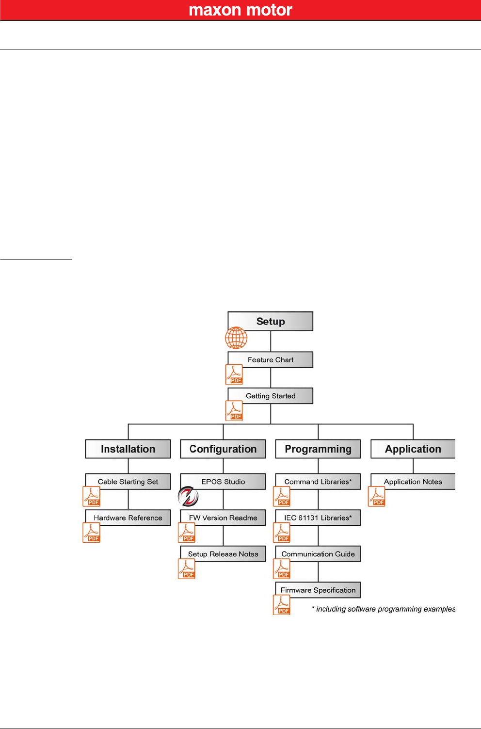
2.1 Documentation Structure
The present document is part of a documentation set. Please find below an overview on the documenta-
tion hierarchy and the interrelationship of its individual parts:
Figure 2-1 Documentation Structure

Introduction
Documentation Structure
© 2016 maxon motor. Subject to change without prior notice.
maxon motor control
2-8 Document ID: rel5984 EPOS2 Positioning Controllers
Edition: May 2016 EPOS2 Communication Guide
••page intentionally left blank••

EPOS2 Command Reference (USB & RS232)
Read Functions
© 2016 maxon motor. Subject to change without prior notice.
maxon motor control
EPOS2 Positioning Controllers Document ID: rel5984 3-9
EPOS2 Communication Guide Edition: May 2016
3 EPOS2 Command Reference (USB & RS232)
3.1 Read Functions
3.1.1 Read Object Dictionary Entry (4 Data Bytes and less)
«ReadObject»
Read an object value from the Object Dictionary at the given Index and SubIndex.
3.1.2 Read Object Dictionary Entry (5 Data Bytes and more)
«InitiateSegmentedRead»
Start reading an object value from the Object Dictionary at the given Index and SubIndex. Use the com-
mand “SegmentRead” to read the data.
Request Frame
OpCode 0x10
Len
Len-1 USB
RS232
2
1
WORD Index Index of Object
Parameters (Low) BYTE SubIndex SubIndex of Object
(High) BYTE NodeId Node ID
Response Frame
OpCode 0x00
Len
Len-1 USB
RS232
4
3
Parameters DWORD ErrorCode “Error Code Definition” on page 8-47
BYTE Data[4] Data Bytes read
Request Frame
OpCode 0x12
Len
Len-1 USB
RS232
2
1
WORD Index Index of Object
Parameters (Low) BYTE SubIndex SubIndex of Object
(High) BYTE NodeId Node ID
Response Frame
OpCode 0x00
Len
Len-1 USB
RS232
2
1
Parameters DWORD ErrorCode “Error Code Definition” on page 8-47

EPOS2 Command Reference (USB & RS232)
Write Functions
© 2016 maxon motor. Subject to change without prior notice.
maxon motor control
3-10 Document ID: rel5984 EPOS2 Positioning Controllers
Edition: May 2016 EPOS2 Communication Guide
«SegmentRead»
Read a data segment of the object initiated with the command “InitiateSegmentedRead”.
3.2 Write Functions
3.2.1 Write Object Dictionary Entry (4 Data Bytes and less)
«WriteObject»
Write an object value to the Object Dictionary at the given Index and SubIndex.
Request Frame
OpCode 0x14
Len
Len-1 USB
RS232
1
0
Parameters (Low) BYTE ControlByte
not used
toggle
not used
[Bit 0…5]
[Bit 6]
[Bit 7]
–
Toggle Bit
–
(High) BYTE Dummy Byte without meaning
Response Frame
OpCode 0x00
Len
Len-1 USB
RS232
3…34
2…33
Parameters
DWORD ErrorCode “Error Code Definition” on page 8-47
(Low) BYTE ControlByte
length
toggle
more
[Bit 0…5]
[Bit 6]
[Bit 7]
Number of data bytes
Toggle Bit
More segments to read
BYTE Data[0…63] Data Bytes read
Request Frame
OpCode 0x11
Len
Len-1 USB
RS232
4
3
Parameters
WORD Index Index of Object
(Low) BYTE SubIndex SubIndex of Object
(High) BYTE NodeId Node ID
BYTE Data[4] Data Bytes to write
Response Frame
OpCode 0x00
Len
Len-1 USB
RS232
2
1
Data DWORD ErrorCode “Error Code Definition” on page 8-47

EPOS2 Command Reference (USB & RS232)
Write Functions
© 2016 maxon motor. Subject to change without prior notice.
maxon motor control
EPOS2 Positioning Controllers Document ID: rel5984 3-11
EPOS2 Communication Guide Edition: May 2016
3.2.2 Write Object Dictionary Entry (5 Data Bytes and more)
«InitiateSegmentedWrite»
Start writing an object value to the Object Dictionary at the given Index and SubIndex. Use the com-
mand “SegmentWrite” to write the data.
«SegmentWrite»
Write a data segment to the object initiated with the command “InitiateSegmentedWrite”.
Request Frame
OpCode 0x13
Len
Len-1 USB
RS232
4
3
Parameters
WORD Index Index of Object
(Low) BYTE SubIndex SubIndex of Object
(High) BYTE NodeId Node ID
DWORD ObjectLength Total number of bytes to write
Response Frame
OpCode 0x00
Len
Len-1 USB
RS232
2
1
Data DWORD ErrorCode “Error Code Definition” on page 8-47
Request Frame
OpCode 0x15
Len
Len-1 USB
RS232
1…32
0…31
Parameters (Low) BYTE ControlByte
length
toggle
not used
[Bit 0…5]
[Bit 6]
[Bit 7]
Number of data bytes
Toggle Bit
–
BYTE Data[0…63] Data bytes to write
Response Frame
OpCode 0x00
Len
Len-1 USB
RS232
3
2
Data DWORD ErrorCode “Error Code Definition” on page 8-47
(Low) BYTE ControlByte
length
toggle
not used
[Bit 0…5]
[Bit 6]
[Bit 7]
Number of data bytes
Toggle Bit
–
(High) BYTE Dummy Byte without meaning

EPOS2 Command Reference (USB & RS232)
Write Functions
© 2016 maxon motor. Subject to change without prior notice.
maxon motor control
3-12 Document ID: rel5984 EPOS2 Positioning Controllers
Edition: May 2016 EPOS2 Communication Guide
3.2.3 NMT Service
«SendNMTService»
Send a NMT service to, for example, change NMT state or reset the device.
Remark: *1) no response with RS232
Request Frame
OpCode 0x0E
Len
Len-1 USB
RS232
2
1
Parameters
WORD NodeId Node ID
WORD CmdSpecifier
1
2
128
129
130
Start Remote Node
Stop Remote Node
Enter Pre-Operational
Reset Node
Reset Communication
Response Frame *1)
OpCode 0x00
Len USB 2
Data DWORD ErrorCode “Error Code Definition” on page 8-47

EPOS2 Command Reference (USB & RS232)
General CAN Commands
© 2016 maxon motor. Subject to change without prior notice.
maxon motor control
EPOS2 Positioning Controllers Document ID: rel5984 3-13
EPOS2 Communication Guide Edition: May 2016
3.3 General CAN Commands
«SendCANFrame»
Send a general CAN Frame to the CAN Bus.
Remark: *1) no response with RS232
«RequestCANFrame»
Request a PDO/Guarding CAN Frame from a CAN Bus using Remote Transmit Request (RTR).
Request Frame
OpCode 0x20
Len
Len-1 USB
RS232
6
5
Parameters
WORD Identifier CAN Frame 11-bit Identifier
WORD Length CAN Frame Data Length Code (DLC)
BYTE Data[8] CAN Frame Data
Response Frame *1)
OpCode 0x00
Len USB 2
Data DWORD ErrorCode “Error Code Definition” on page 8-47
Request Frame
OpCode 0x21
Len
Len-1 USB
RS232
2
1
Parameters WORD Identifier CAN Frame 11-bit Identifier
WORD Length CAN Frame Data Length Code (DLC)
Response Frame
OpCode 0x00
Len USB
RS232
6
5
Data DWORD ErrorCode “Error Code Definition” on page 8-47
BYTE Data[8] CAN Frame Data

EPOS2 Command Reference (USB & RS232)
General CAN Commands
© 2016 maxon motor. Subject to change without prior notice.
maxon motor control
3-14 Document ID: rel5984 EPOS2 Positioning Controllers
Edition: May 2016 EPOS2 Communication Guide
«SendLSSFrame»
Send a LSS master message to the CAN Bus.
Remark: *1) no response with RS232
«ReadLSSFrame»
Read a LSS slave message from the CAN Bus.
Request Frame
OpCode 0x30
Len
Len-1 USB
RS232
4
3
Parameters BYTE Data[8¨] LSS master message
Response Frame *1)
OpCode 0x00
Len USB 2
Data DWORD ErrorCode “Error Code Definition” on page 8-47
Request Frame
OpCode 0x31
Len
Len-1 USB
RS232
1
0
Parameters WORD Timeout Communication timeout [ms]
Response Frame
OpCode 0x00
Len USB
RS232
6
5
Data DWORD ErrorCode “Error Code Definition” on page 8-47
BYTE Data[8¨] LSS slave message
USB Communication
Data Link Layer
© 2016 maxon motor. Subject to change without prior notice.
maxon motor control
EPOS2 Positioning Controllers Document ID: rel5984 4-15
EPOS2 Communication Guide Edition: May 2016
4 USB Communication
4.1 Data Link Layer
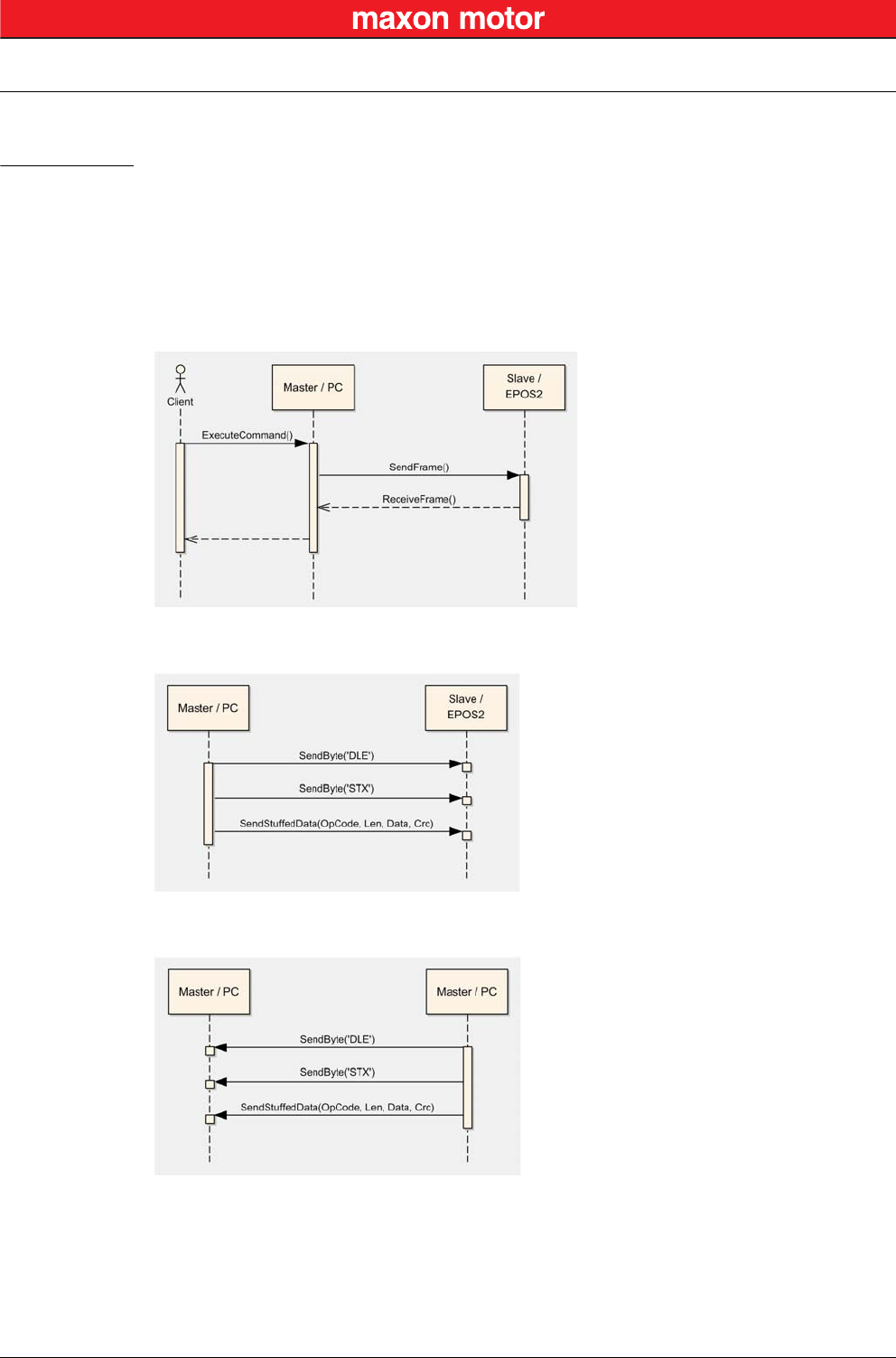
4.1.1 Flow Control
The EPOS2 Positioning Controllers always communicates as a slave. A frame is only sent as an answer
to a request. All EPOS2 commands send an answer. The master always must start the communication
by sending a packet structure.
Below described are the data flow while transmitting and receiving frames.
Figure 4-2 USB Communication – Command Sequence
Figure 4-3 USB Communication – Sending a Data Frame to EPOS2
Figure 4-4 USB Communication – Receiving a Response Data Frame from EPOS2

USB Communication
Data Link Layer
© 2016 maxon motor. Subject to change without prior notice.
maxon motor control
4-16 Document ID: rel5984 EPOS2 Positioning Controllers
Edition: May 2016 EPOS2 Communication Guide
4.1.2 Frame Structure
The data bytes are sequentially transmitted in frames. A frame composes of…
• a synchronization,
• a header,
• a variably long data field and
• a 16-bit long cyclic redundancy check (CRC) for verification of data integrity.
Figure 4-5 USB Communication – Frame Structure
Note
The CRC is calculated before stuffing the data. The elements “OpCode” to “Data[Len-1]” are included in
CRC calculation. The synchronization elements “DLE” and “STX” are not included.
“DLE”
(8-bit)
“STX”
(8-bit)
OpCode
(8-bit)
Len
(8-bit)
Data[0]
(16-bit) …Data[Len-1]
(16-bit)
CRC
(16-bit)
SYNC HEADER DATA CRC
SYNC The first two bytes are used for frame synchronization.
“DLE” Starting frame character “DLE” (Data Link Escape) = 0x90
“STX” Starting frame character “STX” (Start of Text) = 0x02
HEADER The header consists of 2 bytes. The first field determines the type of data frame to be sent
or received. The next field contains the length of the data fields.
OpCode Operation command to be sent to the slave. For details on the command set
“EPOS2 Command Reference (USB & RS232)” on page 3-9.
Len represents the number of words (16-bit value) in the data fields [0…143].
DATA The data field contains the parameters of the message. The low byte of the word is
transmitted first.
Data[i] The parameter word of the command. The low byte is transmitted first.
CRC The 16-bit CRC checksum using the algorithm CRC-CCITT.
The CRC calculation includes all bytes of the frame except the synchronization bytes, the
data bytes must be calculated as a word.
First, you will need to shift to the data word’s high byte.
This represents the opposite way as you transmit the data word.
For calculation, the 16-bit generator polynomial “x16+x12+x5+1” is used.
CRC Checksum of the frame. The low byte is transmitted first.

USB Communication
Data Link Layer
© 2016 maxon motor. Subject to change without prior notice.
maxon motor control
EPOS2 Positioning Controllers Document ID: rel5984 4-17
EPOS2 Communication Guide Edition: May 2016
4.1.3 Error Control
4.1.3.1 Acknowledge
As a reaction to a bad OpCode or CRC value, the slave sends a frame containing the corresponding
error code.
4.1.3.2 CRC Calculation
Figure 4-6 USB Communication – CRC Calculation
Packet M(x): WORD DataArray[n]
Generator Polynom G(x): 10001000000100001 (= x16+x12+x5+x0)
DataArray[0]:
DataArray[1]:
DataArray[2]:
…
DataArray[n-1]:
HighByte(Len) + LowByte(OpCode)
Data[0]
Data[1]
…
0x0000 (ZeroWord)
WORD CalcFieldCRC(WORD* pDataArray, WORD numberOfWords)
{
WORD shifter, c;
WORD carry;
WORD CRC = 0;
//Calculate pDataArray Word by
Word
while(numberOfWords−−)
{
shifter = 0x8000;
c = *pDataArray++;
do
{
//Initialize BitX to Bit15
//Copy next DataWord to c
carry = CRC & 0x8000;
CRC <<= 1;
if(c & shifter) CRC++;
if(carry) CRC ^= 0x1021;
shifter >>= 1;
//Check if Bit15 of CRC is set
//CRC = CRC * 2
//CRC = CRC + 1, if BitX is set in c
//CRC = CRC XOR G(x), if carry is true
//Set BitX to next lower Bit, shifter = shifter/2
} while(shifter);
}
return CRC
}

USB Communication
Data Link Layer
© 2016 maxon motor. Subject to change without prior notice.
maxon motor control
4-18 Document ID: rel5984 EPOS2 Positioning Controllers
Edition: May 2016 EPOS2 Communication Guide
4.1.4 Character Stuffing
The sequence “DLE” and “STX” are reserved for frame start synchronization. If the character “DLE”
appears at a position between “OpCode” and “CRC” and is not a starting character, the character must
be doubled (character stuffing). Otherwise, the protocol begins to synchronize for a new frame. The
character “STX” needs not to be doubled.
Examples:
Important:
Character stuffing is used for all bytes in the frame except the starting characters.
4.1.5 Transmission Byte Order
The unit of data memory in EPOS2 is a word (16-bit value). To send and receive a word (16-bit) via the
serial port, the low byte will be transmitted first.
Multiple byte data (word = 2 bytes, long words = 4 bytes) are transmitted starting with the less significant
byte (LSB) first.
A word will be transmitted in following order: byte0 (LSB), byte1 (MSB).
A long word will be transmitted in following order: byte0 (LSB), byte1, byte2, byte3 (MSB).
4.1.6 Timeout Handling
The timeout is handled over a complete frame. Hence, the timeout is evaluated over the sent data
frame, the command processing procedure and the response data frame. For each frame (frames, data
processing), the timer is reset and timeout handling will recommence.
Table 4-3 USB Communication – Timeout Handling
Note
To cover special requirements, the timeout may be changed by writing to the Object Dictionary!
Sending Data 0x21, 0x90, 0x45
Stuffed Data 0x21, 0x90, 0x90, 0x45
Sending Data 0x21, 0x90, 0x02, 0x45
Stuffed Data 0x21, 0x90, 0x90, 0x02, 0x45
Sending Data 0x21, 0x90, 0x90, 0x45
Stuffed Data 0x21, 0x90, 0x90, 0x90, 0x90, 0x45
Object Index SubIndex Default
USB Frame Timeout 0x2006 0x00 500 [ms]
USB Communication
Data Link Layer
© 2016 maxon motor. Subject to change without prior notice.
maxon motor control
EPOS2 Positioning Controllers Document ID: rel5984 4-19
EPOS2 Communication Guide Edition: May 2016
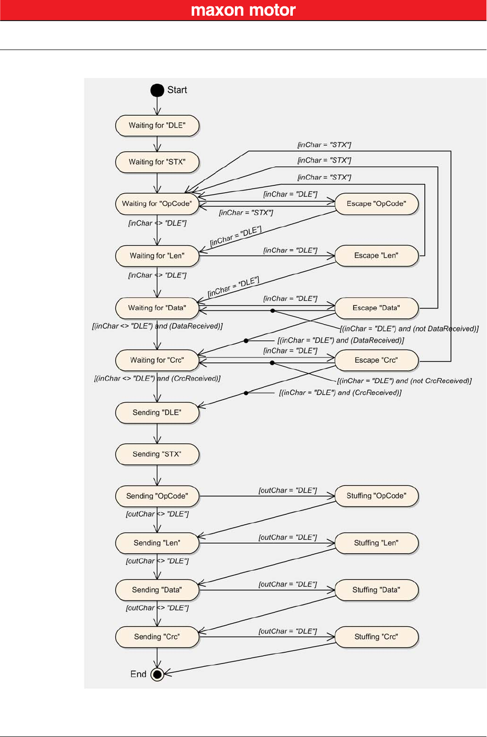
4.1.7 Slave State Machine
Figure 4-7 USB Communication – Slave State Machine
USB Communication
Physical Layer
© 2016 maxon motor. Subject to change without prior notice.
maxon motor control
4-20 Document ID: rel5984 EPOS2 Positioning Controllers
Edition: May 2016 EPOS2 Communication Guide
4.1.8 Example: Command Instruction
The following example shows composition and structure of the EPOS2 messages during transmission
and reception via USB. The command sent to the EPOS2 is “ReadObject”, it may be used to read an
object with 4 Bytes and less.
ReadObject “Home Offset” (Index = 0x2081, SubIndex = 0x00)
Table 4-4 ReadObject “Home Offset”
Transmission Order: 0x90,0x02,0x10,0x02,0x81,0x20,0x00,0x01,0x0F,0x87.
The EPOS2 will answer to the command “ReadObject” with an answer frame and the returned parame-
ters in the data block as follows:
Answer to ReadObject “Home Offset” (Index = 0x2081, SubIndex = 0x00)
Table 4-5 Answer to ReadObject “Home Offset”
Reception Order: 0x90,0x02,0x00,0x04,0x00,0x00,0x00,0x00,0x00,0x00,0x90,0x90,0x80,0x14,0x35
Note
Observe character stuffing methodology (
“Character Stuffing” on page 4-18).
4.2 Physical Layer
Electrical Standard
maxon EPOS2 drives’ USB interface follows the «Universal Serial Bus Specification Revision 2.0». You
may wish to download the file from the Internet (for URL “Sources for additional Information” on
page 1-6), full details are described in chapter “7.3 Physical Layer”.
“DLE” “STX” OpCode Len Data[0] Data[1] CRC
0x90 0x02 0x10 0x02 0x2081 0x0100 0x870F
DLE 0x90 = Data Link Escape
STX 0x02 = Start of Text
OpCode 0x10 = ReadObject
Data[0] 0x2081 = 2 Words
LowByte data[1] 0x00 = SubIndex
HighByte data[1] 0x01 = Node ID
“DLE” “STX” OpCode Len-1 Data[0] Data[1] Data[2] Data[3] CRC
0x90 0x02 0x00 0x04 0x0000 0x0000 0x0000 0x8090 0x3514
DLE 0x90 = Data Link Escape
STX 0x02 = Start of Text
OpCode 0x00 = Answer
Len 0x04 = 4 Words
Data[0] 0x0000 = LowWord ErrorCode
Data[1] 0x0000 = HighWord ErrorCode
Data[2] 0x0000 = Value of Object “HomeOffset”
Data[3] 0x8090 = Word without meaning
RS232 Communication
Data Link Layer
© 2016 maxon motor. Subject to change without prior notice.
maxon motor control
EPOS2 Positioning Controllers Document ID: rel5984 5-21
EPOS2 Communication Guide Edition: May 2016
5 RS232 Communication
The serial EIA RS232 communication protocol is used to transmit and receive data over the EPOS2’s
RS232 serial port. Its principal task is to transmit data from a master (PC or any other central processing
unit) to a single slave. The protocol is defined or point-to-point communication based on the EIA-RS232
standard.
The protocol can be used to implement the command set defined for the EPOS2. For a high degree of
reliability in an electrically noisy environment, it features a checksum.
5.1 Data Link Layer
5.1.1 Flow Control
5.1.1.1 Sequence for sending EPOS2 Commands
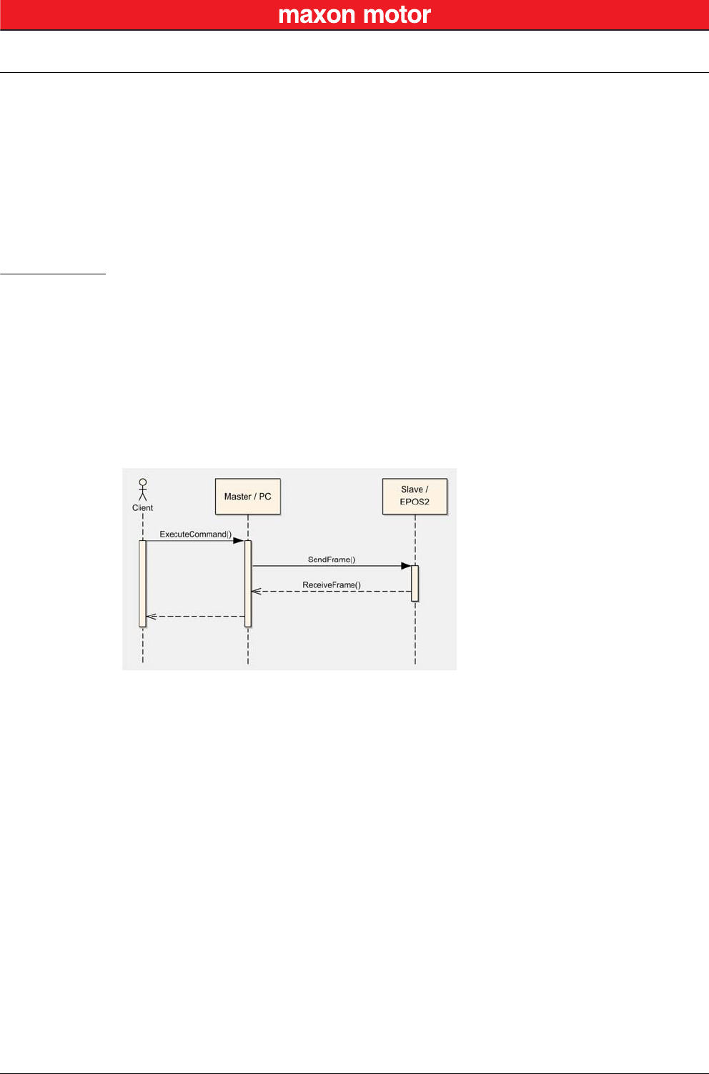
The EPOS2 Positioning Controllers always communicates as a slave. A frame is only sent as an answer
to a request. Some EPOS2 commands send an answer, other commands do not (observe respective
descriptions to determine command that send an answer packets). The master always must start the
communication by sending a packet structure.
Below described are the data flow while transmitting and receiving frame.
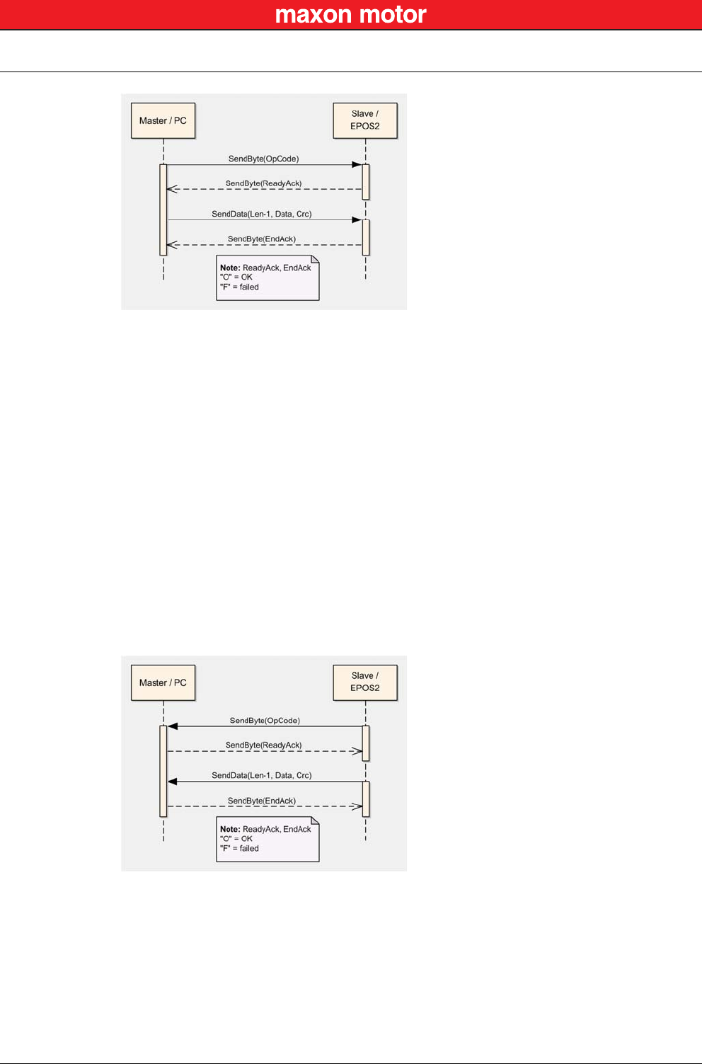
Figure 5-8 RS232 Communication – Command Sequence
5.1.1.2 Sending a Data Frame
When sending a frame, you will need to wait for different acknowledgment.
a) After sending the first frame byte (OpCode), you will need to wait for the EPOS2’s “Ready
Acknowledge”.
b) Once the character “O” (okay) is received, the slave is ready to receive further data.
c) If the character “F” (failed) is received, the slave is not ready to send data and communication
must be stopped.
d) After sending the checksum, you will need to wait for the “End Acknowledge”. The slave
sends either “O” (okay) or “F” (failed).
For the interaction while sending a packet structure Figure 5-9.
RS232 Communication
Data Link Layer
© 2016 maxon motor. Subject to change without prior notice.
maxon motor control
5-22 Document ID: rel5984 EPOS2 Positioning Controllers
Edition: May 2016 EPOS2 Communication Guide
Figure 5-9 RS232 Communication – Sending a Data Frame to EPOS2
5.1.1.3 Receiving a Data Frame
In response to some of the command frames, the EPOS2 returns a response data frame to the master.
The data flow sequence is identical as for sending a data packet, only in the other direction. The master
must also send the two acknowledges to the slave.
a) The value of the first field must always be 0x00, thus representing the operation code describ-
ing a response frame.
b) After receiving the first byte, the master then must send the “Ready Acknowledge”.
c) Send character “O” (okay) if you are ready to receive the rest of the frame.
d) Send character “F” (failed) if you are not ready to receive the rest of the frame.
e) If the EPOS2 does not get an “O” within the specified timeout, the communication is reset.
Sending “F” does not reset the communication.
f) After sending the “Ready Acknowledge” (“O”), EPOS2 sends the rest of the data frame. Then
the checksum must be calculated and compared with the one received. If the checksum is
correct, send acknowledge “O” to the EPOS2, otherwise send acknowledge “F”.
Figure 5-10 RS232 Communication – Receiving a Response Data Frame from EPOS2

RS232 Communication
Data Link Layer
© 2016 maxon motor. Subject to change without prior notice.
maxon motor control
EPOS2 Positioning Controllers Document ID: rel5984 5-23
EPOS2 Communication Guide Edition: May 2016
5.1.2 Frame Structure
The data bytes are sequentially transmitted in frames. A frame composes of…
• a header,
• a variably long data field and
• a 16-bit long cyclic redundancy check (CRC) for verification of data integrity.
Figure 5-11 RS232 Communication – Frame Structure
OpCode
(8-bit)
Len-1
(8-bit)
Data[0]
(16-bit) …Data[Len-1]
(16-bit)
CRC
16-bit
HEADER DATA CRC
HEADER The header consists of 2 bytes. The first field determines the type of data frame to be sent
or received. The next field contains the length of the data fields.
OpCode Operation command to be sent to the slave. For details on the command set
“EPOS2 Command Reference (USB & RS232)” on page 3-9.
Len-1 represents the number of words (16-bit value) in the data fields.
It contains the number of words minus one. The smallest value in this field is
zero, which represents a data length of one word. The data block must
contain at least 1 word.
Examples:
1 word: Len-1 = 0
2 words: Len-1 = 1
256 words: Len-1 = 255
DATA The data field contains the parameters of the message. This data block must contain at
least one word. The low byte of the word is transmitted first.
Data[i] The parameter word of the command. The low byte is transmitted first.
CRC The 16-bit CRC checksum. The algorithm used is CRC-CCITT. The CRC calculation
includes all bytes of the frame. The data bytes must be calculated as a word.
First you will need to shift in the high byte of the data word.
This is the opposite way you transmit the data word.
The 16-bit generator polynomial “x16+x12+x5+1” is used for the calculation.
Order of CRC calculation:
“OpCode”, “len-1”, “data[0]” high byte, “data[0]” low byte, …, ZeroWord low byte = 0x00,
ZeroWord high byte = 0x00
CRC Checksum of the frame. The low byte is transmitted first.

RS232 Communication
Data Link Layer
© 2016 maxon motor. Subject to change without prior notice.
maxon motor control
5-24 Document ID: rel5984 EPOS2 Positioning Controllers
Edition: May 2016 EPOS2 Communication Guide
5.1.3 Error Control
5.1.3.1 CRC Calculation
Figure 5-12 RS232 Communication – CRC-CCITT Calculation
5.1.4 Transmission Byte Order
The unit of data memory in EPOS2 is a word (16-bit value). To send and receive a word (16-bit) via the
serial port, the low byte will be transmitted first.
Multiple byte data (word = 2 bytes, long words = 4 bytes) are transmitted starting with the less significant
byte (LSB) first.
A word will be transmitted in following order: byte0 (LSB), byte1 (MSB).
A long word will be transmitted in following order: byte0 (LSB), byte1, byte2, byte3 (MSB).
5.1.5 Data Format
Data is transmitted in an asynchronous way, thus each data byte is transmitted individually with its own
start and stop bit. The format is 1 Start bit, 8 Data bits, No parity, 1 Stop bit. Most serial communication
chips (SCI, UART) can generate such data format.
Packet M(x): WORD DataArray[n]
Generator Polynom G(x): 10001000000100001 (= x16+x12+x5+x0)
DataArray[0]:
DataArray[1]:
DataArray[2]:
…
DataArray[n-1]:
HighByte(OpCode) + LowByte(len-1)
Data[0]
Data[1]
…
0x0000 (ZeroWord)
WORD CalcFieldCRC(WORD* pDataArray, WORD numberOfWords)
{
WORD shifter, c;
WORD carry;
WORD CRC = 0;
//Calculate pDataArray Word by Word
while(numberOfWords−−)
{
shifter = 0x8000;
c = *pDataArray++;
do
{
//Initialize BitX to Bit15
//Copy next DataWord to c
carry = CRC & 0x8000;
CRC <<= 1;
if(c & shifter) CRC++;
if(carry) CRC ^= 0x1021;
shifter >>= 1;
//Check if Bit15 of CRC is set
//CRC = CRC * 2
//CRC = CRC + 1, if BitX is set in c
//CRC = CRC XOR G(x), if carry is true
//Set BitX to next lower Bit, shifter = shifter/2
} while(shifter);
}
return CRC
}

RS232 Communication
Data Link Layer
© 2016 maxon motor. Subject to change without prior notice.
maxon motor control
EPOS2 Positioning Controllers Document ID: rel5984 5-25
EPOS2 Communication Guide Edition: May 2016
5.1.6 Timeout Handling
The timeout is handled over a complete frame. Hence, the timeout is evaluated over the sent data
frame, the command processing procedure and the response data frame. For each frame (frames, data
processing), the timer is reset and timeout handling will recommence.
Table 5-6 RS232 Communication – Timeout Handling
Note
To cover special requirements, the timeout may be changed by writing to the Object Dictionary!
Object Index SubIndex Default
RS232 Frame Timeout 0x2005 0x00 500 [ms]
RS232 Communication
Data Link Layer
© 2016 maxon motor. Subject to change without prior notice.
maxon motor control
5-26 Document ID: rel5984 EPOS2 Positioning Controllers
Edition: May 2016 EPOS2 Communication Guide
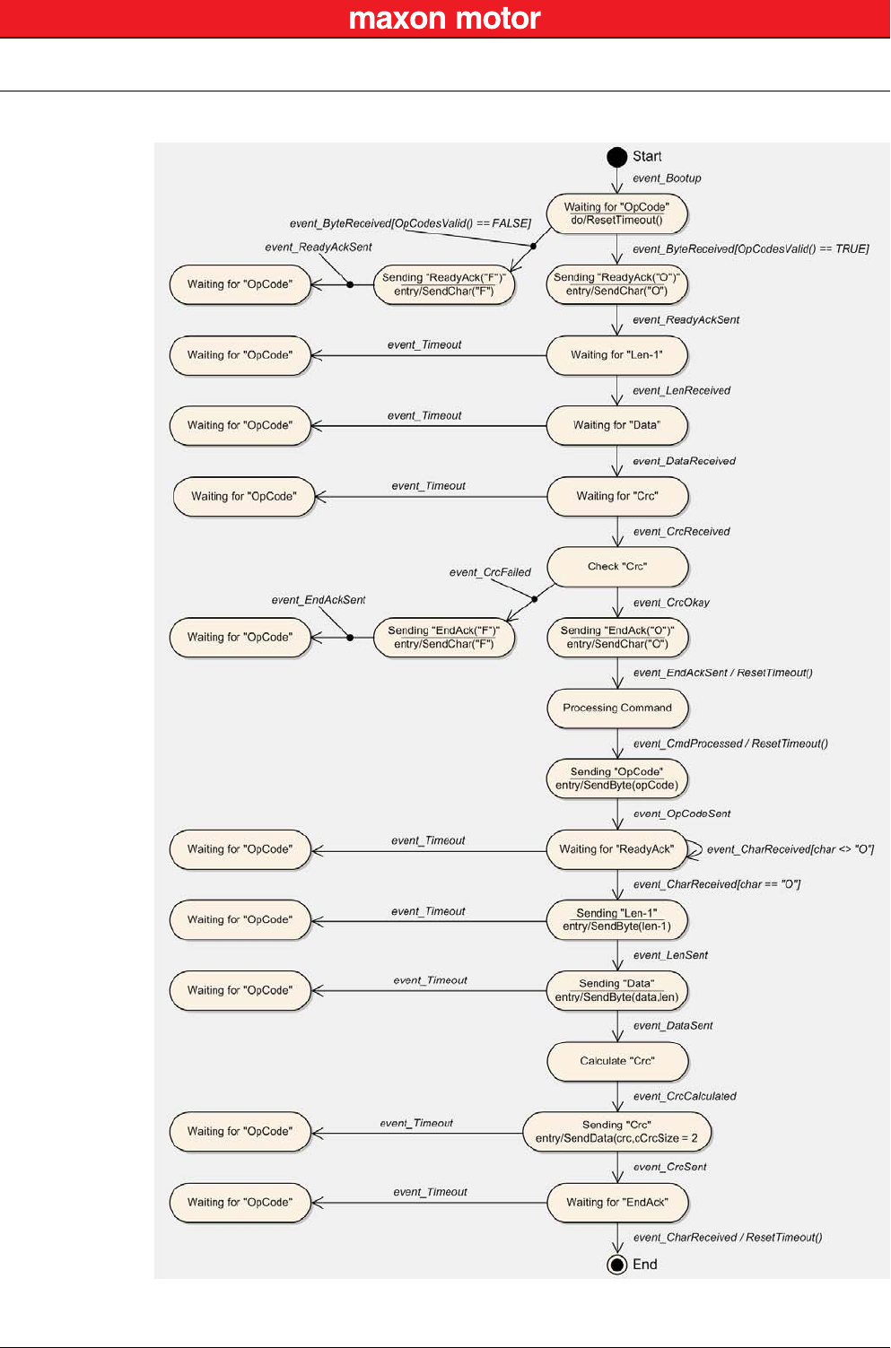
5.1.7 Slave State Machine
Figure 5-13 RS232 Communication – Slave State Machine

RS232 Communication
Data Link Layer
© 2016 maxon motor. Subject to change without prior notice.
maxon motor control
EPOS2 Positioning Controllers Document ID: rel5984 5-27
EPOS2 Communication Guide Edition: May 2016
5.1.8 Example: Command Instruction
The following example shows composition and structure of the EPOS2 messages during transmission
and reception via serial RS232. The command sent to the EPOS2 is “ReadObject”, it may be used to
read an object with 4 Bytes and less.
ReadObject “Software Version” (Index = 0x2003, SubIndex = 0x01)
Table 5-7 ReadObject “Software Version”
Transmission Order: 0x10,0x01,0x03,0x20,0x01,0x02,0x88,0xA8.
The EPOS2 answers to the command ReadObject with an answer frame and the returned parameters in
the data block as follows:
Answer to ReadObject “Software Version” (Index = 0x2003, SubIndex = 0x01)
Table 5-8 Answer to ReadObject “Software Version”
Reception Order: 0x00,0x03,0x00,0x00,0x00,0x00,0x10,0x20,0x10,0x62,0x10,0x26
OpCode Len-1 Data[0] Data[1] CRC
0x10 0x01 0x2003 0x0201 0xA888
OpCode 0x10 = ReadObject
Len-1 0x01 = 2 Words
Data[0] 0x2003 = Index
LowByte data[1] 0x01 = SubIndex
HighByte data[1] 0x02 = Node ID
OpCode Len-1 Data[0] Data[1] Data[2] Data[3] CRC
0x00 0x03 0x0000 0x0000 0x2010 0x6210 0x2610
OpCode 0x00 = Answer
Len-1 0x03 = 4 Words
Data[0] 0x0000 = LowWord ErrorCode
Data[1] 0x0000 = HighWord ErrorCode
Data[2] 0x2010 = Value of Object “SoftwareVersion”
Data[3] 0x6210 = Word without meaning

RS232 Communication
Physical Layer
© 2016 maxon motor. Subject to change without prior notice.
maxon motor control
5-28 Document ID: rel5984 EPOS2 Positioning Controllers
Edition: May 2016 EPOS2 Communication Guide
5.2 Physical Layer
Electrical Standard
The EPOS2 communication protocol uses the RS232 standard to transmit data over a 3-wire cable (sig-
nals TxD, RxD and GND).
The RS232 standard can only be used for point-to-point communication between a master and a single
EPOS2 slave. It uses negative, bipolar logic with a negative voltage signal representing a logic “1”, and
positive voltage representing a logic “0”. Voltages of −3…−25 V with respect to signal ground (GND) are
considered logic “1”, whereas voltages of +3…25 V are considered logic “0”.
Medium
For the physical connection, a 3-wire cable will be required. We recommend to install a shielded and
twisted pair cable in order to achieve good performance, even in an electrically noisy environment.
Depending on the bit rate used, the cable length can range from 3…15 meters. However, we do not rec-
ommend to use RS232 cables longer than 5 meters.
CAN Communication
General Information
© 2016 maxon motor. Subject to change without prior notice.
maxon motor control
EPOS2 Positioning Controllers Document ID: rel5984 6-29
EPOS2 Communication Guide Edition: May 2016
6 CAN Communication
6.1 General Information
maxon EPOS2 drives’ CAN interface follows the CiA CANopen specifications…
• CiA 301 V4.2 Communication Profile for Industrial Systems and
• CiA 402 V3.0 Device Profile for Drives and Motion Control.
6.1.1 Documentation
For further information on CAN/CANopen as well as respective specifications listed references in
chapter “1.4 Sources for additional Information” on page 1-6.
6.1.2 Notations, Abbreviations and Terms used
Table 6-9 CAN Communication – Notations
Table 6-10 CAN Communication – Abbreviations
Notation Description Format
nnnnb Numbers followed by “b”. binary
nnnnh Numbers followed by “h”. hexadecimal
nnnn All other numbers. decimal
Abbreviation Description
CAN CAN Application Layer
CMS CAN Message Specification
COB Communication Object (CAN Message) – a unit of transportation in a CAN message
network. Data must be sent across a network inside a COB.
COB-ID COB Identifier – identifies a COB uniquely in a network and determines the priority
of that COB in the MAC sublayer.
EDS Electronic Data Sheet – a standard form of all CAN objects supported by a device.
Used by external CAN configurators.
ID Identifier – the name by which a CAN device is addressed.
MAC Medium Access Control – one of the sublayers of the Data Link Layer in the CAN
Reference Model. Controls the medium permitted to send a message.
OD Object Dictionary – the full set of objects supported by the node. Represents the
interface between application and communication (term “Object” on page 6-30).
PDO Process Data Object – object for data exchange between several devices.
PLC Programmable Controller – can serve as a CAN Master for the EPOS2.
RO Read Only
RW Read Write
SDO Service Data Object – peer-to-peer communication with access to the device’s
Object Directory.
WO Write Only

CAN Communication
General Information
© 2016 maxon motor. Subject to change without prior notice.
maxon motor control
6-30 Document ID: rel5984 EPOS2 Positioning Controllers
Edition: May 2016 EPOS2 Communication Guide
Table 6-11 CAN Communication – Terms
Term Description
CAN Client
or
CAN Master
A host (typically a PC or other control equipment) supervising the nodes of a
network.
CAN Server
or
CAN Slave
A node in the CAN network that can provide service under the CAN Master’s
control.
Object A CAN message with meaningful functionality and/or data. Objects are referenced
according to addresses in the Object Dictionary.
Receive “received” data is being sent from the control equipment to the EPOS2.
Transmit “transmitted” data is being sent from the EPOS2 to the other equipment.
CAN Communication
CANopen Basics
© 2016 maxon motor. Subject to change without prior notice.
maxon motor control
EPOS2 Positioning Controllers Document ID: rel5984 6-31
EPOS2 Communication Guide Edition: May 2016
6.2 CANopen Basics
Subsequently described are the CANopen communication features most relevant to the maxon motor’s
EPOS2 Positioning Controllerss. For more detailed information consult above mentioned CANopen doc-
umentation.
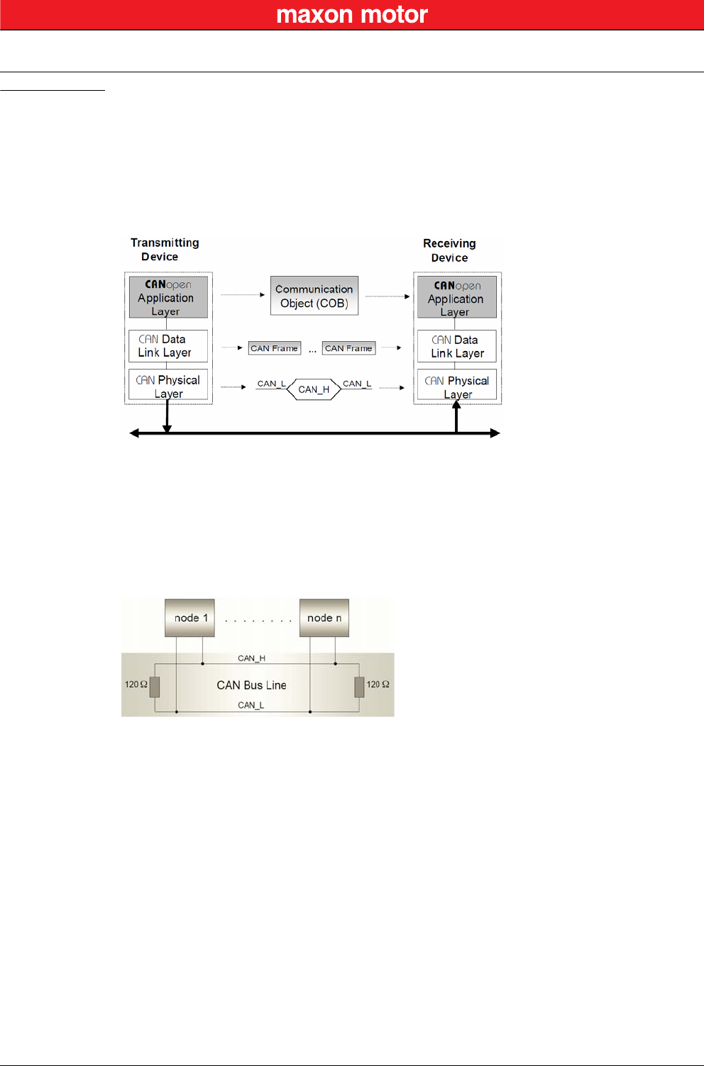
The CANopen communication concept can be described similar to the ISO Open Systems Interconnec-
tion (OSI) Reference Model. CANopen represents a standardized application layer and communication
profile.
Figure 6-14 CAN Communication – Protocol Layer Interactions
6.2.1 Physical Layer
CANopen is a networking system based on the CAN serial bus. It assumes that the device’s hardware
features a CAN transceiver and a CAN controller as specified in ISO 11898. The physical medium is a
differently driven 2-wire bus line with common return.
Figure 6-15 CAN Communication – ISO 11898 Basic Network Setup
CAN Communication
CANopen Basics
© 2016 maxon motor. Subject to change without prior notice.
maxon motor control
6-32 Document ID: rel5984 EPOS2 Positioning Controllers
Edition: May 2016 EPOS2 Communication Guide
6.2.2 Data Link Layer
The CAN data link layer is also standardized in ISO 11898. Its services are implemented in the Logical
Link Control (LLC) and Medium Access Control (MAC) sublayers of a CAN controller.
• The LLC provides acceptance filtering, overload notification and recovery management.
• The MAC is responsible for data encapsulation (decapsulation), frame coding (stuffing/destuff-
ing), medium access management, error detection, error signaling, acknowledgment, and serial-
ization (deserialization).
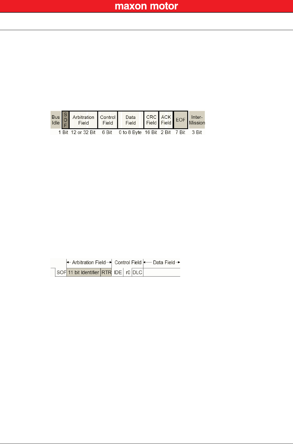
A Data Frame is produced by a CAN node when the node intends to transmit data or if this is requested
by another node. Within one frame, up to 8 byte data can be transported.
Figure 6-16 CAN Communication – CAN Data Frame
• The Data Frame begins with a dominant Start of Frame (SOF) bit for hard synchronization of all
nodes.
• The SOF bit is followed by the Arbitration Field reflecting content and priority of the message.
• The next field – the Control Field – specifies mainly the number of bytes of data contained in the
message.
• The Cyclic Redundancy Check (CRC) field is used to detect possible transmission errors. It con-
sists of a 15-bit CRC sequence completed by the recessive CRC delimiter bit.
• During the Acknowledgment (ACK) field, the transmitting node sends out a recessive bit. Any
node that has received an error-free frame acknowledges the correct reception of the frame by
returning a dominant bit.
• The recessive bits of the End of Frame (EOF) terminate the Data Frame. Between two frames, a
recessive 3-bit Intermission field must be present.
With EPOS2, only the Standard Frame Format is supported.
Figure 6-17 CAN Communication – Standard Frame Format
• The Identifier’s (COB-ID) length in the Standard Format is 11 bit.
• The Identifier is followed by the RTR (Remote Transmission Request) bit. In Data Frames, the
RTR bit must be dominant, within a Remote Frame, the RTR bit must be recessive.
• The Base ID is followed by the IDE (Identifier Extension) bit transmitted dominant in the Standard
Format (within the Control Field).
• The Control Field in Standard Format includes the Data Length Code (DLC), the IDE bit, which is
transmitted dominant and the reserved bit r0, also transmitted dominant.
• The reserved bits must be sent dominant, but receivers accept dominant and recessive bits in all
combinations.

CAN Communication
CANopen Application Layer
© 2016 maxon motor. Subject to change without prior notice.
maxon motor control
EPOS2 Positioning Controllers Document ID: rel5984 6-33
EPOS2 Communication Guide Edition: May 2016
6.3 CANopen Application Layer
6.3.1 Object Dictionary
The most significant part of a CANopen device is the Object Dictionary. It is essentially a grouping of
objects accessible via the network in an ordered, predefined fashion. Each object within the dictionary is
addressed using a 16-bit index and a 8-bit subindex. The overall layout of the standard Object Diction-
ary conforms to other industrial field bus concepts.
Table 6-12 CAN Communication – Object Dictionary Layout
A 16-bit index is used to address all entries within the Object Dictionary. In case of a simple variable, it
references the value of this variable directly. In case of records and arrays however, the index
addresses the entire data structure. The subindex permits individual elements of a data structure to be
accessed via the network.
• For single Object Dictionary entries (such as UNSIGNED8, BOOLEAN, INTEGER32, etc.), the
subindex value is always zero.
• For complex Object Dictionary entries (such as arrays or records with multiple data fields), the
subindex references fields within a data structure pointed to by the main index.
An example: A receive PDO, the data structure at index 1400h defines the communication parameters
for that module. This structure contains fields or the COB-ID and the transmission type. The subindex
concept can be used to access these individual fields as shown below.
Table 6-13 CAN Communication – Object Dictionary Entry
Index Variable accessed
0000h Reserved
0001h-009Fh Data types (not supported on EPOS2)
00A0h-0FFFh Reserved
1000h-1FFFh Communication Profile Area (CiA 301)
2000h-5FFFh Manufacturer-specific Profile Area (maxon motor
6000h-9FFFh Standardized Device Area (CiA 402)
A000h-FFFFh Reserved
Index SubIndex Variable accessed Data Type
1400h 0Number of entries UNSIGNED8
1400h 0COB-ID receive PDO1 UNSIGNED32
1400h 2Transmission type receive PDO1 UNSIGNED8
CAN Communication
CANopen Application Layer
© 2016 maxon motor. Subject to change without prior notice.
maxon motor control
6-34 Document ID: rel5984 EPOS2 Positioning Controllers
Edition: May 2016 EPOS2 Communication Guide
6.3.2 Communication Objects
CANopen communication objects are described by the services and protocols. They are classified as
follows:
• The real-time data transfer is performed by means of Process Data Objects.
• With Service Data Objects, read/write access to entries of a device Object Dictionary is provided.
• Special Function Objects provide application-specific network synchronization and emergency
messages.
• Network Management Objects provide services for network initialization, error control and device
status control.
Table 6-14 CAN Communication – Communication Objects
6.3.3 Predefined Communication Objects
6.3.3.1 PDO Object
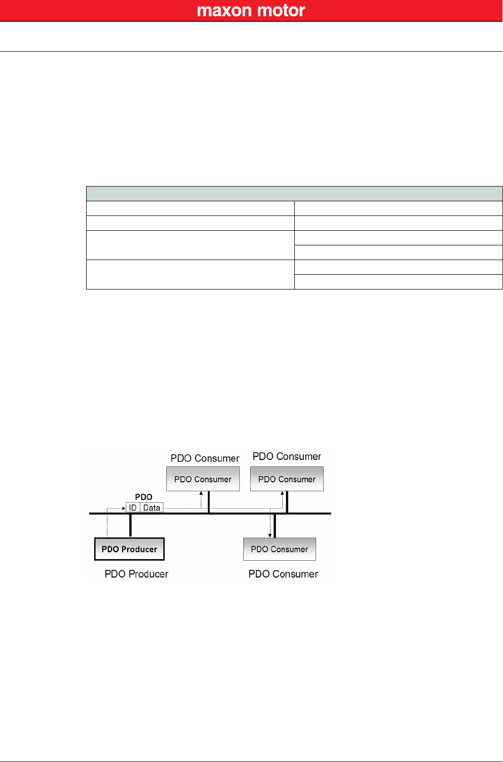
PDO communication can be described by the producer/consumer model. Process data can be transmit-
ted from one device (producer) to one another device (consumer) or to numerous other devices (broad-
casting). PDOs are transmitted in a non-confirmed mode. The producer sends a Transmit PDO
(TxPDO) with a specific identifier that corresponds to the identifier of the Receive PDO (RxPDO) of one
or more consumers.
Figure 6-18 CAN Communication – Process Data Object
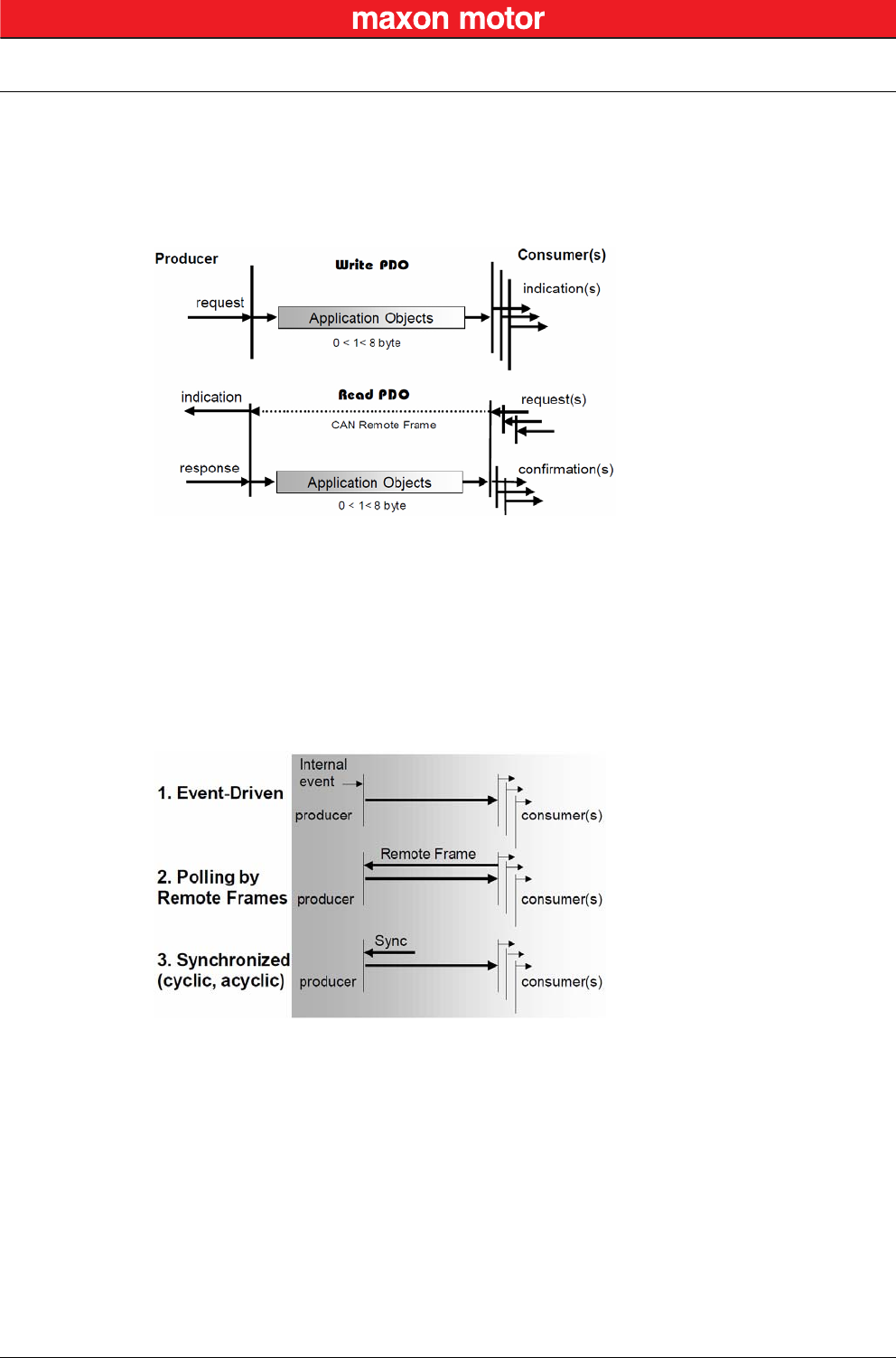
There are two PDO services:
• The Write PDO is mapped to a single CAN Data frame.
• The Read PDO is mapped to CAN Remote Frame, which will be responded by the corresponding
CAN Data Frame.
Read PDOs are optional and depend on the device capability. The complete data field of up to 8 byte
may contain process data. Number and length of a device’s PDOs are application-specific and must be
specified in the device profile.
Communication Objects
Process Data Objects (PDO)
Service Data Objects (SDO)
Special Function Objects
Synchronization Objects (SYNC)
Time Stamp Objects (not used on EPOS2)
Emergency Objects (EMCY)
Network Management Objects NMT Message
Node Guarding Object
CAN Communication
CANopen Application Layer
© 2016 maxon motor. Subject to change without prior notice.
maxon motor control
EPOS2 Positioning Controllers Document ID: rel5984 6-35
EPOS2 Communication Guide Edition: May 2016
The number of supported PDOs is accessible at the Object Dictionary’s index 1004h. The PDOs corre-
spond to entries in the Object Dictionary and serve as interface to application objects. Application
objects’ data type and mapping into a PDO is determined by a corresponding default PDO mapping
structure within the Object Dictionary. This structure is defined in the entries “1600h” (for the first
R_PDO) and “1A00h” (for the first T_PDO). In a CANopen network, up to 512 T_PDOs and 512
R_PDOs may be used.
Figure 6-19 CAN Communication – PDO Protocol
The CANopen communication profile distinguishes three message triggering modes:
a) Message transmission is triggered by the occurrence of an object-specific event specified in
the device profile.
b) The transmission of asynchronous PDOs may be initiated upon receipt of a remote request
initiated by another device.
c) Synchronous PDOs are triggered by the expiration of a specified transmission period syn-
chronized by the reception of the SYNC object.
Figure 6-20 CAN Communication – PDO Communication Modes
CAN Communication
CANopen Application Layer
© 2016 maxon motor. Subject to change without prior notice.
maxon motor control
6-36 Document ID: rel5984 EPOS2 Positioning Controllers
Edition: May 2016 EPOS2 Communication Guide
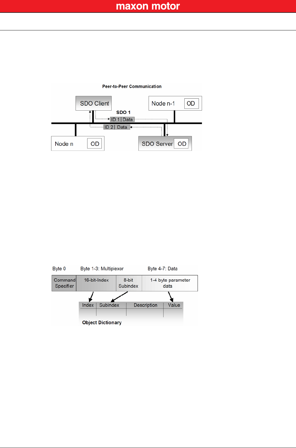
6.3.3.2 SDO Object
With Service Data Objects (SDOs), the access to entries of a device Object Dictionary is provided. A
SDO is mapped to two CAN Data Frames with different identifiers, because communication is con-
firmed. By means of a SDO, a peer-to-peer communication channel between two devices may be estab-
lished. The owner of the accessed Object Dictionary is the server of the SDO. A device may support
more than one SDO, one supported SDO is mandatory and the default case.
Figure 6-21 CAN Communication – Service Data Object
Read and write access to the CANopen Object Dictionary is performed by SDOs. The Client/Server
Command Specifier contains the following information:
• download/upload
• request/response
• segmented/expedited transfer
• number of data bytes
• end indicator
• alternating toggle bit for each subsequent segment
SDOs are described by the communication parameter. The default Server SDO (S_SDO) is defined in
the entry “1200h”. In a CANopen network, up to 256 SDO channels requiring two CAN identifiers each
may be used.
Figure 6-22 CAN Communication – Object Dictionary Access
CAN Communication
CANopen Application Layer
© 2016 maxon motor. Subject to change without prior notice.
maxon motor control
EPOS2 Positioning Controllers Document ID: rel5984 6-37
EPOS2 Communication Guide Edition: May 2016
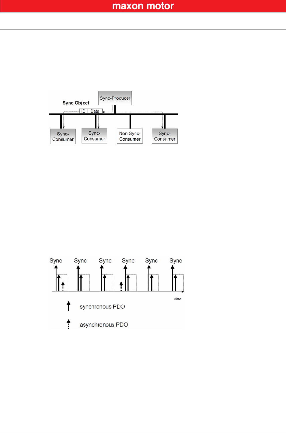
6.3.3.3 SYNC Object
The SYNC producer provides the synchronization signal for the SYNC consumer.
As the SYNC consumers receive the signal, they will commence carrying out their synchronous tasks. In
general, fixing of the transmission time of synchronous PDO messages coupled with the periodicity of
the SYNC Object’s transmission guarantees that sensors may arrange sampling of process variables
and that actuators may apply their actuation in a coordinated manner. The identifier of the SYNC Object
is available at index “1005h”.
Figure 6-23 CAN Communication – Synchronization Object
Synchronous transmission of a PDO means that the transmission is fixed in time with respect to the
transmission of the SYNC Object. The synchronous PDO is transmitted within a given time window “syn-
chronous window length” with respect to the SYNC transmission and, at the most, once for every period
of the SYNC. The time period between SYNC objects is specified by the parameter “communication
cycle period”.
CANopen distinguishes the following transmission modes:
• synchronous transmission
• asynchronous transmission
Synchronous PDOs are transmitted within the synchronous window after the SYNC object. The priority
of synchronous PDOs is higher than the priority of asynchronous PDOs.
Asynchronous PDOs and SDOs can be transmitted at every time with respect to their priority. Hence,
they may also be transmitted within the synchronous window.
Figure 6-24 CAN Communication – Synchronous PDO
CAN Communication
CANopen Application Layer
© 2016 maxon motor. Subject to change without prior notice.
maxon motor control
6-38 Document ID: rel5984 EPOS2 Positioning Controllers
Edition: May 2016 EPOS2 Communication Guide
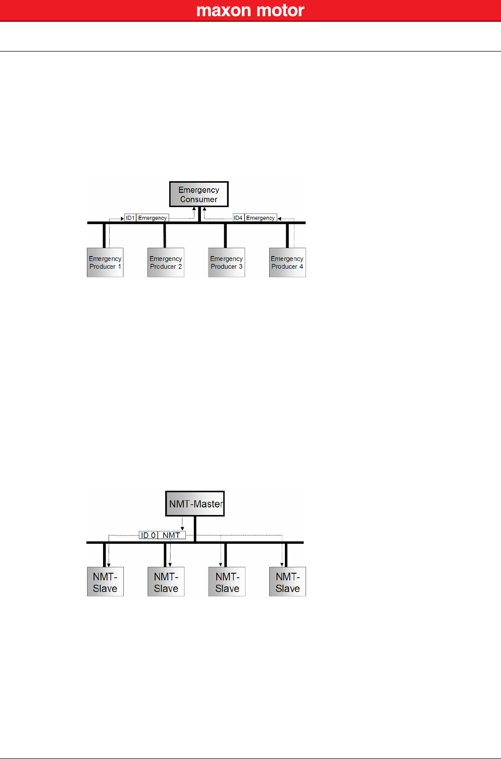
6.3.3.4 EMERGENCY Object
Emergency messages are triggered by the occurrence of a device internal fatal error. They are transmit-
ted by the concerned device to the other devices with high priority, thus making them suitable for inter-
rupt type error alerts.
An Emergency Telegram may be sent only once per “error event”, i.e. the emergency messages must
not be repeated. As long as no new errors occur on a Enter Pre-Operational device, no further emer-
gency message must be sent. The error register as well as additional, device-specific information are
specified in the device profiles by means of emergency error codes defined as to CANopen Communi-
cation Profile.
Figure 6-25 CAN Communication – Emergency Service
6.3.3.5 NMT Services
The CANopen network management is node-oriented and follows a master/slave structure. It requires
one device in the network that fulfils the function of the NMT Master. The other nodes are NMT Slaves.
Network management provides the following functionality groups:
• Module Control Services for initialization of NMT Slaves that want to take part in the distributed
application.
• Error Control Services for supervision of nodes’ and network’s communication status.
• Configuration Control Services for up/downloading of configuration data from/to a network mod-
ule.
A NMT Slave represents that part of a node, which is responsible for the node’s NMT functionality. It is
uniquely identified by its module ID.
Figure 6-26 CAN Communication – Network Management (NMT)
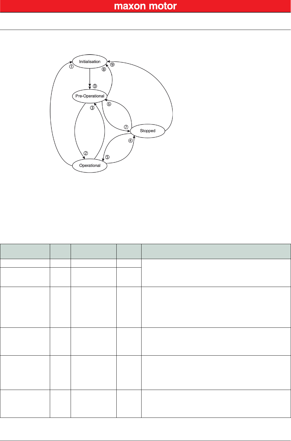
The CANopen NMT Slave devices implement a state machine that automatically brings every device to
“Pre-Operational” state, once powered and initialized.
In “Pre-Operational” state, the node may be configured and parameterized via SDO (e.g. using a config-
uration tool), PDO communication is not permitted. The NMT Master may switch from “Pre-Operational”
to “Operational”, and vice versa.
In “Operational” state, PDO transfer is permitted. By switching a device into “Stopped” state it will be
forced to stop PDO and SDO communication. Furthermore, “Operational” can be used to achieve cer-
tain application behavior. The behavior's definition is part of the device profile’s scope. In “Operational”,
all communication objects are active. Object Dictionary access via SDO is possible. However, imple-
mentation aspects or the application state machine may require to switching off or to read only certain
CAN Communication
CANopen Application Layer
© 2016 maxon motor. Subject to change without prior notice.
maxon motor control
EPOS2 Positioning Controllers Document ID: rel5984 6-39
EPOS2 Communication Guide Edition: May 2016
application objects while being operational (e.g. an object may contain the application program, which
cannot be changed during execution).
Figure 6-27 CAN Communication – NMT Slave State Diagram
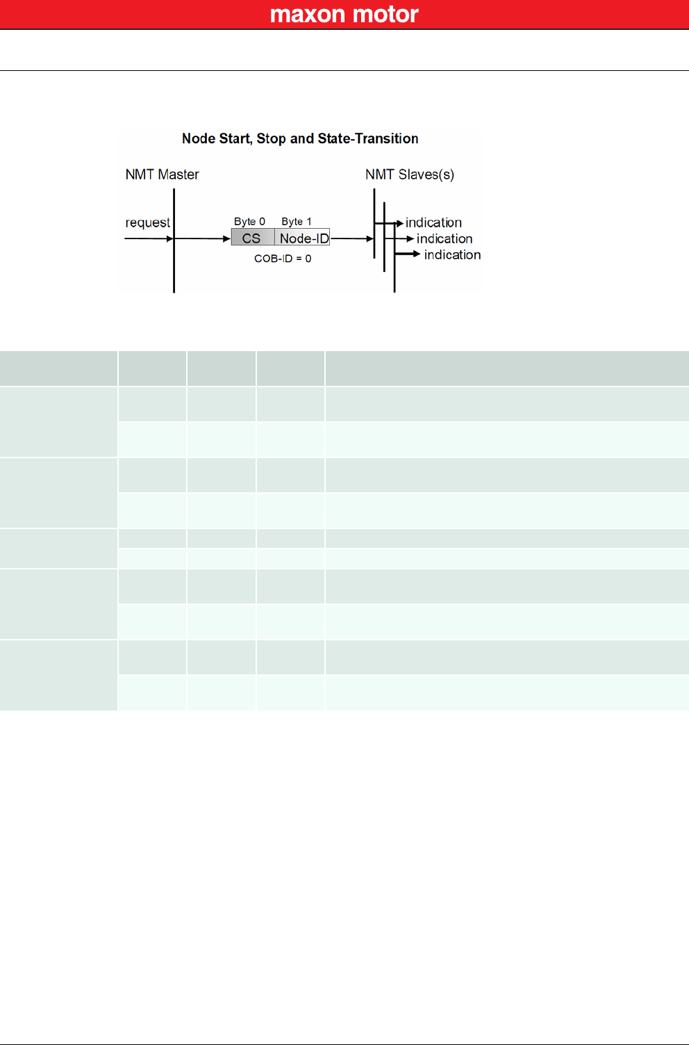
CANopen Network Management provides the following five services, which can be distinguished by the
Command Specifier (CS).
Remarks:
*1) Command may be sent with Network Management (NMT) Protocol.
*2) This Transition is generated automatically by the EPOS2 after initialization is completed.
After initialization a Boot-Up message is send.
*3) Remote flag Bit 9 of the Statusword.
Table 6-15 CAN Communication – NMT Slave (Commands, Transitions and States)
Service
*1
Transi-
tion NMT State after
Command Remote
*3 Functionality
–*2 0 Pre-Operational FALSE Communication:
– Service Data Objects (SDO) Protocol
– Emergency Objects
– Network Management (NMT) Protocol
Enter
Pre-Operational 3, 6 Pre-Operational FALSE
Reset
Communication 1, 8, 9 Initialization
(Pre-Operational) FALSE
Calculates SDO COB-IDs.
Setup Dynamic PDO-Mapping and calculates PDO COB-IDs.
Communication:
– While initialization is active, no communication is supported.
– Upon completion, a boot-up message will be sent to the
CAN Bus.
Reset Node 1, 8, 9 Initialization
(Pre-Operational) FALSE
Generates a general reset of EPOS2 software having same
effect as turning off and on the supply voltage. Not saved
parameters will be overwritten with values saved to the
EEPROM using «Save all Parameters».
Start Remote Node 2, 5 Operational TRUE
Communication:
– Service Data Objects (SDO) Protocol
– Process Data Objects (PDO) Protocol
– Emergency Objects
– Network Management (NMT) Protocol
Stop Remote Node 4, 7 Stopped FALSE
Communication:
– Network Management (NMT) Protocol
– Layer setting services (LSS)
– Lifeguarding (Heartbeating)
CAN Communication
CANopen Application Layer
© 2016 maxon motor. Subject to change without prior notice.
maxon motor control
6-40 Document ID: rel5984 EPOS2 Positioning Controllers
Edition: May 2016 EPOS2 Communication Guide
The communication object possesses the identifier (=0) and consists of two bytes. The Node ID defines
the destination of the message. If zero, the protocol addresses all NMT Slaves.
Figure 6-28 CAN Communication – NMT Object
Table 6-16 CAN Communication – NMT Protocols
Protocol COB-ID CS
(Byte 0) Node ID
(Byte 1) Functionality
Enter
Pre-Operational
00x80 0 (all) All CANopen nodes (EPOS2 devices) will enter NMT State “Pre-
Operational”.
00x80 nThe CANopen node (EPOS2 device) with Node ID “n” will enter
NMT State “Pre-Operational”.
Reset
Communication
00x82 0 (all) All CANopen nodes (EPOS2 devices) will reset the
communication.
00x82 nThe CANopen node (EPOS2 device) with Node ID “n” will reset
the communication.
Reset Node 00x81 0 (all) All CANopen nodes (EPOS2 devices) will reset.
00x81 nThe CANopen node (EPOS2 device) with Node ID “n” will reset.
Start Remote Node
00x01 0 (all) All CANopen nodes (EPOS2 devices) will enter NMT State
“Operational”.
00x01 nThe CANopen node (EPOS2 device) with Node ID “n” will enter
NMT State “Operational”.
Stop Remote Node
00x02 0 (all) All CANopen nodes (EPOS2 devices) will enter NMT State
“Stopped”.
00x02 nThe CANopen node (EPOS2 device) with Node ID “n” will enter
NMT State “Stopped”.
CAN Communication
CANopen Application Layer
© 2016 maxon motor. Subject to change without prior notice.
maxon motor control
EPOS2 Positioning Controllers Document ID: rel5984 6-41
EPOS2 Communication Guide Edition: May 2016
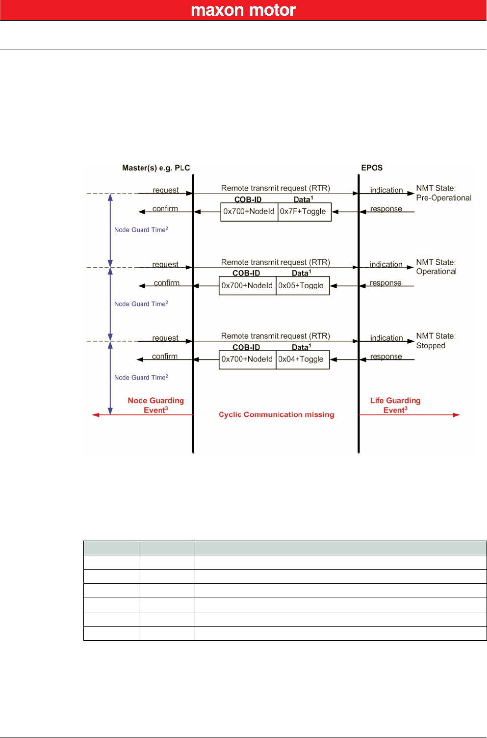
6.3.3.6 Node Guarding Protocol
Used to detect absent devices that do not transmit PDOs regularly (e.g. due of “bus off”). The NMT Mas-
ter can manage “Node Guarding”, a database where, among other information, expected states of all
connected devices are recorded. With cyclic Node Guarding, the NMT Master regularly polls its NMT
Slaves. To detect the absence of the NMT Master, the slaves test internally, whether Node Guarding is
taking place in the defined time interval (Life Guarding).
Node Guarding is initiated by the NMT Master (in “Pre-Operational” state of the slaves) by transmitting a
Remote Frame. Node Guarding is also activated if “Stopped” state is active.
Legend: 1) Data Field / 2) Node Guard Time / 3) Node/Life Guarding Event
Figure 6-29 CAN Communication – Node Guarding Protocol (Timing Diagram)
Data Field
Holds the NMT State. Upon receipt of a node guard answer, bit 8 toggles between 0x00 and 0x80. Thus,
the data field supports the following values:
Table 6-17 CAN Communication – Node Guarding Protocol (Data Field)
Node Guard Time
Is calculated as follows:
Value Toggle EPOS2 NMT State
0x04 not set Stopped
0x84 set Stopped
0x05 not set Operational
0x85 set Operational
0x7F not set Pre-Operational
0xFF set Pre-Operational
NodeGuardTime GuardTime LifeTimeFactor⋅=
CAN Communication
CANopen Application Layer
© 2016 maxon motor. Subject to change without prior notice.
maxon motor control
6-42 Document ID: rel5984 EPOS2 Positioning Controllers
Edition: May 2016 EPOS2 Communication Guide
Node / Life Guarding Event
In case EPOS2 misses the Remote Transmit Request (RTR), it will change it’s device state to “Error”
(Node Guarding Error).
In case the answer is missed by the Master System, it may react with the Node Guarding Event.
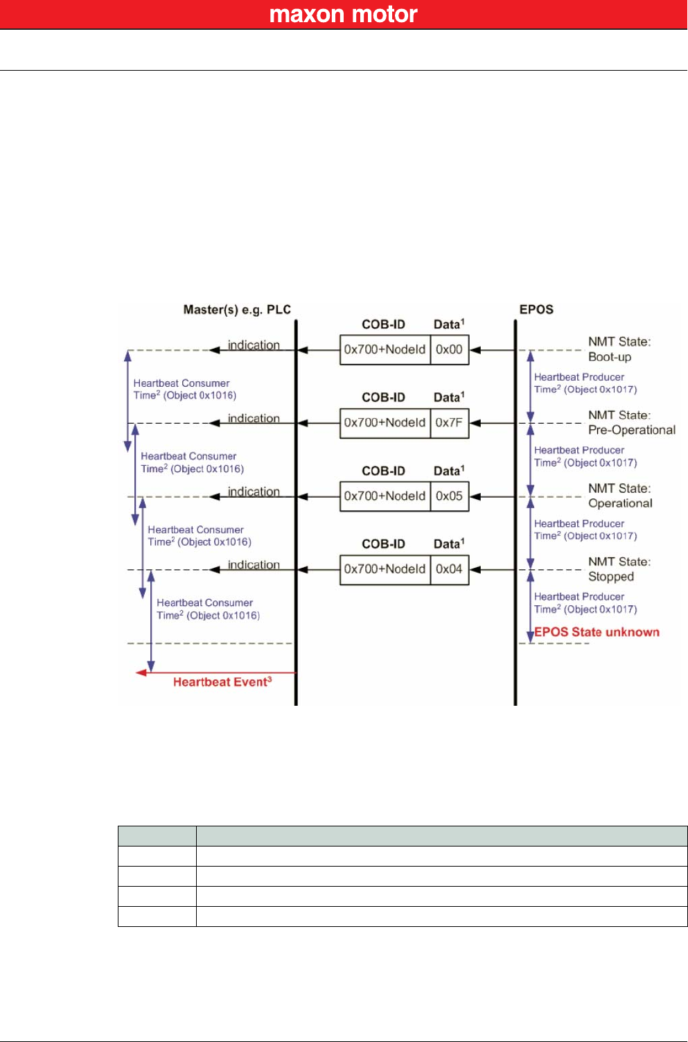
6.3.3.7 Heartbeat Protocol
The Heartbeat Protocol has a higher priority than the Node Guarding Protocol. If both are enabled, only
the Heartbeat Protocol is supported. The EPOS2 transmits a cyclic heartbeat message if the Heartbeat
Protocol is enabled (Heartbeat Producer Time 0 = Disabled / greater than 0 = enabled). The Heartbeat
Consumer guards receipt of the Heartbeat within the Heartbeat Consumer Time. If the Heartbeat Pro-
ducer Time is configured in EPOS2, it will start immediately with the Heartbeat Protocol.
Legend: 1) Data Field / 2) Heartbeat Producer and Heartbeat Consumer Time / 3) Hearbeat Event
Figure 6-30 CAN Communication – Heartbeat Protocol (Timing Diagram)
Data Field
Holds the NMT State. Each time the value of toggle between 0x00 and 0x80. Therefore the following
values for the data field are possible:
Table 6-18 CAN Communication – Heartbeat Protocol (Data Field)
Value EPOS2 NMT State
0x00 Bootup
0x04 Stopped
0x05 Operational
0x7F Pre-Operational
CAN Communication
Identifier Allocation Scheme
© 2016 maxon motor. Subject to change without prior notice.
maxon motor control
EPOS2 Positioning Controllers Document ID: rel5984 6-43
EPOS2 Communication Guide Edition: May 2016
Heartbeat Producer Time and Heartbeat Consumer Time
The Heartbeat Consumer Time must be longer than the Heartbeat Producer Time because of genera-
tion, sending and indication time ( ). Each
indication of the Master resets the Heartbeat Consumer Time.
Heartbeat Event
If EPOS2 is in an unknown state (e.g. supply voltage failure), the Heartbeat Protocol cannot be sent to
the Master. The Master will recognize this event upon elapsed Heartbeat Consumer Time and will gen-
erate a Heartbeat Event.
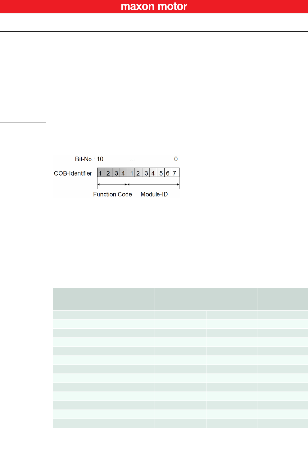
6.4 Identifier Allocation Scheme
The default ID allocation scheme consists of a functional part (Function Code) and a Module ID, which
allows distinguishing between devices. The Module ID is assigned by DIP switches and a SDO Object.
Figure 6-31 CAN Communication – Default Identifier Allocation Scheme
This ID allocation scheme allows peer-to-peer communication between a single master device and up to
127 slave devices. It also supports broadcasting of non-confirmed NMT Services, SYNC and Node
Guarding.
The predefined master/slave connection set supports…
• one emergency object,
• one SDO,
• four Receive PDOs and three Transmit PDOs and the
• node guarding object.
Table 6-19 CAN Communication – Objects of the Default Connection Set
HeartbeatConsumerTime HeartbeatProducerTime 5ms+≥
Object Function Code
(binary) Resulting COB-ID Communication
Parameter at
Index
NMT 0000 0 –
SYNC 0001 128 (0080h) 1005h
EMERGENCY 129…255 (0081h-00FFh) 1014h
PDO1 (tx) 0011 385…511 (0181h-01FFh) 1800h
PDO1 (rx) 0100 513…639 (0201h-027Fh) 1400h
PDO2 (tx) 0101 641…8767 (0281h-02FFh) 1801h
PDO2 (rx) 0110 769…895 (0301h-037Fh) 1401h
PDO3 (tx) 0111 897…1023 (0381h-03FFh) 1802h
PDO3 (rx) 1000 1025…1151 (0401h-047Fh) 1402h
PDO4 (tx) 1001 1153…1279 (0481h-04FFh) 1803h
PDO4 (rx) 1010 1281…1407 (0501h-057Fh) 1403h
SDO1 (tx) 1011 1409…1535 (0581h-05FFh) 1200h
SDO1 (rx) 1100 1537…1663 (0601h-067Fh) 1200h

CAN Communication
Identifier Allocation Scheme
© 2016 maxon motor. Subject to change without prior notice.
maxon motor control
6-44 Document ID: rel5984 EPOS2 Positioning Controllers
Edition: May 2016 EPOS2 Communication Guide
••page intentionally left blank••
Gateway Communication (USB & RS232 to CAN)
© 2016 maxon motor. Subject to change without prior notice.
maxon motor control
EPOS2 Positioning Controllers Document ID: rel5984 7-45
EPOS2 Communication Guide Edition: May 2016
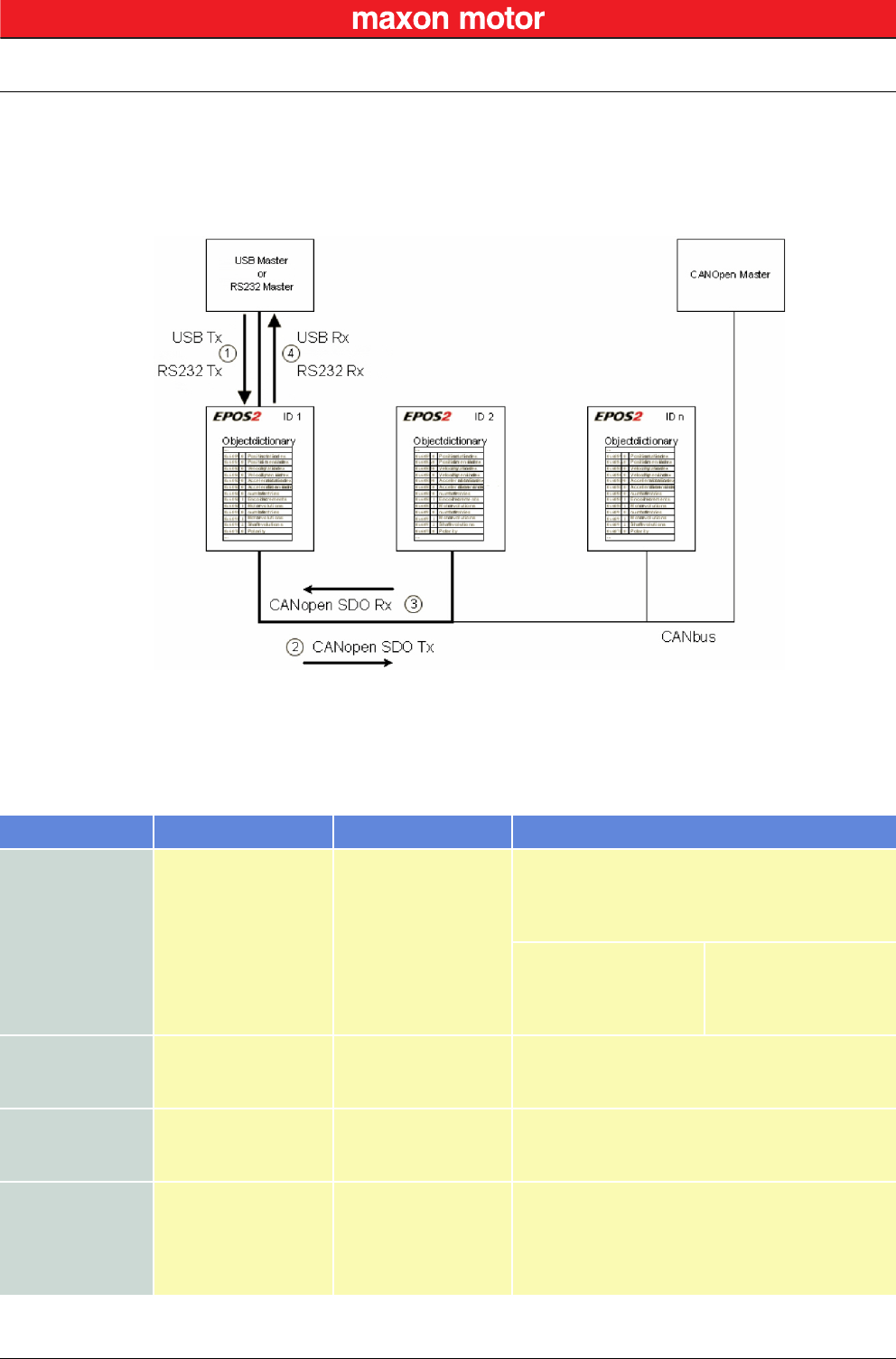
7 Gateway Communication (USB & RS232 to CAN)
Using the gateway functionality, the master can access all other EPOS2 devices connected to the CAN
Bus via the gateway device’s USB port or RS232 interface. Even other CANopen devices (I/O modules)
supporting the CANopen standard CiA 301 may be accessed.
Figure 7-32 Gateway Communication – Structure
Communication data are exchanged between USB/RS232 master and the gateway using a maxon-spe-
cific USB/RS232 protocol.
Data between the gateway and the addressed device are exchanged using the CANopen SDO protocol
according to the CiA 301.
Table 7-20 Gateway Communication – Data Exchange
Step Protocol Sender Receiver Description
1
USB
[maxon-specific]
or
RS232
[maxon-specific]
USB or RS232
Master
EPOS2 ID 1, Gateway
Command including the node ID is sent to the
device working as a gateway. The gateway decides
whether to execute the command or to translate
and forward it to the CAN Bus.
Criteria:
Node ID = 0 (Gateway)
Node ID = DIP switch
else
Execute
Execute
Forward to CAN
2CANopen [SDO]
EPOS2 ID 1, Gateway
EPOS2 ID 2
The gateway is forwarding the command to the
CAN network. The USB/RS232 command is
translated to a CANopen SDO service.
3CANopen [SDO]
EPOS2 ID 2
EPOS2 ID 1, Gateway
The EPOS2 ID 2 is executing the command and
sending the corresponding CAN frame back to the
gateway.
4
USB
[maxon-specific]
or
RS232
[maxon-specific]
EPOS2 ID 1, Gateway
USB or RS232 Master
The gateway is receiving the CAN frame
corresponding to the SDO service. This CAN frame
is translated back to the USB/RS232 frame and
sent back to the USB/RS232 master.

Gateway Communication (USB & RS232 to CAN)
© 2016 maxon motor. Subject to change without prior notice.
maxon motor control
7-46 Document ID: rel5984 EPOS2 Positioning Controllers
Edition: May 2016 EPOS2 Communication Guide
••page intentionally left blank••
Error Code Definition
CANopen-specific Error Codes
© 2016 maxon motor. Subject to change without prior notice.
maxon motor control
EPOS2 Positioning Controllers Document ID: rel5984 8-47
EPOS2 Communication Guide Edition: May 2016
8 Error Code Definition
8.1 CANopen-specific Error Codes
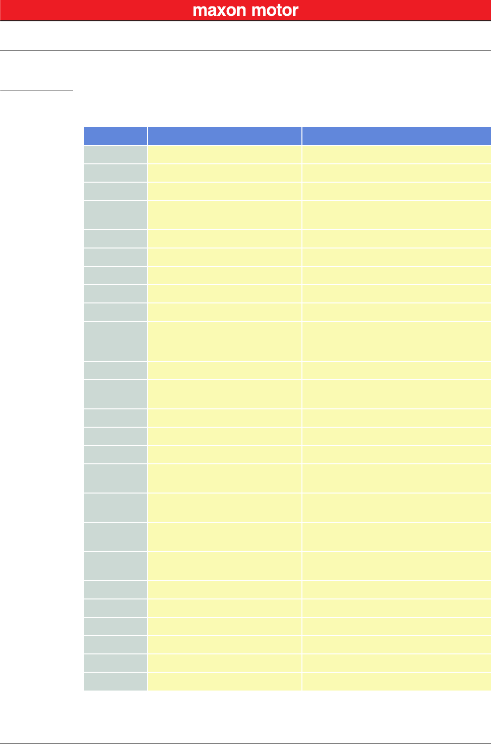
Following error codes are defined by CANopen CiA 301 Communication Profile for Industrial Systems:
Error Code Name Cause
0x0000 0000 No Communication Error RS232 communication successful
0x0503 0000 Toggle Error Toggle bit not alternated
0x0504 0000 SDO Time Out SDO protocol timed out
0x0504 0001 Client / Server Specifier Error Client / server command specifier not valid or
unknown
0x0504 0004 CRC Error CRC
0x0504 0005 Out of Memory Error Out of memory
0x0601 0000 Access Error Unsupported access to an object
0x0601 0001 Write Only Error Read command to a write only object
0x0601 0002 Read Only Error Write command to a read only object
0x0602 0000 Object does not exist Error
Object does not exist in Object Directory. Last
read or write command had wrong object
Index or SubIndex
0x0604 0041 PDO mapping Error Object cannot be mapped to the PDO
0x0604 0042 PDO Length Error Number and length of objects to be mapped
would exceed PDO length
0x0604 0043 General Parameter Error General parameter incompatibility
0x0604 0047 General internal Incompatibility Error General internal incompatibility in device
0x0606 0000 Hardware Error Access failed due to hardware error
0x0607 0010 Service Parameter Error Data type does not match, length or service
parameter does not match
0x0607 0012 Service Parameter too long Error Data type does not match, length of service
parameter too high
0x0607 0013 Service Parameter too short Error Data type does not match, length of service
parameter too low
0x0609 0011 Object SubIndex Error Last read or write command had wrong object
SubIndex
0x0609 0030 Value Range Error Value range of parameter exceeded
0x0609 0031 Value too high Error Value of parameter written too high
0x0609 0032 Value too low Error Value of parameter written too low
0x0609 0036 Maximum less Minimum Error Maximum value is less than minimum value
0x0800 0000 General Error General error
0x0800 0020 Transfer or Store Error Data cannot be transferred or stored
Error Code Definition
maxon-specific Error Codes
© 2016 maxon motor. Subject to change without prior notice.
maxon motor control
8-48 Document ID: rel5984 EPOS2 Positioning Controllers
Edition: May 2016 EPOS2 Communication Guide
Table 8-21 Communication Errors – CANopen-specific Error Codes
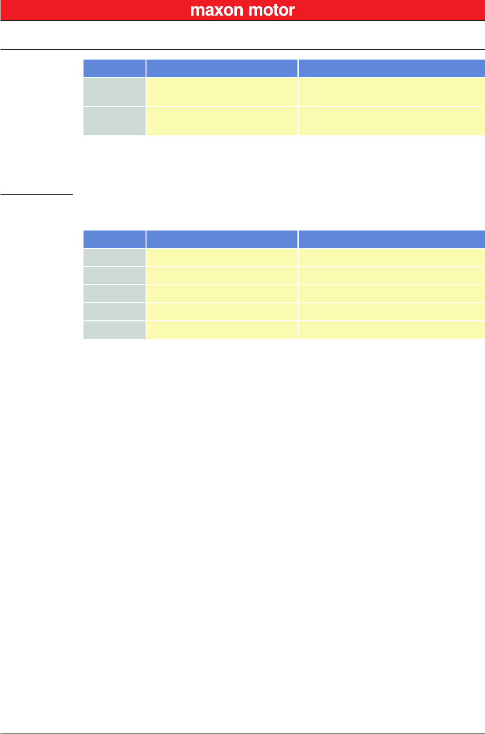
8.2 maxon-specific Error Codes
Following error codes are specific to maxon’s EPOS2 devices:
Table 8-22 Communication Errors – maxon-specific Error Codes
0x0800 0021 Local Control Error Data cannot be transferred or stored to
application because of local control
0x0800 0022 Wrong Device State Data cannot be transferred or stored to
application because of present device state
Error Code Name Cause
Error Code Name Cause
0x0F00 FFC0 Wrong NMT State Error Device is in wrong NMT state
0x0F00 FFBF Illegal Command Error RS232 command is illegal (does not exist)
0x0F00 FFBE Password Error Password is incorrect
0x0F00 FFBC Service Mode Error Device is not in service mode
0x0F00 FFB9 CAN ID Error Wrong CAN ID

maxon motor control
EPOS2 Positioning Controllers Document ID: rel5984 Z-49
EPOS2 Communication Guide Edition: May 2016
© 2016 maxon motor. Subject to change without prior notice.
Figure 2-1 Documentation Structure . . . . . . . . . . . . . . . . . . . . . . . . . . . . . . . . . . . . . . . . . . . . . . . . . . . . . . . . . . . . . . . . .7
Figure 4-2 USB Communication – Command Sequence. . . . . . . . . . . . . . . . . . . . . . . . . . . . . . . . . . . . . . . . . . . . . . . . .15
Figure 4-3 USB Communication – Sending a Data Frame to EPOS2 . . . . . . . . . . . . . . . . . . . . . . . . . . . . . . . . . . . . . . .15
Figure 4-4 USB Communication – Receiving a Response Data Frame from EPOS2 . . . . . . . . . . . . . . . . . . . . . . . . . . .15
Figure 4-5 USB Communication – Frame Structure . . . . . . . . . . . . . . . . . . . . . . . . . . . . . . . . . . . . . . . . . . . . . . . . . . . .16
Figure 4-6 USB Communication – CRC Calculation . . . . . . . . . . . . . . . . . . . . . . . . . . . . . . . . . . . . . . . . . . . . . . . . . . . .17
Figure 4-7 USB Communication – Slave State Machine . . . . . . . . . . . . . . . . . . . . . . . . . . . . . . . . . . . . . . . . . . . . . . . . .19
Figure 5-8 RS232 Communication – Command Sequence . . . . . . . . . . . . . . . . . . . . . . . . . . . . . . . . . . . . . . . . . . . . . . .21
Figure 5-9 RS232 Communication – Sending a Data Frame to EPOS2 . . . . . . . . . . . . . . . . . . . . . . . . . . . . . . . . . . . . .22
Figure 5-10 RS232 Communication – Receiving a Response Data Frame from EPOS2 . . . . . . . . . . . . . . . . . . . . . . . . .22
Figure 5-11 RS232 Communication – Frame Structure. . . . . . . . . . . . . . . . . . . . . . . . . . . . . . . . . . . . . . . . . . . . . . . . . . .23
Figure 5-12 RS232 Communication – CRC-CCITT Calculation . . . . . . . . . . . . . . . . . . . . . . . . . . . . . . . . . . . . . . . . . . . .24
Figure 5-13 RS232 Communication – Slave State Machine . . . . . . . . . . . . . . . . . . . . . . . . . . . . . . . . . . . . . . . . . . . . . . .26
Figure 6-14 CAN Communication – Protocol Layer Interactions . . . . . . . . . . . . . . . . . . . . . . . . . . . . . . . . . . . . . . . . . . . .31
Figure 6-15 CAN Communication – ISO 11898 Basic Network Setup. . . . . . . . . . . . . . . . . . . . . . . . . . . . . . . . . . . . . . . .31
Figure 6-16 CAN Communication – CAN Data Frame. . . . . . . . . . . . . . . . . . . . . . . . . . . . . . . . . . . . . . . . . . . . . . . . . . . .32
Figure 6-17 CAN Communication – Standard Frame Format . . . . . . . . . . . . . . . . . . . . . . . . . . . . . . . . . . . . . . . . . . . . . .32
Figure 6-18 CAN Communication – Process Data Object . . . . . . . . . . . . . . . . . . . . . . . . . . . . . . . . . . . . . . . . . . . . . . . . .34
Figure 6-19 CAN Communication – PDO Protocol . . . . . . . . . . . . . . . . . . . . . . . . . . . . . . . . . . . . . . . . . . . . . . . . . . . . . .35
Figure 6-20 CAN Communication – PDO Communication Modes. . . . . . . . . . . . . . . . . . . . . . . . . . . . . . . . . . . . . . . . . . .35
Figure 6-21 CAN Communication – Service Data Object . . . . . . . . . . . . . . . . . . . . . . . . . . . . . . . . . . . . . . . . . . . . . . . . .36
Figure 6-22 CAN Communication – Object Dictionary Access . . . . . . . . . . . . . . . . . . . . . . . . . . . . . . . . . . . . . . . . . . . . .36
Figure 6-23 CAN Communication – Synchronization Object . . . . . . . . . . . . . . . . . . . . . . . . . . . . . . . . . . . . . . . . . . . . . . .37
Figure 6-24 CAN Communication – Synchronous PDO . . . . . . . . . . . . . . . . . . . . . . . . . . . . . . . . . . . . . . . . . . . . . . . . . .37
Figure 6-25 CAN Communication – Emergency Service . . . . . . . . . . . . . . . . . . . . . . . . . . . . . . . . . . . . . . . . . . . . . . . . . .38
Figure 6-26 CAN Communication – Network Management (NMT) . . . . . . . . . . . . . . . . . . . . . . . . . . . . . . . . . . . . . . . . . .38
Figure 6-27 CAN Communication – NMT Slave State Diagram . . . . . . . . . . . . . . . . . . . . . . . . . . . . . . . . . . . . . . . . . . . .39
Figure 6-28 CAN Communication – NMT Object . . . . . . . . . . . . . . . . . . . . . . . . . . . . . . . . . . . . . . . . . . . . . . . . . . . . . . . .40
Figure 6-29 CAN Communication – Node Guarding Protocol (Timing Diagram). . . . . . . . . . . . . . . . . . . . . . . . . . . . . . . .41
Figure 6-30 CAN Communication – Heartbeat Protocol (Timing Diagram) . . . . . . . . . . . . . . . . . . . . . . . . . . . . . . . . . . . .42
Figure 6-31 CAN Communication – Default Identifier Allocation Scheme . . . . . . . . . . . . . . . . . . . . . . . . . . . . . . . . . . . . .43
Figure 7-32 Gateway Communication – Structure. . . . . . . . . . . . . . . . . . . . . . . . . . . . . . . . . . . . . . . . . . . . . . . . . . . . . . .45
LIST OF FIGURES

maxon motor control
Z-50 Document ID: rel5984 EPOS2 Positioning Controllers
Edition: May 2016 EPOS2 Communication Guide
© 2016 maxon motor. Subject to change without prior notice.
Table 1-1 Notations used in this Document . . . . . . . . . . . . . . . . . . . . . . . . . . . . . . . . . . . . . . . . . . . . . . . . . . . . . . . . . . . 5
Table 1-2 Sources for additional Information . . . . . . . . . . . . . . . . . . . . . . . . . . . . . . . . . . . . . . . . . . . . . . . . . . . . . . . . . . 6
Table 4-3 USB Communication – Timeout Handling . . . . . . . . . . . . . . . . . . . . . . . . . . . . . . . . . . . . . . . . . . . . . . . . . . . 18
Table 4-4 ReadObject “Home Offset”. . . . . . . . . . . . . . . . . . . . . . . . . . . . . . . . . . . . . . . . . . . . . . . . . . . . . . . . . . . . . . . 20
Table 4-5 Answer to ReadObject “Home Offset” . . . . . . . . . . . . . . . . . . . . . . . . . . . . . . . . . . . . . . . . . . . . . . . . . . . . . . 20
Table 5-6 RS232 Communication – Timeout Handling . . . . . . . . . . . . . . . . . . . . . . . . . . . . . . . . . . . . . . . . . . . . . . . . . 25
Table 5-7 ReadObject “Software Version” . . . . . . . . . . . . . . . . . . . . . . . . . . . . . . . . . . . . . . . . . . . . . . . . . . . . . . . . . . . 27
Table 5-8 Answer to ReadObject “Software Version”. . . . . . . . . . . . . . . . . . . . . . . . . . . . . . . . . . . . . . . . . . . . . . . . . . . 27
Table 6-9 CAN Communication – Notations. . . . . . . . . . . . . . . . . . . . . . . . . . . . . . . . . . . . . . . . . . . . . . . . . . . . . . . . . . 29
Table 6-10 CAN Communication – Abbreviations . . . . . . . . . . . . . . . . . . . . . . . . . . . . . . . . . . . . . . . . . . . . . . . . . . . . . . 29
Table 6-11 CAN Communication – Terms . . . . . . . . . . . . . . . . . . . . . . . . . . . . . . . . . . . . . . . . . . . . . . . . . . . . . . . . . . . . 30
Table 6-12 CAN Communication – Object Dictionary Layout. . . . . . . . . . . . . . . . . . . . . . . . . . . . . . . . . . . . . . . . . . . . . . 33
Table 6-13 CAN Communication – Object Dictionary Entry . . . . . . . . . . . . . . . . . . . . . . . . . . . . . . . . . . . . . . . . . . . . . . . 33
Table 6-14 CAN Communication – Communication Objects . . . . . . . . . . . . . . . . . . . . . . . . . . . . . . . . . . . . . . . . . . . . . . 34
Table 6-15 CAN Communication – NMT Slave (Commands, Transitions and States) . . . . . . . . . . . . . . . . . . . . . . . . . . 39
Table 6-16 CAN Communication – NMT Protocols . . . . . . . . . . . . . . . . . . . . . . . . . . . . . . . . . . . . . . . . . . . . . . . . . . . . . 40
Table 6-17 CAN Communication – Node Guarding Protocol (Data Field) . . . . . . . . . . . . . . . . . . . . . . . . . . . . . . . . . . . . 41
Table 6-18 CAN Communication – Heartbeat Protocol (Data Field) . . . . . . . . . . . . . . . . . . . . . . . . . . . . . . . . . . . . . . . . 42
Table 6-19 CAN Communication – Objects of the Default Connection Set . . . . . . . . . . . . . . . . . . . . . . . . . . . . . . . . . . . 43
Table 7-20 Gateway Communication – Data Exchange. . . . . . . . . . . . . . . . . . . . . . . . . . . . . . . . . . . . . . . . . . . . . . . . . . 45
Table 8-21 Communication Errors – CANopen-specific Error Codes . . . . . . . . . . . . . . . . . . . . . . . . . . . . . . . . . . . . . . . 48
Table 8-22 Communication Errors – maxon-specific Error Codes . . . . . . . . . . . . . . . . . . . . . . . . . . . . . . . . . . . . . . . . . . 48
LIST OF TABLES

maxon motor control
EPOS2 Positioning Controllers Document ID: rel5984 Z-51
EPOS2 Communication Guide Edition: May 2016
© 2016 maxon motor. Subject to change without prior notice.
A
Access Error 47
access to CAN bus via USB or RS232 45
applicable EU directive 2
C
CAN
commands 13
communication 29
error codes 47
CAN (definition) 29
CAN Client (definition) 30
CAN Master (definition) 30
CAN Server (definition) 30
CAN Slave (definition) 30
Client / Server Specifier Error 47
CMS (definition) 29
COB (definition) 29
COB-ID (definition) 29
codes (used in this document) 5
communication via gateway 45
E
EDS (definition) 29
Error CAN ID 48
error codes 47
Error Service Mode 48
EU directive, applicable 2
F
functions
read 9
write 10
G
General Error 47
General internal Incompatibility Error 47
General Parameter Error 47
H
Hardware Error 47
Heartbeat Consumer Time, calculation of 43
how to
read this document 2
I
ID (definition) 29
Illegal Command Error 48
incorporation into surrounding system 2
InitiateSegmentedRead (function) 9
InitiateSegmentedWrite (function) 11
intended purpose 7
L
Life Guarding 41
Local Control Error 48
M
MAC (definition) 29
Maximum less Minimum Error 47
N
NMT State
Heartbeat 42
Node Guarding 41
No Communication Error 47
Node Guard Time, calculation of 41
Node Guarding 41
non-compliance of surrounding system 2
notations (used in this document) 5
O
Object (definition) 30
Object does not exist Error 47
Object SubIndex Error 47
OD (definition) 29
operating license 2
OSI Reference Model 31
other machinery (incorporation into) 2
Out of Memory Error 47
P
Password Error 48
PDO (definition) 29
PDO Length Error 47
PDO mapping Error 47
PLC (definition) 29
prerequisites prior installation 2
purpose
of the device 7
of this document 5
INDEX

maxon motor control
Z-52 Document ID: rel5984 EPOS2 Positioning Controllers
Edition: May 2016 EPOS2 Communication Guide
© 2016 maxon motor. Subject to change without prior notice.
R
ReadLSSFrame (function) 14
ReadObject (function) 9
Receive (definition) 30
RequestCANFrame (function) 13
RO (definition) 29
RS232
command reference 9
communication 21
to CAN Gateway 45
RW (definition) 29
S
SDO (definition) 29
SDO Time Out 47
SegmentedWrite (function) 11
SegmentRead (function) 10
SendCANFrame (function) 13
SendLSSFrame (function) 14
SendNMTService (function) 12
Service Parameter Error 47
Service Parameter too long Error 47
Service Parameter too short Error 47
surrounding system (incorporation into) 2
T
Toggle Error 47
Transfer or store Error 47
Transmit (definition) 30
U
USB
command reference 9
communication 15
to CAN Gateway 45
V
Value Range Error 47
Value too high Error 47
Value too low Error 47
W
WO (definition) 29
Write Only 47
WriteObject (function) 10
Wrong Device State 48
Wrong NMT State Error 48

maxon motor control
EPOS2 Positioning Controllers Document ID: rel5984 Z-53
EPOS2 Communication Guide Edition: May 2016
© 2016 maxon motor. Subject to change without prior notice.
••page intentionally left blank••

maxon motor control
Z-54 Document ID: rel5984 EPOS2 Positioning Controllers
Edition: May 2016 EPOS2 Communication Guide
© 2016 maxon motor. Subject to change without prior notice.
© 2016 maxon motor. All rights reserved.
The present document – including all parts thereof – is protected by copyright. Any use (including reproduction, translation,
microfilming and other means of electronic data processing) beyond the narrow restrictions of the copyright law without the
prior approval of maxon motor ag, is not permitted and subject to persecution under the applicable law.
maxon motor ag
Brünigstrasse 220
P.O.Box 263
CH-6072 Sachseln
Switzerland
Phone +41 41 666 15 00
Fax +41 41 666 16 50
www.maxonmotor.com
