User Manual EPS Rev1.2
User Manual:
Open the PDF directly: View PDF ![]() .
.
Page Count: 21

EPS USER MANUAL
Electrical Power System (EPS)

ENDUROSAT
2
USER MANUAL - EPS
1 Change Log ....................................................................................................................... 3
2 Acronyms List .................................................................................................................... 4
3 Highlighted Features .......................................................................................................... 5
4 System Description ............................................................................................................ 5
5 Block Diagram ................................................................................................................. 11
6 Connector Pinout ............................................................................................................. 11
Connectors Location ............................................................................................................ 12
H1 - Stack Connector ........................................................................................................... 13
H2 - Stack Connector ........................................................................................................... 13
P1 To P6 - Solar Panel Input Connector ................................................................................ 14
KS1 And KS2 – Deployment switches ................................................................................... 14
RBF – Remove Before Flight ................................................................................................. 14
7 Electrical Characteristics .................................................................................................. 15
8 Mechanical Drawing ........................................................................................................ 17
9 Envinronmental And Mechanical Test ............................................................................... 20
10 Handling And Storage ...................................................................................................... 20
11 Warnings ......................................................................................................................... 21
ENDUROSAT
3
USER MANUAL - EPS
ELECTRICAL POWER SYSTEM
(EPS)
USER MANUAL
This user manual is specially designed to detail the EnduroSat Electrical Power System (EPS) description,
functions and features.
Please read this manual before unpacking and using the EPS to ensure safe and proper use.
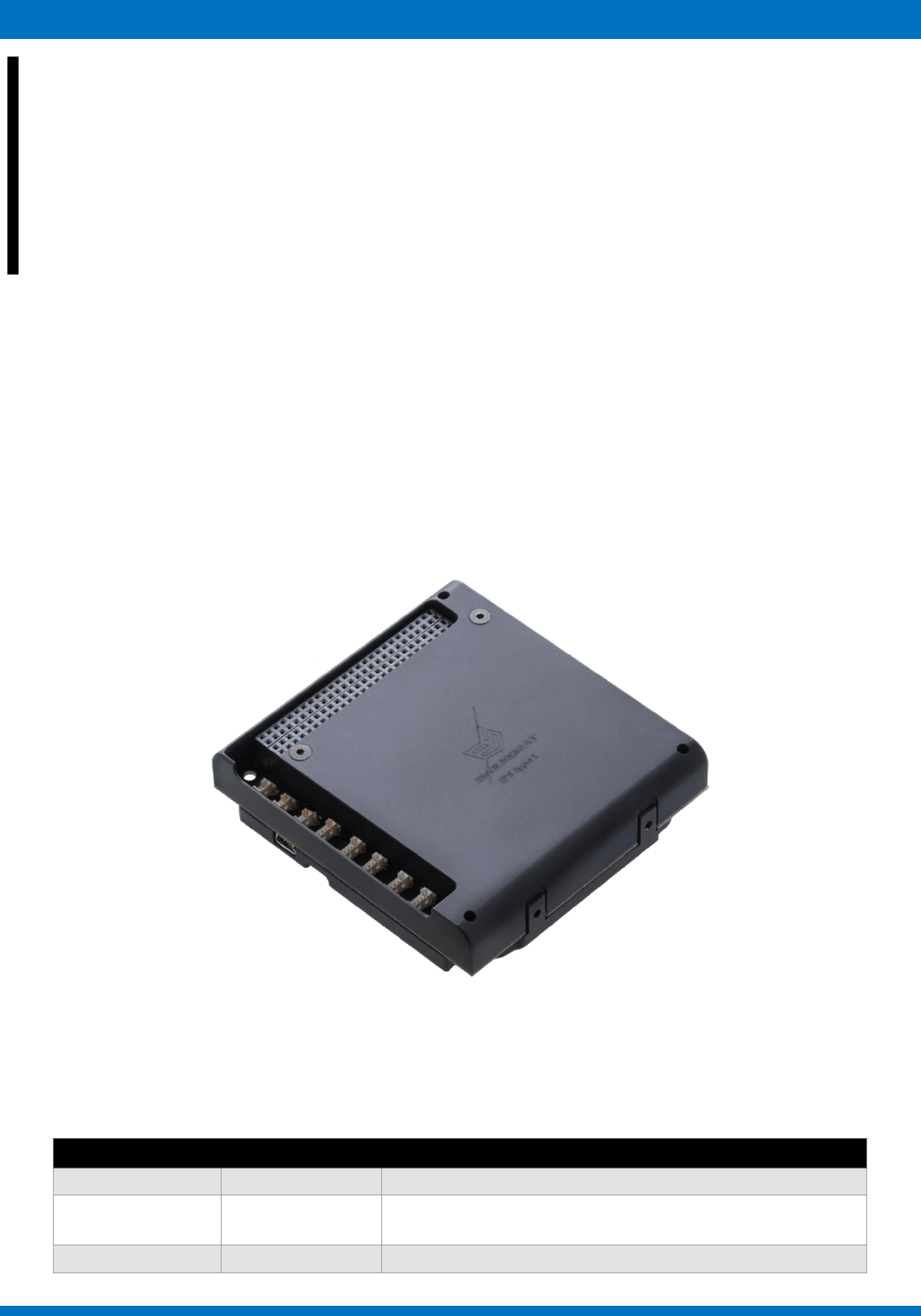
Figure 1 - EPS module
1 CHANGE LOG
Date
Version
Note
03/08/2016
Rev 1.0
13/04/2017
Rev 1.1
Battery EOC changed to 4.1V, minor changes in the
block diagram
12/01/2018
Rev 1.2
Minor changes in text and diagrams

ENDUROSAT
4
USER MANUAL - EPS
2 ACRONYMS LIST
BCR
EOC
EPS
ESD
I2C
Li-Po
LUP
MPPT
PCM
RBF
UART
USB
Battery Charger Regulator
End of Charge
Electrical Power System
Electrostatic Discharge
Inter Integrated Circuit
Lithium Polymer Battery
Latch-up Protected
Maximum Power Point Tracking
Protection Circuit Module
Remove Before Flight
Universal asynchronous receiver/transmitter
Universal Serial Bus
LDO Low Dropout Regulator
MCU Microcontroller

ENDUROSAT
5
USER MANUAL - EPS
3 HIGHLIGHTED FEATURES
✓ 3 Photovoltaic input channels with independent control and monitoring;
✓ Input voltage (per input channel): 0.5 - 5.5 V;
✓ Input current (per input channel): up to 1.8 A;
✓ BCR efficiency: up to 95%;
✓ Battery pack power: 10.4 Wh;
✓ Battery pack voltage: 3.3 - 4.2 V;
✓ Stackable battery packs: up to 8A;
✓ Output power buses: 3.3V, 5V, BCR (5Vmax) and battery raw
✓ Two Latch-up protected outputs
✓ Interfaces: UART, I2C, USB;
✓ Remove before flight switch;
✓ Six outputs for shutdown/reset of other modules;
✓ USB debug & battery charger;
✓ Weight: 198g including 1 battery pack and 278g including 2 battery pack;
4 SYSTEM DESCRIPTION
The power module is most suitable for 1U, 1.5U and 2U CubeSat Satellites. It comes with integrated
one or two Li-Po battery packs encapsulated inside the aluminum box. Capacity of one battery pack is
10.4 Wh, which adds up to 20.8 Wh with 2 stacked battery packs. There are three photovoltaic input
channels for supplying the power from each axis of solar panels. Each channel consists of two
connectors (see paragraph 6.4) that are intended for opposite solar panels in order to maintain the
input parameters within the maximum ratings of the module. Observe the maximum input ratings in all
cases (especially if deployable solar panels are used).
There are three independent channels for control and monitoring of the solar panels on each axis. They
have the following features:
● Precision current and voltage measurement;
● Overcurrent protection;
● Overvoltage protection;
● Overtemperature protection;
● ESD protection;
● Solar panels reverse-insertion protection – turns off the corresponding channel;
● Every solar panel channel supports safe shutdown in case of a problem (optional).

ENDUROSAT
6
USER MANUAL - EPS
The photovoltaic power convertors can handle input voltage up to 5.5V and the current maximum
threshold for overcurrent protection can be set up to 1.8A (hardware customizable). The operating
temperature range is from -40oC to +150oC and overtemperature threshold is set to be +155oC (the
module will turn off if threshold is reached and restart automatically when the temperature decreases
to +130oC). The efficiency of the step-up convertors is up to 95%.
The step-up convertor turns OFF if the input voltage is lower than 0.27V (under voltage lockout) and
restarts when the voltage exceeds 0.34V. A hysteresis is implemented to avoid unpredictable ON-OFF
switching. However the minimum input voltage threshold for boosting is 0.5V.
The step-up convertors work at 100kHz fixed frequency. The duty cycle is controlled by MPPT
algorithm. Boosted output voltage can be accessed through PC/104 connector for additional
functionality such as charging of another battery pack, super capacitors, etc.
Battery charger features operation in both linear and quasi-pulse modes. The advantage of the quasi-
pulse charging method is that it allows the energy harvested by not well illuminated solar cells to be
maximized. Programmable charge current: 230mA / 460mA for slow charge and fast charge
respectively (hardware customizable up to 1A); Hardware and Software monitoring and control.
In the standard configuration, the EPS with one battery pack has 2 Li-Po batteries connected in parallel.
There is hardware and firmware battery protection. Each battery has its own Overcurrent, Overcharge
and Overdischarge protections ensured by integrated protection circuit module (PCM). Special
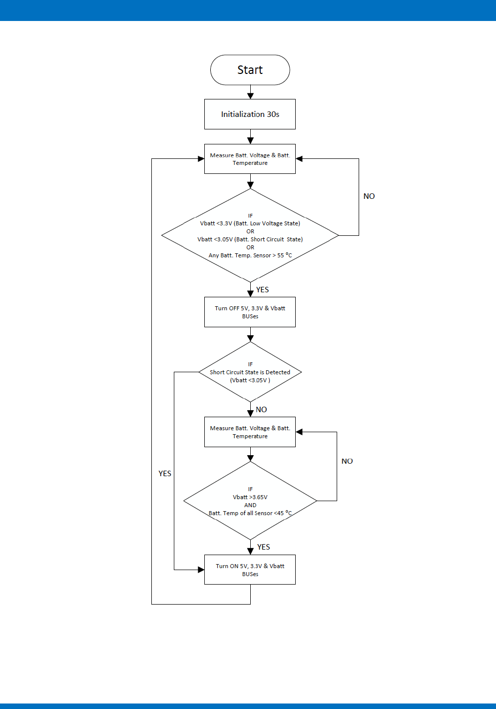
firmware algorithm is implemented for protection of the batteries from short circuit, deep discharge and
overheating (figure 2).
ENDUROSAT
7
USER MANUAL - EPS
Figure 2 – Algorithm for protection of the batteries from short circuit, deep discharge and overheating.
ENDUROSAT
8
USER MANUAL - EPS
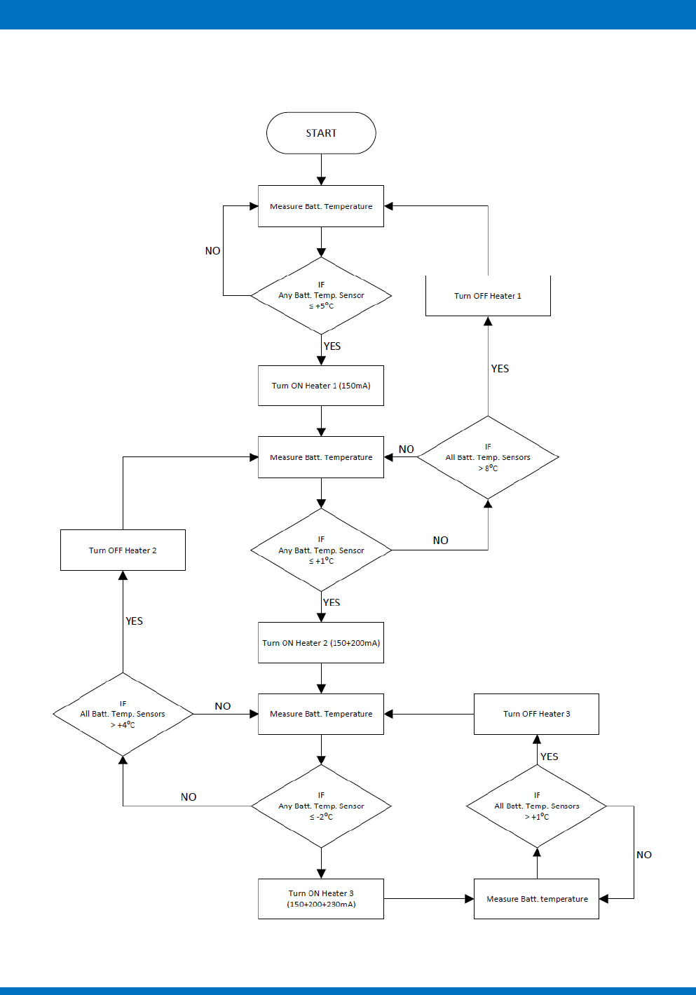
Each battery pack has three independent heaters to prevent charging under 0 ⁰C. Special algorithm
optimizes heater power consumption in relation to the temperature (figure 3).
Figure 3 - Algorithm for the optimization of the heater power consumption

ENDUROSAT
9
USER MANUAL - EPS
The two deployment switch connectors are located at two opposite corners of the CubeSat structure
in accordance with CubeSat Design Specification. A remove-before-flight (RBF) connector is also
available. When the RBF pin is plugged in or both deployment switches are pressed, the module is
inactive. In order to activate the module it is necessary that RBF pin is unplugged and at least one
deployment switch is released.
The deployment switches and RBF disconnect the batteries from the power buses and thereby turn off
the system and stop all power consumption. Once the module is turned on, the self-locking functionality
is activated and the power supply cannot be stopped by the deployment switches or remove before
flight pin anymore. For ground test purposes the self-lock functionality can be stopped through the PC
software via the USB cable provided.
The incoming power along with the energy stored in the batteries is used to feed all main buses:
3.3V@3A, 5V@2.5A and Vbatt@4A (specifications for Power System with 1 Battery Pack). Both DC-
DC converters are synchronized with the same working frequency.
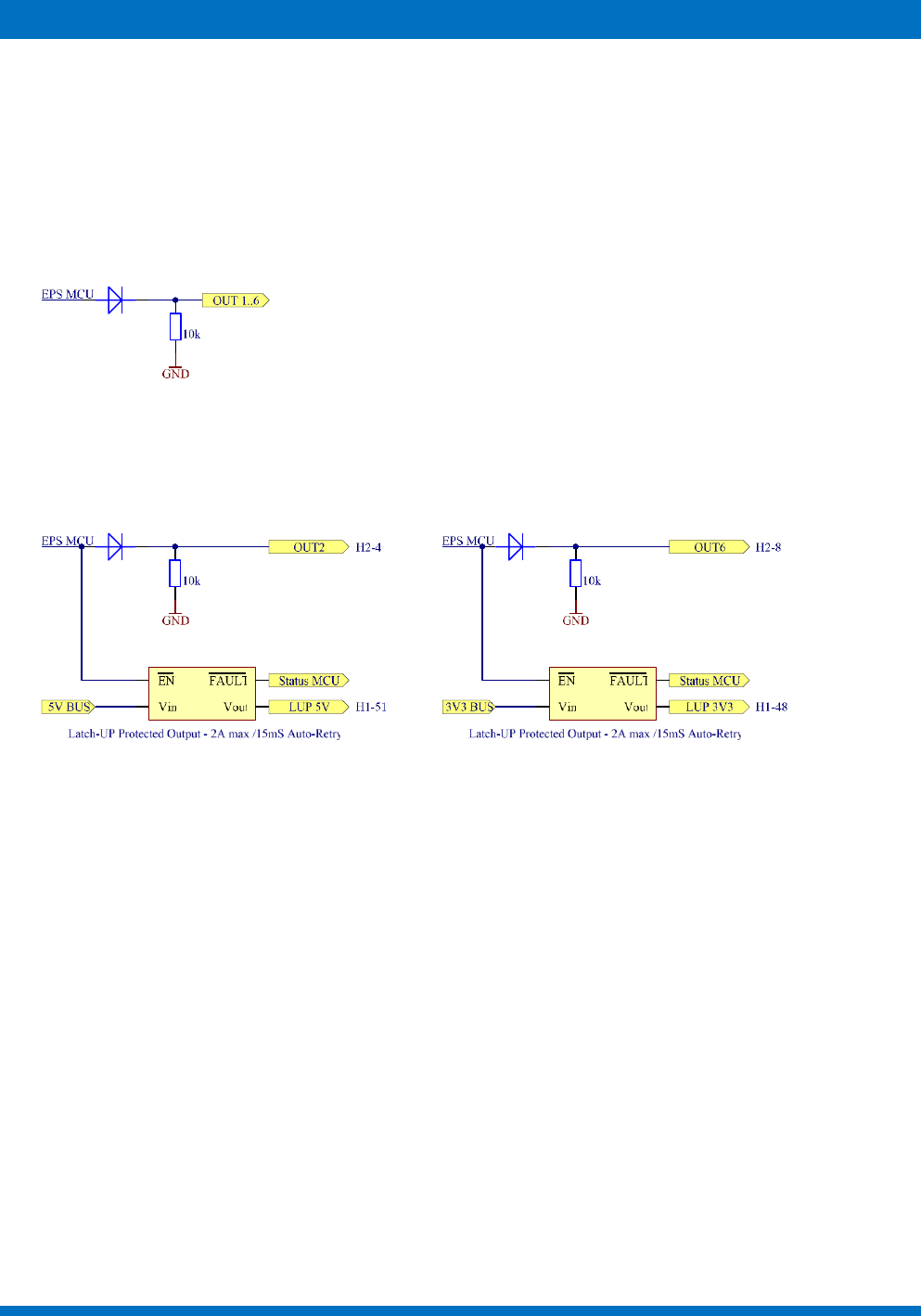
There are two Latch-up protected (LUP) outputs - one connected to the 5V BUS (H1-48) and one to
the 3.3V BUS (H1-51). The set fault current threshold is 2A for both LUPs. If fault current threshold is
reached the LUP disconnects its output. Auto retry mechanism is implemented - every 15ms LUPs
check if the fault current is below fault threshold in order for normal operation to continue. The fault
current can be monitored by status flag.
There is a built-in firmware for monitoring and control, which can display the following parameters:
✓ Solar panels voltages and currents;
✓ BCR voltage (H2-41/42/43/44);
✓ Output power buses current consumptions (5V BUS, 3.3V BUS, Battery BUS and BCR BUS);
✓ Battery pack(s) voltage, current and temperature;
✓ External temperature sensors;
✓ Critical state flags – power cycle; low voltage states, short circuit states, over temperature
states, minimum and maximum reached temperatures of each battery;
✓ Status of output power buses, charging and deployment switches Self-lock.
The firmware provides control over the following features:
✓ Deployment switches Self-lock;
✓ Battery BUS;
✓ BCR Bus;
✓ 3.3V & 5V Buses;
✓ Battery Normal / Fast Charge;
✓ Six general purpose outputs
✓ Battery heaters
The EPS measures current of each solar panel and voltage of opposite panels on each axis. Stabilized
voltage from the three photovoltaic step-up convertors is also monitored – BCR Voltage. Power Module
measures the current consumption through all buses – 5V, 3.3V, Battery Raw and BCR Out. When the
ENDUROSAT
10
USER MANUAL - EPS
5V & 3.3V BUS is within 5% of the regulation voltages status flag is provided. The instant, minimum and
maximum temperature of every battery cell is monitored. Up to three external temperature sensors can
be connected to the module for thermal measurement of user defined critical places inside the satellite.
The EPS Module has six general purpose outputs. Every output can be switched between 2.4V and
Ground. All outputs are protected with diodes and 10k pull-down resistors, which enable other modules
to control them at the same time. Diode OR gate can be realized.
Output 2 and 6 have double usage - they can be used as general purpose outputs or to control the
LUPs. Both LUPs work with inverted logic - when the corresponding Output is set to ground level, LUP
is turned ON.
ENDUROSAT
11
USER MANUAL - EPS
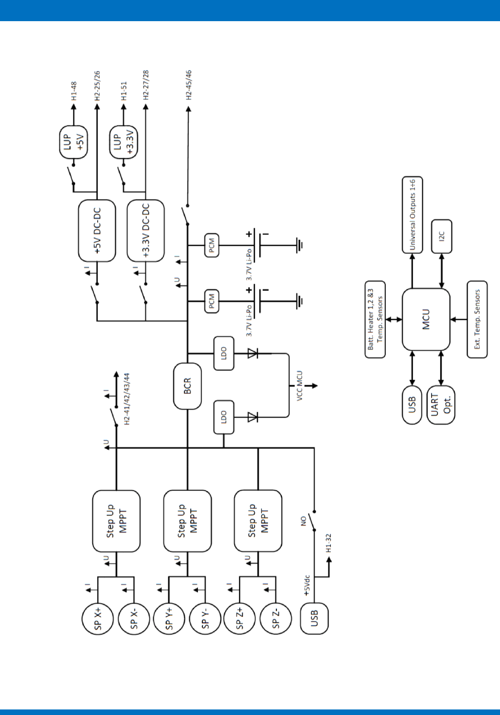
5 BLOCK DIAGRAM
Figure 4 – Block diagram
ENDUROSAT
12
USER MANUAL - EPS
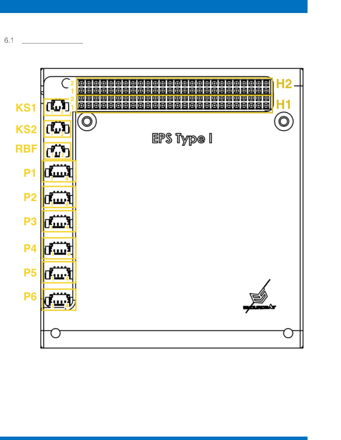
6 CONNECTOR PINOUT
Connectors Location
Figure 5 - Connectors location and pinout

ENDUROSAT
13
USER MANUAL - EPS
H1 - Stack Connector
Pin
Mnemonic
H1-32
5VUSB
H1-33
UART RX*
H1-35
UART TX*
H1-41
I2C SDA
H1-43
I2C CLK
H1-48
LUP2 5V
H1-51
LUP1 3.3V
* (Optional – Hardware Customizable)
H2 - Stack Connector
Pin
Mnemonic
H2-3
OUT1
H2-4
OUT2
H2-5
OUT3
H2-6
OUT4
H2-7
OUT5
H2-8
OUT6
H2-25
5V BUS
H2-26
5V BUS
H2-27
3.3V BUS
H2-28
3.3V BUS
H2-29
GND
H2-30
GND
H2-31
GND
H2-32
GND
H2-41
BCR Out
H2-42
BCR Out
H2-43
BCR Out
H2-44
BCR Out
H2-45
VBATT BUS
H2-46
VBATT BUS

ENDUROSAT
14
USER MANUAL - EPS
P1 to P6 - Solar Panel Input connector
The solar panel input connectors from P1 to P6 are 4 pins MOLEX Picoblade 53398-0471. By default,
they are set in the following configuration:
P1 → X-
P2 → X+
P3 → Y-
P4 → Y+
P5 → Z-
P6 → Z+
This configuration can be modified, taking in account that the pairs: P1 and P2; P3 and P4; P5 and P6 should be
connected to solar panels on opposite sides of the same axis.
The pinout is the same for all 6 connectors:
Pin
Mnemonic
Description
1
-
Negative
2
-
Negative
3
+
Positive
4
+
Positive
KS1 and KS2 – Deployment switches
KS1 and KS2 are respectively deployment switch 1 and deployment switch 2 connectors. Both are 2
pins MOLEX Picoblade 53398-0271 connectors.
RBF – Remove before flight
RBF is the remove before flight connector - 2 pins MOLEX Picoblade 53398-0271

ENDUROSAT
15
USER MANUAL - EPS
7 ELECTRICAL CHARACTERISTICS
Parameter
Unit
Condition
Min
Typ
Max
Battery Capacity
Capacity
mAh
EPS with 1 battery pack
2640
2800
mAh
EPS with 2 battery packs
5280
5600
Wh
EPS with 1 battery pack
10.4
Wh
EPS with 2 battery packs
20.8
Battery Charger
EOC voltage
V
4.08
4.1
4.12
Charge current
mA
Fast Charge Mode (by
default)
430
460
490
mA
Slow Charge Mode
215
230
245
Battery Discharge
Over Discharge
Detection
V
Limited by PCM
2.24
2.3
2.36
Over Current Detection
mA
EPS with 1 battery pack
(limited by PCM)
4000
9000
(8 to
16ms)
mA
EPS with 2 battery packs
(limited by PCM)
8000
16000
(8 to
16ms)
Exp. Cycle Life
mAh
Discharge @ 0.5/1C, 23
±2⁰C;
500 Cycles ≥ 2196 mAh
Unregulated Battery Bus
Output voltage
V
Firmware defined
3.3
4.24
Output current
mA
EPS with 1 battery pack
(limited by PCM)
4000
9000
(8 to
16ms)
mA
EPS with 2 battery packs
(limited by PCM)
8000
16000
(8 to
16ms)
+5 V Bus
Output voltage
V
4.88
5
5.15
Output current
mA
EPS with 1 battery pack
2500
Operating frequency
kHz
380
390
400
Efficiency
Vbatt = 3.8; I5VBUS = 2A
88%
89%
90%
+3.3 V Bus
Output voltage
V
3.3
3.38
3.45
Output current
mA
3000
Operating frequency
kHz
380
390
400

ENDUROSAT
16
USER MANUAL - EPS
Efficiency
Vbatt = 4V; I3.3VBUS = 2A
79%
80%
81%
Module Consumption
Power Consumption
mW
Normal Operation.
LUP5V & LUP3V3 are
OFF
75
mW
Low Voltage or High
Temperature State.
All Buses are OFF
43
Current Consumption
mA
Batt. Low State @3.3V
13
mA
Normal Operation
@3.7V
20
mA
LUP3V3 & LUP5V
3.9
5
mA
Heater 1
150
mA
Heater 2
200
mA
Heater 3
230
Fault Current Threshold
(auto retry every 15ms)
A
LUP3V3 & LUP5V
1.75
2.2
Solar Panels Input
Voltage
V
@25⁰C
0
4.66
5.5
Current
mA
@25⁰C
517
1800
Power
W
@25⁰C
2.6
ENDUROSAT
17
USER MANUAL - EPS
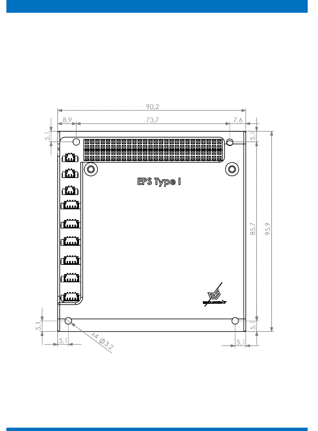
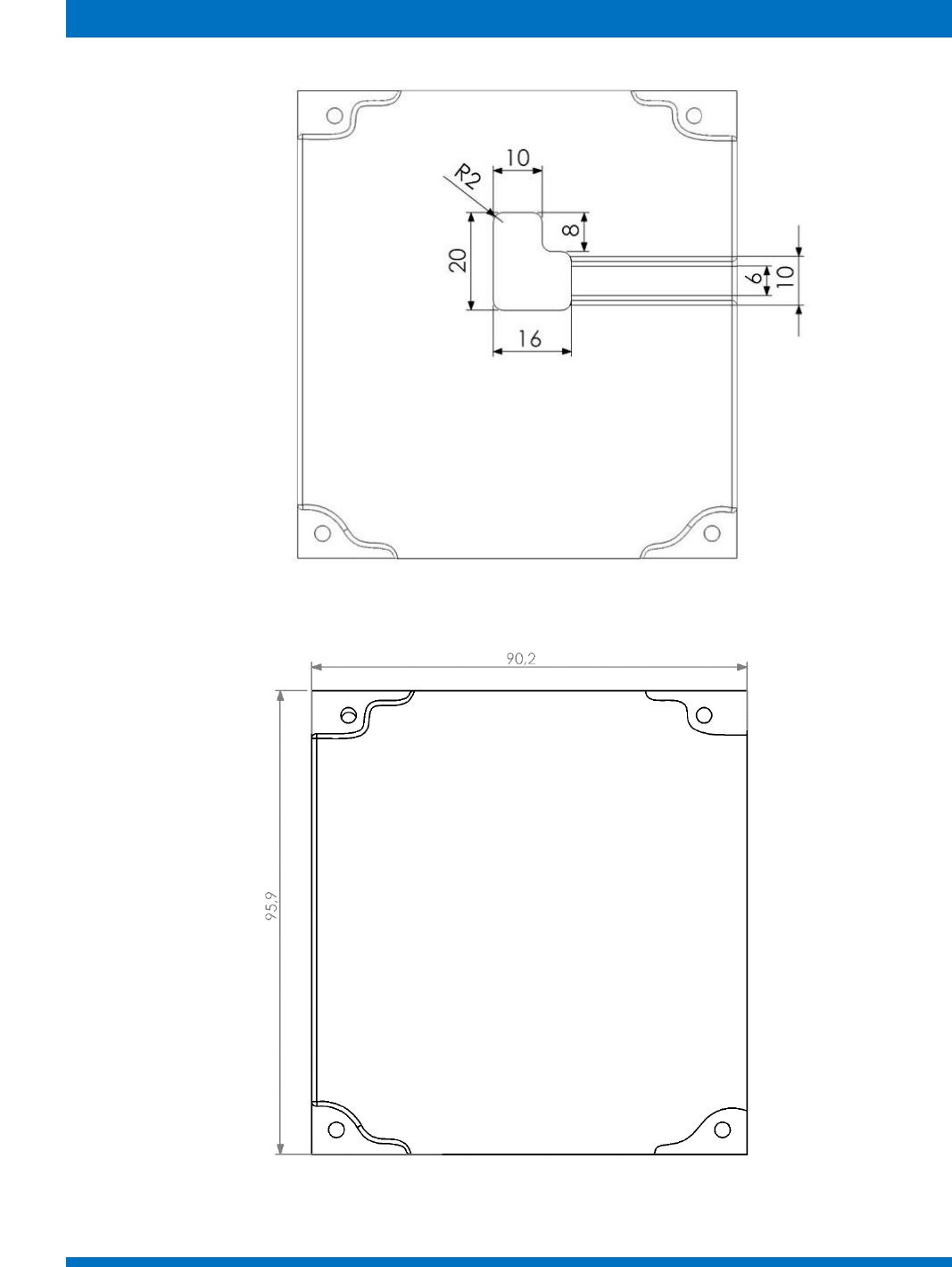
8 MECHANICAL DRAWING
The following pictures show the external dimensions of the EPS subsystem. The EPS, as already
mentioned, has 2 configurations: EPS with one battery pack and with two. The bottom lid of the module
could be with an opening, which is designed to accommodate the RF connector of EnduroSat S-Band
Patch Antenna. The top view is the same for both configurations.
All dimensions are in mm.
Figure 6 – EPS top view
ENDUROSAT
18
USER MANUAL - EPS
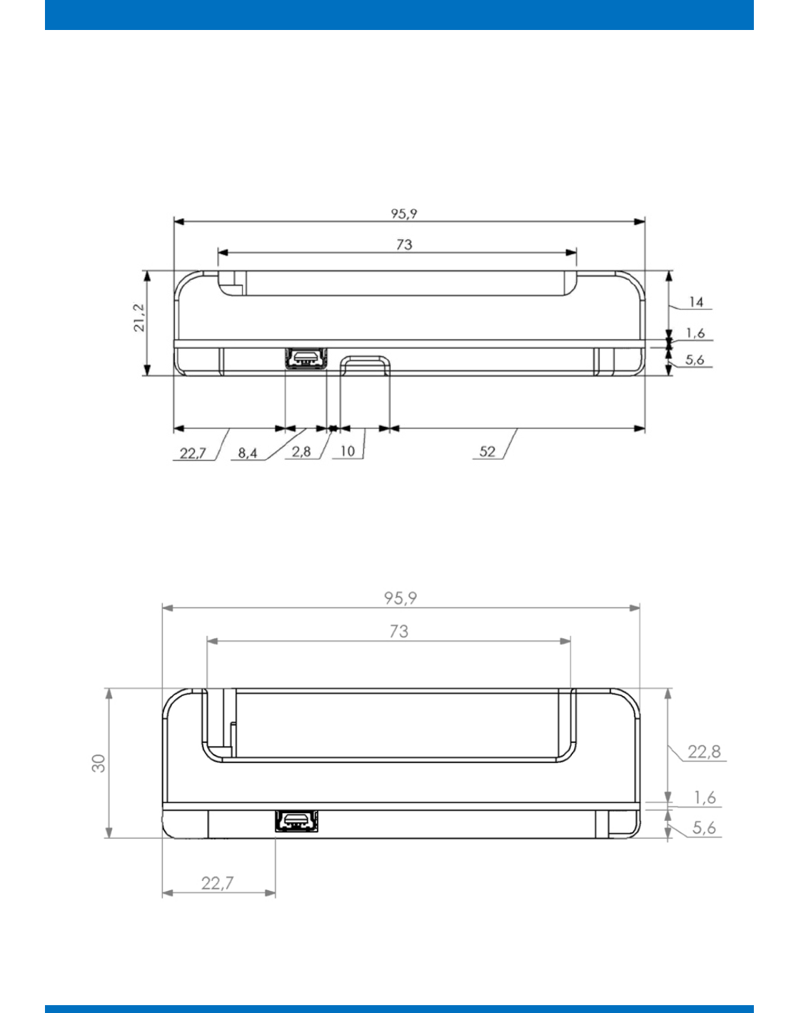
The bottom part of the EPS box has 2 configurations. One has opening as shown in figure 7 and
figure 9 to accommodate cables and connectors for the EnduroSat S-band patch antenna. The
second configuration is without opening as shown in figure 8 and figure 10.
Figure 7 – EPS with 1 battery pack – side view
Figure 8 – EPS with 2 battery packs – side view
ENDUROSAT
19
USER MANUAL - EPS
Figure 9 - EPS - bottom view with opening
Figure 10 - EPS - bottom view without opening

ENDUROSAT
20
USER MANUAL - EPS
9 ENVINRONMENTAL AND MECHANICAL TEST
A full campaign of tests at qualification level was performed on the qualification engineering model
Qualification tests level and duration follow the ESA standard ECSS-E-ST-10-03C and GEVS: GSFC-
STD-7000A. Tests performed:
• Thermal Cycling
• Thermal Vacuum
• Random Vibration
• Sine Vibration
• Shock Test
Test report can be provided upon request.
10 HANDLING AND STORAGE
Particular attention shall be paid to the avoidance of damage to the EPS during handling, storage and
preservation. The handling of the EPS module should be performed in compliance with the following
instructions:
• Handle using PVC, latex, cotton (lint free) or nylon gloves.
• The environment where EPS module will be handled shall meet the requirements for a class
100,000 environment, free of contaminants such dust, oil, grease, fumes and smoke from any
source.
• Store in such a manner as to preclude stress and prevent damage.
• To prevent the deterioration, the power module must be stored in a controlled environment, i.e.
the temperature and humidity levels shall be maintained in the proper ranges:
o Ideal storage temperature range: 15ºC to 27ºC
o Ideal storage humidity range: 30% to 60% relative humidity (RH)
ENDUROSAT
21
USER MANUAL - EPS
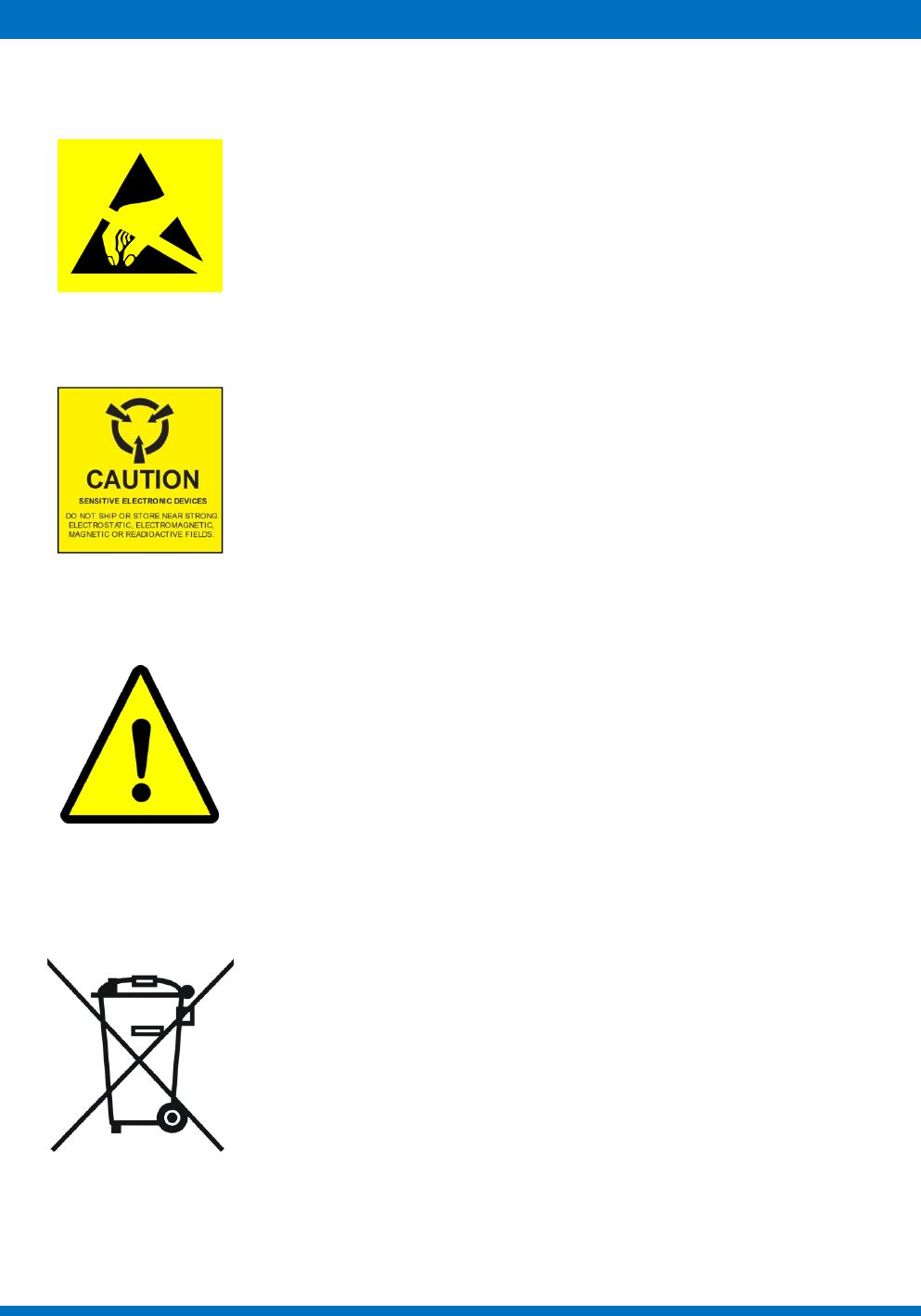
11 WARNINGS
This product uses semiconductors that can be damaged by
electrostatic discharge (ESD). Observe precautions for Handling
Sensitive Electronic device. Do not ship or store near strong
electrostatic, electromagnetic, magnetic or radioactive fields.
LITHIUM ION RECHARGEABLE BATTERY
Caution! May explode if disposed in fire
• Do not incinerate or place near an open flame
• Do not drop, crush, puncture or disassemble battery
• Do not short terminal
• Do not expose to temperature above 140°F/60°C
• Do not replace by a battery other than that specified by
manufacturer
