ERA 1101 F11 Storage System
ERA-1101-f11-StorageSystem ERA-1101-f11-StorageSystem
User Manual: ERA-1101-f11-StorageSystem
Open the PDF directly: View PDF ![]() .
.
Page Count: 20
•
•
•
"
621.31'.'72 :
621.385.132
:
5.'.5
(1) IN'I1lODUCDON
Propoeak for the
coaitructioo
of
~
diaital
computiq
macbiMI
haw
nsu1ted
ill
a
~
'for •
DOW
type
bl
atorqe
system.
'In
order to, eltabJilb a
~
aaainst
wbidl
the
particular
stora_
syttem
dclcribediD
the
p&.ent
paper
may
be
let,
the
introductory
SectiGo
of
die
.....
,-=--
a
delcriptioo
of
the
ayMem,
oIllumbara
to
..
..ct
•
propoeed
computina
machiDea,
tbe·,~
.......-
C"6
....
aystem.
and a
statlme.tlt
of"
...
dpea~:I!IMI~
."
.........
'.,...'
"
."
'1:'.'
.',
,
.',
(1.1)'
'III!t.
.....,
',""
.,
PI
••
,
..
Tbe~'ol
....
tIiIiIal~""the.,mecr
iDa
ItaDdpoinf,
~priinariIJ.
ia
the
~
of
8uitable
. electronic
devices
.haviaa
tho
lime'
IlUIftber
()t·lta.
as.
the.'
lif)atimber
or
P<*l~
values
.r
a
dilit.
10
that
• oao-to-oDe com- .
~
spoo.deoQC
may
be
~blished
between
each
s_
of
the device
,
aDd
eadl value
or
die
diait.
The'
number
of
values which a
digit may
take
depends,
of
COUlICt
Gl
the
system
of
numbers
tiled in
the
machine,
and
it·
follows
that
it is advantageous
to
dIooIe a
system
wbic:bcan.be~Dted,
elcc;trically . with
ease
and
e(:ODomy.
For
theIe
reasons
the
binary ,system
of
numbers
bas
~
popular
in
reoeat
plans fqr.
~Jectronic
digital
com-
putina mach ina.
I,
1 although in the past the
decimal
system has
bOea
\IIed.J.4«
' ,
Systems
of
numbers may be derived
from
the
common
series:
a._.IJra-1 +
...
,+
....
+ a,bl +
tJobO
which repreaents all intelen with "
siaamcant'
figures.
The
dccinial systaD,
(or
example, is obtained
jf
b = 10,
and
-the
a's
are allowed
any
one
of
the
vaI~
,between,
,and including, 0
and 9.
In
tbebinarysyst.elJl b
==
2
and"
is.either 0
or
l.
The
decimal number
19.
say,
is
d1cn1 X
24
+
0'
x -2l + 0 x
2l
+ 1
X
21
+ 1 x
20
~
the
binary
scale, which
can
,be writtc
..
10011
with
the
least
sianificant
figure placed
on
the.
right.
The
decimal,
or
binary, POint is
OD
the immediate right
of
the
term
tJobO.
The series can
be
CQIltinued
to
the
right as follows:
Prof. WiWama &ad Mr. KJlbUl'll
are
at
the
UaiversitJ
ot
Mancbestcr.
"'"'
-~I'.
-10
.........
.'
..
. 1
•.
/1
.
::1.
..• ,.-
;~3"
-0
~
'~
-.;
o
..
(h)
'C
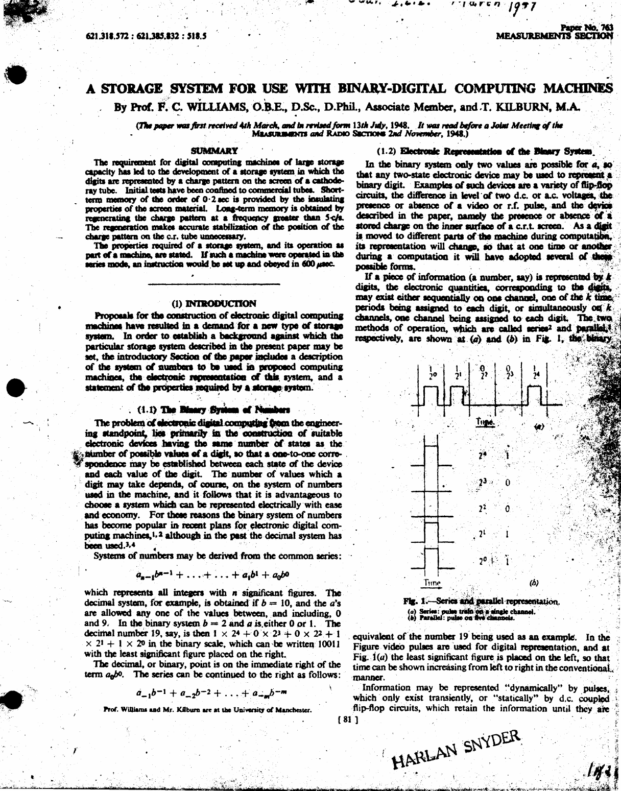
FII~
l;~;~.~llCli~.
(a)
SedeI:
~
.....
p ,
;~9i;~:"
ebaaDeI
•.
(.)PuaIId:
pu1Ie
00'
...
·......'
"
, equivalea.t
of
the
Dumber
19' being
used
as
All
example.
In
tbC
Figure. video pulses are'uaed for. digital repreIeIltah9n.
and
at
Fig. j (a) . the least
signifiant
figure,
is
plaQed
on
the left,
so
that
time
can
be
shown increasing from left
to
right
in
the
conventiOnal:
JDaJU1CI'.
.
Information may be represented
~'dynamicallyU
by
pulses~:
,i
which'
only exist transiently,
or
"statically'· by
d,c.
~~-,
'-
flip-flop circuits. which retain the information until
tbeyale
"~
(
81
1 . t
. ! . r
'.
'.
T\.~$~'l\)£.R,
.
,;;
. .
'.
U,~\..~,
.........'..
~d:f.i
~~~~
__
"~~_'_'_w~L'_\:'_)~'f'_'~~&~"~-_M
__
~N~t~t~·~~~\~~(~~t~~···.~it~;_H·~)j~~~'~**·~t*~b~~j~·C
___
~'~*,
__
*
__
~'~~-~;m~;·~+wt~·~~'**.·:_'~·*~HM.L~·~~~$~"~~~¥~:'5~~~~~;b~~~'4~~;~~~~'<~*~';~~.h¥~;·~~·~*.·(~q;~@t~~1
• •
-.
\
82 WILLIAMS AND KILBURN: A STORAGE SYSTEM
FOR
purposely reset
to
a
standard
condition.
Dynamic
information
may be converted into static information by, for example,
applying the pulses shown
at
(b)
to
five d.c. coupled. flip-flop
,"
circuits.
The
set
of
flip-flop circuits is called a
"staticisor."
( 1 .
3)
Required Properties
of
a Storage System
It
should
be
stated
at
once
that
a
computing
machine
cannot
·'think."
It
follows
that
the first step in setting
up
a problem
on
a machine
is
to
sub-divide it
into
a sequence
of
simple
arithmetic
or
logical operations externally (i.e. outside the
machine),
and
construct a
~
"table
of
instructions." Each
instruction in the table will, in general, require
that
an
elementary
operation be performed
on,
or
by, a number, i.e. a
number
will
be moved from one
"address"
of
the machine
to
another.
To
'every address a digit combination will be assigned
•.
so
that
an
instruction consists
of
two digit combinations, aRd is indis-
tinguishable from a
number
in appearance. Instructions
and
numbers, which
are
collectively termed
"words."
are
therefore
similar, the only difference between them being their function
in the machine.
Since all the words applicable
to
a
probl~m
cannot
be intro-
duced into the machine simultaneously, they must be
'~remem
bered" during the loading period,
and.
until used, during the
solution. Further, temporary
"memory"
of
some type must be
provided during each elementary
computing
operation.
The
storage system provides this memory property
of
the machine.
The
general opinion
of
mathematicians is
that
it will be
necessary
to
store approximately 3·2 X 105 binary digits,
in
the
form
of
lC4
words, with 32 digits
per
word.
If
the two-valve flip-flop circuit. were used,
6'
4 x
lOs
ther-
mionic valves would be required, which is clearly' impracticable
from the
points
of
view
of
size. cost
and
probable
reliability
of
the
equipment. Even in smaller machines the use
of
flip-flop circuits
would defeat,
to
sOme extent. the purpose
of
the change from
decimal
to
binary representation, since decimal representation
by ring counters in a machine
of
similar capacity would require
only three times
more
valves;
and
against this would have
to
be
set the expense
of
the conversion from the decimal
to
the binary
system,
and
vice versa when a binary machine is used.
Recently developed two-state devices, which
are
far less com-
plex
than
existing two-
or
ten-state devices. are the main justifica-
tion for the change
from
decimal
to
binary representation.
Further, they make digital computing machines with large
storage capacity a practical proposition.
Sufficient attention has been given
to
the memory property
to
indicate
that
it is
of
primary importance,
but
in
order
to
make
practical use
of
a store it must also
be
possible
to
insert, extract
or
erase the remembered information.
The
insertion
of
informa-
tion into a store has been
~alled
··writing.·'
The
extraction
of
information from a store.
"reading."
does
not
imply
that
the
information
is
erased from a store, since it may be required
at
a
latcr time.
"Erasing,"
of
I:ourse, implies
that
informati,on is
era~d
from a store.
but
in its prefcrahle form it
is
really a super-
sedtng process in
that
a word may be written into
an
occupied
address. deleting the word already there. This property increases
the etfective
capa~lty
of
a storc. since new inlormation, such as
panial
answers. may he '\\rincn ovcr information which has been
used,
"ithout
an
intermedlah! crasurc
proccs~.
T
\)
summarilc. a st(lrc
mu"';{
ha\c
the following propert:es:
(a)
It
mll
...
t
tx:
pOSSible
tll \\ rile a
\hlrd
qtl1\:kly into any
addrc!\s,
~Lh;h
\\
riling superseding any word alread) present
at
that address.
(/I)
1 he
\\tll\.!s
at all
adJrc"~,,,
not hcing \\filten in must
he
rcmemhcreJ inddinitcly, ch.tnges occurring only as the result
()f
a detinite writmg prcx:ess: errors
of
I digit per million would be
fatal.
,
(c)
11
must'be
possible
to
read the word in any address quickly
without erasing it,
or
.any
other
word.
(d)
It
must be possible to write into
or
read from any address
with absolute certainty. Reading from
or
writing into
an
adjacent address in
error,
even
if
it occurred only once in a
million times, would be a serious disadvantage,
(e)
The
sfore must
be
capable
of
holding a very large number
of
words
(about
1(4)
each comprising a number
of
digits. which
are
either
O's
or
I's.
For
(0)
and
(c) the significance
of
"quickly"
is
related
to
the
time-scale
upon
which the machine as a whole is
to
work. The
longest operation
of
frequent occurrence
is
multiplication.
If
this process occupies, say, 5 millisec
wr~ting
and
reading should
occupy less than, say. 1 millisec, otherwise the computation will
be seriously retarded.
The
paper
describes
an
attempt
to
meet these requirement,
using charge storage
on
a cathode-ray-tube (c.r.t.) screen as the
memory mechanism.
./
(2) PHYSICAL BASIS
OF
THE
STORAGE SYSTEM
Before describing the mechanism
of
digit storage, the arrange-
ment
of
digits
on
the storage surface will first be mentioned
The
digits
are
reprtsented 'by charge distributions which
exi~l
o~
small areas
of
a c.r.t. screen. the charge distributions
bein~
arranged in
the
form
of
a two-dimensional array. This array IS
produced
by a television type
of
raster, in which the digits
of
a line.
and
the lines
of
the raster,
are
scanned sequentially, each
digit corresponding with a
"picture
element.
to
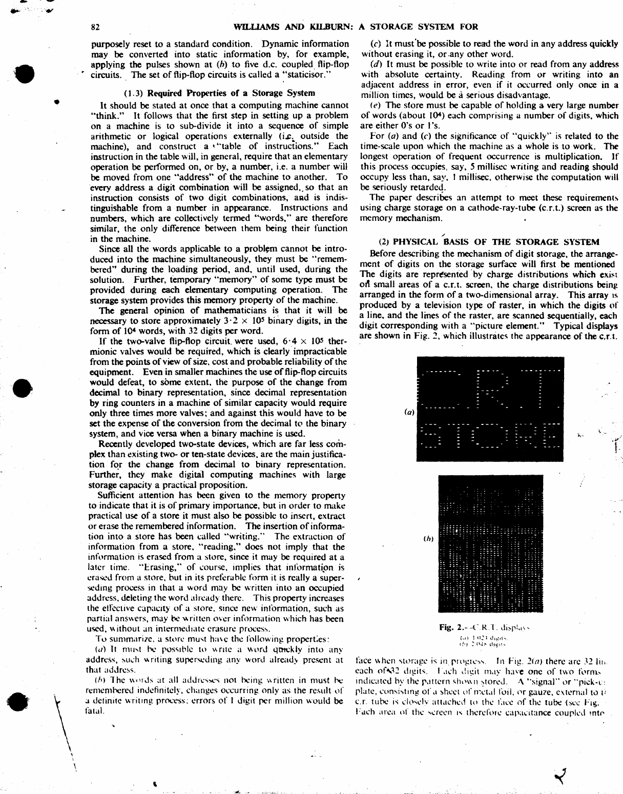
Typical displays
are
shown in Fig. 2, which illustrates the appearance
of
the C,T.t.
(a)
(h)
(,I)
I
"~I
,1
..
':01'
If"
:
0":.""
dl~IL'"
'k'·
face
\\hen
'itm'age is
in
rlllgrl.':-....
In
Fig.
21n) there
an!
J2
lir.
c~lch
of,12
digits,
ILKh
dIgit
Il1LlY
have one
of
two t,,'rnt--
indicatcd
hythe
r;lttcrn
Slll'\\1l
)toreJ.
A
"signal"
or
"pick-t:
plate,
nlOsi~tm~
of.t
~hl.'('{
llf
In.:t;!1 toil, fir gau7e,
e\ternal
h.)
t:
c.r. tube is
d~)sdv
attached
III
the
t'a~:c
of
the
tube
isl.'l.' Fig.
Fach
arca
of
thl.'
...
aCt-'1l
I"
therefor\.'
Capa(ltance
courkd
mt('
i.-/3
•
•
PICk
-
up
plate
1-----0
Output
'--
__
...J
IJ
100
MO.
The
voltase
output
from
the
amplifier
is.
then.
I
volt
per
hundredth
of
a microamp
of
current ftowina
to:
or
from,
the
pick-up plate.
There
is
no
plwe
reversal
in
the
~fier,
and
conventional current ftowing" from the pick-up plate
to
tbe
amplifier
sives
a positiVe
output
voltap.
It
should be noted that this equipment can only detect rates
of
C'hanp
of
surface chariC
on
the c.r.t. screen, so
that
thefoUowiaa
daaiptions
of
potential distribution
on
the screen are
qualitati~
The
absolute value
of
these
distributions is
not
of
primary
. importaDcc to the final
~toraae
system.
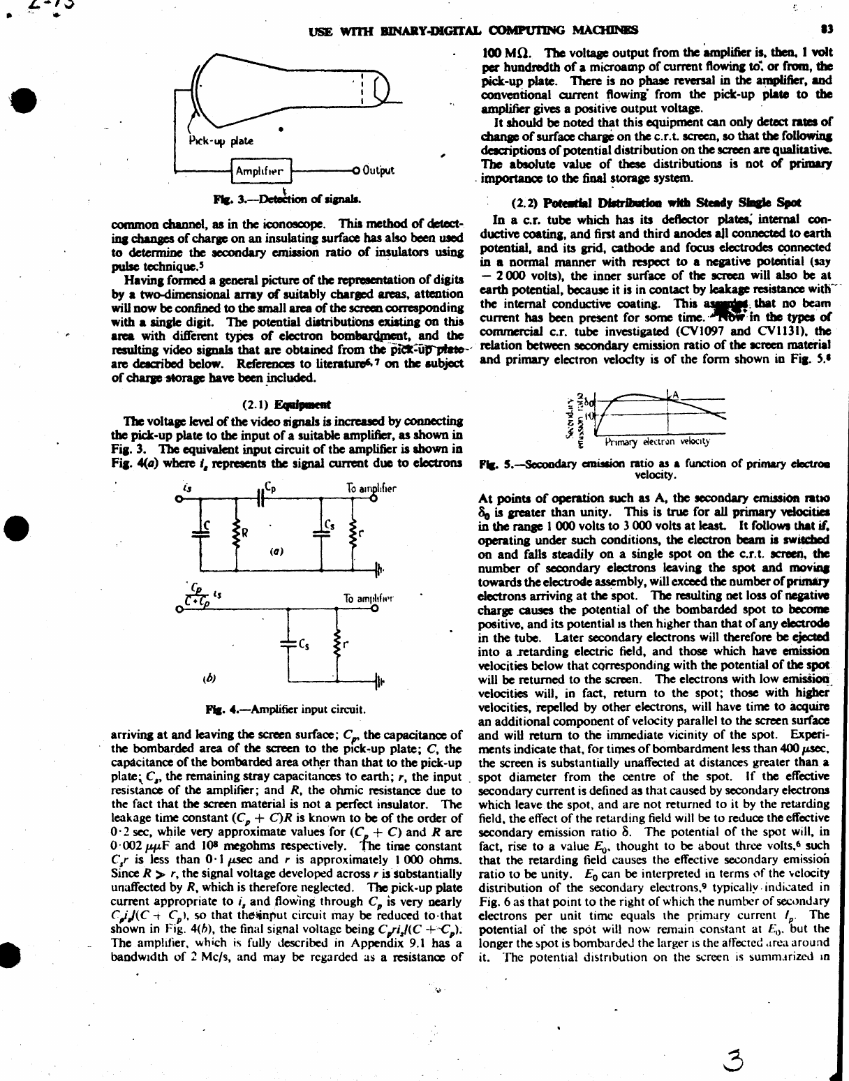
FII.
3.-DetJtion
or
lianaJa.
(2.2) Pot6iIdaI I>JIbiIJutbI
db
Steady
SiIIIIe
Spot
common duumel,
as
in the iconoscope. This
method
of
detect- In a c.r. tube which
has
its deftector plates; internal con-
ina
changes
of
charge
on
an
insulatina surface has also been
UIed
ductive
coatiq,
and
first
and
third anodes all connected
to
earth
to
determine
the
ICCOIJdary
emission ratio
of
insulaton usina potential.
and
its grid, cathode
and
focus
electrodes
connected
pulse technique.' .
in
a normal
manner
with respect
to
a
neptiyc
poteDtial (say
Havin. formed a general picture
of
the
rep...,.tation
of
digits - 2 000 volts), the inner surface
of
the
ICReD
will
also
be
a'
by a two-dimensional
array
of
suitably cbarlCd
aras,
attention
earth
potential, because it is in contact
by
Ieaka,e resistance
witb~
wiD
now
be confined
to
the
small area
of
the screen
correspondinl
the internal conductive coating.
~ia
~~
&bat
no
beam
with a
sinJle
digit.
The
potential distributions existin.
on
thia current
has
been preSent for some
tlrne.·~
In
the
typea
of
area
with different types
of
electron bomhaJ"dlnent.
and
the
co~
c.r. tube
invcsti~~
(CV~097
and
CVl13I).~
resuitin.
video
sipals
that
ate
obtained from
the
-'p~filf'plaelt-'
relation between
secondary
cmtsslon ratio
of
the tcrecn material
are
dac:ribed below.
Referma:s
to
literatuJ'e6. 7
on
the
subject
and
primary electron velocfty is
of
the form shown in
Fil·
S.·
of
charp
·storage have been .included.
(2.1)
FAaafpalcat
'J'be
voltap
level
of
the
video sisnaIs is increased by
connectina
the
pick-up plate
to
the
input
of
a suitable amplifier 9
as
shown
in
Fia. 3.
The
equivalent input circuit
of
the amplifier is shown
in
Fia.
4(41)
where
I.
represents
the
sianal current
due
to
electrons
To
am
!sfler
c r
(0)
To
am"ltf
..
'r
r
Fla.
4.-Amplifier
input circuit.
ur~
. €
I>nmary
eltctr~n
Wloclty
'tc.
5.-5econdary cmlMion ratio as a function
of
primary eIeruoa
velocity.
At
points
of
operation such
as
A,
the
secondary emission nahO
80
is arcater
than
unity. This is
true
for
all primary
~tia
in
the
ranae
1 000 volts
to
3 000 volts
at
least.
It
follows that if.
opcratina
under such conditions. the electron beam is switdlod
on
and
falls steadily
on
a single
spot
on
the
c.r. t.
acreaj,the
number
of
secondary electrons lcavilll the
spot
and
movina
towards
the
electrode
~mbly,
will exceed the number
of
primary
electrons arriving
at
the spot. The resultina net loss
ofneptivo
charlC causes
the
potential
of
the bombarded spot
to
become
positive,
and
its potential IS then higher than that
of
any electrode
in the tube.
Later
secondary electrons will therefore
be
ejected
into a .retarding electric field.
and
those which have emissioD
velocities below
that
CQrrespondinl with the potential
of
the spoJ
will be returned
to
the screen. The electrons with low emisSioIi'
velocities will, in fact, return
to
the
spot;
those with hisher'
velocities, repelled by
other
electrons, will have time
to
acquire
an
additional component
of
velocity parallel
to
the screen surface
arrivilll
at
and
leaving
the
screen surface;
C,.
the
capacitance
of
and
wiD
return
to
the immediate vicinity
of
the spot. Expcri-
the bombarded
area
of
the screen
to
the pick-up plate; C, the ments indicate that. for times
of
bombardment
le5S
than 400
p.sec.
capacitance
of
the bombarded area
oth~r
than
that
to
the pick-up the screen is substantially unaffected
at
distances greater
than
a
plate,
C,t the remaining stray capacitances
to
earth;
'.
the
input.
spot diameter from the centre
of
the spot.
If
tbe effective
resistance
of
the
amplifier;
and
R, the ohmic resistance due
to
secondary current
is
defined as
that
caused by secondary electrons
the fact
tbat
the screen material
is
not
a perfect insulator.
The
which leave the spot,
and
are
not
returned
to
it
by
the retarding
leakage time constant
(e
p +
C)R
is known
to
be
of
the
order
of
field, the effect
of
the retarding field will be
to
reduce the effective
O·
2 sec, while very approximate values
for
(C
L +
C)
and
R are secondary emission ratio
S.
The potential
of
the spot will, in
0·002
p.p.F
and
lOS
megohms respectively.
The
time constant fact, rise
to
a value
Eo.
thought
to
be
about
three volts.6 such
C,r is less than
0·1
p.sec
and
r
is
approximately 1 000 ohms.
that
the retarding field causes the effective secondary emission
Since R > '. the signal voltage developed
across,
issobstantially ratio
to
be unity.
Eo
can
be
interpreted in terms
l")f
the '¥clocity
unaffected by R, which
is
therefore neglected.
The
pick-up plate distribution
of
the secondary electrons.9 typically.
indi~ated
in
current appropriate
to
i,
and
,flow'ing
through ep is very nearly Fig. 6 as
that
point
to
the right
of
which the number
of
sec,}nJ.lry
C,;J(C
-t
Cp
'.
so that thetinJ"ut circuit may
be
reduced
to·that
electrons per unit time equals the primary current
Ip.
The
shown
in
Fig. 4(h). the final signal voltage being C"r;J(C
+'C
p
)'
potential
of
the
spot
will
now remain constant at
Eo.
but the
The amplifier. which
is
fuUy
described
in
Appendix
9.1
bas
a longer the spot
is
bombardeJ
the larger IS the affected .lrl!a around
bandWidth
of
2 Mc/s, and may
be
regarded as a resistance
of
it. The potential distnbution
on
the screen
is
~ummJrizcJ
10
'';'
£.
-13
•
•
• '
•
• j
Pnmary
wloClty
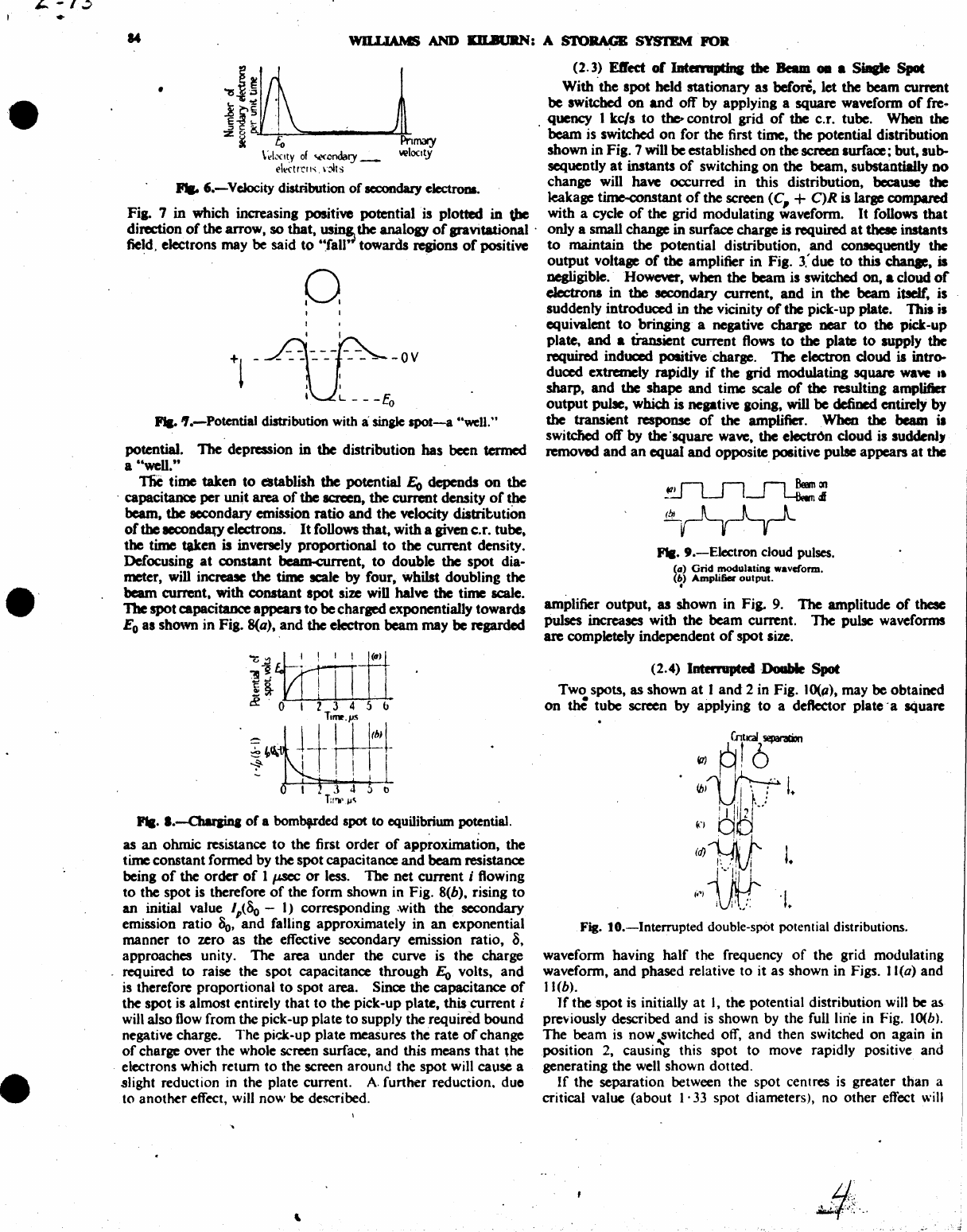
....
6.-Velocity distribution of
secondary
electroua.
Fig. 7 in which increasing positive potential . is plotted in
the
direction
of
the
arrow,
so
that,
us~
the analogy
of
gravitational .
fie~d.
electrons may be said to
'~faW
towards regions
of
positive
o
+1
-~~~-~-ov
U~
-
--Eo
....
'I.-Potential
distribution with a
sinale
spot-a
"well."
potential. The depression in
the
distribution has been
termed
a "well."
TIiC
time taken
to
elItablish the potential
Eo
depends
on
the
, capacitance per unit area
of
the
screeD,
the
current density
of
the
beam, the secondary emission ratio
and
the
velocity
distributiOn
of
the
aecondao'
electrons.
It
follows that, with a
given
c.r. tube,
the time taken is inversely proportional
to
the current density.
Defocusing
at
constant beanJ..cunent,
to
double the spot dia·
meter,
will
increase the
time
scale by four, whilst doubling the
beam
current, with constant spot size
wiD
hal\'C
the
time scale .
1be spot capacitance
appean
to
be
charged exponentially towards
Eo
as shown in Fig. 8(a), and the electron
beam
may be regarded
Fla.
I.-Owaina
of
a bombfrded spot
to
equilibrium potential.
as
an
ohmic resistance to the first order
of
approximation, the
time constant formed by the spot capacitance and beam resistance
being
of
the
order
of
I
p.sec
or
less.
The net
current;
flowing
to the spot
is
therefore
of
the form shown in Fig. 8(b), rising to
an initial value
Ip(So
-
I)
corresponding with the secondary
emission ratio
So,
and falling approximately in
an
exponential
manner to zero as the effective secondary emission ratio,
8,
approaches unity. The area under the curve is the charge
required
to
raise the spot capacitance through
Eo
volts, and
is
therefore proportional
to
spot area. Since the capacitance
of
the spot
is
almost entirely that to the pick-up plate,
this
current;
wilt
also
flow
from
the
pick-up plate to supply
the
required bound
negative charge. The
pid-up
plate meaSures the rate
of
change
of
charge over the whole screen surface, and this means that the
electrons which return to the screen around the spot will cause a
slight reduction
in
the plate current. A. further reduction. due
to another effect,
will
now
be
described.
,
(2.3)
Effect
or
lDtaiiaptina the
Beam
OD • SiIIIIe Spot
With 'the spot held stationary as before, let
the
beam current
be switched on and off by applying a square waveform
of
fre
..
.
Quency
I kc/s to
~control
grid
of
the c.r. tube. When
the
beam
is
switched on for the first time, the potential distribution
shown in Fig. 7 will be established on the screen surface; but, sub..
sequentlyat instants
of
switching on the beam, substantially
no
change will
ha\'C
occurred in this distribution,
bccaU!e
the
leakage tiJne..constant
of
the
screen
(C,
+ C)R is large compared
with a cycle
of
the grid modulating waveform. It follows that
only a small change
in
surface charge is required
at
theae instants
to
maintain the potential distribution, and conJequently the
output voltage
of
the amplifier in Fig.
3.'
due to this
dlanae.
is
negligible. Howe\'Cl', when
the
beam is switched on, • cloud
of
electrons
in
the
secondary current, and in
the
beam
itself:
is
suddenly introduced in
the
vicinity
of
the
pick-up plate.
Thil
is
equivalent
to
bringing a negative charae near to
the
pick-up
plate,
and
a transient current flows
to
the
pla~
to
supply
the
required induced positive charge. 1be electron cloud is intro-
duced extremely rapidly
if
the grid modulating square
waw
It
sharp, and
the
shape and time
scale
of
the resulting amplifier
output pulle, whidl is negati\'C going, will be
defined
entirety by
the
transient
response
of
the amplifier.
When
the
beam i •
switclled
otT
by the'square wave, the
electr~n
cloud is suddenl)
removed and
an
equal
and opposite positive pulse appears at the
F'II.
9.-Electron
cloud
pUlses.
(G)
Grid
modlliatina
waveform.
(11)
Amplifier
output
.
.
amplifier output, as shown in Fig. 9. The amplitude
of
these
pulses increases with
the
beam current. TIle pulse waveforms
are completely independent
of
spot
size.
(2.4)
Interrupted
Doable
Spot
Two spots,
as
shown
at
1
and
2 in Fig. JO(p), may be obtained
on
~
tube screen by applying
to
a deftector plate' a square
CntKAII~
~
Rt6
~11JiuL
!
I~'I""'·
j I
I'
~
(C)
q
MID
1
,-,
~'
...
~.~
'1.+
tAv
Fig.
to.-Interrupted
double-spOt
potential distributions.
waveform having half the frequency
of
the grid modulating
waveform, and phased relative to it as shown in Figs. J 1(0) and
11
(b).
If
the spot
is
initially at
I,
the potential distribution will be as
previously described and
is
shown
by
the full line in Fig.
JO(b).
The beam is now
~witched
off, and then switched on again
in
position
2,
causing this spot to move rapidly positive and
generating the
well
shown dotted .
If
the separation between the spot centres
is
greater than a
critical value (about
l'
33
spot diameters), no other effect
will
•
4-
/3
•
•
•
USB
WI1H
BlNAltY-DlGlTAL
COMPUfING
MAOIINBS
.5
_
--f~}-~--r
1--
f-l_.~
c:
'-'
: '
'_I
, :
rRlsiticn
I
W-P",
..
:--u...
'J!
:4-'...J~2
'('lR1
: i I I • I
. I I I
, I I ,
Ie)
, , I ,
I.
f'
I • t
tIJ
I • I
I',
f
~
• I • r I ,
(i'J~J-L-~~~
Y' I , i
~
: , I
I : I I : : ' I •
. -
~.x;
l :
~
:
~
~
<f)
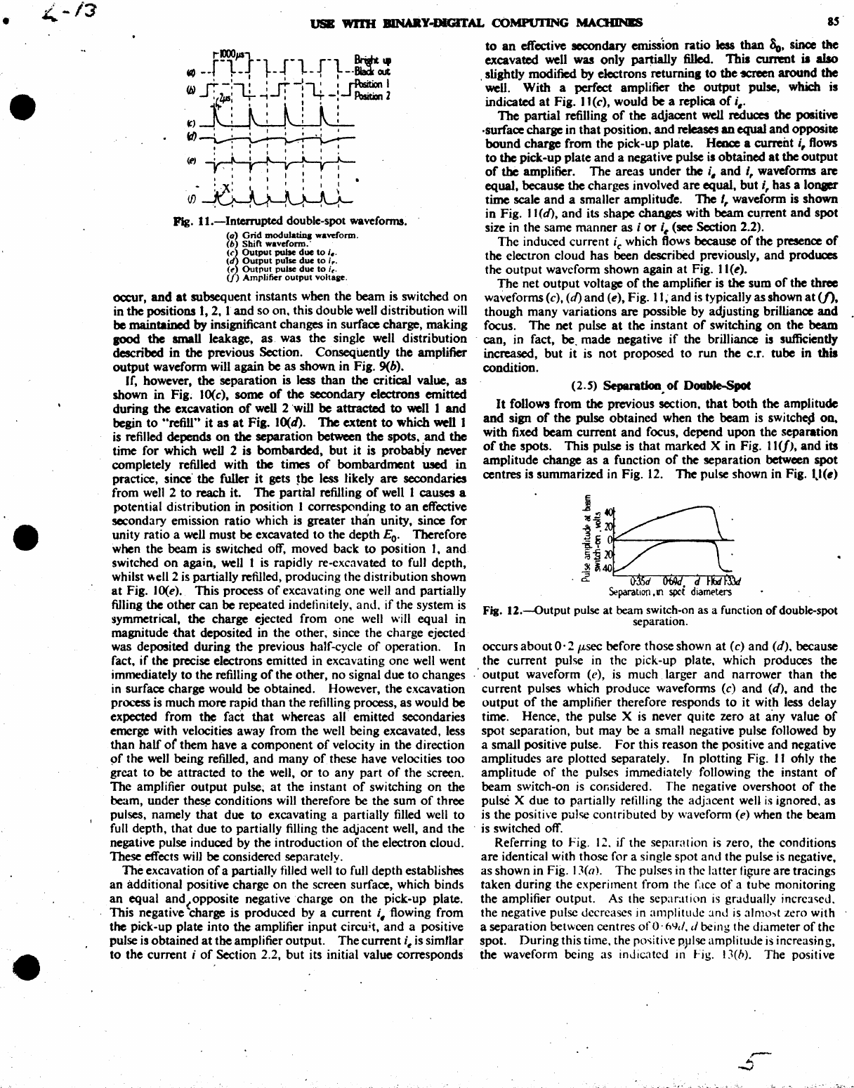
Pig.
I
I.-Interrupted
double-spot wavefonns.
(a)
Grid
modulatiq
waveform.
(~
Shift
waveform.'
(c
Output
pulse
due
to
i
•.
(d
Output
pulse
due
to
ir•
(~
Outl"UI pulse
due
to
i~.
( ) Amplifier
output
voltale.
oocur, and
at
subsequent instants when the beam is switched on
in the positions
1,2,
1
and
so on. this double well distribution will
be maintained by insignificant changes in surface charge, making
aood
the small leakage, as. was the single well distribution
described
in
the previous Section. ConseqUently the amplifier
output
waveform will again
be
as shown in Fig. 9(h).
If, however, the separation is less than the critical value,
as
shown
in
Fig;
100e),
some
of
the
secondary electrons emitted
during the excavation
of
well 2 'will
be
attracted
to
well 1
and
begin
to
"refnr'
it
as
at
Fig. 10(d).
1be
extent
to
which well 1
is
refilled depends
on
the separation between the spots.
and
the
time for which
weD
2 is bombarded,
but
it
is probabiy never
completely refilled with the times
of
bombardment
used
in
practice, since'
the
fuller
it
gets
~be
less likely
are
secondaries
from
well
2
to
reach it. The
panell
refilling
of
well 1 causes a
potential distribution in position 1 corresponding
to
an
effective
secondary emission ratio which is greater than unity, since
for
unity ratio a well must
be
excavated
to
the depth
Eo.
Therefore
when the beam is switched off, moved back
to
position I.
and
switched
on
again, well I
is
rapidly re-excavated
to
full depth,
whilst well 2 is panially refilled, producing the distribution shown
at
Fig.
100e).
This process
of
excavating one well
and
panially
filling the other can
be
repeated indefinitely. and.
if
the system
is
symmetrical. the charge ejected from one well will equal in
magnitude
that
deposited in the other. since the charge ejected
was deposited during the previous half-cycle
of
operation. In
fact,
if
the precise electrons emitted in excavating one well went
immediately
to
the refilling
of
the other, no signal due
to
changes
in
surface charge would
be
obtained. However, the excavation
process is much more rapid than the refilling process, as would
be
expected from
t~
fact
that
whereas all' emitted secondaries
emerge with velocities away from the well being excavated, less
than
half
or
them have a component
of
velocity in the direction
9f
the well being refilled,
and
many
of
these have velocities
too
great
to
be attracted
to
the well,
or
to
any part
of
the screen.
The amplifier
output
pulse~
at
the instant
of
switching
on
the
beam, under
th~
conditions will therefore be the sum
of
three
pulses. namely
that
due
to
excavating a partially filled well
to
full depth. that due
to
partially filling the adjacent well,
and
the
negative pulse induced by the introduction
of
the electron cloud.
These effects will
be
considered separately.
The excavation
of
a panially tilled well
to
full depth establishes
an
additional positive charge
on
the screen surface, which binds
an
equal and(oPposite negative charge
on
the pick-Up plate.
This negative charge is produced by a current
i.flowing
from
the pick-up plate into the amplifier input circuit,
and
a positive
pulse is obtained
at
the amplifier output.
The
current
i~
is simflar
to
the current ;
of
Section 2.2,
but
its initial value corresponds
to
an
effective secondary emisSion ratio
less
than
80,
since the
excavated well was only
pa~ially
filled.
Thil
current is
abo
, slightly modified
by
electrons
retuminl
to
the
'ICfeCfl
around
the
well. With a perfect amplifier the
output
pulse, which is
indicated
at
Fig.
11
(e), would be a replica
of
i •.
The
partial refilling
of
the adjacent well reduces
the
positive
~surface
charge in
that
position.
and
releases
an
equal
and
opposite
bound
charge from the pick-up plate. Heoce a current
i,
ftows
to
the pick-up plate
and
a negative pulse
is
obtained
at
the
output
of
the
amplifier.
The
areas
under
the
i.
and
i, wavefonns are
equal, because the charges involved are equal. but i, has a lonaer
time scale
and
a smaller amplitude.
1be
I, waveform is shown
in Fig. J 1
(d),
and its shape
chanaes
with
beam
cu.rrent
and
spot
size in the same manner as ;
or
i,
(see Section 2.2).
The induced current
ie
which ftows because
of
the presence
of
the electron cloud has been described previously,
and
produces
the
output
waveform shown again
at
Fig. I I (e).
The
net
output
voltage
of
the amplifier is the sum
of
the three
waveforms (e),
(d)
and (e), Fig. 1
I;
and
is
typically as shown
at
(f),
though many variations are possible by adjusting brilliance
and
focus.
The
net pulse
at
the instant
of
switchina
on
the beam
. can, in fact,
be,
made negative
if
the brilliance
is
sufficiently
increased,
but
it is
not
proposed
to
run
the C.T. tube in this
condition.
(2.
S)
Separadoa.
or
DCMlbJe-Spot
It
follows from the previous section,
that
both
the amplitude
and
sign
of
the pulse obtained when the beam is switchesl on.
with fixed beam current
and
focus, depend
upon
the separation
of
the spots. This pulse
is
that marked X in Fig.
11
(1),
and
its
amplitude change as a function
of
the separation between
spot
centres is summarized in Fig.
12.
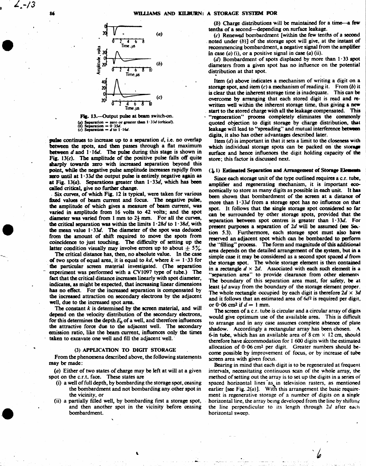
The pulse shown
in
Fig.
1..1(.)
j
~!l
~~
~
~
llP'---:=---~-
fa~
~~40
2
~~~d~rlrr.-d~~~
Separation
,In
spct
diameters
Fig.
12.-Output
pulse at beam switch-on as a function
of
double-spot
separation.
occurs
about
O'
2
(Lsec
before those shown
at
(e) and
(d).
because
the current pulse in the pick.-up plate. which produces the
.'
output
waveform (e), is much larger
and
narrower than the
current pulses which produce waveforms (e)
and
(d),
and the
output
of
the amplifier therefore responds
to
it with less delay
time. Hence, the pulse X
is
never quite zero
at
a'ny
value
of
spot separation, but may
be
a small negative pulse followed by
a small positive pulse.
For
this reason the positive and negative
amplitudes are plotted separately. In plotting Fig.
II
oldy the
amplitude
of
the pulses immediately following the instant
of
beam switch-on is considered. The negative overshoot
of
the
pulse X due
to
partially retllling the adjacent well
is
ignored. as
is the positive pulse contributed
by
waveform (e) when the beam
. is switched off.
Referring
to
Fig.
12.
if
the separation
is
7.ero,
the conditions
are identical with those for a single spot and the pulse
is
negative,
as shown in Fig. ]
3(a). The pulses in the latter
fi~ure
are tracings
taken during the experiment from the face
of
a tuhe monitoring
the amplifier output. As the separation
is
gradually incrc:l,ed.
the negative pulse decrcases in amplitude :lnd
is
31most zero with
a separation between centres
oro·
flYd. d being the diameter
of
the
spot. During this time. the
po..;itive
p.plsc
amplitude
is
increasing,
the waveform being as inJic.lted in Fig. I J(h). The positive
L.-/3
•
•
'.
WILLIAMS AND
XD...BtJRN:
A STORAGE SYSTEM
FOR
(0)
6 , 4
~
8
!I
lIme.f'S
i<:3
:~b
8
~
(b)
TIme.
#AS
~
f'l
'
!f
(c)
20
O}46A~
Ttmt.J.IS
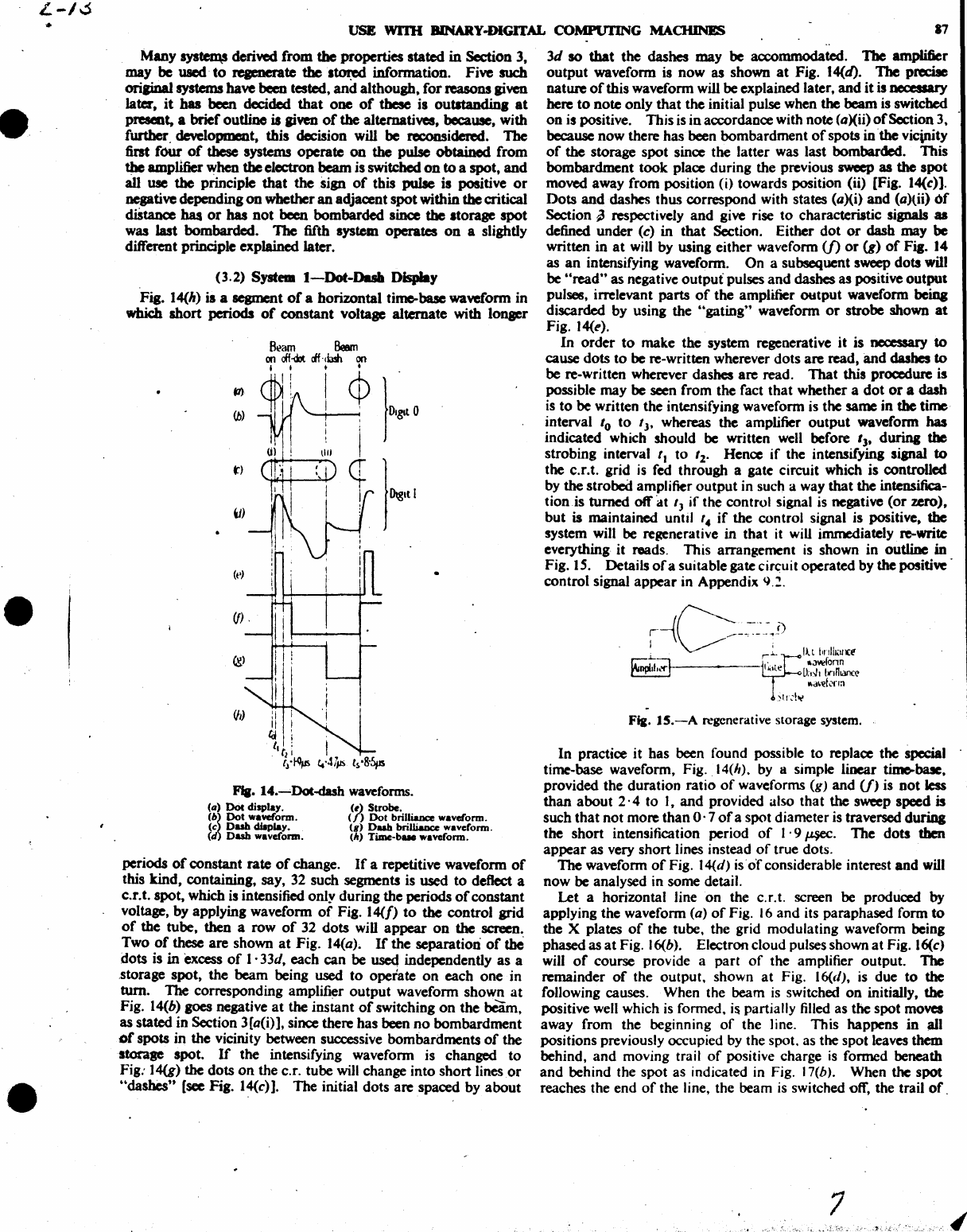
FII.
13.-Output
pulac
at
beam
switch-on.
(Cll
Separation
-zero
or
peater
&baD
1 .
3Jd
(critical).
(6
Separation
-
O·l5tl.
(c SeparatioD -d
to
1 .
If
•.
. puJIe continues
to
increase
Up
to
a separation
d,
i.e.
no
overlap
betvtwD
the
spots,
and
then
passes through a flat maximum
between
d
and
l'
J6d.
The
pulse during this stage is shown
in
Fia.
13(e).
The
amplitude
of
the
positive pulse falls oft' quite
lharply
towards
zero
with
increased
separation beyond this
point, while
the
negative pulse amplitude increases
rapi~ly
from
ao
until
at
l'
33d
the
output
pulse is entirely. negative
apin
as
at
Fig. 13(a).
Separations
greater
than
l'
33d, which
has
been
called critical, give
no
further change. .
. Six curves
of
which Fig.
12
is typical, were taken
for
various
fiMd
values'
of
beam
current
and
focus.
The
negative pulse,
the
amplitude
of
which gives a measure
of
beam
current,
was
varied
in
amplitude from
16
volts
to
42 volts;
and
the
spot
diameter was varied from 1 mm
to
2t
mm.
For
all the curves,
the
aitical
separation
was
within
the
limits
l'
28d
to
1 .
3&1.
with
the
mean
value
I·
33d.
The
diameter
of
the
spot
was
deduced
from the
amount
of
shift required
to
move
the
spots from
coincidence
to
just
touching.
The
difficulty
of
setting
up
the
latter condition visually may involve errors
up
to
about
± S
%.
The
critical distance has, then,
no
a~lute
value. In the
case
of
two spots
of
equal area,
it
is equal
to
kd,
where k =
1'33
for
the
particular
SCMen
ma~rial
investigated. (The separation
experiment was performed with a CVI097
type
of
tUbe.)
The
fact
that
the
critical distance increases linearly with
spot
diameter,
indicates, as might
be
expected,
that
increasing linear dimensions
has
no
effect.
For
the
increased separation is compensated by
the 'increased attraction
on
secondary electrons
by
the
adjacent
well, due
to
the increased
spot
area. .
The
constant k is determined by
the
screen material,
and
will
depend
on
the velocity distribution
of
the secondary electrons,
for
this determines
the
depth
Eo
of
a well,
and
therefore influences
the
attractive force
due
to
the adjacent well.
The
secondary
emission ratio, like
the
beam
current, influences only
the
times
taken
to
excavate
one
well
and
fill
the
adjacent'w~ll.·
(3)
APPUCATION
TO
DIGIT STORAGE
From
the phenomena described above, the following
state~nts
may
be-
made:
(a) Either
of
two states
of
charge may be left
at
will
at
a given
spot
on the c.r.t. face. These states are
(i)
a
well
of
full depth, by bombarding the storage spot, ceasing
the bombardment
and
not
bombarding any
other
spot
in
the vicinity,
or
(ii)
a partially filled well, by bombarding first a storage spot.
and
then
another
spot
in
the vicinity before ceasing
bombardment.
\
(b) Charge distributions will be maintained for a
timo-a
few
tenths
of
a
second-depending
on.
surface leakage.
(c) Renewed bombardment [within the few tenths
of
a second
,noted
under (b))
of
the storage
spot
will give,
at
the instant
of
recommencing bombardment, a negative signal from the amplifier
in
case (a) (i),
or
a positive signal in
Case
(a) (U).
(d)
Bombardment
of
spots displaced by more than 1,
33
spot
diameters from a given spot has
no
influence
on
the potential
distribution
at
that
spot.
Item (a) above indicate! a mechanism
of
writing a digit
on
a
storage spot,
and
item
(c)
a mechanism
of
reading it. From
(b)
it
is clear
that
the
~rent
storage time is inadequate. This can' be
overcome
by
ananging
that
each stored digit
is
read
and
~
written well within the inherent storage time, thus giving a
new
.
start
to
the stored charge with all the leakage compensated. This
. "reaeneration" process completely eliminates the commonly
quoted objection
to
digit storage by charge distribution, thaI
leakaae will lead
to
"spreading"
and
mutual interference betweaI
digits,
it
also has
other
advantages described later. .
Item
(d)
is
important
in
that
it
sets a limit
to
the
cl~ness
With
which
individual storage spots
can
be packed
on
the
stOlql
surface
and
hence influences the digit holding capacity
of
the
store; this factor is discussed next.
(~1)
Estimated Separation and
Ammgemeot
of
Storage
~
Since
each storage
unit
of
the type outlined requires a c.r. tube,
amplifier
and
regenerating Ihcchanism,
it
is important
ec0-
nomically
to
store as many digits as possible
in
each unit.
It
bas
been shown
that
bombardment
of
the
screen
at
a distaooe
or
more
than
1· 33d from a storage
spot
has
no
influence
on
that
spot.
It
follows
that
the
single storage
spot
considered so rar
can
be surrounded by
other
storage spots, provided
that
the
separation
t.etween
spot
centres is greater than 1· 33d.
For
I
present purposes a separation
of
2d will
be
assumed (ace So.;. i
tion
5-.3).
Furthermore, each storage
spot
must also have
reserved
an
adjacent
spot
which
can
be bombarded
to
perform
the
"filling" process.
1be
form
and
magnitude
of
this additional
area
depends
on
the
detailed arrangement
of
the system,
but
in
•
simple
case
it may
be
considered as a second spot spaced d from
the
storage
spot.
The whole storage element is then contained
in a rectangle d x 2d. Associated with each such element is a
"separation area"
to
provide clearance from
other
element'
The
boundary
of
this separation area must, for safety, be
at
least
!d
away from the boundary
of
the storage element proper.
The
whole rectangle occupied by each digit is therefore
2d
x
3d
and
it follows
that
an
estimated area
of
6(/2
is required per digit.
or
0'06
cm
2
if
d = I nun.
The
screen
of
a c.r. tube is circular
and
a circular array
of
digits
would give optimum use
of
the available area. This is difficult
to
arrange
and
in any case assumes complete absence
of
plate
shadow. Accordingly a rectangular array has been. chosen. A
~in
tube, which has
an
available area
of
8 cm x
12
cm, should
therefore have accommodation for I 600 digits with the estimated
allocation
of
0·06
cm2 per digit.
Greater
numbers should be-
come possible by improvement
of
focus,
or
by increase
of
tube
screen area with given focus.
Bearing in mind that each digit
is
to be regenerated
at
frequent
intervals, necessitating continuous scan
of
the whole array.
the
method
of
setting
out
the array is
to
set up the
digit~
in a series
of
spaced horizontal
lines·
as in television rasters, as mentioned
earlier [see
Fig.2(a)].
Willi this arrangement the basic requin:-
ment
is
regenerative storage
of
a number
of
digits on a
sin(EK
. horizontallir..e, the array bemg developed from the line
by
shiftillt!
the line perpendicular
to
its length through
2d
after
cadl
horizontal sweep.
L-/~
•
•
•
USE
WI1H
BlNARY-DlGlTAL
COMPUI'ING
MACHINES
17
Many
sys~
deriwd
from
the
properties stated
in
Section
3,
may be
used·
to
regenerate
the
s~
information. Five such
oriJiDal
systems have been tested,
and
although, for reasons given
later,
it
has
been
decided
that
one
of
these
is
outstaodin.
at
present, a brief outline is given
of
the alternatives, because, with
further. development, this decision will
be
reconsidered.
The
first
four
of
these
systems operate
on
the pulse obtained from
the
amplifier when
the
electron beam is switched
on
to
a spot,
and
all
use
the principle
that
the sign
of
this pulse is positive
or
negative depending on whether an adjacent
spot
within
the
critical
diStance
has
or
has
not
been bombarded
since
the storage
spot
was last bombarded.
The
fifth system operates
on
a slightly
different principle explained later.
(3.2) System
I-Dot-Dash
Display
Fig. 14(h) is a segment
of
a horizontal time-base waveform in
which short
periods
of
constant voltage alternate
with
lonser
(a)
Dot
display.
(b~
Dot waveform.
(c
Dash
display.
(d
Dub
waveform.
(d
Strobe.
(/)
Dot brilliance waveform.
(g)
Dub
brilliaDce waveform.
(It)
Time-b
...
waveform.
periods
of
constant rate
of
change.
If
a repetitive waveform
of
this kind, containing, say,
32
such segments is used
to
deflect a
c.r.t. spot, which is intensified only during the periods
of
constant
voltage, by applying wavefonn
of
Fig. 14(/)
to
the
control grid
of
the tube, then a row
of
32 dots will appear
on
the
screen.
Two
of
these are shown
at
Fig. 14(a).
If
the separation
of
thC
dots is
in
excess
of
1 . 33d, each
can
be used independently
as
a
,storage spot, the beam being
used
to
operate
on
each
one
in
turn. TIle corresponding amplifier
output
wavefonn shown
at
Fig. 14(b)
goes
negative
at
the instant
of
switching
on
the
beam,
as stated in Section
3[a(i)],
since there has been
no
bombardment
of
spots in the vicinity between successive bombardments
of
the
ltorap
spot.
If
the intensifying wavefonn is changed
to
Fig: 14(g)
the
dots
on
the
C.r.
tube will change into short lines
or
"dashes"
(see Fig. l4(c»). The initial dots are spaced by
about
3d
so
that the
dashes
may be accommodated. The amplifier
output
waveform
is
now as shown
at
Fig. 14(d). 1be
pRdae
nature
of
this wavefonn will be explained later,
and
it
is necessary
here
to
note only
that
the initial pulse when the
beam
is switched
on
is positive. This is in accordance with note
(a)(ii)
of
Scction 3.
because now there has been bombardment
of
spots in
'the
vicinity
of
the
storage
spot
since the latter was last bombarded. This
bombardment
took
place during the previous
sweep
as the
spot
moved away from position
(i)
towards position
(ii)
[Fig. l4(c)].
Dots
and
dashes thus correspond with states (a)(i) and (a)tii)
of
Section
~
respectively
and
give rise
to
characteristic signals as
defined under (c) in
that
Section. Either
dot
or
dash may be
written
in
at
will by using either wavefonn
(f)
or
(g)
of
Fia. 14
as
an
intensifying wavefonn.
On
a subsequent
sweep
dots will
be "read" as negative
output
pulses
and
dashes
as
positive output
pulses. irrelevant parts
of
the amplifier
output
waveform beiDa
discarded by using the "gating" waveform
or
strobe shown
at
Fig.
14(1").
In
order
to
make the system regenerative it is necessary
to
cause dots to be re-written wherever dots
are
read,
and
dashes
to
be re-written wherever dashes
are
read.
That
this procedure is
possible may be seen from the fact that whether a
dot
or
a dash
is
to
be
written the intensifying waveform is the same in
the
time
interval
'0
to
'l'
whereas
the
amplifier
output
waveform
has
indicated which should be written
well
before
'l'
during
the
strobing interval
'I
to
'2'
Hence
if
the intensifying sianal
to
the c.r.t. grid
is
fed through a gate circuit which is controlled
by the strobed amplifier
output
in such a way that the intensifica-
tionis
turned
off
at
I)
if
the control signal is negative
(or
zero),
but
is maintained until
14
if
the control signal is positive,
the
system will be regenerative in that it will immediately. re-write
everything it reads. This arrangement
is
shown in outline in
Fig. IS. Details
ofa
suitable gate
cir~uit
operated by the
positi~'
control signal appear in Appendix 9.1 .
Itt
bnHl<lllCt
•
.Jwfonn
U:I>l1
hnnkll1C<.'
lI,wef0l'm
Fig.
lS.-A
regenerative storage
system.
In practice it has been found possible to replace the special
time-base waveform, Fig.
14(11).
by
a simple linear time-bue,
provided the duration ratio
of
waveforms
(g)
and
(f)
is
not
less
than
about
2·4
to
I,
and
provided also that
the
sweep speed is
such that not more than
o·
7
of
a spot diameter is traversed during
the short intensification period
of
I·
9~.
The dots
then
appear
as very short lines instead
of
true dots.
The waveform
of
Fig. 14(d)
iso'f
considerable interest
and
will
now
be
analysed in some detail.
Let a horizontal line
on
the c.r.t. screen be produced
by
applying the wavefonn (a)
of
Fig.
16
and its paraphased form
to
the X plates
of
the tube. the grid modulating waveform being
phased as
at
Fig. l6(b). Electron cloud pulses shown
at
Fig.
16(c)
will
of
course provide a part
of
the amplifier output. The
remainder
of
the output. shown
at
Fig. 16(d),
is
due
to
the
following causes. When the beam
is
switched
on
initially,
the
positive well which
is
formed.
is
partially filled as the spot moves
away from the beginning
of
the Jine. This happens
in
all
positions previously occupied by the spot. as the spot leaves them
behind,
and
moving trail
of
positive charge
is
formed beneath
and
behind the spot as indicated in Fig. J 7(b). When
the
spot
reaches the end
of
the line, the beam
is
switched off, the trail
of
.
7
•
•
•
II
WJLI...IAMS
AND
m.BVRN:
A STORAGE SYST£M FOR
*'
+---...,....-.v----i'"-
,
....
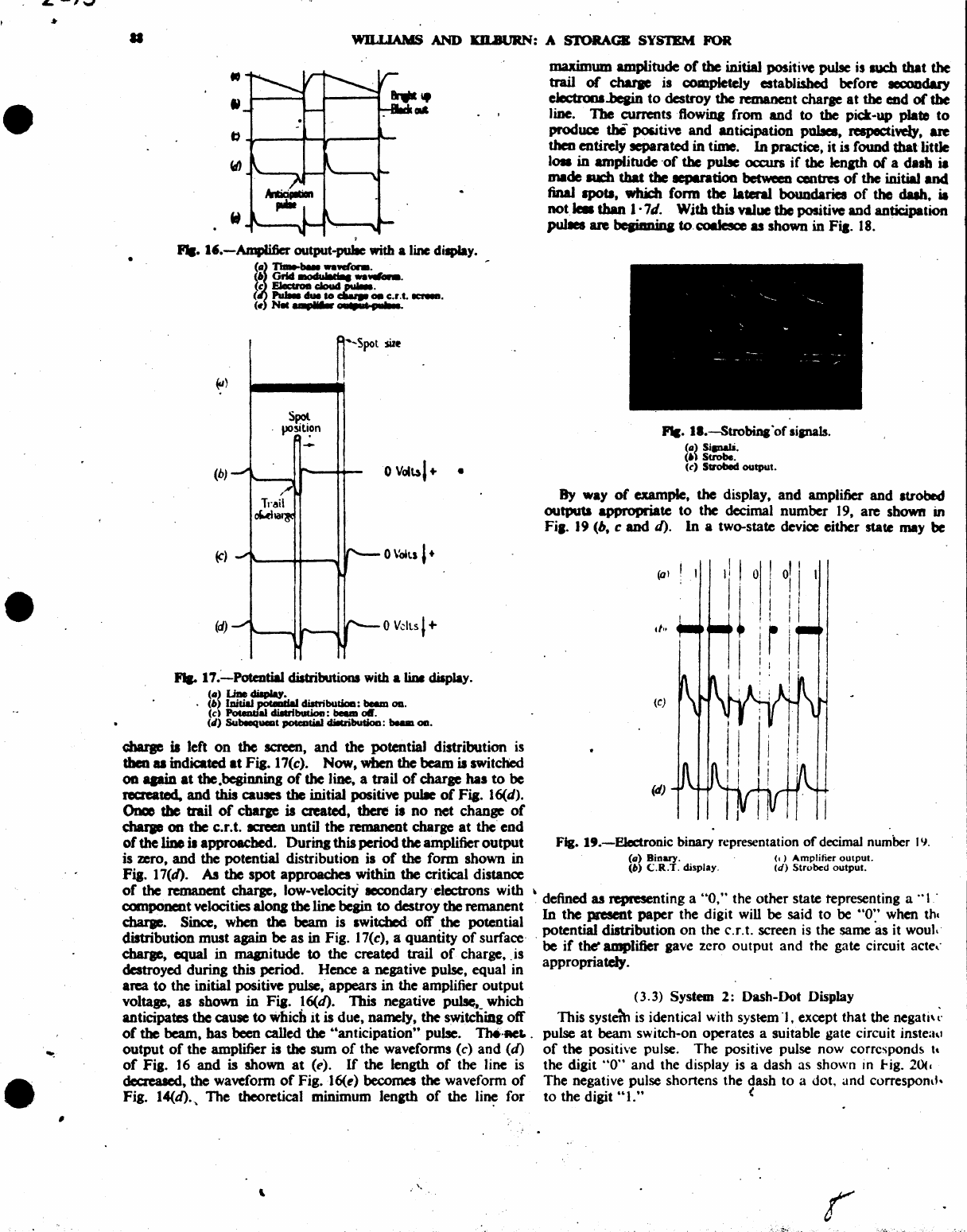
l'.-AmpIifier
output-pullc with a line dilPlay.
(b)
(c)
(d)
(6
Oriel
-0+':
t,.
..
"'-.
(~
n..
........
ont.
(c EJer:uoe cloud
.,....
(
rw..
due
10
~
08
c.r.t.
1CNeIl.
( .
.-..
.................
U
Spot
-
.--.
o VdlSl +
....
17
.~PotentiaJ
distributions with a
liDa
display.
.
~:~
::-J~I
diatributioa: beem
OD.
(d
Poteodal
dilUtbution:
beuI~.
(4)
Subeequaat potCDtial clilcributioa:
....
OD.
maximum amplitude
of
the
initial positive pulse is
aucb
that
the
trail
of
charae
is completely established
~fore
secoudary
electrooa..beain
to
destroy
the
remanent charae
at
the
e:od
of
the
line.
The
currentsflowiDg
from
and
to
the
pick-up plate
to
produce
the po5itive
and
anticipation pubea, respecti\'eJy,
are
then
entirely separated
in
time.
In
practice, it is found
that
little
1011
in
amplitude
'of
the
pulse occurs
if
the
lenlth
of
a dash
i.
made
IUCb
tbat
the
aepuation
between centres
of
the
initial
and
final
spotl,
which
fonn
tbe lateral boundaries
of
the
dub,
it
not_
than 1·7d. With this value
the
positi\'C and anticipation
puIIes are hePmioa
to.'-'OI.Iesce
as
shown
in
Fia.
18.
FIe
.•
I.-Strobina
'of
lianals.
(II)
Sipab.
(')
Strobe.
(c)
SvobecI
output.
By
way
of
example, the display,
and
amplifier
and
Itrobed
outpUts
appropriate
to
the decimal number
19,
are shown
in
Fi,.
19
(b,
c
and
d).
In
a two-state device either state may be
Fig.
It.-Electronic
binary representation
of
decimal number
IY.
(II)
Binary.
(b)
C.R.T.
display.
(.)
Amplifier
output.
(d)
Strobed
output.
\ defined
as
representing a
"0,"
the other state tepresenting a
"I
.
cbarae
iI
left
on
the
screen,
and
the potentia) distribution is
tben u indicated
at
Fig.
17(c).
Now,
when
the
beam is switched
OIl
apin
at
the
.beginning
of
the
line. a trail
of
charge
has
to
be
recreated,
and
this causes
the
initial positive pulle
of
Fig. 16(d).
Once
tbe
trail
of
clwp
iI
created,
there
is
no
net
change
of
duup
on
the
c.r.l.
ICReIl
until the remanent charge
at
the'
end
of
the
tiDe
ia
approached.
Durina
this period
the
amplifier
output
is zero,
and
the potential distribution is
of
the
form shown
in
Fig. 17(d).
As
the
spot
approaches within
the
critical distance
of
the remanent charge, low-velocitY secondary 'electrons with
component velocities along
the
line begin
to
destroy
the
remanent
charge. Since, when
the
beam
is Iwitched
off
the potential
distribution must again
be
as
in
Fig. 17(c), a quantity
of
surface·
charge, equal
in
mapitude
to
the created trail
of
charge, . is
destroyed during this period. Hence a negative pulse, equal in
area
to
the initial positive pulse, appears
in
the amplifier
output
voltage,
as
shown
in
Fia. 16(d). This negative
p~.
which
anticipates the cause
to
which
it
is due, namely,
the
switching off
of
the
beam, has
been
called
the
66
ant
icipation" pulse.
llMt·ReI..
output
of
the amplifier is the
sum
of
the waveforms (c)
and
(d)
of
Fig.
16
and
is shown
at
(e).
If
the
length
of
the Jine is
dcc.raIed,
the
wavefonn
of
Fig. 16(e) becomes the waveform
of
Fig. 14(d).
~
The theoretical minimum length
of
the
li~
for
..
In
the
present
paper
the digit will
be
said to be
"0:'
when
the
potential distribution
on
the c.r.t. screen
is
the
same
as it
wouk
, be
if
the"
amplifier gave zero output and the gate circuit
acte,,'
appropriately.
(3.3) System
2:
Dash-Dot Display
This
systdb
is
identical with
sys~m'),
except
that
the negati';'
pulse
at
beam switch-on operates a suitable gate circuit jnste;",
of
the positive pulse. The positive pulse now corresponds h
the digit "0"
and
the display is a dash as shown
in
Hg.
20Cc
The negative pulse shortens the dash
to
a dot, and correspond.
to
the digit
"1."
(
L-/3
.,.
•
•
•
USE WI11I BINARY-DIGITAL COMPUI'ING
MAaDNBS
89
~
lll~
1
.~t-'
! I r
~
j f t t
f~'
.1
t:)
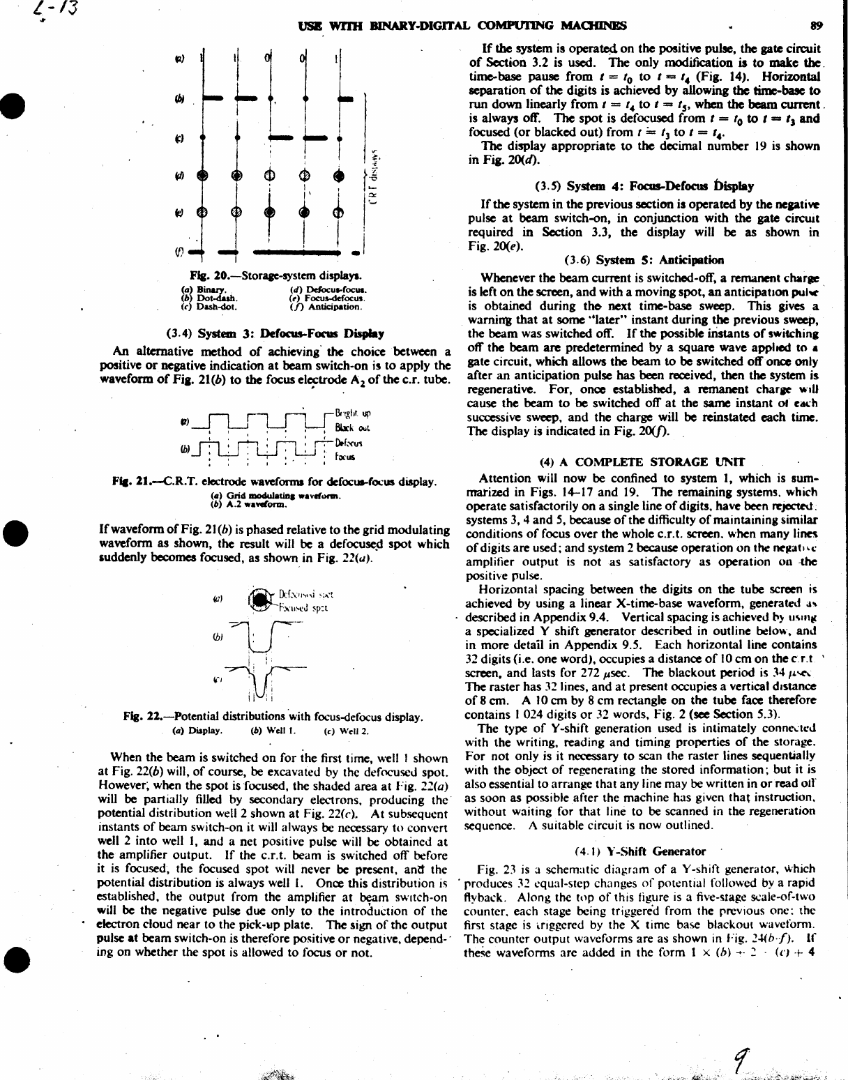
Fig. lO.-Storaae-system displays.
Ca)
Binary
..
(b)
Dot-dash.
(C')
Dash-dot.
(d)
Dcfocul-roc:ua.
(to)
Foc:us-def'ocus.
(f)
Anticipation.
(3.4) System
3:
Defocus-Foras Display
An
alternative
method
of
achieving' the choice between a
positive
or
negative indication
at
beam
switch-on
i5
to
apply the
waveform
of
Fi,.
21(b)
to
the focus
el~trode
Al
of
the
c.r. tube.
t7)
~l.SU8I'fght.
up
.'
",
I
8I.1ck
OUl
(b)
r.--,
;
~
: n :
r.-
o.rXU1
..J
:
~
;
L;-J
:
.L!-J
:
f;x-U$
• I I I I • t
Fla.
ll.--C.R.T.
electrode waveforms for dcfocua-(ocus display.
(_)
Grid
JDOduI.tin
••
aveform.
(b)
A.2
••
wlorm.
If
waveform
of
Fig.
21
(b) is phased relative
to
the grid modulating
waveform
as
shown, the result will
be
a
defocuse~
spot
which
suddenly
becomes
focused,
as
shown in Fig. 22(cl).
IbIV-
"'T
Fla.
ll.-Potential
distributions 'with focus-defocus display.
(a)
Display. (b) Well
I.
(c)
Well 2.
When the beam is switched
on
for
the first time, well I shown
at
Fig. 22(b) will,
of
course, be excavated by the defoe-used spot.
However~
when the
spot
is focused, the shaded
area
at
Fig.
21(a)
will be partially filled by secondary electrons, producing
the'
potential distribution well 2 shown
at
Fig.
22(c).
At
subsequent
instants
of
beam switch-on it will always
be
necessary
to
convert
well 2
into
well I,
and
a
net
positive pulse will
be
obtained
at
the amplifier
output.
If
the c.r.t. beam is switched
off
before
it is focused, the focused
spot
will never be present,
antt
the
potential distribution is always well I. Once this distribution
is
established. the
output
from the amplifier
at
beam SWitch-on
will
be
the negative pulse
due
only
to
the introduction
of
the
• electron cloud
near
to
the pick-up plate.
The
sign
of
the
output
pulse
at
beam
switch-on is therefore po!\itive
or
negative, depend- .
ing
on
whether the
spot
is
allowed
to
focus
or
not
.
If
the system is
operatc4
on
the
positive pulse, the gate circuit
of
Section 3.2 is used. The only modification is
to
make
the.
time-base
pause
from
I =
'0
to
I =
'.
(Fig. 14). Horizontal
separation
of
the
digits is achieved by allowing
the
timc-basc
to
run
down
linearly
from
I =
I.
to
I =
I"
when
the
beam
current.
is always off. TIle
spot
is defocuscd
from
I
==
'0
to
I
==
IJ and
focused
(or
blacked
out)
from I
;..
t)
to
I = I
•.
The display
appropriate
to
the
decimal
number
19 is shown
in
Fia.
20(d).
(3.
S) System
4:
Focus-Defocus Display
If
the
system in
the
previous section is operated by the
nepti~
pulse
at
beam switch-on, in conjunction with the gate
circwt
required
in
Section 3.3,
the
display will
be
as
shown in
Fig. 20(£».
(3.6)
System
5:
Anticipation
Whenever the
beam
current
is switched-off, a remanent
du.rae
is left
on
the
screen,
and
with a moving
spot,
an anticipatIon
pul~
.
is obtained
during
tho
next time-base sweep.
This
gives a
wamin'g
that
at
some
"later"
instant
during
the
previous sweep,
the
beam
was switched off.
If
the possible instants
of
swiichina
off
the
beam
are
predetermined by a
square
wave applied
10
•
gate circuit. which allows
the
beam
to
be switched
off
once only
after
an
anticipation pulse
has
been received, then
the
system is
regenerative.
For,
01lClC
established, a remanent charae
w.D
cause the
beam
to
be
switched
off
at
the
same
instant
of
C<Kh
successive sweep,
and
the
charge will
be
reinstated
each
time.
The display is indicated in Fig. 20([).
(4) A
COMPLETE
STORAGE
UNIT
Attention
will
now
be
confined
to
system
I,
which is
sum-
matized in Figs.
14-17
and
19.
The
remaining systems. which
operate
satisfactorily
on
a single line
of
digits, have
bec-n
rcjcc1N;
systems 3, 4
and
5, because
of
the difficulty
of
maintaining similar
conditions
of
focus
over
the whole c.r.t. screen. when many
linn
of
digits
are
used;
and
system 2 because operation
on
the
~tfatl\oC:
amplifier
output
is
not
as satisfactory as operation 011 -the
positive pulse.
Horizontal spacing between
the
digits
on
the
tube screen is
achieved by using a linear X-time-base waveform, generated
a~
described in Appendix 9.4. Vertical spacing is achieved
~)
U\lI\tc
a specialized Y shift generator described in outline below,
anJ
in
more
detail in Appendix 9.5. Each horizontal line
contains
32 digits (i.e.
one
word), occupies a distance
of
10
cm
on
the
c.r.t \
screen.
and
lasts for 272 ",sec. The
blackout
period is J4IL'Cl.
The raster
has
32 lines,
and
at
present occupies a vertical distance
of
8
em.
A
10
em
by 8
cm
rectangle
on
the
tube
face therefore
contains I 024 digits
or
32 words, Fig. 2 (see Section 5.3).
The
type
of
Y
Mshift
generation used is intimately
conne~tcJ
with the writing, reading
and
timing properties
of
the storage.
For
not
only is it necessary
to
scan the raster lines sequentially
with
the
object
of
regenerating the stored information; but it is
also essential
to
arrange
that
any line may
be
written in
or
read
011"
as soon as possible after the machine has given
that
instruction,
without waiting for
that
line
to
be
scanned in the regeneration
sequence. A suitable circuit is now outlined.
(4.1)
Y-Shift
Generator
Fig. 23
is
a schematic diagram
of
a Y -shift generator. which
. produces
32
~qual-step
changes
of
potential followed
by
a rapid
flyback. Along the
top
of
this figure
is
a five-stage Sl.:ale-of-two
counter. each stage being triggered from the prevIous
onc:
the
first stage is
~nggered
by the X time base blackout wavefoml.
The
counter
output
waveforms are as shown in Fig.
'!.~(b·fJ.
If
theSe waveforms are
added
in the form 1 x
(b)
-+.
2 .
(n
+ 4
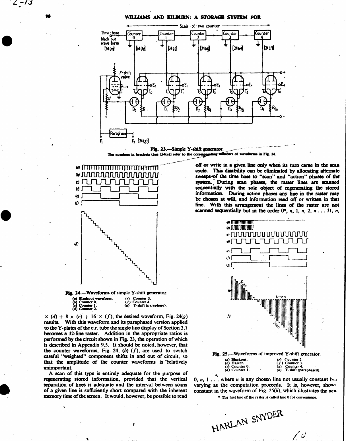
·L-13
Jf
•
•
•
WILLIAMS
AND
JaLBl1IIN: A S'I'OIlAGB SYS'IEM FOR
TiJ1l('-be5e
black-out·
waw-form
[24(aj
_
.............
.
PII.
23.-5imp1e
Y-Ihift
paeratDr.
____
~
o·~
•..•••
-
••
--
••
---
n.
Dumbera
ia
.....
lbaa
1lA<-)J
ref"
to
abe
"!3P
..
~
01
••
~
ia
Fi8.
24
.
.,
111111111111111111'
III
1.11
H f n f n
---'
.-.------
--.-oft' or write in •
given
tiDe
0DIy
wheD
its
tum
came
in
the
IC8Il
,~.
cyde.
Tbia cliIability
can
be
eliminated
by
alJocatinl alternate
\If'
lweepleof
the
time bale
to
66scan"
and
.. action" pbaaea
of
the-
t)
system. •
Durina
ICaD
pbaaes,
the
raster
linea
are
IC8IUled
d scquendauy with
the
.ole object
of
reaenentiq
the
stored
information.
Dwinc
action phases any line
in
the
ruter
may
~
J
be
ctw.n
at
wiD,
and information
read
oft"
or
written
in
that
(f)
J line. With this
arranaement
the lines
of
the raster
are
DOt
FII.
14.-Waveforma
of
simple Y-shift generator.
(6
Counter
O.
.
(.f)
Counter
4.
~~
__
out
wa_Oral.
(,.) Counter 3.
(c
Couat«..
(6)
V-shift
(paraphue).
~
Coaater 2.
X (4) + 8 X
(e)
+
16
x
(/),
the desired waveform, Fig. 24(g)
results. With this waveform and its paraphased version applied
to
theY-plates
of
the c.r. tube the single line display
of
Section
3.1
becomes a 32-line raster. Addition
in
the appropriate ratios is
performed by
the
circuit shown
in
Fig. 23, the operation
of
which
is described in Appendix 9.5.
It
should
be
noted, however,
that
the
counter waveforms, Fig. 24,
(b)-(/),are
used
to
switch
careful "weighted" component shifts in
and
out
of
circuit, so
that
the
amplitude
of
the counter waveforms is -relatively
unimportant.
A scan
of
~is
type is entirely adequate for
the
purpose
of
regenerating stored information, provided that the vertical
acparation
of
lines is adequate and the interval between scans
of
a given line is sufficiently short compared with the inherent
memory
time
of
the
~n.
It
would, however, be possible to read
scanned sequentially but
in
the
order
0·,
n, I,
n,
2. n
...
31,
n •
•
ii1i1lifiliiiiilill
lbI
JlIlIUUUU1JU1f
tI
dI
..,
•
Aftlcn
I
~
I
Fla.
1S.-Waveforms
of
improved Y-shift generator.
~
(a)
Blackout.
(b)
Halver.
(d
Counter
0;
(d)
Counter
I.
(to)
Counter
2.
(I)
Counter
3.
td
Counter
4.
(h)
Y -shift
(parapbued).
0, nt 1
...
where n is any chosen line not usually constant b\,(
varying as
the
computation proceeds.
It
is.
however, she,,",
constant in
the
waveform
of
Fig. 25(h), which illustrates
the
rw-
• The
fint
liDe
or
the
raster
i.
called
IiDc
0
fOl'
convenielra.
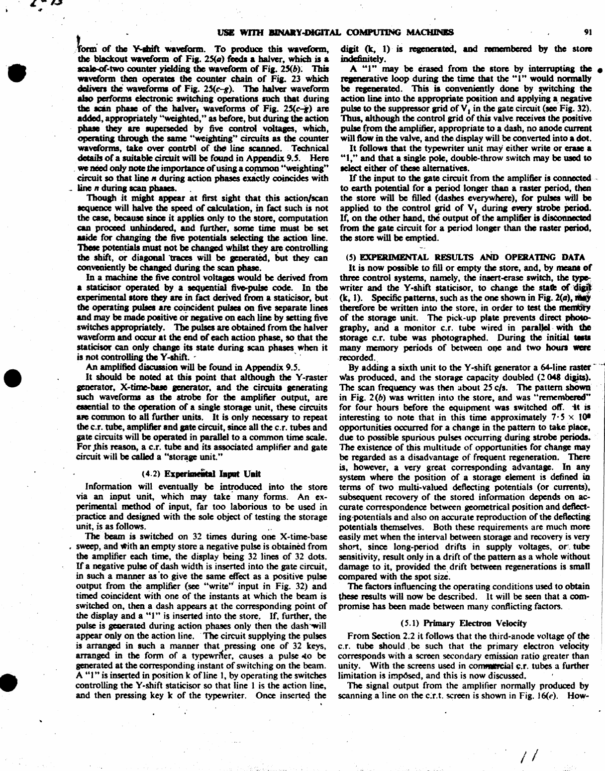
L-I.3
01
-.
•
•
USE WITH IIINMY-DIGlTAL COMPUTING MACHINBS
91
Jomi
of
~
¥-Ibif\
~Yeform.
To
produce
this
waveform,
diait
(t,
t)
is
reaenerated,
and
nmembend
by
the
store
the
blackout
~orm
or
Fil.
2S(.)
reeds
a balver,
wbidl
is a iDdcfinjtely.
acaJo.of-two
counter
yiddina
the
waveform
of
Fil.
2S(b)~
1bia
A
"I"
may
be
erased
from
the
store
by
interruptiRa the •
wawiorm
then
operates
the
counter
chain
of
Fia. 23 which
repnerative
loop
during
the
time
that
the
"1"
would
normaUy
cWiven the
wa~orma
of
Fil.
2S(c-g). The balver
waveform
be
reaeoerated. 'Ibis is conveniently
done
by
switchinl
the
abo performs electronic
switdliDI
operations
audl
that
durina
action line
into
the
appropriate
position
and
applyiDl
a,
nep.ti...e
the
an
pbue
of
the balver. waveforms
of
Fil.
2S(c-i)
are
pulse
to
the
suppressoqpid
of
V I
in
the
pte
circuit
(sec'
Fig. 32).
added, appropriately uwcijbted,"
as
before,
but
durina
the
action
Thus,
although
the
control
arid
of
this valve receives
the
positive
pbaae
they
are superseded
by
five
control
voltqes,
which, pulse
from
the
amplifier,
appropriate
to
a dasb,
no
anode
currmt
operatina
tbroup the same "weiahtina" circuits as
the
counter
will
flOw
in
the
valve,
and
the display will
be
converted
into
a
dot.
waveforms, take
over
~ntrbl
of
~
line saumcd. Technical
It
follows
that
the
typewriter
unit
may
either
write
or
erase a
details
of
a
suitable
circUit will
be
found
in
Appendix
9.S.
Here
&61,"
and
that
a sin&le pole,
double·throw
switch may
be
WJCd
to
,
we
need
only
note
the
importance
of
us
ina
a
common
"weightinl
tt
lelect
either
of
these
alternatives.
circuit
so
that
liDe
II
during
action
phases exActly coincides
with
If
the
input
to
the
gate
circuit
from
the
amplifier is connected· -
_
Line
It
durinl
scaa phaacs. .
to
earth
potential
for
a
period
longer
than
a raster period,
then
Though
it
miaht
appear
at
first
sight
that
this
action/scan
the
store
will
be
filled
(dashes
everywhere),
for
pulses will
be
aequence will halve the speed
of
Qllculation,
in
fact
such
is
not
applied
to
the
control
grid
of
V I
durina
~
strobe
Period.
the
case,
because
siDee
it
applies
only
to
the
store,
computation
If,
on
the
other
band,
the
output
of
the
amplifier is disa:mDeCted
can
proceed
,unhindered,
and
further,
some
time
must
be
set
from
the
pte
circuit
for
a
period
longer
than
the
raster
period.
uide
for
chaDgina
the
fiw
potentials
seJcdinI
the
~ion
line. the
store
will
be
emptied.
1beIe potentials must not
be
chanacd
whilst they are
controlling
the
shift,
or
diagonal
·traces will
be
Jenerated,
but
they
can
conveniently
be
cbanaed
during
the
scan
pbuc.
In
a
machine
the
fiw
control
voltqes
would
be
derived
from
a
statidlOr
operated
by
a sequential five-pulse code.
In
the
experimental
ltore
tbey
are
in
fact derived from a staticisor,
but
the
operatinl
pulses are coincident pulaea on five
separate
lines
and
may
be
made
positiw
or
negative
on
each
line
by
setting
five
switches
appropriately. The
pulses
are
obtained
from
the
balver
waveform
and
ocatt
at
the
end
of
each
action
phase,
so
that
the
staticisor
can
only
chanae
its
state
during
scan
phases
when
it
is
not
controllina the Y -shift. . ' .
An
amplified discussion
will
be
found
in
Appendix
9.S.
It
should
be
noted
at
this
point
that
although
the Y
-raster
aenerator, X-time-bue
aenerator,
and
the
ciraJitJ
aenerating
such waveforms
as
the
atrobe
for
the amplifier
output,
are
euential
to
the
operation
of
a single
storage
unit.
these circuits
ape
common
to
aD
further
units.
It
is
only
necessary
to
repeat
the
c.r.
tube,
amplifier
and
pte
circuit, since all
the
c.r. tubes
and
gate circuits will
be
operated
in parallel
to
a
common
time
scale.
For
Jhis
reason,
a c.r.
tube
and
its associated amplifier
and
gate
circuit will
be
called
a "stOJ1!F
unit."
(4.2)
Esperimeiigllaput
Ullit
Infonnation
will eventually
be
introduced
into
the
store
via
an
input
unit,
which
may
take'
many
forms.
An
ex-
perimental
method
of
input,
far
too
laborioW!
to
be
used
in
practice
and
designed with
the
sole object
of
testing
the
storage
unit, is
as
follows. . .
1be
bam
is swiiched
on
32 times
during
one
X-time-base
• sweep,
and
vtith an
empty
store
a negative pulse is
obtained
from
the
amplifier
each
time,
the
display
being
32 lines
of
32 dots.
If
a negative pulse
of
dash
width
is inserted
into
the
gate
circuit,
in
such
a
manner
as
·to
give
the
same
effect
as
a positive pulse
output
from
the
amplifier (see
"write';
input
in
Fig. 32)
and
timed coincident
with
one
of
the
instants
at
which
the
beam
is
switched
on,
then
a
dash
appears
~t
the
corresponding
point
of
the display
and
a
661"
is inserted
into
the
store. If. further,
the
pulse is
gaaeratcd
during
action
phases only
then
the
dash--will
appear
only
on
the
action
line.
'The
circuit
supplying
the
pulses
isartanged
in
such
a
manner
that
pressing
one
of
32 keys,
arranged
in
the
form
of
a
typewnier,
causes a pulse -to
be
generated
at
the
corresponding
instant
of
switching
on
the
beam.
A
"I"
is inserted
in
position k
ofJine
1,
by
operating
the
switches
controlling
the
Y -shift staticisor
so
that
line I is
the
action
line,
and
then
pressing key k
of
the
typewriter.
Once
inserte4
the
(S) EXPERIMENTAL RESULTS
AND
OPERATING
DATA
It
is
now
possible
to
fill
or
empty
the
store,
and,
by
mama
or
three
control
systems, namely, the iD8ert-erase switch,
the
type-,
writer
and
the
Y-shift staticisor,
to
change
the
sta'"
or'di~l
(k,
1).
Specific patterns.
such
as
the
one
shown
in
Fig.
2(11),
.,
therefore
be
written
into
the
store.
in
order
to
test
the
IIleI1I\iy
of
the
storaae
unit.
The
pick-up
plate prevents direct
pboco..
graphy,
and
a
monitor
c.r. tube wired
in
paratJel,
with tile
storage
c.r.
tube
was
photographed.
During
the
initial
.....
many
memory
periods
of
between
oI)C
and
two
howl
wac
recorded.,
By
adding
a
sixth
unit
to
the
Y -shift generator a 64-line
raster
--
was
produced,
and
the
storage
capacity
doubled
(:!
048 diaits).
The
scan
frequency
was
then
about
2S
cIs. 'The
pattern
shOwn
in
Fig. 2 (b)
was
written
into
the store.
and
was "remembered"
for
four
hours
before
the
equipment
was
switcbcd off.
it
is
interesting
to
note
that
in
this
time
approximately
7· S x lOt
opportunities
occurred
for
a
change
in
the
pattern
to
take
'place,
due
to
possible
spurious
pulses
occurring
during
strobe
periods.
The
existence
of
this
multitude
of
opportunities
for
change
may
be
regarded
as a disadvantage
of
frequent regeneration.
There
is, however, a very
great
corresponding
advantage.
In
any
system
where
the
position
of
a
storage
element is defined
in
terms
of
two
multi·
valued deflecting potentials
(or
currents),
subsequent
recovery
of
the
stored
infonnation
depends
on
aC-
curate
correspondence between geometrical position
and
deflect-
ing,potentials
and
also
on
accurate
reproduction
of
the
deftectini
potentials
themselves.
Both
these requirements
are
much
more
easily
met
when
the
interval between storage
and
recovery is very
short,
since long-period
drifts
in
supply voltages.
or~.
tube
sensitivity, result only
in
a
drift
of
the
pattern
as
a whole
without
damage
to
it,
provided
the
drift
between regenerations is small
compared
with
the
spot
size.
The factors influencing
the
operating
conditions used
to
obtain
these
results will
now
be
described.
It
will
be
seen
that
a
com-
promise
has
been
made
between
many
conflicting factors.
(S.
1)
Primary
Electron Velocity
From
Section 2:2
it
follows
that
the
third-anode
voltage
9f
q.e
c.r.
tube
should.
be
such
that
the
primary
electron velocity
corresponds
with
a screen secondary emissian
ratio
greater
than
unity.
With
the
screens used
in
co~1
~.r.
tubes a
further
limitation
is irnp6sed,
and
this
is
now
discussed •
The signal
output
from
the
amplifier normally produced by
scanning
aline
on
the
c:r.t. screen is shown in Fig. J6(e). How-
/1
.
",,-
......
~,..
_
·_·...,L~
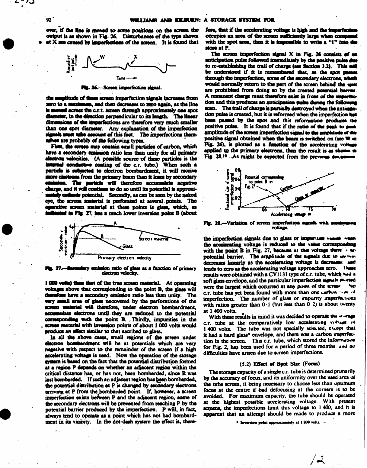
.
£.
-13
"
•
•
•
.AcceIInl
....
' •
.....
2I.-Vari8daa
or
ICI'em
~
.......
WiLda.
, • 7 •
voltap.
. .
the
iIP"ed~
aiaDals
due
to
aIuI or
........
.....
• .....
tbe
ICCIIeratiDa
voltqe
ia
reduced
to
........
COIl..,.
UltIna
with tile
point
B
in
Fi,.
27
........
dMI
wi
....
t
....
",!I
.'
potcotial barrier. The .....,ailude
01
Chc
~
due
CD
..,~
..
~
w.riy
as the
~tiaa
voIta_ is
deerE
--
tends
to
aro
u the acceIeratinl
voltaae
approada
zero.
,-.
results
wen
obtained with a CVl131 type
0(
C.r.
tube.
wbidt
-....
.a
soft
iJasa
eDveiope,
and
the particular
imperfect_
........
".4tId
weM
the
Jarpat
which occuned
at
&II)
poeM
01
tht
~'
~
c.r. tube baa yet
been
found with
more
than
OM
\.4IIh1f\ '
.....
,f
. imperfection. The number
of
aWl
or
impurity
amper1a
tKmS
with ratios areate!' than
0'1
(but less than
o·
2)
is about twenty
at
1
«JO
volts.
With
tbeIe
restdts
in mind it was
decided
to
ope
.........
......
c.r. tube
at
the comparatively low acceleral.R,
Vi."
.....
ut
1400
volts. The tube was not specially
IC_~.
C''''
Nt
it
had
a hard
alau-
en~)ope,
and
there
was
a
cubon
trnprtf«.-
.tioo
in
the
screen.
'Ibis c.r. tube, which stored the infornwl ..
",
.
for
Fi
..
2,
~
been
uaed
for a period
of
three month.
.•
,-,
00
difliculties
ba~
arisen
due
to
acn:en imperfections.
<5.2) Etl'ed 01 Spot Size
(F--)
1'be ltoraae capaeity
of
a sinale c.r. tube
is
determined pnmarily
by
tho ac:curacy
of
focus,
and
its uniformity over the
UIed
area ",'.
the
tube
tcreeD,
it
beinl
neoctS&I'Y
to
choose
Jess
than
opltJDUm
fOCUl
at
the
centre' if bad defocusing
at
the corners
IS
to
be
avoided.
FOI'
maximum capacity. the tube should
be
operated
at
the
mabest
possible aaeleratina voltage. W
it"
present
~,
die imperfections limit this voltaae
to
I
400,
and it is
apparent that
an
attempt
should
be made
to
produce a more
•
IawnioII
poi8t
anwoaiaalCfy
••
I
2100
yolu. -
/ "
/~.
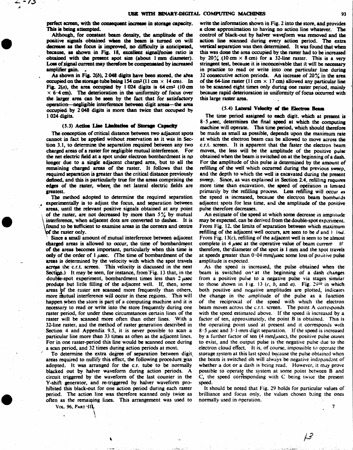
L
-1.$
•
•
VIiB
WD1I
BlNARY-DlGrrAL
COMPUTING
MAQIINES
93
pcrf'ect eaeen, with the
cooaequmt
iDaeue
in
atorqe
capacity.
TbiI is
beina
attempted. '
Althouah,
for
CODItaDt
beam
density,
the
amplitude
of
the
positive
sipalsobtaincd
wIleD
the
beam
is turDcd
on
will
dec:reue u
the
focus b improYed, DO dif6culty is anticipated,
because, u Ibown
iftFia.
18,
exc:eUeot
IiaPW/noile
ratio
is
obtaiDed with the Pl'CIIDt
spot
..
(about
I mm
diameter).
u.
of
Jlipal
current may therefore
be
c:ompcDIated
by
iDa'cued
amplifier
pin.
I
M
shown
in
Fi&-
2(b),
2048
cliaits have
been
stored. the atea
occupiedonthestoralCtubebeina
lS4anl(Han
x,
••
an).
In
Fia- 2(a),
the
area occupied
by
I 024 diaits is 64
anl
(10
em
x
6,4
em).
The
deterioration in
the
uriifonnity
or
focus over
the
Iaraer
area can
be
aeen
by
the
fact
that
for
satisfactory
operation-nealigible
interfereoce between digit
areu-the
ara
ocwpied
by
2 048 digits
is
more
than
twice
that
occupied by
I 024 diaits.
(S.3) Adioa
LIIIe
,
.........
01
Stonae
ea.-:ItJ
The conception
or
critical distance between
two
adjacent spots
cannot
in
fact be applied without reservation
as
it
was
in
Sec-
'lion 3.1,
to
determine.
the
separation required between
any
two
charpd
areas
of
a raster
for
nealigible mutual interference.
For
the
net electric field
at
a
spot
under electron bombardment is
Ilt)
lonaer due
to
a
sinale
adjacent charged area,
but
to
all the
remainin,
cbarpd
an:as
of
tbe
raster.
It
follows
that
the
required separation is greater than
the
critical distance previously
defined,
and
this is particularly
true
for
the
~
comprising the
edaes
of
the
raster,
whe~
the
net
lateral electric fields
are
patest.
The
method adopted
to
determine
the
required separation
'.
experimentally is
to
adjust
the
focus,
and
separation between
areas, until
the
relevant positive signals obtained
at
any
point
"
of
the raster, are
not
decreased by more
than
5 % by mutual
~
._
terference, when adjacent
dots
are converted
to
dashes. It is
found
to
be
sufficient
to
examine areas
in
the
comers
and
centre
r
the
'raster only.
"
Since
a small
amount
of
mutual interference between adjacent
cbaracd areas is allowed
to
occur, the time
of
bombardment
ot
the areas
becomes
important. particularly when this time is
only
of
the
order
of
I~.
(The
time
of
bombardment
of
the
areas
is
determined by the velocity with which
the
spot travels
~
the ·c.r.t. screen. This velocity is discussed in the next
SectipP.)
It
may
be
seen,
for
instance, from ·Flg.
13
that, in
the
double-spot experiment, bombardment times less
than
2
p.sec
prod~
but little filling
of
the adjacent well.
If,
then, some
areas f the raster are scanned more frequently than others.
more-
utual interference will occur in these regions.
This
will
happen
~hen
the
~tore
is part,
of
a computing machine
and
it
is
necessary
to
read
or
write into the store frequently during
one
raster period, for under these circumstances
cenain
lines
of
the
raster will be scanned more often
than
other
lines. _ With a
32-line raster,
and
the method
of
raster generation described in
Section 4
and
Appendix 9.S, it is never possible
to
scan a
particular line more than
33
times as often as the adjacent lines.
For
in
one
raster-period this line would
be
scanned once during
a scan period,
and
32
'times during action periods
at
most.
To
determine the extra degree
of
separation between digit,
areas
required
to
nullify this effect,
the
following procedure
~as
adopted.
It
was arranged for the c.r. tube
to
be normally
blacked
out
-by halver waveform during action periods. A
circuit triggered by the waveform
of
the last counter in the
Y -shift generator.
and
re-triggered
by,
halver waveform pro-
hibited this black-out for
one
action period during each raster
period.
The
action line was therefore scanned only twice as
often as
the
remaiqing lines. This arrangement was used
to
VOL.
96,
PART
~II\
\
,
write
the
information shown
in
Fig. 2 into
the
store,
and
provides
a close approximation
to
haviq
no
action line whatever.
The
control
of
black-out by
halwr
waveform
was
removed
and
the
action
liDo
scanned during every action period.
The
extra
vertica11epar&UOD
was then detennined.
It
was found
that
when
this was
done
the
area
occupied by the raster bad
to
be
increased
by
20%
(10
an
x 8
an)
for
a 32-line raster. This is a very
stringent test,
because
it
is incooceivable
that
it
will
be necessary
in
practice
to
read
or
write
into
one
particular line durina
32
CODICCUtive
action periods.
An
increase
of
20%
in the area
of
the 64-line raster
(II
em
x
17
an)
allowed any particular line
to
be
scanned
eight times only
durina
one
I'8$ter period. mainly -
because
rapid
deterioration in uniformity
of
focus
oCcurred
with
this large raster area.
(S.4) I.atenI VelodtJ
.,
tile FJectro.
...
The time period assisned
to
each digit. whidl
at
present is
8· S
p~,
determines the final
speed
at
which the
computin.
machine will operate. This time period, which should therefore
be made
as
small as possible. depends
upon
the maximum rate
at
which the electron beam can be allowed
to
move acroD the
c.r.t. screen.
It
is
apparent
that
the
faster the electron beam
moves, the less will be the amplitude
of
the positive pullC
obtained when the
beam
is switched
on
at
the beginning
of
a dash.
For
the amplitude
of
this pulse is determined by the amount
of
refilling
of
the
well
which occurred durina
the
previous
sweeP.
and
the depth
to
which the
weU
is excavated during the present
sweep. Since. as was explained in Section 2.4. refilJina rcqulm
more time
than
excavation. the speed
of
operation
is
limited
primarily by the refilling
pr<X.'nS.
Less refiOin,
wiD
occur n
the
speed is increased, because the electron beam bomn.-rJs
adjacent spots for less time.
and
lhe amplitude
of
the
~itive
pulse therefore decreases.
An
estimate
of
the speed
at
which some decrease in amphlude
may bcexpccted. can be derived from the double-spot exp.:rimenl.
From
Fig. 12. the limits
of
separation between which maximum
a:efilling
of
the adjacent well
occun.
are seen
to
be
d and I -I
bJ.
From
Fig. 13(c). refilling
of
the adjacent well
is
seen
to
be
almost
complete in 4
p~
at
the operative value
of
beam current
If
therefore, the'diameter
of
the
spot is 1
mm
and
the spot travels
at
speeds
greater
than
0·04
mm/p.sec
some
loss
of
po.)itivc pulse
amplitude is expected.
As
the speed is increased, the pulse obtained when the
beam is switched
on·
at
the beginning
of
a dash
ch41naes
from a positive pulse
to
a negative pulse via stages similar
to
those shown in Fig.
13
(c,
b,
and
a).
Fig.
29
10 in which
both positive and ru!gative amplitudes- are plotted, indicale\
the change in the amplitude
of
the pulse as a
fU.1ction
of
the reciprocal
of
the
speed
with which the electron
beam moves across the c.r.t. screen. The point A
~orr\!s~nds
with the speed estimated above.
If
the speed
is
increas~
by a
factor
of
ten, approximately, the point B is obtained. This
IS
the operating point used
at
present
and
it corresponds with
8'
5
,...sec
and
3'
I-mm digit separation.
If
the speed
is
increased
by a further factor
of
ten
(4
mm/j.LSCC),
the positive pulse
ceases
to
exist.
and
theroutput pulse is the negative pulse due
to
the
electron cloud' effect.
It
is.
of
course, impossible
h)
operate the
storage system
at
this last speed because the pulse obtained when
the beam is switched
on
will always be negative
ind~p.:nd.!nt
of
whether a
dot
or
a dash
is
being read. However, it
mJY
prove
possible
to
operate the system
at
some point between
Band
C,
the speed
corr~sponding
with C being twice the present
speed.
It
should
be
noted
that
Fig. 29 holds for particular values
of
brilliance
and
focus only, the values chosen b.!ing the ones
normally used in operation.
7
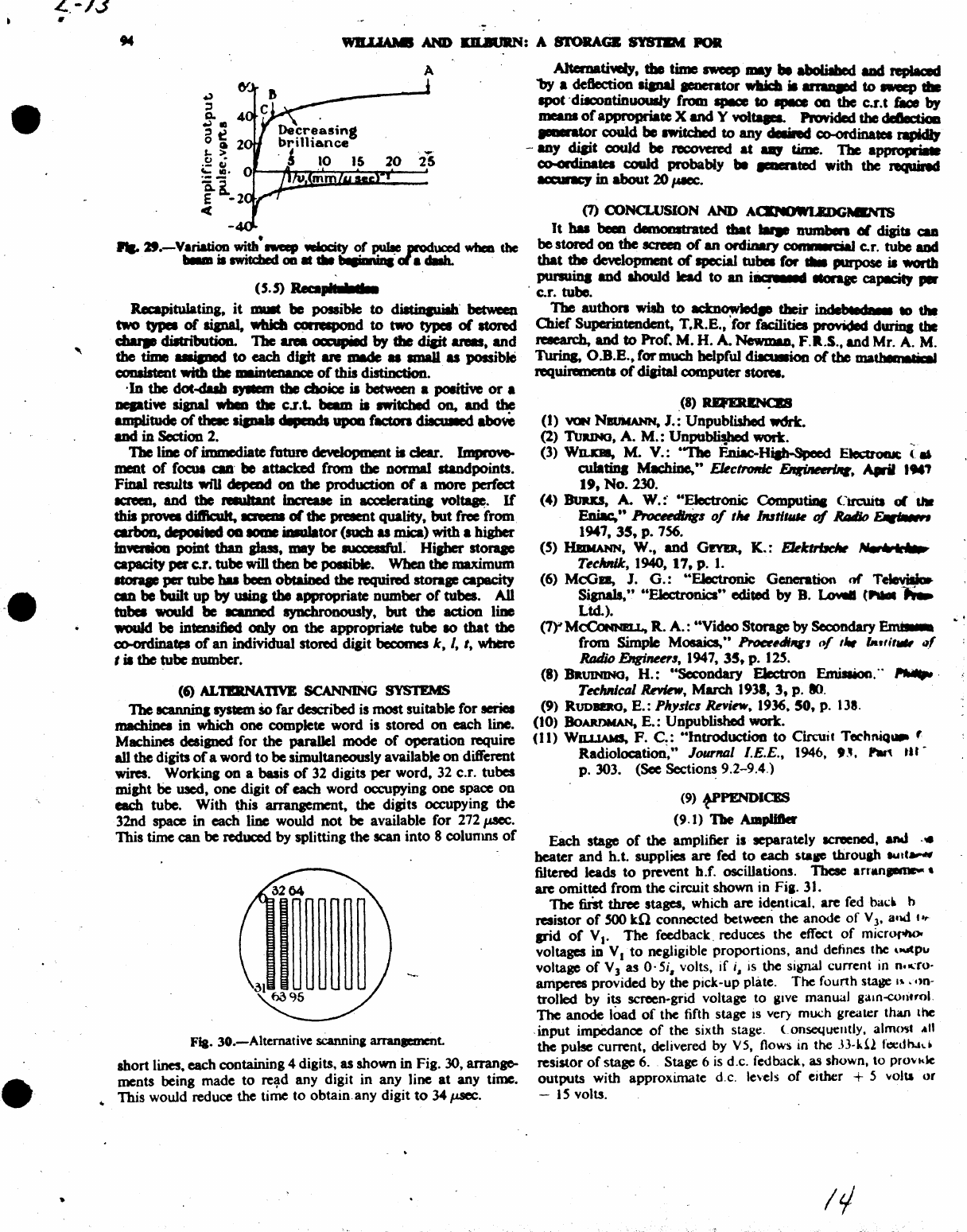
•
•
L.-13
•
•
....
2f.-Variation
with
sweep
w:Iocity
of
~
anduced
wbaa
the
......
illWitcbcd 011
..
eM
..........
oIa
dIIb. .
U.5)
......
kill
Recapitulating, it
mutt
be
possible to diatiqu.iIb' between
two
typeI
of
sipal,
wbidl COIiespond
to
two
types
or
atond
charte
dilCributioD.
The
area
oa:upiId
by
the
dicit
&Na,
and
the
time
..
iped
to
each
dJaft
are IDIde •
smaU.
u possible
CODIistent
with die
maiDteDaIM:e
of
this distinction.
·In
the
clot
.....
.,..aIm
the
c:boia: is between a
poIitift
or
a
neptiYe
sianaJ
wbeD
the
c.r.t.
beam
is
awitcbed
00,
and
the
amplitude
of
there
lipalt
...
hdl
upoD
flld.ors dilculed
~
and
in
Section
2.
The
liDe
of
immediate future deYelopment is
dear.
ImproYo-
ment
of
focus
aID'
be
attacked
from
the
oormaI standpoints.
Final
raults
wfU
depcDd
00
the
production
of
a more perfect
1CRIeII, and
the
.....
t IDaeue
in
aaderatina
wimp.
If
this prowa
difficult.
KNCIII
or
the
preaent quality,
but
free from
carboa, depoIieecl OD
lOme
Dulator
(such u mica) with a
higher
iDWftioD
point
than glass,
may
be
1UCCeIIfuI.
Hisher
storqe
capacity
per c.r.
tube
will
then
be
possible. When the
maximum
ItOrqe
per
tube
hal
been
oblaiDed
the
required
storap
capacity
can
be
built
up
by
UliDI
the
appropriate
number
of
tubes.
AU
tobel
would
be
KaJU'1ed
syncbronously.
but
the
actioo line
would
be
intensified
only
on
the
appropriate
tube
10
that
the
co-ordina",
of
an
individual
stored
digit
becomes
k,
I,
t, where
t
it
the
tube
DUmber.
(6) ALTlRNA11VE SCANNING SYSTEMS
The
acannina
sys1lem
So
far described is
most
suitable for
series
machina
in
wh.idl
one
complete word is stored
00
each line.
Machines deaiancd for
the
parallel mode
of
operation require
aU
the digits
of
a word
to
be
simultaneously available
on
different
wires. Workinl
on
a basis
of
32 digits
per
word. 32 c.r. tubes
might
be
used,
one
digit
of
each word occupying
one
space
on
each tube. With Uti! arrangement. the diaits occupying the
32nd space in
each
line would
not
be
available for 272 p.tcc.
This
tirnecan
be
reduced
by splitting
the
scan
into
8 colunms
of
Fla. 30.-Alternative
sCannina
arranaemcnt.
short
lines. each containing 4 digits, as shown
in
Fig. 30, arrange-
ments being
made
to
re,d
any
digit
in
any
line
at
any
time .
..
This
would reduce
the
time
to
obtain.
any
digit
to
34
~.
AJtemaUWiIy,
tile
time
sweep
...
,
...
boIiabed
aDd
replaced
"by
a deflectioo
lianal
.-rator
wIaidl
it
at'I'aDIId
to
aweep
...
IPOt
·dilcoDtinUOUlly
from
IPICC
to
II*»
OIl
the
c.r.l
&oe
by
means
of
appropriate
X and Y
voltqea.
Provided the deIec:tDa
..-..or
could
be
IWitched
to
any
cIeIiIed
co-ordinatel rapkIIJ
-any
diait
could
be
RICO\'eRd
at
..,
time.
T'be
approprialt
co-ordinatea
could
probably
be
____
ted with
the
requiNd
8CIanCJ
in
about
20
fItICC.
(7) CONCLUSION AND ACKNOWLItDGMKNTS
It
baa
t..l
demonstrated
tbat
....
II1JIIIt.. 01 diP"
caD
be
stored
OIl
the
screen
of
an
ordinary
co
...
_c:iaI
c.r. tube
and
that
the
deYelopment
of
special
tut.
for
....
purpose
it
wortb
punuiq
and abouId
lead
to
an
iar
..
III
IIOrqe
caPKitJ
per
. c.r. tubc. .
1'be
authon
wish
to
actn~
their
iDdeMed
_
to
till
Olief
Superintendent,
T.R.E.,
'for
facilities
pro~ided
durina
the
researdl,
and
to
Prof.
M.
H.
A.
NewmaD.
F.R.S
.•
and
Mr.
A.
M.
Turin&
O.B.B.,
for
much helpful
~
or
the
matMa
.'
requirement.
of
diaital
computer
storeI.
,(8)
RQI'I'll&Naa!I
(I)
VON
NIVNANN,
J.: Unpublished
wdrt.
(2)
TuaIMo,
A.
M.:
Unpublished wort.
(3) WILKIB,
M.
V.:
.-n.e
F..niac-Hiab-SPeed
EIecuoIuc:
(
.•
culatiDa
~
..
&ctrolrk
~,
April
,
..
.,
19,
No.
230.
(4) BuJta,
A.
W.:·
..
Electronic ComPUtiaa CtrcWtI
oIUW
Eniac,"
~6
0/11w
hull".
of
.RAtIio
~
1947,
35,
p. 756.
(s)
HIDtANN.
W.,
and
G!YIIt,
K.:
EkkttVcJw
AIel
.......
Tecltnik,
1940.
17,
p.
1.
(6)
McGa,
J.
G.:
··EIectronic Generation m
TeIeviID
Sianals," "FJcctronics" edited
by
B.
lo¥aI
(
............
Ltd.). .
(7Y
McCoMNEu..
R.
A.:
"Video
Storage
by
Secondary
em...
from
Simple Mosaics."
ho«141f1J
(»{
,,.
la,,;,.
."
Rodio
EngiM~I.
1947.
35,
p.
12S.
(8)
BaUINING,
H.:
"Sccondary Electron Emillion,"
",."..
Teclurlcal
RnIew,
March
193',
3,
p.
Ikl.
(9)
RUDBDO.
E.:
PItY$IC6
Rni~.
1936.50, p.
138.
(10)
BoARDMAN.
E.:
Unpublished work.
(II)
WILI.1AMS,
F.
C.:
"Introduction
to
Ci.mJlt
TechRiQ'"
t
Radiolocation~"
Journal
I.
E.E. , 1946,
9.~.
Pw\
til-
p. 303.
(See
Section~
9.2-9.4.)
(9) t-PPEND1CES
(9.1) The ADlpIifter
Each
stage
of
the amplifier is separately screened.
and
-.
beater
and
h.t. supplies
are
fed
to
each
staF
throuah
knt
....
filtered
leads
to
prevent h.f, oscillations. Tbese
arnm
......
-
are
omitted
from
the
circuit
shown in Fia. 31.
The
first
tb.n=e
stages. which are
id~tical,
are fed
bad
b
resistor
of
SOO
kO
connected between
the
anodc
of
V
3'
and
f.,.
pid
of
VI'
The
feedback, reduces
the
cffect
of
micro,""",
voltages in
Vito
negligible
proponions,
and
defines the '''''P''
voltage
of
V 3
as
O·
5;, volts, if i,
is
the
signal
current
in n."ro-
amperes
provided
by
the
pick-up plate.
The
fourth stage
I"
,')n-
trolled
by
its screen-grid voltage to give manual galn-COlifrol.
The
anode
lOad
of
the
fifth stage
is
very much greater than
the
,
input
impedance
of
the
sixth stage, Consequently. almc".
"n
the pulse current, delivered
by
V5,
flows in
the
J3-kU
t'cedh.Jd
resistor
of
stage 6. Stage 6
is
d .c. fed back. as shown, to
provkk
outputs
with approximate d,c. le,'els
of
either + 5
'oIolla
or
-
IS
volts.
1'1
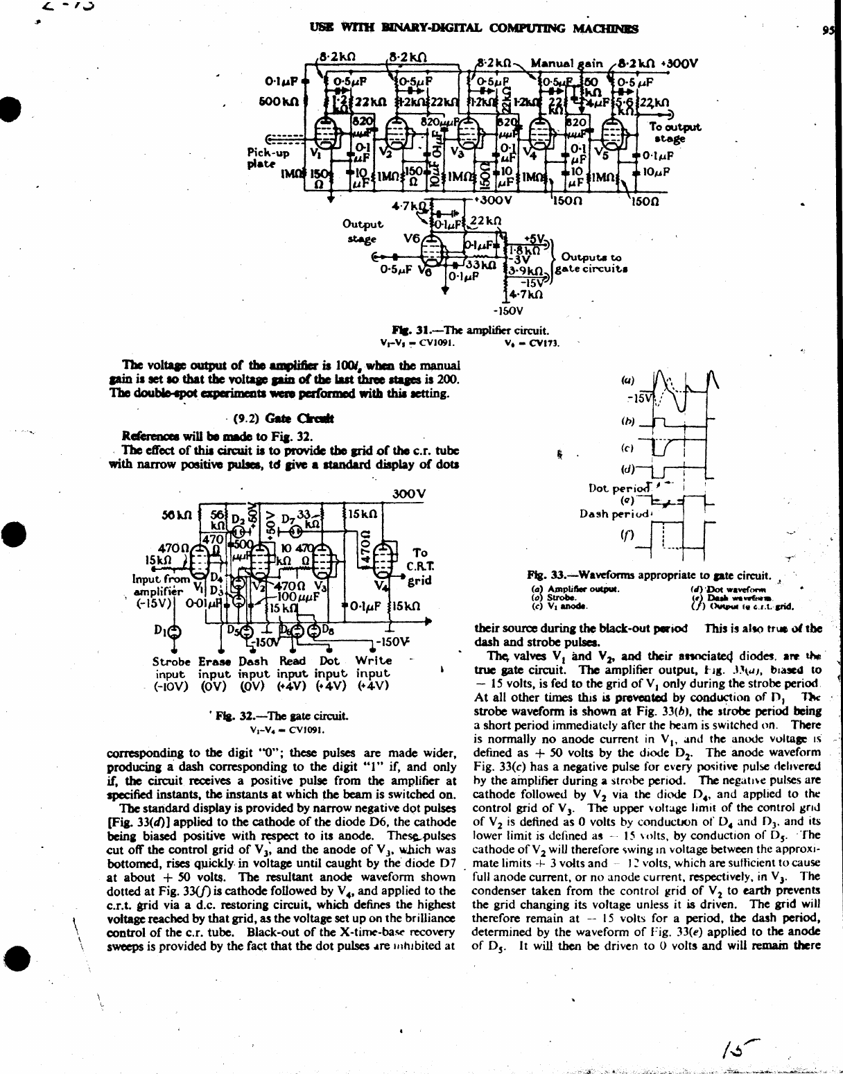
•
•
•
£.. -''':>
\
\
\
USB
WI11f
BlNARY-DlGITAL COMPlJTlNG
MAaDNa
-}&Ov
.....
31.-
The amplifier circuit.
va-v,
~
CV1091.
V.
-CV113.
The
voltqe
outpu&
of
the
amplifia' is UJOI.wbal
the
~ua1
pin
is set
10
that
the
voltaac
pia
or
tile last three
Itqes
is 200.
The
dou~
aperi.meotl
...
paf'0IIDDd with tbia
letting.
.
(9.2)
G.-.
CIraIIt
Referencee
wiD
be
made
to
Fia.
32.
The
eWeet
of
this cin:uit is
to
provide
the
arid
of
the
c.r.
tubc
with
narrow
positiw
pula.
td
ai~
a standard display
of
doll
300
V
Input
from
D4~'
~~~
.
amplifier
VI
D3
\
<-ISV)1
O-O}L.'-'~:':':~:4-~~~"-"
__
4-_'"
Dl~
0
Strobe
Erase
Dash
Read
Dot
input
input
iRput
input.
input.
(-lOY)
(OV) tOY) (+4Y) (+4V)
•
Fla.
31.-The
pte
circuit.
VI-V.
-
CVI09J.
Writ.e
input
(+4Y)
conaponding
to
the
digit
'-0";
these
pulses are
made
wider,
prodocina
a
dash
corresponding
to
the
digit
"I"
if,
and
only
if,
the
circuit receives a positive pulse
from
the
amplifier
at
specified
instants,
the
instants
at
which
the
beam
is switched
on.
The
standard display is provided by
narrow
negative dQt pulses
[Fia- 33(d)] applied
to
the
cathode
of
the
diode
06,
the
cathode
beina biased positive
with
respect
to
its
anode.
The~pulses
cut
off
the
control
grid
of
V
3:
and
the
anode
of
V
J.
w.hich was
bottomed,
rises
Quickly. in voltage until
caught
by
the
diode
07
at
about
+
SO
volts. The
resultant
anode
waveform
shown
dotted
at
Fig.
33(f)
is
cathode
fonowed by V
4'
and
applied
to
the
c.r.t.
arid
via a d.c. restoring circuit, whic:h defines
the
highest
voltage reached
by
that
grid,
as
the
voltage set
up
on
the brilliance
control
of
the c.r. tube. Black-out
of
the
X-time-ba~
recovery
sweeps is provided by
the
fact
that
the
dot
pulses
.Are
IllhJbited
at
• •
Fla.
33.---Waveforms appropriate
to
pte
circuit.
-,
.
~
(d)
A,mplifter
OUCIIUI.
(d)
'Dot wavefone.
(0)
Strobe.
(,)
DbIa
..
~
•.
(c)
VI
anode.
(f)
(Mpur
'e
u.t.trid.
their
source
during
the
black-out
~iod
This
i!
all()
tr\ll
of
the
dash
and
strobe
pulses.
~
valves
VI
and V
lt
and
their
anociate4
diode!. are t'-'
true
gate circuit.
1be
amplifier
output,
...
JI,
J~\~J.
bla!Cd
10
-
15
volts, is fed
to
the grid
of
V J only
during
the strobe period.
At
all
other
times this is provcoWd by
cond~ion
of
0,
11k
strobe waveform is shown
at
Fig.
33(b).
the strobe period being
a
short
period immediately after the beam
is
switched on. There
is normally
no
anode
current
in
VI'
Olnd
the anode vo.taae
IS
defined as +
SO
volts by the diode D2•
The
anode
waveform
Fig. 33(c)
has
a negative pulse for every
pc:xiti\'C
pulse c1ehverw
hy the ainplifier during a strobe period.
"The
negatl\e
pulses are
cathode
followed by V2 via the diode 0 ••
and
applied to the
control
grid
of
V
3'
The
upper
\oltagc
limit
of
the control
gnd
of
V 2
is
defined
as
0 volts by conductJOn
of
D.
and
OJ.
and
its
lower limit
is
defined
a!-·
15
\olts,
by conduction
of
Ds. .
The
cathode
orv
2
wiU
therefore
~wing
In
voltage between the approxI-
mate
limits
+-
3 volts
and
-J
~
volts, which are sufficient
to
cause
full
anode
current,
or
no
anode
current. respectively, in VJ. The
condenser
taken
from the control grid
of
V 1
to
earth
prevents
the
grid changing its voltage unJess it is driven.
The
grid
will
therefore remain
at
-
15
volts for a period. the dash period,
determined
by
the
waveform
of
Fig. 33(e) applied to the
anode
of
Ds.
It
will
then
be
driven
to
0 volts
and
will
remain
there
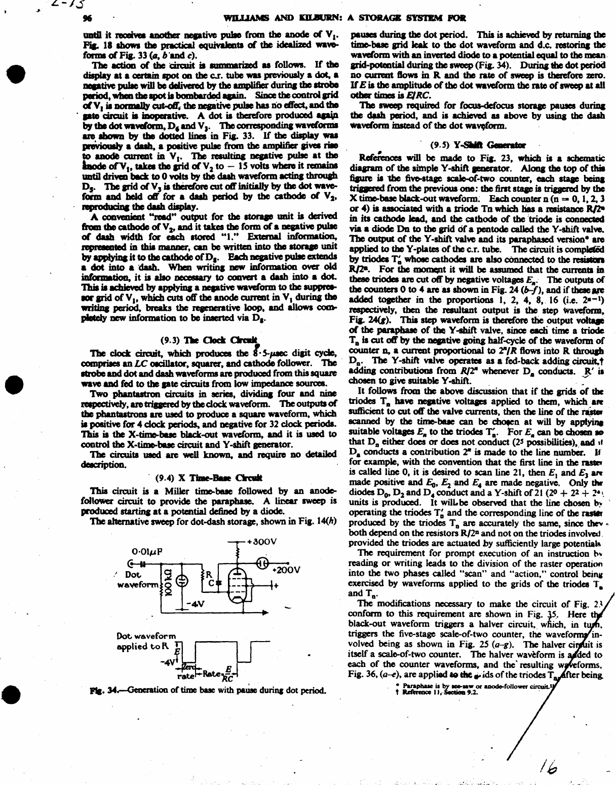
•
•
•
L-/3
"
UDtil
it
naiwI
aDOtber
aepti\le
puIIe
(rom
tho
anode
of
V
••
PiI-
18
IboM
the
practical equiYaJea1l
or
tho
idealized
wa~
forma
or
Fia.
33
(G.
b"and c).
The
action
of
the
dn:uit
iI
IIJIIIIIIatizec
as
follows.
If
the
diapIay
at
a certain &pot
00
the
Cor. tube
was
previously a dot, a
__
dYe
puIIe will
be
deIiwred
by
the
amplifier
duriq
the Itrobe
period,
wbal
tbe
IpOt
II
bombar~
apin.
smce
the controllrid
olV.
is normaJJy
c:ut-oJr,
the.,..tiYe
pul8e
has
n'o"oct.
aDd
the
.
pte
drc:uit
it
iDoperati\le. A
dot
is therefore produced
ap¥l
by
the
dot wawfonn.
D,
and
V
J.
The
comspondini wawforms
ant
Ibown
by
the
dotted lines.
in
FiJ.
33.
If
the
display
wu
~
a
dub,
a poIitive pulIe from
the
ampijfier aiw.
rill
to
anode
cuneIlt
in
VI.
The
resuItiDa
neptiw
pulse
at
the
bode
orv
••
takcI
the
arid
0(
V 2
to
-
IS
volts when
it
rcmaiDa
until dri
..
bKt
to
0 volts by
the
dub
wawform
IICtina
throuIh
D,.
The
arid
orv
J
it
then:(ore
cut
off
Initially
by
the
dot
wa\'eo
faim
and
beId
off
Cor
a
dub
period
by
the
cathode
or
V
2'
npoduciDa
the
dub
display.
A conWllieot
"read"
output
for
the
storqe
unit
II dcriwd
hID
the cathode
or
V
2-
and
it
takes
the
form
or
a
aepti¥e
puIIe
or
dash
width
for
cadl Itored
"I:'
ExtcroaI information.
fepleMDted
in
this
1DIUIDeI',
can
be
written
into
tho
ItOrqe
unit
by
appIyiDa
it
to
the
c:atbode
of
D..
Each
ucptivepulle
extmds
a
dot
into a
dub.
When
writina
DeW iDf'ormation
0\IeI'
old
information,
it
is
abo
DeCeSIaI'Y
to
conw:rt a
dub
into
• dot.
ThiI II
KbieYed
by
applyina a nepti\le waveform
to
the
~
lOr
arid
of
V.' which cuts
08'
the
anode
currcmt
in VI
duriq
the
writiDa
period, breaks
the
re,eaerati\le
loop,
and allows
c0m-
pletely DeW information
to
be
inIerted via D •.
(9.3)
'Be
Clock CIradt
The
clock circuit,
wbidl
produces
the
I·
S-p.sec
digit cycle,
comprises
an
LC
OICiUator.
squan:r,
and
cathode
follower.
The'
ItrObe
and
dot
and
dash
waveforms
are
produced
from
this square
..w
aDd
fed
to
the
pte
circuits from low impedance sources.
Two pbantastron circuits
in
aeries, dividiDa four and nine
~,aretrigered
by
the
dock
waveform.
Tbe
outputs
0(
the
pbaDtutrous
are
used
to
produce a square wavefonn, which
is positive
for
4
dock
periods.
and
negative
for
32
dock
periods.
'Ibis
it
the
X-time-buc
bllck-out
waveform,
and
it
is used
to
control tho X·tiD»-bue circuit
and
Y -shift
pnerator.
The circuits
UIed
are well known,
and
JequUe no detailed
delcription.
. (9.4) X Tiaae-Bue
QaIt
1bia
circuit is a Miller
time-bue
followed
by
an
anode-
foltower
ciJaUt
to
provide
the
parapbue.
A linear sweep is
produced
startina
at
a potential defined
by
a diode.
The
alternative sweep for dot-dash storage, shown in Fia. l4(h)
O·Ol#,lP
(!-u-_
.........
--....
.'
Dot,
~
w6'leform
a
Dot.
waveform
applied
to
I\.
E~'
-4V
f
rate
Rat.elc~
....
34.-GeDeration
of
time bale with
pa~
durina dot period •
paUleS
duriq
the
dot
period. 'Ibis is
achieYed
by
retumina
the
tiJDe..bue
arid
leak
to
the
dot
waveform
and
d.c.
restorina
the
wawCorm with
an
inverted diode
to
a potential equal
to
the
mean·
arid-poteotial
during
the
sweep
(Fia.
34).
I>urioa
the
dot
periOd
DO
cumm
80Wl
in
R
and
the
rate
of
sweep is tbaef'ore zero.
If
E is
the
amplitude
of
the
dot
..
wform
the
rate
of
sweep
at
all
ott.
times
is
EIRe.
Tbe sweep
requinK1
for
focus-defocus
storaae
pauses
duriDa
the
..
period, and
il
achieYed
as
above by usina
the
dash
wawiorm
iDs&ead
of
the
dot
wa~.
.
(9.5)
Y-s1118 G
......
R.elei'aas
wiD
be
made
to
Fia.
23,
which is a
achematic:
diqram
of
the
silnple Y -shift
____
tor.
A10na
tho
top
of
thiI
fipR
is
the
fi
...
taae
scaIo-of-two COUIlta',
each
I.
beiDa
trigered
from
the
previous one:
the
first
slap
is
trigered
by
the
X
time-bue
bIack-out
wawform~
Each
c:ouoter
D
(n
=-
0, 1,2, 1
or
4)
is associated with a triode Tn
wb.ic:b
bas
a
resistaDcc
RJ2rt
in
its
cathode
lead, and
the
cathode
or
the
'triode is
connected
via a diode
On
to
the
arid
of
a pentode
called
the Y -shift val
....
1be
output
of
the
Y -shift
valw
and
its parapbascd version-
are
applied
to
the
Y -plates
of
the c.r. tube.
1be
circuit is complCltid
by
triodeI
T.
whOle cathodes are also
connected
to
the
raiItin
RJ2a.
For
the
~t
it
win
be assumed
that
the
CUl'I'alts
ill
tbeae
triodes
are
cut
off
by
ueptiw
voltaIC'S
E,,:
The outputs
of
the
counters 0
to
4
areu
shown
in
Fig. 24
(~/),
and
if
thae
are
added
toptber
in
the proportions I, 2, 4, 8,. 16 (Le.
2--
1)
~Iy,
then
the
resultant
output
is the step
waveform,
FiJ.
24(r)~
Thia step
wawform
is therefore
the
output
vol
...
0(
the parapbue
of
the
Y -shift valve, since
eadi
time a triode
T.
is
cut
off
by
the
ueptiw
aOina
half-cyclc
oftbC
waveform
of
counter
D,
a
CUI'l'eDt
proportional
to
2"/R
flows
into R
throuab
D..
The V-shift
valw
operates as a fed-back
addinacin:uit,t
addiq
contributioaa
from
R/2"
whenever
D.
conducts.
R'
it
chosen
to
giw
suitable Y -shift. . . :
It
follows
Cram
the
above
discussion
that
if
the grids
of
the
triodes
T.
have
neptive
voltqes
applied
to
them,
Which.
aR
suflicient
to
cut
off
the valve currents, then the line
of
the
,.....
scanned
by
the
time-bue
can
be
mo.en
at
will by applYm.
suitable
voltqes
E"
to
the triodes
T;.
For
Ell
can
be
chosen
to
that
Do
either does
or
does
not
conduct
(25 possibilities),.aad
It
D.
conducts a contribution
2"
is made
to
the line number.
If
for example, with the convention
that
the first line
in
the
~
is called line 0,
it
is desired to scan line 21, then EJ
and
E)
aft
made positive
and
Eo,
E"
·and
E
..
are made negative. Only
thr
diodes
DOt
D"
and
D
..
conduct
and
a Y-shift of21
(20
+
21
+ 2.,.
units is produced.
It
will.be observed
that
the line chosen
b:--
'
operating the triodes
T~
and
the
corresponding line
of
the raster
produced by
the
triodes T a
are
accurately the same, since
thc'Y
..
both
depend
on
the
~jstors
R/2D
and
not
on
the triodes involved.
provided the triodes are actuated
by
sufficiently large potential"
1be
requirement for
prompt
execution
of
an
instruction
h~
reading
or
writing leads to the division
of
the raster operation
into the two phases called
"scan"
and
"action,"
control
beinl
exercised by wavefonns applied
to
the grids
of
the triodes
T.
and
To.
1be
modifications necessary to make
the
circuit
of
Fig.
2.\
confonn
to
this requirement are shown in Fig.
l5..
Here
black-out wavefonn triggers a halver circuit, wfuch, in t
triggers the five-stage scale-of-two counter, the wavefo
volved being as shown in Fig.
25
(a-g).
The halver ci it is
itself a scalc-of-two counter.
The
halver waveform
is
(led
to
each
of
the counter waveforms,
and
the' resulting w eforms.
Fig. 36, (a-e). are applied _
the
..
ids
of
the triodes T fier being
•
Parapbue
is
~
..
w
or
uodo-follower
circuit.1
t RdCreoce
II.·
. 9.2. .
/6
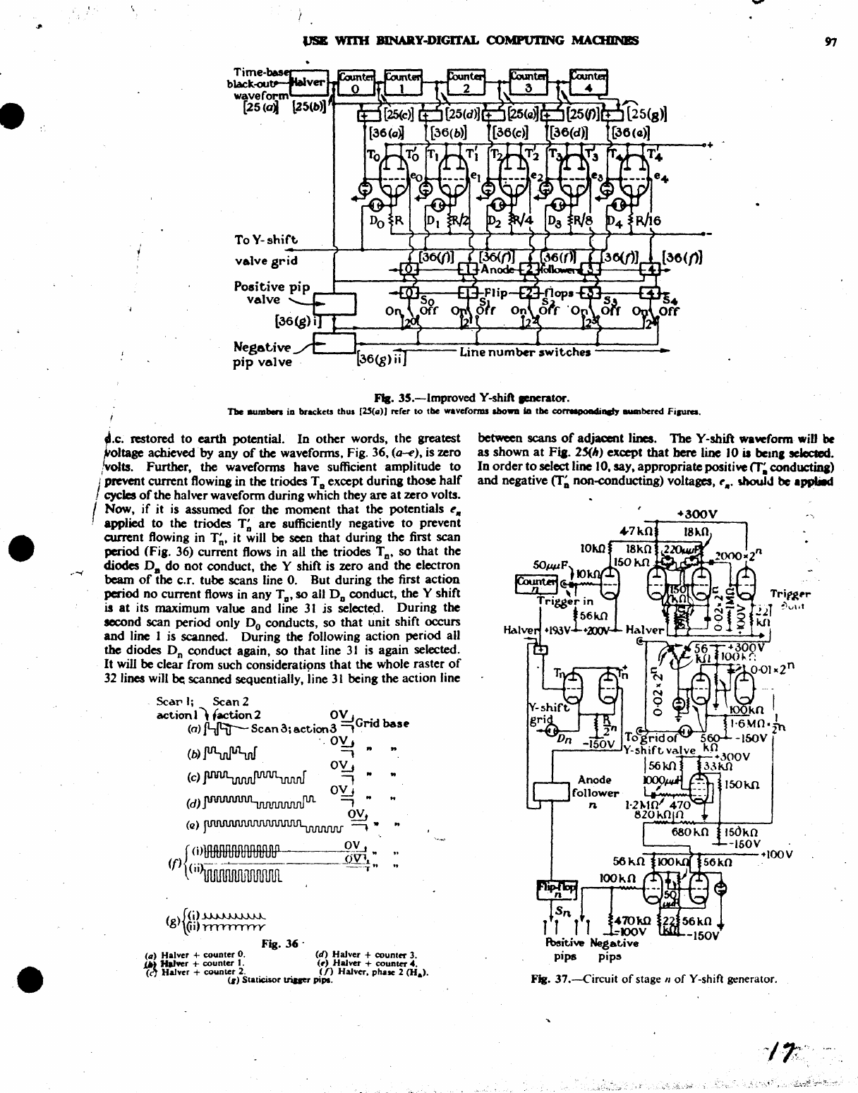
....
•
•
•
....
-'-'
VSE
WI'I1I BlNARY-DIGrrAL COMPVTING
MAaDNBS
To
V-shift,
------?-~~------~~~~~~~~~~~~~
vAlve
grid
Negat:.ive
pip
valve
Fla.
35.-1mproved V-shift
ItMrator.
The IlUJllben
ia
brKkets
thus
{~{G)J
rerer
to
tbe
waveforms
a.bowa
ill
tbe
c:orr.poadi....,
_bercd
Fipra.
~.c.
restored
to
earth potential.
In
other words. the greatest
~oltage
achieved
by
any
of
the wavefonns. Fig. 36.
(a-e).
is zero
/volts. Further. the wavefonns have sufficient amplitude
to
i PftVent current flowing in the triodes T D except during those
half
I cycles
of
the halver waveform during which they are
at
zero volts.
I Now.
if
it is assumed for the moment
that
the potentials ell
, applied
to
the triodes
T~
are sufficiently negative to prevent
current flowing in
T~.
it will
be
seen that during the first scan
period (Fig. 36) current flows in all the triodes Ta.
so
that
the
diodes
D.
do
not conduct.
the
Y shift is zero
and
the electron
beam
of
the c.r. tube scans line
O.
But during the first action
period
no
current flows in any Ta, so all
Do
conduct, the Y shift
is
at
its maximum value and line
31
js
select~.
During
the
second scan period only
Do
conducts, so
that
unit shift occurs
and
line 1 is scanned. During the following action period all
the diodes Dn conduct again,
so
that line
31
is again selected.
It
will
be
clear from such consideratipns that the whole raster
of
32
lines will
be
scanned sequentially, line
31
being the action line
o
ScaT"
I;
Scan
2
action
I",
{action
2 OYJ .
(0)
p,J9j--
SCAn
3;
aet,jon3
-,
Gnd
base
OY..;
(b)
JUl-vUlt'Lut[
-,
OY..;
(c)~
t
OYJ
(d)~
-,
qy,
(Q)~-'.
UUUUTIULJuuliuu
(iVl.L ..
{
(i)mnnnn.nft+0n~n#lnl#ntL0
___
~0Y...t
(f)
(ii~1fU1JlIUl
_oTto ••
()
J(i)~
g \(ii)
rrrnrrrrY
Fig.
36'
(a)
Halve,
+ counter
O.
(d)
Halver
+ count"" 3 .
.LIt}
Halver + counter I.
(,)
Halver +
counter
4 .
(~
Halver +
counter
2.
(f)
HaJvcr, phase 2 (}fa)'
(6)
Staticisor
triuer
pips.
between scans
of
adjacent linea.
The
V-shift
waw(onn
will
be
as
shown
at
Fia.
25(11)
except
that
here line 10
it
belDl
!CIccaed.
In
order
to
seJect line 10, say, appropriate positive
IT;
conductina)
and negative
(T~
non-ronducting) voltages,
~,..
IbouJJ
be
applild
l50kO
-150V
--t----!t-.----
+ 100 V
Fig.
37.-Circuit
of
stage
"of
Y-shift generator.
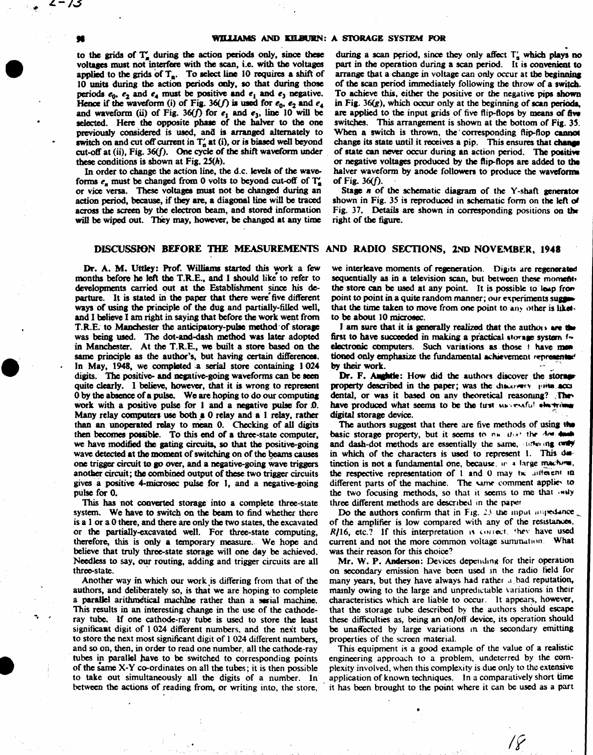
•
••
•
L-/3
-.
"
II
'WJLUAMS
AND
m.auRN:
A SI'ORAGE SYSTEM FOR
to
the grids
of
T,.
during
the
action periods only,
since
these
voltqes
must
not
interfere with the scan, i.e. with the voltages
applied
to
the grids
of
Ta.
To
select
line 10 requires a shift
of
10 units durina
the
action periods ooIy,
10
that
during those
periods
eo,
e2
and
e"
must
be
positM
and
e1
and
e3
negative.
Henc:e
if
the
waveform (i)
of
Fia. 36(f)
iI
used
for
eo.
e2 and
e"
and
waveform. (0)·
of
Fig. 36(J)
for
eJ
and
e3~
line 10
will
be
selected. Here
the
opposite
pbale
of
the
hal\Ier
to
the
one
previously considered is used,
ana
is arranged alternately
to
switch on
and
cut
off current in
T~
at
(i),
or
is biased well beyond
cut-off
at
(iO,
Fig. 36(j).
One
cycle
of
the shift waveform
under
.
these conditions is shown
at
Fig.
2~(h).
In
order
to
change the action line, the
d.c.lema
of
the
wave-
fonDS
ell
must
be
changed from 0 volts
to
beyond cut-off
of
r.
or
vice versa. These volta
..
must
not
be
changed during
an
action period, because,
if
they
ate,
a diagonal line will
be
traced
across the
scnen
by
the
electron beam.
and
stored information
will be wiped out. 'J'hey
may,
however,
be
changed
at
any time
during a scan
Wiod,
since they only affect
T~
which plays
no
part
in
the
operation
during a
scan
period.
It
is convenient
to
arrange
that
a
change
in voltage can only occur at the
beaiDnina
of
the
scan
period immediately following the throw
of
a switch.
To
achieve this. either the positive
or
the negative pips
shown
in
Fia.
36(g), which occur only
at
the beginning
of
scan
periOcII.
are applied
to
the
input
grids
of
five
flip-flops by
means
of
ftw
switcJa.
This
arrangement
is
shown
at
the
bottom
of
Fig.
3~.
When
a switch is thrown.
the'
corresponding flip-flop
QDQOl
change its state until
it
receives a pip. This ensures
that
c:hIaIt
of
state can
neYa'
oc:cur
during
an
action period.
The
positiw
or
negative voltaaes produced
by
the
ftip--ftops
are
added
to
the
balver waveform by anode follO'Nen
to
produce the
waveforn
of
Fig. 36(j).
StalC
II
of
the
schematic diaaram
of
the V-shaft generator
shown in Fig. 35 is reproduced in schematic form
on
the left
01
Fig. 37. Details
are
shown in corresponding positions
on
thr
right
of
the
fiaure.
DISCUSSION BEFORE
DIE
MEASUREMENTS
AND
RADIO
SECI10NS,
lND
NOVEMBER,
1948
Dr. A.
M.
Uttley: Prof. Williams started this work a
few
months before he left the T.R.E.,
and
I should
like"
to
refer
to
developments carried
out
at
the
Establishment since his de-
parture.
It
is stated ill
the
-paper
that
there
were
five different
ways
of
using
the
principle
of
the
dug
and
partially-filled well.
and
I believe I
am
right
in
saying
that
before
the
work
went from
T.R.E:
to
Manchester
the
anticipawry-pulJe method
'of
storalC
was being used. TIle dot-and-dash method was later adopted
in Manchester.
At
the
T.R.E.,
we
built a store
based
on
the
same principle as the author's,
but
having certain differencel .
]n
May, 1948, we completed ,a
serial
store containing
1024
digits.
The
positive-
and
ocptivc-going
waveforms
can
be
Been
quite
ckarly.
I believe, however,
that
it
is wrong
to
represent
o by
the
absence
of
a pulse.
We
are
hoping
to
do
our
computiq
Work with a positive pulse for 1
and
a negative
pulse
for
.0.
Many relay computers use both .• 0 relay
and
a 1 relay. rather
than
an
UDoperated
relay
to
mean
O.
Checking
of
all digits
then becomes possible.
To
this
end
of
a three-state computer,
we have mod.ifiedtbe
pting
Qrcuits,
so
that
the
positive-going
wave detected
at
the
moment
of
switching
on
of
the
~
causes
one trigger cin:uit
to
SO
over,
and
a
ncptivc-going
wave triggers
anotl1er circuit; the combined
output
of
these two trigger circuits
gives· a positive
....
miaosec pulse .for
1,
and
a negative-soing
pulse for
O.
This has
not
converted storage into a complete three-state
system.
We
have
to
switch
on
the beam
to
find whether there
is a 1
or
a 0 there,
and
there
arc
only the two states.
the
excavated
or
the
partially-excavated well.
For
three-state computing.
therefore, this
is
only a temporary measure.. We
hope
and
believe
that
truly
three-state storage will
one
day
be
achieved.
Needless
to
say.
our
routing, adding
and
trigger circuits are all
three-state. .
Another way
in
which
our
work is differing from
that
of
the
authors,
and
deliberately so, is
thai
we are hoping
to
complete
a parallel
ari~tica1
machlnc rather
than
a
..
ial machine.
This results in
an
interesting change in the use
of
the cathode-
ray tube.
If
one cathode-ray .tube is used
to
store the least
significast digit
of
1 024 different numbers.
and
the next tube
to
store the next most significant digit
of
I 024 different numbers,
and
so on. then,
in
order
to
read
one
number, all the cathode-ray
tubes in
paralleillave
to
be switched
to
corresponding points
of
the
Same
X-V co-ordinates
on
all the tubes; it
is
then possible
to
take
out
simultaneously all the digits
of
a number.
In
between the actions
of
reading from,
or
writing into.
the
store,
we
interleave moments
of
rel)lCDCration.
Oilits
are regenerated
sequentially as
in
a television scan. but between
th~
momeftt,
the
store
can
be
used
at
any
point.
It
is possible to
·lCMp
frOf'
point
to
point in a quite
random
manner;
our
e'tperiments su
....
that
the time taken
to
move
from
one
point
to
an),
other is
hUt·
to
be
about
10 miaosee.
)
am
sure
that
it
is generally realized that the authoa.
.,.
..
tint
to
have sua:ecdcd in
mak.ina
a practical
,tora..,
system f
....
electrOD.ic
computers. Such variations
as
those t have
u.
doocd
only emphasize the fundamental aclUevemcnt
~retIIft"'"
by
their work.
".
Dr.
F.
AIIIIatIe:
How
did the authors discover. the
,lor.
property described
in
the
paper;
was
the
Jltur.-.r"
IU
....
.ac.'X:.1
dental,
or
was
it
based
on
any theoretical
reasoruna?
J'J.
have
prodUQCd
what seems
to
be the
tnt
~
...
-,'t:'",~JlI!
."tr~_
digital storage device.
,";
'The
authors suggest
that
there are
five
methods
ofusina
,_
basic storage property.
but
it
seems to !''\Iot
lI,;,'
tlv
.~
....
and
dash-dot methods
are
essentially the same,
'\I~
(n,
,...,
in
which
of
the characters is
used
to
represent
1.
This
,,-.
tinction is
not
a fundamental one,
becaUK,
U'
~
!Mae
~~.
the respective representation
of
1 and 0 may
t..
.HHelen.
10
different parts
of
the machine. The
Ymt'
comment
appl~
to
the two focusing methods, so that it seems
to
me that
.M"Y
three different methods are descnbed 10
the
parer
Do
the authors confirm that in Fig.
L\
Ule mpu\
/I
nltM.lnce
....
of
the amplifier is
Jow
compared with any
of
the resastan..a
..
R/16, etc.?
If
this interpretation
''I
Uti
10..:1,
,ht'v
have used
current
and
not
the more
common
voltage
swrundtuUl.
What
was their reason for this choice?
Mr.
W.
P.
Anderson: Devices depend.
n~
for their operation
on
secoodary emission have been
used
10
the radio tield for
many years,
but
they have always
had
rather .1_ bad reputation.
mamly owing
to
the large
and
unpredi\.:table variations in their
characteristics which are liable
to
occur.
It
appears. however.
that
the storage tube described
by
the authors should escape
these difficulties as, being
an
on/ofl device, its operation should
be
unaffected by large variations
an
the secondary emitting
properties
of
the screen material.
This equipment
is
a good example
of
the value
of
a realistic
engineering approach
to
a problem. undeterred by the com-
plexity involved, when this complexity is due only to the extensive
application
of
known techniques. In a comparatively short time
, it has been brought
to
the point where it can be used as a
part
If
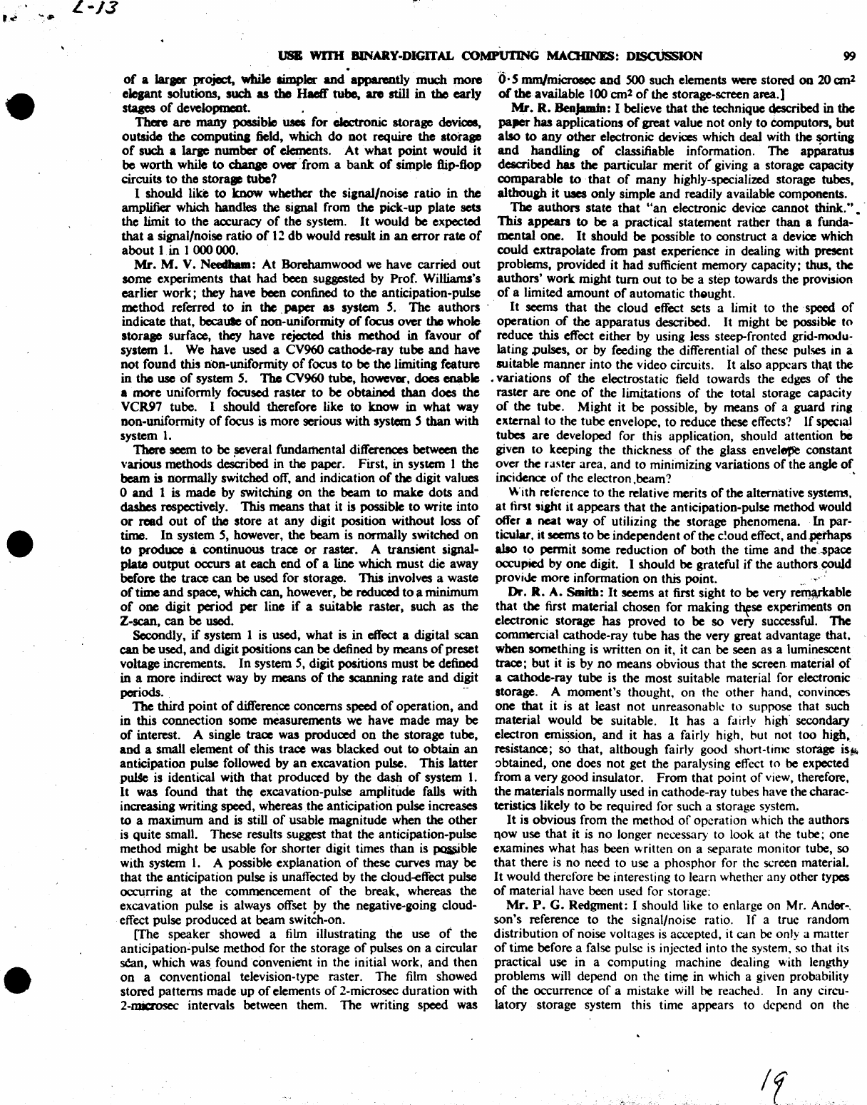
"'
....
L-J3
•
•
•
lJSB Wl'I1I
BINARY-DIGITAL
coMPU'I'ING
'MAOIINES:
D~JON
99
.
of
a
laraar
project,
while
simpler
and
apparently
much
more
'0·
S
mm/microsec
and
SOO
such
elements were
stored
on
20
an
l
elegant solutions,
such
as
the Haeft"
tube.
are
still
in
the
early
or
the
available
l00cm
2
of
the
storage-screen
area.]
stqes
of
deveJopmcot.,
Mr.
R.
Benjambl: I believe
that
the technique described in the
There
are
many
possible uses
for
oJectronic
storage
devices,
pa,er
has
applications
of
great
value
not
only
to
eomputors,
but
outside
the
computina
field,
which
do
Dot
require
the
storage
also
to
any
other
electronic devices which deal with
the
sorting
of
such
a
Iarae
number
of
elements.
At
what
point
would
it
and
handling
of
classifiable information. The
apParatus
be
worth
while to
cbanae
over'
from
a
bank
of
simple flip-flop described has the
panicular
merit
or
giving a storage capacity
circuits
to
the
stora(le tube?
comparable
to'
that
of
many
highly-specialized storage tubes,
I
should
like
to
know
whether
the
si,nal/noise
ratio
in
the
although
it
WICS
only
simple
and
readily available components.
amplifiec which
handles
the signal from the
pick-up
plate
sets The
authors
state
that
"an
electronic device
cannot
think."
• '
the
limit
to
the
accuracy
of
the
system.
It
would
be
expected
This
appears
to
be a practical
statement
rather
than
a funda-
that
a signal/noise
ratio
of
12
db
would
result
in
an
error
rate
of
mental
ODe.
It
should
be possible
to
construct a device which
about
I,
in
I 000 000.
could
extrapolate
from
past
experience in dealing with present
Mr.
M.
V.
Needham:
At
Borehamwood
we
have
carried
out
problems,
provided
it
had
sufficient
memory
capacity; thus,
the
some
experiments
that
had
been suggested by Prof. Williams's
authors'
work
might
tum
out
to
be a step towards the provision
earlier
work;
they
have
been
confined
to
the
anticipation-pulse
of
a limited
amount
of
automatic
th61ught.
method
referred
to
in
the ,paper
as
system
S.
The
authors"
It
seems
that
the
cloud
effect sets a limit
to
the 'speed
of
indicate
that,
becaUle
of
non-uniformity
of
focus
over
the
whole
operation
of
the
apparatus
described.
It
might be possible
to
storalC
surface, they
have
rejected
this
method
in
favour
of
reduce this effect
either
by using less steep-fronted grid-modu-
system
1.
We
have
used
a CV960
cathode-ray
tube
and
have lating .puises,
or
by feeding
the
differential
of
these pulses in a
not
found
this
non-uniformity
of
focus
to
be
the
limiting
feature
suitable
manner
into
the
video circuits. It also
appears
tha.t
the
in
the
use
of
system
S.
The CV960
tube,
however,
does
enable
•
variations
of
the
electrostatic field towards
the
edges
of
the
•
more
uniformly focused
raster
to
be
obtained
than
does
the
raster
are
one
of
the
limitations
of
the
total storage capacity
VCR97
tube. I
should
therefore like
to
know
in
what
way
of
the
tube.
Might
it
be possible, by
means
of
a
guard
rin,
Don-uniformity
of
focus
is
more
serious
with
system S than
with
external
to
the
tube
envelope,
to
reduce these effects?
If
special
system
l.
tubes
are
developed for this application,
should
attention
be
T'here seem
to
be
several fundamental differences between
the
given
to
keeping
the
thickness
of
the
glass envelfJlSe
constant
"anoos
methods
desCribed
in
the
paper.
First,
in system I
the
over
the
ra~ter
area,
and
to
minimizing variations
of
the angle
of
beam
is
normally
switched off,
and
indication
of
the digit values incidence
of
the electron .beam? •
o and 1 is
made
by
switching
on
the
beam
to
make
dots
and
With reference
to
the relative merits
of
the alternative systerm.
dashes
respectively.
This
means
that
it is possible
to
write
into
at
tint
si&ht it
appears
that
the
anticipation-pulse
method
would
or
read
out
of
the
store
at
any
digit position
without
loss
of
offer a
neat
way
of
utilizing the storage
phenomena.
In
par-
time.
In
system
S,
however,
the
beam
is normally switched
on
ticular. it seems
to
be
independent
of
the
c!oud effect.
and.pemaps
to
produce
Ii
continuous
trace
or
raster.
A transient signal-
also
to
penn
it
some
reduction
of
both
the
time
and
the'-space
plate
output
occurs
at
each
end
of
a line
which
must
die
away
occupied by
one
digit. I should
be
grateful
if
the
authorscouJd
before
the
trace
can
be
used for storage.
This
involves a waste
provi\k
more
information
on
this point. " :
of
time
and
space, which
can,
however,
be
reduced
to
a
minimum
Dr.
R.
A.
Smith:
It
seems
at
first sight
to
be
very
re~able
of
one
digit
period
per
line
if
a suitable
raster,
such
as
the
that
the first
material
chosen
for
making
~se
experiments
on
Z-scan,
can
be
used. electronic storage has
proved
to
be
so
very successful. The
Secondly.
if
system 1 is used,
what
is
in
effect a digital
scan
commercial cathode-ray
tube
has
the
very
great
advantage
that.
can
be
used,
and
digit positions
can
be defined by
means
of
preset
when something is written
on
it, it
can
be seen
as
a luminescent
voltage increments.
In
system 5, digit positions
must
be
defined trace;
but
it is by
no
means
obvious
that
the
screen.
materi~lof
in
a
more
indirect way by
means
of
the
scanning
rate
and
digit a
cathode-ray
tube
is
the
most
suitable material for electronic
periods. .
,-
storage. A
moment's
thought,
on
the
other
hand, convince<i
The
third
point
of
difference
concerns
speed
of
operation,
and
one
that
it
is
at
least
not
unreasonabh:
to
suppose that such
in
this
connection
some
measurements
we
have
made
may
be
material would be suitable.
It
has
a fairly high' secondary
of
interest. A single trace was produced
00
the
storage
tube,
electron emission,
and
it
has
a fairly high. but not
too
high,
and
a small element
of
this
trace was blacked
out
to
obtain
an
resistance;
sO
that,
although
fairly good short-time storage
is~
anticipation
pulse followed by
an
excavation pulse.
This
latter
~btained,
one
does
not
get the paralysing effect
to
be expected
p~
is identical
with
that
produced
by
the
dash
of
system I.
from
a very
good
insulator.
From
that
point
of
view, therefore.
It
was
found
that
the
excavation-pulse
amplitude
falls
with
the
materials
nonnally
used in
cathode-ray
tubes have the charac-
increasing writing speed, whereas
the
anticipation
pulse increases teristics likely
to
be
required for such a storage system.
to
a
maximum
and
is still
of
usable
magnitude
when the
other
It
is
obvious
from
the
method
of
operation
which the
authors
is
quite
small. These results suggest
that
the
anticipation-pulse
I\OW
use
that
it
is
no
longer necessary to look
at
the tube;
one
method
might
be
usable for
shorter
digit times
than
is
poaible
examines
what
has
been written
on
a separate monitor tube, so
with system
1.
A possible
explanation
of
these curves
may
be
that
there is
no
need
to
use a
phosphor
for the screen material.
that
the
anticipation
pulse is unaffected by the cloud-effect pulse
It
would therefore
be
interesting
to
learn whether any
other
types
~rring
at
the
commencement
of
the
break.
whereas
the
of
material have been used for storage;
excavation pulse is always offset by
the
negative-going cloud-
Mr.
P.
G.
Redgment: I should like
to
enlarge
on
Mr. Ander-,
effect pulse
produced
at
beam
switCh-on.
son's
reference
to
the signal/noise ratio.
If
a true
random
[The speaker showed a film illustrating
the
use
of
the
distribution
of
noise voltages is accepted. it
can
be
only a
matter
anticipatjon~pulse
method
for
the storage
of
pulses
on
a circular
of
time before a false pulse is injected into the system, so that its
s6ln,
which
was
foundcanvenient
in the initial work,
and
then
practical use
in
a
computing
machine dealing with lengthy
on
a conventional television-type raster.
The
film showed
problems
will depend
on
the
tim~
in which a given probability
stored
patterns
made
up
of
elements
of
2-microsec
duration
with
of
the
occurrence
of
a mistake
will
be
reacheJ. In any circu-
2-microsec intervals between them.
The
writing speed was
latory
storage system this time
appears
to
depend
on
the
'lIIf.;';'--
L-"13
.,. . ,
~
.. '.I- 100 WILIJAMS
ANi>
JW..B1.JRN:
~'S"YS1ZM
FOR
USB
WD1I
BlNARY-DIGITAL COMPU11NG
~OIINES:
DISCVSSION
•
•
•
siana1/noise ratio. In the
~
of
the
men:ury-delay line
type
temperann
on
the
shape
and
penisteace
0(
the
potential
well?
it
acems
that
the
output puIIe may
poIIeII
qualitiel-«lcb
u an Althouah anaIope computation is
not
Itricdy within
the
terms
accurately
controUed
.wid~wbicb
enable
it
to
be distinauilhed,
of
the paper, I should like
to
mention
u.t
""
bave
been
experi-
fiom
noise
and
tbemore
improve
the'
sipaJ/noiJe diIcrimiDa- meotina
ad'
a store for anaIoaue information,
using
a modification
tion. The cathode-ray tube
storap
systems delcribed
provide
Of
the
priDcipie delcribed. Briefty. a trail
of
char8e
is
depoIited
a rather odd-ibaped
puJse,and
it
aecms
that
not
much cin:uit on a catbodo-ray
ICI'een
by a '-writing" spot.
It
is
subiequeody
dilcriminatioD
from noile, other'thaD
that
liven
by the time
at
scanned
by
a raster,
and
the
pulaes.
detected
in the nwmer die
whidl
the
pulse occurs, can be
obCaiDed.Whether
dle
"antici- authors have deacribed, are
used
in
the obvious way to reproduce
.,.tory
puIIe."
or
the
"weD
aDd
weI1..fi11ina"
type
deiCribed by
the
the written waveform via a flip-ftop
or
a strobe circuit. With
authors. is
u.d,
it
eema
,that some importance must
au.dl
to
this,
anaqement
it is perhaps more important
than
with
the
the
liPaIInoile
ratio,
as
it
may determiDe the ultimate
accuncy
dilital
method
to
reach the limits
of
definition,
and
it would
be
whicb the
computor
can
adlieve with any
8iwn
Iia
01
problem.
of
interest
to
know what.relevant cft'ect.
if
uy,
is produced'
by
Mr.
D.
M.
MKKa,:
Is
anytbina
known 01
the
iDftuence
of
cM.nJCS
in
the
temperature
of
the
pboIpbor.
11IE
AUIlIORS'
REPLY
TO
11IE
ABOVE DISCUSSION
PNI.
F.
C.W
.......
and
Mr.
T.
KJIINrn (i"
"ply):
We
shall
not
attempt
to
answer
speakers
individually,
but
will
attempt rather
to
COYer 'most
of
the
points
railed in
the
di8cussion.
Our
knowledae
of
the history
01
this
type
01
ltorap,
apart
from our
own
development,
is JaraeIy
...
on
beanay.
As
far •
we
know the discovery
that.1ipaIs
symptomatic
of
previous
aamnina could
be
obeerw.d
011
an
ordinary
cathode-ray
tUbe
wu
'made
accidentally
at
the Radiation Laboratories,
Boatoo.
U.s.A
.•
durioa
some expcrimmta with a special
atoraae
tube.
~
experiments did
DOt
expote
the
vital fact that
sipals
wcreavailable from the
pick~up
plate in4*mty
of
time
to
permit
0(
~on
on a
siDaIe
tube.
AI
rqpuda
.the
taeeIl
surface
material.
it
is
or
coune
moat
CODWlliait
to
UIO
COIJUDCI'Cial
tuba,
but
it
...
CODfideady
expected
that
a
f~
experiments would
~
• prefcrabk
surface.
Experimen1a
have
been
made
iD
a continuously-
evacuated tube with· various kinds
of
.....
aeveral fluorescent
and
other powders,
~d
with mica; DOGe
of
the materials tested
was
u satisfactory
as
the
ordinary
.....
or
blue
ICI'eeIl,
but it
may
well
be
that
the
technique
of
testina
ia
DOt
yet adequately
developed, extreme cleanliness
bein.
of
peat
importance
ill
studyinl
lClCiODdary-emission
effects.
·.A
The number
of
Iystems
described in the paper is
five
or
three.
dependinl OIl
whether
or
not
the
pte.
dn:uit
is
reprded
as
part
of
the l)'ltem. It is
qreed
that
only
iluee
charae CODfiaurations
are
delcribed.
The
choice
between
tbeao
was made
at
a fairly
early
stqe
in favour
of
the dot-dash
~t,
because the
timina
of
the indicatina pulles
was
cloaely
controlJed, because
the
shape
of
thcac
pulses
was
leu dependent
on
focus.
and
becauSe
thil
system was felt
t(J"
be IDOI'e flexible in
that
it could
also be applied
to
parallelltoMS.
We
arc
very interested in, and now agree with,
the
statement
that in
seria-typemadlines
the anticipation 'pulse method
it
essentially'
fater.
It
1CeIIlI, however.
that
since
the
waveform
shown in
Fi
••
J4(d) is
!devant
to
either
systern;-~
the space
per diait will be
the
same for both
systemS.·..
It
aeems
-.
likely
that
botbtime
and
space
per diait can be
improved
by
the use
of
the
fOCUl-defocus
method.-
The
sianal/noile
ratio
of
the
systems
we
have operated
haS
been
10
lood
that
we
have paid scant attention
to
calculatin.· the
probability
of
enor
from this callie. The caJculation is a diffi-
cult one
since
allowance must be made for
strobinl
and for the
fad
that a
aoile
pulac must exceed
the
datum level for a certain
period. before it becomes effettive. Some rough calculations
bave
DOW
been
....
and indicate that failwe from this cause
should
not
oa:ur
more than'orx:e
in
thirty
centuries
o(-con-
tinuous
runniDa.
10
that
the scant
reprd
paid to this
pomt
therefore appears
to
be justified.
It
may
weU.
be
that
it
is
sounder enaineerina
to
~t
zero .
."
a sianal rather than by the absence
of
a
sipaJ,
linc:e lJeIO
it
ewry
bit
a .vital a
~picce
of
information
as
l.
Our attitude.
boweYer-and
this is relevant
to
the
two previous items as welt
-hal
been that
we
would
proceed
for the time beina with
the
limplesteaentiala
of
the
machine, since
ft
feel that
some
experience
of
the actual operation
of
a madline is quite
'Utaent
at
this
stqe
of
the
development.
We
should like
to
thank
Dr.
Aughtie for
the
co~tions,
com-
municated
to
us privately. which have been incorporated ip ·the
paper,
and
confirm that we have, in
f~ct.
used
current summAtion.
the
IUIOft
beinl
that
in general
we
reprd
this procedure
as
both
. simpler
and
more elegant than voltage summation, whicb
usuaU),
calls
for sublcquent amplification. .
It is
interatinl
to
see
from Mr. Mackay's remarks that
the
storaae property has
some
application also
to
analogue com-
puten.
We rearet that
we
have
no
information about
tty
dfect
of
lemperature
on
definition,
It
is difficult
to
state
at
precisely what point it becomes
eco~
mical
to
use c.r.t. storage instead
of
storage
on
flip-ftops.
If
a"','
cathode-ray tube is counted as equivalent
to
10
valves, then in
a series system taking valve numbers alone as a criterion,
the
c.r.t. system is preferable for any number
of
digits in
excess.
of'
3~,
but it is recognized that the flip-flop system might be
m()re
reliable
and
might therefore
be
used for numbers not too
greatt~
in excess
of
32 digits.
--------~-----.--
----------
-"---
---.
-
---
._-
•
