ES9038Q2MPi Dual Mono Manual Rev1
User Manual:
Open the PDF directly: View PDF ![]() .
.
Page Count: 10

Page 1 2018-12-30 iancanada.mail@gmail.com
9038Q2MPi Dual Mono DAC HAT user’s guide
By Ian Jin and Greg Stewart Feb 24, 2019 Ver. 1.0
A. Introduction
9038Q2MPi Dual Mono DAC HAT is an audiophile grade DAC core board for RaspberryPi. Based on the latest
ES9038Q2M SABRE32 reference DAC technologies, it can provide the highest possible sound quality and
performance for DIY audiophiles.
B. Highlighted Features and Specifications
ES9038Q2M 32bit core RaspberryPi DAC HAT with dual mono architecture.
Supports up to 768KHz 16/24/32 bit PCM, native DSD1024, and DSD256 via DoP and S/PDIF.
Jumper selectable Asynchronous and Synchronous clock modes.
100MHz internal Asynchronous clock or external Synchronous clock range from 22.5792MHz to
98.3040MHz.
Settings controlled by either external ESS controller or possible Linux driver.
To eliminate ground and EMI noise, ESS controller or Linux driver operates in isolated mode when used
with FifoPi or IsolatorPi I/II
Raw balanced current output enables use of a variety of external output stage solutions, both
current-to-voltage conversion (I/V) or voltage direct modes. Plug-compatible external output board
available. Third party I/V stage boards can be used via adapter PCB.
389 Ohm output impedance in dual mono configuration provides greater current output than the normal
stereo architecture.
Ready for 3.3V ultra capacitor power supply or LifePO4 battery power supply.
Can power AVCC, DVCC and VCCA separately.
Independent lock LED indicators for both left and right DAC chips.
Can automatically switch between PCM, DSD, DoP and S/PDIF.
DIY friendly with many modification and upgrading opportunities.
Page 2 2018-12-30 iancanada.mail@gmail.com
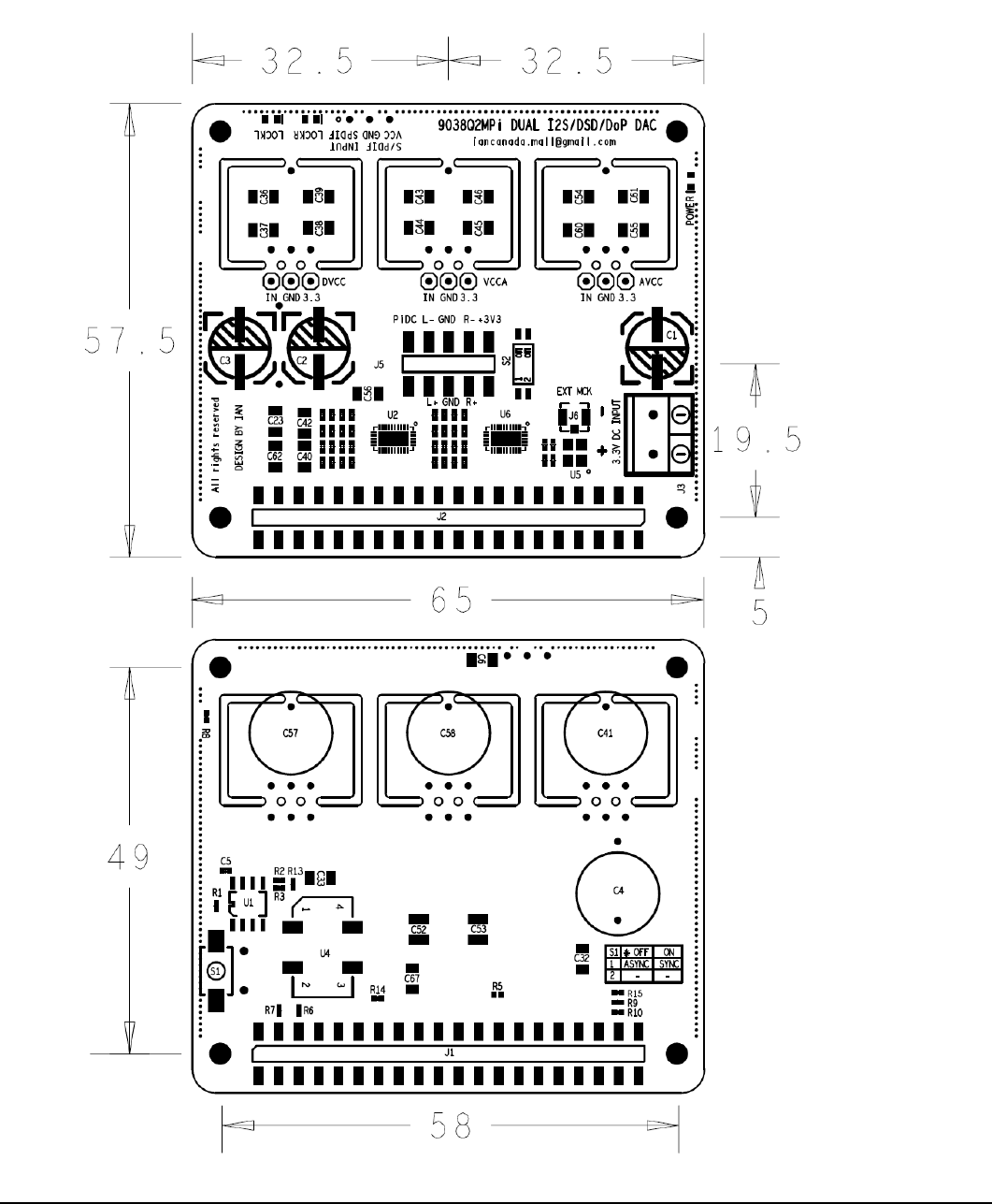
C. Layout and Dimensions (in mm)

Page 3 2018-12-30 iancanada.mail@gmail.com
D. Quick-Start Guide
1. Connect the 9038Q2MPi Dual Mono DAC HAT on top of RaspberryPi.
2. Connect an output board on top of9038Q2MPi.
3. Connect the ESS Controller into GPIO connector J2 (unless you have a Linux driver for ES9038Q2M loaded
on your RaspberryPi).
4. Install a micro SD card loaded with your preferred distro and player combination into your RaspberryPi.
5. Connect a 3.3V / 200mA (minimum) low noise DC power to J3 (ultra capacitor or LifePO4 battery direct
recommended).
6. If needed, connect the appropriate power to the output board.
7. Power the Raspberry Pi (with your preferred distro and player micro SD card installed) as usual. 9038Q2MPi
and output stage can be powered at same time or before.
8. Connect to the RaspberryPi as usual. In the player’s configuration dialog, select generic I2S DAC (for
hardware based volume control from ESS controller), or PCM5122-compatible DAC (such as Hifiberry DAC+)
if you desire additional hardware volume control from player UI. Restart the player if required.
9. Adjust volume to 0dB or other suitable level at first time before turning on the rest of your audio system.
10. Enjoy the music.
E. Connectors
J3: DC power input
Connect a 3.3V DC / 100mA (minimum) power supply to the 2-pin 5.0mm terminal J3, MAINTAINING CORRECT
POLARITY!!! Any low noise linear 3.3V power supply will work. We prefer a direct-connected 3.3V ultra capacitor /
LifePO4 battery power supply for best possible sound quality. The 9038Q2MPi consumes around 50mA average with
50MHz MCLK in asynchonous mode (default).
J6: External MCLK input (u.fl coaxial cable socket)
When operating the 9038Q2MPi in Synchronous mode, connect the external MCLK signal from a FifoPi or similar
synchronous MCLK source using a u.fl coaxial cable. DO NOT connect to J5 when operating in
Asynchronous mode
(default).
J5: Fully balanced ES9038Q2M raw current output
Connect an output stage board as below:
pin number
Descriptions
1
NC
2
RaspberryPi 5V, internally connected to RaspberryPi GPIO pins 2 and 4
3
L+, Left positive current output
4
L-, Left negative current output
5
GND

Page 4 2018-12-30 iancanada.mail@gmail.com
6
GND
7
R+, Right positive current output
8
R-, Right negative current output
9
NC
10
AVCC (ES9038Q2M AVCC 3.3V voltage rail)
S/PDIF input
Connect an optional 3.3V LVTTL logic level optical S/PDIF receiver or other S/PDIF as below:
pin number
Descriptions
1
SPDIF input
2
GND
3
3.3V power, internally connected to J3
40 pin GPIO connectors
pin number
J1
40 PIN GPIO connector to
board below (RaspberryPi,
IsolatorPi I/II, FiFoPi, or
similar)
J2
40 PIN GPIO connector to HAT on top
of 9038Q2MPi
1,17
3.3V from preceding board
3.3V from preceding board
2,4
5V from preceding board
5V from preceding board
6,9,14,20,
25,30,34,
39
GND
GND
3
I2C DA
I2C DA
4
I2C CL
I2C CL
27
ID DA
ID DA
28
ID CL
ID CL
12
SCK input
SCK from preceding board
35
LRCK/D1 input
LRCK/D1PIN from preceding board
40
SD/D2 input
SD/D2 PIN from preceding board
All other pins
same pin from preceding
board
same pin from preceding board
40 pin GPIO connector note:
All input/output signals are
LVTTL (3.3V) logic level except power and ground.
Page 5 2018-12-30 iancanada.mail@gmail.com
F. Jumper settings (Jumper switch S2 is located at top side of PCB)
Jumper Switch S2
OFF (default)
ON
1
Asynchronous clock mode
Synchronous clock mode
Must have synchronous external MCLK
connected to J6 when set in on position
2
I2C address: 0x90
I2C address: 0x92
G. LED indicators
LED
Description
On Indicates...
D2
LOCKL
Left ES9038Q2M DAC U2 is locked to input music signals
D3
LOCKR
Right ES9038Q2M DAC U6 is locked to input music signals
D7
POWER
3.3V power applied
H. How to produce the best sound quality from your 9038Q2MPi
Run your 9038Q2MPi in Synchronous mode
We prefer running this DAC with a synchronous MCK than the default Asynchronous mode. To do that, switch to
Synchronous clock mode by:
1. Installing a FifoPi between the RaspberryPi and the 9038Q2MPi DAC (see FifoPi user’s manual for installation
and configuration details).
2. Installing a pair of really nice clocks into the FifoPi according to your personal preference. The quality of these
clocks is very important to the sound quality and sonic signature.
3. Connecting the MCLK signal from the FifoPi to J6 on the 9038Q2MPi using a u.fl coaxial cable. Cable length
should be as short as possible.
4. Setting pin1 of jumper switch S2 to ‘ON’ position.
5. Setting DPLL bandwidth to lowest level 1 for both PCM and DSD in the ESS Controller, at the "DPLL Bandwidth'
setting panel (see ESS Controller manual for configuration details).
6. Power up and enjoy the music.
After performing the above steps, your 9038Q2MPi now is using an MCLK that is synchronous to the music signal and
is largely bypassing the DPLL.
Further gains can be made by stopping the DPLL and enabling True Sync mode
. BUT there are limitations to True
Sync mode with the ES9038Q2M:
- It supports PCM format only. DSD and DoP are not supported.
- MCLK has to be 128FSR
If you do not follow these limitations, True Sync mode does not work properly. Also, once you have enabled True Sync
mode on the 9038Q2MPi, the lock LEDs stay on continuously.
Enable True Sync mode on your 9038Q2M by:
1. Selecting “True SYNC with DPLL stopped” in the ESS Controller at the “Normal/True SYNC mode” setting panel.
2. Setting both PCM bandwidths to “No band width 0”.
See ESS Controller manual for configuration details.

Page 6 2018-12-30 iancanada.mail@gmail.com
Isolate your 9038Q2MPi from the ESS Controller
ESS Controller contains a micro-processor. It generates EMI noise that can impact sound quality. Connecting the ESS
Controller through an isolator eliminates any direct electronic connections between ESS controller and 9038Q2MPi
and prevents this noise from reaching the DAC. The 9038Q2MPi grounds will be cleaner when configured this way.
To run the ESS Controller in isolated mode, you need to use a FiFoPi or IsolatorPi I/II between your RaspberryPI and
9038Q2MPi and connect the ESS Controller to the non-isolated GPIO connector of the FifoPi or IsolatorPi I/II.
Power your 9038Q2MPi directly from a 3.3V ultra capacitor or LiFePO4 battery power supply
We have found using a directly-connected (no LDO on the output) 3.3V ultra capacitor or LiFePO4 battery power
supply to be a significant improvement over most traditional power supplies. To do this, connect the supply directly to
J3 OBSERVING CORRECT POLARITY!!!
Power your 9038Q2MPi voltage rails separately
For the ultimate power experience, you can power the three voltage rails on your 9038Q2MPi separately. You do this
by removing the three decoupling network daughter boards from the 9038Q2MPi PCB using a side cutter. Then feed
three separate 3.3V power supplies to the 3.3V and GND pins at DVCC/GND, VCCA/GND and AVCC/GND. 3.3V
ultra capacitor power and LiFePO4 battery power supply are of course always preferred.
Select an output board(s) that matches your preferred listening style
Which output board is used makes a significant contribution to both the sound quality and sonic signature produced
from your ES9038QMPi. The standard op-amplifier I/V board (and what opamps you use in the board), OPA861 I/V
board, OPA1632 I/V board, a discrete I/V board, Transformer Output board, and so on, will all sound different. Also
whether you use them in single-ended or balanced mode will also impact the sound quality and sonic signature.
Please choose the output board best suited to your system and your personal preferences. Also use the balanced
XLR outputs if you can in your system. In most cases, we have found the balanced XLR output produces better overall
sound quality than the single ended output.
Experiment with the settings of your ES9038Q2MPi using the ESS Controller
Many of ES9038Q2MPi settings can be programmed using the ESS Controller. Some that make a difference sonically
include DPLL bandwidth for both PCM and DSD format, the seven preset FIR filters, OSF bypassing, IIR bypassing.
Using the guidelines in the ESS Controller manual to safely set these settings, feel free to experiment and find the best
settings for your ES9038Q2MPi setup and your system based on listening.

Page 7 2018-12-30 iancanada.mail@gmail.com
I. Other upgrade options
Assemble optional on-board super capacitors
You can install optional small-footprint super capacitors on your ES9038Q2MPi:
Reference
Description
Device Package
Location
Notes
C4
Optional super capacitor for DC input
J3
Dimension 11.5mm
Through Hole
Bottom
Side
of
PCB
Rated voltage MIUST
be higher than the
power supply
voltage. Normally
5.5V
C57
Optional super capacitor for DVCC
C58
Optional super capacitor for VCCA
C41
Optional super capacitor for AVCC
Use local 3.3V low noise regulators
IF you do not use a directly-connected (no LDO) 3.3V ultra capacitor or LiFePO4 battery power supply, but instead use
a more traditional power supply, you can install three 3.3V low noise regulators for DVCC, AVCC and VCCA and then
feed the appropriate voltage (typically 5V) at J3 ALWAYS OBSERVING POLARITY!!!
You do this by removing the three decoupling network daughter boards from the 9038Q2MPi PCB using a side cutter.
Then install three similar-sized low-noise LDO regulator boards at the IN, GND, and 3.3V pins at DVCC/GND,
VCCA/GND and AVCC/GND. For the best performance, we recommend LT3042/LT3045 low noise regulator boards or
similar. Again, DC input voltage (J3) needs to be 5V or higher according to the requirements of the LDO boards.
Upgrade the on-board 100MHz clock
If you are running your ES9038Q2MPi in Asynchronous mode, you can upgrade on-board XO clock to a higher grade
lower jitter one such as a 100MHz CCHD950 or equivalent. You do this by removing the originally-installed XO U5 and
then installing a new XO clock to the U4 pads on the bottom side of PCB. IF you are operating your ES9038Q2MPi in
Synchronous mode with a FiFoPi or equivalent, there is no need to upgrade the originally-installed XO U5 as it is not
being used in this configuration.
Page 8 2018-12-30 iancanada.mail@gmail.com
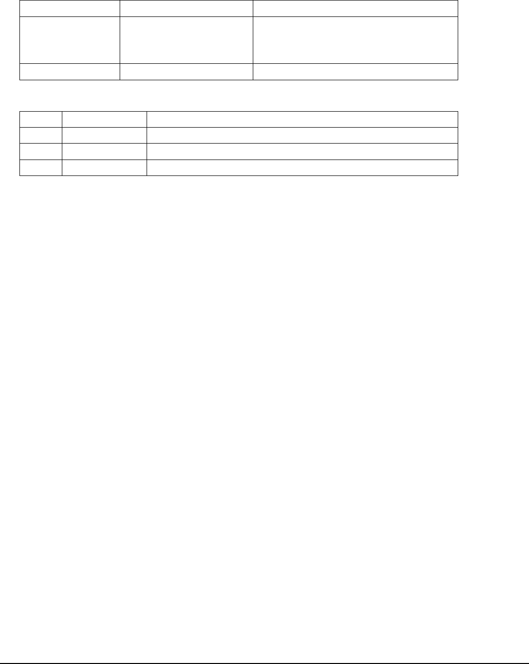
J. ES9038Q2Mpi Dual Mono DAC HAT pictures
1. ES9038Q2MPi dual mono DAC HAT as shipped
2. Getting start with Asynchronous mode (default)
Raspberry Pi + ES9038Q2MPi dual mono DAC HAT + ESS controller + I/V board
Page 9 2018-12-30 iancanada.mail@gmail.com
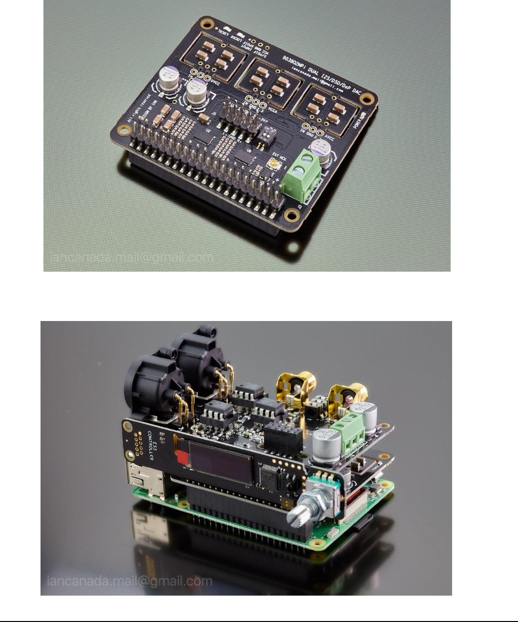
3. Running in isolated Asynchronous mode
Raspberry Pi + IsolatorPi I/II + ESS controller + ES9038Q2MPi dual mono DAC HAT + I/V board
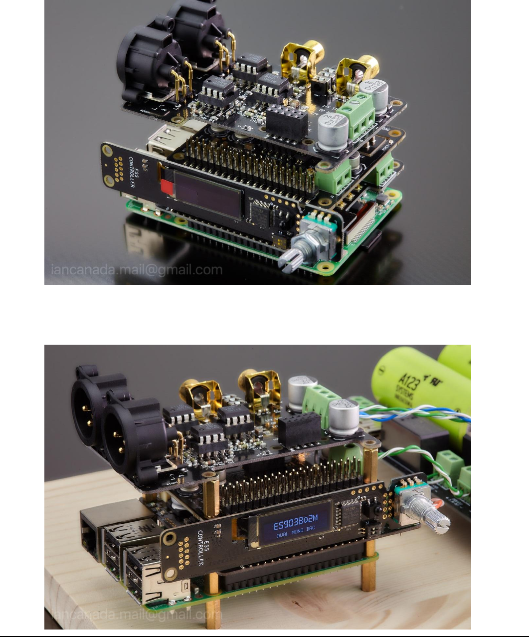
4. Running in Synchronous mode (highly recommended)
Raspberry Pi + FifoPi + ESS controller + ES9038Q2MPi dual mono DAC HAT + I/V board

Page 10 2018-12-30
iancanada.mail@gmail.com
© 2019 Ian Jin. The firmware code embedded in the ES9038Q2MPi is the property of Ian Jin. You are granted a
non-exclusive, non-transferable, non-sublicenseable, royalty-free right to use the ES9038Q2MPi board solely for your own,
non-commercial purposes. You may not distribute, sell, lease, transfer, modify, adapt, translate, reverse engineer, prepare
derivative works of, decompile, or disassemble the software provided. All rights reserved.
