ESR 3037 Simpson Strong Tie Company Inc. ES3037
User Manual: ES3037
Open the PDF directly: View PDF ![]() .
.
Page Count: 21
- ESR-3037 Cover Sheet
- ESR-3037
- TABLE 1A—CARBON STEEL STRONG-BOLT® 2 ANCHOR INSTALLATION INFORMATION1
- TABLE 1B—STAINLESS STEEL STRONG-BOLT® 2 ANCHOR INSTALLATION INFORMATION1
- TABLE 2A—CARBON STEEL STRONG-BOLT® 2 ANCHOR TENSION STRENGTH DESIGN DATA1
- TABLE 2B—STAINLESS STEEL STRONG-BOLT® 2 ANCHOR TENSION STRENGTH DESIGN DATA1
- TABLE 3A—CARBON STEEL STRONG-BOLT® 2 ANCHOR SHEAR STRENGTH DESIGN DATA1
- TABLE 3B—STAINLESS STEEL STRONG-BOLT® 2 ANCHOR SHEAR STRENGTH DESIGN DATA1
- TABLE 4A—CARBON STEEL STRONG-BOLT® 2 ANCHOR TENSION AND SHEAR STRENGTH DESIGN DATA FOR THE SOFFIT OF NORMAL-WEIGHT CONCRETE OVER PROFILE STEEL DECK, FLOOR AND ROOF ASSEMBLIES1,2,6,8
- TABLE 4B—STAINLESS STEEL STRONG-BOLT® 2 ANCHOR TENSION AND SHEAR STRENGTH DESIGN DATA FOR THE SOFFIT OF NORMAL-WEIGHT CONCRETE OVER PROFILE STEEL DECK, FLOOR AND ROOF ASSEMBLIES1,2,6,10
- TABLE 4C—CARBON STEEL STRONG-BOLT® 2 ANCHOR TENSION AND SHEAR STRENGTH DESIGN DATA FOR THE SOFFIT OF NORMAL-WEIGHT CONCRETE OVER PROFILE STEEL DECK, FLOOR AND ROOF ASSEMBLIES1,2,6,8
- TABLE 5A—CARBON STEEL STRONG-BOLT® 2 ANCHOR INSTALLATION INFORMATION IN THE TOPSIDE OF CONCRETE-FILLED PROFILE STEEL DECK FLOOR AND ROOF ASSEMBLIES1,2,3,4
- TABLE 5B—STAINLESS STEEL STRONG-BOLT® 2 ANCHOR INSTALLATION INFORMATION IN THE TOPSIDE OF CONCRETE-FILLED PROFILE STEEL DECK FLOOR AND ROOF ASSEMBLIES1,2,3,4
- TABLE 6—EXAMPLE STRONG-BOLT® 2 ANCHOR ALLOWABLE STRESS DESIGN TENSION VALUES FOR ILLUSTRATIVE PURPOSES1,2,3,4,5,6,7,8,9
- TABLE 7—LENGTH IDENTIFICATION HEAD MARKS ON STRONG-BOLT® 2 ANCHORS (CORRESPONDS TO LENGTH OF ANCHOR – INCHES)
- FIGURE 4—INTERPOLATION OF MINIMUM EDGE DISTANCE AND ANCHOR SPACING1
- FIGURE 5—INSTALLATION IN THE SOFFIT OF CONCRETE OVER PROFILE STEEL DECK FLOOR AND ROOF ASSEMBLIES1
- FIGURE 6—INSTALLATION ON THE TOP OF CONCRETE-FILLED PROFILE STEEL DECK FLOOR AND ROOF ASSEMBLIES
- FIGURE 7—INSTALLATION IN THE SOFFIT OF CONCRETE OVER PROFILE STEEL DECK FLOOR AND ROOF ASSEMBLIES1
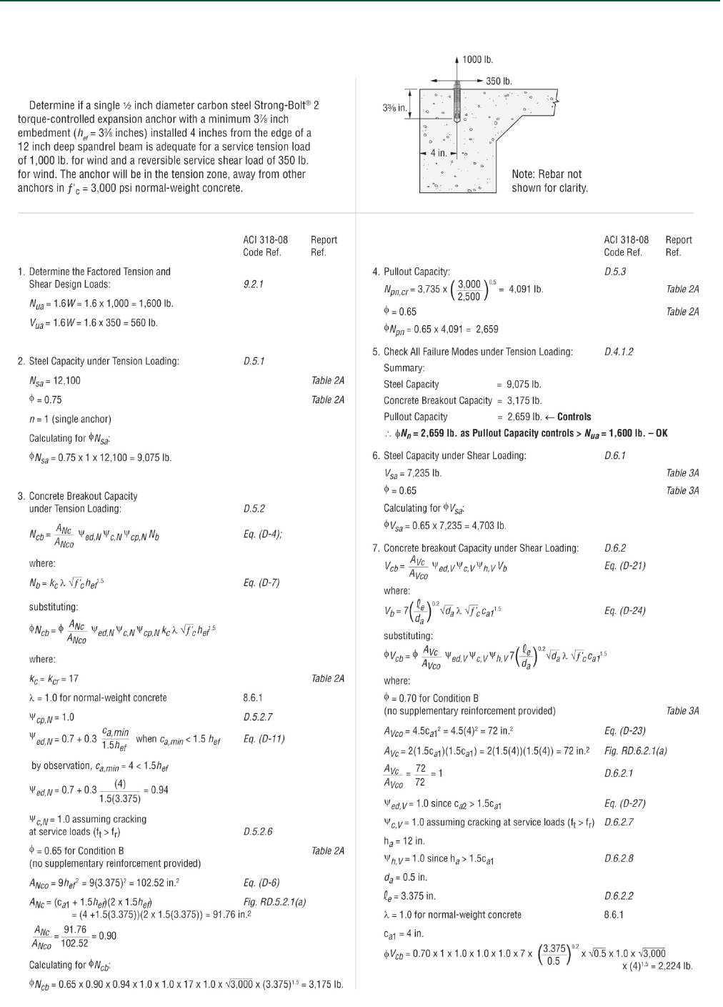
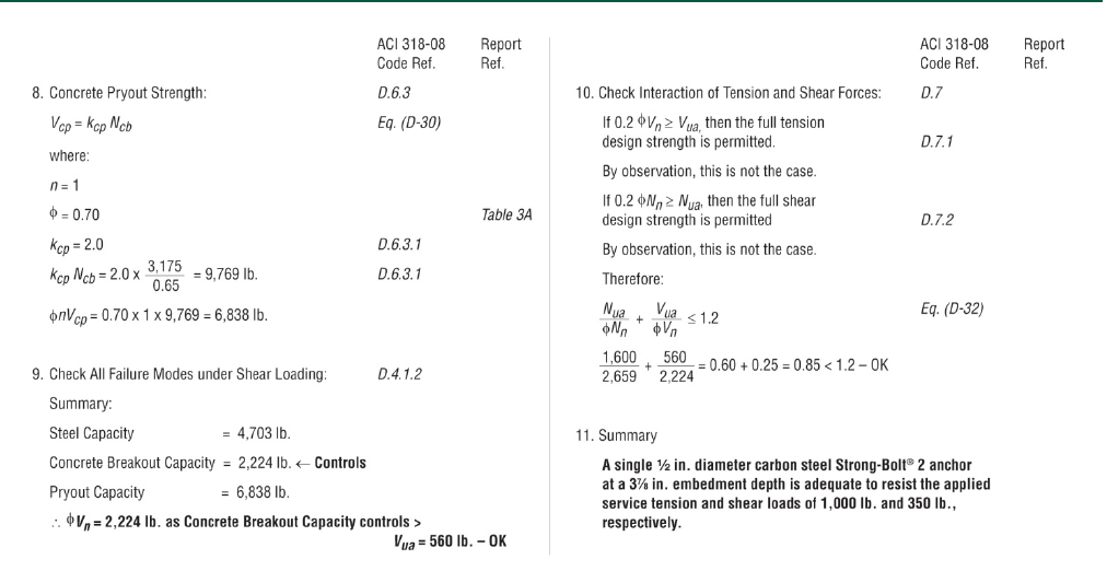
- FIGURE 8—STRONG-BOLT® 2 ANCHOR EXAMPLE CALCULATION
I
I
ICC-
E
s
pec
if
reco
m
to an
y
Cop
y
“20
1
(W
S
Loo
k
0
000
I
CC‐E
S
CC‐ES|(80
0
E
S Evaluatio
n
if
ically addres
s
m
mendation f
o
y
finding or o
t
y
right
©
2018
1
4Recipient
o
S
SPC)Award
i
S
k
forthetru
s
S
Eval
u
0
)423‐6587
n
Reports are
n
s
ed, nor are t
h
o
r its use. The
r
h
er matter in
t
ICCEvaluati
o
o
fPrestigiou
s
i
nExcellence
”
S
S
IMPSON
s
tedmarkso
f
u
atio
n
|(562)699
n
ot to be cons
t
h
ey to be con
s
r
e is no warra
n
t
his report, or
a
o
nService,LL
s
WesternSt
a
”
SE
C
S
ECTION:0
5
SIMP
S
5
STRON
G
CRAC
K
f
Conformity
!
n
Re
po
‐0543|ww
t
rued as repre
s
s
trued as an
e
n
ty by ICC Ev
a
a
s to any prod
u
C.Allrights
r
a
tesSeismic
P
DIVISION
C
TION:031
6
DIVISIO
N
5
0519—P
O
R
E
S
ONSTR
O
5
956WEST
PLEASAN
T
EVAL
G
‐TIE®ST
R
K
EDAND
!
o
rt
w.icc‐es.or
g
s
enting aesth
e
e
ndorsement o
f
a
luation Servi
c
u
ct covered by
r
eserved.
P
olicyCouncil
:030000
—
6
00—CON
C
N
:050000
O
ST‐INSTAL
L
E
PORTHOL
D
O
NG‐TIE
LASPOSIT
A
T
ON,CALIF
O
UATIONS
U
R
ONG‐B
O
UNCRA
C
Most
W
T
h
g
e
tics or any ot
h
f
the subject
of
c
e, LLC, expr
e
the report.
—
CONCRET
E
C
RETEANC
H
—METALS
L
EDCONCR
D
ER:
COMPA
N
A
SBOULEV
A
O
RNIA945
8
U
BJECT:
O
LT®2
W
C
KEDCO
N
W
idelyAcc
e
h
isreportissu
h
er attributes
of
the report o
e
ss or implied,
E
HORS
R
ETEANCH
O
N
YINC.
A
RD
8
8
W
EDGEA
N
N
CRETE
ASubs
eptedan
d
ESR‐
Reiss
u
bjecttorene
w
not
r a
as
O
RS
N
CHORF
O
s
idiaryof
d
Trusted
3037
u
ed08/2017
w
al08/2018.
O
R
ICC-ES Evaluation Report ESR-3037
Reissued August 2017
This report is subject to renewal August 2018.
www.icc-es.org | (800) 423-6587 | (562) 699-0543 A Subsidiary of the International Code Council ®
DIVISION: 03 00 00—CONCRETE
Section: 03 16 00—Concrete Anchors
DIVISION: 05 00 00—METALS
Section: 05 05 19—Post-installed Concrete Anchors
REPORT HOLDER:
SIMPSON STRONG-TIE COMPANY INC.
5956 WEST LAS POSITAS BOULEVARD
PLEASANTON, CALIFORNIA 94588
(800) 999-5099
www.strongtie.com
EVALUATION SUBJECT:
SIMPSON STRONG-TIE® STRONG-BOLT® 2 WEDGE
ANCHOR FOR CRACKED AND UNCRACKED CONCRETE
1.0 EVALUATION SCOPE
Compliance with the following codes:
2015, 2012, 2009, and 2006 International Building
Code® (IBC)
2015, 2012, 2009, and 2006 International Residential
Code® (IRC)
Property evaluated:
Structural
2.0 USES
The 1/4-inch (6.4 mm) Simpson Strong-Tie® Strong-Bolt® 2
wedge anchor is used to resist static, wind and seismic
tension and shear loads in uncracked normal-weight
concrete and lightweight concrete having a specified
compressive strength, f
'
c, of 2,500 psi to 8,500 psi
(17.2 MPa to 58.6 MPa). The 3/8-inch- through 1-inch-
diameter (9.5 mm through 25.4 mm) anchors are used to
resist static, wind and seismic tension and shear loads in
cracked and uncracked normal-weight concrete and
lightweight concrete having a specified compressive
strength, f
'
c, of 2,500 psi to 8,500 psi (17.2 MPa to
58.6 MPa).
The 3/8-inch-, 1/2-inch-, 5/8-inch- and 3/4-inch-diameter
(9.5 mm, 12.7 mm, 15.9 mm and 19.1 mm) anchors may
be installed in the soffit of cracked and uncracked normal-
weight or sand-lightweight concrete-filled steel deck having
a minimum specified compressive strength, f'c, of 3,000 psi
(20.7 MPa), as shown in Figures 5 and 7.
The 3/8-inch- and 1/2-inch-diameter (9.5 mm and
12.7 mm) anchors may be installed in the topside of
cracked and uncracked normal-weight or sand-lightweight
concrete-filled steel deck having a minimum member
thickness, hmin,deck, as noted in Tables 5A and 5B of
this report and a specified compressive strength, f'c, of
2,500 psi to 8,500 psi (17.2 MPa to 58.6 MPa), as shown
in Figure 6.
The Strong-Bolt® 2 complies with Section 1901.3 of the
2015 IBC and Section 1909 of the 2012 IBC, Section 1912
of the 2009 and 2006 IBC. The anchors are alternatives to
cast-in-place anchors described in Section 1908 of the
2012 IBC, Section 1911 of the 2009 and 2006 IBC. The
anchors may also be used where an engineered design is
submitted in accordance with Section R301.1.3 of the IRC.
3.0 DESCRIPTION
3.1 Strong-Bolt® 2:
3.1.1 General: Strong-Bolt® 2 anchors are torque-
controlled, mechanical expansion anchors consisting of an
anchor body, expansion clip, nut, and washer. A typical
anchor (carbon steel version) is shown in Figure 1 of this
report. The anchor body has a tapered mandrel formed on
the installed end of the anchor and a threaded section at
the opposite end. The taper of the mandrel increases in
diameter toward the installed end of the anchor. The
three-segment expansion clip wraps around the tapered
mandrel. Before installation, this expansion clip is free to
rotate about the mandrel. The anchor is installed in a
predrilled hole. When the anchor is set by applying torque
to the hex nut, the mandrel is drawn into the expansion
clip, which engages the drilled hole and transfers the load
to the base material. Pertinent dimensions are as set forth
in Tables 1A and 1B of this report.
3.1.2 Strong-Bolt® 2, Carbon Steel: The anchor bodies
are manufactured from carbon steel material with zinc
plating conforming to ASTM B633, SC1, Type III. The
expansion clip for the 1/4-inch-, 3/8-inch-, 1/2-inch-, 5/8-inch-
and 3/4-inch-diameter carbon steel Strong-Bolt 2 anchors is
fabricated from carbon steel and conforms to ASTM A568.
The expansion clip for the 1-inch-diameter carbon steel
Strong-Bolt 2 anchor is fabricated from stainless steel and
conforms to ASTM A240, Grade 316. The hex nut for the
carbon steel Strong-Bolt 2 anchor conforms
to ASTM A563, Grade A. The washer for the carbon steel
Strong-Bolt 2 anchor conforms to ASTM F844. The
available anchor diameters under this report are 1/4
inch, 3/8 inch,
1/2 inch, 5/8 inch, 3/4 inch and 1 inch (6.4 mm, 9.5 mm,
12.7 mm, 15.9 mm, 19.1 mm, and 25.4 mm).
3.1.3 Strong-Bolt® 2, Stainless Steel: The anchor
bodies of the stainless steel Strong-Bolt 2 anchors are
ICC-ES Evaluation Reports are not to be construed as representing aesthetics or any other attributes not specifically addressed, nor are they to be construed
as an endorsement of the subject of the report or a recommendation for its use. There is no warranty by ICC Evaluation Service, LLC, express or implied, as
to any finding or other matter in this report, or as to any product covered by the report.
Copyright © 2018 ICC Evaluation Service, LLC. All rights reserved. Page 1 of 20

ESR-3037 | Most Widely Accepted and Trusted Page 2 of 20
manufactured from either AISI Type 304 or AISI Type 316
stainless steel. The expansion clip for the stainless steel
Strong-Bolt 2 anchor conforms to AISI Type 304 or AISI
Type 316 stainless steel. The hex nut and washer for the
Type 304 and Type 316 stainless steel Strong-Bolt 2
conform to AISI Type 304 and Type 316 steel,
respectively. The available anchor diameters under this
report are 1/4 inch, 3/8 inch, 1/2 inch, 5/8 inch and 3/4 inch
(6.4 mm, 9.5 mm, 12.7 mm, 15.9 mm and 19.1 mm).
3.2 Concrete:
Normal-weight and lightweight concrete must conform to
Sections 1903 and 1905 of the IBC, as applicable.
3.3 Profile Steel Deck:
The profile steel deck must comply with the configuration
in Figures 5, 6 and 7 and have a minimum base-steel
thickness of 0.035 inch (0.889 mm) [20 gauge]. Steel must
comply with ASTM A653/A653M SS Grade 33 with a
minimum yield strength of 33,000 psi (228 MPa) for figures
5 and 6, and Grade 50 with a minimum yield strength of
50,000 psi (345 MPa) for figure 7.
4.0 DESIGN AND INSTALLATION
4.1 Strength Design:
4.1.1 General: Design strength of anchors complying with
the 2015 IBC as well as Section R301.1.3 of the 2015 IRC,
must be determined in accordance with ACI 318-14 and
this report.
Design strength of anchors complying with the 2012 IBC,
as well as Section R301.1.3 of the 2012 IRC, must be
determined in accordance with ACI 318-11 Appendix D
and this report.
Design strength of anchors complying with the 2009 IBC
and Section R301.1.3 of the 2009 IRC must be in
accordance with ACI 318-08 Appendix D and this report.
Design strength of anchors complying with the 2006 IBC
and Section R301.1.3 of the 2006 IRC must be in
accordance with ACI 318-05 Appendix D and this report.
Design parameters provided in Tables 1A through 6 and
references to ACI 318 are based on the 2015 IBC
(ACI 318-14) and on the 2012 IBC (ACI 318-11) unless
noted otherwise in Sections 4.1.1 through 4.1.12 of this
report. The strength design of anchors must comply with
ACI 318-14 17.3.1 or ACI 318-11 D.4.1, as applicable,
except as required in ACI 318-14 17.2.3 or ACI 318-11
D.3.3, as applicable. A design example in accordance with
the 2009 IBC is given in Figure 8 of this report.
Strength reduction factors,
φ
, as given in ACI 318-14
17.3.3 or ACI 318-11 D.4.3, as applicable, must be used
for load combinations calculated in accordance with
Section 1605.2 of the IBC and Section 5.3 of ACI 318-14
or Section 9.2 of ACI 318-11, as applicable. Strength
reduction factors,
φ
, as given in ACI 318-11 D.4.4 must be
used for load combinations calculated in accordance with
ACI 318-11 Appendix C.
The value of f
c used in the calculations must be limited
to 8,000 psi (55.2 MPa), maximum, in accordance with ACI
318-14 17.2.7 or ACI 318-11 D.3.7, as applicable.
4.1.2 Requirements for Static Steel Strength in
Tension: The nominal steel strength of a single anchor in
tension, Nsa, in accordance with ACI 318-14 17.4.1.2 or
ACI 318-11 D.5.1.2, as applicable, is given in Tables 2A
and 2B of this report. The strength reduction factor,
φ
,
corresponding to a brittle steel element must be used for
the carbon steel 1-inch-diameter anchor as described
in Table 2A of this report. For all other anchors the strength
reduction factor,
φ
, corresponding to a ductile steel
element must be used as described in Tables 2A and 2B of
this report.
4.1.3 Requirements for Static Concrete Breakout
Strength in Tension: The nominal concrete breakout
strength of a single anchor or group of anchors in tension,
Ncb and Ncbg, must be calculated in accordance with ACI
318-14 17.4.2 or ACI 318-11 D.5.2, as applicable, with
modifications as described in this section. The basic
concrete breakout strength in tension, Nb, must be
calculated in accordance with ACI 318-14 17.4.2.2 or ACI
318-11 D.5.2.2, as applicable, using the values of hef and
kcr as described in Tables 2A and 2B of this report. The
nominal concrete breakout strength in tension, Ncb or Ncbg,
in regions of a concrete member where analysis indicates
no cracking at service loads in accordance with ACI
318-14 17.4.3.6 or ACI 318-11 D.5.2.6, as applicable, must
be calculated with the value of kuncr as given in Tables 2A
and 2B of this report and with
Ψ
c,N = 1.0, as described
in Tables 2A and 2B of this report.
For anchors installed in the soffit of sand-lightweight or
normal-weight concrete over profile steel deck floor
and roof assemblies, as shown in Figures 5 and 7,
determination of the concrete breakout strength in
accordance with ACI 318-14 17.4.2 or ACI 318-11 D.5.2,
as applicable, is not required.
4.1.4 Requirements for Static Pullout Strength in
Tension: The nominal pullout strength of a single anchor
in tension in accordance with ACI 318-14 17.4.3 or ACI
318-11 D.5.3, as applicable, in cracked and uncracked
concrete, Np,cr and Np,uncr, is given in Tables 2A and 2B of
this report. Where analysis indicates no cracking at service
load levels in accordance with ACI 318-14 17.4.3.6 or ACI
318-11 D.5.3.6, as applicable, the nominal pullout strength
in uncracked concrete, Np,uncr, applies. Where values for
Np,cr or Np,uncr are not provided in Tables 2A and 2B, the
pullout strength does not need to be considered. In lieu of
ACI 318-14 17.4.3.6 or ACI 318-11 D.5.3.6, as applicable,
Ψ
c,p = 1.0 for all design cases. The nominal pullout
strength in cracked concrete must be adjusted for concrete
strengths according to Eq-1:
Np,f'c=Np,cr f'c
2,500n (lb, psi) (Eq-1)
Np,f'c=Np,cr f'c
17.2n (N, MPa)
where f
c is the specified compressive strength and n is the
factor defining the influence of concrete strength on the
pullout strength. For the stainless steel 3/8-inch-diameter
anchor in cracked concrete n is 0.3. For the stainless
steel 5/8-inch-diameter anchor in cracked concrete n is 0.4.
For all other cases n is 0.5.
In regions where analysis indicates no cracking in
accordance with ACI 318-14 17.4.3.6 or ACI 318 D.5.3.6,
as applicable, the nominal pullout strength in tension must
be adjusted by calculation according to Eq-2:
Np,f'c=Np,uncr f'c
2,500n (lb, psi) (Eq-2)
Np,f'c=Np,uncr f'c
17.2n (N, MPa)
where f
c is the specified compressive strength and n is the
factor defining the influence of concrete strength on the
pullout strength. For the stainless steel 3/8-inch-diameter
anchor in uncracked concrete, n is 0.3. For the stainless
steel 1/4-inch-diameter anchor and stainless steel 3/4-inch-
diameter anchor in uncracked concrete, n is 0.4. For all
other cases, n is 0.5.
The pullout strength in cracked and uncracked concrete
for anchors installed in the soffit of sand-lightweight or
normal-weight concrete over profile steel deck floor and

ESR-3037 | Most Widely Accepted and Trusted Page 3 of 20
roof assemblies, as shown in Figures 5 and 7, is given
in Tables 4A, 4B and 4C of this report. The nominal pullout
strength in cracked concrete must be adjusted for concrete
strength according to Eq-1, using the value of Np,deck,cr in
lieu of Np,cr, and the value of 3,000 psi (20.7 MPa) must be
substituted for the value of 2,500 psi (17.2 MPa) in the
denominator. Where analysis indicates no cracking at
service load levels in accordance with ACI 318-14 17.4.3.6
or ACI 318-11 D.5.3.6, as applicable, the nominal pullout
strength in uncracked concrete must be adjusted for
concrete strength according to Eq-2, using the value of
Np,deck,uncr in lieu of Np,uncr, and the value of 3,000 psi
(20.7 MPa) must be substituted for the value of 2,500 psi
(17.2 MPa) in the denominator. The value of
Ψ
c,p = 1.0 for
all cases.
4.1.5 Requirements for Static Steel Strength in Shear:
The nominal steel strength in shear, Vsa, of a single anchor
in accordance with ACI 318-14 17.5.1.2 or ACI 318-11
D.6.1.2, as applicable, is given in Tables 3A and 3B of this
report and must be used in lieu of values derived by
calculation from ACI 318-14 Eq. 17.5.1.2a or ACI 318-11,
Eq. D-29, as applicable. The strength reduction factor,
φ
,
corresponding to a brittle steel element must be used for
the carbon steel 1-inch-diameter anchor as described
in Table 3A of this report. For all other anchors the strength
reduction factor,
φ
, corresponding to a ductile steel
element must be used for all anchors as described
in Tables 3A and 3B of this report.
The shear strength, Vsa,deck, of anchors installed in the
soffit of sand-lightweight or normal-weight concrete over
profile steel deck floor and roof assemblies, as shown
in Figures 5 and 7, is given in Tables 4A, 4B and 4C of this
report.
4.1.6 Requirements for Static Concrete Breakout
Strength in Shear: The nominal concrete breakout
strength of a single anchor or group of anchors in shear,
Vcb or Vcbg, must be calculated in accordance with
ACI 318-14 17.5.2 or ACI 318-11 D.6.2, as applicable, with
modifications as described in this section. The basic
concrete breakout strength in shear, Vb, must be
calculated in accordance with ACI 318-14 17.5.2.2 or ACI
318-11 D.6.2.2, as applicable, using the values of
λ
e and
da provided in Tables 3A and 3B of this report.
For anchors installed in the topside of concrete-filled
steel deck assemblies, as shown in Figure 6, the nominal
concrete breakout strength of a single anchor or group of
anchors in shear, Vcb or Vcbg, respectively, must be
calculated in accordance with ACI 318-14 17.5.2 or ACI
318-11 D.6.2, as applicable, using the actual member
thickness, hmin,deck, in the determination of AVc. Minimum
member topping thickness for anchors in the topside of
concrete-filled steel deck assemblies is given in Tables 5A
and 5B of this report.
For anchors installed in the soffit of sand-lightweight or
normal-weight concrete over profile steel deck floor and
roof assemblies, as shown in Figures 5 and 7, calculation
of the concrete breakout strength in accordance with ACI
318-14 17.5.2 or ACI 318-11 D.6.2, as applicable, is not
required.
4.1.7 Requirements for Static Concrete Pryout
Strength in Shear: The nominal concrete pryout strength
of a single anchor or group of anchors in shear, Vcp or
Vcpg, must be calculated in accordance with ACI 318-14
17.5.3.1 or ACI 318-11 D.6.3, as applicable, modified by
using the value of kcp described in Tables 3A and 3B of
this report and the value of Ncb or Ncbg as calculated in
accordance with Section 4.1.3 of this report.
For anchors installed in the soffit of sand-lightweight or
normal-weight concrete over profile steel deck floor and
roof assemblies, as shown in Figures 5 and 7, calculation
of the concrete pryout strength in accordance with ACI
318-14 17.5.3.1 or ACI 318-11 D.6.3, as applicable, is not
required.
4.1.8 Requirements for Seismic Design:
4.1.8.1 General: For load combinations including seismic,
the design must be performed in accordance with ACI
318-14 17.2.3 or ACI 318-11 D.3.3, as applicable.
Modifications to ACI 318-14 2.3 17.2.3 shall be applied
under Section 1905.1.8 of the 2015 IBC. For the 2012 IBC,
Section 1905.1.9 must be omitted. Modifications to ACI
318-08 and ACI 318-05 D.3.3, as applicable, must be
applied under Section 1908.1.9 of the 2009 IBC,
Section 1908.1.16 of the 2006 IBC, respectively.
The carbon steel 1-inch-diameter anchor complies with
ACI 318-14 2.3 or ACI 318-11 D.1, as applicable, as a
brittle steel element. All other anchors comply with ACI
318-14 2.3 or ACI 318-11 D.1, as applicable, as ductile
steel elements and must be designed in accordance with
ACI 318-14 Section 17.2.3.4, 17.2.3.5, or 17.2.3.6 or ACI
318-11 Section D.3.3.4, D.3.3.5, or D.3.3.6 or ACI 318-08
Section D.3.3.4, D.3.3.5 or D.3.3.6, or ACI 318-05 Section
D.3.3.4 or D.3.3.5, as applicable, with the modifications
noted above.
4.1.8.2 Seismic Tension: The nominal steel strength and
nominal concrete breakout strength for anchors in tension
must be calculated in accordance with ACI 318-14 17.4.1
an 17.4.2 or ACI 318-11 D.5.1 and D.5.2, as applicable, as
described in Sections 4.1.2 and 4.1.3 of this report.
In accordance with ACI 318-14 17.4.3.2 or ACI 318-11
D.5.3.2, as applicable, the appropriate value for nominal
pullout strength in tension for seismic loads, Np,eq or
Np,deck,eq, provided in Tables 2A, 2B, 4A, 4B and 4C of this
report, must be used in lieu of Np. If no values for Np,eq or
Np,deck,eq are given in Table 2A, 2B, 4A, 4B or 4C, the
pullout strength for seismic loads need not be evaluated.
The values of Np,eq or Np,deck,eq can be adjusted for
concrete strength according to Section 4.1.4.
4.1.8.3 Seismic Shear: The nominal concrete breakout
and concrete pryout strength for anchors in shear must
be calculated in accordance with ACI 318-14 17.5.2
and 17.5.3 or ACI 318-11 D.6.2 and D.6.3, as applicable,
as described in Sections 4.1.6 and 4.1.7 of this report. In
accordance with ACI 318-14 17.5.1.2 or ACI 318-11
D.6.1.2, as applicable, the appropriate value for nominal
steel strength in shear for seismic loads, Vsa,eq or
Vsa,deck,eq, provided in Tables 3A, 3B, 4A, 4B and 4C of this
report, must be used in lieu of Vsa.
4.1.9 Requirements for Interaction of Tensile and
Shear Forces: For loadings that include combined tension
and shear, the design must be performed in accordance
with ACI 318-14 17.6 or ACI 318-11 D.7, as applicable.
4.1.10 Requirements for Critical Edge Distance: In
applications where c < cac and supplemental reinforcement
to control splitting of the concrete is not present, the
concrete breakout strength in tension for uncracked
concrete, calculated according to ACI 318-14 17.4.2 or ACI
318-11 D.5.2, as applicable, must be further multiplied by
the factor Ψcp,N given by Eq-3:
Ψcp,N=c
cac (Eq-3)
where the factor Ψcp,N need not be taken as less than
1.5hef
cac . For all other cases, Ψcp,N = 1.0. In lieu of ACI 318-
14 17.7.6 or ACI 318-11 D.8.6, as applicable, values of cac
provided in Tables 1A and 1B of this report must be used.
ESR-3037 | Most Widely Accepted and Trusted Page 4 of 20
4.1.11 Requirements for Minimum Member Thickness,
Minimum Anchor Spacing and Minimum Edge
Distance: In lieu of ACI 318-14 17.7.1 and 17.7.3 or ACI
318-11 D.8.1 and D.8.3, as applicable, values of smin and
cmin provided in Tables 1A and 1B of this report must be
used. In lieu of ACI 318-14 17.7.5 or ACI 318-11 D.8.5, as
applicable, minimum member thickness, hmin, must be in
accordance with Tables 1A and 1B of this report.
For 3/4-inch-diameter carbon steel, and 3/8-inch-, 1/2-
inch- and 5/8-inch-diameter stainless steel Strong-Bolt® 2
anchors, additional combinations for minimum edge
distance cmin and minimum spacing smin may be derived by
linear interpolation between the boundary given in Tables
1A and 1B and as shown in Figure 4 of this report.
For anchors installed in the topside of normal-weight or
sand-lightweight concrete over profile steel deck floor
and roof assemblies, the anchor must be installed in
accordance with Table 5A for carbon steel anchors
and Table 5B for stainless steel anchors, and Figure 6 of
this report.
For anchors installed in the soffit of steel deck
assemblies, the anchors must be installed in accordance
with Figures 5 and 7, and must have a minimum axial
spacing along the flute equal to the greater of 3hef or
1.5 times the flute width.
4.1.12 Lightweight Concrete: For the use of anchors in
lightweight concrete the modification factor λa equal to 0.8λ
is applied to all values of
c
f′
affecting Nn and Vn.
For ACI 318-14 (2015 IBC), ACI 318-11 (2012 IBC) and
ACI 318-08 (2009 IBC), λ shall be determined in
accordance with the corresponding version of ACI 318.
For ACI 318-05 (2006 IBC), λ shall be taken as 0.75 for all
lightweight concrete and 0.85 for sand-lightweight
concrete. Linear interpolation shall be permitted if partial
sand replacement is used. In addition, the pullout strengths
Np,cr, Np,uncr, and Neq shall be multiplied by the modification
factor, λa, as applicable.
For anchors installed in the soffit of sand-lightweight
concrete-filled steel deck and floor and roof assemblies,
further reduction of the pullout values provided in this
report is not required.
4.2 Allowable Stress Design (ASD):
4.2.1 General: Where design values for use with
allowable stress design (working stress design) load
combinations calculated in accordance with Section 1605.3
of the IBC, must be established using the following
equations:
Tallowable,ASD=
Nn
α (Eq-3)
and
Vallowable,ASD=
Vn
α (Eq-4)
where:
Tallowable,ASD = Allowable tension load (lbf or kN)
Vallowable,ASD = Allowable shear load (lbf or kN)
φ
Nn = Lowest design strength of an anchor or
anchor group in tension as determined in
accordance with ACI 318-14 Chapter 17
and 2015 IBC Section 1905.1.8, ACI 318-
11 Appendix D, ACI 318-08 Appendix D,
and 2009 IBC Section 1908.1.9, ACI 318-
05 Appendix D an IBC Section 1908.1.16,
and Section 4.1 of this report, as
applicable. (lbf or kN).
φ
Vn = Lowest design strength of an anchor or
anchor group in shear as determined in
accordance with ACI 318-14 Chapter 17
and 2015 IBC Section 1905.1.8, ACI
318-11 Appendix D, ACI 318-08 Appendix
D, and 2009 IBC Section 1908.1.9 or
2006 IBC Section 1908.1.16, and Section
4.1 of this report, as applicable. (lbf or
kN).
α = A conversion factor calculated as a
weighted average of the load factors for
the controlling load combination. In
addition, α shall include all applicable
factors to account for non-ductile failure
modes and required over-strength.
The requirements for member thickness, edge distance
and spacing, as described in this report, must apply. An
example calculation for the derivation of allowable stress
design tension values is presented in Table 6.
4.2.2 Interaction of Tensile and Shear Forces: The
interaction of tension and shear loads must be consistent
with ACI 318-14 17.6 or ACI 318-11, -08, -05 D.7, as
applicable, as follows:
If Tapplied ≤ 0.2Tallowable,ASD, then the full allowable strength
in shear, Vallowable,ASD, must be permitted.
If Vapplied ≤ 0.2Vallowable,ASD, then the full allowable
strength in tension, Tallowable,ASD, must be permitted.
For all other cases: Tapplied
Tallowable,ASD +Vapplied
Vallowable,ASD ≤1.2
4.3 Installation:
Installation parameters are provided in Tables 1A and 1B
and 4A, 4B and 4C, and in Figures 2, 3, 5 and 7. Anchor
locations must comply with this report and the plans
and specifications approved by the code official. The
Strong-Bolt® 2 must be installed in accordance with the
manufacturer’s published instructions and this report.
Anchors must be installed in holes drilled into the concrete
using carbide-tipped drill bits conforming to ANSI B212.15-
1994. The nominal drill bit diameter must be equal to the
nominal diameter of the anchor. The minimum drilled hole
depth, hhole, is given in Tables 1A and 1B. The drilled hole
must be cleaned, with all dust and debris removed using
compressed air. The anchor, nut, and washer must be
assembled so that the top of the nut is flush with the top of
the anchor. The anchor must be driven into the hole using
a hammer until the proper embedment depth is achieved.
The nut and washer must be tightened against the base
material or material to be fastened until the appropriate
installation torque value specified in Tables 1A and 1B is
achieved.
For anchors installed in the topside of normal-weight or
sand-lightweight concrete over profile steel deck floor and
roof assemblies, installation parameters are provided
in Tables 5A and 5B and in Figure 6 of this report.
For installation in the soffit of normal-weight or sand-
lightweight concrete over profile steel deck floor and roof
assemblies, the hole diameter in the steel deck must not
exceed the diameter of the hole in the concrete by more
than 1/8 inch (3.2 mm). The minimum drilled hole depth,
hhole, is given in Tables 4A, 4B and 4C. For edge distance
and member thickness requirements for installations into
the soffit of concrete over steel deck assemblies,
see Figures 5 and 7. For installation in the soffit of sand-
lightweight or normal-weight concrete over profile steel
deck floor and roof assemblies, torque must be applied
until the appropriate installation torque value specified
in Tables 4A, 4B and 4C is achieved.
4.4 Special Inspection:
Periodic special inspection is required in accordance with

ESR-3037 | Most Widely Accepted and Trusted Page 5 of 20
Section 1705.1.1 and Table 1705.3 of the 2015 IBC and of
the 2012 IBC or Section 1704.15 of the 2009 IBC, or
Section 1704.13 of the 2006 IBC. The special inspector
must make periodic inspections during anchor installation
to verify anchor type, anchor dimensions, concrete
type, concrete compressive strength, drill-bit type, hole
dimensions, hole cleaning procedures, anchor spacing,
edge distances, concrete member thickness, anchor
embedment, tightening torque and adherence to the
manufacturer’s published installation instructions. The
special inspector must be present as often as required by
the “statement of special inspection.” Under the IBC,
additional requirements as set forth in Sections 1705, 1706
and 1707 must be observed, where applicable.
5.0 CONDITIONS OF USE
The Simpson Strong-Tie® Strong Bolt® 2 wedge anchor
described in this report complies with, or is a suitable
alternative to what is specified in, those codes listed in
Section 1.0 of this report, subject to the following
conditions:
5.1 The anchors must be installed in accordance with the
manufacturer’s published installation instructions and
this report. In case of a conflict, this report governs.
5.2 Anchor sizes, dimensions and minimum embedment
depths are as set forth in this report.
5.3 The 1/4-inch-diameter (6.4 mm) anchors must be
limited to use in uncracked normal-weight concrete
and lightweight concrete having a specified
compressive strength, f′c, of 2,500 psi to 8,500 psi
(17.2 MPa to 58.6 MPa).
The anchor may also be installed in the top of
uncracked normal-weight and sand-lightweight
concrete over profile steel deck where concrete
thickness above upper flute meets the minimum
thicknesses specified in Tables 1A & 1B.
5.4 The 3/8-inch- through 1-inch-diameter (9.5 mm
through 25.4 mm) anchors must be installed in
cracked and uncracked normal-weight and lightweight
concrete having a specified compressive strength, f
c,
of
2,500 psi to 8,500 psi (17.2 MPa to 58.6 MPa).
The anchors may also be installed in the top of
cracked and uncracked normal-weight and sand-
lightweight concrete over profile steel deck where
concrete thickness above upper flute meets the
minimum thicknesses specified in Tables 1A & 1B.
5.5 The 3/8-inch through 3/4-inch-diameter (9.5 mm
through 19.1 mm) carbon steel anchors must be
installed in the soffit of cracked and uncracked sand-
lightweight or normal-weight concrete over profile
steel deck having a minimum specified compressive
strength, f
c, of 3,000 psi (20.7 MPa).
5.6 The 3/8-inch- and 1/2-inch-diameter (9.5 mm and
12.7 mm) anchors may be installed in the topside of
cracked and uncracked normal-weight or sand-
lightweight concrete-filled steel deck having a
minimum specified compressive strength, f'c, of
2,500 psi to 8,500 psi (17.2 MPa to 58.6 MPa).
5.7 The value of f
c used for calculation purposes must
not exceed 8,000 psi (55.2 MPa).
5.8 Strength design values must be established in
accordance with Section 4.1 of this report.
5.9 Allowable stress design values are established in
accordance with Section 4.2 of this report.
5.10 Anchor spacing and edge distance, as well as
minimum member thickness, must comply with Tables
1A, 1B, 4A, 4B, 4C, 5A, 5B; and Figures 4, 5, 6, and 7
of this report.
5.11 Prior to anchor installation, calculations and details
demonstrating compliance with this report must be
submitted to the code official. The calculations and
details must be prepared by a registered design
professional where required by the statutes of the
jurisdiction in which the project is to be constructed.
5.12 Since an ICC-ES acceptance criteria for evaluating
data to determine the performance of expansion
anchors subjected to fatigue or shock loading is
unavailable at this time, the use of these anchors
under such conditions is beyond the scope of this
report.
5.13 The 3/8-inch through 1-inch (9.5 mm through 25.4
mm) anchors may be installed in regions of concrete
where cracking has occurred or where analysis
indicates cracking may occur (ft > fr), subject to the
conditions of this report.
5.14 The 1/4-inch-diameter (6.4 mm) anchors may be used
to resist short-term loading due to wind or seismic
forces, in locations designated as Seismic Design
Categories A and B under the IBC, subject to the
conditions of this report.
5.15 The 3/8-inch through 1-inch (9.5 mm through 25.4
mm) anchors may be used to resist short-term loading
due to wind or seismic forces, in locations designated
as Seismic Design Categories A through F under the
IBC, subject to the conditions of this report.
5.16 Where not otherwise prohibited in the code,
Strong-Bolt® 2 anchors are permitted for use with
fire-resistance-rated construction provided that at
least one of the following conditions is fulfilled:
Anchors are used to resist wind or seismic forces
only.
Anchors that support a fire-resistance-rated
envelope or a fire-resistance-rated membrane, are
protected by approved fire-resistance-rated
materials, or have been evaluated for resistance to
fire exposure in accordance with recognized
standards.
Anchors are used to support nonstructural
elements.
5.17 Use of zinc-plated carbon steel anchors is limited to
dry, interior locations.
5.18 Periodic special inspection must be provided in
accordance with Section 4.4 of this report.
5.19 The anchors are manufactured by Simpson Strong-
Tie Company Inc., under an approved quality-control
program with inspections by ICC-ES.
6.0 EVIDENCE SUBMITTED
Data in accordance with the ICC-ES Acceptance Criteria
for Mechanical Anchors in Concrete Elements (AC193),
dated October 2015, including optional suitability tests for
seismic tension and shear; profile steel deck soffit tests;
and quality control documentation.
7.0 IDENTIFICATION
The Strong-Bolt® 2 anchors are identified in the field by
dimensional characteristics, head stamp, material
specifications and packaging. The Strong-Bolt® 2 anchor
has the Simpson Strong-Tie Company Inc., No Equal logo
≠ stamped on the expansion clip, and a length
identification code embossed on the exposed threaded
end. Table 7 shows the length identification codes.
The packaging label bears the manufacturer’s nameand
contact information, anchor name, anchor size
and length, quantity, and the evaluation report number
ESR-3037 | Most Widely Accepted and Trusted Page 6 of 20
(ESR-3037).
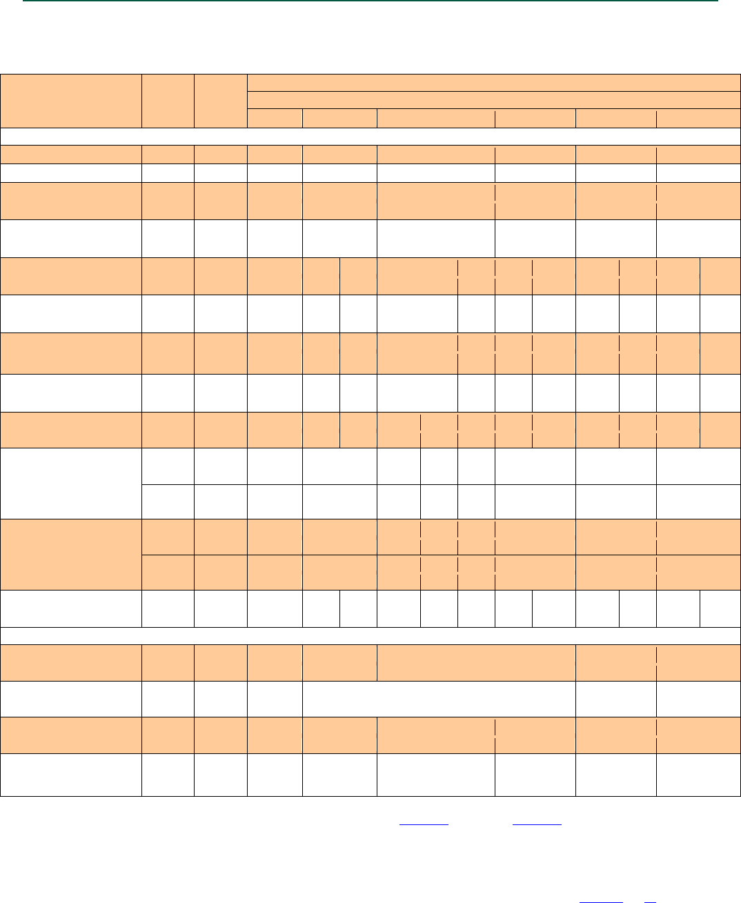
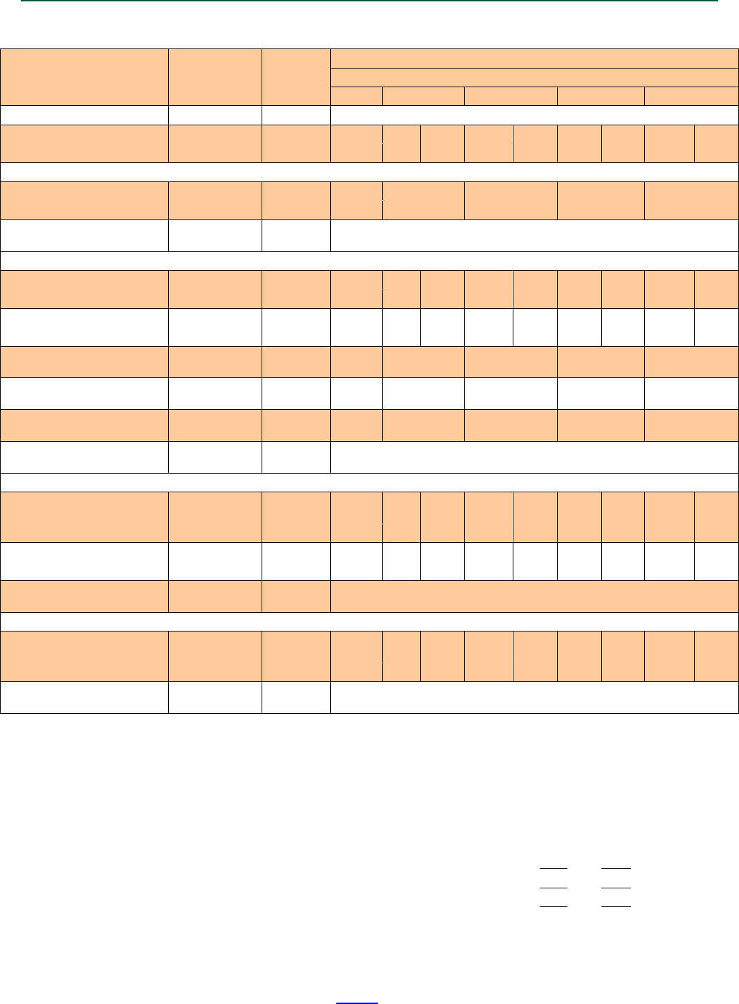
TABLE 1A—CARBON STEEL STRONG-BOLT® 2 ANCHOR INSTALLATION INFORMATION1
CHARACTERISTIC SYMBOL
UNITS
NOMINAL ANCHOR SIZE
Carbon Steel
1/4 inch5
3/8 inch6
1/2 inch6
5/8 inch6
3/4 inch6
1 inch6
Installation Information
Nominal Diameter
da3
in.
1/4
3/8
1/2
5/8
3/4
1
Drill Bit Diameter
d
in.
1/4
3/8
1/2
5/8
3/4
1
Baseplate Clearance Hole
Diameter2 dc
in.
5/16
7/16
9/16
11/16
7/8
11/8
(mm)
(7.9)
(11.1)
(14.3)
(17.5)
(22.2)
(28.6)
Installation Torque Tinst
ft-lbf
4
30
60
90
150
230
(N-m)
(5.4)
(40.7)
(81.3)
(122.0)
(203.4)
(311.9)
Nominal Embedment Depth
hnom
in.
13/4
17/8
27/8
23/4
37/8
33/8
51/8
41/8
53/4
51/4
93/4
(mm)
(45)
(48)
(73)
(70)
(98)
(86)
(130)
(105)
(146)
(133)
(248)
Effective Embedment Depth
hef
in.
11/2
11/2
21/2
21/4
33/8
23/4
41/2
33/8
5
41/2
9
(mm)
(38)
(38)
(64)
(57)
(86)
(70)
(114)
(86)
(127)
(114)
(229)
Minimum Hole Depth hhole
in.
17/8
2
3
3
41/8
35/8
53/8
43/8
6
51/2
10
(mm) (48) (51) (76) (76) (105) (92) (137) (111) (152) (140) (254)
Minimum Overall Anchor
Length
λ
anch
in.
21/4
23/4
31/2
33/4
51/2
41/2
6
51/2
7
7
13
(mm)
(57)
(70)
(89)
(95)
(140)
(114)
(152)
(140)
(178)
(178)
(330)
Critical Edge Distance cac
in.
21/2
61/2
6
61/2
61/2
71/2
71/2
9
9
8
18
131/2
(mm)
(64)
(165)
(152)
(165)
(165)
(191)
(191)
(229)
(229)
(203)
(457)
(343)
Minimum Edge Distance
cmin
in.
13/4
6
7
4
4
61/2
61/2
8
(mm)
(45)
(152)
(178)
(102)
(102)
(165)
(165)
(203)
for s ≥
in.
-
-
-
-
-
-
8
-
(mm)
-
-
-
-
-
-
(203)
-
Minimum Spacing
smin
in.
21/4
3
7
4
4
5
7
8
(mm)
(57)
(76)
(178)
(102)
(102)
(127)
(178)
(203)
for c ≥
in.
-
-
-
-
-
-
8
-
(mm)
-
-
-
-
-
-
(203)
-
Minimum Concrete
Thickness hmin
in.
31/4
31/4
41/2
41/2
51/2
6
51/2
77/8
63/4
83/4
9
131/2
(mm)
(83)
(83)
(114)
(114)
(140)
(152)
(140)
(200)
(172)
(222)
(229)
(343)
Additional Data
Specified Yield Strength fya
psi
56,000
92,000
85,000
70,000
60,000
(MPa)
(386)
(634)
(586)
(483)
(414)
Specified Tensile Strength futa
psi
70,000
115,000
110,000
78,000
(MPa)
(483)
(793)
(758)
(538)
Minimum Tensile and Shear
Stress Area Ase3
in2
0.0318
0.0514
0.105
0.166
0.270
0.472
(mm2)
(21)
(33)
(68)
(107)
(174)
(305)
Axial Stiffness in Service
Load Range - Cracked and
Uncracked Concrete
4
β
lb./in
73,7004
34,820
63,570
91,370
118,840
299,600
(N/mm) (12,898) 4 (6,098) (11,133) (16,001) (20,812) (52,468)
For SI: 1 inch = 25.4 mm, 1 ft-lbf = 1.356 N-m, 1 psi = 6.89 Pa, 1 in2 = 645 mm2, 1 lbf/in = 0.175 N/mm.
1The information presented in this table is to be used in conjunction with the design criteria of ACI 318-14 Chapter 17 or ACI 318-11 Appendix D, as applicable.
2The clearance must comply with applicable code requirements for the connected element.
3For the 2006 IBC do replaces da, Ase,N replaces Ase.
4 The tabulated value of β for 1/4-inch-diameter carbon steel Strong-Bolt® 2 anchor is for installations in uncracked concrete only.
5 The 1/4-inch-diameter (6.4 mm) anchor may be installed in top of uncracked normal-weight and sand-lightweight concrete over profile steel deck where concrete
thickness above upper flute meets the minimum thicknesses specified in this table.
6The 3/8-inch- through 1-inch-diameter (9.5 mm through 25.4 mm) anchors may be installed in topside of cracked and uncracked normal-weight and sand-lightweight
concrete over profile steel deck where concrete thickness above upper flute meets the minimum thicknesses specified in this table, and Tables 5A and 5B for the
3/8-inch and 1/2-inch-diameter (9.5 mm and 12.7 mm) anchors.
ESR-3037 | Most Widely Accepted and Trusted Page 7 of 20
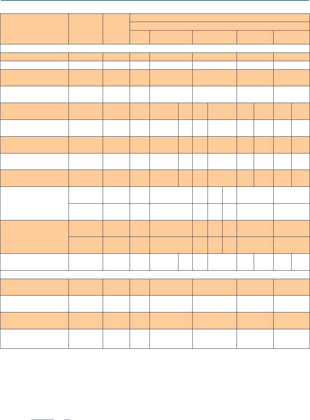
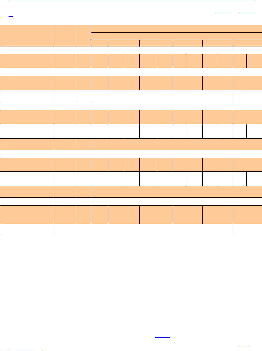
TABLE 1B—STAINLESS STEEL STRONG-BOLT® 2 ANCHOR INSTALLATION INFORMATION1
CHARACTERISTIC SYMBOL UNITS
NOMINAL ANCHOR SIZE
Stainless Steel
1
/4
inch5 3/8 inch6 1/2 inch6 5/8 inch6
3
/4 inch
6
Installation Information
Nominal Diameter da
3
in.
1
/4
3
/8
1
/2
5
/8
3
/4
Drill Bit Diameter d in.
1
/4
3
/8
1
/2
5
/8
3
/4
Baseplate Clearance Hole
Diameter2 dc in.
5
/16
7
/16
9
/16
11
/16
7
/8
(mm) (7.9) (11.1) (14.3) (17.5) (22.2)
Installation Torque Tinst ft-lbf 4 30 65 80 150
(N-m) (5.4) (40.7) (88.1) (108.5) (203.4)
Nominal Embedment Depth hnom in. 1
3
/4 1
7
/8 2
7
/8 2
3
/4 3
7
/8 3
3
/8 5
1
/8 4
1
/8 5
3
/4
(mm) (45) (48) (73) (70) (98) (86) (130) (105) (146)
Effective Embedment Depth hef in. 11/2 11/2 21/2 21/4 33/8 23/4 41/2 33/8 5
(mm) (38) (38) (64) (57) (86) (70) (114) (86) (127)
Minimum Hole Depth hhole in. 1
7
/8 2 3 3 4
1
/8 3
5
/8 5
3
/8 4
3
/8 6
(mm) (48) (51) (76) (76) (105) (92) (137) (111) (152)
Minimum Overall Anchor
Length
λ
anch in. 21/4 23/4 31/2 33/4 51/2 41/2 6 51/2 7
(mm) (57) (70) (89) (95) (140) (114) (152) (140) (178)
Critical Edge Distance cac in. 2
1
/2 6
1
/2 8
1
/2 4
1
/2 7 7
1
/2 9 8 8
(mm) (64) (165) (216)
(114) (178) (191) (229) (203) (203)
Minimum Edge Distance
cmin in. 1
3
/4 6 6
1
/2 5 4 4 6
(mm) (45) (152) (165) (127) (102)
(102) (152)
for s ≥ in. - 10 - - 8 8 -
(mm) - (254) - - (203)
(203) -
Minimum Spacing
smin in. 2
1
/4 3 8 5
1
/2 4 6
1
/4 6
1
/2
(mm) (57) (76) (203) (140) (102)
(159) (165)
for c ≥ in. - 10 - - 8 5
1
/2 -
(mm) - (254) - - (203)
(140) -
Minimum Concrete Thickness hmin in. 3
1
/4 3
1
/4 4
1
/2 4
1
/2 6 5
1
/2 7
7
/8 6
3
/4 8
3
/4
(mm) (83) (83) (114)
(114) (152) (140) (200) (172) (222)
Additional Data
Specified Yield Strength fya psi 96,000
(662)
80,000 92,000 82,000 68,000
(MPa) (552) (634) (565) (469)
Specified Tensile Strength futa psi 120,000
100,000 115,000 108,000 95,000
(MPa) (827) (689) (793) (745) (655)
Minimum Tensile and Shear
Stress Area Ase3 in
2
0.0255 0.0514 0.105 0.166 0.270
(mm
2
) (16) (33) (68) (107) (174)
Axial Stiffness in Service Load
Range - Cracked and
Uncracked Concrete4
β
lb./in 54,430
4
29,150 54,900 61,270 154,290
(N/mm) (9,525)4
(5,105) (9,614) (10,730) (27,020)
For SI: 1 inch = 25.4 mm, 1 ft-lbf = 1.356 N-m, 1 psi = 6.89 Pa, 1 in2 = 645 mm2, 1 lbf/in = 0.175 N/mm.
1The information presented in this table is to be used in conjunction with the design criteria of ACI 318-14 Chapter 17 or ACI 318-11 Appendix
D, as applicable.
2The clearance must comply with applicable code requirements for the connected element.
3For the 2006 IBC do replaces da, Ase,N replaces Ase.
4The tabulated value of
β
for 1/4-inch-diameter stainless steel Strong-Bolt® 2 anchor is for installations in uncracked concrete only.
5The 1/4-inch-diameter (6.4 mm) anchor may be installed in top of uncracked normal-weight and sand-lightweight concrete over profile steel
deck where concrete thickness above upper flute meets the minimum thicknesses specified in this table.
6The 3/8-inch- through 3/4-inch-diameter (9.5 mm through 19.1 mm) anchors may be installed in top of cracked and uncracked normal-weight
and sand-lightweight concrete over profile steel deck where concrete thickness above upper flute meets the minimum thicknesses specified in
this table, and Tables 5A and 5B for the 3/8-inch and 1/2-inch-diameter (9.5 mm and 12.7 mm) anchors.
ESR-3037 | Most Widely Accepted and Trusted Page 8 of 20
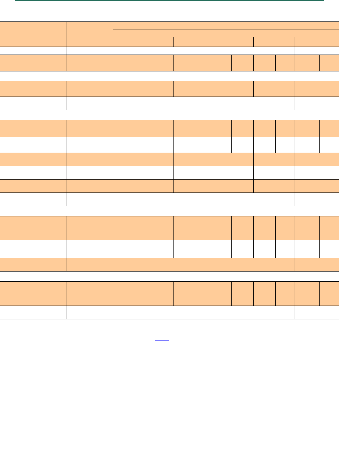
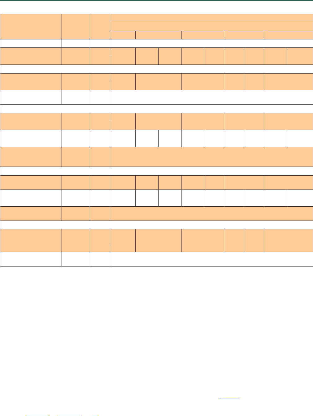
TABLE 2A—CARBON STEEL STRONG-BOLT® 2 ANCHOR TENSION STRENGTH DESIGN DATA1
CHARACTERISTIC SYMBOL UNITS
NOMINAL ANCHOR DIAMETER
Carbon Steel
1/
4
inch8
3/
8
inch9
1/
2
inch9
5/
8
inch9
3/
4
inch9
1 inch9
Anchor Category
1,2 or 3
-
1
2
Nominal Embedment Depth hnom
in.
13/4
17/8
27/8
23/4
37/8
33/8
51/8
41/8
53/4
51/4
93/4
(mm)
(45)
(48)
(73)
(70)
(98)
(86)
(130)
(105)
(146)
(133)
(248)
Steel Strength in Tension (ACI 318-14 Section 17.4.1 or ACI 318-11 Section D.5.1)
Steel Strength in Tension Nsa
lb
2,225
5,600
12,100
19,070
29,700
36,815
(kN)
(9.9)
(24.9)
(53.8)
(84.8)
(132.1)
(163.8)
Strength Reduction Factor -
Steel Failure
2
φ
sa
- 0.75 0.65
Concrete Breakout Strength in Tension (ACI 318-14 Section 17.4.2 or ACI 318-11 Section D.5.2)
Effective Embedment Depth hef in. 1
1
/2 1
1
/2 2
1
/2 2
1
/4 3
3
/8 2
3
/4 4
1
/2 3
3
/8 5 4
1
/2 9
(mm)
(38)
(38)
(64)
(57)
(86)
(70)
(114)
(86)
(127)
(114)
(229)
Critical Edge Distance cac
in.
21/2
61/2
6
61/2
71/2
71/2
9
9
8
18
131/2
(mm)
(64)
(165)
(152)
(165)
(191)
(191)
(229)
(229)
(203)
(457)
(343)
Effectiveness Factor -
Uncracked Concrete
kuncr - 24 24 24 24 24 24
Effectiveness Factor -
Cracked Concrete
kcr -
See
Note 7
17 17 17 17 17
Modification Factor
ψ
c,N
-
See
Note 7
1.00 1.00 1.00 1.00 1.00
Strength Reduction Factor -
Concrete Breakout Failure
3
φ
cb
- 0.65 0.55
Pull-Out Strength in Tension (ACI 318-14 17.4.3.1 or ACI 318-11 Section D.5.3)
Pull-Out Strength Cracked
Concrete (f'c = 2500 psi) Np,cr lb
See
Note 7
1,3005 2,7755
N/A4 3,7355 N/A4 6,8955 N/A4 8,5005 7,7005 11,1855
(kN) - (5.8)
5
(12.3)
5
- (16.6)
5
- (30.7)
5
- (37.8)
5
(34.3)
5
(49.8)
5
Pull-
Out Strength Uncracked
Concrete (f'c = 2500 psi) Np,uncr lb N/A
4
N/A
4
3,340
5
3,615
5
5,255
5
N/A
4
9,025
5
7,115
5
8,870
5
8,360
5
9,690
5
(kN)
-
-
(14.9)5
(16.1)5
(23.4)5
-
(40.1)5
(31.6)5
(39.5)5
(37.2)5
(43.1)5
Strength Reduction Factor -
Pullout Failure
6
φ
p
- 0.65 0.55
Tensile Strength for Seismic Applications (ACI 318-14 17.2.3.3 or ACI 318-11 Section D.3.3.3)
Tension Resistance of Single
Anchor for Seismic Loads
(f'c = 2500 psi) Np,eq lb
See
Note 7
1,3005 2,7755
N/A4 3,7355 N/A4 6,8955 N/A4 8,5005 7,7005 11,1855
(kN) - (5.8)5 (12.3)5
- (16.6)5 - (30.7)5 - (37.8)5 (34.3)5 (49.8)5
Strength Reduction Factor -
Pullout Failure
6
φ
eq
- 0.65 0.55
For SI: 1 inch = 25.4 mm, 1 lbf = 4.45 N.
1The information presented in this table must be used in conjunction with the design criteria of ACI 318-14 Chapter 17 or ACI 318-11 Appendix D, as applicable.
2The tabulated value of
φ
sa applies when the load combinations of Section 1605.2 of the IBC, ACI 318-14 Section 5.3 or ACI 318-11 Section 9.2 are used. If the
load combinations of ACI 318-11 Appendix C are used, the appropriate value of
φ
sa must be determined in accordance with ACI 318-11 D.4.4. The 3/8-inch-,
1/2-inch-, 5/8-inch- and 3/4-inch-diameter carbon steel Strong-Bolt® 2 anchors are ductile steel elements as defined in ACI 318-14 2.3 or ACI 318-11 D.1, as
applicable. The 1-inch-diameter carbon steel Strong-Bolt® 2 anchor is a brittle steel element as defined in ACI 318-14 2.3 or ACI 318-11 D.1, as applicable.
3The tabulated value of
φ
cb applies when both the load combinations of Section 1605.2 of the IBC, ACI 318-14 Section 5.3 or ACI 318-11 Section 9.2 are used
and the requirements of ACI 318-14 17.3.3(c) or ACI 318-11 D.4.3(c), as applicable, for Condition B are met. Condition B applies where supplementary
reinforcement is not provided. For installations where complying supplementary reinforcement can be verified, the
φ
cb factors described in ACI 318-14 17.3.3(c)
or ACI 318-11 D.4.3(c), as applicable, for Condition A are allowed. If the load combinations of ACI 318-11 Appendix C are used, the appropriate value of
φ
cb must
be determined in accordance with ACI 318-11 D.4.4(c).
4As described in Section 4.1.4 of this report, N/A (Not Applicable) denotes that pullout resistance does not need to be considered.
5The characteristic pull-out strength for greater concrete compressive strengths must be increased by multiplying the tabular value by (f
c / 2,500 psi)0.5 or (f
c /
17.2 MPa)0.5.
6The tabulated value of
φ
p or
φ
eq applies when the load combinations of IBC Section 1605.2, ACI 318-14 Section 5.3 or ACI 318-11 Section 9.2, as applicable,
are used and the requirements of ACI 318-14 17.3.3(c) or ACI 318-11 D.4.3(c) for Condition B are met. For installations where complying supplementary
reinforcement can be verified, the
φ
p or
φ
eq
factors described in ACI 318-14 17.3.3(c) or ACI 318-11 D.4.3(c), as applicable, for Condition A are allowed. If the
load combinations of ACI 318-11 Appendix C are used, appropriate value of
φ
must be determined in accordance with ACI 318-11 D.4.4(c).
7The 1/4-inch-diameter carbon steel Strong-Bolt® 2 anchor installation in cracked concrete is beyond the scope of this report.
8The 1/4-inch-diameter (6.4 mm) anchor may be installed in top of uncracked normal-weight and sand-lightweight concrete over profile steel deck where
concrete thickness above upper flute meets the minimum thicknesses specified in Table 1A.
9The 3/8-inch- through 1-inch-diameter (9.5 mm through 25.4 mm) anchors may be installed in top of cracked and uncracked normal-weight and sand-lightweight
concrete over profile steel deck where concrete thickness above upper flute meets the minimum thicknesses specified in Table 1A, and Tables 5A and 5B for the
3/8-inch and 1/2-inch-diameter (9.5 mm and 12.7 mm) anchors.
ESR-3037 | Most Widely Accepted and Trusted Page 9 of 20
TABLE 2B—STAINLESS STEEL STRONG-BOLT® 2 ANCHOR TENSION STRENGTH DESIGN DATA1
CHARACTERISTIC SYMBOL UNITS
NOMINAL ANCHOR DIAMETER
Stainless Steel
1/4 inch10
3/8 inch11 1/2 inch11 5/8 inch11 3/4 inch11
Anchor Category 1,2 or 3 - 1
Nominal Embedment Depth hnom in. 1
3
/4 1
7
/8 2
7
/8 2
3
/4 3
7
/8 3
3
/8 5
1
/8 4
1
/8 5
3
/4
(mm) (45) (48) (73) (70) (98) (86) (130) (105) (146)
Steel Strength in Tension (ACI 318-14 17.4.1 or ACI 318-11 Section D.5.1)
Steel Strength in Tension Nsa Lb 3,060 5,140 12,075 17,930 25,650
(kN) (13.6) (22.9) (53.7) (79.8) (114.1)
Strength Reduction Factor -
Steel Failure2
φ
sa
- 0.75
Concrete Breakout Strength in Tension (ACI 318-14 17.4.2 or ACI 318-11 Section D.5.2)
Effective Embedment Depth hef in. 1
1
/2 1
1
/2 2
1
/2 2
1
/4 3
3
/8 2
3
/4 4
1
/2 3
3
/8 5
(mm) (38) (38) (64) (57) (86) (70) (114) (86) (127)
Critical Edge Distance cac in. 21/2 61/2 81/2 41/2 7 71/2 9 8 8
(mm) (64) (165) (216) (114) (178) (191) (229) (203) (203)
Effectiveness Factor -
Uncracked
Concrete kuncr - 24 24 24 24 24
Effectiveness Factor - Cracked
Concrete kcr -
See Note
9 17 17 17 17
Modification Factor
ψ
c,N
-
See Note
9 1.00 1.00 1.00 1.00
Strength Reduction Factor -
Concrete Breakout Failure3
φ
cb
- 0.65
Pull-Out Strength in Tension (ACI 318-14 17.4.3 or ACI 318-11 Section D.5.3)
Pull-Out Strength Cracked
Concrete (f'c = 2500 psi) Np,cr Lb
See Note
9 1,7206
3,1456 2,5605 4,3055 N/A4 6,5457 N/A4 8,2305
(kN) - (7.7)
6
(14.0)
6
(11.4)
5
(19.1)
5
- (29.1)
7
- (36.6)
5
Pullout Strength Uncracked
Concrete (f'c = 2500 psi) Np,uncr Lb 1,925
7
N/A
4
4,770
6
3,230
5
4,495
5
N/A
4
7,615
5
7,725
7
9,625
7
(kN) (8.6)7 - (21.2)6 (14.4)5 (20.0)5 - (33.9)5 (34.4)7 (42.8)7
Strength Reduction Factor -
Pullout Failure8
φ
p
- 0.65
Tensile Strength for Seismic Applications (ACI 318 17.2.3.3 or ACI 318-11 Section D.3.3.3)
Tension Resistance of Single
Anchor for Seismic Loads
(f'c = 2500 psi) Np,eq Lb
See Note
9 1,7206
2,8306 2,5605 4,3055 N/A4 6,5457 N/A4 8,2305
(kN) - (7.7)
6
(12.6)
6
(11.4)
5
(19.1)
5
- (29.1)
7
- (36.6)
5
Strength Reduction Factor -
Pullout Failure8
φ
eq
- 0.65
For SI: 1 inch = 25.4 mm, 1 lbf = 4.45 N.
1The information presented in this table must be used in conjunction with the design criteria of ACI 318-14 Chapter 17 or ACI 318-11 Appendix D, as applicable.
2The tabulated value of
φ
sa applies when the load combinations of Section 1605.2 of the IBC, ACI 318-14 Section 5.3 or ACI 318-11 Section 9.2 are used. If the
load combinations of ACI 318-11 Appendix C are used, the appropriate value of
φ
sa must be determined in accordance with ACI 318-11 D.4.4. The stainless steel
Strong-Bolt® 2 anchors are ductile steel elements as defined in ACI 318-14 2.3 or ACI 318-11 D.1, as applicable.
3The tabulated value of
φ
cb applies when both the load combinations of Section 1605.2 of the IBC, ACI 318-14 Section 5.3 or ACI 318-11 Section 9.2 are used
and the requirements of ACI 318-14 17.3.3(c) or ACI 318-11 D.4.3(c), as applicable, for Condition B are met. Condition B applies where supplementary
reinforcement is not provided. For installations where complying supplementary reinforcement can be verified, the
φ
cb factors described in ACI 318-14 17.3.3(c)
or ACI 318-11 D.4.3(c), as applicable, for Condition A are allowed. If the load combinations of ACI 318-11 Appendix C are used, the appropriate value of
φ
cb must
be determined in accordance with ACI 318-11 D.4.4(c).
4As described in Section 4.1.4 of this report, N/A (Not Applicable) denotes that pullout resistance does not need to be considered.
5The characteristic pull-out strength for greater concrete compressive strengths must be increased by multiplying by (
,). or (
. )..
6The characteristic pull-out strength for greater concrete compressive strengths must be increased by multiplying by (
,). or (
. )..
7The characteristic pull-out strength for greater concrete compressive strengths must be increased by multiplying by (
,). or (
. )..
8The tabulated value of
φ
p or
φ
eq applies when the load combinations of IBC Section 1605.2.1, ACI 318-14 Section 5.3 or ACI 318-11 Section 9.2 are used and
the requirements of ACI 318-14 17.3.3(c) or ACI 318-11 D.4.3(c), as applicable, for Condition B are met. For installations where complying supplementary
reinforcement can be verified, the
φ
p or
φ
eq factors described in ACI 318-14 17.3.3(c) or ACI 318-11 D.4.3(c), as applicable, for Condition A are allowed. If the
load combinations of ACI 318-11 Appendix C are used, appropriate value of
φ
must be determined in accordance with ACI 318-11 D.4.4(c).
9The 1/4-inch-diameter stainless steel Strong-Bolt® 2 anchor installation in cracked concrete is beyond the scope of this report.
10The 1/4-inch-diameter (6.4 mm) anchor may be installed in top of uncracked normal-weight and sand-lightweight concrete over profile steel deck where concrete
thickness above upper flute meets the minimum thicknesses specified in Table 1B.
ESR-3037 | Most Widely Accepted and Trusted Page 10 of 20
11The 3/8-inch- through 3/4-inch-diameter (9.5 mm through 19.1 mm) anchors may be installed in top of cracked and uncracked normal-weight and sand-
lightweight concrete over profile steel deck where concrete thickness above upper flute meets the minimum thicknesses specified in Table 1B, and Tables 5A
and 5B for the 3/8-inch and 1/2-inch-diameter (9.5 mm and 12.7 mm) anchors.
TABLE 3A—CARBON STEEL STRONG-BOLT® 2 ANCHOR SHEAR STRENGTH DESIGN DATA1
CHARACTERISTIC SYMBOL UNITS
NOMINAL ANCHOR DIAMETER
Carbon Steel
1/4 inch7
3/8 inch8
1/2 inch8
5/8 inch8
3/4 inch8
1 inch8
Anchor Category
1,2 or 3
-
1
2
Nominal Embedment Depth hnom
in.
13/4
17/8
27/8
23/4
37/8
33/8
51/8
41/8
53/4
51/4
93/4
(mm)
(45)
(48)
(73)
(70)
(98)
(86)
(130)
(105)
(146)
(133)
(248)
Steel Strength in Shear (ACI 318-14 17.5.1.1 or ACI 318-11 Section D.6.1)
Shear Resistance of Steel Vsa
Lb
965
1,800
7,235
11,035
14,480
15,020
(kN)
(4.3)
(8.0)
(32.2)
(49.1)
(64.4)
(66.8)
Strength Reduction Factor -
Steel Failure2
φ
sa
- 0.65 0.60
Concrete Breakout Strength in Shear (ACI 318-14 17.5.2 or ACI 318-11 Section D.6.2)
Outside Diameter da5
in.
0.250
0.375
0.500
0.625
0.750
1.000
(mm)
(6.4)
(9.5)
(12.7)
(15.9)
(19.1)
(25.4)
Load Bearing Length of
Anchor in Shear
λ
e
in.
1.500
1.500
2.500
2.250
3.375
2.750
4.500
3.375
5.000
4.500
8.000
(mm) (38) (38) (64) (57) (86) (70) (114) (86) (127) (114) (203)
Strength Reduction Factor -
Concrete Breakout Failure
3
φ
cb
- 0.70
Concrete Pryout Strength in Shear (ACI 318-14 17.5.3 or ACI 318-11 Section D.6.3)
Coefficient for Pryout
Strength kcp - 1.0 1.0 2.0 1.0 2.0 2.0 2.0 2.0
Effective Embedment Depth hef
in.
11/2
11/2
21/2
21/4
33/8
23/4
41/2
33/8
5
41/2
9
(mm)
(38)
(38)
(64)
(57)
(86)
(70)
(114)
(86)
(127)
(114)
(229)
Strength Reduction Factor -
Concrete Pryout Failure4
φ
cp
- 0.70
Steel Strength in Shear for Seismic Applications (ACI 318-14 17.2.3.3 or ACI 318-11 Section D.3.3.3)
Shear Strength of Single
Anchor for Seismic Loads
(f'c = 2500 psi) Vsa,eq Lb See
Note 6
1,800 6,510 9,930 11,775 15,020
(kN) - (8.0) (29.0) (44.2) (52.4) (66.8)
Strength Reduction Factor -
Steel Failure2
φ
sa
- 0.65 0.60
For SI: 1 inch = 25.4 mm, 1 lbf = 4.45 N.
1The information presented in this table must be used in conjunction with the design criteria of ACI 318-14 Chapter 17 or ACI 318-11 Appendix D, as
applicable.
2The tabulated value of
φ
sa applies when the load combinations of Section 1605.2 of the IBC, ACI 318-14 Section 5.3 or ACI 318-11 Section 9.2 are
used. If the load combinations of or ACI 318-11 Appendix C are used, the appropriate value of
φ
sa must be determined in accordance with ACI 318-11
D.4.4. The 3/8-inch-, 1/2-inch-, 5/8-inch- and 3/4-inch-diameter carbon steel Strong-Bolt® 2 anchors are ductile steel elements as defined in ACI 318-14
2.3 or ACI 318-11 D.1, as applicable. The 1-inch-diameter carbon steel Strong-Bolt® 2 anchor is a brittle steel element as defined in ACI 318-14 2.3 or
ACI 318-11 D.1, as applicable.
3The tabulated value of
φ
cb applies when both the load combinations of Section 1605.2 of the IBC, ACI 318-14 Section 5.3 or ACI 318-11 Section 9.2,
as applicable, are used and the requirements of ACI 318-14 17.3.3(c) or ACI 318-11 D.4.3(c) for Condition B are met. Condition B applies where
supplementary reinforcement is not provided. For installations where complying supplementary reinforcement can be verified, the
φ
cb factors
described in ACI 318-14 17.3.3(c) or ACI 318-11 D.4.3(c), as applicable, for Condition A are allowed. If the load combinations of ACI 318-11 Appendix
C are used, the appropriate value of
φ
cb must be determined in accordance with ACI 318-11 D.4.4(c).
4The tabulated value of
φ
cp applies when the load combinations of IBC Section 1605.2, ACI 318-14 5.3 or ACI 318-11 9.2 are used and the
requirements of ACI 318-14 17.3.3(c) or ACI 318-11 D.4.3(c) for Condition B are met. For installations where complying supplementary reinforcement
can be verified, the
φ
cp factors described in ACI 318-14 17.3.3(c) or ACI 318-11 D.4.3(c), as applicable, for Condition A are allowed. If the load
combinations of ACI 318-11 Appendix C are used, the appropriate value of
φ
cp must be determined in accordance with ACI 318-11 D.4.4(c).
5For the 2006 IBC do replaces da.
6The 1/4-inch-diameter carbon steel Strong-Bolt® 2 anchor installation in cracked concrete is beyond the scope of this report.
7The 1/4-inch-diameter (6.4 mm) anchor may be installed in the top of uncracked normal-weight and sand-lightweight concrete over profile steel deck
where concrete thickness above upper flute meets the minimum thicknesses specified in Table 1A.
8The 3/8-inch- through 1-inch-diameter (9.5 mm through 25.4 mm) anchors may be installed in the top of cracked and uncracked normal-weight and
sand-lightweight concrete over profile steel deck where concrete thickness above upper flute meets the minimum thicknesses specified in Table
1A, and Tables 5A and 5B for the 3/8-inch and 1/2-inch-diameter (9.5 mm and 12.7 mm) anchors.
ESR-3037 | Most Widely Accepted and Trusted Page 11 of 20
TABLE 3B—STAINLESS STEEL STRONG-BOLT® 2 ANCHOR SHEAR STRENGTH DESIGN DATA1
CHARACTERISTIC SYMBOL UNITS
NOMINAL ANCHOR DIAMETER
Stainless Steel
1
/4 inch
7
3
/8 inch
8
1
/2 inch
8
5
/8 inch
8
3
/4 inch
8
Anchor Category 1,2 or 3 - 1
Nominal Embedment
Depth hnom in. 1
3
/4 1
7
/8 2
7
/8 2
3
/4 3
7
/8 3
3
/8 5
1
/8 4
1
/8 5
3
/4
(mm) (45) (48) (73) (70) (98) (86) (130) (105) (146)
Steel Strength in Shear (ACI 318-14 17.5.1 or ACI 318-11 Section D.6.1)
Shear Resistance of Steel Vsa Lb 1,605 3,085 7,245 6,745 10,760 15,045
(kN) (7.1) (13.7) (32.2) (30.0) (47.9) (66.9)
Strength Reduction Factor
- Steel Failure2
φ
sa
- 0.65
Concrete Breakout Strength in Shear (ACI 318-14 17.5.2 or ACI 318-11 Section D.6.2)
Outside Diameter da5 in. 0.250 0.375 0.500 0.625 0.750
(mm) (6.4) (9.5) (12.7) (15.9) (19.1)
Load Bearing Length of
Anchor in Shear
λ
e in. 1.500 1.500 2.500 2.250 3.375 2.750 4.500 3.375 5.000
(mm) (38) (38) (64) (57) (86) (70) (114) (86) (127)
Strength Reduction Factor
- Concrete Breakout
Failure3
φ
cb
- 0.70
Concrete Pryout Strength in Shear (ACI 318-14 17.5.2 or ACI 318-11 Section D.6.3)
Coefficient for Pryout
Strength kcp - 1.0 1.0 2.0 1.0 2.0 2.0 2.0
Effective Embedment
Depth hef in. 1
1
/2 1
1
/2 2
1
/2 2
1
/4 3
3
/8 2
3
/4 4
1
/2 3
3
/8 5
(mm) (38) (38) (64) (57) (86) (70) (114) (86) (127)
Strength Reduction Factor
- Concrete Pryout Failure4
φ
cp
- 0.70
Steel Strength in Shear for Seismic Applications (ACI 318-14 17.2.3.3 or ACI 318-11 Section D.3.3.3)
Shear Strength of Single
Anchor for Seismic Loads
(f'c = 2500 psi) Vsa,eq Lb See Note
6 3,085 6,100 6,745 10,760 13,620
(kN) - (13.7) (27.1) (30.0) (47.9) (60.6)
Strength Reduction Factor
- Steel Failure2
φ
sa
- 0.65
For SI: 1 inch = 25.4 mm, 1 lbf = 4.45 N.
1The information presented in this table must be used in conjunction with the design criteria of ACI 318-14 Chapter 17 or ACI 318-11 Appendix
D.
2The tabulated value of
φ
sa applies when the load combinations of Section 1605.2 of the IBC, ACI 318-14 Section 5.3 or ACI 318-11 Section
9.2, as applicable, are used. If the load combinations of or ACI 318-11 Appendix C are used, the appropriate value of
φ
sa must be determined
in accordance with ACI 318-11 D.4.4. The stainless steel Strong-Bolt® 2 anchors are ductile steel elements as defined in ACI 318-14 2.3 or
ACI 318-11 D.1, as applicable.
3The tabulated value of
φ
cb applies when both the load combinations of Section 1605.2 of the IBC, ACI 318-14 Section 5.3 or ACI 318-11
Section 9.2, as applicable, are used and the requirements of ACI 318-14 17.3.3(c) or ACI 318-11 D.4.3(c) for Condition B are met. Condition B
applies where supplementary reinforcement is not provided. For installations where complying supplementary reinforcement can be verified,
the
φ
cb factors described in ACI 318-14 17.3.3 or ACI 318-11 D.4.3, as applicable, for Condition A are allowed. If the load combinations of ACI
318-11 Appendix C are used, the appropriate value of
φ
cb must be determined in accordance with ACI 318-11 D.4.4(c).
4The tabulated value of
φ
cp applies when the load combinations of IBC Section 1605.2, ACI 318-14 5.3 or ACI 318-11 9.2, as applicable, are
used and the requirements of ACI 318-14 17.3.3(c) or ACI 318-11 D.4.3(c) for Condition B are met. For installations where complying
supplementary reinforcement can be verified, the
φ
cp factors described in ACI 318-14 17.3.3 or ACI 318-11 D.4.3, as applicable, for Condition
A are allowed. If the load combinations of ACI 318-11 Appendix C are used, the appropriate value of
φ
cp
must be determined in accordance
with ACI 318-11 D.4.4(c).
5For the 2006 IBC do replaces da.
6The 1/4-inch-diameter stainless steel Strong-Bolt® 2 anchor installation in cracked concrete is beyond the scope of this report.
7The 1/4-inch-diameter (6.4 mm) anchor may be installed in the top of uncracked normal-weight and sand-lightweight concrete over profile
steel deck where concrete thickness above upper flute meets the minimum thicknesses specified in Table 1B.
8The 3/8-inch- through 3/4-inch-diameter (9.5 mm through 19.1 mm) anchors may be installed in the top of cracked and uncracked normal-
weight and sand-lightweight concrete over profile steel deck where concrete thickness above upper flute meets the minimum thicknesses
specified in Table 1B, and Tables 5A and 5B for the 3/8-inch and 1/2-inch-diameter (9.5 mm and 12.7 mm) anchors.
ESR-3037 | Most Widely Accepted and Trusted Page 12 of 20
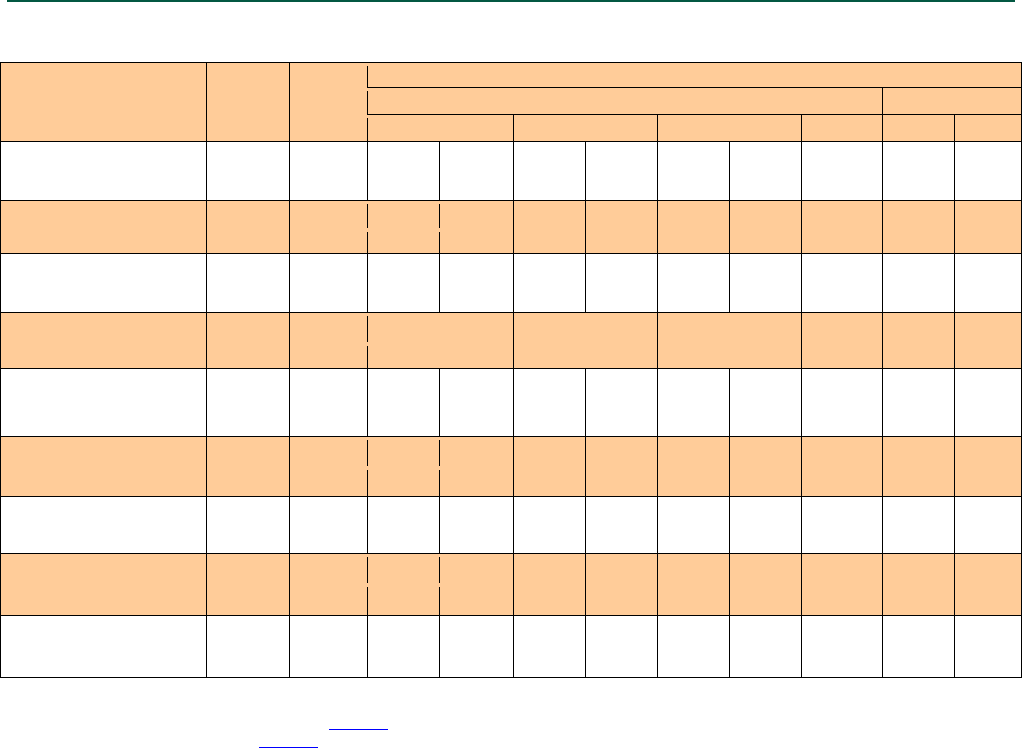
TABLE 4A—CARBON STEEL STRONG-BOLT® 2 ANCHOR TENSION AND SHEAR STRENGTH DESIGN DATA FOR
THE SOFFIT OF NORMAL-WEIGHT CONCRETE OVER PROFILE STEEL DECK, FLOOR AND ROOF ASSEMBLIES1,2,6,8
CHARACTERISTIC SYMBOL UNITS
NOMINAL ANCHOR DIAMETER
Lower Flute
Upper Flute
3/8 inch
1/2 inch
5/8 inch
3/4 inch
3/8 inch
1/2 inch
Nominal Embedment Depth
hnom
in.
2
33/8
23/4
41/2
33/8
55/8
41/8
2
23/4
(mm)
(51)
(86)
(70)
(114)
(86)
(143)
(105)
(51)
(70)
Effective Embedment Depth
hef
in.
15/8
3
21/4
4
23/4
5
33/8
15/8
21/4
(mm)
(41)
(76)
(57)
(102)
(70)
(127)
(86)
(41)
(57)
Minimum Hole Depth hhole
in.
21/8
31/2
3
43/4
35/8
57/8
43/8
21/8
3
(mm)
(54)
(89)
(76)
(121)
(92)
(149)
(111)
(54)
(76)
Installation Torque Tinst
ft-lbf
30
60
90
150
30
60
(N-m)
(40.7)
(81.3)
(122.0)
(203.4)
(40.7)
(81.3)
Pullout Strength, concrete
on metal deck (cracked)3 Np,deck,cr Lb 1,040
7
2,615
7
2,040
7
2,730
7
2,615
7
4,990
7
2,815
7
1,340
7
3,785
7
(kN) (4.6)7 (11.6)7 (9.1)7 (12.1)7 (11.6)7 (22.2)7 (12.5)7 (6.0)7 (16.8)7
Pullout Strength, concrete
on metal deck (uncracked)3 Np,deck,uncr
Lb
1,7657
3,1507
2,5807
3,8407
3,6857
6,5657
3,8007
2,2757
4,7957
(kN)
(7.9)7
(14.0)7
(11.5)7
(17.1)7
(16.4)7
(29.2)7
(16.9)7
(10.1)7
(21.3)7
Pullout Strength, concrete
on metal deck (Seismic)5 Np,deck,eq Lb 1,040
7
2,615
7
2,040
7
2,730
7
2,615
7
4,990
7
2,815
7
1,340
7
3,785
7
(kN)
(4.6)7
(11.6)7
(9.1)7
(12.1)7
(11.6)7
(22.2)7
(12.5)7
(6.0)7
(16.8)7
Steel Strength in
Shear, concrete on metal
deck
4
Vsa.deck
Lb
1,595
3,490
2,135
4,580
2,640
7,000
4,535
3,545
5,920
(kN)
(7.1)
(15.5)
(9.5)
(20.4)
(11.7)
(31.1)
(20.2)
(15.8)
(26.3)
Steel Strength in Shear,
concrete on metal deck
(Seismic)
5
Vsa,deck,eq
Lb
1,595
3,490
1.920
4,120
2,375
6,300
3,690
3,545
5,330
(kN) (7.1) (15.5) (8.5) (18.3) (10.6) (28.0) (16.4) (15.8) (23.7)
For SI: 1 inch = 25.4 mm, 1 lbf = 4.45 N.
1Installation must comply with Section 4.3 and Figure 5.
2Profile steel deck must comply with Figure 5 and Section 3.3 of this report.
3The values must be used in accordance with Section 4.1.4 of this report.
4The values must be used in accordance with Section 4.1.5 of this report.
5The values must be used in accordance with Section 4.1.8 of this report.
6The minimum anchor spacing along the flute must be the greater of 3hef or 1.5 times the flute width.
7The characteristic pull-out strength for greater concrete compressive strengths must be increased by multiplying the tabular value by
(f
c / 3,000psi)0.5 or (f
c / 20.7MPa)0.5.
8Concrete shall be normal-weight or sand-lightweight concrete having a minimum specified compressive strength, f′c, of 3,000 psi (20.7 MPa).
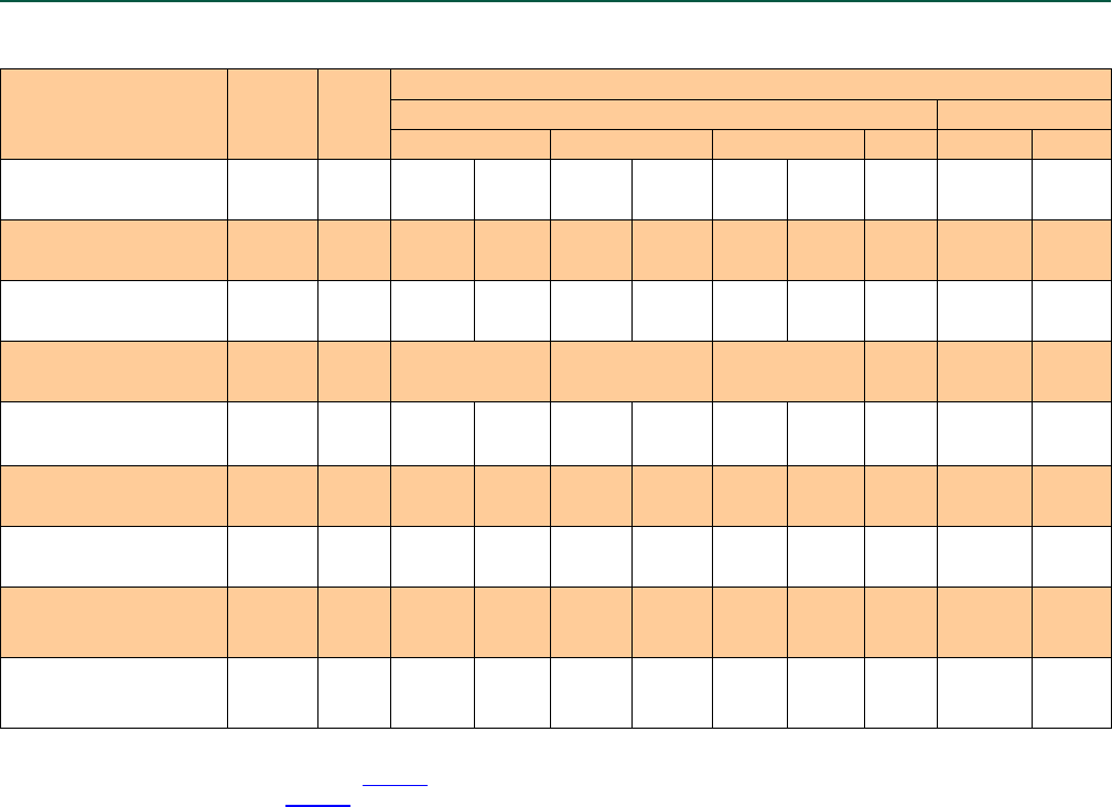
ESR-3037 | Most Widely Accepted and Trusted Page 13 of 20
TABLE 4B—STAINLESS STEEL STRONG-BOLT® 2 ANCHOR TENSION AND SHEAR STRENGTH DESIGN DATA FOR
THE SOFFIT OF NORMAL-WEIGHT CONCRETE OVER PROFILE STEEL DECK, FLOOR AND ROOF ASSEMBLIES1,2,6,10
CHARACTERISTIC SYMBOL UNITS
NOMINAL ANCHOR DIAMETER
Lower Flute Upper Flute
3/
8
inch
1/
2
inch
5/
8
inch
3/
4
inch
3/
8
inch
1/
2
inch
Nominal Embedment Depth hnom in. 2 3
3
/8 2
3
/4 4
1
/2 3
3
/8 5
5
/8 4
1
/8 2 2
3
/4
(mm) (51) (86) (70) (114) (86) (143) (105) (51) (70)
Effective Embedment Depth
hef in. 1
5
/8 3 2
1
/4 4 2
3
/4 5 3
3
/8 1
5
/8 2
1
/4
(mm) (41) (76) (57) (102) (70) (127) (86) (41) (57)
Minimum Hole Depth hhole in. 2
1
/8 3
1
/2 3 4
3
/4 3
5
/8 5
7
/8 4
3
/8 2
1
/8 3
(mm) (54) (89) (76) (121) (92) (149) (111) (54) (76)
Installation Torque Tinst ft-lbf 30 65 80 150 30 65
(N-m) (40.7) (88.1) (108.5) (203.4) (40.7) (88.1)
Pullout Strength, concrete
on metal deck (cracked)3 Np,deck,cr Lb 1,230
8
2,605
8
1,990
7
2,550
7
1,750
9
4,020
9
3,030
7
1,550
8
2,055
7
(kN) (5.5)8 (11.6)8 (8.9)7 (11.3)7 (7.8)9 (17.9)9 (13.5)7 (6.9)8 (9.1) 7
Pullout Strength, concrete
on metal deck (uncracked)3 Np,deck,uncr Lb 1,580
8
3,950
8
2,475
7
2,660
7
2,470
7
5,000
7
4,275
9
1,990
8
2,560
7
(kN) (7.0)
8
(17.6)
8
(11.0)
7
(11.8)
7
(11.0)
7
(22.2)
7
(19.0)
9
(8.9)
8
(11.4)
7
Pullout Strength, concrete
on metal deck (seismic)5 Np,deck,eq Lb 1,230
8
2,345
8
1,990
7
2,550
7
1,750
9
4,020
9
3,030
7
1,550
8
2,055
7
(kN) (5.5)
8
(10.4)
8
(8.9)
7
(11.3)
7
(7.8)
9
(17.9)
9
(13.5)
7
(6.9)
8
(9.1)
7
Steel Strength in
Shear, concrete on metal
deck4 Vsa.deck lb
(kN)
2,285 3,085 3,430 4,680 3,235 5,430 6,135 3,085 5,955
(10.2) (13.7) (15.3) (20.8) (14.4) (24.2) (27.3) (13.7) (26.5)
Steel Strength in
Shear, concrete on metal
deck (seismic)5 Vsa.deck,eq Lb 2,285 3,085 2,400 3,275 3,235 5,430 5,520 3,085 4,170
(kN) (10.2) (13.7) (10.7) (14.6) (14.4) (24.2) (24.6) (13.7) (18.5)
For SI: 1 inch = 25.4 mm, 1 lbf = 4.45 N.
1Installation must comply with Section 4.3 and Figure 5.
2Profile steel deck must comply with Figure 5 and Section 3.3 of this report.
3The values must be used in accordance with Section 4.1.4 of this report.
4The values must be used in accordance with Section 4.1.5 of this report.
5The values must be used in accordance with Section 4.1.8 of this report.
6The minimum anchor spacing along the flute must be the greater of 3hef or 1.5 times the flute width.
7The characteristic pull-out strength for greater concrete compressive strengths must be increased by multiplying the tabular value by
(f
c / 3,000 psi)0.5 or (f
c / 20.7MPa)0.5.
8The characteristic pull-out strength for greater concrete compressive strengths must be increased by multiplying the tabular value by
(f
c / 3,000psi)0.3 or (f
c / 20.7MPa)0.3.
9The characteristic pull-out strength for greater concrete compressive strengths must be increased by multiplying the tabular value by
(f
c / 3,000 psi)0.4 or (f
c / 20.7MPa)0.4.
10Concrete shall be normal-weight or sand-lightweight concrete having a minimum specified compressive strength, f′c, of 3,000 psi
(20.7 MPa).
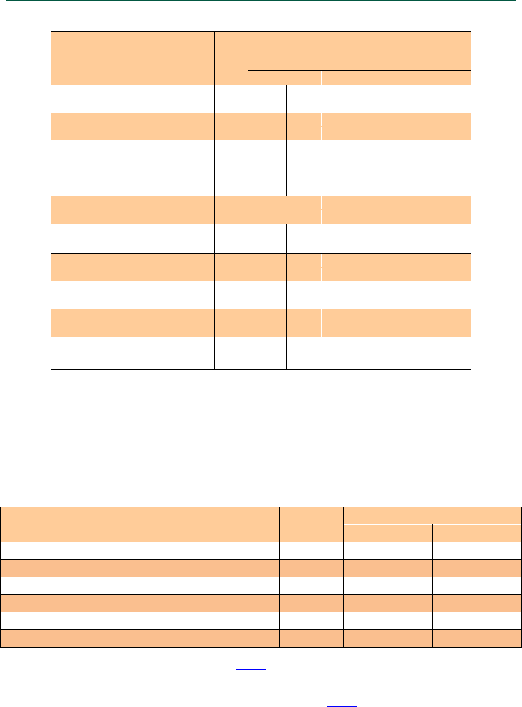
ESR-3037 | Most Widely Accepted and Trusted Page 14 of 20
TABLE 4C—CARBON STEEL STRONG-BOLT® 2 ANCHOR TENSION AND SHEAR STRENGTH DESIGN DATA FOR
THE SOFFIT OF NORMAL-WEIGHT CONCRETE OVER PROFILE STEEL DECK, FLOOR AND ROOF ASSEMBLIES1,2,6,8
CHARACTERISTIC SYMBOL UNITS
NOMINAL ANCHOR DIAMETER
INSTALLED IN LOWER-FLUTE
3
/8 inch
1
/2 inch
5
/8 inch
Nominal Embedment Depth hnom in. 2 33/8 23/4 41/2 33/8 55/8
(mm) (51) (86) (70) (114) (86) (143)
Effective Embedment Depth hef in. 1
5
/8 3 2
1
/4 4 2
3
/4 5
(mm) (41) (76) (57) (102) (70) (127)
Minimum Hole Depth hhole in. 2
1
/8 3
1
/2 3 4
3
/4 3
5
/8 5
5
/8
(mm) (54) (89) (76) (121) (92) (143)
Minimum Concrete Thickness hmin,deck
in. 2 2 2 3
1
/4 2 3
1
/4
(mm) (51) (51) (51) (83) (51) (83)
Installation Torque Tinst ft-lbf 30 60 90
(N-m) (40.7) (81.3) (122)
Pullout Strength, concrete on
metal deck (cracked)3 Np,deck,cr Lb 1,295 2,705 2,585 4,385 3,015 5,120
(kN) (5.8) (12.0) (11.5) (19.5) (13.4) (22.8)
Pullout Strength, concrete on
metal deck (uncracked)3 Np,deck,uncr Lb 2,195
3,260
3,270 6,165 4,250
6,735
(kN) (9.8) (14.5) (14.5) (27.4) (18.9) (30.0)
Pullout Strength, concrete on
metal deck (seismic)5 Np,deck,eq Lb 1,295 2,705 2,585 4,385 3,015 5,120
(kN) (5.8) (12.0) (11.5) (19.5) (13.4)
(22.8)
Steel Strength in
Shear, concrete on metal deck4 Vsa.deck lb
(kN)
1,535 3,420 2,785 5,950 3,395 6,745
(6.8) (15.2) (12.4)
(26.5) (15.1) (30.0)
Steel Strength in
Shear, concrete on metal deck
(seismic)5 Vsa.deck,eq Lb 1,535 3,420 2,505 5,350 3,055 6,070
(kN) (6.8) (15.2) (11.1) (23.8) (13.6) (27.0)
For SI: 1 inch = 25.4 mm, 1 lbf = 4.45 N.
1Installation must comply with Section 4.3 and Figure 7.
2Profile steel deck must comply with Figure 7 and Section 3.3 of this report.
3The values must be used in accordance with Section 4.1.4 of this report.
4The values must be used in accordance with Section 4.1.5 of this report.
5The values must be used in accordance with Section 4.1.8 of this report.
6The minimum anchor spacing along the flute must be the greater of 3hef or 1.5 times the flute width.
7The characteristic pull-out strength for greater concrete compressive strengths must be increased by multiplying the tabular value by
(f
c / 3,000 psi)0.5 or (f
c / 20.7MPa)0.5.
8Concrete shall be normal-weight or sand-lightweight concrete having a minimum specified compressive strength, f
c of 3,000 psi (20.7 MPa).
TABLE 5A—CARBON STEEL STRONG-BOLT® 2 ANCHOR INSTALLATION INFORMATION IN
THE TOPSIDE OF CONCRETE-FILLED PROFILE STEEL DECK FLOOR AND ROOF ASSEMBLIES1,2,3,4
Design Information Symbol Units Nominal Anchor Diameter (inch)
3/8 1/2
Nominal Embedment Depth hnom in. 17/8 17/8 2 3/4
Effective Embedment Depth hef in. 11/2 11/2 21/4
Minimum Concrete Thickness5 hmin,deck in. 21/2 31/4 31/4
Critical Edge Distance cac,deck,top in. 43/4 4 4
Minimum Edge Distance cmin,deck,top in. 43/4 41/2 43/4
Minimum Spacing smin,deck,top in. 7 61/2 8
For Sl: 1 inch = 25.4mm, 1 lbf = 4.45N.
1Installation must comply with Sections 4.1.6, 4.1.11 and 4.3 and Figure 6 of this report.
2Design capacity shall be based on calculations according to values in Tables 2A and 3A of this report.
3Minimum flute depth (distance from top of flute to bottom of flute) is 1½ inch, see Figure 6.
4Steel deck thickness shall be minimum 20 gauge.
5Minimum concrete thickness (hmin,deck ) refers to concrete thickness above upper flute, see Figure 6.
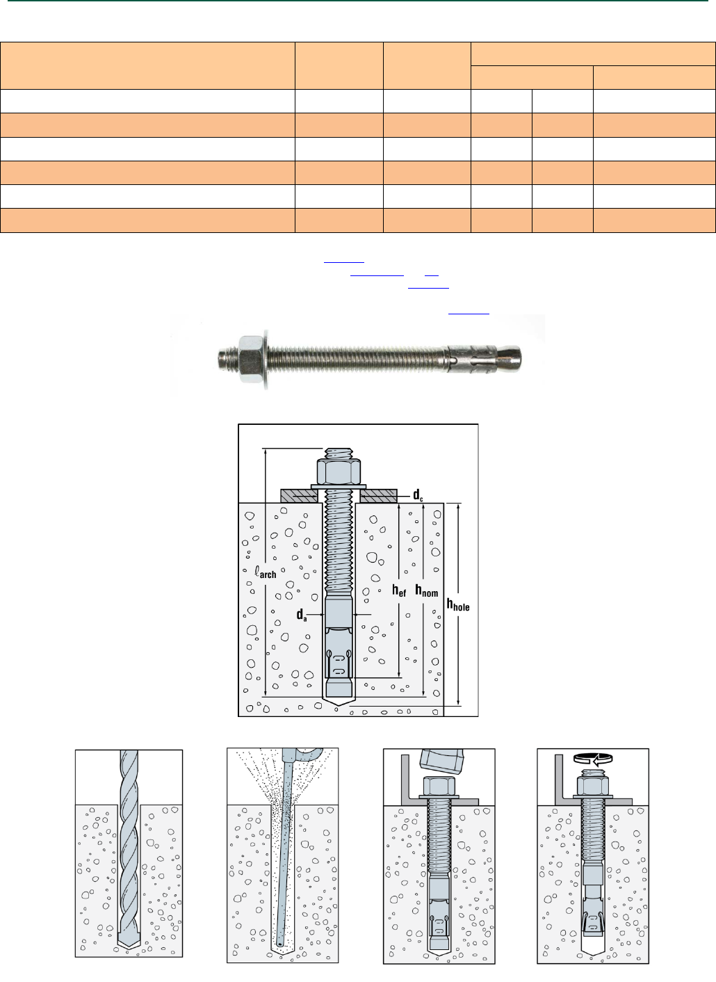
ESR-3037 | Most Widely Accepted and Trusted Page 15 of 20
TABLE 5B—STAINLESS STEEL STRONG-BOLT® 2 ANCHOR INSTALLATION INFORMATION
IN THE TOPSIDE OF CONCRETE-FILLED PROFILE STEEL DECK FLOOR AND ROOF ASSEMBLIES1,2,3,4
Design Information Symbol Units Nominal Anchor Diameter (inch)
3/8 1/2
Nominal Embedment Depth hnom in. 17/8 17/8 2 3/4
Effective Embedment Depth hef in. 11/2 11/2 21/4
Minimum Concrete Thickness5 hmin,deck in. 21/2 31/4 31/4
Critical Edge Distance cac,deck,top in. 43/4 4 4
Minimum Edge Distance cmin,deck,top in. 43/4 43/4 6
Minimum Spacing smin,deck,top in. 61/2 61/2 8
For Sl: 1 inch = 25.4mm, 1 lbf = 4.45N.
1Installation must comply with Sections 4.1.6, 4.1.11 and 4.3 and Figure 6 of this report.
2Design capacity shall be based on calculations according to values in Tables 2B and 3B of this report.
3 Minimum flute depth (distance from top of flute to bottom of flute) is 1½ inch, see Figure 6.
4Steel deck thickness shall be minimum 20 gauge.
5Minimum concrete thickness (hmin,deck ) refers to concrete thickness above upper flute, see Figure 6.
FIGURE 1—STRONG-BOLT® 2 WEDGE ANCHOR (CARBON STEEL VERSION)
FIGURE 2—STRONG-BOLT® 2 WEDGE ANCHOR INSTALLATION
FIGURE 3—STRONG-BOLT® 2 WEDGE ANCHOR INSTALLATION SEQUENCE
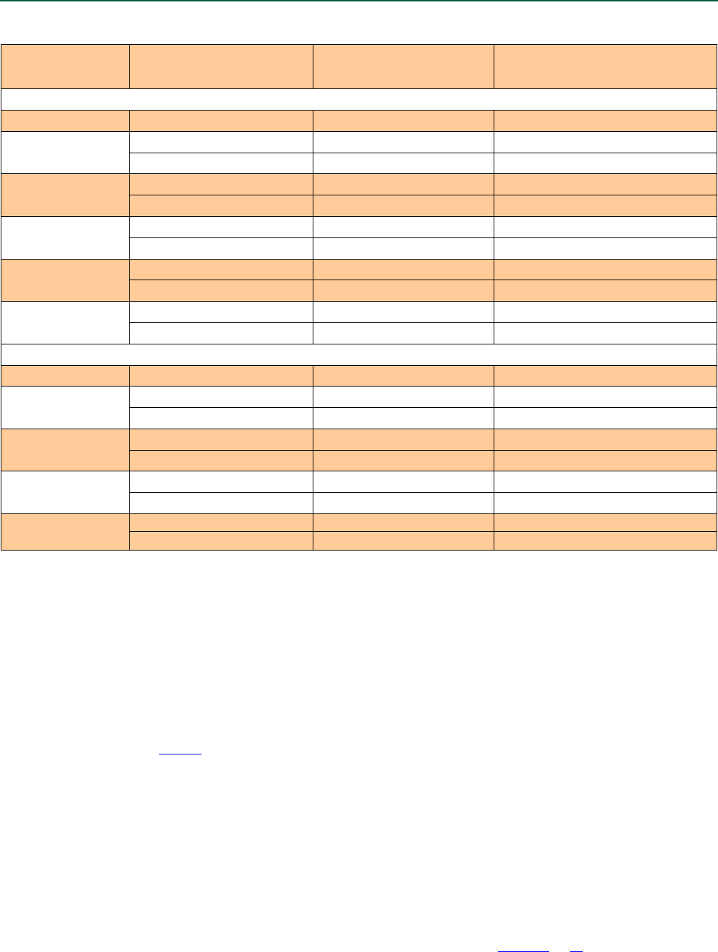
ESR-3037 | Most Widely Accepted and Trusted Page 16 of 20
TABLE 6—EXAMPLE STRONG-BOLT® 2 ANCHOR ALLOWABLE STRESS DESIGN TENSION VALUES
FOR ILLUSTRATIVE PURPOSES1,2,3,4,5,6,7,8,9
Nominal Anchor
Diameter
(in.)
Nominal Embedment Depth, hnom
(in.) Effective Embedment Depth, hef
(in.) Allowable Tension Load, Tallowable
(lbs.)
Carbon Steel
1
/4
1
3
/4 1
1
/2 970
3/8 1
7
/8 1
1
/2 970
2
7
/8 2
1
/2 1,465
1/2 2
3
/4 2
1
/4 1,585
37/8
33/8
2,305*
5/8
33/
8
23/
4
2,400
51/8
41/2
3,965
3/4
41/8
33/8
3,125
53/4
5
3,895
1
51/4
41/2
3,110
93/
4
9
3,600
Stainless Steel
1
/4
1
3
/4 1
1
/2 845
3/8 1
7
/8 1
1
/2 970
27/
8
21/
2
2,080
1/2
2
3
/4
2
1
/4
1,420
37/8
33/8
1,975
5/8
33/8
23/4
2,405
51/8
41/2
3,345
3/4
41/8
33/8
3,270
53/4
5
4,225
Design Assumptions:
1. Single Anchor.
2. Tension load only.
3. Concrete determined to remain uncracked for the life of the anchorage.
4. Load combinations taken from ACI 318-14 Section 5.3 or ACI 318-11 Section 9.2, as applicable (no seismic loading).
5. 30 percent Dead Load (D) and 70 percent Live Load (L); Controlling load combination is 1.2D + 1.6L. Calculation of a based on weighted average: α
= 1.2D + 1.6L = 1.2(0.3) + 1.6(0.7) = 1.48.
6. Normal weight concrete with f
c = 2,500 psi.
7. ca1 = ca2 ≥ cac
8. Concrete thickness, h ≥ hmin
9. Values are for Condition B (supplementary reinforcement in accordance with ACI 318-14 17.3.3 or ACI 318-11 D.4.3 is not provided.)
*Illustrative Procedure (reference Table 2A of this report for design data):
Strong-Bolt® 2 carbon steel: 1/2-inch diameter anchor with an effective embedment depth, hef = 3 3/8".
Step 1: Calculate steel strength in tension in accordance with ACI 318-14 17.4.1 or ACI 318-11 D.5.1, as applicable;
φ
saNsa = 0.75 x 12,100 = 9,075 lbs.
Step 2: Calculate concrete breakout strength in tension in accordance with ACI 318-14 17.4.1.1 or ACI 318-11 D.5.2, as applicable;
φ
cbNcb = 0.65 x 7,440 = 4,836 lbs.
Step 3: Calculate pullout strength in tension in accordance with ACI 318-14 17.4.1.1 or ACI 318-11 D.5.3, as applicable;
φ
pNp,uncr = 0.65 x 5,255 = 3,416 lbs.
Step 4: The controlling value from Steps 1, 2, and 3 above in accordance with ACI 318-14 17.3.1.2 or ACI 318-11 D.4.1.2, as applicable;
φ
Nn = 3,416 lbs.
Step 5: Divide the controlling value by the conversion factor α as determined in footnote 5 and in accordance with Section 4.2.1 of this report;
Tallowable,ASD =
φ
Nn/α = 3,416 / 1.48 = 2,305 lbs.
For single anchor and anchor groups, the edge distance, spacing and member thickness requirements in Tables 1A and 1B of this report apply.
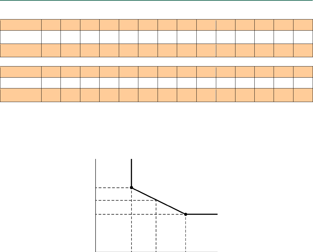
ESR-3037 | Most Widely Accepted and Trusted Page 17 of 20
TABLE 7—LENGTH IDENTIFICATION HEAD MARKS ON STRONG-BOLT® 2 ANCHORS
(CORRESPONDS TO LENGTH OF ANCHOR – INCHES)
Mark Units A B C D E F G H I J K L M
From in 11/2 2 21/2 3 31/2 4 41/2 5 51/2 6 61/2 7 71/2
Up To But Not
Including
in 2 21/2 3 31/2 4 41/2 5 51/2 6 61/2 7 71/2 8
Mark Units N O P Q R S T U V W X Y Z
From in 8 81/2 9 91/2 10 11 12 13 14 15 16 17 18
Up To But Not
Including
in 81/2 9 91/2 10 11 12 13 14 15 16 17 18 19
FIGURE 4—INTERPOLATION OF MINIMUM EDGE DISTANCE AND ANCHOR SPACING1
1Interpolation only valid for 3/4- inch diameter carbon steel and 3/8-, 1/2- and 5/8-inch-diameter stainless-steel anchors. Spacing
and edge distance combinations must fall on or above and to the right of the diagonal line.
c
min
c
design
for c ≥
Edge distance, c
Spacing, s
for c ≥
sdesign
smin
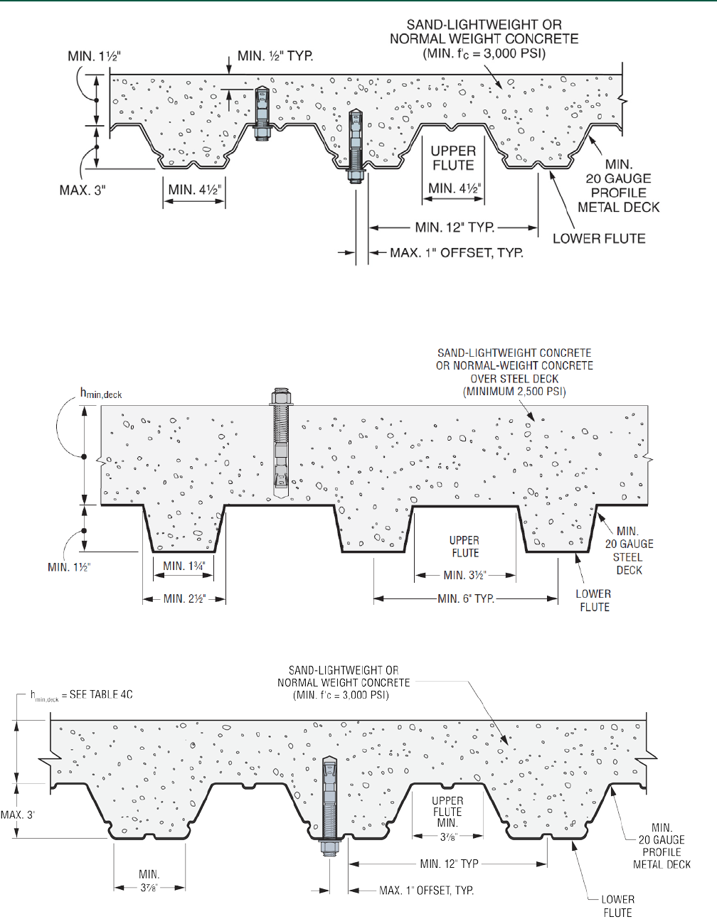
ESR-3037 | Most Widely Accepted and Trusted Page 18 of 20
FIGURE 5—INSTALLATION IN THE SOFFIT OF CONCRETE OVER PROFILE STEEL DECK FLOOR AND ROOF ASSEMBLIES1
1Anchors may be placed in the upper flute or lower flute of the steel deck assembly provided a minimum 1/2-inch concrete cover beyond the end of the
anchor is provided. Anchors in the lower flute of Figure 5 may be installed with a maximum1-inch offset in either direction from the centerline of the flute.
FIGURE 6—INSTALLATION ON THE TOP OF CONCRETE-FILLED PROFILE STEEL DECK FLOOR AND ROOF ASSEMBLIES
FIGURE 7—INSTALLATION IN THE SOFFIT OF CONCRETE OVER PROFILE STEEL DECK FLOOR AND ROOF ASSEMBLIES1
1Anchors may be placed in the lower flute of the steel deck assembly provided a minimum 5/8-inch concrete cover beyond the end of the anchor is
provided. Anchors in the lower flute of Figure 7 may be installed with a maximum 1-inch offset in either direction from the centerline of the flute (1 in =
25.4 mm).