ESScontroller Manual
User Manual:
Open the PDF directly: View PDF ![]() .
.
Page Count: 11

Page 1 2018-12-30 iancanada.mail@gmail.com
Ian’s ESS controller user’s guide
By Ian Jin, Dec 30, 2018 Ver. 0.9 (draft)
A. Introduction
Ian’s ESS controller is the first smart universal ESS DAC driver board that can be installed into standard Raspberry
Pi GPIO port. Equipped with powerful STM32 ARM Cortex processer, this tiny controller provides almost all kind of
possible functions to run an ESS DAC, such as display, control, setting, monitoring, communicating and many more.
It could be so far the best solution to integrate ESS DAC together with Raspberry Pi.
B. Highlighted Features and Specifications
Support ESS9018K2M, ES9028Q2M, and ES9038Q2M DAC in both stereo and dual mono configuration.
Up to 768KHz 16/24/32 bit PCM and native DSD1024 support.
Built-in OLED GUI for volume control and register settings.
Can work in isolated mode to eliminate noise.
Operate with knob encoder, Apple remote control or Web UI (for volume control).
True SYNC mode of ESS DAC is supported.
Real time music signal monitoring.
Real time DPLL status monitoring.
Analyzer mode designed for digital music signal measurement when no ESS DAC is attached.
Mute I2C while music is playing.
Fixable design, can be installed either into GPIO or at front panel through an adapter
Possible to work with external ESS DAC.
Small size PCB with GPIO connector very easy to use with Raspberry Pi audio applications.
Page 2 2018-12-30 iancanada.mail@gmail.com
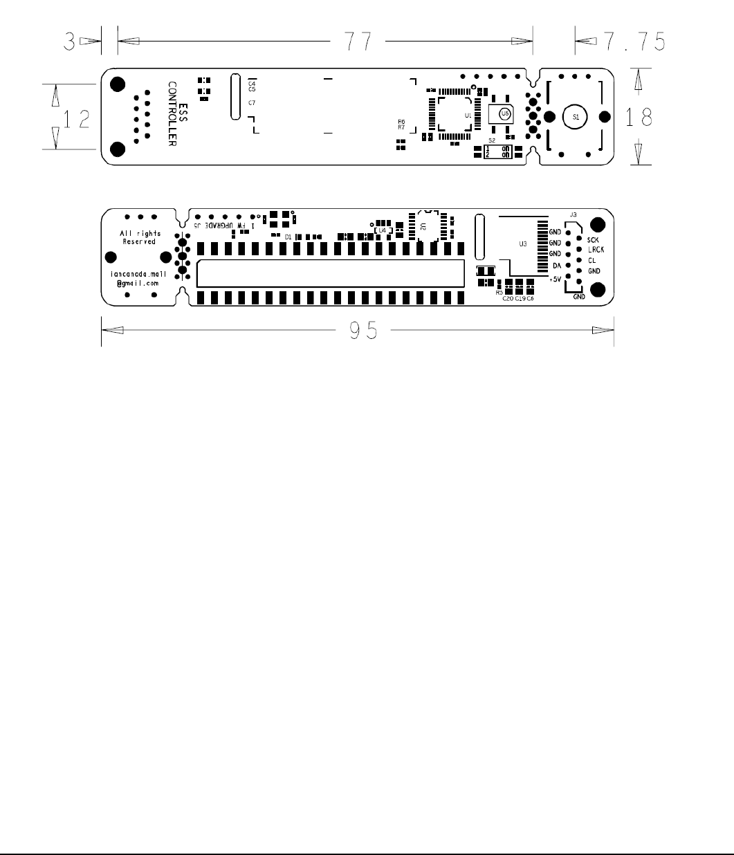
C. Layout and Dimensions (in mm)
D. Getting start
1. Solder the knob encoder to the S1 position of ESS controller. Cut the pin leads by a side cutter if required.
Please skip this step if only use Apple remote control;
2. Plug the ESS controller onto the GPIO of ESS DAC HAT (normal mode) or the non-isolated GPIO of FifoPi or
IsolatorPi (Isolated mode);
3. Power Raspberry Pi and DAC system as usual; ESS DAC ID, address and working mode will be recognized
and displayed on OLED screen. Adjust the volume to 0dB or other suitable level for the first time of operating
if the ESS DAC default setting is too low.
4. On the player’s setup page, select general I2S DAC. Or PCM5122 compatible DAC such Hifiberry DAC+ if
need additional volume control from Web UI. Restart player if it is required.
5. Enjoy the music.

Page 3 2018-12-30 iancanada.mail@gmail.com
E. OLED working screen
OLED display has four sections on the main working screen:
1. Right side of the screen: Volume numbers in unit of dB.
2. Top left of the screen: Music format and sampling rate or Music signal status.
3. Top middle of the screen: Real time measured data length of PCM music, can be 16,24 or 32bit.
4. Bottom left of the screen: Real time measured bit clock (SCK or BCK) frequency in unit of Mhz.
F. Volume control
There are three ways to control the volume of ESS DAC :
1. Turn the knob.
2. Press arrow keys on the Apple remote control.
3. Change the volume at the Web UI of Linux player if the PCM5122 compatible DAC is selected.
Please note that the volume display is in unit of dB corresponding to the ESS DAC internal register settings. 0dB
is the maximal, while the -99dB is the minimal. To keep the best sound quality, please always set the volume to
0dB if you have an analog volume control in your system (such as the one in pre-amplifier or power amplifier).
Linux player will also internally convert volume in unit of percentage into unit of dB.
G. GUI manual of register settings
To open the GUI manual, you need to press the knob or the play key on the Apple remote. Then turn the knob or
press the arrow keys of the remote control to go through all register setting pages. Current settings will be
highlighted.
To change a setting, you just need to press the knob or the play key of the remote control at the highlighted
setting that you want to change. It will go into edit mode with current editing setting in flashing. Turn the knob or
press the arrow keys of the remote control to go through all the options. Press the knob or the play key of the
remote control at the option that you want to change to, it will be set and saved. GUI manual will exit to the main

Page 4 2018-12-30 iancanada.mail@gmail.com
working screen. If cancel is selected, it will exit setting manual without making any change.
Or, you can wait for ten seconds or press the manual key of the remote control at any time; it will automatically go
back the main screen.
Register setting pages
Setting options
Descriptions and notes
DPLL Bandwidth PCM
NO Bandwidth 0
Set the PCM DPLL bandwidth
Smaller numbers can only apply
to better XO or external MCLK of
ESS DAC.
NO bandwidth will only apply to
DAC in true SYNC mode with
DPLL stopped.
Lowest Bandwidth 1
Lower Bandwidth 2
Low default 5
Low-medium 8
Medium 10
High-medium 12
High Bandwidth 14
Highest Bandwidth 15
DPLL Bandwidth DSD
NO Bandwidth 0
Set the DSD DPLL bandwidth
Smaller numbers can only apply
to better XO or external MCLK of
ESS DAC.
NO bandwidth will only apply to
DAC in true SYNC mode with
DPLL stopped, but not a
guarantee to work well with all
DAC
Lowest Bandwidth 1
Lower Bandwidth 2
Low Bandwidth 5
Low-medium 8
Medium default 10
High-medium 12
High Bandwidth 14
Highest Bandwidth 15
IIR filter Bandwidth
1.0757fs default
Set IIR filter Bandwidth
For supported ESS DACs
except ESS9038Q2M
1.1338fs
1.3605fs
1.5873fs

Page 5 2018-12-30 iancanada.mail@gmail.com
FIR filter shape
Fast rolloff default
Slow rolloff
Set IIR filter Bandwidth
For all supported ESS DACs
except ESS9038Q2M
ES9038Q2M filters
Brick Wall Filter
Select digital filters
For ES9038Q2M DAC only
Cor MIN Fast Roll-Off
Apodiz Fast Roll-Off (default)
Minimum Slow Roll-Off
Minimum Fast Roll-Off
Linear Slow Roll-Off
Linear Fast Roll-Off
MCLK true SYNC Mode
ASRC mode default
Default ASYNC mode
SYNC mode stop DPLL
True SYNC mode
Only works for DACs in true
SYNC mode with external MCLK
fed from FifoPi. Needs jumper
switch being set to SYNC mode
on ESS DAC HAT.
OSF Bypass
OSF enabled (default)
OSF enabled
OSF bypass
OSF bypass
IIR Bypass
IIR enabled default
IIR enabled
IIR bypass
IIR bypass
Watch DPLL Ratio
Yes or Cancel
Monitoring internal DPLL ratio
status numbers in real time.
This powerful function is useful
for evaluating the quality of XO
clock or status of SYNC mode.

Page 6 2018-12-30 iancanada.mail@gmail.com
Reset factory default
Yes or Cancel
This function is useful to reset all
register settings back to the
factory default if not happy with
current settings or getting
confused.
H. Connectors
J1: 40PIN GPIO socket to connect to DAC
This right angle GPIO socket can be connected right on top to the 40PIN GPIO connector of the ESS DAC HAT
(normal mode) or to the 40PIN non-isolated GPIO connector of FifoPi or IsolatorPi (isolated mode).
It will hold the ESS controller in the position. Please make sure both of the rows are fitted well into the connector.
PIN numbers
Signal description
2,4
Pi 5V
6,9,14,20,
25,30,34,
39
GND
3
I2C DA
4
I2C CL
8
Txd
10
Rxd
12
SCK input
35
LRCK/D1 input
J3: Optional FFC/FPC cable connector to connected to DAC
This optional FFC/FPC connector will be alternative to J1 to connect to an ESS DAC externally with 10 PIN
FFC/FPC cable. This connector is not assembled by default.
PIN
Signal
PIN
Signal
1
GND
2
SCK input
3
GND
4
LRCK/D1 input
5
GND
6
I2C CL
7
I2C DA
8
GND
9
Pi5V
10
GND
J5: FW upgrade connector
Reserved for firmware upgrade adapter.

Page 7 2018-12-30 iancanada.mail@gmail.com
Note1:
All input/output signals are in
LVTTL (3.3V) logic level.
I. Jumper settings
Jumper switch S2 is located beside the IR receiver at the front side of PCB.
Jumper Switch
S2
OFF (default)
ON
1
Auto mute enabled
Auto mute disabled
2
WebUI volume control enabled
WebUI volume control disabled
For normal applications, please keep all jumper switchs at default position.
J. Tips and application notes
DPLL ratio monitoring
To perform DPLL ratio real time monitoring function, you will need:
1. At the GUI manual “Watch DPLL Ratio” page, select “Yes”.
2. The 32bit hex DPLL ratio number will be displayed on the screen if there is music signal.
FSR = (DPLL_NUM x FMCLK) / 232
This number will keep at 0x00000000 with no change in true SYNC mode because DPLL is stopped.
DPLL ratio number can also be used to evaluate the DPLL lock status or the quality of music signal.
DPLL ratio number display will be terminated automatically in ten seconds.
Music signal analyzer mode
ESS controller can also be used as stand along digital music signal analyzer if no DAC is connected.
To enable this feature, you just need to press and hold the knob for more than 2 second while “Check ESS DAC”
message is showing on the OLED screen.
After enter this mode, the real monitoring music signal status will be displayed on the screen, including music
format, real frequencies and data length.
This feature is useful for hardware debugging by capturing real music signal information without/before DAC
connected.
To get back to normal DAC controller mode, you will need turn off the power and then include an ESS DAC into
system.
Reset register settings back to the factory default
It is very helpful to reset all register settings back to factory default at any time when the setting gets confused or
there is something wrong. To do so, you will need:
At the GUI manual “Reset factory default” page, select “Yes”.

Page 8 2018-12-30 iancanada.mail@gmail.com
The factory default reset is also required when DAC is replaced.
After factory default reset is performed, you may need to change the volume to 0 or other suitable level if the
default volume number is too low.
Enable S/PDIF receiving
To enable S/PDIF receiving, PIN1 of jumper switch S2 needs to be switched to “ON”.
Move ESS controller to the front panel
To move the ESS controller to the front panel rather than plug onto GPIO connector, you will need the Ess
controller extension KIT (sold separately).
1. Plug the ESS extension adapter into the same GPIO connector that the ESS controller was connected to.
2. Solder the 10PIN FFC/FPC connector to J3 position at back side of the ESS controller PCB.
3. Connect the ESS controller to the extension adapter with the 10PIN FPC/FFC cable. Make sure the cable
orientation is correct.
4. Fix the ESS controller at the front panel.
Works with external ESS DAC
It’s also possible to make this ESS controller working as a dedicated controller of an external ESS DAC even
without a Raspberry Pi. To do so, you will need:
1. Solder the 10 wires of the cable to the footprint of J3.
2. Connect the wires of the cable to the corresponding signal pins of the DAC.
3. Remove any possible local controller that connected to the I2C bus of the ESS DAC. Also make sure I2S bus
has pull-up resistors for both signals.
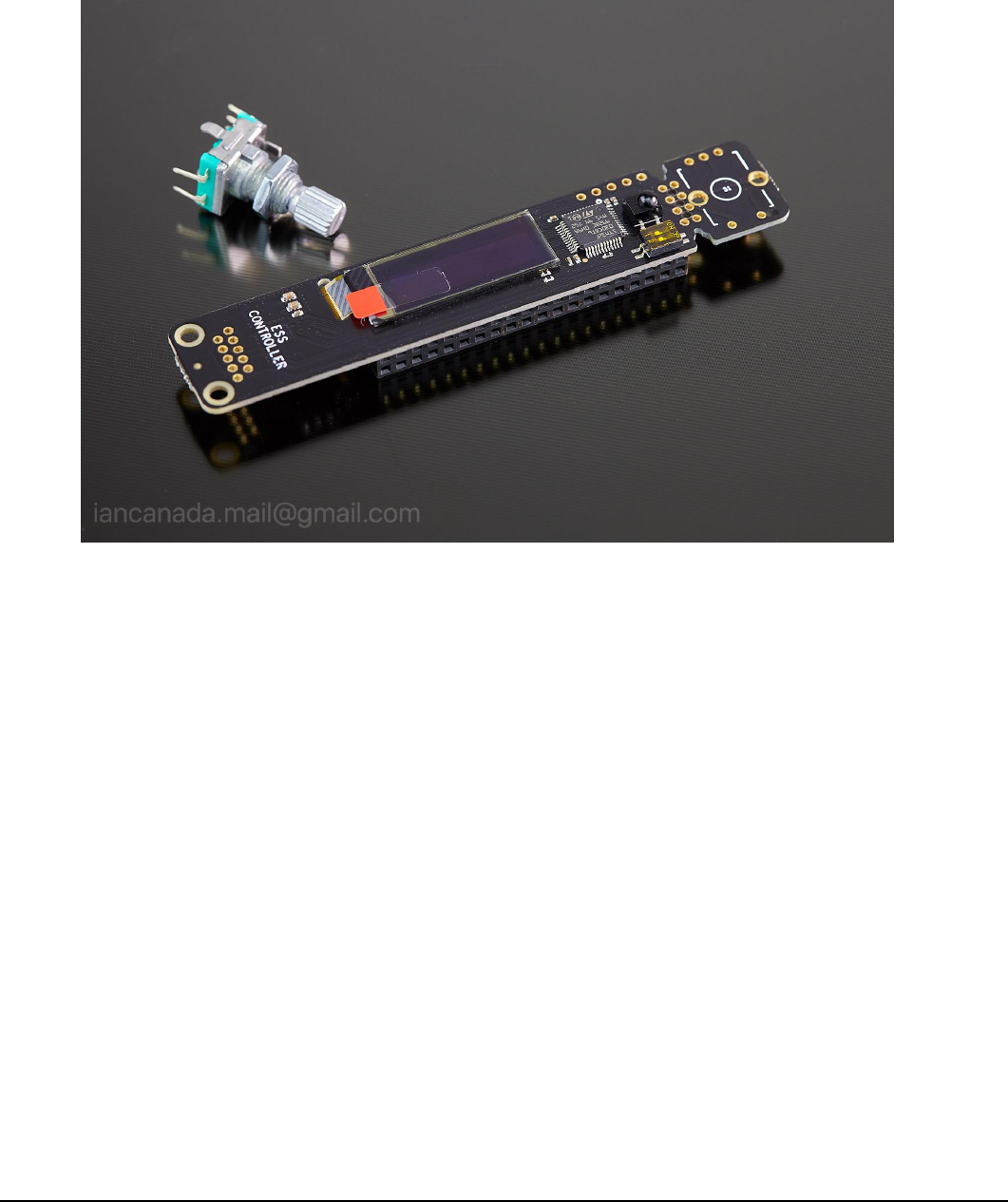
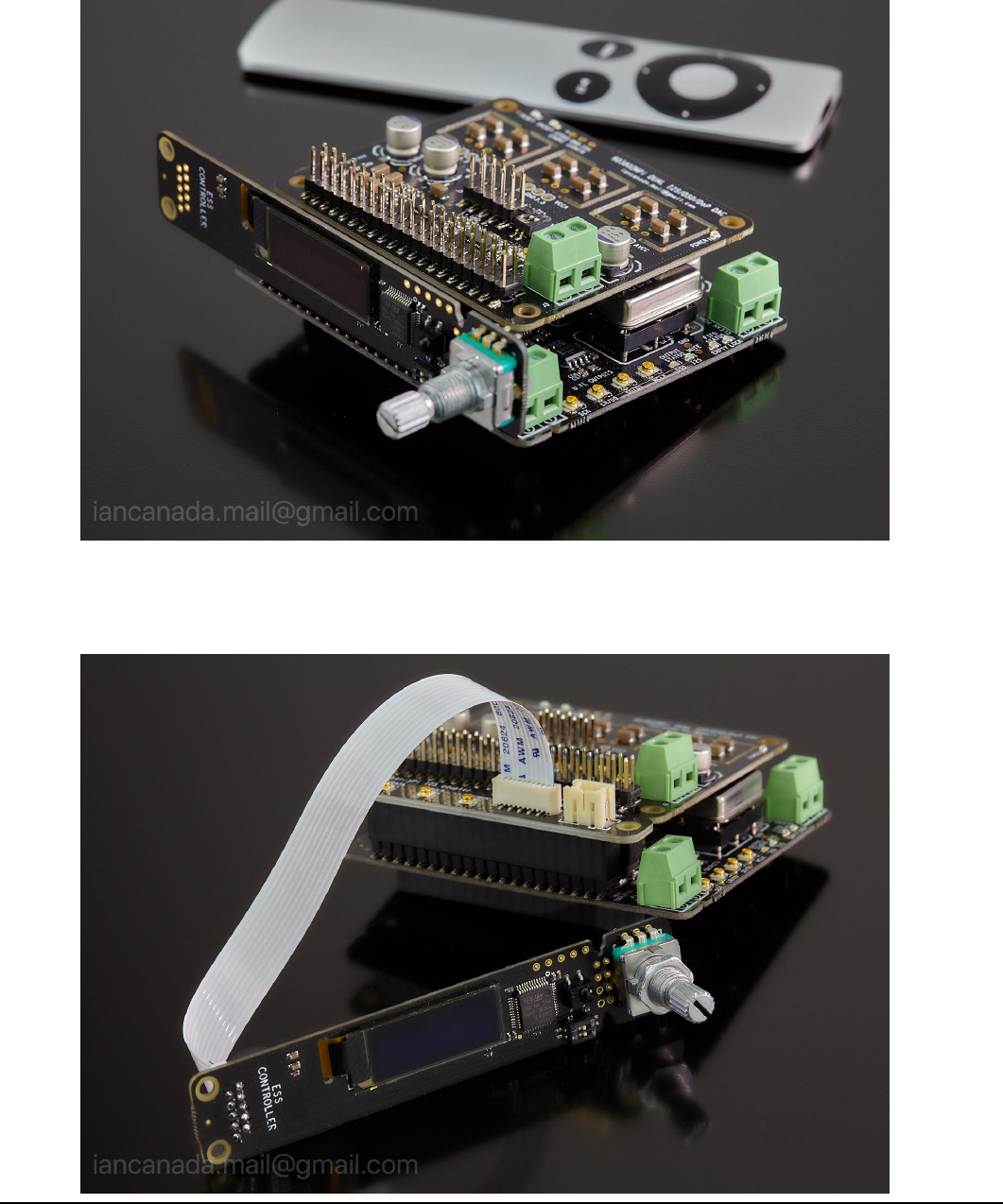
K. ESS controller pictures
Page 9 2018-12-30 iancanada.mail@gmail.com
a. ESS controller
b. Run ESS DAC at normal mode by connecting to the GPIO of DAC HAT
Page 10 2018-12-30
iancanada.mail@gmail.com
c. Run ESS DAC HAT at isolated mode by connecting to non-isolated GPIO of the FifoPi or IsolatorPi
d. Move ESS controller to front panel by an adapter through a FFC/FPC cable

Page 11 2018-12-30
iancanada.mail@gmail.com
e. ESS controller with complete ESS DAC system
Raspberry Pi + FifoPi + ES9038Q2M dual mono + I/V std + ESS controller
© 2019 Ian Jin. The firmware code embedded in the ESS controller is the property of Ian Jin. You are granted a
non-exclusive, non-transferable, non-sublicenseable, royalty-free right to use the ESS controller board solely for your own,
non-commercial purposes. You may not distribute, sell, lease, transfer, modify, adapt, translate, reverse engineer, prepare
derivative works of, decompile, or disassemble the software provided. All rights reserved.
