ET100 Series Timer
User Manual: ET100-series-timer
Open the PDF directly: View PDF ![]() .
.
Page Count: 2
®
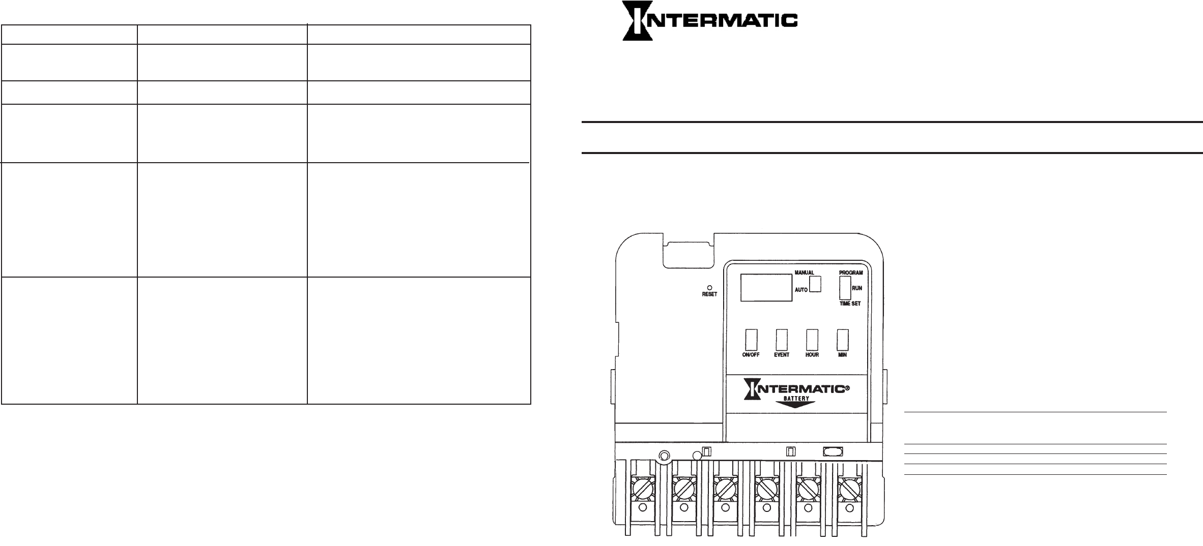
ET100 SERIES
INCLUDING MODELS:
ET101C (SPST)
ET103C (DPST)
ET105C (SPDT)
Electronic 24 Hour Time Switches
With Battery Carryover
OWNER/INSTALLER INSTRUCTION MANUAL
ATTENTION: READ CAREFULLY BEFORE ATTEMPTING TO INSTALL YOUR INTERMATIC
TIME SWITCH. FAILURE TO COMPLY WITH INSTRUCTIONS COULD RESULT IN PERSONAL
INJURY AND/OR PROPERTY DAMAGE! RETAIN FOR FUTURE REFERENCE.
Specifications
CLOCK VOLTAGE: 120 V.A.C., 60 Hz.
POWER CONSUMPTION: 3.0 Watts Max. (ET101C) &
ET105C)
5.0 Watts Max. (ET103C)
CONTACT CONFIGURATION: SPST model ET101C
DPST model ET103C, & SPDT model ET105C.
SWITCH RATING: (Per Pole for ET103C)
• 30AmpsInductive/Resistive,24/120/240V.A.C.,60Hz.
• 20AmpsResistive-28V.D.C.,
• 1H.P.120V.A.C.,60Hz.
• 2H.P.240V.A.C.,60Hz.
• 5AmpsTungsten,120/240V.A.C.,60Hz.
• 20AmpsBallast277V.A.C.,60Hz.
SWITCH RATINGS: ET105C
N.O. N.C. CONTACT
20AMP10AMPResistiveand 28VDC.
GeneralPurpose 120-240VAC
1H.P.1/4H.P.MOTOR120V.A.C.
2H.P.1/2H.P.MOTOR 240V.A.C.
5Amp-TUNGSTEN120-240V.A.C.
20Amp3AmpBALLAST 120-277
V.A.C.
SETPOINTS(EVENTS):8total(4ON/4OFF).
BATTERYPOWEREDCLOCKOPERATION:3Yearsminimum
(AAindustrialgradealkalinesuppliedwithtimeswitch)
MIN.“ON”or“OFF”TIME:1minute.
MAX.“ON”or“OFF”TIME:23hours59minutes.
SHIPPINGWEIGHT:2,5Lbs.(1.1Kg)
CASE: Drawn steel; 7-3/4” (19.7 cm) high, 5” (12.7 cm)
wide, 3” (7.6 cm) deep; gray finish w/lockable spring hasp.
KNOCKOUTS: Combination 1/2 - 3/4” (one on back and
eachside,twoonbottom).
WIRESIZE:AWG#10through#18.
General Safety Information
WARNING: Disconnect all power before installing or
servicingthistimeswitchoritsconnectedloads.
1.Follow all local electrical and safety codes, National
Electric Code (NEC), as well as Occupational Safety and
HealthAct(OSHA).
2.Ifthepowerdisconnectpointisoutofsight,lockitinthe“OFF”
positionandtagittopreventunexpectedapplicationofpower.
3.Thistimeswitchcasemustbegrounded.
4.Donotexceedthemaximumcurrentcarryingcapacityofthis
timeswitch.
5.Always replace the plastic insulator covering the terminal
beforeturningpower“ON”.
AM ON
5:20
Description
The Intermatic Electronic 24 Hour Time Switch automatically
switches loads according to a preset daily schedule.
Thistimeswitchisdesignedtodirectlyswitchloadsupto30amps
and to switch resistive or inductive loads up to the time switch
rating.Foruseasacontroltimerinapplicationsrequiring24hour
load control such as lighting, heating, air conditioning systems,
pumps,etcetera.Uptoeightsetpointsorevents(4ON/4OFF)
canbepreset.thisschedulewillrepeatonadailybasis.Thepro-
gramcanbeoverriddenbyusingtheMANUALposition.
Trouble Shooting
SYMPTOM POSSIBLE CAUSE(S) CORRECTIVE ACTION
Timeswitchhasnodisplay. Batterynotproperlyinstalledor Checkbatteryandreplaceifnecessary.
defective.
Displayshows“L-bA”. Displaymeans“LowBattery”. Replacebatterywithin30days.
Displayshows“Err1”message. Slideswitchnotfullyinitsdetent Repositionslideswitchintodetentor“wiggle”until
position(opencircuit). displayiscorrected.Ifdisplaydoesnotcorrect,
Displayshows“Err2”message. Slideswitchshortedcircuit. contactorreturntofactoryforservice.
Displayshows“Err3”message. Slideswitchillegalposition.
Displayshowsscrambledor Timeswitchhasnotbeenreset. Presstherecessedresetswitchandholdfor
erratictimes. approximately5seconds.
Electricalnoiseisinterferingwiththe Electricalnoiseinterferenceishighlyunlikely
operationofthemicroprocessor. sincetheelectroniccircuitryandthepower
supplyarecompletelyisolated.Theinstallation
ofsurgesuppressors(metaloxidevaristors-
MOVS)acrossterminals3/4(modelET103C
acrossterminals3/4&5/6)willhelptoreduce
electricalnoisegeneratedattheswitching
contacts.
Loaddoesnotswitchat- MANUAL/AUTOselectornotinAUTO BesureMANUAL/AUTOisintheAUTO
programmedtime. position. position.
Timeswitchisprogrammedincorrectly Checkprogram-placetheProgramSelectorin
thePROGRAMmodeandpresstheEventbutton
toreviewalleightpossibleEvents.
Powerhasnotbeensuppliedtothe Besurepowerisappliedtothelineterminals#3
loadthroughtheline(line1and (#3and#5forET103C)inordertopowerthe
line2forET103C)terminals. load.Notethattheoutputcontactsareisolated
fromthetimerpower(terminals1and2).
Thisallowsthetimertoswitchvariousloads
from24voltsthrough277volts.
LIMITED ONE YEAR WARRANTY
Ifwithin one(1)year fromdateof purchase,this productfailsdue toadefect inmaterialorworkmanship,Intermatic Incorporatedwillrepair or
replace,atitssoleoption,theunitfreeofcharge.Thiswarrantyappliesonlytotheoriginalpurchaserandisnottransferable.
Thewarrantydoesnotapplyto:(a)damagecausedbyaccident,abuse,mishandling,dropping,actsofGod,oranynegligentuse;(b)unitswhich
havebeensubjecttounauthorizedrepair,opened,takenapart,orotherwisemodified;(c)unitsnotusedinaccordancewithdirections;(d)damages
exceedingthecostoftheproduct.Somestatesdonotallowalimitationofdamages,sotheforegoinglimitationmaynotapplytoyou.
Thiswarrantygivesyouspecificlegalrightsandyoumayhaveotherrightsthatvaryfromstatetostate.
INTERMATIC INCORPORATED WILL NOT BE LIABLE FOR INCIDENTAL OR CONSEQUENTIAL DAMAGES. THIS WARRANTY IS IN LIEU
OF ALL OTHER EXPRESS OR IMPLIED WARRANTIES. ALL IMPLIED WARRANTIES, INCLUDING THE WARRANTY OF MERCHANTABILITY
AND THE WARRANTY OF FITNESS FOR A PARTICULAR PURPOSE, ARE HEREBY MODIFIED TO EXIST ONLY AS CONTAINED IN THIS
LIMITED WARRANTY AND SHALL BE OF THE SAME DURATION AS THE WARRANTY PERIOD STATED ABOVE.
Thiswarrantyserviceisavailablebyeither(a)returningtheproducttothedealerfromwhomtheunitwaspurchased,or(b)mailingpostageprepaid
tothenearestauthorizedservicecenterlisted.Pleasebesuretowraptheproductsecurelywhenmailingtoavoiddamage.Thiswarrantyismade
by:IntermaticIncorporated/AfterSalesService,7777WinnRd.,SpringGrove,IL60081-9698.
SERVICE CENTER/ SERVICE CENTRE
CENTRE DE SERVICE
INTERMATIC INCORPORATED
AfterSalesService
7777WinnRd.,
(815)675-7000
http://www.intermatic.com
INTERMATIC INCORPORATED
SPRING GROVE, ILLINOIS 60081-9698
158--00385
http://waterheatertimer.org/Intermatic-ET-series-timers-and-manuals.html#ET100
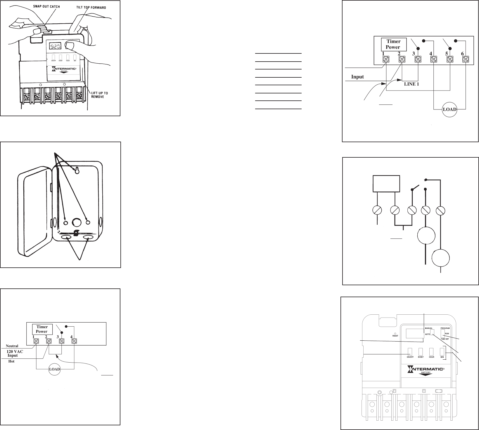
Installation
WARNING: DISCONNECT THE POWER TO THE TIME SWITCH
AND THE LOADS BEFORE INSTALLING THIS TIME SWITCH.
1.Mount the time switch in the desired location using the three
mountingholeswhichareprovided.Mountthetimeswitchateye
level, if possible, providing sufficient room to the left of the
enclosureforthecovertoswingopenfully.(SeeFigure#1and
Figure #2). The time switch mechanism does not need to be
removedfromtheenclosuretomountthetimeswitchsincethe
top mounting hole is a slotted type mounting hole. Secure a
screworotherfastenerateyelevel.Theheadofthescrewor
fastenershouldbeslightlylargerthanthenarrowportionofthe
slotted hole to ensure that the time switch is securely held in
place.Theremainingtwomountingholesareaccessiblewithout
removing the time switch mechanism and will provide secure
andpermanentmountingofthetimeswitch.
2.Ifyoudoremovethemechanism,refertoFigure#1andremove
themechanismfromthecasebydepressingthecatchatthetop
ofthecaseandpullingout.
CAUTION; DO NOT TOUCH THE CIRCUIT BOARD
COMPONENTS SINCE STATIC DISCHARGE COULD
DAMAGE THE MICROPROCESSOR.
3.Replacethemechanisminthecaseifithasbeenremoved.
4.Lifttheleftsideoftheinsulatoroffoftheretainingpostandpivot
itupandawaytoexposetheterminalstrip.
5.Strip the supply and load wires by removing 1/2 inch of
insulation.DONOTUSEALUMINUMWIRE.(Seefigure#3,#4
or#5).Insertthewireendsundertheproperterminalplatesand
tightenthescrewsfirmly.UseAWG#10through#18.Connect
ground wire to grounding terminal at bottom of case.
6.Replacetheplasticinsulator.
7.Be sure that the battery is functioning properly. this can be
checkedbymakingsurethedisplayisvisible.Ifthedisplayhas
scrambled information, press the RESET switch and hold for
three to five seconds. Note that the battery can easily be
replaced without removing the time switch mechanism or field
wiring. simply press in and downward (in the direction of the
arrow) on the battery cover which is identified with the word
“Battery”.Itisrecommendedthatthebatterybereplacedwitha
“AA”industrialgradealkalinecellattwotothreeyearintervals
aspartofthenormaltimeswitchmaintenanceobservingbattery
polarity markings when installing. No other maintenance is
required.
8.Place the selector switches in the “MANUAL” and “RUN”
positions.
9.Reapplypowertothetimeswitch.
Mounting Holes
Knockouts
FIG. #1
FIG. #2
FIG. #3
ET101C SPST
NOTE: For 120 Volt loads only since the timer voltage is 120 VAC
a jumper can be added between terminals 2 and 3 to supply load
power.
CAUTION: Do not use jumper if load(s) are not 120V. because the
loadcan be damaged.Supplyseparate power ofthecorrect voltage
toterminal3.
InstallJumperOnlyIf
TimerInputandLoad
VoltageAreTheSame,
Otherwiseprovidea
separatesourceofload
powertoterminal3.
AM ON
10.Press the reset switch for three to five seconds. The
display will now show 12:00 A.M. and Event #1. The
timerisnowreadyforprogramming.Refertothechart
below and enter the scheduled events (set points)
required.
EVENT TIME
On1
Off 2
On3
Off4
On5
Off 6
On7
Off8
Programming Steps
Refer to programming instructions on time switch door
labelandnotethefollowing:
• TheMANUAL/AUTOselectorcanbeusedtotemporarily
override the program. Under normal operation the
selector should be in the AUTO mode. The MANUAL
mode maintains the program but prevents the loads
fromautomaticallyswitching.
• Theotherselectorswitchisusedtosetthetimeofday
(TIMESET),theprograminformation(PROGRAM)orto
run the program (RUN). FOR A PROGRAM TO
FUNCTION PROPERLY, THE TWO SELECTOR
SWITCHES MUST BE IN THE AUTO AND RUN
POSITIONS.
• TheRESETswitchisusedonlypriortoinitiallyprogram-
mingthetimeswitchortoeraseallprogrammedset
points.
• By holding the hour and/or minute buttons depressed
youcanachieveafastrollofthedisplayedtime.Thisis
useful when setting the time of day or setting the
programmedsetpoints(events).
• Up to 4 ON and 4OFF set points (8 events) can be
programmed.
• TheloadcanmanuallybeswitchedONorOFFatany
time only if the selector switch is in the RUNmode by
pressingtheON/OFFbutton.
• Pressing the ON/OFF button two times in the
PROGRAMmodecausestheeventtimedisplayedtobe
removedfromtheprogram.Thedisplaywillshow0:00
andtheEvent(1through8).
To Operate Timer
After programming is complete, move the selector
switchestotheRUNandAUTOpositions.Thetimeswitch
willfollowthescheduledprogrambutwillnotimmediately
“catch up” to the presently programmed load condition;
thetimeswitchwill“catchup”atthenextscheduledONor
OFF setpoint. If necessary, press the ON/OFF button to
turntheloadonoroff.
FIG. #4
ET103C DPST
LOAD STATUS INDICATOR
“ON” or “OFF”
EVENT
INDICATOR
PROGRAMMING
BUTTONS
MANUAL/AUTO
SELECTOR
PROGRAM
SELECTOR
PROGRAMMING/
MANUAL LOAD
CONTROL
BUTTON
FIG. #6
Install Jumper Only If Timer
Input and Load Voltage Are
The Same, Otherwise provide
a separate source of load
power to terminal 3& 5.
120 V A C
Neutral
Hot
NOTE: For 120 Volt loads only since the timer voltage is 120 VAC
ajumpercanbe added between terminals 2,3and5tosupplyload
power.
CAUTION: Do not use jumper if load(s) are not 120V. because the
loadcan be damaged.Supplyseparate power ofthecorrect voltage
toterminal3and5.
NOTE: For 120 Volt loads only since the timer voltage is 120 VAC
jumperscanbeaddedbetweenterminals2and3tosupplyloadpower.
CAUTION:Donotusejumpersifload(s)arenot120V.becausetheloadcanbe
damaged.Supplyseparatepowerofthecorrectvoltage.
TIMER
POWER
123 4
LOAD 1
5
LOAD 2
NEUTRAL LINE LINE 1
InstalljumperOnlyIf Timer
InputandLoadVoltageAre
TheSame,Otherwiseprovide
aseparatesourceofload
powertoterminal3.
For breaking one side of
120 volt loads.
FIG. #5
ET105C SPDT
