ETABS PT Slab Design
User Manual: ETABS PT Slab Design
Open the PDF directly: View PDF ![]() .
.
Page Count: 649 [warning: Documents this large are best viewed by clicking the View PDF Link!]
- Title
- Copyright
- Disclaimer
- Contents
- Chapter 01 Contents
- Chapter 02 The Tendon Object in ETABS
- Chapter 03 Computing Prestress Losses
- Chapter 04 Loads Due to Post-Tensioning
- PTD Chapter 05 Automated Tendon Layout
- Chapter 06 Design for ACI 318-08
- 6.1 Notations
- 6.2 Design Load Combinations
- 6.3 Limits on Material Strength
- 6.4 Strength Reduction Factors
- 6.5 Design Assumptions for Prestressed Concrete
- 6.6 Serviceability Requirements of Flexural Members
- 6.7 Beam Design (for Reference Only)
- 6.8 Slab Design
- Chapter 07 Design for AS 3600-01
- 7.1 Notations
- 7.2 Design Load Combinations
- 7.3 Limits on Material Strength
- 7.4 Strength Reduction Factors
- 7.5 Design Assumptions for Prestressed Concrete Structures
- 7.6 Serviceability Requirements of Flexural Members
- 7.7 Beam Design (for Reference Only)
- 7.8 Slab Design
- Chapter 08 Design for BS 8110-97
- 8.1 Notations
- 8.2 Design Load Combinations
- 8.3 Limits on Material Strength
- 8.4 Partial Safety Factors
- 8.5 Design Assumptions for Prestressed Concrete Structures
- 8.6 Serviceability Requirements of Flexural Members
- 8.7 Beam Design (for Reference Only)
- 8.8 Slab Design
- Chapter 09 Design for CSA A23.3-04
- 9.1 Notations
- 9.2 Design Load Combinations
- 9.3 Limits on Material Strength
- 9.4 Strength Reduction Factors
- 9.5 Design Assumptions for Prestressed Concrete
- 9.6 Serviceability Requirements of Flexural Members
- 9.7 Beam Design (for Reference Only)
- 9.8 Slab Design
- Chapter 10 Design for Eurocode 2-2004
- 10.1 Notations
- 10.2 Design Load Combinations
- 10.3 Limits on Material Strength
- 10.4 Partial Safety Factors
- 10.5 Design Assumptions for Prestressed Concrete Structures
- 10.6 Serviceability Requirements of Flexural Members
- 10.7 Beam Design (for Reference Only)
- 10.8 Slab Design
- 10.9 Nationally Determined Parameters (NDPs)
- Chapter 11 Design for Hong Kong CP 04
- 11.1 Notations
- 11.2 Design Load Combinations
- 11.3 Limits on Material Strength
- 11.4 Partial Safety Factors
- 11.5 Design Assumptions for Prestressed Concrete Structures
- 11.6 Serviceability Requirements of Flexural Members
- 11.7 Beam Design (for Reference Only)
- 11.8 Slab Design
- Chapter 12 Design for IS 1343-1980
- 12.1 Notations
- 12.2 Design Load Combinations
- 12.3 Limits on Material Strength
- 12.4 Partial Safety Factors
- 12.5 Design Requirements of Prestressed Concrete Structures
- 12.6 Maximum Compression Check
- 12.7 Beam Design (for Reference Only)
- 12.8 Slab Design
- Chapter 13 Design for NZS 3101:06
- 13.1 Notations
- 13.2 Design Load Combinations
- 13.3 Limits on Material Strength
- 13.4 Strength Reduction Factors
- 13.5 Design Assumptions for Prestressed Concrete Structures
- 13.6 Serviceability Requirements of Flexural Members
- 13.7 Beam Design (for Reference Only)
- 13.8 Slab Design
- Chapter 14 Design for Singapore CP 65:99
- 14.1 Notations
- 14.2 Design Load Combinations
- 14.3 Limits on Material Strength
- 14.4 Partial Safety Factors
- 14.5 Design Assumptions for Prestressed Concrete Structures
- 14.6 Serviceability Requirements of Flexural Members
- 14.7 Beam Design (for Reference Only)
- 14.8 Slab Design
- Chapter 15 Design for AS 3600-09
- 15.1 Notations
- 15.2 Design Load Combinations
- 15.3 Limits on Material Strength
- 15.4 Strength Reduction Factors
- 15.5 Design Assumptions for Prestressed Concrete Structures
- 15.6 Serviceability Requirements of Flexural Members
- 15.7 Beam Design (for Reference Only)
- 15.8 Slab Design
- Chapter 16 Design for ACI 318-11
- Notations
- 16.2 Design Load Combinations
- 16.3 Limits on Material Strength
- 16.4 Strength Reduction Factors
- 16.5 Design Assumptions for Prestressed Concrete
- 16.6 Serviceability Requirements of Flexural Members
- 16.7 Beam Design (for Reference Only)
- 16.8 Slab Design
- Chapter 17 Design for TS 3233-1979
- Notations
- 17.2 Design Load Combinations
- 17.3 Limits on Material Strength
- 17.4 Partial Safety Factors
- 17.5 Design Assumptions for Prestressed Concrete Structures
- 17.6 Serviceability Requirements of Flexural Members
- 17.7 Beam Design (for Reference Only)
- 17.8 Slab Design
- Chapter 18 Design for Italian NTC 2008
- Notations
- 18.2 Design Load Combinations
- 18.3 Limits on Material Strength
- 18.4 Partial Safety Factors
- 18.5 Design Assumptions for Prestressed Concrete Structures
- 18.6 Serviceability Requirements of Flexural Members
- 18.7 Beam Design (for Reference Only)
- 18.8 Slab Design
- Chapter 19 Design for Hong Kong CP 2013
- Notations
- 19.2 Design Load Combinations
- 19.3 Limits on Material Strength
- 19.4 Partial Safety Factors
- 19.5 Design Assumptions for Prestressed Concrete Structures
- 19.6 Serviceability Requirements of Flexural Members
- 19.7 Beam Design (for Reference Only)
- 19.8 Slab Design
- Chapter 20 Design for ACI 318-14
- Notations
- 20.2 Design Load Combinations
- 20.3 Limits on Material Strength
- 20.4 Strength Reduction Factors
- 20.5 Design Assumptions for Prestressed Concrete
- 20.6 Serviceability Requirements of Flexural Members
- 20.7 Beam Design (for Reference Only)
- 20.8 Slab Design
- Chapter 21 Design for CSA A23.3-14
- Notations
- 21.2 Design Load Combinations
- 21.3 Limits on Material Strength
- 21.4 Strength Reduction Factors
- 21.5 Design Assumptions for Prestressed Concrete
- 21.6 Serviceability Requirements of Flexural Members
- 21.7 Beam Design (for Reference Only)
- 21.8 Slab Design
- References
- ETABS PT Slab Design_1.pdf
- Title
- Copyright
- Disclaimer
- Contents
- Chapter 1 Introduction
- Chapter 2 Design Prerequisites
- Chapter 3 Design Process
- 3.1 Notation
- 3.2 Design Load Combinations
- 3.3 Limits on Material Strength
- 3.4 Column Design
- 3.5 Beam Design
- 3.6 Joint Design
- 3.7 Summary of Special Considerations for Seismic Design
- Appendices
- References

Post-Tensioned Slab Design Manual

Post-Tensioned Concrete Slab
Design Manual
For ETABS® 2016
ISO ETA122815M63 Rev.0
Proudly developed in the United States of America July 2016

Copyright
Copyright Computers & Structures, Inc., 1978-2016
All rights reserved.
The CSI Logo® and ETABS® are registered trademarks of Computers & Structures, Inc.
Watch & LearnTM is a trademark of Computers & Structures, Inc. Adobe and Acrobat are
registered trademarks of Adobe Systems Incorported. AutoCAD is a registered trademark
of Autodesk, Inc.
The computer program ETABS® and all associated documentation are proprietary and
copyrighted products. Worldwide rights of ownership rest with Computers & Structures,
Inc. Unlicensed use of this program or reproduction of documentation in any form, without
prior written authorization from Computers & Structures, Inc., is explicitly prohibited.
No part of this publication may be reproduced or distributed in any form or by any means,
or stored in a database or retrieval system, without the prior explicit written permission of
the publisher.
Further information and copies of this documentation may be obtained from:
Computers & Structures, Inc.
www.csiamerica.com
info@csiamerica.com (for general information)
support@csiamerica.com (for technical support)
DISCLAIMER
CONSIDERABLE TIME, EFFORT AND EXPENSE HAVE GONE INTO THE
DEVELOPMENT AND TESTING OF THIS SOFTWARE. HOWEVER, THE USER
ACCEPTS AND UNDERSTANDS THAT NO WARRANTY IS EXPRESSED OR
IMPLIED BY THE DEVELOPERS OR THE DISTRIBUTORS ON THE ACCURACY
OR THE RELIABILITY OF THIS PRODUCT.
THIS PRODUCT IS A PRACTICAL AND POWERFUL TOOL FOR STRUCTURAL
DESIGN. HOWEVER, THE USER MUST EXPLICITLY UNDERSTAND THE BASIC
ASSUMPTIONS OF THE SOFTWARE MODELING, ANALYSIS, AND DESIGN
ALGORITHMS AND COMPENSATE FOR THE ASPECTS THAT ARE NOT
ADDRESSED.
THE INFORMATION PRODUCED BY THE SOFTWARE MUST BE CHECKED BY
A QUALIFIED AND EXPERIENCED ENGINEER. THE ENGINEER MUST
INDEPENDENTLY VERIFY THE RESULTS AND TAKE PROFESSIONAL
RESPONSIBILITY FOR THE INFORMATION THAT IS USED.

Contents
Part I Post-Tensioning Concrete Design Theory and
Methodology
Chapter 1 Introduction
1.1 Overview 1-1
1.2 Post Tensioning System in ETABS 1-1
1.3 Definition of Terms 1-2
1.4 Analysis and Design Procedure 1-3
Chapter 2 The Tendon Object in ETABS
2.1 Overview 2-1
2.2 Tendon Geometry 2-1
2.3 Tendon Discretization 2-2
2.4 Tendon Material Property 2-3
2.5 Tendon Property 2-3
2.6 Tendon Loads 2-4
i

Post-Tensioned Concrete Design
Chapter 3 Computing Prestress Losses
3.1 Overview 3-1
3.2 Computation of Short-Term Losses 3-3
3.2.1 Stress Loss Due to Friction (Curvature
and Wobble) 3-3
3.2.2 Anchorage Set Slip Losses 3-4
3.2.3 Elastic Shortening of Concrete 3-6
3.3 Computation of Long-Term Losses 3-6
Chapter 4 Loads Due to Post-Tensioning
4.1 Overview 4-1
4.2 Dead Load-Balancing 4-2
4.3 Primary Moments 4-3
4.4 Secondary (Hyperstatic) Moments 4-4
Chapter 5 Automated Tendon Layout
5.1 Overview 5-1
5.2 Adding Tendons to a ETABS Model 5-2
5.3 Procedures Used in Automated Tendon Layout 5-4
Part II Post-Tensioning Concrete Design Codes
Chapter 6 Design for ACI 318-08
6.1 Notations 6-1
6.2 Design Load Combinations 6-5
6.2.1 Initial Service Load Combination 6-5
6.2.2 Service Load Combination 6-5
6.2.3 Long-Term Service Load Combination 6-6
6.2.4 Strength Design Load Combination 6-6
6.3 Limits on Material Strength 6-7
6.4 Strength Reduction Factors 6-7
ii

Contents
6.5 Design Assumptions for Prestressed Concrete 6-8
6.6 Serviceability Requirements of Flexural
Members 6-10
6.6.1 Serviceability Check at Initial Service
Load 6-10
6.6.2 Serviceability Checks at Service Load 6-10
6.6.3 Serviceability Checks at Long-Term
Service Load 6-11
6.6.4 Serviceability Checks of Prestressing
Steel 6-11
6.7 Beam Design (for Reference Only) 6-12
6.7.1 Design Flexural Reinforcement 6-12
6.7.2 Design Beam Shear Reinforcement 6-23
6.7.3 Design Beam Torsion Reinforcement 6-26
6.8 Slab Design 6-
31
6.8.1 Design for Flexure 6-31
6.8.2 Check for Punching Shear 6-33
6.8.3 Design Punching Shear Reinforcement 6-37
Chapter 7 Design for AS 3600-01
7.1 Notations 7-1
7.2 Design Load Combinations 7-4
7.2.1 Initial Service Load Combination 7-5
7.2.2 Service Load Combination 7-5
7.2.3 Ultimate Limit State Load Combination 7-5
7.3 Limits on Material Strength 7-6
7.4 Strength Reduction Factors 7-7
7.5 Design Assumptions for Prestressed
Concrete Structures 7-7
7.6 Serviceability Requirements of Flexural
Members 7-8
7.6.1 Serviceability Check at Initial Service
Load 7-8
iii

Post-Tensioned Concrete Design
7.6.2 Serviceability Check at Service Load 7-9
7.7 Beam Design (for Reference Only) 7-10
7.7.1 Design Flexural Reinforcement 7-10
7.7.2 Design Beam Shear Reinforcement 7-20
7.7.3 Design Beam Torsion Reinforcement 7-23
7.8 Slab Design 7-28
7.8.1 Design for Flexure 7-28
7.8.2 Check for Punching Shear 7-30
7.8.3 Design Punching Shear Reinforcement 7-32
Chapter 8 Design for BS 8110-97
8.1 Notations 8-1
8.2 Design Load Combinations 8-4
8.2.1 Initial Service Load Combination 8-4
8.2.2 Service Load Combination 8-5
8.2.3 Ultimate Limit State Load Combination 8-5
8.3 Limits on Material Strength 8-6
8.4 Partial ETABSty Factors 8-6
8.5 Design Assumptions for Prestressed
Concrete Structures 8-7
8.6 Serviceability Requirements of Flexural
Members 8-9
8.6.1 Serviceability Check at Initial Service
Load 8-9
8.6.2 Serviceability Check at Service Load 8-9
8.7 Beam Design (for Reference Only) 8-10
8.7.1 Design Flexural Reinforcement 8-11
8.7.2 Design Beam Shear Reinforcement 8-21
8.7.3 Design Beam Torsion Reinforcement 8-24
8.8 Slab Design 8-27
8.8.1 Design for Flexure 8-27
8.8.2 Check for Punching Shear 8-30
8.8.3 Design Punching Shear Reinforcement 8-33
iv

Contents
Chapter 9 Design for CSA A23.3-04
9.1 Notations 9-1
9.2 Design Load Combinations 9-4
9.2.1 Initial Service Load Combination 9-5
9.2.2 Service Load Combinations 9-5
9.2.3 Long-Term Service Load Combination 9-5
9.2.4 Strength Design Load Combination 9-6
9.3 Limits on Material Strength 9-7
9.4 Strength Reduction Factors 9-8
9.5 Design Assumptions for Prestressed Concrete 9-8
9.6 Serviceability Requirements of Flexural
Members 9-9
9.6.1 Serviceability Check at Initial Service
Load 9-9
9.6.2 Serviceability Check at Service Load 9-10
9.6.3 Serviceability Check at Long-Term
Service Load 9-10
9.7 Beam Design (for Reference Only) 9-11
9.7.1 Design Flexural Reinforcement 9-11
9.7.2 Design Beam Shear Reinforcement 9-21
9.7.3 Design Beam Torsion Reinforcement 9-28
9.8 Slab Design 9-33
9.8.1 Design for Flexure 9-33
9.8.2 Check for Punching Shear 9-35
9.8.3 Design Punching Shear Reinforcement 9-38
Chapter 10 Design for Eurocode 2-2004
10.1 Notations 10-2
10.2 Design Load Combinations 10-5
10.2.1 Initial Service Load Combination 10-6
10.2.2 Service Load Combination 10-6
10.2.3 Ultimate Limit State Load Combination 10-6
v

Post-Tensioned Concrete Design
10.3 Limits on Material Strength 10-9
10.4 Partial ETABSty Factors 10-10
10.5 Design Assumptions for Prestressed Concrete
Structures 10-11
10.6 Serviceability Requirements of Flexural
Members 10-12
10.6.1 Serviceability Check at Initial Service
Load 10-12
10.6.2 Serviceability Check at Service Load 10-13
10.7 Beam Design (for Reference Only) 10-13
10.7.1 Design Flexural Reinforcement 10-14
10.7.2 Design Beam Shear Reinforcement 10-25
10.7.3 Design Beam Torsion Reinforcement 10-28
10.8 Slab Design 10-33
10.8.1 Design for Flexure 10-33
10.8.2 Check for Punching Shear 10-35
10.8.3 Design Punching Shear
Reinforcement 10-37
10.9 Nationally Determined Parameters (NDPs) 10-41
Chapter 11 Design for Hong Kong CP-04
11.1 Notations 11-1
11.2 Design Load Combinations 11-4
11.2.1 Initial Service Load Combination 11-4
11.2.2 Service Load Combination 11-5
11.2.3 Ultimate Limit State Load Combination 11-5
11.3 Limits on Material Strength 11-5
11.4 Partial ETABSty Factors 11-6
11.5 Design Assumptions for Prestressed
Concrete Structures 11-7
11.6 Serviceability Requirements of Flexural
Members 11-8
vi

Contents
11.6.1 Serviceability Check at Initial Service
Load 11-8
11.6.2 Serviceability Check at Service Load 11-9
11.7 Beam Design (for Reference Only) 11-10
11.7.1 Design Flexural Reinforcement 11-10
11.7.2 Design Beam Shear Reinforcement 11-21
11.7.3 Design Beam Torsion Reinforcement 11-24
11.8 Slab Design 11-27
11.8.1 Design for Flexure 11-28
11.8.2 Check for Punching Shear 11-30
11.8.3 Design Punching Shear Reinforcement 11-33
Chapter 12 Design for IS 1343-1980
12.1 Notations 12-1
12.2 Design Load Combinations 12-4
12.2.1 Initial Service Load Combination 12-5
12.2.2 Service Load Combination 12-5
12.2.3 Ultimate Limit State Load Combination 12-5
12.3 Limits on Material Strength 12-6
12.4 Partial ETABSty Factors 12-7
12.5 Design Requirements of Prestressed Concrete
Structures 12-7
12.5.1 Limit State of Collapse 12-7
12.5.2 Limit State of Serviceability 12-8
12.6 Maximum Compression Check 12-9
12.6.1 Maximum Compressive Stress at
Transfer 12-9
12.6.2 Maximum Compressive Stress Under
Service Conditions 12-9
12.7 Beam Design (for Reference Only) 12-10
12.7.1 Design Flexural Reinforcement 12-10
12.7.2 Design Beam Shear Reinforcement
(Torsion Excluded) 12-20
vii

Post-Tensioned Concrete Design
12.7.3 Design Beam Shear Reinforcement
(Torsion Included) 12-23
12.8 Slab Design 12-25
12.8.1 Design for Flexure 12-26
12.8.2 Check for Punching Shear 12-27
12.8.3 Design Punching Shear Reinforcement 12-29
Chapter 13 Design for NZ 3101:06
13.1 Notations 13-1
13.2 Design Load Combinations 13-5
13.2.1 Initial Service Load Combination 13-5
13.2.2 Service Load Combination 13-5
13.2.3 Long-Term Service Load Combination 13-5
13.2.4 Ultimate Limit State Load Combination 13-6
13.3 Limits on Material Strength 13-6
13.4 Strength Reduction Factors 13-7
13.5 Design Assumptions for Prestressed
Concrete Structures 13-8
13.6 Serviceability Requirements of Flexural
Members 13-9
13.6.1 Serviceability Check at Initial Service
Load 13-9
13.6.2 Serviceability Check at Service Load 13-10
13.6.3 Serviceability Checks at Long-Term
Service Load 13-11
13.6.4 Serviceability Checks of Prestressing
Steel 13-11
13.7 Beam Design (for Reference Only) 13-11
13.7.1 Design Flexural Reinforcement 13-12
13.7.2 Design Beam Shear Reinforcement 13-22
13.7.3 Design Beam Torsion Reinforcement 13-24
13.8 Slab Design 13-29
13.8.1 Design for Flexure 13-29
13.8.2 Check for Punching Shear 13-31
viii

Contents
13.8.3 Design Punching Shear Reinforcement 13-33
Chapter 14 Design for Singapore CP 65:99
14.1 Notations 14-1
14.2 Design Load Combinations 14-4
14.2.1 Initial Service Load Combination 14-4
14.2.2 Service Load Combination 14-5
14.2.3 Ultimate Limit State Load Combination 14-5
14.3 Limit on Material Strength 14-6
14.4 Partial ETABSty Factors 14-6
14.5 Design Assumptions for Prestressed
Concrete Structures 14-7
14.6 Serviceability Requirements of Flexural
Members 14-8
14.6.1 Serviceability Check at Initial Service
Load 14-8
14.6.2 Serviceability Check at Service Load 14-9
14.7 Beam Design (for Reference Only) 14-10
14.7.1 Design Flexural Reinforcement 14-10
14.7.2 Design Beam Shear Reinforcement 14-21
14.7.3 Design Beam Torsion Reinforcement 14-24
14.8 Slab Design 14-28
14.8.1 Design for Flexure 14-28
14.8.2 Check for Punching Shear 14-30
14.8.3 Design Punching Shear Reinforcement 14-34
Chapter 15 Design for AS 3600-09
15.1 Notations 15-1
15.2 Design Load Combinations 15-4
15.2.1 Initial Service Load Combination 15-5
15.2.2 Service Load Combination 15-5
15.2.3 Ultimate Limit State Load Combination 15-5
15.3 Limits on Material Strength 15-6
ix

Post-Tensioned Concrete Design
15.4 Strength Reduction Factors 15-7
15.5 Design Assumptions for Prestressed
Concrete Structures 15-7
15.6 Serviceability Requirements of Flexural
Members 15-8
15.6.1 Serviceability Check at Initial Service
Load 15-8
15.6.2 Serviceability Check at Service Load 15-9
15.7 Beam Design (for Reference Only) 15-10
15.7.1 Design Flexural Reinforcement 15-10
15.7.2 Design Beam Shear Reinforcement 15-20
15.7.3 Design Beam Torsion Reinforcement 15-23
15.8 Slab Design 15-28
15.8.1 Design for Flexure 15-28
15.8.2 Check for Punching Shear 15-31
15.8.3 Design Punching Shear Reinforcement 15-33
Chapter 16 Design for ACI 318-11
16.1 Notations 16-1
16.2 Design Load Combinations 16-5
16.2.1 Initial Service Load Combination 16-5
16.2.2 Service Load Combination 16-5
16.2.3 Long-Term Service Load Combination 16-6
16.2.4 Strength Design Load Combination 16-
6
16.3 Limits on Material Strength 16-7
16.4 Strength Reduction Factors 16-7
16.5 Design Assumptions for Prestressed
Concrete 16-8
16.6 Serviceability Requirements of Flexural
Members 16-10
16.6.1 Serviceability Check at Initial Service
Load 16-10
16.6.2 Serviceability Checks at Service Load 16-10
x

Contents
16.6.3 Serviceability Checks at Long-Term
Service Load 16-11
16.6.4 Serviceability Checks of Prestressing
Steel 16-11
16.7 Beam Design (for Reference Only) 16-12
16.7.1 Design Flexural Reinforcement 16-12
16.7.2 Design Beam Shear Reinforcement 16-23
16.7.3 Design Beam Torsion Reinforcement 16-26
16.8 Slab Design 16-31
16.8.1 Design for Flexure 16-31
16.8.2 Check for Punching Shear 16-33
16.8.3 Design Punching Shear Reinforcement 16-37
Chapter 17 Design for TS 3233-1979
17.1 Notations 17-1
17.2 Design Load Combinations 17-4
17.2.1 Initial Service Load Combination 17-5
17.2.2 Service Load Combination 17-5
17.2.3 Strength Design Load Combination 17-
5
17.3 Limits on Material Strength 17-6
17.4 Partial ETABSty Factors 17-6
17.5 Design Assumptions for Prestressed
Concrete Structures 17-7
17.6 Serviceability Requirements of Flexural
Members 17-8
17.6.1 Serviceability Check at Initial Service
Load 17-8
17.6.2 Serviceability Check at Service Load 17-9
17.7 Beam Design (for Reference Only) 17-9
17.7.1 Design Flexural Reinforcement 17-10
17.7.2 Design Beam Shear Reinforcement 17-20
17.7.3 Design Beam Torsion Reinforcement 17-23
17.8 Slab Design 17-27
xi

Post-Tensioned Concrete Design
17.8.1 Design for Flexure 17-28
17.8.2 Check for Punching Shear 17-29
17.8.3 Design Punching Shear Reinforcement 17-31
Chapter 18 Design for Italian NTC 2008
18.1 Notations 18-1
18.2 Design Load Combinations 18-5
18.2.1 Ultimate Limit State Load Combination 18-5
18.2.2 Initial Service Load Combination 18-6
18.2.3 Service Load Combination 18-
6
18.3 Limits on Material Strength 18-7
18.4 Partial ETABSty Factors 18-8
18.5 Design Assumptions for Prestressed
Concrete Structures 18-9
18.6 Serviceability Requirements of Flexural
Members 18-10
18.6.1 Serviceability Check at Initial Service
Load 18-10
18.6.2 Serviceability Check at Service Load 18-11
18.7 Beam Design (for Reference Only) 18-12
18.7.1 Design Flexural Reinforcement 18-12
18.7.2 Design Beam Shear Reinforcement 18-23
18.7.3 Design Beam Torsion Reinforcement 18-27
18.8 Slab Design 18-31
18.8.1 Design for Flexure 18-31
18.8.2 Check for Punching Shear 18-33
18.8.3 Design Punching Shear Reinforcement 18-36
Chapter 19 Design for Hong Kong CP 2013
19.1 Notations 19-1
19.2 Design Load Combinations 19-4
xii

Contents
19.2.1 Initial Service Load Combination 19-4
19.2.2 Service Load Combination 19-5
19.2.3 Ultimate Limit State Load Combination 19-5
19.3 Limits on Material Strength 19-5
19.4 Partial ETABSty Factors 19-6
19.5 Design Assumptions for Prestressed
Concrete Structures 19-7
19.6 Serviceability Requirements of Flexural
Members 19-8
19.6.1 Serviceability Check at Initial Service
Load 19-8
19.6.2 Serviceability Check at Service Load 19-9
19.7 Beam Design (for Reference Only) 19-10
19.7.1 Design Flexural Reinforcement 19-10
19.7.2 Design Beam Shear Reinforcement 19-21
19.7.3 Design Beam Torsion Reinforcement 19-24
19.8 Slab Design 19-27
19.8.1 Design for Flexure 19-28
19.8.2 Check for Punching Shear 19-30
19.8.3 Design Punching Shear Reinforcement 19-33
Chapter 20 Design for ACI 318-14
20.1 Notations 20-1
20.2 Design Load Combinations 20-5
20.2.1 Initial Service Load Combination 20-5
20.2.2 Service Load Combination 20-5
20.2.3 Long-Term Service Load Combination 20-6
20.2.4 Strength Design Load Combination 20-
6
20.3 Limits on Material Strength 20-7
20.4 Strength Reduction Factors 20-7
20.5 Design Assumptions for Prestressed
Concrete 20-8
xiii

Post-Tensioned Concrete Design
20.6 Serviceability Requirements of Flexural
Members 20-10
20.6.1 Serviceability Check at Initial Service
Load 20-10
20.6.2 Serviceability Checks at Service Load 20-10
20.6.3 Serviceability Checks at Long-Term
Service Load 20-10
20.6.4 Serviceability Checks of Prestressing
Steel 20-11
20.7 Beam Design (for Reference Only) 20-12
20.7.1 Design Flexural Reinforcement 20-12
20.7.2 Design Beam Shear Reinforcement 20-23
20.7.3 Design Beam Torsion Reinforcement 20-26
20.8 Slab Design 20-31
20.8.1 Design for Flexure 20-31
20.8.2 Check for Punching Shear 20-33
20.8.3 Design Punching Shear Reinforcement 20-37
Chapter 21 Design for CSA A23.3-14
21.1 Notations 21-1
21.2 Design Load Combinations 21-4
21.2.1 Initial Service Load Combination 21-5
21.2.2 Service Load Combination 21-5
21.2.3 Long-Term Service Load Combination 21-5
21.2.4 Strength Design Load Combination 21-6
21.3 Limits on Material Strength 21-7
21.4 Strength Reduction Factors 21-8
21.5 Design Assumptions for Prestressed
Concrete 21-8
21.6 Serviceability Requirements of Flexural
Members 21-9
21.6.1 Serviceability Check at Initial Service
Load 21-9
21.6.2 Serviceability Check at Service Load 21-10
xiv

Contents
21.6.3 Serviceability Check at Long-Term
Service Load 21-10
21.7 Beam Design (for Reference Only) 21-11
21.7.1 Design Flexural Reinforcement 21-11
21.7.2 Design Beam Shear Reinforcement 21-21
21.7.3 Design Beam Torsion Reinforcement 21-28
21.8 Slab Design 21-33
21.8.1 Design for Flexure 21-33
21.8.2 Check for Punching Shear 21-35
21.8.3 Design Punching Shear Reinforcement 21-38
References
xv

Chapter 1
Introduction
1.1 Overview
Part I of this manual describes the methodology and design algorithms per-
formed by ETABS for the analysis and design of post-tensioned structural slabs.
It presents the methods used by ETABS to model tendon objects, prestress
losses, post-tensioning loads, and the automation of tendon layouts.
There are two possible ways to apply prestressing to concrete, namely, post-ten-
sioning and pre-tensioning. ETABS considers only the post-tensioning of slabs.
The post-tensioning tendons may be bonded or unbonded.
1.2 Post-Tensioning System in ETABS
In ETABS, tendon elements are used to provide the post-tensioning. Tendons
can be placed anywhere and in any plan direction (see Chapter 5). Each tendon
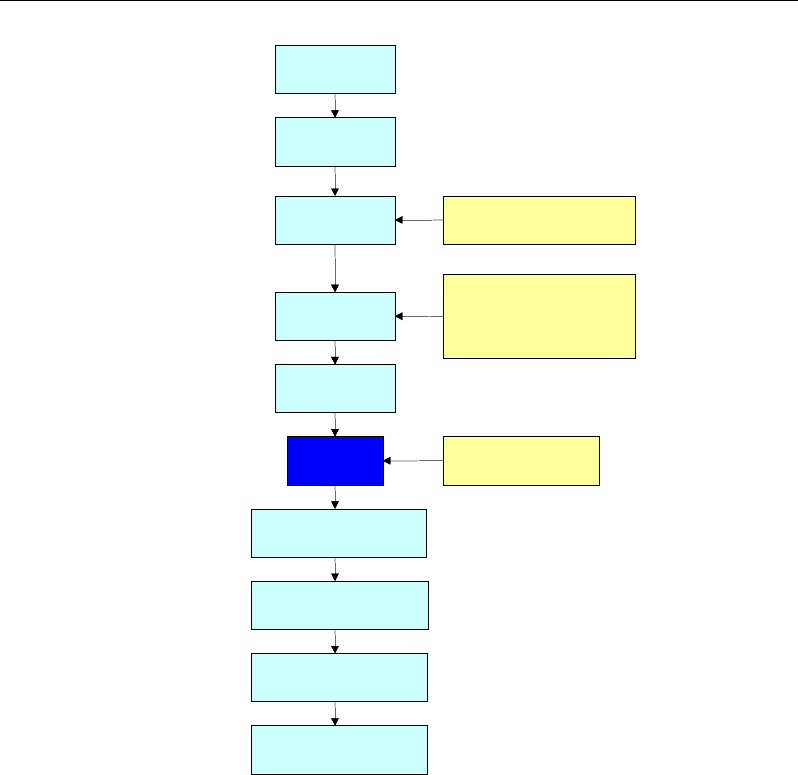
consists of a specific number of strands. Figure 1-1 provides a schematic of the
aspects involved in including post-tensioning, from material definition through
to detailed output.
Overview 1 - 1
Post-Tensioned Concrete Design
Figure 1-1 Schematic of post-tensioning system and process
Specific analysis and design procedures used in ETABS are intended to comply
with the relevant design codes, as presented in Part II of this manual.
1.3 Definition of Terms
Terms used in this manual, within the context of prestressed concrete, are as
follows:
Tendon
Materials
Tendon
Properties
Loss Calculation
Parameters
Tendon
Objects
Draw Tendons
Edit Tendons
Auto Tendon Layout
Forces due to
Tendons
Analysis Other
loads and options
Serviceability Design
Output
Strength Design Output
Detailing Output
Tendon Load
(Jacking force)
Strength and Capacity
Design
Tendon
Materials
Tendon
Properties
Loss Calculation
Parameters
Tendon
Objects
Draw Tendons
Edit Tendons
Auto Tendon Layout
Forces due to
Tendons
Analysis Other
loads and options
Serviceability Design
Output
Strength Design Output
Detailing Output
Tendon Load
(Jacking force)
Strength and Capacity
Design
1 - 2 Definition of Terms

Chapter 1 - Introduction
Prestressed Concrete - This term refers to concrete that has been pre-com-
pressed, often before application of other loads, and in this manual refers to post-
tensioning only.
Post-Tensioning - A procedure in which the steel tendons are tensioned after
the concrete has been cast.
Tendon Object - Consists of a number of high-strength steel wires or strands
enveloped by a duct, placed anywhere in the slab.
Post-Tensioning Loads - The forces that the tendon exerts on the structure. This
includes both the vertical loads due to tendon profile and end forces due to an-
chorage of the tendon. The force due to friction loss is uniformly distributed
along the length of the tendon.
Self Weight - Weight of the structure due to gravity, computed automatically by
ETABS from object dimensions and specified density of materials.
1.4 Analysis and Design Procedure
After a ETABS model has been completed and all of the material property and
section property definitions, model geometry (including tendon layouts, profiles,
and jacking force assignments), member assignments, and loading criteria have
been specified, an analysis is ready to be performed.
During the analysis phase, ETABS will calculate reactions, member displace-
ments, slab forces, and slab stresses for all specified load patterns and combina-
tions. ETABS then performs a design in accordance with the specified design
code and calculates the required amount of mild steel reinforcement and carries
out the appropriate punching shear checks.
ETABS automates several slab and mat design tasks. Specifically, it integrates
slab design moments across design strips and designs the required reinforcement,
and it checks slab punching shear around column supports and concentrated
loads. The actual design algorithms vary based on the specific design code cho-
sen by the user. Part II of this manual describes the algorithms used for the var-
ious codes.
Analysis and Design Procedure 1- 3

Post-Tensioned Concrete Design
It should be noted that the design of post-tensioned reinforced concrete slabs is
a complex subject and the design codes cover many aspects of this process.
ETABS is a tool to help the user in this process. Only the aspects of design doc-
umented in this manual are automated by ETABS design capabilities. The user
must check the results produced and address other aspects not covered by
ETABS.
1 - 4 Analysis and Design Procedure

Chapter 2
The Tendon Object in ETABS
2.1 Overview
Tendons are a special type of object that can be embedded in concrete elements
to represent the effect of post-tensioning. These tendon objects pass through slab
objects, attach to them, and impose loads upon them. The tendons are modeled
as independent elements.
Any number of tendons may be defined. Each tendon is drawn or defined as a
type of line object between two joints, i and j. The two joints must not share the
same location in space. The two ends of the tendon are denoted end I and end J,
respectively. The tendon may have an arbitrary curved or segmented shape in
three dimensions between those points.
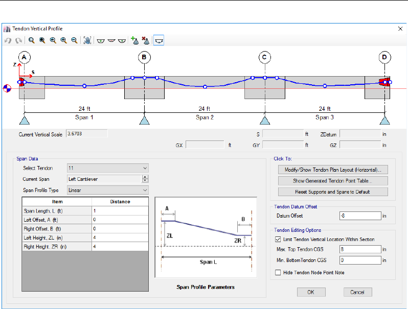
2.2 Tendon Geometry
The vertical profile of a tendon can be defined or modified using the form shown
in Figure 2-1.
Overview 2 - 1
Post-Tensioned Concrete Design
Figure 2-1 Tendon Vertical Profile form, use to define or modify the tendon profile
If a vertical profile is not specified, ETABS will provide a default profile using
the maximum drapes allowed by the clearance conditions specified for the slab
top and bottom. The automated tendon layout capabilities also automate the ten-
don profile, as described in Chapter 5.
2.3 Tendon Discretization
A tendon may be a long object with complicated geometry, but internally, it will
be discretized automatically into shorter segments for the purposes of analysis.
The maximum length of these discretization segments is specified as the maxi-
mum mesh size using the Analyze menu > Automatic Mesh Settings for
Floors command. These lengths can affect how the tendons load the structure
and the accuracy of the analysis results. It is recommended that shorter lengths
be used for tendons with highly curved geometry or for tendons that pass through
2 - 2 Tendon Discretization
Chapter 2 - The Tendon Object in ETABS
parts of the structure with complicated geometry or changes in properties. If un-
sure what value to use, try several different lengths to evaluate the effect on the
results.
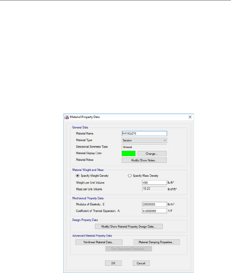
2.4 Tendon Material Property
The material properties for tendons are defined in terms of the weight density,
modulus of elasticity (E), minimum yield stress (f
y
), and minimum tensile stress
(f
u
). Use the Define menu > Materials command, Add New Material button,
and the form shown in Figure 2-2 to specify the tendon material properties. Mul-
tiple properties can be specified if necessary.
Figure 2-2 Material Property Data form
Tendon Material Property 2 - 3
Post-Tensioned Concrete Design
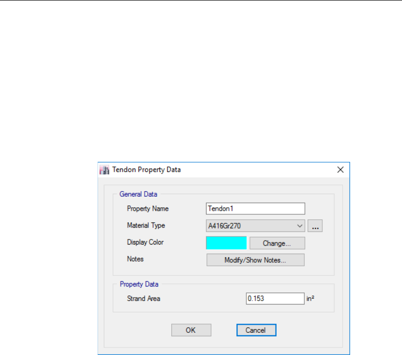
2.5 Tendon Property
The tendon property contains the strand area and tendon material type. Since
tendons can represent single or multiple strands, the area of only a single strand
should be specified in the Tendon Property Data form, shown in Figure 2-3,
which is accessed using the Define menu > Tendon Properties command and
the Add Property button. The number of strands is specified when assigning
tendon properties or editing a tendon (refer to the respective Assign or Edit menu
command).
Figure 2-3 Tendon Property Data form
2.6 Tendon Loads
After the tendons have been added to the ETABS model, tendon loads can be
specified. Loads can be assigned to a single tendon or multiple tendons by first
selecting the tendons to be loaded, selecting the Assign menu > Tendon Loads
> Tendon Loads command, and then modifying the data in the form shown in
Figure 2-4.
2 - 4 Tendon Property
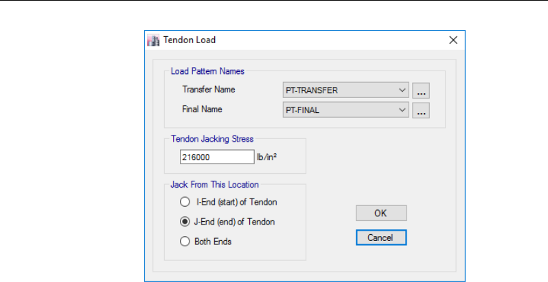
Chapter 2 - The Tendon Object in ETABS
Figure 2-4 Tendon Load form
The load pattern names, jacking locations, and tendon jacking stress are defined
in this form. The tendon load (jacking stress) is the total load applied to one or
both ends of the tendon. The actual tendon force will vary along the length of
the tendon as governed by the frictional and other loss parameters.
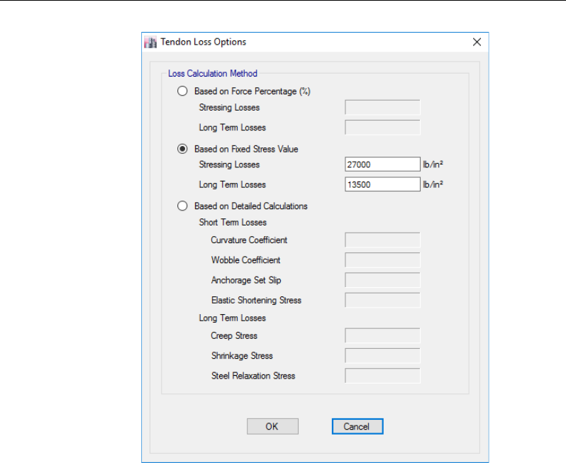
Tendon losses can be assigned to a single tendon or multiple tendons by first
selecting the tendons, selecting the Assign menu > Tendon Loads > Tendon
Losses command and then modifying the data in the form shown in Figure 2-5.
Tendon Loads 2 - 5
Post-Tensioned Concrete Design
Figure 2-5 Tendon Losses form
2 - 6 Tendon Loads

Chapter 3
Computing Prestress Losses
3.1 Overview
The tendon load for a given load case refers to the user-defined jacking force.
The actual load that is applied to slabs will be less than the jacking force because
of prestress losses. The prestress losses are categorized in ETABS into short-
term losses and long-term losses, as follows:
Short-term or Stressing losses - These are losses that occur during and immedi-
ately after the post-tensioning operations and are caused by friction between the
tendons and the duct, elastic shortening, and seating of anchors.
Long-term losses - These types of losses happen over time and also may be re-
ferred to as time-dependent losses and include creep, shrinkage, and steel relax-
ation.
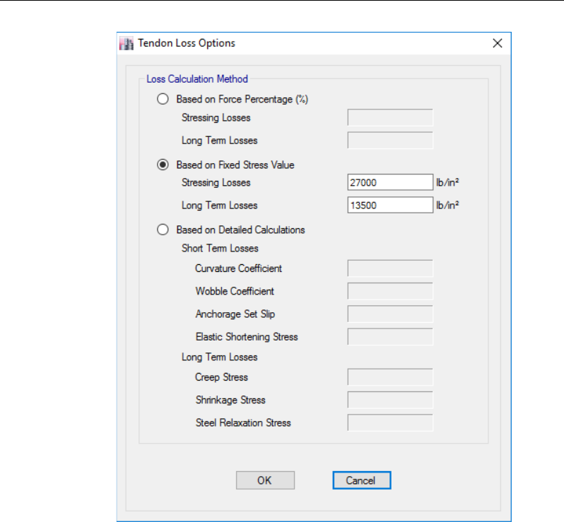
Using the Assign menu > Tendon Loads > Tendon Losses command displays
the form shown in Figure 3-1 and allows the prestress losses to be specified using
one of three methods.
Overview 3 - 1
Post-Tensioned Concrete Design
Figure 3-1 Tendon Load form
The first two Loss Calculation Methods on the form can be used to specify the
prestress losses as a force percentage or fixed stress value for the Stressing
Losses and Long-Term Losses. The third option allows a more detailed calcula-
tion of the prestress losses based on a number of input values for both Short-
Term and Long-Term Losses. Frictional losses are computed internally and ex-
plicitly by ETABS based on the specified wobble and curvature coefficients. All
other losses are directly input on this form.
Other factors, such as changes in temperature and flexing of the structure under
loading, do not significantly lower the prestress level and are not considered ex-
plicitly.
3 - 2 Overview
Chapter 3 - Computing Prestress Losses
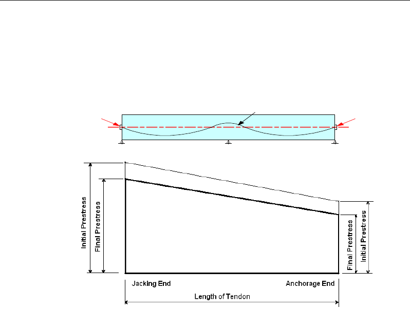
Understanding the stress distribution along the length of a member with respect
to short-term or long-term effects is important for correctly analyzing the model
and interpreting the results. The prestress losses are evident in terms of the stress
distribution along the length, as shown in Figure 3-2. The actual variation in
stress varies exponentially in accordance with Eqn 3.1 in the following section.
Figure 3-2 Prestress load variation along tendon length
The jacking stress is commonly specified as 0.80f
pu
, where f
pu
is the specified
ultimate strength of the strand. Figure 3-2 shows a representation of the tendon
force variation with the tendon jacked from the left end. If the tendon were to be
jacked from the right end, Figure 3-2 would be reversed. If the tendon were
jacked from both ends, the maximum initial prestress force (jacking force) would
exist at each end and would vary to a minimum value midway along the length
of the tendon. The initial prestress forces are reduced to the final prestress forces
in accordance with the long-term losses specified and shown diagrammatically
as the Final Prestress in Figure 3-2.
cgc line
TENDON
PP
Overview 3 - 3
Post-Tensioned Concrete Design
3.2 Computation of Short-Term Losses
3.2.1 Stress Loss Due to Friction (Curvature and Wobble)
When "Based on Detailed Calculations" is the Loss Calculation Method selected,
the frictional losses are calculated using the curvature and wobble coefficients
specified by the user. The frictional loss due to curvature is calculated in ETABS
as:
0( Kx)
(X)
P Pe ,
µα
−+
=
where (Eqn. 3.1)
µ
= curvature friction coefficient
α
= sum of the tendon angular change from the tendon jacking end to
a distance x
K = wobble friction coefficient (rad/unit length2 )
P(X) = Post-tensioning force at a distance x
P0 = Post-tensioning force at stressing
The post-tensioning losses due to friction result in a force distribution along the
length of the tendon that is exponentially decreasing from the jacking point.
In the empirical coefficient, K is the cumulative effect of the rigidity of the
sheathing, the diameter of the sheathing, the spacing of the sheath supports (Fig-
ure 3-3), the tendon type, and the sheath type, including the form of construction.
Figure 3-3 Wobble friction loss
a = intended angle change
intended profile
Sheath supports
Actual profile due
to wobbling
3 - 4 Computation of Short-Term Losses
Chapter 3 - Computing Prestress Losses
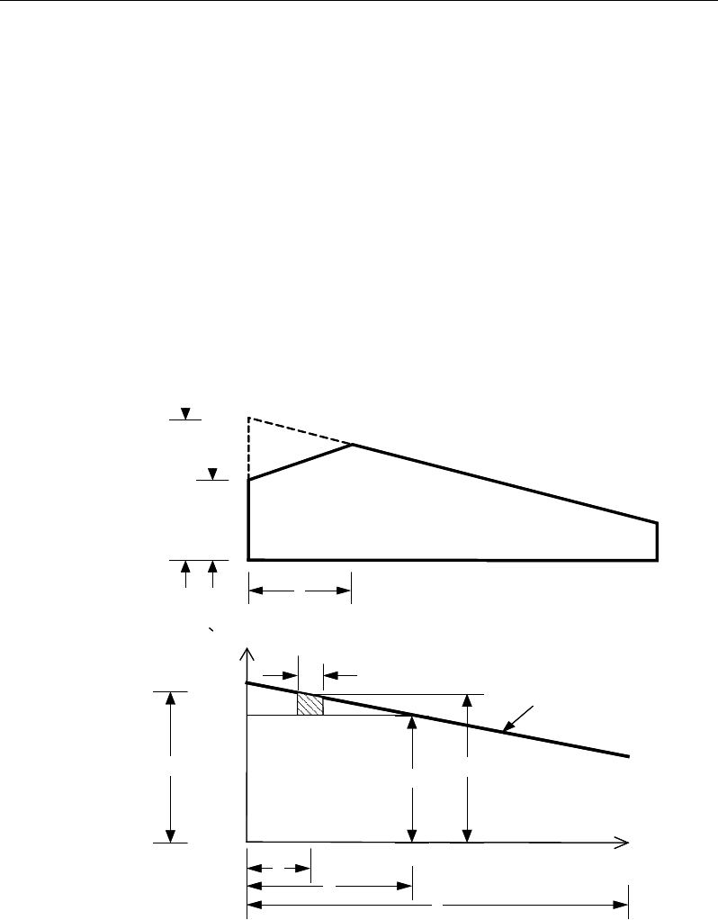
3.2.2 Anchorage Set Slip Losses
At the last stage of the stressing operation, the tendons usually are anchored with
two-piece conical wedges. Anchoring operations normally result in an additional
prestress loss due to seating of the wedges, considering that the strand retracts
when it is released and pulls the wedges into the anchoring device.
Calculation of the stress losses is typically performed in an iterative manner. As
shown in Figure 3-4, the distance “c” refers to the extent of influence of an an-
chor set. Procedurally, anchor set is chosen first (usually about 0.25 to 0.375 in
or 6 to 8 mm), then the distance “c” is set, and finally the corresponding stress is
computed, with the assumption that the stresses vary linearly from the jacking
point.
Figure 3-4 Anchor set influence distance diagram
Jacking Force, Pj
Lock off Force
c
x
Pj
a
c
Pa Px
dx
Force
Anchor Set of Influence
Tendon
Force
Jacking Force, Pj
Lock off Force
c
x
Pj
a
c
Pa Px
dx
Force
Anchor Set of Influence
Tendon
Force
Computation of Short-Term Losses 3 - 5

Post-Tensioned Concrete Design
The seating loss is then calculated using the following equation:
()
jx
s
dx
SL a E
σ −σ
≈=
∫
(Eqn. 3.2)
The iteration process stops when the calculated seating loss is almost equal to
the anchor set “a”; then the maximum stress is calculated, as follows:
)(
max xjj
σσσσ
−−=
(Eqn. 3.3)
Further, the elongation shall be calculated as follows:
s
ax
aAE
dxPP
∫−
=∆ )(
(Eqn. 3.4)
where Δ
a
is the elongation associated with the assumed anchor set distance “a”;
P
x
is the tendon force at a distance x from the jacking point; P
a
is the force in
the tendon under jacking stress at the assumed anchor set distance “a”; dx is the
length of the elements along the tendon; A is the cross-sectional area of the ten-
don; and E
s
is the modulus of elasticity of the tendon material.
3.2.3 Elastic Shortening of Concrete
Elastic shortening refers to the shortening of the concrete as the post-tensioning
force is applied. As the concrete shortens, the tendon length also shortens,
resulting in a loss of prestress. If sequential jacking steps are used, the first ten-
don jacked and locked off will suffer the maximum amount of loss from elastic
shortening. Conversely, there will be no loss because of elastic shortening for
the last tendon in a sequence or in a single tendon because the elastic shortening
will take place before the tendon is locked into the anchoring device. The user-
specified amount of prestress loss from elastic shortening is applied uniformly
over the entire length of the tendon.
3.3 Computation of Long-Term Losses
The long-term prestress losses of a member include creep, shrinkage, and steel
relaxation effects.
3 - 6 Computation of Long-Term Losses

Chapter 3 - Computing Prestress Losses
Several methods can be used to determine the long-term stress losses; however,
ETABS relies on the user-defined values input in the Tendon Losses form shown
in Figure 3-1. Lump sum values input into ETABS should reflect the appropriate
conditions that exist for the structure being modeled. Creep, shrinkage, and steel
relaxation effects are governed by material properties and, in some cases, other
environmental conditions that need to be accounted for when specifying the
long-term loss values. Each stress loss is treated separately and then summed up,
as follows:
TL = CR + SH + RE (Eqn. 3.7)
where TL is the total loss of stress; CR is the stress loss due to creep of the
concrete; SH is the stress loss due to shrinkage of the concrete; and RE is the
stress loss due to relaxation in the tendon steel. The sum of these losses is applied
to the initial (jacking) load of the tendon, as represented in Figure 3-2. All of the
long-term losses are uniformly applied over the length of the tendon.
Computation of Long-Term Losses 3 - 7

Chapter 4
Loads Due to Post-Tensioning
4.1 Overview
ETABS does not rely on an approximate ‘equivalent loading’ method for calcu-
lating member responses subjected to post-tensioning loads. Instead, ETABS
uses a finite element method that includes the tendon effects as a load. When a
parabolic drape is specified for the tendon, ETABS performs a numerical inte-
gration across the finite element using the actual parabolic shape function that
defines the tendon’s geometry. This approach is considered to be more accurate,
especially when deeper members are being considered.
One of the consequences of applying a post-tensioning load to a member is the
introduction of secondary (hyperstatic) forces. These effects and load cases are
discussed in this chapter.
ETABS uses the dead load balancing method as the primary procedure for the
determination of tendon profiles when they are requested to be automated (see
Chapter 5). This chapter also provides information regarding the approach used
to perform a load balanced design.
Overview 4 - 1
Post-Tensioned Concrete Design
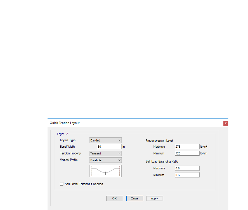
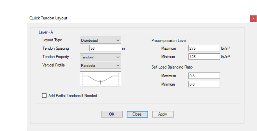
4.2 Dead Load-Balancing
The dead load balancing method is used in ETABS to determine an initial tendon
layout (including the profile, number of strands, and the jacking force) when the
automated tendon layout feature is used. The basic concept of dead load balanc-
ing is that the prestress bending stresses,
f Pe / S,=
are equal but opposite to
the applied dead load bending stresses,
f Mc / I.=
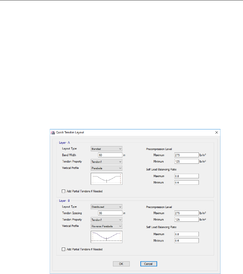
When the Self Load Balanc-
ing Ratio and the Precompression Level in the Quick Tendon Layout form,
shown in Figure 4-1, are specified, ETABS iterates the position of the tendon as
necessary to find the eccentricity, e, that balances the specified dead load
stresses.
Figure 4-1 Quick Tendon Layout form
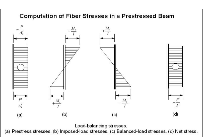
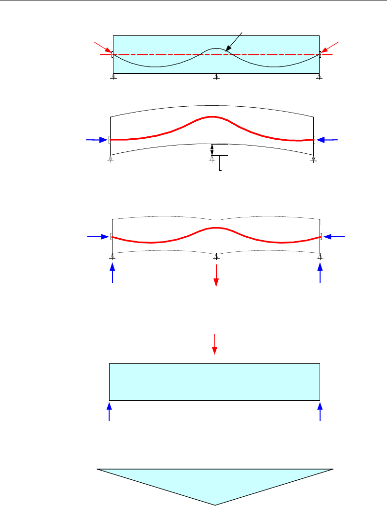
The stress diagrams in Figure 4-2 illustrate the dead load balancing concept. The
specified precompression limit stress is applied first, (a). Then the dead load
stresses are computed, (b), followed by iterating the tendon location to balance
the dead load stresses, (c), that finally results in the precompression state shown
in (d).
The final stress distribution is the result of this precompression stress combined
with the stresses resulting from the application of all remaining loads and design
combinations. If the final stress distribution contains tension stresses that exceed
the design allowable limit, ETABS calculates the required amount of mild steel
reinforcement. Chapter 5 details the steps used by ETABS in the automation of
the tendon layout.
4 - 2 Dead Load-Balancing
Chapter 4 - Loads Due to Post-Tensioning
Figure 4-2 Precompression and Load Balancing Stresses
4.3 Primary Moments
If a section cut is made of a uniformly loaded beam, the actions at the cut sections
will include the concentric force P
x
, a primary moment M
p
, and a shear V
x
. The
primary moment at this section is necessary to maintain equilibrium of the load-
ing, which can be expressed as:
∫+= aPxwdxM
Lp
)(
(Eqn. 4.1)
where, w, is the intensity of loading at a distance “x,” P
L
is the vertical compo-
nent of tendon force at the left anchorage, and a is the distance to the cut section
measured from the left anchorage.
Similarly, a free-body diagram of the tendon would show the concentric force
P
x
and a shear V
x
at the cut sections, along with the loading “w.” In the same
manner, the force P
x
taking moments about the CGC line from an eccentricity
Primary Moments 4 - 3

Post-Tensioned Concrete Design
e’ or the distance from the tendon’s centroid to the neutral axis of the member
yields:
∫
+= aPxwdxeP Lx )('
(Eqn. 4.2)
The right-hand sides of Eqns. 4.1 and 4.2 are identical, therefore the primary
moment can be defined as:
'ePM xp =
(Eqn. 4.3)
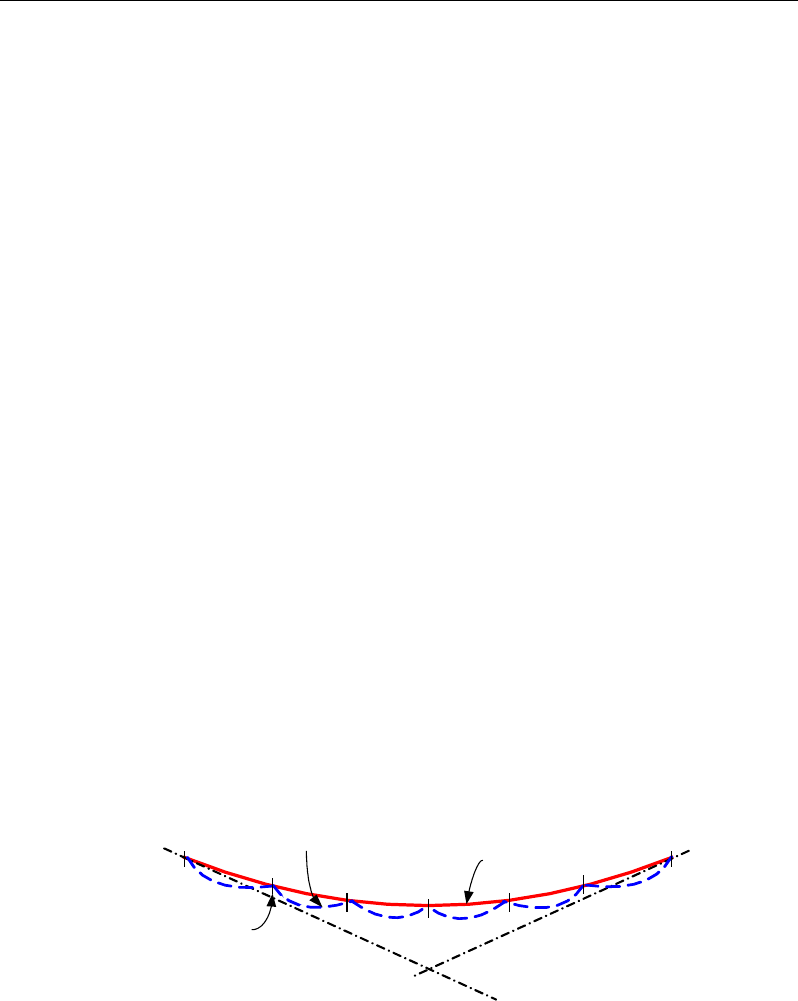
4.4 Secondary (Hyperstatic) Moments
The reactions caused by the post-tensioning forces in continuous slabs or beams
are often referred to as secondary (hyperstatic) reactions. The two-span beam
shown in Figure 4-3 illustrates the reactions and moments because of the eccen-
tric post-tensioning forces.
If the center support is eliminated for the two-span beam shown in Figure 4-3,
the application of the post-tensioning would result in a beam upward displace-
ment of
∆
. The application of the force necessary to displace the beam by the
amount,
−∆
, can be represented as, R
i
. From Figure 4-3 (d) and (e), the hyper-
static reactions in the amount Ri/2 are produced at each end of the beam and the
hyperstatic moment M is produced over the center support. At any section along
the beam, the hyperstatic reactions induce a hyperstatic moment Mhyp and a hy-
perstatic shear Vhyp.
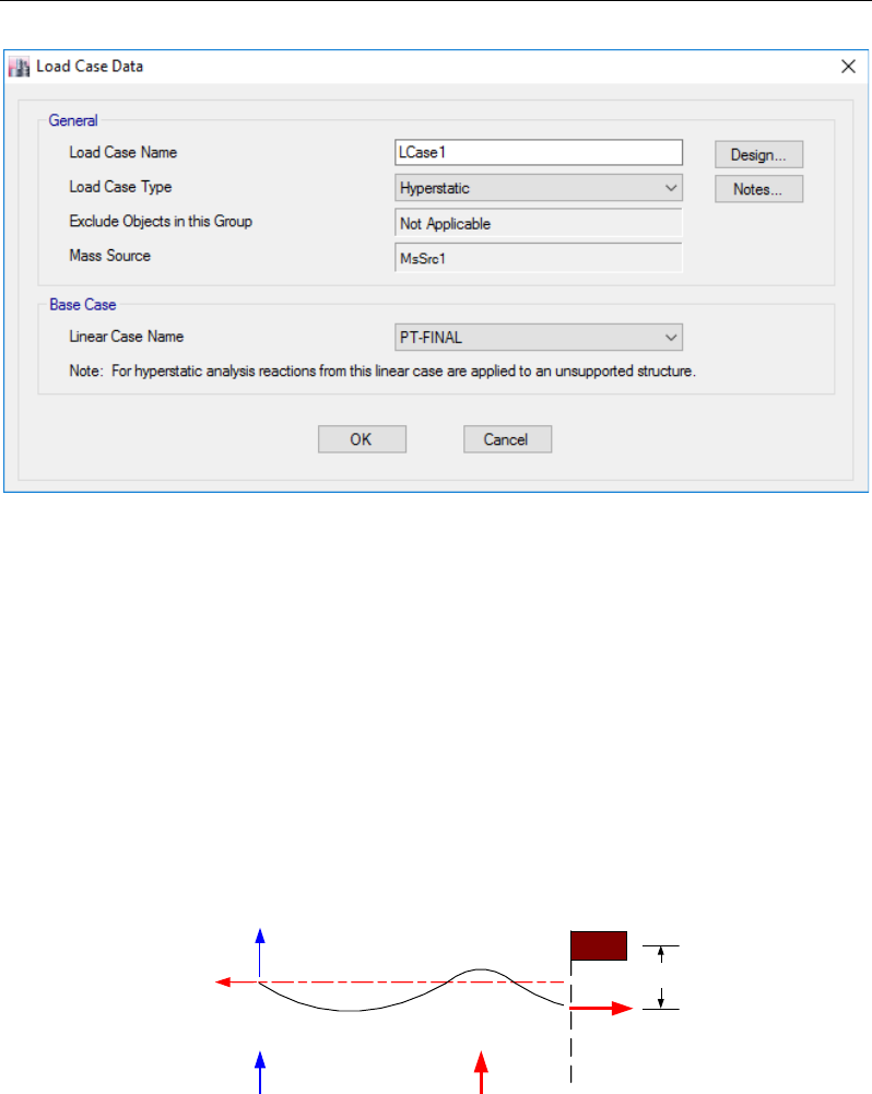
Hyperstatic analysis results can be reviewed by defining a hyperstatic load case
using the Define menu > Load Cases command to add a new load case with a
hyperstatic Load Case Type, as shown in Figure 4-4.
4 - 4 Secondary (Hyperstatic) Moments
Chapter 4 - Loads Due to Post-Tensioning
(a) Two-span post-tensioned beam
(b) Tendon forces cause the beam to lift off the center support
with a deflection Δ upward
(c) Additional hyperstatic reactions develop at the ends due to application of the force,
Ri, which is needed to prevent the beam from lifting off the support
(d) Secondary (hyperstatic) reaction Ri in a theoretical,
simply supported beam
(e) Secondary (hyperstatic) moment diagram due to Ri
Figure 4-3 Secondary (hyperstatic) actions due to post-tensioning
cgc line
TENDON
PP
∆
P
x
P
x
∆
P
x
P
x
R
i
R
i
/2 R
i
/2
P
x
P
x
R
i
R
i
/2 R
i
/2
Secondary (Hyperstatic) Moments 4 - 5
Post-Tensioned Concrete Design
Figure 4-4 Hyperstatic Load Case Data form
In the design process, the secondary moment is assumed to be resisted through
a compression block and a tensile force such that:
TC =
(Eqn. 4.4)
CzTzM==
sec
(Eqn. 4.7)
where C is the total compression force, T is the combined tension force due to
post-tensioning tendons and mild reinforcement, and Z is the lever arm of the
section, as illustrated in Figure 4-5.
Figure 4-5 Section actions due to post-tensioning and
internal distribution of hyperstatic forces
T
P
L
P
x
Concrete Compression
Ri
R
C
Tendon Force
Z
4 - 6 Secondary (Hyperstatic) Moments

Chapter 4 - Loads Due to Post-Tensioning
Thus, the combination of forces stipulated in most design codes for gravity con-
ditions simply considers the addition of the hyperstatic effect to the combinations
used for non-prestressed concrete.
Secondary (Hyperstatic) Moments 4 - 7

Chapter 5
Automated Tendon Layout
5.1 Overview
In the past, the analysis and design of post-tensioned floor slabs has been diffi-
cult because of the high degree of indeterminacy of the structure, large number
of design requirements, and the need to provide an economical design. Some
analysis programs rely on simplified approximations in the analysis and the de-
sign. ETABS eliminates the need for engineers to oversimplify an analysis
model and provides the tools to automate the tendon layout, profile, and jacking
forces.
This chapter describes the various methods for adding tendons to a ETABS
model and the methodology used to automate the tendon input data. Not all of
the methods used to add tendons to a ETABS model are suited for the automation
as explained herein.
The automation of tendon layout, profiles, and jacking forces serves as a starting
point in the analysis and design process. If it is necessary to make further adjust-
ments to the tendon layout, profiles, or jacking forces, these adjustments should
be made manually. ETABS does not perform any revision to the initial tendon
automations. The parameters related to the tendons can be modified easily, fol-
lowed by re-analyzing and re-designing the structure as necessary.
5 - 1
Post-Tensioned Concrete Design
5.2 Adding Tendons to a ETABS Model
Four methods are available for adding tendons to a ETABS model:
Template modeling – If a ETABS model is initialized using the File menu >
New Model command and the appropriate initial model is selected along with
toggling the Add P/T option, post-tensioning data can be defined. The Quick
Tendon Layout form shown in Figure 5-1 allows specification of the tendon lay-
out for the Layer A and B directions, as well as the precompression levels and
self-load balancing ratios. Tendons with the defined layout parameters are then
included in the template model. This can be a quick and easy method to place a
large number of tendons into a ETABS model. The tendon profiles satisfy the
specified clearances.
Figure 5-1 Quick Tendon Layout form
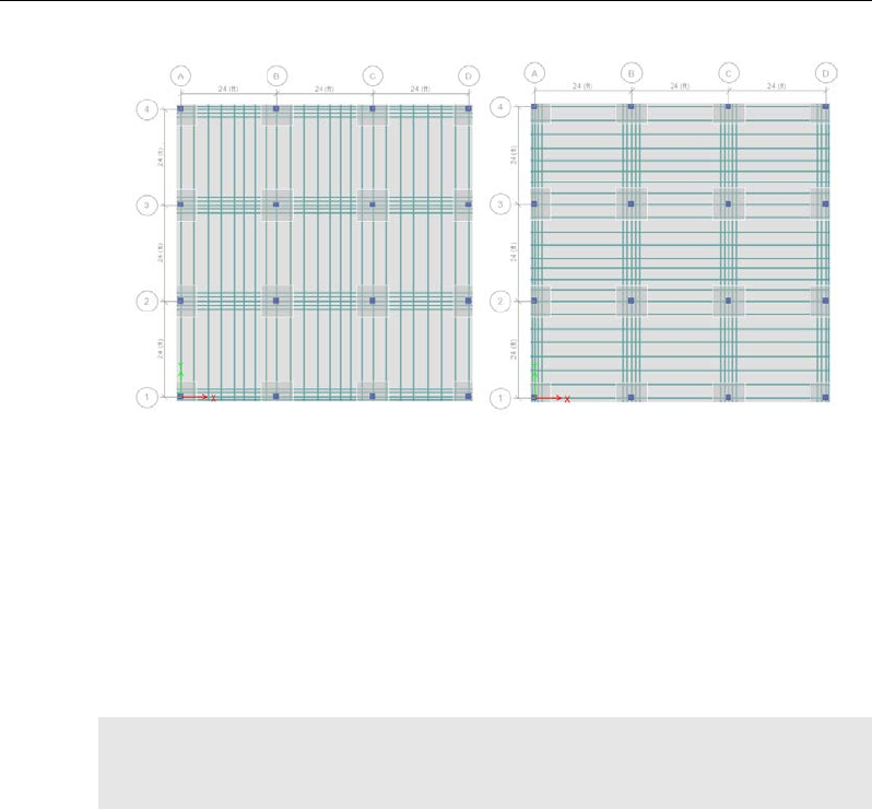
Figure 5-2 shows two of several tendon layout options using banded and uniform
tendon layout types.
5 - 2 Adding Tendons to a ETABS Model
Chapter 5 - Automated Tendon Layout
Figure 5-2 Template models with tendon layout options
Tendon Draw commands – Using the Draw menu > Draw Tendons com-
mand, any number of points can be input to place tendons into a ETABS model.
Default tendon profile data is provided; however, it is expected that it will be
edited to provide the proper tendon profile and other tendon data as required to
satisfy the design requirements. Multiple tendons with the same layout can be
generated easily using the Edit menu > Replicate command. When this option
is used, ETABS replicates the tendon profile of the source tendon.
Note: No automation of the tendon layout, profile, number of strands, or jacking
force is performed by ETABS when the Draw menu > Draw Tendons com-
mand is used to place tendons in a model.
Add Tendons in Strips – The Edit menu > Add/Edit Tendons > Add Tendons
in Strips command can be used to add tendons to an existing ETABS model.
The tendon layouts, profiles, number of strands, and jacking forces are all auto-
mated when tendons are added in this manner, based on the input in the Quick
Tendon Layout form shown in Figure 5-3. The ETABS model can be further
modified by adding additional tendons as necessary.
Adding Tendons to a ETABS Model 5 - 3
Post-Tensioned Concrete Design
Figure 5-3 Quick Tendon Layout form
5.3 Procedures Used in Automated Tendon Layout
The automated tendon layouts (including profiles, number of strands, and jack-
ing forces) are generated based on the design strip definitions. Automated tendon
layouts are developed only on tendons that have been added to design strips.
Each strip is modeled as an equivalent continuous beam with the cross-section
derived from the slab objects lying within the strip width. The self weight loads
are calculated to obtain the load to be used in the load balancing calculation.
Only the loads that are applied within the boundary area of a particular strip are
included in the determination of the automated tendon layout. As an example, if
a column strip is defined as 60 inches wide, only a tributary width of 60 inches
is used to determine the load for use in the self load balancing calculation to
determine the tendon layout.
A representative tendon is placed in the equivalent beam, centered on the
design strip. The supports of the strips are derived from the intersection with
perpendicular design strips and by any column supports within the strip width.
5 - 4 Procedures Used in Automated Tendon Layout

Chapter 5 - Automated Tendon Layout
Note: ETABS does not automatically consider the intersections of strips and
beams to be points of supports for the strips. If it is desired to consider a partic-
ular beam as a support point for a strip, then a strip should be defined at the beam
location.
The support locations are used to determine the spans. For each span, the tendon
profile is automated based on the profile type specified for the tendon (parabola
or reverse parabola). An iterative procedure is then used to determine the effec-
tive jacking force necessary to satisfy the range of dead load to be balanced and
the average precompression stress required. The jacking force is initially calcu-
lated to satisfy the minimum required self load balancing ratio and minimum
precompression level for the longest span in the strip. The tendon profiles in
other spans are then adjusted so as not to exceed the maximum dead load bal-
ancing ratios.
A value of 60 to 80 percent is generally used as the self load balancing ratios.
Typically precompression levels generally range between 0.125 to 0.275 ksi.
Note: It is important to note that it is possible that an automated tendon layout
cannot satisfy the specified dead load balancing ratios and precompression lev-
els. In such cases, ETABS generates a warning so that necessary manual adjust-
ments to the tendon layout and profile can be made, or other modifications to the
ETABS model can be applied where required.
Note: If the addition of partial tendons is active, ETABS may add additional
tendons in long spans or in exterior spans to satisfy the self load balancing and
precompression constraints.
After the total jacking force and profile have been determined for the equivalent
tendon, the actual number and spacing of tendons is determined based on the
following criteria:
For a banded tendon layout, the number of tendons is initially determined based
on the specified Tendon Property (material property and strand area), Precom-
pression Level, and Dead Load Balancing Ratios. The prestress losses are esti-
mated using the Fixed Stress Values from the Tendon Load assignments. If the
number of tendons is too large to fit within the band width with a minimum
spacing of 12 in (300 mm), a larger tendon size is automatically selected by in-
creasing the number of strands. Similarly, if the spacing of the tendons is too
Procedures Used in Automated Tendon Layout 5 - 5

Post-Tensioned Concrete Design
large (greater than 60 in or 1.5 m) or 16 times the slab thickness, a smaller tendon
is selected, with fewer strands.
For a uniform tendon layout, a similar procedure as outlined above for the
banded tendon layout is used.
5 - 6 Procedures Used in Automated Tendon Layout

Chapter 6
Design for ACI 318-08
This chapter describes in detail the various aspects of the post-tensioned concrete
design procedure that is used by ETABS when the user selects the American
code ACI 318-08 [ACI 2008]. Various notations used in this chapter are listed
in Table 6-1. For referencing to the pertinent sections of the ACI code in this
chapter, a prefix “ACI” followed by the section number is used.
The design is based on user-specified load combinations. The program provides
a set of default load combinations that should satisfy the requirements for the
design of most building type structures.
English as well as SI and MKS metric units can be used for input. The code is
based on inch-pound-second units. For simplicity, all equations and descriptions
presented in this chapter correspond to inch-pound-second units unless otherwise
noted.
6.1 Notations
The following table identifies the various notations used in this chapter.
6 - 1

Post-Tensioned Concrete Design
Table 6-1 List of Symbols Used in the ACI 318-08 Code
A
cp
Area enclosed by the outside perimeter of the section, in2
A
g
Gross area of concrete, in2
A
l
Total area of longitudinal reinforcement to resist torsion, in2
A
o
Area enclosed by the shear flow path, sq-in
A
oh
Area enclosed by the centerline of the outermost closed trans-
verse torsional reinforcement, sq-in
A
ps
Area of prestressing steel in flexural tension zone, in2
A
s
Area of tension reinforcement, in2
A'
s
Area of compression reinforcement, in2
A
s(required)
Area of steel required for tension reinforcement, in2
A
t
/s
Area of closed shear reinforcement per unit length of member
for torsion, sq-in/in
A
v
Area of shear reinforcement, in2
A
v
/s
Area of shear reinforcement per unit length of member, in2/in
a
Depth of compression block, in
a
b
Depth of compression block at balanced condition, in
a
max
Maximum allowed depth of compression block, in
b
Width of member, in
b
f
Effective width of flange (T-beam section), in
b
w
Width of web (T-beam section), in
b
0
Perimeter of the punching critical section, in
b
1
Width of the punching critical section in the direction of
bending, in
b
2
Width of the punching critical section perpendicular to the di-
rection of bending, in
c
Depth to neutral axis, in
c
b
Depth to neutral axis at balanced conditions, in
6 - 2 Notations

Chapter 6 - Design for ACI 318-08
Table 6-1 List of Symbols Used in the ACI 318-08 Code
d
Distance from compression face to tension reinforcement, in
d'
Concrete cover to center of reinforcing, in
d
e
Effective depth from compression face to centroid of tension
reinforcement, in
d
s
Thickness of slab (T-beam section), in
d
p
Distance from extreme compression fiber to centroid of pre-
stressing steel, in
E
c
Modulus of elasticity of concrete, psi
E
s
Modulus of elasticity of reinforcement, assumed as
29,000,000 psi (ACI 8.5.2)
f'
c
Specified compressive strength of concrete, psi
f'
ci
Specified compressive strength of concrete at time of initial
prestress, psi
f
pe
Compressive stress in concrete due to effective prestress
forces only (after allowance of all prestress losses), psi
f
ps
Stress in prestressing steel at nominal flexural strength, psi
f
pu
Specified tensile strength of prestressing steel, psi
f
py
Specified yield strength of prestressing steel, psi
f
t
Extreme fiber stress in tension in the precompressed tensile
zone using gross section properties, psi
f
y
Specified yield strength of flexural reinforcement, psi
f
ys
Specified yield strength of shear reinforcement, psi
h
Overall depth of a section, in
h
f
Height of the flange, in
φ
M
n
0
Design moment resistance of a section with tendons only, N-
mm
Notations 6 - 3

Post-Tensioned Concrete Design
Table 6-1 List of Symbols Used in the ACI 318-08 Code
φ
M
n
bal
Design moment resistance of a section with tendons and the
necessary mild reinforcement to reach the balanced condition,
N-mm
M
u
Factored moment at section, lb-in
N
c
Tension force in concrete due to unfactored dead load plus
live load, lb
P
u
Factored axial load at section, lb
s
Spacing of the shear reinforcement along the length of the
beam, in
T
u
Factored torsional moment at section, lb-in
V
c
Shear force resisted by concrete, lb
V
max
Maximum permitted total factored shear force at a section, lb
V
u
Factored shear force at a section, lb
V
s
Shear force resisted by steel, lb
β
1
Factor for obtaining depth of compression block in concrete
β
c
Ratio of the maximum to the minimum dimensions of the
punching critical section
ε
c
Strain in concrete
ε
c, max
Maximum usable compression strain allowed in extreme con-
crete fiber (0.003 in/in)
ε
ps
Strain in prestressing steel
ε
s
Strain in reinforcing steel
ε
s,min
Minimum tensile strain allowed in steel reinforcement at
nominal strength for tension controlled behavior (0.005 in/in)
ϕ
Strength reduction factor
γ
f
Fraction of unbalanced moment transferred by flexure
γ
v
Fraction of unbalanced moment transferred by eccentricity of
shear
6 - 4 Notations

Chapter 6 - Design for ACI 318-08
Table 6-1 List of Symbols Used in the ACI 318-08 Code
λ
Shear strength reduction factor for light-weight concrete
θ
Angle of compression diagonals, degrees
6.2 Design Load Combinations
The design load combinations are the various combinations of the load cases for
which the structure needs to be designed. For ACI 318-08, if a structure is sub-
jected to dead (D), live (L), pattern live (PL), snow (S), wind (W), and earth-
quake (E) loads, and considering that wind and earthquake forces are
reversible, the load combinations in the following sections may need to be con-
sidered (ACI 9.2.1).
For post-tensioned concrete design, the user can specify the prestressing load
(PT) by providing the tendon profile or by using the load balancing options in
the program. The default load combinations for post-tensioning are defined in
the following sections.
6.2.1 Initial Service Load Combination
The following load combination is used for checking the requirements at transfer
of prestress forces, in accordance with ACI 318-08 clause 18.4.1. The prestress-
ing forces are considered without any long-term loses for the initial service load
combination check.
1.0D + 1.0PT
(ACI 18.4.1)
6.2.2 Service Load Combination
The following load combinations are used for checking the requirements of pre-
stress for serviceability in accordance with ACI 318-08 clauses 18.3.3, 18.4.2(b),
and 18.9.3.2. It is assumed that all long-term losses have already occurred at the
service stage.
1.0D + 1.0PT
1.0D + 1.0L + 1.0PT (ACI 18.4.2(b)
)
Design Load Combinations 6 - 5

Post-Tensioned Concrete Design
6.2.3 Long-Term Service Load Combination
The following load combinations are used for checking the requirements of pre-
stress in accordance with ACI 318-08 clause 18.4.2(a). The permanent load for
this load combination is taken as 50 percent of the live load. It is assumed that
all long-term losses have already occurred at the service stage.
1.0D + 1.0PT
1.0D + 0.5L + 1.0PT
(ACI 18.4.2(b)
)
6.2.4 Strength Design Load Combination
The following load combinations are used for checking the requirements of pre-
stress for strength in accordance with ACI 318-08, Chapters 9 and 18.
The strength design combinations required for punching shear require the full
PT forces (primary and secondary). Flexural design requires only the hyperstatic
(secondary) forces. The hyperstatic (secondary) forces are automatically deter-
mined by ETABS by subtracting out the primary PT moments when the flexural
design is carried out.
1.4D + 1.0PT*
(ACI 9.2.1)
1.2D + 1.6L + 1.0PT*
(ACI 9.2.1)
1.2D + 1.6(0.75 PL) + 1.0PT*
(ACI 9.2.1, 13.7.6.3)
0.9D ± 1.6W +1.0PT*
1.2D + 1.0L
± 1.6W + 1.0PT*
(ACI 9.2.1)
0.9D ± 1.0E + 1.0PT*
1.2D + 1.0L
± 1.0E + 1.0PT*
(ACI 9.2.1)
1.2D + 1.6L + 0.5S + 1.0PT*
1.2D +
1.0L + 1.6S + 1.0PT*
(ACI 9.2.1)
1.2D + 1.6S ± 0.8W + 1.0PT*
1.2D + 1.0L + 0.5S
± 1.6W + 1.0PT*
(ACI 9.2.1)
1.2D + 1.0L + 0.2S ± 1.0E + 1.0PT*
(ACI 9.2.1)
* — Replace PT by H for flexural design only
6 - 6 Design Load Combinations

Chapter 6 - Design for ACI 318-08
The IBC 2006 basic load combinations (Section 1605.2.1) are the same. These
also are the default design load combinations in ETABS whenever the ACI 318-
08 code is used. The user should use other appropriate load combinations if roof
live load is treated separately, or if other types of loads are present.
6.3 Limits on Material Strength
The concrete compressive strength, f'c, should not be less than 2500 psi (ACI
5.1.1). The upper limit of the reinforcement yield strength, fy, is taken as 80 ksi
(ACI 9.4) and the upper limit of the reinforcement shear strength, fyt, is taken as
60 ksi (ACI 11.5.2).
ETABS enforces the upper material strength limits for flexure and shear design
of slabs. The input material strengths are taken as the upper limits if they are
defined in the material properties as being greater than the limits. The user is
responsible for ensuring that the minimum strength is satisfied.
6.4 Strength Reduction Factors
The strength reduction factors,
φ
, are applied on the specified strength to obtain
the design strength provided by a member. The
φ
factors for flexure, shear, and
torsion are as follows:
φ
t = 0.90 for flexure (tension controlled) (ACI 9.3.2.1)
φ
c = 0.65 for flexure (compression controlled) (ACI 9.3.2.2(b))
φ
= 0.75 for shear and torsion. (ACI 9.3.2.3)
The value of
φ
varies from compression-controlled to tension-controlled based
on the maximum tensile strain in the reinforcement at the extreme edge,
ε
t
(ACI 9.3.2.2).
Sections are considered compression-controlled when the tensile strain in the
extreme tension reinforcement is equal to or less than the compression-con-
trolled strain limit at the time the concrete in compression reaches its assumed
strain limit of
ε
c.max, which is 0.003. The compression-controlled strain limit is
Limits on Material Strength 6 - 7

Post-Tensioned Concrete Design
the tensile strain in the reinforcement at the balanced strain condition, which is
taken as the yield strain of the reinforcement, (fy/E) (ACI 10.3.3).
Sections are tension-controlled when the tensile strain in the extreme tension
reinforcement is equal to or greater than 0.005, just as the concrete in compres-
sion reaches its assumed strain limit of 0.003 (ACI 10.3.4).
Sections with
ε
t between the two limits are considered to be in a transition region
between compression-controlled and tension-controlled sections (ACI 10.3.4).
When the section is tension-controlled,
φ
t is used. When the section is compres-
sion-controlled,
φ
c is used. When the section is in the transition region,
φ
is lin-
early interpolated between the two values (ACI 9.3.2).
The user is allowed to overwrite these values. However, caution is advised.
6.5 Design Assumptions for Prestressed Concrete
Strength design of prestressed members for flexure and axial loads shall be based
on assumptions given in ACI 10.2.
The strain in the reinforcement and concrete shall be assumed directly propor-
tional to the distance from the neutral axis (ACI 10.2.2).
The maximum usable strain at the extreme concrete compression fiber shall
be assumed equal to 0.003 (ACI 10.2.3).
The tensile strength of the concrete shall be neglected in axial and flexural
calculations (ACI 10.2.5).
The relationship between the concrete compressive stress distribution and the
concrete strain shall be assumed to be rectangular by an equivalent rectangular
concrete stress distribution (ACI 10.2.7).
The concrete stress of 0.85f'c shall be assumed uniformly distributed over an
equivalent-compression zone bounded by edges of the cross-section and a
straight line located parallel to the neutral axis at a distance a =
β
1c from the
fiber of maximum compressive strain (ACI 10.2.7.1).
6 - 8 Design Assumptions for Prestressed Concrete
Chapter 6 - Design for ACI 318-08
The distance from the fiber of maximum strain to the neutral axis, c shall be
measured in a direction perpendicular to the neutral axis (ACI 10.2.7.2).
Elastic theory shall be used with the following two assumptions:
The strains shall vary linearly with depth through the entire load range (ACI
18.3.2.1).
At cracked sections, the concrete resists no tension (ACI 18.3.2.1).
Prestressed concrete members are investigated at the following three stages (ACI
18.3.2):
At transfer of prestress force
At service loading
At nominal strength
The prestressed flexural members are classified as Class U (uncracked), Class T
(transition), and Class C (cracked) based on ft, the computed extreme fiber stress
in tension in the precompressed tensile zone at service loads (ACI 18.3.3).
The precompressed tensile zone is that portion of a prestressed member where
flexural tension, calculated using gross section properties, would occur under
unfactored dead and live loads if the prestress force was not present. Prestressed
concrete is usually designed so that the prestress force introduces compression
into this zone, thus effectively reducing the magnitude of the tensile stress.
For Class U and Class T flexural members, stresses at service load are deter-
mined using uncracked section properties, while for Class C flexural members,
stresses at service load are calculated based on the cracked section (ACI 18.3.4).
A prestressed two-way slab system is designed as Class U only with
ct f
f'6≤
(ACI R18.3.3); otherwise, an over-stressed (O/S) condition is re-
ported.
The following table provides a summary of the conditions considered for the
various section classes.
Prestressed
Design Assumptions for Prestressed Concrete 6 - 9
Post-Tensioned Concrete Design
Class U Class T Class C Nonprestressed
Assumed behavior Uncracked Transition between
uncracked and cracked Cracked Cracked
Section properties for stress
calculation at service loads Gross section
18.3.4 Gross section
18.3.4 Cracked section
18.3.4 No requirement
Allowable stress at transfer 18.4.1 18.4.1 18.4.1 No requirement
Allowable compressive stress based
on uncracked section properties 18.4.2 18.4.2 No requirement No requirement
Tensile stress at service loads
18.3.3
′
≤7.5 c
f
′′
<≤7.5 12
ct c
ff f
No requirement No requirement
6.6 Serviceability Requirements of Flexural Members
6.6.1 Serviceability Check at Initial Service Load
The stresses in the concrete immediately after prestress force transfer (before
time dependent prestress losses) are checked against the following limits:
Extreme fiber stress in compression:
0.60
'
ci
f
(ACI 18.4.1(a))
Extreme fiber stress in tension:
3
'
ci
f
(ACI 18.4.1(b))
Extreme fiber stress in tension at ends of
simply supported members:
6
'
ci
f
(ACI 18.4.1(c))
The extreme fiber stress in tension at the ends of simply supported members is
currently NOT checked by ETABS.
6.6.2 Serviceability Checks at Service Load
The stresses in the concrete for Class U and Class T prestressed flexural mem-
bers at service loads, and after all prestress losses occur, are checked against the
following limits:
Extreme fiber stress in compression due
to prestress plus total load:
0.60 '
c
f
(ACI 18.4.2(b))
Extreme fiber stress in tension in the precompressed tensile zone at service
loads:
6 - 10 Serviceability Requirements of Flexural Members
Chapter 6 - Design for ACI 318-08
– Class U beams and one-way slabs:
c
tff '
5.
7≤
(ACI 18.3.3)
– Class U two-way slabs:
ct ff '6≤
(ACI 18.3.3)
– Class T beams:
ctc
fff '12'5.
7≤<
(ACI 18.3.3)
– Class C beams:
c
tff '
12≥
(ACI 18.3.3)
For Class C prestressed flexural members, checks at service loads are not re-
quired by the code. However, for Class C prestressed flexural members not sub-
ject to fatigue or to aggressive exposure, the spacing of bonded reinforcement
nearest the extreme tension face shall not exceed that given by ACI 10.6.4 (ACI
18.4.4). It is assumed that the user has checked the requirements of ACI 10.6.4
and ACI 18.4.4.1 to 18.4.4 independently, as these sections are not checked by
the program.
6.6.3 Serviceability Checks at Long-Term Service Load
The stresses in the concrete for Class U and Class T prestressed flexural mem-
bers at long-term service loads, and after all prestress losses occur, are checked
against the same limits as for the normal service load, except for the following:
Extreme fiber stress in compression due to prestress plus total load:
0.45
'
c
f
(ACI 18.4.2(a))
6.6.4 Serviceability Checks of Prestressing Steel
The program also performs checks on the tensile stresses in the prestressing steel
(ACI 18.5.1). The permissible tensile stress checks, in all types of prestressing
steel, in terms of the specified minimum tensile stress fpu, and the minimum yield
stress, fy, are summarized as follows:
Due to tendon jacking force: min(0.94fpy, 0.80fpu) (ACI 18.5.1(a))
Immediately after force transfer: min(0.82fpy, 0.74fpu) (ACI 18.5.1(b))
Serviceability Requirements of Flexural Members 6 - 11

Post-Tensioned Concrete Design
At anchors and couplers after force
transfer: 0.70fpu (ACI 18.5.1(c))
6.7 Beam Design (for Reference Only)
Important Note: Post-tensioned beam design is not available in the current ver-
sion of ETABS, but is planned for a future release. This section is provided as
reference only for the documentation of post-tensioned slab design.
In the design of prestressed concrete beams, ETABS calculates and reports the
required areas of reinforcement for flexure, shear, and torsion based on the beam
moments, shear forces, torsion, load combination factors, and other criteria de-
scribed in the subsections that follow. The reinforcement requirements are cal-
culated at each station along the length of the beam.
Beams are designed for major direction flexure, shear, and torsion only. Effects
resulting from any axial forces and minor direction bending that may exist in the
beams must be investigated independently by the user.
The beam design procedure involves the following steps:
Design flexural reinforcement
Design shear reinforcement
Design torsion reinforcement
6.7.1 Design Flexural Reinforcement
The beam top and bottom flexural reinforcement is designed at each station
along the beam. In designing the flexural reinforcement for the major moment
of a particular beam for a particular station, the following steps are involved:
Determine factored moments
Determine required flexural reinforcement
6 - 12 Beam Design (for Reference Only)

Chapter 6 - Design for ACI 318-08
6.7.1.1 Determine Factored Moments
In the design of flexural reinforcement of prestressed concrete beams, the fac-
tored moments for each load combination at a particular beam station are ob-
tained by factoring the corresponding moments for different load cases, with the
corresponding load factors.
The beam is then designed for the maximum positive and maximum negative
factored moments obtained from all of the load combinations. Positive beam
moments can be used to calculate bottom reinforcement. In such cases the beam
may be designed as a rectangular or a flanged beam. Negative beam moments
can be used to calculate top reinforcement. In such cases the beam may be de-
signed as a rectangular or inverted flanged beam.
6.7.1.2 Determine Required Flexural Reinforcement
In the flexural reinforcement design process, the program calculates both the
tension and compression reinforcement. Compression reinforcement is added
when the applied design moment exceeds the maximum moment capacity of a
singly reinforced section. The user has the option of avoiding the compression
reinforcement by increasing the effective depth, the width, or the strength of the
concrete.
The design procedure is based on the simplified rectangular stress block, as
shown in Figure 6-1 (ACI 10.2). Furthermore, it is assumed that the net tensile
strain in the reinforcement shall not be less than 0.005 (tension controlled) (ACI
10.3.4). When the applied moment exceeds the moment capacity at this design
condition, the area of compression reinforcement is calculated on the assumption
that the additional moment will be carried by compression reinforcement and
additional tension reinforcement.
The design procedure used by ETABS, for both rectangular and flanged sections
(L- and T-beams), is summarized in the subsections that follow. It is assumed
that the design ultimate axial force does not exceed
φ
(0.1f'cAg) (ACI 10.3.5);
hence all beams are designed for major direction flexure, shear, and torsion only.
Beam Design (for Reference Only) 6 - 13

Post-Tensioned Concrete Design
6.7.1.2.1 Design of Rectangular Beams
ETABS first determines if the moment capacity provided by the post-tensioning
tendons alone is enough. In calculating the capacity, it is assumed that As = 0. In
that case, the moment capacity
0
n
M
φ
is determined as follows:
Figure 6-1 Rectangular Beam Design
The maximum depth of the compression zone, cmax, is calculated based on the
limitation that the tension reinforcement strain shall not be less than
ε
smin, which
is equal to 0.005 for tension-controlled behavior (ACI 10.3.4):
cmax =
d
sc
c
+
minmax
max
εε
ε
(ACI 10.2.2)
where,
ε
cmax = 0.003 (ACI 10.2.3)
ε
smin = 0.005 (ACI 10.3.4)
Therefore, the limit c ≤ cmax is set for tension-controlled sections.
BEAM
SECTION STRAIN
DIAGRAM STRESS
DIAGRAM
ps
ε
s
ε
0.003ε= c
f
0.85 ′
s
C
s
T
cps
T
ac
1
= β
c
p
d
d′
s
d
s
A
b
ps
A
s
A′
cs
T
BEAM
SECTION STRAIN
DIAGRAM STRESS
DIAGRAM
ps
ε
s
ε
0.003ε= c
f0.85 ′
s
C
s
T
cps
T
ac
1
= β
c
p
d
d′
s
d
s
A
b
ps
A
s
A′
cs
T
6 - 14 Beam Design (for Reference Only)

Chapter 6 - Design for ACI 318-08
The maximum allowable depth of the rectangular compression block, amax, is
given by:
amax =
β
1cmax (ACI 10.2.7.1)
where
β
1 is calculated as:
β
1 = 0.85 − 0.05
−
1000
4000'c
f
, 0.65 ≤
β
1 ≤ 0.85 (ACI 10.2.7.3)
ETABS determines the depth of the neutral axis, c, by imposing force equilib-
rium, i.e., C = T. After the depth of the neutral axis has been determined, the
stress in the post-tensioning steel, fps, is computed based on strain compatibility
for bonded tendons. For unbonded tendons, the code equations are used to com-
pute the stress, fps in the post-tensioning steel.
Based on the calculated fps, the depth of the neutral axis is recalculated, and fps is
further updated. After this iteration process has converged, the depth of the rec-
tangular compression block is determined as follows:
1
ac
β
=
If
max
cc≤
(ACI 10.3.4), the moment capacity of the section, provided by
post-tensioning steel only, is computed as:
0
2
n ps ps p
a
M Af d
φφ
= −
If
max
cc>
(ACI 10.3.4), a failure condition is declared.
If
0,
φ
>
un
MM
ETABS calculates the moment capacity and the As required at
the balanced condition. The balanced condition is taken as the marginal tension
controlled case. In that case, it is assumed that the depth of the neutral axis, c is
equal to cmax. The stress in the post-tensioning steel, fps is then calculated and the
area of required tension reinforcement, As, is determined by imposing force equi-
librium, i.e., C = T.
'max
0.85
c
C fa b=
Beam Design (for Reference Only) 6 - 15

Post-Tensioned Concrete Design
bal bal bal
ps ps s s
T Af A f= +
max
0.85 ′−
=
bal
c ps ps
bal
sbal
s
fa b A f
Af
After the area of tension reinforcement has been determined, the capacity of the
section with post-tensioning steel and tension reinforcement is computed as:
max max
22
bal bal bal bal
n ps ps p s s s
aa
M Afd Afd
φφ φ
= −+ −
In that case, it is assumed that the bonded tension reinforcement will yield, which
is true for most cases. In the case that it does not yield, the stress in the reinforce-
ment, fs, is determined from the elastic-perfectly plastic stress-strain relationship.
The fy value of the reinforcement is then replaced with fs in the preceding four
equations. This case does not involve any iteration in determining the depth of
the neutral axis, c.
6.7.1.2.1.1 Case 1: Post-tensioning steel is adequate
When
0,
un
MM
φ
<
the amount of post-tensioning steel is adequate to resist the
design moment Mu. Minimum reinforcement is provided to satisfy ductility re-
quirements (ACI 18.9.3.2 and 18.9.3.3), i.e.,
0.
un
MM
φ
<
6.7.1.2.1.2 Case 2: Post-tensioning steel plus tension reinforcement
In this case, the amount of post-tensioning steel, Aps, alone is not sufficient to
resist Mu, and therefore the required area of tension reinforcement is computed
to supplement the post-tensioning steel. The combination of post-tensioning
steel and tension reinforcement should result in a < amax.
When
0,
<<
φφ
bal
nu n
MM M
ETABS determines the required area of tension re-
inforcement, As, iteratively to satisfy the design moment Mu and reports this re-
quired area of tension reinforcement. Since Mu is bounded by
0
n
M
φ
at the lower
end and
bal
n
M
φ
at the upper end, and
0
n
M
φ
is associated with
0
s
A=
and
bal
n
M
φ
is associated with
,=bal
ss
AA
the required area will fall within the range of 0 to
Asbal.
6 - 16 Beam Design (for Reference Only)

Chapter 6 - Design for ACI 318-08
The tension reinforcement is to be placed at the bottom if Mu is positive, or at
the top if Mu is negative.
6.7.1.2.1.3 Case 3: Post-tensioning steel and tension reinforcement are not ade-
quate
When
,>
φ
bal
un
MM
compression reinforcement is required (ACI 10.3.5). In
this case ETABS assumes that the depth of the neutral axis, c, is equal to cmax.
The values of fps and fs reach their respective balanced condition values,
bal
ps
f
and
.
bal
s
f
The area of compression reinforcement,
'
,
s
A
is then determined as
follows:
The moment required to be resisted by compression reinforcement and tension
reinforcement is:
bal
us u n
MM M
φ
= −
The required compression reinforcement is given by:
( )( )
φ
''85.0'
'ddff
M
A
ecs
us
s
−−
=
, where
ycss
f
c
dc
Ef ≤
−
=
max
max
max
'
'
ε
(ACI 10.2.2, 10.2.3, 10.2.4)
The tension reinforcement for balancing the compression reinforcement is given
by:
( )
'
com us
s
ys
M
Afd d
φ
=−
Therefore, the total tension reinforcement, As =
bal
s
A
+
,
com
s
A
and the total com-
pression reinforcement is A's. As is to be placed at the bottom and A's is to be
placed at the top if Mu is positive, and vice versa if Mu is negative.
Beam Design (for Reference Only) 6 - 17

Post-Tensioned Concrete Design
6.7.1.2.2 Design of Flanged Beams
6.7.1.2.2.1 Flanged Beam Under Negative Moment
In designing for a factored negative moment, Mu
(i.e., designing top reinforce-
ment), the calculation of the reinforcement area is exactly the same as above,
i.e., no flanged beam data is used.
6.7.1.2.2.2 Flanged Beam Under Positive Moment
ETABS first determines if the moment capacity provided by the post-tensioning
tendons alone is enough. In calculating the capacity, it is assumed that As = 0. In
that case, the moment capacity
0
n
M
φ
is determined as follows:
The maximum depth of the compression zone, cmax, is calculated based on the
limitation that the tension reinforcement strain shall not be less than
ε
smin, which
is equal to 0.005 for tension-controlled behavior (ACI 10.3.4):
cmax =
d
sc
c
+
minmax
max
εε
ε
(ACI 10.2.2)
where,
ε
cmax = 0.003 (ACI 10.2.3)
ε
smin = 0.005 (ACI 10.3.4)
Therefore, the limit c ≤ cmax is set for tension-controlled section:
The maximum allowable depth of the rectangular compression block, amax, is
given by:
amax =
β
1cmax (ACI 10.2.7.1)
where
β
1 is calculated as:
β1 =0.85 − 0.05
−
1000
4000'c
f
, 0.65 ≤ β1 ≤ 0.85 (ACI 10.2.7.3)
6 - 18 Beam Design (for Reference Only)

Chapter 6 - Design for ACI 318-08
Figure 6-2 T-Beam Design
ETABS determines the depth of the neutral axis, c, by imposing force equilib-
rium, i.e., C = T. After the depth of the neutral axis has been determined, the
stress in the post-tensioning steel, fps is computed based on strain compatibility
for bonded tendons. For unbonded tendons, the code equations are used to com-
pute the stress, fps in the post-tensioning steel. Based on the calculated fps, the
depth of the neutral axis is recalculated, and fps is further updated. After this it-
eration process has converged, the depth of the rectangular compression block is
determined as follows:
1
ac
β
=
If c ≤ cmax (ACI 10.3.4), the moment capacity of the section, provided by post-
tensioning steel only, is computed as:
0
2
n ps ps p
a
M Af d
φφ
= −
If c > cmax (ACI 10.3.4), a failure condition is declared.
If
0
,>
φ
un
MM
ETABS calculates the moment capacity and the As required at
the balanced condition. The balanced condition is taken as the marginal tension-
controlled case. In that case, it is assumed that the depth of the neutral axis c is
BEAM
SECTION STRAIN
DIAGRAM STRESS
DIAGRAM
p
d
f
b
s
A
s
A′
s
d
f
h
ps
A
d′
s
f′
c
s
C
s
T
w
T
w
C
bw
0.003
ε=
ps
ε
s
ε
f
T
f
C
c
f0.85 ′
c
f0.85 ′
BEAM
SECTION STRAIN
DIAGRAM STRESS
DIAGRAM
p
d
f
b
s
A
s
A′
s
d
f
h
ps
A
d′
s
f′
c
s
C
s
T
w
T
w
C
bw
0.003ε=
ps
ε
s
ε
f
T
f
C
c
f0.85 ′
c
f0.85 ′
Beam Design (for Reference Only) 6 - 19

Post-Tensioned Concrete Design
equal to cmax. The stress in the post-tensioning steel, fps, is then calculated and
the area of required tension reinforcement, As, is determined by imposing force
equilibrium, i.e., C = T.
If a ≤ hf, the subsequent calculations for As are exactly the same as previously
defined for the rectangular beam design. However, in that case the width of
the beam is taken as bf. Compression reinforcement is required if a > amax.
If a > hf, the calculation for As is given by:
comp
c
cA
fC '85
.
0=
where
com
c
A
is the area of concrete in compression, i.e.,
( )
max
com
c ff w f
A bh b a h=+−
bal bal bal
ps ps s s
T Af A f= +
bal
s
bal
psps
com
cc
bal
s
f
fAAf
A−
='85.0
In that case, it is assumed that the bonded tension reinforcement will yield, which
is true for most cases. In the case that it does not yield, the stress in the reinforce-
ment, fs, is determined from the elastic-perfectly plastic stress-strain relationship.
The fy value of the reinforcement is then replaced with fs in the preceding four
equations. This case does not involve any iteration in determining the depth of
the neutral axis, c.
Case 1: Post-tensioning steel is adequate
When
0
un
MM
φ
<
the amount of post-tensioning steel is adequate to resist the
design moment Mu. Minimum reinforcement is provided to satisfy ductility re-
quirements (ACI 18.9.3.2 and 18.9.3.3), i.e.,
0
un
MM
φ
<
.
Case 2: Post-tensioning steel plus tension reinforcement
In this case, the amount of post-tensioning steel, Aps, alone is not sufficient to
resist Mu, and therefore the required area of tension reinforcement is computed
6 - 20 Beam Design (for Reference Only)

Chapter 6 - Design for ACI 318-08
to supplement the post-tensioning steel. The combination of post-tensioning
steel and tension reinforcement should result in a < amax.
When
0
,<<
φφ
bal
nu n
MM M
ETABS determines the required area of tension re-
inforcement, As, iteratively to satisfy the design moment Mu and reports this re-
quired area of tension reinforcement. Since Mu is bounded by
0
n
M
φ
at the lower
end and
bal
n
M
φ
at the upper end, and
0
n
M
φ
is associated with As = 0 and
bal
n
M
φ
is associated with
,=bal
ss
AA
the required area will fall within the range of 0 to
As.
The tension reinforcement is to be placed at the bottom if Mu is positive, or at
the top if Mu is negative.
Case 3: Post-tensioning steel and tension reinforcement are not adequate
When
,
bal
un
MM
φ
>
compression reinforcement is required (ACI 10.3.5). In
that case, ETABS assumes that the depth of the neutral axis, c, is equal to cmax.
The value of fps and fs reach their respective balanced condition values,
bal
ps
f
and
.
bal
s
f
The area of compression reinforcement,
'
,
s
A
is then determined as fol-
lows:
The moment required to be resisted by compression reinforcement and tension
reinforcement is:
bal
us u n
MM M
φ
= −
The required compression reinforcement is given by:
( )( )
',
' 0.85 ' '
us
s
s cs
M
Af f dd
φ
=−−
where
y
css
f
c
dc
Ef ≤
−
=
max
max
max
'
'
ε
(ACI 10.2.2, 10.2.3, and 10.2.4)
The tension reinforcement for balancing the compression reinforcement is given
by:
Beam Design (for Reference Only) 6 - 21

Post-Tensioned Concrete Design
( )
'
com us
s
ys
M
Afd d
φ
=−
Therefore, the total tension reinforcement, As =
bal
s
A
+
,
com
s
A
and the total com-
pression reinforcement is A's. As is to be placed at the bottom and A's is to be
placed at the top if Mu is positive, and vice versa if Mu is negative.
6.7.1.2.3 Ductility Requirements
ETABS also checks the following condition by considering the post-tensioning
steel and tension reinforcement to avoid abrupt failure.
1.2
n cr
MM
φ
≥
(ACI 18.8.2)
The preceding condition is permitted to be waived for the following:
(a) Two-way, unbonded post-tensioned slabs
(b) Flexural members with shear and flexural strength at least twice that re-
quired by ACI 9.2.
These exceptions currently are NOT handled by ETABS.
6.7.1.2.4 Minimum and Maximum Reinforcement
The minimum flexural tension reinforcement required in a beam section is given
by the following limit:
As ≥ 0.004 Act (ACI 18.9.2)
where, Act is the area of the cross-section between the flexural tension face and
the center of gravity of the gross section.
An upper limit of 0.04 times the gross web area on both the tension reinforce-
ment and the compression reinforcement is imposed upon request as follows:
6 - 22 Beam Design (for Reference Only)

Chapter 6 - Design for ACI 318-08
sw
sw
bd
Abd
bd
Abd
0.4 Rectangular beam
0.4 Flanged beam
0.04 Rectangular beam
0.04 Flanged beam
≤
′≤
6.7.2 Design Beam Shear Reinforcement
The shear reinforcement is designed for each load combination at each station
along the length of the beam. In designing the shear reinforcement for a particu-
lar beam, for a particular loading combination, at a particular station due to the
beam major shear, the following steps are involved:
Determine the factored shear force, Vu.
Determine the shear force, Vc that can be resisted by the concrete.
Determine the shear reinforcement required to carry the balance.
The following three sections describe in detail the algorithms associated with
these steps.
6.7.2.1 Determine Factored Shear Force
In the design of the beam shear reinforcement, the shear forces for each load
combination at a particular beam station are obtained by factoring the corre-
sponding shear forces for different load cases, with the corresponding load com-
bination factors.
6.7.2.2 Determine Concrete Shear Capacity
The shear force carried by the concrete, Vc, is calculated as:
Vc = min(Vci , Vcw) (ACI 11.3.3)
where,
dbf
M
M
V
Vdbf
Vwc
crei
dpwcci '7.
1'6.0
max
λλ
≥++=
(ACI 11.3.3.1)
Beam Design (for Reference Only) 6 - 23

Post-Tensioned Concrete Design
( )
ppwpcccw VdbffV ++= 3.0'5.3
λ
(ACI 11.3.3.2)
0.80
p
dh
≥
(ACI 11.3.3.1)
( )
dpec
t
cre
fff
y
I
M−+
='6
λ
(ACI 11.3.3.1)
where,
fd = stress due to unfactored dead load, at the extreme fiber of the section
where tensile stress is caused by externally applied loads, psi
fpe = compress stress in concrete due to effective prestress forces only
(after allowance for all prestress losses) at the extreme fiber of the
section where tensile stress is caused by externally applied loads, psi
Vd = shear force at the section due to unfactored dead load, lbs
Vp = vertical component of effective prestress force at the section, lbs
Vci = nominal shear strength provided by the concrete when diagonal
cracking results from combined shear and moment
Mcre = moment causing flexural cracking at the section because of exter-
nally applied loads
Mmax = maximum factored moment at section because of externally applied
loads
Vi = factored shear force at the section because of externally applied
loads occurring simultaneously with Mmax
Vcw = nominal shear strength provided by the concrete when diagonal
cracking results from high principal tensile stress in the web
For light-weight concrete, the
c
f'
term is multiplied by the shear strength re-
duction factor λ.
6 - 24 Beam Design (for Reference Only)

Chapter 6 - Design for ACI 318-08
6.7.2.3 Determine Required Shear Reinforcement
The shear force is limited to a maximum of:
( )
dbfVV wcc '8
max +=
(ACI 11.4.7.9)
Given Vu, Vc, and Vmax, the required shear reinforcement is calculated as follows
where,
φ
, the strength reduction factor, is 0.75 (ACI 9.3.2.3).
If
cu VV
φ
5.0≤
s
Av
= 0 (ACI 11.4.6.1)
If
max
5.0 VVV
uc
φφ
≤<
( )
df
VV
s
A
yt
c
uv
φ
φ
−
=
(ACI 11.4.7.1, 11.4.7.2)
≥
yt
w
w
yt
c
v
f
b
b
f
f
s
A50
,
'75.0
max
λ
(ACI 11.4.6.3)
If Vu >
φ
Vmax, a failure condition is declared (ACI 11.4.7.9).
For members with an effective prestress force not less than 40 percent of the
tensile strength of the flexural reinforcement, the required shear reinforcement
is computed as follows (ACI 11.5.6.3, 11.5.6.4):
≥
wyt
pups
w
y
w
y
c
v
b
d
df
fA
b
f
b
f
f
s
A
80
50
,
'75.0
max
min
λ
If Vu exceeds the maximum permitted value of
φ
Vmax, the concrete section
should be increased in size (ACI 11.5.7.9).
Beam Design (for Reference Only) 6 - 25

Post-Tensioned Concrete Design
Note that if torsion design is considered and torsion reinforcement is needed, the
equation given in ACI 11.5.6.3 does not need to be satisfied independently. See
the next section Design of Beam Torsion Reinforcement for details.
If the beam depth h is less than the minimum of 10 in, 2.5hf, and 0.5bw, the min-
imum shear reinforcement given by ACI 11.5.6.3 is not enforced (ACI
11.5.6.1(c)).
The maximum of all of the calculated Av
/s values, obtained from each load com-
bination, is reported along with the controlling shear force and associated load
combination.
The beam shear reinforcement requirements considered by the program are
based purely on shear strength considerations. Any minimum stirrup require-
ments to satisfy spacing and volumetric considerations must be investigated in-
dependently of the program by the user.
6.7.3 Design Beam Torsion Reinforcement
The torsion reinforcement is designed for each design load combination at each
station along the length of the beam. The following steps are involved in design-
ing the shear reinforcement for a particular station due to the beam torsion:
Determine the factored torsion, Tu.
Determine special section properties.
Determine critical torsion capacity.
Determine the torsion reinforcement required.
6.7.3.1 Determine Factored Torsion
In the design of beam torsion reinforcement, the torsions for each load combina-
tion at a particular beam station are obtained by factoring the corresponding tor-
sions for different load cases with the corresponding load combination factors
(ACI 11.6.2).
6 - 26 Beam Design (for Reference Only)

Chapter 6 - Design for ACI 318-08
In a statically indeterminate structure where redistribution of the torsion in a
member can occur due to redistribution of internal forces upon cracking, the de-
sign Tu is permitted to be reduced in accordance with the code (ACI 11.6.2.2).
However, the program does not automatically redistribute the internal forces and
reduce Tu. If redistribution is desired, the user should release the torsional degree
of freedom (DOF) in the structural model.
6.7.3.2 Determine Special Section Properties
For torsion design, special section properties, such as Acp, Aoh, Ao, pcp, and ph are
calculated. These properties are described in the following (ACI 2.1).
A
cp
=
Area enclosed by outside perimeter of concrete cross-sec-
tion
A
oh
=
Area enclosed by centerline of the outermost closed trans-
verse torsional reinforcement
A
o
=
Gross area enclosed by shear flow path
p
cp
=
Outside perimeter of concrete cross-section
p
h
=
Perimeter of centerline of outermost closed transverse tor-
sional reinforcement
In calculating the section properties involving reinforcement, such as Aoh, Ao, and
ph, it is assumed that the distance between the centerline of the outermost closed
stirrup and the outermost concrete surface is 1.75 inches. This is equivalent to
1.5 inches clear cover and a #4 stirrup. For torsion design of flanged beam sec-
tions, it is assumed that placing torsion reinforcement in the flange area is inef-
ficient. With this assumption, the flange is ignored for torsion reinforcement cal-
culation. However, the flange is considered during Tcr calculation. With this as-
sumption, the special properties for a rectangular beam section are given as:
A
cp
=
bh (ACI 11.6.1, 2.1)
A
oh
=
(b
−
2c)(h
−
2c) (ACI 11.6.3.1, 2.1, R11.6.3.6(b))
A
o
=
0.85 A
oh
(ACI 11.6.3.6, 2.1)
Beam Design (for Reference Only) 6 - 27
Post-Tensioned Concrete Design
p
cp
=
2b + 2h (ACI 11.6.1, 2.1)
p
h
=
2(b − 2c) + 2(h − 2c) (ACI 11.6.3.1, 2.1)
where, the section dimensions b, h, and c are shown in Figure 6-3. Similarly, the
special section properties for a flanged beam section are given as:
A
cp
=
b
w
h + (b
f
− b
w
)h
f
(ACI 11.6.1, 2.1)
A
oh
=
(b
w
– 2c)(h – 2c) (ACI 11.6.3.1, 2.1, R11.6.3.6(b))
A
o
=
0.85 A
oh
(ACI 11.6.3.6, 2.1)
p
cp
=
2b
f
+ 2h (ACI11.6.1, 2.1)
p
h
=
2(h – 2c) + 2(b
w
– 2c) (ACI 11.6.3.1, 2.1)
where the section dimensions bf, bw, h, hf, and c for a flanged beam are shown in
Figure 6-3. Note that the flange width on either side of the beam web is limited
to the smaller of 4hf or (h – hf) (ACI 13.2.4).
6.7.3.3 Determine Critical Torsion Capacity
The critical torsion capacity, Tcr, for which the torsion in the section can be ig-
nored is calculated as:
c
pc
cp
cp
ccr f
f
p
A
f
T'
4
1'
2
+
=
φλ
(ACI 11.6.1(b))
where Acp and pcp are the area and perimeter of the concrete cross-section as
described in detail in the previous section; fpc is the concrete compressive stress
at the centroid of the section;
φ
is the strength reduction factor for torsion, which
is equal to 0.75 by default (ACI 9.3.2.3); and f
′
c is the specified concrete com-
pressive strength.
6.7.3.4 Determine Torsion Reinforcement
If the factored torsion Tu is less than the threshold limit, Tcr, torsion can be safely
ignored (ACI 11.6.1). In that case, the program reports that no torsion reinforce-
ment is required. However, if Tu exceeds the threshold limit, Tcr, it is assumed
6 - 28 Beam Design (for Reference Only)
Chapter 6 - Design for ACI 318-08
that the torsional resistance is provided by closed stirrups, longitudinal bars, and
compression diagonal (ACI R11.6.3.6).
If Tu > Tcr the required closed stirrup area per unit spacing, At /s, is calculated as:
yto
ut
fA
T
s
A
2
tan
φ
θ
=
(ACI 11.6.3.6)
and the required longitudinal reinforcement is calculated as:
θφ
tan2yo
hu
lfA
pT
A=
(ACI 11.6.3.7, 11.6.3.6)
Figure 6-3 Closed stirrup and section dimensions for torsion design
where, the minimum value of At /s is taken as:
w
yt
tb
fs
A25
=
(ACI 11.6.5.3)
and the minimum value of Al is taken as follows:
cb
w
2
−
c
c
cc
c
c
cb 2
−
h
s
d
Closed Stirrup in
Rectangular Beam
Closed Stirrup in
T-Beam Section
ch 2
−h
b
ch 2
−
w
b
b
f
cb
w
2
−
c
c
cc
c
c
cb 2
−
h
f
h
Closed Stirrup in
Rectangular Beam
Closed Stirrup in
T-Beam Section
ch 2
−h
b
ch 2
−
w
b
b
f
cb
w
2
−
c
c
cc
c
c
cb 2
−
h
s
d
Closed Stirrup in
Rectangular Beam
Closed Stirrup in
T-Beam Section
ch 2
−h
b
ch 2
−
w
b
b
f
cb
w
2
−
c
c
cc
c
c
cb 2
−
h
s
d
Closed Stirrup in
Rectangular Beam
Closed Stirrup in
T-Beam Section
ch 2
−h
b
ch 2
−
w
b
b
f
cb
w
2
−
c
c
cc
c
c
cb 2
−
h
f
h
Closed Stirrup in
Rectangular Beam
Closed Stirrup in
T-Beam Section
ch 2
−h
b
ch 2
−
w
b
b
f
Beam Design (for Reference Only) 6 - 29
Post-Tensioned Concrete Design
−
′
=
y
yt
h
t
y
cpc
l
f
f
p
s
A
f
Af
A
λ
5
(ACI 11.6.5.3)
In the preceding expressions,
θ
is taken as 45 degrees for prestressed members
with an effective prestress force less than 40 percent of the tensile strength of the
longitudinal reinforcement; otherwise
θ
is taken as 37.5 degrees.
An upper limit of the combination of Vu and Tu that can be carried by the section
is also checked using the equation:
′
+≤
+
c
w
c
oh
hu
w
u
f
db
V
A
pT
db
V8
7.1
2
2
2
φ
(ACI 11.6.3.1)
For rectangular sections, bw is replaced with b. If the combination of Vu and Tu
exceeds this limit, a failure message is declared. In that case, the concrete section
should be increased in size.
When torsional reinforcement is required (Tu > Tcr), the area of transverse closed
stirrups and the area of regular shear stirrups must satisfy the following limit.
′
≥
+
y
w
w
yt
c
tv
f
b
b
f
f
s
A
s
A50
,75.
0max2
λ
(ACI 11.6.5.2)
If this equation is not satisfied with the originally calculated Av /s and At /s, Av /s
is increased to satisfy this condition. In that case, Av /s does not need to satisfy
the ACI Section 11.5.6.3 independently.
The maximum of all of the calculated Al and At /s values obtained from each load
combination is reported along with the controlling combination.
The beam torsion reinforcement requirements considered by the program are
based purely on strength considerations. Any minimum stirrup requirements and
longitudinal reinforcement requirements to satisfy spacing considerations must
be investigated independently of the program by the user.
6 - 30 Beam Design (for Reference Only)

Chapter 6 - Design for ACI 318-08
6.8 Slab Design
Similar to conventional design, the ETABS slab design procedure involves
defining sets of strips in two mutually perpendicular directions. The locations of
the strips are usually governed by the locations of the slab supports. The mo-
ments for a particular strip are recovered from the analysis and a flexural design
is completed using the ultimate strength design method (ACI 318-08) for pre-
stressed reinforced concrete as described in the following sections. To learn
more about the design strips, refer to the section entitled "ETABS
Design Features" in the Key Features and Terminology manual.
6.8.1 Design for Flexure
ETABS designs the slab on a strip-by-strip basis. The moments used for the
design of the slab elements are the nodal reactive moments, which are obtained
by multiplying the slab element stiffness matrices by the element nodal displace-
ment vectors. Those moments will always be in static equilibrium with the ap-
plied loads, irrespective of the refinement of the finite element mesh.
The design of the slab reinforcement for a particular strip is completed at specific
locations along the length of the strip. Those locations correspond to the element
boundaries. Controlling reinforcement is computed on either side of those ele-
ment boundaries. The slab flexural design procedure for each load combination
involves the following:
Determine factored moments for each slab strip.
Determine the capacity of post-tensioned sections.
Design flexural reinforcement for the strip.
These three steps are described in the subsection that follow and are repeated for
every load combination. The maximum reinforcement calculated for the top and
bottom of the slab within each design strip, along with the corresponding con-
trolling load combination, is obtained and reported.
Slab Design 6 - 31
Post-Tensioned Concrete Design
6.8.1.1 Determine Factored Moments for the Strip
For each element within the design strip, for each load combination, the program
calculates the nodal reactive moments. The nodal moments are then added to get
the strip moments.
6.8.1.2 Determine Capacity of Post-Tensioned Sections
Calculation of the post-tensioned section capacity is identical to that described
earlier for rectangular beam sections.
6.8.1.3 Design Flexural Reinforcement for the Strip
The reinforcement computation for each slab design strip, given the bending mo-
ment, is identical to the design of rectangular beam sections described
earlier (or to the flanged beam if the slab is ribbed). In some cases, at a given
design section in a design strip, there may be two or more slab properties across
the width of the design strip. In that case, the program automatically designs the
tributary width associated with each of the slab properties separately using its
tributary bending moment. The reinforcement obtained for each of the tributary
widths is summed to obtain the total reinforcement for the full width of the de-
sign strip at the considered design section. This method is used when drop panels
are included. Where openings occur, the slab width is adjusted accordingly.
6.8.1.3.1 Minimum and Maximum Slab Reinforcement
The minimum flexural tension reinforcement required for each direction of a
slab is given by the following limits (ACI 7.12.2):
As,min = 0.0020 bh for fy = 40 ksi or 50 ksi (ACI 7.12.2.1(a))
As,min = 0.0018 bh for fy = 60 ksi (ACI 7.12.2.1(b))
As,min =
bh
fy
600000018.0 ×
for fy > 60 ksi (ACI 7.12.2.1(c))
Reinforcement is not required in positive moment areas where ft, the extreme
fiber stress in tension in the precompressed tensile zone at service loads (after
all prestress losses occurs) does not exceed
2'
c
f
(ACI 18.9.3.1).
6 - 32 Slab Design

Chapter 6 - Design for ACI 318-08
In positive moment areas where the computed tensile stress in the concrete at
service loads exceeds
2'
c
f,
the minimum area of bonded reinforcement is
computed as:
y
c
sf
N
A5
.0
min,=
, where fy ≤ 60 ksi (ACI 18.9.3.2)
In negative moment areas at column supports, the minimum area of bonded
reinforcement in the top of slab in each direction is computed as:
,min
0.00075
s cf
AA=
(ACI 18.9.3.3)
where Acf is the larger gross cross-sectional area of the slab-beam strip in the two
orthogonal equivalent frames intersecting a column in a two-way slab
system.
When spacing of tendons exceed 54 inches, additional bonded shrinkage and
temperature reinforcement (as computed above, ACI 7.12.2.1) is required be-
tween the tendons at slab edges, extending from the slab edge for a distance equal
to the tendon spacing (ACI 7.12.3.3)
In addition, an upper limit on both the tension reinforcement and compression
reinforcement has been imposed to be 0.04 times the gross cross-sectional area.
Note that the requirements when fy > 60 ksi currently are not handled.
6.8.2 Check for Punching Shear
The algorithm for checking punching shear is detailed in the section entitled
“Slab Punching Shear Check” in the Key Features and Terminology manual.
Only the code specific items are described in the following sections.
6.8.2.1 Critical Section for Punching Shear
The punching shear is checked on a critical section at a distance of d/2 from the
face of the support (ACI 11.11.1.2). For rectangular columns and concentrated
loads, the critical area is taken as a rectangular area with the sides parallel to the
sides of the columns or the point loads (ACI 11.11.1.3). Figure 6-4 shows the
auto punching perimeters considered by ETABS for the various column shapes.
Slab Design 6 - 33
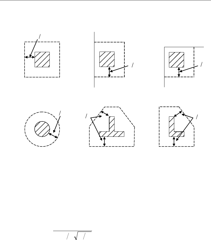
Post-Tensioned Concrete Design
The column location (i.e., interior, edge, corner) and the punching
perimeter may be overwritten using the Punching Check Overwrites.
Figure 6-4 Punching Shear Perimeters
6.8.2.2 Transfer of Unbalanced Moment
The fraction of unbalanced moment transferred by flexure is taken to be
γ
f Mu
and the fraction of unbalanced moment transferred by eccentricity of shear is
taken to be
γ
v Mu.
( )
21
321
1
bb
f+
=
γ
(ACI 13.5.3.2)
γ
v = 1 −
γ
f (ACI 13.5.3.1)
For flat plates,
γ
v is determined from the following equations taken from ACI
421.2R-07 [ACI 2007] Seismic Design of Punching Shear Reinforcement in Flat
Plates.
For interior columns,
d2
Interior Column
Circular Column
d2 d2
d2
T-Shape Column
Edge Column Edge Column
L-Shape Column
d2
d2
d2
Interior Column
Circular Column
d2 d2
d2
T-Shape Column
Edge Column Edge Column
L-Shape Column
d2
d2
6 - 34 Slab Design
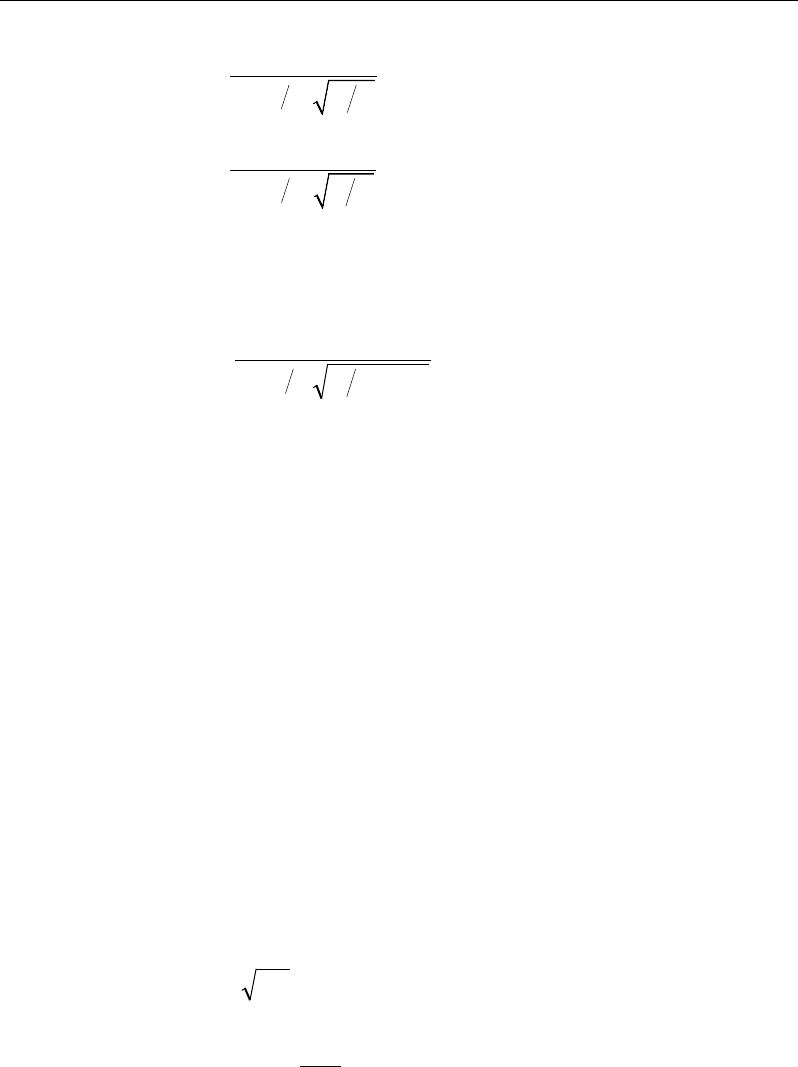
Chapter 6 - Design for ACI 318-08
( )
1
11 23
vx
yx
ll
γ
= − +
(ACI 421.2 C-11)
( )
1
11 23
vy
xy
ll
γ
= − +
(ACI 421.2 C-12)
For edge columns,
γ
vx = same as for interior columns (ACI 421.2 C-13)
( )
2.0321
1
1−+
−=
yx
vy ll
γ
(ACI 421.2 C-14)
γ
vy = 0 when lx/ly ≤ 0.2
For corner columns,
γ
vx = 0.4 (ACI 421.2 C-15)
γ
vy = same as for edge columns (ACI 421.2 C-16)
NOTE: Program uses ACI 421.2-12 and ACI 421.2-15 equations in lieu of ACI
421.2 C-14 and ACI 421.2 C-16 which are currently NOT enforced.
where b1 is the width of the critical section measured in the direction of the span
and b2 is the width of the critical section measured in the direction perpendicular
to the span. The values lx and ly are the projections of the shear-critical section
onto its principal axes, x and y, respectively.
6.8.2.3 Determine Concrete Capacity
The concrete punching shear stress capacity of a two-way prestressed section is
taken as:
( )
ppccpc vffv ++= 3.0'
βφ
(ACI 11.11.2.2)
+= 5.
1,5.3min
o
s
p
b
d
α
β
(ACI 11.11.2.2)
Slab Design 6 - 35
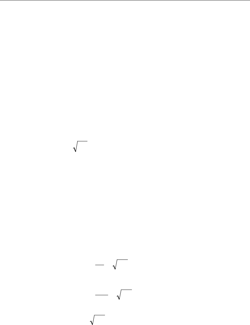
Post-Tensioned Concrete Design
where,
β
p is the factor used to compute vc in prestressed slab; bo is the perimeter
of the critical section; fpc is the average value of fpc in the two directions; vp is the
vertical component of all effective prestress stresses crossing the critical section;
and
α
s is a scale factor based on the location of the critical section.
s
40 for interior columns,
30 for edge columns, and
20 for corner columns.
α=
(ACI 11.11.2.1)
The concrete capacity vc computed from ACI 11.12.2.2 is permitted only when
the following conditions are satisfied:
The column is farther than four times the slab thickness away from any dis-
continuous slab edges.
The value of
c
f'
is taken no greater than 70 psi.
In each direction, the value of fpc is within the range:
125 ≤ fpc ≤ 500 psi
In thin slabs, the slope of the tendon profile is hard to control and special care
should be exercised in computing vp. In case of uncertainty between the design
and as-built profile, a reduced or zero value for vp should be used.
If the preceding three conditions are not satisfied, the concrete punching shear
stress capacity of a two-way prestressed section is taken as the minimum of the
following three limits:
+
+
=
c
c
c
s
c
c
c
f
f
b
d
f
'4
'2
'
4
2
min
λφ
λ
α
φ
λ
β
φ
ν
(ACI 11.11.2.1)
6 - 36 Slab Design
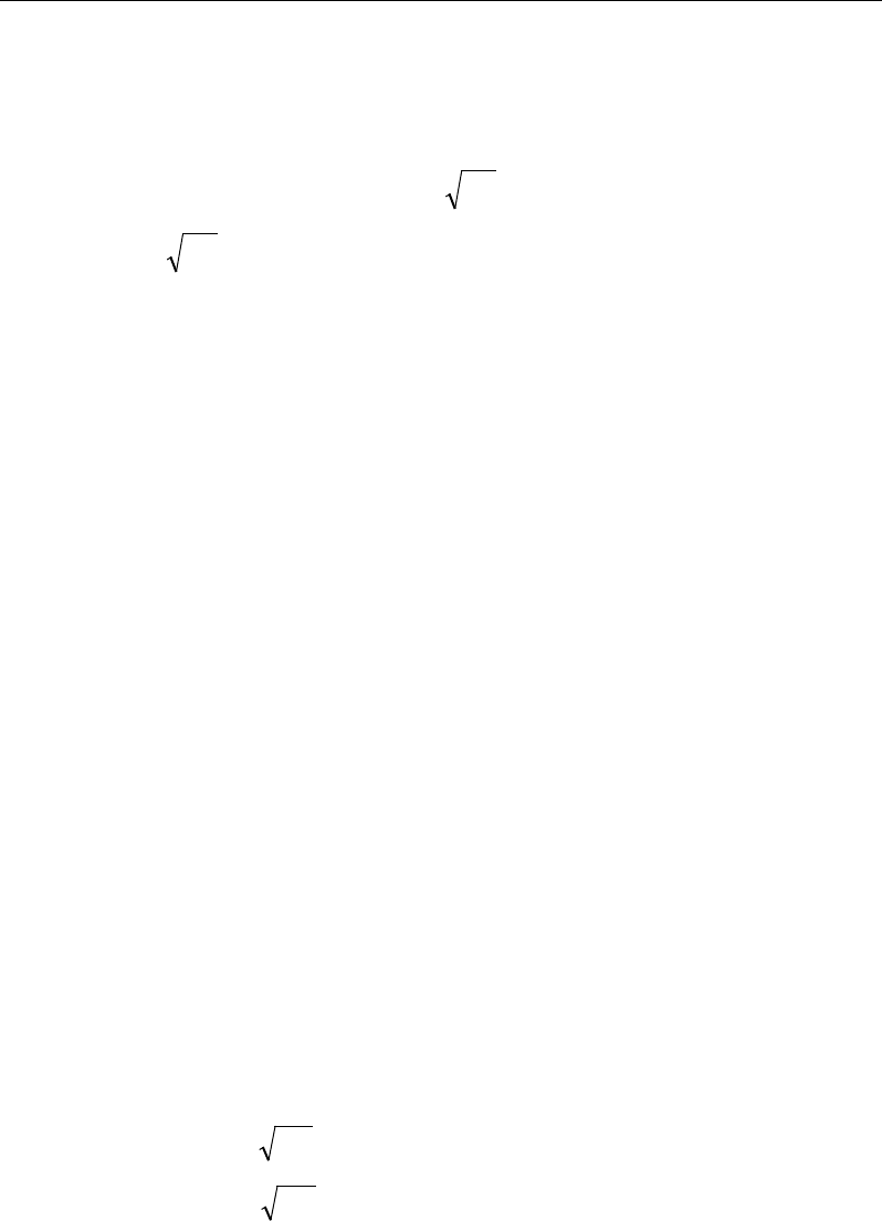
Chapter 6 - Design for ACI 318-08
where,
β
c is the ratio of the maximum to the minimum dimensions of the criti-
cal section, b0 is the perimeter of the critical section, and
α
s is a scale factor
based on the location of the critical section (ACI 11.12.2.1).
A limit is imposed on the value of
c
f'
as:
c
f'
≤ 100 (ACI 11.1.2)
6.8.2.4 Determine Capacity Ratio
Given the punching shear force and the fractions of moments transferred by ec-
centricity of shear about the two axes, the shear stress is computed assuming
linear variation along the perimeter of the critical section. The ratio of the max-
imum shear stress and the concrete punching shear stress capacity is reported as
the punching shear capacity ratio by ETABS.
6.8.3 Design Punching Shear Reinforcement
The use of shear studs as shear reinforcement in slabs is permitted, provided that
the effective depth of the slab is greater than or equal to 6 inches, and not less
than 16 times the shear reinforcement bar diameter (ACI 11.11.3). If the slab
thickness does not meet these requirements, the punching shear reinforcement is
not designed and the slab thickness should be increased by the user.
The algorithm for designing the required punching shear reinforcement is used
when the punching shear capacity ratio exceeds unity. The Critical Section for
Punching Shear and Transfer of Unbalanced Moment as described in the earlier
sections remain unchanged. The design of punching shear reinforcement is car-
ried out as described in the subsections that follow.
6.8.3.1 Determine Concrete Shear Capacity
The concrete punching shear stress capacity of a two-way prestressed section
with punching shear reinforcement is as previously determined, but limited to:
cc fv '
2
λφ
≤
for shear links (ACI 11.11.3.1)
cc fv '
3
λφ
≤
for shear studs (ACI 11.11.5.1)
Slab Design 6 - 37

Post-Tensioned Concrete Design
6.8.3.2 Determine Required Shear Reinforcement
The shear force is limited to a maximum of:
Vmax = 6
'c
f
bod for shear links (ACI 11.11.3.2)
Vmax = 8
'c
f
bod for shear studs (ACI 11.11.5.1)
Given Vu, Vc, and Vmax, the required shear reinforcement is calculated as follows,
where,
φ
, the strength reduction factor, is 0.75 (ACI 9.3.2.3).
( )
uc
v
ys
VV
A
s fd
φ
φ
−
=
(ACI 11.4.7.1, 11.4.7.2)
'
2
c
vo
y
f
Ab
sf
≥
for shear studs
If Vu >
φ
Vmax, a failure condition is declared. (ACI 11.11.3.2)
If Vu exceeds the maximum permitted value of
φ
Vmax, the concrete section
should be increased in size.
6.8.3.3 Determine Reinforcement Arrangement
Punching shear reinforcement in the vicinity of rectangular columns should be
arranged on peripheral lines, i.e., lines running parallel to and at constant dis-
tances from the sides of the column. Figure 6-5 shows a typical arrangement of
shear reinforcement in the vicinity of a rectangular interior, edge, and corner
column.
The distance between the column face and the first line of shear reinforcement
shall not exceed d/2 (ACI R11.3.3, 11.11.5.2). The spacing between adjacent
shear reinforcement in the first line of shear reinforcement shall not exceed 2d
measured in a direction parallel to the column face (ACI 11.11.3.3).
Punching shear reinforcement is most effective near column corners where there
are concentrations of shear stress. Therefore, the minimum number of lines of
shear reinforcement is 4, 6, and 8, for corner, edge, and interior columns respec-
tively.
6 - 38 Slab Design

Chapter 6 - Design for ACI 318-08
Figure 6-5 Typical arrangement of shear studs and critical sections outside
shear-reinforced zone
6.8.3.4 Determine Reinforcement Diameter, Height, and Spacing
The punching shear reinforcement is most effective when the anchorage is close
to the top and bottom surfaces of the slab. The cover of anchors should not be
less than the minimum cover specified in ACI 7.7 plus half of the diameter of
the flexural reinforcement.
Punching shear reinforcement in the form of shear studs is generally available in
3/8-, 1/2-, 5/8-, and 3/4-inch diameters.
When specifying shear studs, the distance, so, between the column face and the
first peripheral line of shear studs should not be smaller than 0.35d. The limits
of so and the spacing, s, between the peripheral lines are specified as:
so ≤ 0.5d (ACI 11.11.5.2)
0 75 for 6
0 50 for 6
uc
uc
. d f'
s. d f'
ν φλ
ν φλ
≤
≤>
(ACI 11.11.5.2)
g ≤ 2d (ACI 11.11.5.3)
The limits of so and the spacing, s, between the links are specified as:
I
y
Typical Studrail
(only first and last
studs shown)
Outermost
peripheral line
of studs
Interior Column Edge Column Corner Column
Critical section
centroid
Free
edge
Free
edge
Critical
section
centroid
Free edge
Outermost
peripheral line
of studs
I
y
I
y
yx
d2 d2
d2
x
I
x
I
x
g
y
g
x
g
0
s0
s
0
s
x
I
y
x
x
I
y
Typical Studrail
(only first and last
studs shown)
Outermost
peripheral line
of studs
Interior Column Edge Column Corner Column
Critical section
centroid
Free
edge
Free
edge
Critical
section
centroid
Free edge
Outermost
peripheral line
of studs
I
y
I
y
yx
d2 d2
d2
x
I
x
I
x
g
y
g
x
g
0
s0
s
0
s
x
I
y
x
x
Slab Design 6 - 39

Post-Tensioned Concrete Design
so ≤ 0.5d (ACI 11.11.3)
0 50≤s .d
(ACI 11.11.3)
6 - 40 Slab Design

Chapter 7
Design for AS 3600-01
This chapter describes in detail the various aspects of the post-tensioned concrete
design procedure that is used by ETABS when the user selects the Australian
code AS 3600-2001 [AS 2001], which also incorporates Amendment Nos. 1
(May 2002), and 2 (October 2004). Various notations used in this chapter are
listed in Table 7-1. For referencing to the pertinent sections of the AS code in
this chapter, a prefix “AS” followed by the section number is used.
The design is based on user-specified load combinations. The program provides
a set of default load combinations that should satisfy the requirements for the
design of most building type structures.
English as well as SI and MKS metric units can be used for input. The code is
based on Newton-millimeter-second units. For simplicity, all equations and de-
scriptions presented in this chapter correspond to Newton-millimeter-second
units unless otherwise noted.
7.1 Notations
The following table identifies the various notations used in this chapter.
Table 7-1 List of Symbols Used in the AS 3600-01 Code
A
g
Gross area of concrete, mm2
Notations 7 - 1

Post-Tensioned Concrete Design
Table 7-1 List of Symbols Used in the AS 3600-01 Code
A
l
Area of longitudinal reinforcement for torsion, mm2
A
p
Area of prestressing steel in flexural tension zone, sq-mm
A
s
Area of tension reinforcement, mm2
A
sc
Area of compression reinforcement, mm2
A
st
Area of tension reinforcement, mm2
A
s(required)
Area of required tension reinforcement, mm2
A
sv
Area of shear reinforcement, mm2
A
sv,min
Minimum area of shear reinforcement, mm2
A
sv
/s
Area of shear reinforcement per unit length, mm2 /mm
A
sw
/s
Area of shear reinforcement per unit length consisting of
closed ties, mm2/mm
A
t
Area of a polygon with vertices at the center of longitudinal
bars at the corners of a section, mm2
s
Spacing of shear reinforcement along the length, mm
a
Depth of compression block, mm
a
b
Depth of compression block at balanced condition, mm
a
max
Maximum allowed depth of compression block, mm
b
Width of member, mm
b
ef
Effective width of flange (flanged section), mm
b
w
Width of web (flanged section), mm
c
Depth to neutral axis, mm
d
Distance from compression face to tension reinforcement,
mm
d'
Concrete cover to compression reinforcement, mm
d
o
Distance from the extreme compression fiber to the centroid
of the outermost tension reinforcement, mm
d
om
Mean value of d
o
, averaged around the critical shear perime-
ter, mm
D
Overall depth of a section, mm
7 - 2 Notations

Chapter 7 - Design for AS 3600-01
Table 7-1 List of Symbols Used in the AS 3600-01 Code
D
s
Thickness of slab (flanged section), mm
E
c
Modulus of elasticity of concrete, MPa
E
s
Modulus of elasticity of reinforcement, MPa
f '
c
Specified compressive strength of concrete, MPa
f'
ci
Specified compressive strength of concrete at time of initial
prestress, MPa
f
pe
Compressive stress in concrete due to effective prestress
forces only (after allowance of all prestress losses), MPa
f
p
Stress in prestressing steel at nominal flexural strength, MPa
f
pu
Specified tensile strength of prestressing steel, MPa
f
py
Specified yield strength of prestressing steel, MPa
f
ct
Characteristic principal tensile strength of concrete, MPa
f '
cf
Characteristic flexural tensile strength of concrete, MPa
f
cv
Concrete shear strength, MPa
f
sy
Specified yield strength of flexural reinforcement, MPa
f
sy,f
Specified yield strength of shear reinforcement, MPa
f '
s
Stress in the compression reinforcement, MPa
D
Overall depth of a section, mm
J
t
Torsional modulus, mm3
k
u
Ratio of the depth to the neutral axis from the compression
face, to the effective depth, d
M
u
0
Design moment resistance of a section with tendons only, N-
mm
M
u
bal
Design moment resistance of a section with tendons and the
necessary mild reinforcement to reach the balanced condi-
tion, N-mm
M
ud
Reduced ultimate strength in bending without axial force, N-
mm
M*
Factored moment at section, N-mm
Notations 7- 3

Post-Tensioned Concrete Design
Table 7-1 List of Symbols Used in the AS 3600-01 Code
N*
Factored axial load at section, N
s
Spacing of shear reinforcement along the beam, mm
T
uc
Torsional strength of section without torsional reinforcement,
N-mm
T
u.max
Maximum permitted total factored torsion at a section, N-mm
T
us
Torsion strength of section with torsion reinforcement, N-mm
T*
Factored torsional moment at a section, N-mm
u
t
Perimeter of the polygon defined by A
t
, mm
V*
Factored shear force at a section, N
V
u.max
Maximum permitted total factored shear force at a section, N
V
u.min
Shear strength provided by minimum shear reinforcement, N
V
uc
Shear force resisted by concrete, N
V
us
Shear force resisted by reinforcement, N
γ
1
Factor for obtaining depth of compression block in concrete
β
h
Ratio of the maximum to the minimum dimensions of the
punching critical section
ε
c
Strain in concrete
ε
c, max
Maximum usable compression strain allowed in extreme con-
crete fiber, (0.003 mm/mm)
ε
s
Strain in reinforcement
φ
Strength reduction factor
θ
t
Angle of compression strut for torsion, degrees
θ
v
Angle of compression strut for shear, degrees
7.2 Design Load Combinations
The design load combinations are the various combinations of the load cases for
which the structure needs to be designed. For AS 3600-01, if a structure is sub-
jected to dead load (D), live load (L), pattern live load (PL), snow (S), wind (W),
and earthquake (E) loads, and considering that wind and earthquake forces are
7 - 4 Design Load Combinations

Chapter 7 - Design for AS 3600-01
reversible, the load combinations in the following sections may need to be con-
sidered (AS 3.3.1, 3.4 and 7.6.7).
For post-tensioned concrete design, the user can specify the prestressing load
(PT) by providing the tendon profile or by using the load balancing options in
the program. The default load combinations for post-tensioning are defined in
the following sections.
7.2.1 Initial Service Load Combination
The following load combination is used for checking the requirements at transfer
of prestress forces in accordance with AS 3600-01 clauses 3.4 and 7.6.7. The
prestressing forces are considered without any long-term loses for the initial ser-
vice load combination check.
1.0D + 1.0PT
(AS 3.4)
1.15D + 1.15PT
0.9D + 1.15PT
(AS 3.4)
(AS 3.4)
7.2.2 Service Load Combination
The following load combinations are used for checking the requirements of pre-
stress for serviceability in accordance with AS3.4 and 7.6.7. It is assumed that
all long-term losses have occurred already at the service stage.
1.0D + 1.0PT
1.0D + 1.0L + 1.0PT
7.2.3 Ultimate Limit State Load Combination
The following load combinations are used for checking the requirements of pre-
stress in accordance with AS 3.3.1, 3.4 and 7.6.7.
The ultimate limit state combinations required for punching shear require the full
PT forces (primary and secondary). Flexural design requires only the hyperstatic
Design Load Combinations 7- 5

Post-Tensioned Concrete Design
(secondary) forces. The hyperstatic (secondary) forces are determined automat-
ically by ETABS by subtracting out the primary PT moments when the flexural
design is carried out.
1.35D + 1.0PT
*
(AS/NZS 1170.0-02, 4.2.2(a))
1.2D + 1.5L + 1.0PT*
(AS/NZS 1170.0-02, 4.2.2(b))
1.2D + 1.5(0.75PL) + 1.0PT*
(AS/NZS 1170.0-02, 4.2.2(b))
1.2D + 0.4L + 1.0S + 1.0PT
*
(AS/NZS 1170.0-02, 4.2.2(g))
0.9D ± 1.0W +1.0PT*
1.2D
± 1.0W + 1.0PT*
1.2D + 0.4L
± 1.0W + 1.0PT*
(AS/NZS 1170.0-02, 4.2.2(e))
(AS/NZS 1170.0-
02, 4.2.2(d))
(AS/NZS 1170.0-
02, 4.2.2(d))
1.0D
±
1.0E + 1.0PT
*
1.0D + 0.4L
± 1.0E + 1.0PT* (AS/NZS 1170.0-02, 4.2.2(f
))
* — Replace PT by H for flexural design only
Note that the 0.4 factor on the live load in three of the combinations is not valid
for live load representing storage areas. These are also the default design load
combinations in ETABS whenever the AS 3600-2001 code is used. If roof live
load is treated separately or other types of loads are present, other appropriate
load combinations should be used.
7.3 Limits on Material Strength
The upper and lower limits of f'c are 65 MPa and 20 MPa, respectively, for all
framing type (AS 6.1.1.1(b)).
' 65MPa≤
c
f
(AS 6.1.1.1)
' 20MPa
c
f≥
(AS 6.1.1.1)
The upper limit of fsy is 500 MPa (AS 6.2.1, Table 6.2.1).
The code allows use of f'c and fsy beyond the given limits, provided special care
is taken regarding the detailing and ductility (AS 6.1.1, 6.2.1, 19.2.1.1).
7 - 6 Limits on Material Strength

Chapter 7 - Design for AS 3600-01
ETABS enforces the upper material strength limits for flexure and shear design
of slabs. The input material strengths are taken as the upper limits if they are
defined in the material properties as being greater than the limits. The user is
responsible for ensuring that the minimum strength is satisfied.
7.4 Strength Reduction Factors
The strength reduction factor,
φ
, is defined as given in the following table (AS
2.3(c), Table 2.3):
Type of action effect
Strength reduction factor (
φ
)
(a) Axial force without bending —
(i) Tension
(ii) Compression
0.8
0.6
(b) Bending without axial tension or compression
where:
(i) ku ≤ 0.4
(ii) ku > 0.4
0.8
0.8 Mud /Muo ≥ 0.6
(c) Bending with axial tension
φ
+[(0.8 −
φ
)(N
u
/N
uot
)]
φ
is obtained from (b)
(d) Bending with axial compression where:
(i) Nu ≥ Nub
(ii) Nu < Nub
0.6
0.6+ [(
φ
- 0.6)(1 − Nu/Nub)]
φ
is obtained from (b)
(e) Shear
0.7
(f) Torsion
0.7
The value Mud is the reduced ultimate strength of the cross-section in bending
where ku = 0.4 and tensile force has been reduced to balance the reduced com-
pressive forces (AS 8.1.3).
These values can be overwritten; however, caution is advised.
7.5 Design Assumptions for Prestressed Concrete Struc-
tures
Ultimate limit state of prestressed members for flexure and axial loads shall be
based on assumptions given in AS 8.1.
Strength Reduction Factors 7- 7

Post-Tensioned Concrete Design
The strain distribution in the concrete in compression is derived from the
assumption that the plane section remains plane (AS 8.1.2.1(a)).
Tensile strength of the concrete is ignored (AS 8.1.2.1 (b)).
The design stresses in the concrete in compression are taken as 0.85
′
c
f
. The
maximum strain at the extreme concrete compression fiber shall be assumed
equal to 0.003 (AS 8.1.2.1 (c), 8.1.2.2).
The strain in bonded prestressing tendons and in any additional reinforcement
(compression or tension) is derived from the assumption that plane section
remains plane (AS 8.1.2.1(a)).
Prestressed concrete members are investigated at the following three stages:
At transfer of prestress force
At service loading
At nominal strength
The prestressed flexural members are classified as uncracked and cracked based
on tensile strength ft, the computed extreme fiber stress in tension in the precom-
pressed tensile zone at service loads.
The precompressed tensile zone is that portion of a prestressed member where
flexural tension, calculated using gross section properties, would occur under
unfactored dead and live loads if the prestress force was not present. Prestressed
concrete is usually designed so that the prestress force introduces compression
into this zone, thus effectively reducing the magnitude of the tensile stress.
7.6 Serviceability Requirements of Flexural Members
7.6.1 Serviceability Check at Initial Service Load
The stresses in the concrete immediately after prestress force transfer (before
time dependent prestress losses) are checked against the following limits (AS
8.1.4.2):
7 - 8 Serviceability Requirements of Flexural Members
Chapter 7 - Design for AS 3600-01
Extreme fiber stress in compression:
0.50 cp
f
The extreme fiber stress in tension should not exceed the cracking stress; other-
wise the section should be designed as a cracked section.
7.6.2 Serviceability Check at Service Load
Flexural cracking in a prestressed beam shall be deemed to be controlled if under
short-term service loads the resulting maximum tensile stress in concrete does
not exceed
0.25 ;
′
c
f
in that case, no further checks are needed (AS 8.6.2).
However, if this limit is exceeded, flexural cracking shall be deemed to be con-
trolled by providing reinforcement or bonded tendons, or both, near the tensile
face and achieving either of the following (AS 8.6.2, 9.4.2):
(a) limiting the calculated maximum flexural tensile stress under short-term ser-
vice loads to
0.6
'
c
f
; or
(b) limiting both of the following
(i) the increment in steel stress near the tension face to 200 MPa, as the load
increases from its value when the extreme concrete tensile fiber is at zero
stress to the short-term service load value; and
(ii) the center-to-center spacing of reinforcement, including bonded ten-
dons, to 200 mm. (This sub clause is a detailing requirement not checked
by the program.)
The program checks the stresses in the concrete prestressed flexural members at
service loads and after all prestress losses against the following limit (AS 8.6.2):
Extreme fiber stress in tension in the
precompressed tensile zone at service loads:
– Extreme fiber stresses in tension for cracked section:
0.5
'
c
f
Thus, although cracking is allowed, it is assumed that the user is limiting the
tensile stress at the service stage as presented in AS 8.6.2.
Serviceability Requirements of Flexural Members 7- 9

Post-Tensioned Concrete Design
7.7 Beam Design (for Reference Only)
Important Note: Post-tensioned beam design is not available in the current ver-
sion of ETABS, but is planned for a future release. This section is provided as
reference only for the documentation of post-tensioned slab design.
In the design of prestressed concrete beams, ETABS calculates and reports the
required areas of reinforcement for flexure, shear, and torsion based on the beam
moments, shear forces, torsion, load combination factors, and other criteria de-
scribed in the subsections that follow. The reinforcement requirements are cal-
culated at each station along the length of the beam.
Beams are designed for major direction flexure, shear, and torsion only. Effects
resulting from any axial forces and minor direction bending that may exist in the
beams must be investigated independently by the user.
The beam design procedure involves the following steps:
Design flexural reinforcement
Design shear reinforcement
Design torsion reinforcement
7.7.1 Design Flexural Reinforcement
The beam top and bottom flexural reinforcement is designed at each station
along the beam. In designing the flexural reinforcement for the major moment
of a particular beam, for a particular station, the following steps are involved:
Determine factored moments
Determine required flexural reinforcement
7 - 10 Beam Design (for Reference Only)

Chapter 7 - Design for AS 3600-01
7.7.1.1 Determine Factored Moments
In the design of flexural reinforcement of prestressed concrete beams, the
factored moments for each load combination at a particular beam station are ob-
tained by factoring the corresponding moments for different load cases, with the
corresponding load factors.
The beam is then designed for the maximum positive and maximum negative
factored moments obtained from all of the load combinations. Positive beam
moments can be used to calculate bottom reinforcement. In such cases the beam
may be designed as a rectangular or a flanged beam. Negative beam moments
can be used to calculate top reinforcement. In such cases, the beam may be de-
signed as a rectangular or inverted flanged beam.
7.7.1.2 Determine Required Flexural Reinforcement
In the flexural reinforcement design process, the program calculates both the
tension and compression reinforcement. Compression reinforcement is added
when the applied design moment exceeds the maximum moment capacity of a
singly reinforced section. The user has the option of avoiding the compression
reinforcement by increasing the effective depth, the width, or the strength of the
concrete.
The design procedure is based on the simplified rectangular stress block, as
shown in Figure 7-1 (AS 8.1.2.2).
Beam Design (for Reference Only) 7- 11
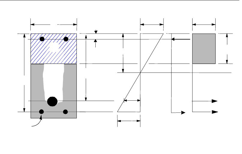
Post-Tensioned Concrete Design
Figure 7-1 Rectangular Beam Design
The design procedure used by ETABS for both rectangular and flanged sections
(L- and T-beams) is summarized in the following subsections. It is assumed that
the design ultimate axial force does not exceed (Ascfsy > 0.15N*) (AS 10.7.1a);
hence all beams are designed for major direction flexure, shear, and torsion only.
7.7.1.2.1 Design of Rectangular Beams
The amount of post-tensioning steel adequate to resist the design moment M and
minimum reinforcement are provided to satisfy the flexural cracking
requirements (AS 8.1.4.1).
ETABS determines the depth of the neutral axis, a, by imposing force equilib-
rium, i.e., C = T, and performs an iteration to compute the depth of the neutral
axis, which is based on stress-strain compatibility for bonded tendons. For un-
bonded tendons, the code equations are used to compute the stress, fps in the post-
tensioning steel. After the depth of the neutral axis has been found, the stress in
the post-tensioning reinforcement fpb is computed based on strain compatibility.
The following assumptions are used for the stress block used to compute the
flexural bending capacity of rectangular sections (AS 8.1.2.2).
BEAM
SECTION STRAIN
DIAGRAM STRESS
DIAGRAM
ps
ε
s
ε
0.003ε=
c
f
0.85 ′
s
C
s
T
cps
T
u
a kd
= γ
c
p
d
d′
s
d
s
A
b
p
A
s
A′
cs
T
s
f′
BEAM
SECTION STRAIN
DIAGRAM STRESS
DIAGRAM
ps
ε
s
ε
0.003ε=
c
f
0.85 ′
s
C
s
T
cps
T
u
a kd
= γ
c
p
d
d′
s
d
s
A
b
p
A
s
A′
cs
T
s
f′
7 - 12 Beam Design (for Reference Only)

Chapter 7 - Design for AS 3600-01
The maximum strain in the extreme compression fiber is taken as 0.003.
A uniform compressive stress of 0.85f'c acts on an area bounded by:
The edges of the cross-sections.
A line parallel to the neutral axis at the strength limit under the loading con-
cerned, and located at a distance
γ
kud from the extreme compression
fiber.
The maximum allowable depth of the rectangular compression block, amax, is
given by
dka u
γ
=
max
where, (AS 8.1.3)
()
[ ]
28'
007
.0
85.
0−−
=
c
f
γ
0.65 0.85
≤γ≤
(AS 8.1.2.2)
ku = 0.4
If
max
aa≤
(AS 8.1.3), the moment capacity of the section, provided by post-
tensioning steel only, is computed as:
0
2
= −
u pp p
a
M Af d
If
max
aa>
(AS 8.1.3), a failure condition is declared.
If
0,
>u
MM
ETABS calculates the moment capacity and the As required at the
balanced condition. The balanced condition is taken as the marginal tension con-
trolled case. In that case, it is assumed that the depth of neutral axis c is equal to
cmax. The stress in the post-tensioning steel, fp is then calculated based on strain
compatibility and the area of required tension reinforcement, As, is determined
by imposing force equilibrium, i.e., C = T.
max
'85.0 bafC
c
=
(AS 8.1.2.2)
= +
bal bal bal
pp s s
T Af A f
Beam Design (for Reference Only) 7- 13

Post-Tensioned Concrete Design
bal
c pp
bal
sbal
s
0.85f' - A f
A= f
After the area of tension reinforcement has been determined, the capacity of the
section with post-tensioning steel and tension reinforcement is computed as:
max max
22
= −+ −
bal bal bal bal
u pp p s s s
aa
M Afd Afd
In that case, it is assumed that the bonded tension reinforcement will yield, which
is true for most cases. In the case that it does not yield, the stress in the reinforce-
ment, fs, is determined from the elastic-perfectly plastic stress-strain relationship.
The fy value of the reinforcement is then replaced with fs in the preceding four
equations. This case does not involve any iteration in determining the depth of
neutral axis, c.
7.7.1.2.1.1 Case 1: Post-tensioning steel is adequate
When
0,
u
MM<
the amount of post-tensioning steel is adequate to resist the de-
sign moment M.. Minimum reinforcement is provided to satisfy the ductility re-
quirements, i.e.,
0.
u
MM<
7.7.1.2.1.2 Case 2: Post-tensioning steel plus tension reinforcement
In this case, the amount of post-tensioning steel, Ap, alone is not sufficient to
resist M, and therefore the required area of tension reinforcement is computed to
supplement the post-tensioning steel. The combination of post-tensioning steel
and tension reinforcement should result in a < amax.
When
0
,
bal
uu
M MM<<
ETABS determines the required area of tension rein-
forcement, As, iteratively to satisfy the design moment M and reports this re-
quired area of tension reinforcement. Since M is bounded by
0
u
M
at the lower
end and
bal
u
M
at the upper end, and
0
u
M
is associated with
0
s
A=
and
bal
u
M
is
associated with
,
bal
ss
AA
=
the required area will fall between the range of 0 to
Asbal.
7 - 14 Beam Design (for Reference Only)

Chapter 7 - Design for AS 3600-01
The tension reinforcement is to be placed at the bottom if M is positive, or at the
top if M is negative.
7.7.1.2.1.3 Case 3: Post-tensioning steel and tension reinforcement are not ade-
quate
When
,
bal
u
MM>
compression reinforcement is required (AS 8.1.3). In that
case, ETABS assumes that the depth of neutral axis, c, is equal to
max .
c
The
values of fp and fs reach their respective balanced condition values,
bal
p
f
and
.
bal
s
f
The area of compression reinforcement,
',
s
A
is determined as follows:
The moment required to be resisted by compression reinforcement and tension
reinforcement is:
bal
us u
M MM= −
The required compression reinforcement is given by:
( )( )
' 0.85 '
us
sc sc
M
Af f dd
φ
=′
−−
, where
0.003
s s sy
cd
fE f
c
′
−
′= ≤
(AS 8.1.2.1, 6.2.2)
The tension reinforcement for balancing the compression reinforcement is given
by:
()
'
φ
=−
com us
s
ys
M
Afd d
Therefore, the total tension reinforcement, As =
bal
s
A
+
,
com
s
A
and the total com-
pression reinforcement is A's. As is to be placed at the bottom and A's is to be
placed at the top if M is positive, and vice versa if M is negative.
7.7.1.2.2 Design of Flanged Beams
7.7.1.2.2.1 Flanged Beam Under Negative Moment
Beam Design (for Reference Only) 7- 15

Post-Tensioned Concrete Design
In designing for a factored negative moment, M (i.e., designing top reinforce-
ment), the calculation of the reinforcement area is exactly the same as described
previously, i.e., no flanged beam data is used.
7.7.1.2.2.2 Flanged Beam Under Positive Moment
ETABS first determines if the moment capacity provided by the post-tensioning
tendons alone is enough. In calculating the capacity, it is assumed that As = 0. In
that case, moment capacity
0
u
M
is determined as follows:
ETABS determines the depth of the neutral axis, a, by imposing force equilib-
rium, i.e., C = T, and performs an iteration to compute the depth of the neutral
axis, which is based on stress-strain compatibility for bonded tendons. For un-
bonded tendons, the code equations are used to compute the stress, fps in the post-
tensioning steel. After the depth of the neutral axis has been determined, the
stress in the post-tensioning steel, fpb is computed based on strain compatibility.
The maximum allowable depth of the rectangular compression block, amax, is
given by
dka u
γ
=
max
where, ku = 0.4 (AS 8.1.3)
If
max
aa≤
(AS 8.1.3), the moment capacity of the section, provided by post-
tensioning steel only, is computed as:
0
2
= −
u pp p
a
M Af d
If
max
aa>
(AS 8.1.3), a failure condition is declared.
If
0,
u
MM>
ETABS calculates the moment capacity and the As required at the
balanced condition. The balanced condition is taken as the marginal tension con-
trolled case. In that case it is assumed that the depth of neutral axis c is equal to
cmax. The stress in the post-tensioning steel, fp is then calculated based on strain
compatibility for bonded tendons. For unbonded tendons, the code equations are
used to compute the stress, fps in the post-tensioning steel, and the area of re-
quired tension reinforcement, As, is determined by imposing force equilibrium,
i.e., C = T.
7 - 16 Beam Design (for Reference Only)

Chapter 7 - Design for AS 3600-01
If a ≤ Ds, the subsequent calculations for As are exactly the same as previously
defined for the rectangular beam design. However, in this case the width of
the beam is taken as bf. Compression reinforcement is required when
dka u
γ
=
max
where, ku = 0.4.
If a > Ds, the calculation for As is given by
max
0.85 ′
=com
cc
C fa A
where
com
c
A
is the area of concrete in compression, i.e.,
( )
max
com
c fs w s
A bD b a D=+−
= +
bal bal bal
pp s s
T Af A f
′com bal
c max c p p
bal
sbal
s
0.85f a A - A f
A= f
In that case, it is assumed that the bonded tension reinforcement will yield, which
is true for most cases. In the case that it does not yield, the stress in the reinforce-
ment, fs, is determined from the elastic-perfectly plastic stress-strain relationship.
The fy value of the reinforcement is then replaced with fs in the preceding four
equations. This case does not involve any iteration in determining the depth of
neutral axis, c.
Beam Design (for Reference Only) 7- 17
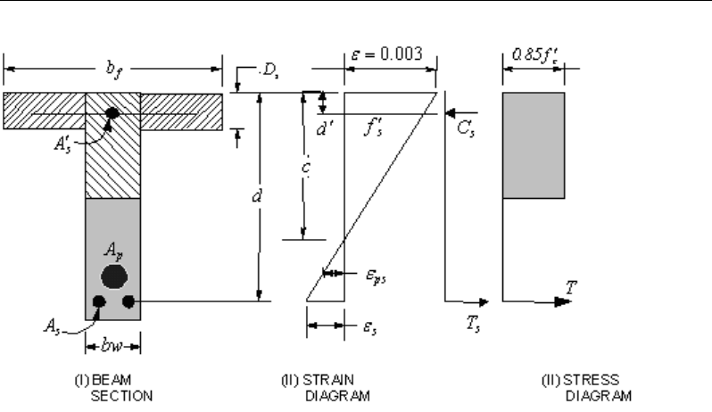
Post-Tensioned Concrete Design
Figure 7-2 T-Beam Design
7.7.1.2.2.3 Case 1: Post-tensioning steel is adequate
When
0,<u
MM
the amount of post-tensioning steel is adequate to resist the de-
sign moment M. Minimum reinforcement is provided to satisfy ductility
requirements, i.e.,
0.
u
MM<
7.7.1.2.2.4 Case 2: Post-tensioning steel plus tension reinforcement
In this case, the amount of post-tensioning steel, Ap, alone is not sufficient to
resist M, and therefore the required area of tension reinforcement is computed to
supplement the post-tensioning steel. The combination of post-tensioning steel
and tension reinforcement should result in a < amax.
When
0
,
bal
uu
M MM<<
ETABS determines the required area of tension rein-
forcement, As, iteratively to satisfy the design moment M and reports the
required area of tension reinforcement. Since M is bounded by
0
u
M
at the lower
end and
bal
u
M
at the upper end, and
0
u
M
is associated with
0
s
A=
and
bal
u
M
is
associated with
,
bal
ss
AA=
the required area will be within the range of 0 to
s
A
.
7 - 18 Beam Design (for Reference Only)

Chapter 7 - Design for AS 3600-01
The tension reinforcement is to be placed at the bottom if M is positive, or at the
top if M is negative.
7.7.1.2.2.5 Case 3: Post-tensioning steel and tension reinforcement are not ade-
quate
When
,
bal
u
MM>
compression reinforcement is required. In that case, ETABS
assumes that the depth of the neutral axis, c, is equal to
max .
c
The values of fp
and fs reach their respective balanced condition values,
bal
p
f
and
.
bal
s
f
The area
of compression reinforcement,
',
s
A
is then determined as follows:
The moment required to be resisted by compression reinforcement and tension
reinforcement is:
bal
us u
M MM= −
The required compression reinforcement is given by:
( )( )
,
0.85 '
φ
′=′′
−−
us
ssc
M
Af f dd
where
max
max
0.003
s s sy
cd
fE f
c
′
−
′= ≤
(AS 8.1.2.1, 6.2.2)
The tension reinforcement for balancing the compression reinforcement is given
by:
( )
'
φ
=−
com us
sys
M
Afd d
Therefore, the total tension reinforcement, As =
bal
s
A
+
,
com
s
A
and the total com-
pression reinforcement is A′s. As is to be placed at the bottom, and A′s is to be
placed at the top if M is positive and vice versa if M is negative.
7.7.1.3 Minimum and Maximum Reinforcement
Reinforcement in post-tensioned concrete beams is computed to increase the
strength of sections as documented for the flexural design of post-tensioned
Beam Design (for Reference Only) 7- 19
Post-Tensioned Concrete Design
beams or to comply with the shear link requirements. The minimum flexural
tension reinforcement required for a beam section to comply with the cracking
requirements needs to be separately investigated by the user.
The ultimate strength in bending (Muo), at critical sections shall not be less than
()
min
uo
M
given by:
()
( )
min 1.2 /
′
= ++
uo cf g
M Z f P A Pe
(AS 8.1.4.1)
where
Z
= the section modulus of the uncracked section, referred to the extreme
fiber at which flexural cracking occurs
'
cf
f
= the characteristic flexural tensile strength of the concrete
e
= the eccentricity of the prestressing force (P), measured from the cen-
troidal axis of the uncracked section
The minimum flexural tension reinforcement required in a beam section is given
by the following limit:
2
.min 0.22 ,
cf
st sy
f
D
A bd
df
′
=
where (AS 8.1.4.1)
ccf ff '6.0' =
(AS 6.1.1.2)
An upper limit of 0.04 times the gross web area on both the tension reinforce-
ment and the compression reinforcement is imposed upon request as follows:
Rectangular beam
Flanged beam
Rectangular beam
Flanged beam
st
w
sc
w
0.04bd
A0.04b d
0.04bd
A0.04b d
≤
≤
7 - 20 Beam Design (for Reference Only)

Chapter 7 - Design for AS 3600-01
7.7.2 Design Beam Shear Reinforcement
The shear reinforcement is designed for each load combination in the major
direction of the beam. In designing the shear reinforcement for a particular beam
for a particular load combination, the following steps are involved
Determine the factored shear force, V*.
Determine the shear force, Vuc, that can be resisted by the concrete.
Determine the shear reinforcement required to carry the balance.
The following three subsections describe in detail the algorithms associated with
these steps.
7.7.2.1 Determine Shear Force
In the design of the beam shear reinforcement, the shear forces for each load
combination at a particular beam station are obtained by factoring the corre-
sponding shear forces for different load cases, with the corresponding load com-
bination factors.
7.7.2.2 Determine Concrete Shear Capacity
The ultimate shear strength (Vuc) of a prestressed beam, excluding the contribu-
tion of shear reinforcement, is the lesser of the values obtained from the follow-
ing, unless the cross-section under consideration is cracked in flexure, in which
case only Flexural-Shear Cracking, Item (a), applies:
(a) Flexural-Shear Cracking
( )
+
13
st pt c
uc 1 2 3 v o o v
wo
A + A f'
V=β β β bd V +P
bd
(AS 8.2.7.2(a))
where,
1.1
1000
6.11.1
1≥
−= o
d
β
(AS 8.2.7.1)
Beam Design (for Reference Only) 7- 21
Post-Tensioned Concrete Design
β2 = 1, or (AS 8.2.7.1)
=
0
5.3
1
*
≥
−
g
A
N
for members subject to significant axial tension, or
=
+
g
A
N
14
1
*
for members subject to significant axial compression.
β3 = 1
Vo = the shear force that would occur at the section when the bending mo-
ment at that section was equal to the decompression moment (Mo)
given by:
o cp.f
M =Zσ
where
cp.f
σ
= the compressive stress because of prestress, at the ex-
treme fiber where cracking occurs
b) Web-shear cracking
uc t v
V VP= +
(AS 8.2.7.2(b))
where
Vt = the shear force, which, in combination with the prestressing force and
other action effects at the section, would produce a principal tensile
stress of
0.33 ′
c
f
at either the centroidal axis or the intersection of
flange and web, whichever is the more critical.
Where significant reversal of loads may occur, causing cracking in a zone
usually in compression, the value of
uc
V
obtained from Clause 8.2.7.1 may not
apply.
7 - 22 Beam Design (for Reference Only)

Chapter 7 - Design for AS 3600-01
7.7.2.3 Determine Required Shear Reinforcement
The shear force is limited to a maximum of:
min
06
u, uc v o
V V . bd= +
(AS 8.2.9)
max 02
u, c o
V . f ' bd=
+ Pv (AS 8.2.6)
Given V*, Vuc, and Vu.max, the required shear reinforcement is calculated as fol-
lows, where,
φ
, the strength reduction factor, is 0.6 by default (AS 2.3).
If
*/2,
uc
VV
φ
≤
0
sv
A,
s=
if D ≤ 750 mm, otherwise Asv.min shall be provided (AS 8.2.5).
If
( )
*.min
/2 ,
uc u
V VV
φφ
<≤
0,
sv
A
s=
if D < bw /2 or 250 mm, whichever is greater (AS 8.2.5(c)(i)),
otherwise Asv.min shall be provided.
If
*
.min .max ,
uu
V VV
φφ
<≤
( )
*
.
,
cot
uc
sv
sy f o v
VV
A
s fd
φ
θ
−
=
(AS 8.2.10)
and greater than Asv.min, defined as:
=
fsy
wsv
f
b
s
A
.
min.35.0
(AS 8.2.8)
θ
v = the angle between the axis of the concrete compression strut and the lon-
gitudinal axis of the member, which varies linearly from 30 degrees when
V*=
φ
Vu.min to 45 degrees when V*=
φ
Vu,max.
If
*max ,
VV
φ
>
a failure condition is declared. (AS 8.2.6)
Beam Design (for Reference Only) 7- 23

Post-Tensioned Concrete Design
If V* exceeds its maximum permitted value
φ
Vmax, the concrete section size
should be increased (AS 8.2.6).
Note that if torsion design is considered and torsion reinforcement is required,
the calculated shear reinforcement is ignored. Closed stirrups are designed for
combined shear and torsion in accordance with AS 8.3.4(b).
The maximum of all of the calculated Asv
/s values obtained from each load com-
bination is reported along with the controlling shear force and associated load
combination.
The beam shear reinforcement requirements considered by the program are
based purely on shear strength considerations. Any minimum stirrup require-
ments to satisfy spacing and volumetric considerations must be investigated in-
dependently of the program by the user.
7.7.3 Design Beam Torsion Reinforcement
The torsion reinforcement is designed for each design load combination at each
station along the length of the beam. The following steps are involved in design-
ing the longitudinal and shear reinforcement for a particular station due to the
beam torsion:
Determine the factored torsion, T*.
Determine special section properties.
Determine critical torsion capacity.
Determine the torsion reinforcement required.
7.7.3.1 Determine Factored Torsion
In the design of beam torsion reinforcement, the torsions for each load combina-
tion at a particular beam station are obtained by factoring the corresponding tor-
sions for different load cases, with the corresponding load combination factors.
In a statically indeterminate structure where redistribution of the torsion in a
member can occur due to redistribution of internal forces upon cracking, the de-
sign T* is permitted to be reduced in accordance with the code (AS 8.3.2). How-
7 - 24 Beam Design (for Reference Only)

Chapter 7 - Design for AS 3600-01
ever, the program does not automatically redistribute the internal forces and re-
duce T*. If redistribution is desired, the user should release the torsional degree
of freedom (DOF) in the structural model.
7.7.3.2 Determine Special Section Properties
For torsion design, special section properties such as At, Jt, and ut are calculated.
These properties are described in the following (AS 8.3).
A
t
=
Area of a polygon with vertices at the center of longitudinal
bars at the corners of the cross-section
u
t
=
Perimeter of the polygon defined by A
t
J
t
=
Torsional modulus
In calculating the section properties involving reinforcement, such as Asw/s and
Al, it is assumed that the distance between the centerline of the outermost closed
stirrup and the outermost concrete surface is 50 mm. This is equivalent to 38-
mm clear cover and a 12-mm-diameter stirrup. For torsion design of flanged
beam sections, it is assumed that placing torsion reinforcement in the flange area
is inefficient. With this assumption, the flange is ignored for torsion reinforce-
ment calculation. However, the flange is considered during Tuc calculation. With
this assumption, the special properties for a rectangular beam section are given
as:
A
t
=
( )( )
2 2,bchc−−
(AS 8.3.5)
u
t
=
( ) ( )
2222,bc hc−+ −
(AS 8.3.6)
J
t
=
0.4x2y (AS 8.3.3)
where, the section dimensions b, h and, c are as shown in Figure 7-3. Similarly,
the special section properties for a flanged beam section are given as:
A
t
=
()( )
2 2,
w
b ch c−−
(AS 8.3.5)
u
t
=
( ) ( )
2 2 2 2,
c wc
hb−+ −
(AS 8.3.6)
J
t
=
0.4Σx2y (AS 8.3.3)
Beam Design (for Reference Only) 7- 25
Post-Tensioned Concrete Design
where the section dimensions bw, h, and c for a flanged beam are as shown in
Figure 7-3. The values x and y refer to the smaller and larger dimensions of a
component rectangle, respectively.
Figure 7-3 Closed stirrup and section dimensions for torsion design
7.7.3.3 Determine Torsion Reinforcement
The torsional strength of the section without torsion reinforcement, Tuc, is calcu-
lated as:
0.3 ′
uc t
T= J f
c
(AS 8.3.5)
where Jt is the torsion modulus of the concrete cross-section as described in
detail in the previous section
Torsion reinforcement also can be ignored if any of the following is satisfied:
uc
TT
φ
25.0
*
≤
(AS 8.3.4(a)(i))
5.0
**
≤+
ucuc
V
V
T
T
φφ
(AS 8.3.4(a)(ii))
c
b2
h
s
d
Closed Stirrup in
Rectangular Beam
Closed Stirrup in
T-Beam Section
ch 2
−h
b
c
h2
−
w
b
Closed Stirrup in
Rectangular Beam
Closed Stirrup in
T-Beam Section
ch 2
−c
h2
−
s
D
ef
b
hh
b
c
c
c
c
c
c
b 2c
−
w
b 2c−
w
b
cb 2
h
s
d
Closed Stirrup in
Rectangular Beam
Closed Stirrup in
T-Beam Section
ch 2
−h
b
c
h2
−
w
b
Closed Stirrup in
Rectangular Beam
Closed Stirrup in
T-Beam Section
ch 2
−c
h2
−
s
D
ef
b
hh
b
c
c
c
c
c
c
b 2c
−
w
b 2c−
w
b
7 - 26 Beam Design (for Reference Only)
Chapter 7 - Design for AS 3600-01
1
**
≤+
ucuc
V
V
T
T
φ
φ
and D ≤ max(250mm, b/2) (AS 8.3.4(a)(iii))
If the factored torsion T* alone or in combination with V* does not satisfy any of
the preceding three conditions, torsion reinforcement is needed. It is assumed
that the torsional resistance is provided by closed stirrups and longitudinal bars
(AS 8.3).
If T* > Tcr, the required closed stirrup area per unit spacing, Asw /s, is calculated
as:
tfsy
t
sw
Af
T
s
A
.
*
2
tan
φ
θ
=
(AS 8.3.5(b))
where, the minimum value of Asw /s is taken as follows:
fsy
w
sw
f
b
s
A
.
min
.35.
0
=
(AS 8.2.8)
The value θt is the angle between the axis of the concrete compression strut and
the longitudinal axis of the member, which varies linearly from 30 degrees when
T* =
φ
Tuc to 45 degrees when T* =
φ
Tu,max.
The following equation shall also be satisfied for combined shear and torsion by
adding additional shear stirrups.
0.1
** ≤+
usus V
V
T
T
φφ
(AS 8.3.4(b))
where,
tt
sw
fsyus
A
s
A
fT
θ
cot2
.
=
(AS 8.3.5(b))
()
vo
fsysvus
sd
fAV
θ
cot/
.
=
(AS 8.2.10(a))
The required longitudinal rebar area is calculated as:
Beam Design (for Reference Only) 7- 27

Post-Tensioned Concrete Design
sy
tt
sw
fsy
lf
u
s
A
f
A
θ
2
.cot5.0
=
(AS 8.3.6(a))
An upper limit of the combination of V* and T* that can be carried by the section
also is checked using the equation:
0.1
max.
*
max.
*≤+
uu V
V
T
T
φφ
(AS 8.3.3)
where,
owcu
dbfV '2.0
max.
=
(AS 8.2.6)
tcu JfT '2.0
max.=
(AS 8.3.5(a))
For rectangular sections, bw is replaced with b. If the combination of V* and T*
exceeds this limit, a failure message is declared. In that case, the concrete section
should be increased in size.
When torsional reinforcement is required (T* > Tcr), the area of transverse closed
stirrups and the area of regular shear stirrups satisfy the following limit.
fsy
swsv
f
b
s
A
s
A
.
35.0
2≥
+
(AS 8.3.7, 8.2.8)
If this equation is not satisfied with the originally calculated Asv/s and Asw/s, Asv/s
is increased to satisfy this condition. In that case, Asv/s does not need to satisfy
AS Section 8.2.8 independently.
The maximum of all of the calculated Al and Asv/s values obtained from each load
combination is reported along with the controlling combination.
The beam torsion reinforcement requirements reported by the program are based
purely on strength considerations. Any minimum stirrup requirements and lon-
gitudinal rebar requirements to satisfy spacing considerations must be investi-
gated independently of the program by the user.
7 - 28 Beam Design (for Reference Only)

Chapter 7 - Design for AS 3600-01
7.8 Slab Design
Similar to conventional design, the ETABS slab design procedure involves
defining sets of strips in two mutually perpendicular directions. The locations of
the strips typically are governed by the locations of the slab supports. The mo-
ments for a particular strip are recovered from the analysis, and a flexural design
is carried out based on the ultimate strength design method (AS 3600-01) for
prestressed reinforced concrete as described in the following subsections. To
learn more about the design strips, refer to the section entitled "ETABS Design
Techniques" in the Key Features and Terminology manual.
7.8.1 Design for Flexure
ETABS designs the slab on a strip-by-strip basis. The moments used for the
design of the slab elements are the nodal reactive moments, which are obtained
by multiplying the slab element stiffness matrices by the element nodal displace-
ment vectors. These moments will always be in static equilibrium with the ap-
plied loads, irrespective of the refinement of the finite element mesh.
The design of the slab reinforcement for a particular strip is carried out at specific
locations along the length of the strip. These locations correspond to the element
boundaries. Controlling reinforcement is computed on either side of these ele-
ment boundaries. The slab flexural design procedure for each load combination
involves the following:
Determine factored moments for each slab strip
Determine the capacity of post-tensioned sections
Design flexural reinforcement for the strip
These three steps are described in the subsections that follow and are repeated
for every load combination. The maximum reinforcement calculated for the top
and bottom of the slab within each design strip, along with the corresponding
controlling load combination, is obtained and reported.
Slab Design 7- 29

Post-Tensioned Concrete Design
7.8.1.1 Determine Factored Moments for the Strip
For each element within the design strip, for each load combination, the program
calculates the nodal reactive moments. The nodal moments are then added to get
the strip moments.
7.8.1.2 Determine Capacity of Post-Tensioned Sections
The calculation of the post-tensioned section capacity is identical to that
described earlier for rectangular beam sections.
7.8.1.3 Design Flexural Reinforcement for the Strip
The reinforcement computation for each slab design strip, given the bending mo-
ment, is identical to the design of rectangular beam sections described
earlier (or to the flanged beam if the slab is ribbed). Where the slab properties
(depth and so forth) vary over the width of the strip, the program automatically
designs slab widths of each property separately for the bending moment to which
they are subjected before summing up the reinforcement for the full width. This
method is used when drop panels are included. Where openings occur, the slab
width is adjusted accordingly.
7.8.1.4 Minimum and Maximum Slab Reinforcement
The minimum requirements for untensioned reinforcement in one-way bonded
slabs is the same as for beams (AS 9.1.1). Flexural cracking in prestressed slabs
shall be deemed controlled if under short-term service loads the resulting stress
is less than
0.25 ′
c
f
; in that case, no further checks are needed (AS 9.4.2).
However, if that limit is exceeded, flexural cracking shall be deemed under con-
trol by providing reinforcement or bonded tendons, or both, near the tensile face
and accomplishing either of the following (AS 9.4.2):
(a) limiting the calculated maximum flexural tensile stress under short-term ser-
vice loads to
0.5
'
c
f
; or
(b) limiting both of the following:
7 - 30 Slab Design
Chapter 7 - Design for AS 3600-01
(i) the increment in steel stress near the tension face to 150 MPa, as the load
increases from its value when the extreme concrete tensile fiber is at zero
stress to the short-term service load value; and
(ii) the center-to-center spacing of reinforcement, including bonded ten-
dons, to 500 mm. (This sub clause is a detailing requirement that is not
checked by the program.)
The program checks the stresses in the concrete prestressed flexural members at
service loads and after all prestress losses have occurred against the following
limit (AS 9.4.2):
Extreme fiber stress in tension in the
precompressed tensile zone at service loads:
– Extreme fiber stresses in tension for cracked section:
0.5
'
c
f
Thus, although cracking is allowed, it is assumed that the user is limiting the
tensile stress at the service stage as presented in AS 9.4.2.
In addition, an upper limit on both the tension reinforcement and compression
reinforcement has been imposed to be 0.04 times the gross cross-sectional area.
7.8.2 Check for Punching Shear
The algorithm for checking punching shear is detailed in the section entitled
“Slab Punching Shear Check” in the Key Features and Terminology manual.
Only the code specific items are described in the following sections.
7.8.2.1 Critical Section for Punching Shear
The punching shear is checked on a critical section at a distance of dom /2 from
the face of the support (AS 9.2.1.1). For rectangular columns and concentrated
loads, the critical area is taken as a rectangular area with the sides parallel to the
sides of the columns or the point loads (AS 9.2.1.3). Figure 7-4 shows the auto
punching perimeters considered by ETABS for the various column shapes. The
column location (i.e., interior, edge, corner) and the punching perimeter may be
overwritten using the Punching Check Overwrites.
Slab Design 7- 31
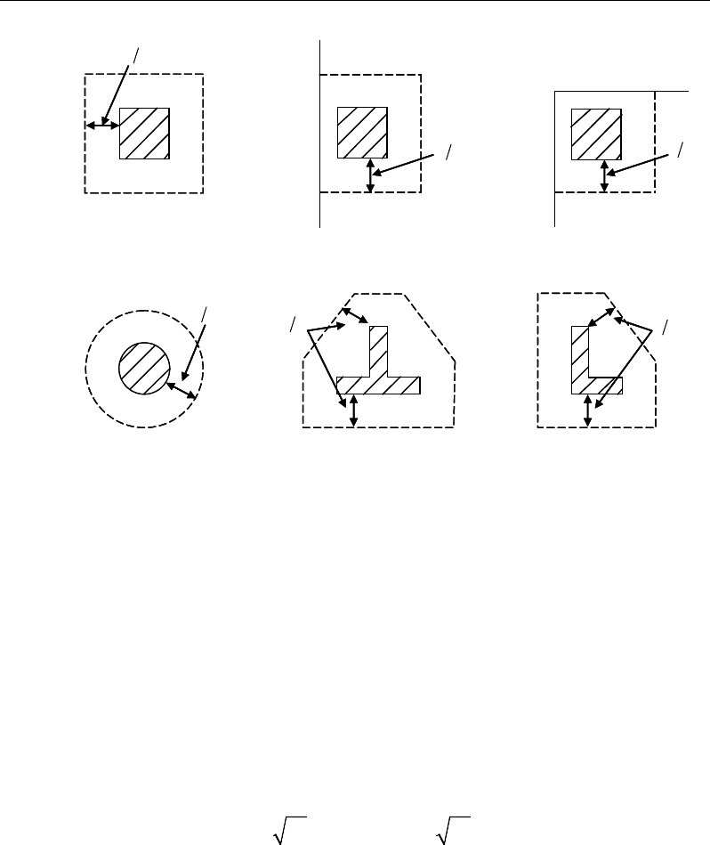
Post-Tensioned Concrete Design
Figure 7-4 Punching Shear Perimeters
7.8.2.2 Determine Concrete Capacity
(i) The ultimate shear strength of a slab where
*
v
M
is zero,
uo
V
, is given as (AS
9.2.3(a)):
a. when no shear link/stud is present
( )
0.3
uo om cv cp
V ud f
σ
= +
(AS 9.2.3(a))
b. when shear link/stud is present
( )
0.5 0.3 0.2
σ
′′
= +≤
uo om c cp c om
V ud f f ud
(AS 9.2.3(b))
where
cv
f
is taken as the minimum of the following two limits:
d2
Interior Column
Circular Column
d2 d2
d2
T-Shape Column
Edge Column Edge Column
L-Shape Column
d2
d2
d2
Interior Column
Circular Column
d2 d2
d2
T-Shape Column
Edge Column Edge Column
L-Shape Column
d2
d2
7 - 32 Slab Design

Chapter 7 - Design for AS 3600-01
β
′
+
=
′
c
h
cv
c
2
0.17 1 f
f min
0.34 f
(AS 9.2.3(a))
where,
β
h is the ratio of the longest to the minimum dimensions of the critical
section.
(ii) The ultimate shear strength of a slab where
*
v
M is not zero and no shear
reinforcement is provided,
u
V
, is given as (AS 9.2.4(a)):
( )
*
/ 1.0 /8
u uo v om
V V uM V ad
= +
(AS 9.2.4(a))
7.8.2.3 Determine Capacity Ratio
Given the punching shear force and the fractions of moments transferred by ec-
centricity of shear about the two axes, the shear stress is computed assuming
linear variation along the perimeter of the critical section. The ratio of the max-
imum shear stress and the concrete punching shear stress capacity is reported by
ETABS.
7.8.3 Design Punching Shear Reinforcement
The design guidelines for shear links or shear studs are not available in AS 3600-
2001. ETABS uses the NZS 3101-06 guidelines to design shear studs or shear
links.
The use of shear studs as shear reinforcement in slabs is permitted, provided that
the effective depth of the slab is greater than or equal to 150 mm, and not less
than 16 times the shear reinforcement bar diameter (NZS 12.7.4.1). If the slab
thickness does not meet these requirements, the punching shear reinforcement is
not designed and the slab thickness should be increased by the user.
The algorithm for designing the required punching shear reinforcement is used
when the punching shear capacity ratio exceeds unity. The Critical Section for
Punching Shear and Transfer of Unbalanced Moment as described in the earlier
sections remain unchanged. The design of punching shear reinforcement is car-
ried out as described in the subsections that follow.
Slab Design 7- 33
Post-Tensioned Concrete Design
7.8.3.1 Determine Concrete Shear Capacity
The concrete punching shear stress capacity of a section with punching shear
reinforcement is as previously determined for the punching check.
7.8.3.2 Determine Required Shear Reinforcement
The shear force is limited to a maximum of:
Vmax = 3 Vu,min = 3×Vu (AS 92.2.4(a), (d))
Where Vu is computed from AS 9.2.3 or 9.2.4.Given V*, Vu, and Vu,max, the re-
quired shear reinforcement is calculated as follows, where,
φ
, is the strength re-
duction factor.
( )
φ
−
=
*
,
u
sv
sy om
VV
A
s fd
(AS 8.2.10)
Minimum punching shear reinforcement should be provided such that:
1'
16
s c om
V f ud
≥
(NZS 12.7.4.3)
If V* >
φ
Vmax, a failure condition is declared. (NZS 12.7.3.4)
If V* exceeds the maximum permitted value of
φ
Vmax, the concrete section
should be increased in size.
7.8.3.3 Determine Reinforcement Arrangement
Punching shear reinforcement in the vicinity of rectangular columns should be
arranged on peripheral lines, i.e., lines running parallel to and at constant dis-
tances from the sides of the column. Figure 7-5 shows a typical arrangement of
shear reinforcement in the vicinity of a rectangular interior, edge, and corner
column.
The distance between the column face and the first line of shear reinforcement
shall not exceed d/2. The spacing between adjacent shear reinforcement in the
first line (perimeter) of shear reinforcement shall not exceed 2d measured in a
direction parallel to the column face (NZS 12.7.4.4).
7 - 34 Slab Design
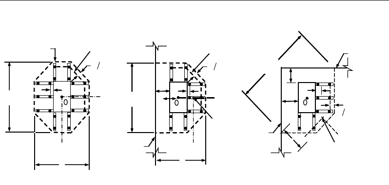
Chapter 7 - Design for AS 3600-01
Figure 7-5 Typical arrangement of shear studs
and critical sections outside shear-reinforced zone
Punching shear reinforcement is most effective near column corners where there
are concentrations of shear stress. Therefore, the minimum number of lines of
shear reinforcement is 4, 6, and 8, for corner, edge, and interior columns respec-
tively.
7.8.3.4 Determine Reinforcement Diameter, Height, and Spacing
The punching shear reinforcement is most effective when the anchorage is close
to the top and bottom surfaces of the slab. The cover of anchors should not be
less than the minimum cover specified in NZS 3.11 plus half of the
diameter of the flexural reinforcement.
When specifying shear studs, the distance, so, between the column face and the
first peripheral line of shear studs should not be smaller than 0.5d. The spacing
between adjacent shear studs, g, at the first peripheral line of studs shall not ex-
ceed 2d and in the case of studs in a radial pattern, the angle between adjacent
stud rails shall not exceed 60 degrees. The limits of so and the spacing, s, between
the peripheral lines are specified as:
so ≤ 0.5d (NZS 12.7.4.4)
s ≤ 0.5d (NZS 12.7.4.4)
g ≤ 2d (NZS 12.7.4.4)
I
y
Typical Studrail
(only first and last
studs shown)
Outermost
peripheral line
of studs
Interior Column Edge Column Corner Column
Critical section
centroid
Free
edge
Free
edge
Critical
section
centroid
Free edge
Outermost
peripheral line
of studs
I
y
I
y
yx
d2 d2
d2
x
I
x
I
x
g
y
g
x
g
0
s0
s0
s
x
I
y
xx
I
y
Typical Studrail
(only first and last
studs shown)
Outermost
peripheral line
of studs
Interior Column Edge Column Corner Column
Critical section
centroid
Free
edge
Free
edge
Critical
section
centroid
Free edge
Outermost
peripheral line
of studs
I
y
I
y
yx
d2 d2
d2
x
I
x
I
x
g
y
g
x
g
0
s0
s0
s
x
I
y
xx
Slab Design 7- 35

Chapter 8
Design for BS 8110-97
This chapter describes in detail the various aspects of the post-tensioned concrete
design procedure that is used by ETABS when British code BS 8110-97 [BSI
1997] is selected. For light-weight concrete and torsion, reference is made to BS
8110-2:1985 [BSI 1985]. Various notations used in this chapter are listed in Ta-
ble 8-1. For referencing to the pertinent sections of the BS code in this chapter,
a prefix “BS” followed by the section number is used.
The design is based on user-specified load combinations. The program provides
a set of default load combinations that should satisfy the requirements for the
design of most building type structures.
English as well as SI and MKS metric units can be used for input. The code is
based on Newton-millimeter-second units. For simplicity, all equations and de-
scriptions presented in this chapter correspond to Newton-millimeter-second
units unless otherwise noted.
8.1 Notations
The following table identifies the various notations used in this chapter.
Table 8-1 List of Symbols Used in the BS 8110-97 Code
A
cv
Area of section for shear resistance, mm2
Notations 8 - 1

Post-Tensioned Concrete Design
Table 8-1 List of Symbols Used in the BS 8110-97 Code
A
g
Gross area of cross-section, mm2
A
s
Area of tension reinforcement, mm
2
A
ps
Area of prestress steel, mm2
A'
s
Area of compression reinforcement, mm2
A
sv
Total cross-sectional area of links at the neutral axis, mm
2
A
sv
/ s
v
Area of shear reinforcement per unit length of the member,
mm2/mm
a
Depth of compression block, mm
a
max
Maximum depth of the compression block, mm
b
Width or effective width of the section in the compression
zone, mm
b
f
Width or effective width of flange, mm
b
w
Average web width of a flanged beam, mm
d or d
e
Effective depth of tension reinforcement, mm
d'
Depth to center of compression reinforcement, mm
E
c
Modulus of elasticity of concrete, MPa
E
s
Modulus of elasticity of reinforcement, assumed as 200,000
MPa
f
ci
Concrete strength at transfer, MPa
f
cu
Characteristic cube strength at 28 days, MPa
f
pu
Characteristic strength of a prestressing tendon, MPa
f
pb
Design tensile stress in tendon, MPa
'
s
f
Compressive stress in a beam compression steel, MPa
f
y
Characteristic strength reinforcement, MPa
f
yv
Characteristic strength of link reinforcement, MPa (< 500
MPa)
h
Overall depth of a section in the plane of bending, mm
8 - 2 Notations
Chapter 8 - Design for BS 8110-97
Table 8-1 List of Symbols Used in the BS 8110-97 Code
h
f
Flange thickness, mm
k
1
Shear strength enhancement factor for support compression
k2 Concrete shear strength factor,
[ ]
3
1
25
cu
f
M
Design moment at a section, N-mm
M
u
Design moment resistance of a section, N-mm
M
u
0
Design moment resistance of a section with tendons only, N-
mm
M
u
bal
Design moment resistance of a section with tendons and the
necessary mild reinforcement to reach the balanced condi-
tion, N-mm
s
v
Spacing of the links along the length of the beam, mm
s
Spacing of shear rails, mm
T
Tension force, N
V
Design shear force at ultimate design load, N
u
Perimeter of the punching critical section, mm
v
Design shear stress at a beam cross-section or at a punch crit-
ical section, MPa
v
c
Design ultimate shear stress resistance of a concrete beam,
MPa
v
co
Ultimate shear stress resistance of an uncracked concrete
section, MPa
v
cr
Ultimate shear stress resistance of a cracked concrete section,
MPa
v
max
Maximum permitted design factored shear stress at a beam
section or at the punch critical section, MPa
v
t
Torsional shear stress, MPa
x
Neutral axis depth, mm
x
bal
Depth of neutral axis in a balanced section, mm
Notations 8 - 3

Post-Tensioned Concrete Design
Table 8-1 List of Symbols Used in the BS 8110-97 Code
z
Lever arm, mm
β
Torsional stiffness constant
β
b
Moment redistribution factor in a member
γ
f
Partial safety factor for load
γ
m
Partial safety factor for material strength
ε
c
Maximum concrete strain, 0.0035
ε
ps
Strain in prestressing steel
ε
s
Strain in tension steel
ε
'
s
Strain in compression steel
8.2 Design Load Combinations
The design load combinations are the various combinations of the load cases for
which the structure needs to be designed. The design load combinations are ob-
tained by multiplying the characteristic loads by appropriate partial factors of
safety, γf (BS 2.4.1.3). For BS 8110-97, if a structure is subjected to dead (D),
live (L), pattern live (PL), snow (S), and wind (W) loads, and considering that
wind forces are reversible, the load combinations in the following sections may
need to be considered (BS 2.4.3, 4.1.7.1, 4.3.4 and 4.3.5).
For post-tensioned concrete design, the user can specify the prestressing load
(PT) by providing the tendon profile or by using the load balancing options in
the program. The default load combinations for post-tensioning are defined in
the following sections.
8.2.1 Initial Service Load Combination
The following load combination is used for checking the requirements at transfer
of prestress forces in accordance with BS 8110-97 clause 4.3.5. The prestressing
forces are considered without any long-term loses for the initial service load
combination check.
8 - 4 Design Load Combinations

Chapter 8 - Design for BS 8110-97
1.0D + 1.0PT
8.2.2 Service Load Combination
The following load combinations are used for checking the requirements of pre-
stress for serviceability in accordance with BS 4.3.4. It is assumed that all long-
term losses have already occurred at the service stage.
1.0D + 1.0PT
1.0D + 1.0L + 1.0PT
8.2.3 Ultimate Limit State Load Combination
The following load combinations are used for checking the requirements of pre-
stress in accordance with BS 2.4.3.1.1, Table 2.1.
The strength design combinations required for punching shear require the full
PT forces (primary and secondary). Flexural design only requires the hyperstatic
(secondary) forces. The hyperstatic (secondary) forces are automatically deter-
mined by ETABS by subtracting out the primary PT moments when the flexural
design is carried out.
1.4D + 1.0PT*
(BS 2.4.3)
1.4D + 1.6L + 1.0PT*
(BS 2.4.3)
1.4D + 1.6(0.75PL) + 1.0PT*
(BS 2.4.3)
1.0D ± 1.4W +1.0PT*
1.4D
± 1.4W + 1.0PT*
1.
2D + 1.2L ± 1.2W + 1.0PT*
(BS 2.4.3
)
1.4D + 1.6L + 1.6S + 1.0PT*
1.2D + 1.2S
± 1.2W + 1.0PT*
1.2D + 1.2L + 1.2S
±
1.2W + 1.0PT
*
(BS 2.4.3
)
* — Replace PT with H for flexural design only
Other appropriate loading combinations should be used if roof live load is sepa-
rately treated, or other types of loads are present.
Design Load Combinations 8 - 5
Post-Tensioned Concrete Design
8.3 Limits on Material Strength
Grade C28/C35 and C32/C40 are the minimum recommended for post-tension-
ing and pre-tensioning respectively. In both cases the concrete strength at trans-
fer should not be less than 25 MPa (BS 4.1.8.1).
The specified characteristic strength of untensioned reinforcement is given as
follows (BS 4.1.8.2, 3.1.7.4):
Hot rolled mild reinforcement - 250 MPa (BS 3.1.7.4, Table 3.1)
High yield reinforcement - 500 MPa (BS 3.1.7.4, Table 3.1)
The specified characteristic strength of prestressing steel should conform to BS
448 and BS 5896.
ETABS also checks the tensile strength in the prestressing steel (BS 4.7.1). The
permissible tensile stresses in all types of prestressing steel, in terms of the spec-
ified minimum tensile strength fpu, are summarized as follows:
a. Due to tendon jacking force: 0.75 fpu
b. Immediately after prestress transfer: 0.70 fpu
In any circumstances, the initial prestressing forces shall not exceed 0.75 fpu.
8.4 Partial Safety Factors
The design strengths for concrete and reinforcement are obtained by dividing the
characteristic strength of the material by a partial safety factor,
γ
m. The values of
γ
m used in the program are listed in the table that follows, as taken from BS Table
2.2 (BS 2.4.4.1):
Values of
γ
m for the ultimate limit state
Reinforcement,
γ
ms 1.15
Prestressing steel,
γ
mp 1.15
Concrete in flexure and axial load,
γ
mc 1.50
Shear strength without shear reinforcement,
γ
mv 1.25
8 - 6 Limits on Material Strength

Chapter 8 - Design for BS 8110-97
These factors are already incorporated in the design equations and tables in the
code. Note that for reinforcement, the default factor of 1.15 is for Grade 500
reinforcement. If other grades are used, this value should be overwritten as nec-
essary. Changes to the partial safety factors are carried through the design equa-
tions where necessary, typically affecting the material strength portions of the
equations.
8.5 Design Assumptions for Prestressed Concrete Struc-
tures
The ultimate limit state of prestressed members for flexure and axial loads shall
be based on assumptions given in BS 4.3.7.1.
The strain distribution in the concrete in compression is derived from the
assumption that a plane section remains plane (BS 4.3.7.1(a)).
The design stresses in the concrete in compression are taken as 0.45 fcu. The
maximum strain at the extreme concrete compression fiber shall be assumed
equal to 0.0035 (BS 4.3.7.1(b)).
Tensile strength of the concrete is ignored (BS 4.3.7.1(c)).
The strain in bonded prestressing tendons and in any additional reinforcement
(compression or tension) is derived from the assumption that the plane section
remains plane (BS 4.3.7.1(d)).
The serviceability limit state of prestressed members uses the following assump-
tions given in BS 4.3.4.1.
Plane sections remain plane, i.e., strain varies linearly with depth through the
entire load range (BS 4.3.4.1(a)).
Elastic behavior exists by limiting the concrete stresses to the values given in
BS 4.3.4.2, 4.3.4.3, and 4.3.5 (BS 4.3.4.1(b)).
In general, it is only necessary to calculate design stresses resulting from the
load arrangements immediately after the transfer of prestress and after all
losses or prestress have occurred; in both cases the effects of dead and imposed
loads on the strain and force in the tendons may be ignored (BS 4.3.4.1(c)).
Design Assumptions for Prestressed Concrete Structures 8 - 7

Post-Tensioned Concrete Design
Prestressed concrete members are investigated at the following three stages (BS
4.3.4.2 and 4.3.4.3):
At transfer of prestress force
At service loading
At nominal strength
The prestressed flexural members are classified as Class 1 (uncracked), Class 2
(cracked but no visible cracking), and Class 3 (cracked) based on tensile strength
ft, the computed extreme fiber stress in tension in the precompressed tensile zone
at service loads (BS 4.1.3).
The precompressed tensile zone is that portion of a prestressed member where
flexural tension, calculated using gross section properties, would occur under
unfactored dead and live loads if the prestress force was not present. Prestressed
concrete is usually designed so that the prestress force introduces compression
into this zone, thus effectively reducing the magnitude of the tensile stress.
Class 1: No flexural tensile stresses
Class 2: Flexural tensile stresses but no visible cracking
Class 3: Flexural tensile stresses but surface width of cracks are as follows:
Crack width ≤ 0.1 mm for members in exposure class XS2, XS3,
XD2, XD3, XF3 and XF4 (Table A.1 of BS 8500-1)
Crack width ≤ 0.2 mm for all other members
8.6 Serviceability Requirements of Flexural Members
8.6.1 Serviceability Check at Initial Service Load
The stresses in the concrete immediately after prestress force transfer (before
time dependent prestress losses) are checked against the following limits (BS
4.3.5.1 and 4.3.5.2):
8 - 8 Serviceability Requirements of Flexural Members
Chapter 8 - Design for BS 8110-97
Extreme fiber stress in compression:
0.50
ci
f
Extreme fiber stress in tension for Class 1: ≤ 1.0 MPa
Extreme fiber stress in tension for Class 2:
pre-tensioned member
0.45
ci
f
post-tensioned member
0.36 ci
f
The extreme fiber stress in tension for Class 3 should not exceed the appropriate
value for a Class 2 member; otherwise the section should be designed as a
cracked section.
8.6.2 Serviceability Check at Service Load
The stresses in the concrete for Class 1 and Class 2 prestressed flexural members
at service loads, and after all prestress losses have occurred, are checked against
the following limits (BS 4.3.4.2, 4.3.4.3):
Extreme fiber stress in compression due
to prestress plus total load:
0.33
cu
f
Extreme fiber stress in compression due
to prestress plus total load for continuous
beams and other statically indeterminate
structures:
0.4
cu
f
Extreme fiber stress in tension in the
precompressed tensile zone at service loads:
– Extreme fiber stresses in tension for Class 1: No tensile stress
– Extreme fiber stresses in tension for Class 2:
pre-tensioned member
0.45
cu
f
post-tensioned member
0.36
cu
f
Serviceability Requirements of Flexural Members 8 - 9

Post-Tensioned Concrete Design
Although cracking is allowed for Class 3, it is assumed that the concrete
section is uncracked and the user is limiting the tensile stress at service stage as
presented in Table 4.2, modified by the coefficients in Table 4.3 of BS 8110-
1997. The user needs to provide the tension limits for Class 3 elements at
service loads in the design preferences BS 4.3.4.3(c)).
8.7 Beam Design (for Reference Only)
Important Note: Post-tensioned beam design is not available in the current ver-
sion of ETABS, but is planned for a future release. This section is provided as
reference only for the documentation of post-tensioned slab design.
In the design of prestressed concrete beams, ETABS calculates and reports the
required areas of reinforcement for flexure, shear, and torsion based on the beam
moments, shear forces, torsion, load combination factors, and other criteria de-
scribed in the subsections that follow. The reinforcement requirements are cal-
culated at each station along the length of the beam.
Beams are designed for major direction flexure, shear, and torsion only. Effects
resulting from any axial forces and minor direction bending that may exist in the
beams must be investigated independently by the user.
The beam design procedure involves the following steps:
Design flexural reinforcement
Design shear reinforcement
Design torsion reinforcement
8.7.1 Design Flexural Reinforcement
The beam top and bottom flexural reinforcement is designed at each station
along the beam. In designing the flexural reinforcement for the major moment
of a particular beam, for a particular station, the following steps are involved:
Determine factored moments
Determine required flexural reinforcement
8 - 10 Beam Design (for Reference Only)

Chapter 8 - Design for BS 8110-97
8.7.1.1 Determine Factored Moments
In the design of flexural reinforcement of prestressed concrete beams, the
factored moments for each load combination at a particular beam station are ob-
tained by factoring the corresponding moments for different load cases, with the
corresponding load factors.
The beam is then designed for the maximum positive and maximum negative
factored moments obtained from all of the load combinations. Positive beam
moments can be used to calculate bottom reinforcement. In such cases the beam
may be designed as a rectangular or a flanged beam. Negative beam moments
can be used to calculate top reinforcement. In such cases the beam may be de-
signed as a rectangular or inverted flanged beam.
8.7.1.2 Determine Required Flexural Reinforcement
In the flexural reinforcement design process, the program calculates both the
tension and compression reinforcement. Compression reinforcement is added
when the applied design moment exceeds the maximum moment capacity of a
singly reinforced section. The user has the option of avoiding the compression
reinforcement by increasing the effective depth, the width, or the strength of the
concrete.
The design procedure is based on the simplified rectangular stress block, as
shown in Figure 8-1 (BS 3.4.4.4, 4.3.7.1). Furthermore, it is assumed that mo-
ment redistribution in the member does not exceed 10 percent (i.e., βb ≥ 0.9) (BS
3.4.4.4). The code also places a limitation on the neutral axis depth, x/d ≤ 0.5, to
safeguard against non-ductile failures (BS 3.4.4.4). In addition, the area of com-
pression reinforcement is calculated on the assumption that the neutral axis depth
remains at the maximum permitted value.
The design procedure used by ETABS, for both rectangular and flanged sections
(L- and T-beams), is summarized in the subsections that follow. It is assumed
that the design ultimate axial force does not exceed 0.1 fcu Ag (BS 3.4.4.1); hence
all beams are designed for major direction flexure, shear, and torsion only.
Beam Design (for Reference Only) 8 - 11

Post-Tensioned Concrete Design
Figure 8-1 Rectangular Beam Design
8.7.1.2.1 Design of Rectangular Beams
The amount of post-tensioning steel adequate to resist the design moment M and
minimum reinforcement are provided to satisfy the flexural cracking
requirements (BS 4.12.6).
ETABS determines the depth of the neutral axis, x, by imposing force equilib-
rium, i.e., C = T, and performs an iteration to compute the depth of the neutral
axis, which is based on stress-strain compatibility. After the depth of the neutral
axis has been found, the stress in the post-tensioning reinforcement fpb is com-
puted based on strain compatibility.
The ductility of a section is controlled by limiting the x/d ratio (BS 3.4.4.4):
x/d = 0.5 (BS 3.4.4.4)
The maximum depth of the compression block is given by:
a = 0.9x (BS 3.4.4.1(b), 4.3.7.3)
BEAM
SECTION STRAIN
DIAGRAM STRESS
DIAGRAM
s
A
0.0035
ε
=
0.67
cu m
f
γ
s
f′
s
C
s
A′
ps
A
s
ε
ps
ε
s
T
cps
T
s
dp
d
b
x
d′=0.9ax
cs
T
BEAM
SECTION STRAIN
DIAGRAM STRESS
DIAGRAM
s
A
0.0035
ε
=
0.67
cu m
f
γ
s
f′
s
C
s
A′
ps
A
s
ε
ps
ε
s
T
cps
T
s
dp
d
b
x
d′=0.9
ax
cs
T
8 - 12 Beam Design (for Reference Only)

Chapter 8 - Design for BS 8110-97
The lever arm of the section must not be greater than 0.95 times the effective
depth (BS 3.4.4.1).
z = d − 0.45x ≤ 0.95de (BS 3.4.4.1(e))
If
max
aa
≤
(BS 3.4.4.4), the moment capacity of the section, provided by post-
tensioning steel only, is computed as:
( )
00.45
u ps pb p
M Af d x= −
(BS 4.3.7.3)
If
max
aa>
(BS 3.4.4.4), a failure condition is declared.
If
0,>u
MM
ETABS calculates the moment capacity and the As required at the
balanced condition. The balanced condition is taken as the marginal tension con-
trolled case. In that case, it is assumed that the depth of neutral axis x is equal to
cmax. The stress in the post-tensioning steel, fpb is then calculated based on strain
compatibility for bonded tendons. For unbonded tendons, the code equations are
used to compute the stress, fps in the post-tensioning steel, and the area of re-
quired tension reinforcement, As, is determined by imposing force equilibrium,
i.e., C = T.
ba
f
C
m
cu max
67.0
γ
=
bal bal bal
ps pb s s
T Af A f= +
bal
s
bal
pbps
m
cu
bal
sf
f
Aba
f
A
−
=
max
67.0
γ
After the area of tension reinforcement has been determined, the capacity of the
section with post-tensioning steel and tension reinforcement is computed as:
max max
22
bal bal bal bal
u ps pb p s s s
aa
M Afd Afd
= −+ −
Beam Design (for Reference Only) 8 - 13

Post-Tensioned Concrete Design
In that case, it is assumed that the bonded tension reinforcement will yield, which
is true for most cases. In the case that it does not yield, the stress in the reinforce-
ment, fs, is determined from the elastic-perfectly plastic stress-strain relationship.
The fy value of the reinforcement is then replaced with fs in the preceding four
equations. This case does not involve any iteration in determining the depth of
neutral axis, x.
8.7.1.2.1.1 Case 1: Post-tensioning steel is adequate
When
0,
u
MM<
the amount of post-tensioning steel is adequate to resist the de-
sign moment M.. Minimum reinforcement is provided to satisfy the ductility re-
quirements, i.e.,
0.
u
MM<
8.7.1.2.1.2 Case 2: Post-tensioning steel plus tension reinforcement
In this case, the amount of post-tensioning steel, Aps, alone is not sufficient to
resist M, and therefore the required area of tension reinforcement is computed to
supplement the post-tensioning steel. The combination of post-tensioning steel
and tension reinforcement should result in a < amax.
When
0
,
bal
uu
M MM<<
ETABS determines the required area of tension rein-
forcement, As, iteratively to satisfy the design moment M and reports this re-
quired area of tension reinforcement. Since M is bounded by
0
u
M
at the lower
end and
bal
u
M
at the upper end, and
0
u
M
is associated with
0
s
A=
and
bal
u
M
is
associated with
,
bal
ss
AA=
the required area will fall between the range of 0 to
Asbal.
The tension reinforcement is to be placed at the bottom if M is positive, or at the
top if M is negative.
8.7.1.2.1.3 Case 3: Post-tensioning steel and tension reinforcement are not ade-
quate
When
,
bal
u
MM>
compression reinforcement is required (BS 3.4.4.4). In that
case, ETABS assumes that the depth of neutral axis, x, is equal to xmax. The
values of fpb and fs reach their respective balanced condition values,
bal
pb
f
and
.
bal
s
f
The area of compression reinforcement,
',
s
A
is determined as follows:
8 - 14 Beam Design (for Reference Only)

Chapter 8 - Design for BS 8110-97
The moment required to be resisted by compression reinforcement and tension
reinforcement is:
bal
us u
M MM= −
The required compression reinforcement is given by:
( )
0 67
us
s
cu
sc
M
A' ,
.f
f' d d'
γ
=
−−
where (BS 3.4.4.4)
s
f′
= Es
ε
c
max
max
a - d'
a
≤ 0.87fy
The tension reinforcement for balancing the compression reinforcement is given
by:
()
0.87 '
com us
s
ys
M
Afd d
=−
Therefore, the total tension reinforcement, As =
bal
s
A
+
,
com
s
A
and the total com-
pression reinforcement is A's. As is to be placed at the bottom and A's is to be
placed at the top if M is positive, and vice versa if M is negative.
8.7.1.2.2 Design of Flanged Beams
8.7.1.2.2.1 Flanged Beam Under Negative Moment
In designing for a factored negative moment, M (i.e., designing top reinforce-
ment), the calculation of the reinforcement area is exactly the same as described
previously, i.e., no flanged beam data is used.
8.7.1.2.2.2 Flanged Beam Under Positive Moment
ETABS first determines if the moment capacity provided by the post-tensioning
tendons alone is enough. In calculating the capacity, it is assumed that As = 0. In
that case, moment capacity
0
u
M
is determined as follows:
Beam Design (for Reference Only) 8 - 15

Post-Tensioned Concrete Design
ETABS determines the depth of the neutral axis, x, by imposing force equilib-
rium, i.e., C = T, and performs an iteration to compute the depth of neutral axis,
which is based on stress-strain compatibility for bonded tendons. For unbonded
tendons, the code equations are used to compute the stress, fps in the post-ten-
sioning steel. After the depth of the neutral axis has been determined, the stress
in the post-tensioning steel, fpb is computed based on strain compatibility.
The ductility of a section is controlled by limiting the x/d ratio (BS 3.4.4.4):
x/d = 0.5 (BS 3.4.4.4)
The maximum depth of the compression block is given by:
a = 0.9x (BS 3.4.4.1(b), 4.3.7.3)
The lever arm of the section must not be greater than 0.95 times its effective
depth (BS 3.4.4.1):
z = d − 0.45x ≤ 0.95de (BS 3.4.4.1(e))
If
max
aa≤
(BS 3.4.4.4), the moment capacity of the section, provided by post-
tensioning steel only, is computed as:
( )
00.45
u ps pb p
M Af d x= −
If
max
aa>
(BS 3.4.4.4), a failure condition is declared.
If
0,
u
MM>
ETABS calculates the moment capacity and the As required at the
balanced condition. The balanced condition is taken as the marginal tension con-
trolled case. In that case it is assumed that the depth of neutral axis x is equal to
xmax. The stress in the post-tensioning steel, fpb is then calculated based on strain
compatibility for bonded tendons. For unbonded tendons, the code equations are
used to compute the stress, fps in the post-tensioning steel, and the area of re-
quired tension reinforcement, As, is determined by imposing force equilibrium,
i.e., C = T.
If a ≤ hf, the subsequent calculations for As are exactly the same as previously
defined for the rectangular beam design. However, in this case the width of
the beam is taken as bf. Compression reinforcement is required when x/d > 0.5.
8 - 16 Beam Design (for Reference Only)

Chapter 8 - Design for BS 8110-97
If a > hf, the calculation for As is given by
max
0.67 com
cu c
c
f
C aA
γ
=
where
com
c
A
is the area of concrete in compression, i.e.,
( )
max
com
c ff w f
A bh b a h=+−
bal bal bal
ps pb s s
T Af A f= +
bal
s
bal
pbps
com
c
m
cu
bal
sf
fA
A
a
f
A
−
=
max
67.
0
γ
In that case, it is assumed that the bonded tension reinforcement will yield, which
is true for most cases. In the case that it does not yield, the stress in the reinforce-
ment, fs, is determined from the elastic-perfectly plastic stress-strain relationship.
The fy value of the reinforcement is then replaced with fs in the preceding four
equations. This case does not involve any iteration in determining the depth of
neutral axis, x.
8.7.1.2.2.3 Case 1: Post-tensioning steel is adequate
When
0,<u
MM
the amount of post-tensioning steel is adequate to resist the de-
sign moment M. Minimum reinforcement is provided to satisfy ductility
requirements.
8.7.1.2.2.4 Case 2: Post-tensioning steel plus tension reinforcement
In this case, the amount of post-tensioning steel, Aps, alone is not sufficient to
resist M, and therefore the required area of tension reinforcement is computed to
supplement the post-tensioning steel. The combination of post-tensioning steel
and tension reinforcement should result in a < amax.
Beam Design (for Reference Only) 8 - 17

Post-Tensioned Concrete Design
Figure 8-2 T-Beam Design
When
0
,
bal
uu
M MM<<
ETABS determines the required area of tension rein-
forcement, As, iteratively to satisfy the design moment M and reports the
required area of tension reinforcement. Since M is bounded by
0
u
M
at the lower
end and
bal
u
M
at the upper end, and
0
u
M
is associated with
0
s
A=
and
bal
u
M
is
associated with
,
bal
ss
AA=
the required area will be within the range of 0 to Asbal.
The tension reinforcement is to be placed at the bottom if M is positive, or at the
top if M is negative.
8.7.1.2.2.5 Case 3: Post-tensioning steel and tension reinforcement are not ade-
quate
When
,
bal
u
MM>
compression reinforcement is required (BS 3.4.4.4). In that
case ETABS assumes that the depth of the neutral axis, x, is equal to xmax. The
values of fpb and f
s
reach their respective balanced condition values,
bal
pb
f
and
.
bal
s
f
The area of compression reinforcement,
,
′
s
A
is then determined as follows:
The moment required to be resisted by compression reinforcement and tension
reinforcement is:
BEAM
SECTION
STRAIN
DIAGRAM STRESS
DIAGRAM
s
A′
s
A
f
b
ps
A
bw
d
x
s
f′
d′
f
h
s
T
w
T
f
T
f
C
w
C
s
C
s
ε
ps
ε
0.0035
ε
=0.67
cu m
f
γ
0.67
cu m
f
γ
BEAM
SECTION
STRAIN
DIAGRAM STRESS
DIAGRAM
s
A′
s
A
f
b
ps
A
bw
d
x
s
f′
d′
f
h
s
T
w
T
f
T
f
C
w
C
s
C
s
ε
ps
ε
0.0035
ε
=0.67
cu m
f
γ
0.67
cu m
f
γ
8 - 18 Beam Design (for Reference Only)

Chapter 8 - Design for BS 8110-97
bal
us u
M MM= −
The required compression reinforcement is given by:
( )
0 67
us
s
cu
sc
M
A' ,
.f
f' d d'
γ
=
−−
where (BS 3.4.4.4)
s
f′
= Es
ε
c
max
max
a - d'
a
≤ 0.87fy.
The tension reinforcement for balancing the compression reinforcement is given
by:
( )
0.87 '
com us
sys
M
Afd d
=−
Therefore, the total tension reinforcement, As =
bal
s
A
+
,
com
s
A
and the total com-
pression reinforcement is A's. As is to be placed at the bottom, and A's is to be
placed at the top if M is positive and vice versa if M is negative.
8.7.1.3 Minimum and Maximum Reinforcement
Reinforcement in post-tensioned concrete beams is computed to increase the
strength of sections as documented for the flexural design of post-tensioned
beams or to comply with the shear link requirements. The minimum flexural
tension reinforcement required for a beam section to comply with the cracking
requirements needs to be separately investigated by the user.
For bonded tendons, there is no minimum un-tensioned reinforcement required.
For unbounded tendons, the minimum flexural reinforcement provided in a rec-
tangular or flanged beam section is given by the following table, which is taken
from BS Table 3.25 (BS 3.12.5.3) with interpolation for reinforcement of inter-
mediate strength:
Beam Design (for Reference Only) 8 - 19
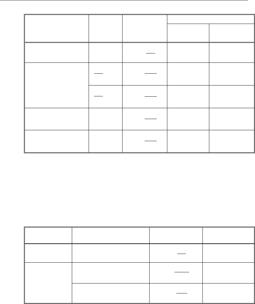
Post-Tensioned Concrete Design
Section
Situation
Definition of
percentage
Minimum percentage
f
y
= 250
MPa
f
y
= 460
MPa
Rectangular 100
bh
A
s
0.24 0.13
T- or L-Beam with
web in tension
f
w
b
b
< 0.4 100
hb
A
w
s
0.32 0.18
f
w
b
b
≥ 0.4 100
hb
A
w
s
0.24 0.13
T-Beam with web in
compression 100
hb
A
w
s
0.48 0.26
L-Beam with web in
compression 100
hb
A
w
s
0.36 0.20
The minimum flexural compression reinforcement, if it is required at all, is given
by the following table, which is taken from BS Table 3.25 (BS 3.12.5.3), with
interpolation for reinforcement of intermediate strength:
Section
Situation
Definition of
percentage
Minimum
percentage
Rectangular 100
s
A
bh
′
0.20
T or L-Beam
Web in tension 100
s
ff
A
bh
′
0.40
Web in compression 100
s
w
A
bh
′
0.20
In addition, an upper limit on both the tension reinforcement and compression
reinforcement is imposed to be 0.04 times the gross cross-sectional area (BS
3.12.6.1).
8 - 20 Beam Design (for Reference Only)
Chapter 8 - Design for BS 8110-97
8.7.2 Design Beam Shear Reinforcement
The shear reinforcement is designed for each load combination in the major
direction of the beam. In designing the shear reinforcement for a particular beam
for a particular load combination, the following steps are involved (BS 3.4.5):
Determine the shear stress, v.
Determine the shear stress, vc, that can be resisted by the concrete.
Determine the shear reinforcement required to carry the balance.
The following three subsections describe in detail the algorithms associated with
these steps.
8.7.2.1 Determine Shear Stress
In the design of the beam shear reinforcement, the shear forces for a particular
load combination at a particular beam section are obtained by factoring the
associated shear forces for different load cases with the corresponding load com-
bination factors.
d
b
V
v
w
=
(BS 3.4.5.2)
The maximum allowable shear stress, vmax is defined as:
vmax = min(0.8
cu
f,
5 MPa) (BS 3.4.5.2)
For light-weight concrete, vmax is defined as:
vmax = min(0.63
cu
f,
4 MPa) (BS 8110-2:1985 5.4)
8.7.2.2 Determine Concrete Shear Capacity
The design ultimate shear resistance of the concrete alone, Vc should be consid-
ered at sections that are as follows:
Uncracked sections in flexure (M < Mo) (BS 4.3.8.3)
Beam Design (for Reference Only) 8 - 21
Post-Tensioned Concrete Design
Cracked sections in flexural (M ≥ Mo) (BS 4.3.8.3)
where,
M is the design bending moment at the section
Mo is the moment necessary to produce zero stress in the concrete at the
extreme tension fiber; in this calculation, only 0.8 of the stress due to
post-tensioning should be taken into account.
8.7.2.2.1.1 Case 1: Uncracked section in flexure
The ultimate shear resistance of the section, Vco, is computed as follows:
( )
0.67 0.8 ,
2
co v t cp t
V = bh f + f f
(BS 4.3.8.4)
where,
ft is the maximum design principal stress (BS 4.3.8.4)
0.24
t cu
f= f
(BS 4.3.8.4)
fcp = design compressive stress at the centroidal axis due to
post-tensioning, taken as positive. (BS 4.3.8.4)
β
sinPVV
coc
+=
(BS 4.3.8.4)
8.7.2.2.1.2 Case 2: Cracked section in flexure
The ultimate shear resistance of the section, Vcr, is computed as follows:
1 0.55 ,
pe
cr c v o
pu
fV
V vbd M
fM
=−+
and (BS 4.3.8.5)
0.1
cr v cu
V bd f≥
(BS 4.3.8.5)
( )
β
sin,min PVVV crcoc+=
(BS 4.3.8.5)
8 - 22 Beam Design (for Reference Only)

Chapter 8 - Design for BS 8110-97
8.7.2.3 Determine Required Shear Reinforcement
Given v, vc and vmax , the required shear reinforcement is calculated as follows
(BS 4.3.8.7):
If v ≤ vc + 0.4,
sv
v
A
s
=
0.4
0.87
w
yv
b
f
(BS 4.3.8.7)
If (vc + 0.4) < v ≤ vmax,
sv
v
A
s
=
( )
0.87
cv
yv
vvb
f
−
(BS 4.3.8.7)
If v > vmax, a failure condition is declared. (BS 3.4.5.2)
In the preceding expressions, a limit is imposed on fyv as:
fyv ≤ 500 MPa. (BS 3.4.5.1, 4.3.8.1)
The maximum of all of the calculated Asv /sv values, obtained from each load
combination, is reported along with the controlling shear force and associated
load combination.
The beam shear reinforcement requirements considered by the program are
based purely on shear strength considerations. Any minimum stirrup require-
ments to satisfy spacing and volumetric considerations must be investigated
independently of the program by the user.
8.7.3 Design Beam Torsion Reinforcement
The torsion reinforcement is designed for each design load combination at each
station along the length of the beam. The following steps are involved in
designing the longitudinal and shear reinforcement for a particular station due to
the beam torsion:
Determine the torsional shear stress, vt
Determine special section properties
Beam Design (for Reference Only) 8 - 23
Post-Tensioned Concrete Design
Determine critical torsion stress
Determine the torsion reinforcement required
Note that references in this section are to BS 8110-2:1985 [BSI 1985].
8.7.3.1 Determine Torsional Shear Stress
In the design of beam torsion reinforcement, the torsions for each load combina-
tion at a particular beam station are obtained by factoring the corresponding tor-
sions for different load cases, with the corresponding load combination factors.
In typical framed construction, specific consideration of torsion is not usually
required where torsional cracking is adequately controlled by shear reinforce-
ment. If the design relies on the torsional resistance of a beam, further consider-
ation should be given using the following algorithms (BS 8110-2:85 3.4.5.13).
The torsional shear stress, vt, for a rectangular section is computed as:
( )
3/
2
minmax
2
min
hhh
T
v
t
−
=
(BS 8110-2:85 2.4.4.1)
For flanged sections, the section is considered as a series of rectangular
segments and the torsional shear stress is computed for each rectangular compo-
nent using the preceding equation, but considering a torsional moment
attributed to that segment, calculated as:
( )
3
min max
seg 3
min max
hh
TT hh
=
∑
(BS 8110-2:85 2.4.4.2)
h
mzx
=
Larger dimension of a rectangular section
h
min
=
Smaller dimension of a rectangular section
If the computed torsional shear stress, vt, exceeds the following limit for sections
with the larger center-to-center dimension of the closed link less than 550 mm,
a failure condition is generated if the torsional shear stress does not satisfy:
21
min(0.8 ,5N/mm ) 550
t cu y
vf≤×
(BS 8110-2:85 2.4.5)
8 - 24 Beam Design (for Reference Only)
Chapter 8 - Design for BS 8110-97
8.7.3.2 Determine Critical Torsion Stress
The critical torsion stress, vt,min, for which the torsion in the section can be
ignored is calculated as:
( )
2
min min 0 067 0 4N/mm
t, cu
v . f ,.=
(BS 8110-2:85 2.4.6)
where fcu is the specified concrete compressive strength.
For light-weight concrete, vt,min is defined as:
( )
2
min
min 0 067 0 4N/mm
t, cu
v . f ,.=
× 0.8 (BS 8110-2:85 5.5)
8.7.3.3 Determine Torsion Reinforcement
If the factored torsional shear stress, vt is less than the threshold limit, vt,min, tor-
sion can be safely ignored (BS 8110-2:85 2.4.6). In that case, the program reports
that no torsion reinforcement is required. However, if vt exceeds the threshold
limit, vt,min, it is assumed that the torsional resistance is provided by closed stir-
rups and longitudinal bars (BS 8110-2:85 2.4.6).
Figure 8-3 Closed stirrup and section dimensions for torsion design
cb
w
2−
c
c
cc
c
c
cb 2−
h
s
d
Closed Stirrup in
Rectangular Beam Closed Stirrup in
T-Beam Section
ch 2−h
b
ch 2−
w
b
bf
cb
w
2−
c
c
cc
c
c
cb 2−
h
s
d
Closed Stirrup in
Rectangular Beam Closed Stirrup in
T-Beam Section
ch 2−h
b
ch 2−
w
b
bf
Beam Design (for Reference Only) 8 - 25

Post-Tensioned Concrete Design
If vt > vt,min, the required closed stirrup area per unit spacing, Asv,t /sv, is calcu-
lated as:
( )
yvv
tsv
fyx
T
s
A
87.08.0 11
,=
(BS 8110-2:85 2.4.7)
and the required longitudinal reinforcement is calculated as:
()
yv
yvt
sv
l
f
s
yxfA
A
1
1
,
+
=
(BS 8110-2:85 2.4.7)
In the preceding expressions, x1 is the smaller center-to-center dimension of
the closed link and y1 is the larger center-to-center dimension of the closed
link.
An upper limit of the combination of v and vt that can be carried by the section
also is checked using the equation:
( )
2
min 0 8 5N/mm
t cu
vv . f,+≤
(BS 8110-2:85 2.4.5)
For light-weight concrete, vmax is defined as:
vmax = min(0.63
cu
f,
4 MPa) (BS 8110-2:85 5.4)
If the combination of shear stress, v and torsional shear stress, vt exceeds this
limit, a failure message is declared. In that case, the concrete section should be
increased in size.
The maximum of all of the calculated Al and Asv,t /sv values obtained from each
load combination is reported along with the controlling combination.
The beam torsion reinforcement requirements reported by the program are based
purely on strength considerations. Any minimum stirrup requirements or longi-
tudinal rebar requirements to satisfy spacing considerations must be
investigated independently of the program by the user.
8 - 26 Beam Design (for Reference Only)

Chapter 8 - Design for BS 8110-97
8.8 Slab Design
Similar to conventional design, the ETABS slab design procedure involves
defining sets of strips in two mutually perpendicular directions. The locations of
the strips typically are governed by the locations of the slab supports. The mo-
ments for a particular strip are recovered from the analysis, and a flexural design
is carried out based on the ultimate strength design method (BS 8110-97) for
prestressed reinforced concrete as described in the following subsections. To
learn more about the design strips, refer to the section entitled "ETABS Design
Techniques" in the Key Features and Terminology manual.
8.8.1 Design for Flexure
ETABS designs the slab on a strip-by-strip basis. The moments used for the
design of the slab elements are the nodal reactive moments, which are obtained
by multiplying the slab element stiffness matrices by the element nodal displace-
ment vectors. Those moments will always be in static equilibrium with the ap-
plied loads, irrespective of the refinement of the finite element mesh.
The design of the slab reinforcement for a particular strip is carried out at specific
locations along the length of the strip. Those locations correspond to the element
boundaries. Controlling reinforcement is computed on either side of those ele-
ment boundaries. The slab flexural design procedure for each load combination
involves the following:
Determine factored moments for each slab strip
Determine the capacity of post-tensioned sections
Design flexural reinforcement for the strip
These three steps are described in the subsections that follow and are repeated
for every load combination. The maximum reinforcement calculated for the top
and bottom of the slab within each design strip, along with the corresponding
controlling load combination, is obtained and reported.
Slab Design 8 - 27

Post-Tensioned Concrete Design
8.8.1.1 Determine Factored Moments for the Strip
For each element within the design strip, for each load combination, the program
calculates the nodal reactive moments. The nodal moments are then added to get
the strip moments.
8.8.1.2 Determine Capacity of Post-Tensioned Sections
The calculation of the post-tensioned section capacity is identical to that
described earlier for rectangular beam sections.
8.8.1.3 Design Flexural Reinforcement for the Strip
The reinforcement computation for each slab design strip, given the bending mo-
ment, is identical to the design of rectangular beam sections described
earlier (or to the flanged beam if the slab is ribbed). In some cases, at a given
design section in a design strip, there may be two or more slab properties across
the width of the design strip. In that case, the program automatically designs the
tributary width associated with each of the slab properties separately using its
tributary bending moment. The reinforcement obtained for each of the tributary
widths is summed to obtain the total reinforcement for the full width of the de-
sign strip at the considered design section. This method is used when drop panels
are included. Where openings occur, the slab width is adjusted accordingly.
8.8.1.4 Minimum and Maximum Slab Reinforcement
There are no minimum requirements for untensioned reinforcement in one-way
bonded slabs. One-way spanning floors with unbounded tendons should have
minimum reinforcement requirements in accordance with BS Table 3.25 (BS
3.12.5.3)
In flat slabs, reinforcement is added at the top over supports to be 0.00075 times
the gross cross-sectional area. This reinforcement extends 1.5 times the slab
depth on each side of the column. The length of the reinforcement should be at
least 0.2L where L is the span of the slab.
There are no minimum requirements for span zone. However, additional un-ten-
sioned reinforcement shall be designed to accommodate the full tension force
8 - 28 Slab Design
Chapter 8 - Design for BS 8110-97
generated by assumed flexural tensile stresses in the concrete for the following
situations (Concrete Society, Technical Report 43):
all locations in one-way spanning floors using unbonded tendons
all locations in one-way spanning floors where transfer tensile stress exceeds
0.36
ci
f
support zones in all flat slabs
span zones in flat slabs using unbonded tendons where the tensile stress
exceeds 0.15
cu
f.
The reinforcement should be designed to act at a stress of 5/8fy as follows:
( )
t
sy
F
A= 5/8 f
where
()
2
ct
t
f h xb
F−
= −
The value of fct will be negative in tension.
In addition, an upper limit on both the tension reinforcement and compression
reinforcement has been imposed to be 0.04 times the gross cross-sectional area
(BS 3.12.6.1).
8.8.2 Check for Punching Shear
The algorithm for checking punching shear is detailed in the section entitled
“Slab Punching Shear Check” in the Key Features and Terminology manual.
Only the code specific items are described in the following sections.
8.8.2.1 Critical Section for Punching Shear
The punching shear is checked at the face of the column (BS 3.7.6.4) and at a
critical section at a distance of 1.5d from the face of the support (BS 3.7.7.6).
Slab Design 8 - 29
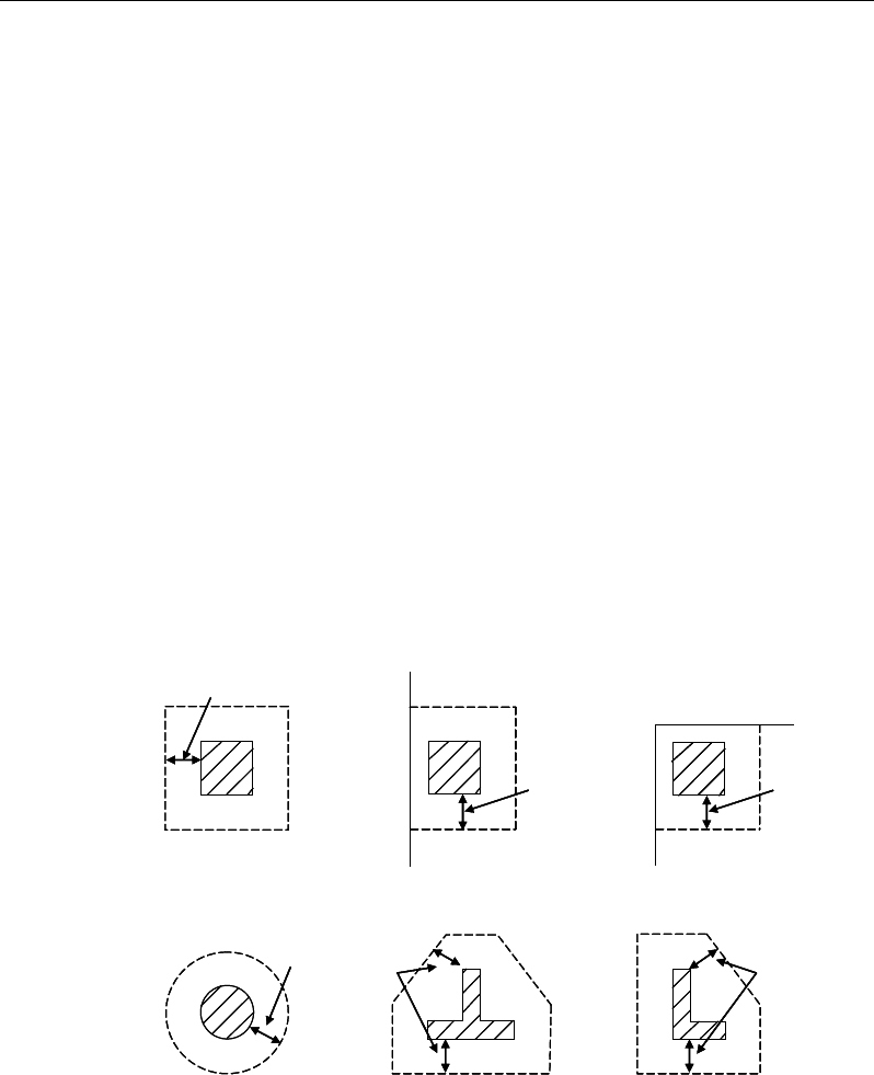
Post-Tensioned Concrete Design
For rectangular columns and concentrated loads, the critical area is taken as a
rectangular area with the sides parallel to the sides of the columns or the point
loads (BS 3.7.7.1). Figure 8-4 shows the auto punching perimeters considered
by ETABS for the various column shapes. The column location (i.e., interior,
edge, corner) and the punching perimeter may be overwritten using the Punching
Check Overwrites.
8.8.2.2 Determine Concrete Capacity
The design ultimate shear resistance of the concrete alone Vc should be consid-
ered at sections that are as follows:
Uncracked sections in flexure (M < Mo) (BS 4.3.8.3)
Cracked sections in flexural (M ≥ Mo) (BS 4.3.8.3)
where,
M is the design bending moment at the section
Figure 8-4 Punching Shear Perimeters
1.5d
Interior Column
Circular Column T-Shape Column
Edge Column Corner Column
L-Shape Column
1.5d 1.5d
1.5d
1.5d
1.5d
1.5d
Interior Column
Circular Column T-Shape Column
Edge Column Corner Column
L-Shape Column
1.5d 1.5d
1.5d
1.5d
1.5d
8 - 30 Slab Design
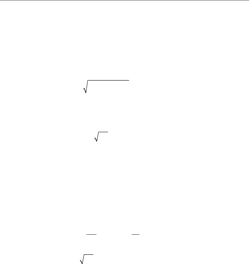
Chapter 8 - Design for BS 8110-97
Mo is the moment necessary to produce zero stress in the concrete at the
extreme tension fiber; in this calculation only 0.8 of the stress due to
post-tensioning should be taken into account.
8.8.2.2.1.1 Case 1: Uncracked section in flexure
The ultimate shear resistance of the section, Vco, is computed as follows:
( )
2
0.67 0.8 ,
co v t cp t
V bh f f f= +
(BS 4.3.8.4)
where,
ft is the maximum design principal stress (BS 4.3.8.4)
0.24
t cu
f= f
(BS 4.3.8.4)
fcp = design compressive stress at the centoidal axis
due to prestress, taken as positive. (BS 4.3.8.4)
Sin
c co
VV P
β
= +
(BS 4.3.8.4)
8.8.2.2.1.2 Case 2: Cracked section in flexure
The ultimate shear resistance of the section, Vcr, is computed as follows:
1 0.55 ,
pe
cr c v o
pu
fV
V vbd M
fM
=−+
and (BS 4.3.8.5)
0.1
cr v cu
V bd f≥
(BS 4.3.8.5)
( )
β
sin,min PVVV crcoc+=
(BS 4.3.8.5)
8.8.2.3 Determine Capacity Ratio
Given the punching shear force and the fractions of moments transferred by
eccentricity of shear about the two axes, the nominal design shear stress, v, is
calculated as:
Slab Design 8 - 31

Post-Tensioned Concrete Design
v =
,
eff
V
ud
where (BS 3.7.7.3)
Veff = V
1.5 1.5
yx
MM
f+ +
Vx Vy ,
(BS 3.7.6.2, 3.7.6.3)
u is the perimeter of the critical section
x and y are the length of the side of the critical section parallel to the axis
of bending
Mx and My are the design moments transmitted from the slab to the col-
umn at the connection
V is the total punching shear force
f is a factor to consider the eccentricity of punching shear force and is
taken as:
1.00 for interior columns
1.25 for edge columns, and
1.25 for corner columns
f
=
(BS 3.7.6.2 and BS 3.7.6.3)
The ratio of the maximum shear stress and the concrete punching shear stress
capacity is reported as the punching shear capacity ratio by ETABS.
8.8.3 Design Punching Shear Reinforcement
The use of shear studs as shear reinforcement in slabs is permitted, provided that
the effective depth of the slab is greater than or equal to 200 mm (BS 3.7.7.5). If
the slab thickness does not meet these requirements, the punching shear rein-
forcement is not designed, and the slab thickness should be increased by the user.
The algorithm for designing the required punching shear reinforcement is used
when the punching shear capacity ratio exceeds unity. The Critical Section for
Punching Shear as described in the earlier sections remains unchanged. The de-
sign of punching shear reinforcement is carried out as described in the subsec-
tions that follow.
8 - 32 Slab Design

Chapter 8 - Design for BS 8110-97
8.8.3.1 Determine Concrete Shear Capacity
The concrete punching shear stress capacity of a section with punching shear
reinforcement is as previously determined for the punching check.
8.8.3.2 Determine Required Shear Reinforcement
The shear stress is limited to a maximum limit of
vmax = 2 vc (BS 3.7.7.5)
Given v, vc and vmax, the required shear reinforcement is calculated as follows
(BS 3.7.7.5).
If v ≤ 1.6vc
s
Av
=
( )
0.4 ,
0.87 0.87
c
yv yv
v v ud ud
ff
−≥
(BS 3.7.7.5)
If 1.6vc ≤ v < 2.0vc
v
A
s
=
( )
5 0.7 0.4 ,
0.87 0.87
c
yv yv
v v ud ud
ff
−≥
(BS 3.7.7.5)
If v > vmax, a failure condition is declared. (BS 3.7.7.5)
If v exceeds the maximum permitted value of vmax, the concrete section should
be increased in size.
8.8.3.3 Determine Reinforcement Arrangement
Punching shear reinforcement in the vicinity of rectangular columns should be
arranged on peripheral lines, i.e., lines running parallel to and at constant dis-
tances from the sides of the column. Figure 8-5 shows a typical arrangement of
shear reinforcement in the vicinity of a rectangular interior, edge, and corner
columns.
Slab Design 8 - 33
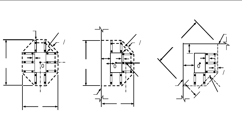
Post-Tensioned Concrete Design
Figure 8-5 Typical arrangement of shear studs and
critical sections outside shear-reinforced zone
The distance between column face and the first line of shear reinforcement shall
not exceed d/2. The spacing between adjacent shear reinforcement in the first
line of shear reinforcement shall not exceed 1.5d measured in a direction parallel
to the column face (BS 11.12.3.3).
Punching shear reinforcement is most effective near column corners where there
are concentrations of shear stress. Therefore, the minimum number of lines of
shear reinforcement is 4, 6, and 8 for corner, edge, and interior columns respec-
tively.
8.8.3.4 Determine Reinforcement Diameter, Height, and Spacing
The punching shear reinforcement is most effective when the anchorage is close
to the top and bottom surfaces of the slab. The cover of anchors should not be
less than the minimum cover specified in BS 3.3 plus half of the diameter of the
flexural reinforcement.
Punching shear reinforcement in the form of shear studs is generally available in
10-, 12-, 14-, 16-, and 20-millimeter diameters.
When specifying shear studs, the distance, so, between the column face and the
first peripheral line of shear studs should not be smaller than 0.5d. The spacing
I
y
Typical Studrail
(only first and last
studs shown)
Outermost
peripheral line
of studs
Interior Column Edge Column Corner Column
Critical section
centroid
Free
edge
Free
edge
Critical
section
centroid
Free edge
Outermost
peripheral line
of studs
I
y
I
y
yx
d2 d2
d2
x
I
x
I
x
g
y
g
x
g
0
s0
s
0
s
x
I
y
x
x
I
y
Typical Studrail
(only first and last
studs shown)
Outermost
peripheral line
of studs
Interior Column Edge Column Corner Column
Critical section
centroid
Free
edge
Free
edge
Critical
section
centroid
Free edge
Outermost
peripheral line
of studs
I
y
I
y
yx
d2 d2
d2
x
I
x
I
x
g
y
g
x
g
0
s0
s
0
s
x
I
y
x
x
8 - 34 Slab Design

Chapter 8 - Design for BS 8110-97
between adjacent shear studs, g, at the first peripheral line of studs shall not
exceed 1.5d. The limit of so and the spacing, s, between the peripheral lines are
specified as:
so ≤ 0.5d (BS 3.7.7.6)
s ≤ 0.75d (BS 3.7.7.6)
g ≤ 1.5d (BS 3.7.7.6)
Slab Design 8 - 35

Chapter 9
Design for CSA A23.3-04
This chapter describes in detail the various aspects of the post-tensioned concrete
design procedure that is used by ETABS when the user selects the Canadian code
CSA A23.3-04 [CSA 2004]. Various notations used in this chapter are listed in
Table 9-1. For referencing to the pertinent sections of the CSA code in this chap-
ter, a prefix “CSA” followed by the section number is used.
The design is based on user-specified load combinations. The program provides
a set of default load combinations that should satisfy the requirements for the
design of most building type structures.
English as well as SI and MKS metric units can be used for input. The code is
based on Newton-millimeter-second units. For simplicity, all equations and
descriptions presented in this chapter correspond to Newton-millimeter-second
units unless otherwise noted.
9.1 Notations
The following table identifies the various notations used in this chapter.
Table 9-1 List of Symbols Used in the CSA A23.3-04 Code
A
p
Area of tension prestressing tendons, mm2
Notations 9 - 1

Post-Tensioned Concrete Design
Table 9-1 List of Symbols Used in the CSA A23.3-04 Code
A
s
Area of tension reinforcement, mm2
A'
s
Area of compression reinforcement, mm2
A
s(required)
Area of steel required for tension reinforcement, mm2
A
v
Area of shear reinforcement, mm2
A
v
/ s
Area of shear reinforcement per unit length of the member,
mm2/mm
Avs
Area of headed shear reinforcement, mm
2
Avs / s
Area of headed shear reinforcement per unit length of the mem-
ber, mm2/mm
a
Depth of compression block, mm
b
Width of member, mm
bf
Effective width of flange (T-beam section), mm
b
w
Width of web (T-beam section), mm
b
0
Perimeter of the punching critical section, mm
b1
Width of the punching critical section in the direction of bend-
ing, mm
b
2
Width of the punching critical section perpendicular to the
direction of bending, mm
c
Depth to neutral axis, mm
d
Distance from compression face to tension reinforcement, mm
d'
Concrete cover to center of reinforcing, mm
dp
Distance from compression face to prestressing tendons, mm
ds
Thickness of slab, mm
9 - 2 Notations

Chapter 9 - Design for CSA A23.3-04
Table 9-1 List of Symbols Used in the CSA A23.3-04 Code
d
v
Effective shear depth, mm
E
c
Modulus of elasticity of concrete, MPa
E
p
Modulus of elasticity of prestressing tendons, MPa
E
s
Modulus of elasticity of reinforcement, assumed as 2×10⁵ MPa
'
ci
f
Specified compressive strength of concrete at time of prestress
transfer, MPa
'
c
f
Specified compressive strength of concrete, MPa
f
y
Specified yield strength of flexural reinforcement, MPa
f
yh
Specified yield strength of shear reinforcement, MPa
f
yv
Specified yield strength of headed shear reinforcement, MPa
h
Overall depth of a section, mm
I
g
Moment of inertia of gross concrete section about centroidal
axis, neglecting reinforcement.
M
f
Factored moment at section, N-mm
φ
M
r
0
Design moment resistance of a section with tendons only, N-
mm
φ
M
r
bal
Design moment resistance of a section with tendons and the
necessary mild reinforcement to reach the balanced condition,
N-mm
s
Spacing of the shear reinforcement along the length of the
beam, mm
V
c
Shear resisted by concrete, N
V
r,max
Maximum permitted total factored shear force at a section, N
Notations 9 - 3

Post-Tensioned Concrete Design
Table 9-1 List of Symbols Used in the CSA A23.3-04 Code
V
f
Factored shear force at a section, N
V
s
Shear force at a section resisted by steel, N
α
1
Ratio of average stress in rectangular stress block to the speci-
fied concrete strength
β
1
Factor for obtaining depth of compression block in concrete
β
c
Ratio of the maximum to the minimum dimensions of the
punching critical section
ε
c
Strain in concrete
ε
cu
Maximum strain in concrete at ultimate
ε
p
Strain in prestressing tendons
ε
s
Strain in reinforcing steel
ϕ
c
Resistance factor for concrete
ϕ
p
Resistance factor for prestressing tendons
ϕ
s
Resistance factor for steel
γ
f
Fraction of unbalanced moment transferred by flexure
γ
v
Fraction of unbalanced moment transferred by eccentricity of
shear
λ
Shear strength factor
9.2 Design Load Combinations
The design load combinations are the various combinations of the load cases for
which the structure needs to be designed. For CSA A23.3-04, if a structure is
subjected to dead (D), live (L), pattern live (PL), snow (S), wind (W), and earth-
quake (E) loads, and considering that wind and earthquake forces are
9 - 4 Design Load Combinations

Chapter 9 - Design for CSA A23.3-04
reversible, the load combinations in the following sections may need to be con-
sidered (CSA 8.3.2, Table C.1).
For post-tensioned concrete design, the user also can specify the prestressing
load (PT) by providing the tendon profile or by using the load balancing
options in the program. The default load combinations for post-tensioning are
defined in the following sections.
9.2.1 Initial Service Load Combination
The following load combination is used for checking the requirements at transfer
of prestress forces, in accordance with CSA 18.3.1. The prestressing forces are
considered without any long-term loses for the initial service load combination
check.
1.0D + 1.0PT
9.2.2 Service Load Combinations
The following load combinations are used for checking the requirements of pre-
stress for serviceability in accordance with CSA 18.3.2. It is assumed that long-
term losses have already occurred at the service stage.
1.0D + 1.0PT
1.0D + 1.0L + 1.0PT
9.2.3 Long-Term Service Load Combination
The following load combinations are used for checking the requirements of pre-
stress in accordance with CSA 18.3.2(a). The permanent load for this load com-
bination is taken as 50 percent of the live load. It is assumed that all long term
losses have already occurred at the service stage.
1.0D + 1.0PT
1.0D + 0.5L + 1.0PT
Design Load Combinations 9 - 5

Post-Tensioned Concrete Design
9.2.4 Strength Design Load Combination
The following load combinations are used for checking the requirements of pre-
stress for strength in accordance with CSA A23.3-04, Chapters 8 and 18.
The strength design combinations required for punching shear require the full
PT forces (primary and secondary). Flexural design requires only the hyperstatic
(secondary) forces. The hyperstatic (secondary) forces are determined automat-
ically by ETABS by subtracting the primary PT moments when the flexural de-
sign is carried out.
1.4D + 1.0PT*
(CSA 8.3.2,Table C.1, Case 1)
1.25D + 1.5L + 1.0PT*
1.25D + 1.5L + 1.0P
T* ± 0.4W
1.25D + 1.5L + 1.0P
T* + 0.5S
0.9D + 1.5L + 1.0P
T*
0.9D + 1.5L + 1.0P
T* ± 0.4W
0.9D + 1.
5L + 1.0PT* + 0.5S
(CSA 8.3.2,Table C.1, Case 2)
1.25D + 1.5(0.75 PL) + 1.0PT*
(CSA 13.8.4.3)
1.25D + 1.5S + 1.0PT*
1.25D + 1.5S + 1.0P
T* + 0.5L
1.25D + 1.5S + 1.0P
T* ± 0.4W
0.9D + 1.5S + 1.0P
T*
0.9D + 1.5S + 1.0P
T* + 0.5L
0.9D + 1.5S + 1.0P
T* ± 0.4W
(
CSA 8.3.2,Table C.1, Case 3)
1.25D ± 1.4W + 1.0PT*
1.25D
± 1.4W + 1.0PT* + 0.5L
1.25D
± 1.4W + 1.0PT* + 0.5S
0.9D
± 1.4W + 1.0PT*
0.9D
± 1.4W + 1.0PT* + 0.5L
0.9D
± 1.4W + 1.0PT* + 0.5S
(CSA 8.3.2,Table C.1, Case 4)
1.0D ± 1.0E + 1.0PT*
1.0D
± 1.0E + 0.5L + 1.0PT*
1.0D
± 1.0E + 0.25S + 1.0PT*
1.0D + 0.5L
+ 0.25S ± 1.0E + 1.0PT*
(CSA 8.3.2,Table C.1, Case 5)
* — Replace PT by H for flexural design only
9 - 6 Design Load Combinations

Chapter 9 - Design for CSA A23.3-04
These are also the default design combinations in ETABS whenever the CSA
A23.3-04 code is used. The user should use other appropriate load combinations
if roof live load is treated separately, or if other types of loads are present.
9.3 Limits on Material Strength
The upper and lower limits of f'c are 80 MPa and 20 MPa respectively. The
upper limit of fy is 500 MPa for non-prestressed reinforcement (CSA 8.6.1.1).
For compression reinforcement with fy exceeding 400 MPa, the value of fy
assumed in design calculations shall not exceed the stress corresponding to a
strain of 0.0035 (CSA 8.5.21).
ETABS enforces the upper material strength limits for flexure and shear design
of slabs. The input material strengths are taken as the upper limits if they are
defined in the material properties as being greater than the limits. The user is
responsible for ensuring that the minimum strength is satisfied.
ETABS also checks the following tensile strength limits in prestressing steel
(CSA 18.4). The permissible tensile stresses in all types of prestressing steel, in
terms of the specified minimum tensile strength fpu, are summarized as follows:
Due to tendon jacking force for post-tensioning tendons:
0.85 fpu ≤ 0.94 fpy
Due to tendon jacking force for pretensioning tendons:
0.80 fpu
Immediately after prestress transfer:
0.82 fpy ≤0.74 fpu
Post-tensioning tendons, at anchorages and couplers, immediately after tendon
anchorage:
0.70 fpu
Limits on Material Strength 9 - 7

Post-Tensioned Concrete Design
The specified yield strength of prestressing tendons is based on the requirements
specified in ASTM A 416/A 416 M, ASTM A 421/A421 M, and ASTM A 722/A
722 m, which specify the following minimum values for fpy:
low-relaxation wire and strands fpy = 0.90 fpu
stress-relieved wire and strands, and plain bars fpy = 0.85 fpu
deformed bar fpy = 0.80 fpu
9.4 Strength Reduction Factors
The strength reduction factors,
φ
, are material dependent and defined as:
φ
c = 0.65 for concrete (CSA 8.4.2)
φ
s = 0.85 for reinforcement (CSA 8.4.3a)
φ
p = 0.90 for post-tensioning tendons (CSA 8.4.3a)
The preceding values for
φ
c,
φ
s, and
φ
p are the default values. These values can
be modified in the design preferences. For structural concrete manufactured in
prequalified manufacturing plants,
φ
c can be taken as 0.7 (CSA 8.4.2, 16.1.3).
9.5 Design Assumptions for Prestressed Concrete
Strength design of prestressed members for flexure and axial loads shall be based
on assumptions given in CSA 10.1.
The strain in the reinforcement and concrete shall be assumed directly propor-
tional to the distance from the neutral axis, except for unbonded tendons (CSA
10.1.2).
The maximum usable strain at the extreme concrete compression fiber shall be
assumed equal to 0.0035 (CSA 10.1.3).
The balanced strain condition shall exist at a cross-section when tension rein-
forcement reaches its yield strain just as the concrete in compression reaches
its maximum strain of 0.0035 (CSA 10.1.4).
9 - 8 Strength Reduction Factors

Chapter 9 - Design for CSA A23.3-04
The tensile strength of concrete shall be neglected in the calculation of the
factored flexural resistance of prestressed concrete members (CSA 10.1.5).
The relationship between the concrete compressive stress distribution and the
concrete strain shall be assumed to be rectangular by an equivalent rectangular
concrete stress distribution (CSA 10.1.7).
The concrete stress of
'
αϕ
ccc
f
shall be assumed uniformly distributed over an
equivalent-compression zone bounded by edges of the cross-section and a
straight line located parallel to the neutral axis at a distance
1
ac
β
=
from the
fiber of maximum compressive strain (CSA 10.1.7(a)).
The distance from the fiber of maximum strain to the neutral axis, c, shall be
measured in a direction perpendicular to the neutral axis (CSA 10.1.7.(b)).
The factors α1 and β1 shall be taken as follows (CSA 10.1.7.(c)).
– α1 = 0.85 – 0.0015
'
c
f
≥ 0.67
– β1 = 0.97 – 0.0025
'
c
f
≥ 0.67
Prestressed concrete members are investigated at the following three stages
(CSA 18.3):
At transfer of prestress force
At service loading
At nominal strength
9.6 Serviceability Requirements of Flexural Members
9.6.1 Serviceability Check at Initial Service Load
The stress in the concrete immediately after prestress force transfer (before time
dependent prestress losses) are checked against the following limits (CSA
18.3.1.1(a), 18.3.1.1(b) and 18.3.1.1(c)):
Extreme fiber stress in compression:
Serviceability Requirements of Flexural Members 9 - 9
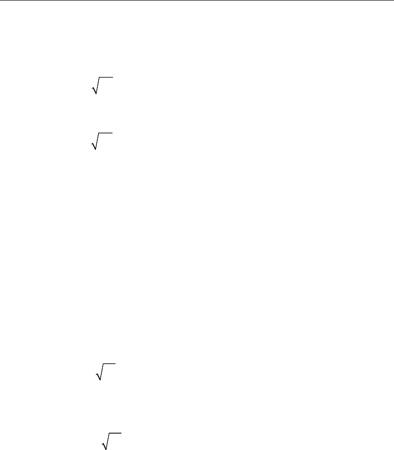
Post-Tensioned Concrete Design
0.60
'
ci
f
Extreme fiber stress in tension, except as permitted in the subsequent item:
0.25λ'
ci
f
Extreme fiber stress in tension at ends of simply supported members:
0.5λ'
ci
f
The extreme fiber stress in tension at the ends of simply supported members is
currently NOT checked by ETABS.
9.6.2 Serviceability Check at Service Load
The stresses in prestressed concrete flexural members at service loads, and after
all prestress losses occur, are checked against the following limits (CSA 18.3.2):
Extreme fiber stress in compression due to prestress plus total load:
0.60
'
c
f
Extreme fiber stress in tension in the precompressed tensile zone at service
loads:
0.5λ
'
c
f
Extreme fiber stress in tension in the precompressed tensile zone at service
loads, exposed to corrosive environment:
0.25λ
'
c
f
9.6.3 Serviceability Check at Long-Term Service Load
The stresses in prestressed concrete flexural members at long-term service loads,
and after all prestress losses have occurred, are checked against the same limits
as for the normal service load, except for the following (CSA 18.3.2):
9 - 10 Serviceability Requirements of Flexural Members

Chapter 9 - Design for CSA A23.3-04
Extreme fiber stress in compression due to prestress plus sustained load:
0.45
'
c
f
9.7 Beam Design (for Reference Only)
Important Note: Post-tensioned beam design is not available in the current ver-
sion of ETABS, but is planned for a future release. This section is provided as
reference only for the documentation of post-tensioned slab design.
In the design of prestressed concrete beams, ETABS calculates and reports the
required areas of reinforcement for flexure, shear, and torsion based on the beam
moments, shear forces, torsion, load combination factors, and other criteria de-
scribed in the subsections that follow. The reinforcement requirements are cal-
culated at each station along the length of the beam.
Beams are designed for major direction flexure, shear, and torsion only. Effects
resulting from any axial forces and minor direction bending that may exist in the
beams must be investigated independently by the user.
The beam design procedure involves the following steps:
Design flexural reinforcement
Design shear reinforcement
Design torsion reinforcement
9.7.1 Design Flexural Reinforcement
The beam top and bottom flexural reinforcement is designed at each station
along the beam. In designing the flexural reinforcement for the major moment
of a particular beam, for a particular station, the following steps are involved:
Determine factored moments
Determine required flexural reinforcement if required
Beam Design (for Reference Only) 9 - 11

Post-Tensioned Concrete Design
9.7.1.1 Determine Factored Moments
In the design of flexural reinforcement of post-tensioned beams, the factored
moments for each load combination at a particular beam station are obtained by
factoring the corresponding moments for different load cases, with the corre-
sponding load factors.
The beam is then designed for the maximum positive and maximum negative
factored moments obtained from all of the load combinations. Positive beam
moments can be used to calculate bottom reinforcement. In such cases the beam
may be designed as a rectangular or flanged beam. Negative beam moments can
be used to calculate top reinforcement. In such cases the beam may be designed
as a rectangular or inverted flanged beam.
9.7.1.2 Determine Required Flexural Reinforcement
In the flexural reinforcement design process, the program calculates both the
tension and compression reinforcement. Compression reinforcement is added
when the applied design moment exceeds the maximum moment capacity of a
singly reinforced section. The user has the option of avoiding the compression
reinforcement by increasing the effective depth, the width, or the strength of the
concrete.
The design procedure is based on the simplified rectangular stress block, as
shown in Figure 9-1 (CSA 10.1.7). Furthermore it is assumed that the compres-
sion carried by the concrete is less than or equal to that which can be carried at
the balanced condition (CSA 10.1.4). When the applied moment exceeds the mo-
ment capacity at this design condition, the area of compression reinforcement is
calculated on the assumption that the additional moment will be carried by com-
pression and additional tension reinforcement.
The design procedure used by ETABS, for both rectangular and flanged sections
(L- and T-beams) is summarized in the subsections that follow. It is assumed
that the design ultimate axial force in a beam is negligible; hence all the beams
are designed for major direction flexure, shear, and torsion only.
9 - 12 Beam Design (for Reference Only)
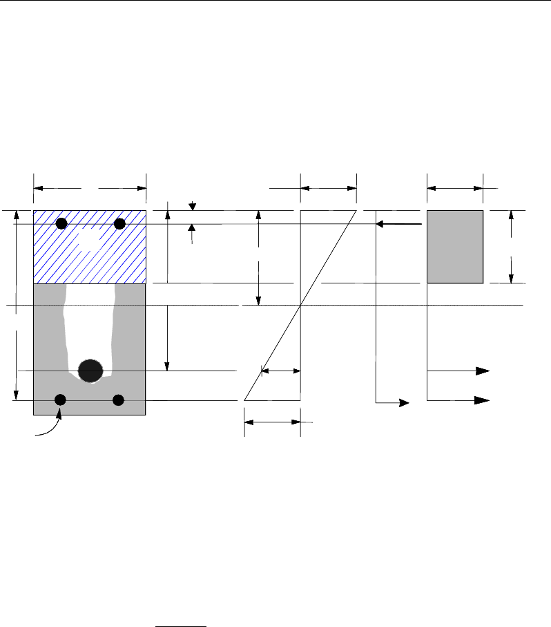
Chapter 9 - Design for CSA A23.3-04
9.7.1.2.1 Design of Rectangular Beams
ETABS first determines whether the moment capacity provided by the post-ten-
sioning tendons alone is enough. In calculating the capacity, it is assumed that
As = 0. In that case, moment capacity
0
n
M
φ
is determined as follows:
Figure 9-1 Rectangular Beam Design
The maximum depth of the compression zone, cmax, is calculated based on strain-
stress compatibility (CSA 18.6.1):
cmax =
cu pp
cu p
εEd
ε +ε
(CSA 18.6.1)
where,
ε
cu = 0.0035 (CSA 10.1.4)
Therefore, the limits
max
cc≤
is set for tension-controlled sections.
(I) BEAM
SECTION (II) STRAIN
DIAGRAM (II) STRESS
DIAGRAM
s
A′
s
A
p
A
s
d
p
d
b
d′
0.0035
ε
=
s
C
c
s
ε
ε
p
s
T
c
T
1
ac
β
=
1
αφ
′
cc
f
(I) BEAM
SECTION (II) STRAIN
DIAGRAM (II) STRESS
DIAGRAM
s
A′
s
A
p
A
s
d
p
d
b
d′
0.0035
ε
=
s
C
c
s
ε
ε
p
s
T
c
T
1
ac
β
=
1
αφ
′
cc
f
Beam Design (for Reference Only) 9 - 13

Post-Tensioned Concrete Design
The ductility of a section is ensured by limiting the c/d ratio and strength
reduction factor
φ
. The minimum ductility required by the CSA code is limited
as c/dp ≤ 0.5 (CSA 18.6.2).
The maximum allowable depth of the rectangular compression block, amax, is
given by:
amax =
β
1cmax (CSA 10.1.7(a))
where
β
1 is calculated as:
β1 = 0.97 – 0.0025
'
c
f
≥ 0.67 (CSA 10.1.7)
ETABS determines the depth of the neutral axis, c, by imposing force equilib-
rium, i.e., C = T. After the depth of the neutral axis has been determined, the
stress in the post-tensioning steel, fpr is computed based on strain compatibility.
On the basis of the calculated fpr, the depth of the neutral axis is recalculated, and
fpr is further updated. After this iteration process has converged, the depth of the
rectangular compression block is determined as follows:
1
ac
β
=
If
max
cc≤
(CSA 18.6.2), the moment capacity of the section, provided by
post-tensioning steel only, is computed as:
0
2
r ps pr p
a
M Af d
φφ
= −
If
max
cc>
(CSA 18.6.2), a failure condition is declared.
If
0,
fr
MM
φ
>
ETABS calculates the moment capacity and the As required at
the balanced condition. The balanced condition is taken as the marginal ten-
sion controlled case. In that case, it is assumed that the depth of the neutral
axis c is equal to cmax. The stress in the post-tensioning steel, fpr is then calcu-
lated based on strain compatibility and the area of required tension reinforce-
ment, As, is determined by imposing force equilibrium, i.e., C = T.
'
1 maxcc
C fab
αφ
=
9 - 14 Beam Design (for Reference Only)

Chapter 9 - Design for CSA A23.3-04
bal bal bal
p pr s s
T Af A f= +
'
1 max bal
c c p pr
bal
sbal
s
f a b Af
Af
αφ
−
=
After the area of tension reinforcement has been determined, the capacity of the
section with post-tensioning steel and tension reinforcement is computed as:
max max
22
bal bal bal bal
r p pr p s s s
aa
M Afd Afd
φφ φ
= −+ −
In that case, it is assumed that the bonded tension reinforcement will yield, which
is true for most cases. In the case that it does not yield, the stress in the reinforce-
ment, fs, is determined from the elastic-perfectly plastic stress-strain relationship.
The fy value of the reinforcement is then replaced with fs in the preceding four
equations. This case does not involve any iteration in determining the depth of
the neutral axis, c.
9.7.1.2.1.1 Case 1: Post-tensioning steel is adequate
When
()
0,
fr
MM
φ
<
the amount of post-tensioning steel is adequate to resist the
design moment Mf. Minimum reinforcement is provided to satisfy the ductility
requirements (CSA 18.3.13, 18.7 and 18.8), i.e.,
( )
0.
fr
MM
φ
<
9.7.1.2.1.2 Case 2: Post-tensioning steel plus tension reinforcement
In this case, the amount of post-tensioning steel, Ap, alone is not sufficient to
resist Mf, and therefore the required area of tension reinforcement is computed
to supplement the post-tensioning steel. The combination of post-tensioning
steel and tension reinforcement should result in a < amax.
When
0,
bal
rf r
MM M
φφ
<<
ETABS determines the required area of tension re-
inforcement, As, iteratively to satisfy the design moment Mf and reports the
required area of tension reinforcement. Since Mf is bounded by
0
r
M
φ
at the lower
end and
bal
r
M
φ
at the upper end, and
0
r
M
φ
is associated with
0
s
A=
and
bal
r
M
φ
Beam Design (for Reference Only) 9 - 15

Post-Tensioned Concrete Design
is associated with
,
bal
ss
AA=
the required area will be within the range of 0 to
s
A
.
The tension reinforcement is to be placed at the bottom if Mf is positive or at the
top if Mf is negative.
9.7.1.2.1.3 Case 3: Post-tensioning steel and tension reinforcement is
not adequate
When
( )
,
bal
fr
MM
φ
>
compression reinforcement is required (CSA 18.6.2). In
that case, ETABS assumes that the depth of the neutral axis, c, is equal to
max .c
The values of fpr and fs reach their respective balanced condition values, bal
pr
f and
.
bal
s
f
The area of compression reinforcement,
,
s
A′
is determined as follows:
The moment required to be resisted by compression reinforcement and tension
reinforcement is:
bal
rs f r
MM M
φ
= −
The required compression reinforcement is given by:
( )( )
1
,
rs
sss c c s
M
Af f dd
φ φα
′=′′′
−−
where
s
f′
= 0.0035Es
c - d'
c
≤ fy (CSA 10.1.2, 10.1.3)
The tension reinforcement for balancing the compression reinforcement is given
by:
( )
sy
rs
com
sddf
M
A
φ
'−
=
Therefore, the total tension reinforcement, As =
bal
s
A
+
,
com
s
A
and the total com-
pression reinforcement is A's. As is to be placed at the bottom and A's is to be
placed at the top if Mf is positive, and vice versa if Mf is negative.
9 - 16 Beam Design (for Reference Only)
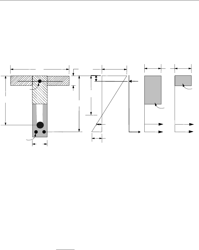
Chapter 9 - Design for CSA A23.3-04
9.7.1.2.2 Design of Flanged Beams
9.7.1.2.2.1 Flanged Beam Under Negative Moment
In designing for a factored negative moment, Mf
(i.e., designing top reinforce-
ment), the calculation of the reinforcement area is exactly the same
as described previously, i.e., no flanged beam data is used.
Figure 9-2 T-Beam Design
9.7.1.2.2.2 Flanged Beam Under Positive Moment
ETABS first determines if the moment capacity provided by the post-tensioning
tendons alone is enough. In calculating the capacity, it is assumed that As = 0. In
that case, the moment capacity
0
n
M
φ
is determined as follows:
The maximum depth of the compression zone, cmax, is calculated based on strain-
stress compatibility (CSA 18.6.1):
cmax =
cu pp
cu p
εEd
ε +ε
(CSA 18.6.1)
where,
STRESS
DIAGRAM
STRAIN
DIAGRAM
BEAM
SECTION
s
A
p
A
p
d
s
d
s
A′
c
0.0035
ε
=
1
αφ
′
cc
f
1
αφ
′
cc
f
s
C
ε
p
s
ε
d′
w
C
t
C
w
Tf
T
s
T
s
h
′
s
f
f
b
w
b
STRESS
DIAGRAM
STRAIN
DIAGRAM
BEAM
SECTION
s
A
p
A
p
d
s
d
s
A′
c
0.0035
ε
=
1
αφ
′
cc
f
1
αφ
′
cc
f
s
C
ε
p
s
ε
d′
w
C
t
C
w
Tf
T
s
T
s
h
′
s
f
f
b
w
b
Beam Design (for Reference Only) 9 - 17

Post-Tensioned Concrete Design
ε
cu = 0.0035 (CSA 10.1.4)
Therefore, the limits
max
cc≤
is set for tension-controlled sections.
The ductility of a section is ensured by limiting the c/d ratio and strength reduc-
tion factor
φ
. The minimum ductility required by the CSA code is limited to c/dp
≤ 0.5 (CSA 18.6.2).
The maximum allowable depth of the rectangular compression block, amax, is
given by:
amax =
β
1cmax (CSA 10.1.7(a))
where
β
1 is calculated as:
β1 = 0.97 – 0.0025
'
c
f
≥ 0.67 (CSA 10.1.7)
ETABS determines the depth of the neutral axis, c, by imposing force equilib-
rium, i.e., C = T. After the depth of the neutral axis has been determined, the
stress in the post-tensioning steel, fpr is computed based on strain compatibility.
Based on the calculated fpr, the depth of the neutral axis is recalculated, and fpr is
further updated. After this iteration process has converged, the depth of the rec-
tangular compression block is determined as follows:
1
ac
β
=
If
max
cc≤
(CSA 18.6.2), the moment capacity of the section, provided by post-
tensioning steel only, is computed as:
0
2
r ps pr p a
M Af d
φφ
= −
If
max
cc>
(CSA 18.6.2), a failure condition is declared.
If
0,
fr
MM
φ
>
ETABS calculates the moment capacity and the As required at
the balanced condition. The balanced condition is taken as the marginal ten-
sion controlled case. In that case, it is assumed that the depth of neutral axis c
is equal to cmax. The stress in the post-tensioning steel, fpr is then calculated
9 - 18 Beam Design (for Reference Only)

Chapter 9 - Design for CSA A23.3-04
based on strain compatibility and the area of required tension reinforcement,
As, is determined by imposing force equilibrium, i.e., C = T.
If a ≤ hs, the subsequent calculations for As are exactly the same as previously
defined for the rectangular beam design. However, in this case the width of
the beam is taken as bf. Compression reinforcement is required when a > amax.
If a > hs, the calculation for As is given by:
1 max com
cc c
C faA
αφ
′
=
where
com
c
A
is the area of concrete in compression, i.e.,
( )
max
com
c fs w s
A bd b a d=+−
bal bal bal
p pr s s
T Af A f= +
1 max com bal
c c c p pr
bal
sbal
s
f a A Af
Af
αφ
′−
=
After the area of tension reinforcement has been determined, the capacity of the
section with post-tensioning steel and tension reinforcement is computed as:
max max
22
bal bal bal bal
r p pr p s s s
aa
M Afd Afd
φφ φ
= −+ −
In that case, it is assumed that the bonded tension reinforcement will yield, which
is true for most cases. In the case that it does not yield, the stress in the reinforc-
ing steel, fs, is determined from the elastic-perfectly plastic stress-strain relation-
ship. The fy value of the reinforcement is then replaced with fs in the preceding
four equations. This case does not involve any iteration in determining the depth
of neutral axis, c.
Beam Design (for Reference Only) 9 - 19

Post-Tensioned Concrete Design
9.7.1.2.2.3 Case 1: Post-tensioning steel is adequate
When
( )
0
fr
MM
φ
<
the amount of post-tensioning steel is adequate to resist the
design moment Mf. Minimum reinforcement is provided to satisfy ductility re-
quirements (CSA 18.3.13, 18.7 and 18.8), i.e.,
( )
0.
fr
MM
φ
<
9.7.1.2.2.4 Case 2: Post-tensioning steel plus tension reinforcement
In this case, the amount of post-tensioning steel, Ap, alone is not sufficient to
resist Mf, and therefore the required area of tension reinforcement is computed
to supplement the post-tensioning steel. The combination of post-tensioning
steel and tension reinforcement should result in a < amax.
When
0,
bal
rf r
MM M
φφ
<<
ETABS determines the required area of tension re-
inforcement, As, iteratively to satisfy the design moment Mf and reports this re-
quired area of tension reinforcement. Since Mf is bounded by
0
r
M
φ
at the lower
end and
bal
r
M
φ
at the upper end, and
0
r
M
φ
is associated with
0
s
A=
and
bal
r
M
φ
is associated with
,
bal
ss
AA=
the required area will be within the range of 0 to
.
s
A
The tension reinforcement is to be placed at the bottom if Mf is positive, or at the
top if Mf is negative.
9.7.1.2.2.5 Case 3: Post-tensioning steel and tension reinforcement is
not adequate
When
( )
,
bal
fr
MM
φ
>
compression reinforcement is required (CSA 18.6.2). In
that case, ETABS assumes that the depth of the neutral axis, c, is equal to
max
c
.
The values of fpr and fs reach their respective balanced condition values,
bal
pr
f
and
.
bal
s
f
Then the area of compression reinforcement,
,
s
A′
is determined as follows:
The moment required to be resisted by compression reinforcement and tension
reinforcement is:
bal
rs f r
MM M
φ
= −
9 - 20 Beam Design (for Reference Only)

Chapter 9 - Design for CSA A23.3-04
The required compression reinforcement is given by:
( )( )
1
,
'
rs
sss c c s
M
Af f dd
φ φα
′=′′
−−
where
s
f′
= 0.0035Es
−
c d'
c
≤ fy. (CSA 10.1.2, 10.1.3)
The tension reinforcement for balancing the compression reinforcement is given
by:
( )
sy
rs
com
s
d
df
M
A
φ
'−
=
Therefore, the total tension reinforcement, As =
bal
s
A
+
,
com
s
A
and the total com-
pression reinforcement is A's. As is to be placed at the bottom and A's is to be
placed at the top if Mf is positive, and vice versa if Mf is negative.
9.7.1.2.3 Minimum and Maximum Reinforcement
The minimum flexural tension reinforcement required in a beam section is given
by the limits specified in CSA 18.8.2, Table 18.1.
An upper limit of 0.04 times the gross web area on both the tension reinforce-
ment and the compression reinforcement is imposed upon request as follows:
Rectangular beam
Flanged beam
Rectangular beam
Flanged beam
s
w
s
w
0.04bd
A0.04b d
0.04bd
A0.04b d
≤
′≤
9.7.2 Design Beam Shear Reinforcement
The shear reinforcement is designed for each load combination at each station
along the length of the beam. In designing the shear reinforcement for a particu-
lar beam, for a particular load combination at a particular station due to the beam
major shear, the following steps are involved:
Beam Design (for Reference Only) 9 - 21
Post-Tensioned Concrete Design
Determine the factored forces acting on the section, Mf and vf. Note that Mf is
needed for the calculation of vc.
Determine the shear stress, vc that can be resisted by the concrete.
Determine the shear reinforcement required to carry the balance.
The following three sections describe in detail the algorithms associated with
these steps.
9.7.2.1 Determine Shear Force
In the design of the beam shear reinforcement of a concrete beam, the shear
forces for a particular load combination at a particular beam section are
obtained by factoring the associated shear forces and moments with the cor-re-
sponding load combination factors.
9.7.2.2 Determine Concrete Shear Capacity
The shear force carried by the concrete, Vc, is calculated as:
c c cwv
V f bd
φ λβ
′
=
(CSA 11.3.4)
where,
′≤8
c
f
MPa (CSA 11.3.4)
φ
c is the resistance factor for concrete. By default it is taken as 0.65 (CSA
8.4.2). For concrete produced in a pre-qualified manufacturing plant, the
value can be taken as 0.70 (CSA 16.1.3). This value can be overwritten in
the design preferences.
λ
is the strength reduction factor to account for low density concrete (CSA
2.2). For normal density concrete, its value is 1 (CSA 8.6.5), which is taken
by the program as the default value. For concrete using lower density ag-
gregate, the user can change the value of
λ
in the material property data.
The recommended value for
λ
is as follows (CSA 8.6.5).
9 - 22 Beam Design (for Reference Only)

Chapter 9 - Design for CSA A23.3-04
λ
=
1.00, for normal density concrete,
0.85, for semi-low-density concrete
in which all of the fine aggregate is natural sand,
0.75, for semi-low-density concrete
in which none of the fine aggregate is natural
sand.
β
is the factor for accounting for the shear resistance of cracked concrete
(CSA 2.2). Its value is normally between 0.1 and 0.4. It is determined
according to CSA 11.3.6 and described further in the following sections.
w
b
is the effective web width. For rectangular beams, it is the width of the
beam. For flanged beams, it is the width of the web of the beam.
v
d
is the effective shear depth. It is taken as the greater of 0.9d or 0.72h (CSA
2.3), where d is the distance from the extreme compression fiber to the
centroid of tension reinforcement, and h is the overall depth of the cross-
section in the direction of the shear force.
The value of
β
is preferably taken as the special value (CSA 11.3.6.2), or it is
determined using the simplified method (CSA 11.3.6.3), if applicable. When the
conditions of the special value or simplified method do not apply, the
general method is used (CSA 11.3.6.4).
If the overall beam depth, h, is less than 250 mm or if the beam depth of a flanged
beam below the slab is not greater than one-half of the width of the web or 350
mm,
β
is taken as 0.21 (CSA 11.3.6.2).
β
= 0.21 (CSA 11.3.6.2)
When the specified yield strength of the longitudinal reinforcing fy does not
exceed 400 MPa, and the specified concrete strength
c
′
f
does not exceed 60
MPa, β is determined in accordance with the simplified method, as follows (CSA
11.6.3.3):
When the section contains at least the minimum transverse reinforcement,
β
is taken as 0.18 (CSA 11.3.6.3a).
β
= 0.18 (CSA 11.3.6.3.a)
Beam Design (for Reference Only) 9 - 23

Post-Tensioned Concrete Design
When the section contains no transverse reinforcement,
β
is determined based
on the specified maximum nominal size of coarse aggregate,
.
g
a
For maximum size of coarse aggregate not less than 20 mm,
β
is taken as:
230
1000
v
d
β
=+
(CSA 11.3.6.3 b)
where dv is the effective shear depth expressed in millimeters, which is
described in preceding sections.
For a maximum size of coarse aggregate less than 20 mm,
β
is taken as:
230
1000 ze
s
β
=+
(CSA 11.3.6.3 c)
where,
35 0.85
15
ze z z
g
S SS
a
= ≥
+
(CSA 11.3.6.3.c)
In the preceding expression, the crack spacing parameter, sze, shall be taken as
the minimum of dv and the maximum distance between layers of distributed lon-
gitudinal reinforcement. However, sze is conservatively taken as equal to dv.
In summary, for simplified cases,
β
can be expressed as follows:
0.18, if minimum transverse reinforcement is provided,
230 , if no transverse reinforcement is provided, and 20mm,
1000
230 , if no transverse reinforcement is provided, and 20mm.
1000
g
v
g
ze
a
d
a
S
β
= ≥
+
<
+
When the specified yield strength of the longitudinal reinforcing fy is greater
than 400 MPa, the specified concrete strength f'c is greater than 60 MPa, or
tension is not negligible,
β
is determined in accordance with the general
method as follows (CSA 11.3.6.1, 11.3.6.4):
9 - 24 Beam Design (for Reference Only)

Chapter 9 - Design for CSA A23.3-04
()( )
0.40 1300
1 1500 1000
βε
= •
++
x ze
S
(CSA 11.3.6.4)
In the preceding expression, the equivalent crack spacing parameter, sze is taken
equal to 300 mm if minimum transverse reinforcement is provided (CSA
11.3.6.4). Otherwise it is determined as stated in the simplified method.
300 if minimum transverse reinforcement is provided,
35 0.85 otherwise.
15
ze zz
g
SSS
a
=≥
+
(CSA 11.3.6.3, 11.3.6.4)
The value of ag in the preceding equations is taken as the maximum aggregate
size for f'c of 60 MPa, is taken as zero for f'c of 70 MPa, and is linearly interpo-
lated between these values (CSA 11.3.6.4).
The longitudinal strain,
ε
x at mid-depth of the cross-section is computed from
the following equation:
( )
ss
ffvf
xAE
NVdM
2
5.0++
=
ε
(CSA 11.3.6.4)
In evaluating
ε
x the following conditions apply:
ε
x is positive for tensile action.
Vf and Mf are taken as positive quantities. (CSA 11.3.6.4(a))
Mf is taken as a minimum of Vfdv. (CSA 11.3.6.4(a))
Nf is taken as positive for tension. (CSA 2.3)
As is taken as the total area of longitudinal reinforcement in the beam. It is taken
as the envelope of the reinforcement required for all design load combinations.
The actual provided reinforcement might be slightly higher than this quantity.
The reinforcement should be developed to achieve full strength (CSA
11.3.6.3(b)).
Beam Design (for Reference Only) 9 - 25
Post-Tensioned Concrete Design
If the value of
ε
x is negative, it is recalculated with the following equation, in
which Act is the area of concrete in the flexural tensile side of the beam, taken as
half of the total area.
( )
ctcss
ffvf
xAEAE
NVdM
+
++
=2
5.0
ε
(CSA 11.3.6.4(c))
200,000
s
E=
MPa (CSA 8.5.4.1)
'
4500
cc
Ef=
MPa (CSA 8.6.2.3)
If the axial tension is large enough to induce tensile stress in the section, the
value of
ε
x is doubled (CSA 11.3.6.4(e)).
For sections closer than dv from the face of the support,
ε
x is calculated based
on Mf and Vf of a section at a distance dv from the face of the support (CSA
11.3.6.4(d)). This condition currently is not checked by ETABS.
An upper limit on
ε
x is imposed as:
003.0≤
x
ε
(CSA 11.3.6.4(f))
In both the simplified and general methods, the shear strength of the section due
to concrete,
,
c
v
depends on whether the minimum transverse reinforcement is
provided. To check this condition, the program performs the design in two
passes. In the first pass, it is assumes that no transverse shear reinforcement is
needed. When the program determines that shear reinforcement is needed, the
program performs the second pass assuming that at least minimum shear rein-
forcement is provided.
9.7.2.3 Determine Required Shear Reinforcement
The shear force is limited to
,maxr
V
where:
d
bfV wccr '25.0
max,
φ
=
(CSA 11.3.3)
Given Vf, Vc, and Vr,max, the required shear reinforcement is calculated as follows:
9 - 26 Beam Design (for Reference Only)
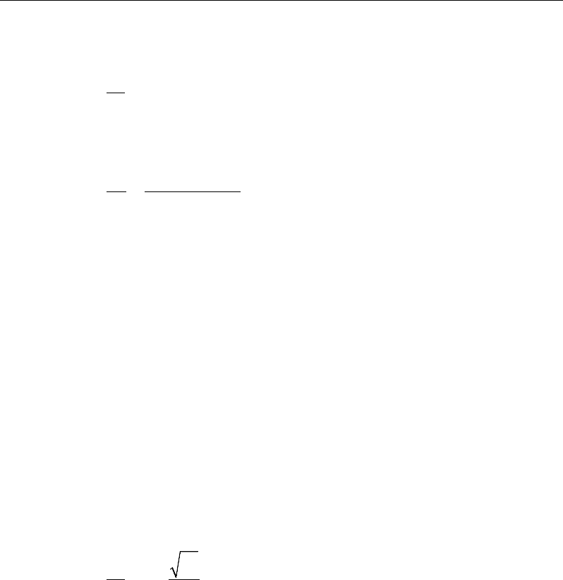
Chapter 9 - Design for CSA A23.3-04
If
≤
fc
VV
0=
v
A
s
(CSA 11.3.5.1)
If
,max
<≤
cfr
VVV
( )
vyts
c
f
v
df
VV
s
A
φ
θ
tan−
=
(CSA 11.3.3, 11.3.5.1)
If
,max
>
fr
VV
, (CSA 11.3.3)
a failure condition is declared.
A minimum area of shear reinforcement is provided in the following regions
(CSA 11.2.8.1):
(a) in regions of flexural members where the factored shear force
f
V
ex-
ceeds
c
V
(b) in regions of beams with an overall depth greater than 750 mm
(c) in regions of beams where the factored torsion
f
T
exceeds 0.25Tcr
Where the minimum shear reinforcement is required by CSA 11.2.8.1, or by cal-
culations, the minimum area of shear reinforcement per unit spacing is taken as:
0.06 c
vw
y
f
Ab
sf
′
≥
(CSA 11.2.8.2)
In the preceding equations, the term
θ
is used where
θ
is the angle of inclination
of the diagonal compressive stresses with respect to the longitudinal axis of the
member. The
θ
value is normally between 22 and 44 degrees. It is determined
according to CSA 11.3.6.
Similar to the
β
factor, which was described previously, the value of
θ
is pref-
erably taken as the special value (CSA 11.3.6.2) or it is determined using the
simplified method (CSA 11.3.6.3), whenever applicable. The program uses the
Beam Design (for Reference Only) 9 - 27

Post-Tensioned Concrete Design
general method when conditions for the simplified method are not satisfied (CSA
11.3.6.4).
If the overall beam depth, h, is less than 250 mm or if the depth of the
flanged beam below the slab is not greater than one-half of the width of the
web or 350 mm,
θ
is taken as 42 degrees (CSA 11.3.6.2).
If the specified yield strength of the longitudinal reinforcing fy does not exceed
400 MPa, or the specified concrete strength f'c does not exceed 60 MPa,
θ
is
taken to be 35 degree (CSA 11.3.6.3).
o
35
θ
=
for
0≤
f
P
or
400≤
y
f
MPa or f'c ≤ 60 MPa (CSA11.3.6.3)
If the axial force is tensile, the specified yield strength of the longitudinal re-
inforcing fy > 400 MPa, and the specified concrete strength f'c > 60 MPa,
θ
is
determined using the general method as follows (CSA 11.3.6.4),
29 7000
θε
= + x
for
0<
f
P
,
>
y
f
400 MPa, f'c ≤ 60 MPa (CSA11.3.6.4)
where
x
ε
is the longitudinal strain at the mid-depth of the cross-section for the
factored load. The calculation procedure has been described in preceding sec-
tions.
The maximum of all of the calculated
v
As
values, obtained from each load
combination, is reported along with the controlling shear force and associated
load combination.
The beam shear reinforcement requirements reported by the program are based
purely on shear strength considerations. Any minimum stirrup requirements to
satisfy spacing and volumetric requirements must be investigated independently
of the program by the user.
9.7.3 Design Beam Torsion Reinforcement
The torsion reinforcement is designed for each design load combination at each
station along the length of the beam. The following steps are involved in
designing the longitudinal and shear reinforcement for a particular station due to
the beam torsion:
9 - 28 Beam Design (for Reference Only)

Chapter 9 - Design for CSA A23.3-04
Determine the factored torsion, Tf
Determine special section properties
Determine critical torsion capacity
Determine the torsion reinforcement required
9.7.3.1 Determine Factored Torsion
In the design of beam torsion reinforcement, the torsions for each load combina-
tion at a particular beam station are obtained by factoring the corresponding tor-
sions for different load cases, with the corresponding load combination factors.
In a statically indeterminate structure where redistribution of the torsion in a
member can occur because of redistribution of internal forces upon cracking, the
design Tf is permitted to be reduced in accordance with the code (CSA 11.2.9.2).
However, the program does not automatically redistribute the internal forces and
reduce Tf. If redistribution is desired, the user should release the torsional degree
of freedom (DOF) in the structural model.
9.7.3.2 Determine Special Section Properties
For torsion design, special section properties, such as Ac, Aoh, Ao, pc, and ph are
calculated. These properties are described in the following (CSA 2.3).
A
c
=
Area enclosed by outside perimeter of concrete cross-sec-
tion
A
oh
=
Area enclosed by centerline of the outermost closed trans-
verse torsional reinforcement
A
o
=
Gross area enclosed by shear flow path
p
c
=
Outside perimeter of concrete cross-section
p
h
=
Perimeter of centerline of outermost closed transverse tor-
sional reinforcement
In calculating the section properties involving reinforcement, such as Aoh, Ao, and
ph, it is assumed that the distance between the centerline of the outermost closed
Beam Design (for Reference Only) 9 - 29

Post-Tensioned Concrete Design
stirrup and the outermost concrete surface is 50 millimeters. This is equivalent
to a 38-mm clear cover and a 12-mm stirrup. For torsion design of flanged beam
sections, it is assumed that placing torsion reinforcement in the flange area is
inefficient. With this assumption, the flange is ignored for torsion reinforcement
calculation. However, the flange is considered during Tcr calculation. With this
assumption, the special properties for a rectangular beam section are given as
follows:
A
c
=
bh (CSA 11.2.9.1)
A
oh
=
(b
−
2c)(h
−
2c) (CSA 11.3.10.3)
Ao
=
0.85
Aoh
(CSA 11.3.10.3)
p
c
=
2b + 2h (CSA 11.2.9.1)
p
h
=
2(b
−
2c) + 2(h
−
2c) (CSA 11.3.10.4)
where, the section dimensions b, h, and c are shown in Figure 9-3. Similarly, the
special section properties for a flanged beam section are given as follows:
A
c
=
b
w
h + (b
f
– b
w
)h
s
(CSA 11.2.9.1)
A
oh
=
(b
w
– 2c)(h – 2c) (CSA 11.3.10.3)
A
o
=
0.85 A
oh
(CSA 11.3.10.3)
p
c
=
2b
f
+ 2h (CSA 11.2.9.1)
p
h
=
2(h – 2c) + 2(b
w
– 2c) (CSA 11.3.10.4)
where the section dimensions bf, bw, h, hf, and c for a flanged beam are shown in
Figure 9-3. Note that the flange width on either side of the beam web is limited
to the smaller of 6hs or 1/12 the span length (CSA 10.3.4).
9 - 30 Beam Design (for Reference Only)
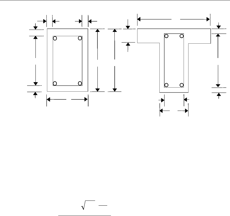
Chapter 9 - Design for CSA A23.3-04
Figure 9-3 Closed stirrup and section dimensions for torsion design
9.7.3.3 Determine Critical Torsion Capacity
The critical torsion capacity, Tcr, for which the torsion in the section can be
ignored is calculated as:
4
'
38.0 2
=c
c
cc
cr
p
A
f
T
λφ
(CSA 11.2.9.1)
where Acp and pc are the area and perimeter of the concrete cross-section as
described in the previous section;
λ
is a factor to account for low-density con-
crete;
φ
c is the strength reduction factor for concrete, which is equal to 0.65; and
f'c is the specified concrete compressive strength.
9.7.3.4 Determine Torsion Reinforcement
If the factored torsion Tf is less than the threshold limit, Tcr, torsion can be safely
ignored (CSA 11.2.9.1). In that case, the program reports that no torsion rein-
cb 2
h
s
d
Closed Stirrup in
Rectangular Beam
Closed Stirrup in
T-Beam Section
c
h2
−h
b
c
h2
−
w
b
Closed Stirrup in
Rectangular Beam
Closed Stirrup in
T-Beam Section
ch 2
−c
h2
−
s
h
ef
b
hh
b
c
c
c
c
c
c
b 2c−
w
b 2c−
w
b
cb 2
h
s
d
Closed Stirrup in
Rectangular Beam
Closed Stirrup in
T-Beam Section
c
h2
−h
b
c
h2
−
w
b
Closed Stirrup in
Rectangular Beam
Closed Stirrup in
T-Beam Section
c
h2
−ch 2
−
s
h
ef
b
hh
b
c
c
c
c
c
c
b 2c−
w
b 2c−
w
b
Beam Design (for Reference Only) 9 - 31
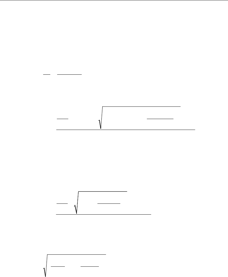
Post-Tensioned Concrete Design
forcement is required. However, if Tf exceeds the threshold limit, Tcr, it is as-
sumed that the torsional resistance is provided by closed stirrups and longitudi-
nal bars (CSA 11.3).
If Tf > Tcr, the required closed stirrup area per unit spacing, At /s, is calculated
as:
tan
2
f
t
s o yt
T
A
s Af
θ
φ
=
(CSA 11.3.10.3)
and the required longitudinal reinforcement is calculated as:
( )
ys
o
fh
sff
v
f
lf
A
Tp
VVN
d
M
A
φ
θ
cot
2
45.0
5.05.0
2
2
+−++
=
(CSA 11.3.10.6, 11.3.9)
In the preceding expressions,
θ
is computed as previously described for shear,
except that if the general method is being used, the value
ε
x is calculated as
specified in CSA 11.3.6.4 is replaced by:
( )
2
2
0.9 0.5
2
2
f hf
ff
vo
x
ss
M pT
VN
dA
EA
ε
++ +
=
(CSA 11.3.10.5)
An upper limit of the combination of Vu and Tu that can be carried by the sec-
tion also is checked using the equation:
cc
oh
hf
vw
ff
A
pT
db
V'25.0
7
.1
2
2
2
φ
≤
+
(CSA 11.3.10.4(b))
For rectangular sections, bw is replaced with b. If the combination of Vf and Tf
exceeds this limit, a failure message is declared. In that case, the concrete section
should be increased in size.
9 - 32 Beam Design (for Reference Only)

Chapter 9 - Design for CSA A23.3-04
When torsional reinforcement is required (Tf > Tcr), the area of transverse closed
stirrups and the area of regular shear stirrups must satisfy the following limit.
yt
w
c
tv
f
b
f
s
A
s
A'
06.
0
2≥
+
(CSA 11.2.8.2)
If this equation is not satisfied with the originally calculated Av /s and At /s, Av /s
is increased to satisfy this condition.
The maximum of all of the calculated Al and At /s values obtained from each load
combination is reported along with the controlling combination.
The beam torsion reinforcement requirements reported by the program are based
purely on strength considerations. Any minimum stirrup requirements or longi-
tudinal rebar requirements to satisfy spacing considerations must be
investigated independently of the program by the user.
9.8 Slab Design
Similar to conventional design, the ETABS slab design procedure involves
defining sets of strips in two mutually perpendicular directions. The locations of
the strips are usually governed by the locations of the slab supports. The mo-
ments for a particular strip are recovered from the analysis and a flexural design
is carried out based on the ultimate strength design method (CSA A 23.3-04) for
prestressed reinforced concrete as described in the following sections. To learn
more about the design strips, refer to the section entitled "ETABS Design Tech-
niques" in the Key Features and Terminology manual.
9.8.1 Design for Flexure
ETABS designs the slab on a strip-by-strip basis. The moments used for the
design of the slab elements are the nodal reactive moments, which are obtained
by multiplying the slab element stiffness matrices by the element nodal displace-
ment vectors. These moments will always be in static equilibrium with the ap-
plied loads, irrespective of the refinement of the finite element mesh.
The design of the slab reinforcement for a particular strip is carried out at specific
locations along the length of the strip. These locations correspond to the element
Slab Design 9 - 33

Post-Tensioned Concrete Design
boundaries. Controlling reinforcement is computed on either side of those ele-
ment boundaries. The slab flexural design procedure for each load combination
involves the following:
Determine factored moments for each slab strip.
Design flexural reinforcement for the strip.
These two steps are described in the subsections that follow and are repeated for
every load combination. The maximum reinforcement calculated for the top and
bottom of the slab within each design strip, along with the corresponding con-
trolling load combination numbers, is obtained and reported.
9.8.1.1 Determine Factored Moments for the Strip
For each element within the design strip, for each load combination, the program
calculates the nodal reactive moments. The nodal moments are then added to get
the strip moments.
9.8.1.2 Design Flexural Reinforcement for the Strip
The reinforcement computation for each slab design strip, given the bending mo-
ment, is identical to the design of rectangular beam sections described
earlier (or to the flanged beam if the slab is ribbed). In some cases, at a given
design section in a design strip, there may be two or more slab properties across
the width of the design strip. In that case, the program automatically designs the
tributary width associated with each of the slab properties separately using its
tributary bending moment. The reinforcement obtained for each of the tributary
widths is summed to obtain the total reinforcement for the full width of the de-
sign strip at the considered design section. This method is used when drop panels
are included. Where openings occur, the slab width is adjusted accordingly.
9.8.1.3 Minimum and Maximum Slab Reinforcement
If the computed tensile stress in the concrete immediately after prestress transfer
exceeds
ci
′
0.25λf
(CSA 18.3.1.1), the bonded reinforcement with a minimum
area of As is provided in the tensile zone to resist the total tensile force, Nc, in the
concrete computed on the basis of an uncracked section (CSA 18.3.1.3).
9 - 34 Slab Design

Chapter 9 - Design for CSA A23.3-04
/(0.5 )
sc y
AN f=
(CSA 18.3.1.3)
The minimum flexural tension reinforcement required for each direction of a
slab is given by the following limit (CSA 18.8.1, 18.8.2):
Concrete stress (see Clause 18.3.2(c))
Tensile stress
≤
05
c
.f
λ
′
Tensile stress
>
05
c
.f
λ
′
Type of tendon Type of tendon
Type of member Bonded Unbonded Bonded Unbonded
Beams
0
0.004A
0.003A
0.005A
One-way slabs
0
0.003A
0.002A
0.004A
Two-way slabs
Negative moment regions
0
0.0006hln
0.00045hln
0.00075hln
Positive moment regions,
concrete stress >
02
c
.f
λ
′
0 0.004A 0.003A 0.005A
Positive moment regions,
concrete tensile stress ≤
02
c
.f
λ
′
0 0 -- --
In addition, an upper limit on both the tension reinforcement and compression
reinforcement has been imposed to be 0.04 times the gross cross-sectional area.
9.8.2 Check for Punching Shear
The algorithm for checking punching shear is detailed in the section entitled
“Slab Punching Shear Check” in the Key Features and Terminology manual.
Only the code specific items are described in the following sections.
9.8.2.1 Critical Section for Punching Shear
The punching shear is checked on a critical section at a distance of d/2 from the
face of the support (CSA 13.3.3.1 and CSA 13.3.3.2). For rectangular columns
and concentrated loads, the critical area is taken as a rectangular area with the
sides parallel to the sides of the columns or the point loads (CSA 13.3.3.3). Fig-
Slab Design 9 - 35

Post-Tensioned Concrete Design
ure 9-4 shows the auto punching perimeters considered by ETABS for the vari-
ous column shapes. The column location (i.e., interior, edge, corner) and the
punching perimeter may be overwritten using the Punching Check Overwrites.
Figure 9-4 Punching Shear Perimeters
9.8.2.2 Transfer of Unbalanced Moment
The fraction of unbalanced moment transferred by flexure is taken to be γf Mu
and the fraction of unbalanced moment transferred by eccentricity of shear is
taken to be γv Mu, where
γf =
( )
12
1,
1 23 bb+
and (CSA 13.10.2)
γv = 1−
( )
12
1,
1 23 bb+
(CSA 13.3.5.3)
d2
Interior Column
Circular Column
d2 d2
d2
T-Shape Column
Edge Column Corner Column
L-Shape Column
d2
d2
d2
Interior Column
Circular Column
d2 d2
d2
T-Shape Column
Edge Column Corner Column
L-Shape Column
d2
d2
9 - 36 Slab Design
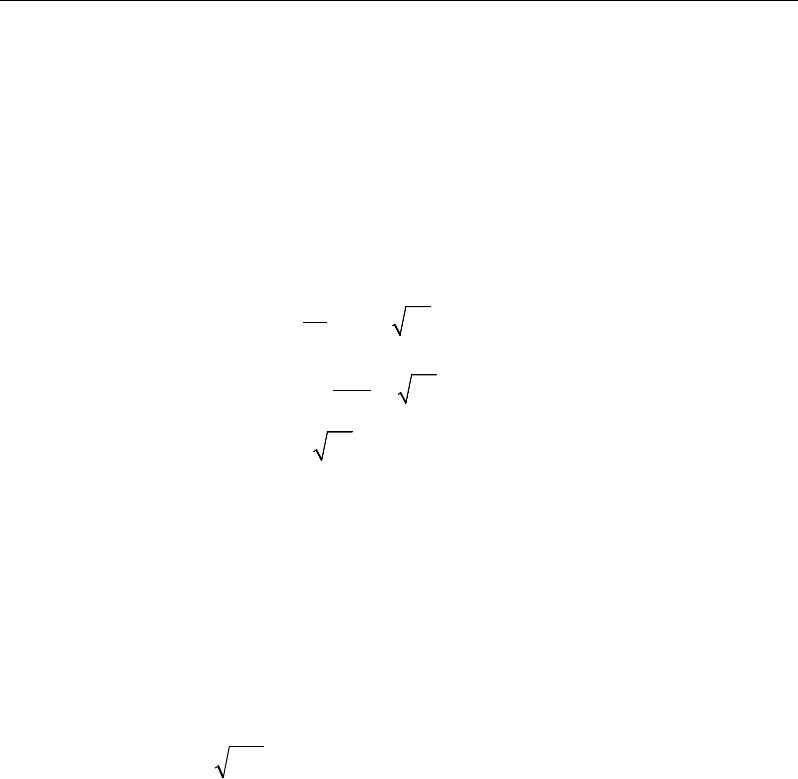
Chapter 9 - Design for CSA A23.3-04
where b1 is the width of the critical section measured in the direction of the span
and b2 is the width of the critical section measured in the direction
perpendicular to the span.
9.8.2.3 Determine Concrete Capacity
The concrete punching shear factored strength is taken as the minimum of the
following three limits:
0
2
1 0.19
min 0.19
0.38
cc
c
s
cc c
cc
f
d
vf
b
f
′
ϕ+ λ
β
α
′
=ϕ +λ
′
ϕλ
(CSA 13.3.4.1)
where, βc is the ratio of the minimum to the maximum dimensions of the critical
section, b0 is the perimeter of the critical section, and αs is a scale factor based
on the location of the critical section.
4 for interior columns,
3 for edge columns, and
2 for corner columns
s
α
=
(CSA 13.3.4.1(b))
The value of
c
f'
is limited to 8 MPa for the calculation of the concrete shear
capacity (CSA 13.3.4.2)
If the effective depth, d, exceeds 300 mm, the value of vc is reduced by a factor
equal to 1300/(1000 + d) (CSA 13.3.4.3).
9.8.2.4 Determine Capacity Ratio
Given the punching shear force and the fractions of moments transferred by
eccentricity of shear about the two axes, the shear stress is computed assuming
linear variation along the perimeter of the critical section. The ratio of the max-
imum shear stress and the concrete punching shear stress capacity is
reported as the punching shear capacity ratio by ETABS.
Slab Design 9 - 37

Post-Tensioned Concrete Design
9.8.3 Design Punching Shear Reinforcement
The use of shear studs as shear reinforcement in slabs is permitted, provided that
the effective depth of the slab is greater than or equal to 120 mm (CSA 13.2.1).
The algorithm for designing the required punching shear reinforcement is used
when the punching shear capacity ratio exceeds unity. The Critical Section for
Punching Shear and Transfer of Unbalanced Moment as described in the earlier
sections remain unchanged. The design of punching shear reinforcement is car-
ried out as follows.
9.8.3.1 Determine Concrete Shear Capacity
The concrete punching shear stress capacity of a two-way prestressed section
with punching shear reinforcement is:
ccc
fv '28.0
λφ
=
for shear studs (CSA 13.3.8.3)
0.19 '
c cc
vf
λφ
=
for shear stirrups (CSA 13.3.9.3)
9.8.3.2 Determine Required Shear Reinforcement
The shear force is limited to a maximum of
,maxr
v
, where
,max 0.75 '
r cc
vf
λφ
=
for shear studs (CSA 13.3.8.2)
,max 0.55 '
r cc
vf
λφ
=
for shear stirrups (CSA 13.3.9.2)
Given vf, vc, and vf,,max, the required shear reinforcement is calculated as follows,
where,
φ
s, is the strength reduction factor.
If vf > vr,max,
( )
fc
vo
s yv
vv
Ab
sf
φ
−
=
(CSA 13.3.8.5, 13.3.9.4)
If vf > vr,max, (CSA 13.3.8.2)
9 - 38 Slab Design

Chapter 9 - Design for CSA A23.3-04
a failure condition is declared.
If Vf exceeds the maximum permitted value of Vr,max, the concrete section
should be increased in size.
9.8.3.3 Determine the Reinforcement Arrangement
Punching shear reinforcement in the vicinity of rectangular columns should be
arranged on peripheral lines, i.e., lines running parallel to and at constant dis-
tances from the sides of the column. Figure 9-5 shows a typical arrangement of
shear reinforcement in the vicinity of a rectangular interior, edge, and corner
columns.
Figure 9-5 Typical arrangement of shear studs and critical sections outside
shear-reinforced zone
The distance between the column face and the first line of shear reinforcement
shall not exceed 0.4d. The spacing between adjacent shear reinforcement in the
first line of shear reinforcement shall not exceed 2d measured in a direction par-
allel to the column face.
Punching shear reinforcement is most effective near column corners where there
are concentrations of shear stress. Therefore, the minimum number of lines of
shear reinforcement is 4, 6, and 8, for corner, edge, and interior columns respec-
tively.
I
y
Typical Studrail
(only first and last
studs shown)
Outermost
peripheral line
of studs
Interior Column Edge Column Corner Column
Critical section
centroid
Free
edge
Free
edge
Critical
section
centroid
Free edge
Outermost
peripheral line
of studs
I
y
I
y
yx
d2 d2
d2
x
I
x
I
x
g
y
g
x
g
0
s0
s0
s
x
I
y
xx
I
y
Typical Studrail
(only first and last
studs shown)
Outermost
peripheral line
of studs
Interior Column Edge Column Corner Column
Critical section
centroid
Free
edge
Free
edge
Critical
section
centroid
Free edge
Outermost
peripheral line
of studs
I
y
I
y
yx
d2 d2
d2
x
I
x
I
x
g
y
g
x
g
0
s0
s0
s
x
I
y
xx
Slab Design 9 - 39

Post-Tensioned Concrete Design
9.8.3.4 Determine Reinforcement Diameter, Height, and Spacing
The punching shear reinforcement is most effective when the anchorage is close
to the top and bottom surfaces of the slab. The cover of anchors should not be
less than the minimum cover specified in CSA 7.9 plus one half of the diameter
of the flexural reinforcement.
Punching shear reinforcement in the form of shear studs is generally available in
9.5-, 12.7-, 15.9-, and 19.1-millimeter diameters.
When specifying shear studs, the distance, so, between the column face and the
first peripheral line of shear studs should not be smaller than 0.4d. The limits of
the spacing, s, between the peripheral lines are specified as:
0.4
o
sd≤
(CSA 13.3.8.6)
0.75 0.56 '
0.50 0.56 '
f cc
f cc
dv f
sdv f
λφ
λφ
≤
≤>
(CSA 13.3.8.6)
For shear stirrups,
≤0.25
o
sd
(CSA 13.3.9.5)
≤0.25sd
(CSA 13.3.9.5)
The minimum depth for reinforcement should be limited to 300 mm (CSA
13.3.9.1).
9 - 40 Slab Design

Chapter 10
Design for Eurocode 2-2004
This chapter describes in detail the various aspects of the post-tensioned concrete
design procedure that is used by ETABS when the user selects the European
code Eurocode 2-2004 [EN 1992-1-1:2004]. For the load combinations reference
also is made to Eurocode 0 [EN 1990], which is identified with the prefix “EC0.”
Various notations used in this chapter are listed in Table 10-1. For referencing
to the pertinent sections of the EC code in this chapter, a prefix “EC2” followed
by the section number is used. It also should be noted that this section describes
the implementation of the CEN Default version of Eurocode 2-2004, without a
country specific National Annex. Where Nationally Determined Parameters
[NDPs] are to be considered, this is highlighted in the respective section by the
notation [NDP].
The design is based on user-specified load combinations. The program provides
a set of default load combinations that should satisfy requirements for the design
of most building type structures.
English as well as SI and MKS metric units can be used for input. The code is
based on Newton-millimeter-second units. For simplicity, all equations and
descriptions presented in this chapter correspond to Newton-millimeter-second
units unless otherwise noted.
Notations 10 - 1

Post-Tensioned Concrete Design
10.1 Notations
The following table identifies the various notations used in this chapter.
Table 10-1 List of Symbols Used in the Eurocode 2-2004 Code
A
c
Area of concrete section, mm
2
A
s
Area of tension reinforcement, mm
2
A'
s
Area of compression reinforcement, mm
2
A
sw
Total cross-sectional area of links at the neutral axis, mm
2
A
sw
/s
v
Area of shear reinforcement per unit length of the member,
mm2
a
Depth of compression block, mm
a
max
Maximum depth of the compression block, mm
b
Width or effective width of the section in the compression
zone, mm
b
f
Width or effective width of flange, mm
b
w
Average web width of a flanged beam, mm
d
Effective depth of tension reinforcement, mm
d'
Effective depth of compression reinforcement, mm
E
c
Modulus of elasticity of concrete, MPa
E
s
Modulus of elasticity of reinforcement, assumed as 200,000
MPa
f
cd
Design concrete strength = αcc fck
/
γc , MPa
f
ck
Characteristic compressive concrete cylinder strength at 28
days, MPa
10 - 2 Notations
Chapter 10 - Design for Eurocode 2-2004
Table 10-1 List of Symbols Used in the Eurocode 2-2004 Code
f
cwd
Design concrete compressive strength for shear design = α
cc
cwk
c
f
γ,
MPa
f
cwk
Characteristic compressive cylinder strength for shear design,
MPa
fyd Design yield strength of reinforcing steel = fyk
/
γs, MPa
f
yk
Characteristic strength of shear reinforcement, MPa
s
f′
Compressive stress in beam compression steel, MPa
f
ywd
Design strength of shear reinforcement =
fywk
/
γs
, MPa
f
ywk
Characteristic strength of shear reinforcement, MPa
h
Overall thickness of slab, mm
h
f
Flange thickness, mm
M
Design moment at a section, N-mm
m
Normalized design moment, M/bd2
η
f
cd
m
lim
Limiting normalized moment capacity as a singly reinforced
beam
M
ED
0
Design moment resistance of a section with tendons only,
N-mm
M
ED
bal
Design moment resistance of a section with tendons and the
necessary mild reinforcement to reach the balanced condi-
tion, N-mm
s
v
Spacing of the shear reinforcement along the length of the
beam, mm
u
Perimeter of the punch critical section, mm
Notations 10 - 3

Post-Tensioned Concrete Design
Table 10-1 List of Symbols Used in the Eurocode 2-2004 Code
V
Rdc
Design shear resistance from concrete alone, N
V
Rd,max
Design limiting shear resistance of a cross-section, N
V
Ed
Shear force at ultimate design load, N
x
Depth of neutral axis, mm
x
lim
Limiting depth of neutral axis, mm
η
Concrete strength reduction factor for sustained loading and
stress-block
β
Enhancement factor of shear resistance for concentrated load;
also the coefficient that takes account of the eccentricity of
loading in determining punching shear stress; factor for the
depth of compressive stress block
γ
f
Partial safety factor for load
γ
c
Partial safety factor for concrete strength
γ
s
Partial safety factor for steel strength
δ
Redistribution factor
ε
c
Concrete strain
ε
s
Strain in tension steel
ε's
Strain in compression steel.
ν
Effectiveness factor for shear resistance without concrete
crushing
ρ
Tension reinforcement ratio
ω
Normalized tensile steel ratio, A
s
f
yd
/
η
f
cd
bd
ω
'
Normalized compression steel ratio, A's fyd γs
/
α f's bd
10 - 4 Notations

Chapter 10 - Design for Eurocode 2-2004
Table 10-1 List of Symbols Used in the Eurocode 2-2004 Code
ω
lim
Normalized limiting tensile steel ratio
10.2 Design Load Combinations
The design load combinations are the various combinations of the load cases for
which the structure needs to be checked. Eurocode 0-2002 allows load combina-
tions to be defined based on EC0 Eqation 6.10 or the less favorable of EC0 Equa-
tions 6.10a and 6.10b [NDP].
∑ ∑
≥ >
+++
1 1 ,,0,1,1,,,
j i ikiiQkQPjkjG QQPG
ψγγγγ
(EC0 Eqn. 6.10)
∑∑
≥ >
++
+
11,,0
,1,
1,0
1,,,
jiikii
QkQ
PjkjG
QQP
G
ψγψ
γγγ
(EC0 Eqn. 6.10a)
∑ ∑
≥ >
+++
1 1 ,,0,1,1,,,
j i ikiiQkQPjkjGj QQPG
ψγγγγξ
(EC0 Eqn. 6.10b)
Load combinations considering seismic loading are generated automatically
based on EC0 Eqation 6.12b.
∑ ∑
≥ >
+++
1 1 ,,2,
j i ikiEdjk QAPG
ψ
(EC0 Eqn. 6.12b)
For this code, if a structure is subjected to dead (D), live (L), pattern live (PL),
snow (S), wind (W), and earthquake (E) loads, and considering that wind and
earthquake forces are reversible, the load combinations in the following sections
may need to be considered (Eurocode 0-2002, Eqation 6.10 or the less favorable
of Equations 6.10a and 6.10b).
For post-tensioned concrete design, the user can specify the prestressing load
(PT) by providing the tendon profile or by using load balancing options in the
program. The default load combinations for post-tensioning are defined in the
following sections.
Design Load Combinations 10 - 5

Post-Tensioned Concrete Design
10.2.1 Initial Service Load Combination
The following load combination is used for checking the requirements at transfer
of prestress force in accordance with EC0 6.5.3 and Table A1.1. The prestressing
forces are considered without any long-term loses for the initial service load
combination check.
1.0D + 1.0PT
10.2.2 Service Load Combination
The following characteristic load combinations are used for checking the
requirements of prestress for serviceability in accordance with EC0 6.5.3 and
Table A1.1. It is assumed that all long-term losses have occurred already at the
service stage.
1.0D + 1.0PT
1.0D + 1.0L + 1.0PT
10.2.3 Ultimate Limit State Load Combination
The following load combinations are used for checking the requirements of pre-
stress in accordance with EC2-2004.
The combinations required for punching shear require the full PT forces (primary
and secondary). Flexural design requires only the hyperstatic (secondary) forces.
The hyperstatic (secondary) forces are determined automatically by ETABS by
subtracting out the primary PT moments when the flexural design is carried out.
The following load combinations need to be considered if Equation 6.10 is spec-
ified for generation of the load combinations (EC0 6.4.3) [NDP].
γ
Gj,sup
D + 1.0PT*
(EC0 Eqn. 6.10)
γ
Gj,sup
D + γ
Q,1
L + 1.0PT*
(EC0 Eqn. 6.10)
γ
Gj,sup
D + (0.75)γ
Q,1
PL + 1.0PT*
(EC0 Eqn. 6.10)
γ
Gj,inf
D ± γ
Q,1
W + 1.0PT*
γ
Gj,sup D ± γQ,1 W + 1.0PT* (EC0 Eqn
. 6.10)
10 - 6 Design Load Combinations

Chapter 10 - Design for Eurocode 2-2004
γ
Gj,sup
D + γ
Q,1
L ± γ
Q,i
ψ
0,i
W + 1.0PT*
γ
Gj,sup D + γQ,1 L + γQ,i ψ0,i S + 1.0PT*
γ
Gj,sup D ± γQ,1 W + γQ,i ψ0,i L + 1.0PT*
γ
Gj,sup D ± γQ,1 W + γQ,i ψ0,i S + 1.0PT*
γ
Gj,sup D + γQ,1 S ± γQ,i ψ0,i W + 1.0PT*
γ
Gj,sup D + γQ,1 S + γQ,i ψ0,i L + 1.0PT*
(EC0 Eqn
. 6.10)
γ
Gj,sup
D + γ
Q,1
L + γ
Q,i
ψ
0,i
S ± γ
Q,i
ψ
0,i
W + 1.0PT*
γ
Gj,sup D ± γQ,1 W + γQ,i ψ0,i L + γQ,i ψ0,i S + 1.0PT*
γ
Gj,sup D + γQ,1 S ± γQ,i ψ0,i W + γQ,i ψ0,i L + 1.0PT* (EC0 Eqn
. 6.10)
D ± 1.0E + 1.0PT*
D
± 1.0E + ψ2,i L + 1.0PT*
D
± 1.0E + ψ2,i L + ψ2,i S + 1.0PT* (EC0 Eqn. 6.12b
)
* — Replace PT with H for flexural design only
If the load combinations are specified to be generated from the max of EC0
Equations. 6.10a and 6.10b, the following load combinations from both equa-
tions are considered in the program.
γ
Gj,sup
D + 1.0PT*
ξ γ
Gj,sup D + 1.0PT*
(EC0 Eqn. 6.10a)
(EC0 Eqn
. 6.10b)
γ
Gj,sup
D + γ
Q,1
ψ
0,1
L + 1.0PT*
ξ
γGj,supD + γQ,1 L + 1.0PT*
(EC0 Eqn. 6.10a)
(EC0 Eqn
. 6.10b)
γ
Gj,sup
D + (0.75)γ
Q,1
ψ
0,1
PL + 1.0PT*
ξ
γGj,supD + (0.75)γQ,1 PL + 1.0PT*
(EC0 Eqn. 6.10a)
(EC0 Eqn
. 6.10b)
γ
Gj,inf
D ± γ
Q,1
ψ
0,1
W + 1.0PT*
γ
Gj,sup D ± γQ,1 ψ0,1 W + 1.0PT*
γ
Gj,inf D ± γQ,1 W + 1.0PT*
ξ
γGj,sup D ± γQ,1 W + 1.0PT*
(EC0 Eqn. 6.10a)
(EC0 Eqn
. 6.10a)
(EC0 Eqn
. 6.10b)
(EC0 Eqn
. 6.10b)
γ
Gj,sup
D + γ
Q,1
ψ
0,1
L ± γ
Q,i
ψ
0,i
W + 1.0PT*
γ
Gj,sup D + γQ,1 ψ0,1 L + γQ,i ψ0,i S + 1.0PT*
γ
Gj,sup D ± γQ,1 ψ0,1 W + γQ,i ψ0,i L + 1.0PT*
γ
Gj,sup D ± γQ,1 ψ0,1 W + γQ,i ψ0,i S + 1.0PT*
γ
Gj,sup D + γQ,1 ψ0,1 S + γQ,i ψ0,i L + 1.0PT*
γ
Gj,sup D + γQ,1 ψ0,1 S ± γQ,i ψ0,i W + 1.0PT*
(EC0 Eqn
. 6.10a)
Design Load Combinations 10 - 7

Post-Tensioned Concrete Design
ξ γ
Gj,sup
D + γ
Q,1
L ± γ
Q,i
ψ
0,i
W + 1.0PT*
ξ
γGj,sup D + γQ,1 L + γQ,i ψ0,i S + 1.0PT*
ξ
γGj,sup D + γQ,1 S ± γQ,i ψ0,i W + 1.0PT*
ξ
γGj,sup D + γQ,1 S + γQ,i ψ0,i L + 1.0PT*
γ
Gj,inf D ± γQ,1 W + γQ,i ψ0,i L + 1.0PT*
γ
Gj,inf D ± γQ,1 W + γQ,i ψ0,i S + 1.0PT*
(EC0 Eqn
. 6.10b)
D ± 1.0E + 1.0PT*
D
± 1.0E + ψ2,i L + 1.0PT*
D
± 1.0E + ψ2,i L + ψ2,i S + 1.0PT* (EC0 Eqn
. 6.12b)
* — Replace PT with H for flexural design only
For both sets of load combinations, the variable values for the CEN Default ver-
sion of the load combinations are defined in the list that follows [NDP].
γGj,sup = 1.35 (EC0 Table A1.2(B))
γGj,inf = 1.00 (EC0 Table A1.2(B))
γQ,1 = 1.5 (EC0 Table A1.2(B))
γQ,i = 1.5 (EC0 Table A1.2(B))
ψ0,i = 0.7 (live load, assumed not to be storage) (EC0 Table A1.1)
ψ0,i = 0.6 (wind load) (EC0 Table A1.1)
ψ0,i = 0.5 (snow load, assumed H ≤ 1000 m) (EC0 Table A1.1)
ξ = 0.85 (EC0 Table A1.2(B))
ψ2,i = 0.3 (live, assumed office/residential space) (EC0 Table A1.1)
ψ2,i = 0 (snow, assumed H ≤ 1000 m) (EC0 Table A1.1)
These are also the default design load combinations in ETABS whenever the
Eurocode 2-2004 code is used. If roof live load is treated separately or other
types of loads are present, other appropriate load combinations should be used.
10 - 8 Design Load Combinations

Chapter 10 - Design for Eurocode 2-2004
10.3 Limits on Material Strength
The characteristic strengths of concrete are provided in EC2 Table 3.1 where
characteristic strengths of concrete range between 12 and 90 MPa.
12MPa 90MPa≤≤
ck
f
(EC2 Table 3.1)
Grades C28/C35 and C32/C40 are the minimum recommended for post-tension-
ing and pre-tensioning respectively. In both cases, the concrete strength at trans-
fer should not be less than 25 MPa.
The specified characteristic strength of reinforcement is given as follows (EC2
3.2.2(3)):
400MPa 600MPa≤≤
yk
f
(EC2 3.2.2(3))
The specified characteristic strength of prestressed steel should conform to EN
10138, Part 2 to 4 or European Technical Approval (EC2 3.3.2).
The program also checks the following tensile strength in prestressing steel (EC2
5.10.2.1). The maximum stresses applied to the tendon, σp,max, in all types of
prestressing steel, in terms of the specified minimum tensile strength fpk, are sum-
marized as follows:
{ }
,max 1 2 0.1
min ,
p pk p k
kf kf
σ
=
(EC2 5.10.2.1)
The recommended value for k1 and k2 are 0.8 and 0.9 where,
( )
0.1pk
f
is defined
as the characteristic value of 0.1% proof load and
( )
pk
f
is the characteristic
maximum load in axial tension (EC2 3.3.3, Figure 3.9).
The stress in tendons immediately after tensioning or after prestress transfer is
also limited to the following:
{ }
0 7 8 0.1
min ,
pm pk p k
kf kf
σ
=
(EC2 5.10.3)
The recommended values for k7 and k8 are 0.75 and 0.85.
Limits on Material Strength 10 - 9
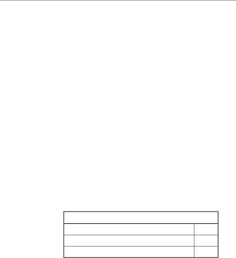
Post-Tensioned Concrete Design
10.4 Partial Safety Factors
The design strengths for concrete and reinforcement are obtained by dividing the
characteristic strength,
,
ck
f
pk
f
and
0.1pk
f
of the material by a partial factor of
safety, γs and γc, as follows (EC2 3.1.6, 3.2.7, 3.3.6(6)) [NDP].
/
cd cc ck c
ff=αγ
(EC2 3.1.6 (1))
/
cwd cc cwk c
ff=αγ
(EC2 3.1.6 (1))
/
yd yk s
ff= γ
(EC2 3.2.7 (2))
/
ywd ywk s
ff
= γ
(EC2 3.2.7 (2))
0.1 /
pd p k s
ff= γ
(EC2 3.3.6 (6))
The value αcc is the coefficient that accounts for long-term effects on the com-
pressive strength; αcc is taken as 1.0 by default and can be overwritten by the
user (EC2 3.1.6(1)).
The values of partial safety factors, γs and γc, for the materials and the design
strengths of concrete and reinforcement used in the program are listed in the
following table (EC2 2.4.2.4 (1), Table 2.1N):
Values of
γ
m for the ultimate limit state [NDP]
Reinforcement,
γ
s 1.15
Prestressing steel,
γ
p 1.15
Concrete in flexure and axial load,
γ
c 1.50
These values are recommended by the code to give an acceptable level of safety
for normal structures under typical design situations (EC2 3.1.6(1)). For acci-
dental and earthquake situations, the recommended values are less than the tab-
ulated value. The user should consider those cases separately.
These factors are already incorporated into the design equations and tables in the
code. The user is allowed to overwrite these values; however, caution is
advised.
10 - 10 Partial Safety Factors

Chapter 10 - Design for Eurocode 2-2004
10.5 Design Assumptions for Prestressed Concrete Struc-
tures
Ultimate limit state design of prestressed members for flexure and axial loads
shall be based on assumptions given in EC2 6.1(2).
The strain distribution in the concrete in compression is derived from the as-
sumption that plane sections remain plane.
The design stresses in the concrete in compression are taken as
η
fcd. Maximum
strain at the extreme concrete compression fiber shall be assumed equal to εcu3.
The tensile strength of the concrete is ignored.
The strains in bonded post-tensioning tendons and in any additional reinforce-
ment (compression or tension) are the same as that in the surrounding concrete.
The serviceability limit state of prestressed members uses the following
assumptions given in EC2 7.2.
Plane sections remain plane, i.e., strain varies linearly with depth through the
entire load range.
Elastic behavior exists by limiting the concrete stresses to the values given in
EC2 7.2(3).
In general, it is only necessary to calculate design stresses due to the load
arrangements immediately after the transfer of prestress and after all losses or
prestress have occurred; in both cases the effects of dead and imposed loads
on the strain and force in the tendons may be ignored.
Prestressed concrete members are investigated at three stages:
At transfer of prestress force
At service loading
At nominal strength
Design Assumptions for Prestressed Concrete Structures 10 - 11

Post-Tensioned Concrete Design
10.6 Serviceability Requirements of Flexural Members
10.6.1 Serviceability Check at Initial Service Load
The stresses in the concrete immediately after prestress force transfer (before
time dependent prestress losses) are checked against the following limits (EC2
5.10.2.2 and 7.1):
Extreme fiber stresses in compression:
0.60 (t)
ck
f
(EC2 5.10.2.2(5))
Unless reinforcing steel has been added, the stress limits will normally be
"without bonded reinforcement" values, as any bonded tendons normally will
be at the compression face at transfer.
Extreme fiber stresses in tension (EC2 7.1)
≤ fctm(t) where, (EC2 7.1(2))
( )
2/3
0.30
ctm ck
ff=
for fck ≤ C50/C60 (EC2 Table 3.1)
()
2.12 1 /10
ctm cm
f ln f= +
for fck > C50/C60 (EC2 Table 3.1)
8MPa
cm ck
ff= +
(EC2 Table 3.1)
Extreme fiber stresses in tension should not exceed fctm; otherwise, the section
should be designed as a cracked section (EC2 7.1).
10.6.2 Serviceability Check at Service Load
The stresses in the concrete for prestressed concrete flexural members at service
loads, and after all prestress losses have occurred, are checked against the fol-
lowing limits (EC2 7.2(2)):
Extreme fiber stress in compression due to prestress plus total load:
0.6 ck
f
(EC2 7.2(2))
10 - 12 Serviceability Requirements of Flexural Members

Chapter 10 - Design for Eurocode 2-2004
Extreme fiber stresses in tension in the precompressed tensile zone at charac-
teristic service loads are defined as follows (EC2 7.2(5)):
– Extreme fiber stresses in tension for reinforcement:
0.8 yk
f
(EC2 7.2(5))
– Extreme fiber stresses in tension for prestressing tendons:
0.75
pk
f
(EC2 7.2(5))
Although cracking is permitted for Exposure Classes X0, XC1, XC2, XC3, and
XC4, it may be assumed that the design hypothetical tensile stresses exist at the
limiting crack widths given in Eurocode 2, Table 7.1N. Limits to the design hy-
pothetical tensile stresses under Frequent Load combinations are given in the
following table (TR43, Second Edition):
Group Limiting crack width(mm) Design stress
Bonded Tendons 0.1
0.2
1.35 fctm
1.65 fctm
Unbonded tendons - 1.35 fctm
10.7 Beam Design (for Reference Only)
Important Note: Post-tensioned beam design is not available in the current ver-
sion of ETABS, but is planned for a future release. This section is provided as
reference only for the documentation of post-tensioned slab design.
In the design of prestressed concrete beams, ETABS calculates and reports the
required areas of reinforcement for flexure, shear, and torsion based on the beam
moments, shear forces, torsion, load combination factors, and other criteria de-
scribed in the subsections that follow. The reinforcement requirements are cal-
culated at each station along the length of the beam.
Beams are designed for major direction flexure, shear, and torsion only. Effects
resulting from any axial forces and minor direction bending that may exist in the
beams must be investigated independently by the user.
Beam Design (for Reference Only) 10 - 13

Post-Tensioned Concrete Design
The beam design procedure involves the following steps:
Design flexural reinforcement
Design shear reinforcement
Design torsion reinforcement
10.7.1 Design Flexural Reinforcement
The beam top and bottom flexural reinforcement is designed at each station
along the beam. In designing the flexural reinforcement for the major moment
of a particular beam for a particular station, the following steps are involved:
Determine factored moments
Determine required flexural reinforcement
10.7.1.1 Determine Factored Moments
In the design of flexural reinforcement of prestressed concrete beams, the
factored moments for each load combination at a particular beam station are ob-
tained by factoring the corresponding moments for different load cases, with the
corresponding load factors.
The beam section is then designed for the maximum positive and maximum neg-
ative factored moments obtained from all of the load combinations. Positive
beam moments can be used to calculate bottom reinforcement. In such cases the
beam may be designed as a rectangular or a flanged beam. Negative beam mo-
ments can be used to calculate top reinforcement. In such cases the beam may
be designed as a rectangular or inverted flanged beam.
10.7.1.2 Determine Required Flexural Reinforcement
In the flexural reinforcement design process, the program calculates both the
tension and compression reinforcement. Compression reinforcement is added
when the applied design moment exceeds the maximum moment capacity of a
singly reinforced section. The user has the option of avoiding the compression
reinforcement by increasing the effective depth, the width, or the strength of the
concrete.
10 - 14 Beam Design (for Reference Only)
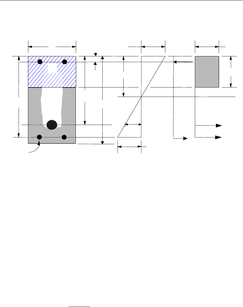
Chapter 10 - Design for Eurocode 2-2004
The design procedure is based on the simplified rectangular stress block shown
in Figure 10-1 (EC2 3.1.7(3)).
Figure 10-1 Rectangular Beam Design
The area of the stress block and the depth of the center of the compressive force
from the most compressed fiber are taken as:
Fc =
η
fcd a b
a = λ x
where x is the depth of the neutral axis; the factor λ defines the effective height
of the compression zone; and the factor
η
defines the effective strength, as fol-
lows:
λ = 0.8 for fck ≤50 MPa (EC2 3.1.7(3))
ck
f50
0.8 400
λ
−
=
MPafor 50 90
ck
f≤≤
(EC2 3.1.7(3))
η
= 1.0 for fck ≤ 50 MPa and (EC2 3.1.7(3))
STRESS
DIAGRAM
STRAIN
DIAGRAM
BEAM
SECTION
s
A
p
A
p
d
s
A′
s
d
b
′
d
h
x
η
cd
f
λ
=ax
ε
p
s
ε
s
C
cs
T
s
T
′
s
f
3
ε
cu
cps
T
STRESS
DIAGRAM
STRAIN
DIAGRAM
BEAM
SECTION
s
A
p
A
p
d
s
A′
s
d
b
′
d
h
x
η
cd
f
λ
=ax
ε
p
s
ε
s
C
cs
T
s
T
′
s
f
3
ε
cu
cps
T
Beam Design (for Reference Only) 10 - 15

Post-Tensioned Concrete Design
50
1.0
200
CK
f
η
−
= −
for 50 90MPa≤≥
ck
f
(EC2 3.1.7(3))
Furthermore, it is assumed that moment redistribution in the beam does not ex-
ceed the code specified limiting value. The code also places a limitation on the
neutral axis depth, to safeguard against non-ductile failures (EC2 5.5(4)). When
the applied moment exceeds the limiting moment capacity as a singly reinforced
beam, the area of compression reinforcement is calculated on the
assumption that the neutral axis depth remains at the maximum permitted value.
The design procedure used by ETABS, for both rectangular and flanged sections
(L- and T-beams), is summarized in the subsections that follow.
10.7.1.2.1 Design of Rectangular Beams
ETABS first determines if the moment capacity provided by the post-tensioning
tendons alone is enough. In calculating the capacity, it is assumed that As = 0. In
that case, the moment capacity
0
ED
M
is determined as follows:
The maximum depth of the compression zone, xmax, is calculated based on the
limitation that the tension reinforcement strain shall not be less than
ε
smin:
cmax =
3
3 min
cu p
cu s
d
ε
εε
+
where,
ε
cu3 = 0.0035
Therefore, the limit
max
xx≤
is set for tension-controlled sections.
The maximum allowable depth of the compression block is given by:
max max
ax
λ
=
(EC2 3.1.7(3))
where,
0.8
λ
=
if
50MPa
ck
f<
(EC2 3.1.7)
10 - 16 Beam Design (for Reference Only)

Chapter 10 - Design for Eurocode 2-2004
50
0.8 400
ck
f
λ
−
= −
if
50MPa
ck
f>
(EC2 3.1.7)
ETABS determines the depth of the neutral axis, c, by imposing force equilib-
rium, i.e., C = T. After the depth of the neutral axis has been determined, the
stress in the post-tensioning steel, fpk is computed based on strain compatibility
for bonded tendons. For unbonded tendons, the code equations are used to com-
pute the stress, fps in the post-tensioning steel.
Based on the calculated fpk, the depth of the neutral axis is recalculated, and fpk is
further updated. After this iteration process has converged, the depth of the rec-
tangular compression block is determined as follows:
ax
λ
=
If
max
aa≤
(EC2 3.1.7(3)), the moment capacity of the section, provided by
post-tensioning steel only, is computed as:
0
2
ED pk p p a
M fA d
= −
If
max
aa>
(EC2 3.1.7(3)), a failure condition is declared.
If
0,
ED
MM>
ETABS calculates the moment capacity and the As required at
the balanced condition. The balanced condition is taken as the marginal ten-
sion-controlled case. In that case, it is assumed that the depth of the neutral
axis x is equal to xmax. The stress in the post-tensioning steel, fpk, is then calcu-
lated based on strain compatibility and the area of required tension reinforce-
ment, As, is determined by imposing force equilibrium, i.e., C = T.
maxcd
C fa b
η
=
bal bal bal
p pk s s
T Af A f= +
max bal
cd p pk
bal
sbal
s
fa b Af
Af
η
−
=
After the area of tension reinforcement has been determined, the capacity of the
section with post-tensioning steel and tension reinforcement is computed as:
Beam Design (for Reference Only) 10 - 17

Post-Tensioned Concrete Design
max max
22
bal bal bal bal
ED p pk p s s s
aa
M Afd Afd
= −+ −
In that case, it is assumed that the bonded tension reinforcement will yield, which
is true for most cases. In the case that it does not yield, the stress in the reinforce-
ment, fs, is determined from the elastic-perfectly plastic stress-strain relationship.
The fy value of the reinforcement is then replaced with fs in the preceding four
equations. This case does not involve any iteration in determining the depth of
the neutral axis, x.
10.7.1.2.1.1 Case 1: Post-tensioning steel is adequate
When
0,
ED
MM<
the amount of post-tensioning steel is adequate to resist the
design moment M. A minimum reinforcement is provided to satisfy the flexural
cracking requirements (EC2 7.3.2).
10.7.1.2.1.2 Case 2: Post-tensioning steel plus tension reinforcement
In this case, the amount of post-tensioning steel, Ap, alone is not sufficient to
resist M, and therefore the required area of tension reinforcement is computed to
supplement the post-tensioning steel. The combination of post-tensioning steel
and tension reinforcement should result in a < amax.
When
( )
0,
bal
ED ED
M MM<<
ETABS determines the required area of tension rein-
forcement, As, iteratively to satisfy the design moment M and reports this
required area of tension reinforcement. Since
M
is bound by
0
ED
M
at the lower
end and
bal
ED
M
at the upper end, and
0
ED
M
is associated with
0=
s
A
and
bal
ED
M
is
associated with
,=
bal
ss
AA
the required area will fall within the range of 0 to
Asbal.
The tension reinforcement is to be placed at the bottom if M is positive, or at the
top if M is negative.
10 - 18 Beam Design (for Reference Only)

Chapter 10 - Design for Eurocode 2-2004
10.7.1.2.1.3 Case 3: Post-tensioning steel and tension reinforcement is not
adequate
When
( )
,>bal
ED
MM
compression reinforcement is required (EC2 5.5 (4)). In that
case, ETABS assumes that the depth of the neutral axis, x, is equal to
max .x
The
values of fpk and fs reach their respective balanced condition values,
bal
pk
f
and
.
bal
s
f
Then the area of compression reinforcement,
,
′
s
A
is determined as fol-
lows:
The moment required to be resisted by compression reinforcement and tension
reinforcement is:
,= − bal
ED s ED
M MM
The required compression reinforcement is given by:
s
A′
=
( )()
,
0.87 ′
ED,s
s cd
M
f-ηf d - d'
where
s
f′
= εcu3Es
max
max
'ad
a
−
≤ 0.87fy.
The tension reinforcement for balancing the compression reinforcement is given
by:
()
,
0.87 '
=−
ED s
com
sys
M
Afd d
Therefore, the total tension reinforcement, As =
bal
s
A
+
,
com
s
A
and the total com-
pression reinforcement is A's. As is to be placed at the bottom and A's is to be
placed at the top if M is positive, and vice versa if M is negative.
Beam Design (for Reference Only) 10 - 19
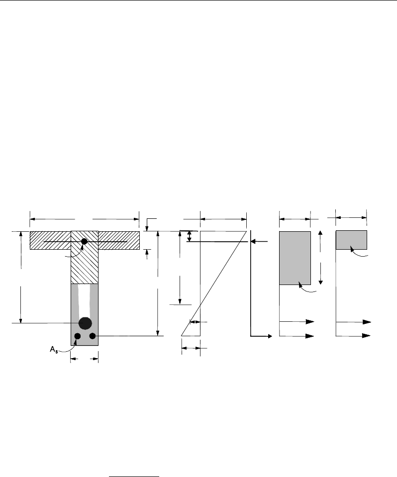
Post-Tensioned Concrete Design
10.7.1.2.2 Design of Flanged Beams
10.7.1.2.2.1 Flanged Beam Under Negative Moment
In designing for a factored negative moment, M
(i.e., designing top reinforce-
ment), the calculation of the reinforcement area is exactly the same as described
previously, i.e., no flanged beam data is used.
10.7.1.2.2.2 Flanged Beam Under Positive Moment
ETABS first determines if the moment capacity provided by the post-tensioning
tendons alone is enough. In calculating the capacity, it is assumed that As = 0. In
that case, the moment capacity
0
ED
M
is determined as follows:
Figure 10-2 T-Beam Design
The maximum depth of the compression zone, xmax, is calculated based on the
limitation that the tension reinforcement strain shall not be less than
ε
smin:
cmax =
3
3 min
cu p
cu s
d
ε
εε
+
where,
ε
cu3 = 0.0035
STRESS
DIAGRAM
STRAIN
DIAGRAM
BEAM
SECTION
ε
ps
s
ε
s
T
w
T
f
T
f
C
w
C
s
C
′
s
f
′
d
p
ds
d
λ
=ax
3
ε
cu
η
cd
f
η
cd
f
x
s
A′
ps
A
w
b
f
bf
h
STRESS
DIAGRAM
STRAIN
DIAGRAM
BEAM
SECTION
ε
ps
s
ε
s
T
w
T
f
T
f
C
w
C
s
C
′
s
f
′
d
p
ds
d
λ
=ax
3
ε
cu
η
cd
f
η
cd
f
x
s
A′
ps
A
w
b
f
bf
h
10 - 20 Beam Design (for Reference Only)

Chapter 10 - Design for Eurocode 2-2004
Therefore, the program limit for the depth of the neutral axis is x ≤ xmax for ten-
sion-controlled sections.
The maximum depth of the compression block is given by:
max max
ax
λ
=
(EC2 3.1.7(3))
where,
λ
=0.8
if
MPa<50
ck
f
(EC2 3.1.7)
λ
−
= −
50
0.8 400
ck
f
if
50MPa
ck
f>
(EC2 3.1.7)
ETABS determines the depth of the neutral axis, c, by imposing force equilib-
rium, i.e., C = T. After the depth of the neutral axis has been determined, the
stress in the post-tensioning steel, fpk, is computed based on strain compatibility
for bonded tendons. For unbonded tendons, the code equations are used to com-
pute the stress, fps, in the post-tensioning steel. Based on the calculated fpk, the
depth of the neutral axis is recalculated, and fpk is further updated. After this
iteration process has converged, the depth of the rectangular compression block
is determined as follows:
ax
λ
=
If a ≤ amax (EC2 3.1.7(3)), the moment capacity of the section, provided by
post-tensioning steel only, is computed as:
0
2
ED pk p p a
M fA d
= −
If a > amax (EC2 3.1.7(3)), a failure condition is declared.
If
ED
MM
0,>
ETABS calculates the moment capacity and the As required at
the balanced condition. The balanced condition is taken as the marginal ten-
sion- controlled case. In that case it is assumed that the depth of the neutral
axis x is equal to xmax. The stress in the post-tensioning steel, fpk, is then calcu-
lated based on strain compatibility, and the area of required tension reinforce-
ment, As, is determined by imposing force equilibrium, i.e., C = T.
Beam Design (for Reference Only) 10 - 21

Post-Tensioned Concrete Design
If a ≤ hf, the subsequent calculations for As are exactly the same as previously
defined for the rectangular beam design. However, in this case, the width of
the beam is taken as bf. Compression reinforcement is required when a > amax.
If a > hf, the calculation for As is given by:
max com
cd c
C fa A
η
=
where
com
c
A
is the area of concrete in compression, i.e.,
bal bal bal
p pk s s
T Af A f
= +
max com bal
cd c p pk
bal
sbal
s
fa A Af
Af
η
−
=
After the area of tension reinforcement has been determined, the capacity of the
section with post-tensioning steel and tension reinforcement is computed as:
max max
22
bal bal bal bal
ED p pk p s s s
aa
M Afd Afd
= −+ −
In that case, it is assumed that the bonded tension reinforcement will yield, which
is true for most cases. In the case that it does not yield, the stress in the reinforc-
ing steel, fs, is determined from the elastic-perfectly plastic stress-strain relation-
ship. The fy value of the reinforcement is then replaced with fs in the preceding
four equations. This case does not involve any iteration in determining the depth
of the neutral axis, x.
10.7.1.2.2.2.1 Case 1: Post-tensioning steel is adequate
When
0,
ED
MM
<
the amount of post-tensioning steel is adequate to resist the
design moment M. Minimum reinforcement is provided to satisfy the flexural
cracking requirements (EC2 7.3.2).
10.7.1.2.2.2.2 Case 2: Post-tensioning steel plus tension reinforcement
In this case, the amount of post-tensioning steel, Ap, alone is not sufficient to
resist M, and therefore the required area of tension reinforcement is computed to
supplement the post-tensioning steel. The combination of post-tensioning steel
and tension reinforcement should result in a < amax.
10 - 22 Beam Design (for Reference Only)

Chapter 10 - Design for Eurocode 2-2004
When
( )
0,
bal
ED ED
M MM<<
ETABS determines the required area of tension rein-
forcement, As, iteratively to satisfy the design moment M and reports the
required area of tension reinforcement. Since
M
is bounded by
0
ED
M
at the
lower end and
bal
ED
M
at the upper end, and
0
ED
M
is associated with
0
s
A=
and
bal
ED
M
is associated with
bal
ss
AA
,
=
the required area will be within the range of
0 to
s
A
.
The tension reinforcement is to be placed at the bottom if M is positive, or at the
top if M is negative.
10.7.1.2.2.2.3 Case 3: Post-tensioning steel and tension reinforcement is not adequate
When
( )
,
bal
ED
MM>
compression reinforcement is required (EC2 5.5 (4)). In that
case ETABS assumes that the depth of the neutral axis, x, is equal to
max .x
The
values of fpk and fs reach their respective balanced condition values,
bal
pk
f
and
.
bal
s
f
Then the area of compression reinforcement,
,
′
s
A
is determined as follows:
The moment required to be resisted by compression reinforcement and tension
reinforcement is:
,bal
ED s ED
M MM= −
The required compression reinforcement is given by:
′
s
A
=
( )( )
,
,
0.87 ' '
ED s
s cd
M
f f dd
η
−−
where
′
s
f
= εcu3Es
max
max
'ad
a
−
≤ 0.87fy.
The tension reinforcement for balancing the compression reinforcement is given
by:
( )
,
0.87 '
ED s
com
sys
M
Afd d
=−
Beam Design (for Reference Only) 10 - 23

Post-Tensioned Concrete Design
Therefore, the total tension reinforcement, As =
bal
s
A
+
,
com
s
A
and the total com-
pression reinforcement is A's. As is to be placed at the bottom and A's is to be
placed at the top if M is positive, and vice versa if M is negative.
10.7.1.2.3 Minimum and Maximum Reinforcement
Reinforcement in prestressed concrete beams is computed to increase the
strength of sections as required in the flexural design of prestressed beam or to
comply with shear link requirements. The minimum flexural tension reinforce-
ment required for a beam section to comply with the cracking requirements must
be separately investigated by the user.
For bonded tendons, there is no minimum un-tensioned reinforcement require-
ments.
For unbonded tendons, the minimum flexural reinforcement provided in a rec-
tangular or flanged beam section is given as [NDP]:
,min 0.26 0.0013
ctm
syk
f
A bd bd
f
= ≥
(EC2 9.2.1.1)
where fctm is the mean value of axial tensile strength of the concrete and is com-
puted as:
( )
32
30.0 ckctm ff =
for fck ≤ 50 MPa (EC2 3.12, Table 3.1)
( )
ctm cm
f ln f2.12 1 10= +
for fck > 50 MPa (EC2 3.12, Table 3.1)
8 MPa
cm ck
ff= +
(EC2 3.12, Table 3.1)
The minimum flexural tension reinforcement required for control of cracking
should be investigated independently by the user.
In addition, an upper limit on both the tension reinforcement and compression
reinforcement has been imposed to be 0.04 times the gross cross-sectional area
(EC2 9.2.1.1(3)).
10 - 24 Beam Design (for Reference Only)

Chapter 10 - Design for Eurocode 2-2004
10.7.2 Design Beam Shear Reinforcement
The shear reinforcement is designed for each loading combination at each
station along the length of the beam. In designing the shear reinforcement for a
particular beam, for a particular loading combination, at a particular station due
to the beam major shear, the following steps are involved (EC2 6.2):
Determine the factored shear force, V
Determine the shear force, VRd,c, that can be resisted by the concrete
Determine the shear reinforcement required to carry the balance
The following three sections describe in detail the algorithms associated with
these steps.
10.7.2.1 Determine Shear Force
In the design of the beam shear reinforcement, the shear forces for each load
combination at a particular beam station are obtained by factoring the cor-re-
sponding shear forces for different load cases with the corresponding load com-
bination factors.
10.7.2.2 Determine Concrete Shear Capacity
The design shear resistance of the beam without shear reinforcement, VRd,c is
calculated as:
VRd,c = [CRd,c k(100 ρ1fck)1/3 + k1 σcp ] (bwd) (EC2 6.2.2(1))
VRd,c ≥ [vmin + k1 σcp ] (bwd), (EC2 6.2.2(1))
where fck is in MPa
200
1 2.0kd
=+≤
with d in mm (EC2 6.2.2(1))
ρ
1 = tension reinforcement ratio =
( )
1s ps
w
AA
bd
+
≤ 0.02 (EC2 6.2.2(1))
Beam Design (for Reference Only) 10 - 25

Post-Tensioned Concrete Design
As1 = area of mild-tension reinforcement (EC2 6.2.2(1))
Aps = area of prestress-tension reinforcement (EC2 6.2.2(1))
σcp = average stress in concrete due to axial
force
Ed c
NA
(EC2 6.2.2(1))
0.2
cp Ed c cd
N A fzσ= <
MPa (EC2 6.2.2(1))
Ac = the total gross area of concrete section
The value of CRd,c, vmin, and k1 for use in a country may be found in its National
Annex. The program default values for CRd,c [NDP], vmin [NDP], and k1 [NDP]
are given as follows (EC2 6.2.2(1)):
CRd,c = 0.18/γc,
vmin = 0.035 k3/2 fck1/2
k1 = 0.15.
If light-weight concrete:
CRd,c= 0.18/γc (EC2 11.6.1(1))
vmin = 0.03 k3/2 fck1/2 (EC2 11.6.1(1))
k1 = 0.15. (EC2 11.6.1(1))
10.7.2.3 Determine Required Shear Reinforcement
The shear reinforcement is designed for each load combination at each station
along the length of the beam. The assumptions in designing the shear reinforce-
ment are as follows:
The beam sections are assumed to be prismatic. The effect of any variation of
width in the beam section on the concrete shear capacity is neglected.
The effect on the concrete shear capacity of any concentrated or distributed
load in the span of the beam between two columns is ignored. Also, the
effect of the direct support on the beams provided by the columns is ignored.
10 - 26 Beam Design (for Reference Only)

Chapter 10 - Design for Eurocode 2-2004
All shear reinforcement is assumed to be perpendicular to the longitudinal
reinforcement.
In designing the shear reinforcement for a particular beam, for a particular load
combination, the following steps of the standard method are involved (EC2 6.2).
Obtain the design value of the applied shear force V from the ETABS analysis
results (EC2 6.2.3(3)).
The shear force is limited to a maximum of:
1
,max ,
cot tan
cw w cd
Rd bz f
V
αν
θθ
=+
where (EC2 6.2.3(3))
αcw [NDP] is conservatively taken as 1 (EC2 6.2.3(3))
The strength reduction factor for concrete cracked in shear, v1 [NDP] is de-
fined as:
−
=250
1
6.0
1ck
f
ν
(EC2 6.2.2(6))
z = 0.9d (EC2 6.2.3(1))
θ is optimized by program and is set to 45° for combinations including seis-
mic loading (EC2 6.2.3(2)).
Given VEd, VRdc, VRd,max, the required shear reinforcement in area/unit length
is calculated as follows:
If VEd ≤ VRdc,
v
sw
s
A
=
s
A
sw min,
If VR,dc < VEd ≤ VRd,max
s
A
zf
V
s
A
sw
ywd
Edsw min,
cot ≥=
θ
(EC2 6.2.3(3))
If VEd > VRd,max
Beam Design (for Reference Only) 10 - 27

Post-Tensioned Concrete Design
a failure condition is declared. (EC2 6.2.3(3))
The maximum of all the calculated Asw /sv values, obtained from each load com-
bination, is reported along with the controlling shear force and associated load
combination number.
The minimum shear reinforcement is defined as:
,min 0.08 ck
sw w
yk
f
Ab
sf
=
(EC2 9.2.2(5))
The beam shear reinforcement requirements considered by the program are
based purely on shear strength considerations. Any minimum stirrup require-
ments to satisfy spacing and volumetric considerations must be investigated
independently of the program by the user.
10.7.3 Design Beam Torsion Reinforcement
The torsion reinforcement is designed for each design load combination at each
station along the length of the beam. The following steps are involved in
designing the longitudinal and shear reinforcement for a particular station due to
the beam torsion:
Determine the factored torsion, TEd
Determine special section properties
Determine critical torsion capacity
Determine the torsion reinforcement required
10.7.3.1 Determine Factored Torsion
In the design of beam torsion reinforcement, the torsions for each load combina-
tion at a particular beam station are obtained by factoring the corresponding tor-
sions for different load cases with the corresponding load combination factors.
In a statically indeterminate structure where redistribution of the torsion in a
member can occur due to redistribution of internal forces upon cracking, the de-
sign TEd is permitted to be reduced in accordance with the code (EC2 6.3.1(2)).
10 - 28 Beam Design (for Reference Only)

Chapter 10 - Design for Eurocode 2-2004
However, the program does not automatically redistribute the internal forces and
reduce TEd. If redistribution is desired, the user should release the torsional de-
gree of freedom (DOF) in the structural model.
10.7.3.2 Determine Special Section Properties
For torsion design, special section properties, such as Ak, tef, u, uk, and zi are cal-
culated. These properties are described in the following (EC2 6.3.2).
A
=
Area enclosed by the outside perimeter of the cross-section
A
k
=
Area enclosed by centerlines of the connecting walls, where
the centerline is located a distance of tef /2 from the outer sur-
face
t
ef
=
Effective wall thickness, A
/
u. It is taken as at least twice the
distance between the edge and center of the longitudinal re-
bar.
u
=
Outer perimeter of the cross-section
u
k
=
Perimeter of the area A
k
z
i
=
Side length of wall i, defined as the distance between the in-
tersection points of the wall centerlines
In calculating the section properties involving reinforcement, such as Ak, and uk,
it is assumed that the distance between the centerline of the outermost closed
stirrup and the outermost concrete surface is 50 mm. This is equivalent to 38-
mm clear cover and a 12-mm stirrup. For torsion design of flanged beam sec-
tions, it is assumed that placing torsion reinforcement in the flange area is inef-
ficient. With this assumption, the flange is ignored for torsion reinforcement cal-
culation. However, the flange is considered during calculation of torsion section
properties. With this assumption, the special properties for a rectangular beam
section are given as:
A
=
bh (EC2 6.3.2(1))
A
k
=
(b
−
t
ef
)(h
−
t
ef
) (EC2 6.3.2(1))
Beam Design (for Reference Only) 10 - 29
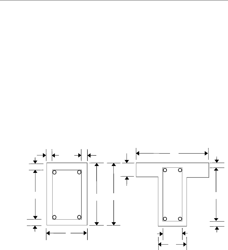
Post-Tensioned Concrete Design
u
=
2b + 2h
(EC2 6.3.2(1))
u
k
=
2(b
−
t
ef
) + 2(h
−
t
ef
) (EC2 6.3.2(3))
where, the section dimensions b, h, and c are shown in Figure 10-3. Similarly,
the special section properties for a flanged beam section are given as:
A
=
b
w
h (EC2 6.3.2(1))
A
k
=
(b
w
– t
ef
)(h – t
ef
) (EC2 6.3.2(1))
u
=
2b
w
+ 2h
(EC2 6.3.2(1))
u
k
=
2(h – t
ef
) + 2(b
w
– t
ef
) (EC2 6.3.2(3))
where the section dimensions bf, bw, h, hf, and c for a flanged beam are shown in
Figure 10-3.
Figure 10-3 Closed stirrup and section dimensions for torsion design
cb 2
h
s
d
Closed Stirrup in
Rectangular Beam
Closed Stirrup in
T-Beam Section
ch 2
−h
b
c
h2
−
w
b
Closed Stirrup in
Rectangular Beam
Closed Stirrup in
T-Beam Section
ch 2
−ch 2
−
f
h
ef
b
hh
b
c
c
cc
c
c
b 2c
−
w
b 2c−
w
b
cb 2
h
s
d
Closed Stirrup in
Rectangular Beam
Closed Stirrup in
T-Beam Section
ch 2
−h
b
c
h2
−
w
b
Closed Stirrup in
Rectangular Beam
Closed Stirrup in
T-Beam Section
ch 2
−ch 2
−
f
h
ef
b
hh
b
c
c
cc
c
c
b 2c
−
w
b 2c−
w
b
10 - 30 Beam Design (for Reference Only)

Chapter 10 - Design for Eurocode 2-2004
10.7.3.3 Determine Critical Torsion Capacity
The torsion in the section can be ignored with only minimum shear reinforce-
ment (EC2 9.2.1.1) required if the following condition is satisfied:
,,
1.0
Ed Ed
Rd c Rd c
TV
TV
+≤
(EC2 6.3.2(5))
where VRd,c is as defined in the previous section and TRd,c is the torsional cracking
moment, calculated as:
kefctdcRd
AtfT 2
,
=
(EC2 6.3.2(1), 6.3.2(5))
where tef, and fctd, the design tensile strength, are defined as:
tef =
Au
(EC2 6.3.2(1))
0 05ctd ct ctk . c
ff
αγ
=
(EC2 Eq. 3.16)
where A is the gross cross-section area, u is the outer circumference of the cross-
section,
α
ct [NDP] is a coefficient, taken as 1.0, taking account of long- term
effects on the tensile strength, and fctk0.05 is defined as:
fctk0.05 = 0.7fctm (EC2 Table 3.1)
10.7.3.4 Determine Torsion Reinforcement
If the expression in the previous subsection is satisfied, torsion can be safely
ignored (EC2 6.3.2(5)) with only minimum shear reinforcement required. In that
case, the program reports that no torsion reinforcement is required. However, if
the equation is not satisfied, it is assumed that the torsional resistance is provided
by closed stirrups, longitudinal bars, and compression diagonals.
If torsion reinforcement in the form of closed stirrups is required, the shear due
to this torsion, Vt, is first calculated, followed by the required stirrup area, as:
θ
cot
ywd
tt
zf
V
s
A=
(EC2 6.2.3(3))
Beam Design (for Reference Only) 10 - 31
Post-Tensioned Concrete Design
( )
2
Ed con
t ef
k
TT
V ht A
−
= −
(EC2 6.3.2(1))
The required longitudinal reinforcement for torsion is defined as:
,
,
1
Ed
con Rd c
Rd c
V
TT
V
= −
(EC2 6.3.2(5))
yd
k
k
Ed
sl
f
u
A
T
A
θ
cot
2
=
(EC2 6.3.2(3))
where
θ
is the angle of the compression struts, as previously defined for beam
shear. In the preceding expressions,
θ
is taken as 45 degrees. The code allows
any value between 21.8 and 45 degrees (EC2 6.2.3(2)), while the program
assumes the conservative value of 45 degrees.
When torsional reinforcement is required, an upper limit on the combination of
VEd and TEd that can be carried by the section without exceeding the capacity of
the concrete struts also is checked using:
0.1
max,max,
≤+
Rd
Ed
Rd
Ed
V
V
T
T
(EC2 6.3.2(4))
where TRd,max, the design torsional resistance moment is defined as:
,max
2 sin cos
Rd cw cd k ef
T f At
να θ θ
=
(EC2 6.3.2(4))
If this equation is not satisfied, a failure condition is declared. In that case, the
concrete section should be increased in size.
The maximum of all of the calculated Asl and At /s values obtained from each
load combination is reported, along with the controlling combination.
The beam torsion reinforcement requirements reported by the program are based
purely on strength considerations. Any minimum stirrup requirements or longi-
tudinal rebar requirements to satisfy spacing considerations must be
investigated independently of the program by the user.
10 - 32 Beam Design (for Reference Only)

Chapter 10 - Design for Eurocode 2-2004
10.8 Slab Design
Similar to conventional design, the ETABS slab design procedure involves
defining sets of strips in two mutually perpendicular directions. The locations of
the strips usually are governed by the locations of the slab supports. The mo-
ments for a particular strip are recovered from the analysis and a flexural design
is carried out based on the ultimate strength design method for prestressed rein-
forced concrete (EC2-2004) as described in the following sections. To learn
more about the design strips, refer to the section entitled "ETABS Design Tech-
niques" in the Key Features and Terminology manual.
10.8.1 Design for Flexure
ETABS designs the slab on a strip-by-strip basis. The moments used for the
design of the slab elements are the nodal reactive moments, which are obtained
by multiplying the slab element stiffness matrices by the element nodal displace-
ment vectors. These moments will always be in static equilibrium with the ap-
plied loads, irrespective of the refinement of the finite element mesh.
The design of the slab reinforcement for a particular strip is carried out at
specific locations along the length of the strip. These locations correspond to the
element boundaries. Controlling reinforcement is computed on either side of
those element boundaries. The slab flexural design procedure for each load com-
bination involves the following:
Determine factored moments for each slab strip.
Design flexural reinforcement for the strip.
These two steps are described in the subsection that follows and are repeated for
every load combination. The maximum reinforcement calculated for the top and
bottom of the slab within each design strip, along with the corresponding con-
trolling load combination numbers, is obtained and reported.
10.8.1.1 Determine Factored Moments for the Strip
For each element within the design strip, for each load combination, the program
calculates the nodal reactive moments. The nodal moments are then added to get
the strip moments.
Slab Design 10 - 33

Post-Tensioned Concrete Design
10.8.1.2 Design Flexural Reinforcement for the Strip
The reinforcement computation for each slab design strip, given the bending mo-
ment, is identical to the design of rectangular beam sections described
earlier (or to the flanged beam if the slab is ribbed). In some cases, at a given
design section in a design strip, there may be two or more slab properties across
the width of the design strip. In that case, the program automatically designs the
tributary width associated with each of the slab properties separately using its
tributary bending moment. The reinforcement obtained for each of the tributary
widths is summed to obtain the total reinforcement for the full width of the de-
sign strip at the considered design section. This method is used when drop panels
are included. Where openings occur, the slab width is adjusted accordingly.
10.8.1.2.1 Minimum and Maximum Slab Reinforcement
The minimum flexural tension reinforcement required for each direction of a
slab is given by the following limits (EC2 9.3.1.1, 9.2.1.1, UK, NA Table NA.1)
[NDP]:
bd
f
f
A
yk
ctm
s
26.0
min,
=
(EC2 9.2.1.1(1))
bdA
s
0013.
0
min,
=
(EC2 9.2.1.1(1))
where fctm is the mean value of axial tensile strength of the concrete and is com-
puted as:
( )
32
30.0 ckctm ff =
for fck ≤ 50 MPa (EC2 Table 3.1)
( )
ctm cm
f ln f
2.12 1 10= +
for fck > 50 MPa (EC2 Table 3.1)
8 MPa
cm ck
ff
= +
(EC2 Table 3.1)
The minimum flexural tension reinforcement required for control of cracking
should be investigated independently by the user.
An upper limit on the tension reinforcement and compression reinforcement has
been imposed to be 0.04 times the gross cross-sectional area (EC2 9.2.1.1(3)).
10 - 34 Slab Design

Chapter 10 - Design for Eurocode 2-2004
10.8.2 Check for Punching Shear
The algorithm for checking punching shear is detailed in the section entitled
“Slab Punching Shear Check” in the Key Features and Terminology manual.
Only the code specific items are described in the following.
10.8.2.1 Critical Section for Punching Shear
The punching shear is checked at the face of the column (EC2 6.4.1(4)) and at a
critical section at a distance of 2.0d from the face of the support (EC2 6.4.2(1)).
The perimeter of the critical section should be constructed such that its length is
minimized. Figure 10-4 shows the auto punching perimeters considered by
ETABS for the various column shapes. The column location (i.e., interior, edge,
corner) and the punching perimeter may be overwritten using the Punching
Check Overwrites.
Figure 10-4 Punching Shear Perimeters
10.8.2.2 Determine Concrete Capacity
The concrete punching shear stress capacity is taken as:
( )
13
,,1 1
100
Rd c Rd c ck cp
V Ck f k
ρσ
= +
(EC2 6.4.4(1))
2d
Interior Column
Circular Column T-Shape Column
Edge Column Corner Column
L-Shape Column
2d 2d
2d
2d
2d
2d
Interior Column
Circular Column T-Shape Column
Edge Column Corner Column
L-Shape Column
2d 2d
2d
2d
2d
Slab Design 10 - 35
Post-Tensioned Concrete Design
with a minimum of:
()
cpc
Rd
kvV
σ
1min
,
+=
(EC2 6.4.4(1))
where fck is in MPa and
200
1 2.0kd
=+≤
with d in mm (EC2 6.4.4(1))
ρ
1 =
yx 1
1
ρρ
≤ 0.02 (EC2 6.4.4(1))
where
ρ
1x and
ρ
1y are the reinforcement ratios in the x and y directions respec-
tively, which is taken as the average tension reinforcement ratios of design strips
in Layer A and layer B where Layer A and Layer design strips are in orthogonal
directions. When design strips are not present in both orthogonal directions then
tension reinforcement ratio is taken as zero in the current implementation, and
σcp = (σcx + σcy)/2 (EC2 6.4.4(1))
where σcx and σcy are the normal concrete stresses in the critical section in the x
and y directions respectively, conservatively taken as zeros.
ccRd
C
γ
18.0
,=
[NDP] (EC2 6.4.4(1))
21
23
min 035.0 ck
fk=
ν
[NDP] (EC2 6.4.4(1))
k1 = 0.15 [NDP] (EC2 6.4.4(1))
10.8.2.3 Determine Maximum Shear Stress
Given the punching shear force and the fractions of moments transferred by ec-
centricity of shear, the nominal design shear stress, vEd, is calculated as:
,2 1 ,3 1
1,2 1,3
1,
=++
Ed Ed
Ed
Ed
Ed Ed
Mu Mu
V
v kk
ud VW VW
where (EC2 6.4.4(2))
k is the function of the aspect ratio of the loaded area in Table 6.1 of EN
1992-1-1
10 - 36 Slab Design

Chapter 10 - Design for Eurocode 2-2004
u1 is the effective perimeter of the critical section
d is the mean effective depth of the slab
MEd is the design moment transmitted from the slab to the column at the
connection along bending axis 2 and 3
VEd is the total punching shear force
W1 accounts for the distribution of shear based on the control perimeter
along bending axis 2 and 3.
10.8.2.4 Determine Capacity Ratio
The ratio of the maximum shear stress and the concrete punching shear stress
capacity is reported as the punching shear capacity ratio by ETABS. If this ratio
exceeds 1.0, punching shear reinforcement is designed as described in the fol-
lowing section.
10.8.3 Design Punching Shear Reinforcement
The use of shear studs as shear reinforcement in slabs is permitted provided that
the effective depth of the slab is greater than or equal to 200 mm.
The algorithm for designing the required punching shear reinforcement is used
when the punching shear capacity ratio exceeds unity. The Critical Section for
Punching Shear as described in the earlier section remain unchanged. The design
of punching shear reinforcement is as described in the following subsections.
10.8.3.1 Determine Required Shear Reinforcement
The shear stress is limited to a maximum limit of
VRd,max =
( )
1
cot tan
cw cd w
vf bz
α
θ+ θ
where (EC2 6.2.3(3))
αcw is conservatively taken as 1
v1 =
0.6 1 250
ck
f
−
Slab Design 10 - 37

Post-Tensioned Concrete Design
z = 0.9d (EC2 6.2.3(1))
1 ≤ cot θ ≤ 2.5, program default value is 1, which can
be overwritten by the user (EC2 6.2.3(2))
Given νEd, vRd,c and vRd,max, the required shear reinforcement is calculated as fol-
lows (EC2 6.4.5):
If νEd < vRd,max,
w
A
=
()
r
s
−
,
0.75
1.5
Ed Rd c
ywd
v vu
f
(EC2 6.4.5)
If νEd > vRd,max, a failure condition is declared. (EC2 6.4.3)
If νEd exceeds the maximum permitted value of vRD,max, the concrete section
should be increased in size.
10.8.3.2 Determine Reinforcement Arrangement
Punching shear reinforcement in the vicinity of a rectangular columns should be
arranged on peripheral lines, i.e., a line running parallel to and at constant dis-
tances from the sides of the column. Figure 10-5 shows a typical arrangement of
shear reinforcement in the vicinity of a rectangular interior, edge, and corner
column.
The distance between the column face and the first line of shear reinforcement
shall not exceed 2d. The spacing between adjacent shear reinforcement in the
first line of shear reinforcement shall not exceed 2d measured in a direction par-
allel to the column face (EC2 6.4.5(4)).
Punching shear reinforcement is most effective near column corners where there
are concentrations of shear stress. Therefore, the minimum number of lines of
shear reinforcement is 4, 6, and 8, for corner, edge, and interior columns respec-
tively.
10 - 38 Slab Design

Chapter 10 - Design for Eurocode 2-2004
Figure 10-5 Typical arrangement of shear studs and
critical sections outside shear-reinforced zone
10.8.3.3 Determine Reinforcement Diameter, Height, and Spacing
The punching shear reinforcement is most effective when the anchorage is close
to the top and bottom surfaces of the slab. The cover of anchors should not be
less than the minimum cover specified in EC2 4.4.1 plus half of the diameter of
the flexural reinforcement.
Punching shear reinforcement in the form of shear studs is generally available in
10-, 12-, 14-, 16-, and 20-millimeter diameters.
When specifying shear studs, the distance, so, between the column face and the
first peripheral line of shear studs should not be smaller than 0.3d. The spacing
between adjacent shear studs, g, at the first peripheral line of studs shall not ex-
ceed 1.5d and should not exceed 2d at additional perimeters. The limits of so and
the spacing, s, between the peripheral lines are specified as:
0.3d ≤ so ≤ 2d (EC2 9.4.3(1))
s ≤ 0.75d (EC2 9.4.3(1))
g ≤ 1.5d (first perimeter) (EC2 9.4.3(1))
g ≤ 2d (additional perimeters) (EC2 9.4.3(1))
I
y
Typical Studrail
(only first and last
studs shown)
Outermost
peripheral line
of studs
Interior Column Edge Column Corner Column
Critical section
centroid
Free
edge
Free
edge
Critical
section
centroid
Free edge
Outermost
peripheral line
of studs
I
y
I
y
yx
d2 d2
d2
x
I
x
I
x
g
y
g
x
g
0
s
0
s
0
s
x
I
y
x
x
I
y
Typical Studrail
(only first and last
studs shown)
Outermost
peripheral line
of studs
Interior Column Edge Column Corner Column
Critical section
centroid
Free
edge
Free
edge
Critical
section
centroid
Free edge
Outermost
peripheral line
of studs
I
y
I
y
yx
d2 d2
d2
x
I
x
I
x
g
y
g
x
g
0
s
0
s
0
s
x
I
y
x
x
Slab Design 10 - 39

Post-Tensioned Concrete Design
10.9 Nationally Determined Parameters (NDPs)
The Comité Européen de Normalisation (CEN) version of Eurocode 2-2004
specifies a set of clauses in the design code, for which Nationally Determined
Parameters (NDPs) are permitted to be adjusted by each member country within
their National Annex. Variations in these parameters between countries are con-
sidered in the program by choosing the desired country from the Options menu
> Preferences > Concrete Frame Design command. This appendix lists the
NDPs as adopted in the program for the CEN Default version of the design code.
Additional tables are provided that list the NDPs that differ from the CEN De-
fault values for each country supported in the program.
Table
10-2 CEN Default NDPs
NDP Clause Value
γ
c 2.4.2.4(1) 1.5
γ
s 2.4.2.4(1) 1.15
α
cc 3.1.6(1) 1.0
α
ct 3.1.6(2) 1.0
max fyk 3.2.2(3) 600MPa
Load Combinations 5.1.3(1) Combinations from Eq. 6.10
θ
0 5.2(5) 0.005
k1 5.5(4) 0.44
k2 5.5(4) 1.25(0.6 + 0.0014/
ε
cu2)
k3 5.5(4) 0.54
k4 5.5(4) 1.25(0.6 + 0.0014/
ε
cu2)
λ
lim 5.8.3.1(1)
20 /ABC n⋅⋅⋅
10 - 40 Nationally Determined Parameters (NDPs)

Chapter 10 - Design for Eurocode 2-2004
Table
10-2 CEN Default NDPs
NDP Clause Value
CRd,c 6.2.2(1) 0.18/
γ
c
vmin 6.2.2(1) 0.035k3/2fck1/2
k1 6.2.2(1) 0.15
θ
6.2.3(2) 45 degrees
ν
1 6.2.3(3)
0.6 1 250
ck
f
−
α
cw 6.2.3(3) 1.0
Beam As,min 9.2.1.1(1)
0.26 0.0013
ctm tt
yk
fbd bd
f≥
Beam As,max 9.2.1.1(3) 0.04Ac
Beam
ρ
w,min 9.2.2(5)
( )
0.08 /
ck yk
ff
α
lcc 11.3.5(1) 0.85
α
lct 11.3.5(2) 0.85
ClRd,c 11.6.1(1) 0.15/
γ
c
vl,min 11.6.1(1) 0.30k3/2flck1/2
k1 11.6.1(1) 0.15
ν1 11.6.2(1) 0.5
η
1(1 – flck/250)
Nationally Determined Parameters (NDPs) 10 - 41
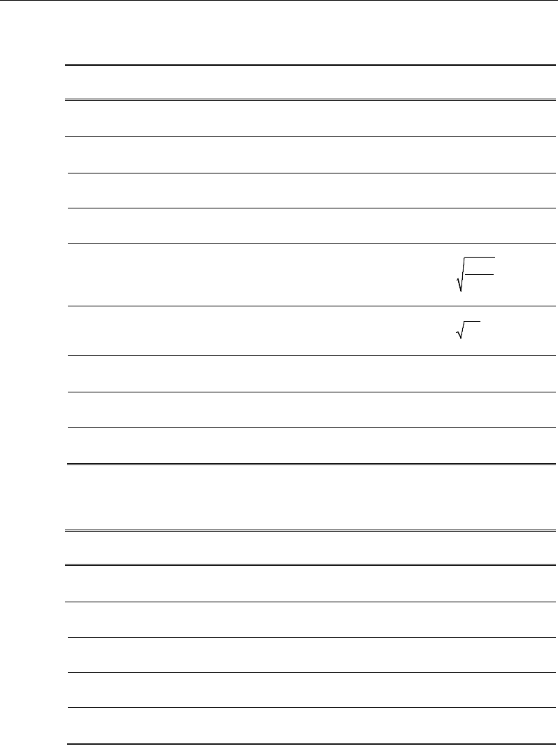
Post-Tensioned Concrete Design
Table 10-3 Denmark NDPs
NDP Clause Value
γc 2.4.2.4(1) 1.45
γs 2.4.2.4(1) 1.20
Max fyk 3.2.2(3) 650MPa
Load Combinations 5.1.3(1) Combinations from Eq. 6.10a/b
λ
lim 5.8.3.1(1)
20
c cd
Ed
Af
N
⋅
Beam
ρ
w,min 9.2.2(5)
( )
0.063 /
ck yk
ff
α
lcc 11.3.5(1) 1.0
α
lct 11.3.5(2) 1.0
vl,min 11.6.1(1) 0.03k2/3flck1/2
Table10-4 Finland NDPs
NDP Clause Value
αcc 3.1.6(1) 0.85
Max fyk 3.2.2(3) 700MPa
Load Combinations 5.1.3(1) Combinations from Eq. 6.10a/b
k2 5.5(4) 1.10
Beam As,max 9.2.1.1(3) Unlimited
10 - 42 Nationally Determined Parameters (NDPs)

Chapter 10 - Design for Eurocode 2-2004
Table 10-5 Norway NDPs
NDP Clause Value
α
cc 3.1.6(1) 0.85
α
ct 3.1.6(2) 0.85
λ
lim 5.8.3.1(1) 13(2 − rm)Af
k1 6.2.2(1) 0.15 for compression
0.3 for tension
vmin 6.2.2(1) 0.035k3/2fck1/2
Beam
ρ
w,min 9.2.2(5)
( )
01
ck yk
. f /f
vl,min 11.6.1(1) 0.03k2/3flck1/2
k1 11.6.1(1) 0.15 for compression
0.3 for tension
ν1 11.6.2(1) 0.5(1 – flck/250)
Table 10-6 Singapore NDPs
NDP Clause Value
αcc 3.1.6(1) 0.85
k1 5.5(4) 0.4
k2 5.5(4) 0.6 + 0.0014/
ε
cu2
k3 5.5(4) 0.54
k4 5.5(4) 0.6 + 0.0014/
ε
cu2
vlim 5.8.3.1(1) 0.30k3/2flck1/2
Nationally Determined Parameters (NDPs) 10 - 43

Post-Tensioned Concrete Design
Table 10-7 Slovenia NDPs
NDP Clause Value
Same As CEN Default
Table 10-8 Sweden NDPs
NDP Clause Value
Beam As,max 9.2.1.1(3) Unlimited
α
lcc 11.3.5(1) 1.0
α
lct 11.3.5(2) 1.0
Table 10-9 United Kingdom NDPs
NDP Clause Value
ψ
0,i (wind load) EC0 Combos 0.5
α
cc 3.1.6(1) 0.85
k1 5.5(4) 0.4
k2 5.5(4) 0.6 + 0.0014/
ε
cu2
k3 5.5(4) 0.4
k4 5.5(4) 0.6 + 0.0014/εcu2
vl,min 11.6.1(1) 0.30k3/2flck1/2
10 - 44 Nationally Determined Parameters (NDPs)

Chapter 11
Design for Hong Kong CP 04
This chapter describes in detail the various aspects of the post-tensioned concrete
design procedure that is used by ETABS when the user selects the Hong Kong
limit state code CP-04 [CP 04], which also incorporates Amendment 1 published
in June 2007. Various notations used in this chapter are listed in
Table 11-1. For referencing to the pertinent sections of the Hong Kong CP code
in this chapter, a prefix “CP” followed by the section number is used.
The design is based on user-specified load combinations. The program
provides a set of default load combinations that should satisfy the requirements
for the design of most building type structures.
English as well as SI and MKS metric units can be used for input. The code is
based on Newton-millimeter-second units. For simplicity, all equations and
descriptions presented in this chapter correspond to Newton-millimeter-second
units unless otherwise noted.
11.1 Notations
The following table identifies the various notations used in this chapter.
Table 11-1 List of Symbols Used in the Hong Kong CP 04 Code
A
cv
Area of section for shear resistance, mm2
Notations 11 - 1

Post-Tensioned Concrete Design
Table 11-1 List of Symbols Used in the Hong Kong CP 04 Code
A
g
Gross area of cross-section, mm2
A
s
Area of tension reinforcement, mm
2
A
ps
Area of prestress steel, mm2
A'
s
Area of compression reinforcement, mm2
A
sv
Total cross-sectional area of links at the neutral axis, mm
2
A
sv
/ s
v
Area of shear reinforcement per unit length of the member,
mm2/mm
a
Depth of compression block, mm
a
max
Maximum depth of the compression block, mm
b
Width or effective width of the section in the compression
zone, mm
b
f
Width or effective width of flange, mm
b
w
Average web width of a flanged beam, mm
d or d
e
Effective depth of tension reinforcement, mm
d'
Depth to center of compression reinforcement, mm
E
c
Modulus of elasticity of concrete, MPa
E
s
Modulus of elasticity of reinforcement, assumed as 200,000
MPa
f
ci
Concrete strength at transfer, MPa
f
cu
Characteristic cube strength, MPa
f
pu
Characteristic strength of a prestressing tendon, MPa
f
pb
Design tensile stress in tendon, MPa
s
f′
Compressive stress in a beam compression steel, MPa
f
y
Characteristic strength reinforcement, MPa
f
yv
Characteristic strength of link reinforcement, MPa
h
Overall depth of a section in the plane of bending, mm
h
f
Flange thickness, mm
11 - 2 Notations
Chapter 11 - Design for Hong Kong CP 04
Table 11-1 List of Symbols Used in the Hong Kong CP 04 Code
k
1
Shear strength enhancement factor for support compression
k2 Concrete shear strength factor,
[ ]
3
1
25
cu
f
M
Design moment at a section, MPa
M
u
Design moment resistance of a section, MPa
M
u
0
Design moment resistance of a section with tendons only, N-
mm
M
u
bal
Design moment resistance of a section with tendons and the
necessary mild reinforcement to reach the balanced condition,
N-mm
s
v
Spacing of the links along the length of the beam, mm
s
Spacing of shear rails, mm
T
Tension force, N
V
Design shear force at ultimate design load, N
u
Perimeter of the punching critical section, mm
v
Design shear stress at a beam cross-section or at a punch crit-
ical section, MPa
v
c
Design ultimate shear stress resistance of a concrete beam,
MPa
v
co
Ultimate shear stress resistance of an uncracked concrete
section, MPa
v
cr
Ultimate shear stress resistance of a cracked concrete section,
MPa
v
max
Maximum permitted design factored shear stress at a beam
section or at the punch critical section, MPa
v
t
Torsional shear stress, MPa
x
Neutral axis depth, mm
x
bal
Depth of neutral axis in a balanced section, mm
z
Lever arm, mm
Notations 11 - 3

Post-Tensioned Concrete Design
Table 11-1 List of Symbols Used in the Hong Kong CP 04 Code
β
Torsional stiffness constant
β
b
Moment redistribution factor in a member
γ
f
Partial safety factor for load
γ
m
Partial safety factor for material strength
ε
c
Maximum concrete strain
ε
ps
Strain in prestressing steel
ε
s
Strain in tension steel
ε
'
s
Strain in compression steel
11.2 Design Load Combinations
The design load combinations are the various combinations of the load cases for
which the structure needs to be designed. The design load combinations are ob-
tained by multiplying the characteristic loads by appropriate partial factors of
safety, γf (CP 2.3.2.1, Table 2.1). For Hong Kong CP 04, if a structure is sub-
jected to dead (D), live (L), pattern live (PL), and wind (W) loads, and consider-
ing that wind forces are reversible, the load combinations in the following sec-
tions may need to be considered (CP 2.3.2.1, 12.3.4.2, 12.3.4.3 and 12.3.5.1).
For post-tensioned concrete design, the user can specify the prestressing load
(PT) by providing the tendon profile or by using the load balancing options in
the program. The default load combinations for post-tensioning are defined in
the following sections.
11.2.1 Initial Service Load Combination
The following load combination is used for checking the requirements at transfer
of prestress forces in accordance with Hong Kong CP 04 clause 12.3.5. The pre-
stressing forces are considered without any long-term loses for the initial service
load combination check.
1.0D + 1.0PT
11 - 4 Design Load Combinations

Chapter 11 - Design for Hong Kong CP 04
11.2.2 Service Load Combination
The following load combinations are used for checking the requirements of pre-
stress for serviceability in accordance with CP 12.3.4. It is assumed that all long-
term losses have occurred already at the service stage.
1.0D + 1.0PT
1.0D + 1.0L + 1.0PT
11.2.3 Ultimate Limit State Load Combination
The following load combinations are used for checking the requirements of pre-
stress in accordance with CP 2.3.2.1, Table 2.1.
The combinations required for punching shear require the full PT forces (primary
and secondary). Flexural design requires only the hyperstatic (secondary) forces.
The hyperstatic (secondary) forces are determined automatically by ETABS by
subtracting the primary PT moments when the flexural design is completed.
1.4D + 1.0PT*
1.4D + 1.6L + 1.0PT*
1.4D + 1.6(0.75PL) + 1.0PT*
1.0D ± 1.4W +1.0PT*
1.4D
± 1.4W + 1.0PT*
1.
2D + 1.2L ± 1.2W + 1.0PT*
* — Replace PT with H for flexural design only
Other appropriate loading combinations should be used if roof live load is sepa-
rately treated, or other types of loads are present.
11.3 Limits on Material Strength
Grade C28/C35 and C32/C40 are the minimum recommended for post-tension-
ing and pre-tensioning respectively. In both cases the concrete strength at trans-
fer should not be less than 25 MPa (CP 12.1.8.1).
Limits on Material Strength 11 - 5
Post-Tensioned Concrete Design
The specified characteristic strength of un-tensioned reinforcement is given as
follows (CP 3.2.3, Table 3.3):
Hot rolled mild reinforcement - 250 MPa (CP 3.2.3, Table 3.3)
High yield reinforcement - 460 MPa (CP 3.2.3, Table 3.3)
The specified characteristic strength of prestressing steel should conform to CP
04 clause 3.3.
ETABS also checks the tensile strength in the prestressing steel (CP 12.7.1). The
permissible tensile stresses in all types of prestressing steel, in terms of the spec-
ified minimum tensile strength fpu, are summarized as follows:
a. Due to tendon jacking force: 0.75 fpu
b. Immediately after prestress transfer: 0.70 fpu
In any circumstances, the initial prestressing forces shall not exceed 0.75 fpu.
11.4 Partial Safety Factors
The design strengths for concrete and reinforcement are obtained by dividing the
characteristic strength of the material by a partial safety factor,
γ
m. The values of
γ
m used in the program are listed in the table that follows, as taken from CP Table
2.2 (CP 2.4.3.2):
Values of
γ
m for the ultimate limit state
Reinforcement,
γ
ms 1.15
Prestressing steel,
γ
mp 1.15
Concrete in flexure and axial load,
γ
mc 1.50
Shear strength without shear reinforcement,
γ
mv 1.25
These factors are already incorporated in the design equations and tables in the
code. Note that for reinforcement, the default factor of 1.15 is for Grade 460
reinforcement. If other grades are used, this value should be overwritten as nec-
essary. Changes to the partial safety factors are carried through the design equa-
tions where necessary, typically affecting the material strength portions of the
equations.
11 - 6 Partial Safety Factors

Chapter 11 - Design for Hong Kong CP 04
11.5 Design Assumptions for Prestressed Concrete Struc-
tures
The ultimate limit state of prestressed members for flexure and axial loads shall
be based on assumptions given in CP 12.3.7.1.
The strain distribution in the concrete in compression is derived from the
assumption that a plane section remains plane (CP 12.3.7.1).
The design stresses in the concrete in compression are taken as 0.45 fcu. The
maximum strain at the extreme concrete compression fiber shall be assumed
equal to 0.0035 (CP 12.3.7.1).
Tensile strength of the concrete is ignored (CP 12.3.7.1).
The strain in bonded prestressing tendons and in any additional reinforcement
(compression or tension) is derived from the assumption that plane
section remains plane (CP 12.3.7.1).
The serviceability limit state of prestressed members uses the following assump-
tions given in CP 12.3.4.1.
Plane sections remain plane, i.e., strain varies linearly with depth through the
entire load range (CP 12.3.4.1).
Elastic behavior exists by limiting the concrete stresses to the values given in
CP 12.3.4.2, 12.3.4.3 and 12.3.5 (CP 12.3.4.1).
In general, it is only necessary to calculate design stresses due to the load
arrangements immediately after the transfer of prestress and after all losses or
prestress have occurred; in both cases the effects of dead and imposed loads
on the strain and force in the tendons may be ignored (CP 12.3.4.1).
Prestressed concrete members are investigated at the following three stages (CP
12.3.4.2 and 12.3.4.3):
At transfer of prestress force
At service loading
At nominal strength
Design Assumptions for Prestressed Concrete Structures 11 - 7

Post-Tensioned Concrete Design
The prestressed flexural members are classified as Group a (uncracked), Group
b (cracked but no visible cracking), and Group c (cracked) based on tensile
strength ft, the computed extreme fiber stress in tension in the precompressed
tensile zone at service loads (CP 12.1.3).
The precompressed tensile zone is that portion of a prestressed member where
flexural tension, calculated using gross section properties, would occur under
unfactored dead and live loads if the prestress force was not present. Prestressed
concrete is usually designed so that the prestress force introduces compression
into this zone, thus effectively reducing the magnitude of the
tensile stress.
Group a: No flexural tensile stresses
Group b: Flexural tensile stresses with no visible cracking
Group c: Flexural tensile stresses with surface crack widths as follows:
≤ 0.1 mm for members in exposure conditions 3 and 4 (Table 4.1 of
CP 04)
≤ 0.2 mm for all other members
11.6 Serviceability Requirements of Flexural Members
11.6.1 Serviceability Check at Initial Service Load
The stresses in the concrete immediately after prestress force transfer (before
time dependent prestress losses) are checked against the following limits (CP
12.3.5.1 and 12.3.5.2):
Extreme fiber stress in compression:
0.50 ci
f
Extreme fiber stress in tension for Group a: ≤ 1.0 MPa
Extreme fiber stress in tension for Group b:
pre-tensioned member
0.45
ci
f
11 - 8 Serviceability Requirements of Flexural Members

Chapter 11 - Design for Hong Kong CP 04
post-tensioned member
0.36
ci
f
The extreme fiber stress in tension for Group c should not exceed the appropriate
value for a Group b member; otherwise the section should be designed as a
cracked section.
11.6.2 Serviceability Check at Service Load
The stresses in the concrete for Group a and Group b prestressed flexural mem-
bers at service loads, and after all prestress losses have occurred, are checked
against the following limits (CP 12.3.4.2 an 12.3.4.3):
Extreme fiber stress in compression due
to prestress plus total load:
0.33
cu
f
Extreme fiber stress in compression due
to prestress plus total load for continuous
beams and other statically indeterminate
structures:
0.4 cu
f
Extreme fiber stress in tension in the
precompressed tensile zone at service loads:
– Extreme fiber stresses in tension for Group a: No tensile stress
– Extreme fiber stresses in tension for Group b:
pre-tensioned member
0.45
cu
f
post-tensioned member
0.36
cu
f
Although cracking is allowed for Group c, it is assumed that the concrete
section is uncracked and the user is limiting the tensile stress at the service stage
as presented in Table 12.2, modified by the coefficients in Table 12.3 of CP 04.
The user needs to provide the tension limits for Group c elements at
service loads in the design preferences (CP 12.3.4.3).
Serviceability Requirements of Flexural Members 11 - 9

Post-Tensioned Concrete Design
11.7 Beam Design (for Reference Only)
Important Note: Post-tensioned beam design is not available in the current ver-
sion of ETABS, but is planned for a future release. This section is provided as
reference only for the documentation of post-tensioned slab design.
In the design of prestressed concrete beams, ETABS calculates and reports the
required areas of reinforcement for flexure, shear, and torsion based on the beam
moments, shear forces, torsion, load combination factors, and other criteria de-
scribed in the subsections that follow. The reinforcement requirements are cal-
culated at each station along the length of the beam.
Beams are designed for major direction flexure, shear, and torsion only. Effects
resulting from any axial forces and minor direction bending that may exist in the
beams must be investigated independently by the user.
The beam design procedure involves the following steps:
Design flexural reinforcement
Design shear reinforcement
Design torsion reinforcement
11.7.1 Design Flexural Reinforcement
The beam top and bottom flexural reinforcement is designed at each station
along the beam. In designing the flexural reinforcement for the major moment
of a particular beam, for a particular station, the following steps are involved:
Determine factored moments
Determine required flexural reinforcement
11.7.1.1 Determine Factored Moments
In the design of flexural reinforcement of prestressed concrete beams, the
factored moments for each load combination at a particular beam station are ob-
tained by factoring the corresponding moments for different load cases, with the
corresponding load factors.
11 - 10 Beam Design (for Reference Only)

Chapter 11 - Design for Hong Kong CP 04
The beam is then designed for the maximum positive and maximum negative
factored moments obtained from all of the load combinations. Positive beam
moments can be used to calculate bottom reinforcement. In such cases the beam
may be designed as a rectangular or a flanged beam. Negative beam moments
can be used to calculate top reinforcement. In such cases the beam may be de-
signed as a rectangular or inverted flanged beam.
11.7.1.2 Determine Required Flexural Reinforcement
In the flexural reinforcement design process, the program calculates both the
tension and compression reinforcement. Compression reinforcement is added
when the applied design moment exceeds the maximum moment capacity of a
singly reinforced section. The user has the option of avoiding the compression
reinforcement by increasing the effective depth, the width, or the strength of the
concrete.
The design procedure is based on the simplified rectangular stress block shown
in Figure 12-1 (CP 6.1.2.4(a)), where
ε
c,max is defined as:
( )
1
,max 2
0.0035 if 60 MPA
0.0035 0.00006 60 if 60 MPA
cu
c
cu cu
f
ff
ε
≤
=−− >
Furthermore, it is assumed that moment redistribution in the member does not
exceed 10% (i.e.,
β
b ≥ 0.9) (CP 6.1.2.4(b)). The code also places a limitation on
the neutral axis depth,
2
2
2
0.5 for 45 N mm
0.4 for 45 70 N mm
0.33 for 70 100 N mm
cu
cu
cu
f
xf
df
≤
≤ <≤
<≤
to safeguard against non-ductile failures (CP 6.1.2.4(b)). In addition, the area of
compression reinforcement is calculated assuming that the neutral axis depth re-
mains at the maximum permitted value.
The design procedure used by ETABS, for both rectangular and flanged sections
(L- and T-beams), is summarized in the subsections that follow. It is assumed
that the design ultimate axial force does not exceed 0.1 fcu Ag (CP 6.1.2.4(a));
hence all beams are designed for major direction flexure, shear, and torsion only.
Beam Design (for Reference Only) 11 - 11

Post-Tensioned Concrete Design
Figure 11-1 Rectangular Beam Design
11.7.1.2.1 Design of Rectangular Beams
The amount of post-tensioning steel adequate to resist the design moment M and
minimum reinforcement are provided to satisfy the flexural cracking
requirements (CP 19.2.1).
ETABS determines the depth of the neutral axis, x, by imposing force equilib-
rium, i.e., C = T, and performs an iteration to compute the depth of the neutral
axis, which is based on stress-strain compatibility. After the depth of the neutral
axis has been found, the stress in the post-tensioning reinforcement fpb is com-
puted based on strain compatibility.
The ductility of a section is controlled by limiting the x/d ratio (CP 6.1.2.4(b)):
2
2
2
0.5, for 45 N mm
0.4, for 45 70 N mm
0.33, for 70 100N mm
≤
= <≤
<≤
cu
cu
cu
f
xf
df
(CP 6.1.2.4(b))
The maximum depth of the compression block is given by:
BEAM
SECTION STRAIN
DIAGRAM STRESS
DIAGRAM
s
A
ε
0.67
cu m
f
γ
s
f′s
C
s
A′
ps
A
s
ε
ps
ε
s
T
cps
T
s
d
p
d
b
x
d′a
cs
T
BEAM
SECTION STRAIN
DIAGRAM STRESS
DIAGRAM
s
A
ε
0.67
cu m
f
γ
s
f′s
C
s
A′
ps
A
s
ε
ps
ε
s
T
cps
T
s
d
p
d
b
x
d′a
cs
T
11 - 12 Beam Design (for Reference Only)
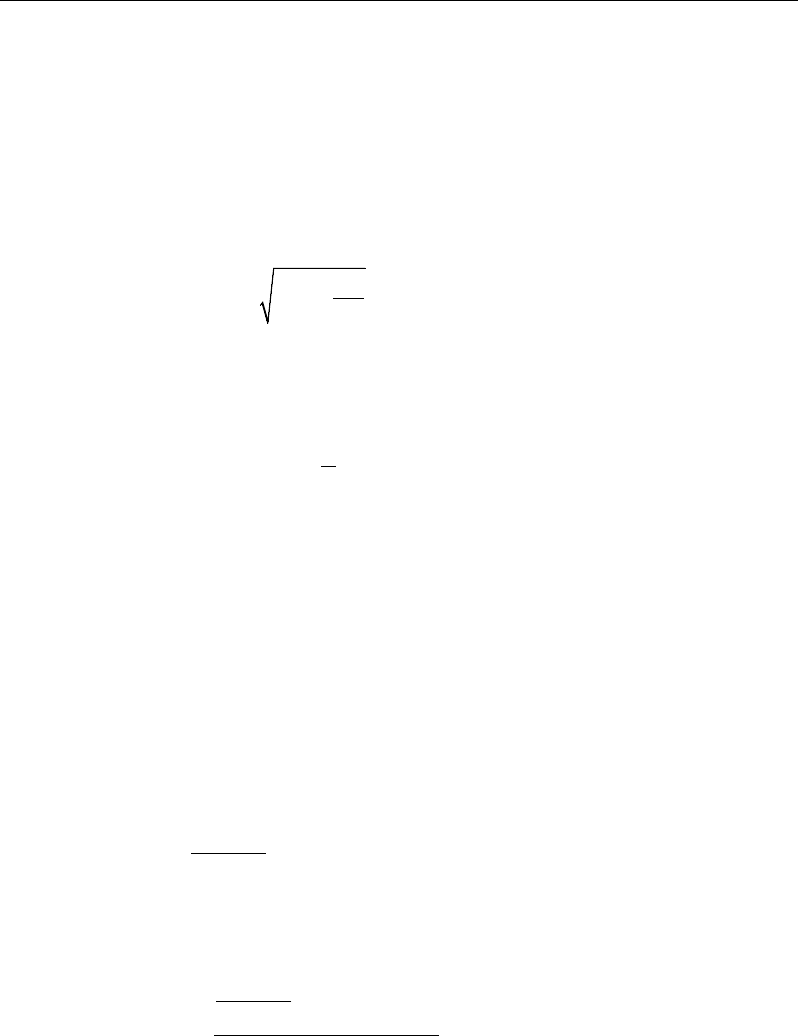
Chapter 11 - Design for Hong Kong CP 04
2
2
2
0.9 for 45 N/mm
0.8 for 45 < 70 N/mm
0.72 for 70 < 100 N/mm
a
≤
= ≤
≤
cu
cu
cu
xf
xf
xf
(CP 6.1.2.4(a))
The lever arm of the section must not be greater than 0.95 times the effective
depth (CP 6.1.2.4(c)).
z = d
0.5 0.25 0.9
K
+−
≤ 0.95d, (CP 6.1.2.4(c))
If
max
aa≤
(CP 6.1.2.4), the moment capacity of the section, provided by post-
tensioning steel only, is computed as:
0
2
= −
u ps pb p a
M Af d
If
max
aa>
(CP 6.1.2.4), a failure condition is declared.
If
0,>u
MM
ETABS calculates the moment capacity and the As required at the
balanced condition. The balanced condition is taken as the marginal tension con-
trolled case. In that case, it is assumed that the depth of neutral axis x is equal to
xmax. The stress in the post-tensioning steel, fpb is then calculated based on strain
compatibility for bonded tendons. For unbonded tendons, the code equations are
used to compute the stress, fps in the post-tensioning steel, and the area of re-
quired tension reinforcement, As, is determined by imposing force equilibrium,
i.e., C = T.
ba
f
C
m
cu max
67.0
γ
=
bal bal bal
ps pb s s
T Af A f= +
bal
s
bal
pbps
m
cu
bal
s
f
fAba
f
A
−
=
max
67.0
γ
Beam Design (for Reference Only) 11 - 13

Post-Tensioned Concrete Design
After the area of tension reinforcement has been determined, the capacity of the
section with post-tensioning steel and tension reinforcement is computed as:
max max
22
bal bal bal bal
u ps pb p s s s
aa
M Afd Afd
= −+ −
In that case, it is assumed that the bonded tension reinforcement will yield, which
is true for most cases. In the case that it does not yield, the stress in the reinforce-
ment, fs, is determined from the elastic-perfectly plastic stress-strain relationship.
The fy value of the reinforcement is then replaced with fs in the preceding four
equations. This case does not involve any iteration in determining the depth of
neutral axis, x.
11.7.1.2.1.1 Case 1: Post-tensioning steel is adequate
When
0,
u
MM<
the amount of post-tensioning steel is adequate to resist the de-
sign moment M.. Minimum reinforcement is provided to satisfy the ductility re-
quirements, i.e.,
0
.
u
MM<
11.7.1.2.1.2 Case 2: Post-tensioning steel plus tension reinforcement
In this case, the amount of post-tensioning steel, Aps, alone is not sufficient to
resist M, and therefore the required area of tension reinforcement is computed to
supplement the post-tensioning steel. The combination of post-tensioning steel
and tension reinforcement should result in a < amax.
When
0,
bal
uu
M MM<<
ETABS determines the required area of tension rein-
forcement, As, iteratively to satisfy the design moment M and reports this re-
quired area of tension reinforcement. Since M is bounded by
0
u
M
at the lower
end and
bal
u
M
at the upper end, and
0
u
M
is associated with
0
s
A=
and
bal
u
M
is
associated with
,
bal
ss
AA=
the required area will be between the range of 0 to
Asbal.
The tension reinforcement is to be placed at the bottom if M is positive, or at the
top if M is negative.
11 - 14 Beam Design (for Reference Only)

Chapter 11 - Design for Hong Kong CP 04
11.7.1.2.1.3 Case 3: Post-tensioning steel and tension reinforcement are not ade-
quate
When
,
bal
u
MM>
compression reinforcement is required (CP 6.1.2.4). In that
case, ETABS assumes that the depth of neutral axis, x, is equal to xmax. The
values of fpb and fs reach their respective balanced condition values,
bal
pb
f
and
.
bal
s
f
The area of compression reinforcement,
,
′
s
A
is determined as follows:
The moment required to be resisted by compression reinforcement and tension
reinforcement is:
bal
us u
M MM= −
The required compression reinforcement is given by:
( )
0 67
us
scu
sc
M
A' ,
.f
f' d d'
γ
=
−−
where (CP 6.1.2.4(c))
1 0.87 ,
s sc y
d
fE f
x
ε
′
′= −≤
(CP 6.1.2.4(c), 3.2.6, Fig. 3.9)
The tension reinforcement for balancing the compression reinforcement is given
by:
( )
0.87 '
com us
s
ys
M
Afd d
=−
Therefore, the total tension reinforcement, A
s
=
bal
s
A
+
,
com
s
A
and the total com-
pression reinforcement is A'
s
. A
s
is to be placed at the bottom and A'
s
is to be
placed at the top if M is positive, and vice versa if M is negative.
11.7.1.2.2 Design of Flanged Beams
11.7.1.2.2.1 Flanged Beam Under Negative Moment
In designing for a factored negative moment, M (i.e., designing top reinforce-
ment), the calculation of the reinforcement area is exactly the same as described
previously, i.e., no flanged beam data is used.
Beam Design (for Reference Only) 11 - 15
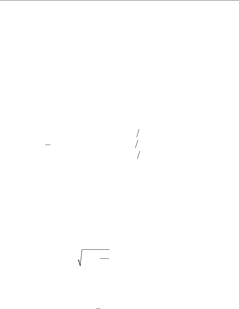
Post-Tensioned Concrete Design
11.7.1.2.2.2 Flanged Beam Under Positive Moment
ETABS first determines if the moment capacity provided by the post-tensioning
tendons alone is enough. In calculating the capacity, it is assumed that A
s
= 0. In
that case, moment capacity
0
u
M
is determined as follows:
ETABS determines the depth of the neutral axis, x, by imposing force equilib-
rium, i.e., C = T, and performs an iteration to compute the depth of neutral axis,
which is based on stress-strain compatibility for bonded tendons. For unbonded
tendons, the code equations are used to compute the stress, fps in the post-ten-
sioning steel. After the depth of the neutral axis has been determined, the stress
in the post-tensioning steel, fpb is computed based on strain compatibility.
The ductility of a section is controlled by limiting the x/d ratio (CP 6.1.2.4(b)):
2
2
2
0.5, for 45 N mm
0.4, for 45 70 N mm
0.33, for 70 100N mm
≤
= <≤
<≤
cu
cu
cu
f
xf
df
(CP 6.1.2.4(b))
The maximum depth of the compression block is given by:
2
2
2
0.9 for 45 N/mm
0.8 for 45 < 70 N/mm
0.72 for 70 < 100 N/mm
a
≤
= ≤
≤
cu
cu
cu
xf
xf
xf
(CP 6.1.2.4(a))
The lever arm of the section must not be greater than 0.95 times the effective
depth (CP 6.1.2.4(c)).
z = d
0.5 0.25 0.9
K
+−
≤ 0.95d, (CP 6.1.2.4(c))
If
max
aa≤
(CP 6.1.2.4), the moment capacity of the section, provided by post-
tensioning steel only, is computed as:
0
2
= −
u ps pb p a
M Af d
If
max
aa>
(CP 6.1.2.4), a failure condition is declared.
11 - 16 Beam Design (for Reference Only)

Chapter 11 - Design for Hong Kong CP 04
If
0
,
u
MM>
ETABS calculates the moment capacity and the As required at the
balanced condition. The balanced condition is taken as the marginal tension con-
trolled case. In that case it is assumed that the depth of neutral axis x is equal to
cmax. The stress in the post-tensioning steel, fpb is then calculated based on strain
compatibility for bonded tendons. For unbonded tendons, the code equations are
used to compute the stress, fps in the post-tensioning steel, and the area of re-
quired tension reinforcement, A
s
, is determined by imposing force equilibrium,
i.e., C = T.
If a ≤ h
f
, the subsequent calculations for A
s
are exactly the same as previously
defined for the rectangular beam design. However, in this case the width of
the beam is taken as b
f
. Compression reinforcement is required when K > K'.
If a > h
f
, the calculation for As is given by
max
0.67 com
cu c
c
f
C aA
γ
=
where
com
c
A
is the area of concrete in compression, i.e.,
( )
max
com
c ff w f
A bh b a h=+−
bal bal bal
ps pb s s
T Af A f= +
bal
s
bal
pbps
com
c
m
cu
bal
s
f
f
AA
a
f
A
−
=
max
67
.0
γ
In that case, it is assumed that the bonded tension reinforcement will yield, which
is true for most cases. In the case that it does not yield, the stress in the reinforce-
ment, f
s
, is determined from the elastic-perfectly plastic stress-strain relation-
ship. The f
y
value of the reinforcement is then replaced with f
s
in the preceding
four equations. This case does not involve any iteration in determining the depth
of neutral axis, c.
Beam Design (for Reference Only) 11 - 17
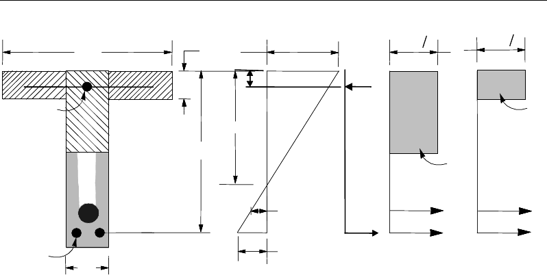
Post-Tensioned Concrete Design
Figure 11-2 T-Beam Design
11.7.1.2.2.3 Case 1: Post-tensioning steel is adequate
When
0,<u
MM
the amount of post-tensioning steel is adequate to resist the de-
sign moment M. Minimum reinforcement is provided to satisfy ductility
requirements.
11.7.1.2.2.4 Case 2: Post-tensioning steel plus tension reinforcement
In this case, the amount of post-tensioning steel, A
ps
, alone is not sufficient to
resist M, and therefore the required area of tension reinforcement is computed to
supplement the post-tensioning steel. The combination of post-tensioning steel
and tension reinforcement should result in a < amax.
When
0,
bal
uu
M MM<<
ETABS determines the required area of tension rein-
forcement, A
s
, iteratively to satisfy the design moment M and reports the
required area of tension reinforcement. Since M is bounded by
0
u
M
at the lower
end and
bal
u
M
at the upper end, and
0
u
M
is associated with
0
s
A=
and
bal
u
M
is
associated with
,
bal
ss
AA=
the required area will be within the range of 0 to Asbal.
(I) BEAM
SECTION
(II) STRAIN
DIAGRAM (II) STRESS
DIAGRAM
s
A′
s
A
f
b
ps
A
bw
d
x
s
f′
d′
f
h
s
T
w
T
f
T
f
C
w
C
s
C
s
ε
ps
ε
ε
0.67
cu m
f
γ
0.67
cu m
f
γ
(I) BEAM
SECTION
(II) STRAIN
DIAGRAM (II) STRESS
DIAGRAM
s
A′
s
A
f
b
ps
A
bw
d
x
s
f′
d′
f
h
s
T
w
T
f
T
f
C
w
C
s
C
s
ε
ps
ε
ε
0.67
cu m
f
γ
0.67
cu m
f
γ
11 - 18 Beam Design (for Reference Only)

Chapter 11 - Design for Hong Kong CP 04
The tension reinforcement is to be placed at the bottom if M is positive, or at the
top if M is negative.
11.7.1.2.2.5 Case 3: Post-tensioning steel and tension reinforcement are not ade-
quate
When
,
bal
u
MM
>
compression reinforcement is required (CP 6.1.2.4). In that
case ETABS assumes that the depth of the neutral axis, x, is equal to xmax. The
values of fpb and f
s
reach their respective balanced condition values,
bal
pb
f
and
.
bal
s
f
The area of compression reinforcement,
,
′
s
A
is then determined as fol-
lows:
The moment required to be resisted by compression reinforcement and tension
reinforcement is:
bal
us u
M MM
= −
The required compression reinforcement is given by:
( )
us
s
cu
sc
M
Af
f dd
',
0.67
''
γ
=
−−
where (CP 6.1.2.4(c))
'
1 0.87
s sc y
d
fE f
x
ε
′= −≤
(CP 6.1.2.4(c))
The tension reinforcement for balancing the compression reinforcement is given
by:
( )
0.87 '
com us
sys
M
Afd d
=−
Therefore, the total tension reinforcement, As =
bal
s
A
+
,
com
s
A
and the total com-
pression reinforcement is A'
s
. A
s
is to be placed at the bottom, and A'
s
is to be
placed at the top if M is positive and vice versa if M is negative.
Beam Design (for Reference Only) 11 - 19
Post-Tensioned Concrete Design
11.7.1.3 Minimum and Maximum Reinforcement
Reinforcement in post-tensioned concrete beams is computed to increase the
strength of sections as documented for the flexural design of post-tensioned
beams or to comply with the shear link requirements. The minimum flexural
tension reinforcement required for a beam section to comply with the cracking
requirements needs to be separately investigated by the user.
For bonded tendons, there is no minimum untensioned reinforcement required.
For unbounded tendons, the minimum flexural reinforcement provided in a rec-
tangular or flanged beam section is given by the following table, which is taken
from CP Table 9.1(CP 9.2.1.1) with interpolation for reinforcement of interme-
diate strength:
Section
Situation
Definition of
percentage
Minimum percentage
f
y
= 250
MPa
f
y
= 460
MPa
Rectangular 100
bh
As
0.24 0.13
T- or L-Beam with
web in tension
f
w
b
b
< 0.4 100
h
b
A
w
s
0.32 0.18
f
w
b
b
≥ 0.4 100
hb
A
w
s
0.24 0.13
T-Beam with web in
compression 100
hb
A
w
s
0.48 0.26
L-Beam with web in
compression 100
hb
A
w
s
0.36 0.20
The minimum flexural compression reinforcement, if it is required at all, is given
by the following table, which is taken from CP Table 9.1(CP 9.2.1.1) with inter-
polation for reinforcement of intermediate strength:
11 - 20 Beam Design (for Reference Only)

Chapter 11 - Design for Hong Kong CP 04
Section
Situation
Definition of
percentage
Minimum
percentage
Rectangular 100
s
A
bh
′
0.20
T- or L-Beam
Web in tension 100
s
ff
A
bh
′
0.40
Web in compression 100
s
w
A
bh
′
0.20
In addition, an upper limit on both the tension reinforcement and compression
reinforcement is imposed to be 0.04 times the gross cross-sectional area (CP
3.12.6.1).
11.7.2 Design Beam Shear Reinforcement
The shear reinforcement is designed for each load combination in the major
direction of the beam. In designing the shear reinforcement for a particular beam
for a particular load combination, the following steps are involved (CP 6.1.2.5):
Determine the shear stress, v.
Determine the shear stress, vc, that can be resisted by the concrete.
Determine the shear reinforcement required to carry the balance.
The following three subsections describe in detail the algorithms associated with
these steps.
11.7.2.1 Determine Shear Stress
In the design of the beam shear reinforcement, the shear forces for a particular
load combination at a particular beam section are obtained by factoring the
associated shear forces for different load cases, with the corresponding load
combination factors.
db
V
v
w
=
(CP 6.1.2.5(a))
Beam Design (for Reference Only) 11 - 21

Post-Tensioned Concrete Design
The maximum allowable shear stress, vmax is defined as:
vmax = min(0.8
,
cu
f
7 MPa) (CP 6.1.2.5(a), 12.3.8.2)
For light-weight concrete, vmax is defined as:
vmax = min(0.63
,
cu
f
5.6 MPa) (BS 8110-2:1985 5.4)
11.7.2.2 Determine Concrete Shear Capacity
The design ultimate shear resistance of the concrete alone, V
c
should be consid-
ered at sections that are as follows:
Uncracked sections in flexure (M < Mo) (CP 12.3.8.3)
Cracked sections in flexural (M ≥ Mo) (CP 12.3.8.3)
where,
M is the design bending moment at the section
Mo is the moment necessary to produce zero stress in the concrete at the
extreme tension fiber; in this calculation, only 0.8 of the stress due to
post-tensioning should be taken into account.
11.7.2.2.1.1 Case 1: Uncracked section in flexure
The ultimate shear resistance of the section, Vco, is computed as follows:
( )
0.67 0.8 ,
2
co v t cp t
V = bh f + f f
(CP 12.3.8.4)
where,
ft is the maximum design principal stress (CP 12.3.8.4)
0.24
t cu
f= f
(CP 12.3.8.4)
fcp = design compressive stress at the centroidal axis due to
post-tensioning, taken as positive. (CP 12.3.8.4)
11 - 22 Beam Design (for Reference Only)
Chapter 11 - Design for Hong Kong CP 04
β
sinPVV coc+=
(CP 12.3.8.4)
11.7.2.2.1.2 Case 2: Cracked section in flexure
The ultimate shear resistance of the section, Vcr, is computed as follows:
1 0.55 ,
pe
cr c v o
pu
fV
V vbd M
fM
=−+
and (CP 12.3.8.5)
0.1
cr v cu
V bd f≥
(CP 12.3.8.5)
( )
β
sin,min PVVV
crcoc
+=
(CP 12.3.8.5)
11.7.2.3 Determine Required Shear Reinforcement
Given v, vc, and vmax, the required shear reinforcement is calculated as follows
(CP 12.3.8.6):
Calculate the design average shear stress that can be carried by minimum shear
reinforcement, vr, as:
( )
2
23
2
23
2
Nmm
Nmm
Nmm
0.4 if 40
0.4 if 40 80
40
80
0.4 if 80
40
cu cu
cu
r cu
cu
ff
f
vf
f
≤
= <≤
>
(CP 12.3.8.7)
80
2
N
mm
cu
f≤
(for calculation purpose only) (CP 6.1.2.5(c))
If
,
cr
vv v≤+
minimum reinforcement is required:
,
0.87
sr
v yv
Avb
sf
=
(CP 12.3.8.7)
If
,
cr
vv v
>+
Beam Design (for Reference Only) 11 - 23

Post-Tensioned Concrete Design
( )
0.87
c
sv
v yv
vvb
A
sf
−
=
(CP 12.3.8.8)
If v > vmax, a failure condition is declared.
In the preceding expressions, a limit is imposed on fyv as:
fyv ≤ 460 MPa.
The maximum of all of the calculated Asv /sv values, obtained from each load
combination, is reported along with the controlling shear force and associated
load combination.
The beam shear reinforcement requirements considered by the program are
based purely on shear strength considerations. Any minimum stirrup require-
ments to satisfy spacing and volumetric considerations must be investigated
independently of the program by the user.
11.7.3 Design Beam Torsion Reinforcement
The torsion reinforcement is designed for each design load combination at each
station along the length of the beam. The following steps are involved in
designing the longitudinal and shear reinforcement for a particular station due to
the beam torsion:
Determine the torsional shear stress, vt
Determine special section properties
Determine critical torsion stress
Determine the torsion reinforcement required
11.7.3.1 Determine Torsional Shear Stress
In the design of beam torsion reinforcement, the torsions for each load combina-
tion at a particular beam station are obtained by factoring the corresponding tor-
sions for different load cases, with the corresponding load combination factors.
11 - 24 Beam Design (for Reference Only)

Chapter 11 - Design for Hong Kong CP 04
In typical framed construction, specific consideration of torsion is not usually
required where torsional cracking is adequately controlled by shear reinforce-
ment. If the design relies on the torsional resistance of a beam, further consider-
ation should be given using the following algorithms (CP 6.3.1).
The torsional shear stress, vt, for a rectangular section is computed as:
( )
3/
2
minmax
2
min
hhh
T
v
t
−
=
(CP 6.3.3(a))
For flanged sections, the section is considered as a series of rectangular
segments and the torsional shear stress is computed for each rectangular compo-
nent using the preceding equation, but considering a torsional moment
attributed to that segment, calculated as:
( )
=∑max
3
min
max
3
min
hh
hh
TTseg
(CP 6.3.3(b))
hmax
=
Larger dimension of a rectangular section
hmin
=
Smaller dimension of a rectangular section
If the computed torsional shear stress, vt, exceeds the following limit for sections
with the larger center-to-center dimension of the closed link less than 550 mm,
a failure condition is generated if the torsional shear stress does not satisfy:
1
min(0.8 ,7 ) 550
t cu
y
vf≤×
2
N/mm
(CP 6.3.4, Table 17)
11.7.3.2 Determine Critical Torsion Stress
The critical torsion stress, vt,min, for which the torsion in the section can be
ignored is calculated as:
( )
2
,min min 0.067 ,0.6 N/mm
t cu
vf
=
(CP 6.3.4, Table 17)
where fcu is the specified concrete compressive strength.
For light-weight concrete, vt,min is defined as:
Beam Design (for Reference Only) 11 - 25
Post-Tensioned Concrete Design
( )
2
min
min 0 067 0 4N/mm
t, cu
v . f ,.=
× 0.8 (BS 8110-2:85 5.5)
11.7.3.3 Determine Torsion Reinforcement
If the factored torsional shear stress, vt is less than the threshold limit, vt,min, tor-
sion can be safely ignored (CP 6.3.5). In that case, the program reports that no
torsion reinforcement is required. However, if vt exceeds the threshold limit,
vt,min, it is assumed that the torsional resistance is provided by closed stirrups and
longitudinal bars (CP 6.3.5).
If vt > vt,min, the required closed stirrup area per unit spacing, Asv,t /sv, is calcu-
lated as:
( )
yvv
tsv
fyx
T
s
A
87.08.0 11
,=
(CP 6.3.6)
and the required longitudinal reinforcement is calculated as:
()
y
v
yv
t
sv
lfs
y
xf
A
A1
1, +
=
(CP 6.3.6)
In the preceding expressions, x1 is the smaller center-to-center dimension of
the closed link, and y1 is the larger center-to-center dimension of the closed
link.
An upper limit of the combination of v and vt that can be carried by the section
is also checked using the equation:
+≤
maxt
vv v
(CP 6.3.4)
( )
≤2
max min 0.8 ,7 N/mm
cu
vf
(CP 6.3.4)
For light-weight concrete, vmax is defined as:
vmax = min(0.63
cu
f,
4 MPa) (BS 8110-2:85 5.4)
11 - 26 Beam Design (for Reference Only)
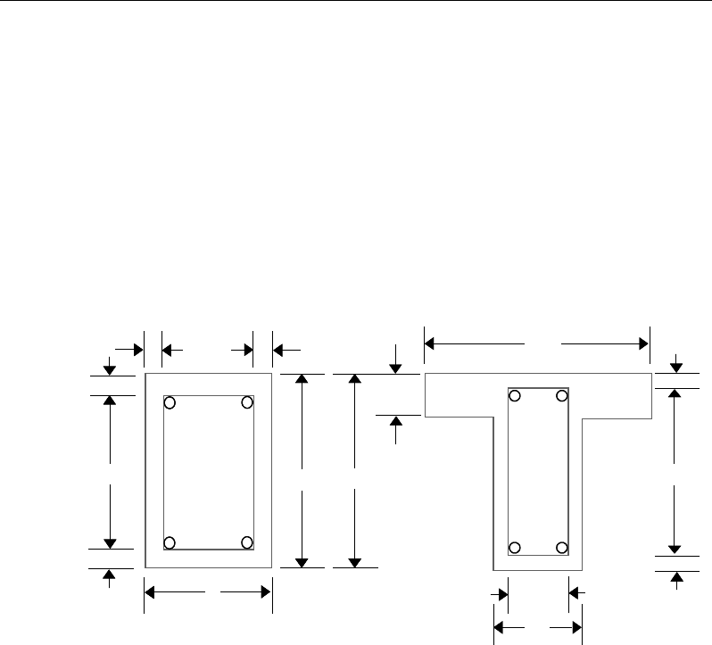
Chapter 11 - Design for Hong Kong CP 04
If the combination of shear stress, v, and torsional shear stress, vt, exceeds this
limit, a failure message is declared. In that case, the concrete section should be
increased in size.
The maximum of all of the calculated Al and Asv,t /sv values obtained from each
load combination is reported along with the controlling combination.
The beam torsion reinforcement requirements reported by the program are based
purely on strength considerations. Any minimum stirrup requirements or longi-
tudinal rebar requirements to satisfy spacing considerations must be
investigated independently of the program by the user.
Figure 11-3 Closed stirrup and section dimensions for torsion design
11.8 Slab Design
Similar to conventional design, the ETABS slab design procedure involves
defining sets of strips in two mutually perpendicular directions. The locations of
the strips typically are governed by the locations of the slab supports. The mo-
ments for a particular strip are recovered from the analysis, and a flexural design
is carried out based on the ultimate strength design method (Hong Kong CP 04)
cb
w
2−
c
c
cc
c
c
cb 2−
h
s
d
Closed Stirrup in
Rectangular Beam Closed Stirrup in
T-Beam Section
ch 2−h
b
ch 2−
w
b
bf
cb
w
2−
c
c
cc
c
c
cb 2−
h
s
d
Closed Stirrup in
Rectangular Beam Closed Stirrup in
T-Beam Section
ch 2−h
b
ch 2−
w
b
bf
Slab Design 11 - 27

Post-Tensioned Concrete Design
for prestressed reinforced concrete as described in the following subsections. To
learn more about the design strips, refer to the section entitled "ETABS Design
Techniques" in the Key Features and Terminology manual.
11.8.1 Design for Flexure
ETABS designs the slab on a strip-by-strip basis. The moments used for the
design of the slab elements are the nodal reactive moments, which are obtained
by multiplying the slab element stiffness matrices by the element nodal displace-
ment vectors. Those moments will always be in static equilibrium with the ap-
plied loads, irrespective of the refinement of the finite element mesh.
The design of the slab reinforcement for a particular strip is carried out at
specific locations along the length of the strip. Those locations correspond to the
element boundaries. Controlling reinforcement is computed on either side of
those element boundaries. The slab flexural design procedure for each load com-
bination involves the following:
Determine factored moments for each slab strip
Determine the capacity of post-tensioned sections
Design flexural reinforcement for the strip
These three steps are described in the subsections that follow and are repeated
for every load combination. The maximum reinforcement calculated for the top
and bottom of the slab within each design strip, along with the corresponding
controlling load combination, is obtained and reported.
11.8.1.1 Determine Factored Moments for the Strip
For each element within the design strip, for each load combination, the program
calculates the nodal reactive moments. The nodal moments are then added to get
the strip moments.
11.8.1.2 Determine Capacity of Post-Tensioned Sections
The calculation of the post-tensioned section capacity is identical to that
described earlier for rectangular beam sections.
11 - 28 Slab Design

Chapter 11 - Design for Hong Kong CP 04
11.8.1.3 Design Flexural Reinforcement for the Strip
The reinforcement computation for each slab design strip, given the bending mo-
ment, is identical to the design of rectangular beam sections described
earlier (or to the flanged beam if the slab is ribbed). In some cases, at a given
design section in a design strip, there may be two or more slab properties across
the width of the design strip. In that case, the program automatically designs the
tributary width associated with each of the slab properties separately using its
tributary bending moment. The reinforcement obtained for each of the tributary
widths is summed to obtain the total reinforcement for the full width of the de-
sign strip at the considered design section. This method is used when drop panels
are included. Where openings occur, the slab width is adjusted accordingly.
11.8.1.4 Minimum and Maximum Slab Reinforcement
There are no minimum requirements for untensioned reinforcement in one-way
bonded slabs. One-way spanning floors with unbounded tendons should have
minimum reinforcement requirements in accordance with CP Table 3.25 (CP
3.12.5.3)
In flat slabs, reinforcement is added at the top over supports to be 0.00075 times
the gross cross-sectional area. This reinforcement extends 1.5 times the slab
depth on each side of the column. The length of the reinforcement should be at
least 0.2L where L is the span of the slab.
There are no minimum requirements for span zone. However, additional un-ten-
sioned reinforcement shall be designed for the full tension force generated by
assumed flexural tensile stresses in the concrete for the following situations
(Concrete Society, Technical Report 43):
all locations in one-way spanning floors using unbonded tendons
all locations in one-way spanning floors where transfer tensile stress exceeds
0.36
ci
f
support zones in all flat slabs
span zones in flat slabs using unbonded tendons where the tensile stress
exceeds 0.15
cu
f.
Slab Design 11 - 29

Post-Tensioned Concrete Design
The reinforcement should be designed to act at a stress of 5/8fy as follows:
( )
t
sy
F
A= 5/8 f
where
()
2
ct
f h xb−
−
t
F=
The value of fct will be negative in tension.
In addition, an upper limit on both the tension reinforcement and compression
reinforcement has been imposed to be 0.04 times the gross cross-sectional area
(CP9.2.1.3).
11.8.2 Check for Punching Shear
The algorithm for checking punching shear is detailed in the section entitled
“Slab Punching Shear Check” in the Key Features and Terminology manual.
Only the code specific items are described in the following sections.
11.8.2.1 Critical Section for Punching Shear
The punching shear is checked at a critical section at a distance of 1.5d from the
face of the support (CP 6.1.5.7(f)). For rectangular columns and concentrated
loads, the critical area is taken as a rectangular area with the sides parallel to the
sides of the columns or the point loads. Figure 11-4 shows the auto punching
perimeters considered by ETABS for the various column shapes. The column
location (i.e., interior, edge, corner) and the punching perimeter may be over-
written using the Punching Check Overwrites.
11 - 30 Slab Design

Chapter 11 - Design for Hong Kong CP 04
Figure 11-4 Punching Shear Perimeters
11.8.2.2 Determine Concrete Capacity
The design ultimate shear resistance of the concrete alone, Vc, should be consid-
ered at sections that are as follows:
Uncracked sections in flexure (M < Mo) (CP 12.3.8.3)
Cracked sections in flexural (M ≥ Mo) (CP 12.3.8.3)
where,
M is the design bending moment at the section
Mo is the moment necessary to produce zero stress in the concrete at the
extreme tension fiber; in this calculation, only 0.8 of the stress due to
post-tensioning should be taken into account.
11.8.2.2.1.1 Case 1: Uncracked section in flexure
The ultimate shear resistance of the section, Vco, is computed as follows:
1.5d
Interior Column
Circular Column T-Shape Column
Edge Column Corner Column
L-Shape Column
1.5d 1.5d
1.5d
1.5d
1.5d
1.5d
Interior Column
Circular Column T-Shape Column
Edge Column Corner Column
L-Shape Column
1.5d 1.5d
1.5d
1.5d
1.5d
Slab Design 11 - 31

Post-Tensioned Concrete Design
( )
0.67 0.8 ,
2
co v t cp t
V = bh f + f f
(CP 12.3.8.4)
where,
ft is the maximum design principal stress (CP 12.3.8.4)
0.24
t cu
f= f
(CP 12.3.8.4)
fcp = design compressive stress at the centoidal axis
due to prestress, taken as positive. (CP 12.3.8.4)
β
sin
PVV co
c+=
(CP 12.3.8.4)
11.8.2.2.1.2 Case 2: Cracked section in flexure
The ultimate shear resistance of the section, Vcr, is computed as follows:
1 0.55 ,
pe
cr c v o
pu
fV
V vbd M
fM
=−+
and (CP 12.3.8.5)
0.1
cr v cu
V bd f≥
(CP 12.3.8.5)
( )
β
sin,min PVVV
crcoc
+=
(CP 12.3.8.5)
11.8.2.3 Determine Maximum Shear Stress
Given the punching shear force and the fractions of moments transferred by ec-
centricity of shear about the bending axis, the nominal design shear stress, vmax,
is calculated as:
= +
1.5
,
Mx
V Vf
eff x Vy
(CP 6.1.5.6(b), 6.1.5.6(c))
= +
1.5
,
My
V Vf
eff y Vx
(CP 6.1.5.6(b), 6.1.5.6(c))
11 - 32 Slab Design

Chapter 11 - Design for Hong Kong CP 04
,
max
,
max
eff x
eff y
V
ud
vV
ud
=
(CP 6.1.5.7)
where,
u is the perimeter of the critical section,
x and y are the lengths of the sides of the critical section parallel to the
axis of bending,
Mx and My are the design moments transmitted from the slab to the column
at the connection,
V is the total punching shear force, and
f is a factor to consider the eccentricity of punching shear force and is
taken as
1 00 for interior columns
1 25 for edge columns
1 25 for corner columns
.
f.
.
=
(CP 6.1.5.6(b), 6.1.5.6(c))
11.8.2.4 Determine Capacity Ratio
The ratio of the maximum shear stress and the concrete punching shear stress
capacity is reported as the punching shear capacity ratio by ETABS. If this ratio
exceeds 1.0, punching shear reinforcement is designed as described in the fol-
lowing section.
11.8.3 Design Punching Shear Reinforcement
The use of shear studs as shear reinforcement in slabs is permitted, provided that
the effective depth of the slab is greater than or equal to 200 mm (CP 6.1.5.7(e)).
If the slab thickness does not meet these requirements, the punching shear rein-
forcement is not designed and the slab thickness should be increased by the user.
Slab Design 11 - 33
Post-Tensioned Concrete Design
The algorithm for designing the required punching shear reinforcement is used
when the punching shear capacity ratio exceeds unity. The Critical Section for
Punching Shear as described in the earlier sections remains unchanged. The de-
sign of punching shear reinforcement is carried out as described in the subsec-
tions that follow.
11.8.3.1 Determine Concrete Shear Capacity
The concrete punching shear stress capacity of a section with punching shear
reinforcement is as previously determined for the punching check.
11.8.3.2 Determine Required Shear Reinforcement
The shear stress is limited to a maximum limit of
vmax = min(0.8
,
cu
f
7 MPa) (CP 6.1.2.5(a))
( )
2
23
2
23
2
Nmm
Nmm
Nmm
0.4 if 40
0.4 if 40 80
40
80
0.4 if 80
40
cu cu
cu
r cu
cu
ff
f
vf
f
≤
= <≤
>
(CP 12.3.8.7)
2
N
mm
80≤
cu
f
(for calculation purpose only) (CP 6.1.2.5(c))
If
,
cr
vv v≤+
minimum reinforcement is required:
,
0.87
sr
v yv
Avb
sf
=
(CP 12.3.8.7)
If
cr
vv v
>+
,
( )
0.87
c
sv
v yv
vvb
A
sf
−
=
(CP 12.3.8.8)
If v > vmax, a failure condition is declared.
11 - 34 Slab Design

Chapter 11 - Design for Hong Kong CP 04
If v exceeds the maximum permitted value of vmax, the concrete section should
be increased in size.
11.8.3.3 Determine Reinforcement Arrangement
Punching shear reinforcement in the vicinity of rectangular columns should be
arranged on peripheral lines, i.e., lines running parallel to and at constant dis-
tances from the sides of the column. Figure 11-5 shows a typical arrangement of
shear reinforcement in the vicinity of a rectangular interior, edge, and corner
columns.
Figure 11-5 Typical arrangement of shear studs and
critical sections outside the shear-reinforced zone
The distance between column face and the first line of shear reinforcement shall
not exceed d/2. The spacing between adjacent shear reinforcement in the first
line of shear reinforcement shall not exceed 0.75d measured in a direction par-
allel to the column face (CP12.3.8.10). When V > 1.8Vc, the maximum spacing
is reduced to 0.5 d.
Punching shear reinforcement is most effective near column corners where there
are concentrations of shear stress. Therefore, the minimum number of lines of
shear reinforcement is 4, 6, and 8 for corner, edge, and interior columns respec-
tively.
I
y
Typical Studrail
(only first and last
studs shown)
Outermost
peripheral line
of studs
Interior Column Edge Column Corner Column
Critical section
centroid
Free
edge
Free
edge
Critical
section
centroid
Free edge
Outermost
peripheral line
of studs
I
y
I
y
yx
d2 d2
d2
x
I
x
I
x
g
y
g
x
g
0
s0
s
0
s
x
I
y
x
x
I
y
Typical Studrail
(only first and last
studs shown)
Outermost
peripheral line
of studs
Interior Column Edge Column Corner Column
Critical section
centroid
Free
edge
Free
edge
Critical
section
centroid
Free edge
Outermost
peripheral line
of studs
I
y
I
y
yx
d2 d2
d2
x
I
x
I
x
g
y
g
x
g
0
s0
s
0
s
x
I
y
x
x
Slab Design 11 - 35

Post-Tensioned Concrete Design
11.8.3.4 Determine Reinforcement Diameter, Height, and
Spacing
The punching shear reinforcement is most effective when the anchorage is close
to the top and bottom surfaces of the slab. The cover of anchors should not be
less than the minimum cover specified in CP 4.2.4 plus half of the diameter of
the flexural reinforcement.
Punching shear reinforcement in the form of shear studs is generally available in
10-, 12-, 14-, 16-, and 20-millimeter diameters.
The following information is taken from the BS 8110-1997 code. When speci-
fying shear studs, the distance, so, between the column face and the first periph-
eral line of shear studs should not be smaller than 0.5d. The spacing between
adjacent shear studs, g, at the first peripheral line of studs shall not
exceed 1.5d. The limit of so and the spacing, s, between the peripheral lines are
specified as:
so ≤ 0.5d (CP 6.1.5.7(f))
s ≤ 0.75d (CP 6.1.5.7(f))
g ≤ 1.5d (CP 6.1.5.7(f))
Stirrups are permitted only when slab thickness is greater than 200 mm (CP
6.1.5.7(e)).
11 - 36 Slab Design

Chapter 12
Design for IS 1343-1980
This chapter describes in detail the various aspects of the post-tensioned concrete
design procedure that is used by ETABS when the user selects the Indian code
IS: 456-2000. When the aforementioned code is selected in ETABS, program
design meets the requirement of the Indian code IS: 1343-1980 [IS: 1980]. Var-
ious notations used in this chapter are listed in Table 12-1. For referencing to the
pertinent sections of the IS:1343 Code of Practice for Prestressed Concrete in
this chapter, a prefix “IS” followed by the section number is used. Additionally,
the latter portion of the chapter references Indian Code IS:456-2000, Plain and
Reinforced Concrete-Code of Practice. For referencing the pertinent sections of
that code, a prefix “IS:456 ” followed by the section number is used to distin-
guish it from IS:1343.
The design is based on user-specified load combinations. The program
provides a set of default load combinations that should satisfy the requirements
for the design of most building type structures.
English as well as SI and MKS metric units can be used for input. The code is
based on Newton-millimeter-second units. For simplicity, all equations and
descriptions presented in this chapter correspond to Newton-millimeter-second
units unless otherwise noted.
Notations 12 - 1

Post-Tensioned Concrete Design
12.1 Notations
The following table identifies the various notations used in this chapter.
Table 12-1 List of Symbols Used in the IS 1343-1980 Code
A
cv
Area of section for shear resistance, mm
2
A
g
Gross area of cross-section, mm
2
A
s
Area of tension reinforcement, mm
2
A
ps
Area of prestress steel, mm
2
A'
s
Area of compression reinforcement, mm
2
A
sv
Total cross-sectional area of links at the neutral axis, mm
2
A
sv
/ s
v
Area of shear reinforcement per unit length of the member,
mm2/mm
b
Width or effective width of the section in the compression
zone, mm
b
f
Width or effective width of flange, mm
b
w
Average web width of a flanged beam, mm
d or d
e
Effective depth of tension reinforcement, mm
d
v
Effective depth of beam in shear, mm
d'
Depth to center of compression reinforcement, mm
E
c
Modulus of elasticity of concrete, MPa
E
s
Modulus of elasticity of reinforcement, assumed as 200,000
MPa
f
ci
Concrete strength at transfer, MPa
f
ck
Characteristic cube strength at 28 days, MPa
12 - 2 Notations

Chapter 12 - Design for IS 1343-1980
Table 12-1 List of Symbols Used in the IS 1343-1980 Code
f
p
Characteristic strength of a prestressing tendon, MPa
f
pe
Maximum prestress in tendon after losses, MPa
f
pi
Maximum initial prestress in tendon, MPa
'
s
f
Compressive stress in a beam compression steel, MPa
f
y
Characteristic strength of non-prestressed reinforcement, MPa
f
yv
Characteristic strength of non-prestressed shear stirrup rein-
forcement, MPa (< 500 MPa)
D
Overall depth of a section in the plane of bending, mm
D
f
Flange thickness, mm
M
Design moment at a section, MPa
M
u
Design moment resistance of a section, MPa
M
u
0
Design moment resistance of a section with tendons only, N-
mm
M
u
bal
Design moment resistance of a section with tendons and the
necessary mild reinforcement to reach the balanced condition,
N-mm
s
v
Spacing of the shear stirrups along the length of the beam, mm
s
Spacing of shear rails, mm
T
Tension force, N
V
Design shear force at ultimate design load, N
u
Perimeter of the punching critical section, mm
v
Design shear stress at a beam cross-section or at a punch criti-
cal section, MPa
Notations 12 - 3

Post-Tensioned Concrete Design
Table 12-1 List of Symbols Used in the IS 1343-1980 Code
v
c
Design ultimate shear stress resistance of a concrete beam, MPa
v
co
Ultimate shear stress resistance of an uncracked concrete
section, MPa
vcr
Ultimate shear stress resistance of a cracked concrete section,
MPa
vmax
Maximum permitted design factored shear stress at a beam
section or at the punch critical section, MPa
x
u
Neutral axis depth, mm
a
max
Depth of neutral axis in a balanced section, mm
z
Lever arm, mm
β
b
Moment redistribution factor in a member
γ
f
Partial safety factor for load
γ
m
Partial safety factor for material strength
ε
c
Maximum concrete strain, 0.0035
ε
sp
Strain in prestressing steel
ε
s
Strain in tension steel
ε
'
s
Strain in compression steel
12.2 Design Load Combinations
The design load combinations are the various combinations of the load cases for
which the structure needs to be designed. For IS 1343-1980, if a structure is sub-
jected to dead (D), live (L), pattern live (PL), snow (S), wind (W), and earth-
quake (E) loads, and considering that wind and earthquake forces are
reversible, the load combinations in the following sections may need to be
defined (IS 20.4.2 and IS Table 5).
12 - 4 Design Load Combinations

Chapter 12 - Design for IS 1343-1980
For post-tensioned concrete design, the user can specify prestressing load (PT)
by providing the tendon profile or by using the load balancing options in the
program. The default load combinations for post-tensioning are defined in the
following subsections.
12.2.1 Initial Service Load Combination
The following load combination is used for checking the requirements at transfer
of prestress force in accordance with IS 19.3 and IS 20.4. The prestressing forces
are considered without any long-term losses for the initial service load combina-
tion check.
1.0D + 1.0PT
12.2.2 Service Load Combination
The following load combinations are used for checking the requirements of pre-
stress for serviceability in accordance with IS 19.3. It is assumed that all long-
term losses have occurred already at the service stage.
1.0D + 1.0PT
1.0D + 1.0L + 1.0PT
12.2.3 Ultimate Limit State Load Combination
The following load combinations are used for checking the requirements of pre-
stress in accordance with IS 20.4.2, Table 5.
The strength design combinations required for punching shear require the full
PT forces (primary and secondary). Flexural design requires only the hyperstatic
(secondary) forces. The hyperstatic (secondary) forces are determined automat-
ically by ETABS by subtracting out the primary PT moments when the flexural
design is carried out.
1.5D + 1.0PT*
1.5D + 1.5L + 1.0PT*
1.5D + 1.5(0.75 PL) + 1.0PT*
Design Load Combinations 12 - 5

Post-Tensioned Concrete Design
1.5D ± 1.5W +1.0PT*
0.9D ± 1.5W + 1.0PT*
1.2D + 1.2L ± 1.2W + 1.0
1.5D
±
1.5E + 1.0PT
*
0.9D ± 1.5E + 1.0PT*
1.2D + 1.2L ± 1.2E + 1.0
* — Replace PT by H for flexural design only
Other appropriate loading combinations should be used if roof live load is treated
separately, or if other types of loads are present.
12.3 Limits on Material Strength
Grade M30 and M40 are the minimum recommended for post-tensioning and
pre-tensioning respectively. In both cases the concrete strength at transfer should
not be less than that specified in IS 15.1.
The specified characteristic strength of nonprestressed reinforcement is given as
follows:
Hot rolled mild steel 250 MPa (IS:432)
Hot rolled deformed steel bars 415 MPa (IS:1139)
High yield strength deformed steel 415 MPa (IS:1786)
The specified characteristic strength of prestressing steel should conform to IS
1785 for plain cold drawn wires and to IS 2090 or IS 6006 for high tensile steel
bars and strands respectively.
ETABS also checks the following tensile strength in prestressing steel (IS
18.5.1). The permissible tensile stresses in all types of prestressing steel, in terms
of the specified minimum tensile strength fpu, are summarized as follows:
a. Initial prestress behind anchorages at transfer: Not more than 0.80 fpu
b. Residual prestress in tendon after losses: Not less than 0.45fpu
12 - 6 Limits on Material Strength
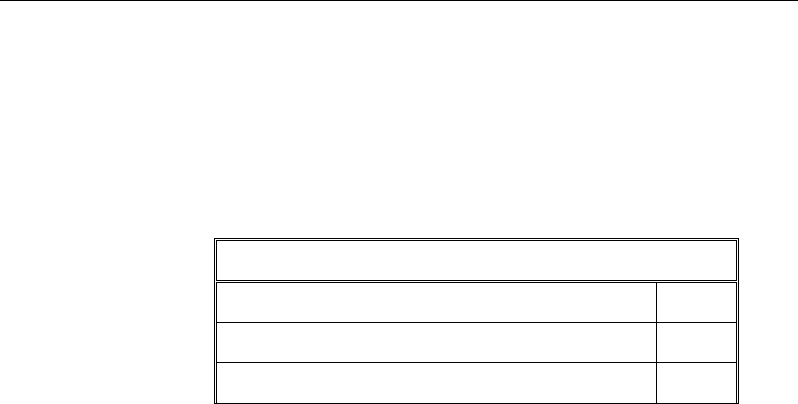
Chapter 12 - Design for IS 1343-1980
12.4 Partial Safety Factors
The design strength for concrete and reinforcement is obtained by dividing the
characteristic strength of the material by a partial factor of safety, γm. The values
of γm used in the program and listed in the following table are taken from IS
20.4.1.1:
Values of
γ
m for the Ultimate Limit State
Nonprestressed reinforcement,
γ
ms 1.15
Prestressing steel,
γ
mp 1.15
Concrete in flexure and axial load,
γ
mc 1.50
These factors are already incorporated in the design equations and tables in the
code. The user is allowed to overwrite these values. However, caution is
advised.
The design load combinations are obtained by multiplying the characteristic
loads by the appropriate partial factor of safety, γf (IS 20.4.2).
12.5 Design Requirements of Prestressed Concrete Struc-
tures
The structural design is based on “Limit State Concepts” (IS 19.1). The limit
state of collapse and limit states of serviceability are considered in design (IS
19.1.1), (IS 19.2) and (IS 19.3).
12.5.1 Limit State of Collapse
The resistance of prestressed structural elements to flexure and shear at every
section will be designed such that the resistance is always greater than the
demand imposed by all types of loads, with the most unfavorable combination
using appropriate partial safety factors (IS 19.2). This will include the design for
the following limit states:
Limit state of collapse in flexure
Limit state of collapse in shear
Partial Safety Factors 12 - 7

Post-Tensioned Concrete Design
Limit State of Collapse: Flexure
Limit state of collapse of prestressed members for flexure is based on the
following assumptions given in IS 1343 clause 22.1.
The strain distribution in the concrete in compression is derived from the
assumption that plane sections normal to the axis remain plane after bending
(IS 22.1.1(a)).
The design stresses in the concrete in compression are taken as 0.67fcu. Maxi-
mum strain at the extreme concrete compression fiber shall be assumed equal
to 0.0035 (IS 22.1.1(b)) and (IS 22.1.1(c)).
Tensile strength of the concrete is ignored (IS 22.1.1(d)).
The stresses in bonded post-tensioning tendons and in any additional rein-
forcement (compression or tension) are derived from the representative stress-
strain curve for the type of steel used given by the manufacturer or typical
curves given in Figure 5 of IS:1343 or in Figure 23 of IS:456 for non-pre-
stressed reinforcement. For design purposes, the partial safety factor shall be
applied as indicated earlier in this chapter.
The stress in unbonded post-tensioning tendons will be obtained from a
rigorous analysis (IS 22.1.1(f)).
12.5.2 Limit State of Serviceability
The check for limit state of serviceability involves checking for deflection,
cracking, and maximum compressive stresses at prestress transfer and under ser-
vice conditions. For checking limit states of serviceability, prestressed structural
elements are classified into the following groups:
Class 1: No flexural tensile stresses permitted (IS 19.3.2 (a))
Class 2: Flexural tensile stresses are allowed, but no visible cracking (IS 19.3.2
(b))
Class 3: Flexural tensile stresses are allowed, but the surface width of cracks
should be limited to 0.1 mm for members in aggressive environments and 0.2
mm for other members
12 - 8 Design Requirements of Prestressed Concrete Structures

Chapter 12 - Design for IS 1343-1980
By default all prestressed concrete elements are assumed to be of type Class-1.
This setting can be overwritten in the Design Preferences.
ETABS checks the following limit states of serviceability (IS 19.3.1):
12.6 Maximum Compression Check
ETABS checks the maximum compressive stress in flexure as defined in the
subsections that follow.
12.6.1 Maximum Compressive Stress at Transfer
Maximum compressive stress due to bending and direct force at the time of trans-
fer of prestress shall not be more than 0.54fci for concrete grade M30 and 0.37fci
for concrete grade M60, where fci is the cube strength of the concrete at transfer,
which will not be less than 0.5fck. For all other grades of concrete, the limiting
stress can be linearly interpolated between these values.
12.6.2 Maximum Compressive Stress Under Service Conditions
Maximum compressive stress due to bending under service conditions for
applied prestress and service loads after deduction of the full losses in prestress
will be limited to the following values.
12.6.2.1 Case I
When compressive stress is not likely to increase during service, maximum com-
pressive stress shall not be more than 0.41fck for concrete grade M30 and 0.35fck
for concrete grade M60, where fck is the cube strength of the concrete at 28 days.
For all other grades of concrete, the limiting stress can be linearly interpolated
between these values.
12.6.2.2 Case II
When compressive stress is likely to increase during service, maximum com-
pressive stress shall not be more than 0.34fck for concrete grade M30 and 0.27fck
for concrete grade M60, where fck is the cube strength of the concrete at 28 days.
For all other grades of concrete, the limiting stress can be linearly interpolated
between these values.
Maximum Compression Check 12 - 9

Post-Tensioned Concrete Design
12.7 Beam Design (for Reference Only)
Important Note: Post-tensioned beam design is not available in the current ver-
sion of ETABS, but is planned for a future release. This section is provided as
reference only for the documentation of post-tensioned slab design.
In the design of prestressed concrete beams, ETABS calculates and reports the
required areas of reinforcement for flexure and shear based on the beam
moments, shear forces, load combination factors, and other criteria described in
the following subsections. The reinforcement requirements are calculated at each
station along the length of the beam.
Beams are designed for major direction flexure and shear only. Effects of
minor direction bending that may exist in the beams must be investigated inde-
pendently by the user.
12.7.1 Design Flexural Reinforcement
The beam top and bottom flexural reinforcement is designed at each station
along the beam. In designing the flexural reinforcement for the major moment
of a particular beam, for a particular station, the following steps are involved:
Determine design bending moments, shears, and torsion
Determine required flexural reinforcement
12.7.1.1 Effects of Torsion
IS 1343 clause 22.5.1 states that wherever torsional stiffness of the member is
taken into account in the analysis of the structure, the member will be designed
for torsion. However, if torsional stiffness of the member has been ignored in the
analysis, no specific calculations for torsion will be required. It should be noted
that the program will not automatically ignore or redistribute torsion. If redistri-
bution is desired, the user should release the torsional degree of freedom (DOF)
in the structural model.
12.7.1.2 Determine Factored Moments, Shears, and Torsional Moments
In the design of flexural reinforcement of post-tensioned concrete beams, the
factored moments, shears, and torsional moments for each load combination at
12 - 10 Beam Design (for Reference Only)

Chapter 12 - Design for IS 1343-1980
a particular beam station are obtained by factoring the corresponding design
forces for different load cases with the corresponding load factors.
IS 1343 uses a simplified approach based on skew bending theory, for design of
post-tensioned concrete members subjected to bending moment, shear, and tor-
sion. In this method, torsion and bending moment are combined as an equivalent
bending moment and the beam is designed for the equivalent moment. Positive
equivalent moments produce bottom reinforcement. In such cases, the beam may
be designed as a rectangular or a flanged beam. Negative equivalent moments
produce top reinforcement. In such cases, the beam may be designed as a rectan-
gular or an inverted flanged beam. Torsion and shear are considered together as
detailed in subsequent sections.
12.7.1.2.1 Determine Design Moments when Torsion is Excluded
In the design of flexural reinforcement of post-tensioned concrete beams, the
factored moments for each load combination at a particular beam section are
obtained by factoring the corresponding moments for different load cases with
the corresponding load factors.
The beam section is then designed for the maximum positive and maximum neg-
ative factored moments obtained from all of the load combinations. Positive
beam moments produce bottom steel. In such cases, the beam may be designed
as a rectangular or a flanged beam. Negative beam moments produce top steel.
In such cases, the beam may be designed as a rectangular or an inverted flanged
beam.
12.7.1.2.2 Determine Design Moments when Torsion is Included
In the design of flexural reinforcement of post-tensioned concrete beams, the
factored moments and torsion for each load combination at a particular beam
section are obtained by factoring the corresponding moments and torsion for dif-
ferent load cases with the corresponding load factors.
The equivalent moment at a particular design station is computed as described
in the following text. The beam section is then designed for the maximum posi-
tive and maximum negative factored moments obtained from all the of the load
combinations. Positive beam moments produce bottom steel. In such cases, the
beam may be designed as a rectangular or a flanged beam. Negative beam mo-
ments produce top steel. In such cases, the beam may be designed as a rectangu-
lar or an inverted flanged beam.
Beam Design (for Reference Only) 12 - 11
Post-Tensioned Concrete Design
The equivalent moment is calculated from the following equation:
Me1 =Mu+ Mt , where (IS 22.5.3.1)
b
D
TM
ut
2
1+=
and D and b are the overall depth and width of the beam, respectively.
If Mt exceeds Mu, additional reinforcement will be computed for the moment Me2
applied in the opposite sense of Mu. Effectively, this will result in additional
longitudinal reinforcement on the compression face of the beam due to reversal
of the moment sign. The additional moment Me2 is computed using the following
equation:
Me2 = Mt − Mu (IS 22.5.3.2)
In addition to the preceding equation, when Mt exceeds Mu the beam shall be
designed to withstand an equivalent transverse moment Me3 not acting simulta-
neously with Me1, given by the following equation:
+
+
+
=
b
D
D
b
e
x
M
M
t
e
2
1
2
1
2
1
2
1
3
(IS 22.5.3.3)
where x1 is the smaller dimension of the closed hoop used as a torsional shear
reinforcement and e = T / V.
After the design moments have been worked out, the design proceeds with
equivalent moments for their respective axes of application, as previously out-
lined.
12.7.1.3 Determine Required Flexural Reinforcement
In the flexural reinforcement design process, the program calculates both the
tension and compression reinforcement. Compression reinforcement is added
when the applied design moment exceeds the maximum moment capacity of a
singly reinforced section. The user has the option of avoiding the compression
12 - 12 Beam Design (for Reference Only)
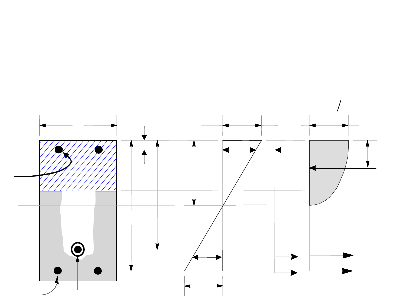
Chapter 12 - Design for IS 1343-1980
reinforcement by increasing the effective depth, the width, or the strength of the
concrete.
The design procedure is based on the parabolic stress block, as shown in Figure
12-1. (IS 22.1.1(c))
Figure 12-1 Rectangular Beam Design
The design procedure used by ETABS for both rectangular and flanged sections
(L- and T-beams) is summarized in the subsections that follow. All beams are
designed for major direction flexure and shear only.
12.7.1.3.1 Design of Rectangular Beams
ETABS first determines if the moment capacity provided by the post-tensioning
tendons alone is enough. In calculating the capacity, it is assumed that As = 0. In
that case, the moment capacity
0
u
M
is determined as follows:
The maximum depth of the compression zone, xu,max, is calculated based on the
limitation that the tension reinforcement strain shall not be less than
ε
smin.
BEAM
SECTION STRAIN
DIAGRAM STRESS
DIAGRAM
0.0035
ε
=0 67 ck m
.f
γ
0 42 u
.x
cs
T
s
T
s
ε
u
xs
C
d′
e
d
b
s
A
s
A′
s
ε
′
C
cps
T
ps
T
sp
ε
ps
A
p
d
BEAM
SECTION STRAIN
DIAGRAM STRESS
DIAGRAM
0.0035
ε
=0 67 ck m
.f
γ
0 42 u
.x
cs
T
s
T
s
ε
u
xs
C
d′
e
d
b
s
A
s
A′
s
ε
′
C
cps
T
ps
T
sp
ε
ps
A
p
d
Beam Design (for Reference Only) 12 - 13

Post-Tensioned Concrete Design
dx
sc
c
u
+
=
minmax
max
max,
εε
ε
where,
ε
cmax = 0.0035
Therefore, the limit
,maxuu
xx≤
is set for tension-controlled sections. The ductil-
ity of a section is controlled by limiting the xu/d ratio (IS 21.1.1(d)):
xu/d ≤ 0.5 (IS 21.1.1(d))
ETABS determines the depth of the neutral axis, xu, by imposing force equilib-
rium, i.e., C = T. After the depth of the neutral axis has been determined, the
stress in the post-tensioning steel, fpb is computed based on strain compatibility
for bonded tendons. For unbonded tendons, the code equations are used to com-
pute the stress, fps in the post-tensioning steel. Based on the calculated fpb, the
depth of the neutral axis is recalculated, and fpb is further updated. After this
iteration process has converged, the depth of compression block, xu is deter-
mined:
If
,max
uu
xx≤
(IS 21.1.1(d)), the moment capacity of the section, provided by
post-tensioning steel only, is computed as:
( )
00.42
u ps pb p u
M Af d x= −
If
,maxuu
xx>
(IS 21.1.1(d)), a failure condition is declared.
If
0,>u
MM
ETABS calculates the moment capacity and the As required at the
balanced condition. The balanced condition is taken as the marginal tension-
controlled case. In that case, it is assumed that the depth of the neutral axis
u
x
is equal to
,max .
u
x
The stress in the post-tensioning steel, fpb, is then calculated
based on strain compatibility, and the area of required tension reinforcement, As,
is determined by imposing force equilibrium, i.e., C = T.
0.36
ck u
C f xb=
12 - 14 Beam Design (for Reference Only)

Chapter 12 - Design for IS 1343-1980
bal bal bal
ps pb s s
T Af A f= +
0.36
bal
ck u ps pb
bal
sbal
s
f xb A f
Af
−
=
After the area of tension reinforcement has been determined, the capacity of the
section with post-tensioning steel and tension reinforcement is computed as:
( )
( )
0.42 0.42
bal bal bal bal
u ps pb p u s s s u
M Afd x Afd x= −+ −
In that case, it is assumed that the bonded tension reinforcement will yield, which
is true for most cases. In the case that it does not yield, the stress in the reinforce-
ment, fs, is determined from the elastic-perfectly plastic stress-strain relationship.
This case does not involve any iteration in determining the depth of neutral axis,
.
u
x
12.7.1.3.1.1 Case 1: Post-tensioning steel is adequate
When
0,
u
MM<
the amount of post-tensioning steel is adequate to resist the de-
sign moment Mu. Minimum reinforcement is provided to satisfy the flexural
cracking requirements (IS 18.6.3.3(a)).
12.7.1.3.1.2 Case 2: Post-tensioning steel plus tension reinforcement
In this case, the amount of post-tensioning steel, Aps, alone is not sufficient to
resist M, and therefore the required area of tension reinforcement is computed to
supplement the post-tensioning steel. The combination of post-tensioning steel
and tension reinforcement should result in
u
x
<
,max
.
u
x
When
0,
bal
uu
M MM<<
ETABS determines the required area of tension rein-
forcement, As, iteratively to satisfy the design moment M and reports this re-
quired area of tension reinforcement. Since
M
is bounded by
0
u
M
at the lower
end and
bal
u
M
at the upper end and
0
u
M
is associated with
0
s
A=
and
bal
u
M
is
associated with
,
bal
ss
AA=
the required area will be within the range of 0 to Asbal.
The tension reinforcement is to be placed at the bottom if M is positive, or at the
top if M is negative.
Beam Design (for Reference Only) 12 - 15

Post-Tensioned Concrete Design
12.7.1.3.1.3 Case 3: Post-tensioning steel and tension reinforcement are
not adequate
When
,>bal
u
MM
compression reinforcement is required. In that case, ETABS
assumes that the depth of the neutral axis,
,
u
x
is equal to
,max
.
u
x
The values of
fpb and fs reach their respective balanced condition values,
bal
pb
f
and
.
bal
s
f
Then
the area of compression reinforcement,
,
s
A′
is determined as follows:
The moment required to be resisted by compression reinforcement and tension
reinforcement is:
bal
us u
M MM= −
The required compression reinforcement is given by:
( )( )
',
0.87 ' ' '
us
ss cs
M
Af f dd
=−−
where
,max
max ,max
'
' 0.87
u
s sc y
u
xd
fE f
x
ε
−
= ≤
The tension reinforcement for balancing the compression reinforcement is given
by:
( )
0.87 '
com us
sys
M
Afd d
=−
Therefore, the total tension reinforcement, As =
bal
s
A
+
,
com
s
A
and the total com-
pression reinforcement is A's. As is to be placed at the bottom and A's is to be
placed at the top if M is positive, and vice versa if M is negative.
12.7.1.3.2 Design of Flanged Beams
12.7.1.3.2.1 Flanged Beam Under Negative Moment
In designing for a factored negative moment, M (i.e., designing top reinforce-
ment), the calculation of the reinforcement area is exactly the same
as described previously, i.e., no flanged beam data is used.
12 - 16 Beam Design (for Reference Only)
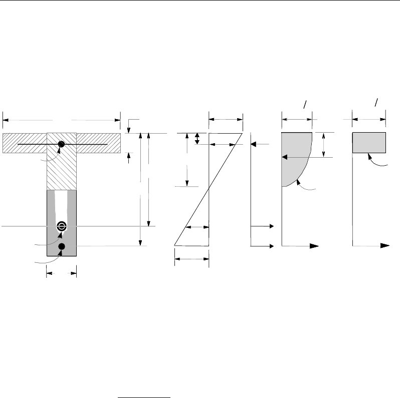
Chapter 12 - Design for IS 1343-1980
12.7.1.3.2.2 Flanged Beam Under Positive Moment
ETABS first determines if the moment capacity provided by the post-tensioning
tendons alone is enough. In calculating the capacity, it is assumed that As = 0. In
that case, the moment capacity
0
u
M
is determined as follows:
Figure 12-2 T-Beam Design
The maximum depth of the compression zone, xu,max, is calculated based on the
limitation that the tension reinforcement strain shall not be less than
ε
smin.
xu,max =
max
max min
cp
cs
εd
ε +ε
where,
ε
cmax = 0.0035
Therefore, the limit
,max
uu
xx≤
is set for tension-controlled sections. The ductil-
ity of a section is controlled by limiting the xu / d ratio (IS 21.1.1(d)):
xu / d ≤ 0.5 (IS 21.1.1(d))
BEAM
SECTION
STRAIN
DIAGRAM STRESS
DIAGRAM
s
A′
s
A
f
b
ps
A
bw
e
d
u
x
ε
′
s
d′
f
D
s
T
w
T
f
T
f
C
w
C
s
C
s
ε
ps
ε
0.0035
ε
=
0.67 cu m
f
γ
0.67 cu m
f
γ
p
d
0.42
u
x
ps
T
BEAM
SECTION
STRAIN
DIAGRAM STRESS
DIAGRAM
s
A′
s
A
f
b
ps
A
bw
e
d
u
x
ε
′
s
d′
f
D
s
T
w
T
f
T
f
C
w
C
s
C
s
ε
ps
ε
0.0035
ε
=
0.67 cu m
f
γ
0.67 cu m
f
γ
p
d
0.42
u
x
ps
T
Beam Design (for Reference Only) 12 - 17

Post-Tensioned Concrete Design
ETABS determines the depth of the neutral axis, xu, by imposing force equilib-
rium, i.e., C = T. After the depth of the neutral axis has been determined, the
stress in the post-tensioning steel, fpb, is computed based on strain compatibility
for bonded tendons. For unbonded tendons, the code equations are used to com-
pute the stress, fps, in the post-tensioning steel. Based on the calculated fpb, the
depth of the neutral axis is recalculated, and fpb is further updated. After the iter-
ation process has converged, the depth of the compression block, xu, is deter-
mined as follows:
If
,maxuu
xx≤
(IS 21.1.1(d)), the moment capacity of the section provided by
post-tensioning steel only is computed as:
( )
00.42
u ps pb p u
M Af d x= −
If
,maxuu
xx>
(IS 21.1.1(d)), a failure condition is declared.
If
0,
u
MM>
ETABS calculates the moment capacity and the As required at the
balanced condition. The balanced condition is taken as the marginal tension-
controlled case. In that case, it is assumed that the depth of neutral axis
u
x
is
equal to
,max
.
u
x
The stress in the post-tensioning steel, fpb, is then calculated
based on strain compatibility and the area of required tension reinforcement, As,
is determined by imposing force equilibrium, i.e., C = T.
If
u
x
≤ Df, the subsequent calculations for As are exactly the same as previ-
ously defined for the rectangular beam design. However, in this case, the width
of the beam is taken as bf. Compression reinforcement is required when
,max
.
uu
xx>
If
u
x
> Df, the calculation for As is given by:
0.36 com
ck u c
C f xA=
where
com
c
A
is the area of concrete in compression, i.e.,
( )
,max
com
c ff w u f
A bD b x D=+−
bal bal bal
ps pb s s
T Af A f= +
12 - 18 Beam Design (for Reference Only)

Chapter 12 - Design for IS 1343-1980
0.36 com bal
ck u c ps pb
bal
sbal
s
f xA A f
Af
−
=
After the area of tension reinforcement has been determined, the capacity of the
section with post-tensioning steel and tension reinforcement is computed as:
( )
( )
0.42 0.42
bal bal bal bal
u ps pb p u s s s u
M Afd x Afd x= −+ −
In that case, it is assumed that the bonded tension reinforcement will yield, which
is true for most cases. In the case that it does not yield, the stress in the reinforc-
ing steel, fs, is determined from the elastic-perfectly plastic stress-strain relation-
ship. This case does not involve any iteration in determining the depth of the
neutral axis,
.
u
x
12.7.1.3.2.2.1 Case 1: Post-tensioning steel is adequate
When
0,
u
MM<
the amount of post-tensioning steel is adequate to resist the de-
sign moment M. Minimum reinforcement is provided to satisfy the flexural
cracking requirements (IS 18.6.3.3(a)).
12.7.1.3.2.2.2 Case 2: Post-tensioning steel plus tension reinforcement
In this case, the amount of post-tensioning steel, Aps, alone is not sufficient to
resist M, and therefore the required area of tension reinforcement is computed to
supplement the post-tensioning steel. The combination of post-tensioning steel
and tension reinforcement should result in
u
x
<
,max
.
u
x
When
0
,
bal
uu
M MM<<
ETABS determines the required area of tension rein-
forcement, As, iteratively to satisfy the design moment M and reports this re-
quired area of tension reinforcement. Since
M
is bounded by
0
u
M
at the lower
end and
bal
u
M
at the upper end and
0
u
M
is associated with
0
s
A=
and
bal
u
M
is
associated with
,
bal
ss
AA=
the required area will fall within the range of 0 to
.
s
A
The tension reinforcement is to be placed at the bottom if M is positive, or at the
top if M is negative.
Beam Design (for Reference Only) 12 - 19

Post-Tensioned Concrete Design
12.7.1.3.2.2.3 Case 3: Post-tensioning steel and tension reinforcement are not ad-
equate
When
,
bal
u
MM>
compression reinforcement is required. In that case, ETABS
assumes that the depth of the neutral axis,
,
u
x
is equal to
,max
.
u
x
The values of
fpb and fs reach their respective balanced condition values,
bal
pb
f
and
.
bal
s
f
Then
the area of compression reinforcement,
,
s
A′
is determined as follows:
The moment required to be resisted by compression reinforcement and tension
reinforcement is:
bal
us u
M MM= −
The required compression reinforcement is given by:
()( )
',
0.87 ' ' '
us
ss cs
M
Af f dd
=−−
where
,max
max ,max
'
' 0.87
u
s sc y
u
xd
fE f
x
ε
−
= ≤
The tension reinforcement for balancing the compression reinforcement is given
by:
( )
0.87 '
com us
sys
M
Afd d
=−
Therefore, the total tension reinforcement, As =
bal
s
A
+
,
com
s
A
and the total com-
pression reinforcement is A's. As is to be placed at the bottom and A's is to be
placed at the top if M is positive, and vice versa if M is negative.
12.7.1.4 Minimum and Maximum Reinforcement
Reinforcement in post-tensioned concrete beams is computed to increase the
flexural strength of sections or to comply with the shear link requirements. The
minimum flexural tension reinforcement required for a beam section to comply
with the cracking requirements must be separately investigated by the user.
For bonded tendons, there are no minimum untensioned reinforcement
requirements.
12 - 20 Beam Design (for Reference Only)

Chapter 12 - Design for IS 1343-1980
In addition, an upper limit on both the tension reinforcement and compression
reinforcement has been imposed to be 0.04 times the gross cross-sectional area
(IS:456 26.5.1.1, 26.5.1.2).
12.7.2 Design Beam Shear Reinforcement (Torsion Excluded)
The shear reinforcement is designed for each load combination at each station
along the length of the beam. In designing the shear reinforcement for a particu-
lar beam, for a particular load combination, at a particular station due to the beam
major shear, the following steps are involved (IS 22.4):
Determine the factored shear force, V.
Determine the shear force, vc, that can be resisted by the concrete.
Determine the shear reinforcement required to carry the balance.
The following three subsections describe in detail the algorithms associated with
these steps.
12.7.2.1 Determine Shear Force
In the design of the beam shear reinforcement, the shear forces for each load
combination at a particular beam station are obtained by factoring the corre-
sponding shear forces and moments for different load cases with the correspond-
ing load combination factors.
12.7.2.2 Determine Concrete Shear Capacity
The design ultimate shear resistance of the concrete alone, Vco, should be con-
sidered at sections as follows:
Uncracked sections in flexure (M < Mo)
Cracked sections in flexural (M ≥ Mo)
where,
M is the design bending moment at the section due to the load combination,
Mo is the moment necessary to produce zero stress in the concrete at the
extreme tension fiber; in this calculation only 0.8 times the stress due to post-
tensioning should be taken into account.
Beam Design (for Reference Only) 12 - 21
Post-Tensioned Concrete Design
Case 1: Uncracked section in flexure
The ultimate shear resistance of the section, Vco, is computed as follows:
( )
2
0.67 0.8
co w t cp t
V bD f f f= +
(IS 22.4.1)
where,
ft is the maximum design principal stress, (IS 22.4.1)
0.24 ,
t ck
ff=
and (IS 22.4.1)
fcp = design compressive stress at the centoidal axis due to
prestress, taken as positive. (IS 22.4.1)
β
sinPVV
coc
+=
(IS 22.4.1)
Case 2: Cracked section in flexure
The ultimate shear resistance of the section, Vcr, is computed as follows:
1 0.55
pe
cr c v o
pu
fV
V vbd M
fM
=−+
(IS 22.4.2)
In the preceding, the shear stress capacity of the concrete, νc is taken from IS
Table 6 for a provided percentage of post-tensioning steel in the section.
0.1
cr w ck
V bd f≥
(IS 22.4.2)
( )
β
sin,min PVVV crco
c+=
(IS 22.4.2)
12.7.2.3 Determine Required Shear Reinforcement
For the section under consideration, compute the following:
v =
,
cv
V
A
Acv =bwd, where
v ≤ vmax, and (IS 22.4.4)
vmax will not exceed the values defined in IS Table 7
12 - 22 Beam Design (for Reference Only)

Chapter 12 - Design for IS 1343-1980
Given v, vc and vmax, the required shear reinforcement is calculated as follows (IS
22.4.3.1):
If v ≤ 0.5vc then no shear reinforcement is to be provided
If 0.5 vc < v ≤ vc,
sv
v
A
s
=
0.4
0.87
w
yv
b
f
(IS 22.4.3.1)
If vc < v ≤ vmax,
sv
v
A
s
=
( )
0.87
cv
yv
vvb
f
−
(IS 22.4.3.2)
If v > vmax, a failure condition is declared. (IS 22.4.4)
In the preceding expressions, a limit is imposed on fyv as
fyv ≤ 415 MPa (IS 40.4)
The maximum of all of the calculated Asv / sv values, obtained from each load
combination, is reported along with the controlling shear force and associated
load combination.
The beam shear reinforcement requirements considered by the program are
based purely on shear strength considerations. Any minimum stirrup require-
ments to satisfy spacing and volumetric considerations must be investigated
independently of the program by the user.
12.7.3 Design Beam Shear Reinforcement (Torsion Included)
The transverse reinforcement to resist shear and torsion is designed for each load
combination at each station along the length of the beam. In designing the trans-
verse reinforcement for a particular beam, for a particular load combination, at
a particular station due to the beam major shear and torsion, the following steps
are involved (IS 22.5.4):
Determine the factored shear force, V, and factored torsion T.
Determine the shear force, Vc1, that can be resisted by the concrete.
Beam Design (for Reference Only) 12 - 23
Post-Tensioned Concrete Design
Determine the torsional moment, Tc1, that is carried by concrete.
Determine the shear reinforcement required to carry the balance shear and tor-
sion.
The following three sections describe in detail the algorithms associated with
these steps.
12.7.3.1 Determine Shear Force and Torsional Moment
In the design of the beam transverse reinforcement, the shear force and
torsional moment for each load combination at a particular beam station are
obtained by factoring the corresponding shear force and torsional moment for
different load cases with the corresponding load combination factors.
12.7.3.2 Determine Torsional Moment Carried by Concrete
The torsional moment carried by the concrete is computed using the following
equation:
+
=
c
cc ee
e
TT 1
, where (IS 22.5.4.1)
ckpc f
b
DbT
λ
−= ∑30
15.1 2
e = T /V
ec= Tc / Vc
+=
ck
cp
pf
f12
1
λ
Vc = min (Vco,Vcr)
Please refer to the previous section for the relevant equations for Vco and Vcr.
12 - 24 Beam Design (for Reference Only)
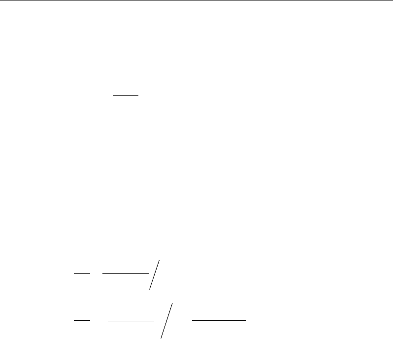
Chapter 12 - Design for IS 1343-1980
12.7.3.3 Determine Shear Force Carried by Concrete
The shear force carried by the concrete is computed using the following equa-
tion:
cc
c
e
VV
ee
1
,
=
+
where (IS 22.5.4.2)
Vc = min (Vco,Vcr)
e = T / V
ec= Tc / Vc
12.7.3.4 Determine Required Shear Reinforcement
For the section under consideration, compute the area of transverse reinforce-
ment using the following two equations and provide the larger area:
11
2
1.5
=
sv t
yv
v
AM
bd f
s
(IS22.5.4.3)
( ) ( )
1
111
2
0.87 0.87
−
−
= +
c
c
sv
yv
v yv
TT
VV
A
fd
s bd f
(IS22.5.4.3)
In the preceding expressions, a limit is imposed on fyv as
fyv ≤ 415 MPa. (IS
40.4)
The maximum of all of the calculated Asv /sv values obtained from each load com-
bination is reported along with the controlling shear force and associated load
combination.
The beam transverse shear and torsional reinforcement requirements considered
by the program are based purely on shear and torsional strength considerations.
Any minimum stirrup requirements to satisfy spacing and volumetric consider-
ations must be investigated independently of the program by the user.
Beam Design (for Reference Only) 12 - 25

Post-Tensioned Concrete Design
12.8 Slab Design
Similar to conventional design, the ETABS slab design procedure involves
defining sets of strips in two mutually perpendicular directions. The locations of
the strips are usually governed by the locations of the slab supports. The mo-
ments for a particular strip are recovered from the analysis and a flexural design
is carried out based on the limit state of collapse for prestressed concrete, as
described in IS 1343. In general, provisions of IS:456 will also apply to the de-
sign of post-tensioned concrete slabs, as described in the following sections. To
learn more about the design strips, refer to the section entitled "ETABS Design
Techniques" in the Key Features and Terminology manual.
12.8.1 Design for Flexure
ETABS designs the slab on a strip-by-strip basis. The moments used for the
design of the slab elements are the nodal reactive moments, which are obtained
by multiplying the slab element stiffness matrices by the element nodal displace-
ment vectors. These moments will always be in static equilibrium with the ap-
plied loads, irrespective of the refinement of the finite element mesh.
The design of the slab reinforcement for a particular strip is carried out at specific
locations along the length of the strip. Those locations correspond to the element
boundaries. Controlling reinforcement is computed on either side of the element
boundaries. The slab flexural design procedure for each load combination in-
volves the following:
Determine factored moments for each slab strip.
Design flexural reinforcement for the strip.
These two steps are described in the text that follows and are repeated for every
load combination. The maximum reinforcement calculated for the top and bot-
tom of the slab within each design strip, along with the corresponding controlling
load combination, is obtained and reported.
12.8.1.1 Determine Factored Moments for the Strip
For each element within the design strip, for each load combination, the program
calculates the nodal reactive moments. The nodal moments are then added to get
the strip moments.
12 - 26 Slab Design
Chapter 12 - Design for IS 1343-1980
12.8.1.2 Design Flexural Reinforcement for the Strip
The reinforcement computation for each slab design strip, given the bending mo-
ment, is identical to the design of rectangular beam sections described
earlier (or to the flanged beam if the slab is ribbed). In some cases, at a given
design section in a design strip, there may be two or more slab properties across
the width of the design strip. In that case, the program automatically designs the
tributary width associated with each of the slab properties separately using its
tributary bending moment. The reinforcement obtained for each of the tributary
widths is summed to obtain the total reinforcement for the full width of the de-
sign strip at the considered design section. This method is used when drop panels
are included. Where openings occur, the slab width is adjusted accordingly.
12.8.1.3 Minimum and Maximum Slab Reinforcement
There are no minimum requirements for un-tensioned reinforcement in one-way
bonded slabs.
In flat slabs, reinforcement is added at the top over supports to be 0.00075 times
the gross cross-sectional area. This reinforcement extends 1.5 times the slab
depth on each side of the column. The length of reinforcement is at least 0.2L
where L is the span of the slab.
There are no minimum requirements for span zones. However, additional un-
tensioned reinforcement shall be designed for the full tension force generated by
assumed flexural tensile stresses in the concrete for the following situations
(Concrete Society, Technical report 43):
all locations in one-way spanning floors using unbonded tendons
all locations in one-way spanning floors where transfer tensile stress exceeds
0.36
ci
f
support zones in all flat slabs
span zones in flat slabs using unbonded tendons where the tensile stress
exceeds 0.15
.
cu
f
In addition, an upper limit on both the tension reinforcement and compression
reinforcement has been imposed to be 0.04 times the gross cross-sectional area
(IS 26.5.1.1).
Slab Design 12 - 27
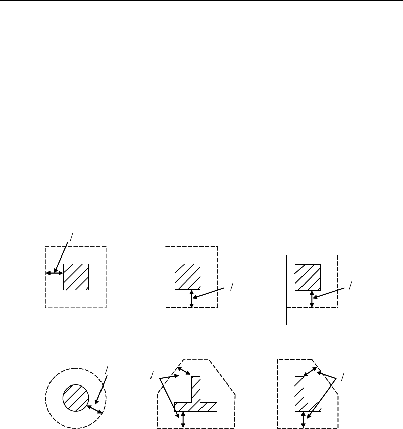
Post-Tensioned Concrete Design
12.8.2 Check for Punching Shear
The algorithm for checking punching shear is detailed in the section entitled
“Slab Punching Shear Check” in the Key Features and Terminology manual.
Only the code specific items are described in the following sections.
12.8.2.1 Critical Section for Punching Shear
The punching shear is checked on a critical section at a distance of d / 2 from the
face of the support (IS:456 30.6.1). For rectangular columns and concentrated
loads, the critical area is taken as a rectangular area with the sides parallel to the
sides of the columns or the point loads (IS:456 30.6.1). Figure 12-3 shows the
auto punching perimeters considered by ETABS for the various column shapes.
The column location (i.e., interior, edge, corner) and the punching
perimeter may be overwritten using the Punching Check Overwrites.
Figure 12-3 Punching Shear Perimeters
12.8.2.2 Transfer of Unbalanced Moment
The fraction of unbalanced moment transferred by flexure is taken to be αMu
and the fraction of unbalanced moment transferred by eccentricity of shear is
taken to be (1 − α) Mu (IS:456 30.6.2.2), where
d2
Interior Column
Circular Column
d2 d2
d2
T-Shape Column
Edge Column Corner Column
L-Shape Column
d2
d2
d2
Interior Column
Circular Column
d2 d2
d2
T-Shape Column
Edge Column Corner Column
L-Shape Column
d2
d2
12 - 28 Slab Design
Chapter 12 - Design for IS 1343-1980
α =
( )
12
1
1 23 aa+
(IS:456 30.3.3)
a1 is the width of the critical section measured in the direction of the span
a2 is the width of the critical section measured in the direction perpendic-
ular to the span.
12.8.2.3 Determine Concrete Shear Capacity
The concrete punching shear factored strength is taken as:
vc = ks
τ
c, where (IS:456 30.6.3.1)
ks = 0.5 + βc ≤ 1.0, (IS:456 30.6.3.1)
τ
c = 0.25
,
ck
f
and (IS:456 30.6.3.1)
β c = ratio of the minimum to the maximum
dimensions of the support section
12.8.2.4 Determine Capacity Ratio
Given the punching shear force and the fractions of moments transferred by
eccentricity of shear about the two axes, the shear stress is computed assuming
linear variation along the perimeter of the critical section. The ratio of the max-
imum shear stress and the concrete punching shear stress capacity is
reported as the punching shear capacity ratio by ETABS.
12.8.3 Design Punching Shear Reinforcement
The use of shear studs as shear reinforcement in slabs is permitted.
The algorithm for designing the required punching shear reinforcement is used
when the punching shear capacity ratio exceeds unity. The Critical Section for
Punching Shear and Transfer of Unbalanced Moment as described in the earlier
sections remain unchanged. The design of punching shear reinforcement is car-
ried out as described in the subsections that follow.
Slab Design 12 - 29

Post-Tensioned Concrete Design
12.8.3.1 Determine Concrete Shear Capacity
The concrete punching shear stress capacity of a section with punching shear
reinforcement is as previously determined, but limited to:
0.5
cc
v
τ
≤
(IS 31.6.3.2)
12.8.3.2 Determine Required Shear Reinforcement
The shear force is limited to a maximum of:
Vmax = 1.5
c
τ
bod (IS 31.6.3.2)
Given Vu, Vc, and Vmax, the required shear reinforcement is calculated as follows
(IS:456 31.6.3.2).
( )
y
cu
v
f
VV
A87.0
5.
0−
=
(IS 31.6.3.2, 40.4)
If Vu > Vmax, a failure condition is declared. (IS 31.6.3.2)
If Vu exceeds the maximum permitted value of Vmax, the concrete section
should be increased in size.
12.8.3.3 Determine Reinforcement Arrangement
Punching shear reinforcement in the vicinity of rectangular columns should be
arranged on peripheral lines, i.e., lines running parallel to and at constant dis-
tances from the sides of the column. Figure 12-4 shows a typical arrangement of
shear reinforcement in the vicinity of a rectangular interior, edge, and corner
column.
12 - 30 Slab Design
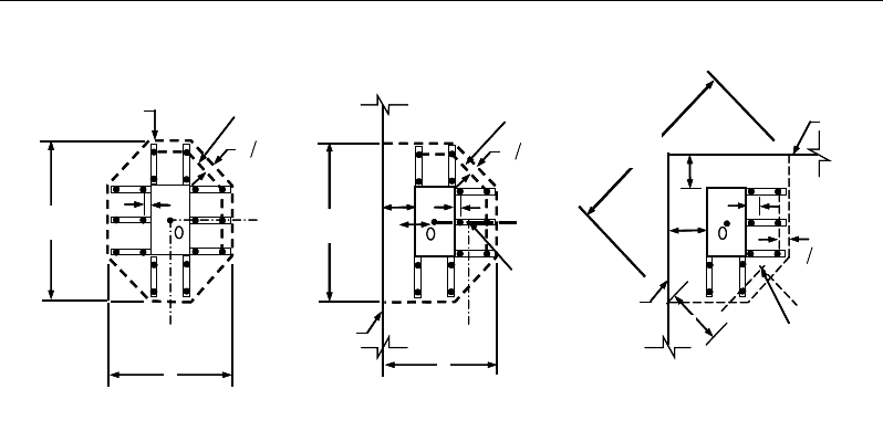
Chapter 12 - Design for IS 1343-1980
Figure 12-4 Typical arrangement of shear studs
and critical sections outside shear-reinforced zone
The distance between the column face and the first line of shear reinforcement
shall not exceed d / 2. The spacing between adjacent shear reinforcement in the
first line (perimeter) of shear reinforcement shall not exceed 2d measured in a
direction parallel to the column face.
Punching shear reinforcement is most effective near column corners where there
are concentrations of shear stress. Therefore, the minimum number of lines of
shear reinforcement is 4, 6, and 8, for corner, edge, and interior columns respec-
tively.
12.8.3.4 Determine Reinforcement Diameter, Height, and
Spacing
The punching shear reinforcement is most effective when the anchorage is close
to the top and bottom surfaces of the slab. The cover of anchors should not be
less than the minimum cover specified in IS:456 26.4 plus half of the
diameter of the flexural reinforcement.
When specifying shear studs, the distance, so, between the column face and the
first peripheral line of shear studs should not be smaller than 0.5d. The spacing
between adjacent shear studs, g, at the first peripheral line of studs shall not
exceed 2d. The limits of so and the spacing, s, between the peripheral lines are
specified as:
I
y
Typical Studrail
(only first and last
studs shown)
Outermost
peripheral line
of studs
Interior Column Edge Column Corner Column
Critical section
centroid
Free
edge
Free
edge
Critical
section
centroid
Free edge
Outermost
peripheral line
of studs
I
y
I
y
yx
d2 d2
d2
x
I
x
I
x
g
y
g
x
g
0
s0
s0
s
x
I
y
xx
I
y
Typical Studrail
(only first and last
studs shown)
Outermost
peripheral line
of studs
Interior Column Edge Column Corner Column
Critical section
centroid
Free
edge
Free
edge
Critical
section
centroid
Free edge
Outermost
peripheral line
of studs
I
y
I
y
yx
d2 d2
d2
x
I
x
I
x
g
y
g
x
g
0
s0
s0
s
x
I
y
xx
Slab Design 12 - 31

Post-Tensioned Concrete Design
so ≤ 0. 5d
s ≤ 0.5d
g ≤ 2d
12 - 32 Slab Design

Chapter 13
Design for NZS 3101:06
This chapter describes in detail the various aspects of the concrete design proce-
dure that is used by ETABS when the New Zealand code NZS 3101:06 [NZS
06] is selected. Various notations used in this chapter are listed in Table 13-1.
For referencing to the pertinent sections of the New Zealand code in this chapter,
a prefix “NZS” followed by the section number is used.
The design is based on user-specified load combinations. The program provides
a set of default load combinations that should satisfy the requirements for the
design of most building type structures.
English as well as SI and MKS metric units can be used for input. The code is
based on Newton-millimeter-second units. For simplicity, all equations and de-
scriptions presented in this chapter correspond to Newton-millimeter-second
units unless otherwise noted.
13.1 Notations
The following table identifies the various notations used in this chapter.
Table 13-1 List of Symbols Used in the NZS 3101:06 Code
A
co
Area enclosed by perimeter of the section, sq-mm
A
cv
Area of concrete used to determine shear stress, sq-mm
Notations 13 - 1

Post-Tensioned Concrete Design
Table 13-1 List of Symbols Used in the NZS 3101:06 Code
A
g
Gross area of concrete, sq-mm
A
l
Area of longitudinal reinforcement for torsion, sq-mm
A
ps
Area of prestressing steel in flexural tension zone, sq-mm
A
o
Gross area enclosed by shear flow path, sq-mm
A
s
Area of tension reinforcement, sq-mm
A'
s
Area of compression reinforcement, sq-mm
A
s(required)
Area of steel required for tension reinforcement, sq-mm
A
t
/s
Area of closed shear reinforcement per unit length for
torsion, sq-mm/mm
A
v
Area of shear reinforcement, sq-mm
A
v
/s
Area of shear reinforcement per unit length, sq-mm/mm
a
Depth of compression block, mm
a
b
Depth of compression block at balanced condition, mm
a
max
Maximum allowed depth of compression block, mm
b
Width of member, mm
b
f
Effective width of flange (flanged section), mm
b
w
Width of web (flanged section), mm
b
0
Perimeter of the punching critical section, mm
b
1
Width of the punching critical section in the direction of
bending, mm
b
2
Width of the punching critical section perpendicular to the di-
rection of bending, mm
c
Distance from extreme compression fiber to the neutral axis,
mm
c
b
Distance from extreme compression fiber to neutral axis at
balanced condition, mm
d
Distance from extreme compression fiber to tension rein-
forcement, mm
d'
Distance from extreme compression fiber to compression re-
inforcement, mm
13 - 2 Notations

Chapter 13 - Design for NZS 3101:06
Table 13-1 List of Symbols Used in the NZS 3101:06 Code
E
c
Modulus of elasticity of concrete, MPa
E
s
Modulus of elasticity of reinforcement, assumed as 200,000
MPa
f'
c
Specified compressive strength of concrete, MPa
f'
ci
Specified compressive strength of concrete at time of initial
prestress, MPa
f
pe
Compressive stress in concrete due to effective prestress
forces only (after allowance of all prestress losses), MPa
f
ps
Stress in prestressing steel at nominal flexural strength, MPa
f
pu
Specified tensile strength of prestressing steel, MPa
f
py
Specified yield strength of prestressing steel, MPa
f
t
Extreme fiber stress in tension in the precompressed tensile
zone using gross section properties, MPa
f'
s
Stress in the compression reinforcement, psi
f
y
Specified yield strength of flexural reinforcement, MPa
f
yt
Specified yield strength of shear reinforcement, MPa
h
Overall depth of sections, mm
h
f
Thickness of slab or flange, mm
k
a
Factor accounting for influence of aggregate size on shear
strength
k
d
Factor accounting for influence of member depth on shear
strength
M
u
0
Design moment resistance of a section with tendons only, N-
mm
M
u
bal
Design moment resistance of a section with tendons and the
necessary mild reinforcement to reach the balanced condi-
tion, N-mm
M*
Factored design moment at a section, N-mm
p
c
Outside perimeter of concrete section, mm
p
o
Perimeter of area A
o
, mm
Notations 13 - 3

Post-Tensioned Concrete Design
Table 13-1 List of Symbols Used in the NZS 3101:06 Code
s
Spacing of shear reinforcement along the length, mm
T*
Factored design torsion at a section, N-mm
t
c
Assumed wall thickness of an equivalent tube for the gross
section, mm
t
o
Assumed wall thickness of an equivalent tube for the area
enclosed by the shear flow path, mm
V
c
Shear force resisted by concrete, N
V*
Factored shear force at a section, N
v*
Average design shear stress at a section, MPa
v
c
Design shear stress resisted by concrete, MPa
v
max
Maximum design shear stress permitted at a section, MPa
v
tn
Shear stress due to torsion, MPa
α
s
Punching shear factor accounting for column location
α
1
Concrete strength factor to account for sustained loading and
equivalent stress block
β
1
Factor for obtaining depth of compression block in concrete
β
c
Ratio of the maximum to the minimum dimensions of the
punching critical section
ε
c
Strain in concrete
ε
c,max
Maximum usable compression strain allowed in the extreme
concrete fiber, (0.003 in/in)
ε
s
Strain in reinforcement
φ
b
Strength reduction factor for bending
φ
s
Strength reduction factor for shear and torsion
γ
f
Fraction of unbalanced moment transferred by flexure
γ
v
Fraction of unbalanced moment transferred by eccentricity of
shear
13 - 4 Notations

Chapter 13 - Design for NZS 3101:06
13.2 Design Load Combinations
The design load combinations are the various combinations of the load cases for
which the structure needs to be designed. For NZS 3101:06, if a structure is sub-
jected to dead (D), live (L), pattern live (PL), snow (S), wind (W), and earth-
quake (E) loads, and considering that wind and earthquake forces are
reversible, the load combinations in the following subsections may need to be
considered (AS/NZS 1170.0, 4.2.2). For post-tensioned concrete design, the user
can specify the prestressing load (PT) by providing the tendon profile or by using
the load balancing options in the program. The default load combinations for
post-tensioning also are defined in the subsections that follow.
13.2.1 Initial Service Load Combination
The following load combination is used for checking the requirements at transfer
of prestress forces in accordance with NZS 3101:06 clause 19.3.3.5.1(b). The
prestressing forces are considered without any long-term loses for the initial ser-
vice load combination check.
1.0D + 1.0PT
13.2.2 Service Load Combination
The following load combinations are used for checking the requirements of pre-
stress for serviceability in accordance with NZS 19.3.3.5.1. It is assumed that all
long-term losses have occurred already at the service stage.
1.0D + 1.0PT
1.0D + 1.0L + 1.0PT
13.2.3 Long-Term Service Load Combination
The following load combinations are used for checking the requirements of pre-
stress in accordance with NZS 19.3.3.5.1. The permanent load for this load com-
bination is taken as 50 percent of the live load (taken from ACI 318-08 clause
18.4.2(a)). It is assumed that all long-term losses have occurred already at the
service stage.
Design Load Combinations 13 - 5

Post-Tensioned Concrete Design
1.0D + 1.0PT
1.0D + 0.5L + 1.0 PT
13.2.4 Ultimate Limit State Load Combination
The following load combinations are used for checking the requirements of pre-
stress in accordance with AS/NZS 1170.0, 4.2.2.
The design combinations required for punching shear require the full PT forces
(primary and secondary). Flexural design requires only the hyperstatic (second-
ary) forces. The hyperstatic (secondary) forces are determined automatically by
ETABS by subtracting out the primary PT moments when the flexural design is
carried out.
1.35D + 1.0PT*
(AS/NZS 1170.0, 4.2.2(a))
1.2D + 1.5L + 1.0PT*
(AS/NZS 1170.0, 4.2.2(b))
1.2D + 1.5(0.75 PL) + 1.0PT*
(AS/NZS 1170.0, 4.2.2(b))
1.2D + 0.4L + 1.0S + 1.0PT*
(AS/NZS 1170.0, 4.2.2(g))
1.2D ± 1.0W + 1.0PT*
0.9D
± 1.0W + 1.0PT*
1.2D + 0.4L
± 1.0W + 1.0PT*
(AS/NZS 1170.0, 4.2.2(d))
(AS/NZS 1170.0, 4.2.2(e))
(AS/NZS 1170.0, 4.2.2(d))
1.0D ± 1.0E + 1.0PT*
1.0D + 0.4L
± 1.0E + 1.0PT*
(AS/NZS 1170.0, 4.2.2(f))
(AS/NZS 1170.0, 4.2.2(f))
* — Replace PT by H for flexural design only
Note that the 0.4 factor on the live load in three of the combinations is not valid
for live load representing storage areas. These also are the default design load
combinations in ETABS whenever the NZS 3101 code is used. If roof live load
is treated separately or if other types of loads are present, other appropriate load
combinations should be used.
13.3 Limits on Material Strength
The upper and lower limits of f'c shall be as follows:
13 - 6 Limits on Material Strength

Chapter 13 - Design for NZS 3101:06
25 ' 100MPa≤≤
c
f
(NZS 5.2.1)
The lower characteristic yield strength of longitudinal reinforcement, fy, should
be equal to or less than 500 MPa (NZS 5.3.3). The lower characteristic yield
strength of transverse (stirrup) reinforcement, fyt, should not be greater than 500
MPa for shear or 800 MPa for confinement (NZS 5.3.3).
The code allows use of f'c and fy beyond the given limits, provided special study
is conducted (NZS 5.2.1).
ETABS enforces the upper material strength limits for flexure and shear design
of slabs. The input material strengths are taken as the upper limits if they are
defined in the material properties as being greater than the limits. The user is
responsible for ensuring that the minimum strength is satisfied.
ETABS also checks the tensile strength in the prestressing steel (NZS 19.3.3.6).
The permissible tensile stresses in all types of prestressing steel, in terms of the
specified minimum tensile strength fpy, are summarized as follows:
a. Due to tendon jacking force: 0.94 fpy
b. Immediately after prestress transfer: 0.82 fpy
In any circumstances, the initial prestressing forces shall not exceed 0.8 fpu.
13.4 Strength Reduction Factors
The strength reduction factors,
φ
, are applied to the specified strength to obtain
the design strength provided by a member. The
φ
factors for flexure, shear, and
torsion are as follows:
φ
b = 0.85 for flexure (NZS 2.3.2.2)
φ
s = 0.75 for shear and torsion (NZS 2.3.2.2)
These values can be overwritten; however, caution is advised.
Strength Reduction Factors 13 - 7

Post-Tensioned Concrete Design
13.5 Design Assumptions for Prestressed Concrete Struc-
tures
The utimate limit state of prestressed members for flexure and axial loads shall
be based on assumptions given in NZS 7.4.2.
The strain distribution in the concrete in compression is derived from the
assumption that a plane section remains plane (NZS 7.4.2.2).
The design stress in the concrete in compression is taken as 0.45 fcu. The max-
imum strain at the extreme concrete compression fiber shall be assumed equal
to 0.003 (N ZS 7.4.2.3).
Tensile strength of the concrete is ignored (NZS 7.4.2.5).
The strain in bonded prestressing tendons and in any additional reinforcement
(compression or tension) is derived from the assumption that a plane section
remains plane (NZS 7.4.2.2).
The serviceability limit state of prestressed members uses the following assump-
tions given in NZS 19.3.3.
Plane sections remain plane, i.e., strain varies linearly with depth through the
entire load range (NZS 19.3.3.2).
Elastic behavior exists by limiting the concrete stresses to the values given in
NZS 19.3.3.5.1.
In general, it is only necessary to calculate design stresses due to the load
arrangements immediately after the transfer of prestress and after all losses or
prestress have occurred; in both cases the effects of dead and imposed loads
on the strain and force in the tendons may be ignored.
Prestressed concrete members are investigated at the following three stages
(NZS 19.3.3.5.2):
At transfer of prestress force
At service loading
At nominal strength
13 - 8 Design Assumptions for Prestressed Concrete Structures
Chapter 13 - Design for NZS 3101:06
The prestressed flexural members are classified as Class U (uncracked), Class T
(transition), and Class C (cracked) based on ft, the computed extreme fiber stress
in tension in the precompressed tensile zone at service loads (NZS 19.3.2).
The precompressed tensile zone is that portion of a prestressed member where
flexural tension, calculated using gross section properties, would occur under
unfactored dead and live loads if the prestress force was not present. Prestressed
concrete is usually designed so that the prestress force introduces compression
into this zone, thus effectively reducing the magnitude of the tensile stress.
For Class U and Class T flexural members, stresses at service load are deter-
mined using uncracked section properties, while for Class C flexural members,
stresses at service load are calculated based on the cracked section (NZS 19.3.3).
The following table provides a summary of the conditions considered for the
various section classes.
Prestressed
Class U Class T Class C Nonprestressed
Assumed Behavior Uncracked Transition between
uncracked and cracked Cracked Cracked
Section properties for stress
calculation at service loads Gross section
19.3.3.3 Gross section
19.3.3.3 Cracked section
19.3.3.3 No requirement
Allowable stress at transfer 19.3.3.6.1 19.3.3.6.1 19.3.3.6.1 No requirement
Allowable compressive stress based
on uncracked section properties 19.3.3.6.2 19.3.3.6.2 No requirement No requirement
Tensile stress at service loads 19.3.2
′
≤0.7 c
f
′′
<≤0.7 ct c
ff f
No requirement No requirement
13.6 Serviceability Requirements of Flexural Members
13.6.1 Serviceability Check at Initial Service Load
The stresses in the concrete immediately after prestress force transfer (before
time dependent prestress losses) are checked against the following limits (NZS
19.3.3.5.1 and 19.3.3.5.2):
Extreme fiber stress in tension:
0 25
ci
.′
f
(NZS 19.3.3.5.2(b))
Serviceability Requirements of Flexural Members 13 - 9
Post-Tensioned Concrete Design
Extreme fiber stress in tension at ends of
simply supported members:
05 ci
.′
f
The extreme fiber stress in tension at the ends of simply supported members is
currently NOT checked by ETABS.
13.6.2 Serviceability Check at Service Load
The stresses in the concrete for Class U and Class T prestressed flexural mem-
bers at service loads, and after all prestress losses occur, are checked against the
following limits:
Extreme fiber stress in compression due
to prestress plus total load:
0 60 c
.′
f
(NZS 19.3.3.5.1)
Extreme fiber stress in tension in the precompressed tensile zone at service
loads:
Class U beams and one-way slabs:
0.7
tc
f′
≤f
(NZS 19.3.2, 19.3.3.5.2(a))
Class U two-way slabs:
0.7 '
tc
ff≤
(NZS 19.3.2, 19.3.3.5.2(a))
Class T beams:
0.7 ' '
ct c
fff<≤
(NZS 19.3.2, 19.3.3.5.2(a))
Class C beams:
'
tc
ff≥
(NZS 19.3.2, 19.3.3.5.2(a))
For Class C prestressed flexural members, checks at service loads are not
required by the code. However, for Class C prestressed flexural members not
subject to fatigue or to aggressive exposure, the spacing of bonded reinforcement
nearest the extreme tension face shall not exceed that given by NZS 19.3.3.5.3.
13 - 10 Serviceability Requirements of Flexural Members

Chapter 13 - Design for NZS 3101:06
It is assumed that the user has checked the requirements of NZS 19.3.3.5.3 inde-
pendently, as these sections are not checked by the program.
13.6.3 Serviceability Checks at Long-Term Service Load
The stresses in the concrete for Class U and Class T prestressed flexural mem-
bers at long-term service loads and after all prestress losses occur are checked
against the same limits as for the normal service load, except for the following:
Extreme fiber stress in compression due to prestress plus total load:
0 45.′
c
f
(NZS 19.3.3.5.2(a))
13.6.4 Serviceability Checks of Prestressing Steel
The program also performs checks on the tensile stresses in the prestressing steel
(NZS 19.3.3.6.1). The permissible tensile stress checks in all types of prestress-
ing steel in terms of the specified minimum tensile stress, fpu, and the minimum
yield stress, fpy, are summarized as follows:
Due to tendon jacking force: min(0.94fpy, 0.80fpu) (NZS 19.3.3.6.1 (a))
Immediately after force transfer: min(0.82fpy, 0.74fpu) (NZS 19.3.3.6.1 (b))
At anchors and couplers after
force transfer: 0.70fpu (NZS 19.3.3.6.1 (c))
13.7 Beam Design (for Reference Only)
Important Note: Post-tensioned beam design is not available in the current ver-
sion of ETABS, but is planned for a future release. This section is provided as
reference only for the documentation of post-tensioned slab design.
In the design of prestressed concrete beams, ETABS calculates and reports the
required areas of reinforcement for flexure, shear, and torsion based on the beam
moments, shear forces, torsion, load combination factors, and other criteria de-
scribed in the subsections that follow. The reinforcement requirements are cal-
culated at each station along the length of the beam.
Beam Design (for Reference Only) 13 - 11

Post-Tensioned Concrete Design
Beams are designed for major direction flexure, shear, and torsion only. Effects
resulting from any axial forces and minor direction bending that may exist in the
beams must be investigated independently by the user.
The beam design procedure involves the following steps:
Design flexural reinforcement
Design shear reinforcement
Design torsion reinforcement
13.7.1 Design Flexural Reinforcement
The beam top and bottom flexural reinforcement is designed at each station
along the beam. In designing the flexural reinforcement for the major moment
of a particular beam, for a particular station, the following steps are involved:
Determine factored moments
Determine required flexural reinforcement
13.7.1.1 Determine Factored Moments
In the design of flexural reinforcement of prestressed concrete beams, the
factored moments for each load combination at a particular beam station are ob-
tained by factoring the corresponding moments for different load cases, with the
corresponding load factors.
The beam is then designed for the maximum positive and maximum negative
factored moments obtained from all of the load combinations. Positive beam
moments can be used to calculate bottom reinforcement. In such cases, the beam
may be designed as a rectangular or a flanged beam. Negative beam moments
can be used to calculate top reinforcement. In such cases, the beam may be de-
signed as a rectangular or inverted flanged beam.
13.7.1.2 Determine Required Flexural Reinforcement
In the flexural reinforcement design process, the program calculates both the
tension and compression reinforcement. Compression reinforcement is added
13 - 12 Beam Design (for Reference Only)
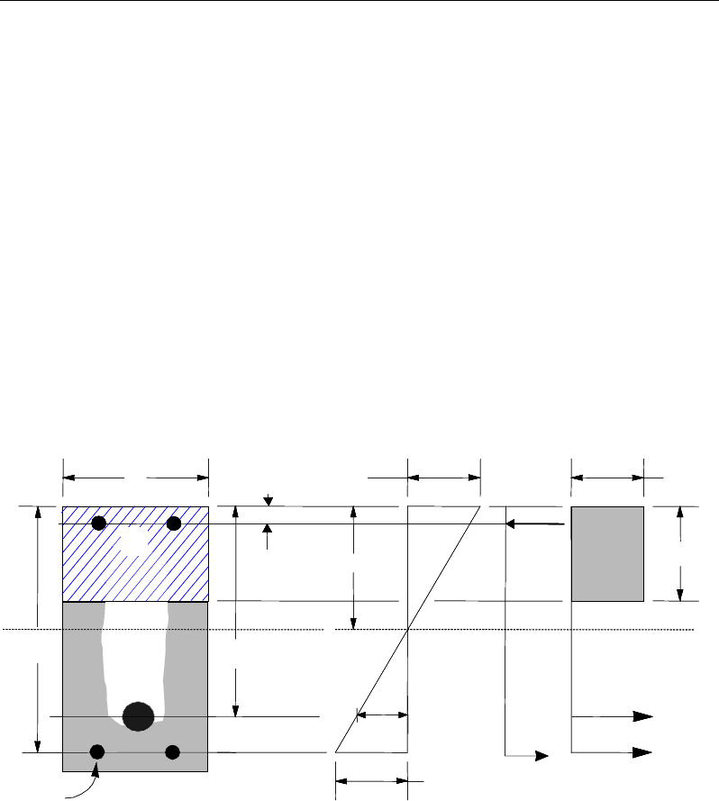
Chapter 13 - Design for NZS 3101:06
when the applied design moment exceeds the maximum moment capacity of a
singly reinforced section. The user has the option of avoiding the compression
reinforcement by increasing the effective depth, the width, or the strength of the
concrete.
The design procedure is based on the simplified rectangular stress block, as
shown in Figure 13-1 (NZS 7.4.2.7). Furthermore, it is assumed that the com-
pression carried by the concrete is 0.75 times that which can be carried at the
balanced condition (NZS 9.3.8.1). When the applied moment exceeds the mo-
ment capacity at the balanced condition, the area of compression reinforcement
is calculated assuming that the additional moment will be carried by compression
reinforcement and additional tension reinforcement.
The design procedure used by ETABS for both rectangular and flanged sections
(L- and T-beams) is summarized in the subsections that follow. The beams are
designed for major direction flexure, shear, and torsion only.
Figure 13-1 Rectangular Beam Design
BEAM
SECTION STRAIN
DIAGRAM STRESS
DIAGRAM
s
A
0.003
ε
=
1
α
′
c
f
s
f′
s
C
s
A′
p
A
s
ε
ε
p
s
T
cps
T
s
dp
d
b
c
d′1
ac
β
=
cs
T
BEAM
SECTION STRAIN
DIAGRAM STRESS
DIAGRAM
s
A
0.003
ε
=
1
α
′
c
f
s
f′
s
C
s
A′
p
A
s
ε
ε
p
s
T
cps
T
s
dp
d
b
c
d′1
ac
β
=
cs
T
Beam Design (for Reference Only) 13 - 13

Post-Tensioned Concrete Design
13.7.1.2.1 Design of Rectangular Beams
The amount of post-tensioning steel adequate to resist the design moment M and
minimum reinforcement are provided to satisfy the flexural cracking
requirements (NZS 19.3.6.7).
The maximum depth of the compression zone, cmax, is calculated based on the
limitation that the tension reinforcement strain shall not be less than
ε
smin, which
is equal to 0.0044 for tension-controlled behavior (NZS 7.4.2.8, 19.3.6.6.2):
ε
εε
=+,min
c
bcs
cd
(NZS 7.4.2.8, 19.3.6.6.2)
The maximum allowed depth of the rectangular compression block, amax, is given
by:
amax = 0.75
β
1cb (NZS 7.4.2.7, 9.3.8.1)
where
β
1 is calculated as:
10.85 for 30,
c
f
β
′
= ≤
(NZS 7.4.2.7)
11
0.85 0.008( 30), 0.65 0.85
c
f
ββ
′
= − − ≤≤
(NZS 7.4.2.7)
ETABS determines the depth of the neutral axis, c, by imposing force equilib-
rium, i.e., C = T. After the depth of the neutral axis has been determined, the
stress in the post-tensioning steel, fps, is computed based on strain compatibility
for bonded tendons. For unbonded tendons, the code equations are used to com-
pute the stress, fps in the post-tensioning steel. Based on the calculated fps, the
depth of the neutral axis is recalculated, and fps is further updated. After this it-
eration process has converged, the depth of the rectangular compression block is
determined as follows:
1
ac
β
=
If a ≤ amax (NZS 9.3.8.1), the moment capacity of the section provided by post-
tensioning steel only is computed as:
0
2
n b ps ps p
a
M Af d
φφ
= −
13 - 14 Beam Design (for Reference Only)

Chapter 13 - Design for NZS 3101:06
If a > amax (NZS 9.3.8.1), a failure condition is declared.
If
*0
,
n
MM
φ
>
ETABS calculates the moment capacity and the As required at the
balanced condition. The balanced condition is taken as the marginal tension con-
trolled case. In that case, it is assumed that the depth of the neutral axis, c is
equal to cmax. The stress in the post-tensioning steel, fps is then calculated based
on strain compatibility, and the area of required tension reinforcement, As, is
determined by imposing force equilibrium, i.e., C = T.
1 maxc
C fa b
α
′
=
bal bal bal
ps ps s s
T Af A f= +
1 max bal
c ps ps
bal
sbal
s
fa b A f
Af
α
′−
=
After the area of tension reinforcement has been determined, the capacity of the
section with post-tensioning steel and tension reinforcement is computed as:
max max
22
bal bal bal bal
n b ps ps p b s s s
aa
M Afd Afd
φφ φ
= −+ −
In that case, it is assumed that the bonded tension reinforcement will yield, which
is true for most cases. In the case that it does not yield, the stress in the reinforce-
ment, fs, is determined from the elastic-perfectly plastic stress-strain relationship.
This case does not involve any iteration in determining the depth of the neutral
axis, c.
13.7.1.2.1.1 Case 1: Post-tensioning steel is adequate
When
*0
,
u
MM<
the amount of post-tensioning steel is adequate to resist the
design moment M.. Minimum reinforcement is provided to satisfy the ductility
requirements.
13.7.1.2.1.2 Case 2: Post-tensioning steel plus tension reinforcement
In this case, the amount of post-tensioning steel, Aps, alone is not sufficient to
resist M*, and therefore the required area of tension reinforcement is computed
Beam Design (for Reference Only) 13 - 15

Post-Tensioned Concrete Design
to supplement the post-tensioning steel. The combination of post-tensioning
steel and tension reinforcement should result in a < amax.
When
0*
,
bal
uu
MMM<<
ETABS determines the required area of tension rein-
forcement, As, iteratively to satisfy the design moment M and reports this re-
quired area of tension reinforcement. Since M is bounded by
0
u
M
at the lower
end and
bal
u
M
at the upper end and
0
u
M
is associated with
0
s
A=
and
bal
u
M
is
associated with
,
bal
ss
AA=
the required area will be between the range of 0 to
Asbal.
The tension reinforcement is to be placed at the bottom if M* is positive, or at
the top if M* is negative.
13.7.1.2.1.3 Case 3: Post-tensioning steel and tension reinforcement are not
adequate
When
*,
bal
u
MM>
compression reinforcement is required (NZS 9.3.8.1). In that
case, ETABS assumes that the depth of neutral axis, c, is equal to
max .c
The
values of fpb and fs reach their respective balanced condition values,
bal
pb
f
and
.
bal
s
f
The area of compression reinforcement,
,
′
s
A
is determined as follows:
The moment required to be resisted by compression reinforcement and tension
reinforcement is:
*bal
us u
M MM
= −
The required compression reinforcement is given by:
( )( )
us
ss cs b
M
A,
f f d d'
1
αφ
′=′′
−−
where
s c,max s y
c d'
fE f
c
ε
−
′= ≤
(NZS 7.4.2.2, 7.4.2.4)
The tension reinforcement for balancing the compression reinforcement is given
by:
13 - 16 Beam Design (for Reference Only)

Chapter 13 - Design for NZS 3101:06
( )
'
com us
s
by s
M
Afd d
φ
=−
Therefore, the total tension reinforcement, As =
bal
s
A
+
,
com
s
A
and the total com-
pression reinforcement is A's. As is to be placed at the bottom, and A's is to be
placed at the top if M* is positive, and vice versa if M* is negative.
13.7.1.2.2 Design of Flanged Beams
13.7.1.2.2.1 Flanged Beam Under Negative Moment
In designing for a factored negative moment, M* (i.e., designing top reinforce-
ment), the calculation of the reinforcement area is exactly the same as described
previously, i.e., no flanged beam data is used.
13.7.1.2.2.2 Flanged Beam Under Positive Moment
ETABS first determines if the moment capacity provided by the post-tensioning
tendons alone is enough. In calculating the capacity, it is assumed that As = 0. In
that case, moment capacity
0
u
M
is determined as follows:
The maximum depth of the compression zone, cmax, is calculated based on the
limitation that the tension reinforcement strain shall not be less than
ε
smin, which
is equal to 0.0044 for tension-controlled behavior (NZS 7.4.2.8, 19.3.6.6.2):
ε
εε
=+,min
c
bcs
cd
(NZS 7.4.2.8, 19.3.6.6.2)
The maximum allowed depth of the rectangular compression block, amax, is given
by:
amax = 0.75
β
1cb (NZS 7.4.2.7, 9.3.8.1)
where
β
1 is calculated as:
10.85 for 30,
c
f
β
′
= ≤
(NZS 7.4.2.7)
11
0.85 0.008( 30), 0.65 0.85
c
f
ββ
′
= − − ≤≤
(NZS 7.4.2.7)
Beam Design (for Reference Only) 13 - 17
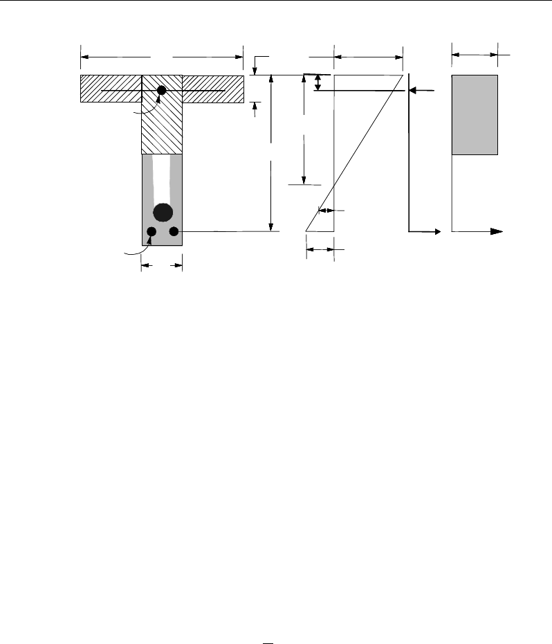
Post-Tensioned Concrete Design
Figure 13-2 T-Beam Design
ETABS determines the depth of the neutral axis, c, by imposing force equilib-
rium, i.e., C = T. After the depth of the neutral axis has been determined, the
stress in the post-tensioning steel, fps, is computed based on strain compatibility
for bonded tendons. For unbonded tendons, the code equations are used to com-
pute the stress in the post-tensioning steel. Based on the calculated fps, the depth
of the neutral axis is recalculated, and fps is further updated. After this iteration
process has converged, the depth of the rectangular compression block is deter-
mined as follows:
1
ac
β
=
If a ≤ amax (NZS 9.3.8.1), the moment capacity of the section, provided by
post-tensioning steel only, is computed as:
0
2
n b ps ps p
a
M Af d
φφ
= −
If a > amax (NZS 9.3.8.1), a failure condition is declared.
If
*0
,
n
MM
φ
>
ETABS calculates the moment capacity and the As required at the
balanced condition. The balanced condition is taken as the marginal tension con-
trolled case. In that case, it is assumed that the depth of the neutral axis, c is
STRESS
DIAGRAM
STRAIN
DIAGRAM
BEAM
SECTION
s
A
p
A
d
s
A′c
0.003
ε
=
1
α
′
c
f
s
C
ε
ps
s
ε
d′
w
T
s
T
f
h
′
s
f
f
b
w
b
STRESS
DIAGRAM
STRAIN
DIAGRAM
BEAM
SECTION
s
A
p
A
d
s
A′c
0.003
ε
=
1
α
′
c
f
s
C
ε
ps
s
ε
d′
w
T
s
T
f
h
′
s
f
f
b
w
b
13 - 18 Beam Design (for Reference Only)

Chapter 13 - Design for NZS 3101:06
equal to cmax. The stress in the post-tensioning steel, fps is then calculated based
on strain compatibility for bonded tendons. For unbonded tendons, the code
equations are used to compute the stress, fps in the post-tensioning steel, and the
area of required tension reinforcement, As, is determined by imposing force equi-
librium, i.e., C = T.
If a ≤ hf, the subsequent calculations for As are exactly the same as previously
defined for the rectangular beam design. However, in that case the width of
the beam is taken as bf. Compression reinforcement is required if a > amax.
If a > hf, the calculation for As is given by
1'comp
cc
C fA
α
=
where
com
c
A
is the area of concrete in compression, i.e.,
( )
max
com
c ff w f
A bh b a h=+−
bal bal bal
ps ps s s
T Af A f= +
1
'
com bal
c c ps ps
bal
sbal
s
f A Af
Af
α
−
=
In that case, it is assumed that the bonded tension reinforcement will yield, which
is true for most cases. In the case that it does not yield, the stress in the reinforce-
ment, fs, is determined from the elastic-perfectly plastic stress-strain relationship.
This case does not involve any iteration in determining the depth of neutral axis,
c.
13.7.1.2.2.3 Case 1: Post-tensioning steel is adequate
When
*0
,<u
MM
the amount of post-tensioning steel is adequate to resist the
design moment M. Minimum reinforcement is provided to satisfy ductility
requirements, i.e.,
*0
.
u
MM<
Beam Design (for Reference Only) 13 - 19

Post-Tensioned Concrete Design
13.7.1.2.2.4 Case 2: Post-tensioning steel plus tension reinforcement
In this case, the amount of post-tensioning steel, Aps, alone is not sufficient to
resist M*, and therefore the required area of tension reinforcement is computed
to supplement the post-tensioning steel. The combination of post-tensioning
steel and tension reinforcement should result in a < amax.
When
0*
,
bal
uu
MMM<<
ETABS determines the required area of tension rein-
forcement, As, iteratively to satisfy the design moment M and reports the
required area of tension reinforcement. Since M* is bounded by
0
u
M
at the lower
end and
bal
u
M
at the upper end, and
0
u
M
is associated with
0
s
A=
and
bal
u
M
is
associated with
,
bal
ss
AA=
the required area will be within the range of 0 to
.
s
A
The tension reinforcement is to be placed at the bottom if M* is positive, or at
the top if M* is negative.
13.7.1.2.2.5 Case 3: Post-tensioning steel and tension reinforcement are not
adequate
When
*
,
bal
u
MM
>
compression reinforcement is required (BS 3.4.4.4). In that
case ETABS assumes that the depth of the neutral axis, c, is equal to
max
.c
The
values of fpb and fs reach their respective balanced condition values,
bal
pb
f
and
.
bal
s
f
The area of compression reinforcement,
,
′
s
A
is then determined as fol-
lows:
The moment required to be resisted by compression reinforcement and tension
reinforcement is:
*bal
us b u
MM M
φ
= −
The required compression reinforcement is given by:
( )( )
1
,
'' '
us
ss cs b
M
Af f dd
αφ
′=−−
where
ycs
s
f
c
dc
Ef ≤
−
=
max
max
max
'
'
ε
13 - 20 Beam Design (for Reference Only)

Chapter 13 - Design for NZS 3101:06
The tension reinforcement for balancing the compression reinforcement is given
by:
( )
'
com us
sby s
M
Afd d
φ
=−
Therefore, the total tension reinforcement, As =
bal
s
A
+
,
com
s
A
and the total com-
pression reinforcement is A's. As is to be placed at the bottom, and A's is to be
placed at the top if M is positive and vice versa if M is negative.
13.7.1.2.3 Ductility Requirements
ETABS also checks the following condition by considering the post-tensioning
steel and tension reinforcement to avoid abrupt failure.
1.2
n cr
MM
φ
≥
(NZS 19.3.6.6.3)
The preceding condition is permitted to be waived for the following:
(a) Two-way, unbonded post-tensioned slabs
(b) Flexural members with shear and flexural strength at least twice that re-
quired by AS/NZS 1170 and NZS 1170.5.
These exceptions currently are NOT handled by ETABS.
13.7.1.3 Minimum and Maximum Reinforcement
The minimum flexural tension reinforcement required in a beam section with
unbonded tendon is given by the following limit:
As ≥ 0.004 A (NZS 19.3.6.7.1)
where A is the area of the cross-section between the flexural tension face and the
center of gravity of the gross section.
An upper limit of 0.04 times the gross web area on both the tension reinforce-
ment and the compression reinforcement is imposed upon request as follows:
Beam Design (for Reference Only) 13 - 21

Post-Tensioned Concrete Design
sw
sw
bd
Abd
bd
Abd
0.4 Rectangular beam
0.4 Flanged beam
0.04 Rectangular beam
0.04 Flanged beam
≤
′≤
13.7.2 Design Beam Shear Reinforcement
The shear reinforcement is designed for each load combination in the major
direction of the beam. In designing the shear reinforcement for a particular beam
for a particular load combination, the following steps are involved:
Determine the factored shear force, V*.
Determine the shear force, Vc, that can be resisted by the concrete.
Determine the shear reinforcement required to carry the balance.
The following three subsections describe in detail the algorithms associated with
these steps.
13.7.2.1 Determine Shear Force and Moment
In the design of the beam shear reinforcement, the shear forces for each load
combination at a particular beam section are obtained by factoring the corre-
sponding shear forces for different load cases, with the corresponding load com-
bination factors.
13.7.2.2 Determine Concrete Shear Capacity
The shear force carried by the concrete, Vc, is calculated using the simplified
procedure given in NZS 19.3.11.2.1. It is assumed that the effective prestress
force is equal to or greater than 40% of the tensile strength of flexural reinforce-
ment and the member is not subjected to axial tension or self-strain action such
as temperature, which can induced significant tensile stresses over part of the
element.
The shear strength provided by concrete, Vc, is given by:
13 - 22 Beam Design (for Reference Only)
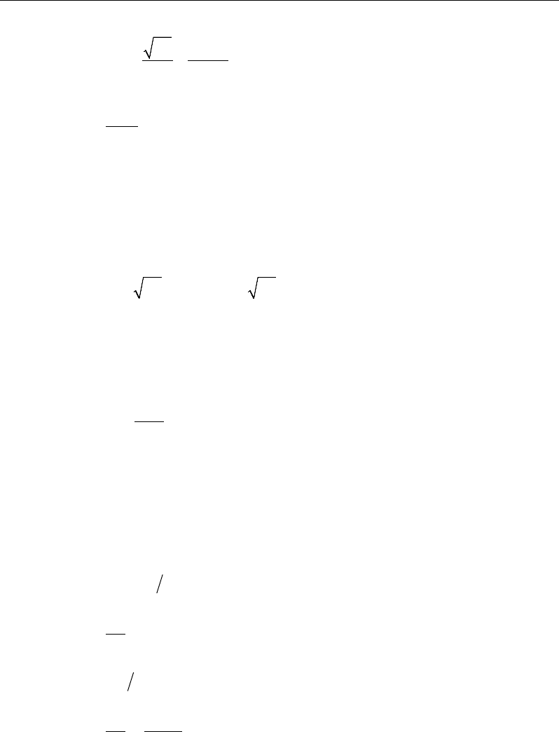
Chapter 13 - Design for NZS 3101:06
′
= +
*
*
5
20
cc
cw
fVd
V bd
M
(NZS 19.3.11.2.1)
≤
*
*
1.0
c
Vd
M
(NZS 19.3.11.2.1)
where
*
V
and
*
M
are the design moment and shear force acting simultaneously
at the section considered, and
c
d
is the distance from extreme compression fiber
to centroid of the prestressed reinforcement.
The following limit is also enforced:
′′
≤≤0.14 0.4
cw c cw
f bd V f bd
(NZS 19.3.11.2.1)
13.7.2.3 Determine Required Shear Reinforcement
The average shear stress is computed for rectangular and flanged sections as:
ν
* =
d
b
V
w
*
(NZS 7.5.1)
The average shear stress is limited to a maximum limit of,
vmax = min
{ }
0.2 , 8 MPa
′
c
f
(NZS 7.5.2, 9.3.9.3.3, 19.3.11.1)
The shear reinforcement is computed as follows:
If
ν
* ≤
φ
s
( )
2
c
v
s
Av
= 0 (NZS 9.3.9.4.13)
If
φ
s
( )
2
c
v
<
ν
* ≤
φ
s
ν
c,
s
Av
=
,minv
A
s
(NZS 9.3.9.4.15, 19.3.11.3.4(b))
Beam Design (for Reference Only) 13 - 23
Post-Tensioned Concrete Design
,min
v
A
s
=
1
16
min
80
w
cyt
ps pu
yw
b
ff
Af d
fd d
′
(NZS 9.3.9.4.15, 19.3.11.3.4(b))
If
φ
s
ν
c <
ν
* ≤
φ
s
ν
max,
( )
df
vv
s
A
yts
csv
φ
φ
−
=
*
(NZS 9.3.9.4.2)
s
Av
≥
,minv
A
s
(NZS 9.3.9.4.15, 19.3.11.3.4(b))
If
ν
* >
ν
max,
a failure condition is declared. (NZS 7.5.2, 9.3.9.3.3)
If the beam depth h is less than the maximum of 300 mm and 0.5bw, no shear
reinforcement is required (AS 9.3.9.4.13).
The maximum of all of the calculated Av
/s values, obtained from each load com-
bination, is reported along with the controlling shear force and associated load
combination.
The beam shear reinforcement requirements considered by the program are
based purely on shear strength considerations. Any minimum stirrup require-
ments to satisfy spacing and volumetric considerations must be investigated
independently of the program by the user.
13.7.3 Design Beam Torsion Reinforcement
The torsion reinforcement is designed for each design load combination at each
station along the length of the beam. The following steps are involved in
designing the longitudinal and shear reinforcement for a particular station due to
the beam torsion:
Determine the factored torsion, T*.
Determine special section properties.
13 - 24 Beam Design (for Reference Only)

Chapter 13 - Design for NZS 3101:06
Determine critical torsion capacity.
Determine the torsion reinforcement required.
13.7.3.1 Determine Factored Torsion
In the design of beam torsion reinforcement, the torsions for each load combina-
tion at a particular beam station are obtained by factoring the corresponding tor-
sions for different load cases with the corresponding load combination
factors.
In a statically indeterminate structure where redistribution of the torsion in a
member can occur because of redistribution of internal forces upon cracking, the
design T* is permitted to be reduced in accordance with the code (NZS 7.6.1.3).
However, the program does not automatically redistribute the internal forces and
reduce T*. If redistribution is desired, the user should release the torsional degree
of freedom (DOF) in the structural model.
13.7.3.2 Determine Special Section Properties
For torsion design, special section properties, such as Aco, Ao, pc, tc, and to, are
calculated. These properties are described in the following (NZS 7.1).
A
co
=
Area enclosed by outside perimeter of concrete cross-section
A
o
=
Gross area enclosed by shear flow path
p
c
=
Outside perimeter of concrete cross-section
p
o
=
Perimeter of area A
o
t
c
=
Assumed wall thickness of an equivalent tube for the gross
section
t
o
=
Assumed wall thickness of an equivalent tube for the area
enclosed by the shear flow path
In calculating the section properties involving reinforcement, such as Ao, po, and
to, it is assumed that the distance between the centerline of the outermost closed
stirrup and the outermost concrete surface is 50 mm. This is equivalent to a 38
Beam Design (for Reference Only) 13 - 25

Post-Tensioned Concrete Design
mm clear cover and a 12 mm stirrup. For torsion design of flanged beam sec-
tions, it is assumed that placing torsion reinforcement in the flange area is inef-
ficient. With this assumption, the flange is ignored for torsion reinforcement cal-
culation. However, the flange is considered during Tcr calculation. With this as-
sumption, the special properties for a rectangular beam section are given as:
A
co
=
bh (NZS 7.1)
A
o
=
(b − 2c)(h − 2c) (NZS 7.1)
p
c
=
2b + 2h (NZS 7.1)
p
o
=
2(b − 2c) + 2(h − 2c) (NZS 7.1)
t
c
=
0.75 A
o
/
p
o
(NZS 7.1)
t
o
=
0.75 A
co
/
p
c
(NZS 7.1)
where, the section dimensions b, h, and c are shown in Figure 13-3.
Similarly, the special section properties for a flanged beam section are given as:
A
co
=
b
w
h + (b
f
– b
w
)h
f
(NZS 7.1)
A
o
=
(b
w
– 2c)(h – 2c) (NZS 7.1)
p
c
=
2b
f
+ 2h (NZS 7.1)
p
o
=
2(h – 2c) + 2(b
w
– 2c) (NZS 7.1)
t
c
=
0.75 A
o
/
p
o
(NZS 7.1)
t
o
=
0.75 A
co
/
p
c
(NZS 7.1)
where the section dimensions bf, bw, h, hf, and c for a flanged beam are shown in
Figure 13-3. Note that the flange width on either side of the beam web is limited
to the smaller of 3hf (NZS 7.6.1.7).
13 - 26 Beam Design (for Reference Only)
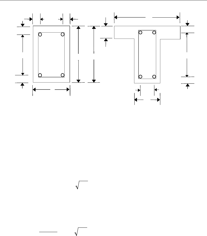
Chapter 13 - Design for NZS 3101:06
Figure 13-3 Closed stirrup and section dimensions for torsion design
13.7.3.3 Determine Critical Torsion Capacity
The critical torsion capacity, Tcr, for which the torsion in the section can be
ignored is calculated as:
cccocr
ftAT '1.0
φ
=
(NZS 7.6.1.2)
where Aco and tc are as described in the previous section, and f'c is the specified
concrete compressive strength. The stress due to torsion also should be limited
in order to ignore torsion, defined as:
c
oo
f
tA
T'08.0
2
*≤
φ
(NZS 7.6.1.3)
13.7.3.4 Determine Torsion Reinforcement
If the factored torsion, T*, is less than the threshold limit, Tcr, and meets the tor-
sion stress limit, torsion can be safely ignored (NZS 7.6.1). In that case, the pro-
gram reports that no torsion reinforcement is required. However, if T* exceeds
cb 2
h
s
d
Closed Stirrup in
Rectangular Beam
Closed Stirrup in
T-Beam Section
ch 2
−h
b
ch 2
−
w
b
Closed Stirrup in
Rectangular Beam
Closed Stirrup in
T-Beam Section
ch 2
−ch 2
−
f
h
f
b
hh
b
c
c
cc
c
c
b 2c
−
w
b 2c
−
w
b
cb 2
h
s
d
Closed Stirrup in
Rectangular Beam
Closed Stirrup in
T-Beam Section
ch 2
−h
b
ch 2
−
w
b
Closed Stirrup in
Rectangular Beam
Closed Stirrup in
T-Beam Section
ch 2
−ch 2
−
f
h
f
b
hh
b
c
c
cc
c
c
b 2c
−
w
b 2c
−
w
b
Beam Design (for Reference Only) 13 - 27
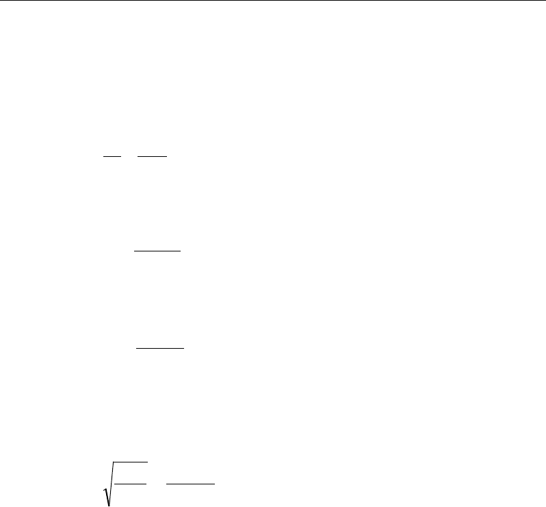
Post-Tensioned Concrete Design
the threshold limit, it is assumed that the torsional resistance is provided by
closed stirrups and longitudinal bars (NZS 7.6.4.1).
If T* > Tcr or the torsion stress limit is not met, the required closed stirrup area
per unit spacing, At
/ s, is calculated as:
yt
otnt
f
tv
s
A=
(NZS 7.6.4.2)
and the required longitudinal reinforcement is calculated as:
y
ootn
l
f
ptv
A=
(NZS 7.6.4.3)
where the torsional shear stress vtn is defined as:
oo
tn
tA
T
v2
*
φ
=
(NZS 7.6.1.6, 7.6.1.5)
The minimum closed stirrups and longitudinal reinforcement shall be such that
the following is satisfied, where At
/ s can be from any closed stirrups for shear
and Al can include flexure reinforcement, provided it is fully developed.
oy
co
o
lt
Af
tA
sp
AA 5.1
=
(NZS 7.6.2)
The term AtAl / po shall not be taken greater than 7At/ s (NZS 7.6.2.3).
An upper limit of the combination of V* and T* that can be carried by the section
also is checked using the equation:
n tn c
v v . f' ,min(0 2 8 MPa)+<
(NZS 7.6.1.8, 7.5.2)
For rectangular sections, bw is replaced with b. If the combination of V* and T*
exceeds this limit, a failure message is declared. In that case, the concrete section
should be increased in size.
The maximum of all of the calculated Al and At / s values obtained from each load
combination is reported along with the controlling combination.
13 - 28 Beam Design (for Reference Only)

Chapter 13 - Design for NZS 3101:06
The beam torsion reinforcement requirements reported by the program are based
purely on strength considerations. Any minimum stirrup requirements or longi-
tudinal rebar requirements to satisfy spacing considerations must be investigated
independently of the program by the user.
13.8 Slab Design
Similar to conventional design, the ETABS slab design procedure involves
defining sets of strips in two mutually perpendicular directions. The locations of
the strips typically are governed by the locations of the slab supports. The mo-
ments for a particular strip are recovered from the analysis, and a flexural design
is carried out based on the ultimate strength design method (NZS 3101:06) for
prestressed reinforced concrete, as described in the following subsections. To
learn more about the design strips, refer to the section entitled "ETABS Design
Techniques" in the Key Features and Terminology manual.
13.8.1 Design for Flexure
ETABS designs the slab on a strip-by-strip basis. The moments used for the
design of the slab elements are the nodal reactive moments, which are obtained
by multiplying the slab element stiffness matrices by the element nodal displace-
ment vectors. These moments will always be in static equilibrium with the ap-
plied loads, irrespective of the refinement of the finite element mesh.
The design of the slab reinforcement for a particular strip is carried out at
specific locations along the length of the strip. Those locations correspond to the
element boundaries. Controlling reinforcement is computed on either side of the
element boundaries. The slab flexural design procedure for each load combina-
tion involves the following:
Determine factored moments for each slab strip
Determine the capacity of post-tensioned sections
Design flexural reinforcement for the strip
These three steps are described in the subsections that follow and are repeated
for every load combination. The maximum reinforcement calculated for the top
Slab Design 13 - 29

Post-Tensioned Concrete Design
and bottom of the slab within each design strip, along with the corresponding
controlling load combination, is obtained and reported.
13.8.1.1 Determine Factored Moments for the Strip
For each element within the design strip, for each load combination, the program
calculates the nodal reactive moments. The nodal moments are then added to get
the strip moments.
13.8.1.2 Determine Capacity of Post-Tensioned Sections
The calculation of the post-tensioned section capacity is identical to that
described earlier for rectangular beam sections.
13.8.1.3 Design Flexural Reinforcement for the Strip
The reinforcement computation for each slab design strip, given the bending mo-
ment, is identical to the design of rectangular beam sections described
earlier (or to the flanged beam if the slab is ribbed). In some cases, at a given
design section in a design strip, there may be two or more slab properties across
the width of the design strip. In that case, the program automatically designs the
tributary width associated with each of the slab properties separately using its
tributary bending moment. The reinforcement obtained for each of the tributary
widths is summed to obtain the total reinforcement for the full width of the de-
sign strip at the considered design section. This method is used when drop panels
are included. Where openings occur, the slab width is adjusted accordingly.
13.8.1.4 Minimum and Maximum Slab Reinforcement
There are no minimum requirements for untensioned reinforcement in one-way
bonded slabs. One-way spanning floors with unbounded tendons should have
minimum reinforcement requirements in accordance with NZS 19.3.6.7.1.
In flat slabs, reinforcement is added at the top over supports to be 0.00075 times
the gross cross-sectional area. This reinforcement extends 1.5 times the slab
depth on each side of the column. The length of the reinforcement should be at
least L / 6 where L is the span of the slab.
13 - 30 Slab Design
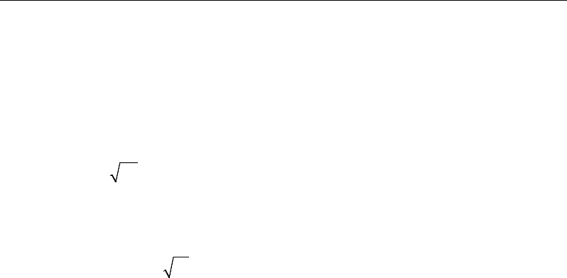
Chapter 13 - Design for NZS 3101:06
There are no minimum requirements for the span zone. However, additional un-
tensioned reinforcement shall be designed for the full tension force generated by
assumed flexural tensile stresses in the concrete for the following situations:
all locations in one-way spanning floors using unbonded tendons
all locations in one-way spanning floors where transfer tensile stress exceeds
0.36
ci
f
support zones in all flat slabs
span zones in flat slabs using unbonded tendons where the tensile stress
exceeds 0.17
c
f
'
In addition, an upper limit on both the tension reinforcement and compression
reinforcement has been imposed to be 0.04 times the gross cross-sectional area.
13.8.2 Check for Punching Shear
The algorithm for checking punching shear is detailed in the section entitled
“Slab Punching Shear Check” in the Key Features and Terminology manual.
Only the code specific items are described in the following sections.
13.8.2.1 Critical Section for Punching Shear
The punching shear is checked on a critical section at a distance of d / 2 from the
face of the support (NZS 12.7.1(b)). For rectangular columns and concentrated
loads, the critical area is taken as a rectangular area with the sides parallel to the
sides of the columns or the point loads (NZS 12.7.1(b)). Figure 13-4 shows the
auto punching perimeters considered by ETABS for the various column shapes.
The column location (i.e., interior, edge, corner) and the punching perimeter may
be overwritten using the Punching Check Overwrites.
Slab Design 13 - 31
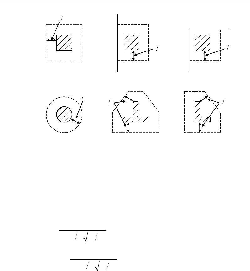
Post-Tensioned Concrete Design
Figure 13-4 Punching Shear Perimeters
13.8.2.2 Transfer of Unbalanced Moment
The fraction of unbalanced moment transferred by flexure is taken to be γf M*
and the fraction of unbalanced moment transferred by eccentricity of shear is
taken to be γv M*, where
γf =
( )
21
321
1
bb+
(NZS 12.7.7.2 )
γv = 1 −
( )
21
321
1
bb+
(NZS 12.7.7.1)
where b1 is the width of the critical section measured in the direction of the span,
and b2 is the width of the critical section measured in the direction perpendicular
to the span.
13.8.2.3 Determine Concrete Capacity
The concrete punching shear factored strength is taken as the minimum of the
following three limits:
d2
Interior Column
Circular Column
d2 d2
d2
T-Shape Column
Edge Column Corner Column
L-Shape Column
d2
d2
d2
Interior Column
Circular Column
d2 d2
d2
T-Shape Column
Edge Column Corner Column
L-Shape Column
d2
d2
13 - 32 Slab Design
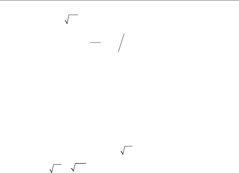
Chapter 13 - Design for NZS 3101:06
' 0.3
c p c pc p
v f fv
β
= ++
(NZS 19.3.11.2.4)
min 0.29, 1.5 12
s
po
d
b
α
β
= +
(NZS 19.3.11.2.4)
=0
p
v
where,
β
p is the ratio of the maximum to the minimum dimension of the critical
section (NZS 12.1, 12.7.3.2(a)), b0 is the perimeter of the critical section, and
α
s
is a scale factor based on the location of the critical section.
α
=
40 for interior columns,
30 for edge columns,
20 for corner columns.
s
(NZS 19.3.11.2.4)
A limit is imposed on the value of
c
f′
as follows:
λ
′
c
f
≤
100
(NZS 5.2.1)
13.8.2.4 Determine Capacity Ratio
Given the punching shear force and the fractions of moments transferred by
eccentricity of shear about the two axes, the shear stress is computed assuming
linear variation along the perimeter of the critical section. The ratio of the max-
imum shear stress and the concrete punching shear stress capacity is
reported as the punching shear capacity ratio by ETABS.
13.8.3 Design Punching Shear Reinforcement
The use of shear studs as shear reinforcement in slabs is permitted, provided that
the effective depth of the slab is greater than or equal to 150 mm, and not less
than 16 times the shear reinforcement bar diameter (NZS 12.7.4.1). If the slab
thickness does not meet these requirements, the punching shear reinforcement is
not designed, and the slab thickness should be increased by the user.
The algorithm for designing the required punching shear reinforcement is used
when the punching shear capacity ratio exceeds unity. The Critical Section for
Slab Design 13 - 33
Post-Tensioned Concrete Design
Punching Shear and Transfer of Unbalanced Moment as described in the earlier
sections remain unchanged. The design of punching shear reinforcement is car-
ried out as described in the subsections that follow.
13.8.3.1 Determine Concrete Shear Capacity
The concrete punching shear stress capacity of a section with punching shear
reinforcement is determined as:
0.17 '
cc
vf=
(NZS 19.3.11.2.4)
13.8.3.2 Determine Required Shear Reinforcement
The shear force is limited to a maximum of:
vmax = 0.5
c
f′
(NZS 12.7.3.4)
Given v*, vc, and vmax, the required shear reinforcement is calculated as follows,
where,
φ
, is the strength reduction factor.
( )
nc
v
yv
vv
A
s fd
φ
−
=
(NZS 12.7.4.2(a))
Minimum punching shear reinforcement should be provided such that:
dbfV
ocs
'
16
1
≥
(NZS 12.7.4.3)
If vn >
φ
vmax, a failure condition is declared. (NZS 12.7.3.4)
If vn exceeds the maximum permitted value of
φ
vmax, the concrete section
should be increased in size.
13.8.3.3 Determine Reinforcement Arrangement
Punching shear reinforcement in the vicinity of rectangular columns should be
arranged on peripheral lines, i.e., lines running parallel to and at constant dis-
tances from the sides of the column. Figure 13-5 shows a typical arrangement of
13 - 34 Slab Design
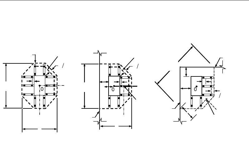
Chapter 13 - Design for NZS 3101:06
shear reinforcement in the vicinity of a rectangular interior, edge, and corner
column.
Figure 13-5 Typical arrangement of shear studs
and critical sections outside shear-reinforced zone
The distance between the column face and the first line of shear reinforcement
shall not exceed d / 2. The spacing between adjacent shear reinforcement in the
first line (perimeter) of shear reinforcement shall not exceed 2d measured in a
direction parallel to the column face (NZS 12.7.4.4).
Punching shear reinforcement is most effective near column corners where there
are concentrations of shear stress. Therefore, the minimum number of lines of
shear reinforcement is 4, 6, and 8, for corner, edge, and interior columns respec-
tively.
13.8.3.4 Determine Reinforcement Diameter, Height, and Spacing
The punching shear reinforcement is most effective when the anchorage is close
to the top and bottom surfaces of the slab. The cover of anchors should not be
less than the minimum cover specified in NZS 3.11 plus half of the
diameter of the flexural reinforcement.
When specifying shear studs, the distance, so, between the column face and the
first peripheral line of shear studs should not be smaller than 0.5d. The spacing
I
y
Typical Studrail
(only first and last
studs shown)
Outermost
peripheral line
of studs
Interior Column Edge Column Corner Column
Critical section
centroid
Free
edge
Free
edge
Critical
section
centroid
Free edge
Outermost
peripheral line
of studs
I
y
I
y
yx
d2 d2
d2
x
I
x
I
x
g
y
g
x
g
0
s0
s0
s
x
I
y
xx
I
y
Typical Studrail
(only first and last
studs shown)
Outermost
peripheral line
of studs
Interior Column Edge Column Corner Column
Critical section
centroid
Free
edge
Free
edge
Critical
section
centroid
Free edge
Outermost
peripheral line
of studs
I
y
I
y
yx
d2 d2
d2
x
I
x
I
x
g
y
g
x
g
0
s0
s0
s
x
I
y
xx
Slab Design 13 - 35

Post-Tensioned Concrete Design
between adjacent shear studs, g, at the first peripheral line of studs shall not ex-
ceed 2d and in the case of studs in a radial pattern, the angle between adjacent
stud rails shall not exceed 60 degrees. The limits of so and the spacing, s, between
the peripheral lines are specified as:
so ≤ 0.5d (NZS 12.7.4.4)
s ≤ 0.5d (NZS 12.7.4.4)
g ≤ 2d (NZS 12.7.4.4)
13 - 36 Slab Design

Chapter 14
Design for Singapore CP 65:99
This chapter describes in detail the various aspects of the post-tensioned concrete
design procedure that is used by ETABS when the user selects the Singapore
Standard CP 65 : 99 [CP 1999], which also incorporates Erratum Nos. 1 and BC
2:2008 Design Guide of High Strength Concrete to Singapore Standard CP 65
[BC 2008]. Various notations used in this chapter are listed in Table 14-1. For
referencing to the pertinent sections of the CP code in this chapter, a prefix “CP”
followed by the section number is used.
The design is based on user-specified load combinations. The program provides
a set of default load combinations that should satisfy the requirements for the
design of most building type structures.
English as well as SI and MKS metric units can be used for input. The code is
based on Newton-millimeter-second units. For simplicity, all equations and de-
scriptions presented in this chapter correspond to Newton-millimeter-second
units unless otherwise noted.
14.1 Notations
The following table identifies the various notations used in this chapter.
Notations 14 - 1

Post-Tensioned Concrete Design
Table 14-1 List of Symbols Used in the CP 65:99 Code
A
cv
Area of section for shear resistance, mm2
A
g
Gross area of cross-section, mm2
A
s
Area of tension reinforcement, mm2
A
ps
Area of prestress steel, mm2
A'
s
Area of compression reinforcement, mm2
A
sv
Total cross-sectional area of links at the neutral axis, mm2
A
sv
/ s
v
Area of shear reinforcement per unit length of the member,
mm2/mm
a
Depth of compression block, mm
b
Width or effective width of the section in the compression
zone, mm
b
f
Width or effective width of flange, mm
b
w
Average web width of a flanged beam, mm
d or d
e
Effective depth of tension reinforcement, mm
d'
Depth to center of compression reinforcement, mm
E
c
Modulus of elasticity of concrete, MPa
E
s
Modulus of elasticity of reinforcement, assumed as 200,000
MPa
f
ci
Concrete strength at transfer, MPa
f
cu
Characteristic cube strength, MPa
f
pu
Characteristic strength of a prestressing tendon, MPa
f
pb
Design tensile stress in tendon, MPa
s
f′
Compressive stress in a beam compression steel, MPa
f
y
Characteristic strength reinforcement, MPa
f
yv
Characteristic strength of link reinforcement, MPa (< 500
MPa)
h
Overall depth of a section in the plane of bending, mm
14 - 2 Notations
Chapter 14 - Design for Singapore CP 65:99
Table 14-1 List of Symbols Used in the CP 65:99 Code
h
f
Flange thickness, mm
k
1
Shear strength enhancement factor for support compression
k2 Concrete shear strength factor,
[]
13
30
cu
f
M
Design moment at a section, MPa
M
u
Design moment resistance of a section, MPa
M
u
0
Design moment resistance of a section with tendons only, N-
mm
M
u
bal
Design moment resistance of a section with tendons and the
necessary mild reinforcement to reach the balanced condition,
N-mm
s
v
Spacing of the links along the length of the beam, mm
s
Spacing of shear rails, mm
T
Tension force, N
V
Design shear force at ultimate design load, N
u
Perimeter of the punching critical section, mm
v
Design shear stress at a beam cross-section or at a punch crit-
ical section, MPa
v
c
Design ultimate shear stress resistance of a concrete beam,
MPa
v
co
Ultimate shear stress resistance of an uncracked concrete
section, MPa
v
cr
Ultimate shear stress resistance of a cracked concrete section,
MPa
v
max
Maximum permitted design factored shear stress at a beam
section or at the punch critical section, MPa
v
t
Torsional shear stress, MPa
x
Neutral axis depth, mm
x
bal
Depth of neutral axis in a balanced section, mm
Notations 14 - 3

Post-Tensioned Concrete Design
Table 14-1 List of Symbols Used in the CP 65:99 Code
a
max
Depth of neutral axis in a balanced section, mm
z
Lever arm, mm
β
Torsional stiffness constant
β
b
Moment redistribution factor in a member
γ
f
Partial safety factor for load
γ
m
Partial safety factor for material strength
ε
c
Maximum concrete strain, 0.0035
ps
ε
Strain in prestressing steel
s
ε
Strain in tension steel
s
ε
′
Strain in compression steel
14.2 Design Load Combinations
The design load combinations are the various combinations of the load cases for
which the structure needs to be designed. The design load combinations are ob-
tained by multiplying the characteristic loads by appropriate partial factors of
safety, γf (CP 2.4.1.3). For CP 65:99, if a structure is subjected to dead (D), live
(L), pattern live (PL), and wind (W) loads, and considering that wind forces are
reversible, the load combinations in the following subsections may need to be
considered (CP 2.4.3, 4.1.7.1, 4.3.4 and 4.3.5).
For post-tensioned concrete design, the user can specify the prestressing load
(PT) by providing the tendon profile or by using the load balancing options in
the program. The default load combinations for post-tensioning are defined in
the following sections.
14.2.1 Initial Service Load Combination
The following load combination is used for checking the requirements at transfer
of prestress forces in accordance with CP 65:99 clause 4.3.5. The prestressing
forces are considered without any long-term loses for the initial service load
combination check.
14 - 4 Design Load Combinations

Chapter 14 - Design for Singapore CP 65:99
1.0D + 1.0PT
14.2.2 Service Load Combination
The following load combinations are used for checking the requirements of pre-
stress for serviceability in accordance with CP 4.3.4. It is assumed that all long-
term losses have already occurred at the service stage.
1.0D + 1.0PT
1.0D + 1.0L + 1.0PT
14.2.3 Ultimate Limit State Load Combination
The following load combinations are used for checking the requirements of pre-
stress in accordance with CP 2.4.3.1.1, Table 2.1.
The design combinations required for punching shear require the full PT forces
(primary and secondary). Flexural design requires only the hyperstatic (second-
ary) forces. The hyperstatic (secondary) forces are determined automatically by
ETABS by subtracting the primary PT moments when the flexural design is per-
formed.
1.4D + 1.0PT*
1.4D + 1.6L + 1.0PT*
1.4D + 1.6(0.75PL) + 1.0PT*
1.0D ± 1.4W +1.0PT*
1.4D
± 1.4W + 1.0PT*
1.
2D + 1.2L ± 1.2W + 1.0PT*
* — Replace PT by H for flexural design only
Other appropriate loading combinations should be used if roof live load is sepa-
rately treated, or other types of loads are present. Note that the automatic com-
bination, including pattern live load, is assumed and should be reviewed before
using for design.
Design Load Combinations 14 - 5

Post-Tensioned Concrete Design
14.3 Limits on Material Strength
Grade C28/C35 and C32/C40 are the minimum recommended for post-tension-
ing and pre-tensioning respectively. In both cases the concrete strength at trans-
fer should not be less than 25 MPa (CP 4.1.8.1).
The specified characteristic strength of untensioned reinforcement is given as
follows (CP 4.1.8.2, 3.1.7.4):
Hot rolled mild reinforcement - 250 MPa (CP 3.1.7.4, Table 3.1)
High yield reinforcement - 460 MPa (CP 3.1.7.4, Table 3.1)
The specified characteristic strength of prestressing steel should conform to SS
2: Part 3: 1987, SS 18: Part 2: 1970, and SS 32 : Part 2: 1988.
ETABS also checks the tensile strength in the prestressing steel (CP 4.7.1). The
permissible tensile stresses in all types of prestressing steel, in terms of the spec-
ified minimum tensile strength fpu, are summarized as follows:
a. Due to tendon jacking force: 0.75 fpu
b. Immediately after prestress transfer: 0.70 fpu
In any circumstances, the initial prestressing forces shall not exceed 0.75 fpu.
14.4 Partial Safety Factors
The design strengths for concrete and reinforcement are obtained by dividing the
characteristic strength of the material by a partial safety factor,
γ
m. The values of
γ
m used in the program are listed in the table that follows, as taken from CP Table
2.2 (CP 2.4.4.1):
Values of
γ
m for the ultimate limit state
Reinforcement,
γ
ms 1.15
Prestressing steel,
γ
mp 1.15
Concrete in flexure and axial load,
γ
mc 1.50
Shear strength without shear reinforcement,
γ
mv 1.25
14 - 6 Limits on Material Strength

Chapter 14 - Design for Singapore CP 65:99
These factors are already incorporated in the design equations and tables in the
code. Note that for reinforcement, the default factor of 1.15 is for Grade 460
reinforcement. If other grades are used, this value should be overwritten as nec-
essary. Changes to the partial safety factors are carried through the design equa-
tions where necessary, typically affecting the material strength portions of the
equations.
14.5 Design Assumptions for Prestressed Concrete Struc-
tures
The ultimate limit state of prestressed members for flexure and axial loads shall
be based on assumptions given in CP 4.3.7.1.
The strain distribution in the concrete in compression is derived from the
assumption that a plane section remains plane (CP 4.3.7.1(a)).
The design stresses in the concrete in compression are taken as 0.45 fcu. The
maximum strain at the extreme concrete compression fiber shall be assumed
equal to 0.0035 (CP 4.3.7.1(b)).
Tensile strength of the concrete is ignored (CP 4.3.7.1(c)).
The strain in bonded prestressing tendons and in any additional reinforcement
(compression or tension) is derived from the assumption that a plane section
remains plane (CP 4.3.7.1(d)).
The serviceability limit state of prestressed members uses the following assump-
tions given in CP 4.3.4.1.
Plane sections remain plane, i.e., strain varies linearly with depth through the
entire load range (CP 4.3.4.1(a)).
Elastic behavior exists by limiting the concrete stresses to the values given in
CP 4.3.4.2, 4.3.4.3, and 4.3.5 (CP 4.3.4.1(b)).
In general, it is only necessary to calculate design stresses due to the load
arrangements immediately after the transfer of prestress and after all losses or
prestress has occurred; in both cases the effects of dead and imposed loads on
the strain and force in the tendons may be ignored (CP 4.3.4.1(c)).
Design Assumptions for Prestressed Concrete Structures 14 - 7

Post-Tensioned Concrete Design
Prestressed concrete members are investigated at the following three stages (CP
4.3.4.2 and 4.3.4.3):
At transfer of prestress force
At service loading
At nominal strength
The prestressed flexural members are classified as Class 1 (uncracked), Class 2
(cracked but no visible cracking), and Class 3 (cracked) based on tensile strength,
ft, the computed extreme fiber stress in tension in the precompressed tensile zone
at service loads (CP 4.1.3).
The precompressed tensile zone is that portion of a prestressed member where
flexural tension, calculated using gross section properties, would occur under
unfactored dead and live loads if the prestress force was not present. Prestressed
concrete is usually designed so that the prestress force introduces compression
into this zone, thus effectively reducing the magnitude of the tensile stress.
Class 1: No flexural tensile stresses
Class 2: Flexural tensile stresses with no visible cracking
Class 3: Flexural tensile stresses with surface width of cracks as follows:
Crack width ≤ 0.1 mm for members in very severe environments as
specified in CP Table 3.2
Crack width ≤ 0.2 mm for all other members
14.6 Serviceability Requirements of Flexural Members
14.6.1 Serviceability Check at Initial Service Load
The stresses in the concrete immediately after prestress force transfer (before
time dependent prestress losses) are checked against the following limits (CP
4.3.5.1 and 4.3.5.2):
14 - 8 Serviceability Requirements of Flexural Members

Chapter 14 - Design for Singapore CP 65:99
Extreme fiber stress in compression:
0.50 ci
f
Extreme fiber stress in tension for Class 1: ≤ 1.0 MPa
Extreme fiber stress in tension for Class 2:
pre-tensioned member
0.45 ci
f
post-tensioned member
0.36
ci
f
The extreme fiber stress in tension for Class 3 should not exceed the appropriate
value for a Class 2 member; otherwise the section should be designed as a
cracked section.
14.6.2 Serviceability Check at Service Load
The stresses in the concrete for Class 1 and Class 2 prestressed flexural members
at service loads, and after all prestress losses occur, are checked against the fol-
lowing limits (CP 4.3.4.2, 4.3.4.3):
Extreme fiber stress in compression due
to prestress plus total load:
0.33
cu
f
Extreme fiber stress in compression due
to prestress plus total load for continuous
beams and other statically indeterminate
structures:
0.4 cu
f
Extreme fiber stress in tension in the
precompressed tensile zone at service loads:
– Extreme fiber stresses in tension for Class 1: No tensile stress
– Extreme fiber stresses in tension for Class 2:
pre-tensioned member
0.45
cu
f
post-tensioned member
0.36
cu
f
Serviceability Requirements of Flexural Members 14 - 9

Post-Tensioned Concrete Design
Although cracking is allowed for Class 3, it is assumed that the concrete
section is uncracked and the user is limiting the tensile stress at service stage as
presented in Table 4.2, modified by the coefficients in Table 4.3 of CP 65 : 1999.
The user needs to provide the tension limits for Class 3 elements at
service loads in the Design Preferences (CP 4.3.4.3(c)).
14.7 Beam Design (for Reference Only)
Important Note: Post-tensioned beam design is not available in the current ver-
sion of ETABS, but is planned for a future release. This section is provided as
reference only for the documentation of post-tensioned slab design.
In the design of prestressed concrete beams, ETABS calculates and reports the
required areas of reinforcement for flexure, shear, and torsion based on the beam
moments, shear forces, torsion, load combination factors, and other criteria de-
scribed in the subsections that follow. The reinforcement requirements are cal-
culated at each station along the length of the beam.
Beams are designed for major direction flexure, shear, and torsion only. Effects
resulting from any axial forces and minor direction bending that may exist in the
beams must be investigated independently by the user.
The beam design procedure involves the following steps:
Design flexural reinforcement
Design shear reinforcement
Design torsion reinforcement
14.7.1 Design Flexural Reinforcement
The beam top and bottom flexural reinforcement is designed at each station
along the beam. In designing the flexural reinforcement for the major moment
of a particular beam, for a particular station, the following steps are involved:
Determine factored moments
Determine required flexural reinforcement
14 - 10 Beam Design (for Reference Only)

Chapter 14 - Design for Singapore CP 65:99
14.7.1.1 Determine Factored Moments
In the design of flexural reinforcement of prestressed concrete beams, the
factored moments for each load combination at a particular beam station are ob-
tained by factoring the corresponding moments for different load cases, with the
corresponding load factors.
The beam is then designed for the maximum positive and maximum negative
factored moments obtained from all of the load combinations. Positive beam
moments can be used to calculate bottom reinforcement. In such cases the beam
may be designed as a rectangular or a flanged beam. Negative beam moments
can be used to calculate top reinforcement. In such cases, the beam may be de-
signed as a rectangular or inverted flanged beam.
14.7.1.2 Determine Required Flexural Reinforcement
In the flexural reinforcement design process, the program calculates both the
tension and compression reinforcement. Compression reinforcement is added
when the applied design moment exceeds the maximum moment capacity of a
singly reinforced section. The user has the option of avoiding the compression
reinforcement by increasing the effective depth, the width, or the strength of the
concrete.
The design procedure is based on the simplified rectangular stress block shown
in Figure 14-1 (CP 3.4.4.4), where
ε
c,max is defined as:
( )
ε
≤
=−
−>
,max
0.0035 if 60 MPA
60
0.0035 if 60 MPA
50000
cu
ccu cu
f
ff
Furthermore, it is assumed that moment redistribution in the member does not
exceed 10 percent (i.e.,
β
b ≥ 0.9; CP 3.4.4.4). The code also places a limitation
on the neutral axis depth,
≤
≤ <≤
<≤
2
2
2
0.5 for 60N mm
0.4 for 60 75 N mm
0.33 for 75 105 N mm
cu
cu
cu
f
xf
df
Beam Design (for Reference Only) 14 - 11
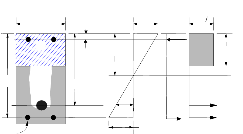
Post-Tensioned Concrete Design
Figure 14-1 Rectangular Beam Design
to safeguard against non-ductile failures (CP 3.4.4.4). In addition, the area of
compression reinforcement is calculated assuming that the neutral axis depth re-
mains at the maximum permitted value.
The design procedure used by ETABS, for both rectangular and flanged sections
(L- and T-beams), is summarized in the subsections that follow. It is assumed
that the design ultimate axial force does not exceed 0.1 fcu Ag (CP 3.4.4.1); hence
all beams are designed for major direction flexure, shear, and torsion only.
14.7.1.2.1 Design of Rectangular Beams
The amount of post-tensioning steel adequate to resist the design moment M and
minimum reinforcement are provided to satisfy the flexural cracking
requirements (CP 4.12.6).
ETABS determines the depth of the neutral axis, x, by imposing force equilib-
rium, i.e., C = T, and performs an iteration to compute the depth of the neutral
axis, which is based on stress-strain compatibility. After the depth of the neutral
BEAM
SECTION STRAIN
DIAGRAM STRESS
DIAGRAM
s
A
ε
0.67
γ
cu m
f
s
f′s
C
s
A′
ps
A
s
ε
ε
ps
s
T
cps
T
s
d
p
d
b
x
d′a
cs
T
BEAM
SECTION STRAIN
DIAGRAM STRESS
DIAGRAM
s
A
ε
0.67
γ
cu m
f
s
f′s
C
s
A′
ps
A
s
ε
ε
ps
s
T
cps
T
s
d
p
d
b
x
d′a
cs
T
14 - 12 Beam Design (for Reference Only)
Chapter 14 - Design for Singapore CP 65:99
axis has been found, the stress in the post-tensioning reinforcement, fpb, is com-
puted based on strain compatibility.
The ductility of a section is controlled by limiting the x / d ratio (CP 3.4.4.4):
−
≤
−
= <≤
−<≤
2
2
2
, for 60 N mm
0.45
, for 60 75 N mm
0.40
, for 75 105N mm
0.36
cu
cu
cu
dz f
dz
xf
dz f
(CP 3.4.4.4)
The maximum depth of the compression block is given by:
cu
cu
cu
xf
xf
xf
≤
= ≤
≤
2
2
2
0.9 for 60 N/mm
0.8 for 60 < 75 N/mm
0.72 for 75 < 105 N/mm
a
(CP 3.4.4.1(b), 4.3.7.3)
The lever arm of the section must not be greater than 0.95 times the effective
depth (CP 3.4.4.1).
z = d − 0. 5a ≤ 0.95de (CP 3.4.4.1(e))
If
max
aa≤
(CP 3.4.4.4), the moment capacity of the section, provided by post-
tensioning steel only, is computed as:
0
2
u ps pb p a
M Af d
= −
(CP 4.3.7.3)
If
max
aa>
(CP 3.4.4.4), a failure condition is declared.
If
0,>u
MM
ETABS calculates the moment capacity and the As required at the
balanced condition. The balanced condition is taken as the marginal tension-
controlled case. In that case, it is assumed that the depth of neutral axis x is equal
to cmax. The stress in the post-tensioning steel, fpb, is then calculated based on
strain compatibility for bonded tendons. For unbonded tendons, the code equa-
tions are used to compute the stress, fps, in the post-tensioning steel, and the area
Beam Design (for Reference Only) 14 - 13
Post-Tensioned Concrete Design
of required tension reinforcement, As, is determined by imposing force equilib-
rium, i.e., C = T.
ba
f
C
m
cu max
67.0
γ
=
bal bal bal
ps pb s s
T Af A f= +
bal
s
bal
pb
ps
m
cu
bal
s
f
fAba
f
A
−
=
max
67
.
0
γ
After the area of tension reinforcement has been determined, the capacity of the
section with post-tensioning steel and tension reinforcement is computed as:
max max
22
bal bal bal bal
u ps pb p s s s
aa
M Afd Afd
= −+ −
In that case, it is assumed that the bonded tension reinforcement will yield, which
is true for most cases. In the case that it does not yield, the stress in the reinforce-
ment, fs, is determined from the elastic-perfectly plastic stress-strain relationship.
This case does not involve any iteration in determining the depth of neutral axis,
x.
Case 1: Post-tensioning steel is adequate
When
0,
u
MM<
the amount of post-tensioning steel is adequate to resist the de-
sign moment M.. Minimum reinforcement is provided to satisfy the ductility re-
quirements, i.e.,
0
.
u
MM<
Case 2: Post-tensioning steel plus tension reinforcement
In this case, the amount of post-tensioning steel, Aps, alone is not sufficient to
resist M, and therefore the required area of tension reinforcement is computed to
supplement the post-tensioning steel. The combination of post-tensioning steel
and tension reinforcement should result in a < amax.
14 - 14 Beam Design (for Reference Only)
Chapter 14 - Design for Singapore CP 65:99
When
0
,
bal
uu
M MM
<<
ETABS determines the required area of tension rein-
forcement, As, iteratively to satisfy the design moment M and reports this re-
quired area of tension reinforcement. Since M is bounded by
0
u
M
at the lower
end and
bal
u
M
at the upper end and
0
u
M
is associated with
0
s
A=
and
bal
u
M
is
associated with
,
bal
ss
AA=
the required area will be between the range of 0 to
Asbal.
The tension reinforcement is to be placed at the bottom if M is positive, or at the
top if M is negative.
Case 3: Post-tensioning steel and tension reinforcement are not ade-
quate
When
,
bal
u
MM>
compression reinforcement is required (CP 3.4.4.4). In that
case, ETABS assumes that the depth of neutral axis, x, is equal to xmax. The
values of fpb and fs reach their respective balanced condition values,
bal
pb
f
and
.
bal
s
f
The area of compression reinforcement,
',
s
A
is determined as follows:
The moment required to be resisted by compression reinforcement and tension
reinforcement is:
bal
us u
M MM= −
The required compression reinforcement is given by:
( )
us
s
cu
sc
M
Af
f dd
,
0.67
γ
′=
′′
−−
where (CP 3.4.4.4)
s
f′
= εcEs
ad
a
max
max
′
−
≤ 0.87fy
The tension reinforcement for balancing the compression reinforcement is given
by:
Beam Design (for Reference Only) 14 - 15
Post-Tensioned Concrete Design
( )
0.87
=′
−
com us
s
ys
M
Afd d
Therefore, the total tension reinforcement, As =
bal
s
A
+
,
com
s
A
and the total com-
pression reinforcement is A's. As is to be placed at the bottom and A's is to be
placed at the top if M is positive, and vice versa if M is negative.
14.7.1.2.2 Design of Flanged Beams
Flanged Beam Under Negative Moment
In designing for a factored negative moment, M (i.e., designing top reinforce-
ment), the calculation of the reinforcement area is exactly the same as described
previously, i.e., no flanged beam data is used.
Flanged Beam Under Positive Moment
ETABS first determines if the moment capacity provided by the post-tensioning
tendons alone is enough. In calculating the capacity, it is assumed that As = 0. In
that case, moment capacity
0
u
M
is determined as follows:
ETABS determines the depth of the neutral axis, x, by imposing force equilib-
rium, i.e., C = T, and performs an iteration to compute the depth of the neutral
axis, which is based on stress-strain compatibility for bonded tendons. For un-
bonded tendons, the code equations are used to compute the stress, fps, in the
post-tensioning steel. After the depth of the neutral axis has been determined,
the stress in the post-tensioning steel, fpb, is computed based on strain compati-
bility.
The ductility of a section is controlled by limiting the x / d ratio (CP 3.4.4.4):
−
≤
−
= <≤
−<≤
2
2
2
, for 60 N mm
0.45
, for 60 75 N mm
0.40
, for 75 105N mm
0.36
cu
cu
cu
dz f
dz
xf
dz f
(CP 3.4.4.4)
14 - 16 Beam Design (for Reference Only)
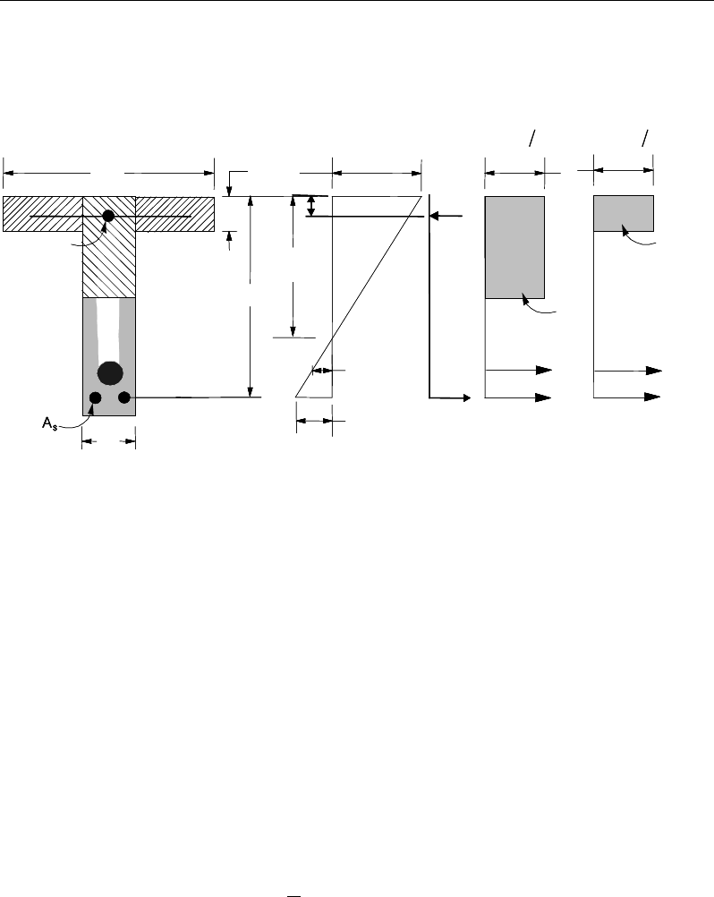
Chapter 14 - Design for Singapore CP 65:99
The maximum depth of the compression block is given by:
Figure 14-2 T-Beam Design
cu
cu
cu
xf
xf
xf
≤
= ≤
≤
2
2
2
0.9 for 60 N/mm
0.8 for 60 < 75 N/mm
0.72 for 75 < 105 N/mm
a
(CP 3.4.4.1(b), 4.3.7.3)
The lever arm of the section must not be greater than 0.95 times its effective
depth (CP 3.4.4.1):
z = d − 0.5a ≤ 0.95de (CP 3.4.4.1(e))
If
max
aa≤
(CP 3.4.4.4), the moment capacity of the section, provided by post-
tensioning steel only, is computed as:
0
2
u ps pb p a
M Af d
= −
(CP 4.3.7.3)
If
max
aa>
(CP 3.4.4.4), a failure condition is declared.
STRESS
DIAGRAM
STRAIN
DIAGRAM
BEAM
SECTION
ε
ps
s
ε
s
T
w
Tf
T
f
C
w
C
s
C
′
s
f
′
d
s
d
ε
0.67
γ
cu m
f
x
s
A′
ps
A
w
b
f
bf
h
0.67
γ
cu m
f
STRESS
DIAGRAM
STRAIN
DIAGRAM
BEAM
SECTION
ε
ps
s
ε
s
T
w
Tf
T
f
C
w
C
s
C
′
s
f
′
d
s
d
ε
0.67
γ
cu m
f
x
s
A′
ps
A
w
b
f
bf
h
0.67
γ
cu m
f
Beam Design (for Reference Only) 14 - 17

Post-Tensioned Concrete Design
If
0
,
u
MM>
ETABS calculates the moment capacity and the As required at the
balanced condition. The balanced condition is taken as the marginal tension-
controlled case. In that case, it is assumed that the depth of neutral axis x is equal
to cmax. The stress in the post-tensioning steel, fpb, is then calculated based on
strain compatibility for bonded tendons. For unbonded tendons, the code equa-
tions are used to compute the stress, fps, in the post-tensioning steel, and the area
of required tension reinforcement, As, is determined by imposing force equilib-
rium, i.e., C = T.
If a ≤ hf, the subsequent calculations for As are exactly the same as previously
defined for the rectangular beam design. However, in this case the width of
the beam is taken as bf. Compression reinforcement is required when x / d ex-
ceed the limits.
If a > hf, the calculation for As is given by
max
0.67 com
cu c
c
f
C aA
γ
=
where
com
c
A
is the area of concrete in compression, i.e.,
( )
max
com
c ff w f
A bh b a h=+−
bal bal bal
ps pb s s
T Af A f= +
bal
s
bal
pbps
com
c
m
cu
bal
s
f
fAAa
f
A
−
=
max
67.0
γ
In that case, it is assumed that the bonded tension reinforcement will yield, which
is true for most cases. In the case that it does not yield, the stress in the reinforce-
ment, fs, is determined from the elastic-perfectly plastic stress-strain relationship.
This case does not involve any iteration in determining the depth of neutral axis,
x.
Case 1: Post-tensioning steel is adequate
14 - 18 Beam Design (for Reference Only)

Chapter 14 - Design for Singapore CP 65:99
When
0
,<
u
MM
the amount of post-tensioning steel is adequate to resist the de-
sign moment M. Minimum reinforcement is provided to satisfy ductility
requirements.
Case 2: Post-tensioning steel plus tension reinforcement
In this case, the amount of post-tensioning steel, Aps, alone is not sufficient to
resist M, and therefore the required area of tension reinforcement is computed to
supplement the post-tensioning steel. The combination of post-tensioning steel
and tension reinforcement should result in a < amax.
When
0,
bal
uu
M MM<<
ETABS determines the required area of tension rein-
forcement, As, iteratively to satisfy the design moment M and reports the
required area of tension reinforcement. Since M is bounded by
0
u
M
at the lower
end and
bal
u
M
at the upper end and
0
u
M
is associated with
0
s
A=
and
bal
u
M
is
associated with
,
bal
ss
AA=
the required area will be within the range of 0 to Asbal.
The tension reinforcement is to be placed at the bottom if M is positive, or at the
top if M is negative.
Case 3: Post-tensioning steel and tension reinforcement are not ade-
quate
When
,
bal
u
MM>
compression reinforcement is required (CP 3.4.4.4). In that
case, ETABS assumes that the depth of the neutral axis, x, is equal to xmax. The
values of fpb and fs reach their respective balanced condition values,
bal
pb
f
and
.
bal
s
f
The area of compression reinforcement,
'
,
s
A
is then determined as follows:
The moment required to be resisted by compression reinforcement and tension
reinforcement is:
bal
us u
M MM= −
The required compression reinforcement is given by:
Beam Design (for Reference Only) 14 - 19
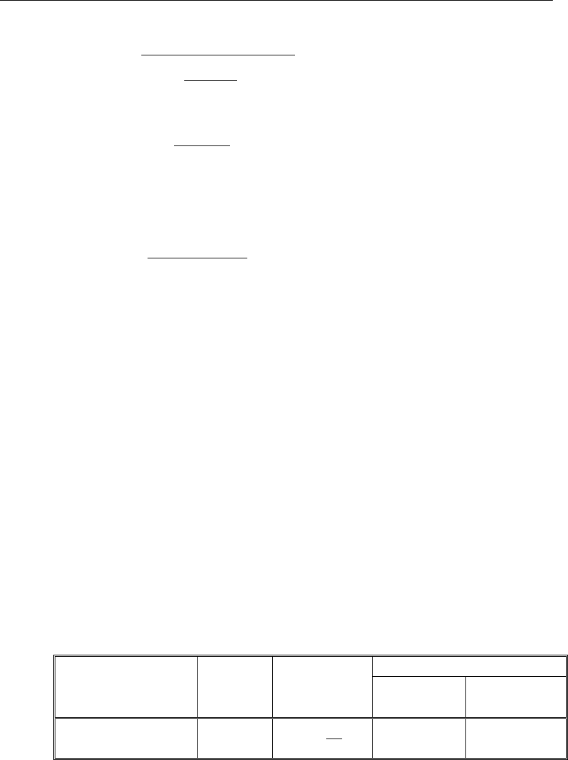
Post-Tensioned Concrete Design
( )
'
67.0
'
'
dd
f
f
M
A
c
cu
s
us
s
−
−
=
γ
, where (CP 3.4.4.4)
s
f′
= εcEs
max
max
'ad
a
−
≤ 0.87fy.
The tension reinforcement for balancing the compression reinforcement is given
by:
( )
0.87 '
com us
sys
M
Afd d
=−
Therefore, the total tension reinforcement, As =
bal
s
A
+
,
com
s
A
and the total com-
pression reinforcement is A's. As is to be placed at the bottom, and A's is to be
placed at the top if M is positive and vice versa if M is negative.
14.7.1.3 Minimum and Maximum Reinforcement
Reinforcement in post-tensioned concrete beams is computed to increase the
strength of sections as documented for the flexural design of post-tensioned
beams or to comply with the shear link requirements. The minimum flexural
tension reinforcement required for a beam section to comply with the cracking
requirements needs to be separately investigated by the user.
For bonded tendons, there is no minimum untensioned reinforcement required.
For unbonded tendons, the minimum flexural reinforcement provided in a rec-
tangular or flanged beam section is given by the following table, which is taken
from CP Table 3.27 (CP 3.12.5.3) with interpolation for reinforcement of inter-
mediate strength:
Section
Situation
Definition of
percentage
Minimum percentage
fy = 250
MPa
fy = 460
MPa
Rectangular 100
s
A
bh
0.24 0.13
14 - 20 Beam Design (for Reference Only)
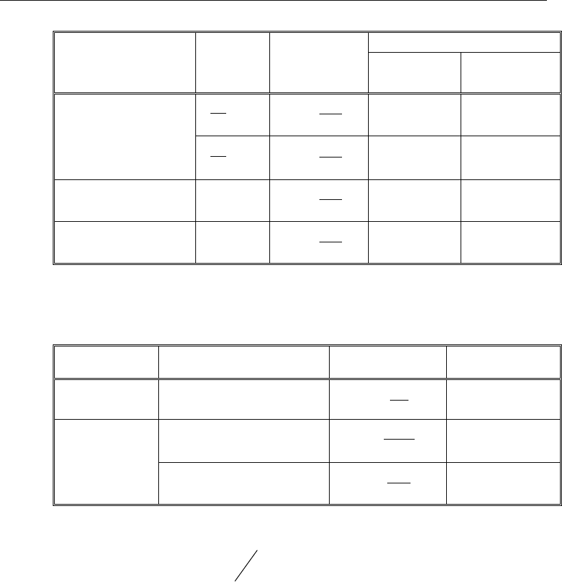
Chapter 14 - Design for Singapore CP 65:99
Section
Situation
Definition of
percentage
Minimum percentage
fy = 250
MPa
fy = 460
MPa
T- or L-Beam with
web in tension
w
f
b
b
< 0.4 100
s
w
A
bh
0.32 0.18
w
f
b
b
≥ 0.4 100
s
w
A
bh
0.24 0.13
T-Beam with web in
compression
100
s
w
A
bh
0.48 0.26
L-Beam with web in
compression
100
s
w
A
bh
0.36 0.20
The minimum flexural compression reinforcement, if it is required at all, is given
by the following table, which is taken from CP Table 3.27 (CP 3.12.5.3) with
interpolation for reinforcement of intermediate strength:
Section
Situation
Definition of
percentage
Minimum
percentage
Rectangular 100
′
s
A
bh
0.20
T- or L-Beam
Web in tension 100
′
s
ff
A
bh
0.40
Web in compression 100
′
s
w
A
bh
0.20
For fcu > 40 MPa, the minimum percentage shown in CP Table 3.27 shall be
multiplied by a factor of
2/3 .
40
cu
f
In addition, an upper limit on both the tension reinforcement and compression
reinforcement is imposed to be 0.04 times the gross cross-sectional area (CP
3.12.6.1).
Beam Design (for Reference Only) 14 - 21
Post-Tensioned Concrete Design
14.7.2 Design Beam Shear Reinforcement
The shear reinforcement is designed for each load combination in the major
direction of the beam. In designing the shear reinforcement for a particular beam
for a particular load combination, the following steps are involved (CP 3.4.5):
Determine the shear stress, v.
Determine the shear stress, vc, that can be resisted by the concrete.
Determine the shear reinforcement required to carry the balance.
The following three subsections describe in detail the algorithms associated with
these steps.
14.7.2.1 Determine Shear Stress
In the design of the beam shear reinforcement, the shear forces for a particular
load combination at a particular beam section are obtained by factoring the
associated shear forces for different load cases, with the corresponding load
combination factors.
db
V
v
w
=
(CP 3.4.5.2)
The maximum allowable shear stress, vmax is defined as:
vmax = min(0.8
,
cu
f
7 MPa) (CP 3.4.5.2)
For light-weight concrete, vmax is defined as:
vmax = min(0.63
,
cu
f
5.6 MPa) (CP 65-2 5.4)
14.7.2.2 Determine Concrete Shear Capacity
The design ultimate shear resistance of the concrete alone, Vc, should be consid-
ered at sections that are as follows:
Uncracked sections in flexure (M < Mo) (CP 4.3.8.3)
14 - 22 Beam Design (for Reference Only)
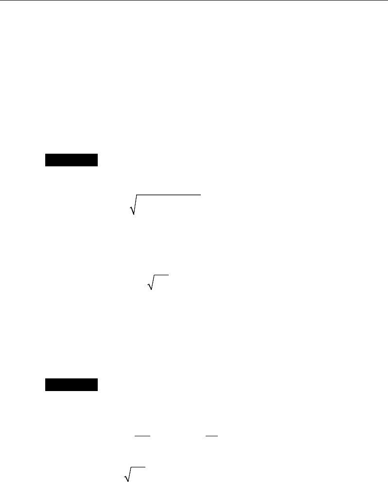
Chapter 14 - Design for Singapore CP 65:99
Cracked sections in flexural (M ≥ Mo) (CP 4.3.8.3)
where,
M is the design bending moment at the section
Mo is the moment necessary to produce zero stress in the concrete at the
extreme tension fiber; in this calculation, only 0.8 of the stress due to
post-tensioning should be taken into account.
Case 1: Uncracked section in flexure
The ultimate shear resistance of the section, Vco, is computed as follows:
( )
2
0.67 0.8 ,
co v t cp t
V bh f f f= +
(CP 4.3.8.4)
where,
ft is the maximum design principal stress (CP 4.3.8.4)
0.24
t cu
f= f
(CP 4.3.8.4)
fcp = design compressive stress at the centoidal axis due to
post-tensioning, taken as positive. (CP 4.3.8.4)
β
sinPVV co
c+=
(CP 4.3.8.4)
Case 2: Cracked section in flexure
The ultimate shear resistance of the section, Vcr, is computed as follows:
1 0.55 ,
pe
cr c v o
pu
fV
V vbd M
fM
=−+
and (CP 4.3.8.5)
0.1
cr v cu
V bd f≥
(CP 4.3.8.5)
( )
β
sin,min PVVV
crcoc
+=
(CP 4.3.8.5)
Beam Design (for Reference Only) 14 - 23
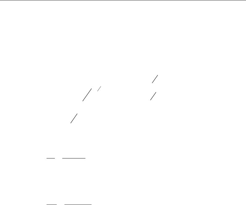
Post-Tensioned Concrete Design
14.7.2.3 Determine Required Shear Reinforcement
Given v, vc and vmax, the required shear reinforcement is calculated as follows
(CP 4.3.8.7):
Calculate the design average shear stress that can be carried by minimum shear
reinforcement, vr, as:
2
23
2
Nmm
Nmm
0.4 if 40
0.4 if 40 80
40
≤
= <≤
cu
rcu cu
f
vff
(CP 3.4.5.3, Table 3.8)
2
N
mm
80≤
cu
f
(for calculation purpose only) (CP 3.4.5.3, Table 3.8)
If
,
cr
vv v≤+
,
0.87
sr
v yv
Avb
sf
=
(CP 3.4.5.3, Table 3.8)
If
,
cr
vv v
>+
( )
0.87
c
sv
v yv
vvb
A
sf
−
=
(CP 3.4.5.3, Table 3.8)
If v > vmax, a failure condition is declared. (CP 3.4.5.2)
In the preceding expressions, a limit is imposed on fyv as:
fyv ≤ 460 MPa. (CP 3.4.5.1)
The maximum of all of the calculated Asv
/ sv values, obtained from each load
combination, is reported along with the controlling shear force and associated
load combination.
The beam shear reinforcement requirements considered by the program are
based purely on shear strength considerations. Any minimum stirrup require-
ments to satisfy spacing and volumetric considerations must be investigated
independently of the program by the user.
14 - 24 Beam Design (for Reference Only)

Chapter 14 - Design for Singapore CP 65:99
14.7.3 Design Beam Torsion Reinforcement
The torsion reinforcement is designed for each design load combination at each
station along the length of the beam. The following steps are involved in
designing the longitudinal and shear reinforcement for a particular station due to
the beam torsion:
Determine the torsional shear stress, vt.
Determine special section properties.
Determine critical torsion stress.
Determine the torsion reinforcement required.
Note that references in this section refer to CP 65:Part 2.
14.7.3.1 Determine Torsional Shear Stress
In the design of beam torsion reinforcement, the torsions for each load combina-
tion at a particular beam station are obtained by factoring the corresponding tor-
sions for different load cases, with the corresponding load combination factors.
In typical framed construction, specific consideration of torsion is not usually
required where torsional cracking is adequately controlled by shear reinforce-
ment. If the design relies on the torsional resistance of a beam, further consider-
ation should be given using the following algorithms (CP 65-2 3.4.5.13).
The torsional shear stress, vt, for a rectangular section is computed as:
( )
3/
2
minmax
2
min hhh
T
vt−
=
(CP 65-2 2.4.4.1)
For flanged sections, the section is considered as a series of rectangular
segments and the torsional shear stress is computed for each rectangular compo-
nent using the preceding equation, but considering a torsional moment
attributed to that segment, calculated as:
( )
=∑max
3
min
max
3
min
hh
hh
TTseg
(CP 65-2 2.4.4.2)
Beam Design (for Reference Only) 14 - 25
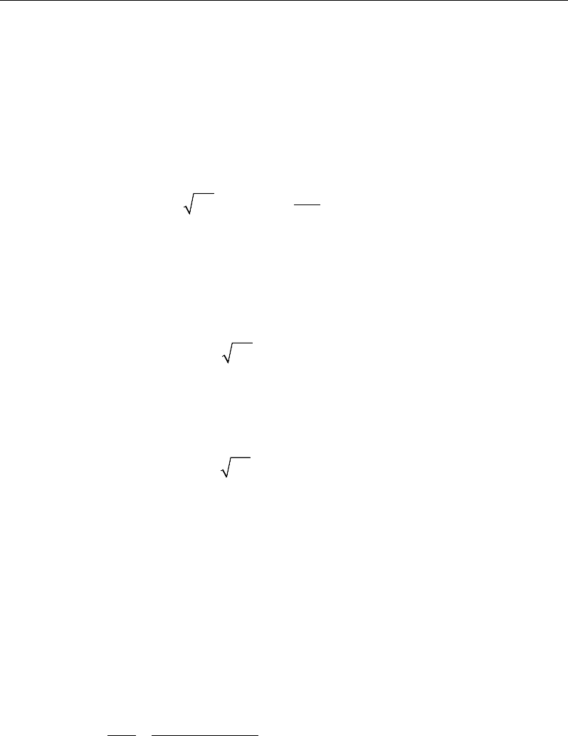
Post-Tensioned Concrete Design
h
mzx
=
Larger dimension of a rectangular section
h
min
=
Smaller dimension of a rectangular section
If the computed torsional shear stress, vt, exceeds the following limit for sections
with the larger center-to-center dimension of the closed link less than 550 mm,
a failure condition is generated if the torsional shear stress does not satisfy:
≤×
21
min(0.8 ,7N/mm ) 550
t cu y
vf
(CP 65-2 2.4.5)
14.7.3.2 Determine Critical Torsion Stress
The critical torsion stress, vt,min, for which the torsion in the section can be
ignored is calculated as:
( )
=
2
min
min 0 067 0 6N/mm
t, cu
v . f ,.
(CP 65-2 2.4.6)
where fcu is the specified concrete compressive strength.
For light-weight concrete, vt,min is defined as:
( )
2
min
min 0 067 0 4N/mm
t, cu
v . f ,.=
x 0.8 (CP 65-2 5.5)
14.7.3.3 Determine Torsion Reinforcement
If the factored torsional shear stress, vt is less than the threshold limit, vt,min, tor-
sion can be safely ignored (CP 65-2 2.4.6). In that case, the program reports that
no torsion reinforcement is required. However, if vt exceeds the threshold limit,
vt,min, it is assumed that the torsional resistance is provided by closed stirrups and
longitudinal bars (CP 65-2 2.4.6).
If vt > vt,min, the required closed stirrup area per unit spacing, Asv,t / sv, is calcu-
lated as:
( )
,
11
0.8 0.87
sv t
vyv
AT
sxy f
=
(CP 65-2 2.4.7)
and the required longitudinal reinforcement is calculated as:
14 - 26 Beam Design (for Reference Only)
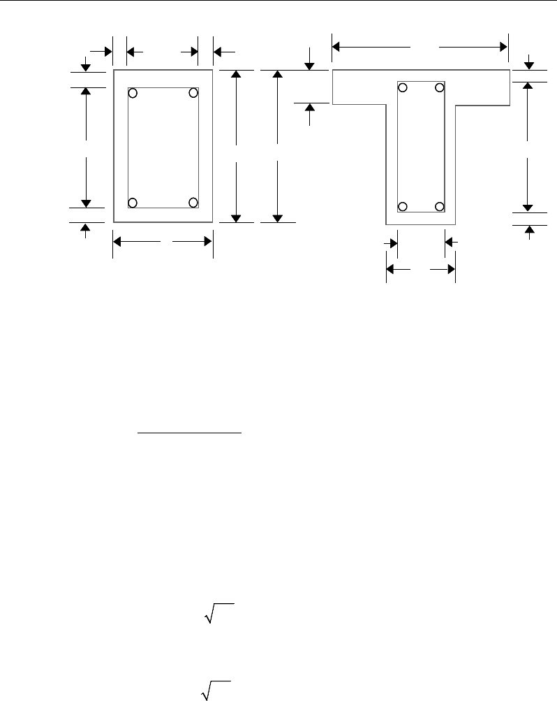
Chapter 14 - Design for Singapore CP 65:99
Figure 14-3 Closed stirrup and section dimensions for torsion design
( )
yv
yvtsv
l
fs
yxfA
A
11,
+
=
(CP 65-2 2.4.7)
In the preceding expressions, x1 is the smaller center-to-center dimension of
the closed link and y1 is the larger center-to-center dimension of the closed
link.
An upper limit of the combination of v and vt that can be carried by the section
also is checked using the equation:
( )
+≤
2
min 0 8 7N/mm
t cu
vv . f,
(CP 65-2 2.4.5)
For light-weight concrete, vmax is defined as:
vmax = min(0.63
,
cu
f
5.6 MPa) (CP 65-2 5.4)
If the combination of shear stress, v, and torsional shear stress, vt, exceeds this
limit, a failure message is declared. In that case, the concrete section should be
increased in size.
cb
w
2−
c
c
cc
c
c
cb 2−
h
s
d
Closed Stirrup in
Rectangular Beam Closed Stirrup in
T-Beam Section
ch 2−h
b
ch 2−
w
b
bf
cb
w
2−
c
c
cc
c
c
cb 2−
h
s
d
Closed Stirrup in
Rectangular Beam Closed Stirrup in
T-Beam Section
ch 2−h
b
ch 2−
w
b
bf
Beam Design (for Reference Only) 14 - 27

Post-Tensioned Concrete Design
The maximum of all of the calculated Al and Asv,t / sv values obtained from each
load combination is reported along with the controlling combination.
The beam torsion reinforcement requirements reported by the program are based
purely on strength considerations. Any minimum stirrup requirements or longi-
tudinal rebar requirements to satisfy spacing considerations must be
investigated independently of the program by the user.
14.8 Slab Design
Similar to conventional design, the ETABS slab design procedure involves
defining sets of strips in two mutually perpendicular directions. The locations of
the strips typically are governed by the locations of the slab supports. The mo-
ments for a particular strip are recovered from the analysis, and a flexural design
is carried out based on the ultimate strength design method (CP 65:99) for pre-
stressed reinforced concrete as described in the following subsections. To learn
more about the design strips, refer to the section entitled "ETABS Design Tech-
niques" in the Key Features and Terminology manual.
14.8.1 Design for Flexure
ETABS designs the slab on a strip-by-strip basis. The moments used for the
design of the slab elements are the nodal reactive moments, which are obtained
by multiplying the slab element stiffness matrices by the element nodal displace-
ment vectors. These moments will always be in static equilibrium with the ap-
plied loads, irrespective of the refinement of the finite element mesh.
The design of the slab reinforcement for a particular strip is carried out at specific
locations along the length of the strip. These locations correspond to the element
boundaries. Controlling reinforcement is computed on either side of these ele-
ment boundaries. The slab flexural design procedure for each load combination
involves the following:
Determine factored moments for each slab strip
Determine the capacity of post-tensioned sections
Design flexural reinforcement for the strip
14 - 28 Slab Design

Chapter 14 - Design for Singapore CP 65:99
These three steps are described in the subsections that follow and are repeated
for every load combination. The maximum reinforcement calculated for the top
and bottom of the slab within each design strip, along with the corresponding
controlling load combination, is obtained and reported.
14.8.1.1 Determine Factored Moments for the Strip
For each element within the design strip, for each load combination, the program
calculates the nodal reactive moments. The nodal moments are then added to get
the strip moments.
14.8.1.2 Determine Capacity of Post-Tensioned Sections
The calculation of the post-tensioned section capacity is identical to that
described earlier for rectangular beam sections.
14.8.1.3 Design Flexural Reinforcement for the Strip
The reinforcement computation for each slab design strip, given the bending mo-
ment, is identical to the design of rectangular beam sections described
earlier (or to the flanged beam if the slab is ribbed). In some cases, at a given
design section in a design strip, there may be two or more slab properties across
the width of the design strip. In that case, the program automatically designs the
tributary width associated with each of the slab properties separately using its
tributary bending moment. The reinforcement obtained for each of the tributary
widths is summed to obtain the total reinforcement for the full width of the de-
sign strip at the considered design section. This method is used when drop panels
are included. Where openings occur, the slab width is adjusted accordingly.
14.8.1.4 Minimum and Maximum Slab Reinforcement
There are no minimum requirements for untensioned reinforcement in one-way
bonded slabs. One-way spanning floors with unbounded tendons should have
minimum reinforcement requirements in accordance with CP Table 3.27 (CP
3.12.5.3)
In flat slabs, reinforcement is added at the top, over supports, to be 0.00075 times
the gross cross-sectional area. This reinforcement extends 1.5 times the slab
Slab Design 14 - 29
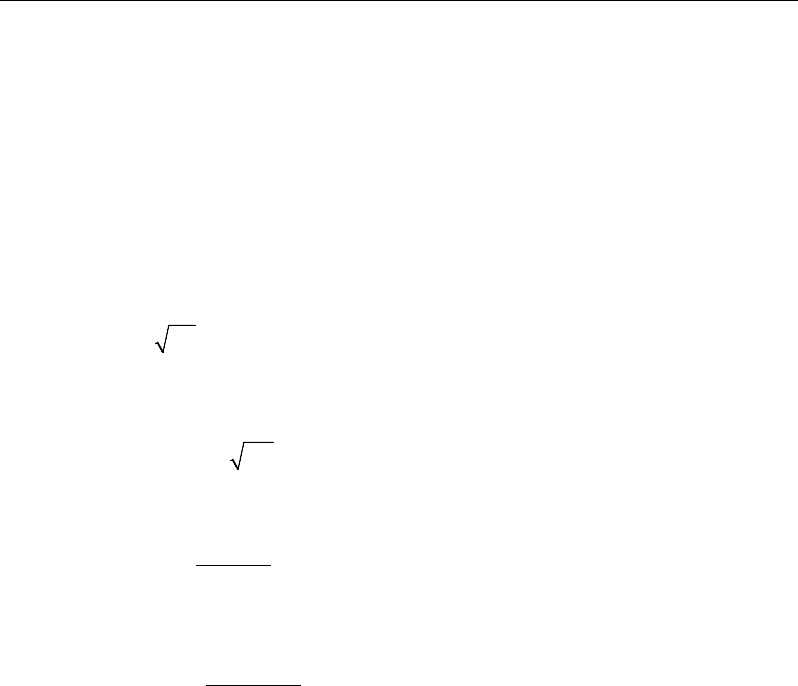
Post-Tensioned Concrete Design
depth on each side of the column. The length of the reinforcement should be at
least 0.2L, where L is the span of the slab.
There are no minimum requirements for the span zone. However, additional un-
tensioned reinforcement shall be designed for the full tension force generated by
assumed flexural tensile stresses in the concrete for the following situations
(Concrete Society, Technical Report 43):
all locations in one-way spanning floors using unbonded tendons
all locations in one-way spanning floors where transfer tensile stress exceeds
0.36
ci
f
support zones in all flat slabs
span zones in flat slabs using unbonded tendons where the tensile stress
exceeds 0.15
.
cu
f
The reinforcement should be designed to act at a stress of 5/8fy as follows:
( )
t
sy
F
A= 5/8 f
where
()
2
ct
t
f h xb
F−
= −
The value of fct will be negative in tension.
In addition, an upper limit on both the tension reinforcement and compression
reinforcement has been imposed to be 0.04 times the gross cross-sectional area
(CP 3.12.6.1).
14.8.2 Check for Punching Shear
The algorithm for checking punching shear is detailed in the section entitled
“Slab Punching Shear Check” in the Key Features and Terminology manual.
Only the code specific items are described in the following sections.
14 - 30 Slab Design
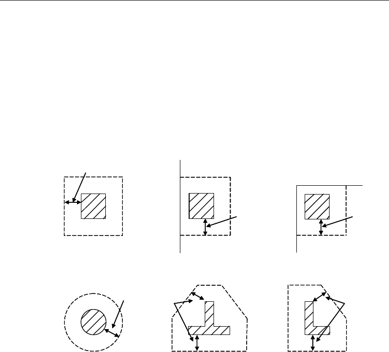
Chapter 14 - Design for Singapore CP 65:99
14.8.2.1 Critical Section for Punching Shear
The punching shear is checked at the face of the column (CP 3.7.6.4) and at a
critical section at a distance of 1.5d from the face of the support (CP 3.7.7.6).
For rectangular columns and concentrated loads, the critical area is taken as a
rectangular area with the sides parallel to the sides of the columns or the point
loads (CP 3.7.7.1). Figure 14-4 shows the auto punching perimeters considered
by ETABS for the various column shapes. The column location (i.e., interior,
edge, corner) and the punching perimeter may be overwritten using the Punching
Check Overwrites.
Figure 14-4 Punching Shear Perimeters
14.8.2.2 Determine Concrete Capacity
The design ultimate shear resistance of the concrete alone Vc should be consid-
ered at sections that are as follows:
Uncracked sections in flexure (M < Mo) (CP 4.3.8.3)
Cracked sections in flexural (M ≥ Mo) (CP 4.3.8.3)
where,
1.5d
Interior Column
Circular Column T-Shape Column
Edge Column Corner Column
L-Shape Column
1.5d 1.5d
1.5d
1.5d
1.5d
1.5d
Interior Column
Circular Column T-Shape Column
Edge Column Corner Column
L-Shape Column
1.5d 1.5d
1.5d
1.5d
1.5d
Slab Design 14 - 31
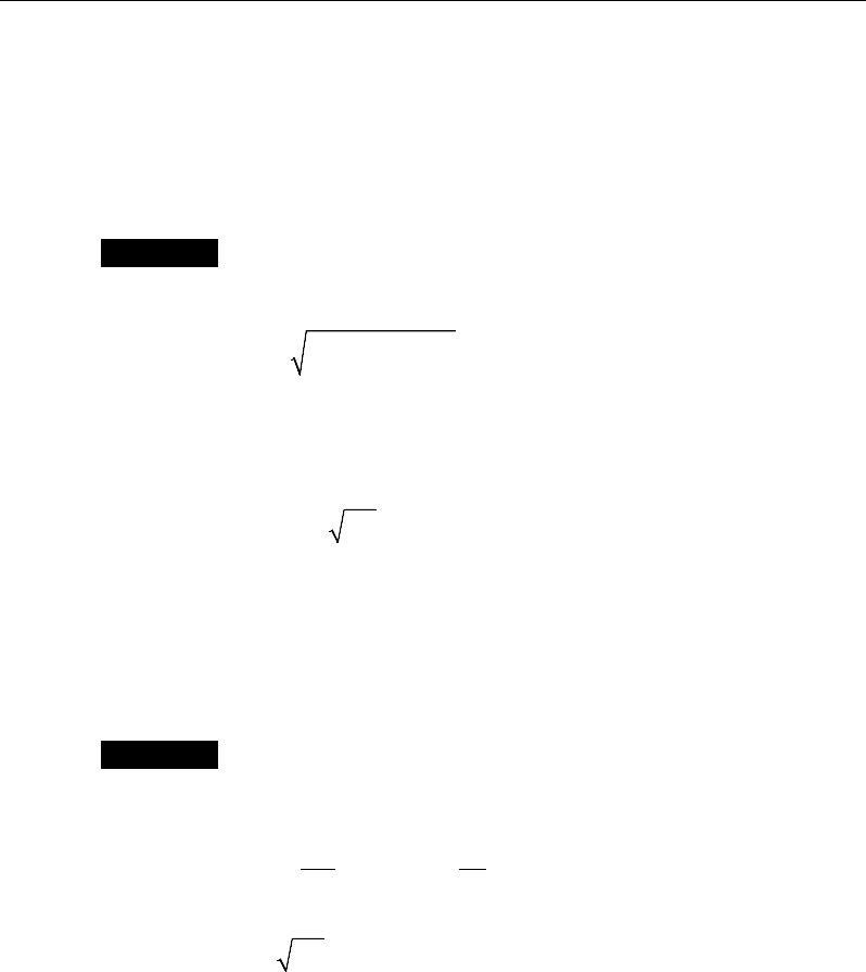
Post-Tensioned Concrete Design
M is the design bending moment at the section
Mo is the moment necessary to produce zero stress in the concrete at the
extreme tension fiber; in this calculation, only 0.8 of the stress due to
post-tensioning should be taken into account.
Case 1: Uncracked section in flexure
The ultimate shear resistance of the section, Vco, is computed as follows:
( )
0.67 0.8
2
co v t cp t
V = bh f + f f ,
(CP 4.3.8.4)
where,
ft is the maximum design principal stress (CP 4.3.8.4)
0.24
t cu
f= f
(CP 4.3.8.4)
fcp = design compressive stress at the centoidal axis
due to prestress, taken as positive. (CP 4.3.8.4)
β
sinPVV coc+=
(CP 4.3.8.4)
Case 2: Cracked section in flexure
The ultimate shear resistance of the section, Vcr, is computed as follows:
1 0.55 ,
pe
cr c v o
pu
fV
V vbd M
fM
=−+
and (CP 4.3.8.5)
0.1
cr v cu
V bd f≥
(CP 4.3.8.5)
( )
β
sin,min PVVV
crcoc
+=
(CP 4.3.8.5)
14.8.2.3 Determine Maximum Shear Stress
Given the punching shear force and the fractions of moments transferred by ec-
centricity of shear about the two axes, the nominal design shear stress, v, is cal-
culated as:
14 - 32 Slab Design

Chapter 14 - Design for Singapore CP 65:99
= +
1.5
,
Mx
V Vf
eff x Vy
(CP 3.7.6.2, 3.7.6.3)
= +
1.5
,
My
V Vf
eff y Vx
(CP 3.7.6.2, 3.7.6.3)
,
max
,
max
eff x
eff y
V
ud
vV
ud
=
(CP 3.7.7.3)
where,
u is the perimeter of the critical section,
x and y are the length of the side of the critical section parallel to the axis
of bending
Mx and My are the design moments transmitted from the slab to the column
at the connection
V is the total punching shear force
f is a factor to consider the eccentricity of punching shear force and is
taken as:
1 00 for interior columns,
1 25 for edge columns, and
1 25 for corner columns.
.
f.
.
=
(CP 3.7.6.2, 3.7.6.3)
14.8.2.4 Determine Capacity Ratio
The ratio of the maximum shear stress and the concrete punching shear stress
capacity is reported as the punching shear capacity ratio by ETABS. If this ratio
exceeds 1.0, punching shear reinforcement is designed as described in the fol-
lowing section.
Slab Design 14 - 33

Post-Tensioned Concrete Design
14.8.3 Design Punching Shear Reinforcement
The use of shear studs as shear reinforcement in slabs is permitted, provided that
the effective depth of the slab is greater than or equal to 200 mm (CP 3.7.7.5). If
the slab thickness does not meet these requirements, the punching shear rein-
forcement is not designed and the slab thickness should be increased by the user.
The algorithm for designing the required punching shear reinforcement is used
when the punching shear capacity ratio exceeds unity. The Critical Section for
Punching Shear as described in the earlier sections remains unchanged. The de-
sign of punching shear reinforcement is carried out as described in the subsec-
tions that follow.
14.8.3.1 Determine Concrete Shear Capacity
The concrete punching shear stress capacity of a section with punching shear
reinforcement is as previously determined for the punching check.
14.8.3.2 Determine Required Shear Reinforcement
The shear stress is limited to a maximum limit of
vmax = 2 vc (CP 3.7.7.5)
Given v, vc and vmax, the required shear reinforcement is calculated as follows
(CP 3.7.7.5).
If v ≤ 1.6vc ,
s
Av
=
( )
0.4 ,
0.87 0.87
c
yv yv
v v ud ud
ff
−≥
(CP 3.7.7.5)
If 1.6vc ≤ v < 2.0vc ,
v
A
s
=
( )
5 0.7 0.4 ,
0.87 0.87
c
yv yv
v v ud ud
ff
−≥
(CP 3.7.7.5)
If v > vmax, a failure condition is declared. (CP 3.7.7.5)
14 - 34 Slab Design
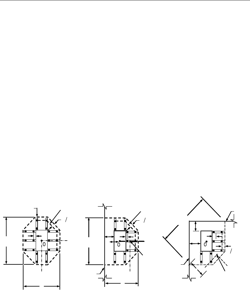
Chapter 14 - Design for Singapore CP 65:99
If v exceeds the maximum permitted value of vmax, the concrete section should
be increased in size.
14.8.3.3 Determine Reinforcement Arrangement
Punching shear reinforcement in the vicinity of rectangular columns should be
arranged on peripheral lines, i.e., lines running parallel to and at constant dis-
tances from the sides of the column. Figure 14-5 shows a typical arrangement of
shear reinforcement in the vicinity of a rectangular interior, edge, and corner
columns.
The distance between the column face and the first line of shear reinforcement
shall not exceed d / 2. The spacing between adjacent shear reinforcement in the
first line of shear reinforcement shall not exceed 1.5d measured in a direction
parallel to the column face (CP 11.12.3.3).
Punching shear reinforcement is most effective near column corners where there
are concentrations of shear stress. Therefore, the minimum number of lines of
shear reinforcement is 4, 6, and 8 for corner, edge, and interior columns respec-
tively.
Figure 14-5 Typical arrangement of shear studs and critical sections outside
shear-reinforced zone
I
y
Typical Studrail
(only first and last
studs shown)
Outermost
peripheral line
of studs
Interior Column Edge Column Corner Column
Critical section
centroid
Free
edge
Free
edge
Critical
section
centroid
Free edge
Outermost
peripheral line
of studs
I
y
I
y
yx
d2 d2
d2
x
I
x
I
x
g
y
g
x
g
0
s0
s
0
s
x
I
y
x
x
I
y
Typical Studrail
(only first and last
studs shown)
Outermost
peripheral line
of studs
Interior Column Edge Column Corner Column
Critical section
centroid
Free
edge
Free
edge
Critical
section
centroid
Free edge
Outermost
peripheral line
of studs
I
y
I
y
yx
d2 d2
d2
x
I
x
I
x
g
y
g
x
g
0
s0
s
0
s
x
I
y
x
x
Slab Design 14 - 35

Post-Tensioned Concrete Design
14.8.3.4 Determine Reinforcement Diameter, Height, and Spacing
The punching shear reinforcement is most effective when the anchorage is close
to the top and bottom surfaces of the slab. The cover of anchors should not be
less than the minimum cover specified in CP 3.3 plus half of the diameter of the
flexural reinforcement.
Punching shear reinforcement in the form of shear studs is generally available in
10-, 12-, 14-, 16-, and 20-millimeter diameters.
When specifying shear studs, the distance, so, between the column face and the
first peripheral line of shear studs should not be smaller than 0.5d. The spacing
between adjacent shear studs, g, at the first peripheral line of studs shall not
exceed 1.5d. The limit of so and the spacing, s, between the peripheral lines are
specified as:
so ≤ 0.5d (CP 3.7.7.6)
s ≤ 0.75d (CP 3.7.7.6)
g ≤ 1.5d (CP 3.7.7.6)
14 - 36 Slab Design

Chapter 15
Design for AS 3600-09
This chapter describes in detail the various aspects of the post-tensioned concrete
design procedure that is used by ETABS when the user selects the Australian
code AS 3600-2009 [AS 2009]. Various notations used in this chapter are listed
in Table 15-1. For referencing to the pertinent sections of the AS code in this
chapter, a prefix “AS” followed by the section number is used.
The design is based on user-specified load combinations. The program provides
a set of default load combinations that should satisfy the requirements for the
design of most building type structures.
English as well as SI and MKS metric units can be used for input. The code is
based on Newton-millimeter-second units. For simplicity, all equations and de-
scriptions presented in this chapter correspond to Newton-millimeter-second
units unless otherwise noted.
15.1 Notations
The following table identifies the various notations used in this chapter.
Table 15-1 List of Symbols Used in the AS 3600-09 Code
A
g
Gross area of concrete, mm2
A
l
Area of longitudinal reinforcement for torsion, mm2
Notations 15 - 1

Post-Tensioned Concrete Design
Table 15-1 List of Symbols Used in the AS 3600-09 Code
A
p
Area of prestressing steel in flexural tension zone, sq-mm
A
s
Area of tension reinforcement, mm2
A
sc
Area of compression reinforcement, mm2
A
st
Area of tension reinforcement, mm2
A
s(required)
Area of required tension reinforcement, mm2
A
sv
Area of shear reinforcement, mm2
A
sv,min
Minimum area of shear reinforcement, mm2
A
sv
/s
Area of shear reinforcement per unit length, mm2 /mm
A
sw
/s
Area of shear reinforcement per unit length consisting of
closed ties, mm2/mm
A
t
Area of a polygon with vertices at the center of longitudinal
bars at the corners of a section, mm2
s
Spacing of shear reinforcement along the length, mm
a
Depth of compression block, mm
a
b
Depth of compression block at balanced condition, mm
a
max
Maximum allowed depth of compression block, mm
b
Width of member, mm
b
ef
Effective width of flange (flanged section), mm
b
w
Width of web (flanged section), mm
c
Depth to neutral axis, mm
d
Distance from compression face to tension reinforcement,
mm
d'
Concrete cover to compression reinforcement, mm
d
o
Distance from the extreme compression fiber to the centroid
of the outermost tension reinforcement, mm
d
om
Mean value of d
o
, averaged around the critical shear perime-
ter, mm
D
Overall depth of a section, mm
D
s
Thickness of slab (flanged section), mm
15 - 2 Notations

Chapter 15 - Design for AS 3600-09
Table 15-1 List of Symbols Used in the AS 3600-09 Code
E
c
Modulus of elasticity of concrete, MPa
E
s
Modulus of elasticity of reinforcement, MPa
f
'
c
Specified compressive strength of concrete, MPa
f
'
ci
Specified compressive strength of concrete at time of initial
prestress, MPa
f
pe
Compressive stress in concrete due to effective prestress
forces only (after allowance of all prestress losses), MPa
f
p
Stress in prestressing steel at nominal flexural strength, MPa
f
pu
Specified tensile strength of prestressing steel, MPa
f
py
Specified yield strength of prestressing steel, MPa
f
ct
Characteristic principal tensile strength of concrete, MPa
f '
cf
Characteristic flexural tensile strength of concrete, MPa
f
cv
Concrete shear strength, MPa
f
sy
Specified yield strength of flexural reinforcement, MPa
f
sy,f
Specified yield strength of shear reinforcement, MPa
f '
s
Stress in the compression reinforcement, MPa
D
Overall depth of a section, mm
J
t
Torsional modulus, mm3
k
u
Ratio of the depth to the neutral axis from the compression
face, to the effective depth, d
M
u
0
Design moment resistance of a section with tendons only, N-
mm
M
u
bal
Design moment resistance of a section with tendons and the
necessary mild reinforcement to reach the balanced condi-
tion, N-mm
M
ud
Reduced ultimate strength in bending without axial force, N-
mm
M*
Factored moment at section, N-mm
N*
Factored axial load at section, N
Notations 15- 3

Post-Tensioned Concrete Design
Table 15-1 List of Symbols Used in the AS 3600-09 Code
s
Spacing of shear reinforcement along the beam, mm
T
uc
Torsional strength of section without torsional reinforcement,
N-mm
T
u.max
Maximum permitted total factored torsion at a section, N-mm
T
us
Torsion strength of section with torsion reinforcement, N-mm
T*
Factored torsional moment at a section, N-mm
u
t
Perimeter of the polygon defined by A
t
, mm
V*
Factored shear force at a section, N
V
u.max
Maximum permitted total factored shear force at a section, N
V
u.min
Shear strength provided by minimum shear reinforcement, N
V
uc
Shear force resisted by concrete, N
V
us
Shear force resisted by reinforcement, N
γ
1
Factor for obtaining depth of compression block in concrete
β
h
Ratio of the maximum to the minimum dimensions of the
punching critical section
ε
c
Strain in concrete
ε
c, max
Maximum usable compression strain allowed in extreme con-
crete fiber, (0.003 mm/mm)
ε
s
Strain in reinforcement
φ
Strength reduction factor
θ
t
Angle of compression strut for torsion, degrees
θ
v
Angle of compression strut for shear, degrees
15.2 Design Load Combinations
The design load combinations are the various combinations of the load cases for
which the structure needs to be designed. For AS 3600-09, if a structure is sub-
jected to dead (D), live (L), pattern live (PL), snow (S), wind (W), and earth-
quake (E) loads, and considering that wind and earthquake forces are reversible,
the load combinations in the following sections may need to be considered (AS
2.4.2).
15 - 4 Design Load Combinations

Chapter 15 - Design for AS 3600-09
For post-tensioned concrete design, the user can specify the prestressing load
(PT) by providing the tendon profile or by using the load balancing options in
the program. The default load combinations for post-tensioning are defined in
the following sections.
15.2.1 Initial Service Load Combination
The following load combination is used for checking the requirements at transfer
of prestress forces in accordance with AS 3600-09 clauses 2.4.2. The prestress-
ing forces are considered without any long-term loses for the initial service load
combination check.
1.0D + 1.0PT
1.15D + 1.15PT
0.9D + 1.15PT
(AS 2.4.2)
(AS 2.4.2)
(AS 2.4.2
)
15.2.2 Service Load Combination
The following load combinations are used for checking the requirements of pre-
stress for serviceability in accordance with AS 2.4.2. It is assumed that all long-
term losses have occurred already at the service stage.
1.0D + 1.0PT
1.0D + 1.0L + 1.0PT
15.2.3 Ultimate Limit State Load Combination
The following load combinations are used for checking the requirements of pre-
stress in accordance with AS 2.4.2.
The ultimate limit state combinations required for punching shear require the full
PT forces (primary and secondary). Flexural design requires only the hyperstatic
(secondary) forces. The hyperstatic (secondary) forces are determined automat-
ically by ETABS by subtracting out the primary PT moments when the flexural
design is carried out.
1.35D + 1.0PT*
(AS/NZS 1170.0-02, 4.2.2(a))
Design Load Combinations 15- 5

Post-Tensioned Concrete Design
1.2D + 1.5L + 1.0PT*
(AS/NZS 1170.0-02, 4.2.2(b))
1.2D + 1.5(0.75PL) + 1.0PT*
(AS/NZS 1170.0-02, 4.2.2(b))
1.2D + 0.4L + 1.0S + 1.0PT
*
(AS/NZS 1170.0-02, 4.2.2(g))
0.9D ± 1.0W +1.0PT*
1.2D
± 1.0W + 1.0PT*
1.2D + 0.4L
± 1.0W + 1.0PT*
(AS/NZS 1170.0-02, 4.2.2(e))
(AS/NZS 1170.0-
02, 4.2.2(d))
(AS/NZS 1170.0-
02, 4.2.2(d))
1.0D
±
1.0E + 1.0PT
*
1.0D + 0.4L
± 1.0E + 1.0PT* (AS/NZS 1170.0-02, 4.2.2(f
))
* — Replace PT with H for flexural design only
Note that the 0.4 factor on the live load in three of the combinations is not valid
for live load representing storage areas. These are also the default design load
combinations in ETABS whenever the AS 3600-2009 code is used. If roof live
load is treated separately or other types of loads are present, other appropriate
load combinations should be used.
15.3 Limits on Material Strength
The upper and lower limits of f'c are 100 MPa and 20 MPa, respectively, for all
framing types (AS 3.1.1.1(b)).
' 100MPa
c
f≤
(AS 3.1.1.1)
' 20MPa
c
f≥
(AS 3.1.1.1)
The upper limit of fsy is 500 MPa for all frames (AS 3.2.1, Table 3.2.1).
The code allows use of f'c and fsy beyond the given limits, provided special care
is taken regarding the detailing and ductility (AS 3.1.1, 3.2.1, 17.2.1.1).
ETABS enforces the upper material strength limits for flexure and shear design
of slabs. The input material strengths are taken as the upper limits if they are
defined in the material properties as being greater than the limits. The user is
responsible for ensuring that the minimum strength is satisfied.
15 - 6 Limits on Material Strength

Chapter 15 - Design for AS 3600-09
15.4 Strength Reduction Factors
The strength reduction factor,
φ
, is defined as given in the following table (AS
2.2.2, Table 2.2.2):
Type of action effect
Strength reduction factor (
φ
)
(a) Axial force without bending —
(i) Tension
(ii) Compression
0.8
0.6
(b) Bending without axial tension or compression
where:
(i) for members with Class N reinforcement only
(ii) for members with Class L reinforcement
0.6 ≤ (1.19-13 kuo /12) ≤ 0.8
0.6 ≤ (1.19-13 kuo /12) ≤ 0.64
(c) Bending with axial tension
φ
+[(0.8 −
φ
)(N
u
/N
uot
)]
φ
is obtained from (b)
(d) Bending with axial compression where:
(i) Nu ≥ Nub
(ii) Nu < Nub
0.6
0.6+ [(
φ
- 0.6)(1 − Nu/Nub)]
φ
is obtained from (b)
(e) Shear
0.7
(f) Torsion
0.7
The value Mud is the reduced ultimate strength of the cross-section in bending
where ku = 0.36 and tensile force has been reduced to balance the reduced com-
pressive forces (AS 8.1.5).
These values can be overwritten; however, caution is advised.
15.5 Design Assumptions for Prestressed Concrete Struc-
tures
Ultimate limit state of prestressed members for flexure and axial loads shall be
based on assumptions given in AS 8.1.
The strain distribution in the concrete in compression is derived from the
assumption that the plane section remains plane (AS 8.1.2.1(a)).
Tensile strength of the concrete is ignored (AS 8.1.2.1 (b)).
Strength Reduction Factors 15- 7

Post-Tensioned Concrete Design
The design stresses in the concrete in compression are taken as
2c
f
α
′
. The
maximum strain at the extreme concrete compression fiber shall be assumed
equal to 0.003 (AS 8.1.2.1 (c), 8.1.2.2).
The strain in bonded prestressing tendons and in any additional reinforcement
(compression or tension) is derived from the assumption that plane section
remains plane (AS 8.1.2.1(a)).
Prestressed concrete members are investigated at the following three stages:
At transfer of prestress force
At service loading
At nominal strength
The prestressed flexural members are classified as uncracked and cracked based
on tensile strength ft, the computed extreme fiber stress in tension in the precom-
pressed tensile zone at service loads.
The precompressed tensile zone is that portion of a prestressed member where
flexural tension, calculated using gross section properties, would occur under
unfactored dead and live loads if the prestress force was not present. Prestressed
concrete is usually designed so that the prestress force introduces compression
into this zone, thus effectively reducing the magnitude of the tensile stress.
15.6 Serviceability Requirements of Flexural Members
15.6.1 Serviceability Check at Initial Service Load
The stresses in the concrete immediately after prestress force transfer (before
time dependent prestress losses) are checked against the following limits (AS
8.1.6.2):
Extreme fiber stress in compression:
0.50
cp
f
The extreme fiber stress in tension should not exceed the cracking stress; other-
wise the section should be designed as a cracked section.
15 - 8 Serviceability Requirements of Flexural Members
Chapter 15 - Design for AS 3600-09
15.6.2 Serviceability Check at Service Load
Flexural cracking in a prestressed beam shall be deemed to be controlled if under
short-term service loads the resulting maximum tensile stress in concrete does
not exceed
0.25 ;
′
c
f
in that case, no further checks are needed (AS 8.6.2). How-
ever, if this limit is exceeded, flexural cracking shall be deemed to be controlled
by providing reinforcement or bonded tendons, or both, near the tensile face and
achieving either of the following (AS 8.6.2, 9.4.2):
(a) limiting the calculated maximum flexural tensile stress under short-term ser-
vice loads to
0.6 ;
'
c
f
or
(b) limiting both of the following
(i) the increment in steel stress near the tension face to 200 MPa, as the load
increases from its value when the extreme concrete tensile fiber is at zero
stress to the short-term service load value; and
(ii) the center-to-center spacing of reinforcement, including bonded ten-
dons, to 200 mm. (This sub clause is a detailing requirement not checked
by the program.)
The program checks the stresses in the concrete prestressed flexural members at
service loads and after all prestress losses against the following limit (AS 8.6.2):
Extreme fiber stress in tension in the
precompressed tensile zone at service loads:
– Extreme fiber stresses in tension for cracked section:
0.5
'
c
f
Thus, although cracking is allowed, it is assumed that the user is limiting the
tensile stress at the service stage as presented in AS 8.6.2.
15.7 Beam Design (for Reference Only)
Important Note: Post-tensioned beam design is not available in the current ver-
sion of ETABS, but is planned for a future release. This section is provided as
reference only for the documentation of post-tensioned slab design.
Beam Design (for Reference Only) 15- 9

Post-Tensioned Concrete Design
In the design of prestressed concrete beams, ETABS calculates and reports the
required areas of reinforcement for flexure, shear, and torsion based on the beam
moments, shear forces, torsion, load combination factors, and other criteria de-
scribed in the subsections that follow. The reinforcement requirements are cal-
culated at each station along the length of the beam.
Beams are designed for major direction flexure, shear, and torsion only. Effects
resulting from any axial forces and minor direction bending that may exist in the
beams must be investigated independently by the user.
The beam design procedure involves the following steps:
Design flexural reinforcement
Design shear reinforcement
Design torsion reinforcement
15.7.1 Design Flexural Reinforcement
The beam top and bottom flexural reinforcement is designed at each station
along the beam. In designing the flexural reinforcement for the major moment
of a particular beam, for a particular station, the following steps are involved:
Determine factored moments and axial forces
Determine required flexural reinforcement
15.7.1.1 Determine Factored Moments
In the design of flexural reinforcement of prestressed concrete beams, the
factored moments for each load combination at a particular beam station are ob-
tained by factoring the corresponding moments for different load cases, with the
corresponding load factors.
The beam is then designed for the maximum positive and maximum negative
factored moments obtained from all of the load combinations. Positive beam
moments can be used to calculate bottom reinforcement. In such cases the beam
may be designed as a rectangular or a flanged beam. Negative beam moments
15 - 10 Beam Design (for Reference Only)
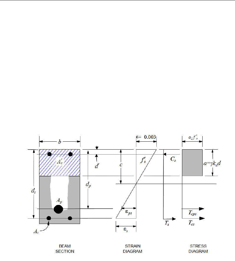
Chapter 15 - Design for AS 3600-09
can be used to calculate top reinforcement. In such cases, the beam may be de-
signed as a rectangular or inverted flanged beam.
15.7.1.2 Determine Required Flexural Reinforcement
In the flexural reinforcement design process, the program calculates both the
tension and compression reinforcement. Compression reinforcement is added
when the applied design moment exceeds the maximum moment capacity of a
singly reinforced section. The user has the option of avoiding the compression
reinforcement by increasing the effective depth, the width, or the strength of the
concrete.
The design procedure is based on the simplified rectangular stress block, as
shown in Figure 15-1 (AS 8.1.2.2).
Figure 15-1 Rectangular Beam Design
The design procedure used by ETABS for both rectangular and flanged sections
(L- and T-beams) is summarized in the following subsections. It is assumed that
the design ultimate axial force does not exceed (Ascfsy > 0.15N*) (AS 10.7.1a);
hence all beams are designed for major direction flexure, shear, and torsion only.
Beam Design (for Reference Only) 15- 11

Post-Tensioned Concrete Design
15.7.1.2.1 Design of Rectangular Beams
The amount of post-tensioning steel adequate to resist the design moment M and
minimum reinforcement are provided to satisfy the flexural cracking
requirements (AS 8.1.6.1).
ETABS determines the depth of the neutral axis, a, by imposing force equilib-
rium, i.e., C = T, and performs an iteration to compute the depth of the neutral
axis, which is based on stress-strain compatibility for bonded tendons. For un-
bonded tendons, the code equations are used to compute the stress, fps in the post-
tensioning steel. After the depth of the neutral axis has been found, the stress in
the post-tensioning reinforcement fpb is computed based on strain compatibility.
The following assumptions are applied for the stress block used to compute the
flexural bending capacity of rectangular sections (AS 8.1.2).
The maximum strain in the extreme compression fiber is taken as 0.003(AS
8.1.3(a)).
A uniform compressive stress of α2f'c acts on an area bounded by (AS
8.1.3(b)):
The edges of the cross-sections.
A line parallel to the neutral axis at the strength limit under the loading con-
cerned, and located at a distance
γ
kud from the extreme compression
fiber.
The maximum allowable depth of the rectangular compression block, amax, is
given by
max u
a kd
γ
=
where, (AS 8.1.3(b))
2
1.0 0.003 '
c
f
α
= −
where,
2
0.67 0.85≤α ≤
(AS 8.1.3(1))
1.05 0.007 '
c
f
γ= −
where,
0.67 0.85≤γ≤
(AS 8.1.3(2))
ku = 0.36 (AS 8.1.5)
If
max
aa≤
(AS 8.1.5), the moment capacity of the section, provided by post-
tensioning steel only, is computed as:
15 - 12 Beam Design (for Reference Only)
Chapter 15 - Design for AS 3600-09
0
2
= −
u pp p a
M Af d
If
max
aa>
(AS 8.1.5), a failure condition is declared.
If
0
,>
u
MM
ETABS calculates the moment capacity and the As required at the
balanced condition. The balanced condition is taken as the marginal tension con-
trolled case. In that case, it is assumed that the depth of neutral axis c is equal to
cmax. The stress in the post-tensioning steel, fp is then calculated based on strain
compatibility and the area of required tension reinforcement, As, is determined
by imposing force equilibrium, i.e., C = T.
2 max
'
c
C f ba
α
=
(AS 8.1.3)
= +
bal bal bal
pp s s
T Af A f
bal
2 c pp
bal
sbal
s
f' - A f
A= f
α
After the area of tension reinforcement has been determined, the capacity of the
section with post-tensioning steel and tension reinforcement is computed as:
max max
22
= −+ −
bal bal bal bal
u pp p s s s
aa
M Afd Afd
In that case, it is assumed that the bonded tension reinforcement will yield, which
is true for most cases. In the case that it does not yield, the stress in the reinforce-
ment, fs, is determined from the elastic-perfectly plastic stress-strain relationship.
The fy value of the reinforcement is then replaced with fs in the preceding four
equations. This case does not involve any iteration in determining the depth of
neutral axis, c.
Case 1: Post-tensioning steel is adequate
When
0,
u
MM<
the amount of post-tensioning steel is adequate to resist the de-
sign moment M.. Minimum reinforcement is provided to satisfy the ductility re-
quirements, i.e.,
0
.
u
MM<
Beam Design (for Reference Only) 15- 13

Post-Tensioned Concrete Design
Case 2: Post-tensioning steel plus tension reinforcement
In this case, the amount of post-tensioning steel, Ap, alone is not sufficient to
resist M, and therefore the required area of tension reinforcement is computed to
supplement the post-tensioning steel. The combination of post-tensioning steel
and tension reinforcement should result in a < amax.
When
0
,
bal
uu
M MM
<<
ETABS determines the required area of tension rein-
forcement, As, iteratively to satisfy the design moment M and reports this re-
quired area of tension reinforcement. Since M is bounded by
0
u
M
at the lower
end and
bal
u
M
at the upper end, and
0
u
M
is associated with
0
s
A=
and
bal
u
M
is
associated with
,
bal
ss
AA
=
the required area will fall between the range of 0 to
Asbal.
The tension reinforcement is to be placed at the bottom if M is positive, or at the
top if M is negative.
Case 3: Post-tensioning steel and tension reinforcement are not
adequate
When
,
bal
u
MM>
compression reinforcement is required (AS 8.1.5). In that
case, ETABS assumes that the depth of neutral axis, c, is equal to
max .
c
The
values of fp and fs reach their respective balanced condition values,
bal
p
f
and
.
bal
s
f
The area of compression reinforcement,
',
s
A
is determined as follows:
The moment required to be resisted by compression reinforcement and tension
reinforcement is:
bal
us u
M MM= −
The required compression reinforcement is given by:
( )( )
''
us
sc s 2c
M
Af f dd
αφ
=′
−−
, where
0.003
s s sy
cd
fE f
c
′
−
′= ≤
(AS 8.1.2.1, 3.2.2)
15 - 14 Beam Design (for Reference Only)
Chapter 15 - Design for AS 3600-09
The tension reinforcement for balancing the compression reinforcement is given
by:
( )
'
φ
=−
com us
s
ys
M
Afd d
Therefore, the total tension reinforcement, As =
bal
s
A
+
,
com
s
A
and the total com-
pression reinforcement is A's. As is to be placed at the bottom and A's is to be
placed at the top if M is positive, and vice versa if M is negative.
15.7.1.2.2 Design of Flanged Beams
Flanged Beam Under Negative Moment
In designing for a factored negative moment, M (i.e., designing top reinforce-
ment), the calculation of the reinforcement area is exactly the same as described
previously, i.e., no flanged beam data is used.
Flanged Beam Under Positive Moment
ETABS first determines if the moment capacity provided by the post-tensioning
tendons alone is enough. In calculating the capacity, it is assumed that As = 0. In
that case, moment capacity
0
u
M
is determined as follows:
ETABS determines the depth of the neutral axis, a, by imposing force equilib-
rium, i.e., C = T, and performs an iteration to compute the depth of the neutral
axis, which is based on stress-strain compatibility for bonded tendons. For un-
bonded tendons, the code equations are used to compute the stress, fps, in the
post-tensioning steel. After the depth of the neutral axis has been determined,
the stress in the post-tensioning steel, fpb, is computed based on strain compati-
bility.
The maximum allowable depth of the rectangular compression block, amax, is
given by
dka u
γ
=
max
where, ku = 0.36 (AS 8.1.5)
If
max
aa≤
(AS 8.1.5), the moment capacity of the section, provided by post-
tensioning steel only, is computed as:
Beam Design (for Reference Only) 15- 15

Post-Tensioned Concrete Design
0
2
= −
u pp p a
M Af d
If
max
aa>
(AS 8.1.5), a failure condition is declared.
If
0
,
u
MM>
ETABS calculates the moment capacity and the As required at the
balanced condition. The balanced condition is taken as the marginal tension con-
trolled case. In that case it is assumed that the depth of neutral axis c is equal to
cmax. The stress in the post-tensioning steel, fp, is then calculated based on strain
compatibility for bonded tendons. For unbonded tendons, the code equations are
used to compute the stress, fps in the post-tensioning steel, and the area of re-
quired tension reinforcement, As, is determined by imposing force equilibrium,
i.e., C = T.
If a ≤ Ds, the subsequent calculations for As are exactly the same as previously
defined for the rectangular beam design. However, in this case the width of
the beam is taken as bf. Compression reinforcement is required when
dka u
γ
=
max
where, ku = 0.36.
If a > Ds, the calculation for As is given by
max com
2c c
C fa A
α
′
=
where
com
c
A
is the area of concrete in compression, i.e.,
( )
max
com
c fs w s
A bD b a D=+−
= +
bal bal bal
pp s s
T Af A f
com bal
2 c max c p p
bal
sbal
s
fa A -A f
A= f
α
′
In that case, it is assumed that the bonded tension reinforcement will yield, which
is true for most cases. In the case that it does not yield, the stress in the reinforce-
ment, fs, is determined from the elastic-perfectly plastic stress-strain relationship.
The fy value of the reinforcement is then replaced with fs in the preceding four
equations. This case does not involve any iteration in determining the depth of
neutral axis, c.
15 - 16 Beam Design (for Reference Only)
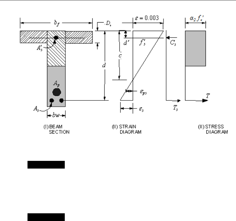
Chapter 15 - Design for AS 3600-09
Figure 15-2 T-Beam Design
Case 1: Post-tensioning steel is adequate
When
0,
<u
MM
the amount of post-tensioning steel is adequate to resist the de-
sign moment M. Minimum reinforcement is provided to satisfy ductility
requirements, i.e.,
0
.
u
MM<
Case 2: Post-tensioning steel plus tension reinforcement
In this case, the amount of post-tensioning steel, Ap, alone is not sufficient to
resist M, and therefore the required area of tension reinforcement is computed to
supplement the post-tensioning steel. The combination of post-tensioning steel
and tension reinforcement should result in a < amax.
When
0,
bal
uu
M MM<<
ETABS determines the required area of tension rein-
forcement, As, iteratively to satisfy the design moment M and reports the
required area of tension reinforcement. Since M is bounded by
0
u
M
at the lower
end and
bal
u
M
at the upper end, and
0
u
M
is associated with
0
s
A=
and
bal
u
M
is
associated with
,
bal
ss
AA=
the required area will be within the range of 0 to
s
A
.
Beam Design (for Reference Only) 15- 17

Post-Tensioned Concrete Design
The tension reinforcement is to be placed at the bottom if M is positive, or at the
top if M is negative.
Case 3: Post-tensioning steel and tension reinforcement are not
adequate
When
,
bal
u
MM
>
compression reinforcement is required. In that case, ETABS
assumes that the depth of the neutral axis, c, is equal to
max .c
The values of fp
and fs reach their respective balanced condition values,
bal
p
f
and
.
bal
s
f
The area
of compression reinforcement,
',
s
A
is then determined as follows:
The moment required to be resisted by compression reinforcement and tension
reinforcement is:
bal
us u
M MM= −
The required compression reinforcement is given by:
( )( )
,
'
us
ss 2c
M
Af f dd
φα
′=′′
−−
where
max
max
0.003
s s sy
cd
fE f
c
′
−
′= ≤
(AS 8.1.2.1, 3.2.2)
The tension reinforcement for balancing the compression reinforcement is given
by:
( )
'
φ
=−
com us
sys
M
Afd d
Therefore, the total tension reinforcement, As =
bal
s
A
+
,
com
s
A
and the total com-
pression reinforcement is A′s. As is to be placed at the bottom, and A′s is to be
placed at the top if M is positive and vice versa if M is negative.
15.7.1.3 Minimum and Maximum Reinforcement
Reinforcement in post-tensioned concrete beams is computed to increase the
strength of sections as documented for the flexural design of post-tensioned
15 - 18 Beam Design (for Reference Only)

Chapter 15 - Design for AS 3600-09
beams or to comply with the shear link requirements. The minimum flexural
tension reinforcement required for a beam section to comply with the cracking
requirements needs to be separately investigated by the user.
The ultimate strength in bending (Muo) at critical sections shall not be less than
( )
min
uo
M
given by:
( )
( )
min
1.2 /
′
= ++
uo cf g
M Z f P A Pe
(AS 8.1.6.1)
where
Z
= the section modulus of the uncracked section, referred to the extreme
fiber at which flexural cracking occurs
'
cf
f
= the characteristic flexural tensile strength of the concrete
e
= the eccentricity of the prestressing force (P), measured from the cen-
troidal axis of the uncracked section
The minimum flexural tension reinforcement required in a beam section is given
by the following limit (AS 8.1.6.1):
2,
.min
,
ct f
st b sy
f
D
A bd
df
α
′
=
where (AS 8.1.6.1(2))
20,
b
α
=
for Rectangular Section (AS8.1.6.1(2))
for L- and T-Sections with the web in tension:
1/4
0.20 1 0.4 0.18 0.20 ,
ff
s
bww
bb
D
bD b
α
=+− − ≥
(AS8.1.6.1(2))
for L- and T-Sections with the flange in tension:
2/3
0.20 1 0.25 0.08 0.20 ,
ff
s
bww
bb
D
bD b
α
=+− − ≥
(AS8.1.6.1(2))
Beam Design (for Reference Only) 15- 19

Post-Tensioned Concrete Design
,
' 0.6 '
ct f c
ff=
(AS 3.1.1.3(b))
An upper limit of 0.04 times the gross web area on both the tension reinforce-
ment and the compression reinforcement is imposed upon request as follows:
Rectangular beam
Flanged beam
Rectangular beam
Flanged beam
st
w
sc
w
0.04bd
A0.04b d
0.04bd
A0.04b d
≤
≤
15.7.2 Design Beam Shear Reinforcement
The shear reinforcement is designed for each load combination in the major
direction of the beam. In designing the shear reinforcement for a particular beam
for a particular load combination, the following steps are involved.
Determine the factored shear force, V*
Determine the shear force, Vuc, that can be resisted by the concrete
Determine the shear reinforcement required to carry the balance
The following three subsections describe in detail the algorithms associated with
these steps.
15.7.2.1 Determine Shear Force
In the design of the beam shear reinforcement, the shear forces for each load
combination at a particular beam station are obtained by factoring the corre-
sponding shear forces for different load cases with the corresponding load com-
bination factors.
15.7.2.2 Determine Concrete Shear Capacity
The ultimate shear strength (Vuc) of a prestressed beam, excluding the contribu-
tion of shear reinforcement, is the lesser of the values obtained from the follow-
ing, unless the cross-section under consideration is cracked in flexure, in which
case only Flexural-Shear Cracking, Item (a), applies:
15 - 20 Beam Design (for Reference Only)
Chapter 15 - Design for AS 3600-09
(a) Flexural-Shear Cracking
( )
+
13
st pt
uc 1 2 3 v o cv o v
wo
A +A
V=β β β b d f' V + P
bd
(AS 8.2.7.2(a))
where,
( )
MPa
1/3
''4
cv c
ff= ≤
(AS 8.2.7.1)
1.
1
1000
6
.1
1
.1
1≥
−= o
d
β
(AS 8.2.7.1)
β2 = 1, or (AS 8.2.7.1)
=
0
5.
3
1*≥
−
g
A
N
for members subject to significant axial tension, or
=
+
g
A
N
14
1*
for members subject to significant axial compression.
β3 = 1
o
o**
M
V=M /V
= the shear force that would occur at the section when the
bending moment at that section was equal to the decompression mo-
ment (Mo) given by:
o cp.f
M =Zσ
where
cp.f
σ
= the compressive stress because of prestress, at the ex-
treme fiber where cracking occurs
b) Web-shear cracking
Beam Design (for Reference Only) 15- 21

Post-Tensioned Concrete Design
uc t v
V VP= +
(AS 8.2.7.2(b))
where
Vt = the shear force, which, in combination with the prestressing force and
other action effects at the section would produce a principal tensile
stress of
0.33 c
f′
at either the centroidal axis or the intersection of
flange and web, whichever is the more critical.
Where significant reversal of loads may occur, causing cracking in a zone
usually in compression, the value of
uc
V
obtained from Clause 8.2.7.1 may not
apply.
15.7.2.3 Determine Required Shear Reinforcement
The shear force is limited to a maximum of:
min
06
u, uc v o
V V . bd= +
(AS 8.2.9)
max
02
u, c o
V . f ' bd=
+ Pv (AS 8.2.6)
Given V*, Vuc, and Vu.max, the required shear reinforcement is calculated as fol-
lows, where,
φ
, the strength reduction factor, is 0.75 by default (AS 2.2.2).
If
*
/2,
uc
VV
φ
≤
0
sv
A,
s=
if D ≤ 750 mm, otherwise Asv.min shall be provided. (AS 8.2.5).
If
( )
*.min
/2 ,
uc u
V VV
φφ
<≤
0,
sv
A
s=
if D < bw /2 or 250 mm, whichever is greater (AS 8.2.5(c)(i)),
otherwise Asv.min shall be provided.
If
*
.min .max ,
uu
V VV
φφ
<≤
15 - 22 Beam Design (for Reference Only)

Chapter 15 - Design for AS 3600-09
( )
*
.
,
cot
uc
sv
sy f o v
VV
A
s fd
φ
θ
−
=
(AS 8.2.10)
and greater than Asv.min, defined as:
=
fsy
wsv
f
b
s
A
.
min.35.0
(AS 8.2.8)
θ
v = the angle between the axis of the concrete compression strut and the lon-
gitudinal axis of the member, which varies linearly from 30 degrees when
V*=
φ
Vu.min to 45 degrees when V*=
φ
Vu,max.
If
*max
,VV
φ
>
a failure condition is declared. (AS 8.2.6)
If V* exceeds its maximum permitted value
φ
Vmax, the concrete section size
should be increased (AS 8.2.6).
Note that if torsion design is considered and torsion reinforcement is required,
the calculated shear reinforcement is ignored. Closed stirrups are designed for
combined shear and torsion in accordance with AS 8.3.4(b).
The maximum of all of the calculated Asv
/s values obtained from each load com-
bination is reported along with the controlling shear force and associated load
combination.
The beam shear reinforcement requirements considered by the program are
based purely on shear strength considerations. Any minimum stirrup require-
ments to satisfy spacing and volumetric considerations must be investigated in-
dependently of the program by the user.
15.7.3 Design Beam Torsion Reinforcement
The torsion reinforcement is designed for each design load combination at each
station along the length of the beam. The following steps are involved in design-
ing the longitudinal and shear reinforcement for a particular station due to the
beam torsion:
Determine the factored torsion, T*.
Beam Design (for Reference Only) 15- 23

Post-Tensioned Concrete Design
Determine special section properties.
Determine critical torsion capacity.
Determine the torsion reinforcement required.
15.7.3.1 Determine Factored Torsion
In the design of beam torsion reinforcement, the torsions for each load combina-
tion at a particular beam station are obtained by factoring the corresponding tor-
sions for different load cases, with the corresponding load combination factors.
In a statically indeterminate structure where redistribution of the torsion in a
member can occur due to redistribution of internal forces upon cracking, the de-
sign T* is permitted to be reduced in accordance with the code (AS 8.3.2). How-
ever, the program does not automatically redistribute the internal forces and re-
duce T*. If redistribution is desired, the user should release the torsional degree
of freedom (DOF) in the structural model.
15.7.3.2 Determine Special Section Properties
For torsion design, special section properties such as At, Jt, and ut are calculated.
These properties are described in the following (AS 8.3).
A
t
=
Area of a polygon with vertices at the center of longitudinal
bars at the corners of the cross-section
u
t
=
Perimeter of the polygon defined by A
t
J
t
=
Torsional modulus
In calculating the section properties involving reinforcement, such as Asw/s and
Al, it is assumed that the distance between the centerline of the outermost closed
stirrup and the outermost concrete surface is 50 mm. This is equivalent to 38-
mm clear cover and a 12-mm-diameter stirrup. For torsion design of flanged
beam sections, it is assumed that placing torsion reinforcement in the flange area
is inefficient. With this assumption, the flange is ignored for torsion reinforce-
ment calculation. However, the flange is considered during Tuc calculation. With
this assumption, the special properties for a rectangular beam section are given
as:
15 - 24 Beam Design (for Reference Only)
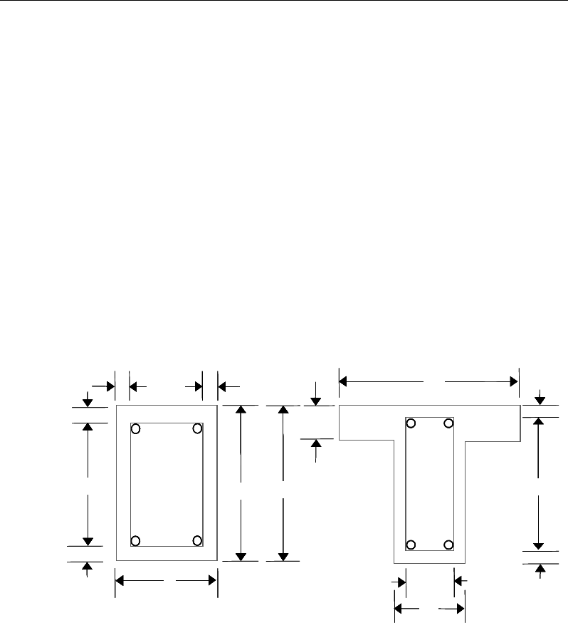
Chapter 15 - Design for AS 3600-09
A
t
=
()( )
2 2,bchc
−−
(AS 8.3.5)
u
t
=
( ) ( )
2222,bc hc−+ −
(AS 8.3.6)
J
t
=
0.33x2y (AS 8.3.3)
where, the section dimensions b, h and, c are shown in Figure 15-3. Similarly,
the special section properties for a flanged beam section are given as:
A
t
=
( )( )
2 2,
w
b ch c−−
(AS 8.3.5)
u
t
=
( ) ( )
2 2 2 2,
c wc
hb−+ −
(AS 8.3.6)
J
t
=
0.33Σx2y (AS 8.3.3)
where the section dimensions bw, h, and c for a flanged beam are shown in Figure
15-3. The values x and y refer to the smaller and larger dimensions of a compo-
nent rectangle, respectively.
Figure 15-3 Closed stirrup and section dimensions for torsion design
cb 2
h
s
d
Closed Stirrup in
Rectangular Beam
Closed Stirrup in
T-Beam Section
ch 2
−h
b
ch 2
−
w
b
Closed Stirrup in
Rectangular Beam
Closed Stirrup in
T-Beam Section
ch 2
−ch 2
−
s
D
ef
b
hh
b
c
c
c
c
c
c
b 2c−
w
b 2c−
w
b
c
b2
h
s
d
Closed Stirrup in
Rectangular Beam
Closed Stirrup in
T-Beam Section
ch 2
−h
b
ch 2
−
w
b
Closed Stirrup in
Rectangular Beam
Closed Stirrup in
T-Beam Section
ch 2
−ch 2
−
s
D
ef
b
hh
b
c
c
c
c
c
c
b 2c−
w
b 2c
−
w
b
Beam Design (for Reference Only) 15- 25
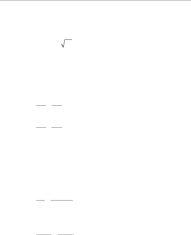
Post-Tensioned Concrete Design
15.7.3.3 Determine Torsion Reinforcement
The torsional strength of the section without torsion reinforcement, Tuc, is calcu-
lated as:
0.3 ′
uc t
T= J f
c
(AS 8.3.5)
where Jt is the torsion modulus of the concrete cross-section as described in
detail in the previous section
Torsion reinforcement also can be ignored if any one of the following is satisfied:
uc
TT
φ
25.0
*
≤
(AS 8.3.4(a)(i))
5.0
**
≤+
ucuc
V
V
T
T
φφ
(AS 8.3.4(a)(ii))
1
**
≤+
ucuc
V
V
T
T
φφ
and D ≤ max(250mm, b/2) (AS 8.3.4(a)(iii))
If the factored torsion T* alone or in combination with V* does not satisfy any of
the preceding three conditions, torsion reinforcement is needed. It is assumed
that the torsional resistance is provided by closed stirrups and longitudinal bars
(AS 8.3).
If T* > Tcr, the required closed stirrup area per unit spacing, Asw /s, is calculated
as:
tfsy
tsw
Af
T
s
A
.
*
2
tan
φ
θ
=
(AS 8.3.5(b))
where, the minimum value of Asw /s is taken as follows:
fsy
wsw
f
b
s
A
.
min.
35.0
=
(AS 8.2.8)
The value θt is the angle between the axis of the concrete compression strut and
the longitudinal axis of the member, which varies linearly from 30 degrees when
T* =
φ
Tuc to 45 degrees when T* =
φ
Tu,max.
15 - 26 Beam Design (for Reference Only)
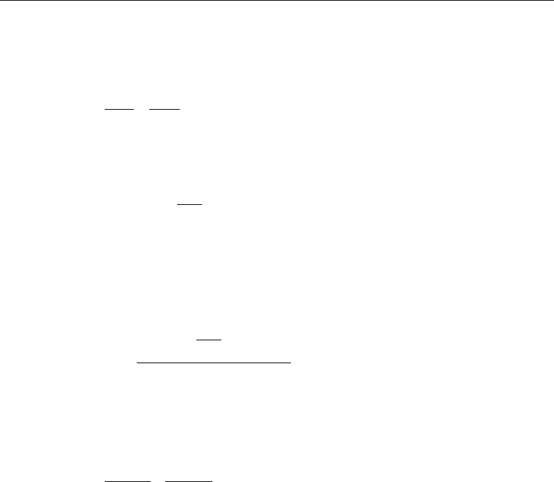
Chapter 15 - Design for AS 3600-09
The following equation shall also be satisfied for combined shear and torsion by
adding additional shear stirrups.
0
.
1
**
≤+
usus
V
V
T
T
φφ
(AS 8.3.4(b))
where,
tt
sw
fsyus A
s
A
fT
θ
cot2
.
=
(AS 8.3.5(b))
( )
vofsysvus sdfAV
θ
cot/
.
=
(AS 8.2.10(a))
The required longitudinal rebar area is calculated as:
sy
tt
sw
fsy
l
f
u
s
A
f
A
θ
2
.
cot5.0
=
(AS 8.3.6(a))
An upper limit of the combination of V* and T* that can be carried by the section
also is checked using the equation:
0.1
max.
*
max.
*
≤+
uu
V
V
T
T
φφ
(AS 8.3.3)
where,
owcu
dbfV '2.0
max.
=
(AS 8.2.6)
tcu JfT '2.
0
max.=
(AS 8.3.5(a))
For rectangular sections, bw is replaced with b. If the combination of V* and T*
exceeds this limit, a failure message is declared. In that case, the concrete section
should be increased in size.
When torsional reinforcement is required (T* > Tcr), the area of transverse closed
stirrups and the area of regular shear stirrups satisfy the following limit.
Beam Design (for Reference Only) 15- 27

Post-Tensioned Concrete Design
fsy
swsv
f
b
s
A
s
A
.
35
.0
2≥
+
(AS 8.3.7, 8.2.8)
If this equation is not satisfied with the originally calculated Asv/s and Asw/s, Asv/s
is increased to satisfy this condition. In that case, Asv/s does not need to satisfy
AS Section 8.2.8 independently.
The maximum of all of the calculated Al and Asv/s values obtained from each
load combination is reported along with the controlling combination.
The beam torsion reinforcement requirements reported by the program are based
purely on strength considerations. Any minimum stirrup requirements and lon-
gitudinal rebar requirements to satisfy spacing considerations must be investi-
gated independently of the program by the user.
15.8 Slab Design
Similar to conventional design, the ETABS slab design procedure involves
defining sets of strips in two mutually perpendicular directions. The locations of
the strips typically are governed by the locations of the slab supports. The mo-
ments for a particular strip are recovered from the analysis, and a flexural design
is carried out based on the ultimate strength design method (AS 3600-09) for
prestressed reinforced concrete as described in the following subsections. To
learn more about the design strips, refer to the section entitled "ETABS Design
Techniques" in the Key Features and Terminology manual.
15.8.1 Design for Flexure
ETABS designs the slab on a strip-by-strip basis. The moments used for the
design of the slab elements are the nodal reactive moments, which are obtained
by multiplying the slab element stiffness matrices by the element nodal displace-
ment vectors. These moments will always be in static equilibrium with the ap-
plied loads, irrespective of the refinement of the finite element mesh.
The design of the slab reinforcement for a particular strip is carried out at specific
locations along the length of the strip. These locations correspond to the element
15 - 28 Slab Design

Chapter 15 - Design for AS 3600-09
boundaries. Controlling reinforcement is computed on either side of these ele-
ment boundaries. The slab flexural design procedure for each load combination
involves the following:
Determine factored moments for each slab strip
Determine the capacity of post-tensioned sections
Design flexural reinforcement for the strip
These three steps are described in the subsections that follow and are repeated
for every load combination. The maximum reinforcement calculated for the top
and bottom of the slab within each design strip, along with the corresponding
controlling load combination, is obtained and reported.
15.8.1.1 Determine Factored Moments for the Strip
For each element within the design strip, for each load combination, the program
calculates the nodal reactive moments. The nodal moments are then added to get
the strip moments.
15.8.1.2 Determine Capacity of Post-Tensioned Sections
The calculation of the post-tensioned section capacity is identical to that
described earlier for rectangular beam sections.
15.8.1.3 Design Flexural Reinforcement for the Strip
The reinforcement computation for each slab design strip, given the bending mo-
ment, is identical to the design of rectangular beam sections described
earlier (or to the flanged beam if the slab is ribbed). Where the slab properties
(depth and so forth) vary over the width of the strip, the program automatically
designs slab widths of each property separately for the bending moment to which
they are subjected before summing up the reinforcement for the full width. This
method is used when drop panels are included. Where openings occur, the slab
width is adjusted accordingly.
Slab Design 15- 29
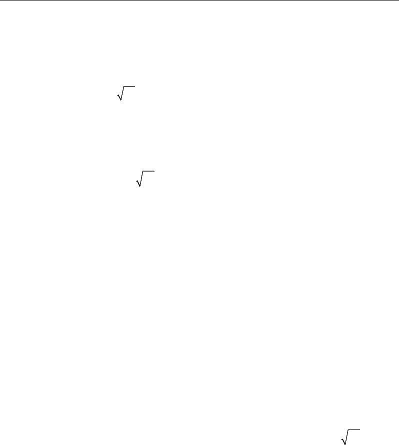
Post-Tensioned Concrete Design
15.8.1.4 Minimum and Maximum Slab Reinforcement
The minimum requirements for untensioned reinforcement in one-way bonded
slabs is the same as for beams (AS 9.1.1). Flexural cracking in prestressed slabs
shall be deemed controlled if under short-term service loads the resulting stress
is less than
0.25 ;
′
c
f
in that case, no further checks are needed (AS 9.4.2). How-
ever, if that limit is exceeded, flexural cracking shall be deemed under control
by providing reinforcement or bonded tendons, or both, near the tensile face and
accomplishing either of the following (AS 9.4.2):
(a) limiting the calculated maximum flexural tensile stress under short-term ser-
vice loads to
0.6 ;
'
c
f
or
(b) limiting both of the following:
(i) the increment in steel stress near the tension face to 200 MPa, as the load
increases from its value when the extreme concrete tensile fiber is at zero
stress to the short-term service load value; and
(ii) the center-to-center spacing of reinforcement, including bonded ten-
dons, to 300 mm. (This sub clause is a detailing requirement that is not
checked by the program.)
The program checks the stresses in the concrete prestressed flexural members at
service loads and after all prestress losses have occurred against the following
limit (AS 9.4.2):
Extreme fiber stress in tension in the precompressed tensile zone at service
loads:
– Extreme fiber stresses in tension for cracked section:
0.6
'
c
f
Thus, although cracking is allowed, it is assumed that the user is limiting the
tensile stress at the service stage as presented in AS 9.4.2.
In addition, an upper limit on both the tension reinforcement and compression
reinforcement has been imposed to be 0.04 times the gross cross-sectional area.
15 - 30 Slab Design
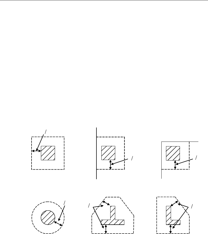
Chapter 15 - Design for AS 3600-09
15.8.2 Check for Punching Shear
The algorithm for checking punching shear is detailed in the section entitled
“Slab Punching Shear Check” in the Key Features and Terminology manual.
Only the code specific items are described in the following sections.
15.8.2.1 Critical Section for Punching Shear
The punching shear is checked on a critical section at a distance of dom /2 from
the face of the support (AS 9.2.1.1). For rectangular columns and concentrated
loads, the critical area is taken as a rectangular area with the sides parallel to the
sides of the columns or the point loads (AS 9.2.1.3). Figure 15-4 shows the auto
punching perimeters considered by ETABS for the various column shapes. The
column location (i.e., interior, edge, corner) and the punching perimeter may be
overwritten using the Punching Check Overwrites.
Figure 15-4 Punching Shear Perimeters
d2
Interior Column
Circular Column
d2 d2
d2
T-Shape Column
Edge Column Edge Column
L-Shape Column
d2
d2
d2
Interior Column
Circular Column
d2 d2
d2
T-Shape Column
Edge Column Edge Column
L-Shape Column
d2
d2
Slab Design 15- 31
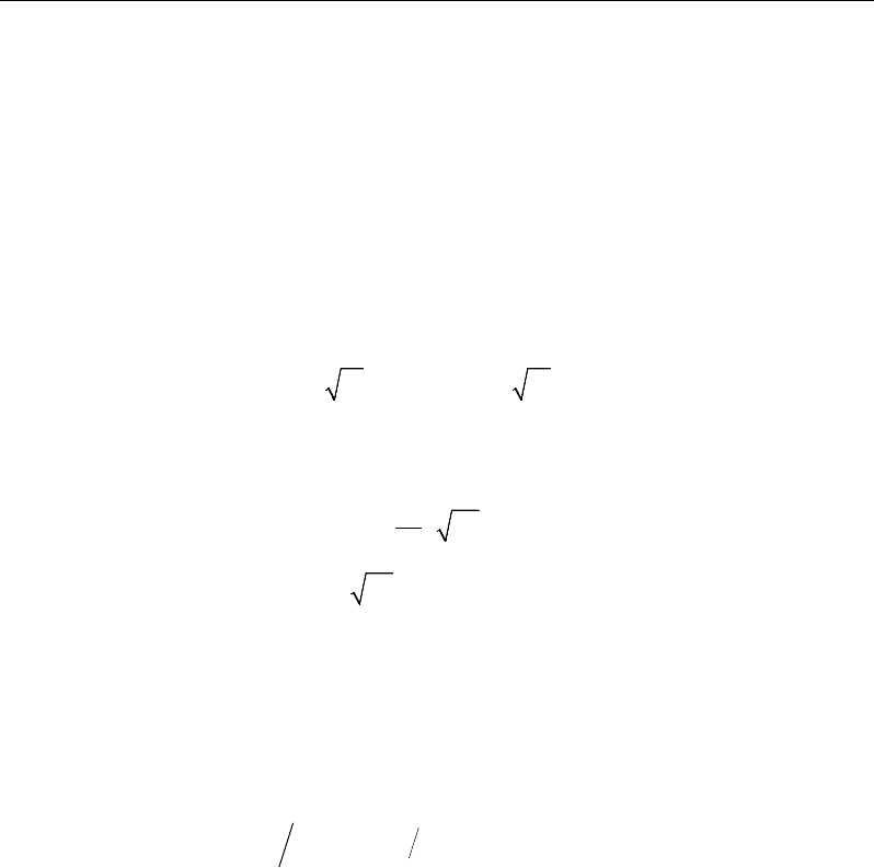
Post-Tensioned Concrete Design
15.8.2.2 Determine Concrete Capacity
(i) The ultimate shear strength of a slab where
*
v
M
is zero,
uo
V
, is given as (AS
9.2.3(a)):
a. when no shear link/stud is present
( )
0.3
uo om cv cp
V ud f
σ
= +
(AS 9.2.3(a))
b. when shear link/stud is present
( )
0.5 0.3 0.2
uo om c cp c om
V ud f f ud
σ
′′
= +≤
(AS 9.2.3(b))
where
cv
f
is taken as the minimum of the following two limits:
2
0.17 1
min
0.34
c
h
cv
c
f
f
f
′
+
β
=
′
(AS 9.2.3(a))
where,
β
h is the ratio of the longest to the minimum dimensions of the critical
section.
(ii) The ultimate shear strength of a slab where
*
v
M
is not zero and no shear
reinforcement is provided,
u
V
, is given as (AS 9.2.4(a)):
()
*
1.0 8
u uo v om
V V uM V ad
= +
(AS 9.2.4(a))
15.8.2.3 Determine Capacity Ratio
Given the punching shear force and the fractions of moments transferred by ec-
centricity of shear about the two axes, the shear stress is computed assuming
linear variation along the perimeter of the critical section. The ratio of the max-
imum shear stress and the concrete punching shear stress capacity is reported by
ETABS.
15 - 32 Slab Design

Chapter 15 - Design for AS 3600-09
15.8.3 Design Punching Shear Reinforcement
The design guidelines for shear links or shear studs are not available in AS 3600-
2009. ETABS uses the NZS 3101-06 guidelines to design shear studs or shear
links.
The use of shear studs as shear reinforcement in slabs is permitted, provided that
the effective depth of the slab is greater than or equal to 150 mm and not less
than 16 times the shear reinforcement bar diameter (NZS 12.7.4.1). If the slab
thickness does not meet these requirements, the punching shear reinforcement is
not designed, and the slab thickness should be increased by the user.
The algorithm for designing the required punching shear reinforcement is used
when the punching shear capacity ratio exceeds unity. The Critical Section for
Punching Shear and Transfer of Unbalanced Moment as described in the earlier
sections remain unchanged. The design of punching shear reinforcement is car-
ried out as described in the subsections that follow.
15.8.3.1 Determine Concrete Shear Capacity
The concrete punching shear stress capacity of a section with punching shear
reinforcement is as previously determined for the punching check.
15.8.3.2 Determine Required Shear Reinforcement
The shear force is limited to a maximum of:
Vmax = 3 Vu,min = 3×Vu (AS 9.2.4(a), (d))
Where Vu is computed from AS 9.2.3 or 9.2.4. Given V*, Vu, and Vu,max, the
required shear reinforcement is calculated as follows, where,
φ
, is the strength
reduction factor.
( )
φ
−
=
*
,
u
sv
sy om
VV
A
s fd
(AS 8.2.10)
Minimum punching shear reinforcement should be provided such that:
Slab Design 15- 33
Post-Tensioned Concrete Design
1'
16
s c om
V f ud≥
(NZS 12.7.4.3)
If V* >
φ
Vmax, a failure condition is declared. (NZS 12.7.3.4)
If V* exceeds the maximum permitted value of
φ
Vmax, the concrete section
should be increased in size.
15.8.3.3 Determine Reinforcement Arrangement
Punching shear reinforcement in the vicinity of rectangular columns should be
arranged on peripheral lines, i.e., lines running parallel to and at constant dis-
tances from the sides of the column. Figure 15-5 shows a typical arrangement of
shear reinforcement in the vicinity of a rectangular interior, edge, and corner
column.
The distance between the column face and the first line of shear reinforcement
shall not exceed d/2. The spacing between adjacent shear reinforcement in the
first line (perimeter) of shear reinforcement shall not exceed 2d measured in a
direction parallel to the column face (NZS 12.7.4.4).
Figure 15-5 Typical arrangement of shear studs
and critical sections outside shear-reinforced zone
Punching shear reinforcement is most effective near column corners where there
are concentrations of shear stress. Therefore, the minimum number of lines of
I
y
Typical Studrail
(only first and last
studs shown)
Outermost
peripheral line
of studs
Interior Column Edge Column Corner Column
Critical section
centroid
Free
edge
Free
edge
Critical
section
centroid
Free edge
Outermost
peripheral line
of studs
I
y
I
y
yx
d2 d2
d2
x
I
x
I
x
g
y
g
x
g
0
s0
s0
s
x
I
y
xx
I
y
Typical Studrail
(only first and last
studs shown)
Outermost
peripheral line
of studs
Interior Column Edge Column Corner Column
Critical section
centroid
Free
edge
Free
edge
Critical
section
centroid
Free edge
Outermost
peripheral line
of studs
I
y
I
y
yx
d2 d2
d2
x
I
x
I
x
g
y
g
x
g
0
s0
s0
s
x
I
y
xx
15 - 34 Slab Design

Chapter 15 - Design for AS 3600-09
shear reinforcement is 4, 6, and 8, for corner, edge, and interior columns respec-
tively.
15.8.3.4 Determine Reinforcement Diameter, Height, and Spacing
The punching shear reinforcement is most effective when the anchorage is close
to the top and bottom surfaces of the slab. The cover of anchors should not be
less than the minimum cover specified in NZS 3.11 plus half of the
diameter of the flexural reinforcement.
When specifying shear studs, the distance, so, between the column face and the
first peripheral line of shear studs should not be smaller than 0.5d. The spacing
between adjacent shear studs, g, at the first peripheral line of studs shall not ex-
ceed 2d and in the case of studs in a radial pattern, the angle between adjacent
stud rails shall not exceed 60 degrees. The limits of so and the spacing, s, between
the peripheral lines are specified as:
so ≤ 0.5d (NZS 12.7.4.4)
s ≤ 0.5d (NZS 12.7.4.4)
g ≤ 2d (NZS 12.7.4.4)
Slab Design 15- 35

Chapter 16
Design for ACI 318-11
This chapter describes in detail the various aspects of the post-tensioned concrete
design procedure that is used by ETABS when the user selects the American
code ACI 318-11 [ACI 2011]. Various notations used in this chapter are listed
in Table 6-1. For referencing to the pertinent sections of the ACI code in this
chapter, a prefix “ACI” followed by the section number is used.
The design is based on user-specified load combinations. The program provides
a set of default load combinations that should satisfy the requirements for the
design of most building type structures.
English as well as SI and MKS metric units can be used for input. The code is
based on inch-pound-second units. For simplicity, all equations and descriptions
presented in this chapter correspond to inch-pound-second units unless otherwise
noted.
16.1 Notations
The following table identifies the various notations used in this chapter.
Notations 16 - 1

Post-Tensioned Concrete Design
Table 16-1 List of Symbols Used in the ACI 318-11 Code
A
cp
Area enclosed by the outside perimeter of the section, in2
A
g
Gross area of concrete, in2
A
l
Total area of longitudinal reinforcement to resist torsion, in2
A
o
Area enclosed by the shear flow path, sq-in
A
oh
Area enclosed by the centerline of the outermost closed trans-
verse torsional reinforcement, sq-in
A
ps
Area of prestressing steel in flexural tension zone, in2
A
s
Area of tension reinforcement, in2
A'
s
Area of compression reinforcement, in2
A
s(re-
quired)
Area of steel required for tension reinforcement, in2
A
t
/s
Area of closed shear reinforcement per unit length of member
for torsion, sq-in/in
A
v
Area of shear reinforcement, in2
A
v
/s
Area of shear reinforcement per unit length of member, in2/in
a
Depth of compression block, in
a
b
Depth of compression block at balanced condition, in
a
max
Maximum allowed depth of compression block, in
b
Width of member, in
b
f
Effective width of flange (T-beam section), in
b
w
Width of web (T-beam section), in
b
0
Perimeter of the punching critical section, in
b
1
Width of the punching critical section in the direction of
bending, in
b
2
Width of the punching critical section perpendicular to the di-
rection of bending, in
c
Depth to neutral axis, in
16 - 2 Notations

Chapter 16 - Design for ACI 318-11
Table 16-1 List of Symbols Used in the ACI 318-11 Code
c
b
Depth to neutral axis at balanced conditions, in
d
Distance from compression face to tension reinforcement, in
d'
Concrete cover to center of reinforcing, in
d
e
Effective depth from compression face to centroid of tension
reinforcement, in
d
s
Thickness of slab (T-beam section), in
d
p
Distance from extreme compression fiber to centroid of pre-
stressing steel, in
E
c
Modulus of elasticity of concrete, psi
E
s
Modulus of elasticity of reinforcement, assumed as
29,000,000 psi (ACI 8.5.2)
f'
c
Specified compressive strength of concrete, psi
f'
ci
Specified compressive strength of concrete at time of initial
prestress, psi
f
pe
Compressive stress in concrete due to effective prestress
forces only (after allowance of all prestress losses), psi
f
ps
Stress in prestressing steel at nominal flexural strength, psi
f
pu
Specified tensile strength of prestressing steel, psi
f
py
Specified yield strength of prestressing steel, psi
f
t
Extreme fiber stress in tension in the precompressed tensile
zone using gross section properties, psi
f
y
Specified yield strength of flexural reinforcement, psi
f
ys
Specified yield strength of shear reinforcement, psi
h
Overall depth of a section, in
h
f
Height of the flange, in
φ
M
n
0
Design moment resistance of a section with tendons only, N-
mm
Notations 16 - 3

Post-Tensioned Concrete Design
Table 16-1 List of Symbols Used in the ACI 318-11 Code
φ
M
n
bal
Design moment resistance of a section with tendons and the
necessary mild reinforcement to reach the balanced condition,
N-mm
M
u
Factored moment at section, lb-in
N
c
Tension force in concrete due to unfactored dead load plus
live load, lb
P
u
Factored axial load at section, lb
s
Spacing of the shear reinforcement along the length of the
beam, in
T
u
Factored torsional moment at section, lb-in
V
c
Shear force resisted by concrete, lb
V
max
Maximum permitted total factored shear force at a section, lb
V
u
Factored shear force at a section, lb
V
s
Shear force resisted by steel, lb
β
1
Factor for obtaining depth of compression block in concrete
β
c
Ratio of the maximum to the minimum dimensions of the
punching critical section
ε
c
Strain in concrete
ε
c, max
Maximum usable compression strain allowed in extreme con-
crete fiber (0.003 in/in)
ε
ps
Strain in prestressing steel
ε
s
Strain in reinforcing steel
ε
s,min
Minimum tensile strain allowed in steel reinforcement at
nominal strength for tension controlled behavior (0.005 in/in)
ϕ
Strength reduction factor
γ
f
Fraction of unbalanced moment transferred by flexure
γ
v
Fraction of unbalanced moment transferred by eccentricity of
shear
16 - 4 Notations

Chapter 16 - Design for ACI 318-11
Table 16-1 List of Symbols Used in the ACI 318-11 Code
λ
Shear strength reduction factor for light-weight concrete
θ
Angle of compression diagonals, degrees
16.2 Design Load Combinations
The design load combinations are the various combinations of the load cases for
which the structure needs to be designed. For ACI 318-11, if a structure is sub-
jected to dead (D), live (L), pattern live (PL), snow (S), wind (W), and earth-
quake (E) loads, and considering that wind and earthquake forces are
reversible, the load combinations in the following sections may need to be con-
sidered (ACI 9.2.1).
For post-tensioned concrete design, the user can specify the prestressing load
(PT) by providing the tendon profile or by using the load balancing options in
the program. The default load combinations for post-tensioning are defined in
the following sections.
16.2.1 Initial Service Load Combination
The following load combination is used for checking the requirements at transfer
of prestress forces, in accordance with ACI 318-11 clause 18.4.1. The prestress-
ing forces are considered without any long-term loses for the initial service load
combination check.
1.0D + 1.0PT
(ACI 18.4.1)
16.2.2 Service Load Combination
The following load combinations are used for checking the requirements of pre-
stress for serviceability in accordance with ACI 318-11 clauses 18.3.3, 18.4.2(b),
and 18.9.3.2. It is assumed that all long-term losses have already occurred at the
service stage.
1.0D + 1.0PT
1.0D + 1.0L + 1.0PT (ACI 18.4.2(b)
)
Design Load Combinations 16 - 5

Post-Tensioned Concrete Design
16.2.3 Long-Term Service Load Combination
The following load combinations are used for checking the requirements of pre-
stress in accordance with ACI 318-11 clause 18.4.2(a). The permanent load for
this load combination is taken as 50 percent of the live load. It is assumed that
all long-term losses have already occurred at the service stage.
1.0D + 1.0PT
1.0D + 0.5L + 1.0PT
(ACI 18.4.2(a)
)
16.2.4 Strength Design Load Combination
The following load combinations are used for checking the requirements of pre-
stress for strength in accordance with ACI 318-11, Chapters 9 and 18.
The strength design combinations required for punching shear require the full
PT forces (primary and secondary). Flexural design requires only the hyperstatic
(secondary) forces. The hyperstatic (secondary) forces are automatically deter-
mined by ETABS by subtracting out the primary PT moments when the flexural
design is carried out.
1.4D + 1.0PT*
(ACI 9.2.1)
1.2D + 1.6L + 1.0PT*
(ACI 9.2.1)
1.2D + 1.6(0.75 PL) + 1.0PT*
(ACI 9.2.1, 13.7.6.3)
0.9D ± 1.0W +1.0PT*
1.2D + 1.0L
± 1.0W + 1.0PT*
(ACI 9.2.1)
0.9D ± 1.0E + 1.0PT*
1.2D + 1.0L
± 1.0E + 1.0PT*
(ACI 9.2.1)
1.2D + 1.6L + 0.5S + 1.0PT*
1.2D + 1.0L + 1.
6S + 1.0PT* (
ACI 9.2.1)
1.2D + 1.6S ± 0.5W + 1.0PT*
1.2D + 1.0L + 0.5S
± 1.0W + 1.0PT*
(ACI 9.2.1)
1.2D + 1.0L + 0.2S ± 1.0E + 1.0PT*
(ACI 9.2.1)
* — Replace PT by H for flexural design only
16 - 6 Design Load Combinations

Chapter 16 - Design for ACI 318-11
The IBC 2012 basic load combinations (Section 1605.2.1) are the same. These
also are the default design load combinations in ETABS whenever the ACI 318-
11 code is used. The user should use other appropriate load combinations if roof
live load is treated separately, or if other types of loads are present.
16.3 Limits on Material Strength
The concrete compressive strength, f'c, should not be less than 2500 psi (ACI
5.1.1). The upper limit of the reinforcement yield strength, fy, is taken as 80 ksi
(ACI 9.4) and the upper limit of the reinforcement shear strength, fyt, is taken as
60 ksi (ACI 11.5.2).
ETABS enforces the upper material strength limits for flexure and shear design
of slabs. The input material strengths are taken as the upper limits if they are
defined in the material properties as being greater than the limits. The user is
responsible for ensuring that the minimum strength is satisfied.
16.4 Strength Reduction Factors
The strength reduction factors,
φ
, are applied on the specified strength to obtain
the design strength provided by a member. The
φ
factors for flexure, shear, and
torsion are as follows:
φ
t = 0.90 for flexure (tension controlled) (ACI 9.3.2.1)
φ
c = 0.65 for flexure (compression controlled) (ACI 9.3.2.2(b))
φ
= 0.75 for shear and torsion. (ACI 9.3.2.3)
The value of
φ
varies from compression-controlled to tension-controlled based
on the maximum tensile strain in the reinforcement at the extreme edge,
ε
t
(ACI 9.3.2.2).
Sections are considered compression-controlled when the tensile strain in the
extreme tension reinforcement is equal to or less than the compression-con-
trolled strain limit at the time the concrete in compression reaches its assumed
strain limit of
ε
c.max, which is 0.003. The compression-controlled strain limit is
Limits on Material Strength 16 - 7

Post-Tensioned Concrete Design
the tensile strain in the reinforcement at the balanced strain condition, which is
taken as the yield strain of the reinforcement, (fy/E) (ACI 10.3.3).
Sections are tension-controlled when the tensile strain in the extreme tension
reinforcement is equal to or greater than 0.005, just as the concrete in compres-
sion reaches its assumed strain limit of 0.003 (ACI 10.3.4).
Sections with
ε
t between the two limits are considered to be in a transition region
between compression-controlled and tension-controlled sections (ACI 10.3.4).
When the section is tension-controlled,
φ
t is used. When the section is compres-
sion-controlled,
φ
c is used. When the section is in the transition region,
φ
is lin-
early interpolated between the two values (ACI 9.3.2).
The user is allowed to overwrite these values. However, caution is advised.
16.5 Design Assumptions for Prestressed Concrete
Strength design of prestressed members for flexure and axial loads shall be based
on assumptions given in ACI 10.2.
The strain in the reinforcement and concrete shall be assumed directly propor-
tional to the distance from the neutral axis (ACI 10.2.2).
The maximum usable strain at the extreme concrete compression fiber shall
be assumed equal to 0.003 (ACI 10.2.3).
The tensile strength of the concrete shall be neglected in axial and flexural
calculations (ACI 10.2.5).
The relationship between the concrete compressive stress distribution and the
concrete strain shall be assumed to be rectangular by an equivalent rectangular
concrete stress distribution (ACI 10.2.7).
The concrete stress of 0.85f'c shall be assumed uniformly distributed over an
equivalent-compression zone bounded by edges of the cross-section and a
straight line located parallel to the neutral axis at a distance a =
β
1c from the
fiber of maximum compressive strain (ACI 10.2.7.1).
16 - 8 Design Assumptions for Prestressed Concrete

Chapter 16 - Design for ACI 318-11
The distance from the fiber of maximum strain to the neutral axis, c shall be
measured in a direction perpendicular to the neutral axis (ACI 10.2.7.2).
Elastic theory shall be used with the following two assumptions:
The strains shall vary linearly with depth through the entire load range (ACI
18.3.2.1).
At cracked sections, the concrete resists no tension (ACI 18.3.2.2).
Prestressed concrete members are investigated at the following three stages (ACI
18.3.2):
At transfer of prestress force
At service loading
At nominal strength
The prestressed flexural members are classified as Class U (uncracked), Class T
(transition), and Class C (cracked) based on ft, the computed extreme fiber stress
in tension in the precompressed tensile zone at service loads (ACI 18.3.3).
The precompressed tensile zone is that portion of a prestressed member where
flexural tension, calculated using gross section properties, would occur under
unfactored dead and live loads if the prestress force was not present. Prestressed
concrete is usually designed so that the prestress force introduces compression
into this zone, thus effectively reducing the magnitude of the tensile stress.
For Class U and Class T flexural members, stresses at service load are deter-
mined using uncracked section properties, while for Class C flexural members,
stresses at service load are calculated based on the cracked section (ACI 18.3.4).
A prestressed two-way slab system is designed as Class U only with
c
tf
f'6≤
(ACI R18.3.3); otherwise, an over-stressed (O/S) condition is re-
ported.
The following table provides a summary of the conditions considered for the
various section classes.
Design Assumptions for Prestressed Concrete 16 - 9

Post-Tensioned Concrete Design
Prestressed
Class U Class T Class C Nonprestressed
Assumed behavior Uncracked Transition between
uncracked and cracked Cracked Cracked
Section properties for stress
calculation at service loads Gross section
18.3.4 Gross section
18.3.4 Cracked section
18.3.4 No requirement
Allowable stress at transfer 18.4.1 18.4.1 18.4.1 No requirement
Allowable compressive stress based
on uncracked section properties 18.4.2 18.4.2 No requirement No requirement
Tensile stress at service loads
18.3.3
′
≤7.5 c
f
′′
<≤7.5 12
ct c
ff f
No requirement No requirement
16.6 Serviceability Requirements of Flexural Members
16.6.1 Serviceability Check at Initial Service Load
The stresses in the concrete immediately after prestress force transfer (before
time dependent prestress losses) are checked against the following limits:
Extreme fiber stress in compression:
0.60
'
ci
f
(ACI 18.4.1(a))
Extreme fiber stress in tension:
3
'
ci
f
(ACI 18.4.1(c))
Extreme fiber stress in tension at ends of
simply supported members:
6
'
ci
f
(ACI 18.4.1(c))
The extreme fiber stress in tension at the ends of simply supported members is
currently NOT checked by ETABS.
16.6.2 Serviceability Checks at Service Load
The stresses in the concrete for Class U and Class T prestressed flexural mem-
bers at service loads, and after all prestress losses occur, are checked against the
following limits:
Extreme fiber stress in compression due
to prestress plus total load:
0.60
'
c
f
(ACI 18.4.2(b))
16 - 10 Serviceability Requirements of Flexural Members
Chapter 16 - Design for ACI 318-11
Extreme fiber stress in tension in the precompressed tensile zone at service
loads:
– Class U beams and one-way slabs:
ct
ff '5.7≤
(ACI 18.3.3)
– Class U two-way slabs:
ct ff '6≤
(ACI 18.3.3)
– Class T beams:
ctc
fff '12'5.7 ≤<
(ACI 18.3.3)
– Class C beams:
ct
ff '12≥
(ACI 18.3.3)
For Class C prestressed flexural members, checks at service loads are not re-
quired by the code. However, for Class C prestressed flexural members not sub-
ject to fatigue or to aggressive exposure, the spacing of bonded reinforcement
nearest the extreme tension face shall not exceed that given by ACI 10.6.4 (ACI
18.4.4). It is assumed that the user has checked the requirements of ACI 10.6.4
and ACI 18.4.4.1 to 18.4.4 independently, as these sections are not checked by
the program.
16.6.3 Serviceability Checks at Long-Term Service Load
The stresses in the concrete for Class U and Class T prestressed flexural mem-
bers at long-term service loads, and after all prestress losses occur, are checked
against the same limits as for the normal service load, except for the following:
Extreme fiber stress in compression due to prestress plus total load:
0.45 '
c
f
(ACI 18.4.2(a))
16.6.4 Serviceability Checks of Prestressing Steel
The program also performs checks on the tensile stresses in the prestressing steel
(ACI 18.5.1). The permissible tensile stress checks, in all types of prestressing
steel, in terms of the specified minimum tensile stress fpu, and the minimum yield
stress, fy, are summarized as follows:
Due to tendon jacking force: min(0.94fpy, 0.80fpu) (ACI 18.5.1(a))
Serviceability Requirements of Flexural Members 16 - 11

Post-Tensioned Concrete Design
At anchors and couplers after force
transfer: 0.70fpu (ACI 18.5.1(b))
16.7 Beam Design (for Reference Only)
Important Note: Post-tensioned beam design is not available in the current ver-
sion of ETABS, but is planned for a future release. This section is provided as
reference only for the documentation of post-tensioned slab design.
In the design of prestressed concrete beams, ETABS calculates and reports the
required areas of reinforcement for flexure, shear, and torsion based on the beam
moments, shear forces, torsion, load combination factors, and other criteria de-
scribed in the subsections that follow. The reinforcement requirements are cal-
culated at each station along the length of the beam.
Beams are designed for major direction flexure, shear, and torsion only. Effects
resulting from any axial forces and minor direction bending that may exist in the
beams must be investigated independently by the user.
The beam design procedure involves the following steps:
Design flexural reinforcement
Design shear reinforcement
Design torsion reinforcement
16.7.1 Design Flexural Reinforcement
The beam top and bottom flexural reinforcement is designed at each station
along the beam. In designing the flexural reinforcement for the major moment
of a particular beam for a particular station, the following steps are involved:
Determine factored moments
Determine required flexural reinforcement
16 - 12 Beam Design (for Reference Only)

Chapter 16 - Design for ACI 318-11
16.7.1.1 Determine Factored Moments
In the design of flexural reinforcement of prestressed concrete beams, the fac-
tored moments for each load combination at a particular beam station are ob-
tained by factoring the corresponding moments for different load cases, with the
corresponding load factors.
The beam is then designed for the maximum positive and maximum negative
factored moments obtained from all of the load combinations. Positive beam
moments can be used to calculate bottom reinforcement. In such cases the beam
may be designed as a rectangular or a flanged beam. Negative beam moments
can be used to calculate top reinforcement. In such cases the beam may be de-
signed as a rectangular or inverted flanged beam.
16.7.1.2 Determine Required Flexural Reinforcement
In the flexural reinforcement design process, the program calculates both the
tension and compression reinforcement. Compression reinforcement is added
when the applied design moment exceeds the maximum moment capacity of a
singly reinforced section. The user has the option of avoiding the compression
reinforcement by increasing the effective depth, the width, or the strength of the
concrete.
The design procedure is based on the simplified rectangular stress block, as
shown in Figure 16-1 (ACI 10.2). Furthermore, it is assumed that the net tensile
strain in the reinforcement shall not be less than 0.005 (tension controlled) (ACI
10.3.4). When the applied moment exceeds the moment capacity at this design
condition, the area of compression reinforcement is calculated on the assumption
that the additional moment will be carried by compression reinforcement and
additional tension reinforcement.
The design procedure used by ETABS, for both rectangular and flanged sections
(L- and T-beams), is summarized in the subsections that follow. It is assumed
that the design ultimate axial force does not exceed
φ
(0.1f'cAg) (ACI 10.3.5);
hence all beams are designed for major direction flexure, shear, and torsion only.
Beam Design (for Reference Only) 16 - 13
Post-Tensioned Concrete Design
16.7.1.2.1 Design of Rectangular Beams
ETABS first determines if the moment capacity provided by the post-tensioning
tendons alone is enough. In calculating the capacity, it is assumed that As = 0. In
that case, the moment capacity
0
n
M
φ
is determined as follows:
Figure 16-1 Rectangular Beam Design
The maximum depth of the compression zone, cmax, is calculated based on the
limitation that the tension reinforcement strain shall not be less than
ε
smin, which
is equal to 0.005 for tension-controlled behavior (ACI 10.3.4):
cmax =
d
sc
c
+minmax
max
ε
ε
ε
(ACI 10.2.2)
where,
ε
cmax = 0.003 (ACI 10.2.3)
ε
smin = 0.005 (ACI 10.3.4)
Therefore, the limit c ≤ cmax is set for tension-controlled sections.
BEAM
SECTION STRAIN
DIAGRAM STRESS
DIAGRAM
ps
ε
s
ε
0.003ε= c
f0.85 ′
s
C
s
T
cps
T
ac
1
= β
c
p
d
d′
s
d
s
A
b
ps
A
s
A′
cs
T
BEAM
SECTION STRAIN
DIAGRAM STRESS
DIAGRAM
ps
ε
s
ε
0.003ε= c
f
0.85 ′
s
C
s
T
cps
T
ac
1
= β
c
p
d
d′
s
d
s
A
b
ps
A
s
A′
cs
T
16 - 14 Beam Design (for Reference Only)

Chapter 16 - Design for ACI 318-11
The maximum allowable depth of the rectangular compression block, amax, is
given by:
amax =
β
1cmax (ACI 10.2.7.1)
where
β
1 is calculated as:
β
1 = 0.85 − 0.05
−
1000
4000'
c
f
, 0.65 ≤
β
1 ≤ 0.85 (ACI 10.2.7.3)
ETABS determines the depth of the neutral axis, c, by imposing force equilib-
rium, i.e., C = T. After the depth of the neutral axis has been determined, the
stress in the post-tensioning steel, fps, is computed based on strain compatibility
for bonded tendons. For unbonded tendons, the code equations are used to com-
pute the stress, fps in the post-tensioning steel.
Based on the calculated fps, the depth of the neutral axis is recalculated, and fps is
further updated. After this iteration process has converged, the depth of the rec-
tangular compression block is determined as follows:
1
ac
β
=
If
max
cc≤
(ACI 10.3.4), the moment capacity of the section, provided by
post-tensioning steel only, is computed as:
0
2
n ps ps p
a
M Af d
φφ
= −
If
max
cc>
(ACI 10.3.4), a failure condition is declared.
If
0,
φ
>
un
MM
ETABS calculates the moment capacity and the As required at
the balanced condition. The balanced condition is taken as the marginal tension
controlled case. In that case, it is assumed that the depth of the neutral axis, c is
equal to cmax. The stress in the post-tensioning steel, fps is then calculated and the
area of required tension reinforcement, As, is determined by imposing force equi-
librium, i.e., C = T.
'max
0.85 c
C fa b=
Beam Design (for Reference Only) 16 - 15

Post-Tensioned Concrete Design
bal bal bal
ps ps s s
T Af A f= +
max
0.85 ′−
=
bal
c ps ps
bal
sbal
s
fa b A f
Af
After the area of tension reinforcement has been determined, the capacity of the
section with post-tensioning steel and tension reinforcement is computed as:
max max
22
bal bal bal bal
n ps ps p s s s
aa
M Afd Afd
φφ φ
= −+ −
In that case, it is assumed that the bonded tension reinforcement will yield, which
is true for most cases. In the case that it does not yield, the stress in the reinforce-
ment, fs, is determined from the elastic-perfectly plastic stress-strain relationship.
The fy value of the reinforcement is then replaced with fs in the preceding four
equations. This case does not involve any iteration in determining the depth of
the neutral axis, c.
16.7.1.2.1.1 Case 1: Post-tensioning steel is adequate
When
0
,
un
MM
φ
<
the amount of post-tensioning steel is adequate to resist the
design moment Mu. Minimum reinforcement is provided to satisfy ductility re-
quirements (ACI 18.9.3.2 and 18.9.3.3), i.e.,
0.
un
MM
φ
<
16.7.1.2.1.2 Case 2: Post-tensioning steel plus tension reinforcement
In this case, the amount of post-tensioning steel, Aps, alone is not sufficient to
resist Mu, and therefore the required area of tension reinforcement is computed
to supplement the post-tensioning steel. The combination of post-tensioning
steel and tension reinforcement should result in a < amax.
When
0
,<<
φφ
bal
nu n
MM M
ETABS determines the required area of tension re-
inforcement, As, iteratively to satisfy the design moment Mu and reports this re-
quired area of tension reinforcement. Since Mu is bounded by
0
n
M
φ
at the lower
end and
bal
n
M
φ
at the upper end, and
0
n
M
φ
is associated with
0
s
A=
and
bal
n
M
φ
is associated with
,=
bal
ss
AA
the required area will fall within the range of 0 to
Asbal.
16 - 16 Beam Design (for Reference Only)

Chapter 16 - Design for ACI 318-11
The tension reinforcement is to be placed at the bottom if Mu is positive, or at
the top if Mu is negative.
16.7.1.2.1.3 Case 3: Post-tensioning steel and tension reinforcement are not ade-
quate
When
,>
φ
bal
un
MM
compression reinforcement is required (ACI 10.3.5). In
this case ETABS assumes that the depth of the neutral axis, c, is equal to cmax.
The values of fps and fs reach their respective balanced condition values,
bal
ps
f
and
.
bal
s
f
The area of compression reinforcement,
',
s
A
is then determined as
follows:
The moment required to be resisted by compression reinforcement and tension
reinforcement is:
bal
us u n
MM M
φ
= −
The required compression reinforcement is given by:
()( )
φ
''85.0'
'ddff
M
A
ecs
us
s−−
=
, where
ycss
f
c
dc
Ef ≤
−
=
max
max
max
'
'
ε
(ACI 10.2.2, 10.2.3, 10.2.4)
The tension reinforcement for balancing the compression reinforcement is given
by:
( )
'
com us
s
ys
M
Afd d
φ
=−
Therefore, the total tension reinforcement, As =
bal
s
A
+
,
com
s
A
and the total com-
pression reinforcement is A's. As is to be placed at the bottom and A's is to be
placed at the top if Mu is positive, and vice versa if Mu is negative.
Beam Design (for Reference Only) 16 - 17

Post-Tensioned Concrete Design
16.7.1.2.2 Design of Flanged Beams
16.7.1.2.2.1 Flanged Beam Under Negative Moment
In designing for a factored negative moment, Mu
(i.e., designing top reinforce-
ment), the calculation of the reinforcement area is exactly the same as above,
i.e., no flanged beam data is used.
16.7.1.2.2.2 Flanged Beam Under Positive Moment
ETABS first determines if the moment capacity provided by the post-tensioning
tendons alone is enough. In calculating the capacity, it is assumed that As = 0. In
that case, the moment capacity
0
n
M
φ
is determined as follows:
The maximum depth of the compression zone, cmax, is calculated based on the
limitation that the tension reinforcement strain shall not be less than
ε
smin, which
is equal to 0.005 for tension-controlled behavior (ACI 10.3.4):
cmax =
d
sc
c
+minmax
max
εε
ε
(ACI 10.2.2)
where,
ε
cmax = 0.003 (ACI 10.2.3)
ε
smin = 0.005 (ACI 10.3.4)
Therefore, the limit c ≤ cmax is set for tension-controlled section:
The maximum allowable depth of the rectangular compression block, amax, is
given by:
amax =
β
1cmax (ACI 10.2.7.1)
where
β
1 is calculated as:
β1 =0.85 − 0.05
−
1000
4000'
c
f
, 0.65 ≤ β1 ≤ 0.85 (ACI 10.2.7.3)
16 - 18 Beam Design (for Reference Only)
Chapter 16 - Design for ACI 318-11
Figure 16-2 T-Beam Design
ETABS determines the depth of the neutral axis, c, by imposing force equilib-
rium, i.e., C = T. After the depth of the neutral axis has been determined, the
stress in the post-tensioning steel, fps is computed based on strain compatibility
for bonded tendons. For unbonded tendons, the code equations are used to com-
pute the stress, fps in the post-tensioning steel. Based on the calculated fps, the
depth of the neutral axis is recalculated, and fps is further updated. After this it-
eration process has converged, the depth of the rectangular compression block is
determined as follows:
1
ac
β
=
If c ≤ cmax (ACI 10.3.4), the moment capacity of the section, provided by post-
tensioning steel only, is computed as:
0
2
n ps ps p
a
M Af d
φφ
= −
If c > cmax (ACI 10.3.4), a failure condition is declared.
If
0,>
φ
un
MM
ETABS calculates the moment capacity and the As required at
the balanced condition. The balanced condition is taken as the marginal tension-
controlled case. In that case, it is assumed that the depth of the neutral axis c is
BEAM
SECTION STRAIN
DIAGRAM STRESS
DIAGRAM
p
d
f
b
s
A
s
A′
s
d
f
h
ps
A
d′
s
f′
c
s
C
s
T
w
T
w
C
bw
0.003
ε=
ps
ε
s
ε
f
T
f
C
c
f0.85 ′
c
f0.85 ′
BEAM
SECTION STRAIN
DIAGRAM STRESS
DIAGRAM
p
d
f
b
s
A
s
A′
s
d
f
h
ps
A
d′
s
f′
c
s
C
s
T
w
T
w
C
bw
0.003ε=
ps
ε
s
ε
f
T
f
C
c
f0.85 ′
c
f0.85 ′
Beam Design (for Reference Only) 16 - 19

Post-Tensioned Concrete Design
equal to cmax. The stress in the post-tensioning steel, fps, is then calculated and
the area of required tension reinforcement, As, is determined by imposing force
equilibrium, i.e., C = T.
If a ≤ hf, the subsequent calculations for As are exactly the same as previously
defined for the rectangular beam design. However, in that case the width of
the beam is taken as bf. Compression reinforcement is required if a > amax.
If a > hf, the calculation for As is given by:
comp
cc A
f
C'
85.
0
=
where
com
c
A
is the area of concrete in compression, i.e.,
( )
max
com
c ff w f
A bh b a h
=+−
bal bal bal
ps ps s s
T Af A f= +
bal
s
bal
psps
com
cc
bal
s
f
fAAf
A−
='85.0
In that case, it is assumed that the bonded tension reinforcement will yield, which
is true for most cases. In the case that it does not yield, the stress in the reinforce-
ment, fs, is determined from the elastic-perfectly plastic stress-strain relationship.
The fy value of the reinforcement is then replaced with fs in the preceding four
equations. This case does not involve any iteration in determining the depth of
the neutral axis, c.
Case 1: Post-tensioning steel is adequate
When
0
un
MM
φ
<
the amount of post-tensioning steel is adequate to resist the
design moment Mu. Minimum reinforcement is provided to satisfy ductility re-
quirements (ACI 18.9.3.2 and 18.9.3.3), i.e.,
0
un
MM
φ
<
.
Case 2: Post-tensioning steel plus tension reinforcement
In this case, the amount of post-tensioning steel, Aps, alone is not sufficient to
resist Mu, and therefore the required area of tension reinforcement is computed
16 - 20 Beam Design (for Reference Only)

Chapter 16 - Design for ACI 318-11
to supplement the post-tensioning steel. The combination of post-tensioning
steel and tension reinforcement should result in a < amax.
When
0,
<<
φφ
bal
nu n
MM M
ETABS determines the required area of tension re-
inforcement, As, iteratively to satisfy the design moment Mu and reports this re-
quired area of tension reinforcement. Since Mu is bounded by
0
n
M
φ
at the lower
end and
bal
n
M
φ
at the upper end, and
0
n
M
φ
is associated with As = 0 and
bal
n
M
φ
is associated with
,=bal
ss
AA
the required area will fall within the range of 0 to
As.
The tension reinforcement is to be placed at the bottom if Mu is positive, or at
the top if Mu is negative.
Case 3: Post-tensioning steel and tension reinforcement are not adequate
When
,
bal
un
MM
φ
>
compression reinforcement is required (ACI 10.3.5). In
that case, ETABS assumes that the depth of the neutral axis, c, is equal to cmax.
The value of fps and fs reach their respective balanced condition values,
bal
ps
f
and
.
bal
s
f
The area of compression reinforcement,
'
,
s
A
is then determined as fol-
lows:
The moment required to be resisted by compression reinforcement and tension
reinforcement is:
bal
us u n
MM M
φ
= −
The required compression reinforcement is given by:
( )( )
',
' 0.85 ' '
us
s
s cs
M
Af f dd
φ
=−−
where
ycss
f
c
dc
Ef ≤
−
=
max
max
max
'
'
ε
(ACI 10.2.2, 10.2.3, and 10.2.4)
The tension reinforcement for balancing the compression reinforcement is given
by:
Beam Design (for Reference Only) 16 - 21

Post-Tensioned Concrete Design
( )
'
com us
s
ys
M
Afd d
φ
=−
Therefore, the total tension reinforcement, As =
bal
s
A
+
,
com
s
A
and the total com-
pression reinforcement is A's. As is to be placed at the bottom and A's is to be
placed at the top if Mu is positive, and vice versa if Mu is negative.
16.7.1.2.3 Ductility Requirements
ETABS also checks the following condition by considering the post-tensioning
steel and tension reinforcement to avoid abrupt failure.
1.2
n cr
MM
φ
≥
(ACI 18.8.2)
The preceding condition is permitted to be waived for the following:
(a) Two-way, unbonded post-tensioned slabs
(b) Flexural members with shear and flexural strength at least twice that re-
quired by ACI 9.2.
These exceptions currently are NOT handled by ETABS.
16.7.1.2.4 Minimum and Maximum Reinforcement
The minimum flexural tension reinforcement required in a beam section is given
by the following limit:
As ≥ 0.004 Act (ACI 18.9.2)
where, Act is the area of the cross-section between the flexural tension face and
the center of gravity of the gross section.
An upper limit of 0.04 times the gross web area on both the tension reinforce-
ment and the compression reinforcement is imposed upon request as follows:
16 - 22 Beam Design (for Reference Only)
Chapter 16 - Design for ACI 318-11
sw
sw
bd
Abd
bd
Abd
0.4 Rectangular beam
0.4 Flanged beam
0.04 Rectangular beam
0.04 Flanged beam
≤
′≤
16.7.2 Design Beam Shear Reinforcement
The shear reinforcement is designed for each load combination at each station
along the length of the beam. In designing the shear reinforcement for a particu-
lar beam, for a particular loading combination, at a particular station due to the
beam major shear, the following steps are involved:
Determine the factored shear force, Vu.
Determine the shear force, Vc that can be resisted by the concrete.
Determine the shear reinforcement required to carry the balance.
The following three sections describe in detail the algorithms associated with
these steps.
16.7.2.1 Determine Factored Shear Force
In the design of the beam shear reinforcement, the shear forces for each load
combination at a particular beam station are obtained by factoring the corre-
sponding shear forces for different load cases, with the corresponding load com-
bination factors.
16.7.2.2 Determine Concrete Shear Capacity
The shear force carried by the concrete, Vc, is calculated as:
Vc = min(Vci , Vcw) (ACI 11.3.3)
where,
dbf
M
MV
VdbfV wc
crei
dpwcci '7.1'6.0
max
λλ
≥++=
(ACI 11.3.3.1)
Beam Design (for Reference Only) 16 - 23
Post-Tensioned Concrete Design
( )
ppwpcccw VdbffV ++= 3.0'5.3
λ
(ACI 11.3.3.2)
0.80
p
dh≥
(ACI 11.3.3.1)
( )
dpec
t
cre
fff
y
I
M−+
='6
λ
(ACI 11.3.3.1)
where,
fd = stress due to unfactored dead load, at the extreme fiber of the section
where tensile stress is caused by externally applied loads, psi
fpe = compress stress in concrete due to effective prestress forces only
(after allowance for all prestress losses) at the extreme fiber of the
section where tensile stress is caused by externally applied loads, psi
Vd = shear force at the section due to unfactored dead load, lbs
Vp = vertical component of effective prestress force at the section, lbs
Vci = nominal shear strength provided by the concrete when diagonal
cracking results from combined shear and moment
Mcre = moment causing flexural cracking at the section because of exter-
nally applied loads
Mmax = maximum factored moment at section because of externally applied
loads
Vi = factored shear force at the section because of externally applied
loads occurring simultaneously with Mmax
Vcw = nominal shear strength provided by the concrete when diagonal
cracking results from high principal tensile stress in the web
For light-weight concrete, the
c
f'
term is multiplied by the shear strength re-
duction factor λ.
16 - 24 Beam Design (for Reference Only)
Chapter 16 - Design for ACI 318-11
16.7.2.3 Determine Required Shear Reinforcement
The shear force is limited to a maximum of:
( )
dbfVV wcc '
8
max +=
(ACI 11.4.7.9)
Given Vu, Vc, and Vmax, the required shear reinforcement is calculated as follows
where,
φ
, the strength reduction factor, is 0.75 (ACI 9.3.2.3).
If
cu VV
φ
5.0≤
s
A
v
= 0 (ACI 11.4.6.1)
If
max
5.0 V
VV
uc
φφ
≤<
( )
df
VV
s
A
yt
cuv
φ
φ
−
=
(ACI 11.4.7.1, 11.4.7.2)
≥
yt
w
w
yt
c
v
f
b
b
f
f
s
A50
,
'75.0
max
λ
(ACI 11.4.6.3)
If Vu >
φ
Vmax, a failure condition is declared (ACI 11.4.7.9).
For members with an effective prestress force not less than 40 percent of the
tensile strength of the flexural reinforcement, the required shear reinforcement
is computed as follows (ACI 11.4.6.3, 11.4.6.4):
≥
wyt
pups
w
y
w
y
c
v
b
d
df
f
A
b
f
b
f
f
s
A
80
50
,
'75.0
max
min
λ
If Vu exceeds the maximum permitted value of
φ
Vmax, the concrete section
should be increased in size (ACI 11.4.7.9).
Beam Design (for Reference Only) 16 - 25

Post-Tensioned Concrete Design
Note that if torsion design is considered and torsion reinforcement is needed, the
equation given in ACI 11.5.6.3 does not need to be satisfied independently. See
the next section Design of Beam Torsion Reinforcement for details.
If the beam depth h is less than the minimum of 10 in, 2.5hf, and 0.5bw, the min-
imum shear reinforcement given by ACI 11.5.6.3 is not enforced (ACI
11.5.6.1(c)).
The maximum of all of the calculated Av
/s values, obtained from each load com-
bination, is reported along with the controlling shear force and associated load
combination.
The beam shear reinforcement requirements considered by the program are
based purely on shear strength considerations. Any minimum stirrup require-
ments to satisfy spacing and volumetric considerations must be investigated in-
dependently of the program by the user.
16.7.3 Design Beam Torsion Reinforcement
The torsion reinforcement is designed for each design load combination at each
station along the length of the beam. The following steps are involved in design-
ing the shear reinforcement for a particular station due to the beam torsion:
Determine the factored torsion, Tu.
Determine special section properties.
Determine critical torsion capacity.
Determine the torsion reinforcement required.
16.7.3.1 Determine Factored Torsion
In the design of beam torsion reinforcement, the torsions for each load combina-
tion at a particular beam station are obtained by factoring the corresponding tor-
sions for different load cases with the corresponding load combination factors
(ACI 11.6.2).
16 - 26 Beam Design (for Reference Only)

Chapter 16 - Design for ACI 318-11
In a statically indeterminate structure where redistribution of the torsion in a
member can occur due to redistribution of internal forces upon cracking, the de-
sign Tu is permitted to be reduced in accordance with the code (ACI 11.6.2.2).
However, the program does not automatically redistribute the internal forces and
reduce Tu. If redistribution is desired, the user should release the torsional degree
of freedom (DOF) in the structural model.
16.7.3.2 Determine Special Section Properties
For torsion design, special section properties, such as Acp, Aoh, Ao, pcp, and ph are
calculated. These properties are described in the following (ACI 2.1).
A
cp
=
Area enclosed by outside perimeter of concrete cross-sec-
tion
A
oh
=
Area enclosed by centerline of the outermost closed trans-
verse torsional reinforcement
A
o
=
Gross area enclosed by shear flow path
p
cp
=
Outside perimeter of concrete cross-section
p
h
=
Perimeter of centerline of outermost closed transverse tor-
sional reinforcement
In calculating the section properties involving reinforcement, such as Aoh, Ao, and
ph, it is assumed that the distance between the centerline of the outermost closed
stirrup and the outermost concrete surface is 1.75 inches. This is equivalent to
1.5 inches clear cover and a #4 stirrup. For torsion design of flanged beam sec-
tions, it is assumed that placing torsion reinforcement in the flange area is inef-
ficient. With this assumption, the flange is ignored for torsion reinforcement cal-
culation. However, the flange is considered during Tcr calculation. With this as-
sumption, the special properties for a rectangular beam section are given as:
A
cp
=
bh (ACI 11.5.1, 2.1)
A
oh
=
(b
−
2c)(h
−
2c) (ACI 11.5.3.1, 2.1, R11.5.3.6(b))
A
o
=
0.85 A
oh
(ACI 11.5.3.6, 2.1)
Beam Design (for Reference Only) 16 - 27
Post-Tensioned Concrete Design
p
cp
=
2b + 2h (ACI 11.5.1, 2.1)
p
h
=
2(b − 2c) + 2(h − 2c) (ACI 11.5.3.1, 2.1)
where, the section dimensions b, h, and c are shown in Figure 16-3. Similarly,
the special section properties for a flanged beam section are given as:
A
cp
=
b
w
h + (b
f
− b
w
)h
f
(ACI 11.5.1, 2.1)
A
oh
=
(b
w
– 2c)(h – 2c) (ACI 11.5.3.1, 2.1, R11.5.3.6(b))
A
o
=
0.85 A
oh
(ACI 11.5.3.6, 2.1)
p
cp
=
2b
f
+ 2h (ACI11.5.1, 2.1)
p
h
=
2(h – 2c) + 2(b
w
– 2c) (ACI 11.5.3.1, 2.1)
where the section dimensions bf, bw, h, hf, and c for a flanged beam are shown in
Figure 16-3. Note that the flange width on either side of the beam web is limited
to the smaller of 4hf or (h – hf) (ACI 13.2.4).
16.7.3.3 Determine Critical Torsion Capacity
The critical torsion capacity, Tcr, for which the torsion in the section can be ig-
nored is calculated as:
2
'1
4'
cp pc
cr c
cp c
Af
Tf
pf
ϕλ λ
= +
(ACI 11.5.1(b))
where Acp and pcp are the area and perimeter of the concrete cross-section as
described in detail in the previous section; fpc is the concrete compressive stress
at the centroid of the section;
φ
is the strength reduction factor for torsion, which
is equal to 0.75 by default (ACI 9.3.2.3); and f
′
c is the specified concrete com-
pressive strength.
16.7.3.4 Determine Torsion Reinforcement
If the factored torsion Tu is less than the threshold limit, Tcr, torsion can be safely
ignored (ACI 11.5.1). In that case, the program reports that no torsion reinforce-
ment is required. However, if Tu exceeds the threshold limit, Tcr, it is assumed
16 - 28 Beam Design (for Reference Only)
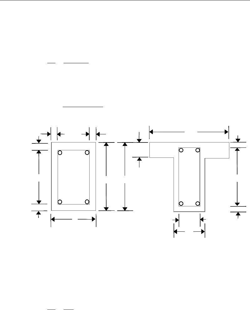
Chapter 16 - Design for ACI 318-11
that the torsional resistance is provided by closed stirrups, longitudinal bars, and
compression diagonal (ACI R11.5.3.6).
If Tu > Tcr the required closed stirrup area per unit spacing, At /s, is calculated as:
yto
ut
fA
T
s
A
2
tan
φ
θ
=
(ACI 11.5.3.6)
and the required longitudinal reinforcement is calculated as:
θφ
tan2
yo
hu
l
fA
pT
A=
(ACI 11.5.3.7, 11.5.3.6)
Figure 16-3 Closed stirrup and section dimensions for torsion design
where, the minimum value of At /s is taken as:
w
yt
t
b
fs
A25
=
(ACI 11.5.5.3)
and the minimum value of Al is taken as follows:
cb
w
2
−
c
c
cc
c
c
cb 2
−
h
s
d
Closed Stirrup in
Rectangular Beam
Closed Stirrup in
T-Beam Section
ch 2
−h
b
ch 2
−
w
b
b
f
cb
w
2
−
c
c
cc
c
c
cb 2
−
h
f
h
Closed Stirrup in
Rectangular Beam
Closed Stirrup in
T-Beam Section
ch 2
−h
b
ch 2
−
w
b
b
f
cb
w
2
−
c
c
cc
c
c
cb 2
−
h
s
d
Closed Stirrup in
Rectangular Beam
Closed Stirrup in
T-Beam Section
ch 2
−h
b
ch 2
−
w
b
b
f
cb
w
2
−
c
c
cc
c
c
cb 2
−
h
s
d
Closed Stirrup in
Rectangular Beam
Closed Stirrup in
T-Beam Section
ch 2
−h
b
ch 2
−
w
b
b
f
cb
w
2
−
c
c
cc
c
c
cb 2
−
h
f
h
Closed Stirrup in
Rectangular Beam
Closed Stirrup in
T-Beam Section
ch 2
−h
b
ch 2
−
w
b
b
f
Beam Design (for Reference Only) 16 - 29
Post-Tensioned Concrete Design
5
c cp yt
t
lh
yy
fA f
A
Ap
f sf
′
= −
(ACI 11.5.5.3)
In the preceding expressions,
θ
is taken as 45 degrees for prestressed members
with an effective prestress force less than 40 percent of the tensile strength of the
longitudinal reinforcement; otherwise
θ
is taken as 37.5 degrees.
An upper limit of the combination of Vu and Tu that can be carried by the section
is also checked using the equation:
′
+≤
+
c
w
c
oh
hu
w
u
f
db
V
A
pT
db
V8
7.1
2
2
2
φ
(ACI 11.5.3.1)
For rectangular sections, bw is replaced with b. If the combination of Vu and Tu
exceeds this limit, a failure message is declared. In that case, the concrete section
should be increased in size.
When torsional reinforcement is required (Tu > Tcr), the area of transverse closed
stirrups and the area of regular shear stirrups must satisfy the following limit.
′
≥
+
y
w
w
yt
c
tv
f
b
b
f
f
s
A
s
A50
,75.0max2
λ
(ACI 11.5.5.2)
If this equation is not satisfied with the originally calculated Av /s and At /s, Av /s
is increased to satisfy this condition. In that case, Av /s does not need to satisfy
the ACI Section 11.5.6.3 independently.
The maximum of all of the calculated Al and At /s values obtained from each load
combination is reported along with the controlling combination.
The beam torsion reinforcement requirements considered by the program are
based purely on strength considerations. Any minimum stirrup requirements and
longitudinal reinforcement requirements to satisfy spacing considerations must
be investigated independently of the program by the user.
16 - 30 Beam Design (for Reference Only)

Chapter 16 - Design for ACI 318-11
16.8 Slab Design
Similar to conventional design, the ETABS slab design procedure involves
defining sets of strips in two mutually perpendicular directions. The locations of
the strips are usually governed by the locations of the slab supports. The mo-
ments for a particular strip are recovered from the analysis and a flexural design
is completed using the ultimate strength design method (ACI 318-11) for pre-
stressed reinforced concrete as described in the following sections. To learn
more about the design strips, refer to the section entitled "ETABS
Design Features" in the Key Features and Terminology manual.
16.8.1 Design for Flexure
ETABS designs the slab on a strip-by-strip basis. The moments used for the
design of the slab elements are the nodal reactive moments, which are obtained
by multiplying the slab element stiffness matrices by the element nodal displace-
ment vectors. Those moments will always be in static equilibrium with the ap-
plied loads, irrespective of the refinement of the finite element mesh.
The design of the slab reinforcement for a particular strip is completed at specific
locations along the length of the strip. Those locations correspond to the element
boundaries. Controlling reinforcement is computed on either side of those ele-
ment boundaries. The slab flexural design procedure for each load combination
involves the following:
Determine factored moments for each slab strip.
Determine the capacity of post-tensioned sections.
Design flexural reinforcement for the strip.
These three steps are described in the subsection that follow and are repeated for
every load combination. The maximum reinforcement calculated for the top and
bottom of the slab within each design strip, along with the corresponding con-
trolling load combination, is obtained and reported.
Slab Design 16 - 31

Post-Tensioned Concrete Design
16.8.1.1 Determine Factored Moments for the Strip
For each element within the design strip, for each load combination, the program
calculates the nodal reactive moments. The nodal moments are then added to get
the strip moments.
16.8.1.2 Determine Capacity of Post-Tensioned Sections
Calculation of the post-tensioned section capacity is identical to that described
earlier for rectangular beam sections.
16.8.1.3 Design Flexural Reinforcement for the Strip
The reinforcement computation for each slab design strip, given the bending mo-
ment, is identical to the design of rectangular beam sections described
earlier (or to the flanged beam if the slab is ribbed). In some cases, at a given
design section in a design strip, there may be two or more slab properties across
the width of the design strip. In that case, the program automatically designs the
tributary width associated with each of the slab properties separately using its
tributary bending moment. The reinforcement obtained for each of the tributary
widths is summed to obtain the total reinforcement for the full width of the de-
sign strip at the considered design section. This method is used when drop panels
are included. Where openings occur, the slab width is adjusted accordingly.
16.8.1.3.1 Minimum and Maximum Slab Reinforcement
The minimum flexural tension reinforcement required for each direction of a
slab is given by the following limits (ACI 7.12.2, 13.3.1):
As,min = 0.0020 bh for fy = 40 ksi or 50 ksi (ACI 7.12.2.1(a))
As,min = 0.0018 bh for fy = 60 ksi (ACI 7.12.2.1(b))
As,min =
bh
fy
600000018.0 ×
for fy > 60 ksi (ACI 7.12.2.1(c))
Reinforcement is not required in positive moment areas where ft, the extreme
fiber stress in tension in the precompressed tensile zone at service loads (after
all prestress losses occurs) does not exceed
2
'
c
f
(ACI 18.9.3.1).
16 - 32 Slab Design

Chapter 16 - Design for ACI 318-11
In positive moment areas where the computed tensile stress in the concrete at
service loads exceeds
2'
c
f,
the minimum area of bonded reinforcement is com-
puted as:
y
c
sf
N
A5.0
min,=
, where fy ≤ 60 ksi (ACI 18.9.3.2)
In negative moment areas at column supports, the minimum area of bonded
reinforcement in the top of slab in each direction is computed as:
,min 0.00075
s cf
AA=
(ACI 18.9.3.3)
where Acf is the larger gross cross-sectional area of the slab-beam strip in the two
orthogonal equivalent frames intersecting a column in a two-way slab
system.
When spacing of tendons exceed 54 inches, additional bonded shrinkage and
temperature reinforcement (as computed above, ACI 7.12.2.1) is required be-
tween the tendons at slab edges, extending from the slab edge for a distance equal
to the tendon spacing (ACI 7.12.3.3)
In addition, an upper limit on both the tension reinforcement and compression
reinforcement has been imposed to be 0.04 times the gross cross-sectional area.
Note that the requirements when fy > 60 ksi currently are not handled.
16.8.2 Check for Punching Shear
The algorithm for checking punching shear is detailed in the section entitled
“Slab Punching Shear Check” in the Key Features and Terminology manual.
Only the code specific items are described in the following sections.
16.8.2.1 Critical Section for Punching Shear
The punching shear is checked on a critical section at a distance of d/2 from the
face of the support (ACI 11.11.1.2). For rectangular columns and concentrated
loads, the critical area is taken as a rectangular area with the sides parallel to the
sides of the columns or the point loads (ACI 11.11.1.3). Figure 16-4 shows the
auto punching perimeters considered by ETABS for the various column shapes.
Slab Design 16 - 33

Post-Tensioned Concrete Design
The column location (i.e., interior, edge, corner) and the punching
perimeter may be overwritten using the Punching Check Overwrites.
Figure 16-4 Punching Shear Perimeters
16.8.2.2 Transfer of Unbalanced Moment
The fraction of unbalanced moment transferred by flexure is taken to be
γ
f Mu
and the fraction of unbalanced moment transferred by eccentricity of shear is
taken to be
γ
v Mu.
( )
21
321
1
bb
f
+
=
γ
(ACI 13.5.3.2)
γ
v = 1 −
γ
f (ACI 13.5.3.1)
For flat plates,
γ
v is determined from the following equations taken from ACI
421.2R-07 [ACI 2007] Seismic Design of Punching Shear Reinforcement in Flat
Plates.
For interior columns,
d2
Interior Column
Circular Column
d2 d2
d2
T-Shape Column
Edge Column Edge Column
L-Shape Column
d2
d2
d2
Interior Column
Circular Column
d2 d2
d2
T-Shape Column
Edge Column Edge Column
L-Shape Column
d2
d2
16 - 34 Slab Design
Chapter 16 - Design for ACI 318-11
()
1
11 23
vx
yx
ll
γ
= − +
(ACI 421.2 C-11)
()
1
11 23
vy
xy
ll
γ
= − +
(ACI 421.2 C-12)
For edge columns,
γ
vx = same as for interior columns (ACI 421.2 C-13)
( )
2.03
21
1
1−+
−
=
yx
vy ll
γ
(ACI 421.2 C-14)
γ
vy = 0 when lx/ly ≤ 0.2
For corner columns,
γ
vx = 0.4 (ACI 421.2 C-15)
γ
vy = same as for edge columns (ACI 421.2 C-16)
NOTE: Program uses ACI 421.2-12 and ACI 421.2-15 equations in lieu of ACI
421.2 C-14 and ACI 421.2 C-16 which are currently NOT enforced.
where b1 is the width of the critical section measured in the direction of the span
and b2 is the width of the critical section measured in the direction perpendicular
to the span. The values lx and ly are the projections of the shear-critical section
onto its principal axes, x and y, respectively.
16.8.2.3 Determine Concrete Capacity
The concrete punching shear stress capacity of a two-way prestressed section is
taken as:
( )
' 0.3
c p c pc p
v f fv
βλ
= ++
(ACI 11.11.2.2)
+= 5.1,5.3min
o
s
p
b
d
α
β
(ACI 11.11.2.2)
Slab Design 16 - 35
Post-Tensioned Concrete Design
where,
β
p is the factor used to compute vc in prestressed slab; bo is the perimeter
of the critical section; fpc is the average value of fpc in the two directions; vp is the
vertical component of all effective prestress stresses crossing the critical section;
and
α
s is a scale factor based on the location of the critical section.
s
40 for interior columns,
30 for edge columns, and
20 for corner columns.
α=
(ACI 11.11.2.1)
The concrete capacity vc computed from ACI 11.12.2.2 is permitted only when
the following conditions are satisfied:
The column is farther than four times the slab thickness away from any dis-
continuous slab edges.
The value of
c
f
'
is taken no greater than 70 psi.
In each direction, the value of fpc is within the range:
125 ≤ fpc ≤ 500 psi
In thin slabs, the slope of the tendon profile is hard to control and special care
should be exercised in computing vp. In case of uncertainty between the design
and as-built profile, a reduced or zero value for vp should be used.
If the preceding three conditions are not satisfied, the concrete punching shear
stress capacity of a two-way prestressed section is taken as the minimum of the
following three limits:
4
2'
min 2 '
4'
c
c
s
cc
c
c
f
df
b
f
λ
β
α
νλ
λ
+
= +
(ACI 11.11.2.1)
16 - 36 Slab Design
Chapter 16 - Design for ACI 318-11
where,
β
c is the ratio of the maximum to the minimum dimensions of the criti-
cal section, b0 is the perimeter of the critical section, and
α
s is a scale factor
based on the location of the critical section (ACI 11.12.2.1).
A limit is imposed on the value of
c
f
'
as:
c
f'
≤ 100 (ACI 11.1.2)
16.8.2.4 Determine Capacity Ratio
Given the punching shear force and the fractions of moments transferred by ec-
centricity of shear about the two axes, the shear stress is computed assuming
linear variation along the perimeter of the critical section. The ratio of the max-
imum shear stress and the concrete punching shear stress capacity is reported as
the punching shear capacity ratio by ETABS.
16.8.3 Design Punching Shear Reinforcement
The use of shear studs as shear reinforcement in slabs is permitted, provided that
the effective depth of the slab is greater than or equal to 6 inches, and not less
than 16 times the shear reinforcement bar diameter (ACI 11.11.3). If the slab
thickness does not meet these requirements, the punching shear reinforcement is
not designed and the slab thickness should be increased by the user.
The algorithm for designing the required punching shear reinforcement is used
when the punching shear capacity ratio exceeds unity. The Critical Section for
Punching Shear and Transfer of Unbalanced Moment as described in the earlier
sections remain unchanged. The design of punching shear reinforcement is car-
ried out as described in the subsections that follow.
16.8.3.1 Determine Concrete Shear Capacity
The concrete punching shear stress capacity of a two-way prestressed section
with punching shear reinforcement is as previously determined, but limited to:
2'
cc
vf
λ
≤
for shear links (ACI 11.11.3.1)
3'
cc
vf
λ
≤
for shear studs (ACI 11.11.5.1)
Slab Design 16 - 37
Post-Tensioned Concrete Design
16.8.3.2 Determine Required Shear Reinforcement
The shear force is limited to a maximum of:
Vmax = 6
'c
f
bod for shear links (ACI 11.11.3.2)
Vmax = 8
'c
f
bod for shear studs (ACI 11.11.5.1)
Given Vu, Vc, and Vmax, the required shear reinforcement is calculated as follows,
where,
φ
, the strength reduction factor, is 0.75 (ACI 9.3.2.3).
( )
uc
v
ys
VV
A
s fd
φ
φ
−
=
(ACI 11.4.7.1, 11.4.7.2)
'
2
c
vo
y
f
Ab
sf
≥
for shear studs
If Vu >
φ
Vmax, a failure condition is declared. (ACI 11.11.3.2)
If Vu exceeds the maximum permitted value of
φ
Vmax, the concrete section
should be increased in size.
16.8.3.3 Determine Reinforcement Arrangement
Punching shear reinforcement in the vicinity of rectangular columns should be
arranged on peripheral lines, i.e., lines running parallel to and at constant dis-
tances from the sides of the column. Figure 16-5 shows a typical arrangement of
shear reinforcement in the vicinity of a rectangular interior, edge, and corner
column.
The distance between the column face and the first line of shear reinforcement
shall not exceed d/2 (ACI R11.3.3, 11.11.5.2). The spacing between adjacent
shear reinforcement in the first line of shear reinforcement shall not exceed 2d
measured in a direction parallel to the column face (ACI 11.11.3.3).
Punching shear reinforcement is most effective near column corners where there
are concentrations of shear stress. Therefore, the minimum number of lines of
shear reinforcement is 4, 6, and 8, for corner, edge, and interior columns respec-
tively.
16 - 38 Slab Design
Chapter 16 - Design for ACI 318-11
Figure 16-5 Typical arrangement of shear studs and critical sections outside
shear-reinforced zone
16.8.3.4 Determine Reinforcement Diameter, Height, and Spacing
The punching shear reinforcement is most effective when the anchorage is close
to the top and bottom surfaces of the slab. The cover of anchors should not be
less than the minimum cover specified in ACI 7.7 plus half of the diameter of
the flexural reinforcement.
Punching shear reinforcement in the form of shear studs is generally available in
3/8-, 1/2-, 5/8-, and 3/4-inch diameters.
When specifying shear studs, the distance, so, between the column face and the
first peripheral line of shear studs should not be smaller than 0.35d. The limits
of so and the spacing, s, between the peripheral lines are specified as:
so ≤ 0.5d (ACI 11.11.5.2)
0 75 for 6
0 50 for 6
uc
uc
. d f'
s. d f'
ν φλ
ν φλ
≤
≤>
(ACI 11.11.5.2)
g ≤ 2d (ACI 11.11.5.3)
The limits of so and the spacing, s, between the links are specified as:
I
y
Typical Studrail
(only first and last
studs shown)
Outermost
peripheral line
of studs
Interior Column Edge Column Corner Column
Critical section
centroid
Free
edge
Free
edge
Critical
section
centroid
Free edge
Outermost
peripheral line
of studs
I
y
I
y
yx
d2 d2
d2
x
I
x
I
x
g
y
g
x
g
0
s0
s
0
s
x
I
y
x
x
I
y
Typical Studrail
(only first and last
studs shown)
Outermost
peripheral line
of studs
Interior Column Edge Column Corner Column
Critical section
centroid
Free
edge
Free
edge
Critical
section
centroid
Free edge
Outermost
peripheral line
of studs
I
y
I
y
yx
d2 d2
d2
x
I
x
I
x
g
y
g
x
g
0
s0
s
0
s
x
I
y
x
x
Slab Design 16 - 39

Post-Tensioned Concrete Design
so ≤ 0.5d (ACI 11.11.3)
0 50≤s .d
(ACI 11.11.3)
16 - 40 Slab Design

Chapter 17
Design for TS 3233-1979
This chapter describes in detail the various aspects of the post-tensioned concrete
design procedure that is used by ETABS when the user selects the TS 500-2000.
When the aforementioned code is selected in ETABS, program design meets the
requirement of the TS 3233-1979 [TS 3233]. Various notations used in this chap-
ter are listed in Table 17-1. For referencing to the pertinent sections or equations
of the TS code in this chapter, a prefix “TS” followed by the section or equation
number is used herein.
The design is based on user-specified load combinations. The program provides
a set of default load combinations that should satisfy requirements for the design
of most building type structures.
English as well as SI and MKS metric units can be used for input. The code is
based on Newton-millimeter-second units. For simplicity, all equations and
descriptions presented in this chapter correspond to Newton-millimeter-second
units unless otherwise noted.
17.1 Notations
The following table identifies the various notations used in this chapter.
Notations 17 - 1

Post-Tensioned Concrete Design
Table 17-1 List of Symbols Used in the TS 3233-1979 Code
A
cp
Area enclosed by the outside perimeter of the section, mm2
A
g
Gross area of concrete, mm2
A
l
Area of longitudinal reinforcement for torsion, mm2
A
o
Area enclosed by the shear flow path, mm2
A
oh
Area enclosed by the centerline of the outermost closed
transverse torsional reinforcement, mm2
A
s
Area of tension reinforcement, mm2
A'
s
Area of compression reinforcement, mm2
A
ot
/s
Area of transverse torsion reinforcement (closed stirrups) per
unit length of the member, mm2/mm
A
ov
/s
Area of transverse shear reinforcement per unit length of the
member, mm2/mm
a
Depth of compression block, mm
A
sw
Area of shear reinforcement, mm2
A
sw
/s
Area of shear reinforcement per unit length of the member,
mm2/mm
a
max
Maximum allowed depth of compression block, mm
b
Width of section, mm
b
f
Effective width of flange (flanged section), mm
b
o
Perimeter of the punching shear critical section, mm
b
w
Width of web (flanged section), mm
b
1
Width of the punching shear critical section in the direction
of bending, mm
b
2
Width of the punching shear critical section perpendicular to
the direction of bending, mm
c
Depth to neutral axis, mm
17 - 2 Notations

Chapter 17 - Design for TS 3233-1979
Table 17-1 List of Symbols Used in the TS 3233-1979 Code
d
Distance from compression face to tension reinforcement,
mm
d'
Distance from compression face to compression reinforce-
ment, in
E
c
Modulus of elasticity of concrete, N/mm2
E
s
Modulus of elasticity of reinforcement, N/mm2
f
cd
Designed compressive strength of concrete, N/mm2
f
ck
Characteristic compressive strength of concrete, N/mm2
f
ctk
Characteristic tensile strength of concrete, N/mm2
f
yd
Designed yield stress of flexural reinforcement, N/mm2.
f
yk
Characteristic yield stress of flexural reinforcement, N/mm2.
f
ywd
Designed yield stress of transverse reinforcement, N/mm2.
h
Overall depth of a section, mm
h
f
Height of the flange, mm
M
d
Design moment at a section, N/mm
V
d
Design axial load at a section, N
p
cp
Outside perimeter of concrete cross-section, mm
p
h
Perimeter of centerline of outermost closed transverse tor-
sional
reinforcement, mm
s
Spacing of shear reinforcement along the beam, mm
T
cr
Critical torsion capacity, N/mm
T
d
Design torsional moment at a section, N/mm
V
c
Shear force resisted by concrete, N
V
max
Maximum permitted total factored shear force at a section, N
V
s
Shear force resisted by transverse reinforcement, N
Notations 17 - 3

Post-Tensioned Concrete Design
Table 17-1 List of Symbols Used in the TS 3233-1979 Code
V
d
Design shear force at a section, N
α
s
Punching shear scale factor based on column location
β
c
Ratio of the maximum to the minimum dimensions of the
punching shear critical section
k
1
Factor for obtaining depth of the concrete compression block
ε
c
Strain in the concrete
ε
c max
Maximum usable compression strain allowed in the extreme
concrete fiber, (0.003 mm / mm)
ε
s
Strain in the reinforcement
ε
cu,
Maximum usable compression strain allowed in extreme con-
crete fiber (0.003 mm/mm)
ε
s
Strain in reinforcing steel
γ
m
Material factor
γ
mc
Material factor for concrete
λ
Shear strength reduction factor for light-weight concrete
17.2 Design Load Combinations
The design load combinations are the various combinations of the load cases for
which the structure needs to be designed. For TS 3233-1979, if a structure is
subjected to dead (G), live (Q), wind (W), and earthquake (E) loads, and con-
sidering that wind and earthquake forces are reversible, the following load com-
binations may need to be considered (TS 8.4.3).
For post-tensioned concrete design, the user can specify the prestressing load
(PT) by providing the tendon profile or by using the load balancing options in
the program. The default load combinations for post-tensioning are defined in
the following sections.
These are the default design load combinations in ETABS whenever the TS
3233-1979 code is used. The user should use other appropriate load combina-
tions if roof live load is treated separately, or if other types of loads are present.
17 - 4 Design Load Combinations

Chapter 17 - Design for TS 3233-1979
17.2.1 Initial Service Load Combination
The following load combination is used for checking the requirements at transfer
of prestress force in accordance with TS 3233 Section 9.1.1. The prestressing
forces are considered without any long-term loses for the initial service load
combination check.
1.0D + 1.0PT
17.2.2 Service Load Combination
The following characteristic load combinations are used for checking the
requirements of prestress for serviceability in accordance with TS 3233 Section
9.1.1. It is assumed that all long-term losses have occurred already at the service
stage.
1.0D + 1.0PT
1.0D + 1.0
L + 1.0PT
17.2.3 Strength Design Load Combination
The following load combinations are used for checking the requirements of pre-
stress for strength in accordance with TS 3233-1979.
The strength design combinations required for punching shear require the full
PT forces (primary and secondary). Flexural design requires only the hyperstatic
(secondary) forces. The hyperstatic (secondary) forces are automatically deter-
mined by ETABS by subtracting out the primary PT moments when the flexural
design is carried out.
1.4G + 1.6Q + 1.0PT*
(TS 8.4.3)
0.9G ± 1.3W + 1.0PT*
1.
0G + 1.3Q ± 1.3W + 1.0PT* (TS 8.4.3
)
(TS 8.4.3
)
0.9G ± 1.0E + 1.0PT*
1.
0G + 1.0Q ± 1.0E + 1.0PT*
(TS 8.4.3)
(TS 8.4.3)
* — Replace PT by hyperstatic (H) for flexural design only
Design Load Combinations 17 - 5

Post-Tensioned Concrete Design
These are also the default design load combinations in ETABS whenever the
Turkish TS 3233-1979 code is used. If roof live load is treated separately or other
types of loads are present, other appropriate load combinations should be used.
17.3 Limits on Material Strength
The concrete compressive strength, f'c, should not be less than 25 N/mm2 (TS
2.3.1).
22
25 N/mm 55 N/mm
ck
f≤≤
(TS 2.3.2)
ETABS enforces the upper material strength limits for flexure and shear design
of slabs. The input material strengths are taken as the upper limits if they are
defined in the material properties as being greater than the limits. The user is
responsible for ensuring that the minimum strength is satisfied.
The specified characteristic strength of reinforcement is given as follows:
420
yk
f≤
N/mm2
17.4 Partial Safety Factors
The design strengths for concrete and reinforcement are obtained by dividing the
characteristic strength,
,
ck
f
pk
f
and
yk
f
of the material by a partial factor of
safety, γs and γc, as follows (TS 8.4.3):
/
cd ck mc
ff= γ
(TS 8.4.3)
/
yd yk ms
ff= γ
(TS 8.4.3)
/
pd pk ms
ff= γ
(TS 8.4.3)
The values of partial safety factors, γms and γmc, for the materials and the design
strengths of concrete and reinforcement used in the program are listed in the
following table (TS 8.4.3):
17 - 6 Limits on Material Strength

Chapter 17 - Design for TS 3233-1979
Values of
γ
m for the Strength Design
Reinforcement,
γ
ms 1.15
Prestressing steel,
γ
mp 1.15
Concrete in flexure and axial load,
γ
mc 1.50
These values are recommended by the code to give an acceptable level of safety
for normal structures under typical design situations.
These factors are already incorporated into the design equations and tables in the
code. The user is allowed to overwrite these values; however, caution is
advised.
17.5 Design Assumptions for Prestressed Concrete Struc-
tures
Strength design of prestressed members for flexure and axial loads shall be based
on assumptions given in TS 8.3.
The strain distribution in the concrete in compression is derived from the
assumption that plane sections remain plane.
The design stresses in the concrete in compression are taken as 0.85 fcd.
Maximum strain at the extreme concrete compression fiber shall be assumed
equal to εcu.
The tensile strength of the concrete is ignored.
The strains in bonded post-tensioning tendons and in any additional
reinforcement (compression or tension) are the same as that in the surrounding
concrete.
The serviceability limit state of prestressed members uses the following
assumptions given in 9.1, 9.2.
Plane sections remain plane, i.e., strain varies linearly with depth through the
entire load range.
Design Assumptions for Prestressed Concrete Structures 17 - 7

Post-Tensioned Concrete Design
Elastic behavior exists by limiting the concrete stresses to the values given in
TS 8.3
In general, it is only necessary to calculate design stresses due to the load
arrangements immediately after the transfer of prestress and after all losses or
prestress have occurred; in both cases the effects of dead and imposed loads
on the strain and force in the tendons may be ignored.
Prestressed concrete members are investigated at three stages:
At transfer of prestress force
At service loading
At nominal strength
17.6 Serviceability Requirements of Flexural Members
17.6.1 Serviceability Check at Initial Service Load
The stresses in the concrete immediately after prestress force transfer (before
time dependent prestress losses) are checked against the following limits (TS
9.1.1 and 9.1.2):
Extreme fiber stresses in compression:
0.60
cjk
f
in N/mm2 (TS 9.1.1)
Unless reinforcing steel has been added, the stress limits will normally be
"without bonded reinforcement" values, as any bonded tendons normally will
be at the compression face at transfer.
Extreme fiber stresses in tension (TS 9.1.2)
0.5 cjk
f
in N/mm2 (TS 9.1.2)
Extreme fiber stresses in tension should not exceed
0.5 cjk
f
; otherwise, the
section should be designed as a cracked section.
17 - 8 Serviceability Requirements of Flexural Members
Chapter 17 - Design for TS 3233-1979
17.6.2 Serviceability Check at Service Load
The stresses in the concrete for prestressed concrete flexural members at service
loads, and after all prestress losses have occurred, are checked against the fol-
lowing limits (TS 9.2)
Extreme fiber stress in compression due to prestress plus total load:
0.45 ck
f
(TS 9.2.1)
Extreme fiber stresses in tension in the precompressed tensile zone at
characteristic service loads are defined as follows (TS 9.2.2):
– Extreme fiber stresses in tension for reinforcement:
0.5
ck
f
(TS 9.2.2)
– Extreme fiber stresses in tension for prestressing tendons:
0.70 pk
f
(TS 9.3)
17.7 Beam Design (for Reference Only)
Important Note: Post-tensioned beam design is not available in the current ver-
sion of ETABS, but is planned for a future release. This section is provided as
reference only for the documentation of post-tensioned slab design.
In the design of prestressed concrete beams, ETABS calculates and reports the
required areas of reinforcement for flexure, shear, and torsion based on the beam
moments, shear forces, torsion, load combination factors, and other criteria de-
scribed in the subsections that follow. The reinforcement requirements are cal-
culated at each station along the length of the beam.
Beams are designed for major direction flexure, shear, and torsion only. Effects
resulting from any axial forces and minor direction bending that may exist in the
beams must be investigated independently by the user.
The beam design procedure involves the following steps:
Design flexural reinforcement
Beam Design (for Reference Only) 17 - 9

Post-Tensioned Concrete Design
Design shear reinforcement
Design torsion reinforcement
17.7.1 Design Flexural Reinforcement
The beam top and bottom flexural reinforcement is designed at each station
along the beam. In designing the flexural reinforcement for the major moment
of a particular beam for a particular station, the following steps are involved:
Determine factored moments
Determine required flexural reinforcement
17.7.1.1 Determine Factored Moments
In the design of flexural reinforcement of prestressed concrete beams, the
factored moments for each load combination at a particular beam station are ob-
tained by factoring the corresponding moments for different load cases, with the
corresponding load factors.
The beam section is then designed for the maximum positive and maximum neg-
ative factored moments obtained from all of the load combinations. Positive
beam moments can be used to calculate bottom reinforcement. In such cases the
beam may be designed as a rectangular or a flanged beam. Negative beam mo-
ments can be used to calculate top reinforcement. In such cases the beam may
be designed as a rectangular or inverted flanged beam.
17.7.1.2 Determine Required Flexural Reinforcement
In the flexural reinforcement design process, the program calculates both the
tension and compression reinforcement. Compression reinforcement is added
when the applied design moment exceeds the maximum moment capacity of a
singly reinforced section. The user has the option of avoiding the compression
reinforcement by increasing the effective depth, the width, or the strength of the
concrete.
The design procedure is based on the simplified rectangular stress block shown
in Figure 17-1 (TS 8.3).
17 - 10 Beam Design (for Reference Only)
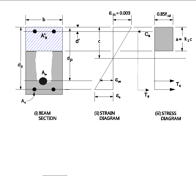
Chapter 17 - Design for TS 3233-1979
Figure 17-1 Rectangular Beam Design
The maximum depth of the compression zone, cb, is calculated based on the com-
pressive strength of the concrete and the tensile steel tension using the following
equation (TS 8.3):
cu s
bcu s yd
E
cd
Ef
ε
ε
=+
(TS 8.3)
The maximum allowable depth of the rectangular compression block, amax, is
given by
max 1
0.85 b
a kc=
(TS 8.3)
where k1 is calculated as follows:
k1 = 0.85 for
30
ck
f≤
N/mm2, (TS 8.3)
k1 = 0.85 − 0.0075
( )
30
ck
f−
, for
30
ck
f>
N/mm2. (TS 8.3)
Furthermore, it is assumed that moment redistribution in the beam does not ex-
ceed the code specified limiting value. The code also places a limitation on the
Beam Design (for Reference Only) 17 - 11

Post-Tensioned Concrete Design
neutral axis depth, to safeguard against non-ductile failures. When the applied
moment exceeds the limiting moment capacity as a singly reinforced beam, the
area of compression reinforcement is calculated on the
assumption that the neutral axis depth remains at the maximum permitted value.
The design procedure used by ETABS, for both rectangular and flanged sections
(L- and T-beams), is summarized in the subsections that follow.
17.7.1.2.1 Design of Rectangular Beams
ETABS first determines if the moment capacity provided by the post-tensioning
tendons alone is enough. In calculating the capacity, it is assumed that As = 0. In
that case, the moment capacity
0
res
M
is determined as follows:
The maximum depth of the compression zone, cmax, is calculated based on the
limitation that the tension reinforcement strain shall not be less than
ε
smin:
cmax =
min
cu p
cu s
d
ε
εε
+
where,
ε
cu = 0.003
Therefore, the limit c ≤ cmax is set for tension-controlled sections.
The maximum allowable depth of the rectangular compression block, amax, is
given by
max 1
0.85 b
a kc=
(TS 8.3)
where k1 is calculated as follows:
k1 = 0.85 for
30
ck
f≤
N/mm2, (TS 8.3)
k1 = 0.85 − 0.0075
()
30
ck
f−
, for
30
ck
f>
N/mm2. (TS 8.3)
ETABS determines the depth of the neutral axis, c, by imposing force equilib-
rium, i.e., C = T. After the depth of the neutral axis has been determined, the
stress in the post-tensioning steel, fpk is computed based on strain compatibility
17 - 12 Beam Design (for Reference Only)

Chapter 17 - Design for TS 3233-1979
for bonded tendons. For unbonded tendons, the code equations are used to com-
pute the stress, fps in the post-tensioning steel.
Based on the calculated fpk, the depth of the neutral axis is recalculated, and fpk is
further updated. After this iteration process has converged, the depth of the rec-
tangular compression block is determined as follows:
1
0.85a kc=
If
max
cc≤
, the moment capacity of the section, provided by post-tensioning
steel only, is computed as:
0
2
res ps ps p
a
M Af d
= −
If
max
cc>
, a failure condition is declared.
If
0,
res
MM>
ETABS calculates the moment capacity and the As required at
the balanced condition. The balanced condition is taken as the marginal
tension-controlled case. In that case, it is assumed that the depth of the neutral
axis c is equal to cmax. The stress in the post-tensioning steel, fpk, is then
calculated based on strain compatibility and the area of required tension
reinforcement, As, is determined by imposing force equilibrium, i.e., C = T.
max
0.85 ,
cd
C fa b=
bal bal bal
p pk s s
T Af A f= +
max
0.85 bal
cd p ps
bal
sbal
s
f a b Af
Af
−
=
After the area of tension reinforcement has been determined, the capacity of the
section with post-tensioning steel and tension reinforcement is computed as:
max max
22
bal bal bal bal
res p ps p s s s
aa
M Afd Afd
= −+ −
Beam Design (for Reference Only) 17 - 13

Post-Tensioned Concrete Design
In that case, it is assumed that the bonded tension reinforcement will yield, which
is true for most cases. In the case that it does not yield, the stress in the reinforce-
ment, fs, is determined from the elastic-perfectly plastic stress-strain relationship.
The fy value of the reinforcement is then replaced with fs in the preceding four
equations. This case does not involve any iteration in determining the depth of
the neutral axis, c.
17.7.1.2.1.1 Case 1: Post-tensioning steel is adequate
When
0
,
d res
MM
<
the amount of post-tensioning steel is adequate to resist the
design moment M. A minimum reinforcement is provided to satisfy the flexural
cracking requirements (TS 10.1.1, 10.2.1).
17.7.1.2.1.2 Case 2: Post-tensioning steel plus tension reinforcement
In this case, the amount of post-tensioning steel, Ap, alone is not sufficient to
resist M, and therefore the required area of tension reinforcement is computed to
supplement the post-tensioning steel. The combination of post-tensioning steel
and tension reinforcement should result in a < amax.
When
()
0,
bal
res d res
M MM<<
ETABS determines the required area of tension re-
inforcement, As, iteratively to satisfy the design moment Md and reports this
required area of tension reinforcement. Since Md is bound by
0
res
M
at the lower
end and
bal
res
M
at the upper end, and
0
res
M
is associated with
0=
s
A
and
bal
res
M
is
associated with
,=
bal
ss
AA
the required area will fall within the range of 0 to
Asbal.
The tension reinforcement is to be placed at the bottom if M is positive, or at the
top if M is negative.
17.7.1.2.1.3 Case 3: Post-tensioning steel and tension reinforcement is not
adequate
When
()
,
bal
d res
MM>
compression reinforcement is required. In that case,
ETABS assumes that the depth of the neutral axis, c, is equal to
max .c
The values
17 - 14 Beam Design (for Reference Only)

Chapter 17 - Design for TS 3233-1979
of fpk and fs reach their respective balanced condition values,
bal
pk
f
and
.
bal
s
f
Then the area of compression reinforcement,
,
′
s
A
is determined as follows:
The moment required to be resisted by compression reinforcement and tension
reinforcement is:
,bal
d s d res
M MM= −
The required compression reinforcement is given by:
s
A′
=
()( )
,
d,s
s cd e
M
f - 0.85f d - d'
′
where
s
f′
= εc3Es
max
max
'cd
c
−
≤ fyd.
The tension reinforcement for balancing the compression reinforcement is given
by:
( )
,
'
ds
com
syd s
M
Afdd
=−
Therefore, the total tension reinforcement, As =
bal
s
A
+
,
com
s
A
and the total com-
pression reinforcement is A's. As is to be placed at the bottom and A's is to be
placed at the top if M is positive, and vice versa if M is negative.
17.7.1.2.2 Design of Flanged Beams
17.7.1.2.2.1 Flanged Beam Under Negative Moment
In designing for a factored negative moment, Md
(i.e., designing top reinforce-
ment), the calculation of the reinforcement area is exactly the same as described
previously, i.e., no flanged beam data is used.
Beam Design (for Reference Only) 17 - 15
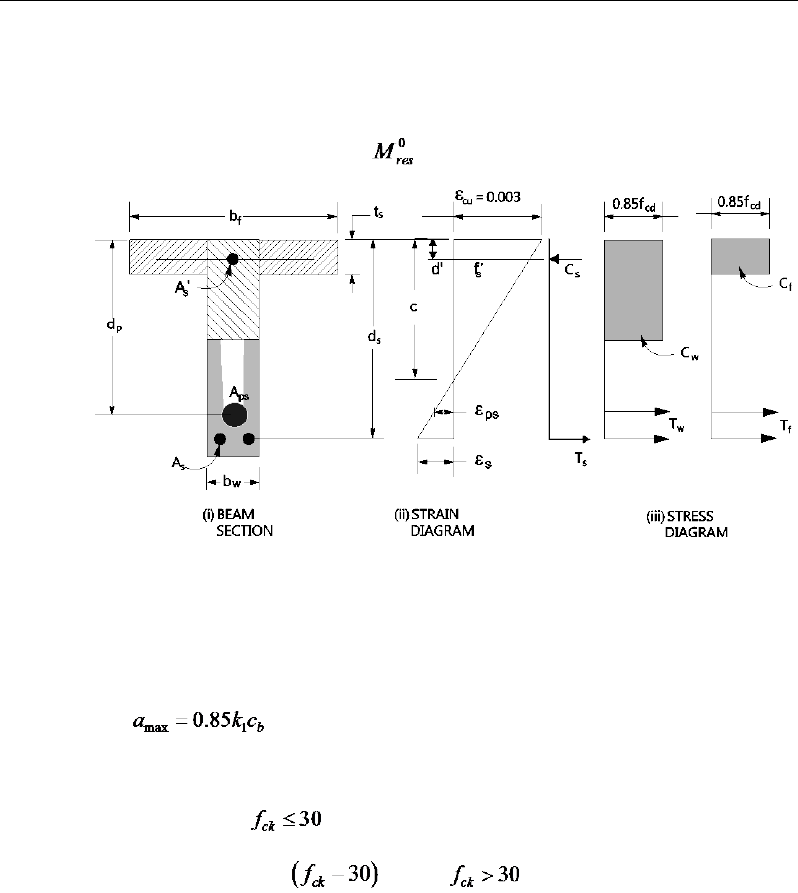
Post-Tensioned Concrete Design
17.7.1.2.2.2 Flanged Beam Under Positive Moment
ETABS first determines if the moment capacity provided by the post-tensioning
tendons alone is enough. In calculating the capacity, it is assumed that As = 0. In
that case, the moment capacity is determined as follows:
Figure 17-2 T-Beam Design
The maximum allowable depth of the rectangular compression block, amax, is
given by
(TS 8.3)
where k1 is calculated as follows:
k1 = 0.85 for N/mm2, (TS 8.3)
k1 = 0.85 − 0.0075 , for N/mm2. (TS 8.3)
ETABS determines the depth of the neutral axis, c, by imposing force equilib-
rium, i.e., C = T. After the depth of the neutral axis has been determined, the
stress in the post-tensioning steel, fpk, is computed based on strain compatibility
for bonded tendons. For unbonded tendons, the code equations are used to com-
pute the stress, fps, in the post-tensioning steel. Based on the calculated fpk, the
depth of the neutral axis is recalculated, and fpk is further updated. After this
17 - 16 Beam Design (for Reference Only)

Chapter 17 - Design for TS 3233-1979
iteration process has converged, the depth of the rectangular compression block
is determined as follows:
1
0.85a kc=
If
max
cc≤
, the moment capacity of the section, provided by post-tensioning
steel only, is computed as:
0
2
res ps ps p
a
M Af d
= −
If
max
cc>
, a failure condition is declared.
If
0,
res
MM>
ETABS calculates the moment capacity and the As required at
the balanced condition. The balanced condition is taken as the marginal
tension- controlled case. In that case it is assumed that the depth of the neutral
axis c is equal to cmax. The stress in the post-tensioning steel, fpk, is then
calculated based on strain compatibility, and the area of required tension
reinforcement, As, is determined by imposing force equilibrium, i.e., C = T.
If a ≤ hf, the subsequent calculations for As are exactly the same as previously
defined for the rectangular beam design. However, in this case, the width of
the beam is taken as bf. Compression reinforcement is required when a > amax.
If a > hf, the calculation for As is given by:
max
0.85
com
cd c
C fa A=
where
com
c
A
is the area of concrete in compression, i.e.,
bal bal bal
p pk s s
T Af A f= +
0.85
com bal
cd c p pk
bal
sbal
s
f A Af
Af
−
=
After the area of tension reinforcement has been determined, the capacity of the
section with post-tensioning steel and tension reinforcement is computed as:
max max
22
bal bal bal bal
res p pk p s s s
aa
M Afd Afd
= −+ −
Beam Design (for Reference Only) 17 - 17

Post-Tensioned Concrete Design
In that case, it is assumed that the bonded tension reinforcement will yield, which
is true for most cases. In the case that it does not yield, the stress in the reinforc-
ing steel, fs, is determined from the elastic-perfectly plastic stress-strain relation-
ship. The fy value of the reinforcement is then replaced with fs in the preceding
four equations. This case does not involve any iteration in determining the depth
of the neutral axis, c.
17.7.1.2.2.2.1 Case 1: Post-tensioning steel is adequate
When
0,
res
MM<
the amount of post-tensioning steel is adequate to resist the
design moment M. Minimum reinforcement is provided to satisfy the flexural
cracking requirements (TS 10.1.1, 10.2.1).
17.7.1.2.2.2.2 Case 2: Post-tensioning steel plus tension reinforcement
In this case, the amount of post-tensioning steel, Ap, alone is not sufficient to
resist M, and therefore the required area of tension reinforcement is computed to
supplement the post-tensioning steel. The combination of post-tensioning steel
and tension reinforcement should result in c < cmax.
When
()
0,
bal
res d res
M MM<<
ETABS determines the required area of tension re-
inforcement, As, iteratively to satisfy the design moment M and reports the
required area of tension reinforcement. Since
M
is bounded by
0
res
M
at the lower
end and
bal
res
M
at the upper end, and
0
res
M
is associated with
0
s
A=
and
bal
res
M
is
associated with
bal
ss
AA,=
the required area will be within the range of 0 to
s
A
.
The tension reinforcement is to be placed at the bottom if Md is positive, or at
the top if Md is negative.
17.7.1.2.2.2.3 Case 3: Post-tensioning steel and tension reinforcement is not adequate
When
()
,
bal
d res
MM>
compression reinforcement is required. In that case
ETABS assumes that the depth of the neutral axis, c, is equal to
max .c
The values
of fpk and fs reach their respective balanced condition values,
bal
pk
f
and
.
bal
s
f
Then
the area of compression reinforcement,
,
′
s
A
is determined as follows:
17 - 18 Beam Design (for Reference Only)
Chapter 17 - Design for TS 3233-1979
The moment required to be resisted by compression reinforcement and tension
reinforcement is:
,bal
res s d res
M MM= −
The required compression reinforcement is given by:
′
s
A
=
( )
( )
,
,
' 0.85 '
res s
s ms cd
M
f f dd
γ
−−
where
′
s
f
= εc3Es
max
max
'cd
c
−
≤
yk ms
f
γ
.
The tension reinforcement for balancing the compression reinforcement is given
by:
( )
,
'
res s
com
syd s
M
Afdd
=−
Therefore, the total tension reinforcement, As =
bal
s
A
+
,
com
s
A
and the total com-
pression reinforcement is A's. As is to be placed at the bottom and A's is to be
placed at the top if Md is positive, and vice versa if Md is negative.
17.7.1.2.3 Minimum and Maximum Tensile Reinforcement
Reinforcement in prestressed concrete beams is computed to increase the
strength of sections as required in the flexural design of prestressed beam or to
comply with shear link requirements. The minimum flexural tension reinforce-
ment required for a beam section to comply with the cracking requirements must
be separately investigated by the user.
For bonded tendons, there is no minimum un-tensioned reinforcement require-
ments.
For unbonded tendons, the minimum flexural reinforcement provided in a rec-
tangular or flanged beam section is given as:
As,min ≥ 0.004 Act (TS 8.6.2)
The minimum flexural tension reinforcement required for control of cracking
should be investigated independently by the user.
Beam Design (for Reference Only) 17 - 19

Post-Tensioned Concrete Design
In addition, an upper limit on both the tension reinforcement and compression
reinforcement has been imposed to be 0.04 times the gross cross-sectional area.
17.7.2 Design Beam Shear Reinforcement
The shear reinforcement is designed for each loading combination at each
station along the length of the beam. In designing the shear reinforcement for a
particular beam, for a particular loading combination, at a particular station due
to the beam major shear, the following steps are involved (TS 11.1 ):
Determine the factored shear force, Vd
Determine the shear force, Vc, that can be resisted by the concrete
Determine the shear reinforcement required to carry the balance
The following three sections describe in detail the algorithms associated with
these steps.
17.7.2.1 Determine Shear Force
In the design of the beam shear reinforcement, the shear forces for each load
combination at a particular beam station are obtained by factoring the cor-re-
sponding shear forces for different load cases with the corresponding load com-
bination factors.
17.7.2.2 Determine Concrete Shear Capacity
The shear force carried by the concrete, Vc, is calculated as:
Vc = min(Vcw, Vcr) (TS 11.1.1, 11.1.2)
where,
( )
0.5
2
0.67 0.8
cw w ct cp ct
V bh
σ σσ
= +
(TS 11.1.1)
0.25
0.25
ct ck
f
σ
=
17 - 20 Beam Design (for Reference Only)
Chapter 17 - Design for TS 3233-1979
cp
σ
=
compress stress in concrete due to effective prestress forces only
(after allowance for all prestress losses) at the extreme fiber of the section
where tensile stress is caused by externally applied loads, N/mm2
1 0.55 0.12
pef d
cr c w o ck w
pk d
V
V bd M f bd
fM
στλ
=− +≥
(TS 11.1.2)
0.80dh≥
(TS 11.1.2)
0.8
o cpd
I
My
σ
=
(TS 11.1.2)
where,
pef
σ
=
compress stress in concrete due to effective prestress forces only
(after allowance for all prestress losses) at the extreme fiber of the section
where tensile stress is caused by externally applied loads,
0.6
pef pk
f
σ
≤
N/mm2
cpd
σ
=
compress stress in concrete due to gravity loading, N/mm2
fpk = characteristic strength of tendon, N/mm2
Vd = designed factored shear force at the section, N
Md = design factored moment at the section, N-mm
Mcre = moment causing flexural cracking at the section because of exter-
nally applied loads
Vcw = shear resistance provided by the concrete when diagonal cracking
results from high principal tensile stress in the web
Vcr = shear resistance provided by the concrete when diagonal cracking
results from combined shear and moment
For light-weight concrete, the
ck
f
term is multiplied by the shear strength reduc-
tion factor λ.
Beam Design (for Reference Only) 17 - 21

Post-Tensioned Concrete Design
17.7.2.3 Determine Required Shear Reinforcement
The shear force is limited to a maximum of:
max max w
V bd
τ
=
(TS 11.1)
0.5
max
0.79
ck
f
τ
=
Given Vd, Vc, and Vmax, the required shear reinforcement is calculated as follows:
If
0.5
dc
VV
≤
sw
A
s
= 0 (TS 11.2.1)
If
max
0.5
cd
VVV<≤
( )
dc
sw
ywd
VV
A
s fd
−
=
(TS 11.2.3)
0.25
sw ctd
w
ywd
Af
b
sf
≥
(TS 11.2.1)
If Vd > Vmax, a failure condition is declared (TS 11.1).
If Vd exceeds the maximum permitted value of Vmax, the concrete section
should be increased in size.
Note that if torsion design is performed and torsion rebar is
needed, the equation given in TS 500-2000 8.1.5 does not need to
be satisfied independently. See the next section Design of Beam
Torsion Reinforcement for details.
The maximum of all of the calculated Asw/s values, obtained from
each design load combination, is reported along with the control-
ling shear force and associated design load combination name.
The beam shear reinforcement requirements considered by the
program are based purely on shear strength considerations. Any
minimum stirrup requirements to satisfy spacing and volumetric
17 - 22 Beam Design (for Reference Only)

Chapter 17 - Design for TS 3233-1979
considerations must be investigated
independently of the program by the user.
17.7.3 Design Beam Torsion Reinforcement
The torsion reinforcement is designed for each design load combination at each
station along the length of the beam. The following steps are involved in design-
ing the longitudinal and shear reinforcement for a particular station due to the
beam torsion:
Determine the factored torsion, Td.
Determine special section properties.
Determine critical torsion capacity.
Determine the torsion reinforcement required.
17.7.3.1 Determine Factored Torsion
In the design of torsion reinforcement of any beam, the factored torsions for each
design load combination at a particular design station are obtained by factoring
the corresponding torsion for different analysis cases with the corresponding de-
sign load combination factors (TS 8.2).
NOTE: All section listed in torsion design refers to TS 500-2000.
In a statistically indeterminate structure where redistribution of the torsional mo-
ment in a member can occur due to redistribution of internal forces upon crack-
ing, the design Td is permitted to be reduced in accordance with code (TS 8.2.3).
However, the program does not try to redistribute the internal forces and to re-
duce Td. If redistribution is desired, the user should release the torsional DOF in
the structural model.
17.7.3.2 Determine Special Section Properties
For torsion design, special section properties such as Ae, S and ue are calculated.
These properties are described as follows (TS 8.2.4).
Beam Design (for Reference Only) 17 - 23
Post-Tensioned Concrete Design
A
e
=
Area enclosed by centerline of the outermost closed trans-
verse torsional reinforcement
S
=
Shape factor for torsion
u
e
=
Perimeter of area A
e
In calculating the section properties involving reinforcement, such as Aov/s, Aot/s,
and ue, it is assumed that the distance between the centerline of the outermost
closed stirrup and the outermost concrete surface is 30 mm. This is equivalent to
25-mm clear cover and a 10-mm-diameter stirrup placement. For torsion design
of T beam sections, it is assumed that placing torsion reinforcement in the flange
area is inefficient. With this assumption, the flange is ignored for torsion rein-
forcement calculation. However, the flange is considered during Tcr calculation.
With this assumption, the special properties for a Rectangular beam section are
given as follows:
Figure 17-3 Closed stirrup and section dimensions for torsion design
A
e
=
()( )
2 2,bchc
−−
(TS 8.2.4)
u
t
=
( ) ( )
2222,bc hc−+ −
(TS 8.2.4)
cb 2
h
s
d
Closed Stirrup in
Rectangular Beam
Closed Stirrup in
T-Beam Section
ch 2
−h
b
c
h2
−
w
b
Closed Stirrup in
Rectangular Beam
Closed Stirrup in
T-Beam Section
ch 2
−ch 2
−
f
h
f
b
hh
b
c
c
c
c
c
c
b 2c
−
w
b 2c−
w
b
cb 2
h
s
d
Closed Stirrup in
Rectangular Beam
Closed Stirrup in
T-Beam Section
ch 2
−h
b
ch 2
−
w
b
Closed Stirrup in
Rectangular Beam
Closed Stirrup in
T-Beam Section
ch 2
−c
h2
−
f
h
f
b
hh
b
c
c
c
c
c
c
b 2c
−
w
b 2c−
w
b
17 - 24 Beam Design (for Reference Only)

Chapter 17 - Design for TS 3233-1979
S
=
x2y/3 (TS 8.2.4 )
(TS
8.2.4) (TS 8.2.4)
where, the section dimensions b, h and c are shown in Figure 3-9. Similarly, the
special section properties for a T beam section are given as follows:
A
e
=
( )( )
2 2,
w
b ch c−−
(TS 8.2.4)
u
t
=
( ) ( )
2 2 2 2,
w
hc b c−+ −
(TS 8.2.4)
S
=
Σx2y/3 (TS 8.2.4)
where the section dimensions bw, h and c for a T-beam are shown in
Figure 13-3.
17.7.3.3 Determine Critical Torsion Capacity
Design for torsion may be ignored if either of the following is satisfied:
(i) The critical torsion limits, Tcr, for which the torsion in the section can be ig-
nored, is calculated as follows:
0.65
d cr ctd
T T fS
≤=
(TS 8.2.3, Eqn 8.12 )
In that case, the program reports shear reinforcement based on TS 8.1.5, Eqn.
8.6. i.e.,
0.3
sw ctd w
ywd
Af
b
sf
≥
(TS 8.1.5, Eqn. 8.6)
(ii) When design shear force and torsional moment satisfy the following equa-
tion, there is no need to compute torsional stirrups. However, the minimum stir-
rups and longitudinal reinforcement shown below must be provided:
22
1
dd
cr cr
VT
VT
+≤
(TS 8.2.2, Eqn 8.10)
where Tcr is computed as follows:
1.35
cr ctd
T fS=
(TS 8.2.2, Eqn 8.11)
Beam Design (for Reference Only) 17 - 25
Post-Tensioned Concrete Design
The required minimum closed stirrup area per unit spacing, Ao /s, is calculated
as:
1.3
0.15 1
o ctd d w
ywd d w
Af T
b
s f Vb
= +
(TS 8.2.4, Eqn. 8.17)
In Eqn. 8.17,
1.0
d
dw
T
Vb ≤
and for the case of statistically indeterminate structure
where redistribution of the torsional moment in a member can occur due to re-
distribution of internal forces upon cracking, minimum reinforcement will ob-
tained by taking
d
T
equal to
cr
T
.
and the required minimum longitudinal rebar area, Asl, is calculated as:
2
de
sl e yd
Tu
AAf
=
(TS 8.2.5, Eqn. 8.18 ).
17.7.3.4 Determine Torsion Reinforcement
If the factored torsion Td is less than the threshold limit, Tcr, torsion can be safely
ignored (TS 8.2.3), when the torsion is not required for equilibrium. In that case,
the program reports that no torsion is required. However, if Td exceeds the
threshold limit, Tcr, it is assumed that the torsional resistance is provided by
closed stirrups, longitudinal bars, and compression diagonals (TS 8.2.4 and
8.2.5).
If Td > Tcr, the required longitudinal rebar area, Asl, is calculated as:
2
de
sl e yd
Tu
AAf
=
(TS 8.2.4, Eqn. 8.16 )
and the required closed stirrup area per unit spacing, Aot /s, is calculated as:
o ov ot
AA A
sss
= +
(TS 8.2.4, Eqn. 8.13)
( )
dc
ov
ywd
VV
A
s df
−
=
(TS 8.2.4, Eqn. 8.14)
17 - 26 Beam Design (for Reference Only)
Chapter 17 - Design for TS 3233-1979
2
ot d
e ywd
AT
s Af
=
(TS 8.2.4, Eqn. 8.15)
where, the minimum value of Ao /s is taken as:
1.3
0.15 1
o ctd d w
ywd d w
Af T
b
s f Vb
= +
(TS 8.2.4, Eqn. 8.17)
where,
1.3 1.0
d
dw
T
Vb ≤
An upper limit of the combination of Vd and Td that can be carried by the section
also is checked using the following equation.
0.22
dd cd
w
TV f
S bd
+≤
(TS 8.2.5b, Eqn. 8.19)
The maximum of all the calculated
sl
A
and
o
As
values obtained from each design
load combination is reported along with the controlling combination names.
The beam torsion reinforcement requirements considered by the program are
based purely on strength considerations. Any minimum stirrup requirements or
longitudinal reinforcement requirements to satisfy spacing considerations must
be investigated independently of the program by the user.
17.8 Slab Design
Similar to conventional design, the ETABS slab design procedure involves
defining sets of strips in two mutually perpendicular directions. The locations of
the strips usually are governed by the locations of the slab supports. The mo-
ments for a particular strip are recovered from the analysis and a flexural design
is carried out based on the ultimate strength design method for prestressed rein-
forced concrete (TS 3233-1979) as described in the following sections. To learn
more about the design strips, refer to the section entitled "ETABS Design Tech-
niques" in the Key Features and Terminology manual.
Slab Design 17 - 27

Post-Tensioned Concrete Design
17.8.1 Design for Flexure
ETABS designs the slab on a strip-by-strip basis. The moments used for the
design of the slab elements are the nodal reactive moments, which are obtained
by multiplying the slab element stiffness matrices by the element nodal displace-
ment vectors. These moments will always be in static equilibrium with the ap-
plied loads, irrespective of the refinement of the finite element mesh.
The design of the slab reinforcement for a particular strip is carried out at
specific locations along the length of the strip. These locations correspond to the
element boundaries. Controlling reinforcement is computed on either side of
those element boundaries. The slab flexural design procedure for each load com-
bination involves the following:
Determine factored moments for each slab strip.
Design flexural reinforcement for the strip.
These two steps are described in the subsection that follows and are repeated for
every load combination. The maximum reinforcement calculated for the top and
bottom of the slab within each design strip, along with the corresponding con-
trolling load combination numbers, is obtained and reported.
17.8.1.1 Determine Factored Moments for the Strip
For each element within the design strip, for each load combination, the program
calculates the nodal reactive moments. The nodal moments are then added to get
the strip moments.
17.8.1.2 Design Flexural Reinforcement for the Strip
The reinforcement computation for each slab design strip, given the bending mo-
ment, is identical to the design of rectangular beam sections described
earlier (or to the flanged beam if the slab is ribbed). In some cases, at a given
design section in a design strip, there may be two or more slab properties across
the width of the design strip. In that case, the program automatically designs the
tributary width associated with each of the slab properties separately using its
tributary bending moment. The reinforcement obtained for each of the tributary
17 - 28 Slab Design

Chapter 17 - Design for TS 3233-1979
widths is summed to obtain the total reinforcement for the full width of the de-
sign strip at the considered design section. This method is used when drop panels
are included. Where openings occur, the slab width is adjusted accordingly.
17.8.1.2.1 Minimum and Maximum Slab Reinforcement
The minimum flexural tension reinforcement required for each direction of a
slab is given by the following limits:
For unbonded tendons, the minimum flexural reinforcement provided in a rec-
tangular or flanged beam section is given as:
As,min ≥ 0.004 Act (TS 8.6.2)
The minimum flexural tension reinforcement required for control of cracking
should be investigated independently by the user.
An upper limit on the tension reinforcement and compression reinforcement has
been imposed to be 0.04 times the gross cross-sectional area.
17.8.2 Check for Punching Shear
The algorithm for checking punching shear is detailed in the section entitled
“Slab Punching Shear Check” in the Key Features and Terminology manual.
Only the code-specific items are described in the following sections.
17.8.2.1 Critical Section for Punching Shear
The punching shear is checked on a critical section at a distance of d / 2 from the
face of the support (TS 8.3.1). For rectangular columns and concentrated loads,
the critical area is taken as a rectangular area with the sides parallel to the sides
of the columns or the point loads (TS 8.3.1). Figure 13-4 shows the auto punch-
ing perimeters considered by ETABS for the various column shapes. The column
location (i.e., interior, edge, corner) and the punching
perimeter may be overwritten using the Punching Check Overwrites.
Slab Design 17 - 29
Post-Tensioned Concrete Design
Figure 17-4 Punching Shear Perimeters
17.8.2.2 Determine Concrete Capacity
The concrete punching shear stress capacity is taken as the following limit:
0.35
pr ctd ck c
vf f
γ
= =
(TS 8.3.1)
17.8.2.3 Computation of Maximum Shear Stress
Given the punching shear force and the fractions of moments transferred by ec-
centricity of shear, the nominal design shear stress, vEd, is calculated as:
,2 ,3
,2 ,3
0.4 0.4
1,
pd pd p pd p
pd
p pd m pd m
V M ud M ud
vud VW VW
ηη
=++
where (TS 8.3.1)
η
factor to be used in punching shear check
d2
Interior Column
Circular Column
d2 d2
d2
T-Shape Column
Edge Column Edge Column
L-Shape Column
d2
d2
d2
Interior Column
Circular Column
d2 d2
d2
T-Shape Column
Edge Column Edge Column
L-Shape Column
d2
d2
17 - 30 Slab Design

Chapter 17 - Design for TS 3233-1979
21
1
1/
bb
η
=+
where
21
0.7
bb
≥
When the aspect ratio of loaded area is greater than 3, the critical perimeter
is limited assuming
3hb=
up is the effective perimeter of the critical section
d is the mean effective depth of the slab
Mpd is the design moment transmitted from the slab to the column at the
connection along bending axis 2 and 3
Vpd is the total punching shear force
Wm section modulus of area within critical punching perimeter (up) along
bending axis 2 and 3.
17.8.2.4 Determine Capacity Ratio
Given the punching shear force and the fractions of moments transferred by ec-
centricity of shear about the two axes, the shear stress is computed assuming
linear variation along the perimeter of the critical section. The ratio of the max-
imum shear stress and the concrete punching shear stress capacity is reported as
the punching shear capacity ratio by ETABS. If this ratio exceeds 1.0, punching
shear reinforcement is designed as described in the following section.
17.8.3 Design Punching Shear Reinforcement
The use of shear studs as shear reinforcement in slabs is permitted, provided that
the slab thickness is greater than or equal to 250 mm, a (TS 8.3.2). If the slab
thickness does not meet these requirements, the punching shear reinforcement is
not designed and the slab thickness should be increased by the user.
The algorithm for designing the required punching shear reinforcement is used
when the punching shear capacity ratio exceeds unity. The Critical Section for
Punching Shear and Transfer of Unbalanced Moment as described in the earlier
sections remain unchanged. The design of punching shear reinforcement is de-
scribed in the subsections that follow.
Slab Design 17 - 31
Post-Tensioned Concrete Design
17.8.3.1 Determine Concrete Shear Capacity
The concrete punching shear stress capacity of a section with punching shear
reinforcement is limited to:
0.35
pr ctd ck c
vf f
γ
= =
(TS 8.3.1)
17.8.3.2 Determine Required Shear Reinforcement
The shear force is limited to a maximum of:
,max 1.5 0.525
pr ctd ck c
vf f
γ
= =
for shear links/shear studs (TS 8.3.1)
Given Vpd, Vpr, and Vpr,max, the required shear reinforcement is calculated as fol-
lows,
( )
pd pr
v
yd
VV
A
s fd
−
=
(TS8.1.4 )
If Vpd > Vpr,max, a failure condition is declared. (TS 8.3.1)
If Vpd exceeds the maximum permitted value of Vpr,max, the concrete section
should be increased in size.
17.8.3.3 Determine Reinforcement Arrangement
Punching shear reinforcement in the vicinity of rectangular columns should be
arranged on peripheral lines, i.e., lines running parallel to and at constant dis-
tances from the sides of the column. Figure 13-6 shows a typical arrangement of
shear reinforcement in the vicinity of a rectangular interior, edge, and corner
column.
17 - 32 Slab Design
Chapter 17 - Design for TS 3233-1979
Figure 17-6 Typical arrangement of shear studs
and critical sections outside shear-reinforced zone
NOTE: Shear Stud and shear links requirements are computed based on ACI
318-08 code as Turkish TS 500-2000 refers to special literature on this topic.
The distance between the column face and the first line of shear reinforcement
shall not exceed d / 2(ACI R11.3.3, 11.11.5.2. The spacing between adjacent
shear reinforcement in the first line (perimeter) of shear reinforcement shall not
exceed 2d measured in a direction parallel to the column face (ACI 11.11.3.3).
Punching shear reinforcement is most effective near column corners where there
are concentrations of shear stress. Therefore, the minimum number of lines of
shear reinforcement is 4, 6, and 8, for corner, edge, and interior columns respec-
tively.
17.8.3.4 Determine Reinforcement Diameter, Height, and Spacing
The punching shear reinforcement is most effective when the anchorage is close
to the top and bottom surfaces of the slab. The cover of anchors should not be
less than the minimum cover specified in ACI 7.7 plus half of the
diameter of the flexural reinforcement.
Punching shear reinforcement in the form of shear studs is generally available in
10-, 12-, 14-, 16-, and 20-millimeter diameters.
I
y
Typical Studrail
(only first and last
studs shown)
Outermost
peripheral line
of studs
Interior Column Edge Column Corner Column
Critical section
centroid
Free
edge
Free
edge
Critical
section
centroid
Free edge
Outermost
peripheral line
of studs
I
y
I
y
yx
d2 d2
d2
x
I
x
I
x
g
y
g
x
g
0
s
0
s
0
s
x
I
y
x
x
I
y
Typical Studrail
(only first and last
studs shown)
Outermost
peripheral line
of studs
Interior Column Edge Column Corner Column
Critical section
centroid
Free
edge
Free
edge
Critical
section
centroid
Free edge
Outermost
peripheral line
of studs
I
y
I
y
yx
d2 d2
d2
x
I
x
I
x
g
y
g
x
g
0
s
0
s
0
s
x
I
y
x
x
Slab Design 17 - 33

Post-Tensioned Concrete Design
When specifying shear studs, the distance, so, between the column face and the
first peripheral line of shear studs should not be smaller than 0.5d. The spacing
between adjacent shear studs, g, at the first peripheral line of studs shall not
exceed 2d, and in the case of studs in a radial pattern, the angle between adjacent
stud rails shall not exceed 60 degrees. The limits of so and the spacing, s, between
the peripheral lines are specified as:
so ≤ 0.5d (ACI 11.11.5.2)
0 75 for 6
0 50 for 6
uc
uc
.d v f
s.d v f
φλ
φλ
′
≤
≤′
>
(ACI 11.11.5.2)
g ≤ 2d (ACI 11.11.5.3)
The limits of so and the spacing, s, between for the links are specified as:
so ≤ 0.5d (ACI 11.11.3)
0 50
≤s .d
(ACI 11.11.3)
17 - 34 Slab Design

Chapter 18
Design for Italian NTC 2008
This chapter describes in detail the various aspects of the post-tensioned concrete
design procedure that is used by ETABS when the user selects the Italian code
NTC2008 [D.M. 14/01/2008]. For the load combinations reference also is made
to NTC2008. Various notations used in this chapter are listed in Table 18-1.
The design is based on user-specified load combinations. The program provides
a set of default load combinations that should satisfy requirements for the design
of most building type structures.
English as well as SI and MKS metric units can be used for input. The code is
based on Newton-millimeter-second units. For simplicity, all equations and
descriptions presented in this chapter correspond to Newton-millimeter-second
units unless otherwise noted.
18.1 Notations
The following table identifies the various notations used in this chapter.
Table 18-1 List of Symbols Used in the Italian NTC 2008 Code
A
c
Area of concrete section, mm2
Notations 18 - 1

Post-Tensioned Concrete Design
Table 18-1 List of Symbols Used in the Italian NTC 2008 Code
A
s
Area of tension reinforcement, mm2
A'
s
Area of compression reinforcement, mm2
A
sw
Total cross-sectional area of links at the neutral axis, mm2
A
sw
/s
v
Area of shear reinforcement per unit length of the member,
mm2
a
Depth of compression block, mm
a
max
Maximum depth of the compression block, mm
b
Width or effective width of the section in the compression
zone, mm
b
f
Width or effective width of flange, mm
b
w
Average web width of a flanged beam, mm
d
Effective depth of tension reinforcement, mm
d'
Effective depth of compression reinforcement, mm
E
c
Modulus of elasticity of concrete, MPa
E
s
Modulus of elasticity of reinforcement, assumed as 200,000
MPa
fcd Design concrete strength = αcc fck
/
γc , MPa
f
ck
Characteristic compressive concrete cylinder strength at 28
days, MPa
f
cwd
Design concrete compressive strength for shear design = α
cc
cwk
c
f
γ,
MPa
18 - 2 Notations

Chapter 18 - Design for Italian NTC 2008
Table 18-1 List of Symbols Used in the Italian NTC 2008 Code
f
cwk
Characteristic compressive cylinder strength for shear design,
MPa
fyd Design yield strength of reinforcing steel = fyk
/
γs, MPa
f
yk
Characteristic strength of shear reinforcement, MPa
s
f′
Compressive stress in beam compression steel, MPa
f
ywd
Design strength of shear reinforcement = f
ywk
/
γs
, MPa
fywk
Characteristic strength of shear reinforcement, MPa
h
Overall thickness of slab, mm
hf
Flange thickness, mm
M
Design moment at a section, N-mm
m Normalized design moment, M
/
bd2
η
fcd
m
lim
Limiting normalized moment capacity as a singly reinforced
beam
M
ED
0
Design moment resistance of a section with tendons only,
N-mm
M
ED
bal
Design moment resistance of a section with tendons and the
necessary mild reinforcement to reach the balanced condi-
tion, N-mm
s
v
Spacing of the shear reinforcement along the length of the
beam, mm
u
Perimeter of the punch critical section, mm
V
Rdc
Design shear resistance from concrete alone, N
V
Rd,max
Design limiting shear resistance of a cross-section, N
V
Ed
Shear force at ultimate design load, N
Notations 18 - 3

Post-Tensioned Concrete Design
Table 18-1 List of Symbols Used in the Italian NTC 2008 Code
x
Depth of neutral axis, mm
x
lim
Limiting depth of neutral axis, mm
η
Concrete strength reduction factor for sustained loading and
stress-block
β
Enhancement factor of shear resistance for concentrated load;
also the coefficient that takes account of the eccentricity of
loading in determining punching shear stress; factor for the
depth of compressive stress block
γ
f
Partial safety factor for load
γ
c
Partial safety factor for concrete strength
γ
s
Partial safety factor for steel strength
δ
Redistribution factor
ε
c
Concrete strain
ε
s
Strain in tension steel
ε's
Strain in compression steel.
ν
Effectiveness factor for shear resistance without concrete
crushing
ρ
Tension reinforcement ratio
ω
Normalized tensile steel ratio, A
s
f
yd
/
η
f
cd
bd
ω
'
Normalized compression steel ratio, A's fyd γs
/
α f's bd
ω
lim
Normalized limiting tensile steel ratio
18 - 4 Notations

Chapter 18 - Design for Italian NTC 2008
18.2 Design Load Combinations
18.2.1 Ultimate Limit State Load Combination
The following load combinations are used for checking the requirements of pre-
stress in accordance with NTC2008.
The combinations required for punching shear require the full PT forces (primary
and secondary). Flexural design requires only the hyperstatic (secondary) forces.
The hyperstatic (secondary) forces are determined automatically by ETABS by
subtracting out the primary PT moments when the flexural design is carried out.
The design load combinations are the various combinations of the load cases for
which the structure needs to be checked. NTC2008 allows load combinations to
be defined based on NTC2008 Equation 2.5.1.
1, 1 , 2 , 2 , ,1 ,1 , 0, ,
11 1
G j kj G kl kl Q k Qi i ki
jl i
G G PT Q Qγ γ γ γψ
≥≥ >
+ ++ +
∑∑ ∑
(Eq. 2.5.1)
Load combinations considering seismic loading are automatically generated
based on NTC2008 Equation 2.5.5.
1 , 2 , 2, ,
11 1
kj kl i ki
jl i
G G PE Q
ψ
≥≥ >
+ +++
∑∑ ∑
(Eq. 2.5.5)
For both sets of load combinations, the variable values are defined in the list that
follows.
γG1,sup = 1.30 (NTC2008 Table 2.6.I)
γG1,inf = 1.00 (NTC2008 Table 2.6.I)
γG2,sup = 1.50 (NTC2008 Table 2.6.I)
γG2,inf = 0.00 (NTC2008 Table 2.6.I)
γQ,1,sup = 1.5 (NTC2008 Table 2.6.I)
γQ,1,inf = 0.0 (NTC2008 Table 2.6.I)
γQ,I,sup = 1.5 (NTC2008 Table 2.6.I)
Design Load Combinations 18 - 5

Post-Tensioned Concrete Design
γQ,I,inf = 0.0 (NTC2008 Table 2.6.I)
ψ0,i = 0.7 (live load, assumed not to be storage) (Table 2.5.I)
ψ0,i = 0.6 (wind load) (Table 2.5.I)
ψ0,i = 0.5 (snow load, assumed H ≤ 1,000 m) (Table 2.5.I)
ψ2,i = 0.3 (live, assumed office/residential space) (Table 2.5.I)
ψ2,i = 0 (snow, assumed H ≤ 1,000 m) (Table 2.5.I)
If roof live load is treated separately or other types of loads are present, other
appropriate load combinations should be used.
18.2.2 Initial Service Load Combination
The following load combination is used for checking the requirements at transfer
of prestress force in accordance with NTC2008 § 4.1.8.1.4. The prestressing
forces are considered without any long-term loses for the initial service load
combination check.
1,
1
kj
j
G PT
≥
+
∑
18.2.3 Service Load Combination
The following characteristic load combinations are used for checking the
requirements of prestress for serviceability in accordance with NTC2008 §
4.1.8.1.3. It is assumed that all long-term losses have occurred already at the
service stage.
1 , 2 , ,1 0, ,
11 1
kj kl k i ki
jl i
G G PT Q Qψ
≥≥ >
+ ++ +
∑∑ ∑
18 - 6 Design Load Combinations
Chapter 18 - Design for Italian NTC 2008
18.3 Limits on Material Strength
The concrete compressive strength, fck, should not be greater than 90 MPa
(NTC2008 Tab. 4.1.I). The reinforcement material should be B450C or B450A
(NTC2008 §11.3.2).
NTC Table 11.3.Ia:
fy,nom
450 N/mm
2
ft,nom
540 N/mm2
NTC Table 11.3.Ib: Material TYPE B450C Properties
Properties
Prerequisite
Fracture %
Characteristic yield stress, f
yk
≥ f
y,nom
5.0
Characteristic rupture stress, f
tk
≥ f
y,nom
5.0
(f
t/
f
y
)
k
≥ 1.15
< 1.35
10.0
Elongation at rupture
(fy/ fy,nom)k
(Agt)k
< 1.25
≥ 7.5 %
10.0
10.0
NTC Table 11.3.Ic: Material TYPE B450A Properties
Properties
Prerequisite
Fracture %
Characteristic yield stress, f
yk
≥ f
y,nom
5.0
Characteristic rupture stress, f
tk
≥ f
y,nom
5.0
(f
t/
f
y
)
k
≥ 1.05
< 1.25
10.0
Elongation at rupture
(fy/ fy,nom)k
(Agt)k
< 1.25
≥ 2.5 %
10.0
10.0
Limits on Material Strength 18 - 7

Post-Tensioned Concrete Design
The specified characteristic strength of prestressed steel should conform to
NTC2008 §11.3.3.
The program also checks the following tensile strength in prestressing steel (EC2
5.10.2.1). The maximum stresses applied to the tendon, σp,max, in all types of
prestressing steel, in terms of the specified minimum tensile strength fpk, are sum-
marized as follows:
{ }
,max 1 2 0.1
min ,
p pk p k
kf kf
σ
=
(EC2 5.10.2.1)
The recommended value for k1 and k2 are 0.8 and 0.9 where,
( )
0.1pk
f
is defined
as the characteristic value of 0.1% proof load and
( )
pk
f
is the characteristic
maximum load in axial tension (EC2 3.3.3, Figure 3.9).
The stress in tendons immediately after tensioning or after prestress transfer is
also limited to the following:
{ }
0 7 8 0.1
min ,
pm pk p k
kf kf
σ
=
(EC2 5.10.3)
The recommended values for k7 and k8 are 0.75 and 0.85.
18.4 Partial Safety Factors
The design strengths for concrete and reinforcement are obtained by dividing the
characteristic strength,
,
ck
f
pk
f
and
0.1pk
f
of the material by a partial factor of
safety, γs and γc, as follows (EC2 3.1.6, 3.2.7, 3.3.6(6)).
/
cd cc ck c
ff=αγ
(NTC Eq. 4.1.4)
/
cwd cc cwk c
ff=αγ
(EC2 3.1.6 (1))
/
yd yk s
ff
= γ
(NTC Eq. 4.1.6)
/
ywd ywk s
ff= γ
(NTC Eq. 4.1.6)
0.1
/= γ
pd p k p
ff
(EC2 3.3.6 (6))
18 - 8 Partial Safety Factors
Chapter 18 - Design for Italian NTC 2008
The value αcc is the coefficient that accounts for long-term effects on the com-
pressive strength; αcc is taken as 0.85 by default and can be overwritten by the
user.
The values of partial safety factors, γs and γc, for the materials and the design
strengths of concrete and reinforcement used in the program are listed in the
following table:
Values of
γ
m for the ultimate limit state
Reinforcement,
γ
s 1.15
Prestressing steel,
γ
p 1.15
Concrete in flexure and axial load,
γ
c 1.50
These factors are already incorporated into the design equations and tables in the
code. The user is allowed to overwrite these values; however, caution is
advised.
18.5 Design Assumptions for Prestressed Concrete Struc-
tures
For Post-Tensioned elements NTC2008 (§ 4.1.8) refers completely to EC2-2004.
So all the particular prescriptions regarding Post-Tensioned elements are
checked according to EC2.
Ultimate limit state design of prestressed members for flexure and axial loads
shall be based on assumptions given in EC2 6.1(2).
The strain distribution in the concrete in compression is derived from the as-
sumption that plane sections remain plane.
The design stresses in the concrete in compression are taken as
η
fcd. Maximum
strain at the extreme concrete compression fiber shall be assumed equal to εcu3.
The tensile strength of the concrete is ignored.
The strains in bonded post-tensioning tendons and in any additional reinforce-
ment (compression or tension) are the same as that in the surrounding concrete.
Design Assumptions for Prestressed Concrete Structures 18 - 9

Post-Tensioned Concrete Design
The serviceability limit state of prestressed members uses the following
assumptions given in EC2 7.2.
Plane sections remain plane, i.e., strain varies linearly with depth through the
entire load range.
Elastic behavior exists by limiting the concrete stresses to the values given in
EC2 7.2(3).
In general, it is only necessary to calculate design stresses due to the load
arrangements immediately after the transfer of prestress and after all losses or
prestress have occurred; in both cases the effects of dead and imposed loads
on the strain and force in the tendons may be ignored.
Prestressed concrete members are investigated at three stages:
At transfer of prestress force
At service loading
At nominal strength
18.6 Serviceability Requirements of Flexural Members
18.6.1 Serviceability Check at Initial Service Load
The stresses in the concrete immediately after prestress force transfer (before
time dependent prestress losses) are checked against the following limits (EC2
5.10.2.2 and 7.1):
Extreme fiber stresses in compression:
0.60 (t)
ck
f
(EC2 5.10.2.2(5))
Unless reinforcing steel has been added, the stress limits will normally be
"without bonded reinforcement" values, as any bonded tendons normally will
be at the compression face at transfer.
Extreme fiber stresses in tension (EC2 7.1)
18 - 10 Serviceability Requirements of Flexural Members

Chapter 18 - Design for Italian NTC 2008
≤ fctm(t) where, (EC2 7.1(2))
( )
2/3
0.30
ctm ck
ff=
for fck ≤ C50/C60 (EC2 Table 3.1)
( )
2.12 1 /10
ctm cm
f ln f= +
for fck > C50/C60 (EC2 Table 3.1)
8MPa
cm ck
ff= +
(EC2 Table 3.1)
Extreme fiber stresses in tension should not exceed fctm; otherwise, the section
should be designed as a cracked section (EC2 7.1).
18.6.2 Serviceability Check at Service Load
The stresses in the concrete for prestressed concrete flexural members at service
loads, and after all prestress losses have occurred, are checked against the fol-
lowing limits (EC2 7.2(2)):
Extreme fiber stress in compression due to prestress plus total load:
0.6
ck
f
(EC2 7.2(2))
Extreme fiber stresses in tension in the precompressed tensile zone at charac-
teristic service loads are defined as follows (EC2 7.2(5)):
– Extreme fiber stresses in tension for reinforcement:
0.8 yk
f
(EC2 7.2(5))
– Extreme fiber stresses in tension for prestressing tendons:
0.75 pk
f
(EC2 7.2(5))
Although cracking is permitted for Exposure Classes X0, XC1, XC2, XC3, and
XC4, it may be assumed that the design hypothetical tensile stresses exist at the
limiting crack widths given in Eurocode 2, Table 7.1N. Limits to the design hy-
pothetical tensile stresses under Frequent Load combinations are given in the
following table (TR43, Second Edition):
Group Limiting crack width(mm) Design stress
Serviceability Requirements of Flexural Members 18 - 11
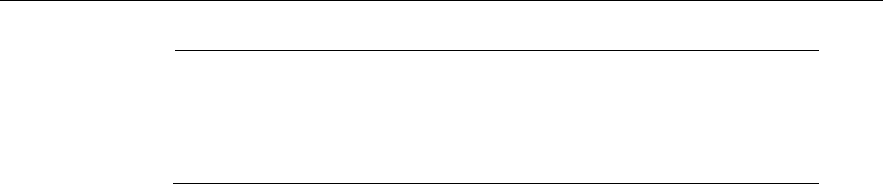
Post-Tensioned Concrete Design
Bonded Tendons 0.1
0.2
1.35 fctm
1.65 fctm
Unbonded tendons - 1.35 fctm
18.7 Beam Design (for Reference Only)
Important Note: Post-tensioned beam design is not available in the current ver-
sion of ETABS, but is planned for a future release. This section is provided as
reference only for the documentation of post-tensioned slab design.
In the design of prestressed concrete beams, ETABS calculates and reports the
required areas of reinforcement for flexure, shear, and torsion based on the beam
moments, shear forces, torsion, load combination factors, and other criteria de-
scribed in the subsections that follow. The reinforcement requirements are cal-
culated at each station along the length of the beam.
Beams are designed for major direction flexure, shear, and torsion only. Effects
resulting from any axial forces and minor direction bending that may exist in the
beams must be investigated independently by the user.
The beam design procedure involves the following steps:
Design flexural reinforcement
Design shear reinforcement
Design torsion reinforcement
18.7.1 Design Flexural Reinforcement
The beam top and bottom flexural reinforcement is designed at each station
along the beam. In designing the flexural reinforcement for the major moment
of a particular beam for a particular station, the following steps are involved:
Determine factored moments
Determine required flexural reinforcement
18 - 12 Beam Design (for Reference Only)

Chapter 18 - Design for Italian NTC 2008
18.7.1.1 Determine Factored Moments
In the design of flexural reinforcement of prestressed concrete beams, the
factored moments for each load combination at a particular beam station are ob-
tained by factoring the corresponding moments for different load cases, with the
corresponding load factors.
The beam section is then designed for the maximum positive and maximum neg-
ative factored moments obtained from all of the load combinations. Positive
beam moments can be used to calculate bottom reinforcement. In such cases the
beam may be designed as a rectangular or a flanged beam. Negative beam mo-
ments can be used to calculate top reinforcement. In such cases the beam may
be designed as a rectangular or inverted flanged beam.
18.7.1.2 Determine Required Flexural Reinforcement
In the flexural reinforcement design process, the program calculates both the
tension and compression reinforcement. Compression reinforcement is added
when the applied design moment exceeds the maximum moment capacity of a
singly reinforced section. The user has the option of avoiding the compression
reinforcement by increasing the effective depth, the width, or the strength of the
concrete.
The design procedure is based on the simplified rectangular stress block shown
in Figure 18-1 (EC2 3.1.7(3)).
Beam Design (for Reference Only) 18 - 13
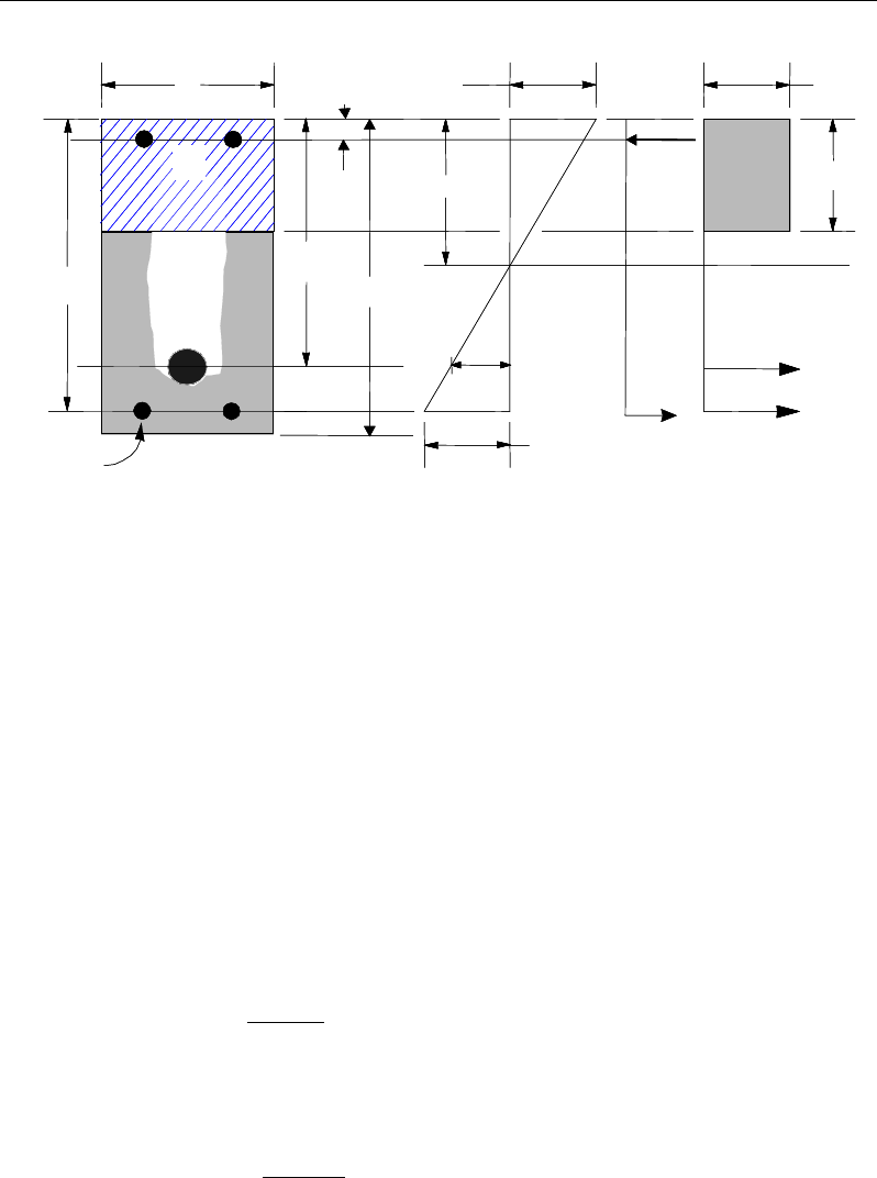
Post-Tensioned Concrete Design
Figure 18-1 Rectangular Beam Design
The area of the stress block and the depth of the center of the compressive force
from the most compressed fiber are taken as:
Fc =
η
fcd a b
a = λ x
where x is the depth of the neutral axis; the factor λ defines the effective height
of the compression zone; and the factor
η
defines the effective strength, as fol-
lows:
λ = 0.8 for fck ≤50 MPa (EC2 3.1.7(3))
ck
f50
0.8 400
λ
−
=
MPafor 50 90
ck
f≤≤
(EC2 3.1.7(3))
η
= 1.0 for fck ≤ 50 MPa and (EC2 3.1.7(3))
50
1.0
200
CK
f
η
−
= −
for 50 90MPa≤≥
ck
f
(EC2 3.1.7(3))
STRESS
DIAGRAM
STRAIN
DIAGRAM
BEAM
SECTION
s
A
p
A
p
d
s
A′
s
d
b
′
d
h
x
η
cd
f
λ
=
ax
ε
p
s
ε
s
C
cs
T
s
T
′
s
f
3
ε
cu
cps
T
STRESS
DIAGRAM
STRAIN
DIAGRAM
BEAM
SECTION
s
A
p
A
p
d
s
A′
s
d
b
′
d
h
x
η
cd
f
λ
=
ax
ε
p
s
ε
s
C
cs
T
s
T
′
s
f
3
ε
cu
cps
T
18 - 14 Beam Design (for Reference Only)

Chapter 18 - Design for Italian NTC 2008
Furthermore, it is assumed that moment redistribution in the beam does not ex-
ceed the code specified limiting value. The code also places a limitation on the
neutral axis depth, to safeguard against non-ductile failures (EC2 5.5(4)). When
the applied moment exceeds the limiting moment capacity as a singly reinforced
beam, the area of compression reinforcement is calculated on the
assumption that the neutral axis depth remains at the maximum permitted value.
The design procedure used by ETABS, for both rectangular and flanged sections
(L- and T-beams), is summarized in the subsections that follow.
18.7.1.2.1 Design of Rectangular Beams
ETABS first determines if the moment capacity provided by the post-tensioning
tendons alone is enough. In calculating the capacity, it is assumed that As = 0. In
that case, the moment capacity
0
ED
M
is determined as follows:
The maximum depth of the compression zone, xmax, is calculated based on the
limitation that the tension reinforcement strain shall not be less than
ε
smin:
cmax =
3
3 min
cu p
cu s
d
ε
εε
+
where,
ε
cu3 = 0.0035
Therefore, the limit
max
xx≤
is set for tension-controlled sections.
The maximum allowable depth of the compression block is given by:
max max
ax
λ
=
(EC2 3.1.7(3))
where,
0.8
λ
=
if
50MPa
ck
f<
(EC2 3.1.7)
50
0.8 400
ck
f
λ
−
= −
if
50MPa
ck
f>
(EC2 3.1.7)
Beam Design (for Reference Only) 18 - 15

Post-Tensioned Concrete Design
ETABS determines the depth of the neutral axis, c, by imposing force equilib-
rium, i.e., C = T. After the depth of the neutral axis has been determined, the
stress in the post-tensioning steel, fpk is computed based on strain compatibility
for bonded tendons. For unbonded tendons, the code equations are used to com-
pute the stress, fps in the post-tensioning steel.
Based on the calculated fpk, the depth of the neutral axis is recalculated, and fpk is
further updated. After this iteration process has converged, the depth of the rec-
tangular compression block is determined as follows:
ax
λ
=
If
max
aa≤
(EC2 3.1.7(3)), the moment capacity of the section, provided by
post-tensioning steel only, is computed as:
0
2
ED pk p p
a
M fA d
= −
If
max
aa>
(EC2 3.1.7(3)), a failure condition is declared.
If
0
,
ED
MM>
ETABS calculates the moment capacity and the As required at
the balanced condition. The balanced condition is taken as the marginal ten-
sion-controlled case. In that case, it is assumed that the depth of the neutral
axis x is equal to xmax. The stress in the post-tensioning steel, fpk, is then calcu-
lated based on strain compatibility and the area of required tension reinforce-
ment, As, is determined by imposing force equilibrium, i.e., C = T.
maxcd
C fa b
η
=
bal bal bal
p pk s s
T Af A f= +
max bal
cd p pk
bal
sbal
s
fa b Af
Af
η
−
=
After the area of tension reinforcement has been determined, the capacity of the
section with post-tensioning steel and tension reinforcement is computed as:
18 - 16 Beam Design (for Reference Only)

Chapter 18 - Design for Italian NTC 2008
max max
22
bal bal bal bal
ED p pk p s s s
aa
M Afd Afd
= −+ −
In that case, it is assumed that the bonded tension reinforcement will yield, which
is true for most cases. In the case that it does not yield, the stress in the reinforce-
ment, fs, is determined from the elastic-perfectly plastic stress-strain relationship.
The fy value of the reinforcement is then replaced with fs in the preceding four
equations. This case does not involve any iteration in determining the depth of
the neutral axis, x.
18.7.1.2.1.1 Case 1: Post-tensioning steel is adequate
When
0
,
ED
MM<
the amount of post-tensioning steel is adequate to resist the
design moment M. A minimum reinforcement is provided to satisfy the flexural
cracking requirements (EC2 7.3.2).
18.7.1.2.1.2 Case 2: Post-tensioning steel plus tension reinforcement
In this case, the amount of post-tensioning steel, Ap, alone is not sufficient to
resist M, and therefore the required area of tension reinforcement is computed to
supplement the post-tensioning steel. The combination of post-tensioning steel
and tension reinforcement should result in a < amax.
When
( )
0
,
bal
ED ED
M MM<<
ETABS determines the required area of tension rein-
forcement, As, iteratively to satisfy the design moment M and reports this
required area of tension reinforcement. Since
M
is bound by
0
ED
M
at the lower
end and
bal
ED
M
at the upper end, and
0
ED
M
is associated with
0=
s
A
and
bal
ED
M
is
associated with
,=
bal
ss
AA
the required area will fall within the range of 0 to
Asbal.
The tension reinforcement is to be placed at the bottom if M is positive, or at the
top if M is negative.
Beam Design (for Reference Only) 18 - 17

Post-Tensioned Concrete Design
18.7.1.2.1.3 Case 3: Post-tensioning steel and tension reinforcement is not
adequate
When
()
,
>
bal
ED
MM
compression reinforcement is required (EC2 5.5 (4)). In that
case, ETABS assumes that the depth of the neutral axis, x, is equal to
max .x
The
values of fpk and fs reach their respective balanced condition values,
bal
pk
f
and
.
bal
s
f
Then the area of compression reinforcement,
,
′
s
A
is determined as fol-
lows:
The moment required to be resisted by compression reinforcement and tension
reinforcement is:
,= − bal
ED s ED
M MM
The required compression reinforcement is given by:
s
A′
=
( )( )
,
0.87 ′
ED,s
s cd
M
f-
ηf d - d'
where
s
f′
= εcu3Es
max
max
'ad
a
−
≤ 0.87fy.
The tension reinforcement for balancing the compression reinforcement is given
by:
( )
,
0.87 '
=−
ED s
com
sys
M
Afd d
Therefore, the total tension reinforcement, As =
bal
s
A
+
,
com
s
A
and the total com-
pression reinforcement is A's. As is to be placed at the bottom and A's is to be
placed at the top if M is positive, and vice versa if M is negative.
18 - 18 Beam Design (for Reference Only)

Chapter 18 - Design for Italian NTC 2008
18.7.1.2.2 Design of Flanged Beams
18.7.1.2.2.1 Flanged Beam Under Negative Moment
In designing for a factored negative moment, M
(i.e., designing top reinforce-
ment), the calculation of the reinforcement area is exactly the same as described
previously, i.e., no flanged beam data is used.
18.7.1.2.2.2 Flanged Beam Under Positive Moment
ETABS first determines if the moment capacity provided by the post-tensioning
tendons alone is enough. In calculating the capacity, it is assumed that As = 0. In
that case, the moment capacity
0
ED
M
is determined as follows:
Figure 18-2 T-Beam Design
The maximum depth of the compression zone, xmax, is calculated based on the
limitation that the tension reinforcement strain shall not be less than
ε
smin:
cmax =
3
3 min
cu p
cu s
d
ε
εε
+
where,
ε
cu3 = 0.0035
STRESS
DIAGRAM
STRAIN
DIAGRAM
BEAM
SECTION
ε
ps
s
ε
s
T
w
T
f
T
f
C
w
C
s
C
′
s
f
′
d
p
ds
d
λ
=ax
3
ε
cu
η
cd
f
η
cd
f
x
s
A′
ps
A
w
b
f
bf
h
STRESS
DIAGRAM
STRAIN
DIAGRAM
BEAM
SECTION
ε
ps
s
ε
s
T
w
T
f
T
f
C
w
C
s
C
′
s
f
′
d
p
ds
d
λ
=ax
3
ε
cu
η
cd
f
η
cd
f
x
s
A′
ps
A
w
b
f
bf
h
Beam Design (for Reference Only) 18 - 19

Post-Tensioned Concrete Design
Therefore, the program limit for the depth of the neutral axis is x ≤ xmax for ten-
sion-controlled sections.
The maximum depth of the compression block is given by:
max max
ax
λ
=
(EC2 3.1.7(3))
where,
λ
=0.8
if
MPa<50
ck
f
(EC2 3.1.7)
λ
−
= −
50
0.8 400
ck
f
if
50MPa
ck
f>
(EC2 3.1.7)
ETABS determines the depth of the neutral axis, c, by imposing force equilib-
rium, i.e., C = T. After the depth of the neutral axis has been determined, the
stress in the post-tensioning steel, fpk, is computed based on strain compatibility
for bonded tendons. For unbonded tendons, the code equations are used to com-
pute the stress, fps, in the post-tensioning steel. Based on the calculated fpk, the
depth of the neutral axis is recalculated, and fpk is further updated. After this
iteration process has converged, the depth of the rectangular compression block
is determined as follows:
ax
λ
=
If a ≤ amax (EC2 3.1.7(3)), the moment capacity of the section, provided by
post-tensioning steel only, is computed as:
0
2
ED pk p p
a
M fA d
= −
If a > amax (EC2 3.1.7(3)), a failure condition is declared.
If
ED
MM
0
,>
ETABS calculates the moment capacity and the As required at
the balanced condition. The balanced condition is taken as the marginal ten-
sion- controlled case. In that case it is assumed that the depth of the neutral
axis x is equal to xmax. The stress in the post-tensioning steel, fpk, is then calcu-
lated based on strain compatibility, and the area of required tension reinforce-
ment, As, is determined by imposing force equilibrium, i.e., C = T.
18 - 20 Beam Design (for Reference Only)

Chapter 18 - Design for Italian NTC 2008
If a ≤ hf, the subsequent calculations for As are exactly the same as previously
defined for the rectangular beam design. However, in this case, the width of
the beam is taken as bf. Compression reinforcement is required when a > amax.
If a > hf, the calculation for As is given by:
max com
cd c
C fa A
η
=
where
com
c
A
is the area of concrete in compression, i.e.,
bal bal bal
p pk s s
T Af A f= +
max com bal
cd c p pk
bal
sbal
s
fa A Af
Af
η
−
=
After the area of tension reinforcement has been determined, the capacity of the
section with post-tensioning steel and tension reinforcement is computed as:
max max
22
bal bal bal bal
ED p pk p s s s
aa
M Afd Afd
= −+ −
In that case, it is assumed that the bonded tension reinforcement will yield, which
is true for most cases. In the case that it does not yield, the stress in the reinforc-
ing steel, fs, is determined from the elastic-perfectly plastic stress-strain relation-
ship. The fy value of the reinforcement is then replaced with fs in the preceding
four equations. This case does not involve any iteration in determining the depth
of the neutral axis, x.
18.7.1.2.2.2.1 Case 1: Post-tensioning steel is adequate
When
0
,
ED
MM<
the amount of post-tensioning steel is adequate to resist the
design moment M. Minimum reinforcement is provided to satisfy the flexural
cracking requirements (EC2 7.3.2).
18.7.1.2.2.2.2 Case 2: Post-tensioning steel plus tension reinforcement
In this case, the amount of post-tensioning steel, Ap, alone is not sufficient to
resist M, and therefore the required area of tension reinforcement is computed to
supplement the post-tensioning steel. The combination of post-tensioning steel
and tension reinforcement should result in a < amax.
Beam Design (for Reference Only) 18 - 21

Post-Tensioned Concrete Design
When
( )
0
,
bal
ED ED
M MM<<
ETABS determines the required area of tension rein-
forcement, As, iteratively to satisfy the design moment M and reports the
required area of tension reinforcement. Since
M
is bounded by
0
ED
M
at the
lower end and
bal
ED
M
at the upper end, and
0
ED
M
is associated with
0
s
A=
and
bal
ED
M
is associated with
bal
ss
AA,=
the required area will be within the range of
0 to
s
A
.
The tension reinforcement is to be placed at the bottom if M is positive, or at the
top if M is negative.
18.7.1.2.2.2.3 Case 3: Post-tensioning steel and tension reinforcement is not adequate
When
( )
,
bal
ED
MM>
compression reinforcement is required (EC2 5.5 (4)). In that
case ETABS assumes that the depth of the neutral axis, x, is equal to
max
.x
The
values of fpk and fs reach their respective balanced condition values, bal
pk
f and
.
bal
s
f
Then the area of compression reinforcement,
,
′
s
A
is determined as follows:
The moment required to be resisted by compression reinforcement and tension
reinforcement is:
,bal
ED s ED
M MM
= −
The required compression reinforcement is given by:
′
s
A
=
()( )
,
,
0.87 ' '
ED s
s cd
M
f f dd
η
−−
where
′
s
f
= εcu3Es
max
max
'ad
a
−
≤ 0.87fy.
The tension reinforcement for balancing the compression reinforcement is given
by:
( )
,
0.87 '
ED s
com
sys
M
Afd d
=−
18 - 22 Beam Design (for Reference Only)

Chapter 18 - Design for Italian NTC 2008
Therefore, the total tension reinforcement, As =
bal
s
A
+
,
com
s
A
and the total com-
pression reinforcement is A's. As is to be placed at the bottom and A's is to be
placed at the top if M is positive, and vice versa if M is negative.
18.7.1.2.3 Minimum and Maximum Reinforcement
Reinforcement in prestressed concrete beams is computed to increase the
strength of sections as required in the flexural design of prestressed beam or to
comply with shear link requirements. The minimum flexural tension reinforce-
ment required for a beam section to comply with the cracking requirements must
be separately investigated by the user.
For bonded tendons, there is no minimum un-tensioned reinforcement require-
ments.
For unbonded tendons, the minimum flexural reinforcement provided in a rec-
tangular or flanged beam section is given as:
,min
0.26 0.0013
ctm
syk
f
A bd bd
f
= ≥
(EC2 9.2.1.1)
where fctm is the mean value of axial tensile strength of the concrete and is com-
puted as:
( )
32
30.0
ckctm
ff =
for fck ≤ 50 MPa (EC2 3.12, Table 3.1)
( )
ctm cm
f ln f2.12 1 10= +
for fck > 50 MPa (EC2 3.12, Table 3.1)
8 MPa
cm ck
ff= +
(EC2 3.12, Table 3.1)
The minimum flexural tension reinforcement required for control of cracking
should be investigated independently by the user.
In addition, an upper limit on both the tension reinforcement and compression
reinforcement has been imposed to be 0.04 times the gross cross-sectional area
(EC2 9.2.1.1(3)).
Beam Design (for Reference Only) 18 - 23

Post-Tensioned Concrete Design
18.7.2 Design Beam Shear Reinforcement
The shear reinforcement is designed for each loading combination at each
station along the length of the beam. In designing the shear reinforcement for a
particular beam, for a particular loading combination, at a particular station due
to the beam major shear, the following steps are involved (EC2 6.2):
Determine the factored shear force, V
Determine the shear force, VRd,c, that can be resisted by the concrete
Determine the shear reinforcement required to carry the balance
The following three sections describe in detail the algorithms associated with
these steps.
18.7.2.1 Determine Shear Force
In the design of the beam shear reinforcement, the shear forces for each load
combination at a particular beam station are obtained by factoring the cor-re-
sponding shear forces for different load cases with the corresponding load com-
bination factors.
18.7.2.2 Determine Concrete Shear Capacity
The design shear resistance of the beam without shear reinforcement, VRd,c is
calculated as:
VRd,c = [CRd,c k(100 ρ1fck)1/3 + k1 σcp ] (bwd) (EC2 6.2.2(1))
VRd,c ≥ [vmin + k1 σcp ] (bwd), (EC2 6.2.2(1))
where fck is in MPa
200
1 2.0kd
=+≤
with d in mm (EC2 6.2.2(1))
ρ
1 = tension reinforcement ratio =
( )
1s ps
w
AA
bd
+
≤ 0.02 (EC2 6.2.2(1))
18 - 24 Beam Design (for Reference Only)

Chapter 18 - Design for Italian NTC 2008
As1 = area of mild-tension reinforcement (EC2 6.2.2(1))
Aps = area of prestress-tension reinforcement (EC2 6.2.2(1))
σcp = average stress in concrete due to axial
force
Ed c
NA
(EC2 6.2.2(1))
0.2
cp Ed c cd
N A fzσ= <
MPa (EC2 6.2.2(1))
Ac = the total gross area of concrete section
The value of CRd,c, vmin, and k1 for use in a country may be found in its National
Annex. The program default values for CRd,c, vmin and k1 are given as follows
(EC2 6.2.2(1)):
CRd,c = 0.18/γc,
vmin = 0.035 k3/2 fck1/2
k1 = 0.15.
If light-weight concrete:
CRd,c= 0.15/γc (EC2 11.6.1(1))
vmin = 0.03 k3/2 fck1/2 (EC2 11.6.1(1))
k1 = 0.15. (EC2 11.6.1(1))
18.7.2.3 Determine Required Shear Reinforcement
The shear reinforcement is designed for each load combination at each station
along the length of the beam. The assumptions in designing the shear reinforce-
ment are as follows:
The beam sections are assumed to be prismatic. The effect of any variation of
width in the beam section on the concrete shear capacity is neglected.
The effect on the concrete shear capacity of any concentrated or distributed
load in the span of the beam between two columns is ignored. Also, the
effect of the direct support on the beams provided by the columns is ignored.
Beam Design (for Reference Only) 18 - 25

Post-Tensioned Concrete Design
All shear reinforcement is assumed to be perpendicular to the longitudinal
reinforcement.
In designing the shear reinforcement for a particular beam, for a particular load
combination, the following steps of the standard method are involved (EC2 6.2).
Obtain the design value of the applied shear force V from the ETABS analysis
results (EC2 6.2.3(3)).
The shear force is limited to a maximum of:
1
,max
,
cot tan
cw w cd
Rd
bz f
V
αν
θθ
=+
where (EC2 6.2.3(3))
αcw is conservatively taken as 1 (EC2 6.2.3(3))
The strength reduction factor for concrete cracked in shear, v1 is defined as:
−= 250
1
6.0
1ck
f
ν
(EC2 6.2.2(6))
z = 0.9d (EC2 6.2.3(1))
θ is optimized by program and is set to 45° for combinations including seis-
mic loading (EC2 6.2.3(2)).
Given VEd, VRdc, VRd,max, the required shear reinforcement in area/unit length
is calculated as follows:
If VEd ≤ VRdc,
v
sw
s
A
=
s
Asw min
,
If VR,dc < VEd ≤ VRd,max
s
A
zf
V
s
Asw
ywd
Edsw min,
cot ≥=
θ
(EC2 6.2.3(3))
If VEd > VRd,max
18 - 26 Beam Design (for Reference Only)

Chapter 18 - Design for Italian NTC 2008
a failure condition is declared. (EC2 6.2.3(3))
The maximum of all the calculated Asw /sv values, obtained from each load com-
bination, is reported along with the controlling shear force and associated load
combination number.
The minimum shear reinforcement is defined as:
,min 0.08 ck
sw w
yk
f
Ab
sf
=
(EC2 9.2.2(5))
The beam shear reinforcement requirements considered by the program are
based purely on shear strength considerations. Any minimum stirrup require-
ments to satisfy spacing and volumetric considerations must be investigated
independently of the program by the user.
18.7.3 Design Beam Torsion Reinforcement
The torsion reinforcement is designed for each design load combination at each
station along the length of the beam. The following steps are involved in
designing the longitudinal and shear reinforcement for a particular station due to
the beam torsion:
Determine the factored torsion, TEd
Determine special section properties
Determine critical torsion capacity
Determine the torsion reinforcement required
18.7.3.1 Determine Factored Torsion
In the design of beam torsion reinforcement, the torsions for each load combina-
tion at a particular beam station are obtained by factoring the corresponding tor-
sions for different load cases with the corresponding load combination factors.
In a statically indeterminate structure where redistribution of the torsion in a
member can occur due to redistribution of internal forces upon cracking, the de-
sign TEd is permitted to be reduced in accordance with the code (EC2 6.3.1(2)).
Beam Design (for Reference Only) 18 - 27

Post-Tensioned Concrete Design
However, the program does not automatically redistribute the internal forces and
reduce TEd. If redistribution is desired, the user should release the torsional de-
gree of freedom (DOF) in the structural model.
18.7.3.2 Determine Special Section Properties
For torsion design, special section properties, such as Ak, tef, u, uk, and zi are cal-
culated. These properties are described in the following (EC2 6.3.2).
A
=
Area enclosed by the outside perimeter of the cross-section
A
k
=
Area enclosed by centerlines of the connecting walls, where
the centerline is located a distance of tef /2 from the outer sur-
face
t
ef
=
Effective wall thickness, A
/
u. It is taken as at least twice the
distance between the edge and center of the longitudinal re-
bar.
u
=
Outer perimeter of the cross-section
u
k
=
Perimeter of the area A
k
z
i
=
Side length of wall i, defined as the distance between the in-
tersection points of the wall centerlines
In calculating the section properties involving reinforcement, such as Ak, and uk,
it is assumed that the distance between the centerline of the outermost closed
stirrup and the outermost concrete surface is 50 mm. This is equivalent to 38-
mm clear cover and a 12-mm stirrup. For torsion design of flanged beam sec-
tions, it is assumed that placing torsion reinforcement in the flange area is inef-
ficient. With this assumption, the flange is ignored for torsion reinforcement cal-
culation. However, the flange is considered during calculation of torsion section
properties. With this assumption, the special properties for a rectangular beam
section are given as:
A
=
bh (EC2 6.3.2(1))
A
k
=
(b
−
t
ef
)(h
−
t
ef
) (EC2 6.3.2(1))
18 - 28 Beam Design (for Reference Only)

Chapter 18 - Design for Italian NTC 2008
u
=
2b + 2h
(EC2 6.3.2(1))
u
k
=
2(b
−
t
ef
) + 2(h
−
t
ef
) (EC2 6.3.2(3))
where, the section dimensions b, h, and c are shown in Figure 18-3. Similarly,
the special section properties for a flanged beam section are given as:
A
=
b
w
h (EC2 6.3.2(1))
A
k
=
(b
w
– t
ef
)(h – t
ef
) (EC2 6.3.2(1))
u
=
2b
w
+ 2h
(EC2 6.3.2(1))
u
k
=
2(h – t
ef
) + 2(b
w
– t
ef
) (EC2 6.3.2(3))
where the section dimensions bf, bw, h, hf, and c for a flanged beam are shown in
Figure 18-3.
Figure 18-3 Closed stirrup and section dimensions for torsion design
cb 2
h
s
d
Closed Stirrup in
Rectangular Beam
Closed Stirrup in
T-Beam Section
c
h2
−h
b
ch 2
−
w
b
Closed Stirrup in
Rectangular Beam
Closed Stirrup in
T-Beam Section
ch 2
−ch 2
−
f
h
ef
b
hh
b
c
c
cc
c
c
b 2c
−
w
b 2c−
w
b
cb 2
h
s
d
Closed Stirrup in
Rectangular Beam
Closed Stirrup in
T-Beam Section
ch 2
−h
b
ch 2
−
w
b
Closed Stirrup in
Rectangular Beam
Closed Stirrup in
T-Beam Section
c
h2
−c
h2
−
f
h
ef
b
hh
b
c
c
cc
c
c
b 2c−
w
b 2c
−
w
b
Beam Design (for Reference Only) 18 - 29

Post-Tensioned Concrete Design
18.7.3.3 Determine Critical Torsion Capacity
The torsion in the section can be ignored with only minimum shear reinforce-
ment (EC2 9.2.1.1) required if the following condition is satisfied:
,,
1.0
Ed Ed
Rd c Rd c
TV
TV
+≤
(EC2 6.3.2(5))
where VRd,c is as defined in the previous section and TRd,c is the torsional cracking
moment, calculated as:
kefctdcRd
AtfT 2
,
=
(EC2 6.3.2(1), 6.3.2(5))
where tef, and fctd, the design tensile strength, are defined as:
tef =
Au
(EC2 6.3.2(1))
0 05ctd ct ctk . c
ff
αγ
=
(EC2 Eq. 3.16)
where A is the gross cross-section area, u is the outer circumference of the cross-
section,
α
ct is a coefficient, taken as 1.0, taking account of long- term effects on
the tensile strength, and fctk0.05 is defined as:
fctk0.05 = 0.7fctm (EC2 Table 3.1)
18.7.3.4 Determine Torsion Reinforcement
If the expression in the previous subsection is satisfied, torsion can be safely
ignored (EC2 6.3.2(5)) with only minimum shear reinforcement required. In that
case, the program reports that no torsion reinforcement is required. However, if
the equation is not satisfied, it is assumed that the torsional resistance is provided
by closed stirrups, longitudinal bars, and compression diagonals.
If torsion reinforcement in the form of closed stirrups is required, the shear due
to this torsion, Vt, is first calculated, followed by the required stirrup area, as:
θ
cot
ywd
tt
zf
V
s
A=
(EC2 6.2.3(3))
18 - 30 Beam Design (for Reference Only)

Chapter 18 - Design for Italian NTC 2008
( )
2
Ed con
t ef
k
TT
V ht A
−
= −
(EC2 6.3.2(1))
The required longitudinal reinforcement for torsion is defined as:
,
,
1
Ed
con Rd c
Rd c
V
TT
V
= −
(EC2 6.3.2(5))
yd
k
k
Ed
sl f
u
A
T
A
θ
cot
2
=
(EC2 6.3.2(3))
where
θ
is the angle of the compression struts, as previously defined for beam
shear. In the preceding expressions,
θ
is taken as 45 degrees. The code allows
any value between 21.8 and 45 degrees (EC2 6.2.3(2)), while the program
assumes the conservative value of 45 degrees.
When torsional reinforcement is required, an upper limit on the combination of
VEd and TEd that can be carried by the section without exceeding the capacity of
the concrete struts also is checked using:
0.1
max,max,
≤+
Rd
Ed
Rd
Ed
V
V
T
T
(EC2 6.3.2(4))
where TRd,max, the design torsional resistance moment is defined as:
,max 2 sin cos
Rd cw cd k ef
T f At
να θ θ
=
(EC2 6.3.2(4))
If this equation is not satisfied, a failure condition is declared. In that case, the
concrete section should be increased in size.
The maximum of all of the calculated Asl and At /s values obtained from each
load combination is reported, along with the controlling combination.
The beam torsion reinforcement requirements reported by the program are based
purely on strength considerations. Any minimum stirrup requirements or longi-
tudinal rebar requirements to satisfy spacing considerations must be
investigated independently of the program by the user.
Beam Design (for Reference Only) 18 - 31

Post-Tensioned Concrete Design
18.8 Slab Design
Similar to conventional design, the ETABS slab design procedure involves
defining sets of strips in two mutually perpendicular directions. The locations of
the strips usually are governed by the locations of the slab supports. The mo-
ments for a particular strip are recovered from the analysis and a flexural design
is carried out based on the ultimate strength design method for prestressed rein-
forced concrete (EC2-2004) as described in the following sections. To learn
more about the design strips, refer to the section entitled "ETABS Design Tech-
niques" in the Key Features and Terminology manual.
18.8.1 Design for Flexure
ETABS designs the slab on a strip-by-strip basis. The moments used for the
design of the slab elements are the nodal reactive moments, which are obtained
by multiplying the slab element stiffness matrices by the element nodal displace-
ment vectors. These moments will always be in static equilibrium with the ap-
plied loads, irrespective of the refinement of the finite element mesh.
The design of the slab reinforcement for a particular strip is carried out at
specific locations along the length of the strip. These locations correspond to the
element boundaries. Controlling reinforcement is computed on either side of
those element boundaries. The slab flexural design procedure for each load com-
bination involves the following:
Determine factored moments for each slab strip.
Design flexural reinforcement for the strip.
These two steps are described in the subsection that follows and are repeated for
every load combination. The maximum reinforcement calculated for the top and
bottom of the slab within each design strip, along with the corresponding con-
trolling load combination numbers, is obtained and reported.
18.8.1.1 Determine Factored Moments for the Strip
For each element within the design strip, for each load combination, the program
calculates the nodal reactive moments. The nodal moments are then added to get
the strip moments.
18 - 32 Slab Design

Chapter 18 - Design for Italian NTC 2008
18.8.1.2 Design Flexural Reinforcement for the Strip
The reinforcement computation for each slab design strip, given the bending mo-
ment, is identical to the design of rectangular beam sections described
earlier (or to the flanged beam if the slab is ribbed). In some cases, at a given
design section in a design strip, there may be two or more slab properties across
the width of the design strip. In that case, the program automatically designs the
tributary width associated with each of the slab properties separately using its
tributary bending moment. The reinforcement obtained for each of the tributary
widths is summed to obtain the total reinforcement for the full width of the de-
sign strip at the considered design section. This method is used when drop panels
are included. Where openings occur, the slab width is adjusted accordingly.
18.8.1.2.1 Minimum and Maximum Slab Reinforcement
The minimum flexural tension reinforcement required for each direction of a
slab is given by the following limits (EC2 9.3.1.1, 9.2.1.1, UK, NA Table NA.1):
bd
f
f
A
yk
ctm
s
26.0
min,
=
(EC2 9.2.1.1(1))
bdA
s
0013.0
min,
=
(EC2 9.2.1.1(1))
where fctm is the mean value of axial tensile strength of the concrete and is com-
puted as:
( )
32
30.0
ckctm
ff =
for fck ≤ 50 MPa (EC2 Table 3.1)
( )
ctm cm
f ln f
2.12 1 10= +
for fck > 50 MPa (EC2 Table 3.1)
8 MPa
cm ck
ff= +
(EC2 Table 3.1)
The minimum flexural tension reinforcement required for control of cracking
should be investigated independently by the user.
An upper limit on the tension reinforcement and compression reinforcement has
been imposed to be 0.04 times the gross cross-sectional area (EC2 9.2.1.1(3)).
Slab Design 18 - 33
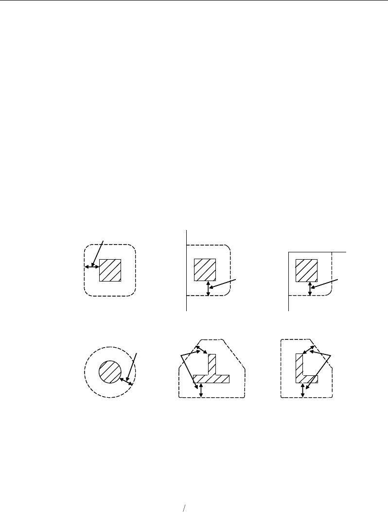
Post-Tensioned Concrete Design
18.8.2 Check for Punching Shear
The algorithm for checking punching shear is detailed in the section entitled
“Slab Punching Shear Check” in the Key Features and Terminology manual.
Only the code specific items are described in the following.
18.8.2.1 Critical Section for Punching Shear
The punching shear is checked at the face of the column (EC2 6.4.1(4)) and at a
critical section at a distance of 2.0d from the face of the support (EC2 6.4.2(1)).
The perimeter of the critical section should be constructed such that its length is
minimized. Figure 18-4 shows the auto punching perimeters considered by
ETABS for the various column shapes. The column location (i.e., interior, edge,
corner) and the punching perimeter may be overwritten using the Punching
Check Overwrites.
Figure 18-4 Punching Shear Perimeters
18.8.2.2 Determine Concrete Capacity
The concrete punching shear stress capacity is taken as:
( )
13
,,1 1
100
Rd c Rd c ck cp
V Ck f k
ρσ
= +
(EC2 6.4.4(1))
2d
Interior Column
Circular Column T-Shape Column
Edge Column Corner Column
L-Shape Column
2d 2d
2d
2d
2d
2d
Interior Column
Circular Column T-Shape Column
Edge Column Corner Column
L-Shape Column
2d 2d
2d
2d
2d
18 - 34 Slab Design
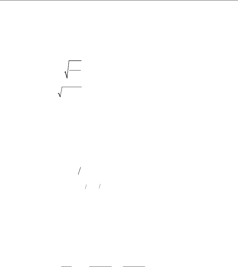
Chapter 18 - Design for Italian NTC 2008
with a minimum of:
( )
cpcRd k
vV
σ
1min,+=
(EC2 6.4.4(1))
where fck is in MPa and
200
1 2.0kd
=+≤
with d in mm (EC2 6.4.4(1))
ρ
1 =
yx 11
ρρ
≤ 0.02 (EC2 6.4.4(1))
where
ρ
1x and
ρ
1y are the reinforcement ratios in the x and y directions respec-
tively, conservatively taken as zeros, and
σcp = (σcx + σcy)/2 (EC2 6.4.4(1))
where σcx and σcy are the normal concrete stresses in the critical section in the x
and y directions respectively, conservatively taken as zeros.
ccRd
C
γ
18.0
,=
(EC2 6.4.4(1))
21
23
min 035.0 ck
fk=
ν
(EC2 6.4.4(1))
k1 = 0.15 (EC2 6.4.4(1))
18.8.2.3 Determine Maximum Shear Stress
Given the punching shear force and the fractions of moments transferred by ec-
centricity of shear, the nominal design shear stress, vEd, is calculated as:
,2 1 ,3 1
1,2 1,3
1,
=++
Ed Ed
Ed
Ed
Ed Ed
Mu Mu
V
v kk
ud VW VW
where (EC2 6.4.4(2))
k is the function of the aspect ratio of the loaded area in Table 6.1 of EN
1992-1-1
u1 is the effective perimeter of the critical section
d is the mean effective depth of the slab
Slab Design 18 - 35

Post-Tensioned Concrete Design
MEd is the design moment transmitted from the slab to the column at the
connection along bending axis 2 and 3
VEd is the total punching shear force
W1 accounts for the distribution of shear based on the control perimeter
along bending axis 2 and 3.
18.8.2.4 Determine Capacity Ratio
The ratio of the maximum shear stress and the concrete punching shear stress
capacity is reported as the punching shear capacity ratio by ETABS. If this ratio
exceeds 1.0, punching shear reinforcement is designed as described in the fol-
lowing section.
18.8.3 Design Punching Shear Reinforcement
The use of shear studs as shear reinforcement in slabs is permitted provided that
the effective depth of the slab is greater than or equal to 200 mm.
The algorithm for designing the required punching shear reinforcement is used
when the punching shear capacity ratio exceeds unity. The Critical Section for
Punching Shear as described in the earlier section remain unchanged. The design
of punching shear reinforcement is as described in the following subsections.
18.8.3.1 Determine Required Shear Reinforcement
The shear stress is limited to a maximum limit of
VRd,max =
( )
1
cot tan
cw cd w
vf bz
α
θ+ θ
where (EC2 6.2.3(3))
αcw is conservatively taken as 1
v1 =
0.6 1 250
ck
f
−
z = 0.9d (EC2 6.2.3(1))
18 - 36 Slab Design

Chapter 18 - Design for Italian NTC 2008
1 ≤ cot θ ≤ 2.5, program default value is 1, which can
be overwritten by the user (EC2 6.2.3(2))
Given νEd, vRd,c and vRd,max, the required shear reinforcement is calculated as fol-
lows (EC2 6.4.5):
If νEd < vRd,max,
w
A
=
()
r
s
−
,
0.75
1.5
Ed Rd c
ywd
v vu
f
(EC2 6.4.5)
If νEd > vRd,max, a failure condition is declared. (EC2 6.4.3)
If νEd exceeds the maximum permitted value of vRD,max, the concrete section
should be increased in size.
18.8.3.2 Determine Reinforcement Arrangement
Punching shear reinforcement in the vicinity of a rectangular columns should be
arranged on peripheral lines, i.e., a line running parallel to and at constant dis-
tances from the sides of the column. Figure 18-5 shows a typical arrangement of
shear reinforcement in the vicinity of a rectangular interior, edge, and corner
column.
The distance between the column face and the first line of shear reinforcement
shall not exceed 2d. The spacing between adjacent shear reinforcement in the
first line of shear reinforcement shall not exceed 2d measured in a direction par-
allel to the column face (EC2 6.4.5(4)).
Punching shear reinforcement is most effective near column corners where there
are concentrations of shear stress. Therefore, the minimum number of lines of
shear reinforcement is 4, 6, and 8, for corner, edge, and interior columns respec-
tively.
Slab Design 18 - 37
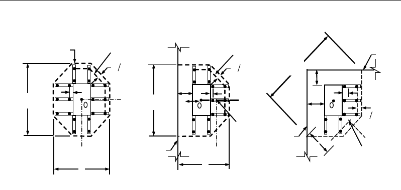
Post-Tensioned Concrete Design
Figure 18-5 Typical arrangement of shear studs and
critical sections outside shear-reinforced zone
18.8.3.3 Determine Reinforcement Diameter, Height, and Spacing
The punching shear reinforcement is most effective when the anchorage is close
to the top and bottom surfaces of the slab. The cover of anchors should not be
less than the minimum cover specified in EC2 4.4.1 plus half of the diameter of
the flexural reinforcement.
Punching shear reinforcement in the form of shear studs is generally available in
10-, 12-, 14-, 16-, and 20-millimeter diameters.
When specifying shear studs, the distance, so, between the column face and the
first peripheral line of shear studs should not be smaller than 0.3d. The spacing
between adjacent shear studs, g, at the first peripheral line of studs shall not ex-
ceed 1.5d and should not exceed 2d at additional perimeters. The limits of so and
the spacing, s, between the peripheral lines are specified as:
0.3d ≤ so ≤ 2d (EC2 9.4.3(1))
s ≤ 0.75d (EC2 9.4.3(1))
g ≤ 1.5d (first perimeter) (EC2 9.4.3(1))
g ≤ 2d (additional perimeters) (EC2 9.4.3(1))
I
y
Typical Studrail
(only first and last
studs shown)
Outermost
peripheral line
of studs
Interior Column Edge Column Corner Column
Critical section
centroid
Free
edge
Free
edge
Critical
section
centroid
Free edge
Outermost
peripheral line
of studs
I
y
I
y
yx
d2 d2
d2
x
I
x
I
x
g
y
g
x
g
0
s
0
s
0
s
x
I
y
x
x
I
y
Typical Studrail
(only first and last
studs shown)
Outermost
peripheral line
of studs
Interior Column Edge Column Corner Column
Critical section
centroid
Free
edge
Free
edge
Critical
section
centroid
Free edge
Outermost
peripheral line
of studs
I
y
I
y
yx
d2 d2
d2
x
I
x
I
x
g
y
g
x
g
0
s
0
s
0
s
x
I
y
x
x
18 - 38 Slab Design

Chapter 19
Design for Hong Kong CP 2013
This chapter describes in detail the various aspects of the post-tensioned concrete
design procedure that is used by ETABS when the user selects the Hong Kong
limit state code CP-2013 [CP 2013]. Various notations used in this chapter are
listed in Table 19-1. For referencing to the pertinent sections of the Hong Kong
CP code in this chapter, a prefix “CP” followed by the section number is used.
The design is based on user-specified load combinations. The program
provides a set of default load combinations that should satisfy the requirements
for the design of most building type structures.
English as well as SI and MKS metric units can be used for input. The code is
based on Newton-millimeter-second units. For simplicity, all equations and
descriptions presented in this chapter correspond to Newton-millimeter-second
units unless otherwise noted.
19.1 Notations
The following table identifies the various notations used in this chapter.
Table 19-1 List of Symbols Used in the Hong Kong CP 2013 Code
A
cv
Area of section for shear resistance, mm2
Notations 19 - 1

Post-Tensioned Concrete Design
Table 19-1 List of Symbols Used in the Hong Kong CP 2013 Code
A
g
Gross area of cross-section, mm2
A
s
Area of tension reinforcement, mm
2
A
ps
Area of prestress steel, mm2
A'
s
Area of compression reinforcement, mm2
A
sv
Total cross-sectional area of links at the neutral axis, mm
2
A
sv
/ s
v
Area of shear reinforcement per unit length of the member,
mm2/mm
a
Depth of compression block, mm
a
max
Maximum depth of the compression block, mm
b
Width or effective width of the section in the compression
zone, mm
b
f
Width or effective width of flange, mm
b
w
Average web width of a flanged beam, mm
d or d
e
Effective depth of tension reinforcement, mm
d'
Depth to center of compression reinforcement, mm
E
c
Modulus of elasticity of concrete, MPa
E
s
Modulus of elasticity of reinforcement, assumed as 200,000
MPa
f
ci
Concrete strength at transfer, MPa
f
cu
Characteristic cube strength, MPa
f
pu
Characteristic strength of a prestressing tendon, MPa
f
pb
Design tensile stress in tendon, MPa
s
f′
Compressive stress in a beam compression steel, MPa
f
y
Characteristic strength reinforcement, MPa
f
yv
Characteristic strength of link reinforcement, MPa
h
Overall depth of a section in the plane of bending, mm
h
f
Flange thickness, mm
19 - 2 Notations

Chapter 19 - Design for Hong Kong CP 2013
Table 19-1 List of Symbols Used in the Hong Kong CP 2013 Code
k
1
Shear strength enhancement factor for support compression
k2 Concrete shear strength factor,
[ ]
3
1
25
cu
f
M
Design moment at a section, MPa
M
u
Design moment resistance of a section, MPa
M
u
0
Design moment resistance of a section with tendons only, N-
mm
M
u
bal
Design moment resistance of a section with tendons and the
necessary mild reinforcement to reach the balanced condition,
N-mm
s
v
Spacing of the links along the length of the beam, mm
s
Spacing of shear rails, mm
T
Tension force, N
V
Design shear force at ultimate design load, N
u
Perimeter of the punching critical section, mm
v
Design shear stress at a beam cross-section or at a punch crit-
ical section, MPa
v
c
Design ultimate shear stress resistance of a concrete beam,
MPa
v
co
Ultimate shear stress resistance of an uncracked concrete
section, MPa
v
cr
Ultimate shear stress resistance of a cracked concrete section,
MPa
v
max
Maximum permitted design factored shear stress at a beam
section or at the punch critical section, MPa
v
t
Torsional shear stress, MPa
x
Neutral axis depth, mm
x
bal
Depth of neutral axis in a balanced section, mm
z
Lever arm, mm
Notations 19 - 3

Post-Tensioned Concrete Design
Table 19-1 List of Symbols Used in the Hong Kong CP 2013 Code
β
Torsional stiffness constant
β
b
Moment redistribution factor in a member
γ
f
Partial safety factor for load
γ
m
Partial safety factor for material strength
ε
c
Maximum concrete strain
ε
ps
Strain in prestressing steel
ε
s
Strain in tension steel
ε
'
s
Strain in compression steel
19.2 Design Load Combinations
The design load combinations are the various combinations of the load cases for
which the structure needs to be designed. The design load combinations are ob-
tained by multiplying the characteristic loads by appropriate partial factors of
safety, γf (CP 2.3.2.1, Table 2.1). For Hong Kong CP 2013, if a structure is sub-
jected to dead (G), live (Q), pattern live (PQ), and wind (W) loads, and consid-
ering that wind forces are reversible, the load combinations in the following sec-
tions may need to be considered (CP 2.3.2.1, 12.3.4.2, 12.3.4.3 and 12.3.5.1).
For post-tensioned concrete design, the user can specify the prestressing load
(PT) by providing the tendon profile or by using the load balancing options in
the program. The default load combinations for post-tensioning are defined in
the following sections.
19.2.1 Initial Service Load Combination
The following load combination is used for checking the requirements at transfer
of prestress forces in accordance with Hong Kong CP 2013 sections 12.3.5. The
prestressing forces are considered without any long-term loses for the initial ser-
vice load combination check.
1.0G + 1.0PT
19 - 4 Design Load Combinations

Chapter 19 - Design for Hong Kong CP 2013
19.2.2 Service Load Combination
The following load combinations are used for checking the requirements of pre-
stress for serviceability in accordance with CP 12.3.4. It is assumed that all long-
term losses have occurred already at the service stage.
1.0G + 1.0PT
1.0
G + 1.0Q + 1.0PT
19.2.3 Ultimate Limit State Load Combination
The following load combinations are used for checking the requirements of pre-
stress in accordance with CP 2.3.2.1, Table 2.1.
The combinations required for punching shear require the full PT forces (primary
and secondary). Flexural design requires only the hyperstatic (secondary) forces.
The hyperstatic (secondary) forces are determined automatically by ETABS by
subtracting the primary PT moments when the flexural design is completed.
1.4G + 1.0PT*
1.4G + 1.6Q + 1.0PT*
1.4G + 1.6(0.75PQ) + 1.0PT*
1.0G ± 1.4W +1.0PT*
1.4
G ± 1.4W + 1.0PT*
1.
2G + 1.2Q ± 1.2W + 1.0PT*
* — Replace PT with H for flexural design only
Other appropriate loading combinations should be used if roof live load is sepa-
rately treated, or other types of loads are present.
19.3 Limits on Material Strength
Grade C28/C35 and C32/C40 are the minimum recommended for post-tension-
ing and pre-tensioning respectively. In both cases the concrete strength at trans-
fer should not be less than 25 MPa (CP 12.1.8.1).
Limits on Material Strength 19 - 5

Post-Tensioned Concrete Design
The specified characteristic strength of un-tensioned reinforcement is given as
follows (CP 3.2.3, Table 3.3):
Hot rolled mild reinforcement - 250 MPa (CP 3.2.3, Table 3.3)
High yield reinforcement - 500 MPa (CP 3.2.3, Table 3.3)
The specified characteristic strength of prestressing steel should conform to CP
2013 section 3.3.
ETABS also checks the tensile strength in the prestressing steel (CP 12.7.1). The
permissible tensile stresses in all types of prestressing steel, in terms of the spec-
ified minimum tensile strength fpu, are summarized as follows:
a. Due to tendon jacking force: 0.75 fpu
b. Immediately after prestress transfer: 0.70 fpu
In any circumstances, the initial prestressing forces shall not exceed 0.75 fpu.
19.4 Partial Safety Factors
The design strengths for concrete and reinforcement are obtained by dividing the
characteristic strength of the material by a partial safety factor,
γ
m. The values of
γ
m used in the program are listed in the table that follows, as taken from CP Table
2.2 (CP 2.4.3.2):
Values of
γ
m for the ultimate limit state
Reinforcement,
γ
ms 1.15
Prestressing steel,
γ
mp 1.15
Concrete in flexure and axial load,
γ
mc 1.50
Shear strength without shear reinforcement,
γ
mv 1.25
These factors are already incorporated in the design equations and tables in the
code. Note that for reinforcement, the default factor of 1.15 is for Grade 460
reinforcement. If other grades are used, this value should be overwritten as nec-
essary. Changes to the partial safety factors are carried through the design equa-
tions where necessary, typically affecting the material strength portions of the
equations.
19 - 6 Partial Safety Factors

Chapter 19 - Design for Hong Kong CP 2013
19.5 Design Assumptions for Prestressed Concrete Struc-
tures
The ultimate limit state of prestressed members for flexure and axial loads shall
be based on assumptions given in CP 12.3.7.1.
The strain distribution in the concrete in compression is derived from the
assumption that a plane section remains plane (CP 12.3.7.1).
The design stresses in the concrete in compression are taken as 0.45 fcu. The
maximum strain at the extreme concrete compression fiber shall be assumed
equal to 0.0035 (CP 12.3.7.1).
Tensile strength of the concrete is ignored (CP 12.3.7.1).
The strain in bonded prestressing tendons and in any additional reinforcement
(compression or tension) is derived from the assumption that plane
section remains plane (CP 12.3.7.1).
The serviceability limit state of prestressed members uses the following assump-
tions given in CP 12.3.4.1.
Plane sections remain plane, i.e., strain varies linearly with depth through the
entire load range (CP 12.3.4.1).
Elastic behavior exists by limiting the concrete stresses to the values given in
CP 12.3.4.2, 12.3.4.3 and 12.3.5 (CP 12.3.4.1).
In general, it is only necessary to calculate design stresses due to the load
arrangements immediately after the transfer of prestress and after all losses or
prestress have occurred; in both cases the effects of dead and imposed loads
on the strain and force in the tendons may be ignored (CP 12.3.4.1).
Prestressed concrete members are investigated at the following three stages (CP
12.3.4.2 and 12.3.4.3):
At transfer of prestress force
At service loading
At nominal strength
Design Assumptions for Prestressed Concrete Structures 19 - 7

Post-Tensioned Concrete Design
The prestressed flexural members are classified as Class 1 (uncracked), Class 2
(cracked but no visible cracking), and Class 3 (cracked) based on tensile strength
ft, the computed extreme fiber stress in tension in the precompressed tensile zone
at service loads (CP 12.1.3).
The precompressed tensile zone is that portion of a prestressed member where
flexural tension, calculated using gross section properties, would occur under
unfactored dead and live loads if the prestress force was not present. Prestressed
concrete is usually designed so that the prestress force introduces compression
into this zone, thus effectively reducing the magnitude of the
tensile stress (CP 12.1.3).
Class 1: No flexural tensile stresses
Class 2: Flexural tensile stresses with no visible cracking
Class 3: Flexural tensile stresses with surface crack widths as follows:
≤ 0.1 mm for members in exposure conditions 3 and 4 (Table 4.1 of
CP 2013)
≤ 0.2 mm for all other members
19.6 Serviceability Requirements of Flexural Members
19.6.1 Serviceability Check at Initial Service Load
The stresses in the concrete immediately after prestress force transfer (before
time dependent prestress losses) are checked against the following limits (CP
12.3.5.1 and 12.3.5.2):
Extreme fiber stress in compression:
0.50 ci
f
Extreme fiber stress in tension for Class 1: ≤ 1.0 MPa
Extreme fiber stress in tension for Calss 2:
pre-tensioned member
0.45
ci
f
19 - 8 Serviceability Requirements of Flexural Members
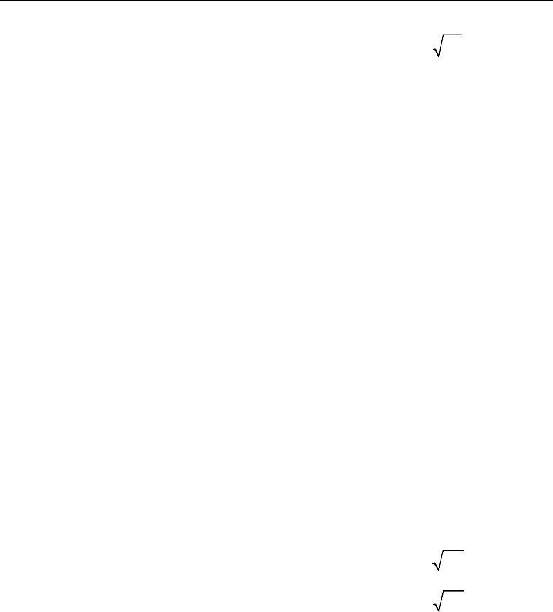
Chapter 19 - Design for Hong Kong CP 2013
post-tensioned member
0.36
ci
f
The extreme fiber stress in tension for Class 3 should not exceed the appropriate
value for a Class 2 member; otherwise the section should be designed as a
cracked section.
19.6.2 Serviceability Check at Service Load
The stresses in the concrete for Class 1 and Class 2 prestressed flexural members
at service loads, and after all prestress losses have occurred, are checked against
the following limits (CP 12.3.4.2 an 12.3.4.3):
Extreme fiber stress in compression due
to prestress plus total load:
0.33
cu
f
Extreme fiber stress in compression due
to prestress plus total load for continuous
beams and other statically indeterminate
structures:
0.4 cu
f
Extreme fiber stress in tension in the
precompressed tensile zone at service loads:
– Extreme fiber stresses in tension for Class 1: No tensile stress
– Extreme fiber stresses in tension for Class 2:
pre-tensioned member
0.45
cu
f
post-tensioned member
0.36
cu
f
Although cracking is allowed for Class 3, it is assumed that the concrete
section is uncracked and the user is limiting the tensile stress at the service stage
as presented in Table 12.2, modified by the coefficients in Table 12.3 of CP
2013. The user needs to provide the tension limits for Class 3 elements at
service loads in the design preferences (CP 12.3.4.3).
Serviceability Requirements of Flexural Members 19 - 9

Post-Tensioned Concrete Design
19.7 Beam Design (for Reference Only)
Important Note: Post-tensioned beam design is not available in the current ver-
sion of ETABS, but is planned for a future release. This section is provided as
reference only for the documentation of post-tensioned slab design.
In the design of prestressed concrete beams, ETABS calculates and reports the
required areas of reinforcement for flexure, shear, and torsion based on the beam
moments, shear forces, torsion, load combination factors, and other criteria de-
scribed in the subsections that follow. The reinforcement requirements are cal-
culated at each station along the length of the beam.
Beams are designed for major direction flexure, shear, and torsion only. Effects
resulting from any axial forces and minor direction bending that may exist in the
beams must be investigated independently by the user.
The beam design procedure involves the following steps:
Design flexural reinforcement
Design shear reinforcement
Design torsion reinforcement
19.7.1 Design Flexural Reinforcement
The beam top and bottom flexural reinforcement is designed at each station
along the beam. In designing the flexural reinforcement for the major moment
of a particular beam, for a particular station, the following steps are involved:
Determine factored moments
Determine required flexural reinforcement
19.7.1.1 Determine Factored Moments
In the design of flexural reinforcement of prestressed concrete beams, the
factored moments for each load combination at a particular beam station are ob-
tained by factoring the corresponding moments for different load cases, with the
corresponding load factors.
19 - 10 Beam Design (for Reference Only)

Chapter 19 - Design for Hong Kong CP 2013
The beam is then designed for the maximum positive and maximum negative
factored moments obtained from all of the load combinations. Positive beam
moments can be used to calculate bottom reinforcement. In such cases the beam
may be designed as a rectangular or a flanged beam. Negative beam moments
can be used to calculate top reinforcement. In such cases the beam may be de-
signed as a rectangular or inverted flanged beam.
19.7.1.2 Determine Required Flexural Reinforcement
In the flexural reinforcement design process, the program calculates both the
tension and compression reinforcement. Compression reinforcement is added
when the applied design moment exceeds the maximum moment capacity of a
singly reinforced section. The user has the option of avoiding the compression
reinforcement by increasing the effective depth, the width, or the strength of the
concrete.
The design procedure is based on the simplified rectangular stress block shown
in Figure 12-1 (CP 6.1.2.4(a)), where
ε
c,max is defined as:
( )
1
,max 2
0.0035 if 60 MPA
0.0035 0.00006 60 if 60 MPA
cu
c
cu cu
f
ff
ε
≤
=−− >
Furthermore, it is assumed that moment redistribution in the member does not
exceed 10% (i.e.,
β
b ≥ 0.9) (CP 6.1.2.4(b)). The code also places a limitation on
the neutral axis depth,
2
2
2
0.5 for 45 N mm
0.4 for 45 70 N mm
0.33 for 70 100 N mm
cu
cu
cu
f
xf
df
≤
≤ <≤
<≤
to safeguard against non-ductile failures (CP 6.1.2.4(b)). In addition, the area of
compression reinforcement is calculated assuming that the neutral axis depth re-
mains at the maximum permitted value.
The design procedure used by ETABS, for both rectangular and flanged sections
(L- and T-beams), is summarized in the subsections that follow. It is assumed
that the design ultimate axial force does not exceed 0.1 fcu Ag (CP 6.1.2.4(a));
hence all beams are designed for major direction flexure, shear, and torsion only.
Beam Design (for Reference Only) 19 - 11
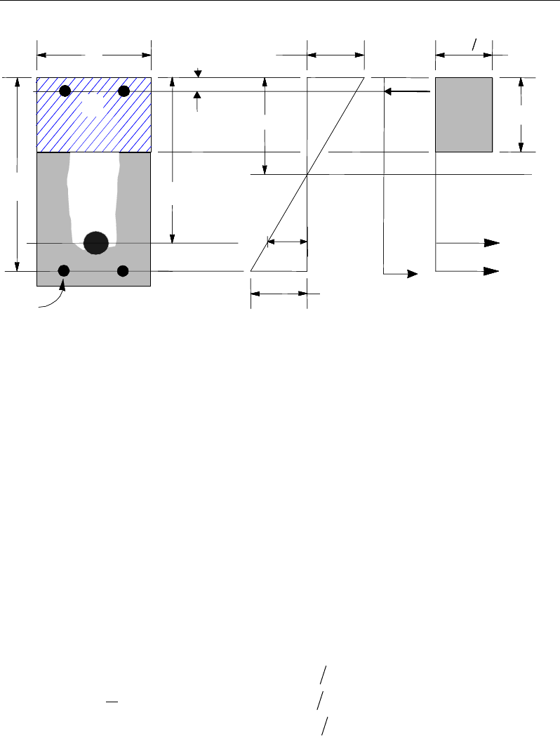
Post-Tensioned Concrete Design
Figure 11-1 Rectangular Beam Design
19.7.1.2.1 Design of Rectangular Beams
The amount of post-tensioning steel adequate to resist the design moment M and
minimum reinforcement are provided to satisfy the flexural cracking
requirements (CP 19.2.1).
ETABS determines the depth of the neutral axis, x, by imposing force equilib-
rium, i.e., C = T, and performs an iteration to compute the depth of the neutral
axis, which is based on stress-strain compatibility. After the depth of the neutral
axis has been found, the stress in the post-tensioning reinforcement fpb is com-
puted based on strain compatibility.
The ductility of a section is controlled by limiting the x/d ratio (CP 6.1.2.4(b)):
2
2
2
0.5, for 45 N mm
0.4, for 45 70 N mm
0.33, for 70 100N mm
≤
= <≤
<≤
cu
cu
cu
f
xf
df
(CP 6.1.2.4(b))
The maximum depth of the compression block is given by:
BEAM
SECTION STRAIN
DIAGRAM STRESS
DIAGRAM
s
A
ε
0.67
cu m
f
γ
s
f′s
C
s
A′
ps
A
s
ε
ps
ε
s
T
cps
T
s
d
p
d
b
x
d′a
cs
T
BEAM
SECTION STRAIN
DIAGRAM STRESS
DIAGRAM
s
A
ε
0.67
cu m
f
γ
s
f′s
C
s
A′
ps
A
s
ε
ps
ε
s
T
cps
T
s
d
p
d
b
x
d′a
cs
T
19 - 12 Beam Design (for Reference Only)

Chapter 19 - Design for Hong Kong CP 2013
2
2
2
0.9 for 45 N/mm
0.8 for 45 < 70 N/mm
0.72 for 70 < 100 N/mm
a
≤
= ≤
≤
cu
cu
cu
xf
xf
xf
(CP 6.1.2.4(a))
The lever arm of the section must not be greater than 0.95 times the effective
depth (CP 6.1.2.4(c)).
z = d
0.5 0.25 0.9
K
+−
≤ 0.95d, (CP 6.1.2.4(c))
If
max
aa≤
(CP 6.1.2.4), the moment capacity of the section, provided by post-
tensioning steel only, is computed as:
0
2
= −
u ps pb p a
M Af d
If
max
aa>
(CP 6.1.2.4), a failure condition is declared.
If
0,>u
MM
ETABS calculates the moment capacity and the As required at the
balanced condition. The balanced condition is taken as the marginal tension con-
trolled case. In that case, it is assumed that the depth of neutral axis x is equal to
xmax. The stress in the post-tensioning steel, fpb is then calculated based on strain
compatibility for bonded tendons. For unbonded tendons, the code equations are
used to compute the stress, fps in the post-tensioning steel, and the area of re-
quired tension reinforcement, As, is determined by imposing force equilibrium,
i.e., C = T.
ba
f
C
m
cu max
67.0
γ
=
bal bal bal
ps pb s s
T Af A f= +
bal
s
bal
pbps
m
cu
bal
s
f
fAba
f
A
−
=
max
67.0
γ
Beam Design (for Reference Only) 19 - 13

Post-Tensioned Concrete Design
After the area of tension reinforcement has been determined, the capacity of the
section with post-tensioning steel and tension reinforcement is computed as:
max max
22
bal bal bal bal
u ps pb p s s s
aa
M Afd Afd
= −+ −
In that case, it is assumed that the bonded tension reinforcement will yield, which
is true for most cases. In the case that it does not yield, the stress in the reinforce-
ment, fs, is determined from the elastic-perfectly plastic stress-strain relationship.
The fy value of the reinforcement is then replaced with fs in the preceding four
equations. This case does not involve any iteration in determining the depth of
neutral axis, x.
19.7.1.2.1.1 Case 1: Post-tensioning steel is adequate
When
0,
u
MM<
the amount of post-tensioning steel is adequate to resist the de-
sign moment M.. Minimum reinforcement is provided to satisfy the ductility re-
quirements, i.e.,
0
.
u
MM<
19.7.1.2.1.2 Case 2: Post-tensioning steel plus tension reinforcement
In this case, the amount of post-tensioning steel, Aps, alone is not sufficient to
resist M, and therefore the required area of tension reinforcement is computed to
supplement the post-tensioning steel. The combination of post-tensioning steel
and tension reinforcement should result in a < amax.
When
0,
bal
uu
M MM<<
ETABS determines the required area of tension rein-
forcement, As, iteratively to satisfy the design moment M and reports this re-
quired area of tension reinforcement. Since M is bounded by
0
u
M
at the lower
end and
bal
u
M
at the upper end, and
0
u
M
is associated with
0
s
A=
and
bal
u
M
is
associated with
,
bal
ss
AA=
the required area will be between the range of 0 to
Asbal.
The tension reinforcement is to be placed at the bottom if M is positive, or at the
top if M is negative.
19 - 14 Beam Design (for Reference Only)

Chapter 19 - Design for Hong Kong CP 2013
19.7.1.2.1.3 Case 3: Post-tensioning steel and tension reinforcement are not ade-
quate
When
,
bal
u
MM>
compression reinforcement is required (CP 6.1.2.4). In that
case, ETABS assumes that the depth of neutral axis, x, is equal to xmax. The
values of fpb and fs reach their respective balanced condition values,
bal
pb
f
and
.
bal
s
f
The area of compression reinforcement,
,
′
s
A
is determined as follows:
The moment required to be resisted by compression reinforcement and tension
reinforcement is:
bal
us u
M MM= −
The required compression reinforcement is given by:
( )
0 67
us
scu
sc
M
A' ,
.f
f' d d'
γ
=
−−
where (CP 6.1.2.4(c))
1 0.87 ,
s sc y
d
fE f
x
ε
′
′= −≤
(CP 6.1.2.4(c), 3.2.6, Fig. 3.9)
The tension reinforcement for balancing the compression reinforcement is given
by:
( )
0.87 '
com us
s
ys
M
Afd d
=−
Therefore, the total tension reinforcement, A
s
=
bal
s
A
+
,
com
s
A
and the total com-
pression reinforcement is A'
s
. A
s
is to be placed at the bottom and A'
s
is to be
placed at the top if M is positive, and vice versa if M is negative.
19.7.1.2.2 Design of Flanged Beams
19.7.1.2.2.1 Flanged Beam Under Negative Moment
In designing for a factored negative moment, M (i.e., designing top reinforce-
ment), the calculation of the reinforcement area is exactly the same as described
previously, i.e., no flanged beam data is used.
Beam Design (for Reference Only) 19 - 15

Post-Tensioned Concrete Design
19.7.1.2.2.2 Flanged Beam Under Positive Moment
ETABS first determines if the moment capacity provided by the post-tensioning
tendons alone is enough. In calculating the capacity, it is assumed that A
s
= 0. In
that case, moment capacity
0
u
M
is determined as follows:
ETABS determines the depth of the neutral axis, x, by imposing force equilib-
rium, i.e., C = T, and performs an iteration to compute the depth of neutral axis,
which is based on stress-strain compatibility for bonded tendons. For unbonded
tendons, the code equations are used to compute the stress, fps in the post-ten-
sioning steel. After the depth of the neutral axis has been determined, the stress
in the post-tensioning steel, fpb is computed based on strain compatibility.
The ductility of a section is controlled by limiting the x/d ratio (CP 6.1.2.4(b)):
2
2
2
0.5, for 45 N mm
0.4, for 45 70 N mm
0.33, for 70 100N mm
≤
= <≤
<≤
cu
cu
cu
f
xf
df
(CP 6.1.2.4(b))
The maximum depth of the compression block is given by:
2
2
2
0.9 for 45 N/mm
0.8 for 45 < 70 N/mm
0.72 for 70 < 100 N/mm
a
≤
= ≤
≤
cu
cu
cu
xf
xf
xf
(CP 6.1.2.4(a))
The lever arm of the section must not be greater than 0.95 times the effective
depth (CP 6.1.2.4(c)).
z = d
0.5 0.25 0.9
K
+−
≤ 0.95d, (CP 6.1.2.4(c))
If
max
aa≤
(CP 6.1.2.4), the moment capacity of the section, provided by post-
tensioning steel only, is computed as:
0
2
= −
u ps pb p a
M Af d
If
max
aa>
(CP 6.1.2.4), a failure condition is declared.
19 - 16 Beam Design (for Reference Only)

Chapter 19 - Design for Hong Kong CP 2013
If
0
,
u
MM>
ETABS calculates the moment capacity and the As required at the
balanced condition. The balanced condition is taken as the marginal tension con-
trolled case. In that case it is assumed that the depth of neutral axis x is equal to
cmax. The stress in the post-tensioning steel, fpb is then calculated based on strain
compatibility for bonded tendons. For unbonded tendons, the code equations are
used to compute the stress, fps in the post-tensioning steel, and the area of re-
quired tension reinforcement, A
s
, is determined by imposing force equilibrium,
i.e., C = T.
If a ≤ h
f
, the subsequent calculations for A
s
are exactly the same as previously
defined for the rectangular beam design. However, in this case the width of
the beam is taken as b
f
. Compression reinforcement is required when K > K'.
If a > h
f
, the calculation for As is given by
max
0.67 com
cu c
c
f
C aA
γ
=
where
com
c
A
is the area of concrete in compression, i.e.,
( )
max
com
c ff w f
A bh b a h=+−
bal bal bal
ps pb s s
T Af A f= +
bal
s
bal
pbps
com
c
m
cu
bal
s
f
f
AA
a
f
A
−
=
max
67
.0
γ
In that case, it is assumed that the bonded tension reinforcement will yield, which
is true for most cases. In the case that it does not yield, the stress in the reinforce-
ment, f
s
, is determined from the elastic-perfectly plastic stress-strain relation-
ship. The f
y
value of the reinforcement is then replaced with f
s
in the preceding
four equations. This case does not involve any iteration in determining the depth
of neutral axis, c.
Beam Design (for Reference Only) 19 - 17

Post-Tensioned Concrete Design
Figure 11-2 T-Beam Design
19.7.1.2.2.3 Case 1: Post-tensioning steel is adequate
When
0,<u
MM
the amount of post-tensioning steel is adequate to resist the de-
sign moment M. Minimum reinforcement is provided to satisfy ductility
requirements.
19.7.1.2.2.4 Case 2: Post-tensioning steel plus tension reinforcement
In this case, the amount of post-tensioning steel, A
ps
, alone is not sufficient to
resist M, and therefore the required area of tension reinforcement is computed to
supplement the post-tensioning steel. The combination of post-tensioning steel
and tension reinforcement should result in a < amax.
When
0,
bal
uu
M MM<<
ETABS determines the required area of tension rein-
forcement, A
s
, iteratively to satisfy the design moment M and reports the
required area of tension reinforcement. Since M is bounded by
0
u
M
at the lower
end and
bal
u
M
at the upper end, and
0
u
M
is associated with
0
s
A=
and
bal
u
M
is
associated with
,
bal
ss
AA=
the required area will be within the range of 0 to Asbal.
(I) BEAM
SECTION
(II) STRAIN
DIAGRAM (II) STRESS
DIAGRAM
s
A′
s
A
f
b
ps
A
bw
d
x
s
f′
d′
f
h
s
T
w
T
f
T
f
C
w
C
s
C
s
ε
ps
ε
ε
0.67
cu m
f
γ
0.67
cu m
f
γ
(I) BEAM
SECTION
(II) STRAIN
DIAGRAM (II) STRESS
DIAGRAM
s
A′
s
A
f
b
ps
A
bw
d
x
s
f′
d′
f
h
s
T
w
T
f
T
f
C
w
C
s
C
s
ε
ps
ε
ε
0.67
cu m
f
γ
0.67
cu m
f
γ
19 - 18 Beam Design (for Reference Only)

Chapter 19 - Design for Hong Kong CP 2013
The tension reinforcement is to be placed at the bottom if M is positive, or at the
top if M is negative.
19.7.1.2.2.5 Case 3: Post-tensioning steel and tension reinforcement are not ade-
quate
When
,
bal
u
MM
>
compression reinforcement is required (CP 6.1.2.4). In that
case ETABS assumes that the depth of the neutral axis, x, is equal to xmax. The
values of fpb and f
s
reach their respective balanced condition values,
bal
pb
f
and
.
bal
s
f
The area of compression reinforcement,
,
′
s
A
is then determined as fol-
lows:
The moment required to be resisted by compression reinforcement and tension
reinforcement is:
bal
us u
M MM
= −
The required compression reinforcement is given by:
( )
us
s
cu
sc
M
Af
f dd
',
0.67
''
γ
=
−−
where (CP 6.1.2.4(c))
'
1 0.87
s sc y
d
fE f
x
ε
′= −≤
(CP 6.1.2.4(c))
The tension reinforcement for balancing the compression reinforcement is given
by:
( )
0.87 '
com us
sys
M
Afd d
=−
Therefore, the total tension reinforcement, As =
bal
s
A
+
,
com
s
A
and the total com-
pression reinforcement is A'
s
. A
s
is to be placed at the bottom, and A'
s
is to be
placed at the top if M is positive and vice versa if M is negative.
Beam Design (for Reference Only) 19 - 19

Post-Tensioned Concrete Design
19.7.1.3 Minimum and Maximum Reinforcement
Reinforcement in post-tensioned concrete beams is computed to increase the
strength of sections as documented for the flexural design of post-tensioned
beams or to comply with the shear link requirements. The minimum flexural
tension reinforcement required for a beam section to comply with the cracking
requirements needs to be separately investigated by the user.
For bonded tendons, there is no minimum untensioned reinforcement required.
For unbounded tendons, the minimum flexural reinforcement provided in a rec-
tangular or flanged beam section is given by the following table, which is taken
from CP Table 9.1(CP 9.2.1.1) with interpolation for reinforcement of interme-
diate strength:
Section
Situation
Definition of
percentage
Minimum percentage
f
y
= 250
MPa
f
y
= 460
MPa
Rectangular 100
bh
As
0.24 0.13
T- or L-Beam with
web in tension
f
w
b
b
< 0.4 100
h
b
A
w
s
0.32 0.18
f
w
b
b
≥ 0.4 100
hb
A
w
s
0.24 0.13
T-Beam with web in
compression 100
hb
A
w
s
0.48 0.26
L-Beam with web in
compression 100
hb
A
w
s
0.36 0.20
The minimum flexural compression reinforcement, if it is required at all, is given
by the following table, which is taken from CP Table 9.1(CP 9.2.1.1) with inter-
polation for reinforcement of intermediate strength:
19 - 20 Beam Design (for Reference Only)
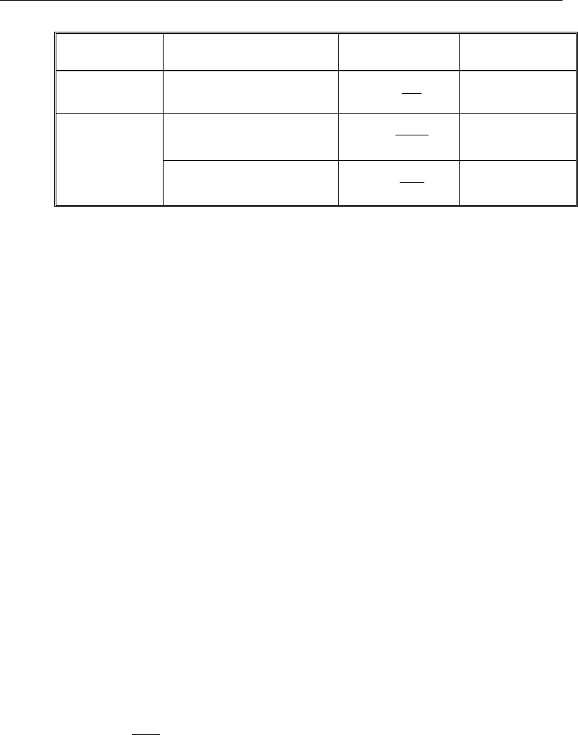
Chapter 19 - Design for Hong Kong CP 2013
Section
Situation
Definition of
percentage
Minimum
percentage
Rectangular 100
s
A
bh
′
0.20
T- or L-Beam
Web in tension 100
s
ff
A
bh
′
0.40
Web in compression 100
s
w
A
bh
′
0.20
In addition, an upper limit on both the tension reinforcement and compression
reinforcement is imposed to be 0.2013 times the gross cross-sectional area (CP
3.12.6.1).
19.7.2 Design Beam Shear Reinforcement
The shear reinforcement is designed for each load combination in the major
direction of the beam. In designing the shear reinforcement for a particular beam
for a particular load combination, the following steps are involved (CP 6.1.2.5):
Determine the shear stress, v.
Determine the shear stress, vc, that can be resisted by the concrete.
Determine the shear reinforcement required to carry the balance.
The following three subsections describe in detail the algorithms associated with
these steps.
19.7.2.1 Determine Shear Stress
In the design of the beam shear reinforcement, the shear forces for a particular
load combination at a particular beam section are obtained by factoring the
associated shear forces for different load cases, with the corresponding load
combination factors.
db
V
v
w
=
(CP 6.1.2.5(a))
Beam Design (for Reference Only) 19 - 21
Post-Tensioned Concrete Design
The maximum allowable shear stress, vmax is defined as:
vmax = min(0.8
,
cu
f
7 MPa) (CP 6.1.2.5(a), 12.3.8.2)
For light-weight concrete, vmax is defined as:
vmax = min(0.63
,
cu
f
5.6 MPa) (BS 8110-2:1985 5.4)
19.7.2.2 Determine Concrete Shear Capacity
The design ultimate shear resistance of the concrete alone, V
c
should be consid-
ered at sections that are as follows:
Uncracked sections in flexure (M < Mo) (CP 12.3.8.3)
Cracked sections in flexural (M ≥ Mo) (CP 12.3.8.3)
where,
M is the design bending moment at the section
Mo is the moment necessary to produce zero stress in the concrete at the
extreme tension fiber; in this calculation, only 0.8 of the stress due to
post-tensioning should be taken into account.
19.7.2.2.1.1 Case 1: Uncracked section in flexure
The ultimate shear resistance of the section, Vco, is computed as follows:
( )
0.67 0.8 ,
2
co v t cp t
V = bh f + f f
(CP 12.3.8.4)
where,
ft is the maximum design principal stress (CP 12.3.8.4)
0.24
t cu
f= f
(CP 12.3.8.4)
fcp = design compressive stress at the centroidal axis due to
post-tensioning, taken as positive. (CP 12.3.8.4)
19 - 22 Beam Design (for Reference Only)

Chapter 19 - Design for Hong Kong CP 2013
β
sinPVV coc+=
(CP 12.3.8.4)
19.7.2.2.1.2 Case 2: Cracked section in flexure
The ultimate shear resistance of the section, Vcr, is computed as follows:
1 0.55 ,
pe
cr c v o
pu
fV
V vbd M
fM
=−+
and (CP 12.3.8.5)
0.1
cr v cu
V bd f≥
(CP 12.3.8.5)
( )
β
sin,min PVVV
crcoc
+=
(CP 12.3.8.5)
19.7.2.3 Determine Required Shear Reinforcement
Given v, vc, and vmax, the required shear reinforcement is calculated as follows
(CP 12.3.8.6):
Calculate the design average shear stress that can be carried by minimum shear
reinforcement, vr, as:
( )
2
23
2
23
2
Nmm
Nmm
Nmm
0.4 if 40
0.4 if 40 80
40
80
0.4 if 80
40
cu cu
cu
r cu
cu
ff
f
vf
f
≤
= <≤
>
(CP 12.3.8.7)
80
2
N
mm
cu
f≤
(for calculation purpose only) (CP 6.1.2.5(c))
If
,
cr
vv v≤+
minimum reinforcement is required:
,
0.87
sr
v yv
Avb
sf
=
(CP 12.3.8.7)
If
,
cr
vv v
>+
Beam Design (for Reference Only) 19 - 23

Post-Tensioned Concrete Design
( )
0.87
c
sv
v yv
vvb
A
sf
−
=
(CP 12.3.8.8)
If v > vmax, a failure condition is declared.
In the preceding expressions, a limit is imposed on fyv as:
fyv ≤ 460 MPa.
The maximum of all of the calculated Asv /sv values, obtained from each load
combination, is reported along with the controlling shear force and associated
load combination.
The beam shear reinforcement requirements considered by the program are
based purely on shear strength considerations. Any minimum stirrup require-
ments to satisfy spacing and volumetric considerations must be investigated
independently of the program by the user.
19.7.3 Design Beam Torsion Reinforcement
The torsion reinforcement is designed for each design load combination at each
station along the length of the beam. The following steps are involved in
designing the longitudinal and shear reinforcement for a particular station due to
the beam torsion:
Determine the torsional shear stress, vt
Determine special section properties
Determine critical torsion stress
Determine the torsion reinforcement required
19.7.3.1 Determine Torsional Shear Stress
In the design of beam torsion reinforcement, the torsions for each load combina-
tion at a particular beam station are obtained by factoring the corresponding tor-
sions for different load cases, with the corresponding load combination factors.
19 - 24 Beam Design (for Reference Only)
Chapter 19 - Design for Hong Kong CP 2013
In typical framed construction, specific consideration of torsion is not usually
required where torsional cracking is adequately controlled by shear reinforce-
ment. If the design relies on the torsional resistance of a beam, further consider-
ation should be given using the following algorithms (CP 6.3.1).
The torsional shear stress, vt, for a rectangular section is computed as:
( )
3/
2
minmax
2
min
hhh
T
v
t
−
=
(CP 6.3.3(a))
For flanged sections, the section is considered as a series of rectangular
segments and the torsional shear stress is computed for each rectangular compo-
nent using the preceding equation, but considering a torsional moment
attributed to that segment, calculated as:
( )
=∑max
3
min
max
3
min
hh
hh
TTseg
(CP 6.3.3(b))
hmax
=
Larger dimension of a rectangular section
hmin
=
Smaller dimension of a rectangular section
If the computed torsional shear stress, vt, exceeds the following limit for sections
with the larger center-to-center dimension of the closed link less than 550 mm,
a failure condition is generated if the torsional shear stress does not satisfy:
1
min(0.8 ,7 ) 550
t cu
y
vf≤×
2
N/mm
(CP 6.3.4, Table 17)
19.7.3.2 Determine Critical Torsion Stress
The critical torsion stress, vt,min, for which the torsion in the section can be
ignored is calculated as:
( )
2
,min min 0.067 ,0.6 N/mm
t cu
vf
=
(CP 6.3.4, Table 17)
where fcu is the specified concrete compressive strength.
For light-weight concrete, vt,min is defined as:
Beam Design (for Reference Only) 19 - 25

Post-Tensioned Concrete Design
( )
2
min
min 0 067 0 4N/mm
t, cu
v . f ,.=
× 0.8 (BS 8110-2:85 5.5)
19.7.3.3 Determine Torsion Reinforcement
If the factored torsional shear stress, vt is less than the threshold limit, vt,min, tor-
sion can be safely ignored (CP 6.3.5). In that case, the program reports that no
torsion reinforcement is required. However, if vt exceeds the threshold limit,
vt,min, it is assumed that the torsional resistance is provided by closed stirrups and
longitudinal bars (CP 6.3.5).
If vt > vt,min, the required closed stirrup area per unit spacing, Asv,t /sv, is calcu-
lated as:
( )
yvv
tsv
fyx
T
s
A
87.08.0 11
,=
(CP 6.3.6)
and the required longitudinal reinforcement is calculated as:
()
y
v
yv
t
sv
lfs
y
xf
A
A1
1, +
=
(CP 6.3.6)
In the preceding expressions, x1 is the smaller center-to-center dimension of
the closed link, and y1 is the larger center-to-center dimension of the closed
link.
An upper limit of the combination of v and vt that can be carried by the section
is also checked using the equation:
+≤
maxt
vv v
(CP 6.3.4)
( )
≤2
max min 0.8 ,7 N/mm
cu
vf
(CP 6.3.4)
For light-weight concrete, vmax is defined as:
vmax = min(0.63
cu
f,
4 MPa) (BS 8110-2:85 5.4)
19 - 26 Beam Design (for Reference Only)

Chapter 19 - Design for Hong Kong CP 2013
If the combination of shear stress, v, and torsional shear stress, vt, exceeds this
limit, a failure message is declared. In that case, the concrete section should be
increased in size.
The maximum of all of the calculated Al and Asv,t /sv values obtained from each
load combination is reported along with the controlling combination.
The beam torsion reinforcement requirements reported by the program are based
purely on strength considerations. Any minimum stirrup requirements or longi-
tudinal rebar requirements to satisfy spacing considerations must be
investigated independently of the program by the user.
Figure 11-3 Closed stirrup and section dimensions for torsion design
19.8 Slab Design
Similar to conventional design, the ETABS slab design procedure involves
defining sets of strips in two mutually perpendicular directions. The locations of
the strips typically are governed by the locations of the slab supports. The mo-
ments for a particular strip are recovered from the analysis, and a flexural design
is carried out based on the ultimate strength design method (Hong Kong CP
cb
w
2−
c
c
cc
c
c
cb 2−
h
s
d
Closed Stirrup in
Rectangular Beam Closed Stirrup in
T-Beam Section
ch 2−h
b
ch 2−
w
b
bf
cb
w
2−
c
c
cc
c
c
cb 2−
h
s
d
Closed Stirrup in
Rectangular Beam Closed Stirrup in
T-Beam Section
ch 2−h
b
ch 2−
w
b
bf
Slab Design 19 - 27

Post-Tensioned Concrete Design
2013) for prestressed reinforced concrete as described in the following subsec-
tions. To learn more about the design strips, refer to the section entitled "ETABS
Design Techniques" in the Key Features and Terminology manual.
19.8.1 Design for Flexure
ETABS designs the slab on a strip-by-strip basis. The moments used for the
design of the slab elements are the nodal reactive moments, which are obtained
by multiplying the slab element stiffness matrices by the element nodal displace-
ment vectors. Those moments will always be in static equilibrium with the ap-
plied loads, irrespective of the refinement of the finite element mesh.
The design of the slab reinforcement for a particular strip is carried out at
specific locations along the length of the strip. Those locations correspond to the
element boundaries. Controlling reinforcement is computed on either side of
those element boundaries. The slab flexural design procedure for each load com-
bination involves the following:
Determine factored moments for each slab strip
Determine the capacity of post-tensioned sections
Design flexural reinforcement for the strip
These three steps are described in the subsections that follow and are repeated
for every load combination. The maximum reinforcement calculated for the top
and bottom of the slab within each design strip, along with the corresponding
controlling load combination, is obtained and reported.
19.8.1.1 Determine Factored Moments for the Strip
For each element within the design strip, for each load combination, the program
calculates the nodal reactive moments. The nodal moments are then added to get
the strip moments.
19.8.1.2 Determine Capacity of Post-Tensioned Sections
The calculation of the post-tensioned section capacity is identical to that
described earlier for rectangular beam sections.
19 - 28 Slab Design
Chapter 19 - Design for Hong Kong CP 2013
19.8.1.3 Design Flexural Reinforcement for the Strip
The reinforcement computation for each slab design strip, given the bending mo-
ment, is identical to the design of rectangular beam sections described
earlier (or to the flanged beam if the slab is ribbed). In some cases, at a given
design section in a design strip, there may be two or more slab properties across
the width of the design strip. In that case, the program automatically designs the
tributary width associated with each of the slab properties separately using its
tributary bending moment. The reinforcement obtained for each of the tributary
widths is summed to obtain the total reinforcement for the full width of the de-
sign strip at the considered design section. This method is used when drop panels
are included. Where openings occur, the slab width is adjusted accordingly.
19.8.1.4 Minimum and Maximum Slab Reinforcement
There are no minimum requirements for untensioned reinforcement in one-way
bonded slabs. One-way spanning floors with unbounded tendons should have
minimum reinforcement requirements in accordance with CP Table 3.25 (CP
3.12.5.3)
In flat slabs, reinforcement is added at the top over supports to be 0.00075 times
the gross cross-sectional area. This reinforcement extends 1.5 times the slab
depth on each side of the column. The length of the reinforcement should be at
least 0.2L where L is the span of the slab.
There are no minimum requirements for span zone. However, additional un-ten-
sioned reinforcement shall be designed for the full tension force generated by
assumed flexural tensile stresses in the concrete for the following situations
(Concrete Society, Technical Report 43):
all locations in one-way spanning floors using unbonded tendons
all locations in one-way spanning floors where transfer tensile stress exceeds
0.36
ci
f
support zones in all flat slabs
span zones in flat slabs using unbonded tendons where the tensile stress
exceeds 0.15
cu
f.
Slab Design 19 - 29

Post-Tensioned Concrete Design
The reinforcement should be designed to act at a stress of 5/8fy as follows:
( )
t
sy
F
A= 5/8 f
where
()
2
ct
f h xb−
−
t
F=
The value of fct will be negative in tension.
In addition, an upper limit on both the tension reinforcement and compression
reinforcement has been imposed to be 0.04 times the gross cross-sectional area
(CP 9.2.1.3).
19.8.2 Check for Punching Shear
The algorithm for checking punching shear is detailed in the section entitled
“Slab Punching Shear Check” in the Key Features and Terminology manual.
Only the code specific items are described in the following sections.
19.8.2.1 Critical Section for Punching Shear
The punching shear is checked at a critical section at a distance of 1.5d from the
face of the support (CP 6.1.5.7(f)). For rectangular columns and concentrated
loads, the critical area is taken as a rectangular area with the sides parallel to the
sides of the columns or the point loads. Figure 11-4 shows the auto punching
perimeters considered by ETABS for the various column shapes. The column
location (i.e., interior, edge, corner) and the punching perimeter may be over-
written using the Punching Check Overwrites.
19 - 30 Slab Design
Chapter 19 - Design for Hong Kong CP 2013
Figure 11-4 Punching Shear Perimeters
19.8.2.2 Determine Concrete Capacity
The design ultimate shear resistance of the concrete alone, Vc, should be consid-
ered at sections that are as follows:
Uncracked sections in flexure (M < Mo) (CP 12.3.8.3)
Cracked sections in flexural (M ≥ Mo) (CP 12.3.8.3)
where,
M is the design bending moment at the section
Mo is the moment necessary to produce zero stress in the concrete at the
extreme tension fiber; in this calculation, only 0.8 of the stress due to
post-tensioning should be taken into account.
19.8.2.2.1.1 Case 1: Uncracked section in flexure
The ultimate shear resistance of the section, Vco, is computed as follows:
1.5d
Interior Column
Circular Column T-Shape Column
Edge Column Corner Column
L-Shape Column
1.5d 1.5d
1.5d
1.5d
1.5d
1.5d
Interior Column
Circular Column T-Shape Column
Edge Column Corner Column
L-Shape Column
1.5d 1.5d
1.5d
1.5d
1.5d
Slab Design 19 - 31
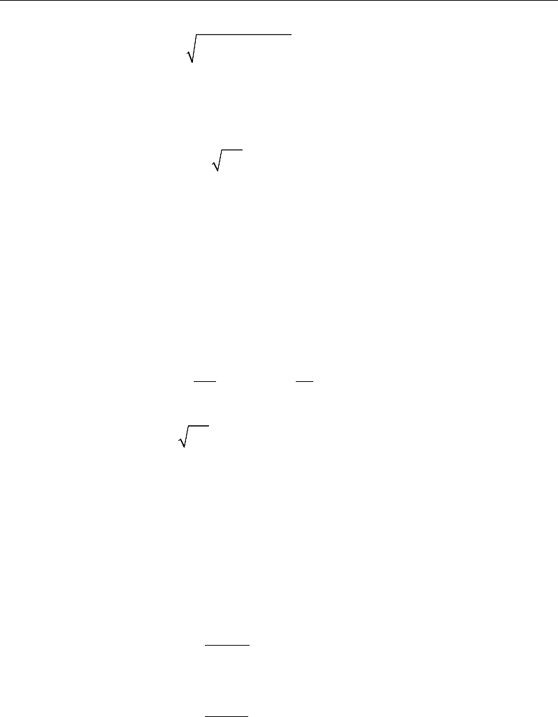
Post-Tensioned Concrete Design
( )
0.67 0.8 ,
2
co v t cp t
V = bh f + f f
(CP 12.3.8.4)
where,
ft is the maximum design principal stress (CP 12.3.8.4)
0.24
t cu
f= f
(CP 12.3.8.4)
fcp = design compressive stress at the centoidal axis
due to prestress, taken as positive. (CP 12.3.8.4)
β
sin
PVV co
c+=
(CP 12.3.8.4)
19.8.2.2.1.2 Case 2: Cracked section in flexure
The ultimate shear resistance of the section, Vcr, is computed as follows:
1 0.55 ,
pe
cr c v o
pu
fV
V vbd M
fM
=−+
and (CP 12.3.8.5)
0.1
cr v cu
V bd f≥
(CP 12.3.8.5)
( )
β
sin,min PVVV
crcoc
+=
(CP 12.3.8.5)
19.8.2.3 Determine Maximum Shear Stress
Given the punching shear force and the fractions of moments transferred by ec-
centricity of shear about the bending axis, the nominal design shear stress, vmax,
is calculated as:
= +
1.5
,
Mx
V Vf
eff x Vy
(CP 6.1.5.6(b), 6.1.5.6(c))
= +
1.5
,
My
V Vf
eff y Vx
(CP 6.1.5.6(b), 6.1.5.6(c))
19 - 32 Slab Design

Chapter 19 - Design for Hong Kong CP 2013
,
max
,
max
eff x
eff y
V
ud
vV
ud
=
(CP 6.1.5.7)
where,
u is the perimeter of the critical section,
x and y are the lengths of the sides of the critical section parallel to the
axis of bending,
Mx and My are the design moments transmitted from the slab to the column
at the connection,
V is the total punching shear force, and
f is a factor to consider the eccentricity of punching shear force and is
taken as
1 00 for interior columns
1 25 for edge columns
1 25 for corner columns
.
f.
.
=
(CP 6.1.5.6(b), 6.1.5.6(c))
19.8.2.4 Determine Capacity Ratio
The ratio of the maximum shear stress and the concrete punching shear stress
capacity is reported as the punching shear capacity ratio by ETABS. If this ratio
exceeds 1.0, punching shear reinforcement is designed as described in the fol-
lowing section.
19.8.3 Design Punching Shear Reinforcement
The use of shear studs as shear reinforcement in slabs is permitted, provided that
the effective depth of the slab is greater than or equal to 200 mm (CP 6.1.5.7(e)).
If the slab thickness does not meet these requirements, the punching shear rein-
forcement is not designed and the slab thickness should be increased by the user.
Slab Design 19 - 33

Post-Tensioned Concrete Design
The algorithm for designing the required punching shear reinforcement is used
when the punching shear capacity ratio exceeds unity. The Critical Section for
Punching Shear as described in the earlier sections remains unchanged. The de-
sign of punching shear reinforcement is carried out as described in the subsec-
tions that follow.
19.8.3.1 Determine Concrete Shear Capacity
The concrete punching shear stress capacity of a section with punching shear
reinforcement is as previously determined for the punching check.
19.8.3.2 Determine Required Shear Reinforcement
The shear stress is limited to a maximum limit of
vmax = min(0.8
,
cu
f
7 MPa) (CP 6.1.2.5(a))
( )
2
23
2
23
2
Nmm
Nmm
Nmm
0.4 if 40
0.4 if 40 80
40
80
0.4 if 80
40
cu cu
cu
r cu
cu
ff
f
vf
f
≤
= <≤
>
(CP 12.3.8.7)
2
N
mm
80≤
cu
f
(for calculation purpose only) (CP 6.1.2.5(c))
If
,
cr
vv v≤+
minimum reinforcement is required:
,
0.87
sr
v yv
Avb
sf
=
(CP 12.3.8.7)
If
cr
vv v
>+
,
( )
0.87
c
sv
v yv
vvb
A
sf
−
=
(CP 12.3.8.8)
If v > vmax, a failure condition is declared.
19 - 34 Slab Design
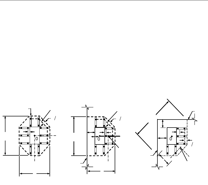
Chapter 19 - Design for Hong Kong CP 2013
If v exceeds the maximum permitted value of vmax, the concrete section should
be increased in size.
19.8.3.3 Determine Reinforcement Arrangement
Punching shear reinforcement in the vicinity of rectangular columns should be
arranged on peripheral lines, i.e., lines running parallel to and at constant dis-
tances from the sides of the column. Figure 11-5 shows a typical arrangement of
shear reinforcement in the vicinity of a rectangular interior, edge, and corner
columns.
Figure 11-5 Typical arrangement of shear studs and
critical sections outside the shear-reinforced zone
The distance between column face and the first line of shear reinforcement shall
not exceed d/2. The spacing between adjacent shear reinforcement in the first
line of shear reinforcement shall not exceed 0.75d measured in a direction par-
allel to the column face (CP12.3.8.10). When V > 1.8Vc, the maximum spacing
is reduced to 0.5 d.
Punching shear reinforcement is most effective near column corners where there
are concentrations of shear stress. Therefore, the minimum number of lines of
shear reinforcement is 4, 6, and 8 for corner, edge, and interior columns respec-
tively.
I
y
Typical Studrail
(only first and last
studs shown)
Outermost
peripheral line
of studs
Interior Column Edge Column Corner Column
Critical section
centroid
Free
edge
Free
edge
Critical
section
centroid
Free edge
Outermost
peripheral line
of studs
I
y
I
y
yx
d2 d2
d2
x
I
x
I
x
g
y
g
x
g
0
s0
s
0
s
x
I
y
x
x
I
y
Typical Studrail
(only first and last
studs shown)
Outermost
peripheral line
of studs
Interior Column Edge Column Corner Column
Critical section
centroid
Free
edge
Free
edge
Critical
section
centroid
Free edge
Outermost
peripheral line
of studs
I
y
I
y
yx
d2 d2
d2
x
I
x
I
x
g
y
g
x
g
0
s0
s
0
s
x
I
y
x
x
Slab Design 19 - 35

Post-Tensioned Concrete Design
19.8.3.4 Determine Reinforcement Diameter, Height, and
Spacing
The punching shear reinforcement is most effective when the anchorage is close
to the top and bottom surfaces of the slab. The cover of anchors should not be
less than the minimum cover specified in CP 4.2.4 plus half of the diameter of
the flexural reinforcement.
Punching shear reinforcement in the form of shear studs is generally available in
10-, 12-, 14-, 16-, and 20-millimeter diameters.
The following information is taken from the BS 8110-1997 code. When speci-
fying shear studs, the distance, so, between the column face and the first periph-
eral line of shear studs should not be smaller than 0.5d. The spacing between
adjacent shear studs, g, at the first peripheral line of studs shall not
exceed 1.5d. The limit of so and the spacing, s, between the peripheral lines are
specified as:
so ≤ 0.5d (CP 6.1.5.7(f))
s ≤ 0.75d (CP 6.1.5.7(f))
g ≤ 1.5d (CP 6.1.5.7(f))
Stirrups are permitted only when slab thickness is greater than 200 mm (CP
6.1.5.7(e)).
19 - 36 Slab Design

Chapter 20
Design for ACI 318-14
This chapter describes in detail the various aspects of the post-tensioned concrete
design procedure that is used by ETABS when the user selects the American
code ACI 318-14 [ACI 2014]. Various notations used in this chapter are listed
in Table 6-1. For referencing to the pertinent sections of the ACI code in this
chapter, a prefix “ACI” followed by the section number is used.
The design is based on user-specified load combinations. The program provides
a set of default load combinations that should satisfy the requirements for the
design of most building type structures.
English as well as SI and MKS metric units can be used for input. The code is
based on inch-pound-second units. For simplicity, all equations and descriptions
presented in this chapter correspond to inch-pound-second units unless otherwise
noted.
20.1 Notations
The following table identifies the various notations used in this chapter.
Notations 20 - 1

Post-Tensioned Concrete Design
Table 20-1 List of Symbols Used in the ACI 318-14 Code
A
cp
Area enclosed by the outside perimeter of the section, in2
A
g
Gross area of concrete, in2
A
l
Total area of longitudinal reinforcement to resist torsion, in2
A
o
Area enclosed by the shear flow path, sq-in
A
oh
Area enclosed by the centerline of the outermost closed trans-
verse torsional reinforcement, sq-in
A
ps
Area of prestressing steel in flexural tension zone, in2
A
s
Area of tension reinforcement, in2
A'
s
Area of compression reinforcement, in2
A
s(re-
quired)
Area of steel required for tension reinforcement, in2
A
t
/s
Area of closed shear reinforcement per unit length of member
for torsion, sq-in/in
A
v
Area of shear reinforcement, in2
A
v
/s
Area of shear reinforcement per unit length of member, in2/in
a
Depth of compression block, in
a
b
Depth of compression block at balanced condition, in
a
max
Maximum allowed depth of compression block, in
b
Width of member, in
b
f
Effective width of flange (T-beam section), in
b
w
Width of web (T-beam section), in
b
0
Perimeter of the punching critical section, in
b
1
Width of the punching critical section in the direction of
bending, in
b
2
Width of the punching critical section perpendicular to the di-
rection of bending, in
c
Depth to neutral axis, in
20 - 2 Notations

Chapter 20 - Design for ACI 318-14
Table 20-1 List of Symbols Used in the ACI 318-14 Code
c
b
Depth to neutral axis at balanced conditions, in
d
Distance from compression face to tension reinforcement, in
d'
Concrete cover to center of reinforcing, in
d
e
Effective depth from compression face to centroid of tension
reinforcement, in
d
s
Thickness of slab (T-beam section), in
d
p
Distance from extreme compression fiber to centroid of pre-
stressing steel, in
E
c
Modulus of elasticity of concrete, psi
E
s
Modulus of elasticity of reinforcement, assumed as
29,000,000 psi (ACI 8.5.2)
f'
c
Specified compressive strength of concrete, psi
f'
ci
Specified compressive strength of concrete at time of initial
prestress, psi
f
pe
Compressive stress in concrete due to effective prestress
forces only (after allowance of all prestress losses), psi
f
ps
Stress in prestressing steel at nominal flexural strength, psi
f
pu
Specified tensile strength of prestressing steel, psi
f
py
Specified yield strength of prestressing steel, psi
f
t
Extreme fiber stress in tension in the precompressed tensile
zone using gross section properties, psi
f
y
Specified yield strength of flexural reinforcement, psi
f
ys
Specified yield strength of shear reinforcement, psi
h
Overall depth of a section, in
h
f
Height of the flange, in
φ
M
n
0
Design moment resistance of a section with tendons only, N-
mm
Notations 20 - 3

Post-Tensioned Concrete Design
Table 20-1 List of Symbols Used in the ACI 318-14 Code
φ
M
n
bal
Design moment resistance of a section with tendons and the
necessary mild reinforcement to reach the balanced condition,
N-mm
M
u
Factored moment at section, lb-in
N
c
Tension force in concrete due to unfactored dead load plus
live load, lb
P
u
Factored axial load at section, lb
s
Spacing of the shear reinforcement along the length of the
beam, in
T
u
Factored torsional moment at section, lb-in
V
c
Shear force resisted by concrete, lb
V
max
Maximum permitted total factored shear force at a section, lb
V
u
Factored shear force at a section, lb
V
s
Shear force resisted by steel, lb
β
1
Factor for obtaining depth of compression block in concrete
β
c
Ratio of the maximum to the minimum dimensions of the
punching critical section
ε
c
Strain in concrete
ε
c, max
Maximum usable compression strain allowed in extreme con-
crete fiber (0.003 in/in)
ε
ps
Strain in prestressing steel
ε
s
Strain in reinforcing steel
ε
s,min
Minimum tensile strain allowed in steel reinforcement at
nominal strength for tension controlled behavior (0.005 in/in)
ϕ
Strength reduction factor
γ
f
Fraction of unbalanced moment transferred by flexure
γ
v
Fraction of unbalanced moment transferred by eccentricity of
shear
20 - 4 Notations

Chapter 20 - Design for ACI 318-14
Table 20-1 List of Symbols Used in the ACI 318-14 Code
λ
Shear strength reduction factor for light-weight concrete
θ
Angle of compression diagonals, degrees
20.2 Design Load Combinations
The design load combinations are the various combinations of the load cases for
which the structure needs to be designed. For ACI 318-14, if a structure is sub-
jected to dead (D), live (L), pattern live (PL), snow (S), wind (W), and earth-
quake (E) loads, and considering that wind and earthquake forces are
reversible, the load combinations in the following sections may need to be con-
sidered (ACI 5.3.1).
For post-tensioned concrete design, the user can specify the prestressing load
(PT) by providing the tendon profile or by using the load balancing options in
the program. The default load combinations for post-tensioning are defined in
the following sections.
20.2.1 Initial Service Load Combination
The following load combination is used for checking the requirements at transfer
of prestress forces, in accordance with ACI 318-14 sections 5.3.11 and 24.5.3.
The prestressing forces are considered without any long-term loses for the initial
service load combination check.
1.0D + 1.0PT
(ACI 5.3.11, 25.4.3)
20.2.2 Service Load Combination
The following load combinations are used for checking the requirements of pre-
stress for serviceability in accordance with ACI 318-14 sections 5.3.11, 24.5.4.
It is assumed that all long-term losses have already occurred at the service stage.
1.0D + 1.0PT
1.0D + 1.0L + 1.0PT (ACI
24.5.4)
Design Load Combinations 20 - 5

Post-Tensioned Concrete Design
20.2.3 Long-Term Service Load Combination
The following load combinations are used for checking the requirements of pre-
stress in accordance with ACI 318-14 sections 5.3.11, 24.5.4.1, and R24.5.4.1.
The permanent load for this load combination is taken as 50 percent of the live
load. It is assumed that all long-term losses have already occurred at the service
stage.
1.0D + 1.0PT
1.0D + 0.5L + 1.0PT
(ACI 5.3.11, 24.5.4.1
)
20.2.4 Strength Design Load Combination
The following load combinations are used for checking the requirements of pre-
stress for strength in accordance with ACI 318-14, Chapters 8, 9, and 24.
The strength design combinations required for punching shear require the full
PT forces (primary and secondary). Flexural design requires only the hyperstatic
(secondary) forces. The hyperstatic (secondary) forces are automatically deter-
mined by ETABS by subtracting out the primary PT moments when the flexural
design is carried out.
1.4D + 1.0PT*
(ACI Eqn. 5.3.1a)
1.2D + 1.6L + 0.5Lr + 1.0PT*
(ACI Eqn.5.3.1b)
1.2D + 1.0L + 1.6L
r
+ 1.0PT*
(ACI Eqn.5.3.1c)
1.2D + 1.6(0.75 PL) + 0.5Lr + 1.0PT*
(ACI Eqn.5.3.1b, 6.4)
1.2D + 1.6L + 0.5S + 1.0PT*
(ACI Eqn.5.3.1b)
1.2D + 1.0L + 1.6S+ 1.0PT*
(ACI Eqn.5.3.1c)
0.9D ± 1.0W + 1.0PT*
(ACI Eqn.5.3.1f)
1.2D + 1.0L + 0.5Lr ± 1.0W + 1.0PT*
(ACI Eqn.5.3.1d)
1.2D + 1.6L
r
± 0.5W + 1.0PT*
(ACI Eqn.5.3.1c)
1.2D + 1.6S ± 0.5W + 1.0PT*
(ACI Eqn.5.3.1c)
1.2D + 1.0L + 0.5S ± 1.0W + 1.0PT*
(ACI Eqn.5.3.1d)
0.9D ± 1.0E + 1.0PT*
1.2D + 1.0L + 0.2S
±
1.0E + 1.0PT
*
(ACI Eqn.5.3.1g)
(ACI Eqn.5.3.1e
)
* — Replace PT by H for flexural design only
20 - 6 Design Load Combinations

Chapter 20 - Design for ACI 318-14
These also are the default design load combinations in ETABS whenever the
ACI 318-14 code is used. The user should use other appropriate load combina-
tions if other types of loads are present.
20.3 Limits on Material Strength
The concrete compressive strength, f'c, should not be less than 2500 psi (ACI
19.2.1, Table 19.2.1.1). The upper limit of the reinforcement yield strength, fy,
is taken as 80 ksi (ACI 20.2.2.4a, Table 20.2.2.4a) and the upper limit of the
reinforcement shear strength, fyt, is taken as 60 ksi (ACI 21.2.2.4a, Table
21.2.2.4a).
ETABS enforces the upper material strength limits for flexure and shear design
of slabs. The input material strengths are taken as the upper limits if they are
defined in the material properties as being greater than the limits. The user is
responsible for ensuring that the minimum strength is satisfied.
20.4 Strength Reduction Factors
The strength reduction factors,
φ
, are applied on the specified strength to obtain
the design strength provided by a member. The
φ
factors for flexure, shear, and
torsion are as follows:
φ
t = 0.90 for flexure (tension controlled) (ACI 21.2.1, Table 21.2.1)
φ
c = 0.65 for flexure (compression controlled) (ACI 21.2.1, Table 21.2.1)
φ
= 0.75 for shear and torsion. (ACI 21.2.1, Table 21.2.1)
The value of
φ
varies from compression-controlled to tension-controlled based
on the maximum tensile strain in the reinforcement at the extreme edge,
ε
t
(ACI 21.2.3).
Sections are considered compression-controlled when the tensile strain in the
extreme tension reinforcement is equal to or less than the compression-con-
trolled strain limit at the time the concrete in compression reaches its assumed
strain limit of
ε
c.max, which is 0.003. The compression-controlled strain limit is
Limits on Material Strength 20 - 7

Post-Tensioned Concrete Design
the tensile strain in the reinforcement at the balanced strain condition, which is
taken as the yield strain of the reinforcement, (fy/E) (ACI 21.2.2.1, Table 21.2.2).
Sections are tension-controlled when the tensile strain in the extreme tension
reinforcement is equal to or greater than 0.005, just as the concrete in compres-
sion reaches its assumed strain limit of 0.003 (Table 21.2.2, Fig R21.2.26).
Sections with
ε
t between the two limits are considered to be in a transition region
between compression-controlled and tension-controlled sections (ACI 21.2.2,
Table 21.2.2).
When the section is tension-controlled,
φ
t is used. When the section is compres-
sion-controlled,
φ
c is used. When the section is in the transition region,
φ
is lin-
early interpolated between the two values (ACI 21.2.2, Table 21.2.2).
The user is allowed to overwrite these values. However, caution is advised.
20.5 Design Assumptions for Prestressed Concrete
Strength design of prestressed members for flexure and axial loads shall be based
on assumptions given in ACI 22.2.
The strain in the reinforcement and concrete shall be assumed directly propor-
tional to the distance from the neutral axis (ACI 22.2.1.2).
The maximum usable strain at the extreme concrete compression fiber shall
be assumed equal to 0.003 (ACI 22.2.2.1).
The tensile strength of the concrete shall be neglected in axial and flexural
calculations (ACI 22.2.2.2).
The relationship between the concrete compressive stress distribution and the
concrete strain shall be assumed to be rectangular by an equivalent rectangular
concrete stress distribution (ACI 22.2.2.3).
The concrete stress of 0.85f'c shall be assumed uniformly distributed over an
equivalent-compression zone bounded by edges of the cross-section and a
straight line located parallel to the neutral axis at a distance a =
β
1c from the
fiber of maximum compressive strain (ACI 22.2.2.4.1).
20 - 8 Design Assumptions for Prestressed Concrete

Chapter 20 - Design for ACI 318-14
The distance from the fiber of maximum strain to the neutral axis, c shall be
measured in a direction perpendicular to the neutral axis (ACI 22.2.2.4.2).
Elastic theory shall be used with the following two assumptions:
The strains shall vary linearly with depth through the entire load range (ACI
24.5.1.2a).
At cracked sections, the concrete resists no tension (ACI 24.5.1.2b).
Prestressed concrete members are investigated at the following three stages (ACI
24.5.1.2):
At transfer of prestress force
At service loading
At nominal strength
The prestressed flexural members are classified as Class U (uncracked), Class T
(transition), and Class C (cracked) based on ft, the computed extreme fiber stress
in tension in the precompressed tensile zone at service loads (ACI 24.5.2.1).
The precompressed tensile zone is that portion of a prestressed member where
flexural tension, calculated using gross section properties, would occur under
unfactored dead and live loads if the prestress force was not present. Prestressed
concrete is usually designed so that the prestress force introduces compression
into this zone, thus effectively reducing the magnitude of the tensile stress.
For Class U and Class T flexural members, stresses at service load are deter-
mined using uncracked section properties, while for Class C flexural members,
stresses at service load are calculated based on the cracked section (ACI 24.5.2.2
and 24.5.2.3).
A prestressed two-way slab system is designed as Class U only with
c
tff '6≤
(ACI R24.5.2.1); otherwise, an over-stressed (O/S) condition is re-
ported.
The following table provides a summary of the conditions considered for the
various section classes.
Design Assumptions for Prestressed Concrete 20 - 9
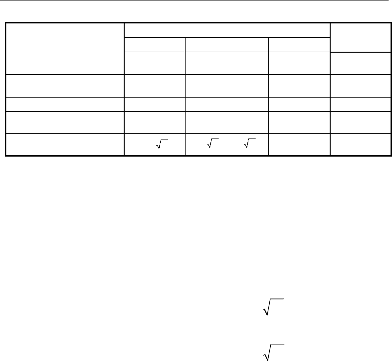
Post-Tensioned Concrete Design
Prestressed
Class U Class T Class C Nonprestressed
Assumed behavior Uncracked Transition between
uncracked and cracked Cracked Cracked
Section properties for stress
calculation at service loads Gross section
24.5.2.2 Gross section
24.5.2.2 Cracked section
24.5.2.2 No requirement
Allowable stress at transfer 24.5.3 24.5.3 24.5.3 No requirement
Allowable compressive stress based
on uncracked section properties 24.5.4 24.5.4 No requirement No requirement
Tensile stress at service loads
24.5.2.1
′
≤7.5 c
f
′′
<≤7.5 12
ct c
ff f
No requirement No requirement
20.6 Serviceability Requirements of Flexural Members
20.6.1 Serviceability Check at Initial Service Load
The stresses in the concrete immediately after prestress force transfer (before
time dependent prestress losses) are checked against the following limits:
Extreme fiber stress in compression:
0.60
'
ci
f
(ACI 24.5.3.1)
Extreme fiber stress in tension:
3
'
ci
f
(ACI 24.5.3.2)
Extreme fiber stress in tension at ends of
simply supported members:
6
'
ci
f
(ACI 24.5.3.2)
The extreme fiber stress in tension at the ends of simply supported members is
currently NOT checked by ETABS.
20.6.2 Serviceability Checks at Service Load
The stresses in the concrete for Class U and Class T prestressed flexural mem-
bers at service loads, and after all prestress losses occur, are checked against the
following limits:
Extreme fiber stress in compression due
to prestress plus total load:
0.60
'
c
f
(ACI 18.4.2(b))
20 - 10 Serviceability Requirements of Flexural Members

Chapter 20 - Design for ACI 318-14
Extreme fiber stress in tension in the precompressed tensile zone at service
loads:
– Class U beams and one-way slabs:
ct
ff '5.7≤
(ACI 24.5.2.1)
– Class U two-way slabs:
ct ff '6≤
(ACI 24.5.2.1)
– Class T beams:
ctc
fff '12'5.7 ≤<
(ACI 24.5.2.1)
– Class C beams:
ct
ff '12≥
(ACI 24.5.2.1)
For Class C prestressed flexural members, checks at service loads are not re-
quired by the code. However, for Class C prestressed flexural members not sub-
ject to fatigue or to aggressive exposure, the spacing of bonded reinforcement
nearest the extreme tension face shall not exceed that given by ACI 24.3.5 (ACI
24.3.2). It is assumed that the user has checked the requirements of ACI 9.7.2.2
and ACI 24.3.1 to 24.3.4 independently, as these sections are not checked by the
program.
20.6.3 Serviceability Checks at Long-Term Service Load
The stresses in the concrete for Class U and Class T prestressed flexural mem-
bers at long-term service loads, and after all prestress losses occur, are checked
against the same limits as for the normal service load, except for the following:
Extreme fiber stress in compression due to prestress plus total load:
0.45 '
c
f
(ACI 24.5.4.1)
20.6.4 Serviceability Checks of Prestressing Steel
The program also performs checks on the tensile stresses in the prestressing steel
(ACI 20.3.2.5). The permissible tensile stress checks, in all types of prestressing
steel, in terms of the specified minimum tensile stress fpu, and the minimum yield
stress, fy, are summarized as follows:
Due to tendon jacking force: min(0.94fpy, 0.80fpu) (ACI 20.3.2.5.1)
Serviceability Requirements of Flexural Members 20 - 11

Post-Tensioned Concrete Design
At anchors and couplers after force
transfer: 0.70fpu (ACI 20.3.2.5.1)
20.7 Beam Design (for Reference Only)
Important Note: Post-tensioned beam design is not available in the current ver-
sion of ETABS, but is planned for a future release. This section is provided as
reference only for the documentation of post-tensioned slab design.
In the design of prestressed concrete beams, ETABS calculates and reports the
required areas of reinforcement for flexure, shear, and torsion based on the beam
moments, shear forces, torsion, load combination factors, and other criteria de-
scribed in the subsections that follow. The reinforcement requirements are cal-
culated at each station along the length of the beam.
Beams are designed for major direction flexure, shear, and torsion only. Effects
resulting from any axial forces and minor direction bending that may exist in the
beams must be investigated independently by the user.
The beam design procedure involves the following steps:
Design flexural reinforcement
Design shear reinforcement
Design torsion reinforcement
20.7.1 Design Flexural Reinforcement
The beam top and bottom flexural reinforcement is designed at each station
along the beam. In designing the flexural reinforcement for the major moment
of a particular beam for a particular station, the following steps are involved:
Determine factored moments
Determine required flexural reinforcement
20 - 12 Beam Design (for Reference Only)

Chapter 20 - Design for ACI 318-14
20.7.1.1 Determine Factored Moments
In the design of flexural reinforcement of prestressed concrete beams, the fac-
tored moments for each load combination at a particular beam station are ob-
tained by factoring the corresponding moments for different load cases, with the
corresponding load factors.
The beam is then designed for the maximum positive and maximum negative
factored moments obtained from all of the load combinations. Positive beam
moments can be used to calculate bottom reinforcement. In such cases the beam
may be designed as a rectangular or a flanged beam. Negative beam moments
can be used to calculate top reinforcement. In such cases the beam may be de-
signed as a rectangular or inverted flanged beam.
20.7.1.2 Determine Required Flexural Reinforcement
In the flexural reinforcement design process, the program calculates both the
tension and compression reinforcement. Compression reinforcement is added
when the applied design moment exceeds the maximum moment capacity of a
singly reinforced section. The user has the option of avoiding the compression
reinforcement by increasing the effective depth, the width, or the strength of the
concrete.
The design procedure is based on the simplified rectangular stress block, as
shown in Figure 20-1 (ACI 22.2). Furthermore, it is assumed that the net tensile
strain in the reinforcement shall not be less than 0.005 (tension controlled) (ACI
9.3.3). When the applied moment exceeds the moment capacity at this design
condition, the area of compression reinforcement is calculated on the assumption
that the additional moment will be carried by compression reinforcement and
additional tension reinforcement.
The design procedure used by ETABS, for both rectangular and flanged sections
(L- and T-beams), is summarized in the subsections that follow. It is assumed
that the design ultimate axial force does not exceed
φ
(0.1f'cAg) (ACI 9.3.3,
9.5.2.1); hence all beams are designed for major direction flexure, shear, and
torsion only.
Beam Design (for Reference Only) 20 - 13

Post-Tensioned Concrete Design
20.7.1.2.1 Design of Rectangular Beams
ETABS first determines if the moment capacity provided by the post-tensioning
tendons alone is enough. In calculating the capacity, it is assumed that As = 0. In
that case, the moment capacity
0
n
M
φ
is determined as follows:
Figure 20-1 Rectangular Beam Design
The maximum depth of the compression zone, cmax, is calculated based on the
limitation that the tension reinforcement strain shall not be less than
ε
smin, which
is equal to 0.005 for tension-controlled behavior (ACI 10.3.4):
cmax =
d
sc
c
+minmax
max
ε
ε
ε
(ACI 21.2.2)
where,
ε
cmax = 0.003 (ACI 21.2.2, Fig R21.2)
ε
smin = 0.005 (ACI 21.2.2, Fig R21.2.26)
Therefore, the limit c ≤ cmax is set for tension-controlled sections.
BEAM
SECTION STRAIN
DIAGRAM STRESS
DIAGRAM
ps
ε
s
ε
0.003ε= c
f0.85 ′
s
C
s
T
cps
T
ac
1
= β
c
p
d
d′
s
d
s
A
b
ps
A
s
A′
cs
T
BEAM
SECTION STRAIN
DIAGRAM STRESS
DIAGRAM
ps
ε
s
ε
0.003ε= c
f
0.85 ′
s
C
s
T
cps
T
ac
1
= β
c
p
d
d′
s
d
s
A
b
ps
A
s
A′
cs
T
20 - 14 Beam Design (for Reference Only)

Chapter 20 - Design for ACI 318-14
The maximum allowable depth of the rectangular compression block, amax, is
given by:
amax =
β
1cmax (ACI 22.2.2.4.1)
where
β
1 is calculated as:
β
1 = 0.85 − 0.05
−
1000
4000'
c
f
, 0.65 ≤
β
1 ≤ 0.85 (ACI 22.2.2.4.3)
ETABS determines the depth of the neutral axis, c, by imposing force equilib-
rium, i.e., C = T. After the depth of the neutral axis has been determined, the
stress in the post-tensioning steel, fps, is computed based on strain compatibility
for bonded tendons. For unbonded tendons, the code equations are used to com-
pute the stress, fps in the post-tensioning steel.
Based on the calculated fps, the depth of the neutral axis is recalculated, and fps is
further updated. After this iteration process has converged, the depth of the rec-
tangular compression block is determined as follows:
1
ac
β
=
If
max
cc≤
(ACI 9.3.3.1, 21.2.2), the moment capacity of the section, provided
by post-tensioning steel only, is computed as:
0
2
n ps ps p
a
M Af d
φφ
= −
If
max
cc>
(ACI 9.3.3), a failure condition is declared.
If
0,
φ
>
un
MM
ETABS calculates the moment capacity and the As required at
the balanced condition. The balanced condition is taken as the marginal tension
controlled case. In that case, it is assumed that the depth of the neutral axis, c is
equal to cmax. The stress in the post-tensioning steel, fps is then calculated and the
area of required tension reinforcement, As, is determined by imposing force equi-
librium, i.e., C = T.
'max
0.85 c
C fa b=
Beam Design (for Reference Only) 20 - 15

Post-Tensioned Concrete Design
bal bal bal
ps ps s s
T Af A f= +
max
0.85 ′−
=
bal
c ps ps
bal
sbal
s
fa b A f
Af
After the area of tension reinforcement has been determined, the capacity of the
section with post-tensioning steel and tension reinforcement is computed as:
max max
22
bal bal bal bal
n ps ps p s s s
aa
M Afd Afd
φφ φ
= −+ −
In that case, it is assumed that the bonded tension reinforcement will yield, which
is true for most cases. In the case that it does not yield, the stress in the reinforce-
ment, fs, is determined from the elastic-perfectly plastic stress-strain relationship.
The fy value of the reinforcement is then replaced with fs in the preceding four
equations. This case does not involve any iteration in determining the depth of
the neutral axis, c.
20.7.1.2.1.1 Case 1: Post-tensioning steel is adequate
When
0
,
un
MM
φ
<
the amount of post-tensioning steel is adequate to resist the
design moment Mu. Minimum reinforcement is provided to satisfy ductility re-
quirements (ACI 8.6.2.2.1 and 8.6.2.3), i.e,
0.
un
MM
φ
<
20.7.1.2.1.2 Case 2: Post-tensioning steel plus tension reinforcement
In this case, the amount of post-tensioning steel, Aps, alone is not sufficient to
resist Mu, and therefore the required area of tension reinforcement is computed
to supplement the post-tensioning steel. The combination of post-tensioning
steel and tension reinforcement should result in a < amax.
When
0
,<<
φφ
bal
nu n
MM M
ETABS determines the required area of tension re-
inforcement, As, iteratively to satisfy the design moment Mu and reports this re-
quired area of tension reinforcement. Since Mu is bounded by
0
n
M
φ
at the lower
end and
bal
n
M
φ
at the upper end, and
0
n
M
φ
is associated with
0
s
A=
and
bal
n
M
φ
is associated with
,=
bal
ss
AA
the required area will fall within the range of 0 to
Asbal.
20 - 16 Beam Design (for Reference Only)

Chapter 20 - Design for ACI 318-14
The tension reinforcement is to be placed at the bottom if Mu is positive, or at
the top if Mu is negative.
20.7.1.2.1.3 Case 3: Post-tensioning steel and tension reinforcement are not ade-
quate
When
,>
φ
bal
un
MM
compression reinforcement is required (ACI 9.3.3.1). In
this case ETABS assumes that the depth of the neutral axis, c, is equal to cmax.
The values of fps and fs reach their respective balanced condition values,
bal
ps
f
and
.
bal
s
f
The area of compression reinforcement,
',
s
A
is then determined as
follows:
The moment required to be resisted by compression reinforcement and tension
reinforcement is:
bal
us u n
MM M
φ
= −
The required compression reinforcement is given by:
()( )
φ
''85.0'
'ddff
M
A
ecs
us
s−−
=
, where
ycss
f
c
dc
Ef ≤
−
=
max
max
max
'
'
ε
(ACI 9.2.1.2, 9.5.2.1, 20.2.2, 22.2.1.2)
The tension reinforcement for balancing the compression reinforcement is given
by:
( )
'
com us
s
ys
M
Afd d
φ
=−
Therefore, the total tension reinforcement, As =
bal
s
A
+
,
com
s
A
and the total com-
pression reinforcement is A's. As is to be placed at the bottom and A's is to be
placed at the top if Mu is positive, and vice versa if Mu is negative.
Beam Design (for Reference Only) 20 - 17

Post-Tensioned Concrete Design
20.7.1.2.2 Design of Flanged Beams
20.7.1.2.2.1 Flanged Beam Under Negative Moment
In designing for a factored negative moment, Mu
(i.e., designing top reinforce-
ment), the calculation of the reinforcement area is exactly the same as above,
i.e., no flanged beam data is used.
20.7.1.2.2.2 Flanged Beam Under Positive Moment
ETABS first determines if the moment capacity provided by the post-tensioning
tendons alone is enough. In calculating the capacity, it is assumed that As = 0. In
that case, the moment capacity
0
n
M
φ
is determined as follows:
The maximum depth of the compression zone, cmax, is calculated based on the
limitation that the tension reinforcement strain shall not be less than
ε
smin, which
is equal to 0.005 for tension-controlled behavior (ACI 22.2.2):
cmax =
d
sc
c
+minmax
max
εε
ε
(ACI 22.2.1.2)
where,
ε
cmax = 0.003 (ACI 21.2.2, Fig R21.2))
ε
smin = 0.005 (ACI 21.2.2, Fig R21.2.26)
Therefore, the limit c ≤ cmax is set for tension-controlled section:
The maximum allowable depth of the rectangular compression block, amax, is
given by:
amax =
β
1cmax (ACI 22.2.2.4.1)
where
β
1 is calculated as:
β1 =0.85 − 0.05
−
1000
4000'
c
f
, 0.65 ≤ β1 ≤ 0.85 (ACI 22.2.2.4.3)
20 - 18 Beam Design (for Reference Only)
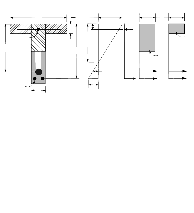
Chapter 20 - Design for ACI 318-14
Figure 20-2 T-Beam Design
ETABS determines the depth of the neutral axis, c, by imposing force equilib-
rium, i.e., C = T. After the depth of the neutral axis has been determined, the
stress in the post-tensioning steel, fps is computed based on strain compatibility
for bonded tendons. For unbonded tendons, the code equations are used to com-
pute the stress, fps in the post-tensioning steel. Based on the calculated fps, the
depth of the neutral axis is recalculated, and fps is further updated. After this it-
eration process has converged, the depth of the rectangular compression block is
determined as follows:
1
ac
β
=
If c ≤ cmax (ACI 9.3.3.1, 21.2.2, Fig 21.2.26, 22.2.2.4.1), the moment capacity
of the section, provided by post-tensioning steel only, is computed as:
0
2
n ps ps p
a
M Af d
φφ
= −
If c > cmax (ACI 9.3.3), a failure condition is declared.
If
0
,>
φ
un
MM
ETABS calculates the moment capacity and the As required at
the balanced condition. The balanced condition is taken as the marginal tension-
controlled case. In that case, it is assumed that the depth of the neutral axis c is
equal to cmax. The stress in the post-tensioning steel, fps, is then calculated and
BEAM
SECTION STRAIN
DIAGRAM STRESS
DIAGRAM
p
d
f
b
s
A
s
A′
s
d
f
h
ps
A
d′
s
f′
c
s
C
s
T
w
T
w
C
bw
0.003
ε=
ps
ε
s
ε
f
T
f
C
c
f0.85 ′
c
f0.85 ′
BEAM
SECTION STRAIN
DIAGRAM STRESS
DIAGRAM
p
d
f
b
s
A
s
A′
s
d
f
h
ps
A
d′
s
f′
c
s
C
s
T
w
T
w
C
bw
0.003ε=
ps
ε
s
ε
f
T
f
C
c
f0.85 ′
c
f0.85 ′
Beam Design (for Reference Only) 20 - 19

Post-Tensioned Concrete Design
the area of required tension reinforcement, As, is determined by imposing force
equilibrium, i.e., C = T.
If a ≤ hf, the subsequent calculations for As are exactly the same as previously
defined for the rectangular beam design. However, in that case the width of
the beam is taken as bf. Compression reinforcement is required if a > amax.
If a > hf, the calculation for As is given by:
comp
cc A
fC '
85.
0
=
where
com
c
A
is the area of concrete in compression, i.e.,
( )
max
com
c ff w f
A bh b a h=+−
bal bal bal
ps ps s s
T Af A f= +
bal
s
bal
psps
com
cc
bal
sf
fAAf
A−
='85.0
In that case, it is assumed that the bonded tension reinforcement will yield, which
is true for most cases. In the case that it does not yield, the stress in the reinforce-
ment, fs, is determined from the elastic-perfectly plastic stress-strain relationship.
The fy value of the reinforcement is then replaced with fs in the preceding four
equations. This case does not involve any iteration in determining the depth of
the neutral axis, c.
Case 1: Post-tensioning steel is adequate
When
0
un
MM
φ
<
the amount of post-tensioning steel is adequate to resist the
design moment Mu. Minimum reinforcement is provided to satisfy ductility re-
quirements (ACI 8.6.2.2.1 and 8.6.2.3), i.e.,
0
un
MM
φ
<
.
Case 2: Post-tensioning steel plus tension reinforcement
In this case, the amount of post-tensioning steel, Aps, alone is not sufficient to
resist Mu, and therefore the required area of tension reinforcement is computed
to supplement the post-tensioning steel. The combination of post-tensioning
steel and tension reinforcement should result in a < amax.
20 - 20 Beam Design (for Reference Only)

Chapter 20 - Design for ACI 318-14
When
0,<<
φφ
bal
nu n
MM M
ETABS determines the required area of tension re-
inforcement, As, iteratively to satisfy the design moment Mu and reports this re-
quired area of tension reinforcement. Since Mu is bounded by
0
n
M
φ
at the lower
end and
bal
n
M
φ
at the upper end, and
0
n
M
φ
is associated with As = 0 and
bal
n
M
φ
is associated with
,=bal
ss
AA
the required area will fall within the range of 0 to
As.
The tension reinforcement is to be placed at the bottom if Mu is positive, or at
the top if Mu is negative.
Case 3: Post-tensioning steel and tension reinforcement are not adequate
When
,
bal
un
MM
φ
>
compression reinforcement is required (ACI 9.3.3.1). In
that case, ETABS assumes that the depth of the neutral axis, c, is equal to cmax.
The value of fps and fs reach their respective balanced condition values,
bal
ps
f
and
.
bal
s
f
The area of compression reinforcement,
'
,
s
A
is then determined as fol-
lows:
The moment required to be resisted by compression reinforcement and tension
reinforcement is:
bal
us u n
MM M
φ
= −
The required compression reinforcement is given by:
( )( )
',
' 0.85 ' '
us
s
s cs
M
Af f dd
φ
=−−
where
ycs
s
f
c
dc
Ef ≤
−
=
max
max
max
'
'
ε
(ACI 9.2.1.2, 9.5.2.1, 20.2.2, 22.2.1.2)
The tension reinforcement for balancing the compression reinforcement is given
by:
( )
'
com us
s
ys
M
Afd d
φ
=−
Beam Design (for Reference Only) 20 - 21

Post-Tensioned Concrete Design
Therefore, the total tension reinforcement, As =
bal
s
A
+
,
com
s
A
and the total com-
pression reinforcement is A's. As is to be placed at the bottom and A's is to be
placed at the top if Mu is positive, and vice versa if Mu is negative.
20.7.1.2.3 Ductility Requirements
ETABS also checks the following condition by considering the post-tensioning
steel and tension reinforcement to avoid abrupt failure.
1.2
n cr
MM
φ
≥
(ACI 8.6.2.2)
The preceding condition is permitted to be waived for the following:
(a) Two-way, unbonded post-tensioned slabs
(b) Flexural members with shear and flexural strength at least twice that re-
quired by ACI 8.6.2.2.1.
These exceptions currently are NOT handled by ETABS.
20.7.1.2.4 Minimum and Maximum Reinforcement
The minimum flexural tension reinforcement required in a beam section is given
by the following limit:
As ≥ 0.004 Act (ACI 9.6.2.3)
where, Act is the area of the cross-section between the flexural tension face and
the center of gravity of the gross section.
An upper limit of 0.04 times the gross web area on both the tension reinforce-
ment and the compression reinforcement is imposed upon request as follows:
sw
sw
bd
Abd
bd
Abd
0.4 Rectangular beam
0.4 Flanged beam
0.04 Rectangular beam
0.04 Flanged beam
≤
′≤
20 - 22 Beam Design (for Reference Only)
Chapter 20 - Design for ACI 318-14
20.7.2 Design Beam Shear Reinforcement
The shear reinforcement is designed for each load combination at each station
along the length of the beam. In designing the shear reinforcement for a particu-
lar beam, for a particular loading combination, at a particular station due to the
beam major shear, the following steps are involved:
Determine the factored shear force, Vu.
Determine the shear force, Vc that can be resisted by the concrete.
Determine the shear reinforcement required to carry the balance.
The following three sections describe in detail the algorithms associated with
these steps.
20.7.2.1 Determine Factored Shear Force
In the design of the beam shear reinforcement, the shear forces for each load
combination at a particular beam station are obtained by factoring the corre-
sponding shear forces for different load cases, with the corresponding load com-
bination factors.
20.7.2.2 Determine Concrete Shear Capacity
The shear force carried by the concrete, Vc, is calculated as:
Vc = min(Vci , Vcw) (ACI 22.5.1.4, 22.5.8.3)
where,
dbf
M
MV
VdbfV wc
crei
dpwcci '7.1'6.0
max
λλ
≥++=
(ACI 22.5.8.3.1a, 22.5.8.3.1b)
( )
ppwpcccw VdbffV +
+= 3.0'5.3
λ
(ACI 22.5.8.3.2)
0.80
p
dh≥
(ACI 22.5.8.3.2)
Beam Design (for Reference Only) 20 - 23
Post-Tensioned Concrete Design
( )
dpec
t
cre
fff
y
I
M−+
='6
λ
(ACI 22.5.8.3.1c)
where,
fd = stress due to unfactored dead load, at the extreme fiber of the section
where tensile stress is caused by externally applied loads, psi
fpe = compress stress in concrete due to effective prestress forces only
(after allowance for all prestress losses) at the extreme fiber of the
section where tensile stress is caused by externally applied loads, psi
Vd = shear force at the section due to unfactored dead load, lbs
Vp = vertical component of effective prestress force at the section, lbs
Vci = nominal shear strength provided by the concrete when diagonal
cracking results from combined shear and moment
Mcre = moment causing flexural cracking at the section because of exter-
nally applied loads
Mmax = maximum factored moment at section because of externally applied
loads
Vi = factored shear force at the section because of externally applied
loads occurring simultaneously with Mmax
Vcw = nominal shear strength provided by the concrete when diagonal
cracking results from high principal tensile stress in the web
For light-weight concrete, the
c
f'
term is multiplied by the shear strength re-
duction factor λ.
20.7.2.3 Determine Required Shear Reinforcement
The shear force is limited to a maximum of:
( )
d
bfVV wcc '8
max +=
(ACI 22.5.1.2)
20 - 24 Beam Design (for Reference Only)
Chapter 20 - Design for ACI 318-14
Given Vu, Vc, and Vmax, the required shear reinforcement is calculated as follows
where,
φ
, the strength reduction factor, is 0.75 (ACI 21.2.2).
If
cu VV
φ
5.0≤
s
A
v
= 0 (ACI 9.6.3.1)
If
max
5.0 VVV
uc
φφ
≤<
( )
df
VV
s
A
yt
cuv
φ
φ
−
=
(ACI 22.5.1.1, 22.5.10.1, 20.5.10.5.3)
≥
yt
w
w
yt
c
v
f
b
b
f
f
s
A50
,
'75.0
max
λ
(ACI 9.6.3.3, Table 9.6.3.3)
If Vu >
φ
Vmax, a failure condition is declared (ACI 22.5.1.2).
For members with an effective prestress force not less than 40 percent of the
tensile strength of the flexural reinforcement, the required shear reinforcement
is computed as follows (ACI 9.6.3.3):
≥
wyt
pups
w
y
w
y
c
v
b
d
df
fA
b
f
b
f
f
s
A
80
50
,
'75.0
max
min
λ
If Vu exceeds the maximum permitted value of
φ
Vmax, the concrete section
should be increased in size (ACI 22.5.1.2).
Note that if torsion design is considered and torsion reinforcement is needed, the
equation given in ACI 9.6.3.3 does not need to be satisfied independently. See
the next section Design of Beam Torsion Reinforcement for details.
If the beam depth h is less than the minimum of 10 in, 2.5hf, and 0.5bw, the min-
imum shear reinforcement given by ACI 9.6.3.3 is not enforced (ACI 9.6.3.1)).
Beam Design (for Reference Only) 20 - 25

Post-Tensioned Concrete Design
The maximum of all of the calculated Av
/s values, obtained from each load com-
bination, is reported along with the controlling shear force and associated load
combination.
The beam shear reinforcement requirements considered by the program are
based purely on shear strength considerations. Any minimum stirrup require-
ments to satisfy spacing and volumetric considerations must be investigated in-
dependently of the program by the user.
20.7.3 Design Beam Torsion Reinforcement
The torsion reinforcement is designed for each design load combination at each
station along the length of the beam. The following steps are involved in design-
ing the shear reinforcement for a particular station due to the beam torsion:
Determine the factored torsion, Tu.
Determine special section properties.
Determine critical torsion capacity.
Determine the torsion reinforcement required.
20.7.3.1 Determine Factored Torsion
In the design of beam torsion reinforcement, the torsions for each load combina-
tion at a particular beam station are obtained by factoring the corresponding tor-
sions for different load cases with the corresponding load combination factors
(ACI 9.4.4.2).
In a statically indeterminate structure where redistribution of the torsion in a
member can occur due to redistribution of internal forces upon cracking, the de-
sign Tu is permitted to be reduced in accordance with the code (ACI 22.7.3.3).
However, the program does not automatically redistribute the internal forces and
reduce Tu. If redistribution is desired, the user should release the torsional degree
of freedom (DOF) in the structural model.
20 - 26 Beam Design (for Reference Only)

Chapter 20 - Design for ACI 318-14
20.7.3.2 Determine Special Section Properties
For torsion design, special section properties, such as Acp, Aoh, Ao, pcp, and ph are
calculated. These properties are described in the following (ACI 2.2).
A
cp
=
Area enclosed by outside perimeter of concrete cross-sec-
tion
A
oh
=
Area enclosed by centerline of the outermost closed trans-
verse torsional reinforcement
A
o
=
Gross area enclosed by shear flow path
p
cp
=
Outside perimeter of concrete cross-section
p
h
=
Perimeter of centerline of outermost closed transverse tor-
sional reinforcement
In calculating the section properties involving reinforcement, such as Aoh, Ao, and
ph, it is assumed that the distance between the centerline of the outermost closed
stirrup and the outermost concrete surface is 1.75 inches. This is equivalent to
1.5 inches clear cover and a #4 stirrup. For torsion design of flanged beam sec-
tions, it is assumed that placing torsion reinforcement in the flange area is inef-
ficient. With this assumption, the flange is ignored for torsion reinforcement cal-
culation. However, the flange is considered during Tcr calculation. With this as-
sumption, the special properties for a rectangular beam section are given as:
A
cp
=
bh (ACI 2.2, R22.7.5)
A
oh
=
(b
−
2c)(h
−
2c) (ACI 2.2, R22.7, Fig R22.7.6.1.1))
A
o
=
0.85 A
oh
(ACI 22.7.6.1.1, Fig R22.7.6.1.1)
p
cp
=
2b + 2h (ACI 2.2, R22.7.5)
p
h
=
2(b
−
2c) + 2(h
−
2c) (ACI 22.7.6.1.1, Fig R22.7.6.1.1)
where, the section dimensions b, h, and c are shown in Figure 20-3. Similarly,
the special section properties for a flanged beam section are given as:
A
cp
=
b
w
h + (b
f
−
b
w
)h
f
(ACI 2.2, R22.7.5)
Beam Design (for Reference Only) 20 - 27
Post-Tensioned Concrete Design
A
oh
=
(b
w
– 2c)(h – 2c) (ACI 2.2, R22.7, Fig R22.7.6.1.1)
A
o
=
0.85 A
oh
(ACI 22.7.6.1.1, Fig R22.7.6.1.1)
pcp
=
2bf + 2h
(ACI 2.2, R22.7.5)
p
h
=
2(h – 2c) + 2(b
w
– 2c) (ACI 2.2, R22.7.5)
where the section dimensions bf, bw, h, hf, and c for a flanged beam are shown in
Figure 20-3. Note that the flange width on either side of the beam web is limited
to the smaller of 4hf or (h – hf).
20.7.3.3 Determine Critical Torsion Capacity
The threshold torsion limit, Tth, and the cracking torsion limits, Tcr, for which the
torsion in the section can be ignored is calculated as:
2
'1
4'
cp pc
th c
cp c
Af
Tf
pf
λλ
= +
(ACI 22.7.4.1, Table 22.7.4.1a)
2
4' 1
4'
cp pc
th c
cp c
Af
Tf
pf
λλ
= +
(ACI 22.7.5.1g, Table 22.7.5.2)
where Acp and pcp are the area and perimeter of the concrete cross-section as
described in detail in the previous section; fpc is the concrete compressive stress
at the centroid of the section;
φ
is the strength reduction factor for torsion, which
is equal to 0.75 by default (ACI 21.2.1g, Table 21.2.1c); and f
′
c is the specified
concrete compressive strength.
20.7.3.4 Determine Torsion Reinforcement
If the factored torsion Tu is less than the threshold limit, ϕTth, torsion can be
safely ignored (ACI 22.7.1.1, 9.6.4.1).). In that case, the program reports that no
torsion reinforcement is required. However, if Tu exceeds the cracking torsion
limit, φTcr, it is assumed that the torsional resistance is provided by closed stir-
rups, longitudinal bars, and compression diagonals (ACI 22.7.1, 22.7.6.1). If Tu
is greater than φTth but less than φTcr, only minimum tension rebar needs to be
provided (ACI 9.6.4.1).
20 - 28 Beam Design (for Reference Only)
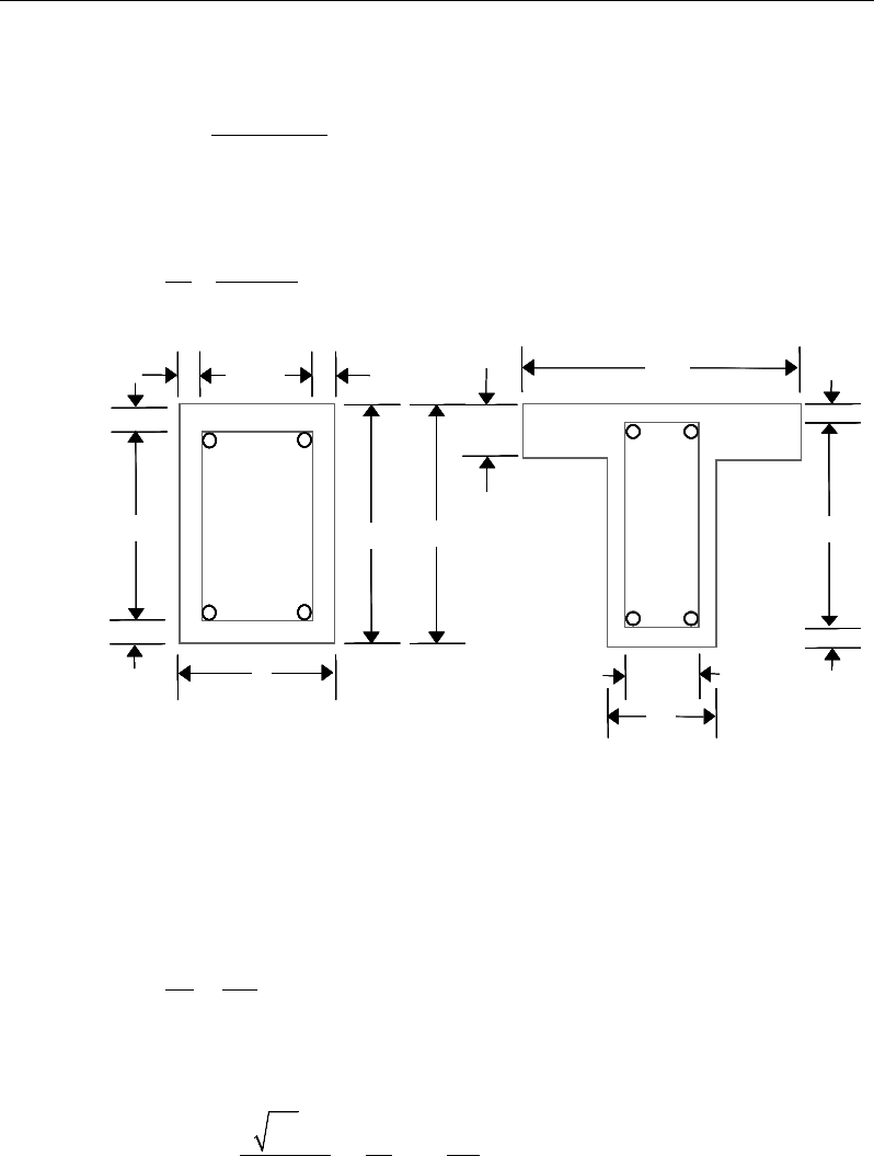
Chapter 20 - Design for ACI 318-14
If Tu > Tcr, the required longitudinal rebar area is calculated as:
0
2 tan
uh
ly
T p tan
AAf
θ
=φθ
(ACI 22.7.6.1)
and the required closed stirrup area per unit spacing, At /s, is calculated as:
0
tan
2
tu
ys
AT
s Af
θ
=φ
(ACI 22.7.6.1)
Figure 20-3 Closed stirrup and section dimensions for torsion design
where, the minimum value of At /s is taken as:
w
yt
t
b
fs
A25
=
(ACI 11.5.5.3)
and the minimum value of Al is taken as the least of the following:
,min
5
c cp ys
t
lh
yy
fA f
A
Ap
f sf
′
≥−
(ACI 9.6.4.3a)
cb
w
2
−
c
c
cc
c
c
cb 2
−
h
s
d
Closed Stirrup in
Rectangular Beam
Closed Stirrup in
T-Beam Section
ch 2
−h
b
ch 2
−
w
b
b
f
cb
w
2
−
c
c
cc
c
c
cb 2
−
h
f
h
Closed Stirrup in
Rectangular Beam
Closed Stirrup in
T-Beam Section
ch 2
−h
b
ch 2
−
w
b
b
f
cb
w
2
−
c
c
cc
c
c
cb 2
−
h
s
d
Closed Stirrup in
Rectangular Beam
Closed Stirrup in
T-Beam Section
ch 2
−h
b
ch 2
−
w
b
b
f
cb
w
2
−
c
c
cc
c
c
cb 2
−
h
s
d
Closed Stirrup in
Rectangular Beam
Closed Stirrup in
T-Beam Section
ch 2
−h
b
ch 2
−
w
b
b
f
cb
w
2
−
c
c
cc
c
c
cb 2
−
h
f
h
Closed Stirrup in
Rectangular Beam
Closed Stirrup in
T-Beam Section
ch 2
−h
b
ch 2
−
w
b
b
f
Beam Design (for Reference Only) 20 - 29
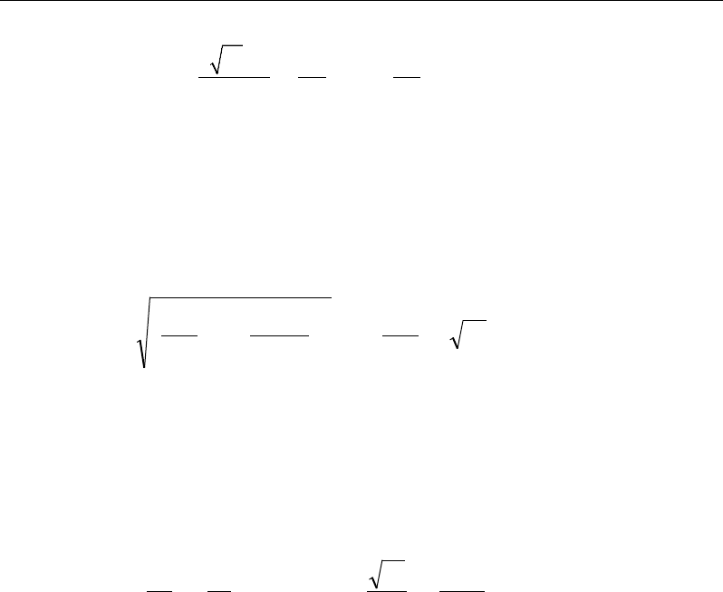
Post-Tensioned Concrete Design
'
,min
525
c cp ys
l wh
y ys y
fA f
A bp
ff f
= −
(ACI 9.6.4.3b)
In the preceding expressions,
θ
is taken as 45 degrees for prestressed members
with an effective prestress force less than 40 percent of the tensile strength of the
longitudinal reinforcement; otherwise
θ
is taken as 37.5 degrees.
An upper limit of the combination of Vu and Tu that can be carried by the section
is also checked using the equation:
′
+≤
+
c
w
c
oh
hu
w
u
f
db
V
A
pT
db
V8
7.1
2
2
2
φ
(ACI 22.7.7.1a)
For rectangular sections, bw is replaced with b. If the combination of Vu and Tu
exceeds this limit, a failure message is declared. In that case, the concrete section
should be increased in size.
When torsional reinforcement is required (Tu > Tcr), the area of transverse closed
stirrups and the area of regular shear stirrups must satisfy the following limit.
′
≥
+
y
w
w
yt
c
tv
f
b
b
f
f
s
A
s
A50
,75.0max2
λ
(ACI 9.6.4.2)
If this equation is not satisfied with the originally calculated Av /s and At /s, Av /s
is increased to satisfy this condition. In that case, Av /s does not need to satisfy
the ACI Section 9.6.6.3 independently.
The maximum of all of the calculated Al and At /s values obtained from each load
combination is reported along with the controlling combination.
The beam torsion reinforcement requirements considered by the program are
based purely on strength considerations. Any minimum stirrup requirements and
longitudinal reinforcement requirements to satisfy spacing considerations must
be investigated independently of the program by the user.
20 - 30 Beam Design (for Reference Only)

Chapter 20 - Design for ACI 318-14
20.8 Slab Design
Similar to conventional design, the ETABS slab design procedure involves
defining sets of strips in two mutually perpendicular directions. The locations of
the strips are usually governed by the locations of the slab supports. The mo-
ments for a particular strip are recovered from the analysis and a flexural design
is completed using the ultimate strength design method (ACI 318-14) for pre-
stressed reinforced concrete as described in the following sections. To learn
more about the design strips, refer to the section entitled "ETABS
Design Features" in the Key Features and Terminology manual.
20.8.1 Design for Flexure
ETABS designs the slab on a strip-by-strip basis. The moments used for the
design of the slab elements are the nodal reactive moments, which are obtained
by multiplying the slab element stiffness matrices by the element nodal displace-
ment vectors. Those moments will always be in static equilibrium with the ap-
plied loads, irrespective of the refinement of the finite element mesh.
The design of the slab reinforcement for a particular strip is completed at specific
locations along the length of the strip. Those locations correspond to the element
boundaries. Controlling reinforcement is computed on either side of those ele-
ment boundaries. The slab flexural design procedure for each load combination
involves the following:
Determine factored moments for each slab strip.
Determine the capacity of post-tensioned sections.
Design flexural reinforcement for the strip.
These three steps are described in the subsection that follow and are repeated for
every load combination. The maximum reinforcement calculated for the top and
bottom of the slab within each design strip, along with the corresponding con-
trolling load combination, is obtained and reported.
Slab Design 20 - 31

Post-Tensioned Concrete Design
20.8.1.1 Determine Factored Moments for the Strip
For each element within the design strip, for each load combination, the program
calculates the nodal reactive moments. The nodal moments are then added to get
the strip moments.
20.8.1.2 Determine Capacity of Post-Tensioned Sections
Calculation of the post-tensioned section capacity is identical to that described
earlier for rectangular beam sections.
20.8.1.3 Design Flexural Reinforcement for the Strip
The reinforcement computation for each slab design strip, given the bending mo-
ment, is identical to the design of rectangular beam sections described
earlier (or to the flanged beam if the slab is ribbed). In some cases, at a given
design section in a design strip, there may be two or more slab properties across
the width of the design strip. In that case, the program automatically designs the
tributary width associated with each of the slab properties separately using its
tributary bending moment. The reinforcement obtained for each of the tributary
widths is summed to obtain the total reinforcement for the full width of the de-
sign strip at the considered design section. This method is used when drop panels
are included. Where openings occur, the slab width is adjusted accordingly.
20.8.1.3.1 Minimum and Maximum Slab Reinforcement
For one-way slab with bonded prestressed reinforcement, total quantities of As
and Aps shall be adequate to develop a factored loads at least 1.2 times the crack-
ing load calculated on the basis of modulus of rupture (ACI 7.6.2.1). Currently
this check is NOT performed in the program.
For one-way slab with unbounded tendons, the minimum area of bounded de-
formed longitudinal reinforcement, As,min, has the following limit (ACI 7.6.2.3):
As,min = 0.004Act (ACI 7.6.2.3)
where Act is the area of that part of the cross-section between the flexural tension
face and the centroid of the gross-section.
20 - 32 Slab Design
Chapter 20 - Design for ACI 318-14
For two-way prestressed slabs, a minimum area of bounded deformed longitudi-
nal reinforcement, As,min, is provided in accordance with ACI section 8.6.2.3, Ta-
ble 8.6.2.3.
Reinforcement is not required in positive moment areas where ft, the extreme
fiber stress in tension in the precompressed tensile zone at service loads (after
all prestress losses occurs) does not exceed
2'
c
f
(ACI 8.6.2.3).
In positive moment areas where the computed tensile stress in the concrete at
service loads exceeds
2'
c
f,
the minimum area of bonded reinforcement is com-
puted as:
y
c
sf
N
A5.0
min,=
, where fy ≤ 60 ksi (ACI 8.6.2.3)
In negative moment areas at column supports, the minimum area of bonded
reinforcement in the top of slab in each direction is computed as:
,min
0.00075
s cf
AA=
(ACI 8.6.2.3)
where Acf is the larger gross cross-sectional area of the slab-beam strip in the two
orthogonal equivalent frames intersecting a column in a two-way slab
system.
In addition, an upper limit on both the tension reinforcement and compression
reinforcement has been imposed to be 0.04 times the gross cross-sectional area.
Note that the requirements when fy > 60 ksi currently are not handled.
20.8.2 Check for Punching Shear
The algorithm for checking punching shear is detailed in the section entitled
“Slab Punching Shear Check” in the Key Features and Terminology manual.
Only the code specific items are described in the following sections.
20.8.2.1 Critical Section for Punching Shear
The punching shear is checked on a critical section at a distance of d/2 from the
face of the support (ACI 22.6.4.2). For rectangular columns and concentrated
Slab Design 20 - 33
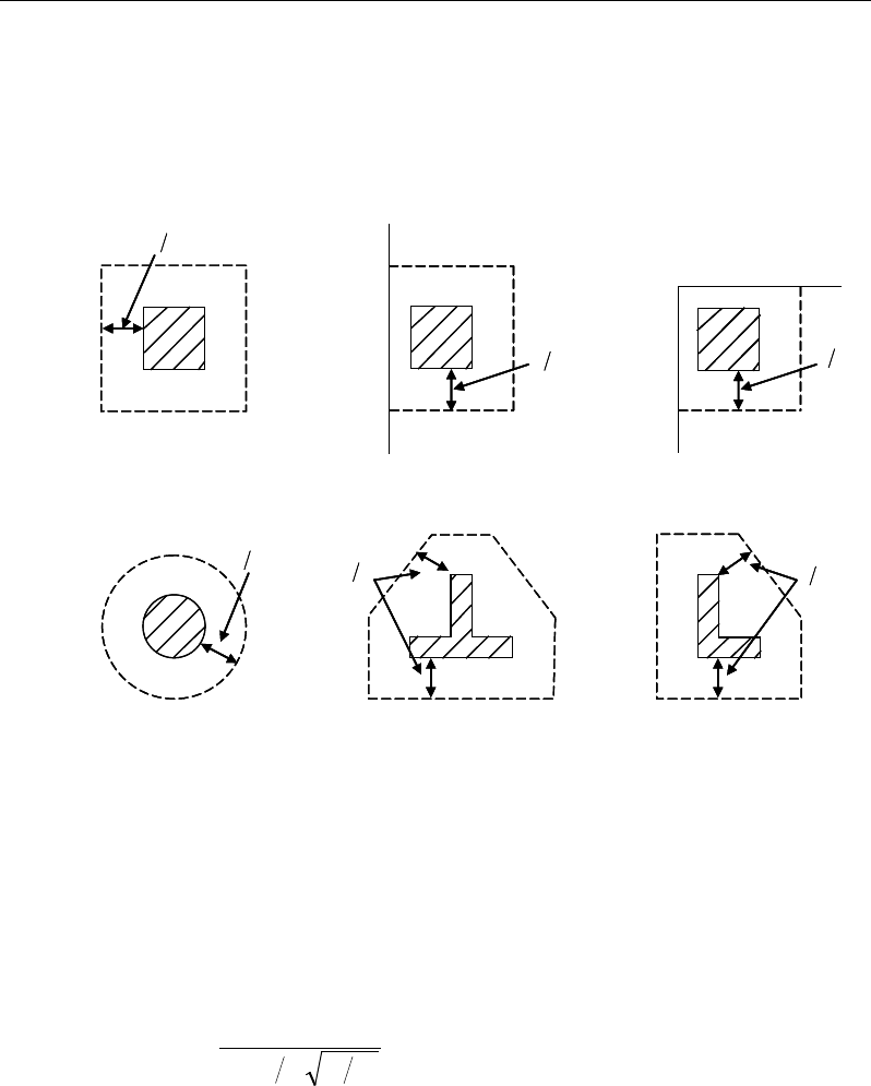
Post-Tensioned Concrete Design
loads, the critical area is taken as a rectangular area with the sides parallel to the
sides of the columns or the point loads (ACI 22.6.4.3). Figure 20-4 shows the
auto punching perimeters considered by ETABS for the various column shapes.
The column location (i.e., interior, edge, corner) and the punching
perimeter may be overwritten using the Punching Check Overwrites.
Figure 20-4 Punching Shear Perimeters
20.8.2.2 Transfer of Unbalanced Moment
The fraction of unbalanced moment transferred by flexure is taken to be
γ
f Msc
and the fraction of unbalanced moment transferred by eccentricity of shear is
taken to be
γ
v Msc.
( )
21
321
1
bb
f
+
=
γ
(ACI 8.4.2.3)
γ
v = 1 −
γ
f (ACI 8.4.4.2.2)
d2
Interior Column
Circular Column
d2 d2
d2
T-Shape Column
Edge Column Edge Column
L-Shape Column
d2
d2
d2
Interior Column
Circular Column
d2 d2
d2
T-Shape Column
Edge Column Edge Column
L-Shape Column
d2
d2
20 - 34 Slab Design
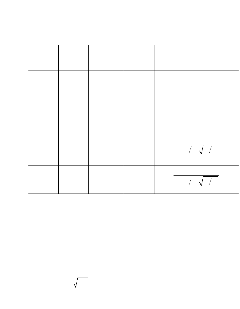
Chapter 20 - Design for ACI 318-14
For reinforced concrete slabs,
γ
f is permitted to increase to the maximum mod-
ified values provided in ACI Table 8.4.2.3.4 provided that the limitations on vug
and εt given in ACI Table 8.4.2.3.4 are satisfied .
Column
Location
Span
Direc-
tion
v
ug
ε
t
Maximum modified
γ
f
Corner
column
Either
direction
≤0.5ϕv
c
≥0.004
1.0
Edge
column
Perpen-
dicular
to the
edge
≤0.75ϕv
c
≥0.004
1.0
Parallel
to
the edge
≤0.4ϕv
c
≥0.010
( )
12
1.25 1.0
1 23
f
bb
γ
= ≤
+
Interior
column
Either
direction
≤0.4ϕv
c
≥0.010
( )
12
1.25 1.0
1 23
f
bb
γ
= ≤
+
where b1 is the width of the critical section measured in the direction of the span
and b2 is the width of the critical section measured in the direction perpendicular
to the span.
20.8.2.3 Determine Concrete Capacity
The concrete punching shear stress capacity of a two-way prestressed section is
taken as:
( )
' 0.3
c p c pc p
v f fv
βλ
= ++
(ACI 22.6.5.5a, 22.6.5.5b)
+= 5.1,5.3min
o
s
p
b
d
α
β
(ACI 22.6.5.5a, 22.6.5.5b)
Slab Design 20 - 35
Post-Tensioned Concrete Design
where,
β
p is the factor used to compute vc in prestressed slab; bo is the perimeter
of the critical section; fpc is the average value of fpc in the two directions; vp is the
vertical component of all effective prestress stresses crossing the critical section;
and
α
s is a scale factor based on the location of the critical section.
s
40 for interior columns,
30 for edge columns, and
20 for corner columns.
α=
(ACI 22.6.5.3)
The concrete capacity vc computed from ACI 22.6.5.5 is permitted only when
the following conditions are satisfied:
The column is farther than four times the slab thickness away from any dis-
continuous slab edges.
The value of
c
f
'
is taken no greater than 70 psi.
In each direction, the value of fpc is within the range:
125 ≤ fpc ≤ 500 psi
In thin slabs, the slope of the tendon profile is hard to control and special care
should be exercised in computing vp. In case of uncertainty between the design
and as-built profile, a reduced or zero value for vp should be used.
If the preceding three conditions are not satisfied, the concrete punching shear
stress capacity of a two-way prestressed section is taken as the minimum of the
following three limits:
4
2'
min
4'
c
c
c
c
f
f
λ
β
ν
λ
+
=
(ACI 22.6.5.2)
where,
β
c is the ratio of the maximum to the minimum dimensions of the criti-
cal section, b0 is the perimeter of the critical section, and
α
s is a scale factor
based on the location of the critical section (ACI 22.6.5.3).
20 - 36 Slab Design
Chapter 20 - Design for ACI 318-14
A limit is imposed on the value of
c
f'
as:
c
f
'
≤ 100 (ACI 22.5.3.1)
20.8.2.4 Determine Capacity Ratio
Given the punching shear force and the fractions of moments transferred by ec-
centricity of shear about the two axes, the shear stress is computed assuming
linear variation along the perimeter of the critical section. The ratio of the max-
imum shear stress and the concrete punching shear stress capacity is reported as
the punching shear capacity ratio by ETABS.
20.8.3 Design Punching Shear Reinforcement
The use of shear studs as shear reinforcement in slabs is permitted, provided that
the effective depth of the slab is greater than or equal to 6 inches, and not less
than 16 times the shear reinforcement bar diameter (ACI 22.6.7.1). If the slab
thickness does not meet these requirements, the punching shear reinforcement is
not designed and the slab thickness should be increased by the user.
The algorithm for designing the required punching shear reinforcement is used
when the punching shear capacity ratio exceeds unity. The Critical Section for
Punching Shear and Transfer of Unbalanced Moment as described in the earlier
sections remain unchanged. The design of punching shear reinforcement is car-
ried out as described in the subsections that follow.
20.8.3.1 Determine Concrete Shear Capacity
The concrete punching shear stress capacity of a two-way prestressed section
with punching shear reinforcement is as previously determined, but limited to:
2'
cc
vf
λ
≤
for shear links (ACI 22.6.6.1)
3'
cc
vf
λ
≤
for shear studs (ACI 22.26.6.1)
20.8.3.2 Determine Required Shear Reinforcement
The shear force is limited to a maximum of:
Slab Design 20 - 37
Post-Tensioned Concrete Design
Vmax = 6
'c
f
bod for shear links (ACI 22.6.6.2)
Vmax = 8
'c
f
bod for shear studs (ACI 22.6.6.2)
Given Vu, Vc, and Vmax, the required shear reinforcement is calculated as follows,
where,
φ
, the strength reduction factor, is 0.75 (ACI 9.3.2.3).
( )
uc
v
ys
VV
A
s fd
φ
φ
−
=
(ACI 22.5.1.1, 22.5.10.1, 20.5.10.5.3)
'
2
c
vo
y
f
Ab
sf
≥
for shear studs
If Vu >
φ
Vmax, a failure condition is declared. (ACI 22.5.1.2)
If Vu exceeds the maximum permitted value of
φ
Vmax, the concrete section
should be increased in size.
20.8.3.3 Determine Reinforcement Arrangement
Punching shear reinforcement in the vicinity of rectangular columns should be
arranged on peripheral lines, i.e., lines running parallel to and at constant dis-
tances from the sides of the column. Figure 20-5 shows a typical arrangement of
shear reinforcement in the vicinity of a rectangular interior, edge, and corner
column.
The distance between the column face and the first line of shear reinforcement
shall not exceed d/2 (ACI ACI 8.7.6.3, Table 8.7.6.3). The spacing between ad-
jacent shear reinforcement in the first line of shear reinforcement shall not ex-
ceed 2d measured in a direction parallel to the column face (ACI 8.7.6.3, Table
8.7.6.3).
Punching shear reinforcement is most effective near column corners where there
are concentrations of shear stress. Therefore, the minimum number of lines of
shear reinforcement is 4, 6, and 8, for corner, edge, and interior columns respec-
tively.
20 - 38 Slab Design

Chapter 20 - Design for ACI 318-14
Figure 20-5 Typical arrangement of shear studs and critical sections outside
shear-reinforced zone
20.8.3.4 Determine Reinforcement Diameter, Height, and Spacing
The punching shear reinforcement is most effective when the anchorage is close
to the top and bottom surfaces of the slab. The cover of anchors should not be
less than the minimum cover specified in ACI 20.6.1.3 plus half of the diameter
of the flexural reinforcement.
Punching shear reinforcement in the form of shear studs is generally available in
3/8-, 1/2-, 5/8-, and 3/4-inch diameters.
When specifying shear studs, the distance, so, between the column face and the
first peripheral line of shear studs should not be smaller than 0.35d. The limits
of so and the spacing, s, between the peripheral lines are specified as:
so ≤ 0.5d (ACI 8.7.7.1.2)
0 75 for 6
0 50 for 6
uc
uc
. d f'
s. d f'
ν φλ
ν φλ
≤
≤>
(ACI 8.7.7.1.2)
g ≤ 2d (ACI 8.7.7.1.2)
The limits of so and the spacing, s, between the links are specified as:
I
y
Typical Studrail
(only first and last
studs shown)
Outermost
peripheral line
of studs
Interior Column Edge Column Corner Column
Critical section
centroid
Free
edge
Free
edge
Critical
section
centroid
Free edge
Outermost
peripheral line
of studs
I
y
I
y
yx
d2 d2
d2
x
I
x
I
x
g
y
g
x
g
0
s0
s
0
s
x
I
y
x
x
I
y
Typical Studrail
(only first and last
studs shown)
Outermost
peripheral line
of studs
Interior Column Edge Column Corner Column
Critical section
centroid
Free
edge
Free
edge
Critical
section
centroid
Free edge
Outermost
peripheral line
of studs
I
y
I
y
yx
d2 d2
d2
x
I
x
I
x
g
y
g
x
g
0
s0
s
0
s
x
I
y
x
x
Slab Design 20 - 39

Post-Tensioned Concrete Design
so ≤ 0.5d (ACI 8.7.6.3)
0 50≤s .d
(ACI 8.7.6.3)
20 - 40 Slab Design

Chapter 21
Design for CSA A23.3-14
This chapter describes in detail the various aspects of the post-tensioned concrete
design procedure that is used by ETABS when the user selects the Canadian code
CSA A23.3-14 [CSA 2014]. Various notations used in this chapter are listed in
Table 21-1. For referencing to the pertinent sections of the CSA code in this
chapter, a prefix “CSA” followed by the section number is used.
The design is based on user-specified load combinations. The program provides
a set of default load combinations that should satisfy the requirements for the
design of most building type structures.
English as well as SI and MKS metric units can be used for input. The code is
based on Newton-millimeter-second units. For simplicity, all equations and
descriptions presented in this chapter correspond to Newton-millimeter-second
units unless otherwise noted.
21.1 Notations
The following table identifies the various notations used in this chapter.
Table 21-1 List of Symbols Used in the CSA A23.3-14 Code
A
p
Area of tension prestressing tendons, mm2
Notations 21 - 1

Post-Tensioned Concrete Design
Table 21-1 List of Symbols Used in the CSA A23.3-14 Code
A
s
Area of tension reinforcement, mm2
A'
s
Area of compression reinforcement, mm2
A
s(required)
Area of steel required for tension reinforcement, mm2
A
v
Area of shear reinforcement, mm2
A
v
/ s
Area of shear reinforcement per unit length of the member,
mm2/mm
Avs
Area of headed shear reinforcement, mm
2
Avs / s
Area of headed shear reinforcement per unit length of the mem-
ber, mm2/mm
a
Depth of compression block, mm
b
Width of member, mm
bf
Effective width of flange (T-beam section), mm
b
w
Width of web (T-beam section), mm
b
0
Perimeter of the punching critical section, mm
b1
Width of the punching critical section in the direction of bend-
ing, mm
b
2
Width of the punching critical section perpendicular to the
direction of bending, mm
c
Depth to neutral axis, mm
d
Distance from compression face to tension reinforcement, mm
d'
Concrete cover to center of reinforcing, mm
dp
Distance from compression face to prestressing tendons, mm
ds
Thickness of slab, mm
21 - 2 Notations

Chapter 21 - Design for CSA A23.3-14
Table 21-1 List of Symbols Used in the CSA A23.3-14 Code
d
v
Effective shear depth, mm
E
c
Modulus of elasticity of concrete, MPa
E
p
Modulus of elasticity of prestressing tendons, MPa
E
s
Modulus of elasticity of reinforcement, assumed as 2×10⁵ MPa
'
ci
f
Specified compressive strength of concrete at time of prestress
transfer, MPa
'
c
f
Specified compressive strength of concrete, MPa
f
y
Specified yield strength of flexural reinforcement, MPa
f
yh
Specified yield strength of shear reinforcement, MPa
f
yv
Specified yield strength of headed shear reinforcement, MPa
h
Overall depth of a section, mm
I
g
Moment of inertia of gross concrete section about centroidal
axis, neglecting reinforcement.
M
f
Factored moment at section, N-mm
φ
M
r
0
Design moment resistance of a section with tendons only, N-
mm
φ
M
r
bal
Design moment resistance of a section with tendons and the
necessary mild reinforcement to reach the balanced condition,
N-mm
s
Spacing of the shear reinforcement along the length of the
beam, mm
V
c
Shear resisted by concrete, N
V
r,max
Maximum permitted total factored shear force at a section, N
Notations 21 - 3

Post-Tensioned Concrete Design
Table 21-1 List of Symbols Used in the CSA A23.3-14 Code
V
f
Factored shear force at a section, N
V
s
Shear force at a section resisted by steel, N
α
1
Ratio of average stress in rectangular stress block to the speci-
fied concrete strength
β
1
Factor for obtaining depth of compression block in concrete
β
c
Ratio of the maximum to the minimum dimensions of the
punching critical section
ε
c
Strain in concrete
ε
cu
Maximum strain in concrete at ultimate
ε
p
Strain in prestressing tendons
ε
s
Strain in reinforcing steel
ϕ
c
Resistance factor for concrete
ϕ
p
Resistance factor for prestressing tendons
ϕ
s
Resistance factor for steel
γ
f
Fraction of unbalanced moment transferred by flexure
γ
v
Fraction of unbalanced moment transferred by eccentricity of
shear
λ
Shear strength factor
21.2 Design Load Combinations
The design load combinations are the various combinations of the load cases for
which the structure needs to be designed. For CSA A23.3-14, if a structure is
subjected to dead (D), live (L), pattern live (PL), snow (S), wind (W), and earth-
quake (E) loads, and considering that wind and earthquake forces are
21 - 4 Design Load Combinations

Chapter 21 - Design for CSA A23.3-14
reversible, the load combinations in the following sections may need to be con-
sidered (CSA 8.3.2, Table C.1a).
For post-tensioned concrete design, the user also can specify the prestressing
load (PT) by providing the tendon profile or by using the load balancing
options in the program. The default load combinations for post-tensioning are
defined in the following sections.
21.2.1 Initial Service Load Combination
The following load combination is used for checking the requirements at transfer
of prestress forces, in accordance with CSA 18.3.1. The prestressing forces are
considered without any long-term loses for the initial service load combination
check.
1.0D + 1.0PT
21.2.2 Service Load Combinations
The following load combinations are used for checking the requirements of pre-
stress for serviceability in accordance with CSA 18.3.2. It is assumed that long-
term losses have already occurred at the service stage.
1.0D + 1.0PT
1.0D + 1.0L + 1.0PT
21.2.3 Long-Term Service Load Combination
The following load combinations are used for checking the requirements of pre-
stress in accordance with CSA 18.3.2(a). The permanent load for this load com-
bination is taken as 50 percent of the live load. It is assumed that all long term
losses have already occurred at the service stage.
1.0D + 1.0PT
1.0D + 0.5L + 1.0PT
Design Load Combinations 21 - 5

Post-Tensioned Concrete Design
21.2.4 Strength Design Load Combination
The following load combinations are used for checking the requirements of pre-
stress for strength in accordance with CSA A23.3-14, Chapters 8 and 18.
The strength design combinations required for punching shear require the full
PT forces (primary and secondary). Flexural design requires only the hyperstatic
(secondary) forces. The hyperstatic (secondary) forces are determined automat-
ically by ETABS by subtracting the primary PT moments when the flexural de-
sign is carried out.
1.4D + 1.0PT*
(CSA 8.3.2,Table C.1a, Case 1)
1.25D + 1.5L + 1.0PT*
1.25D + 1.5L + 1.0P
T* ± 0.4W
1.25D + 1.5L + 1.0P
T* + 0.5S
0.9D + 1.5L + 1.0P
T*
0.9D + 1.5L + 1.0P
T* ± 0.4W
0.9D +
1.5L + 1.0PT* + 0.5S
(CSA 8.3.2,Table C.1a
, Case 2)
1.25D + 1.5(0.75 PL) + 1.0PT*
(CSA 13.8.4.3)
1.25D + 1.5S + 1.0PT*
1.25D + 1.5S + 1.0P
T* + 0.5L
1.25D + 1.5S + 1.0P
T* ± 0.4W
0.9D + 1.5S + 1.0P
T*
0.9D + 1.5S + 1.0P
T* + 0.5L
0.9D + 1.5S + 1.0P
T* ± 0.4W
(CSA 8.3.2,Table C.1a
, Case 3)
1.25D ± 1.4W + 1.0PT*
1.25D
± 1.4W + 1.0PT* + 0.5L
1.25D
± 1.4W + 1.0PT* + 0.5S
0.9D
± 1.4W + 1.0PT*
0.9D
± 1.4W + 1.0PT* + 0.5L
0.9D
± 1.4W + 1.0PT* + 0.5S
(CSA 8.3.2,Table C.1a
, Case 4)
1.0D ± 1.0E + 1.0PT*
1.0D
± 1.0E + 0.5L + 1.0PT*
1.0D
± 1.0E + 0.25S + 1.0PT*
1.0D + 0.5L
+ 0.25S ± 1.0E + 1.0PT*
(CSA 8.3.2,Table C.1a
, Case 5)
* — Replace PT by H for flexural design only
21 - 6 Design Load Combinations

Chapter 21 - Design for CSA A23.3-14
These are also the default design combinations in ETABS whenever the CSA
A23.3-14 code is used. The user should use other appropriate load combinations
if roof live load is treated separately, or if other types of loads are present.
21.3 Limits on Material Strength
The upper and lower limits of f'c are 80 MPa and 20 MPa respectively. The
upper limit of fy is 500 MPa for non-prestressed reinforcement (CSA 8.6.1.1).
For compression reinforcement with fy exceeding 400 MPa, the value of fy
assumed in design calculations shall not exceed the stress corresponding to a
strain of 0.0035 (CSA 8.5.21).
ETABS enforces the upper material strength limits for flexure and shear design
of slabs. The input material strengths are taken as the upper limits if they are
defined in the material properties as being greater than the limits. The user is
responsible for ensuring that the minimum strength is satisfied.
ETABS also checks the following tensile strength limits in prestressing steel
(CSA 18.4). The permissible tensile stresses in all types of prestressing steel, in
terms of the specified minimum tensile strength fpu, are summarized as follows:
Due to tendon jacking force for post-tensioning tendons:
0.85 fpu ≤ 0.94 fpy
Due to tendon jacking force for pretensioning tendons:
0.80 fpu
Immediately after prestress transfer:
0.82 fpy ≤0.74 fpu
Post-tensioning tendons, at anchorages and couplers, immediately after tendon
anchorage:
0.70 fpu
Limits on Material Strength 21 - 7

Post-Tensioned Concrete Design
The specified yield strength of prestressing tendons is based on the requirements
specified in ASTM A 416/A 416 M, ASTM A 421/A421 M, and ASTM A 722/A
722 m, which specify the following minimum values for fpy:
low-relaxation wire and strands fpy = 0.90 fpu
stress-relieved wire and strands, and plain bars fpy = 0.85 fpu
deformed bar fpy = 0.80 fpu
21.4 Strength Reduction Factors
The strength reduction factors,
φ
, are material dependent and defined as:
φ
c = 0.65 for concrete (CSA 8.4.2)
φ
s = 0.85 for reinforcement (CSA 8.4.3a)
φ
p = 0.90 for post-tensioning tendons (CSA 8.4.3a)
The preceding values for
φ
c,
φ
s, and
φ
p are the default values. These values can
be modified in the design preferences. For structural concrete manufactured in
prequalified manufacturing plants,
φ
c can be taken as 0.7 (CSA 8.4.2, 16.1.3).
21.5 Design Assumptions for Prestressed Concrete
Strength design of prestressed members for flexure and axial loads shall be based
on assumptions given in CSA 10.1.
The strain in the reinforcement and concrete shall be assumed directly propor-
tional to the distance from the neutral axis, except for unbonded tendons (CSA
10.1.2).
The maximum usable strain at the extreme concrete compression fiber shall be
assumed equal to 0.0035 (CSA 10.1.3).
The balanced strain condition shall exist at a cross-section when tension rein-
forcement reaches its yield strain just as the concrete in compression reaches
its maximum strain of 0.0035 (CSA 10.1.4).
21 - 8 Strength Reduction Factors

Chapter 21 - Design for CSA A23.3-14
The tensile strength of concrete shall be neglected in the calculation of the
factored flexural resistance of prestressed concrete members (CSA 10.1.5).
The relationship between the concrete compressive stress distribution and the
concrete strain shall be assumed to be rectangular by an equivalent rectangular
concrete stress distribution (CSA 10.1.7).
The concrete stress of
'
αϕ
ccc
f
shall be assumed uniformly distributed over an
equivalent-compression zone bounded by edges of the cross-section and a
straight line located parallel to the neutral axis at a distance
1
ac
β
=
from the
fiber of maximum compressive strain (CSA 10.1.7(a)).
The distance from the fiber of maximum strain to the neutral axis, c, shall be
measured in a direction perpendicular to the neutral axis (CSA 10.1.7.(b)).
The factors α1 and β1 shall be taken as follows (CSA 10.1.7.(c)).
– α1 = 0.85 – 0.0015
'
c
f
≥ 0.67
– β1 = 0.97 – 0.0025
'
c
f
≥ 0.67
Prestressed concrete members are investigated at the following three stages
(CSA 18.3):
At transfer of prestress force
At service loading
At nominal strength
21.6 Serviceability Requirements of Flexural Members
21.6.1 Serviceability Check at Initial Service Load
The stress in the concrete immediately after prestress force transfer (before time
dependent prestress losses) are checked against the following limits (CSA
18.3.1.1(a), 18.3.1.1(b) and 18.3.1.1(c)):
Extreme fiber stress in compression:
Serviceability Requirements of Flexural Members 21 - 9
Post-Tensioned Concrete Design
0.60 '
ci
f
Extreme fiber stress in tension, except as permitted in the subsequent item:
0.25λ
'
ci
f
Extreme fiber stress in tension at ends of simply supported members:
0.5λ'
ci
f
The extreme fiber stress in tension at the ends of simply supported members is
currently NOT checked by ETABS.
21.6.2 Serviceability Check at Service Load
The stresses in prestressed concrete flexural members at service loads, and after
all prestress losses occur, are checked against the following limits (CSA 18.3.2):
Extreme fiber stress in compression due to prestress plus total load:
0.60 '
c
f
Extreme fiber stress in tension in the precompressed tensile zone at service
loads:
0.50 '
c
fλ
Extreme fiber stress in tension in the precompressed tensile zone at service
loads, exposed to corrosive environment:
0.25λ'
c
f
21.6.3 Serviceability Check at Long-Term Service Load
The stresses in prestressed concrete flexural members at long-term service loads,
and after all prestress losses have occurred, are checked against the same limits
as for the normal service load, except for the following (CSA 18.3.2):
21 - 10 Serviceability Requirements of Flexural Members

Chapter 21 - Design for CSA A23.3-14
Extreme fiber stress in compression due to prestress plus sustained load:
0.45 '
c
f
21.7 Beam Design (for Reference Only)
Important Note: Post-tensioned beam design is not available in the current ver-
sion of ETABS, but is planned for a future release. This section is provided as
reference only for the documentation of post-tensioned slab design.
In the design of prestressed concrete beams, ETABS calculates and reports the
required areas of reinforcement for flexure, shear, and torsion based on the beam
moments, shear forces, torsion, load combination factors, and other criteria de-
scribed in the subsections that follow. The reinforcement requirements are cal-
culated at each station along the length of the beam.
Beams are designed for major direction flexure, shear, and torsion only. Effects
resulting from any axial forces and minor direction bending that may exist in the
beams must be investigated independently by the user.
The beam design procedure involves the following steps:
Design flexural reinforcement
Design shear reinforcement
Design torsion reinforcement
21.7.1 Design Flexural Reinforcement
The beam top and bottom flexural reinforcement is designed at each station
along the beam. In designing the flexural reinforcement for the major moment
of a particular beam, for a particular station, the following steps are involved:
Determine factored moments
Determine required flexural reinforcement if required
Beam Design (for Reference Only) 21 - 11

Post-Tensioned Concrete Design
21.7.1.1 Determine Factored Moments
In the design of flexural reinforcement of post-tensioned beams, the factored
moments for each load combination at a particular beam station are obtained by
factoring the corresponding moments for different load cases, with the corre-
sponding load factors.
The beam is then designed for the maximum positive and maximum negative
factored moments obtained from all of the load combinations. Positive beam
moments can be used to calculate bottom reinforcement. In such cases the beam
may be designed as a rectangular or flanged beam. Negative beam moments can
be used to calculate top reinforcement. In such cases the beam may be designed
as a rectangular or inverted flanged beam.
21.7.1.2 Determine Required Flexural Reinforcement
In the flexural reinforcement design process, the program calculates both the
tension and compression reinforcement. Compression reinforcement is added
when the applied design moment exceeds the maximum moment capacity of a
singly reinforced section. The user has the option of avoiding the compression
reinforcement by increasing the effective depth, the width, or the strength of the
concrete.
The design procedure is based on the simplified rectangular stress block, as
shown in Figure 21-1 (CSA 10.1.7). Furthermore it is assumed that the compres-
sion carried by the concrete is less than or equal to that which can be carried at
the balanced condition (CSA 10.1.4). When the applied moment exceeds the mo-
ment capacity at this design condition, the area of compression reinforcement is
calculated on the assumption that the additional moment will be carried by com-
pression and additional tension reinforcement.
The design procedure used by ETABS, for both rectangular and flanged sections
(L- and T-beams) is summarized in the subsections that follow. It is assumed
that the design ultimate axial force in a beam is negligible; hence all the beams
are designed for major direction flexure, shear, and torsion only.
21 - 12 Beam Design (for Reference Only)

Chapter 21 - Design for CSA A23.3-14
21.7.1.2.1 Design of Rectangular Beams
ETABS first determines whether the moment capacity provided by the post-ten-
sioning tendons alone is enough. In calculating the capacity, it is assumed that
As = 0. In that case, moment capacity
0
n
M
φ
is determined as follows:
Figure 21-1 Rectangular Beam Design
The maximum depth of the compression zone, cmax, is calculated based on strain-
stress compatibility (CSA 18.6.1):
cmax =
cu pp
cu p
εEd
ε +ε
(CSA 18.6.1)
where,
ε
cu = 0.0035 (CSA 10.1.4)
Therefore, the limits
max
cc≤
is set for tension-controlled sections.
(I) BEAM
SECTION (II) STRAIN
DIAGRAM (II) STRESS
DIAGRAM
s
A′
s
A
p
A
s
d
p
d
b
d′
0.0035
ε
=
s
C
c
s
ε
ε
p
s
T
c
T
1
ac
β
=
1
αφ
′
cc
f
(I) BEAM
SECTION (II) STRAIN
DIAGRAM (II) STRESS
DIAGRAM
s
A′
s
A
p
A
s
d
p
d
b
d′
0.0035
ε
=
s
C
c
s
ε
ε
p
s
T
c
T
1
ac
β
=
1
αφ
′
cc
f
Beam Design (for Reference Only) 21 - 13

Post-Tensioned Concrete Design
The ductility of a section is ensured by limiting the c/d ratio and strength
reduction factor
φ
. The minimum ductility required by the CSA code is limited
as c/dp ≤ 0.5 (CSA 18.6.2).
The maximum allowable depth of the rectangular compression block, amax, is
given by:
amax =
β
1cmax (CSA 10.1.7(a))
where
β
1 is calculated as:
β1 = 0.97 – 0.0025
'
c
f
≥ 0.67 (CSA 10.1.7)
ETABS determines the depth of the neutral axis, c, by imposing force equilib-
rium, i.e., C = T. After the depth of the neutral axis has been determined, the
stress in the post-tensioning steel, fpr is computed based on strain compatibility.
On the basis of the calculated fpr, the depth of the neutral axis is recalculated, and
fpr is further updated. After this iteration process has converged, the depth of the
rectangular compression block is determined as follows:
1
ac
β
=
If
max
cc≤
(CSA 18.6.2), the moment capacity of the section, provided by
post-tensioning steel only, is computed as:
0
2
r ps pr p
a
M Af d
φφ
= −
If
max
cc>
(CSA 18.6.2), a failure condition is declared.
If
0
,
fr
MM
φ
>
ETABS calculates the moment capacity and the As required at
the balanced condition. The balanced condition is taken as the marginal ten-
sion controlled case. In that case, it is assumed that the depth of the neutral
axis c is equal to cmax. The stress in the post-tensioning steel, fpr is then calcu-
lated based on strain compatibility and the area of required tension reinforce-
ment, As, is determined by imposing force equilibrium, i.e., C = T.
'
1 maxcc
C fab
αφ
=
21 - 14 Beam Design (for Reference Only)

Chapter 21 - Design for CSA A23.3-14
bal bal bal
p pr s s
T Af A f= +
'
1 max bal
c c p pr
bal
sbal
s
f a b Af
Af
αφ
−
=
After the area of tension reinforcement has been determined, the capacity of the
section with post-tensioning steel and tension reinforcement is computed as:
max max
22
bal bal bal bal
r p pr p s s s
aa
M Afd Afd
φφ φ
= −+ −
In that case, it is assumed that the bonded tension reinforcement will yield, which
is true for most cases. In the case that it does not yield, the stress in the reinforce-
ment, fs, is determined from the elastic-perfectly plastic stress-strain relationship.
The fy value of the reinforcement is then replaced with fs in the preceding four
equations. This case does not involve any iteration in determining the depth of
the neutral axis, c.
21.7.1.2.1.1 Case 1: Post-tensioning steel is adequate
When
( )
0,
fr
MM
φ
<
the amount of post-tensioning steel is adequate to resist the
design moment Mf. Minimum reinforcement is provided to satisfy the ductility
requirements (CSA 18.3.13, 18.7 and 18.8), i.e.,
( )
0
.
fr
MM
φ
<
21.7.1.2.1.2 Case 2: Post-tensioning steel plus tension reinforcement
In this case, the amount of post-tensioning steel, Ap, alone is not sufficient to
resist Mf, and therefore the required area of tension reinforcement is computed
to supplement the post-tensioning steel. The combination of post-tensioning
steel and tension reinforcement should result in a < amax.
When
0,
bal
rf r
MM M
φφ
<<
ETABS determines the required area of tension re-
inforcement, As, iteratively to satisfy the design moment Mf and reports the
required area of tension reinforcement. Since Mf is bounded by
0
r
M
φ
at the lower
end and
bal
r
M
φ
at the upper end, and
0
r
M
φ
is associated with
0
s
A=
and
bal
r
M
φ
Beam Design (for Reference Only) 21 - 15

Post-Tensioned Concrete Design
is associated with
,
bal
ss
AA=
the required area will be within the range of 0 to
s
A
.
The tension reinforcement is to be placed at the bottom if Mf is positive or at the
top if Mf is negative.
21.7.1.2.1.3 Case 3: Post-tensioning steel and tension reinforcement is
not adequate
When
( )
,
bal
fr
MM
φ
>
compression reinforcement is required (CSA 18.6.2). In
that case, ETABS assumes that the depth of the neutral axis, c, is equal to
max .c
The values of fpr and fs reach their respective balanced condition values, bal
pr
f and
.
bal
s
f
The area of compression reinforcement,
,
s
A′
is determined as follows:
The moment required to be resisted by compression reinforcement and tension
reinforcement is:
bal
rs f r
MM M
φ
= −
The required compression reinforcement is given by:
( )( )
1
,
rs
sss c c s
M
Af f dd
φ φα
′=′′′
−−
where
s
f′
= 0.0035Es
c - d'
c
≤ fy (CSA 10.1.2, 10.1.3)
The tension reinforcement for balancing the compression reinforcement is given
by:
( )
sy
rs
com
sddf
M
A
φ
'−
=
Therefore, the total tension reinforcement, As =
bal
s
A
+
,
com
s
A
and the total com-
pression reinforcement is A's. As is to be placed at the bottom and A's is to be
placed at the top if Mf is positive, and vice versa if Mf is negative.
21 - 16 Beam Design (for Reference Only)

Chapter 21 - Design for CSA A23.3-14
21.7.1.2.2 Design of Flanged Beams
21.7.1.2.2.1 Flanged Beam Under Negative Moment
In designing for a factored negative moment, Mf
(i.e., designing top reinforce-
ment), the calculation of the reinforcement area is exactly the same
as described previously, i.e., no flanged beam data is used.
Figure 21-2 T-Beam Design
21.7.1.2.2.2 Flanged Beam Under Positive Moment
ETABS first determines if the moment capacity provided by the post-tensioning
tendons alone is enough. In calculating the capacity, it is assumed that As = 0. In
that case, the moment capacity
0
n
M
φ
is determined as follows:
The maximum depth of the compression zone, cmax, is calculated based on strain-
stress compatibility (CSA 18.6.1):
cmax =
cu pp
cu p
εEd
ε +ε
(CSA 18.6.1)
where,
STRESS
DIAGRAM
STRAIN
DIAGRAM
BEAM
SECTION
s
A
p
A
p
d
s
d
s
A′
c
0.0035
ε
=
1
αφ
′
cc
f
1
αφ
′
cc
f
s
C
ε
p
s
ε
d′
w
C
t
C
w
Tf
T
s
T
s
h
′
s
f
f
b
w
b
STRESS
DIAGRAM
STRAIN
DIAGRAM
BEAM
SECTION
s
A
p
A
p
d
s
d
s
A′
c
0.0035
ε
=
1
αφ
′
cc
f
1
αφ
′
cc
f
s
C
ε
p
s
ε
d′
w
C
t
C
w
Tf
T
s
T
s
h
′
s
f
f
b
w
b
Beam Design (for Reference Only) 21 - 17

Post-Tensioned Concrete Design
ε
cu = 0.0035 (CSA 10.1.4)
Therefore, the limits
max
cc≤
is set for tension-controlled sections.
The ductility of a section is ensured by limiting the c/d ratio and strength reduc-
tion factor
φ
. The minimum ductility required by the CSA code is limited to c/dp
≤ 0.5 (CSA 18.6.2).
The maximum allowable depth of the rectangular compression block, amax, is
given by:
amax =
β
1cmax (CSA 10.1.7(a))
where
β
1 is calculated as:
β1 = 0.97 – 0.0025
'
c
f
≥ 0.67 (CSA 10.1.7)
ETABS determines the depth of the neutral axis, c, by imposing force equilib-
rium, i.e., C = T. After the depth of the neutral axis has been determined, the
stress in the post-tensioning steel, fpr is computed based on strain compatibility.
Based on the calculated fpr, the depth of the neutral axis is recalculated, and fpr is
further updated. After this iteration process has converged, the depth of the rec-
tangular compression block is determined as follows:
1
ac
β
=
If
max
cc≤
(CSA 18.6.2), the moment capacity of the section, provided by post-
tensioning steel only, is computed as:
0
2
r ps pr p a
M Af d
φφ
= −
If
max
cc
>
(CSA 18.6.2), a failure condition is declared.
If
0
,
fr
MM
φ
>
ETABS calculates the moment capacity and the As required at
the balanced condition. The balanced condition is taken as the marginal ten-
sion controlled case. In that case, it is assumed that the depth of neutral axis c
is equal to cmax. The stress in the post-tensioning steel, fpr is then calculated
21 - 18 Beam Design (for Reference Only)

Chapter 21 - Design for CSA A23.3-14
based on strain compatibility and the area of required tension reinforcement,
As, is determined by imposing force equilibrium, i.e., C = T.
If a ≤ hs, the subsequent calculations for As are exactly the same as previously
defined for the rectangular beam design. However, in this case the width of
the beam is taken as bf. Compression reinforcement is required when a > amax.
If a > hs, the calculation for As is given by:
1 max com
cc c
C faA
αφ
′
=
where
com
c
A
is the area of concrete in compression, i.e.,
( )
max
com
c fs w s
A bd b a d=+−
bal bal bal
p pr s s
T Af A f= +
1 max com bal
c c c p pr
bal
sbal
s
f a A Af
Af
αφ
′−
=
After the area of tension reinforcement has been determined, the capacity of the
section with post-tensioning steel and tension reinforcement is computed as:
max max
22
bal bal bal bal
r p pr p s s s
aa
M Afd Afd
φφ φ
= −+ −
In that case, it is assumed that the bonded tension reinforcement will yield, which
is true for most cases. In the case that it does not yield, the stress in the reinforc-
ing steel, fs, is determined from the elastic-perfectly plastic stress-strain relation-
ship. The fy value of the reinforcement is then replaced with fs in the preceding
four equations. This case does not involve any iteration in determining the depth
of neutral axis, c.
Beam Design (for Reference Only) 21 - 19

Post-Tensioned Concrete Design
21.7.1.2.2.3 Case 1: Post-tensioning steel is adequate
When
()
0
fr
MM
φ
<
the amount of post-tensioning steel is adequate to resist the
design moment Mf. Minimum reinforcement is provided to satisfy ductility re-
quirements (CSA 18.3.13, 18.7 and 18.8), i.e.,
( )
0
.
fr
MM
φ
<
21.7.1.2.2.4 Case 2: Post-tensioning steel plus tension reinforcement
In this case, the amount of post-tensioning steel, Ap, alone is not sufficient to
resist Mf, and therefore the required area of tension reinforcement is computed
to supplement the post-tensioning steel. The combination of post-tensioning
steel and tension reinforcement should result in a < amax.
When
0,
bal
rf r
MM M
φφ
<<
ETABS determines the required area of tension re-
inforcement, As, iteratively to satisfy the design moment Mf and reports this re-
quired area of tension reinforcement. Since Mf is bounded by
0
r
M
φ
at the lower
end and
bal
r
M
φ
at the upper end, and
0
r
M
φ
is associated with
0
s
A=
and
bal
r
M
φ
is associated with
,
bal
ss
AA=
the required area will be within the range of 0 to
.
s
A
The tension reinforcement is to be placed at the bottom if Mf is positive, or at the
top if Mf is negative.
21.7.1.2.2.5 Case 3: Post-tensioning steel and tension reinforcement is
not adequate
When
( )
,
bal
fr
MM
φ
>
compression reinforcement is required (CSA 18.6.2). In
that case, ETABS assumes that the depth of the neutral axis, c, is equal to
max
c
.
The values of fpr and fs reach their respective balanced condition values,
bal
pr
f
and
.
bal
s
f
Then the area of compression reinforcement,
,
s
A′
is determined as follows:
The moment required to be resisted by compression reinforcement and tension
reinforcement is:
bal
rs f r
MM M
φ
= −
21 - 20 Beam Design (for Reference Only)

Chapter 21 - Design for CSA A23.3-14
The required compression reinforcement is given by:
( )( )
1
,
'
rs
sss c c s
M
Af f dd
φ φα
′=′′
−−
where
s
f′
= 0.0035Es
−
c d'
c
≤ fy. (CSA 10.1.2, 10.1.3)
The tension reinforcement for balancing the compression reinforcement is given
by:
( )
sy
rs
com
sdd
f
M
A
φ
'
−
=
Therefore, the total tension reinforcement, As =
bal
s
A
+
,
com
s
A
and the total com-
pression reinforcement is A's. As is to be placed at the bottom and A's is to be
placed at the top if Mf is positive, and vice versa if Mf is negative.
21.7.1.2.3 Minimum and Maximum Reinforcement
The minimum flexural tension reinforcement required in a beam section is given
by the limits specified in CSA 18.8.2, Table 18.1.
An upper limit of 0.04 times the gross web area on both the tension reinforce-
ment and the compression reinforcement is imposed upon request as follows:
Rectangular beam
Flanged beam
Rectangular beam
Flanged beam
s
w
s
w
0.04bd
A0.04b d
0.04bd
A0.04b d
≤
′≤
21.7.2 Design Beam Shear Reinforcement
The shear reinforcement is designed for each load combination at each station
along the length of the beam. In designing the shear reinforcement for a particu-
lar beam, for a particular load combination at a particular station due to the beam
major shear, the following steps are involved:
Beam Design (for Reference Only) 21 - 21
Post-Tensioned Concrete Design
Determine the factored forces acting on the section, Mf and vf. Note that Mf is
needed for the calculation of vc.
Determine the shear stress, vc that can be resisted by the concrete.
Determine the shear reinforcement required to carry the balance.
The following three sections describe in detail the algorithms associated with
these steps.
21.7.2.1 Determine Shear Force
In the design of the beam shear reinforcement of a concrete beam, the shear
forces for a particular load combination at a particular beam section are
obtained by factoring the associated shear forces and moments with the cor-re-
sponding load combination factors.
21.7.2.2 Determine Concrete Shear Capacity
The shear force carried by the concrete, Vc, is calculated as:
c c cwv
V f bd
φ λβ
′
=
(CSA 11.3.4)
where,
′≤8
c
f
MPa (CSA 11.3.4)
φ
c is the resistance factor for concrete. By default it is taken as 0.65 (CSA
8.4.2). For concrete produced in a pre-qualified manufacturing plant, the
value can be taken as 0.70 (CSA 16.1.3). This value can be overwritten in
the design preferences.
λ
is the strength reduction factor to account for low density concrete (CSA
2.2). For normal density concrete, its value is 1 (CSA 8.6.5), which is taken
by the program as the default value. For concrete using lower density ag-
gregate, the user can change the value of
λ
in the material property data.
The recommended value for
λ
is as follows (CSA 8.6.5).
21 - 22 Beam Design (for Reference Only)

Chapter 21 - Design for CSA A23.3-14
λ
=
1.00, for normal density concrete,
0.85, for semi-low-density concrete
in which all of the fine aggregate is natural sand,
0.75, for semi-low-density concrete
in which none of the fine aggregate is natural
sand.
β
is the factor for accounting for the shear resistance of cracked concrete
(CSA 2.2) and should be equal to or greater than 0.05. . Its value is nor-
mally between 0.1 and 0.4. It is determined according to CSA 11.3.6 and
described further in the following sections.
w
b
is the effective web width. For rectangular beams, it is the width of the
beam. For flanged beams, it is the width of the web of the beam.
v
d
is the effective shear depth. It is taken as the greater of 0.9d or 0.72h (CSA
2.3), where d is the distance from the extreme compression fiber to the
centroid of tension reinforcement, and h is the overall depth of the cross-
section in the direction of the shear force.
The value of
β
is preferably taken as the special value (CSA 11.3.6.2), or it is
determined using the simplified method (CSA 11.3.6.3), if applicable. When the
conditions of the special value or simplified method do not apply, the
general method is used (CSA 11.3.6.4).
If the overall beam depth, h, is less than 250 mm or if the beam depth of a flanged
beam below the slab is not greater than one-half of the width of the web or 350
mm,
β
is taken as 0.21 (CSA 11.3.6.2).
β
= 0.21 (CSA 11.3.6.2)
When the specified yield strength of the longitudinal reinforcing fy does not
exceed 400 MPa, and the specified concrete strength
c
′
f
does not exceed 60
MPa, β is determined in accordance with the simplified method, as follows (CSA
11.6.3.3):
When the section contains at least the minimum transverse reinforcement,
β
is taken as 0.18 (CSA 11.3.6.3a).
Beam Design (for Reference Only) 21 - 23

Post-Tensioned Concrete Design
β
= 0.18 (CSA 11.3.6.3.a)
When the section contains no transverse reinforcement,
β
is determined based
on the specified maximum nominal size of coarse aggregate,
.
g
a
For maximum size of coarse aggregate not less than 20 mm,
β
is taken as:
230
1000 v
d
β
=+
(CSA 11.3.6.3 b)
where dv is the effective shear depth expressed in millimeters, which is
described in preceding sections.
For a maximum size of coarse aggregate less than 20 mm,
β
is taken as:
230
1000 ze
s
β
=+
(CSA 11.3.6.3 c)
where,
35 0.85
15
ze z z
g
S SS
a
= ≥
+
(CSA 11.3.6.3.c)
In the preceding expression, the crack spacing parameter, sze, shall be taken as
the minimum of dv and the maximum distance between layers of distributed lon-
gitudinal reinforcement. However, sze is conservatively taken as equal to dv.
In summary, for simplified cases,
β
can be expressed as follows:
0.18, if minimum transverse reinforcement is provided,
230 , if no transverse reinforcement is provided, and 20mm,
1000
230 , if no transverse reinforcement is provided, and 20mm.
1000
g
v
g
ze
a
d
a
S
β
= ≥
+
<
+
When the specified yield strength of the longitudinal reinforcing fy is greater
than 400 MPa, the specified concrete strength f'c is greater than 60 MPa, or
tension is not negligible,
β
is determined in accordance with the general
method as follows (CSA 11.3.6.1, 11.3.6.4):
21 - 24 Beam Design (for Reference Only)

Chapter 21 - Design for CSA A23.3-14
( ) ( )
0.40 1300
1 1500 1000
βε
= •
++
x ze
S
(CSA 11.3.6.4)
In the preceding expression, the equivalent crack spacing parameter, sze is taken
equal to 300 mm if minimum transverse reinforcement is provided (CSA
11.3.6.4). Otherwise it is determined as stated in the simplified method.
300 if minimum transverse reinforcement is provided,
35 0.85 otherwise.
15
ze zz
g
SSS
a
=≥
+
(CSA 11.3.6.3, 11.3.6.4)
The value of ag in the preceding equations is taken as the maximum aggregate
size for f'c of 60 MPa, is taken as zero for f'c of 70 MPa, and is linearly interpo-
lated between these values (CSA 11.3.6.4).
The longitudinal strain,
ε
x at mid-depth of the cross-section is computed from
the following equation:
( )
ss
ffvf
xAE
NVdM
2
5.0++
=
ε
(CSA 11.3.6.4)
In evaluating
ε
x the following conditions apply:
ε
x is positive for tensile action.
Vf and Mf are taken as positive quantities. (CSA 11.3.6.4(a))
Mf is taken as a minimum of Vfdv. (CSA 11.3.6.4(a))
Nf is taken as positive for tension. (CSA 2.3)
As is taken as the total area of longitudinal reinforcement in the beam. It is taken
as the envelope of the reinforcement required for all design load combinations.
The actual provided reinforcement might be slightly higher than this quantity.
The reinforcement should be developed to achieve full strength (CSA
11.3.6.3(b)).
Beam Design (for Reference Only) 21 - 25

Post-Tensioned Concrete Design
If the value of
ε
x is negative, it is recalculated with the following equation, in
which Act is the area of concrete in the flexural tensile side of the beam, taken as
half of the total area.
( )
ctcss
ffvf
x
AEAE
NVdM
+
++
=2
5.0
ε
(CSA 11.3.6.4(c))
200,000
s
E=
MPa (CSA 8.5.4.1)
'
4500
cc
Ef=
MPa (CSA 8.6.2.3)
If the axial tension is large enough to induce tensile stress in the section, the
value of
ε
x is doubled (CSA 11.3.6.4(e)).
For sections closer than dv from the face of the support,
ε
x is calculated based
on Mf and Vf of a section at a distance dv from the face of the support (CSA
11.3.6.4(d)). This condition currently is not checked by ETABS.
An upper limit on
ε
x is imposed as:
003.0≤
x
ε
(CSA 11.3.6.4(f))
In both the simplified and general methods, the shear strength of the section due
to concrete,
,
c
v
depends on whether the minimum transverse reinforcement is
provided. To check this condition, the program performs the design in two
passes. In the first pass, it is assumes that no transverse shear reinforcement is
needed. When the program determines that shear reinforcement is needed, the
program performs the second pass assuming that at least minimum shear rein-
forcement is provided.
21.7.2.3 Determine Required Shear Reinforcement
The shear force is limited to
,maxr
V
where:
dbfV
wccr
'25.0
max,
φ
=
(CSA 11.3.3)
Given Vf, Vc, and Vr,max, the required shear reinforcement is calculated as follows:
21 - 26 Beam Design (for Reference Only)

Chapter 21 - Design for CSA A23.3-14
If
≤
fc
VV
0=
v
A
s
(CSA 11.3.5.1)
If
,max
<≤
cfr
VVV
( )
vyts
cf
v
df
VV
s
A
φ
θ
tan−
=
(CSA 11.3.3, 11.3.5.1)
If
,max
>
fr
VV
, (CSA 11.3.3)
a failure condition is declared.
A minimum area of shear reinforcement is provided in the following regions
(CSA 11.2.8.1):
(a) in regions of flexural members where the factored shear force
f
V
ex-
ceeds
c
V
(b) in regions of beams with an overall depth greater than 750 mm
(c) in regions of beams where the factored torsion
f
T
exceeds 0.25Tcr
Where the minimum shear reinforcement is required by CSA 11.2.8.1, or by cal-
culations, the minimum area of shear reinforcement per unit spacing is taken as:
0.06 c
vw
y
f
Ab
sf
′
≥
(CSA 11.2.8.2)
In the preceding equations, the term
θ
is used where
θ
is the angle of inclination
of the diagonal compressive stresses with respect to the longitudinal axis of the
member. The
θ
value is normally between 22 and 44 degrees. It is determined
according to CSA 11.3.6.
Similar to the
β
factor, which was described previously, the value of
θ
is pref-
erably taken as the special value (CSA 11.3.6.2) or it is determined using the
simplified method (CSA 11.3.6.3), whenever applicable. The program uses the
Beam Design (for Reference Only) 21 - 27

Post-Tensioned Concrete Design
general method when conditions for the simplified method are not satisfied (CSA
11.3.6.4).
If the overall beam depth, h, is less than 250 mm or if the depth of the
flanged beam below the slab is not greater than one-half of the width of the
web or 350 mm,
θ
is taken as 42 degrees (CSA 11.3.6.2).
If the specified yield strength of the longitudinal reinforcing fy does not exceed
400 MPa, or the specified concrete strength f'c does not exceed 60 MPa,
θ
is
taken to be 35 degree (CSA 11.3.6.3).
o
35
θ
=
for
0≤
f
P
or
400≤
y
f
MPa or f'c ≤ 60 MPa (CSA11.3.6.3)
If the axial force is tensile, the specified yield strength of the longitudinal re-
inforcing fy > 400 MPa, and the specified concrete strength f'c > 60 MPa,
θ
is
determined using the general method as follows (CSA 11.3.6.4),
29 7000
θε
= + x
for
0<
f
P
,
>
y
f
400 MPa, f'c ≤ 60 MPa (CSA11.3.6.4)
where
x
ε
is the longitudinal strain at the mid-depth of the cross-section for the
factored load. The calculation procedure has been described in preceding sec-
tions.
The maximum of all of the calculated
v
As
values, obtained from each load
combination, is reported along with the controlling shear force and associated
load combination.
The beam shear reinforcement requirements reported by the program are based
purely on shear strength considerations. Any minimum stirrup requirements to
satisfy spacing and volumetric requirements must be investigated independently
of the program by the user.
21.7.3 Design Beam Torsion Reinforcement
The torsion reinforcement is designed for each design load combination at each
station along the length of the beam. The following steps are involved in
designing the longitudinal and shear reinforcement for a particular station due to
the beam torsion:
21 - 28 Beam Design (for Reference Only)

Chapter 21 - Design for CSA A23.3-14
Determine the factored torsion, Tf
Determine special section properties
Determine critical torsion capacity
Determine the torsion reinforcement required
21.7.3.1 Determine Factored Torsion
In the design of beam torsion reinforcement, the torsions for each load combina-
tion at a particular beam station are obtained by factoring the corresponding tor-
sions for different load cases, with the corresponding load combination factors.
In a statically indeterminate structure where redistribution of the torsion in a
member can occur because of redistribution of internal forces upon cracking, the
design Tf is permitted to be reduced in accordance with the code (CSA 11.2.9.2).
However, the program does not automatically redistribute the internal forces and
reduce Tf. If redistribution is desired, the user should release the torsional degree
of freedom (DOF) in the structural model.
21.7.3.2 Determine Special Section Properties
For torsion design, special section properties, such as Ac, Aoh, Ao, pc, and ph are
calculated. These properties are described in the following (CSA 2.3).
A
c
=
Area enclosed by outside perimeter of concrete cross-sec-
tion
A
oh
=
Area enclosed by centerline of the outermost closed trans-
verse torsional reinforcement
A
o
=
Gross area enclosed by shear flow path
p
c
=
Outside perimeter of concrete cross-section
p
h
=
Perimeter of centerline of outermost closed transverse tor-
sional reinforcement
In calculating the section properties involving reinforcement, such as Aoh, Ao, and
ph, it is assumed that the distance between the centerline of the outermost closed
Beam Design (for Reference Only) 21 - 29

Post-Tensioned Concrete Design
stirrup and the outermost concrete surface is 50 millimeters. This is equivalent
to a 38-mm clear cover and a 12-mm stirrup. For torsion design of flanged beam
sections, it is assumed that placing torsion reinforcement in the flange area is
inefficient. With this assumption, the flange is ignored for torsion reinforcement
calculation. However, the flange is considered during Tcr calculation. With this
assumption, the special properties for a rectangular beam section are given as
follows:
A
c
=
bh (CSA 11.2.9.1)
A
oh
=
(b
−
2c)(h
−
2c) (CSA 11.3.10.3)
Ao
=
0.85
Aoh
(CSA 11.3.10.3)
p
c
=
2b + 2h (CSA 11.2.9.1)
p
h
=
2(b
−
2c) + 2(h
−
2c) (CSA 11.3.10.4)
where, the section dimensions b, h, and c are shown in Figure 21-3. Similarly,
the special section properties for a flanged beam section are given as follows:
A
c
=
b
w
h + (b
f
– b
w
)h
s
(CSA 11.2.9.1)
A
oh
=
(b
w
– 2c)(h – 2c) (CSA 11.3.10.3)
A
o
=
0.85 A
oh
(CSA 11.3.10.3)
p
c
=
2b
f
+ 2h (CSA 11.2.9.1)
p
h
=
2(h – 2c) + 2(b
w
– 2c) (CSA 11.3.10.4)
where the section dimensions bf, bw, h, hf, and c for a flanged beam are shown in
Figure 21-3. Note that the flange width on either side of the beam web is limited
to the smaller of 6hs or 1/12 the span length (CSA 10.3.4).
21 - 30 Beam Design (for Reference Only)

Chapter 21 - Design for CSA A23.3-14
Figure 21-3 Closed stirrup and section dimensions for torsion design
21.7.3.3 Determine Critical Torsion Capacity
The critical torsion capacity, Tcr, for which the torsion in the section can be
ignored is calculated as:
4
'
38.0 2
=c
c
cc
cr
p
A
f
T
λφ
(CSA 11.2.9.1)
where Acp and pc are the area and perimeter of the concrete cross-section as
described in the previous section;
λ
is a factor to account for low-density con-
crete;
φ
c is the strength reduction factor for concrete, which is equal to 0.65; and
f'c is the specified concrete compressive strength.
21.7.3.4 Determine Torsion Reinforcement
If the factored torsion Tf is less than the threshold limit, Tcr, torsion can be safely
ignored (CSA 11.2.9.1). In that case, the program reports that no torsion rein-
cb 2
h
s
d
Closed Stirrup in
Rectangular Beam
Closed Stirrup in
T-Beam Section
c
h2
−h
b
c
h2
−
w
b
Closed Stirrup in
Rectangular Beam
Closed Stirrup in
T-Beam Section
ch 2
−c
h2
−
s
h
ef
b
hh
b
c
c
c
c
c
c
b 2c−
w
b 2c−
w
b
cb 2
h
s
d
Closed Stirrup in
Rectangular Beam
Closed Stirrup in
T-Beam Section
c
h2
−h
b
c
h2
−
w
b
Closed Stirrup in
Rectangular Beam
Closed Stirrup in
T-Beam Section
c
h2
−ch 2
−
s
h
ef
b
hh
b
c
c
c
c
c
c
b 2c−
w
b 2c−
w
b
Beam Design (for Reference Only) 21 - 31
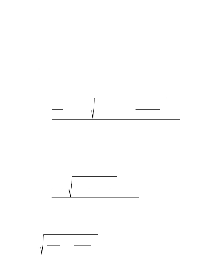
Post-Tensioned Concrete Design
forcement is required. However, if Tf exceeds the threshold limit, Tcr, it is as-
sumed that the torsional resistance is provided by closed stirrups and longitudi-
nal bars (CSA 11.3).
If Tf > Tcr, the required closed stirrup area per unit spacing, At /s, is calculated
as:
tan
2
f
t
s o yt
T
A
s Af
θ
φ
=
(CSA 11.3.10.3)
and the required longitudinal reinforcement is calculated as:
( )
ys
o
fh
sff
v
f
lf
A
Tp
VVN
d
M
A
φ
θ
cot
2
45.0
5.05.0
2
2
+−++
=
(CSA 11.3.10.6, 11.3.9)
In the preceding expressions,
θ
is computed as previously described for shear,
except that if the general method is being used, the value
ε
x is calculated as
specified in CSA 11.3.6.4 is replaced by:
( )
2
20.9 0.5
2
2
f hf
ff
vo
x
ss
M pT
VN
dA
EA
ε
++ +
=
(CSA 11.3.10.5)
An upper limit of the combination of Vu and Tu that can be carried by the sec-
tion also is checked using the equation:
cc
oh
hf
vw
f
f
A
pT
d
b
V'
25.0
7
.1
2
2
2
φ
≤
+
(CSA 11.3.10.4(b))
For rectangular sections, bw is replaced with b. If the combination of Vf and Tf
exceeds this limit, a failure message is declared. In that case, the concrete section
should be increased in size.
21 - 32 Beam Design (for Reference Only)

Chapter 21 - Design for CSA A23.3-14
When torsional reinforcement is required (Tf > Tcr), the area of transverse closed
stirrups and the area of regular shear stirrups must satisfy the following limit.
yt
w
c
tv
f
b
f
s
A
s
A'
06.
0
2≥
+
(CSA 11.2.8.2)
If this equation is not satisfied with the originally calculated Av /s and At /s, Av /s
is increased to satisfy this condition.
The maximum of all of the calculated Al and At /s values obtained from each load
combination is reported along with the controlling combination.
The beam torsion reinforcement requirements reported by the program are based
purely on strength considerations. Any minimum stirrup requirements or longi-
tudinal rebar requirements to satisfy spacing considerations must be
investigated independently of the program by the user.
21.8 Slab Design
Similar to conventional design, the ETABS slab design procedure involves
defining sets of strips in two mutually perpendicular directions. The locations of
the strips are usually governed by the locations of the slab supports. The mo-
ments for a particular strip are recovered from the analysis and a flexural design
is carried out based on the ultimate strength design method (CSA A 23.3-04) for
prestressed reinforced concrete as described in the following sections. To learn
more about the design strips, refer to the section entitled "ETABS Design Tech-
niques" in the Key Features and Terminology manual.
21.8.1 Design for Flexure
ETABS designs the slab on a strip-by-strip basis. The moments used for the
design of the slab elements are the nodal reactive moments, which are obtained
by multiplying the slab element stiffness matrices by the element nodal displace-
ment vectors. These moments will always be in static equilibrium with the ap-
plied loads, irrespective of the refinement of the finite element mesh.
The design of the slab reinforcement for a particular strip is carried out at specific
locations along the length of the strip. These locations correspond to the element
Slab Design 21 - 33

Post-Tensioned Concrete Design
boundaries. Controlling reinforcement is computed on either side of those ele-
ment boundaries. The slab flexural design procedure for each load combination
involves the following:
Determine factored moments for each slab strip.
Design flexural reinforcement for the strip.
These two steps are described in the subsections that follow and are repeated for
every load combination. The maximum reinforcement calculated for the top and
bottom of the slab within each design strip, along with the corresponding con-
trolling load combination numbers, is obtained and reported.
21.8.1.1 Determine Factored Moments for the Strip
For each element within the design strip, for each load combination, the program
calculates the nodal reactive moments. The nodal moments are then added to get
the strip moments.
21.8.1.2 Design Flexural Reinforcement for the Strip
The reinforcement computation for each slab design strip, given the bending mo-
ment, is identical to the design of rectangular beam sections described
earlier (or to the flanged beam if the slab is ribbed). In some cases, at a given
design section in a design strip, there may be two or more slab properties across
the width of the design strip. In that case, the program automatically designs the
tributary width associated with each of the slab properties separately using its
tributary bending moment. The reinforcement obtained for each of the tributary
widths is summed to obtain the total reinforcement for the full width of the de-
sign strip at the considered design section. This method is used when drop panels
are included. Where openings occur, the slab width is adjusted accordingly.
21.8.1.3 Minimum and Maximum Slab Reinforcement
If the computed tensile stress in the concrete immediately after prestress transfer
exceeds
ci
′
0.25λf
(CSA 18.3.1.1), the bonded reinforcement with a minimum
area of As is provided in the tensile zone to resist the total tensile force, Nc, in the
concrete computed on the basis of an uncracked section (CSA 18.3.1.3).
21 - 34 Slab Design

Chapter 21 - Design for CSA A23.3-14
/(0.5 )
sc y
AN f
=
(CSA 18.3.1.3)
The minimum flexural tension reinforcement required for each direction of a
slab is given by the following limit (CSA 18.8.1, 18.8.2):
Concrete stress (see Clause 18.3.2(c))
Tensile stress
≤
05 c
.f
λ
′
Tensile stress
>
05 c
.f
λ
′
Type of tendon Type of tendon
Type of member Bonded Unbonded Bonded Unbonded
Beams
0
0.004A
0.003A
0.005A
One-way slabs
0
0.003A
0.002A
0.004A
Two-way slabs
Negative moment regions
0
0.0006hln
0.00045hln
0.00075hln
Positive moment regions,
concrete stress >
02
c
.f
λ
′
0 0.004A 0.003A 0.005A
Positive moment regions,
concrete tensile stress ≤
02
c
.f
λ
′
0 0 -- --
In addition, an upper limit on both the tension reinforcement and compression
reinforcement has been imposed to be 0.04 times the gross cross-sectional area.
21.8.2 Check for Punching Shear
The algorithm for checking punching shear is detailed in the section entitled
“Slab Punching Shear Check” in the Key Features and Terminology manual.
Only the code specific items are described in the following sections.
21.8.2.1 Critical Section for Punching Shear
The punching shear is checked on a critical section at a distance of d/2 from the
face of the support (CSA 13.3.3.1 and CSA 13.3.3.2). For rectangular columns
and concentrated loads, the critical area is taken as a rectangular area with the
sides parallel to the sides of the columns or the point loads (CSA 13.3.3.3). Fig-
Slab Design 21 - 35
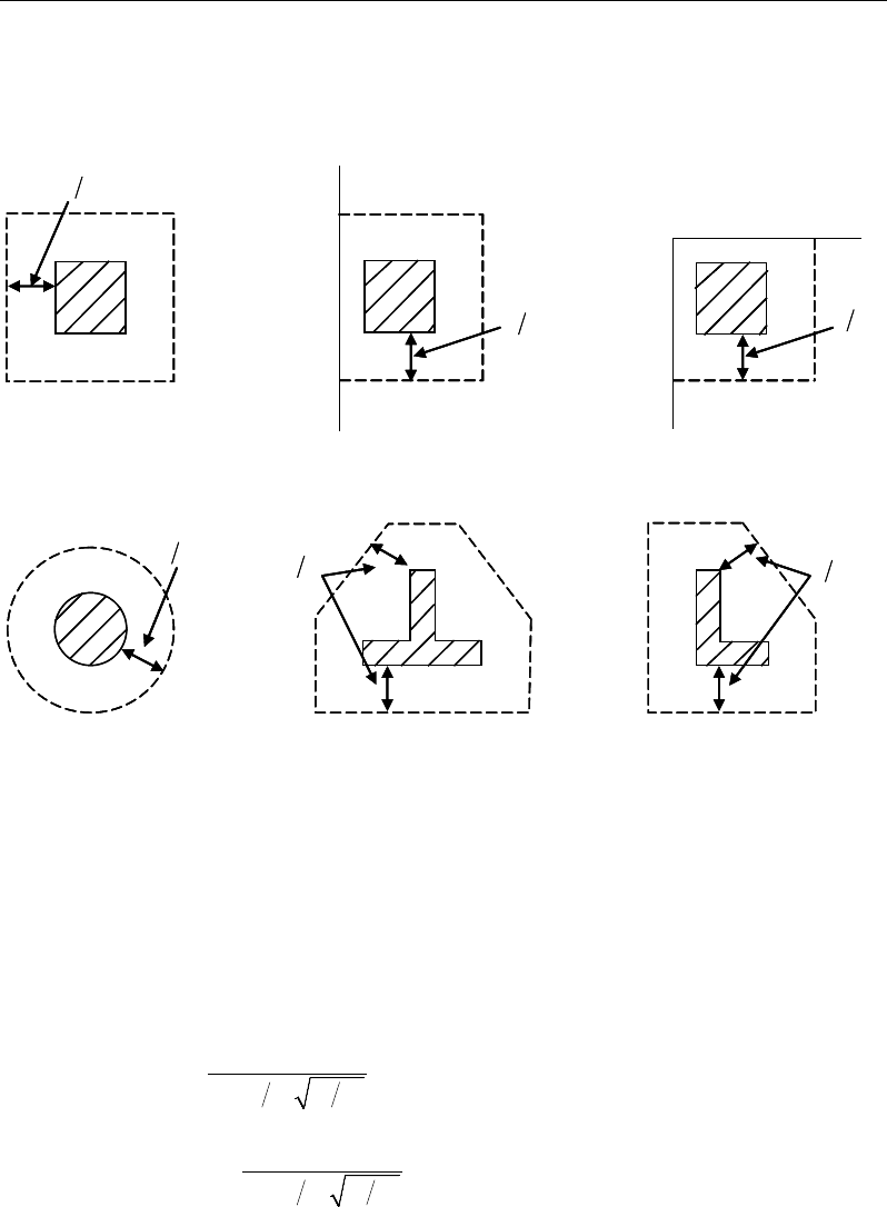
Post-Tensioned Concrete Design
ure 21-4 shows the auto punching perimeters considered by ETABS for the var-
ious column shapes. The column location (i.e., interior, edge, corner) and the
punching perimeter may be overwritten using the Punching Check Overwrites.
Figure 21-4 Punching Shear Perimeters
21.8.2.2 Transfer of Unbalanced Moment
The fraction of unbalanced moment transferred by flexure is taken to be γf Mu
and the fraction of unbalanced moment transferred by eccentricity of shear is
taken to be γv Mu, where
γf =
( )
12
1,
1 23 bb+
and (CSA 13.10.2)
γv = 1−
( )
12
1,
1 23 bb+
(CSA 13.3.5.3)
d2
Interior Column
Circular Column
d2 d2
d2
T-Shape Column
Edge Column Corner Column
L-Shape Column
d2
d2
d2
Interior Column
Circular Column
d2 d2
d2
T-Shape Column
Edge Column Corner Column
L-Shape Column
d2
d2
21 - 36 Slab Design
Chapter 21 - Design for CSA A23.3-14
where b1 is the width of the critical section measured in the direction of the span
and b2 is the width of the critical section measured in the direction
perpendicular to the span.
21.8.2.3 Determine Concrete Capacity
The concrete punching shear factored strength is taken as the minimum of the
following three limits:
0
2
1 0.19
min 0.19
0.38
cc
c
s
cc c
cc
f
d
vf
b
f
′
φ+ λ
β
α
′
=φ +λ
′
φλ
(CSA 13.3.4.1)
where, βc is the ratio of the minimum to the maximum dimensions of the critical
section, b0 is the perimeter of the critical section, and αs is a scale factor based
on the location of the critical section.
4 for interior columns,
3 for edge columns, and
2 for corner columns
s
α
=
(CSA 13.3.4.1(b))
The value of
c
f'
is limited to 8 MPa for the calculation of the concrete shear
capacity (CSA 13.3.4.2)
If the effective depth, d, exceeds 300 mm, the value of vc is reduced by a factor
equal to 1300/(1000 + d) (CSA 13.3.4.3).
21.8.2.4 Determine Capacity Ratio
Given the punching shear force and the fractions of moments transferred by
eccentricity of shear about the two axes, the shear stress is computed assuming
linear variation along the perimeter of the critical section. The ratio of the max-
imum shear stress and the concrete punching shear stress capacity is
reported as the punching shear capacity ratio by ETABS.
Slab Design 21 - 37
Post-Tensioned Concrete Design
21.8.3 Design Punching Shear Reinforcement
The use of shear studs as shear reinforcement in slabs is permitted, provided that
the effective depth of the slab is greater than or equal to 120 mm (CSA 13.2.1).
The algorithm for designing the required punching shear reinforcement is used
when the punching shear capacity ratio exceeds unity. The Critical Section for
Punching Shear and Transfer of Unbalanced Moment as described in the earlier
sections remain unchanged. The design of punching shear reinforcement is car-
ried out as follows.
21.8.3.1 Determine Concrete Shear Capacity
The concrete punching shear stress capacity of a two-way prestressed section
with punching shear reinforcement is:
ccc
fv '28.0
λφ
=
for shear studs (CSA 13.3.8.3)
0.19 '
c cc
vf
λφ
=
for shear stirrups (CSA 13.3.9.3)
21.8.3.2 Determine Required Shear Reinforcement
The shear force is limited to a maximum of
,maxr
v
, where
,max 0.75 '
r cc
vf
λφ
=
for shear studs (CSA 13.3.8.2)
,max 0.55 '
r cc
vf
λφ
=
for shear stirrups (CSA 13.3.9.2)
Given vf, vc, and vf,,max, the required shear reinforcement is calculated as follows,
where,
φ
s, is the strength reduction factor.
If vf > vr,max,
( )
fc
vo
s yv
vv
Ab
sf
φ
−
=
(CSA 13.3.8.5, 13.3.9.4)
If vf > vr,max, (CSA 13.3.8.2)
21 - 38 Slab Design
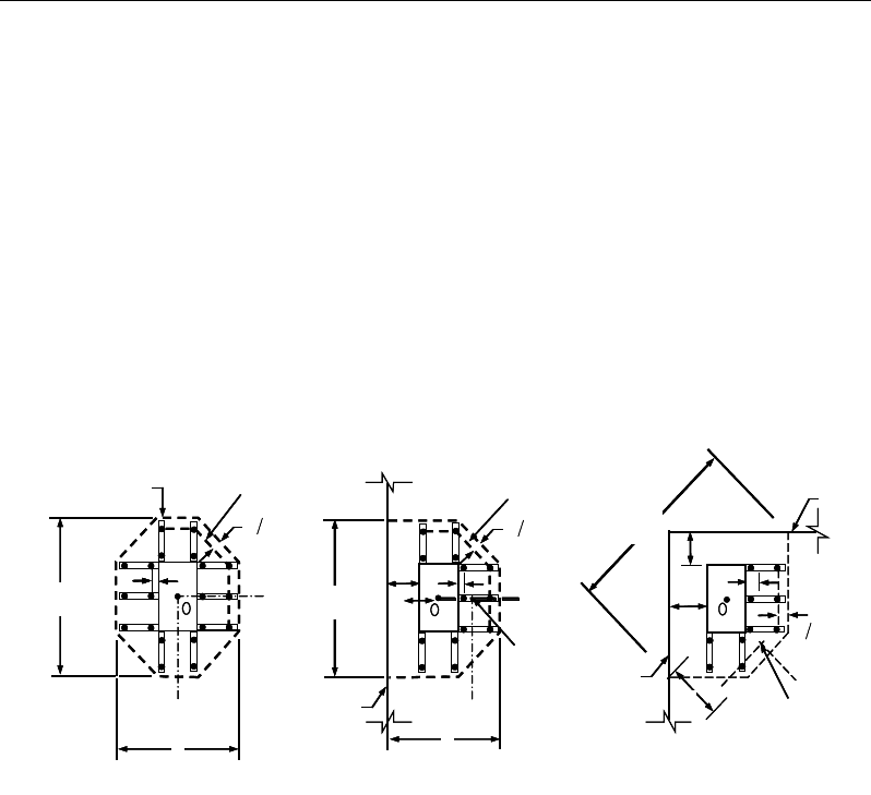
Chapter 21 - Design for CSA A23.3-14
a failure condition is declared.
If Vf exceeds the maximum permitted value of Vr,max, the concrete section
should be increased in size.
21.8.3.3 Determine the Reinforcement Arrangement
Punching shear reinforcement in the vicinity of rectangular columns should be
arranged on peripheral lines, i.e., lines running parallel to and at constant dis-
tances from the sides of the column. Figure 21-5 shows a typical arrangement of
shear reinforcement in the vicinity of a rectangular interior, edge, and corner
columns.
Figure 21-5 Typical arrangement of shear studs and critical sections outside
shear-reinforced zone
The distance between the column face and the first line of shear reinforcement
shall not exceed 0.4d. The spacing between adjacent shear reinforcement in the
first line of shear reinforcement shall not exceed 2d measured in a direction par-
allel to the column face.
Punching shear reinforcement is most effective near column corners where there
are concentrations of shear stress. Therefore, the minimum number of lines of
shear reinforcement is 4, 6, and 8, for corner, edge, and interior columns respec-
tively.
I
y
Typical Studrail
(only first and last
studs shown)
Outermost
peripheral line
of studs
Interior Column Edge Column Corner Column
Critical section
centroid
Free
edge
Free
edge
Critical
section
centroid
Free edge
Outermost
peripheral line
of studs
I
y
I
y
yx
d2 d2
d2
x
I
x
I
x
g
y
g
x
g
0
s0
s0
s
x
I
y
xx
I
y
Typical Studrail
(only first and last
studs shown)
Outermost
peripheral line
of studs
Interior Column Edge Column Corner Column
Critical section
centroid
Free
edge
Free
edge
Critical
section
centroid
Free edge
Outermost
peripheral line
of studs
I
y
I
y
yx
d2 d2
d2
x
I
x
I
x
g
y
g
x
g
0
s0
s0
s
x
I
y
xx
Slab Design 21 - 39
Post-Tensioned Concrete Design
21.8.3.4 Determine Reinforcement Diameter, Height, and Spacing
The punching shear reinforcement is most effective when the anchorage is close
to the top and bottom surfaces of the slab. The cover of anchors should not be
less than the minimum cover specified in CSA 7.9 plus one half of the diameter
of the flexural reinforcement.
Punching shear reinforcement in the form of shear studs is generally available in
9.5-, 12.7-, 15.9-, and 19.1-millimeter diameters.
When specifying shear studs, the distance, so, between the column face and the
first peripheral line of shear studs should not be smaller than 0.4d. The limits of
the spacing, s, between the peripheral lines are specified as:
0.4
o
sd≤
(CSA 13.3.8.6)
0.75 0.56 '
0.50 0.56 '
f cc
f cc
dv f
sdv f
λφ
λφ
≤
≤>
(CSA 13.3.8.6)
For shear stirrups,
≤0.25
o
sd
(CSA 13.3.9.5)
≤0.25
sd
(CSA 13.3.9.5)
The minimum depth for reinforcement should be limited to 300 mm (CSA
13.3.9.1).
21 - 40 Slab Design

References
ACI, 2007. Seismic Design of Punching Shear Reinforcement in Flat
Plates (ACI 421.2R-07), American Concrete Institute, 38800
Country Club Drive, Farmington Hills, Michigan.
ACI, 2008. Building Code Requirements for Structural Concrete (ACI
318-08) and Commentary (ACI 318R-08), American Concrete In-
stitute, P.O. Box 9094, Farmington Hills, Michigan.
ACI, 2011. Building Code Requirements for Structural Concrete (ACI
318-11) and Commentary (ACI 318R-11), American Concrete In-
stitute, P.O. Box 9094, Farmington Hills, Michigan.
AS, 2001. Australian Standard TM for Concrete Structure (AS 3600-2001)
incorporating Amendment No.1 and Amendment No. 2, Standards
Australia International Ltd, GPO Box 5420, Sydney, NSW 2001,
Australia.
AS, 2009. Australian Standard ® for Concrete Structure (AS 3600-2009),
Standards Australia International Ltd, GPO Box 476, Sydney,
NSW 2001, Australia.
BC, 2008. BC 2:2008, Design Guide of High Strength Concrete to Singa-
pore Standard CP65, February 2008, Building and Construction
Authority, Singapore.
R - 1

Post-Tensioned Concrete Design
BSI, 1997. BS 8110-1:1997 Incorporating Amendments Nos. 1, 2, and 3,
Structural Use of Concrete, Part 1, Code of Practice for Design
and Construction, British Standards Institution, London, UK,
2005.
BSI, 1985. BS 8110-2:1985 Reprinted, incorporating Amendments Nos.
1, 2, and 3, Structural Use of Concrete, Part 2, Code of Practice
for Special Circumstances, British Standards Institution, London,
UK, 2005.
CP, 1999. CP 65:Part 1:1999, Code of Practice for Structural Use of Con-
crete Part 1: Design and Construction Incorporating Erratum No.
1, September 2000, Singapore Productivity and Standards Board,
Singapore.
EN 1992-1-1, 2004. Eurocode 2: Design of Concrete Structures, Part 1-1,
General Rules and Rules for Buildings, European Committee for
Standardization, Brussels, Belgium.
EN 1990:2002. Eurocode: Basis of Structural Design (includes Amend-
ment A1:2005), European Committee for Standardization, Brus-
sels, Belgium.
CSA, 2004. A23.3-04, Design of Concrete Structures, Canadian Standards
Association, Rexdale, Ontario, Canada.
HK CP, 2013. Code of Practice for Structural Use of Concrete 2013,
Buildings Department, 12/F-18/F Pioneer Centre, 750 Nathan
Road, Mongkok, Kowloon, Hong Kong
HK CP, 2004. Code of Practice for Structural Use of Concrete 2004,
Buildings Department, 12/F-18/F Pioneer Centre, 750 Nathan
Road, Mongkok, Kowloon, Hong Kong.
Italian NTC, 2008. Design and Calculations of Reinforced and Prestressed
Concrete Structure, Ministerial Decree of January 14, 2008 and pub-
lished in the Offical Gazette No. 29 of February 4, 2008.
IS, 1980. Code of Practice for Prestressed Concrete, First Revision, Incor-
porating Amendment No. 1, 1999. Bureau of Indian Standards,
R - 2

References
Manak Bhavan, 9 Bahadur Shah Zafar Marg, New Delhi 110002,
India.
IS, 2000. Code of Practice for Plain and Reinforced Concrete, Third Edi-
tion, Twentieth Reprint, March 2000, Bureau of Indian Standards,
Manak Bhavan, 9 Bahadur Shah Zafar Marg, New Delhi 110002,
India.
NZS, 2006. Concrete Structures Standard, Part 1 – Design of Concrete
Structures, Standards New Zealand, Private Bag 2439, Welling-
ton, New Zealand.
TS 500-2000. Requirements for Design and Construction of Reinforced
Concrete Structures. Turkish Standard Institute. Necatibey Street No.
112, Bakanliklar, Ankara.
R- 3
