Safety Case Development Manual V2.2_RI_13Nov06 EUROCONTROL
EUROCONTROL%20Safety-case-development-manual
User Manual:
Open the PDF directly: View PDF ![]() .
.
Page Count: 66

EUROPEAN ORGANISATION FOR THE SAFETY OF
AIR NAVIGATION
EUROPEAN AIR TRAFFIC MANAGEMENT
Safety Case Development Manual
DAP/SSH/091
Edition : 2.2
Edition Date : 13 Nov 2006
Status : Released Issue
Class : EATM Stakeholders
Safety Case Development Manual
Page ii Released Issue Edition: 2.2
DOCUMENT CHARACTERISTICS
TITLE
Safety Case Development Manual
EATMP Infocentre Reference:
Document Identifier Edition Number:
2.2
DAP/SSH/091
Edition Date:
13 Nov 2006
Abstract
This Safety Case Development Manual provides the reader with an overview of the methodology
being proposed for the construction and development of Safety Cases. Version 2.2 is a complete
rewrite of Version 1.3 which was published in 2003, taking into consideration user needs and recent
experience with Safety Case developments.
This Manual includes the concept of a Safety Case as presenting the entirety of argument and
evidence needed to satisfy oneself and the regulator with respect to safety. It does not provide
guidance on the generation or documentation of the evidence itself. Where separate guidance is
available, such as the ANS Safety Assessment Methodology (SAM) then this is referenced
accordingly. For further guidance on Safety Assessment see the SAM, or contact DAP/SSH.
Keywords
ESARR 3 Safety Argument Safety Case Lifecycle Safety Objectives
Goal Structuring Notation Safety Case Safety Management Safety Requirements
Contact Person(s)
Tel
Unit
Dr. Bernd TIEMEYER 95038 DAP/SSH
STATUS, AUDIENCE AND ACCESSIBILITY
Status Intended for Accessible via
Working Draft General Public
Intranet
Draft EATM
Stakeholders
Extranet
Proposed Issue Restricted
Audience
Internet (www.eurocontrol.int)
Released Issue
ELECTRONIC SOURCE
Path:
Host System Software Size
Windows_XP Microsoft Word 2002 1127 Kb

Edition: 2.2 Released Issue Page iii
DOCUMENT APPROVAL
The following table identifies all management authorities who have successively approved
the present issue of this document.
AUTHORITY NAME AND SIGNATURE DATE
Co-ordinator
Agency & EATM SMS
DAP/SSH
Bernd TIEMEYER
Chairman of the
SAMTF
Patrick MANA
Chairman of
Safety Team
Erik MERCKX
Director
DAS
Bo REDEBORN
Director
DAP
Guido KERKHOFS

Safety Case Development Manual
Page iv Released Issue Edition: 2.2
DOCUMENT CHANGE RECORD
The following table records the complete history of the successive editions of the present
document.
EDITION
NUMBER EDITION
DATE REASON FOR CHANGE PAGES
AFFECTED
1.3 07.07.03 Proposed Issue – Including editorial corrections All
1.41 29.11.04 Initial Draft of Revised Version All
1.42 13.12.04 Working Draft of Revised Version All
1.43 23.12.04 Further Draft of Revised Version All
1.44 01.02.05 Update following DAP/SAF internal review All
1.45
11.02.05
Chapter 5 and Appendix updated following DAP/SAF
internal review
Chap 5
and
Appdx C
1.5 25.02.05 Minor changes following final DAP/SAF internal review All
2.0 28.09.05 Proposed Issue following external stakeholder review All
2.1
03.09.06
Proposed Issue, incorporating further stakeholder
comments 4, 6, 8,
19
2.2 13.11.06 Released Issue, incorporating final stakeholder
comments 8, 17, 25

Safety Case Development Manual
Edition: 2.2 Released Issue Page v
CONTENTS
PREFACE..............................................................................................................................1
CHAPTER 1 – INTRODUCTION............................................................................................3
1.
Purpose of the Manual ..................................................................................3
2.
Structure of the Manual.................................................................................4
CHAPTER 2 – ESSENTIALS – GETTING STARTED...........................................................5
1.
What is a Safety Case for?............................................................................5
2.
Which Kind of Safety Case? .........................................................................6
3.
Safety Cases and the Project Safety Lifecycle............................................7
4.
Contents of a Safety Case.............................................................................9
5.
Defining the Scope and Boundaries for the Safety Case..........................10
6.
Setting the Context......................................................................................10
CHAPTER 3 – ESSENTIALS – ARGUMENT AND EVIDENCE..........................................13
1.
Introduction..................................................................................................13
2.
Safety Argument..........................................................................................13
3.
Safety Evidence...........................................................................................14
CHAPTER 4 – GUIDANCE – PROCESS AND TECHNIQUES ..........................................17
1.
Overview ......................................................................................................17
2.
Determining the Safety Criteria ..................................................................18
3.
Constructing a Safety Argument................................................................19
4.
Gathering, Assessing and Presenting Safety Evidence ...........................23
5.
Evidence – Safety Requirements Determination.......................................24
6.
Evidence – Safety Requirements Satisfaction...........................................26
7.
Developing a Safety Plan ............................................................................29
8.
Format, Structure and Layout of the Safety Case .....................................30
9.
Verifying the Safety Case............................................................................32
10.
ESARR Compliance.....................................................................................33
CHAPTER 5 GUIDANCE - GSN SAFETY ARGUMENT EXAMPLES.................................35

Safety Case Development Manual
Page vi Released Issue Edition: 2.2
1.
Example Application of GSN – A “Project” Safety Case...........................35
2.
Example Application of GSN – Unit Safety Cases.....................................45
3.
Example Application of GSN – Preliminary Safety Cases ........................48
APPENDIX A
REFERENCES .........................................................................................51
APPENDIX B
GLOSSARY AND ABBREVIATIONS.......................................................53
GLOSSARY ....................................................................................................................53
ABBREVIATIONS...........................................................................................................55
APPENDIX C
SAFETY CASE DEVELOPERS AND REVIEWERS CHECKLIST............57

Safety Case Development Manual Preface
Edition: 2.2 Released Issue Page 1
PREFACE
Background
Related Documents
EATM SMS Context
User Community
Feedback
“Health Warning” !!
Version 2.2 of the Safety Case Development Manual has been
developed based on recent experience, user feedback and
lessons learned since Version 1.3 was published in July 2003.
The new Manual tries to explain in simple terms the ‘Essentials’
of how to construct a Safety Case and then provides supporting
‘Guidance’ and ‘Examples’. It is intended primarily for use within
the EUROCONTROL Agency but may also be used (where
appropriate
1
11
1
) by the Member States.
The provisions of the Manual are intended to be consistent with
ESARRs and the EUROCONTROL ANS Safety Assessment
Methodology (SAM), to which numerous references are made
herein. In particular, the Manual as a whole is intended to
satisfy the requirements of paragraph 5.3 of ESARR 4
concerning the documentation of the arguments and evidence
associated with the risk assessment and mitigation processes.
The Manual provides a product description for the Safety Case
described in Element 5 (Risk Assessment and Mitigation) of the
EATM Safety Management Handbook. Organisational issues
are dealt with in Element 3 (Organisation and Structure).
The Manual is intended primarily for safety professionals who
have received training in SMS and the EUROCONTROL SAM.
We believe that it will be of most immediate use to the willing
developer but accept that it could present some difficulties for
the uncertain starter; we also believe that it has something to
offer to the confident adopter
2
.
Therefore, the contents of the Manual will be supported by
related training, and readers (particularly, but not exclusively
willing developers and uncertain starters) are urged to
undertake this training and the related EUROCONTROL SAM
training before embarking on the development of a Safety Case
for an operational application.
The users of this Manual are invited to provide any feedback
and suggestions for improvement on this current version to me,
which will be taken into consideration when a future updated
Version is produced.
Finally, this Manual cannot give a complete insight into all
aspects of Safety Assessment and Safety Case development
nor provide ready made solutions to fit every situation.
1
“Where appropriate” is inserted here because there is no explicit requirement in ESARRs for ANSPs
to produce Safety Cases. EUROCONTROL has chosen the Safety Case approach for EATM
Programmes and Domain Activities because experience has shown this approach to be effective for
these applications.
2
See EUROCONTROL SAM [5] for explanation of these terms

Preface Safety Case Development Manual
Page 2 Released Issue Edition: 2.2
PAGE INTENTIONALLY LEFT BLANK

Safety Case Development Manual Introduction
Edition: 2.2 Released Issue Page 3
CHAPTER 1
– Introduction
1. Purpose of the Manual
What does it do?
Who is it for?
What is it for?
What does it not do?
This Safety Case Development Manual provides guidance on
the development of Safety Cases as a means of structuring and
documenting the demonstration of the safety of an ATM service
or new / modified System
3
.
The Manual is intended for use by those, employed on projects
or in service-provider organisations, who have to:
• Produce Safety Cases – eg safety practitioners;
• Approve Safety Cases – eg programme managers and
heads of ATSUs;
• Review Safety Cases – eg safety department staff.
The aim is to achieve sound, well-presented Safety Cases
through the adoption of a logical, rigorous, consistent and
accurate approach that is based on good safety practice.
Whereas this Manual should aid the process of developing and
presenting a Safety Case, it cannot give assurance of the
validity of the end product, and it does not, therefore, relieve its
users of their responsibility to provide such assurance.
The Manual does not provide guidance on how to carry out a
safety assessment – see the EUROCONTROL SAM [5] for that
– rather it describes how to present the results of a safety
assessment, in the context of a Safety Case.

Chapter 1 Safety Case Development Manual
Page 4 Released Issue Edition: 2.2
As the Manual is intended to be used within the framework of a
Safety Management System (SMS), it does not address
questions, such as what is a change and when should a Safety
Case be produced – these are assumed to be addressed by the
SMS
4
. Rather, the starting point for the Manual is the point at
which it has been decided to produce a Safety Case for a
particular ATM service or change (a so-called “substantial
change” in this document).
2. Structure of the Manual
Essentials - Getting
Started
Essentials – Argument
and Evidence
Guidance – Process
and Techniques
Guidance - Examples
References
Glossary
Checklists
The remainder of this Manual is presented in a further 4
Chapters, covering the Essentials of Safety Case Development
and supporting Guidance, as follows.
Chapter 2 explains the background to Safety Cases and
provides the key points in planning the development of a Safety
Case.
Chapter 3 presents the essentials of the Safety Case itself.
Chapter 4 provides guidance in support of Chapters 2 and 3,
including the use of Goal-structuring Notation (GSN). The
Guidance may be accessed directly or via links embedded in
the relevant parts of those Chapters.
Chapter 5 provides generic examples of structured Safety
Arguments using GSN. The main example is the introduction of
a substantial change to an ATM service / system. Variations of
that Safety Argument for an on-going ATM service and for a
typical limited-scope Safety Case are also explained.
Appendix A provides a list of the references called up in the
Manual.
The EATMP Glossary document [4] facilitates the search and
use of acronyms, abbreviations, terms and definitions most
frequently used within the EATM Programme. As the EATMP
Glossary document includes more than 5,800 acronyms and
2,000 definitions, a summary of the terms commonly used in
Safety Case development is provided at Appendix B.
Appendix C contains checklists for use by Safety Case
developers, reviewers and approvers in assessing the quality of
the argument structure and presentation of the Safety Case.
3
The term ‘System’ is used throughout this manual to include airspace, equipment, people and
procedures.
4
For guidance on “what is a change” please see the SAM [5] Guidance Material, Part IV, Appendix H.

Safety Case Development Manual Getting Started
Edition: 2.2 Released Issue Page 5
CHAPTER 2
– Essentials –
Getting Started
1. What is a Safety Case for?
A Lesson from History
ICAO Obligation
The Burden of Proof
In the investigation into the Piper Alpha accident [14] Lord
Cullen wrote:
“Primarily the Safety Case is a matter of ensuring that every
company produces a formal safety assessment to assure
itself that its operations are safe.
Only secondarily is it a matter of demonstrating this to a
regulatory body. That said such a demonstration both meets a
legitimate expectation of the workforce and the public and
provides a sound basis for regulatory control.”
ICAO Annex 11 places an obligation on the providers of Air
Traffic Management services to ensure the safety of air traffic,
in respect of those parts of the ATM System and supporting
services within their managerial control.
Implicit to this obligation is the requirement on those with
managerial control to demonstrate positively that the relevant
Safety Regulations are satisfied. In essence there is a “burden
of proof” on Air Navigation Service Providers to show that
acceptable levels of safety
5
are, and continue to be, achieved.
5
As defined by the Safety Criteria – see Chapter 4, section 2

Chapter 2 Safety Case Development Manual
Page 6 Released Issue Edition: 2.2
Primary Purpose
Relationship with
Regulatory Approval
Relation to Safety
Management System
Relation to Safety
Assessment
Broadly, the Safety Case is the documented assurance (ie
argument and supporting evidence) of the achievement
and maintenance of safety. It is primarily the means by
which those who are accountable for service provision or
projects
6
assure themselves that those services or
projects are delivering (or will deliver), and will continue to
deliver, an acceptable level of safety.
As the main objective of safety regulation is to ensure that
those who are accountable for safety discharge their
responsibilities properly, then it follows that a Safety Case
which serves the above primary purpose should also
provide an adequate means of obtaining regulatory
approval for the service or project concerned.
In the context of a Safety Management System, the Safety
Case can be a means of documenting and recording the
safety of a service or system. Conversely, the
implementation of a Safety Management System would
provide evidence to support a Safety Case.
The development of a Safety Case is not an alternative to
carrying out a Safety Assessment, in accordance with, for
example, the EUROCONTROL SAM [5]; rather, it is a
means of structuring and documenting a summary of the
results of a Safety Assessment, and other activities (eg
simulations, surveys etc), in a way that a reader can readily
follow the logical reasoning as to why a change (or on-
going service) can be considered safe.
2. Which Kind of Safety Case?
Types
Safety Cases may come in many forms but most, if not all, can
be thought of as falling into one of two categories, as follows:
• those which are used to demonstrate the safety of an on-
going service – these are known herein as Unit Safety
Cases; and
• those which are used to demonstrate the safety of a
substantial change to that service (and/or underlying
system) – these are known herein as Project Safety Cases.
Unit Safety Case
The two categories are interrelated, as explained below.
An ATSU (or other major, safety-related service / facility) may
decide to produce, and maintain, a (Unit) Safety Case in order
to show that the on-going, day-to-day operations are safe and
that they will remain so indefinitely.

Safety Case Development Manual Getting Started
Edition: 2.2 Released Issue Page 7
Project Safety Case
A Unit Safety Case would include typically an a priori safety
assessment (to show that service / system is predicted to be
safe), together with the results of safety audits, surveys and
operational monitoring (to show that, up that point in time, it
actually has been safe). It should also demonstrate that
processes are in place to ensure that all future changes to the
ATSU’s system will be managed safely through, inter alia,
Project Safety Cases.
An ATSU (or other responsible organisation) may also decide to
produce a Project Safety Case when a particular substantial
change to an existing safety-related service / system (including
the introduction of a new service / system) is to be undertaken.
A Project Safety Case would normally consider only those risks
created or modified by the change and rely on an assumption
(or evidence from the corresponding Unit Safety Case) that the
pre-change situation is at least tolerably safe.
Project Safety Cases are used to update, and are usually
subsumed into, Unit Safety Cases
7
.
Further details of both Unit Safety Cases and Project Safety
Cases are given in section 3 below and in Chapter 5.
3. Safety Cases and the Project Safety Lifecycle
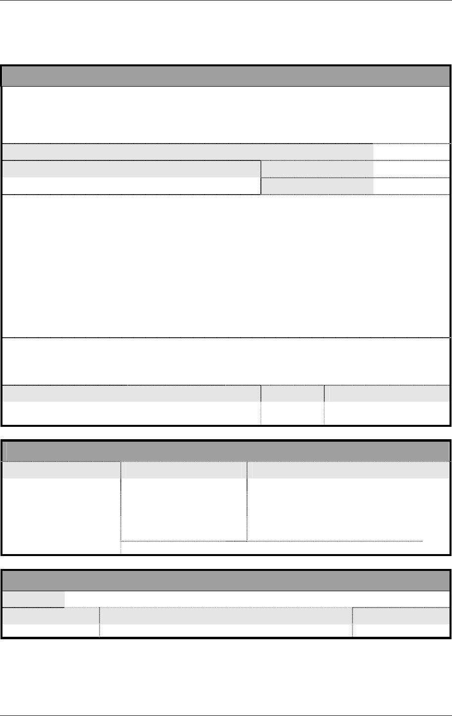
A simplified view of a typical project lifecycle is shown in the
diagram overleaf.
Safety Considerations
This is an EATM SMS process to identify the main safety issues
associated with a project as soon as possible after an
Operational Concept has been developed and to help in
deciding whether a full Safety Plan and Safety Case are
required. It provides an initial assessment of the safety
implications of the project, as the basis for developing a Safety
Plan in which the detailed safety activities will be specified. It
should address, inter alia, what the project is seeking to achieve
(eg to deliver benefits in capacity, efficiency and/or safety), the
possible impact on safety (in general terms only, since a safety
assessment would not have been started at this stage), the
criteria for deciding what is “safe” in the context of the Project
and, in broad terms, the strategy for demonstrating safety.
6
The distinction between services and projects / systems is to emphasise the difference between Unit
and Project (or System) Safety Cases – see section 2. The generic term “project” should be taken to
include EATM Programmes and Domain Activities.
7
However, this is not meant to imply that a Unit Safety Case is merely a collection of project Safety
Cases!
Chapter 2 Safety Case Development Manual
Page 8 Released Issue Edition: 2.2
Safety
Considerations Operational
Concept
Initial
Safety
Argument
FHA
PSSA
Implementation
Transfer into
Operation
Safety
Plan
Project
Safety
Case
Unit
Safety
Case
Evidence
Approval
Evidence
Evidence
Evidence
Evidence
Update, if required
Safety
Monitoring
Reports
Update
Update
Evidence
SSA
Integration
Operation &
Maintenance
Safety
Considerations Operational
Concept
Initial
Safety
Argument
FHA
PSSA
Implementation
Transfer into
Operation
Safety
Plan
Project
Safety
Case
Unit
Safety
Case
Evidence
Approval
Evidence
Evidence
Evidence
Evidence
Update, if required
Safety
Monitoring
Reports
Update
Update
Evidence
SSA
Integration
Operation &
Maintenance
Initial Safety Argument
Safety Plan
Safety Assessment:
FHA
PSSA
Building on the Safety Considerations, the initial Safety
Argument should be as complete as possible and at least
sufficient to provide a set of goals for the Safety Plan to
address. It also provides the starting point, and framework, for
the development of the Project Safety Case, although it needs
to be recognised that the initial view of what the Safety
Argument should look like may need to change, depending on
the results of the subsequent safety assessment.
Specifies the safety activities to be conducted throughout the
project lifecycle and the responsibilities for their execution.
The three main phases of safety assessment (FHA, PSSA and
SSA) provide much of the Evidence needed for the Project
Safety Case, as follows:
o FHA produces Safety Objectives to limit the frequency of
occurrence of hazards, such that the associated risk would
be acceptable, and the external means of mitigating the
effects of the hazards
8
.
o PSSA produces Safety Requirements and Assurance Levels
for the system elements.
o SSA produces the assurance that the Safety Requirements
8
88
8
See further discussion on “external mitigation means” in the Note at end of this Chapter

Safety Case Development Manual Getting Started
Edition: 2.2 Released Issue Page 9
SSA
Implementation &
Integration
Transfer into Operation
Operational Service
Unit Safety Case
and Safety Objectives are met in the implemented system
and that risk is acceptable.
For further information on safety assessment, see the SAM [5].
This phase covers all the preparation needed in order to bring
the new / modified system – the subject of the Safety Case –
into operational service.
Transfer into Operation of the new/modified system would
normally be subject to a risk assessment and mitigation for this
phase itself (part of the Project Safety Case) and be concluded
by finalisation and regulatory approval of the Project Safety
Case.
Because most, if not all, of the preceding safety assessment
work is predictive in nature, it is important that further assurance
of the safety is obtained from what is actually achieved in
operational service. If the operational experience differs
significantly from the results of the predictive safety
assessment, it may be necessary to review and update the
Project Safety Case.
Once a satisfactory steady state has been achieved, it would be
appropriate to update the Unit Safety Case (if one exists) with
the information from the Project Safety Case thus establishing a
new safety baseline for the on-going operational service.
4. Contents of a Safety Case
Aim
Purpose
Scope
System Description
Justification
Argument
Evidence
Caveats
A good Safety Case (of whichever type) should include, at least:
• what the Safety Case is trying to show - this should be
directly related to the Claim that the subject of the Safety
Case is acceptably safe;
• why is the Safety Case being written and for whom;
• what is, and is not, covered - see section 5 below;
• a description of the system / change and its operational /
physical environment, sufficient only to explain what the
Safety Case addresses and for the reader to understand the
remainder of the Safety Case – see section 6 below;
• for project Safety Cases, the justification for introducing the
change (and therefore potentially for incurring some risk);
• a reasoned and well-structured Safety Argument showing
how the Aim is satisfied – see Chapter 3, section 2 below;
• supporting Safety Evidence to substantiate the Safety
Argument – see Chapter 3, section 3 below;
• all Assumptions, outstanding safety Issues, and any
Limitations or restrictions on the operation of the system;

Chapter 2 Safety Case Development Manual
Page 10 Released Issue Edition: 2.2
Conclusions
• a simple statement to the effect that the Aim has been
satisfied, subject to the stated Caveats.
Chapter 4, section 8 provides further guidance on the content,
structure and layout of a Safety Case
5. Defining the Scope and Boundaries for the Safety Case
Scope Definition
Lifecycle Limitations
Defining the scope and boundaries of the Safety Case is an
essential first step in the development of the Safety Case. It
should explain clearly:
• what the Safety Case covers (and does not cover);
• boundaries of responsibility with respect to managerial
control and other stakeholders;
• relationship with other Safety Cases, if applicable;
• applicability and compliance with safety regulations and
standards;
• any assumptions made in defining the scope, boundaries or
safety criteria.
A Safety Case may be (temporarily) restricted to the safety of a
new concept, and therefore be conditional on the subsequent
complete and correct implementation of that concept by the
responsible organisation. This is the situation on those EATM
Programmes (and similar activities) for which EUROCONTROL
is not responsible for implementation; the output would then be
a validated set of Safety Requirements (from the PSSA).
The term Preliminary Safety Case is used herein to cover such
situations, and it should be supported by guidance material for
the subsequent implementation of the Safety Requirements and
for the development of a full Safety Case. An example of a
Preliminary Safety Case, and the sort of guidance that should
accompany it, are given in Chapter 5, section 3.
6. Setting the Context
Rationale
Content
It is vital to fully describe the operational environment to which
the Safety Case applies and the system configuration on which
the Safety Case (and underlying Safety Analysis) is based.
The description of the Context should include:

Safety Case Development Manual Getting Started
Edition: 2.2 Released Issue Page 11
• the purpose of the system from a safety perspective;
• the interfaces with other systems including people,
procedures and equipment;
• the operational environment – including all characteristics
that may be affected and elements that are relied upon,
when assessing acceptable levels of safety;
• A reference to (together with a summary of) Concept of
Operations that explain how the system, and the service that
it supports, are intended to operate
Note on External Mitigation Means (§3 of this chapter):
External Mitigation Means are those mitigations of the consequences of a hazard that lie outside of the
scope of the service / system covered by the FHA. They are often recorded as "assumptions"
concerning, for example, the Operational Environment (levels, type and patterns of traffic etc), other
elements of the system (aircraft equipage, airline compliance to some operation requirements, aircraft
equipment certification etc) and other service providers (adjacent ATSUs, CFMU, Military etc). They
may be either pre-existing or newly identified because of the nature of the "change" covered by the
FHA.
Two matters are crucial to the safety assessment: firstly, as the Assumptions have an impact on the
way the Safety Objectives were set, then the latter are valid only if the former are met; and secondly,
therefore, these Assumptions must be properly recorded, demonstrated as being valid / satisfied prior
to operations, and then continuously monitored and confirmed in operational service, along with the
Safety Requirements that emerge from the PSSA.

Chapter 2 Safety Case Development Manual
Page 12 Released Issue Edition: 2.2
PAGE INTENTIONALLY LEFT BLANK

Safety Case Development Manual Argument and Evidence
Edition: 2.2 Released Issue Page 13
CHAPTER 3
– Essentials –
Argument and Evidence
1. Introduction
Overview
Non-prescriptive
This Chapter presents the essential points of:
• the construction of Safety Arguments;
• the collation, review and presentation of Safety Evidence.
The information presented draws on current good practice
without prescribing a particular methodology, and is supported
by references to the Guidance in Chapter 4.
2. Safety Argument
What is a Safety
Argument?
Making the Claim
Supporting the Claim
A Safety Argument is a statement (or a set of statements) that is
used to assert that the service or system concerned is safe, and
should be developed as follows.
The Safety Argument must start with a top-level statement
(Claim) about what the Safety Case is trying to demonstrate in
relation to the safety of the service or system.
The Claim must be supported by:
• Safety Criteria, which define what is safe in the context of
the Claim;
• for Project Safety Cases, the Justification for introducing

Chapter 3 Safety Case Development Manual
Page 14 Released Issue Edition: 2.2
Structuring the
Argument
Guidance
the change to the service or system concerned;
• the Operational Context for the Claim;
• any fundamental Assumptions on which the Claim relies.
The decomposition of the Claim into lower-level Arguments
provides the essential links between the Claim and the wealth of
Evidence needed to show that the Claim is valid.
In performing this decomposition, it is important that:
• each Argument in the structure is expressed as a simple
predicate – ie a statement that can be only true or false;
• the Argument structure does not contain any negative or
inconclusive Arguments
9
;
• the set of Arguments at each level of decomposition is
necessary and sufficient to show that the parent Argument is
true;
• a valid counter-Argument, which would negate the parent
Argument, does not exist
10
;
• where the rationale for decomposition of an Argument into
lower-level Arguments is not self evident, it is explained by
supporting text;
• the number of levels of decomposition is appropriate to the
complexity of the Safety Case and/or supporting Evidence;
• each branch of the Safety Argument structure is terminated
in supporting Evidence;
• there is a clear distinction between, and correct use of,
Direct (product-based) and Backing (process-based)
Arguments and related Evidence.
Further guidance on the structuring of Safety Arguments is
given in Chapter 4, section 3, and generic ATM examples are
presented in Chapter 5.
3. Safety Evidence
What is Safety
Evidence?
Safety Evidence is information, based on established fact or
expert judgement, which is presented to show that the Safety
Argument to which it relates is valid (ie true).
The essential rules of Evidence are as follows:
Necessity
• Evidence must be presented only to the degree and extent

Safety Case Development Manual Argument and Evidence
Edition: 2.2 Released Issue Page 15
Sufficiency
Appropriateness
Rigour
Relevance
Guidance
necessary to support the related Argument;
11
• Evidence must show that the related Argument is true in a
way that is clear, unequivocal, conclusive and, wherever
possible, objective;
• the type of Evidence – from safety analysis, design,
simulation, test, previous usage, compliance with standards
etc – must be appropriate to the Argument;
• the rigour of the Evidence must be appropriate to the
associated risk;
• Evidence must actually relate to the correct configuration of
the system under consideration.
Further guidance on the gathering, assessing and presenting
Evidence is given in Chapter 4, section 4.
9
The main point here is that lack of Evidence of risk is not Evidence of lack of risk!
10
This point is concerned only with the sufficiency of the Argument – sufficiency of the Evidence is
covered in section 3.
11
The point here concerns only irrelevant Evidence. Clearly any Evidence which actually counters the
Argument must not be ignored; on the contrary, the validity (or at the very least the phrasing) of an
Argument must be reconsidered in the light of such Evidence

Chapter 3 Safety Case Development Manual
Page 16 Released Issue Edition: 2.2
PAGE INTENTIONALLY LEFT BLANK

Safety Case Development Manual Process and Techniques
Edition: 2.2 Released Issue Page 17
CHAPTER 4
– Guidance –
Process and Techniques
1. Overview
Context
Scope
This Chapter provides guidance in support of the requirements
stated in Chapters 2 and 3 above. Whereas this guidance is
based on experience gained on the development of Safety
Cases by EUROCONTROL on a wide range of EATM
Programmes, it is intended to be applicable also to other
environments – eg service provision.
The guidance covers the following areas:
• determining the Safety Criteria - section 2;
• constructing a Safety Argument, using a recognised
notation that is considered to be good practice – ie Goal-
structuring Notation (GSN) - section 3;
• general issues concerning gathering, collating,
assessing and presenting Safety Evidence - section 4;
• specific issues concerning Evidence of Safety
Requirements determination - section 5;
• general issues concerning Safety Requirements
satisfaction - section 6;
• developing a Safety Plan - section 7;
• deciding the format, structure and layout of a Safety
Case - section 8;

Chapter 4 Safety Case Development Manual
Page 18 Released Issue Edition: 2.2
• verifying the Safety Case - section 9;
• ESARR compliance - section 10.
2. Determining the Safety Criteria
Absolute
Relative
Reductive
Selecting Criteria
Safety Criteria are essential to the definition of what is safe in
the context of the top-level Safety Claim
Basically, they fall into three categories as follows:
• Compliance with a defined target – eg the ESARR 4 Risk
Classification Scheme (RCS) or ICAO Target Level of Safety
(TLS) – or portion thereof. Such criteria are usually
quantitative;
• Relative to an existing (or previous) level of safety. Such
criteria may be quantitative or qualitative;
• Where the risk is required to be reduced as far as
reasonably practicable. Such criteria are usually qualitative.
In general, absolute criteria are preferred since satisfaction of
them does not depend on proof of past safety achievement and
such proof may be difficult if a suitable baseline does not exist
or sufficient historical data is not available.
However, in some cases, there may be a problem in
establishing what would be a suitable target on which to base
the criterion because either:
• a regulatory target has not been set for the operational
environment concerned
12
; or
• for Project Safety Cases, it may not be feasible to determine
what portion of the overall target it would be reasonable to
allocate to the system concerned.
As an alternative to the absolute approach, a relative Safety
Argument (ie based on a relative criterion) could be use for a
Project Safety Case
13
if:
• a well-defined baseline, prior to the introduction of (or
change to) a ‘system’, could be established; and
• it can be shown, or at least reasonably be assumed, that the
baseline situation was safe.
The justification for a relative approach is the ATM 2000+ [1]
Safety Objective which requires that risk shall not increase and
preferably decrease, relative to historical achievement. The
12
This is being addressed by the current (2005) EUROCONTROL TLS study
13
For Unit Safety Cases an absolute approach should always be the primary criterion.

Safety Case Development Manual Process and Techniques
Edition: 2.2 Released Issue Page 19
Multiple Criteria
ESARR 4 RCS, although normally considered to be an absolute
measure, is actually a quantified interpretation of the ATM
2000+ Safety Objective
14
.
A reductive approach is called for by ESARR 3 (paragraph
5.1.4), which requires ANSPs to reduce risk as far as
reasonably practicable. It is an important criterion for in-service
safety monitoring – especially regarding incident investigation
and corrective action.
It is usual to specify more than one type of criterion, and
sometimes all three. In ATM, reducing risk as far as reasonably
practicable is rarely adequate on its own
15
but it is often useful in
support of one (or both) of the other two criteria.
Use of Risk
Classification Schemes Risk classification schemes (RCS)
16
are often used as criteria
on which to base absolute Arguments. However, experience
has shown that a lack of understanding by the user as to how
the RCS was originally derived can lead to inappropriate use. If
RCS are used, it is important that the user understands:
• at what level in the system hierarchy the values are intended
to be applied;
• where the probability/frequency values used in the scheme
came from and whether they are (still) valid;
• to what operational environment the values apply – eg type
of airspace, traffic patterns, traffic density, spatial dimension,
phase of flight etc;
• how the aggregate risk, as specified in ESARR 4 for
example, can be deduced from analysis of individual
hazards, in restricted segments of the total system.
These issues should not be a problem for the user in an
organisation that has a single, well-founded RCS, applicable to
all operational environments.
All other RCS users should be aware of, and address, the
issues raised in each of the above bullets.
For further guidance on RCS, please see SAM FHA Chapter 3
GM E, based on ED-125 [15].
3. Constructing a Safety Argument
Requirements Since the Safety Argument forms the framework of a Safety
14
See ESARR 4 [9], Appendix A, Endnote (2)
15
Both ATM 2000+ and ESARR 4 require, as a minimum, that risk must not increase – reducing risk
as far as reasonably practicable on its own does not ensure that this minimum requirement is met.
16
The comments here are aimed at the use of Risk Classification Schemes to determine what is a
tolerable level of risk, not at the use of Severity Classification / Categorisation Schemes proposed in,
inter alia, ESARR 2, ESARR 4 and the EUROCONTROL ANS Safety Assessment Methodology.
Chapter 4 Safety Case Development Manual
Page 20 Released Issue Edition: 2.2
Case, it is important that the Argument is set out in a rigorous,
GSN Solution
hierarchical and well-structured and easily-understood way.
Goal-structuring Notation (GSN), developed by the University of
York, provides a graphical means of setting out hierarchical
Safety Arguments, with textural annotations and references to
supporting Evidence.
The logical approach of GSN, if correctly applied, brings some
rigour into the process of deriving Safety Arguments and
provides the means for capturing essential explanatory material,
including assumptions, context and justifications, within the
argument framework.
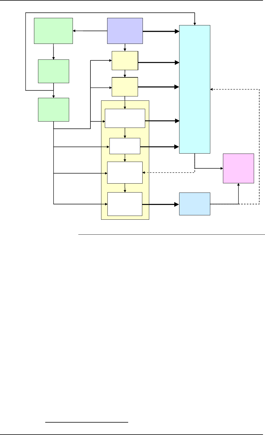
The diagram below shows, in an adapted form of GSN, a
specimen Argument and Evidence structure to illustrate the
GSN symbology most commonly used in EUROCONTROL ATM
Safety Cases.
Argument
Arg 1
Fig n
Overall
Argument /
Claim
Arg 0
Argument
Arg 2
Argument
Arg n
Continuation
page
A0001
Assumption
J0001
Justification
C0001
Context
St0001
Strategy
Argument
Arg 1.2
Argument
Arg 1.1
Ref
Evidence
Ref
Evidence
Cr001
Criteria
Argument
Arg 1
Fig nFig n
Overall
Argument /
Claim
Arg 0
Overall
Argument /
Claim
Arg 0
Argument
Arg 2
Argument
Arg n
Continuation
page
A0001
Assumption
J0001
Justification
C0001
Context
St0001
Strategy
Argument
Arg 1.2
Argument
Arg 1.1
Ref
Evidence
Ref
Evidence
Cr001
Criteria
An Argument should take the form of a simple predicate - ie a
statement which can be shown to be only true or false.
GSN provides for the structured, logical decomposition of
Arguments into lower-level Arguments. For an Argument
structure to be sufficient, it is essential to ensure that, at each
level of decomposition:
Argument
Arg 1.1
Argument
Arg 1.1
Safety Case Development Manual Process and Techniques
Edition: 2.2 Released Issue Page 21
• the set of Arguments covers everything that is needed in
order to show that the parent Argument is true;
• there is no valid (counter) Argument that could undermine
the parent Argument.
In the above diagram, for example, if it can be shown that Arg 1
is satisfied by the combination of Arg 1.1 and Arg 1.2, then we
need to show that Arg 1.1 and Arg 1.2 are true in order to show
that Arg 1 is true.
If this principle is applied rigorously all the way down through
and across a GSN structure, then it is necessary to show only
that each Argument at the very bottom of the structure is
satisfied (ie shown to be true) in order to assert that the top-
level Claim has been satisfied. Satisfaction of the lowest-level
Arguments is the purpose of Evidence.
Unnecessary (or misplaced) Arguments do not in themselves
invalidate an Argument structure; however, they can seriously
detract from a clear understanding of the essential Arguments
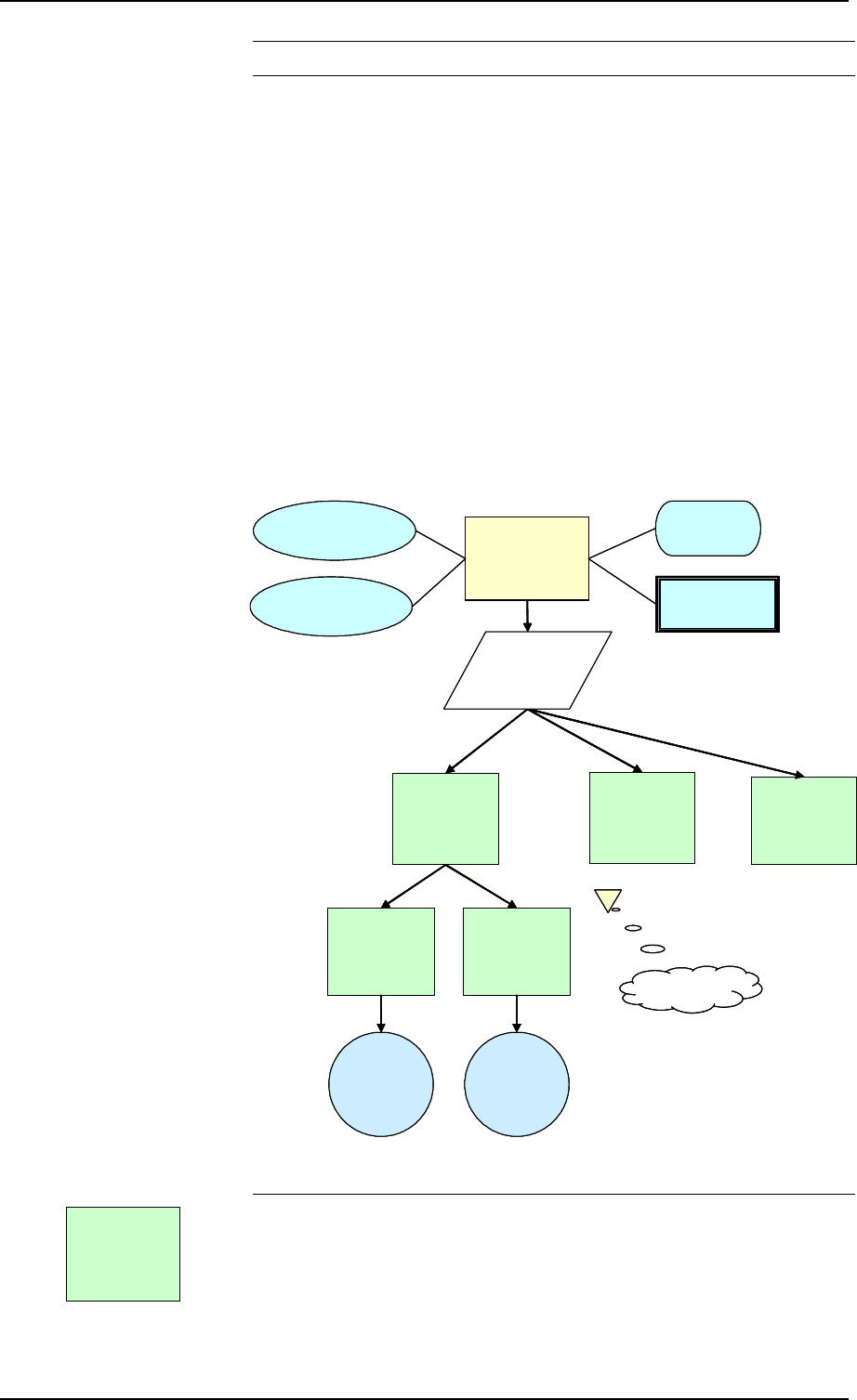
and should be avoided. The cover-up method illustrated in the
three GSN diagrams below can be used to determine identify
unnecessary and misplaced Arguments.
A=True
B=True C=True
E=TrueD=True
A=True
B=True C=True
E=True
D=True
A=True
B=True C=True
E=True
F=True
If this is complete
and correct …
…then D is incorrectly
positioned … …and F is
unnecessary…
D=True
A=True
B=True C=True
E=TrueD=True
A=True
B=True C=True
E=True
D=True
A=True
B=True C=True
E=True
F=True
If this is complete
and correct …
…then D is incorrectly
positioned … …and F is
unnecessary…
D=True
It follows from the above that, for an Argument structure to be
considered to be complete, every branch must be terminated in
a reference to the item of Evidence that supports the Argument
to which it is attached.
Evidence therefore must be:
• appropriate to, and necessary to support, the related
Argument - spurious Evidence (ie information which is not
relevant to an Argument) must be avoided since it would
serve only to confuse the “picture”;
• sufficient to support the related Argument - inadequate
Ref
Evidence

Chapter 4 Safety Case Development Manual
Page 22 Released Issue Edition: 2.2
evidence undermines the related Argument and
consequently all the connected
higher levels of the structure.
Strategies are a useful means of adding “comment” to the
structure to explain, for example, how the decomposition will
develop. They are not predicates and do not form part of the
logical decomposition of the Argument; rather, they are there
purely for explanation of the decomposition.
An Assumption is a statement whose validity has to be relied
upon in order to make an Argument.
Assumptions may also be attached to other GSN elements
including Strategies and Evidence.
Context provides information necessary for an Argument (or
other GSN element) to be understood or amplified.
Context may include a statement which limits the scope of an
Argument in some way.
A Justification is used to give a rationale for the use or
satisfaction of a particular Argument or Strategy. More
generally it can be used to justify the change that is the subject
of the Safety Case.
Criteria are the means by which the satisfaction of an Argument
can be checked.
Numbering It is recommended that Arguments be numbered hierarchically
(eg, Arg 1.1) to reflect their logical structure.
Strategies, Assumptions, Context, and Criteria should be
numbered sequentially (eg, St0001) since they elaborate, but do
NOT form part of, the logic of the structure.
It is recommended that Evidence be numbered according to its
source reference and that the Evidence ‘bubble’ contains a brief
indication of the form that the Evidence takes.
Other Symbology
A Choice can be used while a Safety Argument is being
developed to show a decision point between alternative
Strategies. However, they must be removed before a Safety
Argument is finalised.
A Model is some representation of the system, sub-system or
environment – eg Simulations, Data Flow Diagrams, Circuit
Layouts, State Transition Diagrams etc.
A Stakeholder is the person or role responsible for ensuring
satisfaction of an Argument, Strategy, or Choice.
Constraints are used to restrict the way in which an Argument
can be solved; they are restrictions imposed on the
interpretation of the parent Argument.
St0001
Strategy
A0001
Assumption
C0001
Context
J0001
Justification
Cr001
Criteria
Cr001
Criteria

Safety Case Development Manual Process and Techniques
Edition: 2.2 Released Issue Page 23
A Problem is attached to an Argument to indicate that there is a
possible obstacle to showing that it is true. Problems can also
be attached to other GSN elements.
Examples of the application of GSN to generic Safety
Arguments are presented in Chapter 5.
4. Gathering, Assessing and Presenting Safety Evidence
Importance
Direct and Backing
General Attributes
Necessity
Evidence is the heart of every case and ultimately it is on the
quality and completeness of the Evidence that the validity of a
Safety Case depends. Of course, a well-structured Safety
Argument is very important but only insofar as it provides the
context for, and thus facilitates interpretation of, the Evidence.
In decomposing the Safety Arguments, the following two main
types of Argument (and related Evidence) are used:
• that which shows that a particular objective has been
achieved (ie that a higher level Argument or Claim has been
satisfied) – this is referred to as Direct Argument and
Evidence;
• that which shows that the Direct evidence is trustworthy (ie
that it can be relied upon) – this is referred to as Backing
Argument and Evidence.
Direct Evidence may be thought of as being that which relies
directly on the observable properties of a product (ie the output
of a process), supporting a logical Argument as to how the
product satisfies its safety objectives or requirements, as
appropriate.
Backing Evidence is obtained from the properties of the
processes by which Direct Evidence was obtained, and shows
that those processes, tools and techniques, human resources
etc were appropriate, adequate and properly deployed.
The points below expand upon the “essential rules” outlined in
Chapter 3, section 3 above.
Evidence must be presented only to the degree and extent
necessary to support the related Argument.
The issue here is that, in the context of an Argument-based
approach, any “Evidence” which is unrelated to a part of that
Argument is not only of no value but could also serve as a
distraction from those aspects of the Safety Case that are
relevant. On the other hand, any Evidence which actually
undermines the validity of an Argument must not be ignored –
the existence of such Evidence must be acknowledged and
explained fully in the Safety Case.

Chapter 4 Safety Case Development Manual
Page 24 Released Issue Edition: 2.2
Sufficiency:
o Clarity, and
Conclusiveness
o Objectivity
Appropriateness
Rigour
Relevance
Evidence must be sufficient, as follows.
It is bad (but unfortunately not uncommon!) practice to present
an element of a structured Argument and then refer to a mass of
information as “Evidence” to substantiate the Argument.
It is vital to the integrity of the Safety Case that the Evidence be
presented in such a way that is clear to the reader that the
Evidence does actually show the related Argument to be true,
“beyond all reasonable doubt”.
Where Evidence is contained in appendices or external
documents, a summary justifying the adequacy of the Evidence
should be presented (in the Safety Case) along with the
associated Argument. It is not sufficient to merely reference the
Evidence with statements such as “Evidence to support the
Argument is presented in ….”
Wherever possible, Evidence should consist of proven facts –
eg, the results of a well-established process such as simulations
and testing. Only where such objective Evidence is not
available should Evidence based on expert opinion be used,
and then only when the credentials of the expert(s) and the
means of eliciting the opinion are adequate and have been
presented as Backing Evidence.
The type of Evidence, from safety analysis, design, simulation,
test, previous usage etc, must be appropriate to the Argument –
see sections 5 and 6 below.
The rigour of the Evidence must be appropriate to the
associated risk. This is the principle behind the Assurance
Level concept in ESARR 6 [11] (for software) and the
EUROCONTROL ANS Safety Assessment Methodology [5] for
software, procedures and human aspects.
Evidence must relate to the configuration of the system and
operational environment under consideration - eg a correct and
known:
• version of the equipment, procedures, training, etc.;
•
documentation used in the production of that version;
• range of configuration data.
Application How the above should be applied specifically to the two main
stages of the safety development lifecycle – requirements
determination and requirements satisfaction - is discussed
below, in sections 5 and 6 respectively.
5. Evidence – Safety Requirements Determination
What are Safety
Requirements To paraphrase ESARR 4 [9], Safety Requirements are means
by which the necessary risk reduction measures identified in the
hazard and risk analysis are formally
17
specified. Necessary in
17
In the normal English meaning of the word.

Safety Case Development Manual Process and Techniques
Edition: 2.2 Released Issue Page 25
this context means necessary in order to achieve the required
safety levels, as defined by the Safety Criteria (see section 2
above) and translated into specific Safety Objectives during the
Functional Hazard Assessment [5]
Role of Safety
Requirements in ATM
Types of Safety
Requirement
Direct Evidence of
Safety Requirements
Determination
Backing Evidence of
Safety Requirements
Determination
The primary purpose of ATM is to reduce the risk of accident to
air traffic that would otherwise exist. The amount of risk
reduction is determined primarily by the functionality and
performance of the ATM systems elements, including
equipment, people and procedures. However, failure within the
ATM system can cause risk to increase again, either by
reduction in functionality or performance, or by the introduction
of new risk caused by corruption of the outputs of ATM
functions.
Therefore, in order to achieve a net safety benefit from ATM, the
reduction in risk afforded by the desired functional and
performance properties of ATM needs to be substantially greater
that any increase due to failure
18
. It follows therefore that Safety
Cases are critically dependent on the determination and
satisfaction of a complete and correct set of Safety
Requirements in which system functionality and performance
are appropriately considered alongside system integrity.
19
Direct Evidence of Safety Requirements Determination is
concerned with the requirements themselves and should show,
inter alia, that:
• all relevant Hazards have been identified;
• the potential outcomes of the Hazards have been
categorised correctly;
• Safety Objectives have been specified to control the
frequency of occurrence of the Hazards such that an
acceptable level of risk (as defined by the Safety Criteria) is
achieved;
• Safety Requirements have been specified to control the
causes of the Hazards such that the Safety Objectives are
satisfied, and to capture the external means of mitigation of
the Hazard effects.
The key issue here is to ensure that the Safety Requirements
are complete – ie that all risks are taken into account. It would
not be sufficient to show that the Safety Requirements satisfy
the Safety Criteria if those Safety Requirements were based on
an incomplete / incorrect Hazard assessment.
Backing Evidence of Safety Requirements Determination is
concerned with the process of deriving the requirements and
should show, inter alia, that:
• the Safety Requirements were determined using an
established and appropriate process;
18
SAM [5] expresses the distinction in terms of the “success approach” and the “failure approach”
19
This point is emphasised here because of a popular misconception that safety is dependent mainly
on integrity. Neglect of functionality and performance can lead to systems that are “reliably unsafe”.

Chapter 4 Safety Case Development Manual
Page 26 Released Issue Edition: 2.2
Relationship to
EUROCONTROL Safety
Assessment
Methodology
• the techniques and tools used to support the Safety
Requirements Determination were verified and validated;
• the Safety Requirements Determination process was
executed by suitably competent and experienced personnel.
The Functional Hazard Assessment (FHA) and Preliminary
System Safety Assessment (PSSA) stages of the
EUROCONTROL, Air Navigation System Safety Assessment
Methodology [5] provides an appropriate and sound process for
the determination of ATM Safety Requirements – demonstration
of adherence to the FHA and PSSA processes could therefore
be used as Backing Evidence as in the first bullet point above.
6. Evidence – Safety Requirements Satisfaction
Sources of Evidence
Service Experience
20
2020
20
Direct Evidence from-
Service Experience
Evidence of Safety Requirements satisfaction may be used from
three main sources, as follows:
• Service Experience of previous usage
• Verification and Validation
• Compliance with Standards
Service Experience is data from previous operational use of the
product concerned. Direct Evidence is concerned with analysis
of data from Service Experience and what the results of that
analysis showed in terms of satisfaction of the safety
requirements. Backing Evidence is concerned with showing
that the environment from which the data was obtained is
sufficiently similar to that to which the re-used product will be
subjected, that adequate performance-assessment and fault-
recording processes were in place when the product was
originally deployed, and that the analysis of the outputs of those
processes was adequate and properly carried out.
In assessing and presenting Direct Evidence from Service
Experience, it is important to ensure that:
• an analysis process, with pass/fail criteria, was specified for
each aspect of the product safety requirement whose
satisfaction is being justified using service experience;
• analysis of the service records shows that the criteria for
each product safety requirement, whose satisfaction is being
justified using service experience, have been met;
• all of the details relevant to the argument being made (eg of
length of service, history of modifications, list of users) are
included in the Evidence;
20
Further guidance on Service Experience, specific to CNS/ATM software, may be found in ED-109
[13]. Note, however, that ED-109 makes no distinction between Direct and Backing evidence.

Safety Case Development Manual Process and Techniques
Edition: 2.2 Released Issue Page 27
Backing Evidence from
Service Experience
• any product capabilities that are not necessary to satisfy the
Safety Requirements cannot have an adverse effect on the
safe operation of the system.
In assessing and presenting Backing Evidence from Service
Experience, it is important to ensure, inter alia, that:
Verification and
Validation
• the subject of the Safety Case and the product for which the
Service Experience Evidence is available are identical or
sufficiently similar;
• the conditions of use of the product for which the Service
Experience is available is taken into account in the analysis;
• the proposed operational environment and the operational
environment for which the Service Experience Evidence is
available are identical or sufficiently similar;
• any changes made to the operational environment,
conditions of use, or product during the period of the Service
Experience are analysed to determine whether those
changes alter the applicability of the data obtained from
Service Experience for the period preceding the changes;
• all aspects of those product functions whose safety
requirements that are being justified from Service
Experience have been exercised in the (previously)
deployed product;
• the extent of the Service Experience is sufficient to
demonstrate that each aspect of the product safety
requirement has been met;
• a Defect Reporting, Analysis and Corrective Action System
(DRACAS) is in place for the deployed product, and is
operated in a reliable manner, and is adequate to support
the Service Experience Evidence;
• the procedures and tools used to support the creation and
analysis of Service Experience Evidence were verified and
validated;
• for all reported failures of an aspect in the product
component, the underlying fault has been corrected, or it
has been shown that the fault is not relevant because it has
no safety impact;
• the collection and analysis of Service Experience Evidence
was done by suitably competent and experienced personnel.
Evidence from system Verification and Validation (V&V) may be
based on, inter alia, analysis and/or testing.
Analysis, in this context, covers any proof of requirements
satisfaction that is obtained from the design or other
representation of the product, including models, prototypes,
software source code etc. It includes, for example, simulation
formal proof, hardware reliability prediction, inspection, and
software static and dynamic code analysis.

Chapter 4 Safety Case Development Manual
Page 28 Released Issue Edition: 2.2
Direct Evidence -
V&V
Backing Evidence -
V&V
Testing is restricted largely to tests of the final product in an
environment which is as close as possible to the operational
environment. Its purpose, broadly, is to demonstrate that what
has been built satisfies the requirements, and it is used to
supplement (sometimes replace) Analysis.
It is beyond the scope of this Manual to discuss the relative
merits of analysis and testing, or of the various techniques
within those two broad categories. Suffice it to say that a Safety
Case should set out clear justifications of the selected
techniques according to the nature and integrity required of the
system to which the Safety Case applies. The following
guidance is however given concerning the principal
requirements of Direct and Backing V&V Evidence.
However obtained, Direct evidence is concerned with the output
of the V&V processes, and should include, as a minimum:
21
• specifications of what V&V activities were carried out;
• evidence that the V&V activities and pass/fail criteria were
sufficient to demonstrate that the related requirements were
satisfied;
• the results of the V&V activities;
• analysis of the results to shows that all the specified
pass/fail criteria were met;
• explanation and justification of any discrepancies in the
results.
Whether obtained from analysis or testing, Backing evidence is
concerned with the V&V processes themselves, and should
include, as a minimum Evidence that:
• the processes were specified and performed independently
from design;
• the methods and techniques used are appropriate and
adequate, for the properties of the product under
consideration;
• the tools used to support the processes were verified and
validated to a level appropriate for the assigned assurance
level and were properly used;
• the V&V processes were properly and completely executed,
and the guidance, procedures, and standards were adhered
to;
• for previously existing V&V evidence, obtained for COTS or
re-used products, the evidence is entirely valid for the new
system application;
• any differences between the operational and V&V
21
The list is intended to provide only an overview of the main issues. Further detail on V&V, specific
to CNS/ATM software, may be found in section 3 of ED-109 [13].

Safety Case Development Manual Process and Techniques
Edition: 2.2 Released Issue Page 29
Compliance with
Standards
Product Standards
Process Standards
Relationship to
EUROCONTROL Safety
Assessment
Methodology
environments were identified, and the impact on the results
was assessed and justified.
Evidence of compliance with standards can be a significant
contribution to the safety case. However, the way in which
adherence to a particular standard can be used to demonstrate
compliance with Safety Requirements will depend on the nature
of the standard itself.
Product standards specify precisely what is required of a
specific item of equipment in terms of function, performance,
integrity and, in some cases, form and fit. A good example is
the Arinc 700 series of standards, which define digital avionics
systems and equipment installed on civil aircraft. Currently,
product standards are not common in ATM.
Compliance with product standards could be used as Direct
Evidence of system safety, subject to it being shown that the
standard was appropriate to the particular application and to the
provision of sufficient Backing Evidence concerning the
adequacy of the process by which compliance was
demonstrated.
At the other end of the spectrum, are standards which address
the processes of development and manufacture – examples
range from the very broadly based ISO 9000 series to the more
specific ED-78A (Guidelines for the Approval of the Provision
and Use of ATS Supported by Data Communications) and ED-
109 ( Guidelines for CNS/ATM System Software Integrity
Assurance). In none of these cases would it appropriate to
certify a product against them, from a safety viewpoint;
however, compliance with such standards, especially the more
specific ones, could provide excellent Backing Evidence for
safety requirements determination and/or satisfaction.
The distinction between product- and process-based safety
assurance is clearly fundamental since the former is concerned
with getting the right product and the latter with getting the
product right.
The System Safety Assessment (SSA) stage of the
EUROCONTROL, Air Navigation System Safety Assessment
Methodology [5] provides further guidance on the application of
the above approaches to requirements-satisfaction.
7. Developing a Safety Plan
Introduction
Basic Requirements
Safety Activities
A Safety Plan specifies, inter alia, the safety assurance activities
that are to be carried out in order to create necessary and
sufficient Evidence for the production of a Safety Case.
The SRC-EATM Interface process [6] specifies the following
contents for a Safety Plan:
• the Safety Activities needed to meet the (high-level) safety
objectives, as well as the links and relationships between

Chapter 4 Safety Case Development Manual
Page 30 Released Issue Edition: 2.2
Resources
Roles and
Responsibilities
Safety Deliverables
The Safety / Programme
Lifecycle
Safety Activity /
Deliverables Mapping
Schedule
Specific
Recommendations
Safety Argument
Safety Case
Development
Reviews and Approvals
Handover
Safety Regulation
Safety Case
Maintenance
safety activities and safety objectives;
• the means and resources to carry out safety activities within
the Programme;
• responsibilities and accountabilities for Safety Activities;
• the safety deliverables associated with the Safety Activities;
• the allocation of Safety Activities and Safety Deliverables in
the progression of the Programme;
• the relationships and dependencies between successive
Safety Activities and associated Safety Deliverables;
• the detailed schedule and milestones for conducting Safety
Activities and releasing associated Safety Deliverables.
It is recommended that the following items, specific to the
creation of a Safety Case, also be included in the Safety Plan:
• an initial version of the Safety Argument. The rationale for
this is that most of the Safety Activities (see above) should
be directed at the collection and assessment of Evidence to
support the Safety Argument;
• planned development stages of the Safety Case and their
relationship to the overall Programme milestones;
• requirements for review and approval of the Safety Case;
• arrangements for the proper handover of Safety Case
activities or obligations;
• arrangements for the approval of the Safety Case by the
regulatory authorities;
• arrangements for the maintenance of the Safety Case during
operations.
8. Format, Structure and Layout of the Safety Case
Executive Summary
Introduction:
Background
This section presents guidance on Safety Case layout.
Examples, relating to EATM can be found in the
EUROCONTROL Pre- and Post-Implementation Safety Cases
for RVSM, [2] and [3] respectively. More-recent examples can
be provided on request.
This should provide the reader with an overview of what the
Safety Case is about, what it is trying to show and for whom, a
summary of the conclusions and caveats (see below) and
recommendations (if any).
The Introduction should include:
• an outline of, for example, the circumstances which led to

Safety Case Development Manual Process and Techniques
Edition: 2.2 Released Issue Page 31
Aim
Purpose
Scope
Layout
Service / System
Description
Overall Safety
Argument
Claim
Criteria
Context
Justification
Principal Safety
Arguments
High-level Assumptions
Safety Argument and
Evidence sections
the need for, and development of, the Safety Case;
• a simple statement of the aim – ie what the Safety Case
seeks to demonstrate. It should be related directly to the
top-level Claim (see below);
• the purpose of the Safety Case – ie why, and for whom, it
has been produced;
• the scope and boundary of the Safety Case. It is important
to explain what is included and what is not included;
• the purpose of each of the sections of the document. In
general, the main part of the document should be structured
along the lines of the Safety Argument.
Provide a description of the system to which the Safety Case
applies, including its operational environment, interfaces and
boundaries of responsibility.
This section should describe and explain the highest levels of
the Safety Argument structure, including:
• the Claim – ie the top-level statement which asserts that the
service / system (etc) is safe;
• the Safety Criteria which define what is meant by safe in the
context of the Claim;
• a description of the operational context to which the Safety
Case applies;
• the justification for the change, where the Safety Case
addresses a change to a service and/or system that is not
being made mainly for reasons of improving safety, and
therefore potentially for incurring some risk;
• the principal Safety Arguments – ie the first level of
decomposition of the top-level Claim – these should be
reasoned and well structured, showing how the Safety
Criteria are satisfied and the rationale for the approach
taken in the decomposition;
• the key Assumptions on which the highest levels of the
Safety Argument critically depend – for example, the level of
risk prior to the introduction of a change is acceptable.
Other Assumptions, applicable to the lower levels of the
Safety Argument structure should be included in the
Assumptions section – see below.
These sections should present each of the principal Safety
Arguments (see above) in turn, together with the supporting
Evidence which shows that each of the Arguments is valid. It is
recommend that, where applicable, each section be structured
as follows:
• Objective (of the section) – related directly to the principal
Safety Argument;
• Strategy (breakdown of the principal Safety Argument into

Chapter 4 Safety Case Development Manual
Page 32 Released Issue Edition: 2.2
Assumptions
Issues
Limitations
Conclusions
Recommendations
lower-level arguments);
• Rationale (for the Strategy);
• Lower-level Arguments / Evidence;
• Conclusions (of section).
Present directly, and/or by reference, all the Assumptions on
which the Safety Case depends, including the high-level
Assumptions mentioned above. Assumptions usually relate to
matters outside of the direct control of the organisation
responsible for the Safety Case but which are essential to the
completeness and/or correctness of the Safety Case. Each
Assumption must be shown to be valid or at least reasonable
according to the circumstances.
List any outstanding safety issues that must be resolved before
the Claim can be considered to be valid, together with the
responsibilities and timescales for clearing them.
State and explain any Limitations or restrictions that need to be
placed on the deployment and/or operation of the system.
Do not merely repeat the conclusions from each section here.
The main conclusion should refer to the original Claim and, if
applicable, reassert its validity, subject to the following caveats:
• the Scope – especially what the Safety Case does not
cover;
• the operational Context to which the Safety Case applies;
• the Assumptions that have had to be made;
• the outstanding Issues;
• any Limitations placed on the deployment and/or operation
of the service / system.
Recommendations are not mandatory and any that are made
should not be temporary in nature. For example, it might be
appropriate to make recommendations on the use of the Safety
Case by its recipients, but not concerning its approval.
Recommendations must not contain any statements that would
undermine, or add further caveats to, the Conclusions.
9. Verifying the Safety Case
Further guidance on what to look for in developing and
reviewing a Safety Case can be found in the detailed checklists
in Appendix C.

Safety Case Development Manual Process and Techniques
Edition: 2.2 Released Issue Page 33
10. ESARR Compliance
Overview
ESARR 2
ESARR 3
Compliance with ESARRs may be used in support of a Safety
Case. However, as indicated below, ESARRs are largely
concerned with processes and, therefore, compliance with
ESARRs should normally be used as Backing Evidence, not as
Direct Evidence
22
.
Reporting and Assessment of Safety Occurrences in ATM
The rationale for ESARR 2 is that the achievement of consistent
high levels of aviation safety and the management of safety in
ATM require, as a priority, the successful implementation of
harmonised occurrence reporting and assessment schemes.
Such schemes will lead to more systematic visibility of safety
occurrences and their causes, and will allow identification of
appropriate corrective actions as well as areas where flight safety
could be improved by changes to the ATM system.
Compliance with ESARR 2 can be used as (Backing) Evidence
of having an adequate in-service safety monitoring process in
support of:
• a Project Safety Case – see for example Arg4 / St005 in
Figure 11 of Chapter 5;
• a Unit Safety Case – see for example Arg2.5 in Figure 12 of
Chapter 5.
Use of Safety Management Systems by Service Providers
The rationale for ESARR 3 is that an ATM service provider has a
responsibility to ensure that all relevant safety issues have been
satisfactorily dealt with, and to provide assurance that this has
been done. Safety management is that function of service
provision, which ensures that all safety risks have been identified,
assessed and satisfactorily mitigated. A formal and systematic
approach to safety management will maximise safety benefits in a
visible and traceable way.
Because a typical SMS includes a very wide range of safety
processes in support of ATM operations, compliance with ESARR
3 can be used in many areas of a Safety Case - for example:
• in a Project Safety Case, SMS processes could be used as
Backing Evidence under Arg2.1 and Arg2.2, in Chapter 5,
Figure 8 and Figure 9 respectively;
• in a Unit Safety Case, SMS processes could be used as
Direct Evidence under Arg2.2 / St003, in Figure 14 of
Chapter 5.
In both cases, the SMS-process Evidence would be strengthened
if it could be shown that the SMS was compliant with ESARR 3 –
ie ESARR 3 compliance would provide Backing Evidence.
22
A possible exception to this statement could be a Safety Case which is based mainly on the
satisfaction of the requirements of the ESARR 4 Risk Classification Scheme.

Chapter 4 Safety Case Development Manual
Page 34 Released Issue Edition: 2.2
ESARR 4
Risk Assessment and Mitigation in ATM
ESARR 4 concerns the use of Risk Assessment and Mitigation,
including hazard identification, in Air Traffic Management when
introducing and/or planning changes to the ATM System. In this
ESARR 5
ESARR 6
requirement, Risk Assessment and Mitigation are addressed via a
total–aviation-system approach.
There are two aspects of ESARR 4 which can be used in a Safety
Case, as follows:
• subjective to the provisos of Chapter 4, section 2 above, the
Risk Classification Scheme in Appendix A to ESARR 4 could
be used as the basis of quantitative Safety Criteria – see, for
example, Cr001 / #1 in Chapter 5, Figure 1;
• compliance with the qualitative (process) requirements of
section 5 of ESARR 4 could be used as Backing Evidence as,
for example, in Arg 1.10 in Chapter 5, Figure 6.
ATM Services’ Personnel
ESARR 5 documents general safety regulatory requirements for
all ATM services’ personnel responsible for safety related tasks
within the provision of ATM services across the ECAC area,
including the specific safety regulatory requirements for air traffic
controllers and engineering/technical personnel.
Compliance with ESARR 5 could be used in a Unit Safety Case
to show that the human aspects of the on-going operation are
based on, inter alia, competent personnel. This would appear, for
example in the lower levels of decomposition of Arg2.1 and
Arg2.2 in Chapter 5, Figure 14.
Software in ATM Systems
ESARR 6 deals with the implementation of software safety
assurance systems to ensure that the risks associated with the
use of software in safety-related ground-based ATM systems are
reduced to a tolerable level.
Compliance with ESARR 6 could be used, for example, in:
• a Project Safety Case - software processes could be used as
Backing Evidence under Arg2.1 / St011 and Arg2.2 / St015,
in Figure 8 and Figure 9 respectively of Chapter 5
23
2323
23
;
• a Unit Safety Case - software processes could be used as
Direct Evidence under Arg2.2 / St003, in Figure 14 of
Chapter 5.
23
Direct Evidence would be the outputs of those processes

Safety Case Development Manual GSN Safety Argument Examples
Edition: 2.2 Released Issue Page 35
CHAPTER 5
Guidance -
GSN Safety Argument Examples
1. Example Application of GSN – A “Project” Safety Case
Relationship to the
EUROCONTROL SAM
Figure 1 to Figure 11 overleaf show a structured Safety
Argument for a hypothetical substantial
change (“SGxy”) to an
ATM service which could form the basis of what is known herein
as a Project Safety Case.
The structure is intentionally not complete in all areas of the
decomposition; however, it is intended to be sufficient, in
breadth and depth, to illustrate the use of the GSN notation. A
commentary on the development of the Safety Argument is also
provided below. This commentary is also not exhaustive but is
intended to bring out all the main points concerning the
application of GSN.
Where applicable references are given to those process(es) in
the SAM [5] that would generate the required Evidence.
Claim
Justification
Context
The Safety Argument starts, in Figure 1, with the top-level
Claim (Arg 0) that the ATM service, following the change, will
be acceptably safe.
J001 indicates that the change is justified operationally and this
justification would need to be elaborated in the Safety Case.
C001 provides an essential marker that the change itself needs
to be defined in terms of the ATM service / system and
accompanying operational concept – such descriptions would
need to be provided in the related Safety Case.
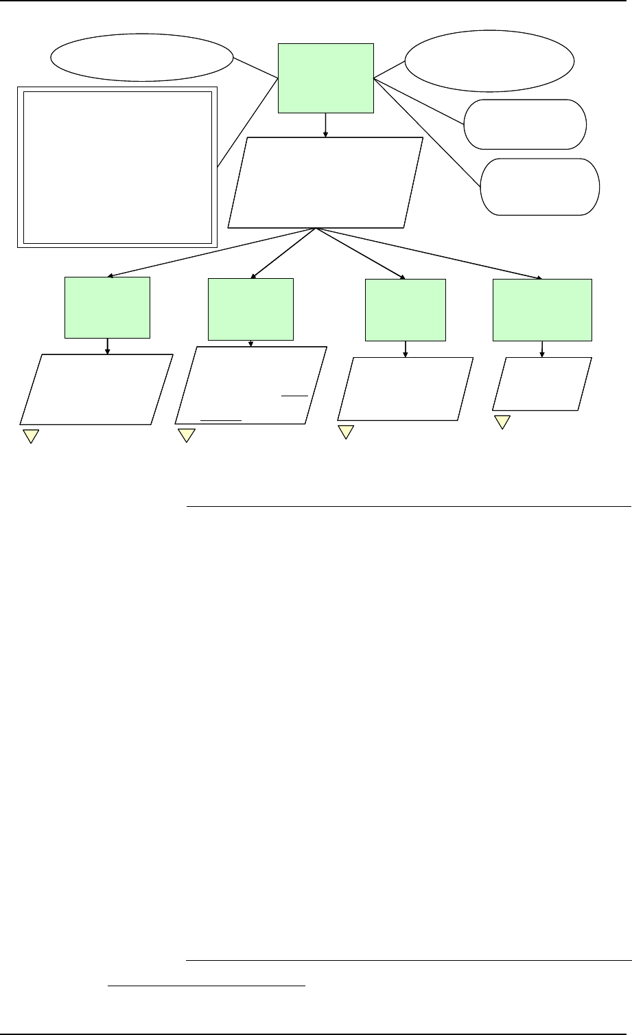
Chapter 5 Safety Case Development Manual
Page 36 Released Issue Edition: 2.2
.
Change_SGxy will
be acceptably safe
in operational
service
Arg 0
St 001
Specify safety criteria for each of the
4 main life-cycle stages and show that
each stage is / will be acceptably safe
– ie the safety criteria are sufficient to
achieve the required level of safety,
and are satisfied
C001
Operational concept
(SAM-FHA ch1-GM A)
Change_SGxy
Implementation
is acceptably safe
Arg 2
Change_SGxy
Concept is
acceptably safe,
in principle
Arg 1
A001
Current ATM service
is accepted as being safe
J001
Change_SGxy is being
introduced to meet a
legitimate operational need
Cr001
The risk of an accident following
Change_SGxy shall be:
1.Within the regulatory requirements – eg:
a. such that the whole ATM service
meets ESARR 4 Design Safety
Targets (SAM-FHA ch3 GM E); OR
b. no greater (and preferably lower)
than currently exists.
AND
2. reduced as far as reasonably
practicable.
Migration to
Change_SGxy
will be
acceptably safe
Arg 3
On-going Operation
of Change_SGxy will
be shown to be
acceptably safe
Arg 4
Fig 2 Fig 7
St004
Show that risk during
(and immediately
following) Migration will
satisfy Cr001 item 2 Fig 11
St005
Safety Monitoring
will satisfy Cr001
items 1 and 2
Fig 10
St002
Show that Safety
Requirements satisfy Cr001:
•item 1 (Args 1.1 & 1.2);
•Item 2 (Arg 1.3)
St003
Show that the Safety
Requirements are satisfied:
1. Initially in system design
2. Subsequently in the
realisation of that design
C002
Subject to declared
Assumptions, Limitations
and outstanding Issues
.
Change_SGxy will
be acceptably safe
in operational
service
Arg 0
Change_SGxy will
be acceptably safe
in operational
service
Arg 0
St 001
Specify safety criteria for each of the
4 main life-cycle stages and show that
each stage is / will be acceptably safe
– ie the safety criteria are sufficient to
achieve the required level of safety,
and are satisfied
St 001
Specify safety criteria for each of the
4 main life-cycle stages and show that
each stage is / will be acceptably safe
– ie the safety criteria are sufficient to
achieve the required level of safety,
and are satisfied
C001
Operational concept
(SAM-FHA ch1-GM A)
Change_SGxy
Implementation
is acceptably safe
Arg 2
Change_SGxy
Implementation
is acceptably safe
Arg 2
Change_SGxy
Concept is
acceptably safe,
in principle
Arg 1
Change_SGxy
Concept is
acceptably safe,
in principle
Arg 1
A001
Current ATM service
is accepted as being safe
J001
Change_SGxy is being
introduced to meet a
legitimate operational need
Cr001
The risk of an accident following
Change_SGxy shall be:
1.Within the regulatory requirements – eg:
a. such that the whole ATM service
meets ESARR 4 Design Safety
Targets (SAM-FHA ch3 GM E); OR
b. no greater (and preferably lower)
than currently exists.
AND
2. reduced as far as reasonably
practicable.
Migration to
Change_SGxy
will be
acceptably safe
Arg 3
Migration to
Change_SGxy
will be
acceptably safe
Arg 3
On-going Operation
of Change_SGxy will
be shown to be
acceptably safe
Arg 4
On-going Operation
of Change_SGxy will
be shown to be
acceptably safe
Arg 4
Fig 2Fig 2 Fig 7Fig 7
St004
Show that risk during
(and immediately
following) Migration will
satisfy Cr001 item 2
St004
Show that risk during
(and immediately
following) Migration will
satisfy Cr001 item 2
St004
Show that risk during
(and immediately
following) Migration will
satisfy Cr001 item 2 Fig 11Fig 11
St005
Safety Monitoring
will satisfy Cr001
items 1 and 2
St005
Safety Monitoring
will satisfy Cr001
items 1 and 2
St005
Safety Monitoring
will satisfy Cr001
items 1 and 2
Fig 10Fig 10
St002
Show that Safety
Requirements satisfy Cr001:
•item 1 (Args 1.1 & 1.2);
•Item 2 (Arg 1.3)
St002
Show that Safety
Requirements satisfy Cr001:
•item 1 (Args 1.1 & 1.2);
•Item 2 (Arg 1.3)
St003
Show that the Safety
Requirements are satisfied:
1. Initially in system design
2. Subsequently in the
realisation of that design
St003
Show that the Safety
Requirements are satisfied:
1. Initially in system design
2. Subsequently in the
realisation of that design
St003
Show that the Safety
Requirements are satisfied:
1. Initially in system design
2. Subsequently in the
realisation of that design
C002
Subject to declared
Assumptions, Limitations
and outstanding Issues
Figure 1 – Arg 0: Safety Argument
Safety Criteria
Choice of Criteria
Assumption
Arg1 to 4
Acceptably safe is defined in terms of the three criteria
summarised in Cr001. These criteria reflect the three main
ways of expressing a Safety Argument – ie:
• Absolutely: as compliance with a (numerical) target level of
safety – eg ESARR 4 (or local regulatory interpretation
thereof), OCP, ICAO, JAR 25 etc;
• Relatively: in relation to a current / previous (usually
qualitative) level of safety;
• Reductively: showing risk to be further reduced as far as
reasonably practicable;
The first two bullets are alternative ways of expressing a typical
regulatory minimum safety level
24
and specify what is
sometimes known as tolerable risk. In the further development
of the Safety Argument for Change SGxy, only the absolute
criterion is actually used
25
, and is supported by the reductive
criterion in order to specify what is sometimes known as an
acceptable level of risk.
If a relative Argument, were to be used it would be necessary to
establish that the pre-change baseline is safe. This is addressed
in A001 which is shown on Figure 1 for illustration only.
As indicated in Strategy St001, Claim Arg 0 is decomposed into
24
It would not normally be necessary to comply with both.
25
For examples of developing Safety Arguments using relative criteria, please contact DAP/SAF
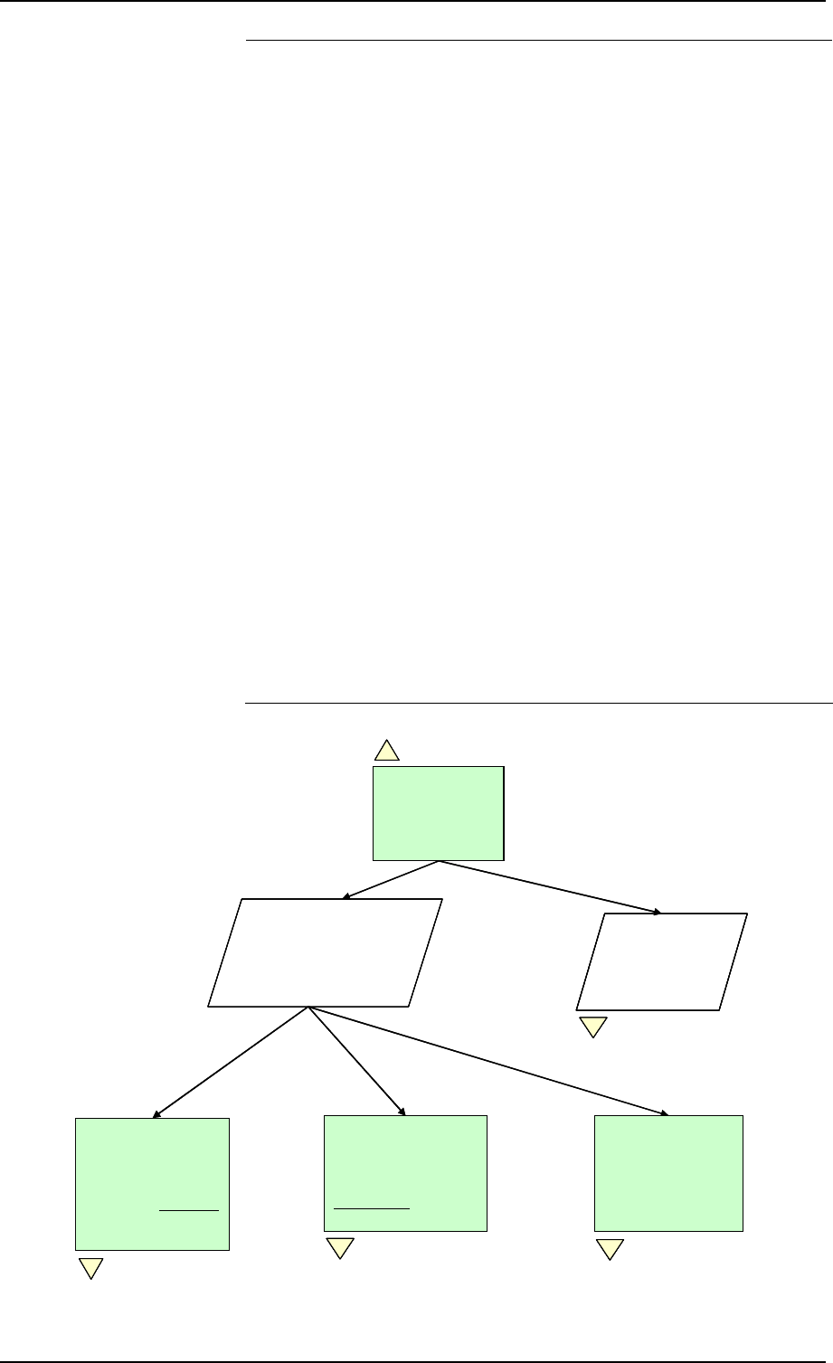
Safety Case Development Manual GSN Safety Argument Examples
Edition: 2.2 Released Issue Page 37
four principal Arguments which, in this case, relate to the four
main, contiguous stages of the lifecycle of the Change. The
outcome of each stage is argued to be acceptably safe and
St002 to St005 are used to indicate, by reference to Cr001 what
is defined as acceptably safe for each stage:
• Arg 1 (through St002) asserts that the Change is acceptably
safe in principle – ie subject to subsequent complete and
correct implementation of the Safety Requirements;
• Arg 2 (through St003) asserts that the Implementation of
the Change is acceptably safe, through satisfaction of the
Safety Requirements, and that the rigour of the Assurance
(ie lower-level Arguments and Evidence) to support this is
appropriate to the risk associated with the Change;
• Arg 3 (through St004) asserts, in effect, that the Migration
from the current state to the post-Change state will not
endanger the on-going operational service. The change in
tense in Arg3 is deliberate since the Safety Argument would
be expected to be finalised once all the Implementation and
Migration steps, except the final “switchover” to the new
state, had been completed satisfactorily. Note that, because
of the short time for which the service is at risk, during
Migration, only Criterion Cr001, item 2 can be applied to this
Argument;
• Arg 4 (through St005) asserts that the monitoring of the on-
going operational service, post Migration, will be sufficient to
show the Change to be acceptably safe
Fig 3
Safety Functions &
Safety Objectives
specify what is
sufficient at functional
level to meet Safety
Criteria Cr001
Arg 1.1
Fig 1
Safety Requirements
specify what is
sufficient at
architectural level to
meet Safety Objectives
Arg 1.2
Fig 4
Risks have been
minimised in the
process of deriving
the Safety
Requirements
Arg 1.3
Fig 5
Change_SGxy
Concept is
acceptably safe,
in principle
Arg 1
St006
Show that Safety
Requirements
evidence is
trustworthy
Fig 6
St002
Show that Safety
Requirements satisfy Cr001:
•item 1 (Args 1.1 & 1.2);
•Item 2 (Arg 1.3)
Fig 3Fig 3
Safety Functions &
Safety Objectives
specify what is
sufficient at functional
level to meet Safety
Criteria Cr001
Arg 1.1
Safety Functions &
Safety Objectives
specify what is
sufficient at functional
level to meet Safety
Criteria Cr001
Arg 1.1
Fig 1Fig 1
Safety Requirements
specify what is
sufficient at
architectural level to
meet Safety Objectives
Arg 1.2
Fig 4
Safety Requirements
specify what is
sufficient at
architectural level to
meet Safety Objectives
Arg 1.2
Fig 4Fig 4
Risks have been
minimised in the
process of deriving
the Safety
Requirements
Arg 1.3
Fig 5
Risks have been
minimised in the
process of deriving
the Safety
Requirements
Arg 1.3
Risks have been
minimised in the
process of deriving
the Safety
Requirements
Arg 1.3
Fig 5Fig 5
Change_SGxy
Concept is
acceptably safe,
in principle
Arg 1
Change_SGxy
Concept is
acceptably safe,
in principle
Arg 1
St006
Show that Safety
Requirements
evidence is
trustworthy
Fig 6
St006
Show that Safety
Requirements
evidence is
trustworthy
St006
Show that Safety
Requirements
evidence is
trustworthy
St006
Show that Safety
Requirements
evidence is
trustworthy
Fig 6Fig 6
St002
Show that Safety
Requirements satisfy Cr001:
•item 1 (Args 1.1 & 1.2);
•Item 2 (Arg 1.3)
St002
Show that Safety
Requirements satisfy Cr001:
•item 1 (Args 1.1 & 1.2);
•Item 2 (Arg 1.3)
Figure 2 – Arg 1: Safety of the “Change SGxy” Concept

Chapter 5 Safety Case Development Manual
Page 38 Released Issue Edition: 2.2
Arg 1
Arg 1 focuses on the output of the Concept stage of the
lifecycle – ie a set of Safety Requirements for the Change that
ultimately satisfy the three safety criteria which define an
acceptable level of safety.
Arg 1 is achieved through a two-fold Strategy, which uses the
principle of Direct Evidence and Backing Evidence, as follows:
• St002 shows, through a sequential set of Arguments (Arg
1.1 to Arg 1.5), that the eventual outputs of the Concept
phase – the Safety Requirements – satisfy the three safety
Criteria. This is clearly a Direct approach since it is
concerned with the outputs of each stage in the sequence,
rather than with the processes that produce those outputs;
• St006 shows that the Direct Evidence is trustworthy – ie can
be relied upon. The Arguments to achieve St006 are
shown in Figure 6 below, and are considered to be of the
Backing type since they are concerned with the processes
that produce the above outputs, rather than with the outputs
themselves (ie they are complementary to St002).
Arg 1.1, Arg 1.2 and Arg 1.3 are decomposed below in
Figure 3, Figure 4 and Figure 5 respectively.
In Figure 3, the Context for Arg 1.1 is an FHA (C004)
associated with the Change. C005 is simply a reminder that the
FHA must encompass all aspects of the Change.
Arg 1.1.1 to Arg 1.1.6 relate to the outputs of the main stages
of a typical FHA. Safety Functions are concerned with
specifying the desired (correct) operation of a system in order
to provide safe ATM services (what the SAM
[5]
describes as
the “success approach”) whereas Safety Objectives limit the
frequency of failure.
The type of Evidence expected to be provided to support each
strand of the Argument is also shown on Figure 3, together with
the relevant references to the SAM
[5]
.
The use of the term “adequately” in Arg 1.1.2 and Arg 1.1.4
illustrates what is sometimes a fine distinction between Direct
and Backing Evidence. In general:
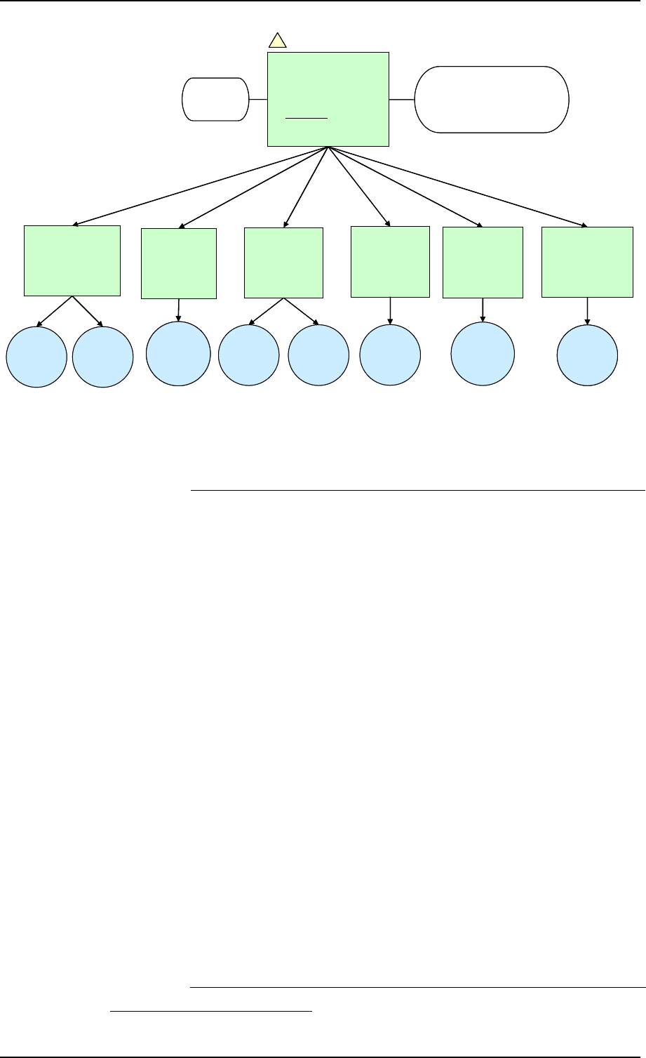
Safety Case Development Manual GSN Safety Argument Examples
Edition: 2.2 Released Issue Page 39
C005
Scope encompasses airspace,
equipment, procedures and human
aspects of Change_SGxy
Safety
Functions are
adequately
specified
Arg 1.1.2
Safety
Objectives are
adequately
specified
Arg 1.1.4
Safety Functions
and Safety
Objectives satisfy
Criteria Cr001
Arg 1.1.6
Change_SGxy
Concept has been
documented and
validated
Arg 1.1.1
C004
FHA
Functional
model &
Safety
Functions
SAM FHA,
Ch 1, 2.1
Safety
Objectives &
Traceability
SAM FHA
Ch 3, 3.2 & Ch 4,
3.2 GMA
Validation
evidence
SAM FHA
Ch 4, 3.1
Concept of
Operations
SAM FHA,
Ch 1, 2.1 &
2.2
Simulation
(etc)
results
SAM FHA,
Ch 1, 2.5
All hazards
correctly
identified and
analysed
Arg 1.1.3
HAZID
results
SAM FHA
Ch 3, 3.1
Event
Trees etc
SAM FHA
Ch 3, 3.2
& 3.3
Mitigations &
Assumptions
SAM FHA
Ch 3, 4, Ch 4,
3.2
All mitigations
captured as
SFs / SObjs or
Assumptions
Arg 1.1.5
Fig 2
Safety Functions &
Safety Objectives
specify what is sufficient
at functional level to
meet the Safety Criteria
Cr001
Arg 1.1
C005
Scope encompasses airspace,
equipment, procedures and human
aspects of Change_SGxy
Safety
Functions are
adequately
specified
Arg 1.1.2
Safety
Objectives are
adequately
specified
Arg 1.1.4
Safety Functions
and Safety
Objectives satisfy
Criteria Cr001
Arg 1.1.6
Safety Functions
and Safety
Objectives satisfy
Criteria Cr001
Arg 1.1.6
Change_SGxy
Concept has been
documented and
validated
Arg 1.1.1
C004
FHA
Functional
model &
Safety
Functions
SAM FHA,
Ch 1, 2.1
Functional
model &
Safety
Functions
SAM FHA,
Ch 1, 2.1
Safety
Objectives &
Traceability
SAM FHA
Ch 3, 3.2 & Ch 4,
3.2 GMA
Validation
evidence
SAM FHA
Ch 4, 3.1
Validation
evidence
SAM FHA
Ch 4, 3.1
Concept of
Operations
SAM FHA,
Ch 1, 2.1 &
2.2
Simulation
(etc)
results
SAM FHA,
Ch 1, 2.5
All hazards
correctly
identified and
analysed
Arg 1.1.3
HAZID
results
SAM FHA
Ch 3, 3.1
Event
Trees etc
SAM FHA
Ch 3, 3.2
& 3.3
Mitigations &
Assumptions
SAM FHA
Ch 3, 4, Ch 4,
3.2
All mitigations
captured as
SFs / SObjs or
Assumptions
Arg 1.1.5
All mitigations
captured as
SFs / SObjs or
Assumptions
Arg 1.1.5
Fig 2
Safety Functions &
Safety Objectives
specify what is sufficient
at functional level to
meet the Safety Criteria
Cr001
Arg 1.1
Fig 2Fig 2
Safety Functions &
Safety Objectives
specify what is sufficient
at functional level to
meet the Safety Criteria
Cr001
Arg 1.1
Safety Functions &
Safety Objectives
specify what is sufficient
at functional level to
meet the Safety Criteria
Cr001
Arg 1.1
Figure 3 – Arg 1.1: Safety Functions and Safety Objectives
• If the Argument / Evidence is concerned with observable
attributes of an output (product) then it should be considered
to be Direct – for example, traceability of Safety Objectives
back to Safety Functions and Safety Criteria would be Direct
since it would be observable (with the assistance of cross-
referencing) from the Safety Objectives, Safety Functions
and Safety Criteria themselves.
• On the other hand, if the Argument / Evidence cannot be
deduced from observable attributes of an output itself, but is
related only to the process, then it should be considered to
be Backing – for example it would be impossible to deduce
from a set of Safety Objectives that they had been
developed by a team with Appropriate expertise – see
Figure 6 below.
The decomposition of Arg 1.2 (see
Figure 4 below)
is similar in
principle to that for Arg 1.1 above. The Context (C004) is the
PSSA – ie the derivation of Safety Requirements – and in this
case is the first stage of PSSA, expressed at the recommended,
Logical-architecture level.
St007 emphasises the importance of considering the safety of
the system when it is working (what the SAM
[5]
calls the
“success approach”, expressed in terms of Safety Requirements
for function and performance) as well as when it fails
(expressed in terms of Safety Requirements for reliability and
integrity).
26
26
This mirrors the distinction between Safety Functions and Safety Objectives, which needs to be
made at the FHA stage.
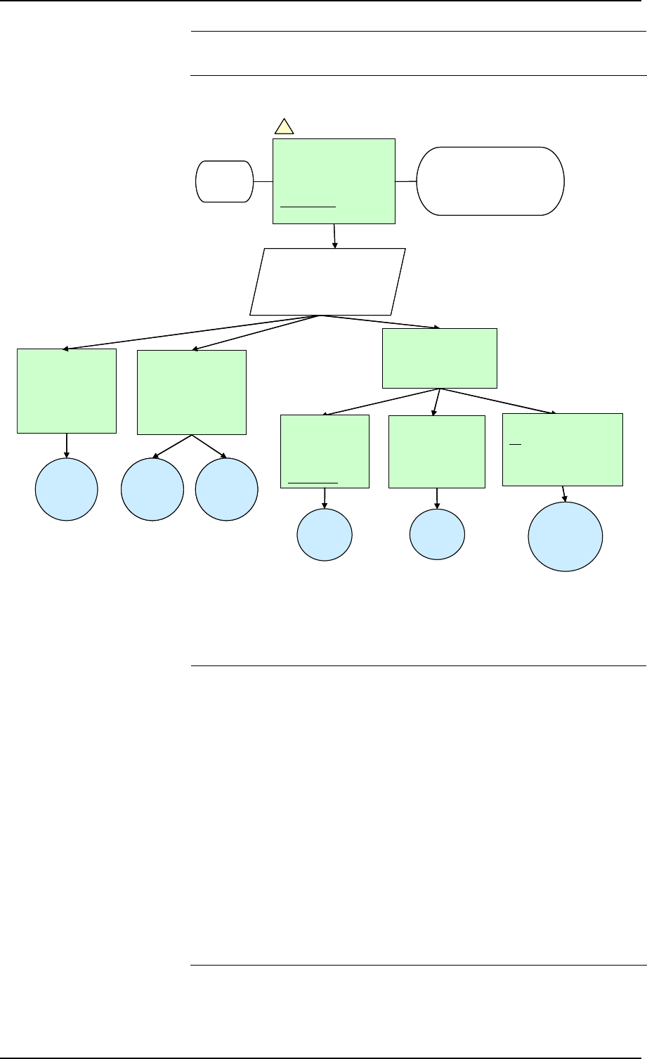
Chapter 5 Safety Case Development Manual
Page 40 Released Issue Edition: 2.2
The type of Evidence expected to be provided to support each
strand of the Argument is also shown in Figure 4.
Safety
Requirements for
function &
performance are
adequately specified
Arg 1.2.2
Logical
Architecture
described
completely and
correctly
Arg 1.2.1
Architectural
Model
SAM PSSA
Ch 1, 2.1 &
2.2
FSRs &
Traceability
SAM PSSA
Ch 3, 3.1,
Ch 5, 3.2
Simulations
etc
Safety Requirements
for integrity are
adequately specified
Arg 1.2.3
Fig 2
Safety Requirements
specify what is
sufficient at
architectural level to
meet Safety Objectives
Arg 1.2
C005
Scope encompasses
airspace, equipment, people,
procedures and training
C004
PSSA
Hazard causes
identified &
modelled
adequately
Arg 1.2.3.1
Fault Trees
SAM PSSA
Ch 3, 3.2, Part
IV GMK
Safety Integrity
Requirements
set to satisfy
Safety Objectives
Arg 1.2.3.2
SRs
SAM PSSA
Ch 3, 3.4,
Ch 4, 3.1
All causal mitigations
captured as Safety
Requirements or
Assumptions
Arg 1.2.3.3
Mitigations
and
Assumptions
SAM PSSA
Ch 3, 3.3 & 4
St007
Derive Safety Requirements
For “success” and “failure”
approaches
Safety
Requirements for
function &
performance are
adequately specified
Arg 1.2.2
Logical
Architecture
described
completely and
correctly
Arg 1.2.1
Architectural
Model
SAM PSSA
Ch 1, 2.1 &
2.2
FSRs &
Traceability
SAM PSSA
Ch 3, 3.1,
Ch 5, 3.2
FSRs &
Traceability
SAM PSSA
Ch 3, 3.1,
Ch 5, 3.2
Simulations
etc
Simulations
etc
Safety Requirements
for integrity are
adequately specified
Arg 1.2.3
Safety Requirements
for integrity are
adequately specified
Arg 1.2.3
Fig 2
Safety Requirements
specify what is
sufficient at
architectural level to
meet Safety Objectives
Arg 1.2
Fig 2Fig 2
Safety Requirements
specify what is
sufficient at
architectural level to
meet Safety Objectives
Arg 1.2
C005
Scope encompasses
airspace, equipment, people,
procedures and training
C004
PSSA
Hazard causes
identified &
modelled
adequately
Arg 1.2.3.1
Hazard causes
identified &
modelled
adequately
Arg 1.2.3.1
Fault Trees
SAM PSSA
Ch 3, 3.2, Part
IV GMK
Safety Integrity
Requirements
set to satisfy
Safety Objectives
Arg 1.2.3.2
Safety Integrity
Requirements
set to satisfy
Safety Objectives
Arg 1.2.3.2
SRs
SAM PSSA
Ch 3, 3.4,
Ch 4, 3.1
All causal mitigations
captured as Safety
Requirements or
Assumptions
Arg 1.2.3.3
Mitigations
and
Assumptions
SAM PSSA
Ch 3, 3.3 & 4
St007
Derive Safety Requirements
For “success” and “failure”
approaches
Figure 4 – Arg 1.2: Safety Requirements
Arg 1.3 (see Figure 5 below) presents the Argument and
Evidence that the qualitative Safety Criteria have been satisfied
via the processes that led to the Safety Requirements for
Change SGxy.
The difficulty with Arg 1.3.1 is that most changes in ATM involve
some inherent risk because the service in general needs to
respond to an ever increasing demand on its capacity to deliver.
Therefore, it is necessary to find safety benefits – in the form of
removal or mitigation of areas of risk – to offset the inherent risk
of change. In most cases the relative Argument involved has to
be made on the basis of qualitative Evidence.
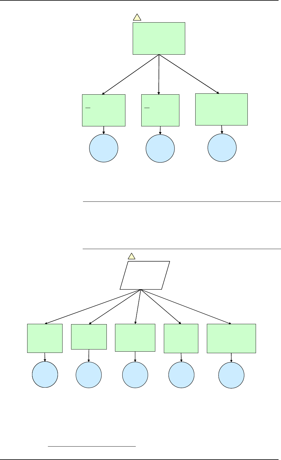
Safety Case Development Manual GSN Safety Argument Examples
Edition: 2.2 Released Issue Page 41
All practicable
mitigations of
cause identified
in PSSA
Arg 1.3.2
All practicable
mitigations of
consequence
identified in FHA
Arg 1.3.1 Safety Requirements
specified to reduce
risk as far as
reasonably practicable
Arg 1.3.3
Process
evidence
SAM PSSA
Ch 3, 3.3
Risks have been
minimised in the
process of deriving the
Safety Requirements
Arg 1.3
Fig 2
Process
evidence
SAM PSSA
Ch 3, 3.3
Process
evidence
SAM FHA Ch 3,
PSSA Ch 3
All practicable
mitigations of
cause identified
in PSSA
Arg 1.3.2
All practicable
mitigations of
consequence
identified in FHA
Arg 1.3.1 Safety Requirements
specified to reduce
risk as far as
reasonably practicable
Arg 1.3.3
Safety Requirements
specified to reduce
risk as far as
reasonably practicable
Arg 1.3.3
Process
evidence
SAM PSSA
Ch 3, 3.3
Risks have been
minimised in the
process of deriving the
Safety Requirements
Arg 1.3
Risks have been
minimised in the
process of deriving the
Safety Requirements
Arg 1.3
Fig 2Fig 2
Process
evidence
SAM PSSA
Ch 3, 3.3
Process
evidence
SAM FHA Ch 3,
PSSA Ch 3
Figure 5 – Arg 1.3: Satisfaction of Qualitative Safety Criteria
The Arguments and Evidence for Arg 1.3.3 are intended to
show that a (properly conducted) FHA and PSSA Stage 1 will
yield safety requirements that, when implemented, will result in
a risk that has been reduced as far as reasonably practicable, at
that stage
27
.
.
Concept of Ops
and simulations
done by
competent staff
Arg 1.4 FHA & PSSA
processes
were executed
by competent staff
Arg 1.6
Competence
evidence
FHA & PSSA
processes
were adequate
Arg 1.5
Process
evidence
SAM FHA, Ch 4
GMA-B-C, 3.3
PSSA, Ch 4 GM A-
B-C, 3.3
Competence
evidence
SAM FHA, Ch2,
PSSA, Ch 4
St006
Show that Safety
Requirements
evidence is
trustworthy
Fig 2
Architectural
model was
done by
competent staff
Arg 1.7
FHA and PSSA
processes comply with
qualitative requirements
of ESARR 4
Arg 1.8
Competence
evidence
SAM PSSA
Ch2
Competence
evidence Process
evidence
GM for SAM,
Annex B
.
Concept of Ops
and simulations
done by
competent staff
Arg 1.4 FHA & PSSA
processes
were executed
by competent staff
Arg 1.6
Competence
evidence
Competence
evidence
FHA & PSSA
processes
were adequate
Arg 1.5
Process
evidence
SAM FHA, Ch 4
GMA-B-C, 3.3
PSSA, Ch 4 GM A-
B-C, 3.3
Competence
evidence
SAM FHA, Ch2,
PSSA, Ch 4
St006
Show that Safety
Requirements
evidence is
trustworthy
Fig 2
St006
Show that Safety
Requirements
evidence is
trustworthy
St006
Show that Safety
Requirements
evidence is
trustworthy
St006
Show that Safety
Requirements
evidence is
trustworthy
Fig 2Fig 2
Architectural
model was
done by
competent staff
Arg 1.7
FHA and PSSA
processes comply with
qualitative requirements
of ESARR 4
Arg 1.8
Competence
evidence
SAM PSSA
Ch2
Competence
evidence
SAM PSSA
Ch2
Competence
evidence
Competence
evidence Process
evidence
GM for SAM,
Annex B
Process
evidence
GM for SAM,
Annex B
Figure 6 – St0006: Safety of the Concept (Backing)
27
The reduction of risk as far as reasonably practicable is further covered in
Arg 3
below
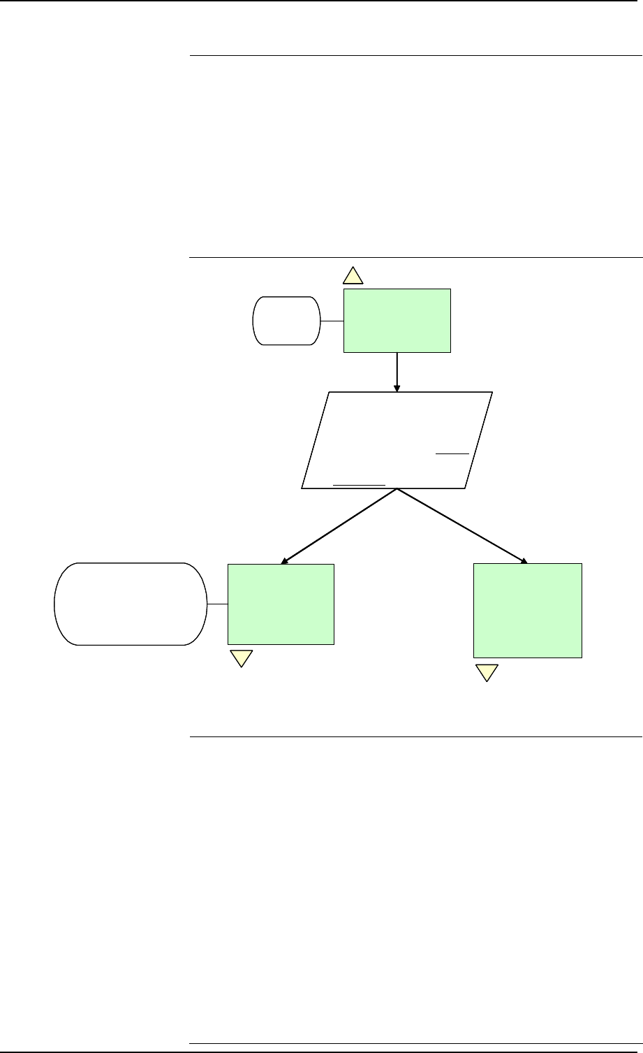
Chapter 5 Safety Case Development Manual
Page 42 Released Issue Edition: 2.2
Arg 2
As with most Backing Evidence, St0006, in Figure 6 above, is
based on arguing the adequacy of the processes (including
techniques and tools) involved and on the competence of the
personnel who executed those processes. In practice, some of
the Arguments may need to be decomposed to a lower level of
detail than shown in this example.
Figure 7 below addresses the Implementation of Change SGxy,
in two stages: physical-level design and realisation of the design
in the physical system – these are further decomposed below in
Figure 8 and Figure 9 respectively.
St004
Show that the Safety
Requirements are satisfied:
1. Initially in system design
2. Subsequently in the
realisation of that design
Fig 1
Change_SGxy
Implementation
is acceptably safe
Arg 2
C008
SSA
Physical-level
design satisfies
the related Safety
Requirements
Arg 2.1
Fig 8
Realisation of the
physical-level
design satisfies
the related Safety
Requirements
Arg 2.2
Fig 9
C009
May include further level(s)
of Safety Requirement
derivation
St004
Show that the Safety
Requirements are satisfied:
1. Initially in system design
2. Subsequently in the
realisation of that design
St004
Show that the Safety
Requirements are satisfied:
1. Initially in system design
2. Subsequently in the
realisation of that design
St004
Show that the Safety
Requirements are satisfied:
1. Initially in system design
2. Subsequently in the
realisation of that design
Fig 1
Change_SGxy
Implementation
is acceptably safe
Arg 2
Fig 1Fig 1
Change_SGxy
Implementation
is acceptably safe
Arg 2
Change_SGxy
Implementation
is acceptably safe
Arg 2
C008
SSA
Physical-level
design satisfies
the related Safety
Requirements
Arg 2.1
Fig 8
Physical-level
design satisfies
the related Safety
Requirements
Arg 2.1
Fig 8Fig 8
Realisation of the
physical-level
design satisfies
the related Safety
Requirements
Arg 2.2
Fig 9
Realisation of the
physical-level
design satisfies
the related Safety
Requirements
Arg 2.2
Fig 9Fig 9
C009
May include further level(s)
of Safety Requirement
derivation
Figure 7 – Arg 2: Safety of Implementation
In this example, Arg2 is decomposed only far enough to show
the elements of the ATM system that might be involved.
For the Implementation of Airspace Design, ATC Procedures
and Operational Training, most of the Evidence of compliance
with the Safety Requirements comes at the Design stage – ie
under Arg 2.1.
For the Implementation of the Equipment aspects, the Evidence
of compliance with the Safety Requirements should also come
from the Design stage – ie under Arg 2.1 – but should be further
substantially supported by testing in the subsequent Realisation
stage – ie under Arg 2.2.
The decomposition of Arg 2.1 would need to include Backing
assurance covering the adequacy of the processes, tools and
techniques employed in the design and realisation, and of the
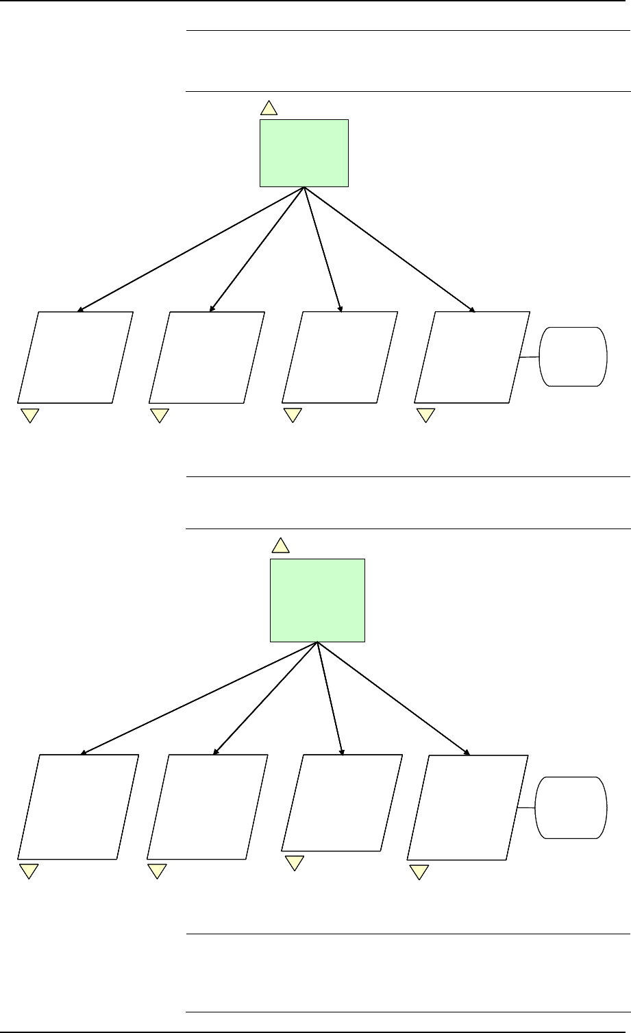
Safety Case Development Manual GSN Safety Argument Examples
Edition: 2.2 Released Issue Page 43
competence of the personnel involved. Full use should be
made of existing operational and engineering procedures in the
organisation’s quality and safety management systems.
Physical-level
design satisfies
the related Safety
Requirements
Arg 2.1
Fig 7
C010
Changes to
hardware and
software
Provide direct
and backing that
Airspace
design satisfies
the related Safety
Requirements
St008
Fig [....]
Provide direct
and backing that
ATC Procedure
design satisfies
the related Safety
Requirements
St009
Fig [....]
Provide direct
and backing that
ATC Training
design satisfies
the related Safety
Requirements
St010
Fig [....]
Provide direct
and backing that
ATC Equipment
design satisfies
the related Safety
Requirements
St011
Fig [....]
Physical-level
design satisfies
the related Safety
Requirements
Arg 2.1
Fig 7Fig 7
C010
Changes to
hardware and
software
Provide direct
and backing that
Airspace
design satisfies
the related Safety
Requirements
St008
Fig [....]
Provide direct
and backing that
Airspace
design satisfies
the related Safety
Requirements
St008
Fig [....]Fig [....]
Provide direct
and backing that
ATC Procedure
design satisfies
the related Safety
Requirements
St009
Fig [....]
Provide direct
and backing that
ATC Procedure
design satisfies
the related Safety
Requirements
St009
Fig [....]Fig [....]
Provide direct
and backing that
ATC Training
design satisfies
the related Safety
Requirements
St010
Fig [....]
Provide direct
and backing that
ATC Training
design satisfies
the related Safety
Requirements
St010
Fig [....]Fig [....]
Provide direct
and backing that
ATC Equipment
design satisfies
the related Safety
Requirements
St011
Fig [....]
Provide direct
and backing that
ATC Equipment
design satisfies
the related Safety
Requirements
St011
Fig [....]Fig [....]
Figure 8 – Arg 2.1: Safety of Design
The decomposition of Arg 2.2 mirrors that for Arg 2.1 above
and is shown in Figure 9.
Realisation of the
physical-level
design satisfies
the related Safety
Requirements
Arg 2.2
Fig 7
C011
Changes to
hardware and
software
Fig [....]
Provide direct
and backing that
the promulgation
of Airspace
changes satisfies
the related Safety
Requirements
St012
Fig [....]
Provide direct
and backing that
ATC Procedure
publication
satisfies the
related Safety
Requirements
St013
Fig [....]
Provide direct
and backing that
ATC Equipment
changes satisfy
the related Safety
Requirements
St015
Fig [....]
Provide direct
and backing that
ATC Training
delivery satisfies
the related Safety
Requirements
St014
Realisation of the
physical-level
design satisfies
the related Safety
Requirements
Arg 2.2
Fig 7
Realisation of the
physical-level
design satisfies
the related Safety
Requirements
Arg 2.2
Realisation of the
physical-level
design satisfies
the related Safety
Requirements
Arg 2.2
Fig 7Fig 7
C011
Changes to
hardware and
software
Fig [....]
Provide direct
and backing that
the promulgation
of Airspace
changes satisfies
the related Safety
Requirements
St012
Fig [....]Fig [....]
Provide direct
and backing that
the promulgation
of Airspace
changes satisfies
the related Safety
Requirements
St012
Provide direct
and backing that
the promulgation
of Airspace
changes satisfies
the related Safety
Requirements
St012
Fig [....]Fig [....]
Provide direct
and backing that
ATC Procedure
publication
satisfies the
related Safety
Requirements
St013
Provide direct
and backing that
ATC Procedure
publication
satisfies the
related Safety
Requirements
St013
Fig [....]
Provide direct
and backing that
ATC Equipment
changes satisfy
the related Safety
Requirements
St015
Fig [....]Fig [....]
Provide direct
and backing that
ATC Equipment
changes satisfy
the related Safety
Requirements
St015
Provide direct
and backing that
ATC Equipment
changes satisfy
the related Safety
Requirements
St015
Fig [....]
Provide direct
and backing that
ATC Training
delivery satisfies
the related Safety
Requirements
St014
Fig [....]Fig [....]
Provide direct
and backing that
ATC Training
delivery satisfies
the related Safety
Requirements
St014
Provide direct
and backing that
ATC Training
delivery satisfies
the related Safety
Requirements
St014
Figure 9 – Arg 2.2: Safety of Realisation
In the case of equipment aspects of Realisation, most of the
Evidence will come from analysis and testing. The Backing for
this is not decomposed herein but should address the V&V
requirements covered in Chapter 4, section 6 above.
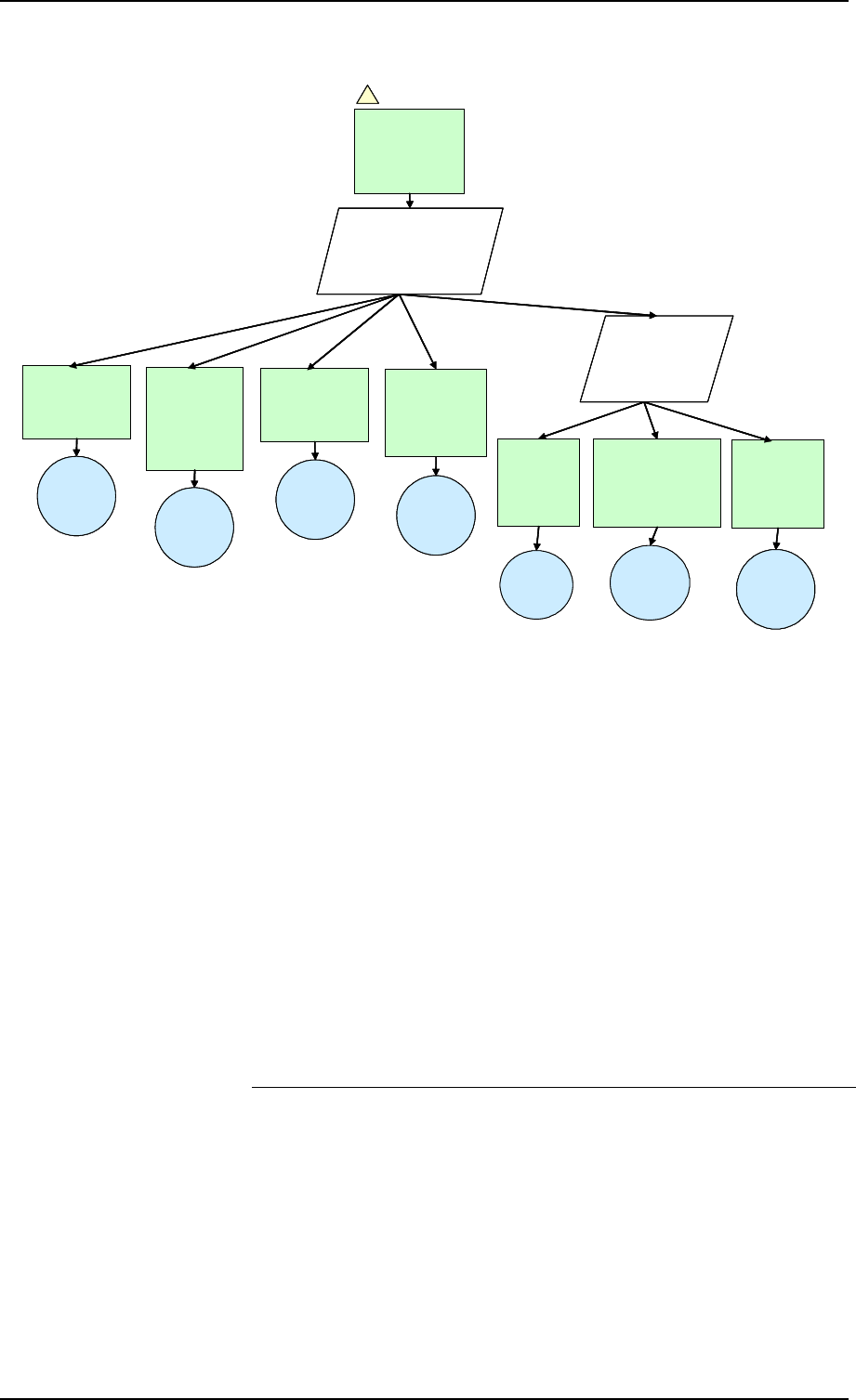
Chapter 5 Safety Case Development Manual
Page 44 Released Issue Edition: 2.2
St004
Show that risk during
(and immediately
following) Migration will
satisfy Cr001 item 2
Detailed plan
for Migration
produced
Arg 3.1
H&RA
results
SAM SSA
Ch 3, 3.2.1
Migration
Plan
Fig 1
Migration to
Change_SGxy
will be
acceptably safe
Arg 3
Hazards and
Risks for
Switchover
identified and
analysed
Arg 3.2
Measures put in
place to control
/ mitigate risks
Arg 3.3
Contingency
plan prepared,
for reversion to
safe state
Arg 3.4
St016
Show that
Migration
evidence is
trustworthy
Risk-
reduction
measures
SAM SSA
Ch 3, 3.2.2
Contingency
Plan
SAM SSA
Ch 3, 3.2.1
H&R
process
adequate
for the task
Arg 3.5
Plans and risk-
reduction measures
independently
validated
Arg 3.6
Contingency
Plan
SAM SSA
Ch 4 GM A-B-C
Planning and
analysis staff
were
competent
Arg 3.7
Competence
evidence
SAM SSA
Ch2
Risk-
reduction
measures
SAM SSA
Ch 4 GM A-B-C
St004
Show that risk during
(and immediately
following) Migration will
satisfy Cr001 item 2
St004
Show that risk during
(and immediately
following) Migration will
satisfy Cr001 item 2
St004
Show that risk during
(and immediately
following) Migration will
satisfy Cr001 item 2
Detailed plan
for Migration
produced
Arg 3.1
Detailed plan
for Migration
produced
Arg 3.1
H&RA
results
SAM SSA
Ch 3, 3.2.1
H&RA
results
SAM SSA
Ch 3, 3.2.1
Migration
Plan
Migration
Plan
Fig 1
Migration to
Change_SGxy
will be
acceptably safe
Arg 3
Fig 1Fig 1
Migration to
Change_SGxy
will be
acceptably safe
Arg 3
Migration to
Change_SGxy
will be
acceptably safe
Arg 3
Hazards and
Risks for
Switchover
identified and
analysed
Arg 3.2
Hazards and
Risks for
Switchover
identified and
analysed
Arg 3.2
Measures put in
place to control
/ mitigate risks
Arg 3.3
Measures put in
place to control
/ mitigate risks
Arg 3.3
Contingency
plan prepared,
for reversion to
safe state
Arg 3.4
Contingency
plan prepared,
for reversion to
safe state
Arg 3.4
St016
Show that
Migration
evidence is
trustworthy
St016
Show that
Migration
evidence is
trustworthy
St016
Show that
Migration
evidence is
trustworthy
Risk-
reduction
measures
SAM SSA
Ch 3, 3.2.2
Risk-
reduction
measures
SAM SSA
Ch 3, 3.2.2
Contingency
Plan
SAM SSA
Ch 3, 3.2.1
Contingency
Plan
SAM SSA
Ch 3, 3.2.1
H&R
process
adequate
for the task
Arg 3.5
H&R
process
adequate
for the task
Arg 3.5
Plans and risk-
reduction measures
independently
validated
Arg 3.6
Plans and risk-
reduction measures
independently
validated
Arg 3.6
Contingency
Plan
SAM SSA
Ch 4 GM A-B-C
Planning and
analysis staff
were
competent
Arg 3.7
Planning and
analysis staff
were
competent
Arg 3.7
Competence
evidence
SAM SSA
Ch2
Competence
evidence
SAM SSA
Ch2
Risk-
reduction
measures
SAM SSA
Ch 4 GM A-B-C
Figure 10 – Arg 3: Safety during Migration
Arg 3
Clearly, in introducing a substantial change (or new system) the
safety of the existing ATM service must be preserved during the
period of Migration form the pre-change to post-change state.
Figure 10 shows a typical decomposition of the Argument, with
supporting Evidence, covering both the Direct and Backing
aspects.
Arg 4
Arg 4 in effect recognises that Evidence provided under Arg 1
to Arg 3 is necessarily predictive in nature and needs to be
confirmed by Evidence of what is actually achieved in practice,
from a safety perspective.
This is illustrated in the decomposition of Arg 4, in Figure 11.
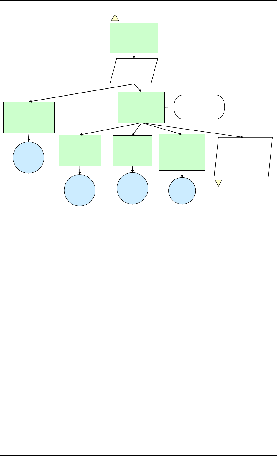
Safety Case Development Manual GSN Safety Argument Examples
Edition: 2.2 Released Issue Page 45
On-going Operation
of Change_SGxy will
be shown to be
acceptably safe
Arg 4
Fig 1
St005
Safety Monitoring
will satisfy Cr001
items 1 and 2
Arg 4.1
Frequency of (service-
level) incidents will be
measured against pre-
defined indicators
Arg 4.2
Corrective actions
will be taken to
prevent recurrence
of incidents
Arg 4.2.2
All reported
incidents will be
investigated
Arg 4.2.3
Corrective actions
will be taken based
on the results of an
incident
investigation
Investigation
process
SAM SSA
Ch 3, 3.3.1
Arg 4.2.1
There is a process
for encouraging
the reporting of
safety incidents
Reporting
process
SAM SSA
Ch 3, 3.3.1
C012
Required for compliance
with Cr001, item 2
St008
Develop Backing
Argument and Evidence
regarding the
effectiveness of the
reporting, investigation
and C/A processes
Fig [….]
Monitoring
process
SAM SSA
Ch 3, 3.3.1 C/A
process
SAM SSA
Ch 3, 3.3.2
On-going Operation
of Change_SGxy will
be shown to be
acceptably safe
Arg 4
Fig 1Fig 1
St005
Safety Monitoring
will satisfy Cr001
items 1 and 2
St005
Safety Monitoring
will satisfy Cr001
items 1 and 2
St005
Safety Monitoring
will satisfy Cr001
items 1 and 2
Arg 4.1
Frequency of (service-
level) incidents will be
measured against pre-
defined indicators
Arg 4.2
Corrective actions
will be taken to
prevent recurrence
of incidents
Arg 4.2.2
All reported
incidents will be
investigated
Arg 4.2.3
Corrective actions
will be taken based
on the results of an
incident
investigation
Investigation
process
SAM SSA
Ch 3, 3.3.1
Arg 4.2.1
There is a process
for encouraging
the reporting of
safety incidents
Reporting
process
SAM SSA
Ch 3, 3.3.1
C012
Required for compliance
with Cr001, item 2
St008
Develop Backing
Argument and Evidence
regarding the
effectiveness of the
reporting, investigation
and C/A processes
St008
Develop Backing
Argument and Evidence
regarding the
effectiveness of the
reporting, investigation
and C/A processes
Fig [….]Fig [….]
Monitoring
process
SAM SSA
Ch 3, 3.3.1 C/A
process
SAM SSA
Ch 3, 3.3.2
Figure 11 – Arg 4: Safety Monitoring
2. Example Application of GSN – Unit Safety Cases
Claim
Unit Safety Case is a commonly used term for the Safety Case
for an on-going operational service. Figure 12 below shows the
high-level Safety Argument for this example application of GSN,
for a hypothetical ATSU.
Arg 0 is the overall Claim, equivalent to that for Change “SGxy”
in Figure 1 above. C001 defines the type(s) of service provided
and C002 is a reminder that the full operational environment –
eg airspace boundaries, structure, classification, rules,
separation minima etc – needs to be fully described in order to
define the Context in which the Claim is being made.
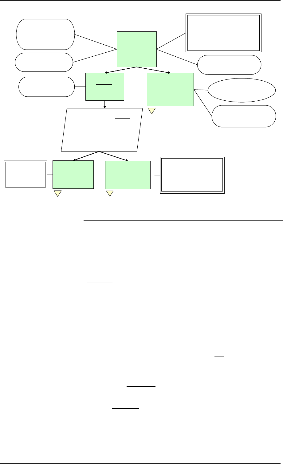
Chapter 5 Safety Case Development Manual
Page 46 Released Issue Edition: 2.2
Arg 0
ATM services
provided by
<<ATSU>> are,
and will remain,
acceptably safe
Arg 2
Any changes to the
ATM System are made
such that the ATM
services will remain
acceptably safe
Arg 1.1
Safety Assessment
shows that the
ATM Services are
acceptably safe
Arg 1
The on-going ATM
Services are
acceptably safe
J001
ATM services are provided by
the ATM system
C001
ATM services comprise eg:
Airspace Management;
ATC Service;
Alerting; and Advisory Service
C002
Operational Environment
Cr001
Acceptably Safe defined as:
The risks of an accident or safety-related
incident:
1 achieve a tolerable level and
2 have been reduced As Far As
Reasonably Practicable (AFARP)
C003
Subject to declared Assumptions,
Limitations and outstanding Issues
Fig 13
Arg 1.2
Safety Monitoring &
Improvement shows
that the ATM Services
are acceptably safe
Fig 14 C005
System includes: airspace,
equipment, people and procedures
and the organisation
C004
For the extant configuration of
the ATM services and system
St001
Decomposition based on two dissimilar
approaches:
1 A proactive, analytical approach based on
inductive Safety Assessment techniques
2 A reactive, empirical approach based on
direct measurement of safety achievement
through in-service Safety Incident
Monitoring and Safety Improvement
Cr003
Tolerable level of risk defined
by Safety Indicators for ESARR
2-defined incidents, based on
historical achievement /
accepted tolerability
Cr002
Tolerable level of risk
defined by ESARR
4-compliant Safety
Targets
Fig [….]
Arg 0
ATM services
provided by
<<ATSU>> are,
and will remain,
acceptably safe
Arg 2
Any changes to the
ATM System are made
such that the ATM
services will remain
acceptably safe
Arg 1.1
Safety Assessment
shows that the
ATM Services are
acceptably safe
Arg 1
The on-going ATM
Services are
acceptably safe
J001
ATM services are provided by
the ATM system
C001
ATM services comprise eg:
Airspace Management;
ATC Service;
Alerting; and Advisory Service
C002
Operational Environment
Cr001
Acceptably Safe defined as:
The risks of an accident or safety-related
incident:
1 achieve a tolerable level and
2 have been reduced As Far As
Reasonably Practicable (AFARP)
C003
Subject to declared Assumptions,
Limitations and outstanding Issues
Fig 13Fig 13
Arg 1.2
Safety Monitoring &
Improvement shows
that the ATM Services
are acceptably safe
Fig 14Fig 14 C005
System includes: airspace,
equipment, people and procedures
and the organisation
C004
For the extant configuration of
the ATM services and system
St001
Decomposition based on two dissimilar
approaches:
1 A proactive, analytical approach based on
inductive Safety Assessment techniques
2 A reactive, empirical approach based on
direct measurement of safety achievement
through in-service Safety Incident
Monitoring and Safety Improvement
St001
Decomposition based on two dissimilar
approaches:
1 A proactive, analytical approach based on
inductive Safety Assessment techniques
2 A reactive, empirical approach based on
direct measurement of safety achievement
through in-service Safety Incident
Monitoring and Safety Improvement
Cr003
Tolerable level of risk defined
by Safety Indicators for ESARR
2-defined incidents, based on
historical achievement /
accepted tolerability
Cr003
Tolerable level of risk defined
by Safety Indicators for ESARR
2-defined incidents, based on
historical achievement /
accepted tolerability
Cr002
Tolerable level of risk
defined by ESARR
4-compliant Safety
Targets
Cr002
Tolerable level of risk
defined by ESARR
4-compliant Safety
Targets
Fig [….]Fig [….]
Figure 12 –: Overall Safety Argument for a Unit Safety Case
Arg 1
Arg 1.1
C003 is a reminder that the eventual conclusion of the Safety
Case will probably be subject to certain Assumptions and
outstanding Issues that need to be addressed and possibly to
some Limitations on the ATM service(s).
The definition of what is acceptably safe is captured in Cr001,–
note that item 1 (as elaborated in Cr002 and Cr003) is an
absolute measure, as is appropriate to an on-going service.
The Claim (Arg 0) is decomposed into two principal Safety
Arguments (Arg 1 and Arg 2) that, in effect, the services are
safe “today” (ie for the current system baseline – C004 refers)
and will remain so because any changes to the baseline will be
managed so as to maintain the safety of the services.
The decomposition of Arg 1 is very similar to that for “Change
SGxy” but, generally, on a much larger scale; in other words,
this part of the Unit Safety Case (although not related to
change) treats the Unit as a large ATM system for which:
• Safety Requirements (for the system) are derived and
satisfied in a predictive Safety Assessment (Arg 1.1);
• actual safety achievement is monitored and improved
through empirical Safety Monitoring (Arg 1.2).
Arg 1.1 is not decomposed further herein but should follow a
similar pattern to the equivalent Argument for Change “SGxy”
except that the underlying FHA, PSSA and SSA activities
should be carried out for the ATSU as a whole.

Safety Case Development Manual GSN Safety Argument Examples
Edition: 2.2 Released Issue Page 47
Arg 1.2 The decomposition of Arg 1.2 , shown in Figure 13 below, is
the equivalent to that for Arg 4 for “Change SGxy” shown in
Figure 11 above, except that the context for the former is the
“present” time, rather than the future.
Arg 1.2.1
ATM Services achieve
tolerable frequencies
of (service-level)
incidents
Arg 1.2.2
Corrective actions
are effective in
preventing
recurrence of
incidents
Fig 12
C006
Based on what is actually
achieved in operational
service
Arg 1.2.2.2
All reported
safety incidents
are investigated
effectively
Arg 1.2.2.3
Recommendations for
corrective actions
from incident
investigations are
implemented
throughout the ATSU
Ref
Incident
Investiga
tion
Reports Ref
C/A
reports
Ref
Safety
Monitoring
Reports
Arg 1.2.2.1
There is a process
and culture for
encouraging the
reporting of safety
incidents
Ref
Reporting
process
C007
Required for compliance
with Cr001, item #2
St002
Develop Backing
Argument and Evidence
regarding the
effectiveness of the
reporting, investigation
and C/A processes and
competence of the staff
involved
Fig [….]
Arg 1.2
Safety Monitoring &
Improvement shows
that the ATM Services
are acceptably safe
Arg 1.2.1
ATM Services achieve
tolerable frequencies
of (service-level)
incidents
Arg 1.2.2
Corrective actions
are effective in
preventing
recurrence of
incidents
Fig 12Fig 12
C006
Based on what is actually
achieved in operational
service
Arg 1.2.2.2
All reported
safety incidents
are investigated
effectively
Arg 1.2.2.3
Recommendations for
corrective actions
from incident
investigations are
implemented
throughout the ATSU
Ref
Incident
Investiga
tion
Reports Ref
C/A
reports
Ref
Safety
Monitoring
Reports
Arg 1.2.2.1
There is a process
and culture for
encouraging the
reporting of safety
incidents
Ref
Reporting
process
C007
Required for compliance
with Cr001, item #2
St002
Develop Backing
Argument and Evidence
regarding the
effectiveness of the
reporting, investigation
and C/A processes and
competence of the staff
involved
St002
Develop Backing
Argument and Evidence
regarding the
effectiveness of the
reporting, investigation
and C/A processes and
competence of the staff
involved
Fig [….]Fig [….]
Arg 1.2
Safety Monitoring &
Improvement shows
that the ATM Services
are acceptably safe
Figure 13 – Safety Monitoring and Improvement
Arg 2 For most Unit Safety Cases the system baseline is not fixed but
is updated periodically by Project Safety Cases produced for
significant changes – eg Change SGxy above.
Arg 2, decomposed in part in Figure 14 below is concerned
with showing that all the necessary processes are in place (and
are properly executed) to ensure that such changes are
managed safely in terms of the on-going service – both during
the period of introducing the change (”Migration”) and in the
subsequent in-service period.
Note that this is one of the few situations that processes are
used as Direct Evidence. Adherence to those same processes
would be used as Backing Evidence in the related Project
Safety Cases.
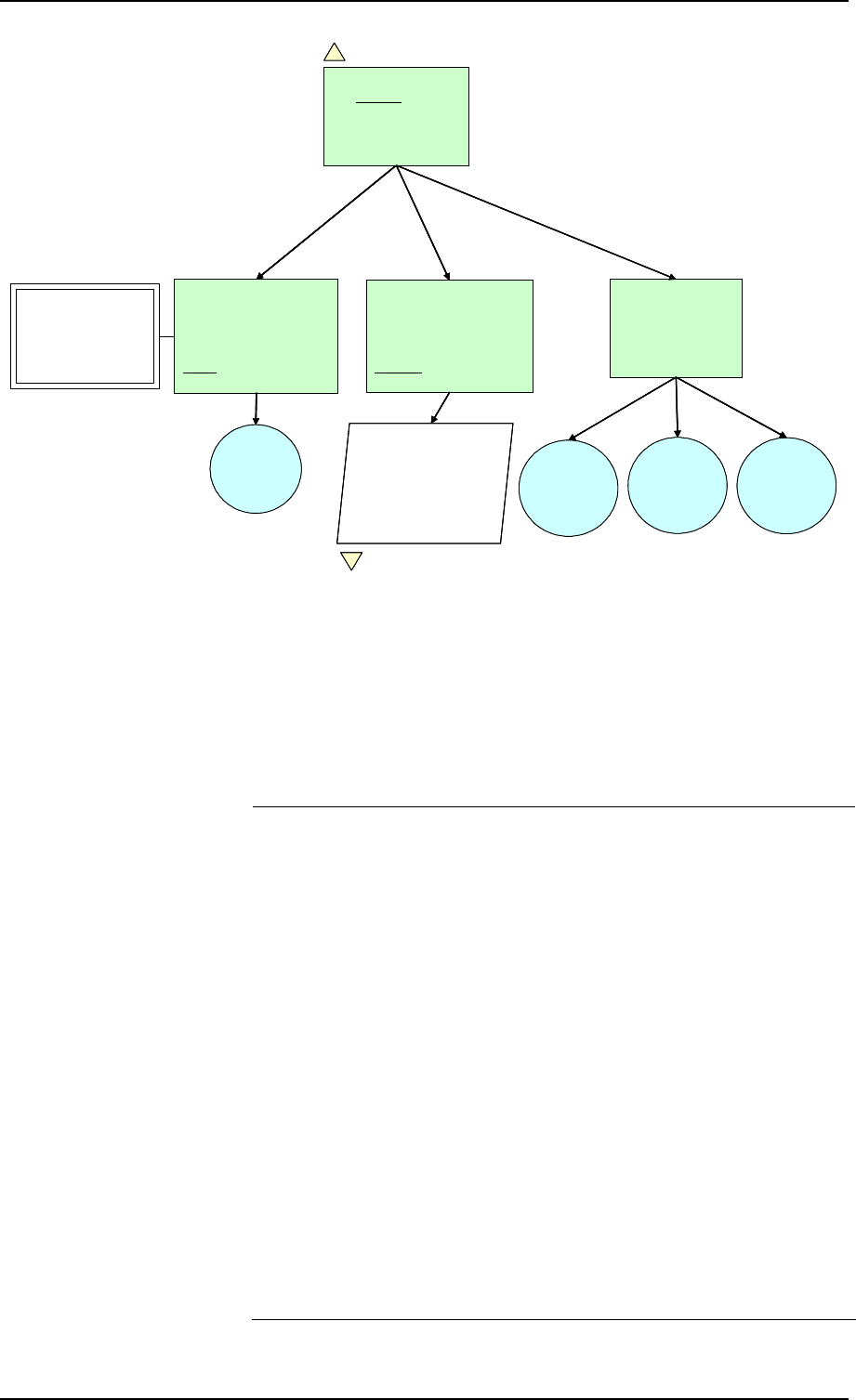
Chapter 5 Safety Case Development Manual
Page 48 Released Issue Edition: 2.2
Arg 2
Any changes to the
ATM System are made
such that the ATM
services will remain
acceptably safe
Fig 12
Arg 2.1
Processes exist to ensure
that changes are made
such that the ATM services
will remain acceptably safe
during migration to the
new system configuration
Cr004
Acceptably safe during
migration defined as:
Risks from migration
have been reduced
AFARP
Arg 2.2
Processes exist to ensure
that changes are made
such that the ATM services
will remain acceptably safe
following migration to the
new system configuration
Ref
Process
Evidence
Arg 2.3
Changes to system
baseline
configuration have
been implemented
correctly
Ref
Other
Change-
acceptance
records
Ref
Project
Safety
Cases
Ref
Safety-audit
records
St003
Decompose to levels
necessary to demonstrate
the effectiveness all SMS
Operational, Engineering
and Mgt processes that are
relevant to the execution of
change
Fig [….]
Arg 2
Any changes to the
ATM System are made
such that the ATM
services will remain
acceptably safe
Fig 12Fig 12
Arg 2.1
Processes exist to ensure
that changes are made
such that the ATM services
will remain acceptably safe
during migration to the
new system configuration
Cr004
Acceptably safe during
migration defined as:
Risks from migration
have been reduced
AFARP
Cr004
Acceptably safe during
migration defined as:
Risks from migration
have been reduced
AFARP
Arg 2.2
Processes exist to ensure
that changes are made
such that the ATM services
will remain acceptably safe
following migration to the
new system configuration
Ref
Process
Evidence
Arg 2.3
Changes to system
baseline
configuration have
been implemented
correctly
Ref
Other
Change-
acceptance
records
Ref
Project
Safety
Cases
Ref
Safety-audit
records
St003
Decompose to levels
necessary to demonstrate
the effectiveness all SMS
Operational, Engineering
and Mgt processes that are
relevant to the execution of
change
St003
Decompose to levels
necessary to demonstrate
the effectiveness all SMS
Operational, Engineering
and Mgt processes that are
relevant to the execution of
change
Fig [….]Fig [….]
Figure 14 – Change Management
3. Example Application of GSN – Preliminary Safety Cases
Preliminary (or Outline) Safety Case is a term used in
EUROCONTROL for the Safety Case that it restricted in both
scope and responsibility. It is particularly applicable to EATM
programmes since EUROCONTROL’s responsibility is usually
restricted to proving the concept behind a change (or new
system) – ie to proving that the service / system will be safe in
principle.
Figure 15 below shows the high-level Safety Argument for this
example application of GSN. The further decomposition and
accompanying commentary is limited to illustrating the main
differences between a full Project Safety Case (eg Change
“SGxy” above) and the equivalent Preliminary Safety Cases.
Figure 15 is the same as Figure 1 above, except as follows:
• A new Argument (Arg 2) has been introduced, and forms an
important bridge between the Preliminary Safety Case (of
which it is a part) and the subsequent Implementation safety
case / safety approval.
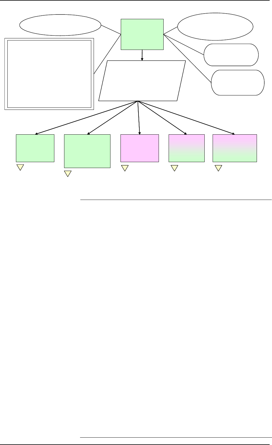
Safety Case Development Manual GSN Safety Argument Examples
Edition: 2.2 Released Issue Page 49
Change_SGxy will
be acceptably safe
in operational
service
Arg 0
St 001
Specify safety criteria for each of the
4 main life-cycle stages and show that
each stage is / will be acceptably safe
– ie the safety criteria are sufficient to
achieve the required level of safety,
and are satisfied
C001
Operational concept
(SAM-FHA ch1-GM A)
Change_SGxy
Implementation
is acceptably safe
Arg 3
Change_SGxy
Concept is
acceptably safe,
in principle
Arg 1
A001
Current ATM service
is accepted as being safe
J001
Change_SGxy is being
introduced to meet a
legitimate operational need
Cr001
The risk of an accident following
Change_SGxy shall be:
1.Within the regulatory requirements – eg:
a. such that the whole ATM service
meets ESARR 4 Design Safety
Targets (SAM-FHA ch3 GM E); OR
b. no greater (and preferably lower)
than currently exists.
AND
2. reduced as far as reasonably
practicable.
Migration to
Change_SGxy
will be
acceptably safe
Arg 4 On-going Operation
of Change_SGxy will
be shown to be
acceptably safe
Arg 5
Fig [….]
C002
Subject to declared
Assumptions, Limitations
and outstanding Issues
Sufficient Guidance
exists to enable
complete and correct
Implementation of the
Safety Requirements
Arg 2
Fig [….]
Fig [….] Fig [….] Fig [….]
Change_SGxy will
be acceptably safe
in operational
service
Arg 0
Change_SGxy will
be acceptably safe
in operational
service
Arg 0
St 001
Specify safety criteria for each of the
4 main life-cycle stages and show that
each stage is / will be acceptably safe
– ie the safety criteria are sufficient to
achieve the required level of safety,
and are satisfied
St 001
Specify safety criteria for each of the
4 main life-cycle stages and show that
each stage is / will be acceptably safe
– ie the safety criteria are sufficient to
achieve the required level of safety,
and are satisfied
C001
Operational concept
(SAM-FHA ch1-GM A)
Change_SGxy
Implementation
is acceptably safe
Arg 3
Change_SGxy
Implementation
is acceptably safe
Arg 3
Change_SGxy
Concept is
acceptably safe,
in principle
Arg 1
Change_SGxy
Concept is
acceptably safe,
in principle
Arg 1
A001
Current ATM service
is accepted as being safe
J001
Change_SGxy is being
introduced to meet a
legitimate operational need
Cr001
The risk of an accident following
Change_SGxy shall be:
1.Within the regulatory requirements – eg:
a. such that the whole ATM service
meets ESARR 4 Design Safety
Targets (SAM-FHA ch3 GM E); OR
b. no greater (and preferably lower)
than currently exists.
AND
2. reduced as far as reasonably
practicable.
Migration to
Change_SGxy
will be
acceptably safe
Arg 4
Migration to
Change_SGxy
will be
acceptably safe
Arg 4 On-going Operation
of Change_SGxy will
be shown to be
acceptably safe
Arg 5
On-going Operation
of Change_SGxy will
be shown to be
acceptably safe
Arg 5
Fig [….]Fig [….]
C002
Subject to declared
Assumptions, Limitations
and outstanding Issues
Sufficient Guidance
exists to enable
complete and correct
Implementation of the
Safety Requirements
Arg 2
Sufficient Guidance
exists to enable
complete and correct
Implementation of the
Safety Requirements
Arg 2
Fig [….]Fig [….]
Fig [….]Fig [….] Fig [….]Fig [….] Fig [….]Fig [….]
Figure 15 – Overall Safety Argument for Preliminary Safety Case
• The Guidance referred to in Arg 2 should include, but not be
limited to, the following:
o an amplification of the scope of the Preliminary Safety
Case – ie what is, and what is not included;
o a clear delineation of the responsibilities between
EUROCONTROL and the organisation(s) responsible for
Implementation;
o clear instructions for the Implementers concerning the
re-use / re-working of the safety assessment results
included in (or accompanying) the Preliminary Safety
Case – these should include a warning that the some of
the parameters on which the original safety assessment
were based may not be directly applicable to the context
in which the implementation is being done because of:
other changes that might have occurred during the time
elapsed between the Preliminary Safety Case and the
implementation, or differences between operational
context / environment assumed in the Preliminary Safety
Case and the local situation;
o clear instructions for the Implementers concerning the
re-use of any other information in the Preliminary Safety
Case; particular attention should be drawn to the Scope,
Operational Context, Assumptions, Issues and
Limitations and to the importance of these being
validated by the Implementer and the analysis reworked
as necessary;
o guidance on the additional safety assessment work
needed to cover the Implementation, Migration and

Chapter 5 Safety Case Development Manual
Page 50 Released Issue Edition: 2.2
Operational phases;
o guidance on how to develop the Preliminary Safety
Case into a full (Project) Safety Case.
• The responsibility for Arg 3 to Arg 5 (equivalent to Arg 2 to
Arg 4 in Figure 1) rests with the Implementer, although
some aspects of responsibility for Migration and on-going
Safety Monitoring (eg specification of requirements) may
rest with EUROCONTROL.

Safety Case Development Manual References
Edition: 2.2 Released Issue Page 51
APPENDIX A REFERENCES
EATM References
[1]
Air Traffic Management Strategy for the Years 2000+, EUROCONTROL
[2]
The EUR RVSM Pre-Implementation Safety Case, Edition 2.0, 14 August 2001
[3]
The EUR RVSM Post-Implementation Safety Case, Edition 2.0, 28 July 2004
[4]
EATMP Glossary, European Organisation for the Safety of Air Navigation (EATMP),
Edition 1.0, 1 August 2000
[5]
EUROCONTROL Air Navigation System Safety Assessment Methodology,
SAF.ET1.ST03.1000-MAN-01, Nov 2006, Edition: 2.1
SRC References
[6]
SRC-EATMP Interface Process, SRC DOC 6, Edition 2.0, Released Issue, 7th
November 2002
[7]
ESARR 2: Reporting and Assessment of Safety Occurrences in ATM, Edition 2.0,
Released Issue, 3rd November 2000.
[8]
ESARR 3: Use of Safety Management Systems by ATM Service Providers, Edition
1.0, Released Issue, 17th July 2000
[9]
ESARR 4: Risk Assessment and Mitigation in ATM, Edition 1.0, Released Issue, 5th
April 2001
[10]
ESARR 5: ATM Services’ Personnel, Edition 2.0, Released Issue, 11 April 2002
[11]
ESARR 6: Software in ATM Systems, Edition 1.0, Released Issue, 06 November
2003
ICAO References
[12]
Annex 11 to the Convention on International Civil Aviation, Air Traffic Control Service
Flight Information Service Alerting Service, Thirteenth Edition, July 2001
External References
[13]
Guidelines for CNS/ATM Systems Software Integrity Assurance, March 2002.
[14]
The Public Inquiry into the Piper Alpha Disaster, Volumes 1 & 2, November 1990,
HMSO Publications Centre ISBN 0-10-113102-X.
[15]
EUROCAE, ED-125, Process for Deriving Risk Classification Scheme and Specifying
Safety Objectives in ATM “in compliance” with ESARR 4, Version 6 (proposed issue).

Appendix A Safety Case Development Manual
Page 52 Released Issue Edition: 2.2
PAGE INTENTIONALLY LEFT BLANK

Safety Case Development Manual Glossary and Abbreviations
Edition: 2.2 Released Issue Page 53
APPENDIX B GLOSSARY AND ABBREVIATIONS
GLOSSARY
Accident An occurrence associated with the operation of an aircraft
which takes place between the time any person boards the
aircraft with the intention of flight until such time as all persons
have disembarked, in which a person is fatally or seriously
injured, the aircraft sustains damage or structural failure, or the
aircraft is missing or is completely inaccessible (ICAO, 1994).
Adequate In the context of the Safety Case Development Manual
adequacy is interpreted to mean necessary and sufficient.
Aircraft Accident An occurrence associated with the operation of an aircraft
which takes place between the time any person boards the
aircraft with the intention of flight until such time as all such
persons have disembarked, in which: a) a person is fatally or
seriously injured as a result of being in the aircraft, or in direct
contact with any part of the aircraft,; or b) the aircraft sustains
damage or structural failure which adversely affect the
structural strength, performance or flight characteristics of the
aircraft, and would normally require major repair or
replacement of the affected component; or c) the aircraft is
missing or is completely inaccessible.
28
Argument A statement asserting a fact that can be shown to be true or
false.
Backing <entity> arguments, strategies or evidence that help support and
validate Direct (qv) evidence of the satisfaction of a goal. For
example, competence, methodology, following a process, etc.
Causes Actions, omissions, events, conditions, or a combination
thereof, which led to the accident or incident. (ICAO).
Direct <entity> Arguments, strategies or evidence that directly support the
satisfaction of the Claim. For example, test results, FHA
results, etc.
Functional Requirements Operational requirements that determine what functions a
system [including person] should perform; they can usually be
expressed by a verb applying to a type of data, (eg display
aircraft position).
Good Practice A practice that is sufficiently recognised by various
people/organisations to allow it to be used as an informal
standard. The concept of Good Practice is derived from our
responsibilities as professional operators, engineers and
managers. We set ourselves a duty of care for all the people
who use, operate, maintain and come into contact with the Air
Traffic Service domain. Our objective is to ensure that we only
28
See ESARR 4 for full definition

Appendix B Safety Case Development Manual
Page 54 Released Issue Edition: 2.2
make claims relating to safety that are supportable by the use
of within current good practice.
Incident An occurrence, other than an accident, associated with the
operation of an aircraft that affects or could affect the safety of
the operation of the aircraft. (ICAO, 1994).
Integrity The assurance that all functions of a system perform within
operational performance limits.
Migration The processes involved in transitioning from the current system
state to the new / modified system state.
Necessary In the context of a Safety Argument, that which must be
included in order to satisfy the Argument – cf sufficient (qv).
Preliminary Safety Case The term used in EATM to describe a Safety Case which
covers of part of the full project lifecycle – typically a
Preliminary Safety Case would demonstrate the safety of a
Concept subject to the subsequent Implementation being
executed completely and correctly.
Product Used herein to denote the output of a process as opposed to
the process itself – the distinction between product and process
is very important in structuring a Safety Argument.
Project In the context of this Manual, “project” is used generically to
denote any temporary endeavour undertaken to introduce a
substantial change to an ATM system or service. It should be
interpreted as including EATM Programmes.
Project Safety Case A Safety Case which addresses the safety of a (proposed)
change to the on-going operation of an ATSU – a Project
Safety Case would normally result in an update of the
corresponding Unit Safety Case (qv).
Reliability The probability of performing a specified function without a
failure under given conditions for a specific period of time.
Risk Analysis A technique used to evaluate risks and to analyse how far
forecasts might go wrong – and at what cost.
Safety Criterion A specification of what is acceptable and/or tolerable in terms
of risk.
Shall, Should 1 – Shall: denotes a mandatory requirement; 2 – Should:
denotes a preferred requirement.
Sufficient In the context of a Safety Argument, (at least) enough to
entirely satisfy the Argument – cf necessary (qv).
System A set of interconnected, interdependent parts, forming an
identifiable, organised complex and dynamic whole. In the
context of this Manual, it includes airspace, equipment, people
and procedures.
Target Level of Safety A level of how far safety is to be achieved in a given context,
assessed with reference to an acceptable or tolerable risk.

Safety Case Development Manual Glossary and Abbreviations
Edition: 2.2 Released Issue Page 55
Unit Safety Case A Safety Case which addresses the safety of the on-going
operation of an ATSU – cf Project Safety Case (qv).
ABBREVIATIONS
ANS Air Navigation Service
ATC Air Traffic Control
ATM Air Traffic Management
ATS Air Traffic Service
ATSU Air Traffic Services Unit
DRACAS Defect Reporting, Analysis and Corrective Action System
EATM European Air Traffic Management [Programme]
ECAC European Civil Aviation Conference
ESARR EUROCONTROL Safety Regulatory Requirements
FHA Functional Hazard Assessment
FTA Fault Tree Analysis
GSN Goal Structuring Notation
ICAO International Civil Aviation Organisation
PSC Preliminary Safety Case
PSSA Preliminary System Safety Assessment
RCS Risk Classification Scheme
RVSM Reduced Vertical Separation Minima
SMS Safety Management System
SRC Safety Regulation Commission
SRU Safety Regulation Unit
SSA System Safety Assessment
TLS Target Level of Safety
USC Unit Safety Case

Appendix B Safety Case Development Manual
Page 56 Released Issue Edition: 2.2
PAGE INTENTIONALLY LEFT BLANK
Safety Case Development Manual Safety Case Checklist
Edition: 2.2 Released Issue Page 57
APPENDIX C SAFETY CASE DEVELOPERS AND REVIEWERS CHECKLIST
E
U
R
O
C
O
N
T
R
O
L
Safety Case Checklist
Ch/S
29
2929
29
Yes
No N/A
Safety Case Presentation: General 2/-
1. Is the aim of the Safety Case explained and clear? 2/3
2. Is the purpose of the Safety Case explained and clear? 2/3
3. Is the scope of the Safety Case explained and clear? 2/3,4
4. Is a justification given as to why the introduction of the
change(s) - ie the subject of the Safety Case - is
necessary?
2/1,2
5. Is the ‘system’ and its environment completely and correctly
described and bounded? 2/3,4
6. Is the operational concept described? 2/3,6
7. Is the regulatory context described? 2/5
8. Is the Safety Case structured along the lines of the
Argument?
9. Is the Argument structure apparent in the layout of each of
the core sections?
Argument Structure 4/3
10. Is the overall Claim a single, clear and unambiguous
statement of what the Safety Case is trying to
demonstrate?
3/2
11. Is the Claim expressed in a positive way – ie does it accept
the “burden of proof”? 2/1
12. Is the context clear?
13. Are the criteria for being ‘acceptably safe’ appropriate and
adequately specified? 4/2
14. Are the initial assumptions explicitly stated?
29
Reference to Chapter/Section(s) in the Safety Case Development Manual for more information
Appendix C Safety Case Development Manual
Page 58 Released Issue Edition: 2.2
Ch/S
29
2929
29
Yes
No N/A
15. Is the decomposition of the Argument structure adequately
explained by “Strategies”?
16. Is the level of decomposition appropriate to the complexity
of the Safety Case and/or Evidence?
17. Is each level of decomposition necessary and sufficient to
show that the parent Argument is true?
18. Is each Argument set out as a simple predicate?
19. Is the Argument structure free of negative and inconclusive
Arguments? [Lack of evidence of risk ≠ Evidence of lack of
risk]
20. Does the Argument structure appear to be immune to
possible counter Arguments which could undermine the
top-level Claim?
21. Is the distinction between product- and process-based
Arguments clear?
22. Are Arguments supposedly related to the observable
properties of the related product (ie Direct Arguments)
actually addressing the outputs of a process?
23. Are Arguments supposedly related to the observable
properties of the related processes which generated that
product (ie Backing Arguments) actually addressing the
process?
24. Are Direct Arguments and Evidence supported by enough
Backing Arguments and Evidence to give sufficient
confidence in the former?
25. Where process-based Arguments are used as Direct
Arguments, is this appropriate?
26. Is each branch of the Safety Argument structure terminated
in Evidence?
Evidence 4/4
27. Is all the presented Evidence necessary to support the
Argument to which it relates?
28. Is all the presented Evidence clear, objective, relevant and
conclusive in showing the related Argument to be true?
29. Is the rigour of the Evidence appropriate to the associated
risk – ie is it to the required level of assurance?
30. Has the Evidence been produced from following an
Safety Case Development Manual Safety Case Checklist
Edition: 2.2 Released Issue Page 59
Ch/S
29
2929
29
Yes
No N/A
accepted and recognised methodology?
31. Is the underlying safety analysis sound?
32. Does the safety analysis address both the desired and
undesired behaviour of the ‘system’?
33. Are the various possible types of Evidence – design, test,
previous usage etc – used appropriately?
34. Where Evidence is contained in appendices or external
documents, is an adequate summary presented in the body
of the Safety Case alongside the related Argument?
35. Where Evidence is based on compliance with standards, is
its usage appropriate and justified?
36. Does the Evidence actually relate to the system /
configuration under consideration?
Caveats 2/3
37. Have all the Assumptions been clearly stated and
validated, or responsibilities for validation been stated?
38. Have all the outstanding Issues been cleared, or
responsibilities for clearing them been stated?
39. Have Limitations on the scope of the analysis been clearly
stated?
40. Have Limitations on the deployment / operation of the
‘system’ been clearly stated?
Conclusions 2/3
41. Is there a clear statement of what the Safety Case
concludes, which relates to the initial, overall Claim?
42. Is it made clear that the conclusions are subject to the
stated Caveats (see above)?
Comments

Appendix C Safety Case Development Manual
Page 60 Released Issue Edition: 2.2
Final Page (Blank)
