DVP PLC Application Examples Of Programming(CURVE) EXEMPLOS_DE_APLICACAO CLP_DVP EXEMPLOS DE APLICACAO CLP
User Manual: EXEMPLOS_DE_APLICACAO-CLP_DVP
Open the PDF directly: View PDF ![]() .
.
Page Count: 267 [warning: Documents this large are best viewed by clicking the View PDF Link!]
- DVP-PLC Application Examples of Programming(CURVE).pdf
- DVP-PLC Application Examples of Programming.pdf
- Foreword
- CONTENTS
- 1. Basic Program Design Examples
- 1.1 Normally Closed Contact in Series Connection
- 1.2 Block in Parallel Connection
- 1.3 Rising-edge Pulse Output for One Scan Cycle
- 1.4 Falling-edge Pulse Output for One Scan Cycle
- 1.5 Latching Control Circuit
- 1.6 Interlock Control Circuit
- 1.7 Automatic Parameter Initialization When Powered Up
- 1.8 Common Latched Circuit and SET/RST Instructions Application
- 1.9 SET/RST - Latched and Unlatched Circuit
- 1.10 Alternate Output Circuit (With Latched Function)
- 1.11 Conditional Control Circuit
- 1.12 First-in Priority Circuit
- 1.13 Last-in Priority Circuit
- 1.14 Entry/Exit Control of the Underground Car Park
- 1.15 Forward/Reverse Control for the Three-Phase Asynchronous Motor
- 1.16 Selective Execution of Programs
- 1.17 MC/MCR - Manual/Auto Control
- 1.18 STL Manual/Auto Control
- 2. Counter Design Examples
- 3. Timer Design Examples
- 3.1 Delay OFF Program
- 3.2 Delay ON Program
- 3.3 Delay ON/OFF Program
- 3.4 Sequential Delay Output (Starting 3 Motors Sequentially)
- 3.5 Pulse-Width Modulation
- 3.6 Artificial Fishpond Water Level Monitoring System (Flashing Circuit)
- 3.7 Burn-in Test System (Timing Extension)
- 3.8 Star-Delta Reduced Voltage Starter Control
- 3.9 Automatic Door Control
- 3.10 Automatic Liquids Mixing Control System
- 3.11 Automatic Coffee Maker
- 3.12 Automatic Urinal Flushing Control Program
- 3.13 Performing Accumulative Function with Normal Timer
- 3.14 Performing Teaching Function with Normal Timer
- 3.15 Auto Interruption Timer
- 3.16 Interesting Fountain
- 3.17 Traffic Lights Control
- 4. Index Registers E, F Design Examples
- 5. Loop Instruction Design Examples
- 6. Data Transmission and Comparison Design Examples
- 7. Elementary Arithmetic Operations Design Examples
- 8. Rotaion and Shift Design Examples
- 9. Data Processing Design Examples
- 10. High-speed Input/Output Design Examples
- 10.1 REF/REFF - DI/DO Refreshment and DI Filter Time Setting
- 10.2 DHSCS - Cutting Machine Control
- 10.3 DHSZ/DHSCR - Multi-segment Coater Control
- 10.4 SPD - Wheel Rotation Speed Measurement
- 10.5 PLSY - Production Line Control Program
- 10.6 PWM - Sprayer Valve Control Program
- 10.7 PLSR - Servo Motor Acceleration/Deceleration Control
- 11. Floating Point Operation Design Examples
- 12. Communication Design Examples
- 12.1 Communication between PLC and Delta VFD-M Series AC Motor Drive
- 12.2 Communication between PLC and Delta VFD-B Series AC Motor Drive
- 12.3 Communication between PLC and Delta VFD-V Series AC Motor Drive
- 12.4 Communication between PLC and Delta ASD-A Series AC Servo Drive
- 12.5 Communication between PLC and Delta ASD-A Series AC Servo Drive
- 12.6 Communication between PLC and Delta DTA Temperature Controller
- 12.7 Communication between PLC and Delta DTB Temperature Controller
- 12.8 PLC LINK 16 Slaves and Read/Write 16 Data (Word)
- 12.9 PLC LINK 32 Slaves and Read/Write 100 Data (Word)
- 12.10 LINK between PLC, Delta AC Motor Drive and AC Servo Drive
- 12.11 LINK between PLC, Delta DTA and DTB Temperature Controllers
- 12.12 Controlling START/STOP of 2 DVP PLCs through Communication
- 12.13 Communication between Delta PLC and Siemens MM420 Frequency Inverter
- 12.14 Communication between Delta PLC and Danfoss VLT6000 Series Adjustable Frequency Drive
- 13. Real Time Calendar Time Design Examples
- 14. Simple Positioning Design Examples
- 15. Handy Instruction Design Examples
- 15.1 ALT - Auto Blackboard Cleaner
- 15.2 RAMP - Ramp Control of Crane
- 15.3 INCD - Traffic Lights Control (Incremental Drum Sequencer)
- 15.4 ABSD - Adding Materials in Different Intervals (Absolute Drum Sequencer)
- 15.5 IST - Electroplating Process Auto Control
- 15.6 FTC - Fuzzy Temperature Control of the Oven
- 15.7 PID - Oven Temperature Control (Auto-tuning for PID Temperature Control)
- 16. Network Connection Design Examples
- 17. Index
Foreword
Industrial Automation Business Unit (IABU) of Delta Electronics focuses our
expertise on "Drive, Motion and Control" with our knowledge and experience in
automation control. Our R&D teams continue researching and developing key
technologies, producing innovative products in industrial automation; for example many
OEM’s use our automation products for processing machines used in the food industry,
textile industry, chemical industry, electronics industry, metal industry and plastic
industry. Our automation equipment is also used in the pharmaceutical industry, printing
industry, as well as for energy saving air-conditioning and water treatment facilities. In
recent years, we have integrated our industrial automation products, developed
industrial control networks, and offered integration services to our clients around the
world.
Delta's DVP series high-speed, stable and highly reliable PLCs are applied in various
automation machines. In addition to its fast logic operations, abundant instructions,
various extension cards and cost-effectiveness, DVP series PLCs support many
communication protocols, seamlessly integrating the industrial automation control
system as a whole.
To meet users’ needs for DVP-PLC programming examples, we provide examples of
basic instructions including sequential/position control, timed counting and input/output
control in DVP-PLC Application Examples. In addition, in this manual we also provides
examples of advanced instructions including elementary arithmetic operations, data
processing, high speed input/output control, network connection, and PLC
communication(AC motor drive / temperature controller / servo motor). DVP-PLC
Application Examples includes most common applications in automation control, such
as parking lot entry/exit control, material mixing, stock monitoring, level monitoring,
traffic lights control, and conveyer belt control. This manual explains methods for
applying basic instructions as well as advanced instructions of DVP-PLC to accomplish
the field application purposes. Users can easily understand how DVP-PLC features in
automation applications through this manual. By referring to our DVP-PLC Application
Manual-
【
Programming
】
, users can also apply DVP-PLC efficiently on particular
purposes and fulfill various control requirements in industrial automation.

i
DVP-PLC Application Examples
CONTENTS
1. Basic Program Design Examples
1.1 Normally Closed Contact in Series Connection........................................ 1-1
1.2 Block in Parallel Connection................................................................... 1-2
1.3 Rising-edge Pulse Output for One Scan Cycle......................................... 1-3
1.4 Falling-edge Pulse Output for One Scan Cycle........................................ 1-4
1.5 Latching Control Circuit.......................................................................... 1-5
1.6 Interlock Control Circuit ......................................................................... 1-6
1.7 Automatic Parameter Initialization When Powered Up.............................. 1-7
1.8 Common Latched Circuit and SET/RST Instructions Application ............... 1-8
1.9 SET/RST - Latched and Unlatched Circuit............................................... 1-9
1.10 Alternate Output Circuit (With Latched Function) ................................... 1-10
1.11 Conditional Control Circuit.................................................................... 1-12
1.12 First-in Priority Circuit .......................................................................... 1-13
1.13 Last-in Priority Circuit .......................................................................... 1-15
1.14 Entry/Exit Control of the Underground Car Park..................................... 1-16
1.15 Forward/Reverse Control for the Three-Phase Asynchronous Motor ....... 1-18
1.16 Selective Execution of Programs .......................................................... 1-19
1.17 MC/MCR - Manual/Auto Control............................................................ 1-21
1.18 STL Manual/Auto Control...................................................................... 1-24
2. Counter Design Examples
2.1 Product Mass Packaging........................................................................ 2-1
2.2 Daily Production Record (16-bit Counting Up Latched Counter)................ 2-2
2.3 Products Amount Calculation (32-bit Counting Up/Down Counter) ............ 2-4
2.4 24-hour Clock Operated by 3 Counters ................................................... 2-5
ii
2.5 A B-phase Pulse High-speed Counter ..................................................... 2-6
3. Timer Design Examples
3.1 Delay OFF Program ............................................................................... 3-1
3.2 Delay ON Program................................................................................. 3-2
3.3 Delay ON/OFF Program ......................................................................... 3-3
3.4 Sequential Delay Output (Starting 3 Motors Sequentially) ........................ 3-4
3.5 Pulse-Width Modulation ......................................................................... 3-6
3.6 Artificial Fishpond Water Level Monitoring System (Flashing Circuit) ........ 3-7
3.7 Burn-in Test System (Timing Extension).................................................. 3-9
3.8 Star-Delta Reduced Voltage Starter Control............................................. 3-11
3.9 Automatic Door Control .......................................................................... 3-13
3.10 Automatic Liquids Mixing Control System .............................................. 3-15
3.11 Automatic Coffee Maker........................................................................ 3-17
3.12 Automatic Urinal Flushing Control Program ........................................... 3-19
3.13 Performing Accumulative Function with Normal Timer ............................ 3-21
3.14 Performing Teaching Function with Normal Timer .................................. 3-23
3.15 Auto Interruption Timer......................................................................... 3-25
3.16 Interesting Fountain ............................................................................. 3-27
3.17 Traffic Lights Control............................................................................ 3-29
4. Index Registers E, F Design Examples
4.1 Summation of Continuous D Registers.................................................... 4-1
4.2 Parameter Setting for Product Recipe..................................................... 4-3
4.3 Controlling Voltage Output of 2 DVP-04DA by 8 VRs (Variable Resistors) . 4-5
5. Loop Instruction Design Examples
5.1 Recipe Setting by CJ Instruction............................................................. 5-1
5.2 Reservoir Level Control.......................................................................... 5-3
5.3 Fire Alarm in the Office (Interruption Application) .................................... 5-5
5.4 Auto Lock up System in the Supermarket (FOR ~ NEXT) ......................... 5-7
iii
6. Data Transmission and Comparison Design Examples
6.1 CMP - Material Mixing Machine .............................................................. 6-1
6.2 ZCP - Water Level Alarm Control ............................................................ 6-3
6.3 BMOV - Multiple History Data Backup ..................................................... 6-4
6.4 FMOV - Single Data Broadcasting .......................................................... 6-5
6.5 CML - Color Lights Flashing ................................................................... 6-7
6.6 XCH - Exchanging the Upper and Lower 8 bits in a Register .................... 6-8
6.7 DIP Switch Input and 7-segment Display Output...................................... 6-9
7. Elementary Arithmetic Operations Design Examples
7.1 Accurate Pipe Flow Measurement........................................................... 7-1
7.2 INC/DEC - Fine Tuning by JOG Control................................................... 7-3
7.3 NEG - Displacement Reverse Control ..................................................... 7-5
8. Rotation and Shift Design Examples
8.1 ROL/ROR - Neon Lamp Design .............................................................. 8-1
8.2 SFTL - Defective Product Detect............................................................. 8-3
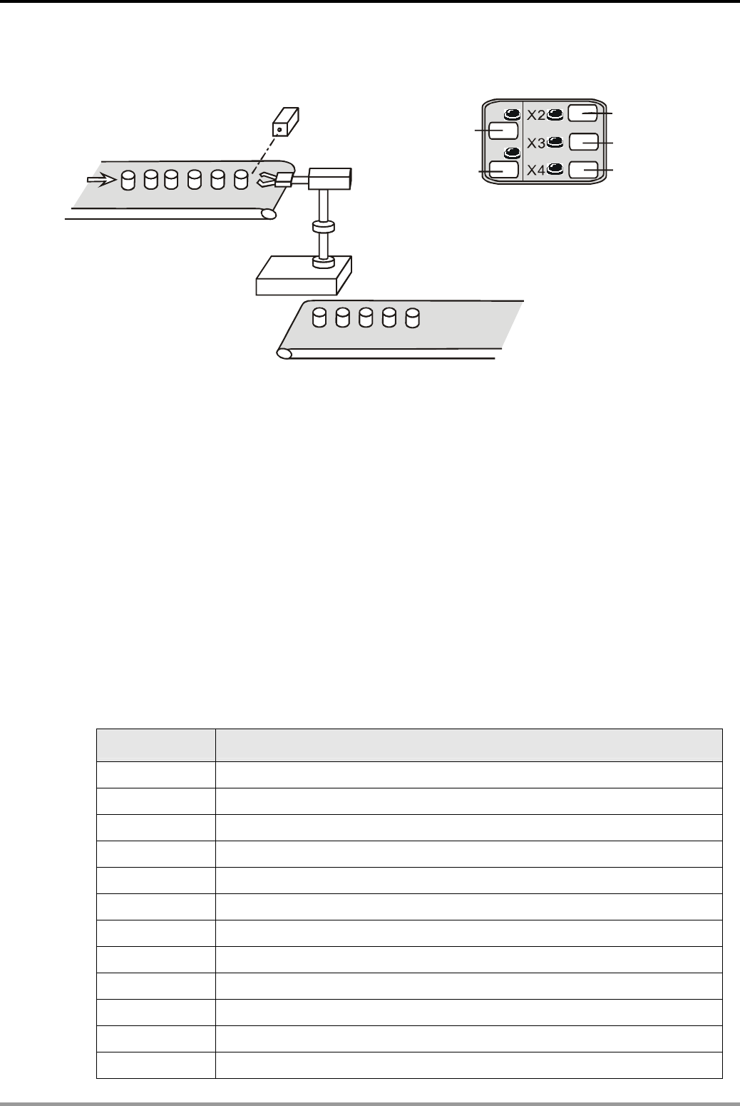
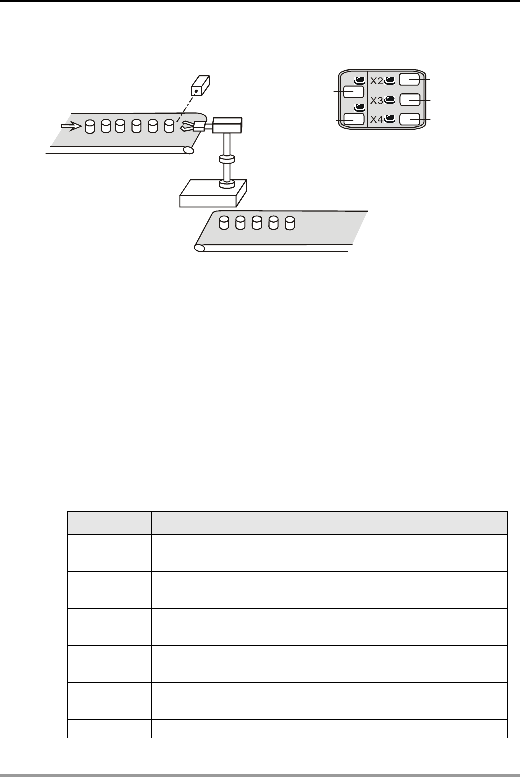
8.3 WSFL - Automatic Sorting Mixed Products .............................................. 8-5
8.4 SFWR/SFRD - Room Service Call Control............................................... 8-8
9. Data Processing Design Examples
9.1 ENCO/DECO - Encoding and Decoding................................................... 9-1
9.2 SUM/BON - Checking and Counting the Number of “1” ............................ 9-3
9.3 MEAN/SQR - Mean Value and Square Root............................................. 9-4
9.4 MEMR/MEMW - File Register Access...................................................... 9-5
9.5 ANS/ANR - Level Monitoring Alarm System ............................................. 9-7
9.6 SORT - Sorting Acquired Data ................................................................ 9-8
9.7 SER - Room Temperature Monitoring...................................................... 9-10
10. High-speed Input/Output Design Examples
10.1 REF/REFF - DI/DO Refreshment and DI Filter Time Setting ................... 10-1
10.2 DHSCS - Cutting Machine Control ........................................................ 10-3
10.3 DHSZ/DHSCR - Multi-segment Coater Control....................................... 10-4
iv
10.4 SPD - Wheel Rotation Speed Measurement........................................... 10-6
10.5 PLSY - Production Line Control Program............................................... 10-7
10.6 PWM - Sprayer Valve Control Program.................................................. 10-9
10.7 PLSR - Servo Motor Acceleration/Deceleration Control .......................... 10-11
11. Floating Point Operation Design Examples
11.1 Elementary Arithmetic for Integer and Floating Point.............................. 11-1
11.2 Elementary Arithmetic for Floating Point................................................ 11-4
12. Communication Design Examples
Introduction................................................................................................. 12-1
12.1 Communication between PLC and Delta VFD-M Series AC Motor Drive .. 12-5
12.2 Communication between PLC and Delta VFD-B Series AC Motor Drive... 12-8
12.3 Communication between PLC and Delta VFD-V Series AC Motor Drive... 12-11
12.4 Communication between PLC and Delta ASD-A Series AC Servo Drive... 12-14
12.5 Communication between PLC and Delta ASD-A Series AC Servo Drive... 12-18
12.6 Communication between PLC and Delta DTA Temperature Controller ..... 12-22
12.7 Communication between PLC and Delta DTB Temperature Controller ..... 12-25
12.8 PLC LINK 16 Slaves and Read/Write 16 Data (Word)............................. 12-28
12.9 PLC LINK 32 Slaves and Read/Write 100 Data (Word)........................... 12-31
12.10 LINK between PLC, Delta AC Motor Drive and AC Servo Drive ............. 12-34
12.11 LINK between PLC, Delta DTA and DTB Temperature Controllers ......... 12-38
12.12 Controlling START/STOP of 2 DVP PLCs through Communication ........ 12-41
12.13 Communication between Delta PLC and Siemens MM420 Frequency Inverter
........................................................................................................ 12-45
12.14 Communication between Delta PLC and Danfoss VLT6000 Series Adjustable
Frequency Drive................................................................................ 12-50
13. Real Time Calendar Time Design Examples
13.1 TRD/TWR/TCMP - Office Bell Timing Control......................................... 13-1
13.2 TRD/TZCP - Control of Warehouse Automatic Door ............................... 13-3
13.3 HOUR - Control of Switching Motors after a Long Time Running............. 13-6
v
14. Simple Positioning Design Examples
14.1 Simple positioning Demonstration System of Delta ASDA AC Servo Drive14-1
14.2 Draw DELTA LOGO by 2-axis Synchronous Motion ................................ 14-6
15. Handy Instruction Design Examples
15.1 ALT - Auto Blackboard Cleaner ............................................................. 15-1
15.2 RAMP - Ramp Control of Crane ............................................................ 15-3
15.3 INCD - Traffic Lights Control (Incremental Drum Sequencer).................. 15-6
15.4 ABSD - Adding Materials in Different Intervals (Absolute Drum Sequencer)15-9
15.5 IST - Electroplating Process Auto Control.............................................. 15-12
15.6 FTC - Fuzzy Temperature Control of the Oven....................................... 15-18
15.7 PID - Oven Temperature Control (Auto-tuning for PID Temperature Control)
.................................................................................................................. 15-22
16. Network Connection Design Examples
16.1 Ethernet Connection ............................................................................ 16-1
16.2 DeviceNet Connection.......................................................................... 16-6
16.3 CANopen Connection........................................................................... 16-9
16.4 RTU-485 Connection............................................................................ 16-12
17. Index.....................................................................................17-1
vi
1. Basic Program Design Examples
DVP-PLC Application Examples 1-1
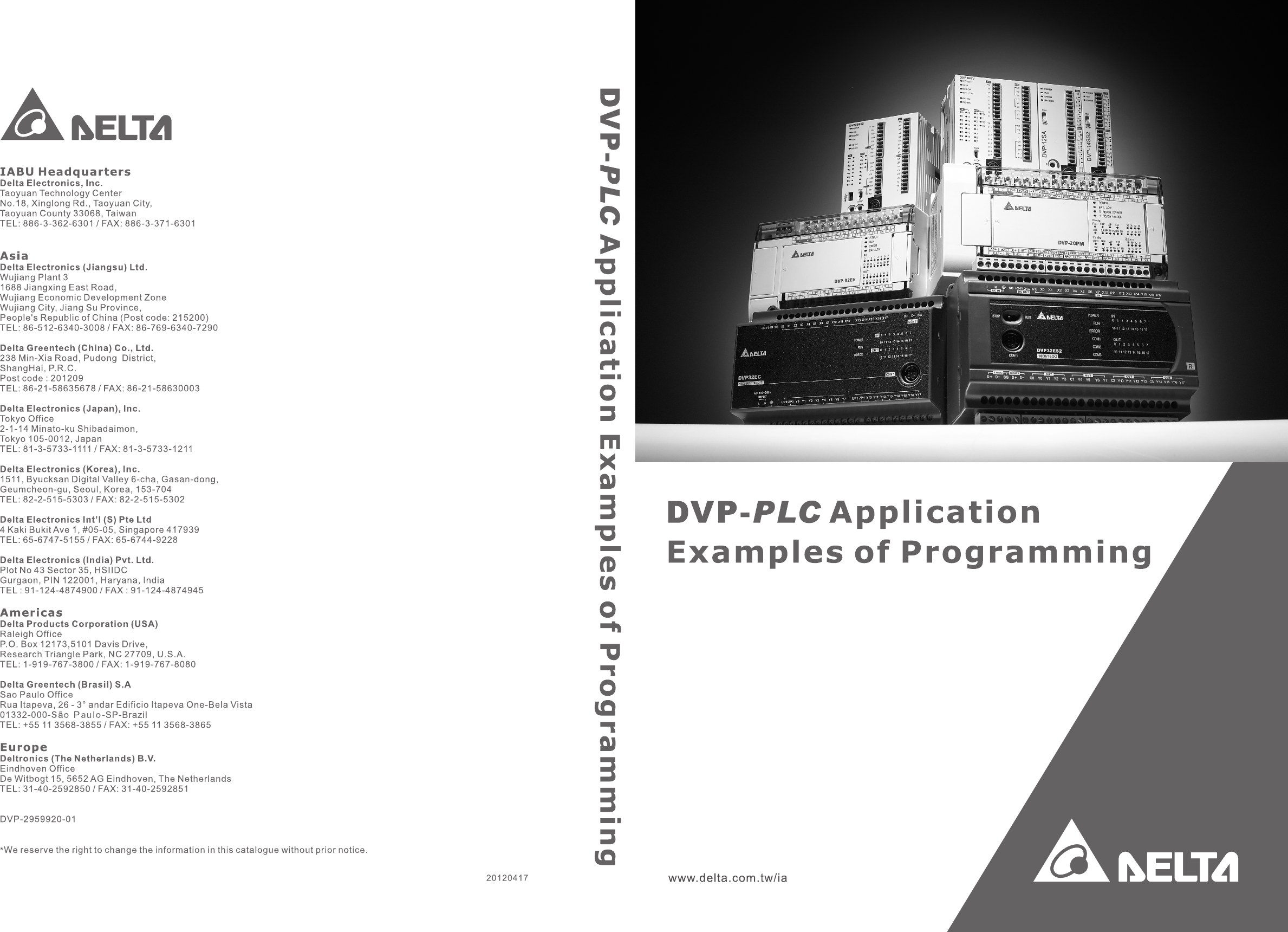
1.1 Normally Closed Contact in Series Connection
X0
X1
Y0
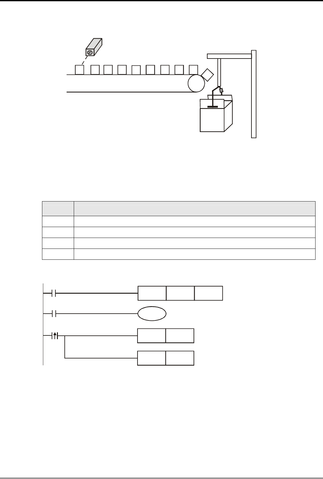
Control Purpose:
z Detecting the standing bottles on the conveyor and pushing the fallen bottles out
Devices:
Device Function
X0 X0 = ON when the detected input signal from the bottle-bottom is sheltered.
X1 X1 = ON when the detected input signal from the bottle-neck is sheltered.
Y0 Pneumatic pushing pole
Control Program:
X0 X1
Y0
Program Description:
z If the bottle on the conveyor belt is upstanding, the input signal from monitoring photocell at both
bottle-bottom and bottle-neck will be detected. In this case, X0 = ON, and X1 = ON. The normally
open (NO) contact X0 will be activated as well as the normally closed (NC) contact X1. Y0 remains
OFF and pneumatic pushing pole will not perform any action.
z If the bottle from the conveyor belt is down, only the input signal from monitoring photocell at the
bottle-bottom will be detected. In this case, X0 = ON, X1 = OFF. The state of output YO will be ON
because the NO contact X0 activates and the NC contact X1 remains OFF. The pneumatic pushing
pole will push the fallen bottle out of the conveyor belt.
1. Basic Program Design Examples
DVP-PLC Application Examples
1-2
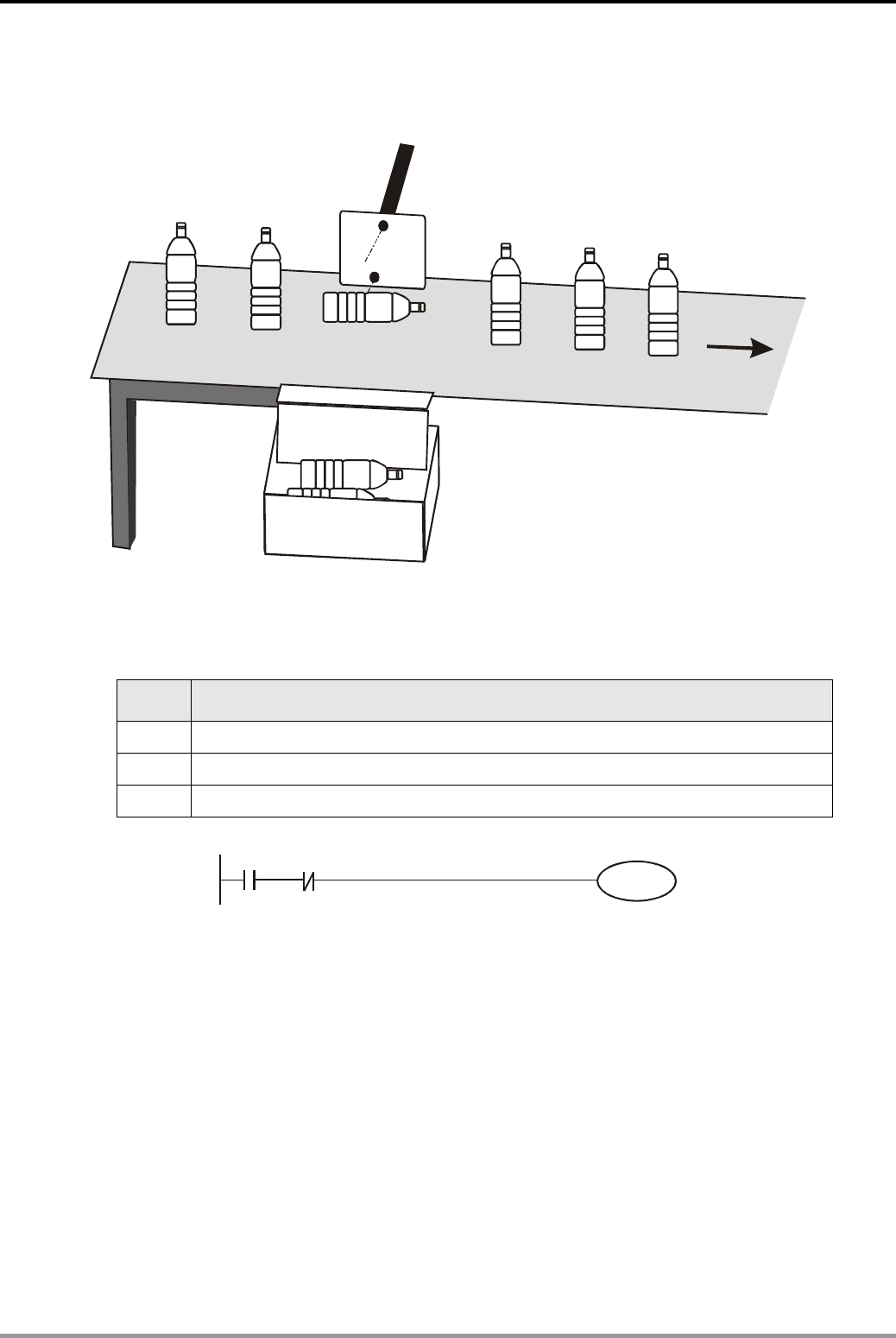
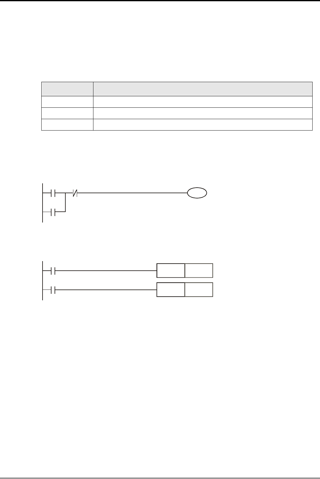
1.2 Block in Parallel Connection
Y0 X1
X0
Control Purpose:
z Setting up a lighting system for users to switch on/off the light whether they are at the bottom or
the top of the stairs.
Devices:
Device Function
X0 X0 turns ON when the bottom switch is turned to the right
X1 X1 turns ON when the top switch is turned to the right.
Y1 Stair light
Control Program:
X0
X0
X1
X1
Y0
Program Description:
z If the states of the bottom switch and the top switch are the same, both ON or OFF, the light will
be ON. If different, one is ON and the other is OFF, the light will be OFF.
z When the light is OFF, users can turn on the light by changing the state of either top switch at the
bottom switch of the stairs. Likewise, when the light is ON, users can turn off the light by
changing the state of one of the two switches..
1. Basic Program Design Examples
DVP-PLC Application Examples 1-3
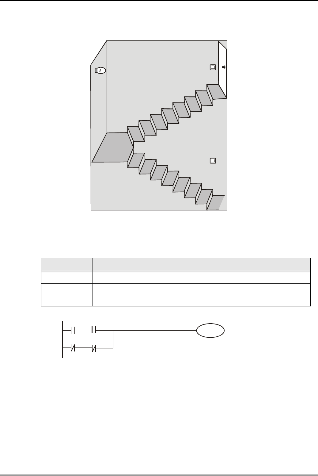
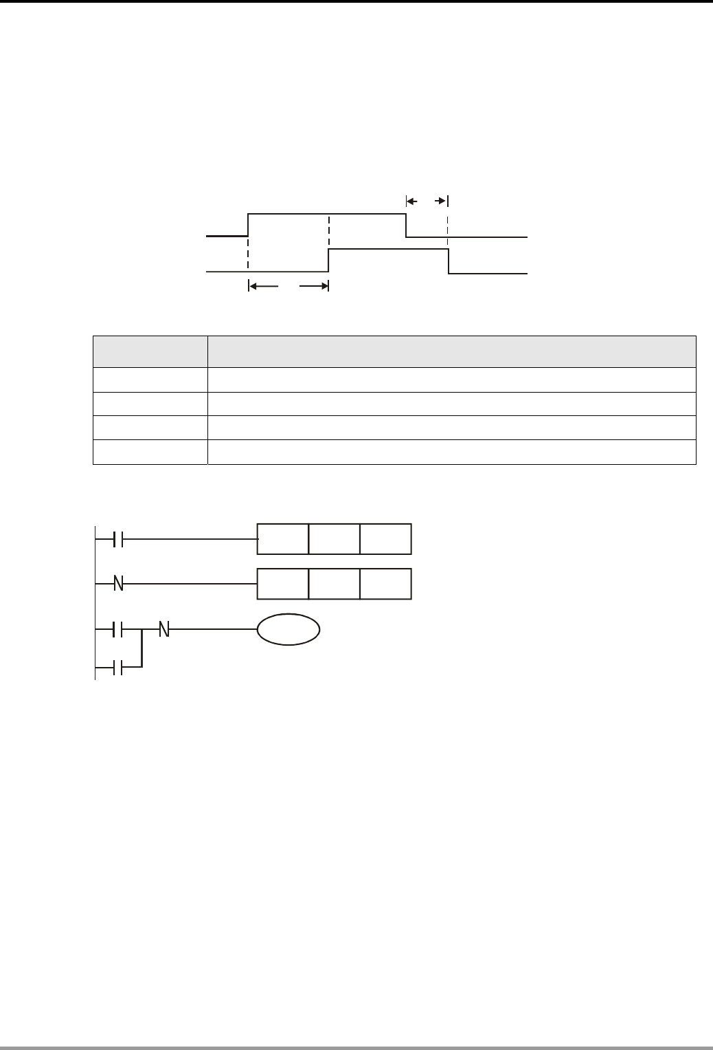
1.3 Rising-edge Pulse Output for One Scan Cycle
Control Purpose:
z Creating a pulse of one program scan cycle as the condition to trigger the indicator or other devices
when the switch (X0) is turned on.
One scan cycle
X0
M10
Y0
Devices:
Device Function
X0 Switch (OFF→ON)
M10 Creating a trigger pulse for one program scan cycle
Y0 Indicator
Control Program:
X0
PLS
M10
SET Y0
M10 turns on for one scan cycle
M10
Program Description:
z When X0 is turned on (Rising-edge triggered), PLS instruction will be executed, and M10 will
send a pulse for one program scan cycle.
z When M10 = ON, [SET Y0] instruction will be executed and Y0 will be ON. In this case, the
indicator will be lighted, and other devices will be activated as well.
1. Basic Program Design Examples
DVP-PLC Application Examples
1-4
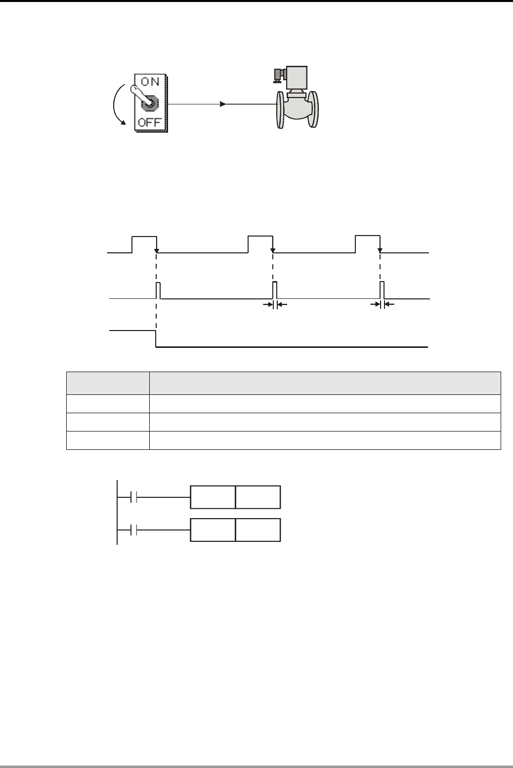
1.4 Falling-edge Pulse Output for One Scan Cycle
X0 Y0(Electromagnetic valve
)
Control Purpose:
z Creating a pulse of one program scan cycle as the condition to trigger the electromagnetic valve or
other devices when the switch is turned off.
X0
M10
Y0
One scan cycle
Devices:
Device Function
X0 Switch(ON→OFF)
M10 Creating a trigger pulse for one program scan cycle
Y0 Electromagnetic valve
Control Program:
X0
M10
RST Y0
M10 turns on for one scan cycle
Y0 = OFF
M10PLF
Program Description:
z When X0 is turned on (Falling-edge triggered), PLF instruction will be executed, and M10
will send a pulse for one program scan cycle.
z When M10 = ON, [RST Y0] instruction will be executed and Y0 will be OFF. In this case, the
electromagnetic valve will be shut down.
1. Basic Program Design Examples
DVP-PLC Application Examples 1-5
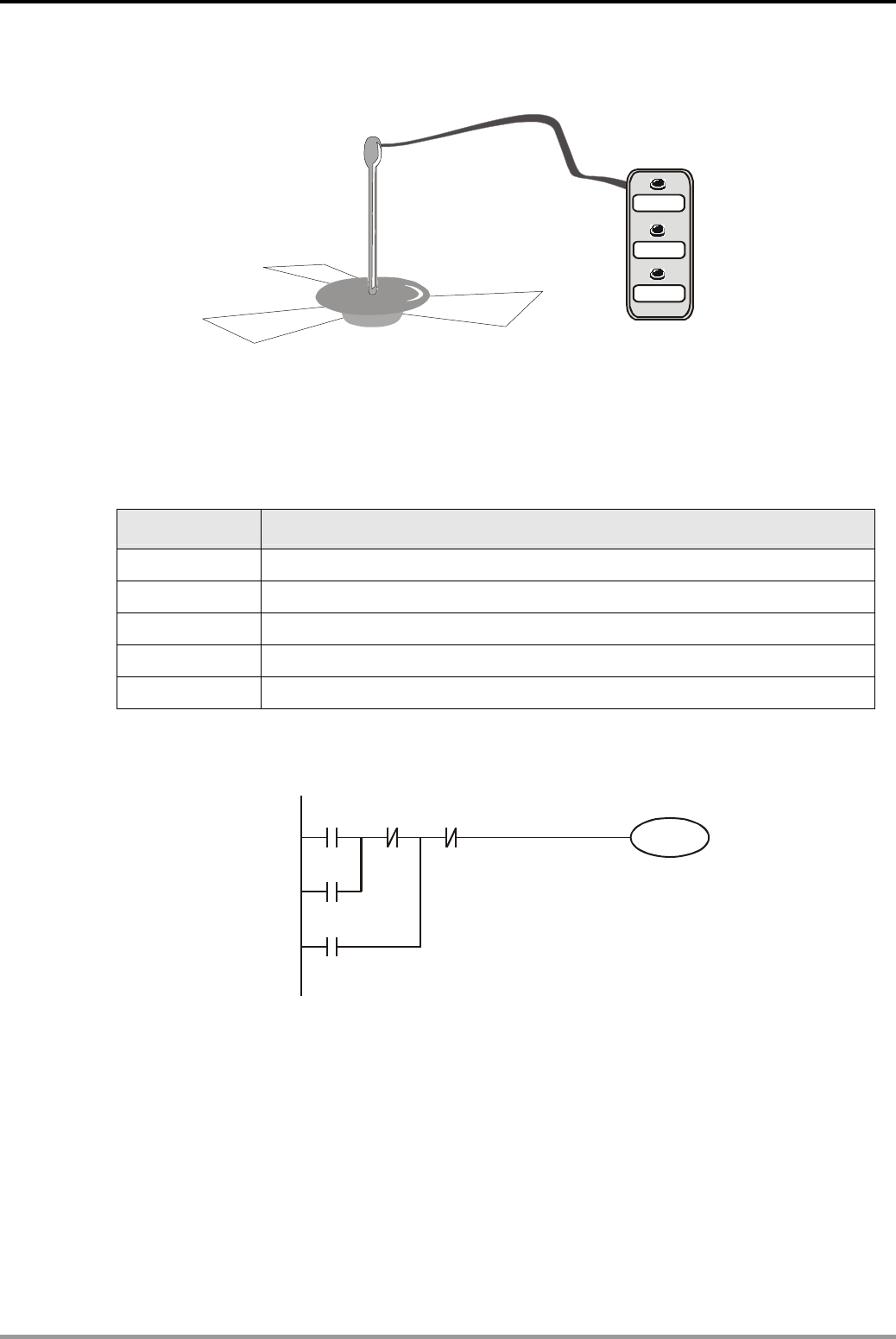
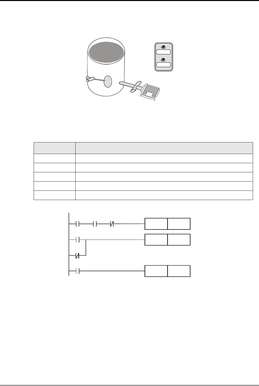
1.5 Latching Control Circuit
START
STOP
TEST
X0
X1
X2
Y0
Control Purpose:
z Controlling the running state of the ceiling-fan by pressing START and STOP.
z Checking if the ceiling-fan is running normally by pressing TEST.
Devices:
Device Function
X0 Press START, X0 = ON.
X1 Press STO, X1 = ON.
X2 Press TEST, X2 = ON.
X3 Error signal
Y1 Ceiling-fan motor control signal
Control Program:
X0
Y1
X1
X2
X3
TEST button
Error Signal
Y1
Program Description:
z Press START lightly and X0 = ON. The ceiling-fan will keep running if no error occurred (X3
= OFF). The action can be practiced by a latching circuit which takes output Y1 as one of the
input condition to keep the fan running even if the START button is not pressed.
z When STOP is pressed, X1 = ON and Y1 = OFF. The ceiling-fan will stop running.
z If error occur (X3 = ON), Y1 will be OFF and the ceiling-fan will stop running.
z When TEST is pressed (X2 = ON), Y1 = ON. The ceiling-fan will start running if no error
occurred (X3 = OFF). On the contrary, when TEST is released, the ceiling-fan will stop
running. The testing function is performed by this process.
1. Basic Program Design Examples
DVP-PLC Application Examples
1-6
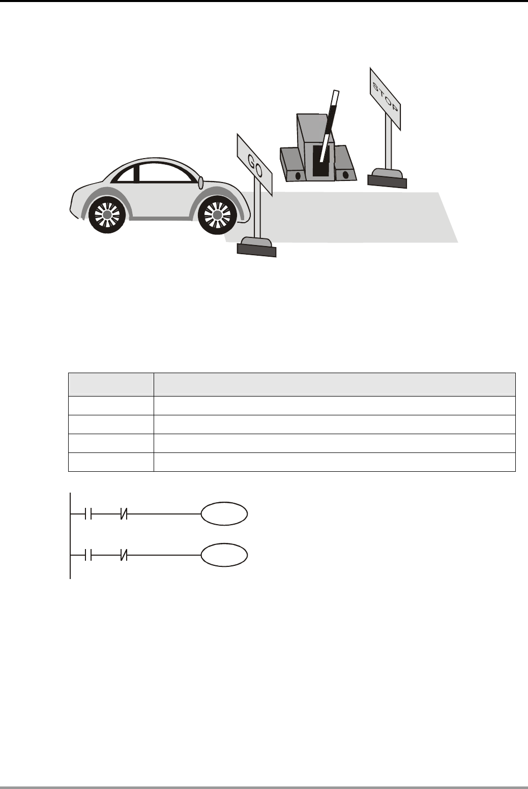
1.6 Interlock Control Circuit
X0 X1
Y0
Y1
Control Purpose:
z The Entry/Exit of the parking lot is a single lane passage. By controlling the indicators, the program
ensures that only one car can pass through the Entry/Exit so as to prevent car accident between
entering and leaving cars
Devices:
Device Function
X0 Car entering sensor. When a car passes through the sensor, X0 = ON.
X1 Car leaving sensor. When a car passes through the sensor, X1 = ON.
Y0 Entering car indicator(ON means “GO”, OFF means “STOP”)
Y1 Leaving car indicator(ON means “GO”, OFF means “STOP”)
Control Program
X0
Y0
Y1
X1 Y0
Entering Indicator
Leaving Indicator
Y1
Program Description:
z In the parking lot, there are two indicators individually directing the entering and leaving cars.
By the interlock control circuit, only one indicator will show “GO” signal and the car accident
will thus be prevented.
z When an entering car draws near the vehicle control barrier, X0 will be ON and so will Y0.
The entering car indicator will show “GO”. At the same time, the leaving car indicator will
show “STOP.” Car entering is allowed but leaving is prohibited in this case.
z When a leaving car draws near the vehicle control barrier, X1 will be ON and so will Y1. The
leaving car indicator will show “GO” and the entering car indicator will show “STOP.”
1. Basic Program Design Examples
DVP-PLC Application Examples 1-7
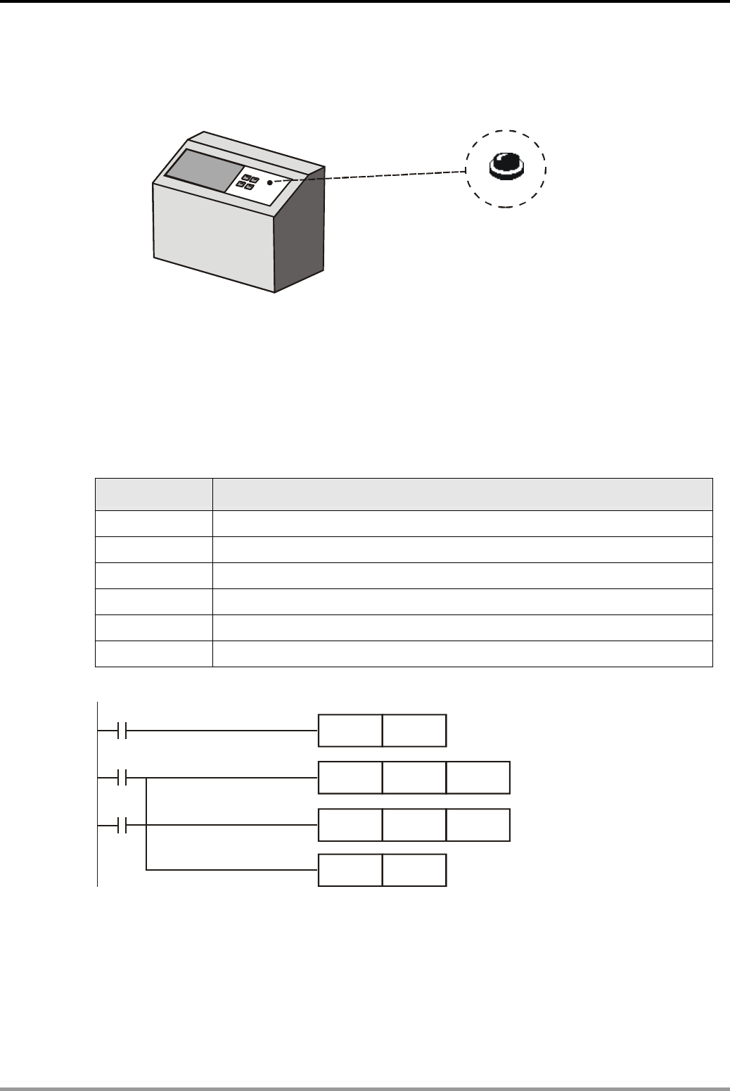
1.7 Automatic Parameter Initialization When Powered Up
Initialization uttonb
X1
Control Purpose:
z When the machine is powered up, all the parameters will be initialized automatically and the
machine will be ready. Users don’t need to set the parameters manually.
z Users can initialize parameters by pressing Initialization button at any time when the
machine is running.
Devices:
Device Function
X1 Initialization button. X1 will be ON when pressed
M1002 Creating a pulse when PLC is powered on
M10 Creating a trigger pulse for one scan cycle
D1120 PLC COM2 communication protocol
D1121 PLC communication address
Y0 Parameter initialization completed signal
Control Program:
X1
M1002
M10
PLS M10
MOV H86 D1120
MOV K1 D1121
SET Y0
Program Description:
z When PLC begins running, M1002 will be ON once and create a pulse with the width of one
scan cycle. This action will be executed for just once during the PLC running process and is
generally used to initialize devices such as D (data register), C (counter) and S (step point)
z By pressing X1, users can initialize parameters at any time during the program running
process, that is, setting PLC Slave ID as No. 1, COM2 communication format as 9600, 7, E,
1 and Y0 to be ON.
1. Basic Program Design Examples
DVP-PLC Application Examples
1-8
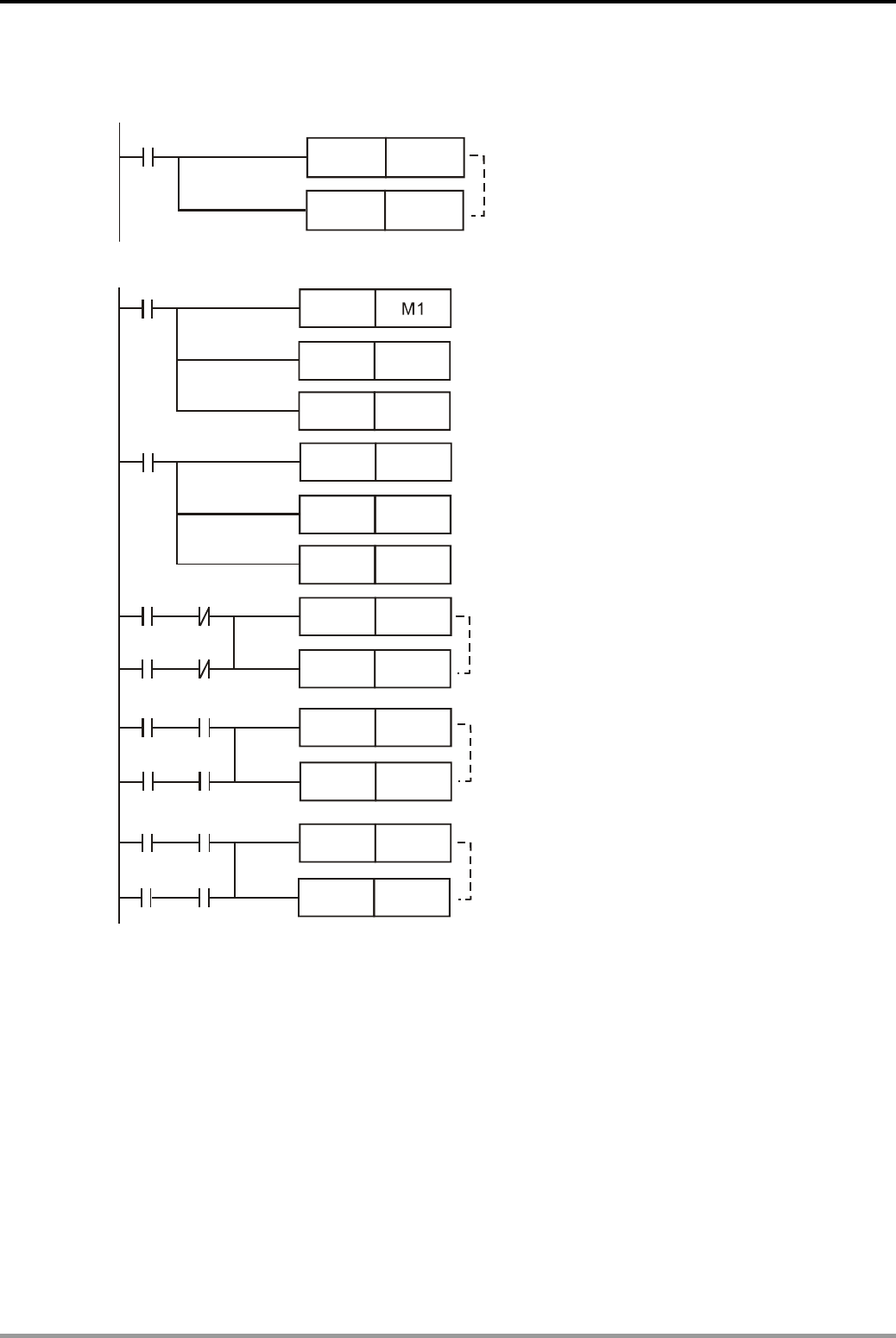
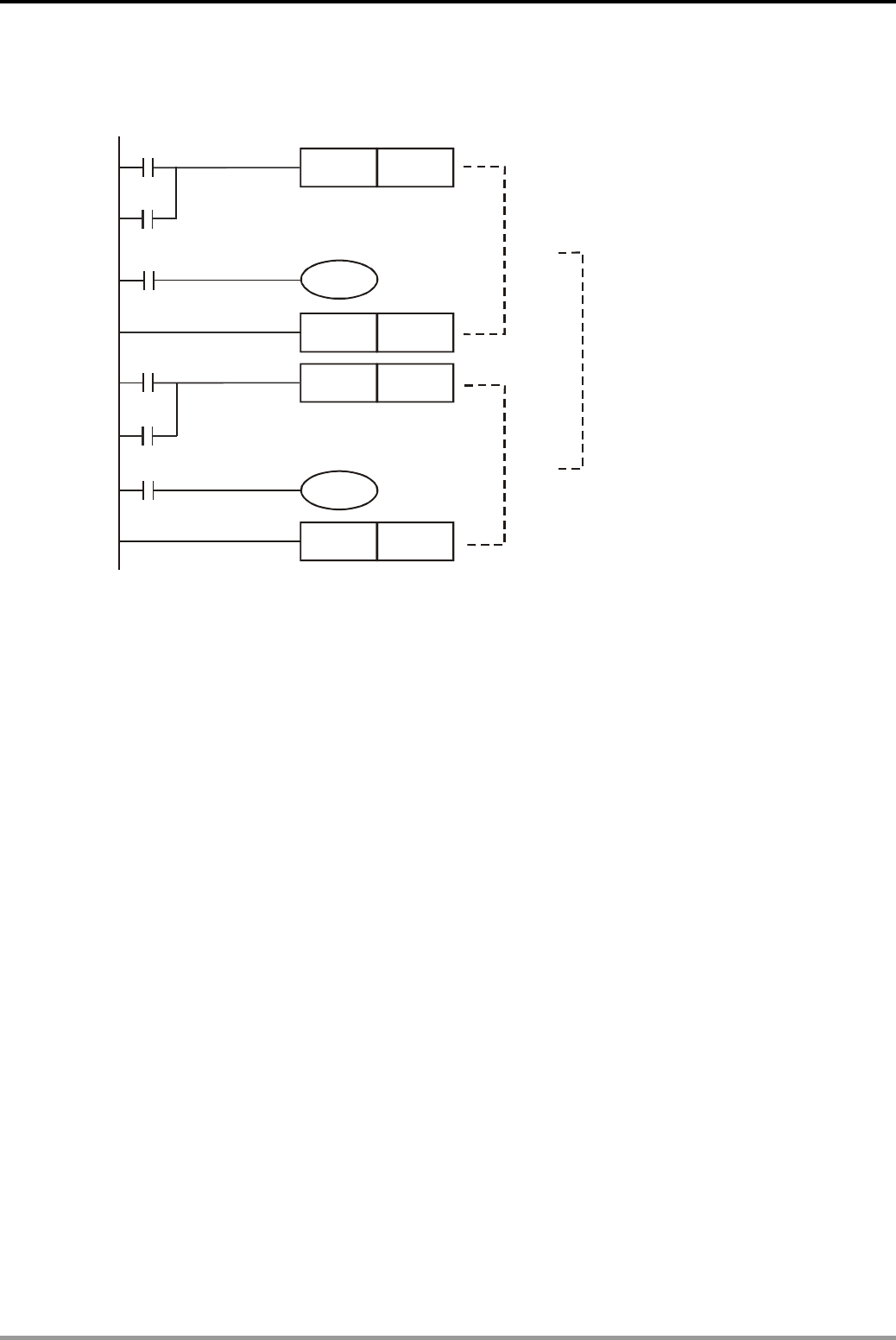
1.8 Common Latched Circuit and SET/RST Instructions Application
Control Purpose:
z Turn on the switch, the light will be ON; turn off the switch, the light will be OFF.
Devices:
Device Function
X0 Switch-on button. X0 will be ON when pressed
X1 Switch-off button. X1 will be ON when pressed
Y0 Indicator
Control Program:
z Common Latched Circuit
X1
Y0
Y0
X0
z Latched Circuit for SET/RST Instructions
X1
X0
SET Y0
RST Y0
Program Description:
z In the above examples, when X0 goes from OFF to ON, Y0 will stay in ON state. When X1
goes from OFF to ON, Y1 will stay in OFF state
z When X0 and X1 are enabled at the same time, it will be “Stop First”, that is, Y1 and the
indicator will be OFF.
1. Basic Program Design Examples
DVP-PLC Application Examples 1-9
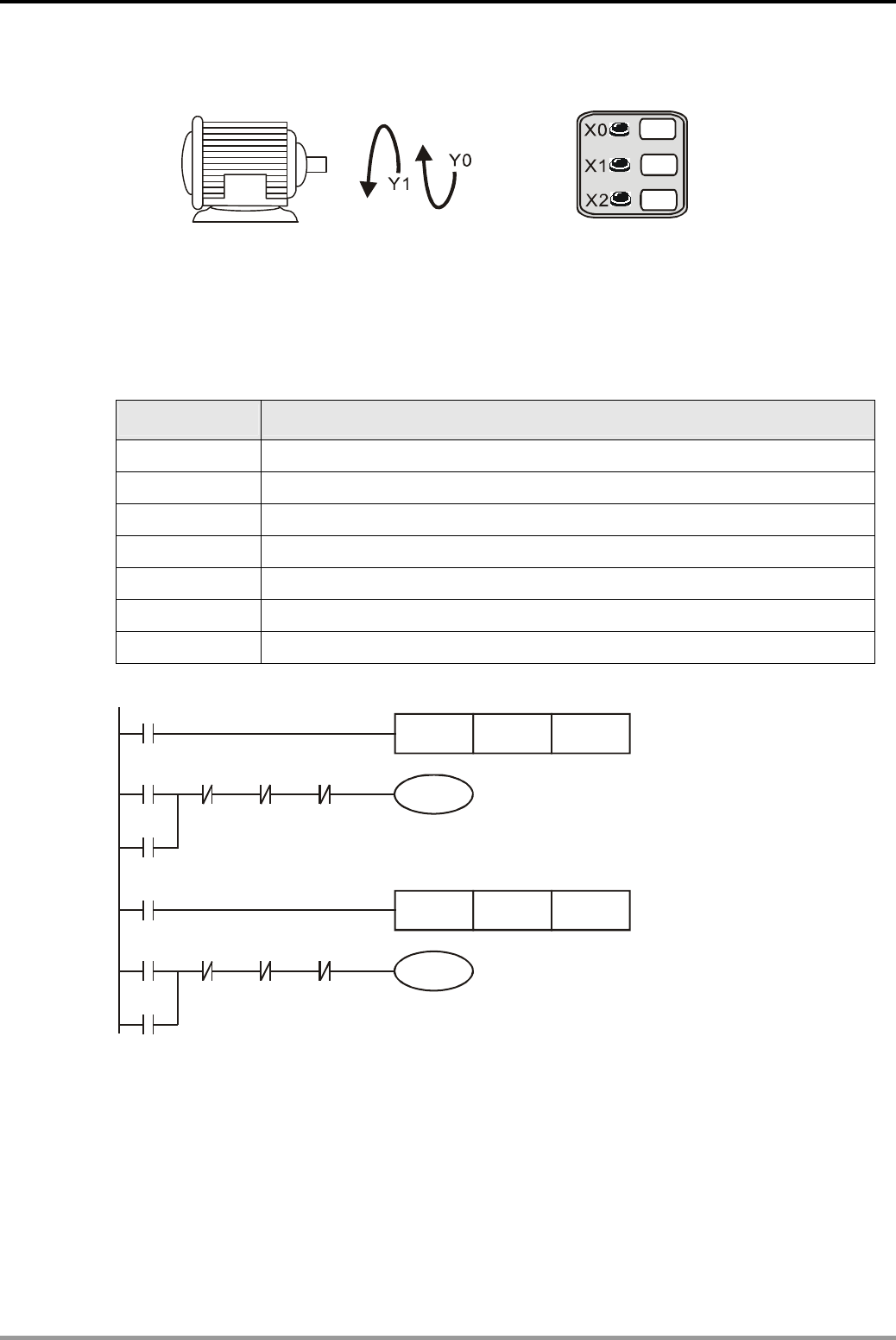
1.9 SET/RST - Latched and Unlatched Circuit
START
STOP
Y0
X2
X1
X0
Control Purpose:
z Press START, the pump begins to pump out the water; press STOP or when the water is
empty, the pump stops working.
Devices:
Device Function
X0 START button. X0 will be ON when pressed
X1 STOP button. X1 will be ON when pressed
X2 Level detector. X2 will be ON if there is water in the container
M0 Trigger pulse for one scan cycle
Y0 Pump motor
Control Program:
X1X0
M0
RST Y0
X2
SET Y0
PLS M0
X1
X2
Program Description:
z X2 will be ON If there is water in the container. When START is pressed, X0 = ON, and SET
instruction will be executed. Y0 will be set, and the pump motor begins pumping the water.
z There are two situations for stopping the motor. First, when STOP is pressed, X1 = ON. PLS
instruction will be executed and M0 will be ON for one scan cycle. RST instruction will thus
be executed, and Y0 will be reset to stop pumping. Second, when the water in the
container is empty, X2 will be OFF and PLS instruction will be executed to trigger M0 for
resetting Y0. In this case, the pump motor will stop pumping as well.
1. Basic Program Design Examples
DVP-PLC Application Examples
1-10
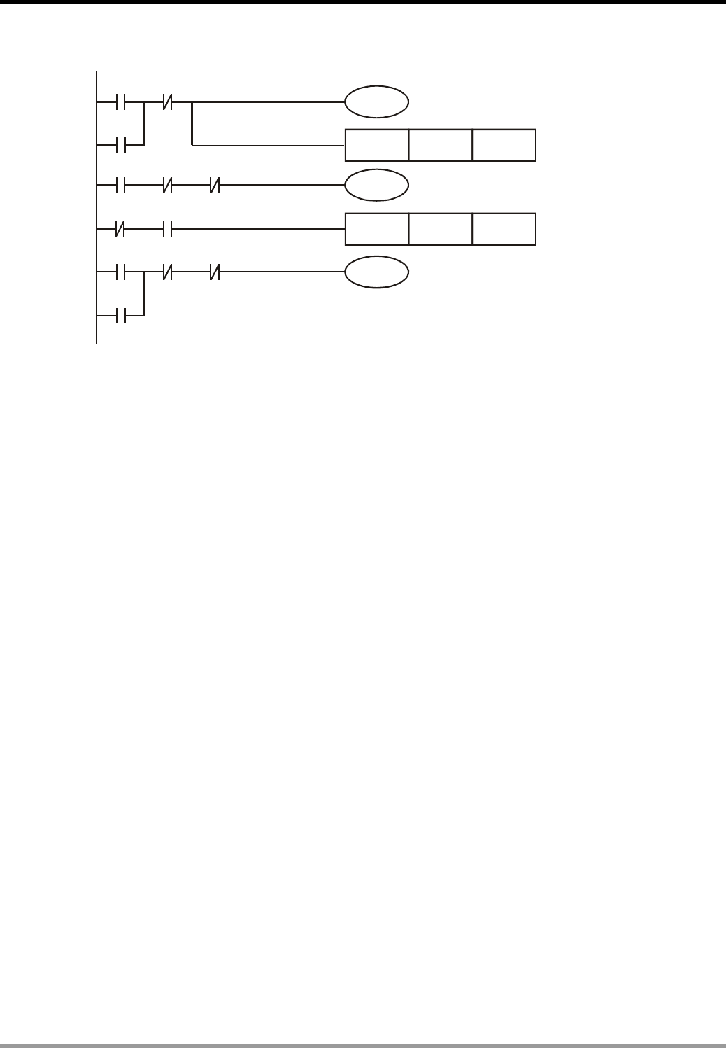
1.10 Alternate Output Circuit (With Latched Function)
Control Purpose:
z Setting the light ON by pressing the switch for the 1st time, the 3rd time, 5th time, etc.; setting
the light OFF by pressing the switch for the 2nd time, 4th time, 6th time, etc.
z Restoring the indicator to the state before power off when the device is powered up again.
Devices:
Device Function
X1 Light switch. X1 will be ON when the button is pressed
M10 Trigger pulse for one scan cycle
M512 If X1 is pressed for odd number of times, M512 ON, M513 = OFF.
M513 If X1 is pressed for even number of times, M512 = OFF, M513 = ON.
Y1 Indicator
Control Program:
X1
Tforrigger pulse one scan cycle
If X1 is pressed for odd number
of times, M512=ON, M513=OFF
If X1 is pressed for even number
of times, M512=OFF, M513=ON
Y1 will be ON/OFF if X1 is
pressed for odd/even number of times
M512
M512
M513
M513
M10
M10
Y1
Y1
M512 M513
Y1
Y1
PLS M10
SET
RST
SET
RST
Program Description:
z Pressing X1 for the 1st time (or odd number of times):
When the switch X1 is pressed, X1 will be ON and the [PLS M10] instruction will be
executed for triggering M10 to be ON for one scan cycle. In this case, M10 is ON and Y1 is
OFF, SET and RST instructions at line 2 will thus be executed. On the contrary, SET and
RST instructions at line 3 will not be executed due to the open loop of Y1. At line 4, coil Y1 is
ON because of the results of Line 2: M512 is ON and M513 is OFF. When the 2nd scan cycle
is started, SET/RST at both line 2 and line 3 will not be executed because M10 is OFF in this
scan cycle. As a result, the light will be ON until the switch is pressed next time.
z Pressing X1 for the 2nd time (or even number of times):
When the switch X1 is pressed again, X1 will be ON and M10 will be ON for one scan cycle.
According to the result of pressing X1 for the first time, the state of Y1 has been ON.
SET/RST instructions at line 3 will thus be executed. In addition, SET/RST instructions at

1. Basic Program Design Examples
DVP-PLC Application Examples 1-11
line 2 won’t be executed due to the open loop of Y1. In this case, M513 will be ON and M512
will be OFF. When the 2nd scan cycle is started, SET/RST at both line 2 and line 3 will not be
executed because M10 is OFF in this scan cycle. As a result, the light will remain OFF until
the switch is pressed next time.
z Alternate output(ON/OFF) function can also be performed by using API 66 ALT instruction
1. Basic Program Design Examples
DVP-PLC Application Examples
1-12
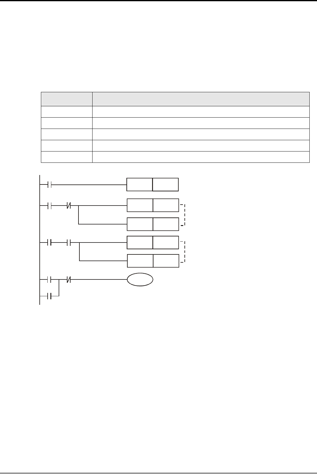
1.11 Conditional Control Circuit
X0
X1
X2
X3
Oil Pump Motor
Main Motor
Y0
Y1 Main Motor
Oil Pump Motor
START STOP
START STOP
Control Purpose:
z Providing lube for the gear box before the lathe spindle starts to run which aims to ensure
that the oil pump motor starts first and the main motor starts subsequently.
Devices:
Device Content
X0 Oil pump START button. X0 will be ON when pressed.
X1 Main motor START button. X0 will be ON when pressed.
X2 Oil pump STOP button. X2 will be ON when pressed.
X3 Main motor STOP button. X3 will be ON when pressed.
Y0 Oil pump motor
Y1 Main motor
Control Program:
Y1
X0
Y0
X1
Y1
X2
X3 Y0
Y0
Program Description:
z This program is a typical application of the conditional control circuit. Y0 = ON when Oil
Pump START button is pressed. Therefore, the oil pump will start to provide lube for the gear
box of main motor(Y1)
z Under the precondition of the operating state of the Oil pump, the main motor (Y1) will be
ON when the Main motor START button is pressed.
z During the operation of main motor (Y1), oil pump (Y0) needs to provide lube continuously.
z The oil pump will be stopped when Oil pump STOP button X2 is activated, and the main
motor will be stopped when Main motor STOP button X3 is activated.
1. Basic Program Design Examples
DVP-PLC Application Examples 1-13
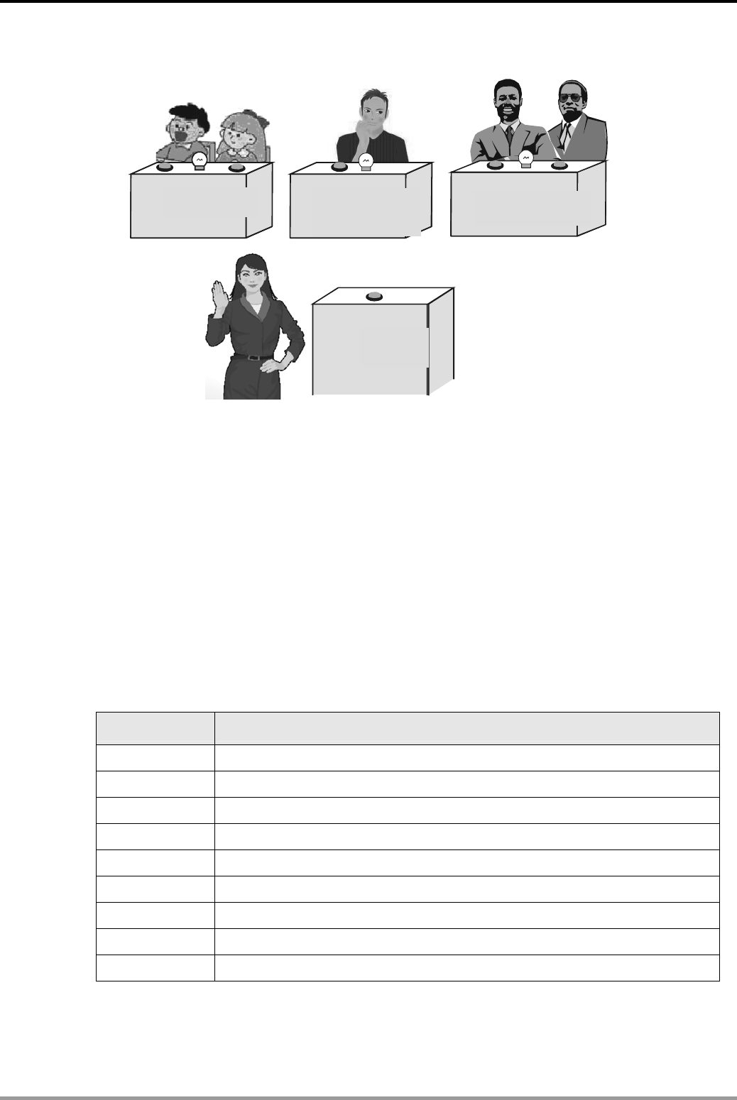
1.12 First-in Priority Circuit
教授组
主持人
小学生组 中学生组
X5
X0 X1
Y0 X2 X3 X4
Y2
Y1
Control Purpose:
z There are 3 groups participating in the quiz game: pupils, high school students and
professors. If they want to get the chance of answering the question from the host, they
must press the answer button on their table first. Other groups’ pressing will be invalid if any
group gets the chance successfully
z There are 2 answer buttons for the pupil group and professor group and 1 answer button for
the high school student group. In order to give preferential treatment to the pupil group, Y0
will be ON if any one of X0 or X1 is pressed. However, in order to limit the professor group,
Y2 will be ON when X3 and X4 are pressed at the same time. For the high school student
group, Y1 will be ON when X2 is pressed.
z If the host presses X5 (Reset button), Y0, Y1 and Y2 will be OFF.
Devices:
Device Function
X0 Answer button for pupil group
X1 Answer button for pupil group
X2 Answer button for high school student group
X3 Answer button for professor group
X4 Answer button for professor group
X5 Reset button for host
Y0 Indicator for pupil group
Y1 Indicator for high school student group
Y2 Indicator for professor group
Pupil Group High School
Student Group
Professor Group
Host
1. Basic Program Design Examples
DVP-PLC Application Examples
1-14
Control Program:
X0
X5
Y1 Y2
Y0
MC N0
X1
X2 Y0 Y2
Y1
X3 X4 Y0
Y2
Y1
Y2
End of main control circuit
Y0
Start of main control circuit
Control of the pupil group
Control of the high school student group
Control of the professor group
Y1
Reset button for the host
N0MCR
Program Description:
z If the host didn’t press the reset button X5, [MC N0] instruction will be executed and the
program between MC and MCR will also be executed normally.
z The answer buttons are connected in parallel connection for the pupil group, and in series
connection for the professor group. For the high school student group, there is only one
answer button. If one group presses the answer button successfully, its indicator will form a
latching circuit, that is, the indicator will be ON even the button is released.
z Through the interlock circuit, any other button pressings will be invalid as long as one
indicator is ON
z When the host presses the reset button, X5 = ON. [MC N0] instruction and the program
between MC and MCR will not be executed. Y0, Y1 and Y2 will be out of power, and all the
indicators for the 3 groups will be OFF. When the host releases the button, X5 = OFF. The
program between MC and MCR will be executed normally again, and the new round will
begin as well.
1. Basic Program Design Examples
DVP-PLC Application Examples 1-15
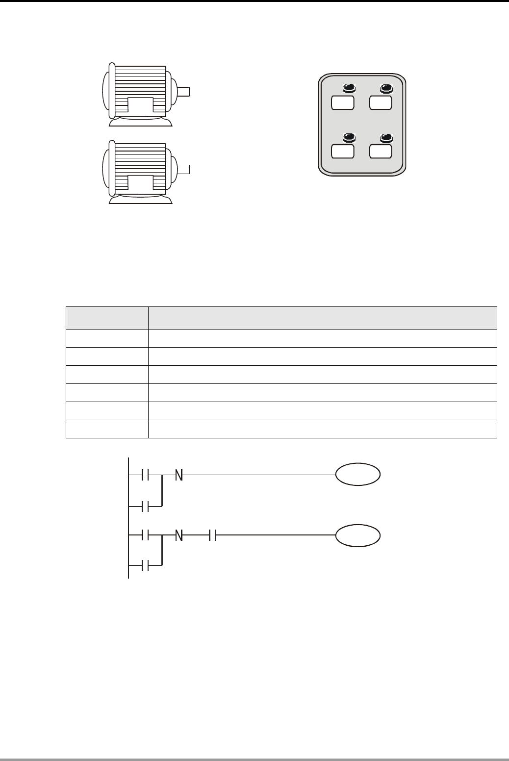
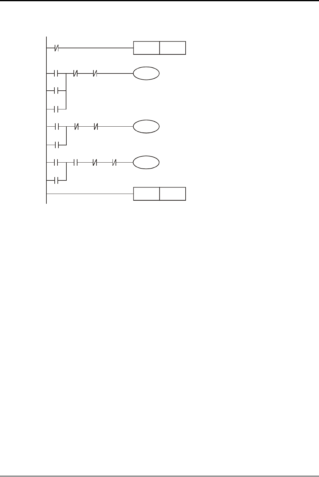
1.13 Last-in Priority Circuit
Control Purpose:
z There are 4 buttons corresponding to 4 indicators. The program is to turn on the indicators
corresponding to pressed buttons and to turn off the previous ON indicators.
Devices:
Device Function
X0 Button 1. X0 will go from OFF to ON when pressed
X1 Button 2. X1 will go from OFF to ON when pressed
X2 Button 3. X2 will go from OFF to ON when pressed
X3 Button 4. X3 will go from OFF to ON when pressed
Y0 Indicator 1
Y1 Indicator 2
Y2 Indicator 3
Y3 Indicator 4
Control Program:
X0
X1
X2
X3
M1000
M11
PLS M0
PLS M1
PLS M2
PLS M3
CMP K1M0 M10K0
MOV K1M0 K1Y0
Program Description:
z When a button is pressed, the corresponding device X will go from OFF to ON. In this scan
cycle, PLS instruction is executed, and the corresponding internal relay M is enabled as well.
CMP instruction will be executed and the compared result is K1M0>0 which makes M10 ON
but M11 OFF. [MOV K1M0 K1Y0] instruction will then be executed and sent out the state of
M to its corresponding output Y. At the same time, the previous ON indicator(Y) will be
turned off.
z When it comes to the 2nd scan cycle, PLS instructions will not be executed and the value of
M0~M3 will be 0. Therefore, the CMP instruction will be executed and set M11 to be ON
(K1M0 = 0). [MOV K1M0 K1Y0] instruction will not be executed, and the 0 state of device M
will not be sent out, either. In this case, Output Y will remain its original state until any other
button is pressed next time.
1. Basic Program Design Examples
DVP-PLC Application Examples
1-16
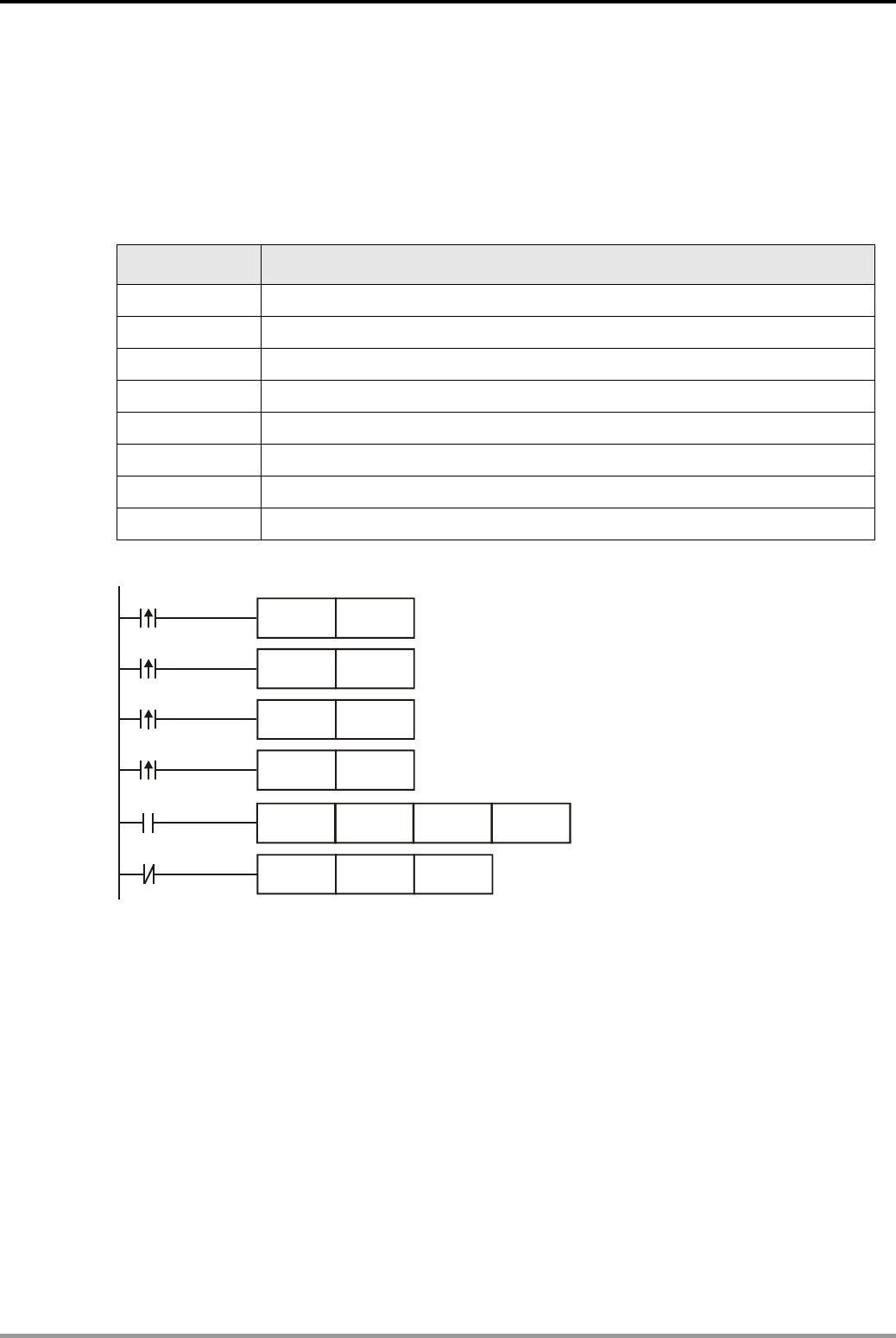
1.14 Entry/Exit Control of the Underground Car Park
Y1 Y2 X1
X2
Entry/Exit of the Ground Floor
Entry/Exit of the Basement
Red Light Green Light
Y1 Y2
Red Light Green Light
Singaan
l Le Passage
Control Purpose:
z The entry/exit of the underground car park is a single lane passage which needs the traffic
lights to control the cars. Red lights prohibit cars entering or leaving while green lights allow
cars to enter or leave.
z When a car enters the passage from the entry of the ground floor, the red lights both on the
ground floor and the basement will be ON, and the green lights will be OFF. Any car entering
or leaving is prohibited during the process till the car passes through the passage completely.
When the passage is clear, the green lights will be ON again and allow other cars entering
from the ground floor or the basement.
z Similarly, when a car leaves the basement and enters the passage, any other car entering or
leaving is prohibited till the car passes from the passage to the ground completely.
z When PLC runs, the initial setting of traffic lights will be green lights ON and red lights OFF.
Devices:
Device Function
X1 Photoelectric switch at the ground floor entry/exit. X1 will be ON when a car passes.
X2 Photoelectric switch at the basement entry/exit. X2 will be ON when a car passes.
M1 M1 will be ON for one scan cycle when a car from the ground floor passes X1.
M2 M2 will be ON for one scan cycle when a car from the basement passes X1.
M3 M3 will be ON for one scan cycle when a car from the basement passes X2.
M4 M4 will be ON for one scan cycle when a car from the ground floor passes X2
M20 M20 = ON during the process of a car entering the passage from the ground floor.
M30 M30 = ON during the process of a car entering the passage from the basement.
Y1 Red lights at the entry/exit of the ground floor and the basement
Y2 Green lights at the entry/exit of the ground floor and the basement
1. Basic Program Design Examples
DVP-PLC Application Examples 1-17
Control Program:
M1002
RST Y1
SET Y2
The green lights will be ON and
the red lights will be OFF when
the program is started
X2
PLS M3
PLF M4
SET M30
M1 M30
M3 M20
M4 M20
M2 M30
RST Y2
SET Y1
RST Y1
SET Y2
RST M20
RST M30
M3 will be ON for one scan cycle
when a car from the basement passes 2.X
M4 M20
M2 M30
M4 will be ON for one scan cycle
when a car from the ground floor passes 2.X
M0=O3 N during the process of a car
entering the passage from the basement.
When a car runs in the passage,
the red lights will be ON and green lights will be OFF.
When a car leaves the passage,
the red lights will be OFF and green lights will be ON.
When a car leaves the passage,
M20 and M30 will be reseted.
PLS
X1
PLF M2
SET M20
M1 will be ON for one scan cycle
when a car from the ground floor passes X1.
M2 will be ON for one scan cycle
when a car from the basement passes X1.
M20=ON during the process of a car
entering the passage from the ground floor.
Program Description:
z The ground floor and the basement share the same red light signal Y1 and green light signal
Y2.
z The key of the program is to identify that the car is entering or leaving the passage at the
ground floor entry/exit when M1 is ON to activate Y1 because [PLS M1] will be executed in
both entering and leaving conditions. Therefore, the confirming signal M20 is required for
confirming that the car is entering the passage from the ground floor.
z Also, it needs to identify that the car is entering or leaving the passage at the basement
entry/exit when M3 is ON because [PLS M3] will be executed in both entering and leaving
conditions. Therefore, the confirming signal M30 is required for confirming that the car is
entering the passage from the basement.
1. Basic Program Design Examples
DVP-PLC Application Examples
1-18
1.15 Forward/Reverse Control for the Three-Phase Asynchronous Motor
Forward
Reverse
Forward
Reverse
Stop
Control Purpose:
z Controlling the motor to run forward when Forward is pressed, run reverse when Reverse is
pressed and stop when Stop is pressed.
Devices:
Device Function
X0 Forward button of the motor. X0 will be ON when pressed
X1 Reverse button of the motor. X1 will be ON when pressed
X2 Stop button. X2 will be ON when pressed.
T1 1 sec timer
T2 1 sec timer
Y0 Forward contactor
Y1 Reverse contactor
Control Program:
X0
TMR T0 K10
T0 X1 X2 Y1
Y0
Y0
X1
T1 X0 X2 Y0
Y1
Y1
TMR T1 K10
Program Description:
z X0 = ON when Forward is pressed. After 1 second, contactor Y0 will be enabled, and the
motor begins to run forward. On the other hand, X1 = ON when Reverse is pressed. After 1
second, contactor Y1 will be enabled, and the motor begins to run reverse. Besides, Y0 and
Y1 will be disabled and the motor will stop running when X2 is pressed.
z The two timers in the program are used to avoid the interphase short-circuit when the motor
changes its running mode. The short circuit may occur if another contactor is enabled
instantly while the electric arc in the disabled contactor still exists.
1. Basic Program Design Examples
DVP-PLC Application Examples 1-19
1.16 Selective Execution of Programs
Green
X1 X2
X3
X0
Y0 Y1
Yellow Blue
Color Selection
Yellow Blue
Control Purpose:
z There are pigments of 3 colors. By controlling different switches, operators can fill the cans
with corresponding pigments.
Devices:
Device Function
X0 Filling Start switch. X0 will be ON when turned on.
X1 Yellow control switch. X1 will be ON when turned on.
X2 Blue control switch. Turn it on, X2 will be On
X3 Green (mixing of yellow and blue) control switch. X3 will be ON when turned on
Y0 Yellow control valve
Y1 Blue control valve
1. Basic Program Design Examples
DVP-PLC Application Examples
1-20
Control Program
X1
X3
X2
X3
Y0
X0
MC N0
MCR N0
MC N0
X0
Y1
N0MCR
Yellow control valve
Blue control valve
Filling yellow pigment
Filling blue pigment
Filling green pigment
Program Description:
z The master switch of filling control needs to be turned on (X0 = ON) before filling started.
When both yellow and blue are filled at the same time, it will become green.
z When the switch of filling yellow pigment is turned on, X1 = ON. The first MC ~ MCR
instruction will be executed. Y0 = ON, and the system begins to fill the yellow color.
z When the switch of filling blue pigment is turned on, X2 = ON. The second MC ~ MCR
instruction will be executed. Y1 = ON, and the system begins to fill the blue color.
z When the switch of filling green pigment is turned on, X3 = ON, both of the two MC ~ MCR
instructions will be executed, and the system begins to fill the green color.
1. Basic Program Design Examples
DVP-PLC Application Examples 1-21
1.17 MC/MCR - Manual/Auto Control
Conveyor A
Conveyor B
Clip
Transfer
Release
Auto
X0
Manual
X1
Control Purpose:
z When the button Manual is pressed, the robotic arm will begin to execute the manual control
process: pressing Clip to clip the product from conveyor A, pressing Transfer to move the
product to the conveyor B, and pressing Release to release the product and send it away by
conveyor B.
z When the button Auto is pressed, the robotic arm will begin to execute the auto control
process once: clip product (keep holding this product before releasing) → transfer product
(the action takes 2 sec) → release the product. Auto control process can be performed one
more time if the button Auto is pressed again.
z Manual control process and auto control process are interlocked.
Devices:
Device Function
X0 Auto button. X0 goes from OFF to ON when pressed.
X1 Manual button. X1 goes from OFF to ON when pressed
X2 Clip button. X2 will be ON when pressed.
X3 Transfer button. X3 will be ON when pressed.
X4 Release button. X4 will be ON when pressed.
M0~M2 Auto control process
M3~M5 Manual control process
M10 Auto control selection
M11 Manual control selection
T0 2 sec timer
Y0 Product clipping/releasing. Y0 is ON/OFF when clipping/releasing the product.
Y1 Product transferring
1. Basic Program Design Examples
DVP-PLC Application Examples
1-22
Control Program:
M1000
M0
TMR
M10 M11
MC
RST
N0
M10
M1000
T0
M2
T0 K20
M1
M2
MCR N0
T0
M10
M11
MC N0
MCR N0
M4
M5
M1
M2
M3
M0
M3
M4
M5
X2
X3
X4
A
uto control process
Manual control process
SET
RST
Y0
Y0
Y1
Product clipping
Product Transferring
Product releasing
X0
X1
SET
SET
RST
RST
M10
M11
M11
M10
Set auto control
Set manual control

1. Basic Program Design Examples
DVP-PLC Application Examples 1-23
Program Description:
z When X0 goes from OFF to ON, the auto control process will be executed once, whereas
when X1 goes from OFF to ON, the manual control process will be executed. In the manual
control, the clipping and releasing actions require pressing the corresponding button for one
time. However, the button Transfer should be pressed for 2 sec during the moving process
till the product is moved to Conveyor B.
z X0 and X1 are interlocked. When the auto control process is executed, the robotic arm will
perform the following actions: first “clipping”, then “transferring” (for 2 sec.), and “releasing.”
When the manual control process is executed, the controlling actions will be performed by 3
corresponding buttons: clipping product by turning on Y0, transferring product by pressing
Y1 and releasing product by turning off Y0.
1. Basic Program Design Examples
DVP-PLC Application Examples
1-24
1.18 STL Manual/Auto Control
Conveyor A
Conveyor B
Clip
Transfer
Release
Auto
X0
Manual
X1
Control Purpose:
z When the button Manual is pressed, the robotic arm will begin to execute the manual control
process: pressing Clip to clip the product from conveyor A, pressing Transfer to move the
product to the conveyor B, and pressing Release to release the product and send it away by
conveyor B.
z When the button Auto is pressed, the robotic arm will begin to execute the auto control
process once: clip product (keep holding this product before releasing) → transfer product
(the action takes 2 sec) → release the product. Auto control process can be performed one
more time if the button Auto is pressed again.
z Manual control process and auto control process are interlocked.
Devices:
Device Function
X0 Auto button. X0 goes from OFF to ON when pressed.
X1 Manual button. X1 goes from OFF to ON when pressed
X2 Clip button. X2 will be ON when pressed.
X3 Transfer button. X3 will be ON when pressed.
X4 Release button. X4 will be ON when pressed.
S0 Initial step
S20 Auto control step
S21 Manual control step
T0 2 sec timer
Y0 Product clipping/releasing. Y0 is ON/OFF when clipping/releasing the product
Y1 Product transferring
1. Basic Program Design Examples
DVP-PLC Application Examples 1-25
Control Program:
S
S
TMR T0 K20
T0
S21
S20
X2
X3
S0
Y1
RET
X4
SET
RST
Y0
Y0
Y1
Clipping Product
Transferring Product
Releasing Product
T0
SET Y0 Clipping Product
Transferring Product
RST Y0 Releasing Product
Y0
S0
M1002
SET S0
S20
SET S21
S
S0 X0
X1
SET
Manual Control Button
Auto Control Button
Program Description:
z When X0 goes from OFF to ON, the step S20 will be set to execute auto control process one
time, and the manual control process will be prohibited at the same time. Auto control
process can be performed one more time if the button Auto is pressed again.
z The auto control process performed by the robotic arm: clipping product when X0 = ON
(keep holding this product before releasing) → transferring product when Y1 = ON (the
action takes 2 sec) → releasing the product when Y0 = OFF.
z When X1 goes from OFF to ON, the step S21 will be set to execute manual control process
one time, and the auto control process will be prohibited at the same time.
z The manual control process performed by the robotic arm: pressing Clip(X2) to clip the
product from conveyor A, pressing Transfer(X3) to move the product to the conveyor B, and
pressing Release(X4) to release the product and send it away by conveyor B.

1. Basic Program Design Examples
DVP-PLC Application Examples
1-26
MEMO
2. Counter Design Examples
DVP-PLC Application Examples 2-1
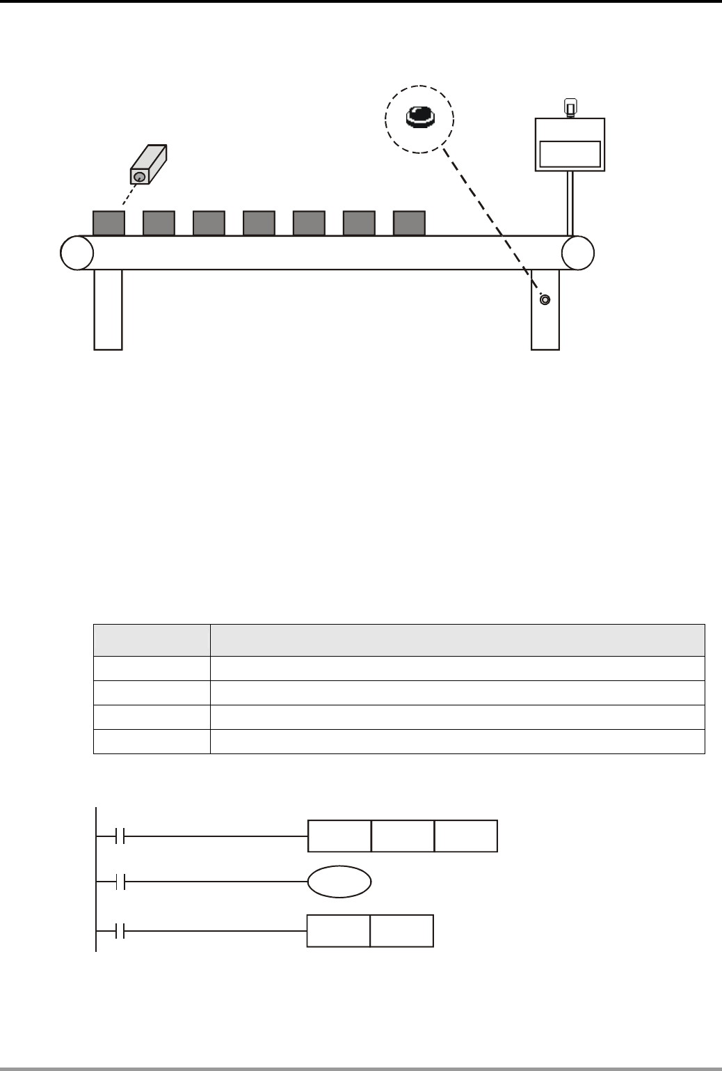
2.1 Product Mass Packaging
X0
X1
Y0
Control Purpose:
z Once the photoelectric sensor detects 10 products, the robotic arm will begin to pack up.
When the action is completed, the robotic arm and the counter will be reset.
Devices:
Device Function
X0 Photoelectric sensor for counting products. X0 = ON when products are detected.
X1 Robotic arm action completed sensor. X1 = ON when packing is completed.
C0 Counter: 16-bit counting up (general purpose)
Y0 Robotic arm for packing
Control Program:
X0 CNT C0 K10
C0
Y0
RST
RST
Y0
C0
X1
Program Description:
z Once the photoelectric sensor detects a product, X0 will go from OFF to ON once, and C0
will count for one time.
z When the present value in C0 reaches 10, the Normally Open contact C0 will be closed. Y0
= ON, and the robotic arm will begin to pack.
z When the packing is completed, the robotic arm action completed sensor will be enabled. X1
will go from OFF to ON and RST instruction will be executed. Y0 and C0 will be reset for the
next packing task.
2. Counter Design Examples
DVP-PLC Application Examples
2-2
2.2 Daily Production Record (16-bit Counting Up Latched Counter)
今日完成
456
Daily Q Cuantity ompletion
456
X0
Clear
X1
Control Purpose:
z The production line may be powered off accidentally or turned off for noon break. The
program is to control the counter to retain the counted number and resume counting after
the power is ON again.
z When the daily production reaches 500, the target completed indicator will be ON to remind
the operator for keeping a record.
z Press the Clear button to clear the history records. The counter will start counting from 0
again.
Devices:
Device Function
X0 Photoelectric sensor. Once detecting the products, X0 will be ON.
X1 Clear button
C120 Counter: 16-bit counting up (latched)
Y0 Target completed indicator
Control Program:
X1
X0
CNT C120 K500
C120
Y0
RST C120
Program Description:
z The latching counter is demanded for the situation of retaining data when power-off.
z When a product is completed, C120 will count for one time. When the number reaches 500,

2. Counter Design Examples
DVP-PLC Application Examples 2-3
target completed indicator Y0 will be ON.
z For different series of DVP-PLC, the setup range of 16-bit latching counter is different. C112
~ C127 for ES/EX/SS series, C96 ~ C199 for SA/SX/SC series and C100 ~ C199 for EH
series.
2. Counter Design Examples
DVP-PLC Application Examples
2-4
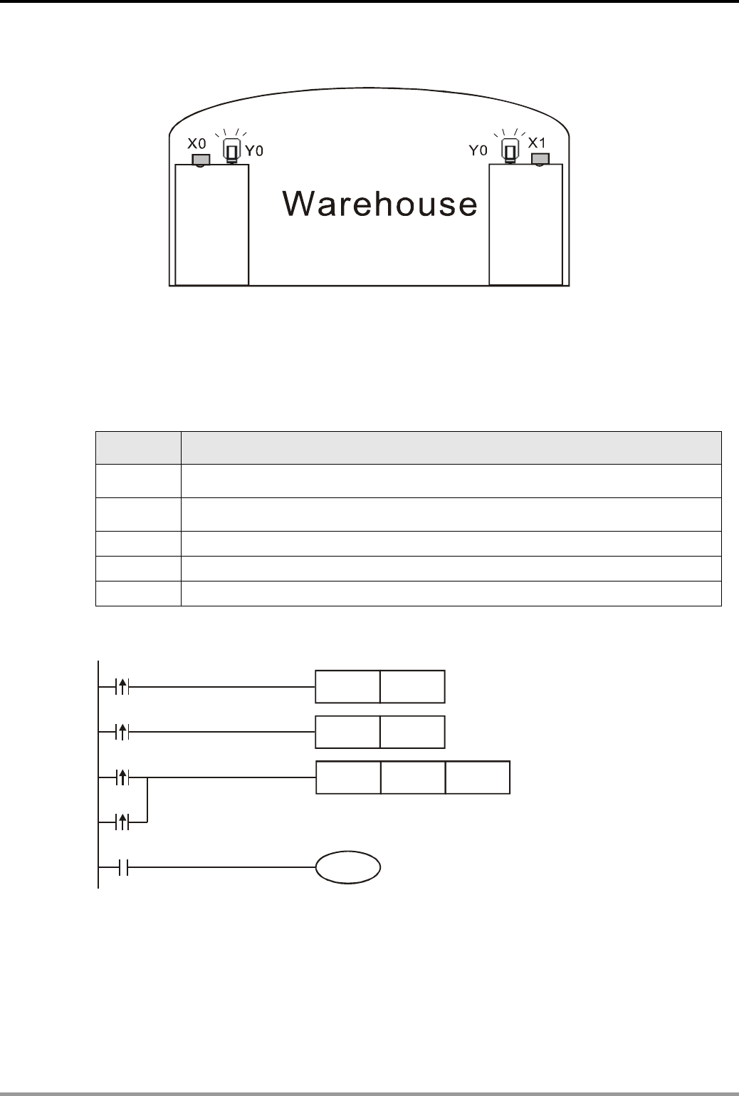
2.3 Products Amount Calculation (32-bit Counting Up/Down Counter)
Entry Exit
Control Purpose:
z This program is used for monitoring the product amount in the warehouse by photoelectric
sensors at both entry and exit. When the amount reaches 40,000, the alarm will be enabled.
Devices:
Device Function
X0 Photoelectric sensors for monitoring incoming goods. X0 = ON when incoming
detected.
X1 Photoelectric sensors for monitoring outgoing goods. X1 = ON when outgoing
detected.
M1216 Counting mode of C216(ON: counting down)
C216 32-bit counting up/down counter
Y0 Alarm
Control Program:
X1
X0
DCNT C 162K40000
Y0
RST M1216
SET M1216
X1
X0
C216
Program Description:
z The key of this example is using the 32-bit addition/subtraction flag M1216 to control the
counting up/ down of C216. When X0 goes from OFF to ON, M1216 = OFF, and C216 will
count up; when X1 goes from OFF to ON, M1216 = ON, C216 will count down.
z When the present value of C216 reaches 40,000, C216 = ON, and the alarm Y0 will be
enabled.
2. Counter Design Examples
DVP-PLC Application Examples 2-5
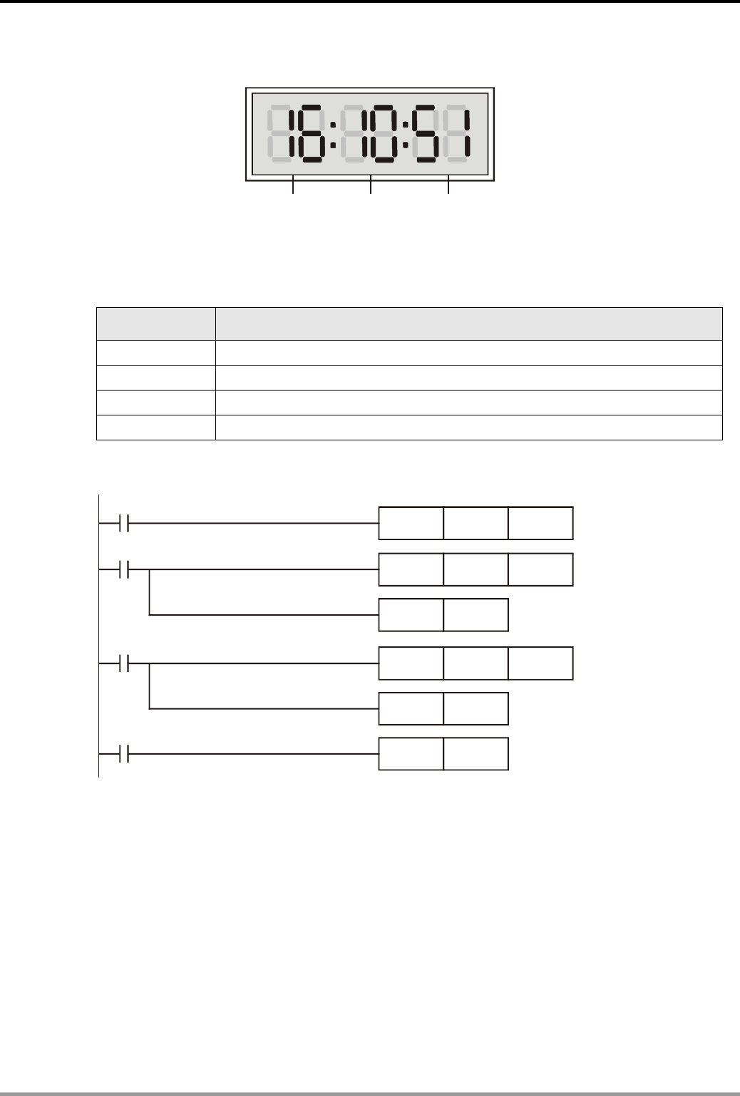
2.4 24-hour Clock Operated by 3 Counters
Hour Minute Second
Control Purpose:
z Using 3 counters together with the flag of M1013 (1s clock pulse) to operate a 24-hour clock.
Devices:
Device Function
C0 count per second
C1 count per minute
C2 count per hour
M1013 1s clock pulse
Control Program:
M1013
CNT C0 K60
C0
CNT C1 K60
RST C0
C1
C2
CNT C2 K24
RST C1
RST C2
Program Description:
z The key of operating a 24-hour clock is to use M1013 (1s clock pulse). When the program is
executed, C0 will count once per second. When the counted number reaches 60(1 minute),
C0 = ON. C1 will count once, and C0 will be reset at the same time; similarly, when the
counted number in C1 reaches 60(1 hour), C1 = ON. C2 will count once, and C1 will be
reset at the same time. Furthermore, when the present value in C2 reaches 24, C2 will be
reset, and the 24-hour counting process will start again.
z The 24-hour clock operates by using C0 to count “second”, C1 to count “minute” and C2 to
count “hour.” In this clock, the value of “second”, “minute” and “hour” can be read by C0, C1
and C2 correspondingly. When the set value of C2 is 12, the clock will be a 12-hour clock.
2. Counter Design Examples
DVP-PLC Application Examples
2-6
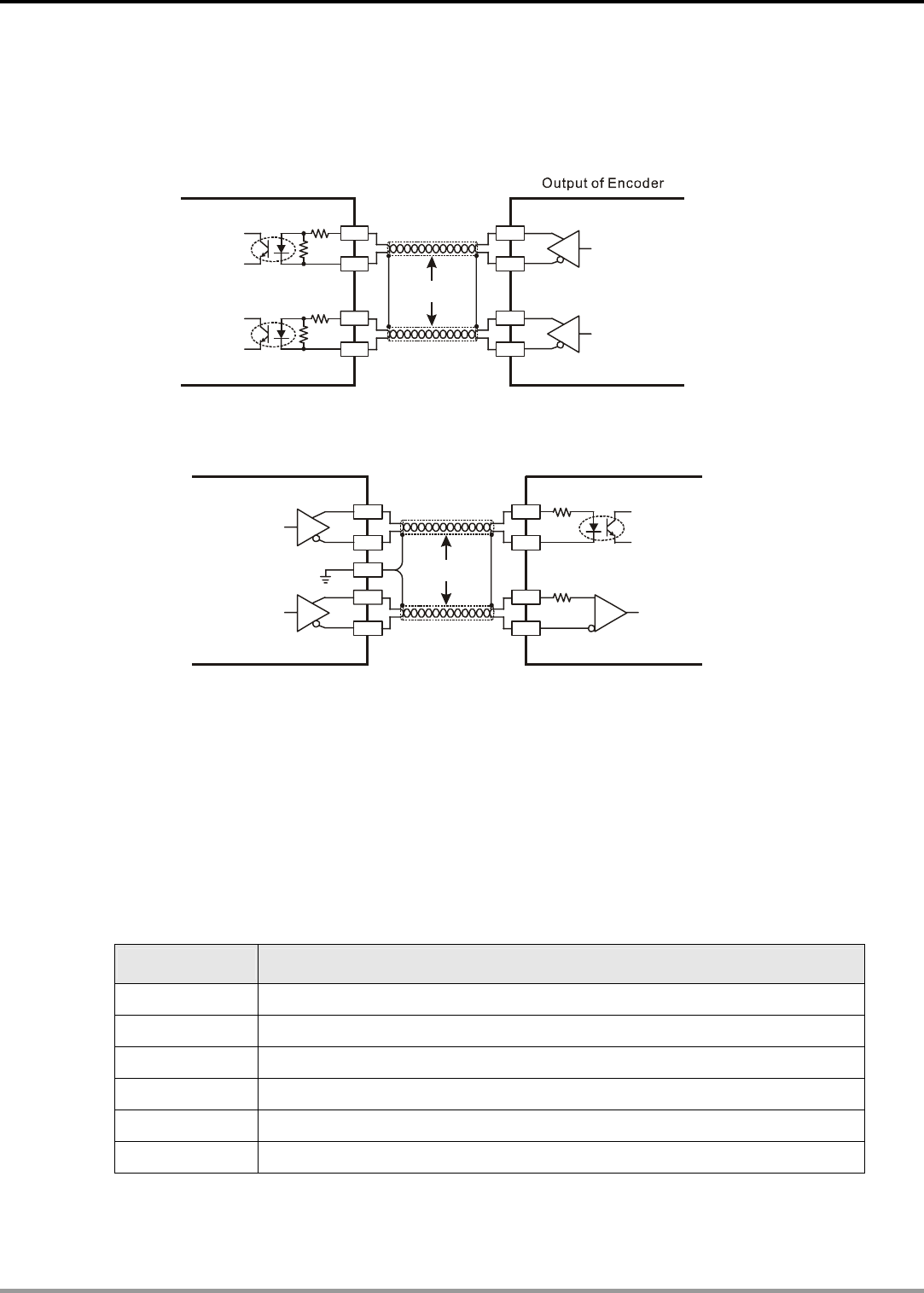
2.5 A B-phase Pulse High-speed Counter
z Wiring for Differential Input(high-speed, high-noise condition)
TPCwisted air able
A
+
A
-
B +
B -
A
B
Differntial Output
X0+
X0-
X1+
X1-
DVP32EH00M High-speed Input
z Wiring for Differential Output
Twisted Pair Cable
A
+
A
-
B +
B -
Y0
Y1
Servo Driver
PLC
Photocouple
Line Receiver
Input Wiring
Input Wiring
Y0+
Y0-
Y1+
Y1-
SG0
Control Purpose:
z DVP32EH00M sends AB-phase pulse to control the servo at a speed of 10,000 pulses per
second. The motor rotation will be encoded by the encoder and the result will be transferred to
the input points (differential input) of PLC high-speed counter. If the counted value in PLC
high-speed counter is different from the number of pulse sent by the MPU, the alarm will be
enabled.
Devices:
Device Function
Y0 100KHz pulse output
Y5 Alarm indicator
M1013 1s clock pulse
M1029 Pulse output completed flag
D1220 Setting the first group output phase, CH0(Y0, Y1)
C251 High-speed counter
2. Counter Designing Example
DVP-PLC Application Examples
2-7
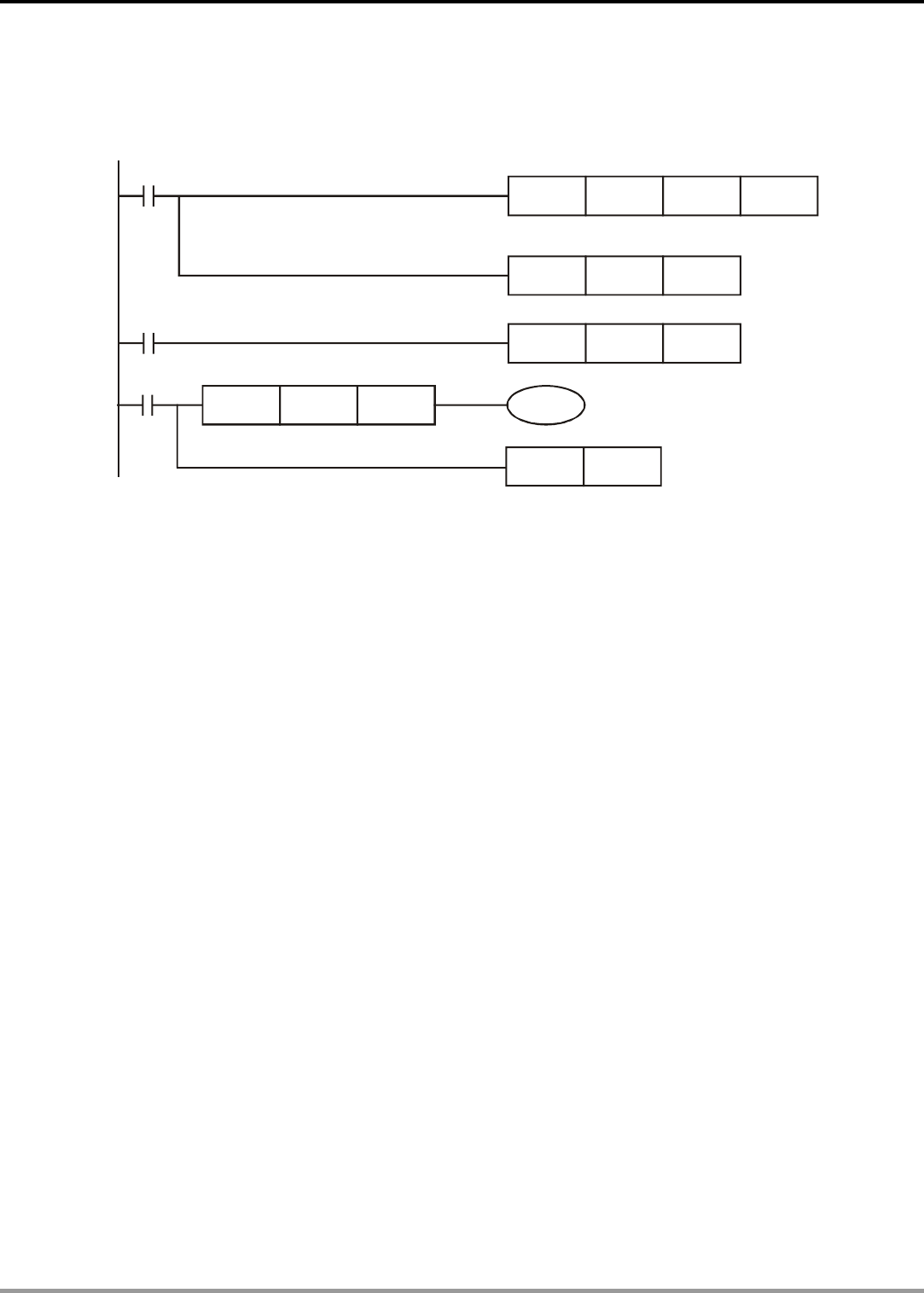
Control Program:
M1013
M1000
M1029
DPLSY K100000 K10000 Y0
Y5
MOV K0 D1220
DCNT
RST
C251
C251
K20000
DLD<= C251 K9990
The output speed of Y0 is 10000 pulses per
second with a frequency of 100K
Program Description:
z In this example, M1013 is used to control PLC for sending pulses. D1220 = K0 activates Y0 to
output pulses and transfer the encoded feedback signal of servo motor from the encoder to the
high-speed inputs (X0, X1). X0 and X1 are corresponded to high-speed counter C251, whose
max counting frequency is 200 kHz.
z When pulse sending is completed, M1029 = ON. The Load Compare instruction DLD<= will be
executed. If the difference between the value of C251 and the number of pulses is above
10(C251 value≦K9990), the alarm Y5 will be enabled.
z When M1029 = ON, [RST C251] will be executed. The value of C251 will be cleared to ensure
that C251 will start counting from 0 next time.
z Since the output signal of servo encoder is differential signal, the example requires
DVP32EH00M model which supports differential signal input with its input terminal X0, X1, X4,
and X5.

2. Counter Design Examples
DVP-PLC Application Examples
2-8
MEMO
3. Timer Design Examples
DVP-PLC Application Examples
3-1
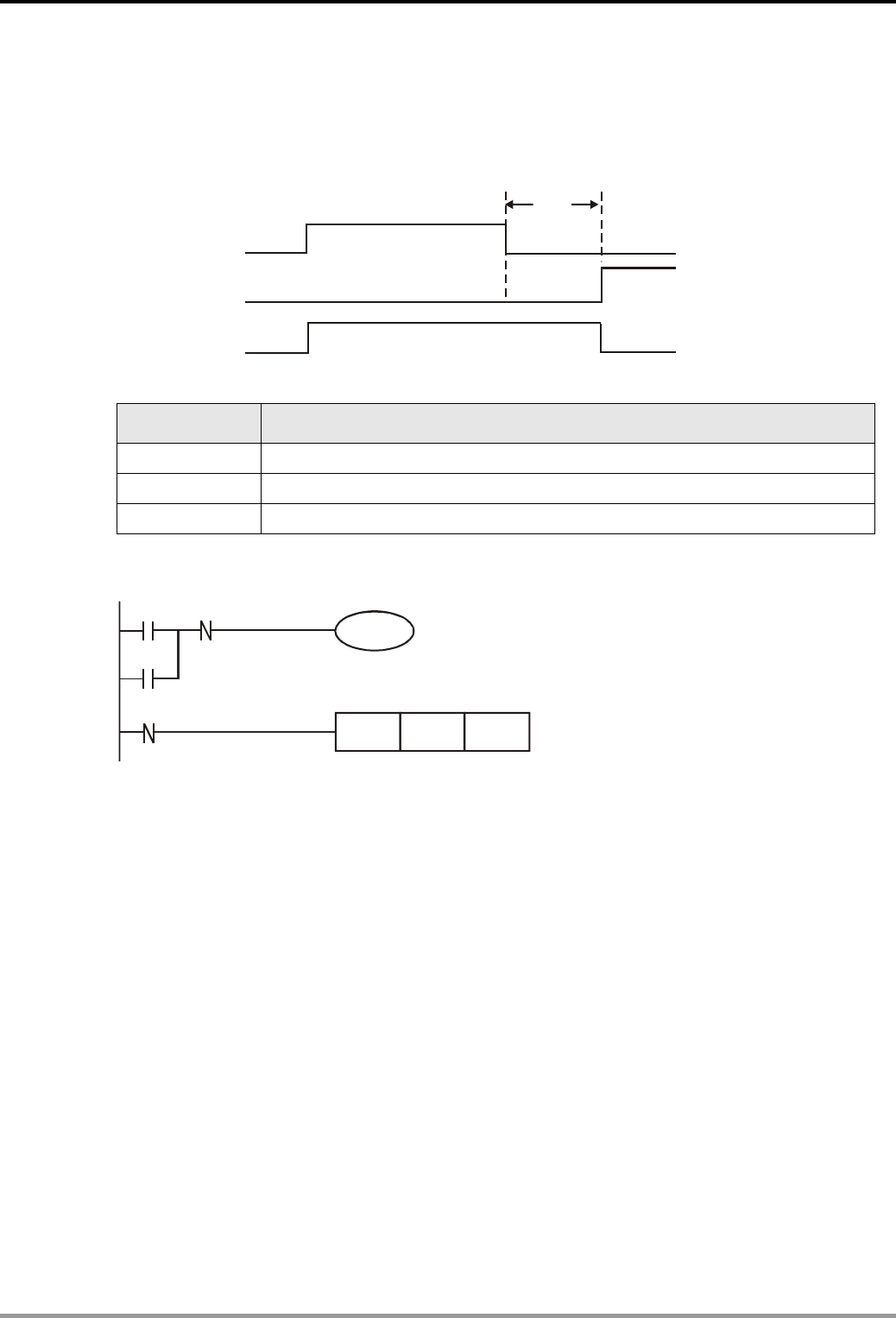
3.1 Delay OFF Program
Control Purpose:
z Enabling the indicator to be ON immediately and OFF after a 5 sec delay by the switch
5s
X1
Y1
T0
Devices:
Device Function
X1 X1 = OFF when the switch is turned off
T1 5 sec timer. Time base = 100ms
Y1 Output indicator
Control Program:
Y1
TMR T1 K50
X1 T1
Y1
X1
Delay OFF for 5 sec
Program Description:
z X1 = ON when the switch is turned on. The NC (Normally Closed) contact X1 will be
activated, and TMR instruction will not be executed. Coil T1 will be OFF and so will the NC
contact T1. Because X1 = ON, the indicator Y1 will be ON and latched.
z X1 = OFF when the switch is turned off. The NC contact X1 will not be activated, which
makes TMR instruction executed. Indicator Y1 will remain ON by the latched circuit until T1
reaches its set value.
z When timer T1 reaches its set value of 5 seconds, coil T1 will be ON. The NC contact T1 will
be activated, which makes the indicator Y1 OFF.
z Delay OFF function can also be performed by using API 65 STMR instruction.
3. Timer Design Examples
DVP-PLC Application Examples
3-2
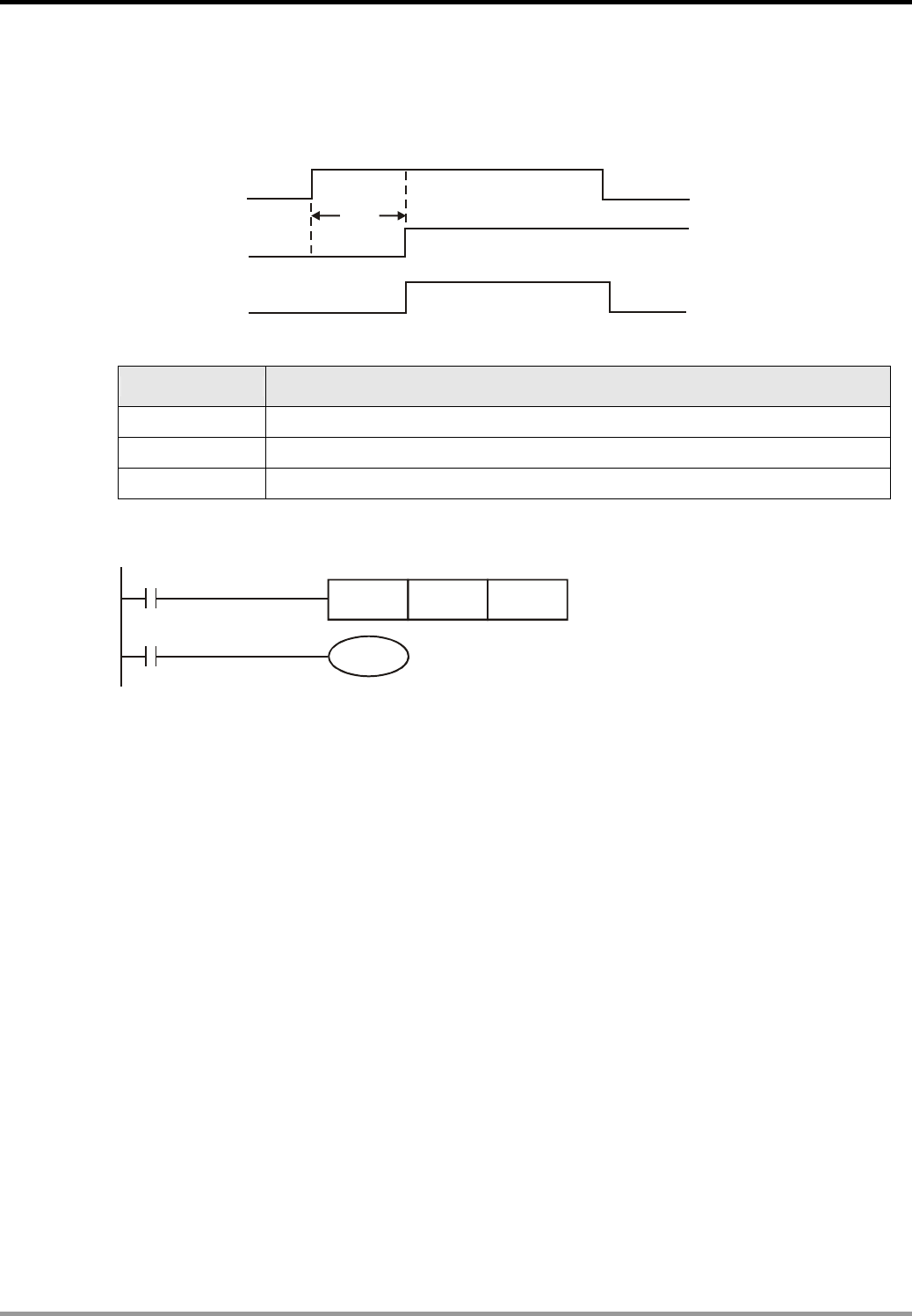
3.2 Delay ON Program
Control Purpose:
z Enabling the indicator to be ON after a 3 sec delay and OFF immediately by the switch
X1
Y1
T0
3s
Devices:
Device Function
X1 X1 = ON when the switch is turned on
T1 3 sec timer, time base = 100ms
Y1 Output indicator
Control Program:
X1
T1
Y1
TMR T1 K30 Delay ON for 3 sec
Program Description:
z When X1 = ON, TMR instruction will be executed. Timer T1 will be ON and start counting for
3 sec. When T1 reaches its set value, the NO (Normally Open) contact T1 will be activated
and indicator YI will be ON.
z When X1 = OFF, TMR instruction will not be executed. Timer T1 will be OFF and so will NO
contact T1. Therefore, the indicator Y1 will be OFF.
3. Timer Design Examples
DVP-PLC Application Examples
3-3
3.3 Delay ON/OFF Program
Control Purpose:
z Enabling the indicator to be ON after a 5 sec delay and OFF after a 3 sec delay by the
switch
Y1
X1
3s
5s
Devices:
Device Function
X1 X1 = ON when the switch is turned on.
T0 5 sec timer, time base = 100ms
T1 3 sec timer, time base = 100ms
Y1 Output indicator
Control Program:
X1
Y1
TMR T0 K50
T0 T1
Y1
X1
TMR T1 K30
Delay ON for 5 sec
Delay OFF for 3 sec
Program Description:
z When X1 = ON, T0 will start counting for 5 sec. When T0 reaches its set value, the NO
contact T0 will be ON while NC contact T1 will remain OFF, which makes the indicator Y1 to
be ON and latched.
z When X1 = OFF, T1 will start counting for 3 sec. When T1 reaches its set value, the NC
contact T1 will be activated while the NO contact T0 will remain OFF, which makes the
indicator Y1 to be OFF.
3. Timer Design Examples
DVP-PLC Application Examples
3-4
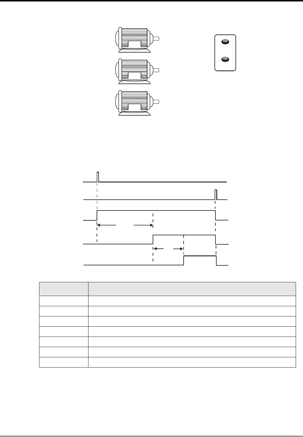
3.4 Sequential Delay Output (Starting 3 Motors Sequentially)
START X0
STOP X1
Y0
Y1
Y2
Oil Pump Motor
Main motor
A
uxiliary Motor
Control Purpose:
z Starting the oil pump motor immediately when START is pressed. The main motor will be
started after a 10 sec delay and then the auxiliary motor after a 5 sec delay. In addition,
stopping all motors immediately when STOP is pressed.
X1
Y2
Y0
Y1
10s
5s
X0
Devices:
Device Function
X0 X0 = ON when START is pressed.
X1 X1 = ON when STOP is pressed.
T0 10 sec timer. Time base: 100ms
T1 5 sec timer. Time base: 100ms
Y0 Starting the oil pump motor
Y1 Starting the main motor
Y2 Starting the auxiliary motor
3. Timer Design Examples
DVP-PLC Application Examples
3-5
Control Program:
X1
X1
X1
Y0
Y1
Y2
X0
T0
T1
Y0
Y1
Y2
TMR
TMR
T0
T1
K100
K50
Y1
Y2
Starting the oil pump motor
Starting the main motor
Starting the auxiliary motor
Program Description:
z When START is pressed, the NO contact X0 will be activated, which makes Y0 to be ON and
latched. The oil pump motor will start the lube system. At the same time, [TMR T0 K100]
instruction will be executed. When T0 reaches its set value of 10 sec, the NO contact T0 will
be ON.
z When the NO contact T0 is ON, Y1 will be ON and latched, which starts the main motor and
stops timer T0. At the same time, [TMR T1 K50] is executed, and the NO contact T1 will be
ON when timer T1 reaches its set value.
z When the NO contact T1 is ON, Y2 will be ON and latched, which starts the auxiliary motor
and stops T1.
z When STOP is pressed, the NC contact X1 will be activated, which makes Y0, Y1 and Y2
OFF. The oil pump motor, main motor and auxiliary motor will stop working.
3. Timer Design Examples
DVP-PLC Application Examples
3-6
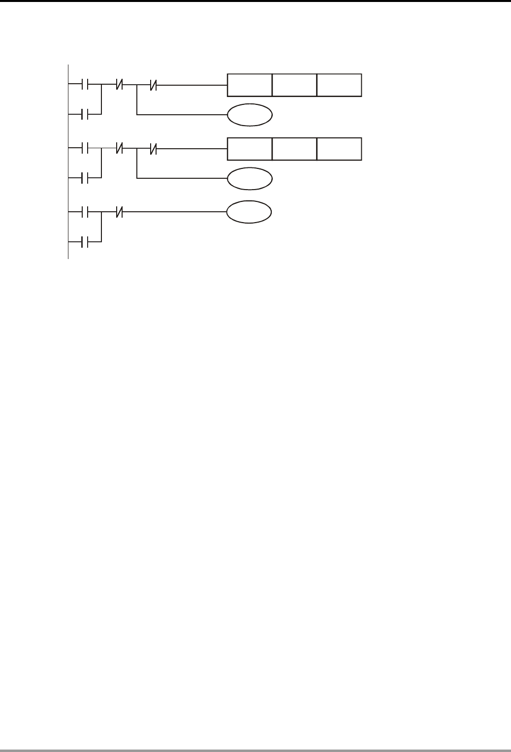
3.5 Pulse-Width Modulation
Control Purpose:
z Performing Pulse Width Modulation function by changing the set value of the timer in the
program. The oscillating pulse is as below: (Y0 = ON for 1 sec. The cycle = 2 sec)
1000ms
2000m
s
X0
Y0
Devices:
Device Function
X0 X0 = ON when the switch is turned on
T0 1 sec timer. Time base: 100ms
T1 2 sec timer. Time base: 100ms
Y0 Oscillating pulse output
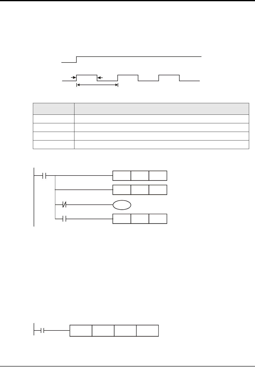
Control Program:
T0
X0
TMR
Y0
T0
T1TMR
T1 T0
ZRST
K10
K20
T1
Program Description:
z When X0 = ON, timer T0/T1 will be activated. Y0 will be ON until timer T0 reaches its set
value. When timer T1 reaches its set value, T0/T1 will be reset. Therefore, Y0 will output the
above oscillating pulse continuously. When X0 = OFF, the output Y0 will be OFF as well.
z Pulse Width Modulation function can be modified by changing the set value of the timer in
the program.
z Pulse Width Modulation function can also be performed by using API 144 GPWM
instruction.
X0
GPWM K1000 K2000 Y0
3. Timer Design Examples
DVP-PLC Application Examples
3-7
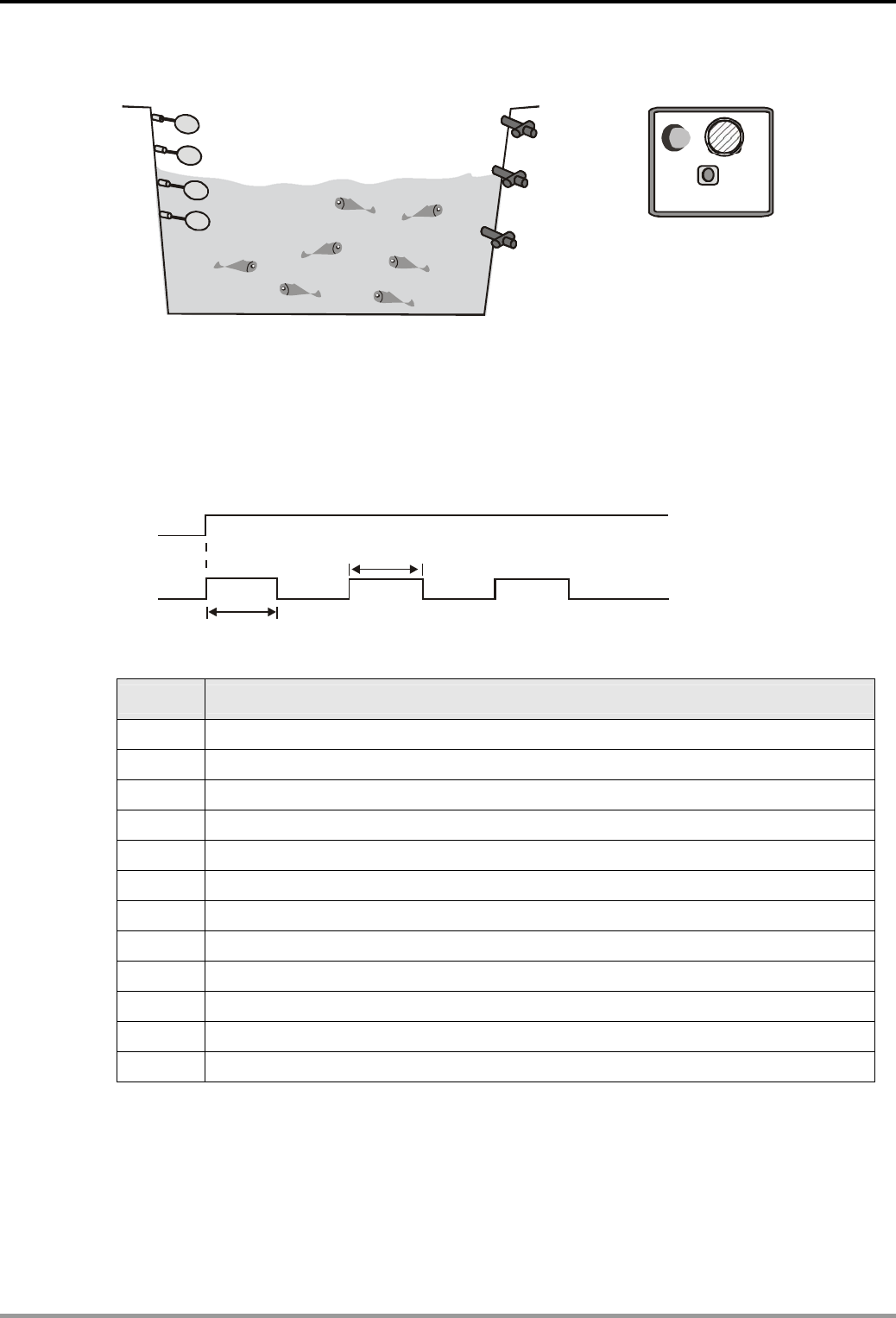
3.6 Artificial Fishpond Water Level Monitoring System (Flashing Circuit)
RESET
X0
X1
X2
X3 Y0
Y1
Y2
Y3
X4
Y4
Control Purpose:
z Feeding or draining water automatically when the water level of artificial fishpond is not at
the normal level. In addition to feeding / draining water, enabling the alarm and alarm lamp
when the water is above or below the alarm level.
z Stopping the alarm when RESET is pressed.
Y3/Y4
X0
A
larm
A
larm Lamp
500ms
500ms
Devices:
Device Function
X0 X0 = ON when the water is above the lowest level of alarm level.
X1 X1 = ON when the water is above the lowest level of normal level.
X2 X2 = ON when the water is above the highest level of normal level.
X3 X3 = ON when the water is above the highest level of alarm level.
X4 X4 = ON when RESET is pressed.
T1 500ms timer. Time base: 100ms.
T2 500ms timer. Time base: 100ms.
Y0 1# drainage pump
Y1 Feeding pump
Y2 2# drainage pump
Y3 Alarm lamp
Y4 Alarm
3. Timer Design Examples
DVP-PLC Application Examples
3-8
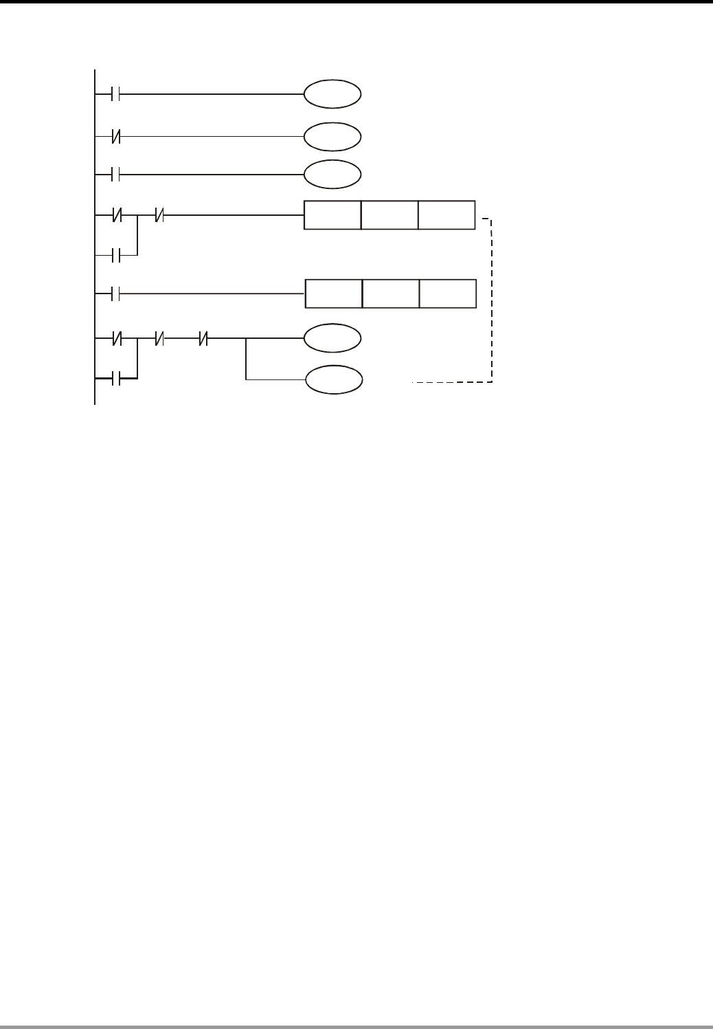
Control Program:
Y4
Y1
X1
Y2
X2
X3
X0 T2
X3
T1
X0 T1 X4
X3
Y0
TMR T1 K5
TMR T2 K5
Y3
Flashing Circuit
RESET
Alarm Lamp
Alarm
Program Description:
z When the water is at normal level: X0 = ON, X1 = ON, X2 = OFF and X3 = OFF. Therefore,
Y0 and Y2 will be OFF. Both the drainage pump and the feeding pump will not work.
z When the water is lower than the normal level, X0 = ON, X1 = OFF, X2 = OFF and X3 = OFF.
Because X1 = OFF, Y1 will be ON. The feeding pump will start working.
z When the water is below the lowest of alarm level, X0 = OFF, X1= OFF, X2 = OFF and X3 =
OFF. Because X1 = OFF, Y1 will be ON. The feeding pump will start working. In addition,
because X0 = OFF, the flashing circuit will be activated, which makes Y3 = ON and Y4 = ON,
The alarm lamp will flash and the alarm will ring.
z When the water is above the normal level, X0 = ON, X1 = ON, X2 = ON, X3 = OFF. Because
X2 = ON, Y2 will be ON. 2# drainage pump will drain water from the fishpond.
z When the water is above the highest of alarm level, X0 = ON, X1 = ON, X2 = ON, X3 = ON.
Because X2 = ON, Y2 will be ON. 2# drainage pump will work. In addition, because X3 = ON,
Y0 will be ON. 2# drainage pump will work. Besides, the alarm circuit will be executed,
which makes Y3 = ON and Y4 = ON. The alarm lamp will flash and the alarm will ring.
z When Reset is pressed, the NC contact X4 will be activated. Y3 = OFF and Y4 = OFF. Both
the alarm and the alarm lamp will stop working.
3. Timer Design Examples
DVP-PLC Application Examples
3-9
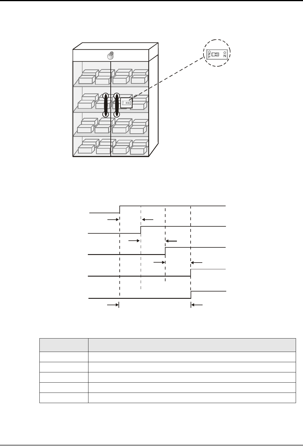
3.7 Burn-in Test System (Timing Extension)
Y0
X0
Control Purpose:
z Warning the operator to take out PLC from the burn-in room by the test completed indicator
after 2.5 hours burn-in process.
X0
T2
Y0
T0
T1
(3000+3000+3000)s
3000 s
3000 s
3000 s
Devices:
Device Function
X0 When X0 = ON, the burn-in test starts
T0 3,000 sec timer. Time base: 100ms
T1 3,000 sec timer. Time base: 100ms
T2 3,000 sec timer. Time base: 100ms
Y0 Burn-in test completed indicator

3. Timer Design Examples
DVP-PLC Application Examples
3-10
Control Program:
T0
T1
T
T1
T2
X0
TMR
TMR
TMR
TMR
TMR
Y0
T0
T1
K30000
K30000
K30000
K30000
K30000
T2
Program Description:
z The upper bound value for a 16-bit timer is 100ms × 32767 = 3276.7s, so it needs several
timers to work together for a timing extension application which is more than 1 hour (3600
sec.) The total time is the sum of each timer’s set value.
z When the burn in test is started, X0 = ON. The timer T0 will start to count for 100ms × 30000
= 3000sec. When T0 reaches its set value, the NO contact T0 will be ON and T1 will start to
count for another 100ms × 30000 = 3000sec. When T1 reaches its set value, T2 will count
one more 3000 sec and turn on the NO contact T2. Finally, the burn-in test completed
indicator Y0 will be ON. The total time of the test is 3000s + 3000s + 3000s = 9000s =
150min = 2.5h.
z The timing extension function can also be performed by using API 169 HOUR instruction.
3. Timer Design Examples
DVP-PLC Application Examples
3-11
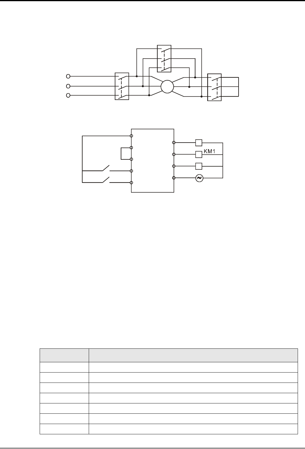
3.8 Star-Delta Reduced Voltage Starter Control
M
KM2
KM0
KM1
Reduced Voltage Starting Main Circuit
Y0
Y1
Y2
COM
KM0
KM2
24V
24G
SS
X0
X1
PLC External Wiring
Control Purpose:
z Usually the starting current of the three-phase AC asynchronous motor is 5 ~7 times larger
than the rated current. To reduce the effect of the starting current on the electrified wire
fence, a star-delta reduced voltage starter should be applied.
z Starting process of a star-delta reduced voltage starter:
When the switch is turned on, the contactors of both motor starter and “Star Reduced
Voltage Starter” will be enabled first. After a 10 sec delay, the contactor of “Star Reduced
Voltage Starter” will be disabled. Finally, the contactor of “Delta Reduced Voltage Starter”
will be enabled after 1 sec, which operates the main motor circuit normally. The control
purpose in this process is to assure the contactor of “Star Reduced Voltage Starter” is
disabled completely before the contactor of “Delta Reduced Voltage Starter” is enabled.
Devices:
Device Function
X0 X0 = ON when START is pressed.
X1 X1 = ON when STOP is pressed.
T1 10 sec timer. Time base: 100ms
T2 1 sec timer. Time base: 100ms
Y0 Motor starting contactor KM0
Y1 “Star Reduced Voltage Starter” contactor KM1
Y2 “Delta Reduced Voltage Starter” conntactor KM2
3. Timer Design Examples
DVP-PLC Application Examples
3-12
Control Program:
X0
TMR T0 K100
Y0
TMR T1 K10
X1
Y0
Y0 T0 Y2
Y1
Y2
Y1 T0
T1 Y1 X1
Y2
Program Description:
z X0 = ON when START is pressed. Y0 will be ON and latched. The motor starting contactor
KM0 will be ON and the timer T0 will start to count for 10 sec. At the same time, because Y0
= ON, T0 = OFF and Y2 = OFF, Y1 will be ON. The “Star Reduced Voltage Starter” contactor
KM1 will be activated.
z When timer T0 reaches its set value, T0 will be ON and Y1 will be OFF. Timer T1 will start to
count for 1 sec. After 1 sec, T1 = ON and Y2 = ON. “Delta Reduced Voltage Starter”
contactor KM2 will be activated.
z X1 = ON when STOP is pressed. Y0, Y1 and Y2 will be OFF and the motor will stop running
no matter it is in starting mode or running mode.
3. Timer Design Examples
DVP-PLC Application Examples
3-13
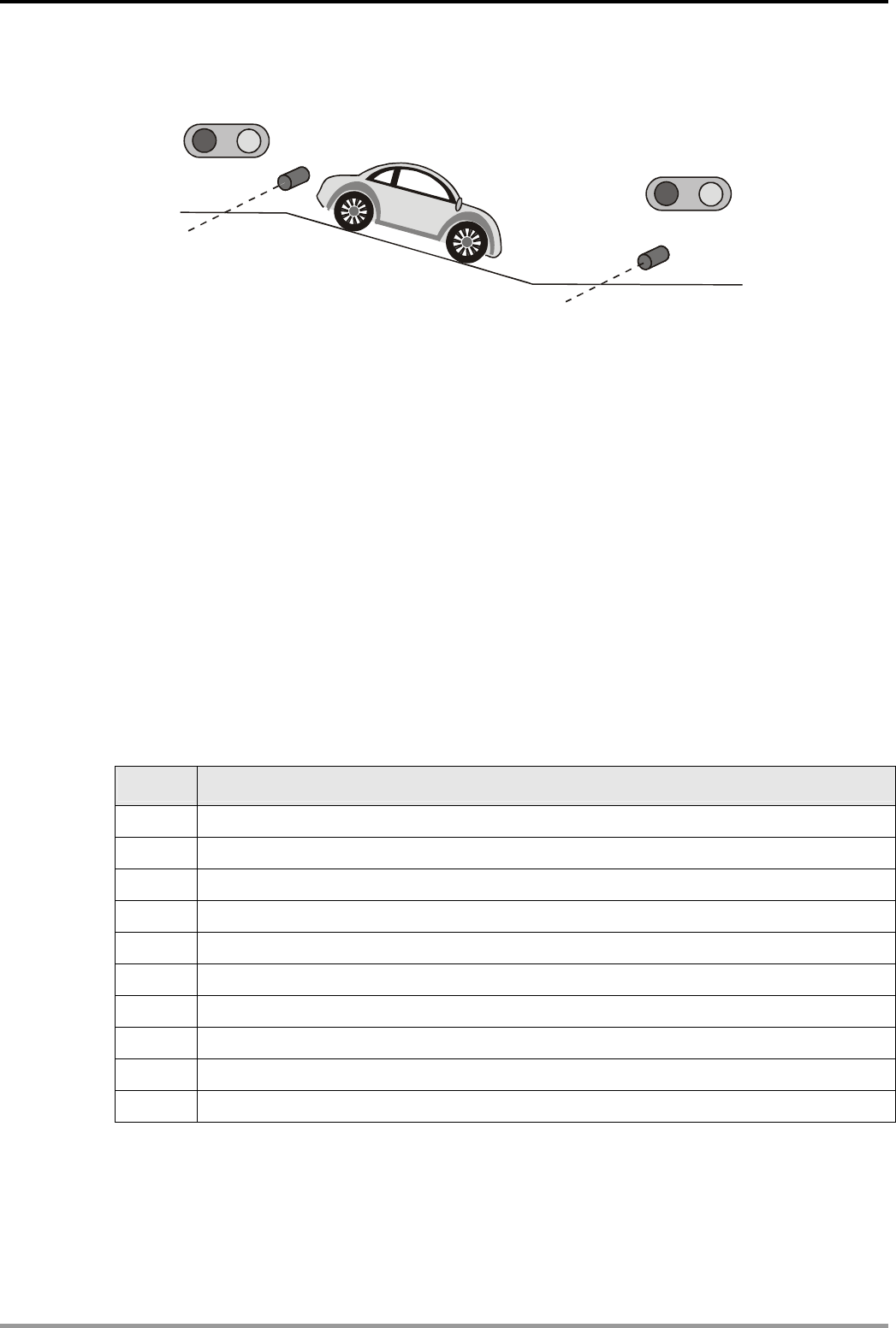
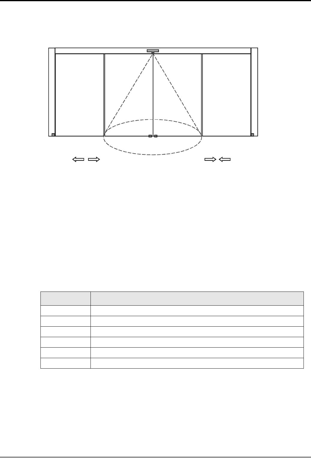
3.9 Automatic Door Control
X0(Infrared Sensor.
)
X1(Closing Limit Switch)
X2(Opening Limit Switch) X2(Opening Limit Switch)
Y1(Close the door)
Y0(Open the door)
Control Purpose:
z When someone enters the infrared sensing field, opening motor starts working to open the
door automatically till the door touches the opening limit switch
z If the door touches the opening limit switch for 7 sec and nobody enters the sensing field,
the closing motor starts working to close the door automatically till the closing limit switch
touched together.
z Stop the closing action immediately if someone enters the sensing field during the door
closing process.
Devices:
Device Function
X0 X0 = ON when someone enters the sensing field.
X1 Closing limit switch. X1 = ON when 2 switches touched together.
X2 Opening limit switch. X2 = ON when the door touched the switches.
T0 7 sec timer. Time base: 100ms
Y0 Opening motor
Y1 Closing motor
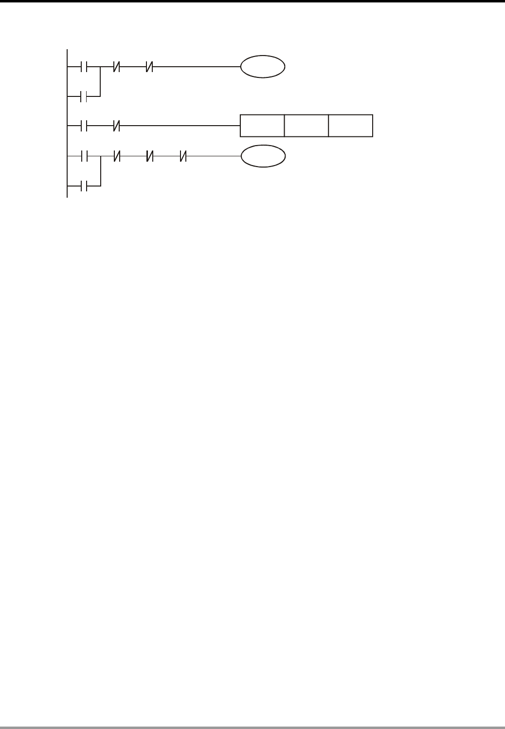
3. Timer Design Examples
DVP-PLC Application Examples
3-14
Control Program:
Y0
X0 X2 Y1
Y0
X2 X0
TMR T0 K70
T0 X0 X1 Y0
Y1
Y1
Program Description:
z X0 = ON if someone enters the sensing field of the infrared sensor. Y0 will be ON and
latched, and the door will be opened as long as the opening limit switches X2 = OFF.
z When the door touches the opening limit switches, X2 = ON. The timer T0 will start to count
for 7 sec if no one enters the sensing field (X0 = OFF). After 7 sec., Y1 will be ON and
latched and the door will be closed.
z During the closing process, X0 = ON if someone enters the sensing field. The NC contact
X0 will be activated to turn Y1 off. Because X0 = ON, X2 = OFF and Y1 = OFF, Y0 will be
ON and the door will be opened once again.
3. Timer Design Examples
DVP-PLC Application Examples
3-15
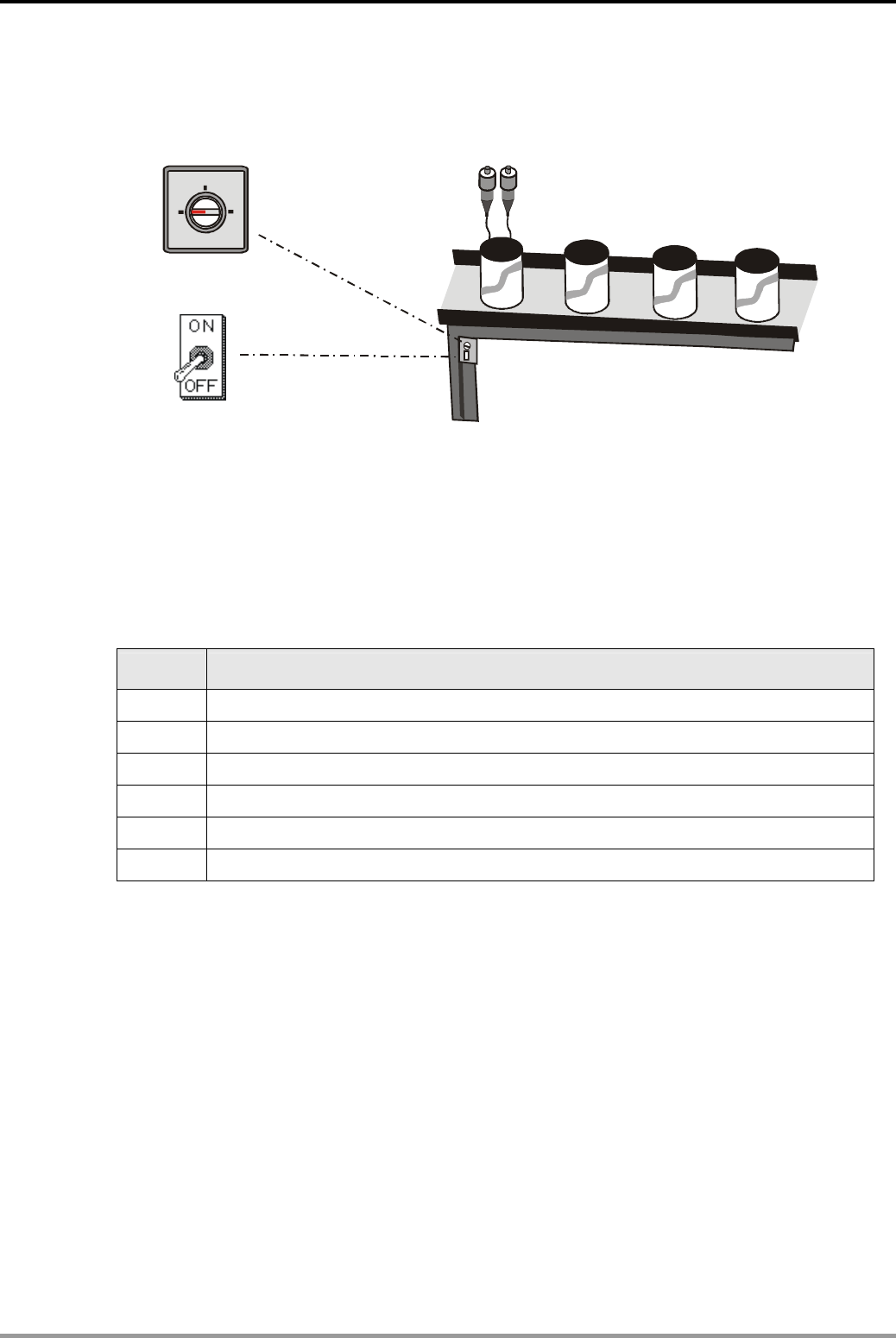
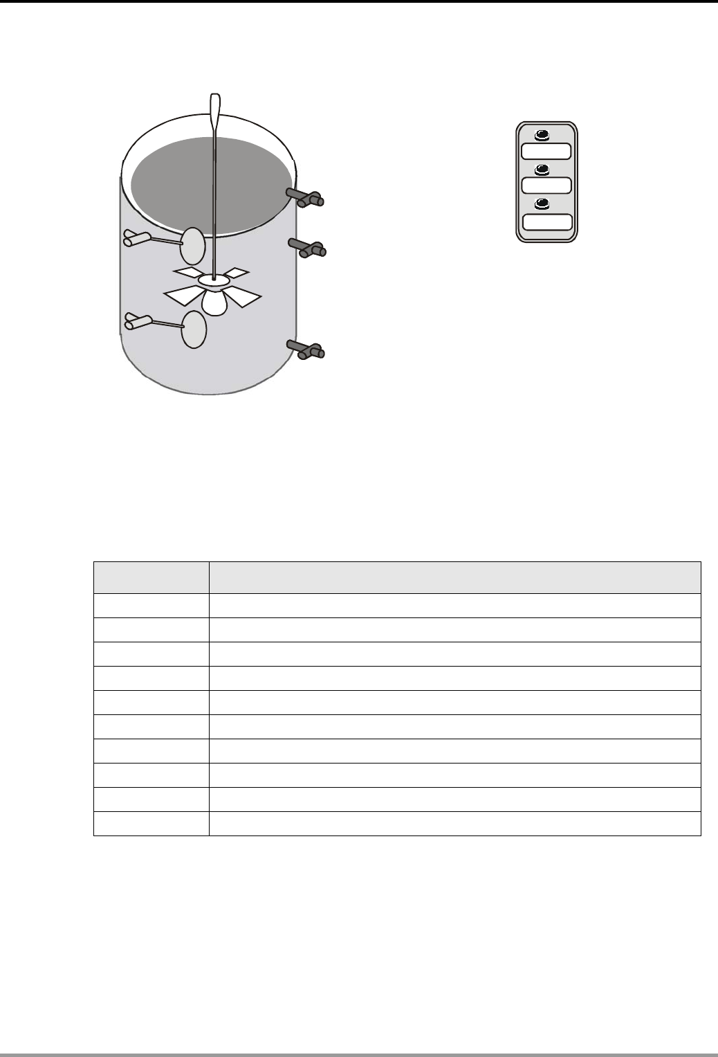
3.10 Automatic Liquids Mixing Control System
START
STOP
X2
X1
Y1( )Liquid B Inlet
Y0 ( A Liquid Inlet )
Y2(Mixture Outlet)
X0
X1
Y3
X10
EMERGENCY STOP
Control Purpose:
z Automatically infusing the container with liquids A and B in order when START is pressed.
When it reaches the set level, mix the two liquids evenly then open the valve to let out the
mixture.
Devices:
Device Function
X0 X0 = ON when START is pressed.
X1 Low level float sensor. X1 = ON when the liquid level reaches X1.
X2 High level float sensor. X2 = ON when the liquid level reaches X2.
X10 EMERGENCY STOP button. X10 = ON when the button is pressed.
T0 60 sec timer. Time base: 100ms
T1 120 sec timer. Time base: 100ms
Y0 Liquid A inlet
Y1 Liquid B inlet
Y2 Mixture outlet
Y3 Agitator
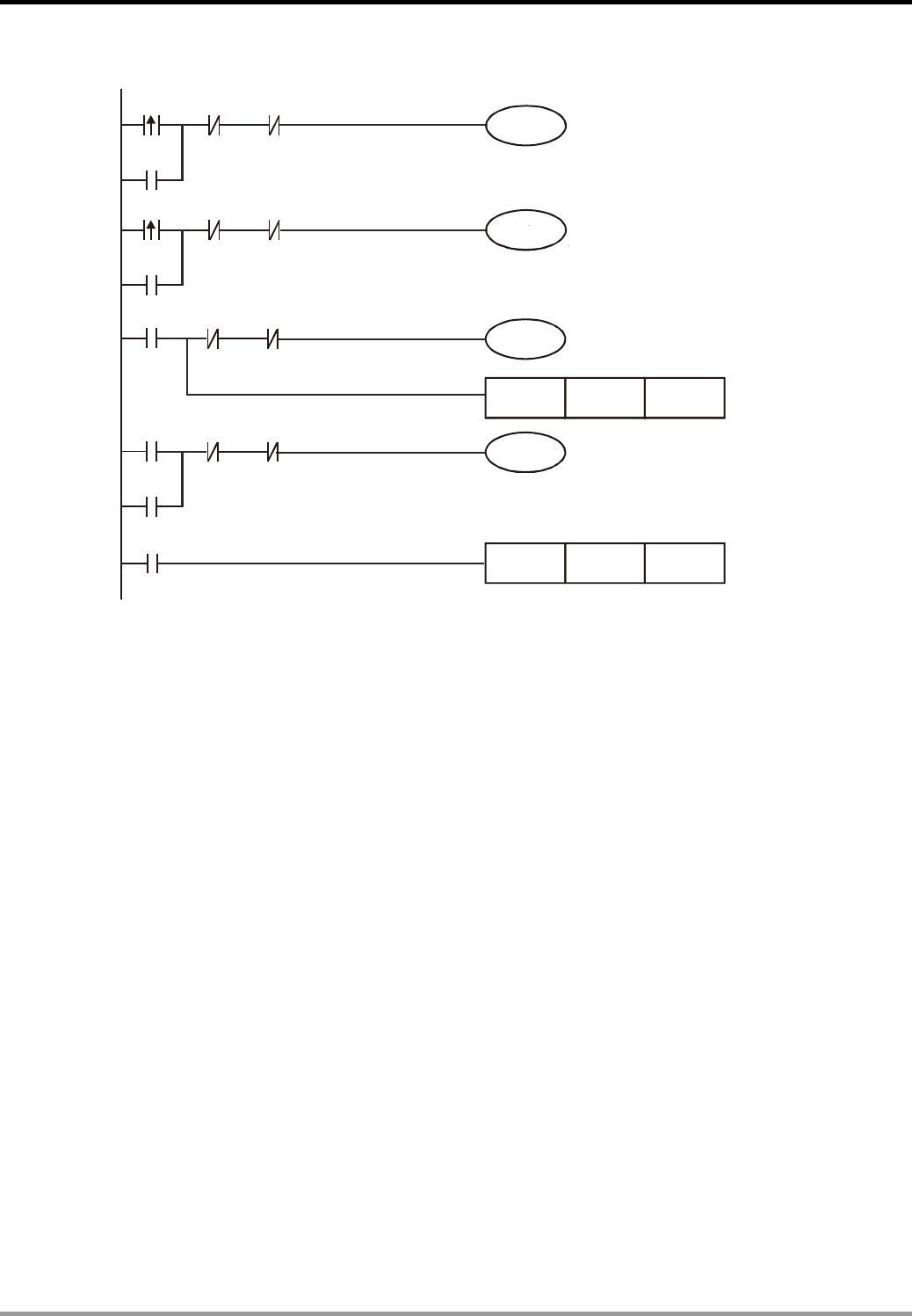
3. Timer Design Examples
DVP-PLC Application Examples
3-16
Control Program:
TMR T0 K600
Y1
X0 X1 X10
Y0
Y0
X1 X2 X10
Y1
X2 T0 X10
Y3
Y2
T0
T1
X10
Y2
Y2
TMR T1 K1200
Program Description:
z X0 = ON when START is pressed. Y0 will be ON and latched, and the valve will be opened
for infusing liquid A until the level reaches the low-level float sensor.
z X1 = ON when the level reaches the low-level float sensor. Y1 will be ON and latched, and
the valve will be opened for infusing liquid B until the level reaches the high-level float
sensor.
z X2 = ON when the level reaches the high-level float sensor. Y3 will be ON and activates the
agitator. Also, timer T0 will start to count for 60 sec. After 60 sec, T0 will be ON, and the
agitator motor Y3 will stop working. Y2 will be ON and latched, and the mixture will drain out
of the container.
z When Y2 = ON, timer T1 will start to count for 120 sec. After 120 sec, T1 will be ON and Y2
will be OFF. The draining process will be stopped.
z When an error occurs, press EMERGENCY STOP button X10. The NC contact X10 will be
ON to disable all the outputs. The system will then stop running.
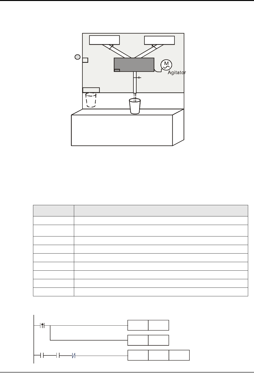
3. Timer Design Examples
DVP-PLC Application Examples
3-17
3.11 Automatic Coffee Maker
咖啡
X0
Coin Detector
Y1 Y2
Y3
Y4
Y0
X1 X2
热水
Coffee Hot Water
Paper Cup Outlet
Mixing Container
X1
Control Purpose:
z Making the paper cup come out of the outlet when a coin is inserted. At the same time, the
coffee pours in the mixing container. After 2 sec, the hot water pours in. 60 sec later, the
ready-made coffee will be pouring out from the coffee outlet.
Devices:
Device Function
X0 Coin detector. X0 = ON when a coin is inserted.
X1 Pressure detector. X1 = ON when the liquid in the container reaches a certain
amount of pressure.
T0 2 sec timer. Time base: 100ms
T1 60 sec timer. Time base: 100ms
Y0 Paper cup outlet
Y1 Coffee outlet
Y2 Hot water outlet
Y3 Agitator
Y4 Ready-made coffee outlet
Control Program:
X0
SET Y1
Y0
TMR T0 K20
SET Y0
Y1 T0
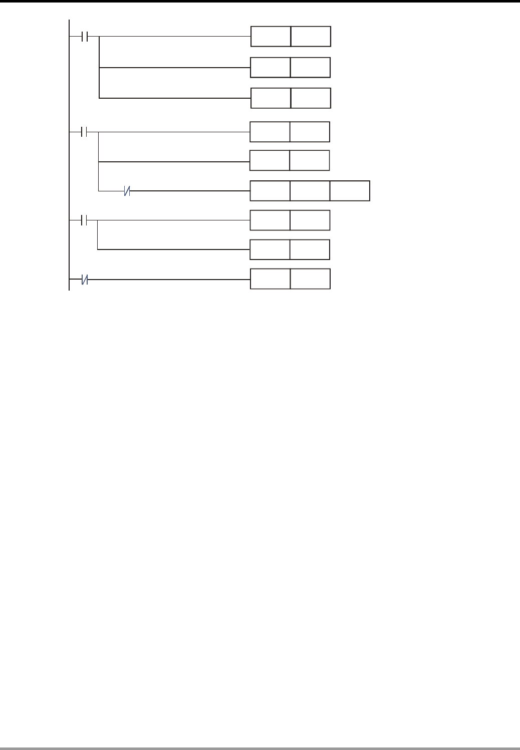
3. Timer Design Examples
DVP-PLC Application Examples
3-18
X1
T0
SET Y2
RST
RST
Y1
Y0
X1
RST Y2
Y3
TMR T1 K600
SET Y4
T1
RST Y3
T1
SET
RST Y4
Program Description:
z X1 = ON when a coin is inserted. Y0 and Y1 will be ON and latched. A paper cup will be sent
out, and a certain amount of coffee will be poured into the container at the same time.
z Y0 and Y1 will be ON for 2 sec which is the set value of timer T0. When NO contact T0 is
ON, Y2 will be activated and the hot water will be poured in the container. At the same time,
the outlets of both paper cup and coffee will be closed.
z When the liquid in the container reaches a certain amount of pressure, X1 = ON. Therefore,
the hot water outlet Y2 will be reset, and the agitator Y3 will be ON for 60 sec. After 60 sec,
NO contact T1 will be ON. Y4 will be ON and latched, and Y3 will be reset at the same time.
The agitator will stop working, and the ready-made coffee will be pouring out from the outlet.
z When the coffee is poured into the paper cup completely, X1 will be OFF and Y4 will be
reset. The ready-made coffee outlet will be closed.
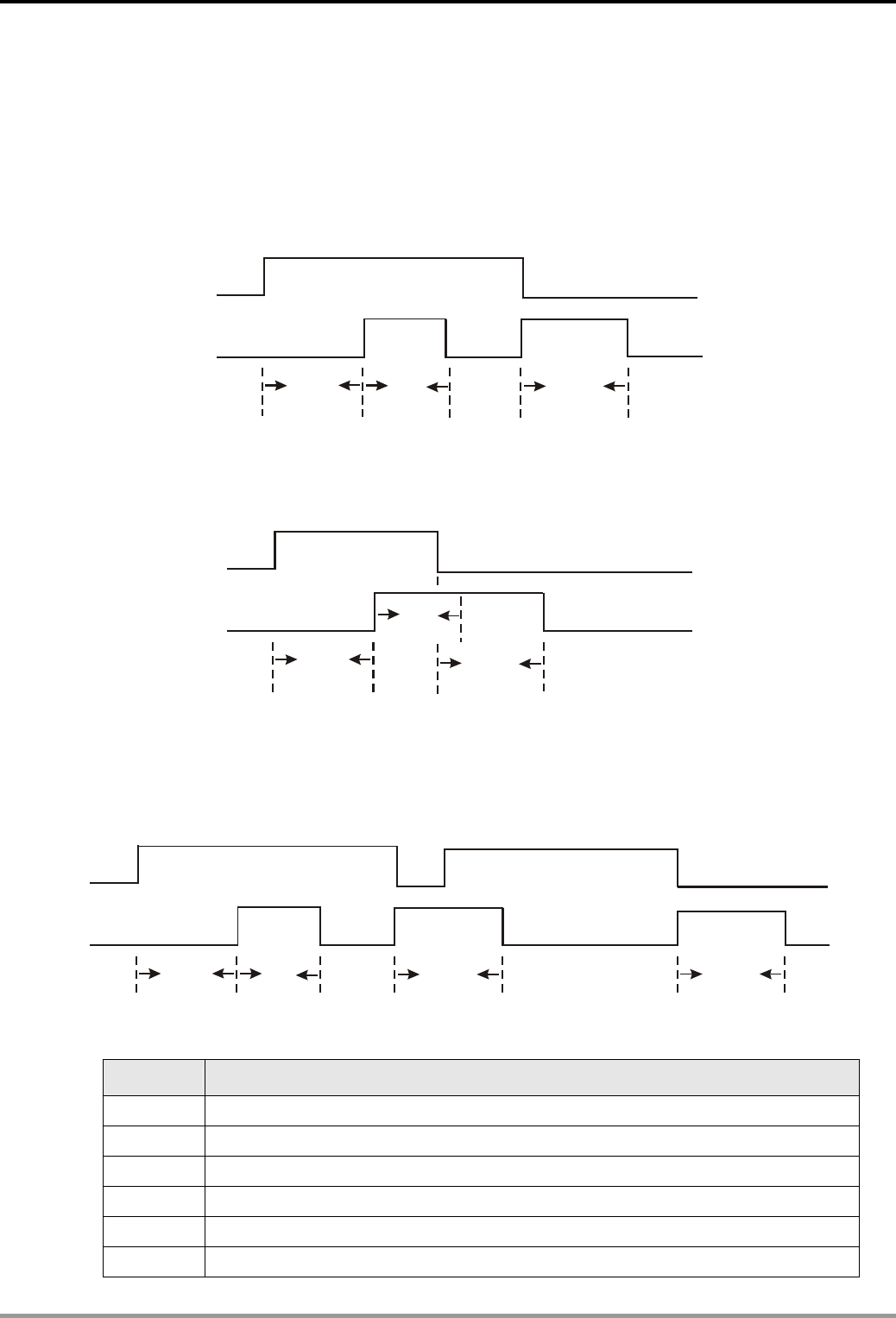
3. Timer Design Examples
DVP-PLC Application Examples
3-19
3.12 Automatic Urinal Flushing Control Program
Control Purpose:
z If a user stands in front of the urinal for more than 3 sec, the flushing control device will flush
the urinal for 3 sec (the first flushing). When the user leaves the urinal, flush for another 4
sec then stop automatically (the second flushing).
3s 3s 4s
X0
Y0
Standing time
The first flushing The second flushing
z Stopping the first flushing and starting the second flushing if the first user leaves the urinal
during the first flushing process.
3s
3s
4s
X0
Y0
The first user
The second flushing
The first flushing
Standing time
z If the second user comes before the finishing of the 4 sec flushing, the flusher will finish the
4 sec flushing process and skip the first 3 sec flushing process. When the second user
leaves the urinal, the flusher will perform another 4 sec flushing.
3s 3s 4s
X0
Y0
4s
The first user The second user
Standing time The first flushing The second flushing The second flushing
Devices:
Device Function
X0 Infrared sensor. X0 = ON when a user is detected.
M0 ~ M2 Internal auxiliary relay
T0 3 sec timer. Time base: 100ms
T1 3 sec timer. Time base: 100ms
T2 4 sec timer. Time base: 100ms
Y0 Flushing valve
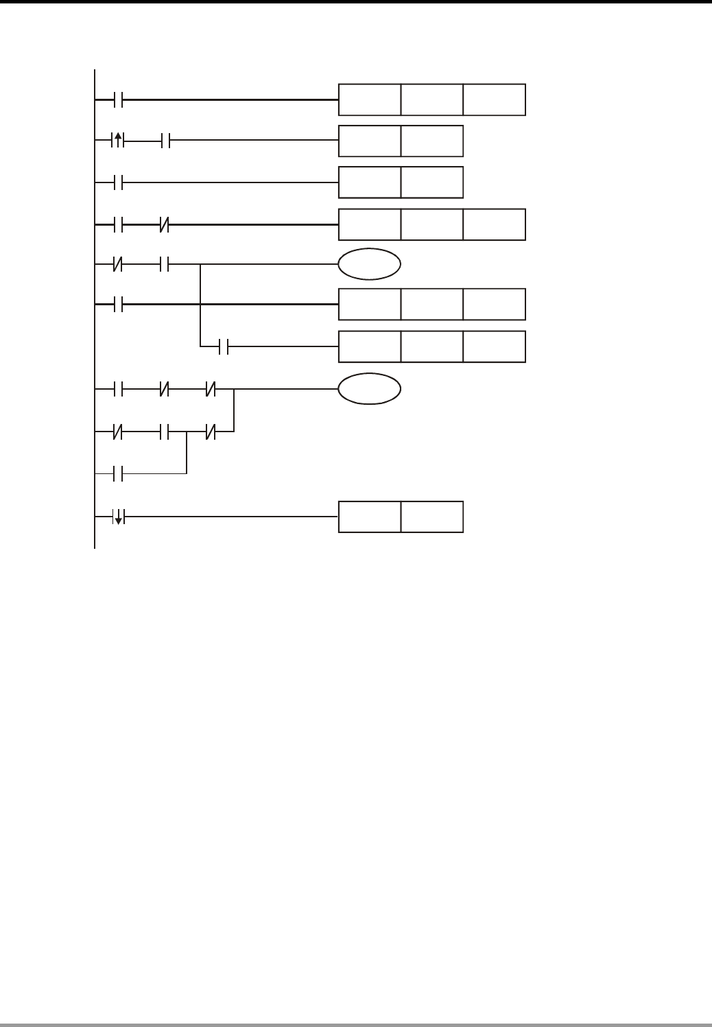
3. Timer Design Examples
DVP-PLC Application Examples
3-20
Control Program:
X0
X0
TMR T0 K30
Y0
X0 Y0
T0
SET M2
SET M0
TMR T1 K30
M0 M2
M0
M1
M1
T2
TMR T2 K40
ZRST M0 M1
M0 T1 M2
X0 M0 T2
M1
X0
RST M2
Program Description:
z When a user is detected, infrared sensor X0 will be ON. In this case, T0 will be ON and start
to count for 3 sec. If the user leaves in 3 sec, X0 = OFF, and T0 will be OFF. No action will be
performed. If the user stands for more than 3 sec, the NO contact T0 will be activated, which
turns on M0. The first flushing will start (Y0 = ON).
z M1 is latched in this program. If the user leaves after 3 sec, which means the NO contact M0
= ON and the NC contact X0 is OFF, M1 will be ON and latched. The second flushing will
then be started. After 4 sec, both the NO contact and the NC contact of T2 will be activated.
Therefore, Y0 will be OFF, and the flushing will be stopped. M0 and M1 will be reset.
Because M1 is latched, the second flushing process will certainly be executed whether X0
changes its state or not.
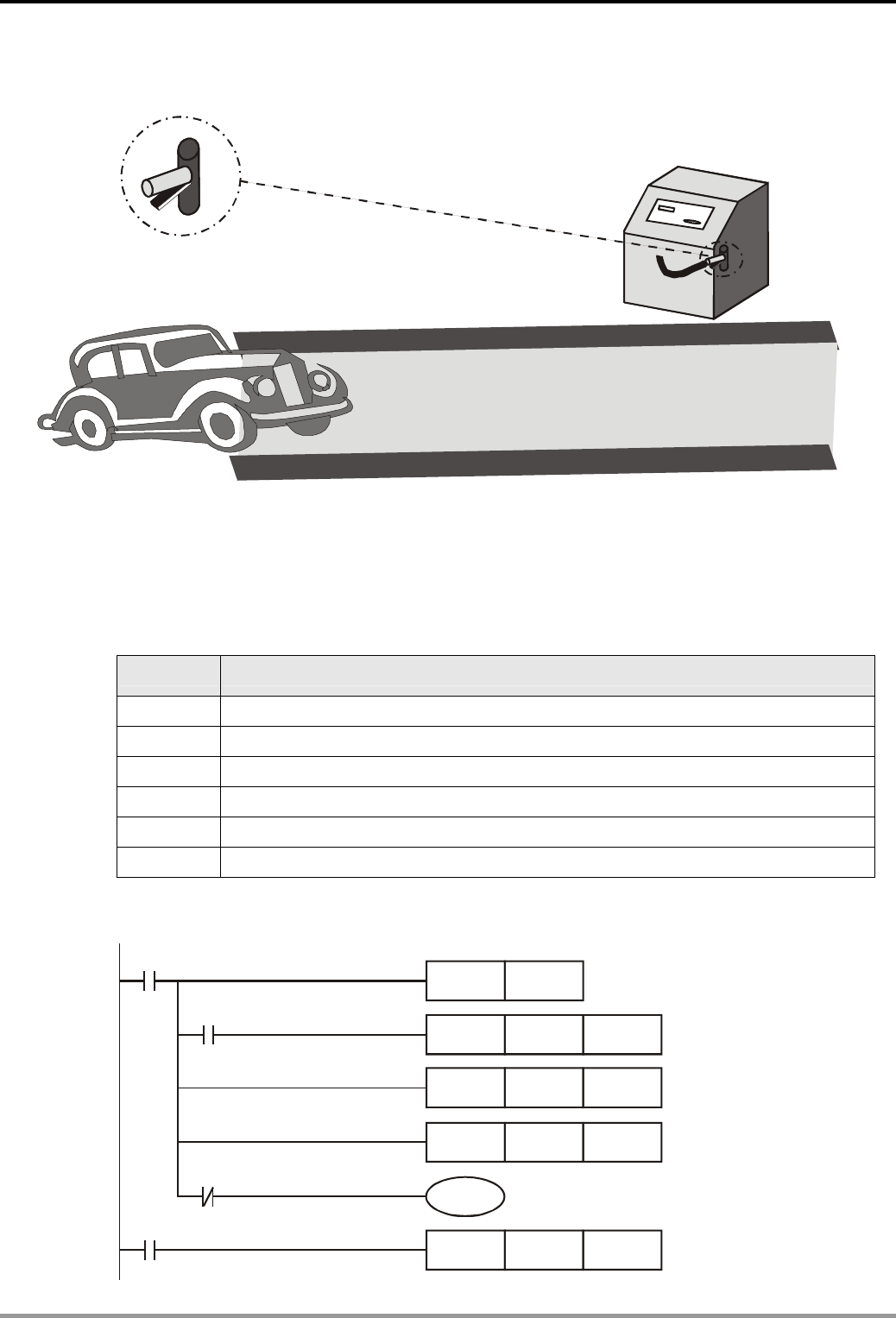
3. Timer Design Examples
DVP-PLC Application Examples
3-21
3.13 Performing Accumulative Function with Normal Timer
GO
Car Washer
X0
Y0
X1
Control Purpose:
z Ensuring that the customers wash their cars for entire 5 minutes no matter how many times
the sprayer valve stops. .
Devices:
Device Function
X0 Sprayer valve switch. X0 = ON when the sprayer handle is held on tightly.
X1 Coin detector. X1 = ON when an inserted coin is detected.
M1 Creating a trigger pulse for one program scan cycle
T1 Timer. Time base: 100ms
D10 Storing present value of T1
Y0 Sprayer valve
Control Program:
X0
Y0
TMR T1 K3000
X1
M1
T1
PLS M1
MOV D10 T1
MOV T1 D10
MOV K0 D10

3. Timer Design Examples
DVP-PLC Application Examples
3-22
Program Description:
z When customers insert coins in the slot, X1 = ON. The time value of D10 will be cleared.
z When customers compress the sprayer handle, X0 = ON. PLS instruction will be executed.
M1 will be ON for one program scan cycle, which starts T1 to count from 0 to 5 min (T1 =
K3000). In this case, Y0 = ON, and the sprayer valve is open.
z If the sprayer handle is released, the timer will stop counting. The present value in the timer
will be saved and the water spraying will be interrupted.
z When customers compress the sprayer handle again, the timer will start to count from the
value saved in D10. Because the present value of T1 is sent to D10 and saved when T1 is
working, the saved value will be sent to T1 as its present value when T1 is activated again.
Therefore, even if there are some interruptions of the sprayer valve in the washing process,
the program assures customers of entire 5 minutes car washing service.
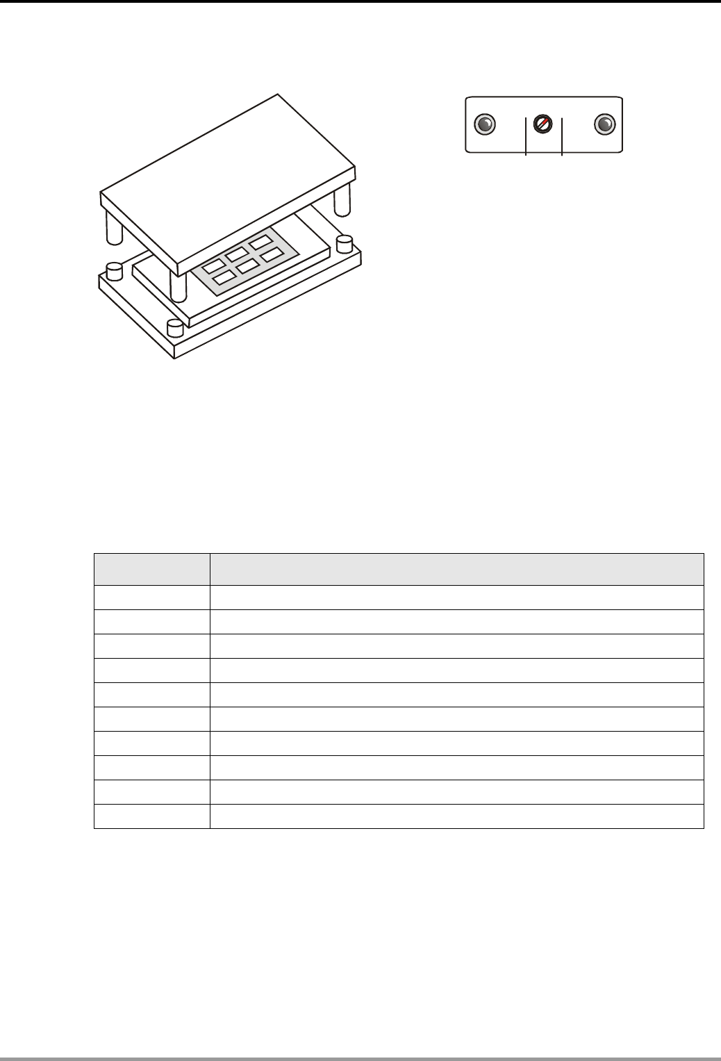
3. Timer Design Examples
DVP-PLC Application Examples
3-23
3.14 Performing Teaching Function with Normal Timer
X2 X3X0 X1
Teach Start
Manual Auto
Control Purpose:
z In Manual mode, the engineers should adjust stamping time according to their experience.
The stamping time depends on the time of pressing Teach.
z In Auto mode, if Start is pressed, the machine will perform stamping process once according
to the time value saved by Teach process.
Devices:
Device Function
X0 Teach Button. X0 = ON when the button Teach is pressed.
X1 Start button. X1 = ON when the button Start is pressed.
X2 Manual mode
X3 Auto mode
M1 Start trigger in auto mode
T0 Timer. Time base: 100ms
T1 Timer. Time base: 100ms
D0 Data register. Saving the time value of stamping
Y0 Starting the punch when Teach is pressed
Y1 Starting the punch when Start is pressed in Auto mode
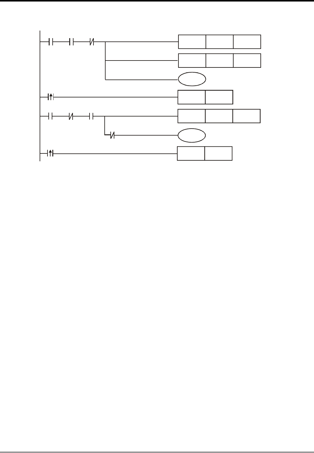
3. Timer Design Examples
DVP-PLC Application Examples
3-24
Control Program:
X0
TMR T0 K32767
T0
TMR T1
X2 X3
M1
T1
X1
X2 X3
Y0
Y1
TMR D0
D0
T1
SET
RST
M1
M1
Program Description:
z X2 = ON when the switch is turned to Manual mode. X0 = ON when Teach is pressed. In this
case, coil Y0 will be ON and start the stamping process. At the same time, T0 will be
executed and its present value will be sent to D0. Release the button Teach when the
stamping process is completed. Y0 will be OFF, and the stamping process will be stopped.
z X3 = ON when the switch is turned to Auto mode. Each time when X1 is pressed, Y1 will be
ON and the stamping process will be executed. At the same time, T1 will be activated to
count until it achieves the target value (the saved value in T0). When the stamping time is
achieved, the NC contact T1 and the rising edge trigger T1 will be activated and enable both
M1 and Y1 to be OFF. The stamping process will thus be stopped. When the button Start is
pressed again, M1 will be ON and repeats the same stamping process.
z The timer teaching function can also be performed by using API 64 TTMR instruction.
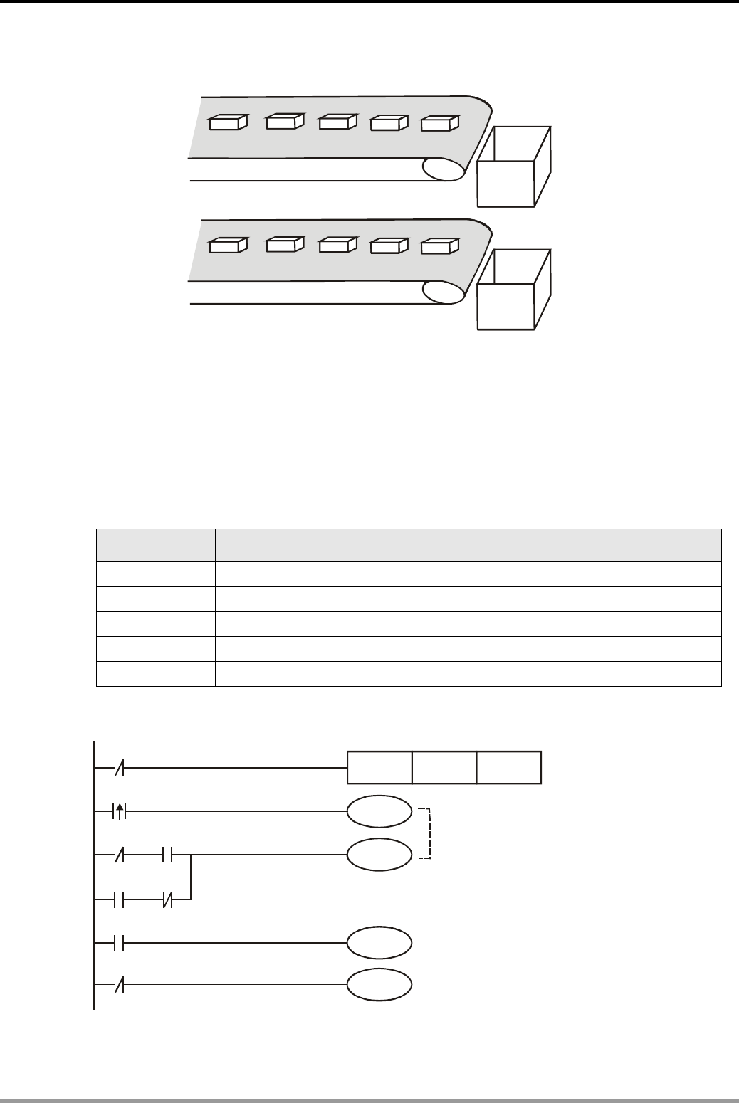
3. Timer Design Examples
DVP-PLC Application Examples 3-25
3.15 Auto Interruption Timer
Y1
Y0
Production Line 1
Production Line 2
Control Purpose:
z In PLC production lines, an operator should be in charge of packing products on two
conveyor belts into 2 boxes. For ensuring that operators have sufficient time for packing, the
program is designed to control two conveyor belts to be running alternatively: stops one
conveyor after 30 sec running and then starts another conveyor for 30 sec running.
Devices:
Device Function
T0 30 sec timer. Time base: 100ms
M0 Controlling the trigger circuit
M1 Alternating the conveyor belt
Y0 Executing the production line 1
Y1 Executing the production line 2
Control Program:
M0
Y1
TMR T0 K300
T0
T0
M1
M0 M1
M1
M1
M0
M1
Y0
Trigger Circuit

3. Timer Design Examples
DVP-PLC Application Examples
3-26
Program Description:
z This program uses the NC contact T0 as the executing condition of the timer T0. When T0
reaches its set value, 30 sec, it will be activated. The trigger circuit will be executed to
change the state of M1. Production line 1 will then start working.
z After 30 sec counting, T0 turns ON. The NC contact T0 will be activated. At the same time,
timer T0 will thus be OFF, which makes the NC contact T0 to be OFF again. In the next scan
period, because the NC contact T0 is OFF, timer T0 will start counting. After 30 sec counting,
T0 will be activated and so will the trigger circuit. In this case, M1 changes its state again.
Production line 1 will be stopped and production line 2 will start working.
z By using the trigger circuit to activate Y0 and Y1 alternatively, the program makes the two
production lines to convey products alternatively.
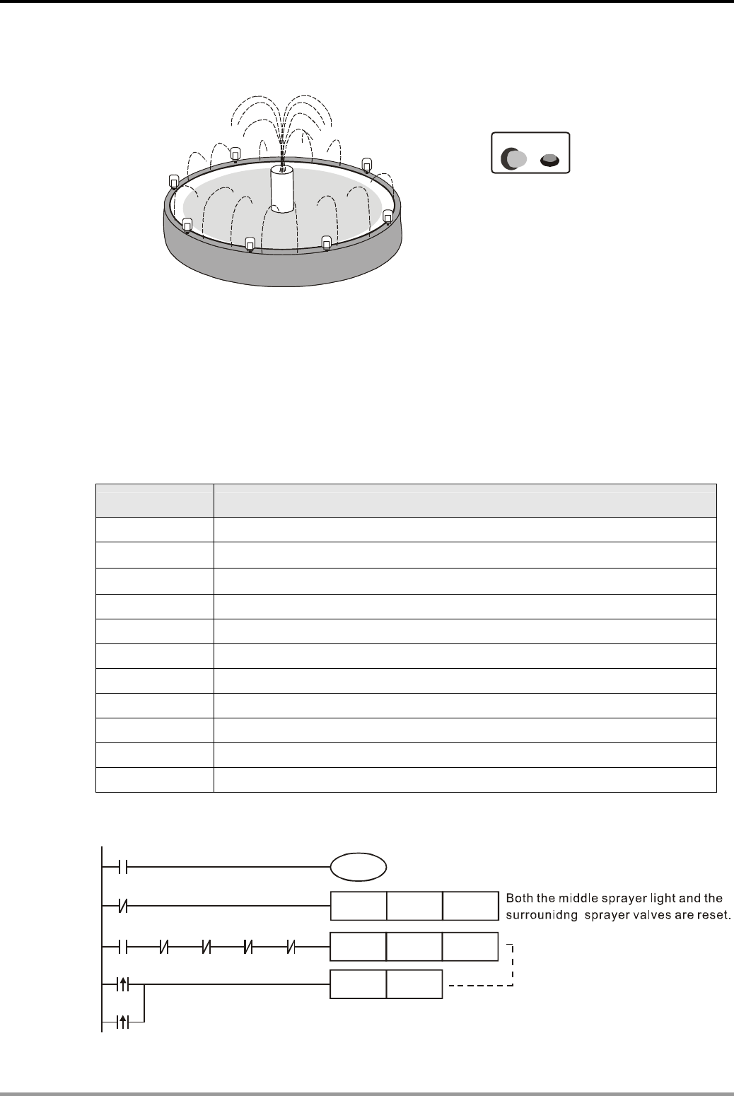
3. Timer Design Examples
DVP-PLC Application Examples 3-27
3.16 Interesting Fountain
Y0 X0
Control Purpose:
z Keeping the Running indicator in ON state when the Start button is pressed.
z Enabling the following devices to start in order after Running indicator is ON for 2 sec:
middle sprayer light > middle sprayer valve > surrounding lights > surrounding sprayer
valves. Each of them will be ON for 2 sec.
Devices:
Device Function
X0 X0 = ON when the Start button of the fountain is pressed.
T0 2 sec timer. Time base: 100ms
T1 2 sec timer. Time base: 100ms
T2 2 sec timer. Time base: 100ms
T3 2 sec timer. Time base: 100ms
T4 2 sec timer. Time base: 100ms
Y0 Running indicator of the fountain
Y1 Middle sprayer light
Y2 Middle sprayer valve
Y3 Surrounding lights
Y4 Surrounding sprayer valves
Control Program:
TMR T0
X0
X0
Y0
Y0 Y1 Y2 Y3 Y4
K20
ZRST Y1 Y4
T0
T4
SET Y1
Running indicator of the fountain
The Running indicator works
for 2 sec.
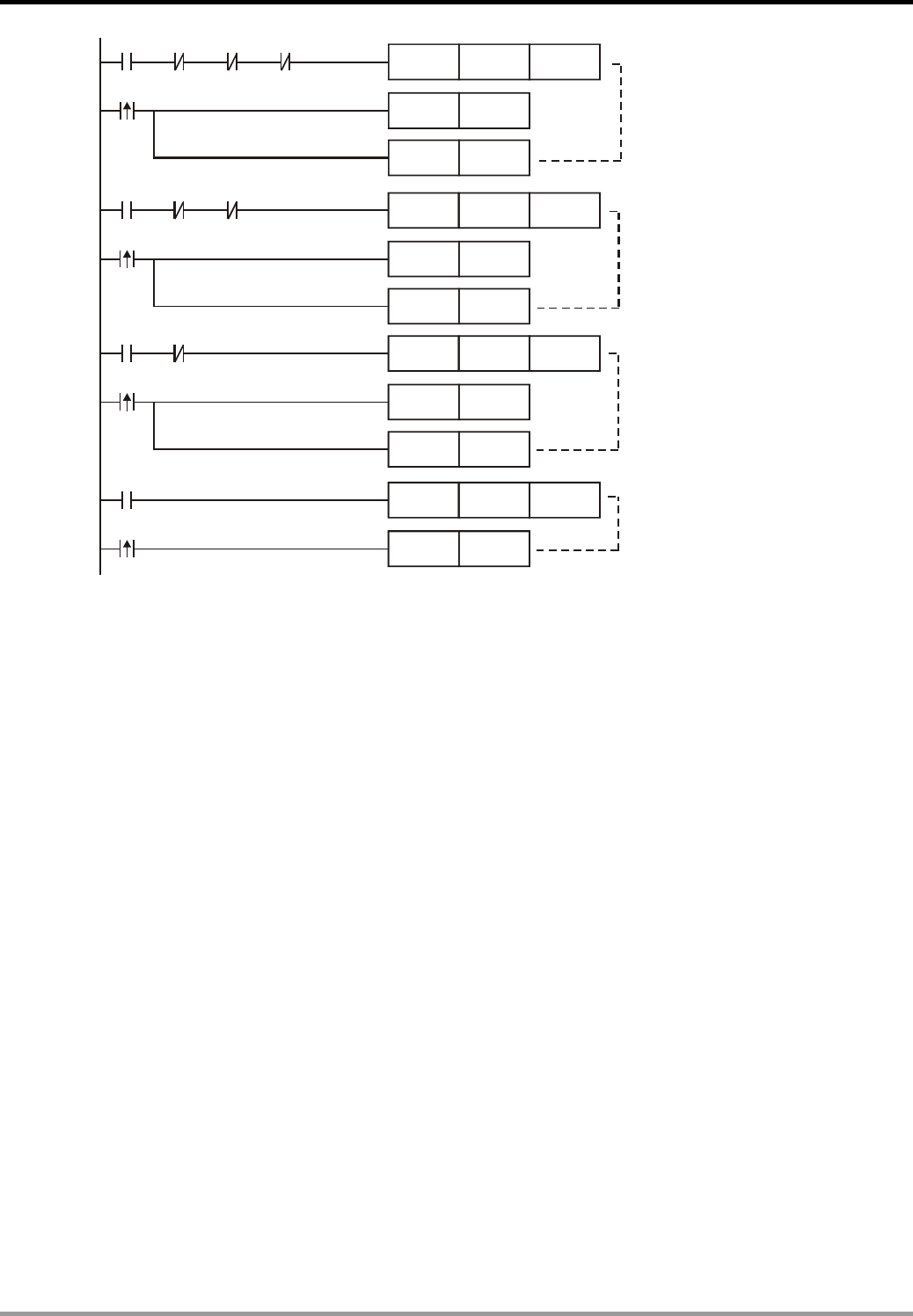
3. Timer Design Examples
DVP-PLC Application Examples
3-28
TMR
TMR
TMR
Y2 Y3 Y4
T2 K20
T2
SET Y3
RST Y4
Y3 Y4
T3 K20
T3
SET Y4
RST Y3
T4 K20
Y4
T4
RST Y4
The middle sprayer valve
works for 2 sec.
The surrounding lights work for 2 sec.
The surrounding sprayer valves
work for 2 sec.
TMR
Y1 Y2 Y3 Y4
T1 K20
T1
SET Y2
RST Y1
The middle sprayer light
works for 2 sec.
Program Description:
z X0 = ON when the button Start is pressed. Coil Y0 will be ON to activate the Running
indicator. Y0 = ON is used as the executing condition for the timer T0. After 2 sec counting
down, T0 goes from OFF to ON and executes [SET Y1] instruction. The middle sprayer light
Y1 will be ON. The Running indicator Y0 will be kept in ON state through the whole working
process.
z Likewise, Y1 = ON is used as the executing condition for the timer T1, and so does Y2 = ON
for the timer T2 as well as Y3 = ON for the timer T3. The executions will be assured in the
following order: Y1, Y2, Y3, and Y4.
z The middle sprayer light, middle sprayer valve, surrounding lights, and surrounding sprayer
valves need to be started in order. Therefore, when T1, T2 and T3 go from OFF to ON and
set the next execution, they also reset the present execution. In addition, the NC contacts of
Y1, Y2, Y3 and Y4 are used for turning off timers T0, T1, T2 and T3.
z After the completion of the last execution, the rising edge switch T4 will reset Y4 and set Y1.
The second round of fountain display will then be started again.
z When X0 = OFF, coil Y0 will be OFF to turn off the Running indicator. In addition, ZRST
instruction will be executed at the same time. Y1, Y2, Y3 and Y4 will be reset and all the
valves and lights in the fountain will be stopped immediately.
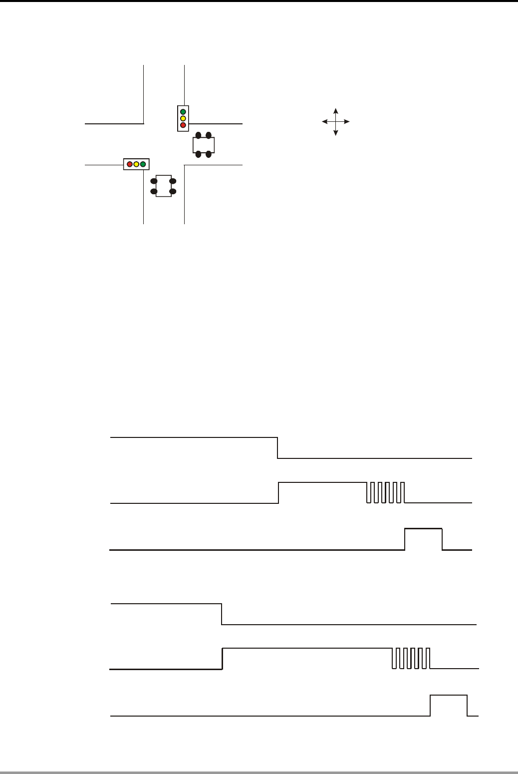
3. Timer Design Examples
DVP-PLC Application Examples 3-29
3.17 Traffic Lights Control
East-West Direction
North-South Direction
Control Purpose:
z Enabling the traffic lights to work by Start button X0 and to stop by Stop button X1.
z Setting the time of red light in East-West direction as 60 sec and North-South direction with
a heavier traffic as 30 sec.
z The time of red light in East-West direction equals to the time of “green light + green light
flashing + yellow light” in North-south direction, and vice versa.
z When yellow light is ON, cars and pedestrians should not cross the road, and yellow light
will last for 5 sec for the crossing cars and pedestrians to pass safely.
z Timing diagram of traffic lights in East-West direction:
Red (Y0)
Green (Y1)
Yellow (Y2)
60
s
20
s
5
s
5
s
z Timing diagram of traffic lights in North-South direction:
Red (Y10)
Green (Y11)
Yellow (Y12)
30 s
60 s
5 s
5 s
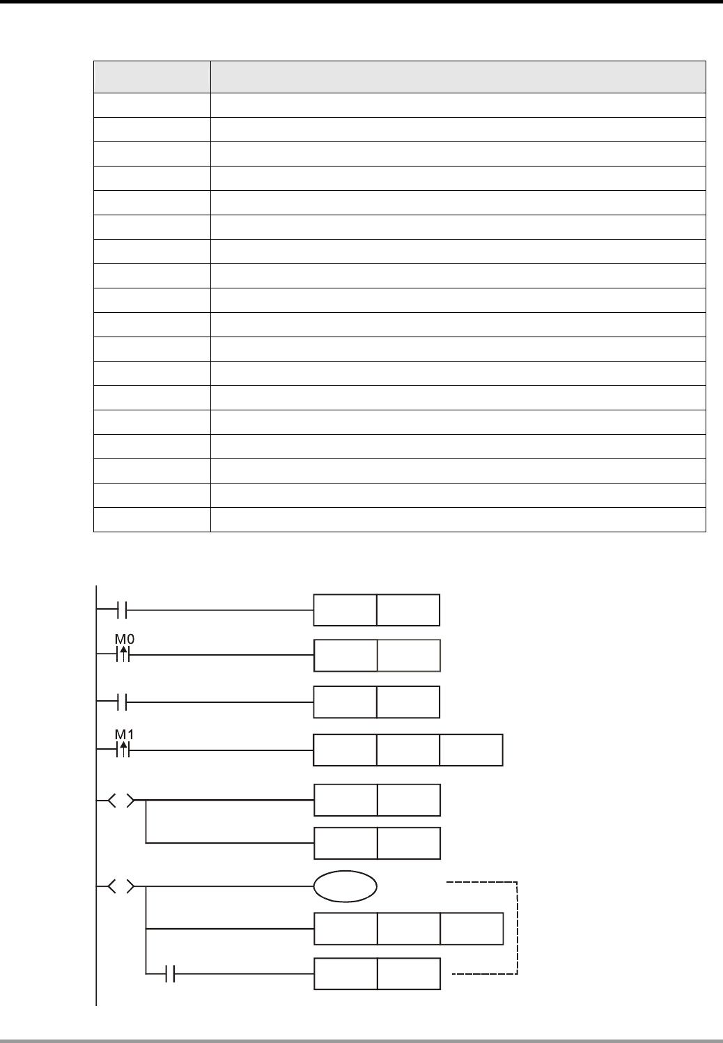
3. Timer Design Examples
DVP-PLC Application Examples
3-30
Devices:
Device Function
X0 Start button
X1 Stop button
T0 60 sec timer. Time base: 100ms
T1 20 sec timer. Time base: 100ms
T2 5 sec timer. Time base: 100ms
T10 50 sec timer. Time base: 100ms
T11 5 sec timer. Time base: 100ms
T12 5 sec timer. Time base: 100ms
T13 30 sec timer. Time base: 100ms
S0 Initial step
S10 ~ S13 Controlling the Traffic lights in East-West direction
S20 ~ S23 Controlling the Traffic lights in North-South direction
Y0 Red light in East-West direction
Y1 Green light in East-West direction
Y2 Yellow light in East-West direction
Y10 Red light in North-South direction
Y11 Green light in North-South direction
Y12 Yellow light in North-South direction
Control Program:
S
S
ZRST S0 S127
PLS
PLS
M0
M1
SET S10
S0
SET S20
S10
TMR T0
SET S11
T0
Y0
K600
X0
X1
SET S0
Red light in East-West direction
is ON for 60 sec.
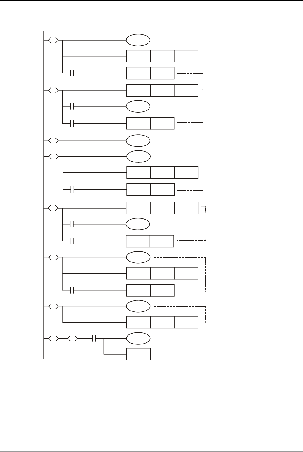
3. Timer Design Examples
DVP-PLC Application Examples 3-31
Program Description:
z When Start is pressed, X0 = ON. PLS instruction will be executed, and M0 will create a
rising-edge pulse to set T0. The program will enter the step ladder process.
z When Stop is pressed, X1 = ON. PLS instruction will be executed, and M1 will create a
rising-edge pulse to execute [ZRST S0 S127] instruction. All steps will be reset and all traffic
S
Y11
S20
TMR T10
SET S21
T10
K500
Green light in North-South direction
is ON for 50 sec.
S
S
S S
T13S13 S23
Y12
S22
TMR
SET
T12
Y10
S23
TMR
S0
RET
T12
S23
K50
T13 K300
S
Y11
S21
TMR T11
SET S22
T11
K50
M1013
Green light in North-South direction
is flashing for 5 sec.
Yellow light in North-South direction
is ON for 5 sec.
Red light in North-South direction
is ON for 30 sec.
S
S
S
Y1
S11
Y2
S13
TMR T1
SET S12
T1
K200
Y1
S12
TMR T2
SET S13
T2
K50
M1013
Green light in East-West direction
is ON for 20 sec.
Green light in East-West direction
is flashing for 5 sec.
Yellow light in East-West direction
is ON.

3. Timer Design Examples
DVP-PLC Application Examples
3-32
lights will be OFF.
z This example is designed by the application of the simultaneous divergence sequence. The
two sequences running simultaneously are East-West direction and North-South direction.
z When the red light of East-West direction is ON, the corresponding state of North-South
direction will be the sequence of “Green ON”, “Green Flashing” and “Yellow ON.”
z When the East-West direction sequence is finished (the yellow light is OFF), the
North-South direction sequence will be finished as well (the red light is OFF). The program
will return to the initial step S0.
z When a step is transferred from one sequence to another sequence, the former sequence
will be reset including the step and output point Y.
z The time of yellow light in East-West direction (Y2) is not controlled by a timer because
when the red light in North-South direction is OFF, the yellow light in North-South direction
will be reset at the same time. In this case, T13 is ON to redirect the program to initial step
S0, and the outputs (Y2 and Y10) corresponding to S13 and S23 will thus be reset.
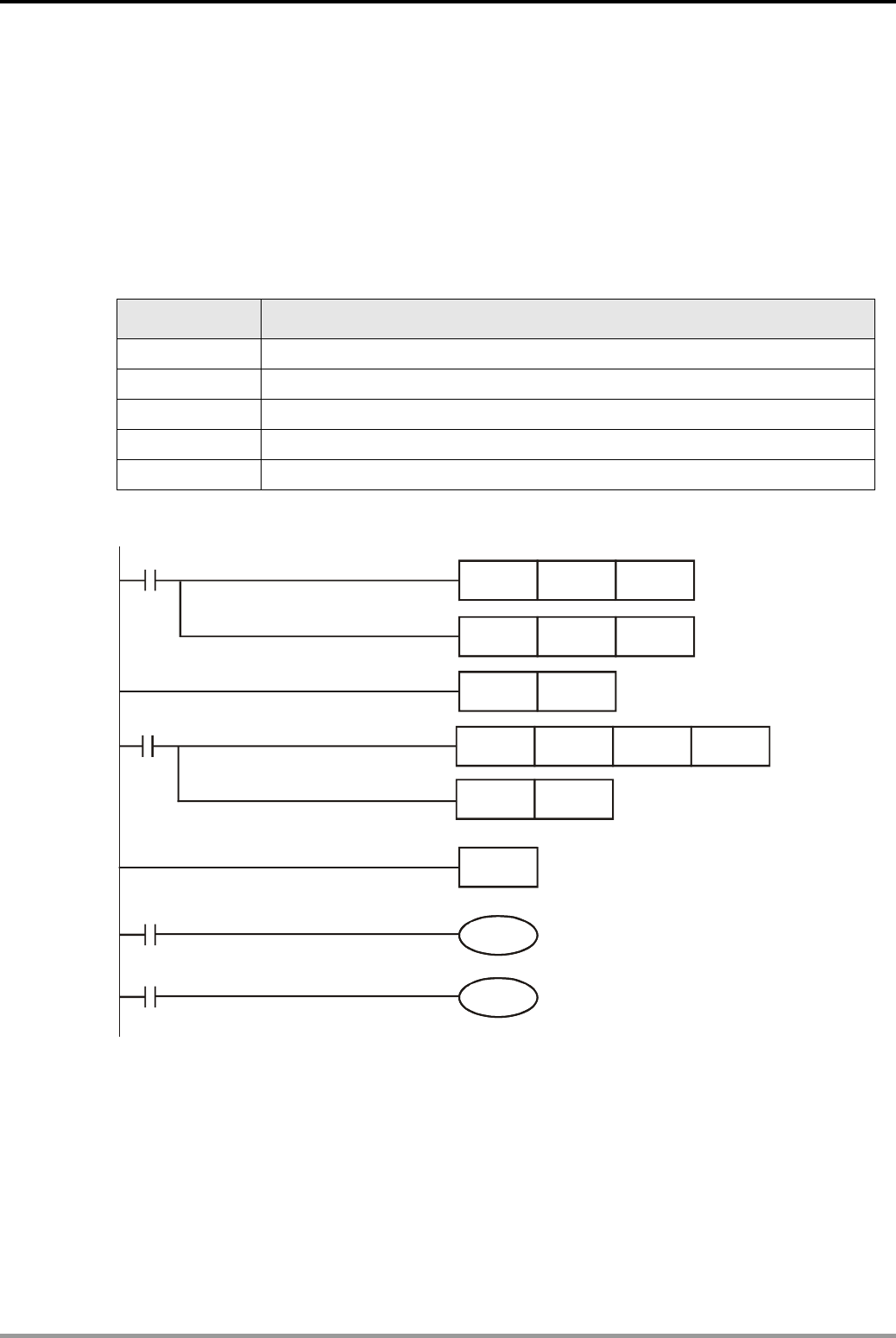
4. Index Registers E, F Design Examples
DVP-PLC Application Examples 4-1
4.1 Summation of Continuous D Registers
Control Purpose:
z Summing up the values of D registers from D101 to DN (the number of N is determined by
users) and storing the operation result in D100. If the result < K-32768, the borrow flag = ON;
if the result > K32767, the carry flag = ON.
Devices:
Device Function
Y0 Borrow flag indicator. When the value in D100 < K-32768, Y0 = ON
Y1 Carry flag indicator. When the value in D100 > K32767, Y1 = ON
E1 Index register
D100 Storing the sum of all D registers
D500 Storing the executing times of FOR-NEXT loop
Control Program:
M1000
M1000
M1021
M1022
MOV K1 E1
MOV K0 D100
FOR
INC
D500
E1
ADD D100 D100
D100E1
NEXT
Y0
Y1
Y0
Program Description:
z The key of the program is to use the index register E1 together with FOR ~ NEXT loop to
vary the addend D100E1. When E1 = K1, D100E1 represents D101; when E1 = K2, D100E1
represents D102. Also, when E1 = K10, D100E1 represents D110.
z The number of continuous D registers is determined by the execution times of FOR ~NEXT
loop which is set by D500. If the value in D500 ≤ 1, the loop will execute 1 time. If the value
in D500 = K10, the loop will execute 10 times first and then execute the instructions behind

4. Index Registers E, F Design Examples
DVP-PLC Application Examples
4-2
the loop.
z In the first FOR ~ NEXT loop, E1 = K1, so D100E1 represents D101. ADD instruction is
executed, and the operation result of D100 plus D101 is stored in D100. Since the
summand D100 = K0, the value stored in D100 equals to the value in D101. At the same
time, INC instruction is executed to set E1 = K2.
z In the second FOR ~ NEXT loop, E1 = K2, so D100E1 represents D102. ADD instruction is
executed, and the operation result of the values of D100 plus D102 is stored in D100. Since
the summand D100 = D101, the value stored in D100 is the sum of the D101 and D102.
z According to the same process, by the 10th FOR ~ NEXT loop the value in D100 will be the
sum of D101, D102, D103, D104, D105, D106, D107, D108, D109 and D110.
z If the operation result < K-32768, M1021 will be ON to activate the output coil Y0. Borrow
flag indicator will be ON. On the contrary, if the operation result > K32767, M1022 will be ON
to activate output coil Y1. Carry flag indicator will be ON in this case.
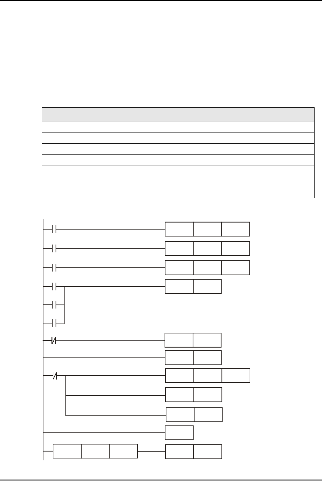
4. Index Registers E, F Design Examples
DVP-PLC Application Examples 4-3
4.2 Parameter Setting for Product Recipe
Control Purpose:
z For one product, there are 3 models which correspond to 3 sets of recipes. Each recipe
includes 10 parameters. The program executes the set parameters according to the
selected recipe switch.
Devices:
Device Function
X0 Switch of the first recipe
X1 Switch of the second recipe
X2 Switch of the third recipe
D500 ~ D509 Parameters of the first group
D510 ~ D519 Parameters of the second group
D520 ~ D529 Parameters of the third group
D100 ~ D109 The present parameters
Control Program:
X0
X0
X1
X1
X2
X2
MOV
RST
RST
MOV
MOV
K500
M0
K510
K520
E1
E1
E1
FOR
INC
SET
INC
K10
F1
M0
E1
MOV D0E1 D100F1
NEXT
LD>= F1 K10
M0
M0
F1

4. Index Registers E, F Design Examples
DVP-PLC Application Examples
4-4
Program Description:
z The key to this program is to use index register E1, F1 together with FOR ~ NEXT loop to
vary the numbers of D registers. In addition, the program transfers the parameters of the
selected recipe to the register of present parameters
z When one recipe is selected, the corresponding switch X0, X1 or X2 will be ON. According
to the selected value of E1, the number of register D0E1 would be D500, D510 or D520.
[RST M0] will be executed to reset F1, and FOR ~ NEXT will be executed. Because F1 is
reset as K0, D100F1 represents D100 in this case.
z The FOR ~ NEXT loop is executed for 10 times in this program. If the first recipe is selected,
D0E1 will vary from D500 to D509 and D100F1 will vary from D100 to D109.
z In addition, the value of D500 will be sent to D100 in the first FOR ~ NEXT loop. The value
of D501 will be sent to D101 in the second loop. By the same process, the value of D509 will
be sent to D109 in the 10th loop.
z When the executing time reaches its set value, which means F1 = K10, [SET M0] instruction
will be executed. The Normally Closed contact M0 will be activated to stop FOR ~ NEXT
loops.
z The program performs the transferring of 10 parameters of each recipe. The numbers of
parameters can easily be changed by setting the executing times of FOR ~ NEXT loop.
Besides, if it requires adding more recipes, the program can also meet this requirement by
adding one more MOV instruction as [MOV K530 E1].
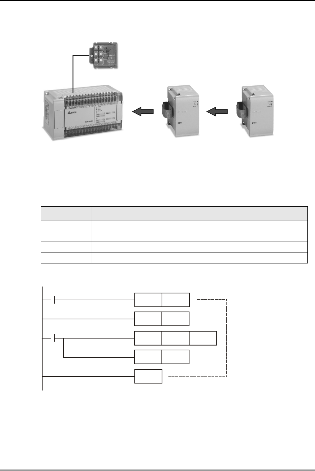
4. Index Registers E, F Design Examples
DVP-PLC Application Examples 4-5
4.3 Controlling Voltage Output of 2 DVP-04DA by 8 VRs (Variable Resistors)
DVP-F6VR
DVP04DA DVP04DA
DVP-EH
MPU
Control Purpose:
z Controlling the voltage output of 2 DVP-04DA to vary from 0 ~ 10V by adjusting 8 VRs on
DVP-EH series PLC (2 VRs on the EH MPU and 6 VRs on DVP-F6VR extension unit).
Devices:
Device Function
X0 Start Switch of reading VR volume
X1 Writing in the value of the first DVP04DA
X2 Writing in the value of the second DVP04DA
E0 Index register
Control Program:
M1000
RST E0
FOR
INC
K8
E0
VRRD K0@E0 D0E0
NEXT
X0 Reading out values of 8
VRs in order by [INC E0]
and FOR ~ NEXT loop
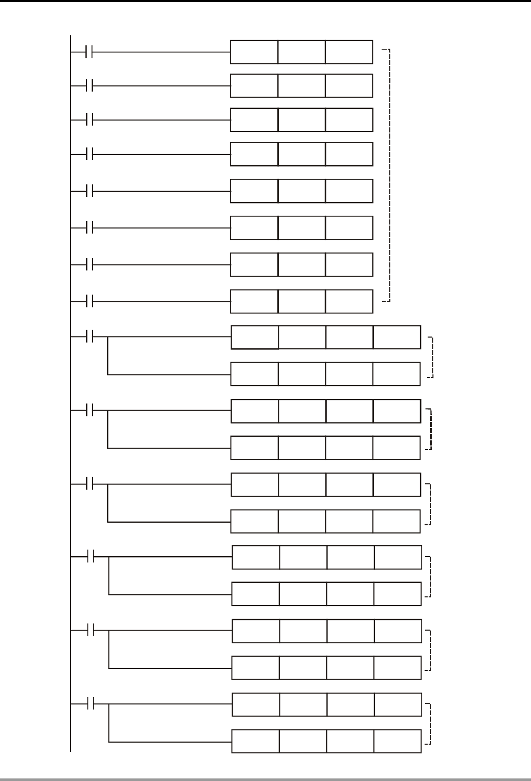
4. Index Registers E, F Design Examples
DVP-PLC Application Examples
4-6
MOV
MOV
MOV
MOV
MOV
MOV
MOV
MOV
D0
D1
D2
D3
D4
D5
D6
D7
D10
D20
D30
D40
D50
D60
D70
D80
X0
X0
X0
X0
X0
X0
X0
X0
K4000
K4000
K255
K255
X0
X0
DMUL
DMUL
DDIV
DDIV
D100
D110
D200
D210
K4000
K255
X0
DMUL
DDIV
D120
D220
K4000
K4000
K4000
K255
K255
K255
X0
X0
X0
DMUL
DMUL
DMUL
DDIV
DDIV
DDIV
D130
D140
D150
D230
D240
D250
Sending the data in
D0 ~ D7 to D10 ~ D80
according ly
Read out value
processing of
the 4th VR
D60
D150
D50
D140
D50
D140
D40
D130
D30
D120
D20
D110
D10
D100
Read out value
processing of
the 1st VR
Read out value
processing of
the 2nd VR
Read out value
processing of
the 3rd VR
Read out value
processing of
the 5th VR
Read out value
processing of
the 6st VR
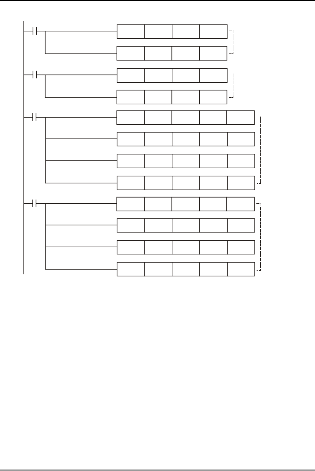
4. Index Registers E, F Design Examples
DVP-PLC Application Examples 4-7
K4000
K4000
K255
K255
X0
X0
DMUL
DMUL
DDIV
DDIV
D160
D170
D260
D270
K6
K6
K7
K7
K8
K8
K9
K9
X1
X2
TO
TO
TO
TO
TO
TO
TO
TO
D200
D240
D210
D250
D220
D260
D230
D270
K1
K1
K1
K1
K1
K1
K1
K1
Controlling
0 ~10V output
from 4 channels
on the 2nd DA
module
D70
D160
D80
D170
K0
K1
K0
K0
K0
K1
K1
K1
Read out value
processing of
the 7th VR
Read out value
processing of
the 8th VR
Controlling
0 ~10V output
from 4 channels
on the 1st DA
module
Program Description:
z The program uses index register E0 and FOR ~ NEXT loop to specify the No. of VR as well
as the No. of D registers which store the read out value of VR.
z In FOR ~ NEXT loop, E0 will change from 0 to 7 because of [INC E0] instruction. In this case,
K0@E0 will change from K0 to K7 and D0E0 will change from D0 to D7. Therefore, the
values of 8 VRs will be read out in order as below, VR0→D0, VR1→D1 … VR7→D7.
z The value range of the VR is K0 ~ K255, and the voltage range of DVP04DA is 0 ~ 10V
corresponding to K0 ~ K4000. Therefore, the program is designed to convert the VR value
K0 ~ K255 into the DVP04DA value K0 ~ K4000. Through this process, the target of
controlling 0 ~ 10V voltage output by adjusting the VR value can be achieved.
z The value which is converted into K0 ~ K4000 will be sent to D200, D210, D220 … D270,
and will be transferred to DVP04DA by TO instruction as the voltage outputs of the
corresponding channels.
z For the application of API85 VRRD instruction and API79 TO instruction, please refer to
DVP-PLC Application Manual - programming.

4. Index Registers E, F Design Examples
DVP-PLC Application Examples
4-8
MEMO
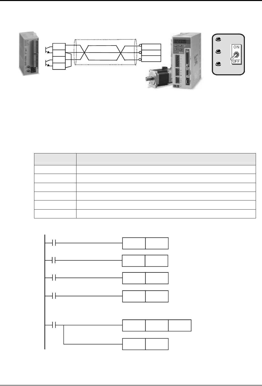
5. Loop Instruction Design Examples
DVP-PLC Application Examples
5-1
5.1 Recipe Setting by CJ Instruction
DVP12SC
Stroke 2
Stroke 1
X1
X2
X3
Stroke 3
X4
Delta Servo
A
SDA
Y10
C2
Pulse Output
Y0
C0 Forward Reverse /
COM-
PLS
SIGN
Control Purpose:
z Controlling 3 stroke distances of Delta ASDA servo by sending pulses from Delta DVP12SC
PLC. Users can choose the adequate stroke distance to meet the working requirement by
pressing 3 individual switches.
Devices:
Device Function
X1 X1 = ON when the switch Stroke 1 is pressed.
X2 X2 = ON when the switch Stroke 2 is pressed.
X3 X3 = ON when the switch Stroke 3 is pressed.
X4 X4 = ON when the servo locating switch is pressed.
Y0 Pulse direction control
Y10 Pulse output point
Control Program:
X1
CJ
X2
CJ
X3
CJ
M1000
CJ
CJ
M1000
MOV D0
P1
P2
P3
P4
K10000
P4
P1

5. Loop Instruction Design Examples
DVP-PLC Application Examples
5-2
CJ
CJ
CJ
X4
M1000
M1000
MOV
MOV
DDRVI
D0
D0
D0 Y10 Y0
P4
P4
P4
K100000
K30000
K20000
P4
P3
P2
Program Description:
z When X1 = ON, X2 = OFF, X3 = OFF, the program will jump from [CJ P1] to P1 and store the
constant K10000 in D0, which means the first stroke distance is selected. At the same time,
the program will jump to address P4 and get ready to output pulses.
z When X2 = ON, X1 = OFF, X3 = OFF, the program will jump from [CJ P2] to P2 and store the
constant K20000 in D0, which means the second stroke distance is selected. At the same
time, the program will jump to address P4 and get ready to output pulses.
z When X3 = ON, X1 = OFF, X2 = OFF, the program will jump from [CJ P3] to P3 and store the
constant K30000 in D0, which means the third stroke distance is selected. At the same time,
the program will jump to address P4 and get ready to output pulses.
z When X1 = OFF, X2 = OFF, X3 = OFF, [CJ p4] instruction will be executed. The program will
jump to pointer P4 directly and get ready to output pulses.
z When X4 = ON, [DDRVI D0 K10000 Y10 Y0] instruction will be executed; that is, Y10 will
output a certain number of pulses with frequency of 100 KHz (the content in D0 is the
number of the pulses), and Y0 will control the pulse direction. Since the operating distance
of the servo motor is proportional to the number of the pulses, the object of controlling servo
operating distance can be achieved by setting PLC output pulses.
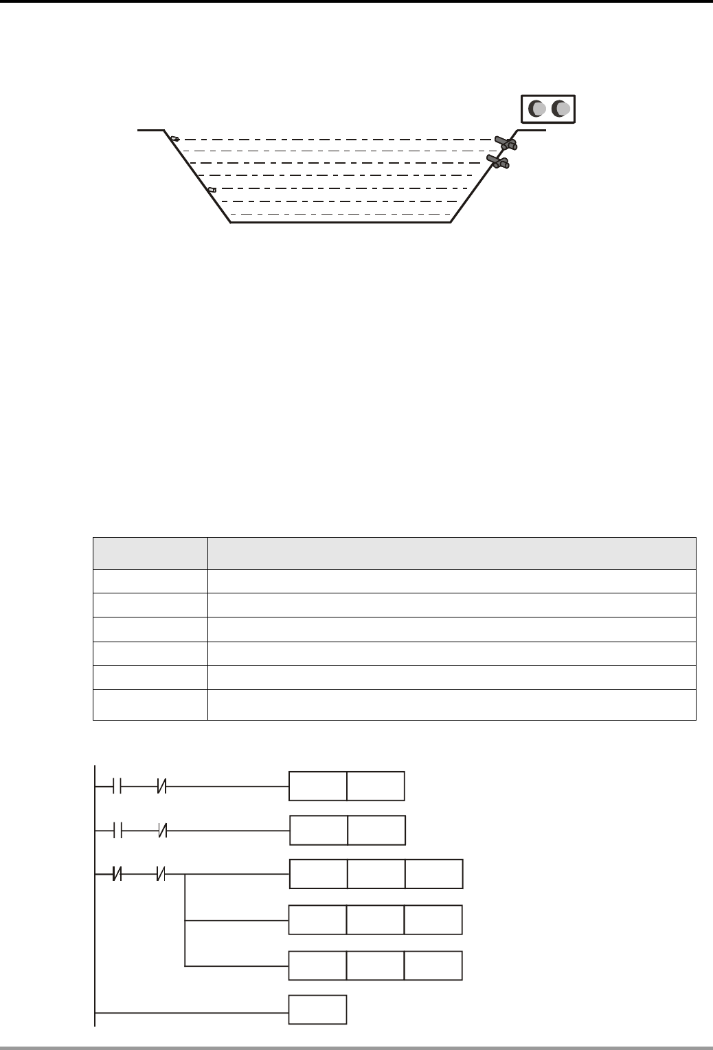
5. Loop Instruction Design Examples
DVP-PLC Application Examples
5-3
5.2 Reservoir Level Control
Y0
Y10 Y11
X1
X0 Y1
Control Purpose:
z Enabling the abnormal situation alarm and draining water from the reservoir when the level
is above the upper bound.
z Enabling the abnormal situation alarm and pouring water into the reservoir when the level is
below the lower bound.
z Enabling the mechanical failure alarm if the upper bound sensor X0 is still ON after draining
water for 10 minutes.
z Enabling the mechanical failure alarm if the lower bound sensor X1 is still ON after pouring
water for 5 minutes.
z Resetting all the alarms and valves when the level is in normal position.
Devices:
Device Function
X0 X0 turns ON when the level reaches the upper bound.
X1 X1 turns ON when the level reaches the lower bound.
Y0 Draining valve
Y1 Pouring valve
Y10 Abnormal situation alarm
Y11 Mechanical failure alarm
Control Program:
X0
X1
X1
CALL
CALL
ZRST
ZRST
ZRST
FEND
Y1
Y11
T1
X1
X0
X0
P0
P10
Y0
Y10
T0
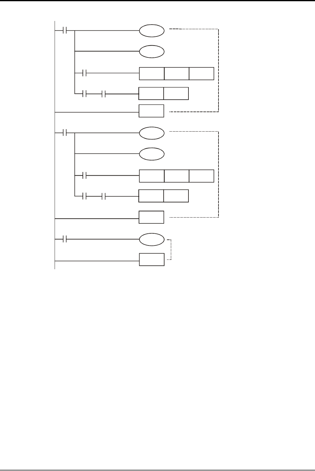
5. Loop Instruction Design Examples
DVP-PLC Application Examples
5-4
CALL
CALL
M1000
M1000
M1000
SRET
SRET
SRET
TMR
TMR
K6000
K3000
Y0
Y1
Y11
Y10
Y10
Y0
Y1
X0
X1
Subroutine for draining
water and enabling alarm
when the level is above
the upper bound.
Subroutine for pouring
water and enabing alarm
when the level is below
the lower bound.
Subroutine for enabling
mechanical failure alarm.
T1
T0
P0
P20
P10
T0
P20
P20
T1
Program Description:
z When the level is above the upper bound, X0 will be ON to execute [CALL P0] instruction.
The abnormal situation alarm Y10 and the draining valve Y0 will start working until the level
is below the upper bound.
z When the level is below the lower bound, X1 will be ON to execute [CALL P10] instruction.
The abnormal situation alarm Y10 and the pouring valve Y1 will start working until the level
is above the lower bound.
z CALL P20 subroutine is nested both in P0 and P10 subroutines. If the upper bound sensor is
still on after draining water for 10 minutes, subroutine P20 will be executed. Coil Y11 will be
ON and the mechanical failure alarm will be enabled.
z Likewise, if the lower bound sensor is still ON after pouring water for 5 minutes, subroutine
P20 will be executed. Coil Y11 will be ON and the mechanical failure alarm will be enabled.
z If the level is at normal position, X0 = OFF, X1 = OFF, ZRST instruction will be executed. Y0,
Y1, Y10, Y11, T0, and T1 will be reset. All valves as well as alarms will be disabled.
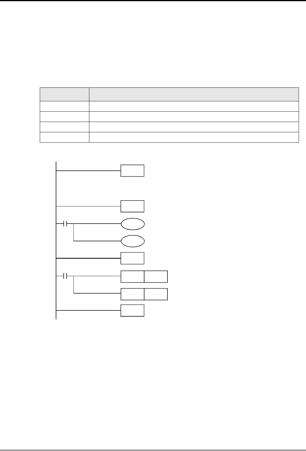
5. Loop Instruction Design Examples
DVP-PLC Application Examples
5-5
5.3 Fire Alarm in the Office (Interruption Application)
Control Purpose:
z Starting the alarm and sprayer when the temperature alarm detects high temperature.
z Stopping the alarm and sprayer when the alarm reset button is pressed.
Devices:
Device Function
X0 Temperature alarm. X0 = ON when the temperature is too high.
X1 Alarm reset button. X1 = ON when the button is pressed.
Y0 Sprayer
Y1 Fire alarm
Control Program:
FEND
RST Y0
RST Y1
M1000
Y1
EI
Y0
IRET
M1000
IRET
I001
I101
Main Program
Program Description:
z In the program, the interruption pointers I001, I101 correspond to the external input points
X0, X1. When X0, X1 is ON, the subroutines corresponding to I001, I101 will be executed.
z If the temperature in the office is normal, X0 = OFF. The temperature alarm will not perform
any action. No interruption signal is generated, and no interruption subroutine will be
executed in this case.
z If the temperature in the office is too high, X0 = ON, the temperature alarm will be enabled.
The PLC will stop the main program to execute the interruption subroutine I001. In this case,
sprayer valve Y0 and alarm Y1 will be enabled. After the execution of I001, the program will
return to the main program and resume execution from the interruption point.

5. Loop Instruction Design Examples
DVP-PLC Application Examples
5-6
z Press the alarm reset button if the alarm situation is cleared. X1 = ON, the PLC will stop the
main program to execute the interruption subroutine I101. In this case, sprayer Y0 and
alarm Y1 will be shut down. After the execution of I101, the program will return to the main
program and resume execution from the interruption point.
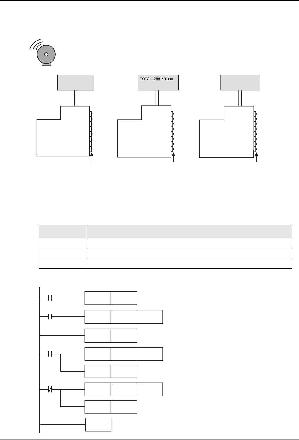
5. Loop Instruction Design Examples
DVP-PLC Application Examples
5-7
5.4 Auto Lock up system in the Supermarket (FOR ~ NEXT)
TOTALD Yuan
CHANGE Yuan
:
:
41.2
8.8
TOTAL: Yuan
CHANGE Yuan
88.00
12.00 :
CHANGE Yuan: 33.2
Y0~Y17 Y20~Y37 Y40~ Y57
X0
TOTAL:
:
41 2 Yuan
CHANGE 8 8Yuan
.
.
Control Purpose:
z Once fire or robbery happened in the supermarket, locking up all cash drawers until the
alarm situation is cleared.
Devices:
Device Function
X0 X0 = ON when the alarm is activated.
D0 The number of cash drawers
D10 Start address of destination register
Control Program:
D10F1
D0
D10F1
H0
D0
F1
F1
F1
MOV
MOV
MOV
NEXT
RST
FOR
INC
INC
M1000
X0
M1002
X0
HFFFF
K3

5. Loop Instruction Design Examples
DVP-PLC Application Examples
5-8
K4Y0
K4Y20
K4Y40
MOV
MOV
MOV
M1000 D10
D11
D12
Program Description:
z The execution times of FOR~NEXT loop which decide the number of controlled cash
counters can be controlled by the value in D0. Each cash counter has 16 drawers. In this
program, D0 = K3, which means it can control 48 cash drawers in 3 counters.
z F10 = K0, D10F1 represents D10; F10 = K1, D10F1 represents D11; F0 = K2, D10F1
represents D12; F0=K3, D10F1 represents D13.
z When the alarm rings, X0 = ON. FOR ~ NEXT loop will be executed for 3 times and HFFFF
will be sent to D10 ~ D12 in order. After the execution, the value in D10 ~ D12 will be sent to
the external outputs. All the outputs Y will be set to be ON in this case. The system will lock
up all the cash drawers.
z When the alarm situation is cleared, X0 = OFF. FOR ~ NEXT loop will be executed for 3
times and H0 will be sent to D10 ~ D12 in order. After the execution, the value in D10 ~ D12
will be sent to the external outputs. All the outputs Y will be reset to be OFF in this case. The
system will unlock all the cash drawers.
z In this program, the index register F1 is used for storing single value in a data stack (series
D registers). According to different application situations, users can make use of the data
stack for controlling timers or counters.
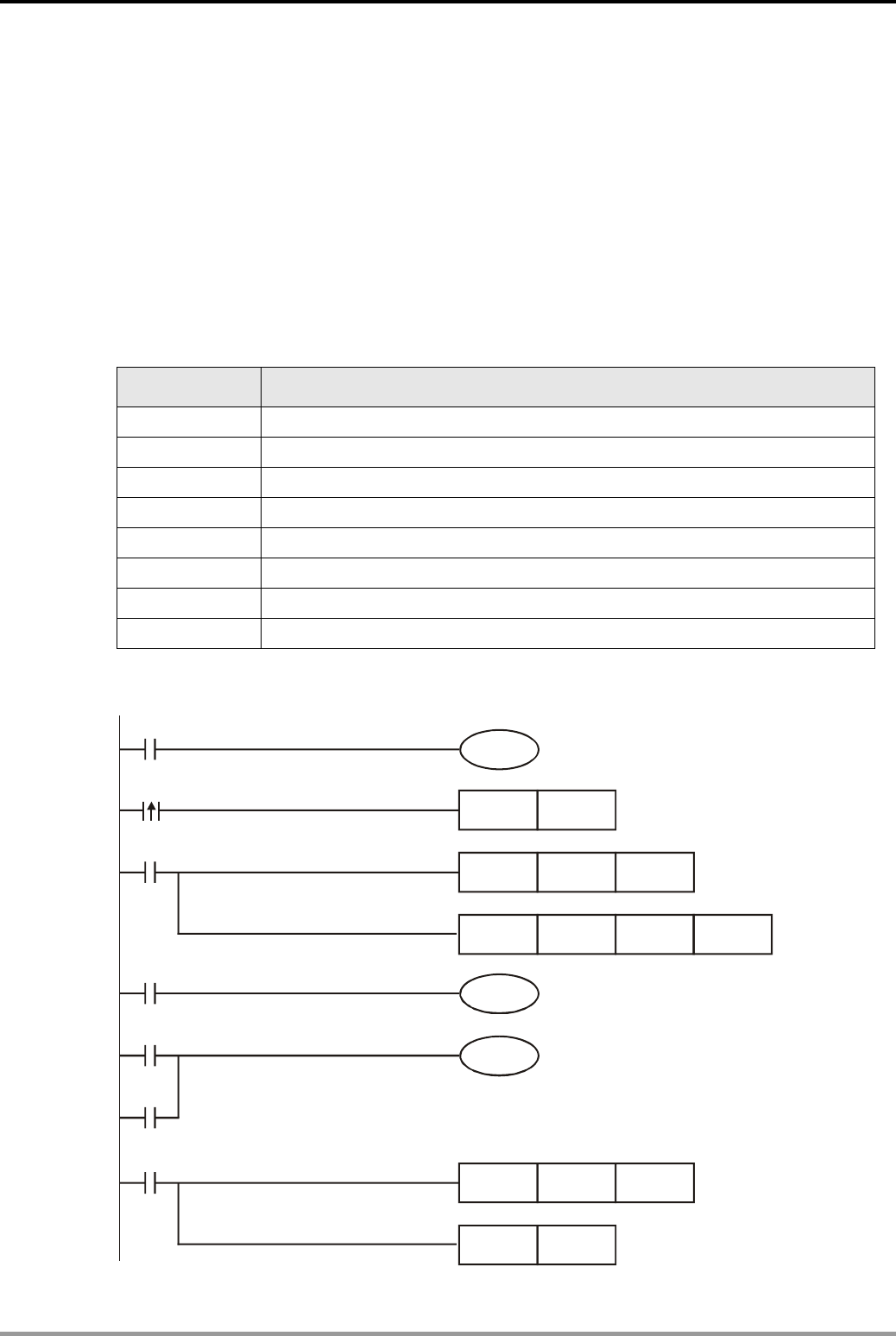
6. Data Transmission and Comparison Design Examples
DVP-PLC Application Examples 6-1
6.1 CMP - Material Mixing Machine
Control Purpose:
z There are materials A and B in the mixing machine. Enabling the indicator(Y0) when the
Power On switch is pressed. Controlling the material A outlet (Y1) to start feeding and
starting the agitator Y3 by pressing the button Process(X1). When material A feeding
process reaches the set time D0, enabling the material B outlet(Y2) to start feeding while the
agitator keeps working. Stopping all processes when the whole mixing time(D1) is achieved.
Devices:
Device Function
X0 X0 = ON when the Power On switch is pressed.
X1 X1 = ON when the button Process is pressed.
Y0 Power On Indicator
Y1 Material A outlet
Y2 Material B outlet
Y3 Agitator
D0 Feeding time of material A
D1 Total feeding time of material A and B
Control Program:
X0
M0
X1
Y3
T0
SET
TMR
ZRST
CMP
RST
Y3
T0
Y1
D0
T0
D1
Y3
T0 M0
M1
M2
Y0
Y1
Y2

6. Data Transmission and Comparison Design Examples
DVP-PLC Application Examples
6-2
Program Description:
z When the Power On switch is pressed, X0 = ON. The Power On indicator Y0 will be ON. .
z When Process button is pressed, X1 = ON. SET Y3 instruction will be executed so as to
execute TMR instruction. Timer T0 will be activated in this case.
z At the same time, CMP instruction will also be executed. When the PV(present value) in T0
is smaller than the SV(set value) in D0, M0 = ON. Therefore, M0 will be ON to turn on coil Y1.
Material A feeding process will start. However, when the PV in T0 ≥ the SV in D0, M1 and
M2 will be ON but M0 will be OFF. Y2 will be ON in this case and the material B feeding
process will start while process A is stopped.
z When the PV in T0 reaches the SV in D1, the NO(Normally Open) contact T0 will be ON to
execute ZRST and RST instructions. Y1, Y2, Y3 and T0 will be reset, and the agitator will
stop until the Process button is pressed again.
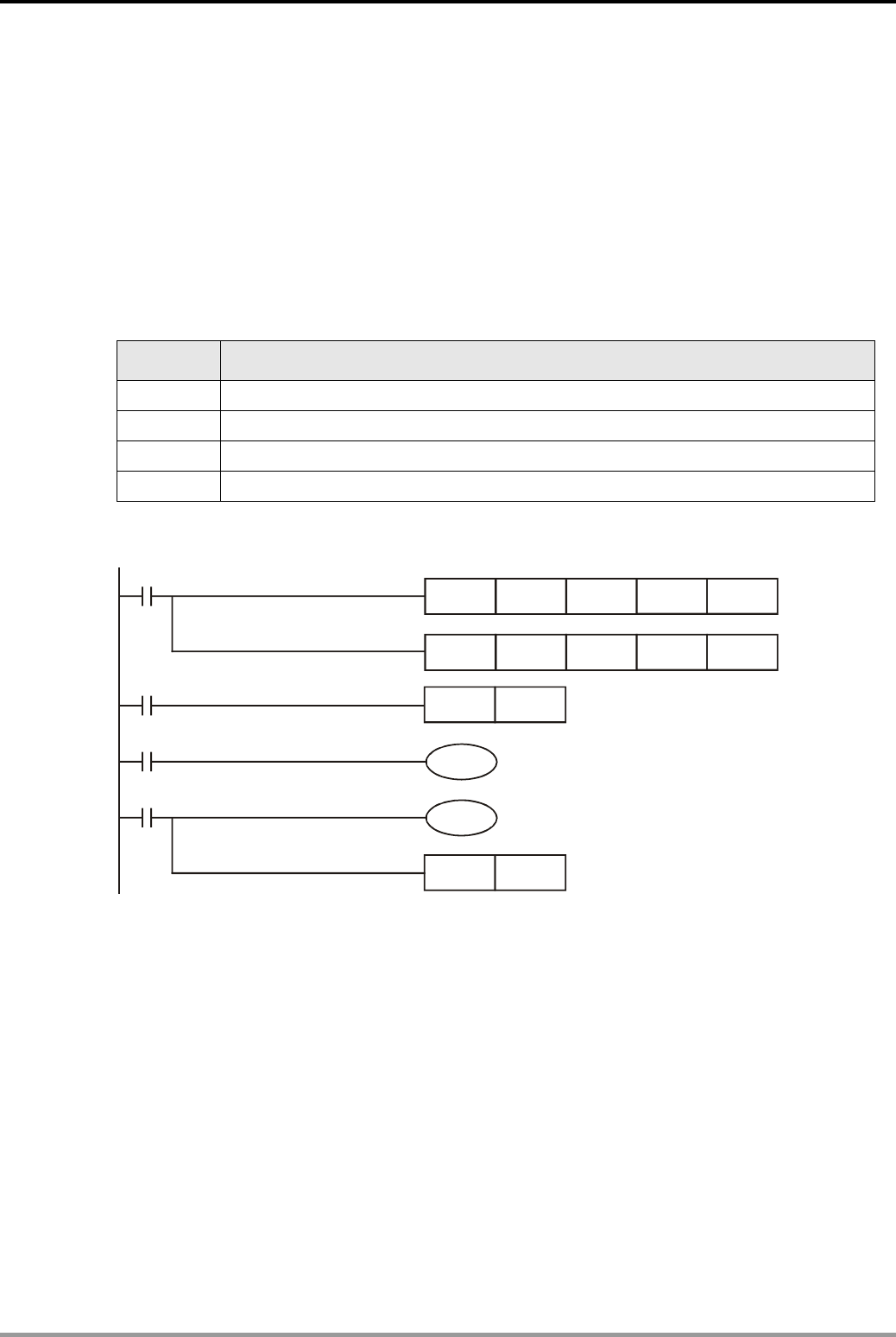
6. Data Transmission and Comparison Design Examples
DVP-PLC Application Examples 6-3
6.2 ZCP - Water Level Alarm Control
Control Purpose:
z Controlling the water level in water tower by using analogue level measuring instrument.
When the water is at normal level, enable the normal level indicator. When there is only 25%
water volume in the water tower, start the feed water valve. When the level reaches the upper
bound, enable the alarm and stop the feed water valve.
Devices:
Device Function
Y0 Feed water valve. ( The lower bound value = K1000)
Y1 Normal level indicator
Y2 Upper limit alarm. ( The upper bound value = K4000)
D0 Data register of the measuring value(K0~K4000)
Control Program:
M0
M1000
FROM
ZCP
SET
RST
K0 D0
K1000
Y0
Y0
K6 K1
M0K4000 D0
M1
M2
Y1
Y2
Program Description:
z The water level is measured by analogue level measuring instrument(Voltage output of
0~10V). Delta DVP04AD extension module converts the measured value into the value of
K0~K4000 and judges the water level by the value saved in D0
z When the value in D0 < K1000(25% water volume), M0 = ON to set the feed water valve Y0.
z When the value is between K1000~K4000, M1 = ON to set the normal level indicator Y1.
z When the value > K4000(the level reaches the upper bound), M2 = ON to set the upper limit
alarm Y2. At the same time, Y0 will be reset, and the feed water valve will be shut down.
z For the application of API78 FROM instruction, please refer to DVP-PLC Application
Manual – Programming.
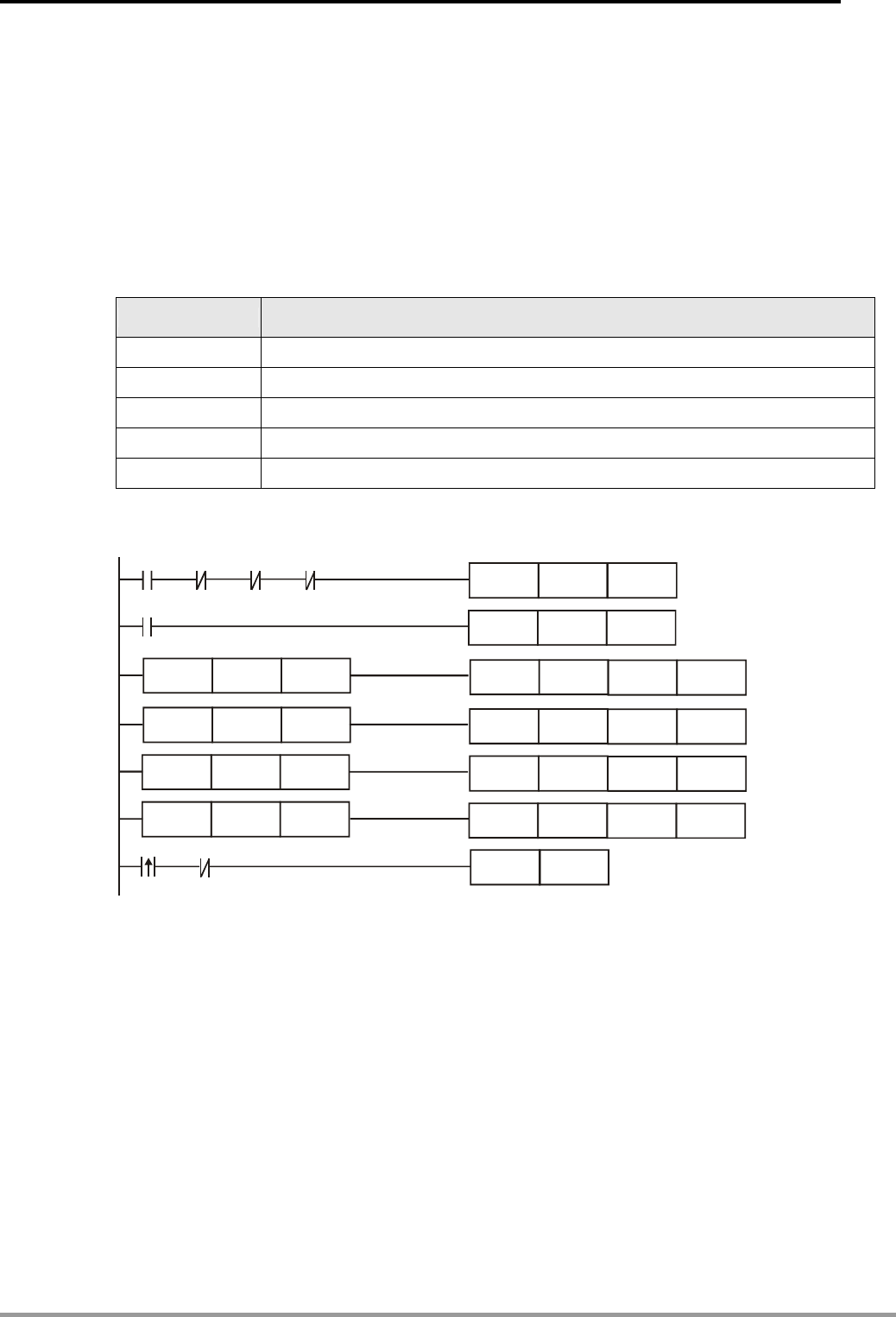
6. Data Transmission and Comparison Design Examples
DVP-PLC Application Examples
6-4
6.3 BMOV - Multiple History Data Backup
Control Purpose:
z Recording the data of the DUT(Device Under Test) in register D0~D99 on the experimental
test bed first, then backup the data in other registers every 30 min by DVP-PLC so that
registers D0~D99 can compile new data again. The test cycle of DUT is 2 hours.
Devices:
Device Function
X0 X0 turns ON when START is pressed.
X1 X1 turns ON when RETEST is pressed.
X2 X2 turns ON when STOP is pressed.
D0~D99 Data compiling
D100~D499 Data backup
Control Program:
TMR T0 K18000
CNT C0 K4
BMOVP D0 D100 K100
BMOVP D0 D200 K100
BMOVP D0 D300 K100
BMOVP D0 D400 K100
X0 X1 X2 T0
T0
LD= C0 K1
LD= C0 K2
LD= C0 K3
LD= C0 K4
X2X1
RST C0
Program Description:
z When X0 = ON, T0 starts to count up, and the NO contact T0 will be ON every 30 minutes.
z In the program, counter C0 is used for counting the ON times of NO contact T0. When C0 =
1, the data in D0~D99 will be sent to D100~D199; when C0 = 2, the data in D0~D99 will be
sent to D200~D299; when C0 = 3, the data in D0~D99 will be sent to D300~D399; when C0
= 4, the data in D0~D99 will be sent to D400~D499 and the test process ends here.
z If the operator needs to retest the DUT, just activate X1 one more time.
z When X2 = ON, the test will be stopped. In this case, no data compiling will be done on DUT
by PLC, and Counter C0 will be cleared as well.
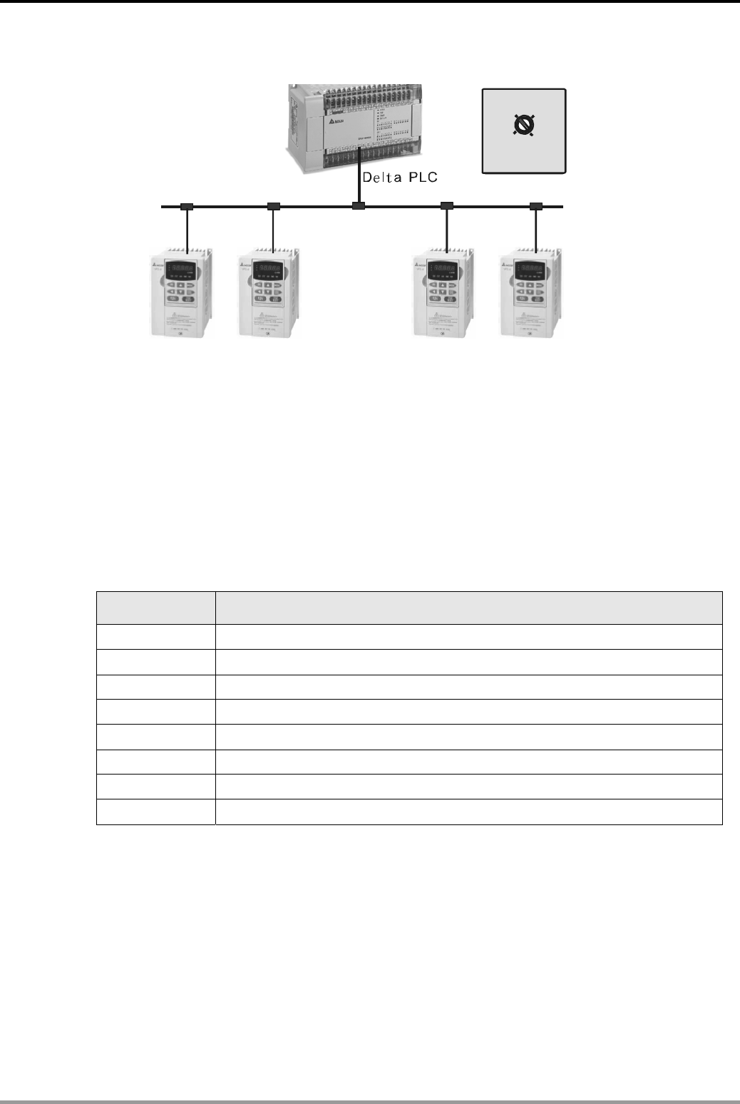
6. Data Transmission and Comparison Design Examples
DVP-PLC Application Examples 6-5
6.4 FMOV - Single Data Broadcasting
50Hz
Frequency Selection
X2 X3
X4
30Hz 40Hz
0Hz
X1
1# ACMD 2# ACM
D
3# ACM
D
4# ACM
D
RS485
Control Purpose:
z Setting frequency of 4 ACMDs (AC Motor Drive) by selecting on the rotary switch.
In some applications users may need to set the frequency on several ACMDs to be the same
when a Delta PLC is connected through RS485 communication format. The control purpose can
be achieved by controlling the value in D10~D13 which corresponds to 4 frequency of four
ACMDs, and then adjusting the frequency by one external rotary switch.
Devices:
Device Function
X1 X1 = ON when the switch is turned to “0Hz”.
X2 X2 = ON when the switch is turned to “30Hz”.
X3 X3 = ON when the switch is turned to “40Hz”.
X4 X4 = ON when the switch is turned to “50Hz”.
D10 Output frequency of 1# AC motor drive
D11 Output frequency of 2# AC motor drive
D12 Output frequency of 3# AC motor drive
D13 Output frequency of 4# AC motor drive

6. Data Transmission and Comparison Design Examples
DVP-PLC Application Examples
6-6
Control Program:
FMOV K0 D10 K4
FMOV D10 K4
FMOV K4000 D10 K4
FMOV
MODWR
MODWR
MODWR
D10
H2001
H2001
H2001
K4
D10
D11
D12
X1
X2
X3
X4
M0
M1
M2
MODWR H2001 D13
M3
Controlling the frequency
of AC motor drive through
RS485 communication format
K3000
K5000
K1
K2
K3
K4
( Part of the whole program)
program Description:
z When X1 = ON, K0 will be sent to D10~D13. The output frequency of ACMD will be 0Hz.
z When X2 = ON, K3000 will be sent to D10~D13. The output frequency of ACMD will be
30Hz.
z When X3 =ON, K4000 will be sent to D10~D13. The output frequency of ACMD will be
40Hz.
z When X4 = ON, K5000 will be sent to D10~D13. The output frequency of ACMD will be
50Hz.
z The program applies MODWR instructions to set output frequency of ACMDs through
RS485 communication. Please note that the 4 MODWR instructions cannot be executed at
the same time due to a possible conflict in communication. For examples of multiple
communication, please refer to Chapter 12 – Communication Design Examples.
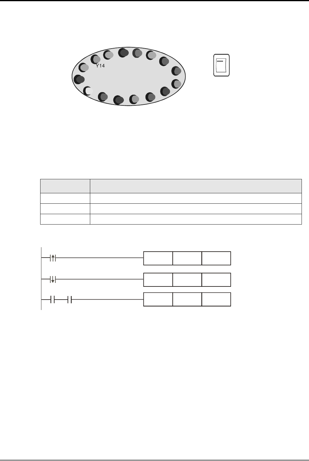
6. Data Transmission and Comparison Design Examples
DVP-PLC Application Examples 6-7
6.5 CML - Color Lights Flashing
ON
OFF
X1
Y0 Y2
Y1 Y3 Y4 Y5
Y6
Y7
Y10
Y11
Y12
Y13
Y15
Y17
Y16
Control Purpose:
z Turning on the even-numbered lights and odd-numbered lights alternately for 1 sec when
the switch is turned ON.
z Turning off all color lights when the switch is turned off.
Devices:
Device Function
X1 Flashing control switch. X1 = ON when the switch is turned to ON.
M1013 1s clock pulse, 0.5s ON / 0.5s OFF
Y0~Y17 16 color lights
Control Program:
MOV
MOV
CMLP
H5555
H0
K4Y0
K4Y0
K4Y0
K4Y0
X1
X1
X1 M1013
Program Description:
z When the switch is turned ON, K4Y0 = H5555 and the state of Y17~Y0 will be “0101 0101
0101 0101,” which means the even-numbered lights will be ON. When M1013 = On, CMLP
instruction will be executed to reverse the state of K4Y0. Y17~Y0 will be “1010 1010 1010
1010,” which means the odd-numbered lights will be ON. The state will last for 1 sec.
z When M1013 is ON again, CMLP instruction will be executed and the state of K4Y0 will be
reversed again. In this case, the even-numbered lights will be ON.
z Every time when M1013 is ON, the state of Y0~Y17 will be reversed and lasts for 1 sec. The
lights will flash alternatively as this cycle.
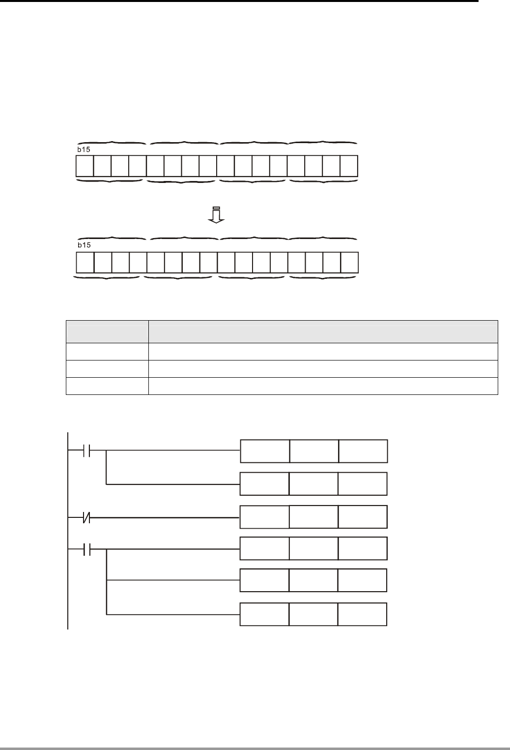
6. Data Transmission and Comparison Design Examples
DVP-PLC Application Examples
6-8
6.6 XCH - Exchanging the Upper and Lower 8 bits in a Register
Control Purpose:
z Exchanging the data NB(Nibble)0 with NB1, NB2 with NB3 in a register every 1 sec.
The data length of D register is Word (16 bits), and a Word is made up of 4 Nibbles.
D0=H5678 (Before exchange)
b6
b6
b0
b0
b1
b1
b2
b2
b3
b3
b4
b4
b5
b5
b7
b7
b8
b8
b9
b9
b10
b10
b11
b11
B12
B12
b13
b13
b14
b14
D0=H6587
(After exchange)
H8
H7
H7
H8H5H6
H6H5
NB0
NB0
NB1NB2NB3
NB1NB2NB3
Devices:
Device Function
T0 1 sec timer. Time base: 100ms
D0 Data register
Y0~Y17 Storing 4 nibbles
Control Program:
MOV
MOV
XCHP
TMR
H5678
D0
K1Y0
T0
D0
K4Y0
K1Y4
K10
M1002
T0
T0
XCHP
MOVP
K1Y10
K4Y0
K1Y14
D0
Program Description:
z First, the program will store the 16 bits ( 4 Nibbles) data in D0 to Y0~Y17. After 1 sec, the
NO contact T0 will be activated to execute XCHP instruction. The data in K1Y0 will be
exchanged with K1Y4 and so will K1Y10 with K1Y14. Then, these data will be sent to D0.
Finally, The data exchange between NB0/NB1 and NB2/NB3 is completed.
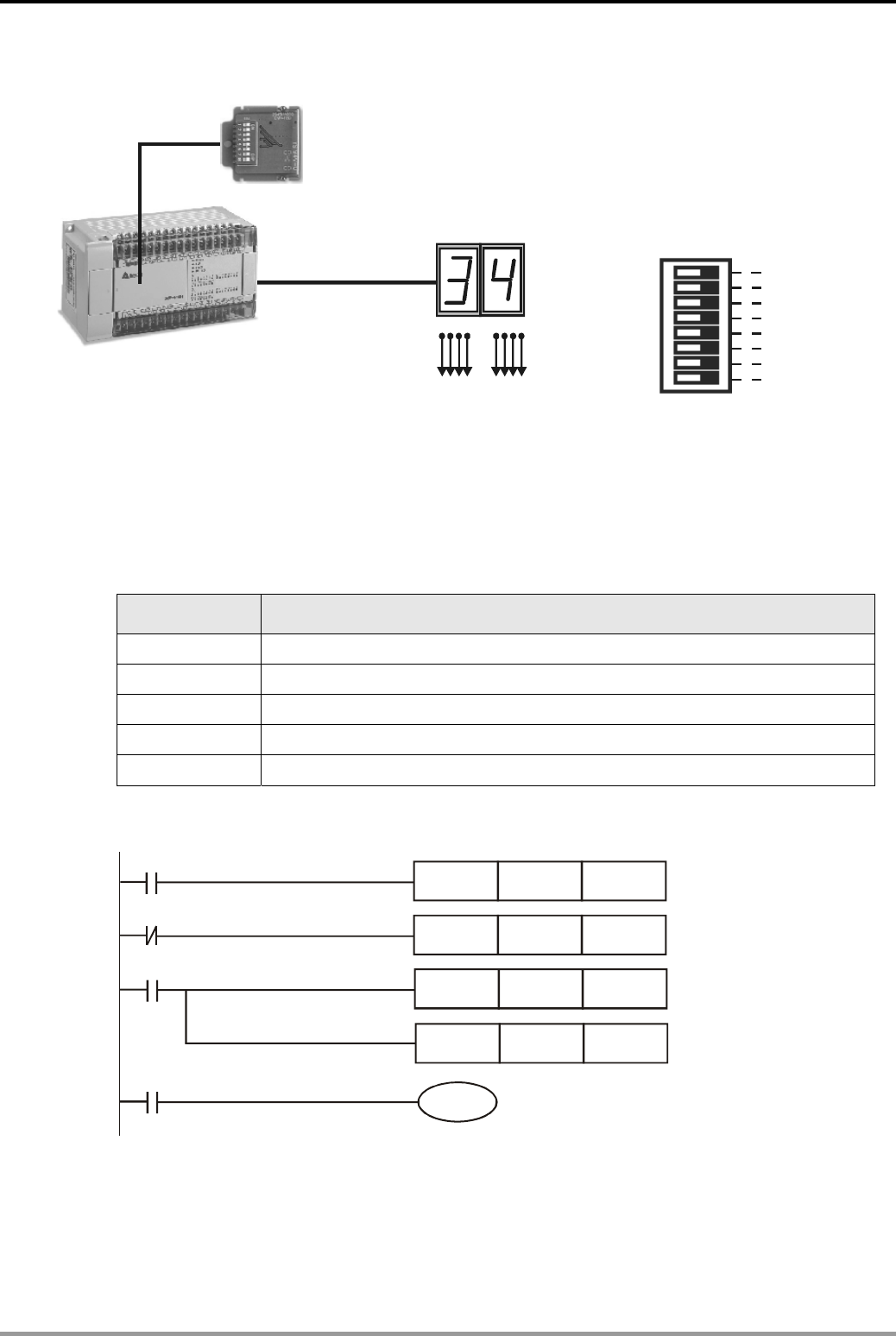
6. Data Transmission and Comparison Design Examples
DVP-PLC Application Examples 6-9
6.7 DIP Switch Input and 7-segment Display Output
DVP-F8ID
84218421
Y3~Y0Y7~Y4
DI0
DI1
DI2
DI3
DI4
DI5
DI6
DI7
M1104
M1105
M1110
M1109
M1108
M1107
M1106
M1111
:
K0~K99
:
K0~K99
DVP-EH
MPU
Display Range Input Range
Equivalent circuit of
DVP-F8ID extension card
Control Purpose:
z Setting the set value of counter C0 in the range of K0~K99 by DVP-F8ID extension card and
displaying the PV (K0~K99) by 7-segment decoding display.
Devices:
Device Function
X0 Switch for starting C0
M1104~M1111 Mapping ON/OFF state of the external 8 switches
D0 Set value of C0
Y0~Y7 Displaying the PV of C0
Y10 Indicator. Y10 = ON when the counter reached its set value
Control Program:
BIN
CNT
BCD
BCD
K2M1104
C0
D0
C0
D0
D0
K2Y0
K2Y0
M1000
C0
X0
X0
Y10
Program Description:
z When PLC runs, ON/OFF state of the external 8 DIP switches will be mapped to PLC
internal auxiliary relay M1104~M1111 by DVP-F8ID extension card. 8 bits switch can
perform 2 digit number input by instructions.

6. Data Transmission and Comparison Design Examples
DVP-PLC Application Examples
6-10
z When the program is executed, M1000 = ON, and the set value of counter in DVP-F8ID
extension card will be stored in D0.
z When the counter is OFF, X0 = OFF, and the 2 digit number display will show the set value
of C0 because of the execution of BCD instruction.
z When the counter is ON, X0 = ON. C0 will start counting and BCD instruction will be
executed. The 2 digit number display will show the PV of C0.
z If the 2 digit number display shows “34” from left to right, it means the state of DI7~DI0 on
DVP-F8ID extension card is “0011 0100.”
z When C0 reaches its set value D0, the NO contact C0 will be activated and Y10 will be ON.
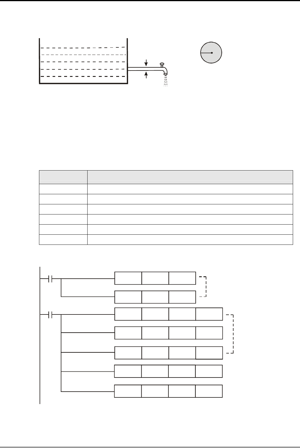
7. Elementary Arithmetic Operations Design Examples
DVP-PLC Application Examples 7-1
7.1 Accurate Pipe Flow Measurement
r
S=
ππ
r= (d/2)
22
Cross-sectional area of the pipe
d
Control Purpose:
z Measuring the flow to an accuracy of 2 decimal places.
In this example, the diameter of the pipe is measured by mm, the flow rate is measured by
dm/s, and the flow is measured by cm3/s. The cross-sectional area of the pipe = πr2 = π(d/2)2 and
the flow = cross-sectional area × flow rate.
Devices:
Device Function
X0 Starting the measurement
D0 Diameter of the pipe (unit: mm; set value: 10mm)
D6 Operation result of the cross-sectional area (unit: mm2)
D10 Flow rate (unit: dm/s; set value: 25dm/s)
D20 Operation result of the flow (unit: mm3/s)
D30 Operation result of the flow (unit: cm3/s)
Control Program:
MUL
MOV
DDIV
DMUL
DDIV
K314
K25
D4
D6
D20
MOV K10 D0
D2
D10
K4
D10
K1000
MUL D0 D0 D2
D4
D6
D20
D30
X0
Calculation of the
cross-sectional area
Total Flow (mm /s )
3
Total Flow (cm /s )
3
M1002
Set value of pipe diameter
and the flow rate

7. Elementary Arithmetic Operations Design Examples
DVP-PLC Application Examples
7-2
Program Description:
z The floating point operation is usually applied to perform decimal calculation. However, it
needs to be converted and is more complicated. Therefore, we use elementary arithmetic
operation instructions to perform decimal calculation in this example.
z The units of mm, cm and dm are used in the program. For calculation requirement, the
program sets these units into mm3 and then converts them into cm3.
z π (π≈3.14) is required when calculating the cross-sectional area of the pipe. In order to get
the calculation accuracy of 2 decimal places, the program increases π 100 times to be K314
instead of increasing the unit dm/s 100 times to be mm/s.
z In the end, the program divides the value in D20 (unit: mm3/s) with 1000 so as to convert the
unit into cm3/s. (1 cm3 = 1 ml, 1l = 1000 ml = 1000 cm3 = 1 dm3 )
z .Assume the pipe diameter D0 is 10 mm and the flow rate D10 is 25 dm/s, the operation
result of the total flow will be 196 cm3/s.
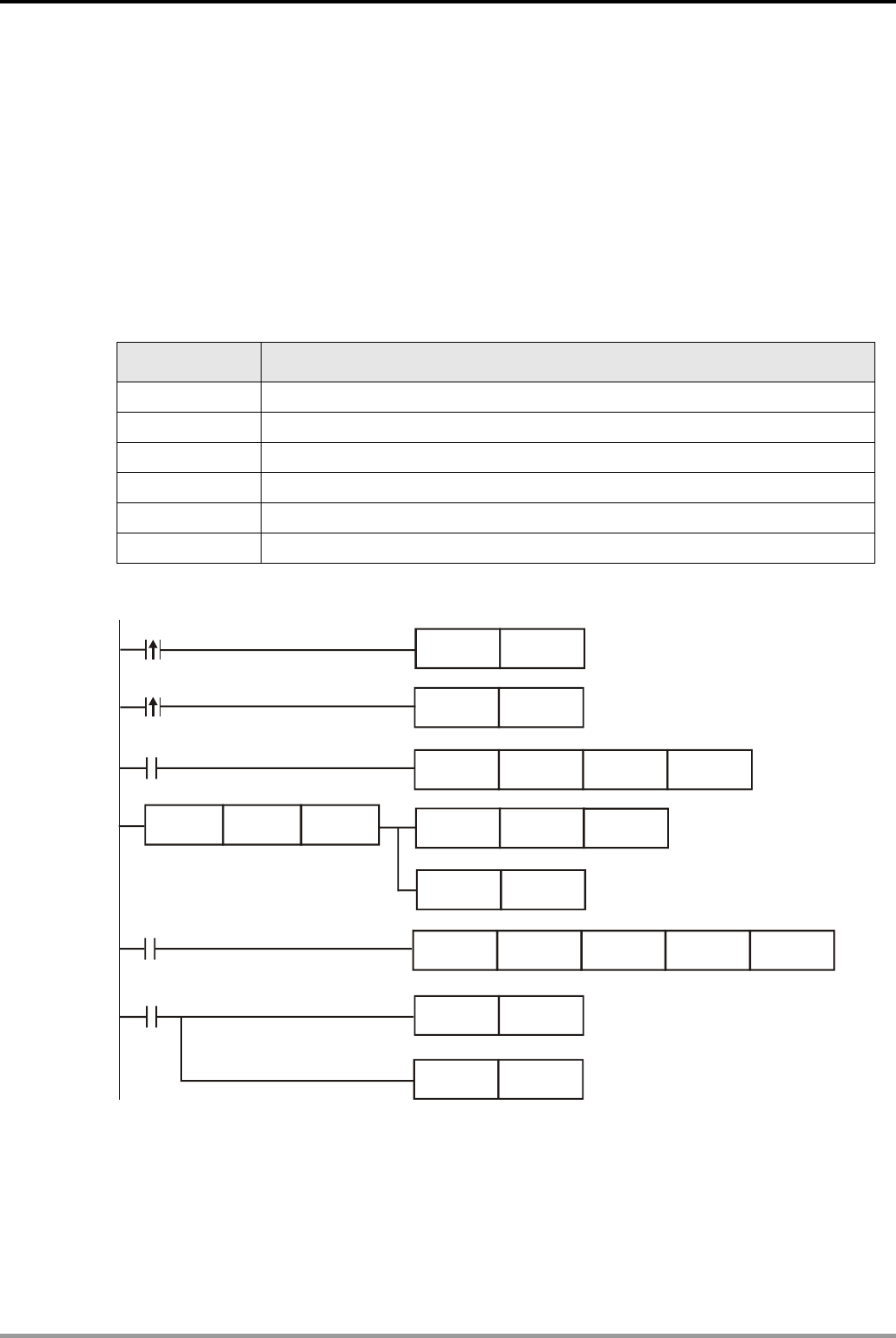
7. Elementary Arithmetic Operations Design Examples
DVP-PLC Application Examples 7-3
7.2 INC/DEC - Fine Tuning by JOG Control
Control Purpose:
z Controlling the fine tuning by JOG left and JOG right switches.
In this assumed position control system, the 1 mm fine tuning can be performed by 100
pulses sent by PLC. When X0 is pressed, JOG left for 1 mm; when X1 is pressed, JOG right for 1
mm.
Devices:
Device Function
X0 JOG left switch
X1 JOG right switch
D0 Target position
D2 The number of pulses for target position
Y0 Pulse output point
Y5 Direction control signal output
Control Program:
DINC
DDEC
DMOV
DDRVA
D0
D0
D2
D4
SET
D4
K50000
M1
X0
X1
M1000
M1029
M1
LD<> D2
MUL
RST
RST
D0
M1
M1029
K100
Y0
D2
Y5
D4
Program Description:
z When JOG left switch X0 is pressed, DINC instruction will execute to increase the value in
D0; when JOG right switch X1 is pressed, DDEC instruction will execute to decrease the
value in D0.
z Assume the initial value of D0 and D4 is K0. When JOG left switch is pressed, D0 will be K1

7. Elementary Arithmetic Operations Design Examples
DVP-PLC Application Examples
7-4
and then be multiplied with 100 as the pulse number. The pulse number will be stored in D2
then transferred to D4 as the target value of DDRVA instruction (absolute position), and M1
will be ON to execute DDRVA instruction.
z According to the execution result of DDRVA, Y0 will output 100 pulses with frequency 50kHz
and the system will JOG to the target position (D4 = D2 = K100) from the initial position (D4
= K0), which means the system will JOG left for 1 mm.
z If X0 is pressed again, D2 will be K200 which is different to the present value in D4 (K100).
The value in D2 (K200) will be sent to D4 as the target value of the absolute position. M1 will
be ON to execute DDRVA instruction. The system will JOG to the target position (D4 = D2 =
K200) from the last position (D4 = K100), which means the system will JOG left for another 1
mm.
z Likewise, the process of JOG right is similar to that of JOG left. The system will JOG right for
1 mm every time the JOG right switch is pressed,
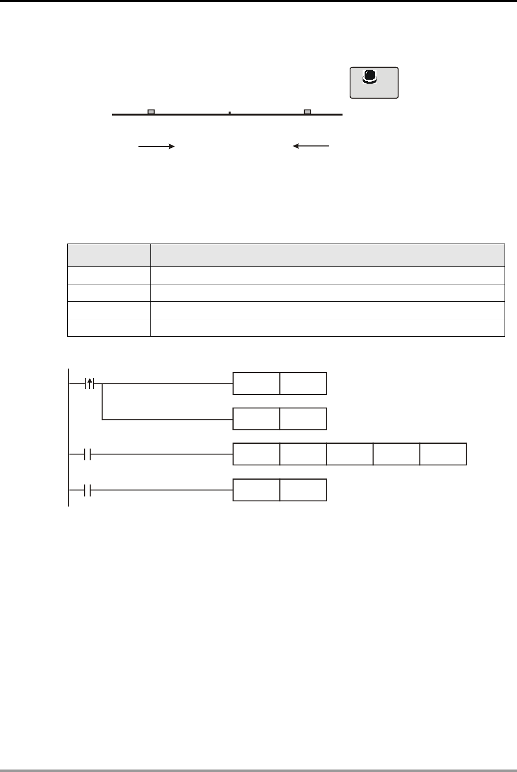
7. Elementary Arithmetic Operations Design Examples
DVP-PLC Application Examples 7-5
7.3 NEG - Displacement Reverse Control
K50000K-50000
(D200,D201) (D200,D201)
(D200,D201 )
X1
Reverse START
Origin(K0)
Control Purpose:
z The symmetric point in this program is the Origin (D200, D201 = K0). Controlling the
displacement to shift between the left end and the right end every time X1 is pressed.
Devices:
Device Function
X1 Reverse START button
Y0 Pulse output point
Y5 Reverse direction control
D200, D201 Storing the target value of the absolute position
Control Program:
DNEG
DDRVA
RST
D200
D200
M0
K5000 Y0
X1
M0
M1029
SET M0
Y5
Program Description:
z Assume the 32-bit initial value of D200 and D201 is K50000. When the Reverse START
button X1 is pressed, the content in D200 and D201 will become K-50000.
z In addition, M0 will be ON to execute DDRVA instruction. The program will shift the present
location K50000 to the target position K-50000 with frequency 5KHZ (K5000). When the
target position is reached, M1029 = ON and M0 will be reset. Y0 will stop pulse sending.
z When X1 is pressed again, the value in D200 and D201 will change from K-50000 to
K50000. M0 will be ON to execute the displacement reverse control until the absolute
position is reached.
z As the actions above, the program will shift from the present location to the other side of the
symmetric point Origin every time when X1 is pressed.

7. Elementary Arithmetic Operations Design Examples
DVP-PLC Application Examples
7-6
MEMO
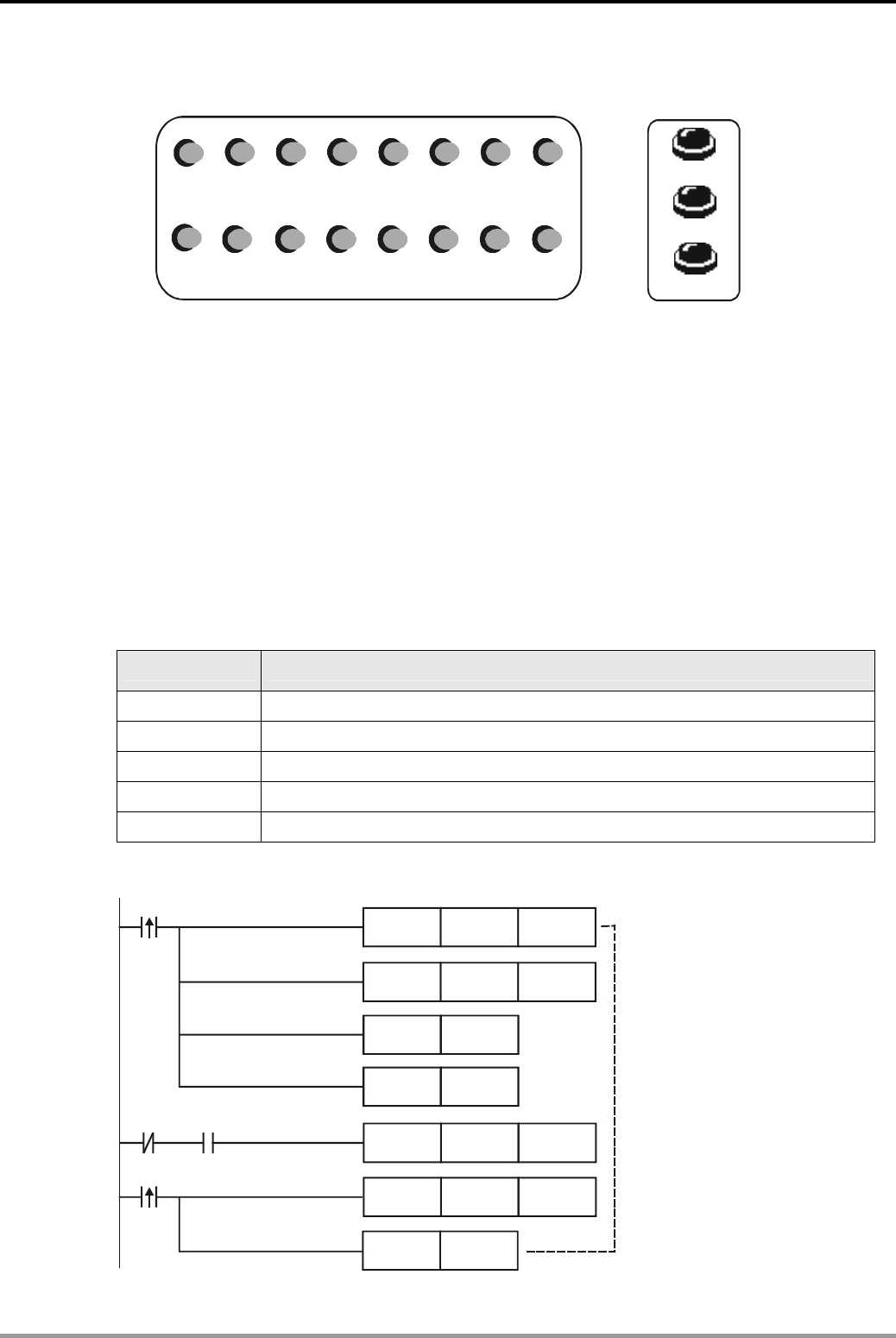
8. Rotation and Shift Design Examples
DVP-PLC Application Examples 8-1
8.1 ROL/ROR - Neon Lamp Design
Y0 Y1 Y2 Y3 Y4 Y5 Y6 Y7
Y10 Y11 Y12 Y13 Y14 Y15 Y16 Y17
X0 Right
X1
Left
X2
Reset
Control Purpose:
z Enabling the 16 neon lamps in the order: Y0~Y7, Y10~Y17 when Rotation Right button is
pressed. Each lamp turns on for 200ms.
z Enabling the 16 neon lamps in the order: Y17~Y10, Y7~Y0 when Rotation Left button is
pressed. Each lamp turns on for 200ms.
z The action of Reset is unnecessary when switching between Rotation Right and Rotation
Left.
z When RESET is pressed, turn off all working neon lamps.
Devices:
Device Function
X0 Rotation Right button. X0 = ON when the button is pressed.
X1 Rotation Left button. X1 = ON when the button is pressed.
X2 X2 turns ON when RESET is pressed.
T0/T1 200ms timer. Time base: 100ms.
Y0~Y17 16 neon lamps
Control Program:
X0
SET Y0
SET
RST
M10
T0
T0 M10
TMR T0 K2
T0
ROL K4Y0 K1
ZRST Y0 Y17
ZRST M10 M11
Enabling the neon lamps
in the order: Y0~Y7, Y10~Y17.
Each lamp for 200ms.
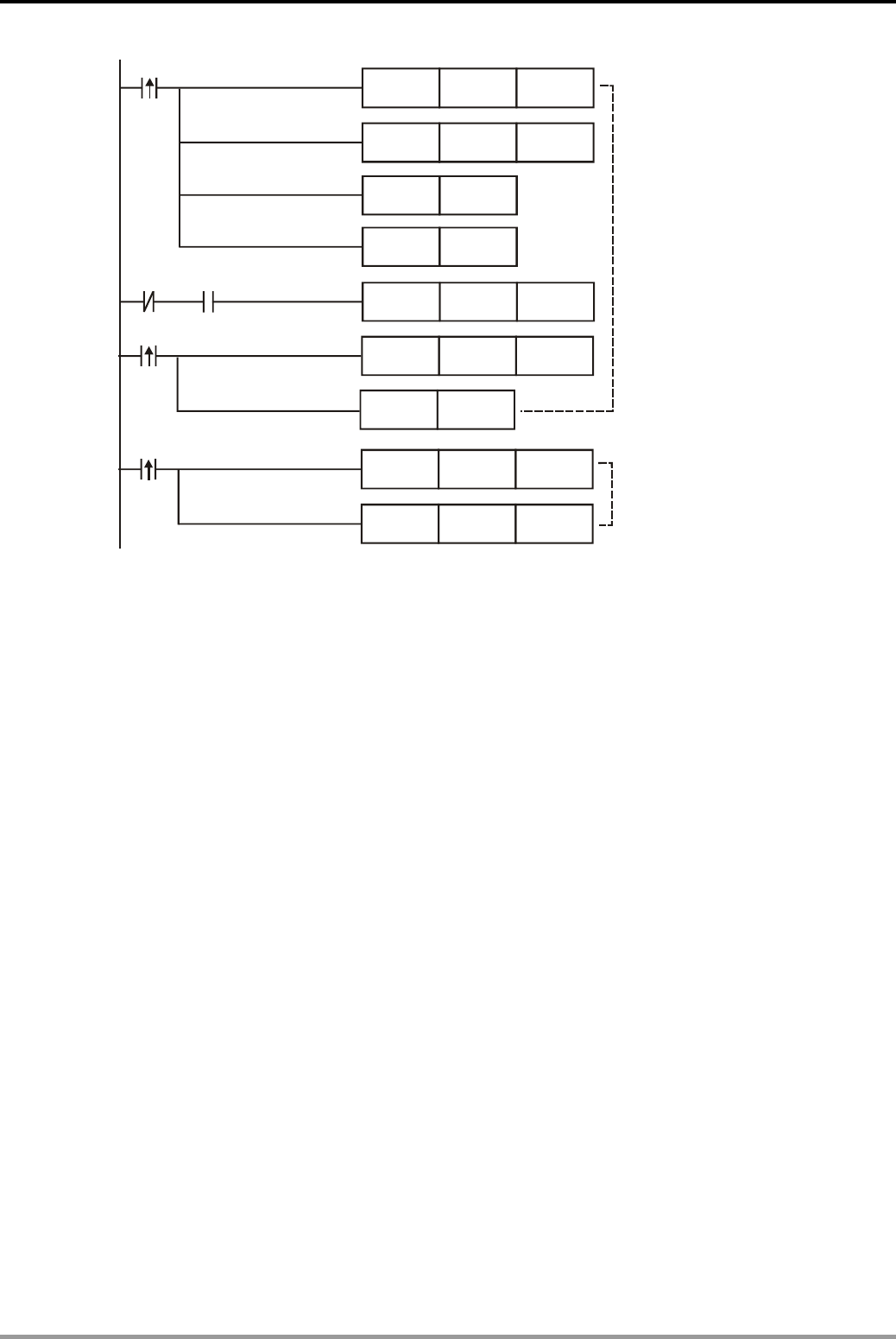
8. Rotation and Shift Design Examples
DVP-PLC Application Examples
8-2
RST T1
X1
Y17
M11
T1
T1
M11
TMR T1 K2
ROR K4Y1 K1
X2
SET
SET
ZRST Y0 Y17
ZRST M10 M11
ZRST Y0 Y17
ZRST M10 M11
Enabling the neon lamps
in the order: Y17~Y10, Y7~Y0.
Each lamp for 200ms.
Reset
Program Description:
z When Rotation Right is pressed, X0 = ON to execute ZRST and SET instructions. Y0~Y17
and M10~M11 will be reset first, then Y0 and M10 will be ON. TMR instruction will be
executed. After 200ms, the contact T0 will be activated once to execute ROL instruction.
The ON state of Y0 will be shifted to Y1, and T0 will then be reset.
z In the next scan cycle, timer T0 starts counting again. After 200ms, ROL instruction will be
executed one more time and the ON state of Y1 will be shifted to Y2. By the same process,
Y0~Y17 will be ON for 200ms in order.
z The rotation left process is similar to the above process. However, the rotation right program
uses ROR instruction to enable the lamps in the order: Y17~Y10, Y7~Y0
z When RESET is pressed, X2 = ON to reset Y0~Y17 and M10~M11. All neon lamps will be
OFF. (Note: in this program, the purpose of placing ZRST instruction after the rising-edge
contacts of X0 and X1 is to ensure that all the neon lamps start flashing from Y0 or Y17.)
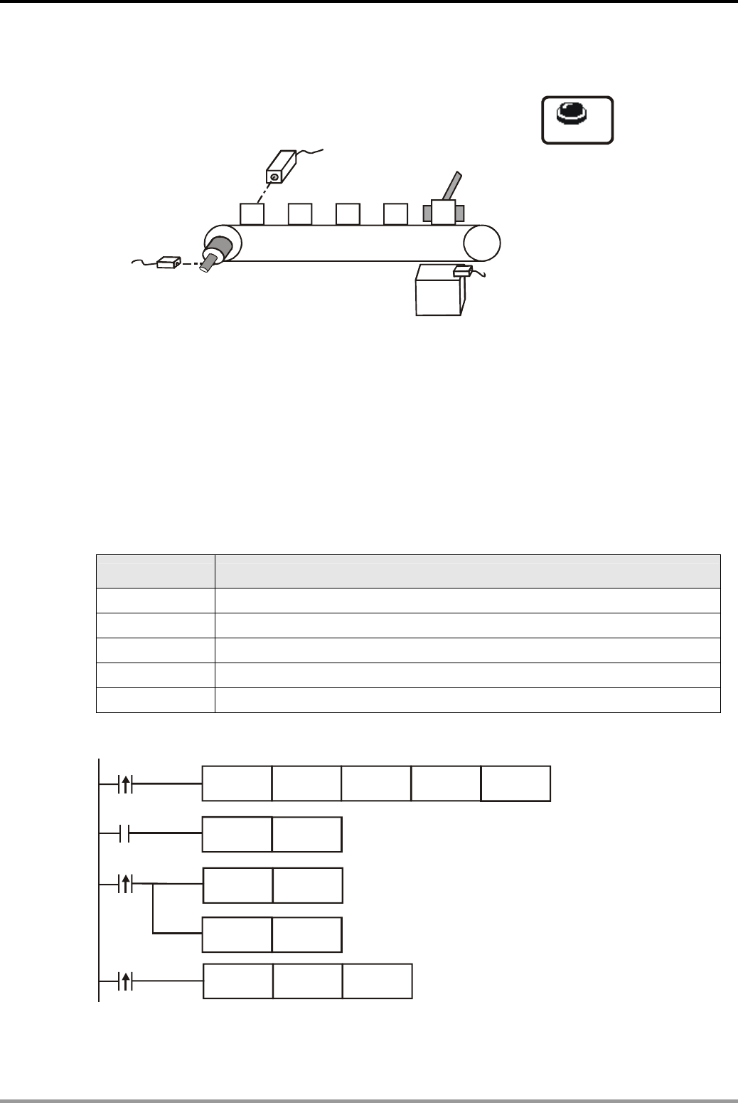
8. Rotation and Shift Design Examples
DVP-PLC Application Examples 8-3
8.2 SFTL - Defective Product Detect
X4
P
for monitoring the cam
hotoelectric sensor
Photoelectric sensor
for detecting defective product
X0
RESET
Y0
Electromagnetic valve
pushing pole
Recycle box for defective product
P
for detecting the falling
of defective products
hotoelectric sensor
5
X
X6
Control Purpose:
z Detecting the defective products (taller than normal dimension) on the conveyor belt by
photoelectric sensor and pushing them into the recycle box at the 5th position.
The pushing pole will be reset when the falling of defective product is detected. When errors
occur, the disorder memory can be cleared and the system can be restarted by pressing RESET.
Devices:
Device Function
X0 Photoelectric sensor for detecting defective products
X4 Photoelectric sensor for monitoring the cam
X5 Photoelectric sensor for detecting the falling of defective products
X6 RESET
Y0 Electromagnetic valve pushing pole
Control Program:
RST
RST
Y0
X4
M4
X5
X6
SFTL X0 M0 K5 K1
SET
Y0
M4
ZRST M0 M4

8. Rotation and Shift Design Examples
DVP-PLC Application Examples
8-4
Program Description:
z Every time the cam rotates once, the product will be moved from one position to another
position. X4 will be activated to execute SFTL instruction once. The content in M0~M4 will
be shift to left for one bit and the state of X0 will be sent to M0.
z When X0 = ON (defective products detected), the value “1” will be sent to M0 and achieve
the 5th position after 4 times of shift. In this case, M4 = ON and the electromagnetic valve Y0
will be ON to push the defective product into the recycle box.
z When the falling of the defective product is detected, X5 will be activated to execute [RST
Y0] and [RST M4] instructions. Y0 and M4 will be reset. The electromagnetic valve will be
OFF till next defective product is detected.
z When RESET is pressed, X6 will be activated to reset M0~M4, so as to ensure that the
system restart the detecting process when the memory which records defective products is
in disorder.
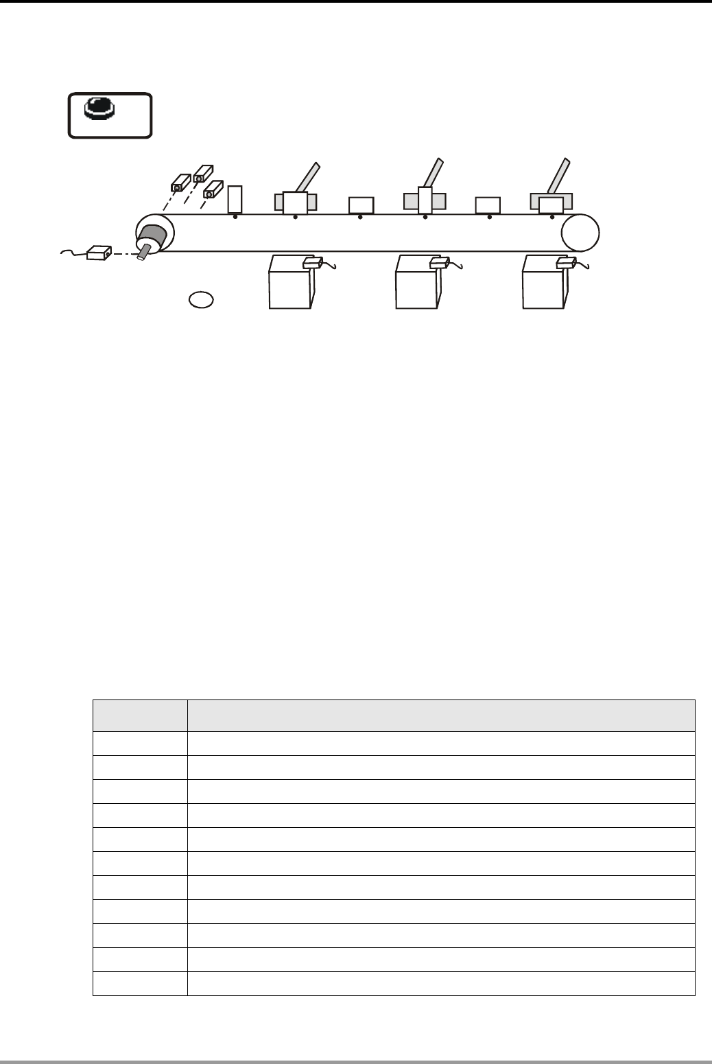
8. Rotation and Shift Design Examples
DVP-PLC Application Examples 8-5
8.3 WSFL - Automatic Sorting Mixed Products
Photoelectric sensor X6
for c monitoring the am
RESET
Position1 Position2 Position3 Position4 Position5 Position6
A
Y0
Electromagnetic valve Electromagnetic valve B
Y1 Electromagnetic valve C
Y2
X3 X4 X5
X7
Container A Container B Container C
X0
X1
X2
Control Purpose:
z Sorting different products on the conveyor belt and pushing each product into its
corresponding container.
1. There are three kinds of products, A, B and C and 6 positions for each product are set on the
conveyor. Products will move forward for one position when the cam rotates once.
2. Sorting each product by product ID (Identification) sensors. Product A will be pushed in container
A at position 2. And so forth, product B in container B at position 4; product C in container C at
position 6.
3. When the product falling is confirmed by sensors, the electromagnetic valve will be reset. When
RESET is pressed, all memory will be cleared and the system will restart the identifying and
sorting process.
Devices:
Device Function
X0 Product A ID sensor. X0 = ON when Product A is detected.
X1 Product B ID sensor. X1 = ON when Product B is detected.
X2 Product C ID sensor. X2 = ON when Product C is detected.
X3 Product A falling sensor. X3 = ON when Product A falls in container A
X4 Product B falling sensor. X4 = ON when Product B falls in container B
X5 Product C falling sensor. X5 = ON when Product C falls in container C
X6 Sensor for the cam. X6 activates 1 time when the cam rotates once.
X7 RESET. X7 = ON when the button is pressed
Y0 Electromagnetic valve A
Y1 Electromagnetic valve B
Y2 Electromagnetic valve C
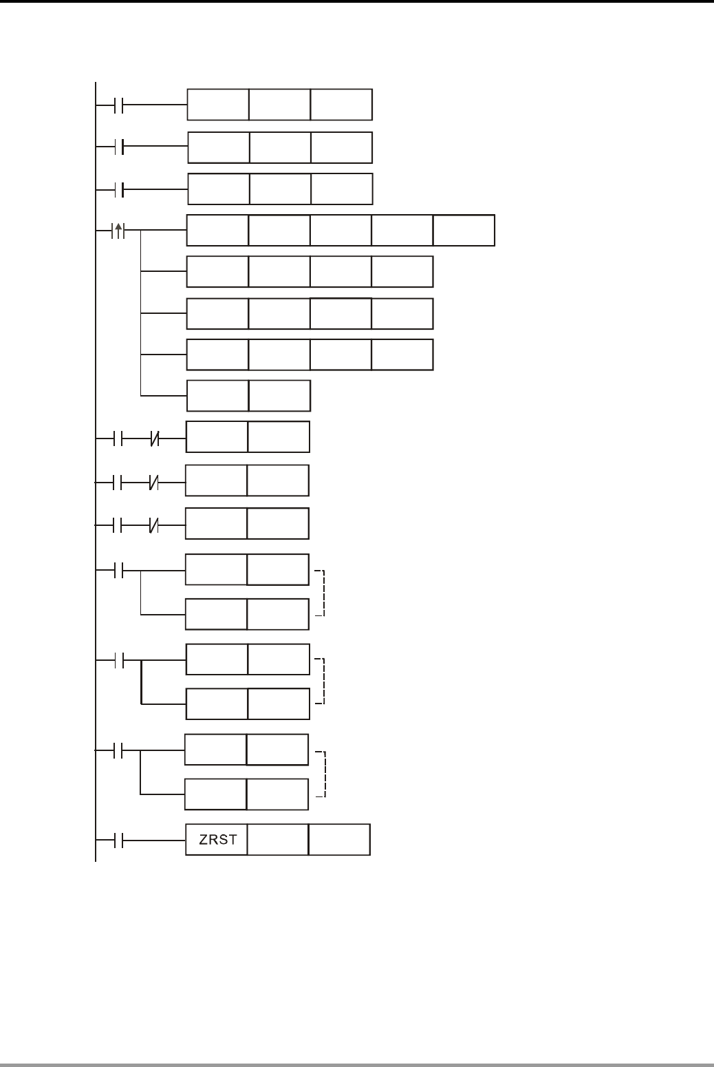
8. Rotation and Shift Design Examples
DVP-PLC Application Examples
8-6
Control Program:
CMP
CMP
CMP
D101
D105
D103
K1
K3
K2
M10
M30
M20
RST
SET
SET
SET
D0
Y0
Y1
Y2
WSFL D0 D100 K6 K1
X6
X0
MOVP K1 D0
D0
D0
K2
K3
MOVP
MOVP
X1
X2
M11
M21
M31
X3
X4
X5
X3
X4
X5
X7
RST
RST
RST
RST
RST
RST
M11
M21
M31
D100
Y0
Y1
Y2
D105
Product A is identified
Product B is identified
Product C is identified
Data in D100~D105 will shift
left for one register
when the cam rotates once
Confirming product A
at position 2
Confirming product B
at positoin 4
Confirming product C
at position 6
Enable electromagnetic valve
if product A is confirmed.
Reset electromagnetic valve A
when falling of product A is detected.
Reset electromagnetic valve B
when falling of product B is detected.
Reset electromagnetic valve C
when falling of product C is detected.
Reset the system and
clear all the data memory.
Enabling electromagnetic valve B
if product B is ocnfirmed.
Enabling electromagnetic valve C
if product C is confirmed.
Program Description:
z When product A is identified on the conveyor belt, X0 activates for one time to execute
MOVP K1 D0 instruction. The value in D0 = K1. Likewise, when product B and C is on the
conveyor, the value in D0 will be K2 and K3.
z Products will move forward for one position when the cam rotates once. X6 activated one
time to execute WSFL instruction. Data in D100~D105 will shift left for one register. At the

8. Rotation and Shift Design Examples
DVP-PLC Application Examples 8-7
same time, CMP instructions will be executed to confirm product A at position 2 (D101),
product B at position 4 (D103) and product C at position 6 (D105). After each CMP
instruction, RST instruction will be executed to clear D0.
z If product A , B or C is confirmed at position 2, 4 or 6, the corresponding M11, M21 or M31
will be ON to enable electromagnetic valve A, B or C to push the products in the containers.
z When the falling of each product is detected by sensors, X3, X4 or X5 will be ON to reset
electromagnetic valve A, B or C.
z When RESET is pressed, X7 = ON to execute ZRST instruction. The value in D100~D105
will be 0, which means all data memory will be cleared.
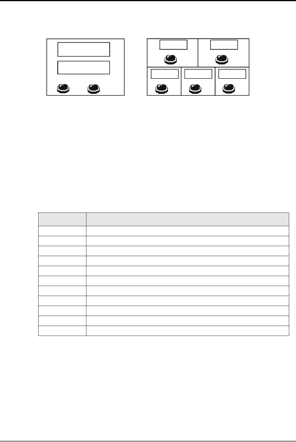
8. Rotation and Shift Design Examples
DVP-PLC Application Examples
8-8
8.4 SFWR/SFRD - Room Service Call Control
Rooms
Room 101
Room 103 Room 104 Room 105
Room102
Service Counter
Room NO.
Amount of calling
CHECK RESET
X5 X6
X0
X2 X3 X4
X1
D11
D0
Control Purpose:
z Recording the calling room numbers and the amount of calling then checking the numbers in
first-in first-out principle, which means the room first called will be first served.
z Clearing all the data memory when RESET is pressed.
The amount of calling will be increased by the pressing times of call buttons, and decreased by
the checking times of CHECK button. If all room numbers are checked, the displayed amount of
calling would be 0.
Devices:
Device Function
X0 Call button of Room 101. X0 = ON when the button is pressed
X1 Call button of Room 102. X1 = ON when the button is pressed
X2 Call button of Room 103. X2 = ON when the button is pressed
X3 Call button of Room 104. X3 = ON when the button is pressed
X4 Call button of Room 105. X4 = ON when the button is pressed
X5 Check button. X5 = ON when CHECK is pressed.
X6 Reset button. X6 = ON when RESET is pressed.
D0 Displaying the amount of calls
D1 ~ D5 Storing the room numbers under check
D10 Storing the input room numbers temporarily
D11 Displaying the room number (First-in first-out)
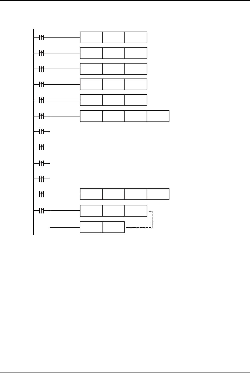
8. Rotation and Shift Design Examples
DVP-PLC Application Examples 8-9
Control Program:
MOV K102 D10
X0
MOV K103 D10
MOV K104 D10
MOV K105 D10
X2
X3
X1
X4
MOV K101 D10
X0
X2
X3
X1
X4
SFWR D10 D0 K6
X5
SFRD D0 D11 K6
X6
ZRST
RST
D0
D11
D5
Send the Room No. 101 to D10
Send the Room No. 102 to D10
Send the Room No. 103 to D10
Send the Room No. 104 to D10
Send the Room No. 105 to D10
Send the value in D10 to
registers specified
by D0 (D1~D5)
Display the value (Room NO.)
according to registers
specified by D0 (D1~D5)
When X6 is activated, the value
in D0~D5 and D11 will be cleared.
Program Description:
z By using API38 SFWR instruction together with API39 SFRD instruction, the program
performs data stack writing and reading control in FIFO(first in, first out) principle. In this
example, the room number first called will be first checked.
z When Call buttons are pressed, the numbers of the five rooms will be stored in D10 first and
then sent to data stack D1~D5 according to the time order.
z When CHECK is pressed, the room number first called will be read to D11 first and the
amount of calling will be decreased corresponding to D0. In addition, by using Delta TP04,
the system can easily monitor the value of D0 (Amount of calling) and D11 (Displaying
Room No.)
z The program clears D0~D5 and D11 by ZRST and RST instructions, which means Amount
of calling and Room number displayed on TP04 will be 0.

8. Rotation and Shift Design Examples
DVP-PLC Application Examples
8-10
MEMO
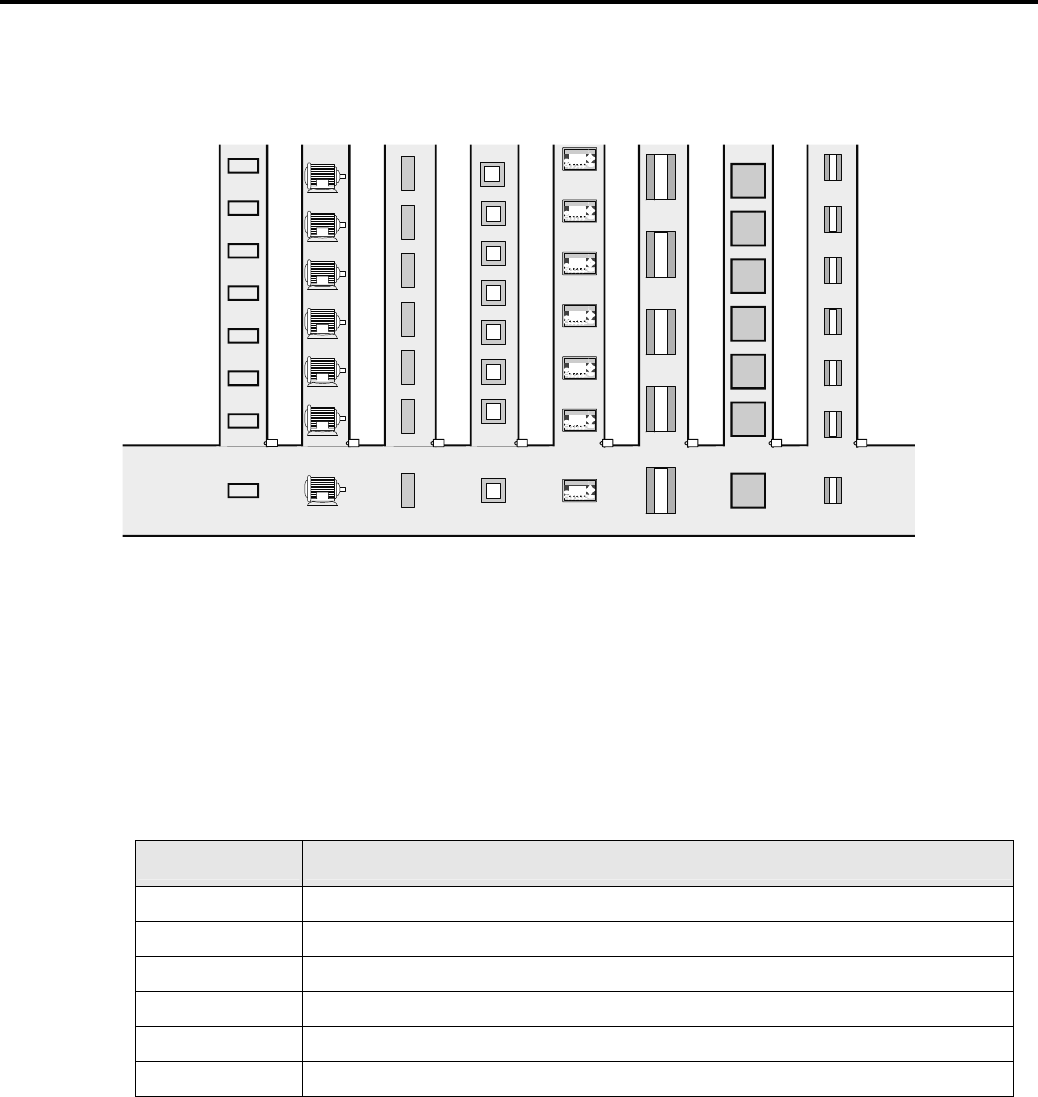
9. Data Processing Design Examples
DVP-PLC Application Examples 9-1
9.1 ENCO/DECO - Encoding and Decoding
Up
Pg Up
RightLeft
Pg Dn
Down
A
LARM
RS-232
RS-485
Up
Pg Up
RightLeft
Pg Dn
Down
A
LARM
RS-232
RS-485
Up
Pg Up
RightLeft
Pg Dn
Down
A
LARM
RS-232
RS-485
Up
Pg Up
RightLeft
Pg Dn
Down
A
LARM
RS-232
RS-485
Up
Pg Up
RightLeft
Pg Dn
Down
A
LARM
RS-232
RS-485
Up
Pg Up
RightLeft
Pg Dn
Down
A
LARM
RS-232
RS-485
Up
Pg Up
RightLeft
Pg Dn
Down
A
LARM
RS-232
RS-485
Main production line
No. 1 sub - production line
X0
X1X2
X3
X4
X5
X6
X7
No. 0 sub - production line
No. 2 sub - production line
No. 3 sub - production line
No. 4 sub - production line
No. 5 sub - production line
No. 6
sub - production line
No. 7 sub - production line
Control Purpose:
z Monitoring the entering products from sub-production lines No.0~7 to main production line
by the value in D0 and disabling certain sub-production lines by setting the value in D10 as
K0~K7.
Devices:
Device Function
X0~X7 Product detecting sensor to identify each entering product.
Y0~Y7 Disabling the corresponding sub production line (No.0~7)
M10 Executing ENCO instruction
M11 Executing DECO instruction
D0 Indicating the entering product from sub-production line No.0~7
D10 Disabling the specified sub-production line

9. Data Processing Design Examples
DVP-PLC Application Examples
9-2
Control Program:
M10
M11
M11
DECO
ZRST
MOV
ENCO
D10
Y0
HFFFF
X0
Y0
Y7
D10
D0
K3
K3
LD>
LD<
D10
D10 K0
K7
Program Description:
z When M10 = ON, ENCO instruction will be executed. Any product entering main production
line will be encoded with its sub-production line number, and the result will be saved in D0.
By monitoring the value in D0, the operator can identify the type of the entering product.
z When M11 = ON, DECO instruction will be executed to decode the specified value in D10
into Y0~Y7 so as to disable the corresponding sub-production line. For example, when D10
= K5, the decoding result will be Y5 = ON. In this case, No. 5 sub-production line will be
disabled. When M11 = OFF, ZRST instruction will be executed and Y0~Y7 will be OFF. All
sub-production lines will operate normally.
z If the set value in D10 is out of the range between K0~K7, HFFFF will be written in D10, so
as to prevent the production line interruption due to other written value in D10.
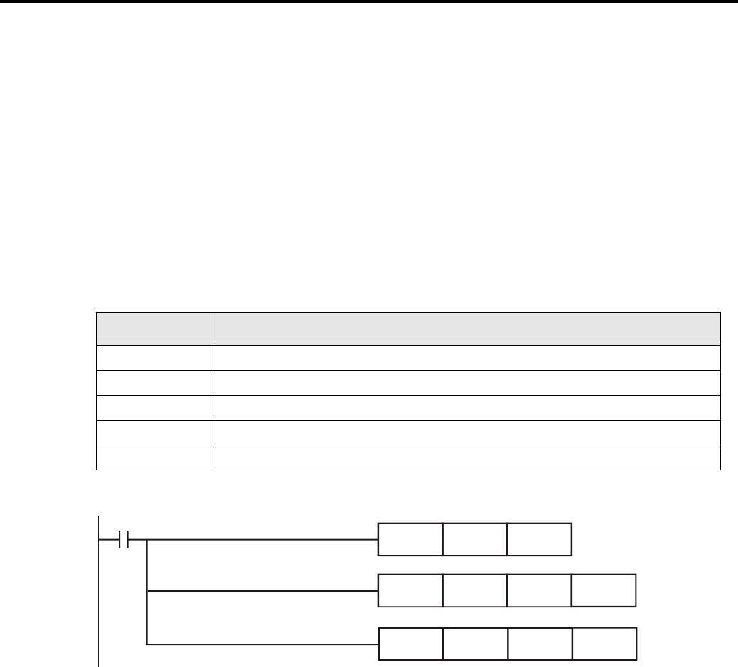
9. Data Processing Design Examples
DVP-PLC Application Examples 9-3
9.2 SUM/BON - Checking and Counting the Number of “1”
Control Purpose:
When X0 = ON,
z Executing SUM instruction to count active bits among Y0~Y17 and to store the value in D0.
z Executing BON instruction to check the ON/OFF state of LSB (Least Significant Bit) and
MSB (Most Significant Bit) and to store the result in M0 and M1
z Indicating the value in D0 and the state of M0 and M1.
Devices:
Device Function
X0 Executing SUM and BON instructions
Y0~Y17 Device for checking and counting
D0 Storing the sum of active bits among Y0~Y17
M0 Storing the ON/OFF state of LSB
M1 Storing the ON/OFF state of MSB
Control Program:
X0
SUM
BON
BON
K4Y0 D0
K4Y0
K4Y0
M0
M1
K0
K15
Program Description:
z When X0 = ON, the program will count the active bits (numbers of “1”) among Y0~Y10 and
check the active state (“1”) of the LSB and MSB.
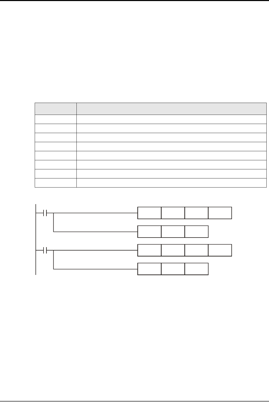
9. Data Processing Design Examples
DVP-PLC Application Examples
9-4
9.3 MEAN/SQR - Mean Value and Square Root
Control Purpose:
z When X0 = ON, calculate the mean of values in D0~D9 and store the value in D200;
calculate the square root of D200 and save the value in D250.
z When X1 = ON, calculate the mean of values in D100~D163, store the value in D300;
calculate the square root of D300 and save the value in D350.
Devices:
Device Function
X0 Executing MEAN/SQR instruction to calculate 10 continuous data
X1 Executing MEAN/SQR instruction to calculate 64 continuous data
D0~D9 Storing historical data
D200 Storing mean value
D250 Storing square root of the mean value
D100~D163 Storing historical data
D300 Storing mean value
D350 Storing square root of the mean value
Control Program:
X0
X1
SQR
SQR
D200
D300
D0
D100
D250
D350
D200
D300
K10
K64
MEAN
MEAN
Program Description:
z If the data number falls out of the range between 1~64 in MEAN instruction, or if the SQR
instruction specifies a negative value, PLC will regard it as an “instruction operation error.”
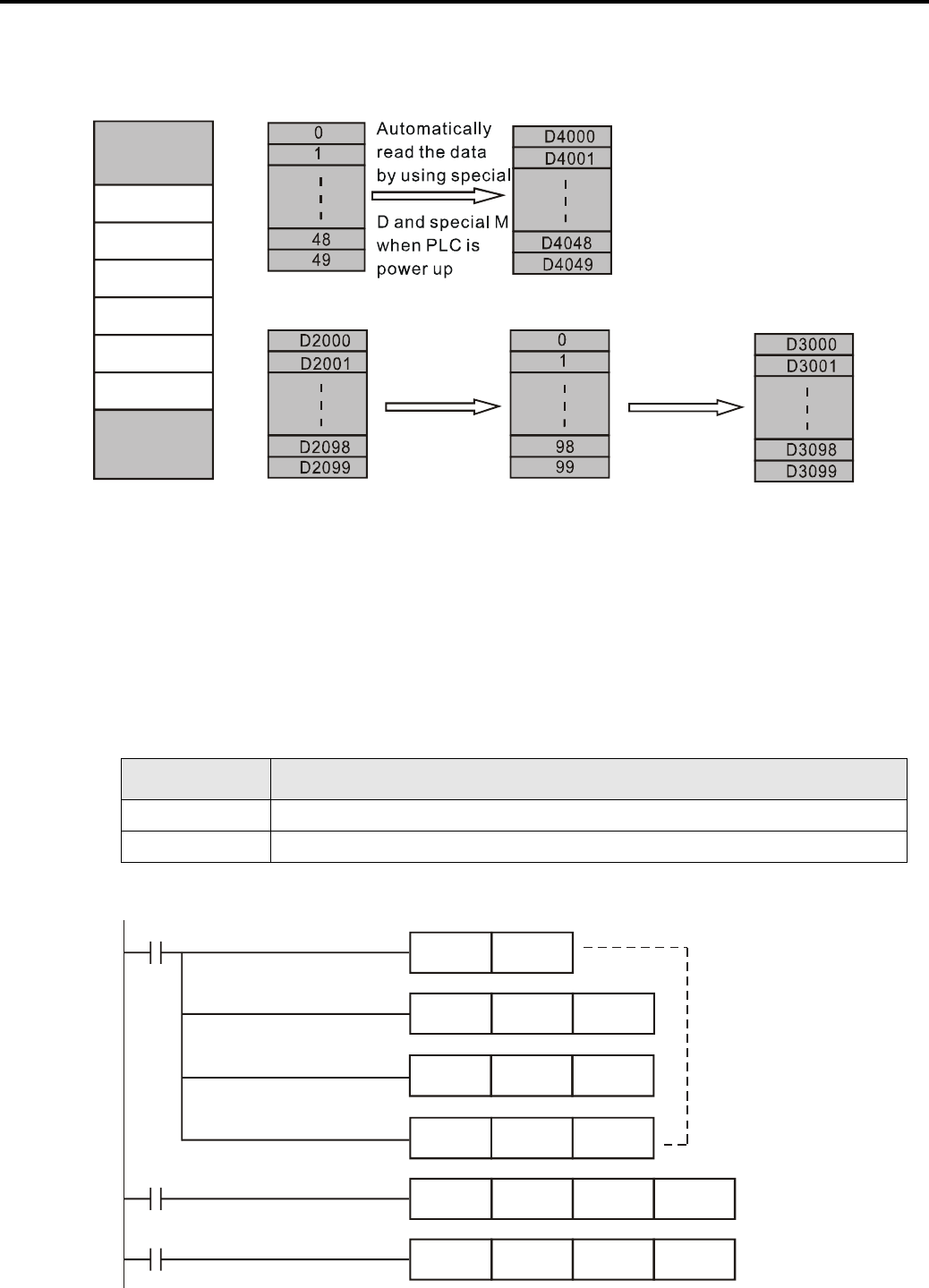
9. Data Processing Design Examples
DVP-PLC Application Examples 9-5
9.4 MEMR/MEMW - File Register Access
MEMW MEMR
File register
D
X
M
Y
C
T
S
File register
memory Data register
memory
Write Read
PLC internal memory Data register
memory File register
memory Data register
memory
Control Purpose:
z Sending 50 data of No.0~No.49 file registers to D4000~D4049 when PLC is power up.
z Writing in 100 data of D2000~D2099 into No.0~No.99 file registers when X0 = ON.
z Reading out 100 data in No.0~No.99 file registers to D3000~D3099 when X1 = ON.
Devices:
Device Function
X0 Write data into file registers
X1 Read data in file registers
Control Program:
M1002
X0
X1
M1101
K0
K50
K4000
D2000
K0
D1101
D1102
D1103
K0
D3000
K100
K100
SET
MOV
MOV
MOV
MEMW
MEMR
Read out the data
from No.0~No.49
file registers to
D4000~D4099 by
using special D
and special M when
PLC is power up

9. Data Processing Design Examples
DVP-PLC Application Examples
9-6
Program Description:
z The memory storing format of PLC internal file registers, Word, is the same as data registers.
However, data in file registers can not be accessed by normal instructions such as MOV.
Therefore, special instructions MEMW/MEMR are needed for accessing file registers.
z When PLC is power up (no matter RUN or STOP) and M1101 = ON, the program will read
out 50 data from file register No.0~No. 49 to data register D4000~D4049. The initial register
number (K0) is specified by D1101, the amount of registers to be moved (K50) by D1102,
and the initial register number of target registers (D4000) by D1103. Note that the execution
will be done by special M and special D only when PLC is power up.

9. Data Processing Design Examples
DVP-PLC Application Examples 9-7
9.5 ANS/ANR - Level Monitoring Alarm System
Y0
X0
X1 Y1
Control Purpose:
z Monitoring the water level of an aquaculture farm by alarm and indicator system.
When the level is below the lower bound for 2 minutes, the alarm and the indicator will be
ON. At the same time, the water feeding valve will start working until the level is back to normal
range.
Devices:
Device Function
X0 Level lower bound sensor
X1 Normal level sensor
Y0 Alarm indicator
Y1 Water feeding valve
Control Program:
M1000
X1
X0
M1049
M1048
ANS T0 K1200 S900
ANRP
Y0
Y1
M1048 will be valid o nly if M1049 = ON.
When X0 = ON for more
than 2 minutes, the alarm
S900 will be ON and latched.
When X1 = ON, the alarm will be reset.
When M1048 = ON, the alarm indicator will be ON,
and the water feeding valve will be enabled.
Program Description:
z When the level is below the lower bound (X0 = ON) for 2 minutes, Y0 and Y1 will be ON.
The alarm indicator will be ON and the water feeding valve will be enabled.
z When the level reaches normal range (X1 = ON), Y0 and Y1 will be OFF. The alarm will be
reset.
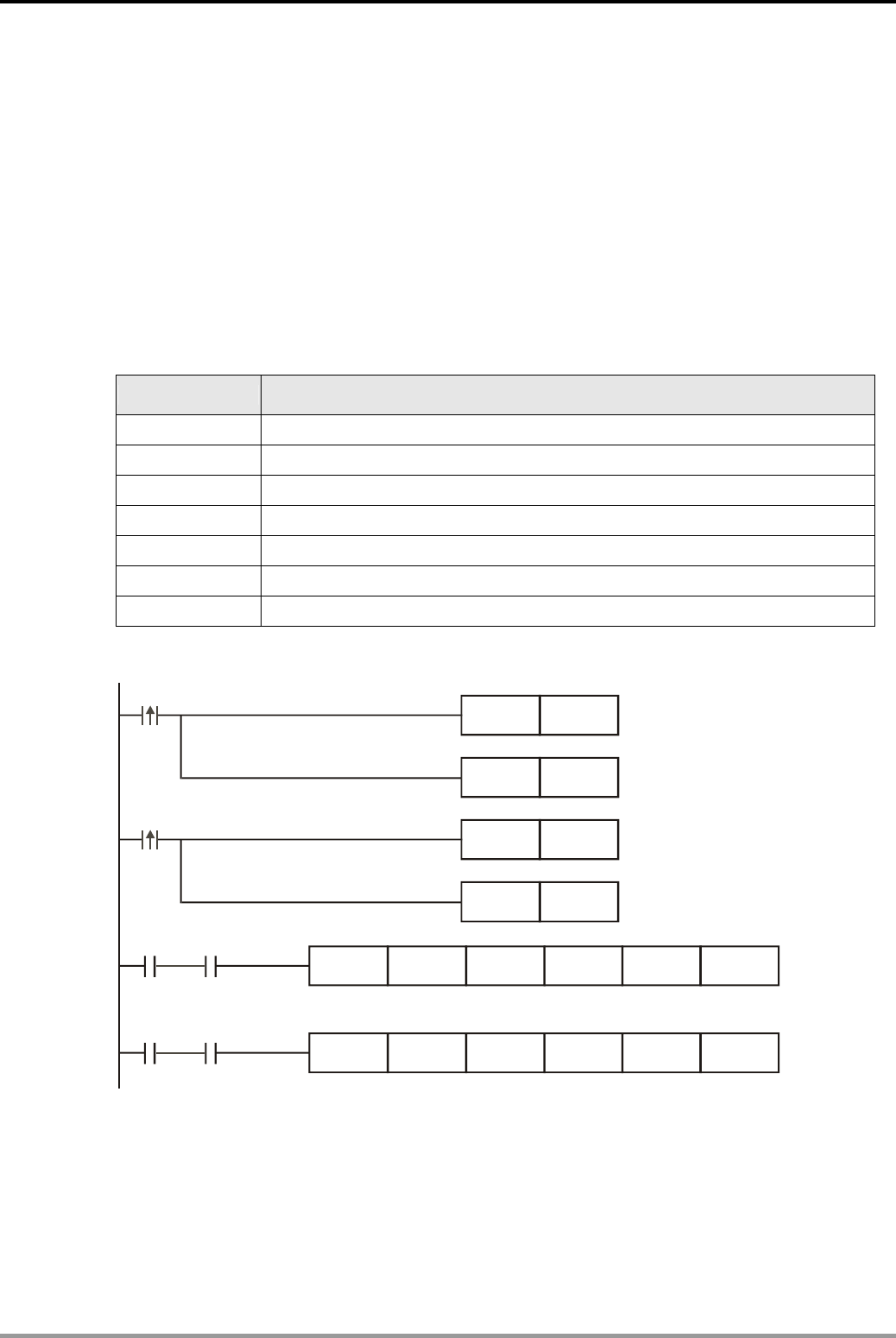
9. Data Processing Design Examples
DVP-PLC Application Examples
9-8
9.6 SORT - Sorting Acquired Data
Control Purpose:
z Collecting 4 voltage data (Corresponding to frequency of AC motor) by DVP04AD-S analog
module and 4 temperature data by DVP04TC-S thermocouple module.
z Sorting the 4 channels by voltage in ascending order when M0 = ON and by temperature in
ascending order when M1 = ON.
z Sorting the data and displaying the sorting result.
Devices:
Device Function
M0 Sorting voltage data
M1 Sorting temperature data
D200~D203 Numbers of channels to be sorted
D204~D207 Storing 4 voltage data
D208~D211 Storing 4 temperature data
D220~D231 Displaying voltage sorting result
D240~D251 Displaying temperature sorting result
Control Program:
M10 D200 K4 D220 K3 K2 SORT
M0
M1
RST
RST
M11
M10
M10
M11
SET
SET
M1013
M11 D200 K4 D240 K3 K3SORT
M1013
Sorting by voltage in ascending order
Sorting by temperature in ascending order
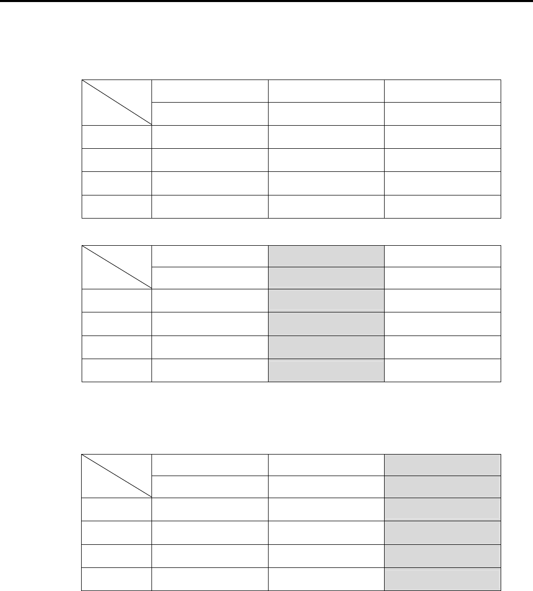
9. Data Processing Design Examples
DVP-PLC Application Examples 9-9
Program Description:
z Acquired data before sorting:
1 2 3
Channel (CH1~CH4) Voltage (DVP04AD-S) Temp. (DVP04TC-S)
1 (D200)1 (D204)57 (D208)47
2 (D201)2 (D205)59 (D209)42
3 (D202)3 (D206)55 (D210)46
4 (D203)4 (D207)53 (D211)43
1) Sorted voltage data in ascending order when M0 = ON:
1 2 3
Channel (CH1~CH4) Voltage (DVP04AD-S) Temp. (DVP04TC-S)
1 (D220)4 (D224)53 (D228)43
2 (D221)3 (D225)55 (D229)46
3 (D222)1 (D226)57 (D230)47
4 (D223)2 (D227)59 (D231)42
The voltage sorting result is: channel 4, channel 3, channel 1, and channel 2. The
minimum value is K53 and the maximum value is K59.
2) Sorted temperature data in ascending order when M1 = ON:
1 2 3
Channel (CH1~CH4) Voltage (DVP04AD-S) Temp. (DVP04TC-S)
1 (D240)4 (D244)59 (D248)42
2 (D241)1 (D245)53 (D249)43
3 (D242)2 (D246)55 (D250)46
4 (D243)3 (D247)57 (D251)47
The temperature sorting result is: channel 4, channel 1, channel 2, and channel 3. The
minimum value of is K42 and the maximum value is K47.
z The purpose of using M1013 (1s clock pulse) after the drive contacts M10 and M11 is to
assure that sorting result can be refreshed in 1s so as to prevent rising edge triggering M10
and M11 when SORT instruction needs to be executed one more time.
z Users can monitor the sorting result and the minimum/maximum value of voltage and
temperature.
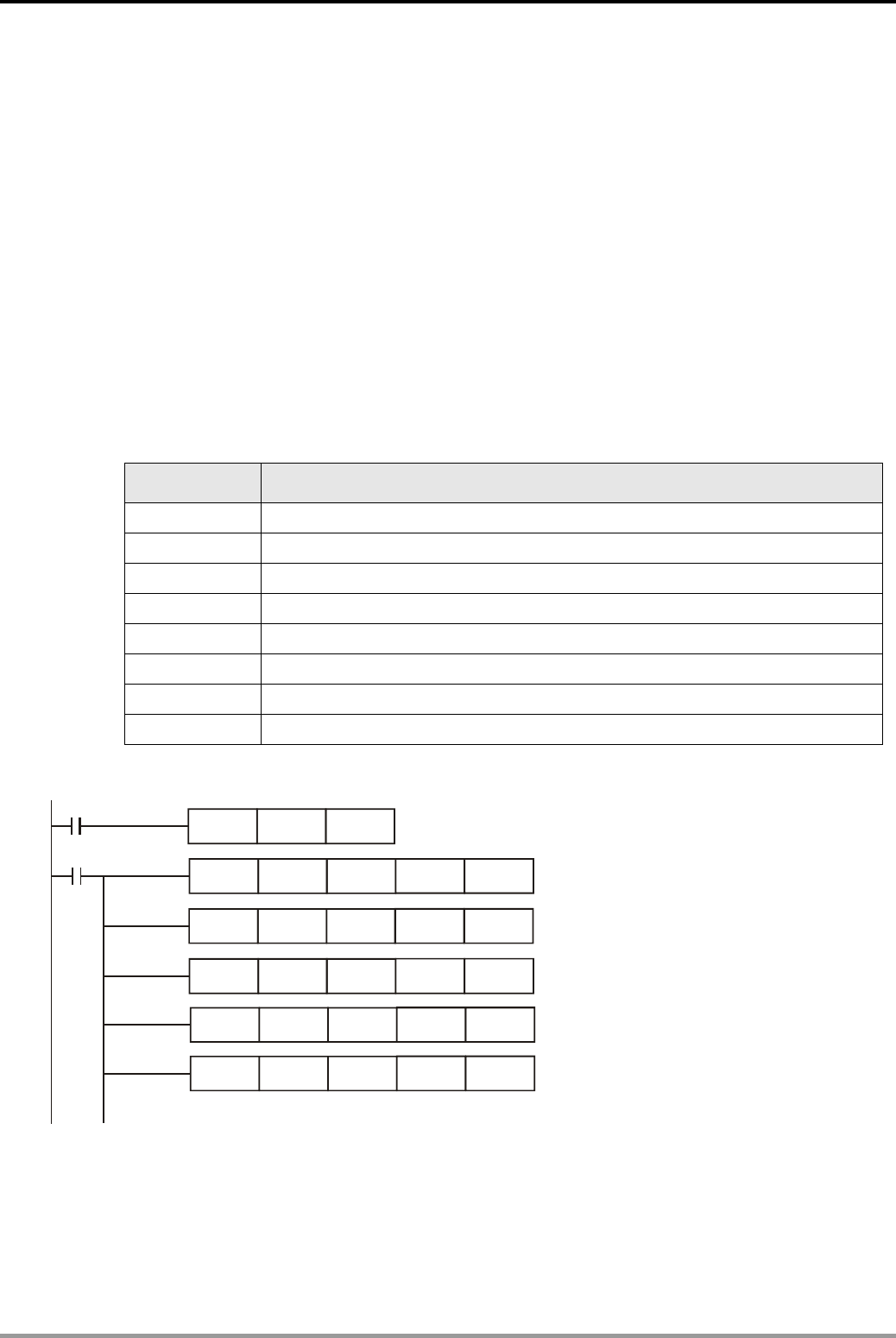
9. Data Processing Design Examples
DVP-PLC Application Examples
9-10
9.7 SER - Room Temperature Monitoring
Control Purpose:
z Monitoring the overall temperature condition by acquiring temp. data through air condition
system from 20 rooms in the building
Compare the present temp. with the target value. If there are more rooms whose temp. match
the target value, it indicates the air condition system functions well.
z Adjusting the air condition devices in rooms with the highest and lowest temp.
Count the amount of rooms whose temp. match the target value so as to judge the efficiency of
the air condition system. In addition, search the rooms with the highest and lowest temp for
adjusting immediately.
Devices:
Device Function
X1 Executing SER instruction to search data
D50~D53 Temperature data acquisition of the 1st thermocouple module (unit: 1°C)
D54~D57 Temperature data acquisition of the 2nd thermocouple module (unit: 1°C)
D58~D61 Temperature data acquisition of the 3rd thermocouple module (unit: 1°C)
D62~D65 Temperature data acquisition of the 4th thermocouple module (unit: 1°C)
D66~D69 Temperature data acquisition of the 5th thermocouple module (unit: 1°C)
D100 Storing the target value
D200~D204 Storing the temperature search result
Control Program:
X1
X1
FROM
MOV
FROM
FROM
FROM
FROM
K0
K25
K1
K2
K3
K4
K6
D100
K6
K6
K6
K6
D0
D4
D8
D12
D16
K4
K4
K4
K4
K4
Initialize the target value as 25
℃
.
Storing the Temp. data acquired from
the 1st thermocouple module in D0~D3.
Storing the Temp. data acquired from
the 2nd thermocouple module in D4~D7.
Storing the Temp. data acquired from
the 3rd thermocouple module in D8~D11.
Storing the Temp. data acquired from
the 4th thermocouple module in D12~D15
.
Storing the Temp. data acquired from
the 5th thermocouple module in D16~D19.
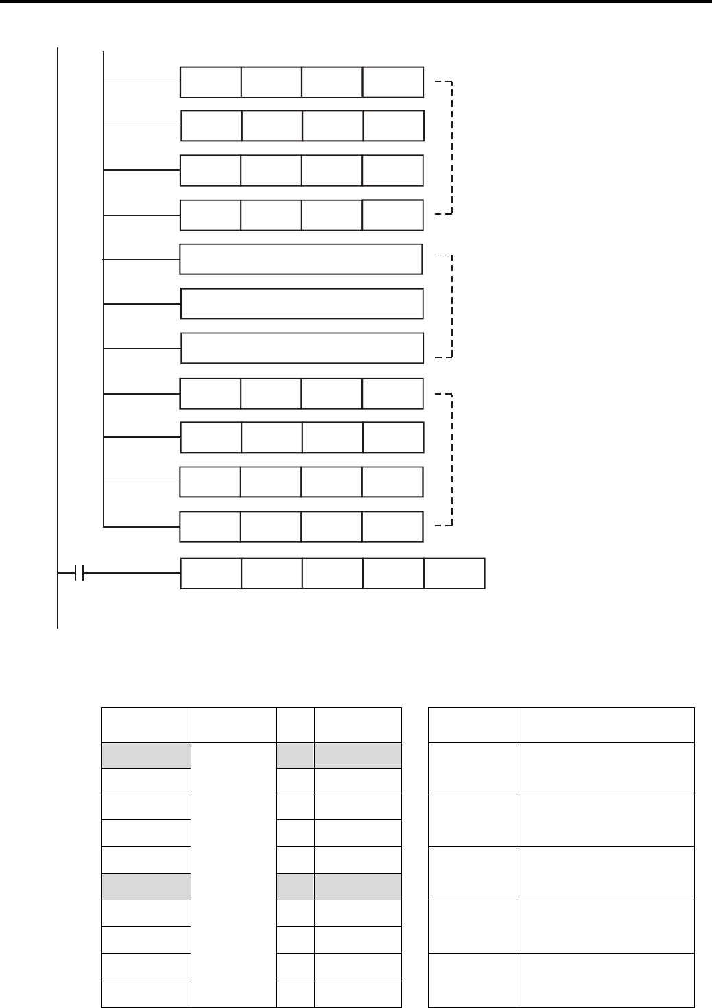
9. Data Processing Design Examples
DVP-PLC Application Examples 9-11
X1 SER
DIV
DIV
DIV
DIV
DIV
DIV
DIV
DIV
D50
D0
D16
D1
D17
D2
D18
D3
D19
D100
K10
K10
K10
K10
K10
K10
K10
K10
D200
D50
D66
D51
D67
D52
D68
D53
D69
K20
Divide the present temp. value
of the first thermocouple module
by 10 so as to change the unit into 1℃
.
The omitted data processing of
module 2, 3, 4 is same as module
1 and module 5.
Data processing for the 2nd
thermocouple module
Data processing for the 3rd
thermocouple module
Data processing for the 4th
thermocouple module
Divide the present temp. value
of the 5th thermocouple module
by 10 so as to change the unit into 1℃
.
Counting the amount of rooms whose temperature is 25
and searching the room number of the highest and lowest temp.
℃
Program Description:
z Acquired temperature data and search result of 20 rooms:
Room temp. Target
value No. Compare
result Search result Content
D50 = K24 0 -
D51 = K25 1 Equal
D200 = K16 The amount of rooms with
temp. of 25°C
D52 = K25 2 Equal
D53 = K25 3 Equal
D201 = K1 The No. of the first room
with temp. of 25°C
D54 = K25 4 Equal
D55 = K22 5 Lowest
D202 = K19 The No. of the last room
with temp. of 25°C
D56 = K25 6 Equal
D57 = K25 7 Equal
D203 = K5 The No. of the room with
lowest temp.
D58 = K25 8 Equal
D59 = K25
D100 = K25
9 Equal
D204 = K11 The No. of the room with
highest temp.

9. Data Processing Design Examples
DVP-PLC Application Examples
9-12
Room temp. Target value No. Compare
result
D60 = K25 10 Equal
D61 = K27 11 Highest
D62 = K25 12 Equal
D63 = K25 13 Equal
D64 = K26 14 -
D65 = K25 15 Equal
D66 = K25 16 Equal
D67 = K25 17 Equal
D68 = K25 18 Equal
D69 = K25
D100 = K25
19 Equal
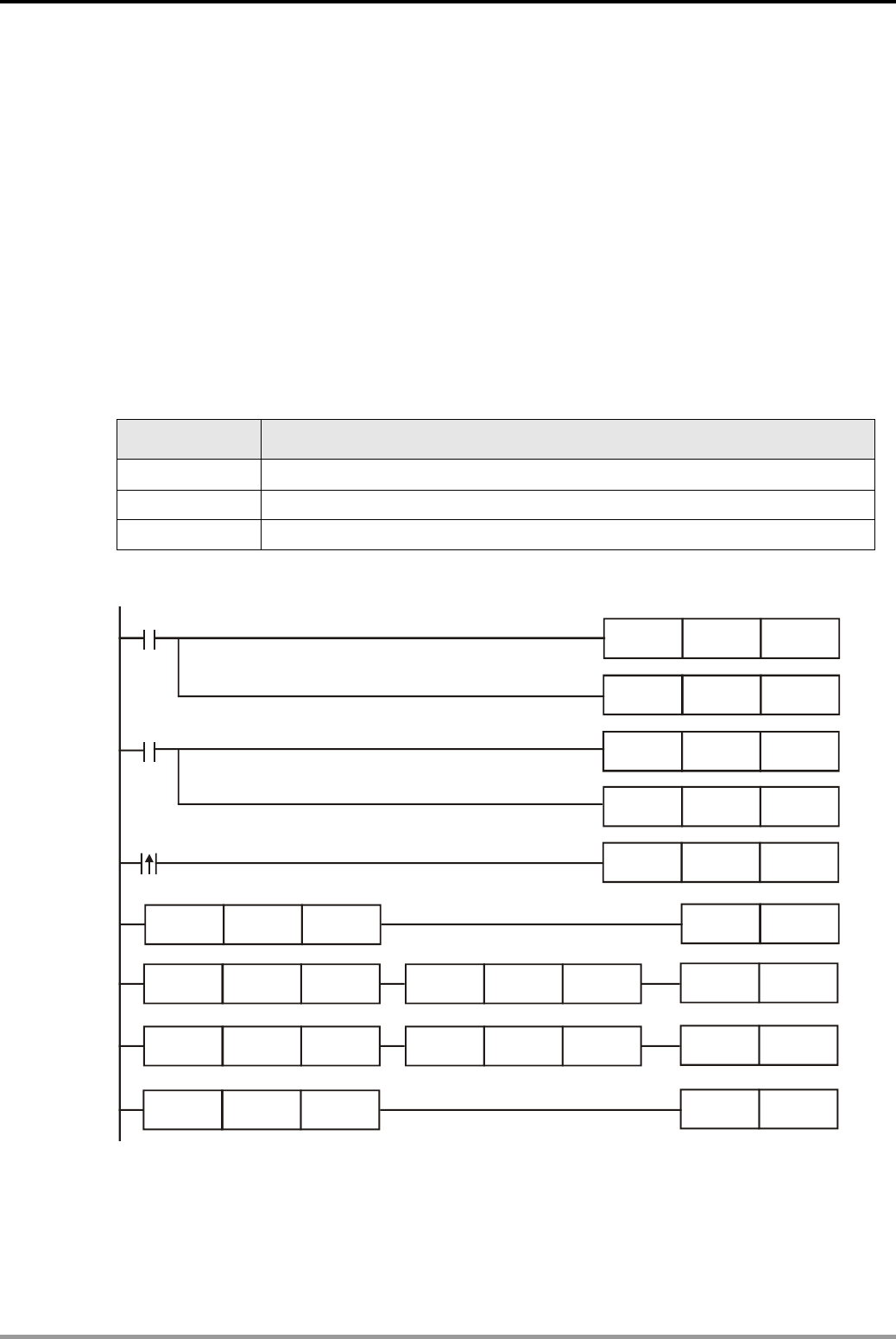
10. High-speed Input/Output Design Examples
DVP-PLC Application Examples 10-1
10.1 REF/REFF - DI/DO Refreshment and DI Filter Time Setting
Control Purpose:
Refreshing DI/DO status immediately and setting/displaying DI filter time.
z When M0 = ON, refresh the status of input points X0~X17 and send the status to D0. When
M1 = ON, transmit the value in D100 to the output points Y0~Y17 and send the output state
to output terminals immediately before END instruction.
z By controlling the value in D200 according to the interference degree, users can set the filter
time of DI as 0 (actual min. value = 50µs), 10ms, 20ms and 30ms.
Devices:
Device Function
M0 Starting to refresh the status of input points X0~X17
M1 Starting to refresh the status of output points Y0~Y17
D200 Storing the filter time of the input points
Control Program:
M0
M1
REF
REF
MOV
MOV
X0
Y0
K4X0
D100
X17
Y17
D0
K4Y0
M1002
MOV K10 D200
LD>=
LD>=
LD<
LD<
LD<
LD>
D200
D200
D200
D200
D200
D200
K10
K20
K20
K30
K10
K30
REFF
REFF
REFF
REFF
K10
K20
K0
K30

10. High-speed Input/Output Design Examples
DVP-PLC Application Examples
10-2
Program Description:
z Generally the input state (X) is refreshed at the beginning of program scan cycle, and the
output state (Y) is refreshed at the end of END instruction. However, the immediate state
refreshing during the program execution process can be performed by Ref instruction.
z Due to severe operating environment, PLC DI signal is frequently interfered and error
operations would thus occur. Usually, the interference will not last for a long time. We can
apply a filter to DI signals so that the interference would be decreased in principle.
z When D200<K10, the filter time of DI signal = 0 (Actual value = 50µs). When
K10≤D200<K20, the filter time = 10ms. When K20≤D200<K30, the filter time = 20ms. When
K30<D200, the filter time = 30ms. The initial setting of this program in D200 = K10, so the
filter time of DI signal in this case is set as 10ms.
z Users can apply MOV instruction to transmit the filter time of DI signal to D1020
(corresponding to X0~X7) and D1021 (corresponding to X10~X17).
z The filter time changed by REFF instruction during program executing process can be
modified in next program scan cycle.
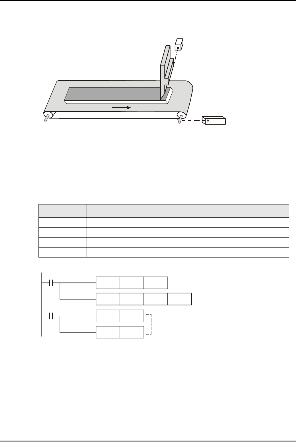
10. High-speed Input/Output Design Examples
DVP-PLC Application Examples 10-3
10.2 DHSCS - Cutting Machine Control
X1
Y1
X1
Y1
X1
Y1
X0
Cutter
Photoelectric sensor
Control Purpose:
z Counting the number of rotations and controlling the cutter according to the value in C235.
X0 counts once when the axis rotates once. When C235 counts to 1000, the cutter will perform
cutting process once.
Devices:
Device Function
X0 Photoelectric sensor. X0 turns on once when the axis rotates once
X1 Photoelectric sensor. X1 = ON when cutter is released (Y1 = OFF).
Y1 Cutter
C235 Counting the number of axis rotations
Control Program:
M1000
X1
DCNT C235 K2000
DHSCS K1000 C235 Y1
RST Y1
RST C235
When PLC runs, high-speed
counter C235 will be enabled.
When X1 = ON, the cutter Y1 will be reset
and the counter C235 will be cleared.
When present value in C235
changes from 999 to 1000 or
1001 to 1000, Y1 will be ON
and output the state immediately.
Program Description:
z The photoelectric sensor X0 is the external input point of C235. X0 turns on once when the
axis of conveyor belt rotates once and therefore C235 counts once.
z During the execution of DHSCS instruction, Y1 will be ON when the value in C235 reaches
1000 (Axis rotation =1000 times) and then output the state immediately to the external
output terminals. Therefore, the cutter will be enabled.
z When the cutter is released, X1 = ON. C235 will be cleared and the cutter Y1 will be reset. In
this case, X1 turns off. C235 will restart counting and the above process will be repeated.
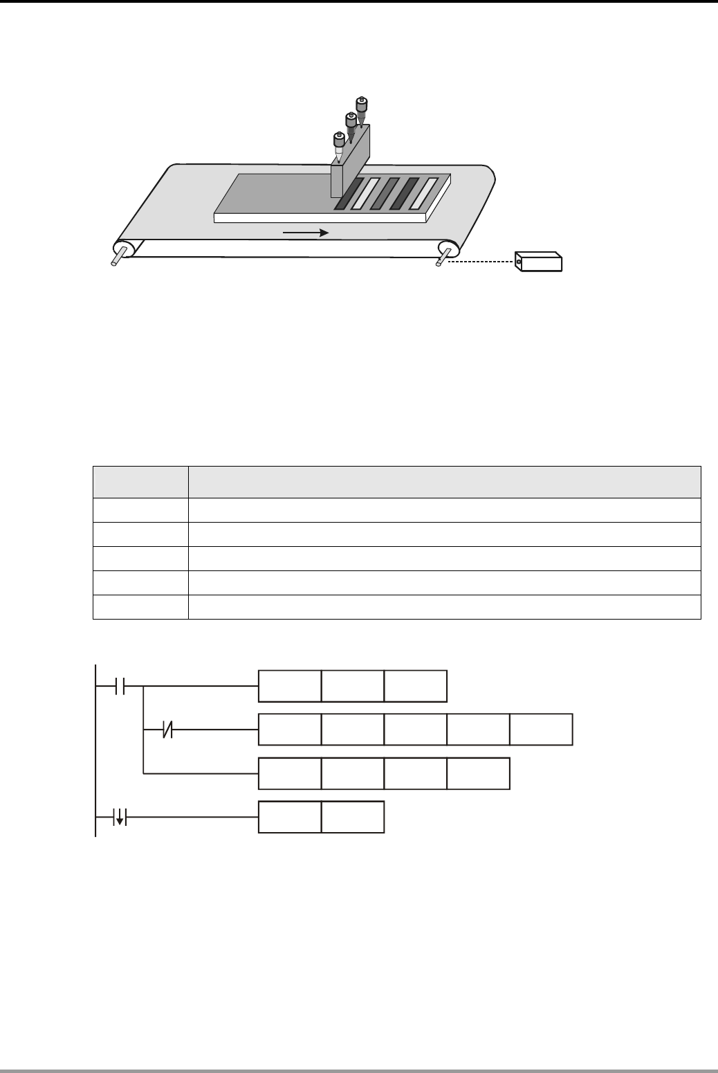
10. High-speed Input/Output Design Examples
DVP-PLC Application Examples
10-4
10.3 DHSZ/DHSCR - Multi-segment Coater Control
X1
Green
Red
Yel l ow
Photoelectric switch
Control Purpose:
z Painting the products with pigments of three colors: red, yellow and green.
When the axis of conveyor rotates 1000 times, the pigment will be changed and therefore the
painting process will be executed as the following order: red, yellow, green, red yellow, green…
Devices:
Device Function
X1 Photoelectric sensor. X1 turns on once when the axis rotates once.
Y1 Painting red pigment
Y2 Painting yellow pigment
Y3 Painting green pigment
C236 Counting the number of axis rotations
Control Program:
M1000
DCNT C236 K4000
RST C236
Y3
DHSZ K1000 K2000 C236 Y1
DHSCR K3000 C236 Y3
Y3
Program Description:
z The photoelectric sensor X1 is the external input point of C235. X1 turns on once when the
axis of conveyor belt rotates once and therefore C236 counts once.
z When the PV (present value) in C236<K1000 (the number of axis rotations<1000), Y1 = ON
and the red pigment will be painted.
z When K1000≤ PV in C236≤K2000 (1000≤axis rotations≤2000), Y1 = OFF and Y2 = ON. The
yellow pigment will be painted.

10. High-speed Input/Output Design Examples
DVP-PLC Application Examples 10-5
z When K2000<PV in C236<K3000 (2000<axis rotations<3000), Y1 = Y2 = OFF and Y3 =
ON. The green pigment will be painted. Because Y3 = ON, the NC (normally closed) contact
Y3 is activated to disable DHSZ instruction. However, Y3 will remain ON.
z When the PV in C236 reaches K3000, DHSCR instruction will be executed and Y3 will be
reset. Counter C236 will be cleared because the falling trigger of Y3. On the other hand, the
NC contact Y3 is OFF and therefore the DHSZ instruction is executed again. C236 starts
counting from 0 and the pigment will be painted again as the specified cycle: red, yellow,
green, red, yellow, green, etc.
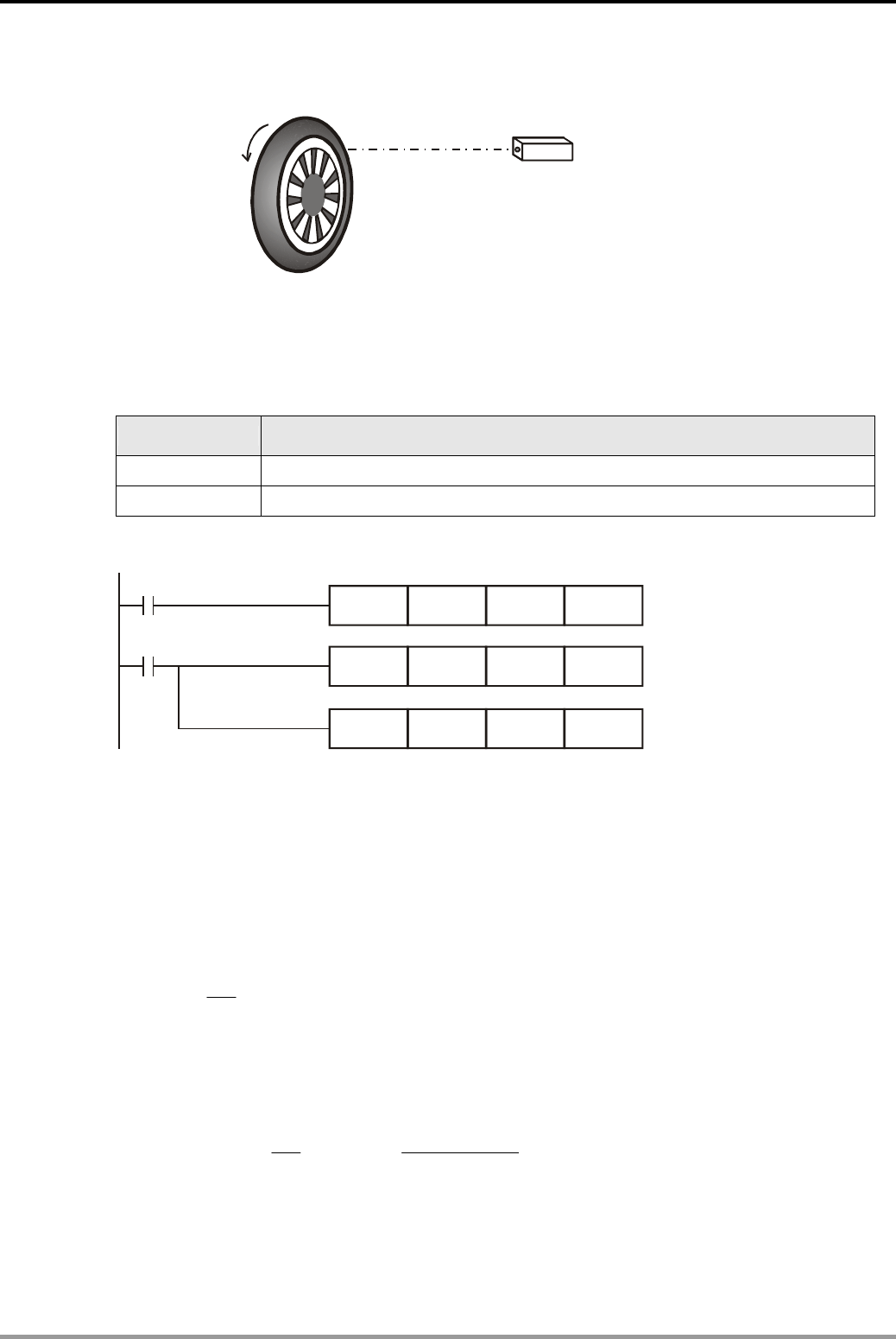
10. High-speed Input/Output Design Examples
DVP-PLC Application Examples
10-6
10.4 SPD - Wheel Rotation Speed Measurement
Photoelectric sensor for
detecting pulses
Control Purpose:
z Calculating the wheel rotation speed by the equation based on the counted input pulses
Devices:
Device Function
X1 Photoelectric sensor for detecting pulses
X7 Executing SPD instruction
Control Program:
X7
M1000
SPD X1 K500 D0
DMUL
DDIV
D0 K60000 D10
D10 K50000 D20
Program Description:
z When X7 = ON, SPD instruction will be executed. D2 will calculate the high-speed input
pulses by X1 and stop the calculation after 500ms. The result will be stored in D0 and D1.
z The following equation is for obtaining the rotation speed of the car:
N: Rotation speed (unit: rpm).
n: The number of pulses produced per rotation
N=
()
rpm
nt
D3
1060
0××
t: Pulse receiving time (ms)
If the number of pulses produced per rotation is K100 and the number of pulses within
500ms is K750, the rotation speed will be:
N= 3
1060
0××
nt
D=
()
rpm×
×
××
500100
1060750 3
=900 rpm
z The rotation speed N is stored in D20 and D21.
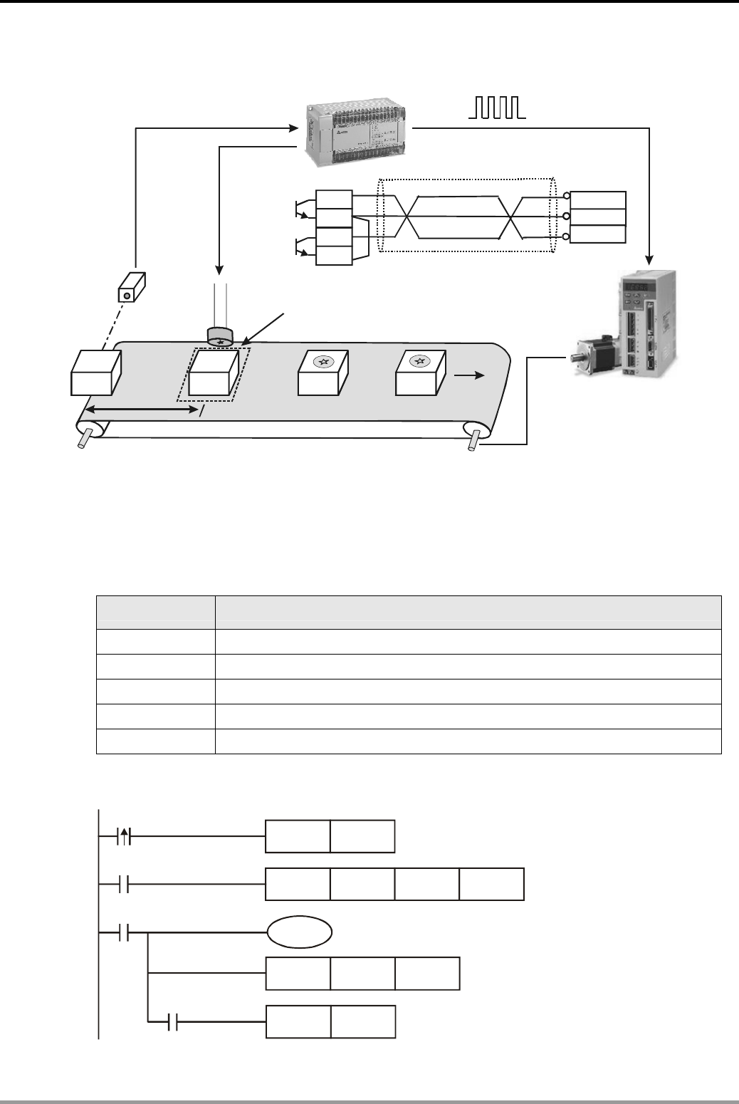
10. High-speed Input/Output Design Examples
DVP-PLC Application Examples 10-7
10.5 PLSY - Production Line Control Program
Y0
Y0
C2
Y1
C0
COM-
PLS
SIGN
Pulse output
Pulse direction
Stamping Device Y2
Stamping location
Delta ASD A Servo Drive
-
Photoelectric
sensor X0
Distance
of 5 circles
Control Purpose:
z When the photoelectric sensor detects products, the servo drive will rotates 5 circles to send
the product to the stamping location and perform 2 sec stamping process.
Devices:
Device Function
X0 Photoelectric sensor. X0 = ON when sheltered.
Y0 Pulse output
Y1 Pulse direction
Y2 Stamping
T0 Setting the stamping time
Control Program:
T0
X0
M0
M1029
SET M0
PLSY K10000 K50000 Y0
TMR T0 K20
RST M0
Y2

10. High-speed Input/Output Design Examples
DVP-PLC Application Examples
10-8
Program Description:
z When a product is detected by the photoelectric sensor X0, SET instruction will be executed
for setting on M0 and PLSY instruction will thus be executed to output pulses by Y1 with
frequency of 10kHz
z When the number of the output pulses reaches 50000, which means the servo drive rotates
5 circles to send the product to stamping location, M1029 will be ON to activate stamping
device Y2. At the same time, timer T0 starts counting for 2 sec. After 2 sec, the NO
(Normally Open) contact T0 will be activated to reset M0, which resets PLSY instruction as
well as M1029 and Y2. Finally, the stamping process is completed.
z When X0 is triggered once again, PLSY will be executed again and Y0 will start to output
pulses. The stamping process will be then repeated.
z Note: In this program, the timing of triggering X0 should be after the complete stamping
process otherwise there would be a processing error.
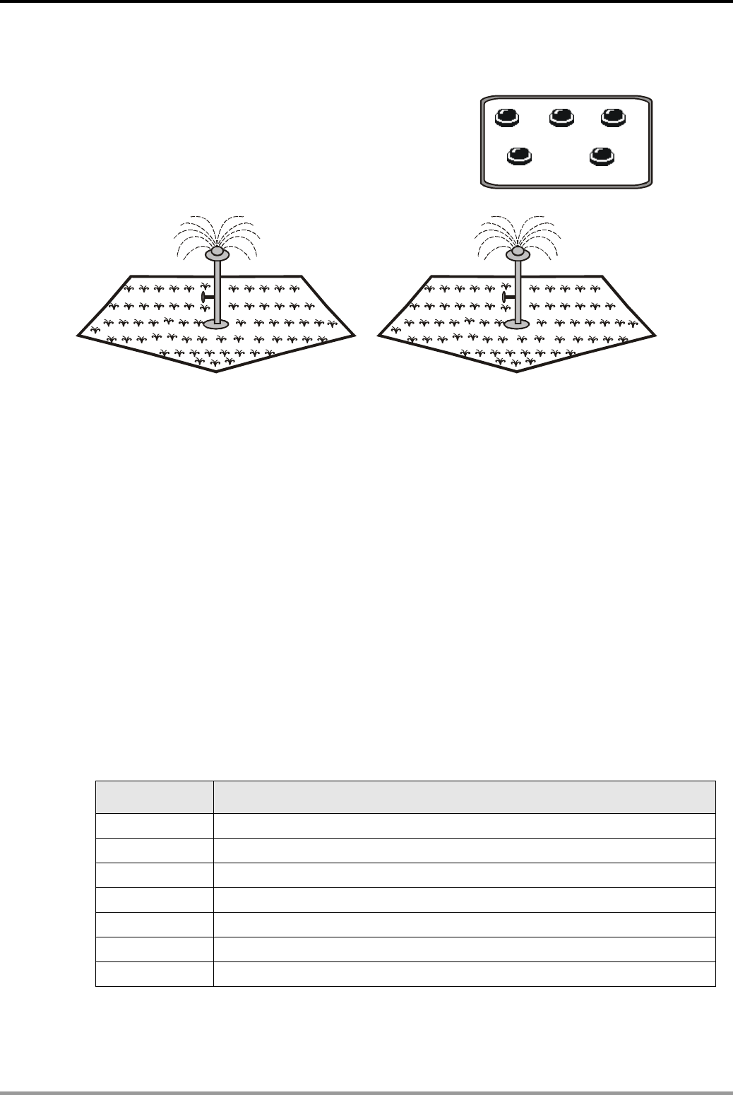
10. High-speed Input/Output Design Examples
DVP-PLC Application Examples 10-9
10.6 PWM - Sprayer Valve Control Program
25% 50%
100%
X2 X3 X4
X0 X1
START STOP
Control Purpose:
z Controlling the sprayer valve opening degree as 25%, 50% and 100% by adjusting the ton/toff
value of PWM technique (24V).
For reducing the energy lost during the gradual shut-down/start-up process, we apply the
switching method which performs immediate turn-on and turn-off of the current valve. The switching
method is somewhat like cutting off the current, and is therefore called a Clipper. However, in the
practical application we apply a transistor between the power and the motor for representing the
function of the clipper. Pulse signal will be applied to the base of the transistor so as to yield a pulse
current between the base and the emitter. The input voltage of motor is in proportion to the ton/toff value.
Therefore, the motor voltage could be adjusted by modulating ton/toff value. There are various methods
to modulate this value and the most common one is to adjust the ON time (ton) rather than adjusting
the ON times within specified time period. The method is called PWM (Pulse-Width Modulation).
Devices:
Device Function
X0 X0 = ON when the button START is pressed
X1 X1 = ON when the button STOP is pressed.
X2 25% opening button.
X3 50% opening button.
X4 100% opening button.
Y1 Controlling the opening degree of the valve
D0 Storing the valve opening degrees
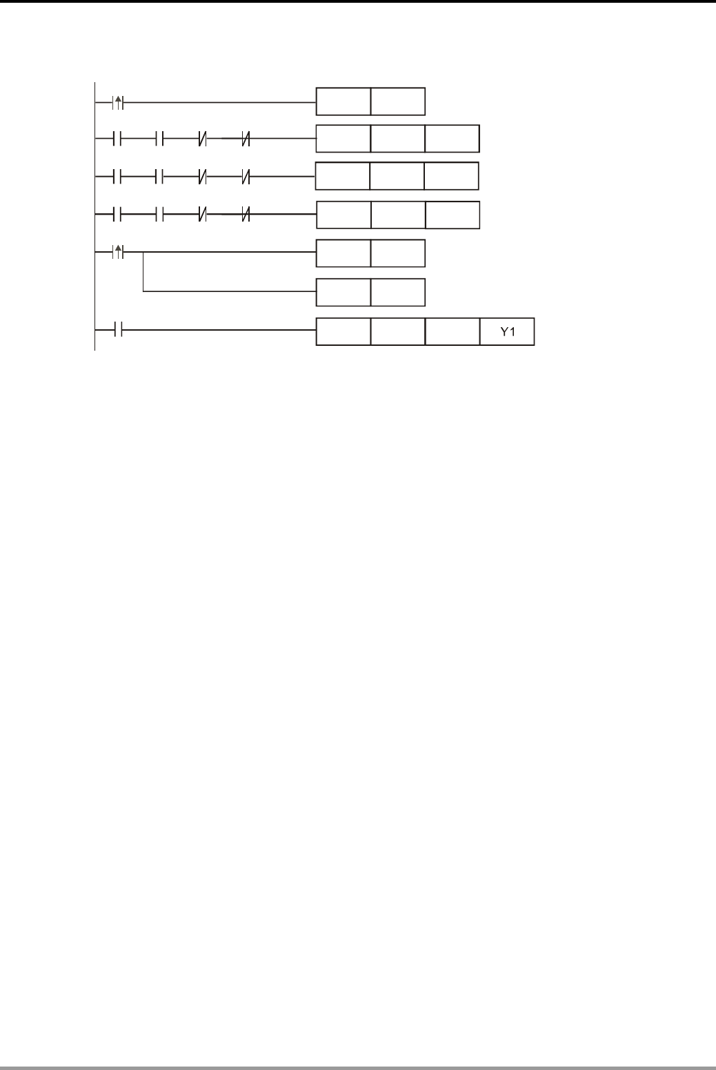
10. High-speed Input/Output Design Examples
DVP-PLC Application Examples
10-10
Control Program:
MOV K200 D0
MOV K333 D0
MOV K500 D0
RST
RST
SET
D0
M0
M0
PWM D0 K1000
M0
X0
X2 X3 X4
M0 X4 X2 X3
X1
M1000
M0 X3 X2 X4
System start
Setting the opening degree as 25%
Setting the opening degree as 50%
Setting the opening degree as 100%
System stop (Opening degree: 0%)
Program Description:
z In this program, the sprayer valve opening degree is controlled by the value in D0. Opening
degree = ton/toff = D0 / (K1000-D0)
z When START is pressed, X0 will be ON to set M0. The water spraying system will be ready
and will start spraying as long as the corresponding opening degree button is pressed.
z When the button 25% is pressed (X2 = ON), the value in D0 = K200 and D0/(K1000-D0) =
0.25. The valve opening degree will be 25%.
z When the button 50% is pressed (X3 = ON), the value in D0 = K333 and D0/(K1000-D0) =
0.50. The valve opening degree will be 50%.
z When the button 25% is pressed (X4 = ON), the value in D0 = K500 and D0/(K1000-D0) =
1. The valve opening degree will be 100%.
z When STOP is pressed, X1 will be ON to clear D0 as 0 and D0/(K1000-D0) = 0. The valve
opening degree = 0. At the same time, the system start flag M0 will also be reset.
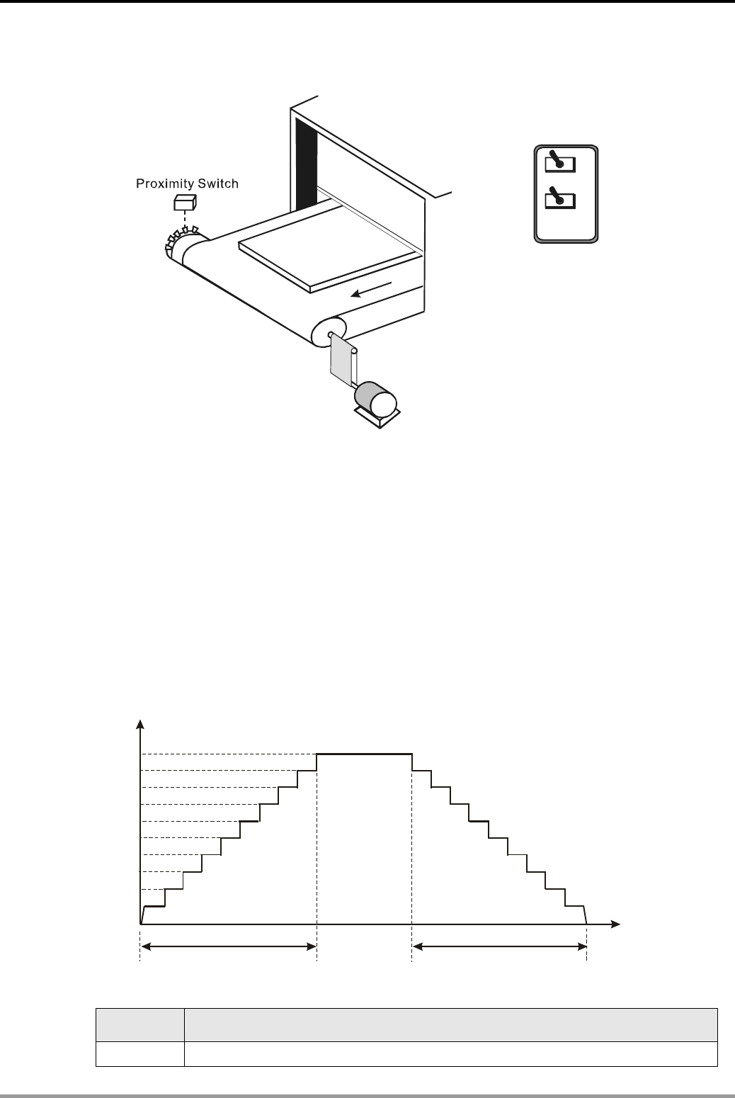
10. High-speed Input/Output Design Examples
DVP-PLC Application Examples 10-11
10.7 PLSR - Servo Motor Acceleration/Deceleration Control
O
F
F
O
N
O
F
F
O
N
X1
X2
X0 Y4
Pulse output
terminal Y0
Cutter
Products under process
Servo motor
Start/Stop
Pause
Control Purpose:
z Counting the pulses generated by servo motor and performing cutting process when
specified number of pulses is counted.
The multi-tooth cam shares same axis with the servo motor. Therefore, when the servo motor
rotates once, the proximity switch will detect 10 pulses sent by the ten-teeth cam. When the servo
motor rotates 10 times (100 pulses), the conveyor will be stopped and the system will perform cutting
process for 1 sec. The program uses a servo motor as a rotation device. Because servo motor
requires a bigger load, there should be an acceleration/deceleration process during the working of
servo motor. The time for acceleration/deceleration is set as 200ms as the below diagram:
8000
6000
4000
2000
9000
7000
5000
3000
1000
200ms
10000
200ms
Frequency of pulse output (Hz)
Acceleration time Deceleration time Time
Devices:
Device Function
X0 Proximity switch for detecting pulses created by the teeth on cam
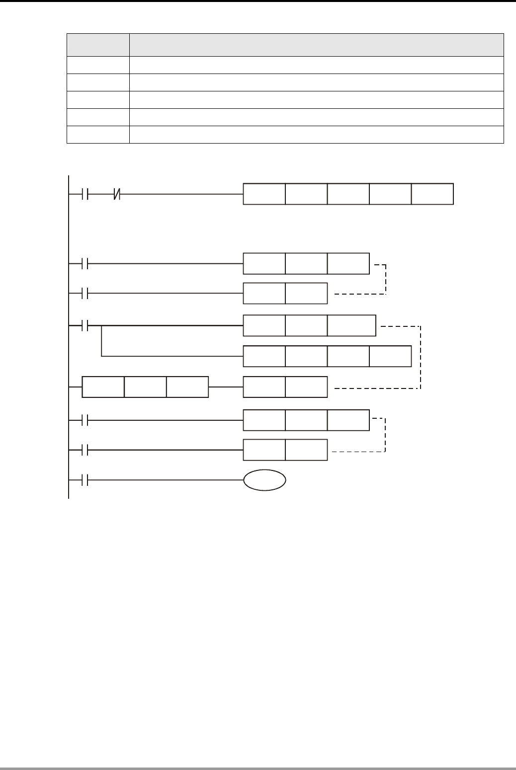
10. High-speed Input/Output Design Examples
DVP-PLC Application Examples
10-12
Device Function
X1 X1 = ON when START is pressed.
X2 X2 = ON when PAUSE is pressed.
Y0 High-speed pulse output
Y4 Cutter
C235 High-speed counter
Control Program:
K100000
X1 M1029
M1029
T0
M1000
DPLSR K10000 K100000 K200 Y0
TMR T0 K50
RST M1029
DCNT C235
DHSCS K100 C235 Y4
DLD>= C235 K100 RST C235
Y4
TMR T1 K10
T1
X2
RST Y4
M1334
Y0 will output pulses. Max. Frequency: 10000Hz
Number of Pulses:100000
Acceleration/Deceleration Time: 200ms
Servo motor rotates
10 times then stop.
M1029 = ON for 5 sec
then be reset by T0.
When proximity
switch X0
detects 100
pulses,Y4 = ON
and the cutter
will start to cut,
then content in
C235 will be
cleared.
The cutter will perform
cutting action for 1sec
and then be reset..
When X2 = ON, the pulse output is paused.
Program Description:
z When START is pressed (X1 = ON), the servo motor will start at the speed of 0.1 r/s (f =
1000Hz) and the speed will be increased by 0.1 r/min every 20ms. After 200ms, the speed
will be 1r/s (f = 10000Hz) and then remain constant. When the set value is nearly reaching,
the servo motor will decelerate and stop rotating when the set value is reached.
z When PAUSE is pressed (X2 = ON), the servo motor will stop rotating, and the PV in C235
will not be stored. When X2 = OFF, the servo motor will start rotating again and stop when
set value is reached.
z When the servo motor rotates once, the proximity switch will detect 10 pulses. When the
servo motor rotates 10 times (100 pulses), it will stop rotating and the system will perform
cutting process for 1 sec.
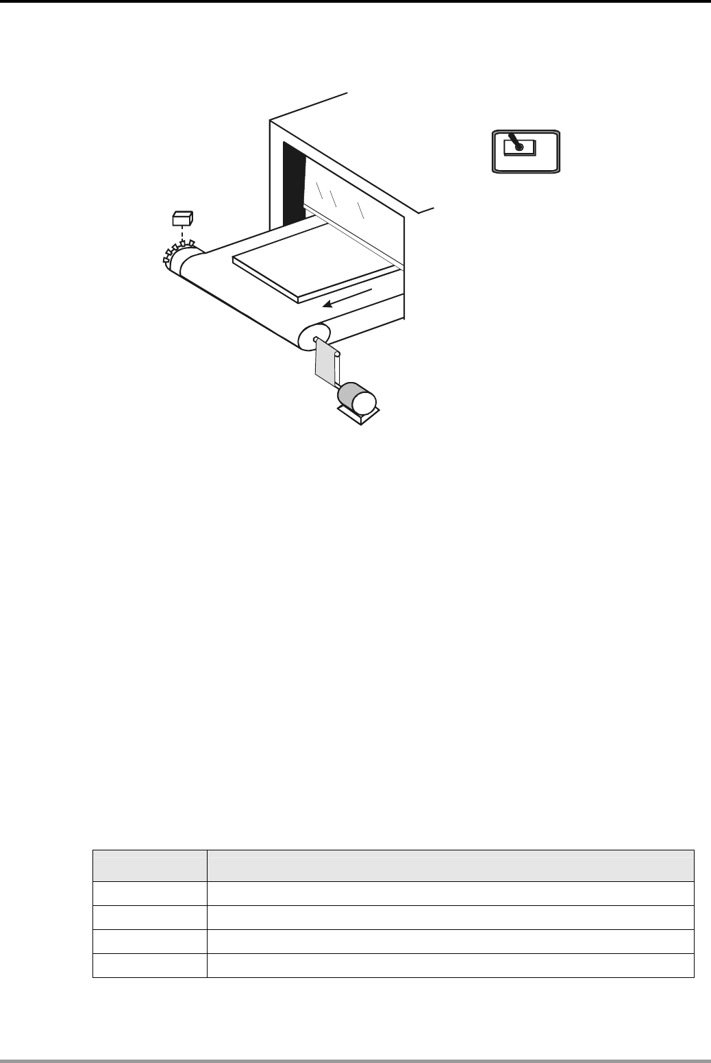
11. Floating Point Operation Design Examples
DVP-PLC Application Examples 11-1
11.1 Elementary Arithmetic for Integer and Floating Point
X1
O
F
F
O
N
X0
Start/Stop
Proximity switch
Product under process
Motor
Control Purpose:
z When the production line runs, the production control engineer needs to monitor its
real-time speed. The target speed is 1.8 m/s.
z The motor and the multi-tooth cam rotate with the same axis. There are 10 teeth on the cam,
so the proximity switch will receive 10 pulse signals when the motor rotate once and the
production line will move forward for 0.325m. The equations are as follows:
Motor rotation speed (r/min) = the received pulses in 1 min/10
The speed of the production line = the rotation times of motor in 1s × 0.325 = (Motor rotation
speed/60) × 0.325.
z Indicator status: Production line speed < 0.8 m/s, the Speed Low indicator will be ON. 0.8
m/s ≤ production line speed ≤ 1.8m/s, the Normal indicator will be on. Production line speed
>1.8m/s, the Speed High indicator will be on.
z Display the production line speed for production control engineers to monitor.
Devices:
Device Function
X0 Pulse frequency detecting switch. X0 = ON when Start is switched on.
X1 Proximity switch. X1 creates a pulse when a tooth on cam is detected.
D0 Storing the detected pulse frequency
D50 Storing the present speed of the production line
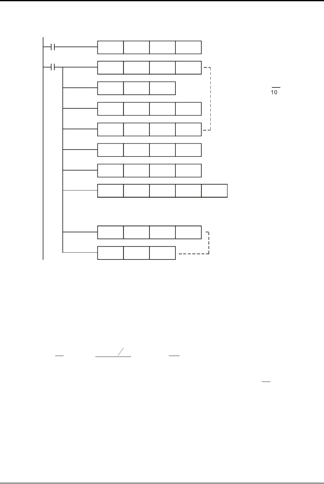
11. Floating Point Operation Design Examples
DVP-PLC Application Examples
11-2
Control Program:
X0
M1000
SPD X1 K1000 D0
DDIV D0 K10 D10
DEDIV K315 K1000 D20
DFLT D10 D12
DEMUL
DEMUL
INT
D12
D50
D60
D50
D60
DEZCP D30 D40 D50 M0
D20
K1000
D70
DEDIV
DEDIV
K8
K18
K10
K10
D30
D40
V= D0 X 0.325
Detecting the number of the pulses
received by the proximity switch in 1s.
Calculate the production speed
by the equation
and store the result into D50, D51
in binary floating point system.
(Note: all parameters must be binary
floating integers. If not, use FLT
instruction to convert the system.)
Convert the lower speed limit
0.8m/s in binary floating point
system.
Convert the target speed
1.8m/s in binary floating point
system.
Present speed < Lower speed limit (D31, D30), M0=ON.
Lower speed limit(D31, D30) present speed arget speed (D41, D40), M1=ON.
≤ ≤ Τ
Present speed arget speed (D41, D40), M2=ON.
>T
In order to show the result onTP04 screen,
multiply the value in D50with 1000 then
store the integer value in D70. However,
the display value in TP04 will remain the
value before multiplication.
Program Description:
z Calculate the motor rotation speed (r/min) by using SPD instruction to detect the pulse
frequency (D0) from the proximity switch. Motor rotation speed = the receiving pulses in
1min/10 = (pulse frequency × 60)/10 = (D0×60)/10.
z The following equation is for obtaining the production line speed through D0:
V: Production line speed
(unit: m/s)
N: Motor speed (unit: r/min)
v= 325.0
60 ×
N=325.0
60
10600 ×
×Dm/s= 325.0
10
0×
Dm/s
D0: Pulse frequency
If the detected pulse frequency D0 = K50, the production line speed = 325.0
10
50 ×m/s
=1.625m/s by the above equation
z The parameter of present production line speed contains decimal points during calculation,
therefore the binary floating point operation instruction is needed for performing the
calculation. .
z DEZCP instruction is used to compare the present speed with the upper/lower speed limits
and the comparison results will be stored in M0~M2.

11. Floating Point Operation Design Examples
DVP-PLC Application Examples 11-3
z There are integers and floating points mixed in the operation. If the operational parameters
are not binary floating point values before calculating the production line speed, they have
to be converted by FLT instruction
z For monitoring easily, the speed value is multiplied with 1000 to obtain the integer in the end
of this program
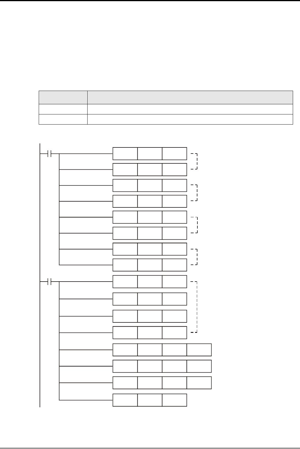
11. Floating Point Operation Design Examples
DVP-PLC Application Examples
11-4
11.2 Elementary Arithmetic for Floating Point
Control Purpose:
z Perform the operation (1.236+1.324)×2.5÷10.24 by Delta’s binary floating point operation
instruction.
Devices:
Device Function
X0 Initialization switch
X1 Operation control switch
Control Program:
X0
MOVP K1236 D0
MOVP K-3 D1
MOVP K1324
K-3
K25
K-1
K1024
K-2
MOVP
MOVP
MOVP
MOVP
MOVP D7
D6
D5
D4
D3
D2
The values in D1 and D0 are
combined into a decimal floating
point value:1.236=1236X10
-3
The values in D3 and D2 are
combined into a decimal floating
point value:1.324=1324X10
-3
The values in D5 and D4 are
combined into a decimal floating
point value:2.5=25X10
-1
The values in D7 and D6 are
combined into a decimal floating
point value:10.24=1024X10
-2
X1
DEBIN D0 D10
DEBIN D2 D12
DEBIN D4 D14
DEBIN D6 D16
DEADD D10 D12 D100
DEMUL D100 D14 D102
DEDIV D102 D16 D104
DEBCD D104 D106
1.236+1.324
(1.236+1.324) 2.5
×
(1.236+1.324) 2.5 10.24
×÷
A
decimal floating point value
is converted into a binary
floating point.
A
binary floating point value is
converted into a decimal floating point .

11. Floating Point Operation Design Examples
DVP-PLC Application Examples 11-5
Program Description:
z When X0 = ON, sent the values of decimal integers to D0~D7 to form 4 decimal floating
points.
z When X1 = ON, elementary arithmetic operations for binary floating points will be executed.
z The binary operational results are not intuitively understandable. Therefore, the binary
floating point value would generally be converted into decimal floating point value. In this
program, the binary values in (D105, D104) are converted into decimal values in (D107,
D106) D106 = K6250, D107 = K-4, so the decimal floating point value 6250×10-4 = 0.625.

11. Floating Point Operation Design Examples
DVP-PLC Application Examples
11-6
MEMO

12. Communication Design Examples
DVP-PLC Application Examples 12-1
Introduction:
The wiring principles of RS-232 / RS-485 communication are keeping the connection as short as
possible and keeping away from high noise source. The RS-232 communication interface is
structured by one to one connections and usually with a shorter connection, so the standard cable or
the cable provided by Delta is compatible for common RS- 232 applications. However, for the
high-speed RS-485 with long distance connection, high communication speed, large number of
stations, high signal attenuation and the possible problems of improper ground potential, mismatched
terminal impedance, noise interference, and wiring methods, the inferior communication quality may
occur if the above factors are not considered properly. Therefore, users should pay attention to the
following notes about the wiring of RS-485 communication:
z The Limit for the Number of Stations:
The limit for the number of stations connected to DVP-PLC is 254. For RS-485
communication, its hardware interface is compatible with max.16 stations. If more than 16
stations are required, a RS-485 repeater (IFD-8510) should be applied. Each repeater
supports 16 more stations. Users can add stations by adding repeaters till the limit of 254.
z The Limit for Distance:
In RS-485 communication, it is a function from the data signaling rate to the maximum cable
length for transmission. The value of maximum cable length is generally influenced by the
factors such as signal distortion and noise. The below graph of the function from signaling
rate to cable length is measured by using 24AWG copper twisted pair telephone cable
(diameter: 0.51mm) with the 52.5PF/M bypass capacitor and the 100 terminal load (please
refer to GB11014-89 Appendix A). From the figure, suppose the max. acceptable signal loss
is 6dBV, when data signaling rate is lower than 90Kbit/S, the limit for cable length will be
1200m (4Kft.). However, the graph is conservative and a longer cable length is accessible in
practical application. Users can get different cable length by different cable diameters. For
example, if the data signaling rate is 600Kbit/S and the cable is 24AWG, the maximum cable
length will be 200m. If the cable is 19AWG (diameter: 0.91mm), the maximum cable length
could be longer than 200m. If the cable is 28AWG (diameter: 0.32mm), the maximum cable
length can only be shorter than 200m.

12. Communication Design Examples
DVP-PLC Application Examples
12-2
The relation between the transmission speed (bps) and the transmission distance (foot) for
RS-485 standard communication interface:
Transmission
speed (bps)
Transmission
distance (feet)
z The Limit for Cables :
Users should choose shielded twisted pair cables for wiring because the quality of cables
will greatly influence the transmission signal. If users use low quality cables (such as PVC
twisted pair cables), the signal attenuation will be higher and the transmission distance will
be significantly shortened. In addition, the communication could be interfered easily due to
the poor noise immunity of low quality cables. Therefore, in situations of high transmission
speed, long distance or high noise, the high quality twisted pair cable (such as Polyethylene
twisted pair cable) should be used. However, in situations of low transmission speed and low
noise, PVC twisted pair cable will be a compatible and cost saving choice though the signal
loss of PVC cable could be 1,000 times bigger than high quality cable. If the transmission
distance is too long to increase the signal attenuation, users can use RS-485 repeater
(IFD-8510) to magnify the signal.
z Wiring Topology:
For RS-485 wiring, the nodes should be near the master cable as much as possible.
Generally, daisy chain topology structure is recommended for RS-485 wiring. Topology is
the link structure of the connection. The topology of RS-485 must be station-by-station
structure, that is, stations should be connected from 1 to 2, 2 to 3, etc. Star and ring
topological structures are not permitted.
z Signal Grounding (SG):
Though the RS-485 network can be connected by twisted cables only, it is easily to be
interfered by noise and should be connected under the condition that the CMV (Common
Mode Voltage) between stations should not exceed the max. allowable CMV of RS-485
transmission IC. If the CMV exceeds the working voltage range of IC, RS-485 will stop
working.
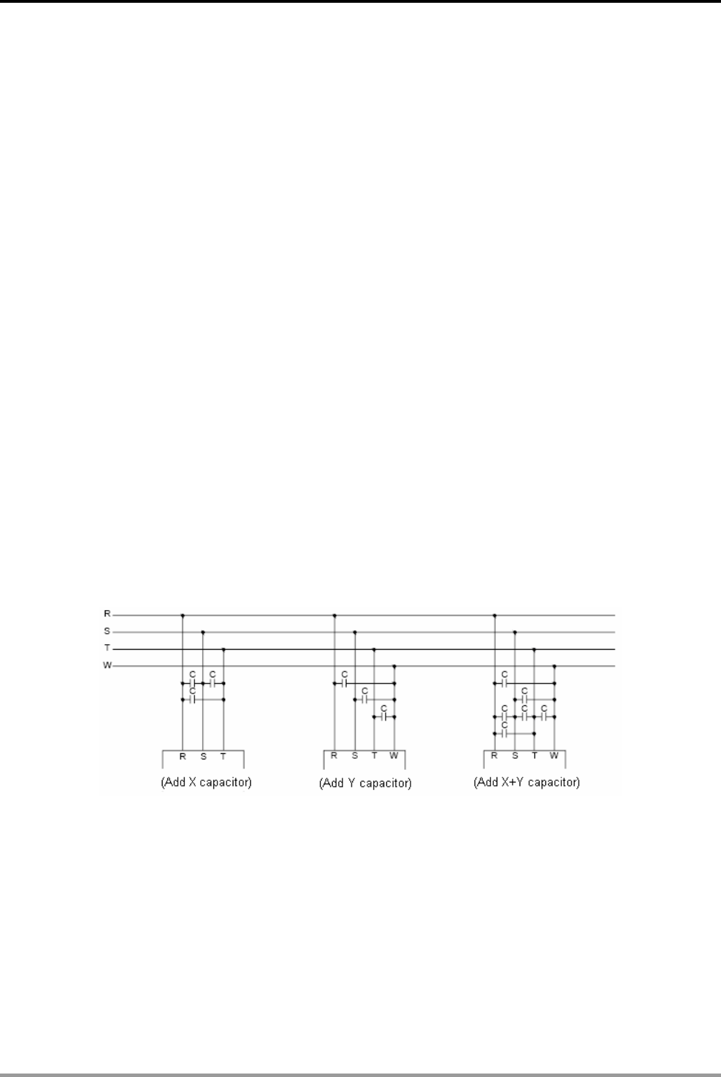
12. Communication Design Examples
DVP-PLC Application Examples 12-3
However, no matter what degree the CMV is, we suggest users connect each SG of stations
(please refer to “Wiring Topology”) by using shielded twisted pair cables so as to reduce the
CMV. This wiring method provides the shortest circuit for communication and improves the
noise immunity as well.
z Terminal Resistor:
All cables have their own characteristic impedance (120 for Twisted Pair). When the signal
is transferred to the terminal and the terminal impedance is different from the characteristic
impedance, echo signal will occur to distort the waveform (convex or concave). This
situation is not obvious for short cables but become serious when the cable length increases.
In this case, a terminal resistor needs to be applied for maintaining the normal
communication.
z Methods to Reduce the Noise:
When RS-485 network is connected according to the above rules and applied with a 120
terminator also, most of the noise interference can be reduced. If the interference continues,
that means there is a strong noise source near the network. In addition to keeping the cable
away from the strong noise source (such as electromagnetic valve, AC motor drive, AC
servo drive, or other power equipment and their power lines), the best way to reduce the
noise is to add a noise suppressor to the noise source. The figure below is the noise
suppressing methods for AC motor drive, AC servo drive, and other power equipment. (To
apply X capacitors, Y capacitors, or X+Y capacitors) C = 0.22f~0.47f/AC630V.
Generally, the RS-485 communication cable is made of twisted pair and transmits the signal
by the potential difference between the twisted pair, and therefore it is called differential
mode transmission. Differential mode interference is transferred between 2 cables and
belongs to symmetric interference, which can be reduced by applying a stabilizing resistor to
the circuit together with twisted pair cables. On the other hand, common mode interference
is transferred between the communication cable and the earth, which belongs to asymmetric
interference. Common mode interference can be eliminated by the following methods:
1. Use shielded twisted-pair cables and ensure it is well-grounded.
2. Use galvanized pipes to shelter the strong electric field.

12. Communication Design Examples
DVP-PLC Application Examples
12-4
3. Keep away from the high voltage line when wiring. Do not bond the high voltage
power lines and the signal lines together.
4. Use linear stabilizer circuit or high quality switching power supply (ripples <
50mV).
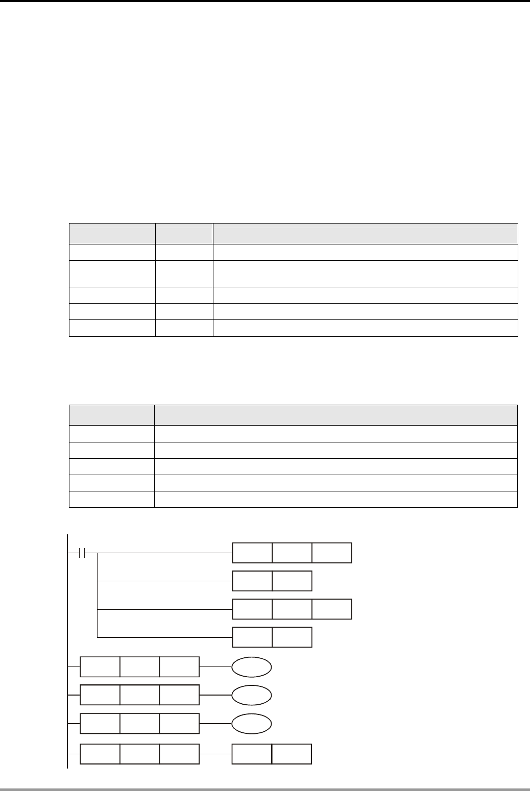
12. Communication Design Examples
DVP-PLC Application Examples 12-5
12.1 Communication between PLC and Delta VFD-M Series AC Motor Drive
(MODRD/MODWR)
Control Purpose:
z Repeatedly reading the master frequency and output frequency of VFD-M series AC motor
drive then store them in D0 and D1 by MODRD instruction.
z Repeatedly setting the running direction and running frequency by MODWR instruction. For
example, setting the AC motor drive to run forward in 40Hz.
Parameter Settings for VFD-M Series AC Motor Drive:
Parameter Set value Explanation
P00 03 Master frequency determined by RS485 com port.
P01 03
Operation determined by RS-485 com port, keypad STOP is
effective.
P88 01 Communication address: 01
P89 01 Communication rate: 9600
P92 01 MODBUS ASCII mode, <7,E,1>
Ú If AC motor drive can not run normally due to improper parameters, users can set P76 = 10
(factory defaults) and then set the parameters according to the above table.
Devices:
Device Function
M0 Executing MODRD instruction to read master and output frequency.
M1 Executing the first MODWR instruction to set the running direction
M2 Executing the second MODWR instruction to set the running frequency
D10 Set value of the drive running direction.
D11 Set value of the drive running frequency.
Control Program:
RST M1143
MOV K100 D1129
M1002
MOV H86 D1120
SET M1120
D1120
Select communication mode:
MODBUS ASCII
LD= C0 K0 M0
LD= C0 K1 M1
LD= C0 K2 M2
LD= C0 K3 RST C0
Set communication
format: 9600, 7, E,1l
Set receiving time-out
: 100ms
Retain communication setting
Execute MODRD instruction
Execute the first MODWR instruction
Execute the second MODWR instruction
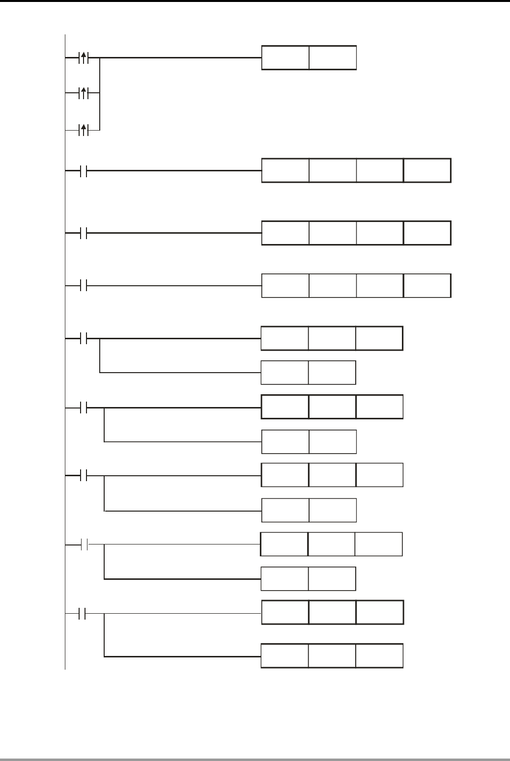
12. Communication Design Examples
DVP-PLC Application Examples
12-6
M0
MODRD K1 H2102 K2
SET M1122
M0
M1
MODWR K1 H2000 D10
M1
M2
MODWR K1 H2001 D11
M2
M1127
CNT C0 K10
RST M1127
M1000
MOV D1050 D0
MOV D1051 D1
RST
RST
RST
M1129
M1140
M1141
M1129
M1140
M1141
CNT C0 K10
CNT C0 K10
CNT C0 K10
Sending request
Read master frequency and output frequency of AC
motor drive and store them in D1050 and D1051
Set the AC motor drive to run forward. D10=H12
Set the master frequency of the drive: 40Hz. D11=K4000
C0 counts once
when data receiving
is completed.
Reset the flag M1127
C0 counts once
when communication
timeout occurs.
Reset the flag M1129
C0 counts once
when data receiving
error occurs.
.
Reset the flag M1140.
C0 counts once
when parameter error
occurs.
.
Reset the flag M1141
Send the master frequency of the drive to D0
Send the output frequency of the drive to D1
Program Description:
z Initialize PLC RS-485 communication port and set the communication format as MODBUS

12. Communication Design Examples
DVP-PLC Application Examples 12-7
ASCII, 9600, 7, E, 1. The RS-485 communication format of AC motor drive should be the
same with PLC.
z There are only 4 situations for MODBUS communication: flag M1127 for normal
communication and M1129, M1140, M1141 for communication errors. Counter C0 counts
once when any of the 4 flags is ON. Therefore, the program assures the communication
reliability by monitoring the On/Off status of the 4 flags and performs 3 MODBUS
instructions in order by the value in counter C0.
z When M0 = ON, [MODRD K1 H2102 K2] instruction will be executed. PLC will read the
master frequency and output frequency of AC motor drive, store them in D1073~1076 in
ASCII format, and automatically convert the content in D1073~1076 into hexadecimal
values to D1050 and D1051.
z When M1 = ON, [MODWR K1 H2000 D10] instruction will be executed. D10 = H12 and the
drive will run forward. The running direction can be changed by the content in D10.
z When M2 = ON, [MODWR K1 H2001 D11] instruction will be executed. D11 = K4000 and
the drive running frequency will be 40Hz. The frequency can be changed by the content in
D11.
z On the bottom of this program, [MOV D1050 D0] instruction stores the master frequency of
the drive in D0, and [MOV D1051 D1] instruction stores the output frequency of the drive in
D1.
z Once PLC starts running, the read/write actions for AC motor drive will be performed
repeatedly according to [LD=] instructions.
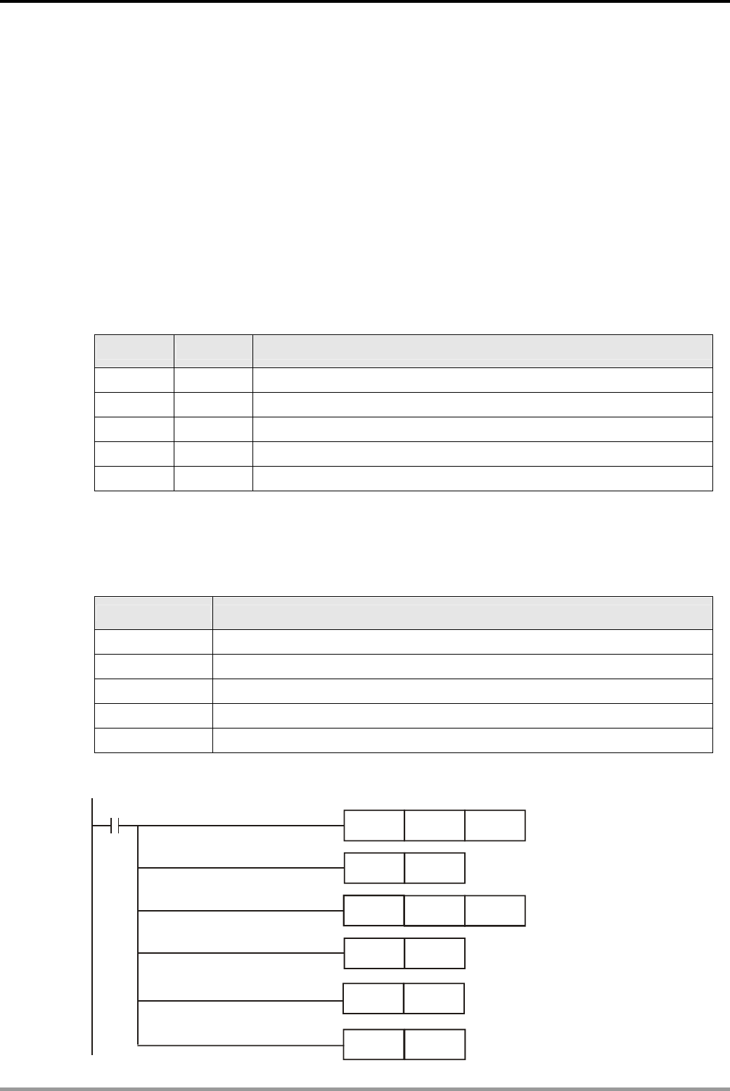
12. Communication Design Examples
DVP-PLC Application Examples
12-8
12.2 Communication between PLC and Delta VFD-B Series AC Motor Drive
(MODRD/MODWR)
Control Purpose:
z Repeatedly reading the master frequency and output frequency of VFD-B series AC motor
drive by MODRD instruction.
z Start AC motor drive in reverse direction when Start is pressed. Increase 1Hz per second
until it reaches 50Hz. Maintain the frequency at 50Hz. (MODWR instruction)
z Stop AC motor drive by when Stop is pressed. (MODWR instruction)
Parameter Settings for VFD-B Series AC Motor Drive:
Parameter Set value Explanation
02-00 04 RS-485 serial communication. Last used frequency saved.
02-01 03 RS-485 serial communication. Keypad STOP/RESET enabled.
09-00 01 Communication address: 01
09-01 02 Communication baud rate: 19200.
09-04 03 MODBUS RTU mode, protocol <8,N,2>
Ú If AC motor drive can not run normally due to improper parameters, users can set P00-02 =
10 (factory defaults) and then set the parameters according to the above table.
Devices:
Device Function
X0 Start button for the drive
X1 Stop button for the drive
M0 Executing MODRD instruction to read master and output frequency
M1 Executing the first MODWR instruction to set the running direction
M2 Executing the second MODWR instruction to set the running frequency
Control Program:
SET M1143
MOV K100 D1129
M1002
MOV H99 D1120
SET M1120
Select communication mode:
MODBUS RTU
RST
RST
D2
D10
Set communication
format: 19200, 8, N, 2
Retain communication setting
Set receiving time-out:
100ms
Reset D2 first when PLC runs
Reset D10 first when PLC runs
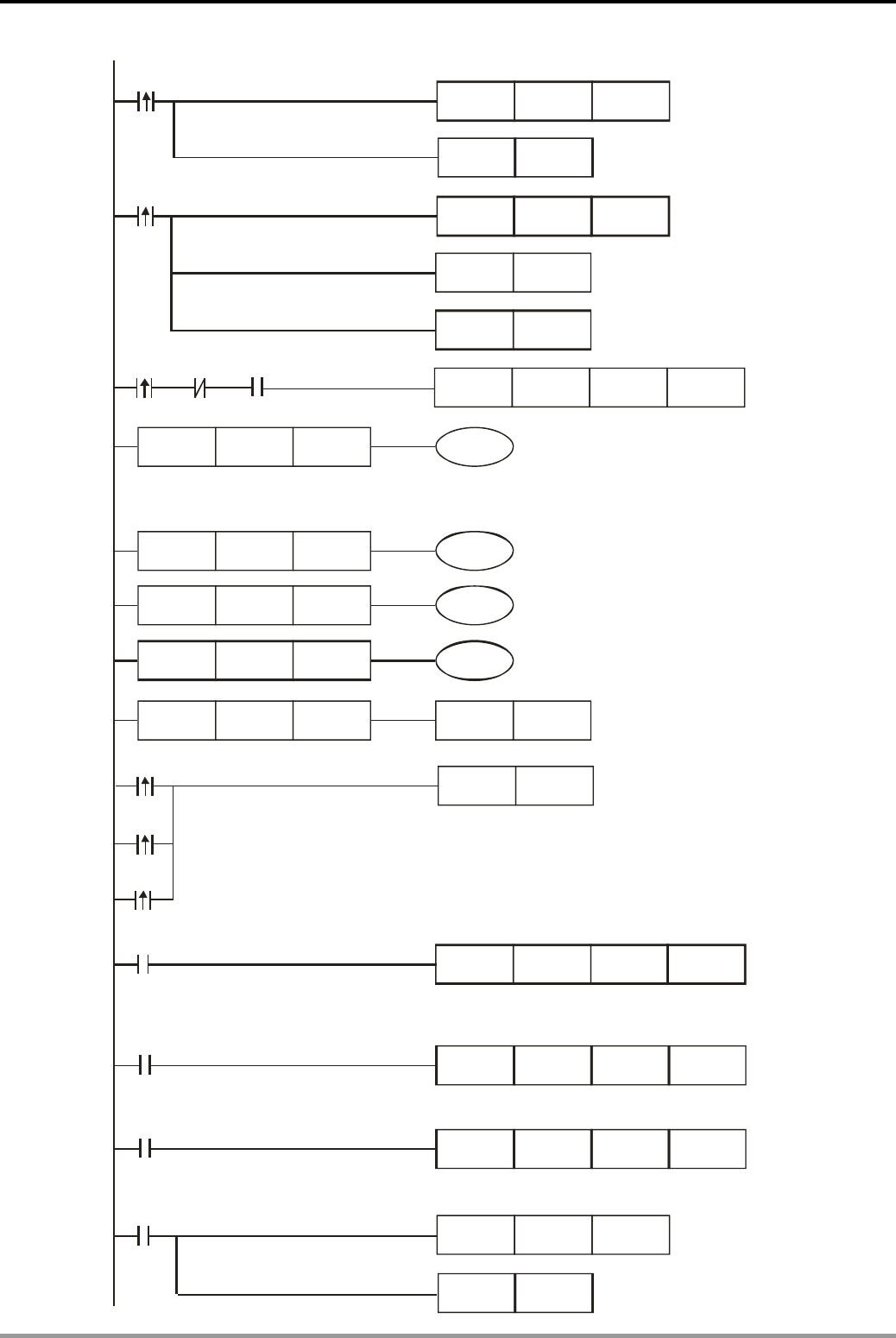
12. Communication Design Examples
DVP-PLC Application Examples 12-9
D10
LD= C0 K0 M0
LD= C0 K1 M1
LD= C0 K2 M2
LD= C0 K3 RST C0
LD>=
M1013 M11
ADD D2 K100 D2
D2 K5000 M11
MOV H22
D10
MOV H1
SET M10
RST M10
M10
RST D2
M0
MODRD K1 H2102 K2
M1
MODWR K1 H2000
M2
MODWR K1 H2001 D2
D10
M1
M2
SET M1122
M0
M1127
CNT C0 K10
RST M1127
X0( Starting AC motor drive)
Reset M10 to stop frequency
increasing
Reset D2
Execute the second MODWR instruction
X1( Stopping AC motor drive)
Set the AC motor drive
to run in reverse when
D10 = H22
Set M10 to increase frequency
Stop AC motor drive
when D10 = H1
Increase the content in D2 with 100
per second (1Hz/sec) until it reaches
50Hz. Maintain the frequency at 50Hz.
Execute MODRD instruction
Execute the first MODWR instruction
Sending request
Read master frequency and output frequency of AC
motor drive and store them in D1073~D1076.
Set the AC motor drive to run in reverse or stop
according to the content in D10
Set the master frequency according to the content
in D2
C0 counts once
when data receiving
is completed.
Reset flag M1127.

12. Communication Design Examples
DVP-PLC Application Examples
12-10
RST
RST
RST
M1129
M1140
M1141
M1129
M1140
M1141
CNT C0 K10
CNT C0 K10
CNT C0 K10
C0 counts once
when communication
timeout occurs.
Reset the flag M1129
Reset the flag M1140
C0 counts once
when data receiving
error occurs.
C0 counts once
when parameter error
occurs.
Reset the flag M1141
Program Description:
z Initialize PLC RS-485 communication port and set the communication format as MODBUS
RTU, 19200, 8, N, 2. The RS-485 communication format of AC motor drive should be the
same with PLC.
z There are only 4 situations for MODBUS communication: flag M1127 for normal
communication and M1129, M1140, M1141 for communication errors. Counter C0 counts
once when any of the 4 flags is ON. Therefore, the program assures the communication
reliability by monitoring the On/Off status of the 4 flags and performs 3 MODBUS
instructions in order by the value in counter C0.
z When M0 = ON, [MODRD K1 H2102 K2] instruction will be executed. PLC will read the
master frequency and output frequency of AC motor drive, store them in D1073~1076 in
ASCII format, and automatically convert the content in D1073~1076 into hexadecimal
values to D1050 and D1051.
z When M1 = ON, [MODWR K1 H2000 D10] instruction will be executed. D10 = H22 and the
drive will run in reverse. If D10 = H1, the drive will be stopped.
z When M2 = ON, [MODWR K1 H2001 D2] instruction will be executed. The frequency can be
changed by the content in D2.
z Once PLC starts running, the read/write actions for AC motor drive will be performed
repeatedly according to [LD=] instructions.
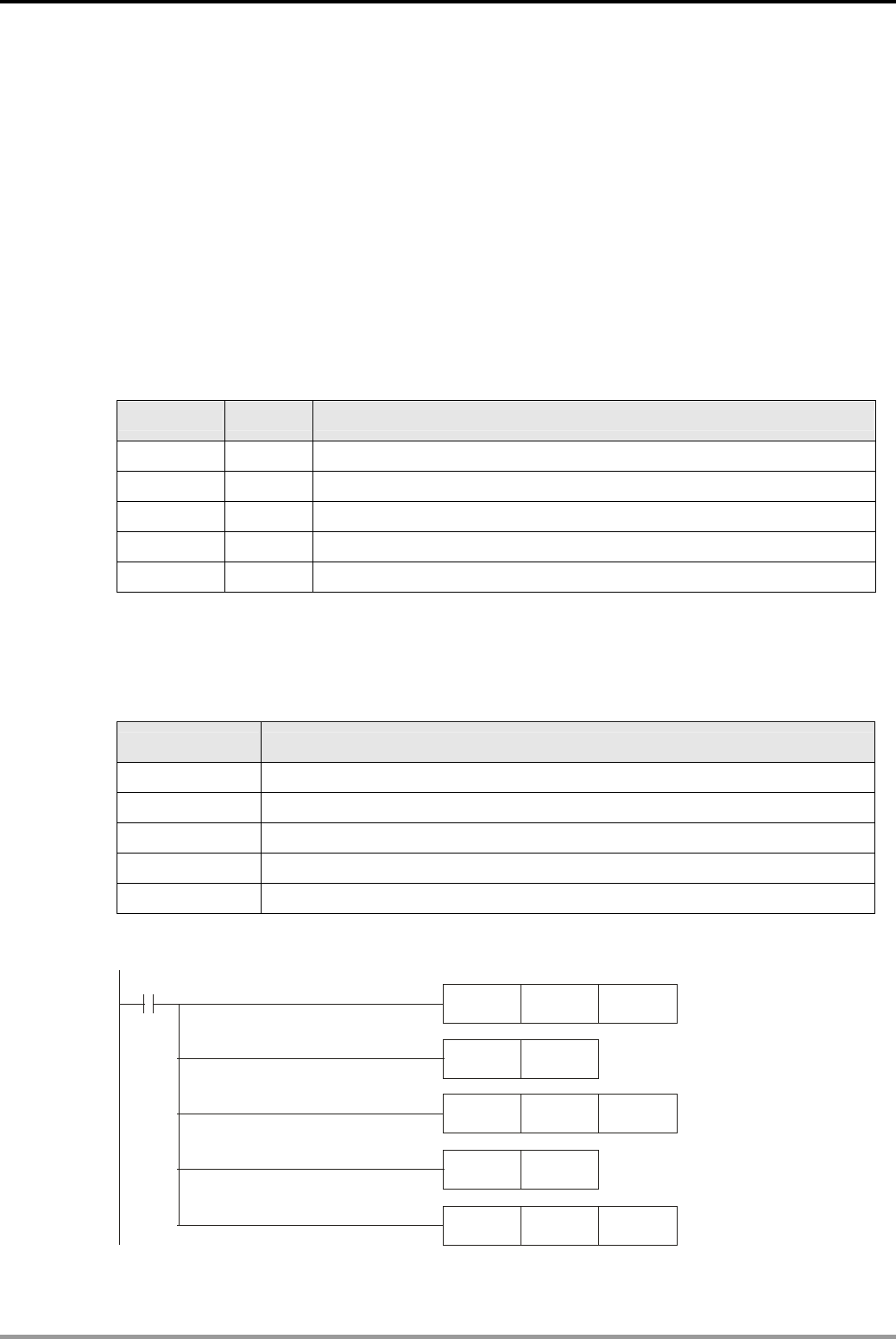
12. Communication Design Examples
DVP-PLC Application Examples 12-11
12.3 Communication between PLC and Delta VFD-V Series AC Motor Drive
(MODRD/MODWR)
Control Purpose:
z Repeatedly reading the master frequency and output frequency of VFD-V series AC motor
drive by MODRD instruction.
z Setting the drive to run forward in 30Hz by MODRW instruction when X0 is pressed.
z Setting the drive to run in reverse in 20Hz by MODRW instruction when X1 is pressed.
z Stopping the drive by MODWR instruction when X2 is pressed.
Parameter Settings for VFD-V Series AC Motor Drive:
Parameter Set value Explanation
00-20 1 Master frequency controlled by RS-485 communication.
00-21 0 Digital keypad (KPV-CE01)
09-00 01 Communication address: 01
09-01 9.6 Communication baud rate: 9600.
09-04 02 ASCII mode. Protocol: (7, E, 1).
Ú If AC motor drive can not run normally due to improper parameters, users can set P00-02 =
10 (factory defaults) and then set the parameters according to the above table.
Devices:
Device Function
X0 Forward
X1 Reverse
X2 Stop
M0 Executing MODRD instruction to read master and output frequency
M1 Executing MODWR instruction to set running direction and frequency
Control Program:
MOV K200 D1129
M1002
MOV H86 D1120
SET M1120
ZRST D0 D1
RST M1143 Select communication mode:
MODBUS ASCII
Set communication
format: 9600, 7, E , 1
Retain communication setting
Set receiving time-out:
200ms
Reset D0 and D1 first
when PLC runs.
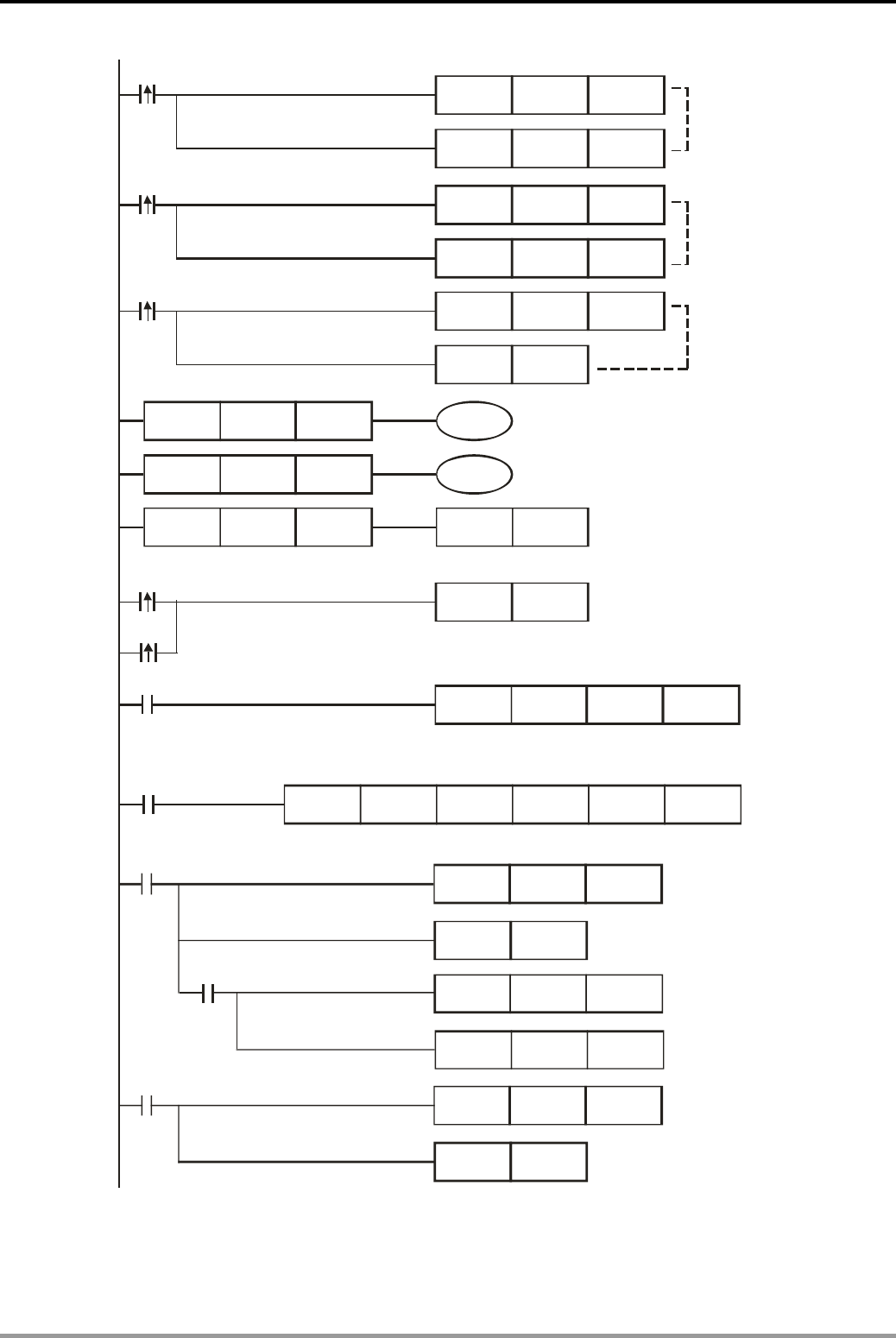
12. Communication Design Examples
DVP-PLC Application Examples
12-12
LD= C0 K0 M0
LD= C0 K1 M1
LD= C0 K2 RST C0
MOV
MOV
K22 D0
K2000 D1
X1
MOV
MOV
H12 D0
K3000 D1
X0
MOV
RST
H1 D0
D1
X2
M1
M1
MODRW K1 K16 H2000 D0 K2
M0
MODRD K1 H2102 K2
SET M1122
M0
M1127
CNT C0 K10
RST M1127
M1129
CNT C0 K10
RST M1129
MOV D1050 D2
MOV D1051 D3
M0
C0 counts once
when communication
timeout occurs.
Reset the flag M1129
Execute MODRD instruction
Execute MODRW instruction
Run forward in 30Hz
when X0 = ON
Run in reverse in 20Hz
when X1 = ON
Stop when X2 = ON
Sending request
Read master frequency and output frequency of AC
motor drive and store them in D1050 and D1051.
Set START/STOP state and master frequency of AC motor drive
C0 counts once
when data receiving
is completed
Reset the flag M1127
Store the master frequency
of AC motor drive in D2
Store the master frequency
of AC motor drive in D3

12. Communication Design Examples
DVP-PLC Application Examples 12-13
M1141
CNT C0 K10
RST M1141
M1140
CNT C0 K10
RST M1140
C0 counts once
when parameter error
occurs.
Reset the flag M1141
C0 counts once
when data receiving
error occurs.
Reset the flag M1140
Program Description:
z Initialize PLC RS-485 communication port and set the communication format as MODBUS
RTU, 19200, 8, N, 2. The RS-485 communication format of AC motor drive should be the
same with PLC.
z Reset D0 and D1 when PLC is powered up so as to ensure the drive is in the Stop status
z When X0 is activated, the drive will run forward (D0 = H12) in 30Hz (D1 = 3000).
z When X1 is activated, the drive will run in reverse (D0 = H22) in 20Hz (D1 = K2000)
z When X2 is activated, the drive will stop. (D0 = H1, D1 = 0)
z There are only 4 situations for MODBUS communication: flag M1127 for normal
communication and M1129, M1140, M1141 for communication errors. Counter C0 counts
once when any of the 4 flags is ON. Therefore, the program assures the communication
reliability by monitoring the On/Off status of the 4 flags and performs 2 MODBUS
instructions in order by the value in counter C0.
z The master frequency and output frequency stored in D1050 and D1051 will be sent to D2
and D3.
z Once PLC starts running, the read/write actions for AC motor drive will be performed
repeatedly according to [LD=] instructions.
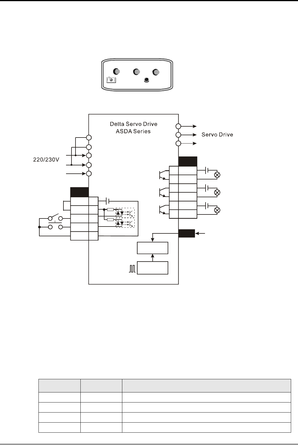
12. Communication Design Examples
DVP-PLC Application Examples
12-14
12.4 Communication between PLC and Delta ASD-A Series AC Servo Drive (Positioning,
MODRD/MODWR)
SON CTRG
AC Servo drive control panel
Power
normal
Start
normal Positioning
completed
Servo ON Positioning enabled
Wiring for Delta ASD-A Series AC Servo Drive:
CN1
COM+
DI1
DI2
17
11
9
10
COM- 45
Electric gear
24V
24V
24V
SON
CTRG
VDD
CN1
R
S
T
24V
U
V
W
DO1+
DO1-
CN2
DO2+
DO2-
DO3+
DO3-2
3
4
5
6
7
4.7K
Power normal
Start normal
Positioning completed
4.7K
L1
L2
Encoder
Error counter
3 phases AC power
Control Purpose:
z Reading the target position of AC servo drive (incremental position) by MODRD instruction.
z Setting the target position of AC servo drive (incremental position) by MODRW instruction.
z Enabling the starting and positioning actions of AC servo drive by the input points DI1~ DI2
when corresponding buttons are pressed.
z Showing the status of AC servo drive through indicators by the output points DO1~DO3
Parameter Settings for ASD-A Series AC Servo Drive:
Parameter Set value Explanation
P1-01 1 Control Mode and Output Direction
P1-33 1 Position Control Mode (Pr)
P2-10 101 Digital Input Terminal 1 (DI1)
P2-11 108 Digital Input Terminal 2 (DI2)
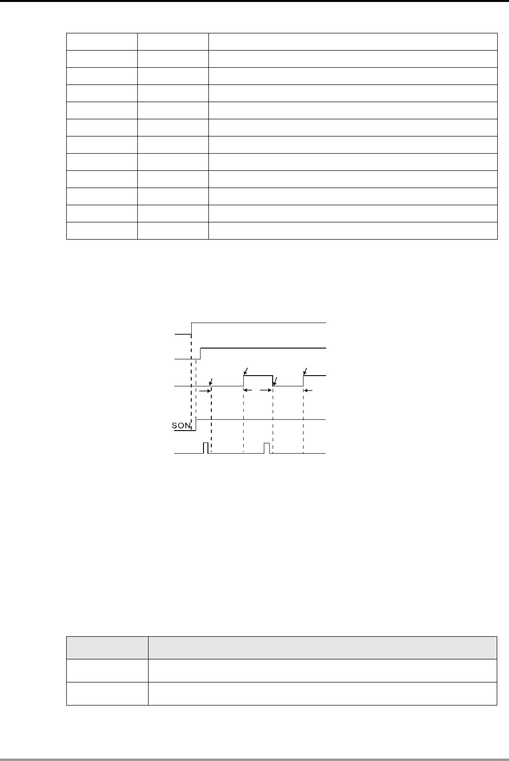
12. Communication Design Examples
DVP-PLC Application Examples 12-15
P2-15 0 Digital Input Terminal 6 (DI6)
P2-16 0 Digital Input Terminal 7 (DI7)
P2-17 0 Digital Input Terminal 8 (DI8)
P2-18 101 Digital Output Terminal 1 (DO1)
P2-19 102 Digital Output Terminal 2 (DO2)
P2-20 105 Digital Output Terminal 3 (DO3)
P3-00 1 Communication Address Setting
P3-01 1 Transmission Speed, Baud rate: 9600
P3-02 1 MODBUS ASCII mode. Data format: (7, E, 1)
P3-03 1 Warning and stopping if communication error occurred.
P3-05 2 RS-485 communication format
P3-06 0 Digital Input Communication Function
Ú If AC servo drive can not run normally due to improper parameters, users can set P2-08 = 10
(factory defaults) and then set the parameters according to the above table.
z Operation Steps:
DO1
DO2
DI1
DI2 CTRG
DO3
10.5 circles
Positioning start
The first time The second time
9circles
Power normal
Start normal
Positioning commpleted
Servo ON
Positioning e
nabled
Positioning start
Positioning end Positioning end
1. Set the parameters of AC servo drive then power up again. If no error occurred, “power
normal” indicator (DO1) will be ON.
2. When Power normal indicator is ON, turn on SON (servo ON) to enable DI1. If no error
occurred, “Start normal” indicator (DO2) will be ON.
3. When “Start normal” indicator in ON, turn on CTRG (positioning enabled) to trigger DI2.
The servo motor will rotate for 10.5 cycles and then the “positioning completed” indicator
(DO3) will be ON.
Devices:
Device Function
M0 Executing MODRD instruction to read rotation number and pulse number of
internal position 1
M1 Executing MODRW instruction to set rotation number and pulse number of
internal position 1
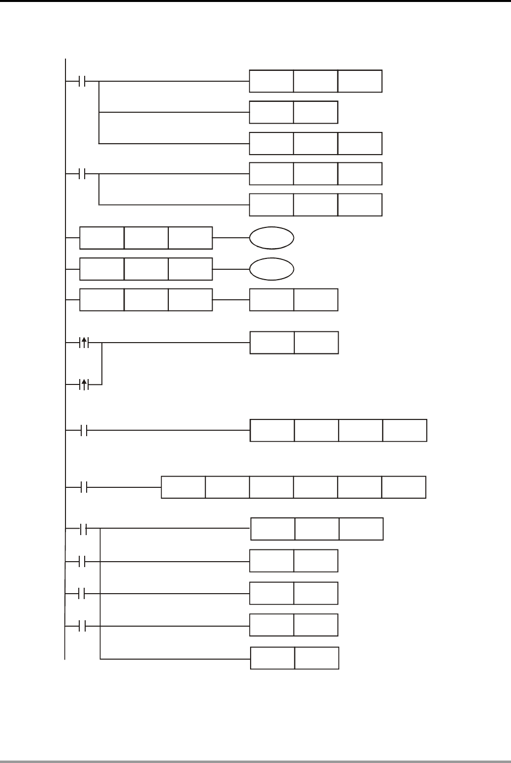
12. Communication Design Examples
DVP-PLC Application Examples
12-16
Control Program:
LD= C0 K0 M0
MOV K500 D1129
M1002
MOV H86 D1120
SET M1120
LD= C0 K1 M1
LD= C0 K2 RST C0
M0
MODRD K1 H10F K2
SET M1122
M0
M1
M1
Sending request
MOV
MOV
K10 D10
K5000 D11
MODRW K1 K16 H10F D10 K2
M1002
Set pulse number of
internal position 1.
Execute MODRW instruction
Execute MODRD instruction
Set communication
format: 9600, 7, E, 1
Retain communication setting
Set receiving time-out:
500ms
Set rotation number of
internal position 1.
Read the rotation number and pulse number of
internal position 1 then store them in D1050 and D1051
Write the content in D10 and D11 into H10F and H110 of AC servo drive
M1127
CNT C0 K10
RST M1127
RST
RST
RST
M1129
M1140
M1141
M1129
M1140
M1141
C0 counts each time when
communication is completed.
Reset the flag M1127
Reset the flag M1129
Reset the flag M1140
Reset the flag M1141

12. Communication Design Examples
DVP-PLC Application Examples 12-17
Program Description:
z Initialize PLC RS-485 communication port and set the communication format as MODBUS
ASCII, 9600, 7, E, 1. The RS-485 communication format of AC servo drive should be the
same with PLC.
z When M0 = ON, [MODRD K1 H10F K2] instruction will be executed to read the rotation
number and the pulse number of internal position 1 and store them in D1050 and D1051.
z When M1 = ON, [MODWR K1 K16 H10F D10 K2] instruction will be executed to write the
content in D10 and D11 into H10F (Rotation number of internal position1) and H10 (pulse
number of internal position 1).
z Both the start signal and the trigger signal are controlled by switches of AC servo drive
through the external wiring. For the wiring methods, please refer to the wiring diagram.
z There are only 4 situations for MODBUS communication: flag M1127 for normal
communication and M1129, M1140, M1141 for communication errors. Counter C0 counts
once when any of the 4 flags is ON. Therefore, the program assures the communication
reliability by monitoring the On/Off status of the 4 flags and performs 2 MODBUS
instructions in order by the value in counter C0.
z Once PLC starts running, the read/write actions for AC servo drive will be performed
repeatedly according to [LD=] instructions.
.
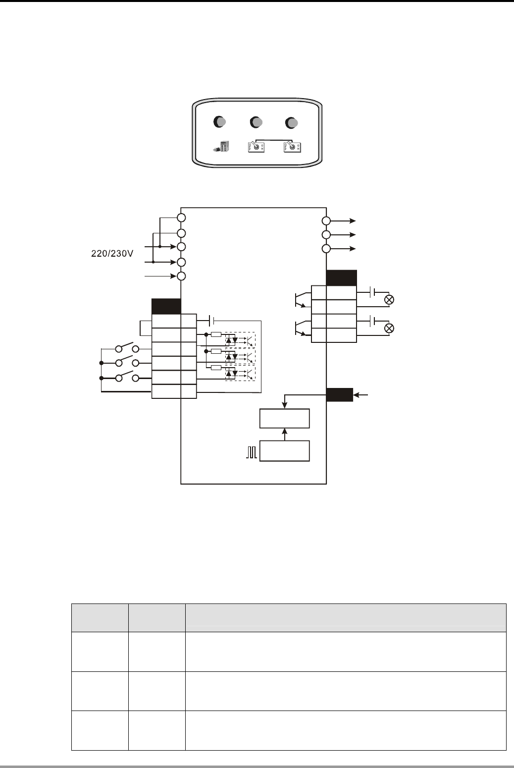
12. Communication Design Examples
DVP-PLC Application Examples
12-18
12.5 Communication between PLC and Delta ASD-A Series AC Servo Drive (Speed
Control, MODRD/MODRW)
SON SPD0 SPD1
AC servo drive control panel
Power normal Start normal Speed reached
Servo ON Speed switching
Wiring for Delta ASD-A Series AC Servo Drive:
CN1
COM+
DI1
DI3
17
11
9
34
COM- 45
24V
24V
SON
VDD
CN1
R
S
T
24V
U
V
W
DO1+
DO1-
CN2
DO2+
DO2-
4
5
6
7
4.7K
4.7K
L1
L2
D14 8
SPD0
SPD1 4.7K
Delta AC servo drive
ASDA series Servo motor
Power normal
Start normal
Encoder
Error counter
Electric gear
3 phases AC power
Control Purpose:
z Reading rotation speed of servo motor and storing it in D0 by MODRD instruction.
z Controlling the motor to rotate in 2 fixed speeds or specified speed by MODRW instruction
together with switches SPD0 and SPD1.
z Definitions of the speed switches of AC servo drive:
SPD0
Status
SPD1
Status Function
ON OFF
SPD0 ON: selecting the first speed set in P1-09 (determined by the
content in D9, fixed as K1500 in this program. The rotation speed of
the motor: 1500 r/min. Direction: forward.)
OFF ON
SPD1 ON: selecting the second speed set in P1-10 (determined by
the content in D10, fixed as K-1500 in this program. The rotation
speed of the motor: 1500 r/min. Direction: reverse.)
ON ON
SPD0 and SPD1 ON: selecting the third speed set in P1-11
(determined by the content in D11. The rotation speed of the motor is
specified by user with the content in D11.
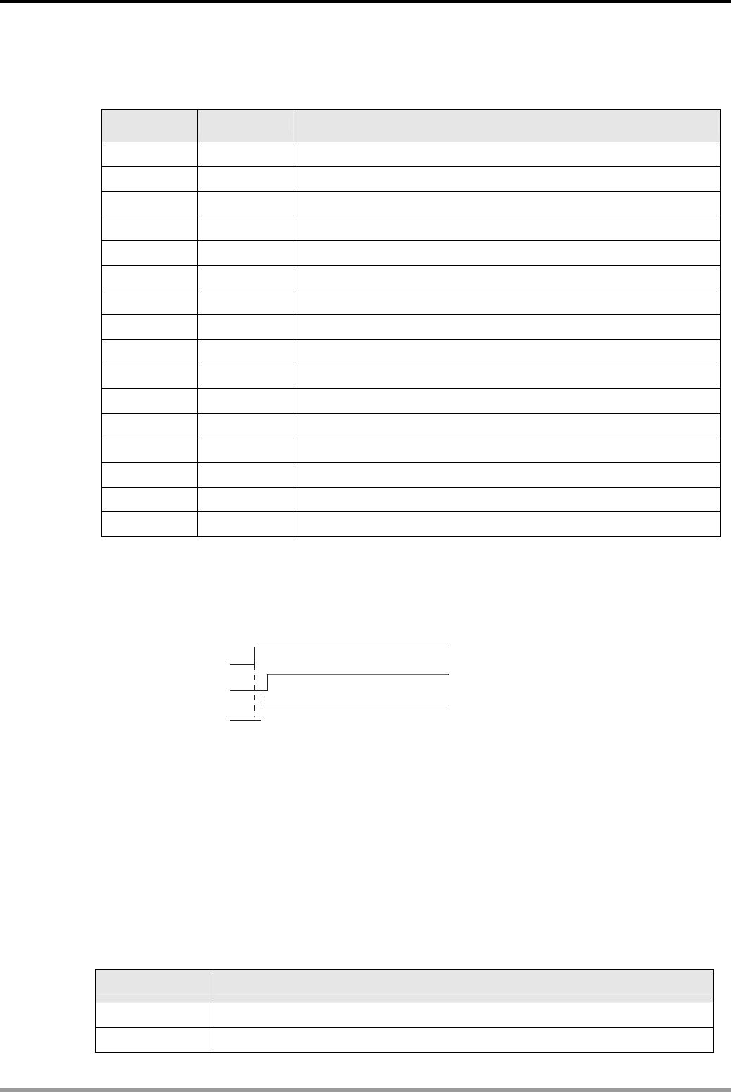
12. Communication Design Examples
DVP-PLC Application Examples 12-19
z Showing the status of AC servo drive through indicators by the output points DO1~DO3.
Parameter Settings for ASDA Series AC Servo Drive:
Parameter Set value Explanation
P1-01 2 Control Mode and Output Direction
P1-39 1500 Target Motor Speed: 1500rpm.
P2-10 101 Digital Input Terminal 1 (DI1)
P2-12 114 DI3: the input terminal of SPD0
P2-13 115 DI4: the input terminal of SPD1
P2-15 0 No function
P2-16 0 No function
P2-17 0 No function
P2-18 101 DO1 = ON if no error occurred after power up
P2-19 102 DO2 = ON if no error occurred after servo started
P2-20 104 DO3 = ON when target speed reached
P3-00 1 Communication Address Setting
P3-01 1 Transmission Speed, Baud rate: 9600
P3-02 1 MODBUS ASCII mode. Data format: (7, E, 1)
P3-05 2 RS-485 communication format
P3-06 0 Digital Input Communication Function
Ú If AC servo drive can not run normally due to improper parameters, users can set P2-08 = 10
(factory defaults) and then set the parameters according to the above table.
z Operation Steps:
DO1
DO2
DI1
SON
Power normal
Start normal
Servo ON
1. Set the parameters of AC servo drive then power up again. If no error occurred, “power
normal” indicator (DO1) will be ON.
2. When Power normal indicator is ON, turn on SON (servo ON) to enable DI1. If no error
occurred, “Start normal” indicator (DO2) will be ON.
3. Turn on “SPD0”, the speed set in parameter P1-09 will be enabled. Turn on “SPD1”, and
the speed set in parameter P1-10 will be enabled. Turn on both “SPD0” and “SPD1”, the
speed set in parameter P1-11 will be enabled.
Devices:
Device Function
M0 Executing MODRD instruction to read the rotation speed of motor
M1 Execute MODWR instruction
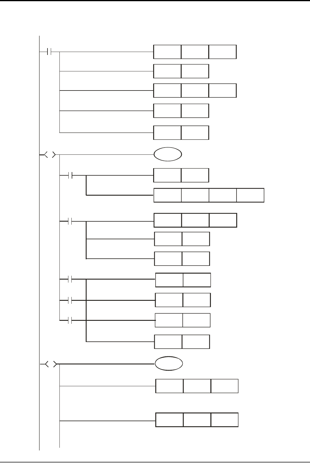
12. Communication Design Examples
DVP-PLC Application Examples
12-20
Control Program:
MOV K500 D1129
M1002
MOV H86 D1120
SET M1120
RST M1143
SET S0
S
M0
S0
M0
M1127
SET M1122
MODRD K1 H4 K1
M1129
M1140
M1141
MOV D1050 D0
RST M1127
SET S20
SET S20
RST
RST
RST
M1129
M1140
M1141
S
S20
M1
MOV K1500 D9
MOV K-1500 D10
Retain communication setting
Set receiving time-out:
500ms
MODBUS ASCII
Enter step S20
Read the rotation speed of servo motor and store it in D1050
Send the content
in D1050 to D0
Reset M1127.
Enter step S20
Reset M1129
Reset M1141
Reset M1140
Set communication
format: 9600, 7, E, 1
Set communication mode:
Enter step S0
Sending request
Set the first speed to 1500 r/min
in forward direction
Set the second speed to 1500 r/min
in reverse direction
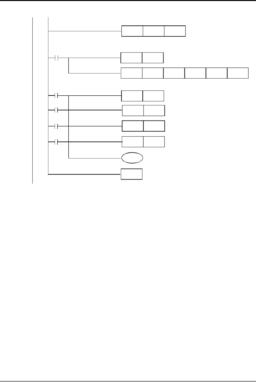
12. Communication Design Examples
DVP-PLC Application Examples 12-21
M1
M1127
SET M1122
M1129
M1140
M1141
RST M1127
RST
RST
RST
M1129
M1140
M1141
MODRW K1 K16 H109 D9 K3
RET
S0
MOV K1000 D11
Reset M1129.
Reset M1441.
Reset M1140.
Reset M1127.
Set the third speed to 1000r/min
in forward direction
Sending request
Write the content in D9, D10, D11 into H109 of AC servo drive
Return to step S0
Program Description:
z Initialize PLC RS-485 communication port and set the communication format as MODBUS
ASCII, 9600, 7, E, 1. The RS-485 communication format of AC servo drive should be the
same with PLC.
z When enter into step point S0, M0 = ON, [MODRD K1 H4 K1] instruction will be executed to
read the motor rotation speed and store it in D1050. Then [MOV D1050 D0] instruction will
be executed for showing the rotation speed in D0.
z When enter into step S20, M1 = ON, [MODWR K1 K16 H109 D9 K3] instruction will be
executed to write the content in D9, D10 and D11 into the H109, H10A and H10B as the
parameters of communication address.
z The initial setting in D11 is K1000. Users can specify the value by actual application.
z When PLC starts, the program will enter step S0 then move to step S20 and return to S0.
The read/write actions for AC servo drive will be performed repeatedly by this process.
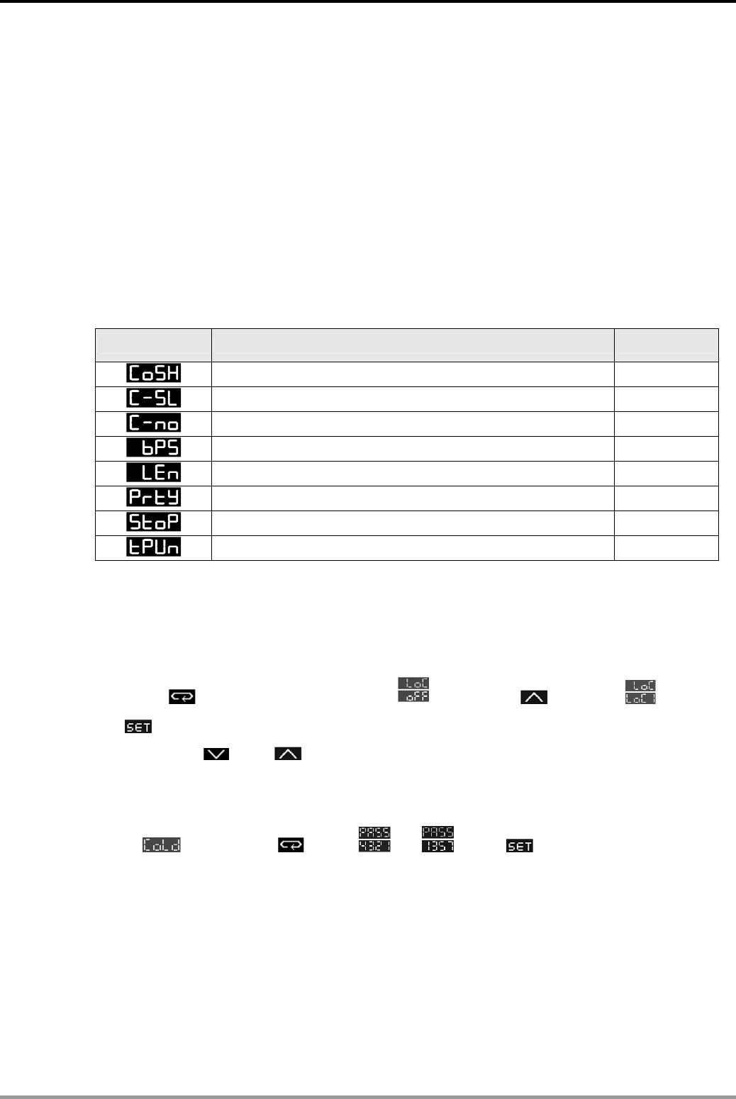
12. Communication Design Examples
DVP-PLC Application Examples
12-22
12.6 Communication between PLC and Delta DTA Series Temperature Controller
(MODRD/MODWR)
Control Purpose:
z Reading the target value and the set value of the temperature controller (TC). (address:
H4700, MODRD instruction)
z Setting the target temperature as 24° (address H4701, MODWR instruction)
z Setting the heating/cooling control cycle. (address: H4712, MODWR instruction)
z Setting the control mode as cooling. (address: H4718, MODWR instruction)
Parameter Settings for DTA Series Temperature Controller:
Parameter Function Set value
C WE: Write-in function disable/enable ON
C-SL: ASCII, RTU communication format selection ASCII
C NO: Communication address setting 1
BPS: Communication baud rate setting 9600
LENGTH: Data length setting 7
PARITY: Parity bit setting E
STOP BIT: Stop bit setting 1
UNIT: Temperature display unit °C or ℉ °C
Ú If TC can not run normally due to improper parameters, users can set the TC to factory
defaults first and then set the parameters according to the above table.
Steps of setting factory defaults:
1. Press in the main screen to enter page. Use to select . Press
to save the setting.
2. Press both and for about 1s to enter default setting mode. (Other operation is
prohibited in this mode, or setting error will occur, and the TC have to be sent back to
factory for adjusting)
3. In page, press to set as . Press to save the setting.
4. Turn off TC then power up again.
5. The communication protocols of DTA series TC are as follows:
z Supporting MODBUS ASCII/RTU. Baud rate: 2400, 4800, 9600, 19200, 38400.
z Supporting function codes: 03H (read multiple words). 06H (write 1 word).
Non-supporting function code: 10H (write multiple words).
z Non-supporting formats in ASCII mode: 7, N, 1 or 8, O, 2 or 8, E, 2.
z Supporting formats in RTU mode: 8, N, 1 or 8, N, 2 or 8, O, 1 or 8, E, 1.
z Available communication address: 1 to 255, 0 is broadcast address.
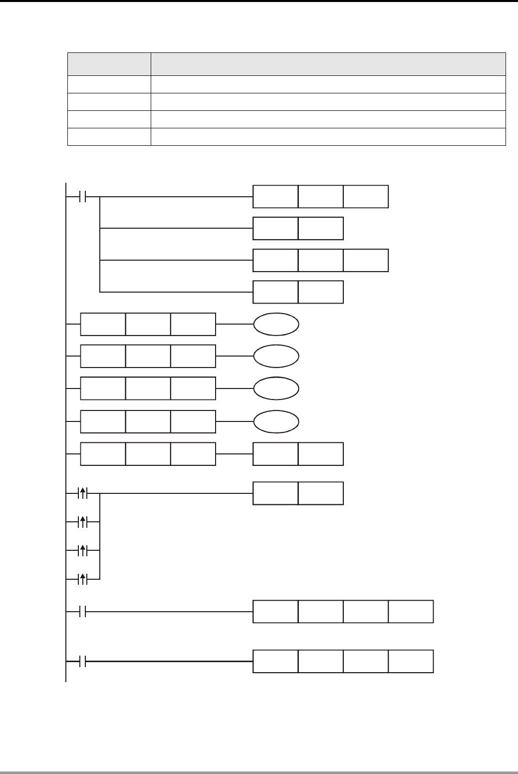
12. Communication Design Examples
DVP-PLC Application Examples 12-23
Devices:
Devices Function
M0 Execute MODRD instruction to read target and current temperature.
M1 Execute the first MODWR instruction to set target temperature of TC.
M2 Execute the 2nd MODWR instruction to set the heating/cooling cycle time.
M3 Execute the 3rd MODWR instruction to set the control mode as Cooling.
Control Program:
LD= C0 K0 M0
RST M1143
MOV K500 D1129
M1002
MOV H86 D1120
SET M1120
LD= C0 K1 M1
LD= C0 K2 M2
LD= C0 K3 M3
LD= C0 K4 RST C0
M0
MODRD K1 H4700 K2
M1
MODWR K1 H4701 K240
Retain communication setting
500ms
SET M1122
M0
Sending request
Execute the 2nd MODWR instruction
Execute the 3rd MODWR instruction
M1
M2
M3
Set communication
format: 9600, 7, E, 1
Set receiving time-out:
Select communication mode:
MODBUS ASCII
Execute MODRD instruction
Execute the 1st MODWR instruction
Read the target value and the present value of the
TC and store them in D1050 and D1051
Set the TC target value as 24
℃
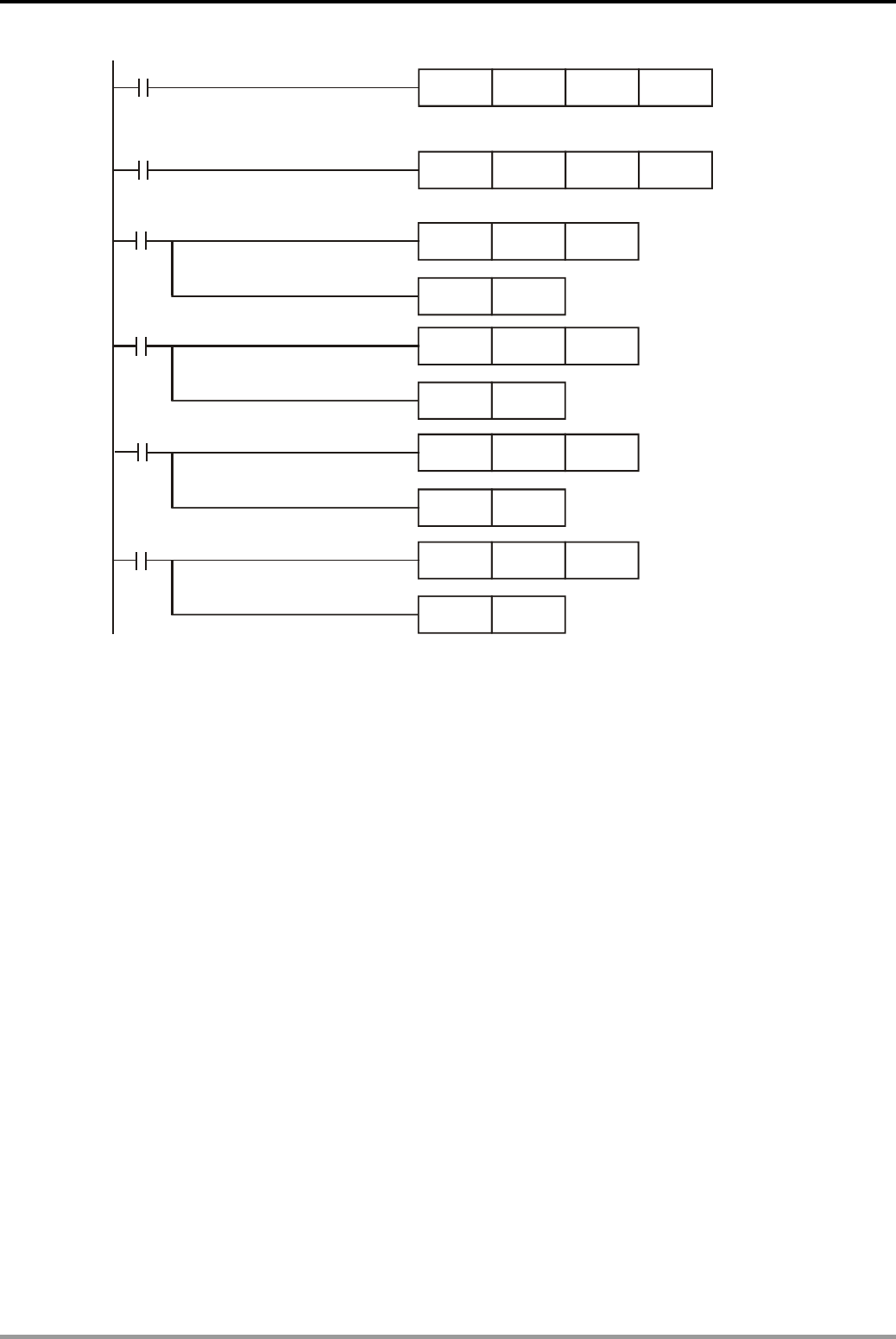
12. Communication Design Examples
DVP-PLC Application Examples
12-24
M1127
CNT C0 K10
RST M1127
C0 counts once
when data receiving
is completed.
RST
RST
RST
M1129
M1140
M1141
M1129
M1140
M1141
CNT C0 K10
CNT C0 K10
CNT C0 K10
C0 counts once
when communication
timeout occurs
Reset M1129
C0 counts once
when data receiving
error occurs
Reset M1140
C0 counts once
when parameter
error occurs
Reset M1141
MODWR K1 H4712 K20
M2
MODWR K1 H4718 K1
M3
Set the heating/cooling cycle time: 20s
Set temperature control mode: cooling mode
Reset M1127
Program Description:
z Initialize PLC RS-485 communication port and set the communication format as MODBUS
ASCII, 9600, 7, E, 1. The RS-485 communication format of TC should be the same with
PLC.
z Since DTA series TC does not support the function code 10H (Write multiple words), the
program needs 3 MODWR instructions to write 3 address data.
z There are only 4 situations for MODBUS communication: flag M1127 for normal
communication and M1129, M1140, M1141 for communication errors. Counter C0 counts
once when any of the 4 flags is ON. Therefore, the program assures the communication
reliability by monitoring the On/Off status of the 4 flags and performs 4 MODBUS
instructions in order by the value in counter C0
z Once PLC starts running, the read/write actions for TC will be performed repeatedly
according to [LD=] instructions.
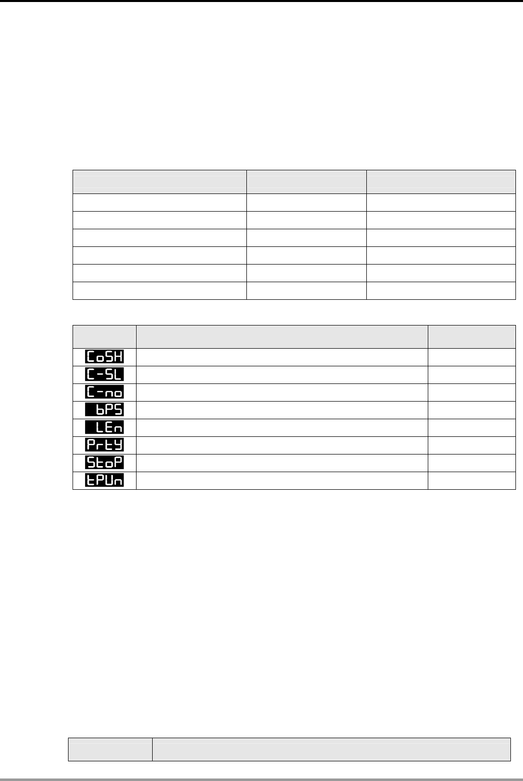
12. Communication Design Examples
DVP-PLC Application Examples 12-25
12.7 Communication between PLC and Delta DTB Series Temperature Controller
(MODRD/MODWR/MODRW)
Control Purpose:
z Reading as well as displaying the target value and the present value of the TC by MODRD
instruction.
z Setting the parameters of the TC as following data by MODWR and MODRW instructions.
Parameter value Communication address
Target temperature 26°C 1001H
Upper limit of temperature range 50°C 1002H
Lower limit of temperature range 0°C 1003H
Output type of alarm 1 The first alarm type 1020H
Upper-limit alarm 1 5°C 1024H
Lower-limit alarm 1 3°C 1025H
Parameter Settings for DTB Series Temperature Controller:
Parameter Function Set value
C WE: Write-in function disable/enable ON
C-SL: ASCII, RTU communication format selection RTU
C NO: Communication address setting 1
BPS: Communication baud rate setting 9600
LENGTH: Data length setting 8
PARITY: Parity bit setting N
STOP BIT: Stop bit setting 2
UNIT: Temperature display unit °C or ℉ °C
Ú If TC can not run normally due to improper parameters, users can set the TC to factory
defaults first and then set the parameters according to the above table. The setting steps of
DTB series are the same with DTA series TC.
Ú Communication protocol of DTB series is as following:
1. Supporting MODBUS ASCII/RTU communication protocol. Communication baud rate:
2400, 4800, 9600, 19200, 38400.
2. Supporting function code: 03H to read the contents of register. 06H to write 1 word into
register. 10H to write many words into register.
3. Non-supported formats in ASCII mode: 7, N, 1 or 8, O, 2 or 8, E, 2
4. Formats in RTU mode: 8, N, 1 or 8, N, 2 or 8, O, 1 or 8, E, 1.
5. Available communication address: 1 to 255, 0 is broadcast address.
Devices:
Device Function
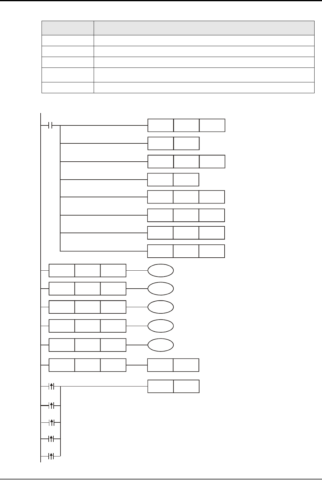
12. Communication Design Examples
DVP-PLC Application Examples
12-26
Device Function
M0 Executing MODRD instruction to read target and present temperature
M1 Executing the 1st MODWR instruction to set target temperature of TC
M2 Executing the 2nd MODWR instruction to set alarm output type
M3 Executing the 1st MODRW instruction to set the upper/lower limit of
temperature range
M4 Executing the 2nd MODRW instruction to set the upper/lower limit of alarm 1
Control Program:
LD= C0 K0 M0
SET M1143
MOV K100 D1129
M1002
MOV H89 D1120
SET M1120
LD= C0 K1 M1
LD= C0 K2 M2
LD= C0 K3 M3
LD= C0 K5 RST C0
MOV K50 D2
MOV K30 D3
LD= C0 K4 M4
Set up communication
format: 9600,8,N,2
Retain communication setting
Set receiving time-out:
100ms
Select communication mode:
MODBUS RTU
Sending request
Upper-limit of the
alarm: 5
℃
Lower-limit of the
alarm:3
℃
MOV K500 D0
MOV K0 D1
Upper limit of temp.
Range:50
℃
Lower limit of temp.
Range:0
℃
SET M1122
M0
M1
M2
M3
M4
Execute MODRD instruction
Execute the 1st MODWR instruction
Execute the 2nd MODWR instruction
Execute the 1st MODRW instruction
Execute the 2nd MODRW instruction
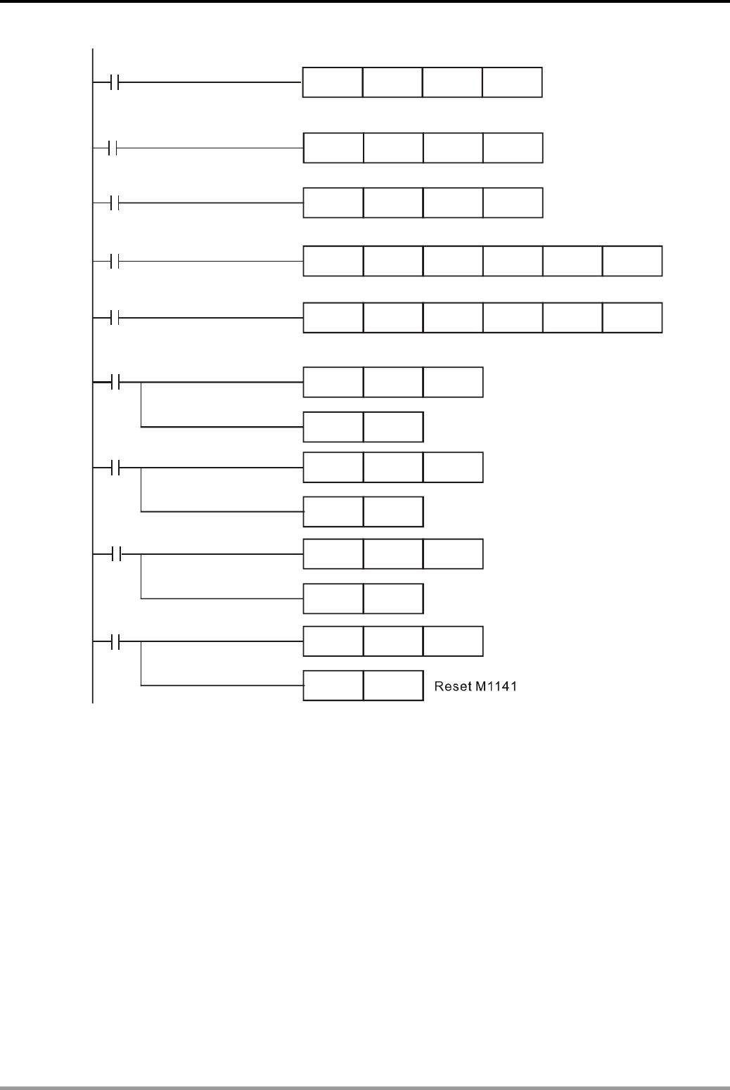
12. Communication Design Examples
DVP-PLC Application Examples 12-27
M3
MODWR K1 H1020 K1
MODRW K1 K2
K16 H1002 D0
M4
MODRW K1 K2
K16 H1024 D2
M1127
CNT C0 K10
RST M1127
C0 counts once
when data receiving
is completed.
Reset M1127
M1129
M1140
M1141
RST M1129
RST M1140
RST M1141
CNT C0 K10
CNT C0 K10
CNT C0 K10
C0 counts once
when communication
timeout occurs.
Reset M1129
Reset M1140
C0 counts once
when parameter error
occurs.
M2
Set target value as 26
℃
M1
MODWR K1 H1001 K260
M0
MODRD K1 H1000 K2
Read the target value and the present value of the
TC and store them in D1073~D1076
Set output mode of alarm 1 as the 1st alarm type
Set upper/lower limit of temperature range
Set the upper/lower limit of alarm 1
C0 counts once
when data receiving
errors occurs.
Program Description:
z Initialize PLC RS-485 communication port and set the communication format as MODBUS
RTU, 9800, 8, N, 2. The RS-485 communication format of TC should be the same with PLC..
z There are only 4 situations for MODBUS communication: flag M1127 for normal
communication and M1129, M1140, M1141 for communication errors. Counter C0 counts
once when any of the 4 flags is ON. Therefore, the program assures the communication
reliability by monitoring the On/Off status of the 4 flags and performs 5 MODBUS
instructions in order by the value in counter C0.
z Since DTB series TC supports the function code 10H, the program uses MODRW instruction
to write multiple words.
z Once PLC starts running, the read/write actions for TC will be performed repeatedly
according to [LD=] instructions.
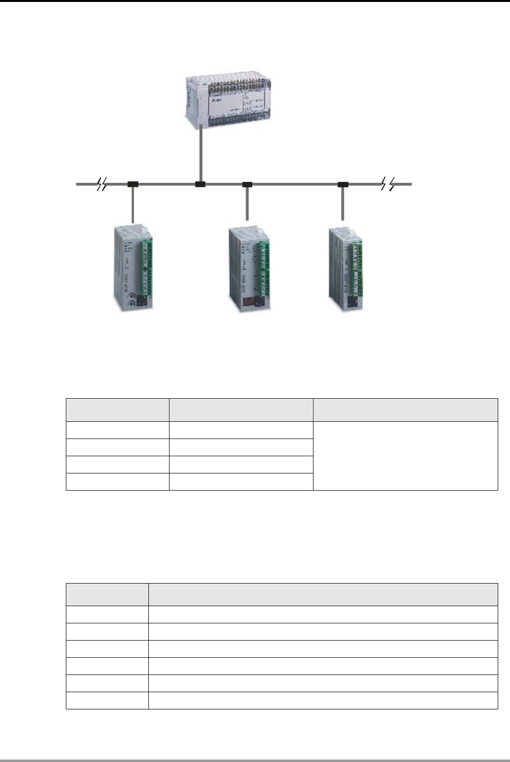
12. Communication Design Examples
DVP-PLC Application Examples
12-28
12.8 PLC LINK 16 Slaves and Read/Write 16 Data (Word)
Slave1 Slave2 Slave3
Master PL
C
Rs485 network
Master address =K20
Slave address
=K2
Slave address
=K3
Slave address
=K4
EH 2
SA SX S
S
Control Purpose:
z Performing 16 words data exchange by PLC LINK between master PLC and 3 slave PLCs.
Parameter Settings for PLC:
Master/Slave Station No. Communication format
Master PLC K20 (D1121 = K20)
Slave 1 K2 (D1121 = K2)
Slave 2 K3 (D1121 = K3)
Slave 3 K4 (D1121 = K4)
ASCII, 9600, 7, E, 1 (D1120 = H86).
Communication format of all connected
PLCs must be the same.
Ú If PLC can not run normally due to improper parameters, users can set the PLC to factory
defaults by clicking ”Communication (C)”> “Format PLC Memory” from the menu bar of WPL
Soft and then set the parameters according to the above table.
Devices:
Device Function
X0 Trigger on PLC LINK
M1350 Enabling EASY PLC LINK
M1351 Enabling auto mode on EASY PLC LINK
M1352 Enabling manual mode on EASY PLC LINK
M1353 Enable 32 slave unit linkage and up to 100 data length of data exchange
M1354 Enable simultaneous data read/write in a polling of EASY PLC LINK
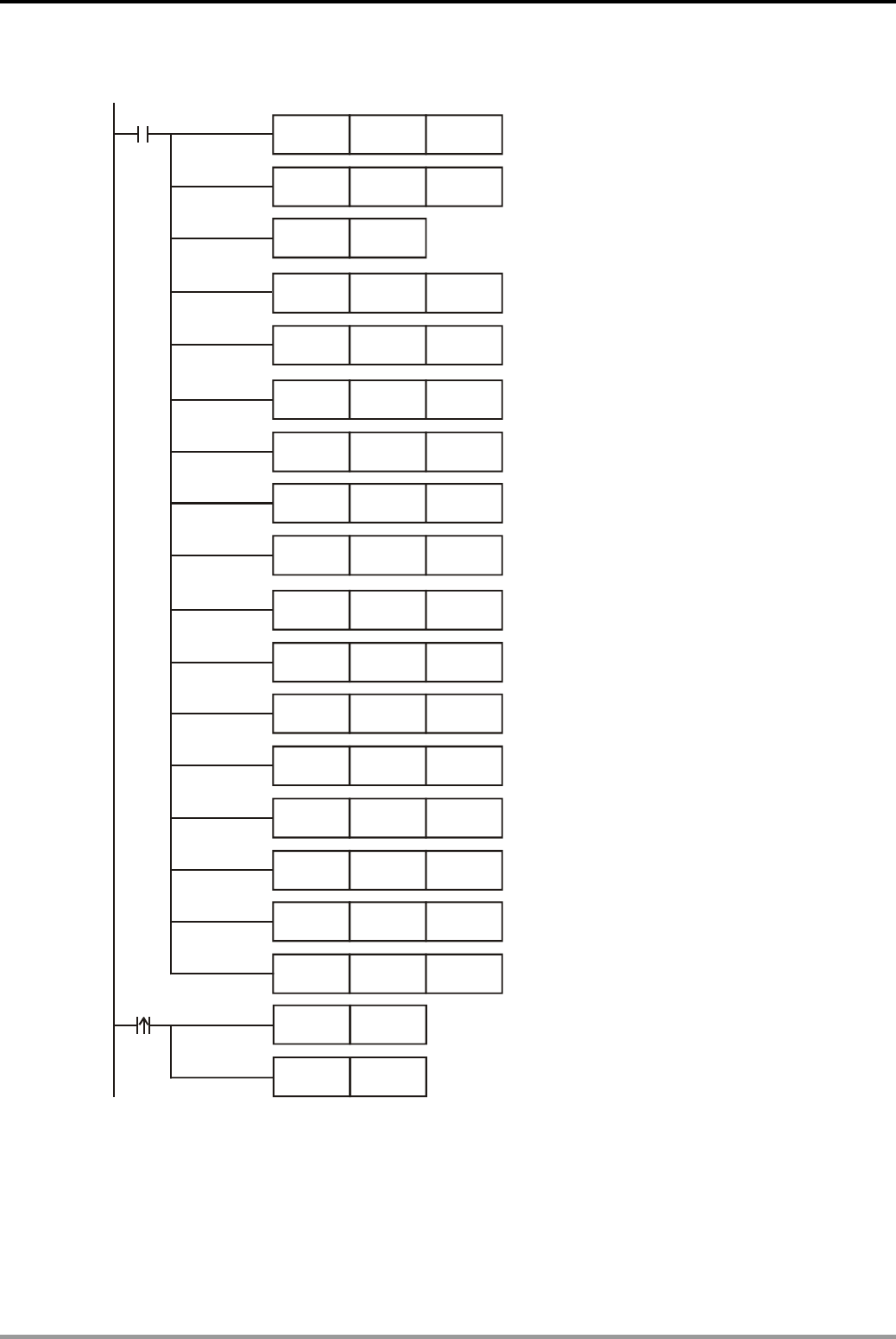
12. Communication Design Examples
DVP-PLC Application Examples 12-29
Control Program:
M1002
MOV K20 D1121
H86 D1120
H1064
K16
MOV
SET M1120
MOV
MOV
D1355
D1434
H10C8
K16
MOV
MOV
D1415
D1450
Enable PLC LINK
H1078
K16
MOV
MOV
D1356
D1435
H10DC
K16
MOV
MOV
D1416
D1451
H108C
K16
MOV
MOV
D1357
D1436
H10F0
K16
MOV
MOV
D1417
D1452
16 data to be written in Slave ID1
Set starting reference as for Master
to read from Slave ID 2: . D120
16 data to be read from Slave ID2
Set starting reference for Master
to write in Slave ID 2: D220
16 data to be written in Slave ID2
Set starting reference for Master
to read from Slave ID 3: . D140
16 data to be read from Slave ID3
Set starting reference for Master
to write in Slave ID 3: D240
16 data to be written in Slave ID3
MOV K200 D1129
K2 D1399
MOV
Set receiving time-out: 200ms
Set starting Slave ID as K2
M1351
M1350
SET
SET
X0
Set the Master PLC
communication address as K20
Set PLC COM2
communication protocol
Retain communication setting
Set starting reference for Master
to read from Slave ID 1: . D100.
16 data Slave ID1 to be read from
Set starting reference for Master
to write in Slave ID 1: . D200
Auto mode
Program Description:
z When X0 = ON, the data exchange between Master and 3 Slaves will be performed through
PLC LINK by the ways explained below: the data in D100 ~ D115, D120~D135, and
D140~D155 of the 3 Slaves will be read respectively into D1480 ~ D1495, D1512 ~ D1527
and D1544~ D1559 of the Master, and the data in D1496 ~ D1511, D1528 ~ D1543 and
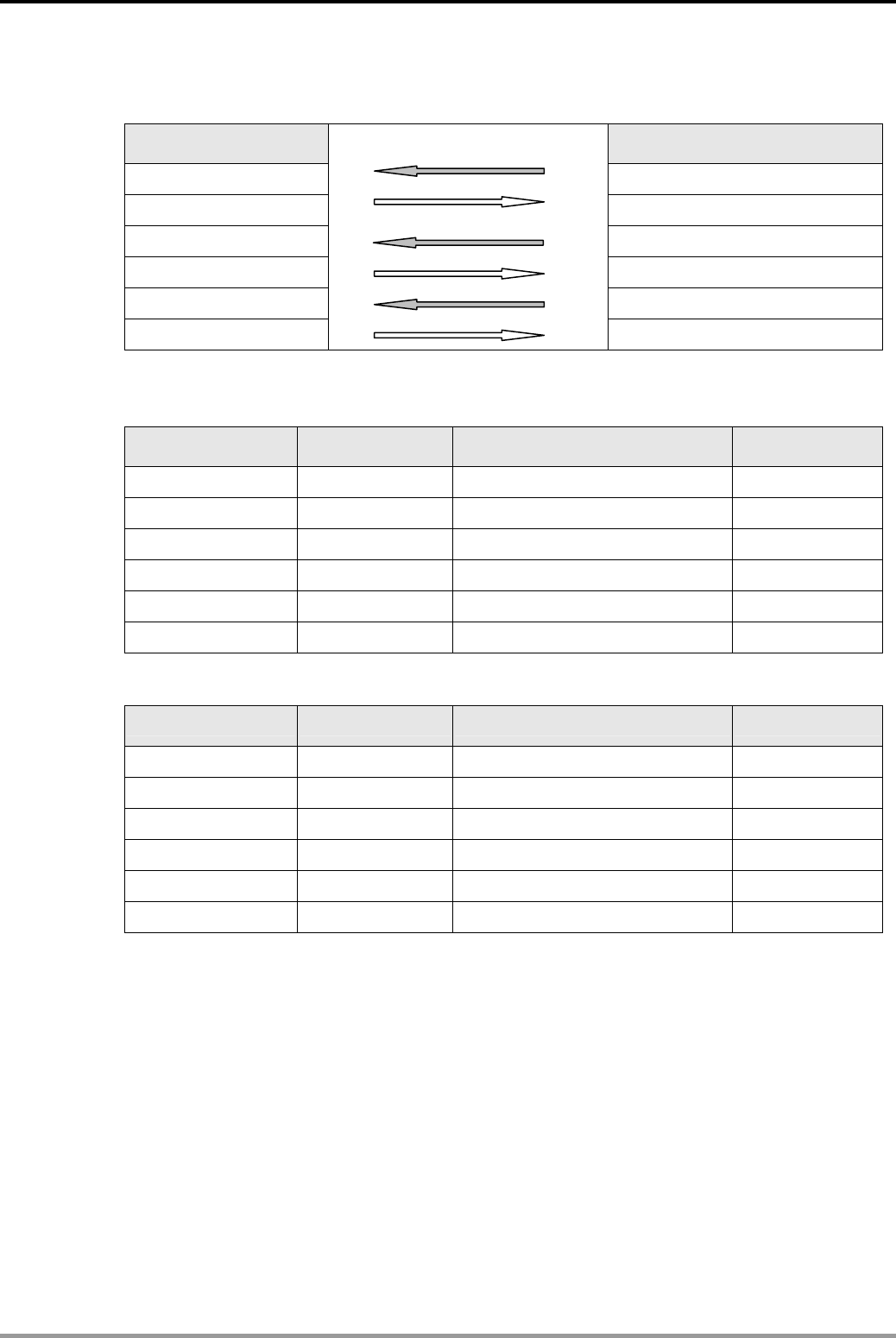
12. Communication Design Examples
DVP-PLC Application Examples
12-30
D1560~D1575 of the Master will be written respectively into D200 ~ D215, D220~D235 and
D240~D255 of the 3 Slaves.
Master PLC *1 Slave PLC *3
D1480~D1495 D100~D115 of Slave ID 2#
D1496~D1511 D200~D215 of Slave ID 2#
D1512~D1527 D120~D135 of Slave ID 3#
D1528~D1543 D220~D235 of Slave ID 3#
D1544~D1559 D140~D155 of Slave ID 4#
D1560~D1575
D240~D255 of Slave ID 4#
z Assume that the data in D for data exchange between Master and Slave before PLC LINK is
enabled (M1350 = OFF) are as below:
Master PLC Set value Slave PLC Set value
D1480~D1495 0 D100~D115 of Slave ID 2# 1
D1496~D1511 100 D200~D215 of Slave ID 2# 0
D1512~D1527 0 D120~D135 of Slave ID 3# 2
D1528~D1543 200 D220~D235 of Slave ID 3# 0
D1544~D1559 0 D140~D155 of Slave ID 4# 3
D1560~D1575 300 D240~D255 of Slave ID 4# 0
After EASY PLC LINK is enabled (M1350 = ON), the data in D for data exchange becomes:
Master PLC Set value Slave PLC Set value
D1480~D1495 1 D100~D115 of Slave ID 2# 1
D1496~D1511 100 D200~D215 of Slave ID 2# 100
D1512~D1527 2 D120~D135 of Slave ID 3# 2
D1528~D1543 200 D220~D235 of Slave ID 3# 200
D1576~D1591 3 D140~D155 of Slave ID 4# 3
D1592~D1607 300 D240~D255 of Slave ID 4# 300
z In Master PLC, set the starting Slave ID (D1399 = K2), i.e. Slave ID 2# corresponds to
Slave1, Slave ID 3# corresponds to Slave2, and Slave ID 4# corresponds to Slave3.
z Station No. of Slave should be continuous and different from the station No. of Master. Only
the SA/SX/SC/SV/EH/EH2 series PLC can be Master, but all DVP-PLC can be Slave.
z When X0 = ON, PLC LINK will be enabled. If enabling action is failed, M1350/M1351 will be
OFF and X0 needs to be activated again.
Write
Write
Read
Read
Write
Read
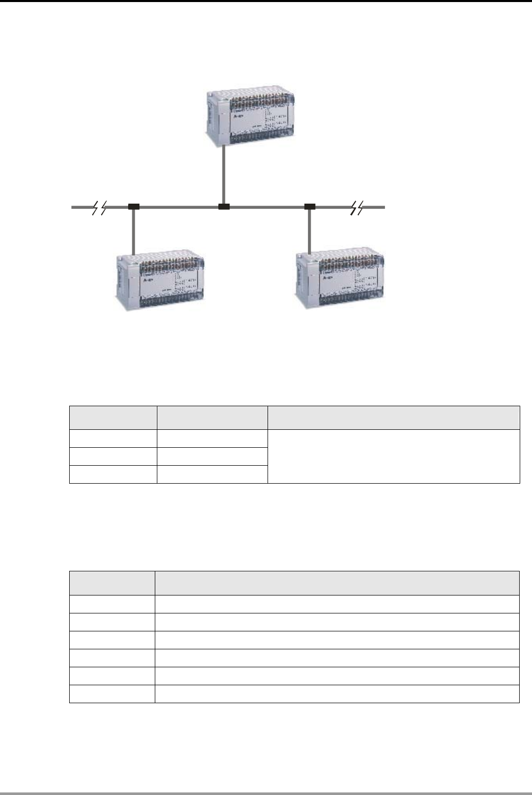
12. Communication Design Examples
DVP-PLC Application Examples 12-31
12.9 PLC LINK 32 Slaves and Read/Write 100 Data (Word)
EH series
EH series EH series
Master PLC
RS485 network
Slave1 Slave2
Master address=K10
Slave address
=K1
Slave address
=K2
Control Purpose:
z Performing 100 words data exchange by PLC LINK between master PLC and 2 Slave PLCs.
Parameter Settings for PLC:
Master/Slave Station No. Communication format
Master PLC K20 (D1121 = K20)
Slave 1 K2 (D1121 = K2)
Slave 2 K3 (D1121 = K3)
RTU, 19200, 8, N, 2(D1120=H99).
Communication format of all connected PLCs must
be the same.
Ú If PLC can not run normally due to improper parameters, users can set the PLC to factory
defaults by clicking ”Communication (C)”> “Format PLC Memory” from the menu bar of WPL
Soft and then set the parameters according to the above table.
Devices:
Device Function
X0 Trigger on PLC LINK
M1350 Enabling EASY PLC LINK
M1351 Enabling auto mode on EASY PLC LINK
M1352 Enabling manual mode on EASY PLC LINK
M1353 Enable 32 slave unit linkage and up to 100 data length of data exchange
M1354 Enable simultaneous data read/write in a polling of EASY PLC LINK
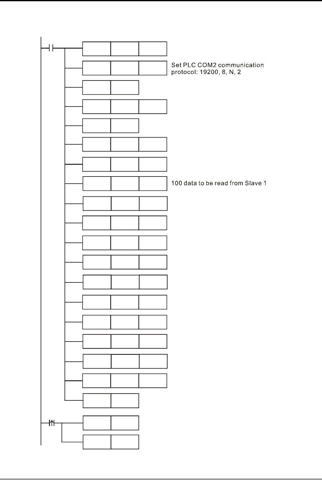
12. Communication Design Examples
DVP-PLC Application Examples
12-32
Control Program:
M1002
MOV
MOV
MOV K10 D1121
MOV H99 D1120
SET M1120
MOV K1000 D1129
SET M1143
MOV K1 D1399
MOV H1000 D1355
MOV
MOV
MOV H1064 D1415
MOV K100 D1450
MOV
MOV
MOV K100 D1435
MOV K200 D1481
MOV K300 D1497
K100 D1434
K0 D1480
K100 D1496
H10C8 D1356
H112C D1416
K100 D1451
Retain communication setting
Set the communication format
of Master PLC: MODBUS RTU
100 data to be written in Slave 1
Auto mode
Enable PLC LINK
M1351
M1350
X0
SET
SET
M1353
SET
Set the Master PLC communication
address as K10
Set communication time-out:
1000ms
Set starting Slave ID as K1
Set starting reference for
Master to read from Slave ID 1
: D0
Set starting reference to store the
data read from D0~D99 of Slave 1: D0
Set starting reference for
Master to write in Slave 1: D100
Set starting reference to store the
data read from D200~D299 of Slave 2: D200
Set starting reference of Master: D100
D100~D199 of Master will be written
in D100~D199 of Slave 1
Set starting reference for Master
to read from Slave ID 2: D200
100 data to be read from Slave 2
100 data to be written in Slave 2
Set starting reference for Master
to write in Slave 2: D300
Set starting reference of Master: D300
D300~D399 of Master will be written
in D300~D399 of Slave 2
Enable 32 slave unit linkage and up to 100 data
length of data exchange
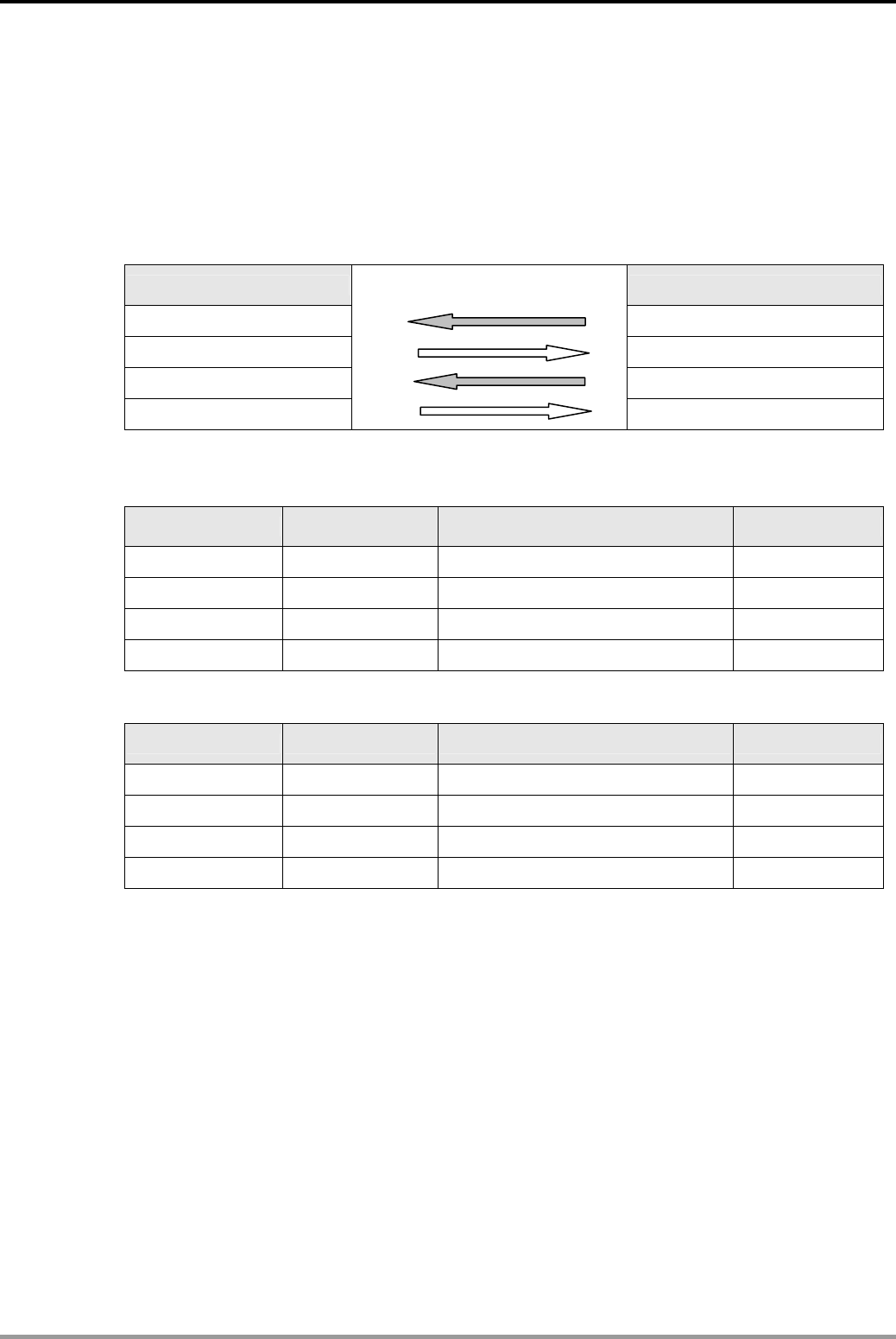
12. Communication Design Examples
DVP-PLC Application Examples 12-33
Program Description:
z When X0 = ON, the data exchange between Master and 3 Slaves will be performed through
PLC LINK by the ways explained below: D0~D99 of Slave 1 will be read to D0~D99 of
Master. D100~D199 of Master will be written in D100~D199 of Slave 1. D200~D299 of
Slave 2 will be read to D200~D299 of Master. D300~D399 will be written to D300~D399 of
Slave 2.
Master PLC *1 Slave PLC *2
D0~D99 D0~D99 of Slave ID 1#
D100~D199 D100~D199 of Slave ID 1#
D200~D299 D200~D299 of Slave ID 2#
D300~D399
D300~D399 of Slave ID 2#
z Assume that the data in D for data exchange between Master and Slave before PLC LINK is
enabled (M1350 = OFF) are as below:
Master PLC Set value Slave PLC Set value
D0~D99 0 D0~D99 of Slave ID 1# 1
D100~D199 100 D100~D199 of Slave ID 1# 0
D200~D299 0 D200~D299 of Slave ID 2# 2
D300~D399 200 D300~D399 of Slave ID 2# 0
After EASY PLC LINK is enabled (M1350 = ON), the data in D for data exchange becomes:
Master PLC Set value Slave PLC Set value
D0~D99 1 D0~D99 of Slave ID 1# 1
D100~D199 100 D100~D199 of Slave ID 1# 100
D200~D299 2 D200~D299 of Slave ID 2# 2
D300~D399 200 D300~D399 of Slave ID 2# 200
z In Master PLC, set the starting Slave ID (D1399 = K1), i.e. Slave ID 1# corresponds to
Slave1 and Slave ID 2# corresponds to Slave2.
z Station No. of Slave should be continuous and different from the station No. of Master. Only
the SV/EH/EH2 series PLC can be Master, but all DVP-PLC can be Slave.
z When X0 = ON, PLC LINK will be enabled. If enabling action is failed, M1350/M1351 will be
OFF and X0 needs to be activated again.
Write
Write
Read
Read

12. Communication Design Examples
DVP-PLC Application Examples
12-34
12.10 LINK between PLC, Delta AC Motor Drive and AC Servo Drive
Wring for Delta ASD-A Series AC Servo drive:
CN1
COM+
DI1
DI3
17
11
9
34
COM- 45
SON
VDD
CN1
R
S
T
24V
U
V
W
CN2
4.7K
4.7K
L1
L2
SPD0
SPD1
Delta AC servo drive
ASDA series Servo motor
3 phases AC power
Encoder
Error counter
Electric gear
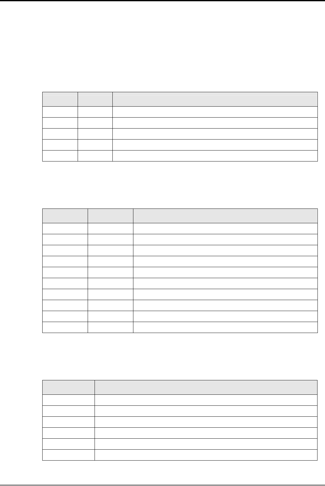
12. Communication Design Examples
DVP-PLC Application Examples 12-35
Control Purpose:
z Setting and reading the frequency to control the Start/Stop and Forward/ Reverse status of
AC motor drive.
z Setting and reading the rotation speed of servo motor.
Parameter Settings for AC Motor Drive:
Parameter Set value Explanation
02-00 04 RS-485 serial communication. Last used frequency saved.
02-01 03 RS-485 serial communication. Keypad STOP/RESET enabled.
09-00 01 Communication address: 01
09-01 01 Communication baud rate: 9600.
09-04 01 MODBUS ASCII mode, protocol <7,E,1>
Ú If AC motor drive can not run normally due to improper parameters, users can set P00-02 =
10 (factory defaults) and then set the parameters according to the above table.
Parameter Settings for AC Servo Drive:
Parameter Set value Explanation
P0-02 6 Drive Status. Display rotation speed on servo panel
P0-04 6 Status Monitor 1. Data register for current rotation speed
P1-01 2 Control Mode and Output Direction
P2-10 101 Digital Input Terminal 1 (DI1)
P2-12 114 Digital Input Terminal 3 (DI3)
P2-15~17 0 Digital Input Terminal 6 (DI6). No function
P3-00 2 Communication Address Setting
P3-01 1 Transmission Speed, Baud rate: 9600
P3-02 1 MODBUS ASCII mode. Data format: (7, E, 1)
P3-05 2 RS-485 communication format
Ú If AC servo drive can not run normally due to improper parameters, users can set P2-08 = 10
(factory defaults) and then set the parameters according to the above table
Devices:
Device Function
X0 Trigger on PLC LINK
M1350 Enabling EASY PLC LINK
M1351 Enabling auto mode on EASY PLC LINK
M1352 Enabling manual mode on EASY PLC LINK
M1353 Enable 32 slave unit linkage and up to 100 data length of data exchange
M1354 Enable simultaneous data read/write in a polling of EASY PLC LINK
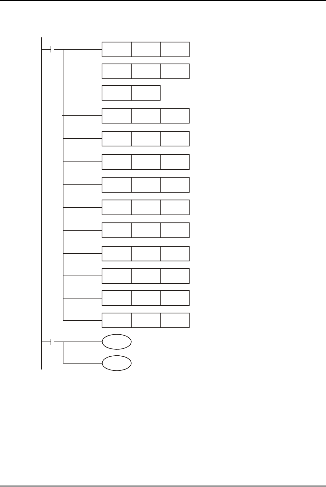
12. Communication Design Examples
DVP-PLC Application Examples
12-36
Control Program:
M1002
MOV K20 D1121
H86 D1120
H2102
K2
M1351
MOV
SET M1120
MOV
MOV
D1355
D1434
M1350
X0
H2000
K2
MOV
MOV
D1415
D1450
Retain communication setting
Enable PLC LINK
H0004
K1
MOV
MOV
D1356
D1435
H0109
K1
MOV
MOV
D1416
D1451
MOV K200 D1129
K1 D1399
MOV
Set Master ID: K20
Set Master communication format
Set receiving time-out:
200ms
Set staring Slave ID as K1
Set starting reference for
Master to read from Slave ID1:
H2102
2 data to be read from AC motor drive
2 data to be written in AC motor drive
Set starting reference for Master
to write in AC motor drive: H2000
Set starting reference for Master to
read from AC servo drive: H0004
1 data to be read from AC servo drive
Set starting reference for Master
to write in AC servo drive: H0109
1 data to be written in AC servo drive
Auto mode
Program Description:
z Registers D1480~D1481 in PLC correspond to parameters H2102~H2103 of AC motor drive.
When X0 = ON, PLC LINK will be enabled and the value of H2102~H2103 will be shown in
D1480~D1481.
z Registers D1496~D1497 in PLC correspond to parameters H2000~H2001 of AC motor drive.
When X0 = ON, PLC LINK will be enabled and the value in H2000~H2001 can be
determined by the content in D1496~D1497.
z Status of AC motor drive can be controlled by setting the value in D1496. (D1496 = H12, AC

12. Communication Design Examples
DVP-PLC Application Examples 12-37
motor drive runs forward. D1496 = H1, AC motor drive stops.)
z Frequency of AC motor drive can be changed by setting the value in D1497. (D1497 =
K4000, the frequency of AC motor drive will be 40Hz.)
z Before PLC LINK is enabled between PLC and servo motor, turn on “SON” to start servo
and then turn on “SPD0” to ensure the speed mode which controlled by internal registers is
enabled.
z D1512 in PLC corresponds to communication parameter H0004 of AC servo drive. When X0
= ON, PLC LINK will be enabled and the value of H0004 will be shown in D1512.
z D1528 in PLC corresponds to communication parameter H0109 of AC servo drive. When X0
= ON, PLC LINK will be enabled and the value of H0109 can be specified in D1528.
z Rotation speed of servo motor can be changed by the content in D1528. (When D1528 =
K3000, the rotation speed of servo motor will be 3000 rpm.
z Station No. of Slave should be continuous and different from the station No. of Master.
SA/SX/SC/SV/EH/EH2 series PLC can be Master. ES/EX/SS series can not be Master.
z When X0 = ON, PLC LINK will be enabled. If enabling action is failed, M1350/M1351 will be
OFF and X0 needs to be activated again..
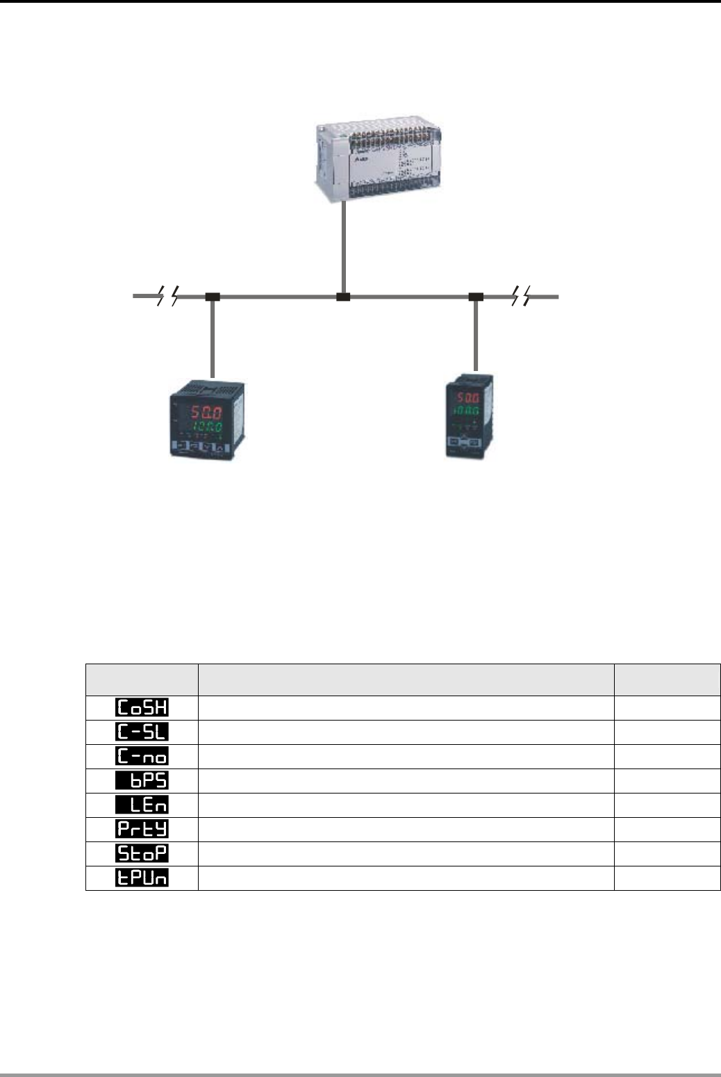
12. Communication Design Examples
DVP-PLC Application Examples
12-38
12.11 LINK between PLC, Delta DTA and DTB Series Temperature Controllers
Master PL
C
DTA Temperature Controller DTB Temperature controller
Slave1 Slave2
RS-485
PLC
Slave address
=K1
Slave address
=K2
Master ID
=K10
Control Purpose:
z Setting the target temperature and reading the present/target temperature of DTA TC.
z Setting the target temperature, upper/lower limit of temperature range and reading the
present/target temperature of DTB TC.
Parameter Settings for DTA Series Temperature Controller:
Parameter Function Set value
C WE: Write-in function disable/enable ON
C-SL: ASCII, RTU communication format selection ASCII
C NO: Communication address setting 1
BPS: Communication baud rate setting 9600
LENGTH: Data length setting 7
PARITY: Parity bit setting E
STOP BIT: Stop bit setting 1
UNIT: Temperature display unit °C or ℉ °C
Ú If TC can not run normally due to improper parameters, users can set the TC to factory
defaults first and then set the parameters according to the above table. DTA TC does not
support writing multiple words, so the number of the written data should set to “1 “.
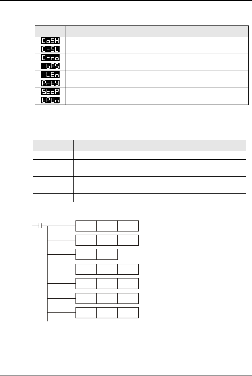
12. Communication Design Examples
DVP-PLC Application Examples 12-39
Parameter Settings for DTB Series Temperature Controller:
Parameter Function Set value
C WE: Write-in function disable/enable ON
C-SL: ASCII, RTU communication format selection ASCII
C NO: Communication address setting 2
BPS: Communication baud rate setting 9600
LENGTH: Data length setting 7
PARITY: Parity bit setting E
STOP BIT: Stop bit setting 1
UNIT: Temperature display unit °C or ℉ °C
Ú If TC can not run normally due to improper parameters, users can set the TC to factory
defaults first and then set the parameters according to the above table.
Devices:
Device Function
X0 Trigger on PLC LINK
M1350 Enabling EASY PLC LINK
M1351 Enabling auto mode on EASY PLC LINK
M1352 Enabling manual mode on EASY PLC LINK
M1353 Enable 32 slave unit linkage and up to 100 data length of data exchange
M1354 Enable simultaneous data read/write in a polling of EASY PLC LINK
Control Program:
M1002
MOV K10 D1121
H86 D1120
H4700
K2
MOV
SET M1120
MOV
MOV
D1355
D1434
MOV K200 D1129
K1 D1399
MOV
Set receiving time-out:
200ms
Set the Master ID
Set the Master COM2
communication format
Retain communication setting
Set starting Slave ID as K1
Set starting reference for
Master to read from DTA: H4700
2 data to be read from DTA
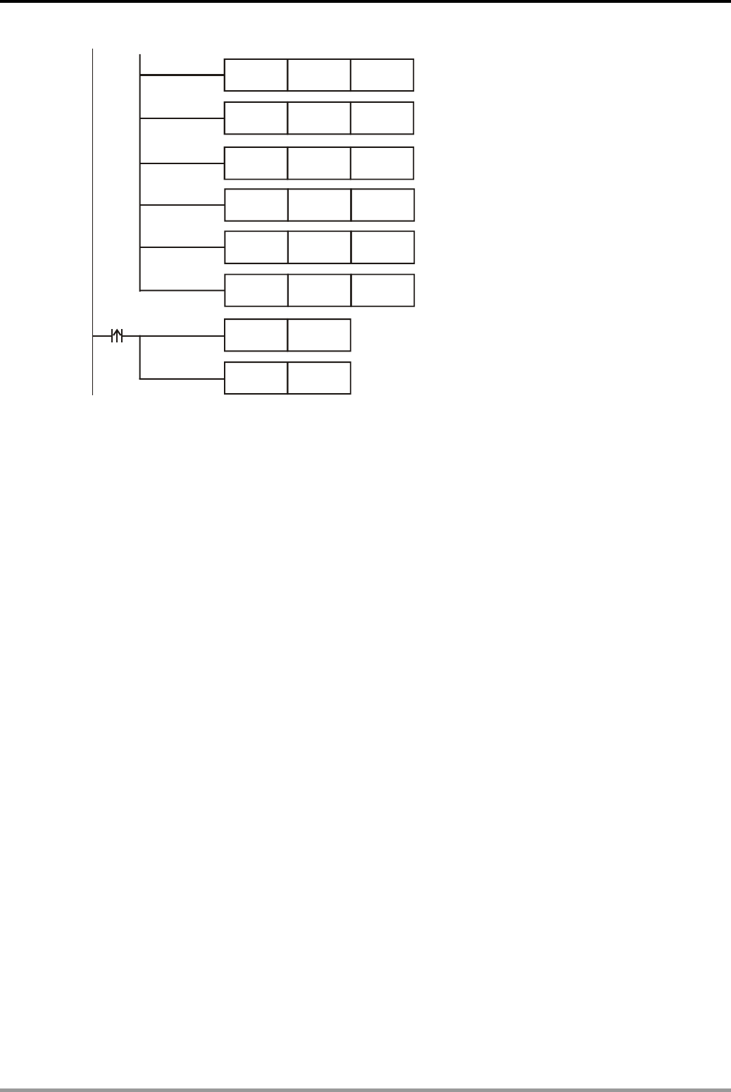
12. Communication Design Examples
DVP-PLC Application Examples
12-40
H4701
K1
MOV
MOV
D1415
D1450
H1000
MOV D1356
Enable PLC LINK
K2MOV D1435
H1001
K3
MOV
MOV
D1416
D1451
M1351
M1350
X0
SET
SET
Set starting reference for Master
to write in DTA: H4701
1 data to be written in DTA
Set starting reference for Master
to read from DTB: H1000: s
2 data to be read from DTB
Set starting reference for Master
to write in DTB: H1001
3 data to be written in DTB
Auto mode
Program Description:
z Registers D1480~D1481 in PLC correspond to communication parameters H4700~H4701
of DTA TC. When X0 = ON, PLC LINK will be enabled and the value of H4700~H4701
(present and target temperature) will be shown in D1480~D1481.
z Register D1496 in PLC corresponds to communication parameter H4701 of DTA TC. When
X0 = ON, PLC LINK will be enabled and the value of H4701 can be determined by the
content in D1496.
z Status of DTA TC can be controlled by setting the value in D1496. (D1496 = K300, the target
temperature will be 30°C.)
z Registers D1512~ D1513 in PLC correspond to communication parameters H1000~H1001
of DTB TC. When X0 = ON, PLC LINK will be enabled and the value of H1000~ H1001
(present and target temperatures) will be shown in D1512~ D1513.
z Registers D1528~D1530 in PLC correspond to communication parameters H1001~ H1003
of DTB series temperature controller. When X0 = ON, PLC LINK will be enabled and the
value of H1001~ H1003 can be determined by the content in D1528~D1530.
z Target temperature of DTB can be specified by the value in D1528 (D1528 = K400, the
target temperature will be 40°C.)
z Upper/lower limit of temperature range of DTB can be specified by the value in D1529~1530.
(D1529 = K500 and D1530 = K10, the upper limit will be 50°C and lower limit will be 1°C.
z Station No. of Slave should be continuous and different from the station No. of Master.
SA/SX/SC/SV/EH/EH2 series PLC can be Master. ES/EX/SS series can not be Master.
z When X0 = ON, PLC LINK will be enabled. If enabling action is failed, M1350/M1351 will be
OFF and X0 needs to be activated again.
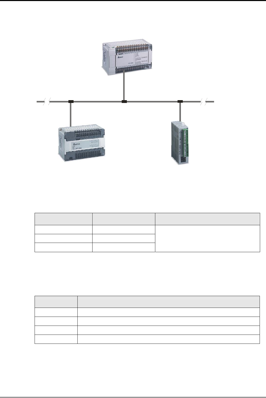
12. Communication Design Examples
DVP-PLC Application Examples 12-41
12.12 Controlling START/STOP of 2 DVP PLCs through Communication (RS Instruction)
Slave1 Slave2
Master PL
C
RS-485
Master ID
= K10
Slave Address
= K2
EH/EH2
ES series SS series
Slave address
= K1
Control Purpose:
z Controlling start/stop status of 2 Slave PLCs through communication by master PLC.
Parameter Settings:
Master/Slave Station No. Communication format
Master PLC K10 (D1121 = K10)
Slave 1 K1 (D1121 = K1)
Slave 2 K2 (D1121 = K2)
ASCII, 9600, 7, E, 1 (D1120 = H86).
Communication format of all connected
Slave PLCs must be the same.
Ú If PLC can not run normally due to improper parameters, users can set the PLC to factory
defaults by clicking ”Communication (C)”> “Format PLC Memory” from the menu bar of WPL
Soft and then set the parameters according to the above table.
Devices:
Device Function
X0 Start/stop Slave 1
X1 Start/stop Slave 2
M0 Execute the 1st RS instruction
M1 Execute the 2nd RS instruction
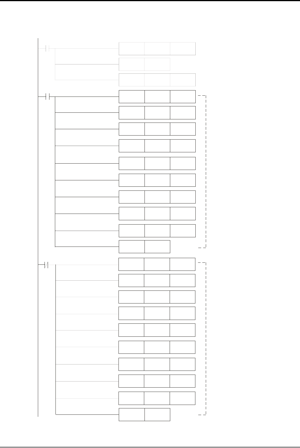
12. Communication Design Examples
DVP-PLC Application Examples
12-42
Control Program:
MOV
MOV
X0
MOV
H303A D100
H3031 D101
H3035 D102
MOV
MOV
H3343 D103
H4630 D104
MOV
MOV
H3046 D105
H4230 D106
MOV
MOV
HD46 D107
HA D108
MOV
MOV
X0
MOV
H303A D100
H3031 D101
H3035 D102
MOV
MOV
H3343 D103
H3030 D104
MOV
MOV
H3030 D105
H4230 D106
MOV
MOV
HD45 D107
HA D108
MOV K300 D1129
M100
2
MOV H86 D1120
SET M1120
PLS M0
PLS M1
Set PLC COM2 communication
protocol: 9600,7,E,1
Retain communication setting
Set receiving time-out:
300ms
When X0 = ON, store the
data which will active
Slave 1 in D100~D108
When X0 = OFF, store the
data which will stop
Slave 1 in D100~D108
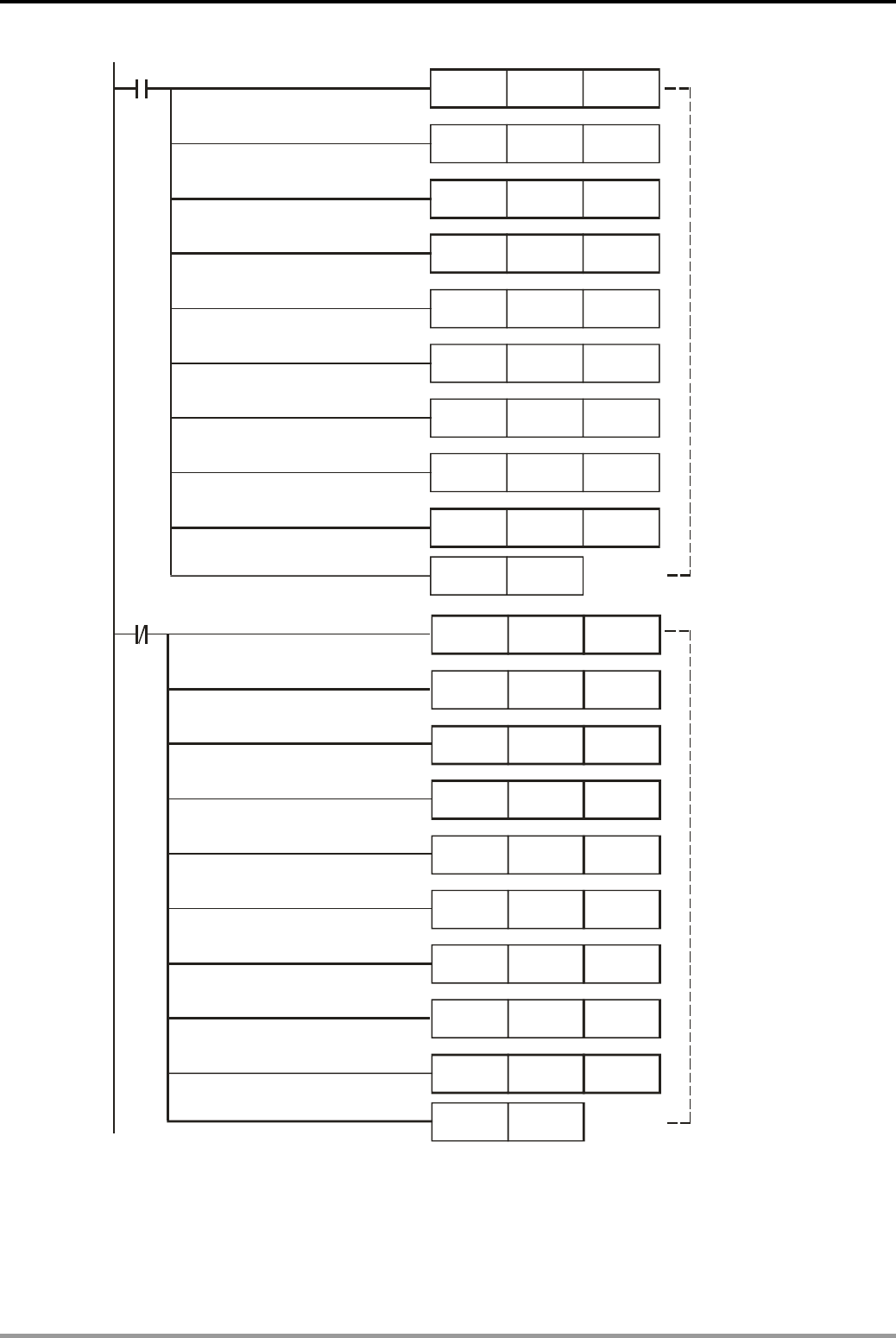
12. Communication Design Examples
DVP-PLC Application Examples 12-43
MOV
MOV
X
1
MOV
H303A D100
H3032 D101
H3035 D102
MOV
MOV
H3343 D103
H4630 D104
MOV
MOV
H3046 D105
H4230 D106
MOV
MOV
HD45 D107
HA D108
MOV
MOV
MOV
H303A D100
H3032 D101
H3035 D102
MOV
MOV
H3343 D103
H3030 D104
MOV
MOV
H3030 D105
H4230 D106
MOV
MOV
HD44 D107
HA D108
X1
PLS M2
PLS M3
When X1 is ON,
store the data
which will
activate Slave 2
in D100~D108
When X1 is OFF,
store the data
which will
stop Slave 2
in D100~D108
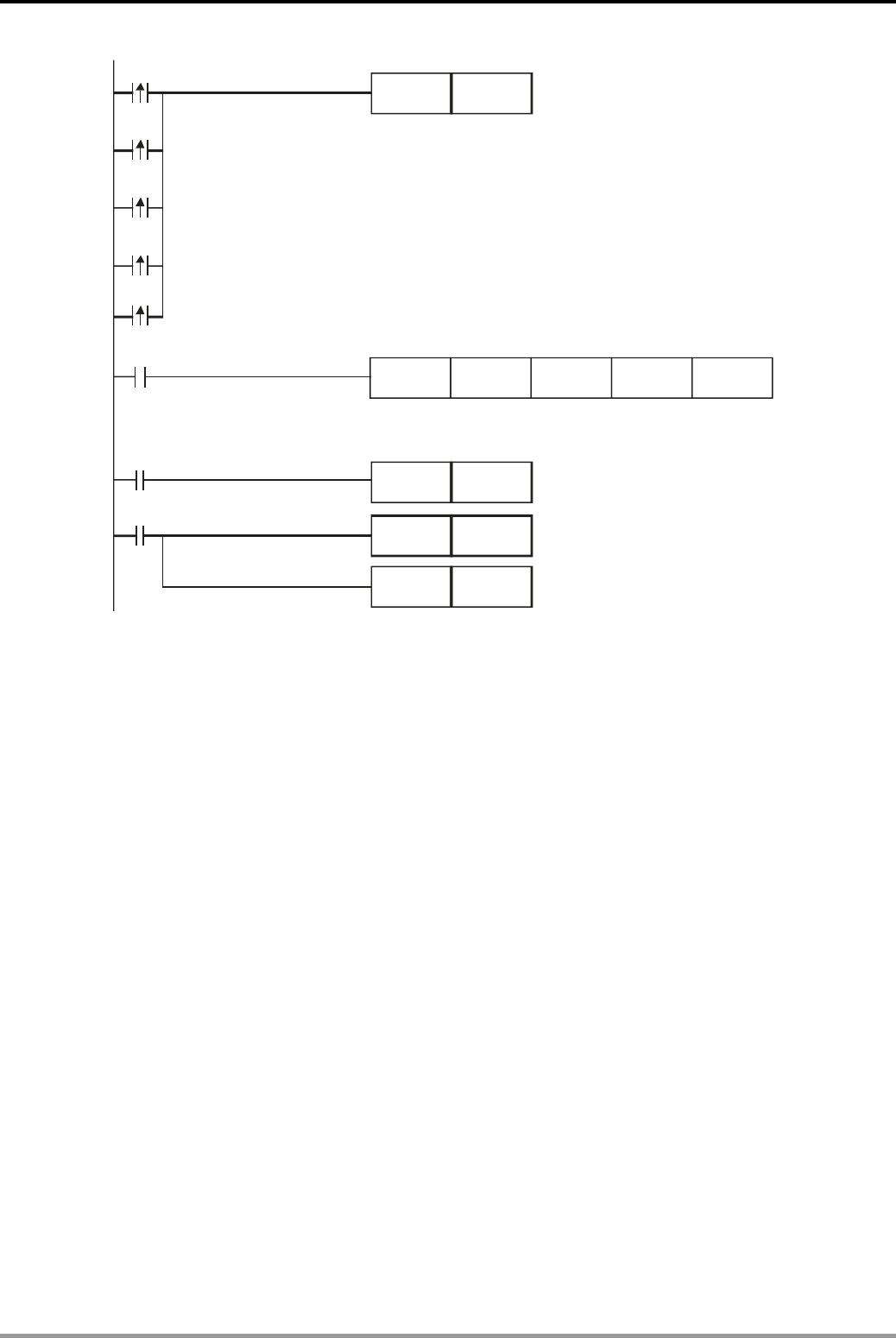
12. Communication Design Examples
DVP-PLC Application Examples
12-44
M1000
SET M1122
M0
RS D100 K17 D120 K17
M1
M1123
RST M1123
M1129
RST M1129
M2
M3
PLS M4 Retry after receiving
time-out
M4
Sending request
Send out the 17 bytes data in D100~D108 and store
the received 17 bytes data in D120~D128
Reset M1123
Reset M1129
Program Description:
z Initialize PLC RS-485 communication port and set the communication format as MODBUS
ASCII, 9600, 7, E, 1. The RS-485 communication format of Slave should be the same with
Master PLC.
z There are 2 situations for RS communication: M1123 for normal communication and M1129
for receiving timeout. When communication time-out occurred, M4 can be used to retry.
z When X0 = ON, Slave 1 will start running. When X0 = OFF, Slave 1 will stop.
z When X1 = ON, Slave 2 will start running. When X1 = OFF, Slave 2 will stop.
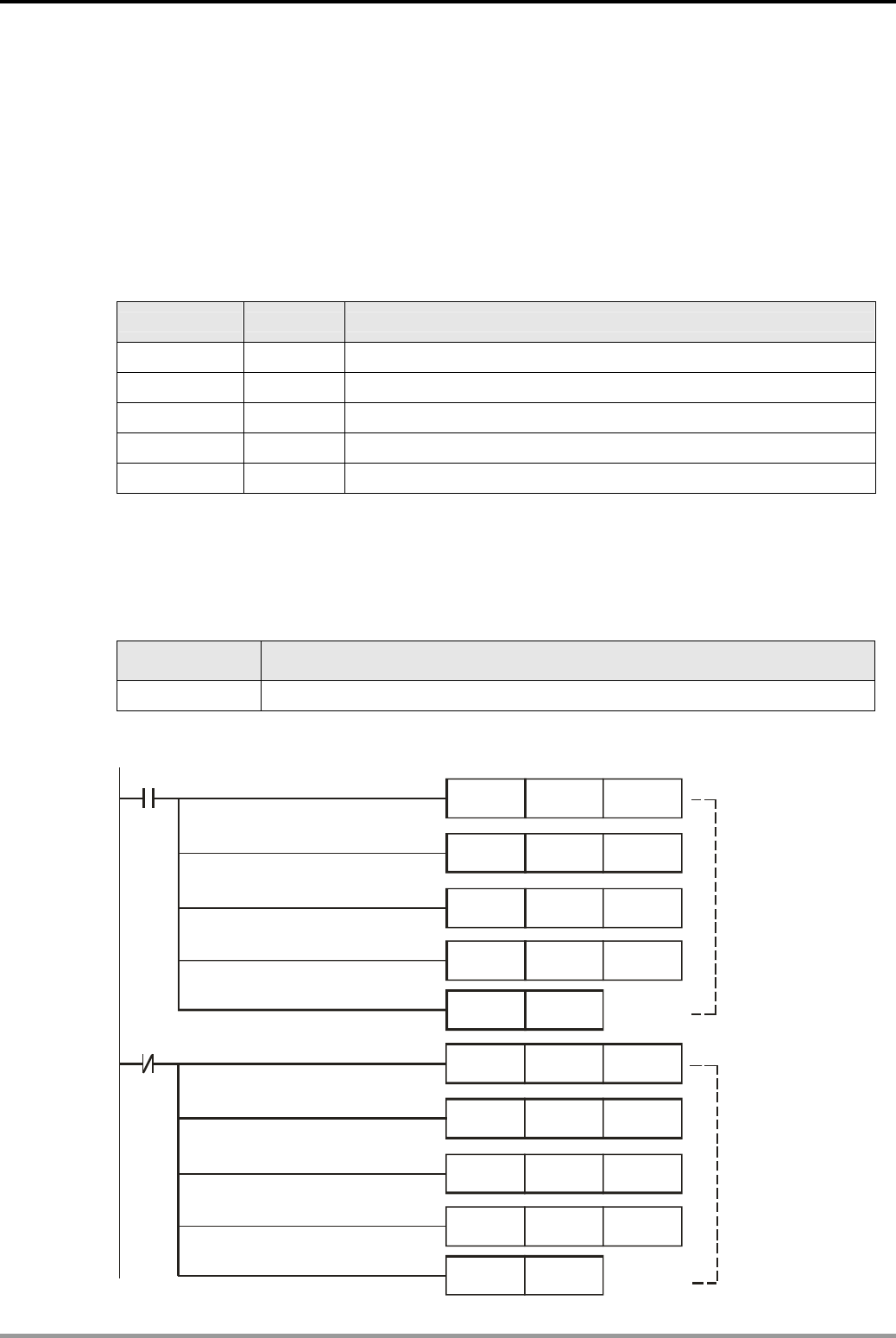
12. Communication Design Examples
DVP-PLC Application Examples 12-45
12.13 Communication between Delta PLC and Siemens MM420 Frequency Inverter (RS
Instruction)
Control Purpose:
z Controlling the start/stop of Siemens MM420 series AC motor drive through communication
by master PLC.
Parameter Settings for MM420 AC Motor Drive:
Parameter Set value Function
P0003 3 User access level: expert
P0700 5 Selection of command source: USS on COM link (RS-485)
P1000 5 Selection of frequency setpoint: USS on COM link (RS-485)
P2010 6 USS baud rate: 9600bps
P2011 0 USS address: 0
Ú If Siemens MM420 can not run normally due to improper parameters, users can set MM420
to factory defaults: set P0010 = 30, P0970 = 1. Then set the parameters according to the
above table.
Devices:
Device Function
X0 Start/stop switch
Control Program:
X0
MOV H602 D100
MOV H400 D101
MOV H337F D102
MOV H7F33 D103
PLS M0
X0
MOV H602 D100
MOV H400 D101
MOV H7A D102
MOV H7A00 D103
PLS M1
When X0 = ON,
send the data
which starts
MM 420 to run
forward in 40Hz
to D100~D103
When X0 = OFF,
send the data
which stops
MM 420 to
D100~D103
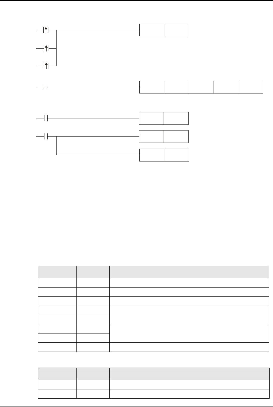
12. Communication Design Examples
DVP-PLC Application Examples
12-46
SET M1122
M1000
M0
M1123
RST M1123
RS D100 K8 D120 K8
M1129
PLS M2
RST M1129
M1
M2
Retry after receiving time-out
Sending request
Send out the 8 bytes data in D100~D103 and store
the received data in D120~D123
Reset M1123.
Reset M1129
Program Description:
z Initialize PLC RS-485 communication port and set the communication format as 9600, 8, E,
1. The RS-485 communication format of MM420 (set by P2010) should be the same with
Master PLC.
z When X0 = ON, MM420 will be started to run forward in 40Hz.
PLCDMM420, PLC sends: 02 06 00 047F 3333 7F
MM420DPLC, PLC receives: 02 06 00 FB34 3333 CB
Registers for sent data (PLC sends out message):
Register DATA Explanation
D100 low 02H Head. Fixed as 02H. (start of the message)
D100 high 06H The number of the following bytes
D101 low 00H Station No. (range: 0~31, corresponding to hex 00H~1FH)
D101 high 04H
D102 low 7FH Control word (starting MM420. Refer to Remarks for definitions.)
D102 high 33H
D103 low 33H Frequency (4000H = base frequency 50Hz, 3333H = 40Hz)
D103 high 7FH Tail. (XOR result of all the bytes before this byte)
Registers for received data (MM420 responds with messages):
Register DATA Explanation
D120 low 02H Head. Fixed as 02H (start of the message)
D120 high 06H The number of the following bytes
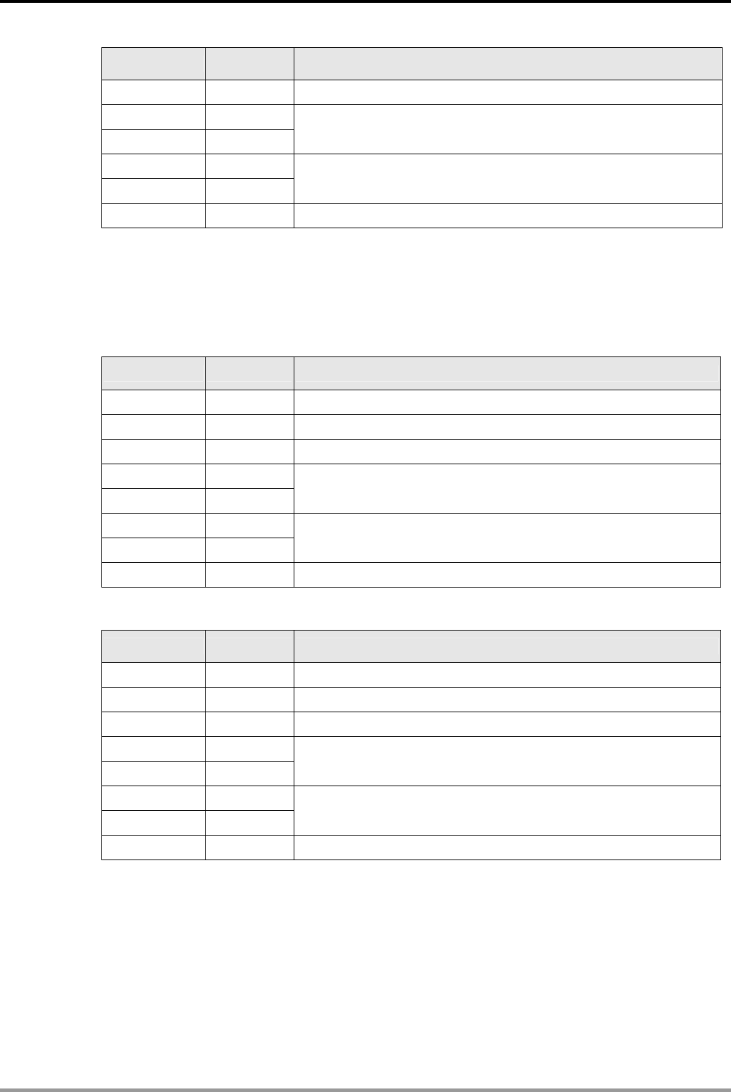
12. Communication Design Examples
DVP-PLC Application Examples 12-47
Register DATA Explanation
D121 low 00H Station No. (range: 0~31, corresponding to hex 00H~1FH)
D121 high FBH
D122 low 34H Status word (Refer to Remarks for definitions)
D122 high 33H
D123 low 33H Frequency (4000H = base frequency 50Hz, 3333H = 40Hz)
D123 high CBH Tail. (XOR result of all the bytes before this byte)
z When X0 = OFF, MM420 will stop.
PLCDMM420,PLC sends: 02 06 00 047A 0000 7A
MM420DPLC,PLC receives: 02 06 00 FB11 0000 EE
Register for sent data (PLC sends out message):
Register DATA Explanation
D100 low 02H Head. Fixed as 02H (start of the message)
D100 high 06H The number of the following bytes
D101 low 00H Station No. (range: 0~31, corresponding to hex 00H~1FH)
D101 high 04H
D102 low 7AH Control word (Refer to Remarks for definitions)
D102 high 00H
D103 low 00H Frequency (0000H = 0 Hz.)
D103 high 7AH Tail. (XOR result of all the bytes before this byte)
Register for received data (MM420 responds with messages):
Register DATA Explanation
D120 low 02H Head. Fixed as 02H (start of the message)
D120 high 06H The number of the following bytes
D121 low 00H Station No. (range: 0~31, corresponding to hex 00H~1FH)
D121 high FBH
D122 low 11H Status word (Refer to Remarks for definitions)
D122 high 00H
D123 low 00H Frequency (0000H = 0 Hz.)
D123 high EEH Tail. (XOR result of all the bytes before this byte)
z There are 2 situations for RS communication: M1123 for normal communication and M1129
for receiving timeout. When communication time-out occurred, M2 can be used to retry
Remarks:
z Siemens MM420 series AC motor drive uses USS communication protocol and allows
maximum of one master connected with 31 slaves. Slave ID: 0~31
The structure of the communication message:
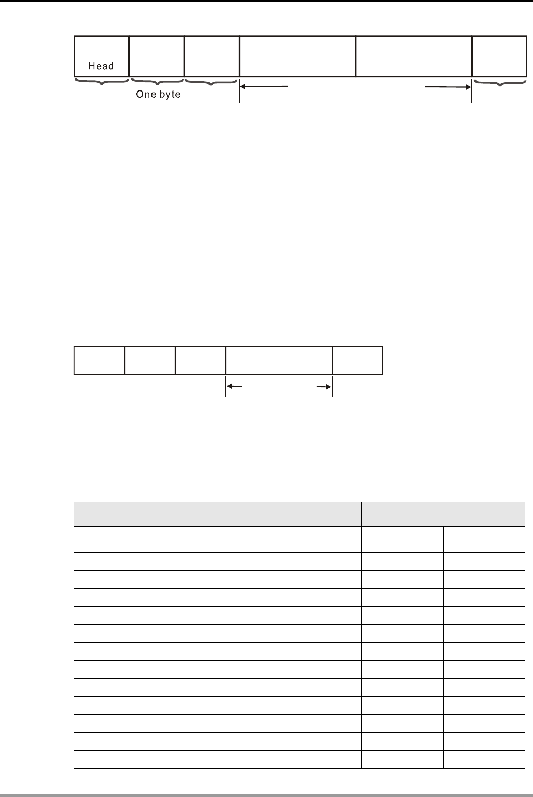
12. Communication Design Examples
DVP-PLC Application Examples
12-48
STX
A
DR PKW
BCC
LGE PZD
One byte One byte One byte
Address Checksum
Parameter data area Process data area
Data length
Data area (N words)
z For STX, LGE, ADR and BCC areas, the data length is fixed as 1 byte.
z STX is fixed as 02H, meaning the start of the message.
z LGE is the number of bytes between ADR area and BCC area.
z ADR is the USS communication address. Range: 0~31 corresponds to hex 00H ~1FH.
z Data area is divided into PKW area and PZD area. PKW area is used for reading/writing the
parameters of AC motor drive and contains 0~4 word. (Usually 4 words, refer to the setting
of P2013). PZD area is used for controlling AC motor drive including frequency setting and
contains 0~4 word. (Usually 2 words, refer to the setting of P2012). The first word is control
word for AC motor drive and the second is for setting the frequency of AC motor drive.
z PKW and PZD can be used either or both. Usually, only PZD is used for controlling the
status and frequency setting of AC motor drive. This program uses PZD with the length of 2
words and the structure is as follows:
STX
A
DR
BCC LGE DATA(PZD)
02 06 00 047F 3333 7F
In the above figure, 047FH is the control word for starting AC motor drive. 3333H is the
frequency. Since H4000 corresponds to base frequency 50Hz, 3333H corresponds to 40Hz.
z BCC checksum: the XOR result of the bytes from STX to PZD.
For example: 02H XOR 06H XOR 00H XOR 04H XOR 7FH XOR 33H XOR 33 = H7F
z Definition of the control word for AC motor drive in PZD area (PLC sends out messages):
Bit Explanation Bit status
00 ON (ramp up enabled)/OFF1 (ramp down
disabled) 0 No (OFF1) 1 Yes (ON)
01 OFF2: Coast to standstill 0 Yes 1 No
02 OFF3: Quick ramp down 0 Yes 1 No
03 Pulses enabled 0 No 1 Yes
04 RFG (ramp function generator) enabled 0 No 1 Yes
05 RFG (ramp function generator) start 0 No 1 Yes
06 Set value of frequency enabled 0 No 1 Yes
07 Fault acknowledge 0 No 1 Yes
08 JOG right 0 No 1 Yes
09 JOG left 0 No 1 Yes
10 Controlled by PLC 0 No 1 Yes
11 Reverse 0 No 1 Yes
12 Reserved - -
12. Communication Design Examples
DVP-PLC Application Examples 12-49
Bit Explanation Bit status
13 MOP (motor potentiometer) up 0 No 1 Yes
14 MOP (motor potentiometer) down 0 No 1 Yes
15 Local/remote control 0 No 1 Yes
Note: Among the control word from by PLC to AC motor drive, bit 10 must be set as 1. If nit
10 is 0, the control word will be invalid and AC motor drive will go on running as before.
z Definition of the status word of AC motor drive in PZD area (AC motor drive responds with
messages):
Bit Explanation Bit status
00 Drive ready 0 No (OFF1) 1 Yes (ON)
01 Drive ready to run 0 No 1 Yes
02 Drive running 0 No 1 Yes
03 Drive fault active 0 No 1 Yes
04 OFF2 active 0 Yes 1 No
05 OFF3 enabled 0 No 1 Yes
06 Switch on inhibit active 0 No 1 Yes
07 Drive warning active 0 No 1 Yes
08 Excessive deviation 0 Yes 1 No
09 PZDI (process data) control 0 No 1 Yes
10 Maximum frequency reached 0 No 1 Yes
11 Over current alarm 0 Yes 1 No
12 Motor holding brake enabled 0 Yes 1 No
13 Motor overload 0 Yes 1 No
14 Motor running forward 0 No 1 Yes
15 Inverter overload 0 Yes 1 No
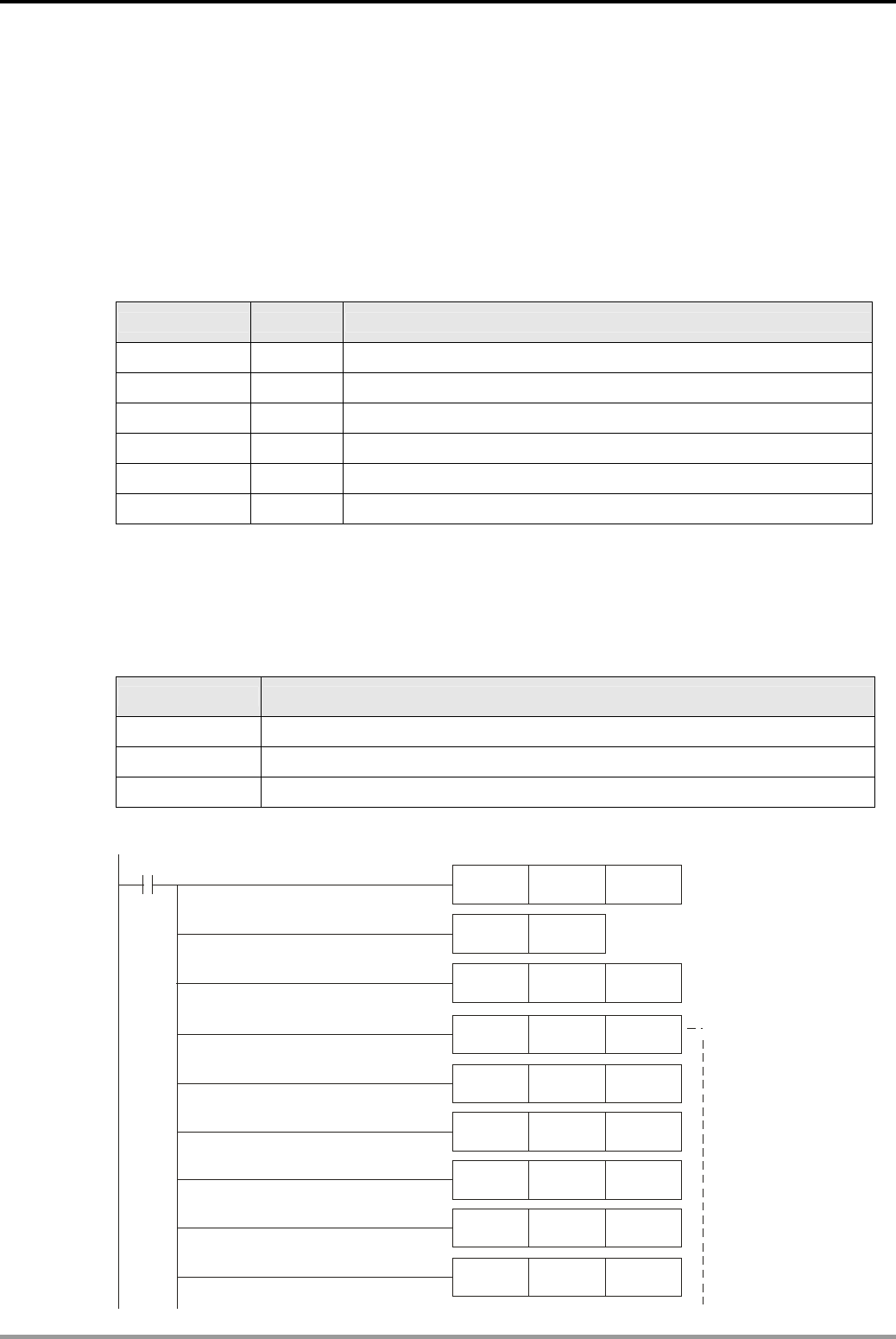
12. Communication Design Examples
DVP-PLC Application Examples
12-50
12.14 Communication between Delta PLC and Danfoss VLT6000 Series Adjustable
Frequency Drive (RS Instruction)
Control Purpose:
z Controlling the start/stop status and reading out the frequency of Danfoss VLT6000 series
frequency drive through communication by master PLC.
Parameter Settings for VLT6000 Series frequency drive:
Parameter Set value Explanation
P500 0 FC protocol : Serial communication protocol
P501 1 FC communication address: 1
P502 5 FC communication baud rate: 9600 bps
P503 1 Coasting stop controlled by serial communication
P504 1 DC braking controlled by serial communication
P505 1 Start controlled by serial communication
Ú If Danfoss VLT6000 frequency inverter can not run normally due to improper parameters,
users can set VLT6000 to factory defaults: set P620 = 3 and press OK. Then set the
parameters according to the above table.
Devices:
DEVICE Function
X0 Start/stop switch
M0 Executing the 1st RS instruction
M1 Executing the 2nd RS instruction
Control Program:
MOV K200 D1129
M1002
MOV H87 D1120
SET M1120
D1120
MOV HE02 D100
MOV H1201 D101
MOV H0 D102
MOV H0 D103
MOV H0 D104
MOV H400 D105
Set communication
format: 9600,8,E,1
Retain communication setting
Set receiving timeout:
200ms
Start VLT6000 to run
forward in 25Hz
and read the running
frequency in D100~D107
12. Communication Design Examples
DVP-PLC Application Examples 12-51
MOV H207F D106
MOV H4400 D107
PLS M0
X0
MOV H602 D200
MOV H401 D201
MOV H77 D202
MOV H7600 D203
X0
SET M1122
M0
M1
M1123
RST M1123
M1129
PLS M2
X1
RS D200 K8 D220 K8
X0
RS D100 K16 D120 K16
Execute the 1st RS instruction
when M0=ON
Execute the 2nd RS instruction
when M1=ON
Sending request
Reset M1129
PLS M1
M2
RST M1129
Retry after receiving time-out
Send the data which
will stop VFT6000
to D200~D203
When M0 = ON, send out 16 bytes data in D100~D107
and store the received data from slave in D120~D127
When M1 = ON, send out 8 bytes data in D200~D203
and store the received data from slave in D220~D223
Reset M1123
Program Description:
z Initialize PLC RS-485 communication port and set the communication format as, 9600, 8, E,
1. The RS-485 communication format of VLT6000 should be the same with Master PLC.
z When X0 = ON, VLT6000 starts to run forward in 40Hz and its output frequency will be read
out.
12. Communication Design Examples
DVP-PLC Application Examples
12-52
PLCDVLT6000, PLC sends: 02 0E 01 1200 0000 00000000 047F 2000 44
VLT6000DPLC, PLC receives: 02 0E 01 1200 0000 000000FA 0F07 1FFF 0D
Register for sent data (PLC sends out messages):
Register Data Explanation
D100 low 02H Head, fixed as 02H (start of the message)
D100 high 0EH The number of the following bytes
D101 low 01H Station No. (range: 0~31, corresponding to hex 00H~1FH)
D101 high 12H
D102 low 00H PKE
1H: function code for reading parameters
200H: parameter No. P512 (output
frequency)
D102 high 00H
D103 low 00H IND Index area (used in indexed parameters,
such as P615. Not used in this program.)
D103 high 00H
D104 low 00H
PWE high Value: 1 (In read status: 0. In write status:
high word will be read)
D104 high 00H
D105 low 00H
PKW area
PWE low Value: 2 (In read status: 0. In write status:
low word will be read)
D105 high 04H
D106 low 7FH PCD1 area Control word (starting VLT6000. For the definition,
please refer to Remarks.)
D106 high 20H
D107 low 00H PCD2 area Frequency (4000H corresponds to base frequency
50Hz and 2000H corresponds to 25Hz)
D107 high 44H BCC area Tail. (XOR result of all the bytes before this byte)
Register for received data (VLT6000 responds with messages):
Register Data Explanation
D120 low 02H Head, fixed as 02H (start of the message)
D120 high 0EH The number of the following bytes
D121 low 01H Station No. (range: 0~31, corresponding to hex 00H~1FH)
D121 high 12H
D122 low 00H PKE
1H: function code for reading parameters
200H: parameter No. P512 (output
frequency)
D122 high 00H
D123 low 00H IND Index area (used in indexed parameters,
such as P615. This program doesn’t use.)
D123 high 00H
D124 low 00H PWEhigh High word will be read
D124 high 00H
D125 low FAH
PKW area
PWElow
Low word will be read (00FAH
corresponds to the decimal value 250
which means the frequency of 25Hz.
D125 high 0FH
D126 low 07H PCD1 area Status word (For the definition, please refer to
Remarks.)
D126 high 1FH
D127 low FFH PCD2 area Frequency (4000H corresponds to the base
frequency 50Hz and 1FFFHZ corresponds to 25Hz)
D127 high 0DH BCC area Tail. (XOR result of all the bytes before this byte)
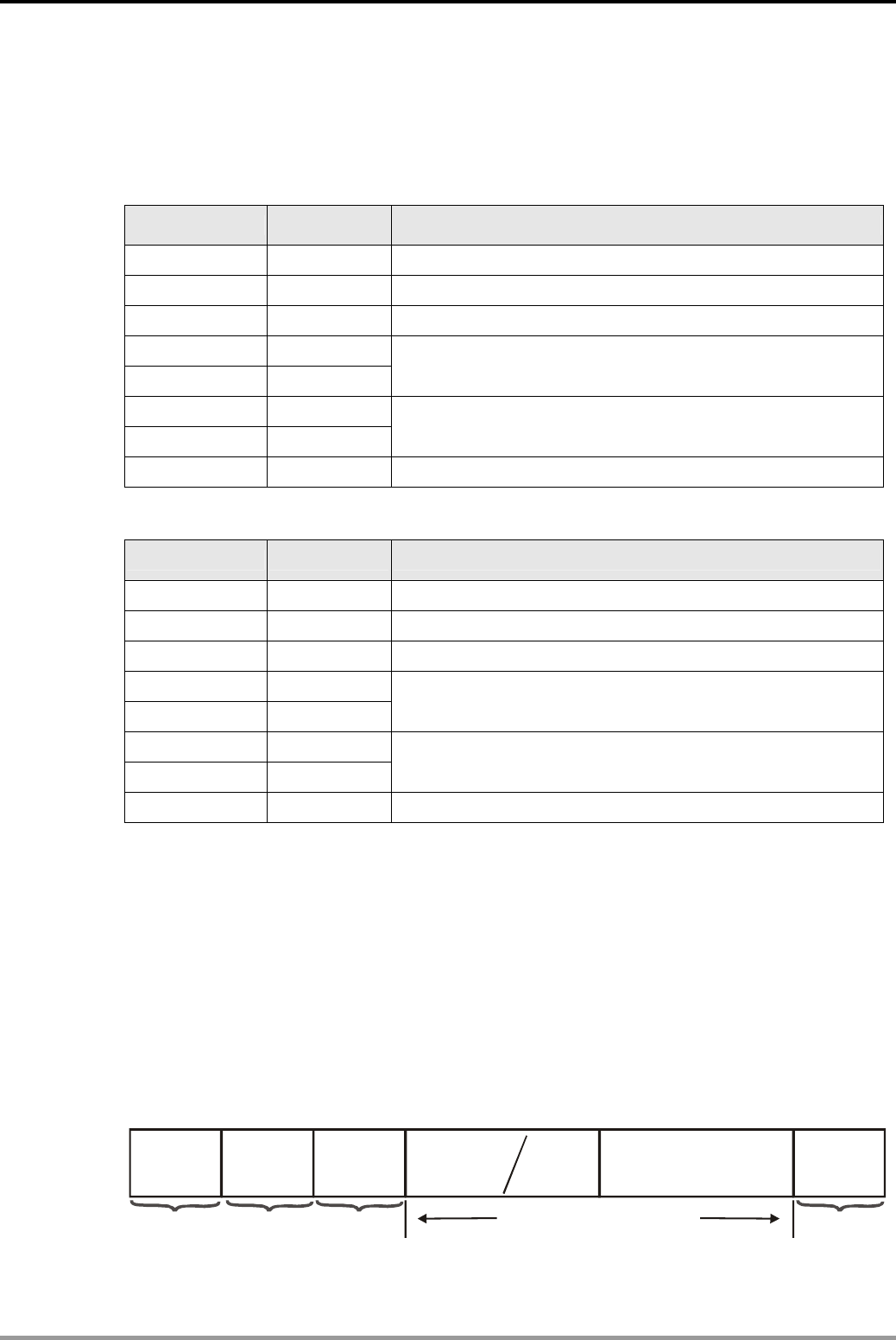
12. Communication Design Examples
DVP-PLC Application Examples 12-53
z When X0 = OFF, AC motor drive will stop. (Only PCD area is applied in this message).
PLCDVLT6000, PLC sends: 02 06 01 0477 0000 76
VLT6000DPLC, PLC receives: 02 06 01 0603 0000 00
Register for sent data (PLC sends out messages):
Register Data Explanation
D200 low 02H Head, fixed as 02H (start of the message)
D200 high 06H The number of the following bytes
D201 low 01H Station No. (range: 0~31, corresponding to hex 00H~1FH)
D201 high 04H
D202 low 77H
Control byte (starting AC motor drive. For the definition,
please refer to Remarks.)
D202 high 00H
D203 low 00H Frequency (0000H corresponding to 0Hz)
D203 high 76H Tail. (XOR result of all the bytes before this byte)
Register for received data (VLT6000 responds with messages):
Register Data Explanation
D220 low 02H Head, fixed as 02H (start of the message)
D220 high 06H The number of the following bytes
D221 low 01H Station No. (range: 0~31, corresponding to hex 00H~1FH)
D221 high 06H
D222 low 03H
Status byte (starting AC motor drive. For the definition, please
refer to Remarks.)
D222 high 00H
D223 low 00H Frequency (0000H corresponding to 0Hz)
D223 high 00H Tail. (XOR result of all the bytes before this byte)
z There are 2 situations for RS communication: M1123 for normal communication and M1129
for receiving timeout. When communication time-out occurred, M2 can be used to retry.
Remarks:
z There are 3 protocols for Danfoss VLT6000 series inverter: FC (default), Metasys N2 and LS
FLN. This program uses FC protocol which is similar with USS protocol used by Siemens
MM420 series inverter: allows maximum of one master connected with 31 slaves. Slave ID:
0~31.
The structure of the communication message:
STX ADR PKW
BCC
LGE PCD
One byte One byte One byte One byte
CH
Head
Data length
Address Parameter
area Tex t ar e a Process data area Checksum
Data area (N words)
z The definitions of STX, LGE, ADR and BCC areas of FC protocol are the same as that of
USS protocol. Please refer to Remarks in example 12.13 for description of USS protocol.
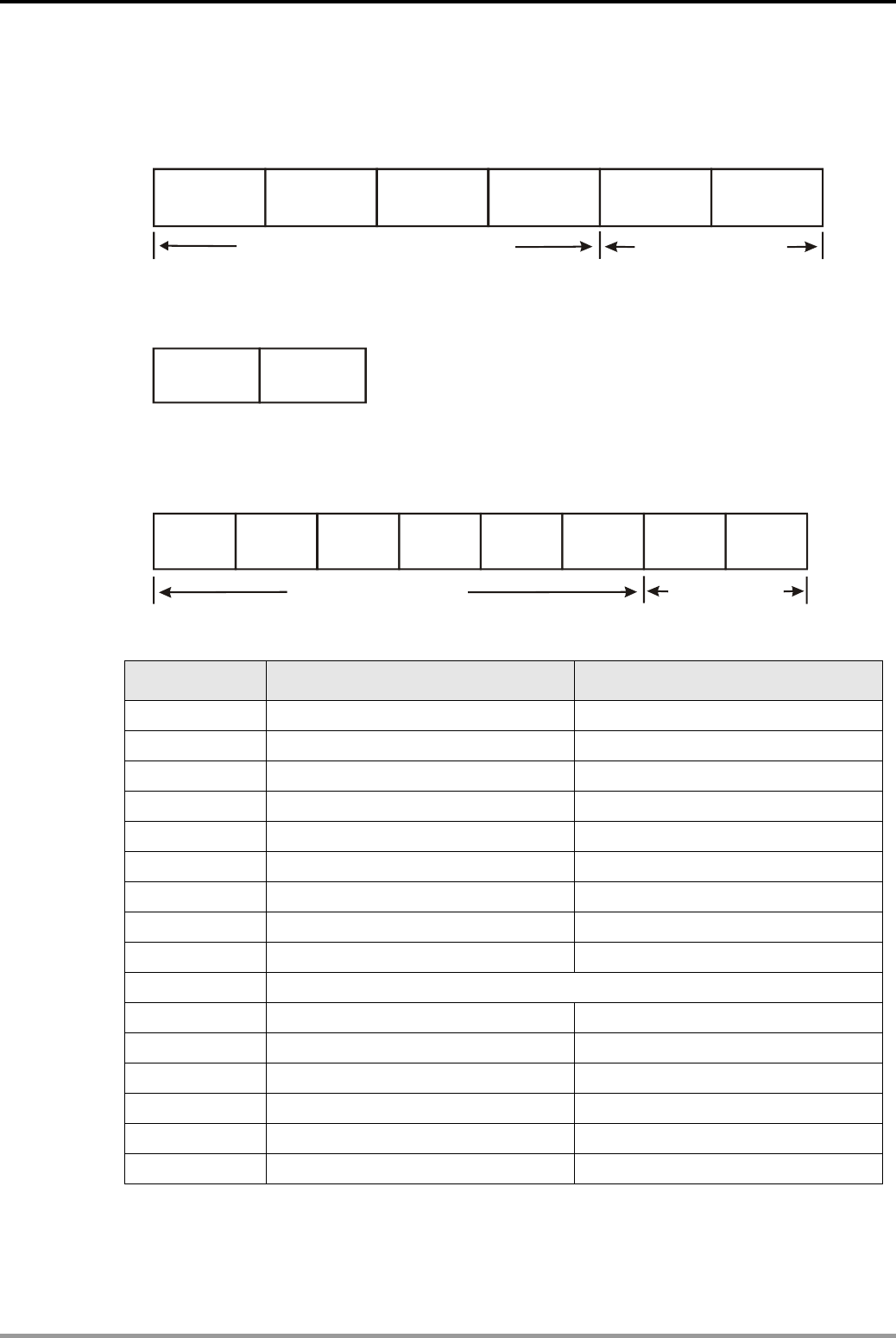
12. Communication Design Examples
DVP-PLC Application Examples
12-54
z 3 kinds of messages can be used in data area:
1. Includes parameter area and process area. Used for transferring parameters in
master-slave system. The 6 words are as below:
PKE IND PWE1 PWE2 PCD1 PCD2
Process
area
()
PZD
Parameter area
(
PKW
)
2. Only process area. Consist of control word (status word) and frequency. The 2 words are
as below:
PCD1 PCD2
Process area (PZD
)
3. Text area for reading/writing text through data area (used when reading/writing
parameter P621-631):
Process
area (PZD
)
Te x t a r e a ( PKW
)
PKE IND PCD1 PCD2CH1 CH2 CHn
...........
z Definition of the control word for AC motor drive in PZD area:
Bit Bit status = 0 Bit status = 1
00 - Preset ref. lsb
01 - Preset ref. msb
02 DC braking -
03 Coasting stop -
04 Quick stop -
05 Freeze output frequency -
06 Ramp stop Start
07 - Reset
08 - JOG
09 No function
10 Data not invalid Data valid
11 - Activate relay 01
12 - Activate relay 02
13 - Choice of setup lsb
14 - Choice of setup msb
15 - Reversing
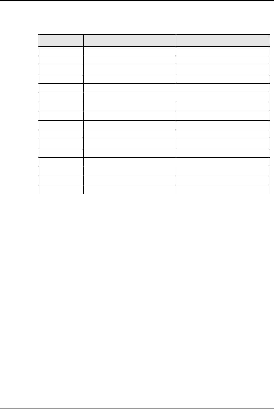
12. Communication Design Examples
DVP-PLC Application Examples 12-55
z Definition of the status word for AC motor drive in PCD area
Bit Bit status = 0 Bit status = 1
00 Trip Control ready
01 - Drive ready
02 - Stand by
03 No trip Trip
04 Not in use
05 Not in use
06 Not in use
07 No warning Warning
08 Speed≠reference Speed = reference
09 Local operation Serial comm. control
10 Out of frequency range -
11 Disable operation Operation indication
12 No function
13 - Voltage warning high/low
14 - Current limit
15 - Thermal warning

12. Communication Design Examples
DVP-PLC Application Examples
12-56
MEMO
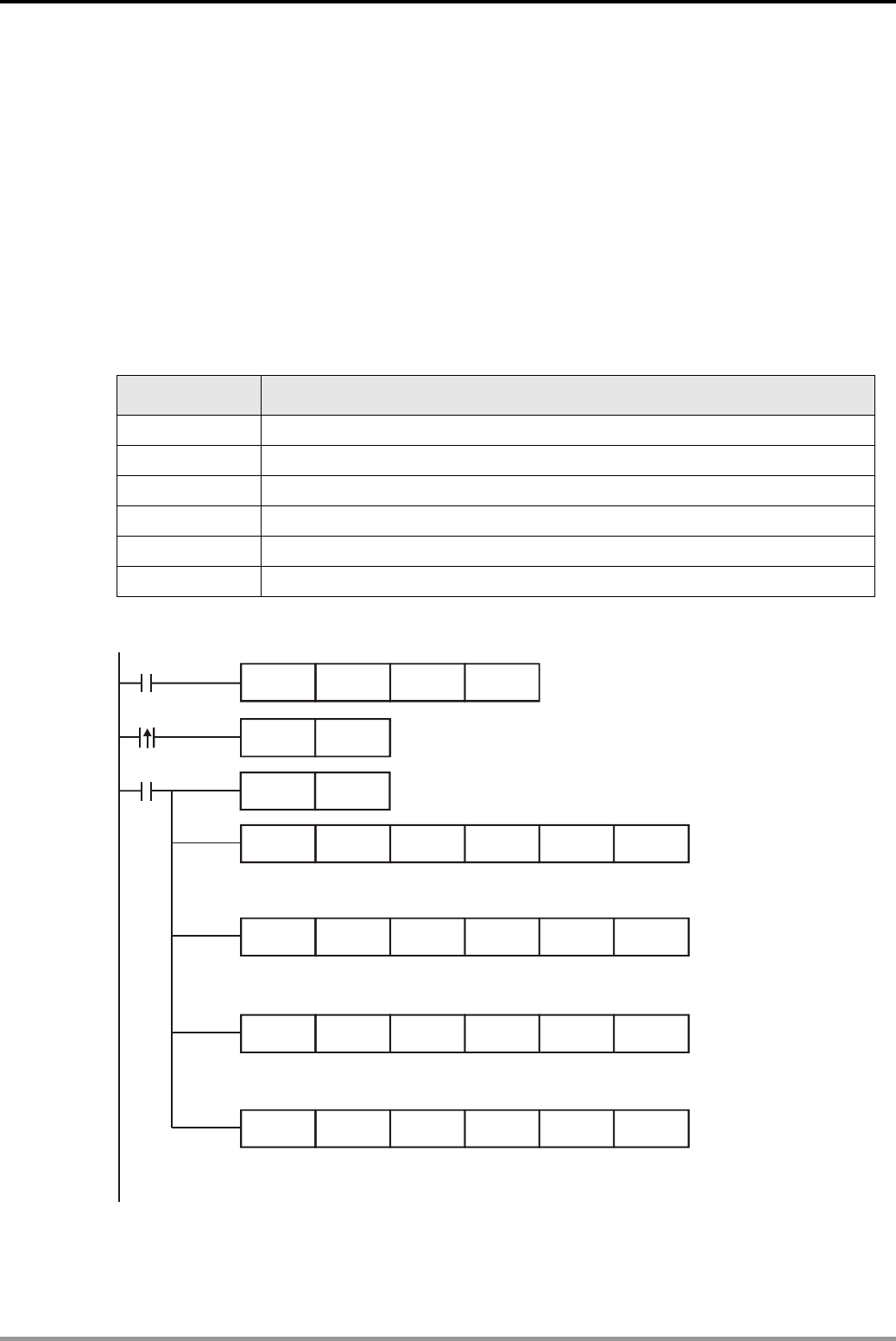
13 . Real Time Calendar Time Design Examples
DVP-PLC Application Examples 13-1
13.1 TRD/TWR/TCMP - Office Bell Timing Control
Control Purpose:
z There are 4 moments the office bell will ring: on-duty / off-duty time in the morning and
on-duty / off-duty time in the afternoon. When the time is reached, the bell will ring
immediately and last for 1 minute. Users can set the 4 moments and adjust the current time
at any time.
z Set the ringing time and adjust the current time.
Devices:
Device Function
M0 Adjust current time
M1 Start the office bell
Y0 Ring the office bell
D0~D6 Store the read Real Time Clock (RTC) data
D200~D206 Store the RTC data to be written in PLC
D300~D311 Store the on-duty / off-duty time
Control Program:
M0
M1
TWR D200
TRD D0
TCMP
FMOV
D300
K1
D301
D200
D302
K4
D4 M10
TCMP D303 D304 D305 D4 M13
TCMP D306 D307 D308 D4 M16
TCMP D309 D310 D311 D4 M19
M1000 Set the written data of Year/Week/
Month/Day as K1 so as to prevent
executing errors of TWR instruction
When M0 is triggered, the contents in D200~
D206 will be written into RTC built in PLC
When M1=ON, store the current time of RTC in D0~D6.
D4, D5 and D6 store the data of Hour/Minute/Second
When M1 = ON, compare the current time in D4~D6 with the morning
on-duty time set in D300~D302. If they are equal, M11 will be ON.
When M1 = ON, compare the current time in D4~D6 with the morning
off-duty time set in D303~D305. If they are equal, M14 will be ON.
When M1 = ON, compare the current time in D4~D6 with the afternoon
on-duty time set in D306~D308. If they are equal, M17 will be ON.
When M1 = ON, compare the current time in D4~D6 with the afternoon
off-duty time set in D309~D311. If they are equal, M20 will be ON.

13 . Real Time Calendar Time Design Examples
DVP-PLC Application Examples
13-2
M11
M14
M17
M20
SET Y0
Y0
TMR T0 K600
T0
RST Y0
When any of M11, M14, M17 and M20 is triggered,
Y0 will be ON and the bell will ring..
The ring will last for 1 minute. Y0 will be
reset and the bell will stop ringing.
Program Description:
z The value in D200~D206 and D300~D311 can be set by WPLSoft or HMI.
z To avoid the execution error of TWR instruction, the program uses [FMOV K1 D200 K4]
instruction at the beginning. This program operates only the data of Hour/Minute/Second in
D204~D206 but not the data of Year/Day/Month/Date in D200~D203. For TWR instruction,
the setting range: 00~99 for Year, 1~7 for Day(Mon ~Sun), 1~12 for Month and 1~31 for
Date. If the values in D200~D203 are out of the above range, the program will regard it as
an operation error and the instruction will not be executed and the Hour/Minute/Second data
can’t be written either. Therefore, the program sets the Year/Week/Month/Day to K1 to fit the
above range and makes sure TWR instruction can be executed for writing in
Hour/Minute/Second data.
z D4, D5 and D6 store the Hour/Minute/Second of the current time read form RTC.
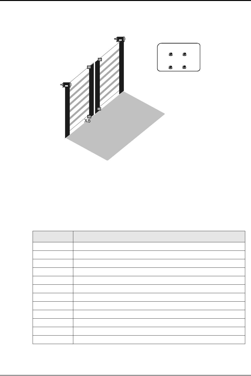
13 . Real Time Calendar Time Design Examples
DVP-PLC Application Examples 13-3
13.2 TRD/TZCP - Control of Warehouse Automatic Door
n
o
Y2/Y3
X0
X2 X3
n
o
X1
Close
CloseOpen
X7
X4
X6
Y0/Y1
Open
Control Purpose:
z The opening hours of the warehouse are from 7:30~22:30, so the door should open at 7:30
and close at 22:30 automatically.
z There are 2 sets of control buttons(Open/Close) in the control room for opening or closing
the door manually for special situations.
Devices:
Device Function
X0 Manual open button for door 1 .
X1 Manual close button for door 1
X2 Manual open button for door 2
X3 Manual close button for door 2
X4 Upper sensor of door 1.
X5 Lower sensor of door 1.
X6 Upper sensor of door 2.
X7 Lower sensor of door 2.
Y0 Motor of door 1 run forward to open the door
Y1 Motor of door 1 run reverse to close the door
Y2 Motor of door 2 run forward to open the door
Y3 Motor of door 2 run reverse to close the door
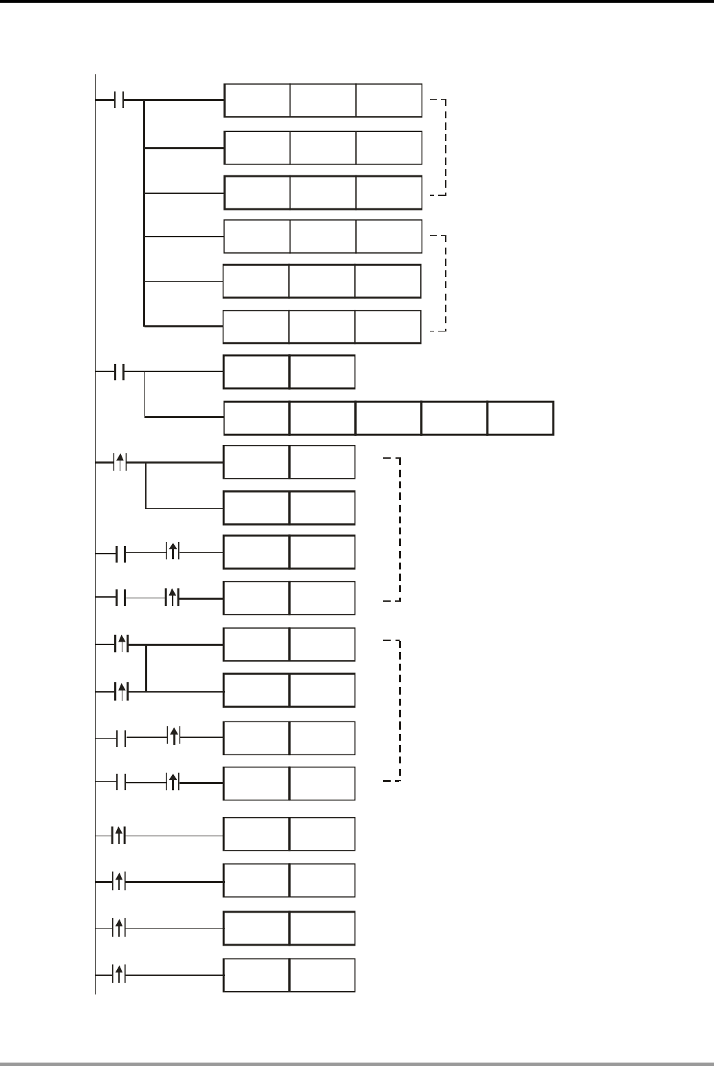
13 . Real Time Calendar Time Design Examples
DVP-PLC Application Examples
13-4
Control Program:
M1000
M10
M1000
X0
M12
M11
MOV K0 D12
MOV K22 D20
MOV K30 D21
MOV K0 D22
MOV K7 D10
D11
K30
MOV
TRD D0
TZCP D10 D20 D4 M10
X4
X6
Set the lower limit of
warehouse opening
hours as 7:30
SET Y0
SET Y2
RST Y0
RST Y2
SET Y1
SET Y3
RST Y1
RST Y3
SET Y0
Y0
Y2
X5
X7
Y1
Y3
X1 SET Y1
X2 SET Y2
X3 SET Y3
Set the upper limit of
warehouse opening
hours as 22:30
Read the RTC of PLC and store the data
in D0~D6. D4~D6 store Hour/Min/Sec data
Time zone compare
the set time with the
read current time
AM7:30~PM10:30, door 1 and door 2 executes
opening action until the upper sensor is activated.
PM10:30~AM7:30, door 1 and door 2 executes
closing action until the lower sensor is activated
Press door 1 manual open button and door 1 will
be opening until the upper sensor is activated
Press door 1 manual close button and door 1 will
be closing until the lower sensor is activated
Press door 2 manual open button and door 2 will
be opening until the upper sensor is activated
Press door 2 manual open button and door 2 will
be closing until the lower sensor is activated

13 . Real Time Calendar Time Design Examples
DVP-PLC Application Examples 13-5
Program Description:
z The program performs control of warehouse automatic door by a RTC Time Zone Compare
instruction (TZCP). Through the Time Read instruction (TRD), the current time in RTC can
be read in D0~D6. D4, D5 and D6 store the Hour/Min/Sec data.
z When Y0 = ON, the motor of door 1will run forward to execute opening action until upper
sensor is activated (X4 = ON).
z When Y1 = ON, the motor of door 1 will run reverse to execute closing action until the lower
sensor in activated (X5 = ON).
z The opening and closing actions of door 2 are the same with that of door 1.
z For some special situations, the opening and closing actions of door 1 and door 2 can also
be performed by pressing manual open buttons (X0/X2) and manual close buttons (X1/X3)
in the control room.
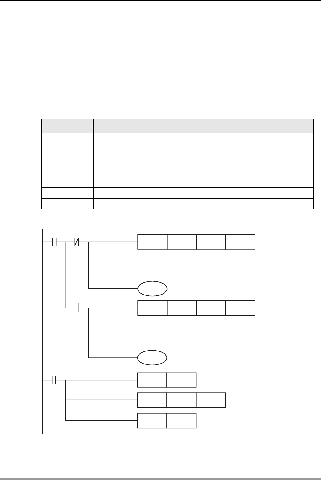
13 . Real Time Calendar Time Design Examples
DVP-PLC Application Examples
13-6
13.3 HOUR - Control of Switching Motors after a Long Time Running
Control Purpose:
z Controlling the automatic motor switching between main motor and auxiliary motor.
In some special applications, we use several motors running by turns to protect each motor and
extend their service life. In this program, there are 2 motors running by turns in the cycle: 2 days
(48 hours) for the main motor, then 1 day (24 hours) for the auxiliary motor.
Devices:
Device Function
X0 Start/Stop of the motor
Y0 Starting the main motor
Y1 Starting the auxiliary motor
M10 M10 = ON when set time of the main motor reached
M11 M11 = ON when set time of the auxiliary motor reached
D0~D1 Storing the current running time of the main motor
D2~D3 Storing the current running time of the auxiliary motor
Control Program:
X0 M0
M0
HOUR K48 D0 M10
Y0
HOUR K24 D2 M11
Y1
M10
SET M0
ZRST D0 D1
RST M10
When X0 = ON, M0 = OFF, the timer starts counting.
Set value: 48 hr. D0~D1 store the current running time
of main motor. hen current running time
reaches the set value..
M10 will be ON w
When X0 = ON, M0 = OFF, Y0 will be
ON and the main motor will b e started.
When X0 = ON, M0 = ON, the timer starts counting.
Set value: 24 hr. D2~D3 store the current running time
of main motor. M10 will be ON when current running time
reaches the set value.
When X0 = ON and M0 = ON, Y1 will be
ON and the auxiliary motor will b e started.
When M10 = ON, SET M0 instruction
will be executed for stopping the main
motor and starting the auxiliary motor.
Clear the current running
time of the main motor
Reset M10

13 . Real Time Calendar Time Design Examples
DVP-PLC Application Examples 13-7
M11
RST M0
ZRST D2 D3
RST M11
When M11 = ON, RST M0 instruction
will be executed for stopping the auxiliary
motor and starting the main motor
Clear the current running
time of the auxiliary motor
Reset M11
Program Description:
z When X0 = OFF, Y0 and Y1 = OFF, both main / auxiliary motor will not run.
z When X0 = ON, the running status of Y0 (main motor) and Y1 (aux. motor) will be decided
by the ON/OFF status of M0 so as to control the two motors running in turns.
z For main motor, D0 and D1 record the current time measured in hour and the current time
that is less than an hour (0~3599s). For auxiliary motor, D2 and D3 record the current time
measured in hour and the current time that is less than an hour (0~3599s).
z 16-bit instruction supports the set time up to 32,767 hours and 32-bit instruction supports
the set time up to 2,147,483,647 hours.
z The timer will go on timing after the set time is reached. For restart timing, users need to
clear the current time stored in D0~D3 and reset flag M10 and M11.

13 . Real Time Calendar Time Design Examples
DVP-PLC Application Examples
13-8
MEMO
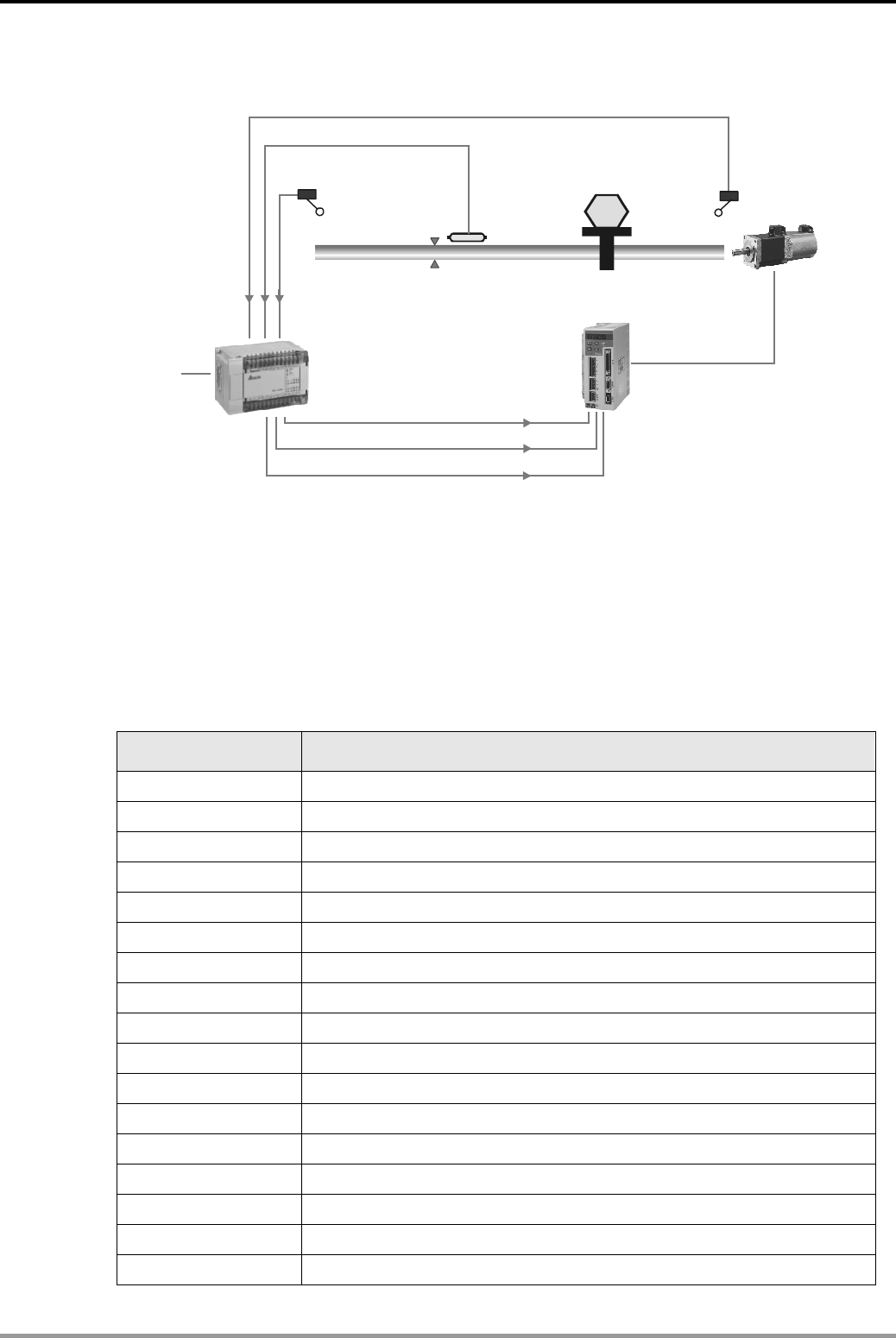
14. Simple Positioning Design Examples
DVP-PLC Application Examples 14-1
14.1 Simple positioning Demonstration System of Delta ASDA series AC servo Drive
Forward limit
sensor X0
DOG
sensor X2
Y0 pulse output
Y1 forward/ reverse
Y4 pulse clear
DOP-A series HMI EH
ASDA series AC servo drive
WPLSoft
Reverse limit
sensor X1
Servo motor
Processing
device
Zero point
Control Purpose:
z Building a simple demonstrating system of position control by the application of Delta PLC
and Delta ASDA servo drive.
z Performing Zero Return, Drive to Increment and Drive to Absolute through pulse sending of
PLC.
Devices:
Device Function
M0 Zero return switch
M1 Switch of running forward for 10 rotations
M2 Switch of running reverse for 10 rotations
M3 Switch of absolute designation: 400,000
M4 Switch of absolute designation: -50,000
M10 Servo ON switch
M11 Error reset switch
M12 Switch of stopping pulse output.
M13 Switch of Emergency stop
X0 Forward limit sensor
X1 Reverse limit sensor
X2 DOG signal sensor
X3 Receiving Servo Ready signal (corresponding to M20)
X4 Receiving At Zero Speed signal (corresponding to M21)
X5 Receiving Homing Completed signal (corresponding to M22)
X6 Receiving At Positioning Completed signal (corresponding to M23)
X7 Receiving Alarm Enabled signal (corresponding to M24)
14. Simple Positioning Design Examples
DVP-PLC Application Examples
14-2
Y0 Pulse output
Y1 Forward / Reverse direction control
Y4 Clear pulse register of servo
Y6 Servo ON
Y7 Error reset
Y10 Forward inhibit limit
Y11 Reverse inhibit limit
Y12 Emergency stop
M20 Servo ready
M21 At zero speed
M22 Homing completed
M23 At positioning completed
M24 Alarm enabled
Parameter Settings for ASD-A AC Servo Drive:
Parameter Set value Function
P0-02 2 Drive Status
P1-00 2 External pulse input type: Pulse+ Direction
P1-01 0 Control Mode and Output Direction
P2-10 101 Digital Input Terminal 1 (DI1)
P2-11 104 Digital Input Terminal 2 (DI2)
P2-12 102 Digital Input Terminal 3 (DI3)
P2-13 122 Digital Input Terminal 4 (DI4)
P2-14 123 Digital Input Terminal 5 (DI5)
P2-15 121 Digital Input Terminal 6 (DI6)
P2-16 0 Digital Input Terminal 7 (DI7)
P2-17 0 Digital Input Terminal 8 (DI8)
P2-18 101 Digital Output Terminal 1 (DO1)
P2-19 103 Digital Output Terminal 2 (DO2)
P2-20 109 Digital Output Terminal 3 (DO3)
P2-21 105 Digital Output Terminal 4 (DO4)
P2-22 107 Digital Output Terminal 5 (DO5)
Ú If AC servo drive can not run normally due to improper parameters, users can set P2-08 = 10
(factory defaults) and then set the parameters according to the above table.
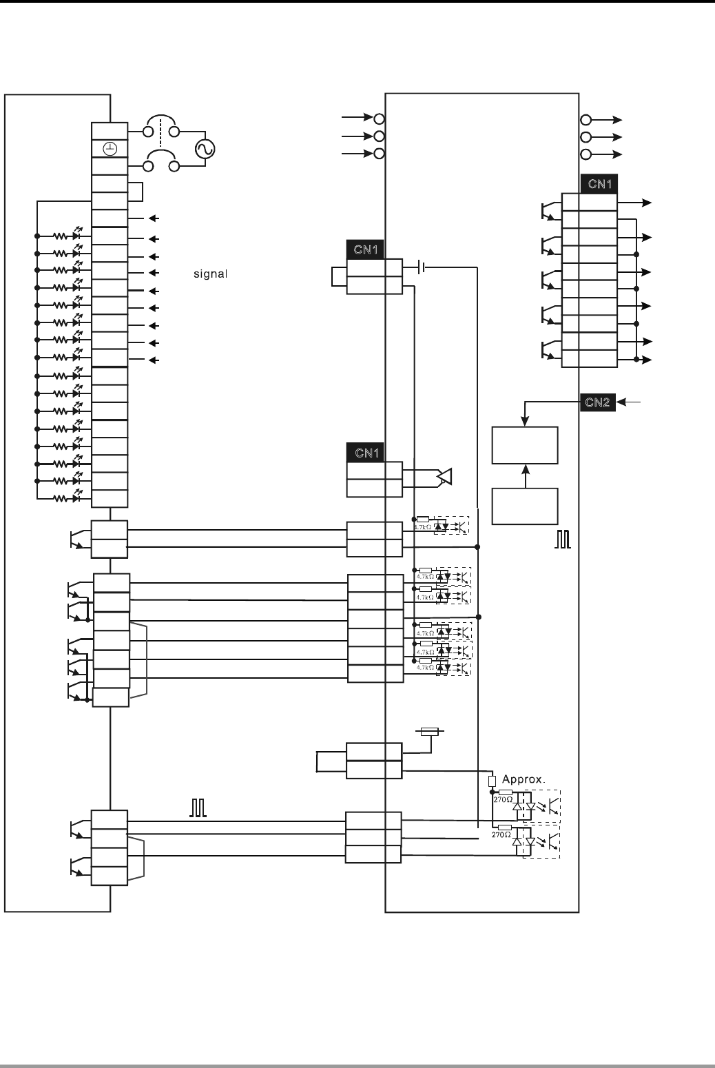
14. Simple Positioning Design Examples
DVP-PLC Application Examples 14-3
Wiring for PLC and AC Servo Drive:
Delta PLC
X2
X13
X14
X15
X16
X17
X0
X1
X3
X4
X5
X6
X7
DI2
DI1
DI3
DI4
COM+
VDD
DO1+
DO1-
DO2+
DO2-
DO3+
DO3-
DO4+
DO5+
DO4-
DO5-
VDD 17
PU-HI 35
Y0
C0
Y1
C1
PLS
COM-
41
47
SIGN 37
COM- 45
10
17
11
9
34
8
+24V
24G
S/S 7
6
5
4
3
2
1
26
28
L
N
220VAC
220VAC
ASDA
U
V
W
24V
OZ 50
/
OZ 24
DC24V
1K
Ω
R
S
T
DI6 32
DO_COM
SRDY
ZSPD
TPOS
ALRM
SRDY - Servo ready
TPOS- At positioning completed
ALRM -Servo Alarm activated
Y4
C4
COM- 45
DOG
X10
X11
X12
DI5 33
ZSPD - At zero speed
11
DO_COM
HOME
27
HOME - Homing completed
DVP32EH00T
Y6
Y7
C4
Y11
C5
Y10
Y12
Single
phase
Dleta servo drive
Servo
motor
Forward limit
Reverse limit
Pulse clear
Servo ON
Servo error reset
Forward inhibit limit
Reverse inhibit limit
Emergency stop
Pulse output
Forward/Reverse direction
Eletric
gear
Error
counter
Encoder
Series
3-phase
power
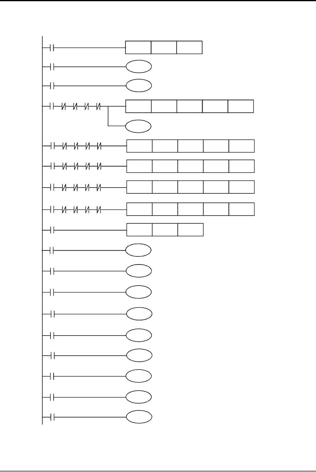
14. Simple Positioning Design Examples
DVP-PLC Application Examples
14-4
Control program:
M1002
MOV K200 D1343
Y7
Y10
Y11
M20
M21
M22
M23
M24
M1334
Y12
M1346
M11
X0
X1
X3
X4
X5
X6
X7
M12
M13
Y6
M10
M0
M1
M2
M3
M4
M1029
DZRN
DDRVI
DDRVI
DDRVA
DDRVA
ZRST
K10000
K100000
K-100000
K400000
K-50000
K5000
K20000
K20000
K200000
K200000
X2
Y0
Y0
Y0
Y0
Y0
Y1
Y1
Y1
Y1
M1
M0
M0
M0
M0
M2
M2
M1
M1
M1
M3
M3
M3
M2
M2
M4
M4
M4
M4
M3
M0 M4
Zero return
Drive to absolute
designation -50,000
Run reverse for
10 rotations
Set accel/decel time to 200ms
Servo ON
Error reset
Clear pulse register of servo
Run forward for
10 rotations
Drive to absolute
designation 400,000
Reset M0~M4 after positioning
is completed
Forward inhibit limit
Reverse inhibit limit
Stopping pulse output
Emergency stop
Servo ready
Servo at zero speed
Servo homing completed
Servo at positioning completed
Error alarm

14. Simple Positioning Design Examples
DVP-PLC Application Examples 14-5
Program Description:
z The M devices work as switches and status display can be designed by Delta DOP-A HMI or
WPLSoft program.
z Power up servo drive, X3 will be ON (servo ready) if there is no alarm signal. Press servo
ON switch and M10 will be ON to activate Y6 (Servo ON)
z When zero return switch M0 = ON, servo drive will execute zero return action. When DOG
signal sensor is activated, servo drive will switch the current speed to JOG speed of 5KHz.
When X2 is OFF, servo motor will stop running immediately and zero return is completed.
z When the switch of 10 rotations forward is pressed (M1 = ON), servo motor will execute
Drive to Increment instruction and stop after running forward for 10 rotations.
z When the switch of 10 rotations reverse is pressed (M2 = ON), servo motor will execute
Drive to Increment instruction and stop after running reverse for 10 rotations.
z When the switch of absolute designation 40,0000 is pressed (M3 = ON), servo motor will
execute Drive to Absolute instruction and stop after positioning completed.
z When the switch of absolute designation -50,000 is pressed (M4 = ON), servo motor will
execute Drive to Absolute instruction and stop after positioning completed.
z If the processing device touches the forward limit sensor (X0 = ON, Y10 = ON), servo motor
will stop and the alarm will be enabled (M24 = ON).
z If the processing device touches the reverse limit sensor (X1 = ON, Y11 = On), servo motor
will stop and the alarm will be enabled (M24 = ON)..
z If servo alarm is enabled, press error reset switch M11 to clear the alarm. Once the alarm is
cleared, the program can resume positioning actions.
z When the switch of stopping pulse output is ON (M12 = ON), PLC pulse output will be
paused and the number of the output pulses will be stored in the register. When M12 = OFF,
PLC will resume pulse output from the number of stored pulses.
z Press emergency stop switch (M13 = ON), and AC servo drive will stop immediately. When
M13 = OFF, for positioning, servo drive will not complete remaining distance.
z M1346 in the program is used for clearing the pulse register after zero return is completed.
When M1346 activated, Y4 of PLC will send a 20ms pulse to clear pulses so as to display 0
on the servo panel (corresponding to servo parameter: P0-02, set as 0)
z M1029 in the program is used for resetting M0~M4 to ensure that every positioning
instruction can be executed properly.
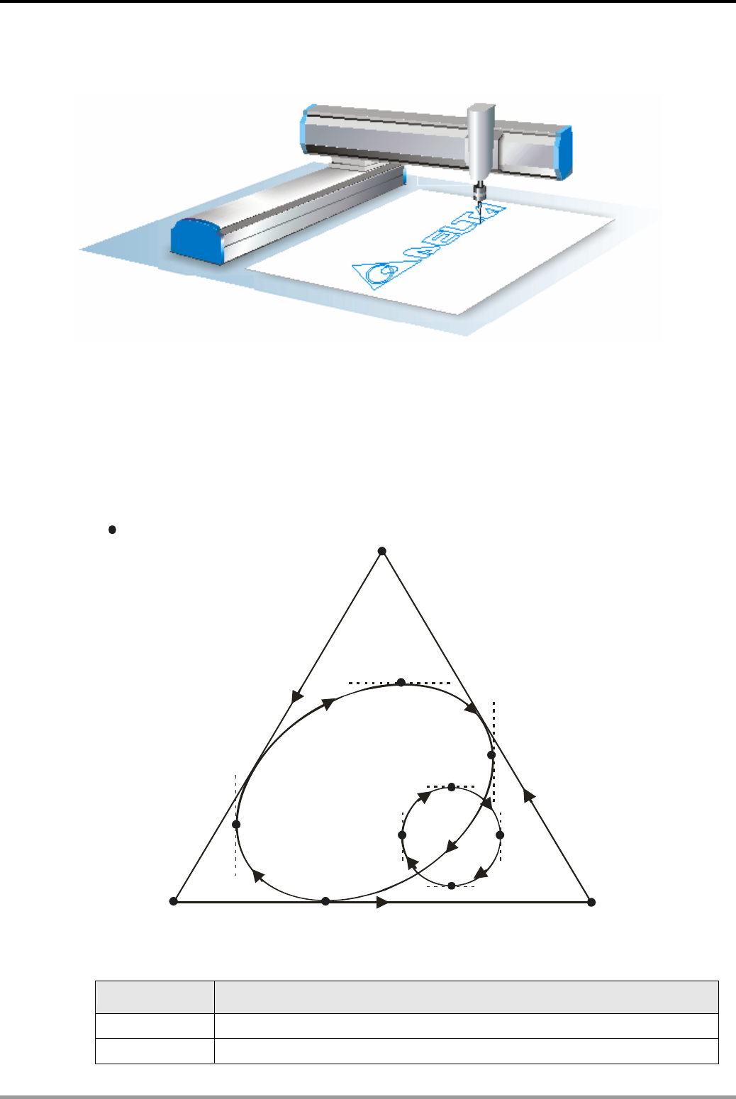
14. Simple Positioning Design Examples
DVP-PLC Application Examples
14-6
14.2 Draw DELTA LOGO by 2-axis Synchronous Motion
Control Purpose:
z Executing Drive to Absolute (DDRVA) and 2-axis synchronous motion instructions (DPPMA
and DPPMR) to draw DELTA LOGO.
z Executing DDRVA instruction to control the up/down movement of the pen on the 3rd axis.
z The locus is as follows:
P1(32500,-500)
P5(34400,-20500)
P6(48800,-33300)
P3(61500,-53400)
P2(600,-53400) P7(23100,-53400)
P4(10300,-43600)
P9(43000,-35800)
P10(50800,-43000)
P8(34500,-43000)
P11(43000,-50800)
P0(0,0)
The origin
Devices:
Device Function
X0 When X0 = ON, 2-axis synchronous motion is enabled.
Y0 X axis pulse output device
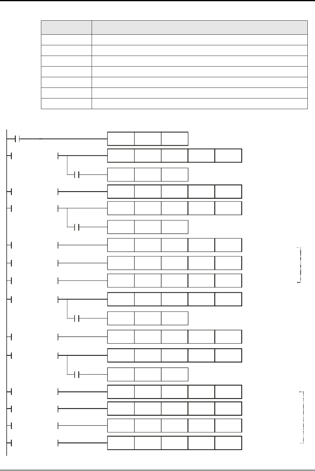
14. Simple Positioning Design Examples
DVP-PLC Application Examples 14-7
Device Function
Y1 X axis direction signal output device
Y2 Y axis pulse output device
Y3 Y axis direction signal output device
Y4 The 3rd axis pulse output device
Y5 The 3rd axis direction signal output device
D0 Drawing steps
D10 Parameter setting
Control Program:
X0
MOVP D0
K1
= D0 K 1
M1036
M1036
M1036
M1036
DDRVA K5000 K10000 Y4 Y5
MOVP K2 D0
= D0 K 2
= D0 K 3
= D0 K 4
= D0 K 5
= D0 K 6
= D0 K 7
= D0 K 8
= D0 K 9
= D0 K 10
= D0 K 11
= D0 K 12
= D0 K 13
DPPMA K32500 K-500 K10000 Y0
K4
DDRVA K10000 Y4 Y5
MOVP D0
K0
DPPMA Y0K10000K600 K-53400
DPPMA Y0K10000K-53400
K61500
DPPMA Y0K10000
K32500 K-500
DDRVA K5000 K10000 Y4 Y5
MOVP D0
K8
DPPMA Y0K10000K10300 K-43600
DDRVA K10000 Y4 Y5
MOVP D0
K0
K10
DCIMA K34400 K-20500 D10 Y0
DCIMA D10 Y0
DCIMA D10 Y0
DCIMA D10 Y0
K48800 K-33300
K23100 K-53400
K10300 K-43600
2-axis positioning
from P1 to P2
Put down the pen
on the 3rd-axis
2-axis positioning
from P2 to P3
2-axis positioning
from P3 to P1
Lift up the pen
on the 3rd axis
2-axis positioning
from P1 to P4
2-axis positioning
from P4 to P5
Put down the pen
on the 3rd axis
2-axis positioning
from P5 to P6
2-axis positioning
from P6 to P7
2-axis positioning
from P7 to P4
Lift up the pen
on the 3rd axis
2-axis positioning
from P0 to P1
Draw the triangle
Draw the ellipse
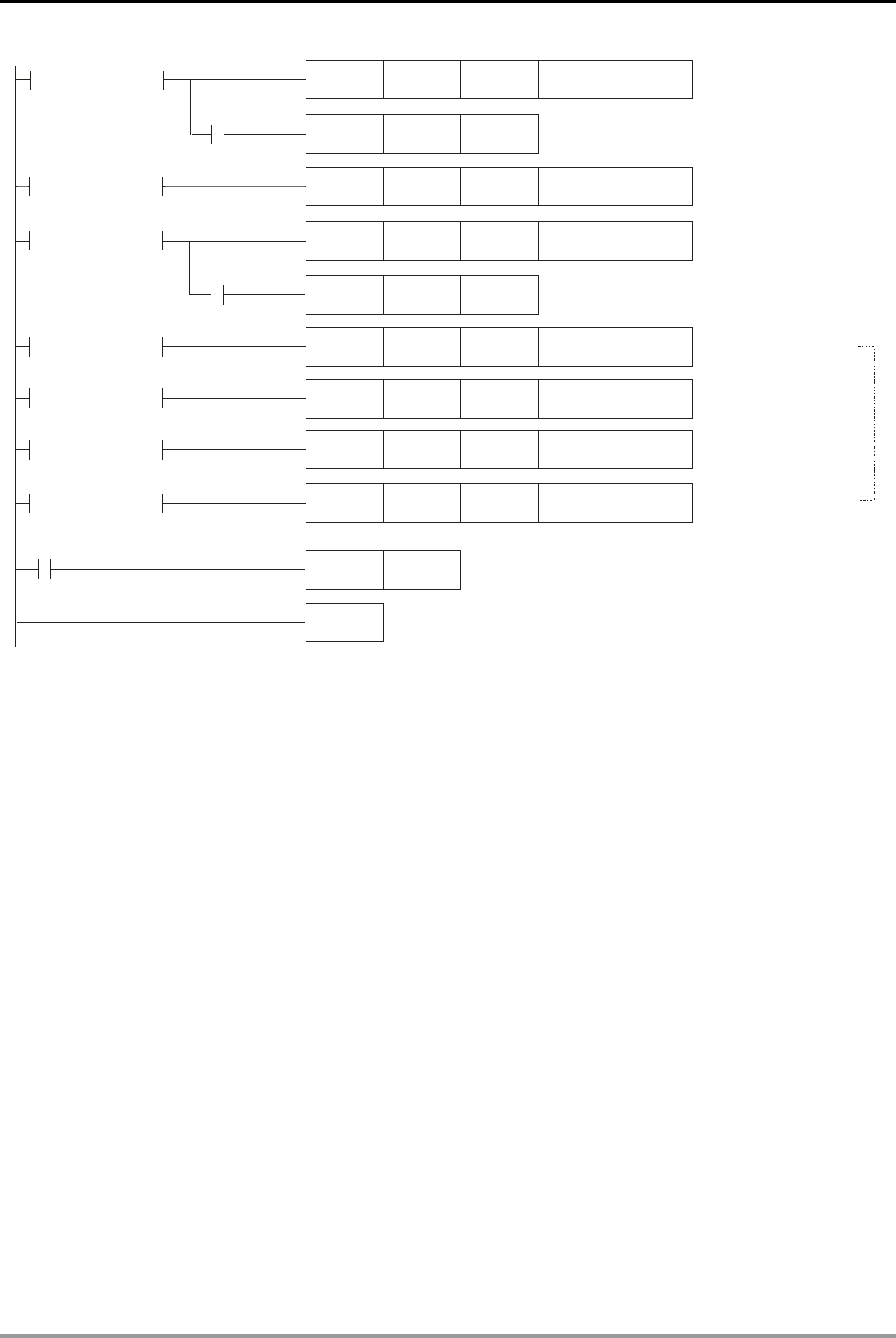
14. Simple Positioning Design Examples
DVP-PLC Application Examples
14-8
M1036
DDRVA K10000 Y4 Y5
MOVP D0
K0
D0
= D0 K15 DPPMA K10000 Y0K34500 K-43000
= D0 K16
K17
= D0 K17
= D0 K18
= D0 K19
= D0 K20
DCIMA D10 Y0
DCIMA D10 Y0
DCIMA D10 Y0
DCIMA D10 Y0
K43000
K50800
K34500
K43000
K-35800
K-43000
K-50800
K-43000
M1029
INCP
END
Put down the pen
on the 3rd axis
2-aixs positioning
from P8 to P9
2-aixs positioning
from P9 to P10
2-aixs positioning
from P10 to P11
2-aixs positioning
from P11 to P8
M1036
= D0 K14
MOVP D0
DDRVA K5000 K10000 Y4 Y5
K15
Lift up the pen
on the 3rd axis
2-aixs positioning
from P4 to P8
Draw the circle
Program Description:
z When X0 = ON, the content in D0 = 1, 2-axis synchronous motion will be enabled to draw
DELTA LOGO.
Step 1: Lift up the pen on the 3rd-axis. Move it from P0 to P1.
Step 2: Put down the pen at P1. Draw with the following locus: P1→ P2→ P3→ P1. Lift up
the pen and the triangle is completed.
Step 3: Move the pen from P1 to P4 and put down the pen at P4. Draw with the following
locus: P4→ P5→ P6→ P7→ P4. Lift up the pen and the ellipse is completed.
Step 4: Move the pen from P4 to P8 and put down the pen at P8. Draw with the following
locus: P8→ P9→ P10→ P11→ P8. Lift up the pen and the circle is completed and
DELTA logo is accomplished.
z M1036 is the flag for indicating the completion of pen movement on 3rd axis. When M1036 =
ON, the program will execute next step.
z M1029 is he flag for indicating the completion of pen movement on X/Y axis. When M1029 =
ON, the content in D0 will increase by 1 and the program will enter next step.
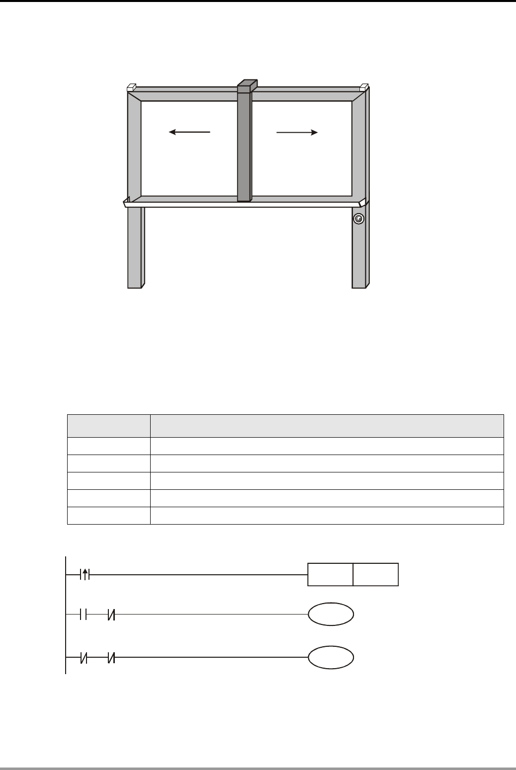
15. Handy Instruction Design Examples
DVP-PLC Application Examples 15-1
15.1 ALT - Auto Blackboard Cleaner
X2
X0(Clean)
Y0 Y1
Move Left Move right
(Left side limit switch) X1 (Right side limit switch)
Control Purpose:
z Controlling the auto cleaner to move left / move right when Clean is pressed.
z When the auto cleaner touches the limit switches of left side or right side, the cleaner will
stop. Next time when Clean is pressed again, the cleaner will move to the opposite direction.
Devices:
Device Function
X0 X0 = ON when Clean is pressed.
X1 X1 = ON when left side limit switch is touched.
X2 X2 = ON when right side limit switch is touched.
Y0 Move left
Y1 Move right
Control Program:
X0
M0
M0
Y0
Y1
A
LT M0
X1
X2
Move left
Move right
Program Description:
z When Clean is pressed, X0 will be activated one time to execute ALT instruction. M0 will be
ON, the cleaner will move left until it touches the left side limit switch. X1 = ON, and Y0 will

15. Handy Instruction Design Examples
DVP-PLC Application Examples
15-2
be OFF. The cleaner will stop working.
z When Clean is pressed again, X0 will be activated again to switch the ON status of M0 to be
OFF. Therefore, Y1 will be ON and the cleaner will move right until it touches the right side
limit switch. X2 = ON, and Y1 will be OFF. The cleaner will stop at the current position.
z Wherever the location of the cleaner is, the cleaner will move to the opposite direction every
time when Clean is pressed.
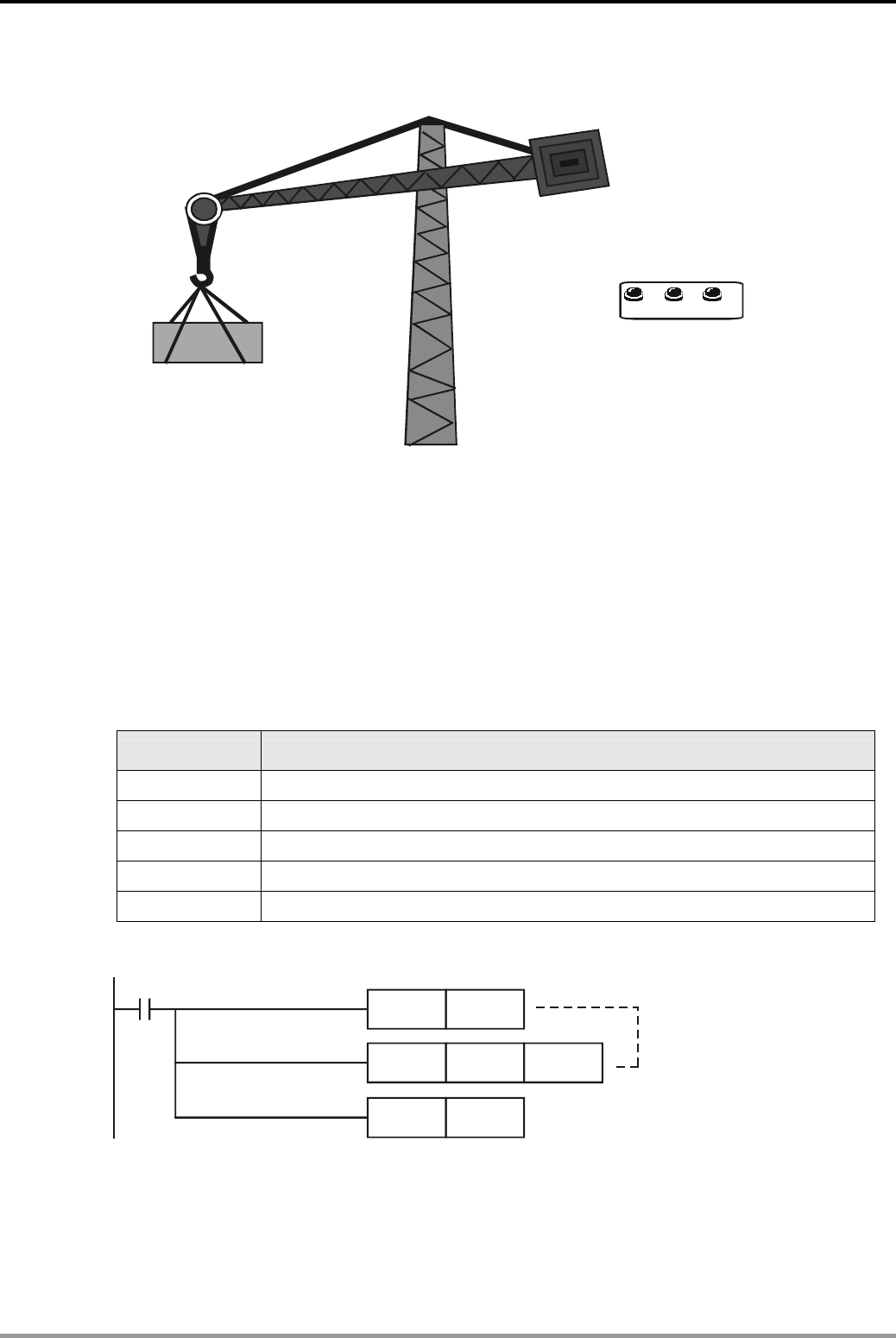
15. Handy Instruction Design Examples
DVP-PLC Application Examples 15-3
15.2 RAMP - Ramp Control of Crane
X1X0 X2
Up Stop
Down
Control Purpose:
z The load of the crane is quite big, so the motor requires ramp up and ramp down control
during gradual start as well as gradual stop process.
z Apply Delta analog output MPU DVP10SX to generate voltages of 0~10V for controlling the
frequency of AC motor drive, and the drive will output variable frequency current to control
rotation speed of the crane motor.
Devices:
Device Function
X0 X0 = ON when Up is pressed.
X1 X1 = ON when Down is pressed.
X2 X2 = ON when Stop is pressed.
Y0 Motor running forward (Lifting goods)
Y1 Motor running reverse (Landing goods)
Control Program:
M1002
SET M1039
MOV K20 D1039
SET M1026 Enabling RAMP mode
Set the scan cycle to 20ms
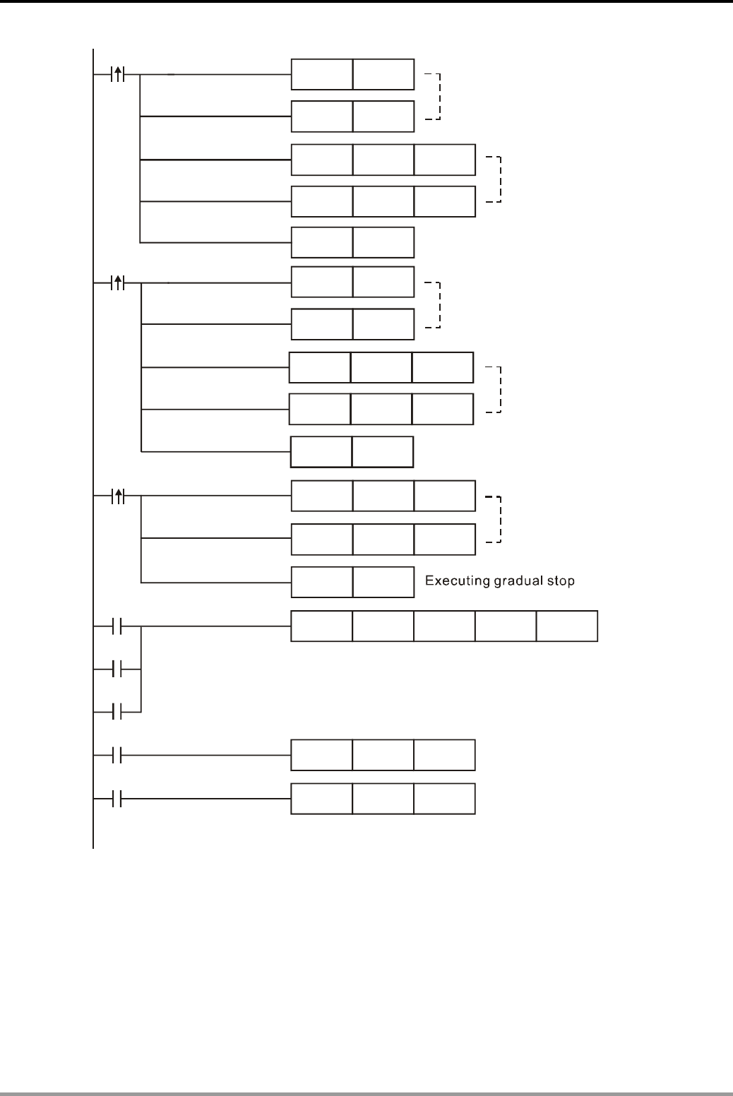
15. Handy Instruction Design Examples
DVP-PLC Application Examples
15-4
X0
X1
MOV K0 D0
MOV K2000 D1
MOV K0 D0
MOV K2000 D1
X2
MOV K2000 D0
MOV K0 D1
M0
M1
M2
M1000
RAMP D0 D1 D2 K100
MOV D2 D1116
Motor running reverse
to land the goods
SET M0
RST Y1
SET M1
RST Y0
SET Y1
SET Y0
M1029
ZRST M0 M2
SET M2
Set the value of start/end
ramp signal when landing goods
Set the value of start/end
ramp signal when stopping goods
Executing gradual lifting
Executing gradual landing
Motor running forward
to lift the goods
Set the value of start/end
ramp signal when lifting goods
At the start of lifting or landing goods, the content in D2 will
increase gradually from 0 to 2,000 in 2 sec. When stopping
goods, the content in D2 will decrease gradually from 2,000
to 0 in 2 sec.
Reset M0~M2 when Ramp process
is completed.
Send the content in D2 to D1116. The content in D1116 determines the output
voltage and the current in the first analog output channel of DVP10SX PLC
Program Description:
z This program applies to PLCs with analog output function, such as DVP20EX and DVP10SX
series MPU. In DVP10SX, when the content in D1116 changes from K0 to K2000, the output
voltage of the first channel will vary from 0 to 10V.
z The parameter of RAMP instruction is directly related to the scan cycle, so users should set
the scan cycle at the start of the program first, then the duration of ramp signal can be fixed.
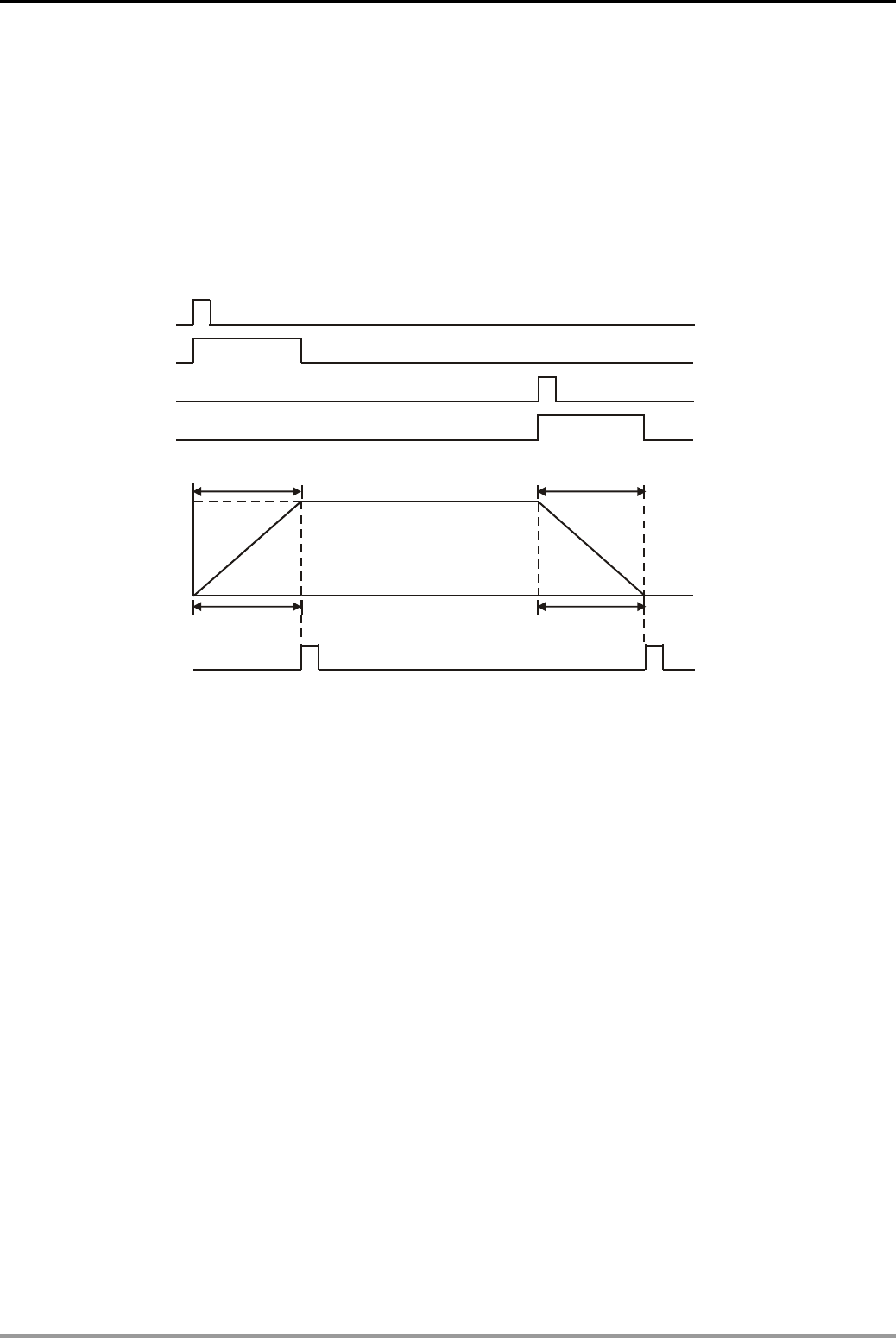
15. Handy Instruction Design Examples
DVP-PLC Application Examples 15-5
In this program, the scan cycle is fixed as 20ms and the scan times of RAMP instruction are
100. Therefore the ramp duration is 2s.
z When the button Up is pressed (M0 = ON), the crane will perform gradual start to lift goods
and the voltage output will increase from 0 to 10V in 2s. When the crane reaches the target
height, operator can press the button Stop (M2 = ON) to execute gradual stop. The voltage
output will decrease from 10 to 0V in 2s. The process is as follows:
0
2000
M1029
X0
M0
X2
M2
(10V)
(0V)
Scan times:100
Gradual start Gradual stop
Scan times: 100
z The goods landing process also requires the same ramp up (gradual start) and ramp down
(gradual stop) duration.
z The frequency of AC motor drive is in proportion to the output voltage of PLC. For example,
the frequency of Delta VFD-M series AC motor drive varies from 0 to 60Hz while the output
voltage of DVP10SX varies from 0 to 10V. In addition, the motor rotation speed is in
proportion to the frequency of drive. Therefore, gradual start and gradual stop can be
performed by controlling the variation of output voltage on DVP10SX.
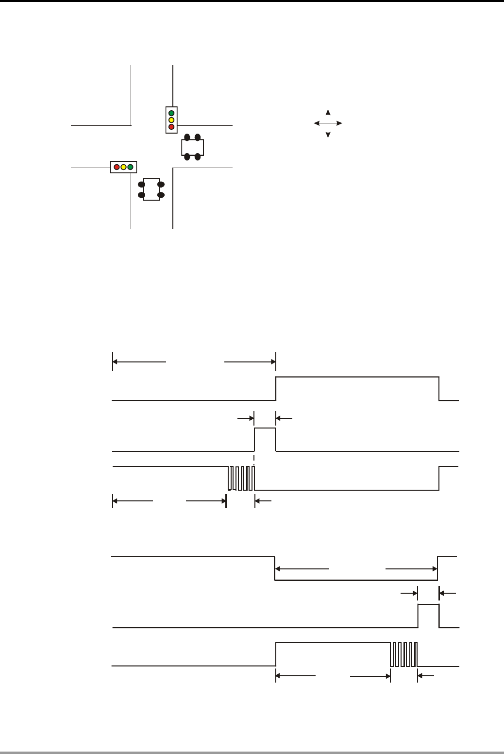
15. Handy Instruction Design Examples
DVP-PLC Application Examples
15-6
15.3 INCD - Traffic Lights Control (Incremental Drum Sequencer)
Vertical direction
Horizontal direction
Control Purpose:
z Performing traffic lights sequence control at the intersection. In both vertical and horizontal
directions, the traffic lights are set as the following sequence: Red lights ON for 60s , Yellow
lights ON for 3s and green lights ON for 52s and green lights flashing for 5s.
z The timing diagrams are as follows:
Vertical
Red
Red
Ye ll ow
Ye ll o w
Green
Green
52s 5s
3s
60s
60s
52s 5s
3s
Horizontal
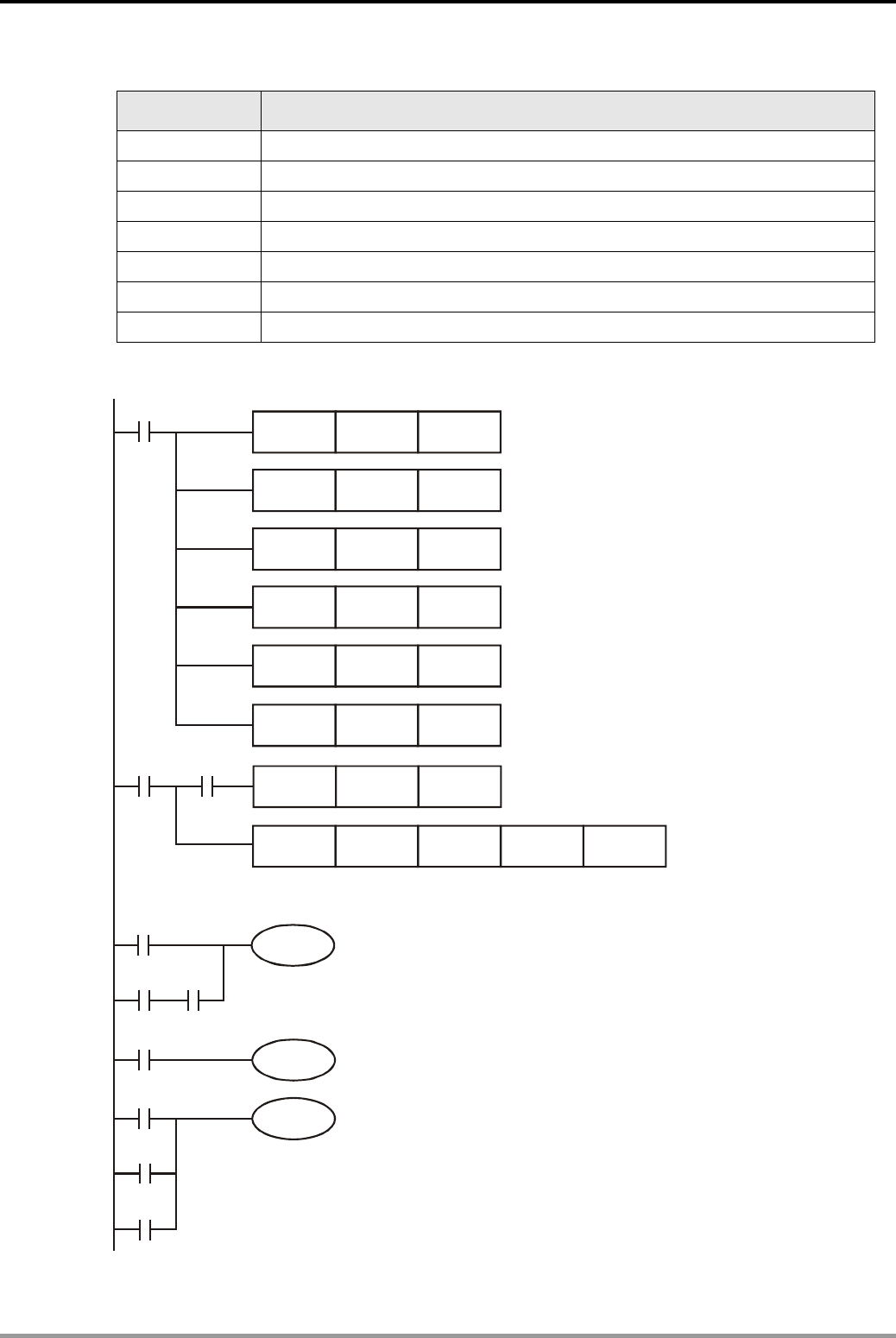
15. Handy Instruction Design Examples
DVP-PLC Application Examples 15-7
Devices:
Device Function
X1 Switch of the traffic lights control program
Y0 Red light (vertical)
Y1 Yellow light (vertical)
Y2 Green light (vertical)
Y10 Red light (horizontal)
Y11 Yellow light (horizontal)
Y12 Green light (horizontal)
Control Program:
Y2
M101
MOV K52 D500
MOV K5 D501
MOV K3 D502
MOV K52 D503
MOV K5 D504
MOV K3 D505
INCD D500 C0
CNT C0 K1000
M1002
M1013
M100
M1013
X0
M100 K6
Vertical green light ON
M102
Y1
Y0
M103
M104
M105
Vertical yellow light ON
Vertical red light ON
Set the ON time of vertical
green light flashing as 5s
Set the ON time of vertical
yellow light as 3s
Set the ON time of horizontal
green light flashing as 5s
Set the ON time of horizontal
yellow light as 3s
C0 counts once every 1s
Set the ON time of
as
vertical
green light 52s
Set the ON time of horizontal
green light as 52s
The corresponding M devices will be ON according to
the set time in D500~D505
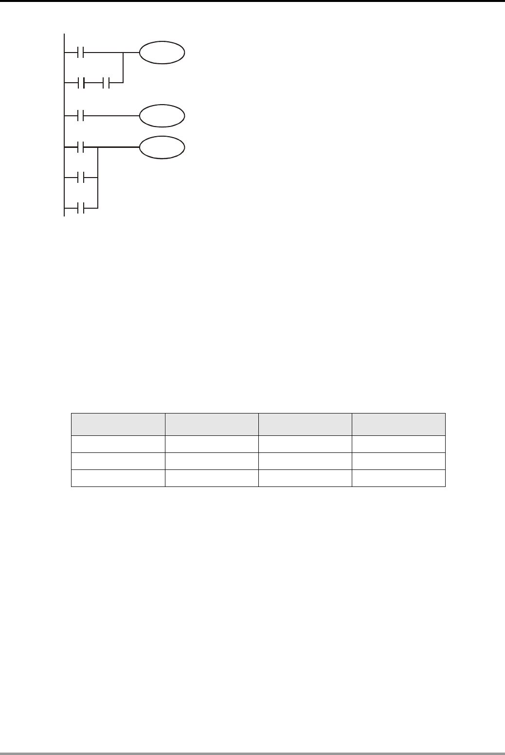
15. Handy Instruction Design Examples
DVP-PLC Application Examples
15-8
M103
M104 M1013
Y12
Y10
M100
M101
M102
M105
Y11
Horizontal red light ON
Horizontal yellow light ON
Horizontal green light ON
Program Description:
z “Incremental Drum Sequencer” is a concept performing repetitive step-by-step process. In
this program, when present value in counter C0 reaches the set value in D 500~D505, the
corresponding output devices M100~M105 will be ON and counter C0 will be reset for
executing next step.
z In order to simplify the program, INCD (Incremental Drum Sequencer) instruction is used
here to control the traffic lights.
z Before the execution of INCD instruction, use MOV instruction to write all the set values into
D500 ~ D505 in advance.
Set value Output device Set value Output device
D500 = 52 M100 D503 = 52 M103
D501 = 5 M101 D504 = 5 M104
D502 = 3 M102 D505 = 3 M105
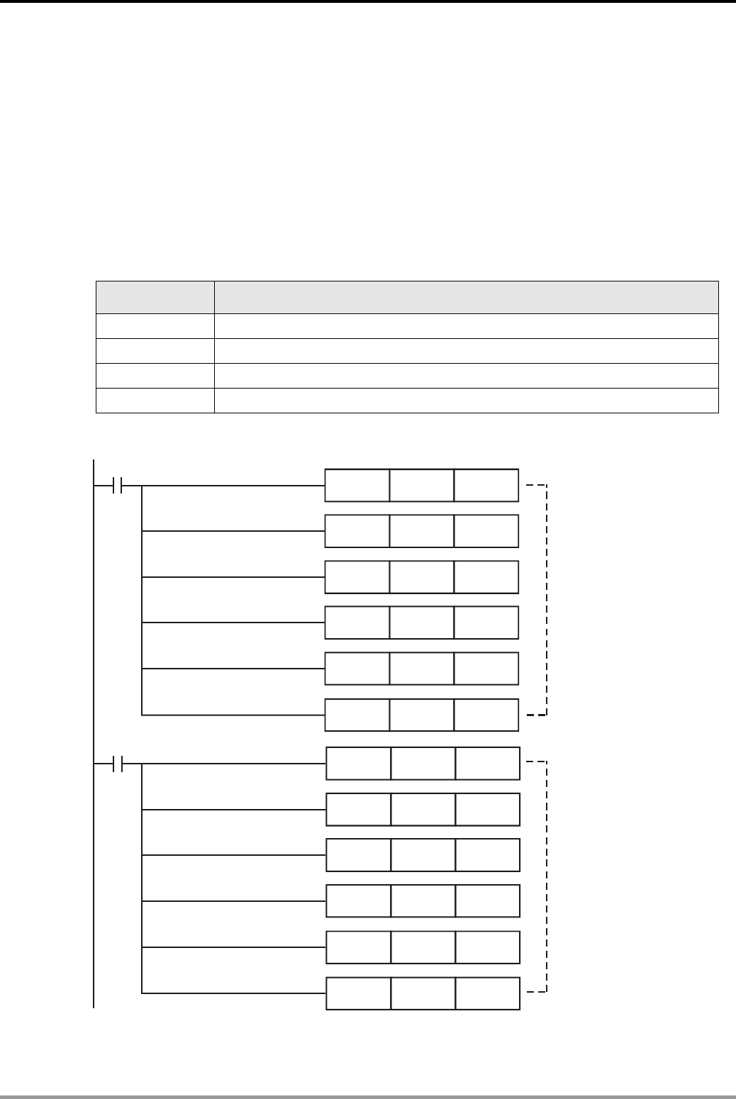
15. Handy Instruction Design Examples
DVP-PLC Application Examples 15-9
15.4 ABSD - Adding Materials in Different Intervals (Absolute Drum Sequencer)
Control Purpose:
z Adding A, B, C materials for production during specified intervals within 60 sec.
z Adding material A in the intervals of 10s~20s, 30s~40s and 50~55s, material B in the interval
of 0~10s, 20s~25s and 40s~50s, and material C in the interval of 20s~25s, 30s~35s and
40s~45s.
Devices:
Device Function
X0 Switch of material adding control program
Y0 Adding material A
Y1 Adding material B
Y2 Adding material C
Control Program:
MOV K10 D500
MOV
MOV
MOV
K20
K0
K50
D501
D506
D511
MOV
MOV
K30
K10
D502
D507
MOV
MOV
K40
K20
D503
D508
MOV
MOV
K50
K25
D504
D509
MOV
MOV
K55
K40
D505
D510
M1002
M1002
Set the time interval for
adding material B
Set the time interval for
adding material A
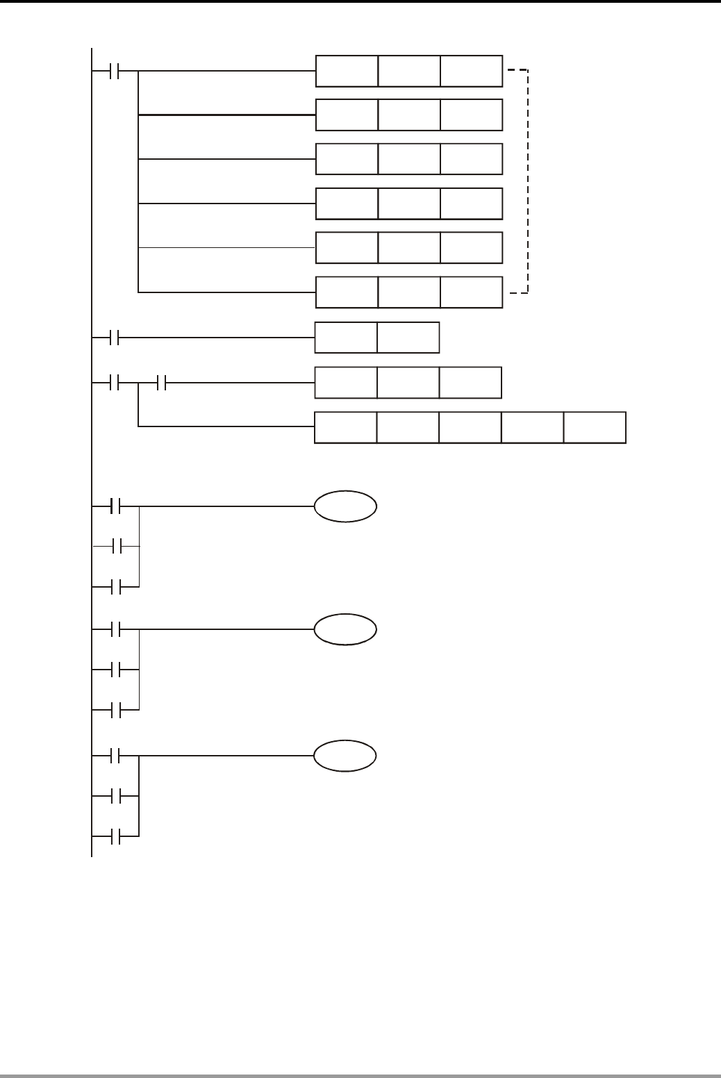
15. Handy Instruction Design Examples
DVP-PLC Application Examples
15-10
Y0
Y1
Y2
M100
M103
M106
M101
M104
M107
M102
M105
M108
A
dd material A
A
dd material B
A
dd material C
MOV K20 D512
MOV K25 D513
MOV
MOV
K30
K40
D514
D516
MOV
MOV
K35
K45
D515
D517
A
BSD D500 C0
CNT
RST
C0
C0
K60
M1002
M1013
X0
C0
M100 K9
Set the time interval for
adding material C
Reset C0 when one production
cycle is completed
When the present value in C0 reaches time intervals
for adding materials, the corresponding output devices
M100~M108 will be ON.
Program Description:
z “Absolute Drum Sequencer” is a concept performing repetitive process consists of multiple
steps which could be executed in the same interval. In this program, when present value in
counter C0 reaches the set value in D 500~D517, the corresponding output devices
M100~M108 will be ON to execute specified actions within single interval.
z Before the execution of ABSD instruction, use MOV instruction to write all the set values into

15. Handy Instruction Design Examples
DVP-PLC Application Examples 15-11
D500 ~ D517 in advance.
Set value Output device Set value Output device
D500 = 10 M100 D509 = 25 M104
D501 = 20 M100 D510 = 40 M105
D502 = 30 M101 D511 = 50 M105
D503 = 40 M101 D512 = 20 M106
D504 = 50 M102 D513 = 25 M106
D505 = 55 M102 D514 = 30 M107
D506 = 0 M103 D515 = 35 M107
D507 = 10 M103 D516 = 40 M108
D508 = 20 M104 D517 = 45 M108
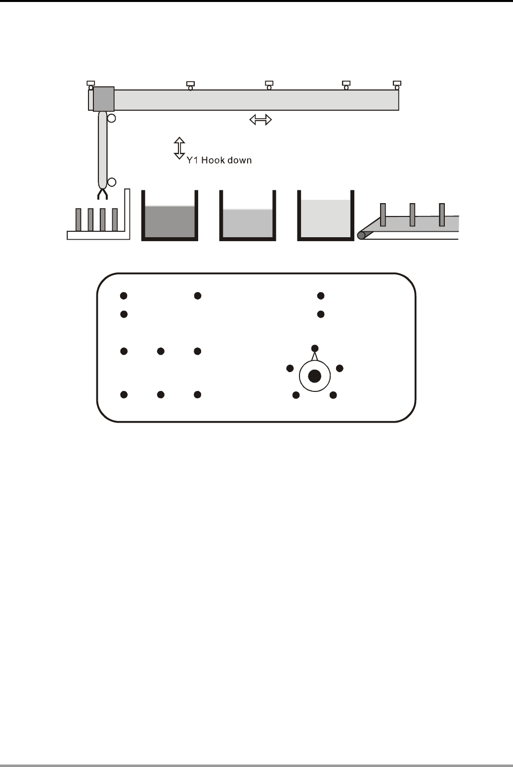
15. Handy Instruction Design Examples
DVP-PLC Application Examples
15-12
15.5 IST - Electroplating Process Auto Control
Y3 Y2
Left-limit
X0
Right-limit
X4
Limit of plating
tank X1
Limit of recovery
tank X2
Limit of rinse
tank X3
Plating tank
Recovery tank Rinse tank
Clipping location Conveyor belt
Move Left Move Right
X5.
Upper-limit
of hook Y0 Hook up
Lower-limit
of hook
X6
Power ON
Power OFF
X15. Zero return ON X16. Auto start
X17. Auto stop
Hook
up
Move
left Clip
Move
right Release
Single Step
X12
Hook
down
X20
X21
X22 X24
X23 X25
Zero return
X11
Manual
X10
X13 One cycle
X14 Continuous
Control Purpose:
z Applying PLC on auto control process of PCB electroplating. There is a traveling crane
equipped with a lifting hook in the production line. The hook has a clip for clipping and
releasing the workpiece. The traveling crane and the lifting hook are controlled by 2 motors
and a control panel. In addition, there are plating tank, recovery tank and rinse tank in the
process of plating workpiece, recycling plating solution and cleaning workpiece.
z Process:
Clip the workpiece → Put it in the plating tank for 280 minutes → lift it to the upper-limit and
stay for 28s → soak it in the recovery tank for 30 minutes → lift it to the upper-limit and stay
for 15s → clean it in the rinse tank for 30s → lift it to the upper-limit and stay for 15s → put it
on the conveyor belt.
z 3 operation modes:
Manual: select manual mode (X10 = ON) and enable/disable output devices by controlling
corresponding switches (X20~X25).
Zero return: select zero return mode (X11 = ON) and press the zero return button X15 to
execute this function.
15. Handy Instruction Design Examples
DVP-PLC Application Examples 15-13
Auto: (Single step/One cycle/Continuous)
1. Single step operation: select Single step (X12 = ON). Execute one step when
pushing Auto start (X16) one time.
2. One cycle operation: select One cycle (X13 = ON). Press Auto start (X16) at the
zero point and the program will execute one cycle of plating process. If Auto
stop (X17) is pressed, the process will be stopped. The program will continue to
finish the cycle if Auto start is pressed again.
3. Continuous operation: select Continuous (X14 = ON). Press Auto start (X16) at
the zero point and the program will perform continuous plating process for
cycles until Auto stop (17) is pressed. If Auto stop is pressed, the program will
finish the cycle and stop at zero point.
Devices:
Device Function
X0 X0 = ON when the left-limit switch is activated.
X1 X1 = ON when the limit switch of plating tank is activated.
X2 X2 = ON when the limit switch of recovery tank is activated.
X3 X3 = ON when the limit switch of rinse tank is activated.
X4 X4 = ON when the right-limit switch is activated.
X5 X5 = ON when the upper-limit switch of lifting hook is activated.
X6 X6 = ON when the lower-limit switch of lifting hook is activated.
X10 X10 = ON when Manual mode is selected
X11 X11 = ON when Zero return mode is selected
X12 X12 = ON when Single step mode is selected
X13 X13 = ON when One cycle mode is selected
X14 X14 = ON when Continuous mode is selected
X15 X15 = ON when Zero return ON is pressed.
X16 X16 = ON when Auto start is pressed.
X17 X17 = ON when Auto stop is pressed.
X20 X20 = ON when Hook up is pressed.
X21 X21 = ON when Hook down is pressed.
X22 X22 = ON when Move left is pressed.
X23 X23 = ON when Move right is pressed.
X24 X24 = ON when Clip is pressed.
X25 X25 = ON when Release is pressed
Y0 Hook up
Y1 Hook down
Y2 Move right
Y3 Move left
Y4 Clipping
15. Handy Instruction Design Examples
DVP-PLC Application Examples
15-14
Control Program:
X0 X5
M1000
M1044
IST X10 S20 S51
Zero point condition
S
Y0
S0 X20 Y1
X21 Y0
X23 X5 Y3
Y1
Y2
X22 X5 Y2
Y3
S
S
X24
X25
SET Y4
RST Y4
S1 X15
SET S10
RST Y4
S10
RST Y1
Y0
X5
SET S11
S
RST Y2
S11
Y3
X0
SET S12
S
SET M1043
S12
RST S12
S
S2 M1041 M1044
SET S20
Hook up
Hook down
Traveling crane move right
Traveling crane move left
Clip
Release clip
Release clip
Hook down stops
Zero return
completed
Enable Auto
operation mode
Manual operation mode
Zero return mode
X5
X6
X4
X0
Traveling crane
move right stops
S
Y1
S20
X6
SET S30
S
SET Y4
S30
T0
SET S31
TMR T0 K20 Clip and
hold for 2s
Enable Zero
return mode
Hook goes up
to upper limit (X5 = ON)
Traveling crane move left
to left limit (X0 = ON)
Enable zero return
completed flag
Hook goes down
to lower limit (X6 = ON)
15. Handy Instruction Design Examples
DVP-PLC Application Examples 15-15
S
Y0
S31
X5
SET S32
S
Y2
S32
X1
SET S33
S
Y1
S33
X6
SET S34
S
S34
T1
S
Y0
S35
X5
SET S36
S
S36
T2
SET S37
S
Y2
S37
X2
SET S38
X5
X1
X6
T1
TMR T1 K24000
CNT C0 K7
C0
SET S35
TMR T2 K280
Hook goes up
to upper limit (X5 = ON)
X5
X2
S
Y1
S38
X6
SET S39
S
S39
T0
SET S40
S
Y0
S40
X5
SET S41
S
S41
T4
SET S42
TMR T0 K18000
TMR T4 K150
Hook goes down
to lower limit (X6 = ON)
Hook goes up
to upper limit (X5 = ON)
X6
X5
Hook goes up
to upper limit (X5 = ON)
Traveling crane move right to the
limit switch of plating tank (X1 = ON)
Hook goes down
to lower limit (X6 = ON)
Dip the workpiece in the plating
tank for 280 minutes
Hold the workpiece upon
the plating tank for 28s
Traveling crane move right to the limit
switch of the recovery tank (X2 = ON)
Dip the workpiece in the
recovery tank for 30 minutes
Hold the workpiece upon
the recovery tank for 15s
15. Handy Instruction Design Examples
DVP-PLC Application Examples
15-16
S
Y2
S42
X3
SET S43
S
Y1
S43
X6
SET S44
S
S44
T5
SET S45
TMR T5 K300
S
Y0
S45
X5
SET S46
S
S46
T6
SET S47
TMR T6 K150
S
Y2
S47
X4
SET S48
X3
X6
X5
X4
S
Y1
S48
X6
SET S49
S
Y0
S50
X5
SET S51
S
S49
TMR T7 K20
T7
SET S50
S
S51
X0
RET
S2
Y3
RST Y4
Hook goes down
to lower limit (X6 = ON)
Release clip
Hook goes up
to upper limit (X5 = ON)
Traveling crane move left
to left limit (X0 = ON)
X6
X5
X0
Traveling crane move right to the
limit switch of rinse tank (X3 = ON)
Hook goes down
to lower limit (X6 = ON)
Clean workpiece in
rinse tank for 30s
Hook goes up
to upper limit (X5 = ON)
Hold the workpiece upon
the rinse tank for 15s
Traveling crane move right
to right limit (X4 = ON)

15. Handy Instruction Design Examples
DVP-PLC Application Examples 15-17
Program Description:
z The program uses Auto/Manual control instructions (IST) to perform auto control process of
PCB electroplating. When IST instruction is applied, S10 ~ S19 can not be used as general
step points, but only can be used for zero return. When S0 ~ S9 are in use, S0 ~ S2 are
specified for manual operation mode, zero return mode and auto operation mode. Therefore,
the content of the 3 steps should be designed first in this program.
z When zero return mode is selected, no zero return action will occur if any step between S10
~ S19 is ON. When auto mode is selected, no action will occur if any step in Auto mode is
ON or if M1043 is ON.
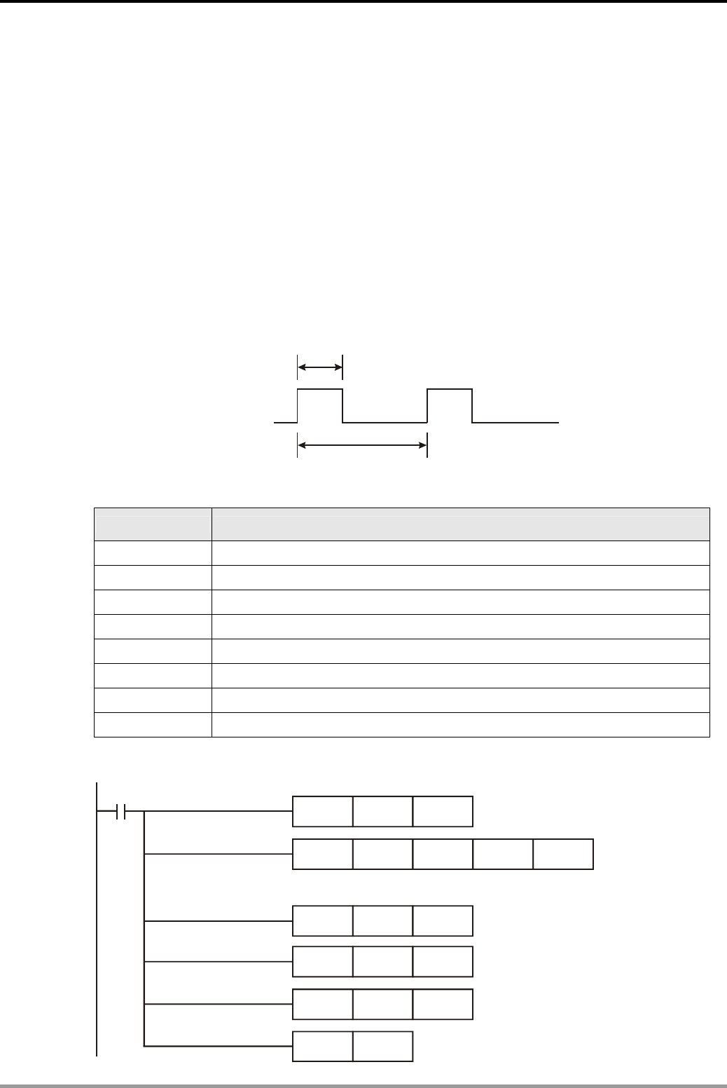
15. Handy Instruction Design Examples
DVP-PLC Application Examples
15-18
15.6 FTC - Fuzzy Temperature Control of the Oven
Control Purpose:
z The heating environment of the oven is “fast heating environment” (D13 = K16) and the
target temperature is 120℃ (D10 = K1200). In order to get the best control results, the
program uses FTC together with GPWM instructions to perform fuzzy temperature control.
z Apply DVP04PT-S temperature measurement module for measuring the present
temperature of the oven and transferring the result to DVP12SA. After execution of FTC
instruction, PLC outputs the operation results in D22 to the input of GPWM instruction.
GPWM instruction outputs width modulatable pulses (width determined by D22) by Y0 to
control the heater and fuzzy temperature control of the oven is completed.
D22
D30
Y0
Devices:
Device Function
M1 Enabling the execution of FTC instruction
Y0 PWM Pulse output device
D10 Storing the target temperature
D11 Storing the present temperature
D12 Storing FTC sampling time parameter
D13 Storing FTC temperature control parameter
D22 Storing the operation results of FTC instruction
D30 Storing the pulse output cycle of GPWM instruction
Control Program:
M1002
TO
MOV
K0
K1200
K2
D10
MOV
MOV
MOV
SET
K40
K16
K4000
M1
D12
D13
D30
K1K2
Set target temperature:120
℃
Set the average time of Channel 1: 2 times DVP04PT
Set sampling time: 4s
Set the heating environment
to "fast heating environment
Set the pulse output cycle of
GPWM: 4s
Execute FTC and GPWM instructions
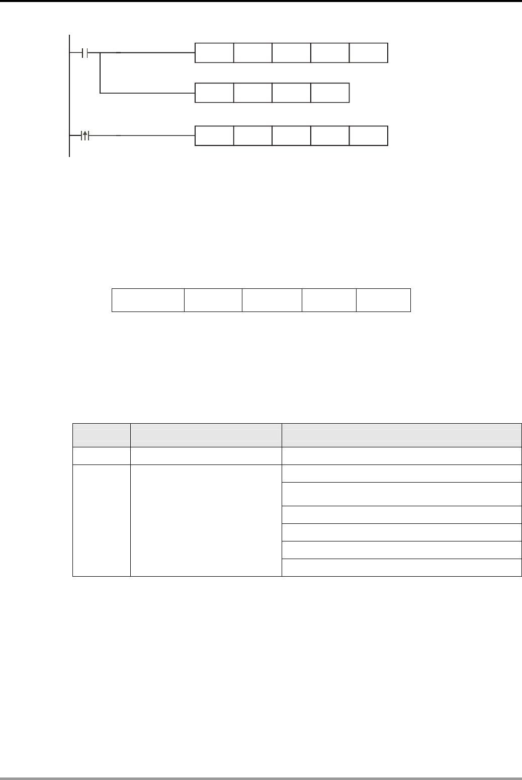
15. Handy Instruction Design Examples
DVP-PLC Application Examples 15-19
M1
GPWM
FTC
FROM
D22
D10
K0
D30
D11
K6
D22
K1
Y0
D12
D11
M1013
Store the operation result of FTC instruction in D22
Y0 outputs pulses (width determined by D22)
Sample present temp. every 1 sec and store
it in D11
Program Description:
z FTC instruction is a handy instruction exclusively designed for temperature control. Unlike
the large amount of parameters required by PID instruction, users only need to set a few
parameters.
z Format of FTC instruction:
FTC S1 S
2 S
3 D
S1 → Set value (SV) (Range:1~5000, shown as 0.1°~500°)
S2 → Present value (PV) (Range:1~5000, shown as 0.1°~500°)
S3 → Parameter (Users need to set parameters S3 and S3+1)
D → Output value (MV) (Range: 0 ~ S3*100)
z Setting of S3 and S3+1:
Device Function Range
S3 Sampling time (Ts) 1~200 (unit: 100ms)
b0 = 0 means ; b0℃ = 1 means ℉
b1 = 0 means without filter function;
b1 = 1 means with filter function
b2 = 1 Slow heating environment
b3 = 1 General heating environment
b4 = 1 Fast heating environment
S3+1
b0: temperature unit
b1: filter function
b2: heating environment
b3~b15: reserved
b5 = 1 High-speed heating environment
z In practical application, users usually need to adjust S3 and S3+1 several times to get the
best control results. The basic rules are as follows:
1. Sampling time should be set to 2 times more than the sampling time of the temperature
sensor, generally between 2s ~6s.
2. The cycle time of GPWM instruction is the same with the sampling time of FTC
instruction, but the unit for GPWM cycle time is 1ms.
3. Properly decrease SV of the sampling time if the control duration is too long.
4. Properly increase SV of the sampling time if the fluctuations occur frequently.
5. “General heating environment” (b3 = 1) is the default setting for the heating
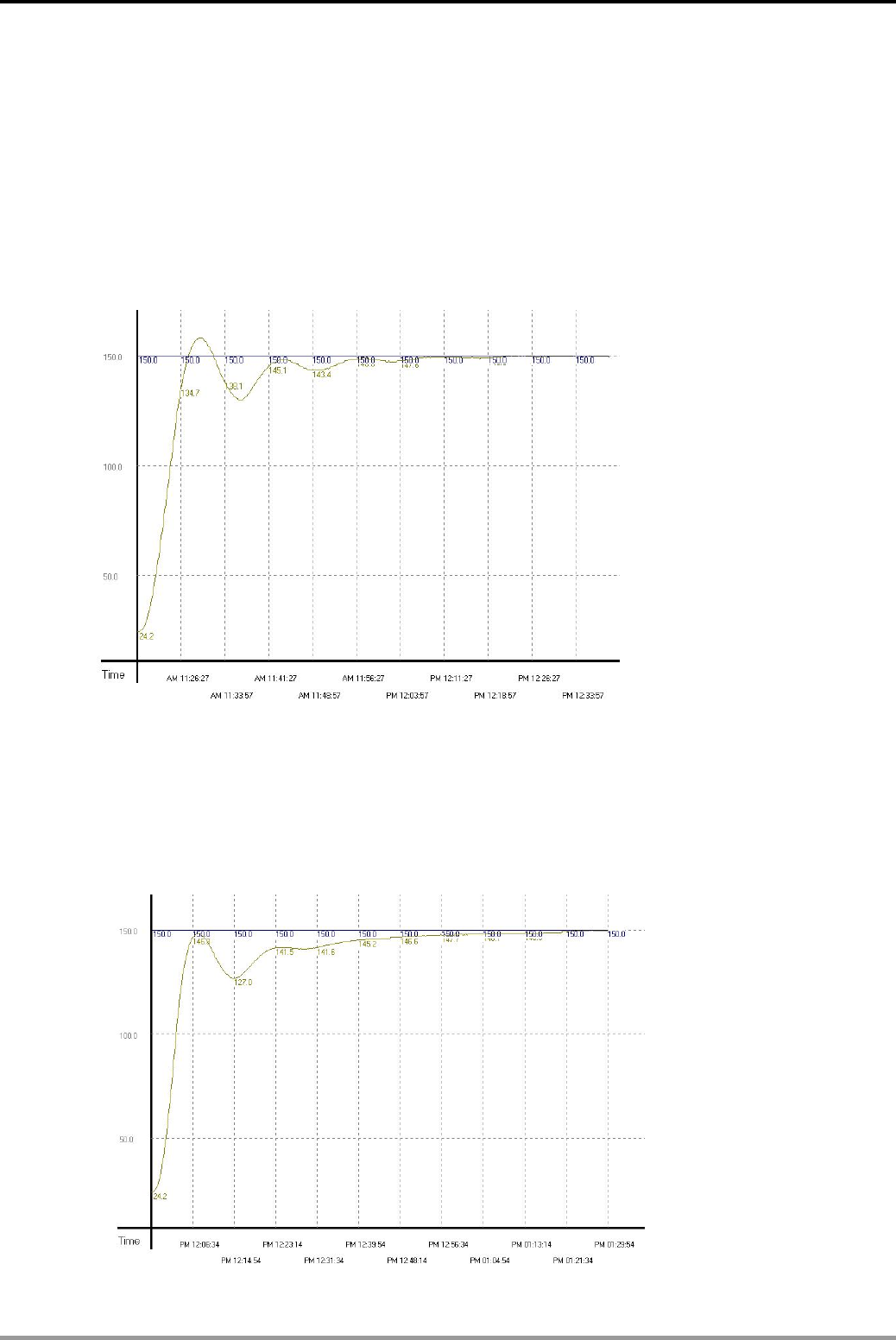
15. Handy Instruction Design Examples
DVP-PLC Application Examples
15-20
environment (bit2~bit5 of S3+1).
6. Select “slow heating environment” (b2 = 1) if the control duration is too long.
7. Select “fast heating environment” (b4 = 1) if overheating or fluctuations occur.
z Adjustment of parameters S3 and S3+1:
Assume parameters S3 and S3+1 of FTC instruction are set as D12 = K60 (6s), D13 = K8
(b3 = 1) and pulse output cycle time of GPWM instruction is set as D30 = K6000 ( =
D12*100), the curve for the control is shown as the below diagram:
As shown in the diagram above, we can see that after about 48 minutes, the temperature is
able to reach the target temperature with ±1℃ accuracy and exceed approx. 10°C of the
target temperature. Due to that the temperature once exceeds the target temperature, we
modify the heating environment into “fast heating environment”, i.e. D13 = K16 (b4 = 1). The
results are shown in the diagram below.
From the diagram above, we see that though the temperature no longer exceeds the target
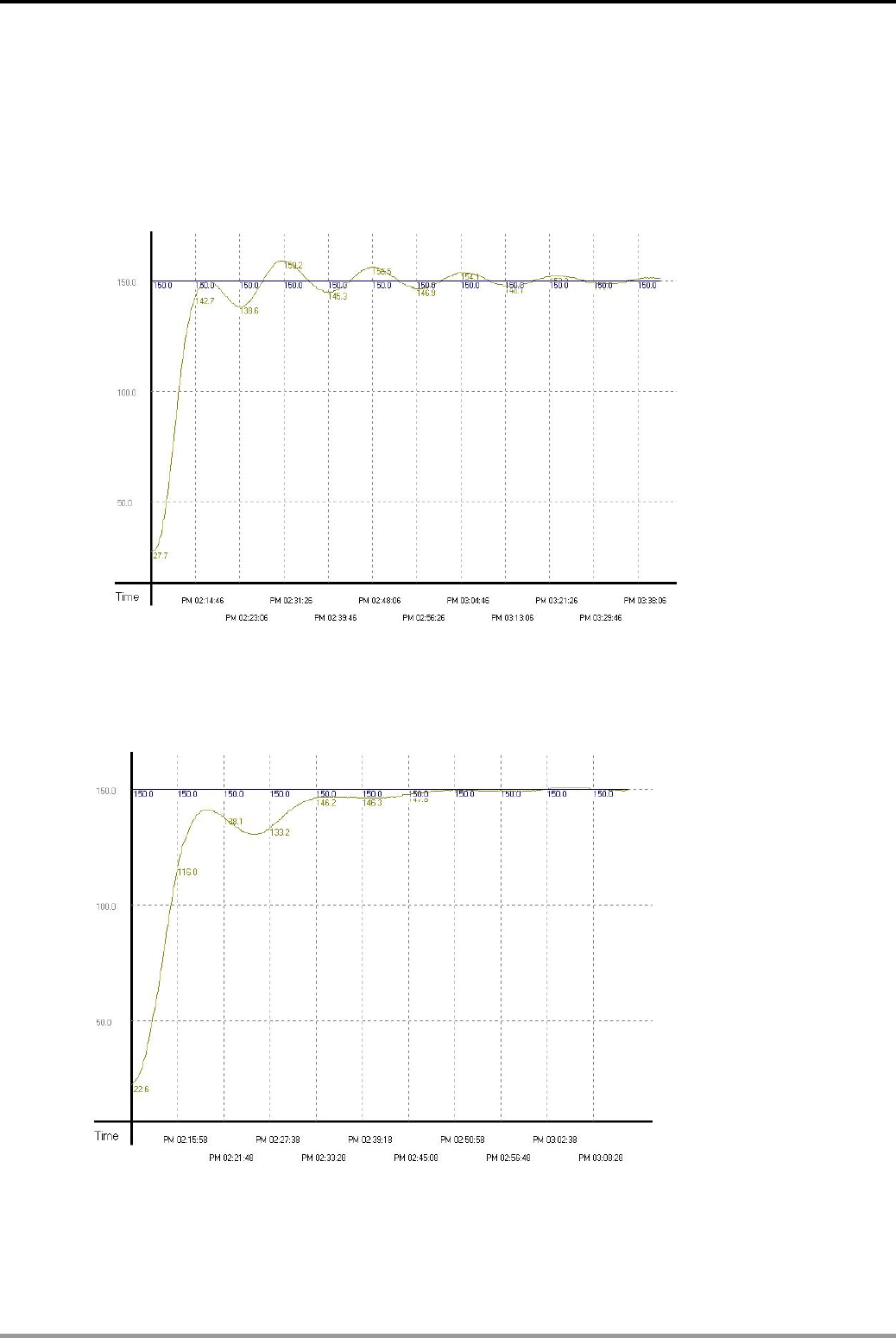
15. Handy Instruction Design Examples
DVP-PLC Application Examples 15-21
temperature, it still needs to take more than 1 hour and 15 minutes to reach the target
temperature with ± 1℃ accuracy. It seems that we have chosen the right environment, but
the sampling time is too long, resulting in the extension of heating time. Therefore, we modify
the sampling time to 2 seconds, i.e. D12 = K20 (2s) and D30 = K2000 (= D12*100). The
results are shown in the diagram below.
From the diagram above, we see that the control system becomes too sensitive and leads to
up and down fluctuations. Therefore, we modify the sampling time to 4s, i.e. D12 = K40 (4s)
and D30 = K4000 (= D12*100). The results are shown in the diagram below.
From the diagram above, we see that the overall control time has been shorten as 37
minutes and no exceeding or fluctuations occur. The basic requirements of the control
system are satisfied.
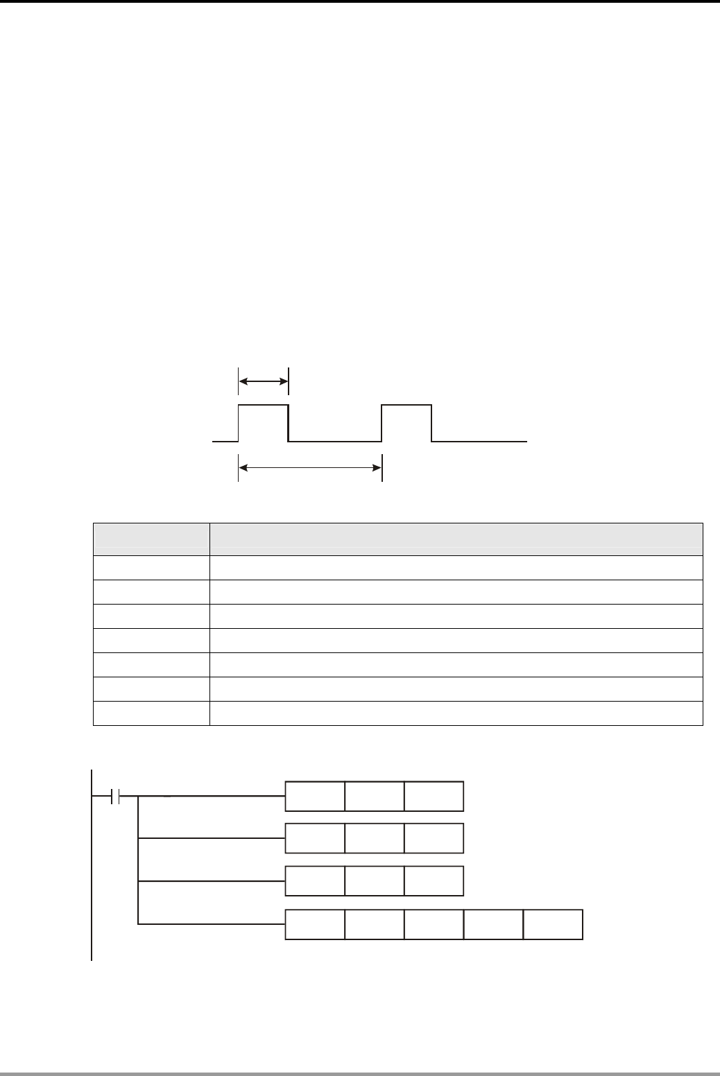
15. Handy Instruction Design Examples
DVP-PLC Application Examples
15-22
15.7 PID - Oven Temperature Control (Auto-tuning for PID Temperature Control)
Control Purpose:
z Execute auto-tuning function of PID instruction to control the temperature of the oven when
the oven is in unknown temperature environment. The target temperature is 80℃.
z Apply DVP04PT-S temperature module for measuring the present temperature of the oven
and transferring the results to PLC. The PLC will execute parameter auto-tuning function
(D204 = K3) to operate the best PID parameters and automatically change the control
direction as “Exclusively for the adjusted temperature control” (D204 = K4).
z PLC outputs the operation results (adjusted parameter) in D0 to the input of GPWM
instruction. Y0 will output PWM pulses (width determined by D0) to control the heater and
PID temperature control is accomplished.
D0
D20
Y0
Devices:
Device Function
M1 Executing PID instruction
Y0 Outputting adjustable pulses
D0 Storing PID operation result
D10 Storing the target temperature
D11 Storing the present temperature
D20 Storing pulse output cycle of GPWM instruction
D200 Storing PID sampling time parameter
Control Program:
M1002
MOV
MOV K400
K4000
D200
D20MOV
K800 D10
TO K0 K2 K1K2
Set cycle time of GPWM
instruction: 4s
Set sampling time: 4s
Set target temp: 80
℃
Set the average time of Channel 1:2 timesDVP04PT
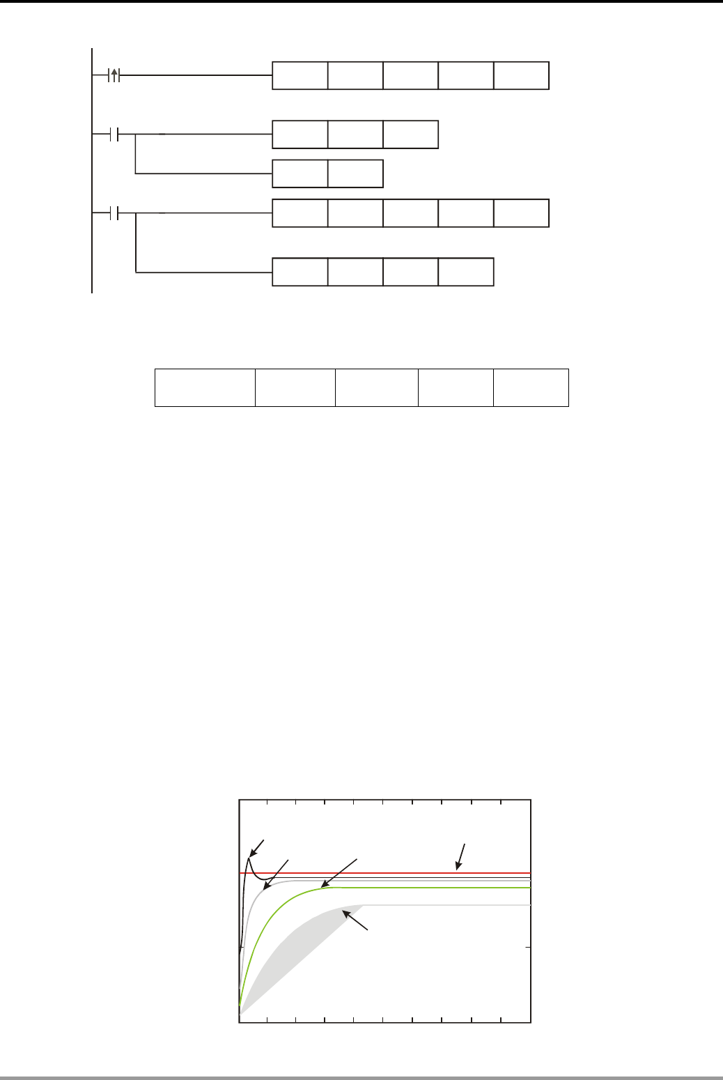
15. Handy Instruction Design Examples
DVP-PLC Application Examples 15-23
M0
M1
GPWM
PID
FROM
MOV
RST M0
D0
D10
K0
K3
D20
D11
K6
D204
D0
K1
Y0
D200
D11
M1013
Store PID operation result in D200
Sample PV of the oven every 1s and store it in D11
Set the control direction
as auto-tuning temperature
Program Description:
z Format of PID instruction:
PID S1 S
2 S
3 D
S1 → Set value (SV)
S2 → Present value (PV)
S3 → Parameter (Users need to set and adjust it. For the definition, refer to PID parameter
table in the last part of this example)
D → Output value (MV) (D has to be the data register area with latched function)
z There are a lot of circumstances where PID instruction can be applied; therefore, please
choose the control functions appropriately. In this example, the parameter auto-tuning for
temperature is only for the temperature control, users cannot use it in a speed or pressure
control environment or errors could occur.
z Generally, adjusting control parameters of PID requires experience and repetitive tests.
(except the auto-tuning function in temperature control environment) The common
parameter adjusting steps are as below:
Step 1: Set KI and KD as 0 and KP as 5, 10, 20 and 40. Record the SV and PV respectively
and the results are as the figure below.
1.5
1
0.5
00 0.1 0.2 0.3 0.4 0.5 0.6 0.7 0.8 0.9 1
K =40
P
K =20
P
K =10
P
SV=1
K =5
P
Time (sec)
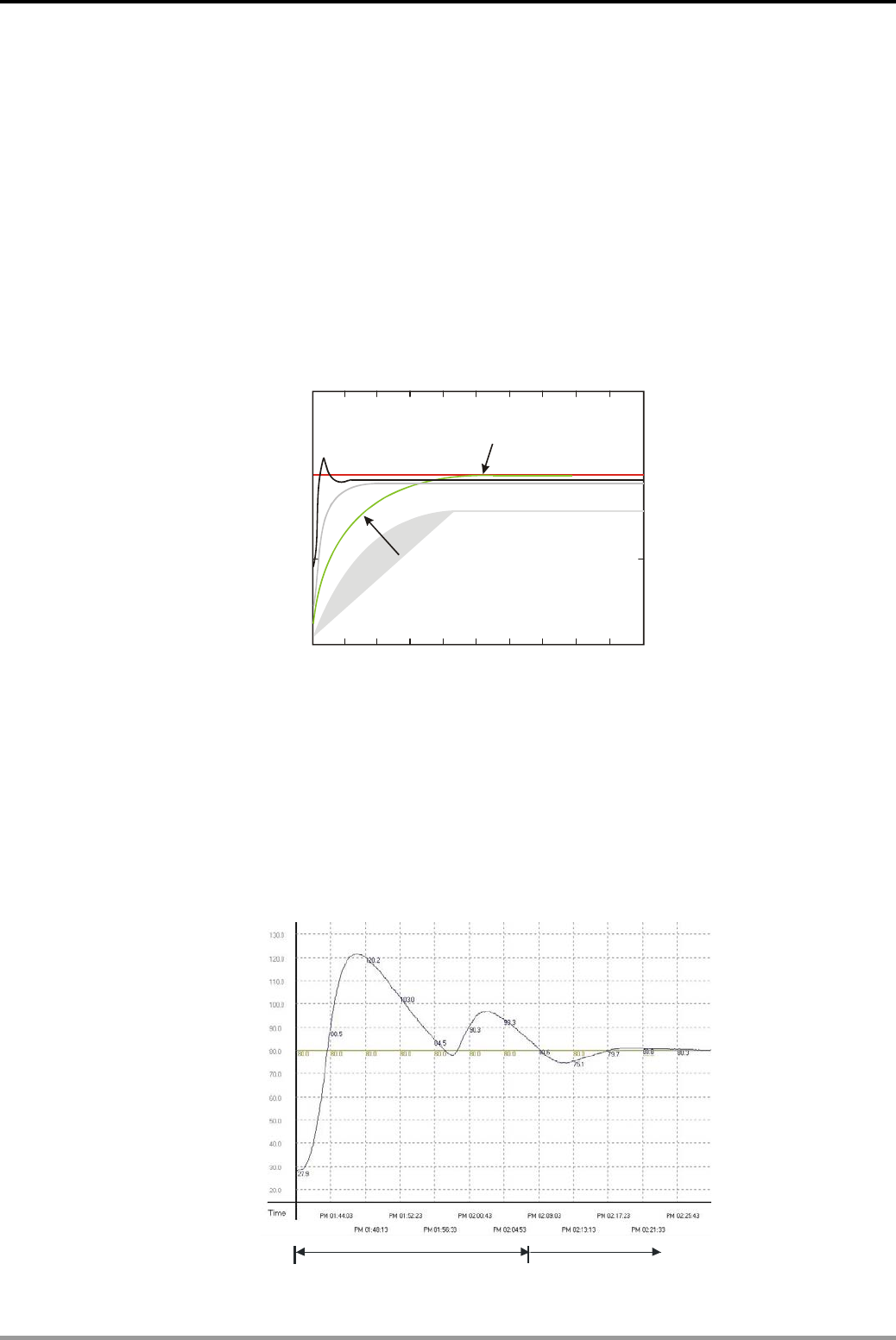
15. Handy Instruction Design Examples
DVP-PLC Application Examples
15-24
Step 2: From the figure, we can see that when KP = 40, there will be over-reaction, so we will
not select it. When KP = 20, the PV reaction curve will be close to SV and there will
not be over-reaction, but due to its fast start-up with big transient MV, we will
consider to put it aside. When KP = 10, the PV reaction curve will get close to SV
value more smoothly, so we will use it. Finally when KP = 5, we will not consider it
due to the slow reaction.
Step 3: Select KP = 10 and adjust KI from small to big (e.g. 1, 2, 4 to 8). KI should not be
bigger than KP. Adjust KD from small to big (e.g. 0.01, 0.05, 0.1 and 0.2). KD should
not exceed 10% of KP. Finally we obtain the figure of PV and SV below.
1.5
1
0.5
00 0.1 0.2 0.3 0.4 0.5 0.6 0.7 0.8 0.9 1
PV=SV
K =10,K =8,K =0.2
PID
Time (sec)
Note: This example is only for your reference. Please adjust your parameters to proper ones
according to your actual condition of the control system.
z In the temperature control environment, Delta PLC provides auto-tuning on parameters of
PID instruction, so users can get good control results without parameter adjusting steps .
See below for the auto-tuning process in this example:
1. Initial adjustment. Operate the most suitable parameter for PID temperature control
and store the result in D200~D219. See the reaction curve below:
Auto tuning area
S +4 = K3
PID control area
S +4 = k4
3
3
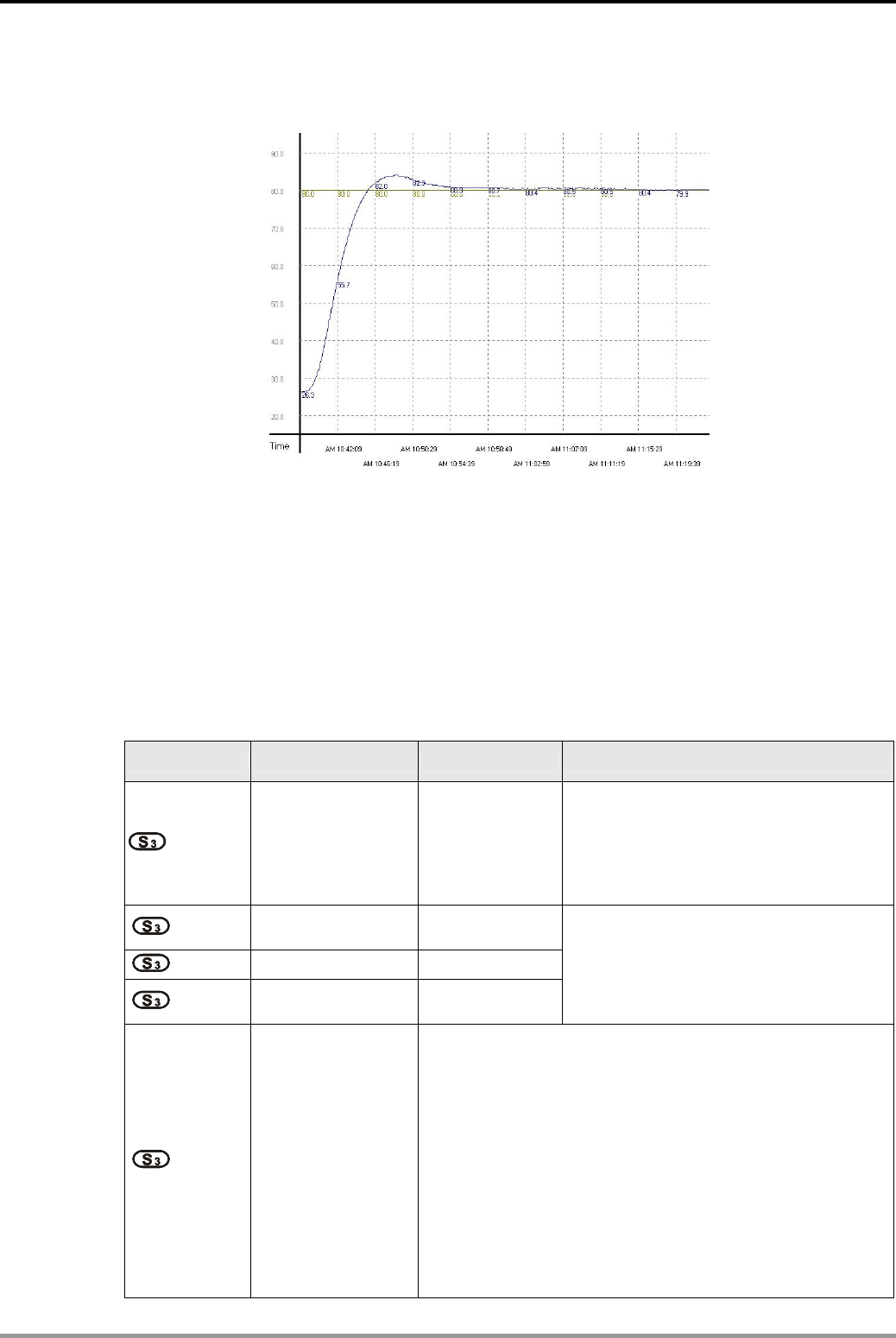
15. Handy Instruction Design Examples
DVP-PLC Application Examples 15-25
2. Use the adjusted parameter in D200~D219 to control temperature. The curve becomes
as below:
From the figure above, we can see that the temperature control after auto-tuning is working
fine and we use only approximately 20 minutes for the control.
z PID sampling time should be set the same with the cycle time of GPWM instruction, but its
unit is 10ms, which is different from the unit 1ms of GPWM instruction.
z Sampling time of PV should be set to 2 times more than the sampling time of PID, generally
between 2s ~6s.
z PID parameter table of S3 for 16-bit instruction:
Device No. Function Range Explanation
: Sampling time (TS)
(unit: 10ms)
1~2,000
(unit: 10ms)
If TS is less than 1 program scan time,
PID instruction will be executed for 1
program scan time. If TS= 0, PID
instruction will not be enabled. The
minimum TS has to be longer than the
program scan time.
+1: Proportional gain
(KP) 0~30,000 (%)
+2: Integral gain (KI) 0~30,000 (%)
+3: Differential gain
(KD)
-3,000~30,000
(%)
If SV is bigger than the max. value, the
output will be the max. value.
+4: Control direction
(DIR)
0: automatic control
1: forward control (E = SV - PV)
2: inverse control (E = PV - SV)
3: Auto-tuning of parameter exclusively for the temperature
control. The device will automatically become K4 when
the auto-tuning is completed and be filled in with the
appropriate parameter KP, KI and KD (not available in the
32-bit instruction).
4: Exclusively for the adjusted temperature control (not
available in the 32-bit instruction).
5: automatic control(with upper/lower bounds of integral
value). Only supported by SV_V1.2 / EH2_V1.2 / SA /
SA_V1.8 / SC_V1.6 or higher version PLC.
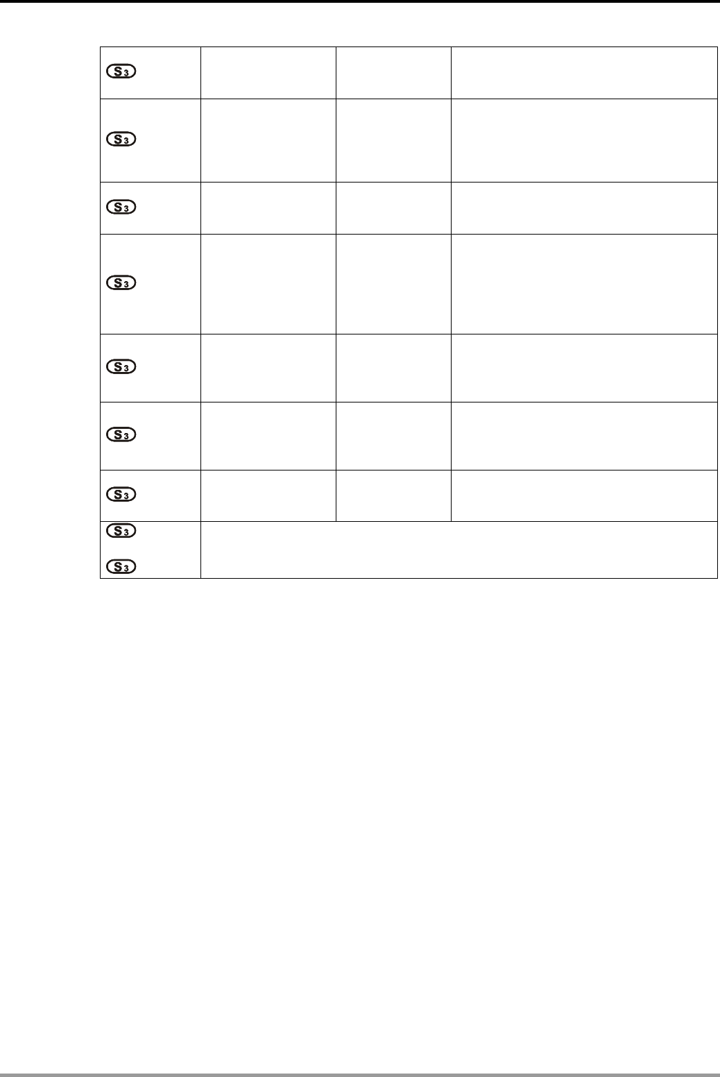
15. Handy Instruction Design Examples
DVP-PLC Application Examples
15-26
+5:
The range that error
value (E) doesn’t
work
0~32,767 Ex: when S3 +5 is set as 5, MV of E
between -5 and 5 will be 0.
+6: Upper bound of
output value (MV) -32,768~ 32,767
Ex: if S3 +6 is set as 1,000, the output
will be 1,000 when MV is bigger than
1,000. S3 +6 has to be bigger or equal
S3 +7; otherwise the upper bound and
lower bound will switch.
+7: Lower bound of
output value (MV) -32,768~ 32,767
Ex: if S3 +7 is set as -1,000, the output
will be -1,000 when MV is smaller than
-1,000.
+8: Upper bound of
integral value -32,768~ 32,767
Ex: if S3 +8 is set as 1,000, the output
will be 1,000 when the integral value is
bigger than 1,000 and the integration
will stop. S3 +8 has to be bigger or
equal S3 +9; otherwise the upper bound
and lower bound will switch.
+9: Lower bound of
integral value -32,768~ 32,767
Ex: if S3 +9 is set as -1,000, the output
will be -1,000 when the integral value is
smaller than -1,000 and the integration
will stop.
+10,11: Accumulated
integral value
32-bit floating
point
The accumulated integral value is only
for reference. You can still clear or
modify it (in 32-bit floating point)
according to your need.
+12: The previous PV -
The previous PV is only for reference.
You can still modify it according to your
need.
+13:
~
+19:
For system use only.
When parameter setting exceeds its range, the upper bound and lower bound will
become the setting value. However, if the motion direction (DIR) exceeds the range, it
will be set to 0.
The maximum error of sampling time TS = - (1 scan time + 1ms) ~ + (1 scan time).
When the error affects the output, please fix the scan time or execute PID instruction in
the interruption subroutine of the timer.
PV of PID instruction has to be stable before the execution of PID instruction. If you are
to extract the input value of DVP04AD/04DA/06XA/04PT/04TC for PID operation,
please be aware of the A/D conversion time of these modules.
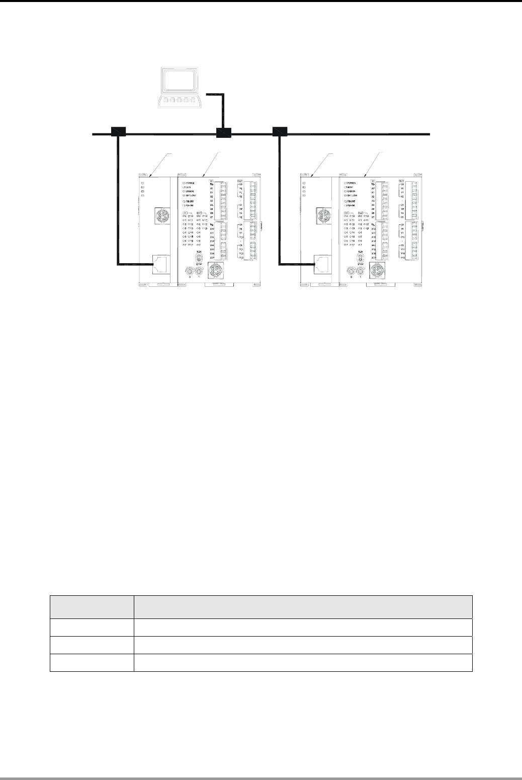
16. Network Connection Design Examples
DVP-PLC Application Examples 16-1
16.1 Ethernet Connection
DVP28SV
LAN
RS-232
DVPEN 01
LINK
100M
POWER
RS-232
D
VP28SV
L
AN
R
S-232
D
VPEN01
LINK
100M
P
OWER
RS-232
DVPEN01
Ethernet
DVP28SV
DVPEN01 DVP28SV
PC Master
PLC_A PLC_B
Control Purpose:
z Setting up network parameters of DVPEN01-SL directly on the PC
(1) IP of PC executing WPLSoft: 192.168.0.3
(2) Subnet mask: 255.255.255.0; Gateway: 192.168.0.1
(3) Set IP of PLC_A: 192.168.0.4; PLC_B: 192.168.0.5
(4) Connect the PC and DVPEN01-SL by RJ-45 cable
Note: Both PC and DVPEN01-SL have to adopt static IP.
z Writing the time of RTC in PLC_B into D0 ~ D6 of PLC_A
(1) Adopting static IP。
(2) IP of PLC_A: 192.168.0.4
(3) IP of PLC_B: 192.168.0.5
(4) Update form PLC_B to PLC_A
Devices:
Device Function
M1013 1s clock pulse
PLC_B M1 Write the data into DVPEN01-SL module
PLC_B M2 Check if data exchange is successfully executed.
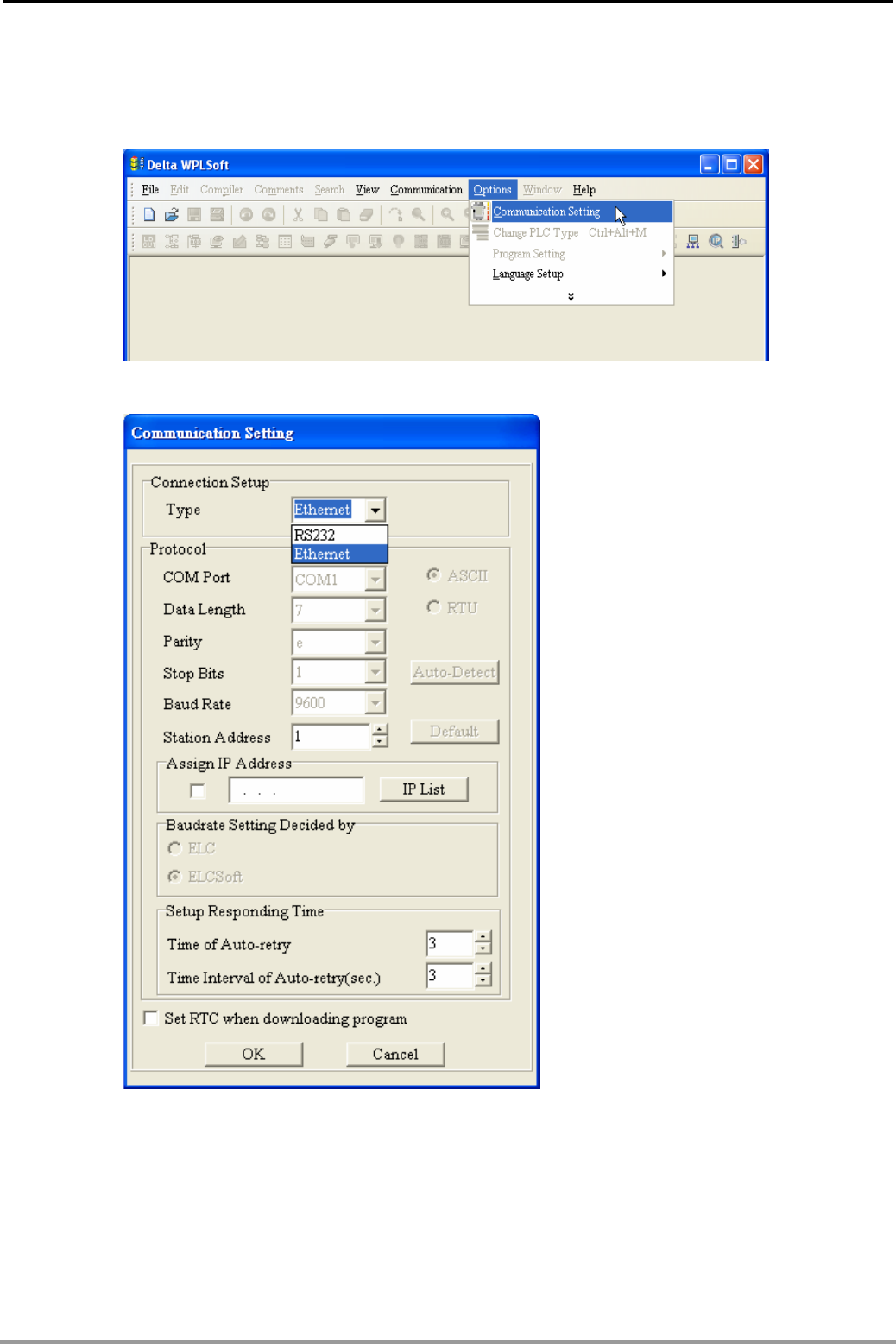
16. Network Connection Design Examples
DVP-PLC Application Examples
16-2
Settings:
z Select Communication Setting in WPLSoft.
z Select Ethernet in connection setup and click OK.
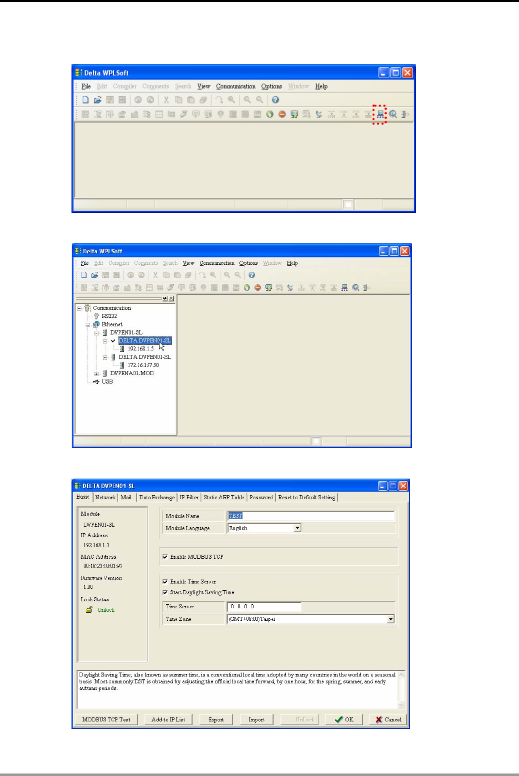
16. Network Connection Design Examples
DVP-PLC Application Examples 16-3
z Click Auto-Search icon to search for all DVPEN01-SL modules in the network.
z Designate a DVPEN01-SL and double click to open the setup page.
z The setup window will appear as below.
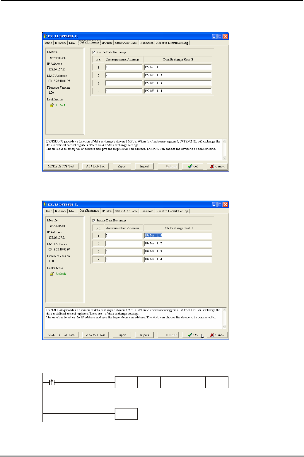
16. Network Connection Design Examples
DVP-PLC Application Examples
16-4
z Switch to Data Exchange window.
z Check Enable Data Exchange box. Enter IP address of PLC_A :192.168.0.4 in No. 1 Data
Exchange Host IP column. Click OK to complete the setting.
Control Program:
z Program of PLC_A:
END
M1013
K7D0K49K100FROM
The data are stored
in CR#49 ~ CR#55 and written into D0 ~ D6.
received every one second
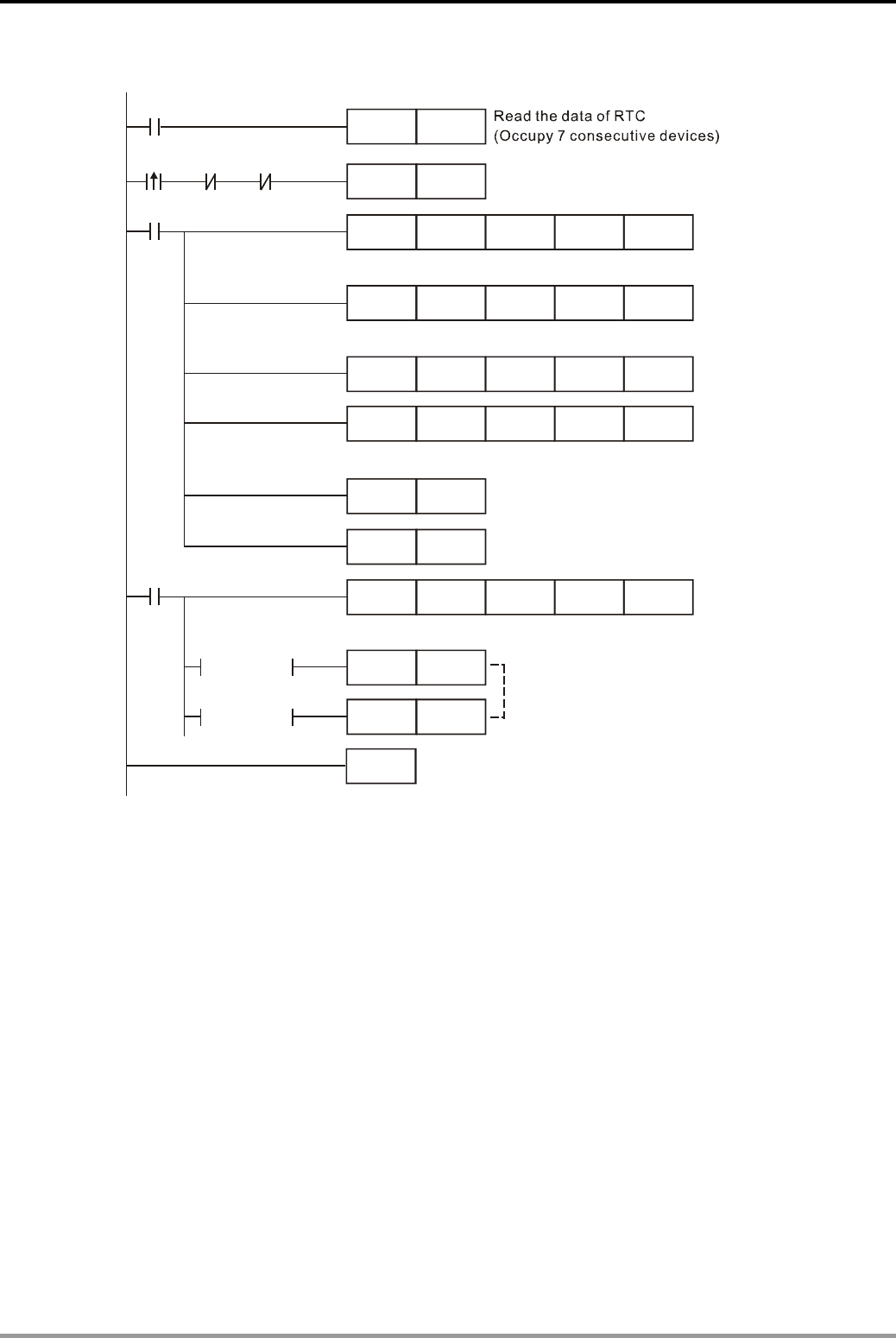
16. Network Connection Design Examples
DVP-PLC Application Examples 16-5
z Program of PLC_B:
END
M1013
K100 K1 K1
K100
K100 K1
M2 M1
M1SET
M1
TOP K28
TOP
TOP
K29
K14
K13
K0
D100 K7
K100 K1TOP K1
SET M2
M1RST
K100 K1
M2
K14 D14
RST M2
RST M2
= D14 K2
= D14 K3
FROM
D100TDR
M1000
The data exchange will be executed
every one second
Write the communication address of the destination PLC in CR#28
Write the data in RTC into CR#29 ~ CR#35
Write 1 into CR#13 to start the data exchange
The received data are stored in CR#14 and witten into D14
CR#14 = 2 refers to
exchange completed
CR#14 = 3 refers to
exchange failed
Program Description:
z Program of PLC_A:
(1) The received data are stored in CR#49 ~ CR#55.
(2) The data received every one second are written into D0 ~ D6.
z Program of PLC_B:
(1) The data exchange will be executed every one second.
(2) Write the communication address of the destination PLC in CR#28, and DVPEN01-SL
will automatically detect by the previous setting that No. 1 IP is “192.168.0.4".
(3) Write the data of RTC into CR#29 ~ CR#355.
(4) Write “1” into CR#13 to start the data exchange.
(5) CR#14 = 2 refers to exchange completed. CR#14 = 3 refers to exchange failed.
z For more instructions of ethernet communication module DVPEN01-SL, please refer to
DVP-PLC Application Manual: Special Modules Ⅱ
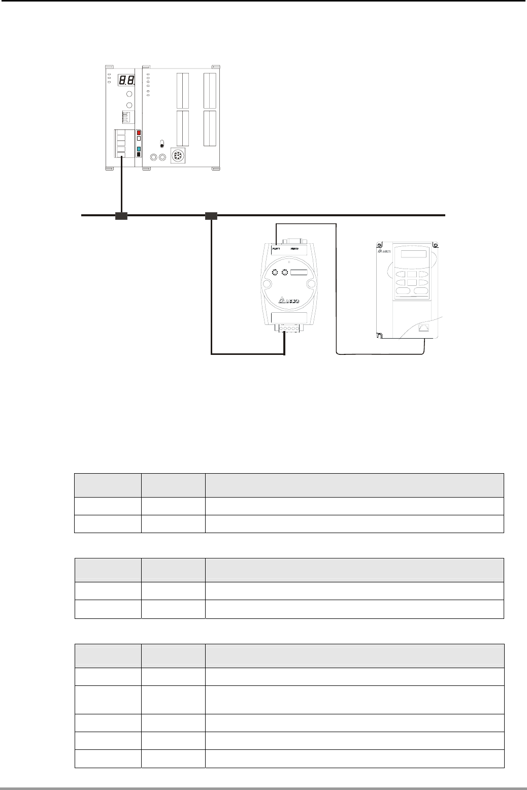
16. Network Connection Design Examples
DVP-PLC Application Examples
16-6
16.2 DeviceNet connection
DVPDNET DVP28SV
RUN
STOP
DeviceNet
RJ12
Node Address :00
Node Address :02
DNA02 VFD-B
RS485
Control Purpose:
z When M0 = ON, read the contenct of DNA02: Class 1>>Instance 1>>Attribute 1.
Devices:
z DVPDNET-SL settings:
Parameter Set value Explanation
Node address 00 Set the node address of DVPDNET-SL to “00”.
Baud rate 500kbps Set communication speed of DVPDNET-SL and bus to 500kbps
z DNA02 settings:
Parameter Set value Explanation
Node address 02 Set the node address of DNA02 to “02".
Baud rate 500kbps Set the communication speed of DNA02 and bus to 500kbps.
z VFD-B parameter settings:
Parameter Set value Explanation
02-00 04 The main frequency is operated on RS-485 interface.
02-01 03
The operation commands are operated on the communication
interface. Operation by keys is valid.
09-00 01 Communication address of VFD-B: 01
09-01 03 Baud rate: 38,400
09-04 03 Modbus RTU mode. Data format <8, N, 2>
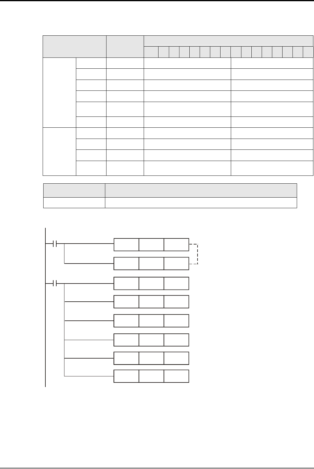
16. Network Connection Design Examples
DVP-PLC Application Examples 16-7
z Explanations on devices:
Explanation
PLC Devive Content 15 14 13 12 11 10 98 7 6 5 4 3 2 1 0
D6250 0101Hex ReqID = 01Hex Command = 01Hex
D6251 0005Hex Port = 00Hex Size = 05Hex
D6252 0E02Hex Service Code = 0EHex MAC ID = 02Hex
D6253 0001Hex High bye ot Class ID = 00Hex Low byte of Class ID = 01Hex
D6254 0001Hex
High byte of Instance ID =
00Hex Low byte of Instance ID =
01Hex
Request
message
editing area
D6255 0001Hex N/A Attribute ID = 01Hex
D6000 0101Hex ReqID = 01Hex Status = 01Hex
D6001 0002Hex Port = 00Hex Size = 02Hex
D6002 8E02Hex Service Code = 8EHex MAC ID = 02Hex
Response
message
editing area
D6003 031FHex
High byte of Service Data =
03Hex Low byte of Service Data =
1FHex
PLC device Function
M0 When M0 = ON, DVPDNET-SL will send out request message
Control Program:
MOV H0101 D6250
M1002
ZRST D6250 D6281
M0
MOV H0005 D6251
MOV H0E02 D6252
MOV H0100 D6253
MOV H0100 D6254
MOV H0100 D6255
ZRST D6000 D6031 Reset response message editing area
& request message editing area
ReqID = 01, Command = 01
Port = 00, Size = 05
Service Code = 0E, MAC ID = 02
Class ID to be read = 01
Instance ID to be read = 01
Attribute ID to be read = 01
Program Description:
z In the beginning of the program, clear the response message editing area and request
message editing area.
z When M0 = ON, DVPDNET-SL will send out request message, reading Class 1>>Instance
1>> Attribute 1 of the target equipment (node address: 02). If the communication of explicit
message is successful, the slave will return with a response message.

16. Network Connection Design Examples
DVP-PLC Application Examples
16-8
z When M0 = ON, DVPDNET-SL will only send out request message once. If you would like it
to send out request message again, you will have to change ReqID.
z When the reading is successful, the message responded from the target equipment will be
stored in D6000 ~ D6003.
z For more instructions of DeviceNet communication module DVPDNET-SL, please refer to
DVP-PLC Application Manual: Special Modules Ⅱ.
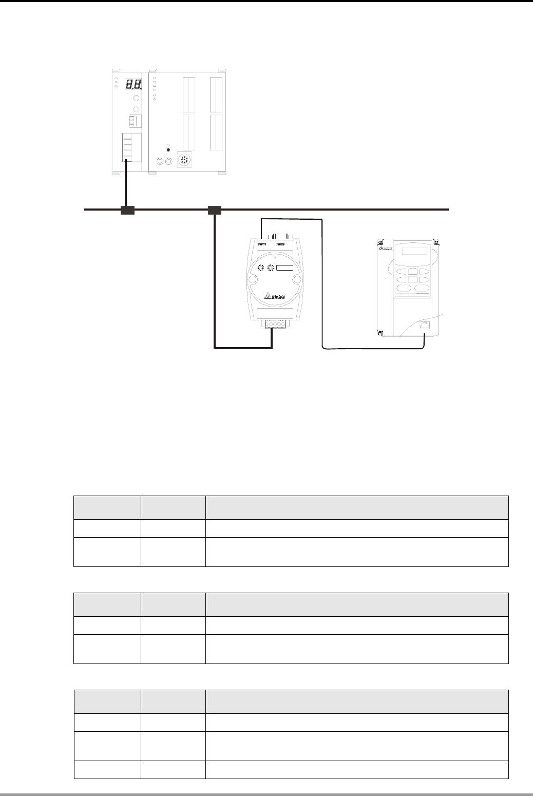
16. Network Connection Design Examples
DVP-PLC Application Examples 16-9
16.3 CANopen Connection
Master
CANopen
RJ12
VFD-B
RS485
COA02
DVPCOPM DVP28SV
RUN
STOP
CAN+
CAN-
SHLD
GND
Node 1
Node 2
Control Purpose:
z When M0 = ON, read the content of index 2021, sub index 4 (i.e. actual output value of AC
motor drive) in COA02.
Devices:
z Settings of DVPCOPM-SL:
Parameter Setting Explanation
Node address 01 Set the node address of DVPCOPM-SL to “01”.
Baud rate 1M bps Set the communication speed between DVPCOPM-SL and bus to
“1M bps”.
z Settings of COA02:
Parameter Setting Explanation
Node address 02 Set the node address of COA02 to “02”.
Baud rate 1M bps Set the communication speed between COA02 and bus to “1M
bps”.
z Settings of VFD-B:
Parameter Setting Explanation
02-00 04 The main frequency is operated by RS-485 interface.
02-01 03 The running command is operated by communication interface.
Operation by keys is valid.
09-00 01 Communication address of VFD-B: 01
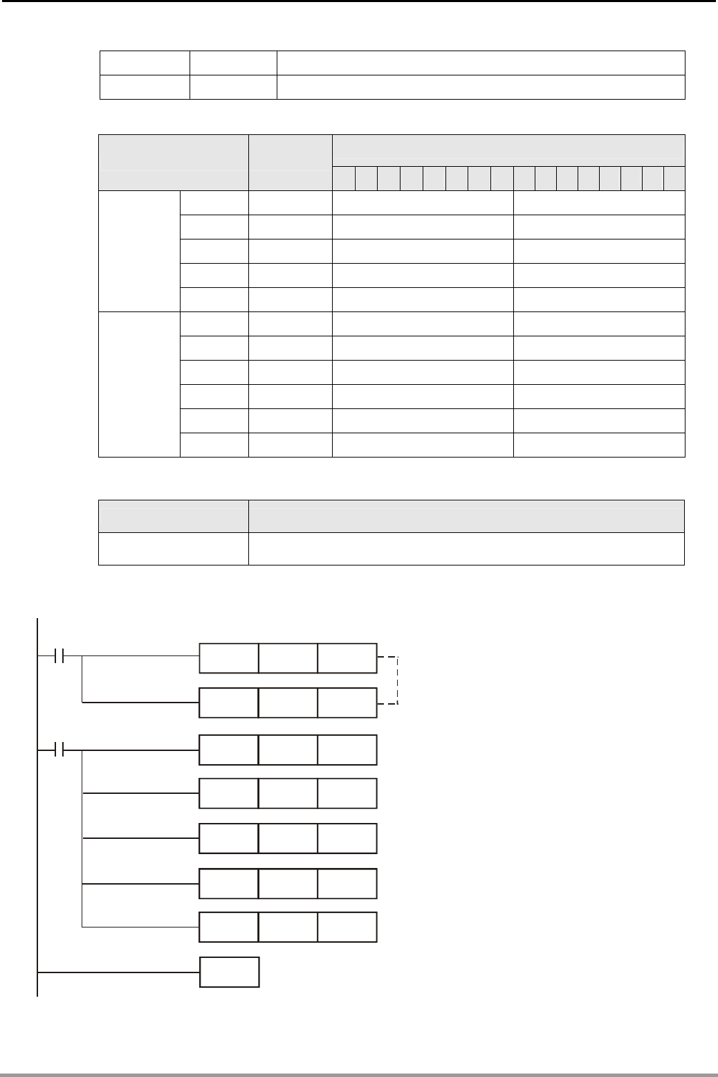
16. Network Connection Design Examples
DVP-PLC Application Examples
16-10
09-01 03 Baud rate: 38,400 bps
09-04 03 Modbus RTU mode, format <8, N, 2>
z Explanation on devices:
Explanation
PLC device content 15 14 13 12 11 10 9 8 7 6 5 4 3 2 1 0
D6250 0101Hex ReqID = 01 Hex Command = 01 Hex
D6251 0004Hex Reserved Size = 04 Hex
D6252 0102Hex Type = 01 Hex MAC ID = 02 Hex
D6253 2021Hex High byte of index = 20 Hex Low byte of index = 21 Hex
SDO
request
message
editing area
D6254 0004Hex Reserved Sub index = 04 Hex
D6000 0101Hex ReqID = 01Hex Status = 01 Hex
D6001 0006Hex Reserved Size = 06 Hex
D6002 4B02Hex Type = 4B Hex MAC ID = 02 Hex
D6003 2021Hex High byte of index = 20 Hex Low byte of index = 21 Hex
D6004 0004Hex Reserved Sub index = 04 Hex
SDO
response
message
editing area
D6005 0100 Hex Datum1 = 01 Hex Datum0 = 00 Hex
0100Hex in D6005 refers to the actual output frequency of the AC motor drive is 2.56Hz.
PLC Device Function
M0 When M0 = ON, CANopen master will send out SDO request
message
Control Program:
MOV H0101 D6250
M1002
ZRST D6250 D6281
M0
MOV H0004 D6251
MOV H0102 D6252
MOV H2021 D6253
MOV H0004 D6254
ZRST D6000 D6031
END
Reset response message editing area
and request message editing area.
ReqID = 01, Command = 01
Size = 04
Type = 01, MAC ID = 02
Index = 2021
Sub index = 04

16. Network Connection Design Examples
DVP-PLC Application Examples 16-11
Program Description:
z The program first reset the SDO request message editing area and SDO response message
editing area.
z When M0 = ON, CANopen master will send out SDO request message and read the
contents in index 2021, sub index 4 of the target equipment (at node address 02). If the
communication is successful, the slave will return with the response message.
z When M0 = ON, CANopen master will send out request message only once. If you would
like it to send out messages again, you will have to change the ReqID.
z The messages returned from the target equipment are stored in D6000 ~ D6005.
z For more instructions of CANopen communication module DVPCOPM-SL, please refer to
DVP-PLC Application Manual: Special Modules Ⅱ.
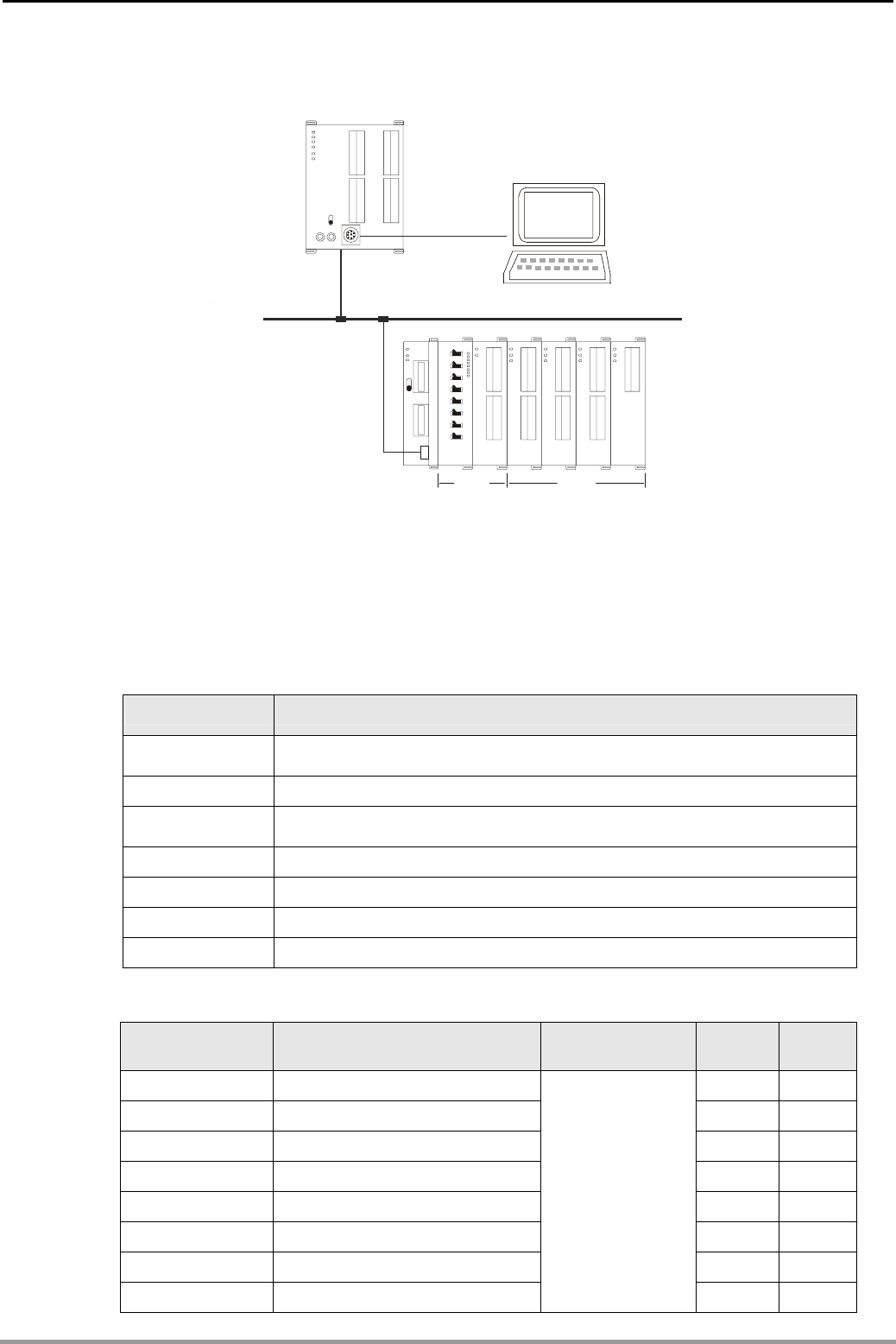
16. Network Connection Design Examples
DVP-PLC Application Examples
16-12
16.4 RTU-485 Connection
DVP28SV
RUN
STOP
DVP-02DA
DVP-08ST
DVP-16SP
DVP-04AD
DVP-04TC
DVP-04PT
RS485
RTU-485
COM2
RTU-485 DI/DO AI/AO
28SV
Control Purpose:
z The station No. of RTU-485 is 1. Write H’0001 into CR#6 of the 1st special module. Max
connectible special modules: 8; Max. DI/DO: 128 inputs and 128 outputs.
Devices:
z Explanation on devices:
PLC Device Function
M0 When M0 = ON, the master device will send out a request message to
RTU-485
D1120 Storing COM2(RS-485) communication protocal
M1120 Retaining COM2(RS-485) protocol. Change of D1120 is invalid when
M1120 = ON.
M1122 Sending request
M1127 Data receiving completed
M1129 Communication timeout
M1143 Selecting ASCII/RTU mode of COM2(RS-485). OFF: ASCII; ON: RTU
z Explanation on communication address:
Communication
address Devices Attribute Data type Length
H’1600 ~ H’1630 1st special module: CR0 ~ CR48 word 49
H’1640 ~ H’1670 2nd special module: CR0 ~ CR48 word 49
H’1680 ~ H’16B0 3rd special module: CR0 ~ CR48 word 49
H’16C0 ~ H’16F0 4th special module: CR0 ~ CR48 word 49
H’1700 ~ H’1730 5th special module: CR0 ~ CR48 word 49
H’1740 ~ H’1770 6th special module: CR0 ~ CR48 word 49
H’1780 ~ H’17B0 7th special module: CR0 ~ CR48 word 49
H’17C0 ~ H’17F0 8th special module: CR0 ~ CR48
Please refer to the
CR attribute of
each special
module.
word 49
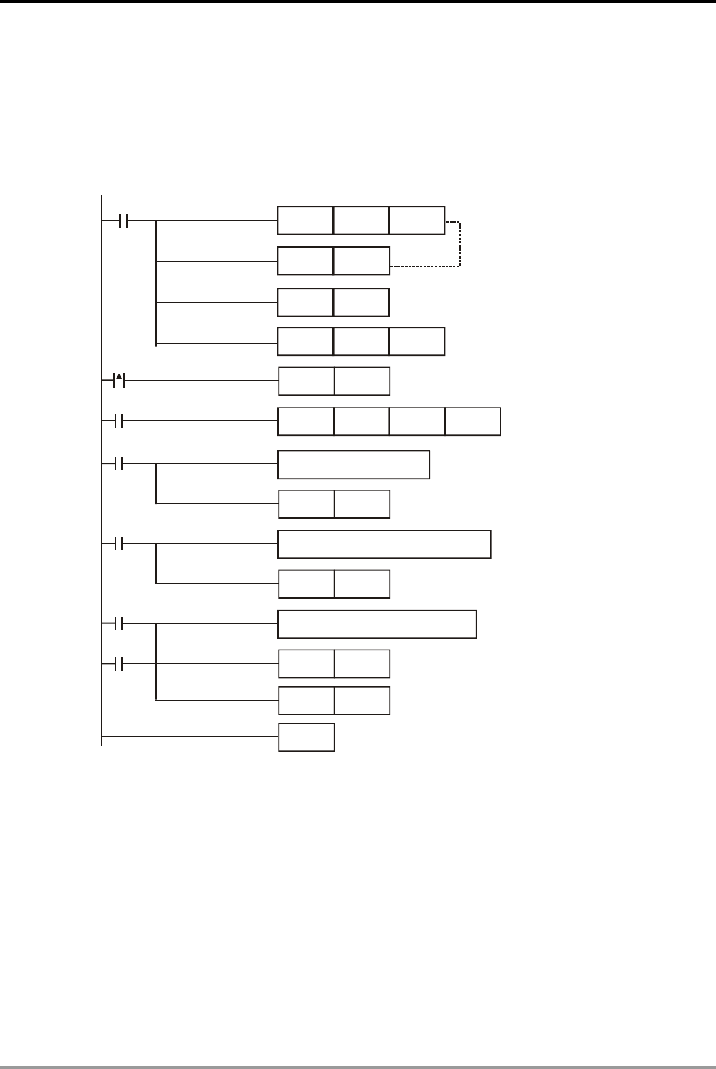
16. Network Connection Design Examples
DVP-PLC Application Examples 16-13
Note:
Maximum 8 special modules are connectible to RTU-485. The first special module connected
is the nearest one on the right side of RTU-485.
Control Program:
z The station No. of RTU-485 is “1”. Write “H’0001” into CR#6 of the 1st AI/AO special module.
Set the communication
protocal:
9600,7,E,1,ASCII
Retain communication settings
Set communication
timeout:
300ms
MOV K300 D1129
M1002
SET M1120
M0
SET M1122
M0
MODWR K1 H1606 H0001
END
RST M1143
Sending request
Write H0001
into CR#6 of the
1st special module
M1127
Process received data
RST M1127
M1129
Process communicaiton timeout
RST M1129
Reset M1127
M1140
Process communication error
RST M1140
M1141
RST M1141
MOV H86 D1120
Program Description:
z Communication format should be set at the beginning of the program, and the protocal of
Master and slave should be the same: 9600,7,E,1,ASCII.
z When M0 = ON, the sending request flag will be ON and the master device will send out a
request message to RTU-485 and write H’0001 into CR#6 of the 1st Ai/AO special module on
the right side of RTU-485.
z For more instructions of communication module RTU-485, please refer to DVP-PLC
Application Manual: Special Modules Ⅱ.

16. Network Connection Design Examples
DVP-PLC Application Examples
16-14
MEMO
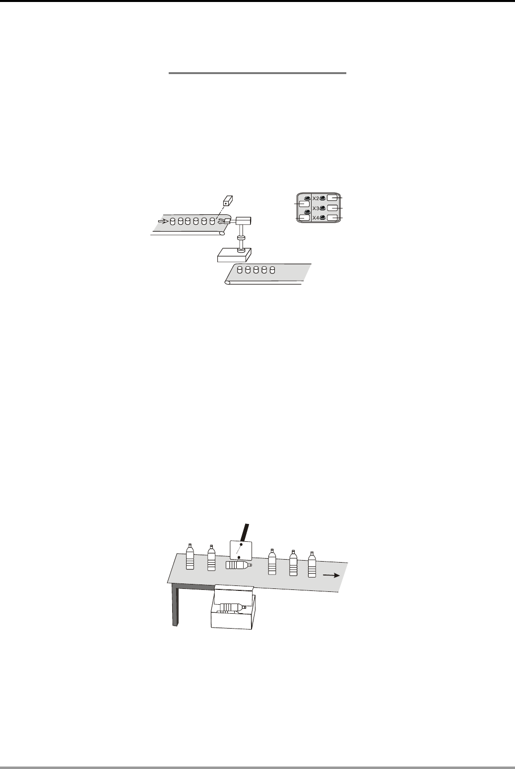
17. Index
DVP-PLC Application Examples 17-1
Index
Production Line Control
Conveyor A
Conveyor B
Clip
Transfer
Release
Auto
X0
Manual
X1
1.17 MC/MCR - Manual/Auto Control.............................................................................. 1-21
1.18 STL Manual/Auto Control ........................................................................................ 1-24
2.1 Product Mass Packaging........................................................................................... 2-1
2.2 Daily Production Record (16-bit Counting Up Latched Counter)............................... 2-2
3.15 Auto Interruption Timer ............................................................................................ 3-25
9.1 ENCO/DECO - Encoding and Decoding.................................................................... 9-1
10.2 DHSCS - Cutting Machine Control .......................................................................... 10-3
10.3 DHSZ/DHSCR - Multi-segment Coater Control....................................................... 10-4
10.7 PLSR - Servo Motor Acceleration/Deceleration Control .......................................... 10-11
11.1 Elementary Arithmetic for Integer and Floating Point............................................... 11-1
15.5 IST - Electroplating Process Auto Control ............................................................... 15-12
Production Line Control – detecting
X0
X1
Y0
1.1 Normally Closed Contact in Series Connection ........................................................ 1-1
8.2 SFTL - Defective Product Detect ............................................................................... 8-3
8.3 WSFL - Automatic Sorting Mixed Products................................................................ 8-5
10.5 PLSY - Production Line Control Program................................................................ 10-7
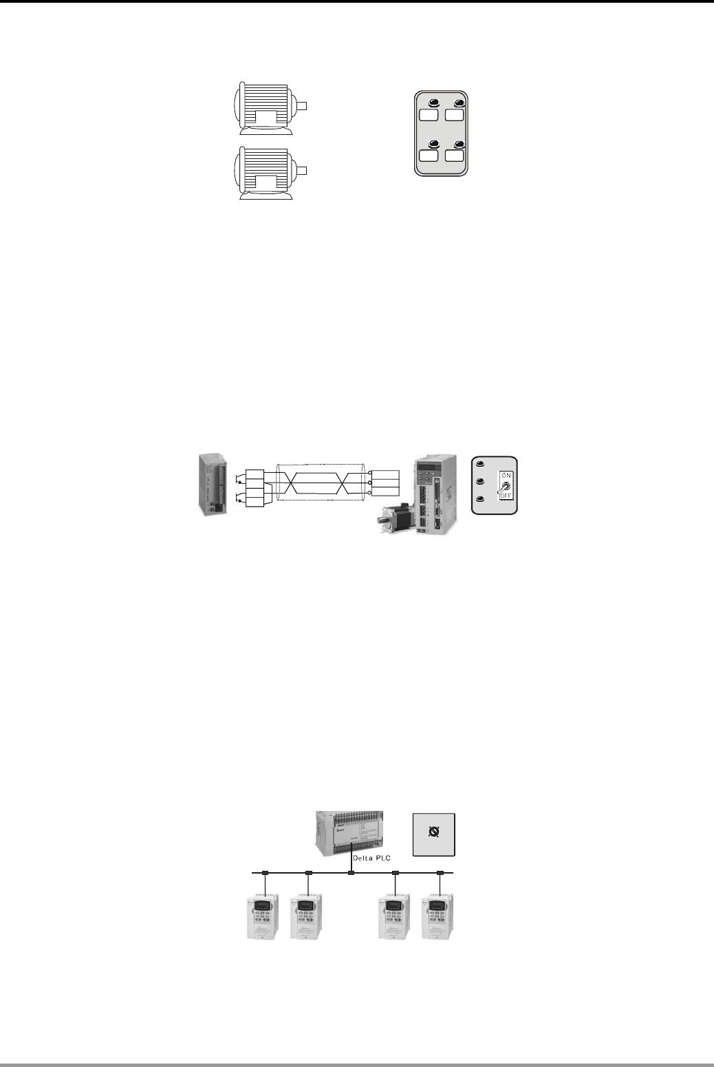
17. Index
DVP-PLC Application Examples
17-2
Motor Control
X0
X1
X2
X3
Oil Pump Motor
Main Motor
Y0
Y1 Main Motor
Oil Pump Motor
START STOP
START STOP
1.9 SET/RST - Latched and Unlatched Circuit................................................................. 1-9
1.11 Conditional Control Circuit........................................................................................ 1-12
1.15 Forward/Reverse Control for the Three-Phase Asynchronous Motor ...................... 1-18
3.4 Sequential Delay Output (Starting 3 Motors Sequentially)......................................... 3-4
3.8 Star-Delta Reduced Voltage Starter Control............................................................... 3-11
13.3 HOUR - Control of Switching Motors after a Long Time Running............................ 13-6
Servo Motor Control
DVP12SC
Stroke 2
Stroke 1
X1
X2
X3
Stroke 3
X4
Delta Servo
A
SD
A
Y10
C2
Pulse Output
Y0
C0 Forward Reverse /
COM-
PLS
SIGN
2.5 A B-phase Pulse High-speed Counter ....................................................................... 2-6
5.1 Recipe Setting by CJ Instruction................................................................................ 5-1
10.7 PLSR - Servo Motor Acceleration/Deceleration Control........................................... 10-11
12.4 Communication between PLC and Delta ASD-A Series AC Servo Drive................. 12-14
12.5 Communication between PLC and Delta ASD-A Series AC Servo Drive................. 12-18
12.10 LINK between PLC, Delta AC Motor Drive and AC Servo Drive ............................ 12-34
14.1 Simple positioning Demonstration System of Delta ASDA AC Servo Drive .............14-1
AC Motor Drive Control
50Hz
Frequency Selection
X2 X3
X4
30Hz 40Hz
0Hz
X1
1# ACMD 2# ACMD 3# ACMD 4# ACMD
RS485
6.4 FMOV - Single Data Broadcasting............................................................................. 6-5
12.1 Communication between PLC and Delta VFD-M Series AC Motor Drive ................ 12-5
12.2 Communication between PLC and Delta VFD-B Series AC Motor Drive................. 12-8
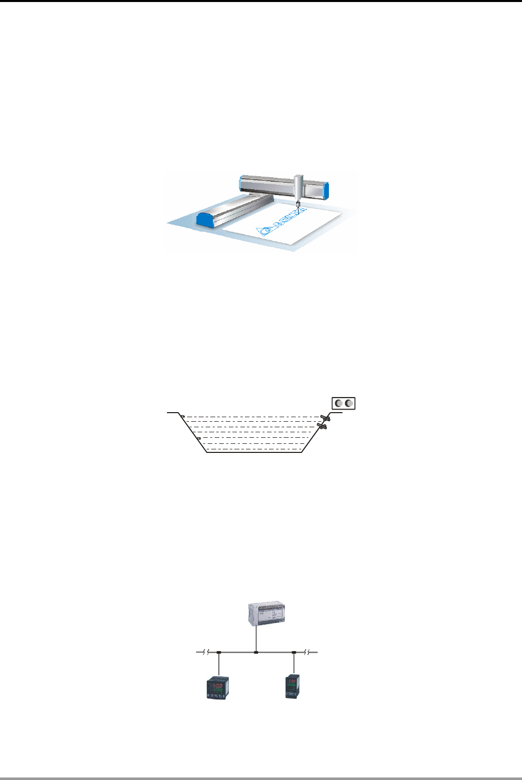
17. Index
DVP-PLC Application Examples 17-3
12.3 Communication between PLC and Delta VFD-V Series AC Motor Drive ................ 12-11
12.10 LINK between PLC, Delta AC Motor Drive and AC Servo Drive............................ 12-34
12.13 Communication between Delta PLC and Siemens MM420 Frequency Inverter.... 12-45
12.14 Communication between Delta PLC and Danfoss VLT6000 Series Adjustable Frequency Drive
.............................................................................................................................. 12-50
Positioning Control
7.2 INC/DEC - Fine Tuning by JOG Control .................................................................... 7-3
7.3 NEG - Displacement Reverse Control....................................................................... 7-5
14.1 Simple positioning Demonstration System of Delta ASDA AC Servo Drive............. 14-1
14.2 Draw DELTA LOGO by 2-axis Synchronous Motion................................................ 14-6
Level Monitoring
Y0
Y10 Y11
X1
X0 Y1
3.6 Artificial Fishpond Water Level Monitoring System (Flashing Circuit)........................ 3-7
5.2 Reservoir Level Control............................................................................................. 5-3
6.2 ZCP - Water Level Alarm Control............................................................................... 6-3
9.5 ANS/ANR - Level Monitoring Alarm System .............................................................. 9-7
Temperature Control
Master PL
C
DTA Temperature Controller DTB Temperature controller
Slave1 Slave2
RS-485
PLC
Slave address
=K1
Slave address
=K2
Master ID
=K10
9.7 SER - Room Temperature Monitoring........................................................................ 9-10
12.6 Communication between PLC and Delta DTA Temperature Controller ................... 12-22
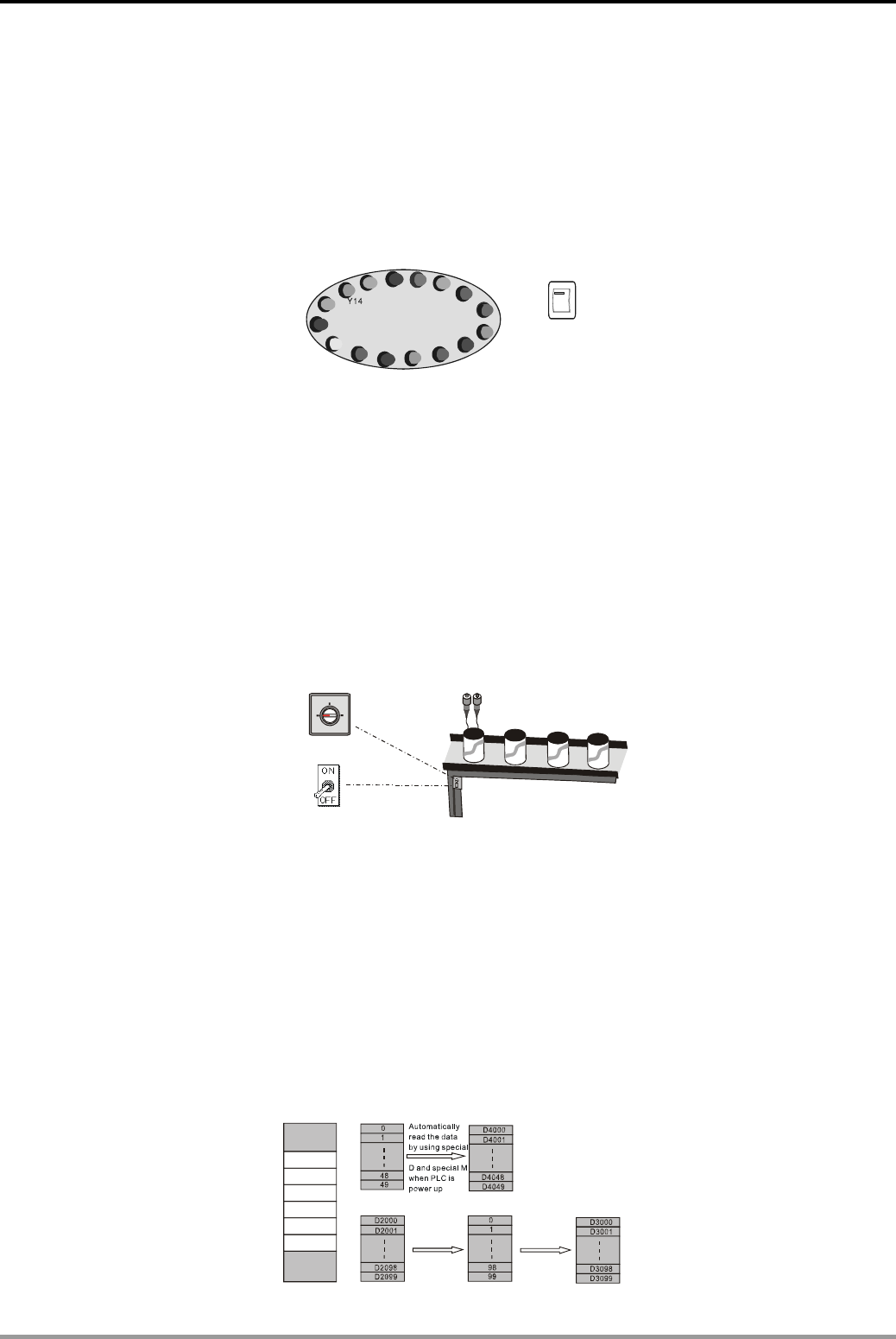
17. Index
DVP-PLC Application Examples
17-4
12.7 Communication between PLC and Delta DTB Temperature Controller ................... 12-25
12.11 LINK between PLC, Delta DTA and DTB Temperature Controllers ........................ 12-38
15.6 FTC - Fuzzy Temperature Control of the Oven ........................................................ 15-18
15.7 PID - Oven Temperature Control (Auto-tuning for PID Temperature Control).......... 15-22
Indicator Control
ON
OFF
X1
Y0 Y2
Y1 Y3 Y4 Y5
Y6
Y7
Y10
Y11
Y12
Y13
Y15
Y17
Y16
1.13 Last-in Priority Circuit............................................................................................... 1-15
3.1 Delay OFF Program................................................................................................... 3-1
3.2 Delay ON Program..................................................................................................... 3-2
3.3 Delay ON/OFF Program............................................................................................. 3-3
6.5 CML - Color Lights Flashing....................................................................................... 6-7
8.1 ROL/ROR - Neon Lamp Design................................................................................. 8-1
Material Mixing
Green
X1 X2
X3
X0
Y0 Y1
Yellow Blue
Color Selection
Yellow Blue
1.16 Selective Execution of Programs ............................................................................. 1-19
3.10 Automatic Liquids Mixing Control System................................................................ 3-15
3.11 Automatic Coffee Maker...........................................................................................3-17
4.2 Parameter Setting for Product Recipe ....................................................................... 4-3
6.1 CMP - Material Mixing Machine ................................................................................. 6-1
15.4 ABSD - Adding Materials in Different Intervals (Absolute Drum Sequencer)........... 15-9
Data Processing
MEMW MEMR
File register
D
X
M
Y
C
T
S
File register
memory Data register
memory
Write Read
PLC internal memory Data register
memory File register
memory Data register
memory

17. Index
DVP-PLC Application Examples 17-5
9.2 SUM/BON - Checking and Counting the Number of “1” ............................................ 9-3
9.3 MEAN/SQR - Mean Value and Square Root ............................................................. 9-4
9.4 MEMR/MEMW - File Register Access ....................................................................... 9-5
9.6 SORT - Sorting Acquired Data................................................................................... 9-8
11.2 Elementary Arithmetic for Floating Point.................................................................. 11-4
Communication
Slave1 Slave2 Slave3
Master PLC
Rs485 network
Master address =K20
Slave address
=K2
Slave address
=K3
Slave address
=K4
EH 2
SA SX S
S
Introduction...................................................................................................................... 12-1
12.1 Communication between PLC and Delta VFD-M Series AC Motor Drive................ 12-5
12.2 Communication between PLC and Delta VFD-B Series AC Motor Drive ................ 12-8
12.3 Communication between PLC and Delta VFD-V Series AC Motor Drive ................ 12-11
12.4 Communication between PLC and Delta ASD-A Series AC Servo Drive ................ 12-14
12.5 Communication between PLC and Delta ASD-A Series AC Servo Drive ................ 12-18
12.6 Communication between PLC and Delta DTA Temperature Controller ................... 12-22
12.7 Communication between PLC and Delta DTB Temperature Controller................... 12-25
12.8 PLC LINK 16 Slaves and Read/Write 16 Data (Word)............................................. 12-28
12.9 PLC LINK 32 Slaves and Read/Write 100 Data (Word)........................................... 12-31
12.10 LINK between PLC, Delta AC Motor Drive and AC Servo Drive............................ 12-34
12.11 LINK between PLC, Delta DTA and DTB Temperature Controllers........................ 12-38
12.12 Controlling START/STOP of 2 DVP PLCs through Communication ...................... 12-41
12.13 Communication between Delta PLC and Siemens MM420 Frequency Inverter.... 12-45
12.14 Communication between Delta PLC and Danfoss VLT6000 Series Adjustable Frequency Drive
.............................................................................................................................. 12-50
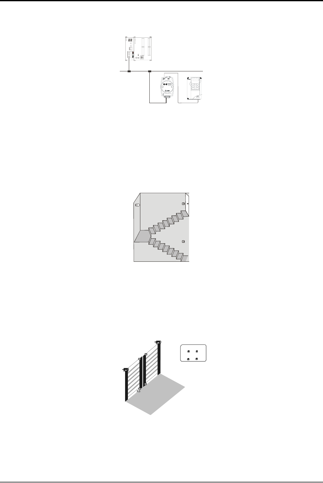
17. Index
DVP-PLC Application Examples
17-6
Network Connection
DVPDNET DVP2 8SV
RUN
STOP
DeviceNet
RJ12
Node Address :00
Node Address :02
DNA02 VFD-B
RS485
16.1 Ethernet Connection ................................................................................................ 16-1
16.2 DeviceNet Connection ............................................................................................. 16-6
16.3 CANopen Connection .............................................................................................. 16-9
16.4 RTU-485 Connection ............................................................................................... 16-12
Light Switch Control
Y0 X1
X0
1.2 Block in Parallel Connection ...................................................................................... 1-2
1.8 Common Latched Circuit and SET/RST Instructions Application............................... 1-8
1.10 Alternate Output Circuit (With Latched Function)..................................................... 1-10
Automatic Door Control
n
o
Y2/Y3
X0
X2 X3
n
o
X1
Close
CloseOpen
X7
X4
X6
Y0/Y1
Open
3.9 Automatic Door Control.............................................................................................. 3-13
13.2 TRD/TZCP - Control of Warehouse Automatic Door................................................ 13-3
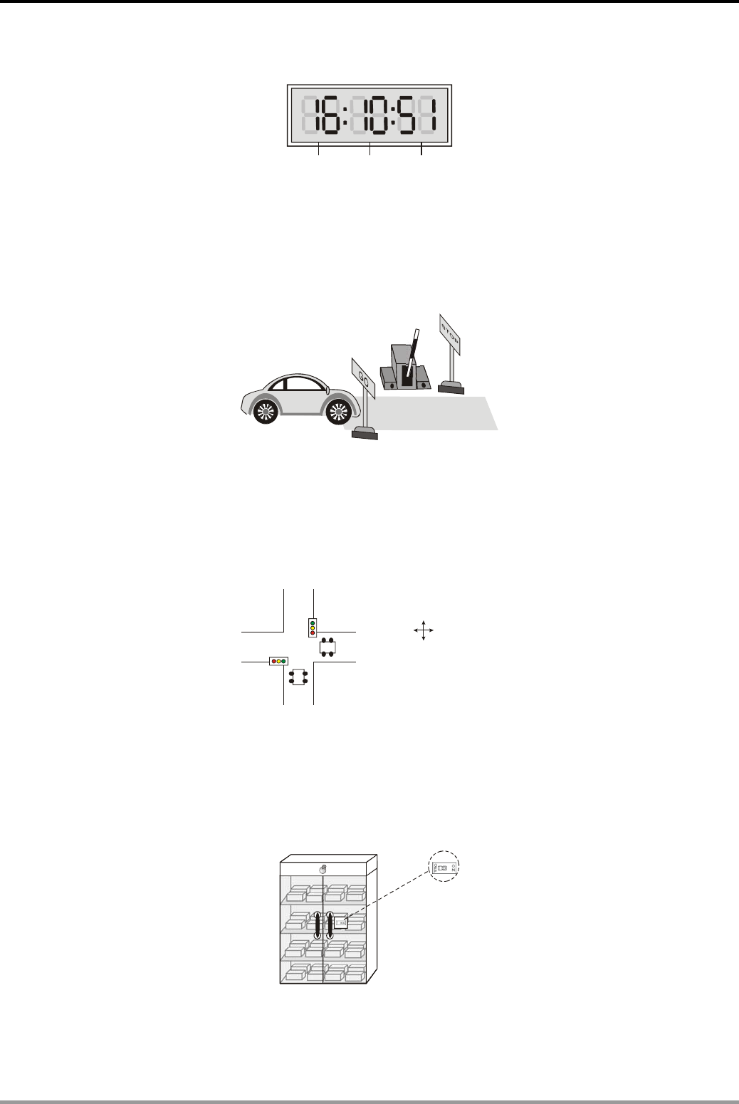
17. Index
DVP-PLC Application Examples 17-7
Real Time Calendar and Time Design Applications
Hour Minute Second
2.4 24-hour Clock Operated by 3 Counters..................................................................... 2-5
13.1 TRD/TWR/TCMP - Office Bell Timing Control ......................................................... 13-1
Parking Lot Entry Control
X0 X1
Y0
Y1
1.6 Interlock Control Circuit ............................................................................................. 1-6
1.14 Entry/Exit Control of the Underground Car Park...................................................... 1-16
Traffic Lights Control
Vertical direction
Horizontal direction
3.17 Traffic Lights Control................................................................................................ 3-29
15.3 INCD - Traffic Lights Control (Incremental Drum Sequencer).................................. 15-6
Product Testing Device Control
Y0
X0
3.7 Burn-in Test System (Timing Extension).................................................................... 3-9
6.3 BMOV - Multiple History Data Backup....................................................................... 6-4

17. Index
DVP-PLC Application Examples
17-8
Alarm Control
TOTALD Yuan
CHANGE Yuan
:
:
41.2
8.8
TOTAL: Yuan
CHANGE Yuan
88.00
12.00 :
CHANGE Yuan: 33.2
Y0~Y17 Y20~Y37 Y40~ Y57
X0
TOTAL:
:
41 2 Yuan
CHANGE 8 8Yuan
.
.
5.3 Fire Alarm in the Office (Interruption Application)....................................................... 5-5
5.4 Auto Lock up System in the Supermarket (FOR ~ NEXT) ......................................... 5-7
Others
1.3 Rising-edge Pulse Output for One Scan Cycle.......................................................... 1-3
1.4 Falling-edge Pulse Output for One Scan Cycle .........................................................1-4
1.5 Latching Control Circuit.............................................................................................. 1-5
1.7 Automatic Parameter Initialization When Powered Up............................................... 1-7
1.12 First-in Priority Circuit............................................................................................... 1-13
2.3 Products Amount Calculation (32-bit Counting Up/Down Counter)............................ 2-4
3.5 Pulse-Width Modulation ............................................................................................. 3-6
3.12 Automatic Urinal Flushing Control Program............................................................. 3-19
3.13 Performing Accumulative Function with Normal Timer............................................. 3-21
3.14 Performing Teaching Function with Normal Timer ................................................... 3-23
3.16 Interesting Fountain ................................................................................................. 3-27
4.1 Summation of Continuous D Registers...................................................................... 4-1
4.3 Controlling Voltage Output of 2 DVP-04DA by 8 VRs (Variable Resistors)................ 4-5
6.6 XCH - Exchanging the Upper and Lower 8 bits in a Register .................................... 6-8
6.7 DIP Switch Input and 7-segment Display Output....................................................... 6-9
7.1 Accurate Pipe Flow Measurement .............................................................................7-1
8.4 SFWR/SFRD - Room Service Call Control ................................................................ 8-8
10.1 REF/REFF - DI/DO Refreshment and DI Filter Time Setting ................................... 10-1
10.4 SPD - Wheel Rotation Speed Measurement............................................................ 10-6
10.6 PWM - Sprayer Valve Control Program.................................................................... 10-9
15.1 ALT - Auto Blackboard Cleaner................................................................................ 15-1
15.2 RAMP - Ramp Control of Crane............................................................................... 15-3
