EXPLORER MANUAL V6b Cover
User Manual:
Open the PDF directly: View PDF ![]() .
.
Page Count: 64
- OVERVIEW
- PART 1: PRODUCT DEMONSTRATION
- PART 2: MISSION PROP BUILDING INSTRUCTIONS & PHOTOS
- PART 3: VEHICLE Design & Building Specifications
- 1.0 GENERAL
- 2.0 SAFETY
- 3.0 Specifications
- 3.1 Operational
- 3.1.1 Multiple Vehicles
- 3.1.2 Environmental
- 3.1.3 Service Requirement
- 3.1.4 Calibration Requirement
- 3.1.5 Maintenance OPER-008: System maintenance during field operations shall be conducted by ROV personnel at their workstations. Work of any kind must not be done by company mentors or advisors. All maintenance parts and equipment necessary to meet...
- 3.2 Mechanical/Physical
- 3.3 Electrical
- 3.4 Onboard Electrical Power
- 3.5 Power Shutdown
- 3.6 Fluid Power
- 3.7 Control Systems
- 3.8 Command, Control, & Communications (C3)
- 3.9 MATE Provided Equipment
- 3.10 Laser Safety Rules
- 3.1 Operational
- PART 4: COMPETITION RULES
- PART 5: ENGINEERING & COMMUNICATION
EXPLORER CLASS

EXPLORER Class 1
2015 MATE ROV COMPETITION:
ROVs in Extreme Environments: Science and Industry in the Arctic
EXPLORER CLASS COMPETITION MANUAL
For general competition information, including a description of the different competition classes, eligibility,
and demonstration requirements, see GENERAL INFORMATION. You can also find information by visiting Team
Info.
CONTENTS
OVERVIEW........................................................................................................................................................... 3
THINK OF YOURSELVES AS ENTREPRENEURS .................................................................................................................... 3
PART 1: PRODUCT DEMONSTRATION ...................................................................................................... 3
TIME ................................................................................................................................................................................. 3
CONTEXT .......................................................................................................................................................................... 4
NEED ................................................................................................................................................................................ 5
OVERVIEW ....................................................................................................................................................................... 6
SCORING OVERVIEW ........................................................................................................................................................ 6
REQUEST FOR PROPOSALS (RFP) ...................................................................................................................................... 7
PRODUCTION DEMONSTRATIONS ...................................................................................................................................12
DEMO 1: SCIENCE UNDER THE ICE .......................................................................................................................................... 12
DEMO 2: SUBSEA PIPELINE INSPECTION & REPAIR .......................................................................................................... 19
DEMO 3: OFFSHORE OILFIED PRODUCTION & MAINTENANCE .................................................................................... 23
PART 2: MISSION PROP BUILDING INSTRUCTIONS & PHOTOS .................................................... 29
PART 3: VEHICLE DESIGN & BUILDING SPECIFICATIONS ............................................................... 29
1.0 GENERAL ...................................................................................................................................................................29
1.1 Glossary and Acronyms ...................................................................................................................................................... 29
1.2 Conventions ........................................................................................................................................................................... 30
1.3 Documentation Required .................................................................................................................................................... 30
EXPLORER Class 2
2.0 SAFETY ................................................................................................................................................................31
2.1 Safety Instruction & Observation Program and HSE Awards ................................................................................. 31
2.2 Safety Pre-inspection ............................................................................................................................................................ 32
2.3 Safety Inspection ..................................................................................................................................................................... 32
2.4 Safety inspection protocol ................................................................................................................................................... 33
2.5 Safety Inspection Points ....................................................................................................................................................... 33
3.0 Specifications ..........................................................................................................................................................33
3.1 Operational ............................................................................................................................................................................... 33
3.2 Mechanical/Physical ............................................................................................................................................................. 35
3.3 Electrical .................................................................................................................................................................................... 36
3.4 Onboard Electrical Power .................................................................................................................................................... 38
3.5 Power Shutdown ..................................................................................................................................................................... 38
3.6 Fluid Power ............................................................................................................................................................................... 38
3.7 Control Systems ....................................................................................................................................................................... 41
3.8 Command, Control, & Communications (C3) ................................................................................................................ 41
3.9 MATE Provided Equipment ................................................................................................................................................. 42
3.10 Laser Safety Rules ................................................................................................................................................................ 42
PART 4: COMPETITION RULES ................................................................................................................. 43
GENERAL .........................................................................................................................................................................43
PROCEDURAL ..................................................................................................................................................................45
DESIGN & SAFETY CONSIDERATIONS ...............................................................................................................................47
PART 5: ENGINEERING & COMMUNICATION ....................................................................................... 48
TIPS FOR EFFECTIVE WRITTEN AND ORAL COMMUNICATION .........................................................................................49
COMPANY SPEC SHEET (ONE PAGE ONLY) .......................................................................................................................50
TECHNICAL DOCUMENTATION ........................................................................................................................................51
SALES PRESENTATION .....................................................................................................................................................53
MARKETING DISPLAY ......................................................................................................................................................57
BONUS POINTS FOR MEDIA OUTREACH – INTERNATIONAL COMPETITION .....................................................................60
EXPLORER Class 3
OVERVIEW
THINK OF YOURSELVES AS ENTREPRENEURS
From deepwater oil drilling to the exploration of shipwrecks and installation of instruments on the seafloor,
individuals who possess entrepreneurial skills are in high demand and stand out in the crowd of potential job
candidates. What are entrepreneurial skills? They include the ability to understand the breadth of business
operations (e.g., finances, research and development, media outreach), work as an integral part of a team,
think critically, and apply technical knowledge and skills in new and innovative ways.
To help you to better understand and develop these skills, the MATE ROV competition challenges you to think
of yourself as an entrepreneur. Your first task is to create a company or organization that specializes in
solutions to real-world marine technology problems. Use the following questions as a guide.
• What is your company name?
• Who are its leaders – the CEO (chief executive officer – the leader) and CFO (chief financial officer who
oversees the budget and spending)?
• Who manages Government and Regulatory Affairs (i.e. who’s in charge of reviewing the competition
rules and making sure that they are understood and followed by everyone)?
• Who is responsible for research and development (R&D)?
• Who is responsible for system(s) engineering? Design integration? Testing? Operations?
• Who is responsible for fund-raising, marketing, and media outreach?
• What other positions might you need? (Depending on your personnel resources, more than one
person may fill more than one role.)
• What products and services do you provide?
• Who are your potential clients?
In this case, the MATE Center, polar scientists, and offshore oil and gas industry executives are your “clients”
who recently released a request for proposals. A request for proposals (RFP) is a document that an
organization posts to solicit bids from potential companies for a product or service. The specifics of your
product design and rules of operation – as well as the specifics of your mission – are included below.
PART 1: PRODUCT DEMONSTRATION
TIME
Each product demonstration includes:
• 5 minutes to set up at the mission station
• 15 minutes to attempt the tasks
• 5 minutes to break down and exit the mission station
Your company will have 5 minutes to set up your system, 15 minutes to complete the tasks, and 5 minutes to
demobilize your equipment and exit the mission station. During the 5-minute set-up, you may place your
EXPLORER Class 4
vehicle in the water for testing and/or trimming purposes, provided that a member of your company has a
hand on the vehicle at all times and uses extreme caution. The 15-minute demonstration period will begin
after the full 5 minutes of set up time expires, regardless of whether you are ready to start the mission. It may
begin sooner if your CEO notifies the mission station judges that your company is ready to begin.
At any time during the demonstration, you may pilot your ROV to the surface and remove the vehicle from the
water for such things as buoyancy adjustments, payload changes, and troubleshooting, but the 15-minute
mission clock will only be stopped by a judge who determines it is necessary for reasons beyond your control.
Otherwise, the clock will only stop after all of the tasks are successfully completed, the ROV has returned to
the surface under its own power so that it touches the side of the pool, and a member of your company at the
mission station has physically touched the vehicle. Your ROV is not required to return to the surface between
tasks.
Your 5-minute demobilization will begin as soon as the 15-minute demonstration time ends, regardless of
where your ROV is located (i.e., still at depth, on the surface, etc.).
TIME BONUS
Your company will receive a time bonus for each product demonstration if you:
1) successfully complete the tasks,
2) return your ROV to the surface under its own power so that it touches the side of the pool, and
3) physically touch your vehicle before the demonstration time ends.
Your company will receive 1 point for every minute and 0.01 point for every second under 15 minutes
remaining.
CONTEXT
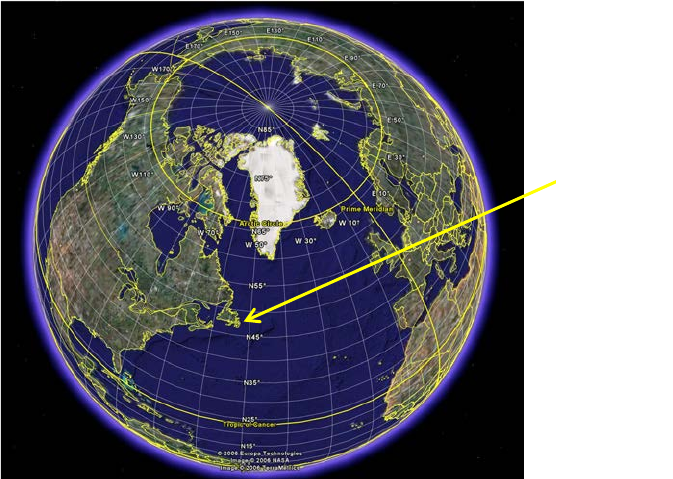
Located ~2,100 km south of the Arctic Circle, St. John's is the capital of the province of Newfoundland and
Labrador, Canada. The oldest city in North America, St. John’s offers an enticing combination of old world
charm, unique architectural, historic and natural attractions, and is located in close proximity to spectacular
coastlines, historic villages, and a diverse selection of wildlife.
EXPLORER Class 5
The city is also home to Memorial University of Newfoundland’s Marine Institute (MI) and the National
Research Council’s Ocean, Coastal, and River Engineering (OCRE) and their world-class facilities. MI houses the
world’s largest flume tank, with a water capacity of 1.7 million liters and water velocity ranging from 0–1
meters per second. The flume tank’s viewing gallery has a 20 meter-by-2 meter viewing window and seats 150
people. The OCRE includes an ice tank and offshore engineering basin. In the ice tank, the water surface can
be frozen and the air temperature maintained at a uniform –30 to 15 degrees Celsius to simulate the polar
environment. The offshore engineering basin is used to simulate the extreme ocean environment; waves,
wind, and currents can be controlled to achieve various sea states.
A number of scientists who work in polar environments are based in St. John’s or use it as a starting point for
their research in the Arctic. Similarly, several companies involved in oil and gas operations on the North
Atlantic continental shelf are headquartered in St. John’s, while a number of others have offices there. Both
polar researchers and offshore oil and gas companies use the facilities at MI and the OCRE to test the
equipment that supports their science and operations before heading out to sea. Both also employ technicians
and engineers to design, build, and operate this equipment both in the “lab” and in the field.
NEED
The polar science community and the offshore oil and gas industry are in need of remotely operated vehicles
that can conduct 1) SCIENCE UNDER THE ICE that includes counting species and sampling organisms,
deploying an instrument, and collecting data about an iceberg to determine its threat level to offshore
installations; 2) SUBSEA PIPELINE INSPECTION & REPAIR that includes replacing a corroded section of oil
pipeline and preparing a wellhead for delivery of a Christmas tree; and 3) OFFSHORE OILFIELD PRODUCTION &
MAINTENANCE that includes testing the grounding of anodes on the “leg” of an oil platform, determining the
angle that a wellhead emerges from the seafloor, and controlling the flow of oil through a pipeline.
St. John’s

EXPLORER Class 6
Members of the polar science community and the offshore oil and gas industry have already contracted with
MI and the OCRE to use their facilities for testing out their new vehicles before taking them into the field. The
facilities are reserved for June 25-27, 2015.
This is where your work begins.
OVERVIEW
EXPLORER class companies will take part in the following THREE product demonstrations that consist of
distinct tasks:
DEMO #1: SCIENCE UNDER THE ICE
Maneuver through a hole in the ice to collect samples, identify and count species, deploy a sensor, and survey
and evaluate an iceberg to determine the threat level to area oil installations.
DEMO #2: SUBSEA PIPELINE INSPECTION & REPAIR
Conduct a visual inspection to locate a corroded section of pipeline, remove that section of pipeline and return
it to the surface, prepare the remaining pipeline for a replacement section, and prepare a wellhead for the
delivery of a Christmas tree.
DEMO #3: OFFSHORE OILFIELD PRODUCTION & MAINTENANCE
Test the grounding of anodes on the leg of an oil platform, determine the angle that a wellhead emerges from
the seafloor, move water through a pipeline system to ensure that oil will flow through the correct pathway,
and measure water flow.
At the international competition, each product demonstration will take place in a separate venue: an ice tank,
an offshore engineering basin, and a flume tank. Your company will get ONE attempt to complete each
product demonstration. The scores of all three demonstrations will be added to your ENGINEERING &
COMMUNICATION score to determine the total, overall score for the competition.
SCORING OVERVIEW
The competition consists of product demonstrations, technical documentation, sales presentations,
marketing displays, and safety with the following scoring breakdown:
• Product Demonstrations
o 300 points (max), plus a time bonus
• Engineering & Communication – 250 points (max)
o Technical documentation
100 points (max)
o Sales presentations
100 points (max)
o Marketing displays
50 points (max)
• International competition ONLY – 5 bonus points for media outreach
EXPLORER Class 7
• Safety
o 30 points (max)
o International competition* – points for safety observation program, including Job Safety
Analysis (JSAs)
TOTAL POINTS (not including the media bonus or safety observation program) = 580
REQUEST FOR PROPOSALS (RFP)
1. General
a. Science in Polar Seas
The Arctic Ocean is the smallest of the world’s four ocean basins with a total area of about 1.4
million square kilometers (compare that to the Pacific, which has a total area of 179.7 million
square kilometers). It is also the world’s least explored ocean; its remoteness and harsh
environmental conditions make accessing and working in it a challenge.
Scientists are planning an expedition to explore and study the frigid depths of the Canada Basin, a
3.7-kilometer deep bowl adjacent to the Beaufort Sea, which is located north of the Northwest
Territories, the Yukon, and Alaska and west of Canada's Arctic islands. It often referred to as “The
Hidden Ocean” because this part of the Arctic is covered with sea ice for most of the year.
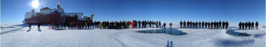
The expedition will take place on board the U.S. Coast Guard (USCG) icebreaker Healy, which is
designed to break four feet of ice continuously at a speed of three knots and can operate in
temperatures as low as -45°C. The Healy can also accommodate a fly-away ROV system
Scientists and the USCG Healy crew on the sea ice in the Canada Basin (photo credit Ian
MacDonald, Texas A&M University)
The scientific objectives of the expedition are to study the Canada Basin from the surface of the
ice to the bottom of the deep sea. This includes cataloging and sampling organisms and
deploying sensors to track the distribution and migratory patterns of whales.
The organisms include algae that live on the “underside” of the ice cover. On average, more than
50% of the primary productivity in the Arctic Ocean comes from unicellular algae that live near
the ice-seawater junction, making this interface a critical part of the polar marine ecosystem.
More than 200 algal species are known to exist in the Arctic sea ice, but, with additional sampling,
many more species are likely to be described.
Also of particular interest is the population of bowhead whales, an endangered baleen whale
found exclusively in arctic waters. Scientists are studying the distribution and migratory patterns
EXPLORER Class 8
of these whales in the hopes that it will lead to a better understanding of their role within the
arctic ecosystem and, possibly, conservation measures that could save the species.
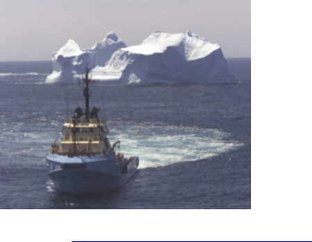
Scientists are partnering with a commercial company interested in using ROVs to collect data
about icebergs. This company provides ice and other environmental services for the offshore oil
and gas industry. The company currently uses satellites, surveillance aircraft, and specialized ice
radar to detect and track icebergs. It uses the information that it collects from these assets to
assess the threat of collision with oil and gas installations. It is interested in expanding its assets
to include ROVs, primarily to document and collect data on the more than 90% of an iceberg that
is below water surface. Engineers and technicians from the company will join scientists during
ROV testing in the OCRE’s ice tank.
b. Oil and Gas Operations along the North Atlantic Continental Shelf
The Atlantic Ocean has contributed significantly to the development and economy of the
countries around it. Besides its major transatlantic transportation and communication routes and
rich fishing resources, the Atlantic offers abundant petroleum deposits in the sedimentary rocks
of the continental shelves.
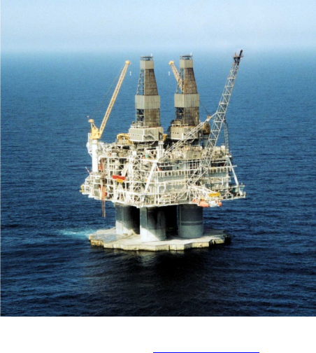
The North Atlantic continental shelf is particularly rich in petroleum. Total oil production from
North Atlantic fields is about 3.2 million barrels per day (mbls/day), or roughly 3.5% of the global
production (total world oil production is ~89.7 mbls/day). Currently there are three countries
with oil-producing platforms in the North Atlantic – the United Kingdom, Norway, and Canada.
The Hibernia oil production platform, one of four installations located off the coast of
Newfoundland (www.hibernia.ca)
ExxonMobil Canada, Chevron Canada Resources, Canada Hibernia Holding Corporation, Murphy
Oil, and, Statoil, Suncor Energy, Husky Energy, Nalcor, and Mosbacher are companies with
EXPLORER Class 9
investments in oil and gas fields in the North Atlantic Ocean offshore of St. John’s. The Terra
Nova field, operated by Suncor Energy, is one example. This field is located offshore
approximately 350 kilometers southeast of St. John’s.
Suncor Energy’s Floating Production Storage and Offloading (FPSO) vessel Terra Nova was
designed for the environment in which it operates. A double-hulled, ice-reinforced vessel, it has
five thrusters (two forward and three aft) and a global dynamic positioning system, which is an
automated system that allows the vessel to maintain its headings. The same system reduces the
impact of waves by allowing the FPSO to change to more favorable headings in high winds and
storms.
The Terra Nova FPSO is one of the largest FPSO vessels ever built. It is 292.2 meters long and 45.5
meters wide, which is approximately the size of three football fields laid end to end. From the
keel to the helideck, it stands more than 18 stories high. The Terra Nova FPSO can store 960,000
barrels of oil and accommodate up to 120 personnel while producing. It can also accommodate
ROV systems to support subsea infrastructure and operations.
The FPSO Terra Nova (www.suncor.com/en/about/4001.aspx)
Suncor Energy is currently seeking vehicles that can perform routine maintenance and repair
tasks as well as assist in the preparation of a wellhead for the delivery of a Christmas tree. A
Christmas tree is an assembly of valves, spools, and fittings that directs and controls the flow of
oil; when the well is ready, valves will be opened and oil will be allowed to flow through a pipeline
system that leads to the Terra Nova FPSO. The Christmas tree is used in conjunction with a
Blowout Preventer to prevent the release of oil into the environment. Once the system is
installed, Suncor Energy will require the ROV to test the pipeline system before oil is allowed to
flow.
Engineers and offshore personnel will evaluate the ROV’s performance in the OCRE’s offshore
engineering basin as well as MI’s flume tank. These facilities will allow the company to assess
how the ROV handles working in the extreme environment of the North Atlantic.
c. Document Scope and Purpose

EXPLORER Class 10
This and the following sections contain the technical specifications and requirements for ROV
services needed to support the polar science community and the offshore oil and gas industry.
In 2015, ROV services include:
1) SCIENCE UNDER THE ICE
• Maneuvering through a 75cm x 75cm hole in the ice.
• Collecting a sample of algae from the underside of the ice sheet.
• Collecting an urchin located on the seafloor.
• Using a species identification handbook to identify and count species of sea star.
• Deploying a passive acoustic sensor in a designated area.
• Measuring the dimensions of an iceberg and calculate its volume.
• Using coordinates to map the location of the iceberg.
• Using the location, heading, and keel depth to determine the threat level of the iceberg to
area oil platforms.
2) SUBSEA PIPELINE INSPECTION & REPAIR
• Conducting a CVI (close visual inspection) of an oil pipeline for corrosion.
• Turning a valve to stop the flow of oil through the pipeline.
• Examining a gauge dial to determine that the pipeline oil pressure is zero.
• Measuring the length of the section of corroded pipeline.
• Attaching a lift line to the corroded section.
• Cutting (simulated) the section of corroded pipeline.
• Removing the section of corroded pipeline and return it to the surface.
• Installing and securing an adapter flange over both cut ends of the pipeline.
• Installing a gasket into a wellhead.
• Inserting a hot stab to simulate injecting corrosion prohibiter into the wellhead.
3) OFFSHORE OILFIELD PRODUCTION & MAINTENANCE
• Testing the grounding of anodes by measuring the voltage of specified points along the leg of
an oil platform.
• Determining which anode(s) is not properly grounded.
• Measuring the height and length of a wellhead from the seafloor to determine the angle that it
emerges from the seafloor.
• Using a map to determine the pathways of flow through a pipeline system.
• Turning valves to ensure that oil will flow through the specified pathway.
• Moving water through the pipeline system to verify that oil will flow through the correct
pathway.
• Determining the average flow rate of the water current.
2. Specifications
See the specific tasks described below as well as the VEHICLE DESIGN & BUILDING SPECIFICATIONS and
COMPETITION RULES sections.

EXPLORER Class 11
3. Maintenance and Technical Support
The company shall warrant the ROV and associated systems and equipment for at least the duration of
the product demonstrations. Repair or replacement shall be at the company’s expense, including the
cost of shipping the ROV to and from the competition facility.
During regional events, the company shall provide at least one day of technical support to resolve
hardware, software, and operational issues. They shall provide at least three days of the same for the
international event.
4. Shipping and Storage
Refer to Shipping Information for specifics on shipping to the international competition site.
Delivery of the ROV and associated systems and equipment shall be no later than the date of the
geographically closest regional contest or by June 25, 2015, which is the start date of the international
competition.
5. Evaluation Criteria
a. Technical documentation
b. Sales presentation
c. Marketing display
d. Product demonstration
6. References
Arctic Ocean
http://en.wikipedia.org/wiki/Arctic_ocean
http://en.wikipedia.org/wiki/Pacific_Ocean
http://en.wikipedia.org/wiki/Beaufort_Sea
Census of Marine Life
www.coml.org
Whales and passive acoustic sensing:
www.enchantedlearning.com/subjects/whales/species/Bowheadwhale.shtml
www.afsc.noaa.gov/nmml/CetaceanAssessment/bowhead/bmsos.htm
http://cetus.ucsd.edu/projects/pubs/BurtenshawDSRII2004.pdf
Ice and Environmental Services
www.provincialaerospace.com/
Offshore Oil and Gas
www.suncor.com
www.hibernia.com
EXPLORER Class 12
IMPORTANT NOTE: Questions about production demonstrations and design and building specifications
must be posted to the competition FAQs board located here. This allows all companies to see the questions
and answers and helps to avoid duplicate questions. That said, please make sure that your question(s) has
not already been asked – and answered – before posting.
PRODUCTION DEMONSTRATIONS
DEMO 1: SCIENCE UNDER THE ICE
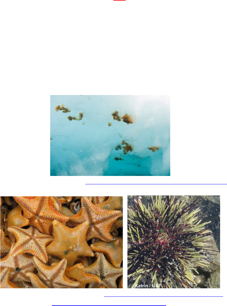
Your company is tasked with collecting an urchin from the seafloor and samples of algae from the underside of
the ice sheet. You must also identify and count the number of sea star species on the seafloor. The MATE
Center will provide a sea star identification handbook.
Algal “lumps” under Arctic Sea ice (www.arctic.noaa.gov/reportcard/sea_ice_biota.html)
Sea stars and urchins on the Arctic seafloor (www.arcodiv.org/seabottom/Asteroids.html and
www.arcodiv.org/seabottom/Urchins.html)
Your company is also tasked with deploying a passive acoustic sensor on the seafloor underneath the ice sheet
to monitor baleen whales. These sensors are essentially underwater hydrophones that “listen” for the whale
calls. Communication cables will run from the sensor to a nearby oil production platform where the recorded
calls will be processed.
EXPLORER Class 13
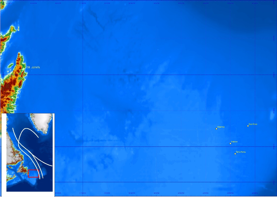
Finally, your company must survey an iceberg to evaluate its threat level to four offshore oil production
facilities in the area. Surveying the iceberg will involve collecting data regarding the iceberg’s coordinates and
heading and measuring its diameter and keel depth in order to calculate its volume. Using the coordinates,
keel depth, and heading of the iceberg in conjunction with the location of the oil installations, companies must
determine the potential threat to both the surface platforms and the subsea assets around the platform.
Map of the Grand Banks off of the coast of Newfoundland and Labrador showing the four offshore oil
installations (Paul Brett, Chair, Ocean Mapping Program, School of Ocean Technology, Fisheries and Marine
Institute of Memorial University)
This task involves the following steps:
• Removing a sample of algae from the underside of the ice sheet – 5 points
• Returning a sample of algae to the surface – 5 points
• Removing a sea urchin from the seafloor – 5 points
• Returning a sea urchin to the surface – 5 points
• Using a species identification handbook to identify and count species of sea stars – up to 10 points
o All sea star species properly identified and counted – 10 points
o At least four sea star species properly identified and counted – 5 points
o Less than four sea star species properly identified and counted – 0 points
• Deploying a passive acoustic sensor in a designated area – 10 points
• Surveying the iceberg at four points around its perimeter – 5 points

EXPLORER Class 14
• Measuring the keel depth of the iceberg– up to 10 points
o < 10 cm from true depth – 10 points
o > 10 cm from true depth – 0 points
• Measuring the diameter of the iceberg – up to 10 points
o < 10 cm from true length – 10 points
o > 10 cm from true length – 0 points
• Using the dimensions of the iceberg to calculate its volume within 10% of true volume – 5 points
• Using the coordinates to map the location of the iceberg – 10 points
• Using the location, heading and keel depth to determine the threat level of the iceberg to the four
area oil platform surface platforms – 10 points
• Using the location, heading, and keel depth to determine the threat level of the iceberg to the four
area oil platform subsea assets – 10 points
TOTAL POINTS = 100
Mission Notes:
The tasks of the science under the ice product demonstration may be completed in any order.
At the international competition, the science under the ice product demonstration will take place in an ice
tank. Companies should be prepared to operate their vehicle in a cold water environment, under a layer of
actual ice. Information about the ice tank and the water solution in the ice tank can be found in the vehicle
design & building specifications.
Companies must launch their vehicle through a 75 cm x 75 cm hole in the ice.
Companies must collect a sample of algae from the underside of the ice sheet. The samples of algae will be
simulated by ping pong balls. There will be 10+ samples of algae located on the underside of the ice sheet.
Companies will receive 5 points when a sample is removed from the bottom of the ice. Removing a sample of
algae from the underside of the ice sheet is defined as the ping pong ball being under control of the vehicle
and no long in contact with the ice sheet. Companies will receive an additional 5 points when the sample of
algae is returned to the surface, removed from the ROV, and placed on the pool deck.
Companies must collect the sample of algae without damaging it. If the ping pong ball is crushed (no longer a
sphere) or cut (inside is open to the water), companies will not receive points for removing it from the
underside of the ice sheet or returning it to the surface. Companies that damage a sample of algae may
attempt to collect another sample.
Companies must collect a sea urchin from the seafloor. The sea urchin will be simulated by a 4-inch O-ball.
There will be 3 sea urchins located on the seafloor; companies only need to collect one of them. Companies
will receive 5 points when a sea urchin is removed from the bottom. Removing a sea urchin from the seafloor
is defined as the O-ball being under control of the vehicle and no longer in contact with the bottom.
EXPLORER Class 15
Companies will receive an additional 5 points when the urchin is returned to the surface, removed from the
ROV, and placed on the pool deck.
Companies must identify and count species of sea stars located on the seafloor. Sea stars will be constructed
from ½-inch PVC. A sea star identification handbook will be provided at each mission station, although
companies may choose to print and bring their own handbook. The sea star identification handbook will have
pictures and scientific names of a variety of sea stars that are commonly found in polar waters. Companies
must identify and count all of the sea stars on the seafloor. Companies do not need to collect or return any of
the sea stars to the surface. The mission station judges will have an accurate count of each sea star species in
the mission area. Companies must report their species count (number of each species) to the mission judge
once all of the sea stars have been identified and counted. Companies that successfully identify and count all
the sea star species will receive 10 points. Companies that successfully identify and count at least four (but not
all) sea star species will receive only 5 points.
Companies may only report one final sea star count (Genus & species name and number of each species) to
the mission station judge. If the count is in error, companies may not go back and attempt to recount sea star
species. The final report must be given to the mission station judge during the product demonstration time;
however, the mission station judge may choose to evaluate the counts during the demobilization period.
Companies should use both the common name and the scientific name (Genus and species) when reporting
their sea star counts to the mission station judge. For example, a company should say they have identified six
purple ochre stars, Pisaster ochraceus.
Companies must deploy a passive acoustic sensor into a 50 cm x 50 cm designated area. The passive acoustic
sensor will be constructed out of ½-inch PVC pipe with a 3-inch PVC float; the passive acoustic sensor will be
attached to the surface by a connecting cable. The passive acoustic sensor will be located on the surface, side
of the pool at the start of the product demonstration. Companies may attach the passive acoustic sensor to
their ROV during the 5-minute set-up period. The sensor must be transported to the designated area by the
ROV; companies may NOT drop or throw the sensor into the water with the intention of recovering it on the
bottom.
Companies will receive 10 points when the passive acoustic sensor is deployed by the ROV within the
designated area. A successfully deployed sensor must have all four legs inside the designated area and be
“right side up.” Companies will not receive points if the sensor is on its side or upside down. The legs of the
sensor may be touching the inside PVC edge of the designated area, but the legs cannot be on top of the PVC
of the designated area. The cable connecting the passive acoustic sensor to the surface can lay over the PVC
of the designated area.
The passive acoustic sensor will weigh less than 30 Newtons in the EGADS water solution of the ice tank.
Companies must survey the iceberg at four points around its perimeter. The iceberg will be constructed of ½-
inch PVC pipe. At the international competition, the top section of the iceberg will be located on the underside
of the ice sheet. The top section is comprised of four equal lengths of ½-inch PVC pipe inserted into a central
EXPLORER Class 16
PVC cross. At the end of each length of pipe is 30 cm length of pipe descending into the water column. A black
ABS plastic rectangle will be positioned near the bottom of each of the four 30 cm lengths of PVC pipe. These
four rectangles will be labeled A, B, C, and D.
To successfully survey the iceberg, companies must show the mission station judge, through a video display,
the letter on all four labeled rectangles. Companies will receive 5 points when the iceberg is successfully
surveyed. Once the iceberg is successfully surveyed, the mission station judge will release the coordinates and
heading of the iceberg.
These labeled rectangles will be approximately 20 to 30 cm below the surface of the ice. The lettering will be
3-inch black on white lettering.
Companies must determine the diameter and keel depth of the iceberg. The diameter can be determined by
measuring the length of one of the PVC pipes that make up the top section of the iceberg. Companies should
measure the diameter from the outside edge of the 90o elbows at the end of each length of pipe. Companies
that successfully measure the diameter of the iceberg within 10 cm will receive 10 points.
Companies must also measure the keel depth of the iceberg below the water line. A length of ½-inch PVC pipe
will descend into the water from a PVC tee next to the cross in the surface structure. The keel depth is the
distance from the bottom edge of the PVC cross to the bottom end of this length of pipe. Companies that
successfully measure the keel depth of the iceberg within 10 cm will receive 10 points.
Companies must report and show all measurements to the mission station judge or inform the mission station
judge of how they are calculating the values; they cannot simply guess at the measurement. If companies
report an incorrect diameter or keel depth to the mission station judge, they will not receive points for that
measurement. Companies may elect to re-measure the dimension for calculating the volume of the iceberg.
Although companies will not receive points, the mission station judge will inform companies if their
subsequent measurements are correct or incorrect.
Once the dimensions of the iceberg are correctly determined, companies must use those values to calculate
the volume of the iceberg. Companies MUST use the formula for a CONE to calculate the iceberg’s volume.
Companies will receive 5 points when they successfully report the volume of the iceberg within 10 percent to
the mission station judge. If a company incorrectly calculates the volume (outside 10% of true volume) they
will not receive points. Companies may not re-calculate the volume until they get a correct answer.
Companies must mark the location of the iceberg on the map provided by the MATE Center. Companies will
receive 10 points when they correctly map the location of the iceberg. The mark indicating the iceberg should
be less than 1 mm by 1 mm and must fall within 0.5 cm of the actual map coordinates given to the company.
The mission station judges will score the mark by overlaying a second map with the iceberg’s actual position.
The iceberg’s location on the overlay must completely cover the mark made by the company. Companies must
show the map with the location of the iceberg to the mission station judge during the mission time. The judge
may choose to evaluate the map during the 5-minute demobilization period.
EXPLORER Class 17
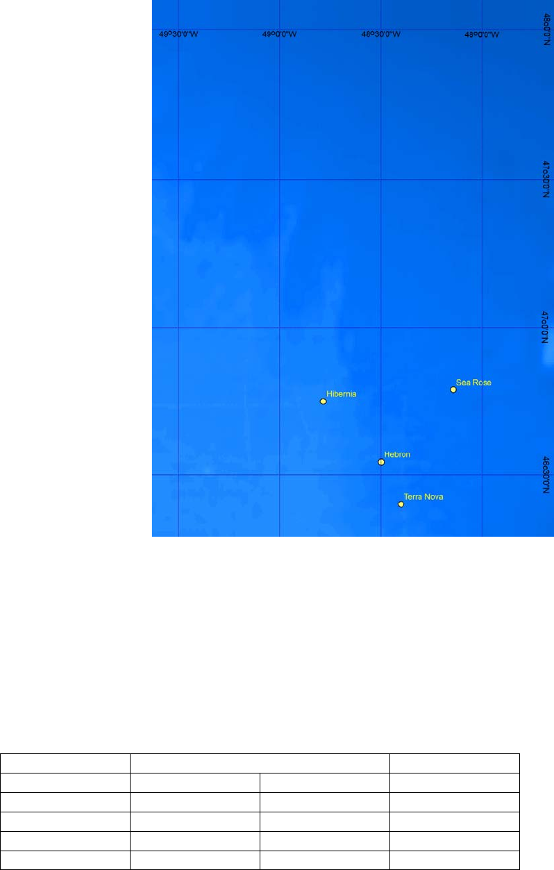
Map of the oil installations.
Companies must also evaluate the location, heading, and keel depth of the iceberg to determine the threat
level to four offshore oil production facilities off the coast of Newfoundland. Companies must determine the
threat level to both the surface platforms and the subsea assets. Since the simulated iceberg will only be 1.5
to 4.0 meters in depth, the mission station judge will provide a more realistic keel depth. This keel depth will
be released when the iceberg is surveyed.
The locations of the four platforms and depth of subsea assets are:
Installation
Location
Ocean depth (m)
Latitude
Longitude
Hibernia
46.7504
-48.7819
-78
Sea Rose
46.7895
-48.1417
-107
Terra Nova
46.4
-48.4
-91
Hebron
46.544
-48.498
-93
EXPLORER Class 18
Companies must determine the threat level for the four surface installations. The threat levels are green,
yellow, and red. If the iceberg is passing more than 10 nautical miles away from an installation, the iceberg
poses a green threat level. If the iceberg is passing between 5 and 10 nautical miles from an installation, it
poses a yellow threat level. If the iceberg is passing less than 5 nautical miles from an installation, it poses a
red threat level.
When a company correctly reports the threat to all four surface platforms, they will receive 10 points. If one
evaluation is incorrect, but by only one threat level, companies will receive 5 points. If more than one
evaluation is incorrect, or one evaluation is off by more than one threat level, companies will receive 0 points.
Companies must also determine the threat level for the subsea assets. Any iceberg passing within 25 nautical
miles could potentially be a threat for subsea assets. Companies will use the keel depth to evaluate the threat
level to any iceberg that passes within 25 nautical miles of a platform.
• If the keel depth of the iceberg is 110% or greater than the depth of the water the installation is
located in, it is never a threat to the subsea assets as it will ground before reaching the assets. Threat
level to subsea assets is green. Note that at this keel depth, the threat to the surface installation is
also green.
• If the keel depth of the iceberg is 90% to 110% of the depth of the water the installation is located in,
the subsea assets are in critical danger. Threat level to the subsea assets is red.
• If the keel depth of the iceberg is 70% - 90% of the depth of the water the installation is located in,
caution should be maintained as the keel may impact the seafloor. Threat level to the subsea assets is
yellow.
• If the keel depth of the iceberg is <70% of the depth of the water the installation is located in, it is
never a threat to the subsea assets. Threat level to subsea assets will be green.
When a company correctly reports the threat level to all four subsea assets, they will receive 10 points. If one
evaluation is incorrect, but by only one threat level, companies will receive 5 points. If more than one
evaluation is incorrect, or one evaluation is off by more than one threat level, companies will receive 0 points.
Companies will only get one attempt to evaluate the threat levels for surface installation and the subsea
assets. Companies that are incorrect may not go back and re-evaluate the threat levels. Companies must
report all threat levels during the 15 minute product demonstration. The mission station judge may choose to
evaluate the company’s threat level assessment after the product demonstration time is completed.
Note that 1 minute of latitude is equal to 1 nautical mile.
If a company has successfully completed all the tasks and is returning to the surface with the final items to be
removed from the pool (the algae sample and a sea urchin), time will stop when a member of the company
touches the vehicle. Samples on board the vehicle may be detached and set on the pool deck after the clock
has stopped. If sample is subsequently dropped from the vehicle into the pool, time will not restart. That
EXPLORER Class 19
company will receive points for collecting the sample, but will not receive points for returning the sample to
the surface and therefore cannot receive a time bonus.
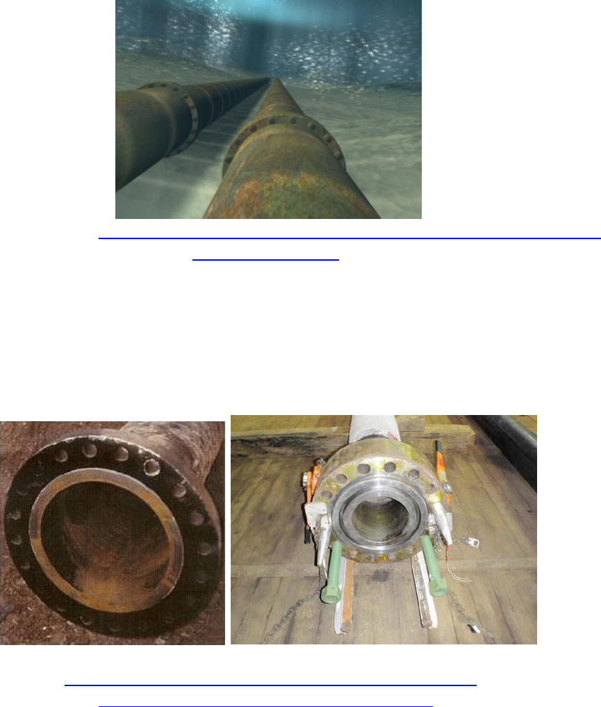
DEMO 2: SUBSEA PIPELINE INSPECTION & REPAIR
Your company is tasked with conducting a close visual inspection (CVI) of an oil pipeline in order to locate a
corroded section. Once the corroded section is found, companies must turn a valve to stop the flow of oil
through the pipeline and examine a pressure gauge to verify that the pressure in the pipe is zero.
Corroded subsea pipeline (http://subseaworldnews.com/2014/04/01/baosteel-yantai-delivers-subsea-steel-
pipes-for-bohai-oilfield/)
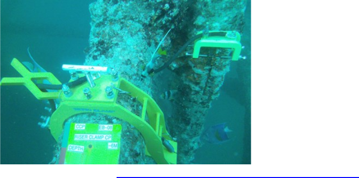
Your company must then measure the section of corroded pipeline, attach a lift line to that section, simulate
cutting the pipeline, then remove the corroded section of pipeline and return it to the surface. Once the
corroded section has been removed, your company must prepare the pipeline for the future installation of a
new section. This involves installing a flange adapter over both cut ends of the remaining pipeline and
securing the flange adapters with bolts.
Examples of flanges on the ends of pipelines
(http://epa.gov/gasstar/newsroom/partnerupdatespring2011.html
and http://gasketinsertiontool.com/tooling-solutions/)

EXPLORER Class 20
Your company is also tasked with preparing a wellhead for the delivery of a Christmas tree. This includes
removing the wellhead’s protective cover, installing a gasket into the wellhead, and replacing the wellhead’s
protective cover. Finally, companies must insert a hot stab into a port on the wellhead to simulate injecting
corrosion prohibiter into the wellhead. When finished, companies must return the hot stab to the surface.
This task involves the following steps:
• Conducting a CVI of an oil pipeline to locate the corroded section – 5 points
• Turning a valve to stop the flow of oil through the pipeline – 10 points
• Examining a gauge dial to determine that the pipeline oil pressure is zero – 5 points
• Measuring the section of corroded pipeline – up to 10 points
o < 3 cm off true length – 10 points
o 3.01 cm to 10 cm off true length – 5 points
o > 10 cm from actual length – 0 points
• Attaching a lift line to the corroded section – 10 points
• Pulling two pins to simulate cutting the section of corroded pipeline – 5 points each, 10 points total
• Removing the section of corroded pipeline and returning it to the surface – 5 points
• Installing the flange adapter over both sides of the cut pipeline – 5 points each, 10 points total
• Inserting two bolts on each flange to secure the flanges to the pipeline – 5 points per flange, 10
points total
• Removing the wellhead’s protective cover – 5 points
• Installing the gasket into the wellhead – 5 points
• Replacing the wellhead’s protective cover – 5 points
• Inserting the hot stab into the port on the wellhead – 5 points
• Removing the hot stab and returning it to the surface – 5 points
Mission Notes:
The steps of the pipeline inspection and repair task must be done in order. The steps of the wellhead
preparation task must be done in order. Companies may choose to skip a step, but will not get points for that
step even if it is completed at a later time. Companies may alternate between completing the pipeline
inspection and repair and the wellhead preparation. For example, a company may start by removing the
wellhead’s protective cover, inserting the gasket, and replacing the wellhead’s cover. The company may then
move on to the pipeline inspection and repair, returning to insert the hot stab, remove it, and return it to the
surface at a later time.
At the international competition, the subsea pipeline inspection and repair product demonstration will take
place in the offshore engineering basin. Companies should be prepared to operate their vehicle in rough water
as well as windy conditions. Information about the offshore engineering basin can be found in the vehicle
design & building specifications.
EXPLORER Class 21
Companies must conduct a CVI of a pipeline to locate a section of corroded pipe. The pipeline will be
constructed out of 2 sizes of PVC pipe. 1 ½-inch inch PVC pipe painted gray will be used for the pipeline that
companies must simulate cutting, lifting, and installing the flange. ½-inch pipe will be used for the remainder
of the pipeline. Corrosion will be simulated by a brown circle, less than 2 cm in diameter. The corrosion may
be located on the top, bottom, or on either side of the pipeline. There will only be one circle of corrosion on
the pipeline. Companies will receive 5 points when they detect the corrosion and show it to the mission
station judge, through a video display.
Once the section of corroded pipeline is located, companies must turn a valve to stop the flow of oil through
the pipeline. The valve will be constructed from ½-inch PVC pipe and a brass gate valve. Turning the valve
completely clockwise will close the valve. Valves may need to be turned up to 1170o (3.25 times around) to be
completely opened or closed. Companies will receive 10 points when they completely close the valve.
Once the valve has been closed, companies must examine a pressure gauge to verify that the pressure in the
pipeline is zero. Companies must show the mission station judge, through a video display, that the dial on the
pressure gauge is at zero. Companies will receive 5 points when they have viewed the pressure gauge at zero.
Companies must then measure the section of corroded pipeline. Companies that successfully measure the
length of the pipe within 3 cm will receive 10 points. Companies must report and show all measurements to
the mission station judge or inform the mission station judge of how they are calculating the values; they
cannot simply guess at the length. If companies report an incorrect length to the mission station judge, they
will not receive points for that measurement. Companies may not go back and re-measure the length of the
pipe if their first measurement is not within 3 cm.
After measuring the length of the corroded section, companies must attach a lift line to the pipeline.
Companies must design and build their own lift line; the MATE Center will not provide one. There will be no
attachment points for a lift line; companies must attach their line directly around the 1 ½-inch segment of
pipe. Companies will receive 10 points when they have successfully attached a lift line around the corroded
section of pipe.
Once the lift line has been attached to the corroded section, companies must pull two pins to simulate cutting
the section of corroded pipeline. The two pins, each simulated by a U-bolt, will be located at either end of the
corroded section of pipe. Companies will receive 5 points for each pin removed, 10 points for removing both.
After removal, the pins may be left on the bottom of the pool without penalty or returned to the surface.
After both pins have been pulled, companies must remove and transport the section of corroded pipeline to
the surface. Companies may use the lift line previously attached to the pipe and pull it to the surface by hand.
Companies will receive 5 points when the corroded section of pipeline is removed from the water and set on
the pool deck. If the pipe falls to the seafloor during lifting, companies may attempt to reattach their lift line
or move on to another task. If companies choose to move on, they will not be awarded 5 points for returning
the corroded section of pipeline to the surface.
EXPLORER Class 22
Once the corroded section is removed, companies must install a flange adapter over each end of the cut
pipeline that remains on the seafloor. After they are installed, the flange adapters must be secured to the
pipeline with bolts.
Companies must install a flange over each end of the cut pipeline. Companies will receive 5 points for each
flange successfully installed on the cut end of the pipe. A successfully installed flange is defined as a flange
that stays on the pipe when the ROV releases it and is positioned so that the holes in the flange are over the
Velcro hooks on the cut end of the pipe.
Once a flange is installed, it must be secured with two bolts. The flange will have six holes. Companies may
insert the bolts into any two of the six holes. The final 5 cm of the 1 ½-inch cut pipe will be covered with
Velcro hooks. The ends of the bolts will be covered with Velcro loops. The Velcro connection will secure the
bolts into the holes and secure the flange onto the pipe. Companies will receive 5 points when each flange is
successfully secured with two bolts. Successfully secured is defined as the bolts remaining in the holes when
the ROV maneuvers away.
Note: There is an exception to the rule that all steps of the pipeline inspection and repair tasks must be done
in order. Companies may choose to secure the first flange with bolts before installing the second flange. For
example, a company could receive 5 points for installing the first flange and 5 more points for securing it with
two bolts. Then the company could move to the other end of the cut pipeline and install the second flange, for
another 5 points, and secure it with two bolts for 5 more points.
The other set of steps of the pipeline inspection and repair product demonstration is to prepare the wellhead
for the delivery of a Christmas tree. The wellhead will be constructed from 2-inch PVC pipe with a 2-inch to 3-
inch adapter at the top. The first step is to remove the wellhead’s protective cover. The wellhead’s protective
cover will be constructed from a 4-inch PVC end cap with a U-bolt as a grab point. Companies will receive 5
points when they lift the protective cover off of the wellhead. Successfully lifting the well cover is defined as
the wellhead cover no longer touching any part of the wellhead. After lifting the wellhead cover off the
wellhead, companies may keep it on their vehicle or set it on the seafloor.
Once the protective cover has been removed, companies must install a gasket into the wellhead. The gasket
will be constructed from a rubber ring and PVC pipe. Companies will receive 5 points when they install the
gasket into the wellhead. Installing the gasket into the wellhead is defined as the gasket no longer in
possession of the ROV and inside the ABS adapter that comprises the top of the wellhead.
After installing the gasket into the wellhead, companies must replace the wellhead’s protective cover over the
top of the wellhead. If a company dropped or placed the wellhead cover on the bottom, they are responsible
for retrieving it from the seafloor. Companies will receive 5 points when the wellhead’s protective cover is
replaced over the top of the wellhead. Replacing the protective cover is defined as the cover sitting flush
against the top of and around the ABS adapter that comprises the top of the wellhead.
EXPLORER Class 23
Once the gasket has been installed and the wellhead cover replaced, companies must insert a hot stab into the
port on the side of the wellhead. The port will be constructed of 2-inch PVC pipe; the hot stab will be
constructed of 1 ½-inch PVC pipe with a ½-inch PVC grab point. A segment of the hot stab, a 1 ½-inch coupling,
will be painted red. The hot stab must be inserted so that at least some of the red segment is inside the port.
Companies must release the hot stab and it must remain within the port for 5 seconds. The mission station
judge will inform the company when the 5 second insertion is complete. Companies will receive 5 points when
they have successfully inserted the hot stab into the port for 5 seconds.
The hot stab must then be returned to the surface. Companies will receive 5 points when the hot stab is
returned to the surface, side of the pool and set on the deck. Companies may only achieve these points after
inserting the hot stab into the port for 5 seconds.
The flanges, bolts, gasket, and hot stab will be located on the surface, side of the pool at the start of the
product demonstration.
If a company has successfully completed all the tasks and is returning to the surface with the hot stab, time will
stop when a member of the company touches the vehicle. If the hot stab is subsequently dropped from the
vehicle into the pool, time will not restart. Companies will not receive points for returning the hot stab to the
surface and therefore cannot receive a time bonus.
DEMO 3: OFFSHORE OILFIED PRODUCTION & MAINTENANCE
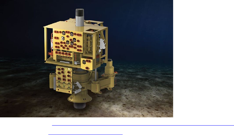
Your company is tasked with testing the grounding of anodes along the simulated leg of an oil platform. If
electricity is passing between two points on the simulated leg, that area is subject to galvanic corrosion.
A RetroClampTM anode on the leg of an oil platform (http://stoprust.com/products-and-services/retroclamp/)
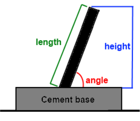
Companies are also tasked with conducting measurements on a new wellhead in preparation for the delivery
of a Christmas tree. The wellhead is emerging from the seafloor at an angle. Your company must measure the
length of the wellhead as well as the height of the top of the wellhead from the seafloor. Using these
measurements, companies must calculate the angle that the wellhead emerges from the seafloor.
EXPLORER Class 24
A Christmas tree installed on a wellhead (www.offshoreenergytoday.com/ge-oil-gas-enhances-subsea-trees-
portfolio-with-dvxt-launch/)
Your company is tasked with ensuring that water (and later oil) will flow through a system of pipelines and exit
through a specified pathway. This involves evaluating a map to determine the pathways of flow through the
pipeline system, checking valves to ensure that water will flow through the specified pathway, and moving
water through the pipeline system to verify that oil will flow through the correct pathway.
Finally, your company is tasked with designing and deploying a sensor to monitor the average flow rate of the
water current in the region. This involves designing a sensor, placing it on the bottom, and obtaining at least 5
minutes of water current data.
This task involves the following steps:
• Testing the grounding of anodes by measuring the voltage of four specified points along the leg of an
oil platform to determine which are subject to galvanic corrosion – 10 points each, 40 points total
• Measuring the height of the top of the wellhead from the seafloor within 3 cm of true length – 5
points
• Measuring the length of the wellhead above the seafloor within 3 cm of true length – 5 points
• Calculating the inclination angle of the wellhead relative to the seafloor within 3 degrees of the true
angle – 5 points
• Evaluating to determine the pathways of flow through a pipeline system and determining which
valves need to be opened or closed to ensure flow through the specified pathway – 5 points
• Checking all six valves and turning the necessary valves to ensure that oil will flow through the
specified pathway – 10 points
• Moving water through the pipeline system to verify that oil will flow through the correct pathway –
up to 20 points
o Flow comes out of only the intended pathway – 20 points
o Flow comes out intended pathway and another pathway – 10 points
o Flow comes out another pathway only – 5 points
o No flow is detected out of any pathway – 0 points
EXPLORER Class 25
• Determining the average flow rate, within 0.05 m/s, of water current over a 5 minute period – 10
points.
Mission Notes:
The steps of the oil field production and maintenance may be completed in any order except for the following:
evaluating the pipeline map, checking and turning valves, and verifying the flow through the pipeline. These
steps must be completed in order.
At the international competition, the oil field maintenance product demonstration will take place in the flume
tank. A constant current of up to 0.25 meters per second will flow through the flume tank. Any ROV that is
“pushed out” of its product demonstration area must be returned to the surface by pulling on the tether,
resulting in a 5 point penalty. The mission station judge will warn the company if they are moving out of their
product demonstration area before requiring them to pull their ROV to the surface. Once returned to the
surface, side of the pool, the ROV may descend and continue the tasks. Companies will receive a 5 point
penalty each time they are required to pull on the tether to bring the ROV to the surface. The oil field
maintenance product demonstration period will be terminated if a company is required to pull the tether
three separate times to remove it from adjacent demonstration areas.
Companies must test the grounding of anodes by measuring the voltage of four specified points along the leg
of an oil platform. Companies must design and place a lead, sensor, or other device across each test point and
a common ground. Electrical current moving across the sensor indicates a failed anode and therefore an area
that is subject to galvanic corrosion. No electrical current moving across the sensor indicates a functioning
anode and therefore area that is safe from galvanic corrosion.
The leg of the platform will be constructed from 2-inch PVC and 2-inch couplings. The base of the platform leg
will consist of an oil pan filled with cement. The leg of the platform will be rising out of the seafloor at an angle
between 60o and 85o relative to the seafloor.
Four test points will be located around the simulated leg of the platform. Each test point will be labeled with a
letter, A, B, C, or D. The test points will be located between 30 cm and 100 cm above the seafloor. The test
points will be constructed from a 10-24 bolt with a 1 ¼-inch x ¼-inch fender washer located on the outside of a
2-inch PVC coupling. Wires will be attached to the bolt inside of the PVC pipe. Judges will use switches to turn
current on or off at the test points between product demonstrations. The four test points will be within 8 cm
of the common ground. A schematic diagram of the circuit will be included within the prop building
instructions.
Companies will receive 10 points for each test point they correctly identify failed or functioning. A failed test
point is one where electrical current is detected. A functioning test point is one where electrical current is not
detected. Companies must show the mission station judge the result of each detection test; companies may
not guess.
EXPLORER Class 26
Companies must calculate the angle of a wellhead that emerges from the seafloor. The wellhead will be
constructed from 2-inch PVC pipe. The base of the wellhead, simulating the seafloor, will consist of an oil pan
filled with cement.
Design note: The wellhead pipe will be different from the angled leg of the platform where galvanic grounding
measurements are performed.
To calculate the angle, companies must measure the height and the length of the wellhead pipe. Companies
will receive 5 points when they report the height of the wellhead above the seafloor within 3 cm of the true
length. Companies will receive 5 points when they determine the length of the wellhead pipe above the
seafloor within 3 cm of the true length. Note that the seafloor for both the height and length measurement is
the top of the cement pan, not the pool bottom. Using these values, companies must calculate the angle of
the pipe relative to the seafloor. Companies will receive 5 points when they report the angle of the wellhead
pipe within 3 degrees of the true angle.
Depiction of the wellhead pipe emerging from the seafloor
Companies may not guess at the height, angle, or length. Companies must show a measurement to the
mission station judge or inform the mission station judge of how they are calculating these values. Companies
that report the incorrect value will receive 0 points for the task, but may measure again to determine the
correct value to use in the angle calculation. Companies must show the secondary measurements to the
mission station judge, who will let them know if the measurement is correct.
Companies must evaluate a pipeline map, turn valves to open and close pathways, and move water through a
pipeline system to verify that oil will flow through the correct pathway. The pipeline map will be available at
the mission station during the 5-minute set-up period.
EXPLORER Class 27
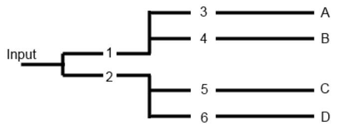
There will be six valves to open or close. The valves will be labeled 1 through 6. The valve labels will be black
on white 2-inch numbering set onto a flat black plastic sheet. There will be four exit pathways for the flow of
water, labeled A, B, C, and D. These pathways will exit the system on the water surface. The exit pathway
labels will be black on white 3-inch lettering set onto a flat black plastic sheet. The mission station judge will
inform the company of the specified exit pathway during the 5-minute set-up.
The pipeline map will show the four pathways and the location of the six valves. After evaluating the pipeline
map, companies must report to the mission station judge which valves must be opened or closed for water to
flow through the specified pathway. Companies must report this information to the mission station judge
during the product demonstration period; they may not report the map evaluation during the 5-minute set-up
period. Companies will receive 5 points when they properly identify which valves need to be opened or
closed. Companies must report on all six valves to receive points. If any report is incorrect, companies will not
receive points for this task. During the company’s evaluation of the map, they may find that it does not matter
if certain valves are opened or closed for the flow of water to exit the correct pathway. If that is the case,
those valves MUST be reported as closed. For safety reasons, any valve that does not need to be opened
should be closed.
If the report is incorrect, companies may re-evaluate the map to determine which valves need to be opened or
closed. The mission station judge will then inform the company when they have the correct report, but
companies will not receive the 5 points for this task.
An example of a pipeline system pathway. If the mission station judge instructed the company to move water
through pathway exit C, companies would open valves 2 and 5 and close valves 1, 3, 4, and 6.
The pipeline will be constructed from ½-inch PVC pipe. The valves will be constructed from a ½-inch gate valve
and ½-inch PVC pipe. The handles of the valve will be approximately 10 cm above and parallel to the seafloor.
Turning a valve completely clockwise will close the valve. Turning a valve completely counter clockwise will
open the valve. Valves may need to be turned up to 1170o (3.25 times around) to be completely opened or
closed.
Companies will receive 10 points when they have checked all six valves to determine if they are opened or
closed and turned those that need to be adjusted. Checking a valve is defined as touching the valve to

EXPLORER Class 28
determine whether it is opened or closed. Turning the valve is defined as turning it until it is completely
opened or closed. If it does not matter whether a valve is opened or closed for the flow of water to exit the
correct pathway, then that valve MUST be closed.
Once the company has adjusted the valves, they must verify that oil will flow through the correct pathway by
moving water through the pipeline. Companies must provide their own device to move water through the
pipeline; the MATE Center will not provide one. This device must be a component of the ROV; it may not be an
independent device.
The input to move water through the pipeline pathway will be a 1 ½-inch PVC coupling. The four exit pathways
will be on the surface of the pool in sight of the mission station. Companies will receive 20 points if the flow
comes out of only the correct pathway. Companies will receive 10 points if flow comes out of the correct
pathway and another pathway as well. Companies will receive 5 points if flow comes out the incorrect
pathway. Companies will receive 0 points if no flow is detected out of any pathway.
If a company does not receive the full 20 points, they may return to the seafloor, re-evaluate and re-adjust any
of the six valves. Companies may move water through the pipeline system multiple times to move water out
the correct exit pathway. When companies attempt to move water through the pipeline a second (third,
fourth …) time, they will lose their previous points and receive a new point total for this task. Note that this
may result with a lower score than a previous attempt. Companies should inform the mission station judge if
they are making another attempt at this task.
Companies must design and deploy a sensor to determine the average flow rate of water through the flume
tank over a 5-minute period. The sensor may be incorporated into the ROV or independent of the vehicle.
Companies using independent sensors must follow the independent sensor specifications of ELEC-001 in the
vehicle design & building specifications.
If an independent sensor is used, the ROV must place the independent sensor on the seafloor; companies may
not just toss the sensor in to sink to the bottom. Companies should consider the placement of their sensor.
The sensor should be placed at least 50 cm from the wall of the flume tank. The sensor should not be placed
directly down current from a large mission object.
Companies must have at least 5 minutes of data before reporting the average flow rate to the mission station
judge. Companies must report the flow rate in meters per second. Companies will receive 10 points when
they report the average flow rate, within 0.05 m/s, to a judge. Companies must also have a display or read out
of the sensor data over the 5-minute period; they may not simply guess at the flow rate.
Companies MUST recover their flow rate sensor after it has obtained its data or at the end of the production
demonstration period. Companies may use their ROV to recover their sensor or may have a line attached to
the sensor and retrieve it by pulling on the line by hand. Companies may retrieve their sensors after the

EXPLORER Class 29
mission time has expired, during the demobilization period. Companies that cannot retrieve their sensor will
be penalized 10 points.
If a company has successfully completed all the tasks, time will stop when a member of the company touches
the vehicle. If a company cannot retrieve the sensor, or drops it from the vehicle after time has stopped, that
company will not receive a time bonus.
The EXPLORER Sea Star Identification Handbook contains information and pictures of the sea star
species.
The EXPLORER Product Demonstration Photos contains photos of completed mission props.
See the EXPLORER SolidWorks files for CAD representations of the missions.
PART 2: MISSION PROP BUILDING INSTRUCTIONS & PHOTOS
By popular request, this section has been removed and made into its own, separate document. This document
will be released and posted by December 20, 2014
PART 3: VEHICLE DESIGN & BUILDING SPECIFICATIONS
1.0 GENERAL
Questions about vehicle design and building specifications, as well as competition rules, should be posted to
Competition Help within the M ATE Forum Hub. This ensures that all companies can view the questions and
answers and helps to avoid duplicate questions. That said, companies should make sure that their questions
have not already been asked – and answered – before posting. When posting their question, companies
should reference the specific specification (e.g. ELEC-002E).
1.1 Glossary and Acronyms
ANSI
American National Standards Institute
Company
Teams providing a ROV System for evaluation purposes
HD
High-Definition
IEC
International Electrotechnical Commission
Instrument
A device that contains one or more sensors and a method for
converting the information from the sensor into a transmittable
and storable form
NEMA
National Electrical Manufacturers Association
LARS
Launch and Recovery System

EXPLORER Class 30
Operate
Correctly performing designed functionality
PWM
Pulse Width Modulation, a method to electronically vary the
effective voltage delivered to an electrical load.
SID
System Interconnection Diagram
1.2 Conventions
All values contained in this document are threshold values unless specifically stated otherwise. All water
depths are given in meters (m). All dimensions and measurements utilize SI units.
1.3 Documentation Required
As part of the Technical Documentation, the following SIDs are required. All diagrams must be drawn with a
CAD (computer assisted drawing) program. Hand drawn figures are not permitted. All symbols must be
standard symbols as specified by ANSI, NEMA, or IEC.
DOC-001: SID Electrical: One figure must be an electrical diagram for all the systems above the waterline.
This diagram should show the ROV system fuse, controls, and tether connections. A second figure should be an
electrical diagram showing the ROV sub-systems and their connections. Both diagrams should not exceed one
page in length. The diagrams must not be component level schematics, but a higher level interconnection
diagram. Do not include individual pins on a board; this is intended to be a higher level diagram. An example
of these diagrams is an Electrical One Line Diagram. Examples of acceptable SIDs can be found here:
• www.marinetech.org/files/marine/files/ROV%20Competition/International%20Competition/2014%20t
ech%20reports/EXPLORER/EXPLORER/Memorial%20University/EER_Memorial_University_Newfoundla
nd_Tech_Report_Final_2014.pdf, page 22
• www.marinetech.org/files/marine/files/ROV%20Competition/International%20Competition/2014%20t
ech%20reports/RANGER/RANGER/Cornerstone%20Academy/Cornerstone_Academy_Tech_Report_fin
al.pdf, page 21
DOC-002: SID Fluid Power: If a company is using fluid power, fluid power diagrams must be provided.
The first figure must document the components on the surface. The second figure must document the
components located onboard the ROV.
DOC-003: Independent Sensor Devices: If a company is utilizing an independent sensor device that will
be installed and released by the ROV, a SID must be included for this device. This diagram must be completed
to the specifications listed in DOC-001.
DOC-004: All required documentation sent to the MATE Center MUST be in PDF format.
DOC-005: All symbols used in documentation must be in ANSI, NEMA or IEC format.

EXPLORER Class 31
2.0 SAFETY
Safety is the competition’s primary concern and guiding principle. Any system that is deemed unsafe by
competition officials will not be allowed to compete. If a safety concern is identified during the initial
inspection, companies are permitted to modify their system and have it re-inspected. Companies are
permitted to have their vehicle re-inspected twice. If a company fails to pass its third and final safety
inspection, it is disqualified from the underwater competition portion of the event. There are NO APPEALS
once an ROV has been disqualified.
Examples of safety violations from previous ROV competitions include:
• The electrical schematic included in the technical documentation did not show a main fuse or circuit
breaker.
• The ROV used pneumatics, but the technical documentation did not include a pneumatics diagram.
• The ROV used pneumatics, but the company had not passed the fluid power quiz two weeks prior to the
competition.
NEW in 2015!!!
2.1 Safety Instruction & Observation Program and HSE Awards
The Safety Instruction & Observation Program is being coordinated by Oceaneering International. Companies
earn points towards a Health, Safety, and Environmental (HSE) Award through this program.
Each member of the company is encouraged to read Oceaneering Americas Region HSE Employee Handbook,
with emphasis placed on the following chapters.
Chapter 1 - Housekeeping
Chapter 9 - Hand Safety
Chapter 11 - Lifting and back safety
Chapter 12 - PPE
Chapter 17 - Tool Safety
Chapter 24 Electrical Safety
Chapter 29 - Employee Observation Program
Chapter 33 - JSEA
Chapter 37 - Working at Other sights
Job Site Safety Analysis (JSAs)
Companies can earn up to 5 points by creating a JSA and submitting it 1) along with the Technical
Documentation and 2) to the Product Demonstration judge when entering the mission station.
A JSA describes job tasks in step-by-step fashion, identifies associated hazards at each step, and outlines proper
hazard controls that minimize the risk of injury or illness to the individual(s) performing that task. JSAs are used
extensively by the offshore industry.

EXPLORER Class 32
For more information and examples, companies can visit the following web sites:
• http://ehs.berkeley.edu/how-do-i-write-and-update-job-safety-analysis-jsa
• www.safetyworksmaine.com/safe_workplace/safety_management/hazard_analysis.html
Observation Program
The observation portion of the Safety Instruction & Observation Program will be implemented by Oceaneering
International at the international competition.
During the event, companies may be approached at any time by MATE staff/judges/safety officers and asked
questions about the HSE handbook or to address concerns about company’s utilization of proper personal
protective equipment, operation, or housekeeping.
A company’s responses will be noted and scored on an observation card. A response viewed as safety
compliant will receive 5 points; responses viewed as a safety violation will receive negative 5 points. No points
will be awarded for responses viewed as marginal. Cards will have a signature block for the company CEO and
the MATE observer; the observer retains the cards once signed. The HSE awards will be based on these and on
companies’ total, overall safety points.
NOTE: Observations and scores are not subject to debate, including with the Chief Judge. There is no debating
safety.
2.2 Safety Pre-inspection
Prior to the competition, safety inspectors will review companies’ spec sheets, SIDs, and/or technical
documentation to identify potential safety violations. Companies with violations will be notified via e-mail.
Once notified, companies must:
a. Respond acknowledging receipt.
b. Layout a plan to address the violation.
c. Submit new documentation if required.
Safety inspectors will compile a list of the safety violations and publish them to the competition web site. This
is not done to “call out” or embarrass companies in any way. It is to emphasize the fact that EVERYONE is
responsible and accountable for ensuring a safe, successful event.
Five points will be subtracted from the safety inspection points (see below) of companies that do NOT submit
the required safety documentation at the assigned time.
2.3 Safety Inspection
Companies must complete their initial safety inspection on the first day of the competition. Companies will be
assigned to a safety inspector(s). The inspector will reference the list of violations as he/she conducts the
safety inspection of the vehicle using the safety inspection sheet.

EXPLORER Class 33
2.4 Safety inspection protocol
1. Before entering the water for practice or a mission run, the ROV system must go through a safety
inspection. Once the company successfully passes inspection, they will turn in their safety
inspection sheet and be presented with a Green PASSED Flag. Companies must present the PASSED
Flag to the pool practice/product demonstration coordinator before their vehicles are permitted to
enter the water. Each company’s flag will be uniquely identified with company number on the flag.
2. Competition staff will conduct a safety inspection of the vehicle using the safety inspection sheet.
3. If the safety inspector(s) identify a safety violation, companies will have the opportunity to address
it. The pool practice or mission run schedule will NOT change to allow companies more time.
4. If during the second safety review the
a. violation has not been properly addressed or
b. another violation is revealed
companies will have ONE additional opportunity to address the issue.
5. If during the third safety review a violation still exists, companies will not be permitted to
participate in the underwater mission component of the competition. However, companies can
still participate in the engineering and communication (technical documentation, sales
presentation, and marketing display) component.
6. Reminder: All companies must present the Green PASSED Flag to the pool practice or product
demonstration coordinator before placing their vehicles in the water. In addition, mission station
judges and competition officials can pause or stop a mission run at any time if they feel that there
is a potential safety concern.
2.5 Safety Inspection Points
The safety inspection is worth 30 points. Each time a company fails its safety inspection it loses 10 points.
After a company fails its second inspection, it must meet with the chief safety inspector to discuss a plan of
action prior to returning to its workstation. THREE STRIKES and a company
a. receives 0 points for the safety inspection and
b. is disqualified from the underwater mission component.
3.0 Specifications
The ROV system (or “system”) must meet the following requirements:
3.1 Operational
3.1.1 Multiple Vehicles
OPER-001: MULTIPLE VEHICLES ARE NOT PERMITTED. Companies are required to design and build ONE
ROV that can complete the necessary mission tasks. “Floating eyeballs” or other vehicles that are not hard
connected to the frame of the main vehicle are NOT permitted. Cameras designed to provide a “birds-eye

EXPLORER Class 34
view” are permitted provided that these cameras are hard connected to the frame of the main vehicle. “Hard
connection” does not include the wiring between the camera and the ROV.
3.1.2 Environmental
OPER-002: The ice tank venue at the international competition is comprised of an EGADS solution. EGADS
is a combination of ethylene glycol, (EG), aliphatic detergent (AD) and sugar (S). The water temperature may
be as low as -2oC. The density of the EGADS solution is equivalent to that of sea water; a specific gravity of
1.025.
The other venues at the international competition will be equivalent to fresh, chlorinated water. Operating
temperatures in these venues will be less than 30oC.
The water at all three venues should be considered conductive of electrical currents.
OPER-003: Low light levels will exist underneath the ice at the international competition. Lower light
levels may exist in the offshore engineering basin. If companies are attending a regional competition to
perform their demonstration requirement, low light levels may exist under or near the simulated ice sheet.
OPER-004: The flume tank venue at the international competition will have a water flow rate of up to 0.25
m/s. The offshore engineering basin venue will have waves and surface winds. Waves will be less than 0.4
meters in height. Winds will be less than 25 km/hr. The ROV must be able to operate in these environments. If
companies are attending a regional competition to perform their demonstration requirement, no water
currents will be intentionally created. However, depending on the venue, pressurized pool filtration system
outlets may cause unexpected currents.
OPER-005: All pool venues at the international competition have flat bottoms, but may have small bottom
features. Companies should be prepared for small bottom topography.
If companies are attending a regional competition to perform their demonstration requirement, they should
contact their regional coordinator for information on the pool venue.
3.1.3 Service Requirement
OPER-006: Companies shall provide a crew of at least 3 but not more than 6 people on the pool deck to
operate the ROV System. Companies can send a larger crew complement, but no more than six can be on the
deck at any time. More information about this “product demonstration team” is provided in the COMPETITION
RULES.
3.1.4 Calibration Requirement
OPER-007: All measurement devices shall be calibrated according to manufacturer recommended
calibration procedure and performed by company members only. Company mentors or advisors are not
permitted to perform calibration procedures. More information about mentor restrictions is provided in the
COMPETITION RULES.

EXPLORER Class 35
3.1.5 Maintenance
OPER-008: System maintenance during field operations shall be conducted by ROV personnel at their
workstations. Work of any kind must not be done by company mentors or advisors. All maintenance parts and
equipment necessary to meet the operation requirements shall be provided by the company. More
information about these regulations is provided in the COMPETITION RULES.
3.2 Mechanical/Physical
This section of the document provides specifications for the mechanical properties of the ROV system.
3.2.1 Materials
MECH-001: Any electronics housings on the ROV shall be capable of operating to depths of 6 meters.
3.2.2 Size and weight
MECH-002: ROV systems must be able to navigate through a 75 cm x 75 cm hole in the ice. Companies
must be able to personally transport the vehicle and associated equipment to the mission station and to the
sales presentation room. ROV systems must be capable of being safely hand launched.
3.2.3 Tether Length
MECH-003E: ROVs must be capable of operating in a maximum pool depth of 5 meters (16 feet). All
underwater missions will take place within 10 meters from the side of the pool. The mission station will be no
more than 3 meters from the side of the pool. Tether length should be calculated accordingly.
3.2.4 Vehicle Deployment and Recovery
MECH-004: The ROV system must be launched and recovered manually; no powered winches or portable
cranes can be used. Hand-powered lifts and levers may be used to launch and recover the vehicle. The vehicle
and any associated equipment must not damage any part of the pool or pool deck.
MECH-005: Any hand-powered lift or levers that are used as a LARS must be detailed in the technical
documentation and must be part of the safety inspection procedure. Any LARS equipment that is deemed as
unsafe at the safety inspection will not be allowed. Ladders, tripods, or other bracing equipment are not
permitted as part of a LARS.
3.2.5 Propellers
MECH-006: Propellers must be shrouded. ROVs that have propellers exposed will not pass the safety
inspection and will not be allowed to compete.
EXPLORER Class 36
3.3 Electrical
ELEC-001: All power provided to the ROV system through an external connection for any purpose during
the competition must be obtained from the MATE competition power supply. This includes dedicated lines for
cameras, manipulators, and any other devices. This is a singular point of connection; all power to the ROV
must pass through the MATE-provided fuse AND the single in-line fuse or circuit breaker as specified in this
section.
The exception to this rule is an independent sensor. If a MATE Center task allows an independent sensor, that
sensor may be powered by other means. Sensors that are independent of the vehicle must be powered from
the surface; no onboard batteries of any type are allowed. Companies may use USB to connect their sensor to
a computer. Companies may also use surface battery packs (limited to 12 volts maximum) or the MATE supply
to provide power for their water flow rate sensor. The independent sensor may only contain the intended
sensor; thrusters, cameras or other systems MAY NOT be attached to the independent sensor.
Companies that use an independent sensor must provide a 3 amp (or less) fast blow fuse on the positive side of
their connection. If companies are using the 48 volt MATE supply to power their sensor, both the ROV and the
sensor must run through the single 40 amp fuse before splitting off to the 3 amp sensor fuse. Companies using
USB only to power an independent sensor may utilize the built-in current limiting of USB and do not need to
add an additional fuse.
ELEC-002E: The ROV system must be capable of operating off the power provided by a MATE supply
with a nominal voltage of 48 VDC. This voltage may be as high as 56 volts. Any power supplies used will be set
at 50.8±0.5 Volts. Power supplies will be a fixed output voltage and will not be “turned down” to
accommodate other than the specified voltage for the class.
ELEC-003E: The ROV system must deliver the supply voltage to the ROV as provided and without
modification. No conversion of this voltage is allowed prior to it arriving at the ROV system bus. Methods on
the surface such as DC/DC converters, voltage drop resistors, and Pulse Width Modulation (PWM) are not
allowed to be used between the ROV and the power source.
ELEC-004E: ROV systems may use any voltage desired up to 48 Volts, but any conversion to a lower voltage
must be made on board the ROV. Companies will not be permitted to operate an ROV that reduces the voltage
on the shore-side/top-side end of the ROV tether.
ELEC-005E: Voltage may not be increased above the nominal 48 volts anywhere in the ROV system.
ELEC-006E: Sonar or other systems that may have DC/DC conversion resulting in voltages above 48V
nominal are not permitted.
ELEC-007E: Voltages in excess of the class parameters set forth in this specification are not allowed on the
ROV system at any time other than the brief moment of back electromotive forces (back EMF) from collapsing
magnetic motor fields typical in any electrical motor situation.

EXPLORER Class 37
3.3.1 Current
ELEC-008E: The ROV system must have a 40A maximum fuse or circuit breaker in the positive power
supply line within 30 cm of the power supply attachment point. The SID and other electrical diagrams must
show the fuse or circuit breaker and include the amperage of the overcurrent protection.
ELEC-009E: ROV systems are allowed one replacement fuse during the product demonstration. In the
event that the ROV system blows the second fuse during the demonstration, the demonstration will be over
and no additional points will be earned.
NEW in 2015!!!
3.3.2 Power Connections
ELEC-010E: Power supply connections will be Anderson Power Connectors. Companies’ ROV system tether
must have proper connectors to obtain power.
http://www.andersonpower.com/products/multipole-sbs.html
Housing: Anderson SBS50BLU-BK
Pins: The proper pin for your tether conductors
12 or 10 AWG: Anderson 1339G3-BK
8 AWG: Anderson 1339G5-BK
6 AWG: Anderson 1339G2-BK
3.3.3 Tether Voltages
The signals in the tether must meet the following specifications:
ELEC-011E: Low voltage, low current AC or DC control or sensor signals. Low voltage is defined as a voltage
equal to or less than the maximum supply voltage per class specification. Low current is defined as being less
than 500mA.
ELEC-012E: DC main-supply at a nominal voltage of 48VDC as provided by the MATE power supply.
ELEC-013E: Ethernet, USB, or other ANSI or IEC accepted serial protocol signals.
ELEC-014E: NTSC or PAL Video signals
ELEC-015E: Fiber optic cabling of any type may be used.
3.3.4 Exposed connections and disposable motors
ELEC-016: ROVs with electrical connections that are exposed to water and not sealed are not permitted to
enter the water.
ELEC-017: “Disposable motors” are not permitted; these are exposed motors with no waterproofing.

EXPLORER Class 38
3.4 Onboard Electrical Power
ELEC-018: Onboard electrical power (i.e., power not provided by the tether): Onboard battery powered
devices are NOT allowed under any circumstance.
NOTE: Water leaking into a closed battery container can result in the generation of hydrogen gas. This gas can
build up inside a pressure housing and create an unsafe situation. For this reason, onboard batteries are NOT
allowed under any circumstance. Any device that needs power must obtain that power directly from the ROV
tether. For devices that operate at a voltage other than the tether voltage, an onboard ROV converter may be
included. The converter must be sealed and not exposed to water. This rule includes commercial “watertight”
battery containers; no battery of any type is permitted on any competition vehicle.
3.5 Power Shutdown
ELEC-019: For safety purposes, any ROV system that is disconnected from the surface supply must stop
functioning in less than 5 seconds. This applies to electrical, pneumatic, and hydraulic power sources. Any
filters, capacitors or accumulators must be sized accordingly to meet this specification.
3.6 Fluid Power
3.6.1 Documentation
FLUID-001: Documentation required must include a fluid power diagram using industry standard symbols,
showing all items, regulators, and control valves.
3.6.2 Hydraulic Power
FLUID-002: Hydraulic fluid: Water or biodegradable food-grade fluid, only.
FLUID-003: If a biodegradable food-grade fluid is used, a Material Safety Data Sheet (MSDS) must be
provided at the safety inspection. The MSDS must show the type of fluid used and its compatibility with the
Biodegradable Food-Grade specification. Companies using water do not need to provide an MSDS.
FLUID-004: The following fluids are approved for use in hydraulic systems:
a. Water
b. Biodegradable Food-Grade Hydraulic Oil ISO Grade 32/46, SAE Grade 20, McMaster-Carr part#
3499K22
All other bio-degradable food-grade fluids must be approved by the Competition Technical Manager by March
1, 2015.
FLUID-005: Maximum Hydraulic pressure allowed: 10.33 bars (150 psig).

EXPLORER Class 39
FLUID-006: Hydraulic system: All lines, fittings, and hydraulic devices must be rated for a minimum
pressure of two (2) times the maximum supply pressure.
FLUID-007: Hydraulic pumps must be part of the safety inspection.
1. They must have a pressure relief valve installed before the pressure regulator.
2. The pump must have a regulator in place and set to 150 psig or less.
3. Pumps with any sign of external rust or deterioration will not be accepted.
5. All wiring must be secure.
6. All guards must be in place.
8. Hydraulic pumps may run off of the 15A 115VAC outlet provided for command and control as long as the
hydraulic fluid is not used to propel the ROV. The hydraulic fluid is to be used for grippers and actuators only.
3.6.3 Pneumatic Power
FLUID-008: Pneumatic fluid: Compressed air or inert gas only
FLUID-009: Maximum pressure allowed: 2.75 bars (40 psig)
FLUID-010: Pneumatic system: All lines, fittings, and pneumatic devices must be rated for a minimum
pressure of two and a half (2.5) times the maximum supply pressure. For example, if an 83 bar (1200 psig) tank
is regulated to 2 bars (30 psig), then all system components must have a minimum rating of 5.17 bars (75 psig).
FLUID-011: Air compressors must be part of the safety inspection. .
1. They must have a pressure relief valve installed before the pressure regulator.
2. The compressor must have a regulator in place and set to 40 psig or less.
3. Compressors with any sign of external rust will not be accepted.
4. The tank drain valve must open.
5. If more than 5 ml of water exits upon opening the drain valve, the compressor will not be accepted.
6. All wiring must be secure.
7. All guards must be in place.
8. Air compressors may run off of the 15A 115VAC outlet provided for command and control as long as the air
is not used for motor thrust. The air is to be used for buoyancy/ballast, grippers and actuators only.
3.6.4 Pressurized Cylinders
FLUID-012: Pressurized cylinders may be used, but must remain above the water surface and meet the
following specifications:
a. Approved by US DOT (Department of Transportation) or TC (Transport Canada). For regional
competitions taking place outside of the US, check with your regional coordinator for approval.
b. Have a current official inspection/test sticker and/or stamp.
c. Stamped with the maximum allowable pressure.
d. Contain a pressure relief safety device.
e. May be filled up to the maximum allowable pressure of the cylinder.

EXPLORER Class 40
f. Must be regulated at its output to a maximum of 2.75 bar (40 psig).
g. Must have an easily accessible shut-off valve that is clearly marked with instructions.
h. May only be stationed on the surface, not on the ROV.
i. Must be secured in a safe manner such that they will not fall or roll around. If the judges feel that a
cylinder is unsafe, they have the discretion to prevent its use.
j. SCUBA tanks are permitted. They must meet all the above specifications and have a current visual
inspection sticker, or “fill permit” visible.
3.6.5 Pressure Storage Devices (Pressure Accumulators)
FLUID-013: Pressure storage devices are allowed on the ROV if they do not exceed 1.25L in total storage
and do not store pressure higher than the allowed pressure for air or hydraulics. It is recognized that a
company may not be able to purchase a pressure accumulator that has the proper rating and fits in the space
needed. In that case, the company must show that their designed accumulator is capable of withstanding the
specified pressures without rupture.
3.6.6 Fluid Power Quiz
FLUID-014: EXPLORER class companies planning to use hydraulics and/or pneumatics (i.e., fluid power) are
required to take and pass an online quiz with a score of 100%.
NOTE: The quiz was developed by MATE Center technical support staff and competition judges and is designed
to ensure that companies understand basic information on these topics and can apply that knowledge to safe
practices. The intention is not to add yet another “requirement,” but rather to provide a safe and successful
learning experience and competition environment.
The quiz should be completed by the STUDENT company members. Each member of the company does NOT
have to take the quiz; students can work together and make it a group effort. ONLY ONE TEST PER COMPANY.
The company’s instructor or mentor can provide guidance and advice, but the questions should be answered by
the students participating on the company. The quiz will be scored and the results provided instantaneously. A
score of 100% is considered a passing grade. Companies can take the quiz as many as 5 times to achieve this
score.
The quiz must be completed with a passing grade by March 1, 2015. Companies failing to complete this quiz
within the given time frame will NOT be permitted to use fluid power during their competition event.
The following are sources of information on hydraulics and pneumatics. This is not intended to be an
exhaustive list, but rather a starting point to encourage Companies to seek out additional information and
resources.
• Underwater Robotics: Science, Design & Fabrication, published by the MATE Center (see
www.marinetech.org/underwater_robotics)

EXPLORER Class 41
• http://www.fxsupply.com/pneumatics/psafety.html
• http://mining.state.co.us/safety/downloads/ppoint/HydraulicPressureIntensification.ppt
• National Fluid Power Association – http://www.nfpa.com/education/mini-book.asp
• Parker Hannifin Corporation – http://www.parker.com/ (look for technical literature links)
3.7 Control Systems
ELEC-020E EXPLORER class ROVs are expected to utilize computer (or electronic) based control
methodologies and H-Bridge or BLDC controllers for the thrusters. Systems using surface switch box controllers
will not be permitted.
3.8 Command, Control, & Communications (C3)
3.8.1 Power Provided
CCC-001: Surface power: MATE will provide one GFI-protected outlet with a nominal 115 Volts AC (60
Hertz) and 15 amps maximum. This outlet is intended to provide power for pumps and other surface support
equipment (e.g. video monitors & control boxes). This AC power source CANNOT be used to directly or
indirectly power the vehicle.
CCC-002: If hydraulic or pneumatic power is used for vehicle thrust, the power for the pump must come
from the MATE supplied DC power supply.
CCC-003: In addition to electric pumps, hydraulic, and pneumatic systems can be powered by manual
pumps (e.g. bicycle tire pump) or supplied from a pre-pressurized cylinder. Companies that are only using
manual pumps do not need to pass the fluid power exam.
3.8.2 Displays
CCC-004E: Companies are not limited to the number of display screens used for video feeds or ROV status
information. Display devices may be made up of any combination of TVs, monitors, laptops, and/or computer
displays.
CCC-005E: These display devices may be powered by the MATE provided GFI-protected 115-Volt AC (60-
cycle) and 15-amp AC power source described in CCC-001, Surface power.
CCC-006E: A company’s C3 station may include devices like video recorders. All C3 devices must be able
to run on the single AC power outlet provided or on its own internal battery power. Any device plugged into
this AC power outlet can only provide C3 functions and cannot provide power to the ROV.

EXPLORER Class 42
3.9 MATE Provided Equipment
MATE will provide NOT provide video monitors at the mission stations this year.
3.9.1 Companies Sharing Equipment
Companies may share the following equipment during the competition event: monitors, joysticks, and
compressors.
Companies may NOT share the following equipment during the competition event: control systems and
payload tools (e.g. grippers, manipulators).
Companies that plan to share equipment during the competition event must notify the Competition Technical
Manager at least 4 weeks prior to the event so that this can be considered when creating the schedule. MATE
will do its best to accommodate companies sharing equipment.
3.10 Laser Safety Rules
LASR-001: Companies using a laser at the international event must inform the MATE Center and provide
the laser specifications by March 1st, 2015. Information and laser specifications should be sent to the
Competition Technical Manager. Specifications will be forwarded to the MATE Center safety inspection team
for evaluation. Once the laser specifications are reviewed, a notification will be sent to the company. If the
laser is being used at a regional event or pool practice, notification will also be sent to the regional competition
coordinator.
LASR-002: All lasers must operate in the visible range at either the 630-680 nm (red) or near the 532 nm
(green) wavelength. All lasers must fall into the Class I, Class II, or Class IIIa category. Red lasers must operate at
5mW or less. Green lasers must operate at 1mW or less.
LASR-003: Companies should include detailed specifications of their laser in their technical
documentation as well as have that information ready and available during their safety inspection and sales
presentations.
LASR-004: Lasers must have an on/off switch. This switch must be on the surface controller.
LASR-005: All lasers must be powered by the MATE surface power supply. Batteries, including batteries for
powering lasers, are not permitted on the vehicle.
LASR-006: Companies using lasers cannot increase the voltage or the current to increase the power of
their lasers. Lasers must use the voltage and current set in their specifications.

EXPLORER Class 43
LASR-007: When out of the water, the laser should have a shield or enclosed beam stop attachment
within 30 cm of the laser. This means that the laser beam should not travel more than 30 cm before reaching
the shield. This is a requirement at all times when the laser is out of the water. The shield does not need to be
attached to the ROV while it is in the water. The shield must be painted with FLAT BLACK paint.
LASR-008: At no time should the laser be focused or deviate from a collimated beam.
LASR-009: When testing the laser at a workstation, companies must display a sign telling others that a
laser is being operated.
LASR-010: Operators working with the laser while the ROV is out of the water should wear appropriate
laser safety glasses at all times. This requirement is for all laser types. Search online to find laser safety glasses
appropriate for the wavelength being used.
PART 4: COMPETITION RULES
GENERAL
• All members of the company and their supporters must follow the safety regulations of the ROV
competition, pool facility, and event venue.
• All company members and their supporters are expected to conduct themselves in a professional
and responsible manner during the competition. Disrespectful behavior towards the judges,
officials, pool staff, audience, or other companies will lead to penalty points or disqualification.
• Sabotaging, stealing, or pilfering equipment of other companies will lead to disqualification.
Companies found cheating will also be disqualified.
• The MATE ROV competition is, at its core, designed to be an educational and inspirational event for
STUDENTS. It is designed to challenge them to apply the physics, math, electronics, and engineering
skills they are learning in the classroom to solving practical problems from the marine workplace.
(See the MATE Competition Philosophy.)
It is expected that all “adults” (non-students; e.g. teachers, mentors, parents) involved in the
competition limit their input to educational and inspirational roles. Actual construction of the ROV
(particularly in the complex electrical and software areas) must be completed by the
students. Adults should teach and advise students about design, electronics, software, and
construction, but not complete the work for the students. Throughout the process adults are
encouraged to focus on benefits to the students from the process and not simply winning. If it

EXPLORER CLASS 44
becomes apparent that adults exercised more than an advisory role, judges reserve the right to
deduct points or, in extreme cases, disqualify companies from the competition.
While at any MATE ROV competition (international and regional), ALL work done on the vehicle
must be conducted by company members. Teachers, mentors, parents, and non-competing
students are not permitted to work on the ROVs. They may provide advisory input, but they may
not work on the ROV directly. This includes writing or editing software code. All mechanical
electrical and software modifications and/or repairs to the ROV must be completed by students.
• To encourage student participation at all levels, MATE is discouraging the use of “off-the-shelf”
technology. The rationale is that engineering involves integrating existing technology into new
systems. As such, students are encouraged to turn to commercially-available technology where
available (and affordable). Individual discrete “components” obtained commercially are acceptable,
provided that they adhere to the design and building as well as safety specifications for the
particular competition class. However, as this is an educational event, students are strongly
discouraged from using commercially available “plug-and-play systems” within their ROVs. These
devices violate the spirit of the competition in that they remove many of the technical challenges of
electrical and software engineering. Thus, they eliminate much of the educational value of the
event. An extreme example would be a company that focused its efforts on fundraising and simply
purchased one of the low-cost ROVs available commercially. Such an entry would not be permitted.
In summary:
Multiple commercial components are ENCOURAGED.
Systems designed to perform multiple, complex functions from one “black box” or a series of
components designed to integrate with each other are DISCOURAGED.
Examples of “components” versus “systems” are provided below. If companies are uncertain about
the commercially-available items that they plan to use, they should contact the MATE Center early
in their design phase. All such questions (and answers) will be posted to the FAQs section of the
MATE competition web site.
The engineering and communication score sheets will reflect MATE’s effort to discourage the use of
off-the-shelf systems. For example, the score sheets contain sections devoted to control
systems. Companies that demonstrate control systems constructed from “scratch” versus complete
control system purchased from a commercial vendor will be awarded higher scores. In addition, the
originality of design and teamwork sections will be weighted more heavily.
Examples of commercially-sourced components:
○ Tethers
○ Thrusters
○ Radio control transmitters and/or receivers

EXPLORER CLASS 45
○ RC servo and/or motor controllers
○ Pressure housings
○ Watertight connectors
○ Cameras with or without watertight housings
○ Structural materials
Examples of commercially-sourced systems:
○ “Black box” controllers that provide for multiple power and control signal interconnections and
manipulations (e.g. FIRST Robotics controller systems)
○ Thrusters, motor controllers, cabling, and control box designed and sold as a “system”
○ Commercially available ROVs, such as VideoRays or LBVs
PROCEDURAL
• Companies must compete during their assigned time slots. Your company is NOT permitted to
switch time slots with another company. Failure to show for your scheduled product demonstration
or for your company’s sales presentation will result in “no score” for that particular competition
category. No exceptions. Assigned time slots will be sent out in advance so that any scheduling
concerns can be addressed prior to the event.
• While there is no limit to the number of students who can compete as part of a company, the
product demonstration team (aka demo team) is limited to six students. The demo team is
defined as the team of students who operate the vehicle and its associated equipment during the
product demonstration. The product demonstration is conducted at a “mission station.” Only six
students will be allowed to enter the mission station, launch, pilot, and perform the tasks.
Instructors, mentors, and/or non-student members cannot participate as part of the demo team.
Companies may alternate students on the demo team for the three product demonstrations. (All
members of the company should participate in the engineering and communication components;
see ENGINEERING & COMMUNICATION for more information.)
• Only the demo team members and judges are allowed at the mission station during the product
demonstration, which includes the set-up and demobilization periods. Other members of the
company, instructors, mentors, audience members, and observers (press or special invited guests)
must remain outside the mission station or in designated viewing areas.
• Instructors, mentors, parents, and “fans” are NOT permitted at the safety inspection stations or
repair tables. Two warnings will be issued before individuals not heeding this rule will be asked to
leave the venue.
• In addition, instructors, mentors, parents, and fans are NOT permitted to work on the ROV.
Individuals who are seen working on the ROV who are not student team members will be issued a
warning. Two warnings will be issued before individuals not heeding this rule will be asked to leave

EXPLORER CLASS 46
the venue. If companies choose to take their ROVs off the competition grounds for maintenance
and repair, they are expected to observe this rule in the interests of the spirit of the competition.
• To help enforce this, teachers, mentors, parents, and non-competing students MAY have limited
access to the work station areas. Limited access can mean that these individuals are not permitted
into the room or building where the workstations are located. Contact your regional coordinator or
the MATE Center for more information.
• Video devices may be used to record the underwater activities for entertainment and learning
purposes only. Video will not be used as an instant replay to review judges’ decisions or to
challenge mission timing.
• Mission stations will be roped off and marked. Mission stations will contain 2-3 chairs and one 6-
foot table long table for companies to use. This table will be within 3 meters of the pool edge.
Mission stations will be set up to prevent the pilot(s) from looking at the ROV in or under the water
except through the ROV cameras.
• At the international competition, companies will need to lift their ROV over railings up to 0.75
meters tall. Companies may also need to carry their vehicle up and down stairs to launch platforms.
• Companies will compete in three different product demonstrations that consist of distinct tasks.
Companies will only get ONE attempt at each product demonstration. All three product
demonstration scores will be added to the engineering and communication score to determine the
total, overall score for the competition.
• The product demonstration time consists of a 5-minute set-up period, a 15-minute performance
period, and a 5-minute demobilization period. If the demo team and all of their equipment are not
out of the mission station at the end of the 5-minute demobilization period, the team will be
penalized 1 point for each additional minute.
• Manipulating the tether to free it from underwater obstacles is permitted. Pulling on the tether to
speed up the recovery of items or to return your vehicle more quickly to the surface is not permitted
and will result in penalty points. Judges will issue one warning if tether pulling occurs. Each future
infraction will result in 5 points deducted from the final product demonstration score.
• SCUBA diver assistance will only be available at one of the three international competition pool
venues – the offshore engineering basin. Diver assistance will not be available during the product
demonstrations within the flume or ice tanks. If your vehicle is completely disabled and/or its tether
tangled and unable to free itself in these venues, emergency divers can be called in to assist the
vehicle. At that point, companies will not be able to continue the product demonstration.
EXPLORER CLASS 47
Companies will receive points for the tasks they have completed thus far, minus 10 penalty points
for emergency diver assistance.
Pilots can only leave the mission station and move poolside to repair, adjust, or alter a vehicle if the
ROV is surfaced and at the side of the pool.
• Companies are not permitted to leave debris in the pool. Any debris must be recovered and
returned to the pool deck before time has expired or the company will be penalized. Debris is
defined as pieces of the ROVs, weights, floats, or other items created by the company. Task props
are not considered debris. The mission notes section may cover special items that can be left in the
pool after time has expired.
• No demo team member shall enter the water to complete an object recovery. Only arms and hands
are allowed into the pool to retrieve an object or to retrieve the vehicle. Companies will be
disqualified or penalized depending on the severity of the infraction.
• Communication between demo team members at the pool edge and demo team members piloting
the vehicle will be limited. Only tether management issues (e.g. how much tether is out, how much
is remaining on the pool deck) can be discussed. Those team members at the pool edge cannot give
any directional or mission task information to the pilot. Judges will issue one warning regarding
illegal communication. Each future infraction will result in 5 points deducted from the final product
demonstration score.
• Communication using cell phones, text messaging, and online social media tools such as Skype,
Facebook, Twitter, instant messaging, etc. is NOT permitted during the product demonstration,
either between the demo team members at poolside or between any demo team member and
anyone outside of the mission station.
• Mission judges and other competition officials will only communicate with students. Judges and
officials will NOT communicate with mentors, parents, or other non-student members regarding
mission information, challenges, or other issues except during pre- and post-competition briefing
sessions.
DESIGN & SAFETY CONSIDERATIONS
• The competition coordinators and host venues stress the importance of safety practices and
procedures to all companies. The score sheets will reflect the MATE Center’s efforts to encourage
and reward companies that demonstrate exceptional safety practices and procedures.
• ALL ROVS MUST PASS A SAFETY INSPECTION CONDUCTED BY COMPETITION OFFICIALS PRIOR TO
ENTERING THE POOL. These inspections will be conducted topside to ensure that ROV systems

EXPLORER CLASS 48
meet the design and building specifications and do not pose a risk to the integrity of the event
venue. See VEHICLE DESIGN & BUILDING SPECIFICATIONS for additional information.
• Keep an eye out for tripping hazards in the mission station and at your company’s work station.
Make sure power cords are not laying in pools of water on the deck.
• During your product demonstration, be sure to secure any equipment so that it does not fall off the
mission station table, damage the deck, or cause injury.
• Loose fitting clothing, jewelry, and long hair could all become safety issues. Consider securing long
shirts or baggy pants, removing jewelry, and tying back long hair when working on or operating your
ROV.
• ROVs may be constructed out of materials of your company’s choice, provided they meet the design
and building specifications and safety regulations. Warning labels should be posted on potentially
hazardous components of your ROV system.
• All company members must wear close-toed shoes and safety glasses or goggles. No one will be
allowed into the work station area without close-toed shoes and safety glasses or goggles. No one
will be allowed on the pool decks without close-toed shoes. This includes company members,
parents, mentors, and guests. Safety glasses/goggles are also recommended when working with
your vehicle on deck.
• At the international competition, all company members at the edge of the pool are required to wear
personal flotation devices (PFDs). A variety of PFDs will be available to the company before the
product demonstration period begins. Your regional coordinator will inform you in PFDs are
required at your regional event.
• In 2015, companies must operate in an ice tank facility. Temperatures may be as low as -10oC.
Companies must also operate in a high wind environment. Winds may be as high as 25 km/hr.
PART 5: ENGINEERING & COMMUNICATION
The ability to effectively communicate information about your vehicle and the design and building
process is equally as important as how well your vehicle performs. Strong communication skills are an
essential part of good business practices. To emphasize this point, the competition requires the
following four engineering and communication components:
• Company Spec Sheet
• Technical Documentation (formerly known as the technical report)

EXPLORER CLASS 49
• Sales Presentation (formerly known as the engineering presentation)
• Marketing Display (formerly known as the poster display)
The Company Spec Sheet, Technical Documentation, and Sales Presentation are components where you
are communicating with technical audiences, such as potential future clients. (Examples of spec sheets
and technical documentation from previous competitions can be found here. Examples of sales
presentations can be found on MATE’s Vimeo channel.) The Marketing Display should be thought of as
part of your marketing strategy and aimed at general (including non-technical) audiences.
TIPS FOR EFFECTIVE WRITTEN AND ORAL COMMUNICATION
Communicating ideas about how to solve a problem and evaluating those ideas against competing
alternatives is a critical skill for anyone thinking about a career in marine technology. It is a skill that is
directly linked to decision making about whether or not to hire (or fund) us and our ability to influence
the work that we do.
The key to a successful technical documentation and sales presentation is the way that critical thinking
and engineering reasoning are communicated. You can think of the process as technical “storytelling.”
Technical storytelling includes the use of text, images, schematics, and data to effectively communicate
the “story” of how your company brainstormed and evaluated ideas to come up with your solution (e.g.
ROV, payload tools, and operational strategies) to the problem at hand(product demonstration tasks). It
also involves organizing content to efficiently present your work and justify why you did what you did.
However, choose details with care. Each detail should help to answer the question "why is what you did
the best solution for your company and for this competition?" Describe why a component in the system
is critical and how you chose it. Include specifications or dimensions only if they help to explain the
“why” and “how” you made choices. Keep in mind that a mechanical drawing with dimensions can
replace a lot of text and in many cases do a better job telling details of the story than text.
Maintaining a project notebook is a good business practice that will help to capture ideas and document
your company’s progress – including your research, designs, trade studies, experiments, data, vehicle
specifications, testing, expenditures, and donations. The notebook is also a place to keep track of your
company member’s contributions (time, support, etc.).
Along with your notebook, here are some items to consider as you prepare to tell your story:
• What was your company's "work breakdown structure" (tasks, time, and people)?
• What were the greatest constraints (schedule, budget, equipment, labor, logistics, etc.) on your
design process?
• How did the product demonstration tasks and rules influence your design and decisions?

EXPLORER CLASS 50
• What systematic process, such as a tradeoff matrix, did you use to evaluate competing design
solutions?
• What were the most important design decisions you made and why?
• How did you arrive at your final power budget? What concessions, if any, did you have to make
and why?
• How do you calibrate your sensors?
• If your vehicle uses software, where does the code execute? Describe the flow and format of the
data.
• Did you have a noteworthy troubleshooting experience? Any problem or procedure that takes
more than 20 minutes to figure out is worth understanding and writing down.
COMPANY SPEC SHEET (ONE PAGE ONLY)
Your company is required to submit a one-page spec sheet along with the Technical Documentation (see
below). The goal of the spec sheet is to provide the judges with a “snapshot” of your company. It
includes basic information about your company and vehicle.
Companies must submit their spec sheets to the MATE Center 2 weeks prior to their demonstration.
The spec sheet MUST be sent as a pdf file attached to an e-mail. The spec sheet should NOT exceed one
page in length and should follow the font style requirements of the technical documentation.
Company spec sheets are reviewed by safety inspectors as well as judges, but not scored.
Spec sheets must include the following information:
COMPANY SPECS
Company and school, club, or community organization name
Home state and/or country
Distance required to travel to the international competition
History of MATE ROV competition participation. Be sure to specify if your company and/or the
members of your company are “new” or “returning.”
Company photo and caption indicating members’ names and roles (e.g. CEO, CFO, Design
Engineer, Pilot, etc.). This photo should include all of the members of your company.
Range of grade/college levels represented by the members of your company
ROV SPECS
ROV name if applicable
Total cost. You must include the approximate cost of any donated items.
Safety features
Special features
Photo of the vehicle

EXPLORER CLASS 51
TECHNICAL DOCUMENTATION
Your company is required to submit technical documentation that will be reviewed and evaluated by a
panel of working professionals – individuals who represent science, exploration, government, and
industry. (These individuals may not be the same judges who evaluate your company’s sales
presentation.) The technical documentation is a means for your company to describe the design,
operations, and features of your vehicle. Your clients should gain a good technical understanding of
your vehicle and your company’s capabilities in addressing your client’s needs for an ROV.
Companies must submit their technical documentation to the MATE Center by May 28th, 2015, which
is 4 weeks prior to the competition date. The documentation MUST be sent as a pdf file attached to an
e-mail. The documentation should not exceed a file size of 8MB.
Any changes or additions that you make to your ROV that differ from the information in the technical
documentation that you submit should be presented to the judges during your company’s sales
presentation. NOTE: The judges will not review and rescore revised versions of your technical
documentation during the competition.
Each judge on the panel will award a score (100 points max). Judges’ scores and comments will be
returned to you shortly after the event.
The guidelines and required components for the documentation are:
NOTE: Make sure to label any and all figures, graphs, diagrams, and photographs. Also note that
these components must be present in your documentation, but you must determine the best logical
order for presenting you them.
Length is 25 pages or less – NO EXCEPTIONS
Font size of at least 12 points (font type can vary)
All measurements are in SI units (metric)
Exceptions include ½-inch PVC pipe and other items described or sold in imperial units.
Title page must include:
o Your company's name
o School, club, or community organization’s name, city, state, and country.
o COMPLETE list of the members of your company and their role (CEO, CFO, Design
Engineer, Pilot, etc.). You can also include degree/area of study (or what you plan to
major in at college) and expected graduation date.
o Names of your instructor(s) and/or mentor(s)
Abstract (250 words or less) that is concise and clearly summarizes the project.
Table of contents
Photograph(s) of your completed ROV

EXPLORER CLASS 52
You are permitted to make modifications that may change the look of your vehicle between the
time you submit your documentation and the competition; however this must be a photo(s) of
your completed, intact vehicle, not photos of individual systems and/or payload.
Project costing
Project costing is an accounting of your income, donations, and expenditures. Items must be
listed as one of the following: purchased, re-used, parts donated, or cash donated. For re-used
or donated items, report the item’s current market value and note the source or organization
that made the donation. See the project costing sheet located here for an example.
Budget
At the beginning of the project, companies should establish a budget. A budget is different than
a project costing sheet in that it is a projection of the cost of the project. Companies should
create categories and realistically estimate what they think that they will spend in each. If well-
thought through, the project costing will align with the budget (i.e., the amount budgeted for a
certain category will be the actual amount spent!). The budget can be included as an appendix.
System Interconnection Diagram (SID)
A SID is a system-level, connection diagram that includes electrical and, if applicable, fluid power
wiring information. Board-level and component-level schematics should not be included;
however, these may be brought to the sales presentation for reference purposes. The intent is
to provide the competition judges with a one-line diagram showing how the various systems are
interconnected without the detail of each and every wire.
The SID must include a clear distinction between the surface controls and the ROV. SIDs must
be computer-drawn; hand-drawn or scanned diagrams are not acceptable. Any electrical,
hydraulic, or pneumatic symbols must be ANSI, NEMA, or IEC recognized symbols. VEHICLE
DESIGN & BUILDING SPECIFICATIONS includes additional details about the SID.
Note: Companies may use free drawing software such as OpenOffice to complete the SIDs.
Block-diagram or flow-chart of software in the ROV (if applicable)
This flow diagram should detail the software code written for your control system or other
elements of your ROV. If you are using a purchased control system that utilizes software, you
are encouraged to learn about its operation and describe it in a diagram.
Design rationale presented in a clear and logical manner. This section should comprise the bulk
of your documentation. It should focus on the technical aspects of your vehicle and how your
ROV was built to perform the specific tasks. See the questions under Sales Presentation below
for an example of information that you should cover.
Safety. This section should describe the steps that your company has taken to identify and
address any safety concerns regarding the design, construction, maintenance, and operation of
your vehicle.
Description of at least one challenge that your company faced and what methods were used to
overcome it. These can include both technical challenges and those related to working as a
team. Be sure to explain how you overcame these challenges.
Description of at least one lesson learned or skill gained during the design and building process.
EXPLORER CLASS 53
Discussion of future improvements
In this case, the MATE Center is your “client” and has defined both the problem to be resolved
and the products and services you need to provide. However, future clients could include
research institutions, private companies, and government agencies. A synopsis of ideas for
future improvements is essential to any entrepreneurial organization.
Reflections on the experience
This can be written from the point of view of your company as a whole or individual members of
the company can contribute a reflection. It can include personal or professional
accomplishments achieved as a result of participating in the competition.
References
List any books, journal articles, magazines, trade publications, web sites, and professional advice
that you used as sources of information for your work.
Acknowledgements
Please recognize your sponsors (companies, organizations (including the MATE Center),
professionals from industry, and/or mentors) and the type of support that they provided (funds,
building supplies, equipment, site visits to facilities, time, and/or technical expertise). You can
include organizations and/or individuals that provided logistical and/or moral support (e.g. your
parents, siblings, or pets). Regional companies should also acknowledge regional contest
supporters.
SALES PRESENTATION
During the competition, your company is required to give a 15-minute oral presentation to a panel of
working professionals – individuals who represent science, exploration, government, and industry.
(These individuals may not be the same judges who evaluate your company’s technical documentation.)
Your presentation should describe the engineering behind your vehicle’s design and operation and
address any possible safety issues. It should also highlight any design innovations or creative solutions
to solving the mission tasks. After the presentation, the judges will take 10-15 minutes to ask the
members of your company questions about your ROV. The judges will evaluate both your presentation
and responses to their questions.
All student members of your company must participate in this presentation and question and answer
(Q&A) period. You are required to have your ROV with you.
NOTE: The sales presentation is designed to be a face-to-face interaction where students and
representatives from industry become engaged in conversation. MATE will not provide audio visual
aids, such as slide projectors, computer projection screens, white boards, etc.; however, you are
welcome to distribute handouts to help judges better understand the information that you are
presenting. PowerPoint presentations are NOT permitted. During the Q&A, all members of the
company must be present and prepared to answer.
Instructors, mentors, family members, friends, and members of other companies are permitted to

EXPLORER CLASS 54
attend. However, we ask that those in attendance be respectful and courteous throughout the
presentation and follow-up question and answer period. Be mindful that this presentation may be a
stressful time for the students. If the room becomes crowded or the spectators become distracting, it is
up to the judges’ discretion to request that some or all spectators leave the presentation. While they
are permitted to attend, instructors and mentors are not allowed to participate.
Each judge on the panel will award a score (100 points max). Judges’ scores and comments will be
returned to you shortly after the event.
The judges will pay particular attention to whether or not the vehicle was built by the students from
“scratch” or excessively uses complete, off-the-shelf systems. The use of complete, commercially-
available systems is highly discouraged (the COMPETITION RULES includes more information on this
topic). Design originality and innovation as well as safeguards to prevent injury or damage to the
underwater environment will be noted.
Here are some examples of questions that the judges may ask or observations they may make. NOTE:
These are only examples and may not be the actual questions asked. Your company must be prepared
to answer questions other than those examples listed below.
Structure
- How did you decide on the shape of the vehicle and the materials used to build it?
- What is the design depth rating of your ROV? Did you test this? How?
- Did you use any pressure housings in your design? Explain how you designed and built these.
- What are o-rings and how do they work?
- How much did it cost to build your vehicle?
- How much does your ROV weigh in air? In water?
Control system
- What type of control scheme have you used? Why?
- How does your control system work?
- How many conductors are in the tether?
- What devices/functions does your system control?
- Is there some unique feature of your control system?
- How did you waterproof your underwater electrical connections?
Propulsion
- How many thrusters does your vehicle have? Why?
- How much thrust does each produce?
- How many watts does one thruster use at full rpm?
- How many amps does one thruster draw under full load?
- How much electrical power does the vehicle draw when all the thrusters are in use? Have you
measured this?
EXPLORER CLASS 55
- Explain how you measured thrust.
- How is power (watts) used by one thruster related to the thrust it produces?
- Do you know the forward speed of your ROV? How did you measure this?
Ballast System
- How does your ROV ballast system work?
- Explain what stability is.
- Why is it important to consider stability in the design of ROVs?
Sensors
- What type of camera(s) did you choose? How did you waterproof it?
- What do your sensors measure or detect?
- What unique features are incorporated into your sensors?
- What additional sensors (other than a camera) have you put on your ROV? Why?
Payload Tools
- What type of payload tool(s) did you design to accomplish the mission tasks and why?
- Explain how the tool(s) works.
Resources
- Did the project stay within budget? If not, why?
- What equipment/building supplies were donated, built, or bought? What strategies did you use
in your fundraising?
- Were you able to produce a functional vehicle that can accomplish the tasks? What tasks did (or
do) you still have difficulty completing?
System Design
- What are the strengths of the design? How will they affect the vehicle’s performance?
- What are the weaknesses? How will they affect the vehicle’s performance?
- Do the safety systems work? How did you come up with them?
Originality
- Does the design of the vehicle and its systems exhibit unique concepts and innovation? What
are they?
- Does the vehicle make excess use of commercially-available systems? Why or why not?
- Are there any innovations or modifications that resulted in higher functionality and reduced
costs?
- If you are using the same vehicle as last year, why? What are the advantages? What, if any,
modifications or additions did you make?
Workmanship
- What is the overall quality of the workmanship?
EXPLORER CLASS 56
- Are the electrical systems neatly contained and wired?
- Is it easy to access components for maintenance? If not, why?
- Is the tether neatly bundled and protected? How did you accomplish this?
- Can the tether withstand the strain from the vehicle weight, handling, and operation? How?
- Does the vehicle look aesthetically pleasing yet have practical functionality? Why do you think
so?
Safety
- What potential safety hazards did you identify then address?
- Are warning labels and safeguards posted on potentially hazardous components?
- Did your company develop a safety checklist or protocol?
Theme
- In the real world, what role do ROVs play in the competition theme?
- What types of organizations’ or individuals’ work relates to the competition theme?
Preparing for your sales presentation and Q&A
• Make sure that every member of your company has a good, general working knowledge of your
vehicle, even though they may have specialized in one specific aspect of its design and
construction.
• Research the specifications of the components that you use in your vehicle. For example, look
up the specs of your ROV’s camera and be familiar with such numbers as the amount of
propulsive force the thrusters produce, the weight of your ROV, etc.
• Make sure that all the members of your company are familiar with your technical
documentation. Ask every member to read it over to catch any errors or omissions. This
exercise will help to familiarize everyone with all aspects of the project.
• Generally, you will have more to say about your ROV than can be presented in 15 minutes. That
is why it is critical to organize your material and practice communicating it. However, avoid
coming across as having memorized your presentation verbatim. Judges want to see that you
are prepared and understand the information, not that you can simply regurgitate a rehearsed
speech from memory. Ask your instructors or mentors to give you feedback.
Other important items
• If during the sales presentation it becomes apparent that instructors, mentors, and other adults
associated with your company exercised more than an advisory role, judges reserve the right to
deduct points or, in extreme cases, disqualify companies.
• Your company is discouraged from using off-the-shelf, plug-and-play systems. You are
encouraged to demonstrate innovation and creativity in the construction of your vehicle and its
systems. This will also be reflected in your score.

EXPLORER CLASS 57
MARKETING DISPLAY
Your company is required to create a display that will be showcased during the competition event. Your
display should be an informative, clear, and concise marketing presentation about your company and
how you designed and built the specialized tools to effectively complete the product demonstrations.
During the competition, your company’s display will be evaluated and scored by a completely different
group of working professionals – individuals who will represent science, business, government, industry,
and education/outreach.
While some judges will have a technical background, others will have a communications, marketing, or
public relations backgrounds. In addition, there will be visitors to the competition who may not
completely understand what an ROV is or how it is used. You can think of these visitors as potential
future clients who may authorize funding for your work, but have a limited understanding of it (i.e., you
need to explain your technology, the tasks at hand, and “sell” them on YOUR products and services).
Design your display to communicate to this type of audience.
Each judge will award a score (50 points max). Judges’ scores and comments will be returned to you
shortly after the event.
******************************************************************************
INTERNATIONAL COMPETITION ONLY!
The MATE Center will supply one, 3-panel tri-fold display board to companies upon request. If your
company will need a presentation board provided by the MATE Center, please contact the Competition
Coordinator by May 28, 2015 with the request.
Each display board is:
Made out of black, corrugated cardboard
36” tall with a total width of 48”
Comprised of three panels
o One 24” wide by 36” tall center panel
o Two 12” wide by 36” tall side panels
Note: If you are providing your own display board, the space that the text and photographs/graphics
occupy CANNOT exceed 36” tall by 48” wide. For example, company names CANNOT be mounted
above the display board. NO EXCEPTIONS!
At the international competition, tables will be provided for the displays.
MATE will provide scissors, tape, glue sticks, adhesives, and other means of attaching display items to
the presentation board, although you are also welcome to bring your own.
******************************************************************************
EXPLORER CLASS 58
The guidelines and required components for the marketing display are:
Note: Keep in mind that, with up to 60 marketing displays to score, the judges will have
approximately 10 minutes to evaluate your display. Make key points. Be concise. Keep the general
public in mind. Also, make sure to label any and all figures, graphs, diagrams, and photographs.
GENERAL GUIDELINES
Font size that is clearly legible from a distance of 1.5 m
Choose a font style and use it throughout
All measurements are in SI units (metric). Exceptions include ½-inch PVC pipe and other items
described or sold in imperial units.
Include headers (see REQUIRED COMPONENTS below)
Photos should be clear and high-quality for the print sizes that you choose
EVERY PHOTO MUST HAVE A CAPTION! No caption = no credit for that photo. Also include photo
credits if the photo was not taken by someone in your company.
Items that you MAY include on your marketing display:
o Diagrams or sketches (CAD drawings, for example). The diagrams should be clearly
labeled with a brief explanation that is understandable to a general, non-technical
audience. For example, technical – a photo caption reading "ROV control system (Radio
Shack project box part #123) with 3 DP/DT momentary switches (part #444)" vs. non-
technical – “a photo of the ROV highlighting its control system.” If they are overly
complicated and require more technical knowledge, do not include them; technical
drawings belong in your company’s technical documentation.
Items that you MAY have on display include:
o Photo journals, pamphlets, business cards
o Copies of your company’s technical documentation
o Resumes of the members of your company
o Company Spec Sheet and safety manual
o Descriptions of mentoring or community outreach that your company participated in
o MEDIA OUTREACH (international competition ONLY)
Items that you MAY NOT include in your marketing display:
o Flip charts on the poster board
o Video screens on or in the actual poster board
REQUIRED COMPONENTS
Note: The following are REQUIRED headers. These headers not only assist the judges in evaluating
your display, they also make your marketing display easy to read.
Company name and school, club, or community organization name (note that this is the only
personalized header)
Make sure that your company name is in large, bold font (larger than any other font on your
marketing display). Include your school, club, or community organization name as well as your
company name. Include your geographic location (i.e. city, state, and country).
Abstract (concise – 250 word limit)

EXPLORER CLASS 59
Include an introduction to your company and how your company designed and built specialized
tools to effectively complete the mission tasks. Make sure to relate the mission to how ROVs can
be used in the real world. Don’t assume that your audience knows what an ROV is or the details
about the competition missions. You can view this section as a summary of your company
information, design rationale, and theme.
Company information
Include photo(s) (group or individual) of all of the members of your company. Provide a brief
description of each member. This description should include the person’s name, role in the
company (e.g. CEO, CFO, design engineer, pilot, marketing and communications specialist, etc.) and
their qualifications, such as grade level, major or area of expertise, career goals, etc.
Design rationale
This section should be the bulk of your marketing display. It will be worth the most points.
o Why did your company build your ROV the way that you did?
o Present your ROV’s “marketable” features. These can include power budgets, payload
tools, and buoyancy systems, among others.
o Highlight your vehicle’s safety features.
o Include photos of your ROV. Make sure to highlight the various systems of your vehicle.
o Include photos or drawings of any special features of your vehicle and how these
features relate to the mission tasks, safety, general operations, etc. This is the most
important part of your design rationale.
Last year’s winning marketing displays are examples of how you can effectively present this
information to a non-technical audience. The 2015 top EXPLORER and RANGER marketing displays
are published here in the Journal of Ocean Technology.
Theme
Describe this year’s competition theme and how ROVs are used to support scientific research and
offshore oil and gas industry operations in the Arctic.
Rather than regurgitating information that you find within the competition manual or on the
Internet, take the time to think through the competition challenges and their significance in the real
world. You can choose to focus on the technical, economic, or socioeconomic issue. In addition to
the Internet, you are encouraged to contact individuals (such as a local scientist or industry
professional) who can offer their views. You should include appropriate photos, diagrams, or
sketches with captions. Be sure to appropriately cite your references / sources at the bottom of
this section.
Company evaluation
Answer the following questions thoroughly and thoughtfully:
o How would you characterize your company’s overall success?
o What do you consider strengths of your company and the ROV you designed?
o What areas do you see needing improvement?
o What was the most rewarding part of this experience?

EXPLORER CLASS 60
o What would you do differently next time?
Acknowledgements
Please recognize your sponsors (companies, organizations (including the MATE Center),
professionals from industry, and/or mentors) and the type of support that they provided (funds,
building supplies, equipment, site visits to facilities, time, and/or technical expertise). You can
include organizations and/or individuals that provided logistical and/or moral support (e.g. your
parents, siblings, or pets). Regional companies should also acknowledge regional contest
supporters.
Note: “Accessories” such as video footage, PowerPoint slide presentations running on laptop
computers, video projections, etc. are permitted but should be used with discretion. Remember that
the judges will have a limited amount of time to evaluate your marketing display and may find excessive
use of audio or video presentations distracting.
However, if you do make a video of your ROV building or competition experience, please submit
information about it to the MATE Center so that it can be shared via MATE’s YouTube and Vimeo
channels.
BONUS POINTS FOR MEDIA OUTREACH – INTERNATIONAL COMPETITION
Companies that participate in the international competition can earn bonus points by writing a press
release and working with their local media to publicize their company’s participation in the competition.
This can help you gain community support, media exposure, and local sponsorship.
NEW FOR 2015: We are no longer collecting paper copies of media articles from the marketing display
area. You must submit your results electronically by the first day of the competition (June 25). Include
the URLs for all media articles you have obtained. If the article was not posted online, please scan a
hard copy and include it with your electronic submission.
The media outreach component is worth 5 bonus points in addition to the 50 total points awarded for
the marketing display.
Media outreach consists of:
• Developing a list local media contacts
• Writing a press release about your participation in the MATE ROV competition
• Distributing it to your media contacts
• Following up with your media contacts to see if they’re interested in your company and its ROV
• Compiling a summary of results
• Submitting your results electronically
Please submit a copy of your press release, a copy of your media contacts list, and a summary of news
articles, TV or radio coverage, etc. that your team received. Include copies of articles and URLs, and list

EXPLORER CLASS 61
any television or radio coverage. Be sure to include name of outlet, date, and a summary of the
coverage.
Media Relations Guidelines
Here are some general guidelines for working with the media.
1. You should begin your media effort about 4-5 weeks before the international competition (which is
from June 25 – 27, 2015).
2. Write a press release highlighting your company’s involvement in the upcoming MATE competition.
If you participated in a regional, feel free to talk about it and how you performed. It doesn’t have to
be more than 1-1 ½ pages, double-spaced. Be creative.
3. Develop a list of community news media contacts, including newspapers, magazines, radio stations
with public service announcements and local news, television news programs, and local online news
reports or blogs. If your town is small and doesn’t have any media outlets, reach out to those in the
city or large town that’s closest to you.
4. Try to find the name and email address of a reporter who covers education or technology—they’re
the ones that will be most interested in your story. You can often find this information online, or
you may have to call the media outlet and speak with a receptionist to find out who the most
appropriate contact is and how to reach them. Usually, email is the best way to contact a reporter.
5. Become familiar with the news outlets and the reporter that you’re going to “pitch” your story to.
For example, learn if they’ve written about your school before, or what kinds of news stories they
tend to develop.
6. Compose an email introducing yourself, your company, and your school. Tell them that you’re
participating in the Marine Advanced Technology Education (MATE) Center’s international ROV
competition, which will be held in June 2015 in St John’s, Newfoundland, Canada. Explain what ROV
stands for, and tell them how ROVs are used in the real world. Give examples of the skills that you
and your teammates have learned by designing, building, and piloting ROVs. You may have already
written some of this information for your marketing display or technical documentation.
7. Reporters are interested when a local team is participating in an international event. So make sure
to let them know that the MATE competition is an international competition, funded by the National
Science Foundation, the Marine Technology Society ROV Committee, and other international
organizations and businesses, and that teams from all over the world participate. Be sure to provide
the link to the ROV competition web site.
8. Copy and paste the press release below your email. (Reporters in general prefer cut and pasted
releases to opening up an attachment.) If you have any photos of your team and/or ROV, especially
a photo of your vehicle in action, feel free to attach the photo to the email. Explain to the reporter
what’s going on in each photo you attach.
9. Make sure you include your name and a phone number where the reporter can reach you. Also
include MATE’s media contact information and let them know they can contact her if they want
more specific information about MATE or the competition. MATE’s media contact is Caroline Brown
at caroline@carolinebrown.com.

EXPLORER CLASS 62
10. After you’ve emailed your media contacts, wait for a week and email them a reminder if you don’t
hear back from them.
11. If a reporter calls and wants more information, be creative about how you provide it. Offer to give
interviews with a few of the company members, your mentor, or even a key sponsor. Invite them to
meet you at the pool to see your ROV in action. Ask them if they want to try piloting the ROV on
their own. If they want to speak with someone from MATE, give them the MATE media contact
information from above.
12. If your team receives media coverage, capture the URL of the article, video or audio. If not, scan in
any printed articles, or for audio/video, list the name of the media outlet, name of reporter, date
and time of broadcast and summary of the broadcast. Include these in your electronic submission.
Remember, we are no longer collecting paper forms or article copies.
13. To earn the five extra points, you must submit your results electronically by the first day of the
competition (June 25, 2015), including:
• a copy of your press release
• a sample of your “pitch” email
• your list of media contacts
• copies or lists/summaries of media coverage
Below is the sample press release to help you get started.
Bridgewater High School Students to Participate in International Underwater Robotics Competition
~~~~~~~~~~~~~~~~~~~~~~~~~~~~~~~~~~
Local students develop underwater robots to learn about scientific research and oilfield operations at
MATE International ROV Competition to be held in Canada
April 15—Bridgewater, Mass.—A team from the Bridgewater High School (BHS) has been selected to
compete the Marine Advanced Technology Education (MATE) Center’s 14th Annual International Student
ROV Competition. Remotely operated vehicles, or ROVs, are tethered underwater robots used to
complete tasks in underwater environments. The BHS team will compete against more than fifty teams
from around the world, using an ROV that they designed and built during the past school year.
At the International ROV Competition, which will be held June 25 – 27 in St. John’s, Newfoundland and
Labrador, Canada, BHS will compete against the top teams from MATE’s network of regional
competitions. BHS was one of the winners in the MATE New England Regional ROV Contest, which was
held last week.
Each year, MATE’s ROV competition encourages students to learn and apply science, technology,
engineering, and math skills to complete tasks that simulate real-world problems from the ocean
workplace. To learn entrepreneurial skills, student teams must form “companies” that produce ROV
products to complete a specific set of tasks.

EXPLORER CLASS 63
This year, the contest focuses on the role that ROVs play in science and industry in the Arctic:
conducting research under the ice and maintaining offshore oil and gas fields. The Marine Institute (MI)
of Memorial University of Newfoundland and the National Research Council’s Ocean, Coastal, and River
Engineering (OCRE) facility will host the competition events.
St. John’s is a hub for scientific research in polar environments as well as oil and gas operations on the
North Atlantic continental shelf. Polar researchers and offshore oil and gas companies use the facilities
at MI and OCRE to test the equipment that supports their science and operations before heading out to
sea. Both industries employ technicians and engineers to design, build, and operate this equipment in
the lab and in the field.
Teams will participate in ROV product demonstrations that require them to pilot their vehicle to
complete tasks such as counting species, sampling organisms, deploying scientific instruments,
collecting iceberg data; replacing a corroded section of oil pipeline, testing the grounding of an oil
platform, and controlling the flow of oil through a pipeline. In addition, teams must prepare technical
documentation for their vehicle, make a sales presentation to a panel of judges, and create a marketing
display.
This is the fifth year that the BHS ROV team has participated in the New England Regional ROV Contest,
and the third year it has attended the MATE International ROV Competition. The team is supported by
local sponsors, including Tom’s Hobby Shop, East Bay Marina, and Schaumberg Electronics.
For more information about the BHS ROV team, please contact team marketing coordinator Jill Smith at
(831) 555-1234 or email@email.com.
For more information about the MATE ROV competition, visit www.marinetech.org/rov-competition/ or
contact Caroline Brown at caroline@carolinebrown.com.
- ### -
