Easikey 250 User And Installation Guide
User Manual: Easikey 250 User and Installation Guide
Open the PDF directly: View PDF ![]() .
.
Page Count: 48
- Easikey 250
- Description
- How to Use the Easikey 250
- Installation
- Boxed Easikey 250
- Initial Programming
- SetReset Latch
- Database Copy
- Dual Controller Option
- Easikey 250 System Troubleshooting
- Other Easikey 250 Products
- Standards
- Specification
™
User and Installation Guide
Easikey 250
17410 v1.0 August 09

Table of Contents
Easikey 250........................................................................................................................3
Description.........................................................................................................................6
How to Use Easikey 250 ...................................................................................................7
Installation.......................................................................................................................13
Boxed Easikey 250 ..........................................................................................................23
Initial Programming.........................................................................................................29
Set-Reset Latch................................................................................................................37
Database Copy .................................................................................................................38
Dual Controller Option ....................................................................................................41
Easikey 250 System Troubleshooting............................................................................44
Other Easikey 250 Products ...........................................................................................45
Standards.........................................................................................................................46
Specification....................................................................................................................47
2
Easikey 250
Facilities
• Simple proximity access control
• Compatible with several types of reader
• Controls one or two doors
• Up to 250 keyholders
• Up to three Editor Keys
• Individual keys may be added and deleted
• Each lock may be Fail-Safe (Fail Open) or Fail-Secure (Fail Closed)
• Request to Exit input
• Set-Reset option, (e.g. for alarm setting)
• Dual Controller option — 2 doors, 500 keyholders
3

Features
Maximum Number of Keys: 250 (500 if using dual controllers)
Number of Doors: 2
Types of Reader: OneProx Classic Standard
OneProx Designer Standard
OneProx Classic Mullion
OneProx Designer Mullion
OneProx Vandal Resistant
OneProx Panel Mount
Easikey Mullion (compatible legacy reader)
Easikey Vandal Resistant (compatible legacy reader)
Easikey Panel Mount (compatible legacy reader)
Access Levels: 3 (allowed through Door 1, Door 2 or both doors)
Lock Release Time: 1–49 seconds
Lock Type: Fail-Safe or Fail-Secure
Number of Editor Keys: Selectable (1, 2 or 3)
Other Features: Request to Exit input
Set-Reset Latch
Database copy
Display last 5 keys given access
About this Guide
This document contains details on installing and using the Easikey 250 system. Installers
should read this entire Guide before continuing with the installation of the system. If you are
already familiar with this product then there is a Quick Start section which will remind you
of the stages of installing and programming the system.
Users and Administrators should read the section How to Use the Easikey 250. This
section also describes how to use the Worksheets provided. Users should also read the
sections on Adding a Key, Deleting Keys and Showing the Last 5 Users.
4
5
Reader
P
K
N
G
L
C
F
E
D
S
B
Q
R
A
+ -
B
Q
<100m<100m
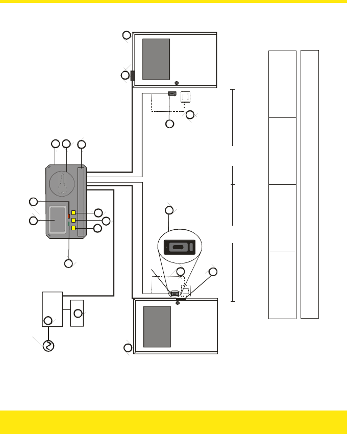
Easikey System Configuration
A
B
C
D
Easikey 250
Reader
Power Supply for Controller,
Readers a nd Locks
Battery Backup
E
F
G
H
J
Door 1
Door 2
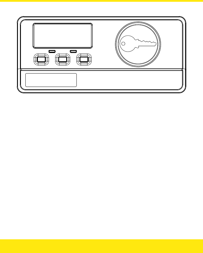
LCD Display
Green LED
Red LED
K
L
M
N
P
Left Button
Middle Button
Right Button
Controller Reader
Removable Cover
Q
R
S
Request to Exit Switch
(on other side o f door)
Example: Magn etic Lock
Example: Electric Release
Readers may be: OneProx Reader (shown)
Easikey Reader
Locks may be: Fail Secure, e.g. Electric Rele ase
Fail Safe, e.g. Magnetic Lock
J
H
M

Description
The Easikey 250 (P/N 20370) is a simple two door access control system using Stanley
Security Products’ proximity readers and electronic keys. The system allows you to control
the access of up to 250 keys through one or two doors.
Components
An Easikey 250 system consists of an Easikey 250 door controller, one or two readers and
up to 250 keys. In addition you will require a power supply, cable and suitable electric locks.
Optional items include Request to Exit switches and backup batteries. Stanley Security
Products also provide a Boxed Easikey, consisting of an Easikey 250 controller housed in a
steel cabinet, complete with 3A power supply, space for backup batteries and complete
internal wiring.
How it Works
Each PAC key contains a unique code. The controller can store the code of up to 250 keys in
its non-volatile memory. When a key is presented to a reader, the code in the key is passed
by the reader to the controller. It is then compared to the codes in the controller’s memory.
If the key is recognised by the controller then a relay will be operated allowing the release of
an electric lock.
Programming
An Easikey 250 system is programmed through the use of Editor Keys. The first one, two
or three keys in the controller’s memory are defined as Editor Keys — you select how many
at installation.
By use of the Editor Keys, an operator may add and delete user keys from the controller’s
memory using the built-in reader.
An LCD display is used to indicate user key and system information.
The display also includes two LEDs (light emitting diodes), red and green, for providing extra
indications depending on the type of operation being performed.
6

How to Use the Easikey 250
This section describes how you should use your Easikey 250 system to its best advantage.
Anyone operating or administering the system should read this section as well as becoming
familiar with Adding Keys and Deleting Keys.
Worksheets
Each Easikey 250 controller is supplied with a set of Programming Worksheets. We strongly
recommend that you use these for recording information about the system as well as for
keeping a record of keyholders. This enables you to find a key on the system, e.g. if you
want to replace a key. The following paragraphs refer to the Programming Worksheets and
how best to use them.
Editor Keys
An Easikey 250 controller can store up to 250 keys in its memory. Door access permission
can be set for every key as follows: Door 1 only, Door 2 only or both doors.
Up to three of these user keys are also given the ability to make changes to the system —
such as adding new keys or deleting existing keys. These are known as Editor Keys. When
the system is first installed the number of Editor Keys is set.
You should know how many user keys are also Editor Keys; if you do not, then find out from
whoever installed the system. There is a section on the Programming Worksheet to record
this number.
It is recommended that you assign two or three keys as editors, and keep at least one in a
safe place. Editor Keys can be deleted and added just like normal keys. However if all your
Editor Keys are lost, you must follow the procedure to replace Editor Key 0. You cannot
change the total number of Editor Keys without clearing the whole memory.
7

Administering Keys
Each key added to the system is given a number, 0–249. The lowest available number is
displayed when a new key is presented, although this can be changed to another unused
number if necessary. When a key is deleted from the Easikey 250’s memory, its number
becomes available again.
If you wish to change an existing key’s number or its door permissions, you must first delete
it from the system and then add it as a new key with the correct information.
When you add a new key to the Easikey 250 system you need to record the number (0-249)
it was given, and to whom it was issued. This is important so that if the keyholder loses the
key you can delete it by entering its 3-digit number. Use the Worksheets supplied for this
purpose.
You can identify keys that have been found by presenting them to the controller reader.
Their 3-digit number will be displayed, along with a red LED. (If a green LED is displayed, it
means the key is unknown to the Easikey 250.)
The worksheet has an unlabelled column in the keyholder section. You can use this for
recording your own information. Typically you may record Department or Office in a
commercial system, or Flat, Building or Block in a residential system.
For residential users different coloured clips are available. These clip over the top of the PAC
key. You can use these clips to identify different keys issued to one keyholder. A residential
system, for instance, may issue a red, blue and yellow key to one resident for use by the
occupants of one dwelling. If one key is lost they can refer to their “red key” as being
missing.
The worksheets contain a column for indicating the colour given to a key.
A grid on one side of the PAC key can also be used for physically marking a key. You put a
small scratch, or drop of paint or correcting fluid, in different boxes to identify individual
keys.
Residential Systems
Two special worksheets are included that are designed for use in Residential applications.
They are labelled Staff and Residents. You should use the Staff worksheet for recording
personnel such as cleaners, maintenance staff, housing officers, etc., and the Residents
worksheet for the residents.
8
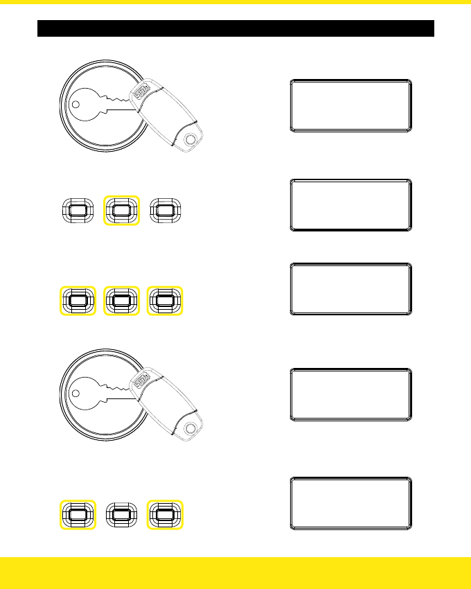
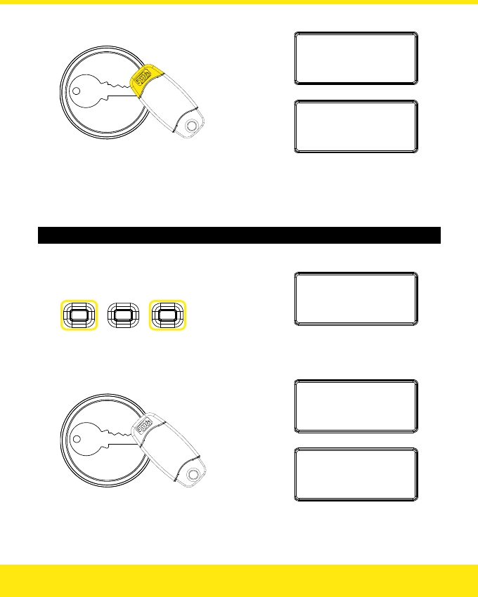
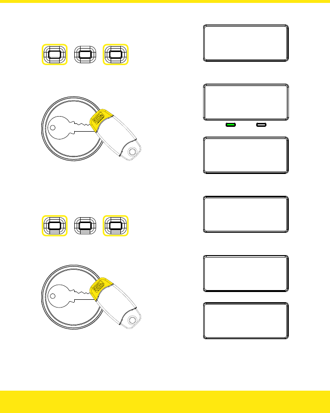
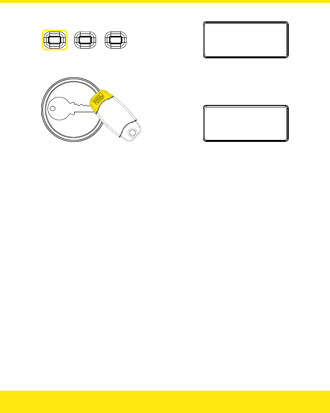
Adding a Key
1. Present the key:
Newuser:3
1:Y2:Y
2. Change key number?
▼
Freeindex
:
3
Press to
change
tens:
Press to
change
hundreds:
Press to
change
units:
Freeindex
:3
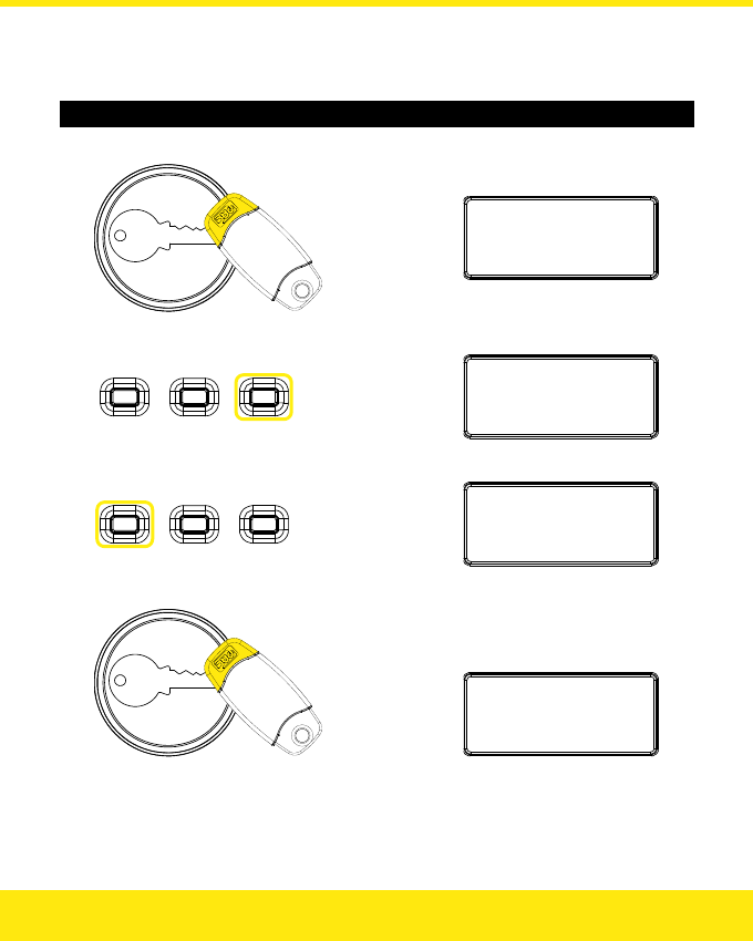
8
▼
Present the key again:
Newuser:3
8
1:Y2:Y
the middle button
:
Press
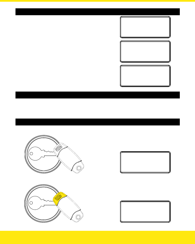
3. Change access level?
Press to change
Door 1 access:
Press to change
Door 2 access:
Newuser:3
8
1:Y2:N
Note: You cannot change the access level to 1:N 2:N.
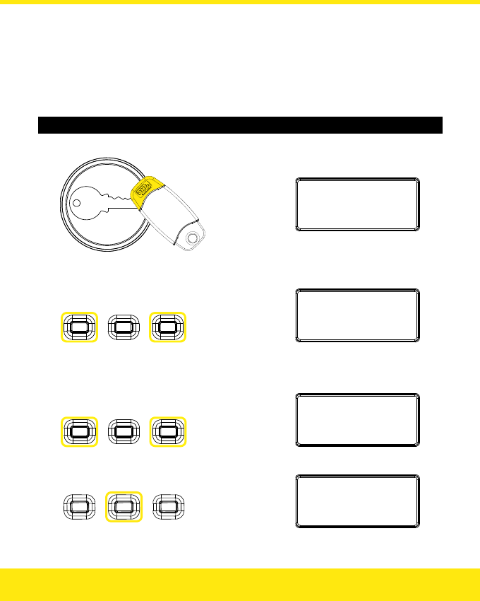
9
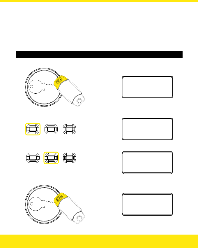
4. Present an Editor Key:
Userkey
:
3
8
Saved
▼
Userkey
:
.
..
1:Y2:N
5. Add more keys?
Yes: Continue to Batch Mode within 15 seconds.
No: Present an Editor Key again, or wait 15 seconds.
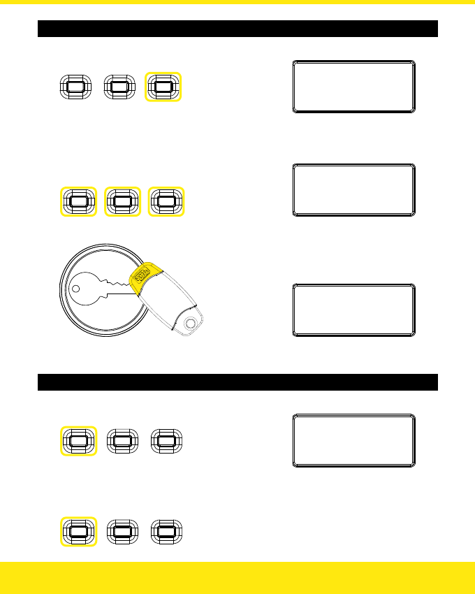
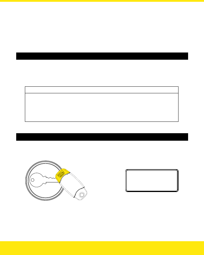
Batch Mode
1. Change access level for keys you are about to add?
Press to change
Door 1 access:
Press to change
Door 2 access:
Userkey:...
1:N2:Y
Note: You cannot set the access level to 1:N 2:N.
2. Present each key in turn:
Userkey
:3
9
Saved
▼
Userkey:...
1:N2:Y
3. Add more keys?
Yes: Repeat steps 1 and 2 as required.
No: Present an Editor Key, or wait 15 seconds.
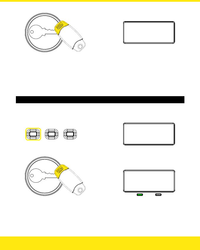
10
11
Possible Issues
Key already in controller’s memory —
present a different key instead:
Userkey
:
2
3
Saved
Key already in controller’s memory (batch mode) —
present a different key instead:
Keyexists
:
2
3
Saved
Memory full — you must delete some keys before you
can add any more:
MemoryisFull
Editing Keys
To change a key’s number or access level, first delete the key, then add it again selecting a
different key number and / or access level.
Deleting Keys — Method 1
1. Present the key to be deleted:
Userkey
:
3
8
Saved
2. Present an Editor Key:
Erased
:
3
8
Note: You cannot delete an Editor Key this way.
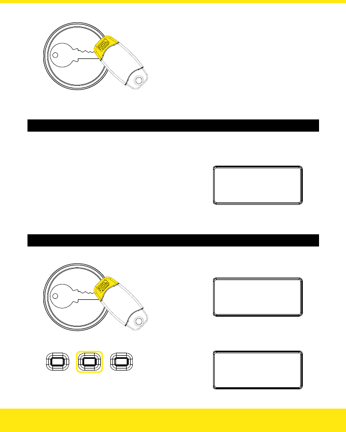
Deleting Keys — Method 2
1. Press the Right button:
Erasetoken
:
0
2. Enter the number of the key:
Press to
change
tens:
Press to
change
hundreds:
Press to
change
units:
Erasetoken
:
3
8
3. Present an Editor Key:
Erased
:
3
8
Note: You cannot use an Editor Key to delete itself.
Showing the Last 5 Users
1. Press the Left button:
Last5:1B1A0B
0B7B
0–249 — Key number, A — Door 1, B — Door 2.
2. Press the Left button again to clear screen:
12

Installation
The installation must meet the requirements of the country of installation’s National Wiring
Regulations and EN60950-1. It must be only carried out by competent, qualified and
experienced personnel. Failure to do so can result in injury or death by electric shock.
Note: See the section on Boxed Easikey 250 for further instructions relating to the
installation of a Boxed Easikey 250 or Boxed Easikey 250 with Cutout.
Quick Start
If you have installed an Easikey 250 system before then you can follow this simple step-by-
step checklist to get the system up and running. If you are new to Easikey 250 then all the
steps below are described in detail in the following pages.
Step 9
1. Install the Easikey 250 controller and power supply in an enclosure or other
secure area.
2. Install the readers and reader cables, including any request to exit switches.
3. Install the electric locks and their cables.
4. Initialise the Easikey 250, set the number of Editor Keys and add one or more
keys.
5. Set the lock release time for each lock.
6. Check the operation of each reader and lock.
7. Add any remaining keys to the controller — use the Worksheet to record details of
keyholders.
13
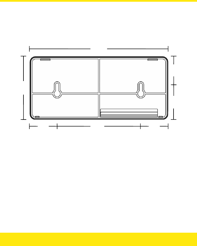
Mounting the Easikey 250 Controller
The controller should be mounted in a lockable cabinet or enclosure containing the power
supply and batteries, if used. It should be easily accessible for programming — the display
should be at about eye level.
Note: The Easikey 250 has the same dimensions as the Easikey 99.
198
90
39 120 39
40
50
Easikey 250 Mounting Plate Dimensions (mm)
14
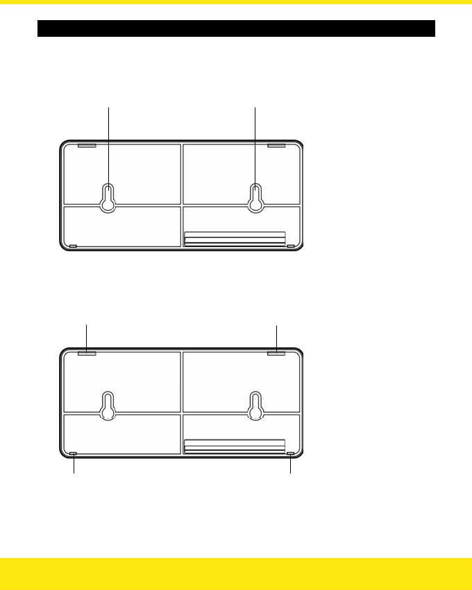
Mounting the Unit
1. If using the provided mounting plate, secure the mounting plate using two
countersunk screws. Take care not to over-tighten the screws as distortion of
the mounting plate may make it difficult to mount the controller:
Screw here Screw here
2. Locate the two slots in the top edge of the unit into the two tabs indicated
below and apply gentle pressure to the bottom edge until the two latches lock
into place:
Insert tab here Insert tab here
Lock latch here Lock latch here
15
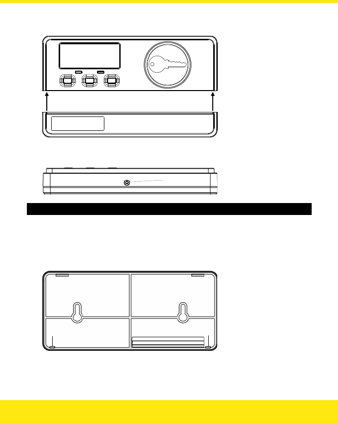
3. Locate the latches on either side of the cable cover into the slots inside each
edge of the upper case:
Lock latch here Lock latch here
4. Secure the cable cover using the screw hole located in the underside of the
cable cover:
Screw here
Removing the Unit
1. Take out the securing screw and apply gentle forward pressure to the underside
of the cable cover which should cause it to unlatch from the upper section.
2. Locate the loop latches each side and squeeze them to release the unit from the
mounting plate:
Release latch here Release latch here
3. While supporting the unit, lower it from the mounting plate locating tabs.
16
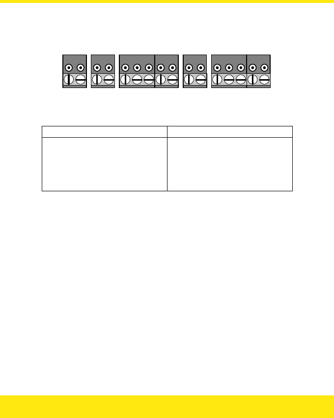
Terminal Blocks
All connections are made to the controller by removable terminal blocks. Always remove
power from the controller before removing a terminal block.
P1 P2 L1 L2 -
V
1 S1 R1 A1 +V1 L3 L4 -V2 S2 R2 A2 +V2
POWER LOCK 1 READER 1 LOCK 2 READER 2
Terminal Blocks
Terminal Block: Function:
POWER Power Input, AC or DC
LOCK 1 Lock 1 Output
READER 1 Reader Channel 1
LOCK 2 Lock 2 Output
READER 2 Reader Channel 2
Power Supply
The Easikey 250 controller and readers are powered from a 12v AC or DC power supply. The
locks are controlled by switching power from the same or different supply. The relays that
control the locks are able to switch 24v DC at up to 2 Amps. A power supply with battery
backup should be selected to provide operation when mains power is lost.
The power supply chosen should be capable of supplying sufficient current to power the
Easikey 250 controller, one or two readers, and one or two electric locks, and provide
charging current for the battery.
Connecting Power
Power is supplied through the P1 and P2 terminal block. See the section Installing Locks and
Power Supply for details of power and lock wiring.
17

Battery Backup
The length of time that a backup battery will last depends on the power consumption of the
system.
The main factor here is the power consumption of the locks. A Fail-Safe (Fail Open) lock
requires current continuously while a Fail-Secure (Fail Closed) lock only draws current when
it operates. You need to estimate how often the lock will operate and then use the following
equation to estimate consumption:
Consumption = Lock Current × (Operations per hour × lock release time) / 3600
Example
A 500mA lock operating 100 times an hour for 5 seconds would use 500 × (100 × 5) /
3600 = 69mA per hour.
Once the total power consumption has been estimated then it can be calculated how long
the fully charged batteries will last. The Ah rating of batteries is usually given as a 10 hour
discharge rate. If the batteries discharge over a shorter period of time they will last for less
than their quoted capacity.
Example
An Easikey 250 with two readers and two continuous (Fail-Safe) locks each drawing
250mA would consume 190 + 90 + 90 + 250 + 250 = 870mA. A fully charged
12Ah battery would last 12 / 0.870 = 13.7 hours.
Readers
Install readers according to the instructions supplied with each reader. Readers are usually
installed at about door handle height on the unhinged side of the door.
All readers have the same wiring terminals, and are fitted with a green LED that illuminates
when access is allowed, and stays illuminated for the duration of the lock release time.
The maximum distance of a reader from the controller is 100m.
If two readers are fitted then they must be at least 300mm apart.
The Easikey 250 is compatible with OneProx readers and Easikey readers.
18
Request to Exit (RTE)
A Request to Exit switch may be fitted on the secure side of the door. This should be a
normally-open switch that closes momentarily when pressed and released. Do not allow the
wiring for the RTE switch to be visible if the reader is removed from the wall.
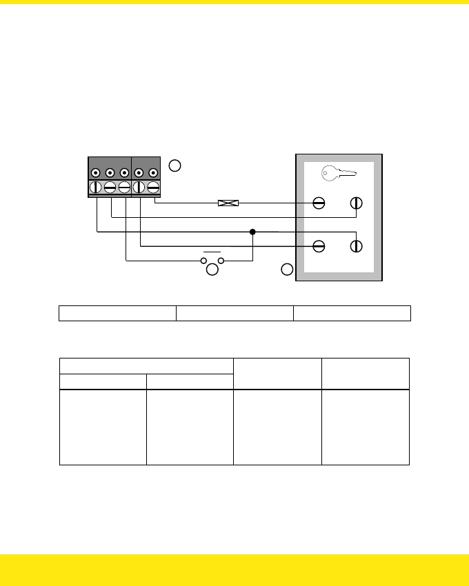
Reader Wiring
If you do not intend to use the RTE switch then unscreened 4-core cable will be suitable;
otherwise use 6-core cable.
-
V
1 S1 R1 A1 +V1
+V SIG
V
CA -
V
A
B C
100 mA
Reader Wiring, including RTE
A Terminal Block BRTE C Reader
Use 7/0.2mm (0.22mm²) 4-core or 6-core unscreened cable.
Controller:
Channel 1 Channel 2
Colour: Reader:
+V1 +V2 Red +V
S1 S2 Blue SIG
R1 R2 White n/c
A1 A2 Yellow VCA
-V1 -V2 Black -V
Note: The reader outputs are set at 90mA. Stanley Security Products strongly recommend
that you fit a 100mA in-line fuse in the reader supply.
19

Installing Locks and Power Supply
Locks should be installed according to the manufacturer’s instructions. The Easikey 250
controls the operation of a lock by switching power using a voltage-free relay. Up to 24v DC
at 2 Amps may be switched by the relays. Each lock may be programmed to be Fail-Safe
(continuously powered, power removed to unlock) or Fail-Secure (power supplied to unlock).
The type of cable used should be sufficient to provide the correct operating voltage at the
lock. Usually at least 0.5mm² will be required for a range of up to 100m.
Lock Suppression
Important
All PAC readers are supplied with a suppression device, a MOV (metal oxide
varistor). This device should be fitted across the lock supply at the lock. These
devices prevent harmful back E.M.F. (“spikes”) from damaging the Easikey 250
controller. Failure to fit these devices may result in long term damage to the
controller and possible problems of door sticking.
20
P1 P2 L1 L2
1
L3 L
4
Z
Z
X
Single Power Supply
X Fuse Z MOV
P1 P2 L1 L2 L3 L4
Z Z
X
X
1 2
Separate Power Supply for Controller and Lock
X Fuse Z MOV
21
Health and Safety
Any installation must comply with any local Fire, Health and Safety regulations. A secured
door that may be part of an escape route from an area should be fitted with:
• A Fail-Safe lock (A), so that the door will be released if the power fails. Ideally a
magnetic lock should be used as these are less likely to jam or seize.
• A normally-closed Break-Glass or Manual Pull (B) in the lock supply wiring, so
that in an emergency the Fail-Safe lock can be immediately depowered.
BA
Checking the System
After completing the wiring of power supply, readers and locks you should make the
following checks.
Checking the System
1. Remove power. Remove all terminal blocks except for the power supply
(P1 and P2). Apply power.
You should have between 10.5 and 20V DC or between 8 and 14.5V AC across
P1 and P2.
2. Remove power. Connect Reader 1 terminal block. Apply power.
You should have between 10 and 16V DC at the controller (+V1, -V1) and 9–16V DC
at the reader (+V, -V).
3. Repeat for Reader 2, if used.
22
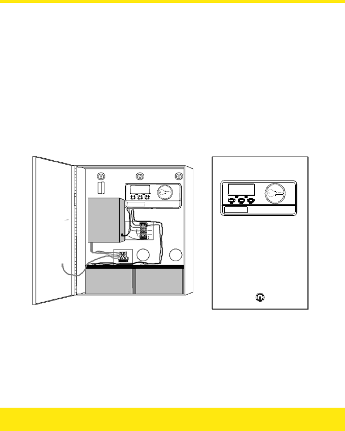
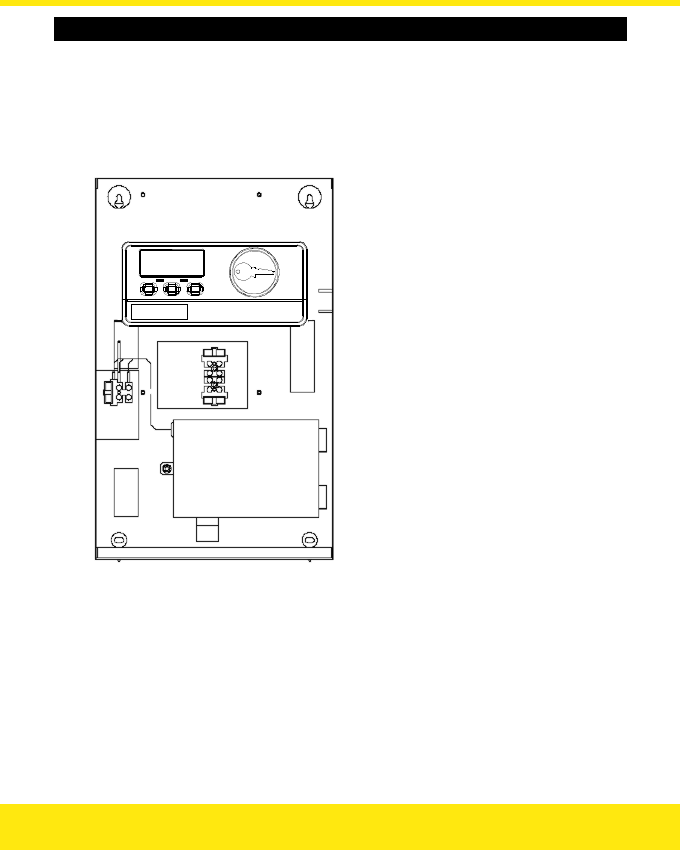
Boxed Easikey 250
The Boxed Easikey 250 (P/N 21275) and Boxed Easikey 250 with Cutout (P/N 21277)
consist of an Easikey 250 controller housed in a metal cabinet, complete with 3 Amp power
supply and wiring. With the addition of readers, electronic keys and electric door locks, a
complete two door access control system can be installed. The assembly as supplied
provides the following features:
• 18 swg Mild Steel Cabinet with hinged lid with space for two 6Ah Batteries
• 3 Amp Power Supply with Battery Backup provision — batteries not supplied
• Easikey 250 two door Controller
• All internal wiring provided, including fuses
• Alternative entry points for external wiring at rear and side (conduit or trunking)
• Cover secured with lock and key
12V 6Ah 12V 6Ah
Boxed Easikey 250 Boxed Easikey 250 with Cutout
23
Installing the Boxed Easikey 250
See Installation for full details on installing the Easikey 250 system. Instructions specific to
the Boxed Easikey 250 / Boxed Easikey 250 with Cutout are given here.
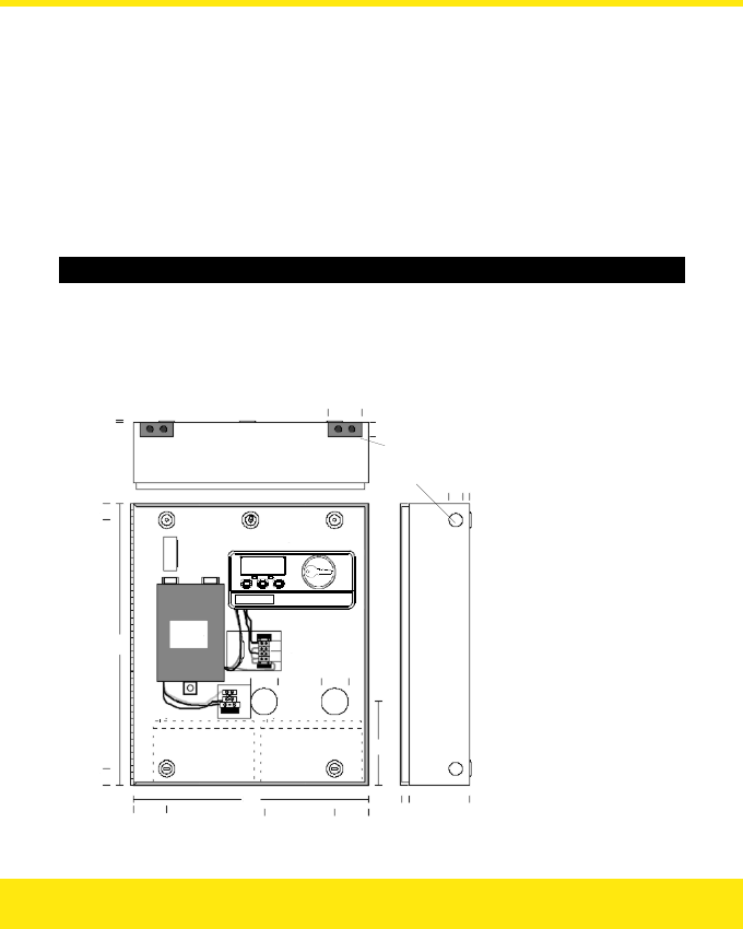
Mounting the Cabinet
The cabinet should be mounted vertically on a flat wall. As the controller is used for
administering the system you should ensure that the cabinet is located in a well lit,
comfortable location allowing personnel easy access. The cabinet should be positioned so
that the controller display is at about eye-level.
Mounting the Cabinet — Boxed Easikey 250
1. Using the keyhole at the top centre as a pivot, temporarily hang the cabinet and
use the four corner holes as a template to mark the position of the fixing points.
2. Use Nº 8 1½" self-tapping screws and appropriate fixings to attach the cabinet
to the wall.
Power
Supply
3
25
420
25
20
50
Lock W iring
Terminal Block
20mm Knockouts
20 × 50mm Inserts
inc. 2 × 15mm Knockouts
Easikey Contr oller
40mm
Holes
350
50 105 50 18
82
20
10
125
40
40
N
E
L
24
Mounting the Cabinet — Boxed Easikey 250 with Cutout
1. Using the keyholes at the top as a template, temporarily hang the cabinet and
then use the two lower holes as a template to mark the position of the fixing
points.
2. Use Nº 8 1½" self-tapping screws and appropriate fixings to attach the cabinet
to the wall.
25

Power Supply Wiring
The cabinet already contains wiring from the power supply to the Easikey 250 controller and
to the battery wiring harness (although batteries are not supplied). Wiring is also in place
bringing the lock outputs to a terminal block below the Easikey 250 controller.
Cable Entry Options — Boxed Easikey 250
• Two 40mm holes in the back of the cabinet for rear entry.
• A 20mm knockout at the top and bottom of each side for surface mounted
conduit.
• A 20mm × 40mm removable plastic insert at each side of the top and bottom
surfaces for surface mounted trunking. Each insert also has two 15mm
knockouts.
Cable Entry Options — Boxed Easikey 250 with Cutout
• Two holes in the back of the cabinet for rear entry.
• Two knockouts on the top suitable for use with 25 × 16mm trunking.
• A 20mm knockout at the bottom of each side for surface mounted conduit.
• Two 20mm knockouts on the bottom for surface mounted conduit.
Mains Power
Mains power, 240v AC, should be supplied to the controller through an illuminated,
unswitched spur. Use the following colour code:
Blue: Neutral
Green / Yellow: Earth
Brown: Live
Fuses
Location Type Rating
Mains Terminal Block 20mm glass, Slow Blow 1 Amp
Lock Supply * 20mm glass, Slow Blow 3.15 Amp
Battery Lead * 20mm glass, Slow Blow 3.15 Amp
Note: The Lock Supply and Battery fuses are located in a terminal block below the Easikey
250 controller.
26
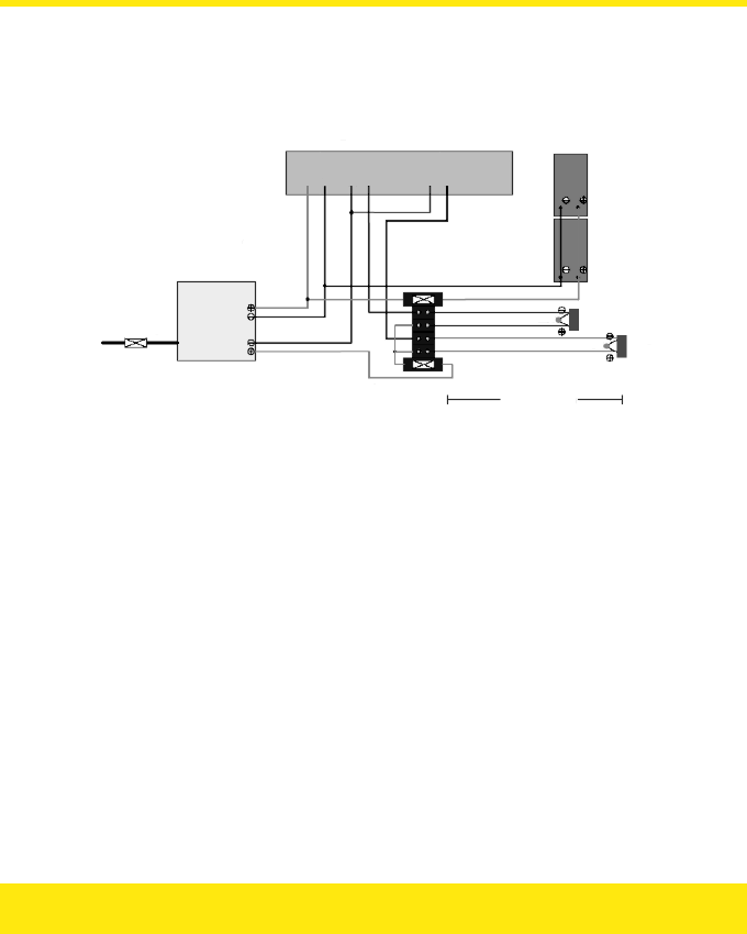
Internal Power Wiring
The diagram below describes the wiring provided inside the cabinet. This provides for
battery backup through a harness capable of connecting two batteries, and two lock 12v
lock outputs through a terminal block.
All wiring is multistranded 0.5mm²
Easikey Controller
Power Supply
Fuse: 3.15 Amp
Fuse: 1.0 Amp
240v AC
Battery Fuse: 3.15 Amp
Lock Fuse: 3.15 Amp
Max. dist: 100m
(Reader wiring
not shown)
Batteries
Lock 1
Lock 2
MOV
MOV
P1 P2 L1 L2 L3 L4
Reader Wiring
See the section on Reader Wiring for instructions on reader wiring.
Lock Wiring
See the section on Installing Locks and Power Supply for information on lock wiring.
Battery Backup
There is room in the cabinet for two 6Ah batteries giving a total of 12 Ah supply. See the
section on Battery Backup for more information.
27

Power Supply Specification
The power supply is capable of supplying a maximum of 3 Amps. This should be sufficient to
power the Easikey 250 controller, one or two readers and one or two electric locks, and
provide charging current for the battery.
Use the following table to ensure you do not overload the power supply:
Item Current (mA)
Easikey 250 Controller 190
Reader 1 90
Reader 2 90
Lock 1
Lock 2
Charging Current 500
Safety Margin 500
Total
The total current should not exceed 3A (3000mA). This leaves approximately 1600mA
available for supplying the locks on a two door system.
Checking the System — Boxed Easikey 250 / Boxed Easikey 250 with Cutout
1. With the mains supply connected, power up the system with no locks or readers
connected.
2. Using a multimeter set to DC volts, measure the voltage across the P1 and P2
terminals of the Easikey 250 controller.
The voltage should read between 13.5 and 13.8v DC.
2. If you are using battery backup, power up with the battery (or batteries)
connected and measure the voltage between P1 and P2.
This should still be between 13.5 and 13.8v DC.
3. Disconnect the mains supply and measure the voltage between P1 and P2.
The voltage should now be approximately 12.5v DC from a fully charged battery.
4. Continue with the procedure described in the section on Checking the System.
5. Finally, repeat the checks described above but with a fully working system
complete with locks and readers.
28
Initial Programming
The initialisation of the controller involves clearing its memory and assigning the number of
Editor Keys (up to 3) that will be used.
Editor Keys are used to confirm the addition, deletion or change of a user key.
Once you have set the number of Editor Keys, you cannot change the number without
clearing the Easikey 250’s memory again. However the actual Editor Keys can be removed
and added — see the sections on Adding Editor Keys and Deleting Keys. Record the number
of Editor Keys on the Programming Worksheet.
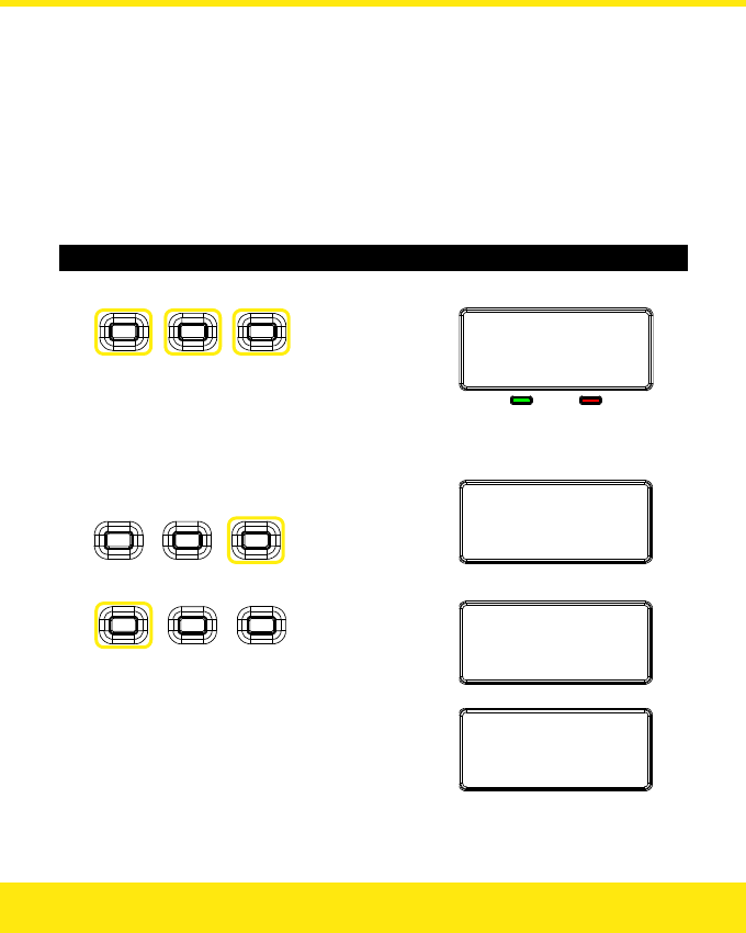
Initialising the Easikey 250
1. Power up the Easikey 250 with all three buttons held down:
SelectEditors
Noofkeys:3
Note: This will clear the memory of the Easikey 250.
2. Change number of Editor Keys?
Press to change
number of Editor Keys
SelectEditors
Noofkeys:2
3. Press the Left button to confirm:
Initialising
▼
EnrolEditorKey
29
Adding Editor Keys
You must now enrol the first Editor Key, i.e. Editor Key 0. Editor Keys will also act as user
keys and allow access through the doors as required.
Like user keys, each Editor Key has an access level. The access level specifies whether the
key can open Door 1 only, Door 2 only or both. It is not possible to set the access level such
that the key cannot open either door.
Editor Key 0 is always set to access both doors — you cannot change this. However, you
can set the access level for Editor Keys 1 and 2.
Notes
There is no difference between adding Editor Keys and adding user keys. Depending on
the number of Editor Keys that you selected when you initialised the controller, keys
number 0 and possibly 1 and 2 will be Editor Keys; all the other keys will be user keys.
You can add Editor Keys using any of the methods you use to add user keys. For
example, you can add Editor Keys singly or in batch; you can set the access level of
Editor Keys; you can start adding an Editor Key and then change its number to be a user
key or vice versa.
The instructions below assume that you will add all the Editor Keys in batch when you
first initialise the Easikey 250. This is the recommended method. See Adding a Key for
other options that are available when adding keys — e.g. if you want to add one Editor
Key now and add others later.
Adding Editor Keys
1. Present the first Editor Key:
EditorKey:0
Saved
▼
EditorKey
:
.
..
1:Y2:Y
30
2. Change access level for second Editor Key?
Press to change
Door 1 access:
Press to change
Door 2 access:
Editor
K
ey
:
...
1:N2:Y
3. Add second Editor Key?
EditorKey:1
Saved
▼
Editor
K
ey
:
...
1:N2:Y
4. Change access level for third Editor Key?
Press to change
Door 1 access:
Press to change
Door 2 access:
Editor
K
ey
:
...
1:N2:Y
5. Add third Editor Key?
Editor
K
ey
:
2
Saved
▼
UserKey
:
...
1:N2:Y
6. Add user keys?
Yes: See the section on Adding a Key.
No: Present an Editor Key, or wait 15 seconds.
31
Lock Time and Fail-Safe / Fail-Secure Settings
Each of the two lock relays can be set to operate the lock for between 1 and 49 seconds.
Each relay may also be set to open or close when operated, allowing the use of Fail-Safe
(power to lock) or Fail-Secure (power to release) locks.
Lock 1 may also be set to operate in a Toggle function — see Set-Reset Latch for details.
Adjusting Lock Time and Fail-Safe / Fail-Secure Settings
1. Present an Editor Key:
EditorKey
:
0
1:Y2:Y
2. Choose a door:
Press to change
Door 1 settings:
Press to change
Door 2 settings:
Lock1Time
:
3
Fail‐Safe
3. Change the lock time?
Press to
change
tens:
Press to
change
units:
Lock1Time
:
1
0
Fail‐Safe
4. Change the Fail-Safe / Fail-Secure Setting?
Lock1Time
:
1
0
Fail‐Secure
Press
the middle button
:
32
5. Present the Editor Key again:
Lock1TimeSaved
Replacing a Lost Editor Key
All Editor Keys, including Editor Key 0, can be deleted and a new key added in their place
using one of the other Editor Keys.
However, if all the Editor Keys are lost, a new Editor Key 0 can be enrolled without having to
clear completely all the user key information.
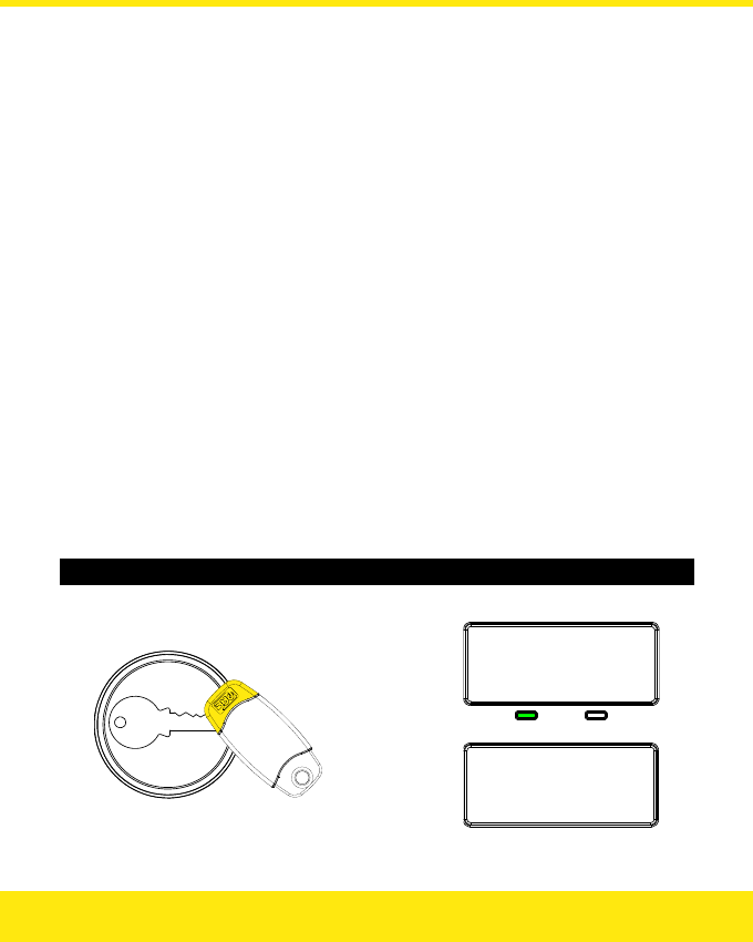
Enrolling a New Editor Key 0
1. Remove power from the Easikey 250.
2. Hold down the Left button and re-apply power:
EnrolEditorKey
3. Present a new Editor Key 0:
EditorKey...
33
3. Present the same Editor Key again to confirm:
Firmware Version
Displaying the Current Firmware Version Number
1. Remove power from the Easikey 250.
2. Re-apply power:
PACEasikey250
V1.00
Silent Mode Operation
Configuring the Buzzer on the Controller
1. Present an Editor Key:
EditorKey
:
0
1:Y2:Y
2. Press the Middle button to display the current mode:
ControllerOnly
34
3. Press the Left button to select the required mode:
SilentModeOn
4. Present an Editor Key to save:
SavedSettings
Notes
The four operating modes are as follows:
• Controller Only — Buzzer sounds only when a token is shown to the controller
reader.
• Reader Only — Buzzer sounds only when access is granted / denied.
• Silent Mode On — Buzzer is silent.
• Silent Mode Off — Buzzer sounds when access is granted / denied and when a
token is shown to the controller reader.
Resetting the controller defaults it to Controller Only mode.
35
Language Support
Available languages are English, Dutch, German, French, Swedish and Norwegian.
Changing the Language
1. Present an Editor Key:
EditorKey
:
0
1:Y2:Y
2. Press and hold the Right button for 2 seconds:
SelectLanguage
English(UK)
3. Press the Left button to select the required language:
SelectLanguage
English(UK)
4. Present an Editor Key to save:
Language
Saved
36
Set-Reset Latch
The set-reset latch facility is available on Lock 1 only. It allows the lock relay to be set
when a valid key is presented, and reset when a valid key is presented again. This allows the
reader to be used like a toggle to operate another system.
Note: When this facility is used, the Request to Exit facility for Door 1 will no longer be
available.
Setting Up the Set-Reset Latch Facility
1. Present an Editor Key:
EditorKey
:
0
1:Y2:Y
2. Press the Left button:
Lock1Time
:
3
Fail‐Safe
3. Press the Middle button to select Set-Reset Latch:
Lock1Time
:
‐
‐
Set‐ResetLatch
4. Present the Editor Key again:
Lock1TimeSaved
37
Database Copy
This facility allows the contents of one Easikey 250’s memory to be copied to another
Easikey 250. The receiving Easikey 250 will have the contents of its memory completely
overwritten by the contents of the sending Easikey 250.
Note: You can copy from one Easikey 250 to another Easikey 250, or from an Easikey 99 to
an Easikey 250. You cannot copy from an Easikey 250 to an Easikey 99.
Connecting Two Easikey 250 Controllers for Database Copy
1. Remove power from both Easikey 250s.
(Only one Easikey 250 needs to be powered during the copy.)
2. Connect Reader terminal 2 of each Easikey 250 with the following cable:
Sending Controller Receiving Controller
-V2 ————————-V2
S2 ———————— A2
A2 ———————— S2
+V2 ————————+V2
Use 0.22mm² reader cable for a distance less than 10m.
Copying from One Easikey250 to Another Easikey 250
1. Power up one Easikey 250.
2. On the sending Easikey 250, present an Editor Key:
EditorKey
:
0
1:Y2:Y
38
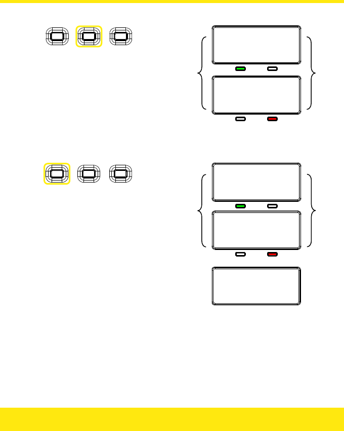
3. On the sending Easikey 250, press the Middle button for two seconds:
CopyingDatabase
Ready
Easikey250
Found
Note: If the cable connection is not correct, only the CopyingDatabase
message is displayed.
2. On the sending Easikey 250, press the Left button:
Copyingdatabase
38%
Copyingdatabase
38%
▼
Copy
c
omplete
100%
Note: Each packet of data is verified during the transfer process to ensure
completeness. The copy will take about 45 seconds to complete.
If the process has not started within 15 seconds, a DatabaseCopy
Failed message is displayed. You should check the cable wiring.
39
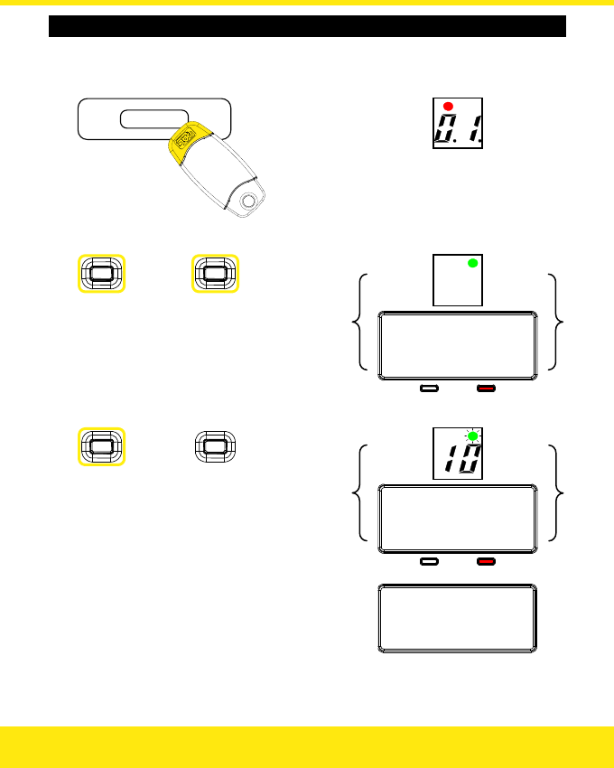
Copying from an Easikey 99 to an Easikey 250
1. Power up the Easikey 99 or the Easikey 250.
2. On the Easikey 99, present an Editor Key:
3. On the Easikey 99, press both buttons:
Easikey99
Found
2. On the Easikey 99, press the Blue button:
Copyingdatabase
20%
▼
Copy
c
omplete
100%
Note: Each packet of data is verified during the transfer process to ensure
completeness. The copy will take about 6 minutes to complete.
40
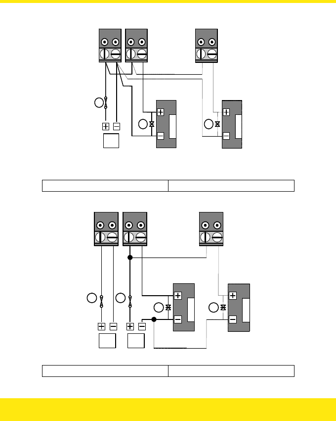
Dual Controller Option
It is possible to increase the number of keyholders by connecting a reader to the same door
channel on two Easikey 250 Controllers. If a key is found in either of the Controllers then
the lock relay will operate. The diagrams below show two controllers controlling one Lock 1.
To control Lock 2, connect a single reader to channel 2 of both controllers, and the lock
through terminals L3 and L4 of each controller. Note that power is supplied to both Easikey
250 controllers.
Note: You can connect two Easikey 250s, or connect an Easikey 250 and an Easikey 99. In
the diagrams below, Controller 1 is always an Easikey 250; Controller 2 may be
either an Easikey 250 or an Easikey 99. The connections for reader and lock wiring
are identical on an Easikey 99 and an Easikey 250.
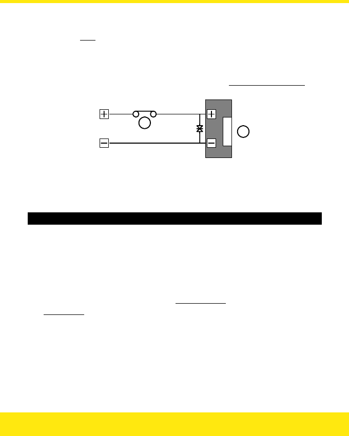
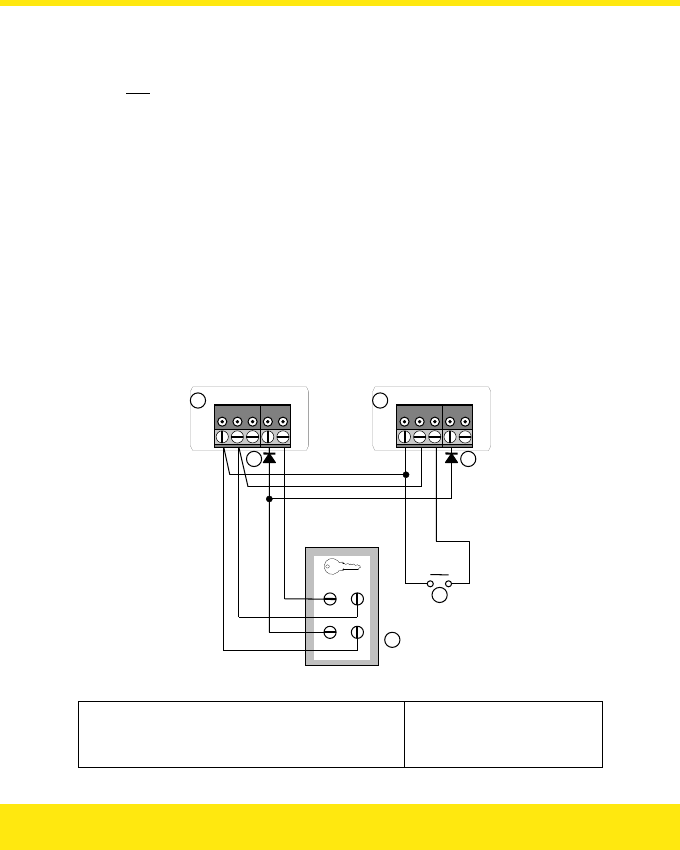
Reader Wiring
Notice that the reader wiring shown below includes a diode (1N4001, not supplied) at each
A1 (or A2) terminal. This is essential to provide correct operation of the reader LED.
The Request to Exit switch can be fitted to either controller.
-V1 S1 R1 A1 +V1
+
V
SIG
VCA -
V
-
V
1 S1 R1 A1 +V1
12
L
B
Y
Y
Reader Wiring for Dual Controller Operation
1 Easikey 250 Controller, Door Channel 1 L Request to Exit
2 Easikey 99 / 250 Controller, Door Channel 1 YDiodes, 1N4001
BReader
41
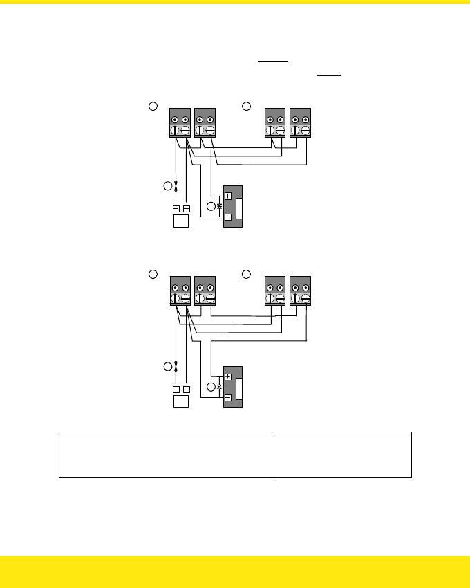
Lock Wiring
Two different lock wiring configurations are required for Fail-Secure and Fail-Safe locks.
Fail-Secure locks are wired so that the relays are in parallel, so that if any relay closes,
power will be applied. Fail-Safe locks are wired with the relays in series, so whenever one
relay opens, power will be removed.
P1 P2 L1 L2 L1 L2
12
Z
X
P
P1 P2
Power and Lock Wiring for Dual Controllers, Fail-Secure
P1 P2 L1 L2 L1 L2
1 2
P
Z
X
P1 P2
Power and Lock Wiring for Dual Controllers, Fail-Safe
1 Easikey 250 Controller, Lock 1 PPower Supply
2 Easikey 99 / 250 Controller, Lock 1 XFuse
Z MOV
42

Programming
Both Easikey 99 / 250s should be installed and initialised as described in this manual.
However, please note the following:
• You should add the same Editor Keys to each Easikey 99 / 250.
• Ensure that the Lock Release Times for each lock are programmed in exactly the
same way on each controller.
• The lock type (Fail-Safe / Fail-Secure) must be the same on both controllers.
• Note to which controller each key is added. If you need to delete a key then you
must know to which controller it was added.
43

Easikey 250 System Troubleshooting
Problem Possible Cause Check
No Power Check AC (mains) power supply and fuse.
Check voltage at P1, P2 terminals; should
be 10-16VDC or 10-12VAC.
Easikey 250
Controller not
working.
Fuse Blown Check controller Fuse (1 amp)
No power at readers Check power at reader, should be
9-16VDC.
Reader wiring incorrect Check wiring.
Easikey 250
controller OK, but
neither reader
operates. Key not added Add key to system.
No power at reader Check power at reader; should be
9-16VDC.
Reader wiring incorrect Check wiring.
One reader OK, but
other is not.
Key does not have
access
Check key has access through both doors.
Power supply is not capable of supplying
enough power to operate lock.
System fails when
a lock operates.
Power supply overload
Lock is faulty and drawing too much
current from power supply.
Faulty reader If the reader is faulty then other keys will
also fail to work — check the reader.
Faulty key Other keys will work without problem —
replace the key.
A key has stopped
working.
Incorrect programming Check that the key exists in the controller,
and it has been given correct access.
44

Other Easikey 250 Products
The following items are available for use with the Easikey 250:
Part No. Description Notes
20478 OneProx Classic
Standard Reader
For internal use.
20068 OneProx Designer
Standard Reader
For internal use.
20073 OneProx Classic
Mullion Reader
For internal use.
20067 OneProx Designer
Mullion Reader
For internal use.
20424 (Black / Yellow)
20483 (Blue / Grey)
OneProx Vandal
Resistant Reader
For external use or where resistance to
abuse is required. Supplied with 4 Vandal
Resistant Screws — requires compatible
screwdriver, e.g. 1950 Screwdriver below.
20042 (Black / Yellow)
20049 (Blue / Grey)
OneProx Panel
Mount Reader
For fitting in steel panels, e.g. as part of a
door entry system.
1950 Screwdriver For Vandal Resistant Screws used on
Vandal Resistant Reader
The following legacy items are also compatible with the Easikey 250:
Part No. Description Notes
20377 (Black)
20387 (White)
Easikey Mullion
Reader
For internal use.
20378 (Steel)
20388 (Brass)
Easikey Vandal
Resistant Reader
For external use or where resistance to
abuse is required. Supplied with 4 Vandal
Resistant Screws — requires compatible
screwdriver, e.g. 1950 Screwdriver above.
20421 Easikey Panel
Mount Reader
For fitting in steel panels, e.g. as part of a
door entry system.
45

Standards
The Easikey 250 meets the requirements of the following Council Directives:
• 1999/5/EC R&TTE
• 2006/95/EC Low Voltage
• 2002/95/EC ROHS
• 2002/96/EC WEEE
A Declaration of Conformity is available on request from Stanley Security Products.
The Easikey 250 uses a non-harmonised frequency (10kHz) and has approval from the
following members of the European Conference of Postal and Telecommunications
Administrations (CEPT):
• Austria
• Belgium
• Bulgaria
• Cyprus
• Czech Republic
• Denmark
• Estonia
• Finland
• Germany
• Hungary
• Iceland
• Malta
• Netherlands
• Norway
• Poland
• Portugal
• Romania
• Spain
• Sweden
• Switzerland / Liechtenstein
• United Kingdom
46

47
Specification
Dimensions
Controller: 198mm W × 90mm H × 28mm D
Readers: See 17991 Oneprox Readers Installation Guide,
17063 Easikey Reader Data Sheet
Environment
Temperature: Controller 0°C to +50°C
Reader -15°C to +60°C
Humidity: Controller 0% to 90% relative humidity,
non-condensing
Reader Sealed construction
Power Requirements
Input Voltage: 10.5V to 20V DC
8V to 14.5V AC 50/60Hz
Current: Controller 190mA (Max.)
Reader 90mA (Max.)
Fuses
A 1A thermally resettable fuse is fitted to protect the power supply.
Cable Requirements
Controller to Reader: Gauge 0.22mm², 4 or 6 core
Max. Dist. 100m
Controller to Lock: Gauge 0.5mm², 2 core
Max. Dist. 100m

United Kingdom:
PAC — A Stanley Security Products Business
1 Park Gate Close
Bredbury
Stockport
Cheshire
SK6 2SZ
Contact:
Tel: +44 (0) 161 406 3400
Fax: +44 (0) 161 406 8984
www.stanleysecurityproducts.co.uk
Technical Support:
Tel: (U.K.) 0845 206 3400 (Int.) +44 (0) 161 430 1340
Fax: +44 (0) 161 406 6749
E-mail: pacsupport@stanleyworks.com
Knowledge Base: www.stanleysecurityproducts.co.uk/support
United States of America:
Stanley Security Products
Contact / Technical Support:
Tel: 800 414-3038
Fax: 800 414-3039
E-mail: support@stanleypac.com
Web: www.stanleysecurityproducts.com
Knowledge Base: www.stanleysecurityproducts.co.uk/support
Stanley is a registered trademark of The Stanley Works, Inc. Unless otherwise indicated, the trademarks and logos
displayed are the property of Stanley Security Products and / or their subsidiary companies.
