Trts0930 Eaton Gen 3 Autoshift Ultrashift Troubleshooting Guide
User Manual: Eaton-Gen-3-Autoshift-Ultrashift--Troubleshooting-Guide Freightliner
Open the PDF directly: View PDF ![]() .
.
Page Count: 381 [warning: Documents this large are best viewed by clicking the View PDF Link!]

Troubleshooting Guide
Eaton Gen III Automated
Transmissions
TRTS0930 EN-US
January 2016
UltraShift®
AutoShift®

Model:
F-5405B-DM3
F-6405B-DM3
FM-14D310B-LST
FM-15D310B-LST
FO-16D313E-LEP
FO-5406B-DM3
FO-6406A-AW3
FO-6406B-AW3
FO-8406A-AW3
FOM-16D313E-LEP
RTLO-14918A-AS3
RTLO-16913L-DM3
RTLO-16918A-AS3
RTO-10910B-DM3
RTO-12910B-AS3
RTO-12910B-DM3
RTO-14910B-AS3
RTO-14910B-DM3
RTO-14910C-AS3
RTO-16910B-AS3
RTO-16910B-DM3
RTO-16910C-AS3
RTO-18910B-AS3
F-5505B-DM3
F-6505B-DM3
RTLO-18918A-AS3
RTLO-20918A-AS3
RTLO-22918A-AS3
RTLOM-16913L-DM3
RTO-10910B-AS3
RTOM-16910B-DM3

2016.01.15 © 2016 Eaton. All rights reserved i
TRTS0930 Table of Contents
Table of Contents
General Information
Warnings and Cautions . . . . . . . . . . . . . . . . . . . . . . . . .1
Transmission Models. . . . . . . . . . . . . . . . . . . . . . . . . . .2
Diagnostic Procedures . . . . . . . . . . . . . . . . . . . . . . . . . .3
Fault Code Retrieval/Clearing . . . . . . . . . . . . . . . . . . . . .5
Retrieving Fault Codes Manually. . . . . . . . . . . . . . . 5
Clearing Fault Codes Manually . . . . . . . . . . . . . . . . 6
Retrieving Fault Codes with ServiceRanger . . . . . . 6
Clearing Fault Codes with ServiceRanger . . . . . . . . 7
Fault Code Isolation Procedure Index. . . . . . . . . . . . . . .8
Symptom-Driven Diagnostics Index. . . . . . . . . . . . . . .10
Product Diagnostic (PD) Mode . . . . . . . . . . . . . . . . . .11
Pretest Procedures
Electrical Pretest . . . . . . . . . . . . . . . . . . . . . . . . . . . . .12
TECU Power Harness . . . . . . . . . . . . . . . . . . . . . . 13
Preferred +12 Volt Connections . . . . . . . . . . . . . . 14
Preferred +12 Volt Connections . . . . . . . . . . . . . . 15
Preferred +24 Volt Connections . . . . . . . . . . . . . . 16
Preferred +24 Volt Connections . . . . . . . . . . . . . . 17
TECU Ignition Circuit . . . . . . . . . . . . . . . . . . . . . . 18
J1939 Data Link . . . . . . . . . . . . . . . . . . . . . . . . . . 19
J1939 Troubleshooting. . . . . . . . . . . . . . . . . . . . . 19
Electrical Pretest . . . . . . . . . . . . . . . . . . . . . . . . . . . . .20
Power-Up Sequence Test. . . . . . . . . . . . . . . . . . . . . . .22
Fault Isolation Procedures
Fault Code 11 - No TECU Operation . . . . . . . . . . . . . . .30
Fault Code 12 - Improper ECU Configuration . . . . . . . .34
Fault Code 13 - J1939 Shift Control Device . . . . . . . . .38
Fault Code 14 - Invalid Shift Lever Voltage (without Park
Pawl) . . . . . . . . . . . . . . . . . . . . . . . . . . . . . . . . . . . . . .42
Fault Code 14 - Invalid Shift Lever Voltage (with Park
Pawl) . . . . . . . . . . . . . . . . . . . . . . . . . . . . . . . . . . . . . .48
Fault Code 15 - HIL Shift Device Configuration . . . . . .54
Fault Code 16 - High Integrity Link (HIL) . . . . . . . . . . .62
Fault Code 17 - Start Enable Relay (SER) Circuit . . . . .70
Fault Code 21 - Auto Neutral Park Brake Switch. . . . . .74
Fault Code 22 - ABS CAN Message Fault . . . . . . . . . . .80
Fault Code 26 - Clutch Slip. . . . . . . . . . . . . . . . . . . . . .84
Fault Code 27 - Clutch Disengagement . . . . . . . . . . . .88
Fault Code 28 - Clutch System . . . . . . . . . . . . . . . . . . .92
Fault Code 29 - Remote Throttle Enable. . . . . . . . . . . .98
Fault Code 31 - Momentary Engine Ignition Interrupt Re-
lay (MEIIR) Test . . . . . . . . . . . . . . . . . . . . . . . . . . . . .102
Fault Code 32 - Loss of Switch Ignition Power Test. .108
Fault Code 33 - Low Battery Voltage Supply . . . . . . .112
Fault Code 34 - Weak Battery Voltage Supply . . . . . .118
Fault Code 35 - J1939 Communication Link. . . . . . . .124
Fault Code 36 - J1939 Engine Message . . . . . . . . . . .130
Fault Code 37 - Power Supply . . . . . . . . . . . . . . . . . .136
Fault Code 41 - Range Failed to Engage. . . . . . . . . . .142
Fault Code 42 - Splitter Failed to Engage . . . . . . . . . .148
Fault Code 43 - Range Solenoid Valve . . . . . . . . . . . .154
Fault Code 44 - Inertia Brake Solenoid Coil . . . . . . . .160
Fault Code 45 - High Capacity (HCIB) Failure. . . . . . .166
Fault Code 46 - Splitter Direct and Indirect Solenoid Valve
170
Fault Code 51 - Rail Position Sensor . . . . . . . . . . . . .176
Fault Code 52 - Gear Position Sensor. . . . . . . . . . . . .182
Fault Code 56 - Input Shaft Speed Sensor . . . . . . . . .188
Fault Code 57 - Main Shaft Speed Sensor . . . . . . . . .194
Fault Code 58 - Output Shaft Speed Sensor . . . . . . . .198
Fault Code 61 - Rail Select Motor. . . . . . . . . . . . . . . .202
Fault Code 63 - Gear Select Motor . . . . . . . . . . . . . . .208
Fault Code 68 - Grade Sensor . . . . . . . . . . . . . . . . . .214
Fault Code 71 - Unable to Disengage Gear . . . . . . . . .218
Fault Code 72 - Failed to Select Rail . . . . . . . . . . . . . .224
Fault Code 73 - Failed to Engage Gear . . . . . . . . . . . .230
Fault Code 74 - Engine Speed Response Fault . . . . . .236
Fault Code 75 - Power Down In Gear . . . . . . . . . . . . .240
Fault Code 81 - Gear Engagement Detected . . . . . . . .244
Fault Code 83 - Shift Lever Missing . . . . . . . . . . . . . .248
Fault Code 84 - Shift Control Device Not Configured .252
Fault Code 85 - Shift Control Device Incompatible. . .256
Fault Code 99 - Direction Mismatch . . . . . . . . . . . . . .260

ii © 2016 Eaton. All rights reserved 2016.01.15
Table of Contents TRTS0930
Symptom Isolation Procedures
Up/Down Button Test. . . . . . . . . . . . . . . . . . . . . . . . .264
Start Enable Relay Contact Test. . . . . . . . . . . . . . . . .268
J1587 Data Link Test . . . . . . . . . . . . . . . . . . . . . . . . .276
Front Box Control Test. . . . . . . . . . . . . . . . . . . . . . . .282
AutoShift Will Not Engage a Gear from Neutral Test .288
UltraShift DM3 Will Not Engage a Gear from Neutral Test
296
UltraShift AW3 Clutch Engagement Test . . . . . . . . . .302
AutoShift AS3 Shift Complaint Test . . . . . . . . . . . . . .306
UltraShift DM3 Shift Complaint Test . . . . . . . . . . . . .316
UltraShift AW3 Shift Complaint Test . . . . . . . . . . . . .326
Shift Lever Back Light Test . . . . . . . . . . . . . . . . . . . . 334
Appendix
Connector Pin Descriptions . . . . . . . . . . . . . . . . . . . .340
Transmission Controller 38-Way (Vehicle Interface
Connector) . . . . . . . . . . . . . . . . . . . . . . . . . . . . . 340
Push Button Shift Control 30-Way Connector . . 341
Cobra Lever 8-Way Connector . . . . . . . . . . . . . . 341
Transmission Controller 38-Way (Eaton Supplied
Assembly) . . . . . . . . . . . . . . . . . . . . . . . . . . . . . 342
Wiring Diagrams . . . . . . . . . . . . . . . . . . . . . . . . . . . .343
UltraShift DM3 6-Speed Wiring Diagram with Analog
Shifter . . . . . . . . . . . . . . . . . . . . . . . . . . . . . . . . 343
UltraShift DM3 6-Speed Wiring Diagram with Push
Button Shifter. . . . . . . . . . . . . . . . . . . . . . . . . . . 345
UltraShift AW3 6-Speed Wiring Diagram with Analog
Shifter . . . . . . . . . . . . . . . . . . . . . . . . . . . . . . . . 347
UltraShift AW3 6-Speed Wiring Diagram with Push
Button Shifter. . . . . . . . . . . . . . . . . . . . . . . . . . . 349
AutoShift 10-Speed Wiring Diagram with Analog
Shifter . . . . . . . . . . . . . . . . . . . . . . . . . . . . . . . . 351
AutoShift 10-Speed Wiring Diagram with Push
Button Shifter. . . . . . . . . . . . . . . . . . . . . . . . . . . 353
UltraShift 10-Speed Wiring Diagram with Analog
Shifter . . . . . . . . . . . . . . . . . . . . . . . . . . . . . . . . 355
UltraShift 10-Speed Wiring Diagram with Push
Button Shifter. . . . . . . . . . . . . . . . . . . . . . . . . . . 357
UltraShift 13-Speed Wiring Diagram with Analog
Shifter . . . . . . . . . . . . . . . . . . . . . . . . . . . . . . . . 359
UltraShift 13-Speed Wiring Diagram with Push
Button Shifter. . . . . . . . . . . . . . . . . . . . . . . . . . . 361
AutoShift 18-Speed Wiring Diagram with Analog
Shifter . . . . . . . . . . . . . . . . . . . . . . . . . . . . . . . . 363
AutoShift 18-Speed Wiring Diagram with Push
Button Shifter. . . . . . . . . . . . . . . . . . . . . . . . . . . 365
Eaton Cobra Lever Wiring Diagram . . . . . . . . . . 367
OEM Shift Lever Wiring Diagram . . . . . . . . . . . . 368
Eaton Push Button Wiring Diagram . . . . . . . . . . 369
OEM J1939 Shift Input Device Wiring Diagram . 371
Proper Clutch Operation . . . . . . . . . . . . . . . . . . . . . . 372
Check For Proper Clutch Operation . . . . . . . . . . 372
Confirm Proper Clutch Adjustment and Clutch Brake
Contact. . . . . . . . . . . . . . . . . . . . . . . . . . . . . . . . 373
Clutch Grease Interval Service Procedure . . . . . 374
Adapter Test Kit J43318 . . . . . . . . . . . . . . . . . . . . . . 375

2016.01.15 © 2016 Eaton. All rights reserved 1
TRTS0930 General Information | Warnings and Cautions
Warnings and Cautions
Warning: Follow the specified procedures in the indicated
order to avoid personal injury
Caution: Follow the specified procedures in the indicated
order to avoid equipment malfunction or damage.
Note: Additional relevant information not covered in the
service procedure.
Before starting a vehicle:
• Ensure adequate fuel level
• Sit in the driver's seat
•Place shift lever in neutral
•Set the parking brake
Before working on a vehicle or leaving the cab
with engine running:
• Ensure ignition is off while hands are within the
clutch housing area.
•Place shift lever in neutral
•Set the parking brake
•Block the wheels
When parking the vehicle or leaving the cab:
• Place shift lever in neutral
•Set the parking brake
Caution: Do not release the parking brake or attempt to
select a gear until the air pressure is at the correct level.
To avoid damage to the transmission during
towing:
1. Place shift lever in neutral
2. Lift the drive wheels off of the ground or discon-
nect the driveline
Do not operate the vehicle if Alternator light is lit or if
gauges indicate low voltage.
!
!
!
2© 2016 Eaton. All rights reserved 2016.01.15
Transmission Models | General Information TRTS0930
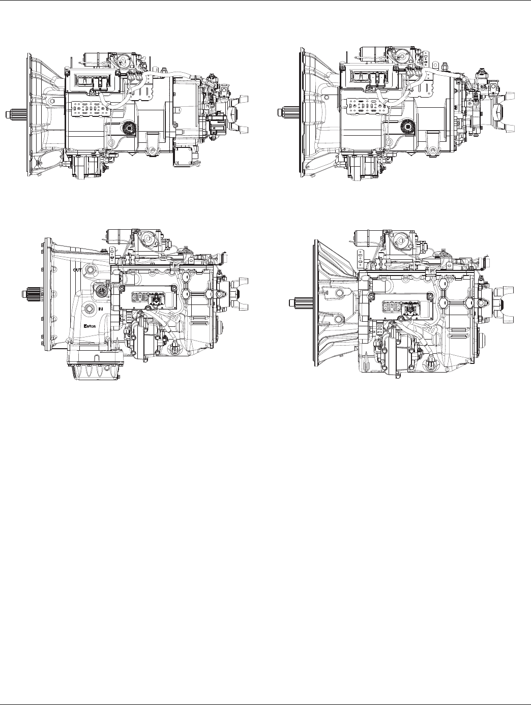
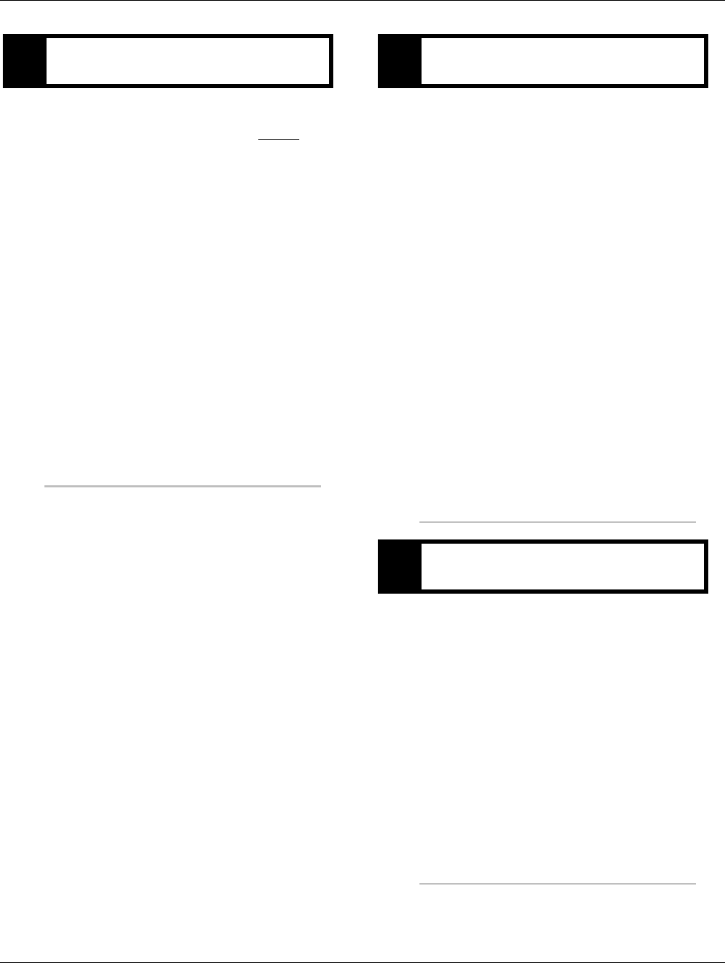
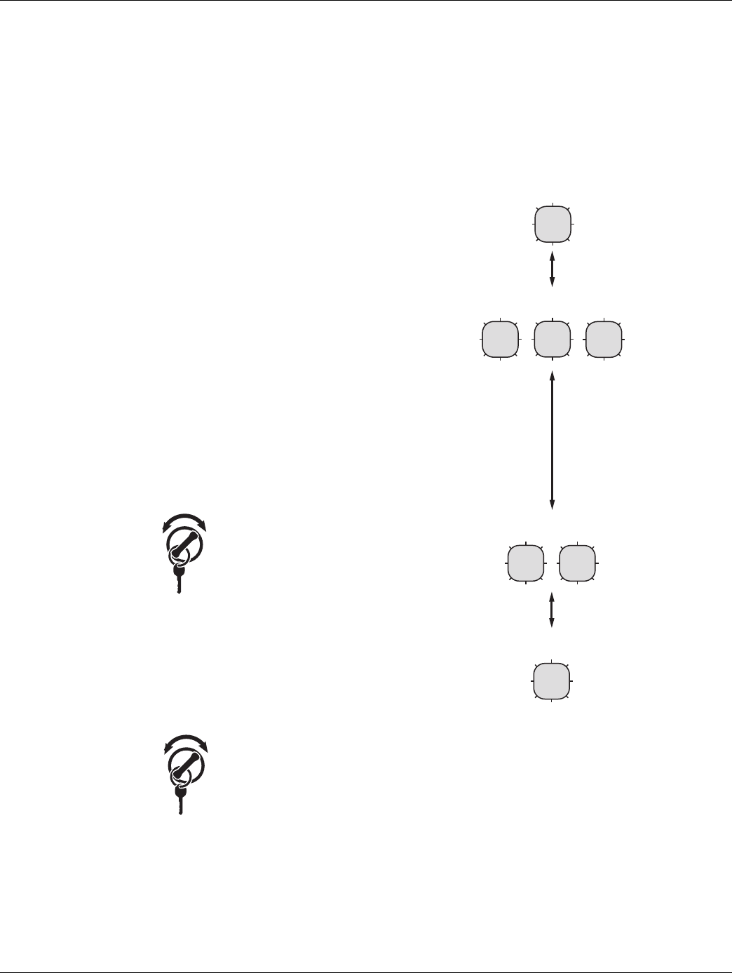
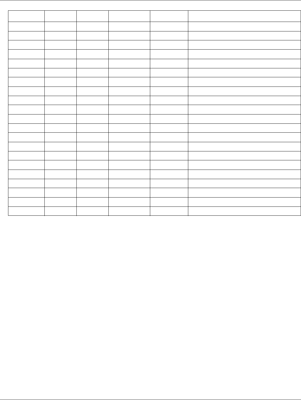
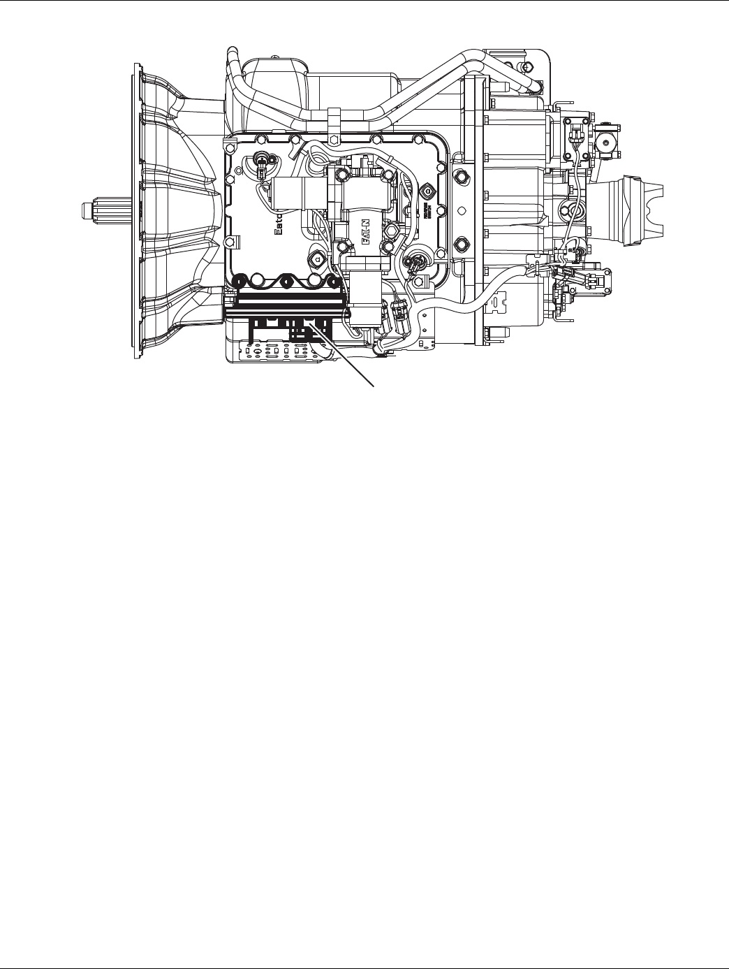
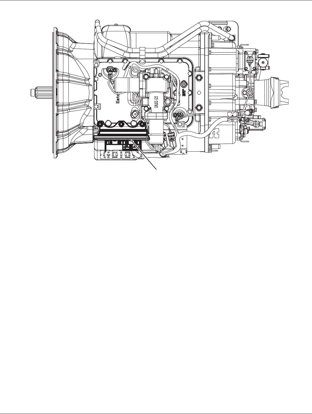
Transmission Models
Heavy-Duty 13-Speed DM3/LEP and 18-Speed AS3 Heavy-Duty 10-Speed AS3/DM3
Medium-Duty 6- and 5-Speed DM3 Medium-Duty 6-Speed AW3

2016.01.15 © 2016 Eaton. All rights reserved 3
TRTS0930 General Information | Diagnostic Procedures
Diagnostic Procedures
1. Key on.
2. Observe gear display.
Note: An “88” may show up in the dash at key on.
This indicates the Transmission Electronic
Control Unit (TECU) has completed
power-up. If the transmission and gear dis-
play power-up at the same time, you may
not see an “88”.
•If blank gear display, go to Step B.
•If “-” (1 dash) on gear display, go to Step D.
•If “--” (2 dashes) or “**” (2 stars) on gear dis-
play, go to Step D.
•“#” (gear number) on gear display
-Verify shift lever or push button is in neutral.
-Turn key off and wait 2 minutes.
-Hold clutch half way to the floor. (If
equipped)
-Turn key on.
-If problem continues, call 1-800-826-HELP
(4357)
•Fault Code F on gear display, go to Step D.
•Neutral “N” on gear display, go to Step B.
1. Attempt to start engine
•No engine crank, lever is in neutral and gear
display is “N” (neutral). See “Start Enable
Relay Contact Test” on page 268.
•No engine crank, lever is in neutral and gear
display is blank. See “Power-Up Sequence
Test” on page 22.. If no problems found, refer
to OEM for gear display problem.
•No engine crank and lever is NOT in neutral.
-Verify shift lever or push button is in neutral.
-Turn key off and wait 2 minutes.
-Hold clutch half way to the floor. (If
equipped)
-Turn key on.
-If problem continues, call 1-800-826-HELP
(4357)
•Engine cranks and gear display is blank. Refer
to OEM for gear display problem.
•Engine cranks and gear display is “N” (neu-
tral), go to Step C.
APurpose: Observe the transmission gear display. BPurpose: Confirm that the engine will crank and
start.
4© 2016 Eaton. All rights reserved 2016.01.15
Diagnostic Procedures | General Information TRTS0930
1. Attempt to engage a gear.
•If gear engaged and drives, go to Step E.
•If the gear display indicates a solid “gear num-
ber” but no drive or reverse, perform “Front
Box Control Test” on page 282
•If unable to engage a gear and transmission is
an AutoShift, perform “AutoShift Will Not
Engage a Gear from Neutral Test” on page 288
•If unable to engage a gear and transmission is
an UltraShift DM3, perform “UltraShift DM3
Will Not Engage a Gear from Neutral Test” on
page 296
•If unable to engage a gear and transmission is
an UltraShift AW3, perform “UltraShift AW3
Clutch Engagement Test” on page 302
1. Check for active fault codes.
Note: If no problem found, refer to OEM for display
problem.
•If codes are present, See “Fault Code Isolation
Procedure Index” on page 8.
•If no codes and gear display is “-” (1 dash)
-Verify shift lever or push button is in neutral.
-Turn key off. Wait 2 minutes.
-Hold clutch half way to the floor. (If
equipped)
-Turn on key.
-If problem continues, call 1-800-826-HELP
(4357)
See “Front Box Control Test” on page 282.
•If no codes and gear display is“--” (2 dashes)
or “**” (2 stars), See “Power-Up Sequence
Test” on page 22.
1. Record and clear Inactive fault codes.
2. Drive vehicle and attempt to reset code.
•If no codes are present, test complete.
•If Inactive transmission component or Fault
Codes, record codes an call 1-800-826-HELP
(4357).
•If active transmission component or Fault
Codes, See “Fault Code Isolation Procedure
Index” on page 8.
CPurpose: Confirm the transmission will engage a
gear from neutral. DPurpose: Check for active or Inactive fault codes.
EPurpose: Drive vehicle and attempt to duplicate a
fault code.
2016.01.15 © 2016 Eaton. All rights reserved 5
TRTS0930 General Information | Fault Code Retrieval/Clearing
Fault Code Retrieval/Clearing
Retrieving Fault Codes Manually
Retrieve fault codes by enabling the system’s self-diagnos-
tic mode.
Note: You can also use a PC- based service tool, such as
ServiceRanger to retrieve fault codes.
1. Place the shift lever in neutral.
2. Set the parking brake.
3. Turn key on with engine off.
Note: If the engine is already running, you may still
retrieve codes; however, do not engage the
starter if the engine stalls.
4. To Retrieve Active Codes: Key on. Turn key off and
on 2 times within five seconds ending with the key
on. After 5 seconds, the Service light begins flash-
ing two-digit fault codes. If no faults are active, the
service light will flash code 25 (no codes). This is
also the procedure to enter, See “Product Diagnos-
tic (PD) Mode” on page 11. for details.
Note: An “88” may show up in the dash at key on,
which is a normal power-up test of the display.
5. To Retrieve Inactive Codes: Turn key on. Turn the
key off and on 4 times within five seconds ending
with the key in the on position. After 5 seconds, the
Service light begins flashing two-digit fault codes.
If no faults are active, the service light will flash
code 25 (no codes).
• Two digit fault codes will be displayed in the gear
display. Some vehicle may be equipped with a ser-
vice light.
6. Observe the sequence of flashes on the service
light and record the codes. A 1- to 2-second pause
separates each stored code, and the sequence
automatically repeats after all codes have been
flashed.
2x
off on
4x
off on
1 Flash
Short
pause
(1/2 sec)
Short
pause
(1/2 sec)
Long Pause
(3-4 sec)
Code 13
Code 21
SERVICE
SERVICE
3 Flashes
SERVICE SERVICE
2 Flashes
SERVICE
SERVICE
1 Flash
SERVICE

6© 2016 Eaton. All rights reserved 2016.01.15
Fault Code Retrieval/Clearing | General Information TRTS0930
Clearing Fault Codes Manually
The following procedure clears all Inactive fault codes from
the TECU’s memory. Active fault codes are automatically
cleared when the fault has been corrected.
Note: You may use a PC-based service tool, such as Ser-
viceRanger, to clear fault codes.
1. Place shift lever in neutral.
2. Set parking brake.
3. Turn key on with engine off.
4. Turn key off and on 6 times within 5 seconds end-
ing with key on.
Note: If the codes have been successfully cleared, the
Service light will come on and stay on for five
seconds. The gear display will show 25 (no
codes).
5. Turn the key off and allow the system to power
down.
Retrieving Fault Codes with
ServiceRanger
This section determines if the TECU is communicating on
the vehicle's J1939 data link and if the component has set
any fault codes. Proper system operation requires the TECU
to communicate with other ECUs on the vehicle's J1939
data link.
Note: This procedure requires ServiceRanger 3.0 or later
and an approved RP1210A communications adapter
that supports J1939 communications.
Detecting Components
1. Connect the service PC to the vehicle's 9-way
J1939 diagnostic port connector with an approved
RP1210A communications adapter.
2. Start the ServiceRanger program and verify that a
connection has been established with the vehicle's
J1939 data link.
•If the TECU is not detected by ServiceRanger,
proceed to the Electrical Pretest procedure to
ensure the TECU has power, and that all com-
ponents are properly connected the vehicle's
J1939 data link.
Viewing Fault Codes
View the Vehicle Fault Codes screen in ServiceRanger and
verify if any Active or Inactive codes have been set.
1. If an Active code is present, record the vehicle fault
information and proceed to Diagnostic Procedure
in this manual for the Active code. Do not clear any
codes at this time.
2. If only Inactive codes are present, record the vehi-
cle fault information and clear all fault codes. Road
test the vehicle to verify proper operation.
6x
off on

2016.01.15 © 2016 Eaton. All rights reserved 7
TRTS0930 General Information | Fault Code Retrieval/Clearing
Clearing Fault Codes with ServiceRanger
After all repairs have been made and the system is function-
ing normally, clear all vehicle codes before placing the vehi-
cle back into service.
Clearing Fault Code
1. Connect the service PC to the vehicle and start Ser-
viceRanger.
2. View the Vehicle Fault Codes screen and select
Clear All.
3. Refresh the screen to verify all Inactive codes have
been cleared, and that no Active codes are present.

8© 2016 Eaton. All rights reserved 2016.01.15
Fault Code Isolation Procedure Index | General Information TRTS0930
Fault Code Isolation Procedure Index
Fault Codes SPN PID SID FMI Description
11 629 254 12 No ECU operation
12 629 254 13, 14 Improper ECU configuration
13 751 231 8, 11 J1939 Shift Control device
14
(without Park
Pawl)
751 18, 19 2, 3, 4, 5 Invalid Shift Lever voltage
14
(with Park
Pawl)
18, 19 2, 3, 4, 5 Invalid Shift Lever voltage
(will show “F” in display)
15 751 18 9 HIL Shift Device communication
16 625 248 2 High Integrity Link (HIL)
17 1321 237 3, 4, 14 Start Enable Relay Coil
21 70 70 14 Auto Neutral Park Brake Switch
22 563 49 9, 14 ABS CAN message fault
25 NO CODES
26 522 55 10 Clutch slip
27 788 55 7, 13 Clutch disengagement
28 788 52,55 3, 4, 5, 7 Clutch system
29 969 372 4, 5 Remote throttle enable
31 1485 218 2, 3, 4, 5, 14 Momentary Engine Ignition Interrupt Relay
(MEIIR)
32 158 43 2 Loss of Switch Ignition power test
33 168 168 4 Low Battery voltage supply
34 168 168 14 Weak Battery voltage supply
35 639 231 2 J1939 communication link
36 639 231 14 J1939 engine message
37 627 251 5 Power supply
41 768 35 7 Range failed to engage
41 769 36 7 Range failed to engage
42 770 37 7 Splitter failed to engage
42 771 38 7 Splitter failed to engage
43 768 35 3, 4, 5 Range High Solenoid Valve
43 769 36 3, 4, 5 Range Low Solenoid Valve
44 787 54 3, 4, 5 Inertia Brake Solenoid Coil
45 787 54 7 Intertia Brake performance
46 770 37 3, 4, 5 Splitter Direct Solenoid Valve
46 771 38 3, 4, 5 Splitter Indirect Solenoid Valve
51 60 60 2, 3, 4, 10 Rail Position Sensor
2016.01.15 © 2016 Eaton. All rights reserved 9
TRTS0930 General Information | Fault Code Isolation Procedure Index
* This code will only be set Inactive
• J1939 Source Address (SA) for Eaton transmis-
sions is 3
• J1587 Module Identifier (MID) for Eaton transmis-
sions is 130
52 59 59 2, 3, 4, 7 Gear Position Sensor
56 161 161 2, 3, 4, 5,10 Input Shaft Speed Sensor
57 160 160 2, 3, 4, 5 Main Shaft Speed Sensor
58 191 191 2, 3, 4, 5, 6, 8 Output Shaft Speed Sensor
61 772 39 1, 5, 6, 12 Rail Select Motor
63 773 40 1, 5, 6, 12 Gear Select Motor
68 520274 227 14 Grade Sensor
68 520321 227 13, 14 Grade Sensor
71 560 60 7 Unable to disengage gear
72 772 59 7 Failed to select rail
73 781 58 7 Failed to engage gear
74 518 93 7 Engine speed response fault
74 898 190 7 Engine torque response fault
75* 560 60 14 Power down in gear
81 780 47 7 Gear engagement detected
83 751 18 14 Shift Lever missing
83 752 19 7, 12 Shift Lever missing
84 751 18 13 Shift Control device not configured
84 752 19 13 Park mechanism not calibrated
85 751 18 12 Shift Control device incompatible
99 781 58 14 Direction mismatch
Fault Codes SPN PID SID FMI Description
10 © 2016 Eaton. All rights reserved 2016.01.15
Symptom-Driven Diagnostics Index | General Information TRTS0930
Symptom-Driven Diagnostics Index
Symptom Isolation Procedure
Unable to shift transmission with Up/Down button Up/Down Button Test
Engine starting system complaint Start Enable Relay Contact Test
No J1587 communication J1587 Data Link Test
Gear display shows a dash Front Box Control Test
AutoShift will not engage a gear from Neutral AutoShift Will Not Engage a Gear from Neutral Test
UltraShift DM will not engage a gear from Neutral UltraShift DM Will Not Engage a Gear from Neutral Test
UltraShift AW3 will not engage a gear from Neutral UltraShift AW3 Clutch Engagement Test
AutoShift AS3 shift complaint AutoShift AS3 Shift Complaint Test
UltraShift DM shift complaint UltraShift DM Shift Complaint Test
UltraShift AW3 shift complaint UltraShift AW3 Shift Complaint Test
Shift Lever back light does not work Shift Lever Back Light Test

2016.01.15 © 2016 Eaton. All rights reserved 11
TRTS0930 General Information | Product Diagnostic (PD) Mode
Product Diagnostic (PD) Mode
Product Diagnostic (PD) Mode
PD Mode is used to help diagnose Inactive codes that may
have been set during normal driving. This diagnostic mode
increases the sensitivity of the fault sensing capability
This procedure tests loose, degraded and intermittent con-
nections. Use the Active Fault Isolation Procedure to guide
you to the wiring and connectors that are associated with
the Inactive fault codes. Flex the wiring harness and con-
nectors and attempt to recreate the fault after activating PD
Mode.
PD Mode is only to be used by a trained service technician
in an authorized dealer.
This procedure is to be used prior to performing fault isola-
tion procedures for component-type codes when there are
no Active codes present.
To enter PD Mode:
Note: Vehicle will not start in PD Mode. You must turn vehi-
cle key off to exit PD Mode.
1. Vehicle must be stationary, engine off, set vehicle
parking brake.
2. Turn the key off and on 2 times, starting with key
on and ending with key on.
Note: Dash may display an 88 at key on. This is a nor-
mal power-up test of the display.
3. The gear display will flash a 25 then a solid PD
(Product Diagnostic Mode) and the mode will be
activated.
4. The service light shall flash code 25 once indicating
no codes. The service light shall then illuminate
solid to indicate PD Mode until such time that an
Active code is detected or PD Mode is exited.
5. Refer to PD Mode section in Fault Isolation proce-
dure for the Inactive fault to be diagnosed.
6. PD will remain in gear display until an active fault
has been set during the PD Mode fault isolation
procedure.
•If the fault is detected during PD Mode the gear dis-
play will display the active fault. The warning tone
will only sound when the fault is active and the tone
will stop when the fault is Inactive. The fault will
stay in the gear display until the system is powered
down.
Note: Active codes set during PD Mode will not be
stored as Inactive.
7. If a fault is detected, exit PD Mode and perform the
corresponding Fault Isolation Procedure.
8. To exit PD Mode, turn the key off.
PD Mode works with the following
Inactive codes:
11, 13, 14, 15,16, 17, 21, 22, 29, 33, 34, 35, 36, 43, 44, 46,
51, 52, 56, 57, 58, 61, 63, 74, and 99.

12 © 2016 Eaton. All rights reserved 2016.01.15
Electrical Pretest | Electrical Pretest Procedures TRTS0930
Electrical Pretest
Overview
The pretest does not relate to any specific fault code, but
must be completed before performing Fault Code Isolation
table procedures. The pretest verifies the batteries are fully
charged.
All Generation 3 products require the OEM to supply power
to the Electronic Control Unit (ECU).
Detection
There is no detection process specifically for the basic elec-
trical supply; however, failures of this type are generally
detected by the transmission or driver as some other type
of fault code or symptom.
Fallback
There is no fallback for the electrical pretest; however, it
may affect other systems.
Possible Causes
The pretest can be used for:
• Low batteries
• Starter/Battery connections
• Main power harness to the Transmission Electronic
Control Unit (TECU)
Additional Tools
• Basic hand tools
• Eaton Test Adapter Kit
• Digital Volt/Ohm meter
• Troubleshooting Guide
• Battery Load tester
• ServiceRanger a PC-based service tool
2016.01.15 © 2016 Eaton. All rights reserved 13
TRTS0930 Electrical Pretest Procedures | Electrical Pretest
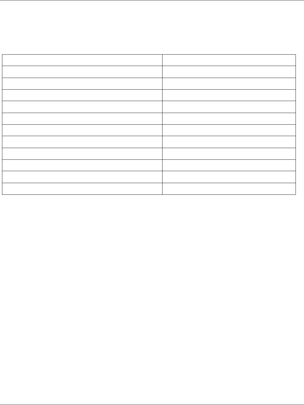
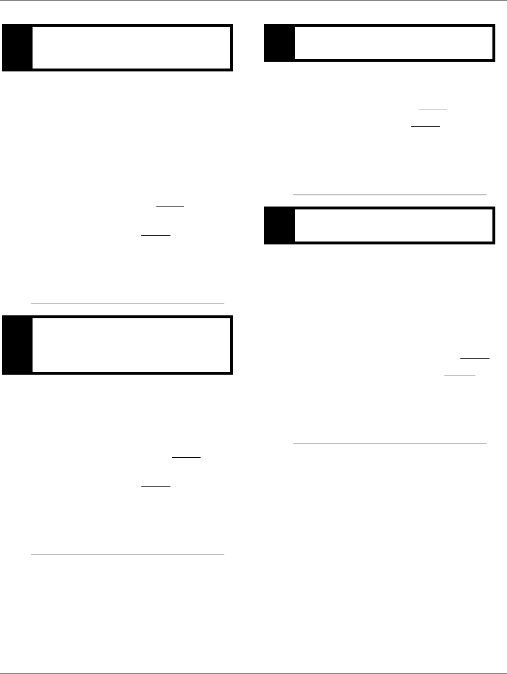
Component Identification
TECU Power Harness
OEM is responsible for overcurrent protection on this cir-
cuit.
1. 30 AMP Fuse
2. TECU Connector (Vehicle Interface)
J1
-+
1.
2.
14 © 2016 Eaton. All rights reserved 2016.01.15
Electrical Pretest | Electrical Pretest Procedures TRTS0930
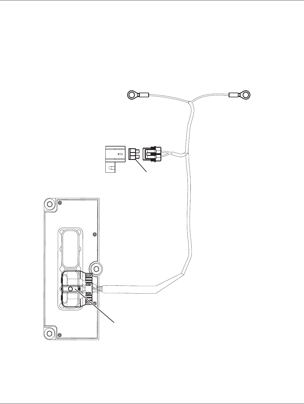
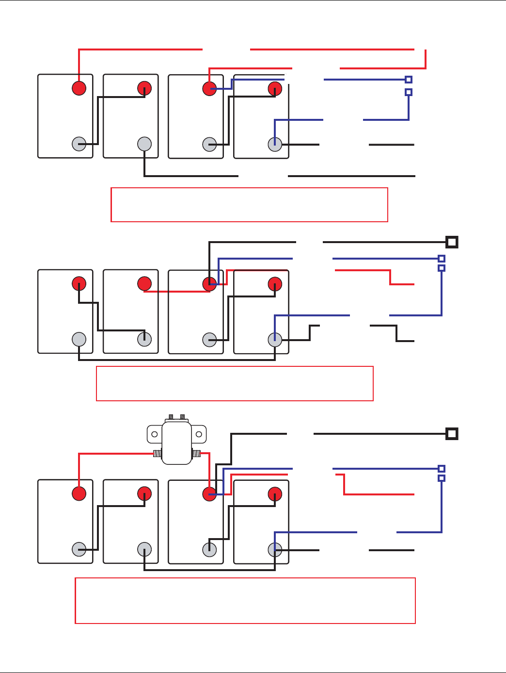
Preferred +12 Volt Connections
RETRATSTTAB ERYP LUS 2
RETRATSETTABRY M INUS 2
RETRATSETTABRY M INUS 1
RETRATS TTAB ERY P LUS 1
+-
BATTERY
12 VOLT
+-
BATTERY
12 VOLT
+-
BATTERY
12 VOLT
+-
BATTERY
12 VOLT
RATS OT SREPMUJ LAUD - KNAB REP SEIRETTAB OWT - SKNAB YRETTAB OWT TER
REWOP 3 NEG .SRIAP YB LELLARAP NI DETCENNOC ERA SEIRETTAB SUPPLIED BY
A SULP HTOB( RETRATS OT TSESOLC YRETTAB ND MINUS)
RETRATS ETTABRYM INUS 1
RETRATSTTABERYP LUS 1
+-
BATTERY
12 VOLT
+-
BATTERY
12 VOLT
+-
BATTERY
12 VOLT
+-
BATTERY
12 VOLT
AMG
LERAY
ENNOCSID HTIW KNAB REP SEIRETTAB OWT - SKNAB YRETTAB OWT CT
EV DNA BAC ROF TCENNOCSID - SRIAP YB LELLARAP NI DETCENNOC ERA SEIRETTAB HICLE START -
PAC TNEMNIATRETNE DNA TROFMOC BAC "EGRAHCSID PEED" SEDIVORP RIAP DETCENNOCSID ABILITY.
C DNA RETRATS OT TSESOLC TES YRETTAB MORF DEILPPUS REWOP 3 NEG OMMONTOCAB POWER
ETTAB UCE 3 NEGRY MINUS
TAB UCE 3 NEGTERYPLUS
ETTAB UCE 3 NEGRYMINUS
RETRATSETTAB RY M INUS 1
RETRATSTTABERYP LUS 1
+-
BATTERY
12 VOLT
+-
BATTERY
12 VOLT
+-
BATTERY
12 VOLT
+-
BATTERY
12 VOLT
IRETTAB RUOF - KNAB YRETTAB ENOES
REWOP 3 NEG .LELLARAP NI DETCENNOC ERA SEIRETTAB SUPPLIED FROM
HTOB( .REWOP BAC HTIW RETRATS OT TSESOLC YRETTABP
LUSAND MINUS)
TAB UCE 3 NEGTERYPLUS
ETTAB UCE 3 NEGRYMINUS
TTAB BACERYPLUS
TAB UCE 3 NEGTERYPLUS
TTAB BAC ERY PLUS
2016.01.15 © 2016 Eaton. All rights reserved 15
TRTS0930 Electrical Pretest Procedures | Electrical Pretest
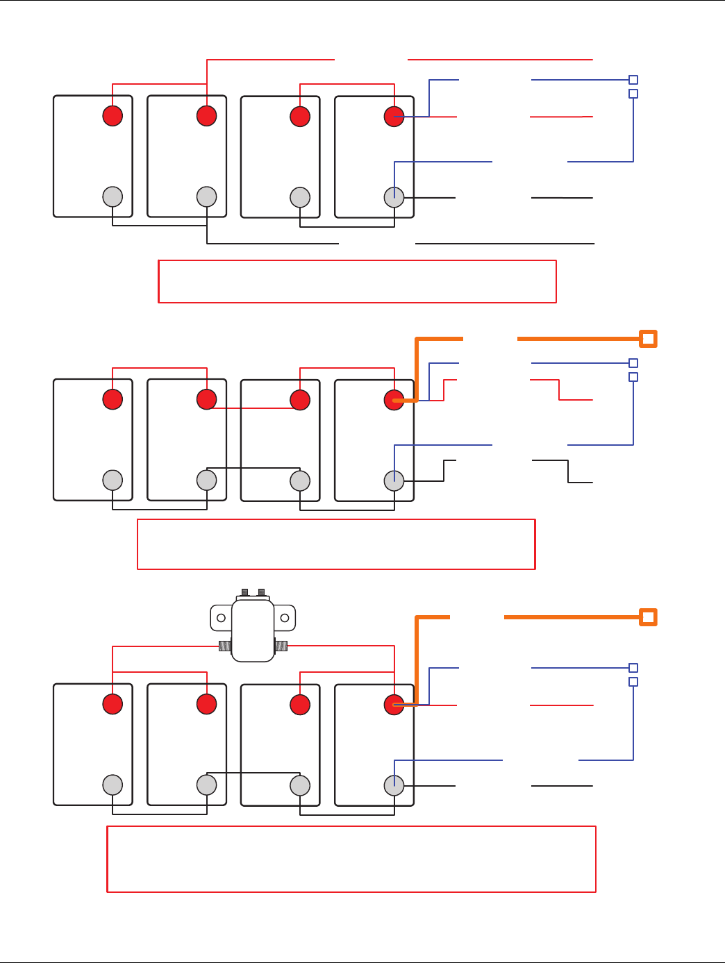
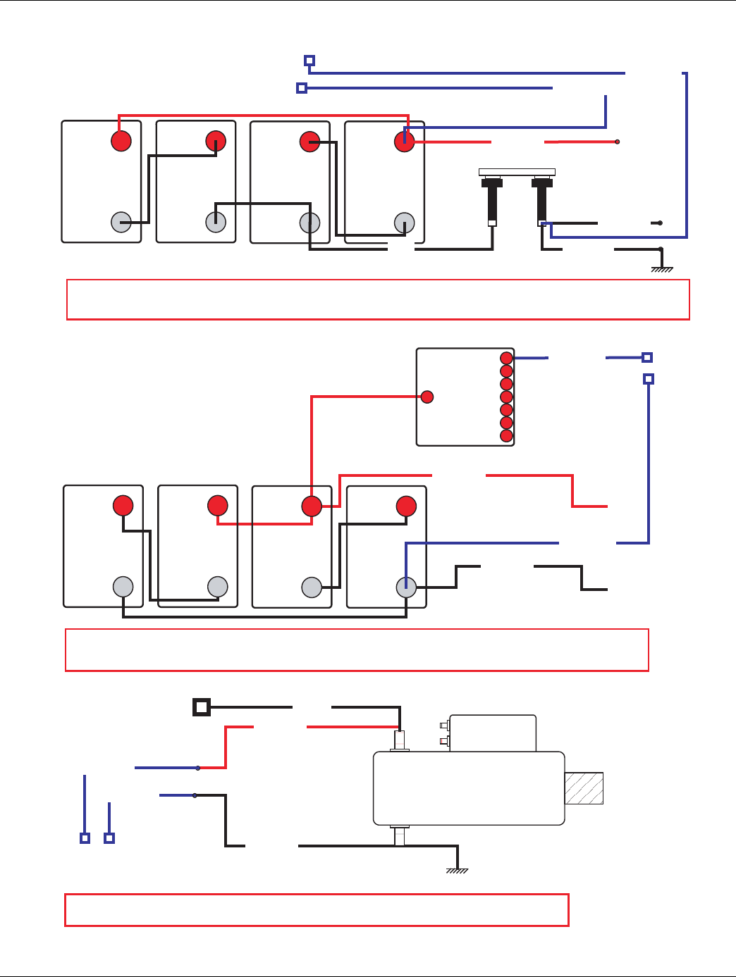
Preferred +12 Volt Connections
TIWS TCENNOCSID EVITAGEN YRETTAB - SKNAB YRETTAB OWTCH
EWOP 3 NEG .EDISNI DEROTS ELCIHEV NEHW NWOD REWOP TA DETCENNOCSID ERA SEIRETTAB RSUPPLIED FROMBATTERY
D OT NOITCENNOC ELBAC ELCIHEV FO TNIOP TA NOITCENNOC EVITAGEN .RETRATS EHT OT TSESOLC ISCONNECT SWITCH
YRETTAB M INUS
AB RETRATSTTERYPLUS
+-
BATTERY
12 VOLT
+-
BATTERY
12 VOLT
+-
BATTERY
12 VOLT
+-
BATTERY
12 VOLT
TAB RETRATS TERYMINUS
TTAB ELCIHEVERY MINUS
TA
B UCE 3 NEG TERY PLUS
ETT
AB UCE 3 NEG RY MINUS
TAB RETRATS TERY MINUS
AB RETRATSTTERYPLUS
+-
BATTERY
12 VOLT
+-
BATTERY
12 VOLT
+-
BATTERY
12 VOLT
+-
BATTERY
12 VOLT
NOITUBIRTSID REWOP MODULE
TTAB NO DETCENNOC SUNIM DNA SULP REWOP ,LELLARAP NI DETCENNOC ERA SEIRETTAB ERY CLO OT TSES EHT
WOL ROF DEZIMITPO HTGNEL DNA EZIS SELBAC .RETRATSV
OLTAGEDROP
TAB UCE 3 NEGTERYPLUS
ETTAB UCE 3 NEGRYMINUS
POWER
DISTRIBUTION
MODULE
(POWER BUS AND
OVER CURRENT
DEVICES)
STARTER BATTERY MINUS
STARTER
CAB BATTERY PLUS
STARTER BATTERY CONNECTION
GEN 3 POWER PLUS AND MINUS CONNECTED ON BATTERY CLOSEST TO THE STARTER.
+-
BATTERY
12 VOLT
+-
BATTERY
12 VOLT
Starter Battery Plus
GEN 3 ECU BATTERY PLUS
GEN 3 ECU BATTERY MINUS
STARTER BATTERY MINUS 1
STARTER BATTERY PLUS 1
+-
BATTERY
12 VOLT
+-
BATTERY
12 VOLT
ONE BATTERY BANK - TWO BATTERIES
BATTERIES ARE CONNECTED IN PARALLEL. GEN 3 POWER SUPPLIED FROM
BATTERY CLOSEST TO STARTER WITH CAB POWER. (BOTH PLUS AND MINUS)
GEN 3 ECU BATTERY PLUS
GEN 3 ECU BATTERY MINUS
CAB BATTERY PLUS
16 © 2016 Eaton. All rights reserved 2016.01.15
Electrical Pretest | Electrical Pretest Procedures TRTS0930
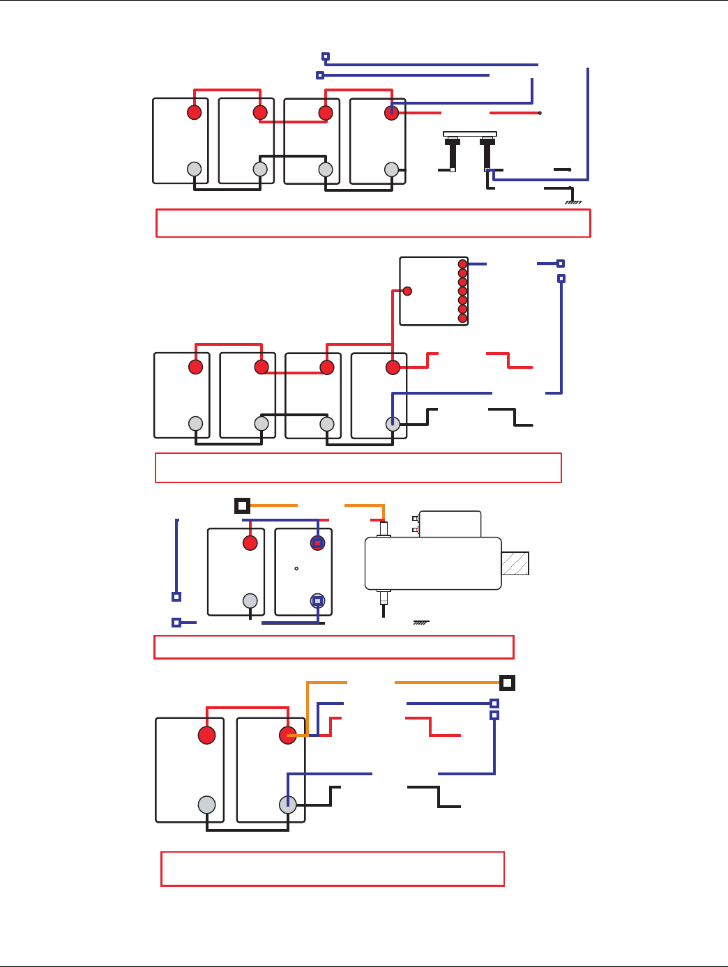
Preferred +24 Volt Connections
STARTER BATTERY PLUS
2
STARTER BATTERY MINUS
2
STARTER BATTERY MINUS
1
+ -
BATTERY
12 VOLT
+ -
BATTERY
12 VOLT
+ -
BATTERY
12 VOLT
+ -
BATTERY
12 VOLT
TWO BATTERY BANKS - TWO BATTERIES IN SERIES PER BANK - DUAL JUMPERS TO
STARTER
BATTERIES ARE CONNECTED IN SERIES/PARALLEL BY PAIRS. GEN 3 POWER
SUPPLIED BY BATTERY CLOSEST TO STARTER (BOTH PLUS AND MINUS)
+ -
BATTERY
12 VOLT
+ -
BATTERY
12 VOLT
+ -
BATTERY
12 VOLT
+ -
BATTERY
12 VOLT
MAG
RELAY
TWO BATTERY BANKS - TWO BATTERIES PER BANK WITH DISCONNECT
BATTERIES ARE CONNECTED IN SERIES/PARALLEL BY PAIRS - DISCONNECT FOR CAB AND VEHICLE
START - DISCONNECTED PAIR PROVIDES "DEEP DISCHARGE" CAB COMFORT AND ENTERTAINMENT
CAPABILITY. GEN 3 POWER SUPPLIED FROM BATTERY SET CLOSEST TO STARTER AND COMMON TO
CAB POWER
GEN 3 ECU BATTERY
PLUS
GEN 3 ECU BATTERY
MINUS
STARTER BATTERY MINUS
1
STARTER BATTERY PLUS
1
+ -
BATTERY
12 VOLT
+ -
BATTERY
12 VOLT
+ -
BATTERY
12 VOLT
+ -
BATTERY
12 VOLT
ONE BATTERY BANK - FOUR BATTERIES - ONE CABLE PAIR TO STARTER
BATTERIES ARE CONNECTED IN SERIES/PARALLEL BY PAIRS. GEN 3 POWER
SUPPLIED FROM BATTERY CLOSEST TO STARTER WITH CAB POWER. (BOTH PLUS
AND MINUS)
GEN 3 ECU BATTERY
PLUS
GEN 3 ECU BATTERY
MINUS
CAB BATTERY
PLUS
STARTER BATTERY PLUS
1
STARTER BATTERY MINUS
1
STARTER BATTERY PLUS
1
GEN 3 ECU BATTERY
MINUS
CAB BATTERY
PLUS
GEN 3 ECU BATTERY
PLUS
2016.01.15 © 2016 Eaton. All rights reserved 17
TRTS0930 Electrical Pretest Procedures | Electrical Pretest
Preferred +24 Volt Connections
+-
BATTERY
12 VOLT
+-
BATTERY
12 VOLT
+-
BATTERY
12 VOLT
+-
BATTERY
12 VOLT
TWO BATTERY BANKS - BATTERY NEGATIVE DISCONNECT SWITCH
BATTERIES ARE DISCONNECTED AT POWER DOWN WHEN VEHICLE STORED INSIDE. GEN 3 POWER SUPPLIED FROM BATTERY
CLOSEST TO THE STARTER. NEGATIVE CONNECTION AT POINT OF VEHICLE CABLE CONNECTION TO DISCONNECT SWITCH
BATTERY
MINUS
STARTER BATTERY
PLUS
STARTER BATTERY
MINUS
VEHICLE BATTERY
MINUS
GEN 3 ECU BATTERY
PLUS
GEN 3 ECU BATTERY
MINUS
STARTER BATTERY
MINUS
STARTER BATTERY
PLUS
+-
BATTERY
12 VOLT
+-
BATTERY
12 VOLT
+-
BATTERY
12 VOLT
+-
BATTERY
12 VOLT
POWER DISTRIBUTION MODULE
BATTERIES ARE CONNECTED IN SERIES/PARALLEL, POWER PLUS AND MINUS CONNECTED ON BATTERY CLOSEST TO THE
STARTER. CABLES SIZE AND LENGTH OPTIMIZED FOR LOW VOLTAGE DROP
GEN 3 ECU BATTERY
PLUS
GEN 3 ECU BATTERY
MINUS
POWER
DISTRIBUTION
MODULE
(POWER BUS AND
OVER CURRENT
DEVICES)
STARTER BATTERY
MINUS
STARTER BATTERY
PLUS
STARTER
CAB BATTERY
PLUS
GEN 3 ECU BATTERY
MINUS
GEN 3 ECU BATTERY
PLUS
STARTER BATTERY CONNECTION
GEN 3 POWER PLUS AND MINUS CONNECTED ON BATTERY CLOSEST TO THE STARTER.
18 © 2016 Eaton. All rights reserved 2016.01.15
Electrical Pretest | Electrical Pretest Procedures TRTS0930
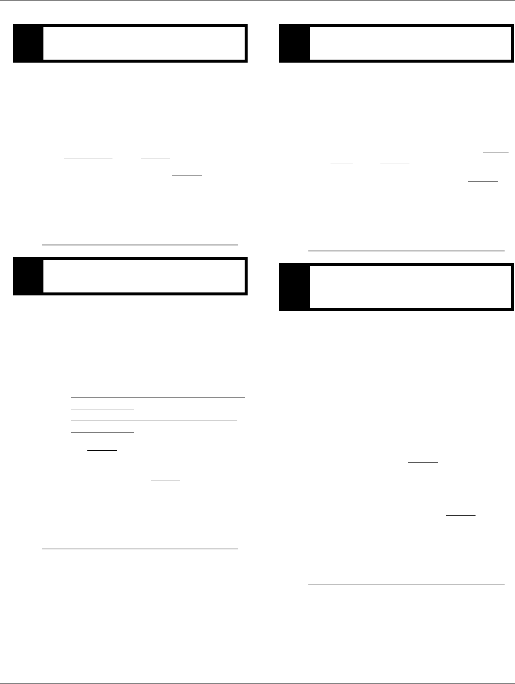
TECU Ignition Circuit
1. TECU connector (vehicle interface)
2. 10 AMP only, manual resetting circuit breaker OR
10 AMP fuse
3. Ignition Key Switch
Note: Run to main power lead that feeds the ignition
bus (OEM responsible for overcurrent protection
on this line)
4. TECU Connector (vehicle interface) front view
Battery and ignition power and ground to the TECU must
not be switched off during the engine start process.
35
23
17
31
24 25
29 30
15 16
26
20
34
27 28
32 33
18 19
7
3
89
1 2
10
6
11 12
4 5
22
21
38
36
37
13 14
35
J1
3.
2.
1.
4.
From To
J1-35 VIGN
2016.01.15 © 2016 Eaton. All rights reserved 19
TRTS0930 Electrical Pretest Procedures | Electrical Pretest
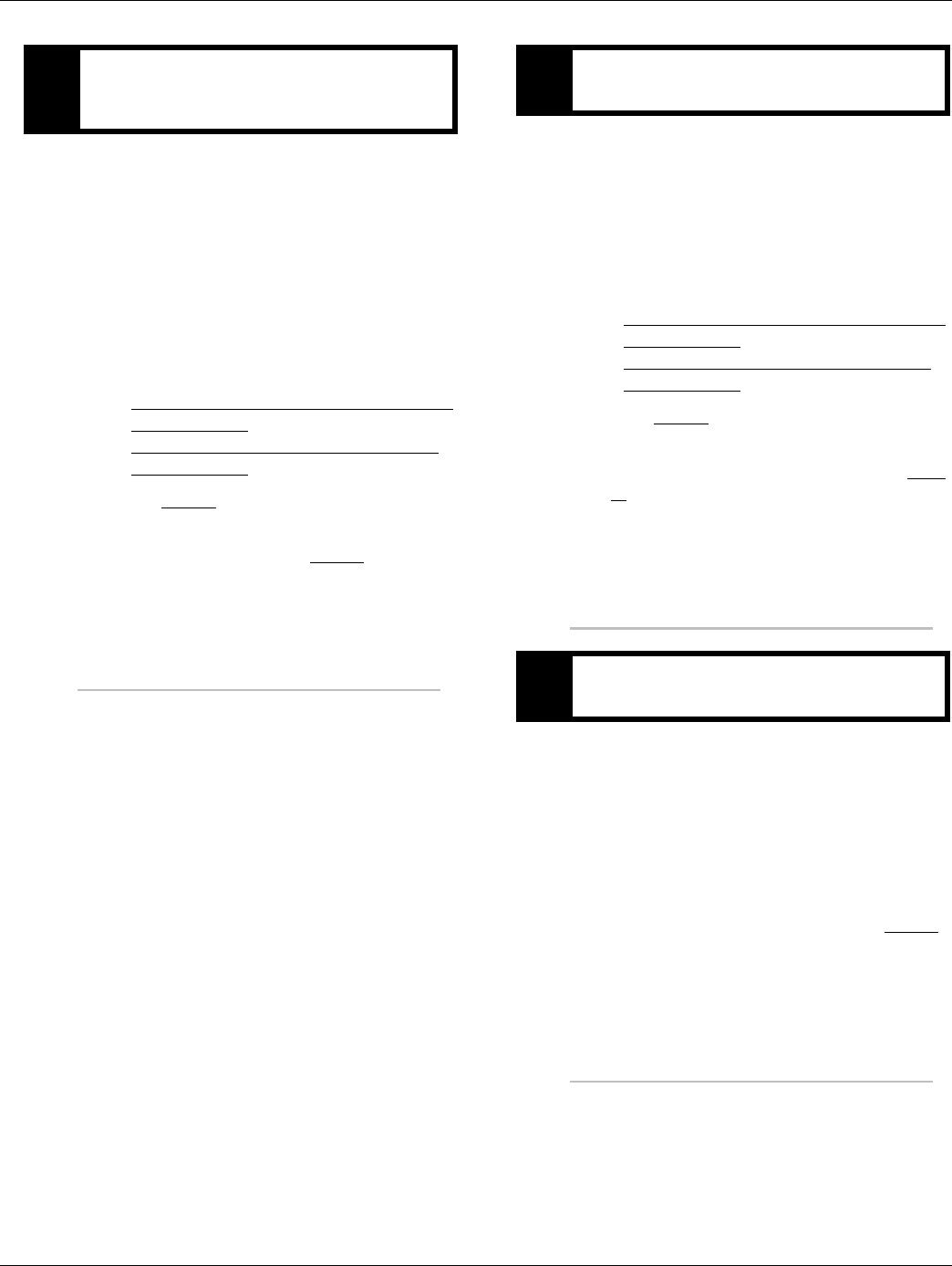
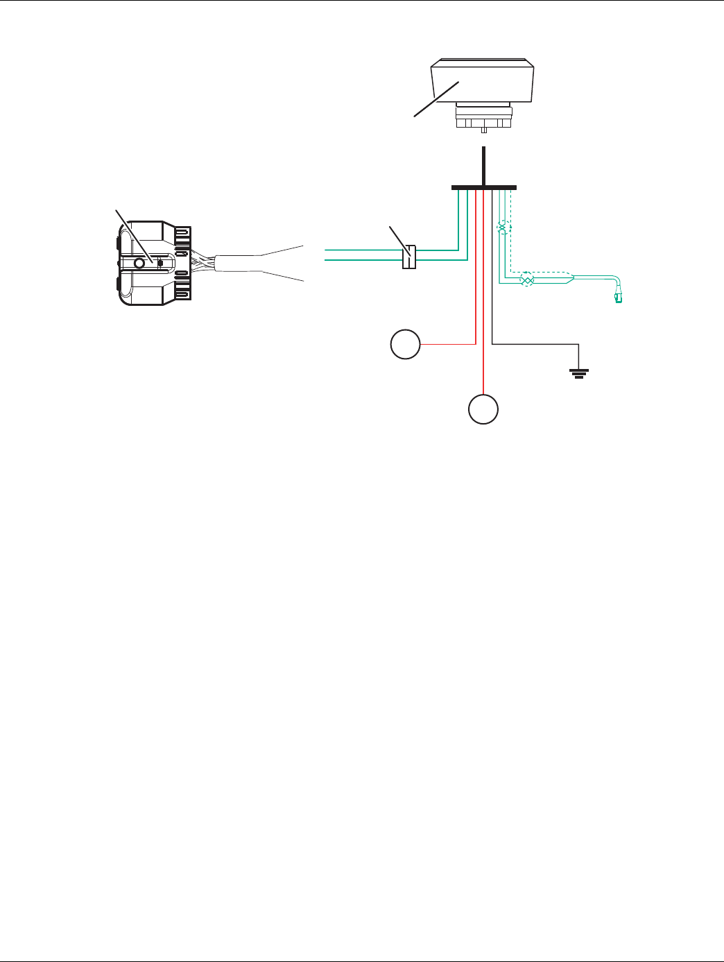
J1939 Data Link
1. TECU connector (vehicle interface)
2. J1587 Data Link
3. 9-Way, for transmission diagnostics
J1939 Troubleshooting
1. Check the resistance of the J1939 Data Link.
2. Key off. Measure resistance between the 9-way
diagnostic connector Pin C and Pin D and record
the reading. The reading should be 60 ohms of
resistance (between 50 and 70.)
3. Check resistance between Pin C and Pin A and the
resistance between Pin D and Pin A. These two
readings should be 10K ohms or greater (open cir-
cuit).
Note: Pin C = J1939+, Pin D = J1939-, Pin A is a chas-
sis ground
• If an Inactive data link fault code is being reported
by the TECU, See “Product Diagnostic (PD) Mode”
on page 11. PDM should be utilized before any fur-
ther steps are taken.
+ Battery
10
11
C
D
B
F
G
A
A
F
J
E
G
H
D
CB
J1
J1939 Low
J1939 High
1.
2.
3.
20 © 2016 Eaton. All rights reserved 2016.01.15
Electrical Pretest | Electrical Pretest Procedures TRTS0930
Electrical Pretest
1. Key off.
2. Remove and clean all battery and battery-to-frame
connections.
3. Remove and clean ground supply to engine ECU.
4. Inspect starter/battery and inline 30 amp fuse
holder connections for corrosion or damaged con-
tacts.
5. Measure voltage across batteries.
•If voltage is 11 to 13 volts on a 12- volt system
or 22 to 26 on a 24 volt system, refer to OEM
guidelines for battery load test. Repair or
replace batteries as required. Go to Step B.
•If voltage is outside of range, repair or replace
batteries and charging system as required.
Repeat this step.
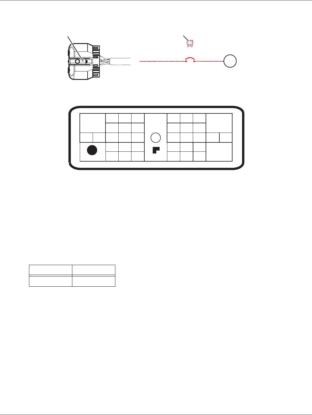
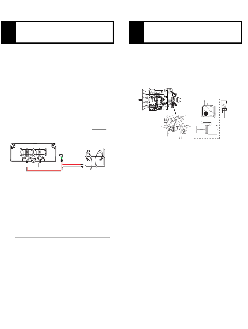
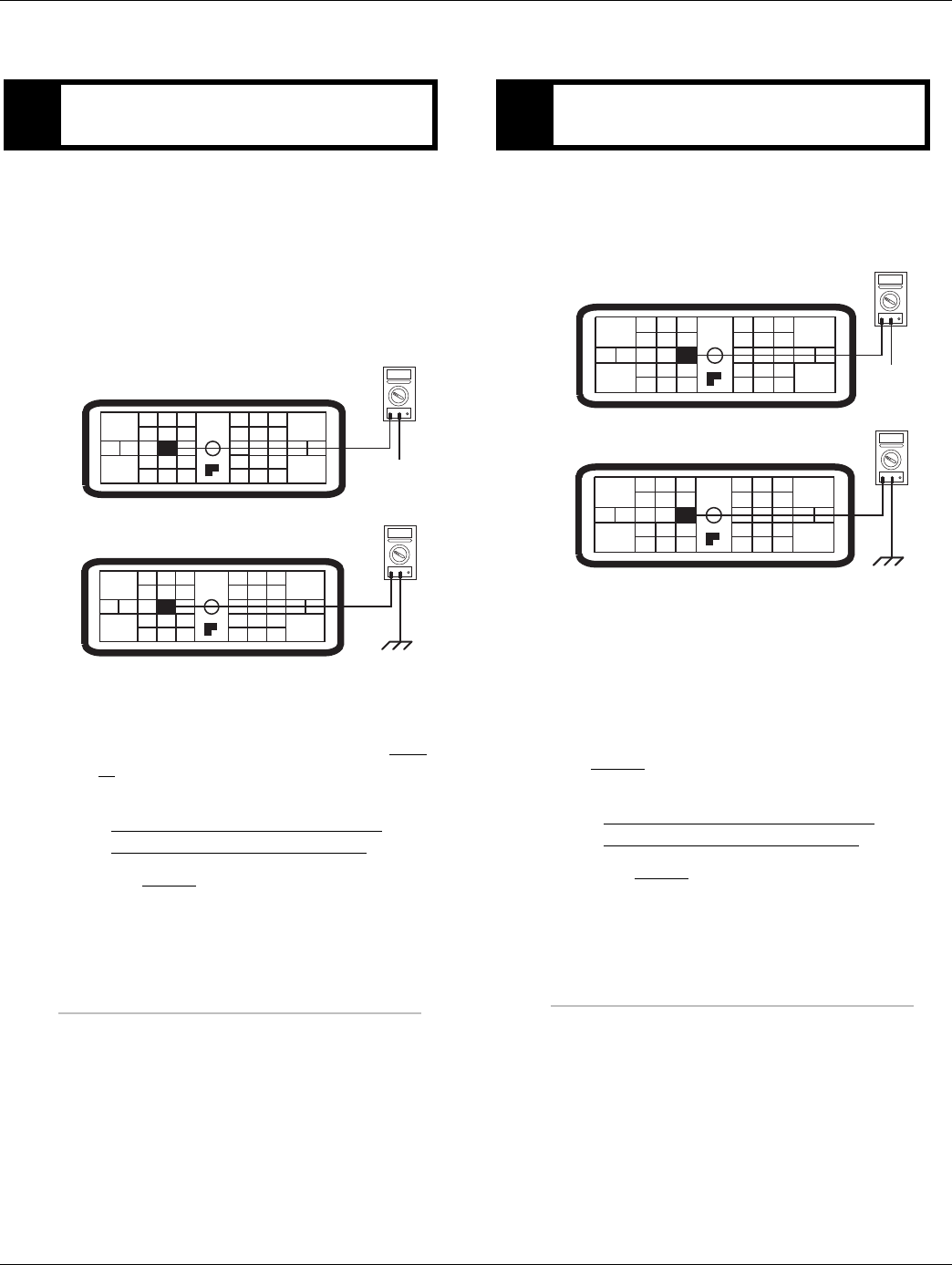
1. Locate diagnostic port on Transmission Harness.
2. Key on.
3. Measure voltage between Pin C and the battery
negative post.
•If voltage is 0.70 volts or less, go to Step C.
•If voltage is outside of range, repair battery
ground supply to Transmission Electrical Con-
trol Unit (TECU). Repeat test.
APurpose: Measure battery voltage. Visually inspect
the batteries, inline fuse and power and ground
supplies at the batteries.
+
–
+
–
Batteries
30 AMP fuse
Transmission ECU
BPurpose: Verify proper ground path between the
batteries and the transmission harness 4-way diag-
nostic connector.
4-Pin Diagnostic Port
(Located at the left rear
corner of the transmission.)
4-Pin Diagnostics Port
4-way
B - Service Bat. +
C - Service Bat. -
A - Service Ignition +
VOLTS
VCOM A
Battery Negative Post
BA
D
C
Warning! - Do Not Load Test at Diagnostic Port
2016.01.15 © 2016 Eaton. All rights reserved 21
TRTS0930 Electrical Pretest Procedures | Electrical Pretest
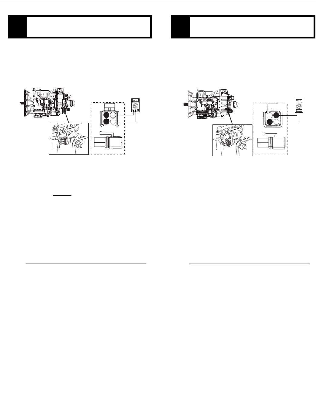
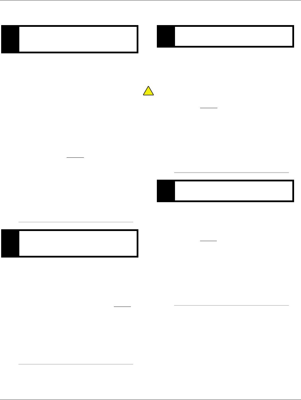
1. Locate diagnostic port on Transmission Harness.
2. Key on.
3. Measure voltage between Pin B and Pin C.
•If voltage is within 0.6 volts of battery voltage,
go to Step D.
•If voltage is outside of range, Repair battery
power supply to TECU. Fuse may be blown.
Repeat test.
1. Key on.
Warning: Do not load test at the diagnostic port.
2. Measure voltage between Pin A and Pin C.
•If voltage is within 0.6 volts of battery voltage,
test complete.
•If voltage is outside of range, repair ignition
power supply to TECU. Fuse may be blown.
Repeat test.
CPurpose: Measure proper battery voltage at the
transmission harness 4-way diagnostic connector.
4-Pin Diagnostics Port
4-way
B - Service Bat. +
C - Service Bat. -
A - Service Ignition +
BA
D
C
4-Pin Diagnostic Port
(Located at the left rear
corner of the transmission.)
Warning! - Do Not Load Test at Diagnostic Port
DPurpose: Measure proper ignition voltage at the
transmission harness 4-way diagnostic connector.
4-Pin Diagnostics Port
4-way
B - Service Bat. +
C - Service Bat. -
A - Service Ignition +
BA
D
C
4-Pin Diagnostic Port
(Located at the left rear
corner of the transmission.)
Warning! - Do Not Load Test at Diagnostic Port

22 © 2016 Eaton. All rights reserved 2016.01.15
Power-Up Sequence Test | Electrical Pretest Procedures TRTS0930
Power-Up Sequence Test
Overview
This test does not relate to any specific fault code, but must
be completed if the self check fails at power-up.
Detection
The TECU checks the program memory every time the key
is turned on.
Fallback
This causes an In-Place fallback while moving and a
self-check failure if it occurs during power-up.
Possible Causes
This fault code can be caused by any of the following:
• Vehicle Harness
• Shift Control Device
• TECU
2016.01.15 © 2016 Eaton. All rights reserved 23
TRTS0930 Electrical Pretest Procedures | Power-Up Sequence Test
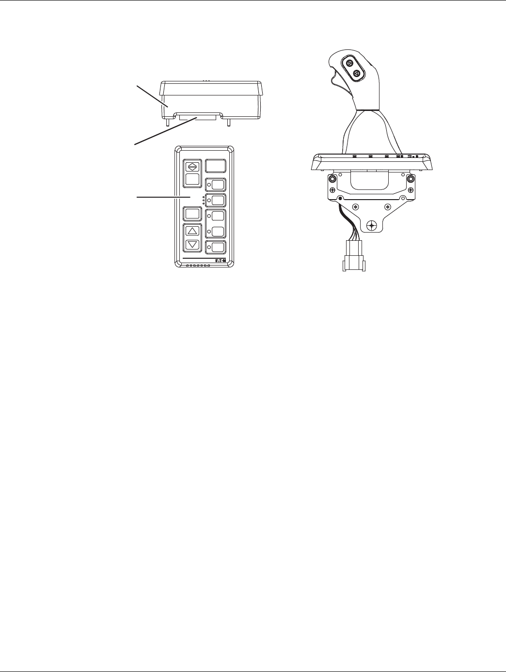
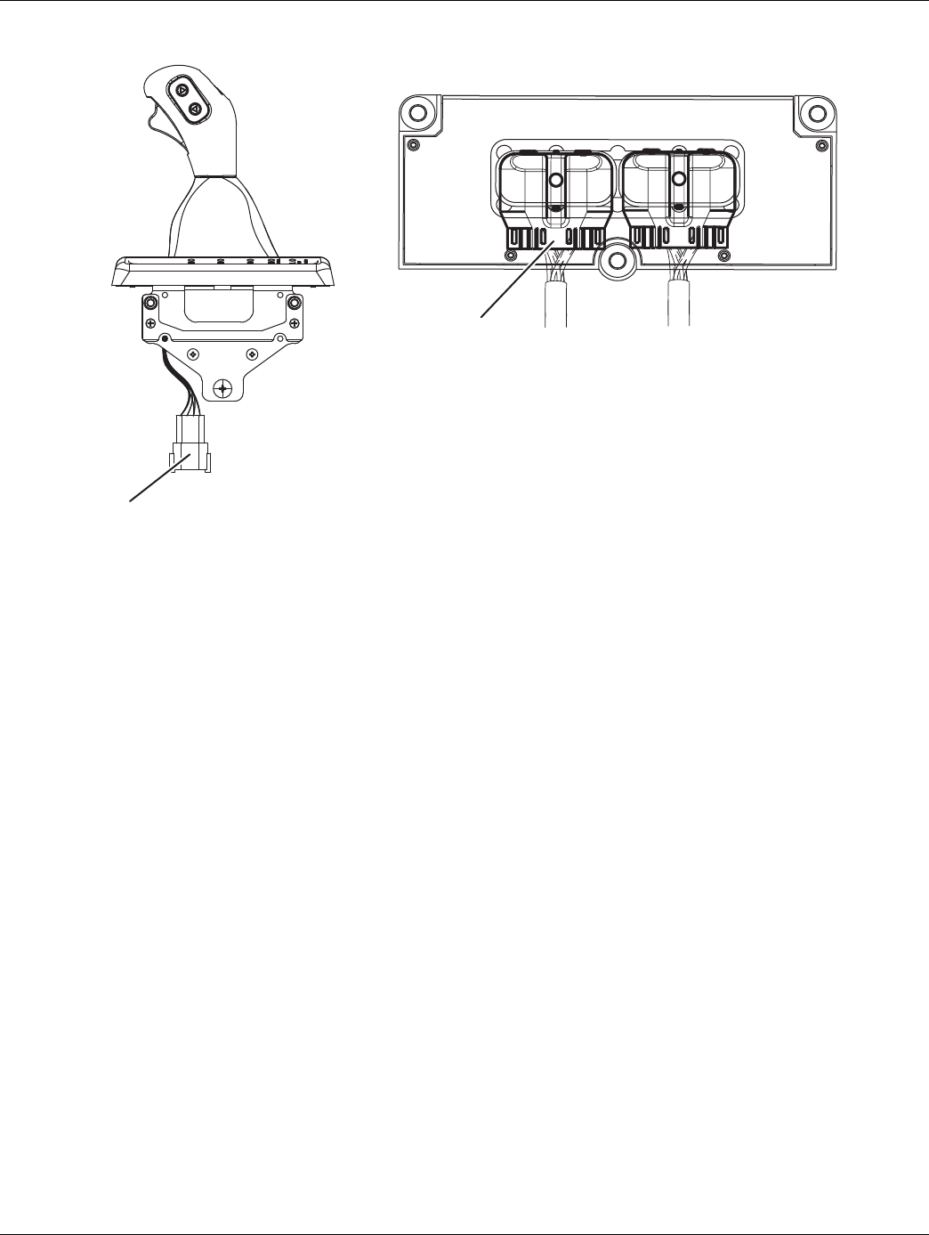
Component Identification
1. Side view of pushbutton shift control
2. Transmission controller 30-way connector
3. Top view of pushbutton shift control
4. Eaton Cobra Lever
4.
VOLUME
CONTROL
SERVICE
SHIFT
Eaton Fuller
Transmissions
L
H
D
N
R
1.
2.
3.
24 © 2016 Eaton. All rights reserved 2016.01.15
Power-Up Sequence Test | Electrical Pretest Procedures TRTS0930
Power-Up Sequence Test
1. Key off.
2. Remove and clean all battery and battery-to- frame
connections.
3. Remove and clean ground supply to engine ECU.
4. Inspect starter/battery and inline 30-amp fuse
holder connections for corrosion or damaged con-
tacts.
5. Measure voltage across batteries.
•If voltage is 11 to 13 volts on a 12-volt system
or 22 to 26 on a 24-volt system, proceed with
battery load test. Repair or replace batteries as
required. Go to Step B.
•If voltage is outside of range, repair or replace
batteries and charging system as required.
Repeat this step.
1. Locate diagnostic port on Transmission Harness.
2. Key on.
3. Measure voltage between Pin C and the battery
negative post.
•If voltage is 0.70 volts or less, go to Step C.
•If voltage is outside of range, repair battery
ground supply to TECU. Repeat test.
1. Locate diagnostic port on Transmission Harness.
2. Key on.
3. Measure voltage between Pin B and Pin C.
Warning: Do not load test at the diagnostic port.
•If voltage is within 0.6 volts of battery voltage,
go to Step D.
•If voltage is outside of range, repair battery
power supply to TECU. Fuse may be blown.
Repeat test.
1. Key on.
2. Measure voltage between Pin A and Pin C.
•If voltage is within 0.6 volts of battery voltage,
go to Step E.
•If voltage is outside of range, repair Ignition
power supply to ECU. Fuse may be blown.
Repeat test.
APurpose: Measure battery voltage. Visually inspect
the batteries, inline fuse and power and ground
supplies at the batteries.
BPurpose: Verify proper ground path between the
batteries and the transmission harness 4-way diag-
nostic connector.
CPurpose: Measure proper battery voltage at the
transmission harness 4-way diagnostic connector.
DPurpose: Measure proper ignition voltage at the
transmission harness 4-way diagnostic connector.
!
2016.01.15 © 2016 Eaton. All rights reserved 25
TRTS0930 Electrical Pretest Procedures | Power-Up Sequence Test
1. Is vehicle equipped with an Shift Lever?
•If vehicle is not equipped with a Shift Lever, go
to Step F.
•If vehicle is equipped with a Shift Lever, go to
Step K.
1. Is it an Eaton Push Button or OEM J1939 Shift
Device?
•If an Eaton Push Button Shift Control, go to
Step G.
•If an OEM J1939 Shift Device, refer to OEM for
troubleshooting procedures.
1. Key on.
2. Observe Service light.
Note: If Service light is flashing, go to Diagnostics
Procedure.
•If Service light illuminates for 1 second and
turns off, test complete.
•If Service light never lights, go to Step H.
•If Service light is on steady, replace Shift Con-
trol. Go to Step V.
1. Key off.
2. Disconnect Shift Control 30-way connector.
3. Key on.
4. Measure voltage between Pin C1 and Pin J3 on the
Shift Control 30-way.
•If voltage is within 1 volt of battery voltage
replace Shift Control. Go to Step V.
•If voltage is outside of range, go to Step I.
EPurpose: Visually identify if the vehicle is equipped
with a shift lever or push button.
FPurpose: Visually identify if the push button is an
Eaton built push button or an OEM built J1939
push button.
GPurpose: Visually observe the Service light during
key-on power up.
HPurpose: Measure the voltage supply at the Shift
Control device.
26 © 2016 Eaton. All rights reserved 2016.01.15
Power-Up Sequence Test | Electrical Pretest Procedures TRTS0930
1. Key off.
2. Disconnect negative battery cable.
3. Disconnect 38-way Vehicle Harness from TECU.
4. Measure resistance between TECU Pin 25 and Shift
Control connector Pin J3 and from then from Pin
J3 to ground.
•If resistance from Pin 25 to J3 is
0 to 0.3 ohms and resistance from J3 to
ground is OL / Open, go to Step J.
•If resistance is outside of range, repair the
Vehicle Harness. Go to Step V.
1. Measure resistance between TECU Pin 31 and Shift
Control connector Pin C1 and then from Pin C1 to
ground.
•If resistance from Pin 31 to C1 is 0 to 0.3
ohms and resistance from C1 to ground is 10K
or OL, replace the TECU. Go to Step V.
•If resistance is outside of range, repair the
Vehicle Harness. Go to Step V.
1. Is vehicle equipped with an Eaton supplied Shift
Lever or an OEM supplied Shift Lever.
•If Eaton Cobra Lever, go to Step L.
•If OEM Shift Lever, go to Step R.
1. Key on.
2. Observe Service light.
Note: If Service light is flashing, See “Diagnostic
Procedures” on page 3.
•If Service light illuminates for 1 second and
turns off, test complete.
•If Service light never comes on, go to Step O.
•If Service light is on steady, go to Step M.
IPurpose: Verify that a proper ground path is being
supplied to the Shift Control Device through the Ve-
hicle Harness and test for a short to ground.
J
Purpose: Measure the resistance of the ignition
voltage supply wire to the Shift Control Device
through the Vehicle Harness and test for a short to
ground.
KPurpose: Visually identify if the shift lever is an Ea-
ton built shift lever or an OEM built shift lever.
LPurpose: Visually observe the Service light during
key-on power up.
2016.01.15 © 2016 Eaton. All rights reserved 27
TRTS0930 Electrical Pretest Procedures | Power-Up Sequence Test
1. Disconnect Shift Lever 8-way connector.
2. Key on.
3. Measure voltage at Pin 6 and ground.
•If voltage is within 2 volts of battery voltage for
one second, then 0 volts, replace the Eaton
Cobra Lever. Go to Step V.
•If voltage is constant, go to Step N.
1. Key off.
2. Disconnect negative cable.
3. Disconnect 38-way Vehicle Harness connector.
4. Measure resistance between Pin 6 and Pin 4.
•If resistance is OL, replace the:
- Medium-Duty Transmission Electronic Con-
trol Unit (TECU)
- Heavy-Duty Transmission Electronic Con-
trol Unit (TECU)
Go to Step V.
•If resistance is less than 10K, repair the Vehi-
cle Harness and go to Step V.
1. Key off.
2. Disconnect Shift Lever 8-way connector.
3. Key on.
4. Measure voltage between Pin 3 and Pin 6.
•If within 1 volt of battery replace Eaton Cobra
Lever, go to Step V.
•If voltage is outside of range, go to Step N.
1. Key off
2. Disconnect 38-way Vehicle Harness connector on
TECU.
3. Measure resistance between Pin 3 on the 8-way
connector and Pin 25 on the 38-way connector and
from Pin 25 to ground.
Note: On Peterbilt disconnect Gear Display,
•If resistance between Pin 3 and Pin 25 is 0 to
0.3 ohms and resistance from Pin 25 to
ground is OL, go to Step Q.
•If resistance is outside of range, repair the
Vehicle Harness between the Vehicle Harness
38-way connector Pin 25 and Vehicle Harness
8-way connector Pin 3. Go to Step V.
MPurpose: Measure the voltage supply to the Service
light during key-on power up.
NPurpose: - Test the Service light voltage supply for
short to power through the Vehicle Harness.
OPurpose: Measure the voltage supply to the Service
light during key-on power up.
PPurpose: Verify that a proper ground path is being
supplied to the Shift Lever through the Vehicle Har-
ness and test for a short to ground.

28 © 2016 Eaton. All rights reserved 2016.01.15
Power-Up Sequence Test | Electrical Pretest Procedures TRTS0930
1. Key off.
2. Measure resistance between:
-Vehicle Harness 38-way connector Pin 31 and
Vehicle Harness 8-way connector Pin 4
-Vehicle Harness 38-way connector Pin 31 and
ground
•If resistance between Pin 31 and Pin 4 is 0 to
0.3 ohms and if resistance between Pin 31 and
ground is OL, replace the:
- Medium-Duty Transmission Electronic Con-
trol Unit (TECU)
- Heavy-Duty Transmission Electronic Con-
trol Unit (TECU)
Go to Step V.
•If any of the above conditions are not met,
replace the Vehicle Harness between Vehicle
Harness 38-way connector Pin 31 and Vehicle
Harness 8-way connector Pin 4. Go to Step V.
1. Key off.
2. Locate Service light connector on Vehicle Harness.
3. Key on.
4. Measure voltage across Pin A and Pin B on the Ser-
vice light connector
•If voltage is within 2 volts of battery voltage for
1 second, then 0 volts, test complete.
•If no voltage is measured, go to Step S.
•If voltage is within 2 volts of battery voltage
continuously, go to Step T.
QPurpose: Measure the resistance of the ignition
voltage supply to the Shift Lever through the Vehi-
cle Harness and test for a short to ground.
RPurpose: Measure the voltage supply to the Service
light during key-on power up.
2016.01.15 © 2016 Eaton. All rights reserved 29
TRTS0930 Electrical Pretest Procedures | Power-Up Sequence Test
1. Key off.
2. Disconnect negative battery cable.
3. Disconnect 38-way connector.
4. Measure resistance from Pin A of the OEM connec-
tor to Pin 23 of the 38-way and from Pin 23 to
ground.
•If resistance from Pin A to Pin 23 is 0 to 0.3
ohms and resistance to ground is 10K or
greater, replace the:
-Medium-Duty Transmission Electronic Con-
trol Unit (TECU)
- Heavy-Duty Transmission Electronic Con-
trol Unit (TECU)
Go to Step V.
•If resistance is outside of range, repair the
Vehicle Harness and go to Step V.
1. Key off.
2. Disconnect negative battery cable.
3. Disconnect TECU 38-way connector.
4. Measure voltage across Service light connector Pin
A and Pin B.
•If no voltage is measured, replace the:
- Medium-Duty Transmission Electronic Con-
trol Unit (TECU)
- Heavy-Duty Transmission Electronic Con-
trol Unit (TECU)
Go to Step V.
•If voltage is within 2 volts of battery voltage,
repair Vehicle Harness as required. Go to Step
V.
1. Key off.
2. Reconnect all connectors and the negative battery
cable.
3. Key on.
•If Power-Up Sequence Test completes, test
complete.
•If Power-Up Sequence Test fails go to Step A.
find error in testing.
SPurpose: Measure the resistance of the service
light supply wire to the Shift Lever through the Ve-
hicle Harness and test for a short to ground.
TPurpose: Test for a short to power at the Shift Le-
ver Service light.
VPurpose: Verify that the system will properly power
up.

30 © 2016 Eaton. All rights reserved 2016.01.15
Fault Code 11 - No TECU Operation | Fault Isolation Procedures TRTS0930
Fault Code 11 - No TECU Operation
J1939: SA 3 SPN 629 FMI 12
J1587: MID130 PID FMI 12
Overview
This fault code indicates an internal failure of the Transmis-
sion Electronic Control Unit (TECU).
Detection
The TECU checks the program memory every time the key
is turned on and throughout operation. If the TECU is able
to detect a failure within its own memory, it sets this fault
code.
Fallback
This fault causes a vehicle In Place fallback while moving
and a self-check failure if it occurs during power-up.
Possible Causes
This fault code can be caused by the following:
• TECU
2016.01.15 © 2016 Eaton. All rights reserved 31
TRTS0930 Fault Isolation Procedures | Fault Code 11 - No TECU Operation
Component Identification
1. TECU
1.

32 © 2016 Eaton. All rights reserved 2016.01.15
Fault Code 11 - No TECU Operation | Fault Isolation Procedures TRTS0930
Fault Code 11 - No TECU Operation
1. Key on.
2. Retrieve codes. See “Fault Code Retrieval/Clearing”
on page 5.
•If Fault Code 11 is Active, replace the:
-Medium-Duty Transmission Electronic Con-
trol Unit (TECU)
- Heavy-Duty Transmission Electronic Con-
trol Unit (TECU)
•If Fault Code 11 is Inactive, test complete.
APurpose: Check for active or Inactive fault codes

2016.01.15 © 2016 Eaton. All rights reserved 33
TRTS0930 Fault Isolation Procedures | Fault Code 11 - No TECU Operation

34 © 2016 Eaton. All rights reserved 2016.01.15
Fault Code 12 - Improper ECU Configuration | Fault Isolation Procedures TRTS0930
Fault Code 12 - Improper ECU Configuration
J1939: SA 3 SPN 629 FMI 13,14
Overview
This fault code indicates the Transmission Electronic Con-
trol Unit (TECU) is not reading valid information from mem-
ory, including the transmission table and calibration values.
Detection
The TECU checks the configuration every time the key is
turned on. If the transmission is not able to detect the
proper configuration, it sets this fault code.
Fallback
This fault causes a power up no crank.
Possible Causes
This fault code can be caused by the following:
• Improper TECU configuration software
2016.01.15 © 2016 Eaton. All rights reserved 35
TRTS0930 Fault Isolation Procedures | Fault Code 12 - Improper ECU Configuration
Component Identification
1. TECU
1.

36 © 2016 Eaton. All rights reserved 2016.01.15
Fault Code 12 - Improper ECU Configuration | Fault Isolation Procedures TRTS0930
Fault Code 12 - Improper ECU Configuration
1. Key on.
2. Retrieve codes. See “Fault Code Retrieval/Clearing”
on page 5.
•If Fault Code 12 is Active, Customer - Call
Eaton at 1-800-826-HELP (4357). CSC - Call
Technician Service.
•If Fault Code 12 is Inactive, test complete.
APurpose: Check for active or Inactive fault codes.

2016.01.15 © 2016 Eaton. All rights reserved 37
TRTS0930 Fault Isolation Procedures | Fault Code 12 - Improper ECU Configuration

38 © 2016 Eaton. All rights reserved 2016.01.15
Fault Code 13 - J1939 Shift Control Device | Fault Isolation Procedures TRTS0930
Fault Code 13 - J1939 Shift Control Device
J1587: MID130 PID 231 FMI 8, 11
J1939: SA 3 SPN751 FMI 8, 11
Overview
This fault indicates communication has been lost, or does
not correspond with the neutral request input from the
J1939 Shift Device.
When troubleshooting an Inactive code, See “Product Diag-
nostic (PD) Mode” on page 11.
Detection
Starting at key on and throughout operation, the Transmis-
sion Electronic Control Unit (TECU) constantly monitors
communication with the J1939 Shift Device. If a neutral
request from the J1939 Shift Device does not match the
neutral signal or is not received from the J1939 Shift
Device, Fault Code 13 is set.
Fallback
This fault causes a downshift-only fallback. Once the trans-
mission re-engages the start gear, there will be no upshifts
as long as the code is active.
Possible Causes
This fault code can be caused by the following:
• OEM J1939 Shift Control Device
• Vehicle Harness
2016.01.15 © 2016 Eaton. All rights reserved 39
TRTS0930 Fault Isolation Procedures | Fault Code 13 - J1939 Shift Control Device
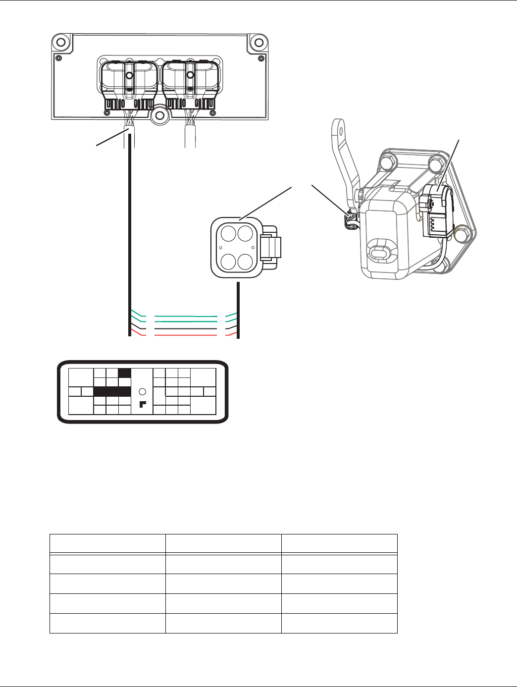
Component Identification
1. TECU Connector (vehicle interface)
2. Bulkhead connector located at firewall
3. OEM J1939 Shift Device
4. Battery Power (Non-switches power run to battery
or starter)
5. Switched Power
J1
J1939
16
17
1.
2.
3.
4.
5.
40 © 2016 Eaton. All rights reserved 2016.01.15
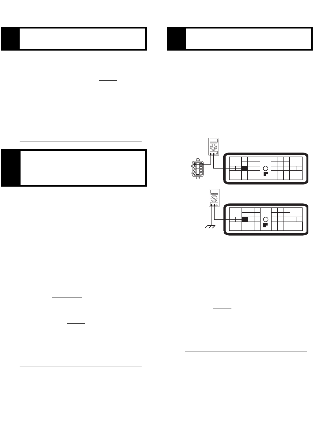
Fault Code 13 - J1939 Shift Control Device | Fault Isolation Procedures TRTS0930
Fault Code 13 - J1939 Shift Control Device
1. Key off.
2. Disconnect negative battery cable.
3. Disconnect Vehicle Harness 38-way connector.
4. Measure resistance between 38-way connector Pin
16 and corresponding OEM pin at J1939 Shift
Device and Pin 16 and ground (see OEM wiring for
correct pin location)
•If resistance is 0 to 0.3 ohms between Pin 16
and the corresponding OEM pin and resistance
to ground is 10K ohms or greater, go to Step
B.
•If resistance is out of range, replace the:
- Medium-Duty Transmission Harness
- Heavy-Duty Transmission Harness
Go to Step V.
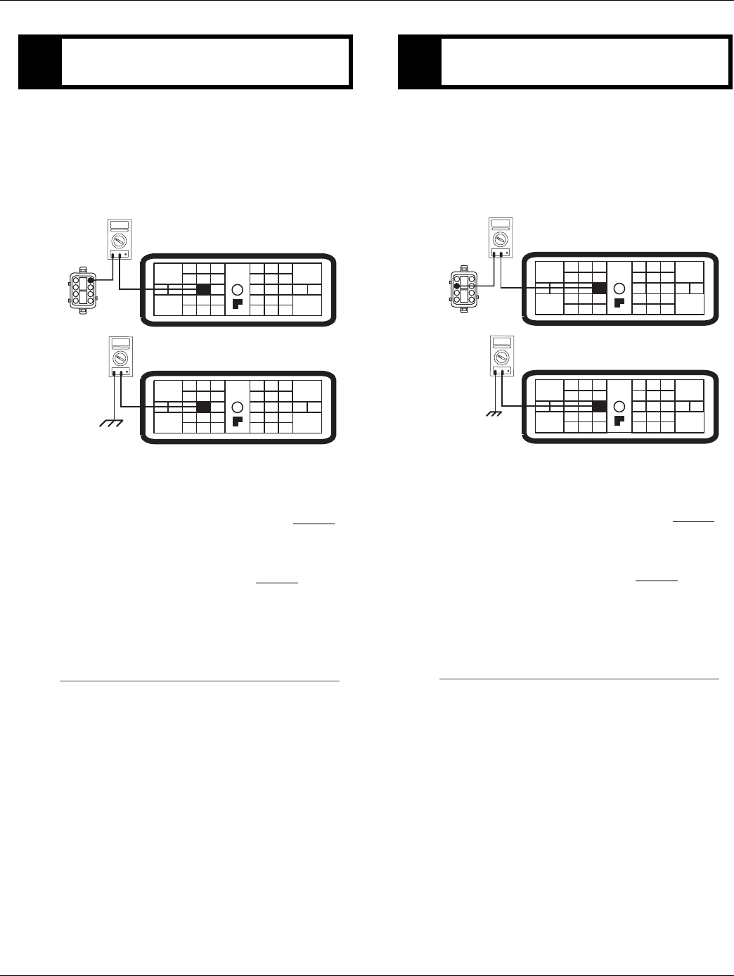
1. Measure resistance between 38-way connector Pin
17 and corresponding OEM pin at J1939 Shift
Device and Pin 17 and ground (see OEM wiring for
correct pin location).
•If resistance is 0 to 0.3 ohms between Pin 17
and the corresponding OEM pin and resistance
to ground is 10K ohms or greater, problem
exists with the J1939 Shift Device, or J1939
Shift Device power, ground or data link wiring.
Contact your OEM for repair strategy. Go to
Step V.
•If resistance is out of range, replace the:
- Medium-Duty Transmission Harness
- Heavy-Duty Transmission Harness
Go to Step V.
APurpose: Verify continuity of Neutral Request Sig-
nal wire
31
24 25
29 30
15 16
26
20
34
27 28
32 33
18 19
7
3
89
12 6
11 12
45
22
21
38
36
37
13 14
35 10
17
23
OHMS
VCOM A
31
24 25
29 30
15 16
26
20
34
27 28
32 33
18 19
7
3
89
12 6
11 12
45
22
21
38
36
37
13 14
35 10
17
23
OHMS
VCOM A
J1939
BPurpose: Verify continuity of Neutral Request Re-
turn wire
OHMS
VCOM A
OHMS
VCOM A
31
24 25
29 30
15 16
26
20
34
27 28
32 33
18 19
7
3
89
12 6
11 12
45
22
21
38
36
37
13 14
35 10
17
23
31
24 25
29 30
15 16
26
20
34
27 28
32 33
18 19
7
3
89
12 6
11 12
45
22
21
38
36
37
13 14
35 10
17
23
J1939

2016.01.15 © 2016 Eaton. All rights reserved 41
TRTS0930 Fault Isolation Procedures | Fault Code 13 - J1939 Shift Control Device
1. Key off.
2. Reconnect all connectors and the negative battery
cable.
3. Key on.
4. Clear codes. See “Fault Code Retrieval/Clearing” on
page 5.
5. Drive vehicle and attempt to reset the code.
6. Check for codes. See “Fault Code Retrieval/Clear-
ing” on page 5.
•If no fault codes, test complete.
•If Fault Code 13 appears go to Step A. to find
error in testing.
•If fault code other than 13 appears, See “Fault
Code Isolation Procedure Index” on page 8.
VPurpose: Verify repair.

42 © 2016 Eaton. All rights reserved 2016.01.15
Fault Code 14 - Invalid Shift Lever Voltage (without Park Pawl) | Fault Isolation Procedures TRTS0930
Fault Code 14 - Invalid Shift Lever Voltage (without Park Pawl)
J1587: MID 130 SID 18, 19 FMI 2, 3, 4, 5
J1939: SA 3 SPN 751 FMI 2, 3, 4, 5
Overview
This fault code indicates an electrical failure of the Eaton
Cobra Lever or OEM Shift Lever.
When troubleshooting an Inactive code See “Product Diag-
nostic (PD) Mode” on page 11.
Detection
Starting at key on and throughout operation the Transmis-
sion Electronic Control Unit (TECU) constantly monitors the
signal from the Park Pawl Position Sensor. The transmis-
sion monitors both sensor signals, if one signal to the TECU
is out of range the code will set.
Fallback
This fault may cause a downshift only fallback mode. The
transmission will re-engage the start gear when returned to
a stop, but will not upshift as long as the code is active.
Possible Causes
This fault code can be caused by any of the following:
• Eaton Cobra Lever or OEM Shift Lever
• Vehicle Harness
• TECU
2016.01.15 © 2016 Eaton. All rights reserved 43
TRTS0930Fault Isolation Procedures | Fault Code 14 - Invalid Shift Lever Voltage (without Park Pawl)
Component Identification
1. Eaton Cobra Lever 8-way connector
2. TECU 38-way connector
1.
2.
44 © 2016 Eaton. All rights reserved 2016.01.15
Fault Code 14 - Invalid Shift Lever Voltage (without Park Pawl) | Fault Isolation Procedures TRTS0930
Fault Code 14 - Invalid Shift Lever Voltage (without Park Pawl)
1. Is vehicle equipped with an Eaton supplied Shift
Lever or an OEM supplied Shift Lever?
•If Eaton Cobra Lever, go to Step B.
•If OEM Shift Lever, contact OEM for trouble-
shooting procedures.
1. Key off.
2. Disconnect Shift Lever 8-way connector.
3. Connect Shift Lever tester to the 8-way Shift Lever
harness.
4. Connect ServiceRanger, a PC-based Service Tool,
to diagnostic port.
5. Key on.
6. Select Monitor Data.
7. Observe transmission range selected.
•If transmission range selected equals neutral,
replace Cobra Lever (only if fault code is
Active). Go to Step V.
•If transmission range selected does not equal
neutral, go to Step C.
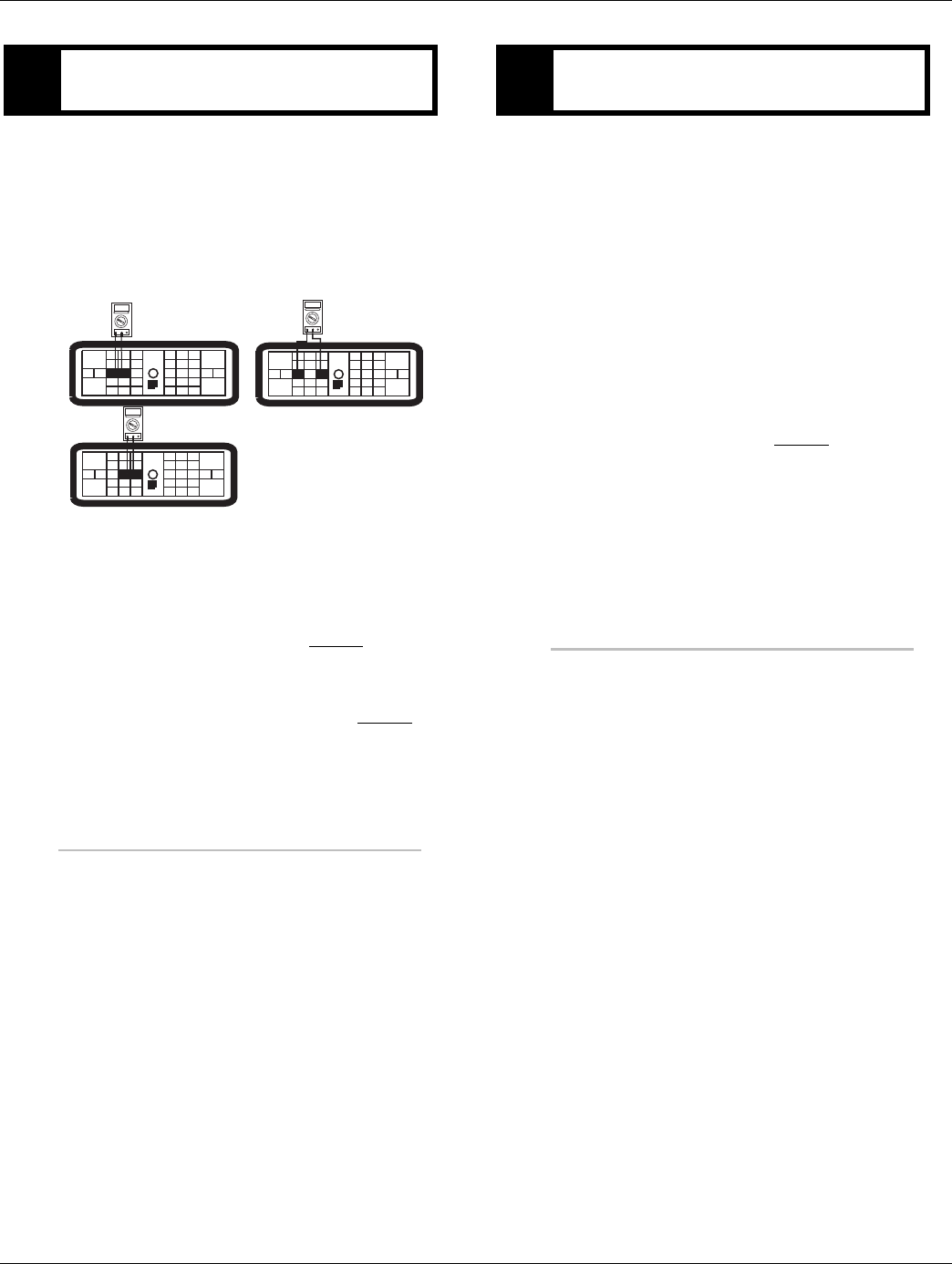
1. Key off.
2. Disconnect negative battery cable.
3. Disconnect TECU 38-way connector.
4. Remove tester from Shift Lever 8-way connector.
5. Measure resistance between:
-ECU 38-way Pin 15 and Shift Lever 8-way con-
nector Pin 1
-ECU 38-way connector Pin 15 and ground
•If resistance between Pin 15 and Pin 1 is 0 to
0.3 ohms and resistance between Pin 15 and
ground is 10K ohm or greater, go to Step D.
•If any of the above conditions are not met,
repair the OEM Vehicle Harness between the
TECU and the Eaton Cobra Lever.
Go to Step V.
APurpose: Visually identify the lever type: Eaton or
OEM manufactured.
B
Purpose: Install the Shift Lever tester and monitor
Transmission Range in ServiceRanger. Utilize the
Shift Lever Tester to verify transmission-lever in-
terface.
CPurpose: Verify continuity of auto mode input wire.
OHMS
VCOM A
OHMS
VCOM A
31
24 25
29 30
15 16
26
20
34
27 28
32 33
18 19
7
3
89
12 6
11 12
45
22
21
38
36
37
13 14
35 10
17
23
1
2
3
45
6
7
8
31
24 25
29 30
15 16
26
20
34
27 28
32 33
18 19
7
3
89
12 6
11 12
45
22
21
38
36
37
13 14
35 10
17
23
2016.01.15 © 2016 Eaton. All rights reserved 45
TRTS0930Fault Isolation Procedures | Fault Code 14 - Invalid Shift Lever Voltage (without Park Pawl)
1. Key off.
2. Measure resistance between:
-TECU 38-way Pin 16 and Shift Lever 8-way con-
nector Pin 8
-TECU 38-way connector Pin 16 and ground
•If resistance between Pin 16 and Pin 8 is 0 to
0.3 ohms and resistance between Pin 16 and
ground is 10K ohm or greater, go to Step E.
•If any of the above conditions are not met,
repair the Vehicle Harness between the Eaton
Cobra Lever and TECU. Go to Step V.
1. Key off.
2. Measure resistance between:
-TECU 38-way Pin 17 and Shift Lever
8-way connector Pin 2
-TECU 38-way connector Pin 17 and ground
•If resistance between Pin 17 and Pin 2 is 0 to
0.3 ohms and resistance between Pin 17 and
ground is 10K ohm or greater, go to Step F.
•If any of the above conditions are not met,
repair the Vehicle Harness between the Eaton
Cobra Lever and TECU. Go to Step V.
DPurpose: Verify continuity of manual mode input
wire.
OHMS
VCOM A
1
2
3
45
6
7
8
31
24 25
29 30
15 16
26
20
34
27 28
32 33
18 19
7
3
89
12 6
11 12
45
22
21
38
36
37
13 14
35 10
17
23
OHMS
VCOM A
31
24 25
29 30
15 16
26
20
34
27 28
32 33
18 19
7
3
89
12 6
11 12
45
22
21
38
36
37
13 14
35 10
17
23
EPurpose: Verify continuity of common ground
wire.
OHMS
VCOM A
1
2
3
45
6
7
8
31
24 25
29 30
15 16
26
20
34
27 28
32 33
18 19
7
3
89
12 6
11 12
45
22
21
38
36
37
13 14
35 10
17
23
OHMS
VCOM A
31
24 25
29 30
15 16
26
20
34
27 28
32 33
18 19
7
3
89
12 6
11 12
45
22
21
38
36
37
13 14
35 10
17
23
46 © 2016 Eaton. All rights reserved 2016.01.15
Fault Code 14 - Invalid Shift Lever Voltage (without Park Pawl) | Fault Isolation Procedures TRTS0930
1. Key off.
2. Measure resistance between:
-Pin 15 and Pin 16 on the TECU 38-way connector.
-Pin 15 and Pin 17 on the TECU 38-way connector.
-Pin 16 and Pin 17 on the TECU 38-way connector.
•If resistance on all three is 10K ohm or greater,
replace Shift Lever and go to Step V.
•If any of the three readings is less than 10K
ohm, repair the Vehicle Harness between the
Eaton Cobra Lever and TECU. Go to Step V.
1. Key off.
2. Reconnect all connectors and the negative battery
cable.
3. Key on.
4. Clear codes, See “Fault Code Retrieval/Clearing” on
page 5.
5. Drive vehicle and attempt to reset the code.
6. Check for codes. See “Fault Code Retrieval/Clear-
ing” on page 5.
•If no codes, test complete.
•If code 14 appears, go to Step A. to find error
in testing.
•If code other than 14 appears, See “Fault Code
Isolation Procedure Index” on page 8.
FPurpose: Check for short circuits in the shift lever
wiring.
OHMS
VCOM A
31
24 25
29 30
15 16
26
20
34
27 28
32 33
18 19
7
3
89
12 6
11 12
45
22
21
38
36
37
13 14
35 10
17
23
OHMS
VCOM A
31
24 25
29 30
15 16
26
20
34
27 28
32 33
18 19
7
3
89
12 6
11 12
45
22
21
38
36
37
13 14
35 10
17
23
OHMS
VCOM A
31
24 25
29 30
16
26
20
34
27 28
32 33
18 19
7
3
89
12 6
11 12
45
22
21
38
36
37
13 14
35 10
15
23
17
VPurpose: Verify repair.

2016.01.15 © 2016 Eaton. All rights reserved 47
TRTS0930Fault Isolation Procedures | Fault Code 14 - Invalid Shift Lever Voltage (without Park Pawl)

48 © 2016 Eaton. All rights reserved 2016.01.15
Fault Code 14 - Invalid Shift Lever Voltage (with Park Pawl) | Fault Isolation Procedures TRTS0930
Fault Code 14 - Invalid Shift Lever Voltage (with Park Pawl)
J1587: MID 130 SID 18, 19 FMI 2, 3, 4, 5
J1939: SA 3 SPN FMI 2, 3, 4, 5
Overview
This fault code indicates a possible failure of the Park Pawl
Position Sensor or OEM circuit. The sensor is a 4 wire dual
hall effect device. When troubleshooting an Inactive code
See “Product Diagnostic (PD) Mode” on page 11.
Detection
Starting at key on and throughout operation the Transmis-
sion Electronic Control Unit (TECU) constantly monitors the
signal from the Park Pawl Position Sensor. The transmis-
sion monitors both sensor signals, if one signal to the TECU
is out of range the code will set.
Fallback
This fault code will cause the transmission to be stuck in
the last known selected position. If the code comes active
while in gear, the transmission will a down shift only fall-
back mode. The transmission will re-engage the start gear
when returned to a stop, but will not upshift as long as the
code is Active.
Possible Causes
This fault code can be caused by any of the following:
• Vehicle Harness
• Park Pawl Position Sensor
• TECU
2016.01.15 © 2016 Eaton. All rights reserved 49
TRTS0930 Fault Isolation Procedures | Fault Code 14 - Invalid Shift Lever Voltage (with Park Pawl)
Component Identification
1. Vehicle Harness 38-way Connector
2. 4-Pin Park Pawl Position Sensor Connector
(DTM06-4S)
3. Park Pawl Position Sensor
4. TECU Connector Front View (Vehicle Interface)
28
31
24 25
29 30
15 16
26
20
34
27
32 33
18 19
7
3
89
12 6
11 12
45
22
21
38
36
37
13 14
35 10
17
DEUTSCH
X
4
21
3
4
3
15
16
1
2
17
31
F2
1.
2.
3.
4.
4-Way Pin# 38-Way PIN# Type
1 17 Ground
2 31 5 Volt Reference
3 16 Signal 1
4 15 Signal 2
50 © 2016 Eaton. All rights reserved 2016.01.15
Fault Code 14 - Invalid Shift Lever Voltage (will show “F” in display) | Fault Isolation Procedures TRTS0930
Fault Code 14 - Invalid Shift Lever Voltage (will show “F” in display)
1. Key on.
2. Retrieve active fault codes and FMIs with Ser-
viceRanger using the
9-way diagnostic connector.
•If Fault Code 14 FMI 2 is active, go to Step B.
•If Fault Code 14 FMI 3, 4 or 5 is active, go to
Step D.
•If Fault Code 14 is Inactive, See “Product Diag-
nostic (PD) Mode” on page 11.
1. Key off.
2. Perform shift cable adjustment procedure per OEM
guidelines.
3. Key on.
4. Retrieve active fault codes and FMIs with Ser-
viceRanger using the 9-way diagnostic connector.
•If Fault Code 14 FMI 2 is Inactive, go to Step
V.
•If Fault Code 14 FMI 2 is Active, go to Step C.
1. Perform Park Pawl Position Sensor calibration
2. Key on.
3. Retrieve active fault codes and FMIs with Ser-
viceRanger using the 9-way diagnostic connector.
•If Fault Code 14 FMI 2 is Inactive, go to Step
V.
•If Fault Code 14 FMI 2 is Active, replace Park
Pawl Position Sensor. go to Step V.
1. Key off.
2. Disconnect the Park Pawl Position Sensor 4-way
connector.
3. Key on.
4. At the Park Pawl Position Sensor 4-way connector,
measure voltage between Pin 1 and Pin 2.
•If 4.5 to 5.5 volts, go to Step E.
•If less than 4.5 volts, go to Step G.
•If greater than 5.5 volts, Repair the Vehicle
Harness for short to power per OEM guide-
lines. Go to Step V.
APurpose: Check for active or Inactive fault codes,
noting FMI.
BPurpose: Perform Shift Cable Adjustment proce-
dure.
CPurpose: Perform Park Pawl Position Sensor cali-
bration.
DPurpose: Measure voltage at the Park Pawl Posi-
tion Sensor.

2016.01.15 © 2016 Eaton. All rights reserved 51
TRTS0930 Fault Isolation Procedures | Fault Code 14 - Invalid Shift Lever Voltage (will show “F” in display)
1. Key off.
2. Disconnect Park Pawl Position Sensor 4-way con-
nector.
3. Disconnect TECU 38-way Transmission Harness
connector.
4. Measure resistance between Pin 15 and Pin 4.
5. Measure resistance between Pin 15 and Ground.
•If resistance is 0.0 to 0.3 ohms between Pin 15
and Pin 4 and OL (open circuit) between Pin15
and Ground, go to Step F.
•If resistance is greater than 0.3 ohms or OL
(open circuit) between Pin 15 and Pin 4 or
indicates resistance (short to ground) between
Pin 15 and Ground, repair Vehicle Harness for
excessive resistance, open or short to ground
per OEM guidelines. Go to Step V.
1. Key off.
2. Disconnect Park Pawl Position Sensor 4-way con-
nector.
3. Disconnect TECU 38-way Transmission Harness
connector.
4. Measure resistance between Pin 16 and Pin 3.
5. Measure resistance between Pin 16 and Ground.
•If resistance is 0.0 to 0.3 ohms between Pin 16
and Pin 3 and OL (open circuit) between Pin
16 and Ground, replace the Park Pawl Posi-
tion Sensor. Go to Step V.
•If resistance is greater than 0.3 ohms or OL
(open circuit) between Pin 16 and Pin 3 or
indicates resistance (short to ground) between
Pin 16 and Ground, repair the Vehicle Harness
for excessive resistance, open or short to
ground per OEM guidelines. Go to Step V.
EPurpose: Verify continuity of Park Pawl Sensor sig-
nal wire. FPurpose: Verify continuity of Park Pawl Sensor sig-
nal wire.
52 © 2016 Eaton. All rights reserved 2016.01.15
Fault Code 14 - Invalid Shift Lever Voltage (will show “F” in display) | Fault Isolation Procedures TRTS0930
1. Key off.
2. Disconnect Park Pawl Position Sensor 4-way con-
nector.
3. Disconnect TECU 38-way Transmission Harness
connector.
4. Measure resistance between Pin 17 and Pin 1.
5. Measure resistance between Pin 17 and Ground.
•If resistance is 0.0 to 0.3 ohms between Pin 17
and Pin 1 and OL (open circuit) between Pin
17 and Ground, go to Step H.
•If resistance is greater than 0.3 ohms or OL
(open circuit) between Pin 17 and Pin 1, or
indicates resistance (short to ground) between
Pin 17 and Ground, repair the Vehicle Harness
for excessive resistance, open or short to
ground per OEM guidelines. Go to Step V.
1. Key off.
2. Disconnect Park Pawl Position Sensor 4-way con-
nector.
3. Disconnect TECU 38-way Transmission Harness
connector.
4. Measure resistance between Pin 31 and Pin 2.
5. Measure resistance between Pin 31 and Ground.
•If resistance is 0.0 to 0.3 ohms between Pin 31
and Pin 2 and OL (open circuit) between Pin
31 and Ground, (if fault code active) replace
the:
- Medium-Duty Transmission Electronic Con-
trol Unit (TECU)
- Heavy-Duty Transmission Electronic Con-
trol Unit (TECU)
go to Step V.
•If resistance is greater than 0.3 ohms or OL
(open circuit) between Pin 31 and Pin 2, or
indicates resistance (short to ground) between
Pin 31 and Ground, repair the Vehicle Harness
for excessive resistance, open or short to
ground per OEM guidelines. Go to Step V.
GPurpose: Verify continuity of Park Pawl Sensor
ground wire. HPurpose: Verify continuity of Park Pawl Sensor
voltage supply wire.

2016.01.15 © 2016 Eaton. All rights reserved 53
TRTS0930 Fault Isolation Procedures | Fault Code 14 - Invalid Shift Lever Voltage (will show “F” in display)
1. Key off.
2. Reconnect all connectors.
3. Key on.
4. Clear codes, see “Fault Code Retrieval/Clearing” on
page 5.
5. Drive vehicle and attempt to reset code.
6. Check for codes, see “Fault Code Retrieval/Clear-
ing” on page 5.
•If no codes, test complete
•If Fault Code 14 sets, go to Step A. to find
error in testing.
•If code other than Fault Code 14 sets, See
“Fault Code Isolation Procedure Index” on
page 8.
VPurpose: Verify repair.

54 © 2016 Eaton. All rights reserved 2016.01.15
Fault Code 15 - HIL Shift Device Configuration | Fault Isolation Procedures TRTS0930
Fault Code 15 - HIL Shift Device Configuration
J1587: MID 130 SID 18 FMI 9
J1939: SA 3 SPN 751 FMI 9
Overview
Controller Area Network (CAN) is a high-speed twisted pair
500K proprietary data link with one 120 ohm resistor at
each end of the link. The Transmission Electronic Control
Unit (TECU) is connected to the CAN data link at the 38-way
connector. This link is used to transmit information to the
TECU as well as communicate or receive data from the
other modules on the network like the HIL Shift Device. See
“Product Diagnostic (PD) Mode” on page 11.
Detection
Fault Code 15 is set when the TECU fails to receive Shift
Device data for 5 continuous seconds, and it is still commu-
nicating with other modules on CAN.
Fallback
This fault causes a downshift only fallback while moving.
Once the transmission re-engages the start gear, there will
be no upshifts as long as the code is active. If the code is
active during power-up a flashing F will appear on the gear
display and the TECU will not engage a gear.
Possible Causes
This fault code can be caused by any of the following:
• CAN data link
• HIL Shift Device
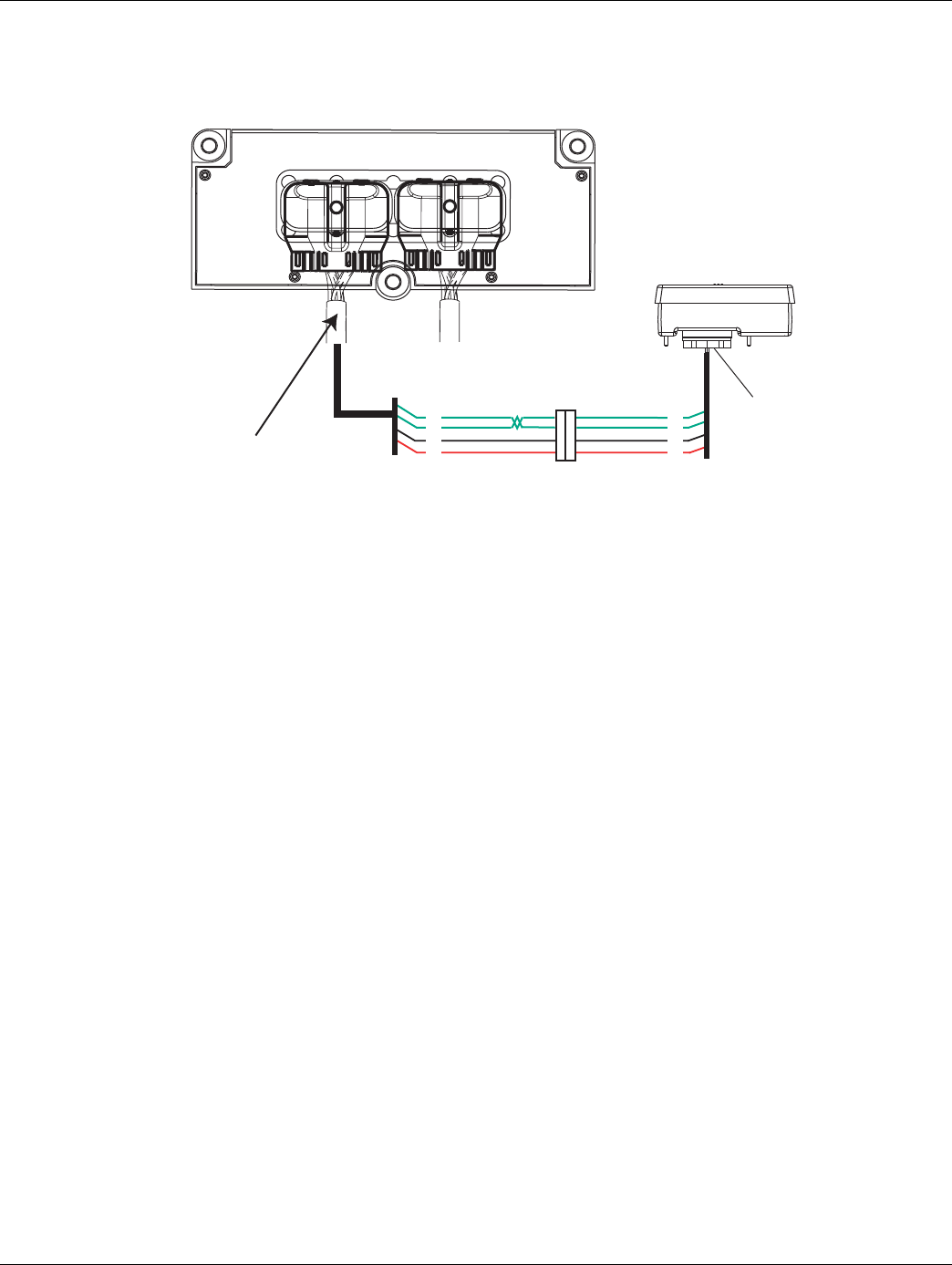
2016.01.15 © 2016 Eaton. All rights reserved 55
TRTS0930Fault Isolation Procedures | Fault Code 15 - HIL Shift Device Configuration
Component Identification
Vehicle bulkhead
connector
HIL Data LinkF1
F2
28
27
Shift control
30-way connector
Vehicle Harness 38-way ConnectorJ3
C1
25
31
All OEM responsible wiring shown is "typical". Consult specific application.
(31) = +12 volt switched from TECU
(28, 27) = Communication from and to the TECU
(25) = Signal returns, grounds, and general OEM wiring
Shift Control ECU Legend

56 © 2016 Eaton. All rights reserved 2016.01.15
Fault Code 15 - HIL Shift Device Configuration | Fault Isolation Procedures TRTS0930
Fault Code 15 - HIL Shift Device Configuration
1. Key on.
2. Retrieve active fault codes and FMIs with Ser-
viceRanger using the 9-way diagnostic connector.
3. Perform electrical pretest, see “Electrical Pretest”
on page 12.
•If no fault codes found during the electrical
pretest and:
-if equipped with a Push Button Shift Control,
go to Step B.
-if equipped with a Cobra Lever or an OEM
shift device, configure the Driver Interface
Type to the correct shift device type with
ServiceRanger. Go to Step V.
•If issue was repaired during electrical pretest,
go to Step V.
1. Key off.
2. Inspect Bulkhead Connector for looseness, corro-
sion and contamination.
•If Bulkhead Connector is found in serviceable
condition, go to Step C.
•If looseness, corrosion, or contamination is
found at the Bulkhead Connector, repair or
replace connector per OEM instructions. Go to
Step V.
1. Disconnect Shift Control 30-way connector.
2. Key on.
3. Measure voltage on 30-way connector Pin J3 and
Pin C1
•If voltage is within 1.2 volts of battery voltage,
go to Step D.
•If out of range, go to Step F.
APurpose: Check for active and Inactive fault codes
and perform electrical pretest.
BPurpose: Visually inspect vehicle bulkhead connec-
tion (if equipped).
CPurpose: Measure voltage supply to Push Button
Shift Controller (PBSC).
K
J
H
G
F
E
D
C
B
A
321
321
Volts
VCOM A
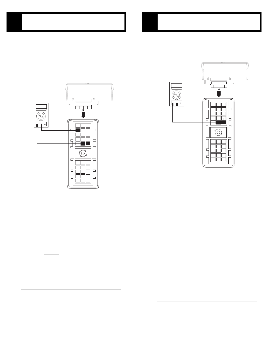
2016.01.15 © 2016 Eaton. All rights reserved 57
TRTS0930Fault Isolation Procedures | Fault Code 15 - HIL Shift Device Configuration
1. Disconnect Shift Control 30-way connector.
2. Key on.
3. Measure voltage on the Shift Controller 30-way
connector pins:
- J3 and F1
- J3 and F2
•If both readings are between 2-3 volts, go to
Step E.
•If any of the above requirements are not met,
go to Step H.
1. Key off.
2. Measure resistance between Pin F1 and Pin F2 on
the Shift Controller 30-way connector.
Note: Ensure key is off for a minimum of 2 minutes
before proceeding. If unsure, disconnect bat-
tery power or remove the 30-amp inline fuse.
•If resistance between Pin F1 and Pin F2 is
110-130 ohms, replace Push Button Shift
Control (only if fault code is Active). Go to
Step V.
•If any of the above requirements are not met,
go to Step H.
DPurpose: Measure signal voltages on HIL.
K
J
H
G
F
E
D
C
B
A
321
321
Volts
VCOM A
EPurpose: Confirm the presence of terminating re-
sistors in the HIL.
K
J
H
G
F
E
D
C
B
A
321
321
Ohms
VCOM A
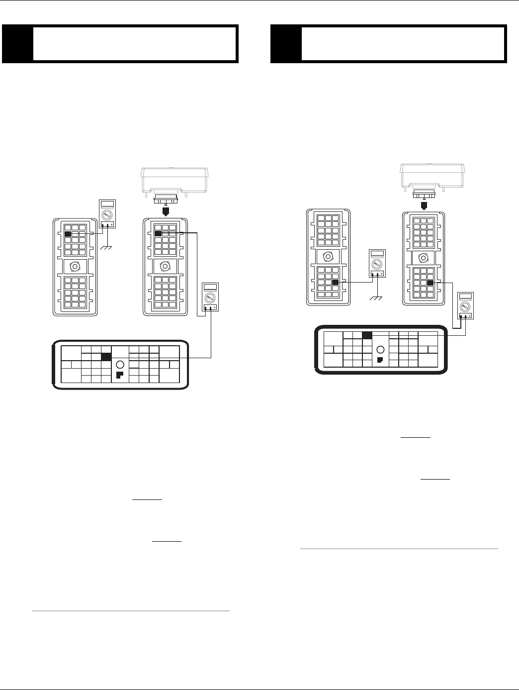
58 © 2016 Eaton. All rights reserved 2016.01.15
Fault Code 15 - HIL Shift Device Configuration | Fault Isolation Procedures TRTS0930
1. Key off.
2. Disconnect negative battery cable.
3. Disconnect Vehicle Harness 38-way connector.
Note: On Peterbilt, disconnect Gear Display.
4. Measure resistance between:
-Shift Control 30-way connector Pin J3 and Vehi-
cle Harness 38-way connector Pin 25
-Shift Control 30-way connector Pin J3 and
ground.
•If resistance between Pin J3 and Pin 25 is 0 to
0.3 ohms and if resistance between Pin J3 and
ground is OL, go to Step G.
•If any of the above conditions are not met,
repair the Vehicle Harness between the Shift
Control and TECU. Go to Step V.
1. Key off.
2. Measure resistance between:
-Shift Control 30-way connector Pin C1 and Vehi-
cle Harness 38-way connector Pin 31.
-Shift Control 30-way connector Pin C1 and
ground.
•If resistance between Pin C1 and Pin 31 is 0 to
0.3 ohms and resistance between Pin C1 and
ground is OL, go to Step H.
•If any of the above conditions are not met,
repair the Vehicle Harness between the Shift
Control and TECU. Go to Step V.
FPurpose: Verify continuity of ground supply to
PBSC and test for short to ground.
K
J
H
G
F
E
D
C
B
A
321
321
OHMS
VCOM A
K
J
H
G
F
E
D
C
B
A
321
OHMS
VCOM A
28
31
24 25
29 30
15 16
26
20
34
27
32 33
18 19
7
3
89
12 6
11 12
45
22
21
38
36
37
13 14
35 10
17
23
GPurpose: Verify continuity of power supply to
PBSC and test for short to ground.
K
J
H
G
F
E
D
C
B
A
321
321
OHMS
VCOM A
K
J
H
G
F
E
D
C
B
A
321
OHMS
VCOM A
28
31
24 25
29 30
15 16
26
20
34
27
32 33
18 19
7
3
89
12 6
11 12
45
22
21
38
36
37
13 14
35 10
17
23
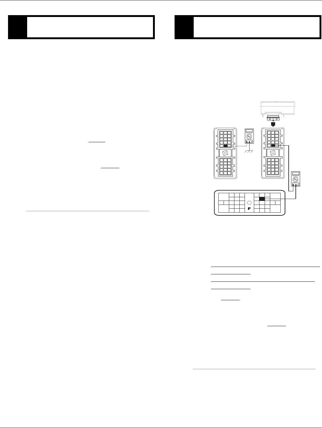
2016.01.15 © 2016 Eaton. All rights reserved 59
TRTS0930Fault Isolation Procedures | Fault Code 15 - HIL Shift Device Configuration
1. Key off.
2. Disconnect negative battery cable.
3. Disconnect Vehicle Harness 38-way connector.
4. Measure resistance between:
-Shift Control 30-way connector Pin F1 and Vehi-
cle Harness 38-way connector Pin 28.
-Shift Control 30-way connector Pin F1 and
ground.
•If resistance between Pin F1 and Pin 28 is 0 to
0.3 ohms and if resistance between Pin F1 and
ground is OL, go to Step I.
•If any of the above conditions are not met,
repair the Vehicle Harness between the Shift
Control and TECU. Go to Step V.
1. Key off.
2. Measure resistance between:
-Shift Control 30-way connector Pin F2 and Vehi-
cle Harness 38-way connector Pin 27
-Shift Control 30-way connector Pin F2 and
ground
•If resistance between Pin F2 and Pin 27 is 0 to
0.3 ohms and resistance between Pin F2 and
ground is OL.
If fault code is Active replace the:
- Medium-Duty Transmission Electronic Con-
trol Unit (TECU)
- Heavy-Duty Transmission Electronic Con-
trol Unit (TECU)
Go to Step V.
•If any of the above conditions are not met,
repair the Vehicle Harness between the Shift
Control and TECU. Go to Step V.
HPurpose: Verify continuity of HIL(+) connection to
the PBSC. IPurpose: Verify continuity of HIL (-) connection to
the PBSC.
K
J
H
G
F
E
D
C
B
A
321
321
OHMS
VCOM A
K
J
H
G
F
E
D
C
B
A
321
OHMS
VCOM A
28
31
24 25
29 30
15 16
26
20
34
27
32 33
18 19
7
3
89
12 6
11 12
45
22
21
38
36
37
13 14
35 10
17
23

60 © 2016 Eaton. All rights reserved 2016.01.15
Fault Code 15 - HIL Shift Device Configuration | Fault Isolation Procedures TRTS0930
1. Key off.
2. Key on.
3. Clear codes. See “Fault Code Retrieval/Clearing” on
page 5.
4. Reconnect all connectors and the negative battery
cable.
5. Driving Vehicle and attempt to reset the code.
6. Check for codes. See “Fault Code Retrieval/Clear-
ing” on page 5.
•If no Fault Codes, test complete.
•If Fault Code 15 appears, go to Step A. to find
error in testing.
•If fault code other than 15 appears, See “Fault
Code Isolation Procedure Index” on page 8.
VPurpose: Verify repair.

2016.01.15 © 2016 Eaton. All rights reserved 61
TRTS0930Fault Isolation Procedures | Fault Code 15 - HIL Shift Device Configuration

62 © 2016 Eaton. All rights reserved 2016.01.15
Fault Code 16 - High Integrity Link (HIL) | Fault Isolation Procedures TRTS0930
Fault Code 16 - High Integrity Link (HIL)
J1587: MID 130 SID 248 FMI 2
J1939: SA 3 SPN 625 FMI 2
Overview
This fault code indicates the Transmission Electronic Con-
trol Unit (TECU) is unable to communicate with the Push
Button Shift Control.
Detection
Starting at key-on and throughout operation, the TECU con-
stantly monitors the communication with the Push Button
Shift Control. If a communication fault occurs for more than
5 seconds, Fault Code 16 is set.
Fallback
This fault causes a downshift only fallback while moving.
Once the transmission re-engages the start gear, there will
be no upshifts as long as the code is active. If the code is
active during power-up a flashing F will appear on the gear
display and the TECU will not engage a gear.
Possible Causes
This fault code can be caused by any of the following:
• Vehicle Harness
• TECU
• Push Button Shift Control
• Charging system
• Low batteries
• Corroded or loose power supply to TECU

2016.01.15 © 2016 Eaton. All rights reserved 63
TRTS0930 Fault Isolation Procedures | Fault Code 16 - High Integrity Link (HIL)
Component Identification
Vehicle bulkhead
connector
HIL Data LinkF1
F2
28
27
Shift control
30-way connector
Vehicle Harness 38-way ConnectorJ3
C1
25
31
All OEM responsible wiring shown is "typical". Consult specific application.
(31) = +12 volt switched from TECU
(28, 27) = Communication from and to the TECU
(25) = Signal returns, grounds, and general OEM wiring
Shift Control ECU Legend
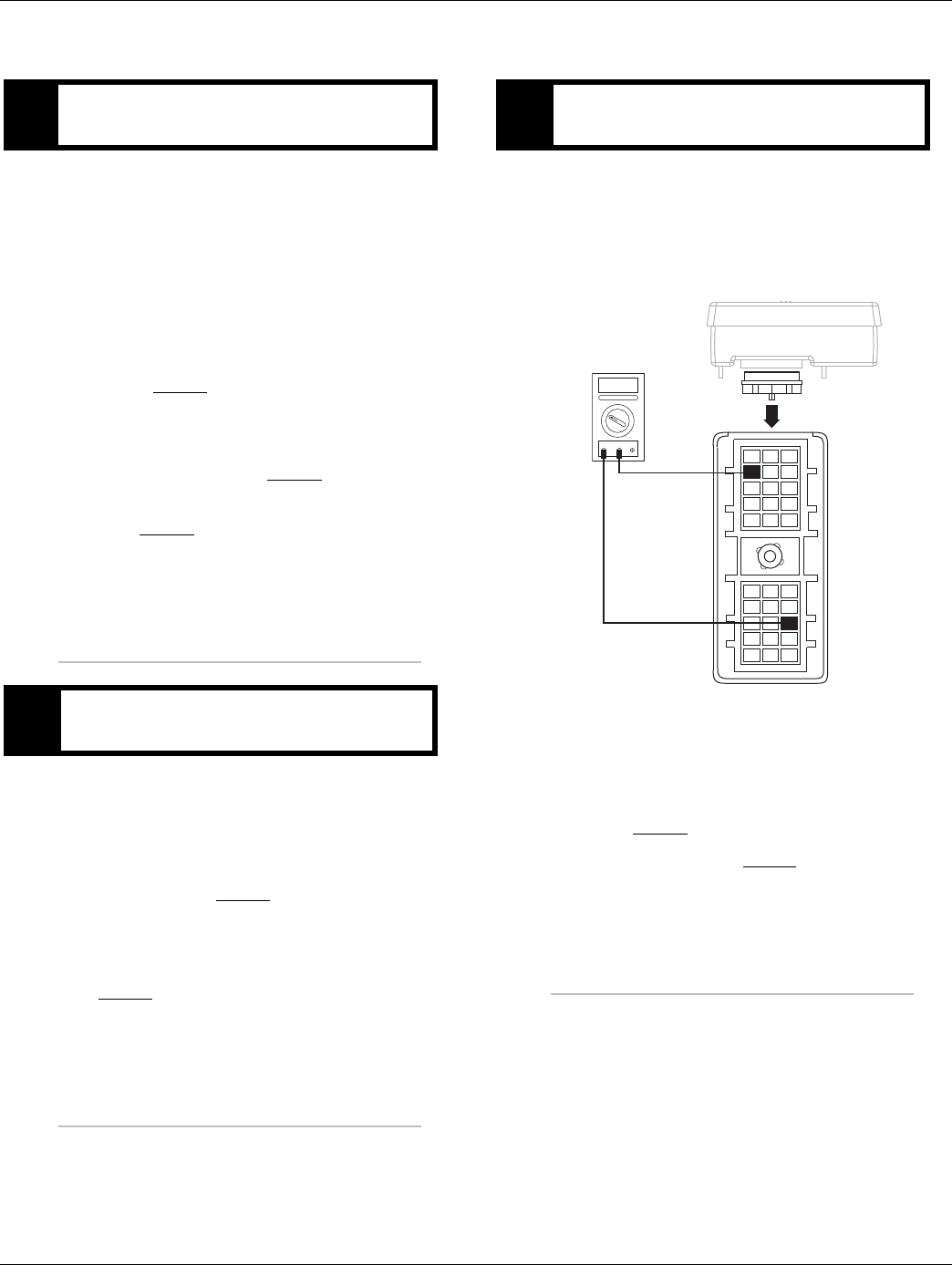
64 © 2016 Eaton. All rights reserved 2016.01.15
Fault Code 16 - High Integrity Link (HIL) | Fault Isolation Procedures TRTS0930
Fault Code 16 - High Integrity Link (HIL)
1. Key on.
2. Retrieve active fault codes and FMIs with Ser-
viceRanger using the 9-way diagnostic connector.
3. Perform electrical pretest, see “Electrical Pretest”
on page 12.
•If no fault codes found during the electrical
pretest and:
-if equipped with a Push Button Shift Control,
go to Step B.
-if equipped with a Cobra Lever or an OEM
shift device, configure the Driver Interface
Type to the correct shift device type with
ServiceRanger. Go to Step V.
•If issue was repaired during electrical pretest,
go to Step V.
1. Key off.
2. Inspect Bulkhead Connector for looseness, corro-
sion and contamination.
•If Bulkhead Connector is found in serviceable
condition, go to Step C.
•If looseness, corrosion, or contamination is
found at the Bulkhead Connector, repair or
replace connector per OEM instructions. Go to
Step V.
1. Disconnect Shift Control 30-way connector.
2. Key on.
3. Measure voltage on 30-way connector Pin J3 and
Pin C1
•If voltage is within 1.2 volts of battery voltage,
go to Step D.
•If out of range, go to Step F.
APurpose: Check for active and Inactive fault codes
and perform electrical pretest.
BPurpose: Visually inspect vehicle bulkhead connec-
tion (if equipped).
CPurpose: Measure voltage supply to Push Button
Shift Controller (PBSC).
K
J
H
G
F
E
D
C
B
A
321
321
Volts
VCOM A

2016.01.15 © 2016 Eaton. All rights reserved 65
TRTS0930 Fault Isolation Procedures | Fault Code 16 - High Integrity Link (HIL)
1. Disconnect Shift Control 30-way connector.
2. Key on.
3. Measure voltage on the Shift Controller 30-way
connector pins:
- J3 and F1
- J3 and F2
•If both readings are between 2-3 volts, go to
Step E.
•If any of the above requirements are not met,
go to Step H.
1. Key off.
2. Measure resistance between Pin F1 and Pin F2 on
the Shift Controller 30-way connector.
Note: Ensure key is off for a minimum of 2 minutes
before proceeding. If unsure, disconnect bat-
tery power or remove the 30-amp inline fuse.
•If resistance between Pin F1 and Pin F2 is
110-130 ohms, replace Push Button Shift
Control (only if fault code is Active). Go to
Step V.
•If any of the above requirements are not met,
go to Step H.
DPurpose: Measure signal voltages on HIL.
K
J
H
G
F
E
D
C
B
A
321
321
Volts
VCOM A
EPurpose: Confirm the presence of terminating re-
sistors in the HIL.
K
J
H
G
F
E
D
C
B
A
321
321
Ohms
VCOM A
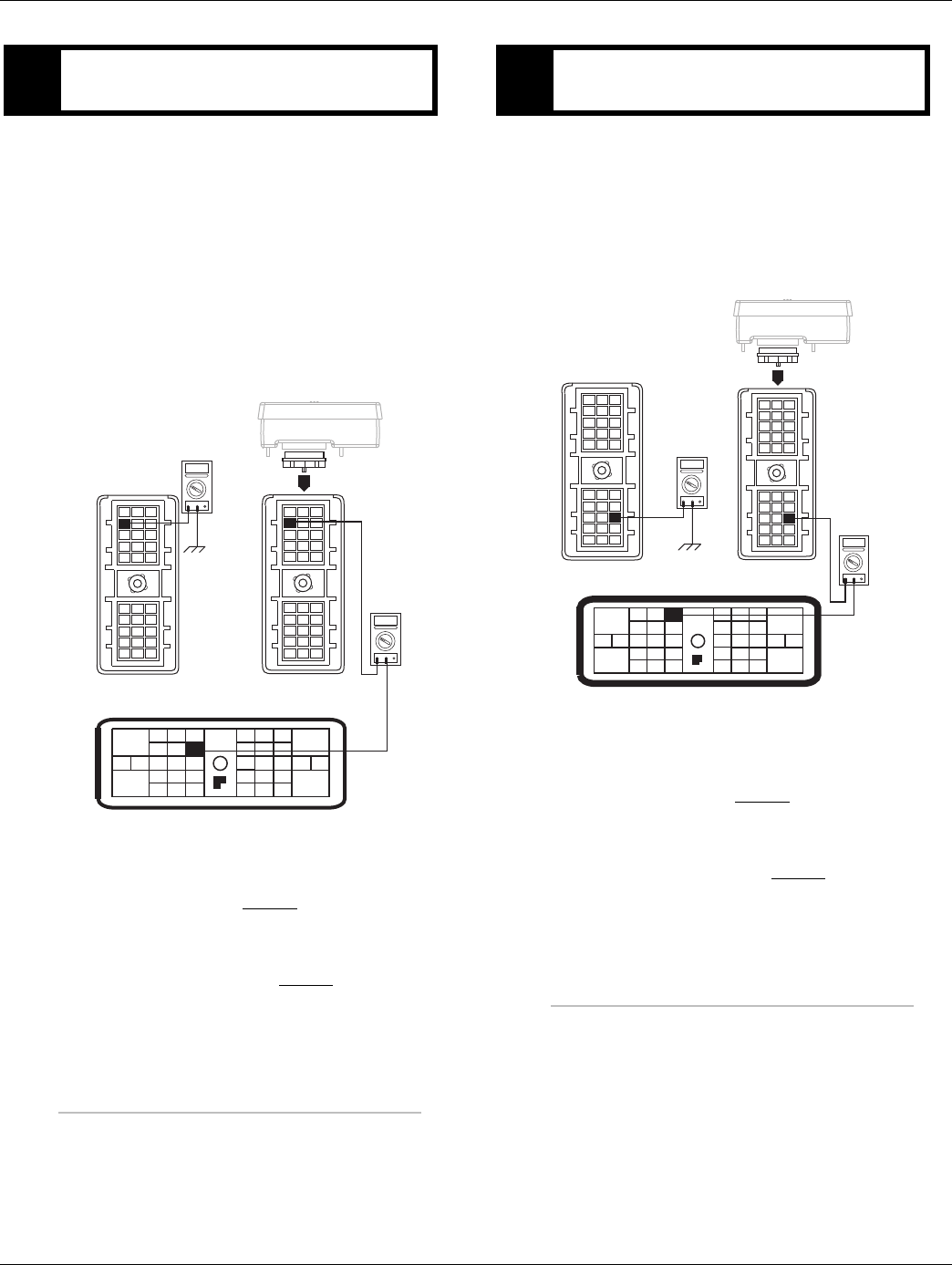
66 © 2016 Eaton. All rights reserved 2016.01.15
Fault Code 16 - High Integrity Link (HIL) | Fault Isolation Procedures TRTS0930
1. Key off.
2. Disconnect negative battery cable.
3. Disconnect Vehicle Harness 38-way connector.
Note: On Peterbilt, disconnect Gear Display.
4. Measure resistance between:
-Shift Control 30-way connector Pin J3 and Vehi-
cle Harness 38-way connector Pin 25.
-Shift Control Shift Control 30-way connector Pin
J3 and ground.
•If resistance between Pin J3 and Pin 25 is 0 to
0.3 ohms and if resistance between Pin J3 and
ground is OL, go to Step G.
•If any of the above conditions are not met,
repair the Vehicle Harness between the Shift
Control and TECU. Go to Step V.
1. Key off.
2. Measure resistance between:
-Shift Control 30-way connector Pin C1 and Vehi-
cle Harness 38-way connector Pin 31.
-Shift Control 30-way connector Pin C1 and
ground.
•If resistance between Pin C1 and Pin 31 is 0 to
0.3 ohms and resistance between Pin C1 and
ground is OL, go to Step H.
•If any of the above conditions are not met,
repair the Vehicle Harness between the Shift
Control and TECU. Go to Step V.
FPurpose: Verify continuity of ground supply to
PBSC and test for short to ground.
K
J
H
G
F
E
D
C
B
A
321
321
OHMS
VCOM A
K
J
H
G
F
E
D
C
B
A
321
OHMS
VCOM A
28
31
24 25
29 30
15 16
26
20
34
27
32 33
18 19
7
3
89
12 6
11 12
45
22
21
38
36
37
13 14
35 10
17
23
GPurpose: Verify continuity of power supply to
PBSC and test for short to ground.
K
J
H
G
F
E
D
C
B
A
321
321
OHMS
VCOM A
K
J
H
G
F
E
D
C
B
A
321
OHMS
VCOM A
28
31
24 25
29 30
15 16
26
20
34
27
32 33
18 19
7
3
89
12 6
11 12
45
22
21
38
36
37
13 14
35 10
17
23
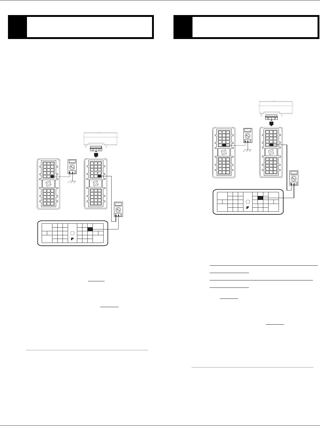
2016.01.15 © 2016 Eaton. All rights reserved 67
TRTS0930 Fault Isolation Procedures | Fault Code 16 - High Integrity Link (HIL)
1. Key off.
2. Disconnect negative battery cable.
3. Disconnect Vehicle Harness 38-way connector.
4. Measure resistance between:
-Shift Control 30-way connector Pin F1 and Vehi-
cle Harness 38-way connector Pin 28.
-Shift Control 30-way connector Pin F1 and
ground.
•If resistance between Pin F1 and Pin 28 is 0 to
0.3 ohms and if resistance between Pin F1 and
ground is OL, go to Step I.
•If any of the above conditions are not met,
repair the Vehicle Harness between the Shift
Control and TECU. Go to Step V.
1. Key off.
2. Measure resistance between:
-Shift Control 30-way connector Pin F2 and Vehi-
cle Harness 38-way connector Pin 27
-Shift Control 30-way connector Pin F2 and
ground
•If resistance between Pin F2 and Pin 27 is 0 to
0.3 ohms and resistance between Pin F2 and
ground is OL.
If fault code is Active replace the:
- Medium-Duty Transmission Electronic Con-
trol Unit (TECU)
- Heavy-Duty Transmission Electronic Con-
trol Unit (TECU)
Go to Step V.
•If any of the above conditions are not met,
repair the Vehicle Harness between the Shift
Control and TECU. Go to Step V.
HPurpose: Verify continuity of HIL(+) connection to
the PBSC.
K
J
H
G
F
E
D
C
B
A
321
321
OHMS
VCOM A
K
J
H
G
F
E
D
C
B
A
321
OHMS
VCOM A
28
31
24 25
29 30
15 16
26
20
34
27
32 33
18 19
7
3
89
12 6
11 12
45
22
21
38
36
37
13 14
35 10
17
23
IPurpose: Verify continuity of HIL (-) connection to
the PBSC.
K
J
H
G
F
E
D
C
B
A
321
321
OHMS
VCOM A
K
J
H
G
F
E
D
C
B
A
321
OHMS
VCOM A
28
31
24 25
29 30
15 16
26
20
34
27
32 33
18 19
7
3
89
12 6
11 12
45
22
21
38
36
37
13 14
35 10
17
23

68 © 2016 Eaton. All rights reserved 2016.01.15
Fault Code 16 - High Integrity Link (HIL) | Fault Isolation Procedures TRTS0930
1. Key off.
2. Reconnect all connectors and negative battery
cable.
3. Key on.
4. Clear codes, see “Fault Code Retrieval/Clearing” on
page 5.
5. Drive the vehicle and attempt to reset the code.
6. Check for codes, see “Fault Code Retrieval/Clear-
ing” on page 5.
•If no fault codes, test complete.
•If Fault Code 16 appears, go to Step A. to find
error in testing.
•If code other than 16 appears, See “Fault Code
Isolation Procedure Index” on page 8.
VPurpose: Verify repair.

2016.01.15 © 2016 Eaton. All rights reserved 69
TRTS0930 Fault Isolation Procedures | Fault Code 16 - High Integrity Link (HIL)

70 © 2016 Eaton. All rights reserved 2016.01.15
Fault Code 17 - Start Enable Relay (SER) Circuit | Fault Isolation Procedures TRTS0930
Fault Code 17 - Start Enable Relay (SER) Circuit
J1587: MID 130 SID 237 FMI 3, 4
J1939: SA 3 SPN 629 FMI 3, 4
Overview
This fault code indicates an electrical failure of the relay that
allows the engine to start after startup conditions are met.
When troubleshooting an Inactive code See “Product Diag-
nostic (PD) Mode” on page 11.
Detection
Starting at key-on and throughout operation, the Transmis-
sion Electronic Control Unit (TECU) constantly measures
the circuit. A failure mode of short to battery, short to
ground or open circuit is detected.
Fallback
The start enable relay has no fallback; however, if the failure
occurred before the engine was started, it is possible the
engine will not start.
Possible Causes
This fault code can be caused by any of the following:
• Start Enable Relay
• Vehicle Harness
• TECU
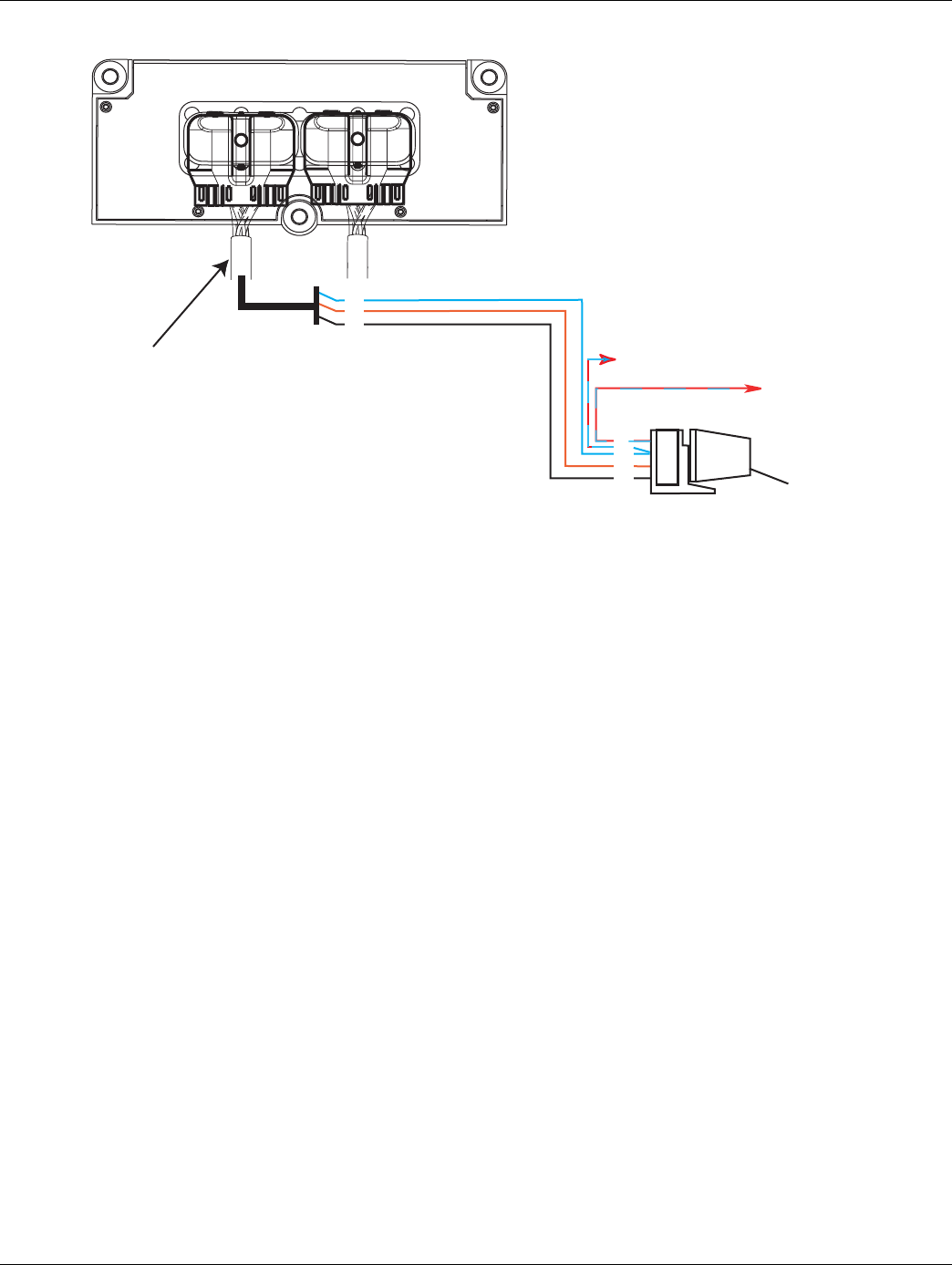
2016.01.15 © 2016 Eaton. All rights reserved 71
TRTS0930 Fault Isolation Procedures | Fault Code 17 - Start Enable Relay (SER) Circuit
Component Identification
Start
enable relay
Run to start
signal from
ignition switch
Run to
starter solenoid
26
32
4
30
87
86
85
Vehicle Harness 38-way Connector
All OEM responsible wiring shown is "typical". Consult specific application.
(30, 87) = Switched ignition
(26-87) = Latch into the ECU
(4-85) = -12 volt relay source
(32-86) = +12 volt relay source
Trans ECU Legend
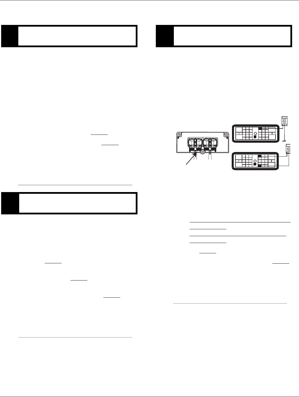
72 © 2016 Eaton. All rights reserved 2016.01.15
Fault Code 17 - Start Enable Relay (SER) Circuit | Fault Isolation Procedures TRTS0930
Fault Code 17 - Start Enable Relay (SER) Circuit
1. Key on.
Note: The SER must be wired according to Eaton
GEN III requirements (shown on previous
page) for tests to work properly. If wired dif-
ferently, consult OEM for correct wiring sche-
matic.
2. Retrieve active fault codes and FMIs with Ser-
viceRanger using the 9-way diagnostic connector.
3. What FMIs are present?
•If FMI 14 is present, go to Step B.
•If FMI 3 or 4 are present, go to Step C.
1. Inspect OEM SER breakout connector and inspect
for misrouted or defective OEM wiring. Inspect per
OEM guidelines.
•If SER breakout connector is not connected to
SER, repair/replace SER per OEM guidelines.
Go to Step V.
•If circuit has been bypassed, rewire per OEM
guidelines. Go to Step V.
•If harness is defective, repair the Vehicle Har-
ness per OEM guidelines. Go to Step V.
1. Key off.
2. Disconnect negative battery cable.
3. Disconnect Vehicle Harness 38-way connector.
4. Measure resistance between Vehicle Harness
38-way connector Pin 32 and Pin 4 and measure
resistance between Vehicle Harness 38-way con-
nector Pin 32 and ground.
•If resistance between Pin 32 and Pin 4 is 40 to
120 ohms (12-volt system) or 140 to 480
ohms (24-volt system) and resistance between
32 and ground is OL, (if fault code is Active)
replace the:
-Medium-Duty Transmission Electronic Con-
trol Unit (TECU)
- Heavy-Duty Transmission Electronic Con-
trol Unit (TECU)
Go to Step V.
•If resistance is outside of range, go to Step B.
APurpose: Verify SER is correctly wired. Check for
active or Inactive fault codes, noting FMI.
BPurpose: Visually inspect SER wiring.
CPurpose: Measure resistance of SER through the
Transmission Harness.
OHMS
VCOM A
31
24 25
29 30
15 16
26
20
34
27 28
32 33
18 19
7
3
89
12 6
11 12
45
22
21
38
36
37
13 14
35 10
17
23
Vehicle Harness 38-way Connector
OHMS
VCOM A
31
24 25
29 30
15 16
26
20
34
27 28
32 33
18 19
7
3
89
12 6
11 12
45
22
21
38
36
37
13 14
35 10
17
23
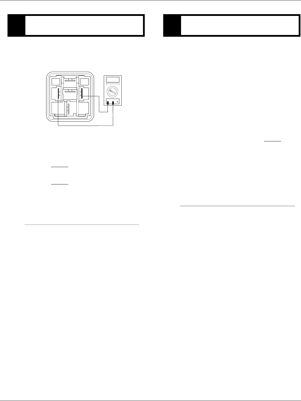
2016.01.15 © 2016 Eaton. All rights reserved 73
TRTS0930 Fault Isolation Procedures | Fault Code 17 - Start Enable Relay (SER) Circuit
1. Remove SER from vehicle dash harness.
2. Measure resistance between SER Pin 85 and Pin
86.
•If resistance is 40 to 120 ohms (12-volt sys-
tem) or 140 to 480 ohms (24-volt system),
repair/replace OEM wiring from TECU to SER.
Go to Step C.
•If resistance is outside of range, replace SER.
Go to Step V.
1. Key off.
2. Reconnect all connectors and negative battery
cable.
3. Key on.
4. Clear codes, see “Fault Code Retrieval/Clearing” on
page 5.
5. Drive the vehicle and attempt to reset the code.
6. Check for codes, see “Fault Code Retrieval/Clear-
ing” on page 5.
•If no codes, test complete.
•If Fault Code 17 appears, go to Step A. to find
error in testing.
•If fault code other than 17 appears, See “Fault
Code Isolation Procedure Index” on page 8.
DPurpose: Measure resistance of SER at the relay.
85
30
86
87
87a
OHMS
VCOM A
VPurpose: Verify repair.

74 © 2016 Eaton. All rights reserved 2016.01.15
Fault Code 21 - Auto Neutral Park Brake Switch | Fault Isolation Procedures TRTS0930
Fault Code 21 - Auto Neutral Park Brake Switch
J1587: MID 130 PID 254 FMI 14
J1939: SA 3 SPN 70 FMI 14
Overview
An auto neutral feature is provided with this transmission
which forces the transmission into neutral in all instances
when the parking brake is applied. The OEM installs a nor-
mally closed T pressure switch into the existing air line to
the parking brake valve. The pressure switch output and
return wires are connected to the vehicle interface trans-
mission Electronic Control Unit (TECU) connector. Consult
OEM for switch location.
This fault code indicates a failure of the switch that reports
engagement of the park brake. When troubleshooting an
Inactive code See “Product Diagnostic (PD) Mode” on
page 11.
Detection
Fault Code 21 is set if the switch indicates the park brake is
set while the truck is moving for more than 5 seconds, or if
the switch state doesn't match the state broadcast on
J1939, or if the switch is unstable for more than 5 seconds.
Fallback
Remote throttle is disabled, and auto neutral may not work.
Possible Causes
This fault code can be caused by any of the following:
• Park brake switch
• Park brake wiring
• TECU
• Park brake hardware not installed
• J1939 reporting error
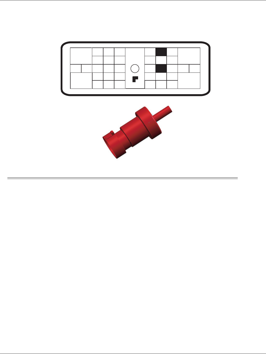
2016.01.15 © 2016 Eaton. All rights reserved 75
TRTS0930 Fault Isolation Procedures | Fault Code 21 - Auto Neutral Park Brake Switch
Component Identification
Description From To
Pressure Switch Signal Wire Pin 19 Signal Wire
Pressure Switch Return Wire Pin 33 Return Wire
23
17
31
24 25
29 30
15 16
26
20
34
27 28
32 33
18 19
7
3
89
126
12
4 5
22
21
38
36
37
13 14
35
Front View
Transmission ECU Connector
(Vehicle Interface)
10 11
1919191919
33
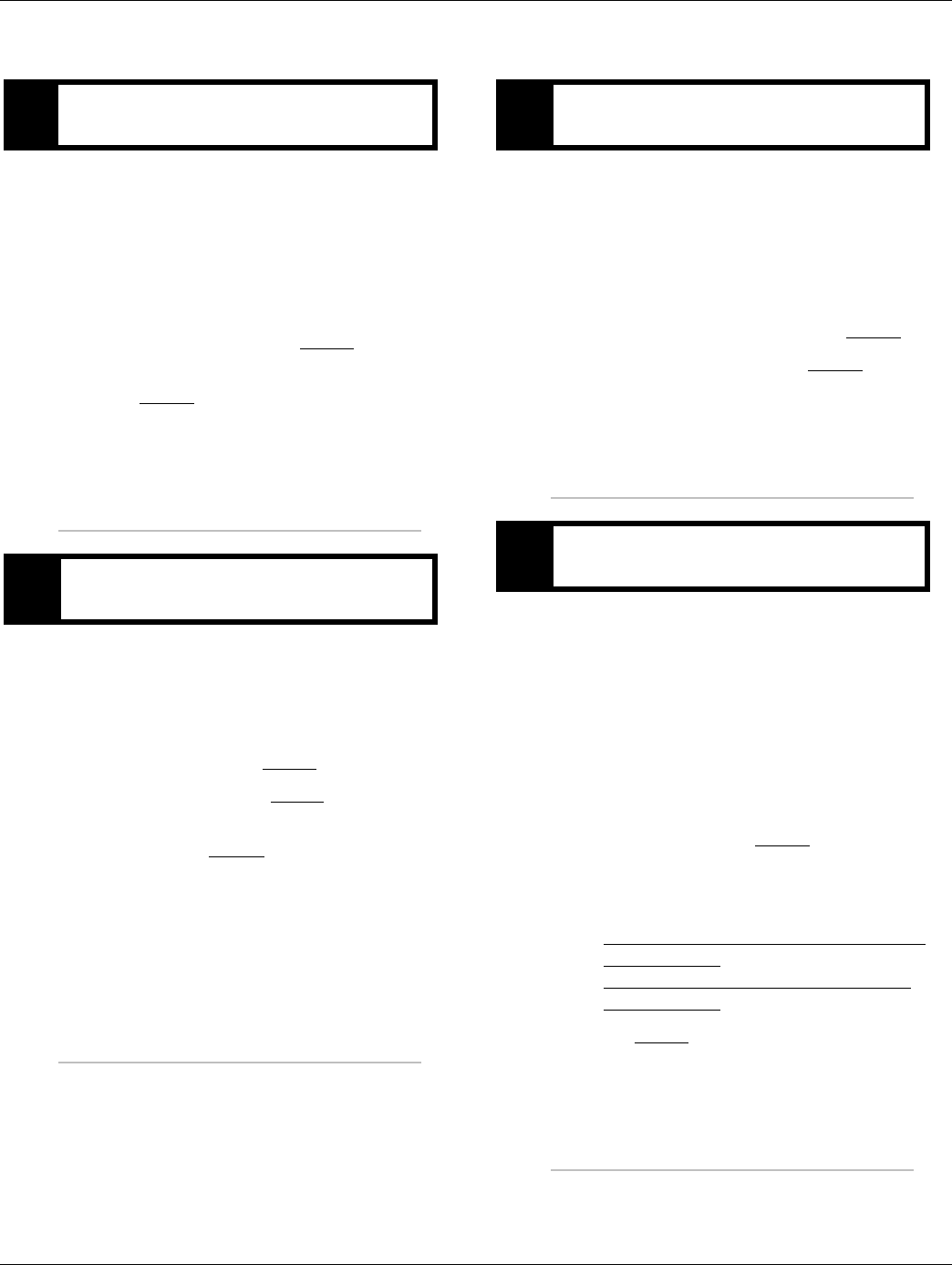
76 © 2016 Eaton. All rights reserved 2016.01.15
Fault Code 21 - Auto Neutral Park Brake Switch | Fault Isolation Procedures TRTS0930
Fault Code 21 - Auto Neutral Park Brake Switch
1. Key on.
2. Retrieve active fault codes and FMIs with Ser-
viceRanger using the 9-way diagnostic connector.
3. Perform electrical pretest, see “Electrical Pretest”
on page 12.
•If no issues found during electrical pretest and
the fault is still active, go to Step B.
•If issue was repaired during electrical pretest,
go to Step V.
1. Ensure vehicle park brake is set and vehicle air sys-
tem is fully charged.
2. Using the Data Monitoring function in Ser-
viceRanger, note the status of the park brake.
•Brake is applied, go to Step C.
•Brake is released, go to Step E.
•Brake is fluctuating between applied and
released, go to Step G.
Note: If Fault Code 21 goes Inactive when park brake is
released, a J1939 reporting error is highly probable.
Seek OEM assistance before proceeding to Step C.
1. Key off.
2. Disconnect negative battery cable.
3. Disconnect the switch.
4. Connect power and key on.
•Status changes to released, repair or replace
switch per OEM instructions. Go to Step V.
•Status remains Applied, go to Step D.
1. Key off.
2. Disconnect negative battery cable.
3. Disconnect the Vehicle Harness TECU 38-way con-
nector.
4. Measure resistance between the Vehicle Harness
38-way connector Pin 19 and ground.
•If resistance between Pin 19 and ground is
less than 10K ohm, repair Vehicle Harness per
OEM guidelines. Go to Step V.
•If resistance between Pin 19 and ground is
greater than 10K ohm or open, (if fault code is
Active) replace the:
- Medium-Duty Transmission Electronic Con-
trol Unit (TECU)
- Heavy-Duty Transmission Electronic Con-
trol Unit (TECU)
Go to Step V.
APurpose: Check for active or Inactive fault codes
and perform electrical pretest.
BPurpose: Monitor park Brake Switch in Ser-
viceRanger.
CPurpose: Remove Park Brake Switch and monitor
Park Brake Switch status in ServiceRanger.
DPurpose: Check for short circuits on Park Brake
Switch Input wiring.
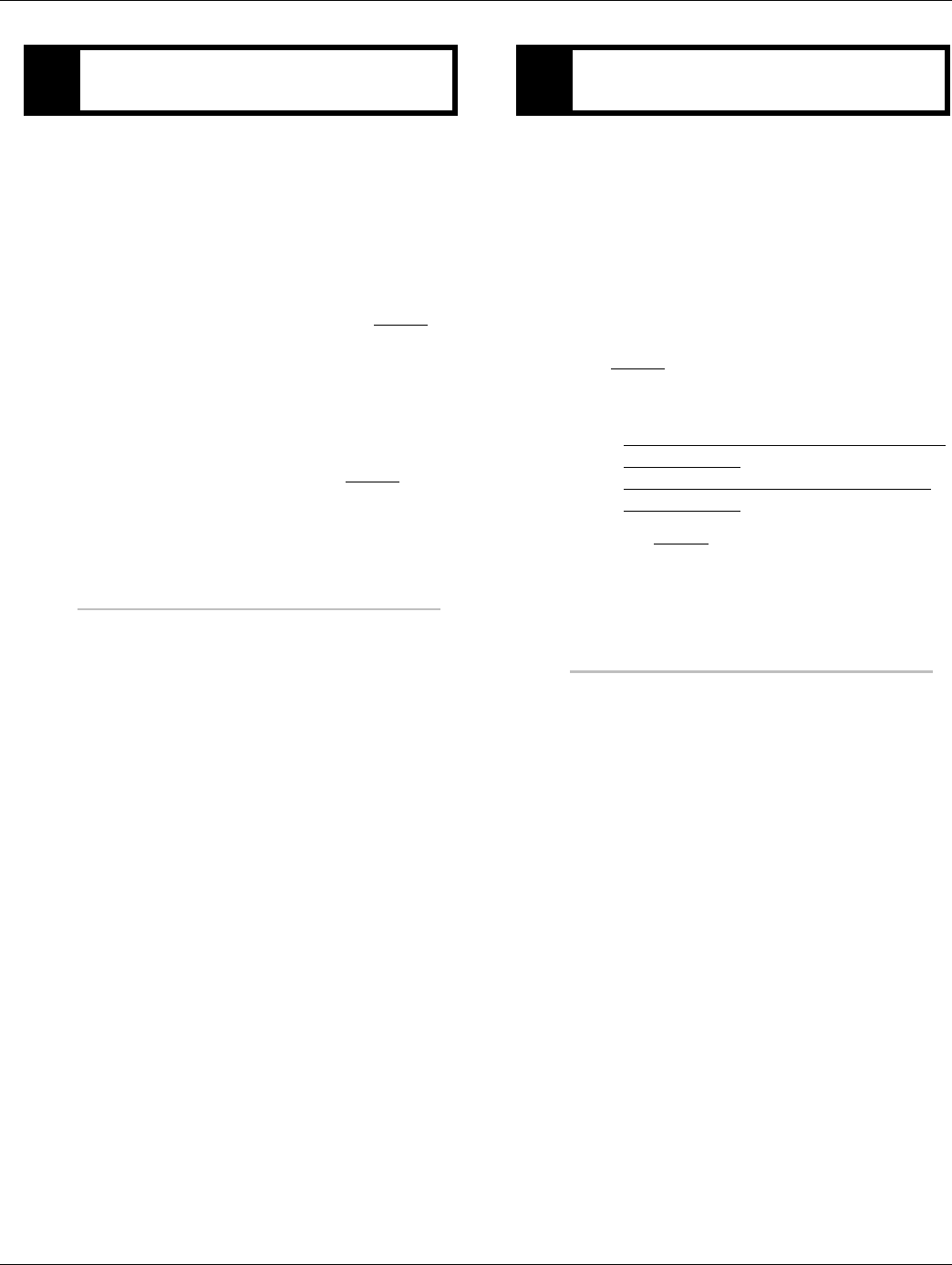
2016.01.15 © 2016 Eaton. All rights reserved 77
TRTS0930 Fault Isolation Procedures | Fault Code 21 - Auto Neutral Park Brake Switch
1. Key off.
2. Disconnect negative battery cable.
3. Bypass the switch by placing a jumper at the switch
connections.
4. Connect power and key on.
•Status changed to Applied, repair or replace
switch per OEM instructions. Go to Step V.
Note: The requirement is for a “normally
closed” switch. If the park brake status
consistently reports contrary values, a
“normally open switch” was possibly
installed in error.
•Status remains Released, go to Step F.
1. Key off.
2. Disconnect negative battery cable.
3. Disconnect the Vehicle Harness TECU 38-way con-
nector.
4. Measure resistance between the Vehicle Harness
38-way connector Pin 33 and Pin 19.
•If resistance is greater than 0.3 ohms, repair
the Vehicle Harness per OEM guidelines. Go to
Step V.
•If resistance is 0 to 0.3 ohms, (if fault code is
Active) replace the:
-Medium-Duty Transmission Electronic Con-
trol Unit (TECU)
- Heavy-Duty Transmission Electronic Con-
trol Unit (TECU)
Go to Step V.
EPurpose: Jump the Park Brake Switch and monitor
Park Brake Switch status in ServiceRanger. FPurpose: Verify continuity of Park Brake switch
status in ServiceRanger.
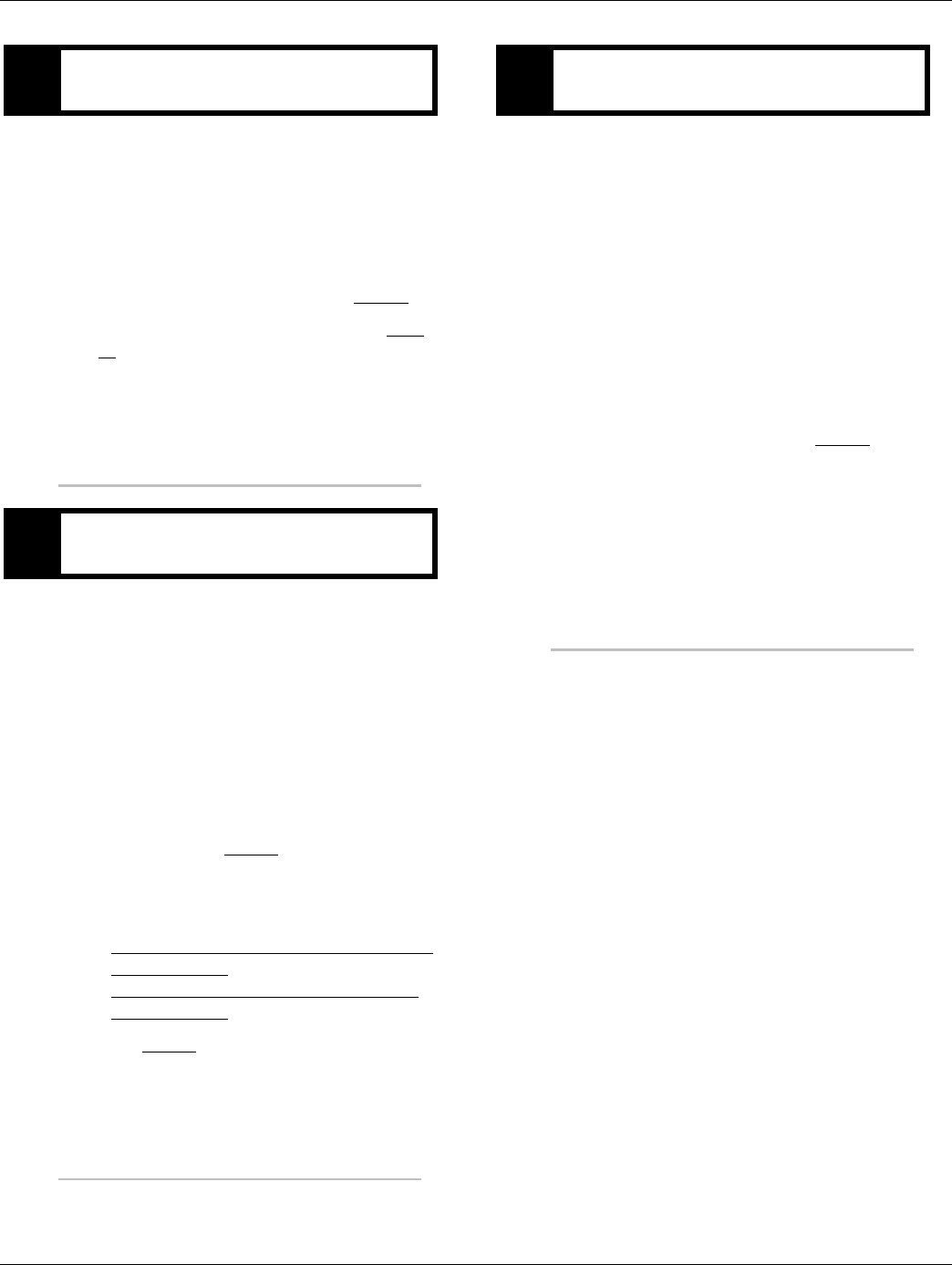
78 © 2016 Eaton. All rights reserved 2016.01.15
Fault Code 21 - Auto Neutral Park Brake Switch | Fault Isolation Procedures TRTS0930
1. Key off.
2. Disconnect negative battery cable.
3. Disconnect the switch.
4. Connect power and key on.
•Status changed to Released, repair or replace
switch per OEM instructions. Go to Step V.
•Status continues changing states, go to Step
H.
1. Key off.
2. Disconnect negative battery cable.
3. Disconnect the Vehicle Harness 38-way connector.
4. Measure resistance between the Vehicle Harness
38-way connector Pin 33 and Pin 19 and measure
the resistance between Pin 19 and ground.
•If resistance between Pin 33 and ground or
between Pin 33 and Pin 19 is less than 10K
ohm, repair the Vehicle Harness per OEM
guidelines. Go to Step V.
•If resistance between Pin 33 and ground and
between Pin 33 and Pin 19 are OL, (if fault
code is Active) replace the:
-Medium-Duty Transmission Electronic Con-
trol Unit (TECU)
- Heavy-Duty Transmission Electronic Con-
trol Unit (TECU)
Go to Step V.
1. Key off.
2. Reconnect all connectors and the negative battery
cable.
3. Key on.
4. Clear fault codes, see “Fault Code Retrieval/Clear-
ing” on page 5.
5. Drive vehicle and attempt to reset the fault code.
6. Check for codes, see “Fault Code Retrieval/Clear-
ing” on page 5.
•If no codes, test complete.
•If Fault Code 21 appears, go to Step A. to find
error in testing.
•If fault code other than 21 appears, See “Fault
Code Isolation Procedure Index” on page 8.
GPurpose: Monitor Park Brake Switch status in Ser-
viceRanger.
HPurpose: Check for short circuits in the shift lever
wiring.
VPurpose: Verify repair.

2016.01.15 © 2016 Eaton. All rights reserved 79
TRTS0930 Fault Isolation Procedures | Fault Code 21 - Auto Neutral Park Brake Switch

80 © 2016 Eaton. All rights reserved 2016.01.15
Fault Code 22 - ABS CAN Message Fault | Fault Isolation Procedures TRTS0930
Fault Code 22 - ABS CAN Message Fault
J1587: MID 130 SID 254 FMI 9, 14
J1939: SA 3 SPN 563 FMI 9, 14
Overview
J1939 is a high-speed twisted pair 250K baud data link with
one 120 ohm resistor at each end of the link. The Transmis-
sion Electronic Control Unit (TECU) is connected to the
J1939 data link at the 38-way vehicle connector. This link is
used to transmit information to the TECU as well as com-
municate or receive data from the other modules on the
network like the ABS module. When troubleshooting an
Inactive code See “Product Diagnostic (PD) Mode” on
page 11.
Detection
Fault Code 22 is detected if J1939 communication from the
ABS is lost for 5 seconds and other devices are present on
J1939.
Fallback
No Fallback mode; however, Hill Start Aid (HSA) will not
function, and the system may attempt a shift during wheel
slip events.
Possible Causes
This fault code can be caused by any of the following:
• J1939 datalink
• ABS module
• ABS module does not support HSA or is not
configured with HSA
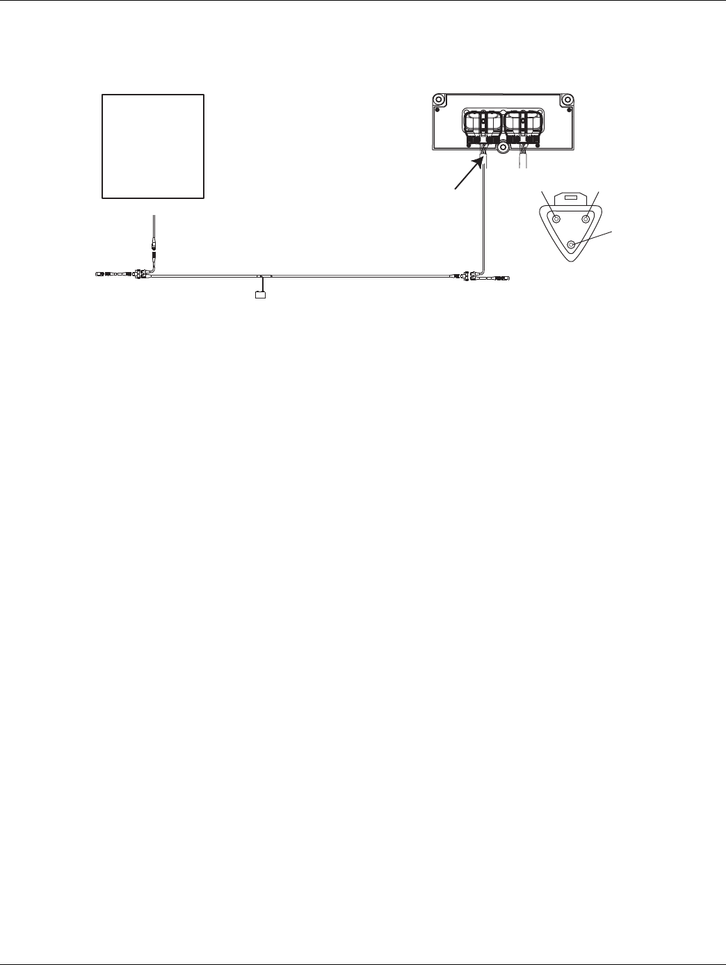
2016.01.15 © 2016 Eaton. All rights reserved 81
TRTS0930 Fault Isolation Procedures | Fault Code 22 - ABS CAN Message Fault
Component Identification
Typical J1939/11 data link harness
(OEM supplied)
ABS ECM
B
A
C
–J1939
+J1939
Shield
Transmission ECU
Vehicle Harness 38-way Connector

82 © 2016 Eaton. All rights reserved 2016.01.15
Fault Code 22 - ABS CAN Message Fault | Fault Isolation Procedures TRTS0930
Fault Code 22 - ABS CAN Message Fault
1. Key on.
2. Retrieve active fault codes and FMIs with Ser-
viceRanger using the 9-way diagnostic connector
•If Fault Code 22 is Active, repair ABS module
or data link per OEM guidelines.
•If Fault Code 22 is Inactive, test complete.
APurpose: Check for active or Inactive fault codes.
Contact the vehicle OEM for further directions.

2016.01.15 © 2016 Eaton. All rights reserved 83
TRTS0930 Fault Isolation Procedures | Fault Code 22 - ABS CAN Message Fault

84 © 2016 Eaton. All rights reserved 2016.01.15
Fault Code 26 - Clutch Slip | Fault Isolation Procedures TRTS0930
Fault Code 26 - Clutch Slip
J1587: MID 130 SID 55 FMI 10
J1939: SA 3 SPN 522 FMI 10
Overview
This fault code indicates the clutch is not performing as
expected. The transmission controller detected excessive
clutch slip.
Detection
When the transmission is in gear and the clutch is fully
engaged, engine speed and input shaft speed are com-
pared. If the engine speed is significantly different from the
input shaft speed for a period of one to two seconds, the
fault code is set.
Clutch Slip Testing
Note: It is recommended that the pilot bearing be replaced
whenever the clutch is replaced.
Note: Refer to Installation Guide TRIG1110 for a list of rec-
ommended pilot bearings.
Note: Secondary clutch failures resulting from conditions
such as pilot bearing failures, excessive torsional
vibration, or clutch abuse, are not covered under
warranty.
Note: Record Vehicle Performance Analysis every time a
clutch is replaced.
Fallback
This fault causes a downshift only fallback. Once the vehicle
is stopped, starting gear and reverse gear can be engaged;
however, the fault will clear at power down. Upshifts will be
allowed until the fault is detected again.
Possible Causes
This fault code can be caused by any of the following:
• Worn or damaged clutch
• Clutch abuse
• Low clutch torque
• Contaminated clutch disks
Additional Tools
• Clutch jack
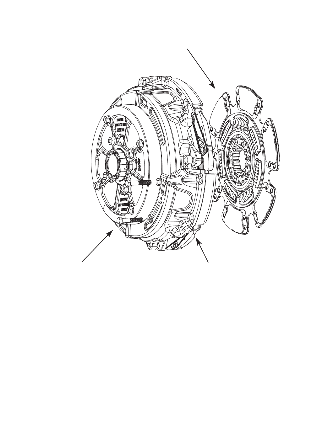
2016.01.15 © 2016 Eaton. All rights reserved 85
TRTS0930 Fault Isolation Procedures | Fault Code 26 - Clutch Slip
Component Identification
Clutch Assembly
Driven Disc
Driven Disc and
Intermediate Plate
DM Clutch

86 © 2016 Eaton. All rights reserved 2016.01.15
Fault Code 26 - Clutch Slip | Fault Isolation Procedures TRTS0930
Fault Code 26 - Clutch Slip
1. Key on.
2. Start engine.
3. Drive vehicle under load in highest gear possible
with engine speed above 1500 RPM. At a steady
speed, quickly and fully press and hold the throttle.
•If Fault Code 26 is Active, replace clutch. Go to
Step V.
•If Fault Code 26 is Inactive, test complete. Go
to Step V.
1. Key off.
2. Reconnect all connectors and the negative battery
cable.
3. Key on.
4. Clear fault codes, see “Fault Code Retrieval/Clear-
ing” on page 5.
5. Drive vehicle and attempt to reset the code.
6. Check for fault codes, see “Fault Code
Retrieval/Clearing” on page 5.
•If no fault codes, test complete.
•If fault code 26 appears go to Step A. to find
error in testing.
•If fault code other than 26 appears, See “Fault
Code Isolation Procedure Index” on page 8.
APurpose: Drive vehicle under load above 1500
RPM. Check for active and Inactive fault codes. VPurpose: Verify repair.

2016.01.15 © 2016 Eaton. All rights reserved 87
TRTS0930 Fault Isolation Procedures | Fault Code 26 - Clutch Slip

88 © 2016 Eaton. All rights reserved 2016.01.15
Fault Code 27 - Clutch Disengagement | Fault Isolation Procedures TRTS0930
Fault Code 27 - Clutch Disengagement
J1587: MID 130 SID 55 FMI 7, 13
J1939: SA 3 SPN 788 FMI 7, 13
Overview
The fault code indicates that the clutch has not disengaged
as expected.
Detection
Starting at key on and throughout operation, the Transmis-
sion Electronic Control Unit (TECU) constantly measures
engine RPM and idle torque from the engine. If the engine
speed falls significantly below idle or engine torque rises
significantly above idle torque upon engaging a start gear,
the fault is set. If the vehicle is brought to a stop when in
gear and engine speed falls significantly below idle, the fault
is set.
Clutch Disengagement Test
Note: It is recommended that the pilot bearing be replaced
whenever the clutch is replaced.
Note: Refer to Installation Guide TRIG1110 for a list of rec-
ommended pilot bearings.
Note: Secondary clutch failures resulting from conditions
such as pilot bearing failures, excessive torsional
vibration or clutch abuse are not covered under war-
ranty.
Note: Record Vehicle Performance Analysis every time a
clutch is replaced
Fallback
No gear engagement from neutral if the truck is stationary;
however, if the TECU determines the vehicle is moving, it
will allow a gear engagement from neutral.
Possible Causes
This fault code can be caused by any of the following:
• Failed clutch
• Clutch thermal abuse
• Drive Disc Assembly over-speed
• Pilot Bearing failure
• Input shaft wear
• Lack of lube in Release Bearing and Bushing
Additional Tools
• Clutch jack
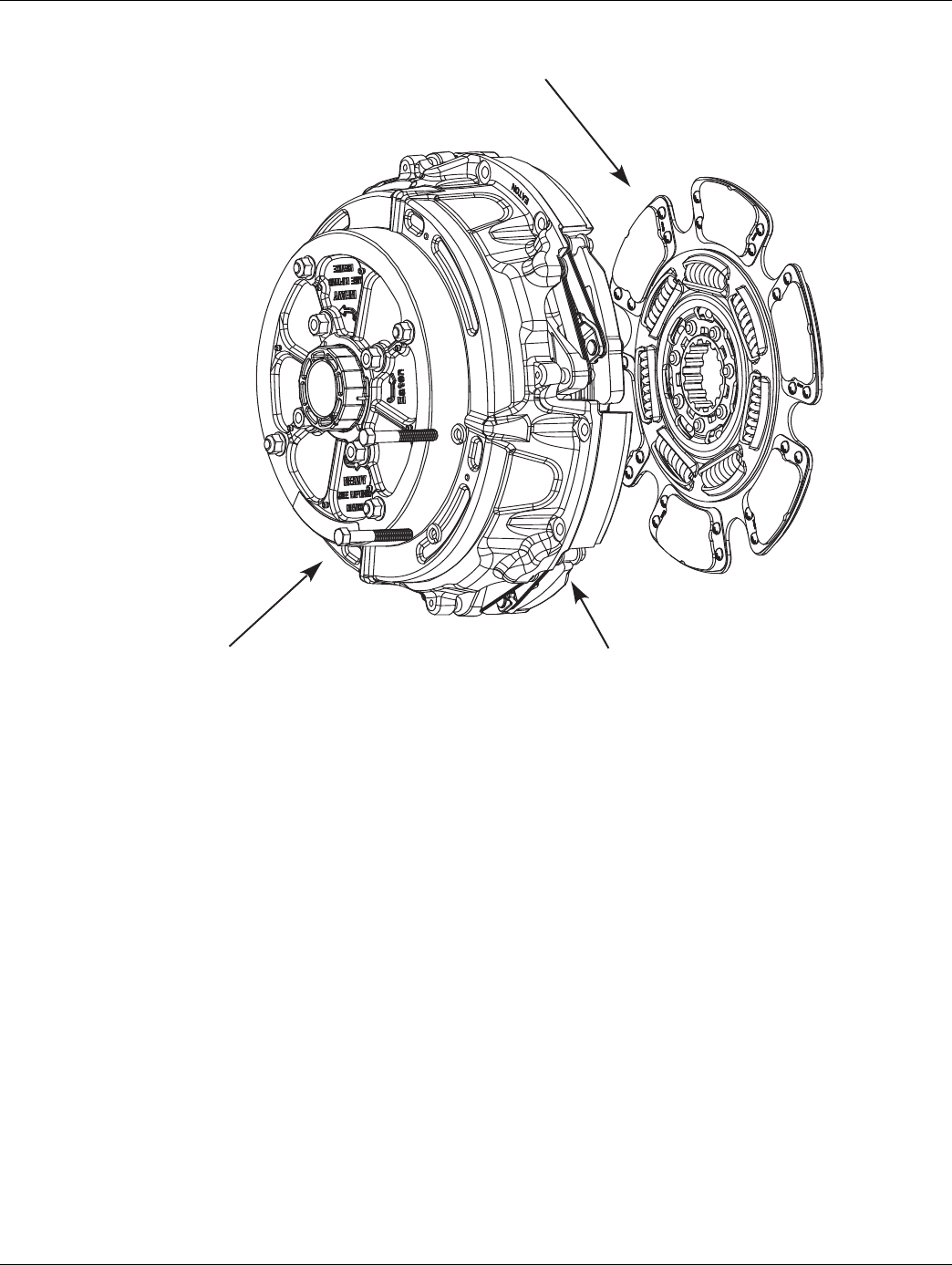
2016.01.15 © 2016 Eaton. All rights reserved 89
TRTS0930 Fault Isolation Procedures | Fault Code 27 - Clutch Disengagement
Component Identification
Clutch Assembly
Driven Disc
Driven Disc and
Intermediate Plate
DM Clutch

90 © 2016 Eaton. All rights reserved 2016.01.15
Fault Code 27 - Clutch Disengagement | Fault Isolation Procedures TRTS0930
Fault Code 27 - Clutch Disengagement
1. Key on.
2. Start engine.
3. Confirm transmission is in neutral.
4. Raise engine speed above 1500 RPM and allow
engine to return to idle.
5. Compare engine RPM to input shaft RPM with Ser-
viceRanger, a PC-based Service Tool.
Note: Engine idle must be 700 RPM or lower.
•If the speeds match at idle and Fault Code 27 is
Active, replace the clutch. Go to Step V.
•If they do not match, test complete.
1. Key off.
2. Reconnect all connectors and the negative battery
cable.
3. Key on.
4. Clear codes, see “Fault Code Retrieval/Clearing” on
page 5.
5. Drive vehicle and attempt to reset the code.
6. Check for fault codes, “Fault Code Retrieval/Clear-
ing” on page 5
•If Fault Code 27 appears go to Step A. to find
error in testing.
•If code other than 27 appears, See “Fault Code
Isolation Procedure Index” on page 8.
APurpose: Monitor and compare engine speed to
transmission input shaft speed in ServiceRanger. VPurpose: Verify repair.

2016.01.15 © 2016 Eaton. All rights reserved 91
TRTS0930 Fault Isolation Procedures | Fault Code 27 - Clutch Disengagement

92 © 2016 Eaton. All rights reserved 2016.01.15
Fault Code 28 - Clutch System | Fault Isolation Procedures TRTS0930
Fault Code 28 - Clutch System
J1587: MID 130 SID 52, 55 FMI 3, 4, 5, 7
J1939: SA 3 SPN 788 FMI 3, 4, 5, 7
Overview
This fault code indicates either an electrical or mechanical
failure in the WetClutch system.
Detection
Starting at key-on and throughout operation, the Transmis-
sion Electronic Control Unit (TECU) constantly monitors
this circuit. A failure mode of short to battery, short to
ground or open circuit is detected.
When the WetClutch is locked after urge to move, engine
speed and input shaft speeds are compared. If the engine
speed is significantly higher than the input shaft speed for a
period of five seconds, the WetClutch is slipping.
Fallback
There is no fallback mode; however, if the failure mode is
open circuit, the engine will be disengaged from the input
shaft.
Possible Causes
This fault code can be caused by any of the following:
• TECU
• Transmission Harness
• Low fluid level
• WetClutch system
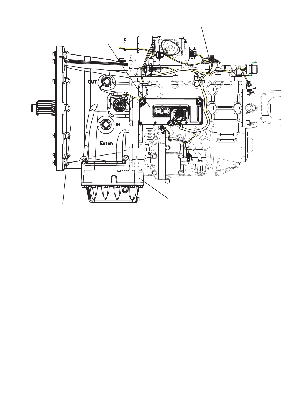
2016.01.15 © 2016 Eaton. All rights reserved 93
TRTS0930 Fault Isolation Procedures | Fault Code 28 - Clutch System
Component Identification
Transmission ECU
Transmission Harness
WetClutch Fluid
WetClutch System
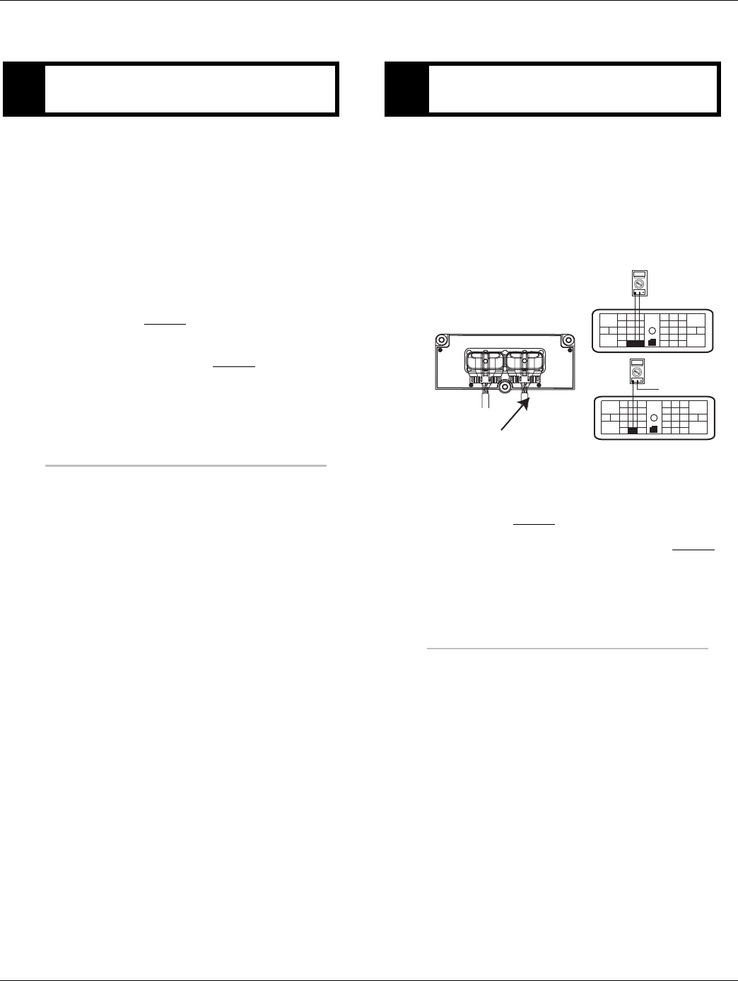
94 © 2016 Eaton. All rights reserved 2016.01.15
Fault Code 28 - Clutch System | Fault Isolation Procedures TRTS0930
Fault Code 28 - Clutch System
1. Key on.
2. Place the transmission in neutral.
3. Allow engine to idle at 700-800 RPM for a mini-
mum of 2 minutes.
Note: Ensure transmission fluid temperature is 60
to 120 degrees F (16 to 49 degrees C).
4. Check WetClutch fluid level.
•If fluid level is at or above the COLD-FULL
mark, go to Step B.
•If fluid level is below the COLD-ADD mark,
Correct fluid level, go to Step V..
1. Key off.
2. Disconnect the negative battery cable.
3. Disconnect the TECU 30-way connector.
4. Measure resistance between the Transmission Har-
ness 38-way connector Pin 2 and Pin 3 and
between Pin 2 and ground.
•If the resistance between 2 and 3 is 6.5 to 9.5
ohms and is resistance from Pin 2 to ground is
OL, go to Step C.
•If resistance is outside of range, go to Step D.
APurpose: Check WetClutch fluid level. BPurpose: Verify continuity of the Clutch Lube Sole-
noid circuit.
31
24 25
29 30
15 16
26
20
34
27 28
32 33
18 19
7
3
89
126
11 12
45
22
21
38
36
37
13 14
35 10
17
23
OHMS
VCOM A
31
24 25
29 30
15 16
26
20
34
27 28
32 33
18 19
7
3
89
126
11 12
45
22
21
38
36
37
13 14
35 10
17
23
OHMS
VCOM A
Ground
Transmission Harness 38-way Connector
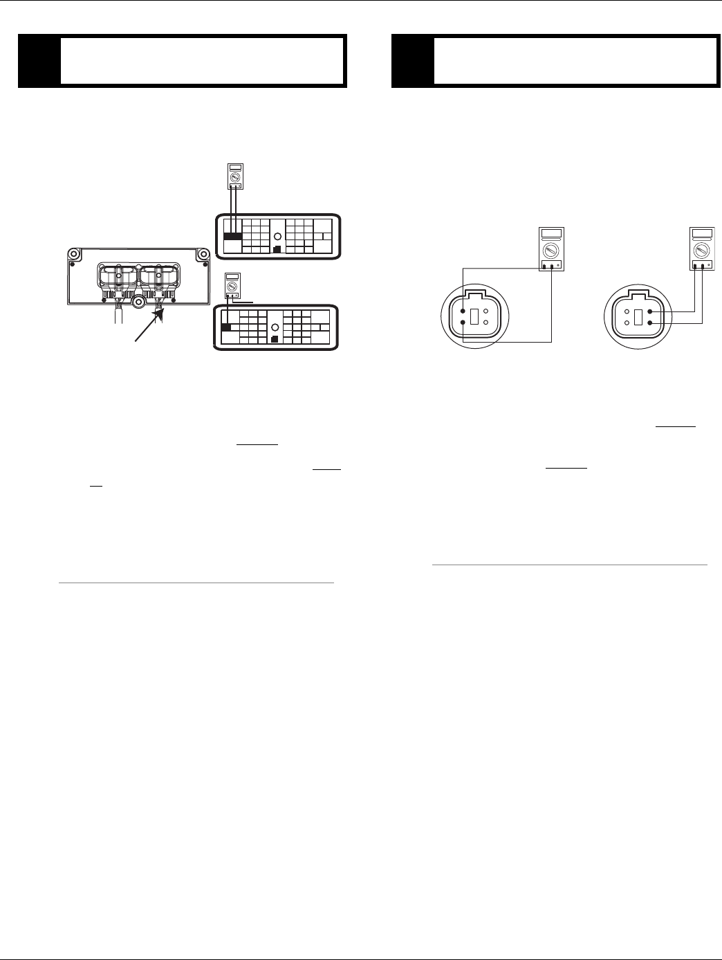
2016.01.15 © 2016 Eaton. All rights reserved 95
TRTS0930 Fault Isolation Procedures | Fault Code 28 - Clutch System
1. Measure resistance between the Transmission Har-
ness 38-way connector Pin 13 and Pin 14 and
between Pin 13 and ground.
•If resistance between Pin 13 and Pin 14 is 8.5
to 12 ohms and resistance from Pin 13 to
ground is [OL], Replace Transmission (Only if
fault code is Active). Go to Step V.
•If resistance is less than 10K ohm, go to Step
D.
1. Disconnect Transmission Harness located on left
side of WetClutch housing.
2. Measure resistance between WetClutch housing
connector pins:
-3 and 4
-1 and 2
•If the resistance between Pin 1 and Pin 2 is 8.5
to 12 ohms and the resistance between Pin 3
and Pin 4 is 6.5 to 9.5 ohms, go to Step E.
•If resistance is outside of range, replace trans-
mission, Go to Step V.
CPurpose: Verify continuity of Clutch Solenoid cir-
cuit.
OHMS
VCOM A
31
24 25
29 30
15 16
26
20
34
27 28
32 33
18 19
7
3
89
12 6
11 12
45
22
21
38
36
37
13 14
35 10
17
23
31
24 25
29 30
15 16
26
20
34
27 28
32 33
18 19
7
3
89
12 6
11 12
45
22
21
38
36
37
13 14
35 10
17
23
OHMS
VCOM A
Ground
Transmission Harness 38-way Connector
DPurpose: Verify continuity of hydraulic manifold
circuits.
OHMS
VCOM A
OHMS
VCOM A
4
3 2
14
3 2
1
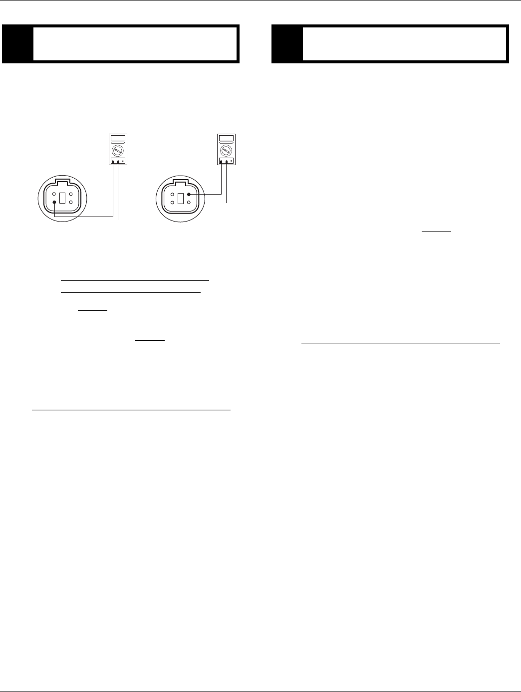
96 © 2016 Eaton. All rights reserved 2016.01.15
Fault Code 28 - Clutch System | Fault Isolation Procedures TRTS0930
1. Measure resistance between WetClutch housing
connector pins:
-3 and ground
-1 and ground
•If resistance from Pin 3 to ground and Pin 1 to
ground is 10K ohm or greater, replace the:
-Medium-Duty Transmission Harness
- Heavy-Duty Transmission Harness
Go to Step V.
•If resistance is less than 10K ohm, Replace
Transmission. Go to Step V.
1. Key off.
2. Reconnect all connectors.
3. Key on.
4. Clear codes, see “Fault Code Retrieval/Clearing” on
page 5.
5. Drive the vehicle and attempt to reset the code.
6. Check for codes, see “Fault Code Retrieval/Clear-
ing” on page 5.
•If no codes, test complete.
•If code 28 appears go to Step A. to find error
in testing.
•If code other than 28 appears, See “Fault Code
Isolation Procedure Index” on page 8.
EPurpose: Test the hydraulic manifold wiring for
short circuits.
OHMS
VCOM A
OHMS
VCOM A
4
3 2
14
3 2
1
GROUND
GROUND
VPurpose: Verify repair.

2016.01.15 © 2016 Eaton. All rights reserved 97
TRTS0930 Fault Isolation Procedures | Fault Code 28 - Clutch System

98 © 2016 Eaton. All rights reserved 2016.01.15
Fault Code 29 - Remote Throttle Enable | Fault Isolation Procedures TRTS0930
Fault Code 29 - Remote Throttle Enable
J1587: MID 130 PID 372 FMI 4, 5
J1939: SA 3 SPN 969 FMI 4, 5
Overview
This fault indicates an electrical failure of the relay that
allows the remote throttle to operate. The relay and wiring
are installed by the OEM. When troubleshooting an Inactive
code See “Product Diagnostic (PD) Mode” on page 11. for
more information on troubleshooting Inactive codes.
Detection
Starting at key-on and throughout operation, the Transmis-
sion Electronic Control Unit (TECU) constantly measures
the circuit. The fault is set if the TECU detects a bad
(open/short) connection for 2 seconds in the wiring from
the TECU to the relay.
Fallback
There is no fallback mode associated with this fault, but the
remote throttle will either not work or always work when
this fault is active.
Possible Causes
This fault code can be caused by any of the following:
• Remote Throttle relay
• Harness
• TECU
• Software misconfiguration
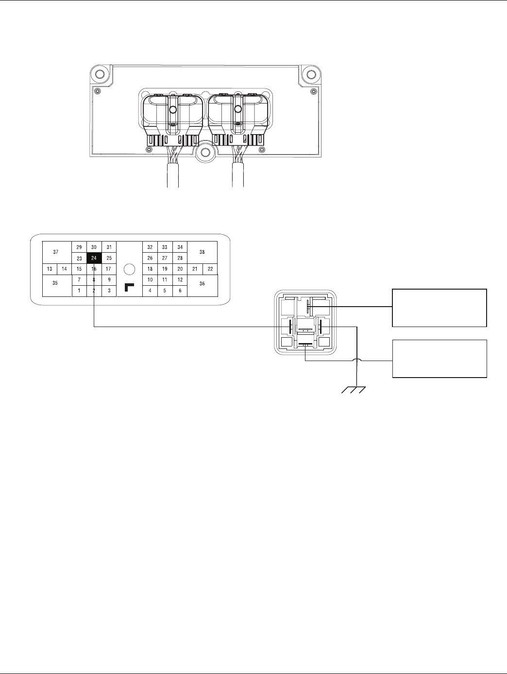
2016.01.15 © 2016 Eaton. All rights reserved 99
TRTS0930 Fault Isolation Procedures | Fault Code 29 - Remote Throttle Enable
Component Identification
Vehicle Harness 38-way Connector
Front View
38-Way Connector
30
86 87a 85
87
Front View
Relay connector
REMOTE THROTTLE
CONTROL SWITCHES
(SET/RESUME)
TO ENGINE OR BODY
CONTROLLER CRUISE
CONTROL INPUT
100 © 2016 Eaton. All rights reserved 2016.01.15
Fault Code 29 - Remote Throttle Enable | Fault Isolation Procedures TRTS0930
Fault Code 29 - Remote Throttle Enable
1. Follow OEM troubleshooting guidelines to ensure
the Remote Throttle Enable Relay has not failed.
•If relay is functional, go to Step B..
•If relay is not functional (faulted), test com-
plete. Go to Step V.
1. Key on.
2. Retrieve active fault codes and FMIs with Ser-
viceRanger using the 9-way diagnostic connector.
3. What FMIs are present?
Note: The Remote Throttle Enable relay must be
wired according to Eaton Gen 3 requirements
(shown on previous page) for tests to work
properly. If wired differently, consult OEM for
correct wiring schematic.
•If FMI 4 is present, go to Step C.
•If FMI 5 is present, go to Step D.
1. Key off.
2. Disconnect battery cable.
3. Disconnect the Vehicle Harness 38-way connector.
4. Measure the resistance between Vehicle Harness
38-way connector Pin 24 and ground.
•If the resistance between 24 and ground is OL.
(If fault code is Active) replace the:
-Medium-Duty Transmission Electronic Con-
trol Unit (TECU)
- Heavy-Duty Transmission Electronic Con-
trol Unit (TECU)
Go to Step V.
•If resistance is out of range, repair the Vehicle
Harness. Go to Step V.
APurpose: Verify Remote Throttle Enable is func-
tioning per OEM requirements.
BPurpose: Check for active or Inactive fault codes,
noting FMI
CPurpose: Test the Remote Throttle Relay circuit for
shorts to ground.
2016.01.15 © 2016 Eaton. All rights reserved 101
TRTS0930 Fault Isolation Procedures | Fault Code 29 - Remote Throttle Enable
1. Key off.
2. Disconnect battery cable.
3. Disconnect the Vehicle Harness 38-way connector.
4. Disconnect the Vehicle Harness from the Throttle
Enable Relay.
5. Measure resistance between Vehicle Harness
38-way connector way 24 and way 86 of the Throt-
tle Enable relay connector.
•If resistance is 0 to 0.3 ohms, (if fault code is
Active) replace the:
- Medium-Duty Transmission Electronic Con-
trol Unit (TECU)
- Heavy-Duty Transmission Electronic Con-
trol Unit (TECU)
Go to Step V.
•If resistance is out of range, repair the Vehicle
Harness and go to Step V.
1. Key off.
2. Reconnect all connectors.
3. Key on.
4. Clear codes, see “Fault Code Retrieval/Clearing” on
page 5.
5. Drive the vehicle and attempt to reset the code.
6. Check for fault codes, see “Fault Code
Retrieval/Clearing” on page 5.
•If no codes, test complete.
•If Fault Code 29 appears go to Step A. to find
error in testing.
•If fault code other than 29 appears, See “Fault
Code Isolation Procedure Index” on page 8.
DPurpose: Verify continuity of the Remote throttle
relay circuit. VPurpose: Verify repair.

102 © 2016 Eaton. All rights reserved 2016.01.15
Fault Code 31 - Momentary Engine Ignition Interrupt Relay (MEIIR) Test | Fault Isolation Procedures TRTS0930
Fault Code 31 - Momentary Engine Ignition Interrupt Relay (MEIIR) Test
J1587: MID 130 SID 218 FMI 2, 3, 4, 5, 14
J1939: SA 3 SPN 1485 FMI 2, 3, 4, 5, 14
Overview
This fault code indicates an electrical failure of the MEIIR
circuit.
When troubleshooting an Inactive code, See “Product Diag-
nostic (PD) Mode” on page 11.
Detection
The fault is detected during power-up. The Transmission
Electronic Control Unit (TECU) checks the MEIIR circuit
every time the system is powered up. If the electrical char-
acteristics of the circuit are incorrect, the fault code is set.
Fallback
There is no fallback associated with this failure. However, if
the engine speed flares uncontrollably while the transmis-
sion is in a gear, the transmission may not be able to
achieve neutral if it is selected due to a torque lock condi-
tion.
Possible Causes
This fault code can be caused by an of the following:
• OEM wiring
• Mechanical failure in the MEIIR relay
• TECU
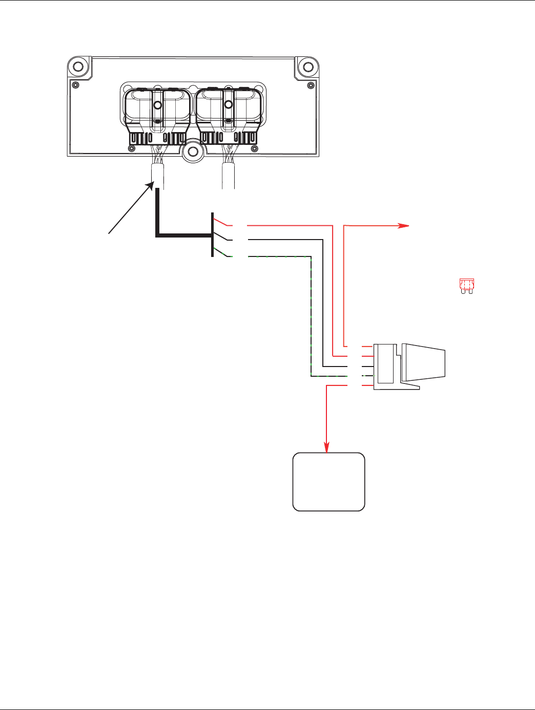
2016.01.15 © 2016 Eaton. All rights reserved 103
TRTS0930 Fault Isolation Procedures | Fault Code 31 - Momentary Engine Ignition Interrupt Relay (MEIIR) Test
Component Identification
Ignition
Interrupt
Relay
Engine ECM
Engine Power Relay
Fused 10 AMP 12 volt
manual resetting
circuit breaker
or
10 AMP
fuse
Run to
Ignition
Transmission ECU
Vehicle Harness 38-way Connector
30
86
85
87
87a
22
21
20
All OEM responsible wiring shown is "typical". Consult specific application.
(30, 87a) = +12 volt switched
(20-(20-87)87) = SigSignal
(21-85) = (21-85) = -12 volt relay source
(22-86) = +12 volt relay source
Ignition Interrupt Legend
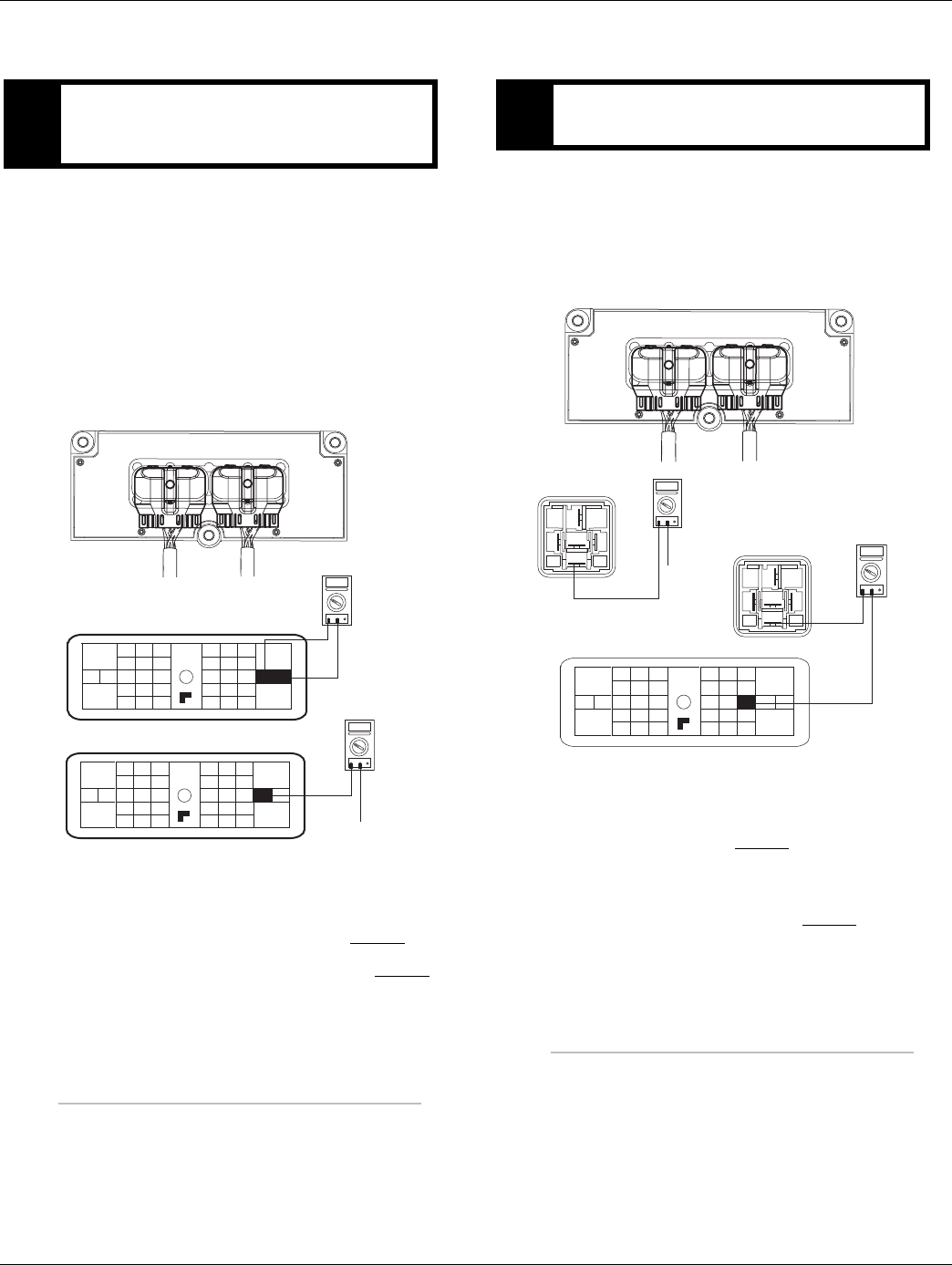
104 © 2016 Eaton. All rights reserved 2016.01.15
Fault Code 31 - Momentary Engine Ignition Interrupt Relay (MEIIR) Test | Fault Isolation Procedures TRTS0930
Fault Code 31 - Momentary Engine Ignition Interrupt Relay (MEIIR) Test
1. Key off.
2. Disconnect negative battery cable.
3. Disconnect TECU Vehicle Harness 38-way connec-
tor.
4. Measure resistance between Vehicle Harness
38-way connector pins 21 and 22 and from Pin 21
to ground.
•If resistance between pins 21 and 22 is 40 to
120 ohms (24 volt system) and resistance
from Pin 21 to ground is OL, go to Step B.
•If resistance is outside of range, go to Step D.
1. Measure resistance between Transmission Vehicle
Harness 38-way connector Pin 20 and MEIIR relay
connector Pin 87 and from MEIIR relay connector
Pin 87 to ground.
•If resistance between pins 20 and 87 is 0 to
0.3 ohms and if resistance between Pin 87 and
ground is OL, go to Step C.
•If resistance is outside of the range, repair the
Vehicle Harness between the TECU and the
MEIIR relay connector. Go to Step V.
APurpose: Verify continuity of Momentary Engine
Ignition Interrupt Relay (MEIIR) circuit and test for
short to ground through Vehicle Interface Harness.
OHMS
VCOM A
31
24 25
29 30
15 16
26
20
34
27 28
32 33
18 19
7
3
89
12 6
11 12
45
22
21
38
36
37
13 14
35 10
17
23
Front View
38-Way Connector
Vehicle Harness 38-way Connector
OHMS
VCOM A
31
24 25
29 30
15 16
26
20
34
27 28
32 33
18 19
7
3
89
12 6
11 12
45
22
21
38
36
37
13 14
35 10
17
23
BPurpose: Verify continuity of MEIIR contact wire
and test for short to ground.
30
86 87a 85
87
Front View
Relay connector
OHMS
VCOM A
31
24 25
29 30
15 16
26
20
34
27 28
32 33
18 19
7
3
89
12 6
11 12
45
22
21
38
36
37
13 14
35 10
17
23
Front View
38-Way Connector
OHMS
VCOM A
30
86 87a 85
87
Ground
Vehicle Harness 38-way Connector
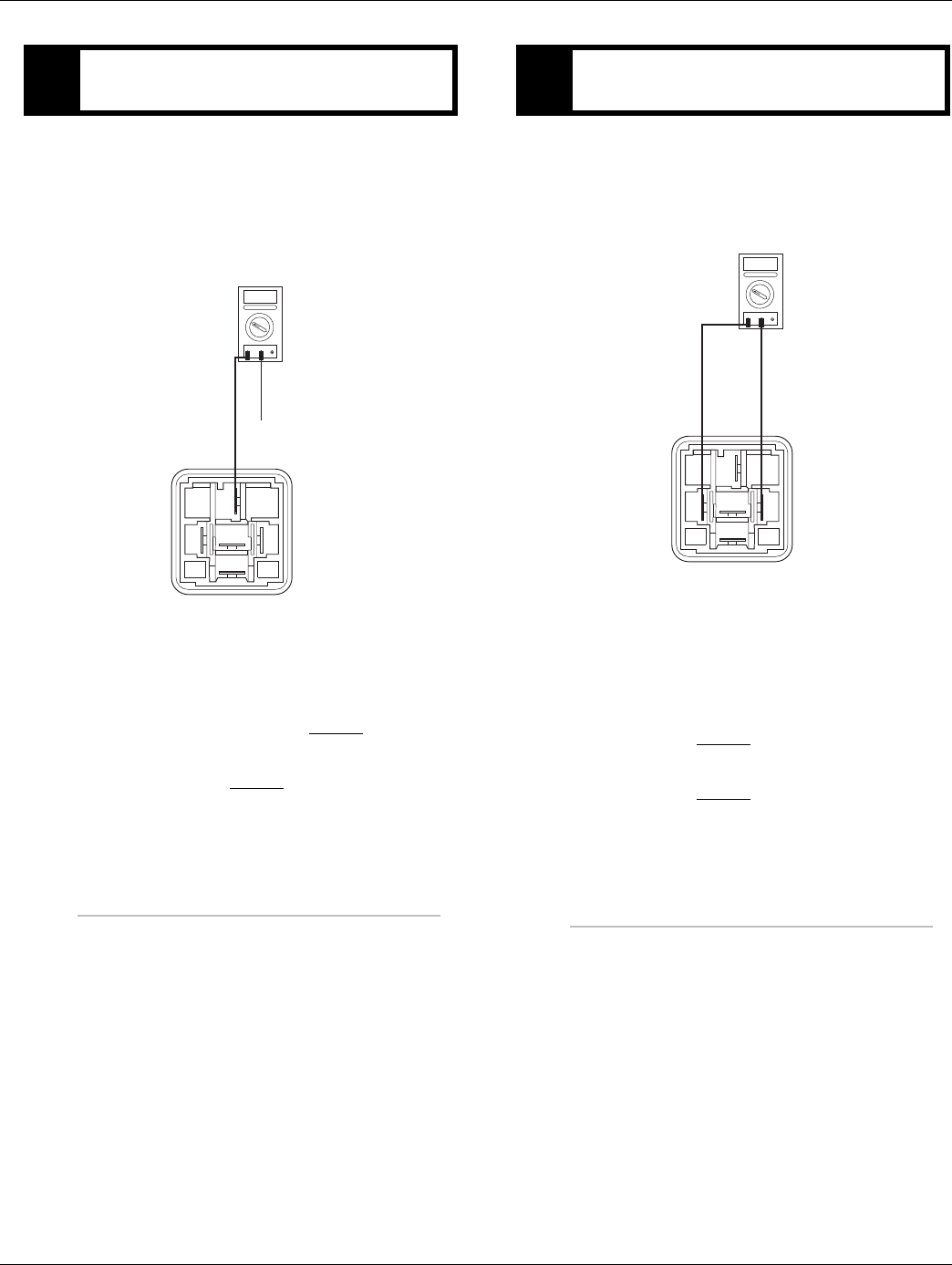
2016.01.15 © 2016 Eaton. All rights reserved 105
TRTS0930 Fault Isolation Procedures | Fault Code 31 - Momentary Engine Ignition Interrupt Relay (MEIIR) Test
1. Disconnect MEIIR relay from connector
2. Key on.
3. Measure voltage from Pin 30 of the MEIIR relay
connector to ground.
•If voltage is within 0.6 volts of battery voltage
replace MEIIR relay. Go to Step E.
•If voltage is outside of range repair the Vehicle
Harness. Go to Step V.
1. Remove MEIIR relay from OEM dash harness.
2. Measure resistance between MEIIR relay pins 85
and 86.
•If resistance is 40 to 120 ohms (12 volt sys-
tem) or 140 to 480 ohms (24 volt system)
repair OEM wiring from the TECU to the MEIIR
relay. Go to Step V.
•If resistance is outside of range replace MEIIR
relay. Go to Step V.
CPurpose: Test the MEIIR relay for shorts to ground
at the relay.
VOLTS
VCOM A
30
8687a 85
87
Front View
Relay connector
Ground
DPurpose: Measure resistance across MEIIR relay.
OHMS
VCOM A
30
8687a 85
87
Front View
Relay connector
106 © 2016 Eaton. All rights reserved 2016.01.15
Fault Code 31 - Momentary Engine Ignition Interrupt Relay (MEIIR) Test | Fault Isolation Procedures TRTS0930
1. Key on.
2. Retrieve codes. See “Fault Code Retrieval/Clearing”
on page 5.
•If Fault Code 31 is Active, replace the:
- Medium-Duty Transmission Electronic Con-
trol Unit (TECU)
- Heavy-Duty Transmission Electronic Con-
trol Unit (TECU)
Go to Step V.
•If Fault Code 31 is Inactive, go to Step V.
1. Key off.
2. Key on.
3. Clear codes. See “Fault Code Retrieval/Clearing” on
page 5.
4. Reconnect all connectors and the negative battery
cable.
5. Drive vehicle and attempt to reset the code
6. Check for codes. See “Fault Code Retrieval/Clear-
ing” on page 5.
•If no codes, test complete.
•If Fault Code 31 appears go to Step A. to find
error in testing.
•If code other than 31 appears, See “Fault Code
Isolation Procedure Index” on page 8.
EPurpose: Check for active or Inactive fault codes. VPurpose: Verify repair.

2016.01.15 © 2016 Eaton. All rights reserved 107
TRTS0930 Fault Isolation Procedures | Fault Code 31 - Momentary Engine Ignition Interrupt Relay (MEIIR) Test

108 © 2016 Eaton. All rights reserved 2016.01.15
Fault Code 32 - Loss of Switch Ignition Power Test | Fault Isolation Procedures TRTS0930
Fault Code 32 - Loss of Switch Ignition Power Test
J1587: MID 130 PID 43 FMI 2
J1939: SA 3 SPN 158 FMI 2
Overview
This fault code indicates a loss of Switched Ignition Power
to the Transmission Electronic Control Unit.
When troubleshooting an Inactive code, See “Product Diag-
nostic (PD) Mode” on page 11.
Detection
The TECU monitors Ignition Power during normal opera-
tion. If Ignition power is lost to the TECU during operation a
fault is logged.
Fallback
This fault causes an In-Place fallback while moving.
Possible Causes
This fault code can be caused by the following:
• Ignition switch is turned off during operation
• Ignition power is lost during operation
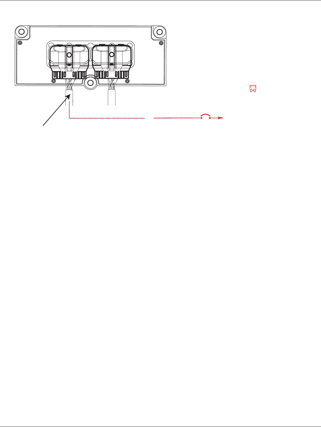
2016.01.15 © 2016 Eaton. All rights reserved 109
TRTS0930 Fault Isolation Procedures | Fault Code 32 - Loss of Switch Ignition Power Test
Component Identification
Ignition power (switched power)
run to main power lead that
feeds the ignition bus
10 AMP 12 volt only
Manual resetting
circuit breaker
10 AMP
fuse
Or
35
Vehicle Harness 38-way Connector
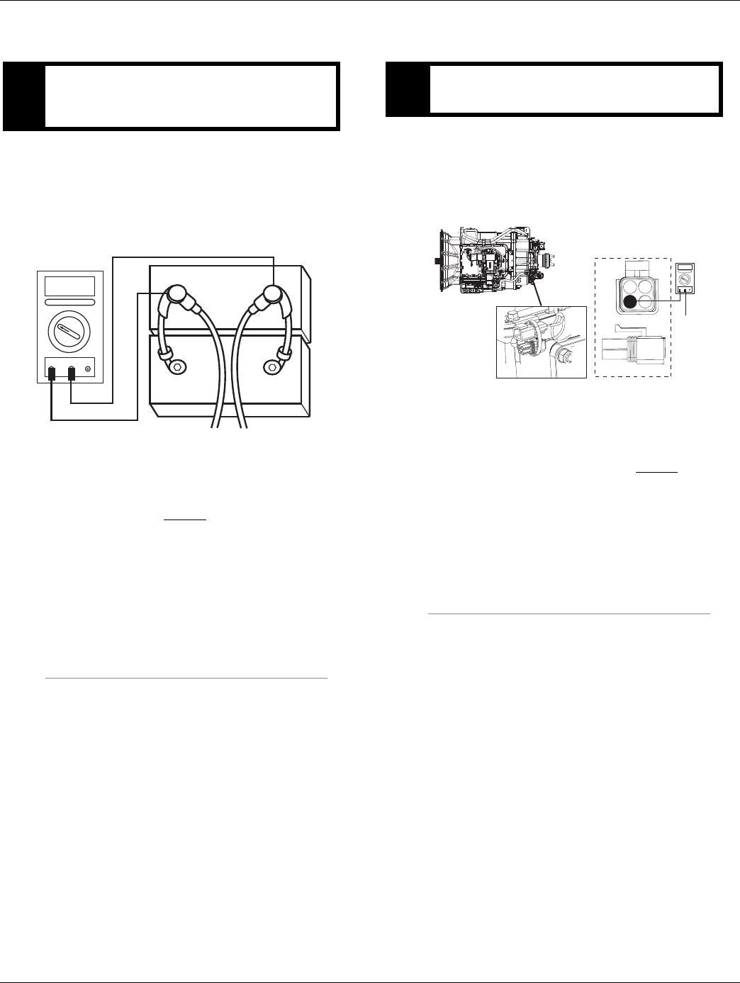
110 © 2016 Eaton. All rights reserved 2016.01.15
Fault Code 32 - Loss of Switch Ignition Power Test | Fault Isolation Procedures TRTS0930
Fault Code 32 - Loss of Switch Ignition Power Test
1. Key off.
2. Inspect starter/battery and inline fuse holder con-
nections for integrity.
3. Measure voltage across batteries.
•If voltage is 11 to 13 volts on a 12-volt system
or 22 to 26 on a 24-volt system, proceed with
battery load test. Repair or replace batteries as
required. Go to Step B.
•If voltage is outside of range, repair or replace
batteries and charging system as required.
Repeat this step.
1. Locate diagnostic port on Transmission Harness.
2. Key on.
3. Measure voltage between Pin C and the battery
negative post.
•If voltage between Pin C and battery negative
post is 0.70 volts or less, go to Step C.
•If voltage is outside of range, repair battery
ground supply to TECU. Repeat test.
APurpose: Measure batter voltage. Visually inspect
the batteries, inline fuse, power, ground supplies to
TECU.
VOLTS
VCOM A
+
–
+
–
BPurpose: Verify proper ground path at 4-way diag-
nostic port.
4-Pin Diagnostic Port
(Located at the left rear
corner of the transmission.)
4-Pin Diagnostics Port
4-way
B - Service Bat. +
C - Service Bat. -
A - Service Ignition +
VOLTS
VCOM A
Battery Negative Post
BA
D
C
Warning! - Do Not Load Test at Diagnostic Port
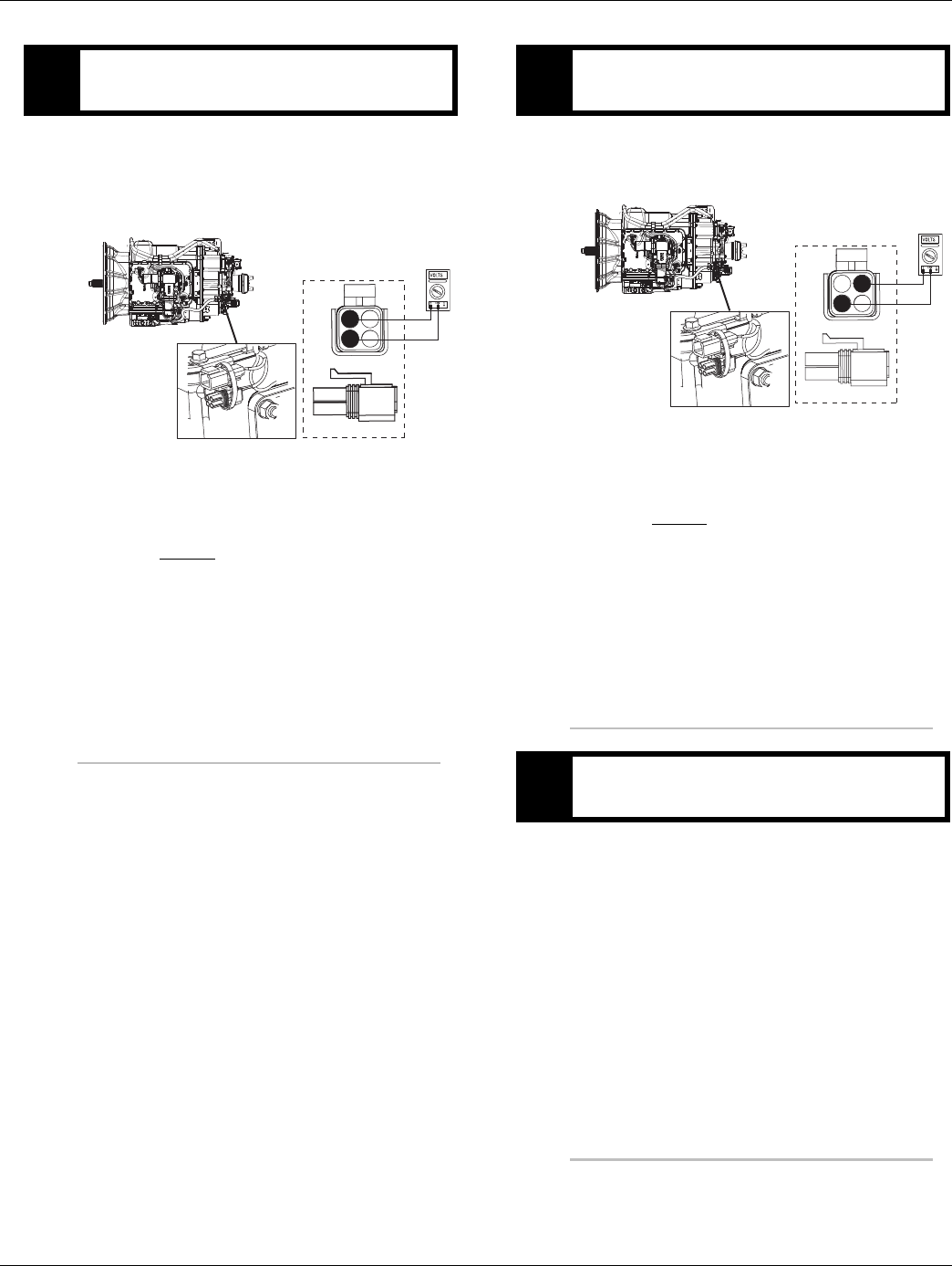
2016.01.15 © 2016 Eaton. All rights reserved 111
TRTS0930 Fault Isolation Procedures | Fault Code 32 - Loss of Switch Ignition Power Test
1. Locate diagnostic port on Transmission Harness.
2. Key on.
3. Measure voltage between Pin B and Pin C.
•If voltage is within 0.6 volts of battery voltage,
go to Step D.
•If voltage is outside of range, repair battery
power supply to TECU. Fuse may be blown.
Repeat test.
1. Key on.
2. Measure voltage between Pin A and Pin C.
•If voltage is within 0.6 volts of battery voltage,
go to Step V.
•If voltage is outside of range, repair ignition
power supply to TECU. Fuse may be blown.
Repeat test.
1. Drive vehicle and attempt to reset codes.
2. Retrieve codes. See “Fault Code Retrieval/Clearing”
on page 5.
•If code 32 is Inactive, This code indicates a
loss of ignition switched power to the TECU
during operation. Verify the key was not turned
off during operation. Inspect ignition circuit for
intermittent open.
CPurpose: Measure battery voltage at 4-way diag-
nostic port.
4-Pin Diagnostics Port
4-way
B - Service Bat. +
C - Service Bat. -
A - Service Ignition +
BA
D
C
4-Pin Diagnostic Port
(Located at the left rear
corner of the transmission.)
Warning! - Do Not Load Test at Diagnostic Port
DPurpose: Measure ignition voltage at 4-way diag-
nostic port.
VPurpose: Verify repair.
4-Pin Diagnostics Port
4-way
B - Service Bat. +
C - Service Bat. -
A - Service Ignition +
BA
D
C
4-Pin Diagnostic Port
(Located at the left rear
corner of the transmission.)
Warning! - Do Not Load Test at Diagnostic Port

112 © 2016 Eaton. All rights reserved 2016.01.15
Fault Code 33 - Low Battery Voltage Supply | Fault Isolation Procedures TRTS0930
Fault Code 33 - Low Battery Voltage Supply
J1587: MID 130 PID 168 FMI 4
J1939: SA 3 SPN 168 FMI 4
Overview
This fault code indicates that the vehicle battery power sup-
ply to the Transmission Electronic Control Unit (TECU) is
below 7 volts.
When troubleshooting an Inactive code, See “Product Diag-
nostic (PD) Mode” on page 11.
Detection
Starting at key-on and throughout operation, the TECU con-
stantly measures vehicle voltage. If voltage is below 7 volts
for more than 1 second, Fault Code 33 will be set and the
service light will flash.
Fallback
If this fault occurs while moving, it causes a 1-speed fall-
back. Once the vehicle is stopped, the starting gear and
reverse can be engaged
Possible Causes
This fault code can be caused by any of the following:
• Corroded or loose power supply to TECU
• Low batteries
• Damaged Vehicle Harness
• TECU
• Charging system
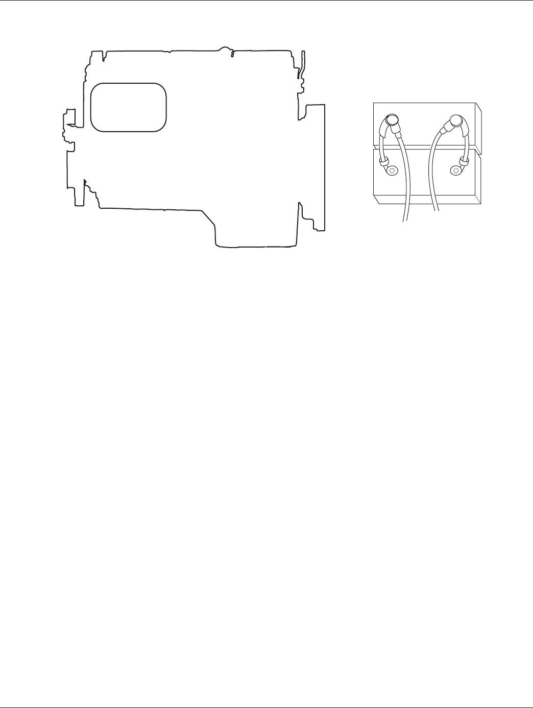
2016.01.15 © 2016 Eaton. All rights reserved 113
TRTS0930 Fault Isolation Procedures | Fault Code 33 - Low Battery Voltage Supply
Component Identification
Vehicle
Charging
System
+
–
+
–
Batteries

114 © 2016 Eaton. All rights reserved 2016.01.15
Fault Code 33 - Low Battery Voltage Supply | Fault Isolation Procedures TRTS0930
Fault Code 33 - Low Battery Voltage Supply
1. Key off.
2. Inspect starter/battery and
in-line fuse holder connections for integrity.
3. Measure voltage across batteries.
•If voltage is 11 to 13 volts on a 12-volt system
or 22 to 26 on a 24-volt system, proceed with
battery load test. Repair or replace batteries as
required. Go to Step B.
•If voltage is outside of range, repair or replace
batteries, charging system as required. Repeat
this step.
1. Locate diagnostic port on Transmission Harness.
2. Key on.
3. Measure voltage between Pin C and the battery
negative post.
•If voltage is 0.70 volts or less, go to Step C.
•If voltage is outside of range, repair battery
ground supply to TECU. Repeat test.
APurpose: Measure battery voltage. Visually inspect
batteries, inline fuse, power and ground supplies to
TECU.
BPurpose: Verify proper ground path at 4-way diag-
nostic port.
4-Pin Diagnostic Port
(Located at the left rear
corner of the transmission.)
4-Pin Diagnostics Port
4-way
B - Service Bat. +
C - Service Bat. -
A - Service Ignition +
VOLTS
VCOM A
Battery Negative Post
BA
D
C
Warning! - Do Not Load Test at Diagnostic Port

2016.01.15 © 2016 Eaton. All rights reserved 115
TRTS0930 Fault Isolation Procedures | Fault Code 33 - Low Battery Voltage Supply
1. Locate diagnostic port on Transmission Harness.
2. Key on.
3. Measure voltage between Pin B and Pin C.
•If voltage is within 0.6 volts of battery voltage,
go to Step D.
•If voltage is outside of range, repair battery
power supply to TECU. Fuse may be blown.
Repeat test.
1. Key on.
2. Measure voltage between Pin A and Pin C.
•If voltage is within 0.6 volts of battery voltage,
go to Step E.
•If voltage is outside of range, repair ignition
power supply to TECU. Fuse may be blown.
Repeat test.
CPurpose: Measure battery voltage at 4-way diag-
nostic port.
4-Pin Diagnostics Port
4-way
B - Service Bat. +
C - Service Bat. -
A - Service Ignition +
BA
D
C
4-Pin Diagnostic Port
(Located at the left rear
corner of the transmission.)
Warning! - Do Not Load Test at Diagnostic Port
DPurpose: Measure ignition voltage at 4-way diag-
nostic port.
4-Pin Diagnostics Port
4-way
B - Service Bat. +
C - Service Bat. -
A - Service Ignition +
BA
D
C
4-Pin Diagnostic Port
(Located at the left rear
corner of the transmission.)
Warning! - Do Not Load Test at Diagnostic Port

116 © 2016 Eaton. All rights reserved 2016.01.15
Fault Code 33 - Low Battery Voltage Supply | Fault Isolation Procedures TRTS0930
1. Key on.
2. Retrieve codes. See “Fault Code Retrieval/Clearing”
on page 5.
•If Fault Code 33 is Active, replace the:
- Medium-Duty Transmission Electronic Con-
trol Unit (TECU)
- Heavy-Duty Transmission Electronic Con-
trol Unit (TECU)
Go to Step V.
•If Fault Code 33 is Inactive, clear codes and go
to Step V.
1. Key off.
2. Key on.
3. Clear codes. See “Fault Code Retrieval/Clearing” on
page 5.
4. Reconnect all connectors and the negative battery
cable.
5. Drive vehicle and attempt to reset the code.
6. Check for codes. See “Fault Code Retrieval/Clear-
ing” on page 5.
•If no codes, test complete.
•If Fault Code 33 appears go to Step A. to find
error in testing.
•If code other than 33 appears, See “Fault Code
Isolation Procedure Index” on page 8.
EPurpose: Check for active and Inactive fault codes.
VPurpose: Verify repair.

2016.01.15 © 2016 Eaton. All rights reserved 117
TRTS0930 Fault Isolation Procedures | Fault Code 33 - Low Battery Voltage Supply

118 © 2016 Eaton. All rights reserved 2016.01.15
Fault Code 34 - Weak Battery Voltage Supply | Fault Isolation Procedures TRTS0930
Fault Code 34 - Weak Battery Voltage Supply
J1587: MID 130 PID 168 FMI 14
J1939: SA 3 SPN 168 FMI 14
Overview
This fault indicates the vehicle is supplying weak battery
voltage to the transmission for 10 seconds.
When troubleshooting an Inactive code See “Product Diag-
nostic (PD) Mode” on page 11.
Detection
Starting at key-on and throughout operation, the Transmis-
sion Electronic Control Unit (TECU) constantly measures
vehicle voltage. If voltage is below 9 volts for more than 10
seconds, Fault Code 34 will be set. The service light will not
flash.
Fallback
If this fault occures while moving, it causes a 1-speed fall-
back. Once the vehicle is stopped, the starting gear and
reverse can be engaged
Possible Causes
This fault code can be caused by any of the following:
• Corroded or loose power supply to TECU
• Low batteries
• Damaged Vehicle Harness
• TECU
• Charging system
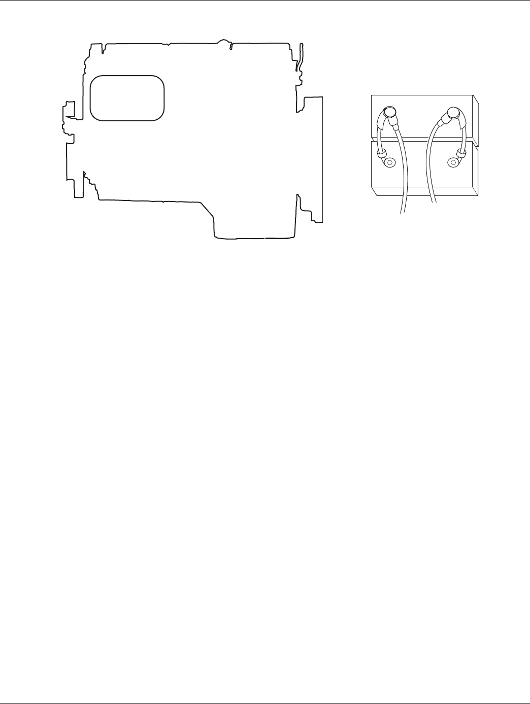
2016.01.15 © 2016 Eaton. All rights reserved 119
TRTS0930 Fault Isolation Procedures | Fault Code 34 - Weak Battery Voltage Supply
Component Identification
Vehicle
Charging
System
+
–
+
–
Batteries
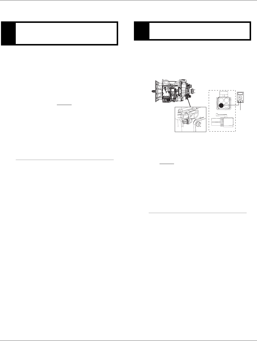
120 © 2016 Eaton. All rights reserved 2016.01.15
Fault Code 34 - Weak Battery Voltage Supply | Fault Isolation Procedures TRTS0930
Fault Code 34 - Weak Battery Voltage Supply
1. Key off.
2. Inspect starter/battery and in-line fuse holder con-
nections for integrity.
3. Measure voltage across batteries.
•If voltage is 11 to 13 volts on a 12-volt system
or 22 to 26 on a 24-volt system, proceed with
battery load test. Repair or replace batteries as
required. Go to Step B.
•If voltage is outside of range, repair or replace
batteries, charging system as required. Repeat
this step.
1. Locate diagnostic port on Transmission Harness.
2. Key on.
3. Measure voltage between Pin C and the battery
negative post.
•If voltage between is 0.70 volts or less, go to
Step C.
•If voltage is outside of range, repair battery
ground supply to TECU. Repeat test.
APurpose: Measure battery voltage. Visually inspect
batteries, inline fuse, power and ground supplies to
TECU.
BPurpose: Verify proper ground path at 4-way diag-
nostic port.
4-Pin Diagnostic Port
(Located at the left rear
corner of the transmission.)
4-Pin Diagnostics Port
4-way
B - Service Bat. +
C - Service Bat. -
A - Service Ignition +
VOLTS
VCOM A
Battery Negative Post
BA
D
C
Warning! - Do Not Load Test at Diagnostic Port

2016.01.15 © 2016 Eaton. All rights reserved 121
TRTS0930 Fault Isolation Procedures | Fault Code 34 - Weak Battery Voltage Supply
1. Locate diagnostic port on Transmission Harness.
2. Key on.
3. Measure voltage between Pin B and Pin C.
•If voltage is within 0.6 volts of battery voltage,
go to Step D.
•If voltage is outside of range, repair battery
power supply to TECU. Fuse may be blown.
Repeat test.
1. Key on.
2. Measure voltage between Pin A and Pin C.
•If voltage is within 0.6 volts of battery voltage,
go to Step E.
•If voltage is outside of range, repair ignition
power supply to TECU. Fuse may be blown.
Repeat test.
CPurpose: Measure battery voltage at 4-way diag-
nostic port.
4-Pin Diagnostics Port
4-way
B - Service Bat. +
C - Service Bat. -
A - Service Ignition +
BA
D
C
4-Pin Diagnostic Port
(Located at the left rear
corner of the transmission.)
Warning! - Do Not Load Test at Diagnostic Port
DPurpose: Measure ignition voltage at 4-way diag-
nostic port.
4-Pin Diagnostics Port
4-way
B - Service Bat. +
C - Service Bat. -
A - Service Ignition +
BA
D
C
4-Pin Diagnostic Port
(Located at the left rear
corner of the transmission.)
Warning! - Do Not Load Test at Diagnostic Port
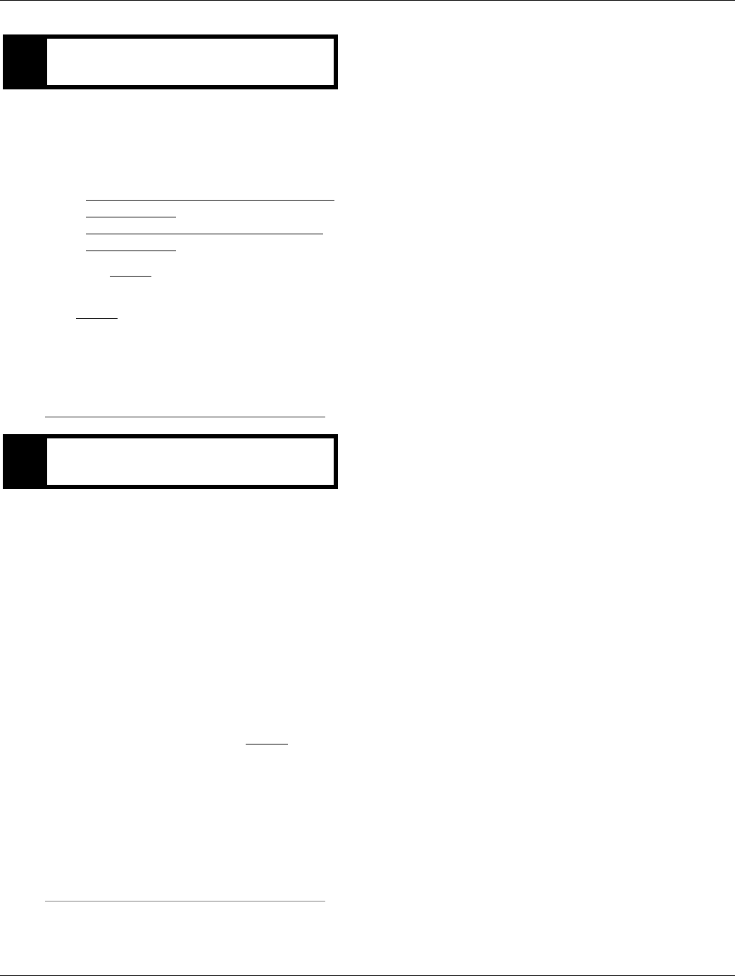
122 © 2016 Eaton. All rights reserved 2016.01.15
Fault Code 34 - Weak Battery Voltage Supply | Fault Isolation Procedures TRTS0930
1. Key on.
2. Retrieve codes. See “Fault Code Retrieval/Clearing”
on page 5.
•If Fault Code 34 is Active, replace the:
-Medium-Duty Transmission Electronic Con-
trol Unit (TECU)
- Heavy-Duty Transmission Electronic Con-
trol Unit (TECU)
Go to Step V.
•If Fault Code 34 is Inactive, clear codes. Go to
Step V.
1. Key off.
2. Key on.
3. Clear codes. See “Fault Code Retrieval/Clearing” on
page 5.
4. Reconnect all connectors and the negative battery
cable.
5. Drive vehicle and attempt to reset the code
6. Check for codes. See “Fault Code Retrieval/Clear-
ing” on page 5.
•If no codes, test complete.
•If Fault Code 34 appears go to Step A. to find
error in testing.
•If code other than 34 appears, See “Fault Code
Isolation Procedure Index” on page 8.
EPurpose: Check for active and Inactive fault codes.
VPurpose: Verify repair.

2016.01.15 © 2016 Eaton. All rights reserved 123
TRTS0930 Fault Isolation Procedures | Fault Code 34 - Weak Battery Voltage Supply

124 © 2016 Eaton. All rights reserved 2016.01.15
Fault Code 35 - J1939 Communication Link | Fault Isolation Procedures TRTS0930
Fault Code 35 - J1939 Communication Link
J1587: MID 130 SID 231 FMI 2
J1939: SA 3 SPN 639 FMI 2
Overview
This fault code indicates the Transmission Electronic Con-
trol Unit (TECU) failed to communicate with the engine over
the J1939 data link.
If you have an Active Fault Code 35 with an UltraShift DM
transmission and the engine will crank but not start, please
check the OEM supplied MEIIR (Momentary Engine Ignition
Interrupt Relay) circuit. Ensure that the engine has proper
ignition voltage.
When troubleshooting an Inactive code See “Product Diag-
nostic (PD) Mode” on page 11.
Detection
Seventy-five seconds after key-on and throughout the oper-
ation, the TECU constantly monitors the communication
with the engine ECM. If a communication fault occurs for
more than 5 seconds, and no other devices are present,
Fault Code 35 is set.
Fallback
If the fault occurs during power-up the transmission will go
into AutoSelect mode. If the fault occurs while moving, it
causes an in-place fallback. The transmission will remain in
the gear that was engaged when the failure occurred. Once
the vehicle stops, start and reverse gears can be selected
and the transmission will operate in AutoSelect mode.
Possible Causes
This fault can be caused by any of the following:
• J1939 Data Link
• Engine ECM
• Vehicle Harness or Connections
• Engine Harness or Connections
• Excessive radio interference
• TECU
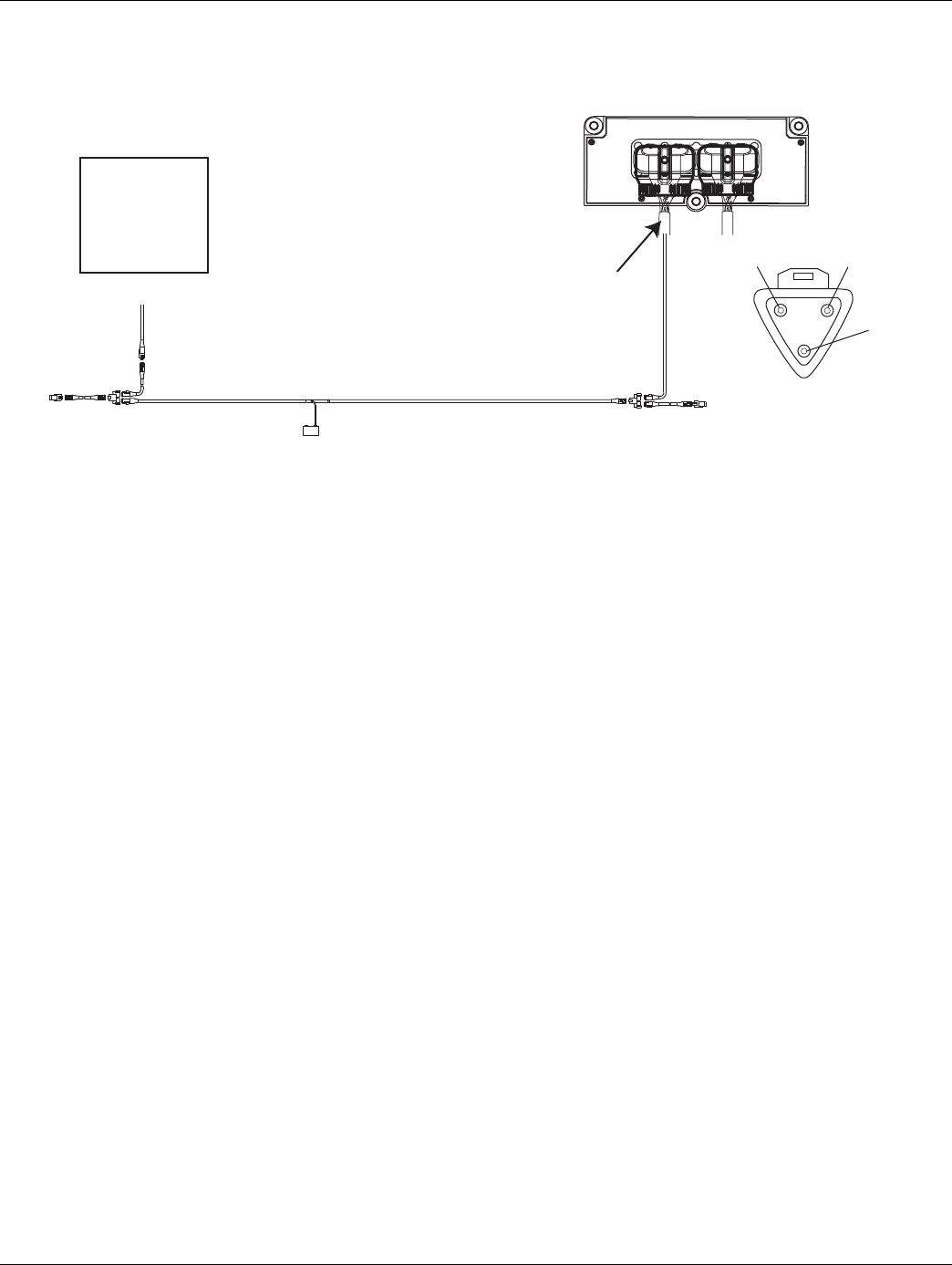
2016.01.15 © 2016 Eaton. All rights reserved 125
TRTS0930 Fault Isolation Procedures | Fault Code 35 - J1939 Communication Link
Component Identification
Typical J1939/11 data link harness
(OEM supplied)
Engine ECM
B
A
C
–J1939
+J1939
Shield
Transmission ECU
Vehicle Harness 38-way Connector
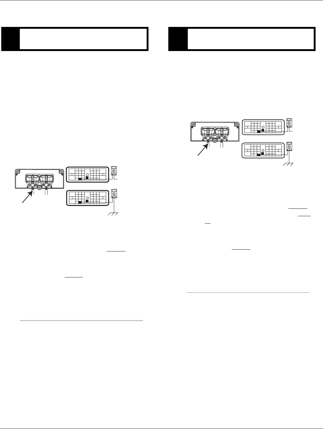
126 © 2016 Eaton. All rights reserved 2016.01.15
Fault Code 35 - J1939 Communication Link | Fault Isolation Procedures TRTS0930
Fault Code 35 - J1939 Communication Link
1. Key off.
2. Disconnect negative battery cable.
3. Disconnect Vehicle Harness 38-way connector.
4. Disconnect engine ECM connector which contains
the J1939 Data Link.
5. Measure resistance between:
-Vehicle Harness 38-way connector Pin 2 and
engine ECM pin number (see OEM wiring for (-)
J1939).
-Vehicle harness 38-way Pin 2 and ground.
•If resistance between Pin 2 and engine ECM
pin is 0 to 0.3 ohms and if resistance between
Pin 2 and ground is OL, go to Step B.
•If resistance is outside of range, repair J1939
Data Link Harness between engine ECM and
TECU. Go to Step V.
1. Key off.
2. Measure resistance between:
-Vehicle Harness 38-way connector Pin 3 and
engine ECM pin number (see OEM J1939 wiring
for (+) J1939)
-Vehicle Harness 38-way Pin 3 and ground
•If resistance between Pin 3 and engine ECM
pin number is 0 to 0.3 ohms, and if resistance
between Pin 3 and ground is OL,
-If equipped with J1939 Lite, go to Step D.
-If not equipped with J1939 Lite, go to Step
C.
•If resistance is outside of range, repair J1939
Data Link Harness between engine ECM and
TECU. Go to Step V.
APurpose: Verify continuity of J1939 Data Link low
(-) circuit and test for short to ground.
OHMS
VCOM A
OHMS
VCOM A
See OEM J1939 Wiring
for correct pin on ECM
31
24 25
29 30
15 16
26
20
34
27 28
32 33
18 19
7
3
89
126
11 12
45
22
21
38
36
37
13 14
35 10
17
23
Front View
38-Way Connector
31
24 25
29 30
15 16
26
20
34
27 28
32 33
18 19
7
3
89
126
11 12
45
22
21
38
36
37
13 14
35 10
17
23
Vehicle Harness 38-way Connector
BPurpose: Verify continuity of J1939 Data Link (+)
circuit and test for short to ground.
OHMS
VCOM A
OHMS
VCOM A
See OEM J1939 Wiring
for correct pin on ECM
31
24 25
29 30
15 16
26
20
34
27 28
32 33
18 19
7
3
89
12 6
11 12
45
22
21
38
36
37
13 14
35 10
17
23
Front View
38-Way Connector
31
24 25
29 30
15 16
26
20
34
27 28
32 33
18 19
7
3
89
12 6
11 12
45
22
21
38
36
37
13 14
35 10
17
23
Vehicle Harness 38-way Connector
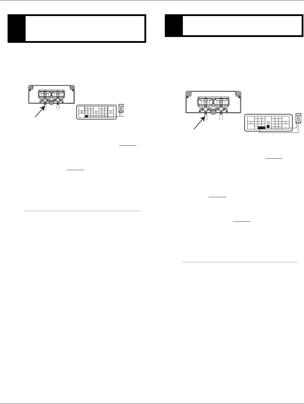
2016.01.15 © 2016 Eaton. All rights reserved 127
TRTS0930 Fault Isolation Procedures | Fault Code 35 - J1939 Communication Link
1. Key off.
2. Measure resistance between Vehicle Harness
38-way connector Pin 1 and engine ECM pin num-
ber (see OEM J1939 wiring for J1939 shield).
•If resistance between Pin 1 and engine ECM
pin number is 0 to 0.3 ohms, go to Step D.
•If resistance is outside of range, Repair J1939
Data Link Harness between engine ECM and
TECU. Go to Step V.
1. Key off.
2. Measure resistance between Vehicle Harness
38-way connector Pin 2 and Pin 3.
Note: En sure the volt/ohm meter is on the proper
scale (around 200 ohm)
•If resistance between Pin 2 and Pin 3 is
between 50 to 70 ohms, go to Step V.
•If resistance is more than 70 ohms, one or
more of the terminating resistors on the J1939
Data Link Harness is either missing or out of
range, repair OEM J1939 Data Link Harness.
Go to Step V.
•If resistance is less than 50 ohms, repair the
J1939 Data Link between the engine ECM and
the TECU. Go to Step V.
CPurpose: Verify continuity of J1939 Data Link
Shield (+) wire (if equipped) and test for short to
ground.
OHMS
VCOM A
See OEM J1939 Wiring
for correct pin on ECM
31
24 25
29 30
15 16
26
20
34
27 28
32 33
18 19
7
3
89
126
11 12
45
22
21
38
36
37
13 14
35 10
17
23
Front View
38-Way Connector
Vehicle Harness 38-way Connector
DPurpose: Confirm the presence of terminating re-
sistors in the J1939 Data Link.
OHMS
VCOM A
31
24 25
29 30
15 16
26
20
34
27 28
32 33
18 19
7
3
89
126
11 12
45
22
21
38
36
37
13 14
35 10
17
23
Front View
38-Way Connector
Vehicle Harness 38-way Connector

128 © 2016 Eaton. All rights reserved 2016.01.15
Fault Code 35 - J1939 Communication Link | Fault Isolation Procedures TRTS0930
1. Key off.
2. Key on.
3. Clear codes. See “Fault Code Retrieval/Clearing” on
page 5.
4. Reconnect all connectors and the negative battery
cable.
5. Drive vehicle and attempt to reset the code
6. Check for codes. See “Fault Code Retrieval/Clear-
ing” on page 5.
•If no codes, test complete.
•If Fault Code 35 appears go to Step A. to find
error in testing.
•If code other than 35 appears, See “Fault Code
Isolation Procedure Index” on page 8.
VPurpose: Verify repair.

2016.01.15 © 2016 Eaton. All rights reserved 129
TRTS0930 Fault Isolation Procedures | Fault Code 35 - J1939 Communication Link

130 © 2016 Eaton. All rights reserved 2016.01.15
Fault Code 36 - J1939 Engine Message | Fault Isolation Procedures TRTS0930
Fault Code 36 - J1939 Engine Message
J1587: MID 130 SID231 FMI 14
J1939: SA 3 SPN 639 FMI 14
Overview
This fault code indicates the Transmission Electronic Con-
trol Unit (TECU) has communicated with another ECU, but
is unable to communicate with the engine ECU over the
J1939 data link.
If you have an Active Fault Code 36 with an UltraShift DM
transmission and engine will crank but not start, please
check the OEM supplied MEIIR (Momentary Engine Ignition
Interrupt Relay) circuit and see that the engine has proper
ignition voltage.
When troubleshooting an Inactive code See “Product Diag-
nostic (PD) Mode” on page 11.
Detection
The fault is detected if J1939 communication from the
engine is lost for 5 seconds and other devices are present
on J1939.
Fallback
If the fault occurs during power-up, the transmission will go
into AutoSelect mode. If the fault occurs while moving, it
causes an in-place fallback and the transmission will remain
in the gear that was engaged when the failure occurred.
Once the vehicle stops, start and reverse gears can be
selected and the transmission will operate in AutoSelect
mode.
Possible Causes
This fault can be caused by any of the following:
• J1939 Data Link
• Engine ECM
• Vehicle Harness or Connections
• Engine Harness or Connections
• Excessive radio interference
• TECU
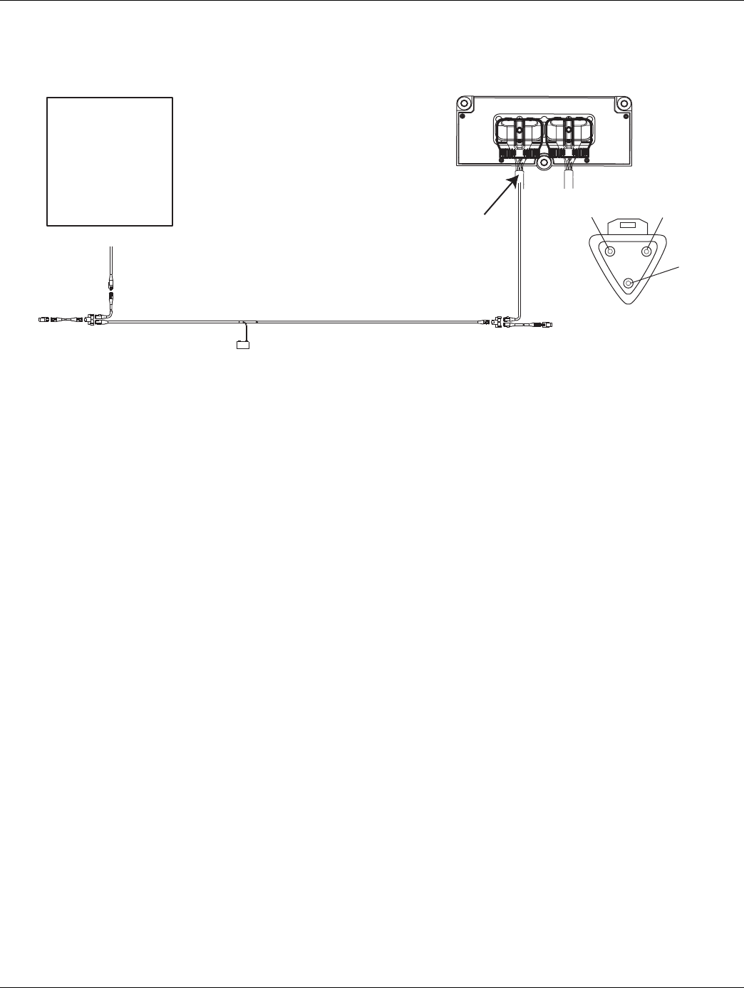
2016.01.15 © 2016 Eaton. All rights reserved 131
TRTS0930 Fault Isolation Procedures | Fault Code 36 - J1939 Engine Message
Component Identification
Typical J1939/11 data link harness
(OEM supplied)
Engine ECM
B
A
C
–J1939
+J1939
Shield
Transmission ECU
Vehicle Harness 38-way Connector
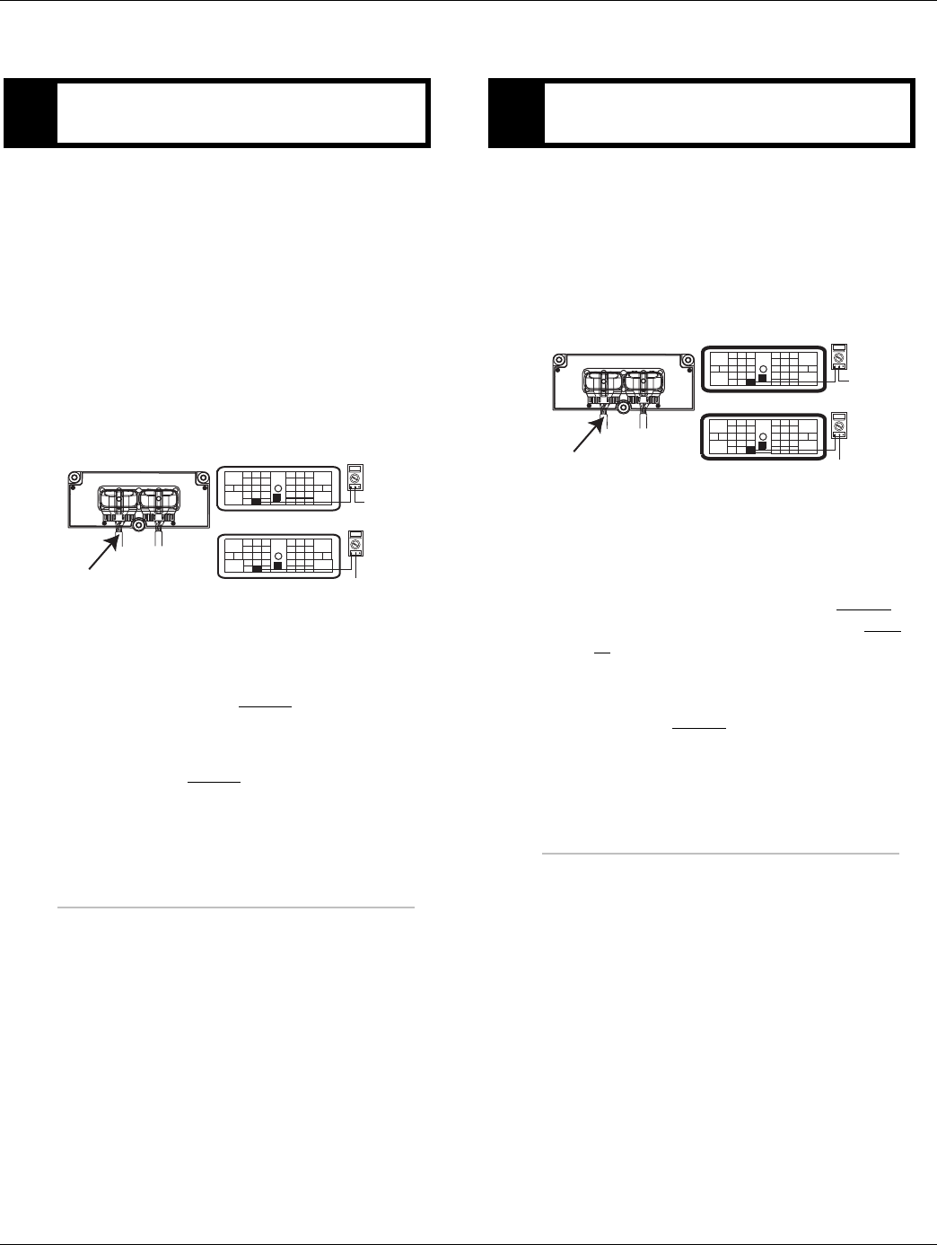
132 © 2016 Eaton. All rights reserved 2016.01.15
Fault Code 36 - J1939 Engine Message | Fault Isolation Procedures TRTS0930
Fault Code 36 - J1939 Engine Message
1. Key off.
2. Disconnect negative battery cable.
3. Disconnect Vehicle Harness 38-way connector.
4. Disconnect engine ECM connector which contains
the J1939 Data Link.
5. Measure resistance between:
-Vehicle Harness 38-way connector Pin 2 and
engine ECM pin # (see OEM wiring for (-) J1939).
-Vehicle Harness 38-way connector Pin 2 and
ground.
•If resistance between Pin 2 and engine ECM
pin # (see OEM wiring for (-)J1939) is 0 to 0.3
ohms and if resistance between Pin 2 and
ground is OL, go to Step B.
•If resistance is outside of range, repair J1939
Data Link Harness between engine ECM and
TECU. Go to Step V.
1. Key off.
2. Measure resistance between:
-Vehicle Harness 38-way connector Pin 3 and
engine ECM pin # (see OEM wiring for (+)J1939)
-Vehicle Harness 38-way connector Pin 3 and
ground
•If resistance between Pin 3 and engine ECM
pin # (see OEM wiring for (+)J1939) is 0 to 0.3
ohms and if resistance between Pin 3 and
ground is OL,
-If equipped with J1939 Lite, go to Step D.
-If not equipped with J1939 Lite, go to Step
C.
•If resistance is outside of range, repair J1939
Data Link Harness between Engine ECM and
TECU. Go to Step V.
APurpose: Verify continuity of J1939 Data Link Low
(-) circuit and test for short to ground.
OHMS
VCOM A
OHMS
VCOM A
GROUND
See OEM J1939 Wiring
for correct pin on ECM
31
24 25
29 30
15 16
26
20
34
27 28
32 33
18 19
7
3
89
126
11 12
45
22
21
38
36
37
13 14
35 10
17
23
Front View
38-Way Connector
31
24 25
29 30
15 16
26
20
34
27 28
32 33
18 19
7
3
89
126
11 12
45
22
21
38
36
37
13 14
35 10
17
23
Vehicle Harness 38-way Connector
BPurpose: Verify continuity of J1939 Data Link High
(+) circuit and test for short to ground.
OHMS
VCOM A
OHMS
VCOM A
GROUND
See OEM J1939 Wiring
for correct pin on ECM
31
24 25
29 30
15 16
26
20
34
27 28
32 33
18 19
7
3
89
12 6
11 12
45
22
21
38
36
37
13 14
35 10
17
23
Front View
38-Way Connector
31
24 25
29 30
15 16
26
20
34
27 28
32 33
18 19
7
3
89
12 6
11 12
45
22
21
38
36
37
13 14
35 10
17
23
Vehicle Harness 38-way Connector
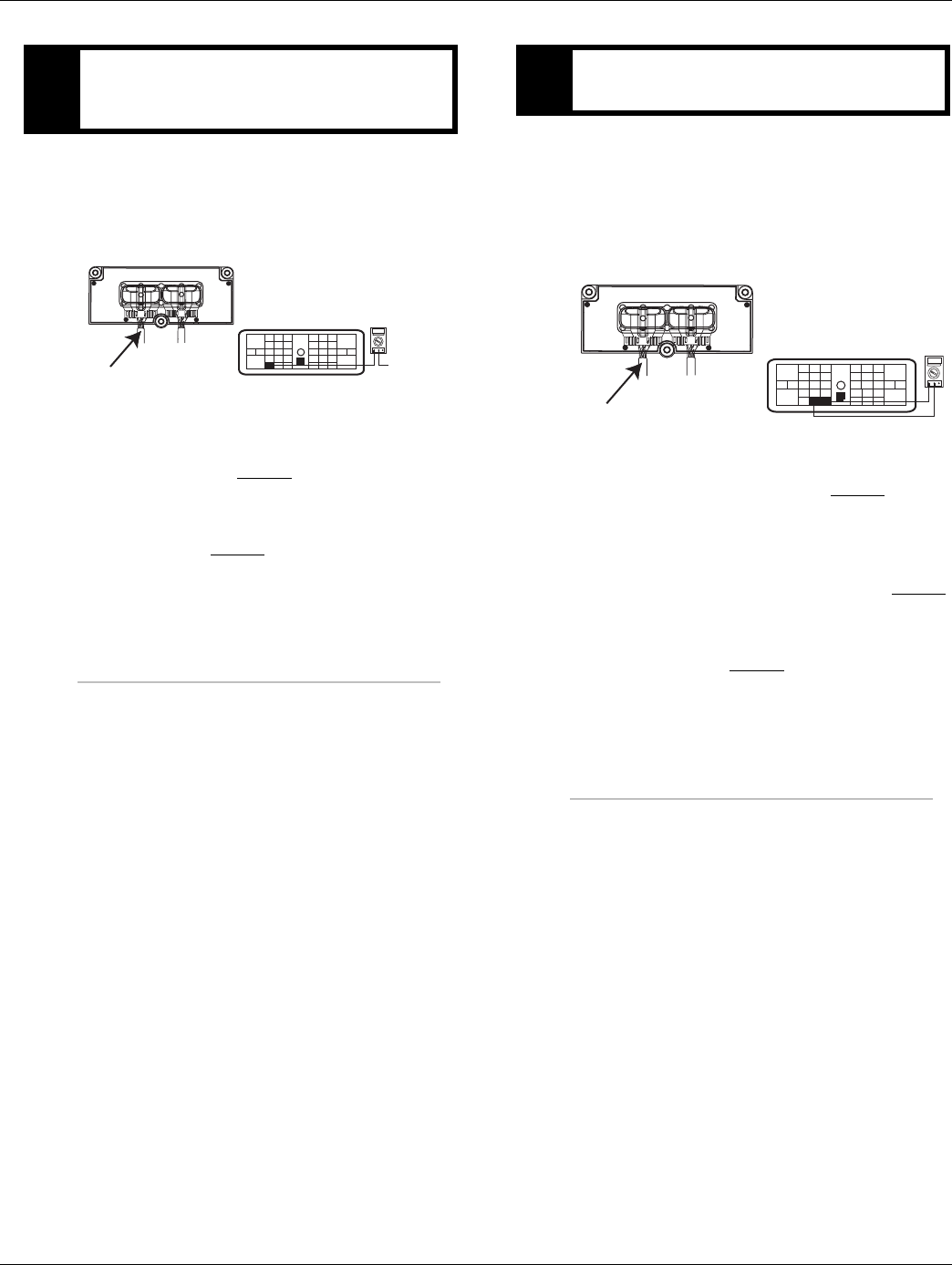
2016.01.15 © 2016 Eaton. All rights reserved 133
TRTS0930 Fault Isolation Procedures | Fault Code 36 - J1939 Engine Message
1. Key off.
2. Measure resistance between Vehicle Harness
38-way connector Pin 1 and engine ECM pin # (see
OEM wiring for J1939 shield).
•If resistance between Pin 1 and engine ECM
pin # (see OEM wiring for J1939 shield) is 0 to
0.3 ohms, go to Step D.
•If resistance is outside of range, repair J1939
Data Link Harness between engine ECM and
TECU. Go to Step V.
1. Key off.
2. Measure resistance between Vehicle Harness
38-way connector Pin 2 and Pin 3.
Note: Make sure the volt/ohm meter is on the
proper scale (around 200 ohm scale).
•If resistance between Pin 2 and Pin 3 is
between 50 to 70 ohms, go to Step V.
•If resistance is more than 70 ohms, 1or more
of the terminating resistors on the J1939 data
link harness is either missing or out of range.
Repair J1939 Data Link Harness. Go to Step V.
•If resistance is less than 50 ohms, repair the
J1939 Data Link between the Engine ECM and
the TECU. Go to Step V.
CPurpose: Verify continuity of J1939 Data Link
Shield (+) wire (if equipped) and test for short to
ground.
OHMS
VCOM A
See OEM J1939 Wiring
for correct pin on ECM
31
24 25
29 30
15 16
26
20
34
27 28
32 33
18 19
7
3
89
126
11 12
45
22
21
38
36
37
13 14
35 10
17
23
Front View
38-Way Connector
Vehicle Harness 38-way Connector
DPurpose: Confirm the presence of terminating re-
sistors in the J1939 Data Link.
OHMS
VCOM A
31
24 25
29 30
15 16
26
20
34
27 28
32 33
18 19
7
3
89
126
11 12
45
22
21
38
36
37
13 14
35 10
17
23
Front View
38-Way Connector
Vehicle Harness 38-way Connector

134 © 2016 Eaton. All rights reserved 2016.01.15
Fault Code 36 - J1939 Engine Message | Fault Isolation Procedures TRTS0930
1. Key off.
2. Reconnect all connectors and the negative battery
cable.
3. Key on.
4. Clear codes. See “Fault Code Retrieval/Clearing” on
page 5.
5. Drive vehicle and attempt to reset the code.
6. Check for codes. See “Fault Code Retrieval/Clear-
ing” on page 5.
•If no codes, test complete.
•If Fault Code 36 appears go to Step A. to find
error in testing,
•If fault code other than 36 appears, See “Fault
Code Isolation Procedure Index” on page 8.
VPurpose: Verify repair.

2016.01.15 © 2016 Eaton. All rights reserved 135
TRTS0930 Fault Isolation Procedures | Fault Code 36 - J1939 Engine Message

136 © 2016 Eaton. All rights reserved 2016.01.15
Fault Code 37 - Power Supply | Fault Isolation Procedures TRTS0930
Fault Code 37 - Power Supply
J1587: MID 130 SID 251 FMI 5
J1939: SA 3 SPN 627 FMI 5
Overview
This fault code indicates excessive resistance has been
detected between the power supply source (battery or
starter) and the Transmission Electronic Control Unit
(TECU).
Detection
The resistance on the TECU power supply circuit is mea-
sured during each shift. If the resistance is greater than 0.4
ohms this fault will set.
Fallback
No fallback mode.
Possible Causes
This fault code can be caused by the following:
• Corrosion on power supply or ground supply con-
nections or wires to the TECU
• Corrosion in fuse holder for TECU power supply.
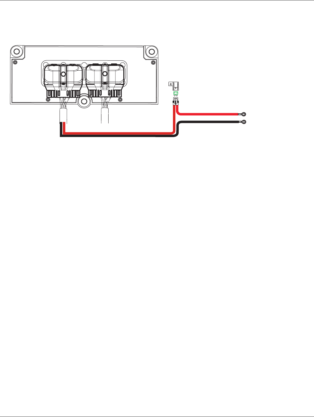
2016.01.15 © 2016 Eaton. All rights reserved 137
TRTS0930 Fault Isolation Procedures | Fault Code 37 - Power Supply
Component Identification
30 AMP fuse
Battery power
(non-switched power)
run to starter
or batteries
Transmission ECU
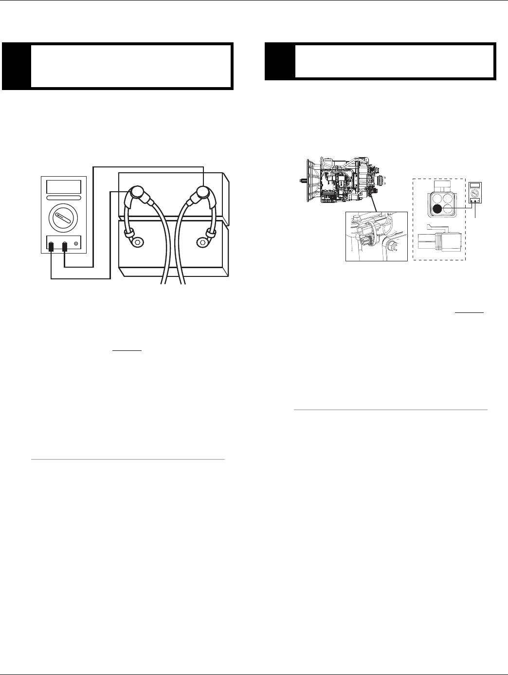
138 © 2016 Eaton. All rights reserved 2016.01.15
Fault Code 37 - Power Supply | Fault Isolation Procedures TRTS0930
Fault Code 37 - Power Supply
1. Key off.
2. Inspect starter/battery and in-line fuse holder con-
nections for integrity.
3. Measure voltage across batteries.
•If voltage is 11 to 13 volts on a 12-volt system
or 22 to 26 on a 24-volt system, proceed with
battery load test. Repair or replace batteries as
required. Go to Step B.
•If voltage is outside of rangeRepair or replace
batteries and charging system as required.
Repeat this step.
1. Locate diagnostic port on Transmission Harness.
2. Key on.
3. Measure voltage between Pin C and the battery
negative post.
•If voltage is 0.70 volts or less, go to Step C.
•If voltage is outside of range, repair battery
ground supply to TECU. Repeat test.
APurpose: Measure battery voltage. Visually inspect
batteries, inline fuse, power and ground supplies to
the TECU.
VOLTS
VCOM A
+
–
+
–
BPurpose: Verify proper ground path at 4-way diag-
nostic port.
4-Pin Diagnostic Port
(Located at the left rear
corner of the transmission.)
4-Pin Diagnostics Port
4-way
B - Service Bat. +
C - Service Bat. -
A - Service Ignition +
VOLTS
VCOM A
Battery Negative Post
BA
D
C
Warning! - Do Not Load Test at Diagnostic Port

2016.01.15 © 2016 Eaton. All rights reserved 139
TRTS0930 Fault Isolation Procedures | Fault Code 37 - Power Supply
1. Locate diagnostic port on Transmission Harness.
2. Key on.
3. Measure voltage between Pin B and Pin C.
•If voltage is within 0.6 volts of battery voltage,
go to Step D.
•If voltage is outside of rang, repair battery
power supply to TECU. Fuse may be blown.
Repeat test.
1. Key on.
2. Measure voltage between Pin A and Pin C.
•If voltage is within 0.6 volts of battery voltage,
go to Step E.
•If voltage is outside of range, repair ignition
power supply to TECU. Fuse may be blown.
Repeat test.
CPurpose: Measure battery voltage at 4-way diag-
nostic port.
4-Pin Diagnostics Port
4-way
B - Service Bat. +
C - Service Bat. -
A - Service Ignition +
BA
D
C
4-Pin Diagnostic Port
(Located at the left rear
corner of the transmission.)
Warning! - Do Not Load Test at Diagnostic Port
DPurpose: Measure ignition voltage at 4-way diag-
nostic port.
4-Pin Diagnostics Port
4-way
B - Service Bat. +
C - Service Bat. -
A - Service Ignition +
BA
D
C
4-Pin Diagnostic Port
(Located at the left rear
corner of the transmission.)
Warning! - Do Not Load Test at Diagnostic Port
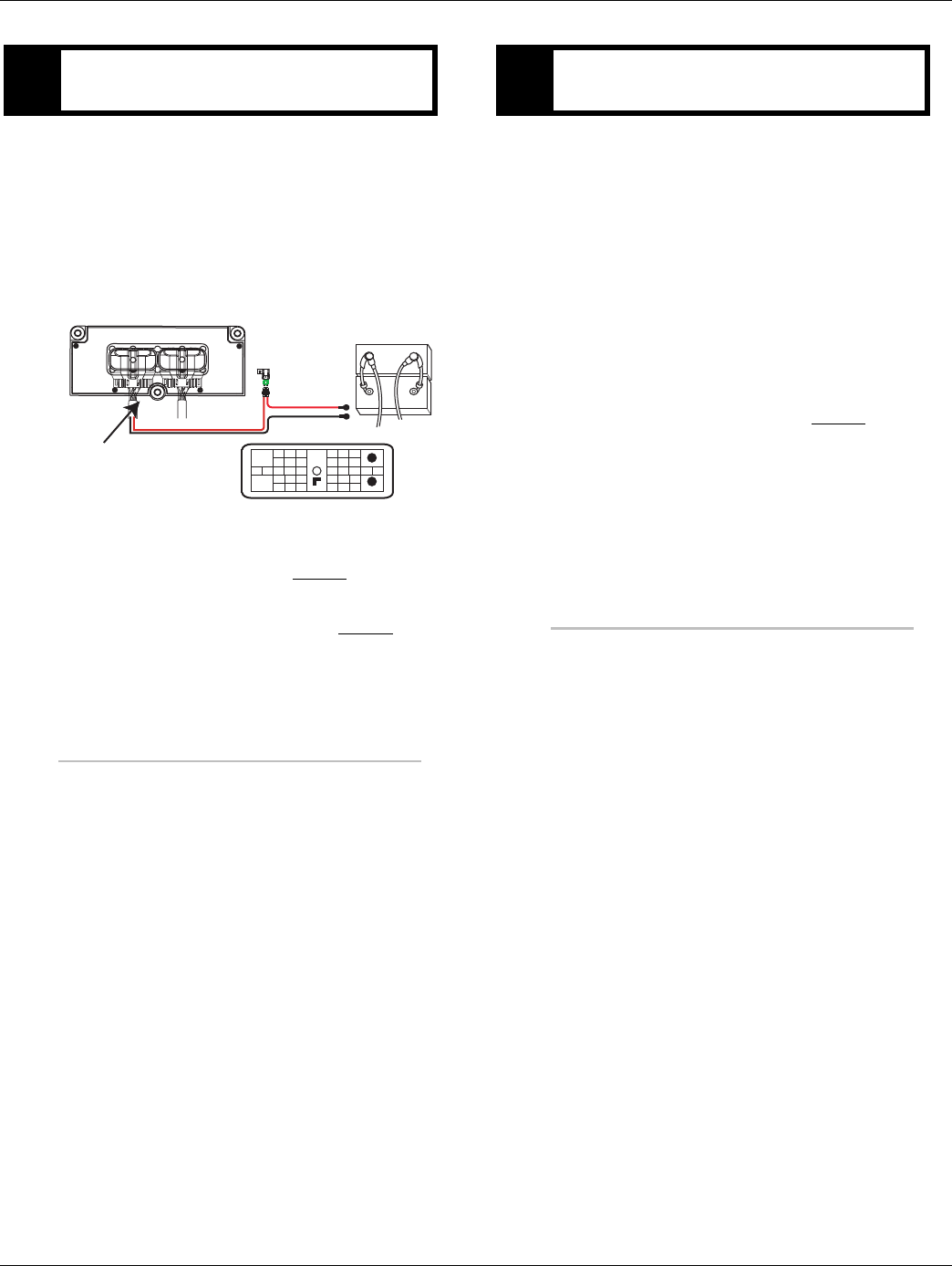
140 © 2016 Eaton. All rights reserved 2016.01.15
Fault Code 37 - Power Supply | Fault Isolation Procedures TRTS0930
1. Key off.
2. Disconnect negative battery cable.
3. Disconnect the Vehicle Harness 38-way.
4. Inspect main power 38-way connector terminals
Pin 36 and Pin 38, in-line fuse holder, and power
supply connections for integrity and corrosion.
•If no problem found, go to Step V.
•If problem is found, repair power/ground path
for the main power supply. Go to Step V.
1. Key off.
2. Clean and reconnect all connectors.
3. Key on.
4. Clear codes. See “Fault Code Retrieval/Clearing” on
page 5.
5. Drive vehicle and attempt to reset the code
6. Check for codes See “Fault Code Retrieval/Clear-
ing” on page 5.
•If no codes, test complete.
•If Fault Code 37 appears go to Step A. to find
error in testing.
•If fault code other than 37 appears, See “Fault
Code Isolation Procedure Index” on page 8.
EPurpose: Visually inspect batteries, inline fuse,
power and ground supplies to the TECU.
+
–
+
–
Batteries
31
24 25
29 30
15 16
26
20
34
27 28
32 33
18 19
7
3
89
12 6
11 12
45
22
21
38
36
37
13 14
35 10
17
23
Front View
38-Way Connector
Vehicle Harness 38-way Connector
30 AMP fuse
Transmission ECU
VPurpose: Verify repair.

2016.01.15 © 2016 Eaton. All rights reserved 141
TRTS0930 Fault Isolation Procedures | Fault Code 37 - Power Supply

142 © 2016 Eaton. All rights reserved 2016.01.15
Fault Code 41 - Range Failed to Engage | Fault Isolation Procedures TRTS0930
Fault Code 41 - Range Failed to Engage
J1587: MID 130 PID 35, 36 FMI 7
J1939: SA 3 SPN 768, 769 FMI 7
Overview
This fault code indicates the transmission is unable to com-
plete a shift across the range. The range is either stuck in
high or low, or cannot complete engagement into high or
low.
Detection
The transmission attempts the same range shift 5 consecu-
tive times and determines the shift cannot be completed
based on the speeds across the back box.
Fallback
This fault causes a current range fallback and the transmis-
sion stays in either low range or high range. When the vehi-
cle comes to a stop, an attempt to shift into low range is
made.
Possible Causes
This fault code can be caused by any of the following:
• Low air pressure
• Contaminated air supply
• Air leak
• Range Solenoid Valve
• Range Synchronizer
• Range Actuator / Cylinder / Piston / Yoke
• Range Cover
Additional Tools
• Two 0-100 PSI Air pressure gauges
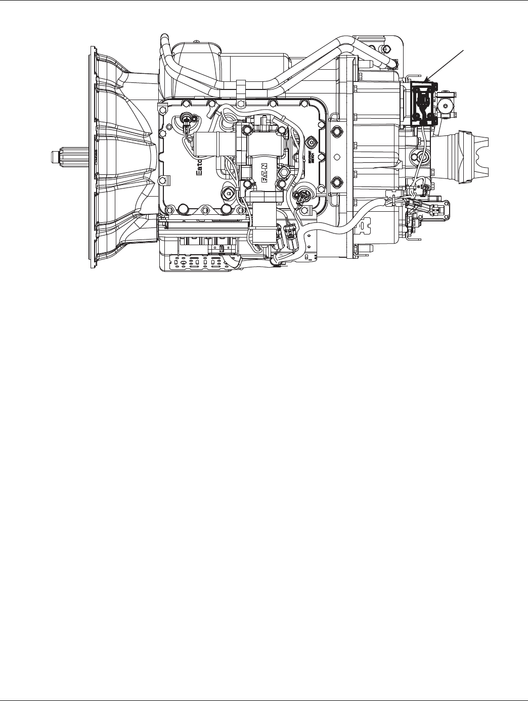
2016.01.15 © 2016 Eaton. All rights reserved 143
TRTS0930 Fault Isolation Procedures | Fault Code 41 - Range Failed to Engage
Component Identification
Range system
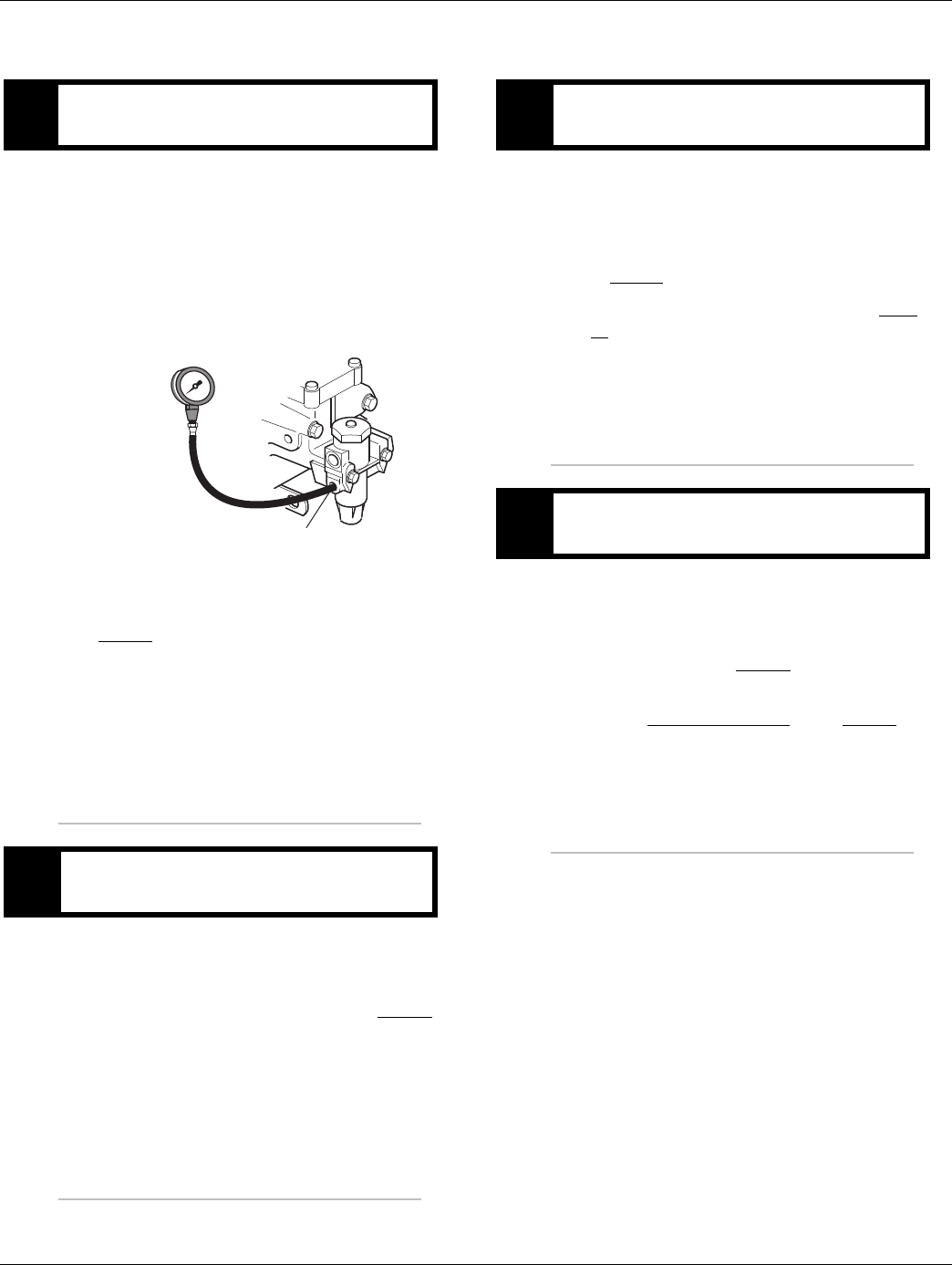
144 © 2016 Eaton. All rights reserved 2016.01.15
Fault Code 41 - Range Failed to Engage | Fault Isolation Procedures TRTS0930
Fault Code 41 - Range Failed to Engage
1. Key off.
2. Install a 0-100 PSI air pressure gauge in the regu-
lated test port of the air filter/regulator.
3. Start engine and allow air pressure to build to gov-
ernor cut-off.
4. Monitor the vehicle air pressure gauge on the dash.
•If air pressure cuts off at 90 to 120 PSI, go to
Step B.
•If air pressure is outside of range, repair the air
system as required. Repeat this step.
1. Key off.
2. Monitor the vehicle air pressure gauge on the dash.
•If vehicle maintains air pressure, go to Step C.
•If vehicle loses air pressure, repair the air sys-
tem as required. Repeat this step.
1. Read air pressure gauge installed at the regulated
port.
•If air pressure is in range is 55 to 65 PSI (or 75
to 80 PSI for UltraShift PLUS LAS Models), go
to Step E.
•If air pressure is outside of range, go to Step
D.
1. Remove air supply line to the air filter /regulator
and check airflow.
•If air flows from the supply line, repair Air Fil-
ter/Regulator. Go to Step C.
•If air does not flow from the supply line,
replace Air Filter Regulator. Go to Step C.
APurpose: Measure vehicle air supply pressure.
BPurpose: Measure vehicle maintains air supply
pressure.
Regulated test port
0-100 PSI
CPurpose: Verify air filter/regulator operation.
DPurpose: Confirm air flow to the filter regulator
supply port.
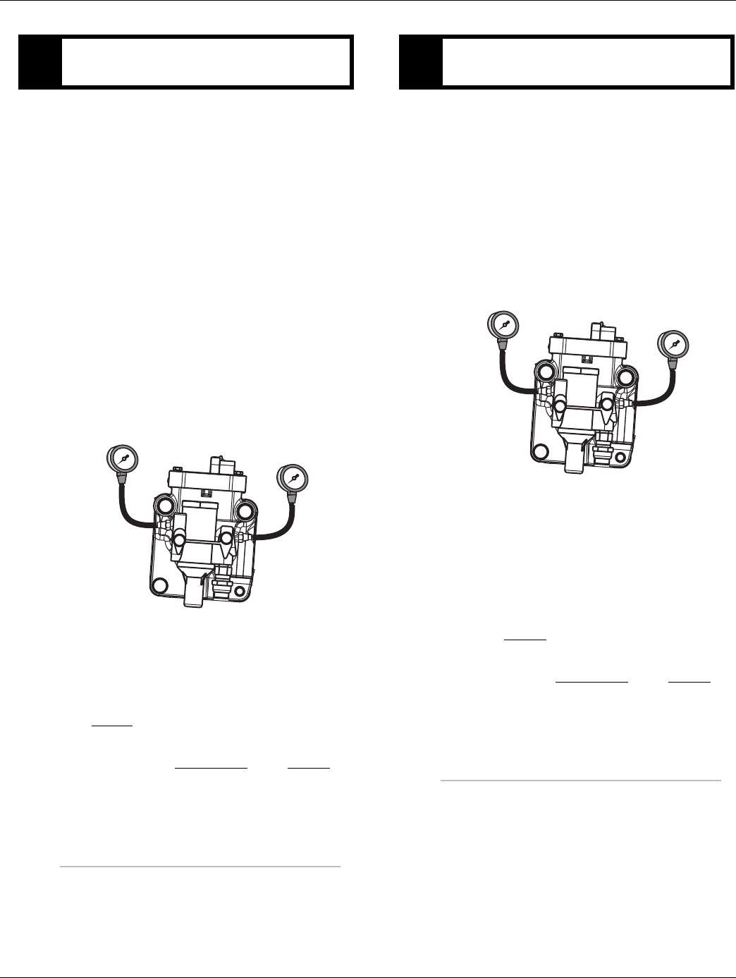
2016.01.15 © 2016 Eaton. All rights reserved 145
TRTS0930 Fault Isolation Procedures | Fault Code 41 - Range Failed to Engage
1. Key off.
2. Install two 0-100 PSI air pressure gauges into the
range cover diagnostic ports.
3. Start vehicle. Allow air pressure to build to gover-
nor cut-off.
4. Turn off engine, but leave key in on position.
5. With Shift Control, select reverse, then select neu-
tral.
Note: Allow 5 minutes for checking the air pressure
after shifting the transmission to neutral.
Note: Monitor gear display after selecting reverse,
then neutral and confirm gear position has changed
in the display. A gear change is required to energize
the range solenoid.
•If low range gauge is 55 to 65 PSI for Non-LAS
Models (75 to 80 PSI for UltraShift PLUS LAS
Models) and if high range gauge is 0 PSI, go to
Step F.
•If air pressure gauges do not read as shown
above, replace Range Valve. Go to Step V.
1. Key on.
2. With Shift Control, select the highest reverse gear
available by pressing the up-shift button/arrow,
then select neutral.
Note: Monitor gear display after selecting the high-
est reverse gear available and confirm gear position
has changed in the display. A gear change is
required to energize the range solenoid.
•If high range gauge
-55 to 65 PSI for Non-LAS Models
-75 to 80 PSI for UltraShift PLUS LAS Models
If low range gauge - 0 PSI for all others
Repair mechanical range system as required.
go to Step V.,
•If air pressure gauges do not read as shown
above, replace Range Valve. Go to Step V.
EPurpose: Measure low range air pressures.
LOW range
0-100 PSI gauge
HIGH range
0-100 PSI gauge
FPurpose: Measure high range air pressures.
LOW range
0-100 PSI gauge
HIGH range
0-100 PSI gauge

146 © 2016 Eaton. All rights reserved 2016.01.15
Fault Code 41 - Range Failed to Engage | Fault Isolation Procedures TRTS0930
1. Key off.
2. Remove all gauges.
3. Key on.
4. Clear codes. See “Fault Code Retrieval/Clearing” on
page 5.
5. Drive vehicle and attempt to reset the code
6. Check for codes. See “Fault Code Retrieval/Clear-
ing” on page 5.
•If no codes, test complete.
•If Fault Code 41 appears go to Step A. to find
error in testing.
•If fault code other than 41 appears, See “Fault
Code Isolation Procedure Index” on page 8.
VPurpose: Verify repair.

2016.01.15 © 2016 Eaton. All rights reserved 147
TRTS0930 Fault Isolation Procedures | Fault Code 41 - Range Failed to Engage

148 © 2016 Eaton. All rights reserved 2016.01.15
Fault Code 42 - Splitter Failed to Engage | Fault Isolation Procedures TRTS0930
Fault Code 42 - Splitter Failed to Engage
J1587: MID 130 PID 37, 38 FMI 7
J1939: SA 3 SPN 770, 771 FMI 7
Overview
This fault code indicates the transmission is unable to com-
plete a shift across the Splitter. The Splitter is either stuck in
high or low, or cannot complete engagement into high or
low.
Detection
The transmission attempts the same splitter shift 3 consec-
utive times and determines the shift cannot be completed
based on the speeds across the back box.
Fallback
This fault causes a current splitter fallback and the trans-
mission stays in either low split or high split.
Possible Causes
This fault code can be caused by any of the following:
• Low air pressure
• Contaminated air supply
• Air leak
• Splitter Solenoid Valve
• Splitter Actuator / Cylinder / Piston / Yoke
• Splitter Clutch
Additional Tools
• Two 0-100 PSI air pressure gauges
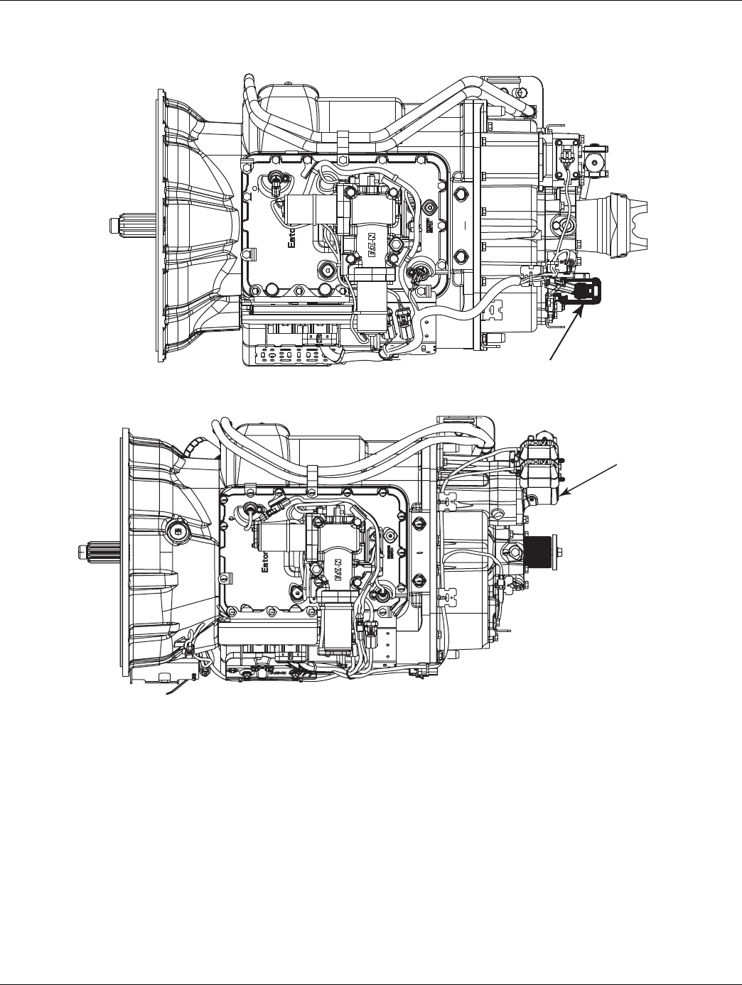
2016.01.15 © 2016 Eaton. All rights reserved 149
TRTS0930 Fault Isolation Procedures | Fault Code 42 - Splitter Failed to Engage
Component Identification
Splitter system
Reduction
Alternate View - Combination
Cylinder Models
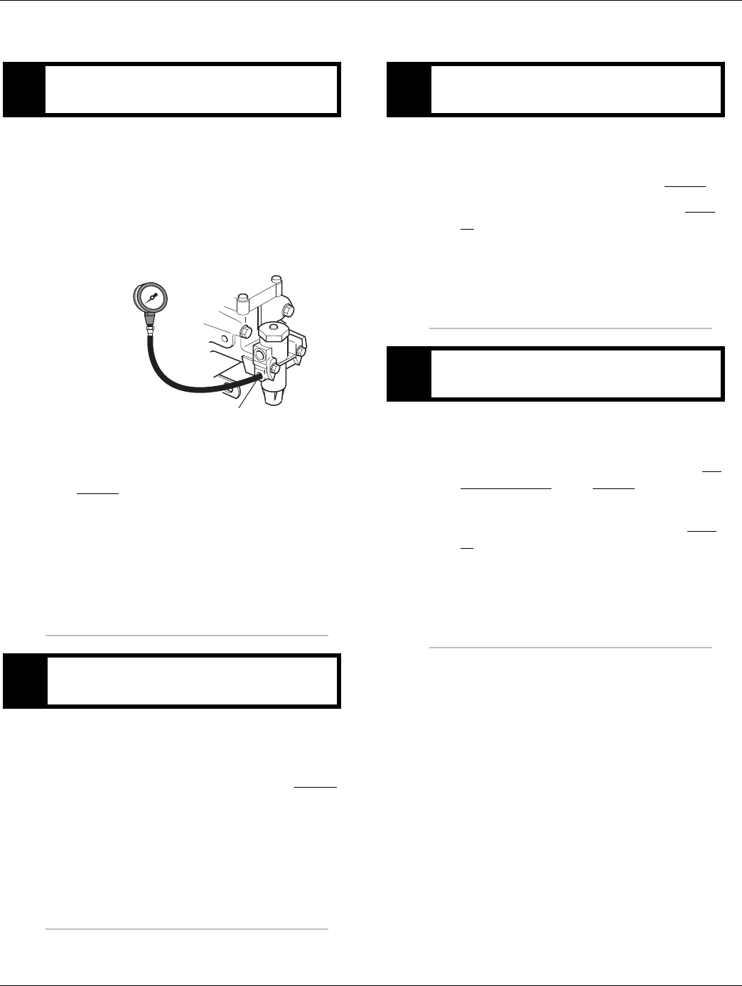
150 © 2016 Eaton. All rights reserved 2016.01.15
Fault Code 42 - Splitter Failed to Engage | Fault Isolation Procedures TRTS0930
Fault Code 42 - Splitter Failed to Engage
1. Key off.
2. Install a 0-100 PSI air pressure gauge in the regu-
lated test port of the air filter/regulator.
3. Start engine and allow air pressure to build to gov-
ernor cut-off.
4. Monitor the vehicle air pressure gauge on the dash.
•If air pressure cuts off at 90 to 120 PSI, go to
Step B.
•If air pressure is outside of range, repair vehi-
cle air system as required. Repeat this step.
1. Key off.
2. Monitor the vehicle air pressure gauge on the dash.
•If vehicle maintains air pressure, go to Step C.
•If vehicle loses air pressure, repair vehicle air
system as required. Repeat this step.
1. Read air pressure gauge installed at the regulated
port.
•If air pressure is 55 to 65 PSI, go to Step E.
•If air pressure is outside of range, go to Step
D.
1. Remove air supply line to the air filter /regulator
and check airflow.
•If air flows from the supply line, replace the Air
Filter Regulator. Go to Step C.
•If air does not flow from the supply line, repair
vehicle air supply to the regulator. Go to Step
C.
APurpose: Measure vehicle air supply pressure.
BPurpose: Measure vehicle maintains air supply
pressure.
Regulated test port
0-100 PSI
CPurpose: Verify air filter/regulator operation.
DPurpose: Confirm air flow to the filter regulator
supply port.
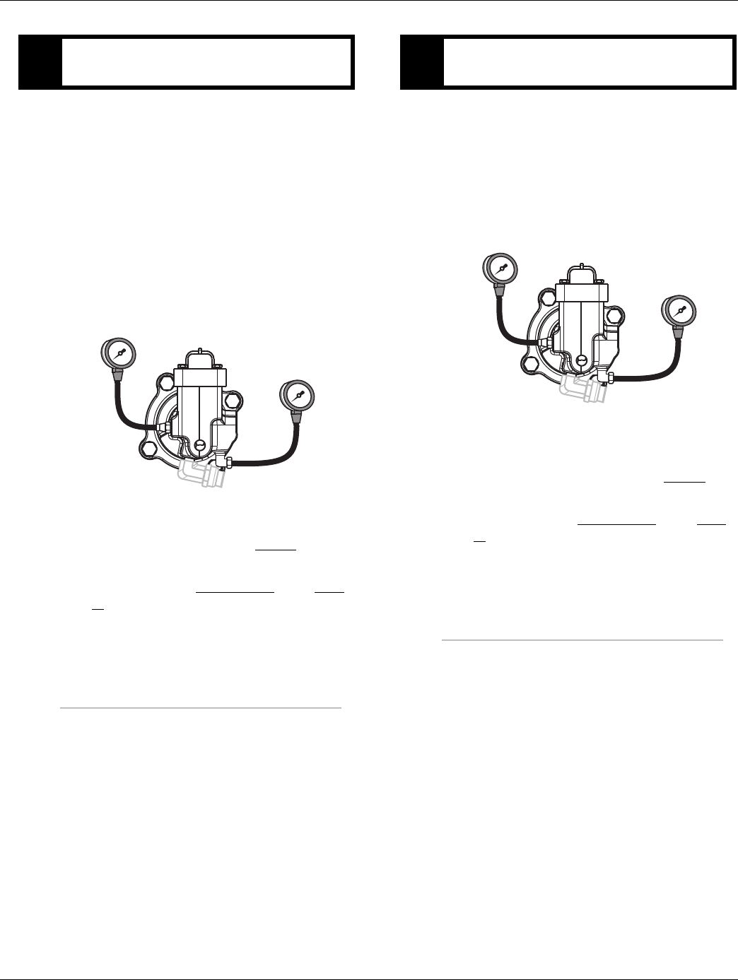
2016.01.15 © 2016 Eaton. All rights reserved 151
TRTS0930 Fault Isolation Procedures | Fault Code 42 - Splitter Failed to Engage
1. Key off.
2. Start vehicle and allow air pressure to build to gov-
ernor cut-off.
3. Turn off engine, but leave key in on position.
4. With Shift Control, select reverse (R1 in gear dis-
play for 13/18-speed), then select neutral.
Note: Five minutes is allowed for checking the
pressure after shifting the transmissions to
neutral.
•If Low Splitter gauge is 55 to 65 PSI and high
Splitter gauge is 0 PSI, go to Step F.
•If air pressure gauges do not read as shown
above, replace the Splitter Valve. Go to Step
V.
1. Key on.
2. With Shift Control, select reverse (R2 in the gear
display 13/18-speed).
Note: If R2 isn’t displayed the up arrow button
needs to be pressed.
•If High Splitter gauge is 55 to 65 PSI and Low
Splitter gauge is 0 PSI, repair Mechanical
Splitter system as required. Go to Step V.
•If air pressure gauges do not read as shown
above, replace the Splitter Valve. Go to Step
V.
EPurpose: Measure low splitter air pressures.
LO split
0-100 PSI gauge
HI split
0-100 PSI gauge
FPurpose: Measure high splitter air pressures.
LO split
0-100 PSI gauge
HI split
0-100 PSI gauge

152 © 2016 Eaton. All rights reserved 2016.01.15
Fault Code 42 - Splitter Failed to Engage | Fault Isolation Procedures TRTS0930
1. Key off.
2. Remove all pressure gauges.
3. Key on.
4. Clear codes. See “Fault Code Retrieval/Clearing” on
page 5.
5. Drive vehicle and attempt to reset the code
6. Check for codes. See “Fault Code Retrieval/Clear-
ing” on page 5.
•If no fault codes, test complete.
•If Fault Code 42 appears go to Step A. to find
error in testing.
•If fault code other than 42 appears, See “Fault
Code Isolation Procedure Index” on page 8.
VPurpose: Verify repair.

2016.01.15 © 2016 Eaton. All rights reserved 153
TRTS0930 Fault Isolation Procedures | Fault Code 42 - Splitter Failed to Engage

154 © 2016 Eaton. All rights reserved 2016.01.15
Fault Code 43 - Range Solenoid Valve | Fault Isolation Procedures TRTS0930
Fault Code 43 - Range Solenoid Valve
J1587: MID 130 PID 35, 36 FMI 3, 4, 5
J1939: SA 3 SPN 768, 769 FMI 3, 4, 5
Overview
This fault code indicates an electrical failure of the sole-
noids that control the Range Solenoid Valve.
When troubleshooting an Inactive code See “Product Diag-
nostic (PD) Mode” on page 11.
Detection
Starting at key-on and throughout operation, the Transmis-
sion Electronic Control Unit (TECU) constantly measures
this circuit. A failure mode of short to battery, short to
ground or open circuit is detected.
Fallback
This fault causes a current range fallback and the transmis-
sion stays in either low range or high range. When the vehi-
cle comes to a stop, an attempt to shift into low range is
made.
Possible Causes
This fault code can be caused by any of the following:
• Range Solenoid Valve
• Transmission Harness
• TECU
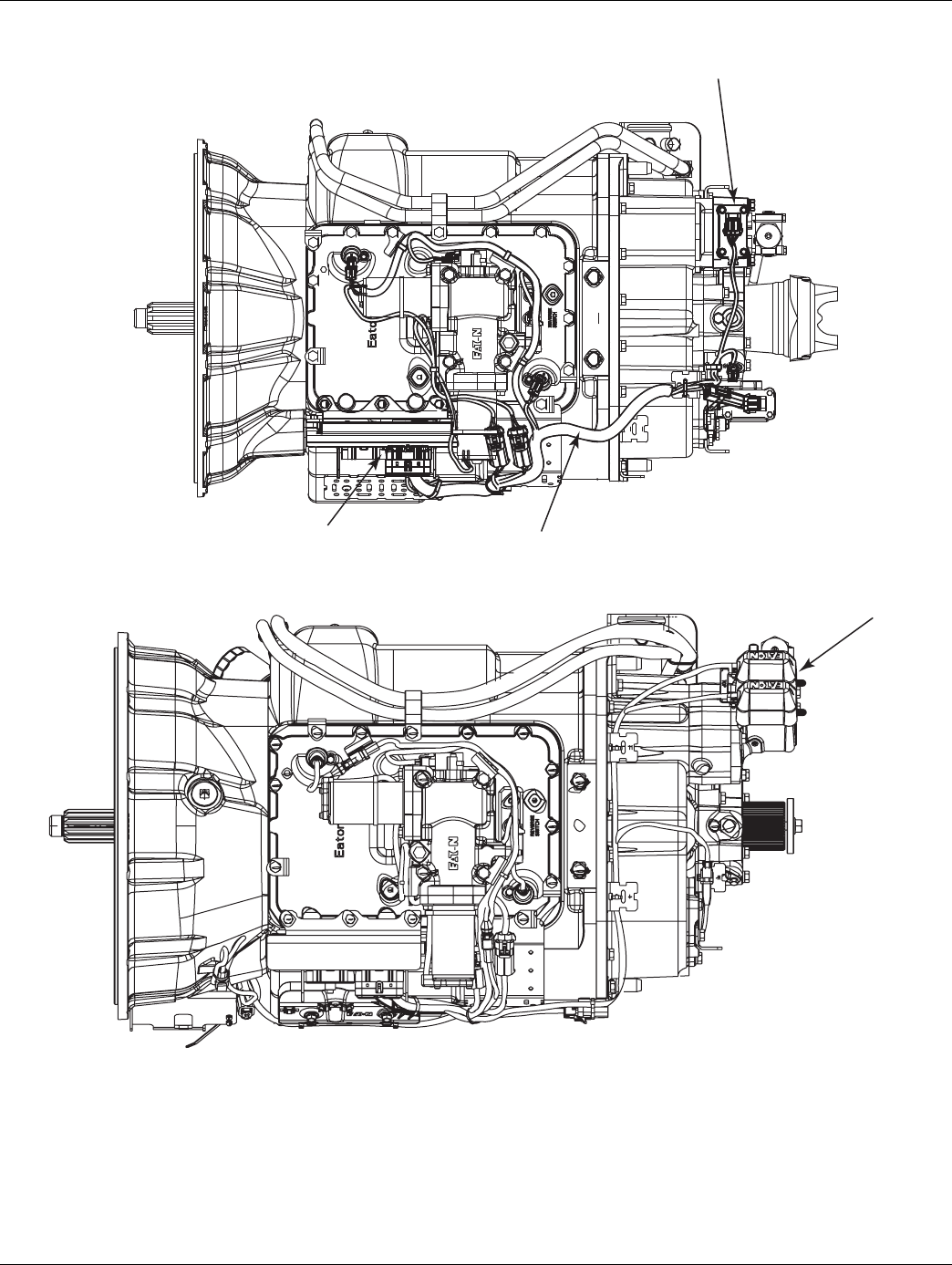
2016.01.15 © 2016 Eaton. All rights reserved 155
TRTS0930 Fault Isolation Procedures | Fault Code 43 - Range Solenoid Valve
Component Identification
Transmission controller
Range valve
Transmission harness
Range
Alternate View - Combination
Cylinder Models
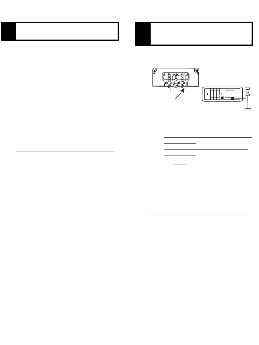
156 © 2016 Eaton. All rights reserved 2016.01.15
Fault Code 43 - Range Solenoid Valve | Fault Isolation Procedures TRTS0930
Fault Code 43 - Range Solenoid Valve
1. Key off.
2. Disconnect negative battery cable.
3. Disconnect the TECU 38-way connector.
4. Measure resistance between Pin 28 and Pin 6 and
between Pin 34 and Pin 6 on the Transmission Har-
ness 38-way connector.
Note: Observe polarity on Volt\Ohm Meter.
•If resistance is 9 to 16 ohms, go to Step B.
•If resistance is outside of range, go to Step C.
1. Measure resistance between the Transmission Har-
ness 38-way connector Pin 6 and ground.
•If resistance is OL, (if fault code is Active)
replace the:
-Medium-Duty Transmission Electronic Con-
trol Unit (TECU)
- Heavy-Duty Transmission Electronic Con-
trol Unit (TECU)
Go to Step V.
•If resistance is less than 10K ohm, go to Step
C.
APurpose: Measure resistance of high and low range
solenoids through the Transmission Harness. BPurpose: Test the Range Solenoid Valve common
line for shorts to ground through the Transmission
Harness.
OHMS
VCOM A
31
24 25
29 30
15 16
26
20
34
27 28
32 33
18 19
7
3
89
12 6
11 12
45
22
21
38
36
37
13 14
35 10
17
23
Front View
Transmission ECU Connector
Transmission Harness 38-way Connector
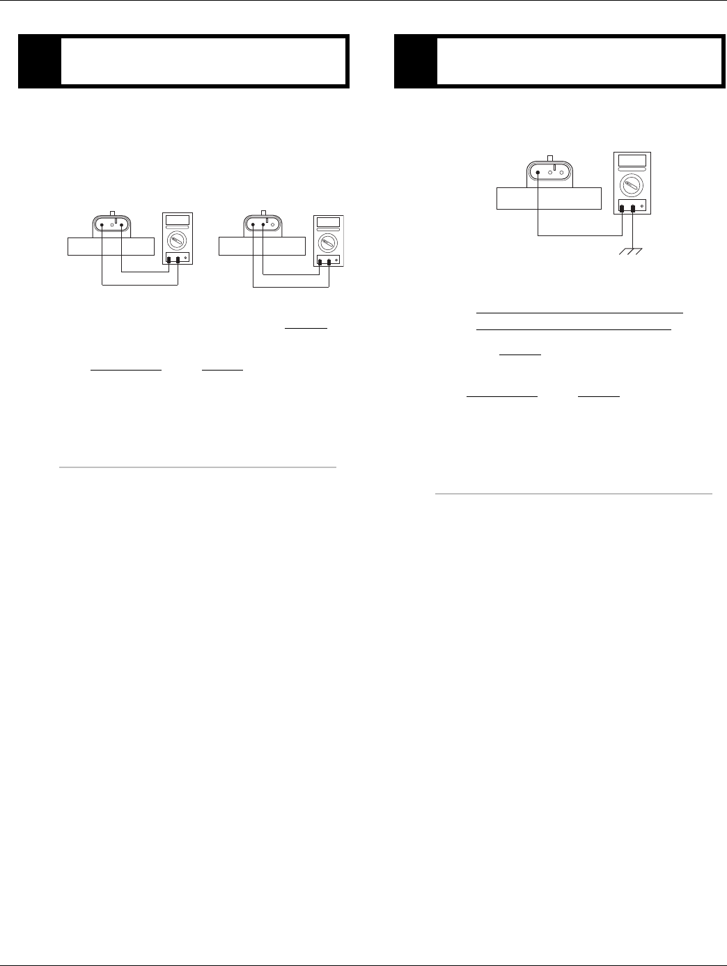
2016.01.15 © 2016 Eaton. All rights reserved 157
TRTS0930 Fault Isolation Procedures | Fault Code 43 - Range Solenoid Valve
1. Disconnect the Transmission Harness from Range
Solenoid Valve.
2. Measure resistance between Pin A and Pin C and
between Pin B and Pin C on the Range Solenoid
Valve pins:
•If resistance is 9 to 16 ohms, go to Step D.
•If resistance is outside of range, replace the
Range Valve. Go to Step V.
1. Measure resistance between Range Solenoid Valve
Pin C and ground.
•If resistance is OL, replace the:
- Medium-Duty Transmission Harness
- Heavy-Duty Transmission Harness
Go to Step V.
•If resistance is less than 10K ohm, replace the
Range Valve. Go to Step V.
CPurpose: Measure resistance of high and low range
solenoids at the Range Solenoid Valve.
BC AOHMS
VCOM A
BC AOHMS
VCOM A
DPurpose: Test the Range Solenoid common line for
shorts to ground at the Range Solenoid Valve.
BC A
OHMS
VCOM A

158 © 2016 Eaton. All rights reserved 2016.01.15
Fault Code 43 - Range Solenoid Valve | Fault Isolation Procedures TRTS0930
1. Key off.
2. Reconnect all connectors and the negative battery
cable.
3. Key on.
4. Clear codes. See “Fault Code Retrieval/Clearing” on
page 5.
5. Drive vehicle and attempt to reset the code.
6. Check for codes. See “Fault Code Retrieval/Clear-
ing” on page 5.
•If no codes, test complete.
•If Fault Code 43 appears go to Step A. to find
error in testing.
•If code other than 43 appears, See “Fault Code
Isolation Procedure Index” on page 8.
VPurpose: Verify repair.

2016.01.15 © 2016 Eaton. All rights reserved 159
TRTS0930 Fault Isolation Procedures | Fault Code 43 - Range Solenoid Valve

160 © 2016 Eaton. All rights reserved 2016.01.15
Fault Code 44 - Inertia Brake Solenoid Coil | Fault Isolation Procedures TRTS0930
Fault Code 44 - Inertia Brake Solenoid Coil
J1587: MID 130 SID 54 FMI 3, 4, 5
J1939: SA 3 SPN 787 FMI 3, 4, 5
Overview
This fault code indicates an electrical failure of the solenoid
that controls the Inertia Brake.
When troubleshooting an Inactive code See “Product Diag-
nostic (PD) Mode” on page 11.
Detection
Starting at key-on and throughout operation, the Transmis-
sion Electronic Control Unit (TECU) constantly measures
this circuit. A failure mode of a short to battery, short to
ground or open circuit is detected.
Fallback
No Fallback Mode; however, if the Inertia Brake system
failed, it may be difficult to engage a gear from a stop if the
Inertia Brake was providing assistance (due to a dragging
clutch). Also, hill shifting performance may be reduced.
Possible Causes
This fault code can be caused by any of the following:
• Inertia Brake Solenoid
• Transmission Harness
• TECU
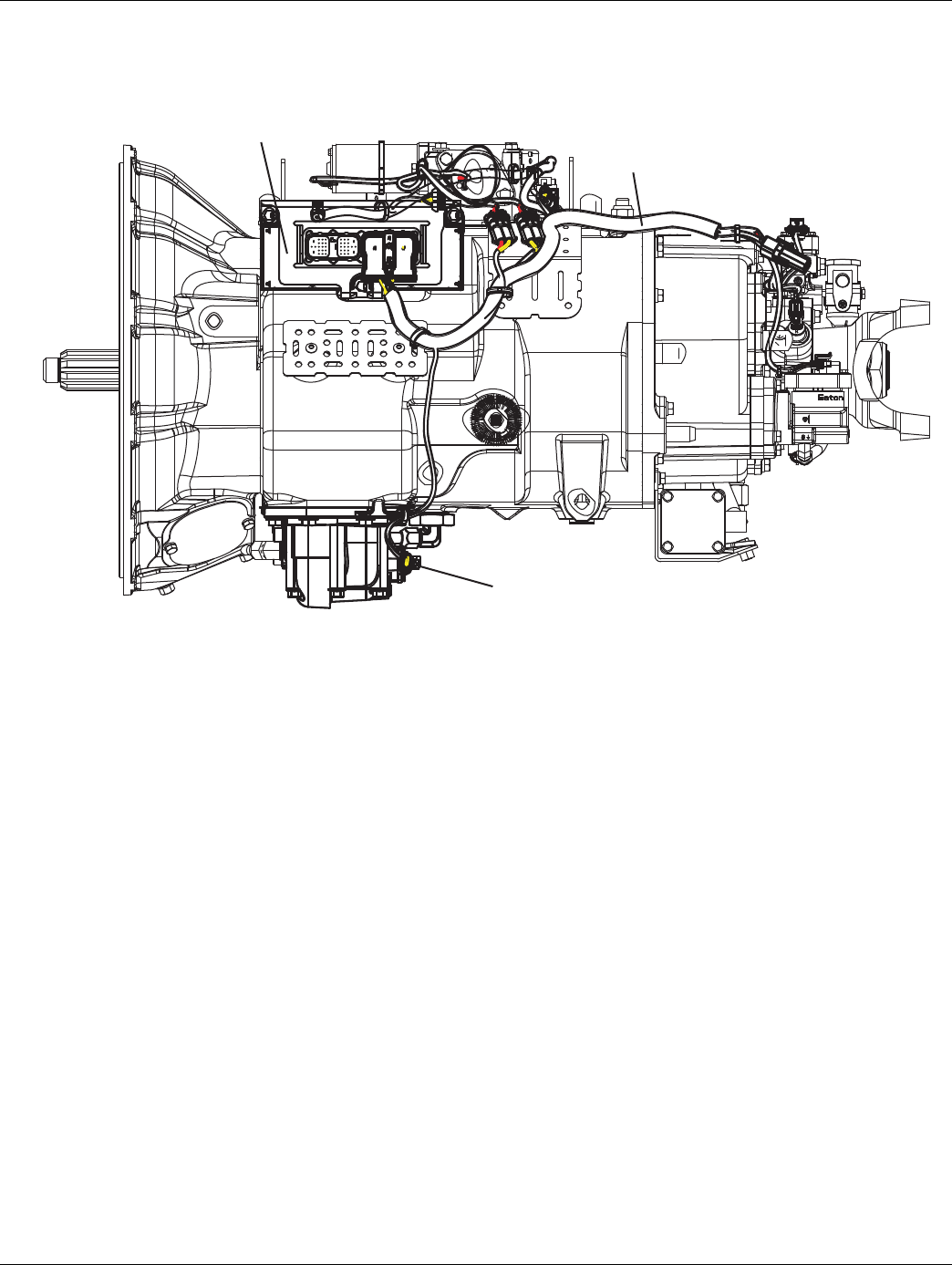
2016.01.15 © 2016 Eaton. All rights reserved 161
TRTS0930Fault Isolation Procedures | Fault Code 44 - Inertia Brake Solenoid Coil
Component Identifica-
tion
Transmission
controllerTransmission
harness
Inertia brake
solenoid coil
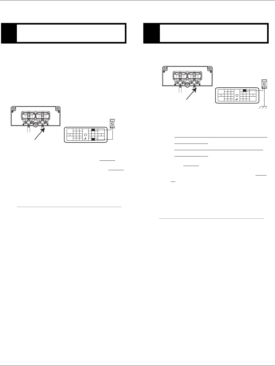
162 © 2016 Eaton. All rights reserved 2016.01.15
Fault Code 44 - Inertia Brake Solenoid Coil | Fault Isolation Procedures TRTS0930
Fault Code 44 - Inertia Brake Solenoid Coil
1. Key off.
2. Disconnect negative battery cable.
3. Disconnect the Transmission Harness 38-way con-
nector.
4. Measure resistance between the Transmission Har-
ness 38-way connector Pin 33 and Pin 5.
•If resistance is 2 to 6 ohms, go to Step B.
•If resistance is outside of range, go to Step C.
1. Measure resistance between the Transmission Har-
ness 38-way connector Pin 33 and ground.
•If resistance is OL, (if fault code is Active)
replace the:
-Medium-Duty Transmission Electronic Con-
trol Unit (TECU)
- Heavy-Duty Transmission Electronic Con-
trol Unit (TECU)
Go to Step V.
•If resistance is less than 10K ohm, go to Step
C.
APurpose: Measure resistance of the Inertia Brake
Solenoid coil through the Transmission Harness.
OHMS
VCOM A
31
24 25
29 30
15 16
26
20
34
27 28
32 33
18 19
7
3
89
12 6
11 12
45
22
21
38
36
37
13 14
35 10
17
23
Front View
38-Way Connector
Transmission Harness 38-way Connector
BPurpose: Test the high side solenoid coil for shorts
to ground through the Transmission Harness.
OHMS
VCOM A
31
24 25
29 30
15 16
26
20
34
27 28
32 33
18 19
7
3
89
12 6
11 12
45
22
21
38
36
37
13 14
35 10
17
23
Front View
38-Way Connector
Transmission Harness 38-way Connector
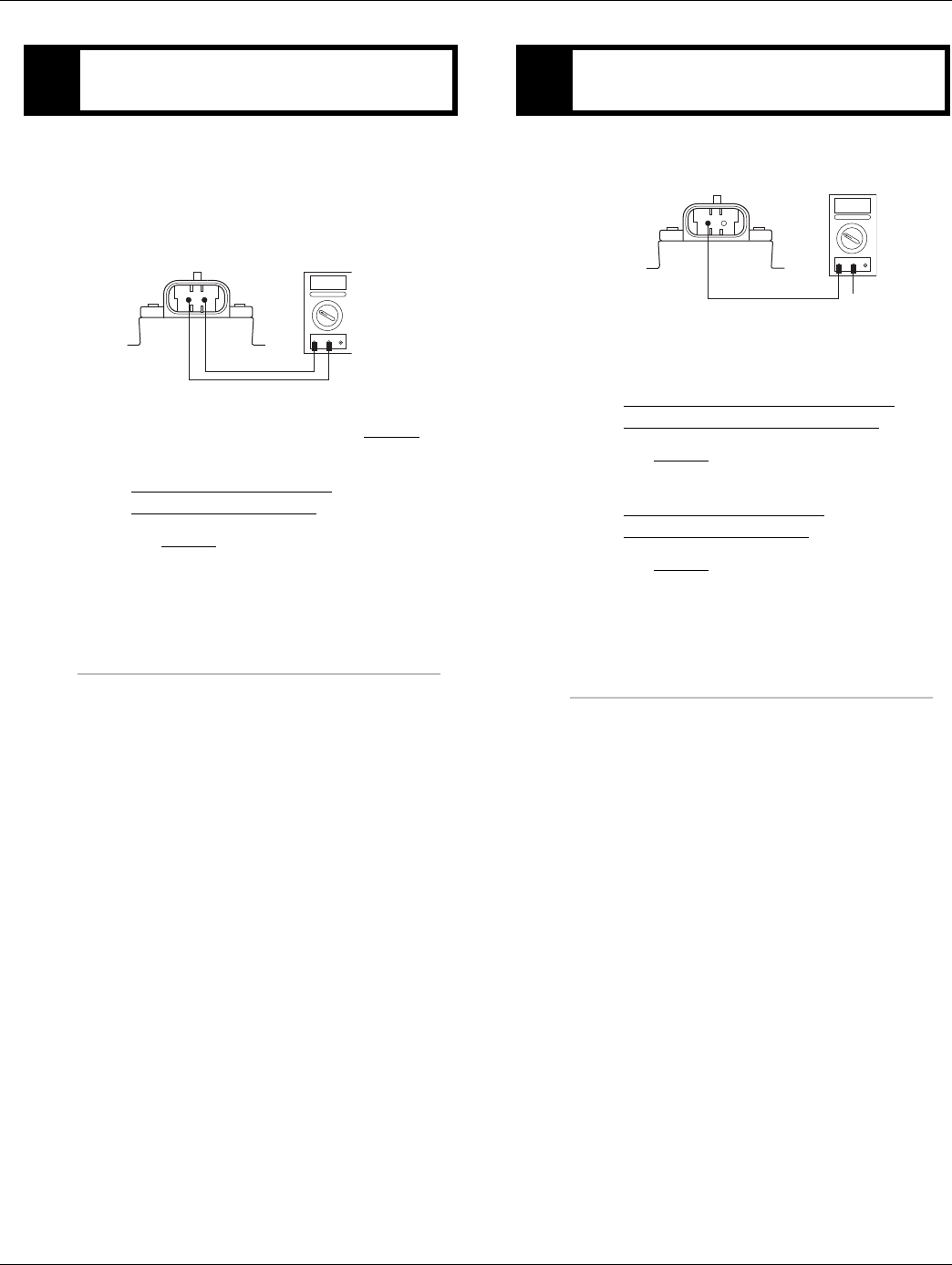
2016.01.15 © 2016 Eaton. All rights reserved 163
TRTS0930Fault Isolation Procedures | Fault Code 44 - Inertia Brake Solenoid Coil
1. Disconnect the Transmission Harness from Inertia
Brake coil.
2. Measure resistance between Inertia Brake coil Pin
A and Pin B.
•If resistance is 2 to 6 ohms, go to Step D.
•If resistance is outside of range, replace the:
- Medium-Duty Inertia Brake
- Heavy-Duty Inertia Brake
Go to Step V.
1. Measure resistance between Inertia Brake coil Pin
A and ground.
•If resistance is OL, replace the:
- Medium-Duty Transmission Harness
- Heavy-Duty Transmission Harness
Go to Step V.
•If resistance is less than 10K ohm, replace the:
- Medium-Duty Inertia Brake
- Heavy-Duty Inertia Brake
Go to Step V.
CPurpose: Measure resistance of the Inertia Brake
Solenoid coil at the Inertia Brake.
OHMS
VCOM A
B
A
DPurpose: Test the solenoid coil for shorts to
ground at the Inertia Brake.
GROUND
OHMS
VCOM A
B
A

164 © 2016 Eaton. All rights reserved 2016.01.15
Fault Code 44 - Inertia Brake Solenoid Coil | Fault Isolation Procedures TRTS0930
1. Key off.
2. Reconnect all connectors and the negative battery
cable.
3. Key on.
4. Clear codes. See “Fault Code Retrieval/Clearing” on
page 5.
5. Drive the vehicle and attempt to reset the code.
6. Check for codes. See “Fault Code Retrieval/Clear-
ing” on page 5.
•If no fault codes, Test complete.
•If Fault Code 44 appears go to Step A. to find
error in testing.
•If code other than 44 appears, See “Fault Code
Isolation Procedure Index” on page 8.
VPurpose: Verify repair.

2016.01.15 © 2016 Eaton. All rights reserved 165
TRTS0930Fault Isolation Procedures | Fault Code 44 - Inertia Brake Solenoid Coil

166 © 2016 Eaton. All rights reserved 2016.01.15
Fault Code 45 - High Capacity (HCIB) Failure | Fault Isolation Procedures TRTS0930
Fault Code 45 - High Capacity (HCIB) Failure
J1587: MID 130 SID 54 FMI 7
J1939: SA 3 SPN 787 FMI 7
Overview
The fault code indicates that the High Capacity Inertia Brake
(HCIB) is not performing as expected.
Detection
The HCIB fault sets if the Inertia Brake is unable to synchro-
nize the transmission during an upshift.
Fallback
No Fallback Mode; however, if the Inertia Brake system has
failed, it may be difficult to engage a gear from a neutral and
shifting performance may be reduced.
Possible Causes
This fault code can be caused by any of the following:
• Failed HCIB
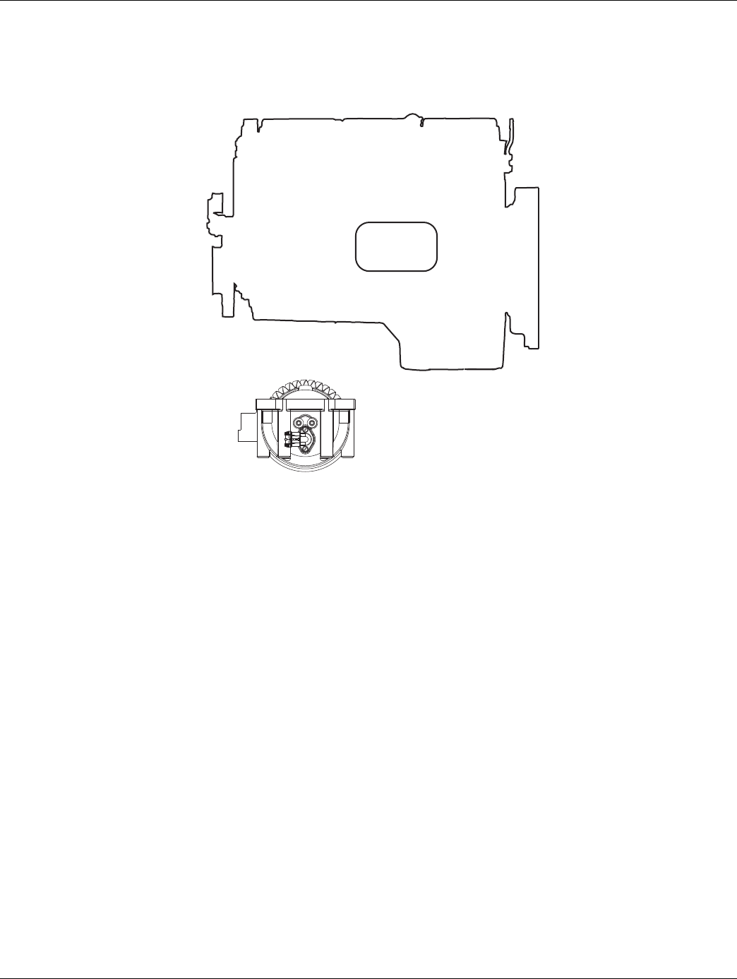
2016.01.15 © 2016 Eaton. All rights reserved 167
TRTS0930 Fault Isolation Procedures | Fault Code 45 - High Capacity (HCIB) Failure
Component Identification
Engine
ECM
Engine control system
High Capacity Inertia brake
A
B
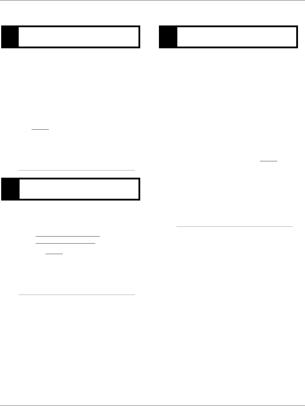
168 © 2016 Eaton. All rights reserved 2016.01.15
Fault Code 45 - High Capacity (HCIB) Failure | Fault Isolation Procedures TRTS0930
Fault Code 45 - High Capacity (HCIB) Failure
1. Key on.
2. Connect ServiceRanger.
3. Retrieve fault codes and FMIs with ServiceRanger
using the 9-way diagnostic connector.
•If Fault Code 27 or 44 are Active or Inactive,
see the “Fault Code Isolation Procedure Index”
on page 8
•If Fault Code 45 is Active or Inactive, go to
Step B.
1. Verify transmission model.
•If the transmission is an UltraShift model
(DM3, LST, LEP, or AW3), Replace the:
- Medium-Duty Inertia Brake
- Heavy-Duty Inertia Brake
Go to Step V.
1. Key off.
2. Reconnect all connectors and verify that all compo-
nents are properly installed.
3. Key on.
4. Clear codes, See “Fault Code Retrieval/Clearing” on
page 5.
5. Drive vehicle and verify proper transmission opera-
tion. Attempt to reset the code.
6. Check for fault codes, See “Fault Code
Retrieval/Clearing” on page 5.
•If no fault codes, test complete.
•If Fault Code 45 appears go to Step A. to find
error in testing.
•If code other than 45 appears, See “Fault Code
Isolation Procedure Index” on page 8.
APurpose: Check for active or Inactive fault codes.
BPurpose: Verify transmission model.
VPurpose: Verify repair.

2016.01.15 © 2016 Eaton. All rights reserved 169
TRTS0930 Fault Isolation Procedures | Fault Code 45 - High Capacity (HCIB) Failure

170 © 2016 Eaton. All rights reserved 2016.01.15
Fault Code 46 - Splitter Direct and Indirect Solenoid Valve | Fault Isolation Procedures TRTS0930
Fault Code 46 - Splitter Direct and Indirect Solenoid Valve
J1587: MID 130 SID 37, 38 FMI 3, 4, 5
J1939: SA 3 SPN 770, 771 FMI 3, 4, 5
Overview
This fault code indicates an electrical failure of the sole-
noids that control the Splitter Solenoid Valve.
When troubleshooting an Inactive code See “Product Diag-
nostic (PD) Mode” on page 11.
Detection
Starting at key-on and throughout operation, the Transmis-
sion Electronic Control Unit (TECU) constantly measures
this circuit. Depending on the reading, a failure mode of
short to battery, short to ground or open circuit is detected.
Fallback
This fault causes a current splitter fallback and the trans-
mission stays in either low split or high split.
Possible Causes
This fault code can be caused by any of the following:
• Splitter Solenoid Valve
• Transmission Harness
• TECU
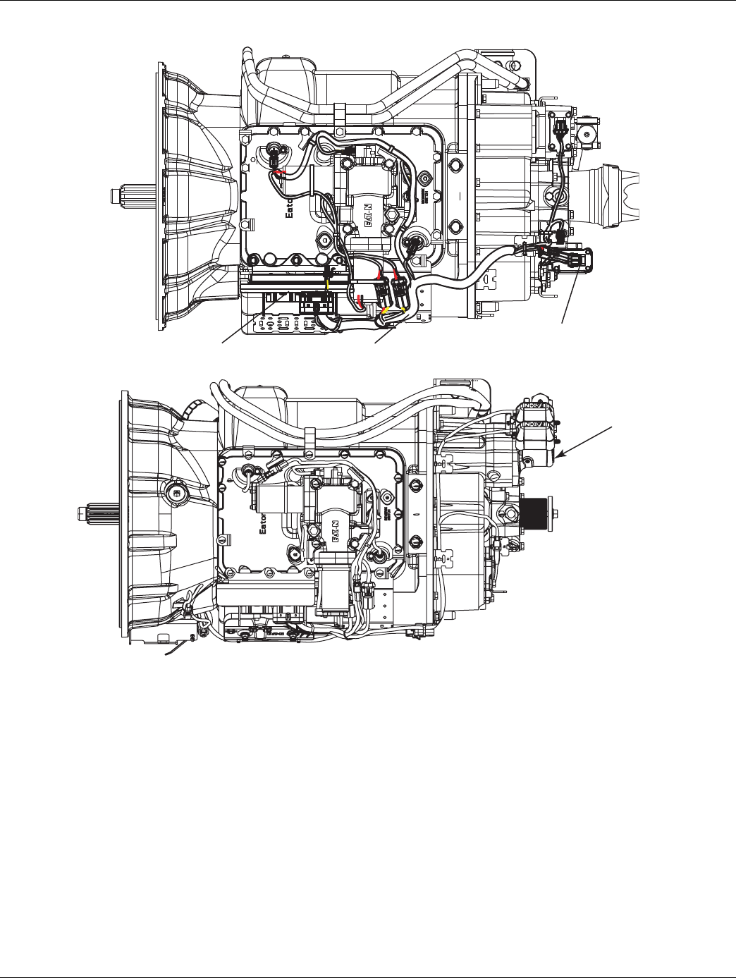
2016.01.15 © 2016 Eaton. All rights reserved 171
TRTS0930 Fault Isolation Procedures | Fault Code 46 - Splitter Direct and Indirect Solenoid Valve
Component Identification
Transmission controller
Splitter valve
Transmission harness
Reduction
Alternate View - Combination
Cylinder Models
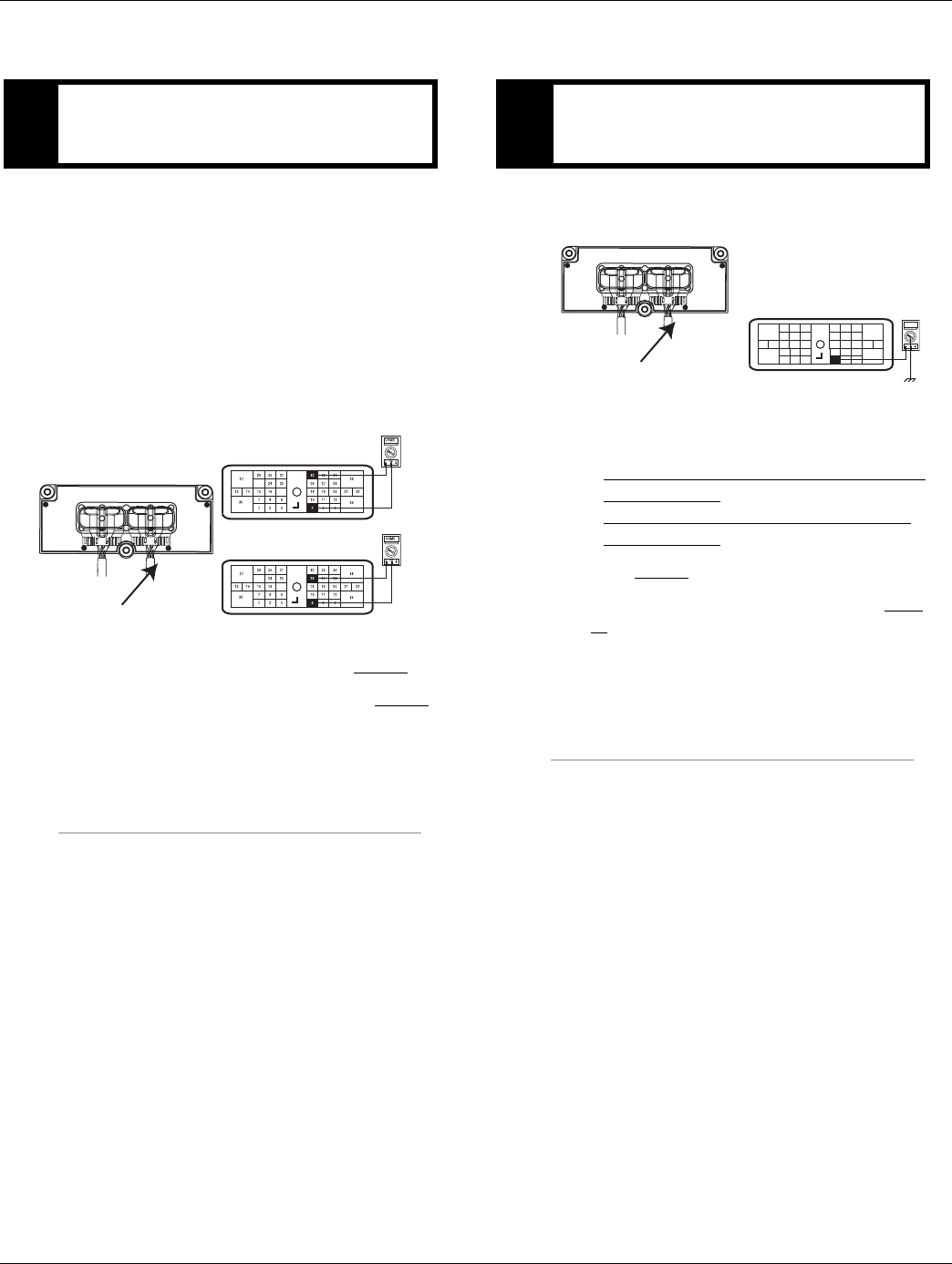
172 © 2016 Eaton. All rights reserved 2016.01.15
Fault Code 46 - Splitter Direct Solenoid Valve | Fault Isolation Procedures TRTS0930
Fault Code 46 - Splitter Direct Solenoid Valve
1. Key off.
2. Disconnect negative battery cable.
3. Disconnect the Transmission Harness 38-way con-
nector.
4. Measure resistance between the Transmission Har-
ness 38-way connector pins:
•32 and 4
•26 and 4
•If resistance is 9 to 16 ohms, go to Step B.
•If resistance is outside of range, go to Step C..
1. Measure resistance between the Transmission Har-
ness 38-way connector Pin 4 and ground.
•If resistance is OL, (if fault code is Active)
replace the:
-Medium-Duty Transmission Electronic Con-
trol Unit (TECU)
- Heavy-Duty Transmission Electronic Con-
trol Unit (TECU)
Go to Step V.
•If resistance is less than 10K ohm, go to Step
C.
APurpose: Measure resistance of the high and low
splitter solenoids through the Transmission Har-
ness
17
23
Front View
38-Way Connector
17
23
Transmission Harness 38-Way Connector
BPurpose: Test the Splitter Solenoid Valve common
line for shorts to ground through the Transmission
Harness.
OHMS
VCOM A
31
24 25
29 30
15 16
26
20
34
27 28
32 33
18 19
7
3
89
12 6
11 12
45
22
21
38
36
37
13 14
35 10
17
23
Front View
38-Way Connector
Transmission Harness 38-way Connector
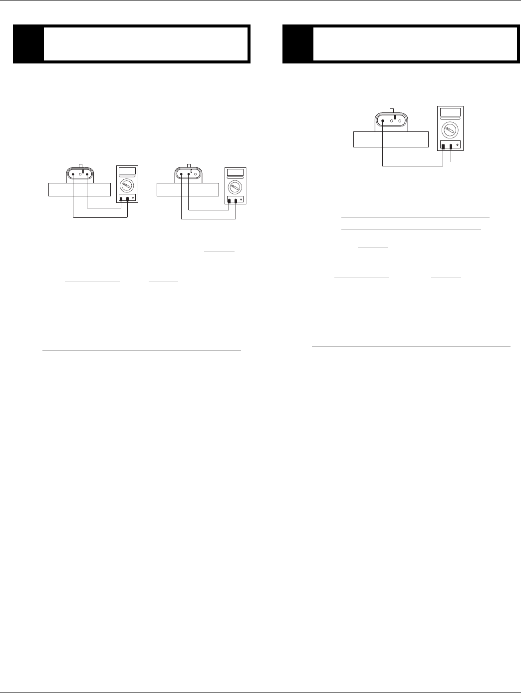
2016.01.15 © 2016 Eaton. All rights reserved 173
TRTS0930 Fault Isolation Procedures | Fault Code 46 - Splitter Direct Solenoid Valve
1. Disconnect the Transmission Harness from Splitter
Solenoid Valve.
2. Measure resistance between Splitter Solenoid Valve
pins:
-A and C
-B and C
•If resistance is 9 to 16 ohms, go to Step D.
•If resistance is outside of range, replace the
Splitter Valve. Go to Step V.
1. Measure resistance between Splitter Solenoid Valve
Pin C and ground.
•If resistance is OL, replace the:
- Medium-Duty Transmission Harness
- Heavy-Duty Transmission Harness
Go to Step V.
•If resistance is less than 10K ohm, replace the
Splitter Valve and go to Step V.
CPurpose: Measure resistance of the high and low
splitter solenoids at the Splitter Solenoid Valve.
BC AOHMS
VCOM A
BC AOHMS
VCOM A
DPurpose: Test the Splitter Solenoid Valve common
line for shorts to ground.
BC A
GROUND
OHMS
VCOM A

174 © 2016 Eaton. All rights reserved 2016.01.15
Fault Code 46 - Splitter Direct Solenoid Valve | Fault Isolation Procedures TRTS0930
1. Key off.
2. Reconnect all connectors and the negative battery
cable.
3. Key on.
4. Clear codes. See “Fault Code Retrieval/Clearing” on
page 5.
5. Drive the vehicle and attempt to reset the code.
6. Check for codes. See “Fault Code Retrieval/Clear-
ing” on page 5.
•If no codes, test complete.
•If Fault Code 46 appears go to Step A. to find
error in testing.
•If code other than 46 appears, See “Fault Code
Isolation Procedure Index” on page 8.
VPurpose: Verify repair.

2016.01.15 © 2016 Eaton. All rights reserved 175
TRTS0930 Fault Isolation Procedures | Fault Code 46 - Splitter Direct Solenoid Valve

176 © 2016 Eaton. All rights reserved 2016.01.15
Fault Code 51 - Rail Position Sensor | Fault Isolation Procedures TRTS0930
Fault Code 51 - Rail Position Sensor
J1587: MID 130 SID 60 FMI 2, 3, 4, 10
J1939: SA 3 SPN 60 FMI 2, 3, 4, 10
Overview
This fault code indicates an electrical failure of the Rail
Select Sensor or mechanical failure on the Electric Shifter.
The transmission controller supplies sensor power to the
Electric Shifter position sensors and uses the reported sen-
sor position to determine gear finger location. There are 4
fault conditions defined by the reported FMI via Ser-
viceRanger software.
This fault will not be set if a System Battery Voltage Low
fault (Fault Code 33) is active.
Detection
Starting at key-on and throughout operation, the transmis-
sion controller constantly monitors the position of the sen-
sor. If a failure condition is detected, the fault code is set.
Conditions to Set Fault Code Active
• FMI 2 - The transmission controller detects the rail
sensor voltage is outside the 10-90% range for 1
second or longer.
• FMI 3 - The transmission controller detects the rail
sensor supply voltage is 5% above the expected
supply voltage for 1 second or longer.
• FMI 4 - The transmission controller detects the rail
sensor supply voltage is 5% below the expected
supply voltage for 1 second or longer.
• FMI 10 - The transmission controller detects the
rail sensor signal moving more than +/- 0.093"
(2%) when the rail motor is turned off in gear.
Fallback
Fallback mode During Power-Up
• The transmission will power-up and may not be
able to confirm neutral, no start gears can be
selected.
•Unit may not crank. An equal sign will appear in the
display.
Fallback Mode During Operation
• The transmission remains in its current gear. An F
may appear in the gear display.
• The service light will blink.
• Until the fault is cleared, driver may have to shut off
engine in gear.
• Will not upshift, downshift nor shift into neutral.
Conditions to Set Fault Code Inactive
• FMI 2 - The fault becomes Inactive when the trans-
mission controller detects the rail sensor output
voltage is within 10% - 90% for 1 second or longer.
• FMI 3, 4 - The fault becomes Inactive when the
transmission controller detects the rail sensor sup-
ply is within +/- 5% of the expected voltage.
• FMI 10 - The rail position is within + / - 0.093" (2%)
of when the shift state went idle.
Possible Causes
This fault code can be caused by any of the following:
FMI 2, 4, 10:
• Transmission Harness - Connections and wires
between the transmission controller and the rail
sensor may be loose or damaged, terminals and
wires may be bent, burnt or wires may be
grounded, open or shorted.
• Electric Shifter - The rail sensor may have been
damaged or malfunctioned.
FMI 3:
•Transmission Controller - The transmission con-
troller may have been damaged or malfunctioned.
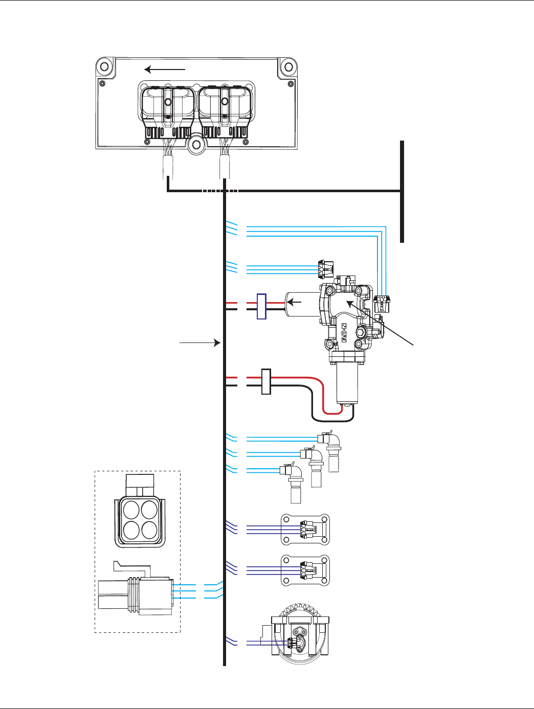
2016.01.15 © 2016 Eaton. All rights reserved 177
TRTS0930 Fault Isolation Procedures | Fault Code 51 - Rail Position Sensor
Component Identification
17
31
25
C
B
A
C
B
A
Range
valve K-3682
Splitter valve
(13 & 18 speed
only) K-3682
A
B
Main shaft
speed sensor K-3231
A
B
A
B
Rail select
sensor
Gear select
sensor
Output shaft speed
sensor K-3231
Input shaft
speed sensor K-3231
18
19
20
10
11
12
23
24
7
8
A
B
C
A
B
C
35
37
36
38
15
16
6
34
28
4
32
26
B
C
A
D
For Transmission
Diagnostics
4-way
B - Service Bat. +
C - Service Bat. -
A - Service Ignition +
B
C
A
Transmission Controller
OEM
Inertia brake (Optional)
A
B
33
5
Black
Connector
Blue
Connector
Front of Transmission
(Located at the left rear
corner of the transmission)
Front
XY Shifter
Assy K-3784
Gen 3 Transmission
Harness Assy
K-3681
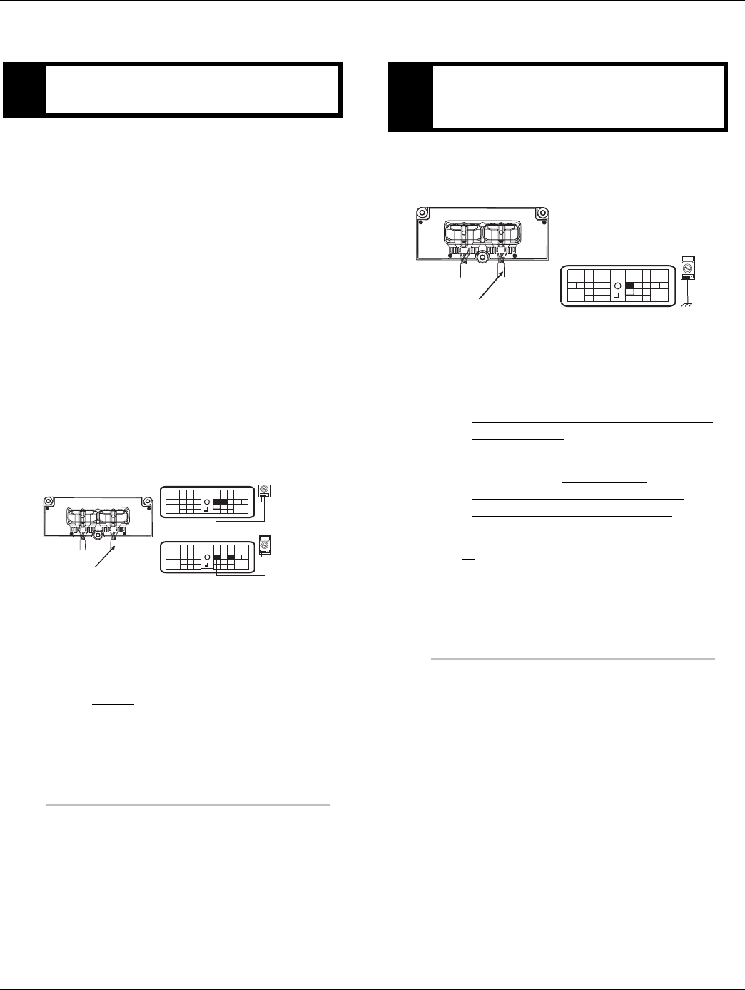
178 © 2016 Eaton. All rights reserved 2016.01.15
Fault Code 51 - Rail Position Sensor | Fault Isolation Procedures TRTS0930
Fault Code 51 - Rail Position Sensor
1. If the fault code is Inactive put unit in PDM mode
and perform the wire wiggle test. Check the overall
harness connections to sensor. If a tone is heard
and/or a fault code appears in the gear display, the
Fault Code Isolation Procedure Index.
2. Key off.
3. Disconnect negative battery cable.
4. Disconnect the Transmission Harness 38-way con-
nector.
5. Measure resistance between Pin 18 and Pin 19 and
between Pin 18 and Pin 20 on the Transmission
Harness 38-way connector.
Note: An Auto Ranging Digital Volt/Ohm Meter
must be used.
6. Measure resistance of the Rail Position Sensors
through the Transmission Harness.
•If resistance between Pin 18 and Pin 19 is 100
to 200 ohms and between Pin 18 and Pin 20
resistance is 5K to 7K ohm, go to Step B.
•If any of the above conditions are not met, go
to Step C.
1. Measure resistance between Transmission Harness
38-way connector Pin 18 to ground.
•If resistance is OL, Reconnect 38-way connec-
tor, (if fault code is Active) replace the:
- Medium-Duty Transmission Electronic Con-
trol Unit (TECU)
- Heavy-Duty Transmission Electronic Con-
trol Unit (TECU)
•If FMI 2, 3, 4, or 10 is present with an Inactive
code, replace the Electric Shifter and the:
- Medium-Duty Transmission Harness
- Heavy-Duty Transmission Harness
•If resistance is less than 10K ohm, go to Step
C.
APurpose: Measure resistance of the Rail Position
Sensors through the Transmission Harness.
OHMS
VCOM A
VCOM A
31
24 25
29 30
15 16
26
20
34
27 28
32 33
18 19
7
3
89
12 6
11 12
45
22
21
38
36
37
13 14
35 10
17
23
31
24 25
29 30
15 16
26
20
34
27 28
32 33
18 19
7
3
89
12 6
11 12
45
22
21
38
36
37
13 14
35 10
17
23
Transmission Harness 38-way Connector
BPurpose: Test the Rail Position Sensor Plus line for
shorts to ground through the Transmission Har-
ness.
OHMS
VCOM A
31
24 25
29 30
15 16
26
20
34
27 28
32 33
18 19
7
3
89
12 6
11 12
45
22
21
38
36
37
13 14
35 10
17
23
Front View
38-Way Connector
Transmission Harness 38-way Connector
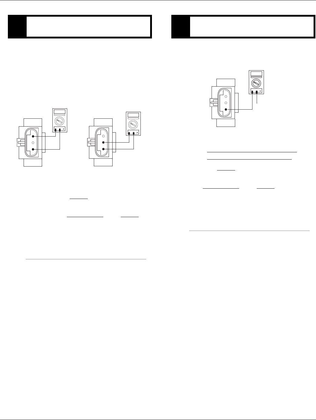
2016.01.15 © 2016 Eaton. All rights reserved 179
TRTS0930 Fault Isolation Procedures | Fault Code 51 - Rail Position Sensor
1. Disconnect Transmission Harness from Rail Select
Sensor.
2. Measure resistance between Pin A and Pin C and
between Pin A and Pin B on the Rail Select Sensor.
Note: An Auto Ranging Digital Volt/Ohm Meter
must be used.
•If resistance between Pin A and Pin C is 5K to
7K and between Pin A and Pin B is 100 to 200
ohms, go to Step D.
•If any of the above conditions are not met,
replace the Electric Shifter. Go to Step V.
1. Measure resistance between Rail Select Sensor Pin
A and ground.
•If resistance is OL, replace the:
- Medium-Duty Transmission Harness
- Heavy-Duty Transmission Harness
Go to Step V.
•If resistance is less than 10K ohm, replace the
Electric Shifter. Go to Step V.
CPurpose: Measure resistance of the Rail Position
Sensor.
OHMS
VCOM A
B
A
C
OHMS
VCOM A
B
A
C
DPurpose: Test the Rail Position Sensor Plus line for
shorts to ground.
OHMS
VCOM A
B
A
C
Ground

180 © 2016 Eaton. All rights reserved 2016.01.15
Fault Code 51 - Rail Position Sensor | Fault Isolation Procedures TRTS0930
1. Key off.
2. Reconnect all connectors.
3. Key on.
4. Clear codes, see “Fault Code Retrieval/Clearing” on
page 5.
5. Drive the vehicle and attempt to reset the code.
6. Check for fault codes, see “Fault Code
Retrieval/Clearing” on page 5.
•If no fault codes, test complete.
•If Fault Code 51 appears go to Step A. to find
error in testing.
•If code other than 51 appears, See “Fault Code
Isolation Procedure Index” on page 8.
VPurpose: Verify repair.

2016.01.15 © 2016 Eaton. All rights reserved 181
TRTS0930 Fault Isolation Procedures | Fault Code 51 - Rail Position Sensor

182 © 2016 Eaton. All rights reserved 2016.01.15
Fault Code 52 - Gear Position Sensor | Fault Isolation Procedures TRTS0930
Fault Code 52 - Gear Position Sensor
J1587: MID 130 SID 59 FMI 2, 3, 4, 7
J1939: SA 3 SPN 59 FMI 2, 3, 4, 7
Overview
This fault code indicates an electrical failure of the Rail
Select Sensor or mechanical failure on the Electric Shifter.
The transmission controller supplies sensor power to the
Electric Shifter position sensors and uses the reported sen-
sor position to determine gear finger location. There are 4
fault conditions defined by the reported FMI via Ser-
viceRanger software.
This fault will not be set if a System Battery Voltage Low
fault (Fault Code 33) is Active.
Detection
Starting at key-on and throughout operation, the transmis-
sion controller constantly monitors the position of the sen-
sor. If a failure condition is detected, the fault code is set.
Conditions to Set Fault Code Active
Conditions to Set the Fault Code Active
• FMI 2 - The transmission controller detects the
gear sensor voltage is outside the 10-90% range
for 1 second or longer.
• FMI 3 - The transmission controller detects the
gear sensor supply voltage is 5% above the
expected supply voltage for 1 second or longer.
• FMI 4 - The transmission controller detects the
gear sensor supply voltage is 5% below the
expected supply voltage for 1 second or longer.
Fallback
Fallback mode During Power-Up
• The transmission will power-up and may not be
able to confirm neutral, no start gears can be
selected.
•Unit may not crank. An equal sign may appear in
the display.
Fallback Mode During Operation
• The transmission remains in its current gear. An F
may appear in the gear display.
• The service light will blink.
• Until the fault is cleared, driver may have to shut off
engine in gear.
• Will not upshift, downshift nor shift to neutral.
Conditions to Set Fault Code Inactive
Conditions to Set the Fault Inactive
• FMI 2 - The fault becomes Inactive when the trans-
mission controller detects the gear sensor output
voltage is within 10% - 90% for 1 second or longer.
• FMI 3, 4 - The fault becomes Inactive when the
transmission controller detects the gear sensor
supply is within +/- 5% of the expected voltage.
• FMI 7 - Shift finger is beyond maximum engage-
ment.
Possible Causes
This fault code can be caused by any of the following:
FMI 2, 4:
• Transmission Harness - Connections and wires
between the transmission controller and the rail
sensor may be loose or damaged, terminals and
wires may be bent, burnt or wires may be
grounded, open, or shorted.
• Electric Shifter - The rail sensor may have been
damaged or malfunctioned.
FMI 3:
•Transmission Controller - The transmission con-
troller may have been damaged or malfunctioned.
FMI 7:
• Electric Shifter - Possible broken shift finger.
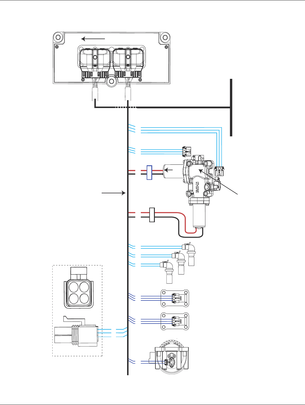
2016.01.15 © 2016 Eaton. All rights reserved 183
TRTS0930 Fault Isolation Procedures | Fault Code 52 - Gear Position Sensor
Component Identification
17
31
25
C
B
A
C
B
A
Range
valve K-3682
Splitter valve
(13 & 18 speed
only) K-3682
A
B
Main shaft
speed sensor K-3231
A
B
A
B
Rail select
sensor
Gear select
sensor
Output shaft speed
sensor K-3231
Input shaft
speed sensor K-3231
18
19
20
10
11
12
23
24
7
8
A
B
C
A
B
C
35
37
36
38
15
16
6
34
28
4
32
26
B
C
A
D
For Transmission
Diagnostics
4-way
B - Service Bat. +
C - Service Bat. -
A - Service Ignition +
B
C
A
Transmission Controller
OEM
Inertia brake (Optional)
A
B
33
5
Black
Connector
Blue
Connector
Front of Transmission
(Located at the left rear
corner of the transmission)
Front
XY Shifter
Assy K-3784
Gen 3 Transmission
Harness Assy
K-3681
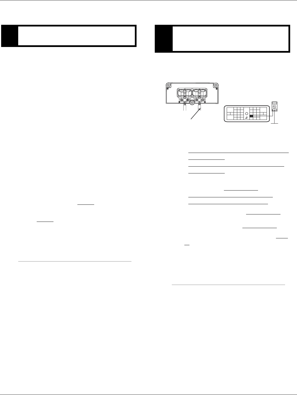
184 © 2016 Eaton. All rights reserved 2016.01.15
Fault Code 52 - Gear Position Sensor | Fault Isolation Procedures TRTS0930
Fault Code 52 - Gear Position Sensor
1. If the fault code is Inactive, see “Product Diagnostic
(PD) Mode” on page 11. Perform the wire wiggle
test. Check the overall harness connections to sen-
sor. If a tone is heard and/or a fault code appears in
the gear display, see “Fault Code Isolation Proce-
dure Index” on page 8..
2. Key off.
3. Disconnect negative battery cable.
4. Disconnect the Transmission Harness 38-way con-
nector.
5. Measure resistance between Transmission Harness
38-way connector pins:
-10 and 11
-10 and 12
Note: An Auto Ranging Digital Volt/Ohm Meter
must be used.
•If resistance between Pin 10 and Pin 11 is 100
to 200 ohms and between Pin 10 and Pin 12 is
5K to 7K ohm, go to Step B.
•If any of the above conditions are not met, go
to Step C.
1. Measure resistance between Transmission Harness
38-way connector Pin 10 to ground.
•If resistance is OL, reconnect 38-way connec-
tor, (if fault code is Active.) replace the:
- Medium-Duty Transmission Electronic Con-
trol Unit (TECU)
- Heavy-Duty Transmission Electronic Con-
trol Unit (TECU)
•If FMI 2, 3, or 4 is present with an Inactive
code, replace the Electric Shifter and the:
- Medium-Duty Transmission Harness
- Heavy-Duty Transmission Harness
•If FMI 7 is present, remove Electric Shifter to
inspect for a broken shift finger. If the shift fin-
ger is broken, replace the Electric Shifter.
•If resistance is less than 10K ohm, go to Step
C.
APurpose: Measure resistance of the Gear Position
Sensor through the Transmission Harness BPurpose: Test the Gear Position Sensor Plus line
for shorts to ground through the Transmission
Harness.
OHMS
VCOM A
31
24 25
29 30
15 16
26
20
34
27 28
32 33
18 19
7
3
89
12 6
11 12
45
22
21
38
36
37
13 14
35 10
17
23
Front View
38-Way Connector
Transmission Harness 38-way Connector
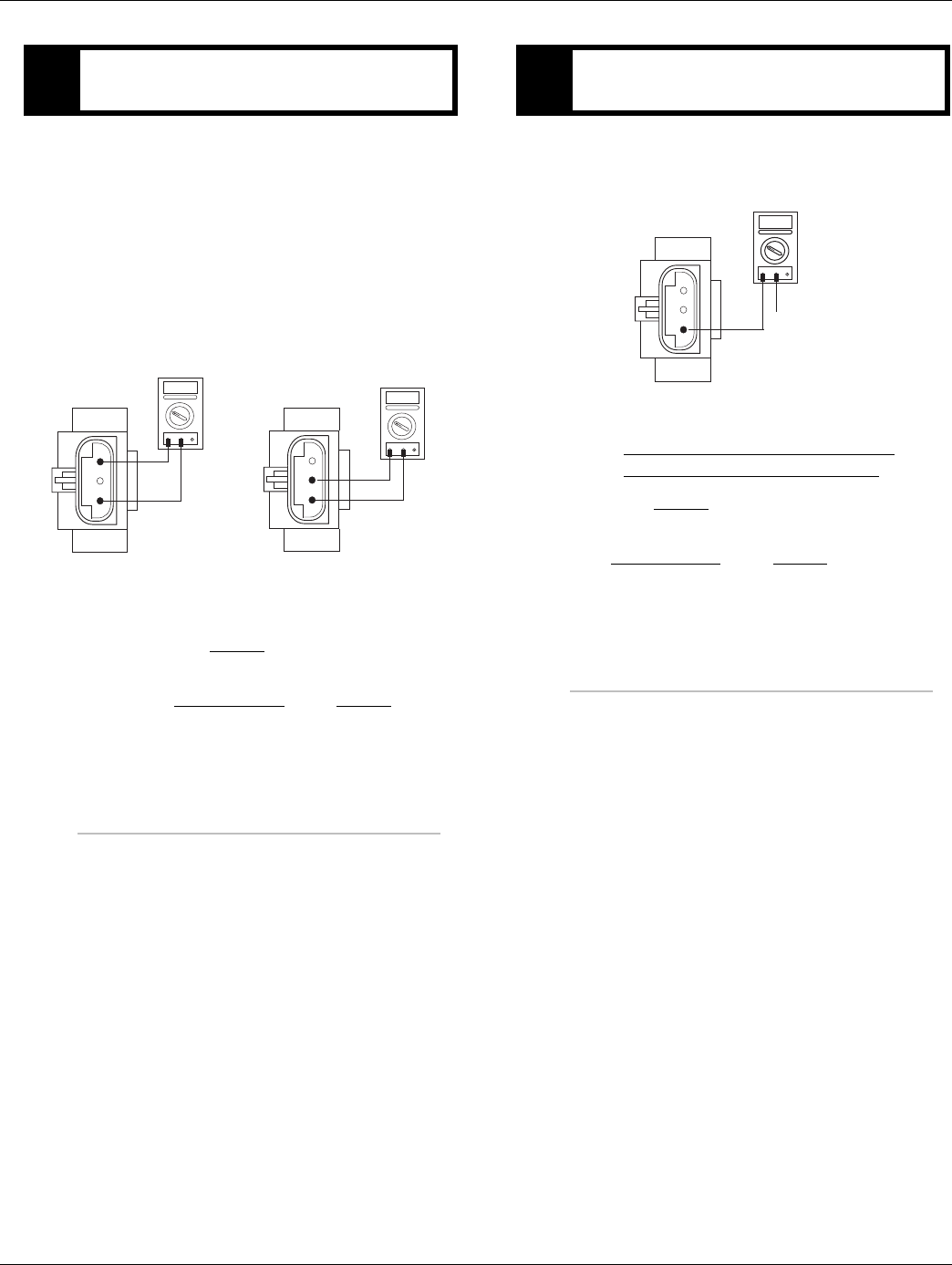
2016.01.15 © 2016 Eaton. All rights reserved 185
TRTS0930 Fault Isolation Procedures | Fault Code 52 - Gear Position Sensor
1. Disconnect Transmission Harness from Gear Select
Sensor.
2. Measure resistance between Gear Select Sensor
pins:
-A and C
-A and B
Note: An Auto Ranging Digital Volt/Ohm Meter
must be used.
•If Pin A and Pin C resistance is 5K to 7K ohm
and if Pin A and Pin B resistance is 100 to 200
ohms, go to Step D.
•If any of the above conditions are not met,
replace Electric Shifter. Go to Step V.
1. Measure resistance between Gear Select Sensor
Pin A and ground.
•If resistance is OL, replace the:
- Medium-Duty Transmission Harness
- Heavy-Duty Transmission Harness
Go to Step V.
•If resistance is less than 10K ohm, replace
Electric Shifter. Go to Step V.
CPurpose: Measure resistance of the Gear Position
Sensor.
OHMS
VCOM A
B
A
C
OHMS
VCOM A
B
A
C
DPurpose: Test the Gear Position Sensor Plus line
for shorts to ground.
OHMS
VCOM A
B
A
C
Ground

186 © 2016 Eaton. All rights reserved 2016.01.15
Fault Code 52 - Gear Position Sensor | Fault Isolation Procedures TRTS0930
1. Key off.
2. Reconnect all connectors.
3. Key on.
4. Clear fault codes, see “Fault Code Retrieval/Clear-
ing” on page 5.
5. Drive the vehicle and attempt to reset the fault
code.
6. Check for fault codes, see “Fault Code
Retrieval/Clearing” on page 5.
•If no fault codes, test complete.
•If Fault Code 52 appears, go to Step A. to find
error in testing.
•If code other than 52 appears, See “Fault Code
Isolation Procedure Index” on page 8.
VPurpose: Verify repair.

2016.01.15 © 2016 Eaton. All rights reserved 187
TRTS0930 Fault Isolation Procedures | Fault Code 52 - Gear Position Sensor

188 © 2016 Eaton. All rights reserved 2016.01.15
Fault Code 56 - Input Shaft Speed Sensor | Fault Isolation Procedures TRTS0930
Fault Code 56 - Input Shaft Speed Sensor
J1587: MID 130 PID 161 FMI 2, 3, 4, 5, 10
J1939: SA 3 SPN 161 FMI 2, 3, 4, 5, 10
Overview
This fault code indicates an electrical problem in the Input
Shaft Speed Sensor circuit. The signal from the sensor did
not match the current operating conditions.
When troubleshooting an Inactive code See “Product Diag-
nostic (PD) Mode” on page 11.
Detection
A speed sensor is determined faulty when all the speed sen-
sor readings are compared and one sensor is inconsistent,
or the sensor is shorted to power or ground.
Fallback
This fault causes an in-place fallback. If the Input Shaft
Speed Sensor fails before power-up, the transmission is
unable to engage a gear.
Possible Causes
This fault code can be caused by any of the following:
• Transmission Harness
• Input Shaft Speed Sensor
• Various Transmission Components
• Transmission Electronic Control Unit (TECU)
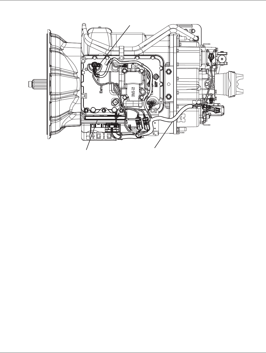
2016.01.15 © 2016 Eaton. All rights reserved 189
TRTS0930 Fault Isolation Procedures | Fault Code 56 - Input Shaft Speed Sensor
Component Identification
Input shaft
speed sensor
Transmission
harness
Transmission
controller
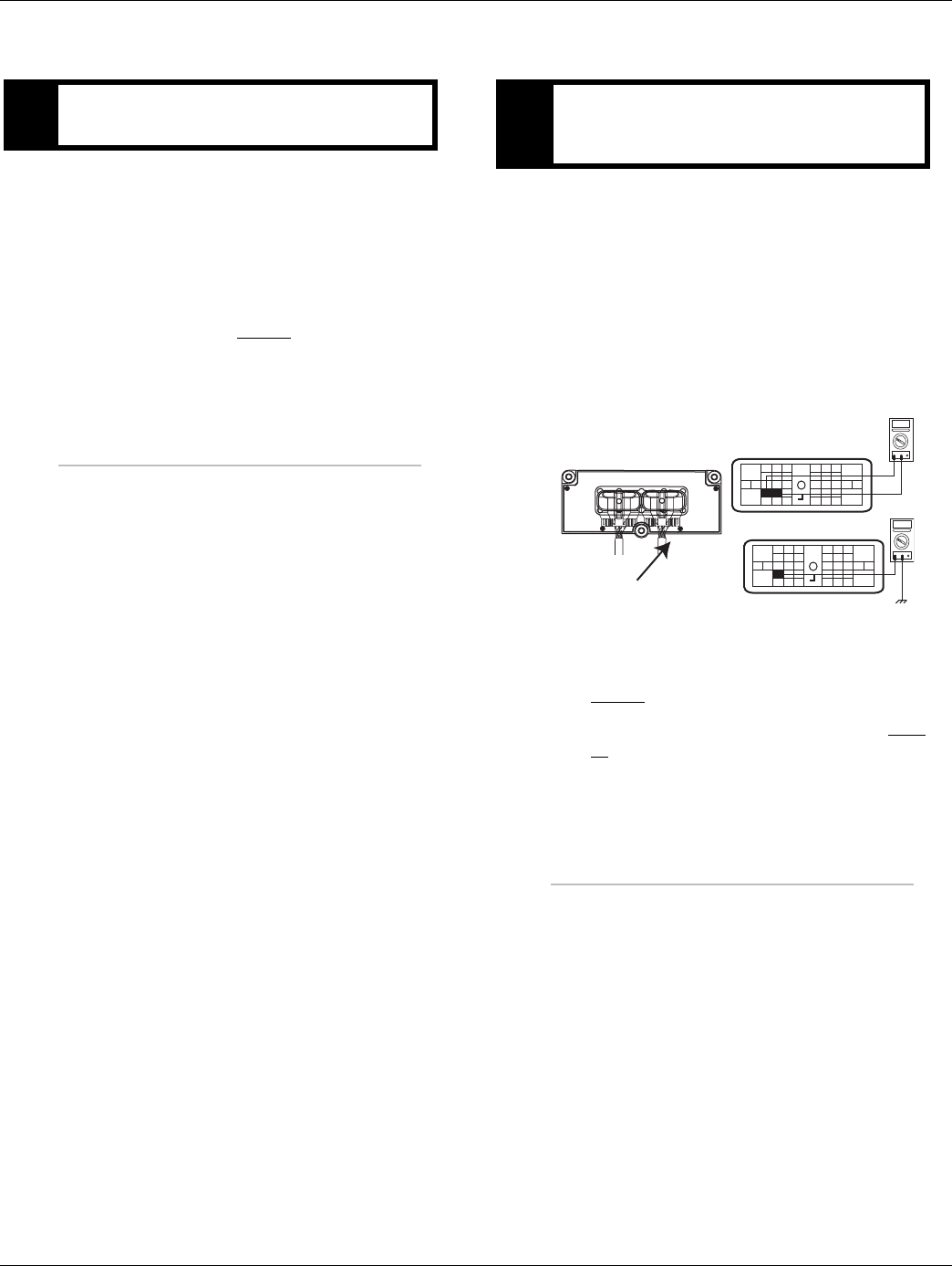
190 © 2016 Eaton. All rights reserved 2016.01.15
Fault Code 56 - Input Shaft Speed Sensor | Fault Isolation Procedures TRTS0930
Fault Code 56 - Input Shaft Speed Sensor
1. Drive vehicle and monitor engine RPM and Input
Shaft RPM with ServiceRanger.
•If engine RPM and Input Shaft RPM are the
same, and code is not active during test drive,
test complete.
•If Input Shaft RPM is erratic or varies from
engine RPM, go to Step B.
1. Key off.
2. Disconnect negative battery cable.
3. Disconnect the Transmission Harness 38-way con-
nector.
4. Measure resistance between the Transmission Har-
ness 38-way connector pins:
-7 and 8
-7 and ground
•If resistance between Pin 7 and Pin 8 is 2K to
4.5K ohm and Pin 7 to ground is OL, go to
Step C.
•If resistance is outside of the range, go to Step
D.
APurpose: Monitor engine speed and Input Shaft
speed in ServiceRanger. BPurpose: Measure Input Shaft Speed Sensor resis-
tance and test for short through the Transmission
Harness.
OHMS
VCOM A
31
24 25
29 30
15 16
26
20
34
27 28
32 33
18 19
7
3
89
12 6
11 12
45
22
21
38
36
37
13 14
35 10
17
23
Front View
38-Way Connector
OHMS
VCOM A
31
24 25
29 30
15 16
26
20
34
27 28
32 33
18 19
7
3
89
12 6
11 12
45
22
21
38
36
37
13 14
35 10
17
23
Transmission Harness 38-way Connector
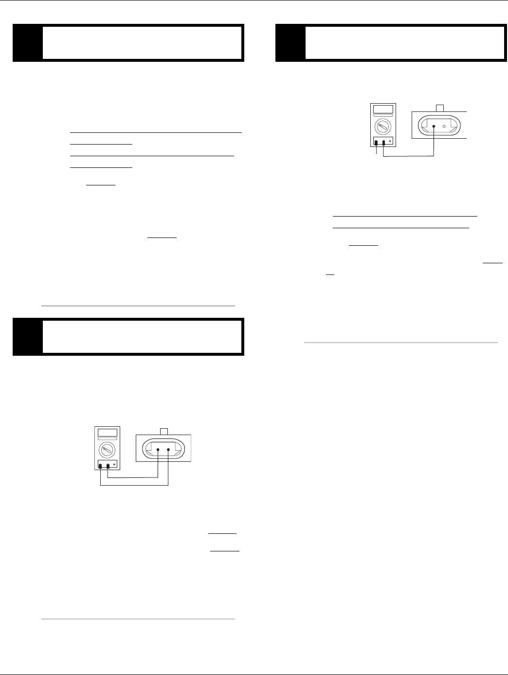
2016.01.15 © 2016 Eaton. All rights reserved 191
TRTS0930 Fault Isolation Procedures | Fault Code 56 - Input Shaft Speed Sensor
1. Inspect Input Shaft Speed Sensor for contamina-
tion or damage.
•If no problem found, (if fault code is Active)
replace the:
- Medium-Duty Transmission Electronic Con-
trol Unit (TECU)
- Heavy-Duty Transmission Electronic Con-
trol Unit (TECU)
Go to Step V.
•If problem found or you were sent here from
Step D or E, replace Input Shaft Speed Sensor
and inspect the upper countershaft PTO gear
for damage and go to Step V.
1. Disconnect the Transmission Harness from Input
Shaft Speed Sensor.
2. Measure resistance between Input Shaft Speed
Sensor Pin A and Pin B.
•If resistance is 2K to 4.5K ohm, go to Step E.
•If resistance is outside of range, go to Step C.
1. Measure resistance between Input Shaft Speed
Sensor Pin A and ground.
•If resistance is OL, replace the:
- Medium-Duty Transmission Harness
- Heavy-Duty Transmission Harness
Go to Step V.
•If resistance is less than 10K ohm, go to Step
C.
CPurpose: Visually inspect Input Shaft Speed Sen-
sor.
DPurpose: Measure Input Shaft Speed Sensor resis-
tance at the Input Shaft Speed Sensor.
AB
OHMS
VCOM A
EPurpose: Test Input Shaft Speed Sensor for shorts
to ground.
GROUND
AB
OHMS
VCOM A

192 © 2016 Eaton. All rights reserved 2016.01.15
Fault Code 56 - Input Shaft Speed Sensor | Fault Isolation Procedures TRTS0930
1. Key off.
2. Reconnect all connectors and the negative battery
cable.
3. Verify proper installation of speed sensor.
4. Key on.
5. Clear fault codes. See “Fault Code Retrieval/Clear-
ing” on page 5.
6. Drive the vehicle and attempt to reset the fault
code.
7. Check for fault codes. See “Fault Code
Retrieval/Clearing” on page 5.
•If no fault code, test complete.
•If Fault Code 56 appears, go to Step A. to find
error in testing,
•If fault code other than 56 appears, See “Fault
Code Isolation Procedure Index” on page 8.
VPurpose: Verify repair.

2016.01.15 © 2016 Eaton. All rights reserved 193
TRTS0930 Fault Isolation Procedures | Fault Code 56 - Input Shaft Speed Sensor

194 © 2016 Eaton. All rights reserved 2016.01.15
Fault Code 57 - Main Shaft Speed Sensor | Fault Isolation Procedures TRTS0930
Fault Code 57 - Main Shaft Speed Sensor
J1587: MID 130 PID 160 FMI 2, 3, 4, 5
J1939: SA 3 SPN 160 FMI 2, 3, 4, 5
Overview
This fault code indicates an electrical problem in the Main
Shaft Speed Sensor circuit. The signal from the sensor did
not match the current operating conditions
When troubleshooting an Inactive code See “Product Diag-
nostic (PD) Mode” on page 11.
Detection
A speed sensor is determined faulty when all the speed sen-
sor readings are compared and one sensor is inconsistent,
or the sensor is shorted to power or ground.
Fallback
This fault causes an In-Place fallback mode.
Possible Causes
This fault code can be caused by any of the following:
• Transmission Harness
• Main Shaft Speed Sensor
• Various transmission components
• Transmission Electronic Control Unit (TECU)
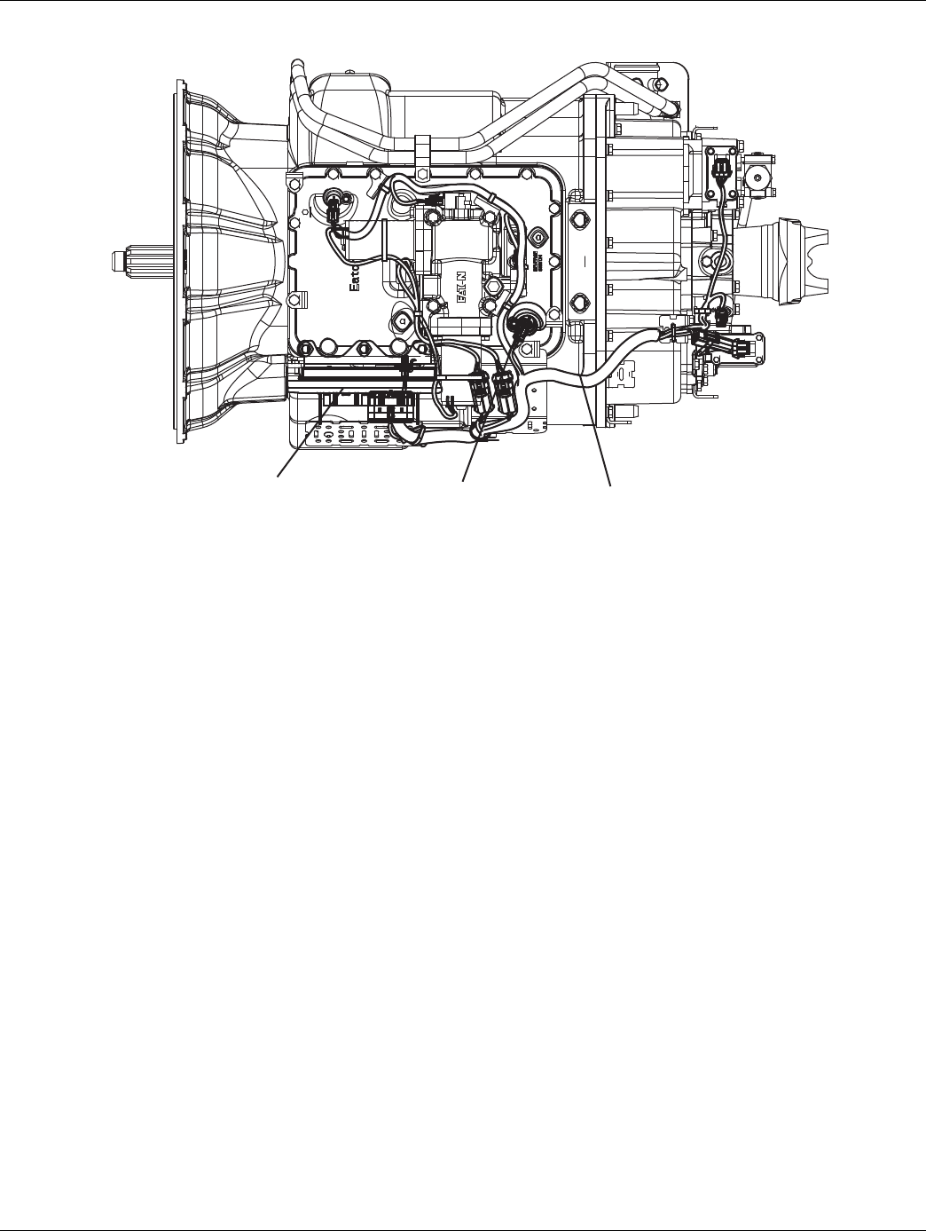
2016.01.15 © 2016 Eaton. All rights reserved 195
TRTS0930 Fault Isolation Procedures | Fault Code 57 - Main Shaft Speed Sensor
Component Identification
Transmission controller
Main shaft
speed sensorTransmission harness
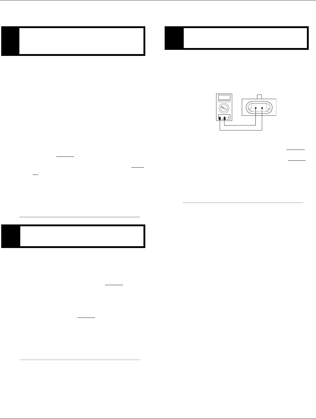
196 © 2016 Eaton. All rights reserved 2016.01.15
Fault Code 57 - Main Shaft Speed Sensor | Fault Isolation Procedures TRTS0930
Fault Code 57 - Main Shaft Speed Sensor
1. Key off.
2. Disconnect negative battery cable.
3. Disconnect the Transmission Harness 38-way con-
nector
4. Measure resistance between the Transmission Har-
ness 38-way connector pins:
-15 and 16
-15 and ground
•If resistance between Pin 15 and Pin 16 is 2k
to 4.5K ohm and between Pin 15 to ground is
OL, go to Step B.
•If resistance is outside of the range, go to Step
C.
1. Inspect Main Shaft Speed Sensor for contamina-
tion or damage.
•If no problem found, replace TECU (only if
fault code is Active) and go to Step V.
•If problem is found or you were sent here from
Step C or D, replace Main Shaft Speed Sensor
and inspect the upper reverse idler gear for
damage and go to Step V.
1. Disconnect the Transmission Harness from the
Main Shaft Speed Sensor.
2. Measure resistance between the Main Shaft Speed
Sensor Pin A and Pin B.
•If resistance is 2K to 4.5K ohm, go to Step D.
•If resistance is outside of range, go to Step B.
APurpose: Measure Main Shaft Speed Sensor resis-
tance, test for short to ground through the Trans-
mission Harness
BPurpose: Visually inspect the Main Shaft Speed
Sensor for contamination and damage.
CPurpose: Measure Main Shaft Speed Sensor resis-
tance.
AB
OHMS
VCOM A
2016.01.15 © 2016 Eaton. All rights reserved 197
TRTS0930 Fault Isolation Procedures | Fault Code 57 - Main Shaft Speed Sensor
1. Measure resistance between Main Shaft Speed
Sensor Pin A and ground.
•If resistance is OL, replace the:
- Medium-Duty Transmission Harness
- Heavy-Duty Transmission Harness
Go to Step V.
•If resistance is less than 10K ohm, go to Step
B.
1. Key off.
2. Reconnect all connectors and the negative battery
cable.
3. Verify proper installation of speed sensor.
4. Key on.
5. Clear codes. See “Fault Code Retrieval/Clearing” on
page 5.
6. Drive the vehicle and attempt to reset the fault
code.
7. Check for fault codes. See “Fault Code
Retrieval/Clearing” on page 5.
•If no fault codes, test complete.
•If Fault Code 57 appears, find error in testing
go to Step A.
•If fault code other than 57 appears, See “Fault
Code Isolation Procedure Index” on page 8.
DPurpose: Test Main Shaft Speed Sensor for shorts
to ground.
GROUND
AB
OHMS
VCOM A
VPurpose: Verify repair.

198 © 2016 Eaton. All rights reserved 2016.01.15
Fault Code 58 - Output Shaft Speed Sensor | Fault Isolation Procedures TRTS0930
Fault Code 58 - Output Shaft Speed Sensor
J1587: MID 130 PID 191 FMI 2, 3, 4, 5, 6, 8
J1939: SA 3 SPN 191 FMI 2, 3, 4, 5, 6, 8
Overview
This fault code indicates an electrical problem in the Output
Shaft Speed Sensor circuit. The signal from the sensor did
not match the current operating conditions
When troubleshooting an Inactive code See “Product Diag-
nostic (PD) Mode” on page 11.
Detection
A speed sensor is determined faulty when all the speed sen-
sor readings are compared and one sensor is inconsistent,
the sensor is shorted to power or ground, a grounded cir-
cuit is detected, or if an abnormal frequency is detected.
Fallback
This fault causes an In-Place fallback.
Possible Causes
This fault code can be caused by any of the following:
• Transmission Harness
• Output Shaft Speed Sensor
• Various transmission components
• Transmission Electronic Control Unit (TECU)
• Failed or loose Tone Wheel
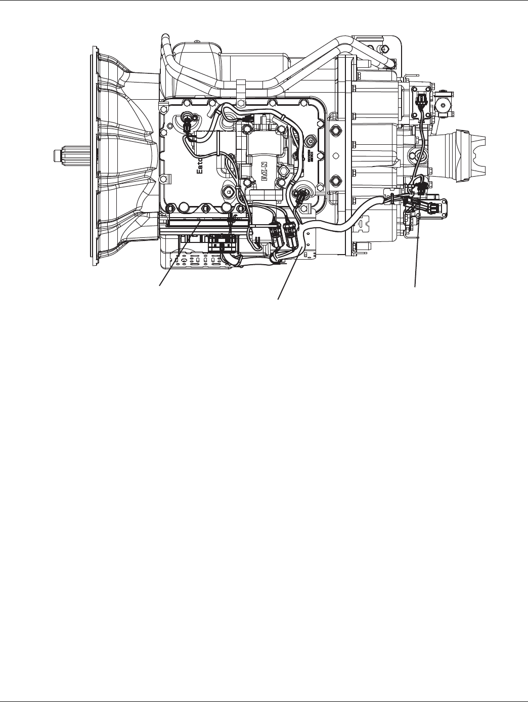
2016.01.15 © 2016 Eaton. All rights reserved 199
TRTS0930 Fault Isolation Procedures | Fault Code 58 - Output Shaft Speed Sensor
Component Identification
Transmission
controllerTransmission harness
Output shaft
speed sensor
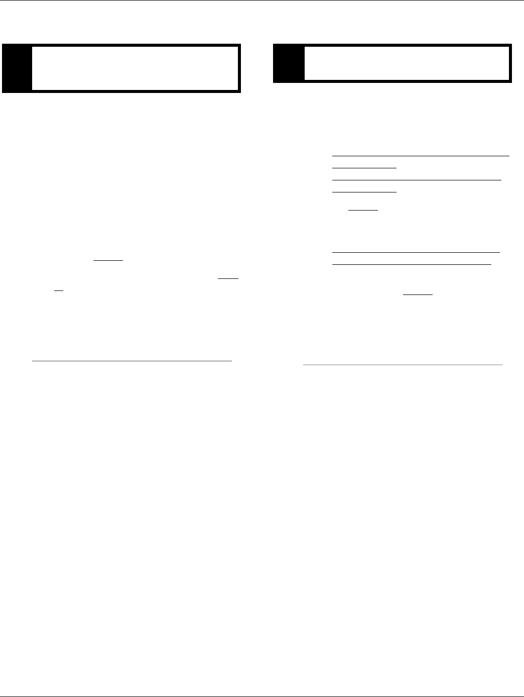
200 © 2016 Eaton. All rights reserved 2016.01.15
Fault Code 58 - Output Shaft Speed Sensor | Fault Isolation Procedures TRTS0930
Fault Code 58 - Output Shaft Speed Sensor
1. Key off.
2. Disconnect negative battery cable.
3. Disconnect the Transmission Harness 38-way con-
nector.
4. Measure resistance between the Transmission Har-
ness 38-way connector pins:
-23 and 24
-23 and ground
•If resistance between Pin 23 and Pin 24 is 2K
to 4.5K ohm and between Pin 23 to ground is
OL, go to Step B.
•If resistance is outside of the range, go to Step
C.
1. Inspect Output Shaft Speed Sensor for contamina-
tion or damage.
•If no problem found, (if fault code is Active)
replace the:
-Medium-Duty Transmission Electronic Con-
trol Unit (TECU)
- Heavy-Duty Transmission Electronic Con-
trol Unit (TECU)
go to Step V.
•If problem is found or you were sent here from
Step C or D, replace the:
-Medium-Duty Output Shaft Speed Sensor
- Heavy-Duty Output Shaft Speed Sensor
Inspect the tone wheel for damage, looseness
or corrosion. Go to Step V.
APurpose: Measure Output Shaft Speed Sensor re-
sistance and test for short to ground through
Transmission Harness.
BPurpose: Visually inspect Output Shaft Speed sen-
sor for contamination and damage.
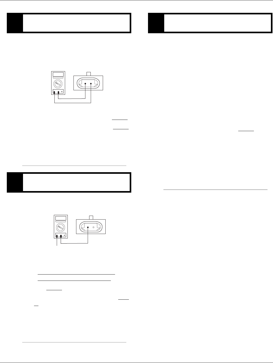
2016.01.15 © 2016 Eaton. All rights reserved 201
TRTS0930 Fault Isolation Procedures | Fault Code 58 - Output Shaft Speed Sensor
1. Disconnect the Transmission Harness from the
Output Shaft Speed Sensor.
2. Measure resistance between Output Shaft Speed
Sensor Pin A and Pin B.
•If resistance is 2K to 4.5K ohm, go to Step D.
•If resistance is outside of range, go to Step B.
1. Measure resistance between Output Shaft Speed
Sensor Pin A and ground.
•If resistance is OL, replace the:
- Medium-Duty Transmission Harness
- Heavy-Duty Transmission Harness
Go to Step V.
•If resistance is less than 10K ohm, go to Step
B.
1. Key off.
2. Reconnect all connectors and the negative battery
cable.
3. Verify proper installation of speed sensor.
4. Key on.
5. Clear fault codes.
6. Drive the vehicle and attempt to reset the fault
code.
7. Check for fault codes.
•If no fault codes, test complete.
•If Fault Code 58 appears go to Step A. to find
error in testing.
•If fault code other than 58 appears, See “Fault
Code Isolation Procedure Index” on page 8.
CPurpose: Measure Output Shaft Speed Sensor re-
sistance.
DPurpose: Test for shorts to ground of the Output
Shaft Speed sensor.
AB
OHMS
VCOM A
GROUND
AB
OHMS
VCOM A
VPurpose: Verify repair.

202 © 2016 Eaton. All rights reserved 2016.01.15
Fault Code 61 - Rail Select Motor | Fault Isolation Procedures TRTS0930
Fault Code 61 - Rail Select Motor
J1587: MID 130 SID 39 FMI 1, 5, 6, 12
J1939: SA 3 SPN 772 FMI 1, 5, 6, 12
Overview
This fault indicates the Electric Shifter Rail Motor system is
not working properly.
The Transmission Electronic Control Unit (TECU) checks
the rail motor for open or shorted connections. There are
four fault conditions defined by the reported FMI via Ser-
viceRanger software.
Detection
Starting at key-on and throughout operation, the TECU con-
stantly monitors the motor circuit. If a failure mode of short
to battery, short to ground, open circuit, or low current is
detected the fault is set.
Conditions to Set Fault Code Active
Conditions to Set the Fault Code Active
• FMI 1 - The TECU detects a high resistance in the
motor circuit (5 ohms or greater) resulting in slow
or no movement of the XY Shift finger. This fault
will set when the Electric Shifter fails to select the
proper rail.
• FMI 5, 6 - This fault is set when the condition is
detected for at least 0.5 seconds and the TECU
attempts to move the XY shift finger. FMI 5 is open
or shorted to ground, FMI 6 is shorted to power.
• FMI 12 - The TECU detects a fault condition within
the TECU XY control circuit, resulting in slow or no
movement of the XY shift finger. This fault is set
when the Electric Shifter fails to select the proper
rail.
Fallback
Fallback Mode During Power-Up
• The transmission will power-up and may not be
able to confirm neutral, no start gear can be
selected.
•The engine will not crank and a dash will be shown
in the gear display.
Fallback Mode During Operation
• The transmission remains in its current gear. An F
may appear in the gear display.
• The service light will blink.
• Until the fault is cleared, driver may have to shut off
engine in gear.
Conditions to Set Fault Code Inactive
Conditions to Set the Fault Code Inactive
• FMI 1, 12 - The fault becomes Inactive when the
shift is completed.
• FMI 5, 6 - The fault becomes Inactive when the
open or short circuit conditions are not detected for
0.5 seconds.
Possible Causes
This fault code can be caused by any of the following:
FMI 1, 5:
• The Electric Shifter rail motor may be damaged,
failed or has developed a low resistance to ground.
• Connections and wires between the rail motor and
the TECU may be loose or damaged, terminals and
wires may be bent, or terminals may be burnt.
• TECU may have an internal short to ground or open
circuit and has failed.
FMI 6:
• The wires between the rail motor and the TECU
may be grounded or shorted.
• TECU may have internal short to power and has
failed.
FMI 12:
•Poor chassis power or ground.
• The wires between the rail motor and the TECU
may be grounded or shorted.
• TECU internal failure.

2016.01.15 © 2016 Eaton. All rights reserved 203
TRTS0930 Fault Isolation Procedures | Fault Code 61 - Rail Select Motor
Component Identification
17
31
25
C
B
A
C
B
A
Range
valve
Splitter valve
(13 & 18 speed only)
A
B
Mainshaft
speed sensor
A
B
A
B
Rail select
sensor
Gearselect
sensor
Outputshaft
speed sensor
Inputshaft
speed sensor
18
19
20
10
11
12
23
24
7
8
A
B
C
A
B
C
35
37
36
38
15
16
6
34
28
4
32
26
B
C
A
D
For Transmission
Diagnostics
4-way
B - Service Bat. +
C - Service Bat. -
A - Service Ignition +
B
C
A
Transmission Controller
OEM
Inertia brake (Optional)
A
B
33
5
Black
Connector
Blue
Connector
Front of Transmission
(Located at the left rear
corner of the transmission)
Front
XY Shifter
Assy
Transmission
Harness Assy
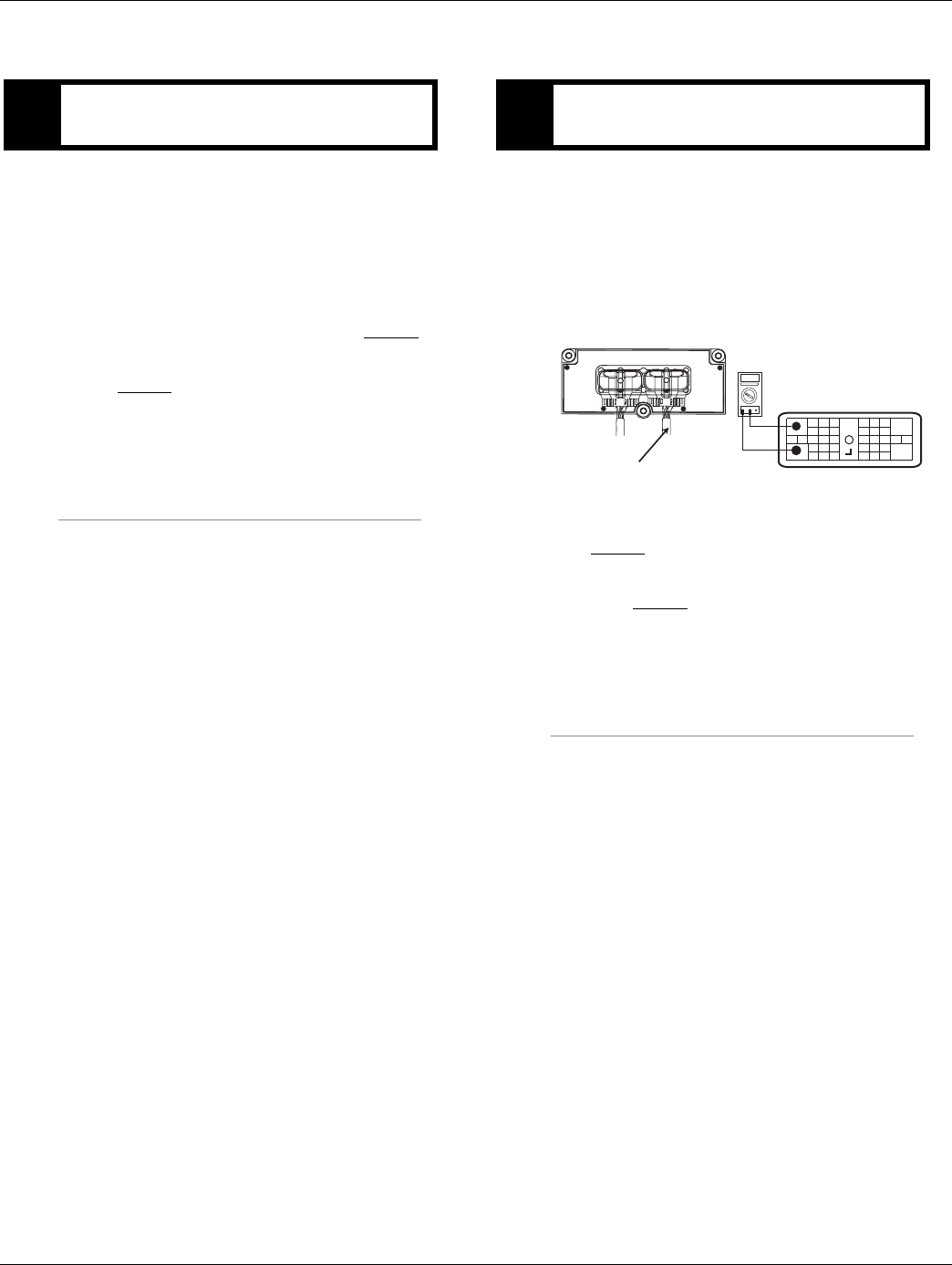
204 © 2016 Eaton. All rights reserved 2016.01.15
Fault Code 61 - Rail Select Motor | Fault Isolation Procedures TRTS0930
Fault Code 61 - Rail Select Motor
1. Use ServiceRanger to retrieve and record fault code
61 FMI information.
2. Perform the “Electrical Pretest” on page 12, inspect
TECU power supply harness and fuse holder.
•Issue found with TECU power supply harness
or vehicle batteries, repair or replace items
found during electrical pretest, go to Step V.
•Electrical pretest passed, no issues found, go
to Step B.
1. Key off.
2. Disconnect the negative battery cable.
3. Disconnect the Transmission Harness 38-way con-
nector from the TECU.
4. Measure resistance between Pin 35 and Pin 37.
•Measured resistance is 2 ohms or less, go to
Step C.
•Measured resistance is greater than 2 ohms,
go to Step D.
APurpose: Check for active or Inactive fault codes
(noting FMI) and perform electrical pretest. BPurpose: Measure the resistance of Electric Shifter
Rail motor through the Transmission Harness.
OHMS
VCOM A
31
24 25
29 30
15 16
26
20
34
27 28
32 33
18 19
7
3
89
12 6
11 12
45
22
21
38
36
13 14
35 10
17
23
Front View
38-Way Connector
37
Transmission Harness 38-way Connector
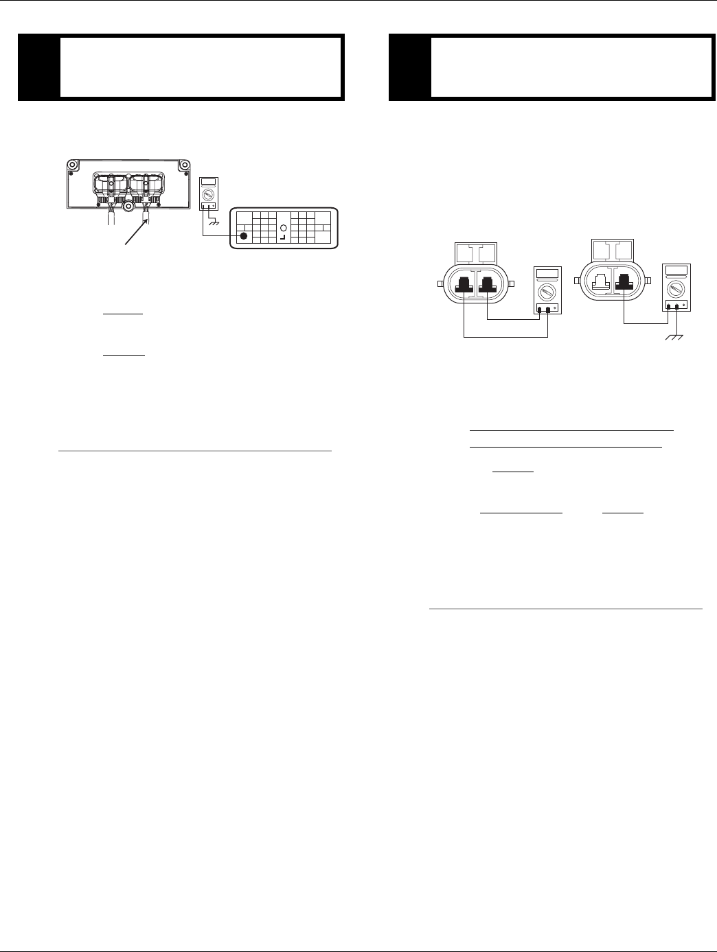
2016.01.15 © 2016 Eaton. All rights reserved 205
TRTS0930 Fault Isolation Procedures | Fault Code 61 - Rail Select Motor
1. Measure the resistance between Pin 35 and
ground.
•Measured resistance is 1 M ohm or greater, go
to Step E.
•Measured resistance is less than 1 M ohm, go
to Step D.
1. Disconnect the black 2-way rail motor connector
from the transmission harness.
2. Measure the resistance of the Rail Motor at the
2-way connector.
-Pin A to Pin B
-Pin A to Ground
•Measured resistance between Pin A and Pin B
is 2 ohms or less, and Pin A to ground is 1 M
ohm or greater, replace the:
- Medium-Duty Transmission Harness
- Heavy-Duty Transmission Harness
Go to Step V.
•Measured resistance is out of range, replace
the Electric Shifter. Go to Step V.
CPurpose: Test the Electric Shifter Rail Motor for
short to ground through the Transmission Har-
ness.
OHMS
VCOM A
31
24 25
29 30
15 16
26
20
34
27 28
32 33
18 19
7
3
89
12 6
11 12
45
22
21
38
36
13 14
35 10
17
23
Front View
38-Way Connector
37
Transmission Harness 38-way Connector
DPurpose: Measure the resistance of Electric Shifter
Rail motor at the Rail Motor and test for short to
ground.
AB
OHMS
VCOM A
AB
OHMS
VCOM A
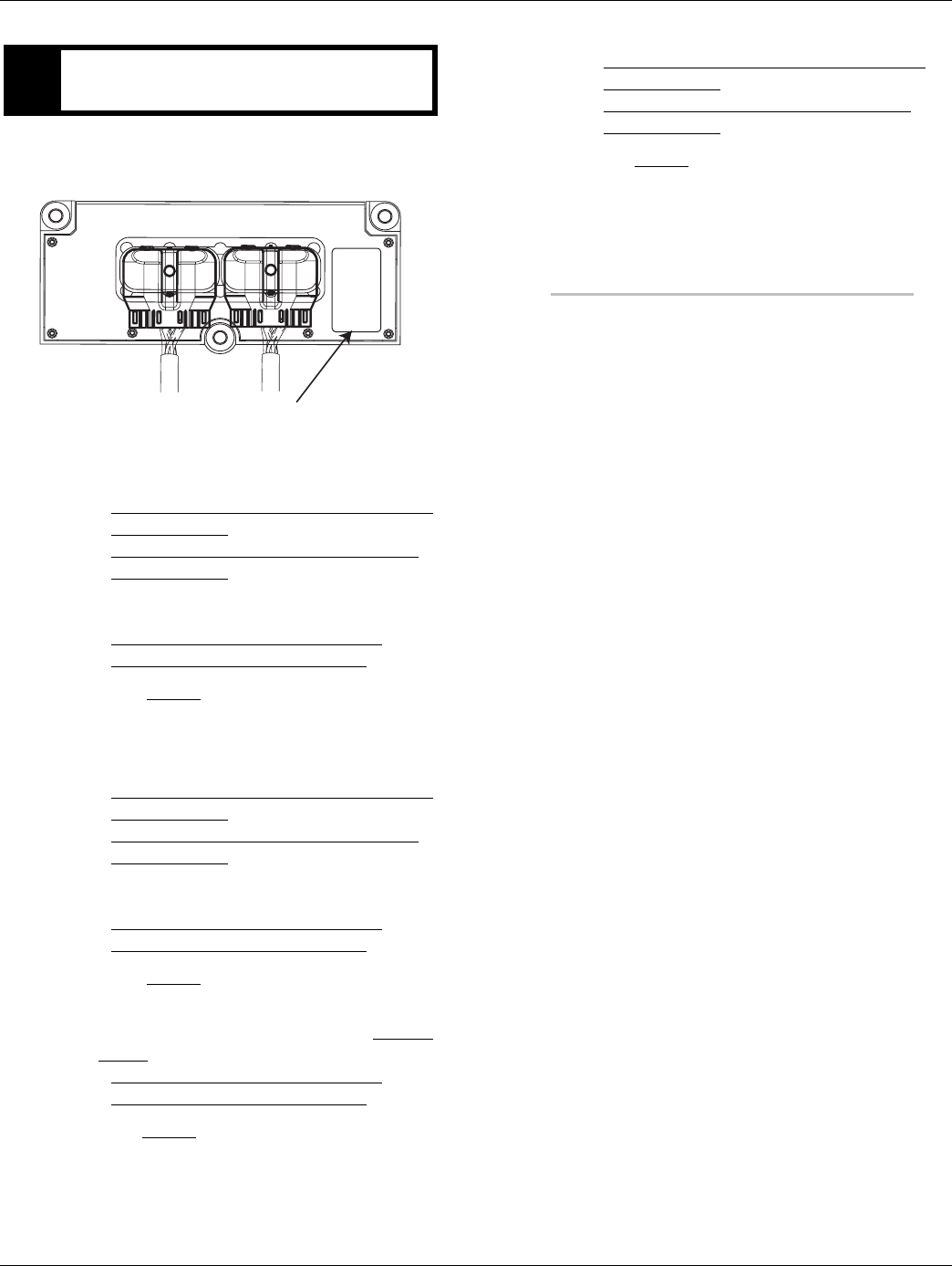
206 © 2016 Eaton. All rights reserved 2016.01.15
Fault Code 61 - Rail Select Motor | Fault Isolation Procedures TRTS0930
1. FMI information recorded from Step A.
•FMI 1 or 5 is Active, replace the:
- Medium-Duty Transmission Electronic Con-
trol Unit (TECU)
- Heavy-Duty Transmission Electronic Con-
trol Unit (TECU)
and the:
- Medium-Duty Transmission Harness
- Heavy-Duty Transmission Harness
Go to Step V.
•FMI 1 or 5 is Inactive and the TECU serial num-
ber is between ETC2000000 and ETC2029918,
replace the:
- Medium-Duty Transmission Electronic Con-
trol Unit (TECU)
- Heavy-Duty Transmission Electronic Con-
trol Unit (TECU)
and the:
- Medium-Duty Transmission Harness
- Heavy-Duty Transmission Harness
Go to Step V.
•FMI 1 or 5 is Inactive and the TECU serial num-
ber is above ETC2029918, replace the Electric
Shifter and the:
- Medium-Duty Transmission Harness
- Heavy-Duty Transmission Harness
Go to Step V.
•FMI 6 or 12 is Active or Inactive, replace the:
- Medium-Duty Transmission Electronic Con-
trol Unit (TECU)
- Heavy-Duty Transmission Electronic Con-
trol Unit (TECU)
Go to Step V.
EPurpose: Use fault code FMI to make a repair deci-
sion.
Model:
Hardware Rev:
Serialno:
Date Code:
TECU Serial Number

2016.01.15 © 2016 Eaton. All rights reserved 207
TRTS0930 Fault Isolation Procedures | Fault Code 61 - Rail Select Motor
1. Key off.
2. Reconnect all connectors and the negative battery
cable.
3. Key on.
4. Clear fault codes, see “Fault Code Retrieval/Clear-
ing” on page 5.
5. Drive the vehicle and attempt to reset the fault
code.
6. Check for fault codes, see “Fault Code
Retrieval/Clearing” on page 5.
•If no fault codes, test complete.
•If Fault Code 61 appears, find error in testing,
go to Step A.
VPurpose: Verify repair.

208 © 2016 Eaton. All rights reserved 2016.01.15
Fault Code 63 - Gear Select Motor | Fault Isolation Procedures TRTS0930
Fault Code 63 - Gear Select Motor
J1587: MID 130 SID 40 FMI 1, 5, 6, 12
J1939: SA 3 SPN 773 FMI 1, 5, 6, 12
Overview
This fault indicates the Electric Shifter Gear Motor system is
not working properly.
The Transmission Electronic Control Unit (TECU) checks
the gear motor and controller for open or shorted connec-
tions. There are 4 fault conditions defined by the reported
FMI via ServiceRanger software.
Detection
Starting at key-on and throughout operation, the TECU con-
stantly monitors the motor circuit. If a failure mode of short
to battery, short to ground, open circuit or low current is
detected the fault is set.
Conditions to Set Fault Code Active
Conditions to Set the Fault Code Active
• FMI 1 - The TECU detects a high resistance in the
motor circuit (5 ohms or greater) resulting in slow
or no movement of the XY shift finger. This fault
will set when the Electric Shifter fails to engage or
disengage a gear.
• FMI 5, 6 - This fault is set when the condition is
detected for at least 0.5 seconds and the TECU
attempts to move the XY shift finger. FMI 5 is open
or shorted to ground, FMI 6 is shorted to power.
• FMI 12 - The TECU detects a fault condition within
the TECU XY control circuit, resulting in slow or no
movement of the XY shift finger. This fault is set
when the Electric Shifter fails to engage or disen-
gage a gear.
Fallback
Fallback Mode During Power-Up
• The transmission will power-up and may not be
able to confirm neutral, no start gear can be
selected.
•The engine will not crank and a dash will be shown
in the gear display.
Fallback Mode During Operation
• The transmission remains in its current gear. An F
may appear in the gear display.
• The service light will blink.
• Until the fault is cleared, driver may have to shut off
engine in gear.
Conditions to Set Fault Code Inactive
Conditions to Set the Fault Inactive
• FMI 1, 12 - The fault becomes Inactive when the
shift is completed.
• FMI 5, 6 - The fault becomes Inactive when the
open or short circuit conditions are not detected for
0.5 seconds.
Possible Causes
This fault code can be caused by any of the following:
FMI 1, 5:
• The Electric Shifter gear motor may be damaged,
failed, or has developed a low resistance to ground.
• Connections and wires between the gear motor and
the TECU may be loose or damaged, terminals and
wires may be bent or terminals may be burnt.
• TECU may have an internal short to ground or open
circuit and has failed.
FMI 6:
• The wires between the gear motor and TECU may
be shorted to power.
• TECU may have internal short to power and has
failed.
FMI 12:
•Poor chassis power or ground.
• The wires between the gear motor and TECU may
be shorted to ground.
• TECU internal failure.
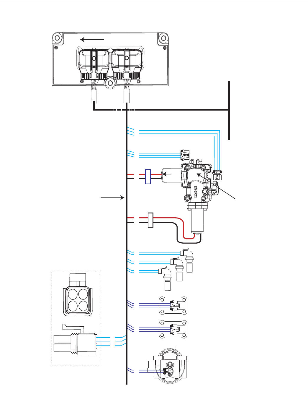
2016.01.15 © 2016 Eaton. All rights reserved 209
TRTS0930 Fault Isolation Procedures | Fault Code 63 - Gear Select Motor
Component Identification
17
31
25
C
B
A
C
B
A
Range
valve
Splitter valve
(13 & 18 speed only)
A
B
Mainshaft
speed sensor
A
B
A
B
Rail select
sensor
Gearselect
sensor
Outputshaft
speed sensor
Inputshaft
speed sensor
18
19
20
10
11
12
23
24
7
8
A
B
C
A
B
C
35
37
36
38
15
16
6
34
28
4
32
26
B
C
A
D
For Transmission
Diagnostics
4-way
B - Service Bat. +
C - Service Bat. -
A - Service Ignition +
B
C
A
Transmission Controller
OEM
Inertia brake (Optional)
A
B
33
5
Black
Connector
Blue
Connector
Front of Transmission
(Located at the left rear
corner of the transmission)
Front
XY Shifter
Assy
Transmission
Harness Assy
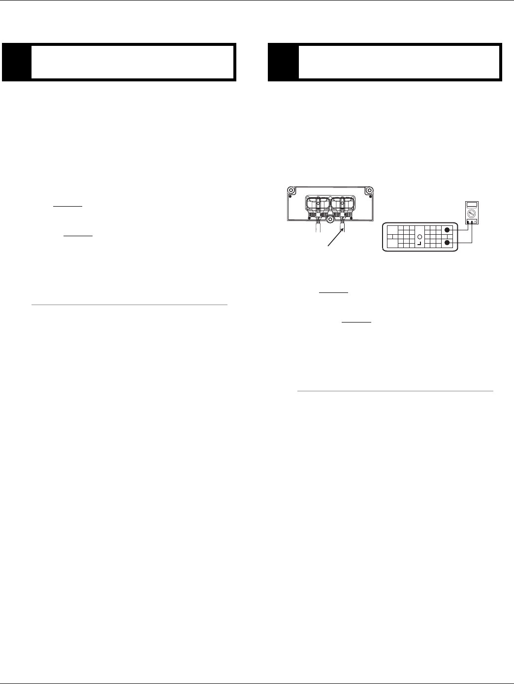
210 © 2016 Eaton. All rights reserved 2016.01.15
Fault Code 63 - Gear Select Motor | Fault Isolation Procedures TRTS0930
Fault Code 63 - Gear Select Motor
1. Use ServiceRanger to retrieve and record Fault
Code 63 FMI information.
2. Perform electrical pretest, see “Electrical Pretest”
on page 12. Inspect TECU power supply harness
and fuse holder.
•If issue found with TECU power supply har-
ness or vehicle batteries, repair or replace
items found during electrical pretest. go to
Step V.
•Electrical pretest passed, no issues found, go
to Step B.
1. Key off.
2. Disconnect the negative battery cable.
3. Disconnect the Transmission Harness 38-way con-
nector from the TECU.
4. Measure resistance between Pin 36 and Pin 38.
•Measured resistance is 2 ohms or less, go to
Step C.
•Measured resistance is greater than 2 ohms,
go to Step D.
APurpose: Check for active or Inactive fault codes
(noting FMI) and perform electrical pretest. BPurpose: Measure the resistance of Electric Shifter
Gear Motor through the Transmission Harness.
OHMS
VCOM A
31
24 25
29 30
15 16
26
20
34
27 28
32 33
18 19
7
3
89
12 6
11 12
45
22
21
38
36
13 14
35 10
17
23
Front View
38-Way Connector
37
Transmission Harness 38-way Connector
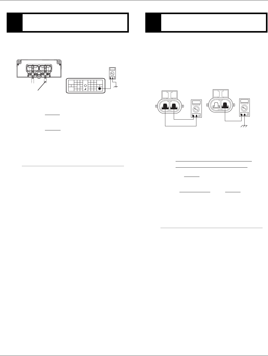
2016.01.15 © 2016 Eaton. All rights reserved 211
TRTS0930 Fault Isolation Procedures | Fault Code 63 - Gear Select Motor
1. Measure the resistance between Pin 36 and
ground.
•If measured resistance is 1 M ohm or greater,
go to Step E.
•If measured resistance is less than 1 M ohm,
go to Step D.
1. Disconnect the blue 2-way gear motor connector
from the transmission harness.
2. Measure the resistance of the gear motor at the
2-way connector.
-Pin A to Pin B
-Pin A to Ground
•If measured resistance between Pin A and Pin
B is 2 ohms or less, and between Pin A and
ground is 1 M ohm or greater, replace the:
- Medium-Duty Transmission Harness
- Heavy-Duty Transmission Harness
Go to Step V.
•If measured resistance is out of range, replace
the Electric Shifter. Go to Step V.
CPurpose: Test the Electric Shifter for a short to
ground through the Transmission Harness.
OHMS
VCOM A
31
24 25
29 30
15 16
26
20
34
27 28
32 33
18 19
7
3
89
12 6
11 12
45
22
21
38
36
13 14
35 10
17
23
Front View
38-Way Connector
37
Transmission Harness 38-way Connector
DPurpose: Measure the resistance of the Electric
Shifter Gear Motor, and test for short to ground.
AB
OHMS
VCOM A
AB
OHMS
VCOM A
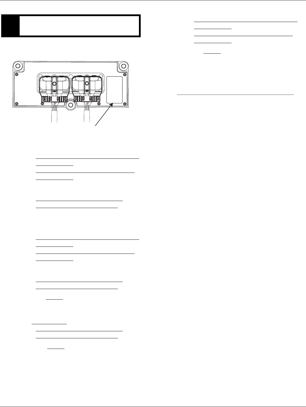
212 © 2016 Eaton. All rights reserved 2016.01.15
Fault Code 63 - Gear Select Motor | Fault Isolation Procedures TRTS0930
1. FMI information recorded from Step A.
•If FMI 1 or 5 is Active, replace the:
- Medium-Duty Transmission Electronic Con-
trol Unit (TECU)
- Heavy-Duty Transmission Electronic Con-
trol Unit (TECU)
and the:
- Medium-Duty Transmission Harness
- Heavy-Duty Transmission Harness
•If FMI 1 or 5 is Inactive and the TECU serial
number is between ETC2000000 and
ETC2029918, replace the:
- Medium-Duty Transmission Electronic Con-
trol Unit (TECU)
- Heavy-Duty Transmission Electronic Con-
trol Unit (TECU)
and the:
- Medium-Duty Transmission Harness
- Heavy-Duty Transmission Harness
Go to Step V.
•If FMI 1 or 5 is Inactive and the TECU serial
number is above ETC2029918, replace the
Electric Shifter and the:
- Medium-Duty Transmission Harness
- Heavy-Duty Transmission Harness
Go to Step V.
•If FMI 6 or 12 is active or Inactive, replace the:
-Medium-Duty Transmission Electronic Con-
trol Unit (TECU)
- Heavy-Duty Transmission Electronic Con-
trol Unit (TECU)
go to Step V.
EPurpose: Use the fault code FMI to make a repair
decision.
Model:
Hardware Rev:
Serialno:
Date Code:
TECU Serial Number

2016.01.15 © 2016 Eaton. All rights reserved 213
TRTS0930 Fault Isolation Procedures | Fault Code 63 - Gear Select Motor
1. Key off.
2. Reconnect all connectors and the negative battery
cable.
3. Key on.
4. Clear fault codes, see “Fault Code Retrieval/Clear-
ing” on page 5.
5. Drive the vehicle and attempt to reset the fault
code.
6. Check for fault codes, see “Fault Code
Retrieval/Clearing” on page 5.
•If no fault codes, test complete.
•If Fault Code 63 appears go to Step A. to find
error in testing.
•If fault code other than 63 appears, See “Fault
Code Isolation Procedure Index” on page 8.
VPurpose: Verify repair.

214 © 2016 Eaton. All rights reserved 2016.01.15
Fault Code 68 - Grade Sensor | Fault Isolation Procedures TRTS0930
Fault Code 68 - Grade Sensor
J1587: MID 130 SID 227 FMI 14
J1939: SA 3 SPN 520274, 520321FMI 13, 14
Overview
The Grade Sensor is mounted inside the Transmission Elec-
tronic Control Unit (TECU) and is essential for Hill-Start Aid.
The Grade Sensor also provides information to the TECU to
assist in smooth vehicle launch and shifting.
Detection
A fault will be set if the grade sensor reports an illogical
grade to the TECU.
Fallback
Hill-Start-Aid is enabled all the time.
Possible Causes
This fault code can be caused by any of the following:
• Improperly mounted TECU
• Uncalibrated TECU
• TECU failure
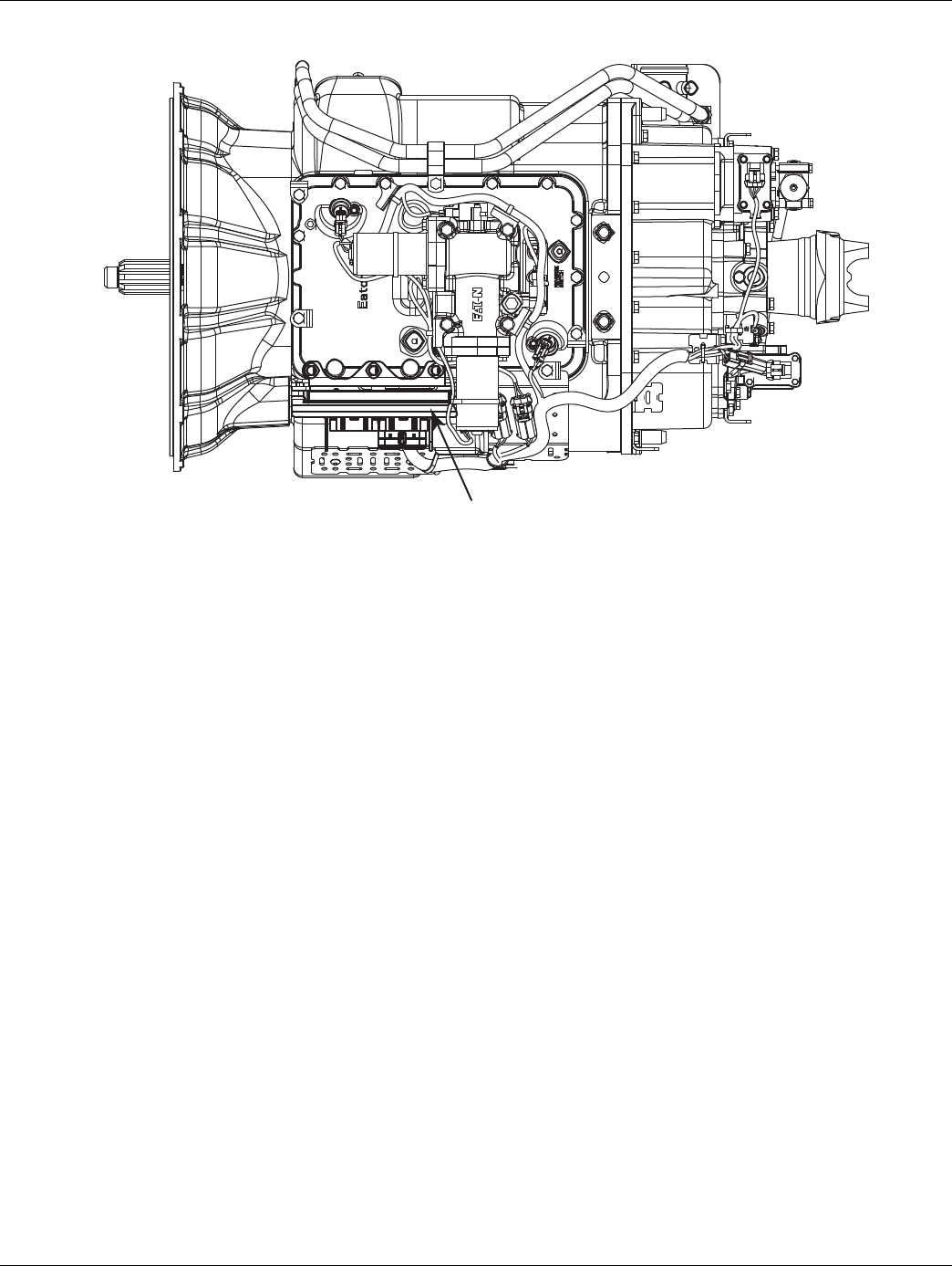
2016.01.15 © 2016 Eaton. All rights reserved 215
TRTS0930 Fault Isolation Procedures | Fault Code 68 - Grade Sensor
Component Identification
Transmission ECU

216 © 2016 Eaton. All rights reserved 2016.01.15
Fault Code 68 - Grade Sensor | Fault Isolation Procedures TRTS0930
Fault Code 68 - Grade Sensor
1. Key on.
2. Retrieve active fault codes and FMIs with Ser-
viceRanger using the 9-way diagnostic connector.
3. Perform electrical pretest, See “Electrical Pretest”
on page 12.
•If FMI 13 is Active after performing the electri-
cal pretest, go to Step B.
•If FMI 14 is Active after performing the electri-
cal pretest, go to Step C.
•If issue was repair during the electrical pretest,
go to Step V.
Note: Before Grade Sensor Calibration, verify the vehicle
is on level ground, the suspension is fully aired
and the vehicle is at the appropriate ride height.
1. Key on.
2. Calibrate the TECU using ServiceRanger. (steps
below)
Note: The Grade Sensor can be calibrated via Ser-
viceRanger or operator-triggered Special
Function. Detailed instructions on both meth-
ods can be found in service manual
TRSM0930.
3. Open the Advanced Product Functions menu and
click on the transmission model.
4. Open the Grade Sensor Calibration and follow the
instructions.
5. Click on Calibrate Grade Sensor.
6. Verify Fault Code 68 has gone Inactive.
•If FMI 13 is not Active, Close ServiceRanger
and turn off ignition switch to save calibration.
go to Step V.
•If FMI 13 is still Active, call Roadranger Tech
Support at 1-800-826-4357 for assistance.
APurpose: Check for active and Inactive fault codes
(noting FMI) and perform electrical pretest. BPurpose: Perform TECU Grade Sensor calibration.
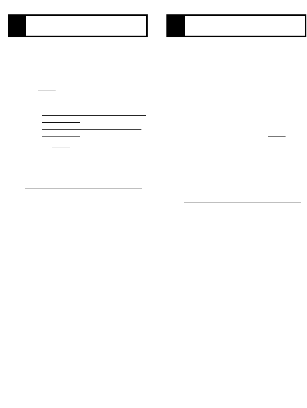
2016.01.15 © 2016 Eaton. All rights reserved 217
TRTS0930 Fault Isolation Procedures | Fault Code 68 - Grade Sensor
1. Key on.
2. Ensure that the TECU is properly mounted and
secured.
•If TECU found insecure or not properly
mounted, properly secure the TECU. Go to
Step V.
•If TECU was found properly mounted and
secure, (if fault code is Active) replace the:
- Medium-Duty Transmission Electronic Con-
trol Unit (TECU)
- Heavy-Duty Transmission Electronic Con-
trol Unit (TECU)
Go to Step V.
1. Key off.
2. Reconnect all connectors.
3. Key on.
4. Clear codes, see “Fault Code Retrieval/Clearing” on
page 5.
5. Drive the vehicle and attempt to reset the code.
6. Check for fault codes, see “Fault Code
Retrieval/Clearing” on page 5.
•If no fault codes, Test complete.
•If Fault Code 68 appears go to Step A. to find
error in testing.
•If fault code other than 68 appears, See “Fault
Code Isolation Procedure Index” on page 8.
CPurpose: Confirm proper TECU mounting. VPurpose: Verify repair.

218 © 2016 Eaton. All rights reserved 2016.01.15
Fault Code 71 - Unable to Disengage Gear | Fault Isolation Procedures TRTS0930
Fault Code 71 - Unable to Disengage Gear
J1587: MID 130 SID 60 FMI 7
J1939: SA 3 SPN 560 FMI 7
Overview
This fault indicates the system cannot disengage from the
current gear. The system will continue attempting to disen-
gage the current gear after the fault is set.
Vehicle must be moving and attempting to change gear
position and no electrical faults are active.
Detection
The system is unable to select the neutral position after 3
consecutive attempts.
Conditions to Set Fault Code Active
Conditions to Set the Fault Code Active
• FMI 7 - The system is unable to select the neutral
position after 3 consecutive attempts.
Fallback
Fallback mode During Power-Up
• None. This fault can not be set at power-up.
Fallback Mode During Operation
• When this fault is Active, the transmission will con-
tinue to attempt to select neutral.
• The system will alternate the engine speed up and
down in an attempt to achieve disengagement.
• The gear display may blink the destination gear.
• The service light will not flash, nor will an F be dis-
played on the dash.
• The diagnostic code will not be transmitted on the
J1587 bus until fault codes have been requested by
a service tool.
Conditions to Set Fault Code Inactive
Conditions to Set the Fault Inactive
• FMI 7 - The fault becomes Inactive when neutral is
achieved.
Possible Causes
This fault code can be caused by any of the following:
Shift Bar Housing
• Mechanical issue with the shift bar housing
• Damaged shift bar housing interlock parts
Electric Shifter
• New Electric Shifter installed and not recalibrated
per the L-Letter (L-2003-30)
• Mechanical issue with the Electric Shifter
• Badly contaminated / gummed up / soiled Electric
Shifter ball screw due to oil cooler leak
• Worn center shaft bushing (TAIB-0814.)
Base Transmission
• Main box mechanical failure
• Sliding clutch / shift yoke wear
Transmission Electronic Control Unit (TECU)
• New TECU installed and not recalibrated per the
L-Letter (L-2005-04)
Engine
• Inaccurately reporting engine torque value
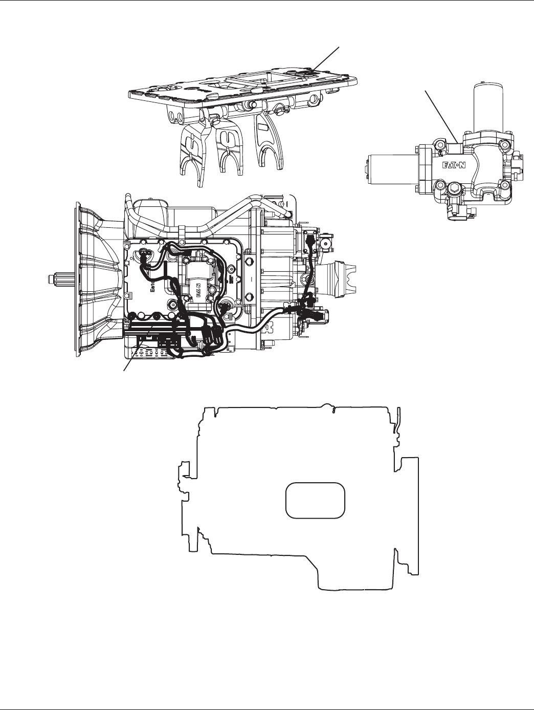
2016.01.15 © 2016 Eaton. All rights reserved 219
TRTS0930 Fault Isolation Procedures | Fault Code 71 - Unable to Disengage Gear
Component Identification
S hift ba r ho us i n g
Elect r ic s hifte r
T r a ns mi ss io n
co n t r olle r
Ba s e T r a ns mi ss io n
E n gi n e
ECM
E n gi n e To r q u e Val u e
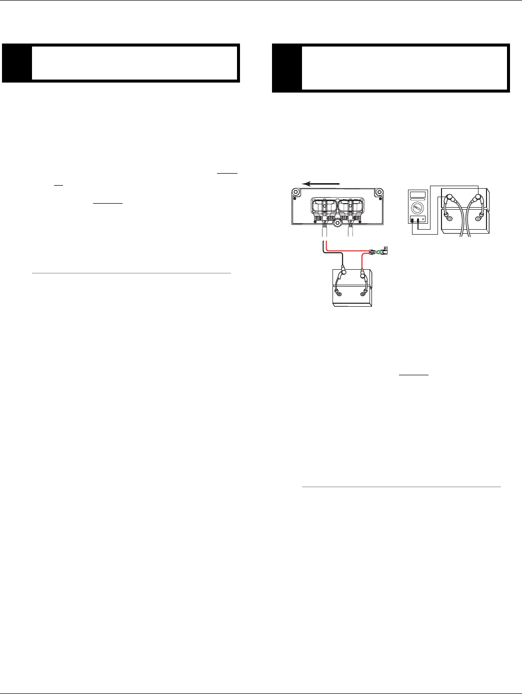
220 © 2016 Eaton. All rights reserved 2016.01.15
Fault Code 71 - Unable to Disengage Gear | Fault Isolation Procedures TRTS0930
Fault Code 71 - Unable to Disengage Gear
1. Key off.
2. Was a new Electric Shifter or TECU just installed
without recalibrating the transmission?
•Yes, perform transmission calibration. Turn
key on, and allow the transmission to power
up. Turn key off, wait 2 minutes and go to Step
V..
•No, go to Step B.
1. Key off.
2. Inspect starter, battery and in-line fuse holder con-
nections for integrity.
3. Measure voltage across batteries.
•If voltage is 11 to 13 volts on a 12-volt system
or 22 to 26 on a 24-volt system, proceed with
battery load test. Repair or replace batteries as
required and go to Step C.
•If voltage is outside of range, repair or replace
batteries and charge system as required.
Repeat test.
APurpose: Determine if an Electric Shifter was in-
stalled without recalibrating the transmission. BPurpose: Measure battery voltage. Visually inspect
the batteries, inline fuse, power and ground sup-
plies to the TECU.
VOLTS
VCOM A
+
–
+
–
30 AMP fuse
Battery power
(Non-switched power)
run to starter or Battery
36 38
Transmission ECU
–
–
+
+
OEM Harness Transmission Harness
Front of Transmission

2016.01.15 © 2016 Eaton. All rights reserved 221
TRTS0930 Fault Isolation Procedures | Fault Code 71 - Unable to Disengage Gear
1. Locate the diagnostic port on the Transmission
Harness - located at the left rear corner of the
transmission.
2. Key on.
3. Measure voltage between Pin C and the battery
negative post.
•If voltage between Pin C and battery negative
post is 0.70 volts or less, go to Step D.
•If voltage is outside of range, repair battery
ground supply to TECU. Repeat test.
1. Key on.
2. Measure voltage between Pin B and Pin C.
•If voltage is within 0.6 volts of battery voltage,
go to Step E.
•If voltage is outside of range, repair battery
power supply to TECU. Fuse may be blown.
Repeat test.
CPurpose: Verify proper ground path at 4-way diag-
nostic port.
4-Pin Diagnostic Port
(Located at the left rear
corner of the transmission.)
4-Pin Diagnostics Port
4-way
B - Service Bat. +
C - Service Bat. -
A - Service Ignition +
Battery Negative Post
BA
D
C
DPurpose: Measure batter voltage at 4-way diagnos-
tic port.
4-Pin Diagnostics Port
4-way
B - Service Bat. +
C - Service Bat. -
A - Service Ignition +
VOLTS
VCOM A
BA
D
C
4-Pin Diagnostic Port
(Located at the left rear
corner of the transmission.)

222 © 2016 Eaton. All rights reserved 2016.01.15
Fault Code 71 - Unable to Disengage Gear | Fault Isolation Procedures TRTS0930
1. Key on.
2. Measure voltage between Pin A and Pin C.
•If voltage is within 0.6 volts of battery voltage,
go to Step F.
•If voltage is outside of range, repair Ignition
power supply to TECU. Fuse may be blown.
Repeat test.
1. Key off.
2. Remove electric shifter from Shift Bar Housing.
3. Inspect the Shift Bar Housing
-Visually inspect shift rails and blocks.
-Verify shift bar housing operation by confirming
shift rails can physically engage each gear indi-
vidually.
-Confirm the shift bar housing can not engage 2
gears at the same time.
4. Inspect Electric Shifter
-Check for mechanical issues with the Electric
Shifter.
-Visually inspect for badly contaminated /
gummed up / soiled Electric Shifter ball screw
due to oil cooler leaks.
-Check for a worn center shaft bushing (see
TAIB-0814).
5. Inspect Base Transmission
-Drain and inspect oil for debris.
-Remove I-brake or PTO cover and inspect for
main box mechanical failure.
- Inspect sliding clutches and shift yokes for wear.
•If no problem found, replace Electric Shifter
and the:
-Medium-Duty Transmission Harness
- Heavy-Duty Transmission Harness
Go to Step V.
•If problem found, repair as required and go to
Step V.
EPurpose: Measure ignition voltage at 4-way diag-
nostic port.
4-Pin Diagnostics Port
4-way
B - Service Bat. +
C - Service Bat. -
A - Service Ignition +
BA
D
C
4-Pin Diagnostic Port
(Located at the left rear
corner of the transmission.)
FPurpose: Visually inspect the Shift bar housing,
Electric Shifter and base transmission for signs of
mechanical damage.

2016.01.15 © 2016 Eaton. All rights reserved 223
TRTS0930 Fault Isolation Procedures | Fault Code 71 - Unable to Disengage Gear
1. Key off.
2. Reconnect all connectors and the negative battery
cable.
3. Key on.
4. Clear fault codes, see “Fault Code Retrieval/Clear-
ing” on page 5.
5. Drive the vehicle and attempt to reset the fault
code.
6. Check for fault codes, see “Fault Code
Retrieval/Clearing” on page 5.
•If no fault codes, test complete.
•If Fault Code 71 appears go to Step A. to find
error in testing.
•If fault code other than 71 appears, See “Fault
Code Isolation Procedure Index” on page 8.
VPurpose: Verify repair.

224 © 2016 Eaton. All rights reserved 2016.01.15
Fault Code 72 - Failed to Select Rail | Fault Isolation Procedures TRTS0930
Fault Code 72 - Failed to Select Rail
J1587: MID 130 SID 59 FMI 7
J1939: SA 3 SPN 772 FMI 7
Overview
This fault indicates the system is unable to position the XY
shift finger on the desired shift rail. The system will con-
tinue attempting to select the desired rail position after the
fault is set.
Vehicle must be moving and attempting to select a rail and
no electrical faults are active.
Detection
The system is unable to select the desired rail position after
5 consecutive attempts.
Conditions to Set Fault Code Active
Conditions to Set the Fault Code Active
• FMI 7 - The system is unable to select the desired
rail position after five consecutive attempts.
Fallback
Fallback mode During Power-Up
• Vehicle may not crank. A dash will appear in the
gear display.
Fallback Mode During Operation
• When this fault is active, the transmission will con-
tinue to attempt to select the desired rail position.
• The system will alternate the engine speed up and
down during a shift.
• The gear display may blink the destination gear.
• The service light will not flash, nor will an F be dis-
played on the dash.
• The diagnostic code will not be transmitted on the
J1587 bus until fault codes have been requested by
a service tool.
Conditions to Set Fault Code Inactive
Conditions to Set the Fault Inactive
• FMI 7 - The fault becomes Inactive when the
desired rail position is achieved.
Possible Causes
This fault code can be caused by any of the following:
FMI 7:
• Mechanical issue with the shift bar housing
• Damaged shift bar housing interlock parts
Electric Shifter
• New Electric Shifter installed and not recalibrated
per the L-Letter (L-2003-30)
• Mechanical issue with the Electric Shifter
• Badly contaminated / gummed up / soiled Electric
Shifter ball screw due to oil cooler leak
• Worn center shaft bushing (TAIB-0814)
Base Transmission
• Main box mechanical failure
• Sliding clutch / shift yoke wear
Transmission Electronic Control Unit (TECU)
• New TECU installed and not recalibrated per the
L-Letter (L-2005-04)
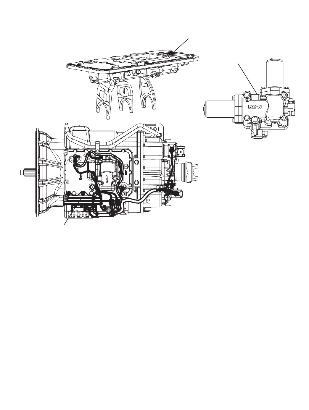
2016.01.15 © 2016 Eaton. All rights reserved 225
TRTS0930 Fault Isolation Procedures | Fault Code 72 - Failed to Select Rail
Component Identification
S hift ba r ho us i n g
Elect r ic s hifte r
T r a ns mi ss io n
co n t r olle r
Ba s e T r a ns mi ss io n
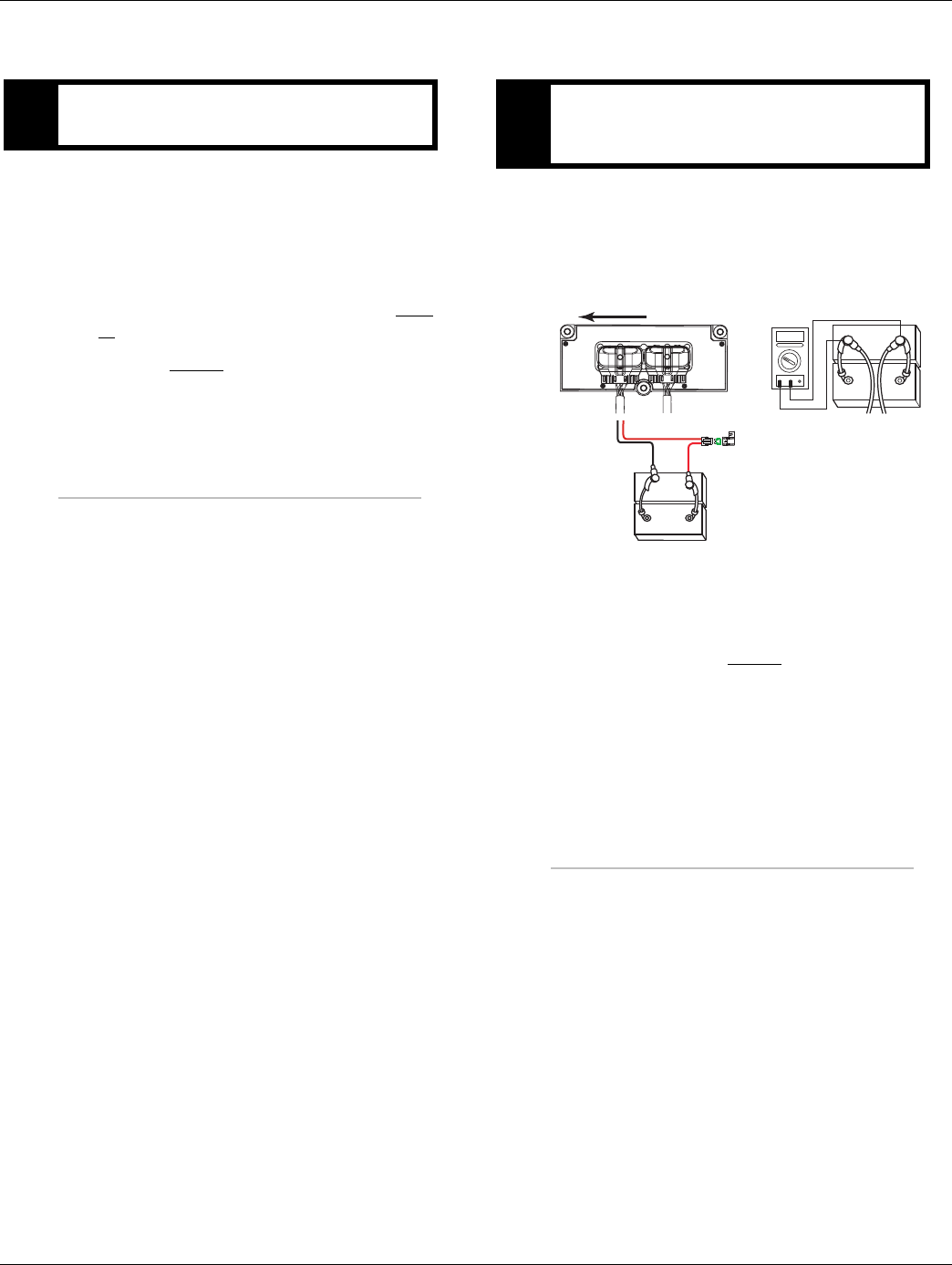
226 © 2016 Eaton. All rights reserved 2016.01.15
Fault Code 72 - Failed to Select Rail | Fault Isolation Procedures TRTS0930
Fault Code 72 - Failed to Select Rail
1. Key off.
2. Was a new Electric Shifter or TECU just installed
without recalibrating the transmission?
•Yes. Perform transmission calibration. Turn
key on and allow the transmission to power
up. Turn key off and wait 2 minutes. go to Step
V.
•No, go to Step B.
1. Key off.
2. Inspect starter / battery and in-line fuse holder con-
nections for integrity.
3. Measure voltage across batteries.
•If voltage is 11 to 13 volts on a 12-volt system
or 22 to 26 on a 24-volt system, proceed with
battery load test. Repair or replace batteries as
required and go to Step C.
•If voltage is outside of range, repair or replace
batteries and charge system as required.
Repeat test.
APurpose: Determine if an Electric Shifter was in-
stalled without recalibrating the transmission. BPurpose: Measure battery voltage. Visually inspect
the batteries, inline fuse, power and ground sup-
plies to the TECU.
VOLTS
VCOM A
+
–
+
–
30 AMP fuse
Battery power
(Non-switched power)
run to starter or Battery
36 38
Transmission ECU
–
–
+
+
OEM Harness Transmission Harness
Front of Transmission
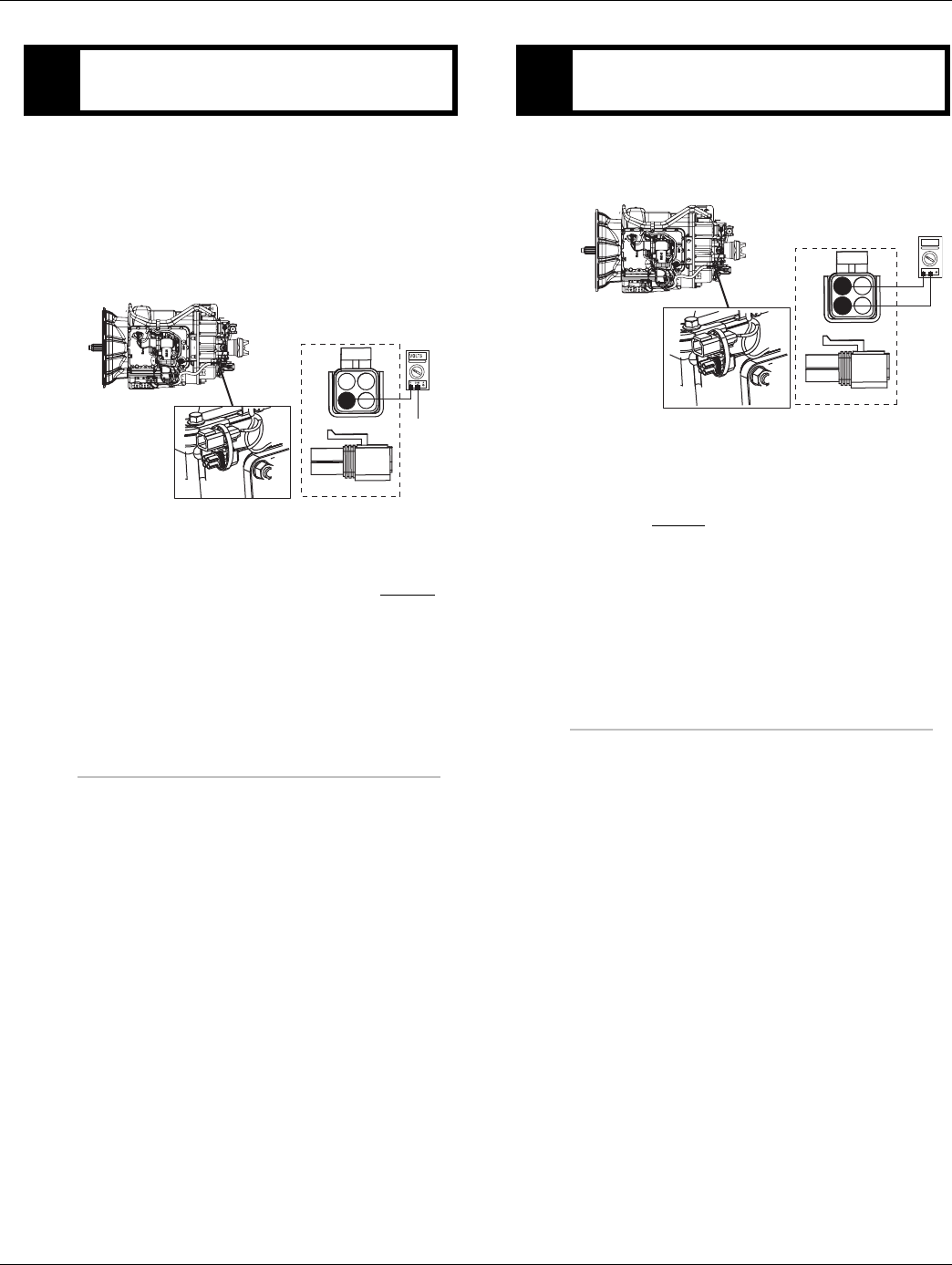
2016.01.15 © 2016 Eaton. All rights reserved 227
TRTS0930 Fault Isolation Procedures | Fault Code 72 - Failed to Select Rail
1. Locate the diagnostic port on the Transmission
Harness - located at the left rear corner of the
transmission.
2. Key on.
3. Measure voltage between Pin C and the battery
negative post.
•If voltage is 0.70 volts or less, go to Step D.
•If voltage is outside of range, repair battery
ground supply to TECU. Repeat test.
1. Key on.
2. Measure voltage between Pin B and Pin C.
•If voltage is within 0.6 volts of battery voltage,
go to Step E.
•If voltage is outside of range, repair battery
power supply to TECU. Fuse may be blown.
Repeat test.
CPurpose: Verify proper ground path at 4-way diag-
nostic port.
4-Pin Diagnostic Port
(Located at the left rear
corner of the transmission.)
4-Pin Diagnostics Port
4-way
B - Service Bat. +
C - Service Bat. -
A - Service Ignition +
Battery Negative Post
BA
D
C
DPurpose: Measure batter voltage at 4-way diagnos-
tic port.
4-Pin Diagnostics Port
4-way
B - Service Bat. +
C - Service Bat. -
A - Service Ignition +
VOLTS
VCOM A
BA
D
C
4-Pin Diagnostic Port
(Located at the left rear
corner of the transmission.)
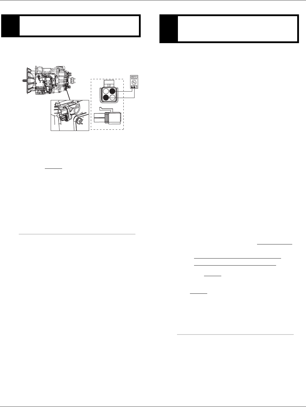
228 © 2016 Eaton. All rights reserved 2016.01.15
Fault Code 72 - Failed to Select Rail | Fault Isolation Procedures TRTS0930
1. Key on.
2. Measure voltage between Pin A and Pin C.
•If voltage is within 0.6 volts of battery voltage,
go to Step F.
•If voltage is outside of range, Repair Ignition
power supply to TECU. Fuse may be blown.
Repeat test.
1. Key off.
2. Remove electric shifter from Shift Bar housing.
3. Inspect the Shift Bar housing
-Visually inspect shift rails and blocks.
-Verify Shift Bar housing operation by confirming
shift rails can physically engage each gear indi-
vidually.
-Confirm the Shift Bar housing can not engage
two gears at the same time.
4. Inspect Electric Shifter
-Check for mechanical issues with the Electric
Shifter.
-Visually inspect for badly contaminated /
gummed up / soiled Electric Shifter ball screw
due to oil cooler leaks.
-Check for a worn center shaft bushing (see
TAIB-0814).
5. Inspect Base Transmission
-Drain and inspect oil for debris.
-Remove I-brake or PTO cover and inspect for
main box mechanical failure.
-Inspect sliding clutches and shift yokes for wear.
•If no problem found, replace Electric Shifter
and the:
-Medium-Duty Transmission Harness
- Heavy-Duty Transmission Harness
Go to Step V.
•If problem found, repair as required. Go to
Step V.
EPurpose: Measure ignition voltage at 4-way diag-
nostic port.
4-Pin Diagnostics Port
4-way
B - Service Bat. +
C - Service Bat. -
A - Service Ignition +
BA
D
C
4-Pin Diagnostic Port
(Located at the left rear
corner of the transmission.)
FPurpose: Visually inspect the Shift Bar housing,
Electric Shifter and base transmission for signs of
mechanical damage.

2016.01.15 © 2016 Eaton. All rights reserved 229
TRTS0930 Fault Isolation Procedures | Fault Code 72 - Failed to Select Rail
1. Key off.
2. Reconnect all connectors and the negative battery
cable.
3. Key on.
4. Clear fault codes, see “Fault Code Retrieval/Clear-
ing” on page 5.
5. Drive the vehicle and attempt to reset the fault
code.
6. Check for fault codes, see “Fault Code
Retrieval/Clearing” on page 5.
•If no fault codes, test complete.
•If Fault Code 72 appears go to Step A. to find
error in testing.
•If fault code other than 72 appears, See “Fault
Code Isolation Procedure Index” on page 8.
VPurpose: Verify repair.

230 © 2016 Eaton. All rights reserved 2016.01.15
Fault Code 73 - Failed to Engage Gear | Fault Isolation Procedures TRTS0930
Fault Code 73 - Failed to Engage Gear
J1587: MID 130 SID 58 FMI 7
J1939: SA 3 SPN 781 FMI 7
Overview
This fault indicates the system cannot engage the desired
gear. The system will continue attempting to engaged the
desired gear after the fault is set.
Vehicle must be moving and attempting to engage a gear
and no electrical faults can be active.
Detection
The system unsuccessfully attempts to engage a gear 5
times with no battery voltage faults.
Conditions to Set Fault Code Active
Conditions to Set Fault Code Active
• FMI 7 - The system is unable to engage a gear 5
times with no battery voltage faults.
Fallback
Fallback mode During Power-Up
• None. This fault can not be set at power-up.
Fallback Mode During Operation
• When this fault is active, the transmission will con-
tinue to attempt to engage the gear.
• The system will alternate the engine speed up and
down in an attempt to achieve engagement.
• The gear display may blink the destination gear.
• The service light will not flash, nor will an F be dis-
played on the dash.
• The diagnostic code will not be transmitted on the
J1587 bus until fault codes have been requested by
a service tool.
Conditions to Set Fault Code Inactive
Conditions to Set Fault Code Active
• FMI 7 - The fault becomes Inactive when neutral is
achieved.
Possible Causes
This fault code can be caused by any of the following:
FMI 7:
• Mechanical issue with the shift bar housing
• Damaged shift bar housing interlock parts
Electric Shifter
• New Electric Shifter installed and not recalibrated
per the L-Letter (L-2003-30)
• Mechanical issue with the Electric Shifter
• Badly contaminated / gummed up / soiled Electric
Shifter ball screw due to oil cooler leak
• Worn center shaft bushing (TAIB-0814)
Base Transmission
• Main box mechanical failure
• Sliding clutch / shift yoke wear
Transmission Electronic Control Unit (TECU)
• New TECU installed and not recalibrated per the
L-Letter (L-2005-04.)
Engine
• Inaccurately or not responding to the transmission
speed control command.
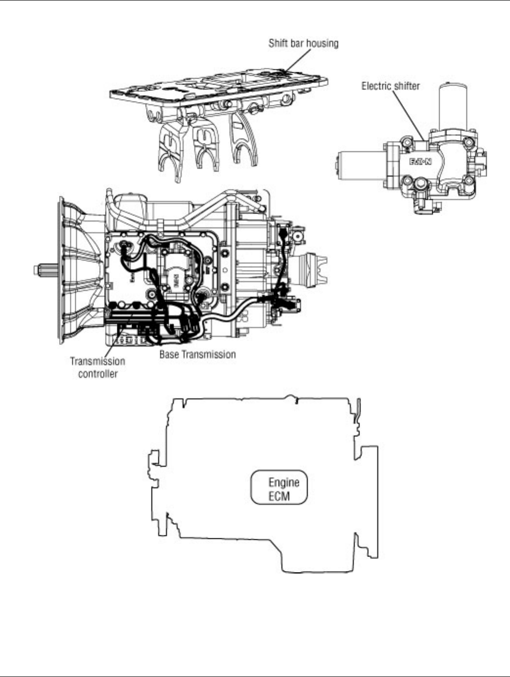
2016.01.15 © 2016 Eaton. All rights reserved 231
TRTS0930 Fault Isolation Procedures | Fault Code 73 - Failed to Engage Gear
Component Identification
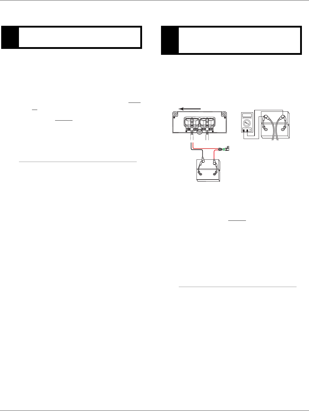
232 © 2016 Eaton. All rights reserved 2016.01.15
Fault Code 73 - Failed to Engage Gear | Fault Isolation Procedures TRTS0930
Fault Code 73 - Failed to Engage Gear
1. Key off.
2. Was a new Electric Shifter or TECU just installed
without recalibrating the transmission?
•Yes, Perform transmission calibration. Turn
key on and allow the transmission to power
up. Turn key off and wait 2 minutes. go to Step
V..
•No, go to Step B.
1. Key off.
2. Inspect starter / battery and in-line fuse holder con-
nections for integrity.
3. Measure voltage across batteries.
•If voltage is 11 to 13 volts on a 12-volt system
or 22 to 26 on a 24-volt system, proceed with
battery load test. Repair or replace batteries as
required. Go to Step C.
•If voltage is outside of range, repair or replace
batteries and charge system as required.
Repeat test.
APurpose: Determine if an Electric Shifter was in-
stalled without recalibrating the transmission. BPurpose: Measure battery voltage. Visually inspect
the batteries, inline fuse, power and ground sup-
plies to the TECU.
VOLTS
VCOM A
+
–
+
–
30 AMP fuse
Battery power
(Non-switched power)
run to starter or Battery
36 38
Transmission ECU
–
–
+
+
OEM Harness Transmission Harness
Front of Transmission
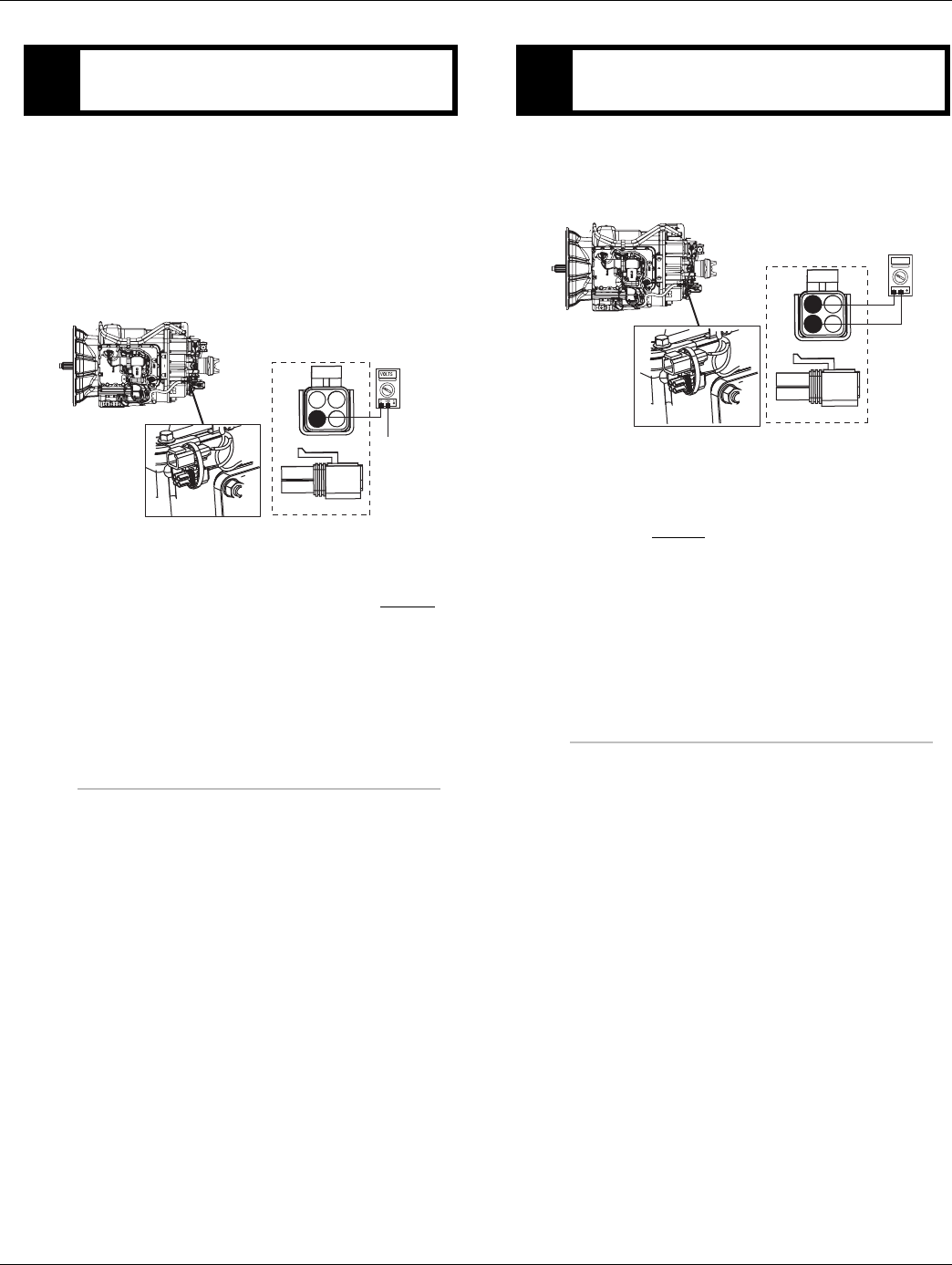
2016.01.15 © 2016 Eaton. All rights reserved 233
TRTS0930 Fault Isolation Procedures | Fault Code 73 - Failed to Engage Gear
1. Locate the diagnostic port on the Transmission
Harness - located at the left rear corner of the
transmission.
2. Key on.
3. Measure voltage between Pin C and the battery
negative post.
•If voltage is 0.70 volts or less, go to Step D.
•If voltage is outside of range, repair battery
ground supply to TECU. Repeat test.
1. Key on.
2. Measure voltage between Pin B and Pin C.
•If voltage is within 0.6 volts of battery voltage,
go to Step E.
•If voltage is outside of range, repair battery
power supply to TECU. Fuse may be blown.
Repeat test.
CPurpose: Verify proper ground path at 4-way diag-
nostic port
4-Pin Diagnostic Port
(Located at the left rear
corner of the transmission.)
4-Pin Diagnostics Port
4-way
B - Service Bat. +
C - Service Bat. -
A - Service Ignition +
Battery Negative Post
BA
D
C
DPurpose: Measure battery voltage at 4-way diag-
nostic port.
4-Pin Diagnostics Port
4-way
B - Service Bat. +
C - Service Bat. -
A - Service Ignition +
VOLTS
VCOM A
BA
D
C
4-Pin Diagnostic Port
(Located at the left rear
corner of the transmission.)
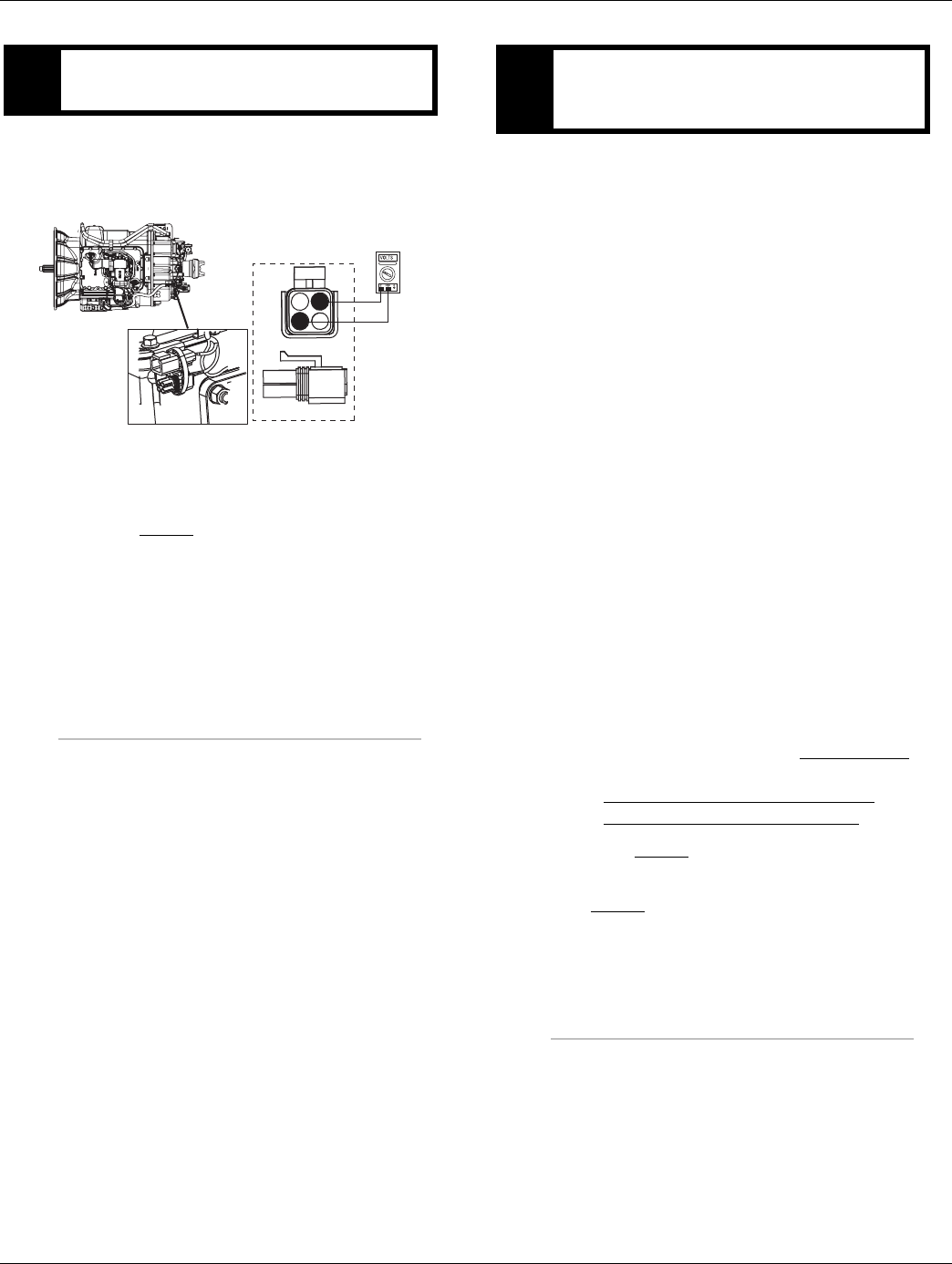
234 © 2016 Eaton. All rights reserved 2016.01.15
Fault Code 73 - Failed to Engage Gear | Fault Isolation Procedures TRTS0930
1. Key on.
2. Measure voltage between Pin A and Pin C.
•If voltage is within 0.6 volts of battery voltage,
go to Step F.
•If voltage is outside of range, repair ignition
power supply to TECU. Fuse may be blown
Repeat test.
1. Key off.
2. Remove electric shifter from Shift Bar housing.
3. Inspect the Shift Bar housing
-Visually inspect shift rails and blocks.
-Verify Shift Bar housing operation by confirming
shift rails can physically engage each gear indi-
vidually.
-Confirm the Shift Bar housing can not engage 2
gears at the same time.
4. Inspect Electric Shifter
-Check for mechanical issues with the Electric
Shifter.
- Visually inspect for badly contaminated /
gummed up / soiled Electric Shifter ball screw
due to oil cooler leaks.
-Check for a worn center shaft bushing (see
TAIB-0814).
5. Inspect base transmission
-Drain and inspect oil for debris.
-Remove I-brake or PTO cover and inspect for
main box mechanical failure.
-Inspect sliding clutches and shift yokes for wear.
•If no problem found, replace Electric Shifter
and the:
-Medium-Duty Transmission Harness
- Heavy-Duty Transmission Harness
Go to Step V.
•If problem found, repair as required. Go to
Step V.
EPurpose: Measure ignition voltage at 4-way diag-
nostic port
4-Pin Diagnostics Port
4-way
B - Service Bat. +
C - Service Bat. -
A - Service Ignition +
BA
D
C
4-Pin Diagnostic Port
(Located at the left rear
corner of the transmission.)
FPurpose: Visually inspect the Shift Bar housing,
Electric Shifter and base transmission for signs of
mechanical damage.

2016.01.15 © 2016 Eaton. All rights reserved 235
TRTS0930 Fault Isolation Procedures | Fault Code 73 - Failed to Engage Gear
1. Key off.
2. Reconnect all connectors and the negative battery
cable.
3. Key on.
4. Clear fault codes, see “Fault Code Retrieval/Clear-
ing” on page 5.
5. Drive the vehicle and attempt to reset the fault
code.
6. Check for fault codes, see “Fault Code
Retrieval/Clearing” on page 5.
•If no fault codes, test complete.
•If Fault Code 73 appears go to Step A. to find
error in testing.
•If fault code other than 73 appears, See “Fault
Code Isolation Procedure Index” on page 8.
VPurpose: Verify repair.

236 © 2016 Eaton. All rights reserved 2016.01.15
Fault Code 74 - Engine Speed Response Fault | Fault Isolation Procedures TRTS0930
Fault Code 74 - Engine Speed Response Fault
J1587: MID 130 PID 93/190 FMI 7
J1939: SA 3 SPN 518/898 FMI 7
Overview
This fault code indicates the transmission is unable to use
system controls to synchronize during a shift.
Detection
If there is engine communication on the J1939 Link and the
engine does not respond to transmission speed and torque
commands, the code will set.
Fallback
If the failure occurs while moving, it could cause a 1-speed
fallback. Once the vehicle is stopped, starting gear and
reverse gear can be engaged.
Possible Causes
This fault code can be caused by any of the following:
• Engine control system
2016.01.15 © 2016 Eaton. All rights reserved 237
TRTS0930 Fault Isolation Procedures | Fault Code 74 - Engine Speed Response Fault
Component Identification
Engine
ECM
Engine Torque Value

238 © 2016 Eaton. All rights reserved 2016.01.15
Fault Code 74 - Engine Speed Response Fault | Fault Isolation Procedures TRTS0930
Fault Code 74 - Engine Speed Response Fault
1. Key on.
2. Retrieve fault codes. See “Fault Code
Retrieval/Clearing” on page 5.
•If Fault Code 74 is Active, contact the OEM
because the engine is failing to respond to the
transmissions command during a shift.
•If fault code is not Active, test complete.
APurpose: Check for active or Inactive fault codes.
Contact vehicle OEM for further direction.

2016.01.15 © 2016 Eaton. All rights reserved 239
TRTS0930 Fault Isolation Procedures | Fault Code 74 - Engine Speed Response Fault

240 © 2016 Eaton. All rights reserved 2016.01.15
Fault Code 75 - Power Down In Gear | Fault Isolation Procedures TRTS0930
Fault Code 75 - Power Down In Gear
J1587: MID 130 SID 60 FMI 14
J1939: SA 3 SPN 560 FMI 14
Overview
This fault is detected when the vehicle is powered-down in
any gear position other than neutral.
Note: This code will only be set Inactive
Detection
The Transmission Electronic Control Unit (TECU) monitors
shift device position and electric shifter position during
vehicle shut down. If a non-neutral shift device position and
in gear position are detected during vehicle shut down, this
code will be set.
Fallback
No Fallback mode. This is a non driving, power-down fault.
It may cause a dash to appear in the gear display during
power-up if the transmission is torque locked after shutting
down in gear.
Possible Causes
This fault code can be caused by any of the following:
• Improper shut down procedure
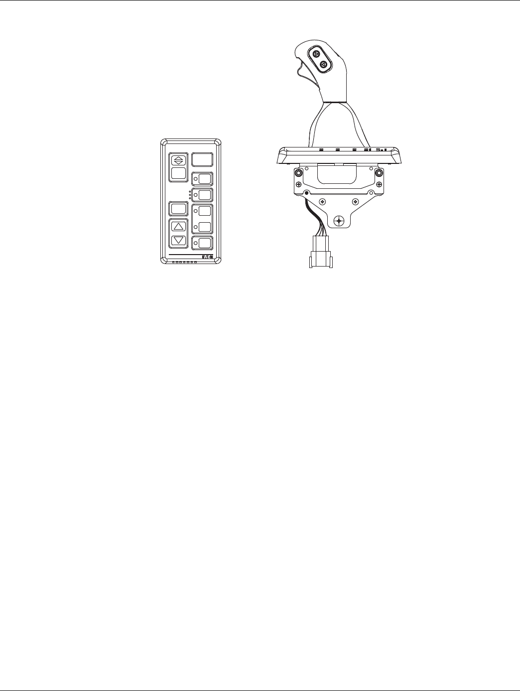
2016.01.15 © 2016 Eaton. All rights reserved 241
TRTS0930 Fault Isolation Procedures | Fault Code 75 - Power Down In Gear
Component Identification
Pushbutton Shift Control
VOLUME
CONTROL
SERVICE
SHIFT
Eaton Fuller
Transmissions
L
H
D
N
R
Eaton Shift Lever

242 © 2016 Eaton. All rights reserved 2016.01.15
Fault Code 75 - Power Down In Gear | Fault Isolation Procedures TRTS0930
Fault Code 75 - Power Down In Gear
1. Key on.
2. Retrieve Codes. See “Fault Code Retrieval/Clearing”
on page 5.
•If Fault Code 75 is Inactive, no action neces-
sary. This code indicates the driver powered
down the system prior to selecting neutral.
•Explain to driver, shift selector must be in neu-
tral before powering down to prevent a
stuck-in-gear situation and/or a power-up no
crank situation.
APurpose: Check for active or Inactive fault codes.

2016.01.15 © 2016 Eaton. All rights reserved 243
TRTS0930 Fault Isolation Procedures | Fault Code 75 - Power Down In Gear

244 © 2016 Eaton. All rights reserved 2016.01.15
Fault Code 81 - Gear Engagement Detected | Fault Isolation Procedures TRTS0930
Fault Code 81 - Gear Engagement Detected
J1587: MID 130 SID 47 FMI 7
J1939: SA 3 SPN 780 FMI 7
Overview
The transmission controller has detected that the shift fin-
ger position indicates neutral and a comparison of input
and main shaft speeds indicate the transmission is in gear.
The comparison of shaft speeds is only performed when
the vehicle is moving and a shift is in process.
Detection
• The fault is detected after the Transmission Elec-
tronic Control Unit (TECU) powers up and a
non-neutral condition is detected during a shift.
• FMI 7 - The transmission controller detected an
inaccurate finger position.
Conditions to Set Fault Code Active
Conditions to Recreate Fault
• Only set during a shift.
Fallback
This fault causes an in-place fallback. The transmission will
remain in current gear.
Conditions to Set Fault Code Inactive
Conditions to Clear Fault
• The fault becomes Inactive after power down.
Possible Causes
This fault code can be caused by any of the following:
• Worn internal transmission components.
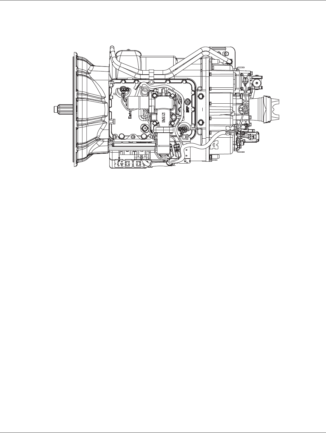
2016.01.15 © 2016 Eaton. All rights reserved 245
TRTS0930 Fault Isolation Procedures | Fault Code 81 - Gear Engagement Detected
Component Identification
Transmission

246 © 2016 Eaton. All rights reserved 2016.01.15
Fault Code 81 - Gear Engagement Detected | Fault Isolation Procedures TRTS0930
Fault Code 81 - Gear Engagement Detected
1. Key on.
2. Retrieve codes. See “Fault Code Retrieval/Clearing”
on page 5.
•If Fault Code 81 is active or Inactive, Customer
- Call Eaton at 1-800-826-HELP (4357).
CSC - Call Technician Service.
APurpose: Check for active or Inactive fault codes.
Contact Eaton support for further direction.

2016.01.15 © 2016 Eaton. All rights reserved 247
TRTS0930 Fault Isolation Procedures | Fault Code 81 - Gear Engagement Detected

248 © 2016 Eaton. All rights reserved 2016.01.15
Fault Code 83 - Shift Lever Missing | Fault Isolation Procedures TRTS0930
Fault Code 83 - Shift Lever Missing
J1587: MID 130 SID 18, 19 FMI 14
J1939: SA 3 SPN 751, 752 FMI 7, 12
Overview
This fault code indicates the Eaton Cobra Lever or the OEM
Shift Lever is not sensing any lever positions.
Detection
Starting at key on and throughout operation, the Transmis-
sion Electronic Control Unit (TECU) constantly measures
the feedback from the Shift Lever circuit. If the Shift Lever
reports no lever positions are sensed, the fault code is set.
Fallback
This fault causes a downshift only and shifts to neutral
when the vehicle stops.
Possible Causes
This fault code can be caused by any of the following:
• Eaton Cobra Lever or OEM Shift Lever
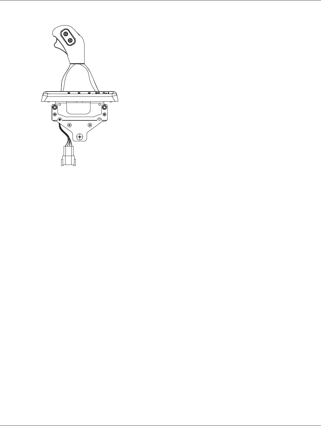
2016.01.15 © 2016 Eaton. All rights reserved 249
TRTS0930 Fault Isolation Procedures | Fault Code 83 - Shift Lever Missing
Component Identification
Eaton Shift Lever

250 © 2016 Eaton. All rights reserved 2016.01.15
Fault Code 83 - Shift Lever Missing | Fault Isolation Procedures TRTS0930
Fault Code 83 - Shift Lever Missing
1. Key on.
2. Retrieve codes. See “Fault Code Retrieval/Clearing”
on page 5.
•If Fault Code 83 is Active, replace Eaton Cobra
Lever or OEM Shift Lever.
•If Fault Code 83 is Inactive, test complete.
APurpose: Check for active or Inactive fault codes.

2016.01.15 © 2016 Eaton. All rights reserved 251
TRTS0930 Fault Isolation Procedures | Fault Code 83 - Shift Lever Missing

252 © 2016 Eaton. All rights reserved 2016.01.15
Fault Code 84 - Shift Control Device Not Configured | Fault Isolation Procedures TRTS0930
Fault Code 84 - Shift Control Device Not Configured
J1587: MID 130 SID 18, 19 FMI 13
J1939: SA 3 SPN 751, 752 FMI 13
Overview
This fault indicates a new Transmission Electronic Control
Unit (TECU) has not detected a Shift Control device.
Detection
The fault is detected the first time the system is powered
up. The TECU looks for a shift control device if none are
detected the system will set this code.
Note: The fault will only be set active.
Fallback
No crank at power-up.
Possible Causes
This fault code can be caused by any of the following:
• Damaged OEM Wiring Harness between TECU and
Shift Control device after new TECU is installed.
•Disconnected Shift Control device after new TECU
is installed.
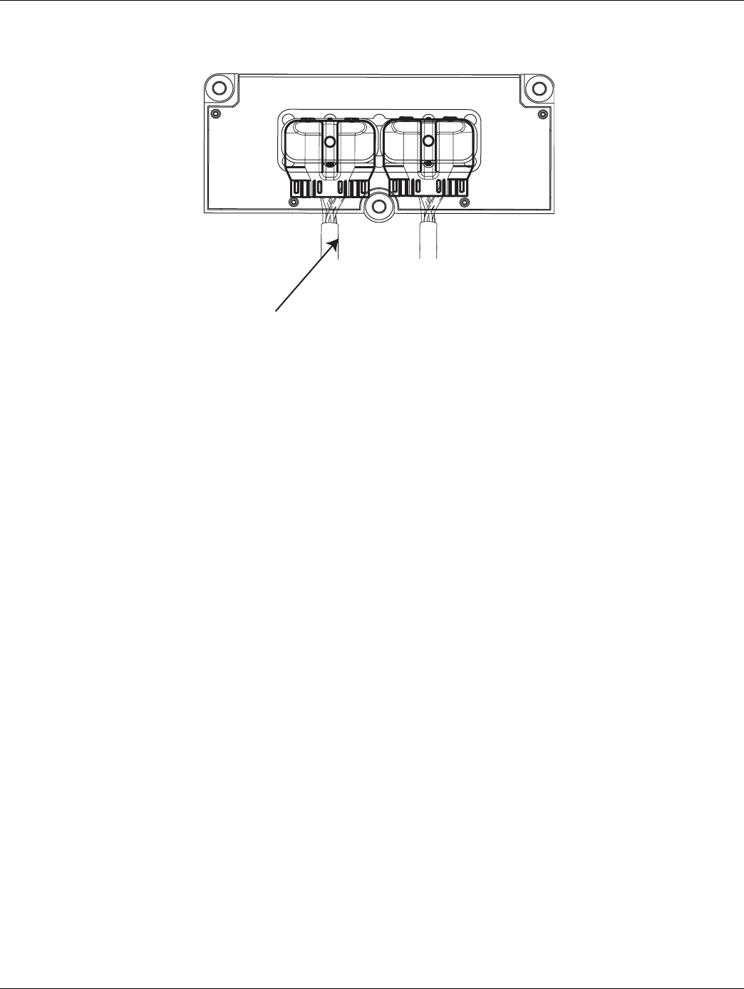
2016.01.15 © 2016 Eaton. All rights reserved 253
TRTS0930 Fault Isolation Procedures | Fault Code 84 - Shift Control Device Not Configured
Component Identification
Vehicle Harness 38-way Connector

254 © 2016 Eaton. All rights reserved 2016.01.15
Fault Code 84 - Shift Control Device Not Configured | Fault Isolation Procedures TRTS0930
Fault Code 84 - Shift Control Device Not Configured
1. Verify Shift Control device is connected to the OEM
wiring.
2. Key on.
3. Retrieve fault codes. See “Fault Code
Retrieval/Clearing” on page 5.
•If Fault Code 84 is Active, repair OEM wiring
between TECU and Shift Control device.
APurpose: Confirm Shift Control device is properly
installed. Check for active or Inactive fault codes.

2016.01.15 © 2016 Eaton. All rights reserved 255
TRTS0930 Fault Isolation Procedures | Fault Code 84 - Shift Control Device Not Configured

256 © 2016 Eaton. All rights reserved 2016.01.15
Fault Code 85 - Shift Control Device Incompatible | Fault Isolation Procedures TRTS0930
Fault Code 85 - Shift Control Device Incompatible
J1587: MID 130 SID 18 FMI 12
J1939: SA 3 SPN 751 FMI 12
Overview
This fault indicates the Transmission Electronic Control Unit
(TECU) has detected a non compatible Shift Control device.
Detection
The TECU looks for a Shift Control device at system
power-up. If a non compatible shift control device is
detected the system will set this code.
Fallback
This fault causes an in-place fallback
Possible Causes
This fault code can be caused by any of the following:
• Non compatible Shift Control device
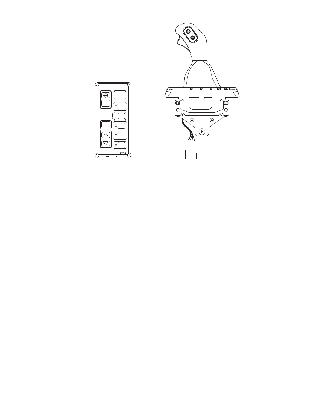
2016.01.15 © 2016 Eaton. All rights reserved 257
TRTS0930 Fault Isolation Procedures | Fault Code 85 - Shift Control Device Incompatible
Component Identification
Pushbutton Shift Control
VOLUME
CONTROL
SERVICE
SHIFT
Eaton Fuller
Transmissions
L
H
D
N
R
Eaton Shift Lever

258 © 2016 Eaton. All rights reserved 2016.01.15
Fault Code 85 - Shift Control Device Incompatible | Fault Isolation Procedures TRTS0930
Fault Code 85 - Shift Control Device Incompatible
1. Verify Shift Control device is connected to the OEM
wiring.
2. Key on.
3. Retrieve fault codes. See “Fault Code
Retrieval/Clearing” on page 5.
•If Fault Code 85 is Active, verify correct Shift
Control device is installed on vehicle.
APurpose: Confirm Shift Control device part num-
ber. Ensure proper device installed.

2016.01.15 © 2016 Eaton. All rights reserved 259
TRTS0930 Fault Isolation Procedures | Fault Code 85 - Shift Control Device Incompatible

260 © 2016 Eaton. All rights reserved 2016.01.15
Fault Code 99 - Direction Mismatch | Fault Isolation Procedures TRTS0930
Fault Code 99 - Direction Mismatch
J1587: MID 130 SID 58 FMI 14
J1939: SA 3 SPN 781 FMI 14
Overview
The transmission controller is monitoring the Gear Position
sensor and has determined the Electric Shifter is moving in
the opposite intended direction.
Detection
• The fault can be detected any time after the Trans-
mission Electronic Control Unit (TECU) powers up
and a non-neutral mode is selected.
• FMI 14 - The transmission controller detected an
incorrect Electric Shifter position.
Conditions to Set Fault Code Active
Conditions to Recreate Fault
• None
Fallback
This fault causes an in-place fallback. The transmission will
remain in current gear.
Conditions to Set Fault Code Inactive
Conditions to Clear Fault
• The fault becomes Inactive after power down.
Possible Causes
This fault code can be caused by the following:
• Internal transmission controller fault.
• Transmission wire harness shorted.
• Electric Shifter failure.
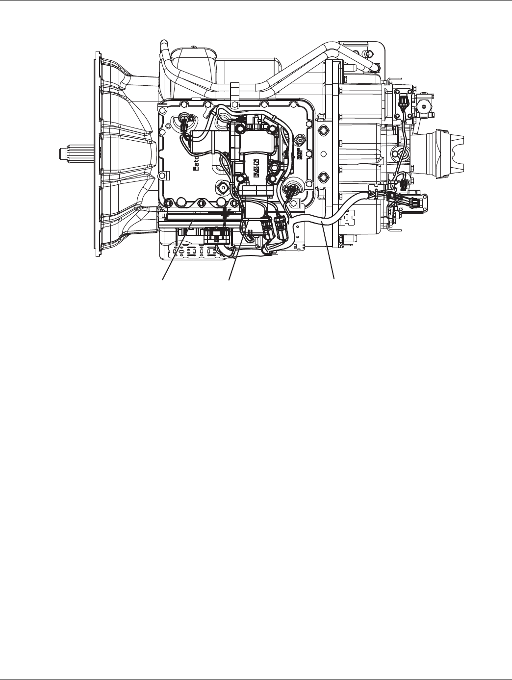
2016.01.15 © 2016 Eaton. All rights reserved 261
TRTS0930 Fault Isolation Procedures | Fault Code 99 - Direction Mismatch
Component Identification
Transmission ControllerXY ShifterTransmission Harness

262 © 2016 Eaton. All rights reserved 2016.01.15
Fault Code 99 - Direction Mismatch | Fault Isolation Procedures TRTS0930
Fault Code 99 - Direction Mismatch
1. Key on.
2. Retrieve fault codes. See “Fault Code
Retrieval/Clearing” on page 5.
•If Fault Code 99 is Active or Inactive, Customer
- Call Eaton at 1-800-826-HELP (4357).
CSC - Call Technician Service.
APurpose: Check for active or Inactive fault codes.
Contact Eaton technical support for further direc-
tion.

2016.01.15 © 2016 Eaton. All rights reserved 263
TRTS0930 Fault Isolation Procedures | Fault Code 99 - Direction Mismatch

264 © 2016 Eaton. All rights reserved 2016.01.15
Up/Down Button Test | Symptom Isolation Procedures TRTS0930
Up/Down Button Test
Overview
This symptom-driven test is performed if unable to shift the
transmission with the Up/Down buttons, and there are no
Active or Inactive codes.
Detection
The shift control has no fault detection capability for this
failure. The failure is observed by the driver when operating
the vehicle.
Fallback
There is no fallback for this symptom.
Possible Causes
This symptom can be caused by any of the following:
• Push button shift control
• Shift Lever
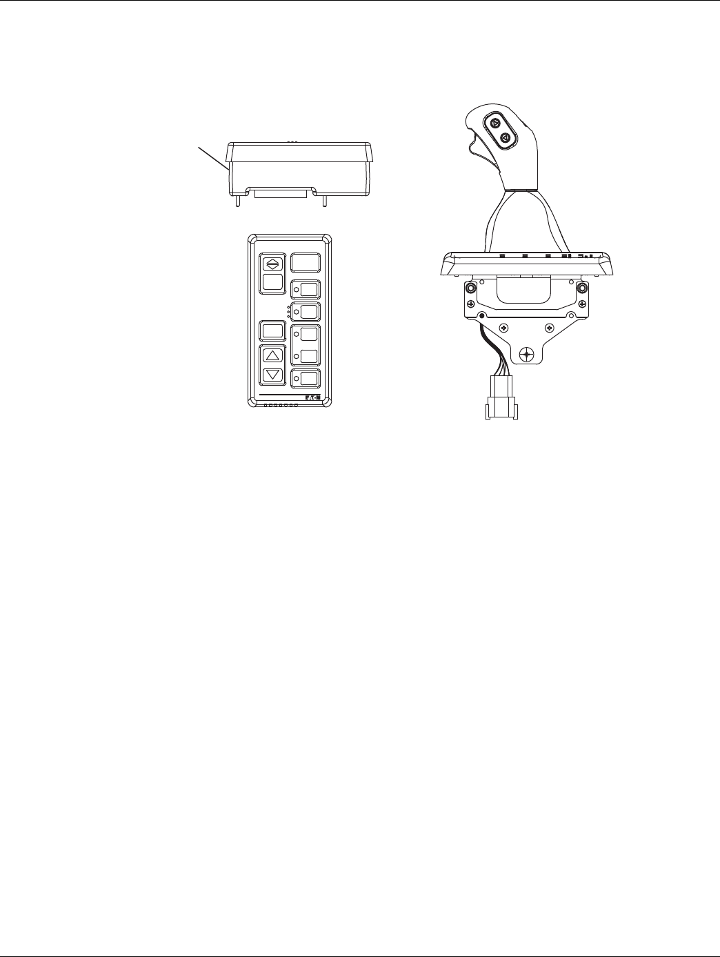
2016.01.15 © 2016 Eaton. All rights reserved 265
TRTS0930 Symptom Isolation Procedures | Up/Down Button Test
Component Identification
Side view
of pushbutton
shift control
Pushbutton Shift Control
VOLUME
CONTROL
SERVICE
SHIFT
Eaton Fuller
Transmissions
L
H
D
N
R
Eaton Shift Lever

266 © 2016 Eaton. All rights reserved 2016.01.15
Up/Down Button Test | Symptom Isolation Procedures TRTS0930
Up/Down Button Test
1. Start engine.
2. Place Shift Device in manual.
3. Drive the vehicle using the buttons to initiate
upshifts and downshifts, when conditions permit.
•If the up and down buttons are working prop-
erly, the transmission will make upshifts and
downshifts, test complete.
•If the transmission does not make upshifts or
downshifts, replace Shift Control. Repeat test.
APurpose: Drive vehicle and attempt to complete
manual button shifts in Manual Mode.

2016.01.15 © 2016 Eaton. All rights reserved 267
TRTS0930 Symptom Isolation Procedures | Up/Down Button Test

268 © 2016 Eaton. All rights reserved 2016.01.15
Start Enable Relay Contact Test | Symptom Isolation Procedures TRTS0930
Start Enable Relay Contact Test
Overview
This symptom-driven test is performed if the engine does
not crank with the Shift Lever in neutral, and there are no
Active or Inactive codes.
Detection
The Transmission Electronic Control Unit (TECU) has no
fault detection capability for this failure. The failure is
observed by the driver when operating the vehicle. To
observe this failure, attempt to start the vehicle.
Fallback
This symptom has no affect on vehicle operation; however,
if the failure occurred before the engine was started, it is
possible the engine will not start.
Possible Causes
This symptom can be caused by any of the following:
• Start Enable Relay
• Starter Solenoid wiring
• Vehicle Harness
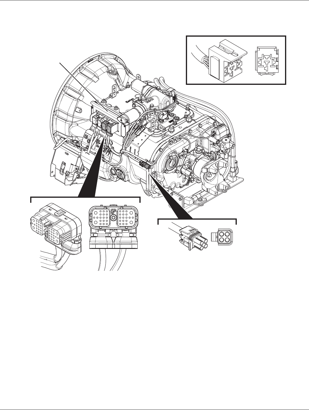
2016.01.15 © 2016 Eaton. All rights reserved 269
TRTS0930 Symptom Isolation Procedures | Start Enable Relay Contact Test
Component Identification
1. 38-Way Transmission Harness Connector
2. Transmission Electronic Control Unit (TECU)
3. 5-Way Start Enable Relay Socket
4. 4-Way Diagnostic Connector
1
4
3
2
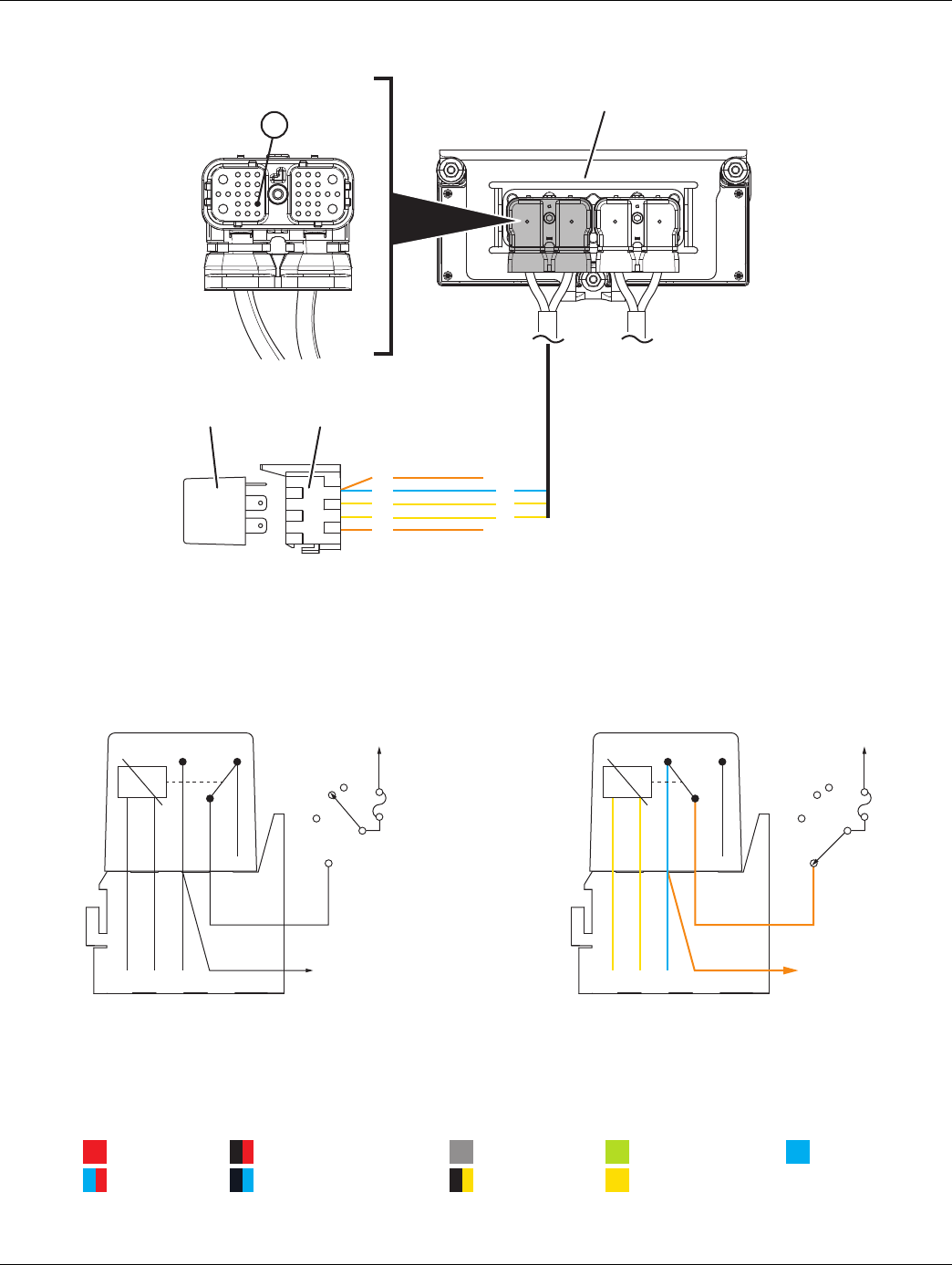
270 © 2016 Eaton. All rights reserved 2016.01.15
Start Enable Relay Contact Test | Symptom Isolation Procedures TRTS0930
1. Transmission Electronic Control Unit (TECU)
2. 38-Way Vehicle Harness Connector
3. 5-Way Start Enable Relay Socket
4. 5-Way Start Enable Relay
Start Enable Relay Circuit States (Normally Open)
5. Open Relay - Key Off (Non-energized State)
6. Closed Relay - Key On and Transmission Confirmed in Neutral (Energized State)
85
87
87
86
4
30 IGN
Starter
26
32
34
12
26
5
87
26324
30 87A8685
START
ACC
OFF
ON
START
ACC
OFF
ON
Starter
6
87
26324
30 87A8685
Starter
++
Signal
Communication
Relay/Solenoid Driver
Ground
Switched Ground
Battery Voltage
Ignition Voltage
Switched Battery from TECU
Switched 5V from TECU
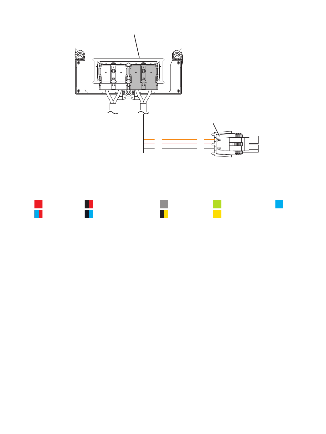
2016.01.15 © 2016 Eaton. All rights reserved 271
TRTS0930 Symptom Isolation Procedures | Start Enable Relay Contact Test
1. Transmission Electronic Control Unit (TECU)
2. 4-Way Diagnostic Connector
25
17
31
A
B
C
2
1
Signal
Communication
Relay/Solenoid Driver
Ground
Switched Ground
Battery Voltage
Ignition Voltage
Switched Battery from TECU
Switched 5V from TECU
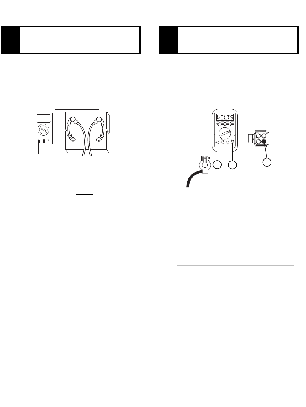
272 © 2016 Eaton. All rights reserved 2016.01.15
Start Enable Relay Contact Test | Symptom Isolation Procedures TRTS0930
Start Enable Relay Contact Test
1. Key off.
2. Inspect starter/battery and
in-line fuse holder connections for integrity.
3. Measure voltage across batteries.
•If voltage is 11–13 volts on a 12-volt system or
22 to 26 on a 24 volt system, proceed with
battery load test. Repair or replace batteries as
required and go to Step B.
•If voltage is outside of range, repair or replace
batteries and charging system as required.
Repeat test.
1. Locate diagnostic port on Transmission Harness.
2. Key on.
3. Measure voltage between Pin C and the battery
negative post.
•If voltage is 0.70 volts or less, go to Step C.
•If voltage is outside of range, repair battery
ground supply to TECU. Repeat test.
APurpose: Measure battery voltage. Visually inspect
the batteries, inline fuse and power and ground
supplies at the batteries.
VOLTS
VCOM A
+
–
+
–
BPurpose: Verify proper ground path between the
batteries and the transmission harness 4-way diag-
nostic connector.
CC
−
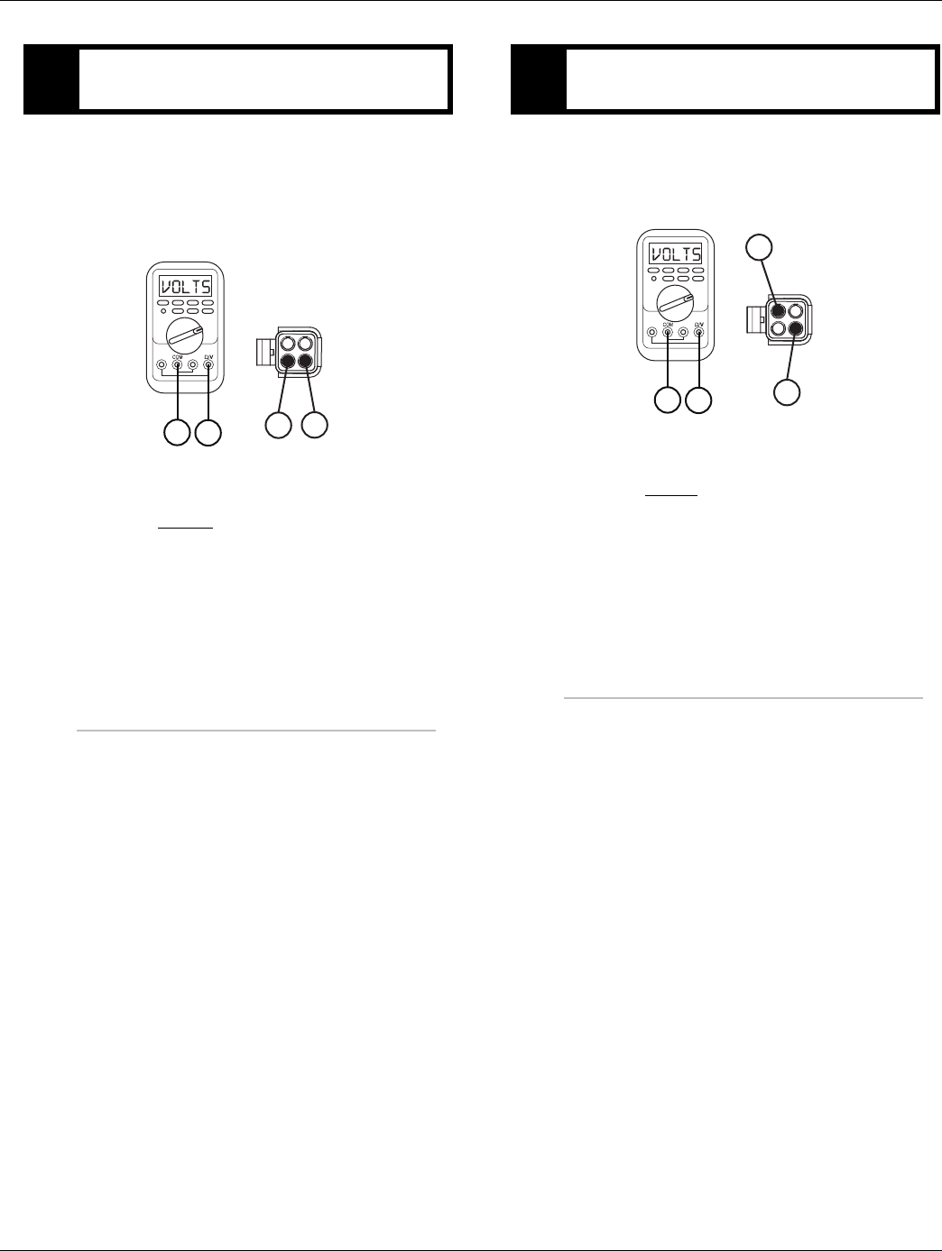
2016.01.15 © 2016 Eaton. All rights reserved 273
TRTS0930 Symptom Isolation Procedures | Start Enable Relay Contact Test
1. Locate diagnostic port on Transmission Harness.
2. Key on.
3. Measure voltage between Pin B and Pin C.
•If voltage is within 0.6 volts of battery voltage,
go to Step D.
•If voltage is outside of range, repair battery
power supply to TECU. Fuse may be blown.
Repeat test.
1. Key on.
2. Measure voltage between Pin A and Pin C.
•If voltage is within 0.6 volts of battery voltage,
go to Step E.
•If voltage is outside of range, repair ignition
power supply to TECU. Fuse may be blown.
Repeat test.
CPurpose: Measure proper battery voltage at the
transmission harness 4-way diagnostic connector.
C
BC
B
DPurpose: Measure proper ignition voltage at the
transmission harness 4-way diagnostic connector.
C
A
AC
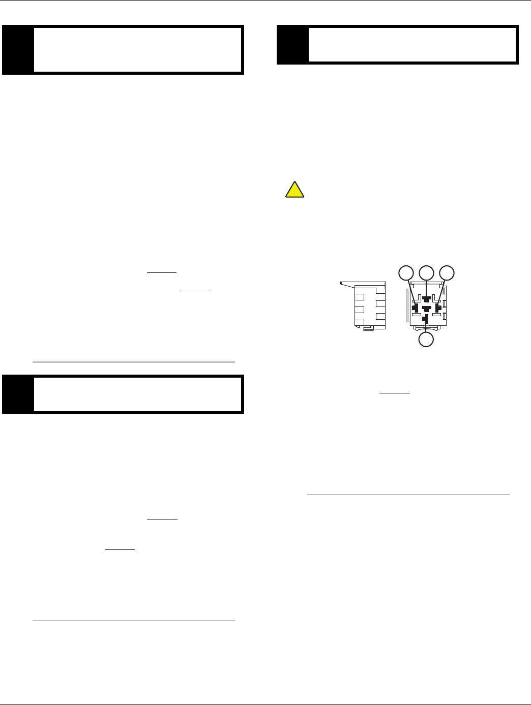
274 © 2016 Eaton. All rights reserved 2016.01.15
Start Enable Relay Contact Test | Symptom Isolation Procedures TRTS0930
1. Key off.
2. Disconnect negative battery cable.
3. Disconnect Vehicle Harness 38-way connector.
4. Reconnect negative battery cable.
5. Key on.
6. Engage starter.
Note: The Start Enable Relay must be wired
according to Eaton GEN III requirements
(shown on previous page) for this test to
work properly. If wired differently, consult
OEM for correct wiring schematic.
•If engine cranks, go to Step F.
•If engine does not crank, go to Step G.
1. Key off.
2. Remove the Start Enable Relay.
3. Key on.
4. Engage starter.
•If vehicle cranks, repair short to power on
Vehicle Harness. go to Step V.
•If vehicle does not crank, replace Start Enable
Relay. go to Step V.
1. Key on.
2. Disconnect negative battery cable.
3. Reconnect Vehicle Harness 38-way connector.
4. Reconnect negative battery cable.
5. Place a jumper wire across connector contact 30
and contact 87.
Warning: Make sure the parking brake is set before
jumping the Start Enable Relay.
6. Key on. Verify neutral on Gear Display.
7. Engage starter.
•If engine cranks, replace the Start Enable
Relay. go to Step H.
•If engine does not crank, refer to OEM for
repair of Vehicle Harness or starter.
EPurpose: Visually inspect Start Enable Relay wiring
and confirm that it is wired per requirements. Con-
firm if the engine will crank.
FPurpose: Remove the Start Enable Relay and con-
firm if the engine will crank.
GPurpose: “Jump” the Start Enable Relay and con-
firm if the engine will crank.
!
87
30
8685
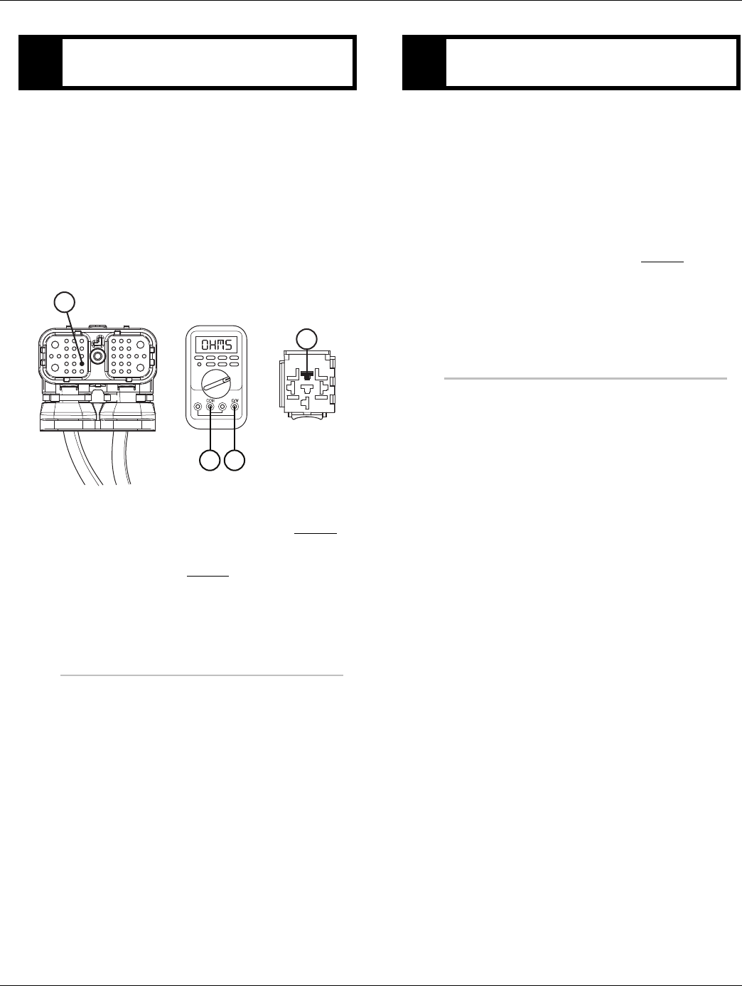
2016.01.15 © 2016 Eaton. All rights reserved 275
TRTS0930 Symptom Isolation Procedures | Start Enable Relay Contact Test
1. Key off.
2. Disconnect negative battery cable.
3. Disconnect Vehicle Harness 38-way connector.
4. Disconnect the Start Enable Relay.
5. Measure resistance between Pin 87 of the Start
Enable Relay connector and Pin 26 of the Vehicle
Harness 38-Way connector.
•If resistance is 0 to 0.3 ohms, go to Step V.
•If resistance is greater than 10K ohm, repair
wiring and go to Step V.
1. Key off.
2. Reconnect all connectors.
3. Key on.
4. Start the engine to determine whether the Start
Enable Relay contact complaint has been repaired.
•If engine starts, test complete.
•If engine does not start go to Step A. to error
in testing.
HPurpose: Verify continuity of the Start Enable Latch
wire.
8726
26
87
VPurpose: Verify repair.

276 © 2016 Eaton. All rights reserved 2016.01.15
J1587 Data Link Test | Symptom Isolation Procedures TRTS0930
J1587 Data Link Test
Overview
This symptom-driven test is performed if the Ser-
viceRanger, a PC-based Service Tool, does not work.
Detection
The service technician observes the failure when operating
ServiceRanger. To observe this failure, simply connect Ser-
viceRanger to the transmission via the J1587 Diagnostic
Connector located in the cab.
Fallback
There is no fallback mode for the J1587 Data Link.
Possible Causes
This symptom can be caused by any of the following:
• J1587 Data Link Harness
• ServiceRanger
•Transmission Electronic Control Unit (TECU)
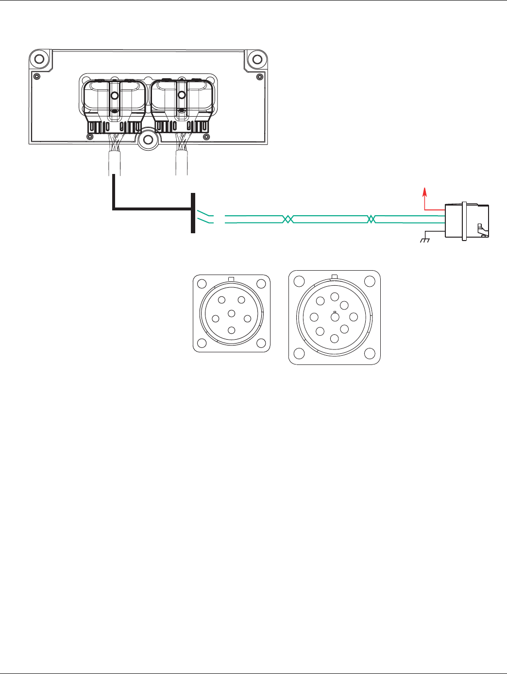
2016.01.15 © 2016 Eaton. All rights reserved 277
TRTS0930 Symptom Isolation Procedures | J1587 Data Link Test
Component Identification
+12
volts
battery
J1587 data link
10
11
GROUND
AB
C
D
E
F
6-way
diagnostic connector
A ATA+
B ATA–
C + Battery
D
EGround
F
9-way
diagnostic connector
AGround
B + Battery
C
D
E
F ATA+
G ATA-
H
J
OEM
Transmission ECU
A
F
J
E
G
H
D
C
B
278 © 2016 Eaton. All rights reserved 2016.01.15
J1587 Data Link Test | Symptom Isolation Procedures TRTS0930
J1587 Data Link Test
1. Key off.
2. Measure voltage either between 6-Way Diagnostic
Connector Pin C and Pin E or 9-Way Diagnostic
Connector Pin B and Pin A.
•If voltage is within 0.6 volts of battery voltage,
go to Step B.
•If voltage is outside of range, repair battery or
ground wire to vehicle Diagnostic connector.
Go to Step V.
1. Key off.
2. Disconnect negative battery cable.
3. Disconnect Vehicle Harness 38-Way Connector.
4. Measure resistance from Vehicle Harness 38-Way
Connector Pin 10 and either 6-Way Diagnostic Con-
nector Pin A or 9-Way Diagnostic Connector Pin F.
•If resistance is 0–0.3 ohms, go to Step C.
•If resistance is outside of range, repair Vehicle
Harness. Repeat this step.
APurpose: Measure battery voltage supply to the ve-
hicle diagnostic connector.
Pins Measurement
C to E
B to A
BPurpose: Verify continuity of the J1587 Plus wire
from the TECU to the vehicle diagnostic connector.
Pins Measurement
10 to A
10 to F
2016.01.15 © 2016 Eaton. All rights reserved 279
TRTS0930 Symptom Isolation Procedures | J1587 Data Link Test
1. Measure resistance between either 6-Way Diagnos-
tic Connector Pin A or 9-Way Diagnostic Connector
Pin F and ground.
•If resistance is OL, go to Step D.
•If resistance is less than 10K ohm, repair Vehi-
cle Harness. Go to Step V.
1. Measure resistance between Vehicle Harness
38-Way Connector Pin 11 and either 6-Way Diag-
nostic Connector Pin B or 9-Way Diagnostic Con-
nector Pin G.
•If resistance is 0–0.3 ohms, go to Step E.
•If resistance is outside of range, repair Vehicle
Harness and go to Step V.
1. Measure resistance between either 6-Way Diagnos-
tic Connector Pin B or 9-Way Diagnostic Connector
Pin G and ground.
•If resistance is OL, go to Step V.
•If resistance is less than 10K ohm, repair Vehi-
cle Harness. Go to Step V.
CPurpose: Test the J1587 Plus wire for a short to
ground through the vehicle diagnostic connector.
Pins Measurement
A to Ground
F to Ground
DPurpose: Verify continuity of the J1587 negative
(–) wire from the TECU to the vehicle diagnostic
connector.
Pins Measurement
11 to B
11 to G
EPurpose: Test the J1587 negative (–) wire for a
short to ground through the vehicle diagnostic con-
nector.
Pins Measurement
B to Ground
G to Ground

280 © 2016 Eaton. All rights reserved 2016.01.15
J1587 Data Link Test | Symptom Isolation Procedures TRTS0930
1. Key on.
2. Connect to ServiceRanger.
•If ServiceRanger functions correctly, test com-
plete.
•If ServiceRanger does not function correctly
go to Step A. find error in testing.
VPurpose: Verify repair.

2016.01.15 © 2016 Eaton. All rights reserved 281
TRTS0930 Symptom Isolation Procedures | J1587 Data Link Test

282 © 2016 Eaton. All rights reserved 2016.01.15
Front Box Control Test | Symptom Isolation Procedures TRTS0930
Front Box Control Test
Overview
This symptom-driven test is performed if a dash is dis-
played on the gear display, and there are no active or Inac-
tive codes.
Detection
Turn the key on and watch the Gear Display. If the Gear Dis-
play shows “-” constantly, the Transmission Electronic Con-
trol Unit (TECU) was not able to confirm front box control.
Any time the service light is flashing, go to Diagnostics Pro-
cedure.
Fallback
This fault causes an in-place fallback while moving, and it
causes a failure during system initialization. A dash will
appear on the Gear Display.
Possible Causes
This symptom can be caused by any of the following:
• Low power to gear select motor
• Electric shifter
• Gear Select Sensor
• Yoke / clutch / main shaft
• Shift Bar housing
• Dragging clutch
• Torque locked in gear
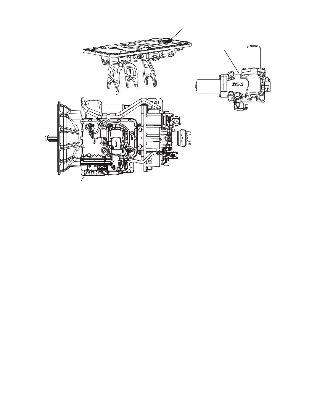
2016.01.15 © 2016 Eaton. All rights reserved 283
TRTS0930 Symptom Isolation Procedures | Front Box Control Test
Component Identification
Shift bar housing
Electric shifter
Transmission
controller
Base Transmission
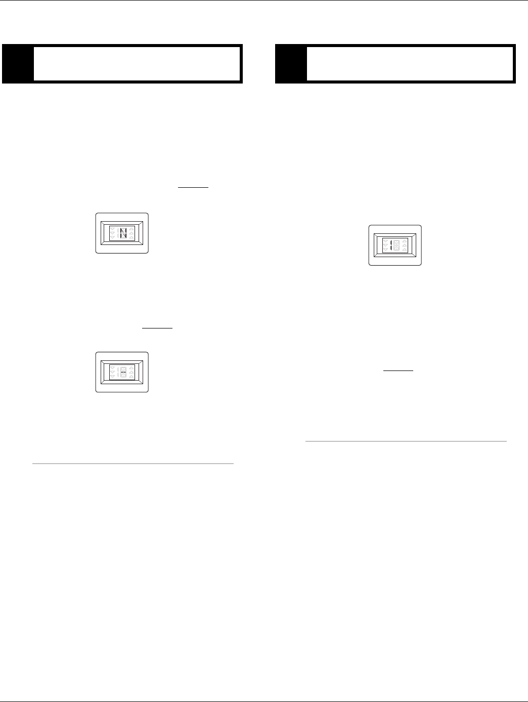
284 © 2016 Eaton. All rights reserved 2016.01.15
Front Box Control Test | Symptom Isolation Procedures TRTS0930
Front Box Control Test
1. Key on.
2. Depress clutch pedal (if equipped) half way to the
floor.
3. Place Shift Device in neutral.
4. Observe Gear Display.
•If Gear Display shows N, go to Step B.
•If service light is flashing, see “Diagnostic Pro-
cedures” on page 3.
•If Gear Display shows: “-” or a flashing gear
with no arrows, go to Step C.
1. Key on.
2. Place Shift Device in neutral.
3. Depress clutch pedal (if equipped) half way to the
floor. If it is a two pedal design apply the service
brake.
4. Select Drive
5. Observe Gear Display.
•If Gear Display shows a solid gear, test com-
plete.
•If service light is flashing, See “Diagnostic
Procedures” on page 3.
•If Gear Display shows a flashing gear with no
arrows, go to Step C.
APurpose: Visually observe the gear display after
power-up. BPurpose: Visually observe the gear display when
placing the transmission into Drive.
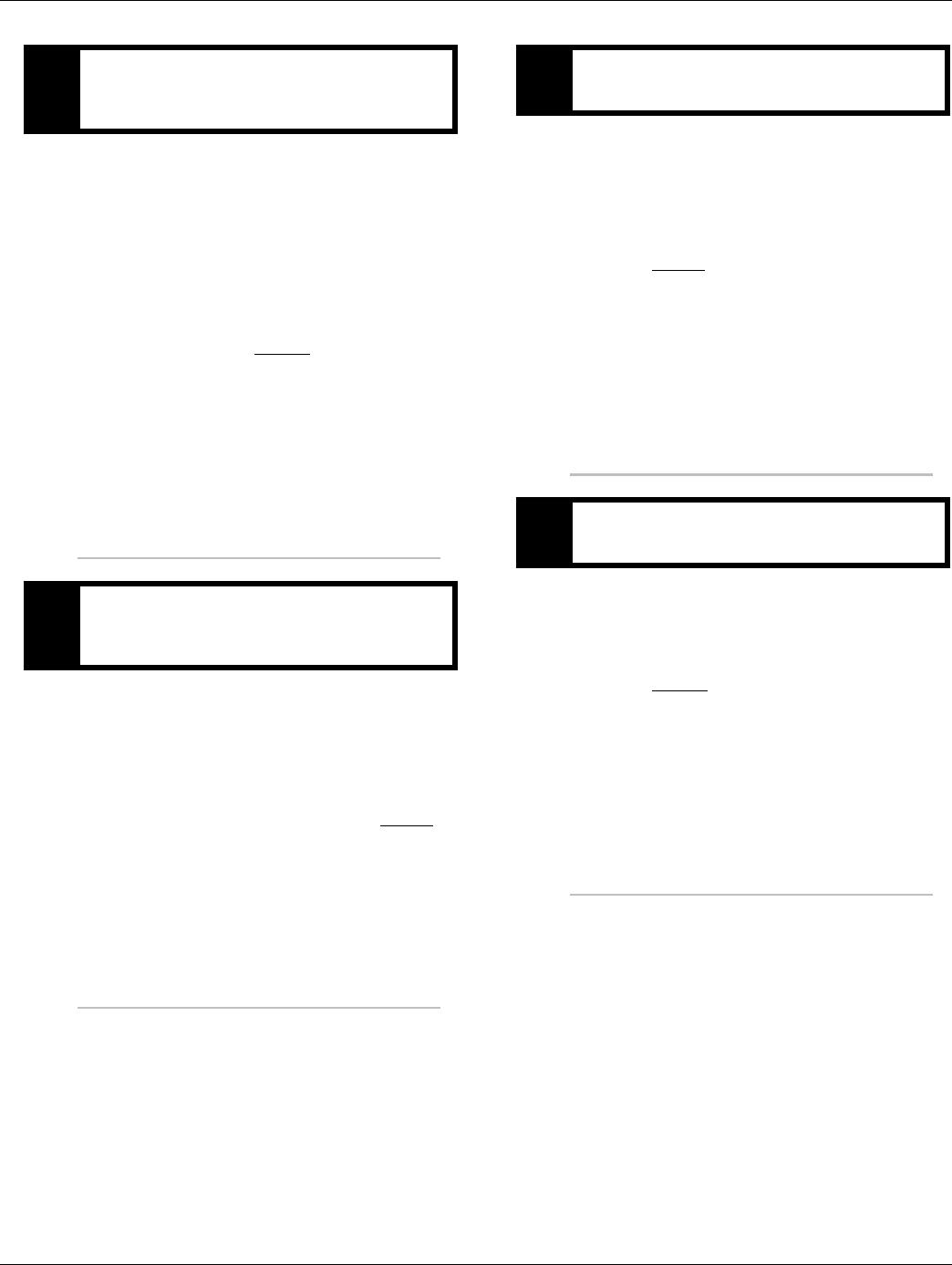
2016.01.15 © 2016 Eaton. All rights reserved 285
TRTS0930 Symptom Isolation Procedures | Front Box Control Test
1. Key off.
2. Inspect starter/battery and in-line fuse holder con-
nections for integrity.
3. Measure voltage across batteries.
•If voltage is 11 to 13 volts on a 12-volt system
or 22 to 26 on a 24-volt system, proceed with
battery load test. Repair or replace batteries as
required and go to Step D.
•If voltage is outside of range, repair or replace
batteries and charging system as required.
Repeat test.
1. Locate diagnostic port on Transmission Harness.
2. Key on.
3. Measure voltage between Pin C and the battery
negative post.
•If voltage is 0.70 volts or less, go to Step E.
•If voltage is outside of range, repair battery
ground supply to TECU. Repeat test.
1. Locate diagnostic port on Transmission Harness.
2. Key on.
3. Measure voltage between Pin B and Pin C.
•If voltage is within 0.6 volts of battery voltage,
go to Step F.
•If voltage is outside of range, repair battery
power supply to TECU. Fuse may be blown.
Repeat test.
1. Key on.
2. Measure voltage between Pin A and Pin C.
•If voltage is within 0.6 volts of battery voltage,
go to Step G.
•If voltage is outside of range, repair Ignition
power supply to TECU. Fuse may be blown.
Repeat test.
CPurpose: Measure battery voltage. Visually inspect
the batteries, inline fuse and power and ground
supplies at the batteries.
DPurpose: Verify proper ground path between the
batteries and the transmission harness 4-way diag-
nostic connector.
EPurpose: Measure proper battery voltage at the
transmission harness 4-way diagnostic connector.
FPurpose: Measure proper ignition voltage at the
transmission harness 4-way diagnostic connector.

286 © 2016 Eaton. All rights reserved 2016.01.15
Front Box Control Test | Symptom Isolation Procedures TRTS0930
1. Key off.
2. Remove Electric Shifter from Shift Bar housing.
3. Inspect the Shift Bar housing:
-Shift Blocks
-Shift Rails
-Inspect Electric Shifter for evidence of lube con-
tamination.
Note: See if the Shift Bar housing can engage two
gears at the same time to verify interlock
operation.
•If no problem found, replace Electric Shifter
go to Step V.
•If problem found, repair as required go to Step
V.
1. Key off.
2. Reconnect all connectors.
3. Place Shift Control into neutral.
4. Key on.
•If Gear Display displays a solid N, test com-
plete.
•If Gear Display does not display a solid N, find
error in testing, return to go to Step A.
GPurpose: Remove Electric Shifter from the Shift
Bar Housing and inspect the mechanical transmis-
sion.
VPurpose: Verify repair.

2016.01.15 © 2016 Eaton. All rights reserved 287
TRTS0930 Symptom Isolation Procedures | Front Box Control Test

288 © 2016 Eaton. All rights reserved 2016.01.15
AutoShift Will Not Engage a Gear from Neutral Test | Symptom Isolation Procedures TRTS0930
AutoShift Will Not Engage a Gear from Neutral Test
Overview
This symptom-driven test is performed if the transmission
does not engage a gear, and there are no active or Inactive
codes.
Detection
If the Transmission Electronic Control Unit (TECU) is unable
to provide a fault code, the driver may observe this failure
as the transmission not initiating or completing a shift. The
driver may observe this failure as the transmission neutral-
izes.
Fallback
There is no fallback mode for this symptom.
Possible Causes
This symptom can be caused by any of the following:
• Input Shaft Speed Sensor
• Transmission
• Clutch Brake/Clutch
• Transmission Harness
• TECU
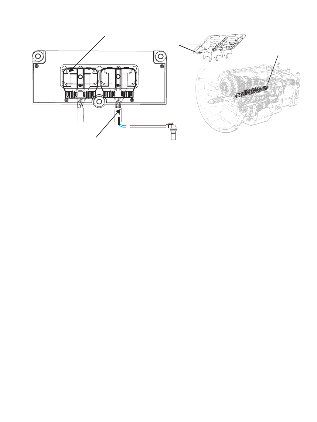
2016.01.15 © 2016 Eaton. All rights reserved 289
TRTS0930 Symptom Isolation Procedures | AutoShift Will Not Engage a Gear from Neutral Test
Component Identification
A
B
Input shaft
speed sensor
D1
D2
Shift Bar Housing
Main Shaft
Transmission Harness 38-way Connector
Transmission Harness 38-way Connector

290 © 2016 Eaton. All rights reserved 2016.01.15
AutoShift Will Not Engage a Gear from Neutral Test | Symptom Isolation Procedures TRTS0930
AutoShift Will Not Engage a Gear from Neutral Test
1. Key off.
2. Inspect starter/battery and
in-line fuse holder connections for integrity.
3. Measure voltage across batteries.
•If voltage is 11 to 13 volts on a 12-volt system
or 22 to 26 on a 24-volt system, proceed with
battery load test. Repair or replace batteries as
required. Go to Step B.
•If voltage is outside of range, repair or replace
batteries and charging system as required.
Repeat test.
1. Locate diagnostic port on Transmission Harness.
2. Key on.
3. Measure voltage between Pin C and the battery
negative post.
•If voltage is 0.70 volts or less, go to Step C.
•If voltage is outside of range, repair battery
ground supply to TECU. Repeat test.
APurpose: Measure battery voltage. Visually inspect
the batteries, inline fuse and power and ground
supplies at the batteries.
VOLTS
VCOM A
+
–
+
–
BPurpose: Verify proper ground path between the
batteries and the transmission harness 4-way diag-
nostic connector.
4-Pin Diagnostic Port
(Located at the left rear
corner of the transmission.)
4-Pin Diagnostics Port
4-way
B - Service Bat. +
C - Service Bat. -
A - Service Ignition +
VOLTS
VCOM A
Battery Negative Post
BA
D
C
Warning! - Do Not Load Test at Diagnostic Port
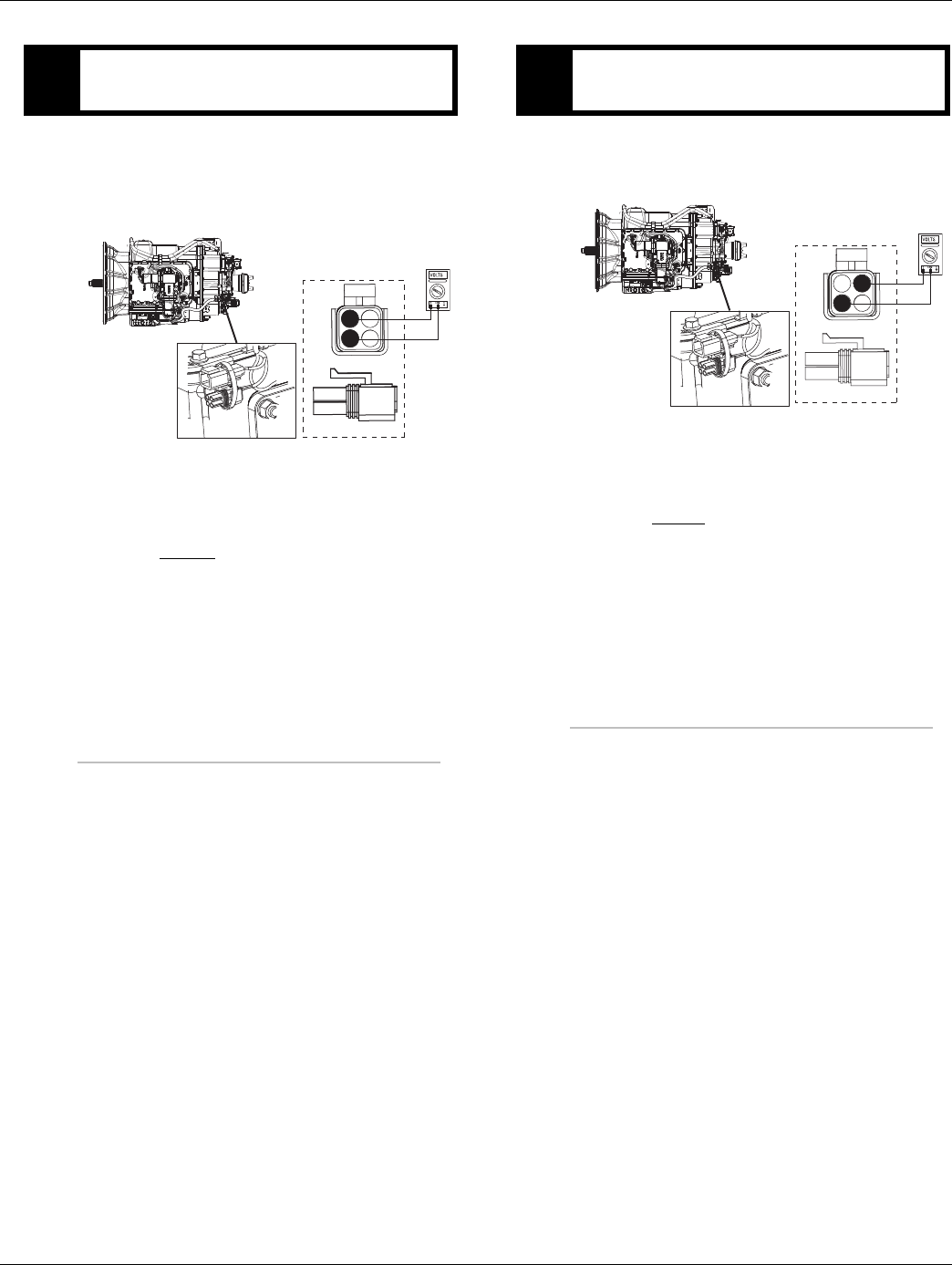
2016.01.15 © 2016 Eaton. All rights reserved 291
TRTS0930 Symptom Isolation Procedures | AutoShift Will Not Engage a Gear from Neutral Test
1. Locate diagnostic port on Transmission Harness.
2. Key on.
3. Measure voltage between Pin B and Pin C.
•If voltage is within 0.6 volts of battery voltage,
go to Step D.
•If voltage is outside of range, repair battery
power supply to TECU. Fuse may be blown.
Repeat test.
1. Key on.
2. Measure voltage between Pin A and Pin C.
•If voltage is within 0.6 volts of battery voltage,
go to Step E.
•If voltage is outside of range, Repair ignition
power supply to TECU. Fuse may be blown.
Repeat test.
CPurpose: Measure proper battery voltage at the
transmission harness 4-way diagnostic connector.
4-Pin Diagnostics Port
4-way
B - Service Bat. +
C - Service Bat. -
A - Service Ignition +
BA
D
C
4-Pin Diagnostic Port
(Located at the left rear
corner of the transmission.)
Warning! - Do Not Load Test at Diagnostic Port
DPurpose: Measure proper ignition voltage at the
transmission harness 4-way diagnostic connector.
4-Pin Diagnostics Port
4-way
B - Service Bat. +
C - Service Bat. -
A - Service Ignition +
BA
D
C
4-Pin Diagnostic Port
(Located at the left rear
corner of the transmission.)
Warning! - Do Not Load Test at Diagnostic Port
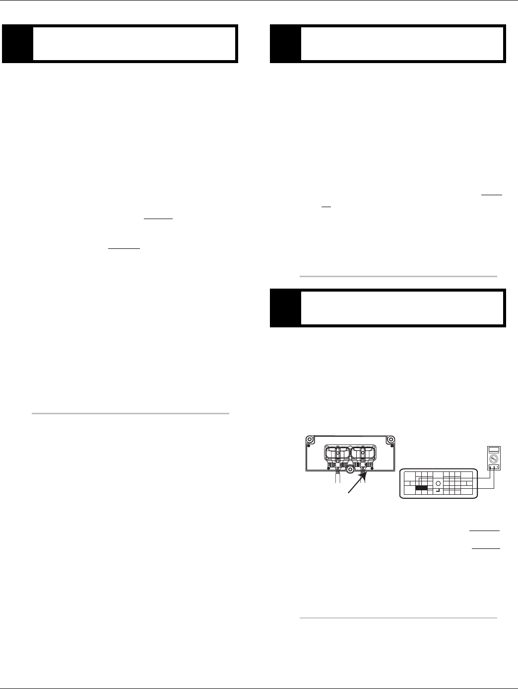
292 © 2016 Eaton. All rights reserved 2016.01.15
AutoShift Will Not Engage a Gear from Neutral Test | Symptom Isolation Procedures TRTS0930
1. Key on.
2. Depress clutch pedal.
3. Start engine.
4. Release clutch pedal to verify input shaft speed.
5. Depress clutch pedal.
6. Place Shift Lever in D.
7. Observe Gear Display.
•If Gear Display shows a solid N and the warn-
ing tone sounds, go to Step F.
•If Gear Display shows a flashing gear with
arrows, go to Step M.
•If Gear Display shows a flashing gear with no
arrows, See “Front Box Control Test” on
page 282.
•If Gear Display shows a solid gear but the vehi-
cle will not move, contact your local Eaton
Representative or call 1-800-826-HELP
(4357).
1. Key off.
2. Connect ServiceRanger, a PC-based Service Tool.
3. Start engine. Release clutch pedal.
4. View Input Shaft speed.
•If Input Shaft speed exists, contact your local
Eaton Representative or call 1-800-826-HELP
(4357).
•If input shaft speed does not exist, go to Step
G.
1. Key off.
2. Disconnect negative battery cable.
3. Disconnect the Transmission Harness 38-way con-
nector.
4. Measure the resistance between the Transmission
Harness 38-way connector Pin 7 and Pin 8.
•If resistance is 2K to 4.5K ohm, go to Step H.
•If resistance is outside of range, go to Step J.
EPurpose: Visually observe the gear display when
placing the transmission into Drive. FPurpose: Monitor Input Shaft Speed in Ser-
viceRanger.
GPurpose: Measure the resistance of the Input Shaft
Speed Sensor through the Transmission Harness.
OHMS
VCOM A
31
24 25
29 30
15 16
26
20
34
27 28
32 33
18 19
7
3
89
12 6
11 12
45
22
21
38
36
37
13 14
35 10
17
23
Front View
Transmission ECU Connector
Transmission Harness 38-way Connector
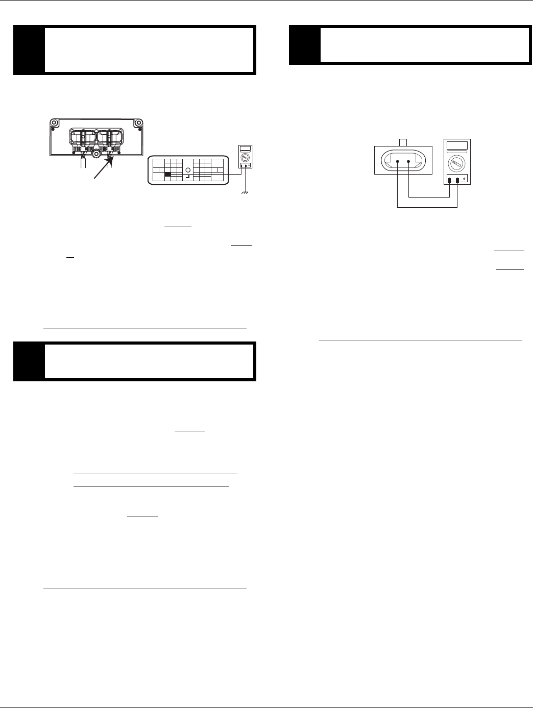
2016.01.15 © 2016 Eaton. All rights reserved 293
TRTS0930 Symptom Isolation Procedures | AutoShift Will Not Engage a Gear from Neutral Test
1. Measure resistance between the Transmission Har-
ness 38-way connector Pin 7 and ground.
•If resistance is OL,go to Step I.
•If resistance is less than 10K ohm, go to Step
J.
1. Inspect Input Shaft Speed Sensor for contamina-
tion or damage.
•If no problem found, go to Step L.
•If problem found or you were sent here from
Step J or K, replace the:
- Medium-Duty Input Shaft Speed Sensor
- Heavy-Duty Input Shaft Speed Sensor
Inspect the upper countershaft PTO gear for
damage. Go to Step V.
1. Disconnect the Transmission Harness from the
Input Shaft Speed Sensor.
2. Measure resistance between Input Shaft Speed
Sensor Pin A and Pin B.
•If resistance is 2K to 4.5K ohm, go to Step K.
•If resistance is outside of range, go to Step I.
HPurpose: Test the Input Shaft Speed Sensor circuit
for a short to ground through the Transmission
Harness.
IPurpose: Visually remove and inspect the Input
Shaft Speed Sensor for contamination or damage.
OHMS
VCOM A
31
24 25
29 30
15 16
26
20
34
27 28
32 33
18 19
7
3
89
12 6
11 12
45
22
21
38
36
37
13 14
35 10
17
23
Front View
Transmission ECU Connector
Transmission Harness 38-way Connector
JPurpose: Measure the resistance of the Input Shaft
Speed Sensor at the Input Shaft Speed Sensor.
OHMS
VCOM A
AB
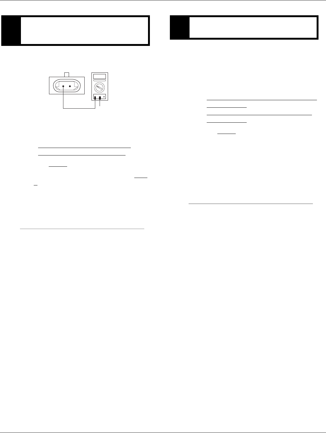
294 © 2016 Eaton. All rights reserved 2016.01.15
AutoShift Will Not Engage a Gear from Neutral Test | Symptom Isolation Procedures TRTS0930
1. Measure resistance between Input Shaft Speed
Sensor Pin A and ground.
•If resistance is OL, replace the:
- Medium-Duty Transmission Harness
- Heavy-Duty Transmission Harness
Go to Step V.
•If resistance is less than 10K ohm, go to Step
I.
1. Key off.
2. Verify the Upper Countershaft is turning.
3. Turn the Input Shaft and verify the Upper Counter-
shaft is rotating.
•If Upper Countershaft is turning, replace the:
- Medium-Duty Transmission Electronic Con-
trol Unit (TECU)
- Heavy-Duty Transmission Electronic Con-
trol Unit (TECU)
Go to Step V.
•If Upper Countershaft is not turning, contact
your Eaton Representative or call Eaton at
1-800-826-HELP (4357).
KPurpose: Test the Input Shaft Speed Sensor circuit
for a short to ground at the Input Shaft Speed Sen-
sor.
OHMS
VCOM A
AB
GROUND
LPurpose: Verify mechanical movement of the up-
per countershaft within the transmission.

2016.01.15 © 2016 Eaton. All rights reserved 295
TRTS0930 Symptom Isolation Procedures | AutoShift Will Not Engage a Gear from Neutral Test
1. Connect PC-based service tool.
2. Start engine.
3. Depress clutch pedal.
4. View input shaft speed.
•If input shaft speed does not drop below 150
RPM, clutch is out of adjustment and/or Input
Shaft Brake (Clutch Brake) is malfunctioning.
Adjust clutch per manufacturer’s specifica-
tions. go to Step V.
•If input shaft speed drops below 150, test
complete and go to Step V.
1. Key off.
2. Reconnect all connectors.
3. Key on.
4. Drive the vehicle to determine whether the com-
plaint has been repaired.
•If the transmission engages a gear, test com-
plete.
•If the transmission does not engage a gear go
to Step A. to find error in testing.
MPurpose: Monitor Input Shaft Speed in Ser-
viceRanger. VPurpose: Verify repair.

296 © 2016 Eaton. All rights reserved 2016.01.15
UltraShift DM3 Will Not Engage a Gear from Neutral Test | Symptom Isolation Procedures TRTS0930
UltraShift DM3 Will Not Engage a Gear from Neutral Test
Overview
This symptom-driven test is performed if the transmission
does not engage a gear, and there are no active or Inactive
codes.
Detection
If the Transmission Electronic Control Unit (TECU) is unable
to provide a fault code, the driver may observe this failure
as the transmission not initiating or completing a shift. The
driver may observe this failure as the transmission neutral-
izes.
Fallback
There is no fallback mode for this symptom.
Possible Causes
This symptom can be caused by any of the following:
• Input Shaft Speed Sensor
• Transmission
• Inertia Brake
• Clutch/Clutch Brake
• OEM Service Brake Switch Operation
• TECU
• Transmission Harness
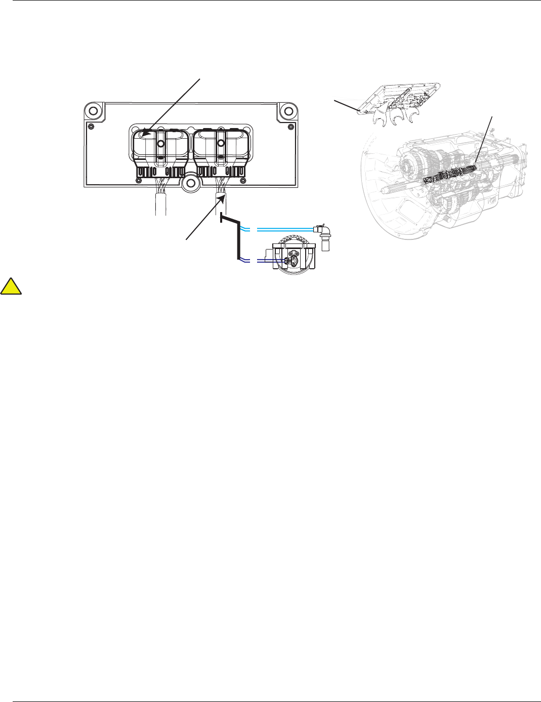
2016.01.15 © 2016 Eaton. All rights reserved 297
TRTS0930 Symptom Isolation Procedures | UltraShift DM3 Will Not Engage a Gear from Neutral Test
Component Identification
Warning: Do not load test at diagnostic port.
A
BInput shaft
speed sensor
Inertia brake
A
B
D1
D2
H1
H2
Shift Bar Housing
Main Shaft
Transmission Harness 38-way Connector
Transmission Harness 38-way Connector
!
298 © 2016 Eaton. All rights reserved 2016.01.15
UltraShift DM3 Will Not Engage a Gear from Neutral Test | Symptom Isolation Procedures TRTS0930
UltraShift DM3 Will Not Engage a Gear from Neutral Test
1. Key off.
2. Inspect starter/battery and in-line fuse holder con-
nections for integrity.
3. Measure voltage across batteries.
•If voltage is 11 to 13 volts on a 12-volt system
or 22 to 26 on a 24-volt system, proceed with
battery load test. Repair or replace batteries as
required. Go to Step B.
•If voltage is outside of range, repair or replace
batteries and charging system as required.
Repeat test.
1. Locate diagnostic port on Transmission Harness.
2. Key on.
3. Measure voltage between Pin C and the battery
negative post.
•If voltage is 0.70 volts or less, go to Step C.
•If voltage is outside of range, repair battery
ground supply to TECU. Repeat test.
1. Locate diagnostic port on Transmission Harness.
2. Key on.
3. Measure voltage between Pin B and Pin C.
•If voltage is within 0.6 volts of battery voltage,
go to Step D.
•If voltage is outside of range, repair battery
power supply to TECU. Fuse may be blown.
Repeat test.
1. Key on.
2. Measure voltage between Pin A and Pin C.
•If voltage is within 0.6 volts of battery voltage,
go to Step E.
•If voltage is outside of range, repair ignition
power supply to TECU. Fuse may be blown.
Repeat test.
APurpose: Measure battery voltage. Visually inspect
the batteries, inline fuse and power and ground
supplies at the batteries.
BPurpose: Verify proper ground path between the
batteries and the transmission harness 4-way diag-
nostic connector.
CPurpose: Measure proper battery voltage at the
transmission harness 4-way diagnostic connector.
DPurpose: Measure proper ignition voltage at the
transmission harness 4-way diagnostic connector.
2016.01.15 © 2016 Eaton. All rights reserved 299
TRTS0930 Symptom Isolation Procedures | UltraShift DM3 Will Not Engage a Gear from Neutral Test
1. Key on.
2. Start engine.
3. Apply service brake while selecting D.
4. Observe Gear Display.
Note: Using a ServiceRanger a PC-based Service
Tool, verify OEM service brake operation.
•If Gear Display shows a solid N and the warn-
ing tone sounds, go to Step F.
•If Gear Display shows a flashing gear with
arrows, go to Step M.
•If Gear Display shows a flashing gear with no
arrows, See “Front Box Control Test” on
page 282.
•If Gear Display shows a solid gear but the vehi-
cle will not move, contact your Eaton Repre-
sentative or call Eaton at 1-800-826-HELP
(4357).
1. Key off.
2. Connect PC-based Service Tool.
3. Start engine. Increase RPM and hold above 1000
RPM.
4. View Input Shaft speed.
•If Input Shaft speed exists, contact your Eaton
Representative or call Eaton at
1-800-826-HELP (4357).
•If Input Shaft speed does not exist, go to Step
G.
1. Key off.
2. Disconnect negative battery cable.
3. Disconnect the Transmission Harness 38-way con-
nector.
4. Measure the resistance between the Transmission
Harness 38-way connector Pin 7 and Pin 8.
•If resistance is 2K to 4.5K ohm, go to Step H.
•If resistance is outside of range, go to Step J.
EPurpose: Visually observe the gear display when
placing the transmission into Drive. FPurpose: Monitor Input Shaft Speed in Ser-
viceRanger.
GPurpose: Measure the resistance of the Input Shaft
Speed Sensor through the Transmission Harness.
300 © 2016 Eaton. All rights reserved 2016.01.15
UltraShift DM3 Will Not Engage a Gear from Neutral Test | Symptom Isolation Procedures TRTS0930
1. Measure resistance between the Transmission Har-
ness 38-way connector Pin 7 and ground.
•If resistance is OL, go to Step I.
•If resistance is less than 10K ohm, go to Step
J.
1. Inspect Input Shaft Speed Sensor for contamina-
tion or damage.
•If no problem found, go to Step L.
•If problem found, replace the:
- Medium-Duty Input Shaft Speed Sensor
- Heavy-Duty Input Shaft Speed Sensor
and inspect the upper countershaft PTO gear
for damage. Go to Step V.
1. Disconnect the Transmission Harness from the
Input Shaft Speed Sensor.
2. Measure resistance between Input Shaft Speed
Sensor Pin A and Pin B.
•If resistance is 2K to 4.5K ohm, go to Step K.
•If resistance is outside of range, replace the:
- Medium-Duty Input Shaft Speed Sensor
- Heavy-Duty Input Shaft Speed Sensor
Go to Step V.
1. Measure resistance between Input Shaft Speed
Sensor Pin A and ground.
•If resistance is OL, replace the:
- Medium-Duty Transmission Harness
- Heavy-Duty Transmission Harness
Go to Step V.
•If resistance is less than 10K ohm, replace the:
- Medium-Duty Input Shaft Speed Sensor
- Heavy-Duty Input Shaft Speed Sensor
Go to Step V.
HPurpose: Test the Input Shaft Speed Sensor circuit
for a short to ground through the Transmission
Harness.
IPurpose: Visually remove and inspect the Input
Shaft Speed Sensor for contamination or damage.
JPurpose: Measure the resistance of the Input Shaft
Speed Sensor at the Input Shaft Speed Sensor.
KPurpose: Test the Input Shaft Speed Sensor circuit
for a short to ground at the Input Shaft Speed Sen-
sor.
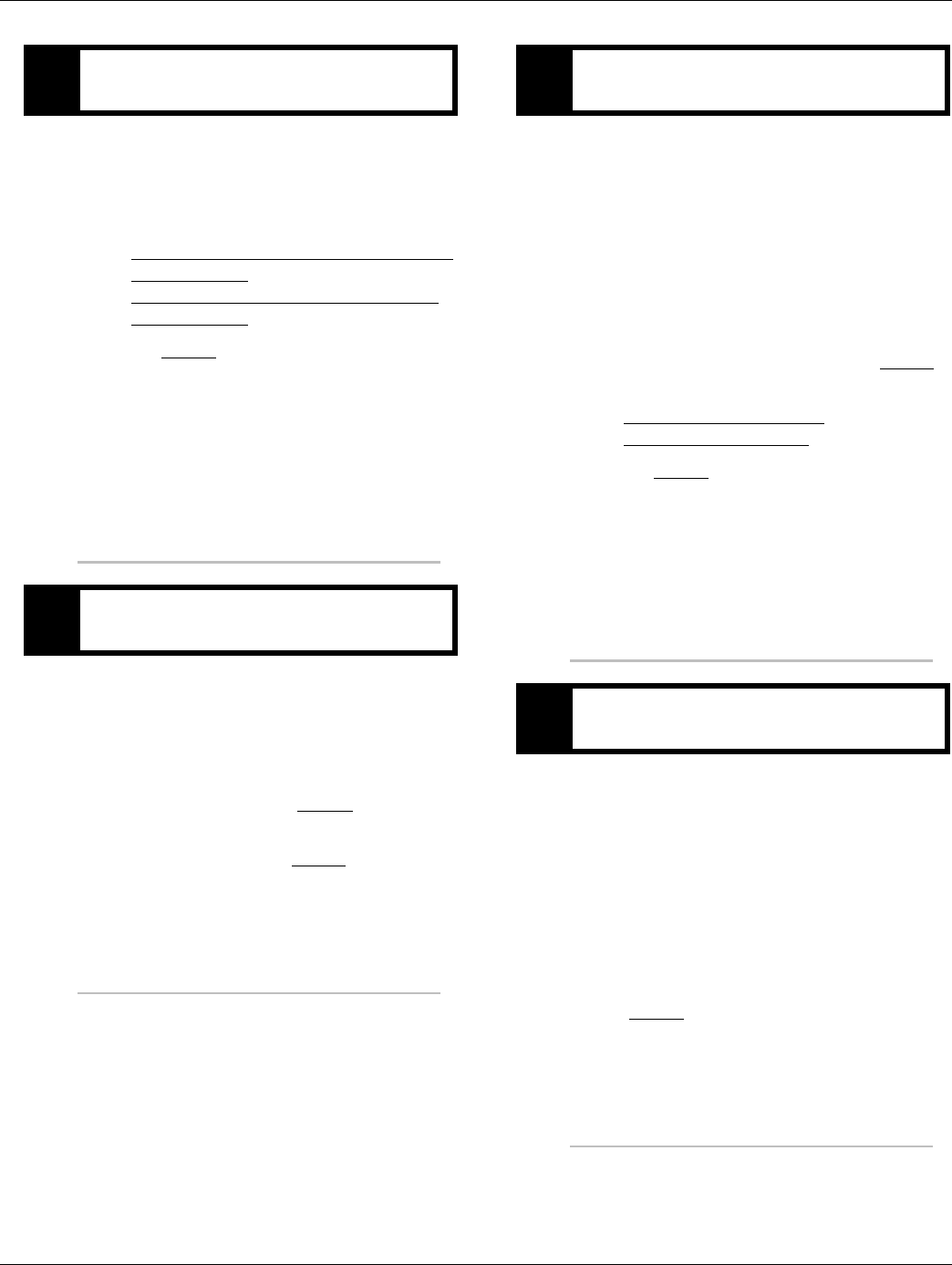
2016.01.15 © 2016 Eaton. All rights reserved 301
TRTS0930 Symptom Isolation Procedures | UltraShift DM3 Will Not Engage a Gear from Neutral Test
1. Key off.
2. Turn the Input Shaft and verify the upper counter-
shaft is rotating.
•If upper countershaft is turning, replace the:
-Medium-Duty Transmission Electronic Con-
trol Unit (TECU)
- Heavy-Duty Transmission Electronic Con-
trol Unit (TECU)
Go to Step V.
•If upper countershaft is not turning, contact
your Eaton Representative or call Eaton at
1-800-826- HELP (4357) for a repair strategy.
1. Connect PC-based service tool.
2. Start engine
3. View input shaft speed.
•If input shaft speed stays above 150 RPM,
clutch is dragging, go to Step N.
•If input shaft speed drops below 150 RPM,
test complete and go to Step V.
1. Key on.
2. Make sure the PTO is off.
3. Connect ServiceRanger a PC-based Service Tool
and select Advanced Product Functions.
4. Start engine.
5. Select Inertia Brake Test.
6. Run test and follow instructions.
•Test passes, replace clutch and go to Step V.
•Test fails, replace the:
- Medium-Duty Inertia Brake
- Heavy-Duty Inertia Brake
Go to Step V.
•Test aborts, correct displayed test failure con-
dition and retest.
1. Key off.
2. Reconnect all connectors.
3. Key on.
4. Drive the vehicle to determine whether the com-
plaint has been repaired.
•If the transmission engages a gear, test com-
plete.
•If the transmission does not engage a gear go
to Step A. to find error in testing.
LPurpose: Verify mechanical movement of the up-
per countershaft within the transmission.
MPurpose: Monitor Input Shaft Speed in Ser-
viceRanger.
NPurpose: Perform Inertia Brake Test using Ser-
viceRanger.
VPurpose: Verify repair.

302 © 2016 Eaton. All rights reserved 2016.01.15
UltraShift AW3 Clutch Engagement Test | Symptom Isolation Procedures TRTS0930
UltraShift AW3 Clutch Engagement Test
Overview
This symptom-driven test is performed if a clutch engage-
ment complaint exists, and there are no active or Inactive
codes.
Detection
There is no detection other than a driver complaint.
Fallback
There is no fallback mode for clutch engagement complaint;
however, it may effect vehicle performance.
Possible Causes
This symptom can be caused by any of the following:
• Low fluid level
• Inertia Brake
• Clutch calibration
• Transmission
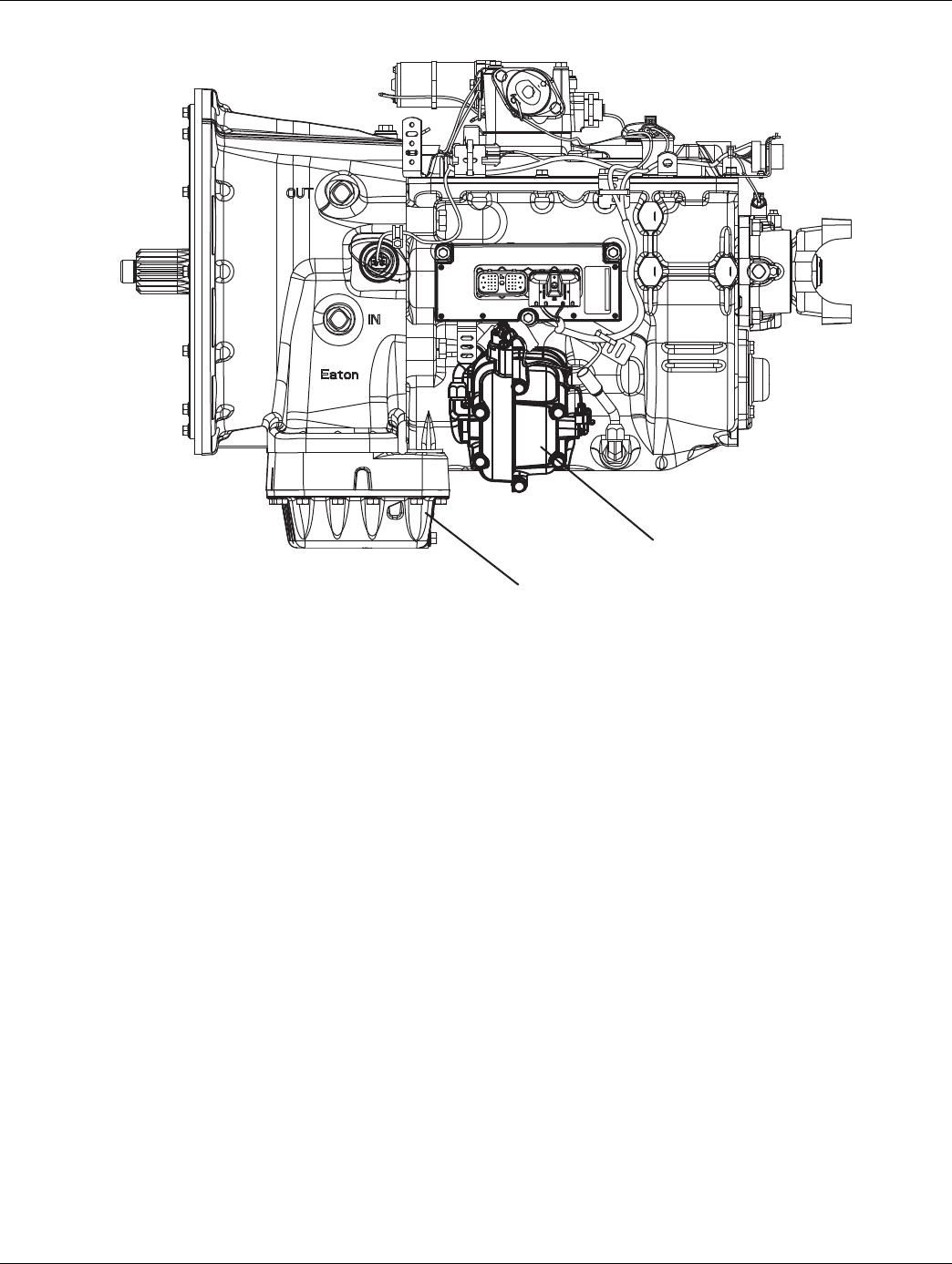
2016.01.15 © 2016 Eaton. All rights reserved 303
TRTS0930 Symptom Isolation Procedures | UltraShift AW3 Clutch Engagement Test
Component Identification
WetClutch Fluid
Inertia Brake
304 © 2016 Eaton. All rights reserved 2016.01.15
UltraShift AW3 Clutch Engagement Test | Symptom Isolation Procedures TRTS0930
UltraShift AW3 Clutch Engagement Test
1. Place transmission in neutral.
2. Allow engine to idle at 600 to 700 RPM for a mini-
mum of 2 minutes. Ensure transmission fluid tem-
perature is 60 to 120 degrees F (16 to 49 degrees
C)
3. Check transmission fluid level.
•If fluid level is at COLD-FULL mark, go to Step
B.
•If fluid level is below the COLD-ADD mark, cor-
rect fluid level, check for leaks. Drive Vehicle, if
clutch engagement complaint exists, repeat
this step.
1. Remove the flywheel inspection cover and inspect
the rubber coupler for damage or shear.
•If no damage is observed, go to Step C.
•If damage is observed, replace the Torsional
Coupler. go to Step V.
1. Key on.
2. Engine running, allow engine to reach operating
temperature.
3. Key off.
4. Start vehicle.
5. Allow vehicle to idle in neutral for a minimum of 2
minutes.
6. Drive vehicle.
•If clutch engagement complaint does not
change, go to Step D.
•If clutch engagement complaint is corrected,
test complete.
APurpose: Inspect the transmission fluid level.
BPurpose: Visually inspect the torsional coupler.
CPurpose: Bring engine up to operating temperature
and test the clutch engagement operation.

2016.01.15 © 2016 Eaton. All rights reserved 305
TRTS0930 Symptom Isolation Procedures | UltraShift AW3 Clutch Engagement Test
1. Key off.
2. Disconnect Transmission Harness from the Inertia
Brake.
3. Key on.
4. Drive vehicle (Flashing Service Light will exist).
•If clutch engagement complaint does not
change, Contact your Eaton Representative or
call Eaton at 1-800-826-HELP (4357).
•If clutch engagement complaint is corrected,
replace the:
- Medium-Duty Inertia Brake
- Heavy-Duty Inertia Brake
Go to Step V.
1. Key Off.
2. Reconnect Transmission Harness to Inertia Brake.
3. Key on.
4. Drive the vehicle to determine whether the com-
plaint has been repaired.
•If shift complaint has not been repaired, con-
tact your Eaton Representative or call Eaton at
1-800-826-HELP (4357).
•If the shift complaint has been repaired, test
complete.
DPurpose: Disconnect the Inertia Brake from the
Transmission Harness and test the clutch engage-
ment operation.
VPurpose: Verify repair.

306 © 2016 Eaton. All rights reserved 2016.01.15
AutoShift AS3 Shift Complaint Test | Symptom Isolation Procedures TRTS0930
AutoShift AS3 Shift Complaint Test
Overview
This symptom-driven test is performed if a shift complaint
exists, and there are no active or Inactive codes.
Detection
There is no detection other than a driver complaint.
Fallback
There is no fallback mode for a shift complaint; however, it
may affect vehicle performance.
Possible Causes
This fault code can be caused by any of the following:
• Electric Shifter
• Range system
• Splitter system
• Input Shaft Speed Sensor
• Transmission Harness
• Shift Bar housing
• Transmission Electronic Control Unit (TECU)
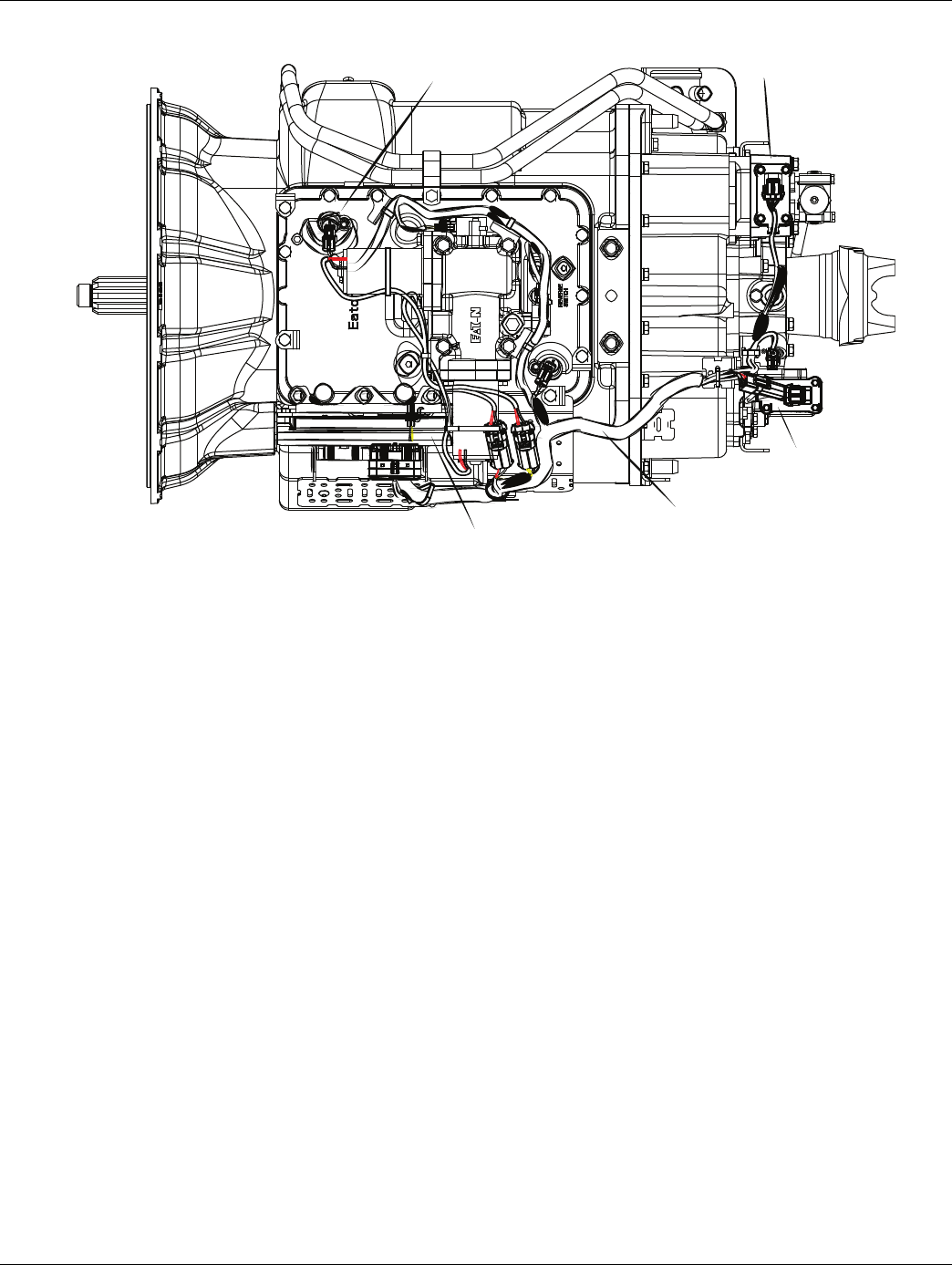
2016.01.15 © 2016 Eaton. All rights reserved 307
TRTS0930 Symptom Isolation Procedures | AutoShift AS3 Shift Complaint Test
Component Identification
Range System
Splitter System
Transmission Harness
Transmission ECU
Input Shaft
Speed Sensor
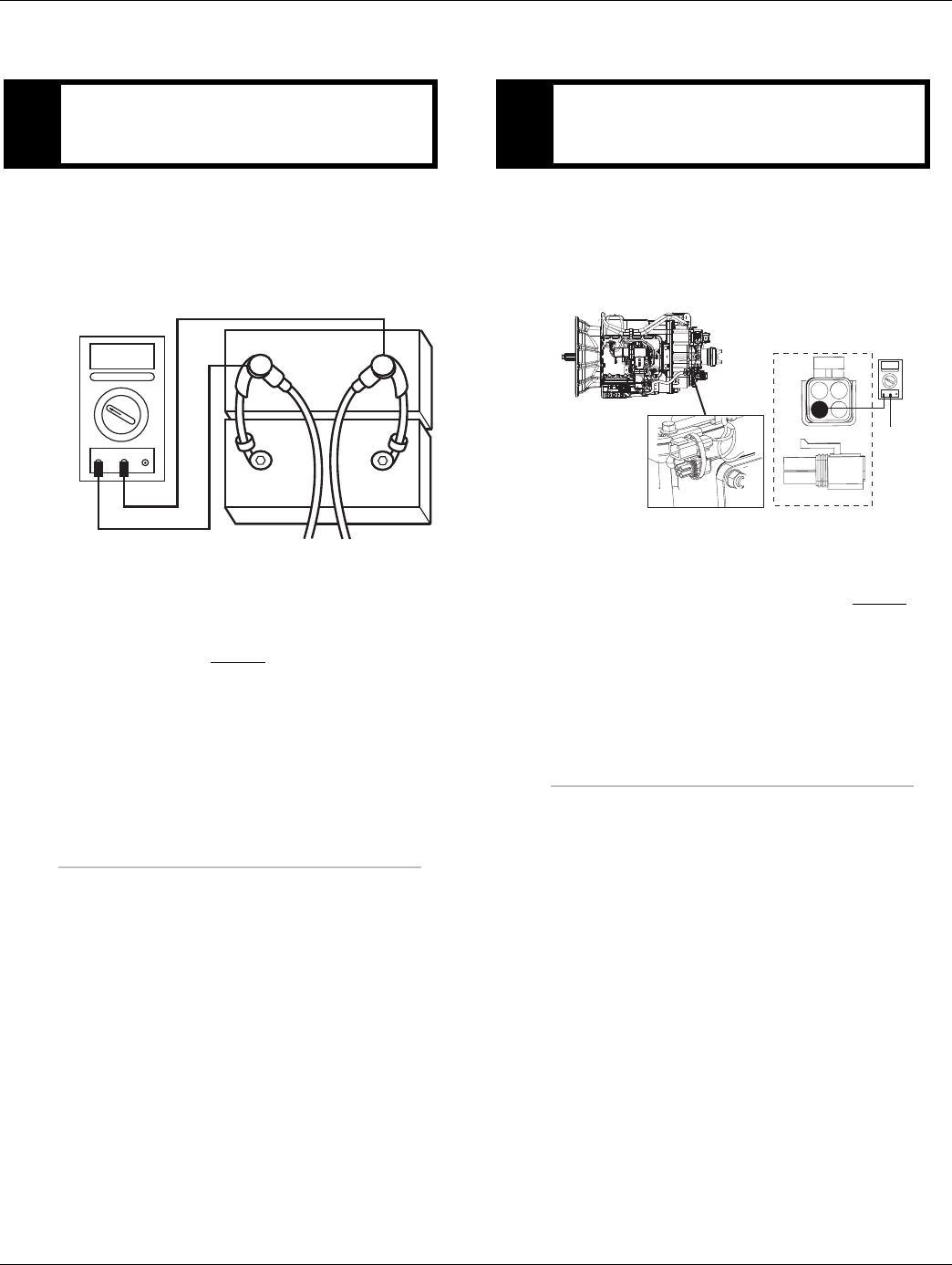
308 © 2016 Eaton. All rights reserved 2016.01.15
AutoShift AS3 Shift Complaint Test | Symptom Isolation Procedures TRTS0930
AutoShift AS3 Shift Complaint Test
1. Key off.
2. Inspect starter/battery and in-line fuse holder con-
nections for integrity.
3. Measure voltage across batteries.
•If voltage is 11 to 13 volts on a 12-volt system
or 22 to 26 on a 24-volt system, proceed with
battery load test. Repair or replace batteries as
required. Go to Step B.
•If voltage is outside of range, repair or replace
batteries and charging system as required.
Repeat this step.
1. Locate diagnostic port on Transmission Harness.
2. Key on.
3. Measure voltage between Pin C and the battery
negative post.
•If voltage is 0.70 volts or less, go to Step C.
•If voltage is outside of range, repair battery
ground supply to TECU. Repeat test.
APurpose: Measure battery voltage. Visually inspect
the batteries, inline fuse and power and ground
supplies at the batteries.
VOLTS
VCOM A
+
–
+
–
BPurpose: Verify proper ground path between the
batteries and the transmission harness 4-way diag-
nostic connector.
4-Pin Diagnostic Port
(Located at the left rear
corner of the transmission.)
4-Pin Diagnostics Port
4-way
B - Service Bat. +
C - Service Bat. -
A - Service Ignition +
VOLTS
VCOM A
Battery Negative Post
BA
D
C
Warning! - Do Not Load Test at Diagnostic Port

2016.01.15 © 2016 Eaton. All rights reserved 309
TRTS0930 Symptom Isolation Procedures | AutoShift AS3 Shift Complaint Test
1. Locate diagnostic port on Transmission Harness.
2. Key on.
3. Measure voltage between Pin B and Pin C.
•If voltage is within 0.6 volts of battery voltage,
go to Step D.
•If voltage is outside of range, repair battery
power supply to TECU. Fuse may be blown.
Repeat test.
1. Key on.
2. Measure voltage between Pin A and Pin C.
•If voltage is within 0.6 volts of battery voltage,
go to Step E.
•If voltage is outside of range, repair ignition
power supply to TECU. Fuse may be blown.
Repeat test.
1. Connect PC-based service tool and monitor Input
Shaft speed with Clutch Pedal released.
•If input shaft speed matches engine RPM, go
to Step K.
•If Input shaft speed reads 0, go to Step F.
CPurpose: Measure proper battery voltage at the
transmission harness 4-way diagnostic connector.
4-Pin Diagnostics Port
4-way
B - Service Bat. +
C - Service Bat. -
A - Service Ignition +
BA
D
C
4-Pin Diagnostic Port
(Located at the left rear
corner of the transmission.)
Warning! - Do Not Load Test at Diagnostic Port
DPurpose: Measure proper ignition voltage at the
transmission harness 4-way diagnostic connector.
EPurpose: Monitor Input Shaft Speed in Ser-
viceRanger.
4-Pin Diagnostics Port
4-way
B - Service Bat. +
C - Service Bat. -
A - Service Ignition +
BA
D
C
4-Pin Diagnostic Port
(Located at the left rear
corner of the transmission.)
Warning! - Do Not Load Test at Diagnostic Port
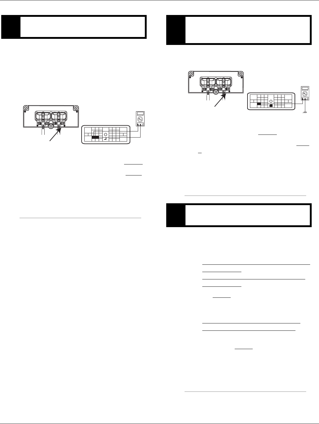
310 © 2016 Eaton. All rights reserved 2016.01.15
AutoShift AS3 Shift Complaint Test | Symptom Isolation Procedures TRTS0930
1. Key off.
2. Disconnect negative battery cable.
3. Disconnect the Transmission Harness 38-way con-
nector.
4. Measure the resistance between the Transmission
Harness 38-way connector Pin 7 and Pin 8.
•If resistance is 2K to 4.5K ohm, go to Step G.
•If resistance is outside of range, go to Step I.
1. Measure resistance between the Transmission Har-
ness 38-way connector Pin 7 and ground.
•If resistance is OL, go to Step H.
•If resistance is less than 10K ohm, go to Step
I.
1. Inspect Input Shaft Speed Sensor for contamina-
tion or damage.
•If no problem found, replace the:
- Medium-Duty Transmission Electronic Con-
trol Unit (TECU)
- Heavy-Duty Transmission Electronic Con-
trol Unit (TECU)
Go to Step V.
•If problem found or you were sent here from
Step H or I, replace the:
- Medium-Duty Input Shaft Speed Sensor
- Heavy-Duty Input Shaft Speed Sensor
Inspect the upper countershaft PTO gear for
damage. Go to Step V.
FPurpose: Measure the resistance of the Input Shaft
Speed Sensor through the Transmission Harness.
OHMS
VCOM A
31
24 25
29 30
15 16
26
20
34
27 28
32 33
18 19
7
3
89
12 6
11 12
45
22
21
38
36
37
13 14
35 10
17
23
Front View
Transmission ECU Connector
Transmission Harness 38-way Connector
GPurpose: Test the Input Shaft Speed Sensor circuit
for a short to ground through the Transmission
Harness.
HPurpose: Visually remove and inspect the Input
Shaft Speed Sensor for contamination or damage.
OHMS
VCOM A
31
24 25
29 30
15 16
26
20
34
27 28
32 33
18 19
7
3
89
12 6
11 12
45
22
21
38
36
37
13 14
35 10
17
23
Front View
Transmission ECU Connector
Transmission Harness 38-way Connector
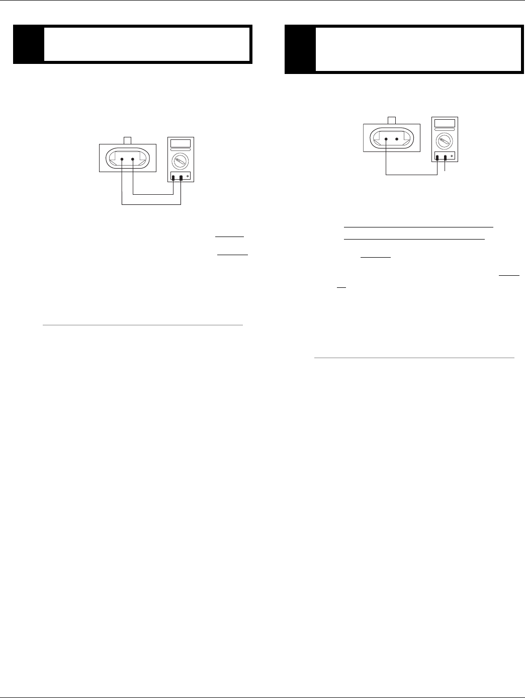
2016.01.15 © 2016 Eaton. All rights reserved 311
TRTS0930 Symptom Isolation Procedures | AutoShift AS3 Shift Complaint Test
1. Disconnect the Transmission Harness from the
Input Shaft Speed Sensor.
2. Measure resistance between Input Shaft Speed
Sensor Pin A and Pin B.
•If resistance is 2K to 4.5K ohm, go to Step J.
•If resistance is outside of range, go to Step H.
1. Measure resistance between Input Shaft Speed
Sensor Pin A and ground.
•If resistance is OL, replace the:
- Medium-Duty Transmission Harness
- Heavy-Duty Transmission Harness
Go to Step V.
•If resistance is less than 10K ohm, go to Step
H.
IPurpose: Measure the resistance of the Input Shaft
Speed Sensor at the Input Shaft Speed Sensor.
OHMS
VCOM A
AB
JPurpose: Test the Input Shaft Speed Sensor circuit
for a short to ground at the Input Shaft Speed Sen-
sor.
OHMS
VCOM A
AB
GROUND
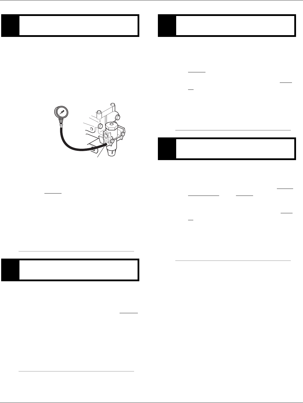
312 © 2016 Eaton. All rights reserved 2016.01.15
AutoShift AS3 Shift Complaint Test | Symptom Isolation Procedures TRTS0930
1. Key off.
2. Install a 0-100 PSI air pressure gauge in the regu-
lated test port of the air filter/regulator.
3. Start engine and allow air pressure to build to gov-
ernor cut-off.
4. Monitor the vehicle air pressure gauge on the dash.
•If air pressure cuts off between 90 to 120 PSI,
go to Step L.
•If air pressure is outside of range, repair vehi-
cle air system as required. Repeat test.
1. Key off.
2. Monitor the vehicle air pressure gauge on the dash.
•If vehicle maintains air pressure, go to Step M.
•If vehicle loses air pressure, repair vehicle air
system as required. Repeat test.
1. Read air pressure gauge installed at the regulated
port.
•If air pressure is between 55 to 65 PSI, go to
Step O.
•If air pressure is outside of range, go to Step
N.
1. Remove air supply line to the air filter/regulator and
check airflow.
•If air flows from the supply line, repair Air Fil-
ter Regulator. Go to Step K.
•If air does not flow from the supply line, repair
vehicle air supply to the regulator. Go to Step
K.
KPurpose: Measure vehicle air supply pressure.
LPurpose: Confirm vehicle maintains air supply
pressure.
Regulated test port
0-100 PSI
MPurpose: Verify air filter/regulator operation.
NPurpose: Confirm air flow to the filter regulator
supply port.
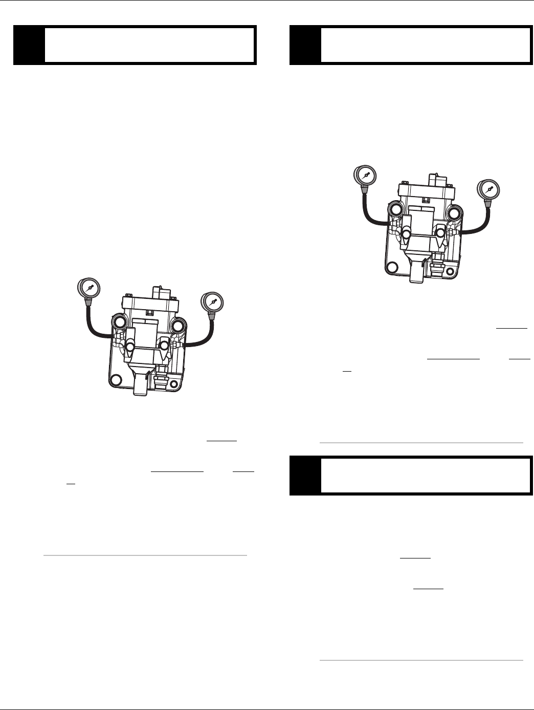
2016.01.15 © 2016 Eaton. All rights reserved 313
TRTS0930 Symptom Isolation Procedures | AutoShift AS3 Shift Complaint Test
1. Key off.
2. Install both 0-100 PSI air pressure gauges into the
range cover diagnostic ports.
3. Start vehicle and allow air pressure to build to gov-
ernor cut-off.
4. Turn off engine, but leave key on.
5. With Shift Control, select reverse, then select neu-
tral.
Note: Five minutes is allowed for checking the air
pressure after shifting the transmission to
neutral.
•If low range gauge is between 55 to 65 PSI and
If high range gauge is 0 PSI, go to Step P.
•If both air pressure gauges do not read as
listed above, replace Range Valve. Go to Step
P.
1. Key on.
2. With the Shift Control, select the highest reverse
gear available by pressing the upshift button/arrow,
then select neutral.
•If high range gauge is between 55 to 65 PSI
and if low range gauge is 0 PSI, go to Step Q.
•If both air pressure gauges do not read as
listed above, replace Range Valve. Go to Step
V.
1. Is the transmission equipped with a splitter sys-
tem? (i.e. 18-Speed)
•If the transmission is equipped with a splitter
system, go to Step R.
•If the transmission is not equipped with a split-
ter system, go to Step V.
OPurpose: Measure low range air pressures.
LO range
0-100 PSI gauge
HI range
0-100 PSI gauge
PPurpose: Measure high range air pressures.
QPurpose: Identify if the transmission is equipped
with a splitter system.
LO range
0-100 PSI gauge
HI range
0-100 PSI gauge
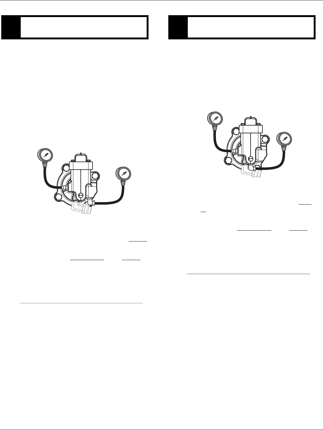
314 © 2016 Eaton. All rights reserved 2016.01.15
AutoShift AS3 Shift Complaint Test | Symptom Isolation Procedures TRTS0930
1. Key off.
2. Start vehicle and allow air pressure to build to gov-
ernor cut-off.
3. Turn off engine, but leave key on.
4. With Shift Control, select reverse (R1 in gear dis-
play for 13/18-speed), then select neutral
Note: Five minutes is allowed for checking the
pressure after moving the Shift Lever to neu-
tral.
•If high splitter gauge is between 55 to 65 PSI
and if low splitter gauge is 0 PSI, go to Step S.
•If air pressure gauges do not read as shown
above, replace Splitter Valve. Go to Step V.
1. Key on.
2. With Shift Control, select reverse (R2 in the gear
display 13/18-speed).
Note: If R2 isn’t displayed the up arrow button
needs to be pressed.
•If low splitter gauge is between 55 to 65 PSI
and if high splitter gauge is 0 PSI, go to Step
V.
•If air pressure gauges do not read as shown
above, replace Splitter Valve. Go to Step V.
RPurpose: Measure high splitter air pressures.
LO split
0-100 PSI gauge
HI split
0-100 PSI gauge
SPurpose: Measure low splitter air pressures.
HIGH split
0-100 PSI gauge
LOW split
0-100 PSI gauge

2016.01.15 © 2016 Eaton. All rights reserved 315
TRTS0930 Symptom Isolation Procedures | AutoShift AS3 Shift Complaint Test
1. Key off.
2. Remove all pressure gauges.
3. Reconnect all connectors.
4. Key on.
5. Drive the vehicle to determine whether the com-
plaint has been repaired.
•If the transmission shifts normal, test com-
plete.
•If the transmission still has a shifting com-
plaint, find error in testing. Go to Step A.
VPurpose: Verify repair.

316 © 2016 Eaton. All rights reserved 2016.01.15
UltraShift DM3 Shift Complaint Test | Symptom Isolation Procedures TRTS0930
UltraShift DM3 Shift Complaint Test
Overview
This symptom-driven test is performed if a shift complaint
exists, and there are no Active or Inactive codes.
Detection
There is no detection other than a driver complaint.
Fallback
There is no fallback mode for shift complaint; however, it
may effect vehicle performance.
Possible Causes
This symptom can be caused by any of the following:
• Inertia Brake
• Input Shaft Speed Sensor
• Transmission Electric Control Unit (TECU)
• Transmission Harness
• Range System
• Splitter System
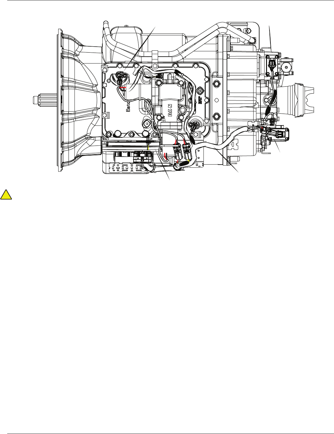
2016.01.15 © 2016 Eaton. All rights reserved 317
TRTS0930 Symptom Isolation Procedures | UltraShift DM3 Shift Complaint Test
Component Identification
Warning: Do not load test at the Diagnostic Port.
Range System
Splitter System
Transmission Harness
Transmission ECU
Input Shaft
Speed Sensor
!
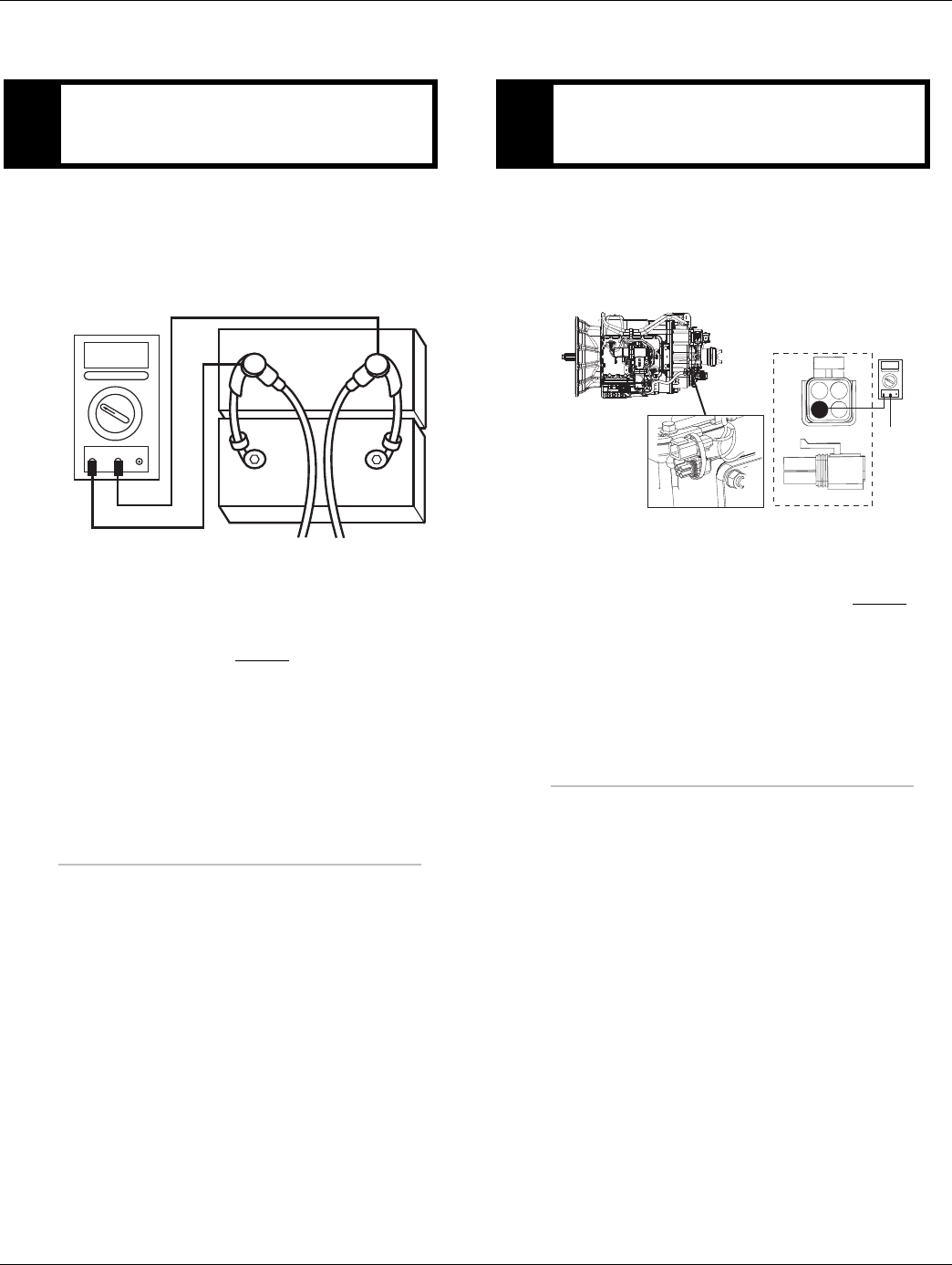
318 © 2016 Eaton. All rights reserved 2016.01.15
UltraShift DM3 Shift Complaint Test | Symptom Isolation Procedures TRTS0930
UltraShift DM3 Shift Complaint Test
1. Key off.
2. Inspect starter/battery and
in-line fuse holder connections for integrity.
3. Measure voltage across batteries.
•If voltage is 11 to 13 volts on a 12-volt system
or 22 to 26 on a 24-volt system, proceed with
battery load test. Repair or replace batteries as
required and go to Step B.
•If voltage is outside of range, repair or replace
batteries and charging system as required.
Repeat test.
1. Locate diagnostic port on Transmission Harness.
2. Key on.
3. Measure voltage between Pin C and the battery
negative post.
•If voltage is 0.70 volts or less, go to Step C.
•If voltage is outside of range, repair battery
ground supply to TECU. Repeat test.
APurpose: Measure battery voltage. Visually inspect
the batteries, inline fuse and power and ground
supplies at the batteries.
VOLTS
VCOM A
+
–
+
–
BPurpose: Verify proper ground path between the
batteries and the transmission harness 4-way diag-
nostic connector.
4-Pin Diagnostic Port
(Located at the left rear
corner of the transmission.)
4-Pin Diagnostics Port
4-way
B - Service Bat. +
C - Service Bat. -
A - Service Ignition +
VOLTS
VCOM A
Battery Negative Post
BA
D
C
Warning! - Do Not Load Test at Diagnostic Port
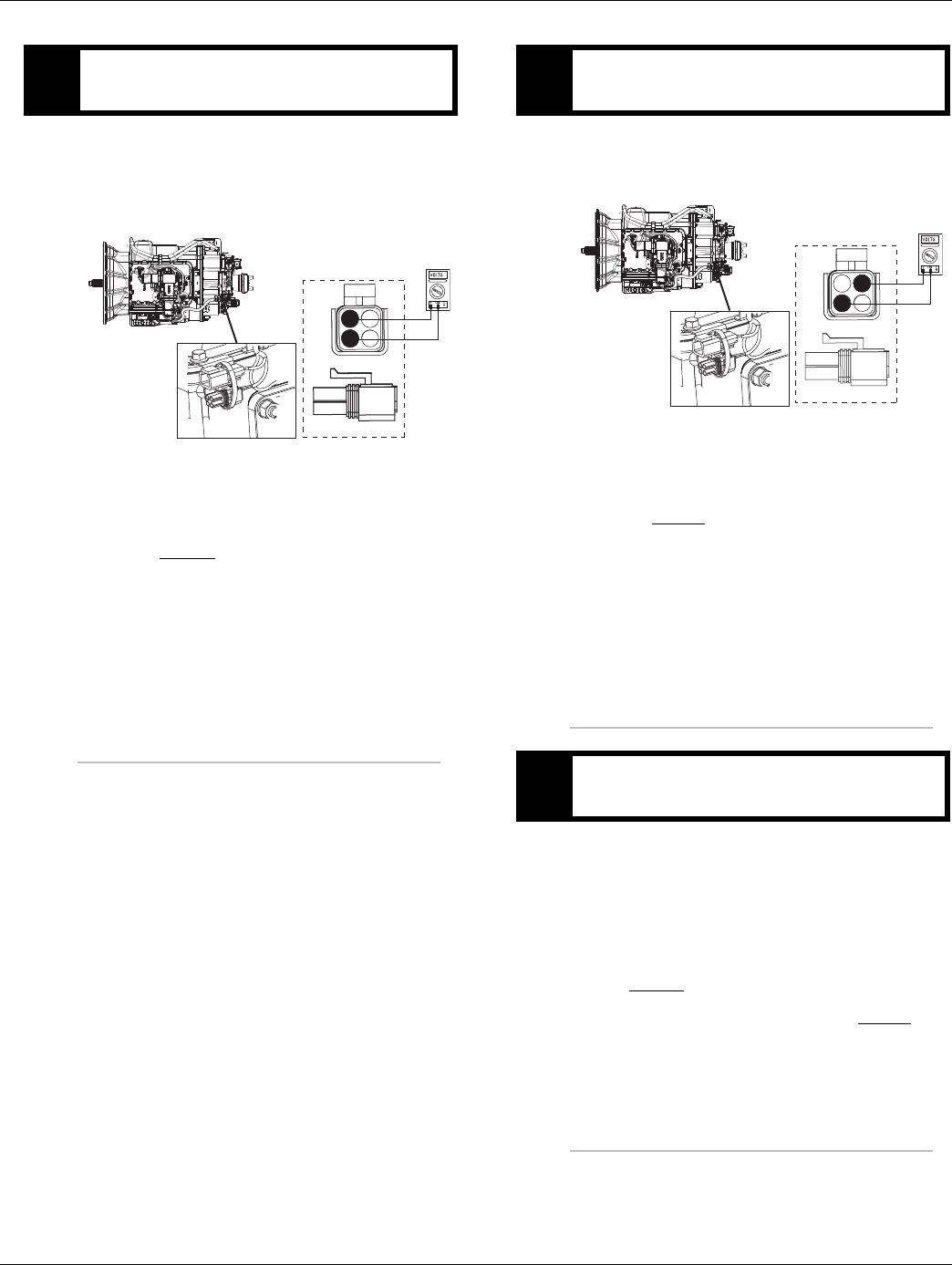
2016.01.15 © 2016 Eaton. All rights reserved 319
TRTS0930 Symptom Isolation Procedures | UltraShift DM3 Shift Complaint Test
1. Locate diagnostic port on Transmission Harness.
2. Key on.
3. Measure voltage between Pin B and Pin C.
•If voltage is within 0.6 volts of battery voltage,
go to Step D.
•If voltage is outside of range, repair battery
power supply to TECU. Fuse may be blown.
Repeat test.
1. Key on.
2. Measure voltage between Pin A and Pin C.
•If voltage is within 0.6 volts of battery voltage,
go to Step E.
•If voltage is outside of range, repair ignition
power supply to TECU. Fuse may be blown.
Repeat test.
1. Compare engine RPM to Input Shaft RPM with Ser-
viceRanger.
Note: Engine RPM must remain above 1000 RPM
during the following test.
•If Input Shaft speed matches engine RPM, go
to Step K.
•If Input shaft speed reads 0, go to Step F.
CPurpose: Measure proper battery voltage at the
transmission harness 4-way diagnostic connector.
4-Pin Diagnostics Port
4-way
B - Service Bat. +
C - Service Bat. -
A - Service Ignition +
BA
D
C
4-Pin Diagnostic Port
(Located at the left rear
corner of the transmission.)
Warning! - Do Not Load Test at Diagnostic Port
DPurpose: Measure proper ignition voltage at the
transmission harness 4-way diagnostic connector.
EPurpose: Monitor Engine Speed and Input Shaft
Speed in ServiceRanger.
4-Pin Diagnostics Port
4-way
B - Service Bat. +
C - Service Bat. -
A - Service Ignition +
BA
D
C
4-Pin Diagnostic Port
(Located at the left rear
corner of the transmission.)
Warning! - Do Not Load Test at Diagnostic Port
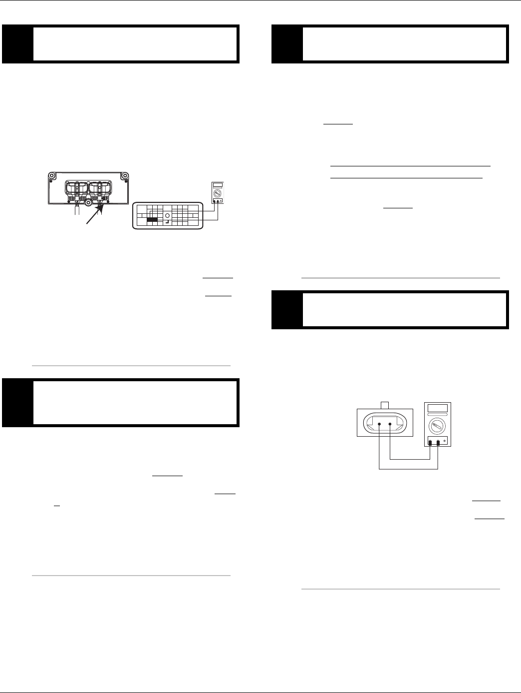
320 © 2016 Eaton. All rights reserved 2016.01.15
UltraShift DM3 Shift Complaint Test | Symptom Isolation Procedures TRTS0930
1. Key off.
2. Disconnect negative battery cable.
3. Disconnect the Transmission Harness 38-way con-
nector.
4. Measure the resistance between the Transmission
Harness 38-way connector Pin 7 and Pin 8.
•If resistance is 2K to 4.5K ohm, go to Step G.
•If resistance is outside of range, go to Step I.
1. Measure resistance between the Transmission Har-
ness 38-way connector Pin 7 and ground.
•If resistance is OL, go to Step H.
•If resistance is less than 10K ohm, go to Step
I.
1. Inspect Input Shaft Speed Sensor for contamina-
tion or damage.
•If no problem found, replace TECU and go to
Step V.
•If problem found or you were sent here from
Step I or Step J, replace the:
- Medium-Duty Input Shaft Speed Sensor
- Heavy-Duty Input Shaft Speed Sensor
Inspect the upper countershaft PTO gear for
damage. Go to Step V.
1. Disconnect the Transmission Harness from the
Input Shaft Speed Sensor.
2. Measure resistance between Input Shaft Speed
Sensor Pin A and Pin B.
•If resistance is 2K to 4.5K ohm, go to Step J.
•If resistance is outside of range, go to Step H.
FPurpose: Measure the resistance of the Input Shaft
Speed Sensor through the Transmission Harness.
GPurpose: Test the Input Shaft Speed Sensor circuit
for a short to ground through the Transmission
Harness.
OHMS
VCOM A
31
24 25
29 30
15 16
26
20
34
27 28
32 33
18 19
7
3
89
12 6
11 12
45
22
21
38
36
37
13 14
35 10
17
23
Front View
Transmission ECU Connector
Transmission Harness 38-way Connector
HPurpose: Visually remove and inspect the Input
Shaft Speed Sensor for contamination or damage.
IPurpose: Measure the resistance of the Input Shaft
Speed Sensor at the Input Shaft Speed Sensor.
OHMS
VCOM A
AB
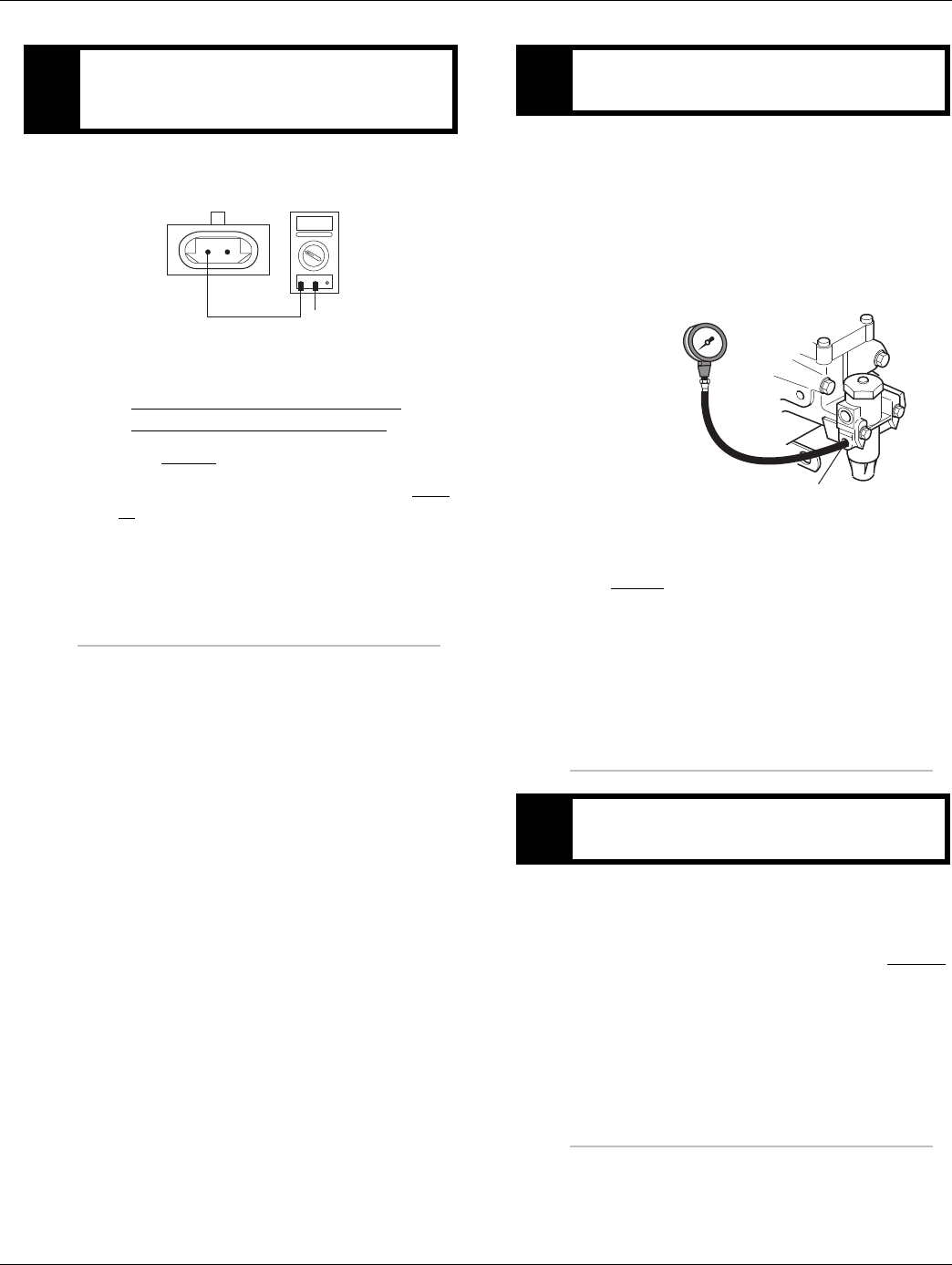
2016.01.15 © 2016 Eaton. All rights reserved 321
TRTS0930 Symptom Isolation Procedures | UltraShift DM3 Shift Complaint Test
1. Measure resistance between Input Shaft Speed
Sensor Pin A and ground.
•If resistance is OL, replace the:
- Medium-Duty Transmission Harness
- Heavy-Duty Transmission Harness
Go to Step V.
•If resistance is less than 10K ohm, go to Step
H.
1. Key off.
2. Install a 0-100 PSI air pressure gauge in the regu-
lated test port of the air filter/regulator.
3. Start engine and allow air pressure to build to gov-
ernor cut-off.
4. Monitor the vehicle air pressure gauge on the dash.
•If air pressure cuts off at 90 to 120 PSI, go to
Step L.
•If air pressure is outside of range, repair vehi-
cle air system as required. Repeat test.
1. Key off.
2. Monitor the vehicle air pressure gauge on the dash.
•If vehicle maintains air pressure, go to Step M.
•If vehicle loses air pressure, repair vehicle air
system as required. Repeat test.
JPurpose: Test the Input Shaft Speed Sensor circuit
for a short to ground at the Input Shaft Speed Sen-
sor.
OHMS
VCOM A
AB
GROUND
KPurpose: Measure vehicle air supply pressure.
LPurpose: Confirm vehicle maintains air supply
pressure.
Regulated test port
0-100 PSI
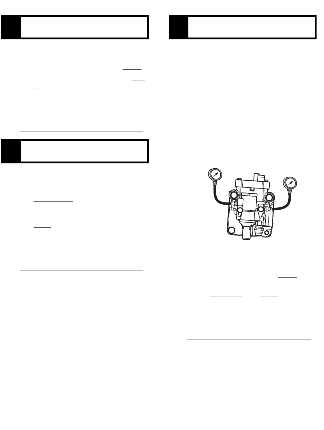
322 © 2016 Eaton. All rights reserved 2016.01.15
UltraShift DM3 Shift Complaint Test | Symptom Isolation Procedures TRTS0930
1. Read air pressure gauge installed at the regulated
port.
•If air pressure is 55 to 65 PSI, go to Step O.
•If air pressure is outside of range, go to Step
N.
1. Remove air supply line to the air filter/regulator and
check airflow.
•If air flows from the supply line, repair the Air
Filter Regulator.
•If air does not flow from the supply line, repair
vehicle air supply to the regulator and go to
Step J.
1. Key off.
2. Install both 0-100 PSI air pressure gauges into the
range cover diagnostic ports.
3. Start vehicle. Allow air pressure to build to gover-
nor cut-off.
4. Turn off engine, but leave key on.
5. With Shift Control, select reverse, then select neu-
tral.
Note: Five minutes is allowed for checking the air
pressure after shifting the transmission to
neutral.
•If low range gauge reads 55 to 65 PSI and high
range gauge reads 0 PSI, go to Step C.
•If neither gauge reads as listed above, replace
the Range Valve. Go to Step V.
MPurpose: Verify air filter/regulator operation.
NPurpose: Confirm air flow to the filter regulator
supply port.
OPurpose: Measure low range air pressures.
LO range
0-100 PSI gauge
HI range
0-100 PSI gauge
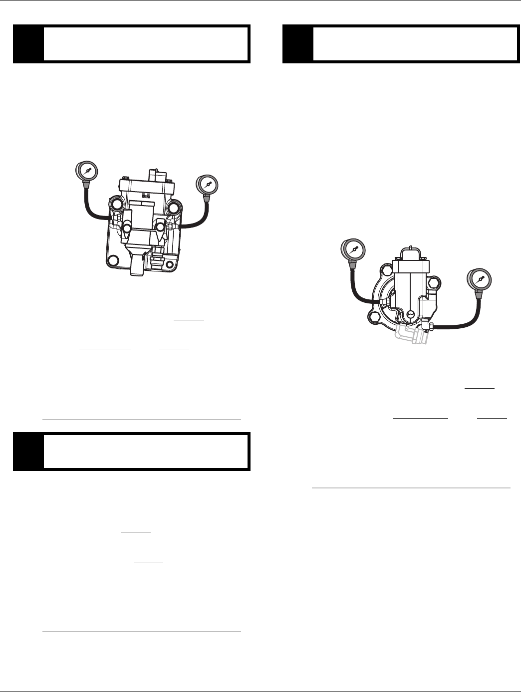
2016.01.15 © 2016 Eaton. All rights reserved 323
TRTS0930 Symptom Isolation Procedures | UltraShift DM3 Shift Complaint Test
1. Key on.
2. With the Shift Control, select the highest reverse
gear available by pressing the upshift button/arrow,
then select neutral.
•If high range gauge reads 55 to 65 PSI and low
range gauge is 0 PSI, go to Step Q.
•If neither gauge reads as listed above, replace
the Range Valve. Go to Step V.
1. Is the transmission equipped with a splitter sys-
tem? (i.e. 13-Speed)
•If the transmission is equipped with a splitter
system, go to Step R.
•If the transmission is not equipped with a split-
ter system, go to Step V.
1. Key off.
2. Start vehicle and allow air pressure to build to gov-
ernor cut-off.
3. Turn off engine, but leave key on.
4. With Shift Control, select reverse (R1 in gear dis-
play for 13/18-speed), then select neutral.
Note: Five minutes is allowed for checking the
pressure after moving the Shift Lever to neu-
tral.
•If high splitter gauge reads 55 to 65 PSI and
low splitter gauge is 0 PSI, go to Step S.
•If air pressure gauges do not read as shown
above, replace Splitter Valve. Go to Step V.
PPurpose: Measure high range air pressures.
QPurpose: Identify if the transmission is equipped
with a splitter system.
LO range
0-100 PSI gauge
HI range
0-100 PSI gauge
RPurpose: Measure high splitter air pressures.
LO split
0-100 PSI gauge
HI split
0-100 PSI gauge
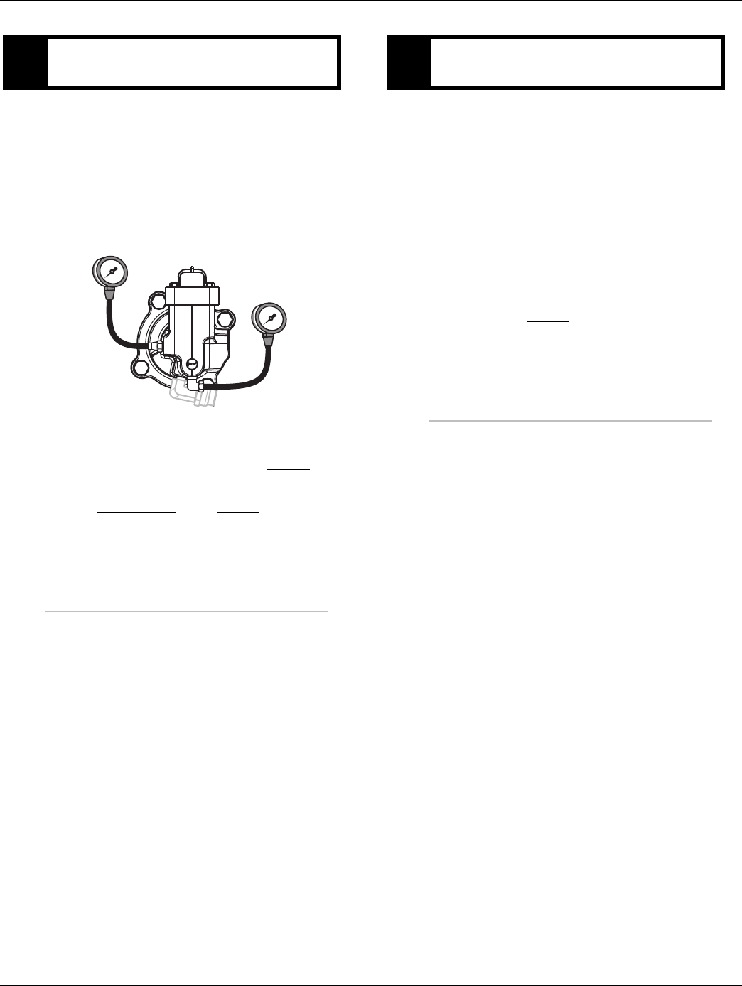
324 © 2016 Eaton. All rights reserved 2016.01.15
UltraShift DM3 Shift Complaint Test | Symptom Isolation Procedures TRTS0930
1. Key on.
2. With Shift Control, select reverse (R2 in the gear
display 13/18-speed).
Note: If R2 isn’t displayed the up arrow button
needs to be pressed.
•If low splitter gauge reads 55 to 65 PSI and if
high splitter gauge is 0 PSI, go to Step V.
•If neither gauge reads as shown above, replace
the Splitter Valve. Go to Step V.
1. Key off.
2. Remove all pressure gauges.
3. Reconnect all connectors.
4. Key on.
5. Drive the vehicle to determine whether the com-
plaint has been repaired.
•If the transmission shifts normal, test com-
plete.
•If the transmission still has a shifting com-
plaint go to Step A. to find error in testing.
SPurpose: Measure low splitter air pressures.
HIGH split
0-100 PSI gauge
LOW split
0-100 PSI gauge
VPurpose: Verify repair.

2016.01.15 © 2016 Eaton. All rights reserved 325
TRTS0930 Symptom Isolation Procedures | UltraShift DM3 Shift Complaint Test

326 © 2016 Eaton. All rights reserved 2016.01.15
UltraShift AW3 Shift Complaint Test | Symptom Isolation Procedures TRTS0930
UltraShift AW3 Shift Complaint Test
Overview
This symptom-driven test is performed if a shift complaint
exists, and there are no Active or Inactive codes.
Detection
There is no detection other than a driver complaint.
Fallback
There is no fallback mode for shift complaint; however, it
may effect vehicle performance.
Possible Causes
This symptom can be caused by any of the following:
• Low Fluid Level
• Inertia Brake
• Input Shaft Speed Sensor
• Transmission Electronic Control Unit (TECU)
• Transmission Harness
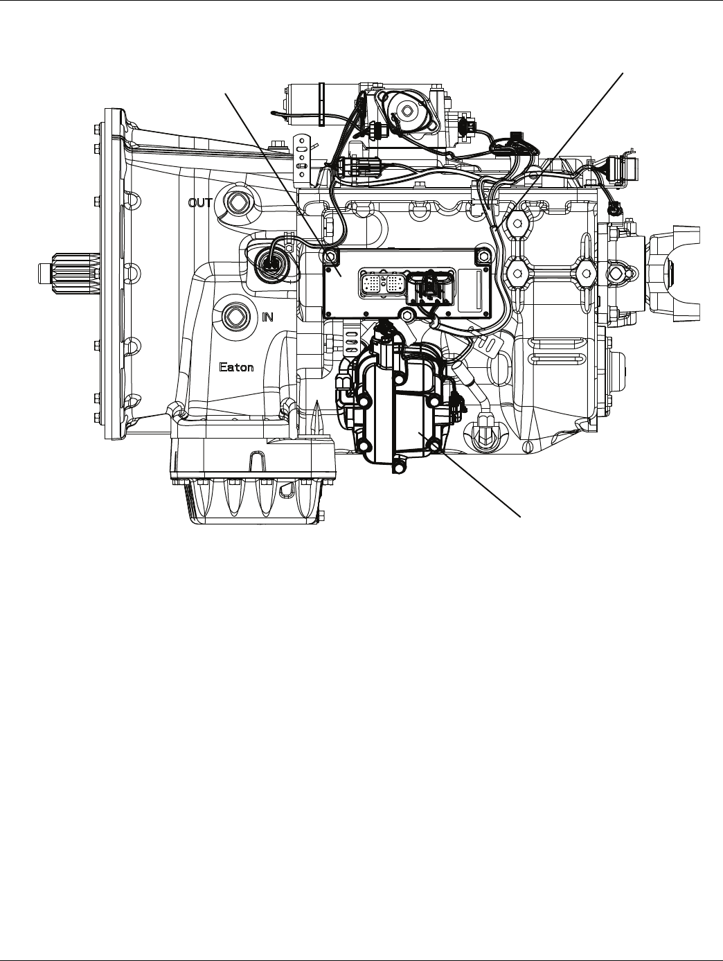
2016.01.15 © 2016 Eaton. All rights reserved 327
TRTS0930 Symptom Isolation Procedures | UltraShift AW3 Shift Complaint Test
Component Identification
Transmission ECU
Transmission Harness
Inertia Brake
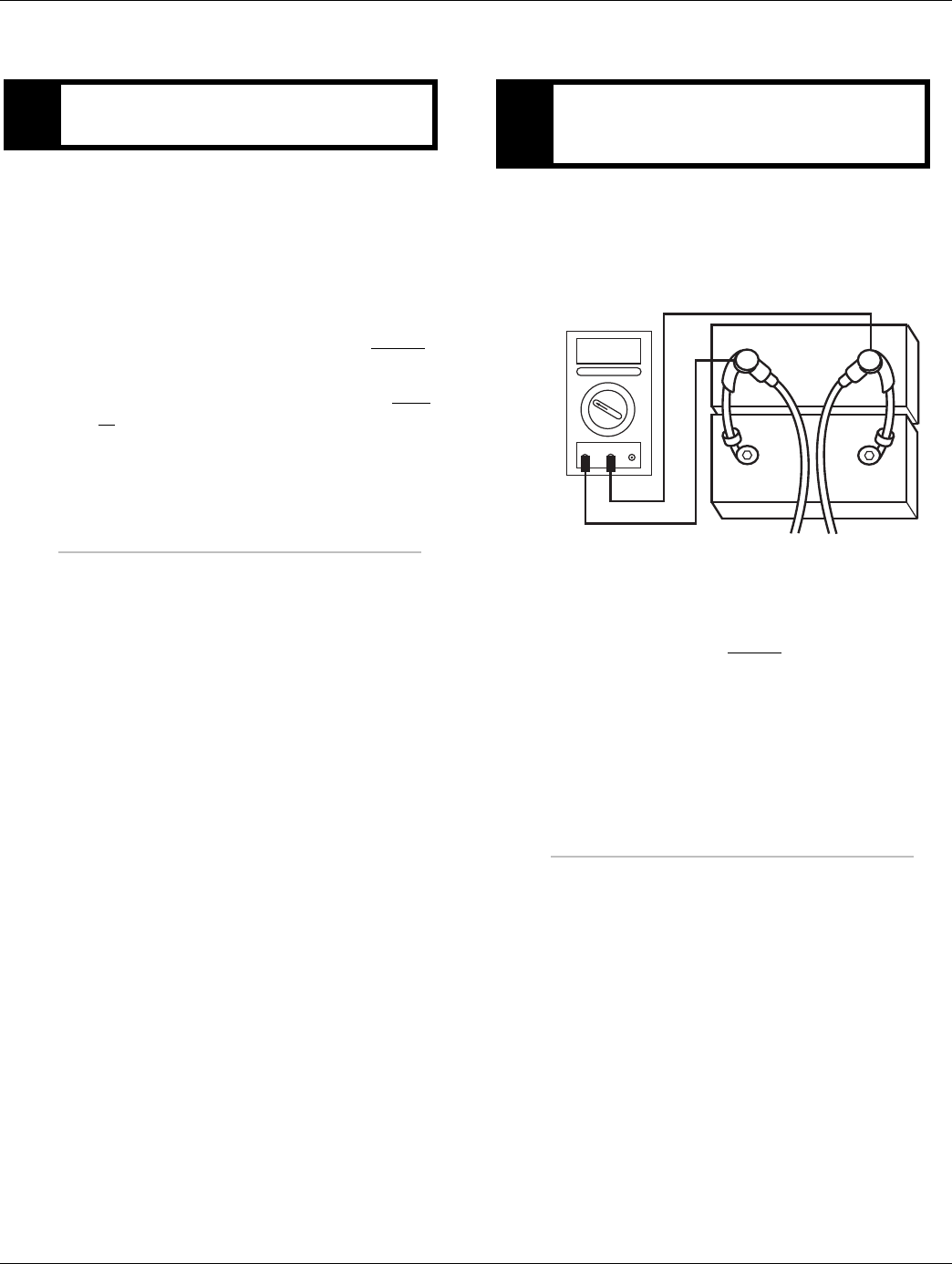
328 © 2016 Eaton. All rights reserved 2016.01.15
UltraShift AW3 Shift Complaint Test | Symptom Isolation Procedures TRTS0930
UltraShift AW3 Shift Complaint Test
1. Place transmission in neutral.
2. Allow engine to idle at 600 to 700 RPM for a mini-
mum of 2 minutes. Ensure transmission fluid tem-
perature is 60 to 120 degrees F (16 to 49 degrees
C)
3. Check transmission fluid level.
•If fluid level is at cold-full mark, go to Step B.
•If fluid level is below the cold-add mark, cor-
rect fluid level, check for leaks and go to Step
V.
1. Key off.
2. Inspect starter/battery and in-line fuse holder con-
nections for integrity.
3. Measure voltage across batteries.
•If voltage is 11 to 13 volts on a 12-volt system
or 22 to 26 on a 24-volt system, proceed with
battery load test. Repair or replace batteries as
required and go to Step C.
•If voltage is outside of range, repair or replace
batteries and charging system as required.
Repeat test.
APurpose: Inspect the transmission fluid level. BPurpose: Measure battery voltage. Visually inspect
the batteries, inline fuse and power and ground
supplies at the batteries.
VOLTS
VCOM A
+
–
+
–
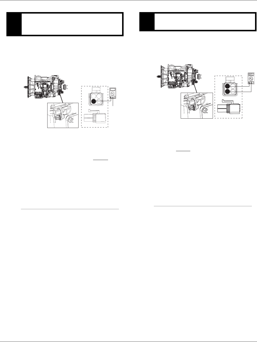
2016.01.15 © 2016 Eaton. All rights reserved 329
TRTS0930 Symptom Isolation Procedures | UltraShift AW3 Shift Complaint Test
1. Locate diagnostic port on Transmission Harness.
2. Key on.
3. Measure voltage between Pin C and the battery
negative post.
•If voltage between Pin C and battery negative
post is 0.70 volts or less, go to Step D.
•If voltage is outside of range, repair battery
ground supply to TECU. Repeat test.
1. Locate diagnostic port on Transmission Harness.
2. Key on.
3. Measure voltage between Pin B and Pin C.
•If voltage is within 0.6 volts of battery voltage,
go to Step E.
•If voltage is outside of range, repair battery
power supply to TECU. Fuse may be blown.
Repeat test.
CPurpose: Verify proper ground path between the
batteries and the transmission harness 4-way diag-
nostic connector.
4-Pin Diagnostic Port
(Located at the left rear
corner of the transmission.)
4-Pin Diagnostics Port
4-way
B - Service Bat. +
C - Service Bat. -
A - Service Ignition +
VOLTS
VCOM A
Battery Negative Post
BA
D
C
Warning! - Do Not Load Test at Diagnostic Port
DPurpose: Measure proper battery voltage at the
transmission harness 4-way diagnostic connector.
4-Pin Diagnostics Port
4-way
B - Service Bat. +
C - Service Bat. -
A - Service Ignition +
BA
D
C
4-Pin Diagnostic Port
(Located at the left rear
corner of the transmission.)
Warning! - Do Not Load Test at Diagnostic Port
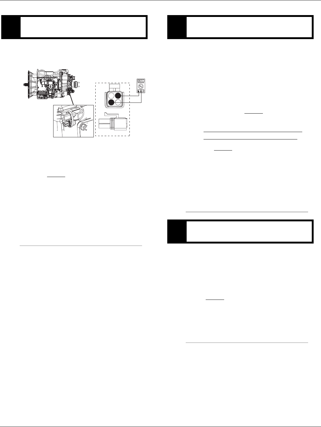
330 © 2016 Eaton. All rights reserved 2016.01.15
UltraShift AW3 Shift Complaint Test | Symptom Isolation Procedures TRTS0930
1. Key on.
2. Measure voltage between Pin A and Pin C.
•If voltage is within 0.6 volts of battery voltage,
go to Step F.
•If voltage is outside of range, repair ignition
power supply to TECU. Fuse may be blown.
Repeat test.
1. Key on.
2. Connect ServiceRanger, select Advanced Product
Function.
3. Start engine, PTO must be disengaged.
4. Select Inertia Brake test.
5. Run test and follow instructions.
•Test passes, go to Step G.
•Test fails, replace the:
- Medium-Duty Input Shaft Speed Sensor
- Heavy-Duty Input Shaft Speed Sensor
Go to Step V.
•Test aborts, correct displayed test failure con-
dition and retest.
1. Drive vehicle and monitor engine RPM and input
shaft RPM with ServiceRanger
•If engine RPM and input shaft rpm match
during the test drive, test complete.
•If input shaft RPM is erratic or reads zero, go
to Step H.
EPurpose: Measure proper ignition voltage at the
transmission harness 4-way diagnostic connector.
4-Pin Diagnostics Port
4-way
B - Service Bat. +
C - Service Bat. -
A - Service Ignition +
BA
D
C
4-Pin Diagnostic Port
(Located at the left rear
corner of the transmission.)
Warning! - Do Not Load Test at Diagnostic Port
FPurpose: Perform “Inertia Brake Test” using Ser-
viceRanger.
GPurpose: Monitor Engine Speed and Input Shaft
Speed in ServiceRanger.
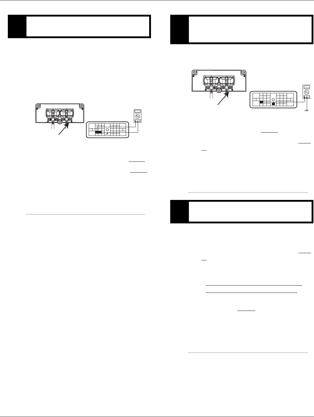
2016.01.15 © 2016 Eaton. All rights reserved 331
TRTS0930 Symptom Isolation Procedures | UltraShift AW3 Shift Complaint Test
1. Key off.
2. Disconnect negative battery cable.
3. Disconnect the Transmission Harness 38-way con-
nector.
4. Measure the resistance between the Transmission
Harness 38-way connector Pin 7 and Pin 8.
•If resistance is 2K to 4.5K ohm, go to Step I.
•If resistance is outside of range, go to Step J.
1. Measure resistance between the Transmission Har-
ness 38-way connector Pin 7 and ground.
•If resistance is OL, go to Step J.
•If resistance is less than 10K ohm, go to Step
K.
1. Inspect Input Shaft Speed Sensor for contamina-
tion or damage.
•If no problem found, replace TECU go to Step
V.
•If problem found or you were sent here from
Step J or K, replace the:
- Medium-Duty Input Shaft Speed Sensor
- Heavy-Duty Input Shaft Speed Sensor
Inspect the upper countershaft PTO gear for
damage. Go to Step V.
HPurpose: Measure the resistance of the Input Shaft
Speed Sensor through the Transmission Harness.
OHMS
VCOM A
31
24 25
29 30
15 16
26
20
34
27 28
32 33
18 19
7
3
89
12 6
11 12
45
22
21
38
36
37
13 14
35 10
17
23
Front View
Transmission ECU Connector
Transmission Harness 38-way Connector
IPurpose: Test the Input Shaft Speed Sensor circuit
for a short to ground through the Transmission
Harness.
JPurpose: Visually remove and inspect the Input
Shaft Speed Sensor for contamination or damage.
OHMS
VCOM A
31
24 25
29 30
15 16
26
20
34
27 28
32 33
18 19
7
3
89
12 6
11 12
45
22
21
38
36
37
13 14
35 10
17
23
Front View
Transmission ECU Connector
Transmission Harness 38-way Connector
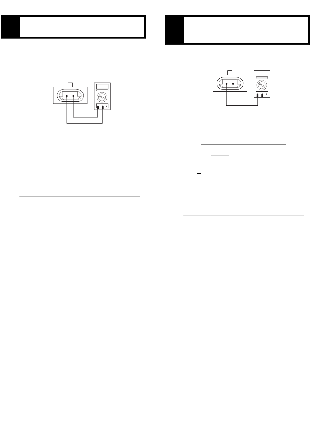
332 © 2016 Eaton. All rights reserved 2016.01.15
UltraShift AW3 Shift Complaint Test | Symptom Isolation Procedures TRTS0930
1. Disconnect the Transmission Harness from the
Input Shaft Speed Sensor.
2. Measure resistance between Input Shaft Speed
Sensor Pin A and Pin B.
•If resistance is 2K to 4.5K ohm, go to Step L.
•If resistance is outside of range, go to Step J.
1. Measure resistance between Input Shaft Speed
Sensor Pin A and ground.
•If resistance is OL, replace the:
- Medium-Duty Transmission Harness
- Heavy-Duty Transmission Harness
Go to Step V.
•If resistance is less than 10K ohm, go to Step
J.
KPurpose: Measure the resistance of the Input Shaft
Speed Sensor at the Input Shaft Speed Sensor.
OHMS
VCOM A
AB
LPurpose: Test the Input Shaft Speed Sensor circuit
for a short to ground at the Input Shaft Speed Sen-
sor.
OHMS
VCOM A
AB
GROUND

2016.01.15 © 2016 Eaton. All rights reserved 333
TRTS0930 Symptom Isolation Procedures | UltraShift AW3 Shift Complaint Test
1. Key off.
2. Reconnect all connectors.
3. Key on.
4. Drive the vehicle to determine whether the com-
plaint has been repaired.
•If the transmission shifts normal, test com-
plete.
•If the transmission still has a shifting com-
plaint go to Step A. to find error in testing.
VPurpose: Verify repair.

334 © 2016 Eaton. All rights reserved 2016.01.15
Shift Lever Back Light Test | Symptom Isolation Procedures TRTS0930
Shift Lever Back Light Test
Overview
This symptom-driven test is performed if the Shift Lever or
Shift Control back lighting is not functioning.
Detection
There is no detection other than a driver complaint.
Fallback
There is no fallback mode for this symptom.
Possible Causes
This symptom can be caused by any of the following:
•OEM Wiring
• Shift Control
• Shift Lever
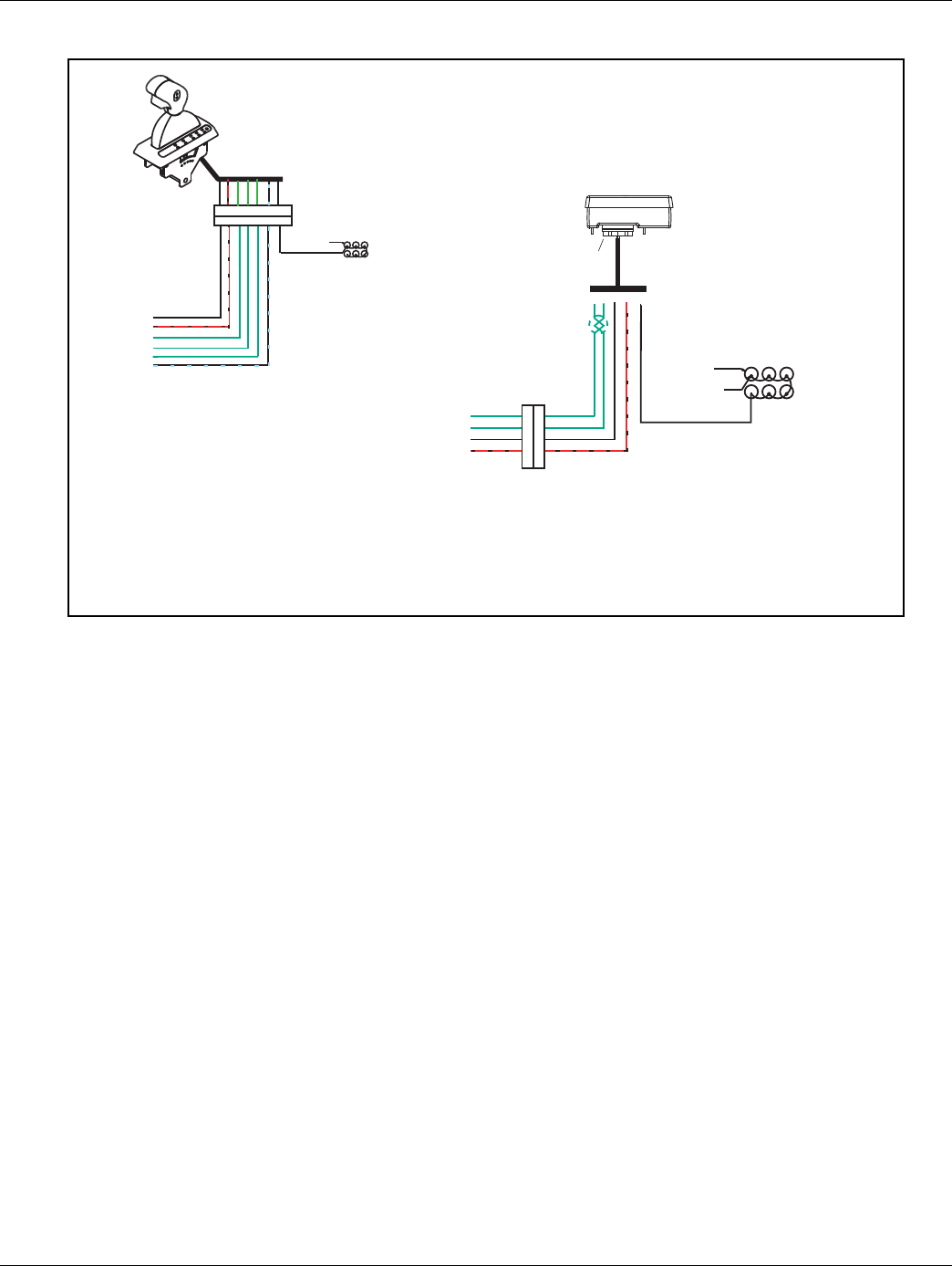
2016.01.15 © 2016 Eaton. All rights reserved 335
TRTS0930 Symptom Isolation Procedures | Shift Lever Back Light Test
Component Identification
Push Button Shift Control
Push Button Control
30-way connector
F2 F1 J3 C1 B3
Back side
of gauges
Dash lights
Dimmer control input
All OEM responsible wiring shown is "typical". Consult specific application.
(4-31, C1) = +12 volt switched from TECU
(1-15, 8-16, 2-17, F2, F1) = Communication from and to the ECU15.8.2
(3-25, 5, J3, B3) = Signal returns, grounds, and general OEM wiring
(6-23) = Signal from ECU
Shift Control ECU Legend
Dimmer control input
25
31
15
16
17
23
3 4 1 8 2 6 5 7
3 4 1 8 2 6 5 7
Back side
of gauges
Dash lights
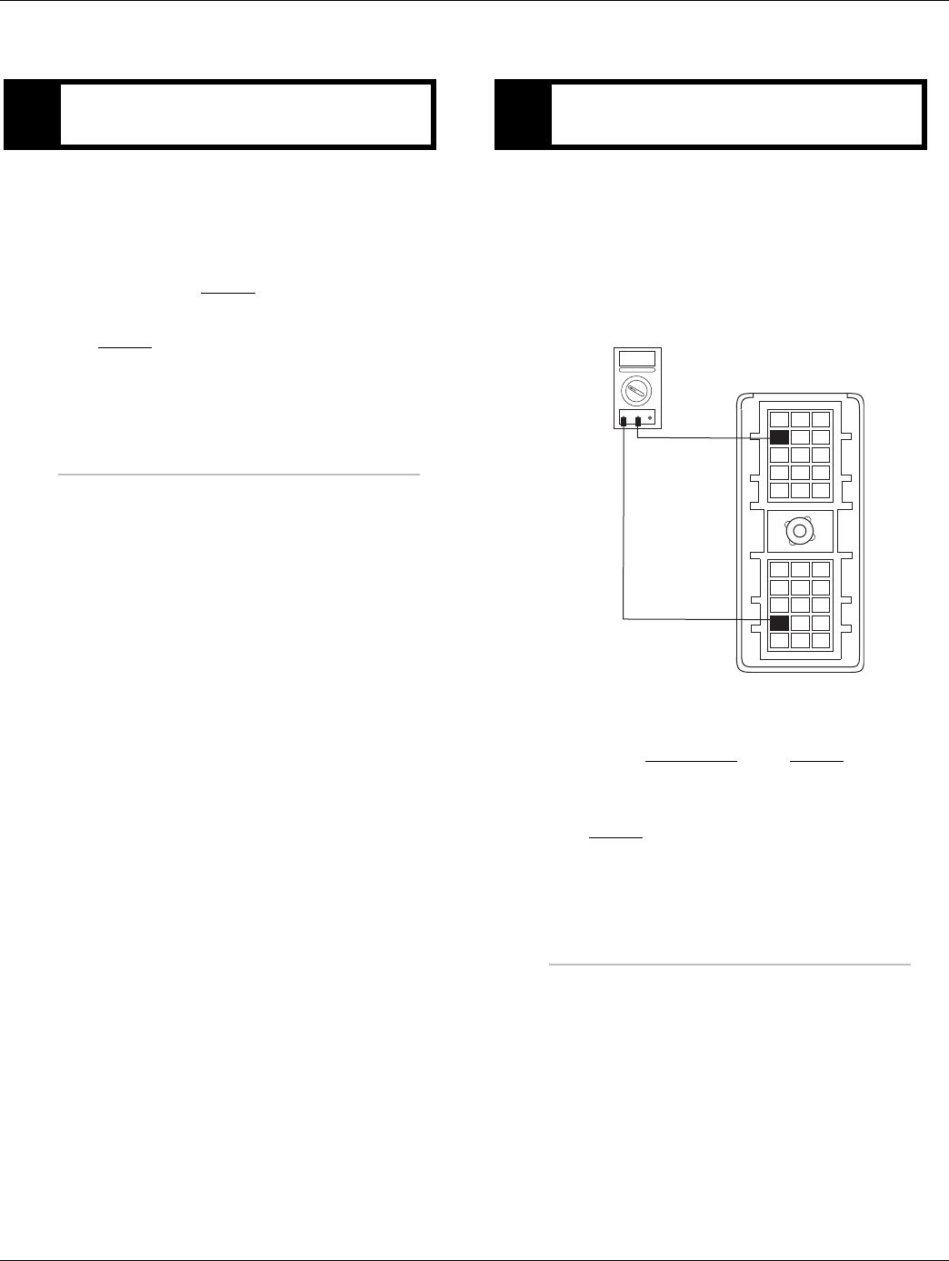
336 © 2016 Eaton. All rights reserved 2016.01.15
Shift Lever Back Light Test | Symptom Isolation Procedures TRTS0930
Shift Lever Back Light Test
1. Verify Shift Lever.
•If vehicle is equipped with an OEM Shift Lever,
refer to OEM for repair strategy.
•If vehicle is equipped with a Push Button Shift
Control, go to Step B.
•If vehicle is equipped with Cobra Lever, go to
Step C.
1. Key off.
2. Disconnect Shift Control 30-way connector.
3. Key on.
4. Turn dimmer switch to max.
5. Measure voltage between Pin B3 and Pin J3.
•If voltage is within 0.6 volts of battery voltage,
replace Shift Control. Go to Step V.
•If voltage is outside of range, repair OEM wire
between Pin B3 and the dash lights and go to
Step V.
APurpose: Visually identify the Driver Interface De-
vice. BPurpose: Measure the dimmer switch voltage sup-
ply to the Shift Control.
VOLTS
VCOM A
K
J
H
G
F
E
D
C
B
A
321
321
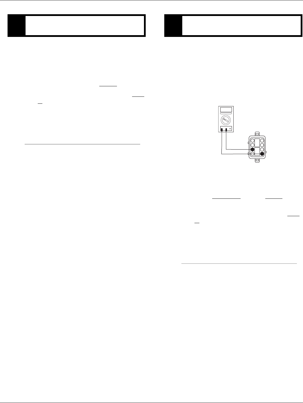
2016.01.15 © 2016 Eaton. All rights reserved 337
TRTS0930 Symptom Isolation Procedures | Shift Lever Back Light Test
1. Key on.
2. Turn vehicle lights on.
3. Turn dimmer switch to max.
•Cobra Lever lights on, but do not dim when
vehicle lights are on, go to Step D.
•Cobra Lever lights do not come on, go to Step
E.
1. Key off.
2. Disconnect Cobra Lever 8-way connector.
3. Key on.
4. Turn dimmer switch to max.
5. Measure voltage between Pin 5 and Pin 3 on the
8-way Vehicle Harness.
•If voltage is within 2 volts of battery voltage,
replace Cobra Lever and go to Step V.
•If voltage is outside of range, repair OEM wire
between Pin 5 and dash lights and go to Step
V.
CPurpose: Inspect Cobra Lever lights with dimmer
switched turned to the max position. DPurpose: Measure the dimmer switch voltage sup-
ply to the Cobra Lever.
VOLTS
VCOM A
1
2
3
45
6
7
8
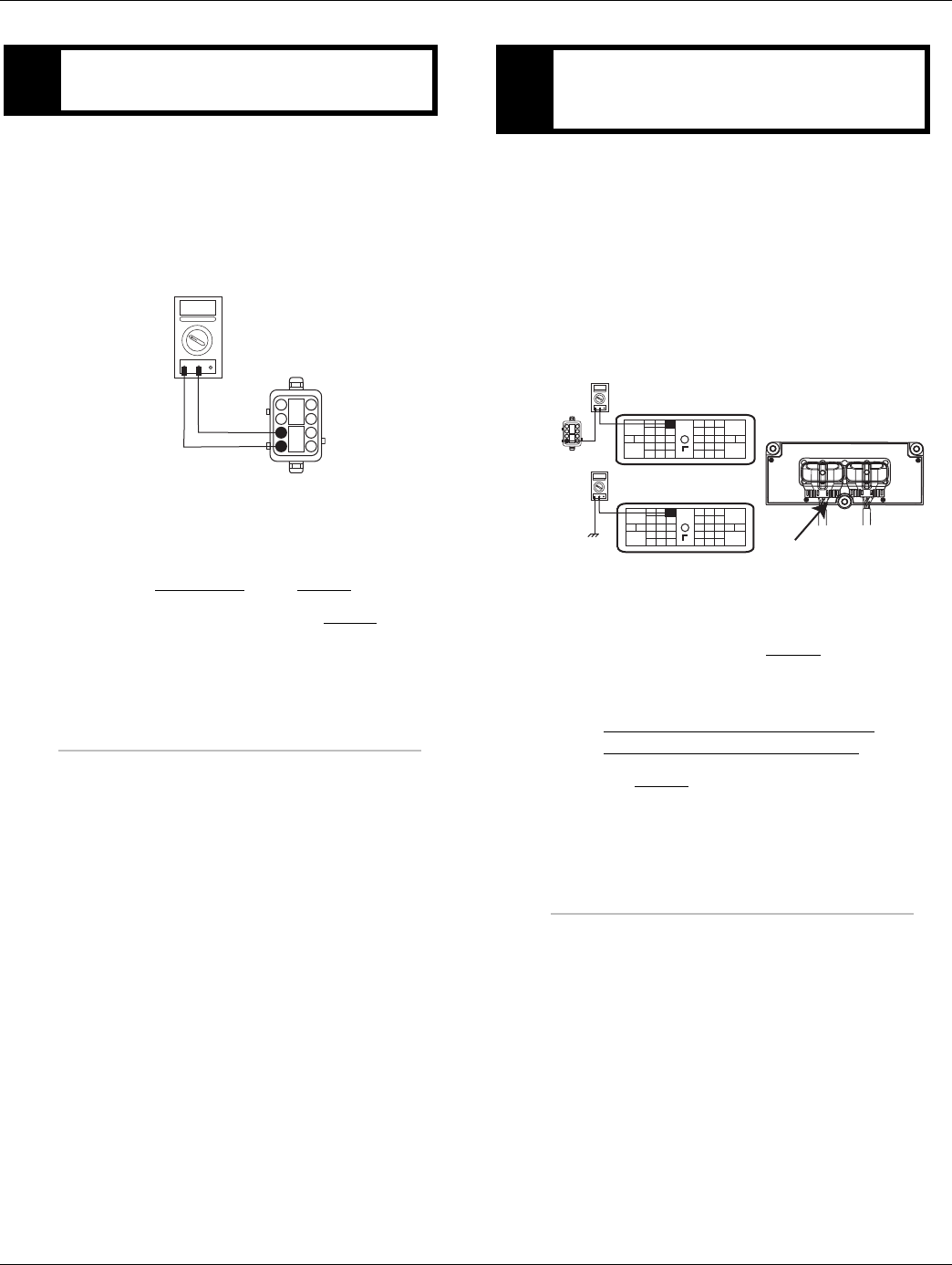
338 © 2016 Eaton. All rights reserved 2016.01.15
Shift Lever Back Light Test | Symptom Isolation Procedures TRTS0930
1. Key off.
2. Disconnect Cobra Lever 8-way connector.
3. Key on.
4. Measure voltage between Pin 3 and Pin 4 on the
8-way Vehicle Harness connector.
•If voltage is within 0.6 volts of battery voltage,
replace Cobra Lever. Go to Step V.
•If voltage is out of range, go to Step F.
1. Key off.
2. Disconnect Negative battery cable.
3. Disconnect Vehicle Harness 38-way connector.
4. Measure resistance between:
-Vehicle Harness 38-way connector Pin 31 and
Vehicle Harness 8-way connector Pin 4.
-Vehicle Harness 38-way connector Pin 31 and
ground.
•If resistance between Pin 31 and Pin 4 is 0 to
0.3 ohms and the resistance between Pin 31
and ground is OL, go to Step G.
•If any of the above conditions are not met,
replace the:
-Medium-Duty Transmission Harness
- Heavy-Duty Transmission Harness
Go to Step V.
EPurpose: Measure the ignition voltage supply to
the Cobra Lever.
VOLTS
VCOM A
1
2
3
45
6
7
8
FPurpose: Verify continuity of the power supply
from the TECU to the Cobra Lever and test for a
short to ground.
OHMS
VCOM A
1
2
3
5
6
7
8
24 25
29 30
15 16
26
20
34
27 28
32 33
18 19
7
3
89
12 6
11 12
45
22
21
38
36
37
13 14
35 10
17
23
Front View
38-Way Connector
OHMS
VCOM A
24 25
29 30
15 16
26
20
34
27 28
32 33
18 19
7
3
89
12 6
11 12
45
22
21
38
36
37
13 14
35 10
17
23
Vehicle Harness 38-way Connector
31
4
31
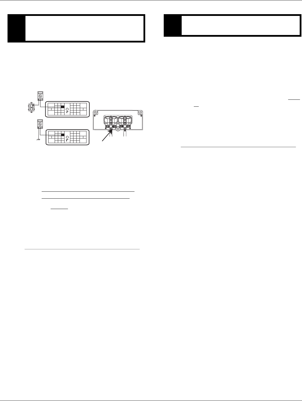
2016.01.15 © 2016 Eaton. All rights reserved 339
TRTS0930 Symptom Isolation Procedures | Shift Lever Back Light Test
1. Key off.
2. Measure resistance between Vehicle Harness
38-way connector Pin 25 and Vehicle Harness
8-way connector Pin 3 Vehicle Harness 38-way
connector Pin 25 and ground.
•If resistance between Pin 25 and Pin 3 is 0 to
0.3 ohms and the resistance between Pin 25
and ground is OL, see “Electrical Pretest” on
page 12. If test passes, replace the
-Medium-Duty Input Shaft Speed Sensor
- Heavy-Duty Input Shaft Speed Sensor
go to Step V.
1. Key off.
2. Reconnect all connectors.
3. Key on.
4. Turn on the dash lights fully.
•If back light works correctly, test complete.
•If back lights do not work correctly, go to Step
A. to find error in testing.
GPurpose: Verify continuity of the ground supply
from the TECU to the Cobra Lever and test for a
short to ground.
OHMS
VCOM A
1
2
3
5
6
7
8
24 25
29 30
15 16
26
20
34
27 28
32 33
18 19
7
3
89
12 6
11 12
45
22
21
38
36
37
13 14
35 10
17
23
Front View
38-Way Connector
OHMS
VCOM A
24 25
29 30
15 16
26
20
34
27 28
32 33
18 19
7
3
89
12 6
11 12
45
22
21
38
36
37
13 14
35 10
17
23
Vehicle Harness 38-way Connector
31
4
31
VPurpose: Verify repair.
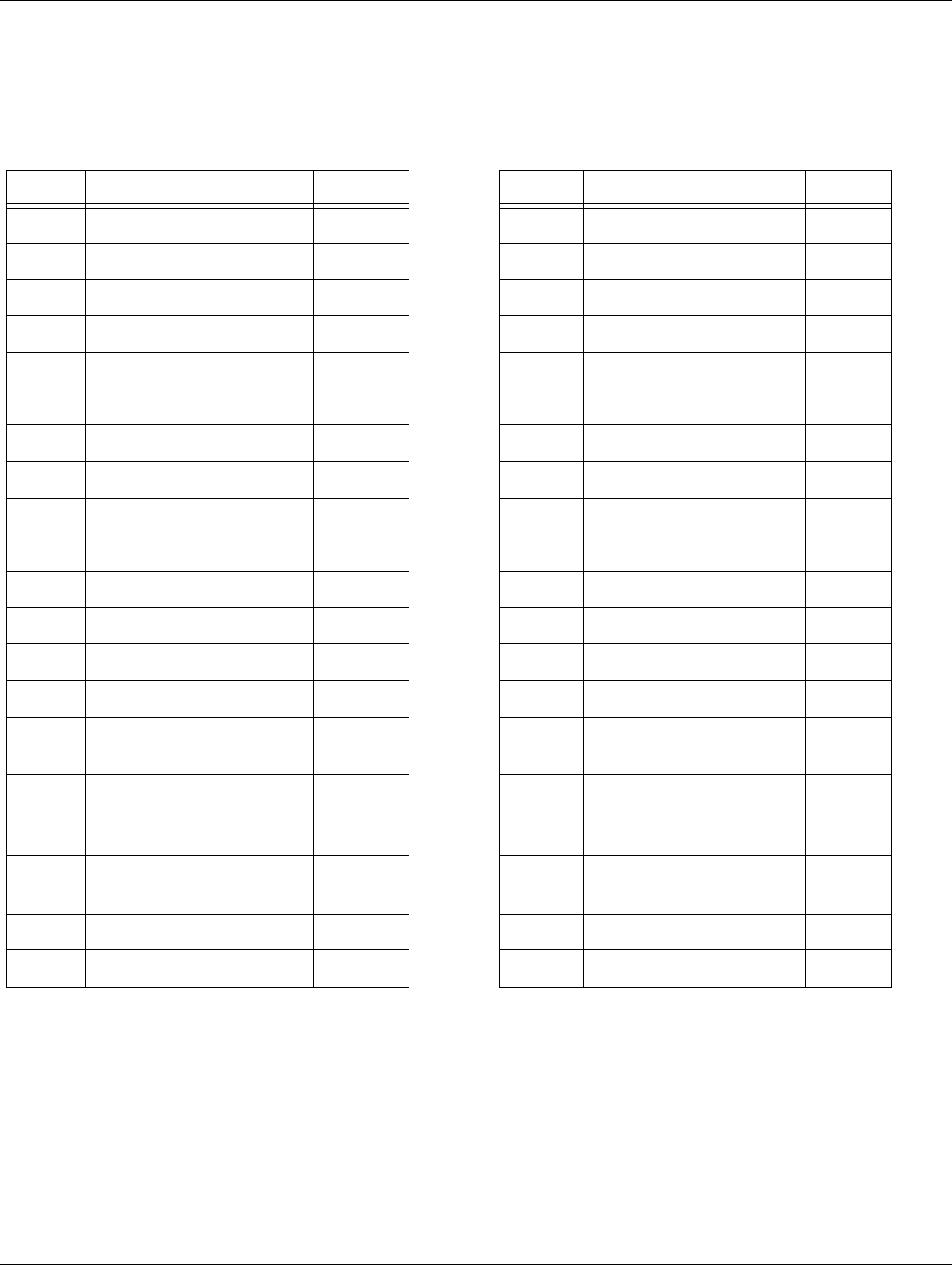
340 © 2016 Eaton. All rights reserved 2016.01.15
Connector Pin Descriptions | Appendix TRTS0930
Connector Pin Descriptions
Transmission Controller 38-Way (Vehicle Interface Connector)
38-Way Description Wire 38-Way Description Wire
1 J1939 Shield (CAN) 18 TXL 20 MEIIR Contact 18 TXL
2 J1939 Low (CAN) 18 TXL 21 MEIIR Minus 18 TXL
3 J1939 High (CAN) 18 TXL 22 MEIIR Plus 18 TXL
4 Start Enable Relay Minus 18 TXL 23 Service Light Output 18 TXL
5 Not Used Plug 24 Not Used 18 TXL
6 Not Used Plug 25 Shift Control Power Minus 18 TXL
7 Not Used Plug 26 Start Enable Latch 18 TXL
8 Not Used Plug 27 HIL Low (Proprietary CAN) 18 TXL
9 Not Used Plug 28 HIL High (Proprietary CAN) 18 TXL
10 J1587 Plus 18 TXL 29 Not Used Plug
11 J1587 Minus 18 TXL 30 Not Used Plug
12 ISO9141-K Communications 18 TXL 31 Shift Control Power Plus 18 TXL
13 Not Used Plug 32 Start Enable Relay Plus 18 TXL
14 Not Used Plug 33 Not Used Plug
15 Shift Control Input (Mode
Auto)
18 TXL 34 Not Used Plug
16 Shift Control Input (Mode
Manual/Neutral Signal)
18 TXL 35 Ignition 12 GXL
or
14SXL
17 Shift Control Input (Mode
Common/Neutral Return)
18 TXL 36 Battery Minus 12 GXL
18 PTO 18 TXL 37 Not Used Plug
19 Auto Neutral AW3 18 TXL 38 Battery Plus 12 GXL
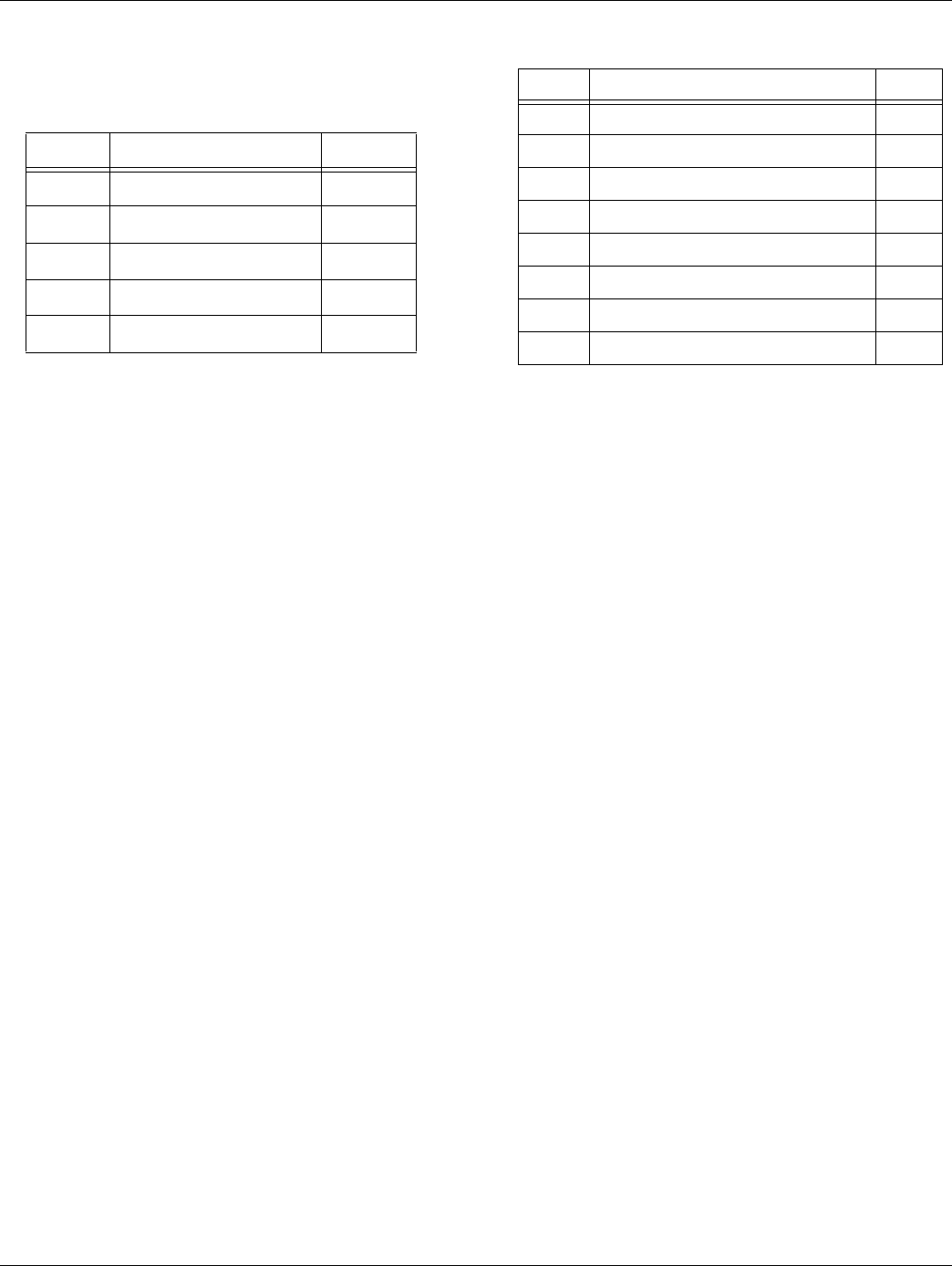
2016.01.15 © 2016 Eaton. All rights reserved 341
TRTS0930 Appendix | Connector Pin Descriptions
Push Button Shift Control 30-Way
Connector
Cobra Lever 8-Way Connector
30-Way Description Wire
C1 Shift Control Power Plus 16 TXL
B3 V Dash 16 TXL
F1 HIL(+) HI 16 TXL
F2 HIL(-) LO 16 TXL
J3 Shift Control Power Minus 16 TXL
8-Way Description Wire
1 Shift Control Input (Mode Auto) 16 TXL
2 Shift Control Input (Mode Common) 16 TXL
3 Shift Control Power Minus 16 TXL
4 Shift Control Lever Power Plus 16 TXL
5 Dash Lights 16 TXL
6 Service Light Output 16 TXL
7 No Connection 16 TXL
8 Shift Control Input (Mode Manual) 16 TXL
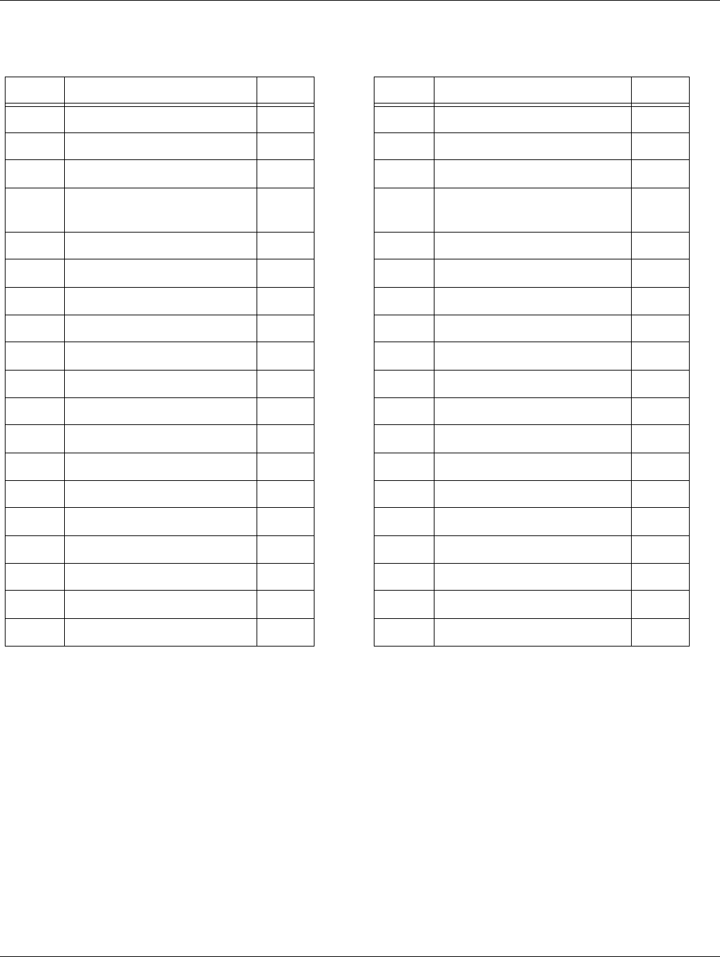
342 © 2016 Eaton. All rights reserved 2016.01.15
Connector Pin Descriptions | Appendix TRTS0930
Transmission Controller 38-Way (Eaton Supplied Assembly)
38-Way Description Wire 38-Way Description Wire
1 Not Used Plug 20 Rail Position Sensor Minus 18 TXL
2 Clutch Lube Solenoid Plus 18 TXL 21 Not Used Plug
3 Clutch Lube Solenoid Minus 18 TXL 22 Not Used Plug
4 Splitter Solenoid Common
Minus
18 TXL 23 Output Shaft Speed Sensor High 18 TXL
5 Inertia Brake Solenoid Minus 18 TXL 24 Output Shaft Speed Sensor Low 18 TXL
6 Range Solenoid Common Minus 18 TXL 25 Service Ignition 18 TXL
7 Input Shaft Speed Sensor High 18 TXL 26 Splitter Indirect Solenoid Plus 18 TXL
8 Input Shaft Speed Sensor Low 18 TXL 27 Not Used Plug
9 Not Used Plug 28 Range High Solenoid Plus 18 TXL
10 Gear Position Sensor Plus 18 TXL 29 Not Used 18 TXL
11 Gear Position Sensor Signal 18 TXL 30 Not Used 18 TXL
12 Gear Position Sensor Minus 18 TXL 31 Service Battery Minus 18 TXL
13 Clutch Solenoid Plus 18 TXL 32 Splitter Direct Solenoid Plus 18 TXL
14 Clutch Solenoid Minus 18 TXL 33 Inertia Brake Solenoid Plus 18 TXL
15 Main Shaft Speed Sensor High 18 TXL 34 Range Low Solenoid Plus 18 TXL
16 Main Shaft Speed Sensor Low 18 TXL 35 Rail Motor Plus 14SXL
17 Service Battery Plus 18 TXL 36 Gear Motor Plus 14SXL
18 Rail Position Sensor Plus 18 TXL 37 Rail Motor Minus 14SXL
19 Rail Position Sensor Signal 18 TXL 38 Gear Motor Minus 14SXL
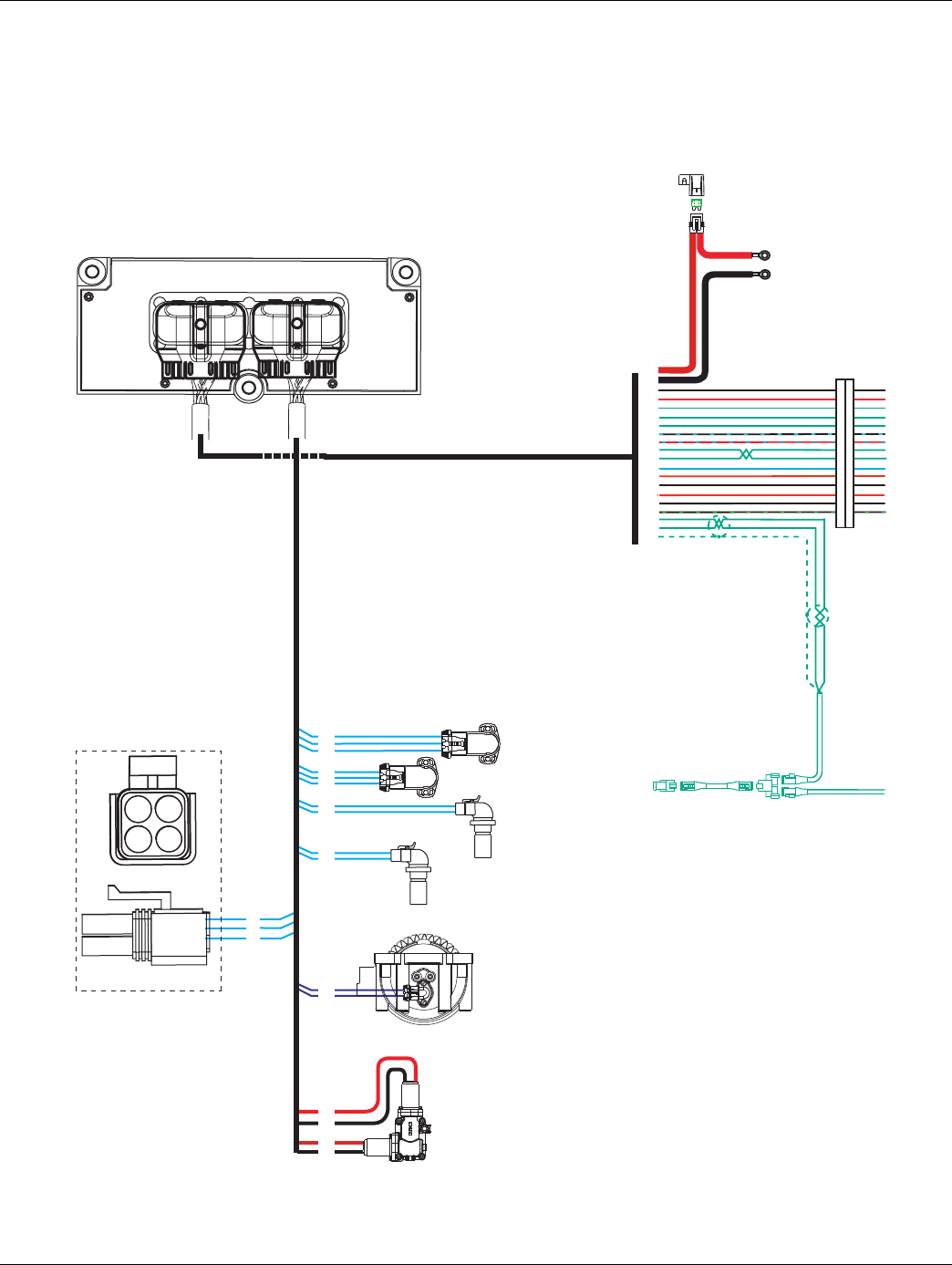
2016.01.15 © 2016 Eaton. All rights reserved 343
TRTS0930 Appendix | Wiring Diagrams
Wiring Diagrams
UltraShift DM3 6-Speed Wiring Diagram
with Analog Shifter
Gear select
motor
Rail select
motor
Electric
shifter
A
B
A
B
Rail select
sensor
Gear select
sensor
Input shaft
speed sensor
Output shaft
speed sensor
Inertia brake
A
B
18
19
20
10
11
12
7
8
23
24
33
5
A
B
C
A
B
C
35
37
36
38
OEM
30 AMP fuse
Battery power
(Non-switched power)
run to starter or Battery
Terminating
resistor
38
36
25
31
15
16
17
23
35
10
11
26
32
4
22
21
20
3
2
1
B
C
A
17
31
25
D
For Transmission
Diagnostics
4-way
B - Service Bat. +
C - Service Bat. -
A - Service Ignition +
B
C
A
Transmission ECU
All OEM responsible wiring shown is "typical". Consult specific application.
(38) = +12 volt non-switched from battery
(35) = +12 volt switched from ignition switch
(26) = Latch into the ECU
(15, 16, 17, 10, 11, 3, 2, 1) = Communication from and to the TECU
(36, 25) = Signal returns, grounds, and general OEM wiring
(4, 21) = -12 volt relay source
(22, 32) = +12 volt relay source
(31) = +12 volt switched from TECU
(23) = Signal from TECU
(20) = Signal into the TECU
Vehicle Interface Legend
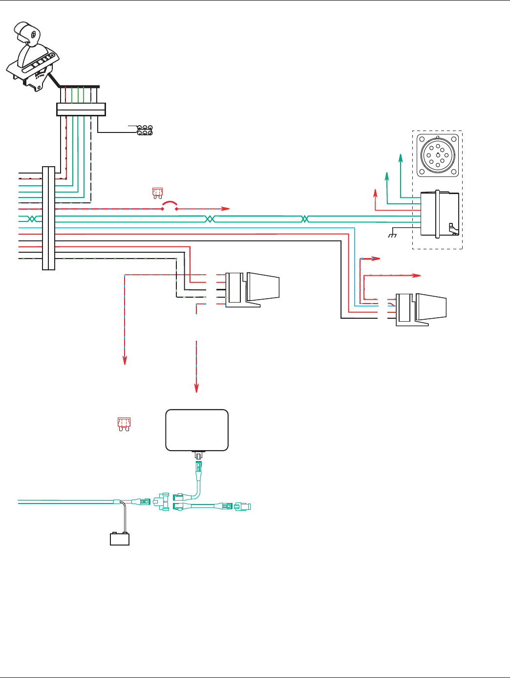
344 © 2016 Eaton. All rights reserved 2016.01.15
Wiring Diagrams | Appendix TRTS0930
All OEM responsible wiring shown is "typical". Consult specific application.
(35, 30, 87, 87a) = +12 volt switched from ignition switch
(26-87) = Latch into the ECU
(15-1, 16-8, 17-2, 10-F, 11-G) = Communication from and to the TECU
(25-3) = Signal returns, grounds, and general OEM wiring
(4-85, 21-85) = -12 volt relay source
(22-86, 32-86) = +12 volt relay source
(31-4) = +12 volt switched from TECU
(23-6) = Signal from TECU
(20-87) = Signal into TECU
Terminating
resistor
J-1939/11 data link
(OEM supplied)
GND
+_
Shield
termination
Engine ECM
Start
enable
relay
Run to start
signal from
igntion switch
10 AMP 12 volt only
manual resetting
circuit breaker
10 AMP fuse
or
J-1587 data link
30
87
86
85
Bulkhead connector
located at firewall
Back side
of gauges
Dash lights
Dimmer control input
Ignition
Interrupt
relay
30
86
85
87
87a
* Run to ignition
input on Engine
ECM
25
31
15
16
17
23
35
10
11
26
32
4
22
21
20
+12 volts
battery
Run to
starter solenoid
9-way
A
F
J
E
G
H
D
CB
C
D
B
F
G
A
J-1939 Low
J-1939 High
For Transmission
Diagnostics per
SAE Standard
Engine Power Relay
Fused 10 AMP 12 volt
manual resetting
circuit breaker
or
10 AMP
fuse
3 4 1 8 2 6 5 7
3 4 1 8 2 6 5 7
Ignition Key Switch
Runs to main power lead that
feeds the ignition bus (OEM
responsible for overcurrent
protection on this line)
Vehicle Interface Legend
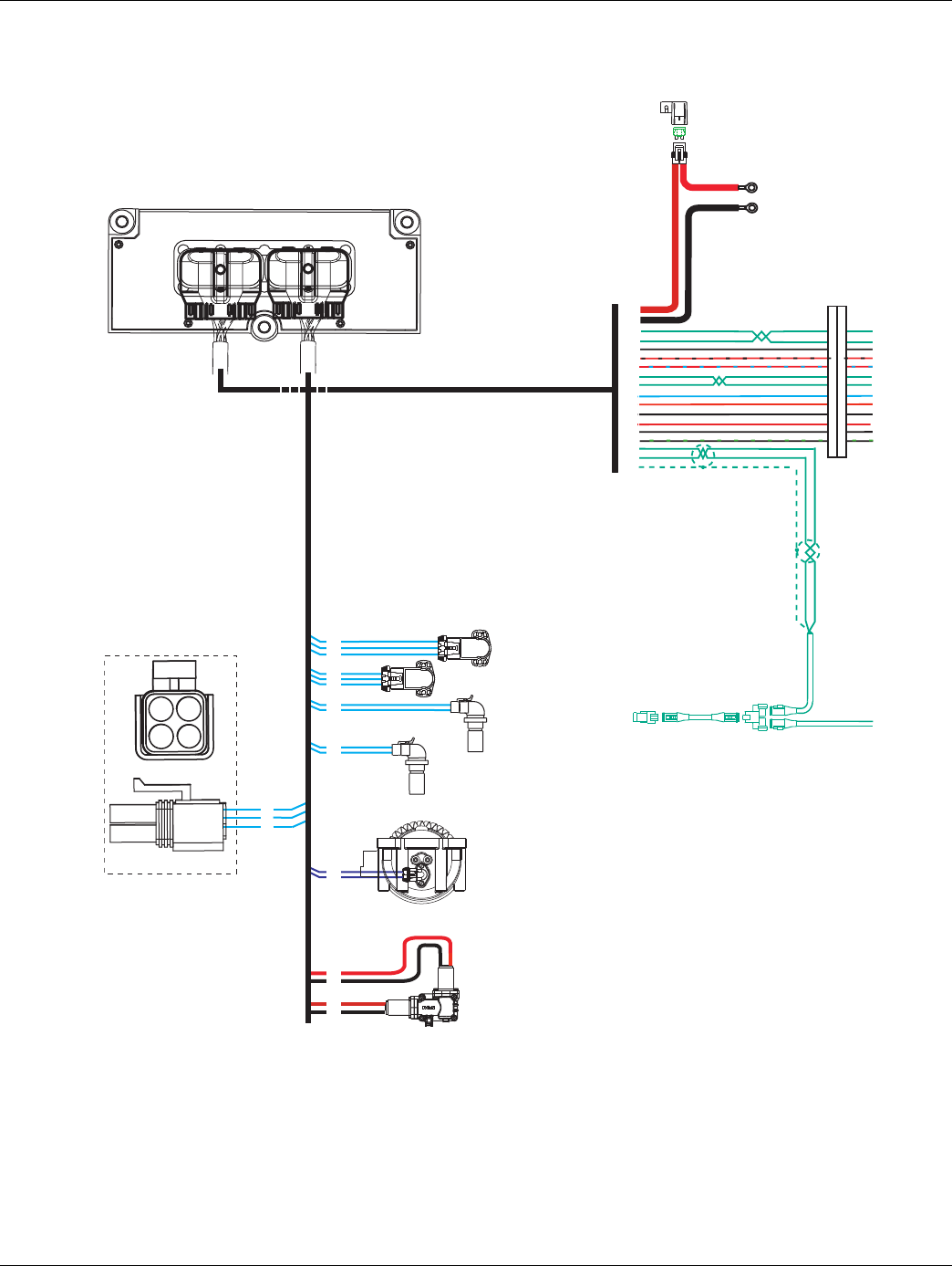
2016.01.15 © 2016 Eaton. All rights reserved 345
TRTS0930 Appendix | Wiring Diagrams
UltraShift DM3 6-Speed Wiring Diagram
with Push Button Shifter
17
31
25
Gear select
motor
Rail select
motor
Electric
shifter
A
B
A
B
Rail select
sensor
Gear select
sensor
Input shaft
speed sensor
Output shaft
speed sensor
Inertia brake
A
B
18
19
20
10
11
12
7
8
23
24
33
5
A
B
C
A
B
C
35
37
36
38
30 AMP fuse
Battery power
(Non-switched power)
run to starter or Battery
Terminating
resistor
38
36
27
28
25
31
35
10
11
26
32
4
22
21
20
3
2
1
OEM
B
C
A
D
For Transmission
Diagnostics
4-way
B - Service Bat. +
C - Service Bat. -
A - Service Ignition +
B
C
A
Transmission ECU
All OEM responsible wiring shown is "typical". Consult specific application.
(38) = +12 volt non-switched from battery
(35) = +12 volt switched from ignition switch
(26) = Latch into the ECU
(27, 28, 10, 11, 3, 2, 1) = Communication from and to the TECU
(36, 25) = Signal returns, grounds, and general OEM wiring
(4, 21) = -12 volt relay source
(22, 32) = +12 volt relay source
(31) = +12 volt switched from TECU
(20) = Signal into the TECU
Vehcile Interface Legend
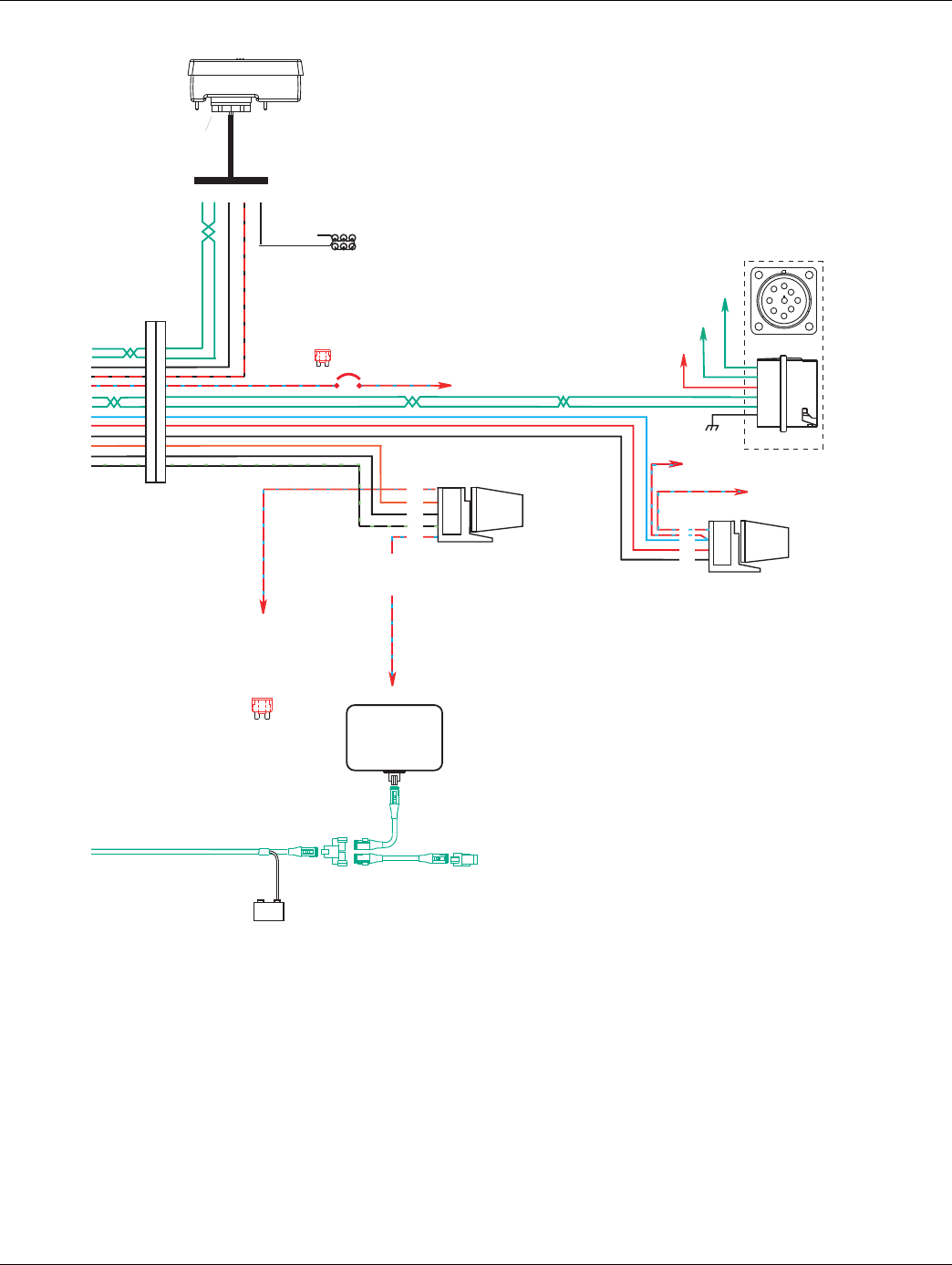
346 © 2016 Eaton. All rights reserved 2016.01.15
Wiring Diagrams | Appendix TRTS0930
Terminating
resistor
J-1939/11 data link
(OEM supplied)
GND
+_
Shield
termination
Engine ECM
Start
enable
relay
Run to start
signal from
igntion switch
10 AMP 12 volt only
manual resetting
circuit breaker
10 AMP fuse
or
J-1587 data link
30
87
86
85
Bulkhead connector
located at firewall
Back side
of gauges
Dash lights
Dimmer control input
Ignition
Interrupt
relay
30
86
85
87
87a
* Run to ignition
input on Engine
ECM
Push Button Shift Control
Push Button Control
30-way connector
F2 F1 J3 C1 B3
27
28
25
31
35
10
11
26
32
4
22
21
20
Engine Power Relay
Fused 10 AMP 12 volt
manual resetting
circuit breaker
or
10 AMP
fuse
+12 volts
battery
Run to
starter solenoid
9-way
A
F
J
E
G
H
D
CB
C
D
B
F
G
A
J-1939 Low
J-1939 High
For Transmission
Diagnostics per
SAE Standard
Ignition Key Switch
Runs to main power lead that
feeds the ignition bus (OEM
responsible for overcurrent
protection on this line)
All OEM responsible wiring shown is "typical". Consult specific application.
(35, 30, 87, 87a) = +12 volt switched from ignition switch
(26-87) = Latch into the ECU
(27-F2, 28-F1, 10-F, 11-G) = Communication from and to the TECU
(25-J3) = Signal returns, grounds, and general OEM wiring
(4-85, 21-85) = -12 volt relay source
(22-86, 32-86) = +12 volt relay source
(31-C1) = +12 volt switched from TECU
(20-87) = Signal into TECU
Vehicle Interface Legend
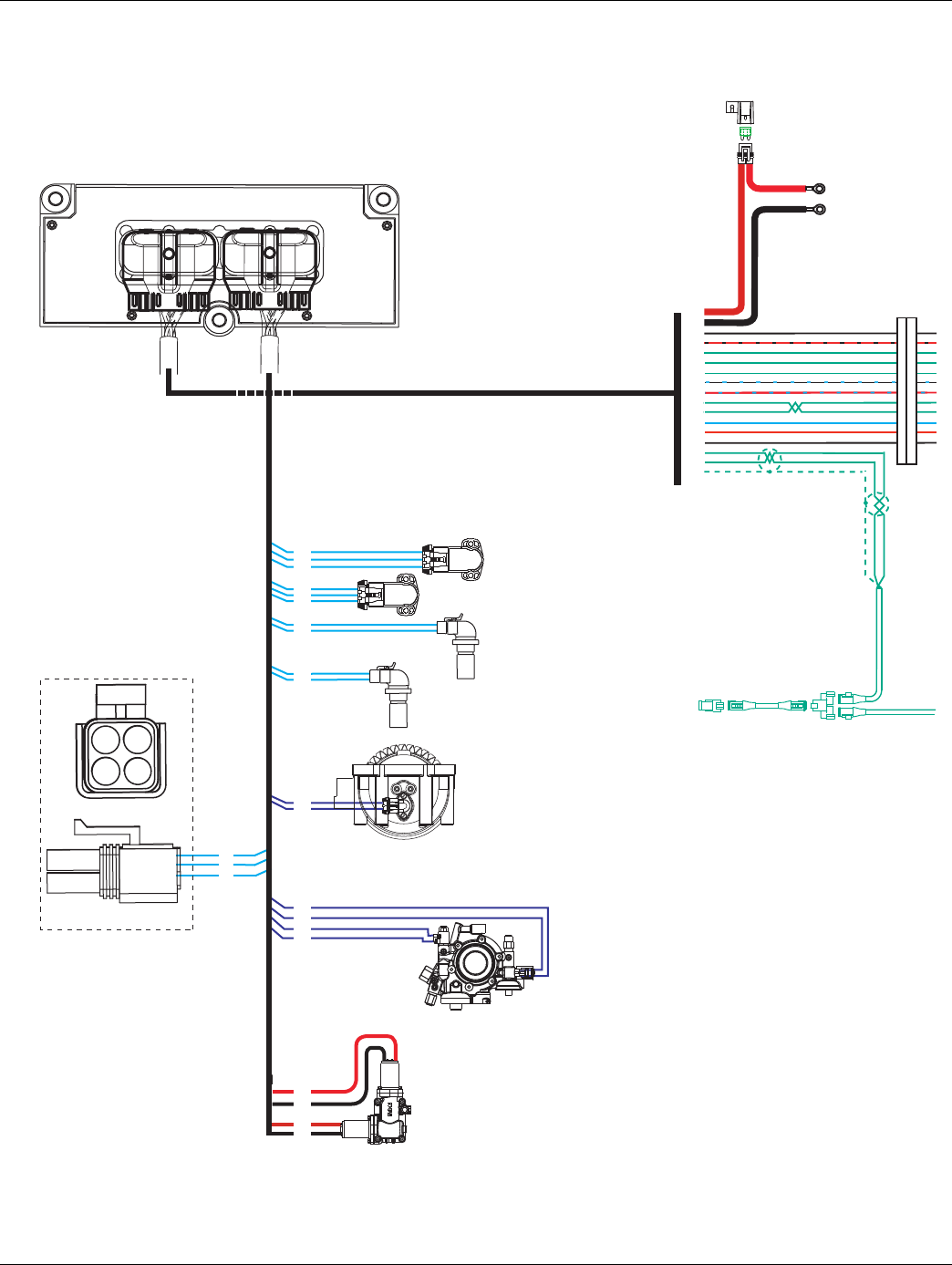
2016.01.15 © 2016 Eaton. All rights reserved 347
TRTS0930 Appendix | Wiring Diagrams
UltraShift AW3 6-Speed Wiring Diagram
with Analog Shifter
17
31
25
Gear select
motor
Rail select
motor
Electric
shifter
A
B
A
B
Rail select
sensor
Gear select
sensor
Input shaft
speed sensor
Output shaft
speed sensor
Inertia brake
A
B
18
19
20
10
11
12
7
8
23
24
33
5
A
B
C
A
B
C
35
37
36
38
Hydraulic manifold
Assembly
2
3
13
14
30 AMP fuse
Battery power
(Non-switched power)
run to starter or Battery
Terminating
resistor
38
36
25
31
15
16
17
23
35
10
11
26
32
4
3
2
1
Transmission ECU
OEM
B
C
A
D
For Transmission
Diagnostics
4-way
B - Service Bat. +
C - Service Bat. -
A - Service Ignition +
B
C
A
All OEM responsible wiring shown is "typical". Consult specific application.
(38) = +12 volt non-switched from battery
(35) = +12 volt switched from ignition switch
(26) = Latch into the ECU
(15, 16, 17, 10, 11, 3, 2, 1) = Communication from and to the TECU
(36, 25) = Signal returns, grounds, and general OEM wiring
(4) = -12 volt relay source
(32) = +12 volt relay source
(31) = +12 volt switched from TECU
(23) = Signal from TECU
Vehicle Interface Legend
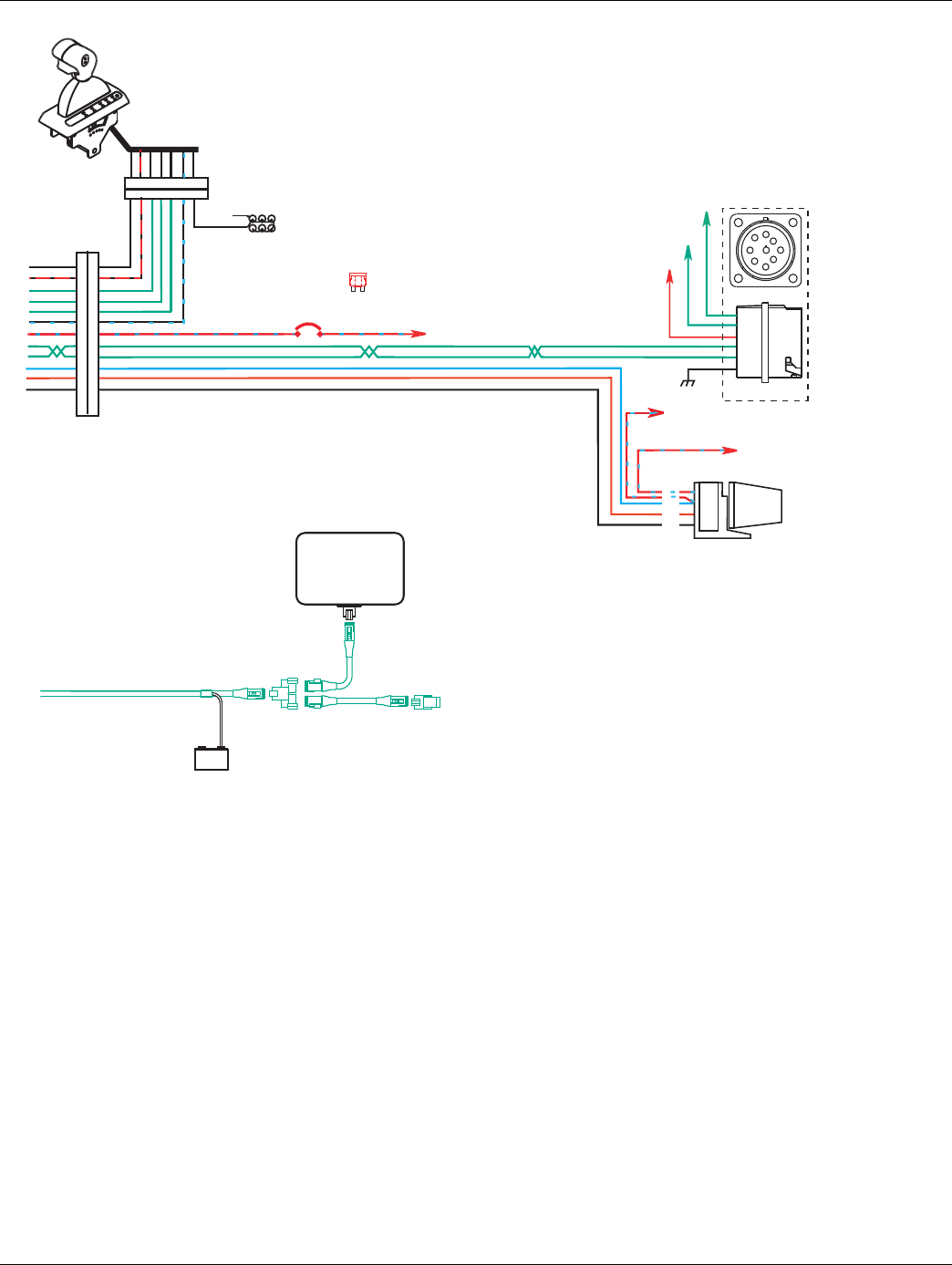
348 © 2016 Eaton. All rights reserved 2016.01.15
Wiring Diagrams | Appendix TRTS0930
Terminating
resistor
J-1939/11 data link
(OEM supplied)
GND
+_
Shield
termination
Engine ECM
Start
enable
relay
Run to start
signal from
igntion switch
Run to
starter solenoid
10 AMP 12 volt only
manual resetting
circuit breaker10 AMP
fuse
or
J-1587 data link
30
87
86
85
Bulkhead connector
located at firewall
Back side
of gauges
Dash lights
Dimmer control input
25
31
15
16
17
23
35
10
11
26
32
4
Transmission
ECU Connector Pins
3 4 1 8 2 6 5 7
3 4 1 8 2 6 5 7
+12 volts
Battery
For transmission
Diagnostics per
SAE Standard
C
D
B
F
G
A
9-way
A
F
J
E
G
H
D
CB
J-1939 Low
J-1939 High
Ignition Key Switch
Runs to main power lead that
feeds the ignition bus (OEM
responsible for overcurrent
protection on this line)
All OEM responsible wiring shown is "typical". Consult specific application.
(35, 30, 87) = +12 volt switched from ignition switch
(26-87) = Latch into the ECU
(15-1, 16-8, 17-2, 10-F, 11-G) = Communication from and to the TECU
(25-3) = Signal returns, grounds, and general OEM wiring
(4-85) = -12 volt relay source
(32-86) = +12 volt relay source
(31-4) = +12 volt switched from TECU
(23-6) = Signal from TECU
Vehicle Interface Legend
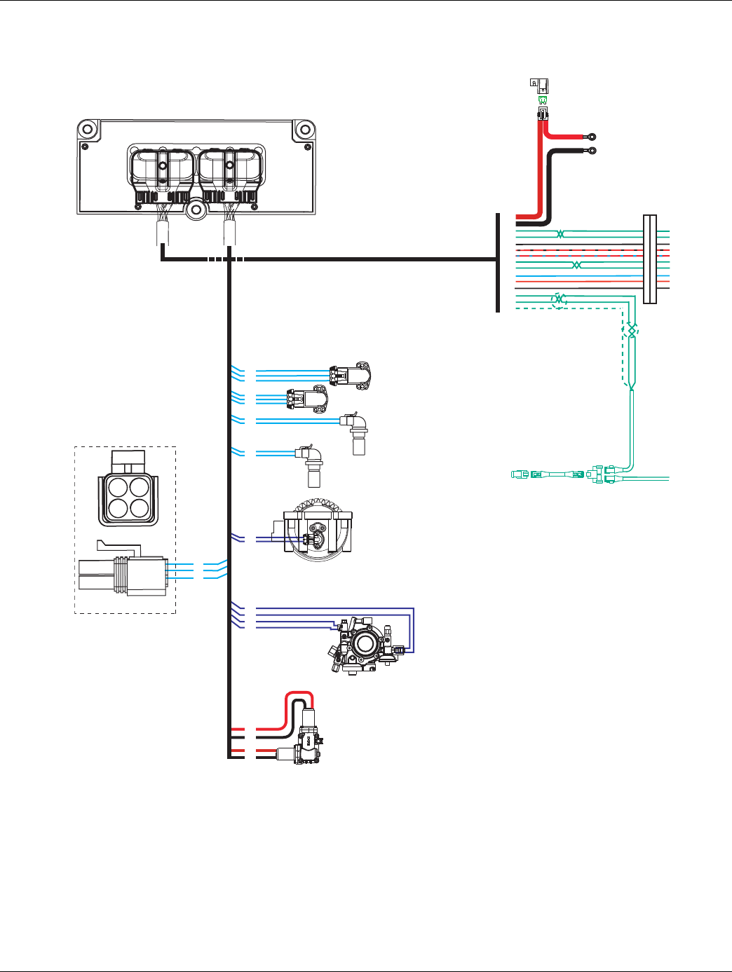
2016.01.15 © 2016 Eaton. All rights reserved 349
TRTS0930 Appendix | Wiring Diagrams
UltraShift AW3 6-Speed Wiring Diagram
with Push Button Shifter
17
31
25
Gear select
motor
Rail select
motor
Electric
shifter
A
B
A
B
Rail select
sensor
Gear select
sensor
Input shaft
speed sensor
Output shaft
speed sensor
Inertia brake
A
B
18
19
20
10
11
12
7
8
23
24
33
5
A
B
C
A
B
C
30 AMP fuse
Battery power
(Non-switched power)
run to starter or Battery
Terminating
resistor
38
36
27
28
25
31
35
10
11
26
32
4
3
2
1
35
37
36
38
Bulkhead connector
located at firewall
Hydraulic manifold
Assembly
2
3
13
14
B
C
A
D
For Transmission
Diagnostics
4-way
B - Service Bat. +
C - Service Bat. -
A - Service Ignition +
B
C
A
Transmission ECU
OEM
All OEM responsible wiring shown is "typical". Consult specific application.
(38) = +12 volt non-switched from battery
(35) = +12 volt switched from ignition switch
(26) = Latch into the ECU
(27, 28, 10, 11, 3, 2, 1) = Communication from and to the TECU
(36, 25) = Signal returns, grounds, and general OEM wiring
(4) = -12 volt relay source
(32) = +12 volt relay source
(31) = +12 volt switched from TECU
Vehicle Interface Legend
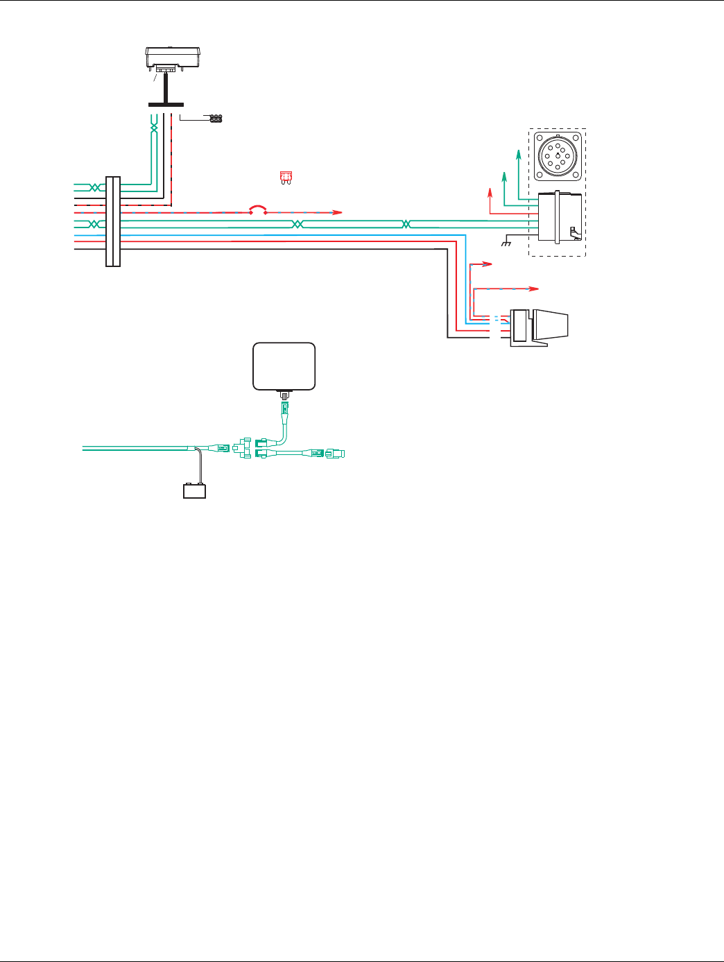
350 © 2016 Eaton. All rights reserved 2016.01.15
Wiring Diagrams | Appendix TRTS0930
Terminating
resistor
J-1939/11 data link
(OEM supplied)
GND
+_
Shield
termination
Engine ECM
Start
enable
relay
Run to start
signal from
igntion switch
10 AMP 12 volt only
manual resetting
circuit breaker10 AMP
fuse
or
J-1587 data link
30
87
86
85
Bulkhead connector
located at firewall
27
28
25
31
35
10
11
26
32
4
Transmission
ECU Connector Pins
Push Button Shift Control
Push Button Control
30-way connector
F2 F1 J3 C1 B3 Back side
of gauges
Dimmer control input
+12 volts
Battery
For transmission
Diagnostics per
SAE Standard
Run to
starter solenoid
C
D
B
F
G
A
F
9-way
A
F
J
E
G
H
D
CB
J-1939 Low
J-1939 High
Ignition Key Switch
Runs to main power lead that
feeds the ignition bus (OEM
responsible for overcurrent
protection on this line)
All OEM responsible wiring shown is "typical". Consult specific application.
(35, 30, 87) = +12 volt switched from ignition switch
(26-87) = Latch into the ECU
(27-F2, 28-F1, 10-F, 11-G) = Communication from and to the TECU
(25-J3) = Signal returns, grounds, and general OEM wiring
(4-85) = -12 volt relay source
(32-86) = +12 volt relay source
(31-C1) = +12 volt switched from TECU
Vehicle Interface Legend
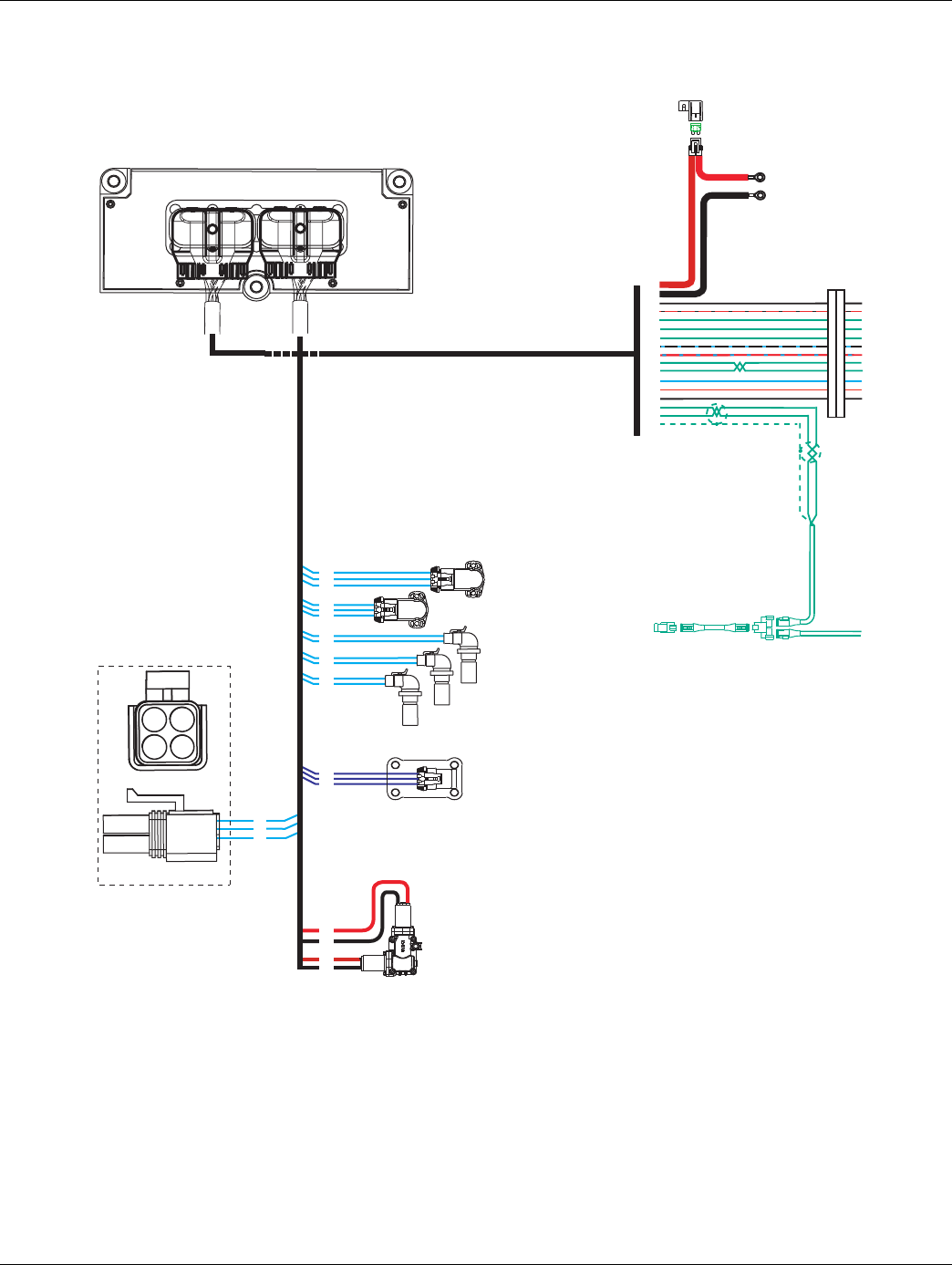
2016.01.15 © 2016 Eaton. All rights reserved 351
TRTS0930 Appendix | Wiring Diagrams
AutoShift 10-Speed Wiring Diagram with
Analog Shifter
17
31
25
C
B
A
Range
valve
Gear select
motor
Rail select
motor
Electric
shifter
A
B
A
B
Rail select
sensor
Gear select
sensor
Input shaft
speed sensor
Output shaft
speed sensor
18
19
20
10
11
12
7
8
23
24
A
B
C
A
B
C
30 AMP fuse
Battery power
(Non-switched power)
run to starter or Battery
Terminating
resistor
38
36
25
31
15
16
17
23
35
10
11
26
32
4
3
2
1
35
37
36
38
A
B
Main shaft
speed sensor
15
16
6
34
28
Transmission ECU
OEM
B
C
A
D
For Transmission
Diagnostics
4-way
B - Service Bat. +
C - Service Bat. -
A - Service Ignition +
B
C
A
All OEM responsible wiring shown is "typical". Consult specific application.
(38) = +12 volt non-switched from battery
(35) = +12 volt switched from ignition switch
(26) = Latch into the ECU
(15, 16, 17, 10, 11, 3, 2, 1) = Communication from and to the TECU
(36, 25) = Signal returns, grounds, and general OEM wiring
(4) = -12 volt relay source
(32) = +12 volt relay source
(31) = +12 volt switched from TECU
(23) = Signal from TECU
Vehicle Interface Legend
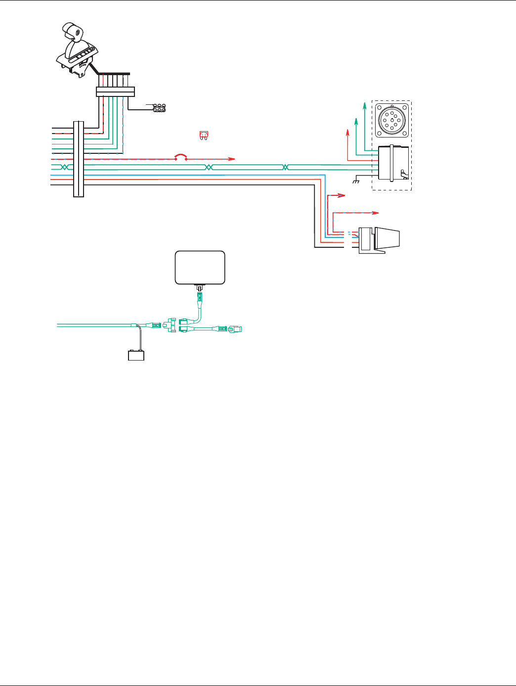
352 © 2016 Eaton. All rights reserved 2016.01.15
Wiring Diagrams | Appendix TRTS0930
Terminating
resistor
J-1939/11 data link
(OEM supplied)
GND
+_
Shield
termination
Engine ECM
Start
enable
relay
Run to start
signal from
igntion switch
Run to
starter solenoid
10 AMP 12 volt only
manual resetting
circuit breaker10 AMP
fuse
or
J-1587 data link
30
87
86
85
Bulkhead connector
located at firewall
Back side
of gauges
Dash lights
Dimmer control input
25
31
15
16
17
23
35
10
11
26
32
4
Transmission
ECU Connector Pins
3 4 1 8 2 6 5 7
3 4 1 8 2 6 5 7
+12 volts
Battery
For transmission
Diagnostics per
SAE Standard
C
D
B
F
G
A
9-way
A
F
J
E
G
H
D
CB
J-1939 Low
J-1939 High
Ignition Key Switch
Runs to main power lead that
feeds the ignition bus (OEM
responsible for overcurrent
protection on this line)
All OEM responsible wiring shown is "typical". Consult specific application.
(35, 30, 87) = +12 volt switched from ignition switch
(26-87) = Latch into the ECU
(15-1, 16-8, 17-2, 10-F, 11-G) = Communication from and to the TECU
(25-3) = Signal returns, grounds, and general OEM wiring
(4-85) = -12 volt relay source
(32-86) = +12 volt relay source
(31-4) = +12 volt switched from TECU
(23-6) = Signal from TECU
Vehicle Interface Legend
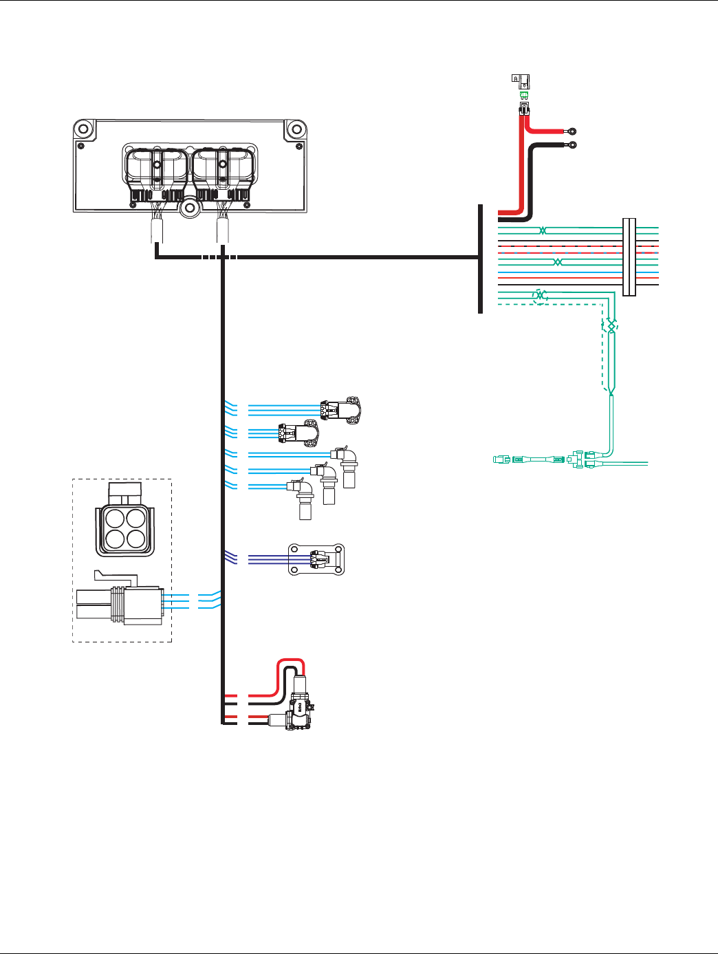
2016.01.15 © 2016 Eaton. All rights reserved 353
TRTS0930 Appendix | Wiring Diagrams
AutoShift 10-Speed Wiring Diagram with
Push Button Shifter
17
31
25
C
B
A
Range
valve
Gear select
motor
Rail select
motor
Electric
shifter
A
B
A
B
Rail select
sensor
Gear select
sensor
Input shaft
speed sensor
Output shaft
speed sensor
18
19
20
10
11
12
7
8
23
24
A
B
C
A
B
C
30 AMP fuse
Battery power
(Non-switched power)
run to starter or Battery
Terminating
resistor
38
36
27
28
25
31
35
10
11
26
32
4
3
2
1
35
37
36
38
A
B
Main shaft
speed sensor
15
16
6
34
28
B
C
A
D
For Transmission
Diagnostics
4-way
B - Service Bat. +
C - Service Bat. -
A - Service Ignition +
B
C
A
Transmission ECU
OEM
All OEM responsible wiring shown is "typical". Consult specific application.
(38) = +12 volt non-switched from battery
(35) = +12 volt switched from ignition switch
(26) = Latch into the ECU
(27, 28, 10, 11, 3, 2, 1) = Communication from and to the TECU
(36, 25) = Signal returns, grounds, and general OEM wiring
(4) = -12 volt relay source
(32) = +12 volt relay source
(31) = +12 volt switched from TECU
Vehicle Interface Legend
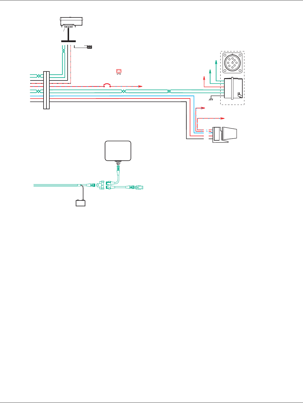
354 © 2016 Eaton. All rights reserved 2016.01.15
Wiring Diagrams | Appendix TRTS0930
Terminating
resistor
J-1939/11 data link
(OEM supplied)
GND
+_
Shield
termination
Engine ECM
Start
enable
relay
Run to start
signal from
igntion switch
10 AMP 12 volt only
manual resetting
circuit breaker10 AMP
fuse
or
J-1587 data link
30
87
86
85
Bulkhead connector
located at firewall
27
28
25
31
35
10
11
26
32
4
Transmission
ECU Connector Pins
Push Button Shift Control
Push Button Control
30-way connector
F2 F1 J3 C1 B3 Back side
of gauges
Dimmer control input
+12 volts
Battery
For transmission
Diagnostics per
SAE Standard
Run to
starter solenoid
C
D
B
F
G
A
F
9-way
A
F
J
E
G
H
D
CB
J-1939 Low
J-1939 High
Ignition Key Switch
Runs to main power lead that
feeds the ignition bus (OEM
responsible for overcurrent
protection on this line)
All OEM responsible wiring shown is "typical". Consult specific application.
(35, 30, 87) = +12 volt switched from ignition switch
(26-87) = Latch into the ECU
(27-F2, 28-F1, 10-F, 11-G) = Communication from and to the TECU
(25-J3) = Signal returns, grounds, and general OEM wiring
(4-85) = -12 volt relay source
(32-86) = +12 volt relay source
(31-C1) = +12 volt switched from TECU
Vehicle Interface Legend
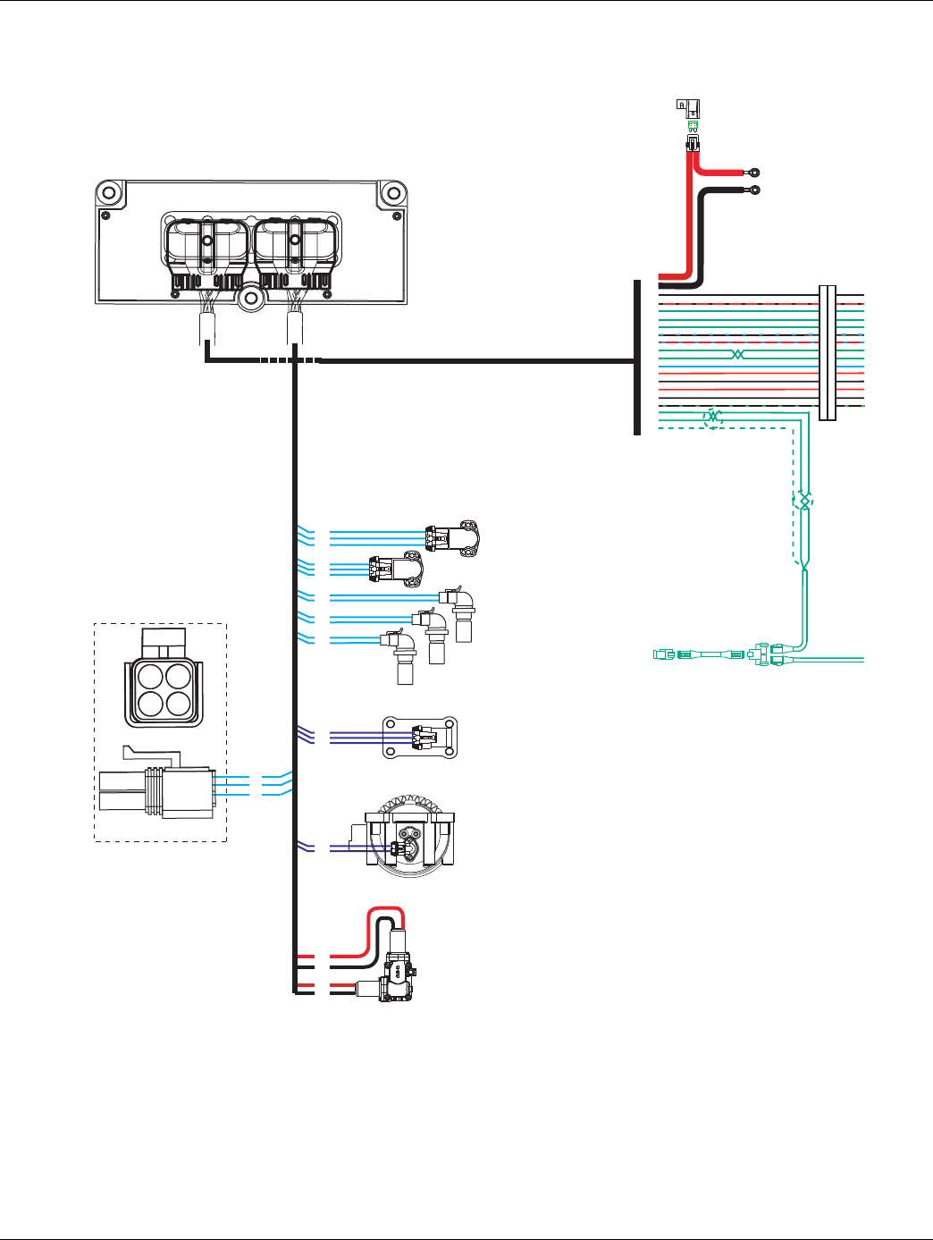
2016.01.15 © 2016 Eaton. All rights reserved 355
TRTS0930 Appendix | Wiring Diagrams
UltraShift 10-Speed Wiring Diagram with
Analog Shifter
17
31
25
C
B
A
Range
valve
Gear select
motor
Rail select
motor
Electric
shifter
A
B
A
B
Rail select
sensor
Gear select
sensor
Input shaft
speed sensor
Output shaft
speed sensor
Inertia brake (Optional)
A
B
18
19
20
10
11
12
7
8
23
24
33
5
A
B
C
A
B
C
35
37
36
38
A
B
Main shaft
speed sensor
15
16
6
34
28
30 AMP fuse
Battery power
(Non-switched power)
run to starter or Battery
Terminating
resistor
38
36
25
31
15
16
17
23
35
10
11
26
32
4
22
21
20
3
2
1
Transmission ECU
OEM
B
C
A
D
For Transmission
Diagnostics
4-way
B - Service Bat. +
C - Service Bat. -
A - Service Ignition +
B
C
A
All OEM responsible wiring shown is "typical". Consult specific application.
(38) = +12 volt non-switched from battery
(35)= +12 volt switched from ignition switch
(26) = Latch into the ECU
(15, 16, 17, 10, 11, 3, 2, 1) = Communication from and to the TECU
(36, 25) = Signal returns, grounds, and general OEM wiring
(4, 21) = -12 volt relay source
(22, 32) = +12 volt relay source
(31) = +12 volt switched from TECU
(23) = Signal from TECU
(20) = Signal into the TECU
Vehicle Interface Legend
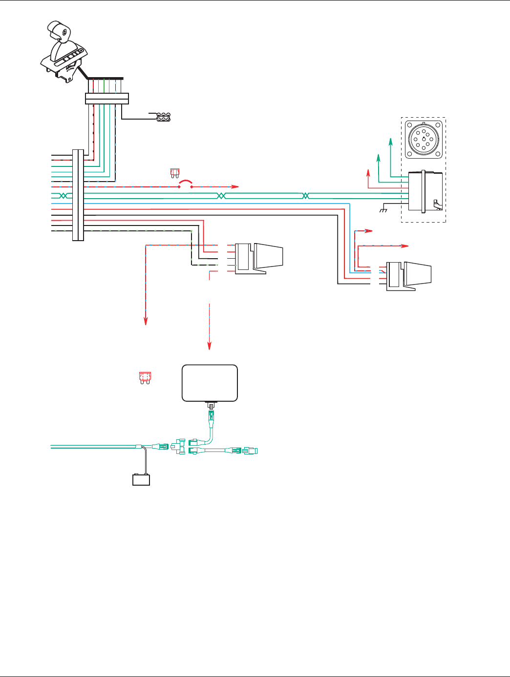
356 © 2016 Eaton. All rights reserved 2016.01.15
Wiring Diagrams | Appendix TRTS0930
All OEM responsible wiring shown is "typical". Consult specific application.
(35, 30, 87, 87a) = +12 volt switched from ignition switch
(26-87) = Latch into the ECU
(15-1, 16-8, 17-2, 10-F, 11-G) = Communication from and to the TECU
(25-3) = Signal returns, grounds, and general OEM wiring
(4-85, 21-85) = -12 volt relay source
(22-86, 32-86) = +12 volt relay source
(31-4) = +12 volt switched from TECU
(23-6) = Signal from TECU
(20-87) = Signal into TECU
Terminating
resistor
J-1939/11 data link
(OEM supplied)
GND
+_
Shield
termination
Engine ECM
Start
enable
relay
Run to start
signal from
igntion switch
10 AMP 12 volt only
manual resetting
circuit breaker
10 AMP fuse
or
J-1587 data link
30
87
86
85
Bulkhead connector
located at firewall
Back side
of gauges
Dash lights
Dimmer control input
Ignition
Interrupt
relay
30
86
85
87
87a
* Run to ignition
input on Engine
ECM
25
31
15
16
17
23
35
10
11
26
32
4
22
21
20
+12 volts
battery
Run to
starter solenoid
9-way
A
F
J
E
G
H
D
CB
C
D
B
F
G
A
J-1939 Low
J-1939 High
For Transmission
Diagnostics per
SAE Standard
Engine Power Relay
Fused 10 AMP 12 volt
manual resetting
circuit breaker
or
10 AMP
fuse
3 4 1 8 2 6 5 7
3 4 1 8 2 6 5 7
Ignition Key Switch
Runs to main power lead that
feeds the ignition bus (OEM
responsible for overcurrent
protection on this line)
Vehicle Interface Legend
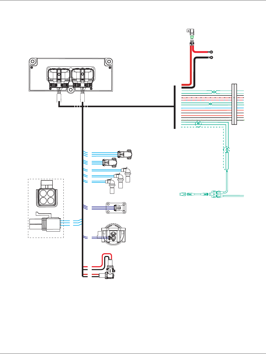
2016.01.15 © 2016 Eaton. All rights reserved 357
TRTS0930 Appendix | Wiring Diagrams
UltraShift 10-Speed Wiring Diagram with
Push Button Shifter
17
31
25
C
B
A
Range
valve
Gear select
motor
Rail select
motor
Electric
shifter
A
B
A
B
Rail select
sensor
Gear select
sensor
Input shaft
speed sensor
Output shaft
speed sensor
Inertia brake (Optional)
A
B
18
19
20
10
11
12
7
8
23
24
33
5
A
B
C
A
B
C
35
37
36
38
A
B
Main shaft
speed sensor
15
16
6
34
28
30 AMP fuse
Battery power
(Non-switched power)
run to starter or Battery
Terminating
resistor
38
36
27
28
25
31
35
10
11
26
32
4
22
21
20
3
2
1
B
C
A
D
For Transmission
Diagnostics
4-way
B - Service Bat. +
C - Service Bat. -
A - Service Ignition +
B
C
A
Transmission ECU
OEM
All OEM responsible wiring shown is "typical". Consult specific application.
(38) = +12 volt non-switched from battery
(35) = +12 volt switched from ignition switch
(26) = Latch into the ECU
(27, 28, 10, 11, 3, 2, 1) = Communication from and to the TECU
(36, 25) = Signal returns, grounds, and general OEM wiring
(4, 21) = -12 volt relay source
(22, 32) = +12 volt relay source
(31) = +12 volt switched from TECU
(20) = Signal into the TECU
Vehicle Interface Legend
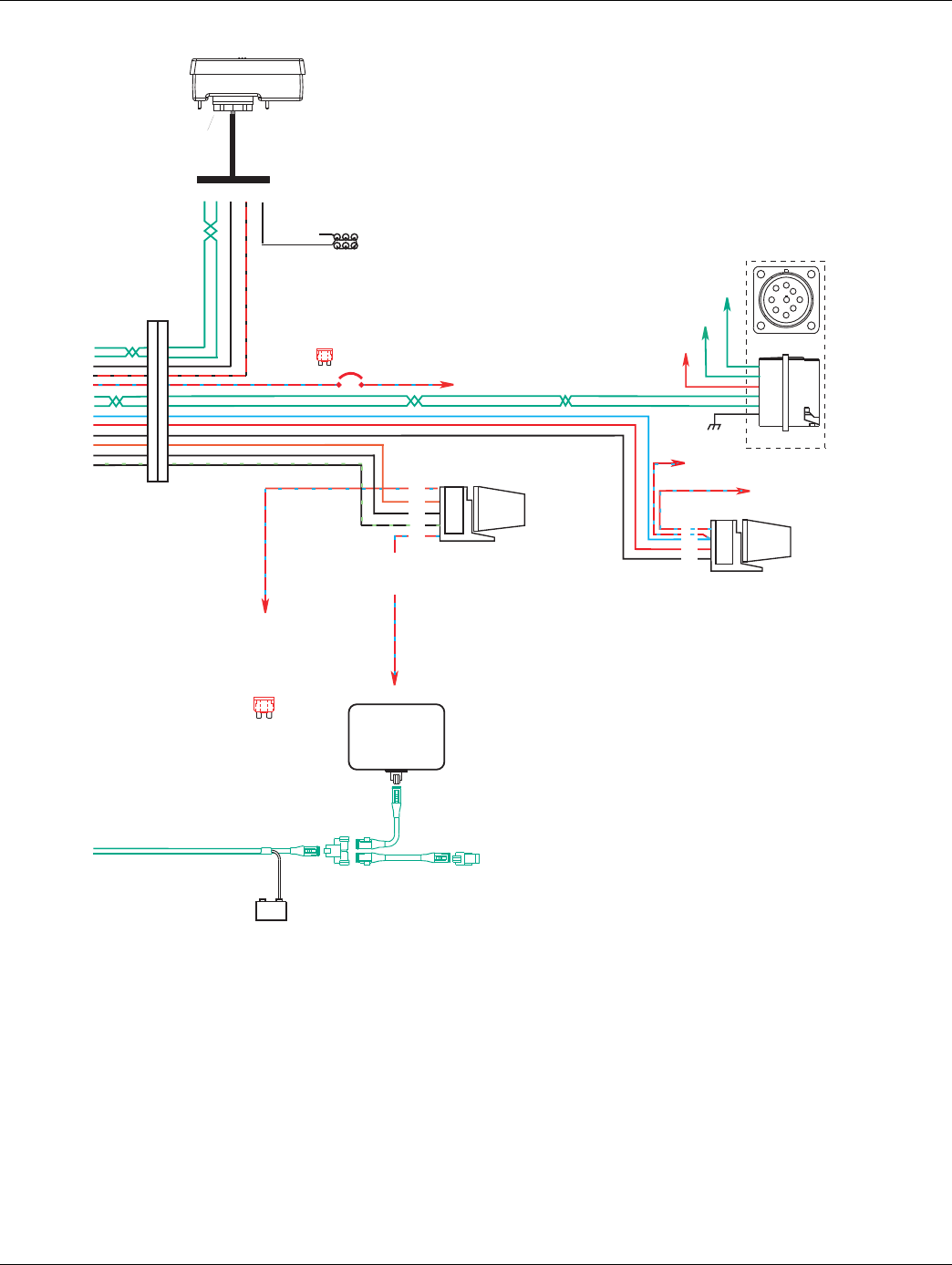
358 © 2016 Eaton. All rights reserved 2016.01.15
Wiring Diagrams | Appendix TRTS0930
Terminating
resistor
J-1939/11 data link
(OEM supplied)
GND
+_
Shield
termination
Engine ECM
Start
enable
relay
Run to start
signal from
igntion switch
10 AMP 12 volt only
manual resetting
circuit breaker
10 AMP fuse
or
J-1587 data link
30
87
86
85
Bulkhead connector
located at firewall
Back side
of gauges
Dash lights
Dimmer control input
Ignition
Interrupt
relay
30
86
85
87
87a
* Run to ignition
input on Engine
ECM
Push Button Shift Control
Push Button Control
30-way connector
F2 F1 J3 C1 B3
27
28
25
31
35
10
11
26
32
4
22
21
20
Engine Power Relay
Fused 10 AMP 12 volt
manual resetting
circuit breaker
or
10 AMP
fuse
+12 volts
battery
Run to
starter solenoid
9-way
A
F
J
E
G
H
D
CB
C
D
B
F
G
A
J-1939 Low
J-1939 High
For Transmission
Diagnostics per
SAE Standard
Ignition Key Switch
Runs to main power lead that
feeds the ignition bus (OEM
responsible for overcurrent
protection on this line)
All OEM responsible wiring shown is "typical". Consult specific application.
(35, 30, 87, 87a) = +12 volt switched from ignition switch
(26-87) = Latch into the ECU
(27-F2, 28-F1, 10-F, 11-G) = Communication from and to the TECU
(25-J3) = Signal returns, grounds, and general OEM wiring
(4-85, 21-85) = -12 volt relay source
(22-86, 32-86) = +12 volt relay source
(31-C1) = +12 volt switched from TECU
(20-87) = Signal into TECU
Vehicle Interface Legend
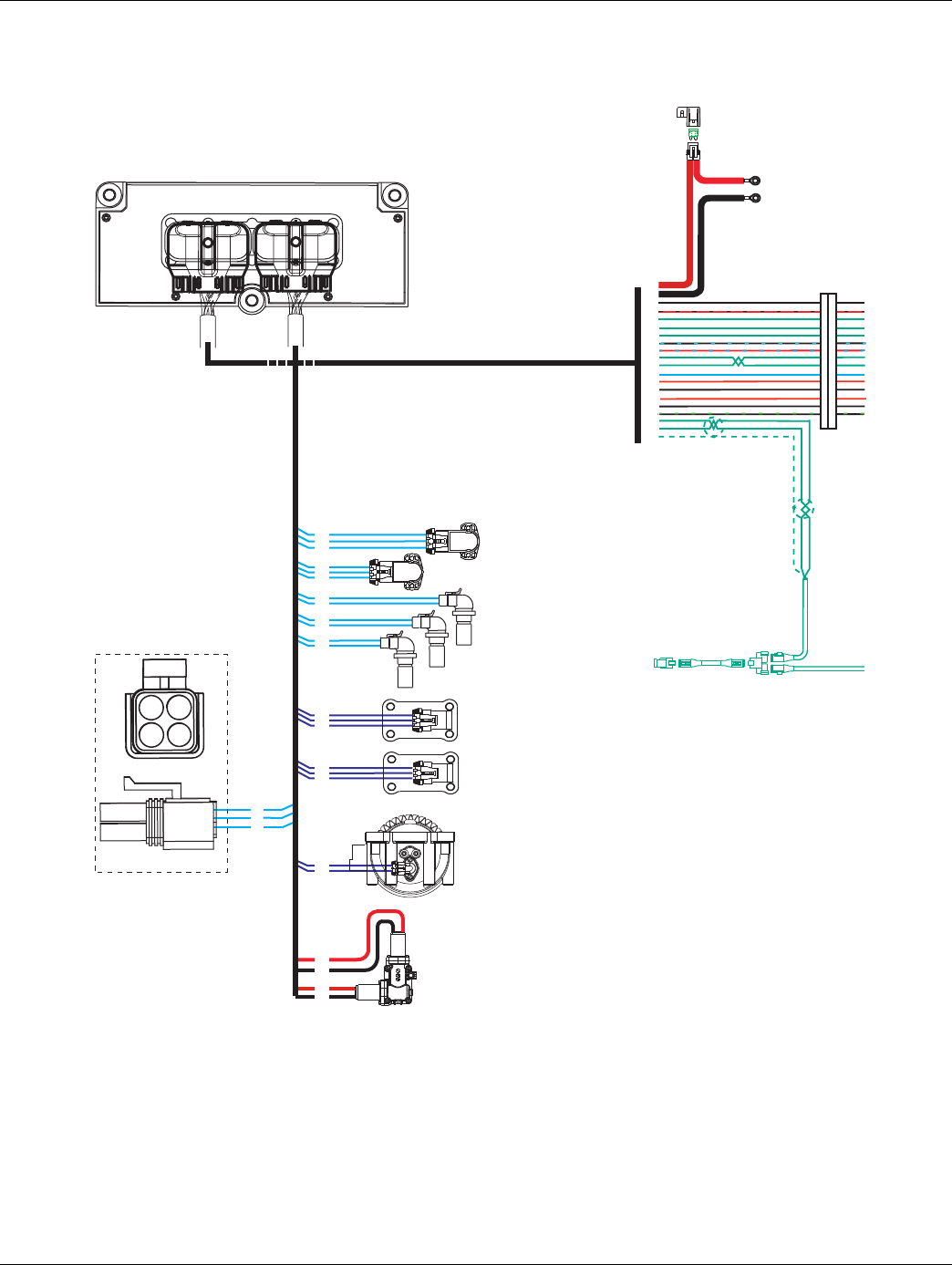
2016.01.15 © 2016 Eaton. All rights reserved 359
TRTS0930 Appendix | Wiring Diagrams
UltraShift 13-Speed Wiring Diagram with
Analog Shifter
17
31
25
C
B
A
Range
valve
Gear select
motor
Rail select
motor
Electric
shifter
A
B
A
B
Rail select
sensor
Gear select
sensor
Input shaft
speed sensor
Output shaft
speed sensor
Inertia brake
A
B
18
19
20
10
11
12
7
8
23
24
33
5
A
B
C
A
B
C
35
37
36
38
A
B
Main shaft
speed sensor
15
16
6
34
28
30 AMP fuse
Battery power
(Non-switched power)
run to starter or Battery
Terminating
resistor
38
36
25
31
15
16
17
23
35
10
11
26
32
4
22
21
20
3
2
1
C
B
A
Splitter
valve
4
32
26
Transmission ECU
OEM
B
C
A
D
For Transmission
Diagnostics
4-way
B - Service Bat. +
C - Service Bat. -
A - Service Ignition +
B
C
A
All OEM responsible wiring shown is "typical". Consult specific application.
(38) = +12 volt non-switched from battery
(35) = +12 volt switched from ignition switch
(26) = Latch into the ECU
(15, 16, 17, 10, 11, 3, 2, 1) = Communication from and to the TECU
(36, 25) = Signal returns, grounds, and general OEM wiring
(4, 21) = -12 volt relay source
(22, 32) = +12 volt relay source
(31) = +12 volt switched from TECU
(23) = Signal from TECU
(20) = Signal into the TECU
Vehicle Interface Legend
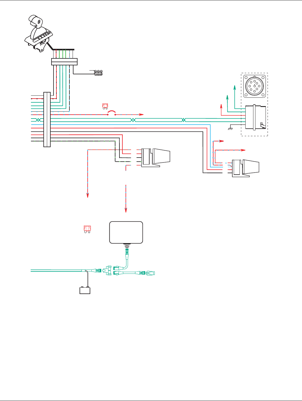
360 © 2016 Eaton. All rights reserved 2016.01.15
Wiring Diagrams | Appendix TRTS0930
Terminating
resistor
J-1939/11 data link
(OEM supplied)
GND
+_
Shield
termination
Engine ECM
Start
enable
relay
Run to start
signal from
igntion switch
10 AMP 12 volt only
manual resetting
circuit breaker
10 AMP fuse
or
J-1587 data link
30
87
86
85
Bulkhead connector
located at firewall
Back side
of gauges
Dash lights
Dimmer control input
Ignition
Interrupt
relay
30
86
85
87
87a
* Run to ignition
input on Engine
ECM
25
31
15
16
17
23
35
10
11
26
32
4
22
21
20
+12 volts
battery
Run to
starter solenoid
9-way
A
F
J
E
G
H
D
CB
C
D
B
F
G
A
F
J-1939 Low
J-1939 High
For Transmission
Diagnostics per
SAE Standard
Engine Power Relay
Fused 10 AMP 12 volt
manual resetting
circuit breaker
or
10 AMP
fuse
3 4 1 8 2 6 5 7
3 4 1 8 2 6 5 7
Ignition Key Switch
Runs to main power lead that
feeds the ignition bus (OEM
responsible for overcurrent
protection on this line)
All OEM responsible wiring shown is "typical". Consult specific application.
(35, 30, 87, 87a)= +12 volt switched from ignition switch
(26-87) = Latch into the ECU
(15-1, 16-8, 17-2, 10-F, 11-G) = Communication from and to the TECU
(25-3) = Signal returns, grounds, and general OEM wiring
(4-85, 21-85) = -12 volt relay source
(22-86, 32-86) = +12 volt relay source
(31-4) = +12 volt switched from TECU
(23-6) = Signal from TECU
(20-87) = Signal into TECU
Vehicle Interface Legend
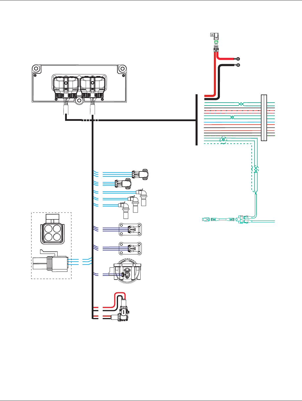
2016.01.15 © 2016 Eaton. All rights reserved 361
TRTS0930 Appendix | Wiring Diagrams
UltraShift 13-Speed Wiring Diagram with
Push Button Shifter
17
31
25
C
B
A
Range
valve
Gear select
motor
Rail select
motor
Electric
shifter
A
B
A
B
Rail select
sensor
Gear select
sensor
Input shaft
speed sensor
Output shaft
speed sensor
Inertia brake (Optional)
A
B
18
19
20
10
11
12
7
8
23
24
33
5
A
B
C
A
B
C
35
37
36
38
A
B
Main shaft
speed sensor
15
16
6
34
28
30 AMP fuse
Battery power
(Non-switched power)
run to starter or Battery
Terminating
resistor
38
36
27
28
25
31
35
10
11
26
32
4
22
21
20
3
2
1
C
B
A
Splitter
valve
4
32
26
B
C
A
D
For Transmission
Diagnostics
4-way
B - Service Bat. +
C - Service Bat. -
A - Service Ignition +
B
C
A
Transmission ECU
OEM
All OEM responsible wiring shown is "typical". Consult specific application.
(38) = +12 volt non-switched from battery
(35) = +12 volt switched from ignition switch
(26) = Latch into the ECU
(27, 28, 10, 11, 3, 2, 1) = Communication from and to the TECU
(36, 25) = Signal returns, grounds, and general OEM wiring
(4, 21) = -12 volt relay source
(22, 32) = +12 volt relay source
(31) = +12 volt switched from TECU
(20) = Signal into the TECU
Vehicle Interface Legend
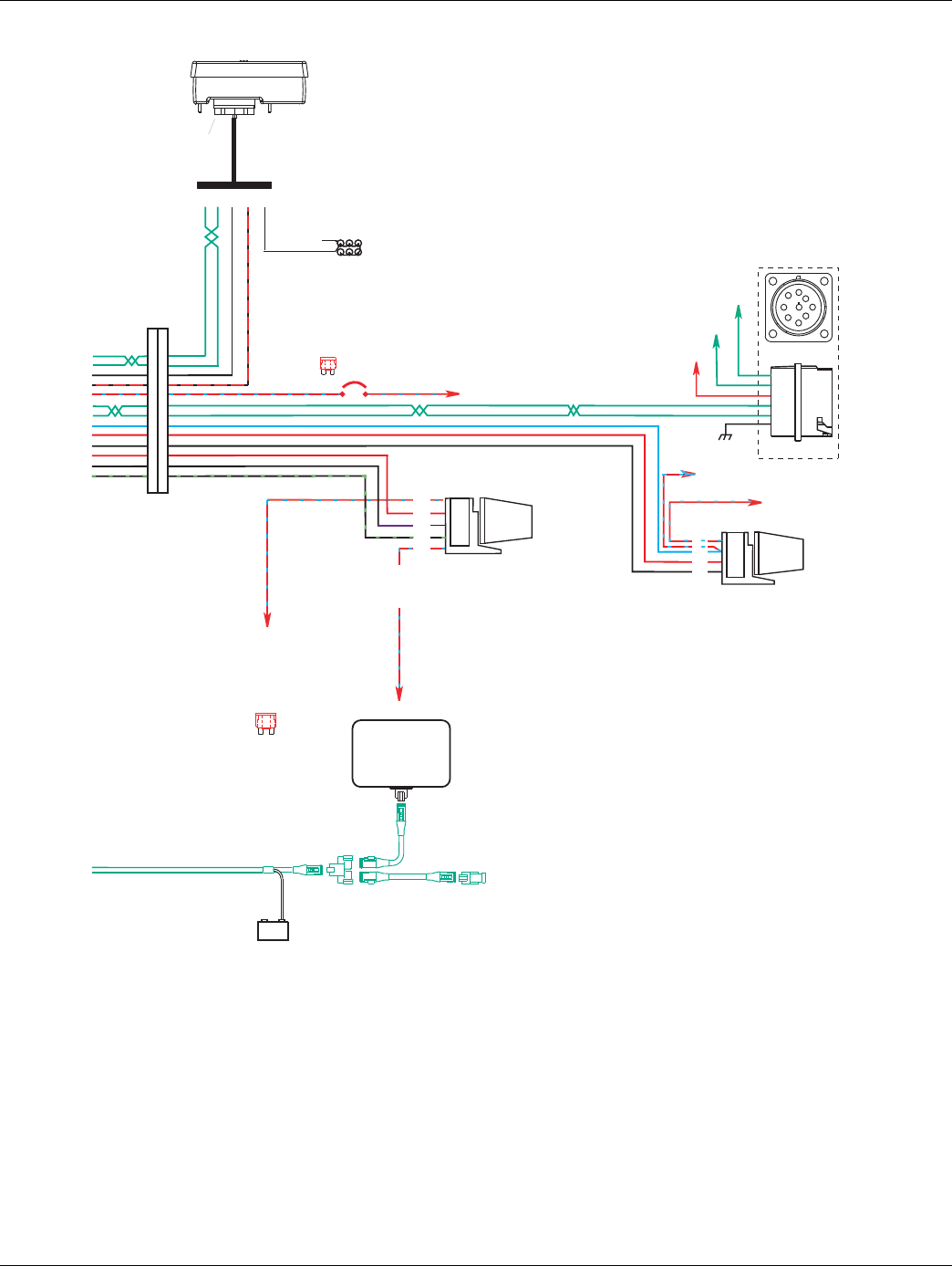
362 © 2016 Eaton. All rights reserved 2016.01.15
Wiring Diagrams | Appendix TRTS0930
Terminating
resistor
J-1939/11 data link
(OEM supplied)
GND
+_
Shield
termination
Engine ECM
Start
enable
relay
Run to start
signal from
igntion switch
10 AMP 12 volt only
manual resetting
circuit breaker
10 AMP fuse
or
J-1587 data link
30
87
86
85
Bulkhead connector
located at firewall
Back side
of gauges
Dash lights
Dimmer control input
Ignition
Interrupt
relay
30
86
85
87
87a
* Run to ignition
input on Engine
ECM
Push Button Shift Control
Push Button Control
30-way connector
F2 F1 J3 C1 B3
27
28
25
31
35
10
11
26
32
4
22
21
20
Engine Power Relay
Fused 10 AMP 12 volt
manual resetting
circuit breaker
or
10 AMP
fuse
+12 volts
battery
Run to
starter solenoid
9-way
A
F
J
E
G
H
D
CB
C
D
B
F
G
A
J-1939 Low
J-1939 High
For Transmission
Diagnostics per
SAE Standard
Ignition Key Switch
Runs to main power lead that
feeds the ignition bus (OEM
responsible for overcurrent
protection on this line)
All OEM responsible wiring shown is "typical". Consult specific application.
(35, 30, 87, 87a) = +12 volt switched from ignition switch
(26-87) = Latch into the ECU
(27-F2, 28-F1, 10-F, 11-G) = Communication from and to the TECU
(25-J3) = Signal returns, grounds, and general OEM wiring
(4-85, 21-85) = -12 volt relay source
(22-86, 32-86) = +12 volt relay source
(31-C1) = +12 volt switched from TECU
(20-87) = Signal into TECU
Vehicle Interface Legend
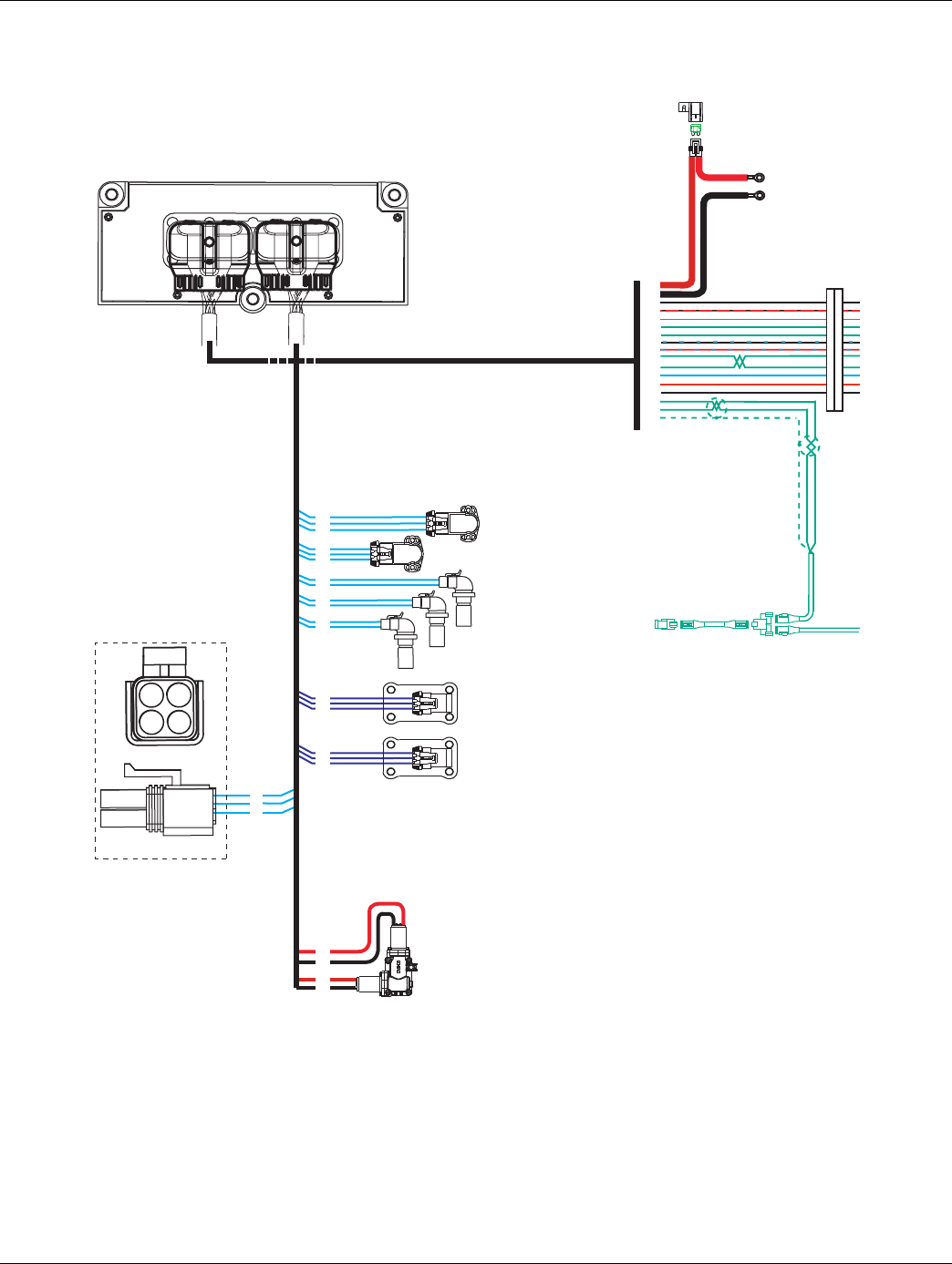
2016.01.15 © 2016 Eaton. All rights reserved 363
TRTS0930 Appendix | Wiring Diagrams
AutoShift 18-Speed Wiring Diagram with
Analog Shifter
17
31
25
C
B
A
C
B
A
Range
valve
Splitter
valve
A
B
Main shaft
speed sensor
Gear select
motor
Rail select
motor
Electric
shifter
A
B
A
B
Rail select
sensor
Gear select
sensor
Input shaft
speed sensor
Output shaft
speed sensor
18
19
20
10
11
12
7
8
23
24
A
B
C
A
B
C
30 AMP fuse
Battery power
(Non-switched power)
run to starter or Battery
Terminating
resistor
38
36
25
31
15
16
17
23
35
10
11
26
32
4
3
2
1
35
37
36
38
15
16
6
34
28
4
32
26
Transmission ECU
OEM
B
C
A
D
For Transmission
Diagnostics
4-way
B - Service Bat. +
C - Service Bat. -
A - Service Ignition +
B
C
A
All OEM responsible wiring shown is "typical". Consult specific application.
(38) = +12 volt non-switched from battery
(35) = +12 volt switched from ignition switch
(26) = Latch into the ECU
(15, 16, 17, 10, 11, 3, 2, 1) = Communication from and to the TECU
(36, 25) = Signal returns, grounds, and general OEM wiring
(4) = -12 volt relay source
(32) = +12 volt relay source
(31) = +12 volt switched from TECU
(23)
= Signal from TECU
Vehicle Interface Legend
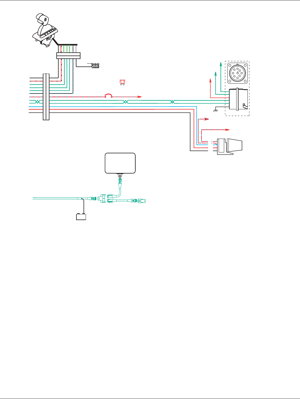
364 © 2016 Eaton. All rights reserved 2016.01.15
Wiring Diagrams | Appendix TRTS0930
Terminating
resistor
J-1939/11 data link
(OEM supplied)
GND
+_
Shield
termination
Engine ECM
Start
enable
relay
Run to start
signal from
igntion switch
Run to
starter solenoid
10 AMP 12 volt only
manual resetting
circuit breaker10 AMP
fuse
or
J-1587 data link
30
87
86
85
Bulkhead connector
located at firewall
Back side
of gauges
Dash lights
Dimmer control input
25
31
15
16
17
23
35
10
11
26
32
4
Transmission
ECU Connector Pins
3 4 1 8 2 6 5 7
3 4 1 8 2 6 5 7
+12 volts
Battery
For transmission
Diagnostics per
SAE Standard
C
D
B
F
G
A
9-way
A
F
J
E
G
H
D
CB
J-1939 Low
J-1939 High
Ignition Key Switch
Runs to main power lead that
feeds the ignition bus (OEM
responsible for overcurrent
protection on this line)
All OEM responsible wiring shown is "typical". Consult specific application.
(35, 30, 87) = +12 volt switched from ignition switch
(26-87) = Latch into the ECU
(15-1, 16-8, 17-2, 10-F, 11-G) = Communication from and to the TECU
(25-3) = Signal returns, grounds, and general OEM wiring
(4-85) = -12 volt relay source
(32-86) = +12 volt relay source
(31-4) = +12 volt switched from TECU
(23-6) = Signal from TECU
Vehicle Interface Legend
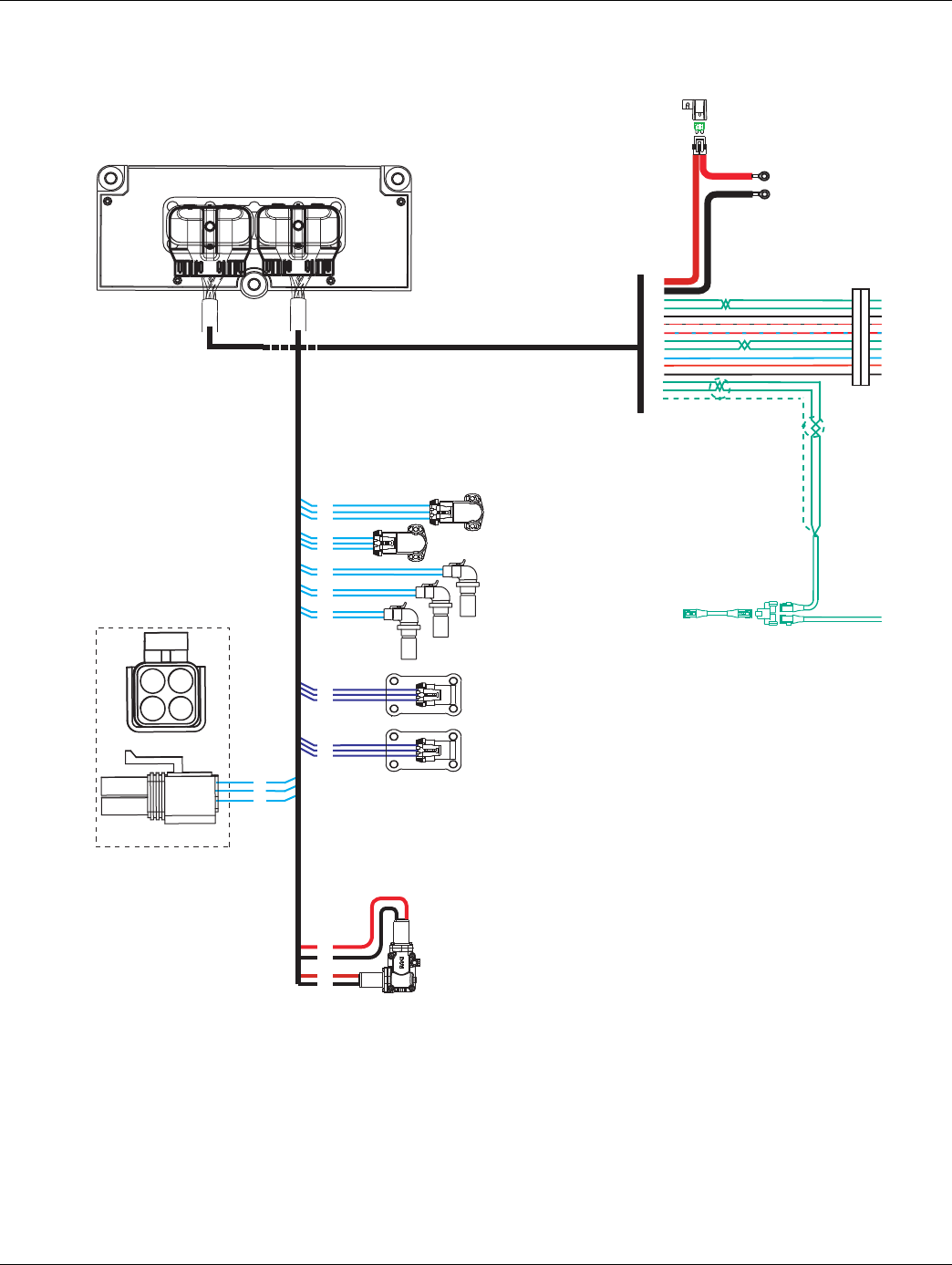
2016.01.15 © 2016 Eaton. All rights reserved 365
TRTS0930 Appendix | Wiring Diagrams
AutoShift 18-Speed Wiring Diagram with
Push Button Shifter
17
31
25
C
B
A
C
B
A
Range
valve
Splitter
valve
A
B
Main shaft
speed sensor
Gear select
motor
Rail select
motor
Electric
shifter
A
B
A
B
Rail select
sensor
Gear select
sensor
Input shaft
speed sensor
Output shaft
speed sensor
18
19
20
10
11
12
7
8
23
24
A
B
C
A
B
C
30 AMP fuse
Battery power
(Non-switched power)
run to starter or Battery
38
36
27
28
25
31
35
10
11
26
32
4
3
2
1
35
37
36
38
15
16
6
34
28
4
32
26
Terminating
resistor
B
C
A
D
For Transmission
Diagnostics
4-way
B - Service Bat. +
C - Service Bat. -
A - Service Ignition +
B
C
A
Transmission ECU
OEM
All OEM responsible wiring shown is "typical". Consult specific application.
(38) = +12 volt non-switched from battery
(35) = +12 volt switched from ignition switch
(26) = Latch into the ECU
(27, 28, 10, 11, 3, 2, 1) = Communication from and to the TECU
(36, 25) = Signal returns, grounds, and general OEM wiring
(4) = -12 volt relay source
(32) = +12 volt relay source
(31) = +12 volt switched from TECU
Vehicle Interface Legend
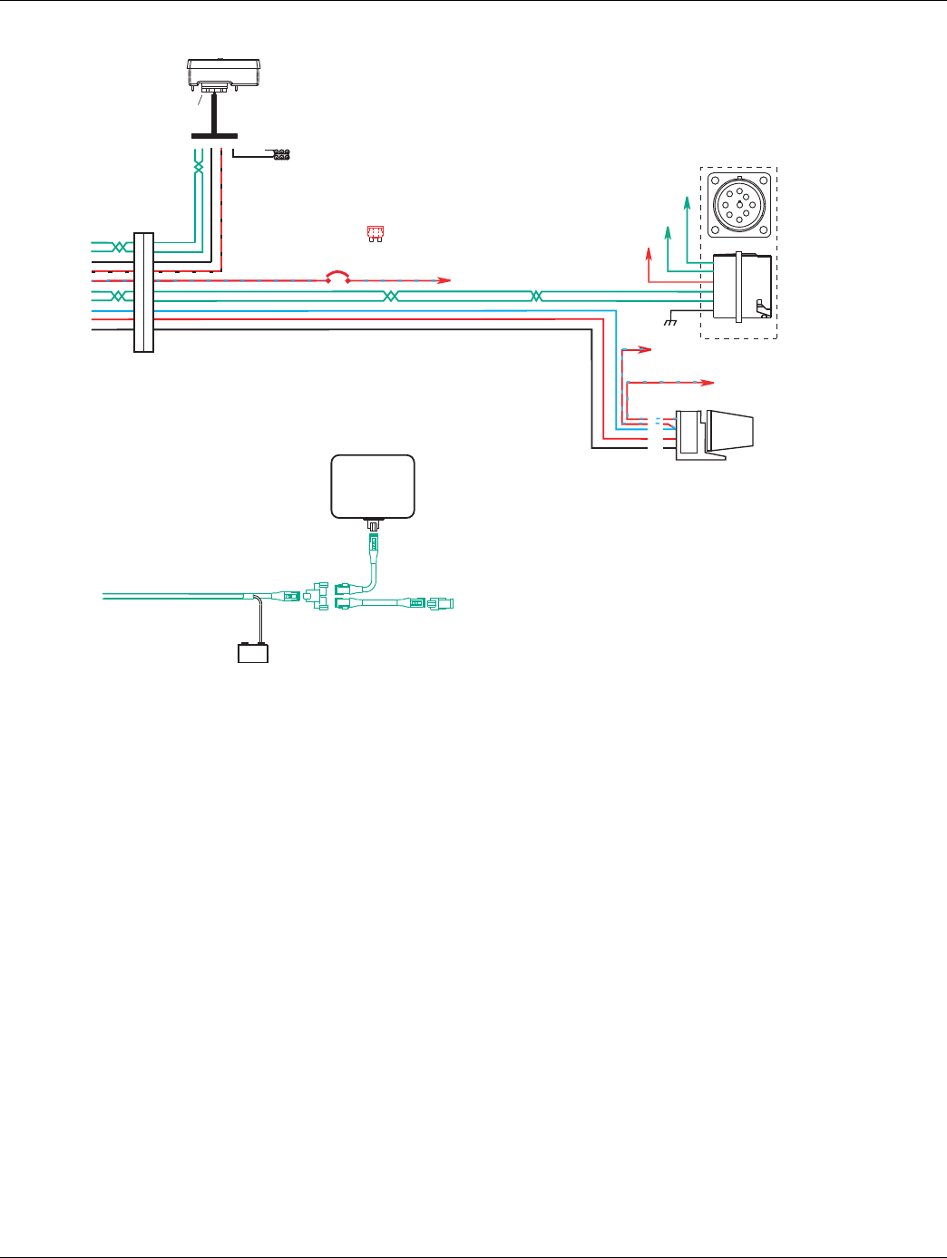
366 © 2016 Eaton. All rights reserved 2016.01.15
Wiring Diagrams | Appendix TRTS0930
Terminating
resistor
J-1939/11 data link
(OEM supplied)
GND
+_
Shield
termination
Engine ECM
Start
enable
relay
Run to start
signal from
igntion switch
10 AMP 12 volt only
manual resetting
circuit breaker10 AMP
fuse
or
J-1587 data link
30
87
86
85
Bulkhead connector
located at firewall
27
28
25
31
35
10
11
26
32
4
Transmission
ECU Connector Pins
Push Button Shift Control
Push Button Control
30-way connector
F2 F1 J3 C1 B3 Back side
of gauges
Dimmer control input
+12 volts
Battery
For transmission
Diagnostics per
SAE Standard
Run to
starter solenoid
C
D
B
F
G
A
9-way
A
F
J
E
G
H
D
CB
J-1939 Low
J-1939 High
Ignition Key Switch
Runs to main power lead that
feeds the ignition bus (OEM
responsible for overcurrent
protection on this line)
All OEM responsible wiring shown is "typical". Consult specific application.
(35, 30, 87) = +12 volt switched from ignition switch
(26-87) = Latch into the ECU
(27-F2, 28-F1, 10-F, 11-G) = Communication from and to the TECU
(25-J3) = Signal returns, grounds, and general OEM wiring
(4-85) = -12 volt relay source
(32-86) = +12 volt relay source
(31-C1) = +12 volt switched from TECU
Vehicle InterfaceLegend
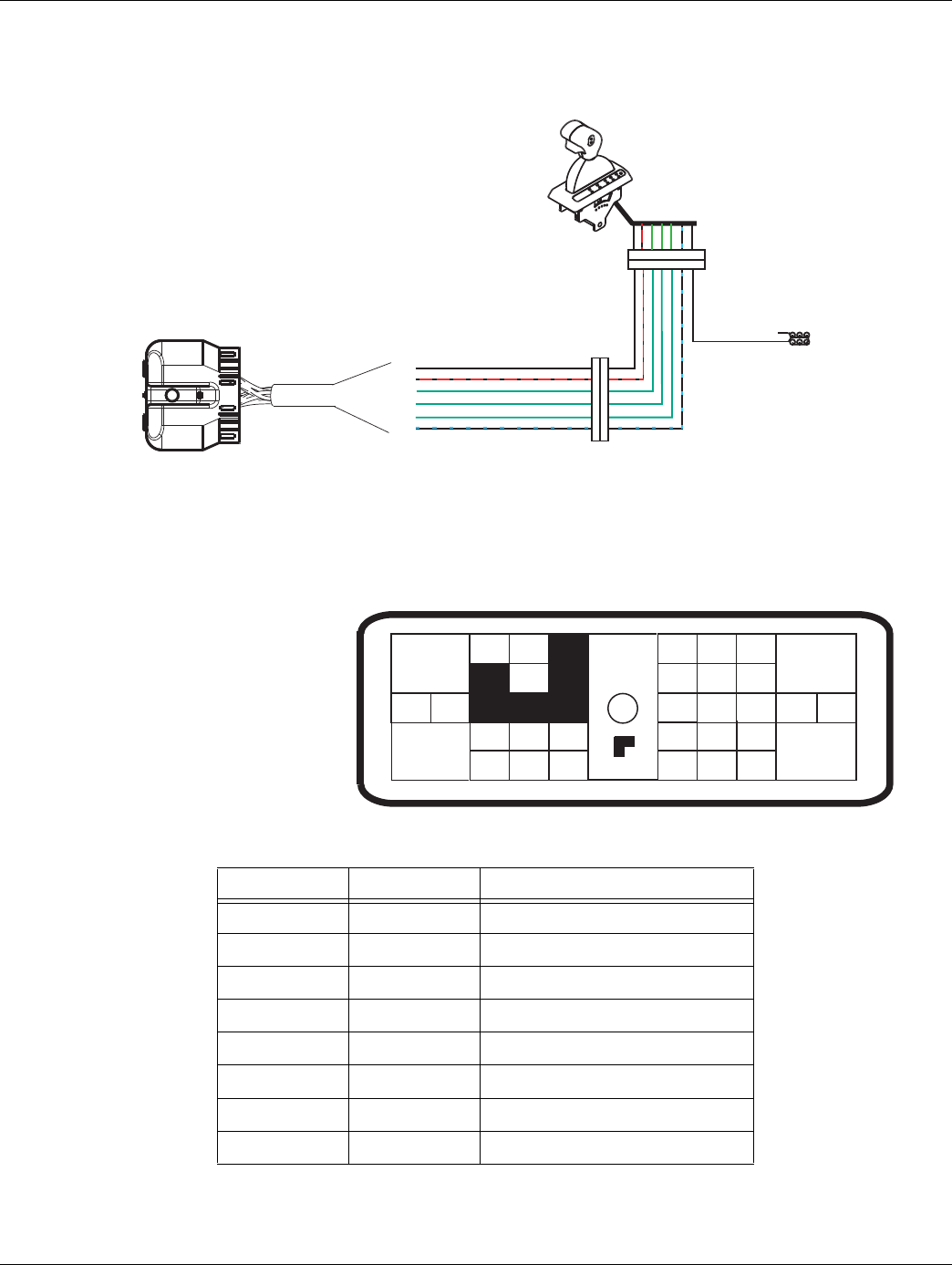
2016.01.15 © 2016 Eaton. All rights reserved 367
TRTS0930 Appendix | Wiring Diagrams
Eaton Cobra Lever Wiring Diagram
FROM TO Description
J1-15 C2-1 Shift Control Input (Mode Auto)
J1-17 C2-2 Shift Control Input (Mode Common)
J1-25 C2-3 Shift Control Power Minus
J1-31 C2-4 Shift Control Power Plus
C2-5 Dash Lights
J1-23 C2-6 Service Light Output
J1-16 C2-8 Shift Control Input (Mode Manual)
C2-7 No Connection
25
31
15
16
17
23
31
24 25
29 30
15 16
26
20
34
27 28
32 33
18 19
7
3
89
126
11 12
4 5
22
21
38
36
37
13 14
35 10
17
23
Front View
Transmission ECU Connector
Transmission ECU Connector
J1
C2
Bulkhead connector
located at firewall
3 4 1 8 2 6 5 7
3 4 1 8 2 6 5 7
Back side
of gauges
Dash lights
Dimmer control input
(Vehicle Interface)
All OEM responsible wiring shown is "typical". Consult specific application.
(31-4) = +12 volt switched from TECU
(15-1, 16-8, 17-2) = Communication from and to the TECU
(25-3, 5) = Signal returns, grounds, and general OEM wiring
(23-6) = Signal from TECU
Trans Control ECU Legend
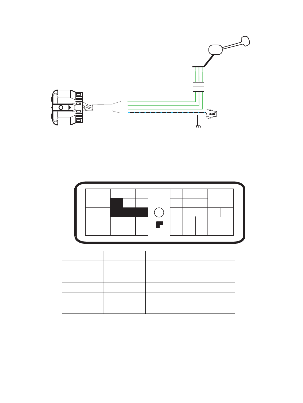
368 © 2016 Eaton. All rights reserved 2016.01.15
Wiring Diagrams | Appendix TRTS0930
OEM Shift Lever Wiring Diagram
FROM TO Description
J1-15 F2-B Shift Control Input (Mode Auto)
J1-16 F2-A Shift Control Input (Mode Manual)
J1-17 F2-C Shift Control Input (Mode Common)
J1-23 F3-A Service Lamp Output
F3-B Ground
15
16
17
23
B A C
B A C
OEM Shift Lever
Service Lamp
Connector
J1
31
24 25
29 30
15 16
26
20
34
27 28
32 33
18 19
7
3
89
126
11 12
4 5
22
21
38
36
37
13 14
35 10
17
23
Front View
Transmission ECU Connector
Transmission ECU Connector
(Vehicle Interface)
All OEM responsible wiring shown is "typical". Consult specific application.
(15-B, 16-A, 17-C) = Communication to and from the TECU
(23) = Signal from TECU
Vehicle Interface Legend
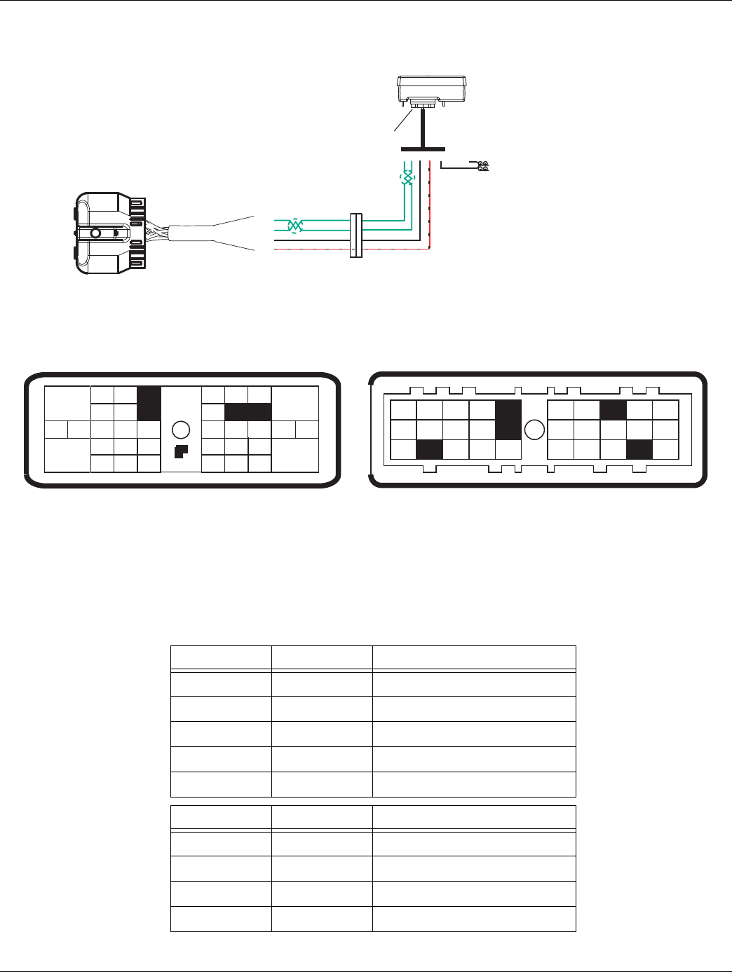
2016.01.15 © 2016 Eaton. All rights reserved 369
TRTS0930 Appendix | Wiring Diagrams
Eaton Push Button Wiring Diagram
FROM TO Description
J1-27 C2-F2 HIL(-) LO
J1-28 C2-F1 HIL(+) HI
J1-25 C2-J3 Shift Control Power Minus
J1-31 C2-C1 Shift Control Power Plus
C2-B3 Dimmer Control Input
FROM TO Description
J1-D1 C2-1 RNDHL
J1-D3 C2-2 COMMON
--------- C2-3 GROUND
J1-J2 C2-4 SPLICE into TRANS BATT 1
27
28
25
31
31
24 25
29 30
15 16
26
20
34
27 28
32 33
18 19
7
3
89
126
11 12
4 5
22
21
38
36
37
13 14
35 10
17
23
Front View
Transmission ECU Connector
(Vehicle Interface)
J1
Dimmer control input
Push Button Shift Control
Push Button Control
30-way connector
C2
F 2 F 1 J 3 C 1 B 3
Bulkhead connector
located at firewall
A1
A2
A3
B1
B3C3
D1
D2
D3
E1
E2
E3F3
H1
H2
H3
Front View
Shift Control (30-Way Connector)
B2C2
K3
J1K1
K2
G1
G2
G3
J2
C1
J3
F2
F1
Transmission ECU Connector
(Vehicle Interface)
All OEM responsible wiring shown is "typical". Consult specific application.
(31-C1) = +12 volt switched from TECU
(27-F2, 28-F1) = Communication from and to the TECU
(25-J3) = Signal returns, grounds, and general OEM wiring
Vehicle Interface Legend
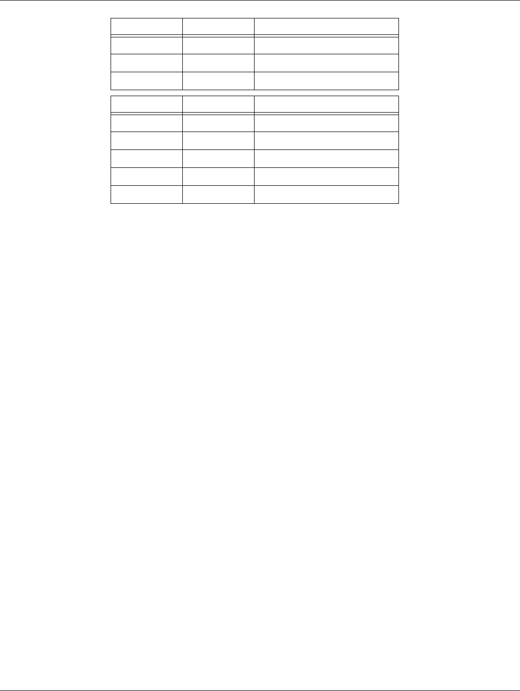
370 © 2016 Eaton. All rights reserved 2016.01.15
Wiring Diagrams | Appendix TRTS0930
J1-B3 C2-5 DIMMER CONTROL
J1-H2 C2-6 SERVICE LAMP
J1-D2 C2-8 MANUAL MODE
FROM TO Description
J1-27 C2-F2 EPL- LO
J1-28 C2-F1 EPL+ HI
J1-25 C2-J3 Ground 1
J1-31 C2-C1 Ignition
C2-B3 Dimmer Control Input
FROM TO Description
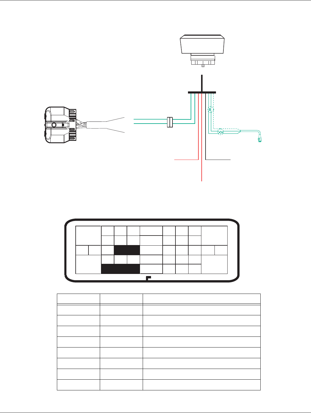
2016.01.15 © 2016 Eaton. All rights reserved 371
TRTS0930 Appendix | Wiring Diagrams
OEM J1939 Shift Input Device Wiring
Diagram
FROM TO Description
J1-16 Connector C2 Shift Control Input (Neutral Request Signal)
J1-17 Connector C2 Shift Control Input (Neutral Request Return)
OEM Connector C2 Shift Control Power Minus (Ground)
OEM Connector C2 Shift Control Power Plus (Ignition)
OEM Connector C2 Shift Control Power Plus (Battery)
Connector C2 OEM J1939 High
OEM Connector C2 J1939 Low
OEM Connector C2 J1939 Shield
23
17
31
24 25
29 30
15 16
26
20
34
27 28
32 33
18 19
78 9
2
10
6
11 12
4 5
2221
38
36
37
13 14
35
13
Transmission ECU Connector
(Vehicle Interface)
Front View
J1
OEM J1939 Shift Device
Bulkhead connector
located at firewall
J1939
Transmission ECU Connector
(Vehicle Interface)
16
17
Switched Power
Ground
Battery Power (Non-switched power
run to Battery or Starter)

372 © 2016 Eaton. All rights reserved 2016.01.15
Proper Clutch Operation | Appendix TRTS0930
Proper Clutch Operation
When performing the test for proper clutch operation, the
vehicle should be in the same condition as when the prob-
lem occurred. For instance, if the problem only occurs
when the vehicle is hot, drive the vehicle to warm it up
before conducting the test.
When the operator depresses the clutch pedal and shifts
from neutral to drive or reverse, the Transmission Elec-
tronic Control Unit (TECU) waits for the transmission input
shaft speed to decrease to less than 150 RPM before shift-
ing the transmission into gear. If the clutch is not disengag-
ing completely or the clutch brake is not functioning
properly, the input shift will not slow down and the trans-
mission will not shift into gear.
Check For Proper Clutch Operation
Note: Refer to publication CLSM0200.
With PC-Base Service Tool
1. Connect ServiceRanger a PC-based Service Tool.
2. Make sure the transmission is in neutral
3. Start engine.
4. Set ServiceRanger a PC-based Service Tool to
monitor input shaft speed.
5. With Clutch pedal up (clutch engaged), compare
input shaft speed and engine speed (RPM). They
should be the same.
Note: If engine speed and input shaft speeds are not the
same, then perform input shaft speed sensor test and
confirm proper clutch adjustment.
6. Check clutch for slippage, and repair or replace as
needed.
7. Depress clutch pedal to active clutch brake. Within
2 seconds, input shaft speed should be less than
25 RPM (0 RPM is desired). If input shaft does not
stop turning, the clutch is not disengaging com-
pletely or the clutch brake is not functioning prop-
erly.
8. Check for proper clutch adjustment, adjust as nec-
essary.
9. Inspect clutch brake for excessive friction material
wear or internal damage. Replace as necessary.
Note: The clutch brake may have to be removed to inspect
properly.
10. If clutch adjustment is correct and clutch brake
appears satisfactory, the problem may be a defec-
tive clutch. The clutch may require repair or
replacement. Refer to the clutch manufacturer’s
service information to verify a dragging clutch.
Without ServiceRanger a PC-based Service Tool
1. Place transmission in neutral.
2. Start engine.
3. Let up on the clutch pedal (clutch engaged).
4. Depress clutch pedal fully to activate clutch brake
and hold for 2 seconds.
5. Place transmission in starting gear.
6. If starting gear display shows a solid gear
(engaged), the procedure is complete. If the gear
display shows a flashing gear (not yet engaged)
continue on to number 7.
7. If flashing gear is displayed, slowly release the
clutch pedal.
8. If flashing gear does not become solid or gear does
not engage, check clutch brake for proper function
and check clutch adjustment.
9. If gear does not engage and clutch is adjusted
properly, troubleshoot for a dragging clutch
according to clutch manufacturer.
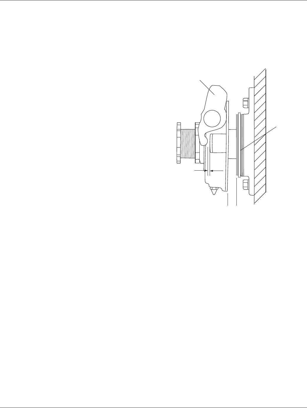
2016.01.15 © 2016 Eaton. All rights reserved 373
TRTS0930 Appendix | Proper Clutch Operation
Confirm Proper Clutch Adjustment and
Clutch Brake Contact
Confirm Release Bearing Travel Gap
Use a 1/2” gauge to verify the release bearing travel gap.
This gap (distance between the rear of the release bearing
and the clutch brake) must be between 1/2” and 9/16”.
If this dimension is incorrect, adjust the clutch per the
clutch manufacturer’s instructions.
Confirm the Free-Play gap*
*For mechanical clutch release systems with free-play.
Use a 1/8” gauge to verify proper free-play gap on Easy
Pedal.
If this dimension is incorrect, adjust the clutch per the
clutch manufacturer’s instructions.
Confirm Proper Clutch Brake Contact
Insert a 0.010” feeler gauge between the release bearing
and the clutch brake have an assistant fully depress the
clutch pedal. The 0.010” feeler gauge should be squeezed
between the rear of the release bearing and the clutch
brake. Have the assistant slowly let up the clutch pedal. The
0.010” feeler gauge should slide out when the clutch pedal
is 1/2” to 1” above the cab floor or lower pedal stop.
If the 0.010” feeler gauge is not adequately squeezed to
prevent removal, or can be removed with the pedal less
than 1/2” or greater than 1”, check and adjust the clutch
pedal height and travel per the chassis manufacturer’s
instructions. In addition, check the external clutch linkage
for excessive wear or obstruction preventing complete
travel.
Release
yoke
Clutch
brake
1/8"

374 © 2016 Eaton. All rights reserved 2016.01.15
Proper Clutch Operation | Appendix TRTS0930
Clutch Grease Interval Service Procedure
Clutch Greasing Guidelines
It is highly important to follow proper clutch lube intervals
as specified in Lubrication Manual, TCMT0021. Failure to
do so may result in clutch failure and unnecessary repairs.
For more detailed cross-shaft greasing information refer to
the “Release Yoke and Cross-shaft(s) Installation” section
of this manual. Refer to Clutch Service Manual, CLSM0200,
for release bearing greasing information.
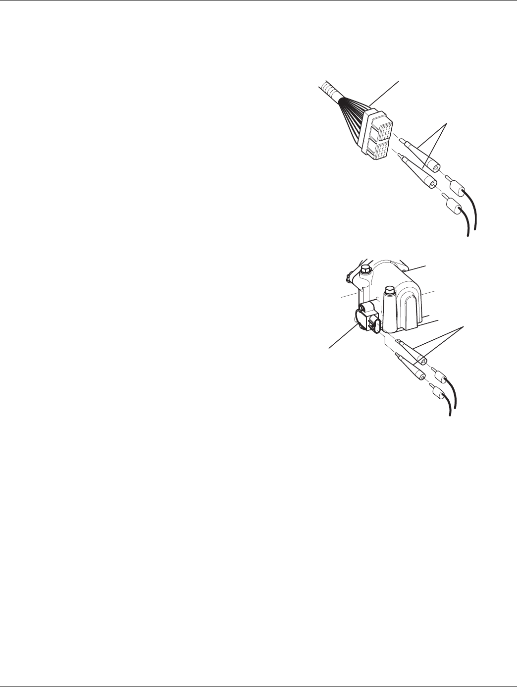
2016.01.15 © 2016 Eaton. All rights reserved 375
TRTS0930 Appendix | Adapter Test Kit J43318
Adapter Test Kit J43318
Note: Use extreme caution when inserting adapters into the
connectors to avoid spreading or distorting of the
terminals.
Gray Adapters
Gray adapter are to only be used for the following connec-
tors:
• Shift Control 30-way connector
• Speed Sensors
• Position Sensors
• Range Solenoid Valve
• Splitter Solenoid Valve
Green and Brown Adapters
Green and brown adapters are to only be used for the fol-
lowing connectors:
• Vehicle interface 38-way connector
• Transmission Electronic Control Unit (TECU)
38-way connector
Purple Adapters
Purple adapter are to only be used for the following connec-
tors:
• Motors
•Main Power
• Inertia Brake
Adapter Pins
Use the male adapter to test the harness pins.
Use the female adapter to test the component pins.
Harness
Male adapters
Component
Female adapters

Eaton
1111 Superior Ave.
Cleveland, OH 44114
Copyright Eaton 2016.
Eaton hereby grant their customers,
vendors, or distributors permission to
freely copy, reproduce and/or distribute
this document in printed format. It may
be copied only in its entirety without any
changes or modifications. THIS INFOR-
MATION IS NOT INTENDED FOR SALE
OR RESALE, AND THIS NOTICE MUST
REMAIN ON ALL COPIES.
Note: Features and specifications listed
in this document are subject to change
without notice and represent the maxi-
mum capabilities of the software and
products with all options installed.
Although every attempt has been made
to ensure the accuracy of information
contained within, Eaton makes no repre-
sentation about the completeness, cor-
rectness or accuracy and assumes no
responsibility for any errors or omis-
sions. Features and functionality may
vary depending on selected options.
For spec’ing or service assistance,
call 1-800-826-HELP (4357) or visit
www.eaton.com/roadranger.
In Mexico, call 001-800-826-4357.
Roadranger: Eaton and trusted partners
providing the best products and ser-
vices in the industry, ensuring more
time on the road.
Eaton
Vehicle Group
P. O . B o x 4 0 1 3
Kalamazoo, MI 49003 USA
800-826-HELP (4357)
www.eaton.com/roadranger
Printed in USA
