EtherCAT User Guide Ecat
User Manual: Ecat-User-Guide
Open the PDF directly: View PDF ![]() .
.
Page Count: 108 [warning: Documents this large are best viewed by clicking the View PDF Link!]

16-01450
Revision 00
December 21, 2015
EtherCAT
User Guide
Important:
The contents of this manual are valid from the firmware versions listed below:
AEM:
AE2:
BEL:
BE2:
SEM:
SE2:
TEL:
TE2:
XEL:
XE2:
Trademarks:
EtherCAT is a registered trademark and patented technology,
licensed by Beckhoff Automation GmbH, Germany
Windows is a registered trademark of Microsoft Corporation
Copley ASCII Interface, Copley Virtual Machine, CVM, Accelnet, Xenus, Stepnet,
and CME 2 are registered trademarks of Copley Controls.
Other designations used in this publication may be trademarks whose use by third parties for
their own purposes could violate the rights of the owners. No part of this document may be
reproduced in any form or by any means, electronic or mechanical, including photocopying,
without express written permission of Copley Controls.

EtherCAT User Guide 16-01450 Rev 00
Page 3
TABLE OF CONTENTS
1 About This Manual ........................................................................................................................................................ 7
1.1 Title, Number, Revision ........................................................................................................................ 7
1.2 Revision History ................................................................................................................................... 7
1.3 Overview and Scope ............................................................................................................................ 7
1.4 Comments ............................................................................................................................................ 7
1.5 Document Validity ................................................................................................................................ 7
1.6 Copley Controls EtherCAT Plus Servo & Stepper Drives .................................................................... 8
2 Related Documentation ................................................................................................................................................ 9
1.1 References ......................................................................................................................................... 10
2.1.1 Common Abbreviations .......................................................................................................... 11
2.1.2 Network Abbreviations ............................................................................................................ 12
3 Introduction to EtherCAT .............................................................................................................................................13
3.1 EtherCAT Technology Group (ETG) .................................................................................................. 13
3.2 Standards for EtherCAT and CoE...................................................................................................... 13
3.3 EtherCAT Overview ........................................................................................................................... 14
3.3.2 EtherCAT Slave Devices (Copley EtherCAT drives) .............................................................. 15
3.3.3 CANopen, EtherCAT, and CoE .............................................................................................. 15
3.4 Elements of an EtherCAT Network .................................................................................................... 16
3.4.1 EtherCAT Master Software ..................................................................................................... 16
3.4.2 EtherCAT Master Stacks ........................................................................................................ 16
3.4.3 EtherCAT Configuration Tool .................................................................................................. 16
3.4.4 EtherCAT Physical Layer ........................................................................................................ 16
3.4.5 EtherCAT Slave Controllers (ESC) ......................................................................................... 16
3.4.6 EtherCAT EEPROM ............................................................................................................... 16
3.4.7 Application Layer Host Controller (a Copley EtherCAT Plus drive) ........................................ 17
3.4.8 ESI (EtherCAT Slave Information) File ................................................................................... 17
3.4.9 Cabling and Connectivity ........................................................................................................ 17
3.5 States ................................................................................................................................................. 17
3.5.1 Synchronization & Distributed Clocks (DC) ............................................................................ 18
3.6 Inside the EtherCAT Drive ................................................................................................................. 19
3.6.1 From the Network to the Drive ................................................................................................ 19
3.6.2 EtherCAT Network Slaves Don’t Think ................................................................................... 19
3.6.3 EtherCAT Time ....................................................................................................................... 20
3.6.4 Synchronization Overview ...................................................................................................... 20
Freerun ............................................................................................................................................ 20
Sync-Manager Synchronization ....................................................................................................... 20
Distributed Clocks (DC) ................................................................................................................... 20
Control System Timing and Process Data ....................................................................................... 20
3.7 EtherCAT Data ................................................................................................................................... 21
Fixed PDOs ...................................................................................................................................... 21
Fixed RxPDOs ................................................................................................................................. 21
Fixed TxPDO ................................................................................................................................... 21
Not-Fixed, or User Programmable PDOs ........................................................................................ 22
Un-Fixed RxPDOs ........................................................................................................................... 22
Un-Fixed TxPDOs ............................................................................................................................ 22
3.8 EtherCAT System Architectures ........................................................................................................ 23
Masters that Use ESI Files .............................................................................................................. 23
Masters That Don’t Use ESI Files .................................................................................................... 24
4 Setting Up for EtherCAT ..............................................................................................................................................25
AC Drive EtherCAT Connectors ...................................................................................................... 25
DC Drive EtherCAT Connectors ...................................................................................................... 25
4.1 EtherCAT Cabling .............................................................................................................................. 25
4.2 Indicators: EtherCAT LEDs ................................................................................................................ 26
4.3 Device ID Switches & Station Alias ................................................................................................... 26
4.4 Drive Axis Indicators .......................................................................................................................... 27
Latching Faults ................................................................................................................................. 27
4.5 Drive Wiring........................................................................................................................................ 27

EtherCAT User Guide 16-01450 Rev 00
Page 4
5 Configuring Drives for EtherCAT ................................................................................................................................28
5.1 Serial RS-232 Connections ................................................................................................................ 28
Serial Connection: Xenus AC Powered Drives ................................................................................ 28
Serial Connection: Accelnet & Stepnet DC Powered Drives ........................................................... 28
EtherCAT Connections .................................................................................................................... 29
5.2 CME2 Installation for EtherCAT ......................................................................................................... 29
Download CME2 .............................................................................................................................. 29
Configure the drive for EtherCAT operation .................................................................................... 30
Motor Set Up .................................................................................................................................... 31
Enable the drive for EtherCAT control ............................................................................................. 32
Download ESI (EtherCAT Slave Information) Files ......................................................................... 33
6 EtherCAT Quick Starts .................................................................................................................................................35
6.1 Beckhoff TwinCAT 3 .......................................................................................................................... 35
Introduction ...................................................................................................................................... 35
TwinCAT3 Software ......................................................................................................................... 35
TC3-Full-Setup ................................................................................................................................. 37
Install ESI Files ................................................................................................................................ 40
Confirm that TwinCAT 3 is the Active Runtime ............................................................................... 40
Assign an Ethernet Port on Your Computer to EtherCAT ............................................................... 40
Running TwinCAT 3 ......................................................................................................................... 41
The New Project Screen .................................................................................................................. 42
Setting Up the NC Controller ........................................................................................................... 47
Encoder Scaling Factor.................................................................................................................... 47
NC Axis Settings .............................................................................................................................. 48
System Real-Time Settings ............................................................................................................. 50
RT Kernel Time-Base Stability ......................................................................................................... 52
RT Kernel Check #1 ......................................................................................................................... 53
RT Kernel Check #2:........................................................................................................................ 53
Activating the Configuration ............................................................................................................. 54
NC: Online ....................................................................................................................................... 54
NC: Manual Control ......................................................................................................................... 55
Jogging ............................................................................................................................................ 55
Single Move: Target Position ........................................................................................................... 56
Single Move: Target Velocity ........................................................................................................... 56
Single Move: Acceleration/Deceleration .......................................................................................... 56
NC: Setting Absolute Position to Zero ............................................................................................. 56
NC: Out/Back Repeating Positions .................................................................................................. 57
Switching Runtime with TwinCAT 2 ................................................................................................. 58
6.2 Beckhoff TwinCAT 2 .......................................................................................................................... 63
Introduction ...................................................................................................................................... 63
Step 1: Configure the Drive for EtherCAT Operation ...................................................................... 63
Step 2: Download the ESI (XML) File from the Copley web-site ..................................................... 63
Step 3: Assign an Ethernet Port on Your Computer to EtherCAT ................................................... 63
Step 4: Download the TwinCAT 2 Software and Install It ................................................................ 64
Language selection .......................................................................................................................... 64
Click-through EULA ......................................................................................................................... 64
After Welcome, Accept .................................................................................................................... 65
Name & Company Entry .................................................................................................................. 65
Installation Level Selection .............................................................................................................. 66
Version Selection ............................................................................................................................. 66
Feature Selection ............................................................................................................................. 67
TwinCAT 2 Destination Folder ......................................................................................................... 67
Restart Prompt ................................................................................................................................. 68
Restart ............................................................................................................................................. 68
System Properties ............................................................................................................................ 69
System Properties ............................................................................................................................ 69
Check ESI File Installation ............................................................................................................... 70
Installation Is Complete.................................................................................................................... 70
Open A New File And Scan For Devices ......................................................................................... 71

EtherCAT User Guide 16-01450 Rev 00
Page 5
Devices Found And Link To Nc Controllers ..................................................................................... 72
Data Linkage In TwinCAT 2 ............................................................................................................. 73
TwinCAT NC Axis ............................................................................................................................ 73
Xenus Plus XEL Drive...................................................................................................................... 73
NC Configuration ............................................................................................................................. 74
NC Units ........................................................................................................................................... 74
NC Velocity And Fault Configurations ............................................................................................. 75
Online Operation Of The NC ........................................................................................................... 76
Enable The Drive ............................................................................................................................. 76
Jogging ............................................................................................................................................ 77
Enable The Drive ............................................................................................................................. 77
Simple Motion Without A PLC In TwinCAT 2................................................................................... 78
Simple Motion Without A PLC In TwinCAT 2 (cont’d) ..................................................................... 79
What Next??? .................................................................................................................................. 80
Beckhoff ........................................................................................................................................... 80
6.3 Delta-Tau Power PMAC ..................................................................................................................... 81
Introduction ...................................................................................................................................... 81
IDE Installation ................................................................................................................................. 81
ESI (XML) Files ................................................................................................................................ 82
Launch the Power PMAC IDE ......................................................................................................... 82
Local Network Configuration ............................................................................................................ 83
Updating Firmware ........................................................................................................................... 84
Start a new PMAC project ............................................................................................................... 85
Reset the Power PMAC ................................................................................................................... 85
System Setup ................................................................................................................................... 86
Create a New Setup ......................................................................................................................... 86
Reset All Masters and Scan for New Devices on the EtherCAT Network ....................................... 87
Set System Clock Frequencies ........................................................................................................ 87
Update Device Files ......................................................................................................................... 88
Configure Master[0] ......................................................................................................................... 89
Amplifiers Set Up ............................................................................................................................. 89
General Tab ..................................................................................................................................... 89
DC Tab ............................................................................................................................................. 90
Startup Tab ...................................................................................................................................... 91
1-Axis Drives .................................................................................................................................... 91
2-Axis Drives .................................................................................................................................... 91
Input PDO Configuration: 1-Axis ...................................................................................................... 92
Input PDO Configuration: 2-Axis ...................................................................................................... 93
Output PDO Configuration: 1-Axis ................................................................................................... 94
Output PDO Configuration: 2-Axis ................................................................................................... 95
Motor Configuration ......................................................................................................................... 96
Add a New Motor ............................................................................................................................. 97
Amplifier Information ........................................................................................................................ 97
Motor Information ............................................................................................................................. 98
Command/Feedback Information .................................................................................................... 98
Hardware Interface: 1-Axis Drives ................................................................................................... 99
Hardware Interface: 2-Axis Drives, Axis A ..................................................................................... 100
Safety ............................................................................................................................................. 100
Hardware Interface: 2-Axis Drives, Axis B ..................................................................................... 101
Safety ............................................................................................................................................. 101
Create Set-Up Files and Save the EtherCAT Project .................................................................... 102
Export EtherCAT Variables ............................................................................................................ 102
Power PMAC Project File Organization ......................................................................................... 102
Generate and Save a Configuration File ....................................................................................... 103
Save All settings to the computer’s hard drive. ............................................................................. 103
PMAC System Structure ................................................................................................................ 103
Generate and Save the EcatActivate0.cfg File .............................................................................. 104
Download the Config Files ............................................................................................................. 104

EtherCAT User Guide 16-01450 Rev 00
Page 6
Save the Configuration .................................................................................................................. 104
Reset the PMAC ............................................................................................................................ 104
Command Entries and Response .................................................................................................. 105
Some typical On-Line Commands ................................................................................................. 105
7 Appendix .....................................................................................................................................................................107
7.1.1 ............................................................................................................................................... 107

EtherCAT User Guide 16-01450 Rev 00
Page 7
1 ABOUT THIS MANUAL
1.1 Title, Number, Revision
Title
EtherCAT User Guide
Document Number
16-01450
Current Revision
00
1.2 Revision History
Revision
Date
ECO
Comments
00
December 21, 2015
n/a
Preliminary version
1.3 Overview and Scope
This manual covers EtherCAT communications as it applies to Copley Controls Plus products. It is written for the
reader who has a basic knowledge of motion control theory and operation, Copley Controls servo drives, and
Copley Controls CME 2 software.
1.4 Comments
The Copley Controls web-site has a link to comment or ask a question about this manual:
http://www.copleycontrols.com/Motion/Contact/support.html.
1.5 Document Validity
Copley Controls reserves the right to modify our products.
The information in this document is subject to change without notice and does not represent
a commitment by Copley Controls. Copley Controls assumes no responsibility for any errors
that may appear in this document.
*********************************** IMPORTANT ***********************************
The purpose of this manual is to provide basic information on EtherCAT communications,
and to show how EtherCAT master software can be set up with Copley servo drives.
All of the Quick Starts use the servo drive as an EtherCAT slave configured for
CSP (Cyclic Synchronous Position) mode.
Before connecting a Copley servo drive to an EtherCAT master, Basic Setup in the CME2
software must be configured for:
Operating mode: Position
Command source: CANopen application protocol over EtherCAT (CoE)
The drive must be set up with the motor, phased properly, and the position mode tuning
adjusted for optimal, stable response. In CSP mode, the servo drive operates as a position-
follower with current/velocity/position loops closed in the drive. The EtherCAT master does
all of the calculations to produce motion profiles that move the motor to desired positions.

EtherCAT User Guide 16-01450 Rev 00
Page 8
1.6 Copley Controls EtherCAT Plus Servo & Stepper Drives
Plus Models Feature:
Absolute encoder feedback
STO (Safe Torque Off) for Panel models
Xenus Plus Panel EtherCAT 1-Axis (XEL)
XEL-230-18, 6 Adc continuous, 18 Adc peak, 100~230 Vac
XEL-230-36, 12 Adc continuous, 36 Adc peak, 100~230 Vac
XEL-230-40, 20 Adc continuous, 40 Adc peak, 100~230 Vac
Xenus Plus Panel EtherCAT 2-Axis (XE2)
XE2-230-20, 10 Adc continuous, 20 Adc peak, 100~230 Vac
Accelnet Plus Panel EtherCAT 1-Axis (BEL)
BEL-090-06, 3 Adc continuous, 6 Adc peak, 14~90 Vdc
BEL-090-14, 7 Adc continuous, 4 Adc peak, 14~90 Vdc
BEL-090-30, 15 Adc continuous, 30 Adc peak, 14~90 Vdc
Accelnet Plus Panel EtherCAT 2-Axis (BE2)
BE2-090-06, 3 Adc continuous, 6 Adc peak, 14~90 Vdc
BE2-090-14, 7 Adc continuous, 14 Adc peak, 14~90 Vdc
BE2-090-20, 10 Adc continuous, 20 Adc peak, 14~90 Vdc
Accelnet Plus Module EtherCAT 1-Axis (AEM)
AEM-090-06, 3 Adc continuous, 6 Adc peak, 14~90 Vdc
AEM-090-14, 7 Adc continuous, 14 Adc peak, 14~90 Vdc
AEM-090-30, 10 Adc continuous, 20 Adc peak, 14~90 Vdc
Accelnet Plus Module EtherCAT 2-Axis (AE2)
AE2-090-06, 3 Adc continuous, 6 Adc peak, 14~90 Vdc
AE2-090-14, 7 Adc continuous, 14 Adc peak, 14~90 Vdc
AE2-090-30, 15 Adc continuous, 30 Adc peak, 14~90 Vdc
Stepnet Plus Module EtherCAT 1-Axis (SEM)
SEM-090-07, 5 Adc continuous, 7 Adc peak, 14~90 Vdc
SEM-090-10, 10 Adc continuous, 10 Adc peak, 14~90 Vdc
Stepnet Plus Module EtherCAT 2-Axis (SE2)
SE2-090-07, 5 Adc continuous, 7 Adc peak, 14~90 Vdc
SE2-090-10, 10 Adc continuous, 10 Adc peak, 14~90 Vdc
Stepnet Plus Panel EtherCAT 2-Axis (TE2)
TE2-090-07, 5 Adc continuous, 7 Adc peak, 14~90 Vdc
TE2-090-10, 10 Adc continuous, 10 Adc peak, 14~90 Vdc
The models below have EtherCAT functionality but have not been Conformance Tested and certified.
Stepnet Plus Panel EtherCAT 1-Axis (TEL)
TEL-090-07, 5 Adc continuous, 7 Adc peak, 14~90 Vdc
TEL-090-10, 10 Adc continuous, 10 Adc peak, 14~90 Vdc
Accelnet Panel EtherCAT 1-Axis (AEP)
AEP-055-18, 6 Adc continuous, 18 Adc peak, 20~55 Vdc
AEP-090-09, 3 Adc continuous, 9 Adc peak, 20~90 Vdc
AEP-090-18, 6 Adc continuous, 18 Adc peak, 20~90 Vdc
AEP-090-36, 12 Adc continuous, 36 Adc peak, 20~90 Vdc
AEP-180-09, 3 Adc continuous, 9 Adc peak, 20~180 Vdc
AEP-180-18, 6 Adc continuous, 18 Adc peak, 20~180 Vdc
Note: If available, resolver versions (-R option) of these products are not shown in the listing above.

EtherCAT User Guide 16-01450 Rev 00
Page 9
2 RELATED DOCUMENTATION
The documents listed below can be found on the Downloads page of the Copley web-site:
http://www.copleycontrols.com/Motion/Downloads/index.html
Documents section, Xenus Plus:
Xenus Plus Ethercat 1-Axis (XEL) Datasheet
Xenus Plus Ethercat 2-Axis (XE2) Datasheet
Xenus Plus User Guide
Absolute & Serial Encoder Guide
Documents section, Accelnet Plus Module
Accelnet Plus EtherCAT 1-Axis Module (AEM) Datasheet
Accelnet Plus EtherCAT 2-Axis Module (AE2) Datasheet
Documents section, Accelnet Plus Panel
Accelnet Plus EtherCAT 1-Axis Panel (BEL) Datasheet
Accelnet Plus EtherCAT 2-Axis Panel (BE2) Datasheet
Documents section, Stepnet Plus Module
Stepnet Plus EtherCAT 1-Axis Module (SEM) Datasheet
Stepnet Plus EtherCAT 2-Axis Module (SE2) Datasheet
Documents section, Stepnet Plus Panel
Stepnet Plus EtherCAT 1-Axis Panel (TEL) Datasheet
Stepnet Plus EtherCAT 2-Axis Panel (TE2) Datasheet
Documents section, Software Documents
Using CME2
CME2 Indexer User Guide
Camming User Guide
CMO Programmers Guide
CME2 Indexer User Guide
CML Datasheet
CPL User Guide
Documents section, Communicationi Protocols
CANopen Manual
ASCII Programmers Guide
Parameter Dictionary
Software Releases section, Firmware & Releases, EDS/ESI section
EtherCAT (a ZIP file that contains ESI files for the Plus models)

EtherCAT User Guide 16-01450 Rev 00
Page 10
1.1 References
Wikipedia: EtherCAT
A very good introduction to EtherCAT that covers all of the basic elements and
has references to other sources of information:
https://en.wikipedia.org/wiki/EtherCAT
EtherCAT Technology Group
http://ethercat.org/default.htm
The ETG is a global organization in which OEM, End Users and Technology Providers join forces to support and
promote the further technology developmen. Follow this link for an excellent tutorial on EtherCAT:
http://ethercat.org/en/technology.html
CiA DS-402 CANopen device profile for drives and motion control
http://www.can-cia.org/index.php?id=530
The device profile for drives and motion control defines the functional behavior of controllers for
servo drives, frequency inverters, and stepper motors.
CoE: CAN Application protocol over EtherCAT
This is the application protocol used by Copley EtherCAT products.
ETG.6010 Implementation Directive for CiA402 Drive Profile
IEC 61800-7 specifies the CiA-402 drive profile that is mapped to EtherCAT.
This specifies the common behavior of servo drives that use the CiA drive profile.
Note that ETG membership is needed to download this specification.
ETG 2200: EtherCAT Slave Implementation Guide
http://www.ethercat.org/pdf/english/ETG2200_V2i0i0_SlaveImplementationGuide.pdf
Technology overview, Network Architecture and Functionality, Slave Implementation procedure
Beckhoff Information System
http://infosys.beckhoff.com/english.php?content=../content/1033/ethercatsystem/html/bt_ethercat
_dc_synchronizing.htm&id=
Good content here, lots of graphics and details on EtherCAT operation. The Beckhoff web pages don’t support
deep-linking. But the material is in this section of the Infosys.beckhoff.com:
Fieldbus Components > EtherCAT Terminals > EtherCAT System documentation

EtherCAT User Guide 16-01450 Rev 00
Page 11
2.1.1 Common Abbreviations
CPU
Central Processing Unit
DC
Distributed Clocks
DPRAM
Dual-Port Random Access Memory
EEPROM
Electrically Erasable Programmable Read-Only Memory
ENI
EtherCAT Network Information (file in XML format)
ESC
EtherCAT Slave Controller
ESI
EtherCAT Slave Information (file in XML format)
ESM
EtherCAT State Machine (Init, Pre-Op, Safe-Op, Op)
ETG
EtherCAT Technology Group
FMMU
Fieldbus Memory Management Unit
FoE
File Access over EtherCAT
FPGA
Field Programmable Gate Array
GPIO
General-Purpose Input/Output
IEC
International Electrotechnical Commission
IP Core
Intellectual Property Core (licensed EtherCAT code in the FPGA
MDP
Modular Device Profile
MII
Media Independent Interface
NIC
Network Interface Card (Ethernet port/card in a desktop PC)
NVRAM
Non-Volatile Read-Only Memory
OEM
Original Equipment Manufacturer
PDI
Process Data Interface
PDO
Process Data Object
PHY
PHYsical circuit interface between internal logic and network signals
PLC
Programmable Logic Controller
SII
Slave Information Interface (EEPROM)
USB
Universal Serial Bus
XML
Extended Mark-Up Language

EtherCAT User Guide 16-01450 Rev 00
Page 12
2.1.2 Network Abbreviations
The reference for these abbreviations is the EtherCAT Specification - Part 3
Data Link Layer service definition, ETG.1000.3 S (R) V1.0
AL
Application Layer
APRD
Auto Increment Physical Read
APRW
Auto Increment Physical Read/Write
APWR
Auto Increment Physical Write
ARMW
Auto Increment Physical Read Multiple Write
BRD
Broadcast Read
BRW
Broadcast Read Write
BWR
Broadcast Write
CoE
CANopen Application layer over EtherCAT
ECAT
Prefix for DL services & protocols
EEPROM
Electrically Erasable Programmable Read-Only Memory
EtherCAT
Ethernet for Control Automation Technology
FPRD
Configured Address Physical Read
FPRW
Configured Address Physical Read/Write
FPWR
Configured Address Physical Write
FRMW
Configured Address Physical Read Multiple Write
LRD
Logical Memory Read
LRW
Logical Memory Read/Write
LWR
Logical Memory Write
MII
Media Independent Interface
PHY
Physical Layer (of a network: cables, sockets, etc)
TCP/IP
Transmission Control Protocol / Internet Protocol
UDP
User Datagram Protocol

EtherCAT User Guide 16-01450 Rev 00
Page 13
3 INTRODUCTION TO ETHERCAT
“EtherCAT is the open real-time Ethernet network originally developed by Beckhoff.”
These words can be found on the EtherCAT Technology Group (ETG) web-site which is the organization set
up by Beckhoff to support and promote EtherCAT. ETG is a source for information on EtherCAT, its operation
and specifications, provides training classes and promotes it in trade shows.
First-time users of EtherCAT should read the Technical Introduction and Overview section of the ETG site for
a short course in this technology.
3.1 EtherCAT Technology Group (ETG)
ETG is the knowledge base for the EtherCAT specifications and other documents describing EtherCAT operation
and applications. Users of Copley Controls EtherCAT products should become familiar with this web-site as the
primary source of information and specifications that apply to EtherCAT.
In 1986 Beckhoff GmbH produced the first PC-based motion controller. In 1996 TwinCAT software was
introduced with a real-time kernel, NC and PLC functions integrated for motion control. EtherCAT was then
produced in 2003 to provide a high-speed, Ethernet based fieldbus system which allowed high-speed updating
of process data for motion control and I/O, as well as tight synchronization of the servo drives on the network.
The ETG was created to separate the production, management, and promulgation of the EtherCAT specification
from Beckhoff GmbH which produces primarily hardware.
Copley Controls is a member of the ETG, and participates yearly in Plug Fests during which members have the
opportunity to test the function and compatibility of their products with those of other members.
ETG Home
Web-site for EtherCAT Technology Group
EtherCAT: The Ethernet Fieldbus
A good brochure about EtherCAT and the basic features of the technology
ETG 2200: Slave Implementation Guide
This document describes the first steps with EtherCAT when starting an EtherCAT slave implementation.
EtherCAT Introduction
Graphic PowerPoint about EtherCAT features
Industrial Ethernet Technology Comparison
A detailed presentation of EtherCAT vs. Profinet, Ethernet/IP, CC-Link I.e., Sercos III, Powerlink,
and Modbus/TCP
EtherCAT Functional Principle
An animated demonstration of EtherCAT operation. Puts the FUN in functional.
3.2 Standards for EtherCAT and CoE
IEC standards that relate to the operation of Copley Controls EtherCAT drives that use CoE.
The EtherCAT standards are international standards available from the IEC:
http://www.iec.ch/index.htm
IEC 61800-7: Generic Interface and use of Profiles for Power Drive Systems
IEC 61800-7-1: Interface Definition
IEC 61800-7-1 Annex A: Mapping to CiA 402
IEC 61800-7-2xx: Profile Specifications
IEC 61800-7-201: Profile CiA 402
IEC 61800-7-3xx: Mapping of profiles to network topologies
IEC 61800-7-301: Mapping to EtherCAT
CoE: CANopen application protocol over EtherCAT
CAN in Automation (CAN-CiA) is the international users' and manufacturers' organization that develops and
supports CAN-based higher-layer protocols such as CAN and CANopen: http://www.can-cia.org/.
EtherCAT User Guide 16-01450 Rev 00
Page 14
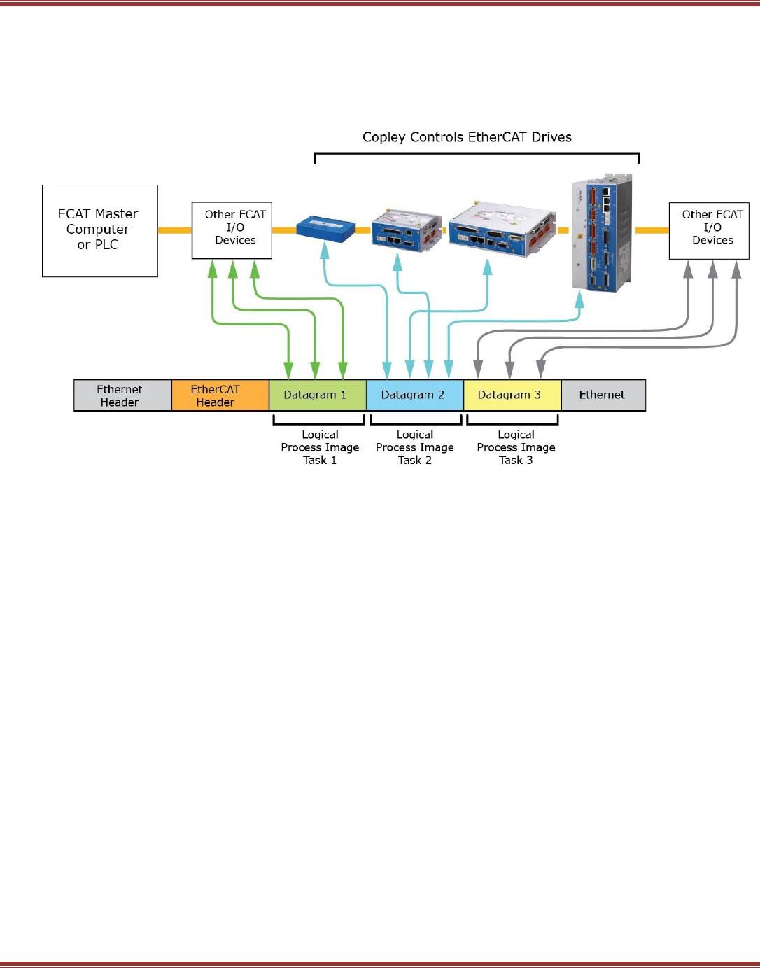
3.3 EtherCAT Overview
These are the components of an EtherCAT system. A single EtherCAT master controls a number of EtherCAT
slaves (also called nodes or devices) on the network. The master transmits EtherCAT frames that can contain a
number of EtherCAT datagrams. Each datagram holds the process data for a specific slave. Process data frames
are sent at a constant, cyclic rate. Inside the master, there can be more than one real-time task with each real-
time task running at its own cyclic rate.
Starting Up Step-by-Step
Install the EtherCAT master software
Place ESI files in master software folder
Dedicate a NIC (Network Interface Card) to EtherCAT
Connect EtherCAT devices from Master to Slaves
Configure slaves for EtherCAT operation and turn on, prepare for EtherCAT operation
Master scans network. Devices found that have matching ESI files may be linked automatically to NC’s
Configure slaves from the master with units and features appropriate with NC controllers
Activate the Master configuration, downloading it to a RT (Real-Time) kernel
Enable slaves from Master.
Create an application program that controls the drives and I/O to control the user’s machine
Note: Beckhoff TwinCAT masters automatically link Copley EtherCAT drives to NC controllers that
produce the cyclic synchronous position data for the drives. Other EtherCAT masters may have
different actions during the configuration.
EtherCAT User Guide 16-01450 Rev 00
Page 15
3.3.2 EtherCAT Slave Devices (Copley EtherCAT drives)
First, some definitions:
Layers characterize and standardize a communication system.
Protocols are the rules for data transmission and reception.
Profiles define the functional behavior of the device.
Copley Plus EtherCAT drive operate under the CANopen application protocol over EtherCAT (CoE).
NETWORK PHYSICAL LAYER
This is the lowest layer that receives and transmits the electrical network signals. The PHY (PHYsical) circuits
convert EtherCAT frames into internal logic signals which read from, or write to DPRAM (Dual-Port RAM)
memory. This is done on the fly and completely in hardware with no delays or connection to internal firmware.
ESC (EtherCAT Slave Controller) Data Link Layer
The DPRAM information is read/written by the firmware. Data written into DPRAM will be transferred to the next
datagram passing through on the network. And data transferred to the DPRAM from the network is available to
read by the firmware at any time between successive write operations. An EEPROM is implemented in the FPGA
and the networks status LEDs are controlled by the IP core.
DRIVE APPLICATION LAYER
This is the layer that is actively exchanging data with the EtherCAT master which is running an application for
an overall macinine-control function. This is the level at which CoE applies.
3.3.3 CANopen, EtherCAT, and CoE
CoE is the abbreviation for CANopen application protocol over EtherCAT.
A Protocol defines a message format and the rules for the exchange of data. DS-402 is the device profile for
drives and motion control which includes Copley servo and stepper drives. CoE carries this well-proven profile
from CANopen to the EtherCAT environment where it operates at much higher speeds. This shortens the
learning curve and builds upon a feature set that has wide acceptance. Users upgrading from CANopen to
EtherCAT don’t have to learn a new control language.

EtherCAT User Guide 16-01450 Rev 00
Page 16
3.4 Elements of an EtherCAT Network
3.4.1 EtherCAT Master Software
Fully featured masters typically incorporate the following elements:
Bus-scanning for network toplogy
ESI file usage for device configuration during scanning
(Typically, but not all masters use ESI files)
Device initialization via Mailbox (SDO) commands
Distributed Clocks (DC) for synchronization over the network
Cylical synchronous PDO commands from the real-time kernel
Real-time kernel with multiple tasks operating at different cycle times
NC (Numerical Control) for motion-control (trajectory generation, PID, virtual drives)
PLC for overall control (IEC 61131 multi-language programming environment)
3.4.2 EtherCAT Master Stacks
Stacks are a class of EtherCAT masters that provide a user’s application software a connection to the EtherCAT
network. The user then develops their own higher level control program with features designed for their
particular applications. Master Stacks may rely on Beckhoff’s Configuration Tool software that uses the ESI files
from the EtherCAT slave manufacturer to scan the network and produce an ENI (EtherCAT Network
Information) file. The result is a high level language interface between the user’s application and the physical
layer of the network.
3.4.3 EtherCAT Configuration Tool
Beckhoff software that generates ENI (EtherCAT Network Information) files based on the ESI (EtherCAT Slave
Information) files, and the slaves discovered after scanning the network. ENI files describe the network
topology, initialization (SDO) commands for each device, and cyclic (PDO) commands. Used most often by
masters that don’t use ESI files and don’t have the ability to scan the network for slaves. ENI files are in XML
format as are ESI files.
3.4.4 EtherCAT Physical Layer
Copley EtherCAT Plus Panel drives all use the Ethernet 100BASE-TX layer which use CAT5 (or higher) standard
Ethernet cables and RJ45 connectors on the drives. EtherCAT Plus Modules which are designed for mounting on
the user’s PC board can mount on Development Kits which are equipped with the same RJ45 connectors. All of
the EtherCAT Plus Products have internal magnetics for isolation from the network and PHYs that manage the
reception and transmission of EtherCAT frames.
3.4.5 EtherCAT Slave Controllers (ESC)
Copley EtherCAT Plus drives implement the ESC as an IP Core in the FPGA which also contains
a DSP (Digital Signal Processor) which is the control core of the drive.
3.4.6 EtherCAT EEPROM
Implemented as a virtual EEPROM in the FPGA, it contains some basic information about the drive which master
software may use.
EtherCAT User Guide 16-01450 Rev 00
Page 17
3.4.7 Application Layer Host Controller (a Copley EtherCAT Plus drive)
The part of the EtherCAT Plus Drive firmware that handles the EtherCAT tasks:
EtherCAT State Machine (ESM) that manages the INIT, PREOP, SAFEOP, and OP states
PDO data transmit/receive
Mailbox data exchange (CoE, FoE)
3.4.8 ESI (EtherCAT Slave Information) File
The Modular Device Profile is defined in ETG5001-1:
Aka “modules and slots”. Works with EtherCAT masters that support this feature. These contain complete
SDO, PDO, and Object Dictionaries for each axis (see below) in addition to the MDP objects.
There are two types of ESI files provided for each EtherCAT Plus drive:
Flat: No MDP, and these no MDP objects in the file. These follow the CiA DS-301 CANopen standard in
which PDOs for Axis B are offset by 0x40 from Axis A PDOs. And, the Object Dictionary for Axis B is offset
by 0x800 from the Object Dictionary of Axis A.
Slots: With MDP, aka “modules and slots”. Works with EtherCAT masters that support this feature.
These contain complete SDO, PDO, and Object Dictionaries for each axis (see below) in addition
to the MDP objects.
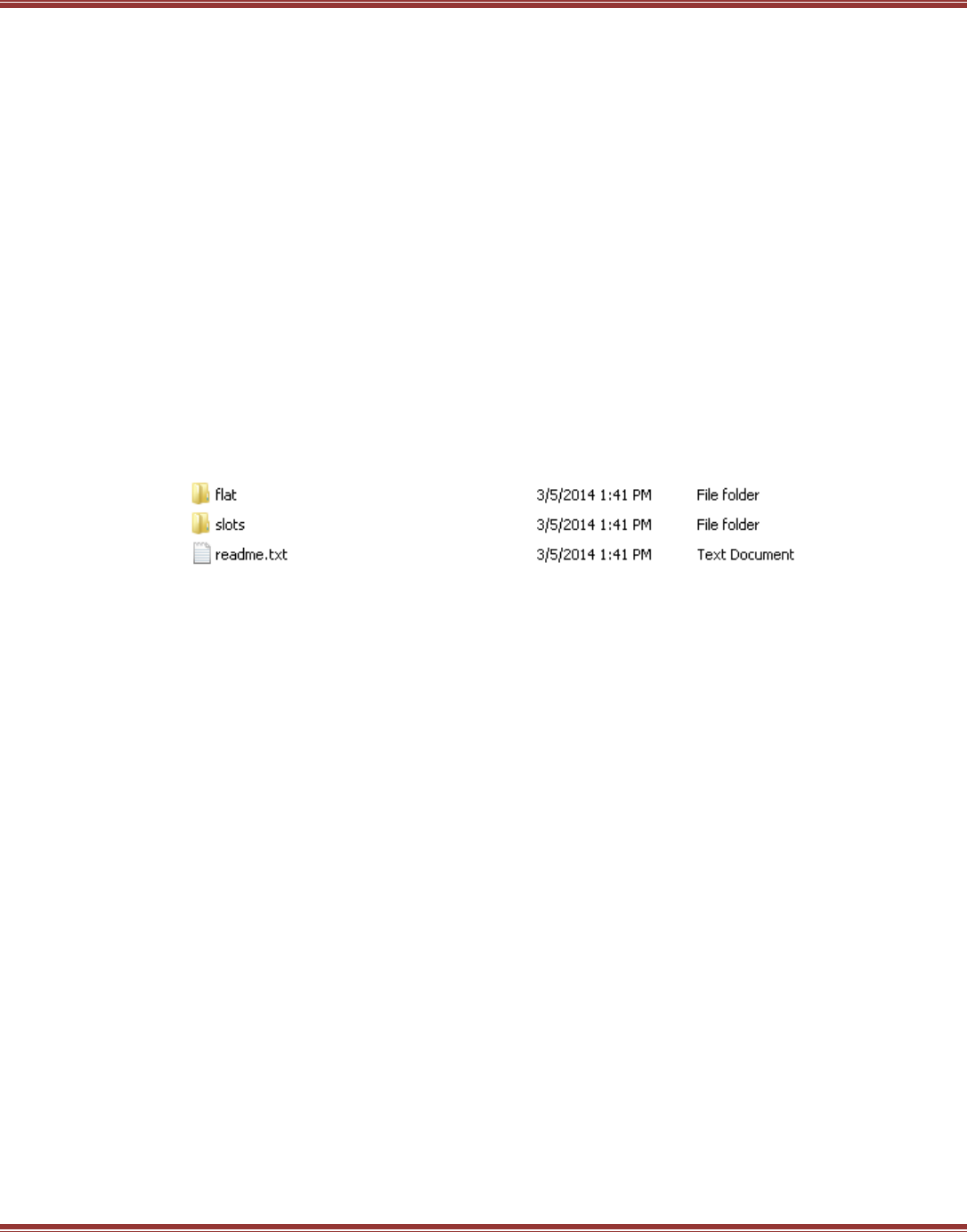
This graphic shows the ESI file folders after un-zipping the ecatxml.zip folder from the Copley web-site:
3.4.9 Cabling and Connectivity
The physical layer of an EtherCAT network that uses copper cabling is 100BASE-TX. Also called Fast Ethernet,
it uses CAT5 (or higher rated) cables and has a transmission rate of 100 Mbit/sec. Maximum cable length
allowed between nodes is 100 metre. The delay through a 100 m cable is about 0.52 usec.
In the context of many industrial networks, this is not a significant delay that affects performance.
Connections can be line, tree, or star. Unlike CANopen, no terminators are required. And, the master interface
hardware is a commonly available NIC (Network Interface Card).
If the cabling is connected in a ring, then two NICs can be used to provide redundancy and identify the location
of a break in the network so it can be located and corrected quickly.
3.5 States
The State of something is the answer to the question “What is it doing?”
An EtherCAT system consists of three basic components, each of which have states:
Master RT (Real Time) kernels: Start, Stop, Config
Network:
Slaves: Init, Pre-Op, Safe-Op, Op
EtherCAT User Guide 16-01450 Rev 00
Page 18
3.5.1 Synchronization & Distributed Clocks (DC)
Question: in a network full of clocks, which clock is the best?
Answer: in most cases, it’s a slave clock, not the master’s as one might expect.
Why? EtherCAT slaves are single-purpose devices. They have one task to manage, and all the resources are
devoted to that task. Compare this to a PC which has a highly variable and unpredictable task load and an
equally variable hardware basis in which to manage those tasks.
And, in order to control power dissipation in the CPU and/or optimize battery life, the running speed of the CPU
clock in laptop computers can vary widely during operation.
Distributed Clocks are a solution to this situation and are able to provide synchronization that holds jitter to the
nanosecond range. Assuming that a slave is selected to be the DC master, all of the other devices can set their
clocks to that slave’s clock. And in Copley drives, if the slave master clock is synchronized to the
position/velocity loop period of 250 usec, then all of the other devices will be controlling
position/velocity/current at the same time.
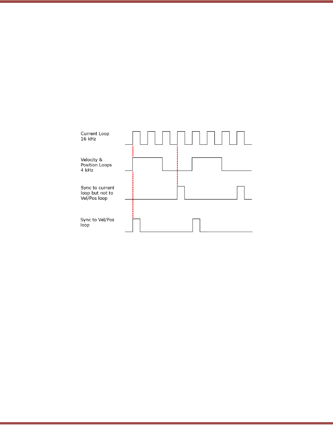
Copley drives have two internal frequencies and 1/F times that are relevant to EtherCAT operation:
16 kHz (62.5 µs) for the current-loop and 4 kHz (250 µs) for the velocity and position loops.
DC syncing between drives using one slave as the DC clock master works best when they sync to the Vel/Pos
loops. If syncing is done to the Current loop, drive will operate at the same frequency at the clock master, but
motion control loops will not be synchronized. Using the Vel/Pos loop as the DC clock master enable all drives to
do motion control with no time-shift between them.
EtherCAT User Guide 16-01450 Rev 00
Page 19
3.6 Inside the EtherCAT Drive
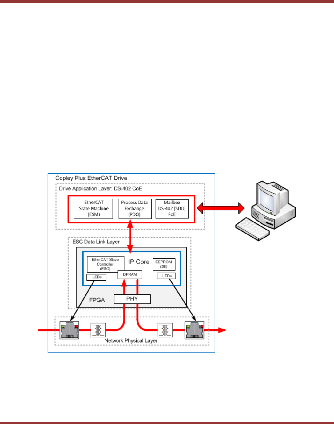
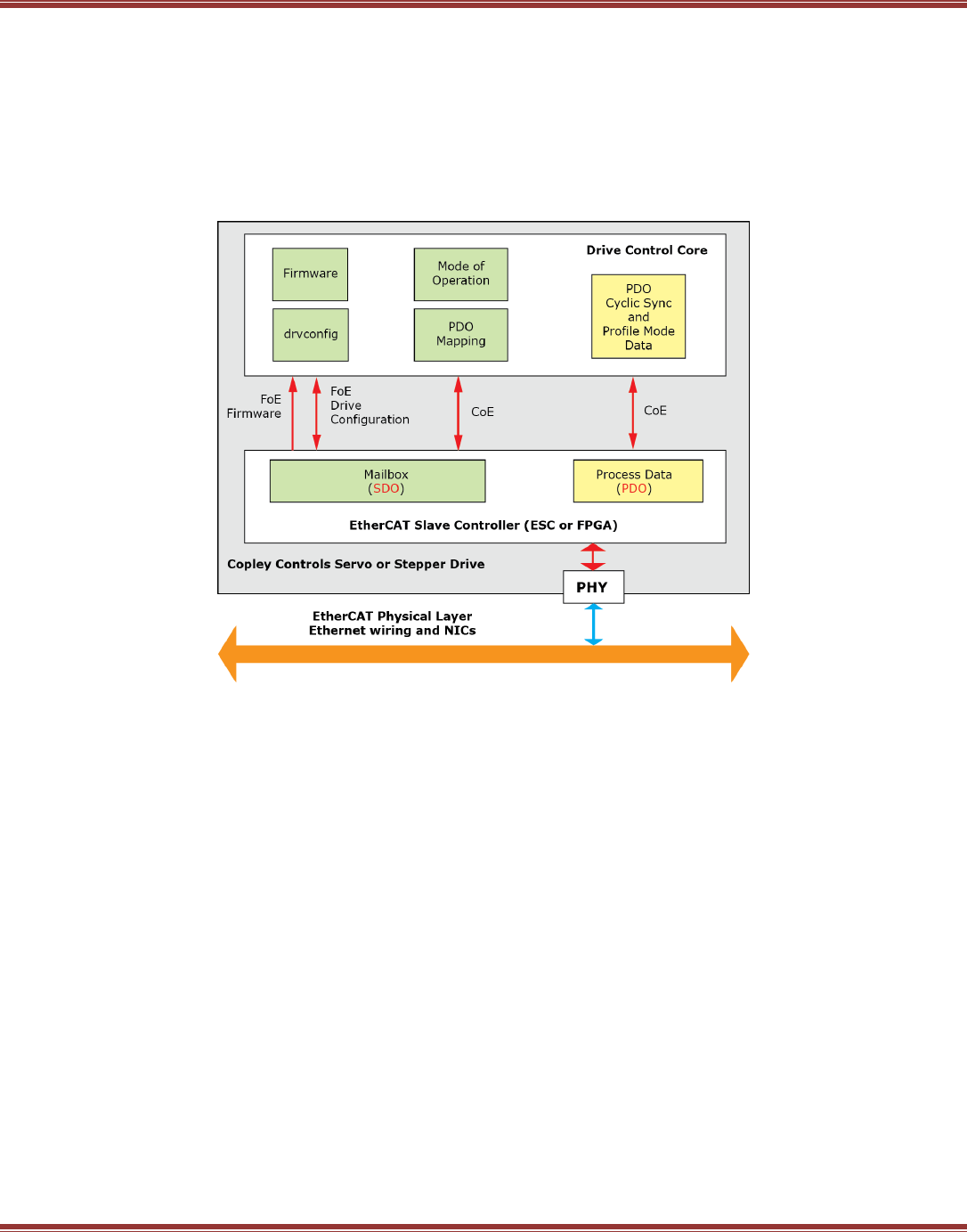
3.6.1 From the Network to the Drive
This diagram shows how the EtherCAT function operates in the drive. The PHY is the PHYsical connection
between the network and the ESC (EtherCAT Slave Controller) which is implemented in an FPGA. Data in the
ESC is either SDO (Service Data Objects) or PDO (Process Data Objects). SDOs are usually sent at
asynchronous time intervals (green) and are used for PDO mapping and setting mode of operation most of the
time. They also support FoE (File over EtherCAT). PDO data is exchanged synchronously (yellow) at a rate
determined by the cyclic task in the master.
3.6.2 EtherCAT Network Slaves Don’t Think
EtherCAT using standard Ethernet cabling produces a control network that moves data at high speed and
enables tight synchronization of the devices operating on the network. Here’s how it works.
On some networks, a data frame is received, processed by the device’s control core, and then re-transmitted.
This processing or “thinking” take time, a lot of it relatively speaking. And, because all slaves see the same data
at about the same time (I.e. CANopen), a frame has to be sent to each slave individually. This adds up to a lot
of network traffic every time it’s desired to update all the slaves.
In EtherCAT, each node has an EtherCAT Slave Controller (ESC) that works together with a network PHY
(PHYsical layer) chip. Next, the EtherCAT frame typically contains all of the process for all of the slaves, not just
one. As the frame passes through the slave, the ESC identifies the data for the slave. Incoming data is stripped
from the frame and deposited in dual-port RAM. Outgoing data is deposited in the frame in the section reserved
for the slave. All of this is done in hardware without any computation by the slave. The in/out transit time for
the frame to move through the slave is fast, less than 1 microsecond.
After the slave data is exchanged, it can begin the computations to process the incoming data. But all of this is
“off-line” from the viewpoint of the network and does not impose any delays on the actual data transmission
over the network.

EtherCAT User Guide 16-01450 Rev 00
Page 20
3.6.3 EtherCAT Time
As Albert Einstein discovered… time is relative. Any discussion of time has to begin with how and where it’s
measured. All of the devices on an EtherCAT network have digital control cores and each of those has a clock.
Each of those clocks measures time based on quartz crystal oscillators and it’s practically a certainty that none
of the clocks measure time exactly the same. Viewed from any point in the network, master or slave, all of the
“other” clocks appear to be running fast or slow.
Next, commands from the master to the network typically travel over copper cabling that has intrinsic delays
because electric signals travel slower than the speed of light. And, there is the time that it takes for an
EtherCAT frame to enter the slave device. Given all of this, how is it possible for devices on a network to set all
their clocks to the same time? And, once that’s done how can they all synchronize their operation when multiple
axes are product multi-dimensional vector motions?
3.6.4 Synchronization Overview
Timing and synchronization in an EtherCAT network takes three forms:
Freerun
Slaves run ‘free’ with no connection to the timing of the master or other slaves. They may have internal tasks
that don’t require a connection to the master. Freerun is used before the real-time kernel is activated. The
master will query the slaves on the network, reading their status and CoE objects but will not transmit data to
the slaves.
Sync-Manager Synchronization
The slave reacts to telegrams from the master, receiving or transmitting data from sync managers.
The timing can vary based on the master’s timing which depends on the host computer’s CPU clock.
Other tasks that may have higher priority in the operating system affect the timing of the sync managers and
laptops constantly “throttle” the CPU clock to save power. This is the sync-mode that results when the real-time
kernel is activated but Distributed Clocks are not enabled. PDO are reading/writing to the slaves and the
network is fully “up” and running. But, the time between cyclic data transfers will have jitter and delays due to
cabling will occur.
Distributed Clocks (DC)
The master designates a slave as the reference clock then adjusts the clocks of other slaves so that they
operate in-sync. Cabling and network delays are compensated for. Current, velocity, and position loops in the
drives are all synchronized within nanoseconds of each other. Jitter in the real-time kernel will not affect the
slave synchronization as long as it does not exceed the update rate of the cyclic data and skip one data cycle,
falling into the next.
Control System Timing and Process Data
With the network wired, DC configured, the master running, and all the slaves synchronized, the foundation has
been laid to do some real motion control. Moving motors in CANopen was commonly done with the “profile”
modes for position, velocity, and current. With these modes, parameters describing the motion are first
configured. When bit 4 of the Control Word 0x6040 is toggled the drive starts to produce the motion without
any further commands from the master. Completion of the profile move is shown by the status of bits in the
Status Word 0x6041.

EtherCAT User Guide 16-01450 Rev 00
Page 21
3.7 EtherCAT Data
Turn off the EtherCAT master and uplug all of the slaves. What’s left is the network, and by itself, it does
nothing! It’s a railroad without trains and stations. And when it connects a master to slaves, it only carries one
thing: data .Although the volume of data it can handle is unlimited, the types of data are few:
• Process (Cyclic) data: transported by PDOs
• Mailbox (Acyclic) data: transported by SDOs
• FoE (File access over EtherCAT) Download firmware and upload drive configuration
Fixed PDOs
First, the bad news: Fixed means that the user can’t change them.
Next, the good news: Fixed means they are saved the the CPU flash memory and are optimized for speed. They
take less CPU time to execute, leaving more time for other tasks.
Receive and Transmit PDOs, relatively speaking…
From this it is clear that transmit & receive must always be discussed in the context of the producer and/or the
consumer of the data.
Master Slave Types of Data
Transmit Receive Control word, target position/velocity/torque, torque/velocity offset
Receive Transmit Status word, actual position/velocity/torque, position (following) error
Fixed RxPDOs
For CSP (Cyclic Synchronous Position) 0x6060 Mode of Operation = 8:
Receive PDO 4: 0x1700
0x6040 Control Word
0x607A Profile Target position
0x60B1 Velocity Offset
0x60B2 Torque Offset
For CSV (Cyclic Synchronous Velocity) 0x6060 Mode of Operation = 9:
Receive PDO 5: 0x1701
0x6040 Control Word
0x60FF Target Velocity
0x60B2 Torque Offset
For CST (Cyclic Synchronous Torque) 0x6060 Mode of Operation = 10:
Receive PDO 6: 0x1702
0x6040 Control Word
0x60FF Target Velocity
0x60B2 Torque Offset
Fixed TxPDO
Transmit PDO 5: 0x1B00
0x6041 Status Word
0x6064 Actual Motor Position
0x60F4 Position Loop Error (following-error)
0x606F Actual Motor Velocity
0x6077 Torque Actual Value

EtherCAT User Guide 16-01450 Rev 00
Page 22
Not-Fixed, or User Programmable PDOs
These are only used when the user defines their contents. They run slower and take more CPU time than the
fixed PDO. This should be kept in mind when defining their contents, keeping the amount of data moved to the
minimum required for tasks. Contents of these PDOs are not linked to any mode of operation as are the fixed
PDOs.
Un-Fixed RxPDOs
Receive PDO 0: 0x1600
Receive PDO 1: 0x1601
Receive PDO 2: 0x1602
Receive PDO 3: 0x1603
Un-Fixed TxPDOs
Transmit PDO 1: 0x1A00
Transmit PDO 2: 0x1A01
Transmit PDO 3: 0x1A02
Transmit PDO 4: 0x1A03
EtherCAT User Guide 16-01450 Rev 00
Page 23
3.8 EtherCAT System Architectures
Common in this context means architectures that are support in common by a number of masters. That is, their
architectures have similar features and implementation. In the graphics below, Beckhoff TwinCAT software is
shown as the master because it has has features that incorporate all the ingredients of an EtherCAT motion
control system.
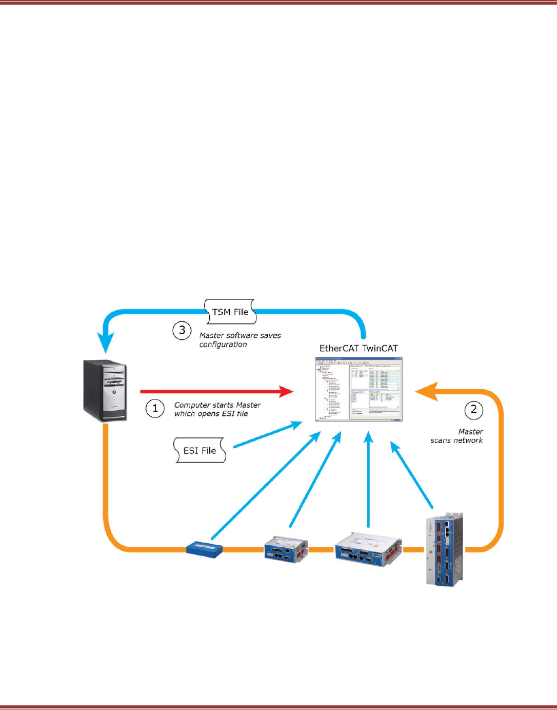
Masters that Use ESI Files
Masters in this category share the common ability to ingest ESI files, scan the network, generate the network
toplogy, and configure startup and cyclic commands. They may or may not have NC or PLC components. The
example below used TwinCAT as the master because it uses ESI files and is fully-featured.
Network setup follows a sequence shown in the graphic below. Not shown is the basic physical connections and
configuration of the servo/stepper drives for EtherCAT control.
1. The Master ingests ESI files after start-up
2. Scanning the network, the ESI file data is used to identify EtherCAT slaves and add them to the virtual
network shown in the folder tree of the TwinCAT System Manager.
3. Based on the default Mode of Operation in the ESI file, NC controllers are linked to the drives.
SDO, PDO, and DC settings are madel between NC and drives. The entire configuration can be saved
to a .TSM file.
At this point the system can be activated (TSM settings downloaded to the RT kernel) and the system can be
started in RUN mode. Basic motion control is possible from the NC controllers, but no PLC programs exist at this
time. The user must then create these to produce the overall machine control system for a given application.
EtherCAT User Guide 16-01450 Rev 00
Page 24
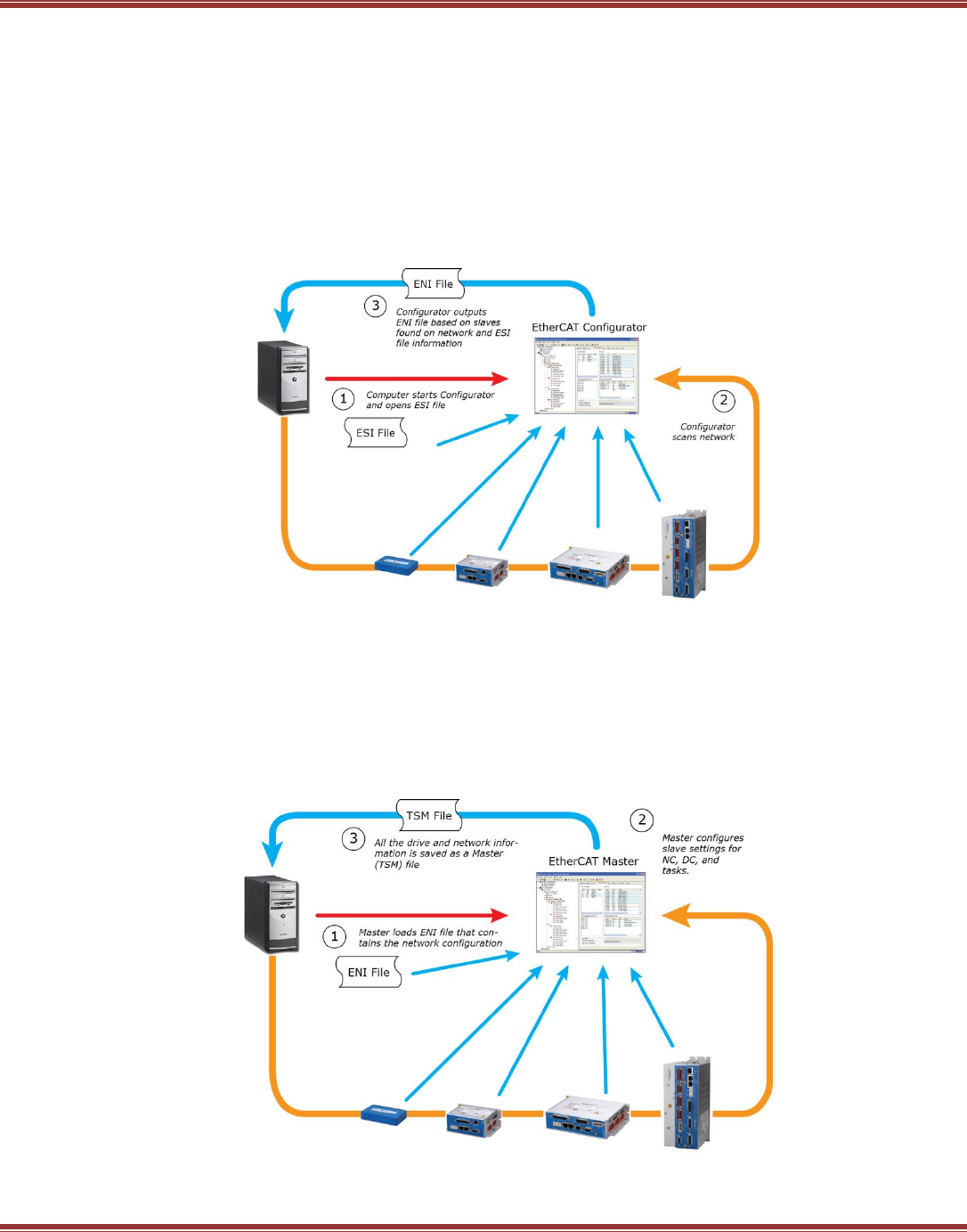
Masters That Don’t Use ESI Files
The feature set of these masters may vary, but all require ENI files that provide all of the network information.
Network setup follows a sequence shown in the graphic below. Not shown is the basic physical connections and
configuration of the servo/stepper drives for EtherCAT control.
Step 1
1. The Configurator program ingests ESI files after start-up
2. Scanning the network, the ESI file data is used to identify EtherCAT slaves and add them to the virtual
network shown in the folder tree of the Configurator
3. The Configurator outputs an ENI (EtherCAT Network Information) file.
Step 2
Using the information from the ENI file, the master makes settings for each drive and then saves the entire
configuration as a Master (TSM in TwinCAT) file that contains all of the control system information.
4. The Master ingests the ENI file
5. Settings are made for each slave on the network
6. The Master outputs a TSM (Master confiiguration) file and activates the configuration.
EtherCAT User Guide 16-01450 Rev 00
Page 25
4 SETTING UP FOR ETHERCAT
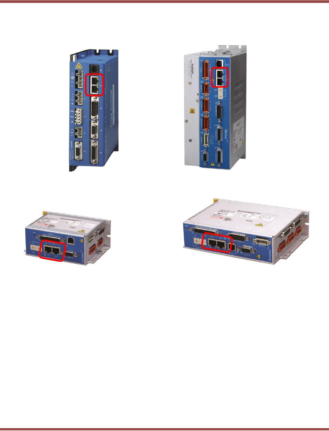
AC Drive EtherCAT Connectors
XEL XE2
DC Drive EtherCAT Connectors
BEL, TEL BE2, TE2
4.1 EtherCAT Cabling
The physical layer of an EtherCAT network is 100BASE-TX which uses Cat 5 (or higher) cabling.
The maximum length between nodes on the network is 100 metres (328 ft.)
The EtherCAT connectors on the drives have IN and OUT ports which should be used when cabling runs
through a drive. These are the same cables and RJ-45 connectors that are used on CANopen drives.
However, EtherCAT network cabling does not require a terminating resistor on the last drive in the network.
The PHY (PHYsical interface) of the last drive in the network will automatically rout the data from the
incoming pair of wires to the returning pair.
Keep EtherCAT cables separated from motor cables that connect to the PWM outputs of the drives.
This will eliminate noise coupling from motor cables into the network cabling.
EtherCAT User Guide 16-01450 Rev 00
Page 26
4.2 Indicators: EtherCAT LEDs
`
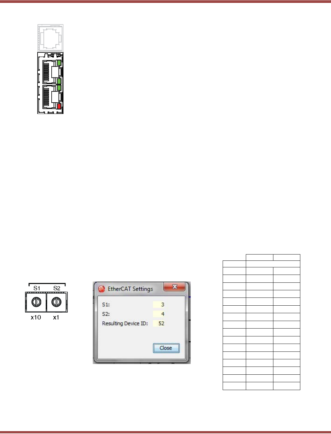
4.3 Device ID Switches & Station Alias
In an EtherCAT network, slaves are automatically assigned fixed addresses based on their position on the
bus. But when the device must have a positive identification that is independent of cabling, a Device ID is
needed. In the Plus Panel drives, this is provided by two 16-position rotary switches with hexadecimal
encoding. These can set the Device ID of the drive from 0x01~0xFF (1~255 decimal). The chart shows the
decimal values of the hex settings of each switch.
Example 1: Find the switch settings for decimal Device ID 52:
1) Find the highest number under S1 that is less than 52 and set S1 to the hex value in the same row:
48 < 52 and 64 > 52, so S1 = 48 = Hex 3
2) Subtract 48 from the desired Device ID to get the decimal value of switch S2 and
set S2 to the Hex value in the same row: S2 = (52 - 48) = 4 = Hex 4
S1
S2
HEX
DECIMAL
0
0
0
1
16
1
2
32
2
3
48
3
4
64
4
5
80
5
6
96
6
7
112
7
8
128
8
9
144
9
A
160
10
B
176
11
C
192
12
D
208
13
E
224
14
F
240
15
L/A
RUN
L/A
ERR
OUT
IN
L/A A green LED indicates the state of the EtherCAT network:
LED Link Activity Condition
ON Yes No Port Open
Flickering Yes Yes Port Open with activity
Off No (N/A) Port Closed
RUN Green: Shows the state of the ESM (EtherCAT State Machine)
Off = Init
Blinking = Pre-operational
Single-flash = Safe-operational
On = Operational
ERR Red: Shows errors such as watchdog timeouts and unsolicited
state changes in the XE2 due to local errors.
Off = EtherCAT communications are working correctly
Blinking = Invalid configuration, general configuration error
Single Flash = Local error, slave has changed
EtherCAT state autonomously
Double Flash = PDO or EtherCAT watchdog timeout,
or an application watchdog timeout has occurred
Device ID
CME2 -> Amplifier -> Network
Configuration
EtherCAT Device ID Switch
Decimal Values
EtherCAT User Guide 16-01450 Rev 00
Page 27
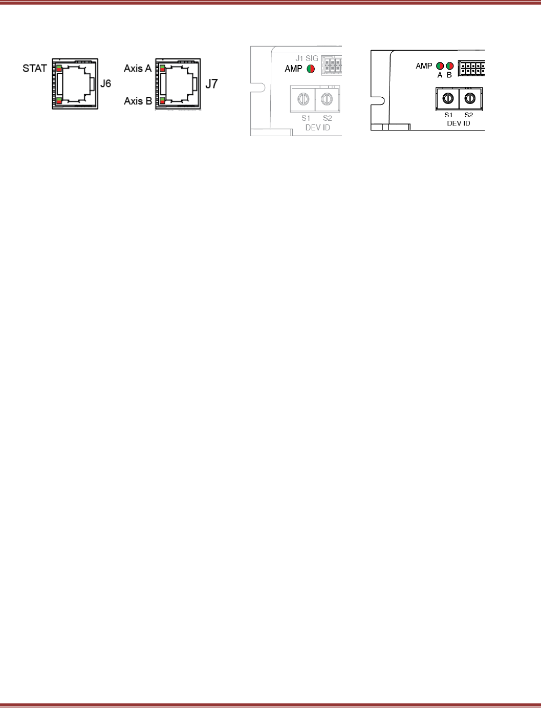
4.4 Drive Axis Indicators
XEL XE2 BEL, TEL BE2, TE2
A bi-color LED gives the state of each axis. Colors do not alternate, and can be solid ON or blinking.
When multiple conditions occur, only the top-most condition will be displayed.
When that condition is cleared the next one below will be shown.
1) Red/Blinking = Latching fault. Operation will not resume until drive is Reset.
2) Red/Solid = Transient fault condition. Drive will resume operation when
the condition causing the fault is removed.
3) Green/Double-Blinking = STO circuit active, drive outputs are Safe-Torque-Off
4) Green/Slow-Blinking = Drive OK but NOT-enabled. Will run when enabled.
5) Green/Fast-Blinking = Positive or Negative limit switch active.
Drive will only move in direction not inhibited by limit switch.
7) Green/Solid = Drive OK and enabled. Will run in response to
reference inputs or EtherCAT commands.
Latching Faults
Defaults Optional (programmable)
• Short circuit (Internal or external) • Over-voltage
• Drive over-temperature • Under-voltage
• Motor over-temperature • Motor Phasing Error
• Feedback Error • Command Input Fault
• Following Error
4.5 Drive Wiring
Before the drive can operate under EtherCAT control, the other non-network connections must be made.
Here is a checklist for these, details can be found in the datasheets for the particular drives:
AC-Powered drives:
Connect to mains power with provisions for on/off control, protection, filtering,
and surge-protection devices (SPD)
DC-Powered drives:
Connect to transformer-isolated DC power sources for +HV and optionally HV-Aux.
General wiring:
Wire inputs to any limit or home switches, and any control system outputs that could operate as Enable
or other control signals.
Wire outputs to motor brakes (if used) or other devices to be controlled.
Connect motors and feedback devices. Route feedback cables apart from motor power cables
to reduce coupling of PWM outputs into feedback signals.
IMPORTANT:
Provide either a hardware Enable signal from the control system, or an EMO (Emergency Off) mushroom
switch for mains or DC power to the drives. It is very important to have the ability to prevent the drive from
producing torque in a motor without using the network which can fail, either due to software control or
cabling, and lose the ability to disable the drive. In addtion to these measures, the STO function can provide
the capability to stop torque production in the motor.
When wiring is complete, launch CME2 and configure the drive for EtherCAT control.
EtherCAT User Guide 16-01450 Rev 00
Page 28
5 CONFIGURING DRIVES FOR ETHERCAT
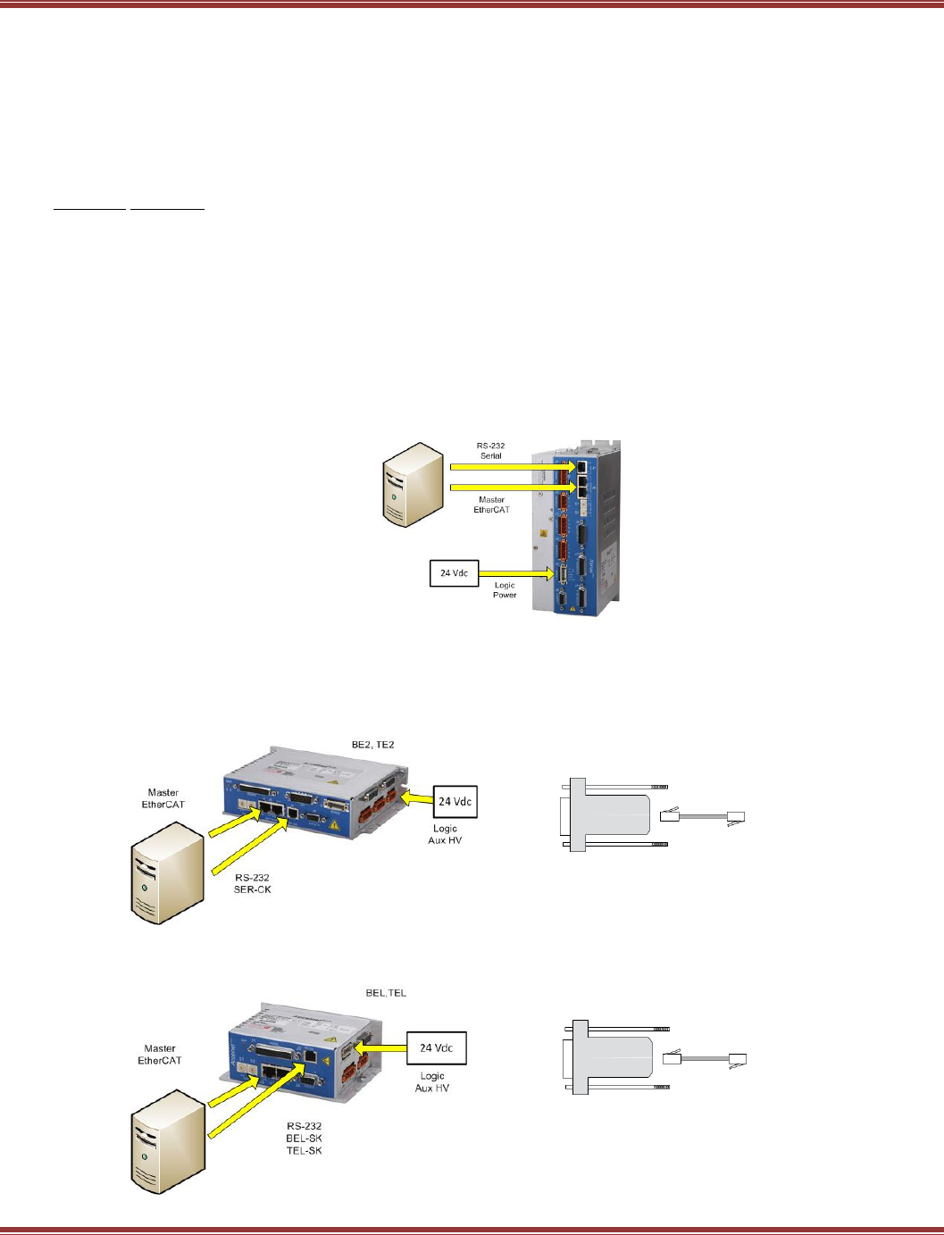
5.1 Serial RS-232 Connections
Serial communication is recommended for EtherCAT operation because CME2 and the EtherCAT master
can not share the EtherCAT port at the same time. With serial communications, CME2 can access the drive
before the network is in operation. Two types of Serial Cables Kits are available that plug into a computer’s
COM port (Dsub-9M) and connect to servo drive:
Cable Kit For Drive
SER-CK XEL,XE2, BE2, TE2
BEL-SK BEL
TEL-SK TEL
The BEL-SK and TEL-SK are electrically identical and will work with either BEL or TEL drives.
Serial Connection: Xenus AC Powered Drives
The SER-CK Serial Cable kit will accept the Dsub-9M connector that is commonly used for the COM1(2,3,4)
port on a computer and adapts it to a modular cable that plugs into the Serial port of the Xenus drives.
Mains power is not needed for the network to operate, so the +24 Vdc supplied to the Xenus will power the
serial port and network operation.
Serial Connection: Accelnet & Stepnet DC Powered Drives
BE2 & TE2 2-Axis drives have an RJ-11 modular socket for the serial data port.
It uses the SER-CK Serial Cable Kit to connect to a computer with a Dsub-9M connector
for the COM1(2,3,4) port.
BEL & TEL 1-axis drives also have an RJ-11 modular socket for the serial data port,
and use the SER-CK.
EtherCAT User Guide 16-01450 Rev 00
Page 29
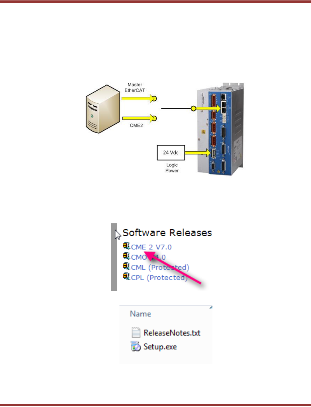
EtherCAT Connections
With serial communications, it is not possible for CME2 to connect to a drive using a COM port that is in use
by another device. But, when EtherCAT is used for the CME2 connection, the NIC (Network Interface Card) is
available for CME2 even though the EtherCAT master program is running and connected to the drive.
Because CME2 can write to and alter drive parameters that may be in use by the master, it is recommended
that CME2 does not be used over EtherCAT when the master is in control.
Before connecting CME2 to a drive over EtherCAT, ensure that the EtherCAT master is disabled. The graphic
below illustrates the concept. The physical switch shown is not necessary, but the switching off of one task
while the other one is on is represented here as a switch.
5.2 CME2 Installation for EtherCAT
Download CME2
Open your web browswer and navigate to the Copley Controls web-site: http://www.copleycontrols.com
From the Menu bar, go to the Downloads page, Sofware Releases and select CME2:
Save to your computer, unZip the file, and launch Setup.exe
EtherCAT User Guide 16-01450 Rev 00
Page 30
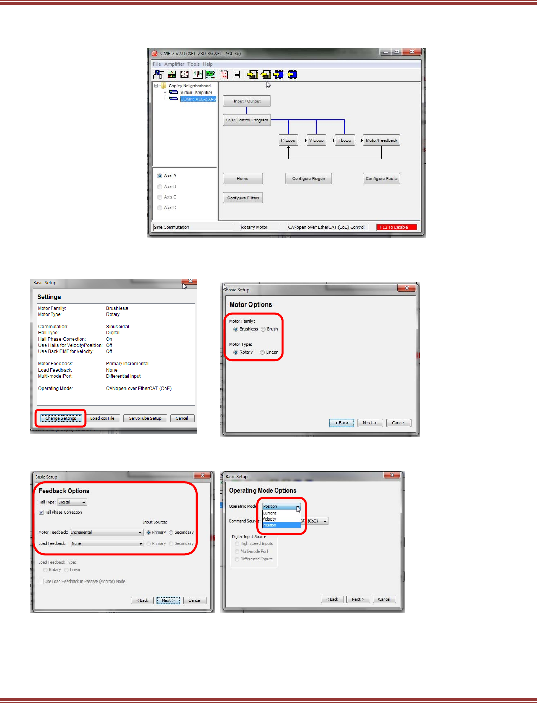
Configure the drive for EtherCAT operation
This is the Home page of CME2
Go to Amplifier > Basic Setup (menu bar) or click the jack-in-the-box icon:
Click [Change Settings] to begin Pick Motor Family and Motor Type
Feedback Options Select Position for Operating Mode (CoE)
Hall Type, Motor Feedback typically Operating Mode: Position is the default
EtherCAT User Guide 16-01450 Rev 00
Page 31
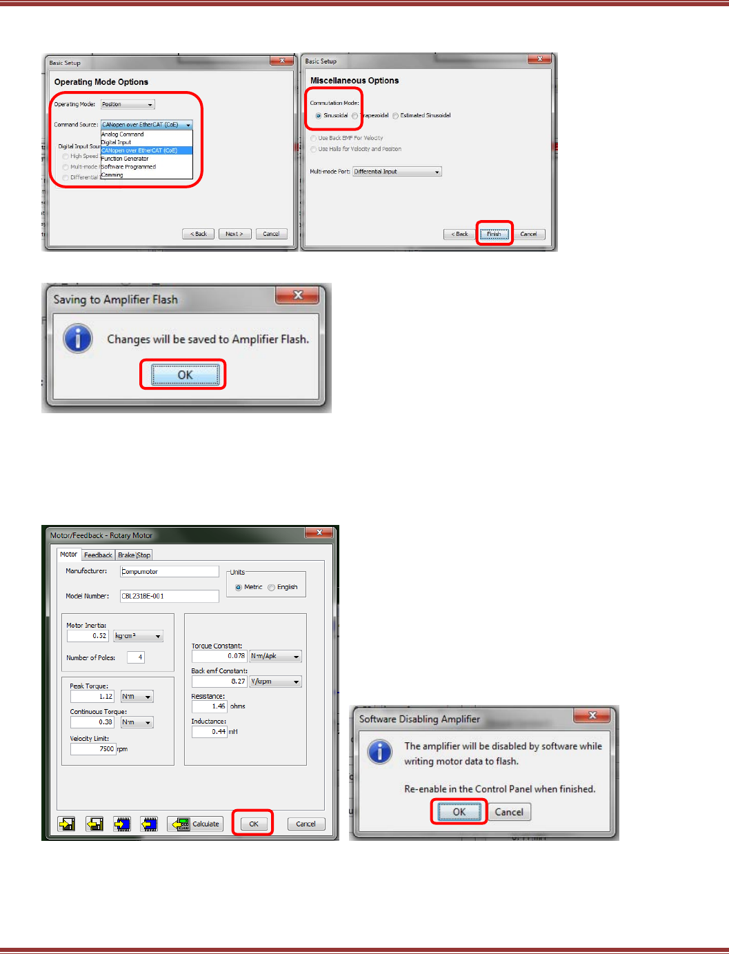
Command Source: for EtherCAT, Miscellaneous Option
use CANopen over EtherCAT (CoE) Default selections are OK for most apps
Click [Finish] to exit Basic Setup, and [OK] to save to flash
This will return you to the CME2 main page.
Click to open the [Motor/Feedback] box.
Motor Set Up
When Basic Setup completes, open the Motor/Feedback block on the CME2 main screen.
Fill in the motor data, followed by the Feedback and Brake (if used) tabs data.
Click [OK] to the Calculate question and
this will be followed by the screen below.
Click [OK] to exit to the main page.
EtherCAT User Guide 16-01450 Rev 00
Page 32
Proceed to Amplifier > Auto Phase to configure the motor commutation. Then, use the CME2 scope to
tune the Velocity and then Position loops. Refer to the CME2 User Guide for details on these operations. This
can be found either in the CME2 installation folder, or on the Copley Controls web-site:
http://www.copleycontrols.com/Motion/pdf/CME2_User_Guide.pdf
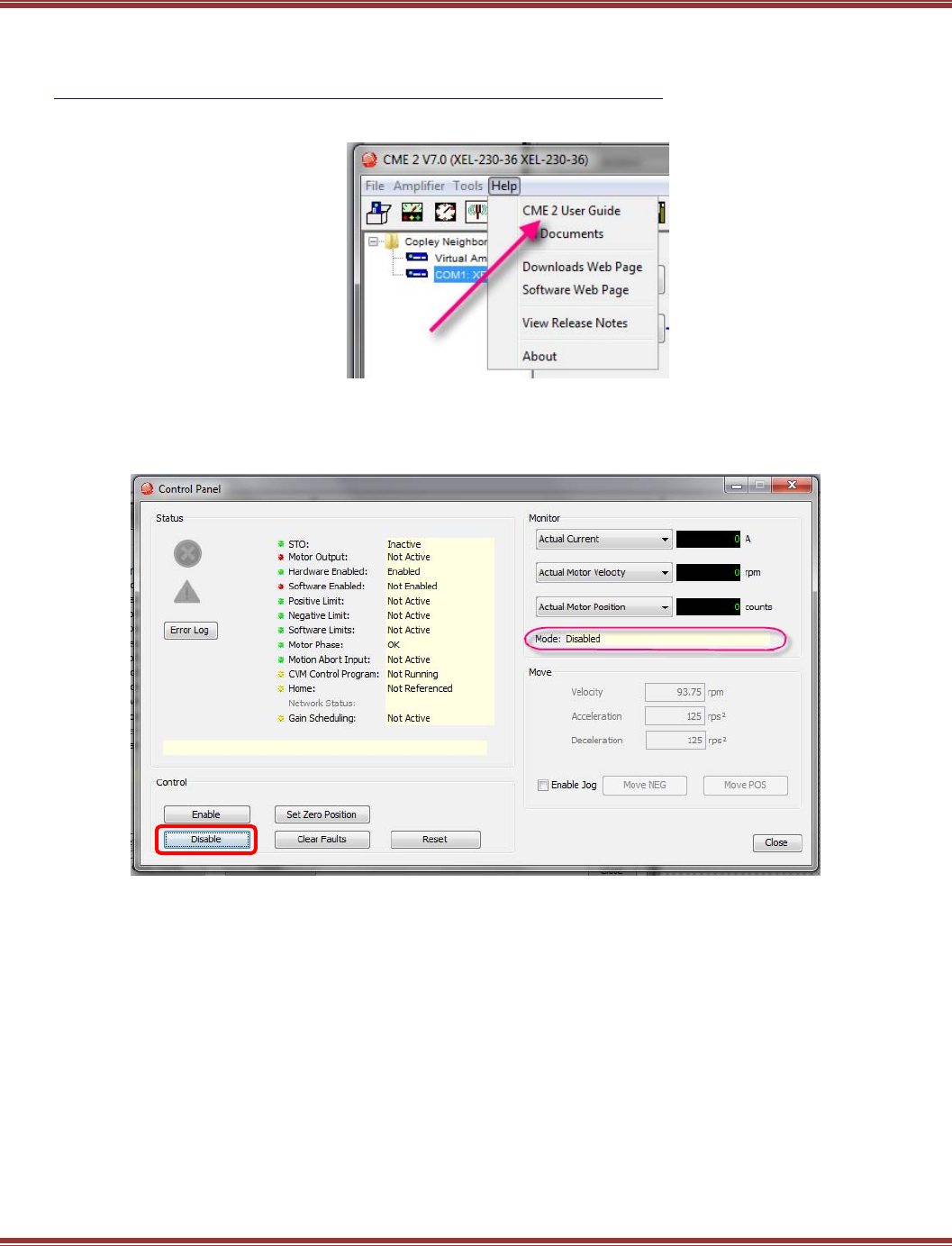
Enable the drive for EtherCAT control
When the motor is set up and tuned well for position mode operation, open the Control Panel.
If it has been “software disabled” by pressing the [Disable] button it will look like this:
EtherCAT User Guide 16-01450 Rev 00
Page 33
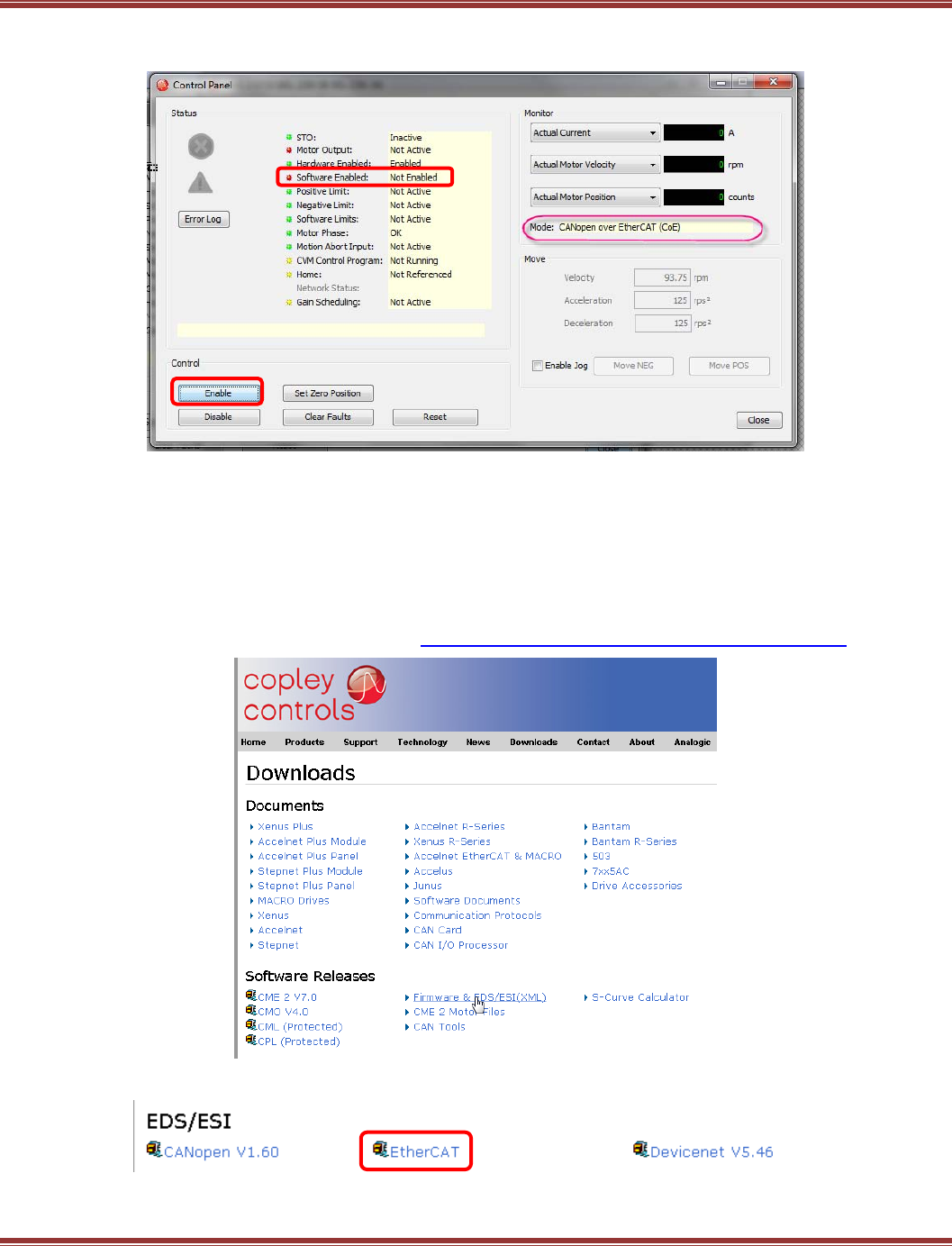
To operate using EtherCAT, it must first be “software enabled” by the CME2 software.
Press the [Enable] button on the Control Panel and the screen should look like this:
IMPORTANT: The operating mode is now CoE and the Software Enabled “led” on the Control Panel is referring
to the EtherCAT master software that will be controlling the drive over the network.
Because the CME2 configuration typically precedes the EtherCAT master software setup, the drive will be not
be software-enabled by the EtherCAT master and the result will be red LEDs for both the Software Enabled and
Motor Output indicating that these items are OFF.
Download ESI (EtherCAT Slave Information) Files
Commonly referred to as XML files, which describes the format of the file but not its contents.
These files are found on the Copley web-site: http://www.copleycontrols.com/Motion/zip/ecatxml.zip
Click the EtherCAT link and download them to your desktop, or other folder for now.
EtherCAT User Guide 16-01450 Rev 00
Page 34
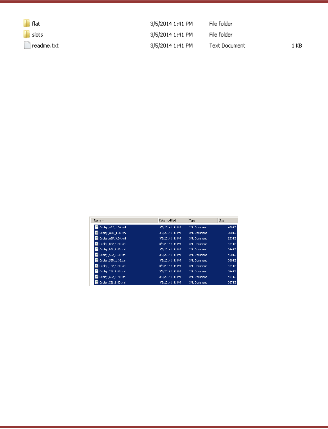
Unzip the ecatxml.zip file and it will produce a folder named ecatxml with these contents:
This is the contents of the readme.txt file:
Copley Controls now provides ESI files for it's EtherCAT drives in two different formats.
The folder named 'slots' provides ESI files which use the 'slots and modules' format for describing
the drive's functionality. This format allows multi-axis drives to be described in a way that makes
setting them up very easy in EtherCAT masters which support the format. These files are preferred
for use with TwinCAT, and other masters which support slots and modules.
The folder named 'flat' provides ESI files which do not use slots and modules. These files should
be used for masters which do not yet support the more modern format.
Only one set of files should be installed at a time. Most EtherCAT masters will complain if they see
multiple ESI files for the same device type.
The slots folder contains ESI files that are for EtherCAT masters that support the MDP (Modular Device Profile)
that is defined in the document ETG 5001. Use the files in the slots folder for TwinCAT 2 & TwinCAT 3.
The flat folder contains ESI files that are for masters that do not support the MDP, such as the
Delta Tau PMAC controllers.
Select all of the slots ESI files and Control-C to copy them to the clipboard.
Use Windows Explorer to navigate to this folder in the TwinCAT installation:
C:\TwinCAT\3.1\Config\Io\EtherCAT. Click in this folder and
Paste (Control-V) the ESI files here.
IMPORTANT: ESI file installation must be complete before TwinCAT 3 is launched.
TwinCAT 3 will only identify slaves on the network that have ESI files in the
C:\TwinCAT\3.1\Config\Io\EtherCAT folder which it scans ONCE after launching.
EtherCAT User Guide 16-01450 Rev 00
Page 35
6 ETHERCAT QUICK STARTS
6.1 Beckhoff TwinCAT 3
Introduction
This document provides information on commissioning Copley Controls EtherCAT servo drives using the
TwinCAT3 EtherCAT master software. When these steps are followed, it should be possible to move a servo
motor via a Copley Controls servo drive from an NC controller in TwinCAT3. For more advanced motion
control it is necessary to consult the Beckhoff InfoSystem software for details.
The first step is to download all of the software and data needed to produce a working TwinCAT 3 system.
TwinCAT3 Software
Find TwinCAT 3 on the Beckhoff web-site here: http://www.beckhoff.com/
Navigate to Download -> Software -> TwinCAT3
Click on TE1xxx | Engineering:
In the next screen, click on TwinCAT 3.1 –eXtended Automation Engineering (XAE):
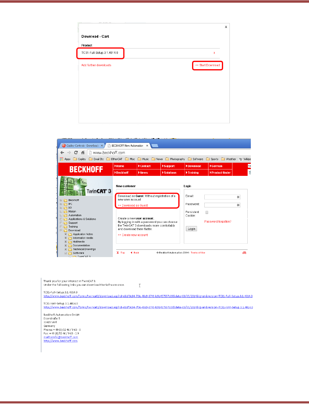
EtherCAT User Guide 16-01450 Rev 00
Page 36
Now click on TC31-Full-Setup.3.1.4040.0
Then click Start Download:
Download as a guest:
.
Using the Download as Guest link, A\a form will appear, so fill it out and click on Register. An email will be
sent to the address you gave on the registration form.
Click on the links in the email to download the TwinCAT3 files for the TC31-Full-Setup software.
After un-zipping the downloads, open the install folder.
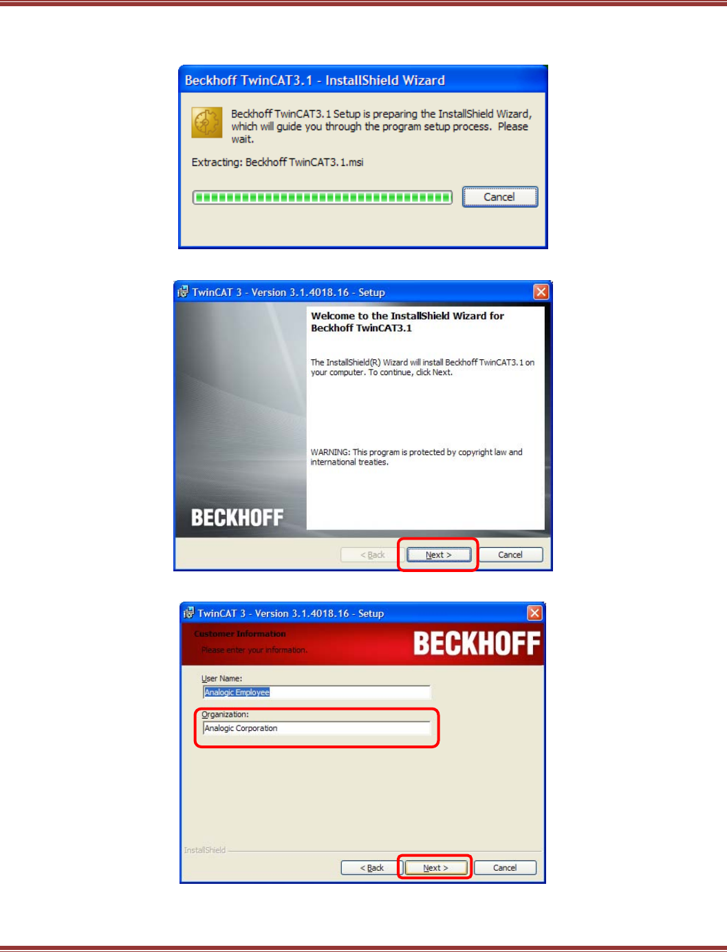
EtherCAT User Guide 16-01450 Rev 00
Page 37
TC3-Full-Setup
Click on the TC31-Full-Setup file (the date numbers may vary) to begin installation.
Click Next to continue:
The Organization box must be used to continue:
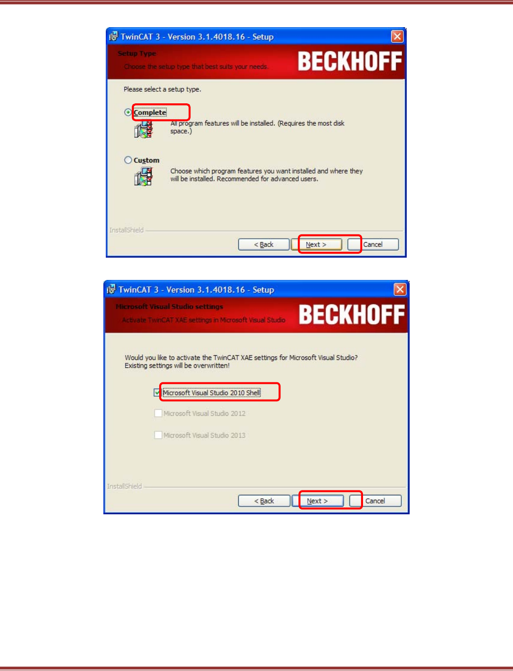
EtherCAT User Guide 16-01450 Rev 00
Page 38
Click to select the Complete installation and click Next to continue::
Click the box to add the TwinCAT XAE feature to the Visual Studio, and then Next to continue:
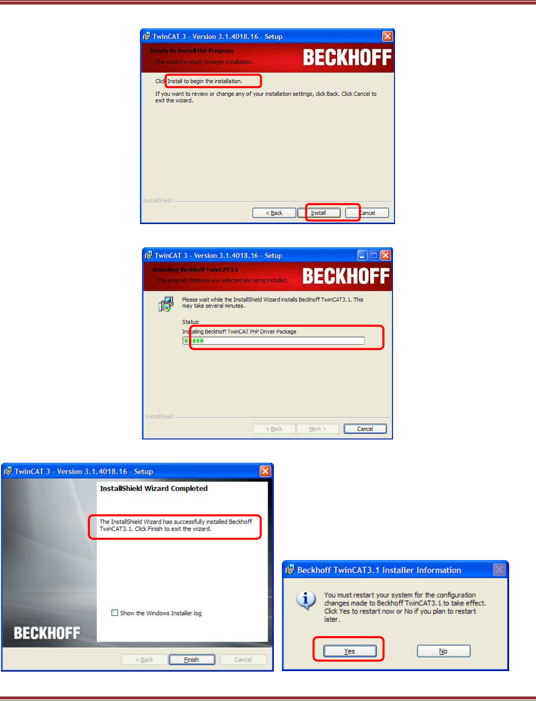
EtherCAT User Guide 16-01450 Rev 00
Page 39
Now click Install to begin the installation:
The progress bar appears while the installation is in process:
You will be prompted when the installation is complete, click Finish and Yes to restart in the next screen:
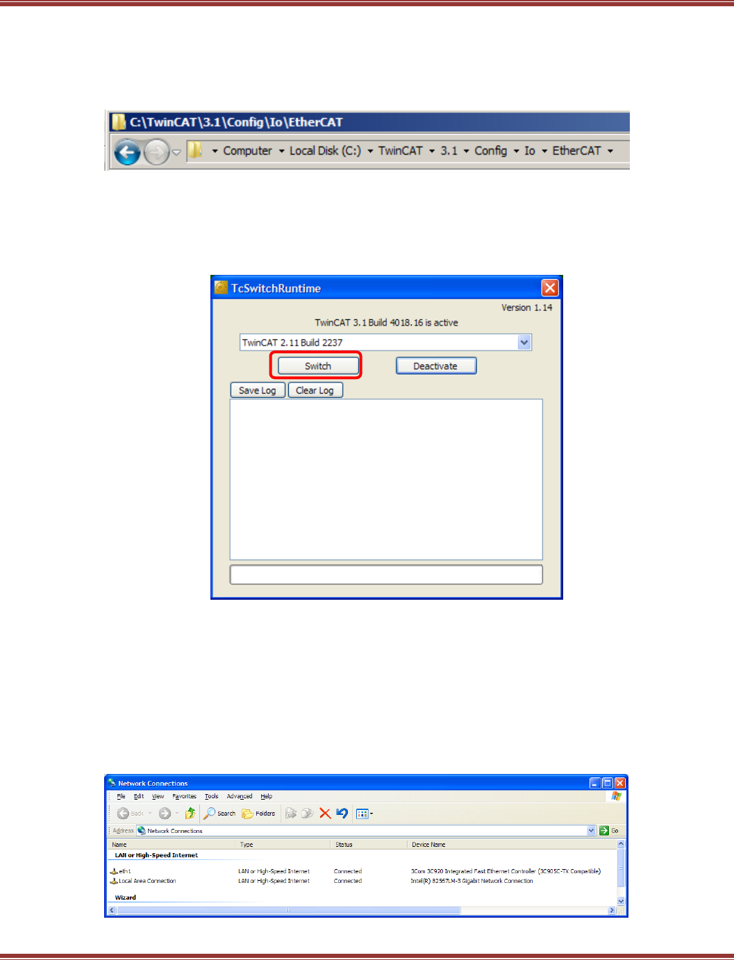
EtherCAT User Guide 16-01450 Rev 00
Page 40
Install ESI Files
DO NOT LAUNCH TWINCAT3 BEFORE INSTALLING THE ESI FILES !
But if you have already opened TwinCAT 3, exit/close it now and proceed to the ESI file installation.
Go to the folder where the Copley ESI files were downloaded. Open the slots folder, select all of the files in the
folder. Copy them and paste into this folder in the TwinCAT 3 installation:
Confirm that TwinCAT 3 is the Active Runtime
TwinCAT 3 will install if TwinCAT 2 is already in the computer. It goes into the 3.1 folder under the
C:\TwinCAT folder. After installation, TwinCAT 2 may appear as the active Runtime, but it is still possible to
make TwinCAT 3 the active Runtime. With the TwinCAT 3 installation there is a file named TcSwitchRuntime
which is a tool that will easily switch the runtime core between TwinCAT 3 and TwinCAT 2.
This screen shows that TwinCAT 3 is the active Runtime. But if the TcSwitchRuntime screen shows
that TwinCAT 2.. is active, then click Switch and follow the steps to make TwinCAT 3 the active Runtime.
Assign an Ethernet Port on Your Computer to EtherCAT
EtherCAT should use a dedicated NIC (Network Interface Card) so that It does not share a port with other
Ethernet traffic. For desktop computers, this can be a PCI card NIC which are commonly available and
inexpensive. For laptops, it’s best to use the built-in Ethernet port for EtherCAT and then use a PC card or
wireless for general Ethernet activity. The built-in Ethernet port will generally run faster than an accessory
port and works better for EtherCAT. In this example, eth1 is used for EtherCAT and the other port is for
general EtherCAT use.
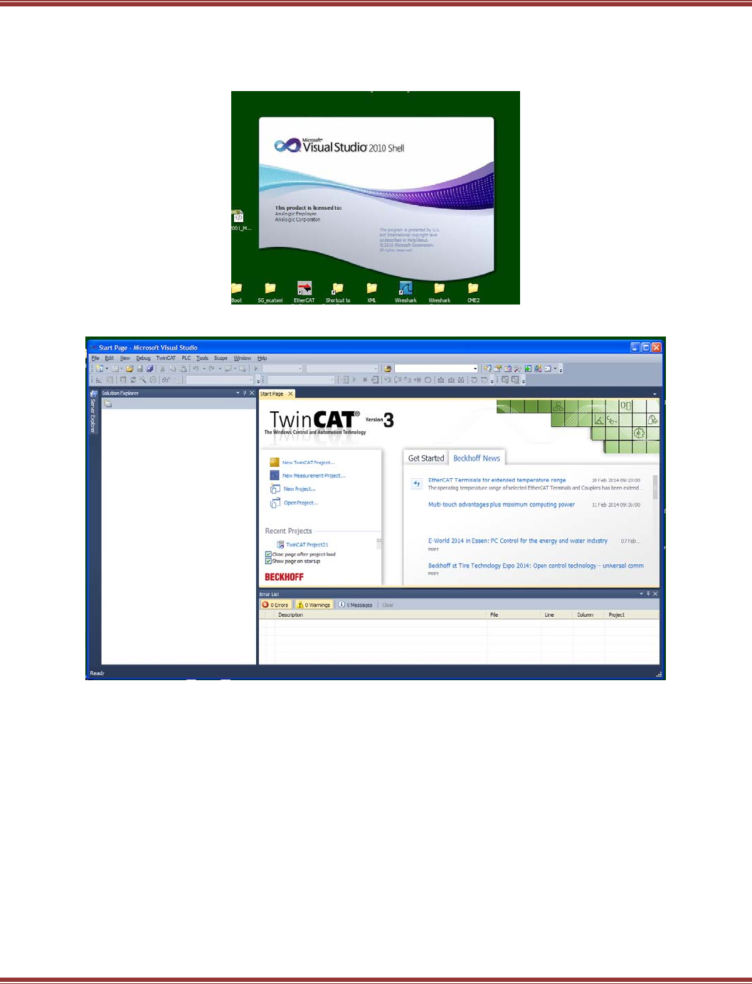
EtherCAT User Guide 16-01450 Rev 00
Page 41
Running TwinCAT 3
Goto: Start Menu → All Programs → Beckhoff → TwinCAT3 → TwinCAT XAE (VS 2010)
First, the splash screen:
Then the TwinCAT3 home page. From here click on New TwinCAT Project:
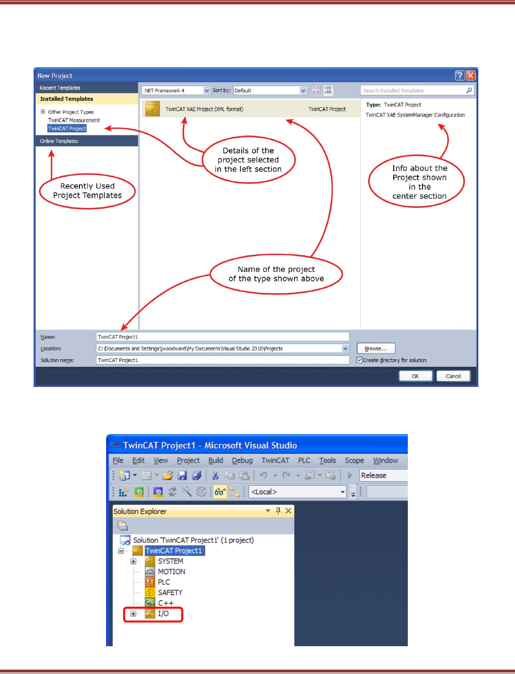
EtherCAT User Guide 16-01450 Rev 00
Page 42
The New Project Screen
Because TwinCAT3 now uses Microsoft Visual Studio as the user interface, file organization follows those
rules. A Solution contains items used to create a complete application which is composed of multiple
Projects, and other supporting data.
Click OK to go ahead with the default TwinCAT Project1, or use your own project name instead.
Now we see the main page of what used to be the System Manager in TwinCAT 2.
Click on the [+] I/O to expand that section.
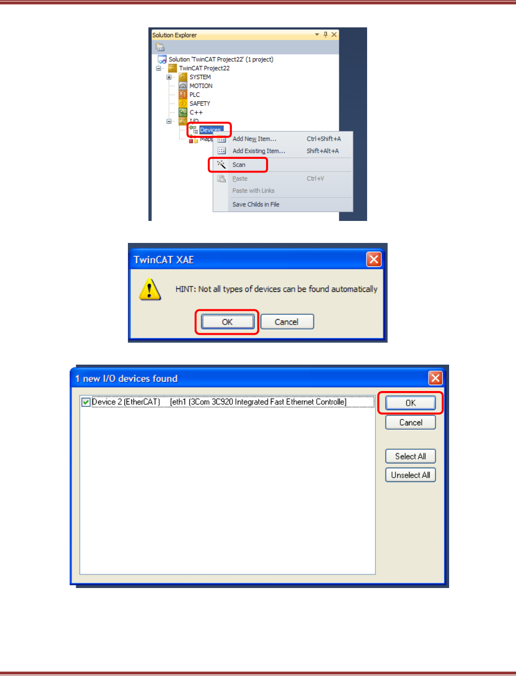
EtherCAT User Guide 16-01450 Rev 00
Page 43
The I/O object opens up to this screen. Right-click on Devices, then click Scan on the pop-up:
Click OK on the next screen, and TwinCAT 3 will start to scan the network for devices:
If the NIC is properly configured, it will show the EtherCAT attribute when it’s found:
Click OK to continue…
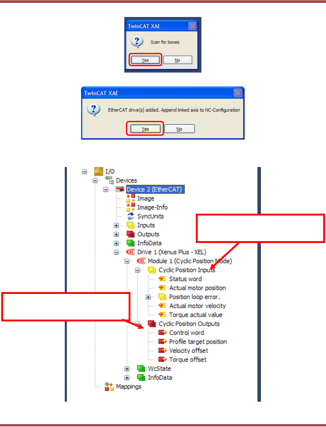
EtherCAT User Guide 16-01450 Rev 00
Page 44
With the NIC open to the EtherCAT network, the next step is to scan for “Boxes” (EtherCAT devices).
A Xenus XEL is found. TwinCAT 3 will automatically link this to an NC controller.
Click on the [+] at Drive 1 (Xenus Plus – XEL) to expand it.
Then click [+] at Module 1, again [+] on Cyclic Position Inputs, then [+] on Cyclic Position Outputs.
This will display the default inputs and outputs for Cyclic Sync Position mode.
Inputs refer to the NC controller which is
receiving data from the Xenus via TxPDO
(Transmit PDO 0x1B00)
Outputs refer to the NC controller which is
sending data to the Xenus via an RxPdo
(Receive PDO 0x1700)
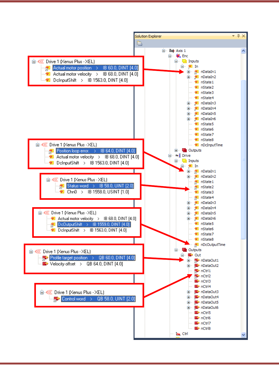
EtherCAT User Guide 16-01450 Rev 00
Page 45
Opening the NC controller shows its construction. Each Axis is an NC that is linked to a drive (or one axis of
a 2-axis drive) on the network. The Enc (encoder) will receive position data from the drive.
The drive Inputs will receive status information. And, the drive Output will be sending
position/velocity/torque data to the drive.
These connections are for the CSP (Cyclic
Sync Position) operating mode which is the
default mode in the ESI file
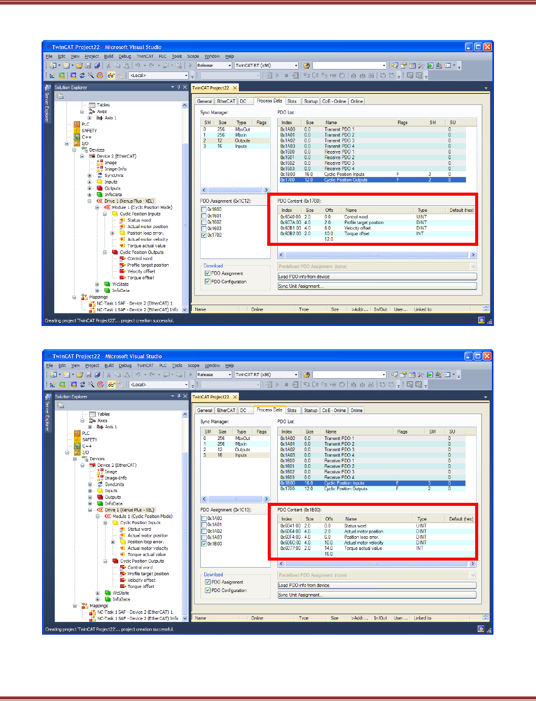
EtherCAT User Guide 16-01450 Rev 00
Page 46
Below is the Xenus RxPdo 0x1700 which receives data from the NC Outputs nCtrl1 & nCtrl2 which are each 1 byte
requiring two of these to compose the 16-bit (2 byte) Control Word:
Below is the Xenus TxPdo 0x1B00 which transmits data to the NC Encoder and Drive Inputs:
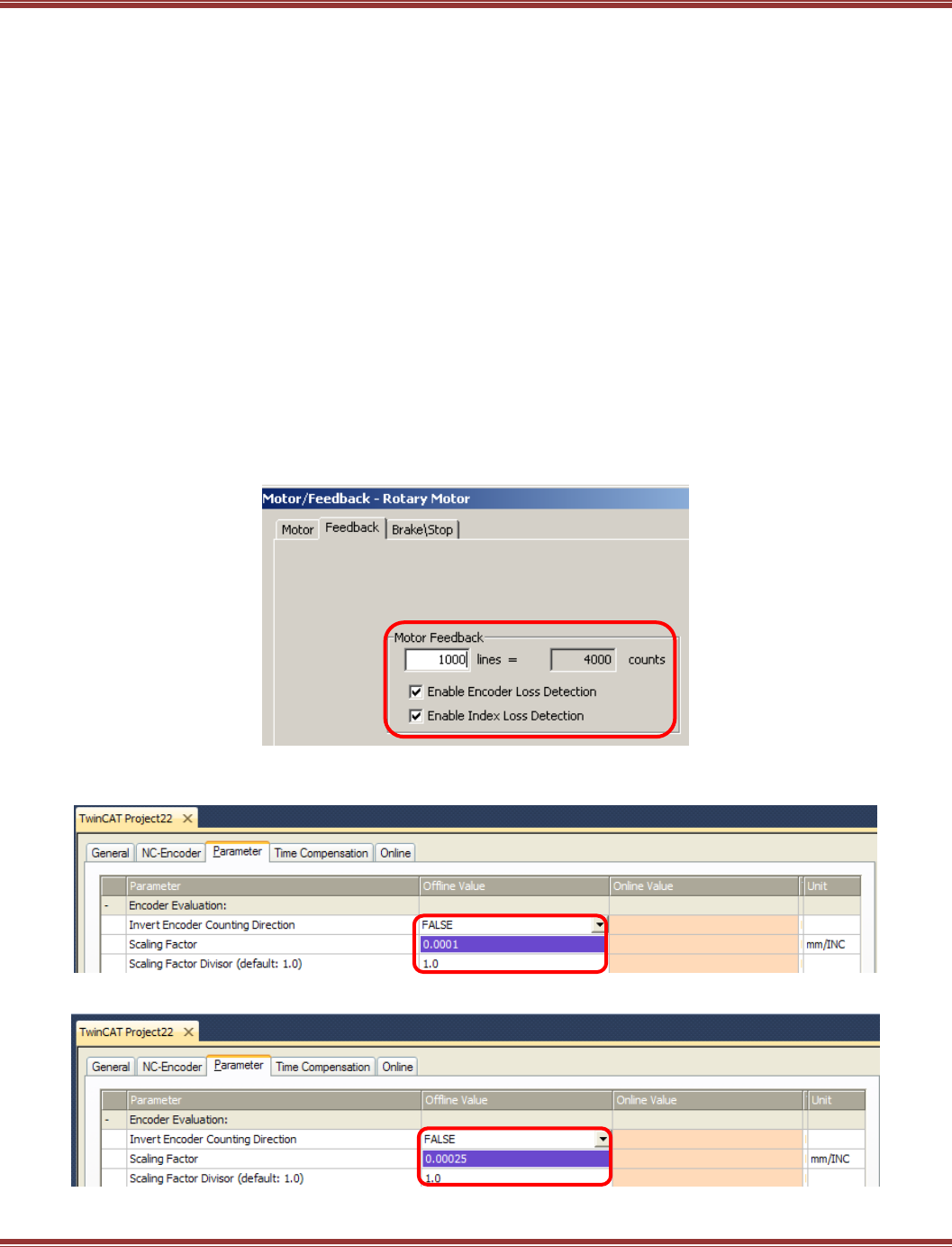
EtherCAT User Guide 16-01450 Rev 00
Page 47
Setting Up the NC Controller
After the connections have been made automatically by TwinCAT 3, it is necessary to configure the following
settings in the NC controller for the drive and motor combination:
Scaling factor (Units of position measurement)
Maximum speed
Jogging speed (Fast, Slow)
Acceleration limits (accel, decel)
Monitoring (of various conditions)
Encoder Scaling Factor
Understanding “mm/INC”
Units of position in TwinCAT 3 are user-settable using the mm/Inc factor.
“mm” = User unit of position (rotary or linear)
“INC” = Position change per increment of feedback (encoder count)
Opening the Axis 1 Enc, Parameter tab will show the parameters for the feedback units.
For this example, this is the screen from CME2 that shows the encoder data:
Taking the 4000 counts/rev and inverting it gives the INC factor of 1/4000, or 0.00025 revs/count.
The screen below shows the default setting of the Scaling factor as 0.0001:
Double-clicking this and changing it to 0.00025 should produce this result:
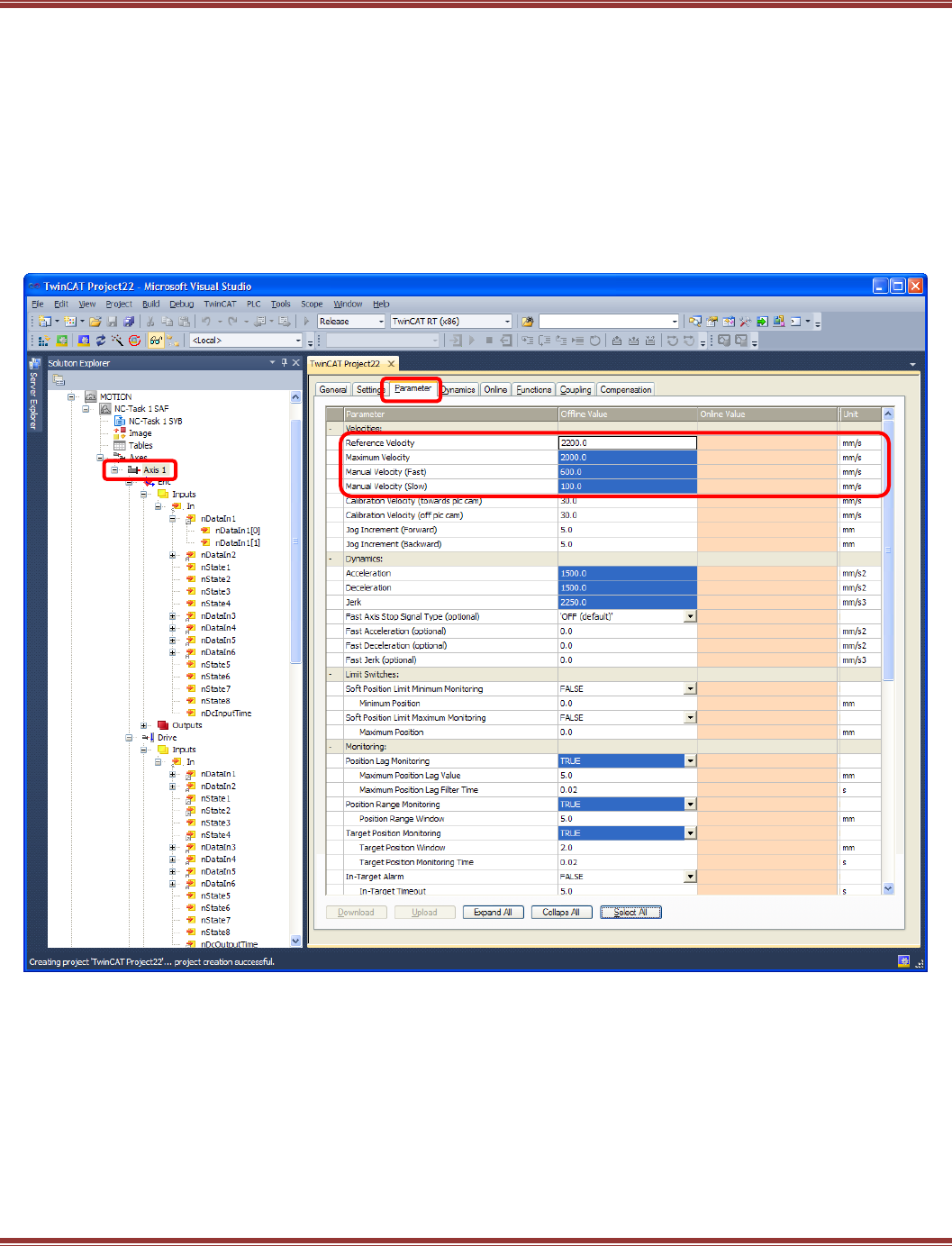
EtherCAT User Guide 16-01450 Rev 00
Page 48
NC Axis Settings
In the TwinCAT 3 Solution Explorer window (folder tree) click on Axis 1, and then on the Parameter tab.
The settings highlighted below are the ones to adjust for the motor/drive combination used.
This assumes that the motor is free to move, and that there are no limit or home switches.
From the mm/INC settings, the unit of position is “rev”, or revolution of a rotary motor. In this screen the units to
be set should be read like this:
mm = rev (revolutions) Distance
mm/s = rev/sec Velocity
mm/s2 = rev/sec2 Acceleration
mm/s3 = rev/sec3 Jerk
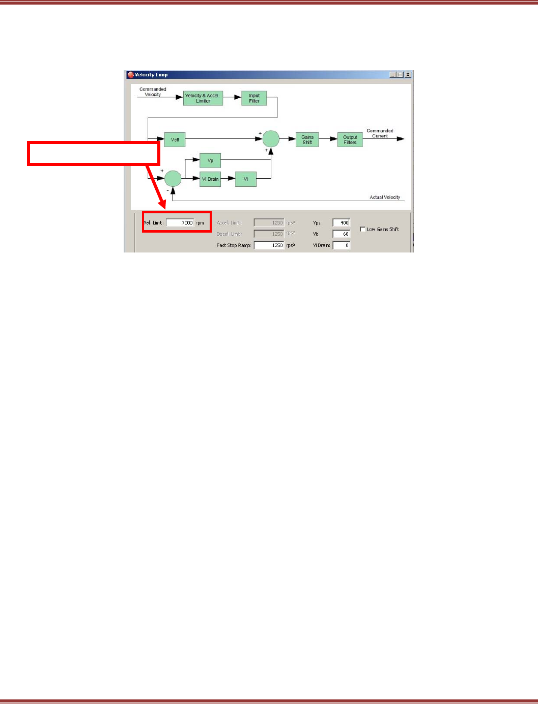
EtherCAT User Guide 16-01450 Rev 00
Page 49
NC Axis Settings (cont’)
Maximum Velocity: Set to ~90% of the value shown in the CME2 V-Loop window:
In this case, that would be 7000 X 0.9 = 6300 RPM (rev/min)
Convert that to rev/sec: 6300 / 60 = 105 and double-click to edit Maximum Velocity and make it 105.
Manual Velocity (Fast) = Speed for the fast jog setting in the NC Online screen.
300 RPM is a common setting, or 5 rev/sec.
Manual Velocity (Slow) = Speed for slow jog setting in the NC Online screen
A good factor here is 1/5 of the Fast Jog speed, 60 RPM, or 1 rev/sec.
Acceleration Assume that the time to 6300 RPM is 1 second,
or (105 rev/sec) / (1 sec) = 105 rev/sec2
Deceleration For this example, use the same value as acceleration
Jerk Multiply Acceleration X4 to get to the same velocity in the
same time = 4 X 105 = 420 rev/sec3
Position Lag Monitoring Also known as following-error, turning this off during commissioning will
eliminate halting during the system tuning/commissioning process. Doing this does assume that the
motor/load combination can tolerate some mis-positioning without damage.
Position Range Monitoring & Target Position Monitoring Together, these indicate a “Move-done”
condition in which the trajectory generator is no longer busy, and the motor is within the position range of
the target position.
Maximum motor velocity
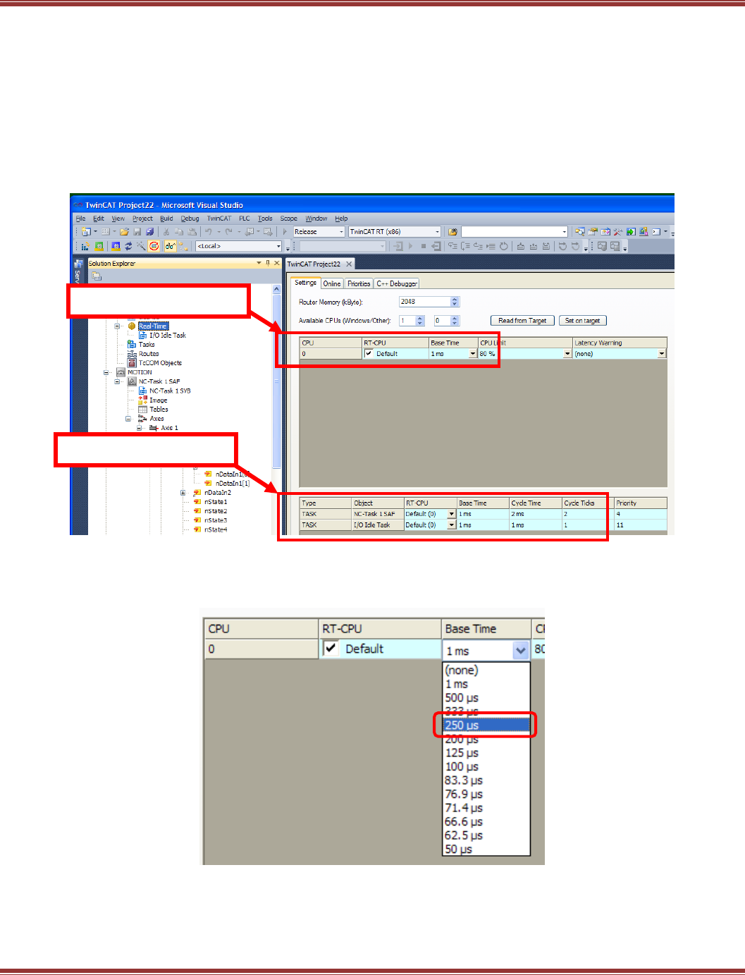
EtherCAT User Guide 16-01450 Rev 00
Page 50
System Real-Time Settings
The RT (Real-Time) CPU time is the fundamental time unit at which the RT kernel operates.
And, within the RT kernel, multiple tasks can operate. The default for this is 1 ms, with each ms seen as a “tick”
of the RT clock by other tasks.
The NC Task 1 SAF produces the cyclic-synchronous data updates to slaves on the network.
The default setting is 2 cycle ticks of the RT clock, resulting in a Cycle Time of 2 ms for the SAF task.
The NC Task 1 SVB is the calculation engine in the NC controller that does the math for the motions to be
executed. The results of these calculations are passed to the SAF task to update the drives. The default timing
for this task is 5X the cycle ticks of the SAF task, resulting in 10 cycle ticks, or 10 ms.
It is possible to run TwinCAT 3 at these timings, but operation at these defaults will produce some audible noise in the
position loop operation. Smoother operation is possible when cyclic position (or velocity) updates occur at the 4 kHz
rate of the Xenus, Accelnet, and Stepnet Plus drives. To set up these timings, begin with the following setting of the
Base Time RT-CPU:
System Base Time
NC Task 1 SAF
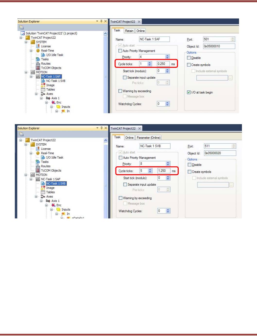
EtherCAT User Guide 16-01450 Rev 00
Page 51
Next, scroll down to the NC Task 1 SAF item under the Motion part of the TwinCAT 3 folder tree.
Click on this to open this screen. Change the Cycle ticks number to 1. The result should look like this:
Now, click on NC-Task 1 SVB and set that to 5 Cycle ticks. This should be the result.
To summarize these settings:
Parameter Default 4kHz
Base Time 1 ms 250 us
NC-Task 1 SAF 1 ms 0.25 ms
NC-Task 1 SVB 1 ms 1.250 ms
Setting these is easy, so is 4kHz the best choice? The answer depends greatly on the characteristics of the
computer that is running TwinCAT 3.
For now, leave the settings at the 1 ms default values. When the system is started it will be possible to
display the jitter in the task timings using TwinCAT 3. If the jitter is low, then the timings can be set up to
the 4kHz numbers.
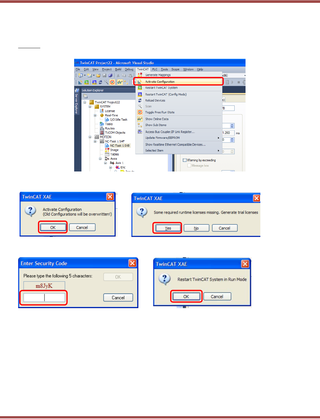
EtherCAT User Guide 16-01450 Rev 00
Page 52
RT Kernel Time-Base Stability
“Stability” describes the uniformity of the time between updates of the slaves on the network.
Ideally it will show no variation. In practice, it will frequently vary widely and inconsistently.
With the settings made in the NC for encoder resolution, velocities, and accelerations, the next step is to
Activate the configuration. This compiles all of the settings in the Visual Studio interface, downloads them to
the RT kernel, and starts the kernel in Run model
This produces this screen (click OK), followed by the license-missing screen.
Click [Yes] to generate a trial license:
Simply enter the characters shown in the window and this will activate a trial license.
Click [OK] to Restart TwinCAT System in Run Mode:
M8JyK
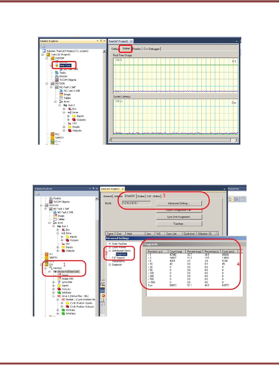
EtherCAT User Guide 16-01450 Rev 00
Page 53
RT Kernel Check #1
Navigate to the System > Real Time icon in the folder tree and click on the Online tab to the right.
This screen shows the percent-usage of the computer’s CPU and the System Latency.
The System Latency is the time at which the system time-tick arrives too late for the RT kernel.
RT Kernel Check #2:
Scroll down to the folder the I/O>Devices>Device4 (EtherCAT), double-click that to open, then select the
EtherCAT tab>Advanced Settings button. Open the Distributed Clocks>Diagnosis item.
This shows the number of network packets under different deviations of the timing. None of them are
greater than 20 us.
These data were taken from a Beckhoff C6920 industrial PC and show a high degree of stability of the
system timing. The same TwinCAT 3 installation on desktop or laptop computers will typically show much
larger deviations in the system timing.
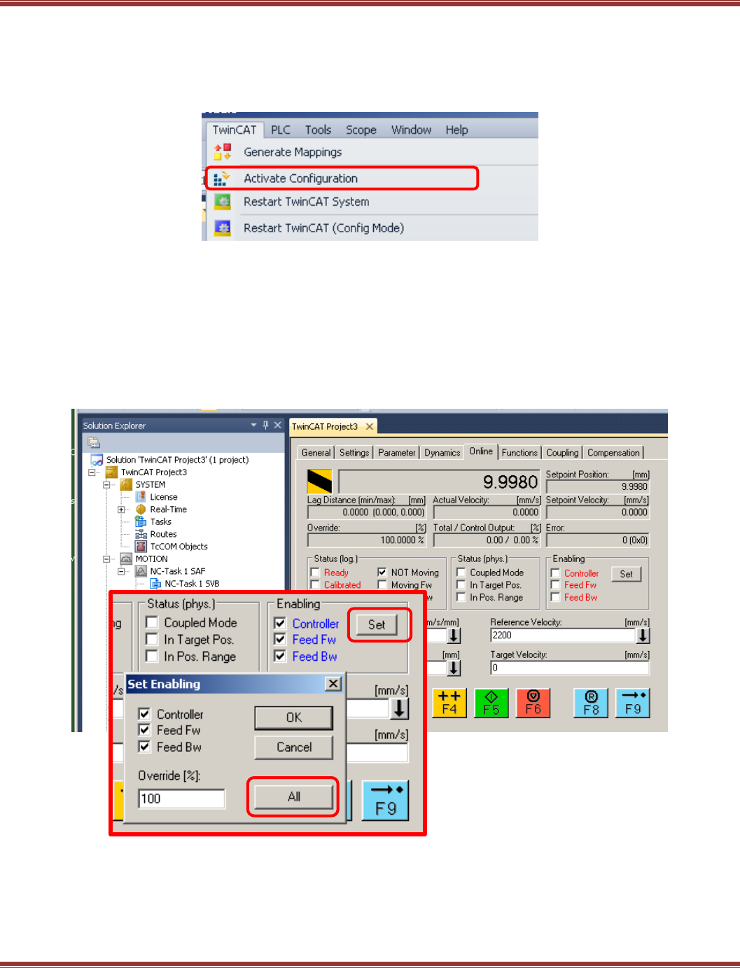
EtherCAT User Guide 16-01450 Rev 00
Page 54
Activating the Configuration
With the NC, encoder, and parameters all set, the configuration is ready for activation.
This is the operation that takes the configuration in the engineering interface (Visual Studio) and downloads
it to the RT kernel. While shortcut keys are shown in other Menu bar options, they are missing from the
TwinCAT objects. Because these are used frequently and are valuable time-savers, they are show below:
Activation will automatically generate mappings and switch TwinCAT to Run mode:
The RT kernel is running, datagrams are generated connecting the nodes with real-time PDO updates.
Config mode stops the RT kernel. Free Run will query the network devices and allow alteration of their data,
but the slaves will not be enabled for motion control.
NC: Online
After activation, click on the Axis under the MOTION..Axis 1 item and open the Online tab.
This mimics the control panel of an NC controller with jogging and other user buttons.
Click [Set] in the Enabling frame, and select All to enable the drive.
Ctrl + M
Ctrl + Shift + F4
Shift + F4
Ctrl + F4
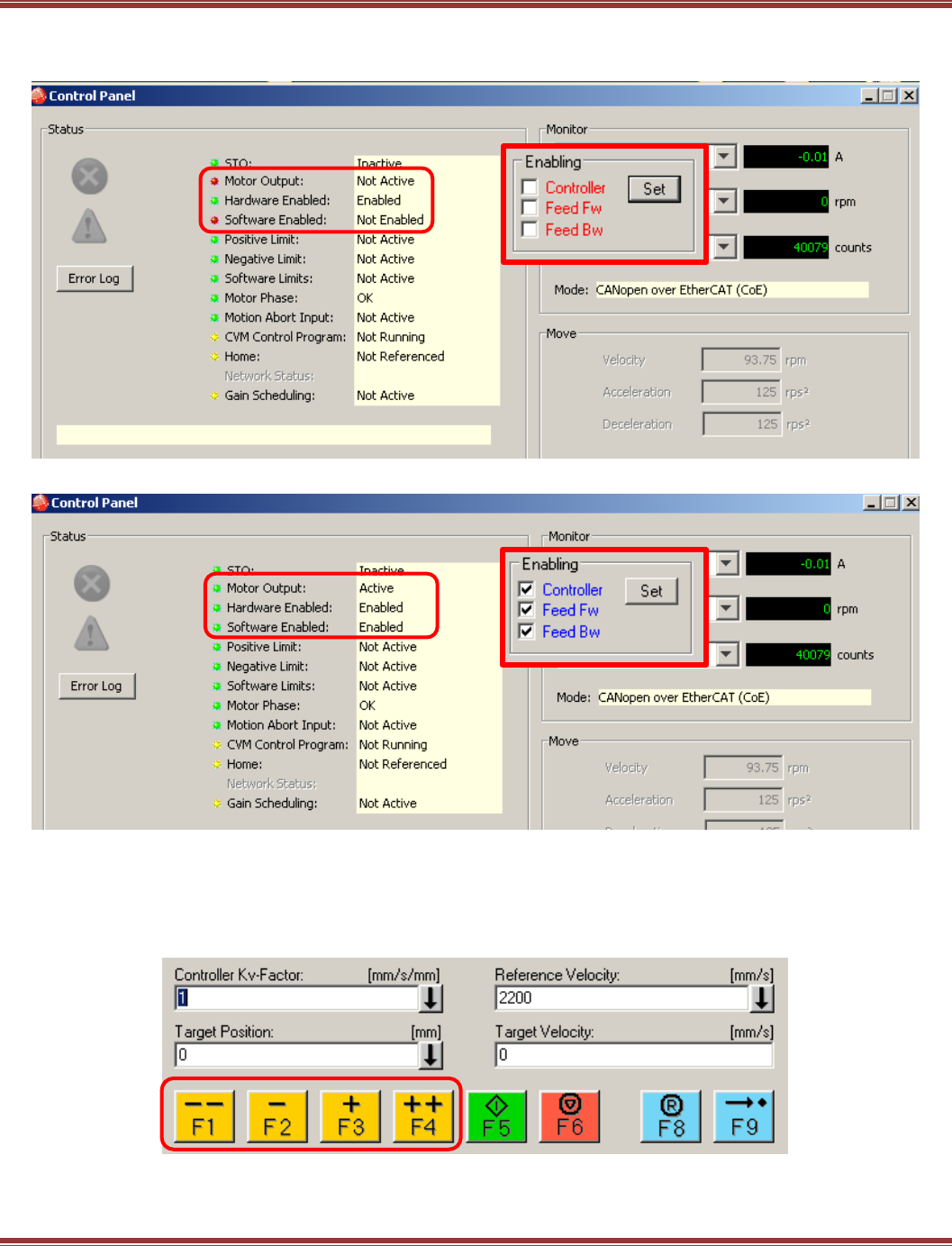
EtherCAT User Guide 16-01450 Rev 00
Page 55
Enabling the drive from an EtherCAT master can be seen via the Control Panel of CME2.
The graphics below show the NC controller’s Enabling frame in red, and the CME2 Control Panel indicators showing
the effects of network enabling (software enabling) of the drive.
NC: Manual Control
Jogging
The F1~F4 keys are used to jog the drive pos/neg at the Manual Velocity (Fast) and Manual Velocity (Slow)
rates that were set up in the NC Parameters tab > Velocities section.
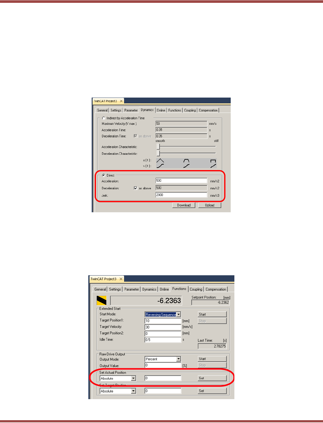
EtherCAT User Guide 16-01450 Rev 00
Page 56
Single Move: Target Position
This value sets the destination in absolute coordinates for a single move. It is in the position units used (“mm”).
In this example, the unit is “rev” or revolutions of the motor. Entering 25 would mean 25 revolutions.
Single Move: Target Velocity
Units are the rate of change of the position units. In this example, that would be rev/sec.
Entering 40 would be 40 rev/sec, or 2400 RPM.
Single Move: Acceleration/Deceleration
Acceleration/deceleration values remain as they were configured in the NC Parameters tab. They can also be
displayed in the Dynamics tab. The default presentation is shown below. The dynamics can also be changed
here with the various Direct and Indirect controls.
NC: Setting Absolute Position to Zero
In TwinCAT 3, Homing is called Referencing and involves a number of settings which will not be covered in
this tutorial. However, it is possible to jog a motor to a position that can be set to “0” after which moves can
be performed in absolute position coordinates.
Step 1: Jog the motor to the position that will become “home”.
Step 2: Open the Functions tab of the NC > Set Actual Position frame. Check for “0” in the number box and
press the [Set] button. The position on the display box above will go to 0 (absolute).
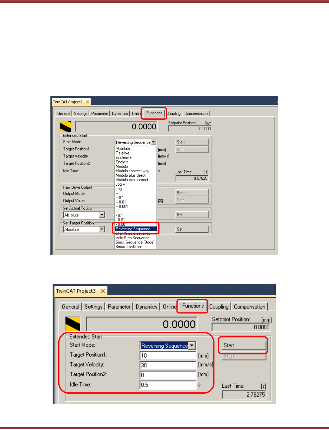
EtherCAT User Guide 16-01450 Rev 00
Page 57
NC: Out/Back Repeating Positions
For tuning an axis over EtherCAT, the NC has a feature that is similar to the Function Generator in CME2.
This is particularly useful because in CME2, the drive is controlled by an internal trajectory generator that is
performing profile-position moves in which the accel/decel, velocity, and target position are fixed values.
In an EtherCAT master in CSP (Cyclic Sync Position) mode, the trajectory generation is in the master.
The servo drive only sees increments of position with every PDO and has no knowledge of the final target
position or velocities. And the rate at which the updates arrive depends on the time-base of the master.
So, setting up out/back moves over EtherCAT enable tuning of the system under actual operating conditions.
Step 1: Open the NC Functions tab > Extended Start frame, and pull-down the Start Mode menu
to Reversing Sequence. Note the 0.0000 position (after zeroing) which will be the starting position
for the reversing moves.
Enter values for Target Position1 (Out position), Velocity, Target Position2 (0 for Back position),
and Idle Time (dwell). Press [Start] to go, and when running press [Stop] to halt. If Stop is pressed for a move in
progress, pressing Start will resume motion without losing the absolute position reference of the moves.
When final tuning has been done, the drive is ready to be operated by the EtherCAT master.
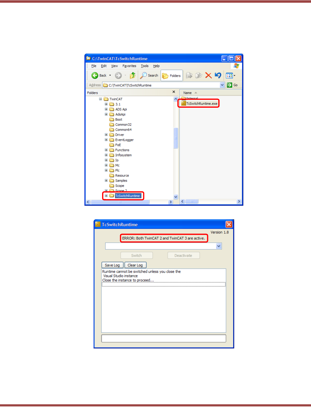
EtherCAT User Guide 16-01450 Rev 00
Page 58
Switching Runtime with TwinCAT 2
If your computer already has TwinCAT 2 installed, then adding TwinCAT3 means that there are now two real-
time kernels in the system. Only of them can operate at the same time, so how to know which one is running?
Fortunately Beckhoff planned for this and there is an application that will get things sorted nicely.
Find it here, and double-click on TcSwitchRuntime.exe
Here’s how it looks with both TwinCAT 2 and TwinCAT3 active:
In order to proceed, the instance to be closed will be TwinCAT3, so close this screen now and
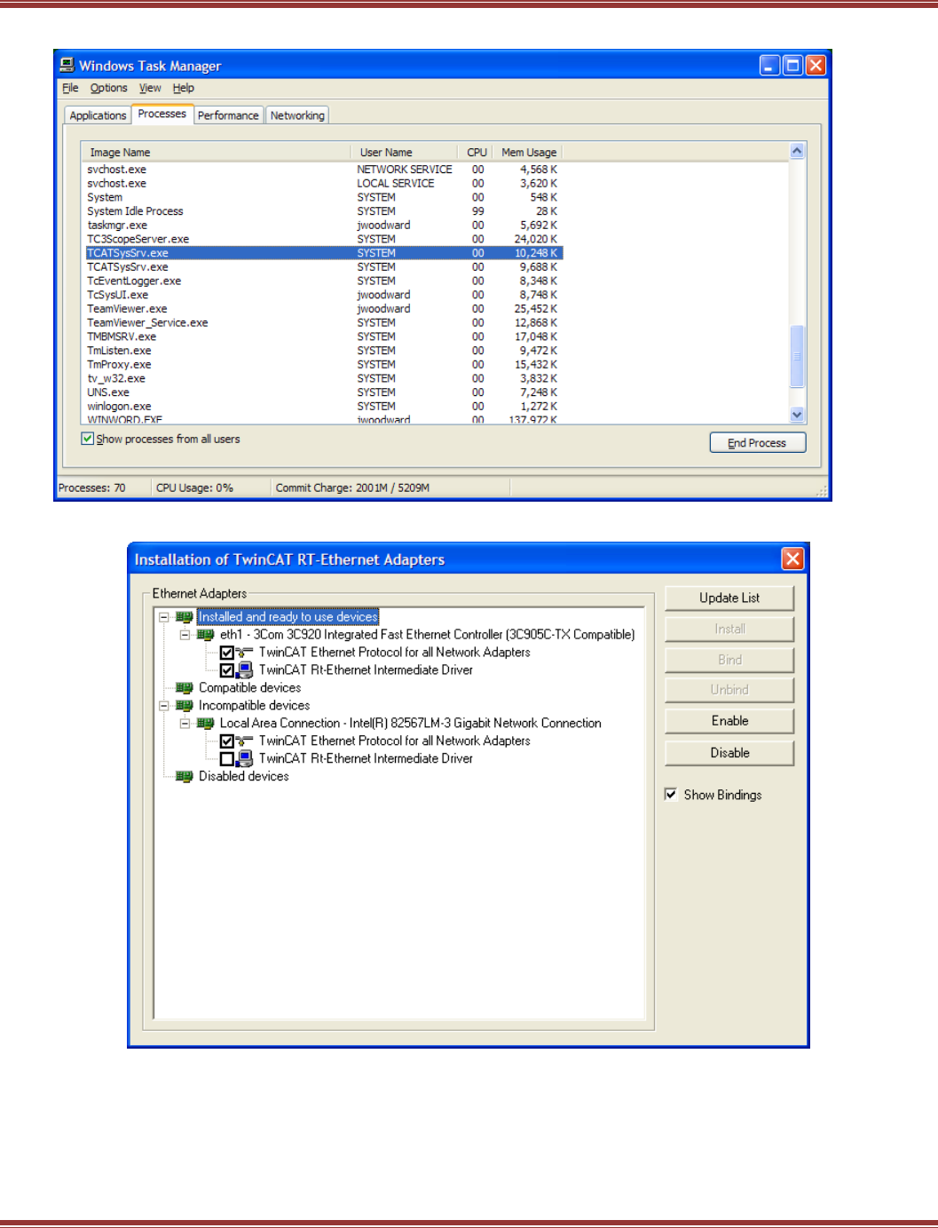
EtherCAT User Guide 16-01450 Rev 00
Page 59
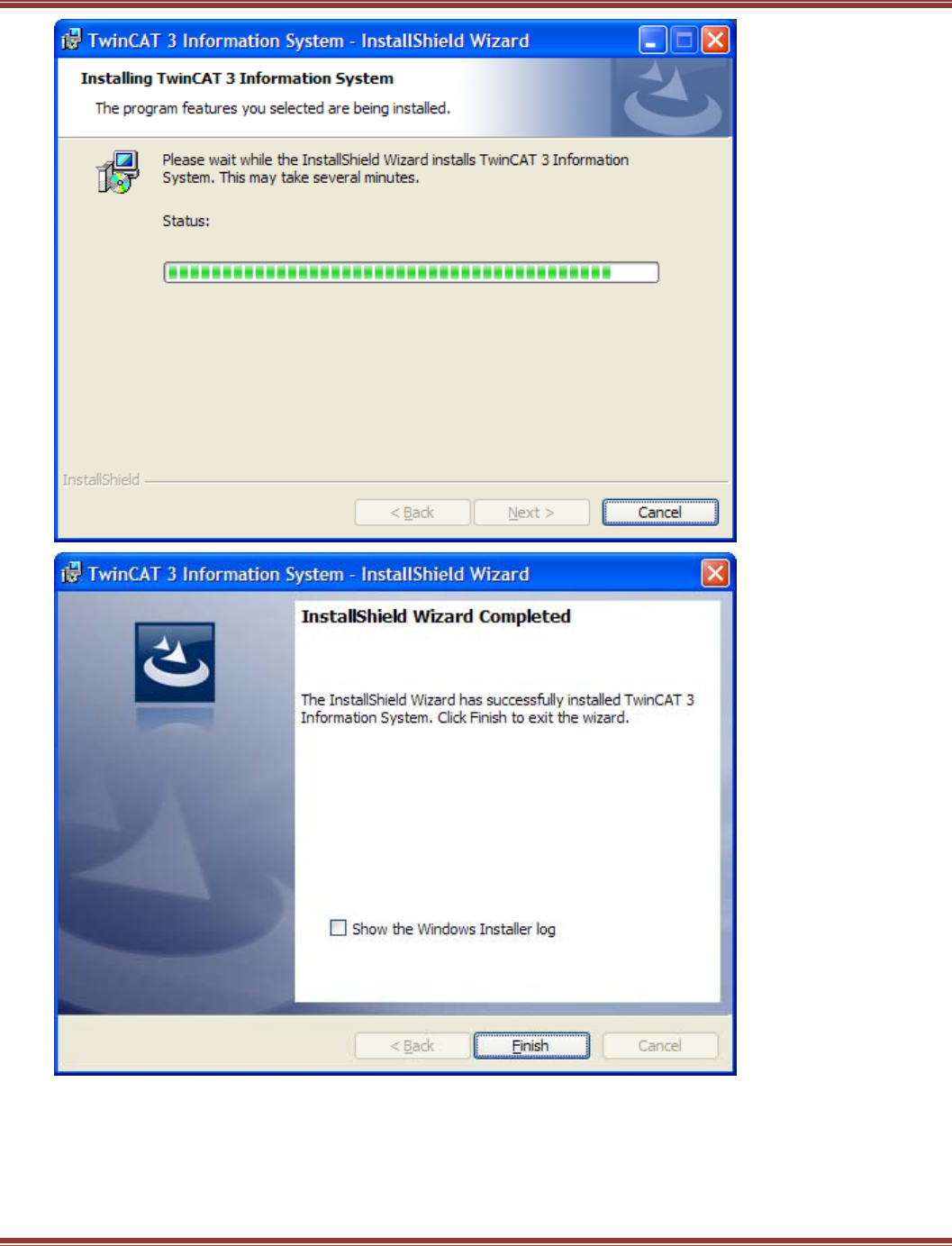
EtherCAT User Guide 16-01450 Rev 00
Page 60
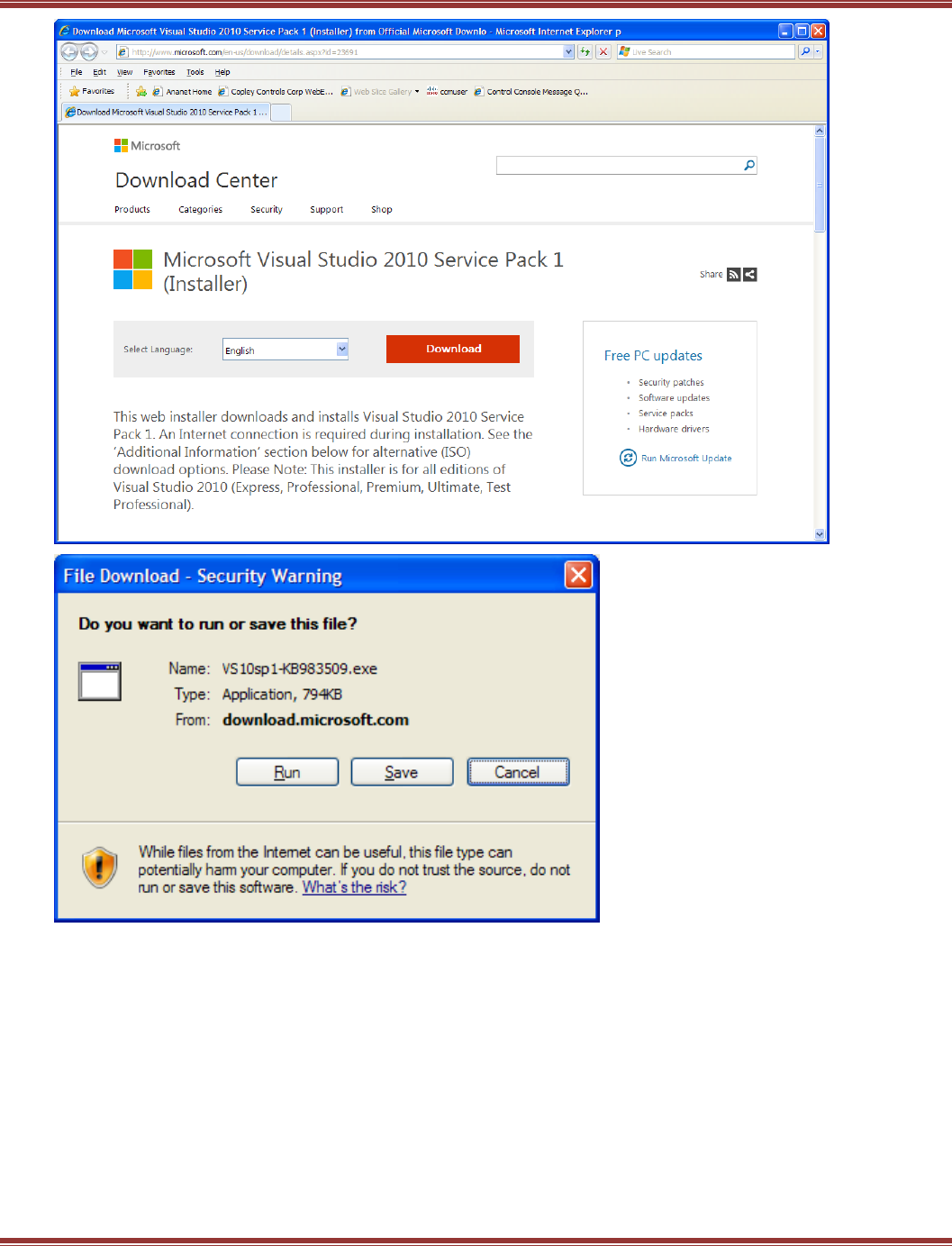
EtherCAT User Guide 16-01450 Rev 00
Page 61

EtherCAT User Guide 16-01450 Rev 00
Page 62

EtherCAT User Guide 16-01450 Rev 00
Page 63
6.2 Beckhoff TwinCAT 2
Introduction
This document provides information on commissioning Copley Controls EtherCAT servo drives using the
TwinCAT 2 EtherCAT master software. When these steps are followed, it should be possible to move a servo
motor via a Copley Controls servo drive from the NC controller in TwinCAT 2. For more advanced motion
control it is necessary to consult the Beckhoff InfoSystem software for details.
Step 1: Configure the Drive for EtherCAT Operation
Install CME2
Run Basic Setup to configure the drive for Position mode, and Command Source
as CANopen over EtherCAT (CoE).
Step 2: Download the ESI (XML) File from the Copley web-site
The file is found here: http://www.copleycontrols.com/Motion/zip/ecatxml.zip
Download it to your desktop, or other folder for now.
Step 3: Assign an Ethernet Port on Your Computer to EtherCAT
EtherCAT requires a dedicated NIC (Network Interface Card). It does not share a port with other Ethernet
traffic and should not be run from an Ethernet switch.
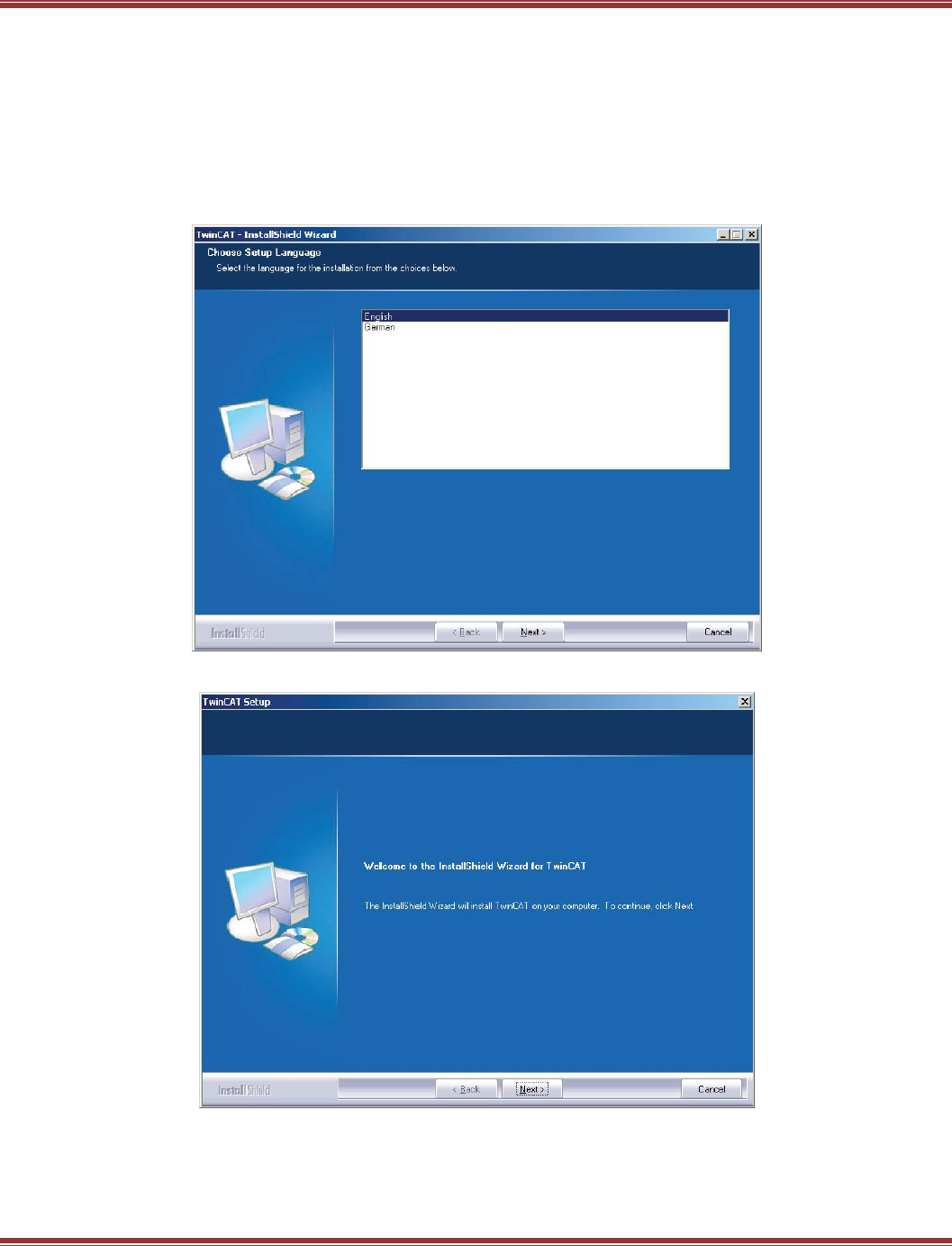
EtherCAT User Guide 16-01450 Rev 00
Page 64
Step 4: Download the TwinCAT 2 Software and Install It
The TwinCAT 2 software will run for 30 days in Demo mode and can be re-installed after that time.
It is on the Beckhoff web-site here: http://www.beckhoff.com/
Navigate to Download -> Software -> TwinCAT 2 30 days version -> Download: TwinCAT 2
Fill out the form and download the file. After that, run Setup to install TwinCAT 2.
DO NOT LAUNCH TWINCAT 2 BEFORE INSTALLING THE ESI FILE !
Here is the sequence of screens you will see during the TwinCAT 2 installation.
Language selection
Click-through EULA
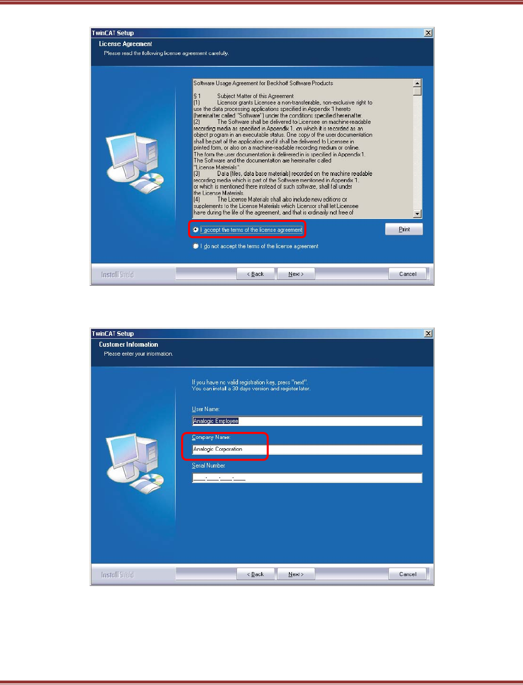
EtherCAT User Guide 16-01450 Rev 00
Page 65
After Welcome, Accept
Name & Company Entry
Leave serial number blank, but a company name is necessary to proceed to the next step.
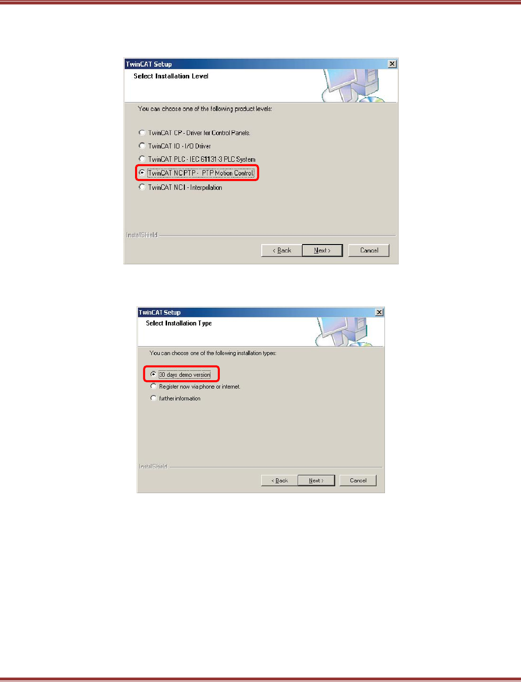
EtherCAT User Guide 16-01450 Rev 00
Page 66
Installation Level Selection
Check the NC PTP item now and all of the items above it will be installed.
This stands for Numerical Control (NC) Point-to-Point (PTP).
Version Selection
Check the 30 days demo, assuming you are a first-time user and not purchasing TwinCAT 2 at this time.
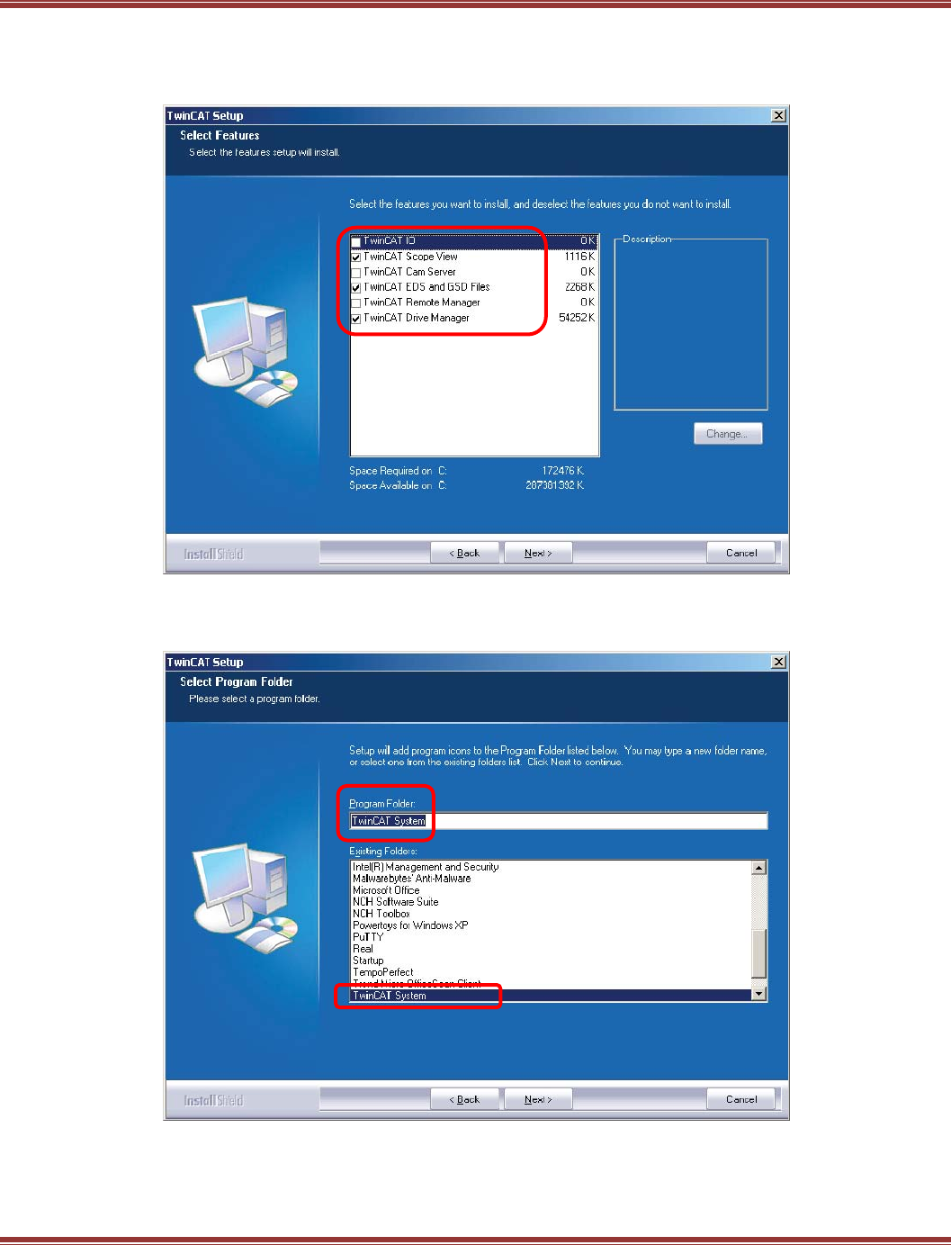
EtherCAT User Guide 16-01450 Rev 00
Page 67
Feature Selection
The default selections are shown below. None are required for running a servo drive with the NC controller
so you can leave these as shown unless conservation of hard-drive storage is a goal.
TwinCAT 2 Destination Folder
The default selections are shown below.
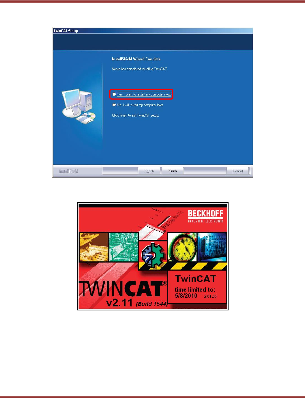
EtherCAT User Guide 16-01450 Rev 00
Page 68
Restart Prompt
Restart is required at this point.
Restart
After restarting, the TwinCAT 2 splash screen will appear:
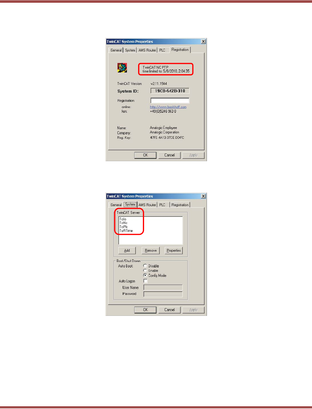
EtherCAT User Guide 16-01450 Rev 00
Page 69
System Properties
Right-click on the TwinCAT 2 icon in the Windows Taskbar and select Properties.
The Registration tab shows version and trial expiration date info:
System Properties
The System tab shows the items installed. Note that TcPLC is shown because it was above NC PTP when the
installation selections were made.
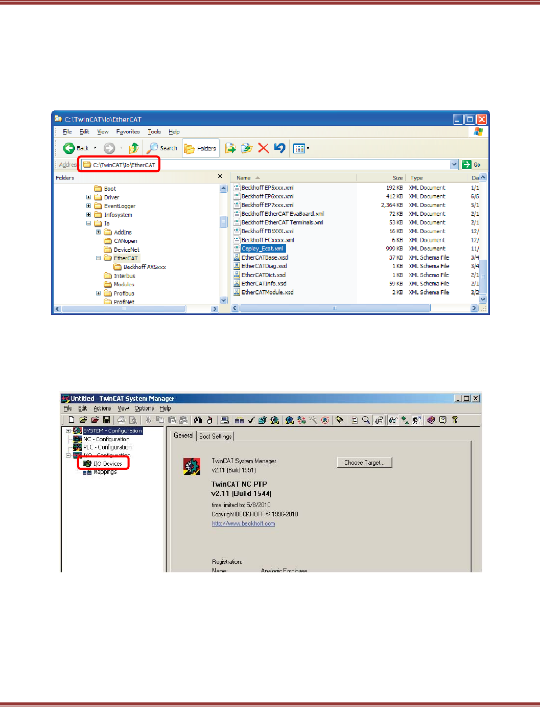
EtherCAT User Guide 16-01450 Rev 00
Page 70
Check ESI File Installation
Download the ESI (XML) files from the Copley Controls web-site and paste them into the
c:\TwinCAT\IO\EtherCAT folder. TwinCAT 2 will scan this folder for devices when it is launched so if it’s
already open, then close it and re-launch.
Also, be sure that there is only one ESI file for each Copley Controls device type in the IO folder. TwinCAT 2
only allows one ESI file for any device type in this folder. The example below shows ESI files for the Accelnet
Plus EtherCAT (AEP) and Xenus Plus EtherCAT (XEL) devices.
Installation Is Complete
At this point, TwinCAT 2 is installed, the Copley Controls ESI files are in the proper folder, so it’s time to
begin setting up a Copley Controls EtherCAT servo drive in TwinCAT 2.
Launch TwinCAT 2 System Manager and this is what appears.
Right-click on I/O Devices in the folder window
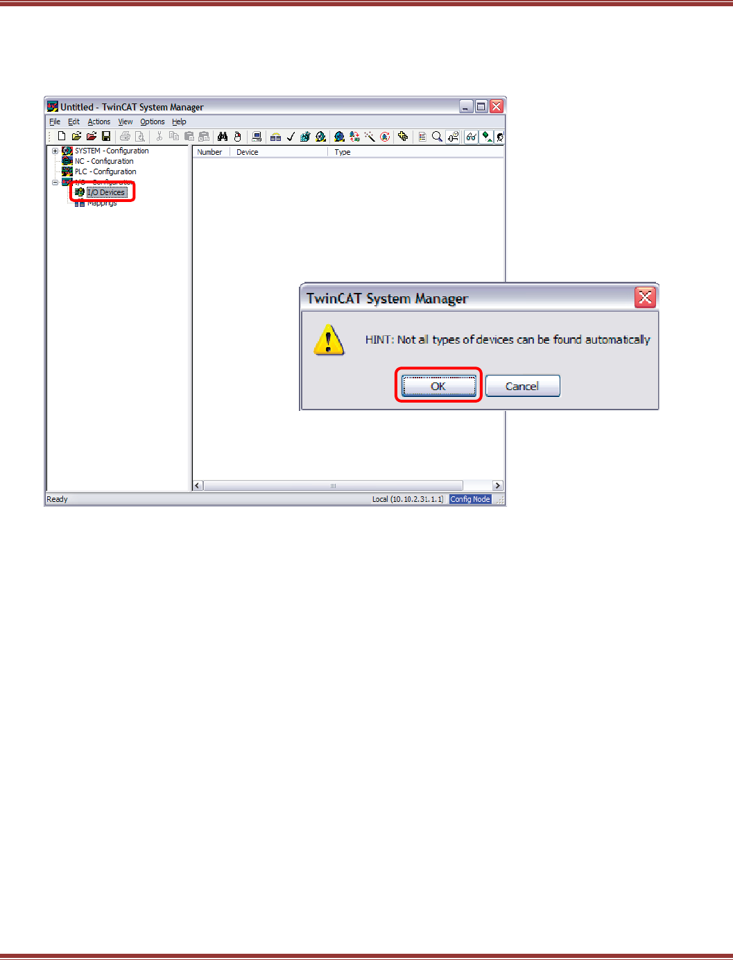
EtherCAT User Guide 16-01450 Rev 00
Page 71
Open A New File And Scan For Devices
From File -> New, or click the icon, create new TwinCAT 2 project.
Next, right-click on the I/O Devices folder and select Scan for Devices.
The pop-up gives a warning but click [OK] to proceed.
Select The Nic For Ethercat
Click [OK] for the EtherCAT port, Scan for Boxes,
Click [Yes] to Add drives to NC-Configuration,
Click [Yes] to Activate Free Run.
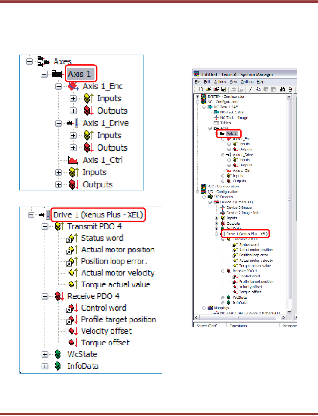
EtherCAT User Guide 16-01450 Rev 00
Page 72
Devices Found And Link To Nc Controllers
If all goes well... TwinCAT 2 should find the CC devices and link these to NC controllers. Expanding the folder
tree to show the NC and XEL items, we can see the encoder and outputs of the NC and the PDOs that have
connected them.
NC Controller Detail
Copley Drive Detail
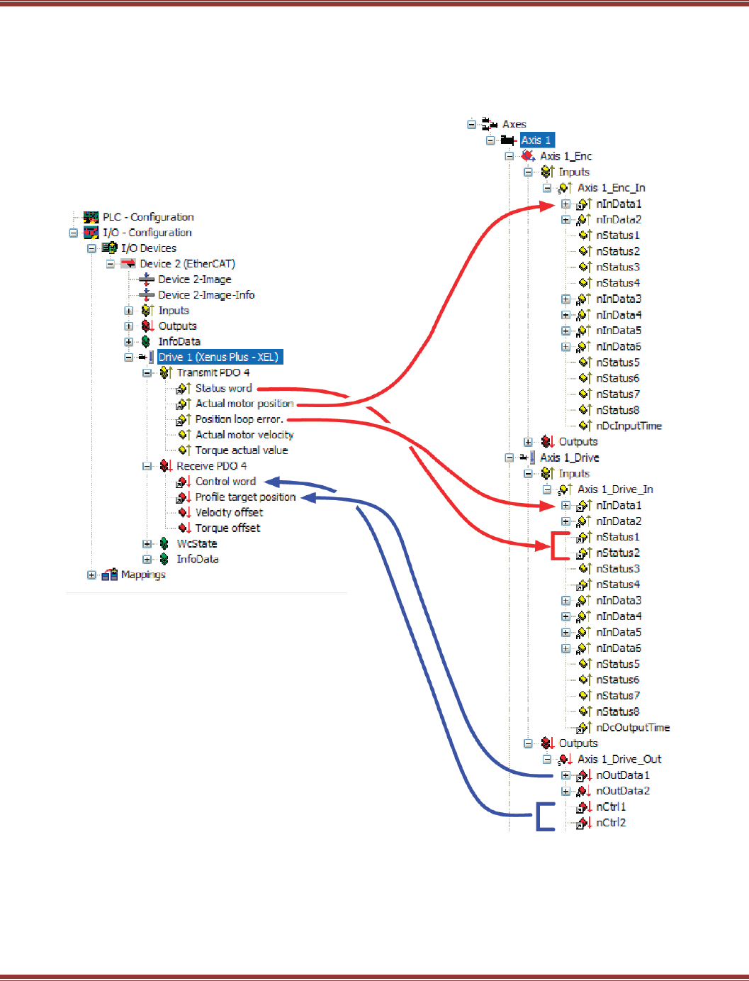
EtherCAT User Guide 16-01450 Rev 00
Page 73
Data Linkage In TwinCAT 2
The diagram below shows how the servo drives is “wired” to the TwinCAT 2 NC using PDO data.
Xenus Plus XEL Drive
TwinCAT NC Axis
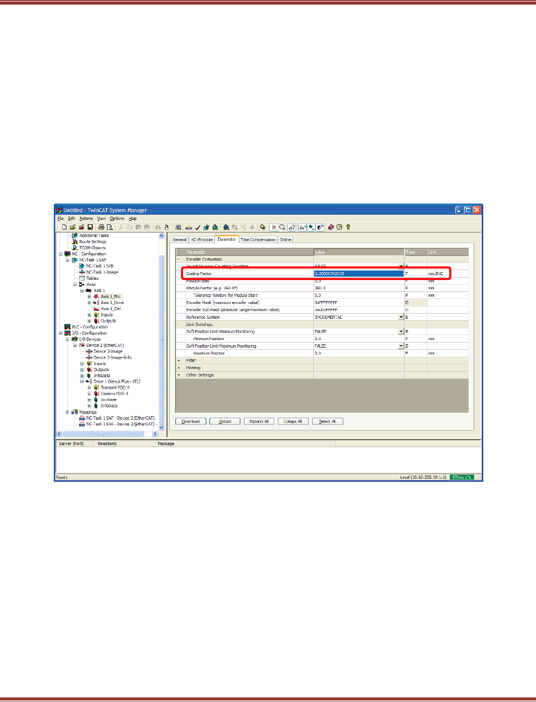
EtherCAT User Guide 16-01450 Rev 00
Page 74
NC Configuration
As a position profile generator, the TwinCAT 2 NC must first have the units of position measurement configured.
In the NC encoder, Axis 1_ENC in this example, Parameter tab the Scaling Factor is the important parameter.
This number = (distance to cover) / (number of counts)
For a rotary motor, distance can be one revolution, and number of counts can be the encoder counts after
quadrature decoding. For a 1000-line quad A/B encoder, this works out to 1000 X 4 = 4000 counts per
revolution.
In this screen, the rotary motor has an absolute encoder that gives 131,072 counts/rev.
The units in TwinCAT 2 are shown as “mm/INC”. The “mm” is really a place-holder, not necessarily for
millimeters, but for the unit of measurement. In this case it will be motor-revolutions.
So, 1 rev / 131,072 counts = .000007629394.
Click in this box and change the default .0001 number to the one for your motor’s encoder or feedback.
You don’t have to hit the Download button now, this change will take effect when the TwinCAT 2 configuration is
“activated” later.
NC Units
If the motor is a linear axis, then the distance to cover might be mm, inches, or metres. All of these can be
used and will be seen in the NC on-line screen when movements, jogging, etc. will all be done in these
units.
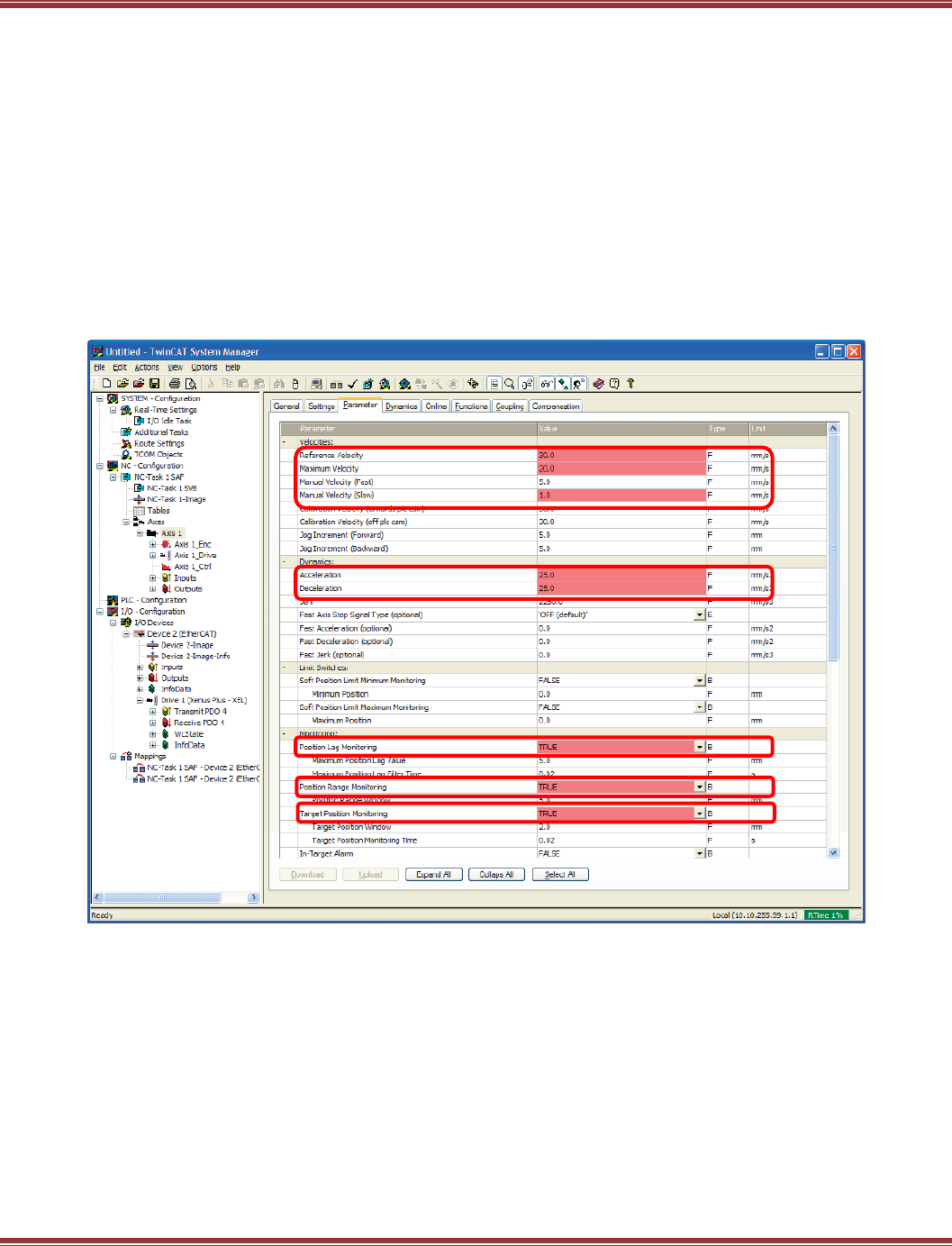
EtherCAT User Guide 16-01450 Rev 00
Page 75
NC Velocity And Fault Configurations
With the feedback units of measure configured, the next step is to set the NC parameters that control the speed
of the motor as well as some fault conditions. This screen shot shows the parameters that will be adjusted.
Reference Velocity: “mm/sec” = units/sec, the same distance-to-measure units that were
used in the encoder parameter tab.
Maximum Velocity:
Manual Velocity (Fast): F1-- or F4++ Jog speed (rev/s)
Manual Velocity (Slow): F2- or F3+ Jog speed (rev/s)
Acceleration: rev/sec for a rotary motor, or mm/sec for linear (Ref_Velocity / Accel_time)
Deceleration: rev/sec for a rotary motor, or mm/sec for linear (Ref_Velocity / Decel_time)
Jerk: rev/sec^2 = 4 * Accel for an S-curve that has the same acc/dec time as trapezoidal
Position Lag Monitoring: Not needed in NC because position loop is closed in the drive
Position Range Monitoring: Not needed in NC because position loop is closed in the drive
Target Position Monitoring: Not needed in NC because position loop is closed in the drive
The numbers show in red now and when the configuration is activated will be updated
and downloaded to the drive.
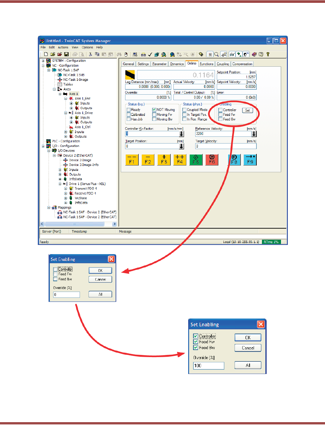
EtherCAT User Guide 16-01450 Rev 00
Page 76
Online Operation Of The NC
When the parameter adjustments have been made, it is possible to operate the motor/drive through this
control panel:
Enable The Drive
Click [Set] and [All] to enable the
drive.
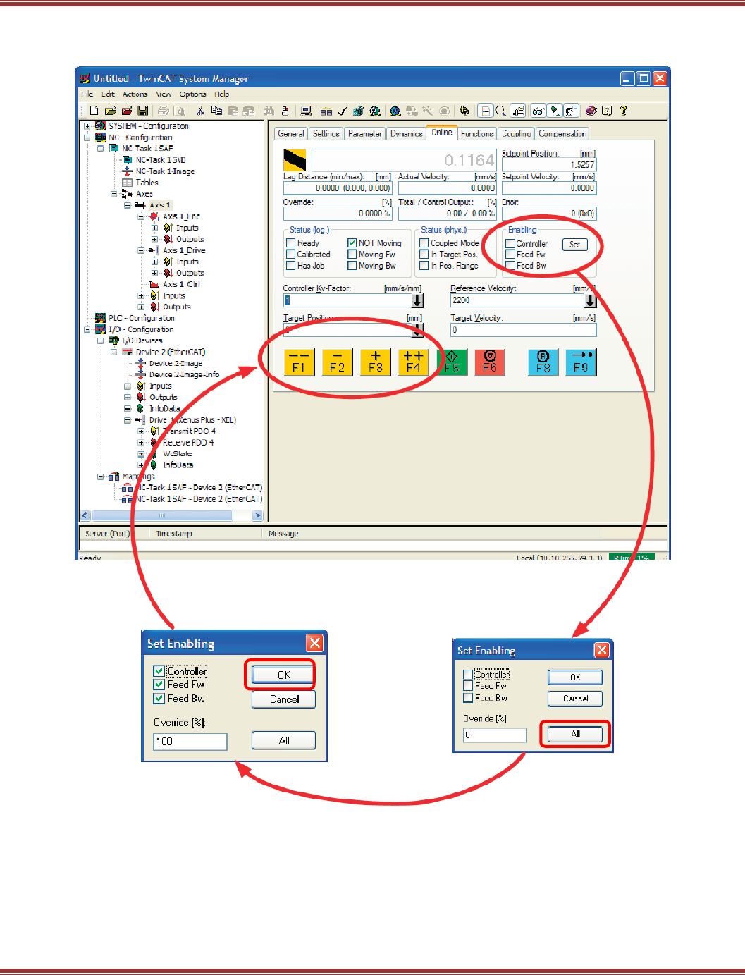
EtherCAT User Guide 16-01450 Rev 00
Page 77
Jogging
The jog keys (F1~F4) should function for fast & slow jogging after the drive is enabled.
Enable The Drive
Click [Set] and [All] to enable the drive.
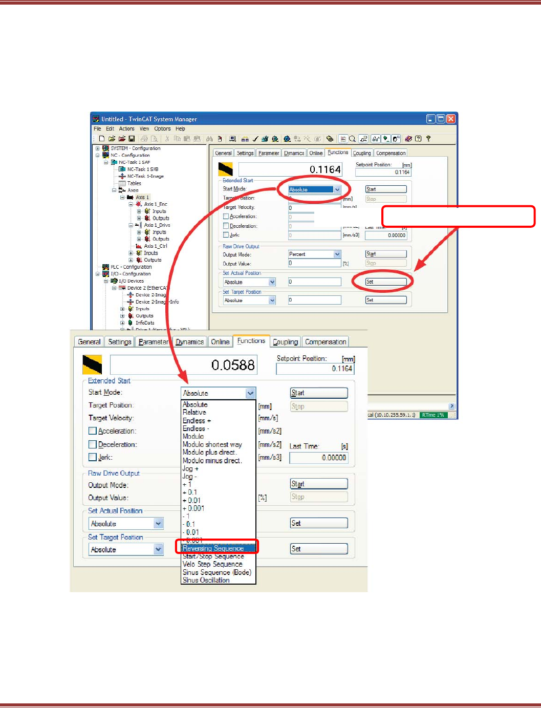
EtherCAT User Guide 16-01450 Rev 00
Page 78
Simple Motion Without A PLC In TwinCAT 2
For tuning or demo, a simple back-forth motion can be made from the NC controller.
First, move the motor to a starting point by jogging, or disable it and move by hand.
Next in the Set Actual Position frame below, click the [Set] button with 0 in the position box.
The number to the right of the yellow-black box (the actual position) should be zero.
In the Extended Start frame -> Start Mode pull-down, open it and pull-down to Reversing Sequence.
Press to set position to zero.
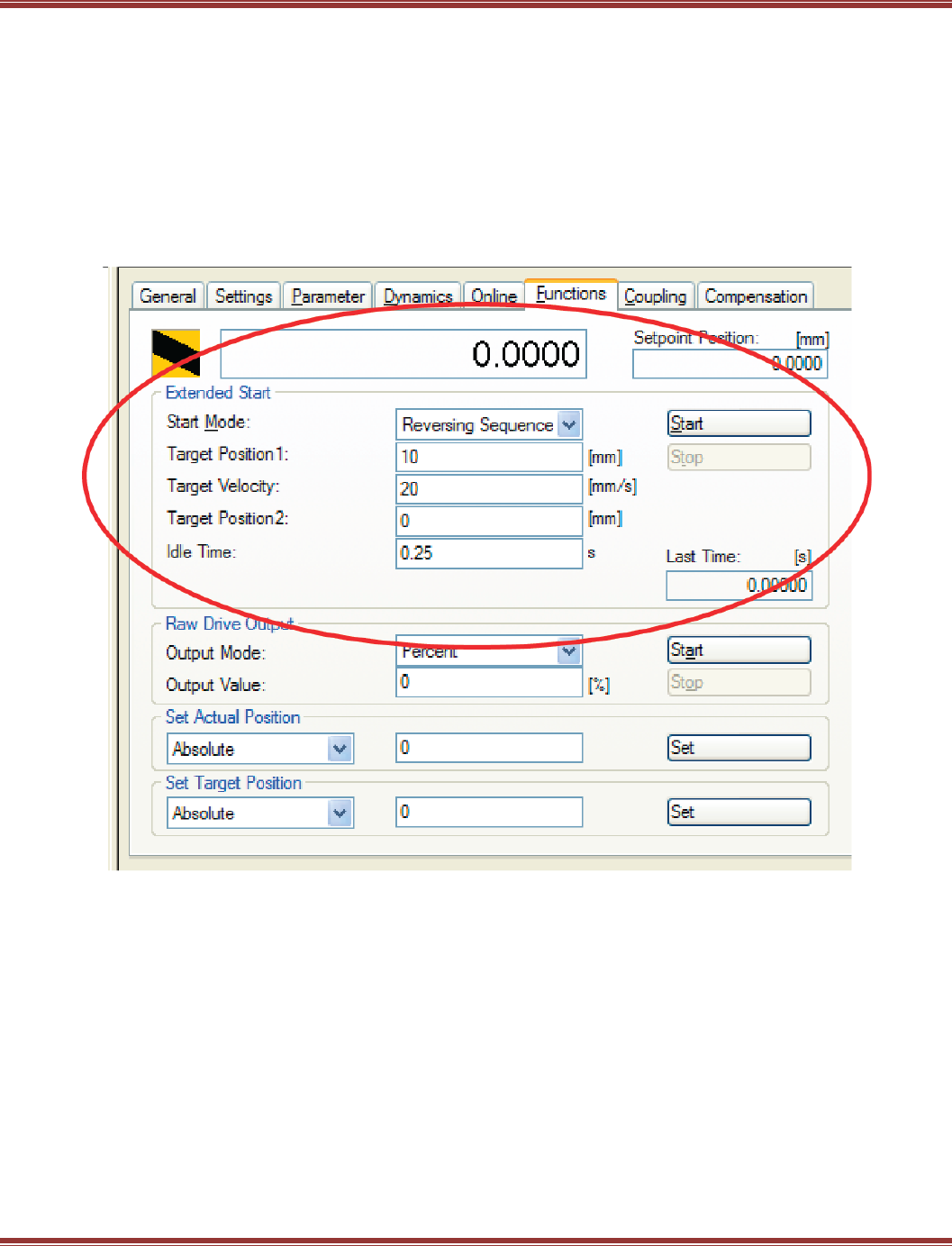
EtherCAT User Guide 16-01450 Rev 00
Page 79
Simple Motion Without A PLC In TwinCAT 2 (cont’d)
From the Reversing Sequence selection set:
Target Position1 = Revolutions for a rotary motor, or mm for a linear to move
Target Velocity = Rev/sec for rotary, or mm/sec for linear
Target Position2 = 0 for an out-back motion from the starting point
Idle Time = Dwell time between moves for the motion to settle
The numbers in this example produce a profile that moves 10 revs at
1200 RPM (20 rev/sec) and dwell for 0.25 sec between moves.
Press the [Start] button in the Extended Start frame to begin and then the [Stop] button will become visible
to stop the motions.

EtherCAT User Guide 16-01450 Rev 00
Page 80
What Next???
A TwinCAT 2 PLC can be designed that provides overall control of the NC & servo-drive combo, I/O modules
might be added, etc. But at this point, the TwinCAT master has found the Copley products and can
communicate with them over an EtherCAT network while producing simple motion from the NC controller.
Beckhoff
Beckhoff web-site: http://www.beckhoff.com
The site is not set up with URLs for every item, so no deep-linking is possible in this document to particular
items on the site. But using the menu, information can be found on some useful topics:
Download -> Software -> TwinCAT: This is where to get TwinCAT, 30 Day Demo version.
Download -> Beckhoff Information System -> Reference in HTML format:
The InfoSys is about 300MB, but has much detail on the Beckhoff products, TwinCAT, etc.
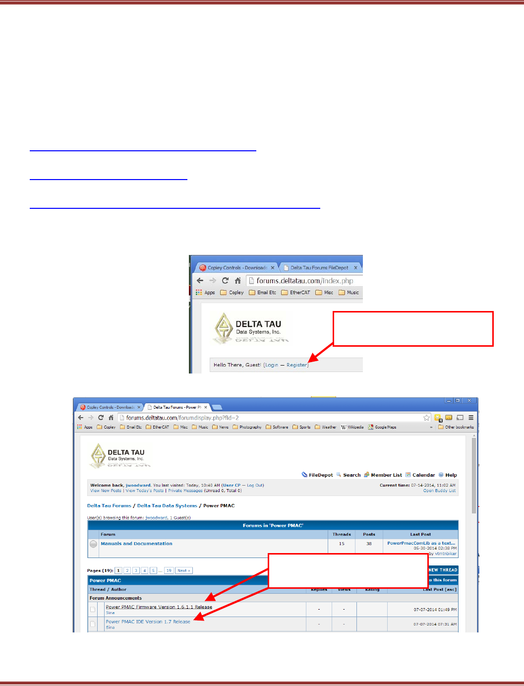
EtherCAT User Guide 16-01450 Rev 00
Page 81
6.3 Delta-Tau Power PMAC
Introduction
This section provides information on commissioning Copley Controls EtherCAT servo drives using the Power
PMAC Suite software. When these steps are followed, it should be possible to move a servo motor via a Copley
Controls servo drive from a PMAC controller. For more advanced motion control it is necessary to consult Delta
Tau for details..
IDE Installation
The first step is to download all of the Delta-Tau software and data needed to produce a working PMAC system.
This is the primary Delta-Tau web-site page for all the software.
http://forums.deltatau.com/showthread.php?tid=152
Click on File Depot, and when the screen opens, click on Power PMAC > Power PMAC IDE
http://forums.deltatau.com/filedepot/
Click on the Release link. The most recent version of the IDE will be at the bottom of the listing that is shown.
http://www.deltatau.com/DT_Products/SoftwareDevelopment.aspx
Download the latest release of the IDE.
For the latest PMAC firmware, go to this link. First-time users can click Login –Register to get a password to
the firmware downloads section.
Under the Forum Announcements section, click the links for the Firmware and IDE items to download.
The firmware is in the Power PMAC -> Firmware folder and the IDE is in the Power PMAC IDE -> Release
folder. Unzip these files after downloading and setup the IDE on your computer.
Do not launch PowerPmacSuite.exe until the Copley ESI files have been installed.
Click Register to get a password
then click Login
Click these links to download
firmware and IDE software
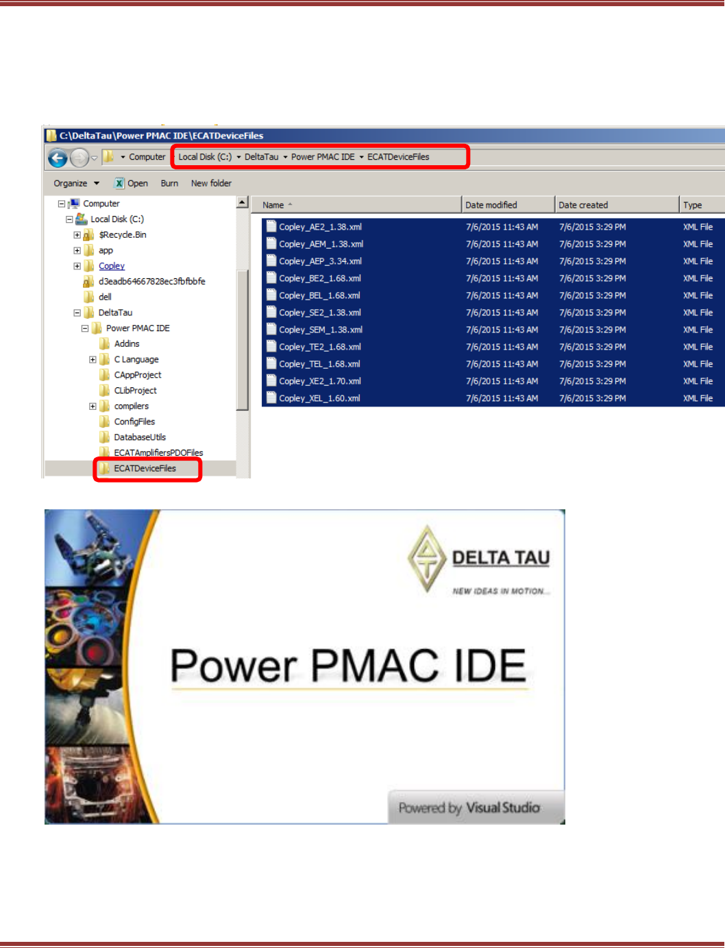
EtherCAT User Guide 16-01450 Rev 00
Page 82
ESI (XML) Files
Go to the Copley Controls web-site, Downloads -> Software Releases -> Firmware & EDS/ESI(XML)
Next, Firmware & EDS/ESI Downloads -> EDS/ESI and click on EtherCAT
Save the file ecatxml.zip to your computer, and then un-zip it to extract the files.
This will produce two folders: “flat” & “slots”. Copy all of the ESI files from the flat folder into the
PMAC ECATDeviceFiles folder as shown below:
Launch the Power PMAC IDE
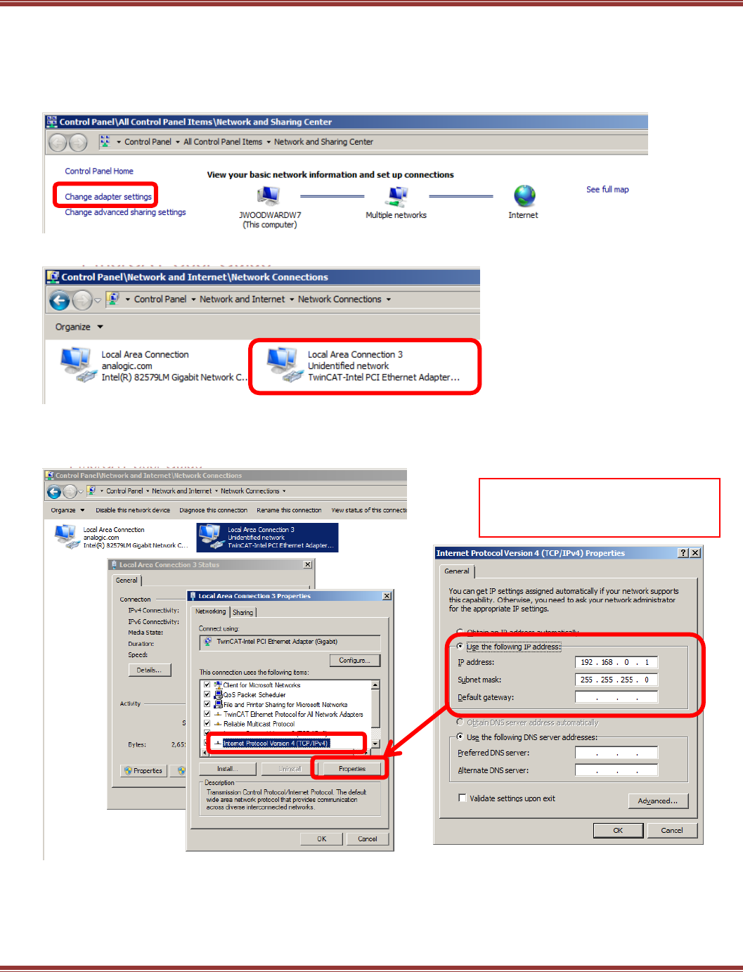
EtherCAT User Guide 16-01450 Rev 00
Page 83
Local Network Configuration
Connect an Ethernet cable between the Eth 0 port of the PMAC and the NIC on your computer.
The PMAC can also operate through an Ethernet switch. Open the Windows Control Panel and
select Network and Sharing Center from the listing. When that screen opens, click on
Change Adapter Settings. Select the adapter to be used for EtherCAT operation
Select the local port to be used and open it:
When the port screen opens, click [Properties]. The PMAC requires TCP/IPv4 so make sure
that there is a check mark in the box for that protocol.
Click on the IPv4 to make it highlighted, then press [Properties]:
Set up the IPv4 properties as shown above. This is the default setting for the PMAC network port.
If the PMAC has been set up with a different IP address, then enter that in this screen.
IPv4 Protocol settings and
PMAC IP Address
AA
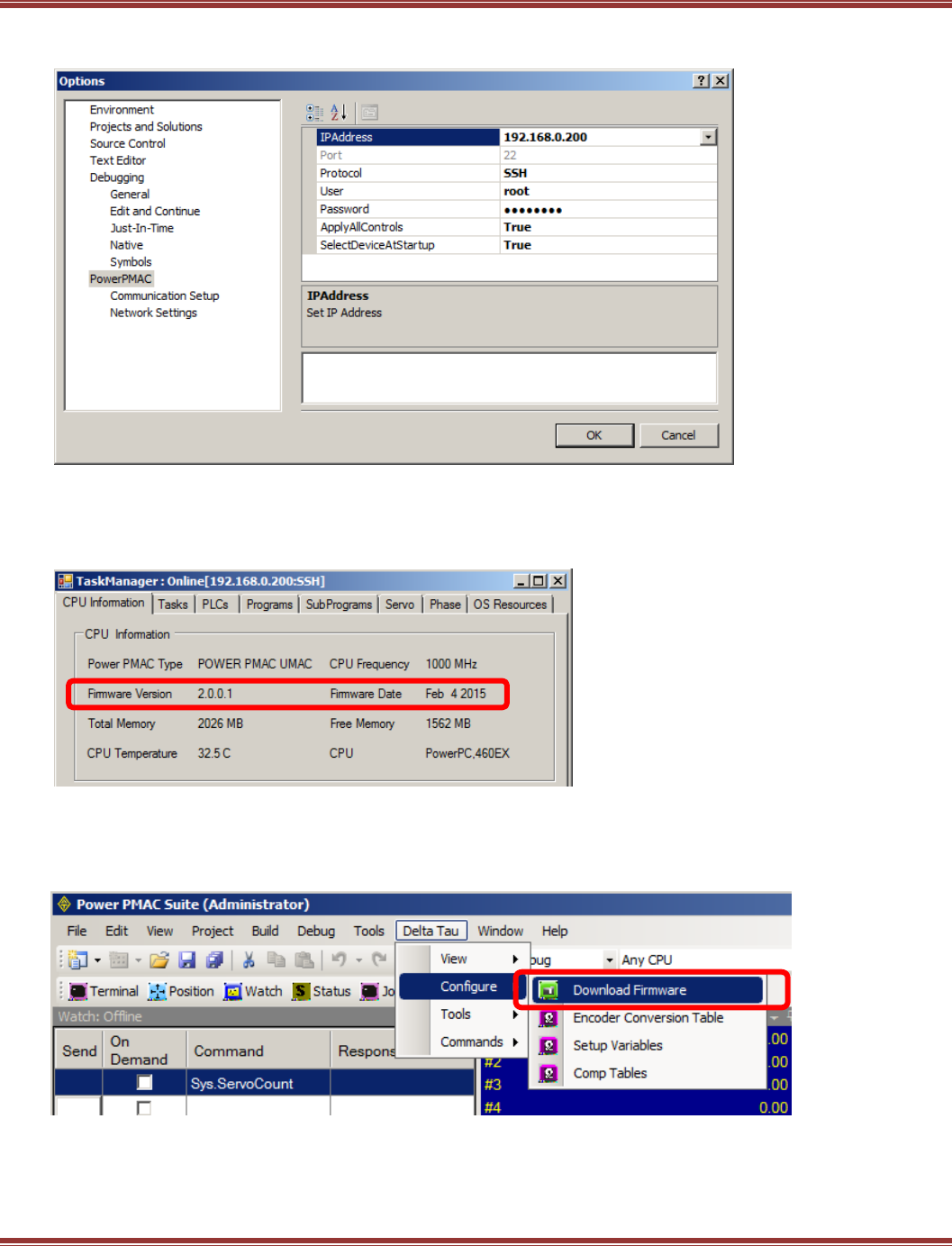
EtherCAT User Guide 16-01450 Rev 00
Page 84
From the PMAC IDE select Tools -> Options -> Power PMAC.
This screen shows the identity of the Power PMAC on the network.
If connection to the IDE is successful, then open the IDE to the main page now.
Updating Firmware
Check the PMAC firmware version from the IDE with Tools -> Task Manager -> Firmware Version:
Check the version number of the firmware that was just downloaded. If it is higher than the firmware version
as shown in the Task Manager > CPU Information, then install it now.
Open this screen: Power PMAC -> Delta Tau -> Configure -> Download Firmware
and follow the instructions.
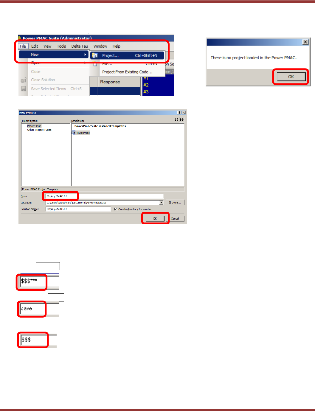
EtherCAT User Guide 16-01450 Rev 00
Page 85
Start a new PMAC project
On the main page, click as shown to create a new PMAC project.
Power PMAC Suite -> File -> New -> Project
Name the new Project and click [OK]
Reset the Power PMAC
This will “wipe” the PMAC and will prepare it for a new and complete configuration.
Using the Terminal Window, reset the PMAC flash memory to factory settings.
This will erase any settings that may be in the PMAC flash from a previous configuration
Enter:$$$***. This clears RAM and loads the factory settings from flash to RAM.
Next, enter:save. This copies the RAM settings to flash, overwriting any existing settings.
Re-boot from flash, loading the factory settings to RAM
This will appear briefly
Click [OK] to continue:
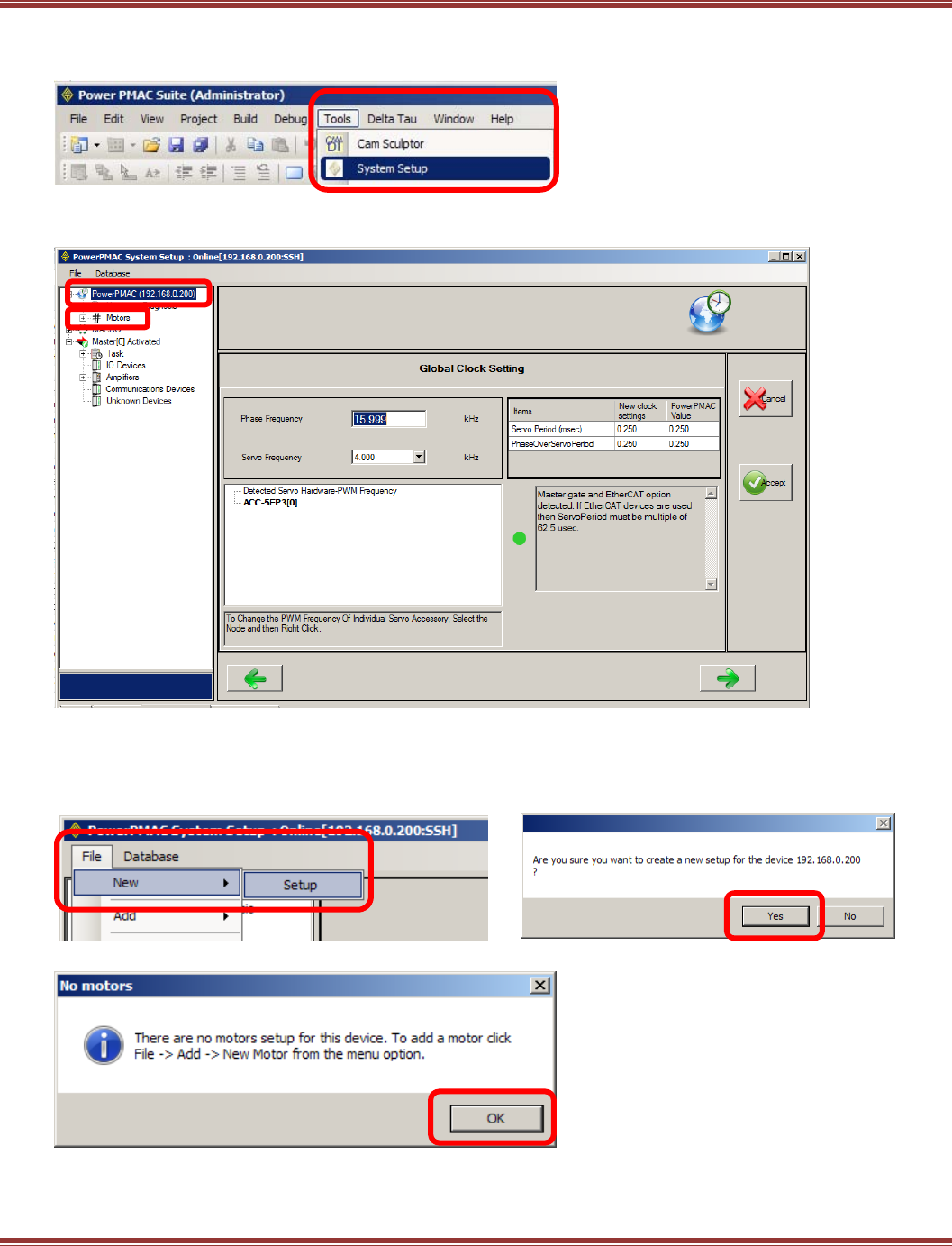
EtherCAT User Guide 16-01450 Rev 00
Page 86
System Setup
Open System Setup: Power PMAC -> Tools -> System Setup
This is the screen after System Setup opens.
Note that the PowerPMAC is highlighted as the default selection.
Create a New Setup
In System Setup, select New -> Setup to clear any Motors that it contained.
Click through the next two prompts:
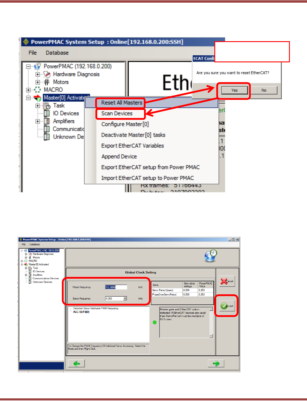
EtherCAT User Guide 16-01450 Rev 00
Page 87
Reset All Masters and Scan for New Devices on the EtherCAT Network
Right-click Master[0] Deactivated to open a menu and select Reset All Masters:
Power PMAC -> Master[0] -> Reset All Masters. Click [Yes} when prompted.
Then select Scan Devices. Follow this with [Yes] to reset scan devices on the network.
.
Set System Clock Frequencies
Set the global clock frequencies to work with the Copley drive. Power PMAC -> Global Clock Setting
Phase Frequency (Copley PWM frequency) is set to 16.000 kHz and the Servo Frequency (Servo loop
frequency in Copley drives) is set to 4.000 kHz.
Click [Accept] when done..
Click [Yes] to reset the
EtherCAT Master[0].
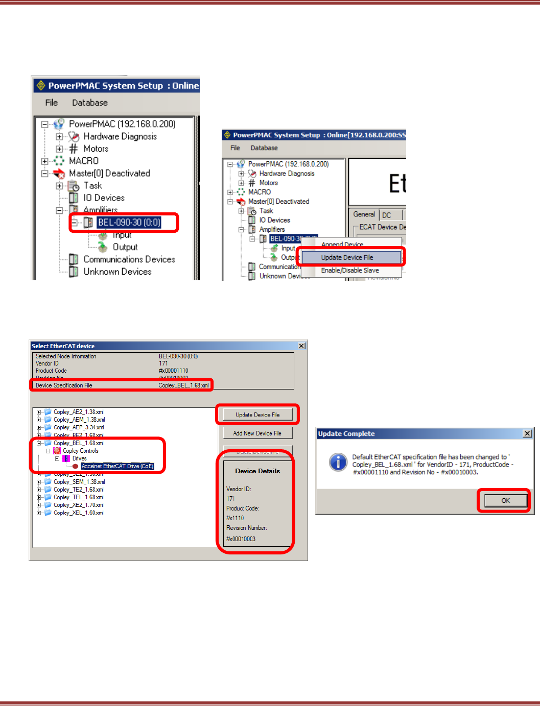
EtherCAT User Guide 16-01450 Rev 00
Page 88
Update Device Files
After the reset, the master will scan the network for EtherCAT devices.
The Copley drive should appear under the Amplifiers section of the Master[0]:
Right-click on the first device and select Update Device File:
The frame at the top of the screen below shows the data for the selected device. Notice “BEL” in the
Device Specification File item. Open the file of the same name in the folder tree below and click to open until
Accelnet EtherCAT Drive (CoE) is shown. Click to select this and the data that shows in the Device Details
box should have the same Product Code as the drive data in the box at the top. Click [Update Device File]:
Repeat this action for any other drives that appear under the Amplifiers section.
This confirms that the ESI (XML) file has
been associated with the matching
device.
Click OK, then close the
Select EtherCAT Device window [X].
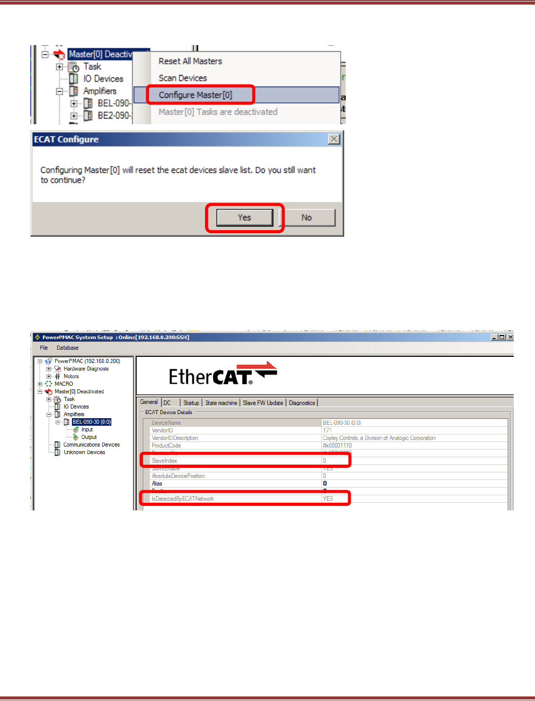
EtherCAT User Guide 16-01450 Rev 00
Page 89
Configure Master[0]
Right-click on Master[0] Deactivated and select Configure Master[0]:
Amplifiers Set Up
General Tab
Click on the first device found under Amplifiers, and in the General tab to the right will be shown
the Product Code. In this example is is #x00001110.
Check the Slave Index. It must be ≥0. If it is < 0, then repeat the Configure Master step.
If Slave Index is OK, then check IsDetectedByECATNetwork and it should be Yes.
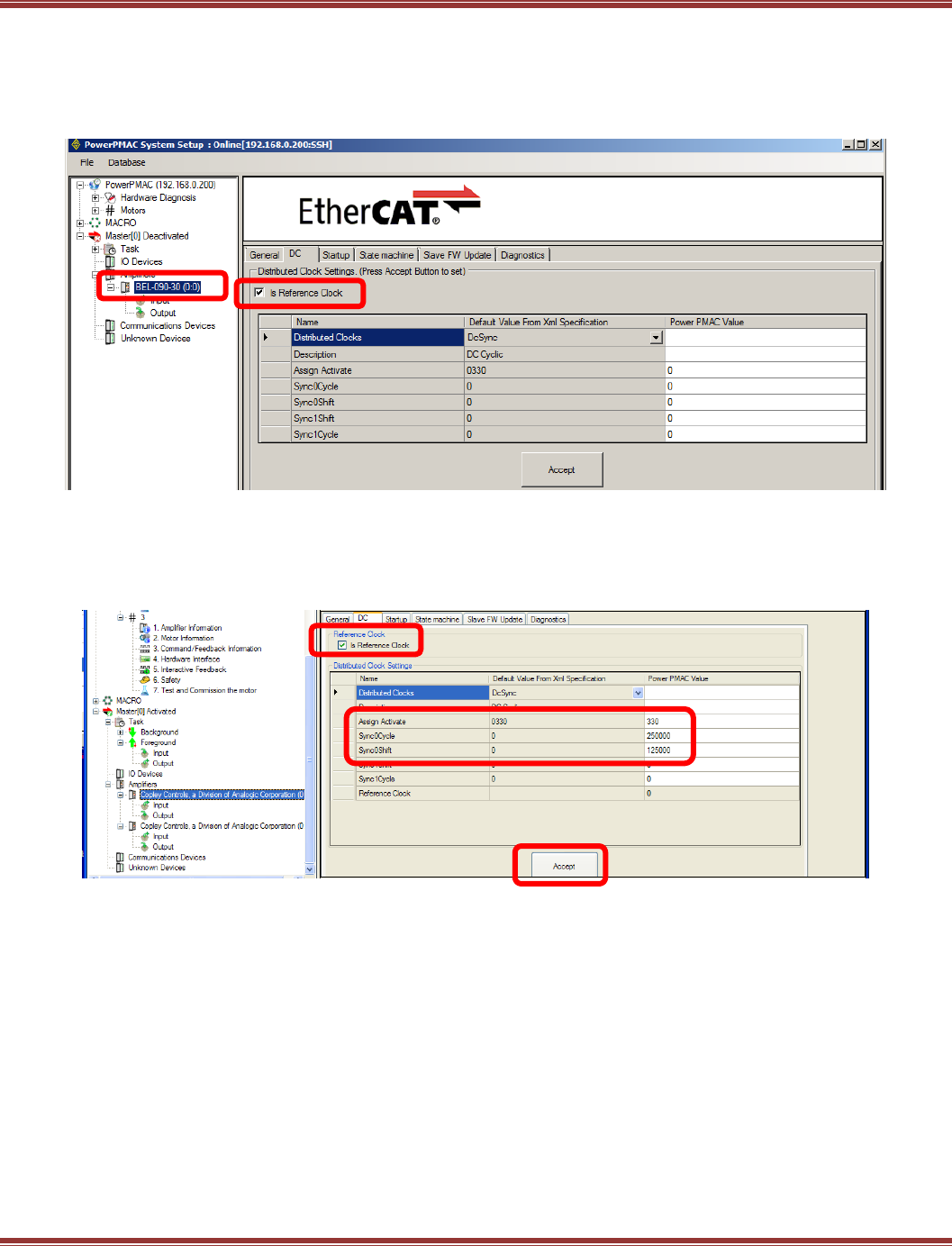
EtherCAT User Guide 16-01450 Rev 00
Page 90
DC Tab
Next, click on the Amplifiers device, then on the DC tab. For the first device in the network, note that
Is Reference Clock is checked. The master will synchronize itself and all of the other slaves on the network with
the clock of this slave.
Important: When there are multiple Amplifiers only one of them can be checked as the Reference Clock
Now, enter data into the Power PMAC Value column. The Assign Activate value is simply copied from the
Default Value column. The Sync0Cycle time should be the Copley servo drives’ position/velocity loop time.
That frequency is 4 kHz so the time is 250 µs, or 250000 ns which is entered in the Power PMAC Value
column. The Sync0Shift time should be one half of that value, 125 µs, or 125000 ns.
Click [Accept] to complete this operation.
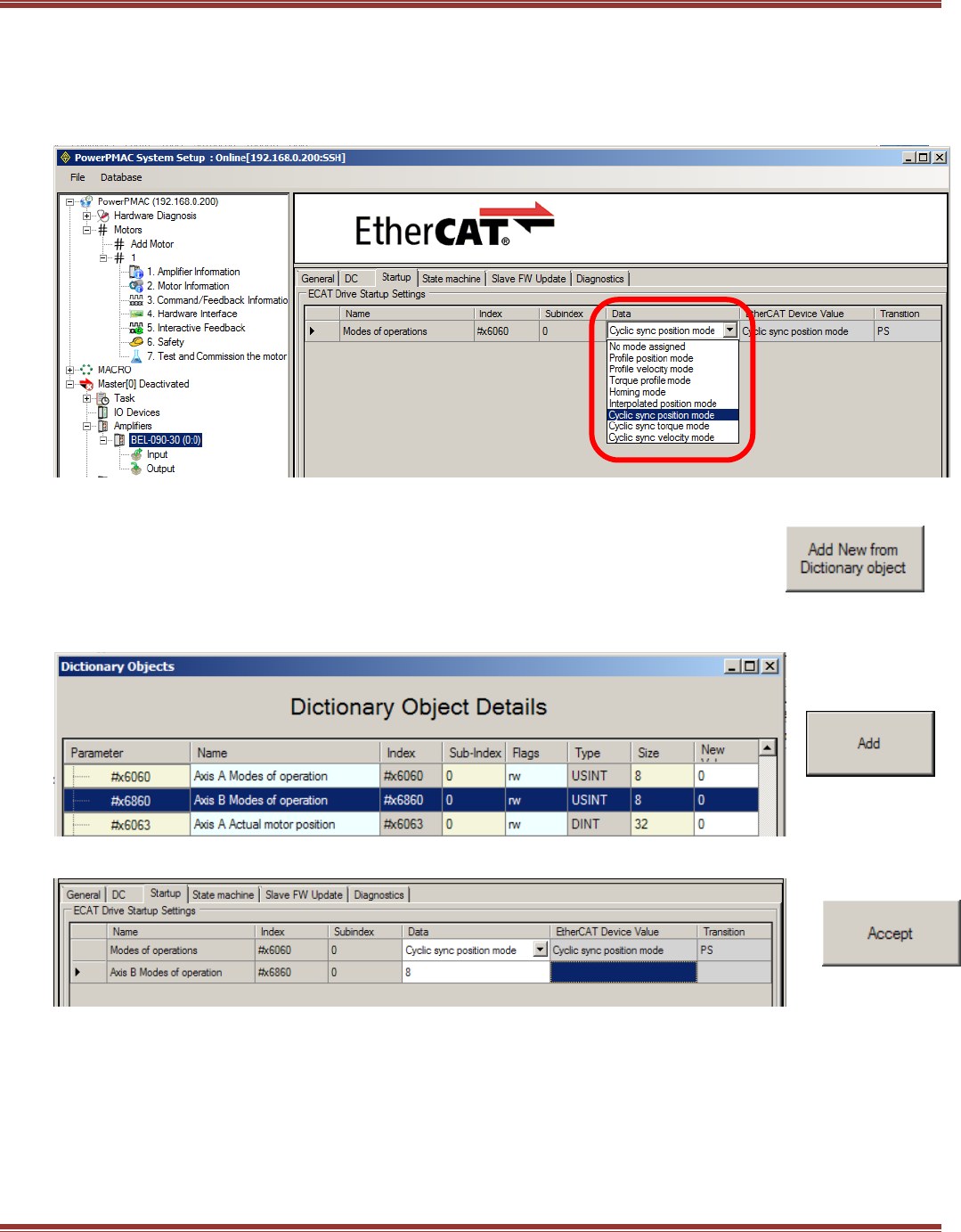
EtherCAT User Guide 16-01450 Rev 00
Page 91
Startup Tab
1-Axis Drives
Open the next tab after the DC tab to access the Startup mode settings. Cyclic Sync Position (CSP)
is the default and set from the ESI file. The pull-down listing shows the other Op Modes that are supported.
Select Cyclic Sync Position and click [Accept] to continue.
2-Axis Drives
Set up DC the same as the previous for Axis-A. For Axis-B leave the reference-clock item
unchecked. On the Startup tab, click the box to Add New from Dictionary object
to set up the startup Mode of operation for Axis B ->
The Axis A Mode of Operation for CSP is #x6060. Axis B will be that + #x0800, or #x6860
Click to highlight that row, and press the Add button:
Click in the Data box in the #x6860 row and enter “8”, the number of the CSP mode:
And press [Accept] to complete the Startup tab:
Note: In future versions of the IDE, the Axis B Mode of Operation will be set automatically
based on the settings in the ESI file.
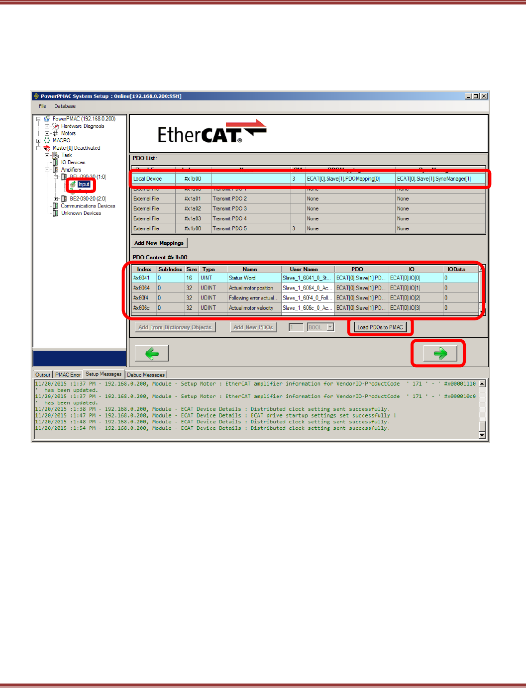
EtherCAT User Guide 16-01450 Rev 00
Page 92
Input PDO Configuration: 1-Axis
Click on the Input item of the drive to show the TxPdo. Note that a PMAC input is a device output. This means
that the drive is transmitting data to the PMAC and that the data will be in a drive TxPDO (Transmit PDO).
The PDO List shows all of the TxPDO, and #x1b00 is the ESI file default PDO. This is also assigned to Sync
Manager (SM) 3 and contains all of the position, velocity, and torque data as well as the Status Word.
After selecting #x1b00, click on [Load PDOs to PMAC]. This will update the PDO Contents as shown below:
Note: after loading the PDO to the PMAC, the columns PDO, I/O, and IOData all are updated and show data.
Click the [->] at the bottom of the screen to go to the next settings.
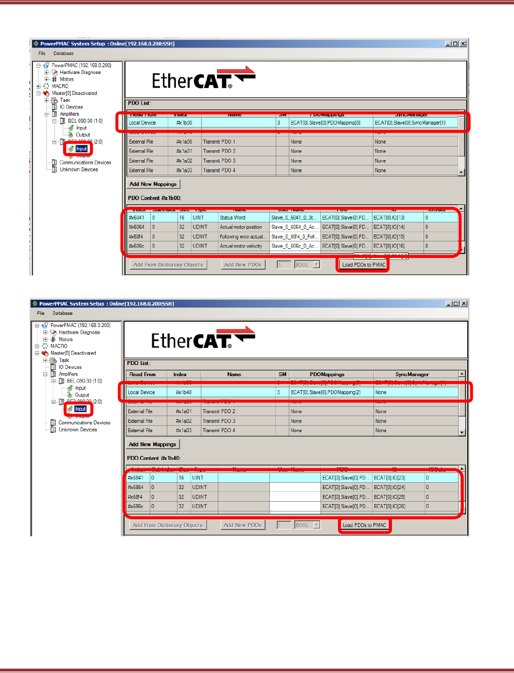
EtherCAT User Guide 16-01450 Rev 00
Page 93
Input PDO Configuration: 2-Axis
Begin with the selection of #x1b00 as in the 1-axis setup, and clicking Load PDOs to PMAC.
Then, highlight the row with #x1b40, and click Load PDOs to PMAC
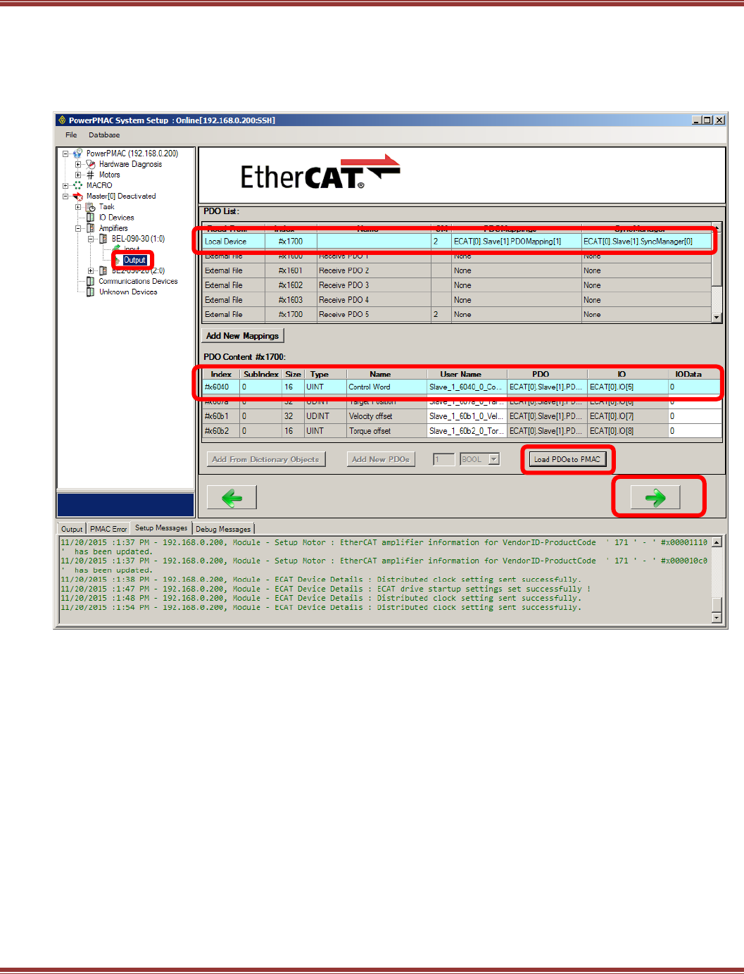
EtherCAT User Guide 16-01450 Rev 00
Page 94
Output PDO Configuration: 1-Axis
Click on Output below the device to show the PDO that the PMAC will send to the device. #x1700 is the
drive RxPdo containing the Control Word, and target position, velocity offset (velocity feedforward), and torque
offset (acceleration feedforward). Click [Load PDOs to PMAC] and the PDO Contents will update.
Click the [->] at the bottom of the screen to go to the next settings.
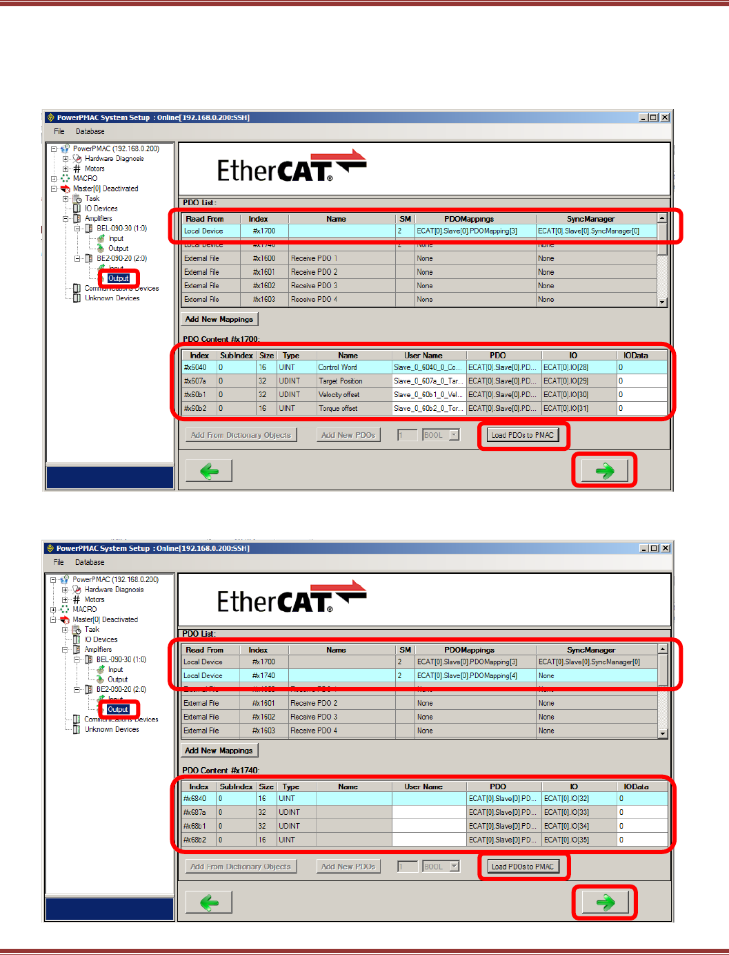
EtherCAT User Guide 16-01450 Rev 00
Page 95
Output PDO Configuration: 2-Axis
Click on Output below the device to show the PDO that the PMAC will send to the device. #x1700 is the
drive RxPdo containing the Control Word, and target position, velocity offset (velocity feedforward), and torque
offset (acceleration feedforward) for Axis-A. Click [Load PDOs to PMAC] and the PDO Contents will update.
Click the [->] at the bottom of the screen to go to the next settings.
Next, highlight the row with #x1740, click [Load PDOs to PMAC] and the PDO Contents will
update the PDOs for Axis-B. Click the [->] at the bottom of the screen to go to the next settings.
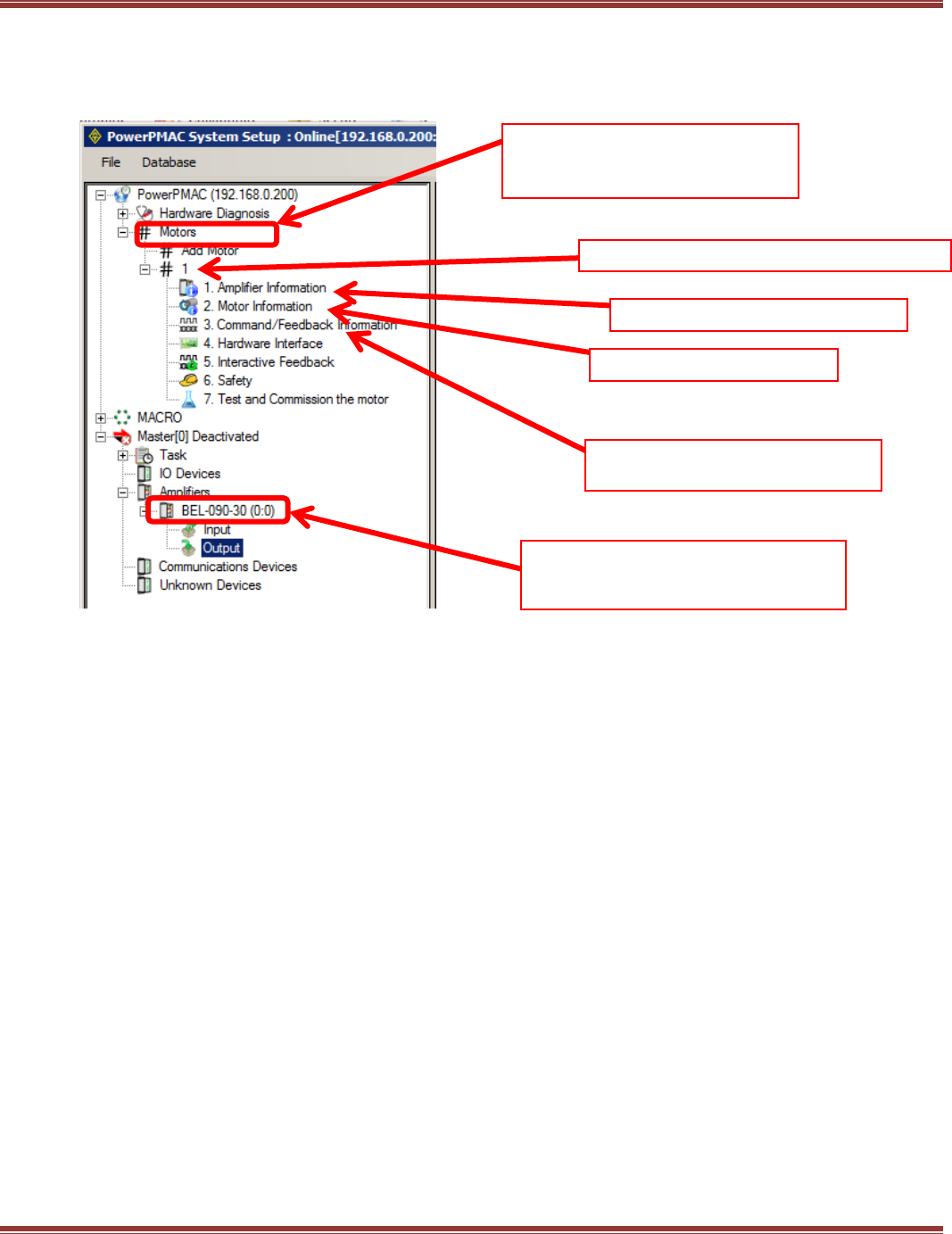
EtherCAT User Guide 16-01450 Rev 00
Page 96
Motor Configuration
Note that “Motor” has two meanings in the PMAC. What is commonly called an Axis in other EtherCAT masters
is called a Motor in Delta-Tau controllers. And, a Delta-Tau Motor comprises the servo drive, a physical motor,
and any feedback devices connected to the motor and/or the load.
“Motors” here are motion axes
and refers to the servo-drives AND
the actual motors attached to them
This is a Copley BEL servo drive
This is an actual motor
Position Feedback encoders
on the actual motor
This device is “1.Amplifier Information”
under Motor #1 above
This number is Motor #1
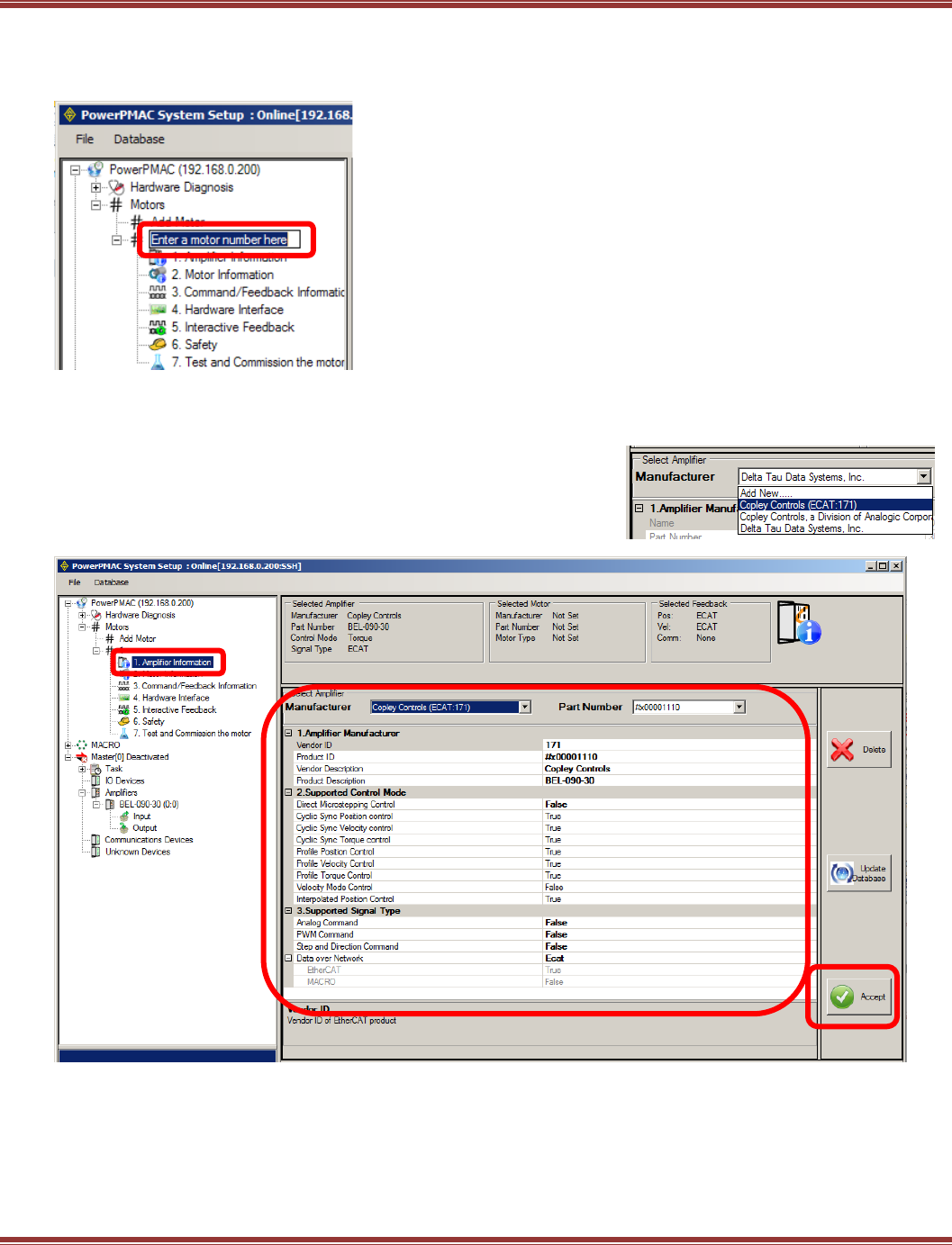
EtherCAT User Guide 16-01450 Rev 00
Page 97
Add a New Motor
Click on Motors to Add a New Motor. Start with “1”. In this example, Motors #1 will be linked
to the BEL amplifier.
Amplifier Information
Click on the Amplifier Information item under Motor #1. This shows the information from the device under
the Amplifiers section of the Master[0] folder tree.
Click on Manufacturer and select Copley Controls (EtherCAT:171):
Next, click on Part Number, and find the one that brings up the
Product Description that matches the model in
Master[0] Deactivated > Amplifiers:
After the drive has been selected, the settings in Supported Control Mode and Supported Signal Type
should appear as above.
Click [Accept] to continue.
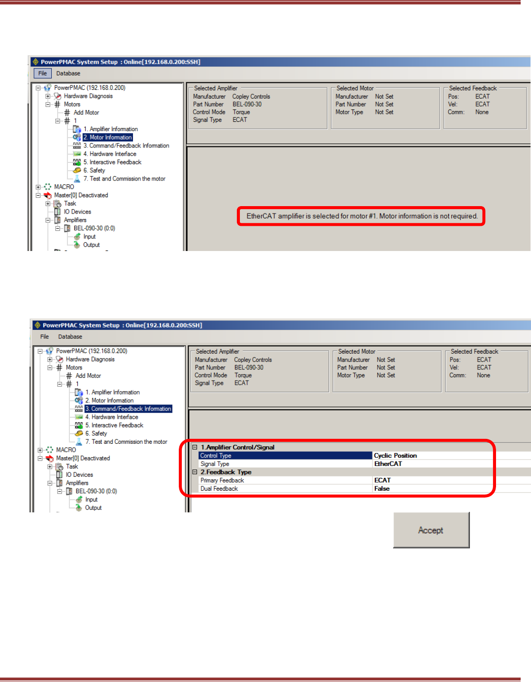
EtherCAT User Guide 16-01450 Rev 00
Page 98
Motor Information
Because the actual motor has already been specified and set up in the BEL configuration, it is not necessary to
add information on the motor in this step. Click [->] to continue.
Command/Feedback Information
Under the Amplifier Control/Signal item, there is a pull-down listing. Select Cyclic Position which works with
the CSP Mode of Operation that was set up in the device configuration. In this example, the only feedback is
Primary Feedback from the motor encoder which sends the position data via EtherCAT (ECAT) to the PMAC.
If there is a secondary feedback encoder on the load, that would be entered under the Dual Feedback item.
Click [Accept] to continue.
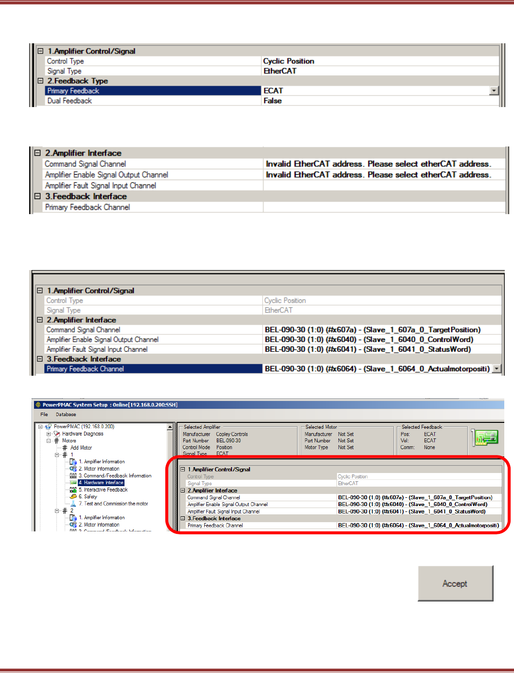
EtherCAT User Guide 16-01450 Rev 00
Page 99
Hardware Interface: 1-Axis Drives
Amplifier Control/Signal Make these selections from the pull-downs for each item.
Amplifier Interface
To configure these items, click on Please select etherCAT address
Scroll down and select #x607a for the Command Signal Channel of amplifier that was selected for Motor #1:
Select #x6040 for the Amplifier Enable Signal Output Channel
Select #x6041 for Amplifier Fault Signal Input Channel
Select #x6064 for Primary Feedback Channel
This is how it looks after selections are completed:
Click [Accept] to continue.
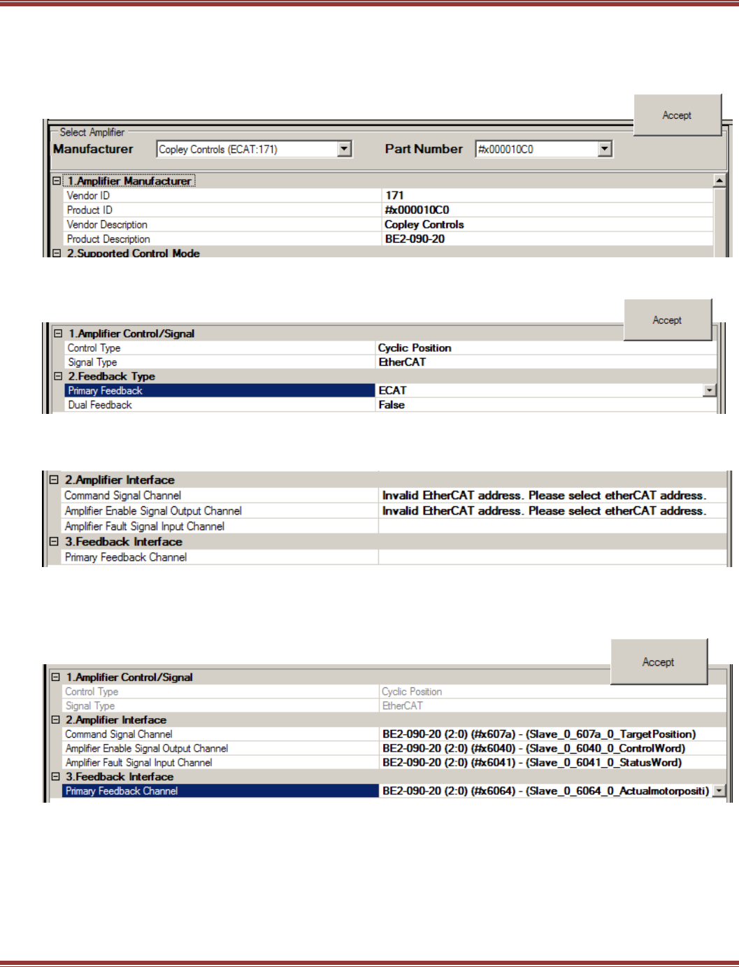
EtherCAT User Guide 16-01450 Rev 00
Page 100
Hardware Interface: 2-Axis Drives, Axis A
Click on Motors to Add a New Motor. In this example, Motor #2 will be linked to the BE2 amplifier, Axis A:
Important! Each axis of a 2-axis drive will be configured as a separate Motor # !
Amplifier Information Select BE2 drive
Click [Accept] to continue.
Command/Feedback Information:
Amplifier Control/Signal and Feedback Type Should appear as below.
Click [Accept] to continue.
Hardware Interface
To configure these items, click on Please select etherCAT address
Scroll down and select #x607a for the Command Signal Channel of amplifier that was selected for Motor #1:
Select #x6040 for the Amplifier Enable Signal Output Channel
Select #x6041 for Amplifier Fault Signal Input Channel
Select #x6064 for Primary Feedback Channel
Click [Accept] to continue.
Safety
The items in this section can be configured in the Copley servo drive. These include:
I2T Current Limiting
Position Following Error limits
Software pos/neg position limits
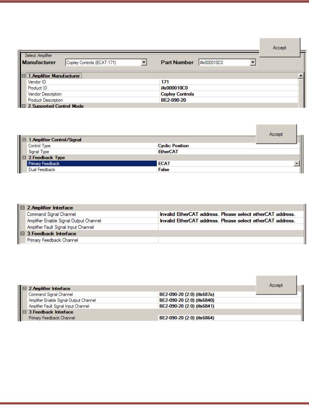
EtherCAT User Guide 16-01450 Rev 00
Page 101
Hardware Interface: 2-Axis Drives, Axis B
Click on Motors to Add a New Motor. In this example, Motor #3 will be linked to the BE2 amplifier, Axis B:
Important! Each axis of a 2-axis drive will be configured as a separate Motor # !
Amplifier Information Select BE2 drive
Click [Accept] to continue.
Command/Feedback Information:
Amplifier Control/Signal and Feedback Type Should appear as below.
Click [Accept] to continue.
Hardware Interface
To configure these items, click on Please select etherCAT address
Important, object numbers for Axis B will be $xn8nn !
Scroll down and select #x687a for the Command Signal Channel of amplifier that was selected for Motor #1:
Select #x6840 for the Amplifier Enable Signal Output Channel
Select #x6841 for Amplifier Fault Signal Input Channel
Select #x6864 for Primary Feedback Channel
Click [Accept] to continue.
Safety
The items in this section can be configured in the Copley servo drive. These include:
I2T Current Limiting
Position Following Error limits
Software pos/neg position limits
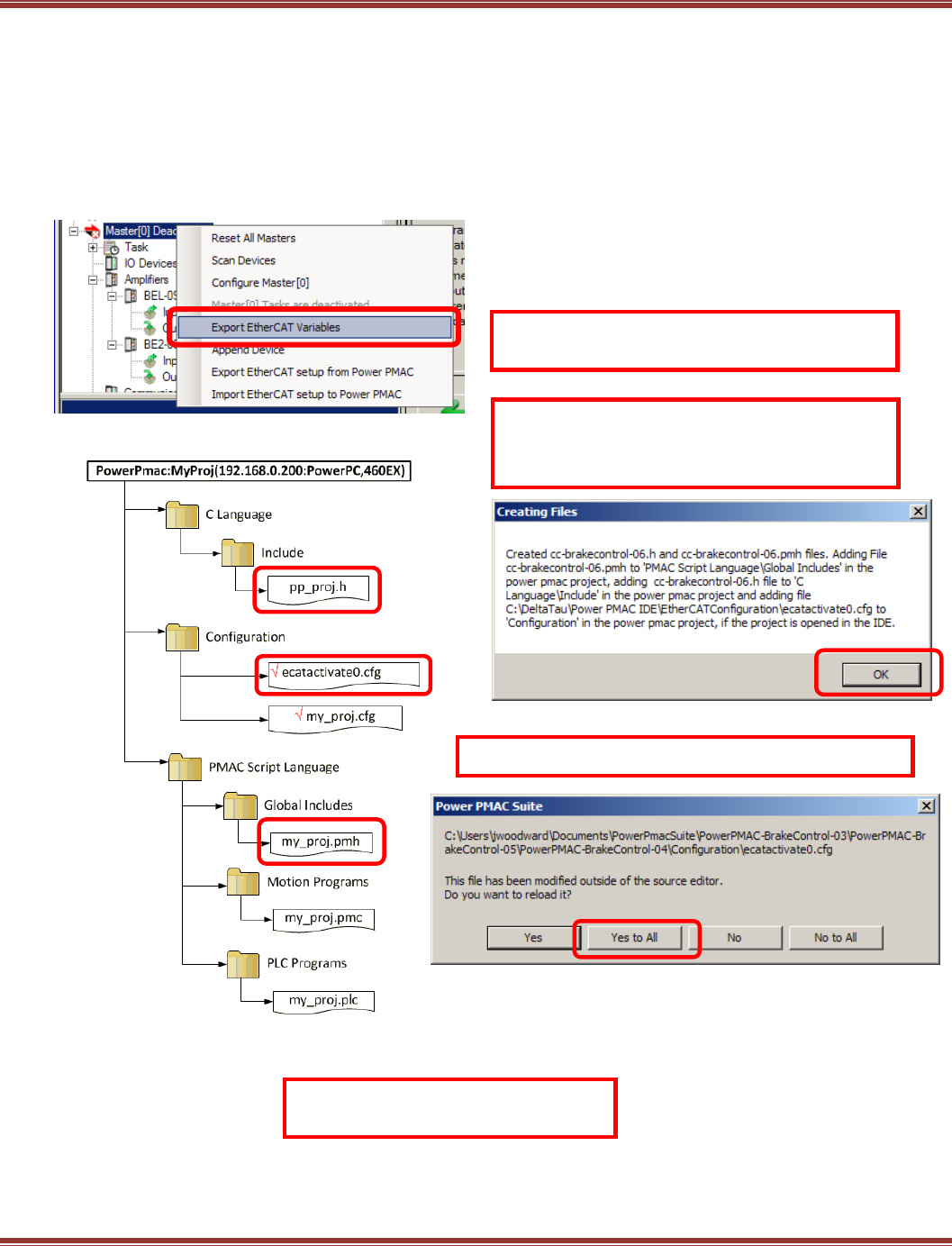
EtherCAT User Guide 16-01450 Rev 00
Page 102
Create Set-Up Files and Save the EtherCAT Project
Export EtherCAT Variables
From System Setup, click this to export EtherCAT variables. This will create three files.
filename.h
EcatActivate0.cfg
filename.pmh
Filename is the user’s name for the file.
Power PMAC Project File Organization
The *.h, *.cfg, and *.pmh files were created by
Export EtherCAT Variables
The files created by this operation
are saved only to the PC hard drive!
This is the confirmation of the files created by
clicking Export EtherCAT Variables (file names
may vary but they always go to these folders.
Click Yes to All when this screen opens
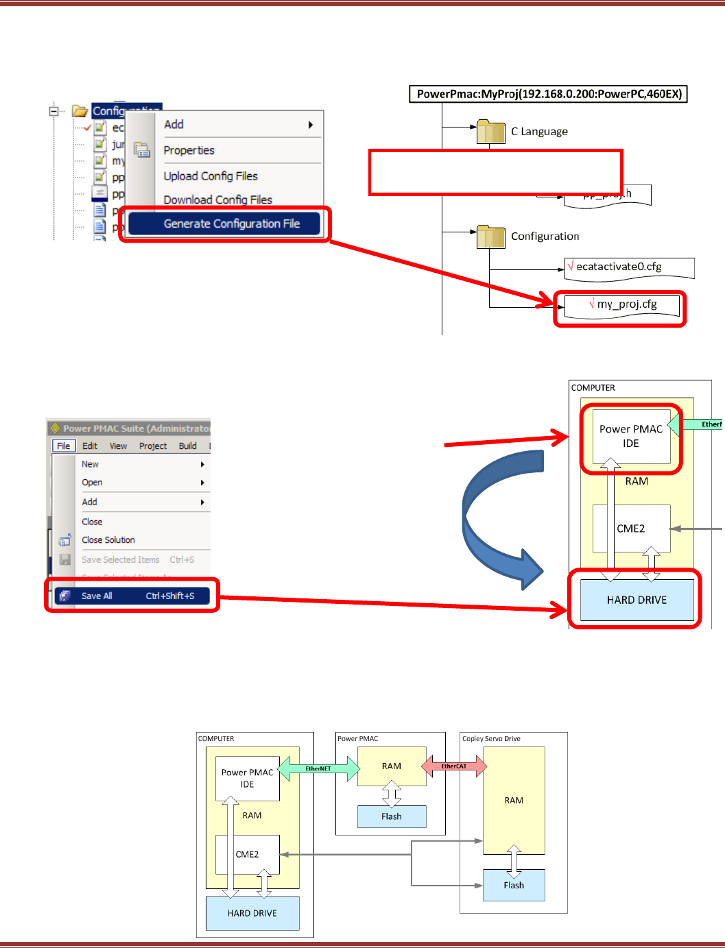
EtherCAT User Guide 16-01450 Rev 00
Page 103
Generate and Save a Configuration File
In the Solution Explorer, right-click on the Configuration folder and select Generate Configuration File.
This file contains all of the settings that were made in System Setup.
After the file is created, right-click on it and select
“Check to Config Download” to add the red check-mark.
Only the config files with red check marks will be downloaded
from the IDE to the PMAC master.
That download does not take place at this time.
Save All settings to the computer’s hard drive.
PMAC System Structure
A PMAC system has three components, each of which has volatile (RAM) and non-volatile (Flash) storage.
When the word “save” is used in the following discussions it means that data is copied from RAM memory to
Flash memory. But, as the diagram shows, it is very important to understand clearly just
where the from > to operation is taking place.
Program variables are saved
to computer Hard Drive
non-volatile memory
Power PMAC IDE is
running under Windows.
Program operation is in
computer RAM memory.
The files created by this operation
are saved only to the PC hard drive!
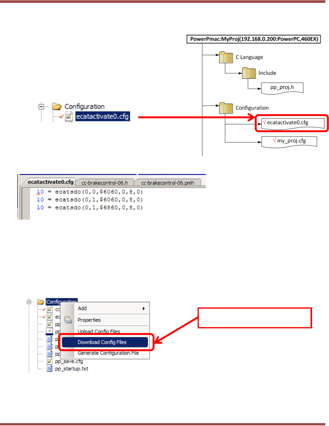
EtherCAT User Guide 16-01450 Rev 00
Page 104
Generate and Save the EcatActivate0.cfg File
This file is run every time that the EtherCAT Master[0] is activated.
Activation occurs when this is entered in the Terminal Window EtherCAT[0].Enable=1
Here is the contents of the file.
Note the “l0” is actually a lower-case L0 which is a “Local L-variable”.
These configure EtherCAT SDOs that set the Mode of Operation of the drives and axes.
The first digit 0 means that this is a write-SDO, sending data to the drive.
Second is the slave index where 0 is the first slave in the example, the 1-axis BEL.
When this is a 1, it is the second slave, the 2-axis BE2.
Note that two SDOs are written to the BE2, setting the Mode of Operation for Axis-A and Axis-B.
Index $6060 is the basic one for setting Mode of Operation and is the same for single-axis
drives and the Axis-A of two-axis drives. Index $6860 is for Axis-B and has the 0x0800 offset
from the $6060 that is used for Axis-B of 2-axis drives.
Download the Config Files
Save the Configuration
Reset the PMAC
After the file is created, right-click on it and select “Check to
Config Download” to add the red check-mark.
Only the config files with red check marks will be
downloaded from the IDE to the PMAC master.
The files created by this operation
are saved only to the PC hard drive!
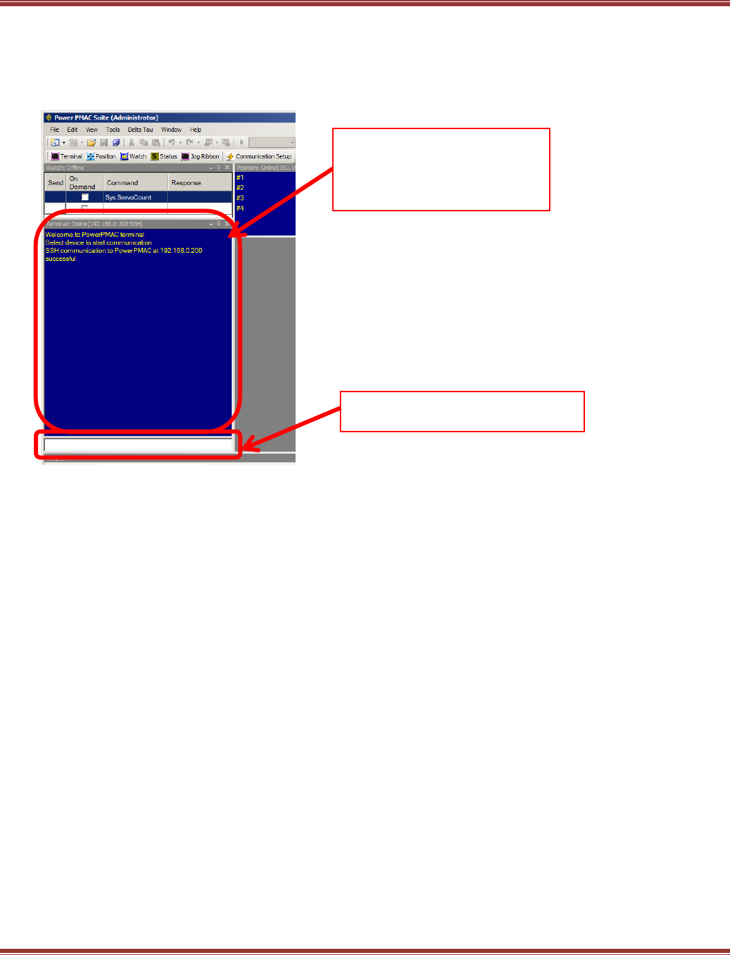
EtherCAT User Guide 16-01450 Rev 00
Page 105
Command Entries and Response
The Terminal window is the primary user interface in the PMAC. This is where commands are entered and
parameters can be read and written as On-Line Commands. These have immediate effect when entered.
The frame above the terminal window is a scrolling display of the commands entered and the PMAC
responses to those commands.
Some typical On-Line Commands
Set the EtherCAT operation to RUN: ECAT[0].Enable = 1
Enable Motor #1: #1/
Enable Motors #1,2,3: #1..3/ or #1,2,3
Jog Motor #1 positive: #1j+
Jog Motor #1,2,3 positive: #1..3j+
Disable all Motors: k
Terminal Window
Keyboard entry of commands here.
Response Window
This area shows the command line
dialog and response messages
from the PMAC

EtherCAT User Guide 16-01450 Rev 00
Page 106

EtherCAT User Guide 16-01450 Rev 00
Page 107
7 APPENDIX
7.1.1

EtherCAT User Guide 16-01450 Rev 00
Page 108
EtherCAT User Guide
P/N 16-01450 Revision 00
December 21, 2015
2014, 2015
Copley Controls
20 Dan Road
Canton, MA 02021 USA
http://www.copleycontrols.com
All rights reserved
