Elementary Electronics 1966 05 06 1
User Manual: Elementary-Electronics-1966-05-06-1
Open the PDF directly: View PDF ![]() .
.
Page Count: 116 [warning: Documents this large are best viewed by clicking the View PDF Link!]
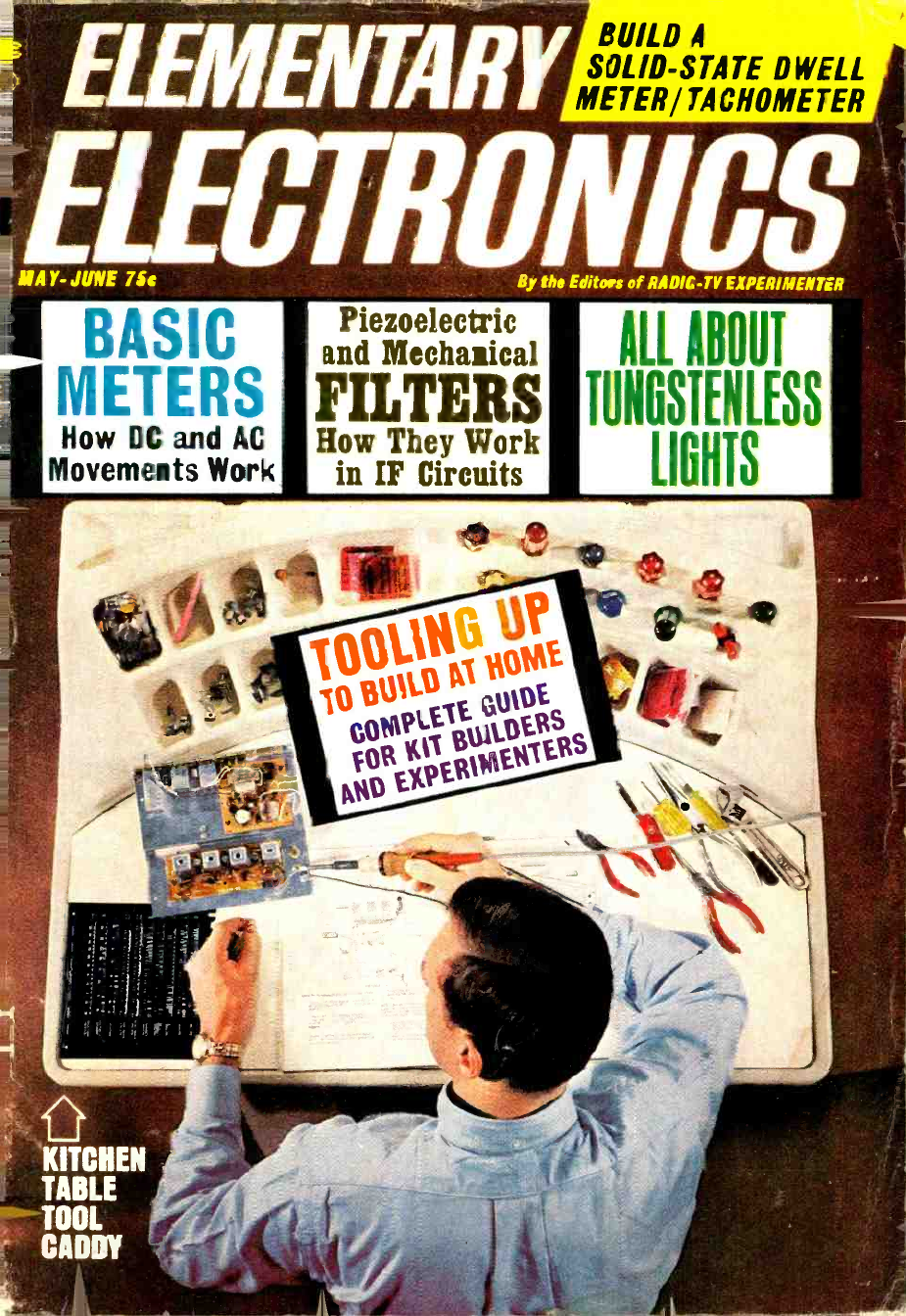
ELEMENTARY
ELECTRONICS
MAY-JUNE 75e By the Editors of RADIC -TV EXPERIMENTER
BUILD A
SOLID -STATE DWELL
METER/ TACHOMETER
BASIC
METERS
Piezoelectric
and Mechanical
FILTERS
How DC and AC
Movements Work How They Work
in IF Circuits
ALL ABOUT
LES
LIGHTS
[UNGSIEN
KITCHEN
TABLE
TOOL
CADDY
www.americanradiohistory.com
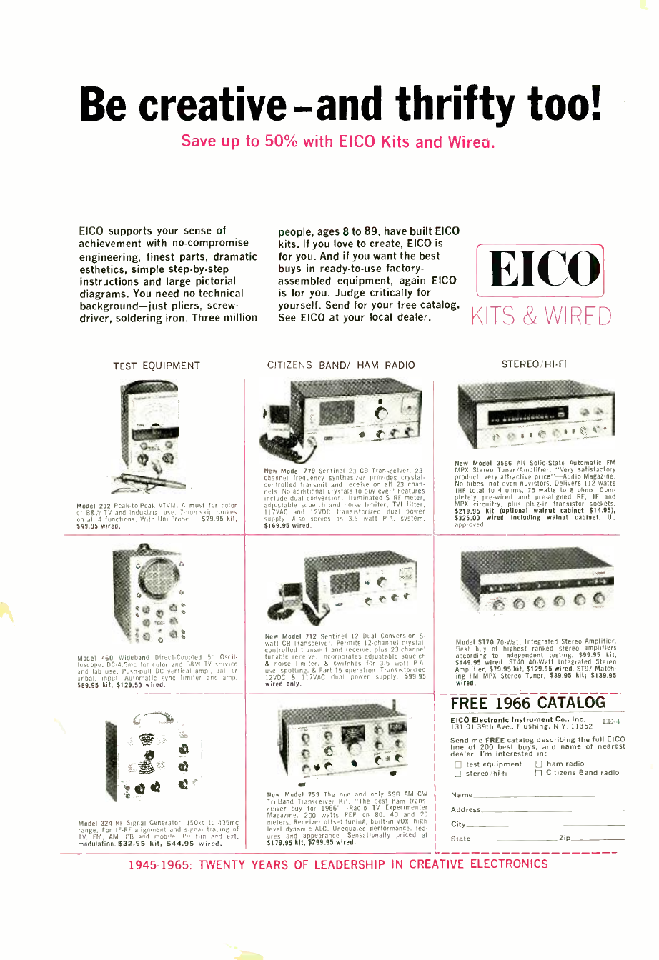
Be creative-and thrifty too!
Save up to 50% with EICO Kits and Wireo.
EICO supports your sense of
achievement with no- compromise
engineering, finest parts, dramatic
esthetics, simple step -by -step
instructions and large pictorial
diagrams. You need no technical
background -just pliers, screw-
driver, soldering iron. Three million
TEST EQUIPMENT
Model 232 Peak -to-Peak VTVM. A must for color
or B5W TV and industrial use. 7-non -skip ranges
on all 4 functions. With Uni-Probe. $29.95 kit,
$49.95 wired.
Model 460 Wideband Direct.Coupled 5" Oscil-
loscope. DC4.5mc for color and B&W TV service
and lab use. Pushpuil DC vertical amp., bai. or
unbal. input. Automatic sync limiter and amp.
$89.95 kit, $129.50 wired.
vd... ..
Model 324 RF Signal Generator. 150kc to 435mc
range. For IF -RF alignment and signal tracing of
TV. FM, AM CB ami mob'i i, P',ilt -in áM ext.
modulation, 532.95 kit, $44.95 wired.
people, ages 8 to 89, have built EICO
kits. If you love to create, EICO is
for you. And if you want the best
buys in ready -to -use factory -
assembled equipment, again EICO
is for you. Judge critically for
yourself. Send for your free catalog.
See EICO at your local dealer.
CITIZENS BAND/ HAM RADIO
New Model 779 Sentinel 23 CB Transceiver. 23-
channel frequency synthesizer provides crystal -
controlled transmit and receive on all 23 chan-
nels. No additional crystals to buy ever! Features
include dual conversion, illuminated S RF meter,
adjustable squelch and noise limiter, TVI filter,
II7VAC and 12VDC transistorized dual power
supply. Also serves as 3.5 watt P.A. system.
$169.95 wired.
:1111111';
. t .
New Model 712 Sentinel 12 Dual Conversion 5-
watt CB Transceiver. Permits 12- channel crystal -
controlled transmit and receive, plus 23- channel
tunable receive. Incorporates adjustable squelch
& noise limiter, & switches for 3.5 watt P.A.
use, spotting, & Part 15 operation. Transistorized
12VDC & 117VAC dual power supply. $99.95
wired only.
New Model 753 The one and only SSO AM CW
Tri -Band Transceiver kit. "The best ham trans-
ceiver buy for 1966" -Radio TV Experimenter
Magazine. 200 walls PEP on 80. 40 and 20
meters. Receiver offset tuning, built -in VOX, high
level dynamic ALC. Unequaled performance, fea-
r and appearance. Sensationally priced at
$179.95 kit, $299.95 wired.
EICO
KITS & WI
STEREO /HI-FI
New Model 3566 All Solid-State Automatic FM
MPX Stereo Tuner /Amplifier. "Very satisfactory
product, very attractive price" -Audio Magazine.
No tubes, not even nuvistors. Delivers 112 watts
I9F total to 4 ohms, 75 watts to 8 ohms. Com-
pletely pre -wired and pre -aligned RF, IF and
MPX circuitry, plus plug -in transistor sockets.
$219.95 kit (optional walnut cabinet $14.951,
$325.00 wired including walnut cabinet. UL
approved.
Model ST70 70 -Watt Integrated Stereo Amplifier.
Best buy of highest ranked stereo amplifiers
according to independent testing. $99.95 kit,
$149.95 wired. ST40 40 -Watt Integrated Stereo
Amplifier, $79.95 kit, $129.95 wired. ST97 Match-
ing FM MPX Stereo Tuner, $89.95 kit; $139.95
wired.
FREE 1966 CATALOG
EICO Electronic Instrument Co., Inc. EE-.I
131.01 39th Ave.. Flushing. N.V. 11352
Send me FREE catalog describing the full EICO
line of 200 best buys, and name of nearest
dealer. I'm interested in:
test equipment ham radio
stereo /hi -fi Citizens Band radio
Name
Address
City
State Zip
1945 -1965: TWENTY YEARS OF LEADERSHIP IN CREATIVE ELECTRONICS
www.americanradiohistory.com
iK-ilfèy¡I=,
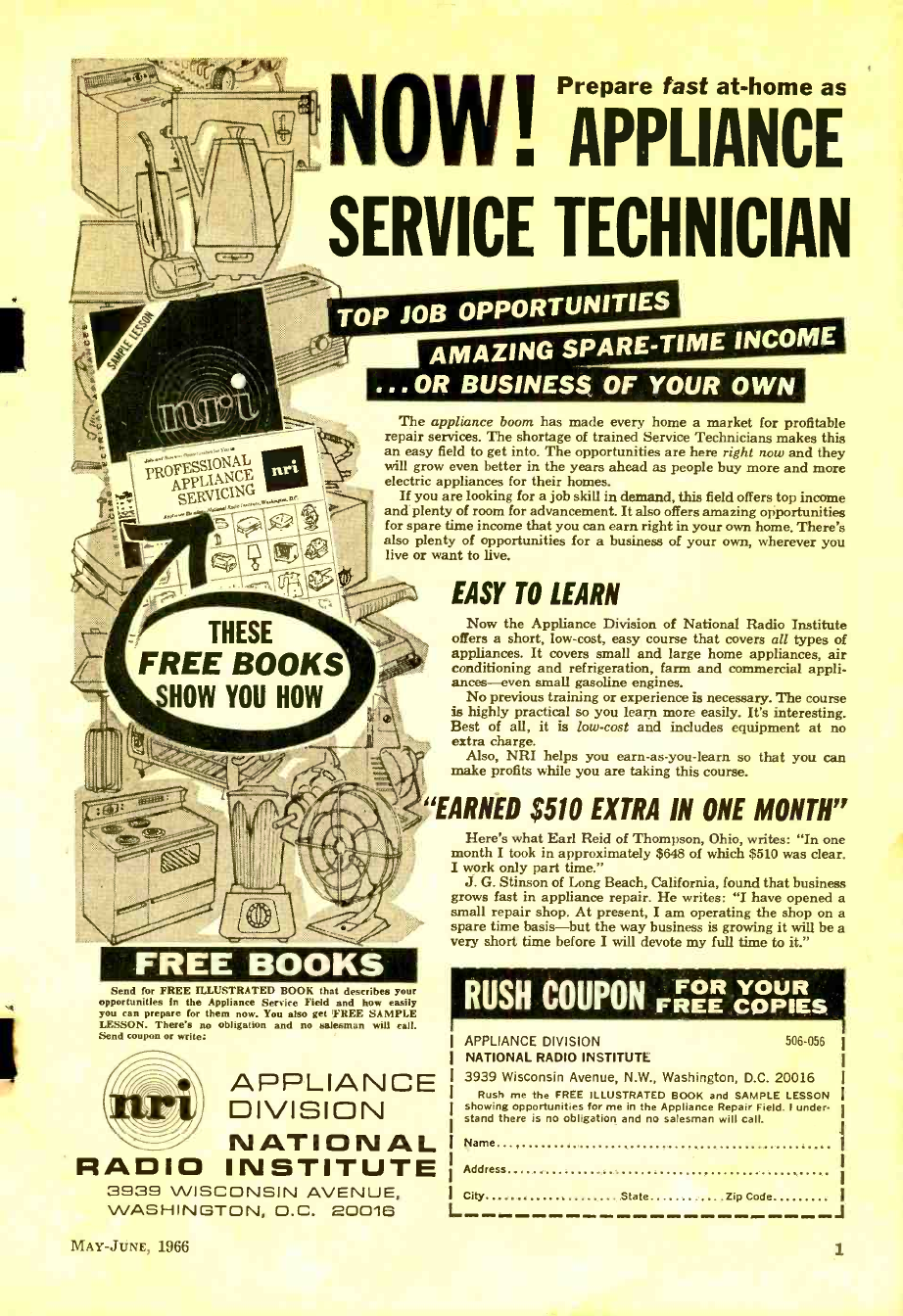
NOW! PAPPLIANCE
SERVICE TECHNICIAN
TOP JOB OPPORTUNITIES
AMAZING SPARE -TIME INCOME
...OR BUSINESS OF YOUR OWN
PR ÄPLl.'iNCE
SERVICING
1
The appliance boom has made every home a market for profitable
repair services. The shortage of trained Service Technicians makes this
an easy field to get into. The opportunities are here right now and they
will grow even better in the years ahead as people buy more and more
electric appliances for their homes.
If you are looking for a job skill in demand, this field offers top income
and plenty of room for advancement. It also offers amazing opportunities
for spare time income that you can earn right in your own home. There's
also plenty of opportunities for a business of your own, wherever you
live or want to live.
THESE
FREE BOOKS
HOW YOU HOW
FREE BOOKS
Send for FREE ILLUSTRATED BOOK that describes your
opportunities in the Appliance Service Field and how easily
you can prepare for them now. You also get ;FREE SAMPLE
LESSON. There's no obligation and no salesman will call.
Send coupon or write:
EASY TO LEARN
Now the Appliance Division of National Radio Institute
offers a short, low -cost, easy course that covers all types of
appliances. It covers small and large home appliances, air
conditioning and refrigeration, farm and commercial appli-
ances -even small gasoline engines.
No previous training or experience is necessary. The course
is highly practical so you learn more easily. It's interesting.
Best of all, it is low -cost and includes equipment at no
extra charge.
Also, NRI helps you earn -as- you -learn so that you can
make profits while you are taking this course.
`EARNED $510 EXTRA IN ONE MONTH"
APPLIANCE
DIVISION
NATIONAL
RADIO INSTITUTE
3939 WISCONSIN AVENUE,
WASHINGTON, D.C. 20016
MAY -JUNE, 1966
Here's what Earl Reid of Thompson, Ohio, writes: "In one
month I took in approximately $648 of which $510 was clear.
I work only part time."
J. G. Stinson of Long Beach, California, found that business
grows fast in appliance repair. He writes: "I have opened a
small repair shop. At present, I am operating the shop on a
spare time basis -but the way business is growing it will be a
very short time before I will devote my full time to it."
RUSH COUPON FOR YOUR
FREE COPIES
APPLIANCE DIVISION
NATIONAL RADIO INSTITUTE
3939 Wisconsin Avenue, N.W., Washington, D.C. 20016
Rush me the FREE ILLUSTRATED BOOK and SAMPLE LESSON
showing opportunities for me in the Appliance Repair Field. I under-
stand there is no obligation and no salesman will call.
506 -056
Name
Address
City State Zip Code
L J
i
www.americanradiohistory.com
web
* Cover Highlights
Authors featured
in this issue:
Donald E. Bowen
Len Buckwalter,
KlODH /KBA4480
Jay Copeland
A. J. Cote, Jr.
James A. Fred
Herbert Friedman,
W2ZL F/K BI9457
Fredrick Foreman
John Lenk
A. A. Mangieri
Howard S. Pyle W70E
John Potter Shields
Leo G. Sands,
W7PH,KBG7906
Marvin Townsend
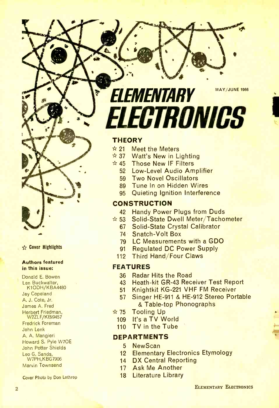
Cover Photo by Don Lothrop
2
ELEMENTARY MAY
ELECTRONICS
THEORY
* 21 Meet the Meters
* 37 Watt's New in Lighting
* 45 Those New IF Filters
52 Low -Level Audio Amplifier
59 Two Novel Oscillators
89 Tune In on Hidden Wires
95 Quieting Ignition Interference
CONSTRUCTION
42 Handy Power Plugs from Duds
* 53 Solid -State Dwell Meter /Tachometer
67 Solid -State Crystal Calibrator
74 Snatch -Volt Box
79 LC Measurements with a GDO
91 Regulated DC Power Supply
112 Third Hand /Four Claws
FEATURES
36 Radar Hits the Road
43 Heath -kit GR -43 Receiver Test Report
51 Knightkit KG -221 VHF FM Receiver
57 Singer HE -911 & HE -912 Stereo Portable
& Table -top Phonographs
* 75 Tooling Up
109 It's a TV World
110 TV in the Tube
DEPARTMENTS
5 NewScan
12 Elementary Electronics Etymology
14 DX Central Reporting
17 Ask Me Another
18 Literature Library
ELEMENTARY ELECTRONICS
www.americanradiohistory.com
Live Better Electronically With
RADIO ELECTR NI
o cs
iIYF aETEïB t:CCffAtl0.lt MTh thfxYtllF 19F,
OUR 45th YE.4k
catatag 6ßß
aae.-Patc5o7
Over 500 Pages
FR E
TV Tubes and Parts
Electronic Parts
Test Equipment
Citizens Band
Tools
Ham Gear
Stereo Hi -Fi
Tape Recorders
Walkie- Talkies
Auto Accessories
LAS AI Ulf.
R AMO Ei.ECi R4N1CS
1966 Catalog 660
ascoN Featuring Everything in Electronics for
HOME INDUSTRY LABORATORY
from the
01 òßa "World's Hi -Fi & Electronics Center"
LAFAYETTE Radio ELECTRONICS
Dept.DEEE6, P.O. Box 10, Syosset, L.I., N.Y. 11791
Cut out and Mall Coupon for FREE Lafayette Catalog
LAFAYETTE'S MAIL ORDER &
LONG ISLAND
SALES CENTER
111 Jericho Turnpike
Syosset, Long Island, New York
OTHER LOCATIONS
NEW YORK
Brooklyn
Syosset
Manhattan
Jamaica
Scarsdale
Bronx
NEW JERSEY MASSACHUSETTS
Newark Boston
Paramus Natick
Pla nfield MARYLAND
Connecticut Mt. Rainier
New Haven (Wash. D. C. Area)
West Hartford
r Send me the Free 1966 Lafayette Catalog 660 Dept. DEEE -6
Name ______
Address
City State
Zip- .......... -- ------ - - - - --
(Please Give Your Zip Code No.
www.americanradiohistory.com
-r
Fill in coupon for a FREE One Year Subscrip-
tion to OLSON ELECTRONICS' Fantastic Value
Packed Catalog- Unheard of LOW, LOW PRICES
on Brand Name Speakers, Changers, Tubes,
Tools, Stereo Amps, Tuners, CB, and other Val-
ues. Credit plan available.
NAME
ADDRESS
CITY ZONE STATE
If you have a friend interested in electronics send
his nome and address for a FREE subscription also.
OLSON ELECTRONICS
INCORPORATED
474 S. Forge Street Akron, Ohio 44308
Because you've got to SEE it to BELIEVE
it ... we will send you a FREE sample!
2
S
LERATE SWITCH
............... A
TIMERS
46.
OTLS TO TO TRACK TRACK I
NINO
IRO
RNKFITFRS TRANS
RNSCRISERS TRANSISTOR!
CS s .k`.
FR
TRANSISTORS TRANSISTORS TRAP
DATAMARK
- the easy new
way to label
your projects!
a Just rub over the pre- print-
ed words or symbols with a
ballpoint pen and they
transfer to any surface -
looks like finest printing!
Label control panels, meter
dials, letter on anything!
LOOK FOR 44414 late444.4
DATAMARK SETS ... only $1.25 each
- at leading electronic distributors
DATAMARK SETS AVAILABLE FOR:
Amateur Radio. CB
Audio, Hi.Fi, TV
Experimenter Home Intercom
Industrial Test Equipment
Switch & Dial Markings
Alphabets & Numerals in 1/2", 1/4" and 1"
- each set has black, white, and gold
SEND FOR FREE SAMPLE
THE DATAK CORPORATION
85 HIGHLAND AVENUE PASSAIC, N. J. 07055
4
ELEMENTARY
ELECTRONICS
MAY -JUNE 1966 Vol. 2 No. 2
JULIAN M. SIENKIEWICZ Editor
WA2CQL /KMD4313
WILLIAM HARTFORD
KKD7432 Technical Editor
ELMER C. CARLSON Construction Editor
ANTHONY MACCARRONE Art Director
IRVING BERNSTEIN Cover Art Director
EUGENE F. LANDINO Associate Art Director
RON STAFFIERI Art Editor
JUDITH ANDERSON Art Associate
ELLIOT S. KRANE Advertising Director
JIM CAPPELLO Advertising Manager
LEONARD F. PINTO Production Director
CARL BARTEE Production Manager
HELEN GOODSTEIN Assistant Production Manager
CLIFF SHEARER Promotion Director
JOSEPH DAFFRON Executive Editor
President and Publisher
B. G. DAVIS
Executive Vice President and Assistant Publisher
JOEL DAVIS
Vice President and Editorial Director
HERB LEAVY, KMD4529
ABC
ELEMENTARY ELECTRONICS, Vol. 2, No. 2 17851 is published bi-
monthly by SCIENCE& MECHANICS PUBLISHING CO., a subsidiary
of Davis Publications, Inc. Editorial, business and subscription offices:
505 Park Ave., New York, N. Y. 10022. One -year subscription Isis
issues)- $4.00; two -year subscription 112 issues1- $7.00; and three -
year subscription 118 issues1- $10.00. Add $1.00 per year for postage
outside the U.S.A. and Canada. Advertising offices: New York, 505
Park Ave., PI-2-6200; Chicago: 520 N. Michigan Ave., 527 -0330; Los
Angeles: 6253 Hollywood Blvd., 213-463-5143; Atlanta: Pirnie & Brown,
3108 Piedmont Rd., N.E., 404- 233 -6729; Long Island: Len Osten, 9 Garden
Street, Great Neck, N. Y., 516-487-3305; Southwestern advertising
representative: Jim Wright, 4 N. Eight St., St. louis, CH 1-1965.
EDITORIAL CONTRIBUTIONS most be accompanied by return postage
and will be handled with reasonable care; however, publisher assumes
no responsibility for return or safety of manuscripts, art work, or
photographs. All contributions should be addressed to the Editor,
ELEMENTARY ELECTRONICS, 505 Park Avenue, New York, N Y. 10022.
Second -class postage paid at New York, New York and at additional
mailing office. Copyright 1966.by Science and Mechanics Publishing Co.
ELEMENTARY ELECTRONICS
www.americanradiohistory.com
4
NEWSCA\
Transistor Space Time
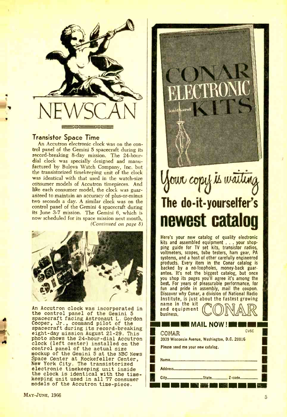
An Accutron electronic clock was on the con-
trol panel of the Gemini 5 spacecraft during its
record- breaking 8 -day mission. The 24 -hour-
dial clock was specially designed and manu-
factured by Bulova Watch Company, Inc. but
the transistorized timekeeping unit of the clock
was identical with that used in the watch -size
consumer models of Accutron timepieces. And
like each consumer model, the clock was guar-
anteed to maintain an accuracy of plus -or -minus
two seconds a day. A similar clock was on the
control panel of the Gemini 4 spacecraft during
its June 3 -7 mission. The Gemini 6, which is
now scheduled for its space mission next month,
(Continued on page 8)
An Accutron clock was incorporated in
the control panel of the Gemini 5
spacecraft facing Astronaut L. Gordon
Cooper, Jr., command pilot of the
spacecraft during its record -breaking
eight -day mission August 21 -29. This
photo shows the 24- hour -dial Accutron
clock (left center) installed on the
control panel of the actual size
mockup of the Gemini 5 at the NBC News
Space Center at Rockefeller Center,
New York City. The transistorized
electronic timekeeping unit inside
the clock is identical with the time-
keeping unit used in all 77 consumer
models of the Accutron time -piece.
MAY -JUNE, 1966
The do- it- yourselfer 's
newest catalog
Here's your new catalog of quality electronic
kits and assembled equipment ... your shop-
ping guide for TV set kits, transistor radios,
voltmeters, scopes, tube testers, ham gear, PA
systems, and a host of other carefully engineered
products. Every item in the Conar catalog is
backed by a no- loopholes, money -back guar-
antee. It's not the biggest catalog, but once
you shop its pages you'll agree it's among the
best. For years of pleasurable performance, for
fun and pride in assembly, mail the coupon.
Discover why Conar, a division of National Radio
Institute, is just about the fastest growing
name qn the kit MAR
and a ui ment
business.
MI MINIM MAIL NOW !MINIM=
co CONAR CV6C
3939 Wisconsin Avenue, Washington, D.C. 20016
Please send me your new catalog.
II City Stata 2 -code
Name
Address
o
J
www.americanradiohistory.com
Build 20 Radio and Electronic
Circuits at Home
ALL GUARANTEED TO WORK!
YOU DON'T HAVE TO SPEND
HUNDREDS OF DOLLARS FOR A RADIO COURSE
The "Edu -Kit" offers you an outstanding PRACTICAL HOME RADIO COURSE at a
rock- bottom price. Our Kit is designed to train Radio & Electronics Technicians, making
most
of the ost modern methods of home training. You will learn radio theory, construc-
tion practice and servicing. THIS IS A COMPLETE RADIO COURSE IN EVERY DETAIL.
You will learn how to build radios, using regular schematics; how to d solder
n
In a professional manner; how to s radios.
adios. You will work with the standard type of
Punched metal chassis a well as the latest development of Printed Circuit chassis.
You will learn the basin principles of radio. You will construct, study and work with
RF and AF amplifiers and oscillators, detectors, rectifiers, test equipment. You will learn
and practice code, using the Progressive Code Oscillator. You will learn and practice
trouble -shooting, using the Progressive Signal Tracer, Progressive Signal Injector, Progre
Dynamic
i mRadi & Electronics Tester. Square Wave Generator and the accompanying
riser You will receive training for the Novice, Technician and general Classes of F.C.C, Radie
Amateur Licenses. You will build Receiver, Transmitter, Square Wave Generator, Code
Oscillator, Signal Tracer and Signal Injector circuits, and learn haw to operate them. You
Will receive an excellent background for television, Hi -Fi and Electronics.
Absolutely no previous knowledge of radio or science is required. The "Edu -Kit" is the
product of many years of teaching and engineering experience. The "Edu-Kit" will pro-
vide you with a basic education in Electronics and Radio, worth many times the complete
price of 526.95. The Signal Tracer alone is worth more than the price of the entire Kit.
THE KIT FOR EVERYONE
You do not need the lightest background
In radio or science. Whether you are inter.
estetl Radio & Electronics because you
want an interesting hobby, a well paying
business or a job with a future, you will find
the 'Edu -Kit" a worth-while investment.
Many thousands of individuals of all
ages and backgrounds have successfully
used the "Edu -Kit" i more than 79 coun-
tries of the world. The Edu -Kit" has been
carefully designed, step by step, no that
you cannot of a mistake. The Edu -Kit"
(low you u to teach yourself at your own
rate. No instructor is necessary.
PROGRESSIVE TEACHING METHOD
The Progressive Radio "Edu -Kit" Is the forefront educational radio kit in the world,
and i universally accepted as the standard in the field of electronics training. The "Edu -
Kit" uses the modern educational principle of "Learn by Doing." Therefore you construct,
learn schematics, study theory, practice trouble -hooting -all n a closely integrated pro-
g ram designed to provide an sly- learned, thorough and interesting background in radio.
You begin by examining the various radio parts of the "Edu- Kit." You then learn the
function, theory and wiring of these u parts. Then st you build aesimpleeoadio. With this first
set you will enjoy listening to regular a theory, practice testing
and trouble -shooting. Then you build a more advanced radio, learn more advanced theory
and techniques. Gradually, progressive manner, and at your o own rate, you will
find yourself constructing advanced multi -tube radio circuits, and doing work like a
professional Radio Technician.
Included In the "Edu -Kit" course are Receiver, Transmitter, Code Oscillator,
Signal Tracer, Square Wave Generator and Signal Injector circuits. These not unprofes-
sional 'breadboard" experiments, but genuine radio circuits, constructed by means of
professional ing and ldering o n s,
m tal chassis, plu the ne method of radio con truc-
te n known a ''Printed Circuitry. " These circuits operate on your regular AC or DC house
current.
THE "EDU -KIT" IS COMPLETE
You will receive all parts and in trustions nec ssary to build 20 different radio and elec-
tronics circuits. each guaranteed to operate. Our Kits contain tubes, tube sockets, v
able, electrolytic, m ceramic ,
and paper dielectric condensers, r sistors, tie strips, coils,
hardware, tubing, punched metal chassis, Instruction Manuals hook -up wire, solder,
selenium rectifiers, volume controls and switches, etc.
In addition y receive Printed Ci cuit materials, including Printed Circuit chassis,
special tube sockets, hardware and instructions. You also eceive e eful set of tools, a
Rrofessional lectric soldering i n, and a elf -powered Dyn mic Radio and Electronics
ester. The ' ,Edu -Kit" also includes Code Instructions and the Progressive Code Oscillator,
in addition to F.C.C.-type Questions and Answers for Radio Amateur License training. You
will lso r ive lessons for icing ith the Prog s s ive Signal Tracer and the Progres-
sive Signal Injector, High Fidelity Guide nd a Quiz Book. You receive Membership in
'tea receive) all' parts, tools.
Consultation
structions, cetc. Evierythingf Merit and
iurs to keep Du it Privileges.
NOW! TRAIN AT HOME
SERVICING LESSONS
You will learn trouble- shooting and e
ing in a progressive m r. You will practice
repairs on the sets that. you construct. You
will learn symptoms and caus of trouble in
home, portable and car radios SYou will learn
how to use the professional Signal Truer,
the unique Signal Injector and the dynamic
Radio & Electronics Tester. While you are
learning in this practical way, you ill be
able to do many repair Job for your friends
and neighbors, and charge fees which will far
exceed the price of the "Edu- Kit." Our Con-
sultation Service will help you with any
technical problems you may have.
J. Stataitis, of 25 Poplar Pl., Waterbury.
Conn., writes: "I have repaired se ral ets
my friends, and made money. The "Edu -
Kit" paid for itself, I was ready to spend
$240 for a Course, but I found your ad and
sent for your Kit."
FROM OUR MAIL BAG
Ben Valerio, P. O. Box 21, Magna, Utah:
"The Edu -Kits are wonderful. Here I am
s ending you the questions and also the an-
..s for them. I have been in Radio for
the last seven years, but like to wok with
Radio Kits, and like to build Radio Testing
Equipment. I enjoyed every m nute 1 rked
with the different kits; the Signal Tracer
works fine. Also like to let you know that I
feel proud of becoming a member of your
Radio-TV Club."
Robert L. Shoff, 1534 Monroe Ave., Hunt-
ington, W. Va.: "Thought I would drop you
a few lines to say that I received my Edu -Kit,
and as really amazed that such a bargain can
be had at such a low price. I have already
started repairing radio. and phonographs. My
friends w really surprised to ee me get
into the awing of it so quickly. The Trouble-
shooting Tester That come. with the Kit is
really swell, and finds the trouble, if there
is any to be found."
PRINTED CIRCUITRY
At no increase in price, the "Edu -Kit"
now Induces Printed Circuitry. You
build a Printed Circuit Signal Injector,
a unique serving Instrument that can
detect many Radio and TV troubles. This
revolutionary new technique of radio con-
struction is now becoming popular in com-
mercial radio and TV sets.
A Printed Circuit Is a special insu-
lated chassis on which has been depos-
ited a conducting material which takes
the place of wiring. The various parts
are merely plugged In and soldered to
terminals.
Printed Circuitry is the basis of mod-
ern Automation Electronics. A knowl-
edge of this subject is a necessity today
for anyone Interested in Electronics.
IN RADIO AND ELECTRONICS
ORDER DIRECT FROM AD .... USE COUPON ON NEXT PAGE
RECEIVE FREE RADIO & TV PARTS JACKPOT
6 ELEMENTARY ELECTRONICS
.'
www.americanradiohistory.com
SCHOOL INQUIRIES INVITED
THE NEW IMPROVED DELUXE
Progressive
Radio "Edu -Kit"
is now ready
NOW INCLUDES
* 12 RECEIVERS
* 3 TRANSMITTERS
* SQ. WAVE GENERATOR
* AMPLIFIER
* SIGNAL TRACER
* SIGNAL INJECTOR
* CODE OSCILLATOR
PRACTICAL
HOME
RADIO
COURSE
only
Rig. U.S.
Pat. Off.
Unconditional Money -Back Guarantee
The Progressive Radio "Edu -Kit" has been sold to many thou.
sands of individuals, schools and organizations, public and private.
throughout the world. It is recognized internationally as the ideal
radio course.
By popular demand, the Progressive Radio "Edu -Kit" is now
available In Spanish as well as English.
It is understood and agreed that should the Progressive Radio
"Edu -Kit" be returned to Progressive "Edu -Kits" Inc. for any rea-
son whatever, the purchase price will be refunded in full, without
quibble or question, and without delay.
The high recognition which Progressive "Edu- Kits" Inc. has
earned through its many years of service to the public is due to
its unconditional insistence upon the maintenance of perfect engl-
naering, the highest instructional standards, and 100% adherence
to its Unconditional Money -Back Guarantee. As a result, we do not
have a single dissatisfied customer throughout the entire world.
TRAINING ELECTRONICS
TECHNICIANS SINCE 1946
FREE
EXTRAS
SET OF TOOLS
SOLDERING IRON
ELECTRONICS TESTER
PLIERS -CUTTERS
VALUABLE DISCOUNT CARD
CERTIFICATE OF MERIT
TESTER INSTRUCTION MANUAL
HIGH FIDELITY GUIDE QUIZZES
TELEVISION BOOK RADIO
TROUBLE -SHOOTING BOOK
MEMBERSHIP IN RADIO -TV CLUB:
CONSULTATION SERVICE FCC
AMATEUR LICENSE TRAINING
PRINTED CIRCUITRY
2J044 Mil %a.l `I>lie NeFnessiue
Radia .9s Penieci
FOR anyone who wishes to learn more
FOR anyone who is looking for an
interesting hobby.
FOR anyone who would like to
learn radio but does not have
time to attend regular school
hours.
FOR anyone who wants to start
studying for a high -paying radio
job.
FOR anyone who wishes to start
in Television.
about radio construction, theory and servicing.
Send "Edu -Kit" postpaid. I enclose full payment of $26.95.
Send "Edu -Kit" C.O.D. I will pay $26.95 plus postage.
Rush me FREE descriptive literature concerning "Edu- Kit."
Name
Address
MAY -JUNE, 1966
PROGRESSIVE "EDU- KITS" INC.
1186 Broadway. Dept. 512DJ, Hewlett. N. Y. 11557
7
www.americanradiohistory.com
BUILD THESE 5 PROJECTS
IN 2 EASY STEPS WINEWHE VERO
PROJECT CONSTRUCTION KIT MODEL PK -5
IMPEDANCE MATCHING MODULE MULTIVIBRATOR MODULE
AUDIO OSCILLATOR MODULE AUDIO AMPLIFIER & RF
PROBE MODULE ENGINE PULSE COUNTER MODULE
Here Is a golden oppor- Veroboards and a book
tunity to build not one let describing in com-
but five useful projects plete detail how to build
using the newVeroboard each of the compact
Kit Model PK5 - at a projects listed.
price so low ... It's al- Send for your Veroboard
most unbelievable! kit now or ask for it at
Each kit contains 5 your local distributor.
Patented
e e 0600 e
,-.4-0-5L-4-2-11.) e
e e ales e
e e e e
60 e e
a e e
tae
e (e)
6 6 6 6 a 6 6 6 a
o e e '
Step No. 1 -Mount corn
ponents and solder Step No.2 -Break cooper
strip where required
TO. E
48 ALLEN BLVD., FARMINGDALE, N.Y.
Please send me your Model PK -5 Kit. I am
enclosing $1.95 (N. Y. S. residents add local
sales tax).
NAME
ADDRESS
CITY
STATF ZIP
IA!'E_ THIS AD TO THE BACK OF YOUR TV SET
ALL BRAND NEW, all at a flat discount price of
o nly
No exceptions all tubes
Si, regardless of list price.
Virtually all types a ailable,
nelud,ng the new color tubes.
All Tubes 1st QUALITY
MADE IN U.S.A.
All Sold on Written
24 -MONTH WARRANTY
All orders SHIPPED 1st
CLASS SAME DAY REC'O.!
Order replacements for your defective tubes @ a flat
$1.00 each plus 50n postage and handling for your en-
tire order. Address Dep't. EE -56.
UNIVERSAL TUBE CO.
Ozone Park, N. Y. 11417
LEARN Enslneering AT HOME
Fis TV, design automation systems, learn transistors. complete
electronics. College level Home Study courses taught so you can
understand them. Eam more In the highly paid electronics in-
dustry. Computers. Missiles, theory and practical. Bite furnished.
Over 30,000 graduates now employed. Resident classes at our
Chicago campus if desired. Founded 1034. Catalog.
AMERICAN INSTITUTE OF ENGINEERING L TECHNOLOGY
1139B West Fullerton Parkway Chicago, Illinois 60614
IF YOU OWN A CAR, you should buy ENGINE.
The new 1966 edition will be at your newsstand
May 3. It is an invaluable ready reference for
maintenance, repairs, servicing, and what's new.
Only 75íj.
8
NEWSCAN
Continued from page 5
will also be equipped with an Accutron clock.
As far as can -be determined, the Accutron
timekeeping unit was the only product orig-
inally developed for the consumer market that
was part of the Gemini 5's instrumentation.
The clock was incorporated in the control panel
immediately in front of the command pilot,
Lieut. Col. L. Gordon Cooper, Jr.
The Accutron timekeeping unit uses a one -
inch tuning fork as its frequency standard. It
hums gently ( between E and F above Middle
C) as it vibrates 360 times a second, or 31,-
104,000 times each 24 hours, or 144 times as
fast as the oscillation rate of the balance wheel
in a conventional watch movement. Like all
consumer models, Gemini 5's Accutron clock
operated on about .000008 watt ( eight one -mil-
lionths of a watt). Power was transmitted
through a transistorized electronic circuit from
a tiny power cell contained within the clock
case. The cell lasts at least a year, as is the
case with consumer models.
The mission of the Gemini 5 spacecraft estab-
lished five world space records for the United
States, and set three world space records for
individuals and two American space records.
The five world records set for the U. S. are:
1. Longest manned space flight: 190 hours
56 minutes.
2. Longest multi- manned space flight: 190
hours 56 minutes.
3. Most revolutions for manned space flight:
120. 4. Brought total of U. S. man -hours in space
to 839 hours 48 minutes.
5. Brought total of U. S. manned space flights
to 9.
ETV in Puerto Rico
Puerto Rico has placed an order with General
Electric for nearly 1,800 educational TV sets
in a move that is expected to have far -reaching
effects in the ETV field.
Believed to be the largest single ETV re-
ceiver order ever placed with a manufacturer,
the $537,000 five -year contract was won by
International General Electric Puerto Rico
which will supply, install and service the sets
designed specifically for school use.
The order is especially significant in view
of the heavy effort being made by Puerto
Rico's Department of Education to improve
the quality of education in the island common-
wealth. Through expansion of the ETV pro-
gram, it will be possible to offer a richer cur-
riculum to the greatest number of students. At
the same time, by watching the performance of
an excellent teacher, instructors will have an
additional resource for improving their teaching
methods and knowledge of subject matter.
ELEMENTARY ELECTRONICS
14M
A-
www.americanradiohistory.com
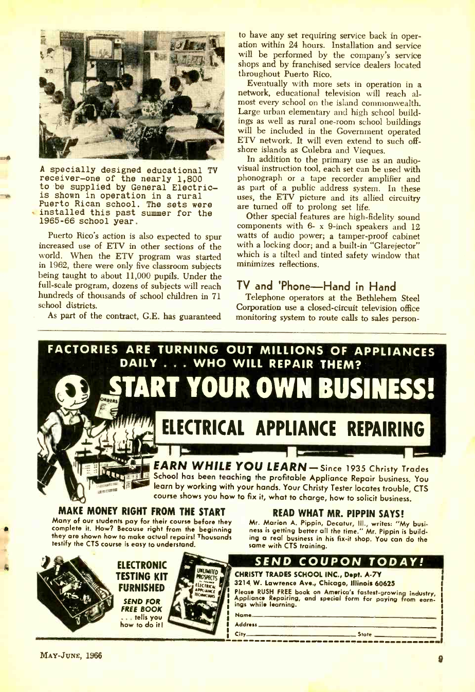
A specially designed educational TV
receiver -one of the nearly 1,800
to be supplied by General Electric -
is shown in operation in a rural
Puerto Rican school. The sets were
installed this past summer for the
1965 -66 school year.
Puerto Rico's action is also expected to spur
increased use of ETV in other sections of the
world. When the ETV program was started
in 1962, there were only five classroom subjects
being taught to about 11,000 pupils. Under the
full -scale program, dozens of subjects will reach
hundreds of thousands of school children in 71
school districts.
As part of the contract, G.E. has guaranteed
to have any set requiring service back in oper-
ation within 24 hours. Installation and service
will be performed by the company's service
shops and by franchised service dealers located
throughout Puerto Rico.
Eventually with more sets in operation in a
network, educational television will reach al-
most every school on the island commonwealth.
Large urban elementary and high school build-
ings as well as rural one -room school buildings
will be included in the Government operated
ETV network. It will even extend to such off-
shore islands as Culebra and Vieques.
In addition to the primary use as an audio-
visual instruction tool, each set can be used with
phonograph or a tape recorder amplifier and
as part of a public address system. In these
uses, the ETV picture and its allied circuitry
are turned off to prolong set life.
Other special features are high- fidelity sound
components with 6- x 9 -inch speakers and 12
watts of audio power; a tamper -proof cabinet
with a locking door; and a built -in "Glarejector"
which is a tilted and tinted safety window that
minimizes reflections.
TV and 'Phone -Hand in Hand
Telephone operators at the Bethlehem Steel
Corporation use a closed- circuit television office
monitoring system to route calls to sales person-
FACTORIES ARE TURNING OUT MILLIONS OF APPLIANCES
DAILY . . . WHO WILL REPAIR THEM?
ELECTRICAL APPLIANCE REPAIRING
EARN WHILE YOU LEARN -Since 1935 Christy Trades
School has been teaching the profitable Appliance Repair business. You
learn by working with your hands. Your Christy Tester locates trouble, CTS
course shows you how to fix it, what to charge, how to solicit business.
MAKE MONEY RIGHT FROM THE START
Many of our students pay for their course before they
complete it. How? Because right from the beginning
they are shown how to make actual repairs) Thousands
testify the CTS course is easy to understand.
ELECTRONIC
TESTING KIT
FURNISHED
SEND FOR
FREE BOOK
. tells you
how to do itI
READ WHAT MR. PIPPIN SAYS!
Mr. Marion A. Pippin, Decatur, Ill., writes: "My busi-
ness is getting better all the time." Mr. Pippin is build-
ing a real business in his fix -it shop. You can do the
some with CTS training.
MAY- .TUNE, 1966
CHRISTY TRADES SCHOOL INC., Dept. A -7Y
3214 W. Lawrence Ave., Chicago, Illinois 60625
Please RUSH FREE book on America's fastest -growing industry,
Appliance Repairing, and special form for paying from earn-
ings while learning.
Name
Address
City State
9
www.americanradiohistory.com
NEWSCAN
nel. Three Sylvania television cameras are in-
stalled to allow telephone operators to view sales
areas, not in the line of sight, from the telephone
switchboard. By looking at the TV monitors
( above) , the operators can determine if a Beth-
lehem salesman is at his desk to receive incoming
phone calls. If he is not available, the operator
can refer the call to another desk or activate a
red light on the telephone to indicate that there
is a message at the switchboard. Other installa-
tions using Sylvania equipment serve Bethle-
hem's Chicago and Atlanta offices. Bethlehem
Steel's Sales Department believes that the closed
circuit television system enables them to provide
their customers with faster and more efficient
telephone service.
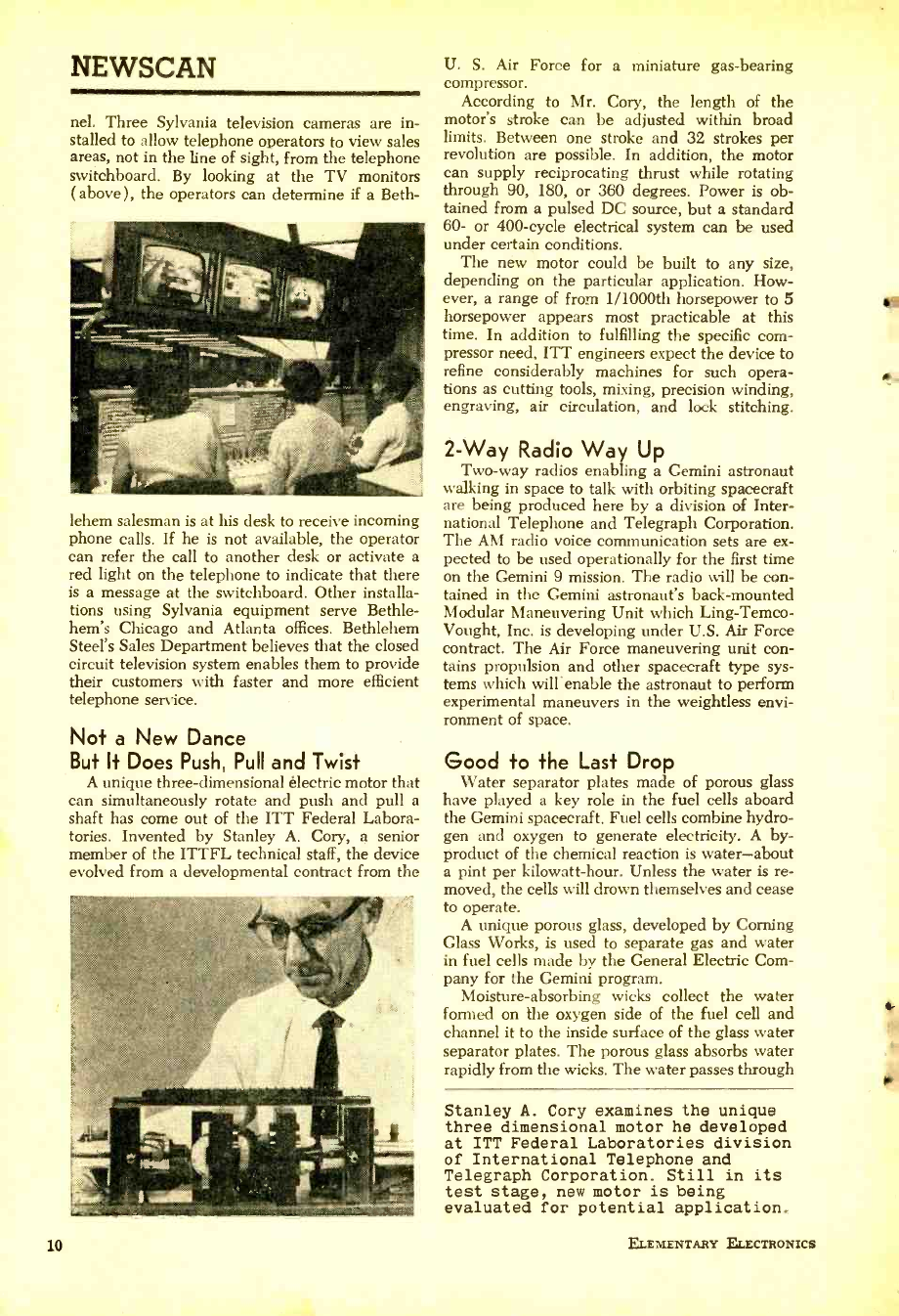
Not a New Dance
But It Does Push, Pull and Twist
A unique three -dimensional electric motor that
can simultaneously rotate and push and pull a
shaft has come out of the ITT Federal Labora-
tories. Invented by Stanley A. Cory, a senior
member of the ITTFL technical staff, the device
evolved from a developmental contract from the
10
U. S. Air Force for a miniature gas- bearing
compressor.
According to Mr. Cory, the length of the
motor's stroke can be adjusted within broad
limits. Between one stroke and 32 strokes per
revolution are possible. In addition, the motor
can supply reciprocating thrust while rotating
through 90, 180, or 360 degrees. Power is ob-
tained from a pulsed DC source, but a standard
60- or 400 -cycle electrical system can be used
under certain conditions.
The new motor could be built to any size,
depending on the particular application. How-
ever, a range of from 1 /1000th horsepower to 5
horsepower appears most practicable at this
time. In addition to fulfilling the specific com-
pressor need, ITT engineers expect the device to
refine considerably machines for such opera-
tions as cutting tools, mixing, precision winding,
engraving, air circulation, and lock stitching.
2 -Way Radio Way Up
Two -way radios enabling a Gemini astronaut
walking in space to talk with orbiting spacecraft
are being produced here by a division of Inter-
national Telephone and Telegraph Corporation.
The AM radio voice communication sets are ex-
pected to be used operationally for the first time
on the Gemini 9 mission. The radio will be con-
tained in the Gemini astronaut's back -mounted
Modular Maneuvering Unit which Ling- Temco-
Vought, Inc. is developing under U.S. Air Force
contract. The Air Force maneuvering unit con-
tains propulsion and other spacecraft type sys-
tems which will'enable the astronaut to perform
experimental maneuvers in the weightless envi-
ronment of space.
Good to the Last Drop
Water separator plates made of porous glass
have played a key role in the fuel cells aboard
the Gemini spacecraft. Fuel cells combine hydro-
gen and oxygen to generate electricity. A by-
product of the chemical reaction is water -about
a pint per kilowatt -hour. Unless the water is re-
moved, the cells will drown themselves and cease
to operate.
A unique porous glass, developed by Corning
Glass Works, is used to separate gas and water
in fuel cells made by the General Electric Com-
pany for the Gemini program.
Moisture -absorbing wicks collect the water
formed on the oxygen side of the fuel cell and
channel it to the inside surface of the glass water
separator plates. The porous glass absorbs water
rapidly from the wicks. The water passes through
Stanley A. Cory examines the unique
three dimensional motor he developed
at ITT Federal Laboratories division
of International Telephone and
Telegraph Corporation. Still in its
test stage, new motor is being
evaluated for potential application.
ELEMENTARY ELECTRONICS
www.americanradiohistory.com
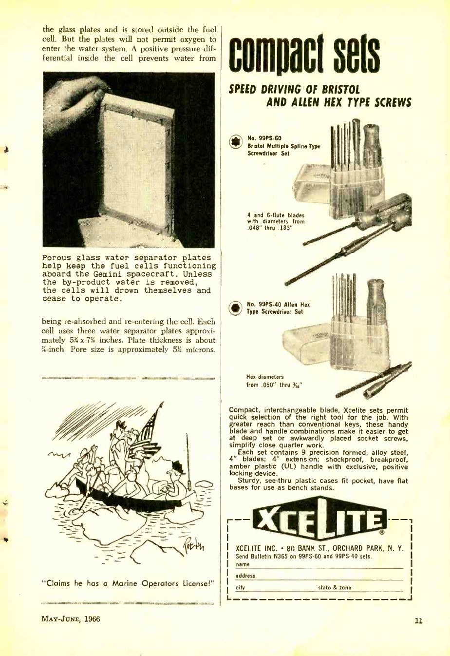
the glass plates and is stored outside the fuel
cell. But the plates will not permit oxygen to
enter the water system. A positive pressure dif-
ferential inside the cell prevents water from
Porous glass water separator plates
help keep the fuel cells functioning
aboard the Gemini spacecraft. Unless
the by- product water is removed,
the cells will drown themselves and
cease to operate.
being re- absorbed and re- entering the cell. Each
cell uses three water separator plates approxi-
mately 5h x 71b inches. Plate thickness is about
3-inch. Pore size is approximately 5h microns.
,1111111111111111.11111111111111111111111111111111111111111111111111w11111111111111111111111111111111111111111111 . 1111111111111111111111 III 11111
"Claims he has a Marine Operators License!"
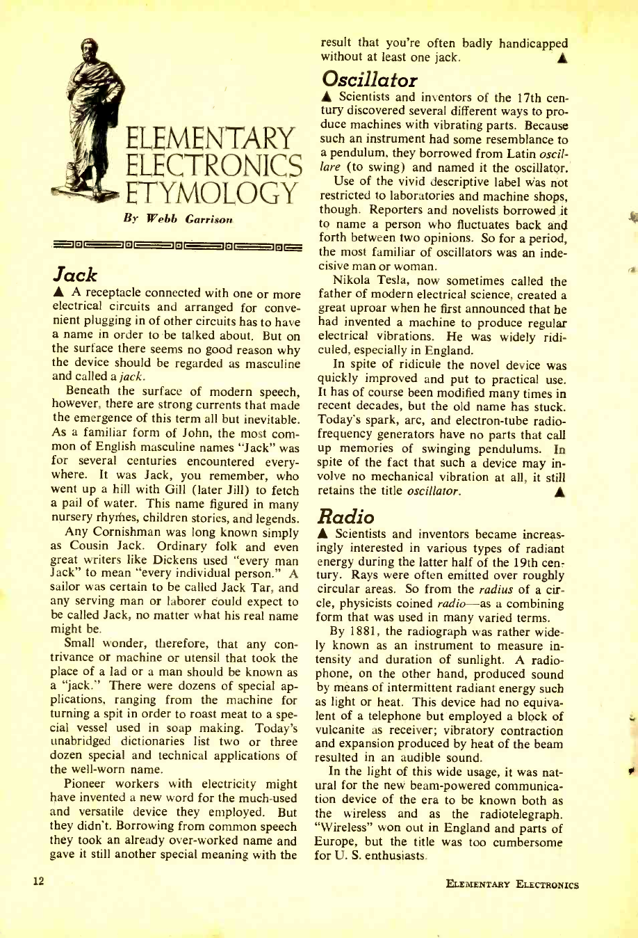
compact sets
SPEED DRIVING OF BRISTOL
AND ALLEN HEX TYPE SCREWS
ONo. 99PS -60
Bristol Multiple Spline Type
Screwdriver Set
4 and 6 -flute blades
with diameters from
.048" thru .183"
ONo. 99PS -40 Allen Hex
Type Screwdriver Set
Hex diameters
from .050" thru 316'
Compact, interchangeable blade, Xcelite sets permit
quick selection of the right tool for the job. With
greater reach than conventional keys, these handy
blade and handle combinations make it easier to get
at deep set or awkwardly placed socket screws,
simplify close quarter work.
Each set contains 9 precision formed, alloy steel,
4" blades; 4" extension; shockproof, breakproof,
amber plastic (UL) handle with exclusive, positive
locking device.
Sturdy, see -thru plastic cases fit pocket, have flat
bases for use as bench stands.
r--
L
XCELITE INC. 80 BANK ST., ORCHARD PARK, N. Y.
Send Bulletin N365 on 99PS -60 and 99PS -40 sets.
name
address
city state & zone
MAY -JUNE, 1966 11
www.americanradiohistory.com
ELEMENTARY
ELLECTRONICS
ETYMOLOGY
By Webb Garrison
= ior otatat=
Jack A receptacle connected with one or more
electrical circuits and arranged for conve-
nient plugging in of other circuits has to have
a name in order to be talked about. But on
the surface there seems no good reason why
the device should be regarded as masculine
and called a jack.
Beneath the surface of modern speech,
however, there are strong currents that made
the emergence of this term all but inevitable.
As a familiar form of John, the most com-
mon of English masculine names "Jack" was
for several centuries encountered every-
where. It was Jack, you remember, who
went up a hill with Gill (later Jill) to fetch
a pail of water. This name figured in many
nursery rhymes, children stories, and legends.
Any Cornishman was long known simply
as Cousin Jack. Ordinary folk and even
great writers like Dickens used "every man
Jack" to mean "every individual person." A
sailor was certain to be called Jack Tar, and
any serving man or laborer could expect to
be called Jack, no matter what his real name
might be.
Small wonder, therefore, that any con-
trivance or machine or utensil that took the
place of a lad or a man should be known as
a "jack." There were dozens of special ap-
plications, ranging from the machine for
turning a spit in order to roast meat to a spe-
cial vessel used in soap making. Today's
unabridged dictionaries list two or three
dozen special and technical applications of
the well -worn name.
Pioneer workers with electricity might
have invented a new word for the much -used
and versatile device they employed. But
they didn't. Borrowing from common speech
they took an already over -worked name and
gave it still another special meaning with the
12
result that you're often badly handicapped
without at least one jack.
Oscillator
Scientists and inventors of the 17th cen-
tury discovered several different ways to pro-
duce machines with vibrating parts. Because
such an instrument had some resemblance to
a pendulum, they borrowed from Latin oscil-
lare (to swing) and named it the oscillator.'
Use of the vivid descriptive label was not
restricted to laboratories and machine shops,
though. Reporters and novelists borrowed it
to name a person who fluctuates back and
forth between two opinions. So for a period,
the most familiar of oscillators was an inde-
cisive man or woman.
Nikola Tesla, now sometimes called the
father of modern electrical science, created a
great uproar when he first announced that he
had invented a machine to produce regular
electrical vibrations. He was widely ridi-
culed, especially in England.
In spite of ridicule the novel device was
quickly improved and put to practical use.
It has of course been modified many times in
recent decades, but the old name has stuck.
Today's spark, arc, and electron -tube radio -
frequency generators have no parts that call
up memories of swinging pendulums. In
spite of the fact that such a device may in-
volve no mechanical vibration at all, it still
retains the title oscillator.
Radio
Scientists and inventors became increas-
ingly interested in various types of radiant
energy during the latter half of the 19th cen-
tury. Rays were often emitted over roughly
circular areas. So from the radius of a cir-
cle, physicists coined radio -as a combining
form that was used in many varied terms.
By 1881, the radiograph was rather wide-
ly known as an instrument to measure in-
tensity and duration of sunlight. A radio-
phone, on the other hand, produced sound
by means of intermittent radiant energy such
as light or heat. This device had no equiva-
lent of a telephone but employed a block of
vulcanite as receiver; vibratory contraction
and expansion produced by heat of the beam
resulted in an audible sound.
In the light of this wide usage, it was nat-
ural for the new beam -powered communica-
tion device of the era to be known both as
the wireless and as the radiotelegraph.
"Wireless" won out in England and parts of
Europe, but the title was too cumbersome
for U. S. enthusiasts.
ELEMENTARY ELECTRONICS
w
www.americanradiohistory.com
UNUSUAL BARGAINS
i
At the 1906 International Radiotelegraph
Convention in Berlin, Americans succeeded
in substituting "radio" for "wireless teleg-
raphy." Six years later the young word was
officially adopted by Congress. First used
to designate an individual wireless message,
radio has since come into global supremacy
as the name for organized broadcasting of
news, music, and other programs -even
when deliberately beamed in such fashion
that the original comparison with "radius of
a circle" no longer holds true.
Volt Alessandro Volta, born in 1745, consid-
ered himself a philosopher rather than a
scientist. He took great interest in the phe-
nomena linked with the newly- discovered
and mysterious forces of electricity and at
age 24 wrote a treatise on "The Attractive
Force of Electric Fire." A few years later,
in 1776, he became professor of natural phi-
losophy at the University of Pavia in his
native Italy.
Volta invented several electrical devices
before stumbling upon a way to produce a
continuous current of electricity by contact
of different substances. This "Voltaic pile"
made him an international celebrity. Sir J.
F. W. Herschel called it "the most wonderful
of all human inventions." Learned societies
competed v ith one another for the honor of
bestowing medals upon him, and Napoleon
brought him to Paris in order to demonstrate
his discoveries before the members of the
French Institute. Eventually he was given
the title of count and made a senator of the
kingdom of Italy.
Fellow pioneers in the study of electrical
phenomena were faced with the problem of
selecting names to indicate quantities and
effects with which they dealt. For several
decades there was no attempt at standardiza-
tion. But delegates to the International Elec-
trical Congress of 1893 realized that order
had to be brought out of chaos. So they de-
fined a number of basic electrical units and
gave each of them a name. In honor of
Alessandro Volta, volt was selected to stand
for "that electromotive force which steadily
applied to a conductor whose resistance is
one ohm will produce a current of one am-
pere."
Practically equivalent to 108 C. G. S. elec-
tromagnetic units, the name of the volt is
familiar to millions of persons who know
little or nothing of Volta and his famous
Voltaic piles.
MAY -JUNE, 1966
... MANY U. S. GOV'T SURPLUS
BARGAIN! 3" ASTRONOMICAL TELESCOPE
See the stars, moon. l'hases of Venus, planeta
.close up! 80 to 180 power -famous Mt. Palomar
Reflecting type. Unusual Buy! Equipped with
Itquatorial mount; finder telescope; hardwood tri-
pud. Included FREE: "STAR CHART "; 272 -
page "HANDBOOK OF HEAVENS "; "HOW TO
l'Fb: YOUR TELESCOPE" book.
-Stock No. 85,050 -EK $29.95 Postpaid
4t /a° Reflecting Telescope -up to 225 Power
Stock No. 83,105 -EK $79.S0 F.O.B.
SOLVE PROBLEMS! TELL FORTUNES! PLAY GAMES!
NEW WORKING MODEL DIGITAL COMPUTER
ACTUAL MINIATURE VERSION
OF GIANT ELECTRONIC BRAINS
Fascinating new see- through model computer
actually solves problems, teaches computer
fundamentals. Adds, subtracts, multiplies,
shifts, complements, carries, memorizes, counts,
compares, sequences. Attractively colored, rigid
plastic parts easily assembled. 12" x 31/2" x
43/4", Incl. step -by -step assembly diagrams.
32.page nstruct:on book covering operation, computer language
(binary system), programming, problems and 15 experiments.
Stock No. 70,683 -EK $5.98 Postpaid
Check, Measure, Inspect with this
6 POWER POCKET COMPARATOR
(Complete with Leather Case)
MEASURES Angles Radii Circle s
Linear -in both decimal inches and milli-
meters.
Use to check layouts, machining on tools. dies,
gauges, to check threads, chamfers wear on cut-
ting tools, etc.
Stock No. 30,061 -EK New Low Price $19.50 Postpaid
Battery Operated COMPARATOR ILLUMINATOR
Stock No. 50,076 -EK (Battery incl.) $7.95 Postpaid
HANDY! FAST!
ACCURATE!
7x50 MONOCULAR
MAKES INEXPENSIVE, LIGHTWEIGHT
TELEPHOTO SYSTEM FOR ANY CAMERA
optimum In optical performance. Field of view
at 1000 yards is 376 feet. Relative light effi-
ciency is 75. Exit pupil measures 7mm. Has
socket to attach to photographic tripod. Precision, Japanese made.
Approx. 12-oz. Incl. case, straps. Stock No. 70,639 -EK $17.95 Postpaid
ADAPTER RINGS ONLY
Stock No. 40,680-EK-For Series V $1.50 Postpaid
Stock No. 40,769-EK-For Series VI $2.25 Postpaid
Bargains Galore! Hours of Fun! Only 55
NEW POPULAR SCIENCE FUN CHEST
Here are Edmund's 9 top selling science toys and
curiosities in one fascinating, low-cost package.
Perfect gift item. Amuse d delight young and
old for hours on end. Educational, too! Teach
basic science principles in a wonderful new fun
way. Incl.: Solar Radiometer -spins at 3,000 rpm;
Albert the Bobbing Bird -runs continuously on
thermal energy; Amazing Sealed Mercury Puzzle:
Five 2 -sided Ceramic Magnets; Big 3'/2" Burning
Glass in Zip -Lip Poly Bag: Magnetic Doggie and
Spinning Ball -ball spins as dog approaches; Ring
t s, fraction Grating, Rainbow Viewer; PIK -UP Rmy
(with You." Popular ragelet, "Astronomy
and You." All in die -cut storage box with com
pieta mntructions.
Stock No. 70,787 -EK $5.00 Postpaid
"Balls of Fun" for Kids . .
Traffic Stoppers for Stores
Terrific for Amateur Meteorologists . . .
SURPLUS GIANT WEATHER BALLOONS
At last . available again In 5 ft. and 10 ft.
diameters. Create a neighborhood sensation.
Great backyard fun. Exciting beach attraction.
Blow up with vacuum cleaners or auto air hose.
Sturdy enough for hard play; all other uses.
Filled with helium (available locally) use bal-
loons high in the sky to attract crowds, adver-
tise store sales, announce fair openings, etc.
Amateur meteorologists use ballonsatormea terse
cloud heights, win speed, temperature, pres-
sure, humidity at various heights. Photogra
phera can utilize for low -cost aerial photos.
Recent Govt. surplus of heavy rubber.
Stock No. 60,562 -EK- 5 ft. diam. size $2.00 Postpaid
Stock No. 60,564 -EK -10 ft. diam. size $4.00 Postpaid
Order by Stock No. -Send Check or M.O.- Money -Back Guarantee
EDMUND SCIENTIFIC CO., Barrington, New Jersey
MAIL COUPON for FREE CATALOG "EK"
EDMUND SCIENTIFIC CO., Barrington, N. J.
Completely New 1966 Edition. 148 pages.
Nearly 77 ?? Bargains.
Please rush Free Giant Catalog -EK
Name
Address Zip
City State Code
13
www.americanradiohistory.com
PRIM
GIANT NEW CATALOG
Ilq! 74et,s
t,4T3+,
,,r
100's OF BIG P GES
CRAMMED WITH SAVINGS
BURSTEIN-APPLEBEE CO.
Dept. EEX, 1012 McGee, Kansas City,Mo. 64106
I Rusts me FREE 1966 B -A Catalog
I Name
Address .... i
I City ... I FREE
State,,,,,,,
' Please be sure to show your Zip No I
LEARN HOW
TO ADJUST YOUR
NEW COLOR TV SET
and save money too!
In the Spring /Summer RADIO TV
REPAIRS -at your newsstand -M
If you already own a color TV
set, or if you plan to buy one,
this feature story on "COLOR
TV SET ADJUSTMENTS is im-
portant to you.
In easy -to- understand language,
complete with illustrations, the
money saving steps to making
color TV adjustments are ex-
plained. This and more can be
found in the new RADIO TV
REPAIRS.
RADIO TV REPAIRS /505 Park Ave. /New York /10022
I am enclosing $1.00 (includes postage & handling/.
Please send me my copy of RADIO TV REPAIRS.
NAME (PLEASE PRINT)
ADDRESS
CITY STATE lIP E£-785
14
DX
CENTRAL
REPORTING
It's very seldom that one comes across
regular magazine coverage of one of the
most fascinating aspects of electronics, that
is DX'ing (or "SWL'ing, if you prefer that
term) on the so- called "utility" bands. The
utility bands are those portions of the radio
spectrum wherein operate thousands of ships,
aircraft, radio telephone stations, scientific,
police, military, and press stations. These are
the "cream of DX, almost all of the stations
are of relative low power, many of them will
QSL. We at ELECTRONIC EXPERIMENTER have
always felt that these utilities stations are sort
of the private domain of the experimenter,
and our own international monitoring sta-
tion, DX CENTRAL, devotes a considerable
amount of time to listening in on these
transmissions.
We have convinced the operators at DX
CENTRAL to part with some of their DX
loggings and will present them here for our
readers. In addition, we'll frequently take a
look at some particular piece of monitoring
equipment (even military surplus gear)
which you can use to your advantage. Now
and then, we will even have a little contest
for our readers. We will also be looking for
reports from our readers regarding their own
loggings.
Go Aero. One of the best ways to get
started and rack up new countries is on the
aeronautical frequencies, which chatter away
with DX both day and night. On these
frequencies you'll be able to log countries
which can't be heard on the short -wave
broadcast bands. Some of the most interest-
ELEMENTARY ELECTRONICS
www.americanradiohistory.com
ing and active of these frequencies are 2945,
2966, 2987, 5611, 5619, 5641, 6537, 6567,
8837, 8845, 8871, 8879, 8888, 8905, 8930,
and 8947 kc. Look for rare countries such
as Eire (home of the wee folk), Italy,
Senegal, Brazil, Scotland, Azores Islands,
Curacao (N.W.I.) and dozens of others.
Best times to listen on these frequencies
are after dark in your local area. Tune in
one of the frequencies we have listed and
"sit on it" for a few hours. Try to see how
many different stations you can hear in a
given time period. Soon you'll find that one
or two of the frequencies will become your
favorites, you'll probably even get to recog-
nize the voices of the operators after a while.
The aero stations usually identify by the
name of the city in which they are located, so
you are liable to hear "Santa Maria" in the
Azores, "San Juan" in Puerto Rico, or
"Dakar" in Senegal. If you hear "Brooklyn"
calling, you'll know it's that Flatbush CB'er
tuning up his final.
You will be hearing ground stations com-
municating with each other, or working air-
line flights. While some of the ground sta-
tions are elaborate communications centers,
many are little more than a single operator
talking into a desk -top transmitter at an iso-
lated airdrome. Pressing the mike button with
one hand, swatting mosquitos with the other,
these operators let you sit -in on the exciting
world of international aviation.
Let Us Know. Say, what about one of
those reader contests we mentioned? Suppose
we tried this on the aero frequencies for a
starter. See how many different countries you
,,,.,,,,,,,,,..111...11111,1I,,,,,,,,,,191,,,,,,10,......,1,,,1,,,,1,,,,1,....111,1.11111,,.
"No kidding? It's a color TV set?
MAY -JUNE, 1966
DOES BUYING
HI -FI COMPONENTS
CONFUSE YOU?
It's no wonder with so many to choose from.
Just which do you buy -which is really best
for your home?
If this is your problem, or if you just enjoy
keeping up -to -date on the newest components
available, the new Mid -Year 1966 edition of
HI -FI BUYERS' GUIDE will be a most valu-
able companion.
You'll find a thorough and detailed section de-
voted to test reports conducted by an independ-
ent laboratory. In this issue of HI -FI BUYERS'
GUIDE, this objective testing organization has
reviewed high fidelity integrated stereo amplifiers
(preamps and power amps on one chassis -both
stereo solid state and vacuum tube models), high
fidelity stereo phono cartridges and high fidelity
stereo headphones.
Each unit reviewed has been rated:
APPROVED
NOT APPROVED
There's a comprehensive feature on the best
methods of selecting a microphone for your tape
recorder. This is more than an expanded glos-
sary of terms; this article explains the various
microphone types and how their characteristics
and prices should be considered in light of the
buyer's recording needs.
There's a provocative article on Record Clubs;
another on the latest trends in "housing" high
fidelity components in furniture. There are 96
highly informative pages which will aid you in
making your next high fidelity purchase an easy
and fun -filled task.
On sale April 5th, $1.25
HI -FI BUYERS' GUIDE /505 Park Avenue /New York, EE -785
N. Y./10022
Please send me my copy of HI -Fl BUYERS' GUIDE. Enclosed
is $1.50 (includes postage & handling).
Name
Address
City State Zip
(please print)
15
www.americanradiohistory.com
The
April /May
issue of
RADIO -TV
EXPERIMENTER
at your
Newsstand
Now -75C
RADIO-TV
EXPERIMENTER
MIMI* COMPUTE BERMS,
mew
Features a solid -state 6 -meter transmitter con-
struction project for the amateur. Another proj-
ect for tigers is a kookie T -bird turn- indicator
that you can easily add to your car.
Want to snoop on police calls? VHF FM re-
ceiver round -up will get you started.
RADIO -TV EXPERIMENTER EE -785
505 Park Avenue /New York, N.Y. /10022
I'M ENCLOSING _$4.00 FOR A 1 YEAR SUBSCRIPTION TO
RADIO -TV EXPERIMENTER. -$7.00 FOR 2 YEARS; _$10.00
FOR 3 YEARS; _BILL ME. (FOREIGN: ADD 75 A YEAR.)
Name
(please print)
Address
City State Zip
It's Easier
When
You
Know
How
Like anything else, when you know how to do some-
thing, it's easy! And the easiest way to learn the
basics of electronics, is through the easy -to -read
pages of ELEMENTARY ELECTRONICS.
Whether the subject is test equipment, your car's
ignition system, intercom systems, electronic data
processing; whether it's about antenna theory com-
munications or color TV operation; no matter what
the subject, if it has electronics as its basis, you'll
find the right information, the right way to do it in
ELEMENTARY ELECTRONICS. Subscribe today.
ELEMENTARY ELECTRONICS EE -785
505 Park Avenue, New York, N. Y. 10022
Begin my subscription to ELEMENTARY ELEC-
TRONICS right away. I am enclosing $4.00
for 1 year; $7.00 for 2 years. (Foreign: add
75 for postage and handling.)
Name (PLEASE PRINT)
Address
City State Zip
16
DX CENTRAL REPORTING
can hear on aero channels and send us a
listing of the "heard" stations and their
frequencies and we'll publish the winners in
a future issue. No prizes, no cash, just the
glory of being the top of the heap. Address
your loggings to: DX CENTRAL, ELECTRONIC
EXPERIMENTER, 505 Park Avenue, New
York, N.Y. 10022.
There's More. Other good bets on the
utility bands include station ZUO which
sends out time signals from Johannesburg,
South Africa, on 5 mc. Try for them around
2200 EST beneath WWV and WWVH. Oh,
speaking of WWV, did you know that they
send out a very nice QSL card if you address
your reception report to: Station WWV,
National Bureau of Standards, Beltsville,
Md. Listen for KLW61, operated by the Voice
of America at Greenville, N.C. They have
been heard on 18,500 kc. working the VOA
relay station in Monrovia, Liberia. Liberia's
call signs are 5L25 and 5L28. Look for these
stations on SSB at about 0800 EST.
Pull in a Cop. Utility listening wouldn't
be complete without a police station or two,
and our nomination for a good starter would
be KEA317 of the Monmouth County Police
Department in Freehold, N.J. They can be
heard on 2422 kc. most evenings with a
powerful signal. If you send them a detailed
reception report and enclose a stamped, self -
addressed reply card, you will probably be
proud to add their verification (QSL) to
your collection.
Before we sign off for this visit to your
monitoring station, we will pass along to
you a few of the busiest utilities frequencies
which you might wish to tackle. On 2182 kc.
you will get a kick out of marine calling and
distress operations. Between 2600 and 2800
kc. there are a number of U.S. Coast Guard
and Navy channels offering tasty DX fare
for the hobbiest. At the upper and lower
edges of the standard broadcast band a
number of slow -speed CW beacons can be
heard during the evenings. These are located
in Canada, and throughout most of Central
and South America.
We will be looking forward to reading
your reports. Don't forget to include time
(in EST), frequency, call, location, etc. And
if you have a picture of yourself at your
gear, send it along. We're apt to print
anything.
ELEMENTARY ELECTRONICS
www.americanradiohistory.com
e/
ASK
ME
ANOTHER
Elementary Electronics brings the know -how of an
electronics expert to its readers. Leo G. Sands,
columnist for Radio-TV Experimenter, will be
happy to answer your question. Just type or print
your unsolved problem on the back of a 4a postal
card and send it to "Ask Me Another," Elementary
Electronics, 505 Park Avenue, New York, New
York 10022. Leo will try to answer all your ques-
tions in the available space in upcoming issues of
Elementary Electronics. Sorry, Leo will be unable
to answer your questions by mail.
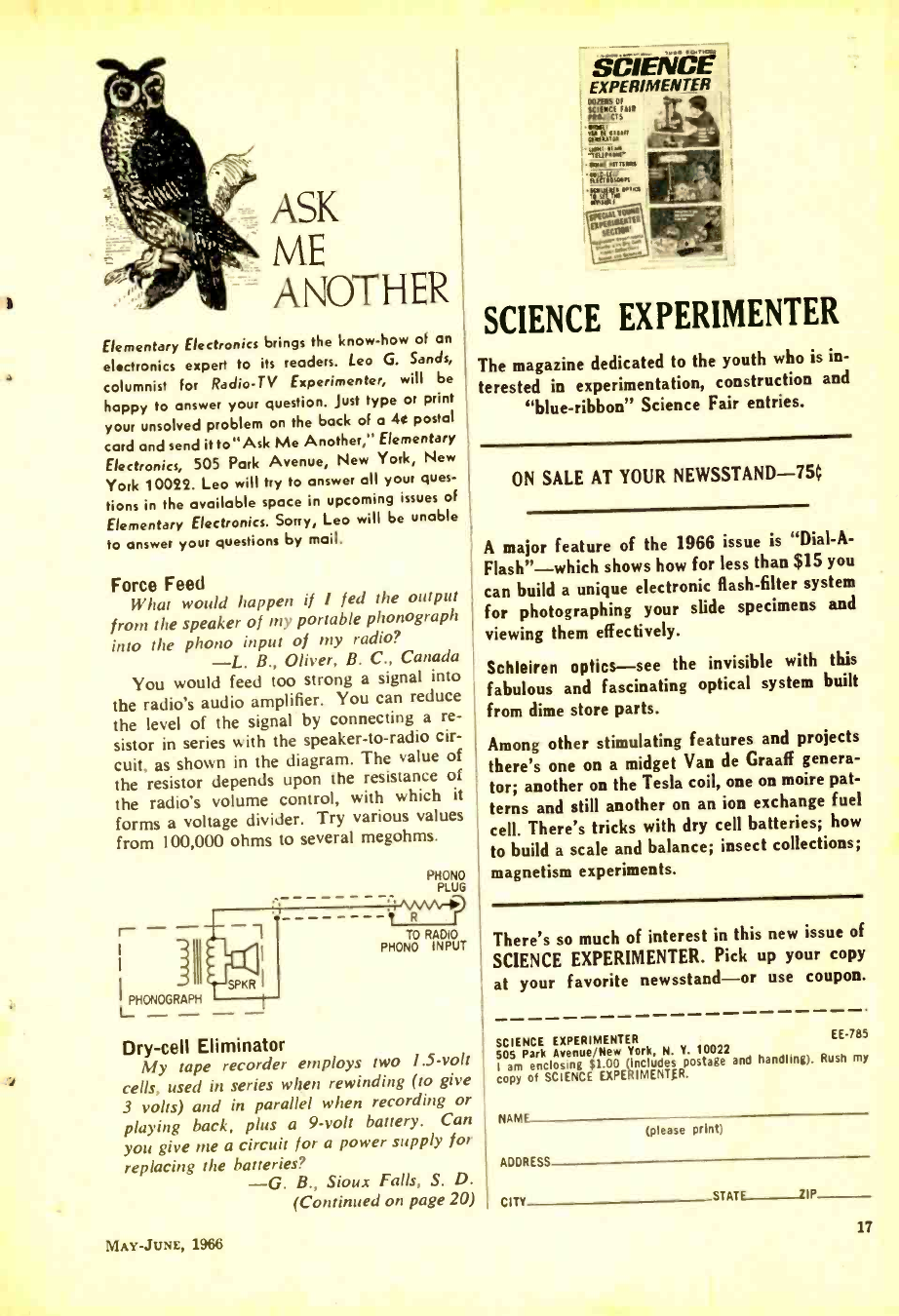
Force Feed
What would happen if I fed the output
from the speaker of my portable phonograph
into the phono input of ,ny radio?
-L. B., Oliver, B. C., Canada
You would feed too strong a signal into
the radio's audio amplifier. You can reduce
the level of the signal by connecting a re-
sistor in series with the speaker -to -radio cir-
cuit, as shown in the diagram. The value of
the resistor depends upon the resistance of
the radio's volume control, with which it
forms a voltage divider. Try various values
from 100,000 ohms to several megohms.
r - -
I
I
I PHONOGRAPH
- - SPKR I
PHONO
PLUG
t R
TO RADIO
PHONO INPUT
Dry -cell Eliminator
My tape recorder employs two 1.5 -volt
cells, used in series when rewinding (to give
3 volts) and in parallel when recording or
playing back, plus a 9 -volt battery. Can
you give me a circuit for a power supply for
replacing the batteries?
-G. B., Sioux Falls, S. D.
(Continued on page 20)
MAY -JUNE, 1966
SCIENCE EXPERIMENTER
The magazine dedicated to the youth who is in-
terested in experimentation, construction and
"blue- ribbon" Science Fair entries.
ON SALE AT YOUR NEWSSTAND -75¢
A major feature of the 1966 issue is "Dial -A-
Flash" -which shows how for less than $15 you
can build a unique electronic flash -filter system
for photographing your slide specimens and
viewing them effectively.
Schleiren optics -see the invisible with this
fabulous and fascinating optical system built
from dime store parts.
Among other stimulating features and projects
there's one on a midget Van de Graaff genera-
tor; another on the Tesla coil, one on moire pat-
terns and still another on an ion exchange fuel
cell. There's tricks with dry cell batteries; how
to build a scale and balance; insect collections;
magnetism experiments.
There's so much of interest in this new issue of
SCIENCE EXPERIMENTER. Pick up your copy
at your favorite newsstand -or use coupon.
SCIENCE EXPERIMENTER
505 Park Avenue /New York, N. Y. 10022
I am enclosing É EXPERIMENTER.
(includes postage and handling). Rush my
copy of
EE-785
NAMF
ADDRESS
(please print)
CITY STATE IIP
17
www.americanradiohistory.com
18
HEATHKIT 1966
Literature Library
Numbers in heavy type indicate
advertisers in this issue. Consult
their ads for additional information.
LAFAY ETTE
FA910 E1KIRpyf(5
ELECTRONIC PARTS 25 U
y
as a 32- pat geflyer from "way
EdlieElects nits
d Get one.
nusual surplus and new eqùip- n to four- track, fully transistorized
1. This catalog is so widely used
a reference book, that it's regarde
as a standard by people in the elec
tronics industry. Don't you have th
latest Allied Radio catalog? The sur
prising thing is that it's free!
2. The new 510 -page 1966 edition
Lafayette Radio's multi -colored cata
log is a perfect buyer's guide for hi
Sera, experimenters, kit builders
CB'ers and hams. Get your free copy,
today!
3. Progressive "Edu -Kits" Inc. now
has available their new 1966 catalog
featuring hi -fi, CB, Amateur, test
equipment in kit and wired form.
Also lists books, parts, tools. etc.
4. We'll exert our influence to get
you on the Olson mailing list. This
catalog comes out regularly with lots
of new and surplus items. If you find
your name hidden in the pages, you
win $5 in free merchandise!
5. Unusual scientific optical and
mathematical values. That's what Ed-
mund Scientific has. War surplus
equipment as well as many other
hard -to -get items are included in this
new 148 -page catalog.
6. Bargains galore, that's what's in
store! Poly -Paks Co. will send you
their latest eight -page flyer listing the
latest in merchandise available, in-
cluding a giant $1 special sale.
7. Whether you buy surplus or new,
will Fair uck full
of buys for every experimenter.
booklet. Portable battery operated
e 75. Transistors Unlimited has
- brand new catalog listing hundred
of Don't trmiss these bargains! low prices
o
HI -FI /AUDIO
15. A name well -known in audio
circles is Acoustic Research. Here's
its booklet on the famous AR speak-
ers and the new AR turntable.
. stereos cover every recording need.
32. "Everybody's Tape Recording
Handbook" is the title of a booklet
a that Sarkes- Tarzian will send you.
s It's 24 -pages jam -packed with info for
the home recording enthusiast. In-
cludes a valuable table of recording
times for various tapes.
8. Want a colorful catalog of
goodies? John Meshna, Jr. has one
that covers everything from assemblies
to zener diodes. Listed are govern-
ment surplus radio, radar, parts, etc.
All at unbelievable prices.
10. Burstein- Applebee offers a new
giant catalog containing 100's of big
pages crammed with savings includ-
ing hundreds of bargains on hi -fi kits,
power tools, tubes, and parts.
11. Now available from EDI (Elec-
tronic Distributors, Inc.) a catalog
containing hundreds of electronic
items. EDI will be happy to place you
on their mailing list.
12. VHF listeners will want the
latest catalog from Kuhn Electronics.
All types and forms of complete re-
ceivers and converters.
23. No electronics bargain hunter
should be caught without the latest
copy of Radio Shack's catalog. Some
equipment and kit offers are so low,
they look like mis- prints. Buying is
believing.
16. Garrard has prepared a 32 -page
booklet on its full line of automatic
turntables including the Lab 80, the
first automatic transcription turntable.
Accessories are detailed too.
17. Build your own bass reflex en-
closures from fool -proof plans offered
by Electra-Voice. At the same time
get the specs on EV's solid -state hi -fi
line -a new pace setter for the audio
industry.
19. Empire Scientific's new 8 -page,
full color catalog is now available to
our readers. Don't miss the sparkling
decorating -with -sound ideas. Just cir-
cle #19.
22. A wide variety of loudspeakers
and enclosures from Utah Electronics
lists sizes shapes and prices. All
types are covered in this heavily illus-
trated brochure.
26. Always a leader, H. H. Scott
introduces a new concept in stereo
console catalogs. "At Home With
Stereo" the 1966 guide, offers deco-
rating ideas, a complete explanation
of the more technical aspects of stereo
consoles, and, of course, the complete
new line of Scott consoles.
27. An assortment of high fidelity
components and cabinets are described
in the Sherwood brochure. The cab-
inets can almost be designed to your
requirements, as they use modules.
95. Confused about stereo? Want to
beat the high cost of hi -fi without
compromising on the results? Then
you need the new 24 -page catalog by
Jensen Manufacturing.
99. Interested in learning about am-
plifier specifications as well as what's
available in kit and wired form from
Acoustech? Then get your copy of
Acoustech's 8 -page colorful brochure.
TAPE RECORDERS AND TAPE
31. "All the Facts" about Concord
Electronics Corporation tape record-
ers are yours for the asking in a free
33. Become the first to learn about
Norelco's complete Carry- Corder 150
portable tape recorder outfit. Four -
color booklet describes this new car-
tridge -tape unit.
34. The 1966 line of Sony tape re-
corders, microphones and accessories
is illustrated in a new 16 -page full
color booklet just released by Super -
scope, Inc., exclusive U.S. distributor.
35. If you are a serious tape audio-
phile, you will be interested in the
new Viking of Minneapolis line -they
carry both reel and cartridge re-
corders you should know about.
91. Sound begins and ends with a
Uher tape recorder. Write for this
new 20 page catalog showing the en-
tire line of Uher recorders and acces-
sories. How to synchronize your slide
projector, execute sound on sound,
and many other exclusive features.
HI -FI ACCESSORIES
76. A new voice -activated tape re-
corder switch is now available from
Kinematix. Send for information on
this and other exciting products.
39. A 12 -page catalog describing the
audio accessories that make hi -fi liv-
ing a bit easier is yours from Switch -
craft, Inc. The cables, mike mixers,
and junctions are essentials!
98. Swinging to hi -fi stereo head-
sets? Then get your copy of Superex
Electronics' 16 -page catalog featuring
a large selection of quality headsets.
104. You can't hear FM stereo un-
less your FM antenna can pull 'em in.
Learn more and discover what's avail-
able from Finco's 6 -pager "Third Di-
mensional Sound."
KITS
41. Here's a firm that makes every-
thing from TV kits to a complete line
of test equipment. Conar would like
to send you their latest catalog -just
ask for it.
42. Here's a colorful 108 -page cata-
log containing a wide assortment of
electronic kits. You'll find something
for any interest, any budget. And
Heath Co. will happily send you a
copy.
44. A new short-form catalog (pock-
et size) is yours for the asking from
EICO. Includes hi -fi, test gear, CB
rigs and amateur equipment -many
kits are solid -state projects.
ELEMENTARY ELECTRONICS
www.americanradiohistory.com
AMATEUR RADIO
46. A long -time builder of ham
equipment, Hallicra /tern will send you
lots of info on the ham, CB and com-
mercial radio-equipment.
CB- BUSINESS RADIO
SHORT -WAVE RADIO
48. Hy- Gain's new CB antenna cata-
log is packed full of useful informa-
tion and product data that every
CB'er should know about. Get a
copy.
49. Want to see the latest in com-
munication receivers? National Ra-
dio Co. puts out a line of mighty fine
ones and their catalog will tell you all
about them.
50. Are you getting all you can from
your Citizens Band radio equipment?
Amphenol Cadre Industries has a
booklet that answers lots of the ques-
tions you may have.
100. You can get increased CB range
and clarity using the "Cobra" trans-
ceiver with speech compressor -re-
ceiver sensitivity is excellent. Catalog
sheet will be mailed by B &K Division
of Dynascan Corporation.
54. A catalog for CB'ers, hams and
experimenters, with outstanding val-
ues. Terrific buys on Grove Electron-
ics' antennas, mikes and accessories.
90. If two -way radio is your meat,
send for Pearce -Simpson's new book-
let! Its 18 pages cover equipment
selection, license application, prin-
ciples of two-way communications,
reception, and installation.
93. Heath Co. has a new 23- channel
all- transistor 5 -watt CB rig at the
lowest cost on the market, plus a full
line of CB gear. See their new 10-
band AM /FM /Shortwave portable
and line of shortwave radios. #93
on the coupon.
96. If a rugged low -cost business/
industrial two -way radio is what
you've been looking for. Be sure to
send for the brochure on E. F. John-
son Co.'s brand new Messenger "202."
101. If it's a CB product, chances
are International Crystal has it listed
in their colorful catalog. Whether kit
or wired, accessory or test gear, this
CB oriented company can be relied on
to fill the bill.
102. Sentry Mfg. Co. has some inter-
esting poop sheets on speech clippers,
converters, talk power kits and the
like for interested CB'ers, hams and
SWL'ers, too.
103. Squire -Sanders would like you
to know about their CB transceivers,
the "23'er" and the new "SSS." Also,
CB accessories that add versatility to
their 5- watters.
SCHOOLS AND EDUCATIONAL
56. Bailey Institute of Technology
offers courses in electronics, basic
electricity and drafting as well as re-
frigeration. More information in their
informative pamphlet.
57. National Radio Institute, a pio-
neer in home -study technical training,
has a new book describing your op-
portunities in all branches of elec-
tronics. Unique training methods
make learning as close to being fun
as any school can make it.
59. For a complete rundown on cur-
riculum, lesson outlines, and full de-
tails from a leading electronic school,
ask for this brochure from the Indiana
Home Study Institute.
61. ICS (International Correspond-
ence Schools) offers 236 courses in-
cluding many in the fields of radio,
TV, and electronics. Send for free
booklet "It's Your Future."
74. How to get an F.C.C. license,
plus a description of the complete
electronic courses offered by Cleve-
land Institute of Electronics are in
their free catalog. Circle #74.
94. Intercontinental Electronics
School offers three great courses:
stereo radio & electronics; basic elec-
tricity; transistors. They are all de-
scribed in Inesco's 1966, 16 -page
booklet.
ELECTRONIC PRODUCTS
62. Information on a new lab transis-
tor kit is yours for the asking from
Arkay International. Educational kit
makes 2U projects.
66. Try instant lettering to mark
control panels and component parts.
Datak's booklets and sample show
this easy dry transfer method.
64. If you can use 117 -volts, 60 -cycle
power where no power is available,
the Terado Corp. Tray- Electric 50 -160
is for you. Specifications are for the
asking.
67. "Get the most measurement
value per dollar," says Electronics
Measurements Corp. Send for their
catalog and find out how!
92. How about installing a transis-
torized electronic ignition system in
your current car' AEC Laboratories
will mail their brochure giving you
specifications, schematics.
TELEVISION
70. Heath Co. now has a 25" rec-
tangular -tube color TV kit in addi-
tion to their highly successful 21"
model. Both sets can be installed in
a wall or cabinet: both are money-
saving musts!
73. Attention, TV servicemen! Barry
Electronics "Green Sheet" lists many
TV tube, parts, and equipment buys
worth while examining. Good values,
sensible prices.
72. Get your 1966 catalog of Cisin's
TV, radio, and hi -fi service books.
Bonus -TV tube substitution guide
and trouble -chaser chart is yours for
the asking.
29. Install your own TV or FM an-
tenna! Jefferson King's exclusive free
booklet reveals secrets of installation,
orientation; how to get TV -FM trans-
mission data.
97. Interesting, helpful brochures de-
scribing the TV antenna discovery
of the decade -the log periodic an-
tenna for UHF and UHF -TV, and
FM stereo. From JFD Electronics
Corporation.
TOOLS
78. Scrulox square recess screws
pose no problems for the serviceman
who carries either of Xcelite's two
new compact Scrulox screwdriver sets
in his pocket or toolbox. Bulletin
N 1065 has the details.
Elementary Electronics, Dept. LL -785
505 Park Avenue, New York, N. Y. 10022
Please arrange to have the literature whose numbers I
have encircled sent to me as soon as possible. I am en-
closing 250 (no stamps) to cover handling charges.
1
17
39
62
92
2 3 4 5 6 7
19 22 23 25 26 27
41 42 44 46 48 49
64 66 67 70 72 73
93 94 95 96 97 98
l
8 10
29 31
50 54
74 75
I am a subscriber
Indicate total number
of booklets requested
11 12
32 33
56 57
76 78
15 16
34 35
59 61
90 91
99 100 101 102 103 104
NAME (Print clearly)
ADDRESS
CITY STATE ZIP CODE
MAY -JUNE, 1966 19
www.americanradiohistory.com
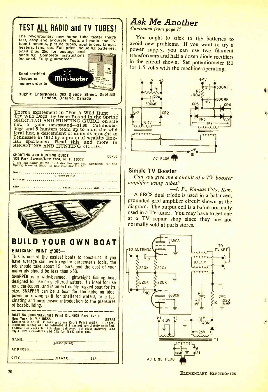
TEST ALL RADIO and TV TUBES!
The revolutionary new home tube tester that's
fast, easy and accurate. Tests all radio and TV
tube filaments, picture tubes, appliances, lamps,
heaters, fans, etc. Full price including batteries,
$2.49 plus 25c for postage and
handling. Complete instructions
included. Fully guaranteed.
Send certified
cheque or
money order to
Hughie Enterprises, 363 Dieppe Street, Dept.EE1,
London, Ontario, Canada
There's excitement in For A Wild Hunt .
Try Wild Dogs" by Gene Round in the Spring
SHOOTING AND HUNTING GUIDE, on sale
now at your newsstand -$1.00. Catahoulas
dogs and 5 hunters team up to hunt the wild
feral hog, a descendent of animals brought to
Tennessee in 1912 by a group of wealthy Eng-
lish sportsmen. Read this and more in
SHOOTING AND HUNTING GUIDE.
SHOOTING AND HUNTING GUIDE EE785
505 Park Avenue /New York, N. Y. 10022
I am enclosing $1.25 (includes postage and handling) for the
Spring issue of Shooting and Hunting Guide.
Name
Address
City State Zip
(please Print)
BUILD YOUR OWN BOAT
BOATCRAFT PRINT #365 -
This is one of the easiest boats to construct. If you
have average skill with regular carpenter's tools, the
job should take about 15 hours, and the cost of your
materials should be less than $50.
SNAPPER is a wide -beamed, lightweight fishing boat
designed for use on sheltered waters. It's ideal for use
as a car -topper, and is an extremely rugged boat for its
size. SNAPPER can be a boat for the kids; an ideal
power or rowing skiff for sheltered waters, or a fas-
cinating and inexpensive introduction to the pleasures
of boat -building.
BOATING JOURNAL /Craft Print Div. /505 Park Ave./
New York, N. Y./10022. EE785
Enclosed is $5.00. Please send me Craft Print #365. I under-
stand my money will be refunded if I am not completely satisfied.
(Allow 3 -4 weeks for 4th class delivery. 1st class delivery, add
56e.) NYC residents add 5/ for NYC sales tax.
NAME (please print)
ADDRESS
CITY STATE ZIP
20
Ask Me Another
Continued from page 17
You ought to stick to the batteries to
avoid new problems. If you want to try a
power supply, you can use two filament
transformers and half a dozen diode rectifiers
in the circuit shown. Set potentiometer R1
for 1.5 volts with the machine operating.
-CrrYYVYN^
I
SI
AC PLUG
Simple TV Booster
Can you give me a circuit of a TV booster
amplifier using tubes?
-J. P., Kansas City, Kan.
A 6BC8 dual triode is used in a balanced,
grounded grid amplifier circuit shown in the
diagram. The output coil is a balun normally
used in a TV tuner. You may have to get one
at a TV repair shop since they are not
normally sold at parts stores.
26EC8
TO ANTENNA
lo
220K 220K
220K 2201 -
10 268C8
H2
6.3V i
-frrrrYli
.OIMF 1 GI
AC LINE PLUG
TI
ELEMENTARY ELECTRONICS
www.americanradiohistory.com
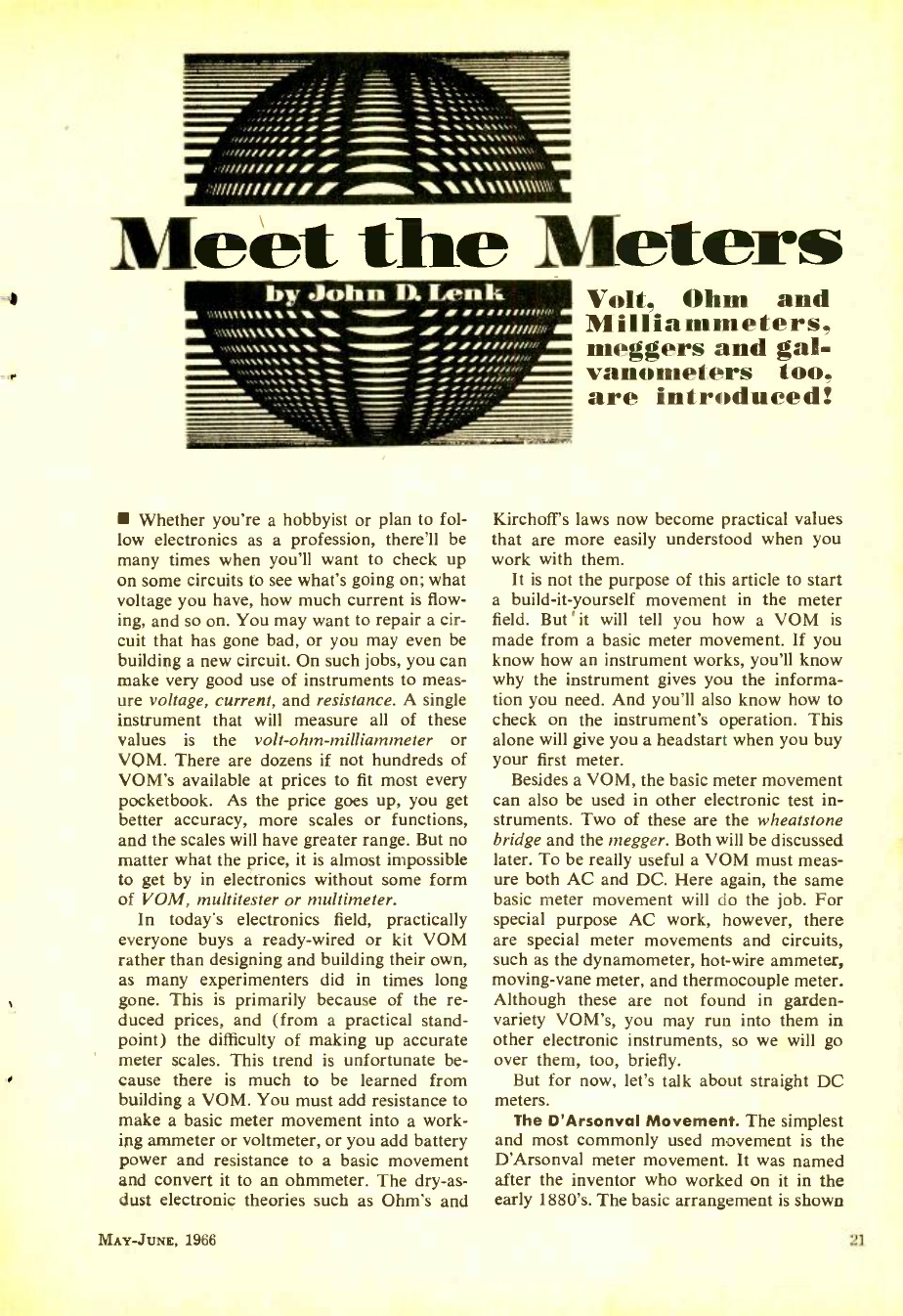
' '. ,,;;;;: AI AI
,,...... AP"
,,,........ `MM. "11. ",,..
........,
.........,.
1/////// "IF 11h,\11.,\NA.\\\\\V\
Í'N111//////// \\\\\\\\\\\\\N
Meet the Meters
by John D. Lenk
\,....... .4
\\%11,11116."."11=11.... .. / Mfifirn
,,,........11% ..,,.,,,,,,,
min Air..,,,,,,,,,
, ..,,,,,,,,
/I í.1,00,/,
".1tiLZ MIME SS1f/,'.'
Aar f '-..
Whether you're a hobbyist or plan to fol-
low electronics as a profession, there'll be
many times when you'll want to check up
on some circuits to see what's going on; what
voltage you have, how much current is flow-
ing, and so on. You may want to repair a cir-
cuit that has gone bad, or you may even be
building a new circuit. On such jobs, you can
make very good use of instruments to meas-
ure voltage, current, and resistance. A single
instrument that will measure all of these
values is the volt- ohm -milliammeter or
VQM. There are dozens if not hundreds of
VOM's available at prices to fit most every
pocketbook. As the price goes up, you get
better accuracy, more scales or functions,
and the scales will have greater range. But no
matter what the price, it is almost impossible
to get by in electronics without some form
of VOM, multitester or multimeter.
In today's electronics field, practically
everyone buys a ready -wired or kit VOM
rather than designing and building their own,
as many experimenters did in times long
gone. This is primarily because of the re-
duced prices, and (from a practical stand-
point) the difficulty of making up accurate
meter scales. This trend is unfortunate be-
cause there is much to be learned from
building a VOM. You must add resistance to
make a basic meter movement into a work-
ing ammeter or voltmeter, or you add battery
power and resistance to a basic movement
and convert it to an ohmmeter. The dry-as-
dust electronic theories such as Ohm's and
Volt, Ohm and
Milliammeters,
meggers and gal-
vanometers too,
are introduced!
Kirchoff's laws now become practical values
that are more easily understood when you
work with them.
It is not the purpose of this article to start
a build -it- yourself movement in the meter
field. But it will tell you how a VOM is
made from a basic meter movement. If you
know how an instrument works, you'll know
why the instrument gives you the informa-
tion you need. And you'll also know how to
check on the instrument's operation. This
alone will give you a headstart when you buy
your first meter.
Besides a VOM, the basic meter movement
can also be used in other electronic test in-
struments. Two of these are the wheatstone
bridge and the megger. Both will be discussed
later. To be really useful a VOM must meas-
ure both AC and DC. Here again, the same
basic meter movement will do the job. For
special purpose AC work, however, there
are special meter movements and circuits,
such as the dynamometer, hot -wire ammeter,
moving -vane meter, and thermocouple meter.
Although these are not found in garden -
variety VOM's, you may run into them in
other electronic instruments, so we will go
over them, too, briefly.
But for now, let's talk about straight DC
meters.
The D'Arsonval Movement. The simplest
and most commonly used movement is the
D'Arsonval meter movement. It was named
after the inventor who worked on it in the
early 1880's. The basic arrangement is shown
MAY-JUN e, 1966 21
www.americanradiohistory.com
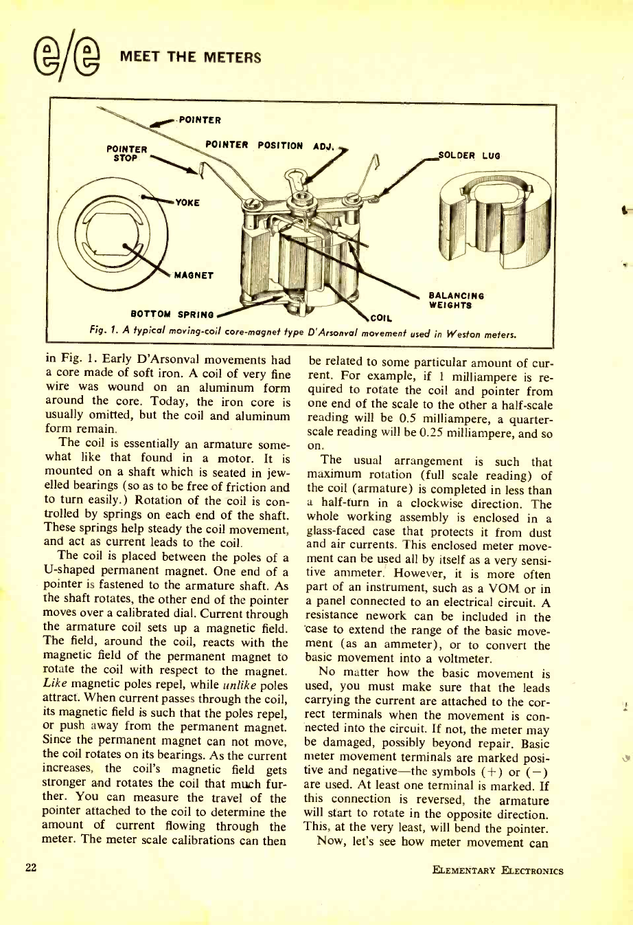
(g/@ MEET THE METERS
POINTER
POINTER
STOP
POINTER POSITION ADJ. SOLDER LUG
YOKE
MAGNET
BALANCING
WEIGHTS
BOTTOM SPRING COIL
Fig. 1. A typical moving -coil core- magnet type D'Arsonval movement used in Weston meters.
'n Fig. 1. Early D'Arsonval movements had
a core made of soft iron. A coil of very fine
wire was wound on an aluminum form
around the core. Today, the iron core is
usually omitted, but the coil and aluminum
form remain.
The coil is essentially an armature some-
what like that found in a motor. It is
mounted on a shaft which is seated in jew-
elled bearings (so as to be free of friction and
to turn easily.) Rotation of the coil is con-
trolled by springs on each end of the shaft.
These springs help steady the coil movement,
and act as current leads to the coil.
The coil is placed between the poles of a
U- shaped permanent magnet. One end of a
pointer is fastened to the armature shaft. As
the shaft rotates, the other end of the pointer
moves over a calibrated dial. Current through
the armature coil sets up a magnetic field.
The field, around the coil, reacts with the
magnetic field of the permanent magnet to
rotate the coil with respect to the magnet.
Like magnetic poles repel, while unlike poles
attract. When current passes through the coil,
its magnetic field is such that the poles repel,
or push away from the permanent magnet.
Since the permanent magnet can not move,
the coil rotates on its bearings. As the current
increases, the coil's magnetic field gets
stronger and rotates the coil that much fur-
ther. You can measure the travel of the
pointer attached to the coil to determine the
amount of current flowing through the
meter. The meter scale calibrations can then
22
be related to some particular amount of cur-
rent. For example, if 1 milliampere is re-
quired to rotate the coil and pointer from
one end of the scale to the other a half -scale
reading will be 0.5 milliampere, a quarter -
scale reading will be 0.25 milliampere, and so
on. The usual arrangement is such that
maximum rotation (full scale reading) of
the coil (armature) is completed in less than
a half -turn in a clockwise direction. The
whole working assembly is enclosed in a
glass -faced case that protects it from dust
and air currents. This enclosed meter move-
ment can be used all by itself as a very sensi-
tive ammeter.' However, it is more often
part of an instrument, such as a VOM or in
a panel connected to an electrical circuit. A
resistance nework can be included in the
'case to extend the range of the basic move-
ment (as an ammeter), or to convert the
basic movement into a voltmeter.
No matter how the basic movement is
used, you must make sure that the leads
carrying the current are attached to the cor-
rect terminals when the movement is con-
nected into the circuit. If not, the meter may
be damaged, possibly beyond repair. Basic
meter movement terminals are marked posi-
tive and negative -the symbols (-F) or (-)
are used. At least one terminal is marked. If
this connection is reversed, the armature
will start to rotate in the opposite direction.
This, at the very least, will bend the pointer.
Now, let's see how meter movement can
ELEMENTARY ELECTRONICS
t-
www.americanradiohistory.com
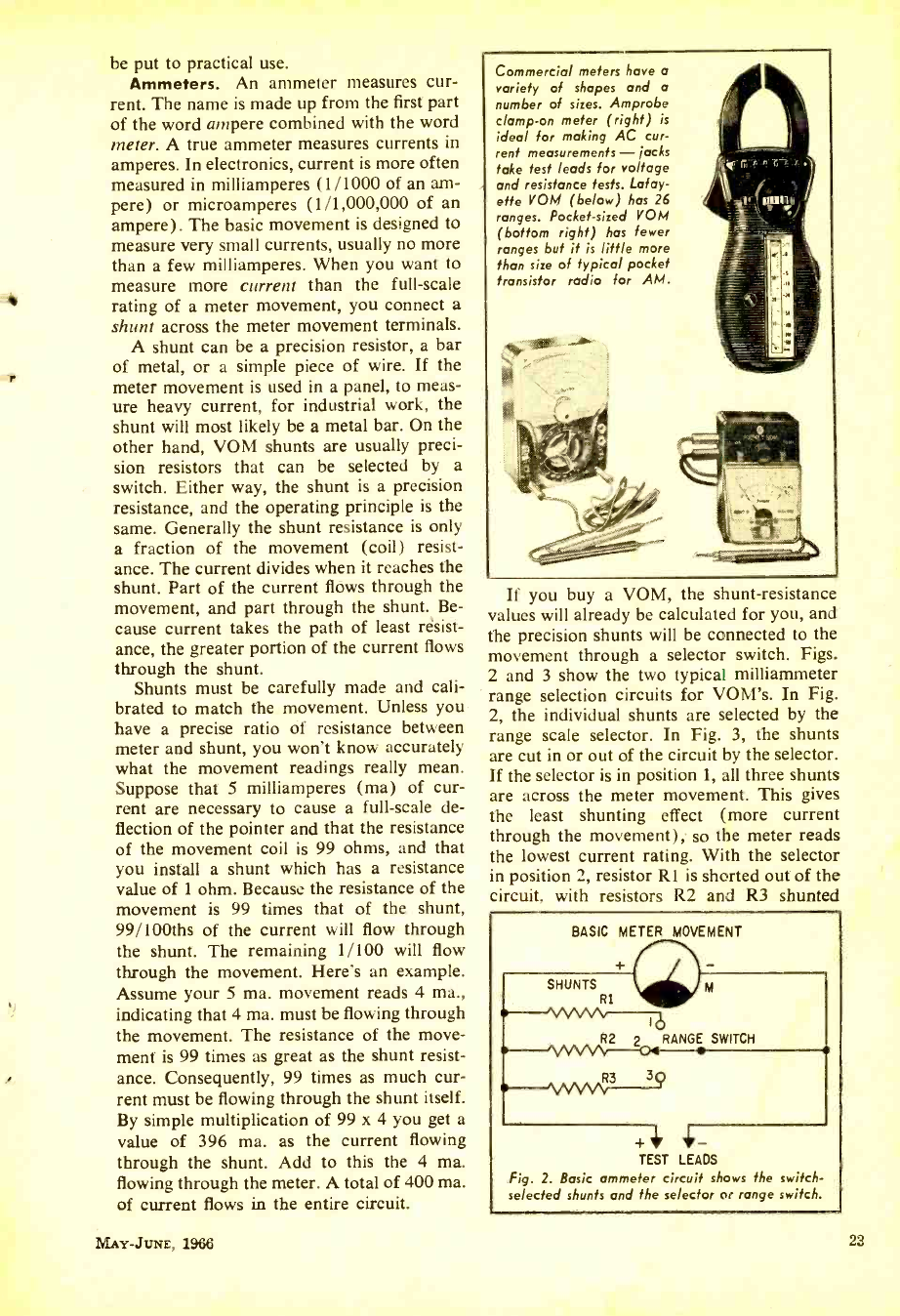
be put to practical use.
Ammeters. An ammeter measures cur-
rent. The name is made up from the first part
of the word ampere combined with the word
meter. A true ammeter measures currents in
amperes. In electronics, current is more often
measured in milliamperes (1/1000 of an am-
pere) or microamperes (1 /1,000,000 of an
ampere). The basic movement is designed to
measure very small currents, usually no more
than a few milliamperes. When you want to
measure more current than the full -scale
rating of a meter movement, you connect a
shunt across the meter movement terminals.
A shunt can be a precision resistor, a bar
of metal, or a simple piece of wire. If the
meter movement is used in a panel, to meas-
ure heavy current, for industrial work, the
shunt will most likely be a metal bar. On the
other hand, VOM shunts are usually preci-
sion resistors that can be selected by a
switch. Either way, the shunt is a precision
resistance, and the operating principle is the
same. Generally the shunt resistance is only
a fraction of the movement (coil) resist-
ance. The current divides when it reaches the
shunt. Part of the current flows through the
movement, and part through the shunt. Be-
cause current takes the path of least résist-
ance, the greater portion of the current flows
through the shunt.
Shunts must be carefully made and cali-
brated to match the movement. Unless you
have a precise ratio of resistance between
meter and shunt, you won't know accurately
what the movement readings really mean.
Suppose that 5 milliamperes (ma) of cur-
rent are necessary to cause a full -scale de-
flection of the pointer and that the resistance
of the movement coil is 99 ohms, and that
you install a shunt which has a resistance
value of 1 ohm. Because the resistance of the
movement is 99 times that of the shunt,
99/100ths of the current will flow through
the shunt. The remaining 1/100 will flow
through the movement. Here's an example.
Assume your 5 ma. movement reads 4 ma.,
indicating that 4 ma. must be flowing through
the movement. The resistance of the move-
ment is 99 times as great as the shunt resist-
ance. Consequently, 99 times as much cur-
rent must be flowing through the shunt itself.
By simple multiplication of 99 x 4 you get a
value of 396 ma. as the current flowing
through the shunt. Add to this the 4 ma.
flowing through the meter. A total of 400 ma.
of current flows in the entire circuit.
Commercial meters have a
variety of shapes and a
number of sizes. Am probe
clamp -on meter (right) is
ideal for making AC cur-
rent measurements - jacks
take test leads for voltage
and resistance tests. Lafay-
ette VOM (below) has 26
ranges. Pocket -sized VOM
(bottom right) has fewer
ranges but it is little more
than size of typical pocket
transistor radio for AM.
If you buy a VOM, the shunt -resistance
values will already be calculated for you, and
the precision shunts will be connected to the
movement through a selector switch. Figs.
2 and 3 show the two typical milliammeter
range selection circuits for VOM's. In Fig.
2, the individual shunts are selected by the
range scale selector. In Fig. 3, the shunts
are cut in or out of the circuit by the selector.
If the selector is in position 1, all three shunts
are across the meter movement. This gives
the least shunting effect (more current
through the movement), so the meter reads
the lowest current rating. With the selector
in position 2, resistor Rl is shorted out of the
circuit, with resistors R2 and R3 shunted
BASIC METER MOVEMENT
R3
TEST LEADS
Fig. 2. Basic ammeter circuit shows the switch -
selected shunts and the selector or range switch.
MAY -JUNE, 1966 23
www.americanradiohistory.com
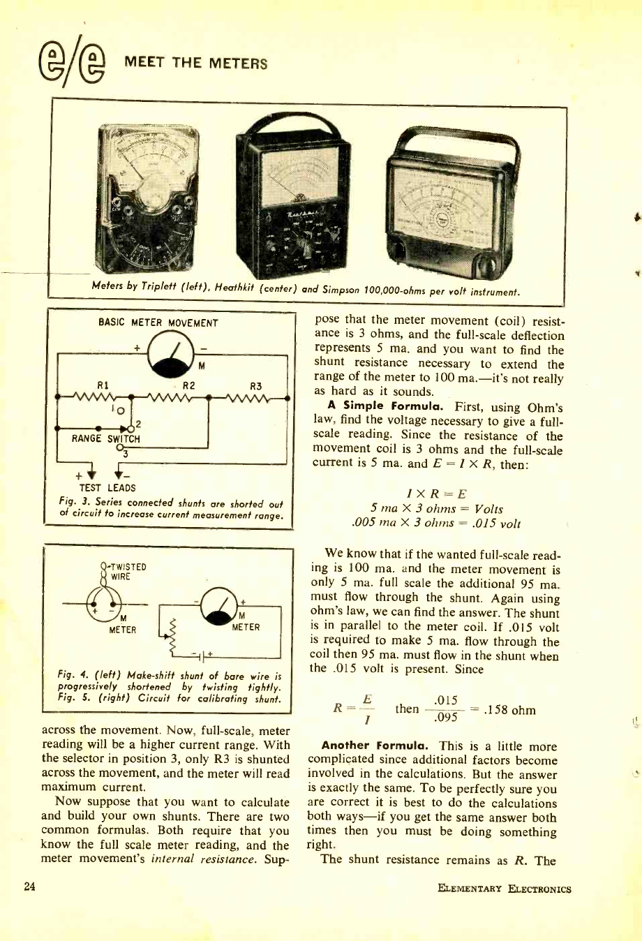
24
MEET THE METERS
Meters by Triplett (left), Heathkit (center) and Simpson 100,000 -ohms per volt instrument.
BASIC METER MOVEMENT
2
RANGE SWITCH
3
TEST LEADS
Fig. 3. Series connected shunts are shorted out
of circuit to increase current measurement range.
TWISTED
WIRE
METER
Fig. 4. (left) Make -shift shunt of bare wire is
progressively shortened by twisting tightly.
Fig. 5. (right) Circuit for calibrating shunt.
across the movement. Now, full -scale, meter
reading will be a higher current range. With
the selector in position 3, only R3 is shunted
across the movement, and the meter will read
maximum current.
Now suppose that you want to calculate
and build your own shunts. There are two
common formulas. Both require that you
know the full scale meter reading, and the
meter movement's internal resistance. Sup-
pose that the meter movement (coil) resist-
ance is 3 ohms, and the full -scale deflection
represents 5 ma. and you want to find the
shunt resistance necessary to extend the
range of the meter to 100 ma. -it's not really
as hard as it sounds.
A Simple Formula. First, using Ohm's
law, find the voltage necessary to give a full -
scale reading. Since the resistance of the
movement coil is 3 ohms and the full -scale
current is 5 ma. and E = 1 X R, then:
1XR =E
5 ma X 3 ohms = Volts
.005 ma X 3 ohms = .015 volt
We know that if the wanted full -scale read-
ing is 100 ma. and the meter movement is
only 5 ma. full scale the additional 95 ma.
must flow through the shunt. Again using
ohm's law, we can find the answer. The shunt
is in parallel to the meter coil. If .015 volt
is required to make 5 ma. flow through the
coil then 95 ma. must flow in the shunt when
the .015 volt is present. Since
R = then 095 = .158 ohm
Another Formula. This is a little more
complicated since additional factors become
involved in the calculations. But the answer
is exactly the same. To be perfectly sure you
are correct it is best to do the calculations
both ways -if you get the same answer both
times then you must be doing something
right. The shunt resistance remains as R. The
ELEMENTARY ELECTRONICS
www.americanradiohistory.com
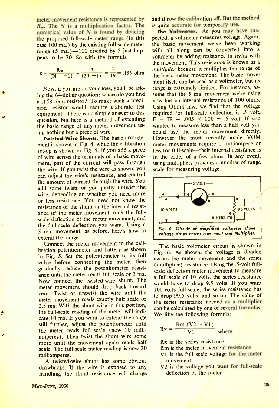
a
r
meter- movement resistance is represented by
R,. The N is a multiplication factor. The
numerical value of N is found by dividing
the proposed full -scale meter range (in this
case 100 ma.) by the existing full -scale meter
range (5 ma.) -100 divided by 5 just hap-
pens to be 20. So with the formula
Rm 3 3
R (N -1) (20 -1) 19 - 158 ohm
Now, if you are on your toes, you'll be ask-
ing the 64- dollar question: where do you find
a .158 ohm resistor? To make such a preci-
sion resistor would require elaborate test
equipment. There is no simple answer to this
question, but here is a method of extending
the basic range of any meter movement us-
ing nothing but a piece of wire.
Twisted -Wire Shunts. The basic arrange-
ment is shown in Fig. 4, while the calibration
set -up is shown in Fig. 5. If you add a piece
of wire across the terminals of a basic move-
ment, part of the current will pass through
the wire. If you twist the wire as shown, you
can adjust the wire's resistance, and control
the amount of current through the wire. You
add some twists or you partly untwist the
wire, depending on whether you need more
or less resistance. You need not know the
resistance of the shunt or the internal resist-
ance of the meter movement, only the full -
scale deflection of the meter movement, and
the full -scale deflection you want. Using a
5 ma. movement, as before, here's how to
extend the range.
Connect the meter movement to the cali-
bration potentiometer and battery as shown
in Fig. 5. Set the potentiometer to its full
value before connecting the meter, then
gradually reduce the potentiometer resist-
ance until the meter reads full scale or 5 ma.
Now connect the twisted -wire shunt. The
meter movement should drop back toward
zero. Twist or untwist the wire until the
meter movement reads exactly half scale or
2.5 ma. With the shunt wire in this position,
the full -scale reading of the meter will indi-
cate 10 ma. If you want to extend the range
still further, adjust the potentiometer until
the meter reads full scale (now 10 milli-
amperes). Then twist the shunt wire some
more until the movement again reads half
scale. The full -scale meter reading is now 20
milliamperes.
A twisted wire shunt has some obvious
drawbacks. If the wire is exposed to any
handling, the shunt resistance will change
MAY-JUNE, 1966
and throw the calibration off. But the method
is quite accurate for temporary use.
The Voltmeter. As you may have sus-
pected, a voltmeter measures voltage. Again,
the basic movement we've been working
with all along can be converted into a
voltmeter by adding resistance in series with
the movement. This resistance is known as a
multiplier because it multiplies the range of
the basic meter movement. The basic move-
ment itself can be used as a voltmeter, but its
range is extremely limited. For instance, as-
sume that the 5 ma. movement we're using
now has an internal resistance of 100 ohms.
Using Ohm's law, we find that the voltage
required for full -scale deflection is .5 volt,
E = IR = .005 X 100 = .5 volt. If you
wanted to measure less than a half volt you
could use the meter movement directly.
However the most recently made VOM
meter movements require 1 milliampere or
less for full -scale -their internal resistance is
in the order of a few ohms. In any event,
using multipliers provides a number of range
scale for measuring voltage.
10 VOLTS
R
MULTIPLIER
9.5 VOLTS
Fig. 6. Circuit of simplified voltmeter shows
voltage drops across movement and multiplier.
The basic voltmeter circuit is shown in
Fig. 6. As shown, the voltage is divided
across the meter movement and the series
(multiplier) resistance. Using the .5 -volt full-
scale deflection meter movement to measure
a full scale of 10 volts, the series resistance
would have to drop 9.5 volts. If you want
100 -volts full -scale, the series resistance has
to drop 99.5 volts, and so on. The value of
the series resistance needed as a multiplier
can be calculated by one of several formulas.
We like the following formula:
Rx - V1 where
Rm (V2 - V1)
Rx is the series resistance
Rm is the meter movement resistance
V1 is the full scale voltage for the meter
movement
V2 is the voltage you want for full-scale
deflection of the meter
25
www.americanradiohistory.com
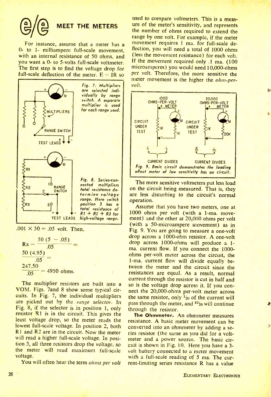
MEET THE METERS
For instance, assume that a meter has a
0- to 1- milliampere full -scale movement,
with an internal resistance of 50 ohms, and
you want a 0- to 5 -volts full -scale voltmeter.
The first step is to find the voltage drop for
full -scale deflection of the meter. E = IR so
MULTIPLIERS
RANGE SWITCH
TEST LEADS
RI
R2 RANGE
SWITCH
R3
Fig. 7. Multipliers
are selected indi-
vidually by range
switch. A separate
multiplier is used
for each range used.
Fig. 8. Series-con-
nected multipliers
total resistance de-
termine voltage
range. Here switch
position 3 has a
total resistance of
+ - R1+R2+R3for
TEST LEADS high -voltage range.
.001 X 50 = .05 volt. Then,
50 (5 - .05)
Rx - .05 =
50 (4.95)
.05
247.50
05 - 4950 ohms.
The multiplier resistors are built into a
VOM. Figs. land 8 show some typical cir-
cuits. In Fig. 7, the individual multipliers
are picked out by the range selector. In
Fig. 8, if the selector is in position 1, only
resistor Rl is in the circuit. This gives the
least voltage drop, so the meter reads the
lowest full -scale voltage. In position 2, both
R1 and R2 are in the circuit. Now the meter
will read a higher full -scale voltage. In posi-
tion 3, all three resistors drop the voltage, so
the meter will read maximum full -scale
voltage.
You will often hear the term ohms per volt
26
used to compare voltmeters. This is a meas-
ure of the meter's sensitivity, and represents
the number of ohms required to extend the
range by one volt. For example, if the meter
movement requires 1 ma. for full -scale de-
flection, you will need a total of 1000 ohms
(less the movement resistance) for each volt.
If the movement required only .1 ma. (100
microamperes) you would need 10,000 -ohms
per volt. Therefore, the more sensitive the
meter movement is the higher the ohm -per-
volt.
1000
OHMS- PER -VOLT
+ METER
CIRCUIT
UNDER
TEST
-M CIRCUIT
UNDER
IK TEST
20,000
OHMS-PER -VOLT
+ METER
20K
1 T
CURRENT DIVIDES CURRENT DIVIDES
Fig. 9. Basic circuit demonstrates the loading
effect meter of low sensitivity has on circuit.
The more sensitive voltmeters put less load
on the circuit being measured. That is, they
are less disturbing to the circuit's normal
operation.
Assume that you have two meters, one at
1000 ohms per volt (with a 1 -ma. move-
ment) and the other at 20,000 ohms per volt
(with a 50- microampere movement) as in
Fig. 9. You are going to measure a one -volt
drop across a 1000 -ohm resistor. A one -volt
drop across 1000 -ohms will produce a 1-
ma. current flow. If you connect the 1000 -
ohms per -volt meter across the circuit, the
1 -ma. current flow will divide equally be-
tween the meter apd the circuit since the
resistances are equal. As a result, normal
current through the resistor is cut in half and
so is the voltage drop across it. If you con-
nect the 20,000 -ohms per -volt meter across
the same resistor, only 1{io of the current will
pass through the meter, and 19ko will continue
through the resistor.
The Ohmmeter. An ohmmeter measures
resistance. A basic meter movement can be
converted into an ohmmeter by adding a se-
ries resistor (the same as you did for a volt-
meter and a power source. The basic cir-
cuit is shown in Fig. 10. Here you have a 3-
volt battery connected to a meter movement
with a full -scale reading of 5 ma. The cur-
rent- limiting series resistance R has a value
ELEMENTARY ELECTRONICS
www.americanradiohistory.com
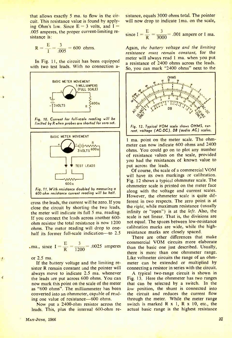
that allows exactly 5 ma. to flow in the cir-
cuit. This resistance value is found by apply-
ing Ohm's law. Since E = 3 volts, and I =
.005 amperes, the proper current -limiting re-
sistance is:
R I 005 = 600 ohms.
In Fig. 11, the circuit has been equipped
with two test leads. With no connection a-
BASIC METER MOVEMENT
5 MILLIAMPERS
(FULL SCALE)
-T3 VOLTS 600 n
Fig. 10. Current for full -scale reading will be
limited by R when probes are shorted for zero set.
BASIC METER MOVEMENT
rt1w VOLT S 6 On
1 1 TEST LEADS
600n
Fig. 11. With resistance doubled by measuring a
600 -ohm resistance current reading will be half.
cross the leads, the current will be zero. If you
close the circuit by shorting the two leads,
the meter will indicate its full 5 ma. reading.
If you connect the leads across another 600 -
ohm resistor the total resistance is now 1200
ohms. The meter reading will drop to one -
half its former full -scale indication -to 2.5
E 3
.ma., since I = R 1200 .0025 amperes
or 2.5 ma.
If the battery voltage and the limiting re-
sistor R remain constant and the pointer will
always move to indicate 2.5 ma. whenever
the leads are put across 600 ohms. You can
now mark this point on the scale of the meter
as "600 ohms ". The milliammeter has been
converted into an ohmmeter, capable of read-
ing one value of resistance -600 ohms.
Now put a 2400 -ohm resistor across the
leads. This, plus the internal 600 -ohm re-
MAY-JUNE, 1966
sistance, equals 3000 ohms total. The pointer
will now drop to indicate 1 ma. on the scale,
E 3
since I = R 3000 .001 ampere or 1 ma.
Again, the battery voltage and the limiting
resistance must remain constant, for the
meter will always read 1 ma. when you put
a resistance of 2400 ohms across the leads.
So, you can mark "2400 ohms" next to the
M OHMS
30 m
Fig. 12. Typical VOM scale shows OHMS, cur-
rent, voltage (AC -DC), DB (audio AC) scales.
1 ma. point on the meter scale. The ohm-
meter can now indicate 600 ohms and 2400
ohms. You could go on to plot any number
of resistance values on the scale, provided
you had the resistances of known value to
put across the leads.
Of course, the scale of a commercial VOM
will have its own markings or calibration.
Fig. 12 shows a typical ohmmeter scale. The
ohmmeter scale is printed on the meter face
along with the voltage and current scales.
However, the ohmmeter scale is quite dif-
ferent in two respects. The zero point is at
the right, while maximum resistance (usually
infinity or "open ") is at the left. Also, the
scale is not linear. That is, the divisions are
not equal. The spaces between low- resistance
calibration marks are wide, while the high -
resistance marks are closely spaced.
There are other differences that make
commercial VOM circuits more elaborate
than the basic one just described. Usually,
there is more than one ohmmeter range.
Like voltmeter circuits the range of an ohm-
meter can be extended or multiplied by
connecting a resistor in series with the circuit.
A typical two -range circuit is shown in
Fig. 13. Here the ohmmeter has two ranges
that can be selected by a switch. In the
low position, the shunt is connected into
the circuit and reduces the current flow
through the meter. While the meter range
switch is marked R x 1, R x 10, etc., the
actual basic range is the highest resistance
www.americanradiohistory.com
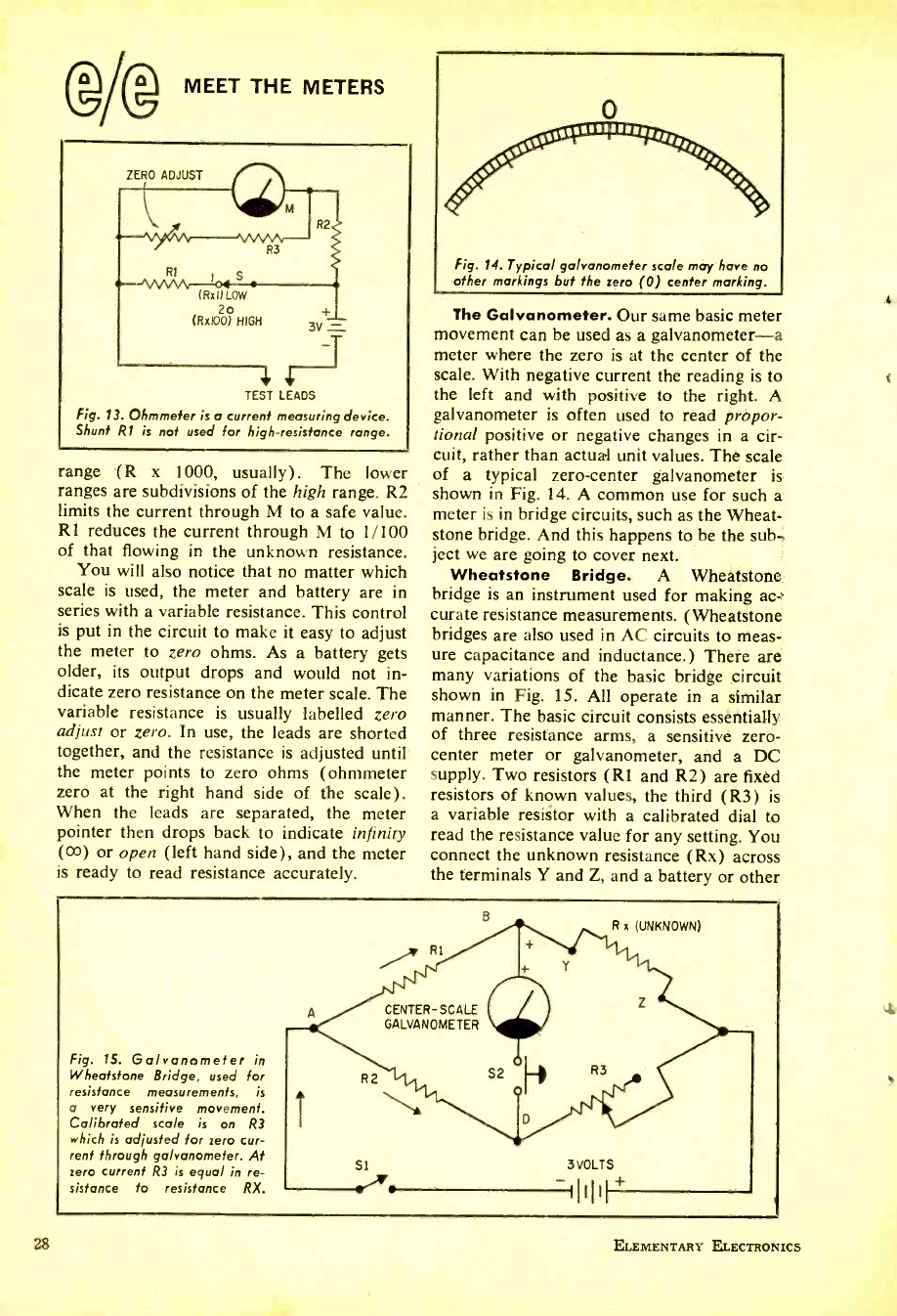
28
(g/f@ MEET THE METERS
ZERO ADJUST
(Rx I) LOW
2o
(Rx100) HIGH 3V
TEST LEADS
Fig. 13. Ohmmeter is a current measuring device.
Shunt R1 is not used for high- resistance range.
range (R x 1000, usually). The lower
ranges are subdivisions of the high range. R2
limits the current through M to a safe value.
RI reduces the current through M to 1 /100
of that flowing in the unknown resistance.
You will also notice that no matter which
scale is used, the meter and battery are in
series with a variable resistance. This control
is put in the circuit to make it easy to adjust
the meter to zero ohms. As a battery gets
older, its output drops and would not in-
dicate zero resistance on the meter scale. The
variable resistance is usually labelled zero
adjust or zero. In use, the leads are shorted
together, and the resistance is adjusted until'
the meter points to zero ohms (ohmmeter
zero at the right hand side of the scale).
When the leads are separated, the meter
pointer then drops back to indicate infinity
(co) or open (left hand side), and the meter
is ready to read resistance accurately.
,'ssgsN///fff/flff
Fig. 14. Typical galvanometer scale may have no
other markings but the zero (0) center marking.
The Galvanometer. Our same basic meter
movement can be used as a galvanometer -a
meter where the zero is at the center of the
scale. With negative current the reading is to
the left and with positive to the right. A
galvanometer is often used to read propor-
tional positive or negative changes in a cir-
cuit, rather than actual unit values. The scale
of a typical zero -center galvanometer is
shown in Fig. 14. A common use for such a
meter is in bridge circuits, such as the Wheat-
stone bridge. And this happens to be the sub-
ject we are going to cover next.
Wheatstone Bridge. A Wheatstone
bridge is an instrument used for making ac-
curate resistance measurements. (Wheatstone
bridges are also used in AC circuits to meas-
ure capacitance and inductance.) There are
many variations of the basic bridge circuit
shown in Fig. 15. All operate in a similar
manner. The basic circuit consists essentially
of three resistance arms, a sensitive zero -
center meter or galvanometer, and a DC
supply. Two resistors (R1 and R2) are fixed
resistors of known values, the third (R3) is
a variable resistor with a calibrated dial to
read the resistance value for any setting. You
connect the unknown resistance (Rx) across
the terminals Y and Z, and a battery or other
Fig. 15. Galvanometer in
Wheatstone Bridge, used for
resistance measurements, is
a very sensitive movement.
Calibrated sco /e is on R3
which is adjusted for zero cur-
rent through galvanometer. At
zero current R3 is equal in re-
sistance to resistance RX.
Si 3 VOLTS
+
ELEMENTARY ELECTRONICS
A
www.americanradiohistory.com
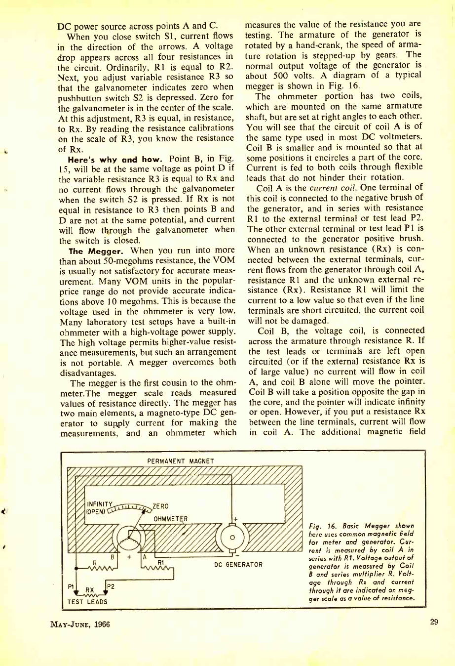
DC power source across points A and C.
When you close switch Si, current flows
in the direction of the arrows. A voltage
drop appears across all four resistances in
the circuit. Ordinarily, Rl is equal to R2.
Next, you adjust variable resistance R3 so
that the galvanometer indicates zero when
pushbutton switch S2 is depressed. Zero for
the galvanometer is in the center of the scale.
At this adjustment, R3 is equal, in resistance,
to Rx. By reading the resistance calibrations
on the scale of R3, you know the resistance
of Rx.
Here's why and how. Point B, in Fig.
15, will be at the same voltage as point D if
the variable resistance R3 is equal to Rx and
no current flows through the galvanometer
when the switch S2 is pressed. If Rx is not
equal in resistance to R3 then points B and
D are not at the same potential, and current
will flow tl1rough the galvanometer when
the switch is closed.
The Megger. When you run into more
than about 50- megohms resistance, the VOM
is usually not satisfactory for accurate meas-
urement. Many VOM units in the popular -
price range do not provide accurate indica-
tions above 10 megohms. This is because the
voltage used in the ohmmeter is very low.
Many laboratory test setups have a built -in
ohmmeter with a high -voltage power supply.
The high voltage permits higher -value resist-
ance measurements, but such an arrangement
is not portable. A megger overcomes both
disadvantages.
The megger is the first cousin to the ohm -
meter.The megger scale reads measured
values of resistance directly. The megger has
two main elements, a magneto -type DC gen-
erator to supply current for making the
measurements, and an ohmmeter which
measures the value of the resistance you are
testing. The armature of the generator is
rotated by a hand -crank, the speed of arma-
ture rotation is stepped -up by gears. The
normal output voltage of the generator is
about 500 volts. A diagram of a typical
megger is shown in Fig. 16.
The ohmmeter portion has two coils,
which are mounted on the same armature
shaft, but are set at right angles to each other.
You will see that the circuit of coil A is of
the same type used in most DC voltmeters.
Coil B is smaller and is mounted so that at
some positions it encircles a part of the core.
Current is fed to both coils through flexible
leads that do not hinder their rotation.
Coil A is the current coil. One terminal of
this coil is connected to the negative brush of
the generator, and in series with resistance
R1 to the external terminal or test lead P2.
The other external terminal or test lead P 1 is
connected to the generator positive brush.
When an unknown resistance (Rx) is con-
nected between the external terminals, cur-
rent flows from the generator through coil A,
resistance Rl and the unknown external re-
sistance (Rx). Resistance R1 will limit the
current to a low value so that even if the line
terminals are short circuited, the current coil
will not be damaged.
Coil B, the voltage coil, is connected
across the armature through resistance R. If
the test leads or terminals are left open
circuited (or if the external resistance Rx is
of large value) no current will flow in coil
A, and coil B alone will move the pointer.
Coil B will take a position opposite the gap in
the core, and the pointer will indicate infinity
or open. However, if you put a resistance Rx
between the line terminals, current will flow
in coil A. The additional magnetic field
PERMANENT MAGNET
DC GENERATOR
TEST LEADS
Fig. 16. Basic Megger shown
here uses common magnetic field
for meter and generator. Cur-
rent is measured by coil A in
series with Rl. Voltage output of
generator is measured by Coil
B and series multiplier R. Volt-
age through Rx and current
through it are indicated on meg-
ger scale as a value of resistance.
MAY -JUNE, 1966 29
www.americanradiohistory.com
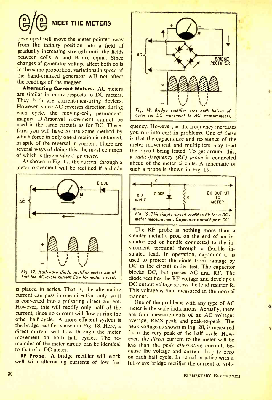
MEET THE METERS
developed will move the meter pointer away
from the infinity position into a field of
gradually increasing strength until the fields
between coils A and B are equal. Since
changes of generator voltage affect both coils
in the same proportion, variations in speed of
the hand -cranked generator will not affect
the readings of the megger.
Alternating Current Meters. AC meters
are similar in many respects to DC meters.
They both are current- measuring devices.
However, since AC reverses direction during
each cycle, the moving -coil, permanent -
magnet D'Arsonval movement cannot be
used in the same circuits as for DC. There-
fore, you will have to use some method by
which force in only one direction is obtained,
in spite of the reversal in current. There are
several ways of doing this, the most common
of which is the rectifier -type meter.
As shown in Fig. 17, the current through a
meter movement will be rectified if a diode
AC
DIODE
a
$ r I a
r ti
Fig. 17. Half -wave diode rectifier makes use of
half the AC -cycle current flow for meter circuit.
is placed in series. That is, the alternating
current can pass in one direction only, so it
is converted into a pulsating direct current.
However, this will rectify only half of the
current, since no current will flow during the
other half cycle. A more efficient system is
the bridge rectifier shown in Fig. 18. Here, a
direct current will flow through the meter
movement on both half cycles. The re-
mainder of the meter circuit can be identical
to that of a DC meter.
RF Probe. A bridge rectifier will work
well with alternating currents of low fre-
30
AC BRIDGE
RECTIFIER
I I I .
I I S
:.
Fig. 18. Bridge rectifier uses both halves of
cycle for DC movement in AC measurements.
quency. However, as the frequency increases
you run into certain problems. One of these
is that the capacitance and resistance of the
meter movement and multipliers may load
the circuit being tested. To get around this,
a radio- frequency (RF) probe is connected
ahead of the meter circuits. A schematic of
such a probe is shown in Fig. 19.
P F
INPUT
4
DIODE DC OUTPUT
TO
METER
Fig. 19. This simple circuit rectifies RF for a DC-
meter measurement. Capacitor doesn't pass DC.
The RF probe is nothing more than a
slender metallic prod on the end of an in-
sulated rod or handle connected to the in-
strument terminal through a flexible in-
sulated lead. In operation, capacitor C is
used to protect the diode from damage by
DC in the circuit under test. The capacitor
blocks DC, but passes AC and RF. The
diode rectifies the RF voltage and develops a
DC output voltage across the load resistor R.
This voltage is then measured in the normal
manner.
One of the problems with any type of AC
meter is the scale indications. Actually, there
are four measurements of an AC voltage:
average, RMS peak and peak -to -peak. The
peak voltage as shown in Fig. 20, is measured
from the very peak of the half cycle. How-
ever, the direct current to the meter will be
less than the peak alternating current, be-
cause the voltage and current drop to zero
on each half cycle. In actual practice with a
full -wave bridge rectifier the current or volt-
ELEMENTARY ELECTRONICS
www.americanradiohistory.com
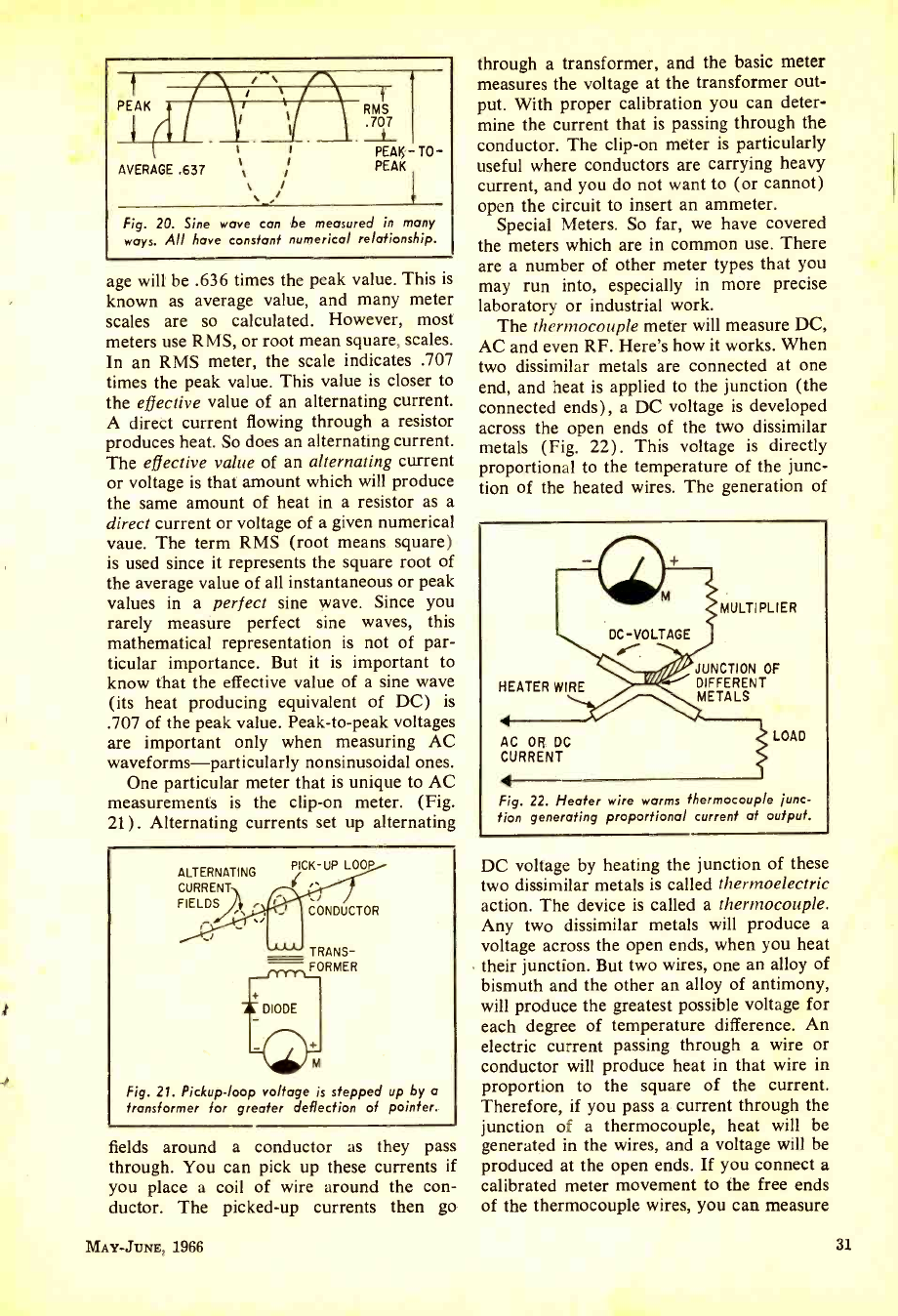
PEAK g1
AVERAGE .637 t / .,
RAT
PEAK - TO-
PEAK
Fig. 20. Sine wave can be measured in many
ways. All have constant numerical relationship.
age will be .636 times the peak value. This is
known as average value, and many meter
scales are so calculated. However, most
meters use RMS, or root mean square, scales.
In an RMS meter, the scale indicates .707
times the peak value. This value is closer to
the effective value of an alternating current.
A direct current flowing through a resistor
produces heat. So does an alternating current.
The effective value of an alternating current
or voltage is that amount which will produce
the same amount of heat in a resistor as a
direct current or voltage of a given numerical
vaue. The term RMS (root means square)
is used since it represents the square root of
the average value of all instantaneous or peak
values in a perfect sine wave. Since you
rarely measure perfect sine waves, this
mathematical representation is not of par-
ticular importance. But it is important to
know that the effective value of a sine wave
(its heat producing equivalent of DC) is
.707 of the peak value. Peak -to -peak voltages
are important only when measuring AC
waveforms - particularly nonsinusoidal ones.
One particular meter that is unique to AC
measurements is the clip -on meter. (Fig.
21). Alternating currents set up alternating
ALTERNATING
CURRENT
FIELDS .
PICK-UP LOOP
CONDUCTOR
TRANS-
- FORMER
Fig. 21. Pickup -loop voltage is stepped up by a
transformer for greater deflection of pointer.
fields around a conductor as they pass
through. You can pick up these currents if
you place a coil of wire around the con-
ductor. The picked -up currents then go
MAY-JUNE, 1966
through a transformer, and the basic meter
measures the voltage at the transformer out-
put. With proper calibration you can deter-
mine the current that is passing through the
conductor. The clip -on mèter is particularly
useful where conductors are carrying heavy
current, and you do not want to (or cannot)
open the circuit to insert an ammeter.
Special Meters. So far, we have covered
the meters which are in common use. There
are a number of other meter types that you
may run into, especially in more precise
laboratory or industrial work.
The thermocouple meter will measure DC,
AC and even RF. Here's how it works. When
two dissimilar metals are connected at one
end, and heat is applied to the junction (the
connected ends), a DC voltage is developed
across the open ends of the two dissimilar
metals (Fig. 22) . This voltage is directly
proportional to the temperature of the junc-
tion of the heated wires. The generation of
HEATER WIRE
AC OR DC
CURRENT
MULTIPLIER
JUNCTION OF
DIFFERENT
METALS
LOAD
Fig. 22. Heater wire warms thermocouple ¡unc-
tion generating proportional current at output.
DC voltage by heating the junction of these
two dissimilar metals is called thermoelectric
action. The device is called a thermocouple.
Any two dissimilar metals will produce a
voltage across the open ends, when you heat
their junction. But two wires, one an alloy of
bismuth and the other an alloy of antimony,
will produce the greatest possible voltage for
each degree of temperature difference. An
electric current passing through a wire or
conductor will produce heat in that wire in
proportion to the square of the current.
Therefore, if you pass a current through the
junction of a thermocouple, heat will be
generated in the wires, and a voltage will be
produced at the open ends. If you connect a
calibrated meter movement to the free ends
of the thermocouple wires, you can measure
31
www.americanradiohistory.com
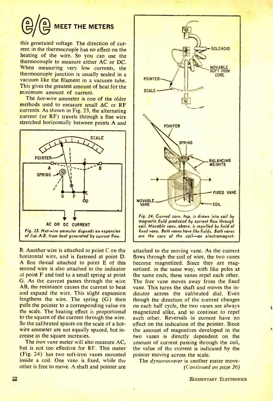
lam-+ MEET THE METERS
this generated voltage. The direction of cur-
rent in the thermocouple has no effect on the
heating of the wire. So you can use the
thermocouple to measure either AC or DC.
When measuring very low currents, the
thermocouple junction is usually sealed in a
vacuum like the filament in a vacuum tube.
This gives the greatest amount of heat for the
minimum amount of current.
The hot -wire ammeter is one of the older
methods used to measure small AC or RF
currents. As shown in Fig. 23, the alternating
current (or RF) travels through a fine wire
stretched horizontally between points A and
POI NTER-
A
SPRING
SCALE
AC OR DC CURRENT
Fig. 23. Hot -wire ammeter depends on expansion
of link A -B, from heat generated by current flow.
B. Another wire is attached to point C on the
horizontal wire, and is fastened at point D.
A fine thread attached to point E of this
second wire is also attached to the indicator
at point F and tied to a small spring at point
G. As the current passes through the wire
AB, the resistance causes the current to heat
and expand the wire. This slight expansion
lengthens the wire. The spring (G) then
pulls the pointer to a corresponding value on
the scale. The heating effect is proportional
to the square of the current through the wire.
So the calibrated spaces on the scale of a hot -
wire ammeter are not equally spaced, but in-
crease as the square increases.
The iron vane meter will also measure AC,
but is not too effective for RF. This meter
(Fig. 24) has two soft -iron vanes mounted
inside a coil. One vane is fixed, while the
other is free to move. A shaft and pointer are
32.
POINTER
SCALE
POINTER
SOLENOID
MOVABLE
SOFT IRON
CORE
BALANCING
WEIGHTS
FIXED VANE
u 1
MVANELE L"--- COIL
Fig. 24. Curved core, fop, is drawn into coil by
magnetic field produced by current flow through
coil. Movable vane, above, is repelled by field of
fixed vane. Both vanes have like fields. Both vanes
are the core of the coil -an electromagnet.
attached to the moving vane. As the current
flows through the coil of wire, the two vanes
become magnetized. Since they are mag-
netized. in the same way, with like poles at
the same ends, these vanes repel each other.
The free vane moves away from the fixed
vane. This turns the shaft and moves the in-
dicator across the calibrated dial. Even
though the direction of the current changes
on each half cycle, the two vanes are always
magnetized alike, and so continue to repel
each other. Reversals in current have no
effect on the indication of the pointer. Since
the amount of magnetism developed in the
two vanes is directly dependent on the
amount of current passing through the coil,
the value of the current is indicated by the
pointer moving across the scale.
The dynamometer is another meter move -
(Continued on page 36)
ELEMENTARY ELECTRONICS
www.americanradiohistory.com
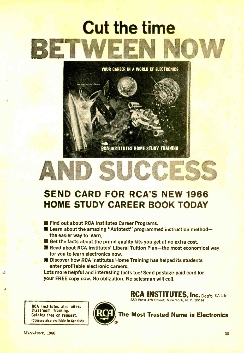
Cut the time
BETWEEN NOW
YOUR CAREER IN A WORLD CF ELECTRONICS
with
RCA INSTITUTES HOME STUDY TRAINING
AND SUCCESS
SEND CARD FOR RCA'S NEW 1966
HOME STUDY CAREER BOOK TODAY
Find out about RCA Institutes Career Programs.
Learn about the amazing "Autotext" programmed instruction method -
the easier way to learn.
Get the facts about the prime quality kits you get at no extra cost.
Read about RCA Institutes' Liberal Tuition Plan -the most economical way
for you to learn electronics now.
Discover how RCA Institutes Home Training has helped its students
enter profitable electronic careers.
Lots more helpful and interesting facts too! Send postage -paid card for
your FREE copy now. No obligation. No salesman will call.
RCA Institutes also offers
Classroom Training.
Catalog free on request.
(Courses also available in Spanish)
RCA INSTITUTES, Inc. Dept EA -56
350 West 4th Street, New York, N.Y. 10014
The Most Trusted Name in Electronics
MAY -TUNE, 1966 35
www.americanradiohistory.com
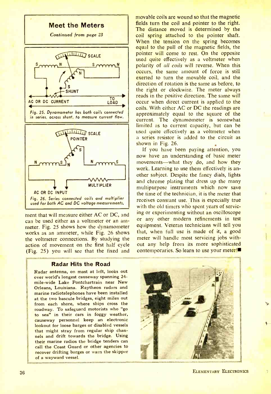
Meet the Meters
Continued from page 23
SCALE
S __
S
SHUNT
AC OR DC CURRENT LOAD
Fig. 25. Dynamometer has both coils connected
in series, across shunt, to measure current flow.
POINTER
SCALE
MULTIPLIER
AC OR DC INPUT
Fig. 26. Series connected coils and multiplier
used for both AC and DC voltage measurements.
36
ment that will measure either AC or DC, and
can be used either as a voltmeter or an am-
meter. Fig. 25 shows how the dynamometer
works as an ammeter, while Fig. 26 shows
the voltmeter connections. By studying the
action of movement on the first half cycle
(Fig. 25) you will see that the fixed and
movable coils are wound so that the magnetic
fields turn the coil and pointer to the right.
The distance moved is determined by the
coil spring attached to the pointer shaft.
When the tension on the spring becomes
equal to the pull of the magnetic fields, the
pointer will come to rest. On the opposite
used quite effectively as a voltmeter when
polarity of all coils will reverse. When this
occurs, the same amount of force is still
exerted to turn the movable coil, and the
direction of rotation is the same as before, to
the right or clockwise. The meter always
reads in the positive direction. The same will
occur when direct current is applied to the
coils. With either AC or DC the readings are
approximately equal to the square of the
current. The dynamometer is somewhat
limited as to current capacity, but can be
used quite effectively as a voltmeter when
a series resistor is added to the circuit as
shown in Fig. 26.
If you have been paying attention, you
now have an understanding of basic meter
movements -what they do, and how they
work. Learning to use them effectively is an-
other subject. Despite the fancy dials, lights
and chrome plating that dress up the many
multipurpose instruments which now save
the time of the technician, it is the meter that
receives constant use. This is especially true
with the old timers whb spent years of servic-
ing or experimenting without an oscilloscope
or any other modern refinements in test
equipment. Veteran technicians will tell you
that, when full use is made of it, a good
meter will handle most servicing jobs with-
out any help from its more sophisticated
contemporaries. So learn to use your meter!
1111111111111111111111111111111111' ..1111111111111111111111111111111 1.11111111111111111
Radar Hits the Road
Radar antenna, on mast at left, looks out
over world's longest causeway spanning 24-
mile -wide Lake Pontchartrain near New
Orleans, Louisiana. Raytheon radars and
marine radiotelephones have been installed
at the two bascule bridges, eight miles out
from each shore, where ships cross the
roadway. To safeguard motorists who "go
to sea" in their cars in foggy weather,
causeway personnel keep an electronic
lookout for loose barges or disabled vessels
that might stray from regular ship chan-
nels and drift towards the bridge. Using
their marine radios the bridge tenders can
call the Coast Guard or other agencies to
recover drifting barges or warn the skipper
of a wayward vessel.
111111111111111111111 11111111111111 ,,
11111111111111 111111111111111 11111111111111111111111 111111 11 11
ELEMENTARY ELECTRONICS
www.americanradiohistory.com
Sonie illuminating
facts about the new
brilliance available
in lighting fixtures
Watt es New lit gh rt- í
by Len i;ucliwal ler
Not long after Edison demonstrated the
first practical lamp, he made a prediction. He
believed it unlikely that the incandescent
lamp would ever be improved. That was
sixty -five years ago. Not only has the lamp
undergone much improvement, but lamp -
makers now do things that would make an
Edison stare in disbelief. Today they make
bulbs that resemble waffles, some lamps
called "people heaters" and, most shocking
of all, they sell light you can't even see. The
lamp industry is over 80 years old, but it's
still trying to find new and better ways to
MAY-JUNE, 1966
eclipse its biggest competitor which, accord-
ing to one General Electric official, is the sun.
The big change in lighting happened just
before 1940. By scrapping a glowing fila-
ment, the fluorescent lamp proved it could
deliver four times more light and last ten
times longer than the traditional incandes-
cent. You may use regular bulbs (still a big
bargain) but more than two- thirds of all light
produced today comes from an assortment of
long, flattened or squiggly fluorescents. How
do they work?
Fluorescent Operation. The light seen
37
www.americanradiohistory.com
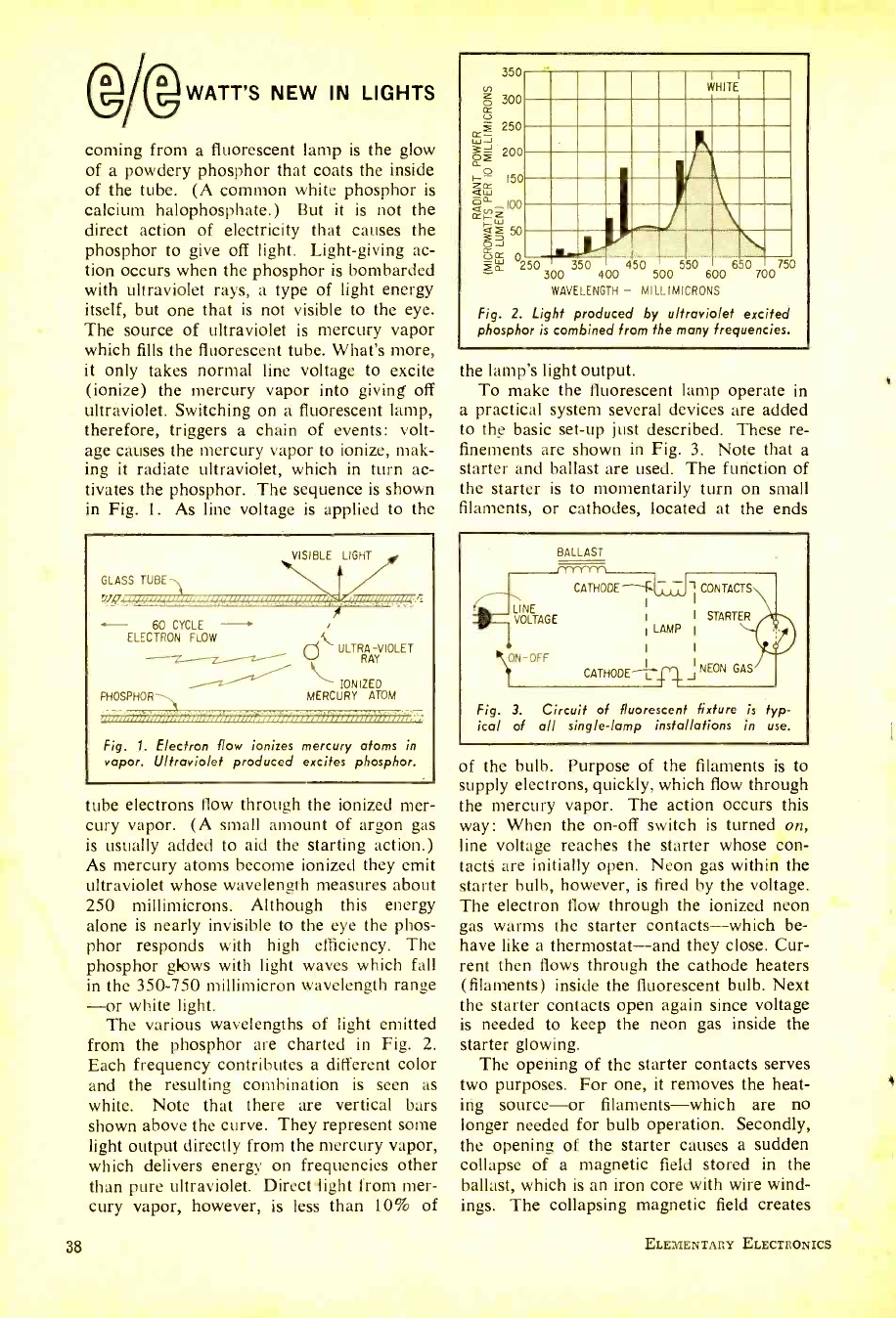
WATT'S NEW IN LIGHTS
coming from a fluorescent lamp is the glow
of a powdery phosphor that coats the inside
of the tube. (A common white phosphor is
calcium halophosphate.) But it is not the
direct action of electricity that causes the
phosphor to give off light. Light -giving ac-
tion occurs when the phosphor is bombarded
with ultraviolet rays, a type of light energy
itself, but one that is not visible to the eye.
The source of ultraviolet is mercury vapor
which fills the fluorescent tube. What's more,
it only takes normal line voltage to excite
(ionize) the mercury vapor into giving off
ultraviolet. Switching on a fluorescent lamp,
therefore, triggers a chain of events: volt-
age causes the mercury vapor to ionize, mak-
ing it radiate ultraviolet, which in turn ac-
tivates the phosphor. The sequence is shown
in Fig. 1. As line voltage is applied to the
GLASS TUBE
VISIBLE LIGHT
uinouinii
60 CYCLE -
ELECTRON FLOW
ULTRRA- VIOLET
AY
IONIZED
PHOSPHOR---, MERCURY ATOM
Fig. 1. Electron flow ionizes mercury atoms in
vapor. Ultraviolet produced excites phosphor.
tube electrons flow through the ionized mer-
cury vapor. (A small amount of argon gas
is usually added to aid the starting action.)
As mercury atoms become ionized they emit
ultraviolet whose wavelength measures about
250 millimicrons. Although this energy
alone is nearly invisible to the eye the phos-
phor responds with high efficiency. The
phosphor glows with light waves which fall
in the 350 -750 millimicron wavelength range
-or white light.
The various wavelengths of light emitted
from the phosphor are charted in Fig. 2.
Each frequency contributes a different color
and the resulting combination is seen as
white. Note that there are vertical bars
shown above the curve. They represent some
light output directly from the mercury vapor,
which delivers energy on frequencies other
than pure ultraviolet. Direct light from mer-
cury vapor, however, is less than 10% of
38
V)
z o ¢
g 250
WJ
3 z 150
áá 1.41
ce 100
w
I-- 60
350
300
200
OJ
UFs á 0250 300 350 400 450 500 550 600 650 700 750
WAVELENGTH - MILLIMICRONS
Fig. 2. Light produced by ultraviolet excited
phosphor is combined from the many frequencies.
111111:11
n =1917 ,111111111
I MIL ; ! 117 , wino
the lamp's light output.
To make the fluorescent lamp operate in
a practical system several devices are added
to the basic set -up just described. These re-
finements are shown in Fig. 3. Note that a
starter and ballast are used. The function of
the starter is to momentarily turn on small
filaments, or cathodes, located at the ends
BALLAST
LINE
VOLTAGE
ON-OFF
CATHODE --F. ¡CONTACTS
1
I STARTER
LAMP I
1 I
I NEON GAS
CATHODE
Fig. 3. Circuit of fluorescent fixture is typ-
ical of all single -lamp installations in use.
of the bulb. Purpose of the filaments is to
supply electrons, quickly, which flow through
the mercury vapor. The action occurs this
way: When the on -off switch is turned on,
line voltage reaches the starter whose con-
tacts are initially open. Neon gas within the
starter bulb, however, is fired by the voltage.
The electron flow through the ionized neon
gas warms the starter contacts -which be-
have like a thermostat -and they close. Cur-
rent then flows through the cathode heaters
(filaments) inside the fluorescent bulb. Next
the starter contacts open again since voltage
is needed to keep the neon gas inside the
starter glowing.
The opening of the starter contacts serves
two purposes. For one, it removes the heat-
ing source -or filaments -which are no
longer needed for bulb operation. Secondly,
the opening of the starter causes a sudden
collapse of a magnetic field stored in the
ballast, which is an iron core with wire wind-
ings. The collapsing magnetic field creates
ELEMENTARY ELECTRONICS
www.americanradiohistory.com
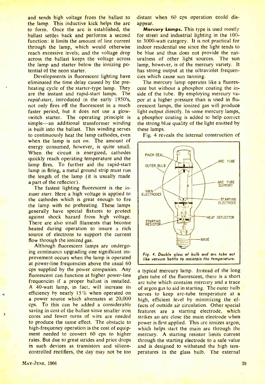
and sends high voltage from the ballast to
the lamp. This inductive kick helps the arc
to form. Once the arc is established, the
ballast settles back and performs a second
function: it limits the amount of line current
through the lamp, which would otherwise
reach excessive levels; and the voltage drop
across the ballast keeps the voltage across
the lamp and starter below the ionizing po-
tential of the neon starter.
Developments in fluorescent lighting have
eliminated the time delay caused by the pre-
heating cycle of the starter -type lamp. They
are the instant and rapid -start lamps. The
rapid- start, introduced in the early 1950's,
not only fires off the fluorescent in a much
faster period, but it does not use a glow -
switch starter. The operating principle is
simple -an additional transformer winding
is built into the ballast. This winding serves
to continuously heat the lamp cathodes, even
when the lamp is not on. The amount of
energy consumed, however, is quite small.
When the circuit is energized, cathodes
quickly reach operating temperature and the
lamp fires. To further aid the rapid -start
lamp in firing, a metal ground strip must run
the length of the lamp (it is usually made
a part of the reflector).
The fastest lighting fluorescent is the in-
stant start. Here a high voltage is applied to
the cathodes which is great enough to fire
the lamp with no preheating. These lamps
generally have special fixtures to protect
against shock hazard from high voltage.
There are also small filaments that become
heated during operation to insure a rich
source of electrons to support the current
flow through the ionized gas.
Although fluorescent lamps are undergo-
ing continuous upgrading one significant im-
provement occurs when the lamp is operated
at power -line frequencies above the usual 60
cps supplied by the power companies. Any
fluorescent can function at higher power -line
frequencies if a proper ballast is installed.
A 40 -watt lamp, in fact, will increase its
efficiency by nearly 15% when operated on
a power source which alternates at 20,000
cps. To this can be added a considerable
saving in cost of the ballast since smaller iron
cores and fewer turns of wire are needed
to produce the same effect. The obstacle to
high- frequency operation is the cost of equip-
ment needed to convert 60 cps to higher
rates. But due to great strides and price drops
in such devices as transistors and silicon -
controlled rectifiers, the day may not be too
MAY-JUNE, 1966
distant when 60 cps operation could dis-
appear.
Mercury Lamps. This type is used mostly
for street and industrial lighting in the 100 -
to 3000 -watt category. It is not practical for
indoor residential use since the light tends to
be blue and thus does not provide the nat-
uralness of other light sources. The sun
lamp, however, is of the mercury variety. It
has strong output at the ultraviolet frequen-
cies which cause sun tanning.
The mercury lamp operates like a fluores-
cent but without a phosphor coating the in-
side of the tube. By employing mercury va-
por at a higher pressure than is used in flu-
orescent lamps, the ionized gas will produce
light output directly. In some mercury lamps,
a phosphor coating is added to help correct
the strong blue quality of the light emitted by
these lamps.
Fig. 4 reveals the internal construction of
PINCH SEA ai C
OUTER B
MAIN
ELECTRODES
STARTING
RESISTOR
ARC TUBE
ARC TUBE
SUPPORT
STARTING
ELECTRODE
HEAT DEFLECTOR
^BASE
Fig. 4. Double glass of bulb and arc tube act
like vacuum bottle to maintain the temperature.
a typical mercury lamp. Instead of the long
glass tube of the fluorescent, there is a short
arc tube which contains mercury and a trace
of argon gas to aid in starting. The outer bulb
serves to keep arc -tube temperature at a
high, efficient level by minimizing the ef-
fects of outside air circulation. Other special
features are a starting electrode, which
strikes an arc close the main electrode when
power is first applied. This arc ionizes argon,
which helps start the main arc through the
mercury. A starting resistor limits current
through the starting electrode to a safe value
and is designed to withstand the high tem-
peratures in the glass bulb. The external
39
www.americanradiohistory.com
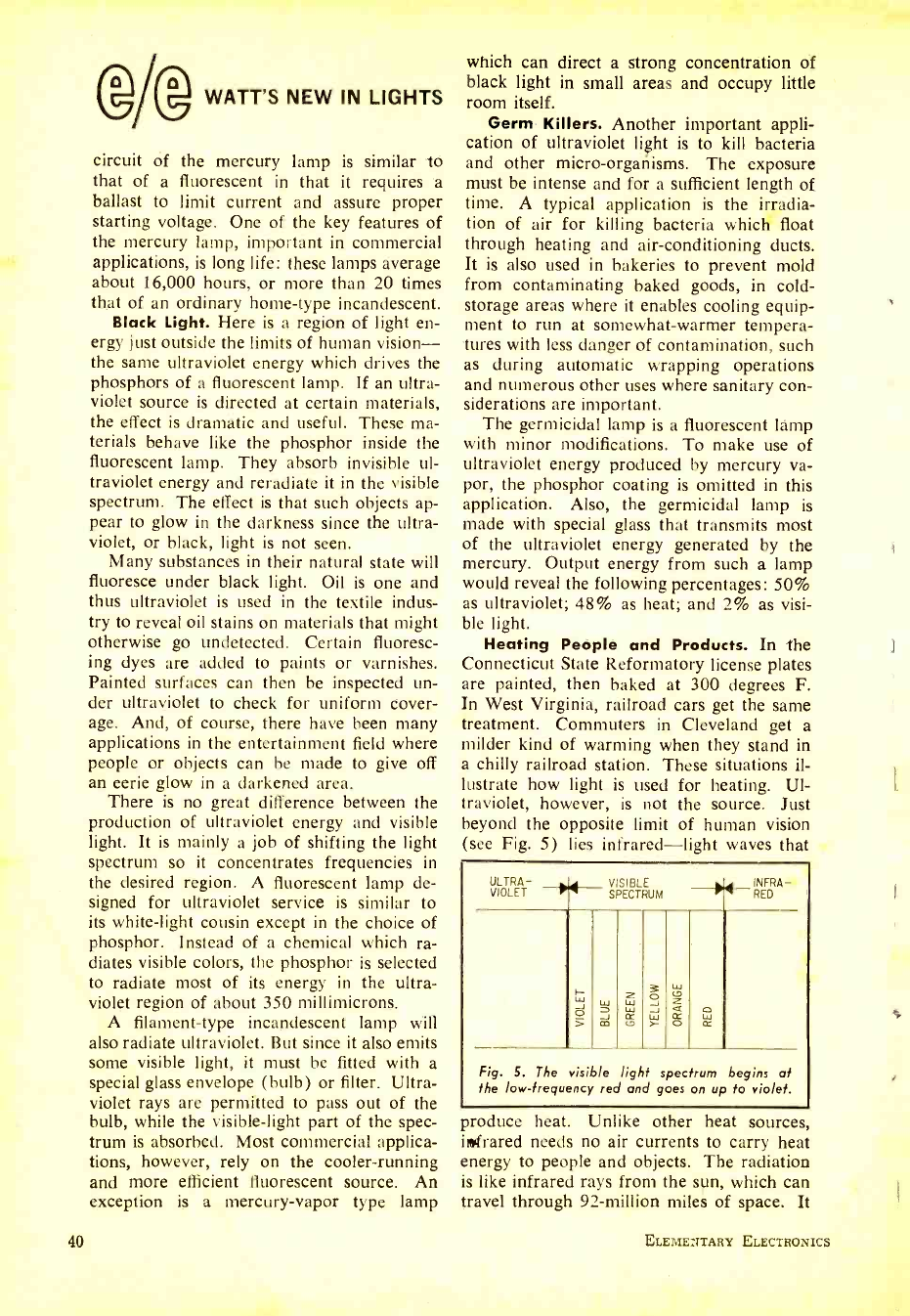
@Ag WATT'S NEW IN LIGHTS
circuit of the mercury lamp is similar to
that of a fluorescent in that it requires a
ballast to limit current and assure proper
starting voltage. One of the key features of
the mercury lamp, important in commercial
applications, is long life: these lamps average
about 16,000 hours, or more than 20 times
that of an ordinary home -type incandescent.
Black Light. Here is a region of light en-
ergy just outside the limits of human vision -
the same ultraviolet energy which drives the
phosphors of a fluorescent lamp. If an ultra-
violet source is directed at certain materials,
the effect is dramatic and useful. These ma-
terials behave like the phosphor inside the
fluorescent lamp. They absorb invisible ul-
traviolet energy and reradiate it in the visible
spectrum. The effect is that such objects ap-
pear to glow in the darkness since the ultra-
violet, or black, light is not seen.
Many substances in their natural state will
fluoresce under black light. Oil is one and
thus ultraviolet is used in the textile indus-
try to reveal oil stains on materials that might
otherwise go undetected. Certain fluoresc-
ing dyes are added to paints or varnishes.
Painted surfaces can then be inspected un-
der ultraviolet to check for uniform cover-
age. And, of course, there have been many
applications in the entertainment field where
people or objects can be made to give off
an eerie glow in a darkened area.
There is no great difference between the
production of ultraviolet energy and visible
light. It is mainly a job of shifting the light
spectrum so it concentrates frequencies in
the desired region. A fluorescent lamp de-
signed for ultraviolet service is similar to
its white -light cousin except in the choice of
phosphor. Instead of a chemical which ra-
diates visible colors, the phosphor is selected
to radiate most of its energy in the ultra-
violet region of about 350 millimicrons.
A filament -type incandescent lamp will
also radiate ultraviolet. But since it also emits
some visible light, it must be fitted with a
special glass envelope (bulb) or filter. Ultra-
violet rays are permitted to pass out of the
bulb, while the visible -light part of the spec-
trum is absorbed. Most commercial applica-
tions, however, rely on the cooler- running
and more efficient fluorescent source. An
exception is a mercury-vapor type lamp
40
which can direct a strong concentration of
black light in small areas and occupy little
room itself.
Germ Killers. Another important appli-
cation of ultraviolet light is to kill bacteria
and other micro -organisms. The exposure
must be intense and for a sufficient length of
time. A typical application is the irradia-
tion of air for killing bacteria which float
through heating and air -conditioning ducts.
It is also used in bakeries to prevent mold
from contaminating baked goods, in cold -
storage areas where it enables cooling equip-
ment to run at somewhat -warmer tempera-
tures with less danger of contamination, such
as during automatic wrapping operations
and numerous other uses where sanitary con-
siderations are important.
The germicidal lamp is a fluorescent lamp
with minor modifications. To make use of
ultraviolet energy produced by mercury va-
por, the phosphor coating is omitted in this
application. Also, the germicidal lamp is
made with special glass that transmits most
of the ultraviolet energy generated by the
mercury. Output energy from such a lamp
would reveal the following percentages: 50%
as ultraviolet; 48% as heat; and 2% as visi-
ble light.
Heating People and Products. In the
Connecticut State Reformatory license plates
are painted, then baked at 300 degrees F.
In West Virginia, railroad cars get the same
treatment. Commuters in Cleveland get a
milder kind of warming when they stand in
a chilly railroad station. These situations il-
lustrate how light is used for heating. Ul-
traviolet, however, is not the source. Just
beyond the opposite limit of human vision
(see Fig. 5) lies infrared -light waves that
ULTRA-
VIOLET V SIBLE
SPECTRUM INFRA-
RED
w o s LU
CO
w K c
ó -J > á ó W CC
Fig. 5. The visible light spectrum begins at
the low- frequency red and goes on up to violet.
produce heat. Unlike other heat sources,
infrared needs no air currents to carry heat
energy to people and objects. The radiation
is like infrared rays from the sun, which can
travel through 92- million miles of space. It
ELEMENTARY ELECTRONICS
www.americanradiohistory.com
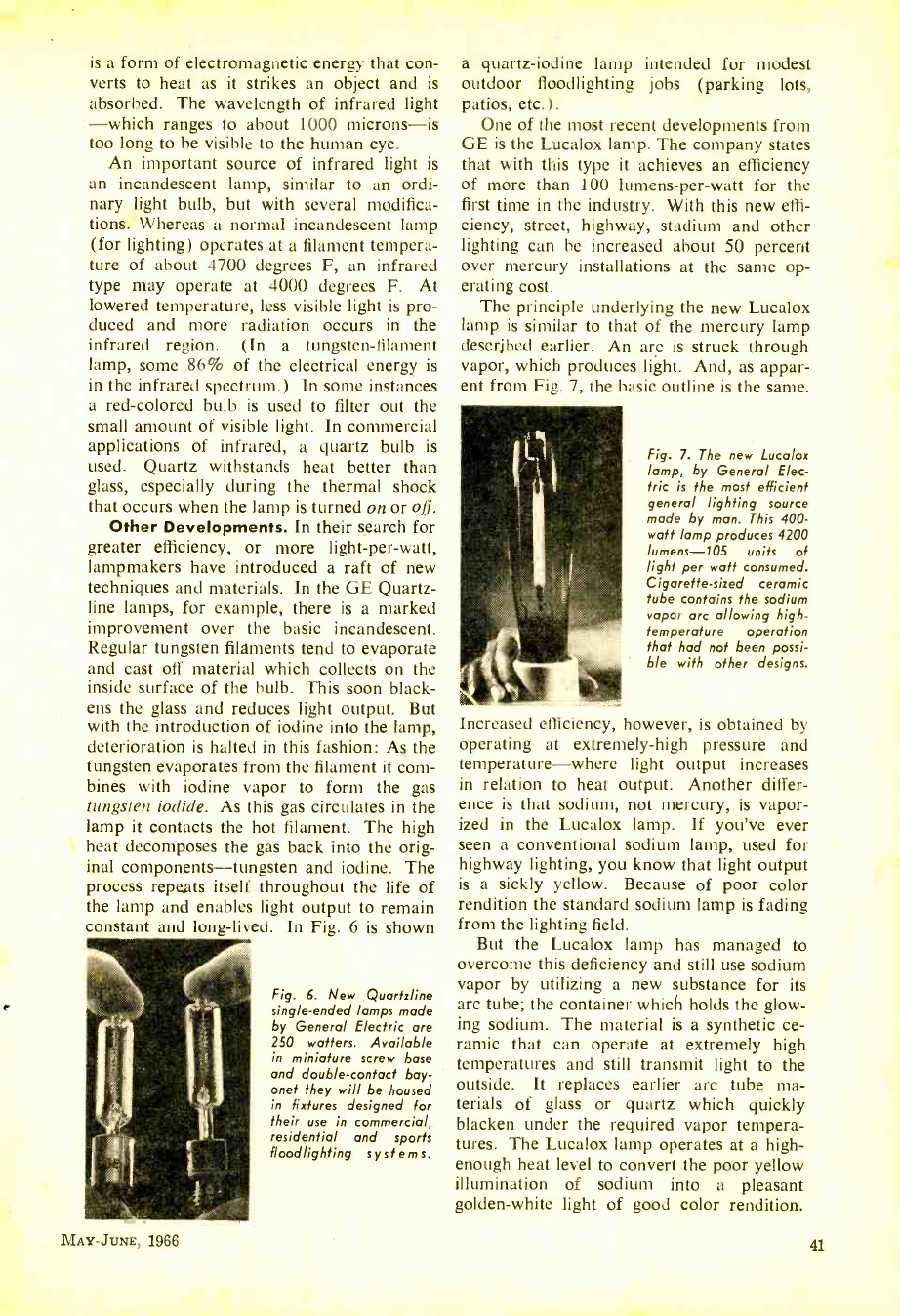
is a form of electromagnetic energy that con-
verts to heat as it strikes an object and is
absorbed. The wavelength of infrared light
-which ranges to about 1000 microns -is
too long to be visible to the human eye.
An important source of infrared light is
an incandescent lamp, similar to an ordi-
nary light bulb, but with several modifica-
tions. Whereas a normal incandescent lamp
(for lighting) operates at a filament tempera-
ture of about 4700 degrees F, an infrared
type may operate at 4000 degrees F. At
lowered temperature, less visible light is pro-
duced and more radiation occurs in the
infrared region. (In a tungsten -filament
lamp, some 86% of the electrical energy is
in the infrared spectrum.) In some instances
a red -colored bulb is used to filter out the
small amount of visible light. In commercial
applications of infrared, a quartz bulb is
used. Quartz withstands heat better than
glass, especially during the thermal shock
that occurs when the lamp is turned on or oi.
Other Developments. In their search for
greater efficiency, or more light -per -watt,
lampmakers have introduced a raft of new
techniques and materials. In the GE Quartz -
line lamps, for example, there is a marked
improvement over the basic incandescent.
Regular tungsten filaments tend to evaporate
and cast off material which collects on the
inside surface of the bulb. This soon black-
ens the glass and reduces light output. But
with the introduction of iodine into the lamp,
deterioration is halted in this fashion: As the
tungsten evaporates from the filament it com-
bines with iodine vapor to form the gas
tungsten iodide. As this gas circulates in the
lamp it contacts the hot filament. The high
heat decomposes the gas back into the orig-
inal components- tungsten and iodine. The
process repeats itself throughout the life of
the lamp and enables light output to remain
constant and long -lived. In Fig. 6 is shown
Fig. 6. New Quartzline
single -ended lamps made
by General Electric are
250 waiters. Available
in miniature screw base
and double -contact bay-
onet they will be housed
in fixtures designed for
their use in commercial,
residential and sports
floodlighting systems.
a quartz- iodine lamp intended for modest
outdoor floodlighting jobs (parking lots,
patios, etc.) .
One of the most recent developments from
GE is the Lucalox lamp. The company states
that with this type it achieves an efficiency
of more than 100 lumens -per -watt for the
first time in the industry. With this new effi-
ciency, street, highway, stadium and other
lighting can be increased about 50 percent
over mercury installations at the same op-
erating cost.
The principle underlying the new Lucalox
lamp is similar to that of the mercury lamp
described earlier. An arc is struck through
vapor, which produces light. And, as appar-
ent from Fig. 7, the basic outline is the same.
Fig. 7. The new Lucalox
lamp, by General Elec-
tric is the most efficient
general lighting source
made by man. This 400 -
watt lamp produces 4200
lumens -105 units of
light per watt consumed.
Cigarette -sized ceramic
tube contains the sodium
vapor arc allowing high -
temperature operation
that had not been possi-
ble with other designs.
Increased efficiency, however, is obtained by
operating at extremely -high pressure and
temperature -where light output increases
in relation to heat output. Another differ-
ence is that sodium, not mercury, is vapor-
ized in the Lucalox lamp. If you've ever
seen a conventional sodium lamp, used for
highway lighting, you know that light output
is a sickly yellow. Because of poor color
rendition the standard sodium lamp is fading
from the lighting field.
But the Lucalox lamp has managed to
overcome this deficiency and still use sodium
vapor by utilizing a new substance for its
arc tube; the container which holds the glow-
ing sodium. The material is a synthetic ce-
ramic that can operate at extremely high
temperatures and still transmit light to the
outside. It replaces earlier arc tube ma-
terials of glass or quartz which quickly
blacken under the required vapor tempera-
tures. The Lucalox lamp operates at a high -
enough heat level to convert the poor yellow
illumination of sodium into a pleasant
golden -white light of good color rendition.
MAY -JUNE, 1966 41
www.americanradiohistory.com
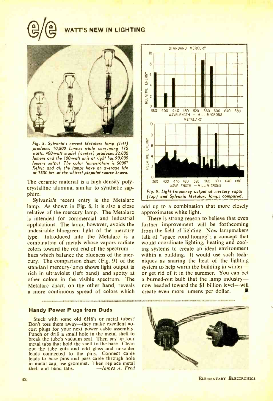
WATT'S NEW IN LIGHTING
Fig. 8. Sylvania's newest Metalarc lamp (left)
produces 10,500 lumens while consuming 175
watts. 400 -watt model (center) produces 32,000
lumens and the 100 -watt unit at right has 90,000
lumens output. The color temperature is 5000°
Kelvin and all the lamps have an average life
of 7500 hrs. of the whitest pinpoint source known.
The ceramic material is a high- density poly-
crystalline alumina, similar to synthetic sap-
phire.
Sylvania's recent entry is the Metalarc
lamp. As shown in Fig. 8, it is also a close
relative of the mercury lamp. The Metalarc
is intended for commercial and industrial
applications. The lamp, however, avoids the
undesirable bluegreen light of the mercury
type. Introduced into the Metalarc is a
combination of metals whose vapors radiate
colors toward the red end of the spectrum -
hues which balance the blueness of the mer-
cury. The comparison chart (Fig. 9) of the
standard mercury -lamp shows light output is
rich in ultraviolet (left band) and spotty at
other colors in the visible spectrum. The
Metalarc chart, on the other hand, reveals
a more continuous spread of colors which
10
8
CD 6
¢ w Z w 4
w >
áJ 2
Li
360
¢
w
STANDARD MERCURY
i
10
8
> 4
J _
0
360 400 440 480 520 560 600 640 680
WAVELENGTH - MILLIMICRONS
Fig. 9. Light- frequency output of mercury vapor
(top) and Sylvania Metalarc lamps compared.
add up to a combination that more closely
approximates white light.
There is strong reason to believe that even
further improvement will be forthcoming
from the field of lighting. Now lampmakers
talk of "space conditioning "; a concept that
would coordinate lighting, heating and cool-
ing systems to create an ideal environment
within a building. It would use such tech-
niques as snaring the heat of the lighting
system to help warm the building in winter -
or get rid of it in the summer. You can bet
a burned -out bulb that the lamp industry-
now headed toward the $1 billion level -will
create even more lumens per dollar.
i i i
400 440 480 520 560 600 640 680
WAVELENGTH - MILLIMICRONS
METALARC
.MM.
.I ,. I
I ,. I
ww n Iew
. ,..
MIMI ,1,1111.1,,,,,,,,,,,,,,1 ,,,,,,,,,,,,,,,,,,,,,,,,,,,,,,,,,,.,,,,,,,,,,,,,WM,,,,,lMUM,1111=g, 14110M111,11.1=1.1.1.11111.0 ,,,,,,,,,, ,11,,M,,,,M I NM,.,,,,, ,I,,,,,,,,,,,,,,,
Handy Power Plugs from Duds
Stuck with some old 6H6's or metal tubes?
Don't toss them away -they make excellent no-
cost plugs for your next power cable assembly.
Punch or drill a small hole in the metal shell to
break the tube's vacuum seal. Then pry up four
metal tabs that hold the shell to the base. Clean
out the tube guts and odd glass and unsolder
leads connected to the pins. Connect cable
leads to base pins and pass cable through hole
in metal cap, use grommet. Then replace metal
shell and bend tabs. -James A. Fred
42 ELEMENTARY ELECTRONICS
www.americanradiohistory.com
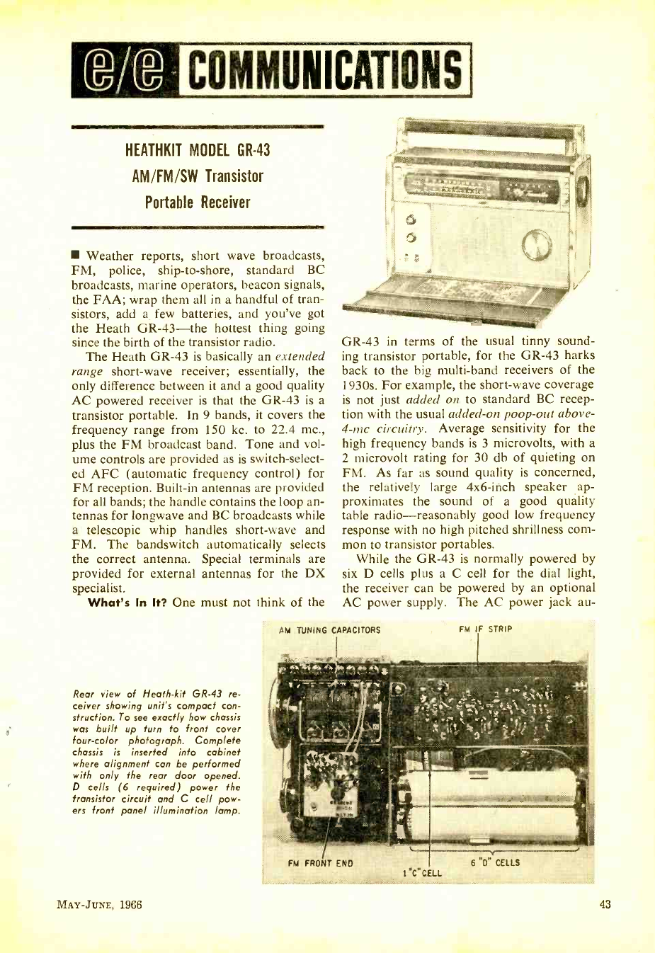
6/12 COMMUNICATIONS
HEATHKIT MODEL GR -43
AM /FM /SW Transistor
Portable Receiver
Weather reports, short wave broadcasts,
FM, police, ship -to- shore, standard BC
broadcasts, marine operators, beacon signals,
the FAA; wrap them all in a handful of tran-
sistors, add a few batteries, and you've got
the Heath GR -43 -the hottest thing going
since the birth of the transistor radio.
The Heath GR -43 is basically an extended
range short -wave receiver; essentially, the
only difference between it and a good quality
AC powered receiver is that the GR -43 is a
transistor portable. In 9 bands, it covers the
frequency range from 150 kc. to 22.4 mc.,
plus the FM broadcast band. Tone and vol-
ume controls are provided as is switch- select-
ed AFC (automatic frequency control) for
FM reception. Built -in antennas are provided
for all bands; the handle contains the loop an-
tennas for longwave and BC broadcasts while
a telescopic whip handles short -wave and
FM. The bandswitch automatically selects
the correct antenna. Special terminals are
provided for external antennas for the DX
specialist.
What's In It? One must not think of the
Rear view of Heath -kit GR -43 re-
ceiver showing unit's compact con -
struction. To see exactly how chassis
was built up turn to front cover
four -color photograph. Complete
chassis is inserted into cabinet
where alignment can be performed
with only the rear door opened.
D cells (6 required) power the
transistor circuit and C cell pow-
ers front panel illumination lamp.
GR -43 in terms of the usual tinny sound-
ing transistor portable, for the GR -43 harks
back to the big multi -band receivers of the
1930s. For example, the short -wave coverage
is not just added on to standard BC recep-
tion with the usual added -on poop -out above -
4-mc circuitry. Average sensitivity for the
high frequency bands is 3 microvolts, with a
2 microvolt rating for 30 db of quieting on
FM. As far as sound quality is concerned,
the relatively large 4x6-inch speaker ap-
proximates the sound of a good quality
table radio -reasonably good low frequency
response with no high pitched shrillness com-
mon to transistor portables.
While the GR -43 is normally powered by
six D cells plus a C cell for the dial light,
the receiver can be powered by an optional
AC power supply. The AC power jack au-
AM TUNING CAPACITORS FM IF STRIP
FM FRONT ENO I C "GEIL
MAY -JUNE, 1966 43
www.americanradiohistory.com
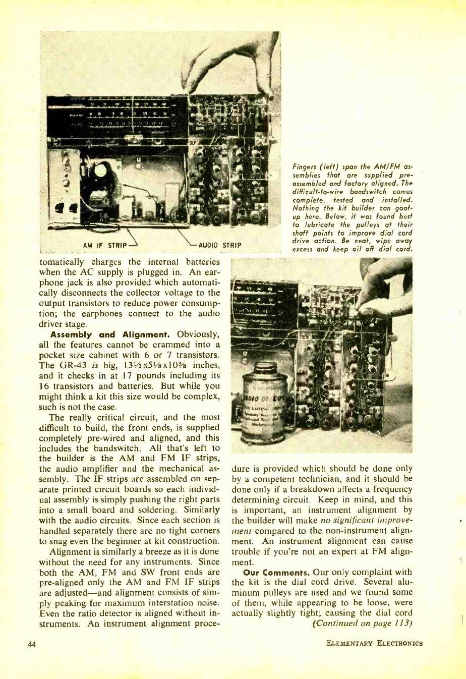
AM IF STRIP- AUDIO STRIP
tomatically charges the internal batteries
when the AC supply is plugged in. An ear-
phone jack is also provided which automati-
cally disconnects the collector voltage to the
output transistors to reduce power consump-
tion; the earphones connect to the audio
driver stage.
Assembly and Alignment. Obviously,
all the features cannot be crammed into a
pocket size cabinet with 6 or 7 transistors.
The GR-43 is big, 131/2 x51 /s x103/13 inches,
and it checks in at 17 pounds including its
16 transistors and batteries. But while you
might think a kit this size would be complex,
such is not the case.
The really critical circuit, and the most
difficult to build, the front ends, is supplied
completely pre -wired and aligned, and this
includes the bandswitch. All that's left to
the builder is the AM and FM IF strips,
the audio amplifier and the mechanical as-
sembly. The IF strips are assembled on sep-
arate printed circuit boards so each individ-
ual assembly is simply pushing the right parts
into a small board and soldering. Similarly
with the audio circuits. Since each section is
handled separately there are no tight corners
to snag even the beginner at kit construction.
Alignment is similarly a breeze as it is done
without the need for any instruments. Since
both the AM, FM and SW front ends are
pre -aligned only the AM and FM IF strips
are adjusted -and alignment consists of sim-
ply peaking for maximum interstation noise.
Even the ratio detector is aligned without in-
struments. An instrument alignment proce-
44
Fingers (left) span the AM /FM as-
semblies that are supplied pre -
assembled and factory aligned. The
difficult -to -wire bandswitch comes
complete, tested and installed.
Nothing the kit builder can goof -
up here. Below, it was found best
to lubricate the pulleys at their
shaft points to improve dial cord
drive action. Be neat, wipe away
excess and keep oil off dial cord.
dure is provided which should be done only
by a competent technician, and it should be
done only if a breakdown affects a frequency
determining circuit. Keep in mind, and this
is important, an instrument alignment by
the builder will make no significant improve-
ment compared to the non -instrument align-
ment. An instrument alignment can cause
trouble if you're not an expert at FM align-
ment. Our Comments. Our only complaint with
the kit is the dial cord drive. Several alu-
minum pulleys are used and we found some
of them, while appearing to be loose, were
actually slightly tight; causing the dial cord
(Continued on page 113)
ELEMENTARY ELECTRONICS
www.americanradiohistory.com
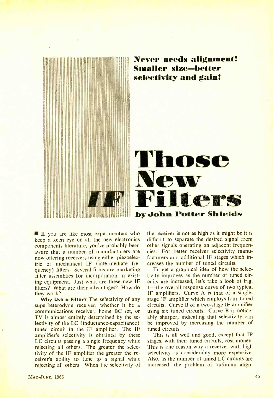
Never needs alignment!
Smaller size- better
selectivity and gain!
Those
New
Filters
by John Potter Shields
If you are like most experimenters who
keep a keen eye on all the new electronics
components literature, you've probably been
aware that a number of manufacturers are
now offering receivers using either piezoelec-
tric or mechanical IF (intermediate fre-
quency) filters. Several firms are marketing
filter assemblies for incorporation in exist-
ing equipment. Just what are these new IF
filters? What are their advantages? How do
they work?
Why Use a Filter? The selectivity of any
superheterodyne receiver, whether it be a
communications receiver, home BC set, or
TV is almost entirely determined by the se-
lectivity of the LC (inductance- capacitance)
tuned circuit in the IF amplifier. The IF
amplifier's selectivity is obtained by these
LC circuits passing a single frequency while
rejecting all others. The greater the selec-
tivity of the IF amplifier the greater the re-
ceiver's ability to tune to a signal while
rejecting all others. When the selectivity of
MAY -JUNE, 1966
the receiver is not as high as it might be it is
difficult to separate the desired signal from
other signals operating on adjacent frequen-
cies. For better receiver selectivity manu-
facturers add additional IF stages which in-
creases the number of tuned circuits.
To get a graphicál idea of how the selec-
tivity improves as the number of tuned cir-
cuits are increased, let's take a look at Fig.
1 -the overall response curve of two typical
IF amplifiers. Curve A is that of a single -
stage IF amplifier which employs four tuned
circuits. Curve B of a two -stage IF amplifier
using six tuned circuits. Curve B is notice-
ably sharper, indicating that selectivity can
be improved by increasing the number of
tuned circuits.
This is all well and good, except that IF
stages, with their tuned circuits, cost money.
This is one reason why a receiver with high
selectivity is considerably more expensive.
Also, as the number of tuned LC circuits are
increased, the problem of optimum align-
45
www.americanradiohistory.com
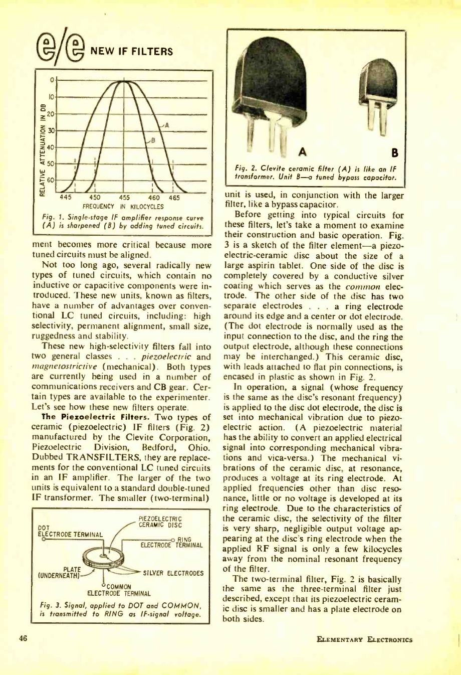
@/@ NEW IF FILTERS
o
lo
a, 0 z 2
E 30
z 40
a 50
> á 60
cc 445 450 455 460 465
FREQUENCY IN KILOCYCLES
Fig. 1. Single -stage IF amplifier response curve
(A) is sharpened (B) by adding tuned circuits.
ment becomes more critical
tuned circuits must be aligned.
Not too long ago, several radically new
types of tuned circuits, which contain no
inductive or capacitive components were in-
troduced. These new units, known as filters,
have a number of advantages over conven-
tional LC tuned circuits, including: high
selectivity, permanent alignment, small size,
ruggedness and stability.
These new high -selectivity filters fall into
two general classes . . . piezoelectric and
rnagnetostrictive (mechanical). Both types
are currently being used in a number of
communications receivers and CB gear. Cer-
tain types are available to the experimenter.
Let's see how these new filters operate.
The Piezoelectric Filters. Two types of
ceramic (piezoelectric) IF filters (Fig. 2)
manufactured by the Clevite Corporation,
Piezoelectric Division, Bedford, Ohio.
Dubbed TRANSFILTERS, they are replace-
ments for the conventional LC tuned circuits
in an IF amplifier. The larger of the two
units is equivalent to a standard double -tuned
IF transformer. The smaller (two-terminal)
because more
DOT
ELECTRODE TERMINAL
PIEZOELECTRIC
CERAMIC DISC
PLATE__,
RING
ELECTRODE TERMINAL
SILVER ELECTRODES
COMMON
ELECTRODE TERMINAL
Fig. 3. Signal, applied to DOT and COMMON,
is transmitted to RING as IF- signal voltage.
46
A B
Fig. 2. Clevite ceramic filter (A) is like an IF
transformer. Unit B-a tuned bypass capacitor.
unit is used, in conjunction with the larger
filter, like a bypass capacitor.
Before getting into typical circuits for
these filters, let's take a moment to examine
their construction and basic operation. Fig.
3 is a sketch of the filter element -a piezo-
electric-ceramic disc about the size of a
large aspirin tablet. One side of the disc is
completely covered by a conductive silver
coating which serves as the common elec-
trode. The other side of the disc has two
separate electrodes . . . a ring electrode
around its edge and a center or dot electrode.
(The dot electrode is normally used as the
input connection to the disc, and the ring the
output electrode, although these connections
may be interchanged.) This ceramic disc,
with leads attached to flat pin connections, is
encased in plastic as shown in Fig. 2.
In operation, a signal (whose frequency
is the same as the disc's resonant frequency)
is applied to the disc dot electrode, the disc is
set into mechanical vibration due to piezo-
electric action. (A piezoelectric material
has the ability to convert an applied electrical
signal into corresponding mechanical vibra-
tions and vica -versa.) The mechanical vi-
brations of the ceramic disc, at resonance,
produces a voltage at its ring electrode. At
applied frequencies other than disc reso-
nance, little or no voltage is developed at its
ring electrode. Due to the characteristics of
the ceramic disc, the selectivity of the filter
is very sharp, negligible output voltage ap-
pearing at the disc's ring electrode when the
applied RF signal is only a few kilocycles
away from the nominal resonant frequency
of the filter.
The two -terminal filter, Fig. 2 is basically
the same as the three -terminal filter just
described, except that its piezoelectric ceram-
ic disc is smaller and has a plate electrode on
both sides.
ELEMENTARY ELECTRONICS
www.americanradiohistory.com
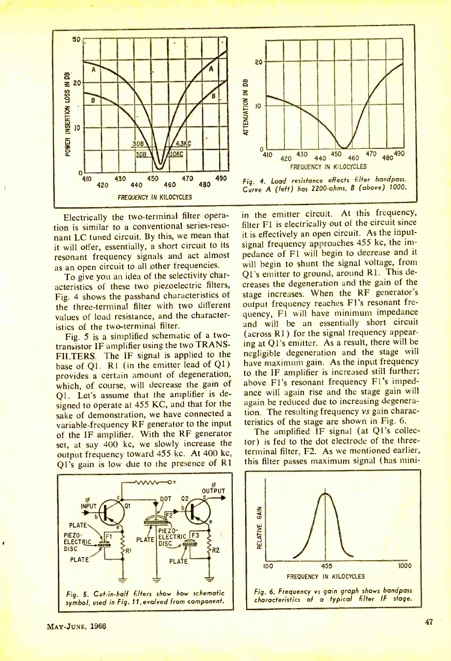
50
20
g
w 10
1
Mar
NM/
CUM
31r4 3KC
410 430 450 470 490
420 440 460 480
FREQUENCY IN KILOCYCLES
20
IO
410 420 430 440 450 460 470 480490
FREQUENCY IN KILOCYCLES
Fig. 4. Load resistance effects filter bandpass.
Curve A (left) has 2200 -ohms, 8 (above) 1000.
Electrically the two -terminal filter opera-
tion is similar to a conventional series -reso-
nant LC tuned circuit. By this, we mean that
it will offer, essentially, a short circuit to its
resonant frequency signals and act almost
as an open circuit to all other frequencies.
To give you an idea of the selectivity char-
acteristics of these two piezoelectric filters,
Fig. 4 shows the passband characteristics of
the three -terminal filter with two different
values of load resistance, and the character-
istics of the two-terminal filter.
Fig. 5 is a simplified schematic of a two -
transistor IF amplifier using the two TRANS -
FILTERS. The IF signal is applied to the
base of Ql. Rl (in the emitter lead of Q1)
provides a certain amount of degeneration,
which, of course, will decrease the gain of
Ql. Let's assume that the amplifier is de-
signed to operate at 455 KC, and that for the
sake of demonstration, we have connected a
variable- frequency RF generator to the input
of the IF amplifier. With the RF generator
set, at say 400 kc, we slowly increase the
output frequency toward 455 kc. At 400 kc,
Q1's gain is low due to the presence of Rl
IF
INPUT /4Qt
bL
PLATE
PIE20-
ELECTRIC
DISC
PLATE
e
IF
OUTPUT
DOT 02
b
F2
/ }ImmisssaaPIEZO-
PLATE ELECTRIC
DIS,1®
R1
F3
PLATE
R2
Fig. S. Cut -in -half filters how how schematic
symbol, used in Fig. 11,evolved from component.
MAY -JUNE, 1966
in the emitter circuit. At this frequency,
filter F1 is electrically out of the circuit since
it is effectively an open circuit. As the input -
signal frequency approaches 455 kc, the im-
pedance of F1 will begin to decrease and it
will begin to shunt the signal voltage, from
QI's emitter to ground, around R1. This de-
creases the degeneration and the gain of the
stage increases. When the RF generator's
output frequency reaches F1's resonant fre-
quency, Fl will have minimum impedance
and will be an essentially short circuit
(across Rl) for the signal frequency appear-
ing at Q1's emitter. As a result, there will be
negligible degeneration and the stage will
have maximum gain. As the input frequency
to the. IF amplifier is increased still further;
above F1's resonant frequency F1's imped-
ance will again rise and the stage gain will
again be reduced due to increasing degenera-
tion. The resulting frequency vs gain charac-
teristics of the stage are shown in Fig. 6.
The amplified IF signal (at Ql's collec-
tor) is fed to the dot electrode of the three -
erminal filter, F2. As we mentioned earlier,
this filter passes maximum signal (has mini-
z
100 455 1000
FREQUENCY IN KILOCYCLES
Fig. 6. Frequency vs gain graph shows bandpass
characteristics of a typical filter IF stage.
47
www.americanradiohistory.com
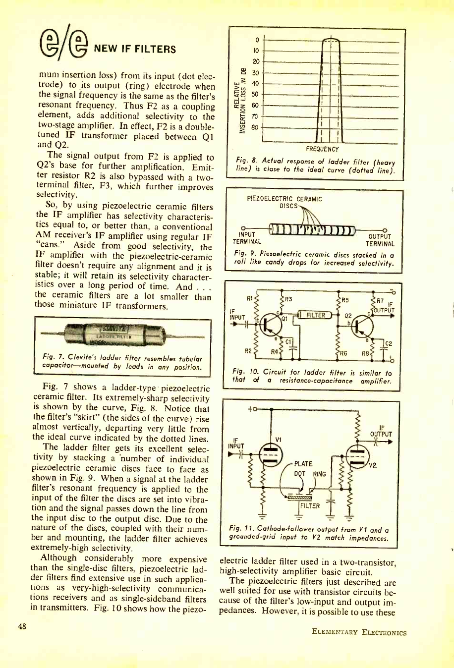
@/@ NEW IF FILTERS
mum insertion loss) from its input (dot elec-
trode) to its output (ring) electrode when
the signal frequency is the same as the filter's
resonant frequency. Thus F2 as a coupling
element, adds additional selectivity to the
two -stage amplifier. In effect, F2 is a double -
tuned IF transformer placed between Q1
and Q2.
The signal output from F2 is applied to
Q2's base for further amplification. Emit-
ter resistor R2 is also bypassed with a two -
terminal filter, F3, which further improves
selectivity.
So, by using piezoelectric ceramic filters
the IF amplifier has selectivity characteris-
tics equal to, or better than, a conventional
AM receiver's IF amplifier using regular IF
"cans." Aside from good selectivity, the
IF amplifier with the piezoelectric- ceramic
filter doesn't require any alignment and it is
stable; it will retain its selectivity character-
istics over a long period of time. And .. .
the ceramic filters are a lot smaller than
those miniature IF transformers.
Fig. 7. Clevite's ladder filter resembles tubular
capacitor- mounted by leads in any position.
Fig. 7 shows a ladder -type piezoelectric
ceramic filter. Its extremely -sharp selectivity
is shown by the curve, Fig. 8. Notice that
the filter's "skirt" (the sides of the curve) rise
almost vertically, departing very little from
the ideal curve indicated by the dotted lines.
The ladder filter gets its excellent selec-
tivity by stacking a 'number of individual
piezoelectric ceramic discs face to face as
shown in Fig. 9. When a signal at the ladder
filter's resonant frequency is applied to the
input of the filter the discs are set into vibra-
tion and the signal passes down the line from
the input disc to the output disc. Due to the
nature of the discs, coupled with their num-
ber and mounting, the ladder filter achieves
extremely -high selectivity.
Although considerably more expensive
than the single -disc filters, piezoelectric lad-
der filters find extensive use in such applica-
tions as very- high -selectivity communica-
tions receivers and as single -sideband filters
in transmitters. Fig. 10 shows how the piezo-
48
0
10
20
co 30
- co
J ó
W 80
40
50
60
70
FREQUENCY
Fig. 8. Actual response of ladder filter (heavy
line) is close to the ideal curve (dotted line).
PIEZOELECTRIC CERAMIC
DISCS
31111k11111/BD
INPUT OUTPUT
TERMINAL TERMINAL
Fig. 9. Piezoelectric ceramic discs stacked in a
roll like candy drops for increased selectivity.
RI
IF INPUT
R2
R7 IF
OUTPUT
C2
Fig. 10. Circuit for ladder filter is similar to
that of a resistance -capacitance amplifier.
INPUT
H VI
r PLATE if D RING
11LTER T
IF
OUTPUT
H
V2
Fig. 11. Cathode- follower output from V1 and a
grounded -grid input to V2 match impedances.
electric ladder filter used in a two- transistor,
high- selectivity amplifier basic circuit.
The piezoelectric filters just described are
well suited for use with transistor circuits be-
cause of the filter's low -input and output im-
pedances. However, it is possible to use these
ELEMENTARY ELECTRONICS
www.americanradiohistory.com
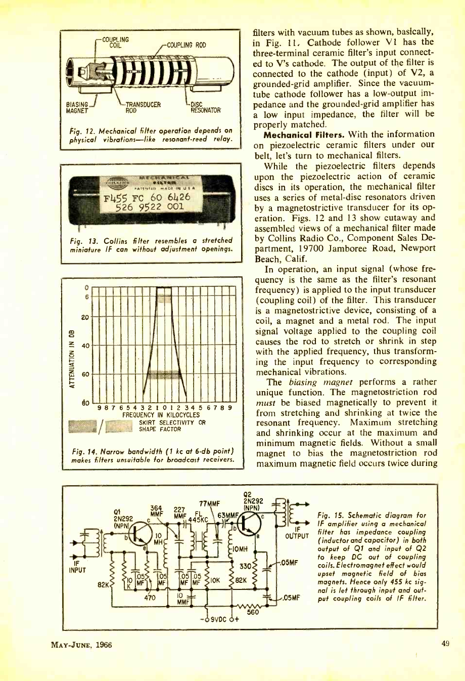
COUPLING
COIL
BIASING TRANSDUCER DISC
MAGNET ROD RESONATOR
Fig. 12. Mechanical filter operation depends on
physical vibrations- like resonant -reed relay.
Fig. 13. Collins filter resembles a stretched
miniature IF can without adjustment openings.
0
6
20
40
w 60
éo 9 8 7 6 5 4 3 2 1 0 2 3 4 5 6 7 8 9
FREQUENCY N KILOCYCLES
SKIRT SELECTIVITY OR
.É SHAPE FACTOR
Fig. 14. Narrow bandwidth (1 kc at 6 -db point)
makes filters unsuitable for broadcast receivers.
filters with vacuum tubes as shown, basically,
in Fig. 11. Cathode follower V 1 has the
three -terminal ceramic filter's input connect-
ed to V's cathode. The output of the filter is
connected to the cathode (input) of V2, a
grounded -grid amplifier. Since the vacuum -
tube cathode follower has a low- output im-
pedance and the grounded -grid amplifier has
a low input impedance, the filter will be
properly matched.
Mechanical Filters. With the information
on piezoelectric ceramic filters under our
belt, let's turn to mechanical filters.
While the piezoelectric filters depends
upon the piezoelectric action of ceramic
discs in its operation, the mechanical filter
uses a series of metal -disc resonators driven
by a magnetostrictive transducer for its op-
eration. Figs. 12 and 13 show cutaway and
assembled views of a mechanical filter made
by Collins Radio Co., Component Sales De-
partment, 19700 Jamboree Road, Newport
Beach, Calif.
In operation, an input signal (whose fre-
quency is the same as the filter's resonant
frequency) is applied to the input transducer
(coupling coil) of the filter. This transducer
is a magnetostrictive device, consisting of a
coil, a magnet and a metal rod. The input
signal voltage applied to the coupling coil
causes the rod to stretch or shrink in step
with the applied frequency, thus transform-
ing the input frequency to corresponding
mechanical vibrations.
The biasing magnet performs a rather
unique function. The magnetostriction rod
must be biased magnetically to prevent it
from stretching and shrinking at twice the
resonant frequency. Maximum stretching
and shrinking occur at the maximum and
minimum magnetic fields. Without a small
magnet to bias the magnetostriction rod
maximum magnetic field occurs twice during
i
Ot 2N292
(NPN)
77MMF
MME 227 FL
445KC
Q2
2N292
(NPN)
IF
INPUT
82K
Fig. 15. Schematic diagram for
IF amplifier using a mechanical
IF
OGÍTPUT filter has impedance coupling
(inductor and capacitor) in both
output of Q1 and input of Q2
05MF to keep DC out of coupling
coils. Electromagnet effect would
upset magnetic field of bias
magnets. Hence only 455 kc sig-
nal is let through input and out -
05MF put coupling coils of IF filter.
9VDC + 560
MAY -JUNE, 1966 49
www.americanradiohistory.com
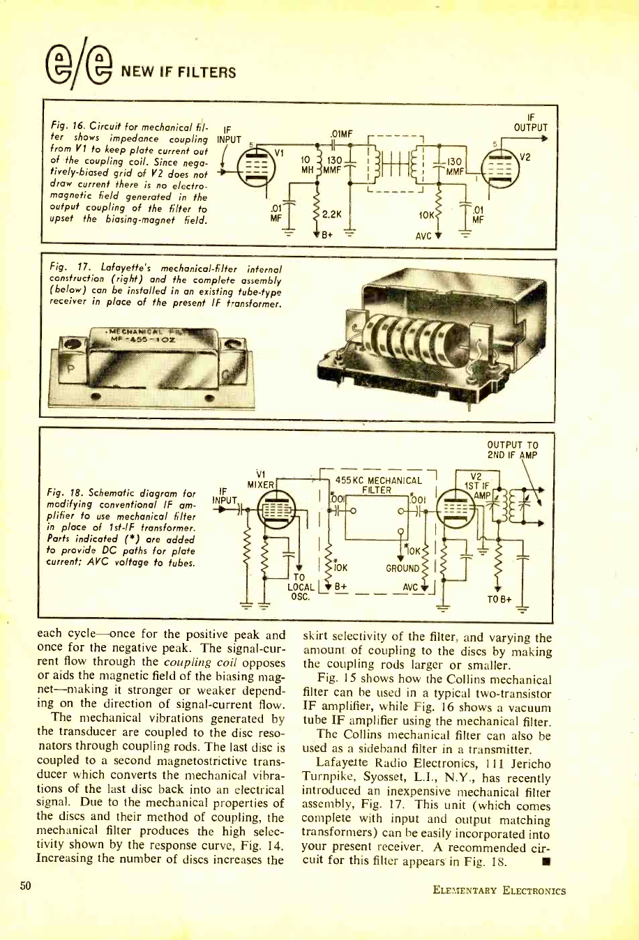
(gAg NEW IF FILTERS
Fig. 16. Circuit for mechanical fil-
ter shows impedance coupling
from V1 to keep plate current out
of the coupling coil. Since nega-
tively- biased grid of V2 does not
draw current there is no electro-
magnetic field generated in the
output coupling of the filter to
upset the biasing- magnet field.
IF
INPUT .01MFr-----
V1 10 130 ¡ ) I i 130
MH MMF I
MMF
L J
.01
MF 2.2K
B+
10K
AVC
IF
OUTPUT
T.01 MF
V2
Fig. 17. Lafayette's mechanical -filter internal
construction (right) and the complete assembly
(below) can be installed in an existing tube -type
receiver in place of the present IF transformer.
Fig. 18. Schematic diagram for
modifying conventional IF am-
plifier to use mechanical filter
in place of 1st -IF transformer.
Parts indicated ( *) are added
to provide DC paths for plate
current; AVC voltage to tubes.
INPUT
VI
MIXER 455 KC MECHANICAL
FILTER .0o1
10K
10K GROUND
TO
LOCAL L B+ AVC
OSC. J
OUTPUT TO
2ND IF AMP
TO B+
each cycle -once for the positive peak and
once for the negative peak. The signal -cur-
rent flow through the coupling coil opposes
or aids the magnetic field of the biasing mag-
net- making it stronger or weaker depend-
ing on the direction of signal- current flow.
The mechanical vibrations generated by
the transducer are coupled to the disc reso-
nators through coupling rods. The last disc is
coupled to a second magnetostrictive trans-
ducer which converts the mechanical vibra-
tions of the last disc back into an electrical
signal. Due to the mechanical properties of
the discs and their method of coupling, the
mechanical filter produces the high selec-
tivity shown by the response curve, Fig. 14.
Increasing the number of discs increases the
50
skirt selectivity of the filter, and varying the
amount of coupling to the discs by making
the coupling rods larger or smaller.
Fig. 15 shows how the Collins mechanical
filter can be used in a typical two -transistor
IF amplifier, while Fig. 16 shows a vacuum
tube IF amplifier using the mechanical filter.
The Collins mechanical filter can also be
used as a sideband filter in a transmitter.
Lafayette Radio Electronics, 111 Jericho
Turnpike, Syosset, L.I., N.Y., has recently
introduced an inexpensive mechanical filter
assembly, Fig. 17. This unit (which comes
complete with input and output matching
transformers) can be easily incorporated into
your present receiver. A recommended cir-
cuit for this filter appears in Fig. 18.
ELEMENTARY ELECTRONICS
www.americanradiohistory.com
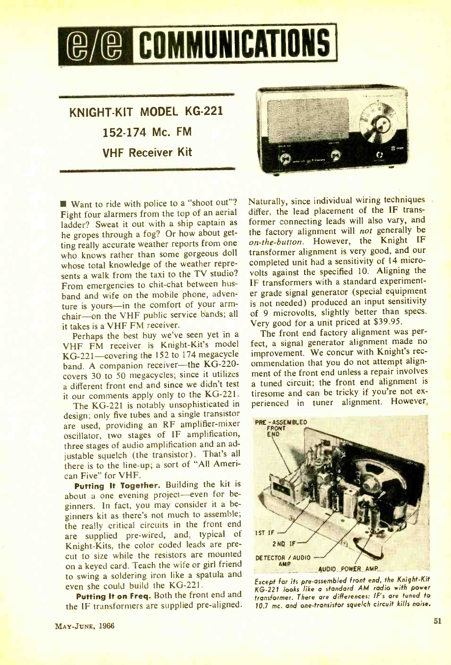
3/9 COMMUNICATIONS
KNIGHT -KIT MODEL KG -221
152 -174 Mc. FM
VHF Receiver Kit
Want to ride with police to a "shoot out "?
Fight four alarmers from the top of an aerial
ladder? Sweat it out with a ship captain as
he gropes through a fog? Or how about get-
ting really accurate weather reports from one
who knows rather than some gorgeous doll
whose total knowledge of the weather repre-
sents a walk from the taxi to the TV studio?
From emergencies to chit -chat between hus-
band and wife on the mobile phone, adven-
ture is yours -in the comfort of your arm -
chair-on the VHF public service bands; all
it takes is a VHF FM receiver.
Perhaps the best buy we've seen yet in a
VHF FM receiver is Knight -Kit's model
KG- 221 -covering the 152 to 174 megacycle
band. A companion receiver -the KG -220-
covers 30 to 50 megacycles; since it utilizes
a different front end and since we didn't test
it our comments apply only to the KG -221.
The KG -221 is notably unsophisticated in
design; only five tubes and a single transistor
are used, providing an RF amplifier -mixer
oscillator, two stages of IF amplification,
three stages of audio amplification and an ad-
justable squelch (the transistor). That's all
there is to the line -up; a sort of "All Ameri-
can Five" for VHF.
Putting It Together. Building the kit is
about a one evening project -even for be-
ginners. In fact, you may consider it a be-
ginners kit as there's not much to assemble;
the really critical circuits in the front end
are supplied pre -wired, and, typical of
Knight -Kits, the color coded leads are pre-
cut to size while the resistors are mounted
on a keyed card. Teach the wife or girl friend
to swing a soldering iron like a spatula and
even she could build the KG -221.
Putting It on Freq. Both the front end and
the IF transformers are supplied pre- aligned.
MAY- .TUNE, 1966
Naturally, since individual wiring techniques
differ, the lead placement of the IF trans-
former connecting leads will also vary, and
the factory alignment will not generally be
on- the -button. However, the Knight IF
transformer alignment is very good, and our
completed unit had a sensitivity of 14 micro-
volts against the specified 10. Aligning the
IF transformers with a standard experiment-
er grade signal generator (special equipment
is not needed) produced an input sensitivity
of 9 microvolts, slightly better than specs.
Very good for a unit priced at $39.95.
The front end factory alignment was per-
fect, a signal generator alignment made no
improvement. We concur with Knight's rec-
ommendation that you do not attempt align-
ment of the front end unless a repair involves
a tuned circuit; the front end alignment is
tiresome and can be tricky if you're not ex-
perienced in tuner alignment. However,
PRE -ASSEMBLED
FRONT
END
!ST IF
2ND IF
DETECTOR / AUDIO -
AMP AUDIO POWER AMP
Except for its pre -assembled front end, the Knight -Kit
KG -221 looks like a standard AM radio with power
transformer. There are differences: IF's are tuned to
10.7 mc. and one -transistor squelch circuit kills noise.
51
www.americanradiohistory.com
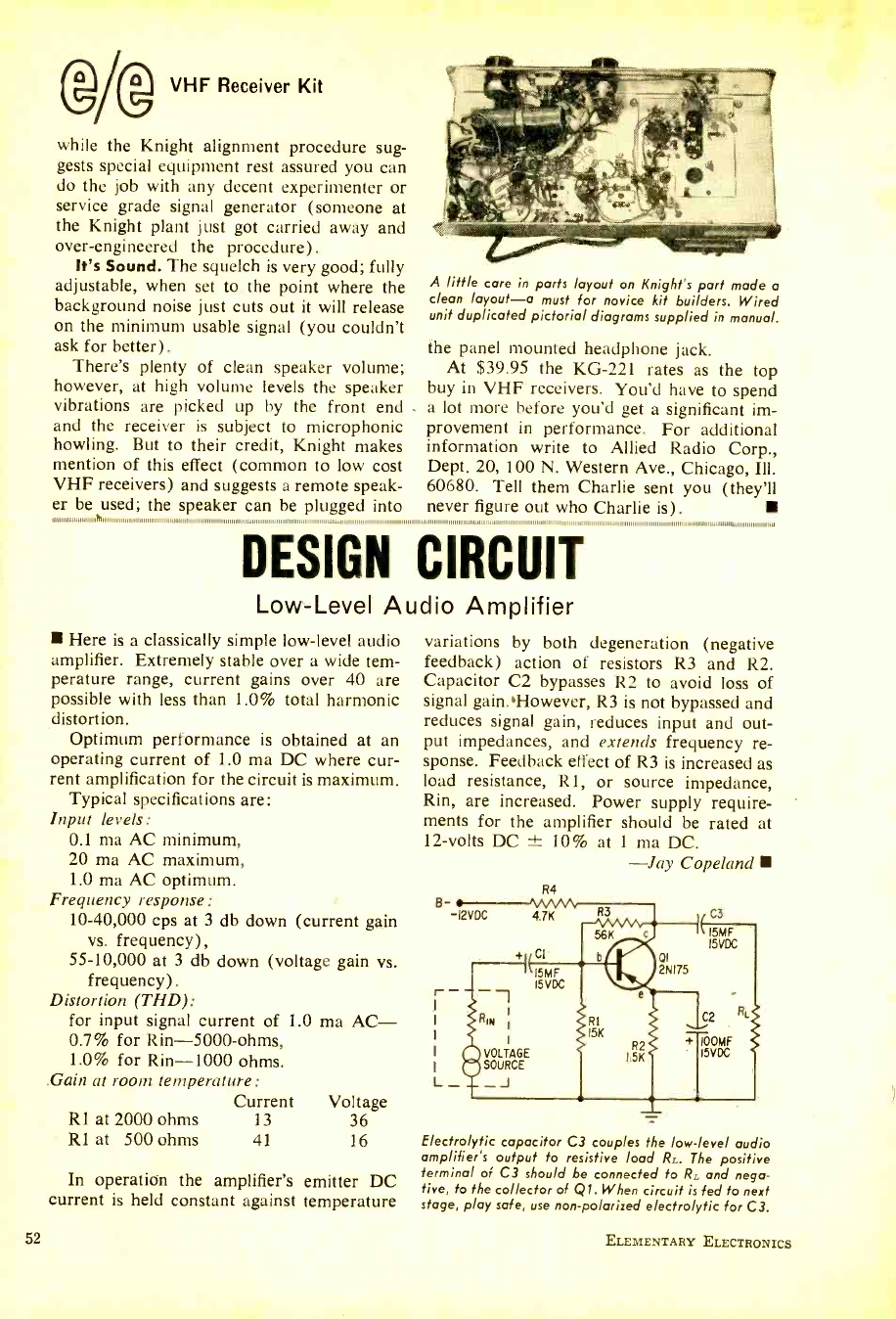
@AD VHF Receiver Kit
while the Knight alignment procedure sug-
gests special equipment rest assured you can
do the job with any decent experimenter or
service grade signal generator (someone at
the Knight plant just got carried away and
over -engineered the procedure).
It's Sound. The squelch is very good; fully
adjustable, when set to the point where the
background noise just cuts out it will release
on the minimum usable signal (you couldn't
ask for better).
There's plenty of clean speaker volume;
however, at high volume levels the speaker
vibrations are picked up by the front end -
and the receiver is subject to microphonic
howling. But to their credit, Knight makes
mention of this effect (common to low cost
VHF receivers) and suggests a remote speak-
er be used; the speaker can he plugged into
A little care in parts layout on Knight's part made a
clean layout -a must for novice kit builders. Wired
unit duplicated pictorial diagrams supplied in manual.
the panel mounted headphone jack.
At $39.95 the KG -221 rates as the top
buy in VHF receivers. You'd have to spend
a lot more before you'd get a significant im-
provement in performance. For additional
information write to Allied Radio Corp.,
Dept. 20, 100 N. Western Ave., Chicago, Ill.
60680. Tell them Charlie sent you (they'll
never figure out who Charlie is).
o,,,,,,,,,,11,1111,111>w111,1,1,1,111111,,,,,11111111111111,111,111111,,,1,,.1,11111,1,,,,,,11,,,,,,,,,,,,,,1 _.,,,1111,1111,11,,,,,,1,1,1111111111111111111111,1,111,,111,1111, ,
DESIGN CIRCUIT
Low -Level Audio Amplifier
Here is a classically simple low -level audio
amplifier. Extremely stable over a wide tem-
perature range, current gains over 40 are
possible with less than 1.0% total harmonic
distortion.
Optimum performance is obtained at an
operating current of 1.0 ma DC where cur-
rent amplification for the circuit is maximum.
Typical specifications are:
Input levels:
0.1 ma AC minimum,
20 ma AC maximum,
1.0 ma AC optimum.
Frequency response:
10- 40,000 cps at 3 db down (current gain
vs. frequency),
55- 10,000 at 3 db down (voltage gain vs.
frequency).
Distortion (THD):
for input signal current of 1.0
0.7% for Rin -5000 -ohms,
1.0% for Rin -1000 ohms.
.Gain at room temperature:
Current
R1 at 2000 ohms 13
R1 at 500 ohms 41
ma AC-
Voltage
36
16
In operation the amplifier's emitter DC
current is held constant against temperature
52
variations by both degeneration (negative
feedback) action of resistors R3 and R2.
Capacitor C2 bypasses R2 to avoid loss of
signal gain.However, R3 is not bypassed and
reduces signal gain, reduces input and out-
put impedances, and extends frequency re-
sponse. Feedback effect of R3 is increased as
load resistance, R1, or source impedance,
Rin, are increased. Power supply require-
ments for the amplifier should be rated at
12 -volts DC 10% at 1 ma DC.
-Jay Copeland
R4
B -I2VDC 4.7K
r
L-_J
+i CI-
I5MF
I5 VDC
RIN
VOLTAGE
SOURCE
R3
DI 2N175
RI I5K
R2
1.5K
C3
15 I5VDC
C2
RL
'00MF
I5VDC
Electrolytic capacitor C3 couples the low -level audio
amplifier's output to resistive load RL. The positive
terminal of C3 should be connected to RL and nega-
tive, to the collector of Q1. When circuit is fed to next
stage, play safe, use non -polarized electrolytic for C3.
ELEMENTARY ELECTRONICS
www.americanradiohistory.com
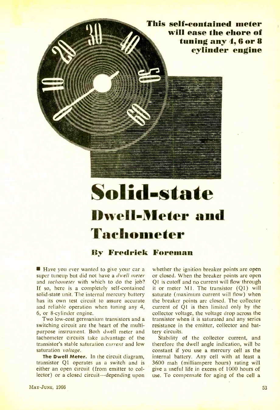
This self -contained meter
will ease the chore of
tuning any 4, 6 or 8
cylinder engine
Solid- state
Dwell -Meter and
Tachometer
By Fredrick Foreman
Have you ever wanted to give your car a
super tuneup but did not have a dwell meter
and tachometer with which to do the job?
If so, here is a completely self- contained
solid -state unit. The internal mercury battery
has its own test circuit to assure accurate
and reliable operation when tuning any 4,
6, or 8- cylinder engine.
Two low -cost germanium transistors and a
switching circuit are the heart of the multi-
purpose instrument. Both dwell meter and
tachometer circuits take advantage of the
transistor's stable saturation current and low
saturation voltage.
The Dwell Meter. In the circuit diagram,
transistor Q1 operates as a switch and is
either an open circuit (from emitter to col-
lector) or a closed circuit -depending upon
MAY -JUNE, 1966
whether the ignition breaker points are open
or closed. When the breaker points are open
Q1 is cutoff and no current will flow through
it or meter M1. The transistor (QI) will
saturate (maximum current will flow) when
the breaker points are closed. The collector
current of Q1 is then limited only by the
collector voltage, the voltage drop across the
transistor when it is saturated and any series
resistance in the emitter, collector and bat-
tery circuits.
Stability of the collector current, and
therefore the dwell angle indication, will be
constant if you use a mercury cell as the
internal battery. Any cell with at least a
3600 mah (milliampere hours) rating will
give a useful life in excess of 1000 hours of
use. To compensate for aging of the cell a
53
www.americanradiohistory.com
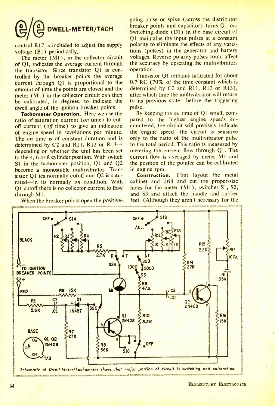
R6 I5K
C1 01
+N
IN457 S2C
;R7
.27K
DWELL- METER /TACH
control R17 is included to adjust the supply
voltage (BI) periodically.
The meter (M1), in the collector circuit
of Ql, indicates the average current through
the transistor. Since transistor Q1 is con-
trolled by the breaker points the average
current through Q1 is proportional to the
amount of time the points are closed and the
meter (M 1) in the collector circuit can then
be calibrated, in degrees, to indicate the
dwell angle of the ignition breaker points.
Tachometer Operation. Here we use the
ratio of saturation current (on time) to cut-
off current (off time) to give an indication
of engine speed in revolutions per minute.
The on time is of constant duration and is
determined by C2 and R11, R12 or R13-
depending on whether the unit has been set
to the 4, 6 or 8 cylinder position. With switch
Sl in the tachometer position, Q1 and Q2
become a monostable multivibrator. Tran-
sistor Q1 ics normally cutoff and Q2 is satu-
rated-in its normally on condition. With
Q1 cutoff there is no collector current to flow
through Ml.
When the breaker points open the positive-
going pulse or spike (across the distributor
breaker points and capacitor) turns Q1 on.
Switching diode (Dl) in the base circuit of
Q1 maintains the input pulses at a constant
polarity to eliminate the effects of any varia-
tions (pulses) in the generator and battery
voltages. Reverse polarity pulses could affect
the accuracy by upsetting the multivibrators
operation.
Transistor Q1 remains saturated for about
0.7 RC (70% of the time constant which is
determined by C2 and R11, R12 or R13),
after which time the multivibrator will return
to its previous state -before the triggering
pulse.
By keeping the on time of Q1 small, com-
pared to the highest engine speeds en-
countered, the circuit will precisely indicate
the engine speed -the circuit is sensitive
only to the ratio of the multivibrator pulse
to the total period. This ratio is measured by
metering the current flow through Ql. The
current flow is averaged by meter MI. and
the position of the pointer can be calibrated
in engine rpm.
Construction. First layout the metal
cabinet and drill and cut the proper -size
holes for the meter (M1), switches Si, S2,
and S3 and attach the handle and rubber
feet. (Although they aren't necessary for the
BLACK
TO IGNITION
BREAKER POINTS
u+
RED
R2 R3 R4
R5
2.TK D
S2A
5.6K .01
BASE
01, 02
2N408
TAB
MI
2N408
R8
56K SIC
S3
R9
47A
RIO
8.2K
OFF
( C2
R14
27K
02
R15
2.2K
2N408
BI
I.35V
R16
I5K
RI7
IOOa
Schematic of Dwell- Meter /Tachometer shows that major portion of circuit is switching and calibration.
59 ELEMENTARY ELECTRONICS
www.americanradiohistory.com
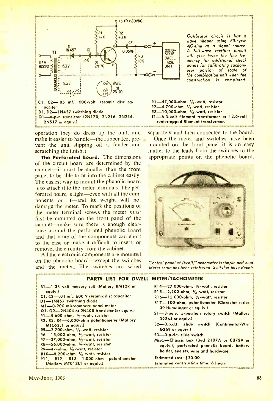
,,,,,,,..,,,,,,,,,,,,,,..,,,,..,.
T1
115 V
60CPS
,1111 ,,,,, ,,,,
;R3
'10K
:3.3V oc\ BASE
b 2N170
o e/
Cl, C2 -.05 mf., 600 -volt, ceramic disc ca-
pacitor
D1, D2 -1N457 switching diode.
01 -n -p -n transistor (2N170, 2N216, 2N254,
2N517 or equiv.)
SOLID -
STATE
DWELL
TACH.
UNIT
11 11 1111 11 1,,,,1,,,,,,,,,,1,1,,
Calibrator circuit is just a
wave shaper using 60 -cycle
AC -line as a signal source.
A full -wave rectifier circuit
will give twice the line fre-
quency for additional check
points for calibrating tachom-
eter portion of scale of
the combination unit when the
construction is completed.
R1- 47,000 -ohm, 1/2-watt, resistor
R2- 4,700 -ohm, 1/2-watt, resistor
R3- 10,000 -ohm, 1/2 -watt, resistor
T1 -6.3 -volt filament transformer or 12.6 -volt
centertapped filament transformer.
operation they do dress up the unit, and
make it easier to handle -the rubber feet pre-
vent the unit slipping off a fender and
scratching the finish.)
The Perforated Board. The dimensions
of the circuit board are determined by the
cabinet -it must be smaller than the front
panel to be able to fit into the cabinet easily.
The easiest way to mount the phenolic board
is to attach it to the meter terminals. The per-
forated board is light -even with all the com-
ponents on it -and its weight will not
damage the meter. To mark the positions of
the meter terminal screws the meter must
first be mounted on the front panel of the
cabinet -make sure there is enough clear-
ance around the perforated phenolic board
and that none of the components can short
to the case or make it difficult to insert, or
remove, the circuitry from the cabinet.
All the electronic components are mounted
on the phenolic board -except the switches
and the meter. The switches are wired
separately and then connected to the board.
Once the meter and switches have been
mounted on the front panel it is an easy
matter to the leads from the switches to the
appropriate points on the phenolic board.
Control panel of Dwell /Tachometer is simple and neat.
Meter scale has been re/ettered. Switches have decals.
PARTS LIST FOR DWEL
B1 -1.35 volt mercury cell (Mallory RM12R or
equiv.)
Cl, C2 -.01 mf., 600 V ceramic disc capacitor
D1-1N457 switching diode
M1 -0 -200 microampere panel meter
01, 02 -2N404 or 2N408 transistor (or equiv.)
RI- 5,600 -ohm, l/2 -watt, resistor
R2, R3, R4- 6,000 -ohm potentiometer (Mallory
MTC63L1 or equiv.)
R5- 2,700 -ohm, 1/2 -watt, resistor
R6 -1 5,000 -ohm, 1/2 -watt, resistor
R7- 27,000 -ohm, 1/2-watt, resistor
R8- 56,000 -ohm, 1/2 -watt, resistor
R9-47 -ohm, 1/2-watt, resistor
R10- 8,200 -ohm, 1/2 watt, resistor
R11, R12, R13- 1,000 -ohm potentiometer
(Mallory MTC13L1 or equiv.)
L METER /TACHOMETER
R14- 27,000 -ohm, 1/2 -watt, resistor
R15- 2,200 -ohm, 1/2 -watt, resistor
R16- 15,000 -ohm, 1/2-watt, resistor
R17- 100 -ohm, potentiometer (Clarostat series
39 Humdinger or equiv.)
51 -3 -pole, 5- position rotary switch (Mallory
3236J or equiv.)
52- 3.p.d.t. slide switch (Continental -Wirt
G369 or equiv.)
S3- D.p.d.t. slide switch
Misc.- Chassis box (Bud 2107A or CU729 or
equiv.), perforated phenolic board, battery
holder, eyelets, wire and hardware.
Estimated cost: $20.00
Estimated construction time: 6 hours
lunii,ii,aiiii,iiiii,iiimminuililillilliiil 1111111111111111111111111111, 1,11111111111111111111,111111,1111,,,,11111111111,111111111,11111111111111111111111111,111,,,,,11,,,,,,,.1.111,.
MAY -JUNE, 1966 55
www.americanradiohistory.com
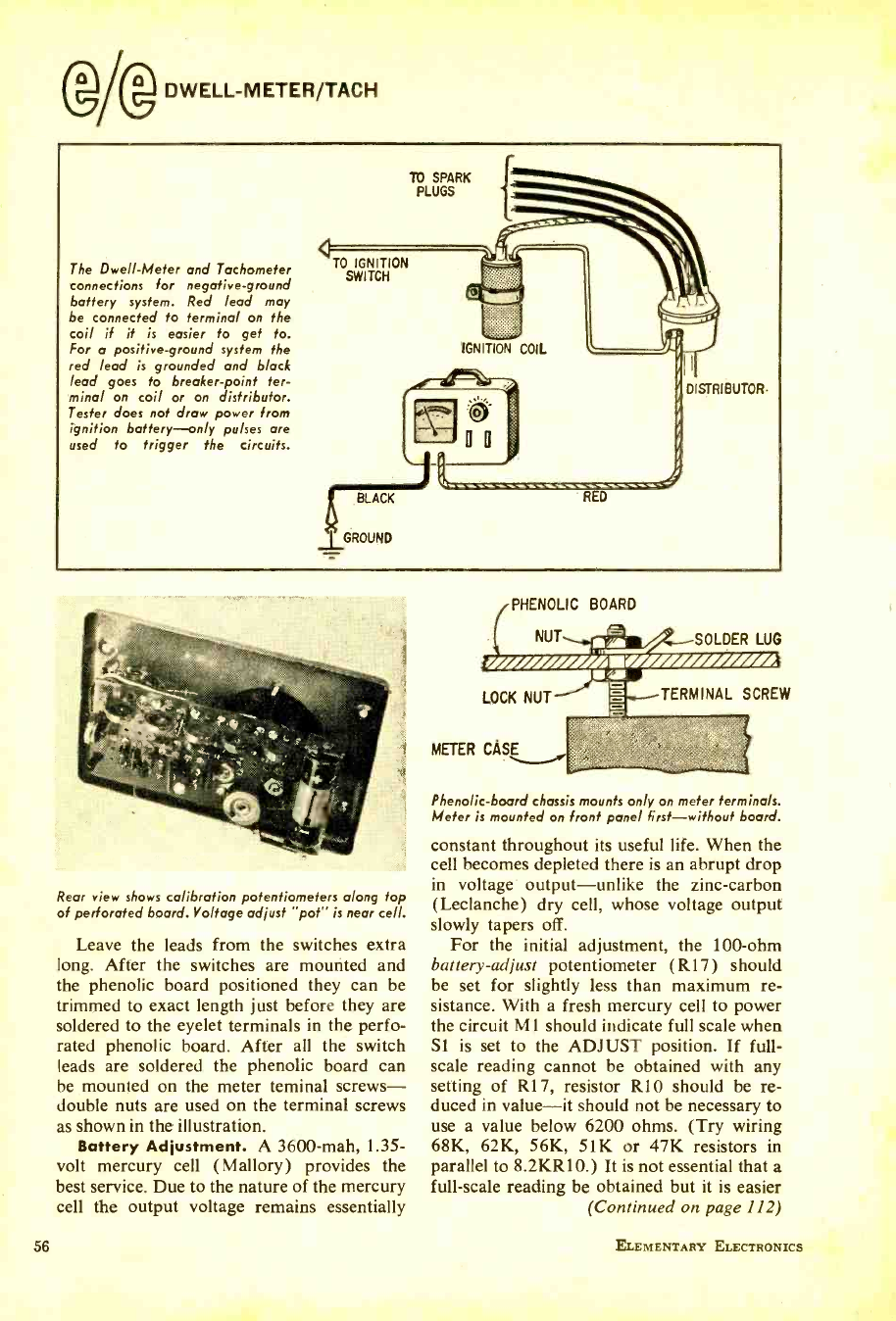
DWELL- METER /TACH
The Dwell -Meter and Tachometer
connections for negative -ground
battery system. Red lead may
be connected fo terminal on the
coil if it is easier to get to.
For a positive- ground system the
red lead is grounded and black
lead goes to breaker -point ter-
minal on coil or on distributor.
Tester does not draw power from
ignition battery -only pulses are
used to trigger the circuits.
TO IGNITION
SWITCH
BLACK
GROUND
TO SPARK
PLUGS
DISTRIBUTOR-
RED
Rear view shows calibration potentiometers along top
of perforated board. Voltage adjust "pot" is near cell.
Leave the leads from the switches extra
long. After the switches are mounted and
the phenolic board positioned they can be
trimmed to exact length just before they are
soldered to the eyelet terminals in the perfo-
rated phenolic board. After all the switch
leads are soldered the phenolic board can
be mounted on the meter teminal screws -
double nuts are used on the terminal screws
as shown in the illustration.
Battery Adjustment. A 3600 -mah, 1.35 -
volt mercury cell (Mallory) provides the
best service. Due to the nature of the mercury
cell the output voltage remains essentially
56
PHENOLIC BOARD
NUT
LOCK NUT
METER CASE
Phenolic -board chassis mounts only on meter terminals.
Meter is mounted on front panel first -without board.
constant throughout its useful life. When the
cell becomes depleted there is an abrupt drop
in voltage output -unlike the zinc- carbon
(Leclanche) dry cell, whose voltage output
slowly tapers off.
For the initial adjustment, the 100 -ohm
battery- adjust potentiometer (R17) should
be set for slightly less than maximum re-
sistance. With a fresh mercury cell to power
the circuit Mt should indicate full scale when
Si is set to the ADJUST position. If full -
scale reading cannot be obtained with any
setting of R17, resistor RIO should be re-
duced in value -it should not be necessary to
use a value below 6200 ohms. (Try wiring
68K, 62K, 56K, 51K or 47K resistors in
parallel to 8.2KR10.) It is not essential that a
full -scale reading be obtained but it is easier
(Continued on page 112)
TERMINAL SCREW
ELEMENTARY ELECTRONICS
www.americanradiohistory.com
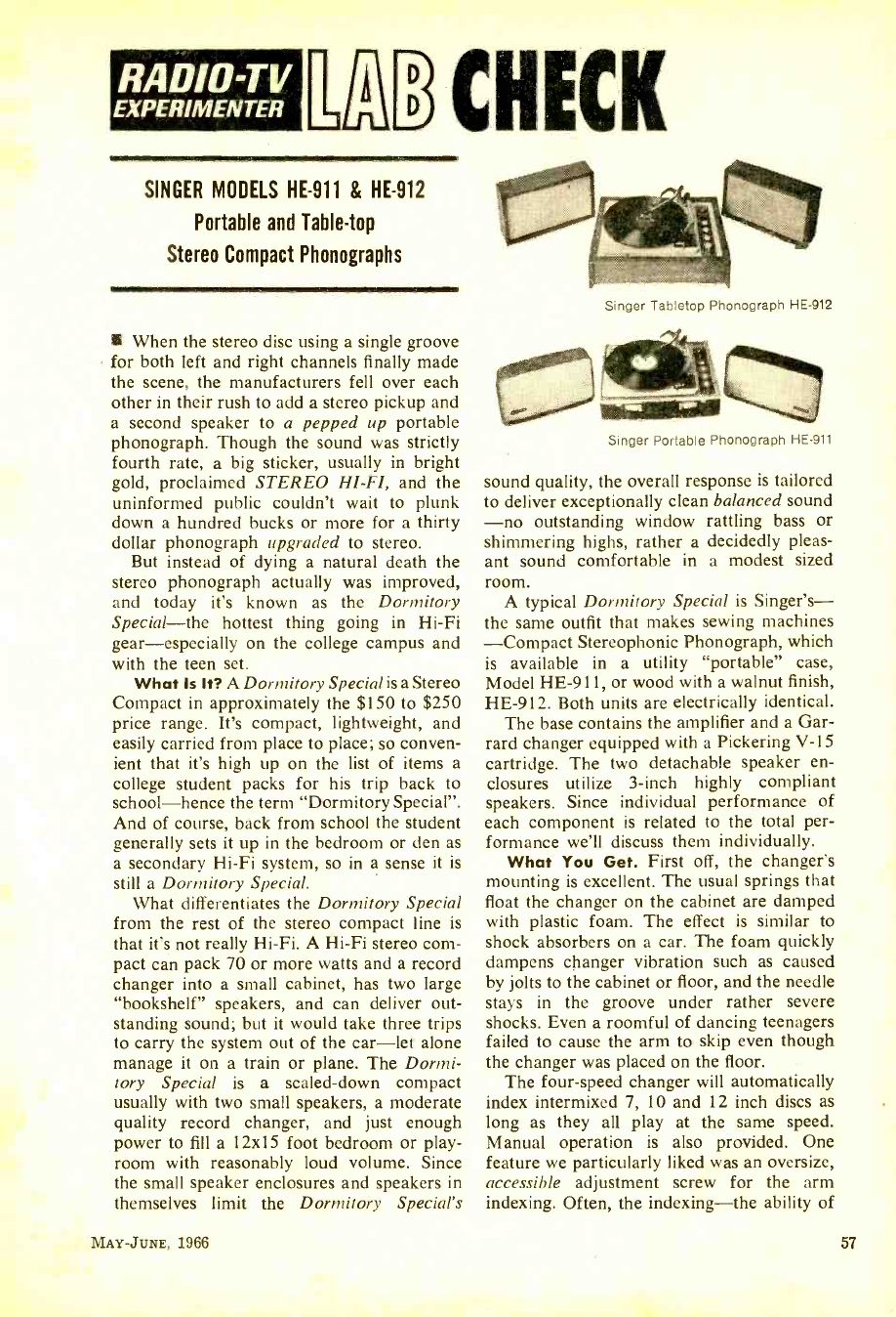
RADIO-TV
EXPERIMENTER EIHECK
SINGER MODELS HE -911 & HE -912
Portable and Table -top
Stereo Compact Phonographs
When the stereo disc using a single groove
for both left and right channels finally made
the scene, the manufacturers fell over each
other in their rush to add a stereo pickup and
a second speaker to a pepped up portable
phonograph. Though the sound was strictly
fourth rate, a big sticker, usually in bright
gold, proclaimed STEREO HI -FI, and the
uninformed public couldn't wait to plunk
down a hundred bucks or more for a thirty
dollar phonograph upgraded to stereo.
But instead of dying a natural death the
stereo phonograph actually was improved,
and today it's known as the Dormitory
Special -the hottest thing going in Hi -Fi
gear- especially on the college campus and
with the teen set.
What Is It? A Dormitory Special is a Stereo
Compact in approximately the $150 to $250
price range. It's compact, lightweight, and
easily carried from place to place; so conven-
ient that it's high up on the list of items a
college student packs for his trip back to
school -hence the term "Dormitory Special ".
And of course, back from school the student
generally sets it up in the bedroom or den as
a secondary Hi -Fi system, so in a sense it is
still a Dormitory Special.
What differentiates the Dormitory Special
from the rest of the stereo compact line is
that it's not really Hi -Fi. A Hi -Fi stereo com-
pact can pack 70 or more watts and a record
changer into a small cabinet, has two large
"bookshelf" speakers, and can deliver out-
standing sound; but it would take three trips
to carry the system out of the car -let alone
manage it on a train or plane. The Dormi-
tory Special is a scaled -down compact
usually with two small speakers, a moderate
quality record changer, and just enough
power to fill a 12x15 foot bedroom or play-
room with reasonably loud volume. Since
the small speaker enclosures and speakers in
themselves limit the Dormitory Special's
MAY -JUNE, 1966
Singer Tabletop Phonograph HE -912
Singer Portable Phonograph HE -911
sound quality, the overall response is tailored
to deliver exceptionally clean balanced sound
-no outstanding window rattling bass or
shimmering highs, rather a decidedly pleas-
ant sound comfortable in a modest sized
room.
A typical Dormitory Special is Singer's -
the same outfit that makes sewing machines
-Compact Stereophonic Phonograph, which
is available in a utility "portable" case,
Model HE -911, or wood with a walnut finish,
HE -912. Both units are electrically identical.
The base contains the amplifier and a Gar-
rard changer equipped with a Pickering V -15
cartridge. The two detachable speaker en-
closures utilize 3 -inch highly compliant
speakers. Since individual performance of
each component is related to the total per-
formance we'll discuss them individually.
What You Get. First off, the changer's
mounting is excellent. The usual springs that
float the changer on the cabinet are damped
with plastic foam. The effect is similar to
shock absorbers on a car. The foam quickly
dampens changer vibration such as caused
by jolts to the cabinet or floor, and the needle
stays in the groove under rather severe
shocks. Even a roomful of dancing teenagers
failed to cause the arm to skip even though
the changer was placed on the floor.
The four -speed changer will automatically
index intermixed 7, 10 and 12 inch discs as
long as they all play at the same speed.
Manual operation is also provided. One
feature we particularly liked was an oversize,
accessible adjustment screw for the arm
indexing. Often, the indexing -the ability of
57
www.americanradiohistory.com
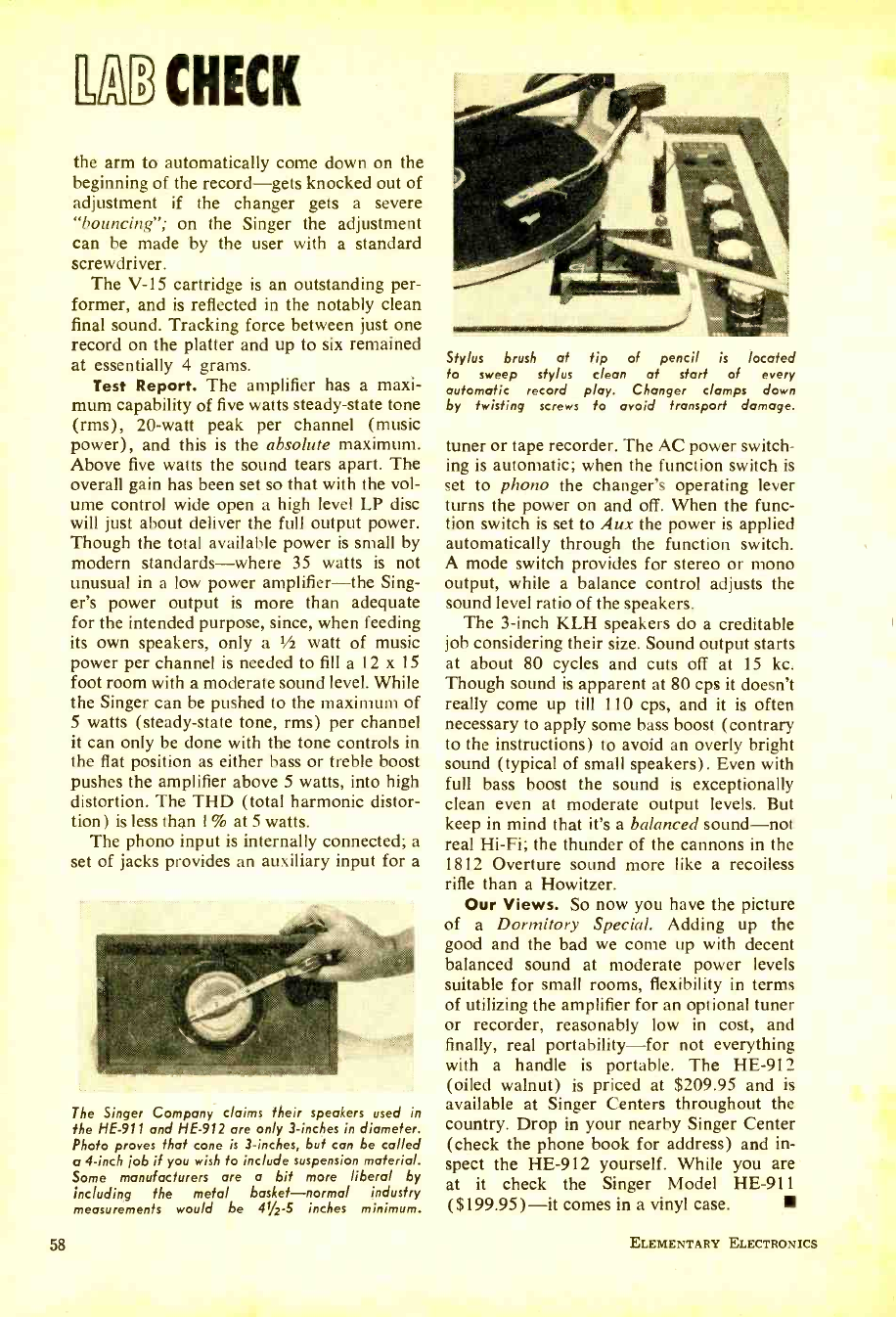
dpa CHECK
the arm to automatically come down on the
beginning of the record -gets knocked out of
adjustment if the changer gets a severe
"bouncing "; on the Singer the adjustment
can be made by the user with a standard
screwdriver.
The V -15 cartridge is an outstanding per-
former, and is reflected in the notably clean
final sound. Tracking force between just one
record on the platter and up to six remained
at essentially 4 grams.
Test Report. The amplifier has a maxi-
mum capability of five watts steady -state tone
(rms), 20 -watt peak per channel (music
power), and this is the absolute maximum.
Above five watts the sound tears apart. The
overall gain has been set so that with the vol-
ume control wide open a high level LP disc
will just about deliver the full output power.
Though the total available power is small by
modern standards -where 35 watts is not
unusual in a low power amplifier -the Sing-
er's power output is more than adequate
for the intended purpose, since, when feeding
its own speakers, only a I/2 watt of music
power per channel is needed to fill a 12 x 15
foot room with a moderate sound level. While
the Singer can be pushed to the maximum of
5 watts (steady -state tone, rms) per channel
it can only be done with the tone controls in
the flat position as either bass or treble boost
pushes the amplifier above 5 watts, into high
distortion. The THD (total harmonic distor-
tion) is less than 1% at 5 watts.
The phono input is internally connected; a
set of jacks provides an auxiliary input for a
The Singer Company claims their speakers used in
the HE -911 and HE -912 are only 3- inches in diameter.
Photo proves that cone is 3- inches, but can be called
o 4 -inch ¡ob if you wish to include suspension material.
Some manufacturers are a bit more liberal by
including the metal basket -normal industry
measurements would be 41/2-S inches minimum.
58
Stylus brush at tip of pencil is located
to sweep stylus clean at start of every
automatic record play. Changer clamps down
by twisting screws to avoid transport damage.
tuner or tape recorder. The AC power switch-
ing is automatic; when the function switch is
set to phono the changer's operating lever
turns the power on and off. When the func-
tion switch is set to Aux the power is applied
automatically through the function switch.
A mode switch provides for stereo or mono
output, while a balance control adjusts the
sound level ratio of the speakers.
The 3 -inch KLH speakers do a creditable
job considering their size. Sound output starts
at about 80 cycles and cuts off at 15 kc.
Though sound is apparent at 80 cps it doesn't
really come up till 110 cps, and it is often
necessary to apply some bass boost (contrary
to the instructions) to avoid an overly bright
sound (typical of small speakers). Even with
full bass boost the sound is exceptionally
clean even at moderate output levels. But
keep in mind that it's a balanced sound -not
real Hi -Fi; the thunder of the cannons in the
1812 Overture sound more like a recoiless
rifle than a Howitzer.
Our Views. So now you have the picture
of a Dormitory Special. Adding up the
good and the bad we come up with decent
balanced sound at moderate power levels
suitable for small rooms, flexibility in terms
of utilizing the amplifier for an optional tuner
or recorder, reasonably low in cost, and
finally, real portability -for not everything
with a handle is portable. The HE -912
(oiled walnut) is priced at $209.95 and is
available at Singer Centers throughout the
country. Drop in your nearby Singer Center
(check the phone book for address) and in-
spect the HE -912 yourself. While you are
at it check the Singer Model HE -911
($199.95) -it comes in a vinyl case.
ELEMENTARY ELECTRONICS
www.americanradiohistory.com
Theoretical explanations and some
practical experiments with circuits.
Two
Novel
Oscillators
By A. J. Cote, Jr.
Just about every child of three who has
managed to find enough time to pick up four
or more years of electronics background has
heard of the Colpitts and Hartley oscillator
circuits. And those of lesser experience have
probably encountered them without realizing
it. They are circuit classics found in almost
every book that pretends to treat electronic
circuits.
But how many of you have ever heard of
the Y -type and Z -type oscillators?
Well, I'll introduce you to these two cir-
cuits and show you why they are fundamen-
tally just as basic as the Hartley and Colpitts
configurations. And we'll also point out why
these little known wonders apparently weren't
discovered until about ten years ago.
We'll begin by briefly reviewing some im-
portant aspects of oscillators and refresh your
memories as to the form of the Hartley and
Colpitts circuits. We will also review what
components are important in determining the
frequency of oscillation and frequency sta-
bility of all four oscillators. Then we'll move
MAY -JUNE, 1966
to the workbench, breadboard a couple of
the Z -type circuits and discuss their perform-
ance. Basic Ingredients. Every component in
an electronic circuit is there to perform a par-
ticular function which will contribute to the
overall performance of the circuit. Some-
times a component will do extra duty and
handle more than one job. But they generally
have only one primary mission.
In any oscillator circuit, there are three
functions that must be fulfilled. One group of
components will combine to insure proper
feedback conditions and also determine the
frequency at which the circuit oscillates. An-
other will provide the necessary power gain.
And the third group will determine the op-
erating conditions of the circuit. Since this
third group is found in all types of circuits,
we'll ignore it initially, because it will detract
from our focus on the conditions that influ-
ence oscillator performance.
Some Basic Oscillators. There are so
many ways to build an oscillator that it some-
59
www.americanradiohistory.com
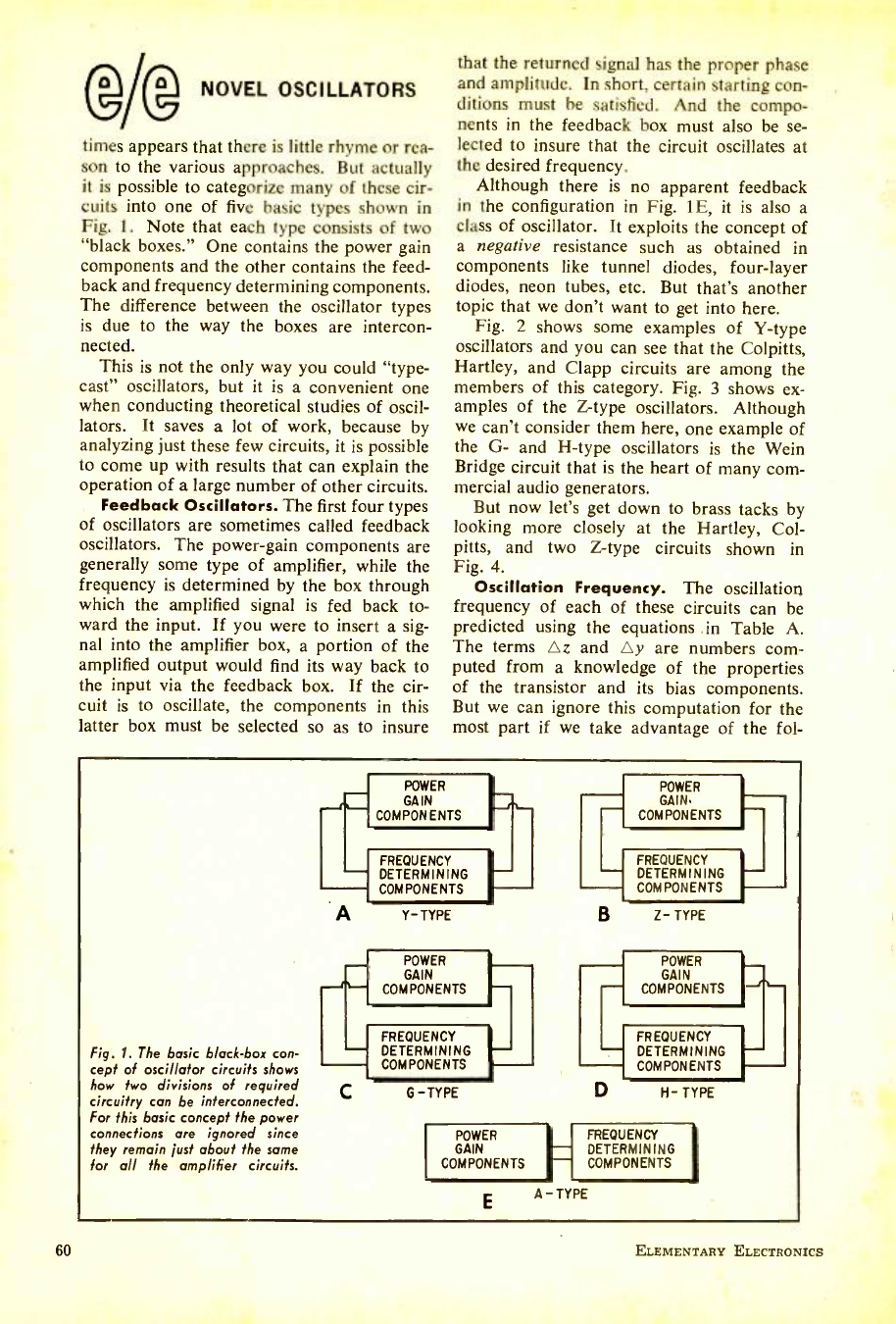
60
NOVEL OSCILLATORS
times appears that there is little rhyme or rea-
son to the various approaches. But actually
it is possible to categorize many of these cir-
cuits into one of five basic types shown in
Fig. 1. Note that each type consists of two
"black boxes." One contains the power gain
components and the other contains the feed-
back and frequency determining components.
The difference between the oscillator types
is due to the way the boxes are intercon-
nected.
This is not the only way you could "type-
cast" oscillators, but it is a convenient one
when conducting theoretical studies of oscil-
lators. It saves a lot of work, because by
analyzing just these few circuits, it is possible
to come up with results that can explain the
operation of a large number of other circuits.
Feedback Oscillators. The first four types
of oscillators are sometimes called feedback
oscillators. The power -gain components are
generally some type of amplifier, while the
frequency is determined by the box through
which the amplified signal is fed back to-
ward the input. If you were to insert a sig-
nal into the amplifier box, a portion of the
amplified output would find its way back to
the input via the feedback box. If the cir-
cuit is to oscillate, the components in this
latter box must be selected so as to insure
that the returned signal has the proper phase
and amplitude. In short, certain starting con-
ditions must be satisfied. And the compo-
nents in the feedback box must also be se-
lected to insure that the circuit oscillates at
the desired frequency.
Although there is no apparent feedback
in the configuration in Fig. 1E, it is also a
class of oscillator. It exploits the concept of
a negative resistance such as obtained in
components like tunnel diodes, four -layer
diodes, neon tubes, etc. But that's another
topic that we don't want to get into here.
Fig. 2 shows some examples of Y -type
oscillators and you can see that the Colpitts,
Hartley, and Clapp circuits are among the
members of this category. Fig. 3 shows ex-
amples of the Z -type oscillators. Although
we can't consider them here, one example of
the G- and H -type oscillators is the Wein
Bridge circuit that is the heart of many com-
mercial audio generators.
But now let's get down to brass tacks by
looking more closely at the Hartley, Col -
pitts, and two Z -type circuits shown in
Fig. 4.
Oscillation Frequency. The oscillation
frequency of each of these circuits can be
predicted using the equations in Table A.
The terms Az and Ay are numbers com-
puted from a knowledge of the properties
of the transistor and its bias components.
But we can ignore this computation for the
most part if we take advantage of the fol-
Fig. 1. The basic black -box con-
cept of oscillator circuits shows
how two divisions of required
circuitry can be interconnected.
For this basic concept the power
connections are ignored since
they remain just about the same
for all the amplifier circuits.
POWER
GAIN
COMPONENTS
FREQUENCY
DETERMINING
COMPONENTS
A Y- TYPE
POWER k
GAIN.
COMPONENTS
H_
FREQUENCY
DETERMINING
COMPONENTS
B Z- TYPE
POWER POWER
GAIN GAIN
COMPONENTS COMPONENTS
FREQUENCY
DETERMINING
COMPONENTS
C G-TYPE
POWER
GAIN
COMPONENTS
E
FREQUENCY
DETERMINING
COMPONENTS
D H- TYPE
FREQUENCY
DETERMINING
COMPONENTS
A - TYPE
ELEMENTARY ELECTRONICS
www.americanradiohistory.com
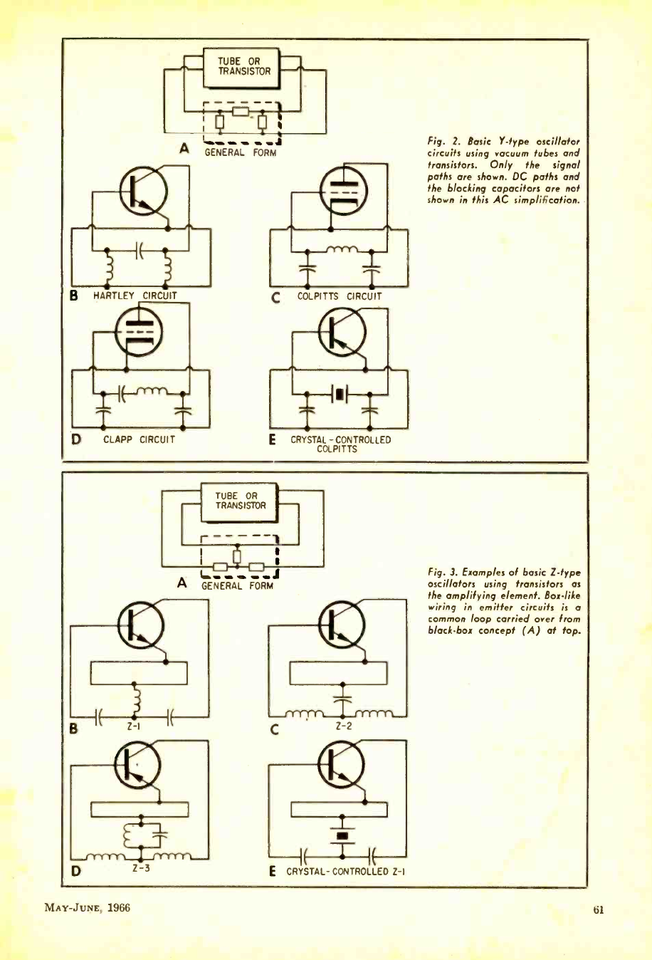
A
TUBE OR
TRANSISTOR
s o
I
GENERAL FORM
HARTLEY CIRCUIT
CLAPP CIRCUIT
C COLPITTS CIRCUIT
CRYSTAL - CONTROLLED
COLPITTS
Fig. 2. Basic Y -type oscillator
circuits using vacuum tubes and
transistors. Only the signal
paths are shown. DC paths and
the blocking capacitors are not
shown in this AC simplification.
TUBE OR
TRANSISTOR
I 1
A_GENERAL ö M,
Z 3 ( 1 I
E CRYSTAL- CONTROLLED Z -I
Fig. 3. Examples of basic Z -type
oscillators using transistors as
the amplifying element. Box -like
wiring in emitter circuits is a
common loop carried over from
black -box concept (A) at top.
MAY -JUNE, 1966 .,I
www.americanradiohistory.com
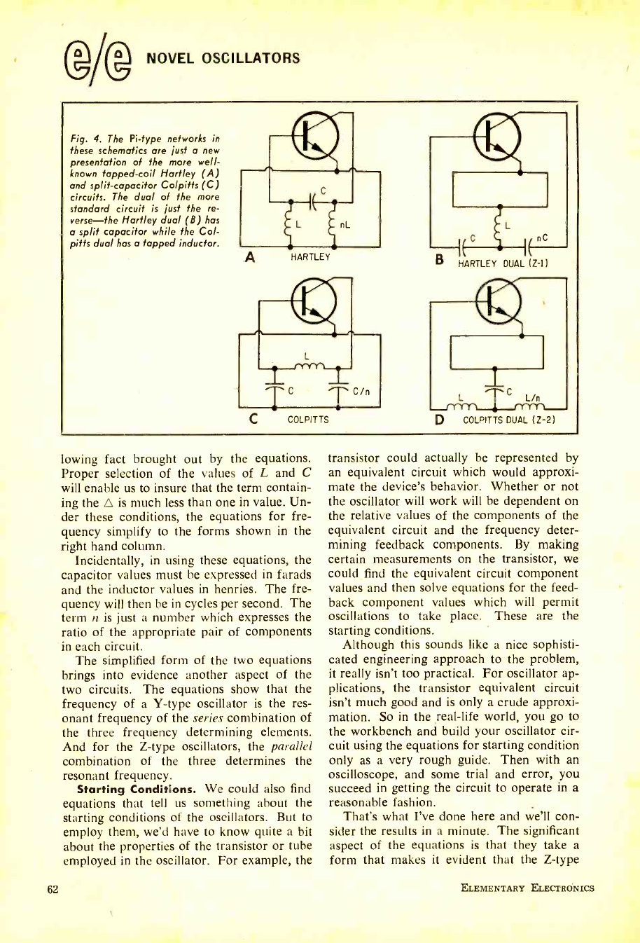
NOVEL OSCILLATORS
Fig. 4. The Pi -type networks in
these schematics are just a new
presentation of the more well -
known tapped -coil Hartley (A)
and split- capacitor Co!pitts (C)
circuits. The dual of the more
standard circuit is just the re-
verse -the Hartley dual (8) has
a split capacitor while the Cot-
pith dual has a tapped inductor.
HARTLEY
COLPITTS
HARTLEY DUAL (Z-11
COLPITTS DUAL (Z -2)
lowing fact brought out by the equations.
Proper selection of the values of L and C
will enable us to insure that the term contain-
ing the 0 is much less than one in value. Un-
der these conditions, the equations for fre-
quency simplify to the forms shown in the
right hand column.
Incidentally, in using these equations, the
capacitor values must be expressed in farads
and the inductor values in henries. The fre-
quency will then be in cycles per second. The
term n is just a number which expresses the
ratio of the appropriate pair of components
in each circuit.
The simplified form of the two equations
brings into evidence another aspect of the
two circuits. The equations show that the
frequency of a Y -type oscillator is the res-
onant frequency of the series combination of
the three frequency determining elements.
And for the Z -type oscillators, the parallel
combination of the three determines the
resonant frequency.
Starting Conditions. We could also find
equations that tell us something about the
starting conditions of the oscillators. But to
employ them, we'd have to know quite a bit
about the properties of the transistor or tube
employed in the oscillator. For example, the
62
transistor could actually be represented by
an equivalent circuit which would approxi-
mate the device's behavior. Whether or not
the oscillator will work will be dependent on
the relative values of the components of the
equivalent circuit and the frequency deter-
mining feedback components. By making
certain measurements on the transistor, we
could find the equivalent circuit component
values and then solve equations for the feed-
back component values which will permit
oscillations to take place. These are the
starting conditions.
Although this sounds like a nice sophisti-
cated engineering approach to the problem,
it really isn't too practical. For oscillator ap-
plications, the transistor equivalent circuit
isn't much good and is only a crude approxi-
mation. So in the real -life world, you go to
the workbench and build your oscillator cir-
cuit using the equations for starting condition
only as a very rough guide. Then with an
oscilloscope, and some trial and error, you
succeed in getting the circuit to operate in a
reasonable fashion.
That's what I've done here and we'll con-
sider the results in a minute. The significant
aspect of the equations is that they take a
form that makes it evident that the Z -type
ELEMENTARY ELECTRONICS
www.americanradiohistory.com
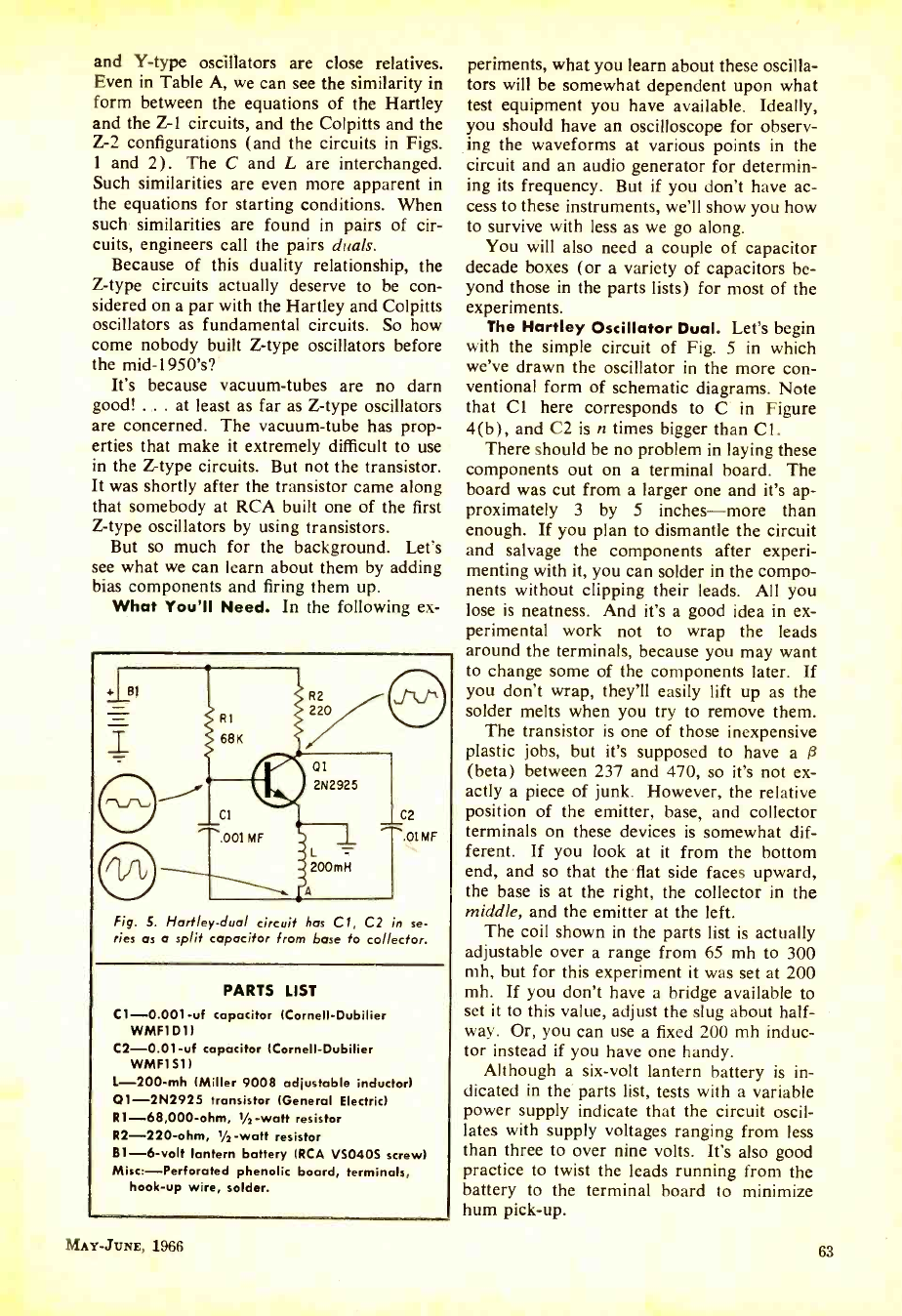
and Y -type oscillators are close relatives.
Even in Table A, we can see the similarity in
form between the equations of the Hartley
and the Z-1 circuits, and the Colpitts and the
Z-2 configurations (and the circuits in Figs.
1 and 2). The C and L are interchanged.
Such similarities are even more apparent in
the equations for starting conditions. When
such similarities are found in pairs of cir-
cuits, engineers call the pairs duals.
Because of this duality relationship, the
Z-type circuits actually deserve to be con-
sidered on a par with the Hartley and Colpitts
oscillators as fundamental circuits. So how
come nobody built Z -type oscillators before
the mid- 1950's?
It's because vacuum -tubes are no darn
good! ... at least as far as Z -type oscillators
are concerned. The vacuum -tube has prop-
erties that make it extremely difficult to use
in the Z -type circuits. But not the transistor.
It was shortly after the transistor came along
that somebody at RCA built one of the first
Z-type oscillators by using transistors.
But so much for the background. Let's
see what we can learn about them by adding
bias components and firing them up.
What You'll Need. In the following ex-
RI
68K
Ci
001 MF
A ul
2N2925
L 200m H
A
Fig. 5. Hartley -dual circuit has Cl, C2 'n se-
ries as a split capacitor from base to collector.
PARTS LIST
C1- 0.001 -uf capacitor (Cornell -Dubilier
WMF1D1)
C2- 0.01 -uf capacitor (Cornell- Dubilier
WMF151)
L- 200 -mh (Miller 9008 adjustable inductor)
Q1- 2N2925 transistor (General Electric)
R1- 68,000 -ohm, 1/2 -watt resistor
R2- 220 -ohm, 1/2-watt resistor
B1 -6 -volt lantern battery (RCA V50405 screw)
Misc:- Perforated phenolic board, terminals,
hook -up wire, solder.
MAY -JUNE, 1966
periments, what you learn about these oscilla-
tors will be somewhat dependent upon what
test equipment you have available. Ideally,
you should have an oscilloscope for observ-
ing the waveforms at various points in the
circuit and an audio generator for determin-
ing its frequency. But if you don't have ac-
cess to these instruments, we'll show you how
to survive with less as we go along.
You will also need a couple of capacitor
decade boxes (or a variety of capacitors be-
yond those in the parts lists) for most of the
experiments.
The Hartley Oscillator Dual. Let's begin
with the simple circuit of Fig. 5 in which
we've drawn the oscillator in the more con-
ventional form of schematic diagrams. Note
that Cl here corresponds to C in Figure
4(b), and C2 is n times bigger than Cl.
There should be no problem in laying these
components out on a terminal board. The
board was cut from a larger one and it's ap-
proximately 3 by 5 inches -more than
enough. If you plan to dismantle the circuit
and salvage the components after experi-
menting with it, you can solder in the compo-
nents without clipping their leads. All you
lose is neatness. And it's a good idea in ex-
perimental work not to wrap the leads
around the terminals, because you may want
to change some of the components later. If
you don't wrap, they'll easily lift up as the
solder melts when you try to remove them.
The transistor is one of those inexpensive
plastic jobs, but it's supposed to have a P
(beta) between 237 and 470, so it's not ex-
actly a piece of junk. However, the relative
position of the emitter, base, and collector
terminals on these devices is somewhat dif-
ferent. If you look at it from the bottom
end, and so that the flat side faces upward,
the base is at the right, the collector in the
middle, and the emitter at the left.
The coil shown in the parts list is actually
adjustable over a range from 65 mh to 300
mh, but for this experiment it was set at 200
mh. If you don't have a bridge available to
set it to this value, adjust the slug about half-
way. Or, you can use a fixed 200 mh induc-
tor instead if you have one handy.
Although a six -volt lantern battery is in-
dicated in the parts list, tests with a variable
power supply indicate that the circuit oscil-
lates with supply voltages ranging from less
than three to over nine volts. It's also good
practice to twist the leads running from the
battery to the terminal board to minimize
hum pick -up.
63
www.americanradiohistory.com
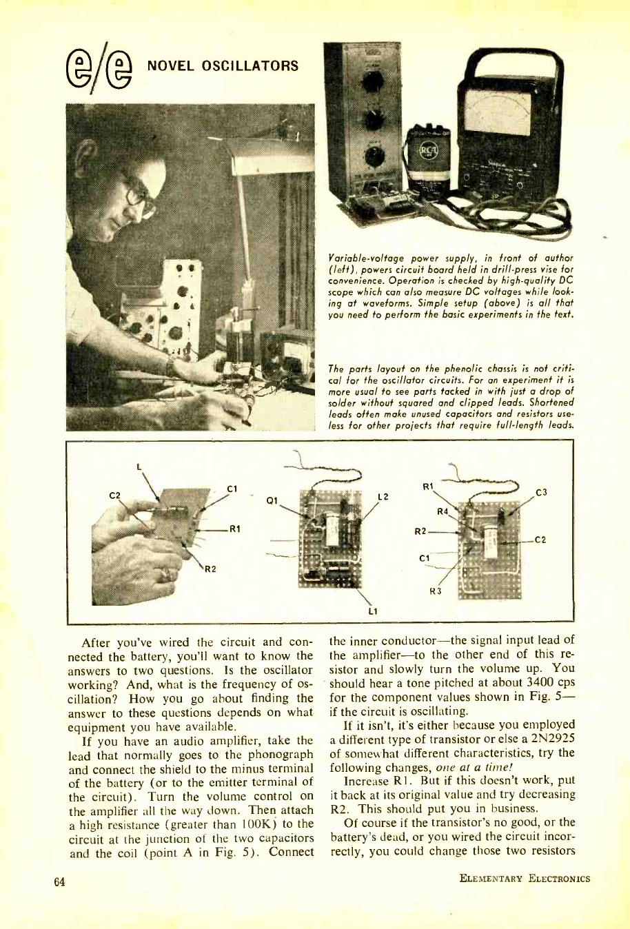
GM NOVEL OSCILLATORS
Variable -voltage power supply, in front of author
(left), powers circuit board held in drill -press vise for
convenience. Operation is checked by high- quality DC
scope which can also measure DC voltages while look-
ing at waveforms. Simple setup (above) is all that
you need to perform the basic experiments in the text.
The parts layout on the phenolic chassis is not criti-
cal for the oscillator circuits. For an experiment it is
more usual to see parts tacked in with just a drop of
solder without squared and clipped leads. Shortened
leads often make unused capacitors and resistors use-
less for other projects that require full -length leads.
After you've wired the circuit and con-
nected the battery, you'll want to know the
answers to two questions. Is the oscillator
working? And, what is the frequency of os-
cillation? How you go about finding the
answer to these questions depends on what
equipment you have available.
If you have an audio amplifier, take the
lead that normally goes to the phonograph
and connect the shield to the minus terminal
of the battery (or to the emitter terminal of
the circuit). Turn the volume control on
the amplifier all the way down. Then attach
a high resistance (greater than 100K) to the
circuit at the junction of the two capacitors
and the coil (point A in Fig. 5). Connect
64
the inner conductor -the signal input lead of
the amplifier -to the other end of this re-
sistor and slowly turn the volume up. You
should hear a tone pitched at about 3400 cps
for the component values shown in Fig. 5-
if the circuit is oscillating.
If it isn't, it's either because you employed
a different type of transistor or else a 2N2925
of somewhat different characteristics, try the
following changes, one at a time!
Increase Rl. But if this doesn't work, put
it back at its original value and try decreasing
R2. This should put you in business.
Of course if the transistor's no good, or the
battery's dead, or you wired the circuit incor-
rectly, you could change those two resistors
ELEMENTARY ELECTRONICS
www.americanradiohistory.com
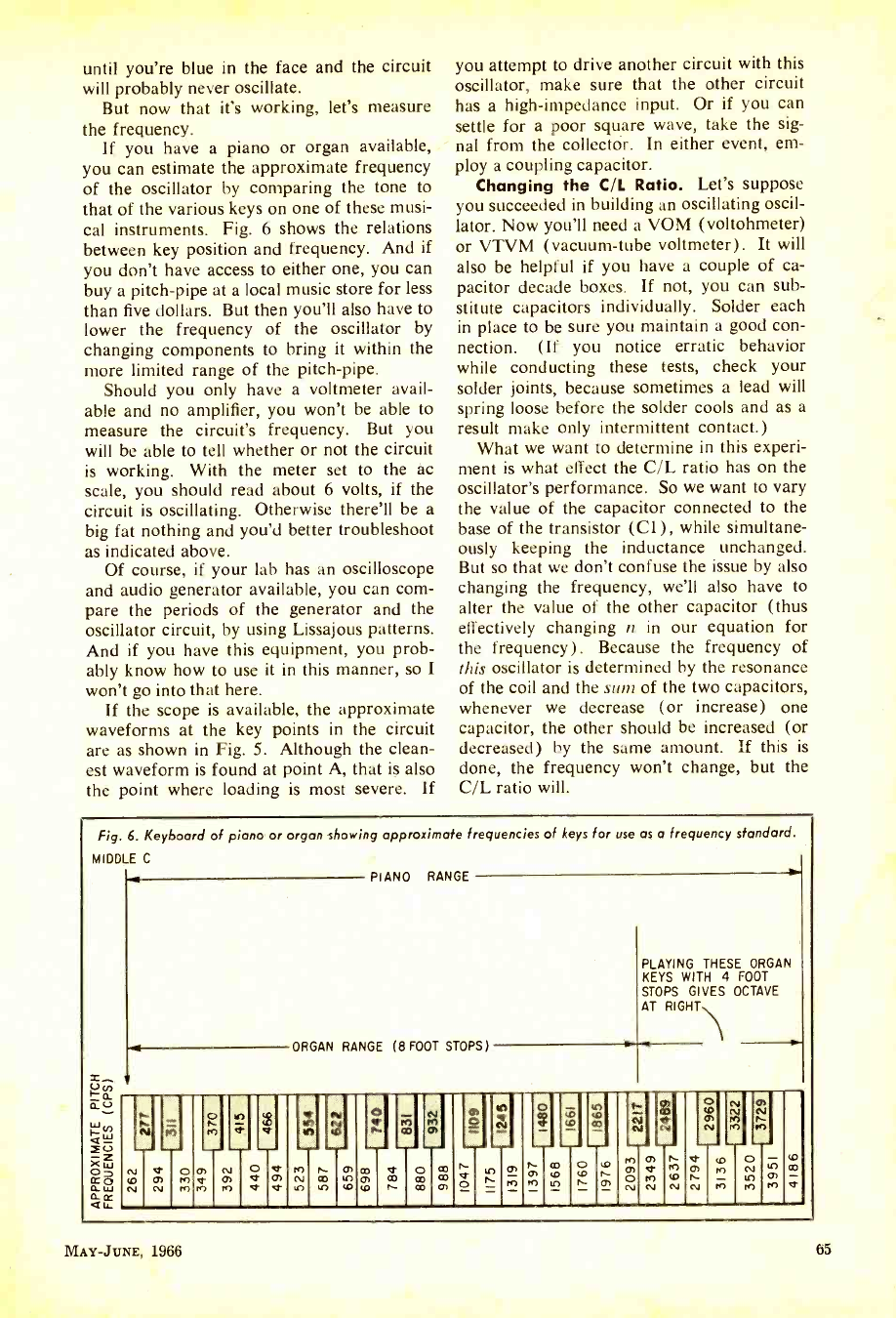
until you're blue in the face and the circuit
will probably never oscillate.
But now that it's working, let's measure
the frequency.
If you have a piano or organ available,
you can estimate the approximate frequency
of the oscillator by comparing the tone to
that of the various keys on one of these musi-
cal instruments. Fig. 6 shows the relations
between key position and frequency. And if
you don't have access to either one, you can
buy a pitch -pipe at a local music store for less
than five dollars. But then you'll also have to
lower the frequency of the oscillator by
changing components to bring it within the
more limited range of the pitch -pipe.
Should you only have a voltmeter avail-
able and no amplifier, you won't be able to
measure the circuit's frequency. But you
will be able to tell whether or not the circuit
is working. With the meter set to the ac
scale, you should read about 6 volts, if the
circuit is oscillating. Otherwise there'll be a
big fat nothing and you'd better troubleshoot
as indicated above.
Of course, if your lab has an oscilloscope
and audio generator available, you can com-
pare the periods of the generator and the
oscillator circuit, by using Lissajous patterns.
And if you have this equipment, you prob-
ably know how to use it in this manner, so I
won't go into that here.
If the scope is available, the approximate
waveforms at the key points in the circuit
are as shown in Fig. 5. Although the clean-
est waveform is found at point A, that is also
the point where loading is most severe. If
you attempt to drive another circuit with this
oscillator, make sure that the other circuit
has a high- impedance input. Or if you can
settle for a poor square wave, take the sig-
nal from the collector. In either event, em-
ploy a coupling capacitor.
Changing the C/L Ratio. Let's suppose
you succeeded in building an oscillating oscil-
lator. Now you'll need a VOM (voltohmeter)
or VTVM (vacuum -tube voltmeter). It will
also be helpful if you have a couple of ca-
pacitor decade boxes. If not, you can sub-
stitute capacitors individually. Solder each
in place to be sure you maintain a good con-
nection. (If you notice erratic behavior
while conducting these tests, check your
solder joints, because sometimes a lead will
spring loose before the solder cools and as a
result make only intermittent contact.)
What we want to determine in this experi-
ment is what effect the C/L ratio has on the
oscillator's performance. So we want to vary
the value of the capacitor connected to the
base of the transistor (Cl), while simultane-
ously keeping the inductance unchanged.
But so that we don't confuse the issue by also
changing the frequency, we'll also have to
alter the value of the other capacitor (thus
effectively changing n in our equation for
the frequency). Because the frequency of
this oscillator is determined by the resonance
of the coil and the sum of the two capacitors,
whenever we decrease (or increase) one
capacitor, the other should be increased (or
decreased) by the same amount. If this is
done, the frequency won't change, but the
C/L ratio will.
Fig. 6. Keyboard of piano or organ showing approximate frequencies of keys for use as a frequency standard.
MIDDLE C
PIANO RANGE
+ ORGAN RANGE (8 FOOT STOPS)
PLAYING THESE ORGAN
KEYS WITH 4 FOOT
STOPS GIVES OCTAVE
AT RIGHT
ti
N
tNo
N
v a>
N o n3 as
M
o M
rn to
o v
h
ro
N
to
rt- co to M
o
ti
to fh a+
MAY -JUNE, 1966 65
www.americanradiohistory.com
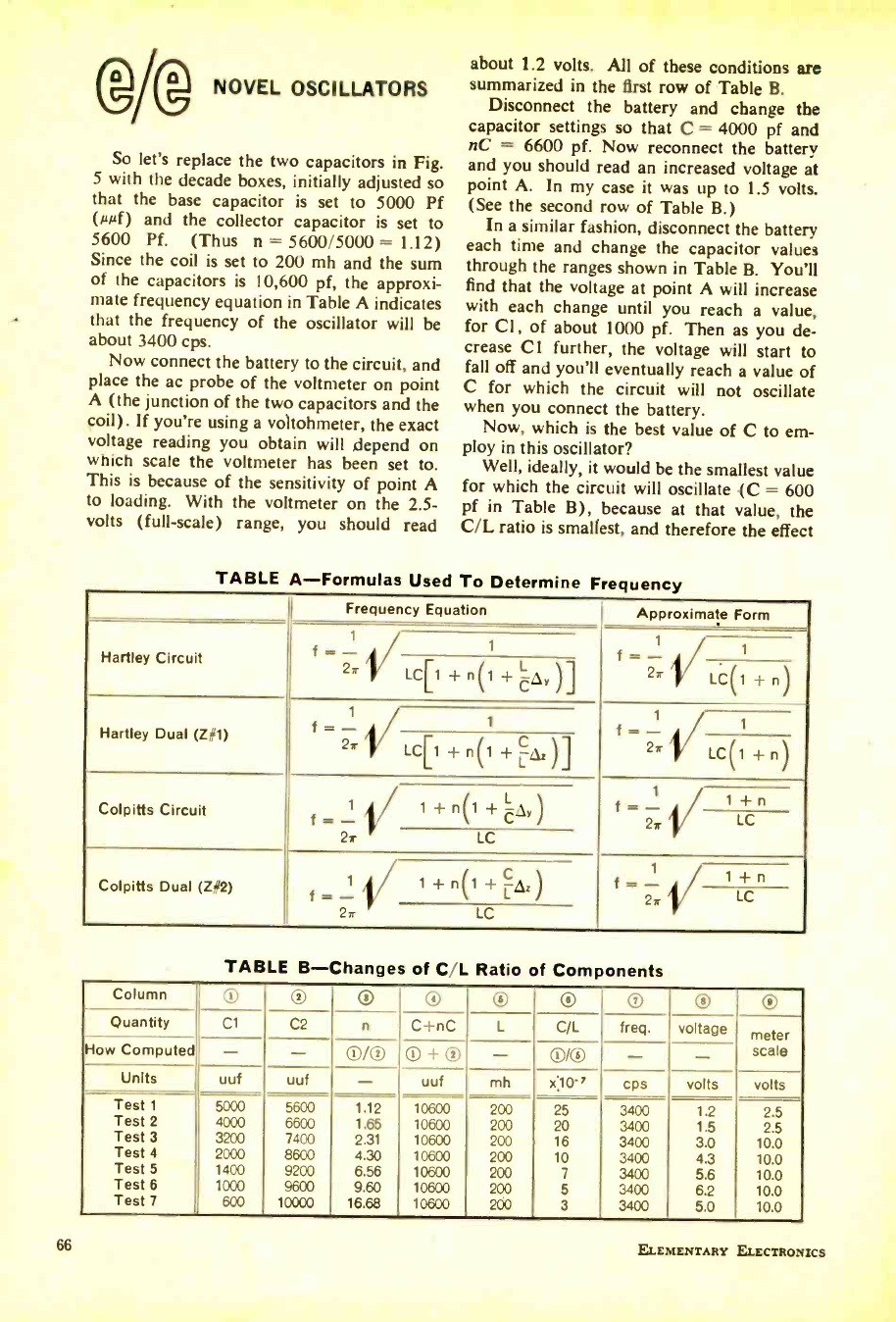
(g/® NOVEL OSCILLATORS
So let's replace the two capacitors in Fig.
5 with the decade boxes, initially adjusted so
that the base capacitor is set to 5000 Pf
(µµf) and the collector capacitor is set to
5600 Pf. (Thus n = 5600/5000 = 1.12)
Since the coil is set to 200 mh and the sum
of the capacitors is 10,600 pf, the approxi-
mate frequency equation in Table A indicates
that the frequency of the oscillator will be
about 3400 cps.
Now connect the battery to the circuit, and
place the ac probe of the voltmeter on point
A (the junction of the two capacitors and the
poil). If you're using a voltohmeter, the exact
voltage reading you obtain will depend on
which scale the voltmeter has been set to.
This is because of the sensitivity of point A
to loading. With the voltmeter on the 2.5-
volts (full -scale) range, you should read
about 1.2 volts. All of these conditions are
summarized in the first row of Table B.
Disconnect the battery and change the
capacitor settings so that C = 4000 pf and
nC = 6600 pf. Now reconnect the battery
and you should read an increased voltage at
point A. In my case it was up to 1.5 volts.
(See the second row of Table B.)
In a similar fashion, disconnect the battery
each time and change the capacitor values
through the ranges shown in Table B. You'll
find that the voltage at point A will increase
with each change until you reach a value,
for Cl, of about 1000 pf. Then as you de-
crease Cl further, the voltage will start to
fall off and you'll eventually reach a value of
C for which the circuit will not oscillate
when you connect the battery.
Now, which is the best value of C to em-
ploy in this oscillator?
Well, ideally, it would be the smallest value
for which the circuit will oscillate (C = 600
pf in Table B), because at that value, the
C/L ratio is smallest, and therefore the effect
TABLE A- Formulas Used To Determine Fre
Frequency Equation Approximate Form
Hartley Circuit f - 1 f = - 1
2r LCr1 +n(1 +CQv)1 271/ LC(1 + n)
Hartley Dual (Z#1)
1
f = - t
f = -
rr
2r LC[1 +n(1 +Qz)] 2rLC(1 +nl
Colpitts Circuit 1
f 1 + n(1 + CQy) f = 1 Cn
27
2r LC
Colpitts Dual (Z }2) \
1 1 + n(1 + Qz)
f = - 1
f = - / 1
2r LC
2r LC
TABLE B- Changes of C/L Ratio of Components
Column ® ® ú ® ® U U ® ®
Quantity Cl C2 n C +nC L C/L freq. voltage meter
How Computed - - QI /® ® + ® - OI /® - - scale
Units uuf uuf - uuf mh x'10-7 cps volts volts
Test 1 5000 5600 1.12 10600 200 25 3400 1.2 2.5
Test 2 4000 6600 1.65 10600 200 20 3400 1.5 2.5
Test 3 3200 7400 2.31 10600 200 16 3400 3.0 10.0
Test 4 2000 8600 4.30 10600 200 10 3400 4.3 10.0
Test 5 1400 9200 6.56 10600 200 7 3400 5.6 10.0
Test 6 1000 9600 9.60 10600 200 5 3400 6.2 10.0
Test 7 600 10000 16.68 10600 200 3 3400 5.0 10.0
ELEMENTARY ELECTRON ICS
www.americanradiohistory.com
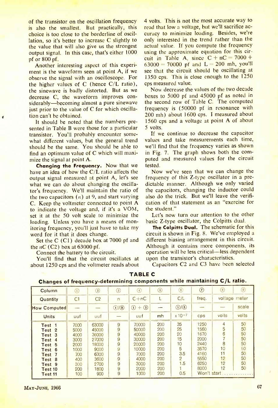
of the transistor on the oscillation frequency
is also the smallest. But practically, this
choice is too close to the borderline of oscil-
lation, so it's better to increase C slightly to
the value that will also give us the strongest
output signal. In this case, that's either 1000
pf or 800 pf.
Another interesting aspect of this experi-
ment is the waveform seen at point A, if we
observe the signal with an oscilloscope. For
the higher values of C (hence C/L ratio),
the sinewave is badly distorted. But as we
decrease C, the waveform improves con-
siderably- becoming almost a pure sinewave
just prior to the value of C for which oscilla-
tion can't be obtained.
It should be noted that the numbers pre-
sented in Table B were those for a particular
transistor. You'll probably encounter some-
what different values, but the general trend
should be the same. You should be able to
find an optimum value of C which will maxi-
mize the signal at point A.
Changing the Frequency. Now that we
have an idea of how the C/L ratio affects the
output signal measured at point A, let's see
what we can do about changing the oscilla-
tor's frequency. We'll maintain the ratio of
the two capacitors (n) at 9, and start varying
C. Keep the voltmeter connected to point A
to indicate the voltage and, if it's a VOM,
set it at the 50 volt scale to minimize the
loading. Unless you have a means of mon-
itoring frequency, you'll just have to take my
word for it that it does change.
Set the C (C1) decade box at 7000 pf and
the nC (C2) box at 63000 pf.
Connect the battery to the circuit.
You'll find that the circuit oscillates at
about 1250 cps and the voltmeter reads about
4 volts. This is not the most accurate way to
read that low a voltage, but we'll sacrifice ac-
curacy to minimize loading. Besides, we're
only interested in the trend rather than the
actual value. If you compute the frequency
using the approximate equation for this cir-
cuit in Table A, since C + nC = 7000 +
63000 = 70000 pf and L = 200 mh, you'll
see that the circuit should be oscillating at
1350 cps. This is close enough to the 1250
cps measured value.
Now decrease the values of the two decade
boxes to 5000 pf and 45000 pf as noted in
the second row of Table C. The computed
frequency is (50000 pf in resonance with
200 mh) about 1600 cps. I measured about
1560 cps and a voltage at point A of about
5 volts.
If we continue to decrease the capacitor
values and take measurements each time,
we'll find that the frequency varies as shown
in Fig. 7. The graph shows both the com-
puted and measured values for the circuit
tested.
Now we've seen that we can change the
frequency of this Z -type oscillator in a pre-
dictable manner. Although we only varied
the capacitors, changing the inductor could
also do the trick. But we'll leave the verifi-
cation of that statement as an "exercise for
the student."
Let's now turn our attention to the other
basic Z -type oscillator, the Colpitts dual.
The Colpitts Dual. The schematic for this
circuit is shown in Fig. 8. We've employed a
different biasing arrangement in this circuit.
Although it contains more components, its
operation will be less critical -less dependent
upon the transistor's characteristics.
Capacitors C2 and C3 have been selected
TABLE C
Changes of frequency- determining components while maintaining C/L ratio.
Column O O O O ® ® ® ® 1®
Quantity Cl C2 n C +nC L CIL freq. voltage meter
How Computed - - O/® ® + ® - OK) - - scale
Units uuf uuf - uuf mh x10 -7 cps volts volts
Test 1 7000 63000 9 70000 200 35 1250 4 50
Test 2 5000 45000 9 50000 200 25 1560 5 50
Test 3 4000 36000 9 40000 200 20 1670 6 50
Test 4 3000 27000 9 30000 200 15 2000 7 50
Test 5 2000 18000 9 20000 200 10 2440 8 50
Test 6 1000 9000 9 10000 200 5 3570 10 50
Test 7 700 6300 9 7000 200 3.5 4160 11 50
Test 8 400 3600 9 4000 200 2 5550 12 50
Test 9 300 2700 9 3000 200 1.5 6250 12 50
Test 10 200 1800 9 2000 200 1 8000 12 50
Test 11 100 900 9 1000 200 0.5 Won't start
MAY -JUNE, 1966 67
www.americanradiohistory.com
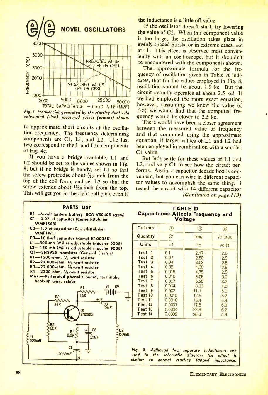
68
®Ag NOVEL OSCILLATORS
8000
5000
- 3000
2000
p MEASURED VALUE
l PF OR CPS
LL
PREDICTED VALUE
-< (PF OR CPS)
1000 2000 5000 10000 25000 50000
TOTAL CAPACITANCE - C *nC IN PF (MMF)
Fig.7. Frequencies generated by the Hartley dual with
calculated (line), measured values (crosses) shown.
to approximate short circuits at the oscilla-
tion frequency. The frequency determining
components are Cl, L1, and L2. The last
two correspond to the L and L/n components
of Fig. 4c.
If you have a bridge available, L1 and
L2 should be set to the values shown in Fig.
8; but if no bridge is handy, set L1 so that
the screw protrudes about hic -inch from the
top of the coil form, and set L2 so that the
screw extends about 51e -inch from the top.
This will get you in the right ball park even if
the inductance is a little off value.
If the oscillator doesn't start, try lowering
the value of C2. When this component value
is too large, the oscillation takes place in
evenly spaced bursts, or in extreme cases, not
at all. This effect is observed most conven-
iently with an oscilloscope, but it shouldn't
he encountered with the components shown.
The . approximate formula for the fre-
quency of oscillation given in Table A indi-
cates, that for the values employed in Fig. 8,
oscillation should he about 1.9 kc. But the
circuit actually operates at about 2.5 kc! If
we had employed the more exact equation,
however, (assuming we knew the value of
Az) we would find that the computed fre-
quency would be closer to 2.5 kc.
There would have been a closer agreement
between the measured value of frequency
and that computed using the approximate
equation, if larger values of L1 and L2 had
been employed in combination with a smaller
Cl value.
But let's settle for these values of L1 and
L2, and vary Cl to see how the circuit per-
forms. Again, a capacitor decade box is con-
venient, but you can wire in different capaci-
tor values to accomplish the same thing. I
tested the circuit with 14 different capacitor
(continued on page 113)
PARTS LIST
B1 -6 -volt lantern battery (RCA VS0405 screw)
C1- 0.07 -uf capacitor (Cornell -Dubilier
Whin 568)
C2- 1.0 -uf capacitor (Cornell- Dubilier
WMF1 W1)
C3- 10.0 -uf capacitor (Kemet K10C35K)
L1- 300 -mh (Miller adjustable inductor 9008)
L2- 150 -mh (Miller adjustable inductor 9008)
Q1- 2N2925 transistor (General Electric)
R1- 1500 -ohm, 1/2 -watt resistor
R2- 22,000 -ohm, 1/1 -watt resistor
R3- 22,000 -ohm, 1/2-watt resistor
R4- 2200 -ohm, 1/2 -watt resistor
Misc:-Perforated phenolic board, terminals,
hook -up wire, solder
TABLE D
Capacitance Affects Frequency and
Voltage
Column 0 ®
Quantity Cl freq. voltage
Units of kc volts
Test 1 0.1 2.17 2.5
Test 2 0.07 2.50 2.5
Test 3 0.04 3.03 2.5
Test 4 0.02 4.00 2.5
Test 5 0.015 4.75 2.5
Test 6 0.010 5.25 3.0
Test 7 0.007 6.25 3.2
Test 8 0.004 8.33 4.0
Test 9 0.002 11.1 5.0
Test 10 0.0015 12.5 5.2
Test 11 0.0010 15.4 5.8
Test 12 0.0007 17.8 6.0
Test 13 0.0004 22.8 6.2
Test 14 0.0002 28.6 5.8
Fig. 8. Although two separate inductances are
used in the schematic diagram the effect is
similar to normal Hartley tapped inductance.
ELEMENTARY ELECTRONICS
www.americanradiohistory.com
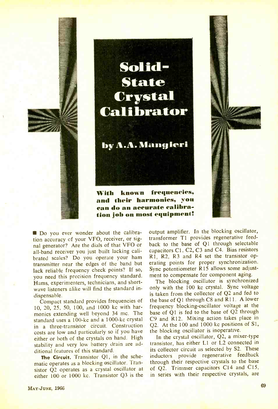
Soli ßd-
State
Crystal
Calibrator
by A.A. n1a l>tfi ieri
With known frequencies,
and their harmonics, you
can do an accurate calibra-
tion job on most equipment!
Do you ever wonder about the calibra-
tion accuracy of your VFO, receiver, or sig-
nal generator? Are the dials of that VFO or
all -band receiver you just built lacking cali-
brated scales? Do you operate your ham
transmitter near the edges of the band but
lack reliable frequency check points? If so,
you need this precision frequency standard.
Hams, experimenters, technicians, and short-
wave listeners alike will find the standard in-
dispensable.
Compact standard provides frequencies of
10, 20, 25, 50, 100, and 1000 kc with har-
monics extending well beyond 34 mc. The
standard uses a 100 -kc and a 1000 -kc crystal
in a three -transistor circuit. Construction
costs are low and particularly so if you have
either or both of the crystals on hand. High
stability and very low battery drain are ad-
ditional features of this standard.
The Circuit. Transistor Q1, in the sche-
matic operates as a blocking oscillator. Tran-
sistor Q2 operates as a crystal oscillator at
either 100 or 1000 kc. Transistor Q3 is the
MAY -JUNE, 1966
;;u u úp1pIHn111
output amplifier. In the blocking oscillator,
transformer T1 provides regenerative feed-
back to the base of Q1 through selectable
capacitors Cl, C2, C3 and C4. Bias resistors
R1, R2, R3 and R4 set the transistor op-
erating points for proper synchronization.
Sync potentiometer R15 allows some adjust-
ment to compensate for component aging.
The blocking oscillator is synchronized
only with the 100 kc crystal. Sync voltage
is taken from the collector of Q2 and fed to
the base of Q1 through C8 and R11. A lower
frequency blocking -oscillator voltage at the
base of Q1 is fed to the base of Q2 through
C9 and R12. Mixing action takes place in
Q2. At the 100 and 1000 kc positions of Si,
the blocking oscillator is inoperative.
In the crystal oscillator, Q2, a mixer -type
transistor, has either Ll or L2 connected in
its collector circuit as selected by S2. These
inductors provide regenerative feedback
through their respective crystals to the base
of Q2. Trimmer capacitors C14 and C15,
in series with their respective crystals, are
69
www.americanradiohistory.com
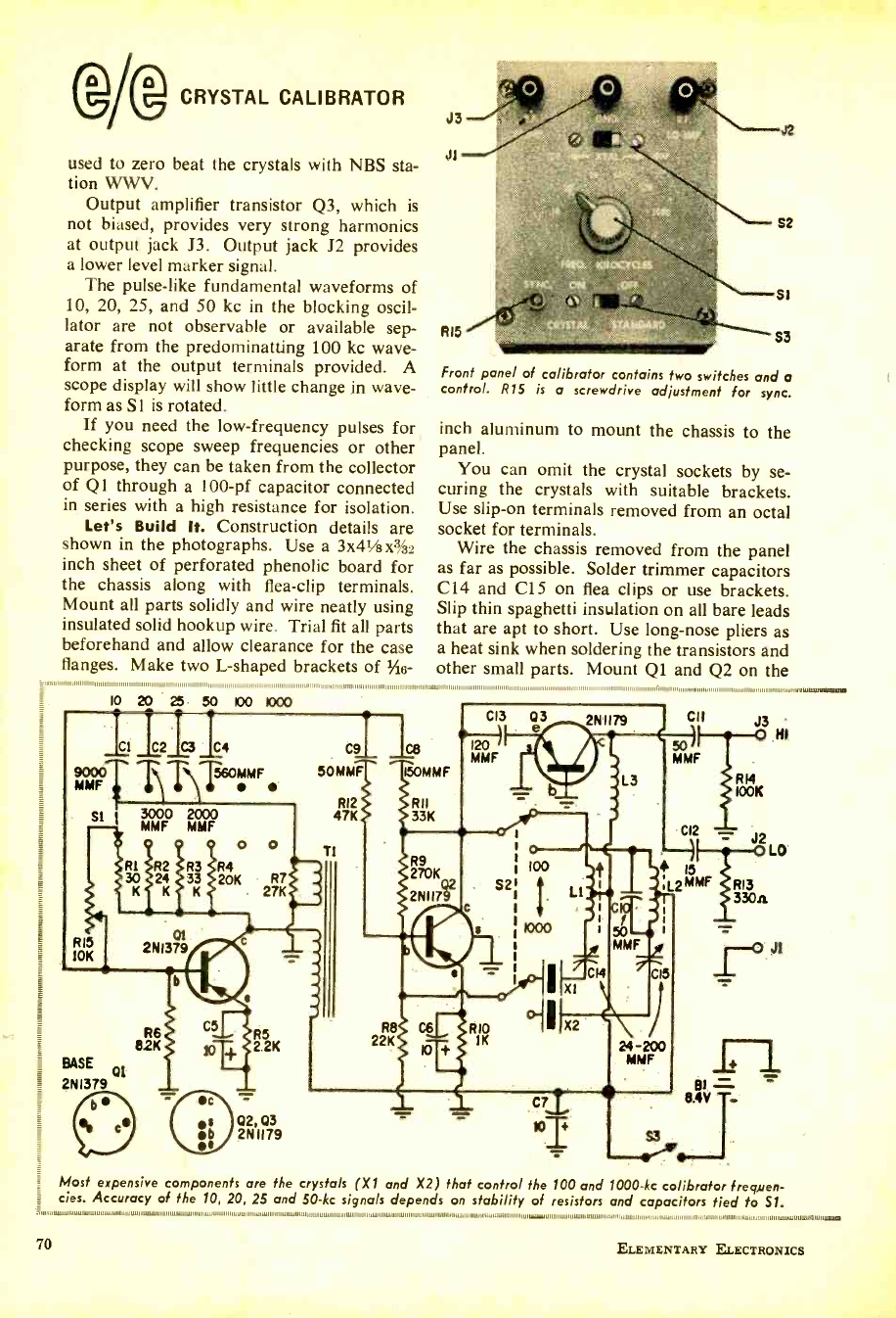
O p CRYSTAL CALIBRATOR
used to zero beat the crystals with NBS sta-
tion WWV.
Output amplifier transistor Q3, which is
not biased, provides very strong harmonics
at output jack J3. Output jack J2 provides
a lower level marker signal.
The pulse -like fundamental waveforms of
10, 20, 25, and 50 kc in the blocking oscil-
lator are not observable or available sep-
arate from the predominatting 100 kc wave-
form at the output terminals provided. A
scope display will show little change in wave-
form as S1 is rotated.
If you need the low- frequency pulses for
checking scope sweep frequencies or other
purpose, they can be taken from the collector
of Q 1 through a 100 -pf capacitor connected
in series with a high resistance for isolation.
Let's Build It. Construction details are
shown in the photographs. Use a 3x41/8 X %2
inch sheet of perforated phenolic board for
the chassis along with flea -clip terminals.
Mount all parts solidly and wire neatly using
insulated solid hookup wire. Trial fit all parts
beforehand and allow clearance for the case
flanges. Make two L- shaped brackets of %io-
10 20 25 50 100 1000
_1
900° TT\T560MMF
MMF
SI
Rl 30
K
RIS
10K
3000 2000
MMF MMF
O o
R4 20K R7
27K
2NI379
BASE 01
= 2NI379
82K T,y 2 2K
front panel of calibrator contains two switches and a
control. RlS is a screwdrive adjustment for sync.
inch aluminum to mount the chassis to the
panel.
You can omit the crystal sockets by se-
curing the crystals with suitable brackets.
Use slip -on terminals removed from an octal
socket for terminals.
Wire the chassis removed from the panel
as far as possible. Solder trimmer capacitors
C14 and C15 on flea clips or use brackets.
Slip thin spaghetti insulation on all bare leads
that are apt to short. Use long -nose pliers as
a heat sink when soldering the transistors and
other small parts. Mount Q1 and Q2 on the
C9I 1p
50 MMF 150MMF
R12 RII
47K 33K
T1 R9
270K
2N117
,., .11
cu
Ml/ MIE
Ó HI
RI4
IOOK
Most expensive components are the crystals (X/ and X2) that control the 100 and 1000 -kc calibrator frequen-
i ties. Accuracy of the 10, 20, 25 and 50 -kc signals depends on stability of resistors and capacitors tied to 51.
70
111111111ww.1,11/wM....
ELEMENTARY ELECTRONICS
www.americanradiohistory.com
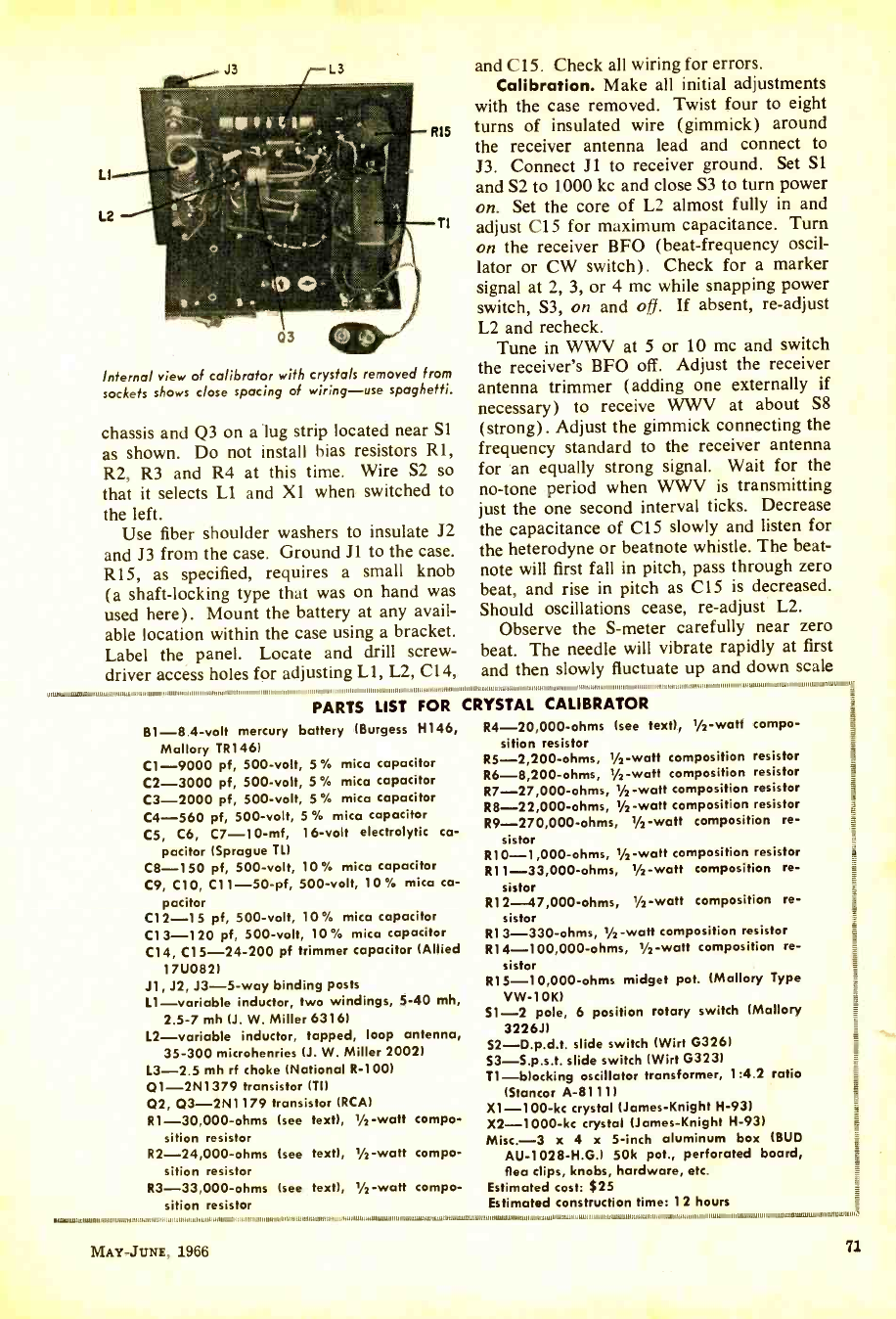
Internal view of calibrator with crystals removed from
sockets shows close spacing of wiring -use spaghetti.
chassis and Q3 on a lug strip located near S1
as shown. Do not install bias resistors R1,
R2, R3 and R4 at this time. Wire S2 so
that it selects L1 and Xl when switched to
the left.
Use fiber shoulder washers to insulate J2
and J3 from the case. Ground J1 to the case.
R15, as specified, requires a small knob
(a shaft -locking type that was on hand was
used here). Mount the battery at any avail-
able location within the case using a bracket.
Label the panel. Locate and drill screw-
driver access holes for adjusting LI, L2, C14,
and C15. Check all wiring for errors.
Calibration. Make all initial adjustments
with the case removed. Twist four to eight
turns of insulated wire (gimmick) around
the receiver antenna lead and connect to
J3. Connect J1 to receiver ground. Set S1
and S2 to 1000 kc and close S3 to turn power
on. Set the core of L2 almost fully in and
adjust C15 for maximum capacitance. Turn
on the receiver BFO (beat- frequency oscil-
lator or CW switch). Check for a marker
signal at 2, 3, or 4 me while snapping power
switch, S3, on and off. If absent, re- adjust
L2 and recheck.
Tune in WWV at 5 or 10 me and switch
the receiver's BFO off. Adjust the receiver
antenna trimmer (adding one externally if
necessary) to receive WWV at about S8
(strong). Adjust the gimmick connecting the
frequency standard to the receiver antenna
for an equally strong signal. Wait for the
no -tone period when WWV is transmitting
just the one second interval ticks. Decrease
the capacitance of C15 slowly and listen for
the heterodyne or beatnote whistle. The beat -
note will first fall in pitch, pass through zero
beat, and rise in pitch as C15 is decreased.
Should oscillations cease, re- adjust L2.
Observe the S -meter carefully near zero
beat. The needle will vibrate rapidly at first
and then slowly fluctuate up and down scale
,,,,,,,,,,,,,,1,,,,111,11,11 .1,1111 1 1 11 10,,1111:111 ,,:11::u111 1,111111 11,,:,,:1,,,111 ,1:1,1,:1 iii1 1,,,1:::1,11:,,1 11,11111,1111,1111,1,.:11111111111:1,.11:1111,1.111w1w.wUI
PARTS LIST FOR CRYSTAL CALIBRATOI'
R
B1 -8.4 -volt mercury battery (Burgess H146,
Mallory TR146)
C1 -9000 pf, 500 -volt, 5 % mica capacitor
C2 -3000 pf, 500 -volt, 5 % mica capacitor
C3 -2000 pf, 500 -volt, 5 % mica capacitor
C4 -560 pf, 500 -volt, 5 % mica capacitor
C5, C6, C7- 10 -mf, 16 -volt electrolytic ca-
pacitor (Sprague TL)
C8 -150 pf, 500 -volt, 10 % mica capacitor
C9, C10, C11- 50 -pf, 500 -volt, 10 % mico ca-
pacitor
C12 -15 pf, 500 -volt, 10 % mica capacitor
C13 -120 pf, 500 -volt, 10 % mica capacitor
C14, C15 -24 -200 pf trimmer capacitor (Allied
17U082)
Ji, J2, J3 -5 -way binding posts
L1- variable inductor, two windings, 5 -40 mh,
2.5 -7 mh (J. W. Miller 6316)
L2- variable inductor, tapped, loop antenna,
35 -300 microhenries (J. W. Miller 2002)
L3 -2.5 mh rf choke (National R -1001
Q1- 2N1379 transistor (TO
02, Q3- 2N1179 transistor (RCA)
R1- 30,000 -ohms (see text), 1/2 -watt compo-
sition resistor
R2- 24,000 -ohms (see text), 1/2 -watt compo-
sition resistor
R3- 33,000 -ohms (see text), 1/2 -watt compo-
sition resistor
MAY -JUNE. 1966
R4- 20,000 -ohms (see text), 1/2-watt compo-
sition resistor
R5- 2,200 -ohms, 1/2-watt composition resistor
R6 -8,200 -ohms, 1/2-watt composition resistor
R7- 27,000 -ohms, 1/2-watt composition resistor
R8- 22,000 -ohms, 1/2-watt composition resistor
R9- 270,000 -ohms, l/2 -watt composition re-
sistor
R10- 1,000 -ohms, 1/2 -watt composition resistor
R11- 33,000 -ohms, 1/2 -watt composition re-
sistor
R12- 47,000 -ohms, 1/2-watt composition re-
sistor
R13- 330 -ohms, 1/2 -watt composition resistor
R14- 100,000 -ohms, 1/2 -watt composition re-
sistor
R15- 10,000 -ohms midget pot. (Mallory Type
VW -10K)
S1 -2 pole, 6 position rotary switch (Mallory
3226J1
S2- D.p.d.t. slide switch (Wirt G326)
S3- S.p.s.t. slide switch (Wirt G323)
T1- blocking oscillator transformer, 1:4.2 ratio
(Stancor A -8111)
X1- 100 -kc crystal (James- Knight H -93)
X2- 1000 -kc crystal (James -Knight H -93)
Misc.-3 x 4 x 5 -inch aluminum box (BUD
AU- 1028 -H.G.) 50k pot., perforated board,
flea clips, knobs, hardware, etc.
Estimated cost: S25
Estimated construction time: 12 hours
71
www.americanradiohistory.com
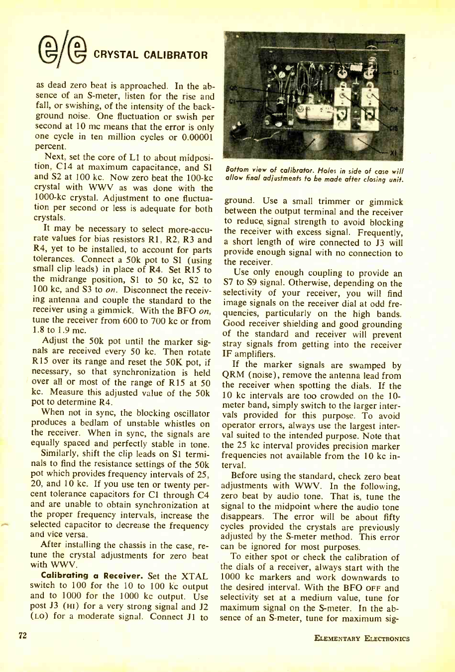
CRYSTAL CALIBRATOR
as dead zero beat is approached. In the ab-
sence of an S- meter, listen for the rise and
fall, or swishing, of the intensity of the back-
ground noise. One fluctuation or swish per
second at 10 mc means that the error is only
one cycle in ten million cycles or 0.00001
percent.
Next, set the core of Ll to about midposi-
tion, C14 at maximum capacitance, and Si
and S2 at 100 kc. Now zero beat the 100 -kc
crystal with WWV as was done with the
1000 -kc crystal. Adjustment to one fluctua-
tion per second or less is adequate for both
crystals.
It may be necessary to select more -accu-
rate values for bias resistors Rl, R2, R3 and
R4, yet to be installed, to account for parts
tolerances. Connect a 50k pot to S1 (using
small clip leads) in place of R4. Set R15 to
the midrange position, Si to 50 kc, S2 to
100 kc, and S3 to on. Disconnect the receiv-
ing antenna and couple the standard to the
receiver using a gimmick. With the BFO on,
tune the receiver from 600 to 700 kc or from
1.8 to 1.9 mc.
Adjust the 50k pot until the marker sig-
nals are received every 50 kc. Then rotate
R15 over its range and reset the 50K pot, if
necessary, so that synchronization is held
over all or most of the range of R15 at 50
kc. Measure this adjusted value of the 50k
pot to determine R4.
When not in sync, the blocking oscillator
produces a bedlam of unstable whistles on
the receiver. When in sync, the signals are
equally spaced and perfectly stable in tone.
Similarly, shift the clip leads on S1 termi-
nals to find the resistance settings of the 50k
pot which provides frequency intervals of 25,
20, and 10 kc. If you use ten or twenty per-
cent tolerance capacitors for Cl through C4
and are unable to obtain synchronization at
the proper frequency intervals, increase the
selected capacitor to decrease the frequency
and vice versa.
After installing the chassis in the case, re-
tune the crystal adjustments for zero beat
with WWV.
Calibrating a Receiver. Set the XTAL
switch to 100 for the 10 to 100 kc output
and to 1000 for the 1000 kc output. Use
post J3 (xi) for a very strong signal and J2
(Lo) for a moderate signal. Connect J1 to
72
Bottom view of calibrator. Holes in side of case will
allow final adjustments to be made after closing unit.
ground. Use a small trimmer or gimmick
between the output terminal and the receiver
to reduce signal strength to avoid blocking
the receiver with excess signal. Frequently,
a short length of wire connected to J3 will
provide enough signal with no connection to
the receiver.
Use only enough coupling to provide an
S7 to S9 signal. Otherwise, depending on the
selectivity of your receiver, you will find
image signals on the receiver dial at odd fre-
quencies, particularly on the high bands.
Good receiver shielding and good grounding
of the standard and receiver will prevent
stray signals from getting into the receiver
IF amplifiers.
If the marker signals are swamped by
QRM (noise), remove the antenna lead from
the receiver when spotting the dials. If the
10 kc intervals are too crowded on the 10-
meter band, simply switch to the larger inter-
vals provided for this purpose. To avoid
operator errors, always use the largest inter-
val suited to the intended purpose. Note that
the 25 kc interval provides precision marker
frequencies not available from the 10 kc in-
terval.
Before using the standard, check zero beat
adjustments with WWV. In the following,
zero beat by audio tone. That is, tune the
signal to the midpoint where the audio tone
disappears. The error will be about fifty
cycles provided the crystals are previously
adjusted by the S -meter method. This error
can be ignored for most purposes.
To either spot or check the calibration of
the dials of a receiver, always start with the
1000 kc markers and work downwards to
the desired interval. With the BFO OFF and
selectivity set at a medium value, tune for
maximum signal on the S- meter. In the ab-
sence of an S- meter, tune for maximum sig-
ELEMENTARY ELECTRONICS
www.americanradiohistory.com
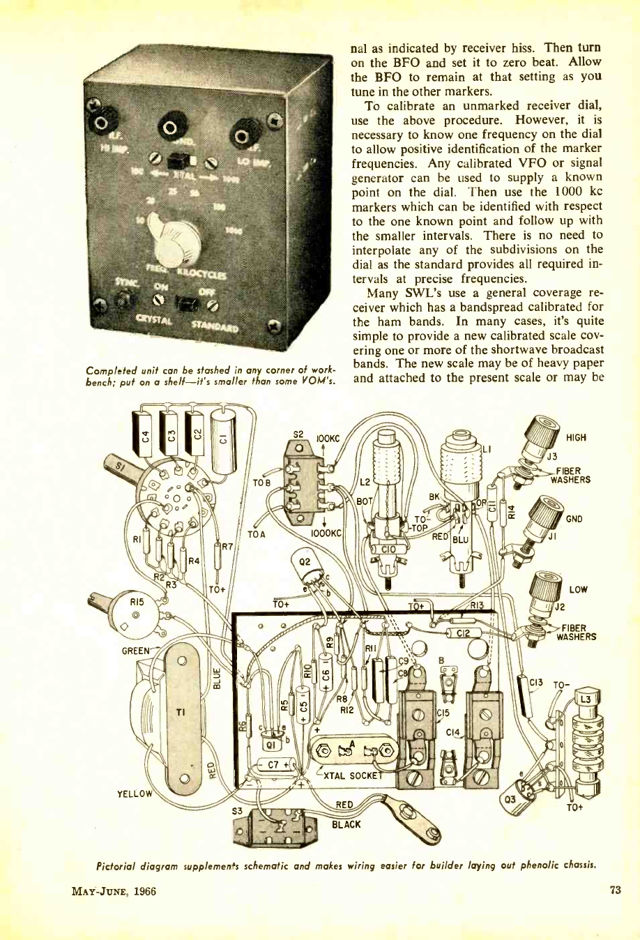
Completed unit can be stashed in any corner of work-
bench; put on a shelf -it's smaller than some VOM's.
nal as indicated by receiver hiss. Then turn
on the BFO and set it to zero beat. Allow
the BFO to remain at that setting as you
tune in the other markers.
To calibrate an unmarked receiver dial,
use the above procedure. However, it is
necessary to know one frequency on the dial
to allow positive identification of the marker
frequencies. Any calibrated VFO or signal
generator can be used to supply a known
point on the dial. Then use the 1000 kc
markers which can be identified with respect
to the one known point and follow up with
the smaller intervals. There is no need to
interpolate any of the subdivisions on the
dial as the standard provides all required in-
tervals at precise frequencies.
Many SWL's use a general coverage re-
ceiver which has a bandspread calibrated for
the ham bands. In many cases, it's quite
simple to provide a new calibrated scale cov-
ering one or more of the shortwave broadcast
bands. The new scale may be of heavy paper
and attached to the present scale or may be
J3
FIBER
WASHERS
FIBER
WASHERS
Pictorial diagram supplemen's schematic and makes wiring easier for builder laying out phenolic chassis.
MAY -JUNE. 1966 73
www.americanradiohistory.com
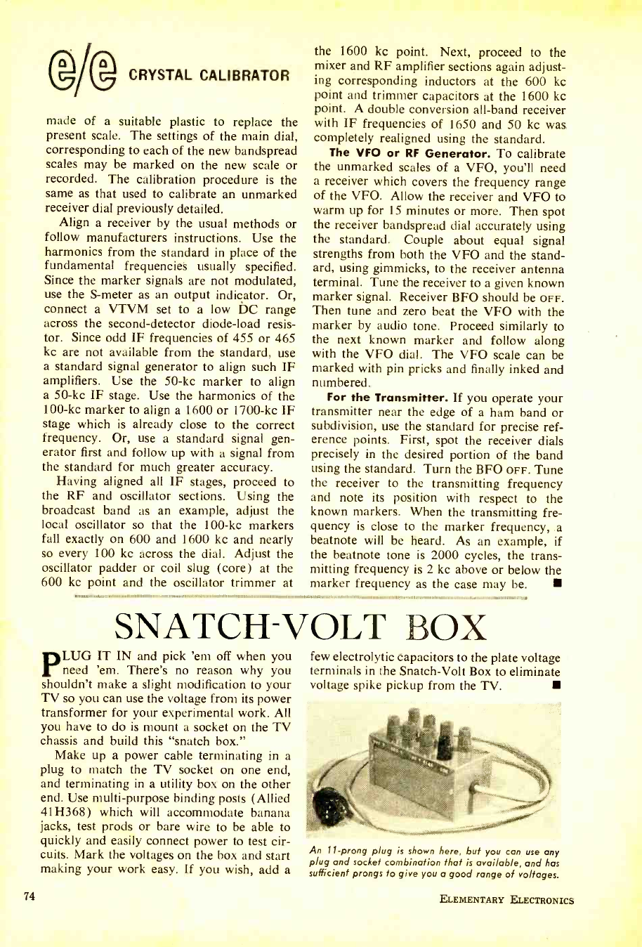
CRYSTAL CALIBRATOR
made of a suitable plastic to replace the
present scale. The settings of the main dial,
corresponding to each of the new bandspread
scales may be marked on the new scale or
recorded. The calibration procedure is the
same as that used to calibrate an unmarked
receiver dial previously detailed.
Align a receiver by the usual methods or
follow manufacturers instructions. Use the
harmonics from the standard in place of the
fundamental frequencies usually specified.
Since the marker signals are not modulated,
use the S -meter as an output indicator. Or,
connect a VTVM set to a low DC range
across the second -detector diode -load resis-
tor. Since odd IF frequencies of 455 or 465
kc are not available from the standard, use
a standard signal generator to align such IF
amplifiers. Use the 50 -kc marker to align
a 50 -kc IF stage. Use the harmonics of the
100 -kc marker to align a 1600 or 1700 -kc IF
stage which is already close to the correct
frequency. Or, use a standard signal gen-
erator first and follow up with a signal from
the standard for much greater accuracy.
Having aligned all IF stages, proceed to
the RF and oscillator sections. Using the
broadcast band as an example, adjust the
local oscillator so that the 100 -kc markers
fall exactly on 600 and 1600 kc and nearly
so every 100 kc across the dial. Adjust the
oscillator padder or coil slug (core) at the
600 kc point and the oscillator trimmer at
the 1600 kc point. Next, proceed to the
mixer and RF amplifier sections again adjust-
ing corresponding inductors at the 600 kc
point and trimmer capacitors at the 1600 kc
point. A double conversion all -band receiver
with IF frequencies of 1650 and 50 kc was
completely realigned using the standard.
The VFO or RF Generator. To calibrate
the unmarked scales of a VFO, you'll need
a receiver which covers the frequency range
of the VFO. Allow the receiver and VFO to
warm up for 15 minutes or more. Then spot
the receiver bandspread dial accurately using
the standard. Couple about equal signal
strengths from both the VFO and the stand-
ard, using gimmicks, to the receiver antenna
terminal. Tune the receiver to a given known
marker signal. Receiver BFO should be OFF.
Then tune and zero beat the VFO with the
marker by audio tone. Proceed similarly to
the next known marker and follow along
with the VFO dial. The VFO scale can be
marked with pin pricks and finally inked and
numbered.
For the Transmitter. If you operate your
transmitter near the edge of a ham band or
subdivision, use the standard for precise ref-
erence points. First, spot the receiver dials
precisely in the desired portion of the band
using the standard. Turn the BFO OFF. Tune
the receiver to the transmitting frequency
and note its position with respect to the
known markers. When the transmitting fre-
quency is close to the marker frequency, a
beatnote will be heard. As an example, if
the beatnote tone is 2000 cycles, the trans-
mitting frequency is 2 kc above or below the
marker frequency as the case may be.
SNATCH -VOLT BOX
LUG IT IN and pick 'em off when you
r need 'em. There's no reason why you
shouldn't make a slight modification to your
TV so you can use the voltage from its power
transformer for your experimental work. All
you have to do is mount a socket on the TV
chassis and build this "snatch box."
Make up a power cable terminating in a
plug to match the TV socket on one end,
and terminating in a utility box on the other
end. Use multi -purpose binding posts (Allied
41H368) which will accommodate banana
jacks, test prods or bare wire to be able to
quickly and easily connect power to test cir-
cuits. Mark the voltages on the box and start
making your work easy. If you wish, add a
74
few electrolytic capacitors to the plate voltage
terminals in the Snatch -Volt Box to eliminate
voltage spike pickup from the TV.
An 11 -prong plug is shown here, but you can use any
plug and socket combination that is available, and has
sufficient prongs to give you a good range of voltages.
ELEMENTARY ELECTRONICS
www.americanradiohistory.com
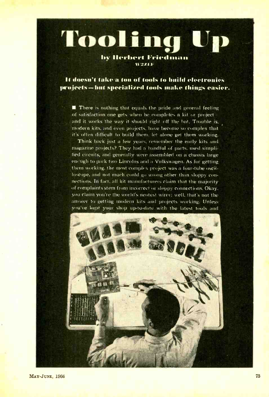
l i.iq Up
by l'rivcl nc:uc
1.1
11 doesn't talco a ton of tools to build electronics
projects-but specialized tools make things easier.
There is nothing that equals the pride and general feeling
of satisfaction one gets when he completes a kit or project -
and it works the way it should right off the bat. Trouble is,
modern kits, and even projects, have become so complex that
it's often difficult to build them, let alone get them working.
Think back just a few years, remember the early kits and
magazine projects? They had a handful of parts, used simpli-
fied circuits, and generally were assembled on a chassis large
en,ugh to park two Lincolns and a Volkswagen. As for getting
them working, the most complex project was a four -tube uscil-
k >scope, and not much could go wrung either than sloppy con-
nections. In fact, all kit manufacturers claim that the majority
of complaints stem from incorrect or sloppy connections. Okay.
you claim you're the world's neatest wirer: well, that's not the
answer to getting modern kits and projects working. Unless
you've kept your shop up -to -date with the latest tools and
MAY -JUNE, I966
www.americanradiohistory.com
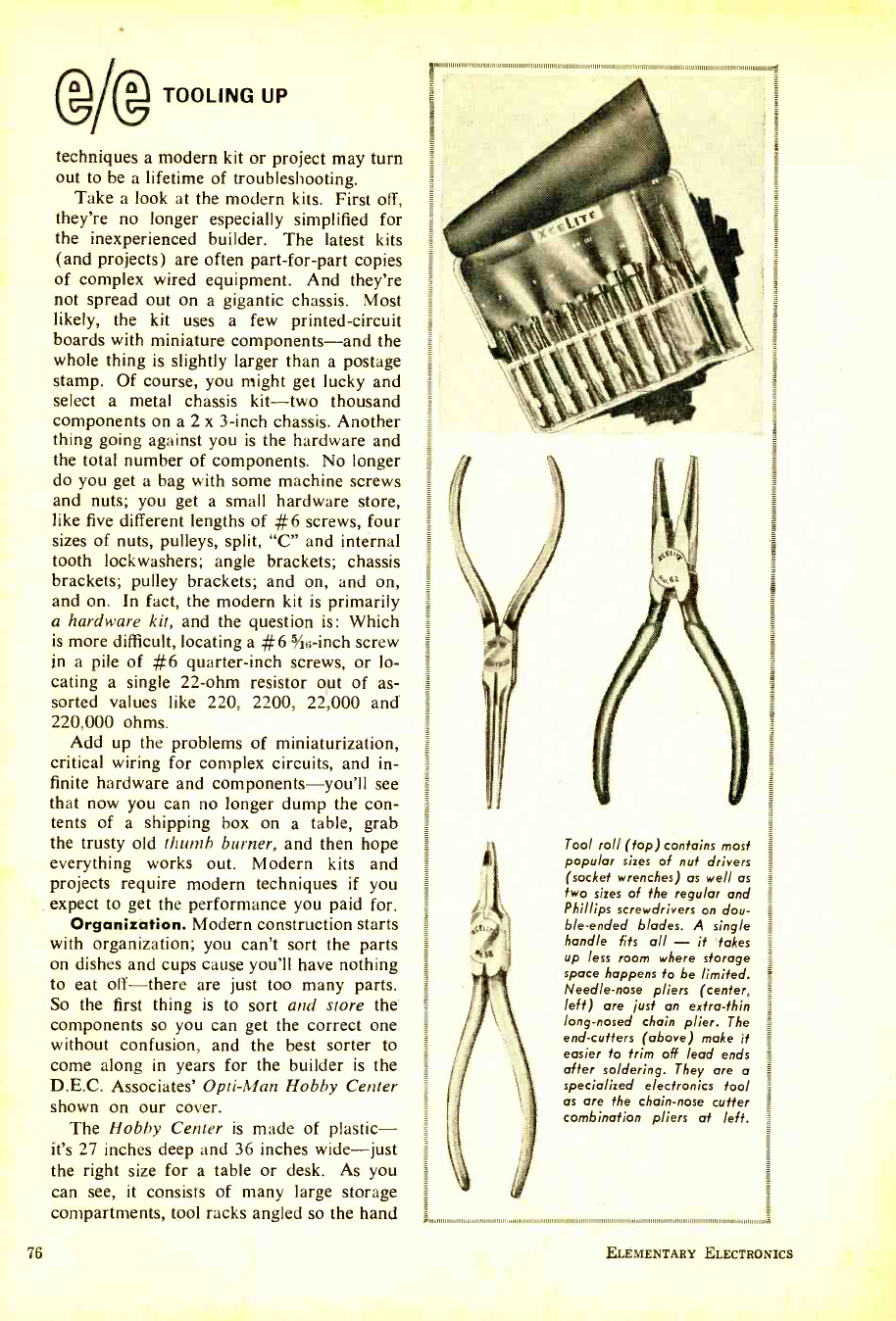
(IgM TOOLING UP
techniques a modern kit or project may turn
out to be a lifetime of troubleshooting.
Take a look at the modern kits. First off,
they're no longer especially simplified for
the inexperienced builder. The latest kits
(and projects) are often part- for -part copies
of complex wired equipment. And they're
not spread out on a gigantic chassis. Most
likely, the kit uses a few printed- circuit
boards with miniature components -and the
whole thing is slightly larger than a postage
stamp. Of course, you might get lucky and
select a metal chassis kit -two thousand
components on a 2 x 3 -inch chassis. Another
thing going against you is the hardware and
the total number of components. No longer
do you get a bag with some machine screws
and nuts; you get a small hardware store,
like five different lengths of #6 screws, four
sizes of nuts, pulleys, split, "C" and internal
tooth lockwashers; angle brackets; chassis
brackets; pulley brackets; and on, and on,
and on. In fact, the modern kit is primarily
a hardware kit, and the question is: Which
is more difficult, locating a #6 5 /ie -inch screw
in a pile of #6 quarter -inch screws, or lo-
cating a single 22 -ohm resistor out of as-
sorted values like 220, 2200, 22,000 and
220,000 ohms.
Add up the problems of miniaturization,
critical wiring for complex circuits, and in-
finite hardware and components -you'll see
that now you can no longer dump the con-
tents of a shipping box on a table, grab
the trusty old thumb burner, and then hope
everything works out. Modern kits and
projects require modern techniques if you
expect to get the performance you paid for.
Organization. Modern construction starts
with organization; you can't sort the parts
on dishes and cups cause you'll have nothing
to eat off -there are just too many parts.
So the first thing is to sort and store the
components so you can get the correct one
without confusion, and the best sorter to
come along in years for the builder is the
D.E.C. Associates' Opti -Man Hobby Center
shown on our cover.
The Hobby Center is made of plastic -
it's 27 inches deep and 36 inches wide -just
the right size for a table or desk. As you
can see, it consists of many large storage
compartments, tool racks angled so the hand
76
ËIII IIIIIII
111111 111,1
Tool roll (top) contains most
popular sizes of nut drivers
(socket wrenches) as well as
two sizes of the regular and
Phillips screwdrivers on dou-
ble -ended blades. A single
handle fits all - it takes
up less room where storage
space happens to be limited.
Needle -nose pliers (center,
left) are just an extra -thin
long -nosed chain plier. The
end -cutters (above) make it
easier to trim off lead ends
after soldering. They are a
specialized electronics tool
as are the chain -nose cutter
combination pliers at left.
ELEMENTARY ELECTRONICS
www.americanradiohistory.com
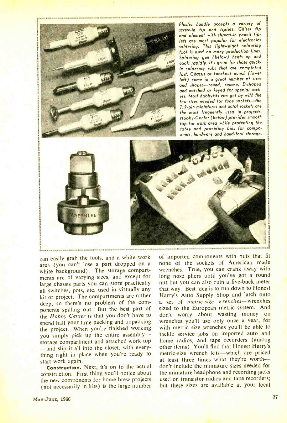
1111711111111 I/ il 1111 111111111111111111 Itviniuninmillo
Plastic handle accepts a variety of
screw -in tip and tiplets. Chisel tip
and element with thread -in pencil tip -
lets are most popular for electronics
soldering. This lightweight soldering
tool is used on many production lines.
Soldering gun (below) heats up and
cools rapidly. It's great for those quick-
ie soldering jobs that are completed
fast. Chassis or knockout punch (lower
left) come in a great number of sizes
and shapes- round, square, D- shaped
and notched or keyed for special sock-
ets. Most hobbyists can get by with the
few sizes needed for tube sockets -the
7,9 -pin miniatures and octal sockets are
the most frequently used in projects.
Hobby- Center (below) provides smooth
top for work area while protecting the
table and providing bins for compo-
nents, hardware and hand -tool storage.
11 11 11111111 111111111111 1111 11
can easily grab the tools, and a white work
area (you can't lose a part dropped on a
white background). The storage compart-
ments are of varying sizes, and except for
large chassis parts you can store practically
all switches, pots, etc. used in virtually any
kit or project. The compartments are rather
deep, so there's no problem of the com-
ponents spilling out. But the best part of
the Hobby Center is that you don't have to
spend half your time packing and unpacking
the project. When you're finished working
you simply pick up the entire assembly -
storage compartment and attached work top
-and slip it all into the closet, with every-
thing right in place when you're ready to
start work again.
Construction. Next, it's on to the actual
construction. First thing you'll notice about
the new components for home -brew projects
(not necessarily in kits) is the large number
MAY -JUNE, 1966
of imported components with nuts that fit
none of the sockets of American made
wrenches. True, you can crank away with
long nose pliers until you've got a round
nut but you can also ruin a five -buck meter
that way. Best idea is to run down to Honest
Harry's Auto Supply Shop and latch onto
a set of metric -size wrenches -wrenches
sized to the European metric system. And
don't worry about wasting money on
wrenches you'll use only once a year, for
with metric size wrenches you'll be able to
tackle service jobs on imported auto and
home radios, and tape recorders (among
other items). You'll find that Honest Harry's
metric -size wrench kits -which are priced
at least three times what they're worth -
don't include the miniature sizes needed for
the miniature headphone and recording jacks
used on transistor radios and tape recorders;
but these sizes are available at your local
77
www.americanradiohistory.com
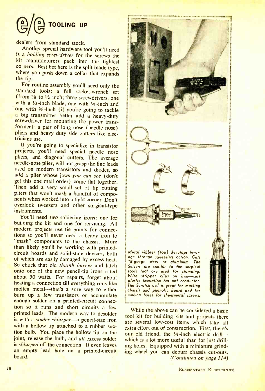
ssA
Metal nibbler (top) deve lops lever-
age through squeezing action. Cuts
18 -gauge steel or aluminum. The
Seizers are similar to the surgical
tools that are used for clamping.
Wire stripper clips on iron -cuts
plastic insulation but not conductor.
The Scratch awl is great for marking
chassis and phenolic board and for
making holes for sheetmetal screws.
,i,ili 11,,,,,,,,,11,,,11111111111111111111111111111111111111111111111111111,1,1,,,,,,,,11,1111,1111ti, i ,,,,,,,,, ,I
(DAD TOOLING UP
dealers from standard stock.
Another special hardware tool you'll need
is a holding screwdriver for the screws the
kit manufacturers pack into the tightest
corners. Best bet here is the split -blade type,
where you push down a collar that expands
the tip.
For routine assembly you'll need only the
standard tools: a full socket -wrench set
(from 1/8 to 1/2 inch; three screwdrivers, one
with a 1/2 -inch blade, one with 1/4 -inch and
one with 3/s -inch (if you're going to tackle
a big transmitter better add a heavy -duty
screwdriver for mounting the power trans-
former); a pair of long nose (needle nose)
pliers and heavy duty side cutters like elec-
tricians use.
If you're going to specialize in transistor
projects, you'll need special needle nose
pliers, and diagonal cutters. The average
needle -nose plier, will not grasp the fine leads
used on modern transistors and diodes, so
add a plier whose jaws you can see (don't
get this one mail order) come flat together.
Then add a very small set of tip cutting
pliers that won't mash a handful of compo-
nents when worked into a tight corner. Don't
overlook tweezers and other surgical -type
instruments.
You'll need two soldering irons: one for
building the kit and one for servicing. All
modern projects use tie points for connec-
tions so you'll never need a heavy iron to
"mash" components to the chassis. More
than likely you'll be working with printed -
circuit boards and solid -state devices, both
of which are easily damaged by excess heat.
So chuck that old thumb burner and latch
onto one of the new pencil -tip irons rated
about 50 watts. For repairs, forget about
heating a connection till everything runs like
molten metal -that's a sure way to either
burn up a few transistors or accumulate
enough solder on a printed- circuit connec-
tion so it runs and short circuits a few
printed leads. The modern way to desolder
is with a solder shlurper -a pencil -size iron
with a hollow tip attached to a rubber suc-
tion bulb. You place the hollow tip on the
joint, release the bulb, and all excess solder
is shlurped off the connection. It even leaves
an empty lead hole on a printed- circuit
board.
78
While the above can be considered a basic
tool kit for building kits and projects there
are several low -cost items which take all
extra effort out of construction. First, there's
our old friend, the 1/2 -inch electric drill -
which is a lot more useful than for just drill-
ing holes. Equipped with a miniature grind-
ing wheel you can deburr chassis cut -outs,
(Continued on page 114)
ELEMENTARY ELECTRONICS
www.americanradiohistory.com
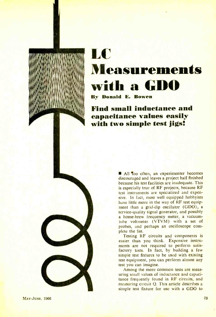
LL Measurements
with a GDO
By Donald E. Bowen
Find small inductance and
capacitance values easily
with two simple test jigs!
MAY -JUNE, 1966
All loo often, an experimenter becomes
discouraged and leaves a project half finished
because his test facilities are inadequate. This
is especially true of RF projects, because RF
test instruments are specialized and expen-
sive. In fact, most well equipped hobbyists
have little more in the way of RF test equip-
ment than a grid -dip oscillator (GDO), a
service -quality signal generator, and possibly
a home -brew frequency meter, a vacuum -
tube voltmeter (VTVM) with a set of
probes, and perhaps an oscilloscope com-
plete the list.
Testing RF circuits and components is
easier than you think. Expensive instru-
ments are not required to perform satis-
factory tests. In fact, by building a few
simple test fixtures to be used with existing
test equipment, you can perform almost any
test you can imagine.
Among the more common tests are meas-
uring small values of inductance and capaci-
tance frequently found in RF circuits, and
measuring circuit Q. This article describes a
simple test fixture for use with a GDO to
79
www.americanradiohistory.com
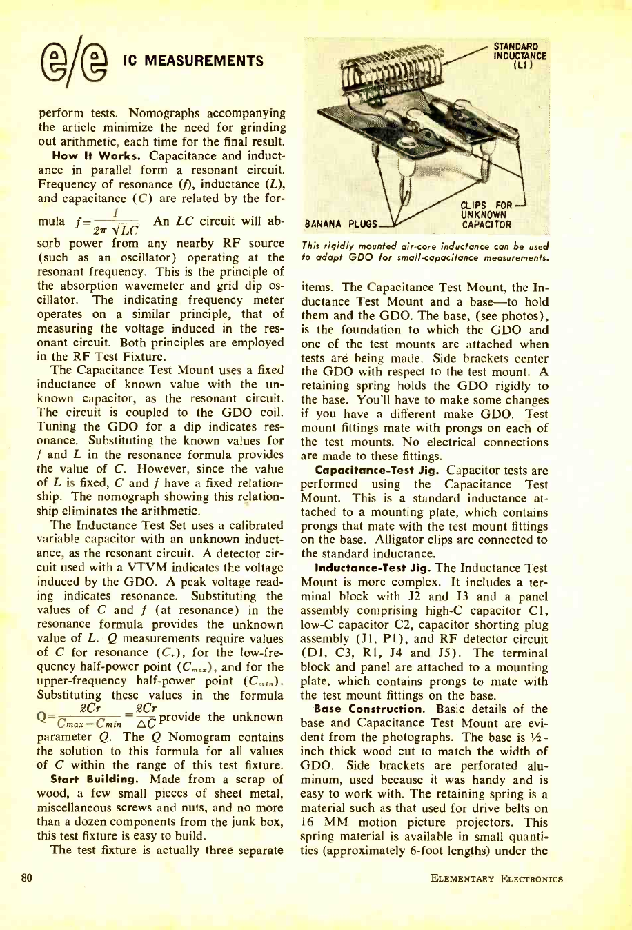
@Ag IC MEASUREMENTS
perform tests. Nomographs accompanying
the article minimize the need for grinding
out arithmetic, each time for the final result.
How It Works. Capacitance and induct-
ance in parallel form a resonant circuit.
Frequency of resonance (f), inductance (L),
and capacitance (C) are related by the for-
mula f= 1 An LC circuit will ab-
27r PLC
sorb power from any nearby RF source
(such as an oscillator) operating at the
resonant frequency. This is the principle of
the absorption wavemeter and grid dip os-
cillator. The indicating frequency meter
operates on a similar principle, that of
measuring the voltage induced in the res-
onant circuit. Both principles are employed
in the RF Test Fixture.
The Capacitance Test Mount uses a fixed
inductance of known value with the un-
known capacitor, as the resonant circuit.
The circuit is coupled to the GDO coil.
Tuning the GDO for a dip indicates res-
onance. Substituting the known values for
f and L in the resonance formula provides
the value of C. However, since the value
of L is fixed, C and f have a fixed relation-
ship. The nomograph showing this relation-
ship eliminates the arithmetic.
The Inductance Test Set uses a calibrated
variable capacitor with an unknown induct-
ance, as the resonant circuit. A detector cir-
cuit used with a VTVM indicates the voltage
induced by the GDO. A peak voltage read-
ing indicates resonance. Substituting the
values of C and f (at resonance) in the
resonance formula provides the unknown
value of L. Q measurements require values
of C for resonance (C,), for the low -fre-
quency half -power point (C,R,,), and for the
upper- frequency half -power point (Cm,, ).
Substituting these values in the formula
2Cr 2Cr
Q= provide the unknown
Cmas -(min OC
parameter Q. The Q Nomogram contains
the solution to this formula for all values
of C within the range of this test fixture.
Start Building. Made from a scrap of
wood, a few small pieces of sheet metal,
miscellaneous screws and nuts, and no more
than a dozen components from the junk box,
this test fixture is easy to build.
The test fixture is actually three separate
80
STANDARD
INDUCTANCE
(LI. )
BANANA PLUGS
CLIPS FOR
UNKNOWN
CAi,ACtTOR
This rigidly mounted air -core inductance can be used
to adapt GDO for small -capacitance measurements.
items. The Capacitance Test Mount, the In-
ductance Test Mount and a base -to hold
them and the GDO. The base, (see photos),
is the foundation to which the GDO and
one of the test mounts are attached when
tests are being made. Side brackets center
the GDO with respect to the test mount. A
retaining spring holds the GDO rigidly to
the base. You'll have to make some changes
if you have a different make GDO. Test
mount fittings mate with prongs on each of
the test mounts. No electrical connections
are made to these fittings.
Capacitance -Test Jig. Capacitor tests are
performed using the Capacitance Test
Mount. This is a standard inductance at-
tached to a mounting plate, which contains
prongs that mate with the test mount fittings
on the base. Alligator clips are connected to
the standard inductance.
Inductance -Test Jig. The Inductance Test
Mount is more complex. It includes a ter-
minal block with J2 and J3 and a panel
assembly comprising high -C capacitor Cl,
low -C capacitor C2, capacitor shorting plug
assembly (JI, P1), and RF detector circuit
(D1, C3, R1, J4 and J5). The terminal
block and panel are attached to a mounting
plate, which contains prongs to mate with
the test mount fittings on the base.
Base Construction. Basic details of the
base and Capacitance Test Mount are evi-
dent from the photographs. The base is 1/2-
inch thick wood cut to match the width of
GDO. Side brackets are perforated alu-
minum, used because it was handy and is
easy to work with. The retaining spring is a
material such as that used for drive belts on
16 MM motion picture projectors. This
spring material is available in small quanti-
ties (approximately 6 -foot lengths) under the
ELEMENTARY ELECTRONICS
www.americanradiohistory.com
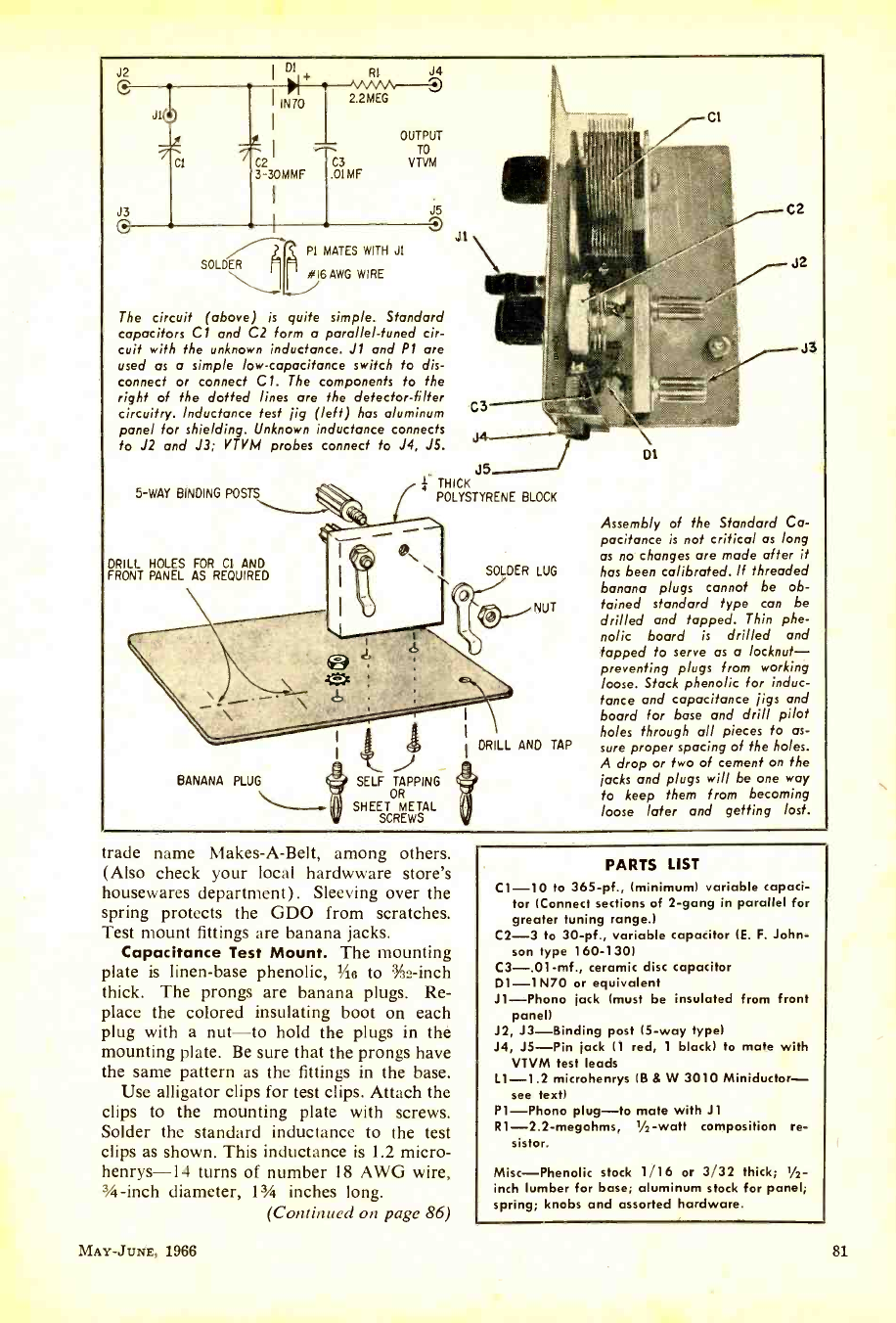
J2
JI+U
TI
J3
SOL 6A WI
I DI RI
j4
IN70 2.2 R1
--t -
-7-c 2I C3
3-30MMF .OIMF
OUTPUT
TO
VTVM
PI MATES WITH JI
DER yyG RE
J5
J1
The circuit (above) is quite simple. Standard
capacitors Cl and C2 form a parallel -tuned cir-
cuit with the unknown inductance. J1 and PI are
used as a simple low -capacitance switch fo dis-
connect or connect Cl. The components to the
right of the dotted lines are the detector -filter
circuitry. Inductance test jig (left) has aluminum
panel for shielding. Unknown inductance connects
to J2 and J3; VTVM probes connect to J4, J5.
5 -WAY BINDING POSTS
DRILL HOLES FOR CI AND
FRONT PANEL AS REQUIRED
®s,
C3
J5
THICK
POLYSTYRENE BLOCK
SOLDER LUG
BANANA PLUG ® SELF TAPPING
OR
SHEET METAL
SCREWS
NUT
DRILL AND TAP
D1
C2
J2
J3
Assembly of the Standard Ca-
pacitance is not critical as long
as no changes are made after it
has been calibrated. If threaded
banana plugs cannot be ob-
tained standard type can be
drilled and tapped. Thin phe-
nolic board is drilled and
tapped to serve as a locknut-
preventing plugs from working
loose. Stack phenolic for induc-
tance and capacitance jigs and
board for base and drill pilot
holes through all pieces to as-
sure proper spacing of the holes.
A drop or two of cement on the
jacks and plugs will be one way
to keep them from becoming
loose later and getting lost.
rade name Makes -A -Belt, among others.
(Also check your local hardwware store's
housewares department). Sleeving over the
spring protects the GDO from scratches.
Test mount fittings are banana jacks.
Capacitance Test Mount. The mounting
plate is linen -base phenolic, '/is to :;'32 -inch
thick. The prongs are banana plugs. Re-
place the colored insulating boot on each
plug with a nut -to hold the plugs in the
mounting plate. Be sure that the prongs have
the same pattern as the fittings in the base.
Use alligator clips for test clips. Attach the
clips to the mounting plate with screws.
Solder the standard inductance to the test
clips as shown. This inductance is 1.2 micro -
henrys-14 turns of number 18 AWG wire,
3/4 -inch diameter, 13/4 inches long.
(Continued on page 86)
MAY -JUNE, 1966
PARTS LIST
C1 -10 to 365 -pf., (minimum) variable capaci-
tor (Connect sections of 2 -gang in parallel for
greater tuning range.)
C2 -3 to 30 -pf., variable capacitor (E. F. John-
son type 160 -130)
C3- .01 -mf., ceramic disc capacitor
D1 -1N70 or equivalent
J1 -Phono jack (must be insulated from front
panel)
J2, J3- Binding post (5 -way type)
J4, J5 -Pin jack (1 red, 1 black) to mate with
VTVM test leads
L1 -1.2 microhenrys (B & W 3010 Miniductor-
see text)
P1 -Phono plug -to mate with J1
R1- 2.2- megohms, 1/2 -watt composition re-
sistor.
Misc -Phenolic stock 1/16 or 3/32 thick; r /2-
inch lumber for base; aluminum stock for panel;
spring; knobs and assorted hardware.
81
www.americanradiohistory.com
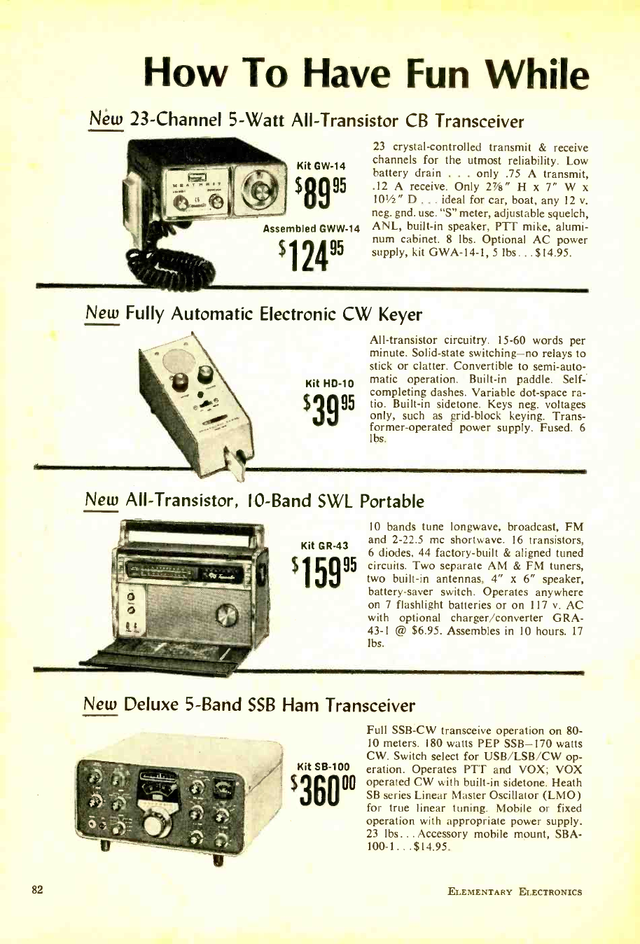
How To Have Fun While
Néw 23- Channel 5 -Watt All- Transistor CB Transceiver
Kit GW -14
$8995
Assembled GWW -14
$12495
23 crystal -controlled transmit & receive
channels for the utmost reliability. Low
battery drain . . . only .75 A transmit,
.12 A receive. Only VA " H x 7" W x
101/2" D ... ideal for car, boat, any 12 v.
neg. gnd. use. "S" meter, adjustable squelch,
ANL, built -in speaker, PTT mike, alumi-
num cabinet. 8 lbs. Optional AC power
supply, kit GWA -14 -1, 5 lbs... $14.95.
New Fully Automatic Electronic CW Keyer
Kit HD -10
$3995
All- transistor circuitry. 15 -60 words per
minute. Solid -state switching -no relays to
stick or clatter. Convertible to semi -auto-
matic operation. Built -in paddle. Self-
completing dashes. Variable dot -space ra-
tio. Built -in sidetone. Keys neg. voltages
only, such as grid -block keying. Trans-
former- operated power supply. Fused. 6
lbs.
New All -Transistor, 10 -Band SWL Portable
82
10 bands tune longwave, broadcast, FM
and 2 -22.5 me shortwave. 16 transistors,
6 diodes, 44 factory -built & aligned tuned
circuits. Two separate AM & FM tuners,
two built -in antennas, 4" x 6" speaker,
battery -saver switch. Operates anywhere
on 7 flashlight batteries or on 117 v. AC
with optional charger /converter GRA-
43-1 @ $6.95. Assembles in 10 hours. 17
lbs.
New Deluxe 5 -Band SSB Ham Transceiver
Kit SB -100
$360°°
Full SSB -CW transceive operation on 80-
10 meters. 180 watts PEP SSB -170 watts
CW. Switch select for USB /LSB /CW op-
eration. Operates PTT and VOX; VOX
operated CW with built -in sidetone. Heath
SB series Linear Master Oscillator (LMO)
for true linear tuning. Mobile or fixed
operation with appropriate power supply.
23 lbs... Accessory mobile mount, SBA -
100- 1...$14.95.
ELEMENTARY ELECTRONICS
www.americanradiohistory.com
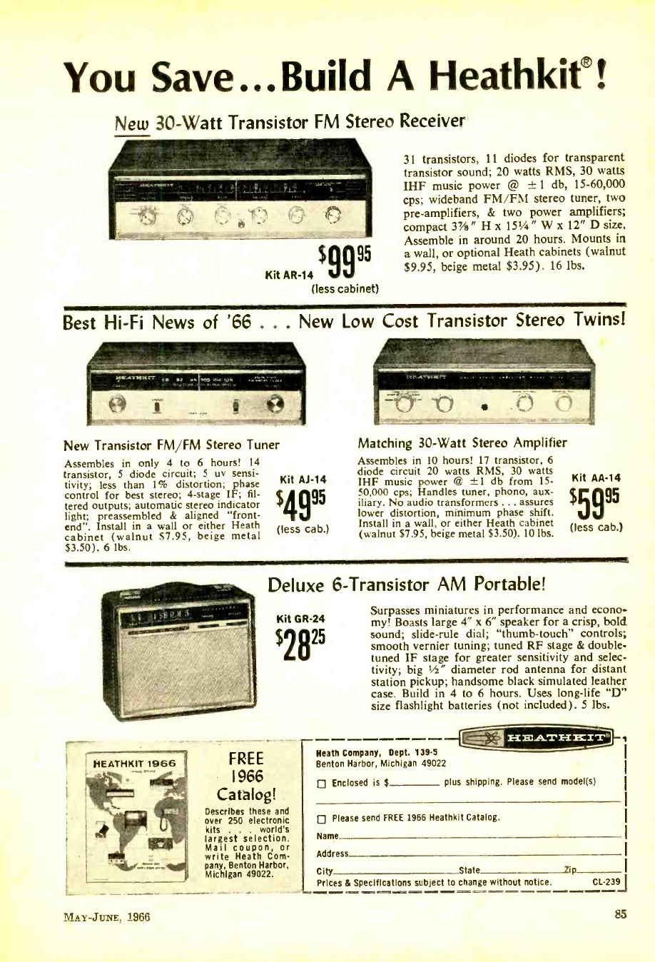
You Save...Build A Heathkif!
New 30 -Watt Transistor FM Stereo Receiver
Kit AR -14 (less cabinet)
$9995
31 transistors, 11 diodes for transparent
transistor sound; 20 watts RMS, 30 watts
IHF music power @ ± 1 db, 15- 60,000
cps; wideband FM /FM stereo tuner, two
pre -amplifiers, & two power amplifiers;
compact 3v /e" H x 151/4" W x 12" D size.
Assemble in around 20 hours. Mounts in
a wall, or optional Heath cabinets (walnut
$9.95, beige metal $3.95). 16 lbs.
Best Hi -Fi News of '66 ... New Low Cost Transistor Stereo Twins!
New Transistor FM /FM Stereo Tuner
Assembles in only 4 to 6 hours! 14
transistor, 5 diode circuit; 5 uy sensi-
tivity; less than 1% distortion; phase
control for best stereo; 4 -stage IF; fil-
tered outputs; automatic stereo indicator
light; preassembled & aligned "front -
end". Install in a wall or either Heath
cabinet (walnut $7.95, beige metal
$3.50). 6 lbs.
Kit AJ -14
$4995
(less cab.)
Matching 30 -Watt Stereo Amplifier
Assembles in 10 hours! 17 transistor, 6
diode circuit 20 watts RMS, 30 watts
IHF music power @ ±1 db from 15-
50,000 cps; Handles tuner, phono, aux-
iliary. No audio transformers ... assures
lower distortion, minimum phase shift.
Install in a wall, or either Heath cabinet
(walnut $7.95, beige metal $3.50). 10 lbs.
Kit AA -14
$5995
(less cab.)
HEATHKIT 1966
Deluxe 6- Transistor AM Portable!
Surpasses miniatures in performance and econo-
Kit GR -24 my! Boasts large 4" x 6" speaker for a crisp, bold
sound; slide -rule dial; "thumb- touch" controls;
smooth vernier tuning; tuned RF stage & double -
tuned IF stage for greater sensitivity and selec-
tivity; big 1/2" diameter rod antenna for distant
station pickup; handsome black simulated leather
case. Build in 4 to 6 hours. Uses long -life "D"
size flashlight batteries (not included). 5 lbs.
s2825
FREE
1966
Catalog!
Describes these and
over 250 electronic
kits . world's
largest selection.
Mail coupon, or
write Heath Com-
pany, Benton Harbor,
Michigan 49022.
Heath Company, Dept. 139-5
Benton Harbor, Michigan 49022
Enclosed is $ plus shipping. Please send model(s)
- --
=_.
Please send FREE 1966 Heathkit Catalog.
Name
Address
City State lip
Prices & Specifications subject to change without notice. CL -239J
MAY -JUNE, 1966 83
www.americanradiohistory.com
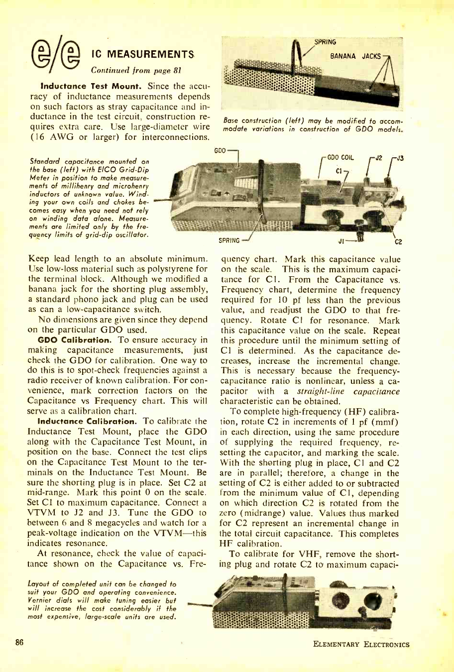
@AD IC MEASUREMENTS
Continued from page 81
Inductance Test Mount. Since the accu-
racy of inductance measurements depends
on such factors as stray capacitance and in-
ductance in the test circuit, construction re-
quires extra care. Use large- diameter wire
(16 AWG or larger) for interconnections.
Standard capacitance mounted on
the base (left) with EICO Grid -Dip
Meter in position to make measure-
ments of millihenry and microhenry
inductors of unknown value. Wind-
ing your own coils and chokes be-
comes easy when you need not rely
on winding data alone. Measure-
ments are limited only by the fre-
quency limits of grid -dip oscillator.
SPRING
BANANA JACKS
Base construction (left) may be modified to accom-
modate variations in construction of GDO mode/s.
GDO -
Keep lead length to an absolute minimum.
Use low -loss material such as polystyrene for
the terminal block. Although we modified a
banana jack for the shorting plug assembly,
a standard phono jack and plug can be used
as can a low- capacitance switch.
No dimensions are given since they depend
on the particular GDO used.
GDO Calibration. To ensure accuracy in
making capacitance measurements, just
check the GDO for calibration. One way to
do this is to spot -check frequencies against a
radio receiver of known calibration. For con-
venience, mark correction factors on the
Capacitance vs Frequency chart. This will
serve as a calibration chart.
Inductance Calibration. To calibrate the
Inductance Test Mount, place the GDO
along with the Capacitance Test Mount, in
position on the base. Connect the test clips
on the Capacitance Test Mount to the ter-
minals on the Inductance Test Mount. Be
sure the shorting plug is in place. Set C2 at
mid -range. Mark this point 0 on the scale.
Set Cl to maximum capacitance. Connect a
VTVM to J2 and J3. Tune the GDO to
between 6 and 8 megacycles and watch for a
peak -voltage indication on the VTVM -this
indicates resonance.
At resonance, check the value of capaci-
tance shown on the Capacitance vs. Fre-
Layout of completed unit can be changed to
suit your GDO and operating convenience.
Vernier dials will make tuning easier but
will increase the cost considerably if the
most expensive, large -scale units are used.
86
quency chart. Mark this capacitance value
on the scale. This is the maximum capaci-
tance for C1. From the Capacitance vs.
Frequency chart, determine the frequency
required for 10 pf less than the previous
value, and readjust the GDO to that fre-
quency. Rotate Cl for resonance. Mark
this capacitance value on the scale. Repeat
this procedure until the minimum setting of
Cl is determined. As the capacitance de-
creases, increase the incremental change.
This is necessary because the frequency -
capacitance ratio is nonlinear, unless a ca-
pacitor with a straight -line capacitance
characteristic can be obtained.
To complete high- frequency (HF) calibra-
tion, rotate C2 in increments of 1 pf (mmf)
in each direction, using the same procedure
of supplying the required frequency, re-
setting the capacitor, and marking the scale.
With the shorting plug in place, Cl and C2
are in parallel; therefore, a change in the
setting of C2 is either added to or subtracted
from the minimum value of Cl, depending
on which direction C2 is rotated from the
zero (midrange) value. Values thus marked
for C2 represent an incremental change in
the total circuit capacitance. This completes
HF calibration.
To calibrate for VHF, remove the short-
ing plug and rotate C2 to maximum capaci-
ELEMENTARY ELECTRONICS
www.americanradiohistory.com
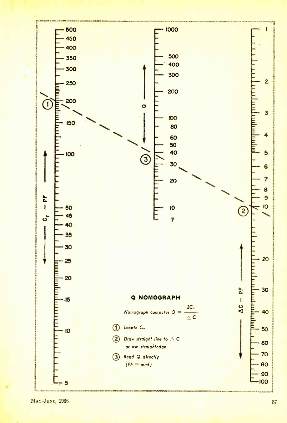
O
- 500
- 450
- 400
- 350
- 300
- 250
200
_ \ %,
- I50
- 100
- 50
45
- 40
35
30
-25
=-20
IS
- IO
5
rumnimm,,,,,.,,,,,nmnn,,m,,,,,ati ungun,uammtmi,r,,,,in.,a,,m,trnnumm,n,tumnimmninmmninur,alaumn,,,,,,,,,,,,,,,n,uaatumvxm ,tau,,,oumm,,m,ttai,wnainnianemlian mmnninuom,,,,,,,n
1000
500
400
300
200
100
80
60
50 40
30
20
Io
7
Q NOMOGRAPH
Nomograph computes Q =
OLocate C.
0 Draw straight line to C
or use straightedge
O Read Q directly
(PF = mmf)
2C.
C
5
- 6
- 7
- 8
- 9
10 =
30
- 60
- 70 =
- 80
- 90 _
- 100
1,,,, 1,11,,,,,,,,,,,,,1.1,1,,,,11,, ,,.,,1., I/11 arm ,,.m..,,nn,mm,m R,rum,n,,,nnrrmm, ,mnm,annin,,vem.m 17=MTIIIMIUMISfilL217091,,,w,M11111wf1111,1,1 ww
MAY -JUNE, 1966 87
www.americanradiohistory.com
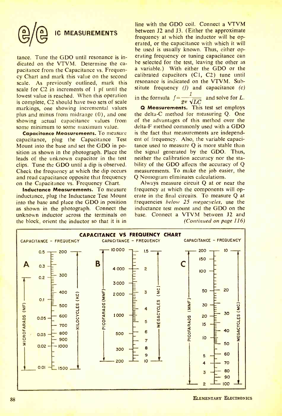
hb
(g/@ IC MEASUREMENTS
tance. Tune the GDO until resonance is in-
dicated on the VTVM. Determine the ca-
pacitance from the Capacitance vs. Frequen-
cy Chart and mark this value on the second
scale. As previously outlined, mark this
scale for C2 in increments of 1 pf until the
lowest value is reached. When this operation
is complete, C2 should have two sets of scale
markings, one showing incremental values
plus and minus from midrange (0), and one
showing actual capacitance values from
some minimum to some maximum value.
Capacitance Measurements. To measure
capacitance, plug the Capacitance Test
Mount into the base and set the GDO in po-
sition as shown in the photograph. Place the
leads of the unknown capacitor in the test
clips. Tune the GDO until a dip is observed.
Check the frequency at which the dip occurs
and read capacitance opposite that frequency
on the Capacitance vs. Frequency Chart.
Inductance Measurements. To measure
inductance, plug the Inductance Test Mount
into the base and place the GDO in position
as shown in the photograph. Connect the
unknown inductor across the terminals on
the block, orient the inductor so that it is in
line with the GDO coil. Connect a VTVM
between J2 and J3. (Either the approximate
frequency at which the inductor will be op-
erated, or the capacitance with which it will
be used is usually known. Thus, either op-
erating frequency or tuning capacitance can
be selected for the test, leaving the other as
a variable.) With either the GDO or the
calibrated capacitors (C1, C2) tune until
resonance is indicated on the VTVM. Sub-
stitute frequency (f) and capacitance (c)
in the formula f PLC and solve for L.
Q Measurements. This test set employs
the delta -C method for measuring Q. One
of the advantages of this method over the
delta -F method commonly used with a GDO
is the fact that measurements are independ-
ent of frequency. Also, the variable capaci-
tance used to measure Q is more stable than
the signal generated by the GDO. Thus,
neither the calibration accuracy nor the sta-
bility of the GDO affects the accuracy of Q
measurements. To make the job easier, the
Q Nomogram eliminates calculations.
Always measure circuit Q at or near the
frequency at which the components will op-
erate in the final circuits. To measure Q at
frequencies below 25 megacycles, use the
inductance test mount and the GDO on the
base. Connect a VTVM between J2 and
(Continued on page 116)
CAPACITANCE VS FREQUENCY CHART
CAPACITANCE - FREQUENCY CAPACITANCE - FREQUENCY
0.5 200
A 0.3
- 300
0.2
0.1
400
r=-- 500
- 600
- 700
0.03 s- - 800
- 900
0.02 1000
0.01 s 1500
10 000 -- 5
B 4 000
3 000
7 2 000
2
co a
cc 1000
ñ.
500
300
200
4
5
6
7
8
9
IO -1-
CAPACITANCE - FREQUENCY
200 10
150
C 100
50
30
20
15
10
5
20
30
40
50
60
4 70
3 --L 80
- 90
2 100
ELEMENTARY ELECTRONICS
www.americanradiohistory.com
> Y. a a s w s a< a r WO e r sr wd
a a a a w w a i rI e we
arwaIera ir rri
aa a-.a a+ er sarsees -_
a aa M a r. NV OW a a a a r f a
r r
a a a w wi.aa I Ifw Of s rr
w. a.aa ¢a a:Ilrra fn
w a a aw a r Y I r r..'
a a a I e r T,._
a a a w . r w a r s er
_ _ w . .1 r r r Y IM'.. alga
a. . . aa .v. a r I r. f e MI Ale
!. aaaaw lb Mr rie r re
w a , Oa r r sIra .n.e
a ra a a v. I r r w 0// AY' r.n
. aa ww,..'..tI,..t- eeI f rr
a. r, w r.. .r .r
_ _ rris r a ifs.e .r oe ± e.'
a. . w'a r r w w. .w. _ r
. r f r rr..r.,e- .rw-
w r .r ..r er :
.e.: . .r a. a. ,. O .e .w- .e AMY. ...r'
s r r f r::..e- ..r ..r
a - ws r f e. ala ,..e-
`s. .. ti a.a. I.s..-. r
alla r f ..w .r. r ..
. .a.- ...w- .w.e.-' a es- ... . ,fi.r.-...rr. _.+w' ..rr.-
y.......\ . ,.... .r.r:r': .-.,,.,-. ...we^
.i. iii r., i...- .I- ...r' ,+.. ....rr-..
J- r e fI
. '-wea...._
- .en...... .,.a
-.w....... ..
WW
-+.._. -+eru
.,. w.. . .w -.--.e.. ..:.
t.,, a
AI/ I - '.aw..
- _a an f au "a S. `we.. .
.. at e f. .. w 4. \.
..Y y f " - - _ a. w M' r .. I . . . . ' R .. . _ <_ . ... . . - __ _ . .. '._ . 'aw . ..
e e tttw\ww w` v vw. ^.11.
I .rrl ').t<1.t\\<'\wwa NI, aa _
rfI . a+a ,r.-a...waa+ a r ++r_
.. . w a. .w.
- - _ r ,:,; __,._._ .. ! Y_t1_ laaa `..
eIe _. aaaaaa.a le. a _r Ir r . . . . . . . w w w We a a a a
- wa a a a:a, `:... a.
OW f e,...sa -a a a...,_ w. ear a Ala a rr_I a ow Ie .r +i.Mwwaaa
r. Irlretallasweawa.aay. W at.
ws rrIIIe+I aaa aa:aaa wr.
r. AO a a a a a e .+.. aer ..
attla .e f w e r:e r I e s . . a a a .. an a'
.I.r i e ..... tii a a aa a a w a. aa
AMY MP i a - . a a a v. a a aw +.
al.r er t! r ..... a a a a a
r. r r R .. el, It .......
.. I s a r s r ta
WO /Fr
f a .e
r. <.r
a =a+ta
a VW
a a a at
a a a
a VOL aw
All you need is a signal generator and a sensitive
transistor radio to ferret out the hidden wires for
AC power, bell wiring and heating system thermostats
You're ready to install an in-the-wall air -
conditioner or heater -but where's the elec-
tric wiring? Will you cut into the wall only
to find you've cut through a cable? Or a cir-
cuit goes dead and you want to trace it back
to the source -how do you find the cables
without chopping the walls? The answer?
With a transistor radio and a borrowed signal
generator you can trace a "road map" of the
house wiring.
Just connect a signal generator -set to any
quiet spot on the broadcast band -to a
"dead" outlet and tune in the signal with the
transistor radio. Now reduce the generator's
output level till the signal can just barely be
heard when the radio is next to the generator.
MAY-Jm.m, 1966
Place the generator against the wall and
sweep it slowly back and forth. When the
radio is directly over an electric cable the
signal will suddenly increase sharply. (The
received signal is the 400 -cycle tone from the
generator.) By moving the radio along the
wall the wiring can be "mapped" with rea-
sonable accuracy.
Keep in mind that even though the outlet
is "dead " -whether by removing the fuse or
opening a circuit breaker -the signal is trans-
ferred to all the house wiring through the
junction boxes via the common wire. For
example, if the generator is connected to
a "dead" basement outlet it will be received
in the "live" attic wiring as well as the
89
www.americanradiohistory.com
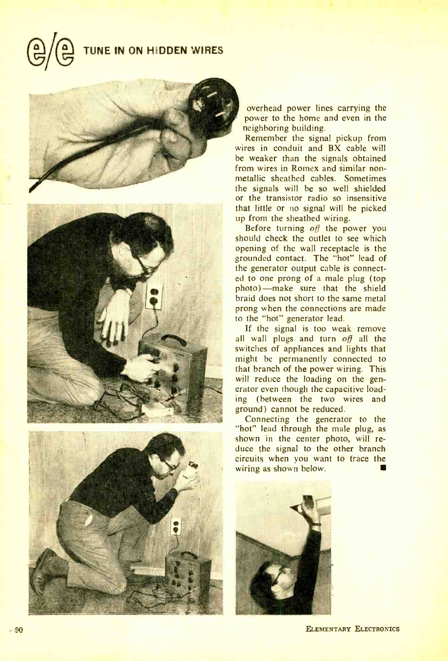
90
TUNE IN ON HIIDDEN WIRES
overhead power lines carrying the
power to the home and even in the
neighboring building.
Remember the signal pickup from
wires in conduit and BX cable will
be weaker than the signals obtained
from wires in Romex and similar non-
metallic sheathed cables. Sometimes
the signals will be so well shielded
or the transistor radio so insensitive
that little or no signal will be picked
up from the sheathed wiring.
Before turning off the power you
should check the outlet to see which
opening of the wall receptacle is the
grounded contact. The "hot" lead of
the generator output cable is connect-
ed to one prong of a male plug (top
photo) -make sure that the shield
braid does not short to the same metal
prong when the connections are made
to the "hot" generator lead.
If the signal is too weak remove
all wall plugs and turn off all the
switches of appliances and lights that
might be permanently connected to
that branch of the power wiring. This
will reduce the loading on the gen-
erator even though the capacitive load-
ing (between the two wires and
ground) cannot be reduced.
Connecting the generator to the
"hot" lead through the male plug, as
shown in the center photo, will re-
duce the signal to the other branch
circuits when you want to trace the
wiring as shown below.
ELEMENTARY ELECTRONICS
www.americanradiohistory.com
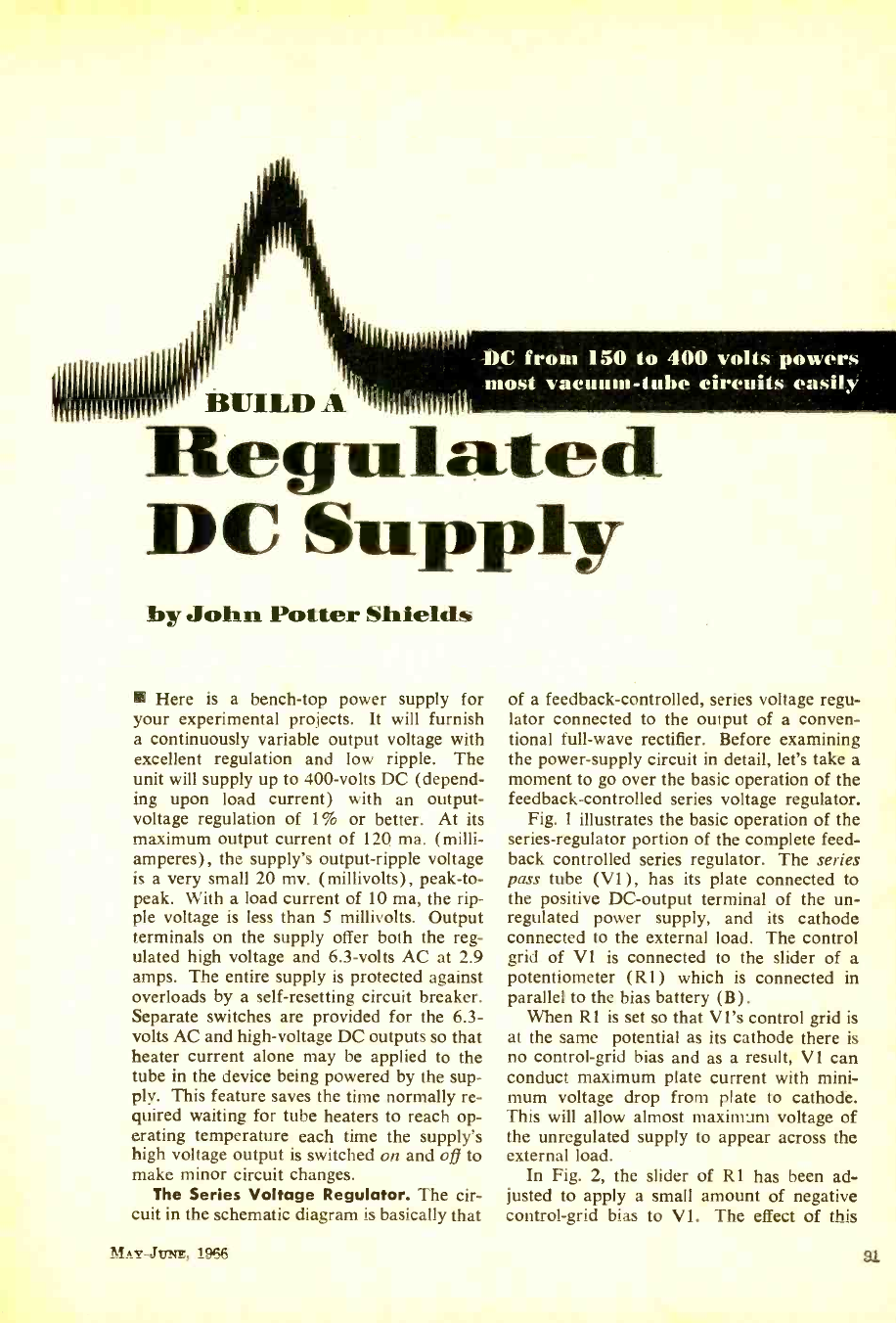
DC from 150 to 400 volts powers
most vacuum -tube circuits easily
. lated
DC S.ppty
by John Potter Shields
Here is a bench -top power supply for
your experimental projects. It will furnish
a continuously variable output voltage with
excellent regulation and low ripple. The
unit will supply up to 400 -volts DC (depend-
ing upon load current) with an output -
voltage regulation of 1% or better. At its
maximum output current of 120 ma. (milli-
amperes), the supply's output -ripple voltage
is a very small 20 mv. (millivolts), peak -to-
peak. With a load current of 10 ma, the rip-
ple voltage is less than 5 millivolts. Output
terminals on the supply offer both the reg-
ulated high voltage and 6.3 -volts AC at 2.9
amps. The entire supply is protected against
overloads by a self- resetting circuit breaker.
Separate switches are provided for the 6.3-
volts AC and high -voltage DC outputs so that
heater current alone may be applied to the
tube in the device being powered by the sup-
ply. This feature saves the time normally re-
quired waiting for tube heaters to reach op-
erating temperature each time the supply's
high voltage output is switched on and off to
make minor circuit changes.
The Series Voltage Regulator. The cir-
cuit in the schematic diagram is basically that
MAY-Jvxs, 1966
of a feedback -controlled, series voltage regu-
lator connected to the output of a conven-
tional full -wave rectifier. Before examining
the power -supply circuit in detail, let's take a
moment to go over the basic operation of the
feedback -controlled series voltage regulator.
Fig. 1 illustrates the basic operation of the
series- regulator portion of the complete feed-
back controlled series regulator. The series
pass tube (VI ) , has its plate connected to
the positive DC- output terminal of the un-
regulated power supply, and its cathode
connected to the external load. The control
grid of VI is connected to the slider of a
potentiometer (R1) which is connected in
parallel to the bias battery (B).
When RI is set so that VI's control grid is
at the same potential as its cathode there is
no control -grid bias and as a result, VI can
conduct maximum plate current with mini-
mum voltage drop from plate to cathode.
This will allow almost maximum voltage of
the unregulated supply to appear across the
external load.
In Fig. 2, the slider of R1 has been ad-
justed to apply a small amount of negative
control -grid bias to VI. The effect of this
91
www.americanradiohistory.com
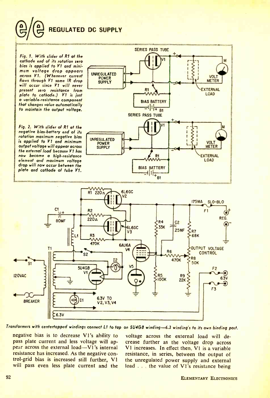
Q REGULATED DC SUPPLY
Fig. 1. With slider of R1 at the
cathode end of its rotation zero
bias is applied fo V1 and mini-
mum voltage drop appears
across VI. (Whenever current
Rows through VI some IR drop
will occur since Y1 will never
present zero resistance from
plate to cathode.) V1 is just
o variable- resistance component
that changes value automatically
to maintain the output voltage.
Fig. 2. With slider of R1 at the
negative bias- battery end of its
rotation maximum negative bias
is applied to Y1 and minimum
output voltage will appear across
the external load because Y1 has
now become o high -resistance
element and maximum voltage
drop will now occur between the
plate and cathode of tube VI.
SERIES PASS TUBE
EXTERNAL
LOAD
BIAS BATTERY
II + BI
SERIES PASS TUBE
BIAS BATTERY
Bt
uumnimummennmsommiumitainnunnunm
EXTERNAL
LOAD
Si
120VAC
BREAKER
175MA SLO-BLO
T
5U4GB
VI
V5
6.3V
11 6.3V TO
V2,V3,V4
470K
R5 R9
I00K 22K
R7
68K
F1 U+
REG.
1
OUTPUT VOLTAGE
CONTROL
R8
50K
F2
6.3V
--ter - F3
Transformers with centerfapped windings connect LI to tap on 5U4GB winding -6.3 winding's to its own binding post.
negative bias is to decrease VI's ability to
pass plate current and less voltage will ap-
pear across the external load -V1 's internal
resistance has increased. As the negative con-
trol -grid bias is increased still further, V 1
will pass even less plate current and the
92
voltage across the external load will de-
crease further as the voltage drop across
V 1 increases. In effect then, V1 is a variable
resistance, in series, between the output of
the unregulated power supply and external
load ... the value of VI's resistance being
ELEMENTARY ELECTRONICS
www.americanradiohistory.com
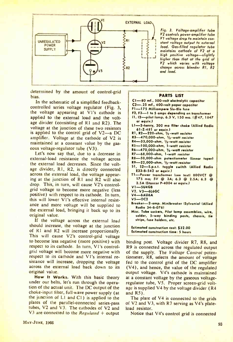
VI EXTERNAL LOAD
UNREGULATED
POWER
SUPPLY
_J
M1111111114. 11110 11
111111111,1
Fig. 3. Voltage -amplifier tube i
V2 controls power -amplifier tube I
Y1 voltage drop fo maintain con -
stant voltage output to external
load. Gas -filled regulator tube
maintains cathode of Y2 at a
high positive voltage -slightly
higher than that at the grid of
V2 which varies with voltage
change across bleeder 121, R2
and load.
determined by the amount of control -grid
bias. In the schematic of a simplified feedback -
controlled series voltage regulator (Fig. 3,
the voltage appearing at VI's cathode is
applied to the external load and the volt-
age divider (consisting of R1 and R2). The
voltage at the junction of these two resistors
is applied to the control grid of V2 -a DC
amplifier. Voltage at the cathode of V2 is
maintained at a constant value by the gas-
eous voltage- regulator tube (V3).
Let's now say that, due to a decrease in
external -load resistance the voltage across
the external load decreases. Since the volt-
age divider, Rl, R2, is directly connected
across the external load, the voltage appear-
ing at the junction of Rl and R2 will also
drop. This, in turn, will cause V2's control -
grid voltage to become more negative (less
positive) with respect to its cathode. In turn,
this will lower VI's effective internal resist-
ance and more voltage will be supplied to
the external load, bringing it back up to its
original value.
If the voltage across the external load
should increase, the voltage at the junction
of Rl and R2 will increase proportionally.
This will cause V2's control -grid voltage
to become less negative (more positive) with
respect to its cathode. In turn, V l's control -
grid voltage will become more negative with
respect to its cathode and V l's internal re-
sistance will increase, dropping the voltage
across the external load back down to its
original value.
How It Works. With this basic theory
under our belts, let's run through the opera-
tion of the actual unit. The DC output of the
choke -input filter, full -wave power supply (at
the junction of Ll and Cl) is applied to the
plates of the parallel- connected series -pass
tubes, V2 and V3. The cathodes of V2 and
V3 are connected to the Regulated + output
MAY -JUNE, 1966
(
l
)
111
PARTS LIST
C1 -80 mf., 500 -volt electrolytic capacitor
C2 -.25 mf., 400 -volt paper capacitor
Fl -175 Milliampere Slo -Blo fuse
F2, F3 -1 to 5 amps depending on transformer
I1, 12 -pilot lamp, 6.3 V, 150 ma. ( #47, 1847
or equiv.)
1.1 -2 -henry, 200 ma filter choke (Allied Radio
61 -Z -481 or equiv.)
Rl, R2 -220 -ohm, 1/2-watt resistor
R3- 470,000 -ohm, 1/2-watt resistor
R4- 33,000 -ohm, 1/2-watt resistor
R5- 100,000 -ohm, 1 -watt resistor
R6- 470,000 -ohm, 1/2-watt resistor
R7- 68,000 -ohm, 1 -watt resistor
R8- 50,000 -ohm potentiometer (linear taper)
R9- 22,000 -ohm, 1/2 -watt resistor
S1, 52- S.p.s.t. toggle switch (Allied Radio
E33 -B -542 or equiv.)
T1 -Power transformer (see text) 800VCT
175 ma; SV @ 3A; 6.3 @ 2.SA; 6.3
2.5A IStancor P -4004 or equiv.)
V1 -5U4GB
V2, V3 -6L6GC
V4 -6AU6A
V5 -0C2
Breaker -2 -amp. Minibreaker (Sylvania) (Allied
Radio 34 -B -076)
Misc. Tube sockets, Pilot lamp assemblies, wire,
solder, 5 -way binding posts, chassis, tie
strips, fuse holders, etc.
t Estimated construction cost: $32.00
Estimated construction time: 5 hours
binding post. Voltage divider R7, R8, and
R9 is connected across the regulated output
of the supply. The Voltage Control poten-
tiometer, R8, selects the amount of voltage
fed to the control grid of the DC amplifier
(V4), and hence, the value of the regulated
output voltage. V4's cathode is maintained
at a constant voltage by the gaseous voltage -
regulator tube, V5. Proper screen -grid volt-
age is supplied V4 by the voltage divider (R4
and R5).
The plate of V4 is connected to the grids
of V2 and V3, with R7 serving as V4's plate -
load resistor.
Notice that V4's control grid is connected
93
www.americanradiohistory.com
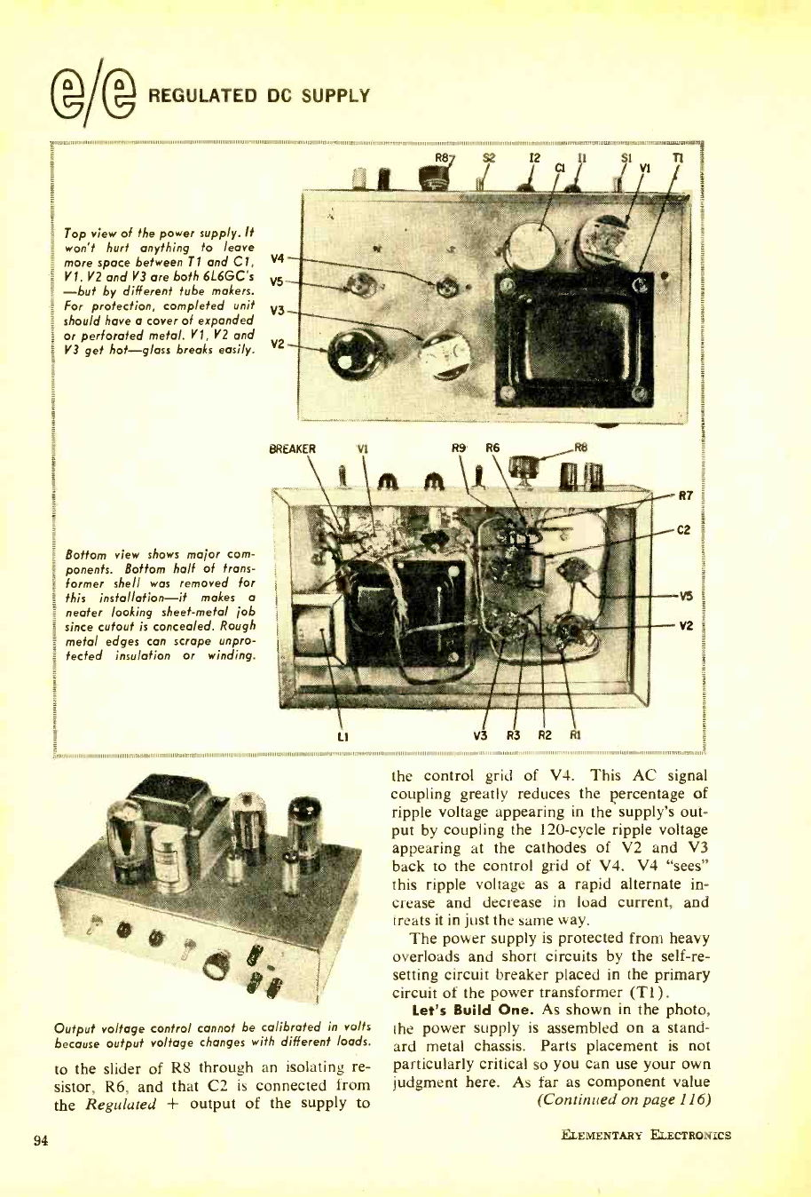
REGULATED DC SUPPLY
Top view of the power supply. It
won't hurt anything to leave
more space between Ti and Cl,
V1. V2 and V3 are both 6L6GC's
-but by different tube makers.
For protection, completed unit
should have a cover of expanded
or perforated metal. V1, Y2 and
V3 get hot -glass breaks easily.
Bottom view shows major com-
ponents. Bottom half of trans-
former shell was removed for
this installation -it makes a
neater looking sheet -metal job
since cutout is concealed. Rough
metal edges can scrape unpro-
tected insulation or winding.
111 11111111111111111 1111,,,,1,,,,1,.,,,,,,, ,,w 11 11M11111,111111111111111111111111fl111111111111111111111111111111MIII1M1H1111.111/11111111111111111111111111,1111111,111111111
12 t Tt
s2
LIi
111111111111 11 11
R7
2
V2
11111111111111111111111141111111.1111/1111111111111111111111111/111111111111
Output voltage control cannot be calibrated in volts
because output voltage changes with different loads.
to the slider of R8 through an isolating re-
sistor, R6, and that C2 is connected from
the Regulated + output of the supply to
94
the control grid of V4. This AC signal
coupling greatly reduces the percentage of
ripple voltage appearing in the supply's out-
put by coupling the 120 -cycle ripple voltage
appearing at the cathodes of V2 and V3
back to the control grid of V4. V4 "sees"
this ripple voltage as a rapid alternate in-
crease and decrease in load current, and
treats it in just the same way.
The power supply is protected from heavy
overloads and short circuits by the self -re-
setting circuit breaker placed in the primary
circuit of the power transformer (Ti).
Let's Build One. As shown in the photo,
the power supply is assembled on a stand-
ard metal chassis. Parts placement is not
particularly critical so you can use your own
judgment here. As far as component value
(Continued on page 116)
ELEMENTARY ELECTRONICS
www.americanradiohistory.com
Stamp out ignition
hash and generator whine!
Don't blame your rig
-check your car!
Quieting
Ignition
Interference
Radio -frequency
and audio -frequency
interference, created
by an engine's igni-
tion and electrical
system, have been
around for a long
time. The problem is
becoming worse be-
cause of engine de-
sign changes and in-
creased receiver
sensitivity. And it doesn't make any differ-
ence if the engine is in an automobile, truck
or a boat. It can still create a serious inter-
ference or noise problem. Equipment manu-
facturers have taken steps to combat this
noise problem. Some have added shielding
and electrical filters to the sensitive portions
of the receivers. Most have incorporated
squelch and automatic noise -limiter circuits.
Effective as these circuits are, they serve
By John D. Lenk
MAY -JUNE, 1966
Icm.
only to reduce the
noise level - make
it bearable. Weak
signals below
this level simply do
not get through the
noise and communi-
cation range is re-
duced.
This article pro-
vides a "shirt sleeves"
approach to the prob-
The major sources of engine interfer-
ence are pinpointed, along with some hints
on how the sources may be located. Then
conventional remedies to reduce or eliminate
such noise or interference sources and how
to use the special noise elimination compo-
nents or kits.
What Is Interference? It can be any elec-
trical disturbance that causes an undesirable
response, or a malfunctioning of communica-
95
www.americanradiohistory.com
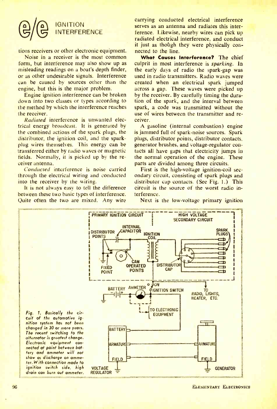
I NT E
INTERFERENCE
carrying conducted electrical interference
serves as an antenna and radiates this inter-
ference. Likewise, nearby wires can pick up
radiated electrical interference and conduct
96
tions receivers or other electronic equipment.
Noise in a receiver is the most common
form, but interference may also show up as
misleading readings on a boat's depth finder,
or as other undesirable signals. Interference
can be caused by sources other than the
engine, but this is the major problem.
Engine ignition interference can be broken
down into two classes or types according to
the method by which the interference reaches
the receiver.
Radiated interference is unwanted elec-
trical energy broadcast. It is generated by
the combined actions of the spark plugs, the
distributor, the ignition coil, and the spark -
plug wires themselves. This energy can be
transferred either by radio waves or magnetic
fields. Normally, it is picked up by the re-
ceiver antenna.
Conducted interference is noise carried
through the electrical wiring and conducted
into the receiver by the wiring.
It is not always easy to tell the difference
between these two basic types of interference.
Quite often the two are mixed. Any wire
tmiii.111111111111..111:1111111111111011011111111111,11E1111111111110=11111111111,1111-
IGNITION CIRCUIT
Fig. 1. Basically the cir-
cuit of the automotive ig-
nition system has not been
changed in 30 or more years.
The recent switching to the
alternator is greatest change.
Electronic equipment con-
nected at point between bat-
tery and ammeter will not
show as discharge on amme-
ter. With connection made to
ignition switch side, high
drain can burn ouf ammeter.
it just as thoùgh they were physically con-
nected to the line.
What Causes Interference? The chief
culprit in most interference is sparking. In
the early days of radio the spark -gap was
used in radio transmitters. Radio waves were
created when an electrical spark jumped
across a gap. These waves were picked up
by the receiver. By carefully timing the dura-
tion of the spark, and the interval between
spark, a code was transmitted without the
use of wires between the transmitter and re-
ceiver.
A gasoline (internal combustion) engine
is jammed full of spark -noise sources. Spark
plugs, distributor points, distributor contacts,
generator brushes, and voltage- regulator con-
tacts all have gaps that electricity jumps in
the normal operation of the engine. These
parts are divided among three circuits.
First is the high -voltage ignition -coil sec-
ondary circuit, consisting of spark plugs and
distributor cap contacts. (See Fig. 1.) This
circuit is the source of the worst radio in-
terference.
Next is the low -voltage primary ignition
.. ,.11111111111. ,
1 INTERNAL
DISTRIBUTOR. /CAPACITOR IGNITION
POINTS COIL
L
FIXED
POINT
CAM
OPERATED
POINTS
HIGH VOLTAGE
SECONDARY CIRCUIT
DISTRIBUTOR
CAP
BATTERY AMMETER o IGNITION SWITCH
1 , © ,
J
Lit ELECTRONIC
QUIPMENT
BATTERY
ARMATURE
FIELD
VOLTAGE I
REGULATOR =
SPARK
PLUGS
+
_J
TO
RADIO, LIGHTS,
HEATER, ETC.
-ARMATUR
HELD
GENERATOR
ELEMENTARY ELECTRONICS
www.americanradiohistory.com
coil circuit that consists of the distributor
cam -operated points, and internal capacitor
(condenser).
Finally, there is the battery, generator and
voltage -regulator circuitry.
How They Work. The distributor points
are opened and closed by a cam at a rate
determined by the engine speed. When the
points are closed current from the battery
(or generator) flows through the ignition
switch, distributor points, and primary wind-
ing of the ignition coil. There is no current
in the secondary circuit at this time. When
the points open, the magnetic field in the
ignition coil collapses. This induces a high
voltage in the secondary winding of the igni-
tion coil.
The coil secondary has many more turns
than the primary. A ratio of 50:1 or 100:1
is not unusual. When the 'distributor points
open, the sudden collapse of the magnetic
field induces a voltage across the secondary
winding that is not proportional to the ratio
of turns in the coil. The resulting 10,000
volts passes through the contacts in the dis-
tributor cap, and discharges through one
spark plug. Consequently, there are two
high- voltage arcs or sparks each time the
distributor points open -a major one at the
spark plug (to fire the gasoline) and a lesser
one in the distributor cap.
Radio waves are created whenever a spark
jumps between two contacts. In the engine,
radio waves are generated in the secondary
ignition circuit. They are picked up by most
sensitive electronic gear and appear as noise
or interference in the speaker or other out-
put. The primary ignition circuit also produces
noise. There is a spark when the breaker
points first open. You have probably noticed
that a noise (or "pop ") is produced in your
home radio each time a light or appliance
is switched off or on. In an engine this same
noise is duplicated by the distributor points
which constantly are being opened and
closed. Although the primary -power source
of the engine is only 12 volts (against the
120 volts of home wiring), it is direct current
which has a much stronger tendency to arc
across switches as they are opened.
The specific details of the generator and
voltage -regulator circuits vary from engine
to engine, but the basic operation of all of
them is essentially the same. The generator
is driven by the engine, producing a contin-
uous "output of direct current (with the help
of a commutator) at approximately the same
MAY -JUNE, 1966
voltage as the battery. The voltage -regulator
contacts control the current flow through
the generator's field winding. Each time
the voltage output falls below the correct
operating point, contacts close and short
out a resistance in the generator field cir-
cuit. The increased current flow increases
the generator voltage to normal. The rapidly
opening and closing voltage regulator can be
a source of noise due to arcing across the
contacts.
Generator noise is caused by the spark
that occurs between the generator brushes,
and the commutator on the armature. Al-
though this spark is normal for any gener-
ator, the spark amplitude increases when the
commutator segments are worn or dirty, or
when the carbon brushes are worn or im-
properly seated. Naturally, the greater the
spark, the more interference will be gen-
erated.
Some late -model autos and boats have
alternators instead of generators. In this
case, the alternator is driven by the engine,
producing alternating current instead of di-
rect current. The alternating current is then
rectified for use by the battery and the
ignition system. An alternator uses brushes
and slip -rings instead of commutator seg-
ments to make contact with the rotating
armature. This results in less sparking and,
consequently, less noise interference. How-
ever, the ignition system (voltage regulator,
distributor and spark plugs) create the same
interference whether an AC alternator or
DC generator is used.
This comment on dirty carbon brushes
and slip -rings brings up the first rule in con-
trolling engine interference. Keep the elec-
trical and ignition system in top condition. A
well- adjusted and carefully tuned engine
creates some radio interference, but a de-
fective or "borderline" ignition system will
surely add to the problem. If spark plugs,
distributor points, and rotor contacts are
fouled, worn, or pitted, there will be more
sparking (or a longer spark) that will create
more noise. The same is true if generator
brushes are dirty, if the spark plug gap has
widened, if alternator slip rings are dirty, or
if the voltage -regulator points are burned or
pitted.
Getting Rid of Noise. Electric arcs
(sparks) from any source start undesirable
radio waves that can be radiated or con-
ducted into electronic gear. Of course, you
could get rid of the interference by stopping
the engine or cutting off the generator each
97
www.americanradiohistory.com
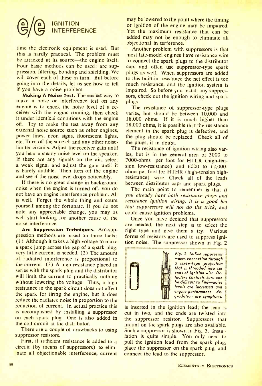
®/@ IGNITION
INTERFERENCE
time the electronic equipment is used. But
this is hardly practical. The problem must
be attacked at its source -the engine itself.
Four basic methods can be used: arc sup-
pression, filtering, bonding and shielding. We
will cover each of these in turn. But before
going into the details, let us see how to tell
if you have a noise problem.
Making A Noise Test. The easiest way to
make a noise or interference test on any
engine is to check the noise level of a re-
ceiver with the engine running, then check
it under identical conditions with the engine
off. Try to make the test away from any
external noise source such as other engines,
power lines, neon signs, fluorescent lights,
etc. Turn off the squelch and any other noise-
limiter circuits. Adjust the receiver gain until
you hear a steady noise level on the speaker.
If there are any signals on the air, select
a weak signal and adjust the gain until it
is barely audible. Then turn off the engine
and see if the noise level drops noticeably.
If there is no great change in background
noise when the engine is turned off, you do
not have an engine interference problem. All
is well. Forget the whole thing and count
yourself among the fortunate. If you do not
note any appreciable change, you may as
well start looking for another cause of the
noise interference.
Arc Suppression Techniques. Arc -sup-
pression methods are based on three facts:
(1) Although it takes a high voltage to make
a spark jump across the gap of a spark plug,
very little current is needed. (2) The amount
of radiated interference is proportional to
the current. (3) A high resistance placed in
series with the spark plug and the distributor
will limit the current to practically nothing
without lowering the voltage. Thus, a high
resistance in the spark circuit does not affect
the spark for firing the engine, but it does
reduce the radiated noise in proportion to the
reduction of current. In actual practice this
is accomplished by installing a suppressor
on each spark plug. One is also added in
the coil circuit at the distributor.
There are a couple of drawbacks to using
suppressor resistors.
First, if sufficient resistance is added to a
circuit (by means of suppressors) to elim-
inate all objectionable interference, current
98
may be lowered to the point where the timing
or ignition of the engine may be impaired.
Yet the maximum resistance that can be
added may not be enough to eliminate all
objectional in terference.
Another problem with suppressors is that
most late -model engines have resistance wire
to connect the spark plugs to the distributor
cap, and often use suppressor -type spark
plugs as well. When suppressors are added
to this built -in resistance the net effect is too
much resistance, and the ignition system is
impaired. So before you install any suppres-
sors, check out the ignition wiring and spark
plugs.
The resistance of suppressor -type plugs
varies, but should be between 10,000 and
18,000 ohms. If it is much higher than
18,000 ohms, it is possible that the resistance
element in the spark plug is defective, and
the plug should be replaced. Check all of
the plugs, if in doubt.
The resistance of ignition wiring also var-
ies, but is in the general area of 3000 to
7000 -ohms per foot for HTLR (high -ten-
sion low- resistance) and 6000 to 12,000 -
ohms per foot for HTHR (high- tension high -
resistance) wire. Check all of the leads
between distributor caps and spark plugs.
The main point to remember is that if
you already have both resistance plugs and
resistance ignition wiring, it is a good bet
that suppressors will not do the trick, and
could cause ignition problems.
Once you have decided that suppressors
are needed, the next step is to select the
right type and give them a try. Various
forms of resistors are used to suppress igni-
tion noise. The suppressor shown in Fig. 2
11, 11 11 111111111111111111111111111111111,i
Fig. 2. In -line suppressor _
makes connection through
a screw -type projection
that is threaded into cut
ends of ignition wire. De-
fective contacts here can
be difficult to find -noise
levels are increased and
engine -performance de-
gradation are symptoms.
1111/ 1111111111 1111111111111,,1111111,.11111 ,1,111, ,,,,,,,,,,,,,,,,,,, 1,,,,,,1111111,,, 1111111.1
is inserted in the ignition lead; the lead is
cut in two, and the ends are twisted into
the suppressor resistor. Suppressors that
mount on the spark plugs are also available.
Such a suppressor is shown in Fig. 3. Instal-
lation is quite simple. You only need to
pull the ignition lead from the spark plug,
place the suppressor on the spark plug, and
connect the lead to the suppressor.
ELEMENTARY ELECTRONICS
www.americanradiohistory.com
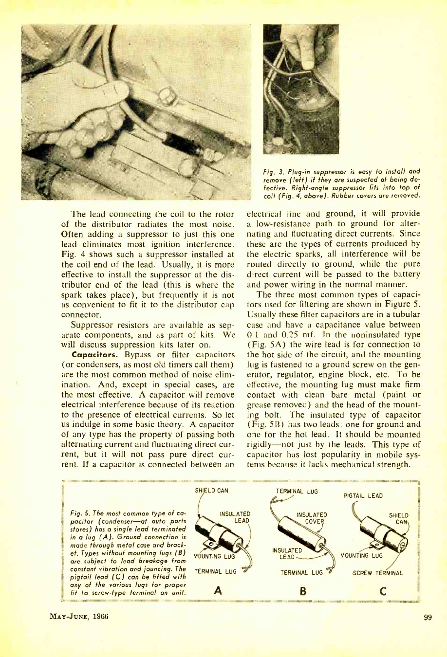
The lead connecting the coil to the rotor
of the distributor radiates the most noise.
Often adding a suppressor to just this one
lead eliminates most ignition interference.
Fig. 4 shows such a suppressor installed at
the coil end of the lead. Usually, it is more
effective to install the suppressor at the dis-
tributor end of the lead (this is where the
spark takes place), but frequently it is not
as convenient to fit it to the distributor cap
connector.
Suppressor resistors are available as sep-
arate components, and as part of kits. We
will discuss suppression kits later on.
Capacitors. Bypass or filter capacitors
(or condensers, as most old timers call them)
are the most common method of noise elim-
ination. And, except in special cases, are
the most effective. A capacitor will remove
electrical interference because of its reaction
to the presence of electrical currents. So let
us indulge in some basic theory. A capacitor
of any type has the property of passing both
alternating current and fluctuating direct cur-
rent, but it will not pass pure direct cur-
rent. If a capacitor is connected between an
Fig. 3. Plug -in suppressor is easy to install and
remove (left) if they are suspected of being de-
fective. Right -angle suppressor fits into top of
coil (Fig. 4, above). Rubber covers are removed.
electrical line and ground, it will provide
a low- resistance path to ground for alter-
nating and fluctuating direct currents. Since
these are the types of currents produced by
the electric sparks, all interference will be
routed directly to ground, while the pure
direct current will be passed to the battery
and power wiring in the normal manner.
The three most common types of capaci-
tors used for filtering are shown in Figure 5.
Usually these filter capacitors are in a tubular
case and have a capacitance value between
0.1 and 0.25 mf. In the noninsulated type
(Fig. 5A) the wire lead is for connection to
the hot side of the circuit, and the mounting
lug is fastened to a ground screw on the gen-
erator, regulator, engine block, etc. To be
effective, the mounting lug must make firm
contact with clean bare metal (paint or
grease removed) and the head of the mount-
ing bolt. The insulated type of capacitor
(Fig. 513) has two leads: one for ground and
one for the hot lead. It should be mounted
rigidly -not just by the leads. This type of
capacitor has lost popularity in mobile sys-
tems because it lacks mechanical strength.
g .11111111111111.,,,,minimmilmmunu ,,,,,,,1,1 1,,,,,,,,,,,,,, 1,,,,,,,,,,11,1,1
Fig. 5. The most common type of ca-
pacitor (condenser -at auto parts
stores) has a single lead terminated
in a lug (A). Ground connection is
made through metal case and brack-
et. Types without mounting lugs (B)
are subject to lead breakage from
constant vibration and jouncing. The TERMINAL LUG
pigtail lead (C) can be fitted with
any of the various lugs for proper
fit to screw -type terminal on unit.
SHIELD CAN
INSULATED
LEAD
,,,,,,,, i,,III1,1,,,1,1,1111,1,1111111111111111111111111,111111,111,1,,,11111111111111111111,,,,,,,,.,,111,,,,1,1,,,,,111,,,,,,
TERMINAL LUG
INSULATED
COVER
PIGTAIL LEAD
MOUNTING LUG
INSULATED
LEAD
TERMINAL LUG
MOUNTING LUG
SCREW TERMINAL
A B C =
MAY -JUNE, 1966 99
www.americanradiohistory.com
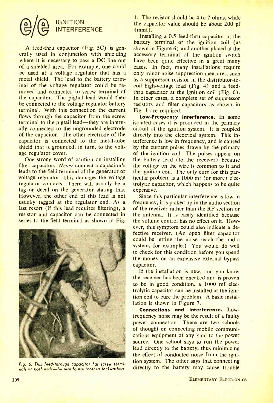
IGNITION
INTERFERENCE
A feed -thru capacitor (Fig. 5C) is gen-
erally used in conjunction with shielding
where it is necessary to pass a DC line out
of a shielded area. For example, one could
be used at a voltage regulator that has a
metal shield. The lead to the battery term-
inal of the voltage regulator could be re-
moved and connected to screw terminal of
the capacitor. The pigtail lead would then
be connected to the voltage regulator battery
terminal. With this connection the current
flows through the capacitor from the screw
terminal to the pigtail lead -they are intern-
ally connected to the ungrounded electrode
of the capacitor. The other electrode of the
capacitor is connected to the metal -tube
shield that is grounded, in turn, to the volt-
age regulator cover.
One strong word of caution on installing
filter capacitors. Never connect a capacitor's
leads to the field terminal of the generator or
voltage regulator. This damages the voltage
regulator contacts. There will usually be a
tag or decal on the generator stating this.
However, the other end of this lead is not
usually tagged at the regulator end. As a
last resort (if this lead requires filtering), a
resistor and capacitor can be connected in
series to the field terminal as shown in Fig.
Fig. 6. This feed -through capacitor has screw fermi -
na/s on both ends -be sure to use toothed /ockwashers.
100
1. The resistor should be 4 to 7 ohms, while
the capacitor value should be about 200 pf
(mmf) .
Installing a 0.5 feed -thru capacitor at the
battery terminal of the ignition coil (as
shown in Figure 6) and another placed at the
accessory terminal of the ignition switch
have been quite effective in a great many
cases. In fact, many installations require
only minor noise -suppression measures, such
as a suppressor resistor in the distributor -to-
coil high -voltage lead (Fig. 4) and a feed -
thru capacitor at the ignition coil (Fig. 6).
In other cases, a complete set of suppressor
resistors and filter capacitors as shown in
Fig. 1 are required.
Low- Frequency Interference. In some
isolated cases it is produced in the primary
circuit of the ignition system. It is coupled
directly into the electrical system. This in-
terference is low in frequency, and is caused
by the current pulses drawn by the primary
of the ignition coil. The pulses appear on
the battery lead (to the receiver) because
the voltage on the wire is common to it and
the ignition coil. The only cure for this par-
ticular problem is a 1000 mf (or more) elec-
trolytic capacitor, which happens to be quite
expensive.
Since this particular interference is low in
frequency, it is picked up in the audio section
of the receiver rather than the RF section or
the antenna. It is easily identified because
the volume control has no effect on it. How-
ever, this symptom could also indicate a de-
fective receiver. (An open filter capacitor
could be letting the noise reach the audio
system, for example.) You would do well
to check for this condition before you spend
the money on an expensive external bypass
capacitor.
If the installation is new, and you know
the receiver has been checked and is proven
to be in good condition, a 1000 mf elec-
trolytic capacitor can be installed at the igni-
tion coil to cure the problem. A basic instal-
lation is shown in Figure 7.
Connections and Interference. Low -
frequency noise may be the result of a faulty
power connection. There are two schools
of thought on connecting mobile communi-
cations equipment of any kind to the power
source. One school says to run the power
lead directly to the battery, thus minimizing
the effect of conducted noise from the igni-
tion system. The other says that connecting
directly to the battery may cause trouble
ELEMENTARY ELECTRONICS
www.americanradiohistory.com
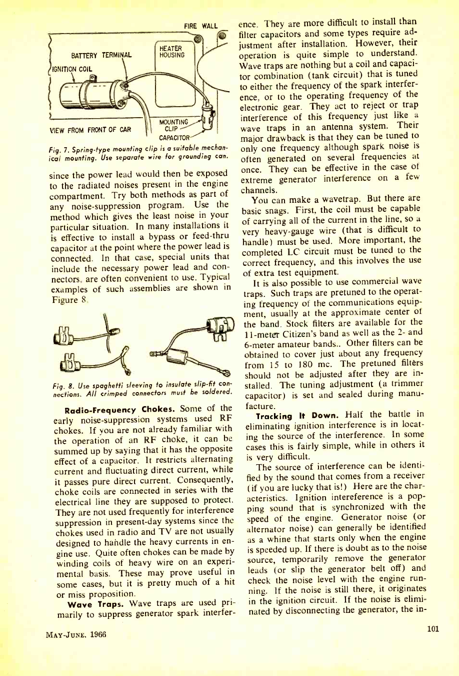
FIRE WALL
BATTERY TERMINAL
IGNITION COIL
HEATER
HOUSING
G
MOUNTING
VIEW FROM FRONT OF CAR I CLIP
CAPACITOR
Fig. 7. Spring -type mounting clip is a suitable mechan-
ical mounting. Use separate wire for grounding can.
since the power lead would then be exposed
to the radiated noises present in the engine
compartment. Try both methods as part of
any noise -suppression program. Use the
method which gives the least noise in your
particular situation. In many installations it
is effective to install a bypass or feed -thru
capacitor at the point where the power lead is
connected. In that case, special units that
include the necessary power lead and con-
nectors, are often convenient to use. Typical
examples of such assemblies are shown in
Figure 8.
Fig. 8. Use spaghetti sleeving to insulate slip -fit con-
nections. All crimped connectors must be soldered.
Radio- Frequency Chokes. Some of the
early noise -suppression systems used RF
chokes. If you are not already familiar with
the operation of an RF choke, it can be
summed up by saying that it has the opposite
effect of a capacitor. It restricts alternating
current and fluctuating direct current, while
it passes pure direct current. Consequently,
choke coils are connected in series with the
electrical line they are supposed to protect.
They are not used frequently for interference
suppression in present -day systems since the
chokes used in radio and TV are not usually
designed to handle the heavy currents in en-
gine use. Quite often chokes can be made by
winding coils of heavy wire on an experi-
mental basis. These may prove useful in
some cases, but it is pretty much of a hit
or miss proposition.
Wave Traps. Wave traps are used pri-
marily to suppress generator spark interfer-
MAY -JUNE. 1966
ence. They are more difficult to install than
filter capacitors and some types require ad-
justment after installation. However, their
operation is quite simple to understand.
Wave traps are nothing but a coil and capaci-
tor combination (tank circuit) that is tuned
to either the frequency of the spark interfer-
ence, or to the operating frequency of the
electronic gear. They act to reject or trap
interference of this frequency just like a
wave traps in an antenna system. Their
major drawback is that they can be tuned to
only one frequency although spark noise is
often generated on several frequencies at
once. They can be effective in the case of
extreme generator interference on a few
channels.
You can make a wavetrap. But there are
basic snags. First, the coil must be capable
of carrying all of the current in the line, so a
very heavy -gauge wire (that is difficult to
handle) must be used. More important, the
completed LC circuit must be tuned to the
correct frequency, and this involves the use
of extra test equipment.
It is also possible to use commercial wave
traps. Such traps are pretuned to the operat-
ing frequency of the communications equip-
ment, usually at the approximate center of
the band. Stock filters are available for the
11 -meter Citizen's band as well as the 2- and
6 -meter amateur bands.. Other filters can be
obtained to cover just about any frequency
from 15 to 180 mc. The pretuned filters
should not be adjusted after they are in-
stalled. The tuning adjustment (a trimmer
capacitor) is set and sealed during manu-
facture.
Tracking It Down. Half the battle in
eliminating ignition interference is in locat-
ing the source of the interference. In some
cases this is fairly simple, while in others it
is very difficult.
The source of interference can be identi-
fied by the sound that comes from a receiver
(if you are lucky that is!) Here are the char-
acteristics. Ignition intereference is a pop-
ping sound that is synchronized with the
speed of the engine. Generator noise (or
alternator noise) can generally be identified
as a whine that starts only when the engine
is speeded up. If there is doubt as to the noise
source, temporarily remove the generator
leads (or slip the generator belt off) and
check the noise level with the engine run-
ning. If the noise is still there, it originates
in the ignition circuit. If the noise is elimi-
nated by disconnecting the generator, the in-
101
www.americanradiohistory.com
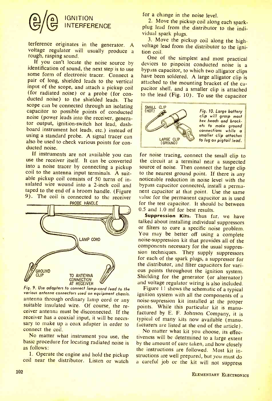
IGNITION
INTERFERENCE
terference originates in the generator. A
voltage regulator will usually produce a
rough, rasping sound.
If you can't locate the noise source by
identification of sound, the next step' is to use
some form of electronic tracer. Connect a
pair of long, shielded leads to the vertical
input of the scope, and attach a pickup coil
(for radiated noise) or a probe (for con-
ducted noise) to the shielded leads. The
scope can be connected through an isolating
capacitor to possible points of conducted
noise (power leads into the receiver, genera-
tor output, ignition- switch hot lead, dash-
board instrument hot leads, etc.) instead of
using a standard probe. A signal tracer can
also be used to check various points for con-
ducted noise.
If instruments are not available you can
use the receiver itself. It can be converted
into a noise tracer by connecting a pickup
coil to the antenna input terminals. A suit-
able pickup coil consists of 50 turns of in-
sulated wire wound into a 2 -inch coil and
taped to the end of a broom handle. (Figure
9). The coil is connected to the receiver
PROBE HANDLE
LAMP CORD
102
GROUND
CLIP TO ANTENNA
CONNECTION
AT RECEIVER
Fig. 9. Use adapters to connect lamp -cord lead to the
various antenna connectors used on equipment chassis.
antenna through ordinary lamp cord or any
suitable insulated wire. Of course, the re-
ceiver antenna must be disconnected. If the
receiver has a coaxial input, it will be neces-
sary to make up a coax adapter in order to
connect the coil.
No matter what instrument you use, the
basic procedure for locating radiated noise is
as follows:
1. Operate the engine and hold the pickup
coil near the distributor. Listen or watch
for a change in the noise level.
2. Move the pickup coil along each spark -
plug lead from the distributor to the indi-
vidual spark plugs.
3. Move the pickup coil along the high -
voltage lead from the distributor to the igni-
tion coil.
One of the simplest and most practical
devices to pinpoint conducted noise is a
bypass capacitor, to which two alligator clips
have been soldered. A large alligator clip is
attached to the mounting bracket of the ca-
pacitor shell, and a smaller clip is attached
to the lead (Fig. 10). To use the capacitor
SMALL CLIP
(HOT)
LARGE CLIP
(GROUND)
Fig. 10. Large battery
clip will grasp most
hex heads and brad -
ets to make ground
connections while a
smaller clip attaches
to lug on pigtail lead.
for noise tracing, connect the small clip to
the circuit at a terminal near a suspected
source of noise. Then connect the large clip
to the nearest ground point. If there is any
noticeable reduction in noise level with the
bypass capacitor connected, install a perma-
nent capacitor at that point. Use the same
value for the permanent capacitor as is used
for the test capacitor. It should be between
0.5 and 1.0 mf for best results.
Suppression Kits. Thus far, we have
talked about installing individual suppressors
or filters to cure a specific noise problem.
You may be better off using a complete
noise -suppression kit that provides all of the
components necessary for the usual suppres-
sion techniques. They supply suppressors
for each of the spark plugs, a suppressor for
the distributor, and filter capacitors for vari-
ous points throughout the ignition system.
Shielding for the generator (or alternator)
and voltage regulator wiring is also included.
Figure 11 shows the schematic of a typical
ignition system with all the components of a
noise -supression kit installed at the proper
points. While this particular kit is manu-
factured by E. F. Johnson Company, it is
typical of many kits now available (manu-
facturers are listed at the end of the article).
No matter what kit you choose, its effec-
tiveness will be determined to a large extent
by the amount of care taken, and how closely
the instructions are followed. Most kit in-
structions are well prepared, but you must do
a careful job or the kit will not suppress
ELEMENTARY ELECTRONICS
www.americanradiohistory.com
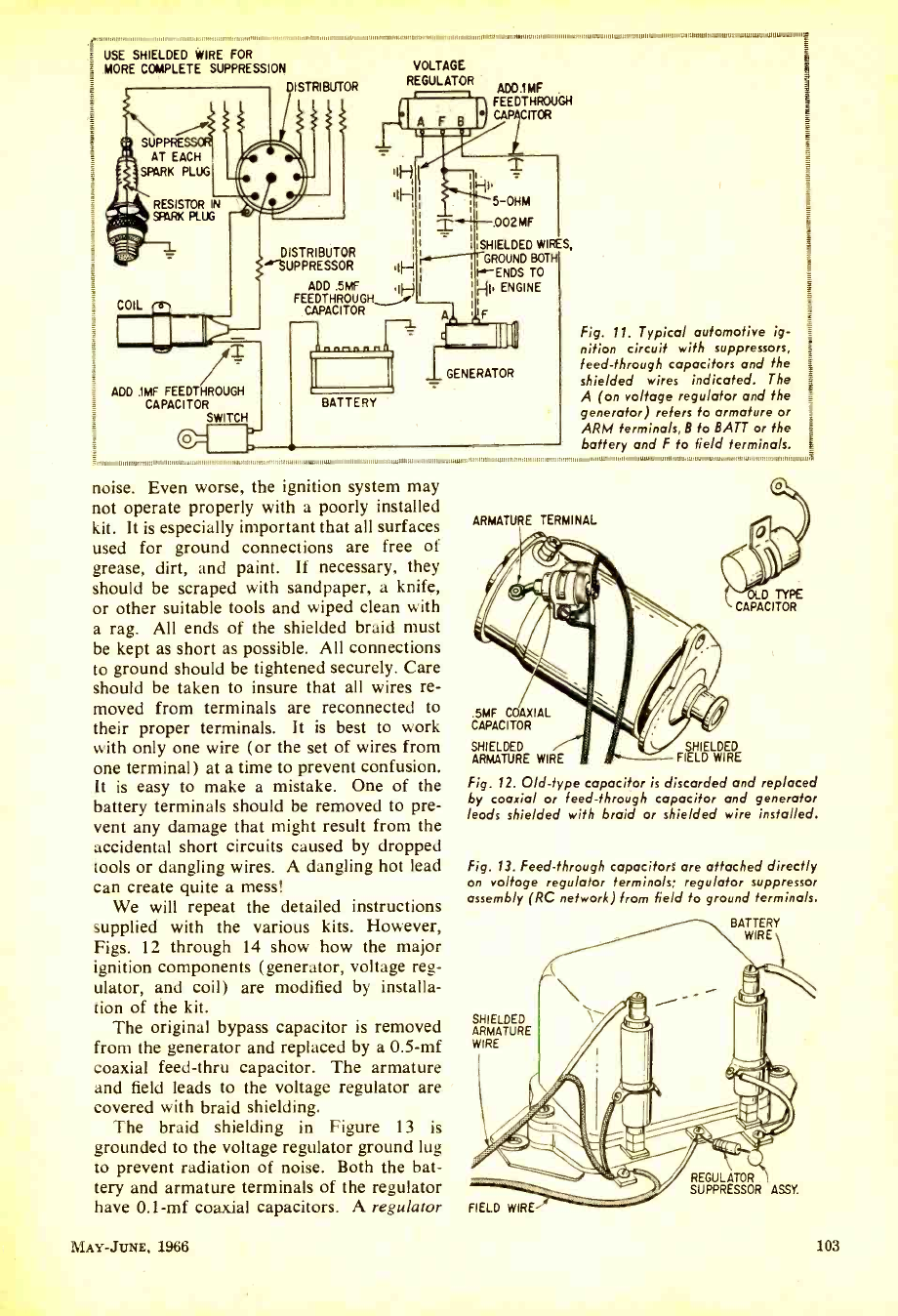
USE SHIELDED WIRE FOR
MORE COMPLETE SUPPRESSION
DISTRIBUTOR
ADD .IMF FEEDTHROUGH
CAPACITOR SWITCH r
VOLTAGE
REGULATOR ADD.IMF
FEEDTHROUGH
CA CITOR
HI'
5 -OHM
.002 MF
SHIELDED WIRES,
GROUND BOTH
I.-ENDS TO
HI. ENGINE
T
DISTRIBUTOR
SUPPRESSOR .IF-+
ADD .5W
FEEDTHROUGH.
CAPACITOR F
BATTERY
GENERATOR
Fig. 11. Typical automotive ig-
nition circuit with suppressors,
feed -through capacitors and the
shielded wires indicated. The
A (on voltage regulator and the
generator) refers to armature or
ARM terminals, B to BATT or the
battery and F to field terminals.
noise. Even worse, the ignition system may
not operate properly with a poorly installed
kit. It is especially important that all surfaces
used for ground connections are free of
grease, dirt, and paint. If necessary, they
should be scraped with sandpaper, a knife,
or other suitable tools and wiped clean with
a rag. All ends of the shielded braid must
be kept as short as possible. All connections
to ground should be tightened securely. Care
should be taken to insure that all wires re-
moved from terminals are reconnected to
their proper terminals. It is best to work
with only one wire (or the set of wires from
one terminal) at a time to prevent confusion.
It is easy to make a mistake. One of the
battery terminals should be removed to pre-
vent any damage that might result from the
accidental short circuits caused by dropped
tools or dangling wires. A dangling hot lead
can create quite a mess!
We will repeat the detailed instructions
supplied with the various kits. However,
Figs. 12 through 14 show how the major
ignition components (generator, voltage reg-
ulator, and coil) are modified by installa-
tion of the kit.
The original bypass capacitor is removed
from the generator and replaced by a 0.5 -mf
coaxial feed -thru capacitor. The armature
and field leads to the voltage regulator are
covered with braid shielding.
The braid shielding in Figure 13 is
grounded to the voltage regulator ground lug
to prevent radiation of noise. Both the bat-
tery and armature terminals of the regulator
have 0.1 -mf coaxial capacitors. A regulator
ARMATURE TERMINAL
.5MF COAXIAL
CAPACITOR
SHIELDED SHIELDED
ARMATURE WIRE FIELD WIRE
Fig. 12. Old -type capacitor is discarded and replaced
by coaxial or feed -through capacitor and generator
leads shielded with braid or shielded wire installed.
D TYPE
CAPACITOR
Fig. 13. Feed -through capacitors are attached directly
on voltage regulator terminals; regulator suppressor
assembly (RC network) from field to ground terminals.
BATTERY
WIRE
SHIELDED
ARMATURE
WIRE
FIELD WIRE
REGULATOR
SUPPRESSOR ASSY.
MAY -JowE. 1966 103
www.americanradiohistory.com
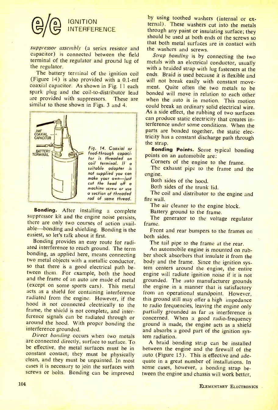
IGNITION
INTERFERENCE
suppressor assembly (a series resistor and
capacitor) is connected between the field
terminal of the regulator and ground lug of
the regulator.
The battery terminal of the ignition coil
(Figure 14) is also provided with a 0.1 -mf
coaxial capacitor. As shown in Fig. 11 each
spark plug and the coil -to- distributor lead
are provided with suppressors. These are
similar to those shown in Figs. 3 and 4.
_p,,,..u,.,i,iii,,,,,1,,,11,11,11111,1,,,111,,,,,1 ,,,,,,,,,,1 , ,,, 1,,,,, 111111111111,111 ,,,, , 1111 ,.,,,,
COAXIAL
CAPACITOR
BATTERY
TERMINAL
rrrrilll
Fig. 14. Coaxial or
feed -through capaci-
tor is threaded on =
coil terminal. If a
suitable adapter is
not supplied you can
make your own -just
cut the head off a =
machine screw or use
a section of threaded =
rod of some thread. _
Bonding. After installing a complete
suppressor kit and the engine noise persists,
there are only two courses of action avail-
able- bonding and shielding. Bonding is the
easiest, so let's talk about it first.
Bonding provides an easy route for radi-
ated interference to reach ground. The term
bonding, as applied here, means connecting
two metal objects with a metallic conductor,
so that there is a good electrical path be-
tween them. For example, both the hood
and the frame of an auto are made of metal
(except on some sports cars). This metal
acts as a shield for containing interference
radiated from the engine. However, if the
hood is not connected electrically to the
frame, the shield is not complete, and inter-
ference signals can be radiated through or
around the hood. With proper bonding the
interference grounded.
Direct bonding occurs when two metals
are connected directly, surface to surface. To
be effective, the metal surfaces must be in
constant contact; they must be physically
clean, and they must be unpainted. In most
cases it is necessary to join the surfaces with
screws or bolts. Bonding can be improved
104
by using toothed washers (internal or ex-
ternal). These washers cut into the metals
through any paint or insulating surface; they
should be used at both ends of the screws so
that both metal surfaces are in contact with
the washers and screws.
Strap bonding is by connecting the two
metals with an electrical conductor, usually
with a braided strap with lug fasteners at the
ends. Braid is used because it is flexible and
will not break easily with constant move-
ment. Quite often the two metals to be
bonded will move in relation to each òther
when the auto is in motion. This motion
could break an ordinary solid electrical wire.
As a side effect, the rubbing of two surfaces
can produce static electricity that creates in-
terference under some conditions. When the
parts are bonded together, the static elec-
tricity has a constant discharge path through
the strap.
Bonding Points. Some typical bonding
points on an automobile are:
Corners of the engine to the frame.
The exhaust pipe to the frame and the
engine.
Both sides of the hood.
Both sides of the trunk lid.
The coil and distributor to the engine and
fire wall.
The air cleaner to the engine block.
Battery ground to the frame.
The generator to the voltage regulator
frame.
Front and rear bumpers to the frames on
both sides.
The tail pipe to the frame at the rear.
An automobile engine is mounted on rub-
ber shock absorbers that insulate it from the
body and the frame. Since the ignition sys-
tem centers around the engine, the entire
engine will radiate ignition noise if it is not
grounded. The auto manufacturer grounds
the engine in a manner that is satisfactory
from an operational standpoint. However,
this ground still may offer a high impedance
to radio frequencies, leaving the engine only
partially grounded as far as interference is
concerned. When a good radio -frequency
ground is made, the engine acts as a shield
and absorbs a good part of the ignition sys-
tem radiation.
A braid bonding strap can be installed
between the engine and the firewall of the
auto (Figure 15). This is effective and ade-
quate in a great number of installations. In
some cases, however, a bonding strap be-
tween the engine and chassis will work better,
ELEMENTARY ELECTRONICS
www.americanradiohistory.com
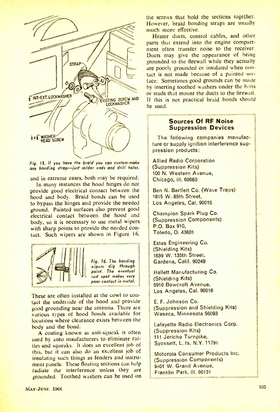
} INT EXT. LOCm ÁSHER
}xf WASHER
HEAD SCREW
EX STING SCREW AND
R
Fig. 15. If you have Me braid you can custom -make
any bonding strap -just solder ends and drill holes.
and in extreme cases, both may be required.
In many instances the hood hinges do not
provide good electrical contact between the
hood and body. Braid bonds can be used
to bypass the hinges and provide the needed
ground. Painted surfaces also prevent good
electrical contact between the hood and
body, so it is necessary to use metal wipers
with sharp points to provide the needed con-
tact. Such wipers are shown in Figure 16.
jlutl'111:'41111111wI11111111111111 11I
Fig. 16. The bonding
wipers dig through
paint. The eventual
rust spot makes very
poor contact in metal.
11 11 111111111 111 11111 11111 111111111111111111 I' 111111,1 AI I ,'
These are often installed at the cowl to con-
tact the underside of the hood and provide
good grounding near the antenna. There are
various types of hood bonds available for
locations where clearance exists between the
body and the bond.
A coating known as anti -squeak is often
used by auto maufacturers to eliminate rat -
ties and squeaks. It does an excellent job of
this, but it can also do an excellent job of
insulating such things as fenders and instru-
ment panels. These floating sections can help
radiate the interference unless they are
grounded. Toothed washers can be used on
MAY -JUNE, 1966
the screws that hold the sections together.
However, braid bonding straps are usually
much more effective.
Heater ducts, control cables, and other
parts that extend into the engine compart-
ment often transfer noise to the receiver.
Ducts may give the appearance of being
grounded to the firewall while they actually
are poorly grounded or insulated when con-
tact is not made because of a painted sur-
face. Sometimes good grounds can be made
by inserting toothed washers under the bolts
or studs that mount the ducts to the firewall.
If this is not practical braid bonds should
be used.
11111111111111 11 111111111 11111
Sources Of RF Noise
Suppression Devices
The following companies manufac-
ture or supply ignition interference sup-
pression products:
Allied Radio Corporation
(Suppression Kits)
100 N. Western Avenue,
Chicago, Ill. 60680
Ben N. Bartlett Co. (Wave Traps)
1815 W. 85th Street,
Los Angeles, Cal. 90016
Champion Spark Plug Co.
(Suppression Components)
P.O. Box 910,
Toledo, O. 43601
Estes Engineering Co.
(Shielding Kits)
1639 W. 135th Street,
Gardena, Calif. 90249
Hallett Manufacturing Co.
(Shielding Kits)
5910 Bowcroft Avenue,
Los Angeles, Cal. 90016
E. F. Johnson Co.
(Suppression and Shielding Kits)
Waseca, Minnesota 56093
Lafayette Radio Electronics Corp.
(Suppression Kits)
111 Jericho Turnpike,
Syossett, L. Is. N.Y. 11791
Motorola Consumer Products Inc.
(Suppression Components)
1 9401 W. Grand Avenue,
Franklin Park, III. 60131
105
www.americanradiohistory.com
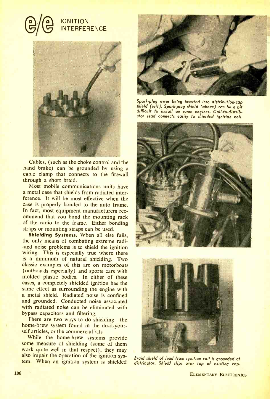
IGNITION
INTERFERENCE
Cables, (such as the choke control and the
hand brake) can be grounded by using a
cable clamp that connects to the firewall
through a short braid.
Most mobile communications units have
a metal case that shields from radiated inter-
ference. It will be most effective when the
case is properly bonded to the auto frame.
In fact, most equipment manufacturers rec-
ommend that you bond the mounting rack
of the radio to the frame. Either bonding
straps or mounting straps can be used.
Shielding Systems. When all else fails,
the only means of combating extreme radi-
ated noise problems is to shield the ignition
wiring. This is especially true where there
is a minimum of natural shielding. Two
classic examples of this are on motorboats
(outboards especially) and sports cars with
molded plastic bodies. In either of these
cases, a completely shielded ignition has the
same effect as surrounding the engine with
a metal shield. Radiated noise is confined
and grounded. Conducted noise associated
with radiated noise can be eliminated with
bypass capacitors and filtering.
There are two ways to do shielding -the
home -brew system found in the do -it -your-
self articles, or the commercial kits.
While the home -brew systems provide
some measure of shielding (some of them
work quite well in that respect), they may
also impair the operation of the ignition sys-
tem. When an ignition system is shielded
106
Spark -plug wires being inserted into distribution -cap
shield (left). Spark -plug shield (above) can be a bit
difficult to install on some engines. Coil-to- distrib-
utor lead connects easily to shielded ignition coil.
Braid shield of lead from ignition coil is grounded at
distributor. Shield slips over top of existing cap.
ELEMENTARY ELECTRONICS
www.americanradiohistory.com
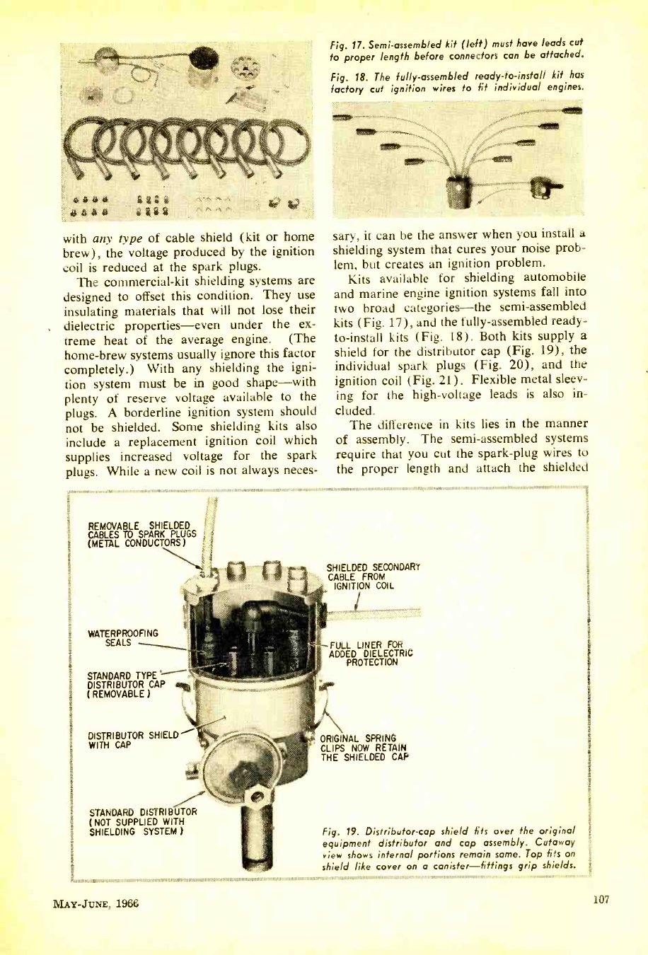
Fig. 17. Semi -assembled kit (left) must have leads cut
to proper length before connectors can be attached.
Fig. 18. The fully -assembled ready -to- install kit has
factory cut ignition wires to fit individual engines,
with any type of cable shield (kit or home
brew), the voltage produced by the ignition
coil is reduced at the spark plugs.
The commercial -kit shielding systems are
designed to offset this condition. They use
insulating materials that will not lose their
dielectric properties -even under the ex-
treme heat of the average engine. (The
home -brew systems usually ignore this factor
completely.) With any shielding the igni-
tion system must be in good shape -with
plenty of reserve voltage available to the
plugs. A borderline ignition system should
not be shielded. Some shielding kits also
include a replacement ignition coil which
supplies increased voltage for the spark
plugs. While a new coil is not always neces-
sary, it can be the answer when you install a
shielding system that cures your noise prob-
lem, but creates an ignition problem.
Kits available for shielding automobile
and marine engine ignition systems fall into
two broad categories -the semi- assembled
kits (Fig. 17), and the fully- assembled ready -
to- install kits (Fig. 18). Both kits supply a
shield for the distributor cap (Fig. 19), the
individual spark plugs (Fig. 20), and the
ignition coil (Fig. 21). Flexible metal sleev-
ing for the high -voltage leads is also in-
cluded.
The difference in kits lies in the manner
of assembly. The semi -assembled systems
require that you cut the spark -plug wires to
the proper length and attach the shielded
REMOVABLE SHIELDED
CABLES TO SPARK PLUGS
(METAL CONDUCTORS)
ç
WATERPROOFING
SEALS
STANDARD TYPE
DISTRIBUTOR CAP (web ,,j
(REMOVABLE)
1111111111111111111111111 11 1
SHIELDED SECONDARY
CABLE FROM
IGNITION COIL
FULL LINER FOR
ADDPROTECTION RIG
DISTRIBUTOR SHIELD
WITH CAP
STANDARD DISTRIBUTOR
(NOT SUPPLIED WITH
SHIELDING SYSTEM )
ORIGINAL SPRING
CLIPS NOW RETAIN
THE SHIELDED CAP
Fig. 19. Distributor -cap shield fits over the original
equipment distributor and cap assembly. Cutaway
view shows internal portions remain same. Top fits on
shield like cover on a canister- fittings grip shields.
MAY-JUNE, 1966 107
www.americanradiohistory.com
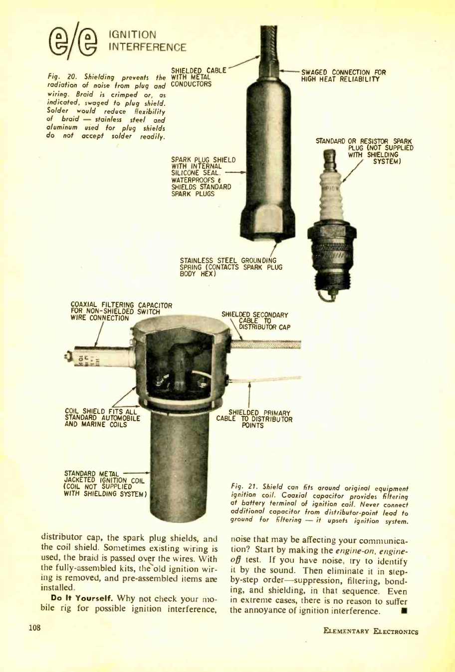
IGNITION
INTERFERENCE
SHIELDED CABLE
Fig. 20. Shielding prevents the WITH METAL
radiation of noise from plug and CONDUCTORS
wiring. Braid is crimped or, as
indicated, swaged fo plug shield.
Solder would reduce flexibility
of braid - stainless steel and
aluminum used for plug shields
do not accept solder readily.
SWAGED CONNECTION FOR
HIGH HEAT RELIABILITY
STANDARD OR RESISTOR SPARK
PLUG (NOT SUPPLIED
WITH SHIELDING
/ SYSTEM)
SPARK PLUG SHIELD
WITH INTERNAL
SILICONE SEAL.
WATERPROOFS C
SHIELDS STANDARD
SPARK PLUGS
COAXIAL FILTERING CAPACITOR
FOR NON - SHIELDED SWITCH
WIRE CONNECTION
STAINLESS STEEL GROUNDING
SPRING (CONTACTS SPARK PLUG
BODY HEX)
SHIELDED SECONDARY
CABLE TO
DISTRIBUTOR CAP
COIL SHIELD FITS ALL
STANDARD AUTOMOBILE
AND MARINE COILS
STANDARD METAL
JACKETED IGNITION COIL
(COIL NOT SUPPLIED
WITH SHIELDING SYSTEM)
i
SHIELDED PRIMARY
CABLE TO DISTRIBUTOR
POINTS
distributor cap, the spark plug shields, and
the coil shield. Sometimes existing wiring is
used, the braid is passed over the wires. With
the fully -assembled kits, the old ignition wir-
ing is removed, and pre -assembled items are
installed.
Do It Yourself. Why not check your mo-
bile rig for possible ignition interference,
108
Fig. 21. Shield can fits around original equipment
ignition coil. Coaxial capacitor provides filtering
at battery terminal of ignition coil. Never connect
additional capacitor from distributor -point lead to
ground for filtering - it upsets ignition system.
noise that may be affecting your communica-
tion? Start by making the engine -on, engine-
off test. If you have noise, try to identify
it by the sound. Then eliminate it in step -
by -step order -suppression, filtering, bond-
ing, and shielding, in that sequence. Even
in extreme cases, there is no reason to suffer
the annoyance of ignition interference.
ELEMENTARY ELECTRONICS
www.americanradiohistory.com
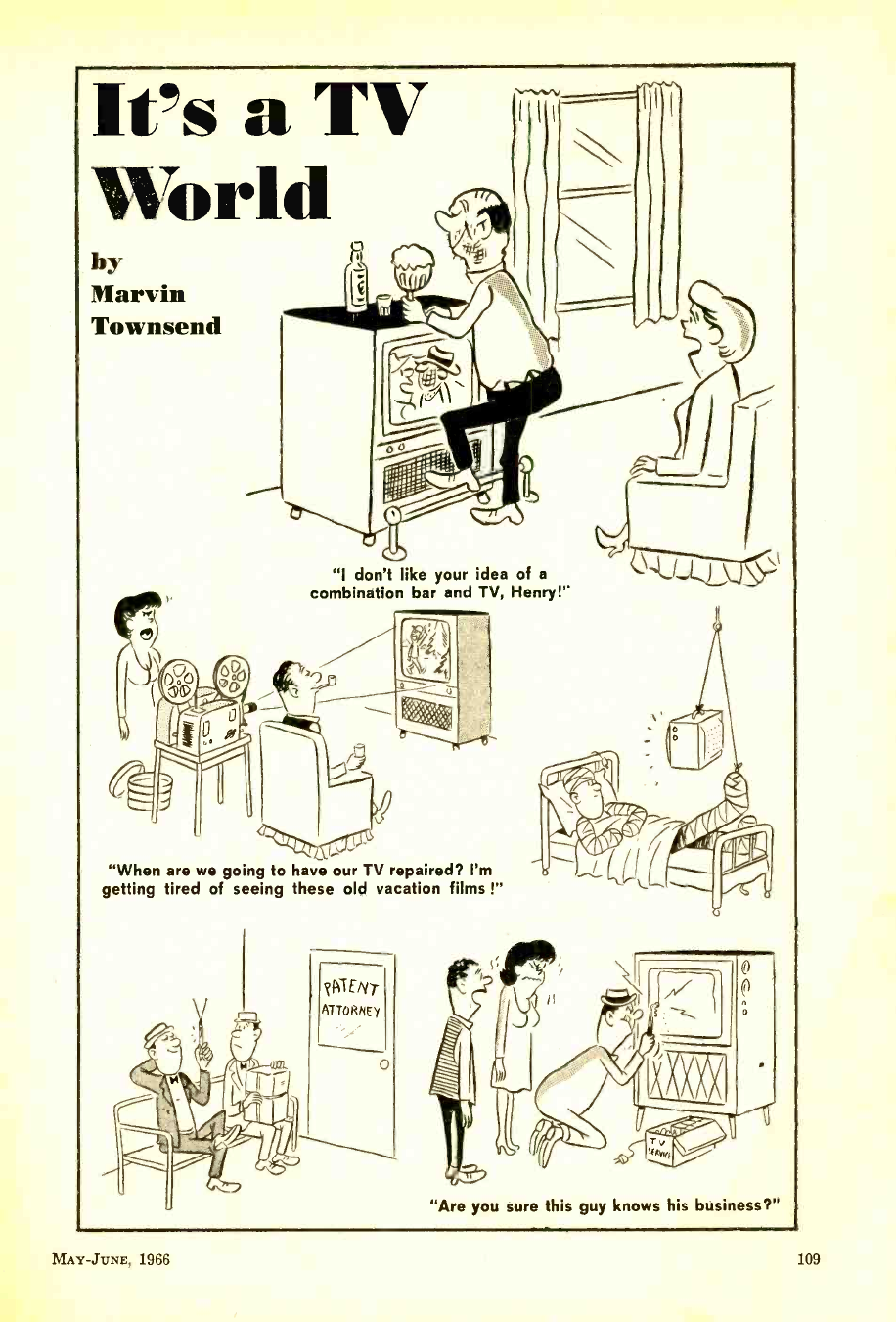
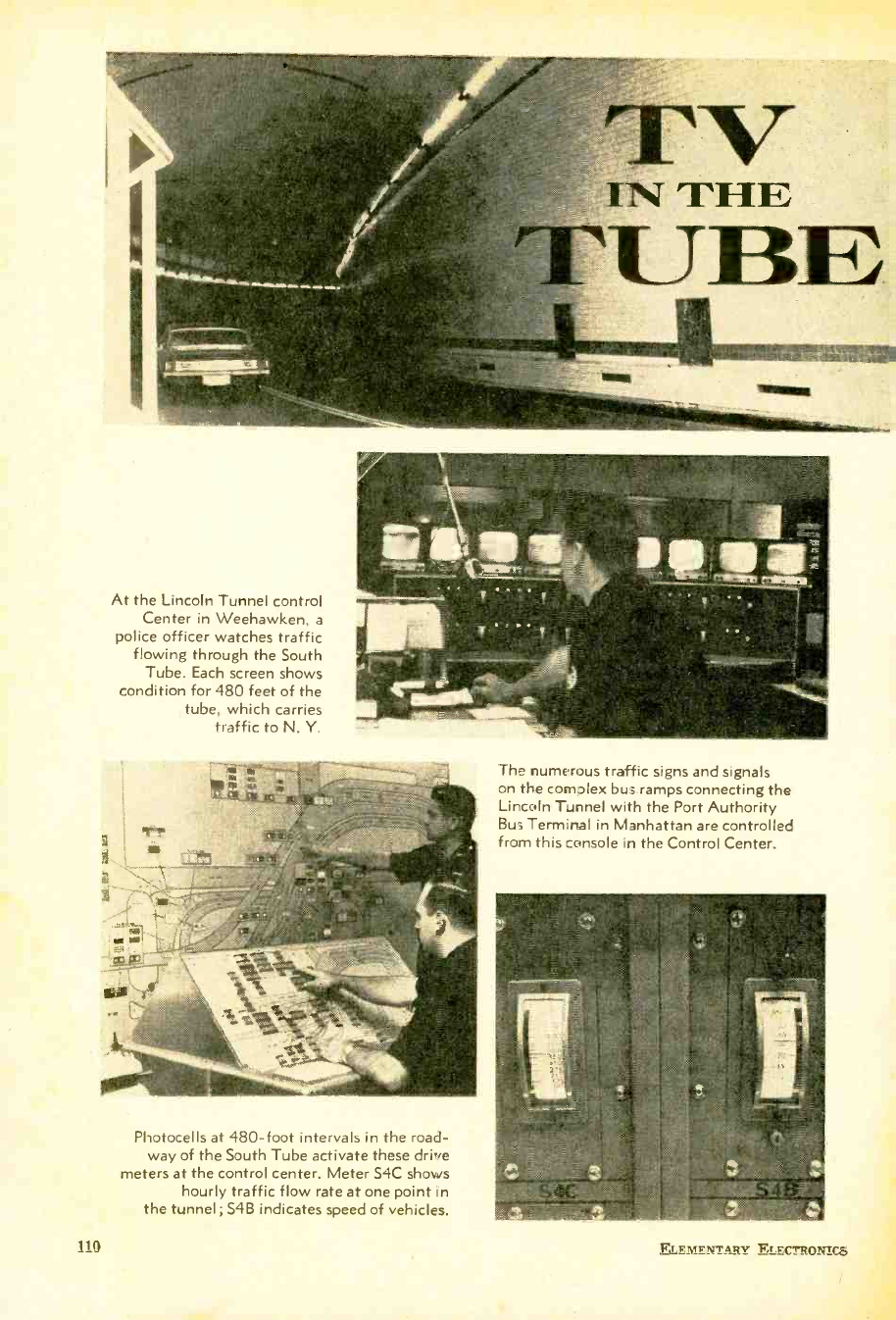
At the Lincoln Tunnel control
Center in Weehawken, a
police officer watches traffic
flowing through the South
Tube. Each screen shows
condition for 480 feet of the
tube, which carries
traffic to N. Y.
The numerous traffic signs and signals
on the c:omolex bus ramps connecting the
Lincoln Tunnel with the Port Authority
Bus Terminal in Manhattan are controlled
from this console in the Control Center.
Photocells at 480 -foot intervals in the road-
way of the South Tube activate these drive
meters at the control center. Meter S4C shows
hourly traffic flow rate at one point in
the tunnel; S4B indicates speed of vehicles.
110 ELEMENTARY Fr.FC3RO?i3C$
www.americanradiohistory.com
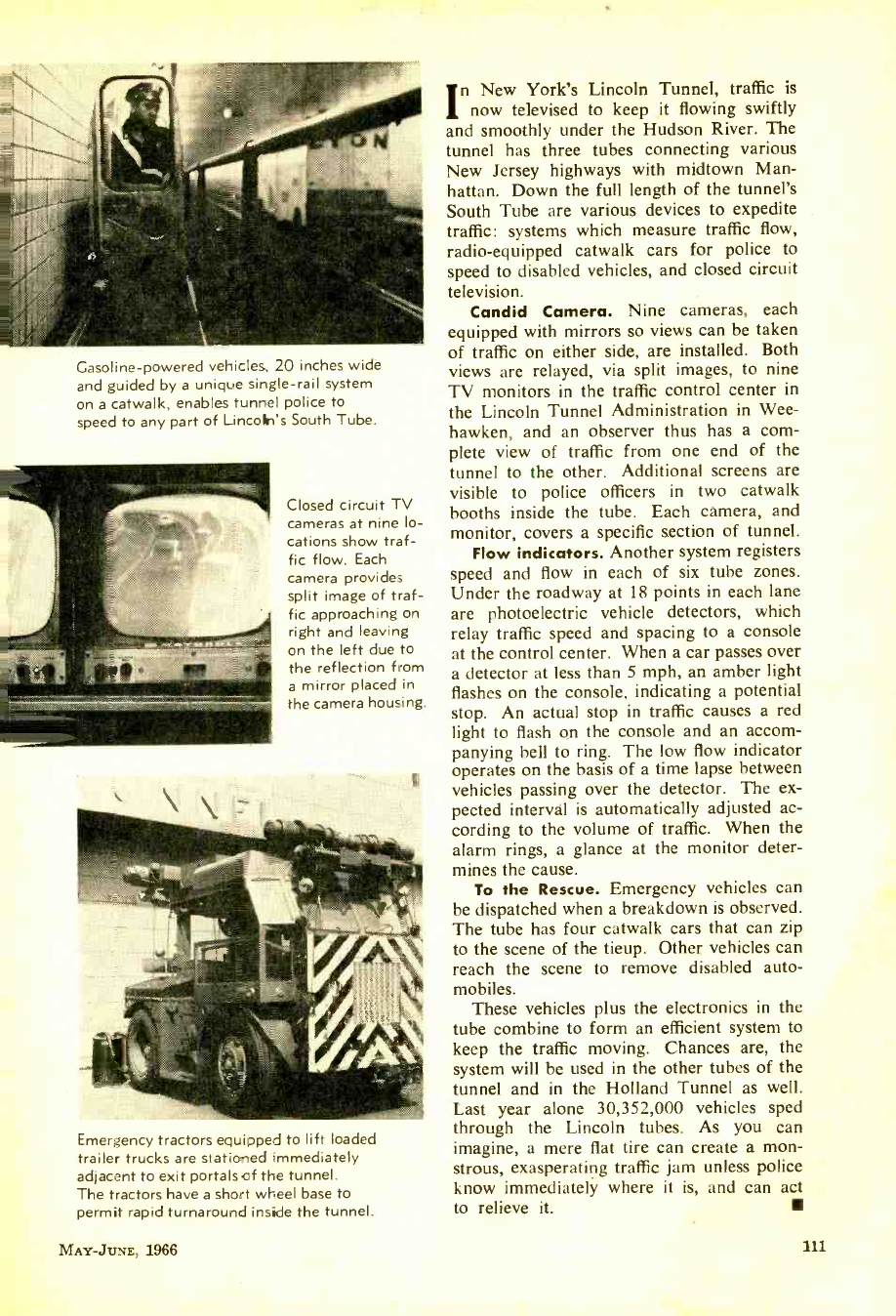
Gasoline -powered vehicles, 20 inches wide
and guided by a unique single -rail system
on a catwalk, enables tunnel police to
speed to any part of Lincoln's South Tube.
Closed circuit TV
cameras at nine lo-
cations show traf-
fic flow. Each
camera provides
split image of traf-
fic approaching on
right and leaving
on the left due to
the reflection from
a mirror placed in
the camera housing.
Emergency tractors equipped to lift loaded
trailer trucks are stationed immediately
adjacent to exit portals of the tunnel.
The tractors have a short wheel base to
permit rapid turnaround inside the tunnel.
MAY -JUNE, 1966
In New York's Lincoln Tunnel, traffic is
now televised to keep it flowing swiftly
and smoothly under the Hudson River. The
tunnel has three tubes connecting various
New Jersey highways with midtown Man-
hattan. Down the full length of the tunnel's
South Tube are various devices to expedite
traffic: systems which measure traffic flow,
radio-equipped catwalk cars for police to
speed to disabled vehicles, and closed circuit
television.
Candid Camera. Nine cameras, each
equipped with mirrors so views can be taken
of traffic on either side, are installed. Both
views are relayed, via split images, to nine
TV monitors in the traffic control center in
the Lincoln Tunnel Administration in Wee-
hawken, and an observer thus has a com-
plete view of traffic from one end of the
tunnel to the other. Additional screens are
visible to police officers in two catwalk
booths inside the tube. Each camera, and
monitor, covers a specific section of tunnel.
Flow indicators. Another system registers
speed and flow in each of six tube zones.
Under the roadway at 18 points in each lane
are photoelectric vehicle detectors, which
relay traffic speed and spacing to a console
at the control center. When a car passes over
a detector at less than 5 mph, an amber light
flashes on the console, indicating a potential
stop. An actual stop in traffic causes a red
light to flash on the console and an accom-
panying bell to ring. The low flow indicator
operates on the basis of a time lapse between
vehicles passing over the detector. The ex-
pected interval is automatically adjusted ac-
cording to the volume of traffic. When the
alarm rings, a glance at the monitor deter-
mines the cause.
To the Rescue. Emergency vehicles can
be dispatched when a breakdown is observed.
The tube has four catwalk cars that can zip
to the scene of the tieup. Other vehicles can
reach the scene to remove disabled auto-
mobiles.
These vehicles plus the electronics in the
tube combine to form an efficient system to
keep the traffic moving. Chances are, the
system will be used in the other tubes of the
tunnel and in the Holland Tunnel as well.
Last year alone 30,352,000 vehicles sped
through the Lincoln tubes. As you can
imagine, a mere flat tire can create a mon-
strous, exasperating traffic jam unless police
know immediately where it is, and can act
to relieve it.
111
www.americanradiohistory.com
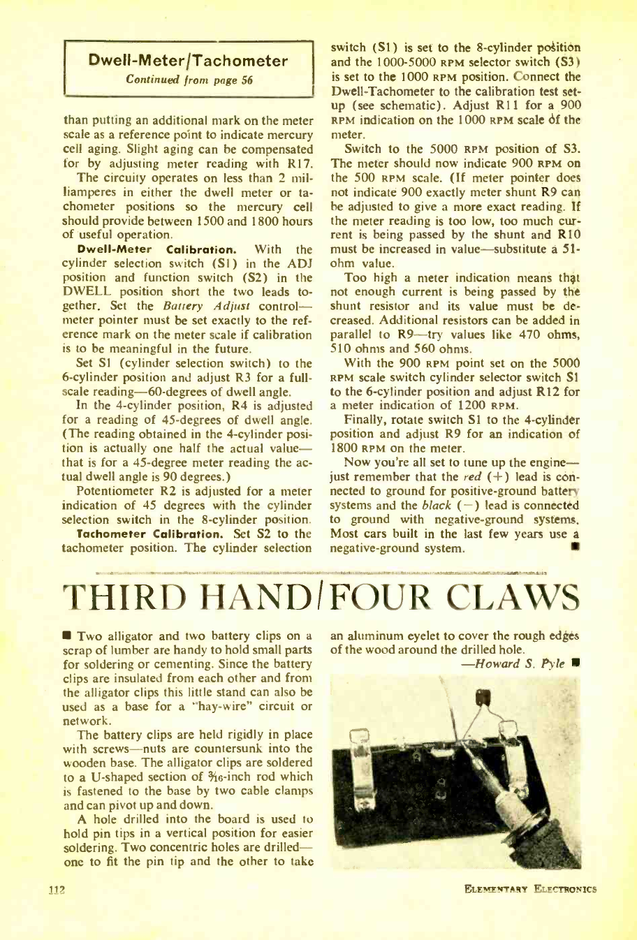
Dwell- Meter/Tachometer
Continued from page 56
than putting an additional mark on the meter
scale as a reference point to indicate mercury
cell aging. Slight aging can be compensated
for by adjusting meter reading with R17.
The circuity operates on less than 2 mil-
liamperes in either the dwell meter or ta-
chometer positions so the mercury cell
should provide between 1500 and 1800 hours
of useful operation.
Dwell -Meter Calibration. With the
cylinder selection switch (Si) in the ADJ
position and function switch (S2) in the
DWELL position short the two leads to-
gether. Set the Battery Adjust control -
meter pointer must be set exactly to the ref-
erence mark on the meter scale if calibration
is to be meaningful in the future.
Set SI (cylinder selection switch) to the
6- cylinder position and adjust R3 for a full -
scale reading -60- degrees of dwell angle.
In the 4- cylinder position, R4 is adjusted
for a reading of 45- degrees of dwell angle.
(The reading obtained in the 4- cylinder posi-
tion is actually one half the actual value -
that is for a 45- degree meter reading the ac-
tual dwell angle is 90 degrees.)
Potentiometer R2 is adjusted for a meter
indication of 45 degrees with the cylinder
selection switch in the 8- cylinder position.
Tachometer Calibration. Set S2 to the
tachometer position. The cylinder selection
switch (Si) is set to the 8- cylinder position
and the 1000 -5000 RPM selector switch (S3)
is set to the 1000 RPM position. Connect the
Dwell -Tachometer to the calibration test set-
up (see schematic). Adjust R11 for a 900
RPM indication on the 1000 RPM scale of the
meter.
Switch to the 5000 RPM position of S3.
The meter should now indicate 900 RPM on
the 500 RPM scale. (If meter pointer does
not indicate 900 exactly meter shunt R9 can
be adjusted to give a more exact reading. If
the meter reading is too low, too much cur-
rent is being passed by the shunt and R10
must be increased in value- substitute a 51-
ohm value.
Too high a meter indication means that
not enough current is being passed by the
shunt resistor and its value must be de-
creased. Additional resistors can be added in
parallel to R9 -try values like 470 ohms,
510 ohms and 560 ohms.
With the 900 RPM point set on the 5000
RPM scale switch cylinder selector switch Si
to the 6- cylinder position and adjust R12 for
a meter indication of 1200 RPM.
Finally, rotate switch Si to the 4- cylinder
position and adjust R9 for an indication of
1800 RPM on the meter.
Now you're all set to tune up the engine -
just remember that the red ( +) lead is con-
nected to ground for positive -ground battery
systems and the black ( -) lead is connected
to ground with negative -ground systems.
Most cars built in the last few years use a
negative -ground system.
THIRD HANDIFOUR CLAWS
Two alligator and two battery clips on a
scrap of lumber are handy to hold small parts
for soldering or cementing. Since the battery
clips are insulated from each other and from
the alligator clips this little stand can also be
used as a base for a "hay- wire" circuit or
network.
The battery clips are held rigidly in place
with screws -nuts are countersunk into the
wooden base. The alligator clips are soldered
to a U- shaped section of %o -inch rod which
is fastened to the base by two cable clamps
and can pivot up and down.
A hole drilled into the board is used to
hold pin tips in a vertical position for easier
soldering. Two concentric holes are drilled -
one to fit the pin tip and the other to take
112
an aluminum eyelet to cover the rough edges
of the wood around the drilled hole.
-Howard S. Pyle
ELE?NF!fTANY ELECTRONICS
www.americanradiohistory.com
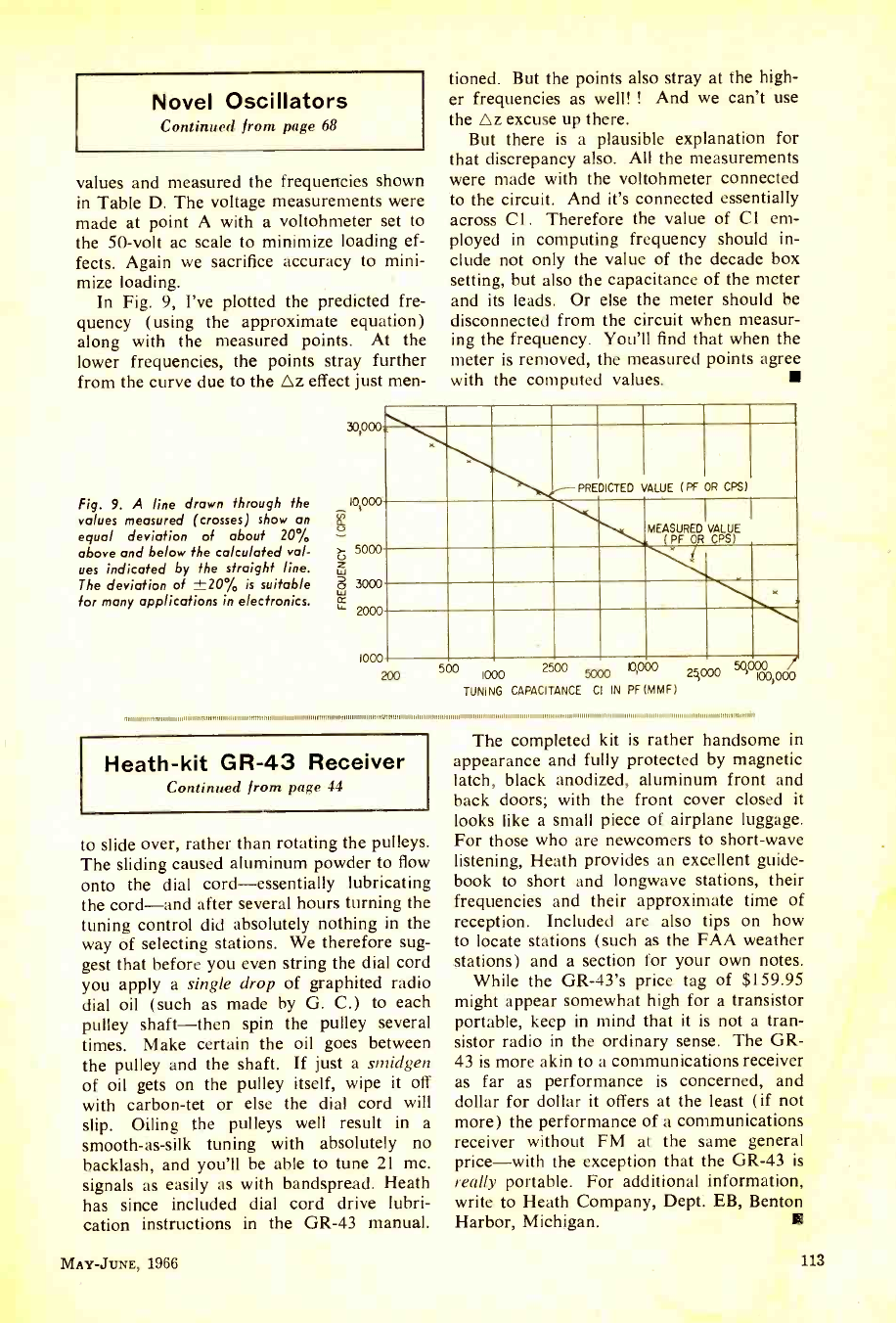
Novel Oscillators
Continued from page 68
values and measured the frequencies shown
in Table D. The voltage measurements were
made at point A with a voltohmeter set to
the 50 -volt ac scale to minimize loading ef-
fects. Again we sacrifice accuracy to mini-
mize loading.
In Fig. 9, I've plotted the predicted fre-
quency (using the approximate equation)
along with the measured points. At the
lower frequencies, the points stray further
from the curve due to the Oz effect just men-
Fig. 9. A line drawn through the
values measured (crosses) show an
equal deviation of about 20%
above and below the calculated val-
ues indicated by the straight line.
The deviation of ±20% is suitable
for many applications in electronics.
30;
tioned. But the points also stray at the high-
er frequencies as well! ! And we can't use
the Oz excuse up there.
But there is a plausible explanation for
that discrepancy also. All the measurements
were made with the voltohmeter connected
to the circuit. And it's connected essentially
across Cl. Therefore the value of Cl em-
ployed in computing frequency should in-
clude not only the value of the decade box
setting, but also the capacitance of the meter
and its leads. Or else the meter should be
disconnected from the circuit when measur-
ing the frequency. You'll find that when the
meter is removed, the measured points agree
with the computed values.
I
PREDICTED VALUE (PF OR CPS)
MEASURED VALUE
(PF OR CPS)
-
200 1000 `mow 5000 M'' 2000
TUNING CAPACITANCE CI IN PF(MMF)
111111111 11111111 ,1111111111 1 1111111111111111111111111111111 111111111111111111 11111111111111111 n1111111 m 11 m 111/1/1111111 o111111111111111 o 1111 11111111111111111111111111 11 111111111 11111111111111111111111111111111111111111111111111111111111111111111111 1111111/111111111111111 111111111111111 1111111111111111111111111111111111
Heath -kit GR -43 Receiver
Continued from page 44
to slide over, rather than rotating the pulleys.
The sliding caused aluminum powder to flow
onto the dial cord -essentially lubricating
the cord -and after several hours turning the
tuning control did absolutely nothing in the
way of selecting stations. We therefore sug-
gest that before you even string the dial cord
you apply a single drop of graphited radio
dial oil (such as made by G. C.) to each
pulley shaft -then spin the pulley several
times. Make certain the oil goes between
the pulley and the shaft. If just a smidgen
of oil gets on the pulley itself, wipe it off
with carbon -tet or else the dial cord will
slip. Oiling the pulleys well result in a
smooth -as -silk tuning with absolutely no
backlash, and you'll be able to tune 21 mc.
signals as easily as with bandspread. Heath
has since included dial cord drive lubri-
cation instructions in the GR -43 manual.
MAY -JUNE, 1966
The completed kit is rather handsome in
appearance and fully protected by magnetic
latch, black anodized, aluminum front and
back doors; with the front cover closed it
looks like a small piece of airplane luggage.
For those who are newcomers to short -wave
listening, Heath provides an excellent guide-
book to short and longwave stations, their
frequencies and their approximate time of
reception. Included are also tips on how
to locate stations (such as the FAA weather
stations) and a section for your own notes.
While the GR -43's price tag of $159.95
might appear somewhat high for a transistor
portable, keep in mind that it is not a tran-
sistor radio in the ordinary sense. The GR-
43 is more akin to a communications receiver
as far as performance is concerned, and
dollar for dollar it offers at the least (if not
more) the performance of a communications
receiver without FM at the same general
price -with the exception that the GR -43 is
really portable. For additional information,
write to Heath Company, Dept. EB, Benton
Harbor, Michigan.
113
www.americanradiohistory.com
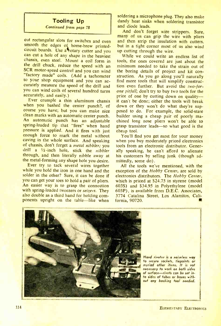
11
Tooling Up
Continued from page 78
cut rectangular slots for switches and even
smooth the edges ok home -brew printed -
circuit boards. Use aotary cutter and you
can cut a hole of any shape in the heaviest
chassis, even steel. Mount a coil form in
the drill chuck, reduce the speed with an
SCR motor -speed control and you can wind
"factory made" coils. (Add a tachometer
to your shop equipment and you can ac-
curately measure the speed of the drill and
you can wind coils of several hundred turns
accurately, and easily.)
Ever crumple a thin aluminum chassis
when you bashed the center punch ?, of
course you have; but you can make nice
clean marks with an automatic center punch.
An automatic punch has an adjustable
spring -loaded tip that "fires" when hand
pressure is applied. And it fires with just
enough force to mark the metal without
caving in the whole surface. And speaking
of chassis, don't forget a metal nibbler; you
drill a 1/z -inch hole, stick the nibbler
through, and then literally nibble away at
the metal- forming any shape hole you desire.
Ever try to tack several wires together
while you hold the iron in one hand and the
solder in the other? Sure, it can be done if
you can get your toes to hold a pair of pliers.
An easier way is to grasp the connection
with spring -loaded tweezers or seizers. They
also double as a third hand for holding com-
ponents upright on the table -like when
soldering a microphone plug. They also make
dandy heat sinks when soldering transistor
and diode leads.
And don't forget wire strippers. Sure,
many of us can grip the wire with pliers
and then strip the insulation with cutters,
but in a tight corner most of us also wind
up cutting through the wire.
While we could write an endless list of
tools, the ones covered are just about the
minimum needed to take the strain out of
the boring details of project and kit con-
struction. As you go along you'll naturally
find more tools that will simplify construc-
tion even further. But avoid the two -for-
one pitfall; don't try to buy two tools for the
price of one by cutting down on quality -
it can't be done; either the tools will break
down or they won't do what they're sup-
posed to do. For example, the solid -state
builder using a cheap pair of poorly ma-
chined long nose pliers won't be able to
grasp transistor leads -so what good is the
cheap tool.
You'll find you get most for your money
when you buy moderately priced electronics
tools from an electronic distributor. Gener-
ally speaking, he can't afford to alienate
his customers by selling junk (though ad-
mittedly, some do).
All the tools we've mentioned, with the
exception of the Hobby Center, are sold by
electronics distributors. The Hobby Center,
which is priced at $24.75 in styrene (model
6035) and $34.95 in Polyethylene (model
603P), is available from D.E.C. Associates,
3774 Catalina Street, Los Alamitos, Cali-
fornia, 90720.
111.111 111111 Ill /I HIM
131,11,,,,,1.1,,,,,,,,,111111,,,,,,11,11,,,,,,,MIm,,,wil,ll.16,,,,,,,,17,,,,o1,111,11,111,A,,,1.1m111,
Hand riveter is a noiseless way
to secure sockets, tiepoints or
myriad other items. It is not
necessary to work on both sides
of surface -rivets can be set in-
to sides of tubes or boxes with-
out any backing tool needed.
114 ELEMENTARY ELECTRONICS
www.americanradiohistory.com
Classified Ads 550 per word, each insertion, minimum 10 words, payable in advance. To
be included in the next available issue of ELEMENTARY ELECTRONICS, copy must be in
our New York Office by May 10th. Address orders to C. D. Wilson, Manager, Classified
Advertising, ELEMENTARY ELECTRONICS, 505 Park Ave., New York, N. Y. 10022.
AUTHOR'S SERVICE
WANTED Writers! Short stories, arti-
cles, books, plays, poetry. Will help place,
sell your work. Write today, free particu-
lars! Literary Agent Mead, Dept. 22A,
915 Broadway, New York 10, N. Y.
PUBLISH your book! Join our success-
ful authors publicity advertising promo-
tion, beautiful books. All subjects in-
vited. Send for free manuscript report
and detailed booklet. Carlton Press, Dept.
SMD, 84 Fifth Avenue, New York 10011.
BOATS, MOTORS & MARINE SUPPLIES
FULL size, cut -to -shape boat patterns,
blueprints. Send 50¢ for big New illus-
trated "Build a Boat" catalog includes
Fishing Boats, Garvies, Cruisers, Catama-
rans, Houseboats -Outboards, Inboards
Sailboats -7', to 38'. "How to Build a
Boat" booklet $2.50. Cleveland Boat Blue-
print Co., Box 18250, Cleveland, Ohio.
BOOKS & PERIODICALS
DO It Yourself and Technical Books for
Radio, TV, HI -Fi. Top Numbers Only.
Send for Free List and Bargain Catalogue.
Indian River Book Shop, Indian River,
Michigan 49749.
BUSINESS OPPORTUNITIES
I MADE $40,000.00 a Year by Mailorder.
Helped others to make money! Start with
910.00 -Free Proof. Torrey, Box 63566T,
Oklahoma City, Okla. 73106.
FREE Book "990 Successful Little -
Known Businesses." Fascinating! Work
home! Plymouth- 911 -A, Brooklyn, N. Y.
11218.
OPPORTUNITY to earn $15,000 -$30,000
annually. Franchise protected. Guaran-
teed on $15,000 basis. No merchandise to
buy. Self employed. One of most exclu-
sive and noncompetitive businesses In
United States and Canada. Patent pend
ing. Send resume or $1.00 for 26 -page
brochure (Returnable). Executives, P.O.
Box 4080 -ID, New Orleans, Louisiana.
EARTHWORMS
BIG Money Raising Fishworms and
Crickets. Free Literature. Carter Farm -O,
Plains, Georgia.
EDUCATION & INSTRUCTION
YOUR F.C.C. first class license (elec-
tronics, broadcasting) -prepare by corre-
spondence or resident classes. Then con-
tinue, if you wish, for A.S.E.E. Degree.
Free catalog. Grantham Engineering
Institute, 1505 North Western Ave.,
Hollywood, Calif. 90027.
OPERATE Collection Agency. "Little
Gold Mine." Franklin Credit, Roanoke,
Virginia.
ELECTRONIC EQUIPMENT
BARGAINS Galore. Free Coupon Book
with Membership. Details Free. Elec-
tronic Experimenters' Club, Box 5332 -EG,
Inglewood, Calif. 90310.
FIREARMS, AMMUNITION &
EQUIPMENT
SILENCERS: Pistols, Rifles. Details,
Construction Operation $1.00. Gunsco,
Soquel, Calif. 95073.
FLORIDA LAND
FLORIDA Water Wonderland -Home,
cottage, Mobilesites. Established area,
$590.00 full price, $9.00 a month. Swim-
ming, fishing, boating. Write: Lake Weir,
Box MG38, Silver Springs, Florida AD
646127 (F -1).
FOR INVENTORS
PATENT Searches -48 hour airmail
service, $6.00, including nearest patent
copies. More than 200 registered patent
attorneys have used my service. Free
invention protection Forms. Write Miss
Ann Hastings, Patent Searcher, P. O. Box
176, Washington 4, D. C.
FOR SALE -MISCELLANEOUS
BARGAINS Our Business. Catalog 106
Refundable. Tojocar, 2907 -B West 39th
Place, Chicago, Ill. 60632.
CATALOG of all Science & Mechanics
Craftprints. Send 256 to cover postage
and handling to Craftprint Div., Science
& Mechanics, 505 Park Ave., New York,
New York 10022.
GIFTS THAT PLEASE
MEXICAN Tooled Leather Coin Purse.
Ideal gift for women and men. $2.25.
Marcos Co., Box 5253 -B, Sherman Oaks,
California.
GIVE the best reading in the Mechani-
cal Field -give Science & Mechanics! $4.00
for year's subscription. Science & Mechan-
ics, 505 Park Ave., New York, N. Y. 10022.
HYPNOTISM
NEW concept teaches you self -hypnosis
quickly! Free literature. Smith -McKinley,
Box 3038, San Bernardino, Calif.
INVENTIONS WANTED
WE either sell your invention or pay
cash bonus. Write for details. Universal
Inventions, 298 -Al, Marion, Ohio.
MAIL ORDER OPPORTUNITIES
MAKE Mail Order pay. Get "How To
Write a Classified Ad That Pulls." In-
cludes certificate worth $2.00 toward clas-
sified ad in S & M. Send $1.00 to C. D.
Wilson, Science & Mechanics, 505 Park
Ave., New York, N. Y. 10022.
PATENT SERVICE
PATENT Searches, $6.00; For free "In-
vention Record" and "Important Infor-
mation Inventors Need," Write: Miss
Hayward, 1029D Vermont, Washington 5,
District of Columbia.
PATENT Searches -48 hour airmail
service, $6.00, including nearest patent
copies. More than 200 registered patent
attorneys have used my service. Free
Invention Protection Forms write: Miss
Ann Hastings, Patent Searcher, P. O. Box
176, Washington 4, D. C.
PERSONAL
EUROPEAN Tonic Grows Hair, Controls
Falling. International Laboratories, 5462
Merrick Rd., Massapequa, N. Y. 11759.
PETS -DOGS, BIRDS, RABBITS,
HAMSTERS. ETC.
MAKE big money raising rabbits for us.
Information 256. Keeney Brothers, New
Freedom, Penna.
PROFITABLE OCCUPATIONS
INVESTIGATE Accidents. Earn $750.00
to $1,500.00 monthly. Car furnished. Ex-
penses paid. No selling. No college educa-
tion necessary. Pick own job location In
U. S., Canada or overseas. Investigate
full time. Or earn $8.44 hour spare time.
Men urgently needed now. Write for Free
information. Absolutely no obligation.
Universal, CMH, 6801 Hillcrest, Dallas 5,
Texas.
PROFITS! Profits! Read the dozens of
proven and successful ways to be your
own boss or conduct a small business on
a full or part -time basis. Buy your copy
of "Income Opportunities" $1.00, or re-
ceive every issue ($4.50 per year). Write
today: Income Opportunities, 505 Park
Ave., New York, N. Y. 10022.
RADIO & TELEVISION
McGEE Radio Company. Big 1966 Cata-
log Sent Free. America's Best Values.
Hi -Ft, Amplifiers, Speakers, Electronic
Parts. Send Name, Address and Zip Code
Number to McGee Radio Company, 1901
McGee Street, Dept. RTV, Kansas City,
Missouri 64108.
CONVERT any television to supersensi-
tive, big- screen oscilloscope. No electronic
experience necessary. Only minor changes
required. Illustrated plans $2.00. Relco-
A135, Box 10563, Houston, Texas 77018.
FREE Trial Membership, No Obligation.
Kit -of- the -Month Club, Box 44718 -KU,
Los Angeles, Calif. 90044.
WIRING Instructions for Toggle Switch
to control any pair of lamps to burn
bright or dim. $1.00. Shumway Enter-
prises, 627 -P San Vicente Blvd., Santa
Monica, Calif.
BEGINNERS All Wave Radio Kit, tube
and transistor included $3.00. Ekeradfo,
Box 131, Temple City, Calif.
NEW! HI -FI Enthusiasts--A Special
Magazine for you. Read the unbiased
tests on new equipment. Send $1.50 to
HI -FI Buyers' Guide, 505 Park Ave.,
New York, N. Y. 10022.
SONGWRITERS
POEMS Wanted for musical setting and
recording. Send poems. Free examination.
Crown Music, 49 -SC West 32, New York 1.
SPECIAL SERVICES
LOOK Men -especially Golf Players. Cut
your shoe cost. Send 256 for details.
Delph's Leather Products, Tamaqua,
Pennsylvania 18252.
TREASURE FINDERS -PROSPECTING
EQUIPMENT
TREASURE, gold, silver, coins. New
inexpensive transistor instrument detects
them all. Underwater models available.
$19.95 up. Free Catalog. Relco -A35, Box
10563, Houston, Texas 77018.
THERE IS NO CHARGE FOR THE ZIP CODE - PLEASE USE IT IN YOUR CLASSIFIED AD
MAY -JUNE, 1966 115
www.americanradiohistory.com
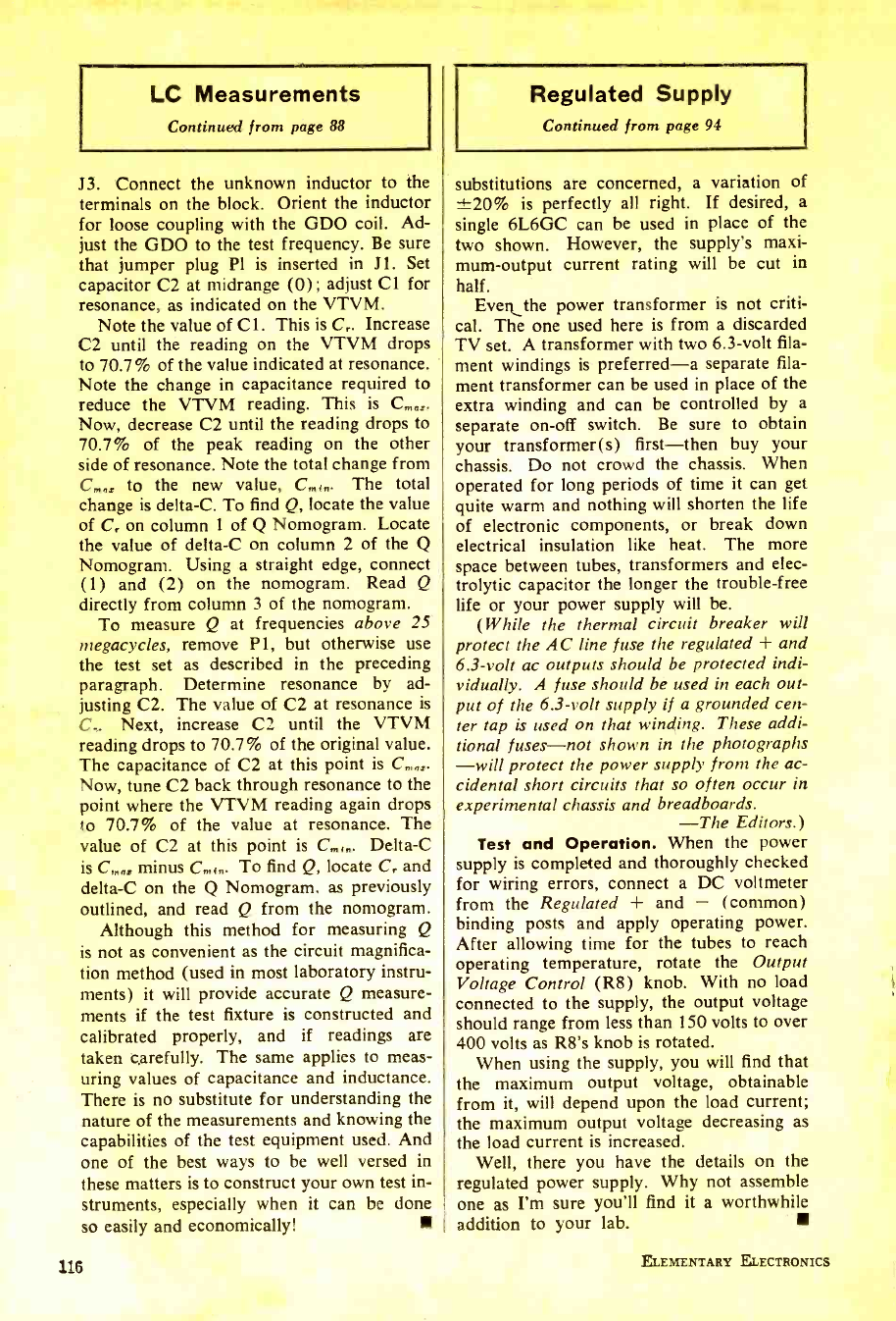
LC Measurements
Continued from page 88
J3. Connect the unknown inductor to the
terminals on the block. Orient the inductor
for loose coupling with the GDO coil. Ad-
just the GDO to the test frequency. Be sure
that jumper plug Pl is inserted in J1. Set
capacitor C2 at midrange (0); adjust Cl for
resonance, as indicated on the VTVM.
Note the value of Cl. This is C,. Increase
C2 until the reading on the VTVM drops
to 70.7% of the value indicated at resonance.
Note the change in capacitance required to
reduce the VTVM reading. This is C,,,,.
Now, decrease C2 until the reading drops to
70.7% of the peak reading on the other
side of resonance. Note the total change from
C,,,, to the new value, C,,,,,. The total
change is delta -C. To find Q, locate the value
of Cr on column 1 of Q Nomogram. Locate
the value of delta -C on column 2 of the Q
Nomogram. Using a straight edge, connect
(1) and (2) on the nomogram. Read Q
directly from column 3 of the nomogram.
To measure Q at frequencies above 25
megacycles, remove P1, but otherwise use
the test set as described in the preceding
paragraph. Determine resonance by ad-
justing C2. The value of C2 at resonance is
C.. Next, increase C2 until the VTVM
reading drops to 70.7% of the original value.
The capacitance of C2 at this point is C,a,.
Now, tune C2 back through resonance to the
point where the VTVM reading again drops
to 70.7% of the value at resonance. The
value of C2 at this point is C,,,,,. Delta -C
is C,,,, minus C. t. To find Q, locate C, and
delta -C on the Q Nomogram, as previously
outlined, and read Q from the nomogram.
Although this method for measuring Q
is not as convenient as the circuit magnifica-
tion method (used in most laboratory instru-
ments) it will provide accurate Q measure-
ments if the test fixture is constructed and
calibrated properly, and if readings are
taken carefully. The same applies to meas-
uring values of capacitance and inductance.
There is no substitute for understanding the
nature of the measurements and knowing the
capabilities of the test equipment used. And
one of the best ways to be well versed in
these matters is to construct your own test in-
struments, especially when it can be done
so easily and economically!
116
Regulated Supply
Continued from page 94
substitutions are concerned, a variation of
±20% is perfectly all right. If desired, a
single 6L6GC can be used in place of the
two shown. However, the supply's maxi-
mum- output current rating will be cut in
half. Even the power transformer is not criti-
cal. The one used here is from a discarded
TV set. A transformer with two 6.3 -volt fila-
ment windings is preferred -a separate fila-
ment transformer can be used in place of the
extra winding and can be controlled by a
separate on -off switch. Be sure to obtain
your transformer(s) first -then buy your
chassis. Do not crowd the chassis. When
operated for long periods of time it can get
quite warm and nothing will shorten the life
of electronic components, or break down
electrical insulation like heat. The more
space between tubes, transformers and elec-
trolytic capacitor the longer the trouble -free
life or your power supply will be.
(While the thermal circuit breaker will
protect the AC line fuse the regulated + and
6.3 -volt ac outputs should be protected indi-
vidually. A fuse should be used in each out-
put of the 6.3 -volt supply if a grounded cen-
ter tap is used on that winding. These addi-
tional fuses -not shown in the photographs
-will protect the power supply from the ac-
cidental short circuits that so often occur in
experimental chassis and breadboards.
-The Editors.)
Test and Operation. When the power
supply is completed and thoroughly checked
for wiring errors, connect a DC voltmeter
from the Regulated + and - (common)
binding posts and apply operating power.
After allowing time for the tubes to reach
operating temperature, rotate the Output
Voltage Control (R8) knob. With no load
connected to the supply, the output voltage
should range from less than 150 volts to over
400 volts as R8's knob is rotated.
When using the supply, you will find that
the maximum output voltage, obtainable
from it, will depend upon the load current;
the maximum output voltage decreasing as
the load current is increased.
Well, there you have the details on the
regulated power supply. Why not assemble
one as I'm sure you'll find it a worthwhile
addition to your lab.
ELEMENTARY ELECTRONICS
www.americanradiohistory.com
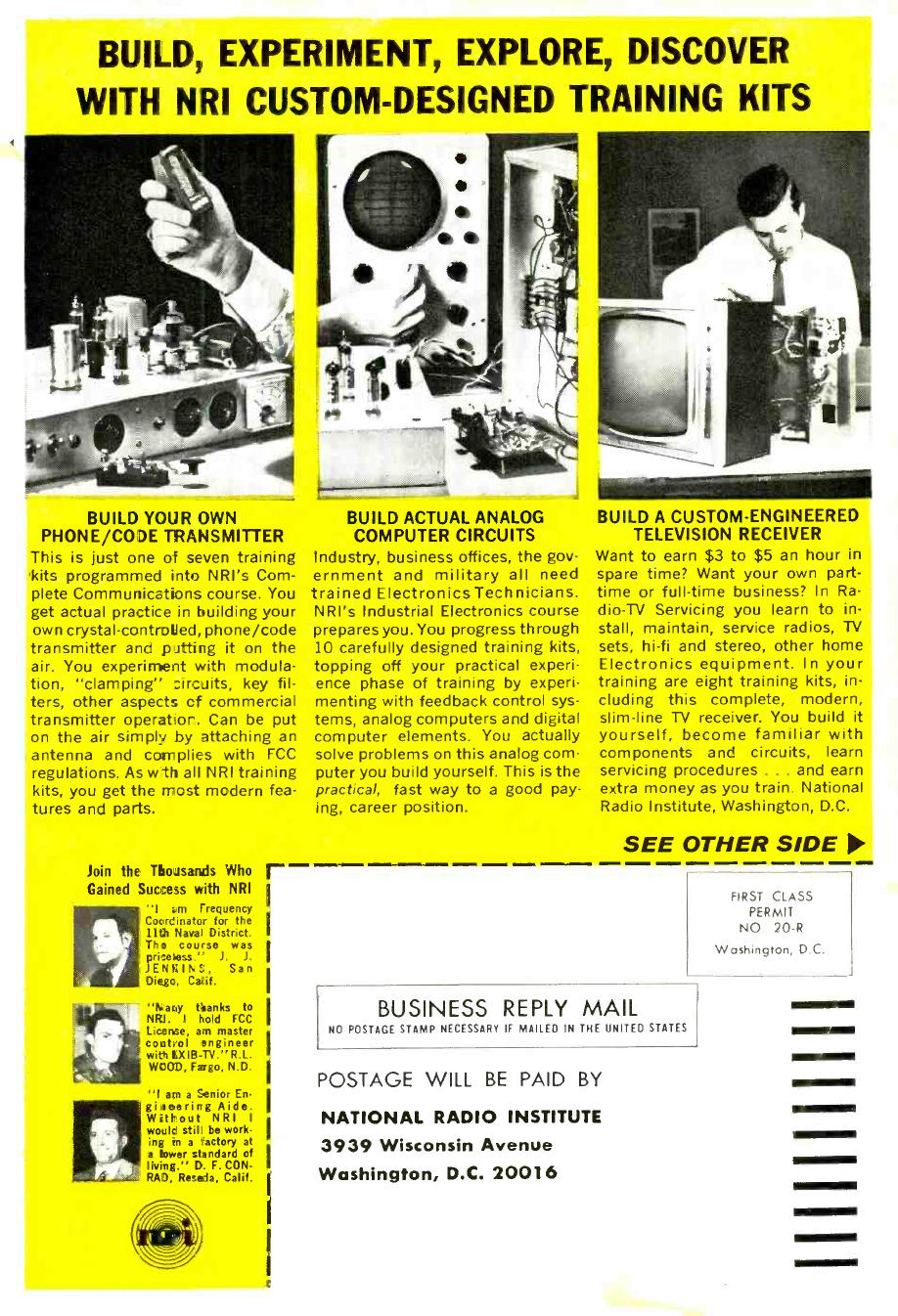
BUILD, EXPERIMENT, EXPLORE, DISCOVER
WITH NRI CUSTOM- DESIGNED TRAINING KITS
BUILD YOUR OWN
PHONE/CODE TRANSMITTER
This is just one of seven training
kits programmed into NRI's Com-
plete Communications course. You
get actual practice in building your
own crystal -controlled, phone /code
transmitter and putting it on the
air. You experiment with modula-
tion, "clamping" circuits, key fil-
ters, other aspects cf commercial
transmitter operator. Can be put
on the air simply by attaching an
antenna and complies with FCC
regulations. As wth all NRI training
kits, you get the most modern fea-
tures and parts.
Join the Thousands Who r
Gained Success with NRI
"Irm Frequency
Coordinator for the
11th Naval District.
The course was
Priceless." J. J.
JENKINS, San
Diego, Calif.
"Nany thanks to
NRI. I hold FCC
License, am master
coatol engineer
with HXIB- TV. "R.L.
WOOD, Fargo, N.D.
"I am a Senior En
glittering Aide.
Without NRI I
would still be work-
ing in a r`actory at
a bower standard of
living." D. F. CON -
RAD, Reseda, Calif.
BUILD ACTUAL ANALOG
COMPUTER CIRCUITS
Industry, business offices, the gov-
ernment and military all need
trained Electronics Technicians.
NRI's Industrial Electronics course
prepares you. You progress through
10 carefully designed training kits,
topping off your practical experi-
ence phase of training by experi-
menting with feedback control sys-
tems, analog computers and digital
computer elements. You actually
solve problems on this analog com-
puter you build yourself. This is the
practical, fast way to a good pay-
ing, career position.
BUILD A CUSTOM- ENGINEERED
TELEVISION RECEIVER
Want to earn $3 to $5 an hour in
spare time? Want your own part -
time or full -time business? In Ra-
dio-TV Servicing you learn to in-
stall, maintain, service radios, TV
sets, hi -fi and stereo, other home
Electronics equipment. In your
training are eight training kits, in-
cluding this complete, modern,
slim -line TV receiver. You build it
yourself, become familiar with
components and circuits, learn
servicing procedures ... and earn
extra money as you train. National
Radio Institute, Washington, D.C.
SEE OTHER SIDE
FIRST CLASS
PERMIT
NO 20 -R
Washington, D.C.
BUSINESS REPLY MAIL
NO POSTAGE STAMP NECESSARY IF MAILED IN THE UNITED STATES
POSTAGE WILL BE PAID BY
NATIONAL RADIO INSTITUTE
3939 Wisconsin Avenue
Washington, D.C. 20016
www.americanradiohistory.com
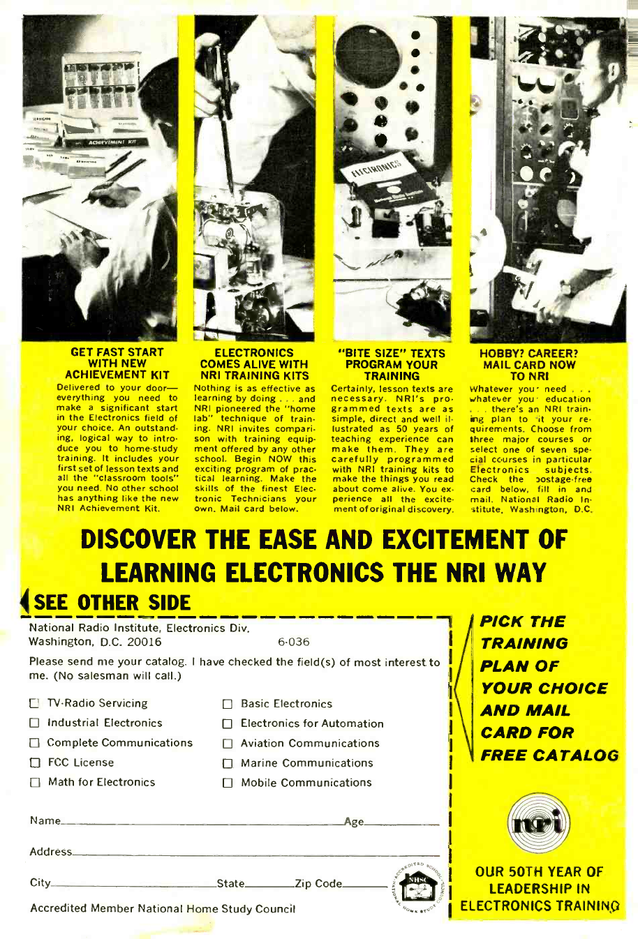
GET FAST START
WITH NEW
ACHIEVEMENT KIT
Delivered to your door -
everything you need to
make a significant start
in the Electronics field of
your choice. An outstand-
ing, logical way to intro-
duce you to home -study
training. It includes your
first set of lesson texts and
all the "classroom tools"
you need. No other school
has anything like the new
NRI Achievement Kit.
. a.
ELECTRONICS
COMES ALIVE WITH
NRI TRAINING KITS
Nothing is as effective as
learning by doing ... and
NRI pioneered the "home
lab" technique of train-
ing. NRI invites compari-
son with training equip-
ment offered by any other
school. Begin NOW this
exciting program of prat
tical learning. Make the
skills of the finest Elec.
tronic Technicians your
own. Mail card below.
"BITE SIZE" TEXTS
PROGRAM YOUR
TRAINING
Certainly, lesson texts are
necessary. NRI's pro
grammed texts are as
simple, direct and well il-
lustrated as 50 years of
teaching experience can
make them. They are
carefully programmed
with NRI training kits to
make the things you read
about come alive. You ex.
perience all the excite
ment of original discovery.
HOBBY? CAREER?
MAIL CARD NOW
TO NRI
Whatever you' need .
whatever you- education
there's an NRI train
ing plan to it your re.
quirements. Choose from
three major courses or
select one of seven spe.
cial courses in particular
Etectronics subjects.
Check the aostage -free
card below, fill in and
mail. National Radio In.
stitute, Washington, D.C.
DISCOVER THE EASE AND EXCITEMENT OF
LEARNING ELECTRONICS THE NRI WAY
SEE OTHER SIDE
National Radio Institute, Electronics Div.
Washington, D.C. 20016 6 -036
Please send me your catalog. I have checked the field(s) of most interest to
me. (No salesman will call.)
-11
TV -Radio Servicing
Industrial Electronics
Complete Communications
FCC License
Math for Electronics
Basic Electronics
Electronics for Automation
Aviation Communications
Marine Communications
Mobile Communications
Name Age
Address
City State Zip Code
Accredited Member National Home Study Council
PICK THE
TRAINING
PLAN OF
YOUR CHOICE
AND MAIL
CARD FOR
FREE CATALOG
OUR 50TH YEAR OF
LEADERSHIP IN
ELECTRONICS TRAINING
www.americanradiohistory.com
