01A03 Elementary Electronics 1967 03 04
User Manual: 01A03
Open the PDF directly: View PDF ![]() .
.
Page Count: 118 [warning: Documents this large are best viewed by clicking the View PDF Link!]
HowTo
ELEMENTARY UA SÑÓTS
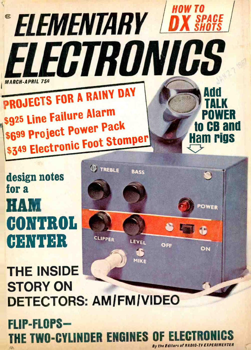
EL MARCH -APRIL 75C
PROJECTS FOR p RAINY DAY
$925 Line Failure e Alarm
$699 project Powe r Pack
Electronic Foot Stomper
$349 Electr
design notes
for a
HAM
CONTROL
CENTER
THE INSIDE
STORY ON
DETECTORS: AMIFMIVIDEO
FLIP- FLOPS-
THE TWO -CYLINDER ENGINES OF ELECTRONICS
By the Editors of RADIO -TV EXPERIMENTER
Add
TALK
POWER
to CB and
Ham rigs
iCr
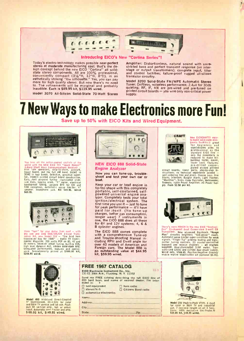
Introducing EICO's New "Cortina Series "!
Today's electro- technology makes possible near -perfect
stereo at moderate manufacturing cost: that's the de-
sign concept behind the new EICO "Cortina" all solid -
state stereo components. All are 100% professional,
conveniently compact (31/8 "H, 12"W, 8 "D), in an
esthetically striking "low silhouette." Yes, you can pay
more for high quality stereo. But now there's no need
to. The refinements will be marginal and probably
inaudible. Each is $89.95 kit, $119.95 wired.
Model 3070 All- Silicon Solid -State 70 -Watt Stereo
Amplifier: Distortionless, natural sound with unre-
stricted bass and perfect transient response (no inter -
stage or output transformers); complete input, filter
and control facilities; failure -proof rugged all -silicon
transistor circuitry.
Model 3200 Solid -State FM /MPX Automatic Stereo
Tuner: Driftless, noiseless performance; 2.4µV for 30db
quieting; RF, IF, MX are pre -wired and pre -tuned on
printed circuit boards - you wire only non -critical power
supply.
7 New Ways to make Electronics more Fun!
Save up to 50% with EICO Kits and Wired Equipment.
!`
You hear all the action -packed capitals of the
world with the NEW EICO 711 "Space Ranger"
4 -Band Short Wave Communications Receiver -
plus ham operators, ship -to- shore, aircraft,
Coast Guard, and the full AM band. 550KC to
30MC In four bands. Selective, sensitive super -
het, modern printed circuit board construction.
Easy, -fast pinpoint tuning: Illuminated slide.
rule dials, logging scale; "S" meter, electrical
bandspread tuning, variable BFO for CW and
SSB reception, automatic noise limiter. 4"
speaker. Headphone jack. KIt 949.95. Wired
$69.95.
t
More "ham" for your dollar than ever - with
the one and only SSB /AM /CW 3 -Band Trans-
ceiver Kit, new Model 753 - "the best ham
transceiver buy for 1966" - Radio TV Experi-
menter Magazine. 200 watts PEP on 80, 40 and
20 meters. Receiver offset tuning, built -in VOX,
high level dynamic ALC, silicon solid -state VFO.
Unequaled performance, features and appear.
ance. Sensationally priced at $199.95 kit,
$299.95 wired.
Model 460 Wideband Direct- Coupled
5" Oscilloscope. DC -4.5mc for color
and B8W TV service and lab use. Push.
pull DC vertical amp., bal. or unbal.
snout. Automatic suer 'miter and amp.
$109.95 kit, $149.95 wired.
NEW EICO 888 Solid -State
Engine Analyzer
Now you can tune -up, trouble-
shoot and test your own car or
boat.
Keep your car or boat engine in
tip -top shape with this completely
portable, self- contained, self -
powered universal engine ana-
lyzer. Completely tests your total
ignition /electrical system. The
first time you use it - just to tune
for peak performance - it'll have
paid for itself. (No tune -up
charges, better gas consumption,
longer wear) 7 instruments in
one, the EICO 888 does all these
for 6V and 12V systems; 4, 6 &
8 cylinder engines.
The EICO 888 comes complete
with a comprehensive Tune -up
and Trouble- shooting Manual in-
cluding RPM and Dwell angle for
over 40 models of American and
Foreign cars. The Model 888 is
an outstanding value at $44.95
kit, $59.95 wired.
FREE 1967 CATALOG
EICO Electronic Instrument Co., Inc.
131 -01 39th Ave., Flushing, N. Y. 11352
Send me FREE catalog describing the tug EICO line of
200 best buys, and name of nearest dealer: I'm inter-
ested in:
D test equipment D ham radio
New EICOCRAFT'' easy -
to -build solid -state elec-
tronic TruKits: 4 great
for beginners and
sophisticates alike. As
professional as the
standard EICO line -
only the complexity Is
reduced to make kit.
building faster, easier,
lower cost. Features:
pre -drilled copper -
plated etched printed
circuit boards; finest parts; step -by -step in-
structions; no technical experience needed -
just soldering iron and pliers. Choose from: Fire
Alarm; Intercom; Burglar Alarm; Light Flasher;
"Mystifier "; Siren; Code Oscillator; Metronome;
Tremolo; Audio Power Amplifier; AC Power Sup-
ply. From $2.50 per kit.
There's more PUNCH in the new EICO "Sentinel.
Pro" 23- channel Dual Conversion 5 -watt CB
Transceiver. New advanced Big -Reach "Range
Plus" circuitry lengthens "talk- power" reach.
Automatic noise limiter super. sensitizes for weak
signals. "Finger Tip" antenna loading and trans-
mitter tuning controls. 23 crystal -controlled
transmit and receive channels - all crystals
supplied. Rear -illuminated S /RF meter. Tran-
sistorized 12VDC and 117VAC dual power supply.
Wired only, $169.95. Positive- Negative Ground/
Mobile Marine Modification kit (optional $5.95).
D stereo /hi -fi D Citizens Band radio
automotive electronics
Name
Address
City
State Zip
l J
Model 232 Peak -to -Peak VTVM. A must
for color or 88W TV and Industrial
use. 7 non -skip ranges on all 4 func-
tions. With exclusive UniProbe.W
$29.95 kit, $49.95 wired.
4,
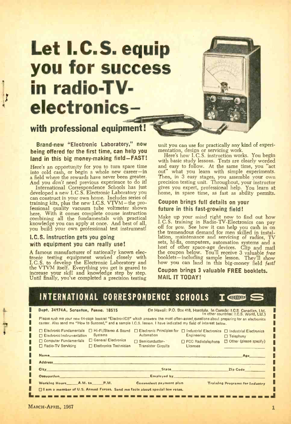
Let I.C.S. equip
you for success
in radio-TV-
electronics
with professional equipment!
Brand -new "Electronic Laboratory," now
being offered for the first time, can help you
land in this big money- making field -FAST!
Here's an opportunity for you to turn spare time
into cold cash, or begin a whole new career -in
a field where the rewards have never been greater.
And you don't need previous experience to do it!
International Correspondence Schools has just
developed a new I. C. S. Electronic Laboratory you
can construct in your own home. Includes series of
training kits, plus the new I.C.S. VTVM -the pro-
fessional quality vacuum tube voltmeter shown
here. With it comes complete course instruction
combining all the fundamentals with practical
knowledge you can apply at once. And best of all,
you build your own professional test instrument!
I.C.S. instruction gets you going
with equipment you can really use!
A famous manufacturer of nationally known elec-
tronic testing equipment worked closely with
I.C. S. to develop the Electronic Laboratory and
the VTVM itself. Everything you get is geared to
increase your skill and knowledge step by step.
Until finally, you've completed a precision testing
unit you can use for practically any kind of experi-
mentation, design or servicing work.
Here's how I. C. S. instruction works. You begin
with basic study lessons. Texts are clearly worded
and easy to follow. At the same time, you "act
out" what you learn with simple experiments.
Then, in 3 easy stages, you assemble your own
precision testing unit. Throughout, your instructor
gives you expert, professional help. You learn at
home, in spare time, as fast as ability permits.
Coupon brings full details on your
future in this fast -growing field!
Make up your mind right now to find out how
I. C. S. training in Radio -TV- Electronics can pay
off for you. See how it can help you cash in on
the tremendous demand for men skilled in instal-
lation, maintenance and servicing of radios, TV
sets, hi -fis, computers, automation systems and a
host of other space -age devices. Clip and mail
the coupon below. You'll receive 3 valuable free
booklets-including ample lesson. They'll show
how you can land in this big -money field fast!
Coupon brings 3 valuable FREE booklets.
MAIL IT TODAY!
INTERNATIONAL CORRESPONDENCE SCHOOLS I
II.
Dept. 34974A, Scranton, Penna. 18515 (In Hawaii: P.O. Box 418, Honolulu. In Canada: I.C.S. Canadian, Ltd.
in other countries: I.C.S. World, Ltd.)
Please rush me your new 64 -page booklet "ElectroniCS" which answers the most often- asked,guestions about preparing for an electronics
career. Also send me "How to Succeed," and a sample I.C.S. lesson. I have indicated my field of interest below.
Electronic Fundamentals Hi -Fi /Stereo & Sound Electronic Principles for Industrial Electronics Industrial Electronics
Electronic Instrumentation Systems Automation Engineering Telephony
Computer Fundamentals General Electronics Semiconductor- FCC Radiotelephone E Other (please specify)
Radio -TV Servicing Electronics Technician Transistor Circuits Licenses
Name Age
Address
City State Zip Code
Occupation Employed by
Working Hours A.M. te P.M. Convenient payment plan
I am a member of U.S. Armed Forces. Send me facts about special low rates.
Training Programs for Industry
J
MARCH- APRIL, 1967 1
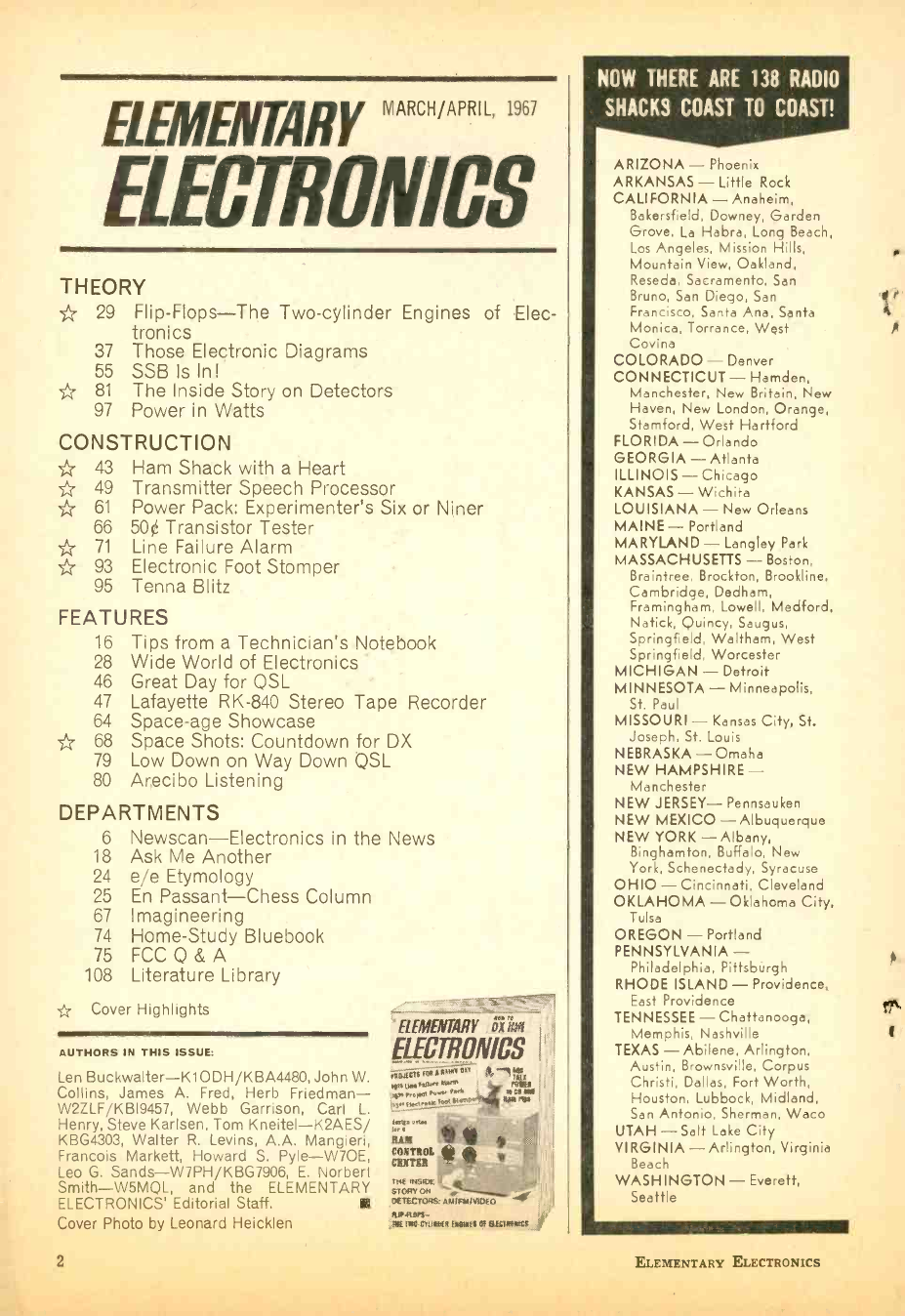
ELEMENTARY "' " " " "R ,
ELECTRONICS
THEORY
* 29 Flip -Flops -The Two -cylinder Engines of Elec-
tronics
37 Those Electronic Diagrams
55 SSB Is In!
* 81 The Inside Story on Detectors
97 Power in Watts
CONSTRUCTION
- 43 Ham Shack with a Heart
' 49 Transmitter Speech Processor
* 61 Power Pack: Experimenter's Six or Niner
66 50¢ Transistor Tester
* 71 Line Failure Alarm
* 93 Electronic Foot Stomper
95 Tenna Blitz
FEATURES
16 Tips from a Technician's Notebook
28 Wide World of Electronics
46 Great Day for QSL
47 Lafayette RK -840 Stereo Tape Recorder
64 Space -age Showcase
' 68 Space Shots: Countdown for DX
79 Low Down on Way Down QSL
80 Arecibo Listening
DEPARTMENTS
NOW THERE ARE 138 RADIO
SHACKS COAST TO COAST!
ARIZONA - Phoenix
ARKANSAS - Little Rock
CALIFORNIA - Anaheim,
Bakersfield, Downey, Garden
Grove, La Habra, Long Beach,
Los Angeles, Mission Hills,
Mountain View, Oakland,
Reseda, Sacramento, San
Bruno, San Diego, San
Francisco, Santa Ana, Santa
Monica, Torrance, West
Covina
COLORADO - Denver
CONNECTICUT- Hamden,
Manchester, New Britain, New
Haven, New London, Orange,
Stamford, West Hartford
FLORIDA - Orlando
GEORGIA - Atlanta
ILLINOIS - Chicago
KANSAS - Wichita
LOUISIANA - New Orleans
MAINE- Portland
MARYLAND - Langley Park
MASSACHUSETTS - Boston,
Braintree, Brockton, Brookline,
Cambridge, Dedham,
Framingham, Lowell, Medford,
Natick, Quincy, Saugus,
Springfield, Waltham, West
Springfield, Worcester
MICHIGAN - Detroit
MINNESOTA- Minneapolis,
St. Paul
MISSOURI - Kansas City, St.
Joseph, St. Louis
NEBRASKA - Omaha
NEW HAMPSHIRE -
Manchester
NEW JERSEY- Pennsauken
NEW MEXICO - Albuquerque
6 Newscan -Electronics in the News
18 Ask Me Another
24 e/e Etymology
25 En Passant -Chess Column
67 Imagineering
74 Home -Study Bluebook
75 FCCQ &A
108 Literature Library
' Cover Highlights
AUTHORS IN THIS ISSUE:
Len Buckwalter- K1ODH /KBA4480, John W.
Collins, James A. Fred, Herb Friedman -
W2ZLF/KB19457, Webb Garrison, Carl L.
Henry, Steve Karlsen, Tom Kneitel- K2AES/
KBG4303, Walter R. Levins, A.A. Mangieri,
Francois Markett, Howard S. Pyle -W70E,
Leo G. Sands- W7PH /KBG7906, E. Norbert
Smith- W5MQL, and the ELEMENTARY
ELECTRONICS' Editorial Staff.
Cover Photo by Leonard Heicklen
2
AAA
"ELEMENTARY o.,
EIECrAONICs
4AAM,'OiY
,4Mip Powx PveM
NEW YORK - Albany,
Binghamton, Buffalo, New
York, Schenectady, Syracuse
OHIO - Cincinnati, Cleveland
OKLAHOMA - Oklahoma City,
Tulsa
OREGON - Portland
PENNSYLVANIA -
Philadelphia, Pittsburgh
RHODE ISLAND - Providence,
East Providence
TENNESSEE - Chattanooga,
Memphis, Nashville
TEXAS - Abilene, Arlington,
Austin, Brownsville, Corpus
Christi, Dallas, Fort Worth,
Houston, Lubbock, Midland,
San Antonio, Sherman, Waco
UTAH -Salt Lake City
VIRGINIA - Arlington, Virginia
Beach
WASHINGTON - Everett,
Seattle
ELEMENTARY ELECTRONICS
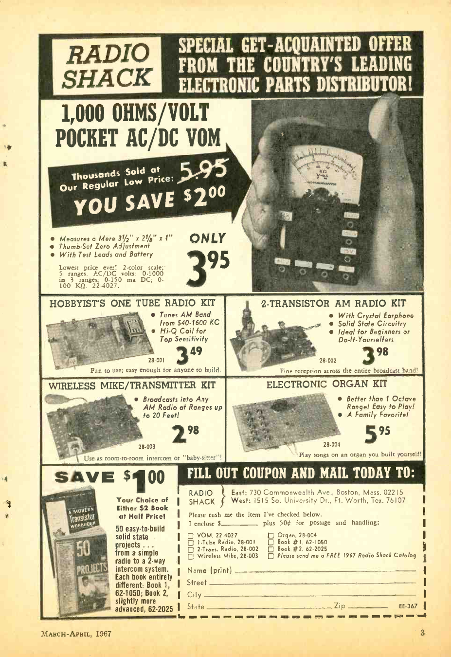
RADIO
SHACK
SPECIAL GET - ACQUAINTED OFFER
FROM THE COUNTRY'S LEADING
PARTS 01 TRIBUT I ; I
1,000 OHMS /VOLT
POCKET AC /DC VOM
Measures o Mere 31/2" x 21/4" x 1"
Thumb -Set Zero Adjustment
With Test Leads and Battery
Lowest price ever! 2 -color scale;:
5 ranges. AC /DC volts: 0 -1000
in 3 ranges; 0 -150 ma DC; 0-
100 KU. 22 -4027.
HOBBYIST'S ONE TUBE RADIO KIT
Tunes AM Band
from 540 -1600 KC
Hi -Q Coil for
Top Sensitivity
2- TRANSISTOR AM RADIO KIT
With Crystal Earphone
Solid State Circuitry
Ideal for Beginners or
Do- lt- Yourselfers
28-001 3 49
Fun to use; easy enough for anyone to build.
ß8-002 398
Fine reception across the entire broadcast band!
WIRELESS MIKE /TRANSMITTER KIT
Broadcasts into Any
AM Radio at Ranges up
to 20 Feet!
28-003
Use as room -to -room intercom or "baby- sitter"!
298
SAVE $100
MARCH -APRIL, 1967
Your Choice of
Either $2 Book
at Half Price!
50 easy -to -build
solid state
projects ...
from a simple
radio to a 2 -way
intercom system.
Each book entirely
different: Book 1,
62 -1050; Book 2,
slightly more
advanced, 62 -2025
ELECTRONIC ORGAN KIT
Better than 1 Octave
Range! Easy to Play!
A Family Favorite!
28 -004
Play songs on an organ you built yourself!
5 95
FILL OUT COUPON AND MAIL TODAY TO:
L.
RADIO East: 730 Commonwealth Ave., Boston, Mass. 02215
SHACK West: 1515 So. University Dr., Ft. Worth, Tex. 76107
Please rush me the item I've checked below.
I enclose $ , plus 500 for postage and handling:
VOM, 22- 4027 Organ, 28.004
I -Tube Radio, 28 -001 Book # I, 62 -1050
2- Trans. Radio, 28-002 Book #2, 62 -2025
Wireless Mike, 28 -003 Please send me a FREE 1967 Rodio Shack Catalog
Name (print)
Street
City
State Zip EE -367 ..a
3
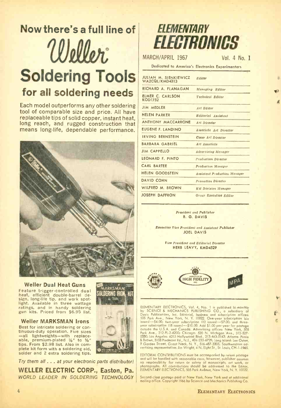
Now there's a full line of
Soldering Tools
for all soldering needs
Each model outperforms any other soldering
tool of comparable size and price. All have
replaceable tips of solid copper, instant heat,
long reach, and rugged construction that
means long -life, dependable performance.
Weller Dual Heat Guns
Feature trigger -controlled dual
heat, efficient double -barrel de-
sign, long -life tip, and work spot-
light. Available in three wattage
ratings, and in handy soldering
gun kits. Priced from $6.95 list.
Weller MARKSMAN Irons
Best for intricate soldering or con-
tinuous -duty operation. Five sizes
-all lightweights -with replace-
able, premium -plated Vs" to Vs"
tips. From $2.98 list. Also in com-
plete kit form with a soldering aid,
solder and 2 extra soldering tips.
T r y them all ... at your electronic parts distributor!
WELLER ELECTRIC CORP., Easton, Pa.
WORLD LEADER IN SOLDERING TECHNOLOGY
$41$,
SOLDERING IRON KIT
:1;xr';+.
4
fLfMFN(gqY
ELECTNONICS
MARCH /APRIL 1967 Vol. 4 No. 1
Dedicated to America's Electronics Experimenters
JULIAN M. SIENKIEWICZ
WA2CQL/KMD4313
RICHARD A. FLANAGAN
ELMER C. CARLSON
KOD1752
Editor
Managing Editor
Technical Editor
JIM MEDLER Art Editor
HELEN PARKER Editorial Assistant
ANTHONY MACCARRONE Art Director
EUGENE F. LANDINO Associate Art Director
IRVING BERNSTEIN Cover Art Director
BARBARA GABRIEL Art Associate
JIM CAPPELLO Advertising Manager
LEONARD F. PINTO Production Director
CARL BARTEE Production Dianager
HELEN GOODSTEIN Assistant Production Manager
DAVID COHN
WILFRED M. BROWN
Promotion Director
Kit Division Manager
JOSEPH DAFFRON Group Executive Editor
President and Publisher
B. G. DAVIS
Executive Vice President and Assistant Publisher
JOEL DAVIS
Vice President and Editorial Director
HERB LEAVY, KMD4529
rs
ELEMENTARY ELECTRONICS, Vol. 4, No. 1 is published bi- monthly
by SCIENCE & MECHANICS PUBLISHING CO., a subsidiary of
Davis Publications, Inc. Editorial, business and subscription offices:
505 Park Ave., New York, N. Y. 10022. One -year subscription Isis
issuesl- $4.00; two -year subscription 112 issuesl- $7.00; and three -
year subscription 118 issuesl -$10.00. Add $1.00 per year for postage
outside the U.S.A. and Canada. Advertising offices: New York, 505
Park Ave., 212 -PL -2 -6200; Chicago: 520 N. Michigan Ave., 312-527-
0330; Los Angeles: 6253 Hollywood Blvd., 213 - 463 -5143; Atlanta: Pirnie
& Brown, 3108 Piedmont Rd., N.E., 404 -233 -6729; Long Island: Len Osten,
9 Garden Street, Great Neck, N. Y., 516. 487.3305; Southwestern ad-
vertising representative: Jim Wright, 4 N. Eight St., St. Louis, CH.1 -1965.
EDITORIAL CONTRIBUTIONS must be accompanied by return postage
and will be handled with reasonable core; however, publisher assumes
no responsibliity for return or safety of manuscripts, art work, or
photographs. All contributions should be addressed to the Editor,
ELEMENTARY ELECTRONICS, 505 Park Avenue, New York, N. Y. 10022.
Second -class postage paid at New York, New York and at additional
mailing office. Copyright 1966 by Science and Mechanics Publishing Co.
ELEMENTARY ELECTRONICS
vi?
A
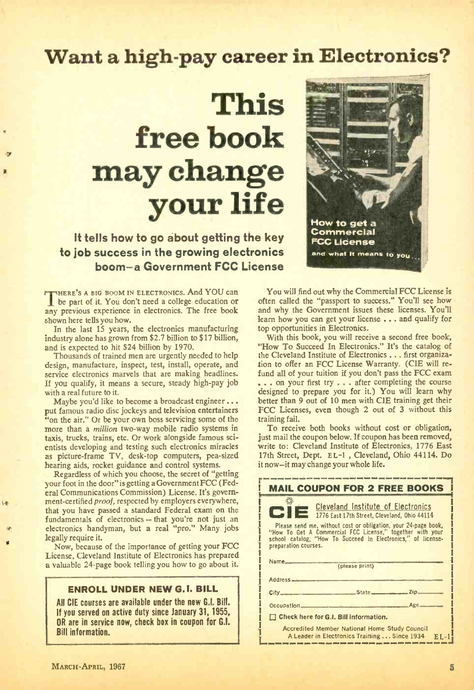
Want a high -pay career in Electronics?
This
free book
may change
your life
It tells how to go about getting the key
to job success in the growing electronics
boom -a Government FCC License
THERE'S A BIG BOOM IN ELECTRONICS. And YOU can
he part of it. You don't need a college education or
any previous experience in electronics. The free book
shown here tells you how.
In the last 15 years, the electronics manufacturing
industry alone has grown from $2.7 billion to $17 billion,
and is expected to hit $24 billion by 1970.
Thousands of trained men are urgently needed to help
design, manufacture, inspect, test, install, operate, and
service electronics marvels that are making headlines.
If you qualify, it means a secure, steady high -pay job
with a real future to it.
Maybe you'd like to become a broadcast engineer...
put famous radio disc jockeys and television entertainers
"on the air." Or be your own boss servicing some of the
more than a million two -way mobile radio systems in
taxis, trucks, trains, etc. Or work alongside famous sci-
entists developing and testing such electronics miracles
as picture -frame TV, desk -top computers, pea -sized
hearing aids, rocket guidance and control systems.
Regardless of which you choose, the secret of "getting
your foot in the door" is getting a Government FCC (Fed-
eral Communications Commission) License. It's govern-
ment- certified proof, respected by employers everywhere,
that you have passed a standard Federal exam on the
fundamentals of electronics - that you're not just an
electronics handyman, but a real "pro." Many jobs
legally require it.
Now, because of the importance of getting your FCC
License, Cleveland Institute of Electronics has prepared
a valuable 24 -page book telling you how to go about it.
ENROLL UNDER NEW G.I. BILL
AU CIE courses are available under the new G.I. Bill.
If you served on active duty since January 31, 1955,
OR are in service now, check box in coupon for G.I.
Bill information.
MARCH- APRIL, 1967
You will find out why the Commercial FCC License is
often called the "passport to success." You'll see how
and why the Government issues these licenses. You'll
learn how you can get your license ... and qualify for
top opportunities in Electronics.
With this book, you will receive a second free book,
"How To Succeed In Electronics." It's the catalog of
the Cleveland Institute of Electronics . .. first organiza-
tion to offer an FCC License Warranty. (CIE will re-
fund all of your tuition if you don't pass the FCC exam
on your first try ... after completing the course
designed to prepare you for it.) You will learn why
better than 9 out of 10 men with CIE training get their
FCC Licenses, even though 2 out of 3 without this
training fail.
To receive both books without cost or obligation,
just mail the coupon below. If coupon has been removed,
write to: Cleveland Institute of Electronics, 1776 East
17th Street, Dept. EL-1 , Cleveland, Ohio 44114. Do
it now -it may change your whole life.
r 1
MAIL COUPON FOR 2 FREE BOOKS
C.' Cleveland Institute of Electronics
E 1776 East 17th Street, Cleveland, Ohio 44114
Please send me, without cost or obligation, your 24 -page book,
"How To Get A Commercial FCC License," together with your
school catalog, "How To Succeed In Electronics," of license -
preparation courses.
Name (please print)
Address
City State Zip
Occupation Age
Check here for G.I. Bill information.
Accredited Member National Home Study Council
A Leader in Electronics Training ... Since 1934 E L-1J
5
SHOPPING MART
GIANT SURPLUS BALLOONS
"Balls of fun" for the kids.
traffic stoppera for stores, ter-
rific for amateur meteorolo-
gists. Create a neighborhood
sensation. Great backyard fun.
Exciting beach attraction. Ama-
teur meteorologists use to
measure cloud heights, wind
black n
rubber. I heavy
Inflate with vac-
uum cleaner or auto air hose;
or locally available helium for
high rise. 8' diem. $2.00 Ppd.
Order Stock No. 60,568EK.
Edmund Scientific Co., Barrington, New Jersey 08007.
HI- VOLTAGE ELECTROSTATIC GENERATOR
Van De Graf low -amp type.
200,000 volt potential, yet
completely safe. Demonstrates
lightning, St. Elnico's fire. re-
pulsion of charges, electro-
static dust Collection, many
other electrical wonders. Mo-
tor, 110V, 80- cycle, AC. Hu-
midity range, 0 -90 %. Current,
1.5 to 2.5 microamps. Alumi-
num base, frame and charge
. collector. Unbreakable plastic.
Insulating column. Ht. 17 ",
die. Ba /q . Full instructions.
$43.50 Ppd. Order B70,284EK. Edmund Scientific Co., Barrington,
New Jersey 08007.
EXPERIMENTAL FUN WITH TESLA COIL
Now perform spectacular ex-
periments without wires res
as Nicola Tesla did 50 yrs.
trancos itseextremely high Cfre- fre-
quency (millions
electromagnetic yclesa per
secondi- through space. Lights
fluorescent tube 2 ft. away,
ionizes gases, performs total
of 21 fascinating experiments.
Incl. Neon Lamp, discharge
electrode, 2 radiation antenna
plates. Generates 5.000 V. for
8". $44.00 Ppd. Order Jt70,301EK. 1Edmund OScientfic Meas.
Co. Bar
rington, New Jersey 08007.
DuPONT PLASTIC LIGHT GUIDE KIT
Experiment with amazing new
plastic fiber optic light guides.
1001 uses for mfrs., experi-
menters, hobbyists. Use for
exciting new projects and
products. Guides transmit
light same as wire conducts
electricity. Use to illuminate
remote areas, multiple loca-
tions from single source, con-
fine light to small areas, con-
duct sensing and control sys-
tems. Inc. 2 guides, source,
lens, dyes, connectors. $10
Ppd. Order jj70,855EK. Ed-
mund Scientific Co., Barring-
ton, New Jersey 08007.
DIGITAL COMPUTER
Solve problems, tell fortunes,
play games with miniature
version of
brains! Adds, subtracts, mul-
tiplies, shifts, complements.
carries, memorizes. Colored
plastic parts easily assembled.
/z" x 43/4 ". Incld.
step -by -step assembly dia-
grams, 32 -p. instruction book
covering
language operation
(binary system)
em) re -
peammins. problems & 15 ex-
periments. Ppd. Order
1!i Edmund Scientific Barrington, N. J.
"FISH" WITH A MAGNET
Go treasure hunting on the
bottom! Fascinating fun &
w;.+L sometimes profitable! Tie a
line to our 5 -lb. Magnet -drop
it overboard in bay, river, lake
or ocean. Troll it along bot-
tom -your "treasure" haul can
he outboard motors, anchors,
other metal valuables. 5 -1b.
Magnet is war surplus -Alnico
V Type- Gov't. cost $50. Line
over 150 lbs. on land -much
greater weights under water.
$12.50 Ppd. Order Stock
Jt70,571EK. Edmund Scien-
tific Co., Barrington, N. J. 08007.
GIANT FREE CATALOG
Completely new 1987 edition
-148 pages. Bargains galore!
New categories, items, illus-
tration- 1.000's of buys for
industry - Optics, Science,
Math, On -the -Job helps, qual-
ity control aids. Optics for
research labs, design engi-
neers, experimenters- Instru-
menta for checking, measuring
to speed work, improve
quality, cut costs. Hard -to -get
war surplus bargains. Write
for Catalog EK. Edmund Sci-
entific Co., Barrington, New
Jersey 08007.
NEW MODEL
6
EWSCA
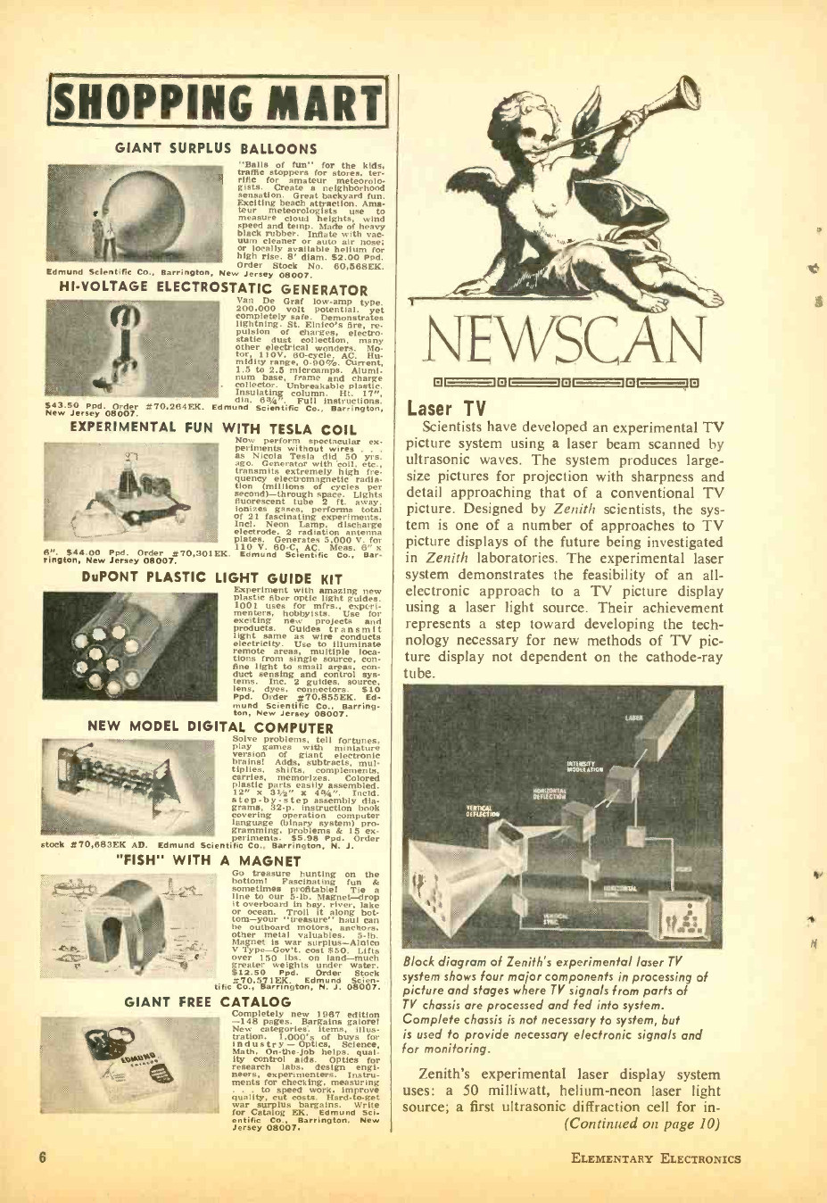
Laser TV
Scientists have developed an experimental TV
picture system using a laser beam scanned by
ultrasonic waves. The system produces large -
size pictures for projection with sharpness and
detail approaching that of a conventional TV
picture. Designed by Zenith scientists, the sys-
tem is one of a number of approaches to TV
picture displays of the future being investigated
in Zenith laboratories, The experimental laser
system demonstrates the feasibility of an all -
electronic approach to a TV picture display
using a laser light source. Their achievement
represents a step toward developing the tech-
nology necessary for new methods of TV pic-
ture display not dependent on the cathode -ray
tube.
Block diagram of Zenith's experimental laser TV
system shows four major components in processing of
picture and stages where TV signals from parts of
TV chassis are processed and fed into system.
Complete chassis is not necessary to system, but
is used to provide necessary electronic signals and
for monitoring.
Zenith's experimental laser display system
uses: a 50 milliwatt, helium -neon laser light
source; a first ultrasonic diffraction cell for in-
(Continued on page 10)
ELEMENTARY ELECTRONICS
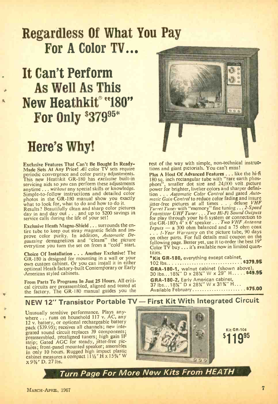
Regardless Of What You Pay
For A Color TV...
It Can't Perform
As Well As This
New Heathkit® "180"
For Only $37995*
Here's Why!
Exclusive Features That Can't Be Bought In Ready -
Made Sets At Any Price! All color TV sets require
periodic convergence and color purity adjustments.
This new Heathkit GR -180 has exclusive built -in
servicing aids so you can perform these adjustments
anytime ... without any special skills or knowledge.
Simple -to- follow instructions and detailed color
photos in the GR -180 manual show you exactly
what to look for, what to do and how to do it.
Results? Beautifully clean and sharp color pictures
day in and day out ... and up to $200 savings in
service calls during the life of your set!
Exclusive Heath Magna -Shield ... surrounds the en-
tire tube to keep out stray magnetic fields and im-
prove color purity. In addition, Automatic De-
gaussing demagnetizes and "cleans" the picture
everytime you turn the set on from a "cold" start.
Choice Of Installation ... Another Exclusive! The
GR -180 is designed for mounting in a wall or your
own custom cabinet. Or you can install it in either
optional Heath factory -built Contemporary or Early
.American styled cabinets.
From Parts To Programs In Just 25 Hours. All criti-
cal circuits are preassembled, aligned and tested at
the factory. The GR -180 manual guides you the
rest of the way with simple, non -technical instruc-
tions and giant pictorials. You can't miss!
Plus A Host Of Advanced Features ... like the hi -fi
180 sq. inch rectangular tube with "rare earth phos-
phors", smaller dot size and 24,000 volt _picture
power for brighter, livelier colors and sharper defini-
tion ... Automatic Color Control and gated Auto-
matic Gain Control to reduce color fading and insure
jitter -free pictures at all times . deluxe VHF
Turret Tuner with "memory" fine tuning ... 2 -Speed
Transistor UHF Tuner ... Two Hi -Fi Sound Outputs
for play through your hi -fi system or connection to
the GR -180's 4" x 6" speaker ... Two VHF Antenna
Inputs -a 300 ohm balanced and a 75 ohm coax
... I -Year Warranty on the picture tube, 90 days
on other parts. For full details mail coupon on the
following page. Better yet, use it to order the best 19'
Color TV buy ... it's available now in limited quan-
tities.
*Kit GR -180, everything except cabinet,
102 lbs. $379.95
GRA- 180 -1, walnut cabinet (shown above),
30 lbs...183/4" D x 283/4" W x 29" H..... $49.95
GRA- 180 -2, Early American cabinet,
37lbs ...183/4" Dx28%. "Wx313/4" H...
Available February $75.00
NEW 12" Transistor Portable TV - First Kit With Integrated Circuit
Unusually sensitive performance. Plays any-
where ... runs on household 117 v. AC, any
12 v. battery, or optional rechargeable battery
pack ($39.95); receives all channels; new inte-
grated sound circuit replaces 39 components;
preassembled, prealigned tuners; high gain IF
strip; Gated AGC for steady, jitter -free pic-
tures; front -panel mounted speaker; assembles
in only 10 hours. Rugged high impact plastic
cabinet measures a compact 111/2" H x 15'/4" W
x 93A" D. 27 lbs.
Kit GR -104
$1 1 995
Turn Page For More New Kits From HEATH
MARCH -APRIL, 1967 7
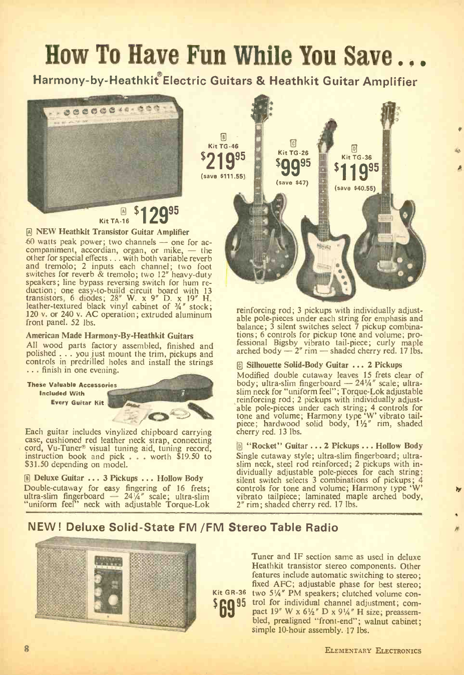
How To Have Fun While You Save ..
Harmony -by- Heathkit Electric Guitars & Heathkit Guitar Amplifier
D
o $12995
Kit TA -16
NEW Heathkit Transistor Guitar Amplifier
o
Kit TG -46
$21995
(save $11111.55)
60 watts peak power; two channels - one for ac-
companiment, accordian, organ, or mike, - the
other for special effects ... with both variable reverb
and tremolo; 2 inputs each channel; two foot
switches for reverb & tremolo; two 12" heavy -duty
speakers; line bypass reversing switch for hum re-
duction; one easy -to -build circuit board with 13
transistors, 6 diodes; 28" W. x 9" D. x 19" H.
leather- textured black vinyl cabinet of 3 %" stock;
120 v. or 240 v. AC operation; extruded aluminum
front panel. 52 lbs.
American Made Harmony -By- Heathkit Guitars
All wood parts factory assembled, finished and
polished . .. you just mount the trim, pickups and
controls in predrilled holes and install the strings
... finish in one evening.
These Valuable Accessories
Included With
Every Guitar Kit
Each guitar includes vinylized chipboard carrying
case, cushioned red leather neck strap, connecting
cord, Vu- Tuner® visual tuning aid, tuning record,
instruction book and pick . . . worth $19.50 to
$31.50 depending on model.
0 Deluxe Guitar ... 3 Pickups ... Hollow Body
Double- cutaway for easy fingering of 16 frets;
ultra -slim fingerboard - 2434" scale; ultra -slim
"uniform feel" neck with adjustable Torque -Lok
Kit TG -26
$0095 Kit TG -36
0
(save $47) (save S40.55)
reinforcing rod; 3 pickups with individually adjust-
able pole -pieces under each string for emphasis and
balance; 3 silent switches select 7 pickup combina-
tions; 6 controls for pickup tone and volume; pro-
fessional Bigsby vibrato tail -piece; curly maple
arched body - 2" rim - shaded cherry red. 17 lbs.
D Silhouette Solid -Body Guitar ... 2 Pickups
Modified double cutaway leaves 15 frets clear of
body; ultra -slim fingerboard - 24'/4" scale; ultra -
slim neck for "uniform feel "; Torque -Lok adjustable
reinforcing rod; 2 pickups with individually adjust-
able pole -pieces under each string; 4 controls for
tone and volume; Harmony type `W' vibrato tail-
piece; hardwood solid body, 1'/2" rim, shaded
cherry red. 13 lbs.
0 "Rocket" Guitar ... 2 Pickups ... Hollow Body
Single cutaway style; ultra -slim fingerboard; ultra -
slim neck, steel rod reinforced; 2 pickups with in-
dividually adjustable pole -pieces for each string;
silent switch selects 3 combinations of pickups; 4
controls for tone and volume; Harmony type 'W'
vibrato tailpiece; laminated maple arched body,
2" rim; shaded cherry red. 17 lbs.
NEW! Deluxe Solid -State FM /FM Stereo Table Radio
Tuner and IF section same as used in deluxe
Heathkit transistor stereo components. Other
features include automatic switching to stereo;
fixed AFC; adjustable phase for best stereo;
Kit GR -36 two 5'/4" PM speakers; clutched volume con-
$6995 trol for individual channel adjustment; com-
pact 19" W x 61/2" D x 91/4" H size; preassem-
bled, prealigned "front- end "; walnut cabinet;
simple 10 -hour assembly. 17 lbs.
8 ELEMENTARY ELECTRONICS
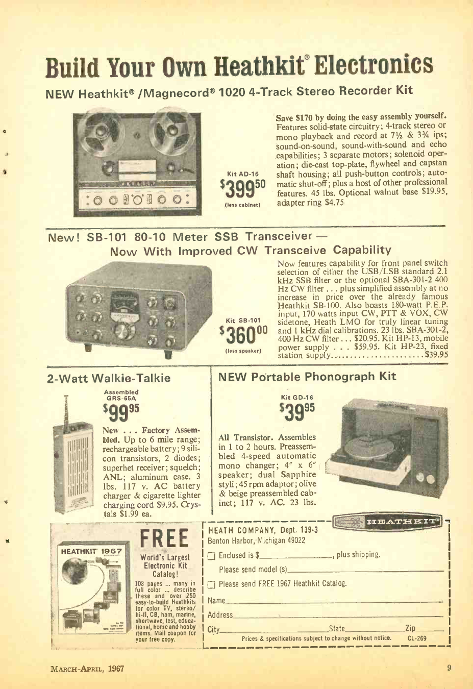
Build Your Own Heathkif Electronics
NEW Heathkit® /Magnecord® 1020 4 -Track Stereo Recorder Kit
Kit AD -16
$39950
(less cabinet)
Save $170 by doing the easy assembly yourself.
Features solid -state circuitry; 4 -track stereo or
mono playback and record at 71/2 & 31/4 ips;
sound -on- sound, sound -with -sound and echo
capabilities; 3 separate motors; solenoid oper-
ation; die -cast top -plate, flywheel and capstan
shaft housing; all push- button controls; auto-
matic shut-off; plus a host of other professional
features. 45 lbs. Optional walnut base $19.95,
adapter ring $4.75
New! SB -101 80 -10 Meter SSB Transceiver -
Now With Improved CW Transceive Capability
Now features capability for front panel switch
selection of either the USB /LSB standard 2.1
kHz SSB filter or the optional SBA -30I -2 400
Hz CW filter ... plus simplified assembly at no
increase in price over the already famous
Heathkit SB -100. Also boasts 180 -watt P.E.P.
input, 170 watts input CW, PTT & VOX, CW
sidetone, Heath LMO for truly linear tuning
and 1 kHz dial calibrations. 23 lbs. SBA -301 -2,
400 Hz CW filter ... $20.95. Kit HP -13, mobile
power supply ... $59.95. Kit HP -23, fixed
station supply $39.95
Kit SB -101
$36000
(less speaker)
2 -Watt Walkie -Talkie
Assembled
GRS-65A
$9995
New ... Factory Assem-
bled. Up to 6 mile range;
rechargeable battery; 9 sili-
con transistors, 2 diodes;
superhet receiver; squelch;
ANL; aluminum case. 3
lbs. 117 v. AC battery
charger & cigarette lighter
charging cord $9.95. Crys-
tals $1.99 ea.
FREE
HEATHKIT 1967 World's Largest
Electronic Kit
Catalog!
108 pages ... many in
full color ... describe
these and over 250
easy -to -build Heathkits
for color TV, stereo/
hi -fi, CB, ham, marine,
shortwave, test, educa-
tional, home and hobby
items. Mail coupon for
your free copy.
MARCH -APRIL, 1967
r
NEW Portable Phonograph Kit
Kit GD -16
$3995
All Transistor. Assembles
in 1 to 2 hours. Preassem-
bled 4 -speed automatic
mono changer; 4" x 6"
speaker; dual Sapphire
styli; 45 rpm adaptor; olive
& beige preassembled cab-
inet; 117 v. AC. 23 lbs.
HEATH COMPANY, Dept. 139.3
Benton Harbor, Michigan 49022
Enclosed is $ , plus shipping.
Please send model (s)
Please send FREE 1967 Heathkit Catalog.
Name
Address
City State Zip
L Prices & specifications subject to change without notice. CL -269
9
When a Pioneer Speaks
...it's time to listen!
That's when you'll hear the optimum in tonal
quality ... sound reproduction at its faithful
best.
You can always count on Pioneer speakers and
speaker systems to deliver a quality perform-
ance. Every time. All the time.
Made by the world's largest manufacturer of
speakers, this premium audio equipment is avail-
able at popular prices.
And you can select from many fine models -from
the unique, handsome metal -grilled CS -24 Auxil-
iary Wall Speaker to the efficient, compact CS -20,
CS -52 and the Ultimate 5- speaker CS -61 Book-
shelf System. All carried only by franchised
dealers.
A word from you and we'll send literature and
the name of your nearest dealer.
(A) CS -62 Bookshelf 3 -way speaker system (3 speakers ).
Oiled walnut enclosure. Meas. 254 "x 15% 6 '" x 111 ,,
retail price: $142.00.
(B) CS -61 Bookshelf 3 -way speaker system (5 speakers).
Oiled walnut enclosure. Meas. 241/4" x 161 MG" x 131/4 ",
retail price: $175.00.
(C) CS -20 Compact 2-way speaker system. Oiled walnut
enclosure. Meas. 131/4" x 8" x 81/2", retail price: $35.00.
(D) CS-24 wall or enclosure. Meas. system.
4
x 105/. "x 43/4 ", retail price: $27.75.
(E) CS-52 Compact 2 -way speaker system. Oiled walnut
enclosure with gold metal trim. Meas. 131/2" 81/4" x 81/2",
retail price: $59.95.
PIONEER ELECTRONICS U.S.A.
CORPORATION
140 SMITH AVENUE, FARMINGDALE, LONG ISLAND, N.Y. 11735
(516) 6947720
10
NEWSCAN
tensity modulation; a second diffraction cell
that acts as a horizontal deflector which pro-
vides a high degree of resolution; and a ver-
tical deflector. They perform essentially the
same functions as parts of a conventional pic-
ture tube and deflection yoke. In addition there
are a number of optical components to shape
and focus the beam on a screen. Because a
helium -neon laser emits a red light beam, the
picture on the screen is black and red.
The principle of using ultrasonic waves to
interact with a light beam is one that has been
known for some 30 years. Previously it was
thought that ultrasound could only be applied
to intensity modulation or control of bright-
ness. TV signals for display by the system are
provided by portions of a regular TV chassis
and are processed before being fed into the
intensity modulation (video), horizontal deflec-
tion and vertical deflection stages of the system.
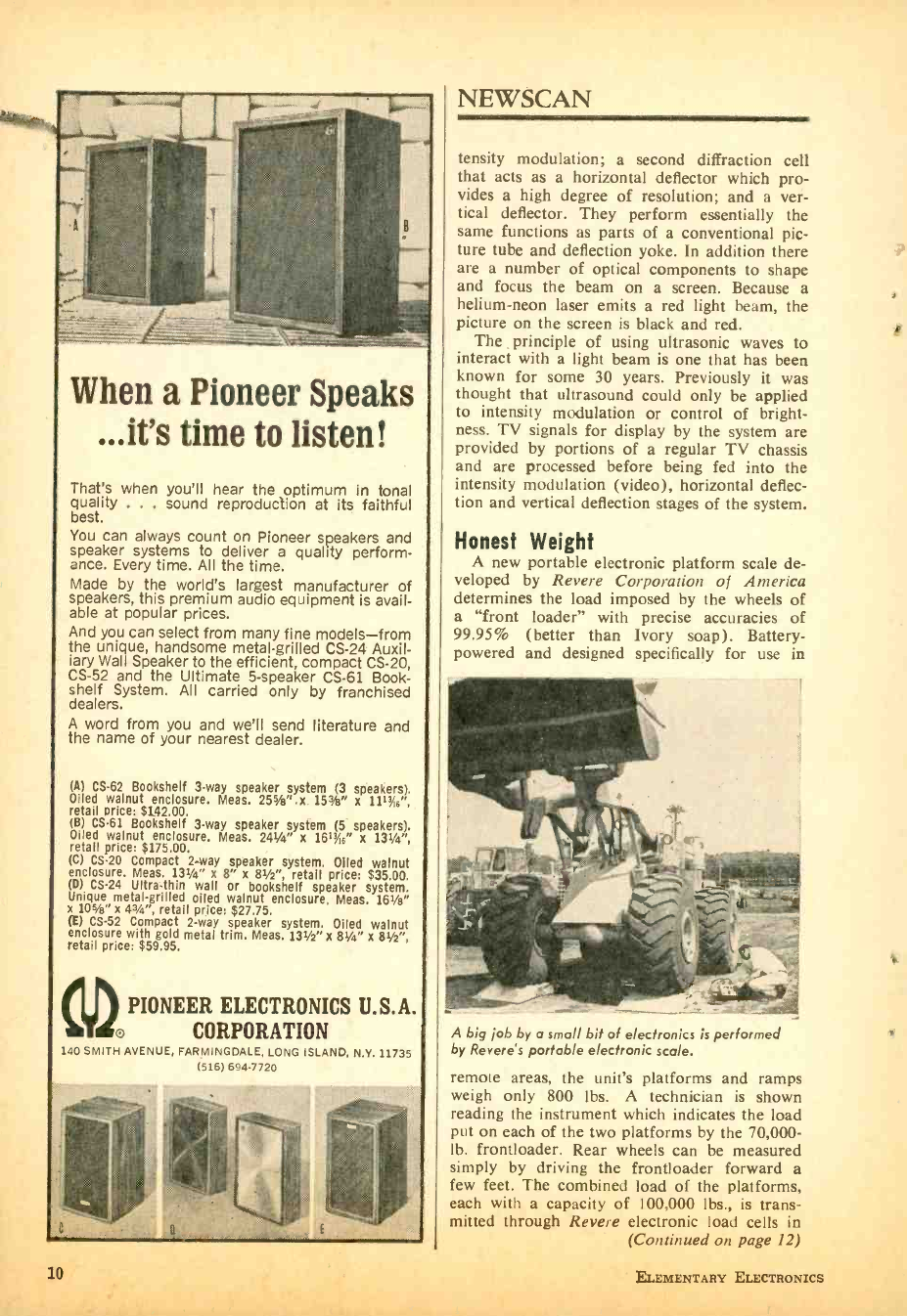
Honest Weight
A new portable electronic platform scale de-
veloped by Revere Corporation of America
determines the load imposed by the wheels of
a "front loader" with precise accuracies of
99.95% (better than Ivory soap). Battery -
powered and designed specifically for use in
A big ¡ob by a small bit of electronics is performed
by Revere's portable electronic scale.
remote areas, the unit's platforms and ramps
weigh only 800 lbs. A technician is shown
reading the instrument which indicates the load
put on each of the two platforms by the 70,000 -
lb. frontloader. Rear wheels can be measured
simply by driving the frontloader forward a
few feet. The combined load of the platforms,
each with a capacity of 100.000 lbs., is trans-
mitted through Revere electronic load cells in
(Continued on page 12)
ELEMENTARY ELECTRONICS
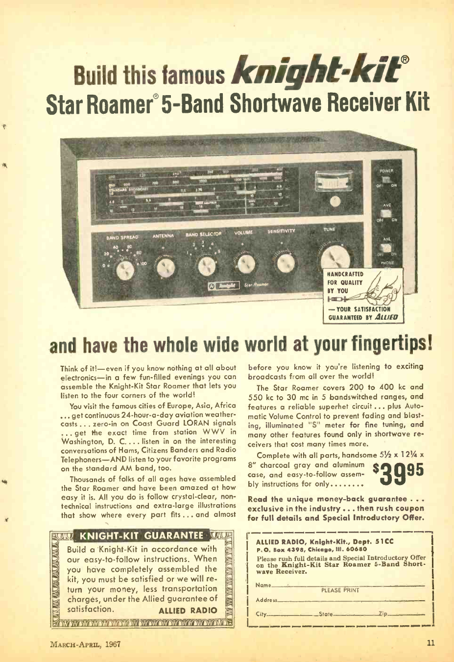
Build this famous knightkif
Star Roamer® 5 -Band Shortwave Receiver Kit
- YOUR SATISFACTION
GUARANTEED BY 4111(0
and have the whole wide world at your fingertips!
Think of it! -even if you know nothing at all about
electronics -in a few fun -filled evenings you can
assemble the Knight -Kit Star Roamer that lets you
listen to the four corners of the world!
You visit the famous cities of Europe, Asia, Africa
... get continuous 24- hour -a -day aviation weather -
casts ... zero -in on Coast Guard LORAN signals
. get the exact time from station W W V in
Washington, D. C.... listen in on the interesting
conversations of Hams, Citizens Banders and Radio
Telephoners -AND listen to your favorite programs
on the standard AM band, too.
Thousands of folks of all ages have assembled
the Star Roamer and have been amazed at how
easy it is. All you do is follow crystal -clear, non-
technical instructions and extra -large illustrations
that show where every part fits ... and almost
r
i..
04 ,
_ _ KNIGHT -KIT GUARANTEE vJVJ
Build a Knight -Kit in accordance with
our easy -to- follow instructions. When
you have completely assembled the
kit, you must be satisfied or we will re-
turn your money, less transportation
charges, under the Allied guarantee of
satisfaction. ALLIED RADIO
,
1 1
'.4 ,
r -,rnt%rIfnr-n u - i IIAlif iVilli Pn +lrrliiIMll ï
MARCH -APRII., 1967
before you know it you're listening to exciting
broadcasts from all over the world!
The Star Roamer covers 200 to 400 kc and
550 kc to 30 me in 5 bandswitched ranges, and
features a reliable superhet circuit... plus Auto-
matic Volume Control to prevent fading and blast-
ing, illuminated "5" meter for fine tuning, and
many other features found only in shortwave re-
ceivers that cost many times more.
Complete with all parts, handsome 51/2 x 121/2 x
8" charcoal gray and aluminum
case, and easy -to- follow assem-
bly instructions for only
Read the unique money -back guarantee ..
exclusive in the industry ... then rush coupon
for full details and Special Introductory Offer.
r ALLIED RADIO, Knight -Kit., Dept. S 1 CC
P.O. Box 4398, Chicago, III. 60680
Please rush full details and Special Introductory Offer
on the Knight -Kit Star Roamer 5 -Band Short-
wave Receiver.
Name
Address
City State lip
PLEASE PRINT
11
tom"
Fill in coupon for a FREE One Year Subscrip-
tion to OLSON ELECTRONICS' Fantastic Value
Packed Catalog- Unheard of LOW, LOW PRICES
on Brand Name Speakers, Changers, Tubes,
Tools, Stereo Amps, Tuners, CB, and other Val-
ues. Credit plan available.
NAME
ADDRESS
CITY STATE ZIP_
If you have a friend interested in electronics send
his name and address for a FREE subscription also.
OLSON ELECTRONICS
INCORPORATED
577 S. Forge Street Akron, Ohio 44308
Get Your
F.C.C. LICENSE
and
A.S.E.E. DEGREE
We offer the following courses - all
approved under the new G.I. Bill. Select
the course you are interested in, and write
or phone for free details.
Electronics Engineering Technology (resident
course, which leads to the A.S.E.E. degree) ;
Basic Electronics Engineering Technology
(correspondence course, which covers the first
1/3 of the EET course listed above, and credit
for which can be applied toward the A.S.E.E.
degree) ;
Communications Electronics (resident course
which leads to the FCC first class license and
trains you to be a communications technician) ;
F.C.C. License Course (correspondence course,
which prepares you for your FCC first class
radiotelephone license - after completing this
course, if you should fail to pass the FCC
exam for this license all your tuition payments
will be refunded).
For free brochure, write:
Desk 6 -R
Grantham School of Electronics
1505 N. Western Ave., Hollywood, Cal. 90027
Phone: (213) 469 -7878
818.18th St., NW, Washington, D.C. 20006
Phone: (202) 298 -7460
12
NEWSCAN
the ramps to the readout instrument, where the
signal is amplified and translated into a meter
reading giving the actual load. Device can be set
up alongside highways in minutes to check axle
loads on trucks. State police checking axle
loads of trucks will now be able to set up check
points almost anywhere.
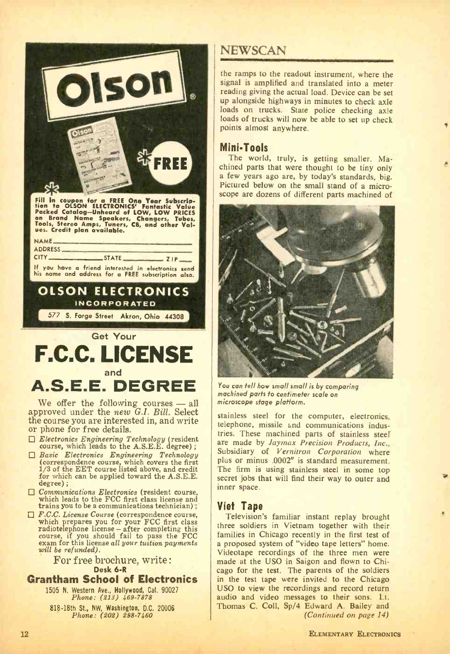
Mini -Tools
The world, truly, is getting smaller. Ma-
chined parts that were thought to be tiny only
a few years ago are, by today's standards, big.
Pictured below on the small stand of a micro-
scope are dozens of different parts machined of
You can tell how small small is by comparing
machined parts to centimeter scale on
microscope stage platform.
stainless steel for the computer, electronics,
telephone, missile and communications indus-
tries. These machined parts of stainless steel
are made by laymax Precision Products, Inc.,
Subsidiary of Vernitron Corporation where
plus or minus .0002" is standard measurement.
The firm is using stainless steel in some top
secret jobs that will find their way to outer and
inner space.
Viet Tape
Television's familiar instant replay brought
three soldiers in Vietnam together with their
families in Chicago recently in the first test of
a proposed system of "video tape letters" home.
Videotape recordings of the three men were
made at the USO in Saigon and flown to Chi-
cago for the test. The parents of the soldiers
in the test tape were invited to the Chicago
USO to view the recordings and record return
audio and video messages to their sons. Lt.
Thomas C. Coll, Sp /4 Edward A. Bailey and
(Continued on page 14)
ELEMENTARY ELECTRONICS
LAFAYETTE HB -525 Solid State
Mobile 2 -Way Radio
All Crystals Supplied!
Size: 23/4" by 61/4" 99.3076WX*
All CB Cha
Crystal nnels
Controlled
Plus 2 Reserve Channels
19 Transistors, 7 Diodes, Thermistor
Dual Conversion Receiver for Extra Selectivity
and Sensitivity
Full 5-Watt Input
Range BoostTM Circuitry for Added Power
3- Position Delta Tune -Provides Accurate Fine
Tuning
Mechanical 455KC Filter for Superior
Selectivity
FREE
Over 500 Pages
MARCH-APRIL, 1967
Push -to -Talk Dynamic Microphone
Variable Squelch plus Series Gate Automatic
Noise Limiting
Public Address System (with external speaker)
12 -Volt DC Operation (pos. or neg. ground) 6-
Volt DC (with optional DC Power Supply)
Pi- Network for Optimum RF Output
117 Volt AC Operation with Optional Power
Supply `Imported
1967 CATALOG NO 670
Featuring Everything in Electronics for
HOME INDUSTRY LABORATORY
from the "World's HiFi & Electronics Center"
LAFAYETTE Radio ELECTRONICS
Dept. DEEC -1 P.O. Box 10
Syosset, L. I., N. Y. 11791
I I I Name
I
I City
Address
Send me the FREE 1967 LAFAYETTE Catalog 670
State Zip
()EEC-]
r- I McGEE RADIO CO..
1907 McGee St.
Kansas City 8, Missouri
SEND 1967 McGEE CATALOG
I NAME
I ADDRESS
p_ CITY ZONE.... STATE
NOW RI FOR M c G E E' S
1967 CATALOG
1001 BARGAINS IN
SPEAKERS -PARTS- TUBES -HIGH FIDELITY
COMPONENTS -RECORD CHANGERS -
TAPE RECORDERS -KITS-
EVERYTHING IN ELECTRONICS
J
Tape this ad to the back of your TV or Radio Set
ALL TV- RADIO $ 1
RECEIVING TUBES ra
ALL BRAND -NEW, First Quality. All
Types Available. Orders Shipped First
Class Same Day Rec'd. Unconditionally
Guaranteed. 24 Month Warranty.
Send $1 for ea. tube + 50e. postage &
handling of entire order. FREE: Write
for "do -it- yourself" TV Test Chart and
Tube List to Dept. EE -347. et%
UNIVERSAL TUBE CO. Ozone Park, N. V. 11417
Learn how to become a
GAME WARDEN
GOV'T HUNTER, FORESTER, WILDLIFE MANAGER
Exciting job openings now for qualified men who love
outdoor work. Protect forests and wildlife- arrest vio-
lators! Good poy, security, prestige and authority for
respected career Conservation Officers. Easy home -
study plan! Send for FREE Fact BOOK, aptitude QUIZ,
SUBSCRIPTION to Conservation magazine. State age.
NORTH AMERICAN SCHOOL OF CONSERVATION
Campus Drive, Dept. 1353, Newport, Calif. 92660
ALL BAND BATTERY SHORT WAVE RADIO KIT .12.95
Listen around the world-Thousands of miles
away! Ships -Aircraft -Voice of America -Rus-
sia- London- Australla- Amateurs -Police. Also
LSA Broadcast -5 Wave Bands Le to 43 MC!
Calibrated tuning dial. Wt. only 3 lbs. World
wide reception.
Send only gg g5 COO pstgnr sendp$12.95
$3 00 for PP del In USA. Basic Kit as
f shown Secludes plastic case and
BC cull FREE. Long Distance antenna. if you
order NOW. Available only from Midway Co.,
Dept. BE -3, Kearney, Nebr.
Learn of the many money making ideas
and low cost /high profit businesses you can
start in.
INCOME OPPORTUNITIES -750
on sale now
Take the guessing out of home buying.
Complete plans and specifications from
leading architects.
SMALL HOME PLANS -$1.25
on sale now or write Davis Publications,
Inc. /505 Park Ave. /New York, N. Y. 10022.
Add 25 each for postage & handling.
NEWSCAN
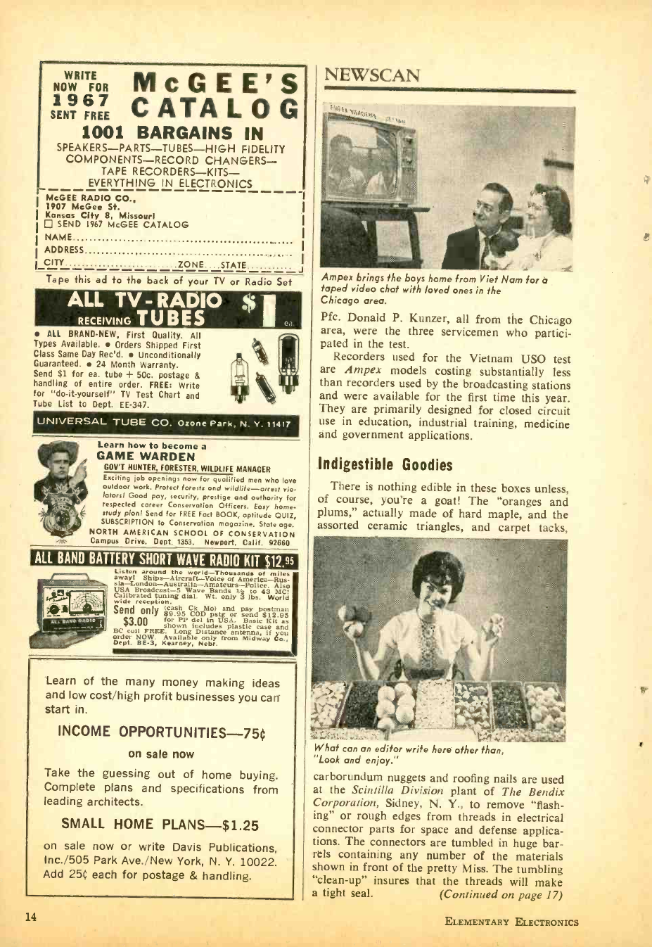
Ampex brings the boys home from Viet Nam for a
taped video chat with loved ones in the
Chicago area.
Pfc. Donald P. Kunzer, all from the Chicago
area, were the three servicemen who partici-
pated in the test.
Recorders used for the Vietnam USO test
are Ampex models costing substantially less
than recorders used by the broadcasting stations
and were available for the first time this year.
They are primarily designed for closed circuit
use in education, industrial training, medicine
and government applications.
Indigestible Goodies
There is nothing edible in these boxes unless,
of course, you're a goat! The "oranges and
plums," actually made of hard maple, and the
assorted ceramic triangles, and carpet tacks,
What can an editor write here other than,
"Look and enjoy."
carborundum nuggets and roofing nails are used
at the Scintilla Division plant of The Bendix
Corporation, Sidney, N. Y., to remove "flash-
ing" or rough edges from threads in electrical
connector parts for space and defense applica-
tions. The connectors are tumbled in huge bar-
rels containing any number of the materials
shown in front of the pretty Miss. The tumbling
"clean -up" insures that the threads will make
a tight seal. (Continued on nape 171
14 ELEMENTARY ELECTRONICS
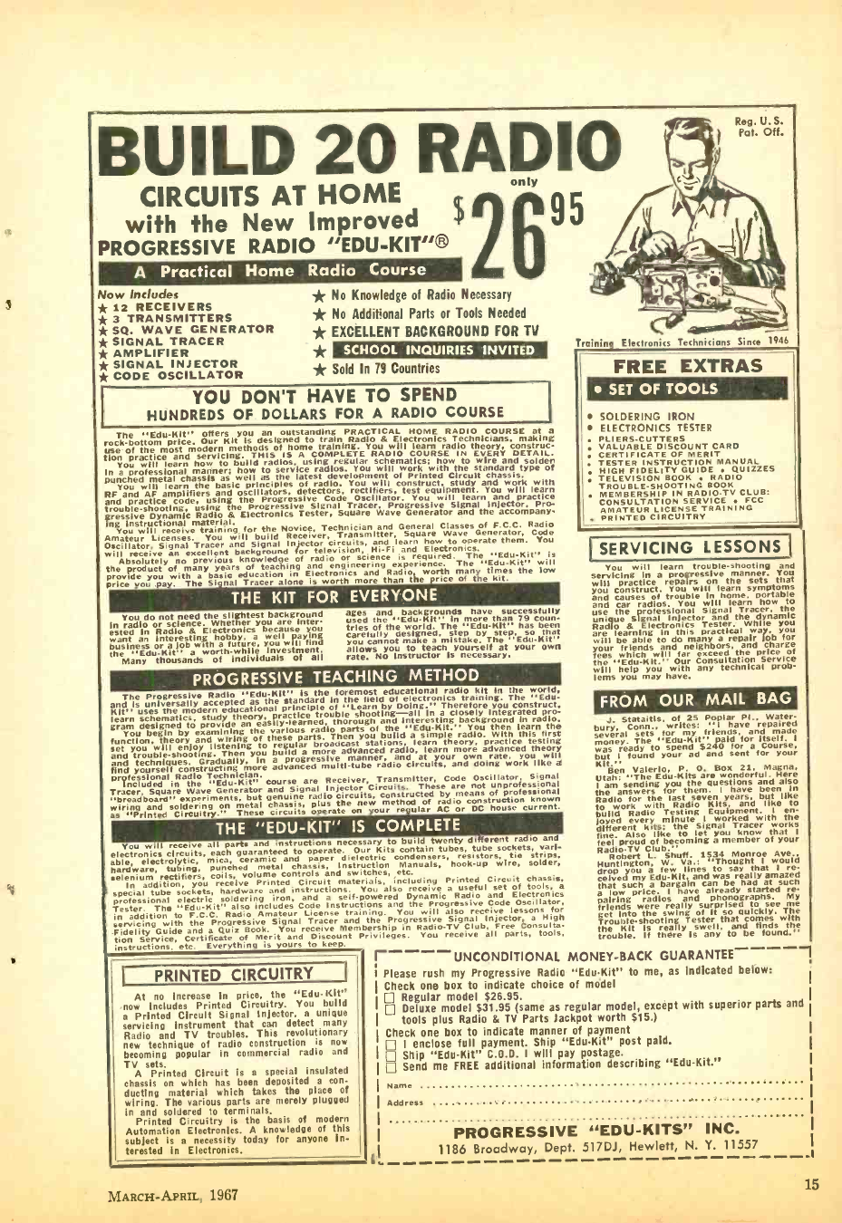
BUILD 20 RADIO
CIRCUITS AT HOME
with the New Improved
PROGRESSIVE RADIO "EDU -KIT "®
A Practical Home Radio Course
Now Includes
* 12 RECEIVERS
* 3 TRANSMITTERS
* SQ. WAVE GENERATOR
* SIGNAL TRACER
* AMPLIFIER
* SIGNAL INJECTOR
* CODE OSCILLATOR
only
* No Knowledge of Radio Necessary
* No Additional Parts or Tools Needed
* EXCELLENT BACKGROUND FOR TV
* * Sold In 79 Countries
SCHOOL INQUIRIES INVITED
95
YOU DON'T HAVE TO SPEND
HUNDREDS OF DOLLARS FOR A RADIO COURSE
The "Edil -Kit" offers you an outstanding PRACTICAL HOME RADIO COURSE at a
rock - bottom price. Our Kit is designed to train Radio & Electronics Technicians, making
use Of the most modern methods Of home training. You will learn radio theory, Construc-
tion practice and servicing. THIS IS A COMPLETE RADIO COURSE IN EVERY DETAIL.
You will learn how to build radios, using regular schematics; how to wire and solden
In a professional manner; how to service radios- You will work with the standard type of
punched metal chassis as well as the latest development of Printed Circuit chassis.
You will learn the basic principles of radio. You will construct, study and work with
RF and AF amplifiers and oscillators, detectors, r ctifiers, test equipment. You will learn
and practice code, using the Progressive Code Oscillator. You will learn and practice
trouble -shooting, using the Progressive Signal Tracer, Progressive Signal Injector, Pro -
gressive Dynamic Radio & Electronics Tester, Square Wave Generator and the accompany-
ing Instructional material.
You will receive training for the Novice, Technician and General s of F.C.C. Radio
Amateur Licenses. You will build Receiver, Transmitter, Square Wave Generator, Code
Oscillator, Signal Tracer and Signal Injector circuits, and learn how to operate them. You
will receive an excellent background for television, Hi-Fi and Electronics.
Absolutely no prevìou knowledge of radio or science is required. The "Edu -Kit" is
teaching
product of many years of teaching nd engineering experience. The 'Edu -Kit" will
provide you with basic education in Electronics and Radio worth many times the low
price you .pay. The i more
Tracer alone is worth m e than the rice
e of the kit.
THE KIT FOR EVERYONE
You do not need the slightest background
In radio or science. Whether you are Inter-
ested in Radio & Electronics because you
want an interesting hobby. a well aying
business or a job with a future, you will find
the any0uthousandsw ofh Individuals
Investment.
of all
ages and backgrounds have successfully
used the "EduKit'' in more than 79 coon.
tries of the world. The "Edu -Kit" has been
carefully designed, step by tep, so that
you cannot make a mistake. The Edu -Kit"
allows you to teach yourself at your own
rate. NO instructor is necessary.
PROGRESSIVE TEACHING METHOD
The Progressive Radio "EduKit" Is the foremost educational radio kit in the world.
and is universally accepted as the standard in the field of electronics training. The "Edu -
Kit" uses the modern educational principle of "Learn by Doing -" Therefore you construct,
learn schematics, study theory, practice trouble shooting -all In a closely Integrated pro-
gram designed to provide an asilYlearned, thorough and Interesting background in radio.
You begin by examining the various radio parts of the Edu-Kit." You then learn the
function. theory and iring of these parts. Then you build a simple radio- With this first
set You will goy listening to regular broadcast stations, learn theory. practice testing
and trouble-shooting. Then you build a more advanced radio, learn more advanced theory
and techniques. Gradually, in a progressive manner. and at your own rate. you will
find yourself constructing more advanced multi -tube radio circuits. and doing work like a
Professional Radio Technician.
Included in the 'Edu -Kit" course are Receiver, Transmitter, Code Oscillator, Signal
Tracer. Square Wave Generator and Signal Injector Circuits. These are not unprofessional l
"breadboard" experiments, but genuine rags the rats,
circuits, constructed by
of of pro^e siown
wiring and soldering on metal chassis. p
as "Printed Circuitry." These circuits operate on our re ,ular AC or construction
house current.
THE "EDU -KIT" IS COMPLETE
You will receive all parts and instructions necessary to build twenty different radio and
electronics circuits, each aranteed to operate. Our Kits contain tubes, tube sockets. vari-
able, electrolytic, mica, ceramic and paper dielectric condensers, resistors, tie strips,
hardware, tubing, punched metal chassis, Instruction Manuals, hook -up wire, solder,
selenium ectifiers, coils, volume controls and switches, etc.
In addirtion, you receive Printed Circuit materials, including Printed Circuit chassis,
special tube sockets, hardware and instructions. You also receive a useful set of tools, a
professional electric soldering iron, and a self -powered Dynamic Radio and Electronics
Tester. The "Edu -Kit" also includes Code Instructions and the Progressive Code Oscillator,
in addition to F.C.C. Radio Amateur License training. You will also receive lessons for
servicing
with the Progressive Signal Tracer and the Progressive Signal Injector, a High
Guide and a Quiz Book. You r a eeive Membership in Radio -TV Club, Free Consulta-
tion Service, Certificate f Merit and Discount Privileges. You receive all parts, tools,
instructions, etc. Everything is yours to keep.
PRINTED CIRCUITRY
At no increase in price, the "Edu -Kit"
now includes Printed Circuitry. You build
a Printed Circuit Signal Injector, a unique
servicing instrument that can detect many
Radio and TV troubles. This revolutionary
new technique of radio construction is now
becoming popular in commercial radio and
TV sets.
A Printed Circuit is a special insulated
chassis on which has been deposited a con-
ducting material which takes the place of
wiring. The various parts are merely plugged
in and soldered to terminals.
Printed Circuitry is the basis of modern
Automation Electronics. A knowledge of this
subject is a necessity today for anyone in-
terested in Electronics.
MARCH -APRIL, 1967
Reg. U. S.
Pat. Off.
Training Electronics Technicians Since 1946
FREE EXTRAS
SET OF TOOLS
SOLDERING IRON
ELECTRONICS TESTER
PLIERS -CUTTERS
VALUABLE DISCOUNT CARD
CERTIFICATE OF MERIT
TESTER INSTRUCTION MANUAL
HIGH FIDELITY GUIDE QUIZZES
TELEVISION BOOK RADIO
TROUBLE -SHOOTING BOOK
MEMBERSHIP IN RADIO.TV CLUB:
CONSULTATION SERVICE FCC
AMATEUR LICENSE TRAINING
. PRINTED CIRCUITRY
I SERVICING LESSONS I
You will learn ggrr s e manner.
trouble- shooting nd
You
prac s
tice repairs on the sets t at
will construct. You will learn symptoms
and causes of trouble in home, portable
and car radios. You will learn how to
use the professional Signal Tracer, the
unique & Signal
Electroniics TesterL Welle h you
are learning in this practical way, you
will be able to do many a repair lob for
your
fees friends and neighbors. d the price
eighbo d char
s will far
the ' help you with any technical
ou
lems you may have.
FROM OUR MAIL BAG
J. Stataitis, of 25 Poplar Pl., Water-
bury. Conn., writes: I have repaired
several
o. sets for friends,
' pai fora and made
as ready to spend $240 for a Course.
but I found your ad and sent for your
Kit." Ben Valerio. P. 0. Box 21. Magna,
Utah:
am sending POU the are uesti
questions Here
answers for them. I have been In
Radio for the last seven years, but like
to wOrk with Radio Kits. and like to
build Radiyyo Testing Equipment. 1 en-
joyed every minute
the a Signal worked with works
fine. Also like to let you know that I
feel proud of becoming a member of your
Radio -TV Club."
Robert L. Shutt. 1534 Monroe Ave..
dreg
Huntinton a few lines to say
"Thought
u that I re.
celved by adba gain and can as y had at (such
a low price. I have already started re-
pairing radios and phonographs. MY
friends were really surprised to see me
get Into the swing of It so quickly. The
Trouble-shooting Tester that comes with
the Kit Is really swell. and finds the
trouble. If there Is any to be found."
r----UNCONDITIONAL MONEY -BACK GUARANTEE
Ì Please rush my Progressive Radio "Edu -Kit" to me, as Indicated below:
Check one box to indicate choice of model
Regular model $26.95.
Deluxe model $31.95 (same as regular model, except with superior parts and
tools plus Radio & TV Parts Jackpot worth $15.)
Check one box to indicate manner of payment
I enclose full payment. Ship "Edu -Kit" post paid.
Ship "Edu -Kit" C.D.D. I will pay postage.
Send me FREE additional information describing "Edu -Kit."
Name
Address
PROGRESSIVE "EDU - KITS" INC.
1186 Broadway, Dept. 517DJ, Hewlett, N. Y. 11557
15
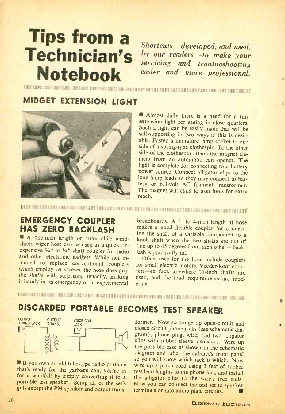
Tips from a
Technician's
Notebook
Shortcuts -developed, and used,
by our readers -to make your
servicing and troubleshooting
easier and more professional.
11111111111111!
MIDGET EXTENSION LIGHT
Almost daily there is a need for a tiny
extension light for seeing in close quarters.
Such a light can be easily made that will be
self- supporting in two ways if this is desir-
able. Fasten a miniature lamp socket to one
side of a spring -type clothespin. To the other
side of the clothespin attach the magnet ele-
ment from an automatic can opener. The
light is complete for connecting to a battery
power source. Connect alligator clips to the
long lamp leads so they may connect to bat-
tery or 6.3 -volt AC filament transformer.
The magnet will cling to iron tools for extra
reach.
1111111111111111111111I11111111111111111111111111111111111111111111111111111111111111111111111111111111111111ÌI
EMERGENCY COUPLER breadboards. A 3- to 4 -inch length of hose
HAS ZERO BACKLASH makes a good flexible coupler for connect-
ing the shaft of a variable component to a
A one -inch length of automobile wind- knob shaft when the two shafts are out of
shield wiper hose can be used as a quick, in- line up to 45 degrees from each other -back-
expensive 1/4 "- to -1/4" shat coupler for radio lash is practically nil.
and other electronic gadgets. While not in- Other uses for the hose include couplers
tended to replace conventional couplers for small electric motors, Veeder -Root coun-
which employ set screws, the hose does grip ters -in fact, anywhere 1/4 -inch shafts are
the shafts with surprising tenacity, making used, and the load requirements are mod -
it handy in an emergency or in experimental erate.
!1! 1111111! 11111111111 !IIIIIIIi11111111I11111!IIIII
DISCARDED PORTABLE BECOMES TEST SPEAKER
OUTPUT OUTPUT VOICE COIL
TRANS. JACK TRANS. JACK
V
If you own an old tube -type radio portable
that's ready for the garbage can, you're in
for a windfall by simply converting it to a
portable test speaker. Scrap all of the set's
guts except the PM speaker and output trans-
former. Now scrounge up open- circuit and
closed circuit phone jacks (see schematic dia-
gram), phone plug, wire, and two alligator
clips with rubber sleeve insulators. Wire up
the portable case as shown in the schematic
diagram and label the cabinet's front panel
so you will know which jack is which. Now
wire up a patch cord using 3 feet of rubber
test lead lengths to the phone jack and install
the alligator clips to the wire's free ends.
Now you can connect the test set to speaker
terminals nr into andin nlata r.,rr,,;t.
16 ELEMENTARY ELECTRONICS
s
NEWSCAN
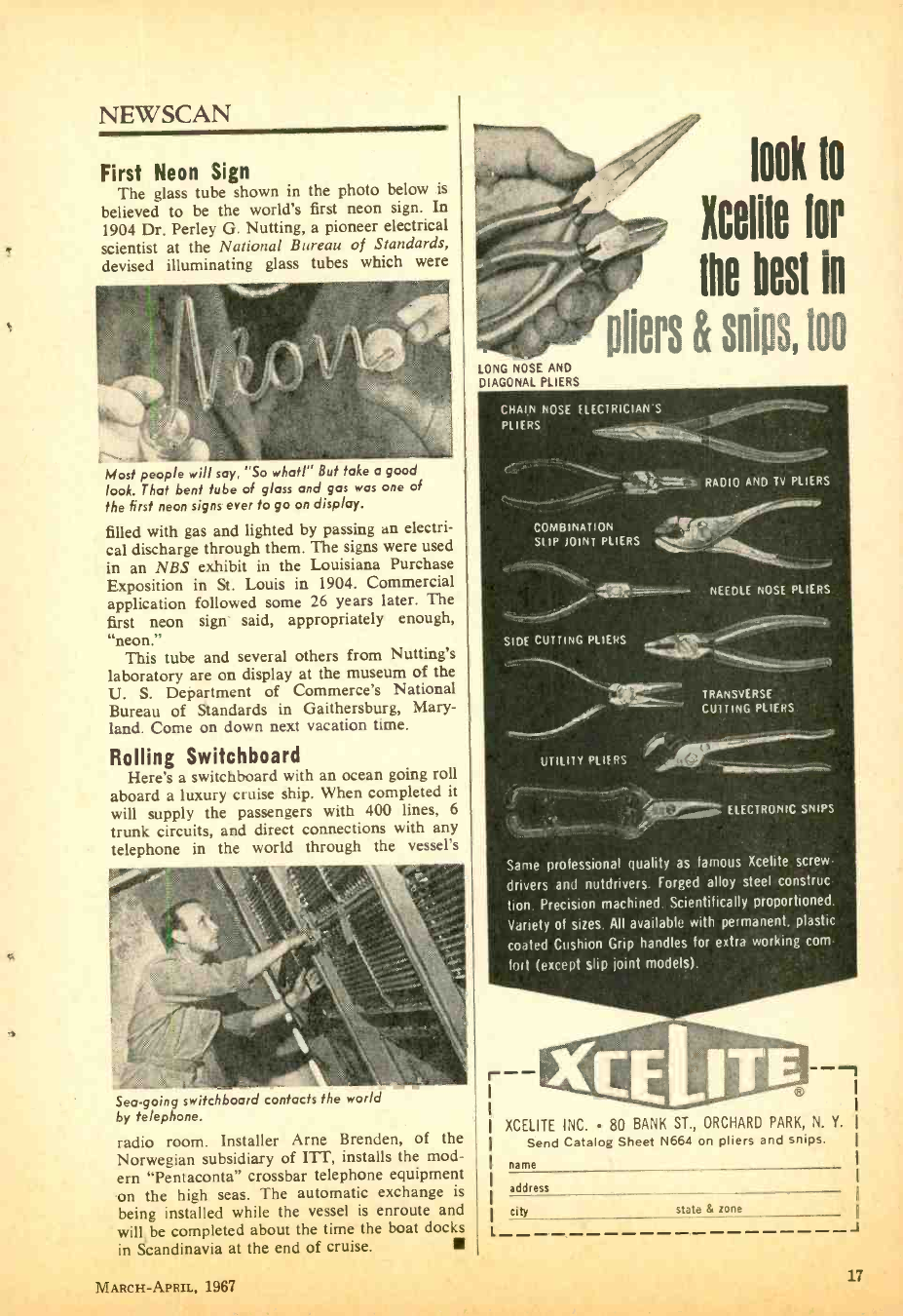
First Neon Sign
The glass tube shown in the photo below is
believed to be the world's first neon sign. In
1904 Dr. Perley G. Nutting, a pioneer electrical
scientist at the National Bureau of Standards,
devised illuminating glass tubes which were
LONG NOSE AND
DIAGONAL PLIERS
look 10
Icelile for
me best in
p1Ì¢15 & SÑps, 100
CHAIN NOSE ELECTRICIANS
PLIERS
Most people will say, "So what!" But take a good
look. That bent tube of glass and gas was one of
the first neon signs ever to go on display.
filled with gas and lighted by passing an electri-
cal discharge through them. The signs were used
in an NBS exhibit in the Louisiana Purchase
Exposition in St. Louis in 1904. Commercial
application followed some 26 years later. The
first neon sign said, appropriately enough,
"neon."
This tube and several others from Nutting's
laboratory are on display at the museum of the
U. S. Department of Commerce's National
Bureau of Standards in Gaithersburg, Mary-
land. Come on down next vacation time.
Rolling Switchboard
Here's a switchboard with an ocean going roll
aboard a luxury cruise ship. When completed it
will supply the passengers with 400 lines, 6
trunk circuits, and direct connections with any
telephone in the world through the vessel's
VIVZ,.: RADIO AND TV PLIERS
COMBINATION
SIIP JOINT PLIERS
SIDE CUTTING PLIERS
TRANSVERSE
CUTTING PLIERS
UTILITY PLIERS
Sea -going switchboard contacts the world
by telephone.
radio room. Installer Arne Brenden, of the
Norwegian subsidiary of ITT, installs the mod-
ern "Pentaconta" crossbar telephone equipment
on the high seas. The automatic exchange is
being installed while the vessel is enroute and
will be completed about the time the boat docks
in Scandinavia at the end of cruise.
Same professional quality as famous Xcelite screw
drivers and nutdrivers. Forged alloy steel construc-
tion. Precision machined. Scientifically proportioned.
Variety of sizes. All available with permanent. plastic
coated Cushion Grip handles for extra working com
fort (except slip joint models).
r-- --1
XCELITE INC. 80 BANK ST., ORCHARD PARK, N. Y.
Send Catalog Sheet N664 on pliers and snips.
name
address
city state & zone
MARCH -APRIL, 1967 17
ASK
ME
ANOTHER.
Elementary Electronics brings the know -how of an
electronics expert to its readers. Leo G. Sands,
columnist for Radio -TV Experimenter, will be
happy to answer your question. Just type or print
your unsolved problem on the back of a 40 postal
card and send it to "Ask Me Another," Elementary
Electronics, 505 Park Avenue, New York, New
York 10022. Leo will try to answer all your ques-
tions in the available space in upcoming issues of
Elementary Electronics. Sorry, Leo will be unable
to answer your questions by mail.
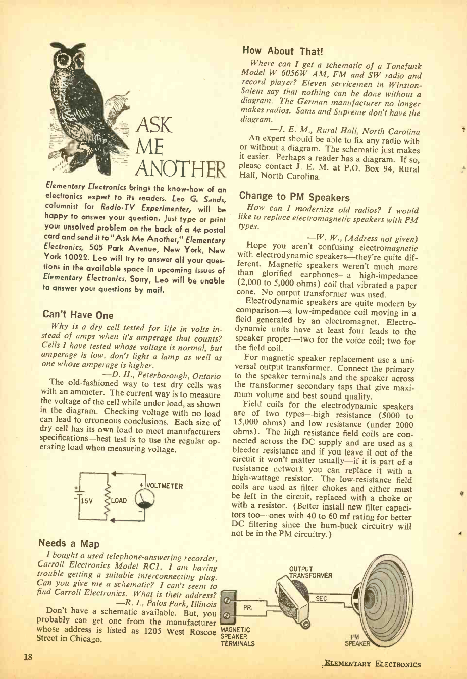
Can't Have One
Why is a dry cell tested for life in volts in-
stead of amps when it's amperage that counts?
Cells I have tested whose voltage is normal, but
amperage is low, don't light a lamp as well as
one whose amperage is higher.
-D. H., Peterborough, Ontario
The old- fashioned way to test dry cells was
with an ammeter. The current way is to measure
the voltage of the cell while under load, as shown
in the diagram. Checking voltage with no load
can lead to erroneous conclusions. Each size of
dry cell has its own load to meet manufacturers
specifications -best test is to use the regular op-
erating load when measuring voltage.
1 115v
+ VOLTMETER
LOAD
Needs a Map
I bought a used telephone -answering recorder,
Carroll Electronics Model RCI. I am having
trouble getting a suitable interconnecting plug.
Can you give me a schematic? I can't seem to
find Carroll Electronics. What is their address?
How About That!
Where can I get a schematic of a Tonefunk
Model W 6056W AM, FM and SW radio and
record player? Eleven servicemen in Winston -
Salem say that nothing can be done without a
diagram. The German manufacturer no longer
makes radios. Sams and Supreme don't have the
diagram. -1. E. M., Rural Hall, North Carolina
An expert should be able to fix any radio with
or without a diagram. The schematic just makes
it easier. Perhaps a reader has a diagram. If so,
please contact J. E. M. at P.O. Box 94, Rural
Hall, North Carolina.
Change to PM Speakers
How can I modernize old radios? 1 would
like to replace electromagnetic speakers with PM
types. -W. W., (Address not given)
Hope you aren't confusing electromagnetic
with electrodynamic speakers -they're quite dif-
ferent. Magnetic speakers weren't much more
than glorified earphones -a high- impedance
(2,000 to 5,000 ohms) coil that vibrated a paper
cone. No output transformer was used.
Electrodynamic speakers are quite modern by
comparison -a low- impedance coil moving in a
field generated by an electromagnet. Electro-
dynamic units have at least four leads to the
speaker proper -two for the voice coil; two for
the field coil.
For magnetic speaker replacement use a uni-
versal output transformer. Connect the primary
to the speaker terminals and the speaker across
the transformer secondary taps that give maxi-
mum volume and best sound quality.
Field coils for the electrodynamic speakers
are of two types -high resistance (5000 to
15,000 ohms) and low resistance (under 2000
ohms). The high resistance field coils are con-
nected across the DC supply and are used as a
bleeder resistance and if you leave it out of the
circuit it won't matter usually -if it is part of a
resistance network you can replace it with a
high- wattage resistor. The low- resistance field
coils are used as filter chokes and either must
be left in the circuit, replaced with a choke or
with a resistor. (Better install new filter capaci-
tors too -ones with 40 to 60 mf rating for better
DC filtering since the hum -buck circuitry will
not be in the PM circuitry.)
-R. J., Palos Park, Illinois PRI
Don't have a schematic available. But, you ,®
probably can get one from the manufacturer iwrJ
whose address is listed as 1205 West Roscoe MAGNETIC
Street in Chicago. SPEAKER
TERMINALS
OUTPUT
TRANSFORMER
18
PM
SPEAKER
ELEMENTARY ELECTRONICS
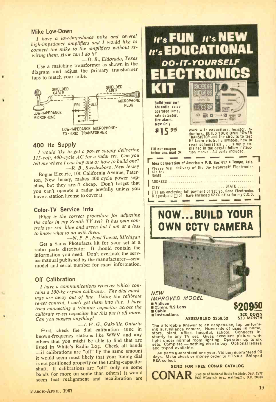
Mike Low -Down
1 have a low -impedance mike and several
high- impedance amplifiers and 1 would like to
connect the mike to the amplifiers without re-
wiring them. How can 1 do it?
-D. B., Eldorado, Texas
Use a matching transformer as shown in the
diagram and adjust the primary transformer
taps to match your mike.
SHIELDED
CABLE
LOW-IMPEDANCE
MICROPHONE
SHIELDED
CABLE
LOW-IMPEDANCE MICROPHONE -
TO - GRID TRANSFORMER
MICROPHONE
PLUG
400 Hz Supply
1 would like to get a power supply delivering
115 -volt, 400 -cycle AC for a radar set. Can you
tell me where 1 can buy one or how to build one?
-R. B., Swedesboro, New Jersey
Bogue Electric, 100 California Avenue, Pater-
son, New Jersey, makes 400 -cycle power sup-
plies, but they aren't cheap. Don't forget that
you can't operate a radar lawfully unless you
have a station license to cover it.
Color -TV Service Info
What is the correct procedure for adjusting
the color in my Zenith TV set? It has gain con-
trols for red, blue and green but I am at a loss
to know what to do with them.
-N. P. P., East Tawas, Michigan
Get a Sams Photofacts kit for your set at a
radio parts distributor. It should contain the
information you need. Don't overlook the serv-
ice manual published by the manufacturer -send
model and serial number for exact information.
Off Calibration
1 have a communications receiver which con-
tains a 100 -kc crystal calibrator. The dial mark-
ings are away out of line. Using the calibrate
re -set control, 1 can't get them into line. 1 have
tried connecting a trimmer capacitor across the
calibrate re -set capacitor but this put it off more.
Can you suggest anything?
-J. W. G., Oakville, Ontario
First, check the dial calibration -tune in
known- frequency stations like WWV and any
others that you might be able to find that are
listed in White's Radio Log. Check all bands
-if calibrations are "off" by the same amount
it would seem most likely that your tuning dial
is not positioned properly on the tuning- capacitor
shaft. If calibrations are "off" only on some
bands (or more on some than others) it would
seem that realignment and recalibration are
it's FUN it's NEW
it's EDUCATIONAL
DO -,T- YOURSELF
ELECTRONICS
KIT
Build your own
AM radio, voice
operated lamp,
rain detector,
fire alarm.
Now Only
$159s
Fill out coupon
below and mail to:
Idea Corporation
IPlease rush deli
Kit to:
NAME
Work with capacitors, resistor, in-
ductors. BUILD YOUR OWN POWER
TRANSISTOR and the circuits to test
it Learn electronic symbols. how to
read schematics .. simply ex-
plained in the easy -to- follow instruc-
tion manual. All parts included.
of America P.O. Box 417 Tempe, Ariz.
very of the Do -it- yourself Electronics
I ADDRESS
CITY STATE
I I am enclosing full payment of $15.95. Send Electronics
Kit postpaid or I have enclosed $2.00 extra for my C.O.D. J
NOW... BUILD YOUR
OWN CCTV CAMERA
NEW
IMPROVED MODEL
Vidicon
25mm. f1.9 Lens
Cable
Instructions ASSEMBLED $259.50 $20 DOWN
$10 MONTH
The affordable answer to an easy -to -use, top perform-
ing surveillance camera. Hundreds of uses in home,
store, plant, office, hospital, school. Connects in-
stantly to any TV set. Gives excellent picture with
light under normal room lighting. Operates up to six
sets. Complete - nothing else to buy. Optional lenses
and tripod available.
All parts guaranteed one year. Vidicon guaranteed 90
days. Make check or money order to CONAR. Shipped
REA collect.
SEND FOR FREE CONAR CATALOG
CONARDivision of National Radio Institute, Dept. CVIC
3939 Wisconsin Ave., Washington, D.C. 20016
MARCH- APRIL, 1967 19
ASK ME ANOTHER
needed. Once the dial is calibrated properly
tune to WWV on 2.5, 5, 10 or 15 MHz (mc)
and adjust to 100 -kHz (kc) crystal calibrator
to zero -beat with the WWV carrier.
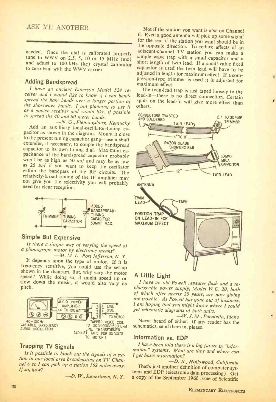
Adding Bandspread
I have an ancient Emerson Model 524 re-
ceiver and 1 would like to know if I can band -
spread the ham bands over a longer portion of
the shortwave bands. I am planning to use it
as a novice receiver and would like, if possible
to spread the 40 and 80 meter bands.
-N. G., Flemingsburg, Kentucky
Add an auxilliary local- oscillator- tuning ca-
pacitor as shown in the diagram. Mount it close
to the present tuning capacitor gang -use a shaft
extender, if necessary, to couple the bandspread
capacitor to its own tuning dial. Maximum ca-
pacitance of the bandspread capacitor probably
won't be as high as 50 uuf and may be as low
as 25 uuf if you want to keep the oscillator
within the bandpass of the RF circuits. The
relatively -broad tuning of the IF amplifier may
not give you the selectivity you will probably
need for clear reception.
ADDED
BANDSPREAD-
TUNING TUNING
CAPACITOR
CAPACITOR 50MMF MAX.
4
Simple But Expensive
Is there a simple way of varying the speed of
a phonograph motor by electronic means?
-M. M. L., Port Jefferson, N. Y.
It depends upon the type of motor. If it is
frequency sensitive, you could use the set -up
shown in the diagram. But, why vary the motor
speed? While doing so, it might speed up or
slow down the music, it would also vary its
pitch.
000
40-100 Hz
VARIABLE FREQUENCY
AUDIO OSCILLATOR
AUDIO POWER
A
40 TO 100 WATTS
LINE
SIDE
0 0 O (J II 4 TO MOTOR
TAPPED VOICE COIL
TO 500 /1000 /1500 OHM
LINE TRANSFORMER
(ADJUST TAPS FOR 115 VOLTS
TO MOTOR )
Trapping TV Signals
Is it possible to block out the signals of a sta-
tion in our local area broadcasting on TV Chan-
nel 6 so I can pick up a station 162 miles away.
If so, how? -D. W., Jamestown, N. Y.
20
Not if the station you want is also on Channel
6. Even a good antenna will pick up some signal
for the rear if the station you want should be in
the opposite direction. To reduce effects of an
adjacent -channel TV station you can make a
simple wave trap with a small capacitor and a
short length of twin lead. If a small -value fixed
capacitor is used the twin lead will have to be
adjusted in length for maximum effect. If a com-
pression -type trimmer is used it is adjusted for
maximum effect.
The twin -lead trap is just taped loosely to the
lead -in -there is no direct connection. Certain
spots on the lead -in will give more effect than
others.
CONDUCTORS TWISTED
AND SOLDERED
TWIN LEAD?
2.7 TO 30MMF
TRIMMER
4 "T08.
RAZOR BLADE
SHORTING BAR
ANTENNA
IOMMF
MICA
CAPACITOR
12° TWIN LEAD
TWIN
LEAD TAPE
POSITION TRAP
ON LEAD -IN FOR
MAXIMUM EFFECT
A Little Light
I have an old Powell repeater flash and a re-
chargeable power supply, Model W.C. 20, both
of which after nearly 20 years, are now giving
me trouble. As Powell has gone out of business,
I am hoping that you might know where I could
get schematic diagrams of both units.
-W. J. M., Pocatello, Idaho
Never heard of either. If any reader has the
schematics, send them in, please.
Information vs. EDP
I have been told there is a big future in "infor-
mation" systems. What are they and where can
I get basic information?
-D. R., Hollywood, California
That's just another definition of computer sys-
tems and EDP (electronic data processing). Get
a copy of the September 1966 issue of Scientific
ELEMENTARY ELECTRONIça
i
1
American. For 60 cents you can get around 30
huge magazine pages of the latest information
about "information" and computers. If your
newsstand can't get you a copy order one from
the publisher at 415 Madison Avenue in New
York City. If you want to dig more deeply, get
a copy of "Computer Dictionary and Handbook"
by Charles J. Sippl, published by Sams. It costs
$12.95. Your local book store or radio parts
distributor should be able to get you a copy.
Are You for Real?
Where can I get a catalog listing schematics
of radio and TV sets which I repair.
-T. F. B., Springfield, Massachusetts
Write to Howard W. Sams & Co., Inc., 4300
West 62nd Street, Indianapolis, Indiana, and ask
for a Photof acts catalog.
Missed Aerobander
Can you give me a circuit for a transistor con-
verter covering from 108 to 132 me (MHz) for
use with a BCB transistor radio?
-B. R., Hunlock Creek, Pennsylvania
See the December 1965- January 1966 issue of
RADIO -TV EXPERIMENTER. On page 45 you will
find a construction article -the Aerobander.
Send us 75' and we'll send you a copy of that
issue if you don't have it- include 25Ç for post-
age and handling.
New Speaker Is Problem
Where can I get a field coil speaker for a small
table radio? Or, can I use a 4 -ohm PM speaker?
The black speaker lead runs to pin 6 of 12SK7,
the green one to the output transformer and the
yellow lead to pin 8 of a 35Z5.
-A. E. F., Phoenix, Arizona
Connect a PM speaker as shown in the dia-
gram, adding a filter choke to take the place of
the field coil.
ST ANC OR
C1002
OR EQUAL
Parts Problem!
In one of your construction articles an NE -77
neon lamp and a cadmium- sulphide photocell
are listed. I can't find such a neon lamp and
Your Own Business Now Provides
For Their Future
better
What conduct investment
profitablythan thru he pagee ofINCOME OPPORTUNITIES.
Whether you're interested in full or part -time, the Mar /Apr issue
provides "55 Businesses for Under $500" .. tells
how they work and reveals their pros and cons.
Read INCOME OPPORTUNITIES for up- to -the-
minute details on franchises with investments
as low as $1,000 and also valuable guides on
mail order and personal business.
Special Introductory Offer...
Now you can prepare for the future with
INCOME OPPORTUNITIES for only $3.00
per year.
INCOME OPPORTUNITIES EE -367
505 Park Avenue, New York, N.Y. 10022
Begin my subscription to INCOME OPPOR-
TUNITIES with the next issue. Enclosed is
me.o(Fo (Foreign: (cash
dd 75c a money-order). Bill
Name please print
Address
City
State Zip
MARCH- APRIL, 1967 21
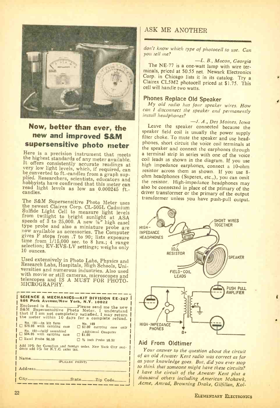
Now, better than ever, the
new and improved S &M
supersensitive photo meter
Here is a precision instrument that meets
the highest standards of any meter available.
It offers consistently accurate readings at
very low light levels, which, if required, can
be converted to ft.-candles from a graph sup -
plied. Researchers, scientists, educators and
hobbyists have confirmed that this meter can
read light levels as low as 0.000245 ft.-
candles.
The S &M Supersensitive Photo Meter uses
the newest Clairex Corp. CL -505L Cadmium
Sulfide Light Cell to measure light levels
from twilight to bright sunlight at ASA
speeds of 3 to 25,000. A new %" high easel
type probe and also a miniature probe are
now available as accessories. The Computer
gives F stops from .7 to 90; lists exposure
time from 1/15,000 sec. to 8 hrs.; 4 range
selection; EV- EVS -LV settings; weighs only
10 ounces.
Used extensively in Photo Labs, Physics and
Research Labs, Hospitals, High Schools, Uni-
versities and numerous industries. Also used
with movie or still cameras, microscopes and
telescopes and IS A MUST FOR PHOTO-
MICROGRAPHY,
r SCIENCE & MECHANICS -KIT DIVISION EE -887
505 Park Avenue /New York, N.Y. 10022
Enclosed is $ Please send me the new
S &M Supersensitive Photo Meter. I understand
that if I am not completely satisfied, I may return
the meter within 10 days for a complete refund.
No. 10I -In kit form No. 105
$29.95 with carrying case $2.00 carrying case only
No. 102 -fully assembled
$34.95 with carrying case Additional Computer
$1.00
Easel Probe $6.50 % inch Probe 56.50
Add 105, for Canadian and foreign order. New York City resi-
dents add 5% for N.Y.C. sales tax.
Name (PLEASE PRINT)
Address
City State Zip Code
22
ASK ME ANOTHER
don't know which type of photocell to use. Can
you tell me? -L. B., Macon, Georgia
The NE -77 is a one -watt lamp with wire ter-
minals, priced at $0.55 net. Newark Electronics
Corp. in Chicago lists it in its catalog. Try a
Clairex CL5M2 photocell priced at $1.75. This
cell will handle two watts.
Phones Replace Old Speaker
My old radio has four speaker wires. How
can I disconnect the speaker and permanently
install headphones? -l. A., Des Moines, Iowa
Leave the speaker connected because the
speaker field coil is usually the power supply
filter choke. To mute the speaker and use head-
phones, short circuit the voice coil terminals at
the speaker and connect the earphones through
a terminal strip in series with one of the voice
coil leads as shown in the diagram. If you use
high impedance earphones, connect a 10 -ohm
resistor across them as shown. If you use 8-
ohm headphones (Superex, etc.,), you can omit
the resistor. High- impedance headphones may
also be connected in place of the primary of the
driver transformer or the primary of the output
transformer unless you have push -pull output.
/// SHORT WIRES
HIGH- TOGETHER
IMPEDANCE
HEADPHONES
10n
RESISTOR
FIELD- COIL
LEADS
C T.
HIGH - IMPEDANCE
PHONES
SPEAKER
PUSH PULL
AMPLIFIER
Aid From Oldtimer
Your answer to the question about the circuit
of an old Atwater Kent radio was correct as far
as your knowledge goes. But, did you ever stop
to think that someone might have these circuits?
I have the circuit of the Atwater Kent plus a
thousand others including American Mohawk,
Acme, Amrad, Browning Drake, Gilfillan, Ko!-
ELEMENTARY ELECTRONICS
a
ster, Ozark, Silver Marshall, Wells Gardner, etc.
In the future I suggest you ask through your
pages if someone else may have what you are
looking for. Maybe we old radio men could help.
-S. E. S., Chatham, Ontario
So we're asking you. Those names are still
familiar and bring fond memories. How about
Fada, Sparton, Stewart Warner, Remler and
Bremer Tully? Readers, S. E. S. is Syd Sutton
whose address is 325 St. Clair Street in Chatham.
Syd, we'll keep you in mind and are delighted
to know someone had sense enough to save those
old schematics.
Add An S -Meter
How can 1 hook up an "S" meter to my short-
wave receiver? -S. H., Stillwater, Minn.
Easy. Simply add two potentiometers and
connect a 0 -1 DC milliammeter between the
cathode of an 'IF amplifier which is controlled
by AVC and the cathode of the AF power am-
plifier as shown in heavy lines in the diagram.
Replace the AF power amplifier cathode re-
sistor with a 2 -watt potentiometer (Rl) having
approximately the same resistance as the orig-
inal resistor. Adjust this pot for meter zero
with no signal received and pot R2 to meter
full -scale when receiving the strongest signals.
AFAhPOWER
P
BREAK CIRCUIT HERE
10 -Code for CBing
I am planning to have some CB QSL cards
printed and want to list the 10 -code (104, etc.).
I have seen several 10 -code charts but some
numbers are not listed. Where do I get the whole
list from 10 -1 to 10 -100?
-S. D. G., Fort Stockton, Texas
All of the possible numbers are not used. The
official police and fire 10 -code has been enriched
by CBers and new numbers are not necessarily
used by everyone. Why not settle for the num-
bers you have? If you embellish it, recipients
may not know what you are trying to say.
Seeking Schematic
Where can I get a schematic of a Lear RM-
402C receiver? -B, C., Tullahoma, Tennessee
Try writing to Lear Jet Corp., 13131 Lyndon
Avenue, Detroit, Michigan or Motorola, Inc.,
4501 West Augusta Blvd., Chicago, Illinois,
°ch bought up Ianr'c evinnicc business.
Color TV `Acting -up "?
Learn How To Adjust Your
New Color TV Set!
Save money too!
Avoid the expense of calling a repairman
each time your TV set "acts -up ". In easy -
to- understand language, complete with il-
lustrations, learn just how to adjust your
color TV; the right way to replace any
picture tube; how to fix your own tape
recorder, kiddie phono, fm tune, stereo
system and ac /dc radio. These and many
more dollar -saving tips in the new edition
of TV REPAIR.
Now on sale at your newsstand!
TV REPAIR EE -367
505 Park Avenue
New York, N. Y. 10022
Please send me my personal copy of TV
REPAIR. Enclosed is $1.00, which in-
cludes postage and handling.
Name
Address
City State Zip
(please print)
MARCH- APRIL, 1967 23
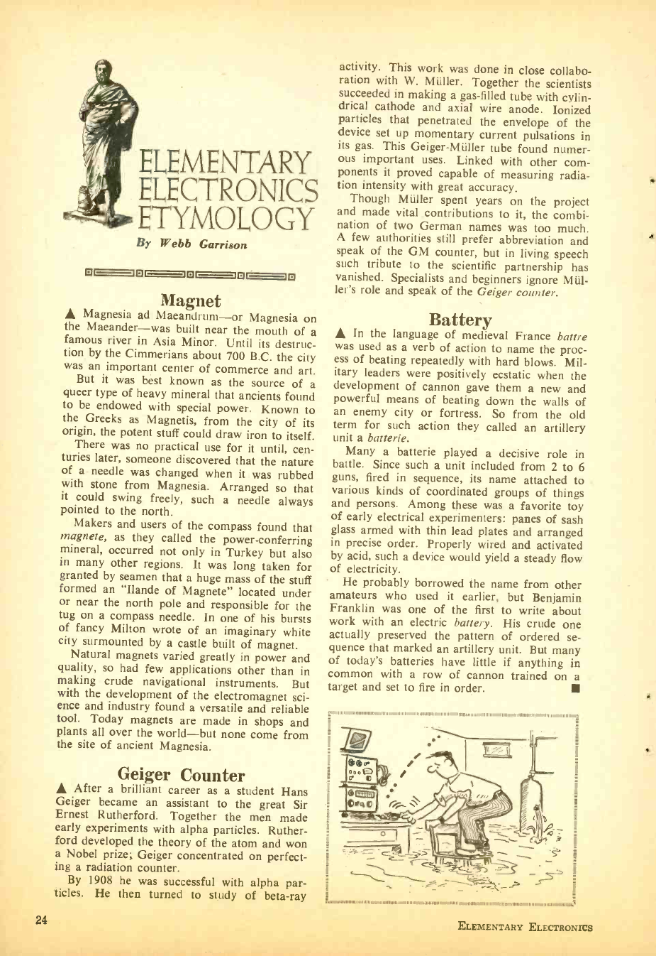
ELEMENTARY
EI,ECTRONICS
ETYMOLOGY
By Webb Garrison
t7 ©O ©O G ®O
Magnet
A Magnesia ad Maeandrum -or Magnesia on
the Maeander -was built near the mouth of a
famous river in Asia Minor. Until its destruc-
tion by the Cimmerians about 700 B.C. the city
was an important center of commerce and art.
But it was best known as the source of a
queer type of heavy mineral that ancients found
to be endowed with special power. Known to
the Greeks as Magnetis, from the city of its
origin, the potent stuff could draw iron to itself.
There was no practical use for it until, cen-
turies later, someone discovered that the nature
of a- needle was changed when it was rubbed
with stone from Magnesia. Arranged so that
it could swing freely, such a needle always
pointed to the north.
Makers and users of the compass found that
magnete, as they called the power -conferring
mineral, occurred not only in Turkey but also
in many other regions. It was long taken for
granted by seamen that a huge mass of the stuff
formed an "Ilande of Magnete" located under
or near the north pole and responsible for the
tug on a compass needle. In one of his bursts
of fancy Milton wrote of an imaginary white
city surmounted by a castle built of magnet.
Natural magnets varied greatly in power and
quality, so had few applications other than in
making crude navigational instruments. But
with the development of the electromagnet sci-
ence and industry found a versatile and reliable
tool. Today magnets are made in shops and
plants all over the world -but none come from
the site of ancient Magnesia.
Geiger Counter
A After a brilliant career as a student Hans
Geiger became an assistant to the great Sir
Ernest Rutherford. Together the men made
early experiments with alpha particles. Ruther-
ford developed the theory of the atom and won
a Nobel prize; Geiger concentrated on perfect-
ing a radiation counter.
By 1908 he was successful with alpha par-
ticles. He then turned to study of beta -ray
24
activity. This work was done in close collabo-
ration with W. Müller. Together the scientists
succeeded in making a gas -filled tube with cylin-
drical cathode and axial wire anode. Ionized
particles that penetrated the envelope of the
device set up momentary current pulsations in
its gas. This Geiger -Müller tube found numer-
ous important uses. Linked with other com-
ponents it proved capable of measuring radia-
tion intensity with great accuracy.
Though Müller spent years on the project
and made vital contributions to it, the combi-
nation of two German names was too much.
A few authorities still prefer abbreviation and
speak of the GM counter, but in living speech
such tribute to the scientific partnership has
vanished. Specialists and beginners ignore Mül-
ler's role and speak of the Geiger counter.
Battery
A In the language of medieval France battre
was used as a verb of action to name the proc-
ess of beating repeatedly with hard blows. Mil-
itary leaders were positively ecstatic when the
development of cannon gave them a new and
powerful means of beating down the walls of
an enemy city or fortress. So from the old
term for such action they called an artillery
unit a batterie.
Many a batterie played a decisive role in
battle. Since such a unit included from 2 to 6
guns, fired in sequence, its name attached to
various kinds of coordinated groups of things
and persons. Among these was a favorite toy
of early electrical experimenters: panes of sash
glass armed with thin lead plates and arranged
in precise order. Properly wired and activated
by acid, such a device would yield a steady flow
of electricity.
He probably borrowed the name from other
amateurs who used it earlier, but Benjamin
Franklin was one of the first to write about
work with an electric battery. His crude one
actually preserved the pattern of ordered se-
quence that marked an artillery unit. But many
of today's batteries have little if anything in
common with a row of cannon trained on a
target and set to fire in order.
11111.1,111 11
JEW
o tii3>
-_
: 111111111111111111,:
ELEMENTARY ELECTRONICS
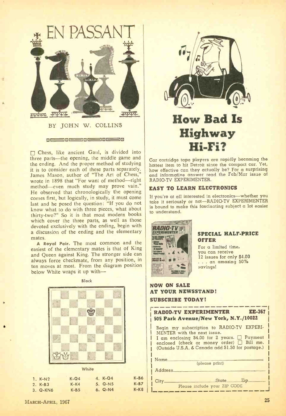
E\ PASSANT
BY JOHN W. COLLINS
17OO=1l7C-OOOI]
Chess, like ancient Gaul. is divided into
three parts -the opening, the middle game and
the ending. And the proper method of studying
it is to consider each of these parts separately.
James Mason, author of "The Art of Chess,"
wrote in 1898 that "For want of method -right
method -even much study may prove vain."
He observed that chronologically the opening
comes first, but logically, in study, it must come
last and he posed the question: "If you do not
know what to do with three pieces, what about
thirty- two ?" So it is that most modern books
which cover the three parts, as well as those
devoted exclusively with the ending, begin with
a discussion of the ending and the elementary
mates.
A Royal Pair. The most common and the
easiest of the elementary mates is that of King
and Queen against King. The stronger side can
always force checkmate, from any position, in
ten moves at most. From the diagram position
below White wraps it up with-
Black
White
1. K-N2 K-Q4 4. K-04 K-B6
2. K-B3 K-K4 5. Q-N5 K-B7
3. Q-KN6 K-B5 6. Q-N4 K-K8
How Bad Is
Highway
Hi -Fi?
Car cartridge tape players are rapidly becoming the
hottest item to hit Detroit since the compact car. Yet,
how effective can they actually be? For a surprising
and informative answer read the Feb /Mar issue of
RADIO -TV EXPERIMENTER.
EASY TO LEARN ELECTRONICS
If you're at all interested in electronics -whether you
take it seriously or not -RADIO -TV EXPERIMENTER
is bound to make this fascinating subject a lot easier
to understand.
';WU, w -
d"`
SPECIAL HALF -PRICE
OFFER
For a limited time,
you can receive
12 issues for only $4.00
. . . an amazing 50%
savings!
NOW ON SALE
AT YOUR NEWSSTAND!
SUBSCRIBE TODAY!
RADIO -TV EXPERIMENTER EE -367
505 Park Avenue /New York, N.Y. /10022
Begin my subscription to RADIO -TV EXPERI-
MENTER with the next issue.
I am enclosing $4.00 for 2 years. Payment
enclosed (check or money order) Bill me.
(Outside U.S.A. & Canada add $1.50 for postage.)
Name (please print)
Address
City State Zip
Please include your ZIP CODE J
MARCH -APRIL, 1967 25
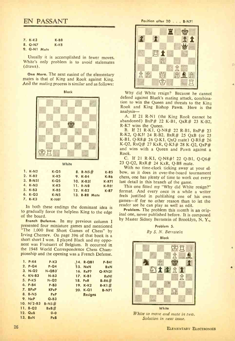
EN PASSANT
7. K -K3 K -B8
8. 0-N7 K -K8
9. 0-N1 Mate
Usually it is accomplished in fewer moves.
White's only problem is to avoid stalemates
(draws).
One More. The next easiest of the elementary
mates is that of King and Rook against King.
And the mating process is similar and as follows:
Black
White
1. K-N2 K-05 8. R-N5# K-R5
2. K-B2 K-K5 9. K-B4 K-R6
3. R-N5I K-05 10. K-B3I K-R7!
4. K-N3 K-K5 11. R-N8 K-R8!
5. K-B3 K-85 12. K-B2 K-R7
6. K-Q3 K-N5 13. R-R8 Mate
7. K-K3 K-N6!
In both these endings the dominant idea is
to gradually force the helpless King to the edge
of the board.
French Defense. In my previous column I
presented four miniature games and mentioned
"The 1,000 Best Short Games of Chess" by
Irving Chernev. On page 396 of that book is a
short short I won. I played Black and my oppo-
nent was Frutsaert of Belgium. It occurred in
the 1948 World Correspondence Chess Cham-
pionship and the opening was a French Defense.
1.
2.
3.
4.
5.
6.
7.
8.
9.
10.
11.
12.
13.
P-K4 P-K3
P-04 P-04
N-02 N-0B3
KN-B3 N-B3
P-K5 N-02
P-B4 P-B3
BPxP KPxP
B-N5 PxP
NxP 0-B3
N/2-83 B-N5#
B-02 BxB#
QxB 0-0
BxN PxB
14. R-0B1 P-B4!
115. NxN BxN
16. RxP? Q-KN3!
17. K-B1 RxN!
18. PxR B-R6#
19. K-K2 R-K1 #
20. K-01 B-N7!
Resigns
Position after 20 . . . B -N7!
1 I I
í
,VA
/%,
' "'.
/ / g
Why did White resign? Because he cannot
defend against Black's mating attack, combina-
tion to win the Queen and threats to the King
Rook and King Bishop Pawn. Here is the
analysis - A. If 21 R -NI (the King Rook cannot be
abandoned) BxP# 22 K -B1, QxR# 23 K -B2,
R -K7 wins the Queen.
B. If 21 R -K1, Q -N8# 22 R -B1, BxP# 23
R -K2, Q -K5! 24 R -B2, BxR# 25 QxB (or 25
K -B1, Q -R8# 26 Q -K1, QxQ mate) Q -R8# 26
K -Q2, RxQ# 27 KxR, Q -K5# 28 K -Q2, QxP#
and wins with a Queen and Pawn against a
Rook.
C. If 21 R -K1, Q -N8 #! 22 Q -B1, Q -Q6#
23 Q -Q2, RxR# 24 KxR, Q -B8 mate.
With no time -clock ticking away at your el-
bow, as it does in over- the -board tournament
chess, one has plenty of time to work out every
last detail in this branch of the game.
This one fitted my "Why did White resign ?"
format. And every once in a while a writer
feels justified in publishing one of his own
games -if for no other reason than to let the
reader see he can play as well as edit.
Problem. The problem this month is an orig-
inal one, never published before. It is composed
by Master Sidney Bernstein of Brooklyn, N. Y.,
Problem 5.
By S. N. Bernstein
Black
' j i-i "e
,, } ,,,,. }
%*..fiii S '.%i1f,"..
j
j j j j
j j j White
White to move and mate in two.
Solution in next issue.
4
26 ELEMENTARY ELECTRONICS
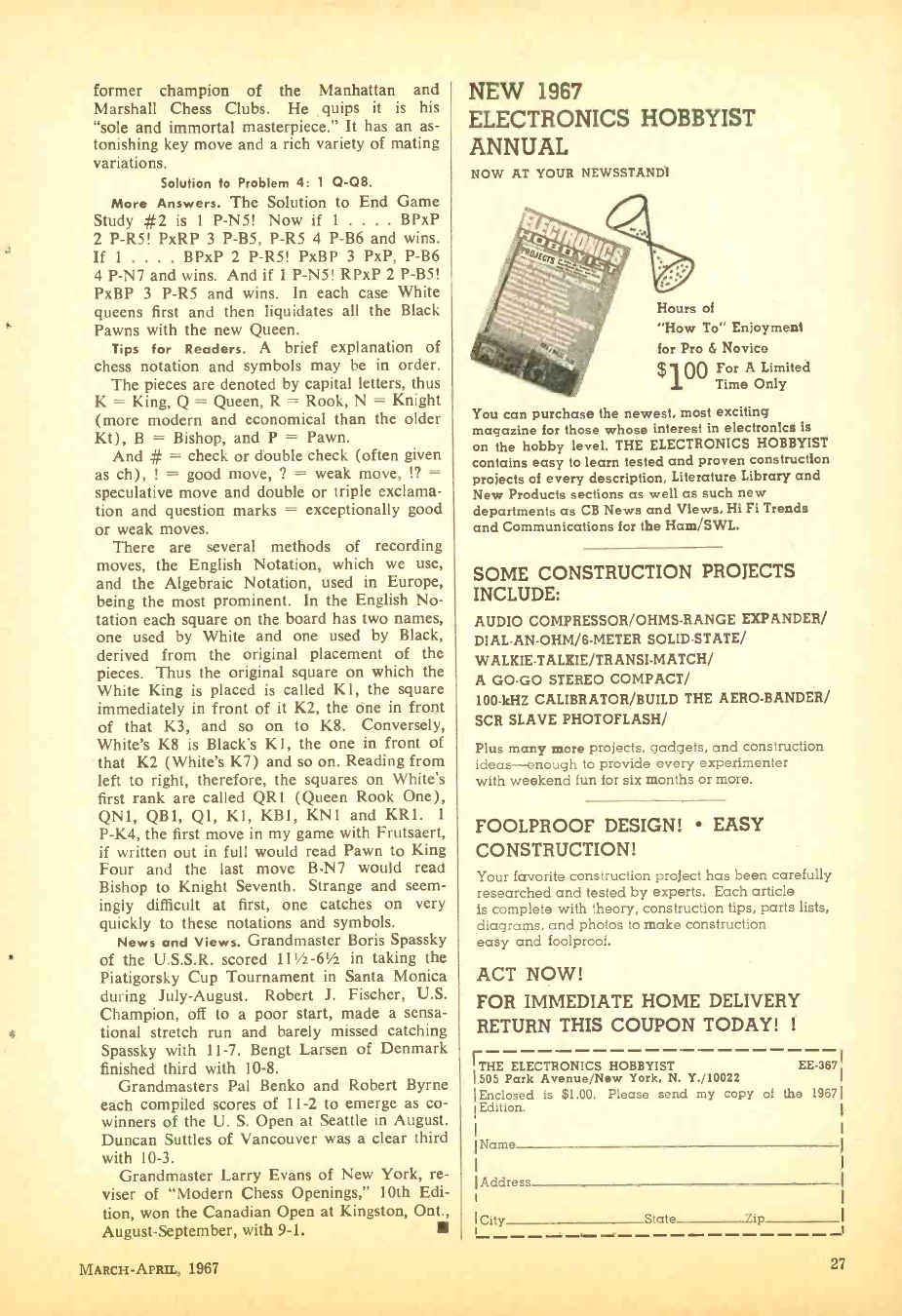
former champion of the Manhattan and
Marshall Chess Clubs. He quips it is his
"sole and immortal masterpiece." It has an as-
tonishing key move and a rich variety of mating
variations.
Solution to Problem 4: 1 Q -08.
More Answers. The Solution to End Game
Study #2 is 1 P -N5! Now if 1 .... BPxP
2 P -R5! PxRP 3 P -B5, P -R5 4 P -B6 and wins.
If 1 .... BPxP 2 P -R5! PxBP 3 PxP, P -B6
4 P -N7 and wins. And if 1 P -N5! RPxP 2 P -B5!
PxBP 3 P -R5 and wins. In each case White
queens first and then liquidates all the Black
Pawns with the new Queen.
Tips for Readers. A brief explanation of
chess notation and symbols may be in order.
The pieces are denoted by capital letters, thus
K = King, Q = Queen, R = Rook, N = Knight
(more modern and economical than the older
Kt), B = Bishop, and P = Pawn.
And # = check or double check (often given
as ch), ! = good move, ? = weak move, !? _
speculative move and double or triple exclama-
tion and question marks = exceptionally good
or weak moves.
There are several methods of recording
moves, the English Notation, which we use,
and the Algebraic Notation, used in Europe,
being the most prominent. In the English No-
tation each square on the board has two names,
one used by White and one used by Black,
derived from the original placement of the
pieces. Thus the original square on which the
White King is placed is called KI, the square
immediately in front of it K2, the one in front
of that K3, and so on to K8. Conversely,
White's K8 is Black's K1, the one in front of
that K2 (White's K7) and so on. Reading from
left to right, therefore, the squares on White's
first rank are called QR1 (Queen Rook One),
QN1, QB1, Ql, KI, KB1, KN1 and KR1. 1
P -K4, the first move in my game with Frutsaert,
if written out in full would read Pawn to King
Four and the last move B -N7 would read
Bishop to Knight Seventh. Strange and seem-
ingly difficult at first, one catches on very
quickly to these notations and symbols.
News and Views. Grandmaster Boris Spassky
of the U.S.S.R. scored 111/2-61/2 in taking the
Piatigorsky Cup Tournament in Santa Monica
during July- August. Robert J. Fischer, U.S.
Champion, off to a poor stárt, made a sensa-
tional stretch run and barely missed catching
Spassky with 11 -7. Bengt Larsen of Denmark
finished third with 10 -8.
Grandmasters Pal Benko and Robert Byrne
each compiled scores of 11 -2 to emerge as co-
winners of the U. S. Open at Seattle in August.
Duncan Suttles of Vancouver was a clear third
with 10 -3.
Grandmaster Larry Evans of New York, re-
viser of "Modern Chess Openings," 10th Edi-
tion, won the Canadian Open at Kingston, Ont.,
August- September, with 9 -1.
NEW 1967
ELECTRONICS HOBBYIST
ANNUAL
NOW AT YOUR NEWSSTAND'
Hours of
"How To" Enjoyment
for Pro & Novice
$100 For A Limited
Time Only
You can purchase the newest, most exciting
magazine for those whose interest in electronics Is
on the hobby level. THE ELECTRONICS HOBBYIST
contains easy to learn tested and proven construction
projects of every description, Literature Library and
New Products sections as well as such new
departments as CB News and Views, Hi Fi Trends
and Communications for the Ham /SWL.
SOME CONSTRUCTION PROJECTS
INCLUDE:
AUDIO COMPRESSOR /OHMS -RANGE EXPANDER/
DIAL -AN- OHM /8 -METER SOLID-STATE/
WALGIE- TALKIE /TRANSI- MATCH/
A GO -GO STEREO COMPACT/
100 -kHZ CALIBRATOR /BUILD THE AERO- BANDER/
SCR SLAVE PHOTOFLASH/
Plus many more projects, gadgets, and construction
ideas -enough to provide every experimenter
with weekend fun for six months or more.
FOOLPROOF DESIGN! EASY
CONSTRUCTION!
Your favorite construction project has been carefully
researched and tested by experts. Each article
is complete with theory, construction tips, parts lists,
diagrams, and photos to make construction
easy and foolproof.
ACT NOW!
FOR IMMEDIATE HOME DELIVERY
RETURN THIS COUPON TODAY! 1
rTHE ELECTRONICS HOBBYIST EE -367
505 Park Avenue /New York, N. Y./10022
Enclosed is $1.00. Please send my copy of the 1967
Edition.
Name
Address
!City State yip J
MARCH -APRIL, 1967 27
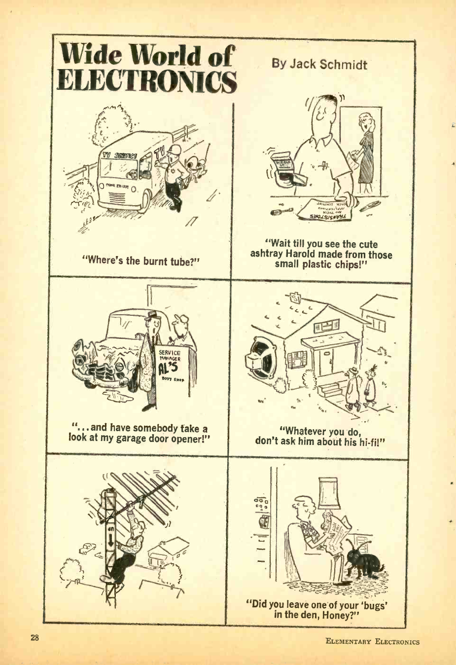
L
Wide World of
ELECTRONICS
"Where's the burnt tube ?"
By Jack Schmidt
b 1eitym,S 1,1,11
4°-4° suzisKNYbL ,1
"Wait till you see the cute
ashtray Harold made from those
small plastic chips!"
". . and have somebody take a
look at my garage door opener!" "Whatever you do,
don't ask him aboìit his hi -fi!"
oma
oGm
"Did you leave one of your 'bugs'
in the den, Honey ?"
28 ELEMENTARY ELECTRONICS
FLIP- FLPS
El'Ib -Ef b2
THE 2- CYLINDER
ENGINES OF
ELECTRONICS
By Len Buckwalter, KIODH/ KBA4480
Click -click, push -pull go zillions of flip -
flops every day -that is, if you could
hear these silent electronic double -throw
switches. They utter no sound as they tip -toe
through computers, see -saw in sonar, or skim
through counting circuits. They're not only
quiet, but perform the switching job without
moving parts, friction or wear. And they're
fast. That's why in numberless applications,
the flip -flop has given the heave -ho to the
mechanical toggle switch and relay.
The flip -flop is filed under several names
because of the different jobs it does and the
way it does them. Some are called a multi -
vibrator, others relaxation oscillator, or may-
be something special like a Schmitt Trigger.
Whatever the name, the flip -flop has these
distinguishing features. First, it's a two -stage
combination of tubes or transistors with a
feedback connection between them. When-
ever one stage is on (conducting current) the
other is off. But a stupendous feature of the
flip -flop is that it abhors any in- between con-
dition. Like pushing a flower pot off a win-
dow ledge, once the action starts it is
self-completing. Snappy switchover is im-
portant -when flipping to flop, in a comput-
er for example, a gradual transition for a
counting operation might print your tax -
refund check as $10,000 instead of 10 cents.
As we'll see, the circuit's feedback assures
that the on stage always tries to force the
other one off. That's a persistent theme des-
pite numerous variations.
Another peculiarity is that the circuit pro-
duces signals which don't resemble the
familiar, flowing sine wave generated by
regular oscillators. The wave form is often
square, clipped or sawtooth in shape. That's
because the circuit switches quickly as stages
are driven between on and off. This is im-
portant for generating pulses in radar equip-
ment which needs squared -off signals of fast
rise and decay time. Another quality of the
flip -flop is that it can trigger itself or feed on
external signals. To penetrate the heart of a
flip -flop, we can start with the method for
developing the switching action.
Putting Phase in Reverse. Let's feed a
simple amplifier tube with an input signal
and cause it to conduct current. The input
is shown as a positive -going pulse (1) ap-
plied to the tube grid in Fig. 1. As in any
conventional amplifier, a positive -going grid
voltage produces an increase in plate- current
flow through the tube (from cathode to
plate). It also produces another effect: volt-
age at the plate (2) will drop to a lower
value. Reason for the drop is that more
current flows through the plate -load resistor
and that component drops more B+ supply
voltage than previously. The plate of the tube
receives less supply voltage, since current
flow has increased, and the tube appears (to
the power supply) as a lower value resistance.
POSITIVE -
GOING PULSE CATHODE
TO GRID
PLATE
VOLTAGE`
DROPS
COUPLING
CAPACITOR Zr
NEGATIVE-GOING
OUTPUT PULSE
PLATE LOAD
RESISTOR
B+
Fig. 1. Basic triode amplifier shows effects of a
square -wave signal passing through the circuit. The
numbers relate to specific actions covered in text.
MARCH-APRIL, 1 137 L;i
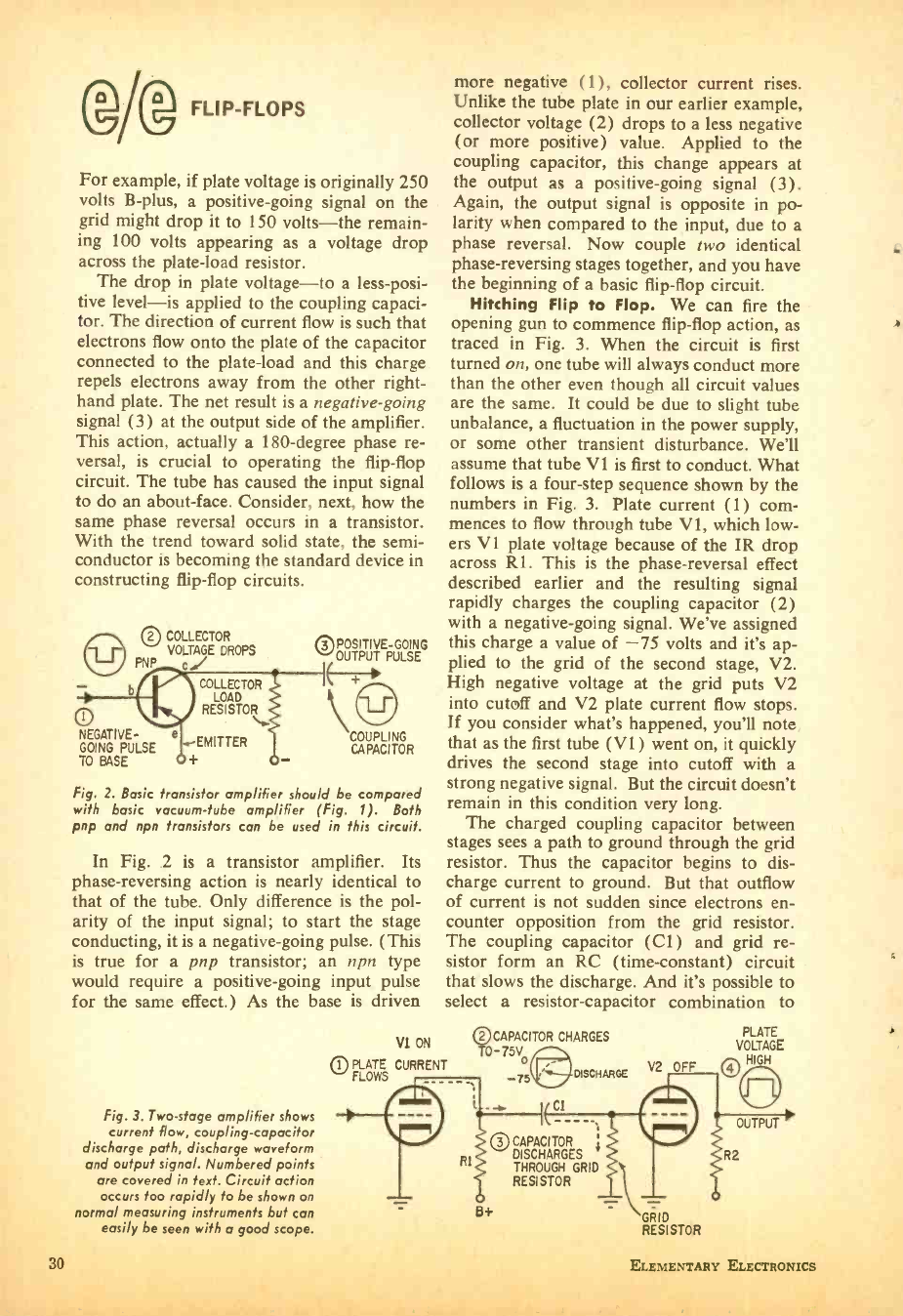
1@i® FLIP -FLOPS
For example, if plate voltage is originally 250
volts B -plus, a positive -going signal on the
grid might drop it to 150 volts -the remain-
ing 100 volts appearing as a voltage drop
across the plate -load resistor.
The drop in plate voltage -to a less -posi-
tive level -is applied to the coupling capaci-
tor. The direction of current flow is such that
electrons flow onto the plate of the capacitor
connected to the plate -load and this charge
repels electrons away from the other right -
hand plate. The net result is a negative -going
signal (3) at the output side of the amplifier.
This action, actually a 180 -degree phase re-
versal, is crucial to operating the flip -flop
circuit. The tube has caused the input signal
to do an about -face. Consider, next, how the
same phase reversal occurs in a transistor.
With the trend toward solid state, the semi-
conductor is becoming the standard device in
constructing flip-flop circuits.
b
0 COLLECTOR
VOLTAGE DROPS
PNP ed/
COLLECTOR
RESISTOR'
EMITTER
t
NEGATIVE- e
GOING PULSE
TO BASE
POSITIVE -GOING
0_ UTPUT PULSE
COUPLING
CAPACITOR
Fig. 2. Basic transistor amplifier should be compared
with basic vacuum -tube amplifier (Fig. 1). Both
pnp and npn transistors can be used in this circuit.
In Fig. 2 is a transistor amplifier. Its
phase- reversing action is nearly identical to
that of the tube. Only difference is the pol-
arity of the input signal; to start the stage
conducting, it is a negative -going pulse. (This
is true for a pnp transistor; an npn type
would require a positive -going input pulse
for the same effect.) As the base is driven
Fig. 3. Two -stage amplifier shows
current flow, coupling -capacitor
discharge path, discharge waveform
and output signal. Numbered points
are covered in text. Circuit action
occurs too rapidly to be shown on
normal measuring instruments but can
easily be seen with a good scope.
more negative (1), collector current rises.
Unlike the tube plate in our earlier example,
collector voltage (2) drops to a less negative
(or more positive) value. Applied to the
coupling capacitor, this change appears at
the output as a positive -going signal (3).
Again, the output signal is opposite in po-
larity when compared to the input, due to a
phase reversal. Now couple two identical
phase- reversing stages together, and you have
the beginning of a basic flip -flop circuit.
Hitching Flip to Flop. We can fire the
opening gun to commence flip -flop action, as
traced in Fig. 3. When the circuit is first
turned on, one tube will always conduct more
than the other even though all circuit values
are the same. It could be due to slight tube
unbalance, a fluctuation in the power supply,
or some other transient disturbance. We'll
assume that tube VI is first to conduct. What
follows is a four -step sequence shown by the
numbers in Fig. 3. Plate current (1) corn -
mences to flow through tube VI, which low-
ers Vl plate voltage because of the IR drop
across Rl. This is the phase -reversal effect
described earlier and the resulting signal
rapidly charges the coupling capacitor (2)
with a negative -going signal. We've assigned
this charge a value of -75 volts and it's ap-
plied to the grid of the second stage, V2.
High negative voltage at the grid puts V2
into cutoff and V2 plate current flow stops.
If you consider what's happened, you'll note
that as the first tube (V1) went on, it quickly
drives the second stage into cutoff with a
strong negative signal. But the circuit doesn't
remain in this condition very long.
The charged coupling capacitor between
stages sees a path to ground through the grid
resistor. Thus the capacitor begins to dis-
charge current to ground. But that outflow
of current is not sudden since electrons en-
counter opposition from the grid resistor.
The coupling capacitor (C1) and grid re-
sistor form an RC (time- constant) circuit
that slows the discharge. And it's possible to
select a resistor -capacitor combination to
VI ON
pl PLATE CURRENT
FLOWS -75
Rl
CAPACITOR CHARGES
-75V-
i-
2
CI
DISCHARGE V2 s FF
PLATE
VOLTAGE
HIGH
J
OUTPUT
R2
30 CAPACITOR
DISCHARGES
THROUGH GRID
RESISTOR
8+ -rks, GRID
RESISTOR
A
30 ELEMENTARY ELECTRONICS
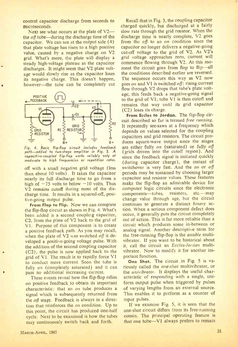
control capacitor discharge from seconds to
microseconds.
Next see what occurs at the plate of V2-
the o$ tube -during the discharge time of the
capacitor. We can see at the output side (4)
that plate voltage has risen to a high positive
value, caused by a negative charge on V2
grid. What's more, the plate will display a
steady high -voltage plateau as the capacitor
discharges. It might seem that V2 plate volt-
age would slowly rise as the capacitor loses
its negative charge. This doesn't happen,
however -the tube can be completely cut
POSITIVE
4,- FEEDBACK
V1 C2
C
GRID
RESISTOR
GRID
Rl. RESISTOR
B+ _ - B+
Fig. 4. Basic flip -flop circuit includes feedback
path -added to two -stage amplifier in Fig. 3. A
capacitive -coupled flip -flop works reliably only at
moderate to high frequencies or repetition rates.
off with a small negative grid voltage (less
than about 10 volts). It takes the capacitor
nearly its full discharge time to go from a
high of -75 volts to below -10 volts. Thus
V2 remains cutoff during most of the dis-
charge time. It results in a squared -off, posi-
tive -going output pulse.
From Flop to Flip. Now we can complete
the flip -flop circuit as shown in Fig. 4. What's
been added is a second coupling capacitor,
C2, from the plate of V2 back to the grid of
V1. Purpose of this component is to create
a positive feedback path. As you may recall,
when the plate of V2 was switched off it de-
veloped a positive -going voltage pulse. With
the addition of the second coupling capacitor
(C2), the pulse is now applied back to the
grid of VI. The result is to rapidly force V1
to conduct more current. Soon the tube is
fully on (completely saturated) and it can
pass no additional increasing current.
These events reveal how the flip -flop relies
on positive feedback to obtain its important
characteristic: that an on tube produces a
signal which is subsequently returned from
the off stage. Feedback is always in a direc-
tion that reinforces the on condition. Up to
this point, the circuit has produced one -half
cycle. Next to be examined is how the tubes
may continuously switch back and forth.
MnaCH-APen., 1967
Recall that in Fig. 3, the coupling capacitor
charged quickly, but discharged at a fairly
slow rate through the grid resistor. When the
discharge time is nearly complete, V2 goes
from the off to an on condition since the
capacitor no longer delivers a negative -going
cut -off voltage to the grid of V2. As V2's
grid voltage approaches zero, current will
commence flowing through V2. At this mo-
ment the circuit goes from flop to flip -all
the conditions described earlier are reversed.
The sequence occurs this way as V2 now
goes on and V1 is switched off: rising current
flow through V2 drops that tube's plate volt-
age; this feeds back a negative -going signal
to the grid of V 1; tube V1 is then cutoff and
remains that way until its grid capacitor
(C2) loses its charge.
From Eccles to Jordan. The flip -flop cir-
cuit described so far is termed free running.
It repeatedly see -saws at a frequency which
depends on values selected for the coupling
capacitors and grid resistors. The circuit pro-
duces square -wave output since the stages
are either fully on (saturated) or fully off
(grids driven into the cutoff region) . And
since the feedback signal is initiated quickly
(during capacitor charge), the instant of
switchover is very fast. And the on or off
periods may be sustained by choosing larger
capacitor and resistor values. These features
make the flip -flop an admirable device for
computer logic circuits since the electronic
components- tubes, resistors, etc. -may
change value through age, but the circuit
continues to generate a distinct binary ac-
tion. When a serious component defect does
occur, it generally puts the circuit completely
out of action. This is far more reliable than a
circuit which produces some in- between or
analog signal. Another descriptive term for
the free -running flip -flop is the astable multi -
vibrator. If you want to be historical about
it, call the circuit an Eccles -Jordan multi -
vibrator. Now to modify it for another im-
portant function.
One Shot. The circuit .in Fig. 5 is va-
riously called the one -shot multivibrator, or
the univibrator. It displays the useful char-
acteristic of responding with a single, uni-
form output pulse when triggered by pulses
of varying lengths from an external source.
This enables it to perform as a counter of
input pulses.
If we examine Fig. 5, it is seen that the
one -shot circuit differs from its free -running
cousin. The principal operating feature is
that one tube -VI always prefers to remain
31
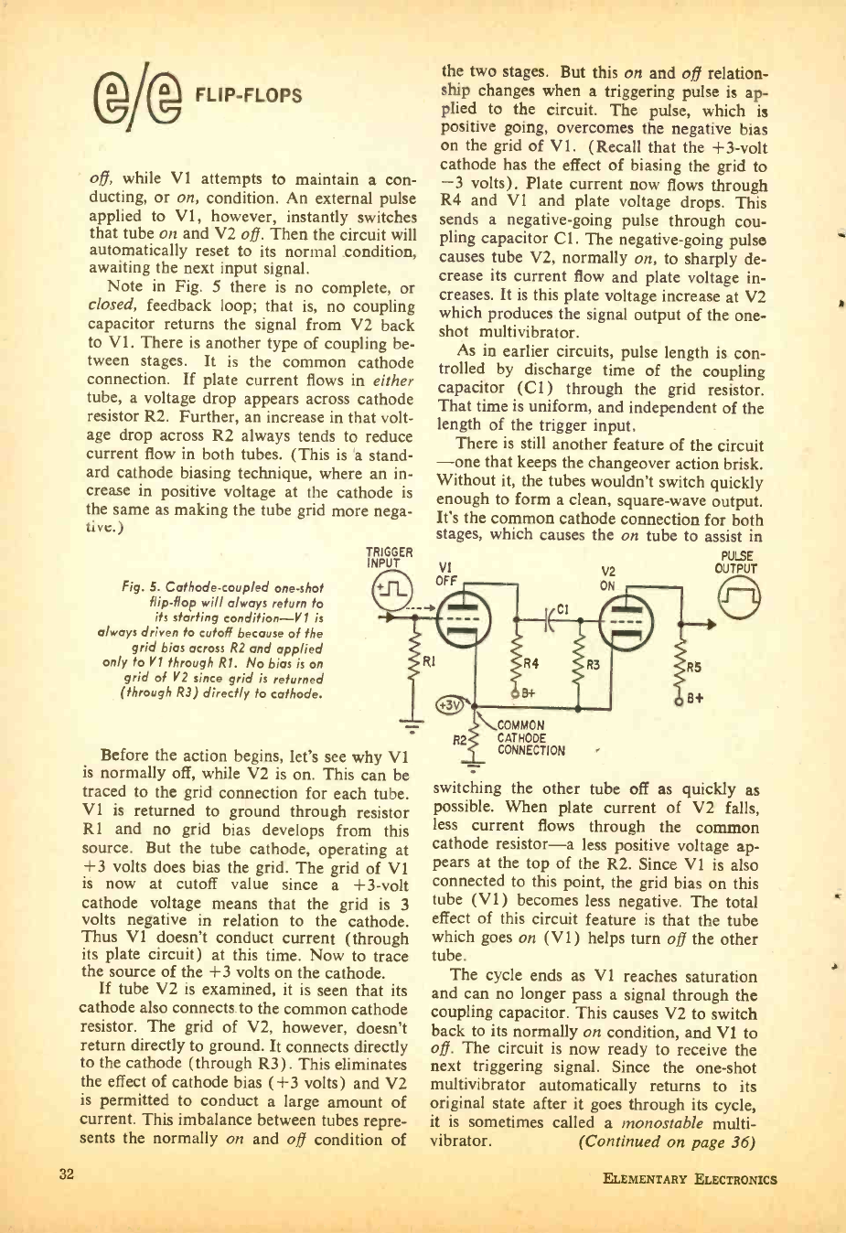
GA FLIP -FLOPS
off, while VI attempts to maintain a con-
ducting, or on, condition. An external pulse
applied to VI, however, instantly switches
that tube on and V2 off. Then the circuit will
automatically reset to its normal condition,
awaiting the next input signal.
Note in Fig. 5 there is no complete, or
closed, feedback loop; that is, no coupling
capacitor returns the signal from V2 back
to V 1. There is another type of coupling be-
tween stages. It is the common cathode
connection. If plate current flows in either
tube, a voltage drop appears across cathode
resistor R2. Further, an increase in that volt-
age drop across R2 always tends to reduce
current flow in both tubes. (This is a stand-
ard cathode biasing technique, where an in-
crease in positive voltage at the cathode is
the same as making the tube grid more nega-
tive.)
TRIGGER
INPUT
Fig. 5. Cathode- coupled one -shot
flip -flop will always return to
its starting condition -VI is
always driven to cutoff because of the
grid bias across R2 and applied
only to VI through RI. No bias is on
grid of V2 since grid is returned
(through R3) directly to cathode.
the two stages. But this on and o13 relation-
ship changes when a triggering pulse is ap-
plied to the circuit. The pulse, which is
positive going, overcomes the negative bias
on the grid of V1. (Recall that the +3 -volt
cathode has the effect of biasing the grid to
-3 volts). Plate current now flows through
R4 and V1 and plate voltage drops. This
sends a negative -going pulse through cou-
pling capacitor Cl. The negative -going pulse
causes tube V2, normally on, to sharply de-
crease its current flow and plate voltage in-
creases. It is this plate voltage increase at V2
which produces the signal output of the one -
shot multivibrator.
As in earlier circuits, pulse length is con-
trolled by discharge time of the coupling
capacitor (CI) through the grid resistor.
That time is uniform, and independent of the
length of the trigger input,
There is still another feature of the circuit
-one that keeps the changeover action brisk.
Without it, the tubes wouldn't switch quickly
enough to form a clean, square -wave output.
It's the common cathode connection for both
stages, which causes the on tube to assist in
PULSE
OUTPUT
V2
Before the action begins, let's see why VI
is normally off, while V2 is on. This can be
traced to the grid connection for each tube.
VI is returned to ground through resistor
Rl and no grid bias develops from this
source. But the tube cathode, operating at
+3 volts does bias the grid. The grid of V1
is now at cutoff value since a +3 -volt
cathode voltage means that the grid is 3
volts negative in relation to the cathode.
Thus V1 doesn't conduct current (through
its plate circuit) at this time. Now to trace
the source of the +3 volts on the cathode.
If tube V2 is examined, it is seen that its
cathode also connects to the common cathode
resistor. The grid of V2, however, doesn't
return directly to ground. It connects directly
to the cathode (through R3) . This eliminates
the effect of cathode bias ( +3 volts) and V2
is permitted to conduct a large amount of
current. This imbalance between tubes repre-
sents the normally on and off condition of
32
COMMON
CATHODE
CONNECTION
switching the other tube off as quickly as
possible. When plate current of V2 falls,
less current flows through the common
cathode resistor -a less positive voltage ap-
pears at the top of the R2. Since VI. is also
connected to this point, the grid bias on this
tube (V1 ) becomes less negative. The total
effect of this circuit feature is that the tube
which goes on (VI ) helps turn off the other
tube. The cycle ends as VI reaches saturation
and can no longer pass a signal through the
coupling capacitor. This causes V2 to switch
back to its normally on condition, and VI to
off. The circuit is now ready to receive the
next triggering signal. Since the one -shot
multivibrator automatically returns to its
original state after it goes through its cycle,
it is sometimes called a monostable multi -
vibrator. (Continued on page 36)
ELEMENTARY ELECTRONICS
SEND CARD FOR RCA'S
NEW 1967 HOME STUDY
CAREER BOOK TODAY
YOUR CAREER IN A WORLD OF ELECTRONICS
with
RCA INSTITUTES HOME STUDY TRAINING
CUT THE TIME BETWEEN NOW AND SUCCESS
Find out about RCA Institutes Career Programs.
Learn about the amazing "Autotext" programmed instruction method -
the easier way to learn.
Get the facts about the prime quality kits you get at no extra cost.
Read about RCA Institutes' Liberal Tuition Plan -the most economical way
for you to learn electronics now.
Discover how RCA Institutes Home Training has helped its students
enter profitable electronic careers.
Lots more helpful and interesting facts too! Send postage -paid card for
your FREE copy now. No obligation. No salesman will call.
RCA Institutes also offers
Classroom Training.
Catalog Free on request.
(Courses also available in Spanish)
RCA INSTITUTES, Inc, Dep't. EA -37
350 West 4th Street, New York, N.Y. 10014
The Most Trusted Name in Electronics
MARCH -APRIL, 1967 35
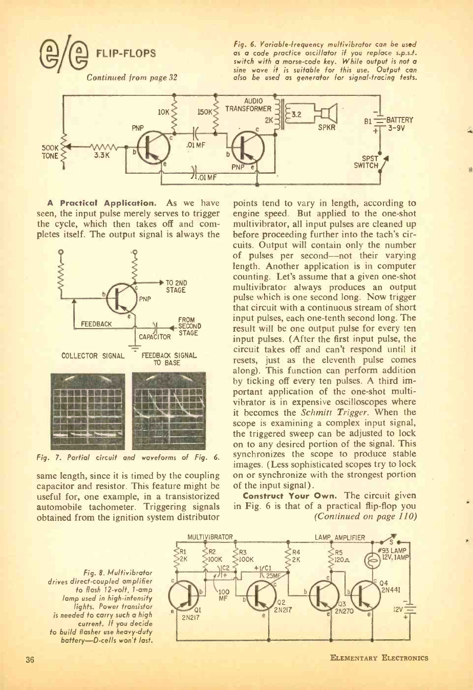
(DA FLIP -FLOPS
Continued from page 32
Fig. 6. Variable-frequency multivibrafor can be used
as a code practice oscillator if you rep/ace s.p.s.t.
switch with a morse -code key. While output is not a
sine wove if is suitable for this use. Output can
also be used as generator for signal -tracing tests.
500K
TONE 3.3K
PNP
10K 150K
I(
,01MF
e
I.OIMF
AUDIO
TRANSFORMER
2K
A Practical Application. As we have
seen, the input pulse merely serves to trigger
the cycle, which then takes off and com-
pletes itself. The output signal is always the
PNP
FEEDBACK
T0 2ND
STAGE
FROM
SECOND
CAPACITOR STAGE
COLLECTOR SIGNAL FEEDBACK SIGNAL
TO BASE
Fig. 7. Partial circuit and waveforms of Fig. 6.
same length, since it is timed by the coupling
capacitor and resistor. This feature might be
useful for, one example, in a transistorized
automobile tachometer. Triggering signals
obtained from the ignition system distributor
Fig. 8. Multivibrator
drives direct- coupled amplifier
to flash 12 -volt, 1 -amp
lamp used in high- intensity
lights. Power transistor
is needed to carry such a high
current. If you decide
to build flasher use heavy -duty
battery -D -cells won't last.
SPKR
-1
Bi = BATTERY
fT 3 -9V
SPST
SWITCH
points tend to vary in length, according to
engine speed. But applied to the one -shot
multivibrator, all input pulses are cleaned up
before proceeding further into the tach's cir-
cuits. Output will contain only the number
of pulses per second -not their varying
length. Another application is in computer
counting. Let's assume that a given one -shot
multivibrator always produces an output
pulse which is one second long. Now trigger
that circuit with a continuous stream of short
input pulses, each one -tenth second long. The
result will be one output pulse for every ten
input pulses. (After the first input pulse, the
circuit takes off and can't respond until it
resets, just as the eleventh pulse comes
along). This function can perform addition
by ticking off every ten pulses. A third im-
portant application of the one -shot multi -
vibrator is in expensive oscilloscopes where
it becomes the Schmitt Trigger. When the
scope is examining a complex input signal,
the triggered sweep can be adjusted to lock
on to any desired portion of the signal. This
synchronizes the scope to produce stable
images. (Less sophisticated scopes try to lock
on or synchronize with the strongest portion
of the input signal).
Construct Your Own. The circuit given
in Fig. 6 is that of a practical flip -flop you
(Continued on page 110)
MULTI VIBRATOR LAMP AMPLIFIER S
93 LAMP
12V, !AMP
Q4 2N441
I2V-
36 ELEMENTARY ELECTRONICS
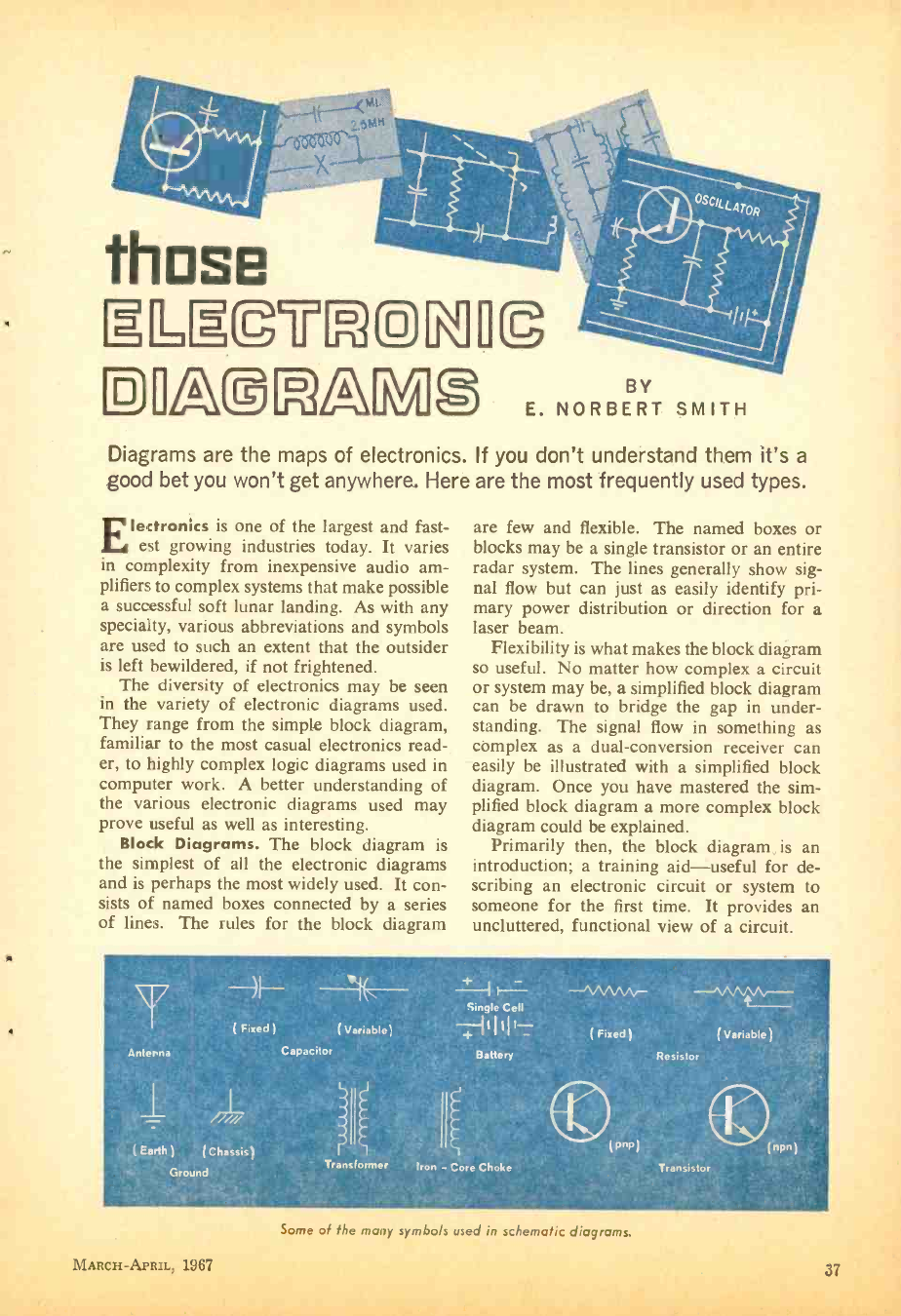
4
those
ELIECMCM11©
DI1A@G3AG3 BY
E. NORBERT SMITH
Diagrams are the maps of electronics. If you don't understand them it's a
good bet you won't get anywhere. Here are the most frequently used types.
Electronics is one of the largest and fast-
est growing industries today. It varies
in complexity from inexpensive audio am-
plifiers to complex systems that make possible
a successful soft lunar landing. As with any
specialty, various abbreviations and symbols
are used to such an extent that the outsider
is left bewildered, if not frightened.
The diversity of electronics may be seen
in the variety of electronic diagrams used.
They range from the simple block diagram,
familiar to the most casual electronics read-
er, to highly complex logic diagrams used in
computer work. A better understanding of
the various electronic diagrams used may
prove useful as well as interesting.
Block Diagrams. The block diagram is
the simplest of all the electronic diagrams
and is perhaps the most widely used. It con-
sists of named boxes connected by a series
of lines. The rules for the block diagram
are few and flexible. The named boxes or
blocks may be a single transistor or an entire
radar system. The lines generally show sig-
nal flow but can just as easily identify pri-
mary power distribution or direction for a
laser beam.
Flexibility is what makes the block diagram
so useful. No matter how complex a circuit
or system may be, a simplified block diagram
can be drawn to bridge the gap in under-
standing. The signal flow in something as
complex as a dual- conversion receiver can
easily be illustrated with a simplified block
diagram. Once you have mastered the sim-
plified block diagram a more complex block
diagram could be explained.
Primarily then, the block diagram is an
introduction; a training aid -useful for de-
scribing an electronic circuit or system to
someone for the first time. It provides an
uncluttered, functional view of a circuit.
T
Anlerna
( Fixed ) ( Variable)
Capacitor
/7137
( Earth) (Chassis)
Ground Transformer
Single Cell
-47111111-
Battery
Iron - Core Choke
-Jvv A -ten vv_
( Fixed) ( Variable)
Resistor
(pop)
Transistor
(npn)
Some of the many symbols used in schema /ic diaaroms.
MARCH -APRIL, 1967 37
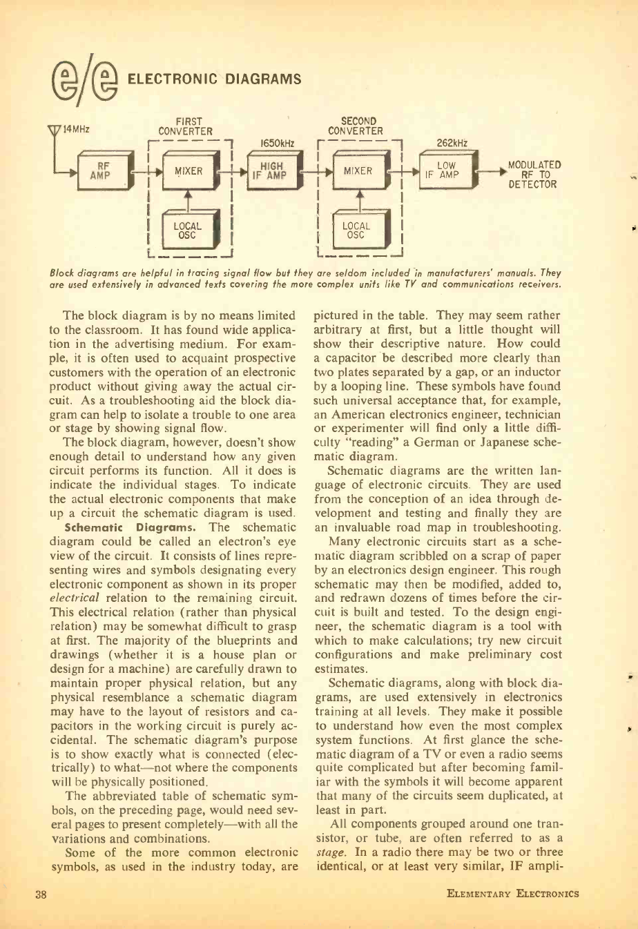
(g @ ELECTRONIC DIAGRAMS
FIRST
CONVERTER
1650kHz
SECOND
CONVERTER
r - - ---'
I
262kHi
MIXER
I I
(
LOCA
Ì
L----J
MODULATED
RF TO
DETECTOR
Block diagrams are helpful in tracing signal flow hut they are seldom included in manufacturers' manuals. They
are used extensively in advanced texts covering the more complex units like TY and communications receivers.
The block diagram is by no means limited
to the classroom. It has found wide applica-
tion in the advertising medium. For exam-
ple, it is often used to acquaint prospective
customers with the operation of an electronic
product without giving away the actual cir-
cuit. As a troubleshooting aid the block dia-
gram can help to isolate a trouble to one area
or stage by showing signal flow.
The block diagram, however, doesn't show
enough detail to understand how any given
circuit performs its function. All it does is
indicate the individual stages. To indicate
the actual electronic components that make
up a circuit the schematic diagram is used.
Schematic Diagrams. The schematic
diagram could be called an electron's eye
view of the circuit. It consists of lines repre-
senting wires and symbols designating every
electronic component as shown in its proper
electrical relation to the remaining circuit.
This electrical relation (rather than physical
relation) may be somewhat difficult to grasp
at first. The majority of the blueprints and
drawings (whether it is a house plan or
design for a machine) are carefully drawn to
maintain proper physical relation, but any
physical resemblance a schematic diagram
may have to the layout of resistors and ca-
pacitors in the working circuit is purely ac-
cidental. The schematic diagram's purpose
is to show exactly what is connected (elec-
trically) to what -not where the components
will be physically positioned.
The abbreviated table of schematic sym-
bols, on the preceding page, would need sev-
eral pages to present completely -with all the
variations and combinations.
Some of the more common electronic
symbols, as used in the industry today, are
38
pictured in the table. They may seem rather
arbitrary at first, but a little thought will
show their descriptive nature. How could
a capacitor be described more clearly than
two plates separated by a gap, or an inductor
by a looping line. These symbols have found
such universal acceptance that, for example,
an American electronics engineer, technician
or experimenter will find only a little diffi-
culty "reading" a German or Japanese sche-
matic diagram.
Schematic diagrams are the written lan-
guage of electronic circuits. They are used
from the conception of an idea through de-
velopment and testing and finally they are
an invaluable road map in troubleshooting.
Many electronic circuits start as a sche-
matic diagram scribbled on a scrap of paper
by an electronics design engineer. This rough
schematic may then be modified, added to,
and redrawn dozens of times before the cir-
cuit is built and tested. To the design engi-
neer, the schematic diagram is a tool with
which to make calculations; try new circuit
configurations and make preliminary cost
estimates.
Schematic diagrams, along with block dia-
grams, are used extensively in electronics
training at all levels. They make it possible
to understand how even the most complex
system functions. At first glance the sche-
matic diagram of a TV or even a radio seems
quite complicated but after becoming famil-
iar with the symbols it will become apparent
that many of the circuits seem duplicated, at
least in part.
All components grouped around one tran-
sistor, or tube, are often referred to as a
stage. In a radio there may be two or three
identical, or at least very similar, IF ampli-
ELEMENTARY ELECTRONICS
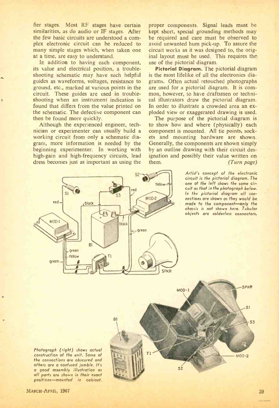
fier stages. Most RF stages have certain
similarities, as do audio or IF stages. After
the few basic circuits are understood a com-
plex electronic circuit can be reduced to
many simple stages which, when taken one
at a time, are easy to understand.
In addition to having each component,
its value and electrical position, a trouble-
shooting schematic may have such helpful
guides as waveforms, voltages, resistance to
ground, etc., marked at various points in the
circuit. These guides are used in trouble-
shooting when an instrument indication is
found that differs from the value printed on
the schematic. The defective component can
then be found more quickly.
Although the experienced engineer, tech-
nician or experimenter can usually build a
working circuit from only a schematic dia-
gram, more information is needed . by the
beginning experimenter. In working with
high -gain and high- frequency circuits, lead
dress becomes just as important as using the
red
Sl
proper components. Signal leads must be
kept short, special grounding methods may
be required and care must be observed to
avoid unwanted hum pick -up. To assure the
circuit works as it was designed to, the orig-
inal layout must be used. This requires tht
use of the pictorial diagrám.
Pictorial Diagram. The pictorial diagram
is the most lifelike of all the electronics dia-
grams. Often actual retouched photographs
are .used for a pictorial diagram. It is com-
mon, however, to have draftsmen or techni-
cal illustrators draw the pictorial diagram.
In order to illustrate a crowded area an ex-
ploded view or exaggerated drawing is used.
The purpose of the pictorial diagram is
to show how and where (physically) each
component is mounted. All tie points, sock-
ets and mounting hardware are shown.
Generally, the components are shown simply
by an outline drawing with their circuit des-
ignation and possibly their value written on
them. (Turn page)
green
green
green
. Yellow Ti
JSPKR
Artist's concept of the electronic
circuit is the pictorial diagram. The
one at the left shows the same cir-
cuit as that in the photograph below.
In the pictorial diagram all con-
nections are shown as they would be
made to the component -only the
chassis is not shown here. Tubular
objects are solderless connectors.
Photograph (right) shows actual
construction of the unit. Some of
the connections are obscured and
others are a confused jumble. Its
a good assembly illustration as
all nods are shown in their erect
positions- mounted in cabinet.
MARCH-APRIL, 1967 39
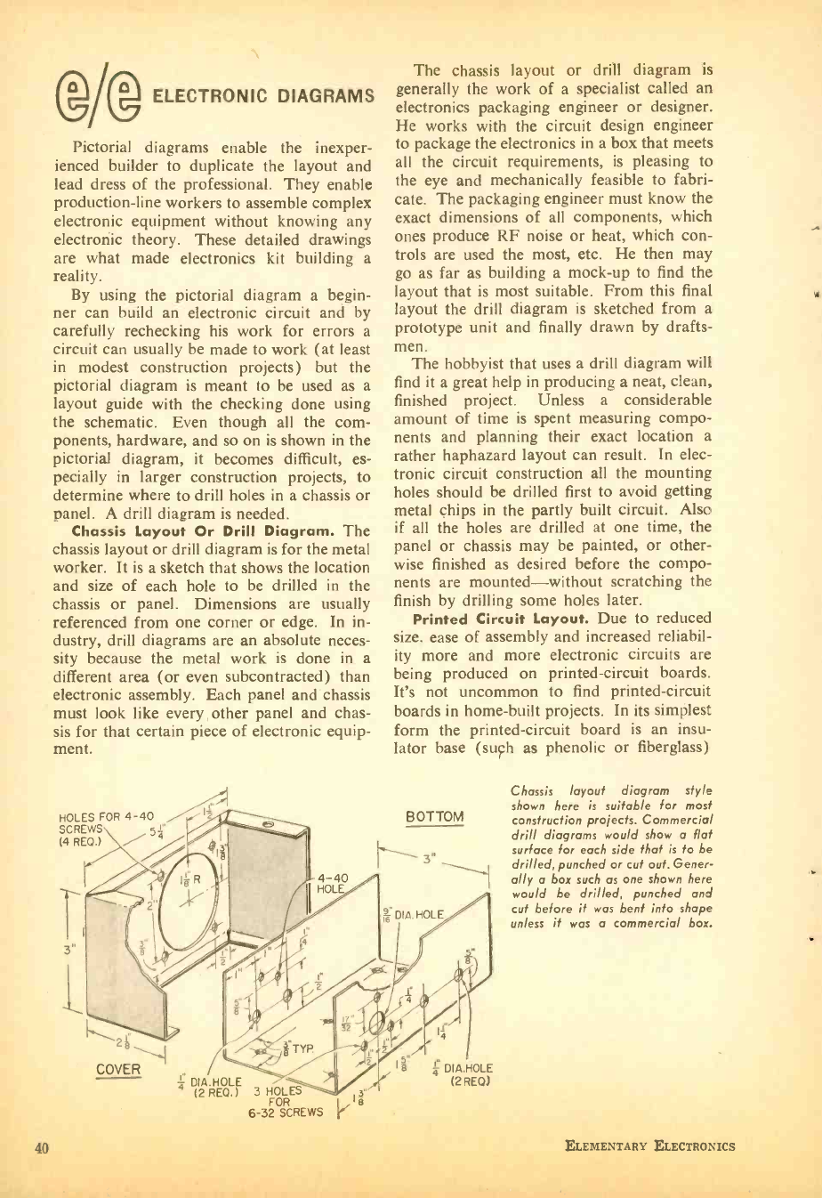
AgELECTRONIC DIAGRAMS
Pictorial diagrams enable the inexper-
ienced builder to duplicate the layout and
lead dress of the professional. They enable
production -line workers to assemble complex
electronic equipment without knowing any
electronic theory. These detailed drawings
are what made electronics kit building a
reality.
By using the pictorial diagram a begin-
ner can build an electronic circuit and by
carefully rechecking his work for errors a
circuit can usually be made to work (at least
in modest construction projects) but the
pictorial diagram is meant to be used as a
layout guide with the checking done using
the schematic. Even though all the com-
ponents, hardware, and so on is shown in the
pictorial diagram, it becomes difficult, es-
pecially in larger construction projects, to
determine where to drill holes in a chassis or
panel. A drill diagram is needed.
Chassis Layout Or Drill Diagram. The
chassis layout or drill diagram is for the metal
worker. It is a sketch that shows the location
and size of each hole to be drilled in the
chassis or panel. Dimensions are usually
referenced from one corner or edge. In in-
dustry, drill diagrams are an absolute neces-
sity because the metal work is done in a
different area (or even subcontracted) than
electronic assembly. Each panel and chassis
must look like every other panel and chas-
sis for that certain piece of electronic equip-
ment.
HOLES FOR 4 -40
SCREWS 5á
(4 REQ.) /
The chassis layout or drill diagram is
generally the work of a specialist called an
electronics packaging engineer or designer.
He works with the circuit design engineer
to package the electronics in a box that meets
all the circuit requirements, is pleasing to
the eye and mechanically feasible to fabri-
cate. The packaging engineer must know the
exact dimensions of all components, which
ones produce RF noise or heat, which con-
trols are used the most, etc. He then may
go as far as building a mock -up to find the
layout that is most suitable. From this final
layout the drill diagram is sketched from a
prototype unit and finally drawn by drafts-
men. The hobbyist that uses a drill diagram will
find it a great help in producing a neat, clean,
finished project. Unless a considerable
amount of time is spent measuring compo-
nents and planning their exact location a
rather haphazard layout can result. In elec-
tronic circuit construction all the mounting
holes should be drilled first to avoid getting
metal chips in the partly built circuit. Also
if all the holes are drilled at one time, the
panel or chassis may be painted, or other-
wise finished as desired before the compo-
nents are mounted -without scratching the
finish by drilling some holes later.
Printed Circuit Layout. Due to reduced
size, ease of assembly and increased reliabil-
ity more and more electronic circuits are
being produced on printed- circuit boards.
It's not uncommon to find printed -circuit
boards in home -built projects. In its simplest
form the printed- circuit board is an insu-
lator base (such as phenolic or fiberglass)
BOTTOM
4 -40
HOLE
DIA.HOLE
2 L
COVER á DIA. HOLE
(2 REQ.) 3 FORES
6 -32 SCREWS s
g DIA.HOLE
(2 REO)
Chassis layout diagram style
shown here is suitable for most
construction projects. Commercial
drill diagrams would show a flat
surface for each side that is to be
drilled, punched or cut out. Gener-
ally a box such as one shown here
would be drilled, punched and
cut before it was bent into shape
unless it was a commercial box.
40 ELEMENTARY ELECTRONICS
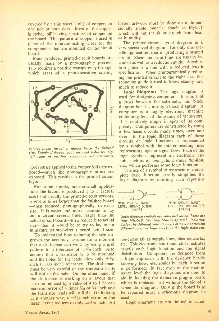
covered by a thin sheet (foil) of copper, on
one side or both sides. Most of the copper
is etched off leaving a pattern of copper on
the board. This pattern of copper is used in
place of the interconnecting wires for the
components that are mounted on the circuit
board.
Mass produced printed -circuit boards are
usually made by a photographic process.
This requires a positive transparency through
which areas of a photo- sensitive coating
15*
16
11ß"
Printed- circuit layout is almost twice the finished
size. Doughnut -shaped pads surround holes for pig-
tail leads of resistors, capacitors and transistors.
(previously applied to the copper foil) are ex-
posed -much like photographic prints are
exposed. This positive is the printed circuit
layout.
For some simple, not -too -small applica-
tions the layout is produced 1 to i (actual
size) but usually the printed- circuit artwork
is several times larger than the finished board
-then reduced, photographically, to exact
size. It is easier and more accurate to lay
out a circuit several times larger than the
actual circuit board -then reduce it to actual
size -than it would be to try to lay out a
miniature printed- circuit board actual size.
To understand how reducing the size im-
proves the accuracy, assume for a mbment
that a draftsman can work by using a grid
pattern to a tolerance of -i-1in inch. Also
assume that a transistor is to be mounted
and the holes for the leads allow only ±1/32
inch ( ±.03 inch) tolerance. The draftsman
must be very careful or the transistor leads
will not fit the hole. On the other hand, if
the draftsman is working on a layout that
is to be reduced by a ratio of 4 to 1 he can
make an error of 4 times Áu or Vs inch and
the transistor leads will still fit. Or looking
at it another way, a ±-1/32-inch error on the
large layout reduces to only -!-Mí28 inch. All
layout artwork must be done on a dimen-
sionally stable material (such as Mylar)
which will not shrink or stretch from heat
or humidity.
The printed -circuit layout diagram is a
very specialized diagram -for only one spe-
cific application; that of producing a printed
circuit. Shear and trim lines are usually in-
cluded as well as a reduction guide. A reduc-
tion guide is a line with a reduced length
specification. When photographically reduc-
ing the printed circuit to the right size, this
reduction guide is used to know exactly how
much to reduce it.
Logic Diagrams. The logic diagram is
used for designing computers. It is sort of
a cross between the schematic and block
diagram but it is mostly a block diagram. A
computer is a highly electronic machine
containing tens of thousands of transistors.
It is relatively simple in spite of its com-
plexity. Computers are constructed by using
a few basic circuits many times, over and
over. In the logic diagram each of these
circuits or logic functions is represented
by a symbol with the interconnecting lines
representing logic or signal flow. Each of the
logic symbols represent an electronic cir-
cuit, such as an and gate, bistable flip -flop,
etc., which performs some logic function.
The use of a symbol to represent one com-
plete logic function greatly simplifies the
logic diagram by omitting such repetitive
D-
WITH
03
POSITIVE INPUT WITH GROUND INPUT
LEVEL, GROUND OUTPUT LEVEL, POSITIVE OUTPUT
(NOR) (NAND)
Logic diagram symbols are many and varied. These are
from MIL -STD (Military Standard) 806B. Industrial
designs by different manufacturers often use somewhat
different forms as logic blocks in the logic diagrams.
nonessentials as supply lines, bias networks,
etc. This electronic shorthand still illustrates
exactly each logic function and the signal
distribution. Computers are designed from
a logic approach with the designer hardly
knowing how, electronically, each function
is performed. In fact even at the mainte-
nance level the logic diagrams are used to
aid in locating the defective plug -in board
which is replaced -all without the aid of a
schematic diagram. Only if the board is to
be repaired must a schematic diagram be
used.
1 oglc re 1;^, * °
alagrams an to ralrn-
MARCH-APRIL, 1967 41
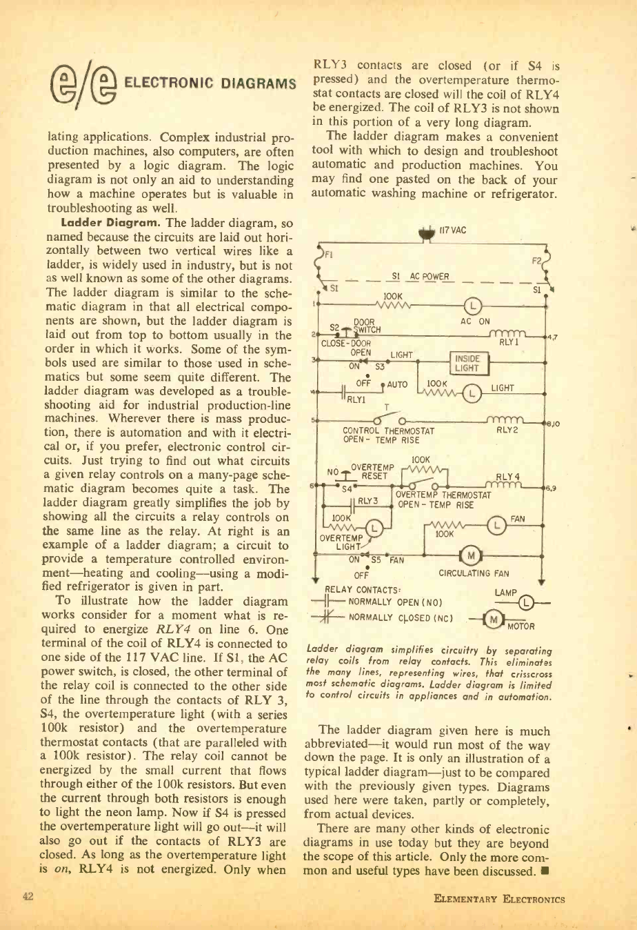
Wg ELECTRONIC DIAGRAMS
lating applications. Complex industrial pro-
duction machines, also computers, are often
presented by a logic diagram. The logic
diagram is not only an aid to understanding
how a machine operates but is valuable in
troubleshooting as well.
Ladder Diagram. The ladder diagram, so
named because the circuits are laid out hori-
zontally between two vertical wires like a
ladder, is widely used in industry, but is not
as well known as some of the other diagrams.
The ladder diagram is similar to the sche-
matic diagram in that all electrical compo-
nents are shown, but the ladder diagram is
laid out from top to bottom usually in the
order in which it works. Some of the sym-
bols used are similar to those used in sche-
matics but some seem quite different. The
ladder diagram was developed as a trouble-
shooting aid for industrial production -line
machines. Wherever there is mass produc-
tion, there is automation and with it electri-
cal or, if you prefer, electronic control cir-
cuits. Just trying to find out what circuits
a given relay controls on a many -page sche-
matic diagram becomes quite a task. The
ladder diagram greatly simplifies the job by
showing all the circuits a relay controls on
the same line as the relay. At right is an
example of a ladder diagram; a circuit to
provide a temperature controlled environ-
ment- heating and cooling -using a modi-
fied refrigerator is given in part.
To illustrate how the ladder diagram
works consider for a moment what is re-
quired to energize RLY4 on line 6. One
terminal of the coil of RLY4 is connected to
one side of the 117 VAC line. If S1, the AC
power switch, is closed, the other terminal of
the relay coil is connected to the other side
of the line through the contacts of RLY 3,
S4, the overtemperature light (with a series
100k resistor) and the overtemperature
thermostat contacts (that are paralleled with
a 100k resistor). The relay coil cannot be
energized by the small current that flows
through either of the 100k resistors. But even
the current through both resistors is enough
to light the neon lamp. Now if S4 is pressed
the overtemperature light will go out -it will
also go out if the contacts of RLY3 are
closed. As long as the overtemperature light
is on, RLY4 is not energized. Only when
42
RLY3 contacts are closed (or if S4 is
pressed) and the overtemperature thermo-
stat contacts are closed will the coil of RLY4
be energized. The coil of RLY3 is not shown
in this portion of a very long diagram.
The ladder diagram makes a convenient
tool with which to design and troubleshoot
automatic and production machines. You
may find one pasted on the back of your
automatic washing machine or refrigerator.
1I7VAC
FI
SI
SI AC POWER
100K
vww
DOOR
2 SWITCH
CLOSE -DOOR
OPEN LIGHT
ON~ S34
OFFFF AUTO 100K
RLY' 1 T
s4 Crqp FYYYY T L-mio
RLY2
F2
Si
AC ON
RLYT n_04.7
INSIDE
I
LIGHT
LIGHT
CONTROL THERMOSTAT
OPEN- TEMP RISE
IOOK
RLY4
NO OVERTEMP
RESET
6.+ -+S4 6.9
RLY3 OVERTEMP
OPEN - TEMP RISE
THERMOSTAT
100K _ w FAN
OVERTEMP
LIGHT
ON" S5 *FAN
OFF
100K
CIRCULATING FAN
RELAY CONTACTS,
--H-- NORMALLY OPEN (NO)
-->- NORMALLY CLOSED (NC)
LAMP
MOTOR
Ladder diagram simplifies circuitry by separating
relay coils from relay contacts. This eliminates
the many lines, representing wires, that crisscross
most schematic diagrams. Ladder diagram is limited
to control circuits in appliances and in automation.
The ladder diagram given here is much
abbreviated -it would run most of the way
down the page. It is only an illustration of a
typical ladder diagram -just to be compared
with the previously given types. Diagrams
used here were taken, partly or completely,
from actual devices.
There are many other kinds of electronic
diagrams in use today but they are beyond
the scope of this article. Only the more com-
mon and useful types have been discussed. f
ELEMENTARY ELECTRONICS
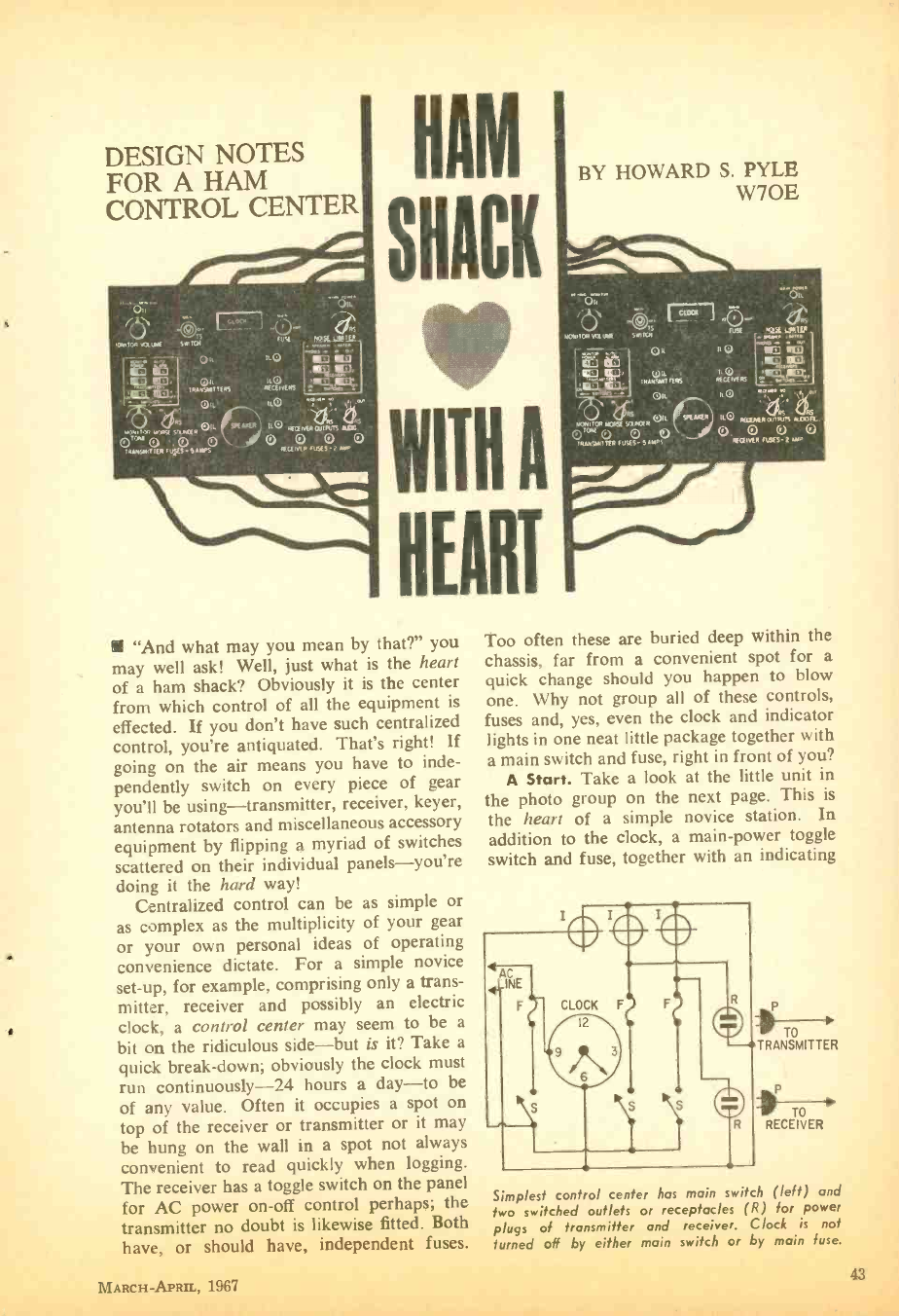
w
DESIGN NOTES
FOR A HAM
CONTROL CENTER
NAM
SHACK
r WITH A
HEART
"And what may you mean by that ?" you
may well ask! Well, just what is the heart
of a ham shack? Obviously it is the center
from which control of all the equipment is
effected. If you don't have such centralized
control, you're antiquated. That's right! If
going on the air means you have to inde-
pendently switch on every piece of gear
you'll be using- transmitter, receiver, keyer,
antenna rotators and miscellaneous accessory
equipment by flipping a myriad of switches
scattered on their individual panels - you're
doing it the hard way!
Centralized control can be as simple or
as complex as the multiplicity of your gear
or your own personal ideas of operating
convenience dictate. For a simple novice
set -up, for example, comprising only a trans-
mitter, receiver and possibly an electric
clock, a control center may seem to be a
bit on the ridiculous side -but is it? Take a
quick break -down; obviously the clock must
run continuously -24 hours a day -to be
of any value. Often it occupies a spot on
top of the receiver or transmitter or it may
be hung on the wall in a spot not always
convenient to read quickly when logging.
The receiver has a toggle switch on the panel
for AC power on -off control perhaps; the
transmitter no doubt is likewise fitted. Both
have, or should have, independent fuses.
BY HOWARD S. PYLE
W7OE
Too often these are buried deep within the
chassis, far from a convenient spot for a
quick change should you happen to blow
one. Why not group all of these controls,
fuses and, yes, even the clock and indicator
lights in one neat little package together with
a main switch and fuse, right in front of you?
A Start. Take a look at the little unit in
the photo group on the next page. This is
the heart of a simple novice station. In
addition to the clock, a main -power toggle
switch and fuse, together with an indicating
TO
TRANSMITTER
P
TO
RECEIVER
Simplest control center has main switch (left) and
two switched outlets or receptacles (R) for power
plugs of transmitter and receiver. Clock is not
turned off by either main switch or by main fuse.
MARCH- APRIL, 1967 43
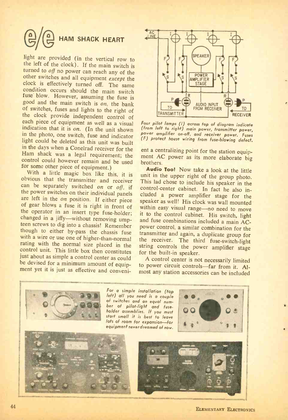
44
1 c- HAM SHACK HEART
ttt777 j light are provided (in the vertical row to
the left of the clock). If the main switch is
turned to off no power can reach any of the
other switches and all equipment except the
clock is effectively turned off. The same
condition occurs should the main switch
fuse' blow. However, assuming the fuse is
good and the main switch is on, the bank
of switches, fuses and lights to the right of
the clock provide independent control of
each piece of equipment as well as a visual
indication that it is on. (In the unit shown
in the photo, one switch, fuse and indicator
light could be deleted as this unit was built
in the days when a Conelrad receiver for the
Ham shack was a legal requirement; the
control could however remain and be used
for some other piece of equipment.)
With a little magic box like this, it is
obvious that the transmitter and receiver
can be separately switched on or off, if
the power switches on their individual panels
are left in the on position. If either piece
of gear blows a fuse it is right in front of
the operator in an insert type fuse -holder;
changed in a jiffy -without removing ump-
teen screws to dig into a chassis! Remember
though to either by -pass the chassis fuse
with a wire or use one of higher- than -normal
rating with the normal size placed in the
control unit. This little box then constitutes
just about as simple a control center as could
be devised for a minimum amount of equip-
ment yet it is just as effective and conveni-
911 .,m.....,111.. 11111 .,,,,.,111..,,,,,,,,,, , ........11..,,,,11m,. .,.,...,.,.
LINE
TO To
RECEIVER
Four pi of lamps (l) across lop of diagram indicate
(from left to right) main power, transmitter power,
power amplifier on -off, and receiver power. Fuses
(F) protect house wiring from fuse- blowing defect.
ent a centralizing point for the station equip-
ment AC power as its more elaborate big
brothers.
Audio Tool Now take a look at the little
unit in the upper right of the group photo.
This lad chose to include his speaker in the
control- center cabinet. In fact he also in-
cluded a power amplifier stage for the
speaker as well! His clock was wall mounted
within easy visual range -no need to move
it to the control cabinet. His switch, light
and fuse combinations included a main AC-
power control, a similar combination for the
transmitter and again, a duplicate group for
the receiver. The third fuse- switch -light
string controls the power amplifier stage
for the built -in speaker.
A control center is not necessarily limited
to power circuit controls -far from it. Al-
most any station accessories can be included
For a simple installation (top
left) all you need is a couple
of switches and an equal num-
ber of pilot -light and fuse -
ho/der assemblies. If you must
start small it is best to leave
lots of room for expansion -for
equipment never dreamed of now.
1111...,.,,,.1,,,.11111,,,,,,,,.1..1, 1.,,,,111111,,,,,1111111,1,.1111..11:P1
;/1/11111 . 1.. ......... , 1.111111.111111111111111111..1..1..11..1.,.1111111...1.11111111111111111.1.1111..1..1.1.11111111. ..1.1...1.1..1...111111.1.111111111.1.....1..1....1..1...111.1.11..111..1.1.11111111111111-..1.1
ELEMENTARY ELECTRONICS
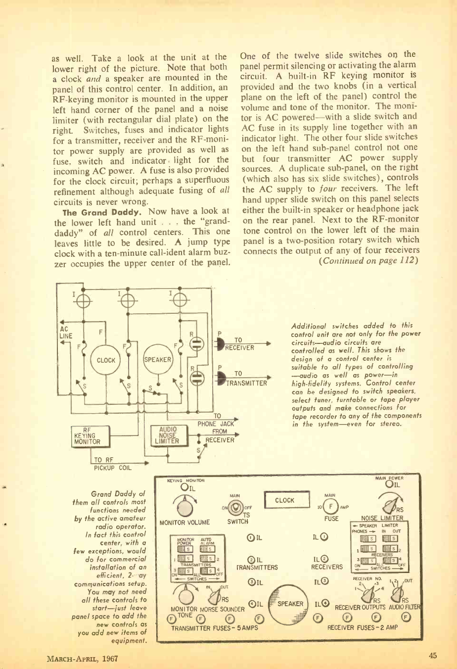
as well. Take a look at the unit at the
lower right of the picture. Note that both
a clock and a speaker are mounted in the
panel of this control center. In addition, an
RF- keying monitor is mounted in the upper
left hand corner of the panel and a noise
limiter (with rectangular dial plate) on the
right. Switches, fuses and indicator lights
for a transmitter, receiver and the RF -moni-
tor power supply are provided as well as
fuse, switch and indicator. light for the
incoming AC power. A fuse is also provided
for the clock circuit; perhaps a superfluous
refinement although adequate fusing of all
circuits is never wrong.
The Grand Daddy. Now have a look at
the lower left hand unit . . . the "grand-
daddy" of all control centers. This one
leaves little to be desired. A jump type
clock with a ten -minute call -ident alarm buz-
zer occupies the upper center of the panel.
RF
KEYING
MONITOR
TO RF
PICKUP COIL
Grand Daddy of
them all controls most
functions needed
by the active amateur
radio operator.
In fact this control
center, with a
few exceptions, would
do for commercial
installation of an
efficient, 2- .ay
communications setup.
You may not need
all these controls to
start -just leave
panel space to odd the
new controls as
you add new items of
One of the twelve slide switches on the
panel permit silencing or activating the alarm
circuit. A built -in RF keying monitor is
provided and the two knobs (in a vertical
plane on the left of the panel) control the
volume and tone of the monitor. The moni-
tor is AC powered -with a slide switch and
AC fuse in its supply line together with an
indicator light. The other four slide switches
on the left hand sub -panel control not one
but four transmitter AC power supply
sources. A duplicate sub -panel, on the right
(which also has six slide switches), controls
the AC supply to four receivers. The left
hand upper slide switch on this panel selects
either the built -in speaker or headphone jack
on the rear panel. Next to the RF- monitor
tone control on the lower left of the main
panel is a two -position rotary switch which
connects the output of any of four receivers
(Continued on page 112)
P
RECEIVER
T
- TRA7 NSMITTER
TO
AUDIO
NOISE
LIMITER
PHONE JACK
FROM
I RECEIVER
Additional switches added to this
control unit are not only for the power
circuits -audio circuits are
controlled as well. This shows the
design of a control center is
suitable to all types of controlling
-audio as well as power -in
high -fidelity systems. Control center
can be designed to switch speakers,
select tuner, turntable or tape player
outputs and make connections for
tape recorder to any of the components
in the system -even for stereo.
KEYING
MONITOR
MONITOR
OIL
ON
VOLUME
MAIN POWER
OIL
RS
NOISE LIMITER
MAIN
I CLOCK 10O AMP
IUI OFF
TS FUSE
SWITCH
Q IL iL Q
OIL IL®
TRANSMITTERS RECEIVERS
f SPEAKER LIMITER
PHONES IN OUT
MONITOR AUTO
POWER ALARM 111111© 111111©
lil11© VIII© ,'11111© 11111 ©2
RECEIVERS
111111© VIII© 2
TRANSMITTERS : 111111©
O
c:,111111©AL11111 ©óFF
SWITCHES OIL
U (fRS aQIL
MONITOR MORSE SOUNDER
OTONE O O O
TRANSMITTER FUSES- 5 AMPS
ILO RECEIVER NO OUT
2 .3
\
ILO RECEIVER OUTPUTS AUDIO FRIER
O Q O
RECEIVER FUSES -2 AMP
Y
MARCH -APRIL, 1967 45
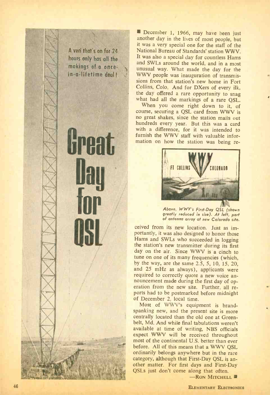
A veri that's on for 24
hours only has all the
makings of a once -
in -a- lifetime deal!
December 1, 1966, may have been just
another day in the lives of most people, but
it was a very special one for the staff of the
National Bureau of Standards' station WWV.
It was also a special day for countless Hams
and SWLs around the world, and in a most
unusual way. What made the day for the
WWV people was inauguration of transmis-
sions from that station's new home in Fort
Collins, Colo. And for DXers of every ilk,
the day offered a rare opportunity to snag
what had all the markings of a rare QSL.
When you come right down to it, of
course, securing a QSL card from WWV is
no great shakes, since the station mails out
hundreds every year. But this was a card
with a difference, for it was intended to
furnish the WWV staff with valuable infor-
mation on how the station was being re-
Above, WWV's First-Day QSL (shown
greatly reduced in size). At left, part
of antenna array at new Colorado site.
ceived from its new location. Just as im-
portantly, it was also designed to honor those
Hams and SWLs who succeeded in logging
the station's new transmitter during its first
day on the air. Since WWV is a cinch to
tune on one of its many frequencies (which,
by the way, are the same 2.5, 5, 10, 15, 20,
and 25 mHz as always), applicants were
required to correctly quote a new voice an-
nouncement made during the first day of op-
eration from the new site. Further, all re-
ports had to be postmarked before midnight
of December 2, local time.
Most of WWV's equipment is brand -
spanking new, and the present site is more
centrally located than the old one at Green-
belt, Md. And while final tabulations weren't
available at time of writing, NBS officials
expect WWV will be received throughout
most of the continental U.S. better than ever
before. All of this means that a WWV QSL
ordinarily belongs anywhere but in the rare
category, although that First -Day QSL is an-
other matter. For first days and First -Day
QSLs just don't come along that often.
-RON MITCHELL
46 ELEMENTARY ELECTRONICS
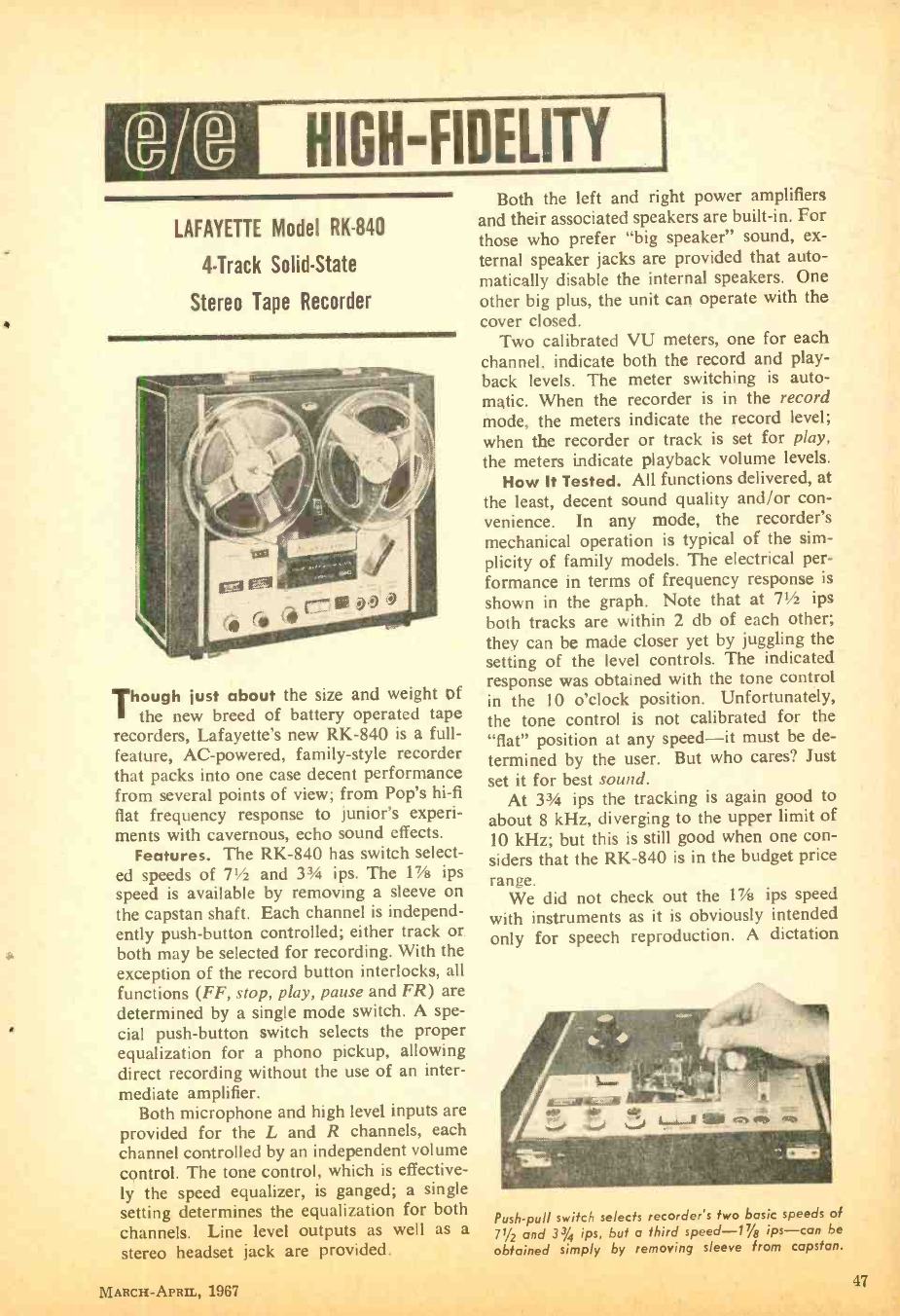
HIGH- FIDELITY
LAFAYETTE Model RK -840
4 -Track Solid -State
Stereo Tape Recorder
Though just about the size and weight of
the new breed of battery operated tape
recorders, Lafayette's new RK -840 is a full -
feature, AC- powered, family -style recorder
that packs into one case decent performance
from several points of view; from Pop's hi -fi
flat frequency response to junior's experi-
ments with cavernous, echo sound effects.
Features. The RK -840 has switch select-
ed speeds of 71/2 and PA ips. The 1% ips
speed is available by removing a sleeve on
the capstan shaft. Each channel is independ-
ently push- button controlled; either track or
both may be selected for recording. With the
exception of the record button interlocks, all
functions (FF, stop, play, pause and FR) are
determined by a single mode switch. A spe-
cial push- button switch selects the proper
equalization for a phono pickup, allowing
direct recording without the use of an inter-
mediate amplifier.
Both microphone and high level inputs are
provided for the L and R channels, each
channel controlled by an independent volume
control. The tone control, which is effective-
ly the speed equalizer, is ganged; a single
setting determines the equalization for both
channels. Line level outputs as well as a
stereo headset jack are provided.
MARCH -APRII,, 1967
Both the left and right power amplifiers
and their associated speakers are built -in. For
those who prefer "big speaker" sound, ex-
ternal speaker jacks are provided that auto-
matically disable the internal speakers. One
other big plus, the unit can operate with the
cover closed.
Two calibrated VU meters, one for each
channel, indicate both the record and play-
back levels. The meter switching is auto-
matic. When the recorder is in the record
mode, the meters indicate the record level;
when the recorder or track is set for play,
the meters indicate playback volume levels.
How It Tested. All functions delivered, at
the least, decent sound quality and /or con-
venience. In any mode, the recorder's
mechanical operation is typical of the sim-
plicity of family models. The electrical per-
formance in terms of frequency response is
shown in the graph. Note that at 71/2 ips
both tracks are within 2 db of each other;
they can be made closer yet by juggling the
setting of the level controls. The indicated
response was obtained with the tone control
in the 10 o'clock position. Unfortunately,
the tone control is not calibrated for the
"flat" position at any speed -it must be de-
termined by the user. But who cares? Just
set it for best sound.
At 33/4 ips the tracking is again good to
about 8 kHz, diverging to the upper limit of
10 kHz; but this is still good when one con-
siders that the RK -840 is in the budget price
range.
We did not check out the 1% ips speed
with instruments as it is obviously intended
only for speech reproduction. A dictation
Push -pull switch selects recorder's two basic speeds of
71/2 and 33/4 ips, but a third speed -17/8 ips -can be
obtained simply by removing sleeve from capstan.
47
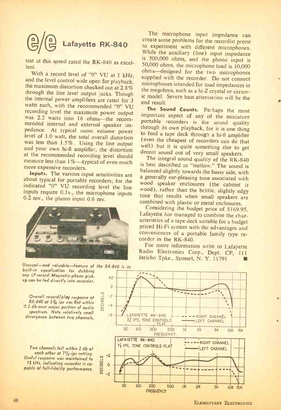
Ol® Lafayette RK -840
test at this speed rated the RK -840 as excel-
lent. With a record level of "0" VU at 1 kHz,
and the level control wide open for playback,
the maximum distortion checked out at 2.8%
through the line level output jacks. Though
the internal power amplifiers are rated for 3
watts each, with the recommended "0" VU
recording level the maximum power output
was 2.2 watts into 16 ohms -the recom-
mended internal and external speaker im-
pedance. At typical room volume power
level of 1.0 watt, the total overall distortion
was less than 1.5 %. Using the line output
and your own hi -fi amplifier, the distortion
at the recommended recording level should
measure less than 1%-typical of even much
more expensive recorders.
Inputs. The various input sensitivities are
about typical for portable recorders; for the
indicated "0" VU recording level the line
inputs require 0.1v., the microphone inputs
0.2 mv., the phono input 0.6 mv.
Unusual -and valuable -feature of the RK -840 is its
built -in equalization for dubbing
any LP record. Magnetic -phono pick-
up can be fed directly into recorder.
Overall record /play response of
RK -840 at 33/4 ips was flat within
±2 db over major portion of audio
spectrum. Note relatively small
divergence between two channels.
Two channels fell within 2 db of
each other at 71/2-ips setting.
Useful response was maintained to
15 kHz, indicating recorder is ca-
pable of full- fidelity performance.
48
+2
0
V) w 2
m
Z3 4
0 -6
The microphone input impedance can
create some problems for the recordist prone
to experiment with different microphones.
While the auxiliary (line) input impedance
is 500,000 ohms, and the phono input is
50,000 ohms, the microphone load is 10,000
ohms -designed for the two microphones
supplied with the recorder. Do not connect
microphones intended for load impedances in
the megohms, such as a hi -Z crystal or ceram-
ic model. Severe bass attenuation will be the
end result.
The Sound Counts. Perhaps the most
important aspect of any of the miniature
portable recorders is the sound quality
through its own playback, for it is one thing
to feed a tape deck through a hi -fi amplifier
(even the cheapest of recorders can do that
well) but it is quite something else to get
decent sound out of very small speakers.
The integral sound quality of the RK -840
is best described as "mellow." The sound is
balanced slightly towards the bassy side, with
a generally ear - pleasing tone associated with
wood speaker enclosures (the cabinet is
wood), rather than the brittle, slightly edgy
tone that results when small speakers are
combined with plastic or metal enclosures.
Considering the budget price of $169.95,
Lafayette has managed to combine the char-
acteristics of a tape deck suitable for a budget
priced Hi -Fi system with the advantages and
conveniences of a portable family type re-
corder in the RK -840.
For more information write to Lafayette
Radio Electronics Corp., Dept. CP, 111
Jericho Tpke., Syosset, N. Y. 11791
i
LAFAYETTE
34IPS;
I
RK
TONE CONTROLS
I
-840 - - RIGHT
LEFT CHANNEL
CHANNEL
I FLAT
-_ -
50 100 200 500 1
FREQUENCY 2 5 10K 15K
LAFAYETTE
7i IPS, TONE
RK -840
FLAT
_ RIGHT CHANNEL
LEFT CHANNEL
100 200 500
FREQUENCY
IK 2K 5K 10K 15K
ELEMENTARY ELECTRONICS
4-
1
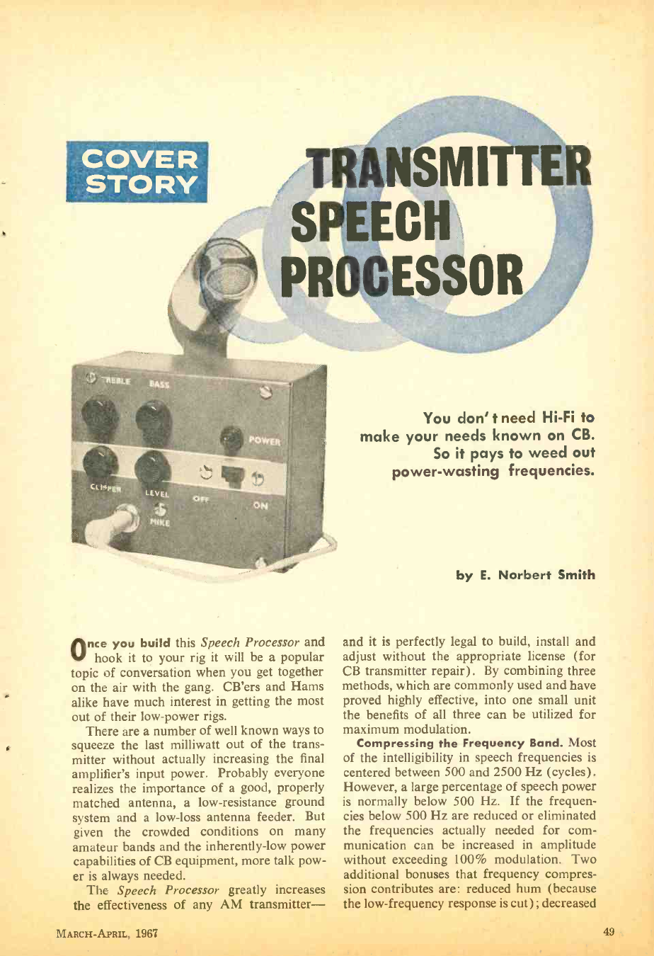
COVER
STORY TRANSMI
SPEECH
PROCESSOR
Alice you build this Speech Processor and
hook it to your rig it will be a popular
topic of conversation when you get together
on the air with the gang. CB'ers and Hams
alike have much interest in getting the most
out of their low -power rigs.
There are a number of well known ways to
squeeze the last milliwatt out of the trans-
mitter without actually increasing the final
amplifier's input power. Probably everyone
realizes the importance of a good, properly
matched antenna, a low- resistance ground
system and a low -loss antenna feeder. But
given the crowded conditions on many
amateur bands and the inherently -low power
capabilities of CB equipment, more talk pow-
er is always needed.
The Speech Processor greatly increases
the effectiveness of any AM transmitter-
MARCH-APRIL, 1967
You don' t need Hi -Fi to
make your needs known on CB.
So it pays to weed out
power- wasting frequencies.
by E. Norbert Smith
and it is perfectly legal to build, install and
adjust without the appropriate license (for
CB transmitter repair). By combining three
methods, which are commonly used and have
proved highly effective, into one small unit
the benefits of all three can be utilized for
maximum modulation.
Compressing the Frequency Band. Most
of the intelligibility in speech frequencies is
centered between 500 and 2500 Hz (cycles).
However, a large percentage of speech power
is normally below 500 Hz. If the frequen-
cies below 500 Hz are reduced or eliminated
the frequencies actually needed for com-
munication can be increased in amplitude
without exceeding 100% modulation. Two
additional bonuses that frequency compres-
sion contributes are: reduced hum (because
the low- frequency response is cut) ; decreased
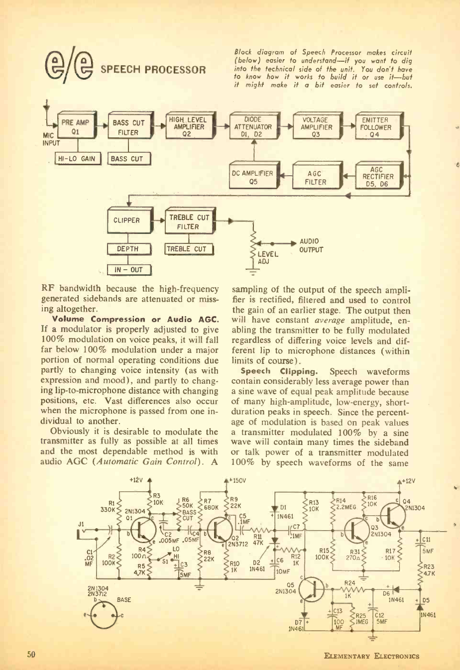
D D
e SPEECH PROCESSOR
HIGH LEVEL
AMPLIFIER
02
Block diagram of Speech Processor makes circuit
(below) easier to understand -if you wont to dig
into the technical side of the unit. You don't have
to know how it works to build it or use it -but
it might make it a bit easier to set controls.
DIODE
ATTENUATOR to
Dl, D2
A
DC AMPLIFIER
Q5
VOLTAGE
AMPLIFIER
03
AGC
FILTER
RF bandwidth because the high- frequency
generated sidebands are attenuated or miss-
ing altogether.
Volume Compression or Audio AGC.
If a modulator is properly adjusted to give
100% modulation on voice peaks, it will fall
far below 100% modulation under a major
portion of normal operating conditions due
partly to changing voice intensity (as with
expression and mood), and partly to chang-
ing lip -to- microphone distance with changing
positions, etc. Vast differences also occur
when the microphone is passed from one in-
dividual to another.
Obviously it is desirable to modulate the
transmitter as fully as possible at all times
and the most dependable method is with
audio AGC (Automatic Gain Control). A
RI
330K
+12V
R3
10K
AUDIO
OUTPUT
4
EMITTER IL
FOLLOWER
Q4
AGC
RECTIFIER
D5, 06
sampling of the output of the speech ampli-
fier is rectified, filtered and used to control
the gain of an earlier stage. The output then
will have constant average amplitude, en-
abling the transmitter to be fully modulated
regardless of differing voice levels and dif-
ferent lip to microphone distances (within
limits of course).
Speech Clipping. Speech waveforms
contain considerably less average power than
a sine wave of equal peak amplitude because
of many high -amplitude, low- energy, short -
duration peaks in speech. Since the percent-
age of modulation is based on peak values
a transmitter modulated 100% by a sine
wave will contain many times the sideband
or talk power of a transmitter modulated
100% by speech waveforms of the same
+150V
R6 R7 R9
50K 680K 22K
2N1304 BASS C5
01 c CUT c ,IMF
C2 C4 b02 Rll
.005MF .05MF e 2N3712 47k
LO
HI
CI
.02
MF
R2
R4
100n
100K SI en + C3
5MF
2N1304
2N3712
D BASE
50
R10 D2
1K 1N461
D1
1N461
C7
.IMF
+ C6 R12
1K
10MF
05
R13
10K
R14
2.2MEG
R15
100K
b
R16
10K c
R31
270n
c b
03 2N1304
e
R17
-10K
+12V
04 2N1304
R24
e J 1K D6
+ C13 R25 C12
D7 + 100 IMEG 5MF
1N46 MF
2N1304
1N461
ELEMENTARY ELECTRONICS
C11
5MF
R23
4.7K
D5
IN461
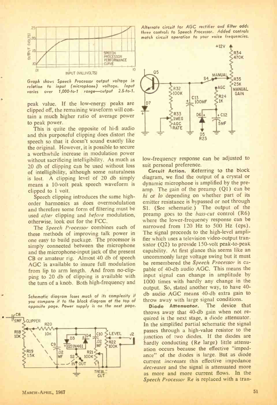
i3 ßi10
INPUT (MILLIVOLTS)
Graph shows Speech Processor output voltage in
relation to input (microphone) voltage. Input
varies over 1,C00 -to -1 range-output 2.5 -fo -1.
PROCESSOR
PERFORMANCE
CURVE
10
peak value. If the low- energy peaks are
clipped off, the remaining waveform will con-
tain a much higher ratio of average power
to peak power.
This is quite the opposite of hi -fi audio
and this purposeful clipping does distort the
speech so that it doesn't sound exactly like
the original. However, it is possible to secure
a worthwhile increase in modulation power
without sacrificing intelligibility. As much as
20 db of clipping can be used without loss
of intelligibility, although some naturalness
is lost. A clipping level of 20 db simply
means a 10 -volt peak speech waveform is
clipped to 1 volt.
Speech clipping introduces the same high -
order harmonics as does overmodulation
and therefore some form of filtering must be
used after clipping and before modulation,
otherwise, look out for the FCC.
The Speech Processor combines each of
these methods of improving talk power in
one easy to build package. The processor is
simply connected between the microphone
and the microphone -input jack of the present
CB or amateur rig. Almost 40 db of speech
AGC is available to insure full modulation
from lip to arm length. And from no-clip-
ping to 20 db of clipping is available with
the turn of a knob. Both high- frequency and
Schematic diagram /oses much of its complexity if
you compare if fo the block diagram at the top of
opposite page. Power supply is on the next page.
CB
.IMF CLIPPER R20
TREBL_
CUT
Alternate circuit for AGC rectifier and filter adds
three controls to Speech Processor. Added controls
match circuit operation to your voice frequencies.
05
S4
D7
R32
100K
R33
1MEG
AGC
RATE
C13
100MF S 1K
+12V
MANUA
AGC
R24
D6 + + C12
TMF
- D5 -
R23
R34
470K
R35
25K
MANUAL
GAIN
low- frequency response can be adjusted to
suit personal preference.
Circuit Action. Referring to the block
diagram, we find the output of a crystal or
dynamic microphone is amplified by the pre -
amp. The gain of the preamp (Q1) can be
hi or to depending on whether part of its
emitter resistance is bypassed or not through
SI. (See schematic.) The output of the
preamp goes to the bass -cut control (R6)
where the lower- frequency response can be
narrowed from 120 Hz to 500 Hz (cps).
The signal proceeds to the high -level ampli-
fier which uses a television video-output tran-
sistor (Q2) to provide 150 -volt peak -to -peak
capability. At first glance this seems like an
uncommonly large voltage swing but it must
be remembered the Speech Processor is ca-
pable of 40-db audio AGC. This means the
input signal can change in amplitude by
1000 times with hardly any change in the
output. So, stated another way, to have 40-
db audio AGC means 40 -db extra gain to
throw away with large signal conditions.
Diode Attenuator. The device that
throws away that 40-db gain when not re-
quired is the next stage, a diode attenuator.
In the simplified partial schematic the signal
passes through a high -value resistor to the
junction of two diodes. If the diodes are
hardly conducting (Re large) little attenu-
ation occurs because the effective "imped-
ance of the diodes is large. But as diode
current increases this effective impedance
decreases and the signal is attenuated more
as more and more current flows. In the
Speech Processor Re is replaced with a tran-
MARCH -APRIL. 1967 51
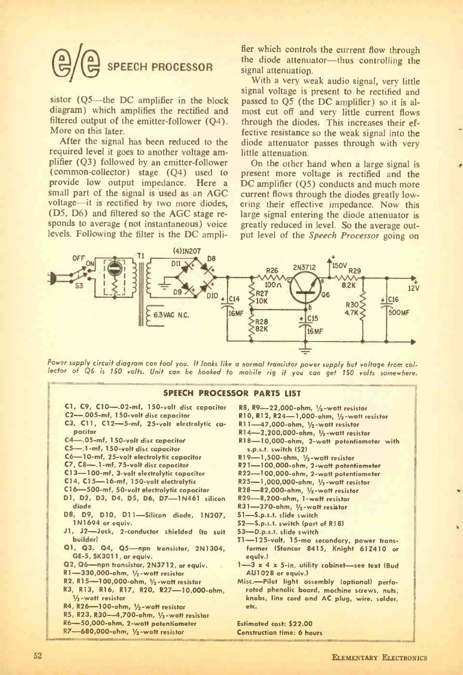
(DA SPEECH PROCESSOR
sistor (Q5 -the DC amplifier in the block
diagram) which amplifies the rectified and
filtered output of the emitter -follower (Q4).
More on this later.
After the signal has been reduced to the
required level it goes to another voltage am-
plifier (Q3) followed by an emitter -follower
(common -collector) stage. (Q4) used to
provide low output impedance. Here a
small part of the signal is used as an AGC
voltage -it is rectified by two more diodes,
(D5, D6) and filtered so the AGC stage re-
sponds to average (not instantaneous) voice
levels. Following the filter is the DC ampli-
(4)1N207
D8
fier which controls the current flow through
the diode attenuator -thus controlling the
signal attenuation.
With a very weak audio signal, very little
signal voltage is present to be rectified and
passed to Q5 (the DC amplifier) so it is al-
most cut off and very little current flows
through the diodes. This increases their ef-
fective resistance so the weak signal into the
diode attenuator passes through with very
little attenuation.
On the other hand when a large signal is
present more voltage is rectified and the
DC amplifier (Q5) conducts and much more
current flows through the diodes greatly low-
ering their effective impedance. Now this
large signal entering the diode attenuator is
greatly reduced in level. So the average out-
put level of the Speech Processor going on
12a V
4 C16
500MF
EVAC N.C.
Power supply circuit diagram can fool you. It looks like a normal transistor power supply but voltage from col-
lector of Q6 is 150 volts. Unit can be hooked to mobile rig if you can get 150 volts somewhere.
,,,.,,, ,.:.,,I,IIII111111,11111111111111111111111111111,1111111111111111,1111IIIIIIIIII.III1111111111111111$11111111 011111011111g
SPEECH PROCESSOR PARTS LIST
Cl, C9, C10- ,02 -mf, 150 -volt disc capacitor
C2- .005 -mf, 150 -volt disc capacitor
C3, CI1, C12 -5 -mf, 25 -volt electrolytic ca-
pacitor
C4- ,05 -mf, 150 -volt disc capacitor
C5- ,1 -mf, 150 -volt disc capacitor
C6-1 0-mf, 25 -volt electrolytic capacitor
C7, C8- ,1 -mf, 75 -volt disc capacitor
Cl 3-100-mf, 3 -volt electrolytic capacitor
C14, C15- 16 -mf, 150 -volt electrolytic
Cl6- 500 -mf, 50 -volt electrolytic capacitor
D1, D2, D3, D4, D5, D6, D7 -1N461 silicon
diode
D8, D9, D10, D11- Silicon diode, 1N207,
1N1694 or equiv.
J1, J2 -Jack, 2- conductor shielded (to suit
builder)
01, 03, Q4, Q5 -npn transistor, 2N1304,
GE -5, SK3011, or equiv.
02, 06-npn transistor, 2N3712, or equiv.
R1- 330,000 -ohm, 1/2 -watt resistor
R2, R15- 100,000 -ohm, 1/2 -watt resistor
R3, R13, R16, R17, R20, R27- 10,000 -ohm,
1/2 -watt resistor
R4, R26 -100 -ohm, 1/2 -watt resistor
R5, R23, R30 -4,700 -ohm, 1/2 -watt resistor
R6- 50,000 -ohm, 2 -watt potentiometer
R7- 680,000 -ohm, 1/2-waft resistor
R8, R9- 22,000 -ohm, 1/2 -watt resistor
RIO, R12, R24- 1,000 -ohm, 1/2 -watt resistor
Rl 1- 47,000 -ohm, 1/2 -watt resistor
RI 4-2,200,000-ohm, 1/2 -watt resistor
RI 8-I0,000-ohm, 2 -watt potentiometer with
s.p.s.t. switch (52)
R19 -1,500 -ohm, 1/2 -watt resistor
R21- 100,000 -ohm, 2 -watt potentiometer
R22- 100,000 -ohm, 2 -waft potentiometer
R25- 1,000,000 -ohm, 1/2 -watt resistor
R28- 82,000 -ohm, 1/2 -watt resistor
R29- 8,200 -ohm, 1 -waft resistor
R31 -270 -ohm, 1/2 -watt resistor
S1- S.p.s.t. slide switch
S2- S.p.s.t. switch (part of Rl 8)
53- D.p.s.t. slide switch
T1- 125 -volt, 15 -ma secondary, power trans-
former (Stancor 8415, Knight 612410 or
equiv.)
1 -3 x 4 x 5 -in. utility cabinet -see text (Bud
AU1028 or equiv.)
Misc. -Pilot light assembly (optional) perfo-
rated phenolic board, machine screws, nuts,
knobs, line cord and AC plug, wire, solder,
etc.
Estimated cost: $22.00
Construction time: 6 hours
52 ELEMENTARY ELECTRONICS
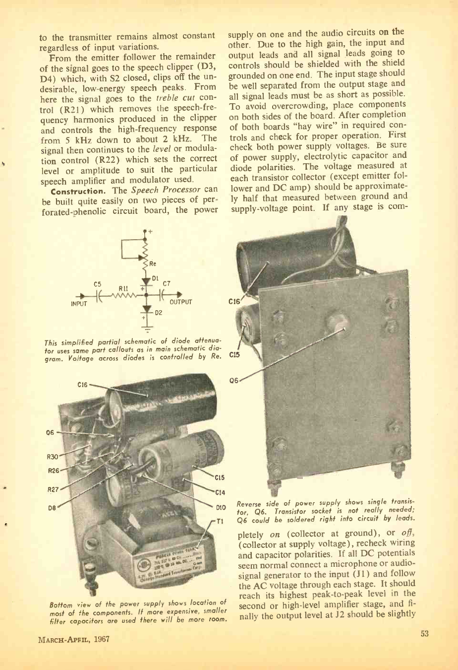
to the transmitter remains almost constant
regardless of input variations.
From the emitter follower the remainder
of the signal goes to the speech clipper (D3,
D4) which, with S2 closed, clips off the un-
desirable, low- energy speech peaks. From
here the signal goes to the treble cut con-
trol (R21) which removes the speech -fre-
quency harmonics produced in the clipper
and controls the high- frequency response
from 5 kHz down to about 2 kHz. The
signal then continues to the level or modula-
tion control (R22) which sets the correct
level or amplitude to suit the particular
speech amplifier and modulator used.
Construction. The Speech Processor can
be built quite easily on two pieces of per-
forated- phenolic circuit board, the power
INPUT
This simplified partial schematic of diode attenua-
tor uses some part ca//outs as in main schematic dia-
gram. Voltage across diodes is controlled by Re. C15
supply on one and the audio circuits on the
other. Due to the high gain, the input and
output leads and all signal leads going to
controls should be shielded with the shield
grounded on one end. The input stage should
be well separated from the output stage and
all signal leads must be as short as possible.
To avoid overcrowding, place components
on both sides of the board. After completion
of both boards "hay wire" in required con-
trols and check for proper operation. First
check both power supply voltages. Be sure
of power supply, electrolytic capacitor and
diode polarities. The voltage measured at
each transistor collector (except emitter fol-
lower and DC amp) should be approximate-
ly half that measured between ground and
supply -voltage point. If any stage is corn-
C16
Bottom view of the power supply shows location of
most of the components. If more expensive, smaller
filter capacitors are used there will be more room.
MARCH -APFIL, 1967
Reverse side of power supply shows single transis-
tor, Q6. Transistor socket is not really needed;
Q6 could be soldered right into circuit by leads.
pletely on (collector at ground) , or ofi,
(collector at supply voltage), recheck wiring
and capacitor polarities. If all DC potentials
seem normal connect a microphone or audio -
signal generator to the input (J1) and follow
the AC voltage through each stage. It should
reach its highest peak -to -peak level in the
second or high -level amplifier stage, and fi-
nally the output level at J2 should be slightly
53
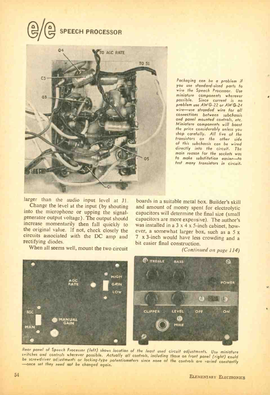
54
(gg SPEECH PROCESSOR
larger than the audio input level at J 1.
Change the level at the input (by shouting
into the microphone or upping the signal -
generator output voltage). The output should
increase momentarily then fall quickly to
the original value. if not, check closely the
circuits associated with the DC amp and
rectifying diodes.
When all seems well, mount the two circuit
.
AGC
MAN
AGC
PATE
MAN JAI
GAIN
HIGH
GAIN
LOW
Packaging can be o problem if
you use standard -sized parts to
wire the Speech Processor. Use
miniature components wherever
possible. Since current is no
problem use AWG -22 or AWG -24
wire -use stranded wire for all
connections between subchassis
and panel mounted controls, etc.
Miniature components will boost
the price considerably unless you
shop carefully. All five of the
transistors on the other side
of this subchassis can be wired
directly into the circuit. The
main reason for the sockets was
to make substitution easier -to
test many transistors in circuit.
boards in a suitable metal box. Builder's skill
and amount of money spent for electrolytic
capacitors will determine the final size (small
capacitors are more expensive). The author's
was installed in a 3 x 4 x 5 -inch cabinet, how-
ever, a somewhat larger box, such as a 5 x
7 x 3 -inch would have less crowding and a
bit easier final construction.
(Continued on page 114)
Rear panel of Speech Processor (left) shows location of the least used circuit adjustments. Use miniature
switches and controls wherever possible. Actually all controls, including those on front panel (right) could
be screwdriver adjustments or locking -type potentiometers since none of the controls are varied constantly
-once set they need not be changed again.
ELEMENTARY ELECTRONICS
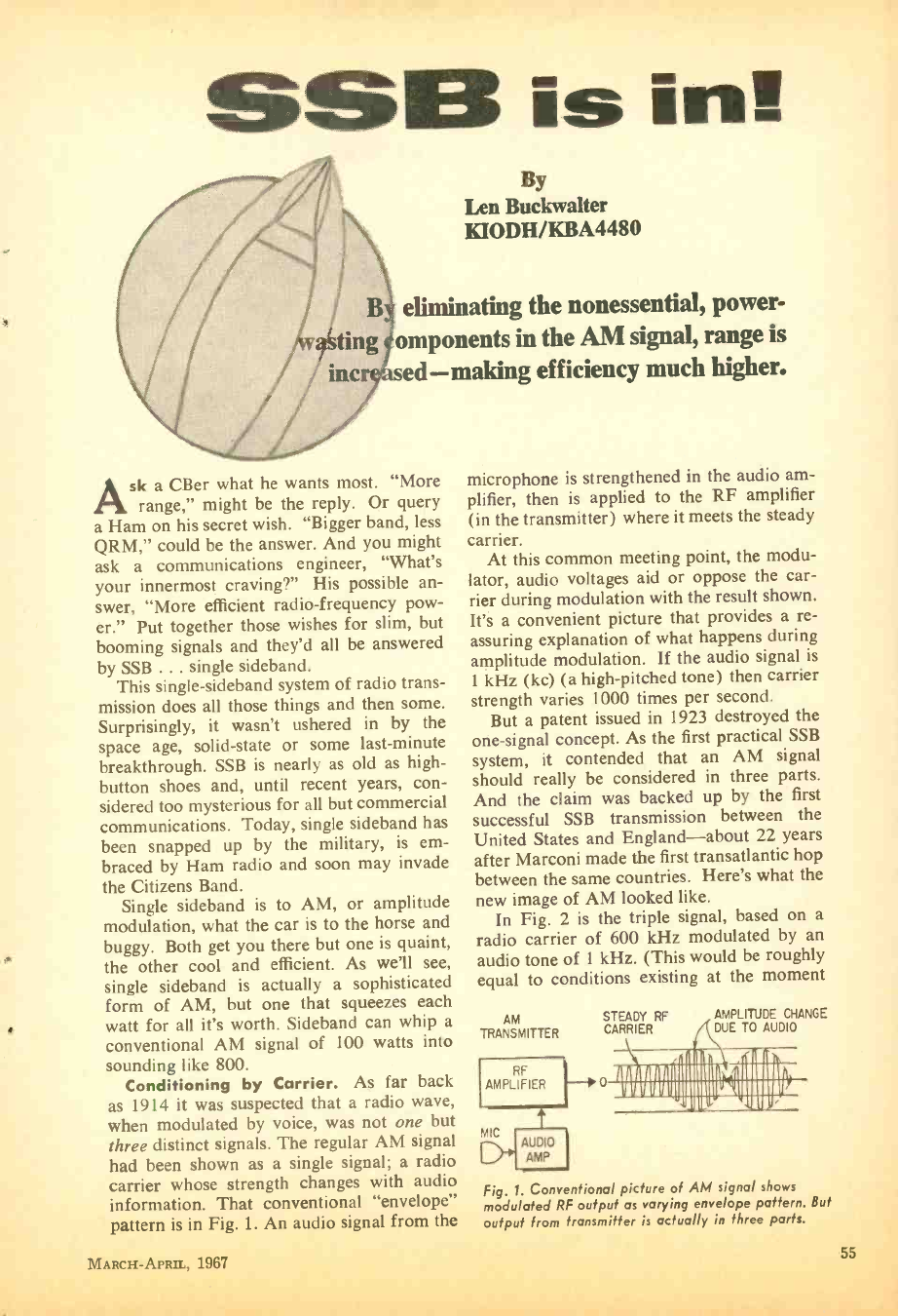
SSB is ins
By
Len Buckwalter
KIODH /KBA4480
eliminating the nonessential, power -
omponents in the AM signal, range is
sed- making efficiency much higher.
A sk a CBer what he wants most. "More
range," might be the reply. Or query
a Ham on his secret wish. "Bigger band, less
QRM," could be the answer. And you might
ask a communications engineer, "What's
your innermost craving ?" His possible an-
swer, "More efficient radio -frequency pow-
er." Put together those wishes for slim, but
booming signals and they'd all be answered
by SSB ... single sideband.
This single -sideband system of radio trans-
mission does all those things and then some.
Surprisingly, it wasn't ushered in by the
space age, solid -state or some last- minute
breakthrough. SSB is nearly as old as high -
button shoes and, until recent years, con-
sidered too mysterious for all but commercial
communications. Today, single sideband has
been snapped up by the military, is em-
braced by Ham radio and soon may invade
the Citizens Band.
Single sideband is to AM, or amplitude
modulation, what the car is to the horse and
buggy. Both get you there but one is quaint,
the other cool and efficient. As we'll see,
single sideband is actually a sophisticated
form of AM, but one that squeezes each
watt for all it's worth. Sideband can whip a
conventional AM signal of 100 watts into
sounding like 800.
Conditioning by Carrier. As far back
as 1914 it was suspected that a radio wave,
when modulated by voice, was not one but
three distinct signals. The regular AM signal
had been shown as a single signal; a radio
carrier whose strength changes with audio
information. That conventional "envelope"
pattern is in Fig. 1. An audio signal from the
MARCH-APRIL, 1967
microphone is strengthened in the audio am-
plifier, then is applied to the RF amplifier
(in the transmitter) where it meets the steady
carrier.
At this common meeting point, the modu-
lator, audio voltages aid or oppose the car-
rier during modulation with the result shown.
It's a convenient picture that provides a re-
assuring explanation of what happens during
amplitude modulation. If the audio signal is
1 kHz (kc) (a high -pitched tone) then carrier
strength varies 1000 times per second.
But a patent issued in 1923 destroyed the
one -signal concept. As the first practical SSB
system, it contended that an AM signal
should really be considered in three parts.
And the claim was backed up by the first
successful SSB transmission between the
United States and England -about 22 years
after Marconi made the first transatlantic hop
between the same countries. Here's what the
new image of AM looked like.
In Fig. 2 is the triple signal, based on a
radio carrier of 600 kHz modulated by an
audio tone of 1 kHz. (This would be roughly
equal to conditions existing at the moment
AM
TRANSMITTER
AMPLIFIER
RF
(MIC
LJ"
t
AUDIO
AMP
STEADY RF AMPLITUDE CHANGE
CARRIER DUE TO AUDIO
1111111111i11111111111111 1 1111111 I
IIIIIIT11111111I1 II 11111111
Fig. Conventional picture of AM signal shows
modulated RF output as varying envelope pattern. Buf
output from transmitter is actually in three parts.
55
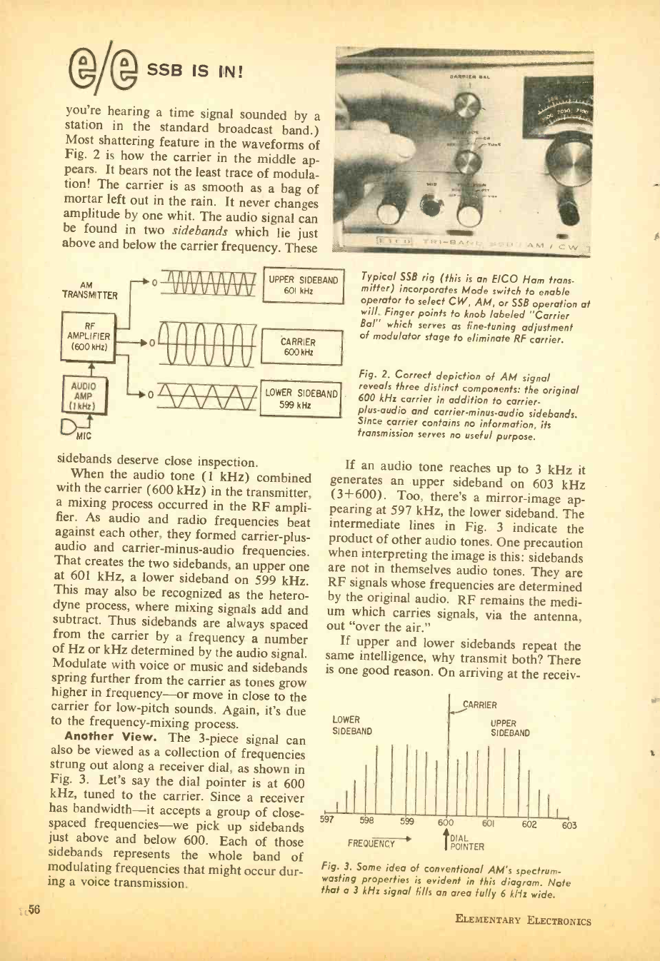
SSB IS IN!
you're hearing a time signal sounded by a
station in the standard broadcast band.)
Most shattering feature in the waveforms of
Fig. 2 is how the carrier in the middle ap-
pears. It bears not the least trace of modula-
tion! The carrier is as smooth as a bag of
mortar left out in the rain. It never changes
amplitude by one whit. The audio signal can
be found in two sidebands which lie just
above and below the carrier frequency. These
RF
AMPLIFIER
(600 kHz)
AUDIO
AMP
(1kHz)
AINFAVAIVAIII/
VARYAVAIRV
UPPER SIDEBAND
601 kHz
Typical SSB rig (this is an E /CO Ham trans-
mitter) incorporates Mode switch to enable
operator to select CW, AM, or SSB operation at
will. Finger points to knob labeled "Carrier
Bal which serves as fine- tuning adjustment
of modulator stage to eliminate RF carrier.
CARRIER
600 kHz
LOWER SIDEBAND
599 kHz
sidebands deserve close inspection.
When the audio tone (1 kHz) combined
with the carrier (600 kHz) in the transmitter,
a mixing process occurred in the RF ampli-
fier. As audio and radio frequencies beat
against each other, they formed carrier -plus-
audio and carrier -minus -audio frequencies.
That creates the two sidebands, an upper one
at 601 kHz, a lower sideband on 599 kHz.
This may also be recognized as the hetero-
dyne process, where mixing signals add and
subtract. Thus sidebands are always spaced
from the carrier by a frequency a number
of Hz or kHz determined by the audio signal.
Modulate with voice or music and sidebands
spring further from the carrier as tones grow
higher in frequency -or move in close to the
carrier for low -pitch sounds. Again, it's due
to the frequency -mixing process.
Another View. The 3 -piece signal can
also be viewed as a collection of frequencies
strung out along a receiver dial, as shown in
Fig. 3. Let's say the dial pointer is at 600
kHz, tuned to the carrier. Since a receiver
has bandwidth -it accepts a group of close -
spaced frequencies -we pick up sidebands
just above and below 600. Each of those
sidebands represents the whole band of
modulating frequencies that might occur dur-
ing a voice transmission.
56
Fig. 2. Correct depiction of AM signal
reveals three distinct components: the original
600 kHz carrier in addition to carrier -
plus -audio and carrier- minus -audio sidebands.
Since carrier contains no information, its
transmission serves no useful purpose.
If an audio tone reaches up to 3 kHz it
generates an upper sideband on 603 kHz
(3 +600). Too, there's a mirror-image ap-
pearing at 597 kHz, the lower sideband. The
intermediate lines in Fig. 3 indicate the
product of other audio tones. One precaution
when interpreting the image is this: sidebands
are not in themselves audio tones. They are
RF signals whose frequencies are determined
by the original audio. RF remains the medi-
um which carries signals, via the antenna,
out "over the air."
If upper and lower sidebands repeat the
same intelligence, why transmit both? There
is one good reason. On arriving at the receiv-
LOWER
SIDEBAND
,SII
CARRIER
UPPER
SIDEBAND
Iil,
597 598
FREQUENCY
599 600 t 601 602 603
DIAL
POINTER
Fig. 3. Some idea of conventional AM's spectrum -
wasting properties is evident in this diagram. Note
that a 3 kHz signal fills an area fully 6 kHz wide.
ELEMENTARY ELECTRONICS
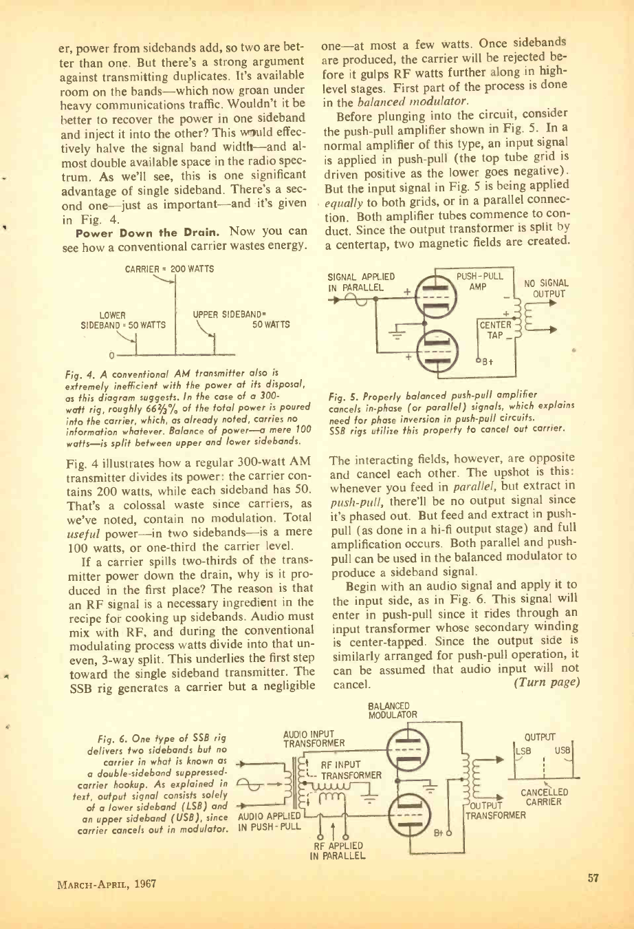
er, power from sidebands add, so two are bet-
ter than one. But there's a strong argument
against transmitting duplicates. It's available
room on the bands -which now groan under
heavy communications traffic. Wouldn't it be
better to recover the power in one sideband
and inject it into the other? This would effec-
tively halve the signal band width -and al-
most double available space in the radio spec-
trum. As we'll see, this is one significant
advantage of single sideband. There's a sec-
ond one -just as important -and it's given
in Fig. 4.
Power Down the Drain. Now you can
see how a conventional carrier wastes energy.
CARRIER = 200 WATTS
LOWER
SIDEBAND = 50 WATTS
UPPER SIDEBAND
50 WATTS
Fig. 4. A conventional AM transmitter also is
extremely inefficient with the power at its disposal,
as this diagram suggests. In the case of a 300 -
watt rig, roughly 662/3% of the total power is poured
into the carrier, which, as already noted, carries no
information whatever. Balance of power -a mere 100
watts -is split between upper and lower sidebands.
Fig. 4 illustrates how a regular 300 -watt AM
transmitter divides its power: the carrier con-
tains 200 watts, while each sideband has 50.
That's a colossal waste since carriers, as
we've noted, contain no modulation. Total
useful power -in two sidebands -is a mere
100 watts, or one -third the carrier level.
If a carrier spills two- thirds of the trans-
mitter power down the drain, why is it pro-
duced in the first place? The reason is that
an RF signal is a necessary ingredient in the
recipe for cooking up sidebands. Audio must
mix with RF, and during the conventional
modulating process watts divide into that un-
even, 3 -way split. This underlies the first step
toward the single sideband transmitter. The
SSB rig generates a carrier but a negligible
Fig. 6. One type of SSB rig
delivers two sidebands but no
carrier in what is known as
a double -sideband suppressed -
carrier hookup. As explained in
text, output signal consists solely
of a lower sideband (LSB) and
an upper sideband (USB), since
carrier cancels out in modulator.
one -at most a few watts. Once sidebands
are produced, the carrier will be rejected be-
fore it gulps RF watts further along in high -
level stages. First part of the process is done
in the balanced modulator.
Before plunging into the circuit, consider
the push -pull amplifier shown in Fig. 5. In a
normal amplifier of this type, an input signal
is applied in push -pull (the top tube grid is
driven positive as the lower goes negative).
But the input signal in Fig. 5 is being applied
equally to both grids, or in a parallel connec-
tion. Both amplifier tubes commence to con-
duct. Since the output transformer is split by
a centertap, two magnetic fields are created.
SIGNAL APPLIED
IN PARALLEL + NO SIGNAL
OUTPUT
Fig. 5. Properly balanced push -pull amplifier
cancels in -phase (or parallel) signals, which explains
need for phase inversion in push -pull circuits.
SSB rigs utilize this property to cancel out carrier.
The interacting fields, however, are opposite
and cancel each other. The upshot is this:
whenever you feed in parallel, but extract in
push -pull, there'll be no output signal since
it's phased out. But feed and extract in push -
pull (as done in a hi -fi output stage) and full
amplification occurs. Both parallel and push -
pull can be used in the balanced modulator to
produce a sideband signal.
Begin with an audio signal and apply it to
the input side, as in Fig. 6. This signal will
enter in push -pull since it rides through an
input transformer whose secondary winding
is center -tapped. Since the output side is
similarly arranged for push -pull operation, it
can be assumed that audio input will not
cancel. (Turn page)
AUDIO INPUT
TRANSFORMER
BALANCED
MODULATOR
RF INPUT
- TRANSFORMER
AUDIO APPLIED
IN PUSH -PULL
RF APPLIED
IN PARALLEL
OUTPUT
ILSB USI
J ,
CANCELLED
OUTPUT CARRIER
TRANSFORMER
MARCH -APRIL, 1967 57
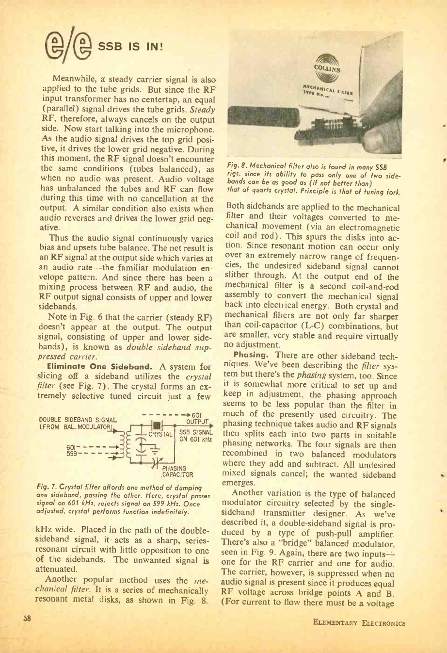
58
SSB IS IN!
Meanwhile, a steady carrier signal is also
applied to the tube grids. But since the RF
input transformer has no centertap, an equal
(parallel) signal drives the tube grids. Steady
RF, therefore, always cancels on the output
side. Now start talking into the microphone.
As the audio signal drives the top grid posi-
tive, it drives the lower grid negative. During
this moment, the RF signal doesn't encounter
the same conditions (tubes balanced), as
when no audio was present. Audio voltage
has unbalanced the tubes and RF can flow
during this time with no cancellation at the
output. A similar condition also exists when
audio reverses and drives the lower grid neg-
ative. Thus the audio signal continuously varies
bias and upsets tube balance. The net result is
an RF signal at the output side which varies at
an audio rate -the familiar modulation en-
velope pattern. And since there has been a
mixing process between RF and audio, the
RF output signal consists of upper and lower
sidebands.
Note in Fig. 6 that the carrier (steady RF)
doesn't appear at the output. The output
signal, consisting of upper and lower side -
bands), is known as double sideband sup-
pressed carrier.
Eliminate One Sideband. A system for
slicing off a sideband utilizes the crystal
filter (see Fig. 7). The crystal forms an ex-
tremely selective tuned circuit just a few
- 601
DOUBLE SIDEBAND SIGNAL OUTPUT
(FROM BAL,MODULATOR)0 1.11 SSB SIGNAL
CRYSTAL ON 601 kHz
601
599
PHASING
.CAPACITOR
Fig. 7. Crystal filter affords one method of dumping
one sideband, passing the other. Here, crystal passes
signal on 601 kHz, rejects signal on 599 kHz. Once
adjusted, crystal performs function indefinitely.
kHz wide. Placed in the path of the double -
sideband signal, it acts as a sharp, series -
resonant circuit with little opposition to one
of the sidebands. The unwanted signal is
attenuated.
Another popular method uses the me-
chanical filter. It is a series of mechanically
resonant metal disks, as shown in Fig. 8.
4,011.1 N s
MrNANIC4t FILTER
Fig. 8. Mechanical filter also is found in many SSB
rigs, since its ability to pass only one of two side -
bands can be as good as (if not better than)
that of quartz crystal. Principle is that of tuning fork.
Both sidebands are applied to the mechanical
filter and their voltages converted to me-
chanical movement (via an electromagnetic
coil and rod). This spurs the disks into ac-
tion. Since resonant motion can occur only
over an extremely narrow range of frequen-
cies, the undesired sideband signal cannot
slither through. At the output end of the
mechanical filter is a second coil -and -rod
assembly to convert the mechanical signal
back into electrical energy. Both crystal and
mechanical filters are not only far sharper
than coil- capacitor (L -C) combinations, but
are smaller, very stable and require virtually
no adjustment.
Phasing. There are other sideband tech-
niques. We've been describing the filter sys-
tem but there's the phasing system, too. Since
it is somewhat more critical to set up and
keep in adjustment, the phasing approach
seems to be less popular than the filter in
much of the presently used circuitry. The
phasing technique takes audio and RF signals
then splits each into two parts in suitable
phasing networks. The four signals are then
recombined in two balanced modulators
where they add and subtract. All undesired
mixed signals cancel; the wanted sideband
emerges.
Another variation is the type of balanced
modulator circuitry selected by the single -
sideband transmitter designer. As we've
described it, a double -sideband signal is pro-
duced by a type of push -pull amplifier.
There's also a "bridge" balanced modulator,
seen in Fig. 9. Again, there are two inputs-
one for the RF carrier and one for audio.
The carrier, however, is suppressed when no
audio signal is present since it produces equal
RF voltage across bridge points A and B.
(For current to flow there must be a voltage
nLEMENTARY ELECTRONICS
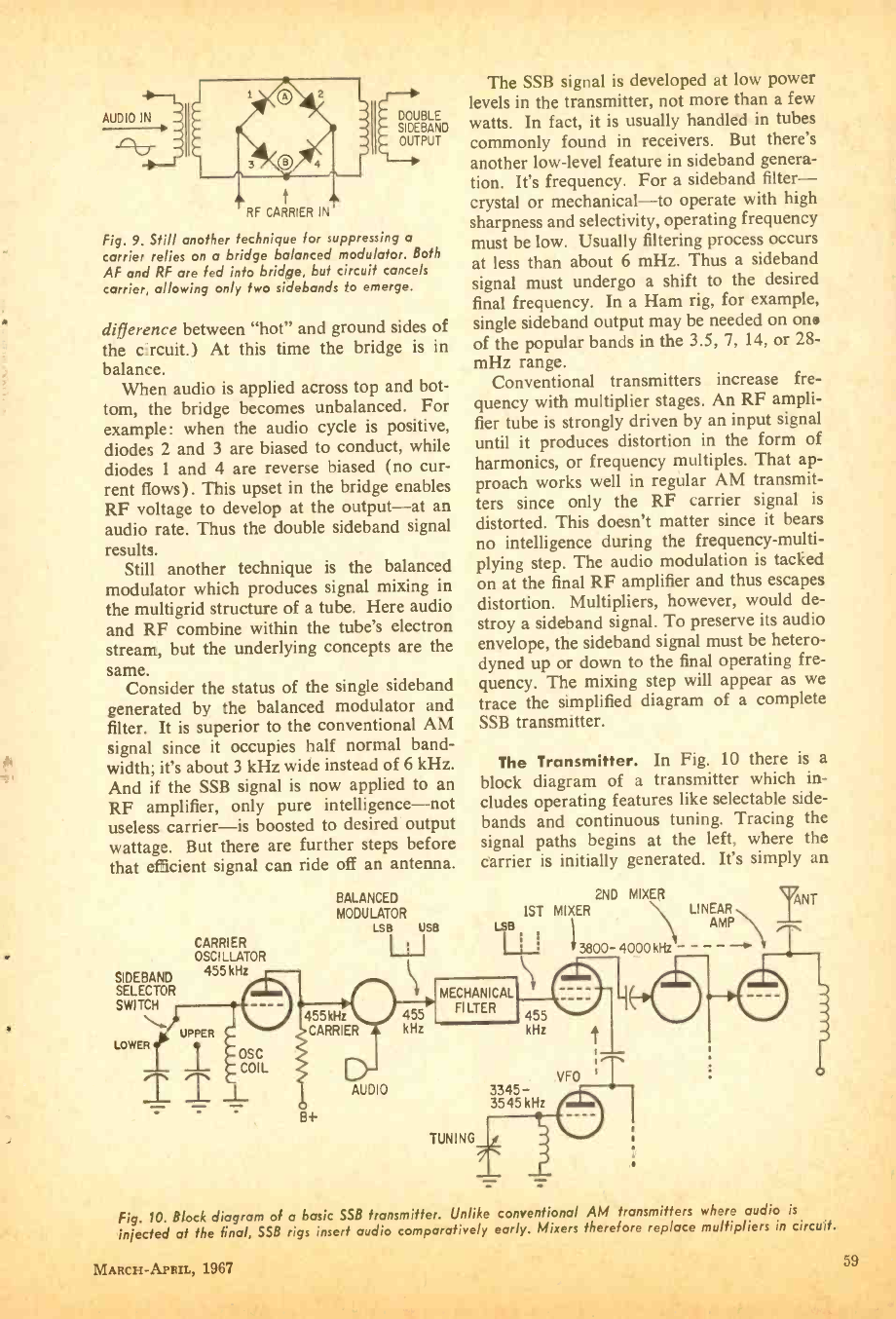
AUDIO IN
RF CARRIER IN
DOUBLE
SIDEBAND
OUTPUT
Fig. 9. Still another technique for suppressing a
carrier relies on a bridge balanced modulator. Both
AF and RF are fed into bridge, but circuit cancels
carrier, allowing only two sidebands to emerge.
difference between "hot" and ground sides of
the circuit.) At this time the bridge is in
balance.
When audio is applied across top and bot-
tom, the bridge becomes unbalanced. For
example: when the audio cycle is positive,
diodes 2 and 3 are biased to conduct, while
diodes 1 and 4 are reverse biased (no cur-
rent flows). This upset in the bridge enables
RF voltage to develop at the output -at an
audio rate. Thus the double sideband signal
results.
Still another technique is the balanced
modulator which produces signal mixing in
the multigrid structure of a tube. Here audio
and RF combine within the tube's electron
stream, but the underlying concepts are the
same. Consider the status of the single sideband
generated by the balanced modulator and
filter. It is superior to the conventional AM
signal since it occupies half normal band-
width; it's about 3 kHz wide instead of 6 kHz.
And if the SSB signal is now applied to an
RF amplifier, only pure intelligence -not
useless carrier -is boosted to desired output
wattage. But there are further steps before
that efficient signal can ride off an antenna.
SIDEBAND
SELECTOR
SWITCH
LOWER
CARRIER
OSCILLATOR
455 kHz
UPPER
1
II
BALANCED
MODULATOR
LSB USB
1) 455kHz 455
CARRIER kHz
OSC
COIL
8+
AUDIO
The SSB signal is developed at low power
levels in the transmitter, not more than a few
watts. In fact, it is usually handled in tubes
commonly found in receivers. But there's
another low -level feature in sideband genera-
tion. It's frequency. For a sideband filter -
crystal or mechanical -to operate with high
sharpness and selectivity, operating frequency
must be low. Usually filtering process occurs
at less than about 6 mHz. Thus a sideband
signal must undergo a shift to the desired
final frequency. In a Ham rig, for example,
single sideband output may be needed on one
of the popular bands in the 3.5, 7, 14, or 28-
mHz range.
Conventional transmitters increase fre-
quency with multiplier stages. An RF ampli-
fier tube is strongly driven by an input signal
until it produces distortion in the form of
harmonics, or frequency multiples. That ap-
proach works well in regular AM transmit-
ters since only the RF carrier signal is
distorted. This doesn't matter since it bears
no intelligence during the frequency- multi-
plying step. The audio modulation is tacked
on at the final RF amplifier and thus escapes
distortion. Multipliers, however, would de-
stroy a sideband signal. To preserve its audio
envelope, the sideband signal must be hetero-
dyned up or down to the final operating fre-
quency. The mixing step will appear as we
trace the simplified diagram of a complete
SSB transmitter.
The Transmitter. In Fig. 10 there is a
block diagram of a transmitter which in-
cludes operating features like selectable side -
bands and continuous tuning. Tracing the
signal paths begins at the left, where the
carrier is initially generated. It's simply an
2ND MIXER
1ST MIXER \ LINEAR _TNT
LSB 1 \i AMP
1 S ; + 3800- 4000 kHz - - - - --
MECHANICAL
FILTER
TUNING
3345-
3545 kHz
T
VFO
Fig. 10. Block diagram of a basic SSB transmitter. Unlike conventional AM transmitters where audio is
injected at the final, SSB rigs insert audio comparatively early. Mixers therefore replace multipliers in circuit.
MARCH- APRIL, 1967 59
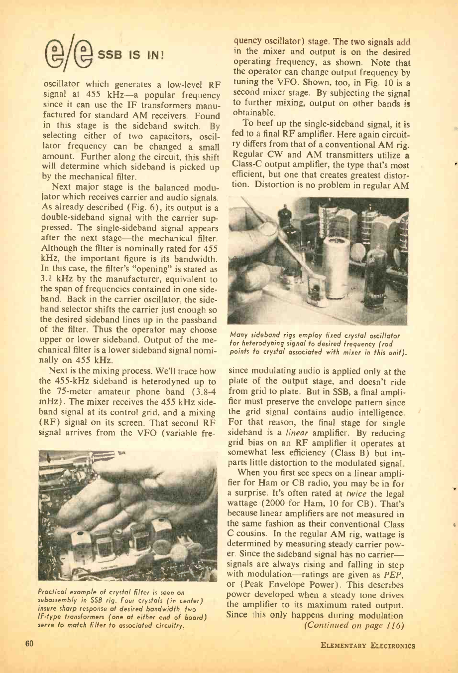
(/ssB IS IN!
oscillator which generates a low -level RF
signal at 455 kHz -a popular frequency
since it can use the IF transformers manu-
factured for standard AM receivers. Found
in this stage is the sideband switch. By
selecting either of two capacitors, oscil-
lator frequency can be changed a small
amount. Further along the circuit, this shift
will determine which sideband is picked up
by the mechanical filter.
Next major stage is the balanced modu-
lator which receives carrier and audio signals.
As already described (Fig. 6), its output is a
double -sideband signal with the carrier sup-
pressed. The single -sideband signal appears
after the next stage -the mechanical filter.
Although the filter is nominally rated for 455
kHz, the important figure is its bandwidth.
In this case, the filter's "opening" is stated as
3.1 kHz by the manufacturer, equivalent to
the span of frequencies contained in one side-
band. Back in the carrier oscillator, the side-
band selector shifts the carrier just enough so
the desired sideband lines up in the passband
of the filter. Thus the operator may choose
upper or lower sideband. Output of the me-
chanical filter is a lower sideband signal nomi-
nally on 455 kHz.
Next is the mixing process. We'll trace how
the 455 -kHz sideband is heterodyned up to
the 75 -meter amateur phone band (3.8 -4
mHz). The mixer receives the 455 kHz side-
band signal at its control grid, and a mixing
(RF) signal on its screen. That second RF
signal arrives from the VFO (variable fre-
Practical example of crystal filter is seen on
subassembly in SSB rig. Four crystals (in center)
insure sharp response at desired bandwidth, two
IF -type transformers (one at either end of board)
serve to match filter to associated circuitry.
60
quency oscillator) stage. The two signals add
in the mixer and output is on the desired
operating frequency, as shown. Note that
the operator can change output frequency by
tuning the VFO. Shown, too, in Fig. 10 is a
second mixer stage. By subjecting the signal
to further mixing, output on other bands is
obtainable.
To beef up the single -sideband signal, it is
fed to a final RF amplifier. Here again circuit-
ry differs from that of a conventional AM rig.
Regular CW and AM transmitters utilize a
Class -C output amplifier, the type that's most
efficient, but one that creates greatest distor-
tion. Distortion is no problem in regular AM
Many sideband rigs employ fixed crystal oscillator
for heterodyning signal to desired frequency (rod
points to crystal associated with mixer in this unit).
since modulating audio is applied only at the
plate of the output stage, and doesn't ride
from grid to plate. But in SSB, a final ampli-
fier must preserve the envelope pattern since
the grid signal contains audio intelligence.
For that reason, the final stage for single
sideband is a linear amplifier. By reducing
grid bias on an RF amplifier it operates at
somewhat less efficiency (Class B) but im-
parts little distortion to the modulated signal.
When you first see specs on a linear ampli-
fier for Ham or CB radio, you may be in for
a surprise. It's often rated at twice the legal
wattage (2000 for Ham, 10 for CB). That's
because linear amplifiers are not measured in
the same fashion as their conventional Class
C cousins. In the regular AM rig, wattage is
determined by measuring steady carrier pow-
er. Since the sideband signal has no carrier -
signals are always rising and falling in step
with modulation- ratings are given as PEP,
or (Peak Envelope Power) . This describes
power developed when a steady tone drives
the amplifier to its maximum rated output.
Since this only happens during modulation
(Continued on page 116)
ELEMENTARY ELECTRONICS
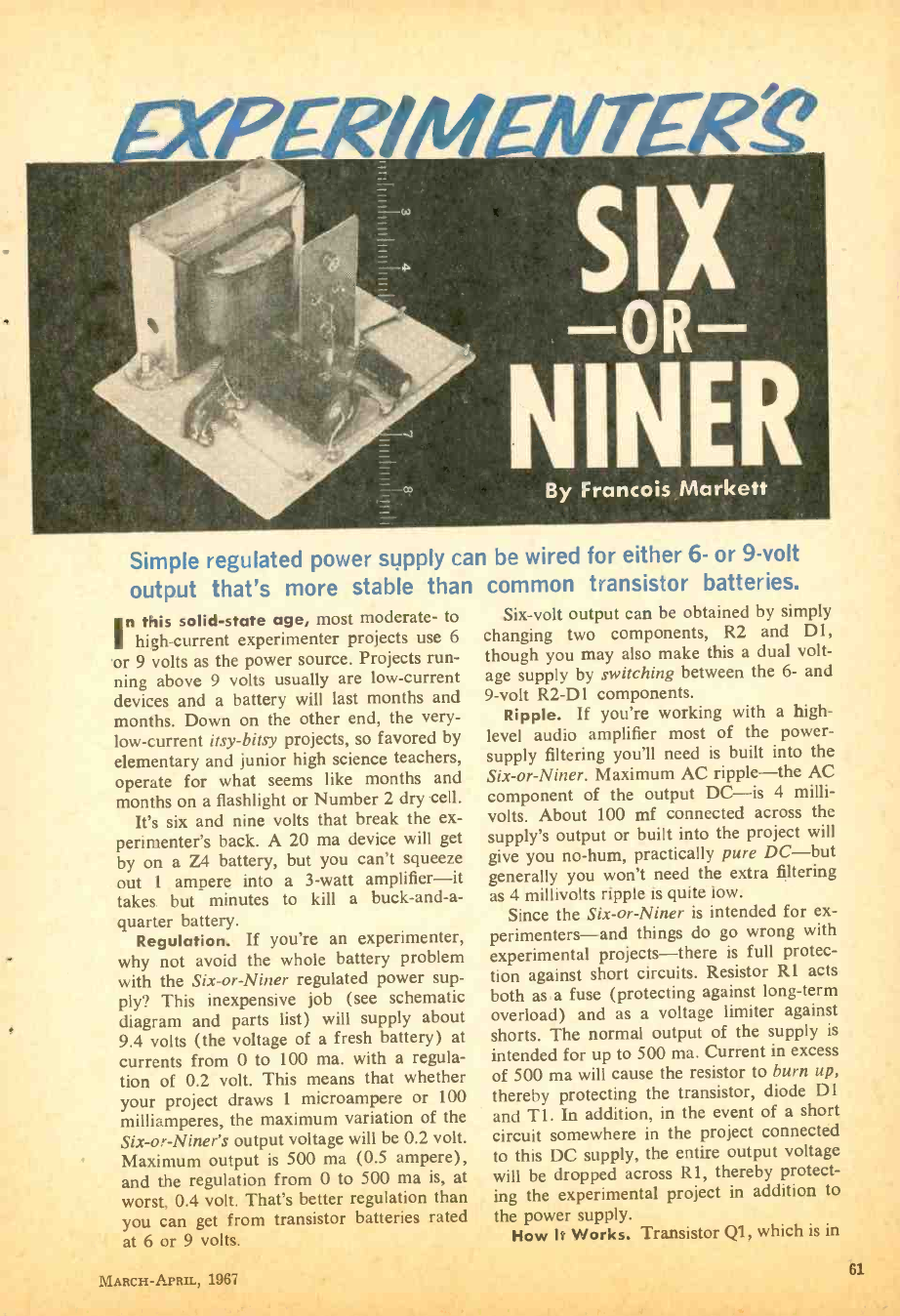
Simple regulated power supply can be wired for either 6- or 9 -volt
output that's more stable than common transistor batteries.
Six -volt output can be obtained by simply
changing two components, R2 and D1,
though you may also make this a dual volt-
age supply by switching between the 6- and
9 -volt R2 -D 1 components.
Ripple. If you're working with a high -
level audio amplifier most of the power -
supply filtering you'll need is built into the
Six -or- Niner. Maximum AC ripple -the AC
component of the output DC -is 4 milli-
volts. About 100 mf connected across the
supply's output or built into the project will
give you no -hum, practically pure DC -but
generally you won't need the extra filtering
as 4 millivolts ripple is quite low.
Since the Six -or -Niner is intended for ex-
perimenters -and things do go wrong with
experimental projects -there is full protec-
tion against short circuits. Resistor R1 acts
both as a fuse (protecting against long -term
overload) and as a voltage limiter against
shorts. The normal output of the supply is
intended for up to 500 ma. Current in excess
of 500 ma will cause the resistor to burn up,
thereby protecting the transistor, diode D1
and Ti. In addition, in the event of a short
circuit somewhere in the project connected
to this DC supply, the entire output voltage
will be dropped across R1, thereby protect-
ing the experimental project in addition to
the power supply.
How It Works. Transistor Ql, which is in
'n this solid -state age, most moderate- to
high- current experimenter projects use 6
or 9 volts as the power source. Projects run-
ning above 9 volts usually are low- current
devices and a battery will last months and
months. Down on the other end, the very-
low- current itsy -bitsy projects, so favored by
elementary and junior high science teachers,
operate for what seems like months and
months on a flashlight or Number 2 dry cell.
It's six and nine volts that break the ex-
perimenter's back. A 20 ma device will get
by on a Z4 battery, but you can't squeeze
out l ampere into a 3 -watt amplifier -it
takes but minutes to kill a buck- and -a-
quarter battery.
Regulation. If you're an experimenter,
why not avoid the whole battery problem
with the Six- or -Niner regulated power sup-
ply? This inexpensive job (see schematic
diagram and parts list) will supply about
9.4 volts (the voltage of a fresh battery) at
currents from 0 to 100 ma. with a regula-
tion of 0.2 volt. This means that whether
your project draws 1 microampere or 100
milliamperes, the maximum variation of the
Six -or- Niner's output voltage will be 0.2 volt.
Maximum output is 500 ma (0.5 ampere),
and the regulation from 0 to 500 ma is, at
worst, 0.4 volt. That's better regulation than
you can get from transistor batteries rated
at 6 or 9 volts.
MARCH -APRIL, 1967 61
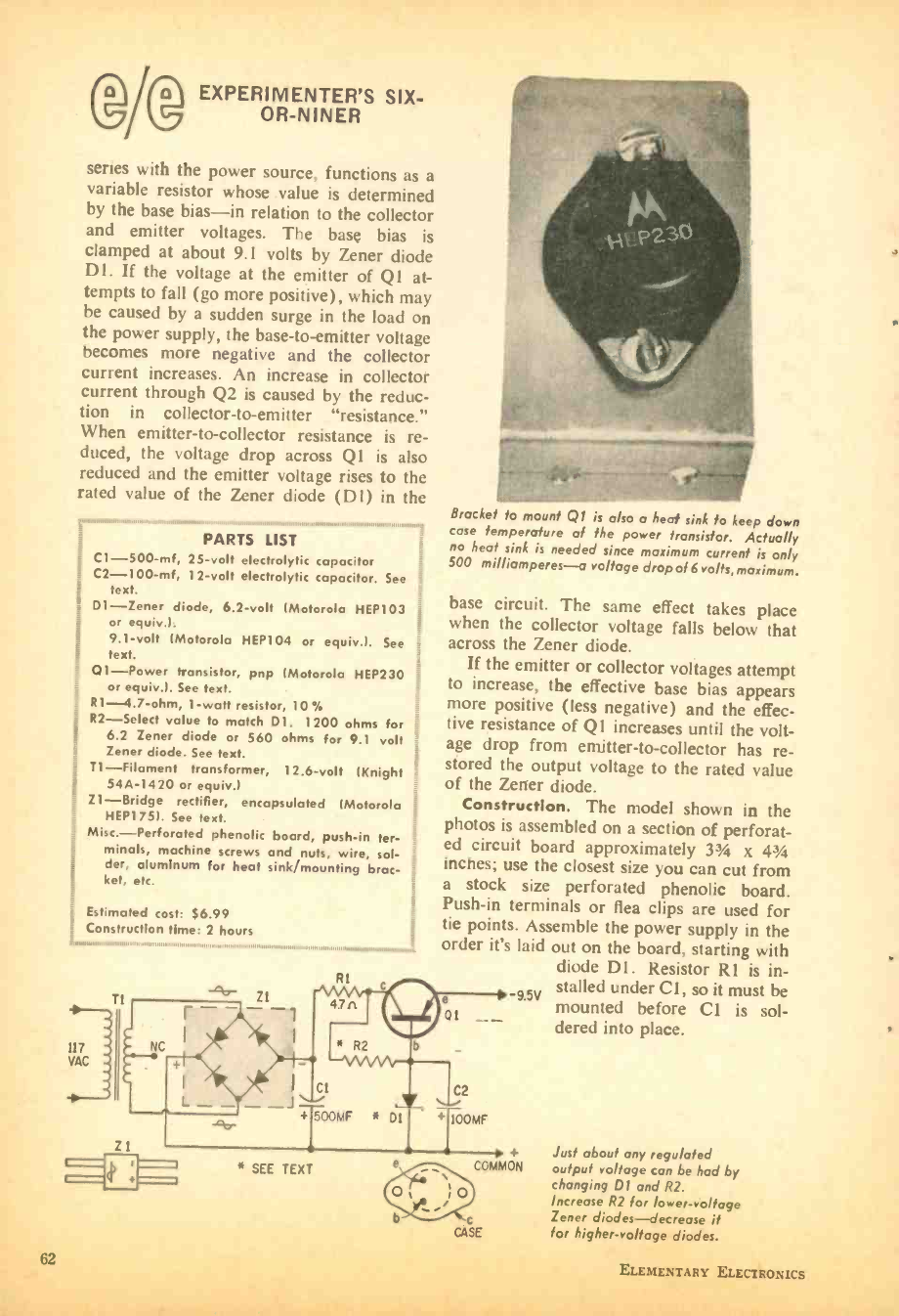
®I® EXPERIMENTER'S SIX -
OR-NINER
series with the power source, functions as a
variable resistor whose value is determined
by the base bias -in relation to the collector
and emitter voltages. The base bias is
clamped at about 9.1 volts by Zener diode
Dl. If the voltage at the emitter of Q1 at-
tempts to fall (go more positive), which may
be caused by a sudden surge in the load on
the power supply, the base -to- emitter voltage
becomes more negative and the collector
current increases. An increase in collector
current through Q2 is caused by the reduc-
tion in collector -to- emitter "resistance."
When emitter -to-collector resistance is re-
duced, the voltage drop across Q1 is also
reduced and the emitter voltage rises to the
rated value of the Zener diode (D1) in the
PARTS LIST
IC1- 500 -mf, 25 -volt electrolytic capacitor
C2- 100 -mf, 12 -volt electrolytic capacitor. See
text.
D1 -Zener diode, 6.2 -volt (Motorola HEP103
or equiv.).
9.1 -volt (Motorola HEP104 or equiv I. See
_ text.
Q1 -Power transistor, pnp (Motorola HEP230
or equiv.). See text.
R1-4.7-ohm, 1 -watt resistor, 10 %
R2- Select value to match D1. 1200 ohms for
6.2 Zener diode or 560 ohms for 9.1 volt
Zener diode. See text.
T1- Filament transformer, 12.6 -volt (Knight
54A -1420 or equiv.) i
Z1- Bridge rectifier, encapsulated (Motorola
HEP175). See text.
Misc.- Perforated phenolic hoard, push -in ter-
minais, machine screws and nuts, wire, sol- t
der, aluminum for heat sink /mounting broc- 3
+i
ket, etc.
i
117
Estimated cost: $6.99
Construction time: 2 hours
VAC
o
62
R1
Bracket to mount Q/ is also a heat sink fo keep down
cose temperature of the power transistor. Actually
no heat sink is needed since maximum current is only
S00 milliamperes -a voltage drop of 6 volts, maximum.
base circuit. The same effect takes place
when the collector voltage falls below that
across the Zener diode.
If the emitter or collector voltages attempt
to increase, the effective base bias appears
more positive (less negative) and the effec-
tive resistance of Q1 increases until the volt-
age drop from emitter -to-collector has re-
stored the output voltage to the rated value
of the Zener diode.
Construction. The model shown in the
photos is assembled on a section of perforat-
ed circuit board approximately 334 x 43/4
inches; use the closest size you can cut from
a stock size perforated phenolic board.
Push -in terminals or flea clips are used for
tie points. Assemble the power supply in the
order it's laid out on the board, starting with
diode Dl. Resistor R1 is in-
stalled under Cl, so it must be
e 95V mounted before CI is sol-
01 -_ dered into place.
C2
+ 100MF
COMMON
Z1
* SEE TEXT
Just about any regulated
output voltage can be had by
changing D1 and R2.
Increase R2 for lower- voltage
Zener diodes -decrease it
for higher -voltage diodes.
ELEMENTARY ELECTRONICS
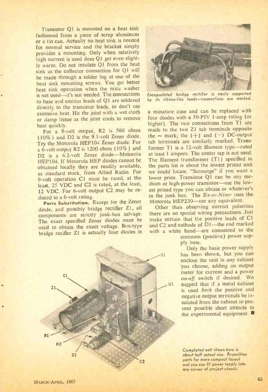
Transistor Q 1 is mounted on a heat sink
fashioned from a piece of scrap aluminum
or a tin can. Actually no heat sink is needed
for normal service and the bracket simply
provides a mounting. Only when relatively
high current is used does Q I get even slight-
ly warm. Do not insulate Q1 from the heat
sink as the collector connection for Q1 will
be made through a solder lug at one of the
heat sink mounting screws. You get better
heat sink operation when the mica washer
is not used -it's not needed. The connections
to base and emitter leads of Q1 are soldered
directly to the transistor leads, so don't use
excessive heat. Hit the joint with a wet cloth
or damp tissue as the joint cools to remove
heat quickly.
For a 9 -volt output, R2 is 560 ohms
(10 %) and D2 is the 9.1 -volt Zener diode.
Try the Motorola HEP104 Zener diode. For
a 6 -volt output R2 is 1200 ohms (10 %) and
D2 is a 6.2 -volt Zener diode -Motorola
HEP 104. If Motorola HEP diodes cannot be
obtained locally they are readily available,
as standard stock, from Allied Radio. For
9 -volt operation C 1 must be rated, at the
least, 25 VDC and C2 is rated, at the least,
12 VDC. For 6 -volt output C2 may be re-
duced to a 6 -volt rating.
Parts Substitution. Except for the Zener
diode, and possibly bridge rectifier Z1, all
components are strictly junk -box salvage.
The exact specified Zener diodes must be
used to obtain the exact voltage. Box -type
bridge recifier Z1 is actually four diodes in
Rl
Encapsulated bridge rectifier is easily supported
by its ribbon -like leads -connections are marked.
a minature case and can be replaced with
four diodes with a 50-PIV 1 -amp rating (or
higher). The two connections from T1 are
made to the two Z1 tab terminals opposite
the mark; the (+) and ( -) DC- output
tab terminals are similarly marked. Trans-
former T1 is a 12 -volt filament type -rated
at least 1 ampere. The center tap is not used.
The filament transformer (T1) specified in
the parts list is about the lowest priced unit
we could locate. "Scrounge" if you want a
lower price. Transistor Q1 can be any me-
dium or high -power transistor -use the low-
est priced type you can obtain or whatever's
in the junk box. The Six -or -Niner uses the
Motorola HEP230 -use any equivalent.
Other than observing correct polarities
there are no special wiring precautions. Just
make certain that the positive leads of CI
and C2 and cathode of Dl -the end marked
with a white band -are connected to the
common (positive) power sup-
ply buss.
Only the basic power supply
t1 has been shown, but you can
enclose the unit in any cabinet
you choose, adding an output
meter for current and a power
on-off switch if desired. We
suggest that if a metal cabinet
is used both the positive and
negative output terminals be in-
sulated from the cabinet to pre-
vent possible short circuits to
the experimental equipment.
Dl
MARCH- APRIL, 1967
Completed unit shown here is
about half actual size. Reposition
parts for more compact layout
and you can fit power supply into
any corner of project chassis.
63
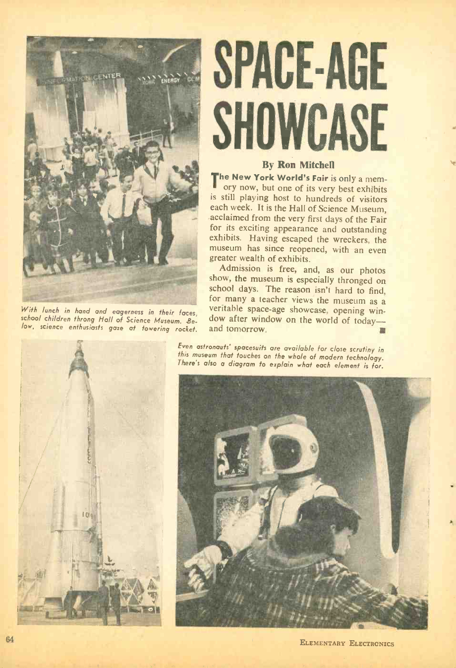
With lunch in hand and eagerness in their faces,
school children throng Hall of Science Museum. Be-
low, science enthusiasts gaze at towering rocket.
SPACE -AGE
SHOWCASE
By Ron Mitchefi
The New York World's Fair is only a mem-
ory now, but one of its very best exhibits
is still playing host to hundreds of visitors
each week. It is the Hall of Science Museum,
acclaimed from the very first days of the Fair
for its exciting appearance and outstanding
exhibits. Having escaped the wreckers, the
museum has since reopened, with an even
greater wealth of exhibits.
Admission is free, and, as our photos
show, the museum is especially thronged on
school days. The reason isn't hard to find,
for many a teacher views the museum as a
veritable space -age showcase, opening win-
dow after window on the world of today -
and tomorrow.
Even astronauts' spacesuits are available for c lose scrutiny in
this museum that touches on the whole of modern technology.
There's also a diagram to explain what each element is for.
64 ELEMENTARY ELECTRONICS
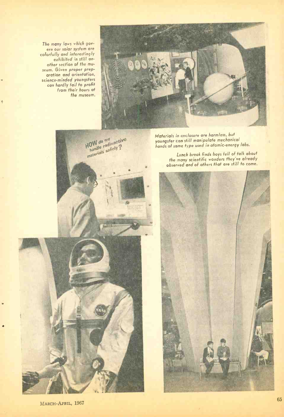
The many laws which gov-
ern our solar system are
colorfully and interestingly
exhibited in still an-
other section of the mu-
seum. Given proper prep-
aration and orientation,
science- minded youngsters
can hardly fall to profit
from their hours at
the museum.
w
too- , mate eaVS
Materials in enclosure are harmless, but
youngster carp still manipulate mechanical
hands of same type used in atomic- energy labs.
Lunch break finds boys full of talk about
the many scientific wonders they've already
observed and of others that are still to come.
MARCH -APRIL, 1967 65
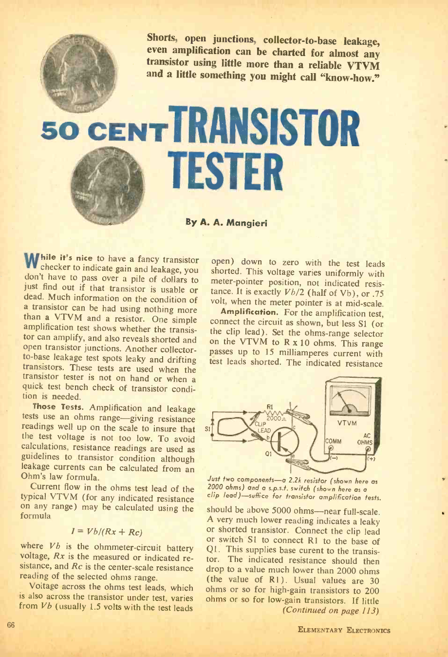
Shorts, open junctions, collector -to -base leakage,
even amplification can be charted for almost any
transistor using little more than a reliable VTVM
and a little something you might call "know- how."
50 CENTTRANSISTOR
TESTER
By A. A. Mangieri
While it's nice to have a fancy transistor
checker to indicate gain and leakage, you
don't have to pass over a pile of dollars to
just find out if that transistor is usable or
dead. Much information on the condition of
a transistor can be had using nothing more
than a VTVM and a resistor. One simple
amplification test shows whether the transis-
tor can amplify, and also reveals shorted and
open transistor junctions. Another collector -
to -base leakage test spots leaky and drifting
transistors. These tests are used when the
transistor tester is not on hand or when a
quick test bench check of transistor condi-
tion is needed.
Those Tests. Amplification and leakage
tests use an ohms range -giving resistance
readings well up on the scale to insure that
the test voltage is not too low. To avoid
calculations, resistance readings are used as
guidelines to transistor condition although
leakage currents can be calculated from an
Ohm's law formula.
Current flow in the ohms test lead of the
typical VTVM (for any indicated resistance
on any range) may be calculated using the
formula
1= Vb /(Rx Rc)
where Vb is the ohmmeter -circuit battery
voltage, Rx is the measured or indicated re-
sistance, and Rc is the center -scale resistance
reading of the selected ohms range.
Voltage across the ohms test leads, which
is also across the transistor under test, varies
from Vb (usually 1.5 volts with the test leads
66
open) down to zero with the test leads
shorted. This voltage varies uniformly with
meter- pointer position, not indicated resis-
tance. It is exactly Vb /2 (half of Vb), or .75
volt, when the meter pointer is at mid -scale.
Amplification. For the amplification test,
connect the circuit as shown, but less S1 (or
the clip lead) . Set the ohms -range selector
on the VTVM to R x 10 ohms. This range
passes up to 15 milliamperes current with
test leads shorted. The indicated resistance
s1 VTVM
AC
COMM OHMS
Just two components -a 2.2k resistor (shown here as
2000 ohms) and a s.p.s.t. switch (shown here as a
clip lead) -suffice for transistor amplification tests.
should be above 5000 ohms -near full -scale.
A very much lower reading indicates a leaky
or shorted transistor. Connect the clip lead
or switch SI to connect Rl to the base of
Ql. This supplies base curent to the transis-
tor. The indicated resistance should then
drop to a value much lower than 2000 ohms
(the value of R1). Usual values are 30
ohms or so for high -gain transistors to 200
ohms or so for low -gain transistors. If little
(Continued on page 113)
ELEMENTARY ELECTRONICS
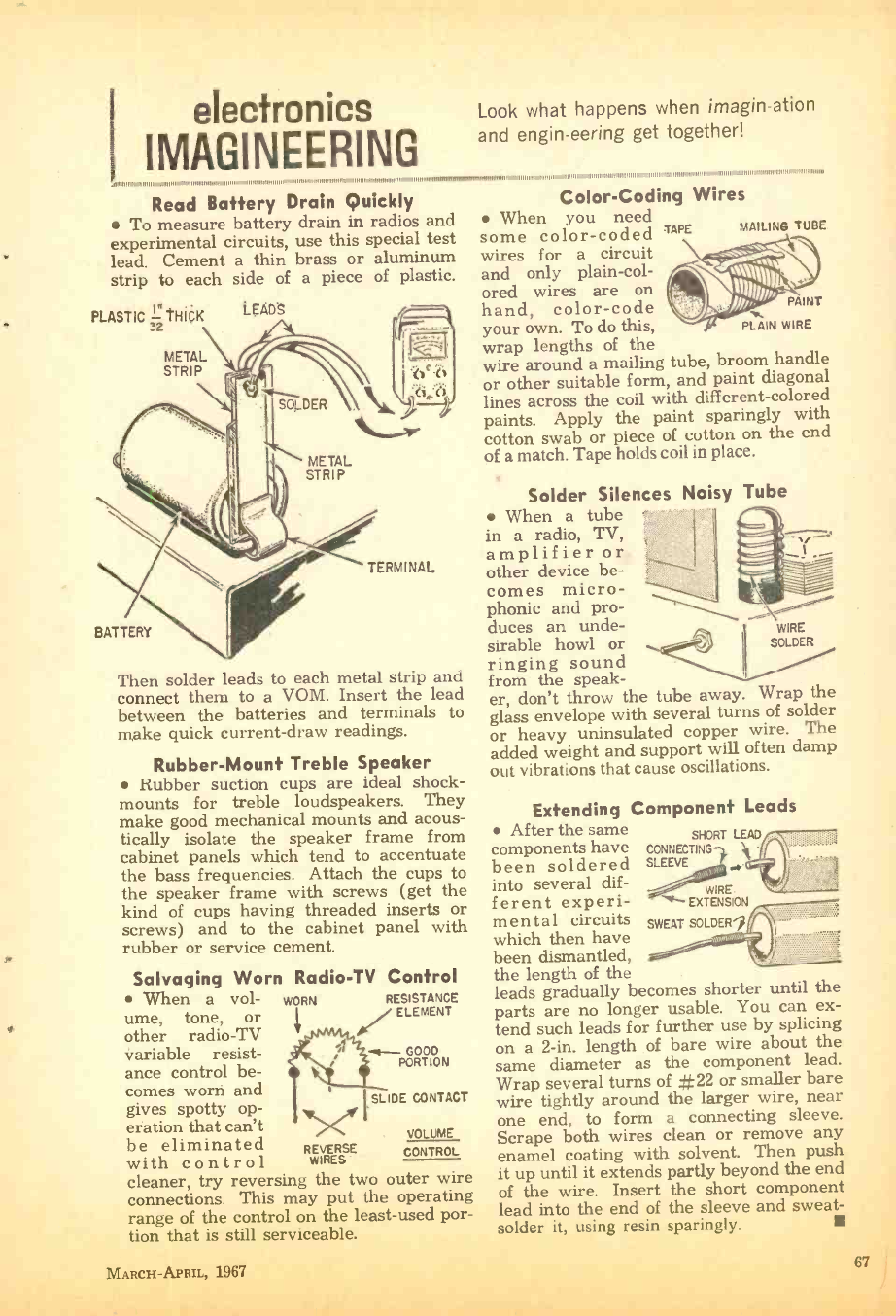
electronics
IMAGINEERING
Look what happens when imagin -ation
and engin -eering get together!
,.,,.1.,1,,,,111,11,1 ,1,,...1,1,1,.,,1111,1, ,11111,...I,.n../..,1,,,,1,1,1111 1,11,... 111,111111...,11,.11MIM
Read Battery Drain Quickly
To measure battery drain in radios and
experimental circuits, use this special test
lead. Cement a thin brass or aluminum
strip to each side of a piece of plastic.
PLASTIC 32 THICK
METAL
STRIP
LEAD'S
SOLDER
(>.`h
METAL
STRIP
BATTERY
TERMINAL
Then solder leads to each metal strip and
connect them to a VOM. Insert the lead
between the batteries and terminals to
make quick current -draw readings.
Rubber -Mount Treble Speaker
Rubber suction cups are ideal shock -
mounts for treble loudspeakers. They
make good mechanical mounts and acous-
tically isolate the speaker frame from
cabinet panels which tend to accentuate
the bass frequencies. Attach the cups to
the speaker frame with screws (get the
kind of cups having threaded inserts or
screws) and to the cabinet panel with
rubber or service cement.
Salvaging Worn
When a vol-
ume, tone, or
other radio -TV
variable resist-
ance control be-
comes worn and
gives spotty op-
eration that can't
be eliminated
with control
Radio -TV Control
RESISTANCE
/ ELEMENT
(-4- GOOD
PORTION
SLIDE CONTACT
WORN
WIRES E
cleaner, try reversing the two ouiwer wiic
connections. This may put the operating
range of the control on the least -used por-
tion that is still serviceable.
VOLUME
CONTROL
MARCH-APRIL, 1967
Color- Coding Wires
When you need
some color -coded TAPE
wires for a circuit
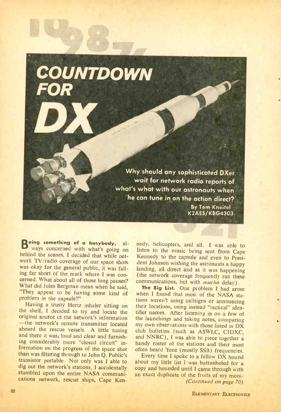
COUNTDOWN
FOR
Why should any sophisticated DXer
wait for network radio reports of
what's what with our astronauts when
he can tune in on the action direct?
By Tom Kneael
K2AES /KBG4303
Being something of a busybody, al-
ways concerned with what's going on
behind the scenes, I decided that while net-
work TV /radio coverage of our space shots
was okay for the general public, it was fall-
ing far short of the mark where I was con-
cerned. What about all of those long pauses?
What did Jules Bergman mean when he said,
"They appear to be having some kind of
problem in the capsule ?"
Having a trusty Hertz inhaler sitting on
the shelf, I decided to try and locate the
original source of the network's information
-the network's remote transmitter located
aboard the rescue vessels. A little tuning
and there it was, loud and clear and furnish-
ing considerably more "closed circuit" in-
formation on the progress of the space shot
than was filtering through to John Q. Public's
transistor portable. Not only was I able to
dig out the network's stations, I accidentally
stumbled upon the entire NASA communi-
cations network, rescue ships, Cape Ken-
nedy, helicopters, and all. I was able to
listen to the music being sent from Cape
Kennedy to the capsule and even to Presi-
dent Johnson wishing the astronauts a happy
landing, all direct and as it was happening
(the network coverage frequently ran these
communications, but with mucho delay).
The Big List. One problem I had arose
when I found that most of the NASA sta-
tions weren't using callsigns or announcing
their locations, using instead "tactical" iden-
tifier names. After listening in on a few of
the launchings and taking notes, comparing
my own observations with those listed in DX
club bulletins (such as ASWLC, CIDXC,
and NNRC), I was able to piece together a
handy roster of the stations and their most
often heard 'fone (mostly SSB) frequencies.
Every time I spoke to a fellow DX hound
about my little list I was buttonholed for a
copy and hounded until I came through with
an exact duplicate of the fruits of my moni-
(Continued on page 70)
ELEMENTARY ELECTRONICS
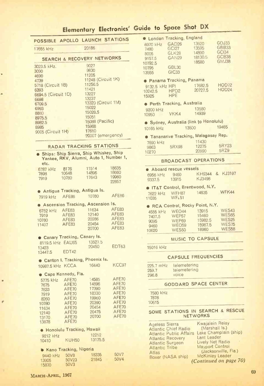
Elementary Electronics' Guide to Space Shot DX
POSSIBLE APOLLO LAUNCH STATIONS
17655 kHz 20186
SEARCH & RECOVERY NETWORKS
3023.5 kHz.
3090
4690
4739
5718 (Circuit 1B)
6393
6694.5 (Circuit 1D)
6698
6709.5
6993
8880
8975.5
8982.5
8985
9005 (Circuit 11I)
9027
9830
11205
11248 (Circuit 1K)
11256.5
11421
13227
13237
13320 (Circuit 1M)
15022
15028.5
15051
15088 (Pacific)
15968
17610
20007 (emergency)
RADAR TRACKING STATIONS
Ships: Ship Sierra, Ship Whiskey, Ship
Yankee, RKV, Alumni, Auto 1, Number 1,
etc.
6787 kHz 8176 11514 18635
7898 10648 14896 18660
7919 10780 17643 19960
22857
Antigua Tracking, Antigua Is.
7919 kHz AFE86 10780 AFE86
Ascension Tracking, Ascension Is.
6752 kHz AFE83 11634 AFE83
7919 AFE83 12140 AFE83
10780 AFE83 20286 AFE83
11407 AFE83 20454 AFE83
20700 AFE83
Canary Tracking, Canary Is.
8119.5 kHz EAU65 13527.5
13423 20450 EDT63
13447.5 EDT42
Canton I. Tracking, Phoenix Is.
10987.5 kHz KCCA 16440 KCC97
Cape Kennedy, Fla.
5775 kHz AFE70 14585 AFE70
7675 AFE70 14896 AFE70
7833 AFE70 17390 AFE70
7919 AFE70 18330 AFE70
8260 AFE70 19960 AFE70
10780 AFE70 20390 AFE70
11634 AFE70 20454 AFE70
12140 AFE70 20475 AFE70
13170 AFE70 20700 AFE70
13878 AFE70
Honolulu Tracking, Hawaii
9212 kHz 12212
10410 KUH50 13175.5
Kano Tracking, Nigeria
9440 kHz 50V8 18335
13905 50V23 21845
London Tracking, England
6970 kHz GAD26 13620 GDJ33
7480 GC127 13595 GBB33
8005 GLK28 14890 GCI34
9157.5 GAN29 18130.5 GCB38
10792.5 18580 GMJ38
10795 GBL30
13555 GIC33
Panama Tracking, Panama
9132.5 kHz HPI 17682.5 HOD72
10242.5 HPD2 20727.5 HOD24
15925 HPE
Perth Tracking, Australia
9200 kHz 13580
10950 V K K4 14939
Sydney, Australia (link to Honolulu)
10165 kHz 13500 19465
Tananarive Tracking, Malagasay Rep.
7690 kHz 11430
9863 5RX98 12275 5RY23
10270 20990 5RZ9
BROADCAST OPERATIONS
Aboard rescue vessels
6956 kHz 9460 KH9344 & KJ3197
9337.5 13915 KJ3498
IT &T Control, Brentwood, N.Y.
7622 kHz WFH87 14635 WFK44
11035 WFL51
RCA Control, Rocky Point, N.Y.
4555 kHz WEO44
7407.5 WEP57
9095 WEP69
9460 WE059
10620 W ES50
13915
15460
15982.5
15987.5
18960
WES43
WES65
WES25
WES75
WES58
MUSIC TO CAPSULE
15016 kHz
CAPSULE FREQUENCIES
225.7 mHz
259.7
296.8
telemetering
telemetering
voice
GODDARD SPACE CENTER
7580 kHz
7878
10615
SOME STATIONS IN SEARCH & RESCUE
NETWORKS
Ageless Sierra Kwajalein Relay
Atlantic Chief Radio (Marshall Is.)
Atlantic Public Affairs Lake Champlain (ship)
Atlantic Recovery Lant Leader
Atlantic Surgeon Lively Net Radio
Atlantic Tribe Mayport Control
50V7 Atlas (Jacksonville, Fla.)
Boxer (NASA ship) McKinley Leader
50V4 (Continued on pnon 701
15870 50V3
MARCH -APRIL, 1967 69
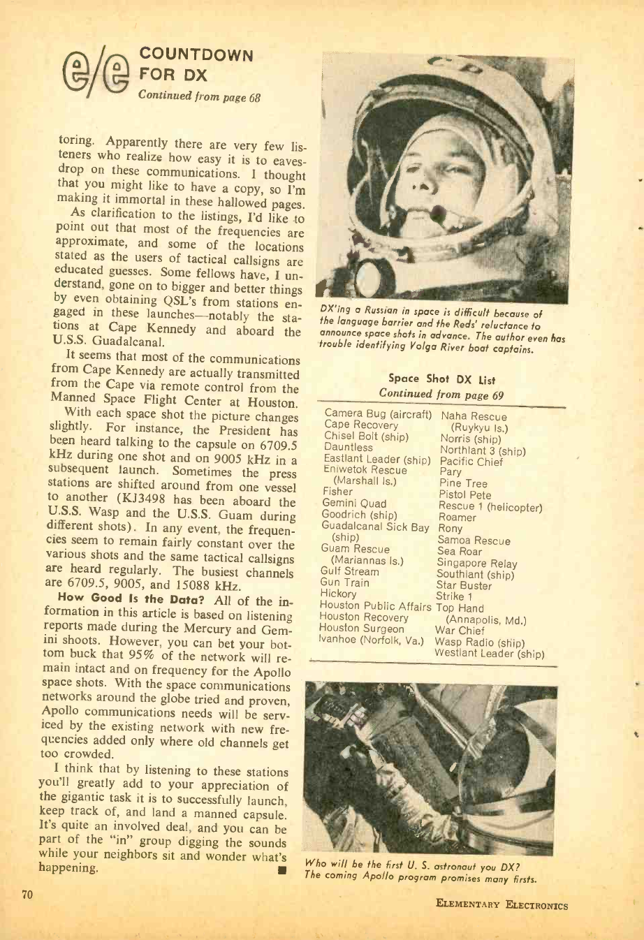
COUNTDOWN
A FOR DX
Continued from page 68
toring. Apparently there are very few lis-
teners who realize how easy it is to eaves-
drop on these communications. I thought
that you might like to have a copy, so I'm
making it immortal in these hallowed pages.
As clarification to the listings, I'd like to
point out that most of the frequencies are
approximate, and some of the locations
stated as the users of tactical callsigns are
educated guesses. Some fellows have, I un-
derstand, gone on to bigger and better things
by even obtaining QSL's from stations en-
gaged in these launches -notably the sta-
tions at Cape Kennedy and aboard the
U.S.S. Guadalcanal.
It seems that most of the communications
from Cape Kennedy are actually transmitted
from the Cape via remote control from the
Manned Space Flight Center at Houston.
With each space shot the picture changes
slightly. For instance, the President has
been heard talking to the capsule on 6709.5
kHz during one shot and on 9005 kHz in a
subsequent launch. Sometimes the press
stations are shifted around from one vessel
to another (KJ3498 has been aboard the
U.S.S. Wasp and the U.S.S. Guam during
different shots). In any event, the frequen-
cies seem to remain fairly constant over the
various shots and the same tactical callsigns
are heard regularly. The busiest channels
are 6709.5, 9005, and 15088 kHz.
How Good Is the Data? All of the in-
formation in this article is based on listening
reports made during the Mercury and Gem-
ini shoots. However, you can bet your bot-
tom buck that 95% of the network will re-
main intact and on frequency for the Apollo
space shots. With the space communications
networks around the globe tried and proven,
Apollo communications needs will be serv-
iced by the existing network with new fre-
quencies added only where old channels get
too crowded.
I think that by listening to these stations
you'll greatly add to your appreciation of
the gigantic task it is to successfully launch,
keep track of, and land a manned capsule.
It's quite an involved deal, and you can be
part of the "in" group digging the sounds
while your neighbors sit and wonder what's
happening.
70
DX'ing a Russian in space is difficult because of
the language barrier and the Reds' reluctance to
announce space shots in advance. The author even has
trouble identifying Volga River boat captains.
Space Shot DX List
Continued from page 69
Camera Bug (aircraft)
Cape Recovery
Chisel Bolt (ship)
Dauntless
Eastlant Leader (ship)
Eniwetok Rescue
(Marshall Is.)
Fisher
Gemini Quad
Goodrich (ship)
Guadalcanal Sick Bay
(ship)
Guam Rescue
(Mariannas Is.)
Gulf Stream
Gun Train
Hickory
Houston Public Affairs
Houston Recovery
Houston Surgeon
Ivanhoe (Norfolk, Va.)
Naha Rescue
(Ruykyu Is.)
Norris (ship)
Northlant 3 (ship)
Pacific Chief
Pary
Pine Tree
Pistol Pete
Rescue 1 (helicopter)
Roamer
Rony
Samoa Rescue
Sea Roar
Singapore Relay
Southlant (ship)
Star Buster
Strike 1
Top Hand
(Annapolis, Md.)
War Chief
Wasp Radio (ship)
Westlant Leader (ship)
Who will be the first U. S. astronaut you DX?
The coming Apollo program promises many firsts.
ELEMENTARY ELECTRONICS
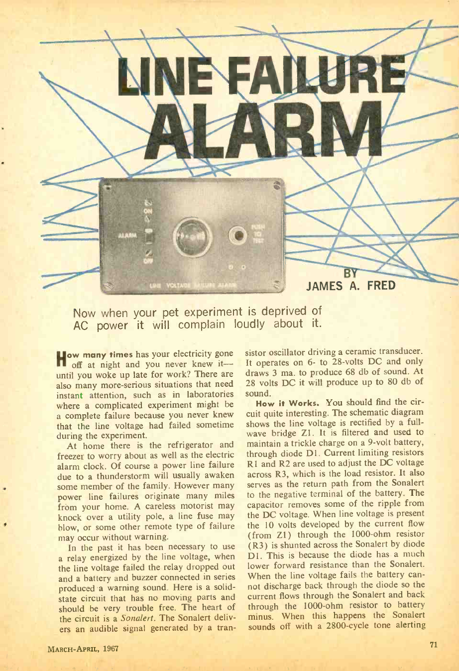
Now when your pet experiment is deprived of
AC power it will complain loudly about it.
How many times has your electricity gone
off at night and you never knew it-
until you woke up late for work? There are
also many more -serious situations that need
instant attention, such as in laboratories
where a complicated experiment might be
a complete failure because you never knew
that the line voltage had failed sometime
during the experiment.
At home there is the refrigerator and
freezer to worry about as well as the electric
alarm clock. Of course a power line failure
due to a thunderstorm will usually awaken
some member of the family. However many
power line failures originate many miles
from your home. A careless motorist may
knock over a utility pole, a line fuse may
blow, or some other remote type of failure
may occur without warning.
In the past it has been necessary to use
a relay energized by the line voltage, when
the line voltage failed the relay dropped out
and a battery and buzzer connected in series
produced a warning sound. Here is a solid -
state circuit that has no moving parts and
should be very trouble free. The heart of
the circuit is a Sonalert. The Sonalert deliv-
ers an audible signal generated by a tran-
sistor oscillator driving a ceramic transducer.
It operates on 6- to 28 -volts DC and only
draws 3 ma. to produce 68 db of sound. At
28 volts DC it will produce up to 80 db of
sound.
How it Works. You should find the cir-
cuit quite interesting. The schematic diagram
shows the line voltage is rectified by a full -
wave bridge Zl. It is filtered and used to
maintain a trickle charge on a 9 -volt battery,
through diode D1. Current limiting resistors
R1 and R2 are used to adjust the DC voltage
across R3, which is the load resistor. It also
serves as the return path from the Sonalert
to the negative terminal of the battery. The
capacitor removes some of the ripple from
the DC voltage. When line voltage is present
the 10 volts developed by the current flow
(from Z1) through the 1000 -ohm resistor
(R3) is shunted across the Sonalert by diode
D1. This is because the diode has a much
lower forward resistance than the Sonalert.
When the line voltage fails the battery can-
not discharge back through the diode so the
current flows through the Sonalert and back
through the 1000 -ohm resistor to battery
minus. When this happens the Sonalert
ennnrc off with a 2800 -cycle tone alerting
MARCH- APRIL, 1967 71
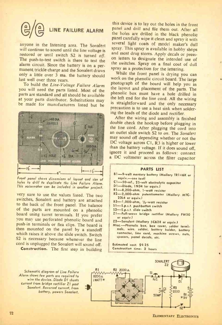
AgLINE FAILURE ALARM
anyone in the listening area. The Sonalert
will continue to sound until the line voltage is
restored or until switch S2 is turned off.
The push -to -test switch is there to test the
alarm circuit. Since the battery is on a per-
manent trickle charge and the Sonalert draws
only a little over 3 ma. the battery should
last well over three years.
To build the Line- Voltage Failure Alarm
you will need the parts listed. Most of the
parts are standard and all should be available
at your parts distributor. Substitutions may
be made for manufacturers listed but be
Front panel shows dimensions of layout and size of
holes to drill to duplicate the Line Failure Alarm.
This noisemaker can be included in another project.
very sure to use the values listed. The two
switches, Sonalert and battery are attached
to the back of the front panel. The balance
of the parts are mounted on a phenolic
board using turret terminals. If you prefer
you may use perforated phenolic board and
push -in terminals or flea clips. The board is
then mounted on the panel by a standoff
which raises it above the slide switch. Switch
S2 is necessary because whenever the line
cord is unplugged the Sonalert will sound off.
Construction. The first step in building
Schematic diagram of Line Failure
Alarm shows few parts are required to
wire the device. Diode D1 shunts
current from bridge rectifier Z1 past
Sonalert. Reversed current, from
battery, powers Sonalert.
72
R1
this device is to lay out the holes in the front
panel and drill and file them out. After all
the holes are drilled in the black phenolic
panel carefully wipe it clean and spray it with
several light coats of model maker's dull
spray. This spray is available in hobby shops
and most drug stores. Apply decals or press -
on letters to designate the intended use of
the switches. Spray on a final coat of dull
spray as a protection for the lettering.
While the front panel is drying you can
work on the phenolic circuit board. The large
photograph of the board will help you in
the layout and placement of the parts. The
phenolic box must have a hole drilled in
the left end for the line cord. All the wiring
is straightforward and the only necessary
precaution is to use a heat sink when solder-
ing the leads of the diode and rectifier.
After the wiring and assembly is finished
double check the hookup before plugging in
the line cord. After plugging the cord into
an outlet slide switch S2 to on. The Sonalert
may sound off depending whether or not the
DC voltage across Cl, R3 is higher or lower
than the battery voltage. If it does sound off,
ignore it and proceed as follows: connect
a DC voltmeter across the filter capacitor
PARTS LIST j
B1 -9 -volt mercury battery (Mallory TR146X or
equiv. -see text)
C1- 50 -mf., 25 -volt electrolytic capacitor
D1- Diode, 1N34 (or equiv.)
R1 -8,200 -ohm, 1 -watt resistor
R2 -2,000 -ohm potentiometer (Mallory MTC-
2314 or equiv.)
R3 -1,000 -ohm, 1/2-watt resistor
Sl- S.p.s.t. pushbutton switch
S2- S.p.s.t. slide switch
Z1 -Full -wave bridge rectifier (Mallory FW50
or equiv.)
Z2- Sonalert (Mallory 5C628 or equiv.)
Misc. -Phenolic box, box cover, solder termi-
nals, wire, solder, battery holder, battery
connector, line cord, machine screws, nuts,
spacers, panel decals, etc.
Estimated cost: 89.25
Construction time: 2 hours
R2 2000A Sl
SONALERT
Z2
AC -1
R3
1000 - 81 -
*9v T
S2
ELEMENTARY ELECTRONICS
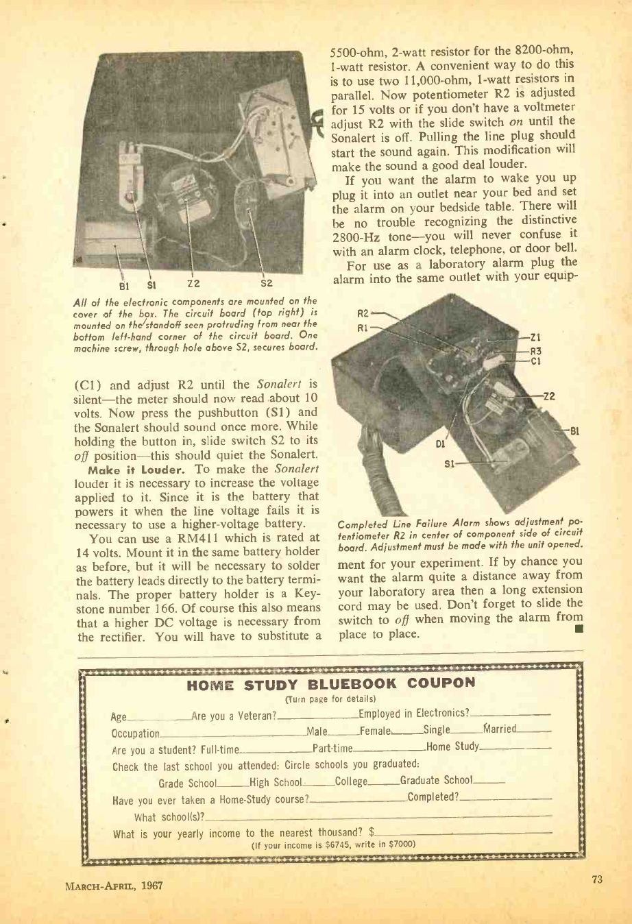
BI S1 Z2 S2
All of the electronic components are mounted on the
cover of the box. The circuit board (top right) is
mounted on the/standoff seen protruding from near the
bottom left -hand corner of the circuit board. One
machine screw, through hole above S2, secures board.
(Cl) and adjust R2 until the Sonalert is
silent -the meter should now read about 10
volts. Now press the pushbutton (Si) and
the Sonalert should sound once more. While
holding the button in, slide switch S2 to its
oft position -this should quiet the Sonalert.
Make it Louder. To make the Sonalert
louder it is necessary to increase the voltage
applied to it. Since it is the battery that
powers it when the line voltage fails it is
necessary to use a higher -voltage battery.
You can use a RM411 which is rated at
14 volts. Mount it in the same battery holder
as before, but it will be necessary to solder
the battery leads directly to the battery termi-
nals. The proper battery holder is a Key-
stone number 166. Of course this also means
that a higher DC voltage is necessary from
the rectifier. You will have to substitute a
5500 -ohm, 2 -watt resistor for the 8200 -ohm,
1 -watt resistor. A convenient way to do this
is to use two 11,000 -ohm, 1 -watt resistors in
parallel. Now potentiometer R2 is adjusted
for 15 volts or if you don't have a voltmeter
adjust R2 with the slide switch on until the
Sonalert is off. Pulling the line plug should
start the sound again. This modification will
make the sound a good deal louder.
If you want the alarm to wake you up
plug it into an outlet near your bed and set
the alarm on your bedside table. There will
be no trouble recognizing the distinctive
2800 -Hz tone -you will never confuse it
with an alarm clock, telephone, or door bell.
For use as a laboratory alarm plug the
alarm into the same outlet with your equip-
Completed Line Failure Alarm shows adjustment po-
tentiometer R2 in center of component side of circuit
board. Adjustment must be made with the unit opened.
ment for your experiment. If by chance you
want the alarm quite a distance away from
your laboratory area then a long extension
cord may be used. Don't forget to slide the
switch to oft when moving the alarm from
place to place.
.........-.. r..-......-......-.......-..-..-«...-..-..-...,..-........-.,..-.....-...-...-....-.<
: HOME STUDY BLUEBOOK COUPON
(Turn page for details)
Age Are you a Veteran? Employed in Electronics?
Occupation Male Female Single Married
Are you a student? Full -time Part -time Home Study
Check the last school you attended: Circle schools you graduated:
Grade School High School College Graduate School
Have you ever taken a Home -Study course? Completed?
What school(s)?
What is your yearly income to the nearest thousand? $
(If your income is $6745, write in $7000)
.--..H... 1-111.-.
MARCH- AFRIL, 1967 73
HOME STUDY
BLUEBOOK
e /e's Guide to selected
Home -Study Courses
now being offered by
Electronics Schools
CL:, One of the E's in Electronics is for Educa-
tion- wherever you can get it. Fortunately,
many of our readers are located near resident
schools offering electronics courses suited to
their educational needs. A far greater number,
however, are less privileged on one or both of
two counts: resident schools are either located
so far away that attendance would be impracti-
cal or personal educational needs have become
so esoteric and specialized that resident schools
simply can't provide appropriate instruction.
And this is where home -study courses from non-
resident schools can prove indispensable. For
such schools not only fill normal educational
needs, they actually forge ahead by offering
courses and personalized educational services
resident schools can never hope to provide.
CA Listed below are a few courses from several
home study schools. For more information,
circle those course numbers that interest you on
the coupon below, and fill out both sides of the
coupon. ELEMENTARY ELECTRONICS will for-
ward your request to the schools and ask that
additional data be sent to you directly.
1. 2 -Way Radio. National Radio Institute's Complete Communications Course gets
you to pass the FCC First Class Radiotelephone license exam or returns your money.
This "beginner- oriented" course covers mobile, marine, aircraft, and railroad com-
munications, plus radio -TV transmission, microwave relay, and teletype. Course con-
tains 70 lessons with texts, 13 reference texts, 7 training kits. Tuition: $309 with time
payment optional; average completion time, two years. GI Bill approved.
2. 2 -Way Radio. Grantham School of Electronics' FCC License Course (Course
FL). No previous training required; enrollment at any time; up to one full year
allowed for completion. Prepares student for First Class FCC Radiotelephone license;
if he fails, all tuition payments are refunded. Course of 88 lessons in basic mathe-
matics, basic electricity, basic electronics, and communications electronics. $130 cash
in advance; or $25 down, 6 monthly $20 payments. GI Bill approved.
3. Radio Construction and Repair. Progressive Edu -Kits train you to become a Radio
Technician (no education or experience necessary). For $26.95, you receive all parts
and instructions for building 20 different radio and electronic circuits, guaranteed to
operate. Kits contain 12 receivers, 3 transmitters, signal tracer, amplifier, signal injector,
code oscillator, square -wave generator. You also receive printed circuit materials, a
multiple tool set, electric soldering iron, books and other valuable items.
4. Computer in a Case. Cleveland Institute of Electronics offers four Auto -
Programmed Glide rule lessons along with their already- famous electronics slide rule,
which features nine conventional scales plus an "H" scale to solve resonant frequency
problems and the "2 pi" scale for inductive or capacitive reactance problems. Lessons
and slide rule (complete with case) are only $24.95.
1 ELEMENTARY ELECTRONICS, Dept. HS -1
1 505 Park Avenue, New York, N. Y. 10022
1
1
1
1 1 2 3 4
CUT HERE
CS. Yes! I would like to know more about the electronics
interested in only the course numbers circled below.
home
1
1
1
1
1
I
le
Name
Address
City State _
(Fill in facts on reverse side)
study courses described above. I
Zip
Age
Veti
am
1
1
1
1
1
1
I
1
1
1
I
I I
!
ELEMENTARY ELECTRONICS
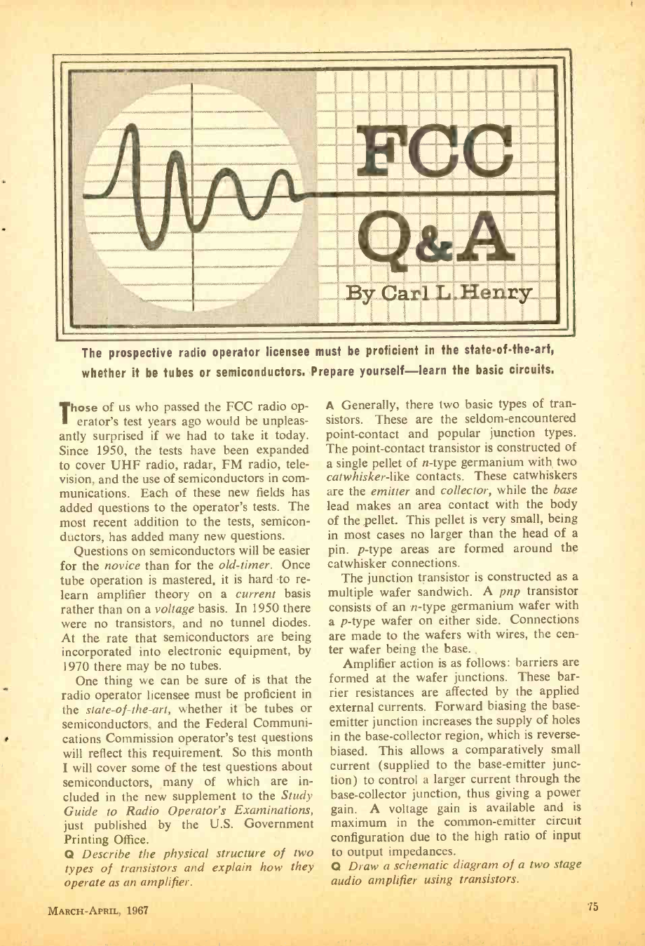
The prospective radio operator licensee must be proficient in the state-of-the-art,
whether it be tubes or semiconductors. Prepare yourself -learn the basic circuits.
Those of us who passed the FCC radio op-
erator's test years ago would be unpleas-
antly surprised if we had to take it today.
Since 1950, the tests have been expanded
to cover UHF radio, radar, FM radio, tele-
vision, and the use of semiconductors in com-
munications. Each of these new fields has
added questions to the operator's tests. The
most recent addition to the tests, semicon-
ductors, has added many new questions.
Questions on semiconductors will be easier
for the novice than for the old -timer. Once
tube operation is mastered, it is hard to re-
learn amplifier theory on a current basis
rather than on a voltage basis. In 1950 there
were no transistors, and no tunnel diodes.
At the rate that semiconductors are being
incorporated into electronic equipment, by
1970 there may be no tubes.
One thing we can be sure of is that the
radio operator licensee must be proficient in
the state -of- the -art, whether it be tubes or
semiconductors, and the Federal Communi-
cations Commission operator's test questions
will reflect this requirement. So this month
I will cover some of the test questions about
semiconductors, ,many of which are in-
cluded in the new supplement to the Study
Guide to Radio Operator's Examinations,
just published by the U.S. Government
Printing Office.
Q Describe the physical structure of two
types of transistors and explain how they
operate as an amplifier.
A Generally, there two basic types of tran-
sistors. These are the seldom- encountered
point- contact and popular junction types.
The point -contact transistor is constructed of
a single pellet of n -type germanium with two
catwhisker -like contacts. These catwhiskers
are the emitter and collector, while the base
lead makes an area contact with the body
of the pellet. This pellet is very small, being
in most cases no larger than the head of a
pin. p -type areas are formed around the
catwhisker connections.
The junction transistor is constructed as a
multiple wafer sandwich. A pnp transistor
consists of an n -type germanium wafer with
a p -type wafer on either side. Connections
are made to the wafers with wires, the cen-
ter wafer being the base. ,
Amplifier action is as follows: barriers are
formed at the wafer junctions. These bar-
rier resistances are affected by the applied
external currents. Forward biasing the base -
emitter junction increases the supply of holes
in the base -collector region, which is reverse -
biased. This allows a comparatively small
current (supplied to the base -emitter junc-
tion) to control a larger current through the
base -collector junction, thus giving a power
gain. A voltage gain is available and is
maximum in the common- emitter circuit
configuration due to the high ratio of input
to output impedances.
Q Draw a schematic diagram of a two stage
audio amplifier using transistors.
MARCH-APRIL, 1967 75
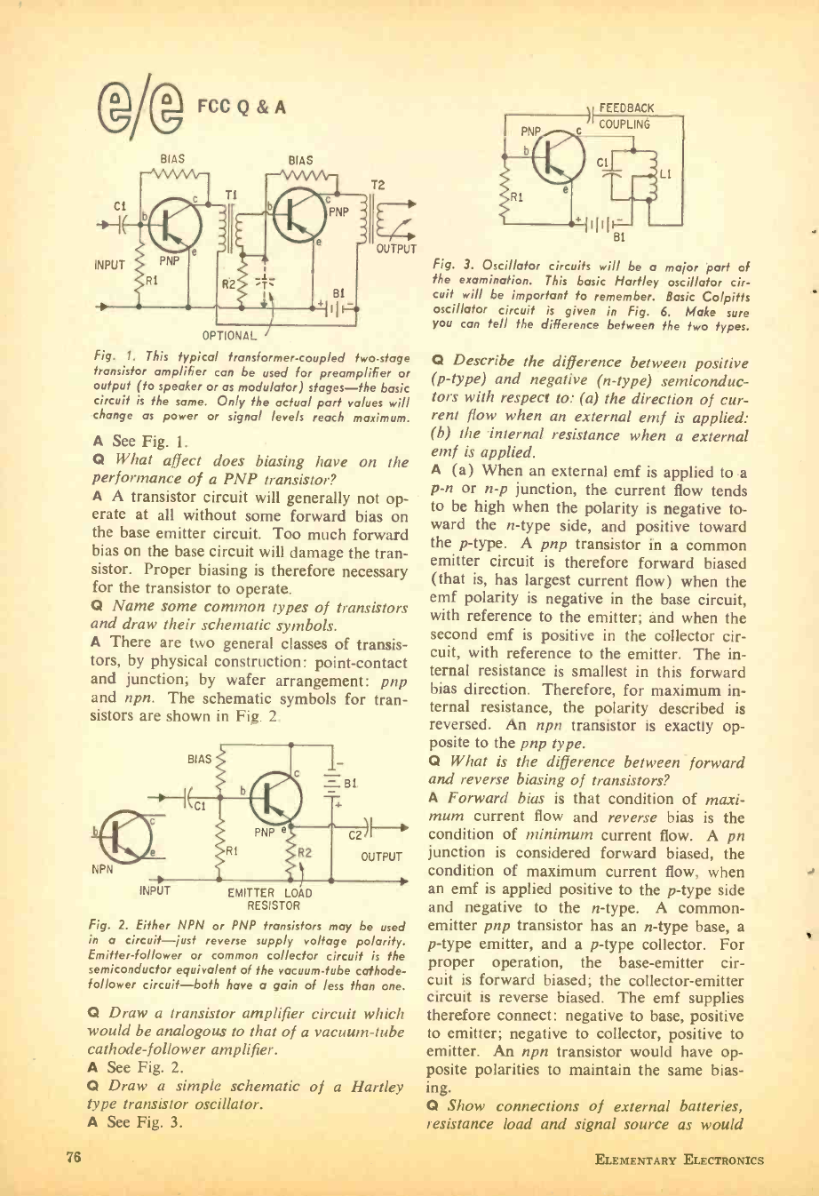
1(g FCC Q&A
Ti
R2
BIAS
INPUT
BIAS
OPTIONAL
Fig. 1. This typical transformer -coupled two -stage
transistor amplifier can be used for preamplifier or
output (to speaker or as modulator) stages -the basic
circuit is the same. Only the actual part values will
change as power or signal levels reach maximum.
A See Fig. 1.
Q What affect does biasing have on the
performance of a PNP transistor?
A A transistor circuit will generally not op-
erate at all without some forward bias on
the base emitter circuit. Too much forward
bias on the base circuit will damage the tran-
sistor. Proper biasing is therefore necessary
for the transistor to operate.
Q Name some common types of transistors
and draw their schematic symbols.
A There are two general classes of transis-
tors, by physical construction: point- contact
and junction; by wafer arrangement: pnp
and npn. The schematic symbols for tran-
sistors are shown in Fig. 2.
T2
I2
OUTPUT
NPN
INPUT EMITTER LOAD
RESISTOR
Fig. 2. Either NPN or PNP transistors may be used
in a circuit -just reverse supply voltage polarity.
Emitter- follower or common collector circuit is the
semiconductor equivalent of the vacuum -tube cathode -
follower circuit -both have a gain of less than one.
Q Draw a transistor amplifier circuit which
would be analogous to that of a vacuum -tube
cathode- follower amplifier.
A See Fig. 2.
Q Draw a simple schematic of a Hartley
type transistor oscillator.
A See Fig. 3.
76
FEEDBACK
COUPLING
Fig. 3. Oscillator circuits will be a major part of
the examination. This basic Hartley oscillator cir-
cuit will be important to remember. Basic Colpitts
oscillator circuit is given in Fig. 6. Make sure
you can tell the difference between the two types.
Q Describe the difference between positive
(p -type) and negative (n -type) semiconduc-
tors with respect to: (a) the direction of cur-
rent flow when an external emf is applied:
(b) the internal resistance when a external
emf is applied.
A (a) When an external emf is applied to a
p -n or n -p junction, the current flow tends
to be high when the polarity is negative to-
ward the n -type side, and positive toward
the p -type. A pnp transistor in a common
emitter circuit is therefore forward biased
(that is, has largest current flow) when the
emf polarity is negative in the base circuit,
with reference to the emitter; and when the
second emf is positive in the collector cir-
cuit, with reference to the emitter. The in-
ternal resistance is smallest in this forward
bias direction. Therefore, for maximum in-
ternal resistance, the polarity described is
reversed. An npn transistor is exactly op-
posite to the pnp type.
Q What is the difference between forward
and reverse biasing of transistors?
A Forward bias is that condition of maxi-
mum current flow and reverse bias is the
condition of minimum current flow. A pn
junction is considered forward biased, the
condition of maximum current flow, when
an emf is applied positive to the p -type side
and negative to the n -type. A common -
emitter pnp transistor has an n -type base, a
p -type emitter, and a p -type collector. For
proper operation, the base- emitter cir-
cuit is forward biased; the collector- emitter
circuit is reverse biased. The emf supplies
therefore connect: negative to base, positive
to emitter; negative to collector, positive to
emitter. An npn transistor would have op-
posite polarities to maintain the same bias-
ing.
Q Show connections of external batteries,
resistance load and signal source as would
ELEMENTARY ELECTRONICS
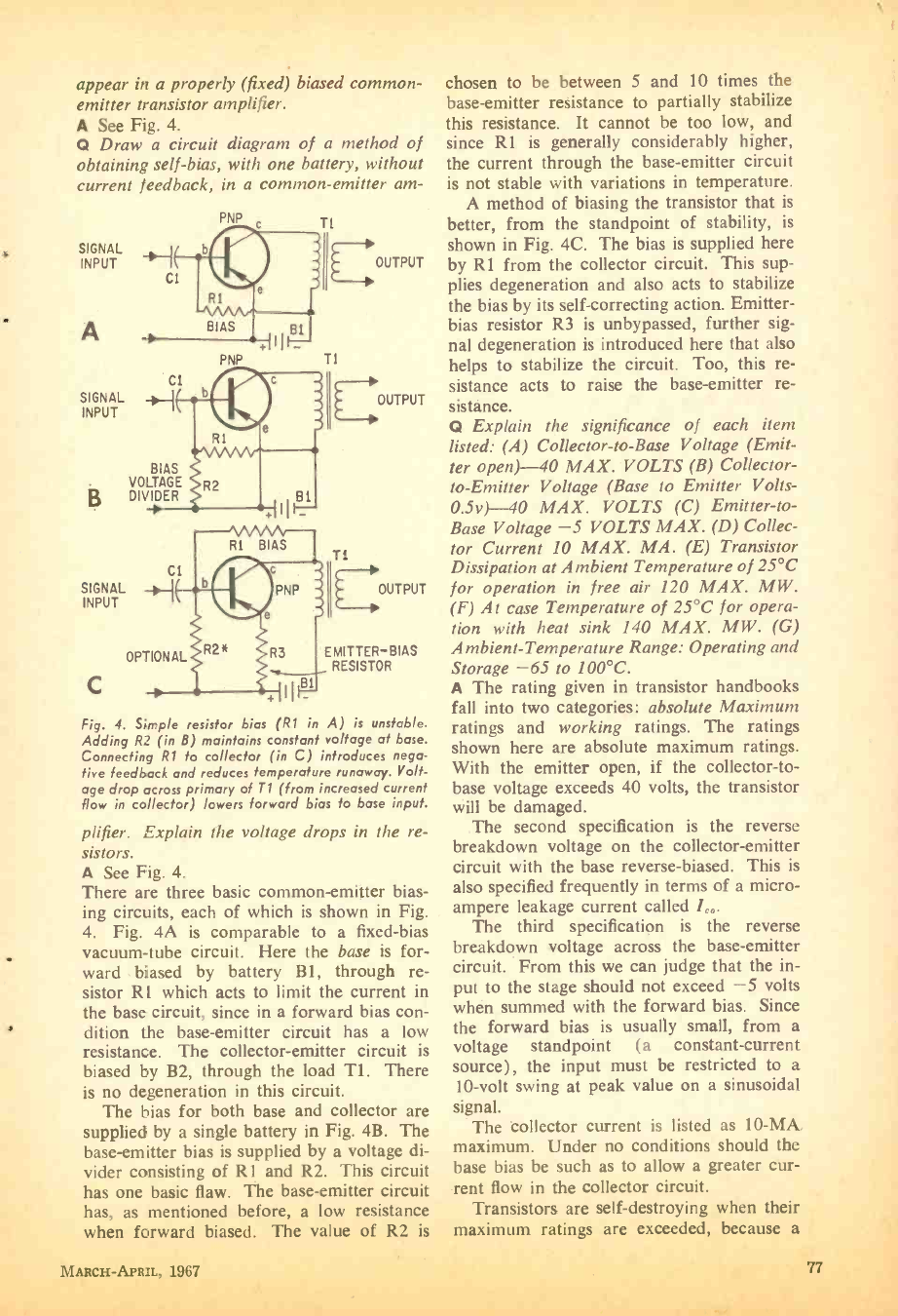
appear in a properly (fixed) biased common -
emitter transistor amplifier.
A See Fig. 4.
Q Draw a circuit diagram of a method of
obtaining self -bias, with one battery, without
current feedback, in a common -emitter am-
PNP
SIGNAL o, J
INPUT I
A
SIGNAL
INPUT
ci
BIAS
VOLTAGE
g DIVIDER
SIGNAL
INPUT
BIAS
PNP
BI
Ti
B
ii
OUTPUT
OUTPUT
OUTPUT
R3 EMITTER -BIAS
RESISTOR
Fig. 4. Simple resistor bias (R1 in A) is unstable.
Adding R2 (in 8) maintains constant voltage at base.
Connecting R1 to collector (in C) introduces nega-
tive feedback and reduces temperature runaway. Volt-
age drop across primary of T1 (from increased current
flow in collector) lowers forward bias to base input.
plifier. Explain the voltage drops in the re-
sistors.
A See Fig. 4.
There are three basic common- emitter bias-
ing circuits, each of which is shown in Fig.
4. Fig. 4A is comparable to a fixed -bias
vacuum -tube circuit. Here the base is for-
ward biased by battery B1, through re-
sistor R l which acts to limit the current in
the base circuit, since in a forward bias con-
dition the base -emitter circuit has a low
resistance. The collector -emitter circuit is
biased by B2, through the load Tl. There
is no degeneration in this circuit.
The bias for both base and collector are
supplied by a single battery in Fig. 4B. The
base -emitter bias is supplied by a voltage di-
vider consisting of R1 and R2. This circuit
has one basic flaw. The base -emitter circuit
has, as mentioned before, a low resistance
when forward biased. The value of R2 is
MARCH -APRIL, 1967
chosen to be between 5 and 10 times the
base -emitter resistance to partially stabilize
this resistance. It cannot be too low, and
since R1 is generally considerably higher,
the current through the base -emitter circuit
is not stable with variations in temperature.
A method of biasing the transistor that is
better, from the standpoint of stability, is
shown in Fig. 4C. The bias is supplied here
by R1 from the collector circuit. This sup-
plies degeneration and also acts to stabilize
the bias by its self- correcting action. Emitter -
bias resistor R3 is unbypassed, further sig-
nal degeneration is introduced here that also
helps to stabilize the circuit. Too, this re-
sistance acts to raise the base -emitter re-
sistance.
Q Explain the significance of each item
listed: (A) Collector -to -Base Voltage (Emit-
ter open) -40 MAX. VOLTS (B) Collector -
to- Emitter Voltage (Base to Emitter Volts -
0.5v)-40 MAX. VOLTS (C) Emitter -to-
Base Voltage -5 VOLTS MAX. (D) Collec-
tor Current 10 MAX. MA. (E) Transistor
Dissipation at Ambient Temperature of 25 °C
for operation in free air 120 MAX. MW.
(F) At case Temperature of 25 °C for opera-
tion with heat sink 140 MAX. MW. (G)
Ambient -Temperature Range: Operating and
Storage -65 to 100 °C.
A The rating given in transistor handbooks
fall into two categories: absolute Maximum
ratings and working ratings. The ratings
shown here are absolute maximum ratings.
With the emitter open, if the collector -to-
base voltage exceeds 40 volts, the transistor
will be damaged.
The second specification is the reverse
breakdown voltage on the collector- emitter
circuit with the base reverse- biased. This is
also specified frequently in terms of a micro-
ampere leakage current called 1,,.
The third specification is the reverse
breakdown voltage across the base -emitter
circuit. From this we can judge that the in-
put to the stage should not exceed -5 volts
when summed with the forward bias. Since
the forward bias is usually small, from a
voltage standpoint (a constant- current
source), the input must be restricted to a
10 -volt swing at peak value on a sinusoidal
signal.
The collector current is listed as 10-MA.
maximum. Under no conditions should the
base bias be such as to allow a greater cur-
rent flow in the collector circuit.
Transistors are self -destroying when their
maximum ratings are exceeded, because a
77
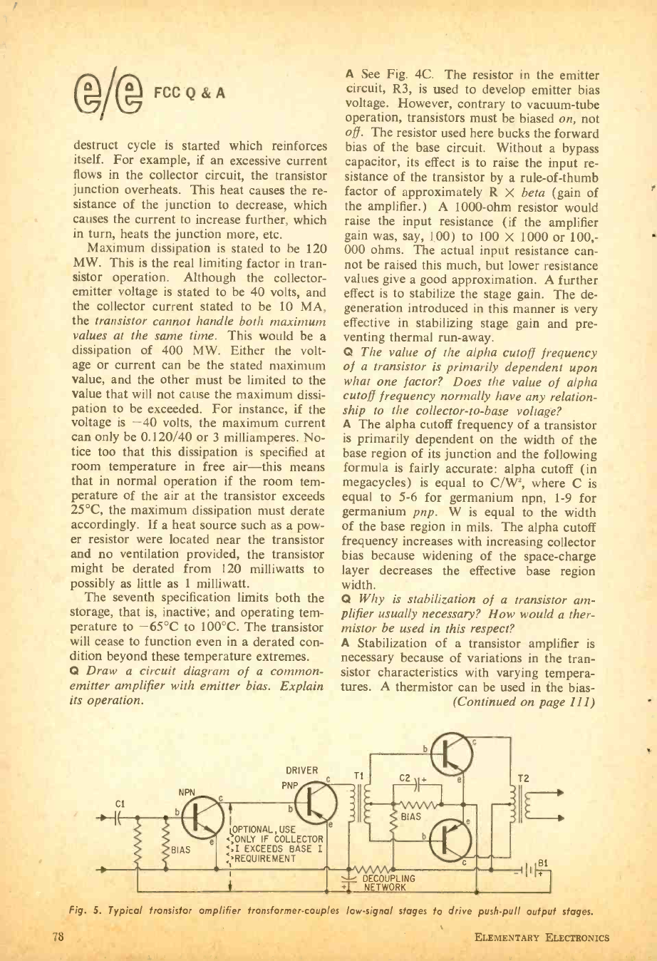
IJ
@ g FCC Q & A
destruct cycle is started which reinforces
itself. For example, if an excessive current
flows in the collector circuit, the transistor
junction overheats. This heat causes the re-
sistance of the junction to decrease, which
causes the current to increase further, which
in turn, heats the junction more, etc.
Maximum dissipation is stated to be 120
MW. This is the real limiting factor in tran-
sistor operation. Although the collector -
emitter voltage is stated to be 40 volts, and
the collector current stated to be 10 MA,
the transistor cannot handle both maximum
values at the same time. This would be a
dissipation of 400 MW. Either the volt-
age or current can be the stated maximum
value, and the other must be limited to the
value that will not cause the maximum dissi-
pation to be exceeded. For instance, if the
voltage is -40 volts, the maximum current
can only be 0.120/40 or 3 milliamperes. No-
tice too that this dissipation is specified at
room temperature in free air -this means
that in normal operation if the room tem-
perature of the air at the transistor exceeds
25 °C, the maximum dissipation must derate
accordingly. If a heat source such as a pow-
er resistor were located near the transistor
and no ventilation provided, the transistor
might be derated from 120 milliwatts to
possibly as little as 1 milliwatt.
The seventh specification limits both the
storage, that is, inactive; and operating tem-
perature to -65 °C to 100 °C. The transistor
will cease to function even in a derated con-
dition beyond these temperature extremes.
Q Draw a circuit diagram of a common -
emitter amplifier with emitter bias. Explain
its operation.
DRIVER
PNP
A See Fig. 4C. The resistor in the emitter
circuit, R3, is used to develop emitter bias
voltage. However, contrary to vacuum -tube
operation, transistors must be biased on, not
off. The resistor used here bucks the forward
bias of the base circuit. Without a bypass
capacitor, its effect is to raise the input re-
sistance of the transistor by a rule -of -thumb
factor of approximately R X beta (gain of
the amplifier.) A 1000 -ohm resistor would
raise the input resistance (if the amplifier
gain was, say, 100) to 100 X 1000 or 100,-
000 ohms. The actual input resistance can-
not be raised this much, but lower resistance
values give a good approximation. A further
effect is to stabilize the stage gain. The de-
generation introduced in this manner is very
effective in stabilizing stage gain and pre-
venting thermal run -away.
Q The value of the alpha cutoff frequency
of a transistor is primarily dependent upon
what one factor? Does the value of alpha
cutoff frequency normally have any relation-
ship to the collector -to -base voltage?
A The alpha cutoff frequency of a transistor
is primarily dependent on the width of the
base region of its junction and the following
formula is fairly accurate: alpha cutoff (in
megacycles) is equal to C /Wa, where C is
equal to 5 -6 for germanium npn, 1 -9 for
germanium pnp. W is equal to the width
of the base region in mils. The alpha cutoff
frequency increases with increasing collector
bias because widening of the space- charge
layer decreases the effective base region
width.
Q Why is stabilization of a transistor am-
plifier usually necessary? How would a ther-
mistor be used in this respect?
A Stabilization of a transistor amplifier is
necessary because of variations in the tran-
sistor characteristics with varying tempera-
tures. A thermistor can be used in the bias-
(Continued on page 111)
b
` OPTIONAL, USE
,ONLY IF COLLECTOR
EXCEEDS BASE I
+REQUIREMENT
Fig. 5. Typical transistor amplifier transformer -couples low- signal stages to drive push -pull output stages.
ELEMENTARY ELECTRONICS
Paradys, S. Afr"...a
Sarawak, Mayl ly i 1
Lusaka, Zombi,
Suva, Fiji
Tananarive, Malagasy
Gwelo, Rhodesia
Pyongyang, Khrc n
Wewak, Palau*
Taipei, Taiwan
Conakry, Guinea
Kabul, Afraganistan
Bagdad, Iraq
Kabul, Afghanistan
Paradys, S. Africa
R r k, Maylaysia
L ! ¡I G . Zambia
Suva, Fiji
Tananarive, Malagasy
Gwelo, Rhodesia
Pyongyang, Korea
1 { t 1 Papua
I diwan
Conakry, Guinea
Kabul, Afraganistan
lagdad, Iraq
'ibul, Afghanistan
By Walter R. Levins
Tired of the ordinary SW DX? Looking
for a new frontier to conquer? Well,
here's something new and difficult for even
the old -time Shortwave Listener (SWL) to
add to his list of rare DX loggings.
For the average SWL, 90 meters is an
unknown part of the SWBC ( ShortWave
BroadCast) spectrum -a part he never tunes
in. However, here on 90 meters lurks that
rare DX on a relatively low frequency. Low
frequencies coupled with low power present
a challenge you can't afford to miss. But in
return, that rare QSL comes and makes the
undertaking well worthwhile. With winter
here, the 90 -meter SWBC band should be
at its maximum.
The band extends from approximately
3250 kHz (kc) to about 3995 kHz (which
actually is 75.09 meters). On these fre-
quencies some of the rarest DX can be
found. Most 90 -meter stations broadcast pri-
marily for listeners in regional areas and
very few for international purposes. Hence,
there are mostly low -power stations on 90
meters. Now let's have a look at these sta-
tions by continent.
Africa. This continent is hard to log
for some SWLs. Not many stations have
high power. But on this band, Africans
constitute a large part of the DX. Countries
like Rhodesia and South Africa, with their
policies of apartheid, bear some attention.
Both of these countries can be logged on the
SW outlet on this band. A high -powered
station (100 kw) operated by Radio Clube
de Mozambique offers the only high -pow-
ered transmissions from Africa on this band.
Mozambique is one of the last colonies in
Africa, thus making it a controversial coun-
try to verify.
Frequency Power Station & Country
(kHz) (kw)
3250 20 Paradys, S. Africa
3255 10 Liberian Bc. Corp., Liberia
3259 20 R. Malaysia, Sarawak
3260 100 R. Clube de Mozambique
3270 10 Lusaka, Zambia
3284 10 Suva, Fiji Isl.
3288 30 Tananarive, Malagasy Rep.
3290 25 R. Nacional, Colombia
3295 100 Delhi & Bombay, India
3306 10 Gwelo, Rhodesia
3320 50 Pyongyang, Korea
3335 10 R. Wewak Papua
3335 10 Taipei, Taiwan
3375 10 R. Angola
3376 50 Conakry, Guinea
3780 100 R. Iran
3925 50 Tokyo, Japan
3985 50 R. Kabul, Afghanistan
3990 50 Baghdad, Iraq
Asia. This is a continent which many
SWLs lack in terms of logged countries -
especially those SWLs on the East Coast.
The Far East has many offerings; such as
Sarawak, Indonesia, Fiji Islands and Taiwan.
Most Asian transmitters are of the low -
power variety, save India (100 kw), Japan
(50 kw), Pakistan (50 kw) and Afghani-
stan (50 kw). Middle East stations in Iran
90 -meter band. Sierra Leone has its only
MARCH -APRIL, 1967
(Continued on page 113)
79
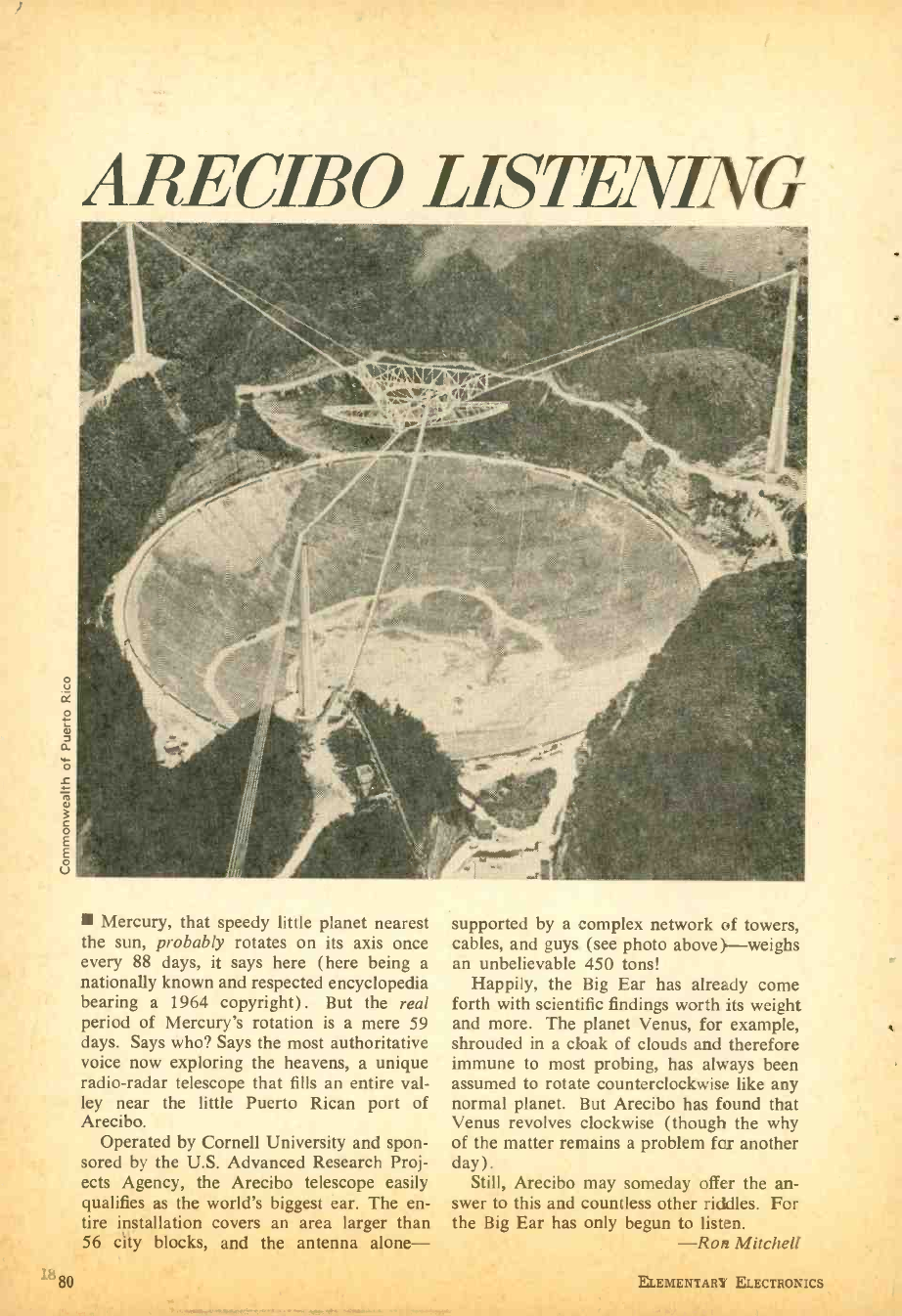
ce
o
a
ó
v
c 0 E E o
V
880
ARECIBO LISTENING
Mercury, that speedy little planet nearest
the sun, probably rotates on its axis once
every 88 days, it says here (here being a
nationally known and respected encyclopedia
bearing a 1964 copyright). But the real
period of Mercury's rotation is a mere 59
days. Says who? Says the most authoritative
voice now exploring the heavens, a unique
radio -radar telescope that fills an entire val-
ley near the little Puerto Rican port of
Arecibo.
Operated by Cornell University and spon-
sored by the U.S. Advanced Research Proj-
ects Agency, the Arecibo telescope easily
qualifies as the world's biggest ear. The en-
tire installation covers an area larger than
56 city blocks, and the antenna alone-
supported by a complex network of towers,
cables, and guys. (see photo above )-weighs
an unbelievable 450 tons!
Happily, the Big Ear has already come
forth with scientific findings worth its weight
and more. The planet Venus, for example,
shrouded in a cloak of clouds and therefore
immune to most probing, has always been
assumed to rotate counterclockwise like any
normal planet. But Arecibo has found that
Venus revolves clockwise (though the why
of the matter remains a problem for another
day). Still, Arecibo may someday offer the an-
swer to this and countless other riddles. For
the Big Ear has only begun to listen.
-Ron Mitchell
ELEMENTARY ELECTRONICS
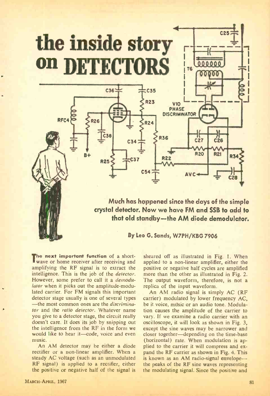
the inside story
on DETECTORS
RFC4
C36 `L
R26
138
B+
R25
-1-C35
R23
C34
C37
R24
r
1T6 ' ÓÓ 00'
I
1/10 L-
PHASE
DISCRIMINATOR
R36
C541
R22
l C27
R20
C26
R21
J
R34
Much has happened since the days of the simple
crystal detector. Now we have FM and SSB to add to
that old standby -the AM diode demodulator.
By Leo G. Sands, W7PH /KBG 7906
The next important function of a short-
wave or home receiver after receiving and
amplifying the RF signal is to extract the
intelligence. This is the job of the detector.
However, some prefer to call it a demodu-
lator when it picks out the amplitude -modu-
lated carrier. For FM signals this important
detector stage usually is one of several types
-the most common ones are the discrimina-
tor and the ratio detector. Whatever name
you give to a detector stage, the circuit really
doesn't care. It does its job by snipping out
the intelligence from the RF in the form we
would like to hear it -code, voice and even
music.
An AM detector may be either a diode
rectifier or a non -linear amplifier. When a
steady AC voltage (such as an unmodulated
RF signal) is applied to a rectifier, either
sheared off as illustrated in Fig. 1. When
applied to a non -linear amplifier, either the
positive or negative half cycles are amplified
more than the other as illustrated in Fig. 2.
The output waveform, therefore, is not a
replica of the input waveform.
An AM radio signal is simply AC (RF
carrier) modulated by lower frequency AC,
be it voice, music or an audio tone. Modula-
tion causes the amplitude of the carrier to
vary. If we examine a radio carrier with an
oscilloscope, it will look as shown in Fig. 3,
except the sine waves may be narrower and
closer together- depending on the time -base
(horizontal) rate. When modulation is ap-
plied to the carrier it will compress and ex-
pand the RF carrier as shown in Fig. 4. This
is known as an AM radio -signal envelope -
the peaks of the RF sine waves representing
the positive or negative half of the signal is
MARCH- APRIL, 1967
the modulating signal. Since the positive and
81
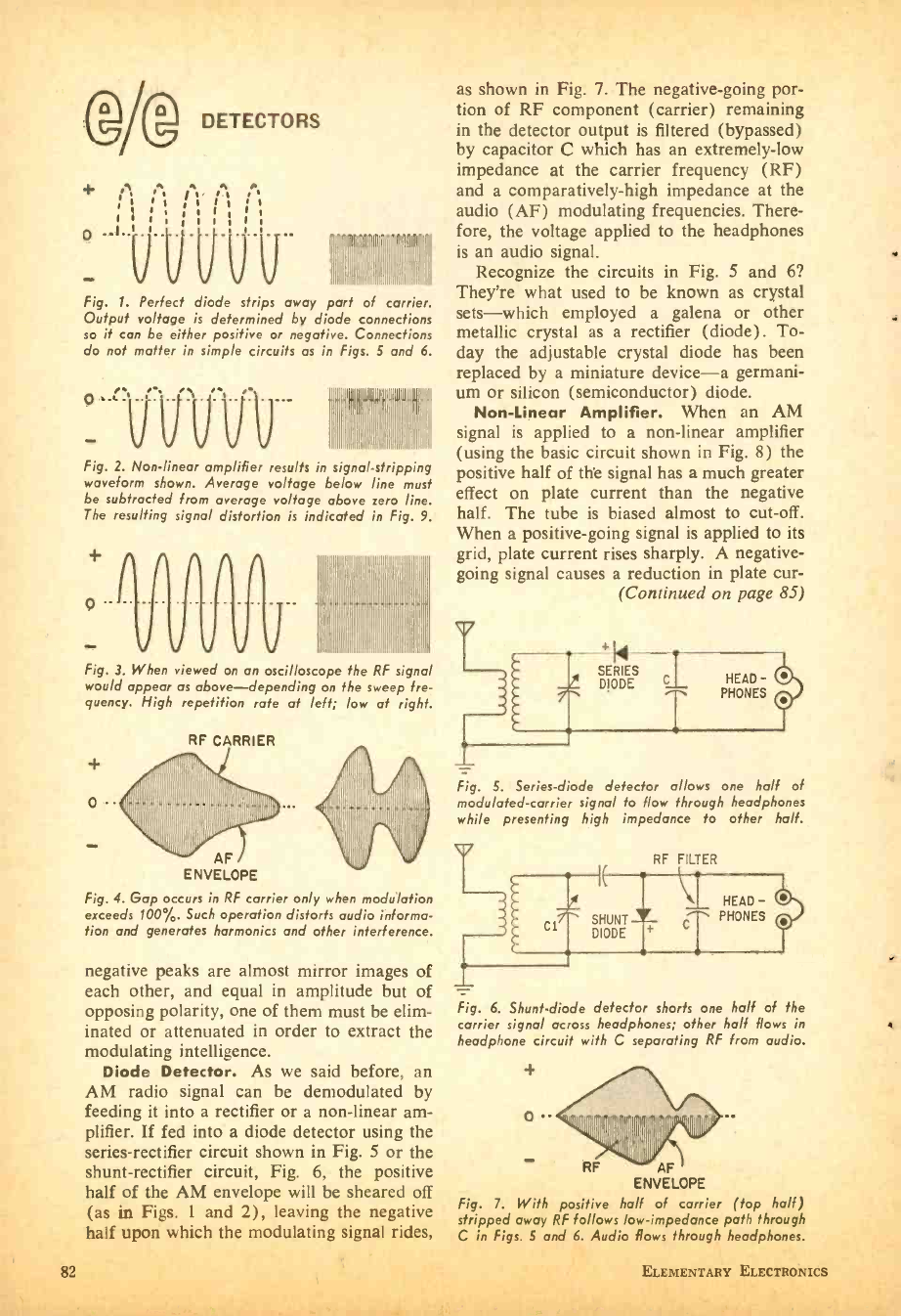
DETECTORS
ti. j. ¡ ' s
, , , 1
1 1 1 1 1 1
,
1
Fig. 1. Perfect diode strips away part of carrer
Output voltage is determined by diode connections
so it can be either positive or negative. Connections
do not matter in simple circuits as in Figs. 5 and 6.
Fig. 2. Non -linear amplifier results in s'gnal stripp ng
waveform shown. Average voltage below line must
be subtracted from average voltage above zero line.
The resulting signal distortion is indicated in Fig. 9.
0 -
Fig. 3. When viewed on an oscilloscope the RF s'gnal
would appear as above -depending on the sweep fre-
quency. High repetition rate at left; low at right.
0 -
RF CARRIER
as shown in Fig. 7. The negative -going por-
tion of RF component (carrier) remaining
in the detector output is filtered (bypassed)
by capacitor C which has an extremely -low
impedance at the carrier frequency (RF)
and a comparatively -high impedance at the
audio (AF) modulating frequencies. There-
fore, the voltage applied to the headphones
is an audio signal.
Recognize the circuits in Fig. 5 and 6?
They're what used to be known as crystal
sets -which employed a galena or other
metallic crystal as a rectifier (diode). To-
day the adjustable crystal diode has been
replaced by a miniature device -a germani-
um or silicon (semiconductor) diode.
Non -Linear Amplifier. When an AM
signal is applied to a non -linear amplifier
(using the basic circuit shown in Fig. 8) the
positive half of the signal has a much greater
effect on plate current than the negative
half. The tube is biased almost to cut -off.
When a positive -going signal is applied to its
grid, plate current rises sharply. A negative -
going signal causes a reduction in plate cur -
(Continued on page 85)
Fig. 5. Series -diode detector allows one half of
modulated -carrier signal to flow through headphones
while presenting high impedance to other half.
AF
ENVELOPE
Fig. 4. Gap occurs in RF carrier only when modulation
exceeds 100 %. Such operation distorts audio informa-
tion and generates harmonics and other interference.
RF FILTER
Cl SHUNT
DIODE
negative peaks are almost mirror images of
each other, and equal in amplitude but of
opposing polarity, one of them must be elim-
inated or attenuated in order to extract the
modulating intelligence.
Diode Detector. As we said before, an
AM radio signal can be demodulated by
feeding it into a rectifier or a non -linear am-
plifier. If fed into a diode detector using the
series -rectifier circuit shown in Fig. 5 or the
shunt -rectifier circuit, Fig. 6, the positive
half of the AM envelope will be sheared off
(as in Figs. 1 and 2), leaving the negative
half upon which the modulating signal rides,
Fig. 6. Shunt -diode detector shorts one half of the
carrier signal across headphones; other half flows in
headphone circuit with C separating RF from audio.
o
RF AF
ENVELOPE
Fig. 7. With positive half of carrier (top half)
stripped away RF follows low -impedance path through
C in Figs. 5 and 6. Audio flows through headphones.
82 ELEMENTARY ELECTRONICS
4111E0 1967 CATALOG'
NAME-PLEASE PRINT
ADDRESS
CITY
STATE 51C ZIP
tf
CHOOSE FROM THE WORLD'S LARGEST
SELECTION IN ELECTRONICS . . . AND SAVE!
Buy from the world's largest electronics supplier. Use
the Allied Credit Fund Plan to enjoy what you wont
NOW-no money down, 24 months to pay.
idwr.
COMPLETE
611 knight-kit
cn.n.Oc
IWw
' ,f,r"wrItromff=
- NEW 514 -PAGE
ALL/Ell CATALOG
r
L
TOP SAVINGS ON THE BEST IN
ELECTRONICS FOR EVERYONE ..
Famous Knight -Kits Stereo Hi -Fi Tape
Recorders & Tape CB 2 -Way Gear Walkie-
talkies FM -AM & AM Radios Short Wave
Radios Portable TV Intercoms & P.A.
Phonographs, Accessories Amateur Gear
Automotive Electronics Test Instruments
TV Antennas & Tubes Power Tools Parts
Hardware Transistors Batteries Books
NO MONEY DOWN -24 MONTHS TO PAY!
Low Monthly Payments to flt your budget.
RUSH THIS CARD NOW!
' e, t:CS `
' 1° 9 O p '
toO
% o mat
o
ö
W u
J4
NAME -PLEASE PRINT
ADDRESS
CITY
STATE 51C ZIP
CHOOSE FROM THE WORLD'S LARGEST
SELECTION IN ELECTRONICS . AND SAVE!
B f the Id' I
Buy from a wor s largest electronics supplier. Use
the Allied Credit Fund Plan to enjoy what you want
NOW - no money down, 24 months to pay.
RUSH THIS CARD NOW!
FRE E
NEW 1967
411 /ED
¡JA 1411111
514 pages! See everything
new in electronics...
featured first at Allied,
the world's largest
electronics headquarters!
Naiii for the audiophile Maid for the ham operator
4 Knight -KitRP 6 -Meter Amateur
Transceiver with universal
solid -state power supply.
Knight -Kira Deluxe Stereo
FM -AM Tuner. Easy -to -build
solid -state design.
Nefor the CB user Nd for the serviceman
_ _ -- C1
'' gym e
KNIGHT Á` 2 -Way Radio. Com- Knight -KitA Portable Solid -
pact solid -state design at State Color /Bar Pattern Gen -
amazingly low cost! erator. A top value!
Nadfor everyone Nod for TV and FM owners
IIIIII
V Antenna and
Rotor Systems
á for color and
Ampex 6200 HVR Home C. black -and-
Videotape Recorder. Make white TV ...
videotapes at home! FM, tool
hundreds more new and exclusive items,
and scores of special Allied values!
NO MONEY DOWN!
Enjoy the things you want now, while you take 24
months to pay for them on the Allied easy- on -the-
budget Credit Fund Plan.
ALLIED RADIO
P.O. BOX 4398
CHICAGO, ILLINOIS 60680
DO A FRIEND A FAVOR -give him this card to send
for his FREE ALLIED CATALOG
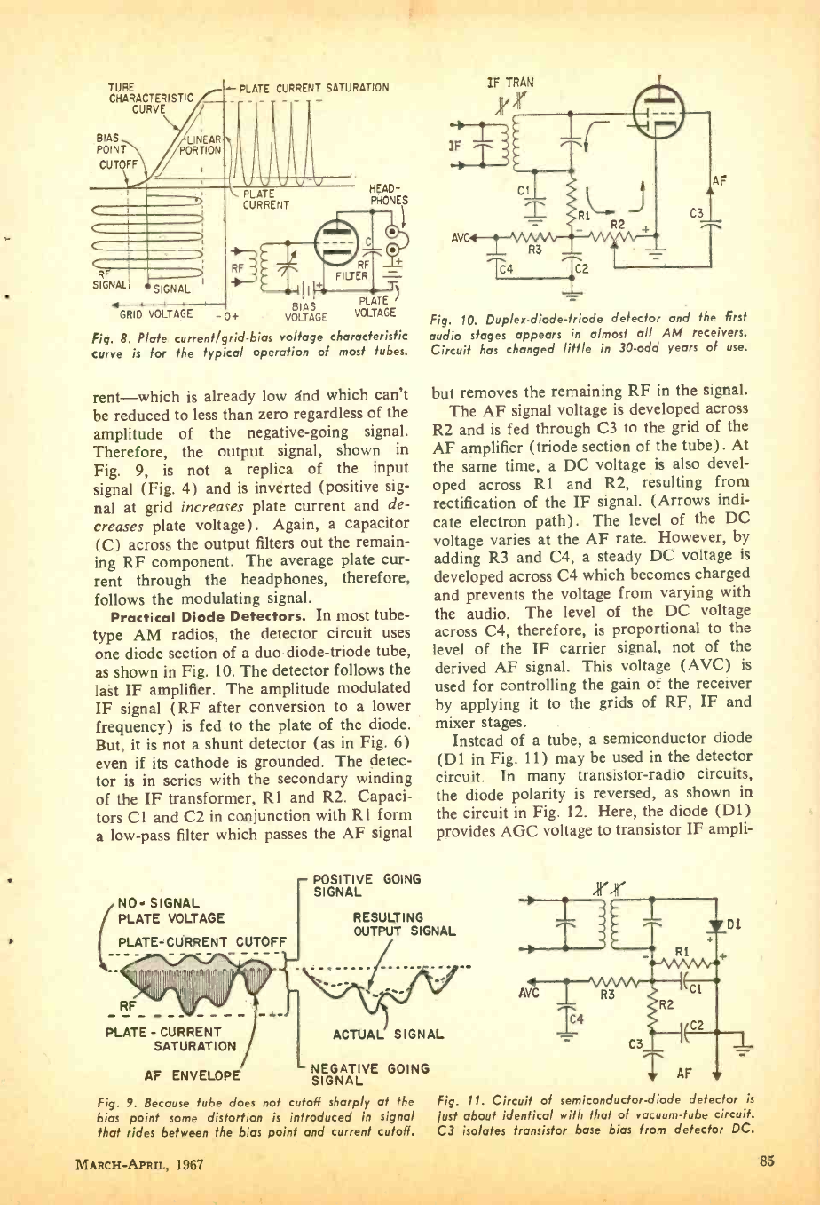
TUBE
CHARACTERISTIC
CURVE
BIAS
POINT
CUTOFF
LINEAR
PORTION
C
c RF I
SIGNAL SIGNAL I
GRID VOLTAGE
PLATE CURRENT SATURATION
PLATE
CURRENT
RF
HEAD-
PHONES
BIAS PLATE )
- 0+ VOLTAGE VOLTAGE
Fig. 8. Plate current /grid -bias voltage characteristic
curve is for the typical operation of most tubes.
rent -which is already low and which can't
be reduced to less than zero regardless of the
amplitude of the negative -going signal.
Therefore, the output signal, shown in
Fig. 9, is not a replica of the input
signal (Fig. 4) and is inverted (positive sig-
nal at grid increases plate current and de-
creases plate voltage). Again, a capacitor
(C) across the output filters out the remain-
ing RF component. The average plate cur-
rent through the headphones, therefore,
follows the modulating signal.
Practical Diode Detectors. In most tube -
type AM radios, the detector circuit uses
one diode section of a duo -diode- triode tube,
as shown in Fig. 10. The detector follows the
last IF amplifier. The amplitude modulated
IF signal (RF after conversion to a lower
frequency) is fed to the plate of the diode.
But, it is not a shunt detector (as in Fig. 6)
even if its cathode is grounded. The detec-
tor is in series with the secondary winding
of the IF transformer, R1 and R2. Capaci-
tors Cl and C2 in conjunction with R1 form
a low -pass filter which passes the AF signal
NO- SIGNAL
PLATE VOLTAGE
PLATE -CURRENT CUTOFF
POSITIVE GOING
SIGNAL
IFMTRAN
C 1
AVC R3
C4
AF
C3
C2
Fig. 10. Duplex- diode -triode detector and the first
audio stages appears in almost all AM receivers.
Circuit has changed little in 30 -odd years of use.
but removes the remaining RF in the signal.
The AF signal voltage is developed across
R2 and is fed through C3 to the grid of the
AF amplifier (triode section of the tube). At
the same time, a DC voltage is also devel-
oped across R1 and R2, resulting from
rectification of the IF signal. (Arrows indi-
cate electron path) . The level of the DC
voltage varies at the AF rate. However, by
adding R3 and C4, a steady DC voltage is
developed across C4 which becomes charged
and prevents the voltage from varying with
the audio. The level of the DC voltage
across C4, therefore, is proportional to the
level of the IF carrier signal, not of the
derived AF signal. This voltage (AVC) is
used for controlling the gain of the receiver
by applying it to the grids of RF, IF and
mixer stages.
Instead of a tube, a semiconductor diode
(D1 in Fig. 11) may be used in the detector
circuit. In many transistor -radio circuits,
the diode polarity is reversed, as shown in
the circuit in Fig. 12. Here, the diode (D1)
provides AGC voltage to transistor IF ampli-
RESULTING
OUTPUT SIGNAL
PLATE - CURRENT
SATURATION
AF ENVELOPE
ACTUAL SIGNAL
NEGATIVE GOING
SIGNAL
Fig. 9. Because tube does not cutoff sharply at the Fig. 11. Circuit of semiconductor -diode defector is
bias point some distortion is introduced in signal just about identical with that of vacuum -tube circuit.
that rides between the bias point and current cutoff. r o ^I ^ +e. t.^ . ;d ^. 6te h ;ny frnm detector DC.
MARCH -APRIL, 1967 85
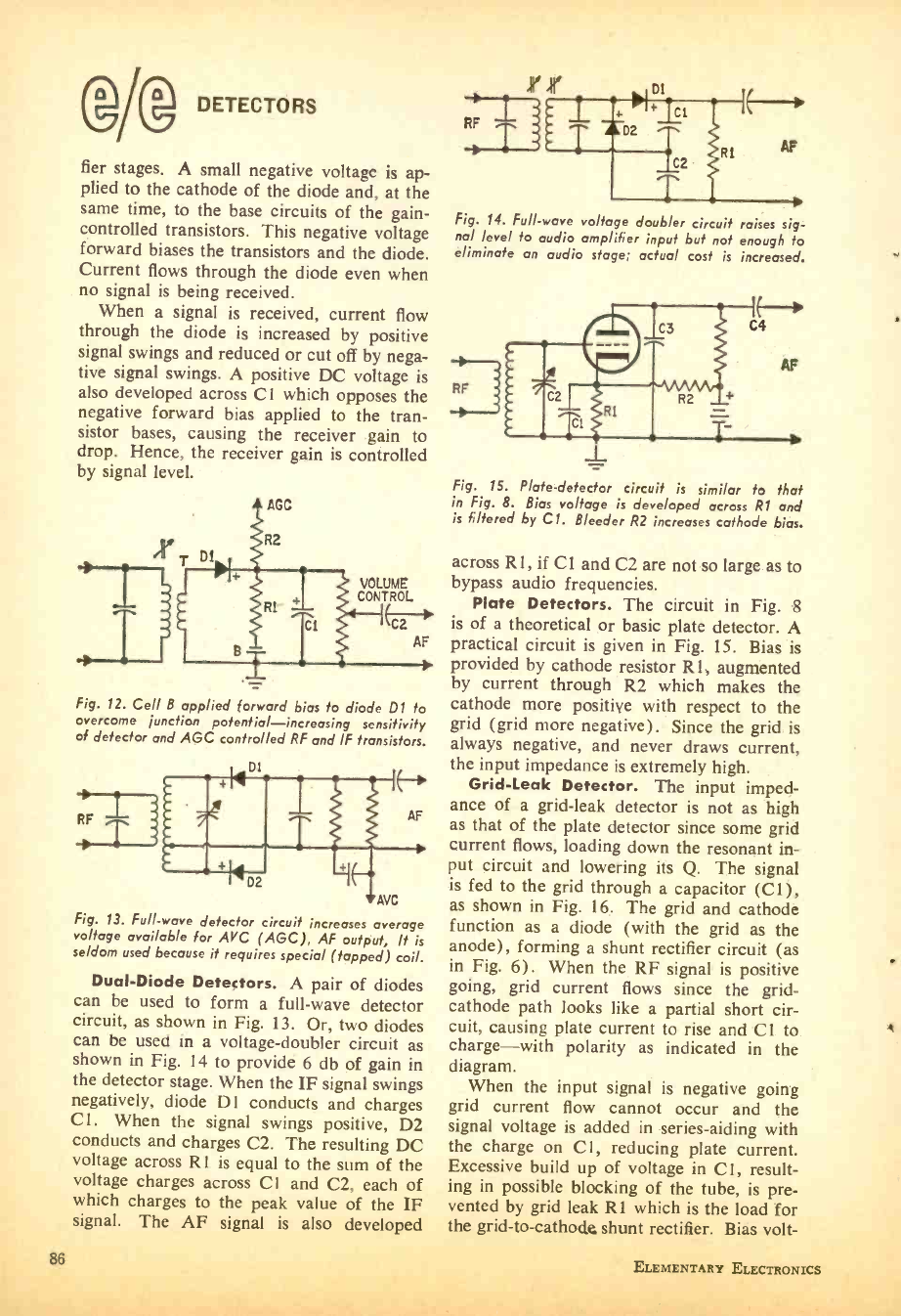
DETECTORS
fier stages. A small negative voltage is ap-
plied to the cathode of the diode and, at the
same time, to the base circuits of the gain -
controlled transistors. This negative voltage
forward biases the transistors and the diode.
Current flows through the diode even when
no signal is being received.
When a signal is received, current flow
through the diode is increased by positive
signal swings and reduced or cut off by nega-
tive signal swings. A positive DC voltage is
also developed across CI which opposes the
negative forward bias applied to the tran-
sistor bases, causing the receiver gain to
drop. Hence, the receiver gain is controlled
by signal level.
) T
VOLUME
CONTROL
Fig. 12. Cell B applied forward bias to diode D1 to
overcome junction potential- increasing sensitivity
of detector and AGC controlled RF and IF transistors.
AVC
Fig. 13. Full -wave detector circuit increases average
voltage available for AVC (AGC), AF output. It is
seldom used because it requires special (tapped) coil.
Dual -Diode Detectors. A pair of diodes
can be used to form a full -wave detector
circuit, as shown in Fig. 13. Or, two diodes
can be used in a voltage -doubler circuit as
shown in Fig. 14 to provide 6 db of gain in
the detector stage. When the IF signal swings
negatively, diode D1 conducts and charges
Cl. When the signal swings positive, D2
conducts and charges C2. The resulting DC
voltage across R 1 is equal to the sum of the
voltage charges across C I and C2, each of
which charges to the peak value of the IF
signal. The AF signal is also developed
86
Fig. 14. Full -wave voltage doubler circuit
nol level to audio amplifier input but not
eliminate an audio stage; actual cost is
RF
raises sig-
enough to
increased.
Fig. 15. Plate -detector circuit is similar to that
in Fig. 8. Bias voltage is developed across R1 and
is filtered by Cl. Bleeder R2 increases cathode bias.
across R1, if Cl and C2 are not so large as to
bypass audio frequencies.
Plate Detectors. The circuit in Fig. 8
is of a theoretical or basic plate detector. A
practical circuit is given in Fig. 15. Bias is
provided by cathode resistor R1, augmented
by current through R2 which makes the
cathode more positive with respect to the
grid (grid more negative). Since the grid is
always negative, and never draws current,
the input impedance is extremely high.
Grid -Leak Detector. The input imped-
ance of a grid -leak detector is not as high
as that of the plate detector since some grid
current flows, loading down the resonant in-
put circuit and lowering its Q. The signal
is fed to the grid through a capacitor (C1),
as shown in Fig. 16. The grid and cathode
function as a diode (with the grid as the
anode), forming a shunt rectifier circuit (as
in Fig. 6). When the RF signal is positive
going, grid current flows since the grid -
cathode path looks like a partial short cir-
cuit, causing plate current to rise and Cl to
charge -with polarity as indicated in the
diagram.
When the input signal is negative going
grid current flow cannot occur and the
signal voltage is added in series -aiding with
the charge on Cl, reducing plate current.
Excessive build up of voltage in Cl, result-
ing in possible blocking of the tube, is pre-
vented by grid leak R1 which is the load for
the grid -to- cathode shunt rectifier. Bias volt-
ELEMENTARY ELECTRONICS
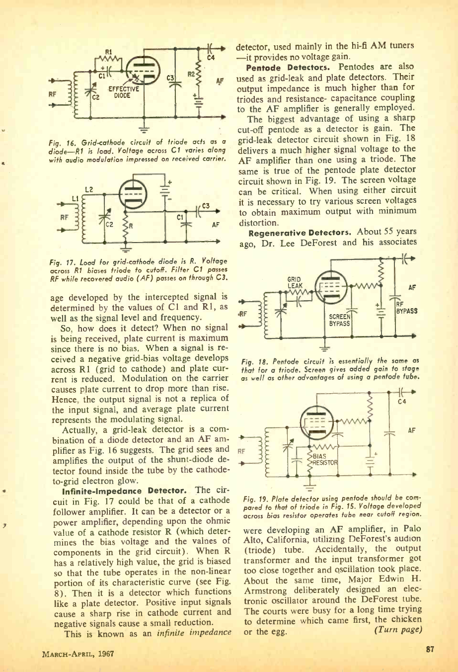
9
RF 1
Fig. 16. Grid- cathode circuit of triode acts as a
diode -R1 is load. Voltage across Cl varies along
with audio modulation impressed on received carrier.
LI
RF
j
Fig. 17. Load for grid -cathode diode is R. Voltage
across R1 biases triode to cutoff. Filter Cl passes
RF while recovered audio (AF) passes on through C3.
age developed by the intercepted signal is
determined by the values of Cl and R1, as
well as the signal level and frequency.
So, how does it detect? When no signal
is being received, plate current is maximum
since there is no bias. When a signal is re-
ceived a negative grid -bias voltage develops
across R1 (grid to cathode) and plate cur-
rent is reduced. Modulation on the carrier
causes plate current to drop more than rise.
Hence, the output signal is not a replica of
the input signal, and average plate current
represents the modulating signal.
Actually, a grid -leak detector is a com-
bination of a diode detector and an AF am-
plifier as Fig. 16 suggests. The grid sees and
amplifies the output of the shunt -diode de-
tector found inside the tube by the cathode -
to -grid electron glow.
Infinite- Impedance Detector. The cir-
cuit in Fig. 17 could be that of a cathode
follower amplifier. It can be a detector or a
power amplifier, depending upon the ohmic
value of a cathode resistor R (which deter-
mines the bias voltage and the valves of
components in the grid circuit). When R
has a relatively high value, the grid is biased
so that the tube operates in the non -linear
portion of its characteristic curve (see Fig.
8) . Then it is a detector which functions
like a plate detector. Positive input signals
cause a sharp rise in cathode current and
negative signals cause a small reduction.
This is known as an infinite impedance
MARCH- APRIL, 1967
detector, used mainly in the hi -fi AM tuners
-it provides no voltage gain.
Pentode Detectors. Pentodes are also
used as grid -leak and plate detectors. Their
output impedance is much higher than for
triodes and resistance- capacitance coupling
to the AF amplifier is generally employed.
The biggest advantage of using a sharp
cut -off pentode as a detector is gain. The
grid -leak detector circuit shown in Fig. 18
delivers a much higher signal voltage to the
AF amplifier than one using a triode. The
same is true of the pentode plate detector
circuit shown in Fig. 19. The screen voltage
can be critical. When using either circuit
it is necessary to try various screen voltages
to obtain maximum output with minimum
distortion.
Regenerative Detectors. About 55 years
ago, Dr. Lee DeForest and his associates
.RF SCREEN
BYPASS
Fig. 18. Pentode circuit is essentially the same as
that for a triode. Screen gives added gain to stage
as well as other advantages of using a pentode tube.
RF i BIAS
RESIST
Fig. 19. Plate detector using pentode should be com-
pared to that of triode in Fig. 15. Voltage developed
across bias resistor operates tube near cutoff region.
were developing an AF amplifier, in Palo
Alto, California, utilizing DeForest's audion
(triode) tube. Accidentally, the output
transformer and the input transformer got
too close together and oscillation took place.
About the same time, Major Edwin H.
Armstrong deliberately designed an elec-
tronic oscillator around the DeForest tube.
The courts were busy for a long time trying
to determine which came first, the chicken
or the egg. (Turn page)
87
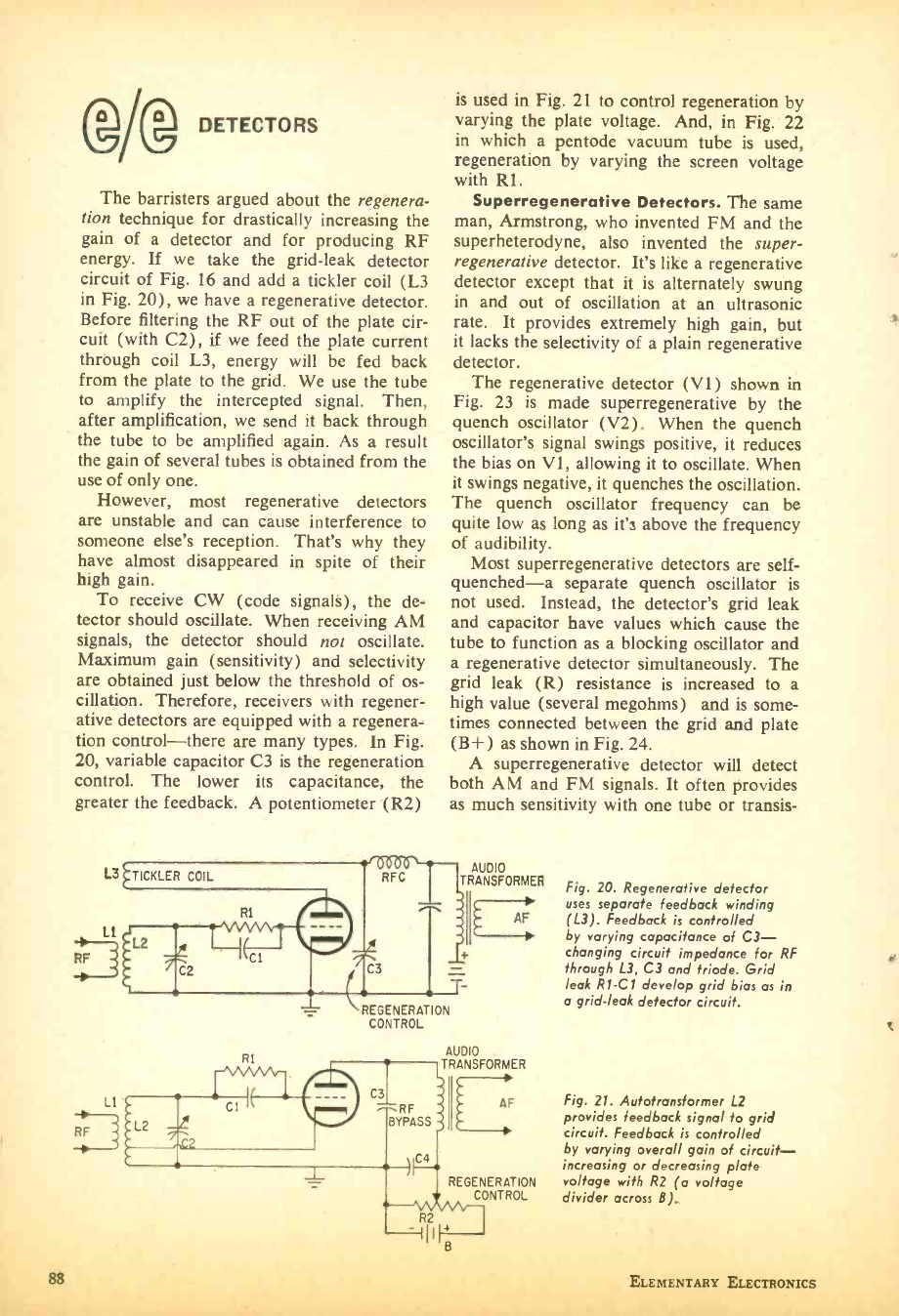
eDETECTORS
The barristers argued about the regenera-
tion technique for drastically increasing the
gain of a detector and for producing RF
energy. If we take the grid -leak detector
circuit of Fig. 16 and add a tickler coil (L3
in Fig. 20), we have a regenerative detector.
Before filtering the RF out of the plate cir-
cuit (with C2), if we feed the plate current
through coil L3, energy will be fed back
from the plate to the grid. We use the tube
to amplify the intercepted signal. Then,
after amplification, we send it back through
the tube to be amplified again. As a result
the gain of several tubes is obtained from the
use of only one.
However, most regenerative detectors
are unstable and can cause interference to
someone else's reception. That's why they
have almost disappeared in spite of their
high gain.
To receive CW (code signals), the de-
tector should oscillate. When receiving AM
signals, the detector should not oscillate.
Maximum gain (sensitivity) and selectivity
are obtained just below the threshold of os-
cillation. Therefore, receivers with regener-
ative detectors are equipped with a regenera-
tion control -there are many types. In Fig.
20, variable capacitor C3 is the regeneration
control. The lower its capacitance, the
greater the feedback. A potentiometer (R2)
L3
RF /
LI
RF
88
is used in Fig. 21 to control regeneration by
varying the plate voltage. And, in Fig. 22
in which a pentode vacuum tube is used,
regeneration by varying the screen voltage
with R1.
Superregenerative Detectors. The same
man, Armstrong, who invented FM and the
superheterodyne, also invented the super -
regenerative detector. It's like a regenerative
detector except that it is alternately swung
in and out of oscillation at an ultrasonic
rate. It provides extremely high gain, but
it lacks the selectivity of a plain regenerative
detector.
The regenerative detector (V1) shown in
Fig. 23 is made superregenerative by the
quench oscillator (V2). When the quench
oscillator's signal swings positive, it reduces
the bias on V1, allowing it to oscillate. When
it swings negative, it quenches the oscillation.
The quench oscillator frequency can be
quite low as long as it's above the frequency
of audibility.
Most superregenerative detectors are self -
quenched-a separate quench oscillator is
not used. Instead, the detector's grid leak
and capacitor have values which cause the
tube to function as a blocking oscillator and
a regenerative detector simultaneously. The
grid leak (R) resistance is increased to a
high value (several megohms) and is some-
times connected between the grid and plate
(B +) as shown in Fig. 24.
A superregenerative detector will detect
both AM and FM signals. It often provides
as much sensitivity with one tube or transis-
AUDIO
TRANSFORMER
RI
REGENERATION
CONTROL
Fig. 20. Regenerative detector
uses separate feedback winding
AF (L3). Feedback is controlled
by varying capacitance of C3-
changing circuit impedance for RF
through L3, C3 and triode. Grid
leak R1 -C1 develop grid bias as in
a grid -leak detector circuit.
AUDIO
TRANSFORMER
AF
REGENERATION
Fig. 21. Autotransformer L2
provides feedback signal to grid
circuit. Feedback is controlled
by varying overall gain of circuit -
increasing or decreasing plate
voltage with R2 (a voltage
CONTROL divider across B).
ELEMENTARY ELECTRONICS
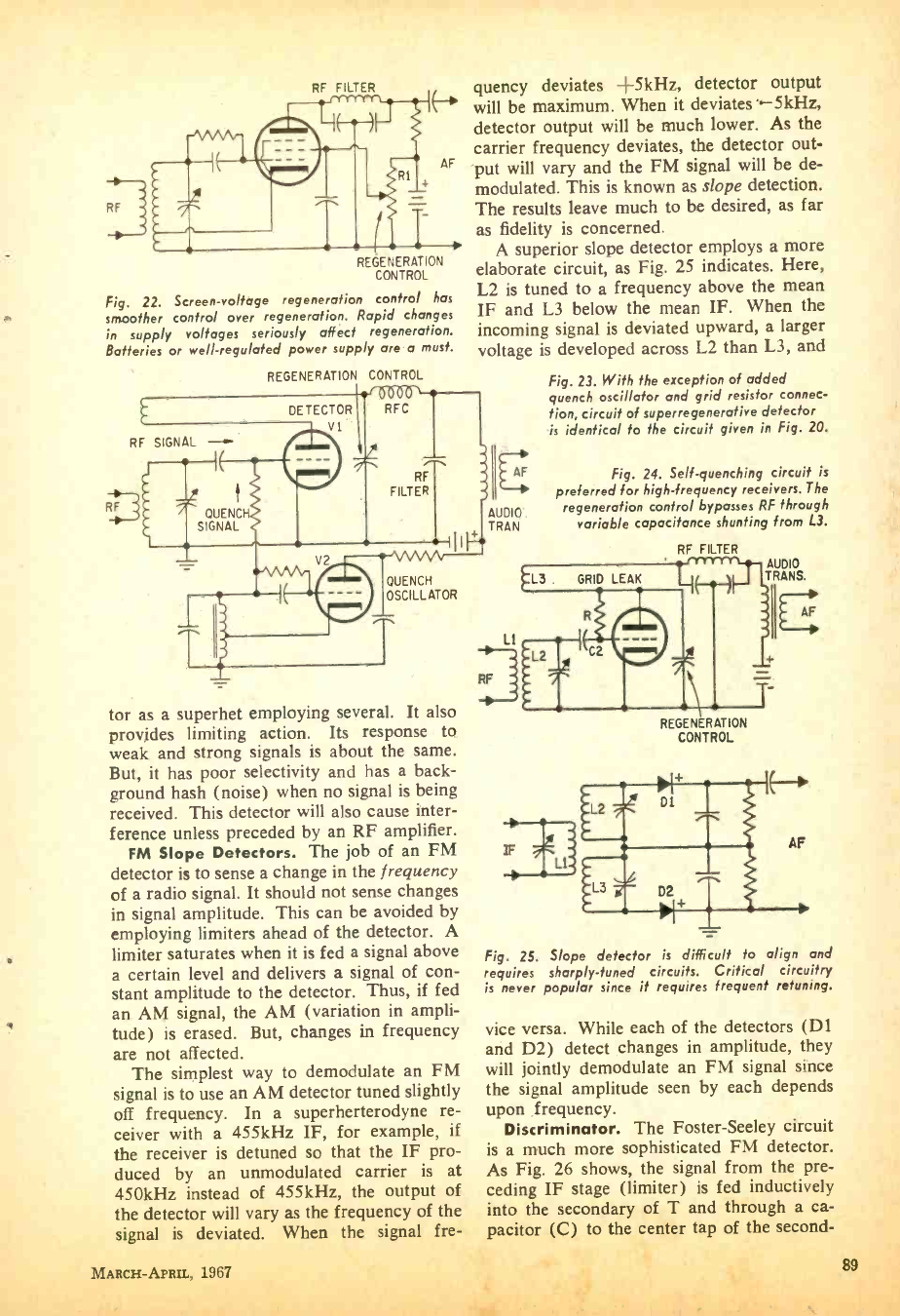
I
RF
REGENERATION
CONTROL
Fig. 22. Screen -voltage regeneration control has
smoother control over regeneration. Rapid changes
in supply voltages seriously affect regeneration.
Batteries or well- regulated power supply are a must.
REGENERATION CONTROL
no
DETECTOR RFC
V1
RF
RF SIGNAL -
quency deviates -+kHz, detector output
will be maximum. When it deviates'.-5kHz,
detector output will be much lower. As the
carrier frequency deviates, the detector out-
put will vary and the FM signal will be de-
modulated. This is known as slope detection.
The results leave much to be desired, as far
as fidelity is concerned.
A superior slope detector employs a more
elaborate circuit, as Fig. 25 indicates. Here,
L2 is tuned to a frequency above the mean
IF and L3 below the mean IF. When the
incoming signal is deviated upward, a larger
voltage is developed across L2 than L3, and
Fig. 23. With the exception of added
quench oscillator and grid resistor connec-
tion, circuit of superregenerative detector
is identical to the circuit given in Fig. 20.
QUENCH
SIGNAL
V2 e
RF
FILTER
QUENCH
OSCILLATOR
tor as a superhet employing several. It also
provides limiting action. Its response to
weak and strong signals is about the same.
But, it has poor selectivity and has a back-
ground hash (noise) when no signal is being
received. This detector will also cause inter-
ference unless preceded by an RF amplifier.
FM Slope Detectors. The job of an FM
detector is to sense a change in the frequency
of a radio signal. It should not sense changes
in signal amplitude. This can be avoided by
employing limiters ahead of the detector. A
limiter saturates when it is fed a signal above
a certain level and delivers a signal of con-
stant amplitude to the detector. Thus, if fed
an AM signal, the AM (variation in ampli-
tude) is erased. But, changes in frequency
are not affected.
The simplest way to demodulate an FM
signal is to use an AM detector tuned slightly
off frequency. In a superherterodyne re-
ceiver with a 455kHz IF, for example, if
the receiver is detuned so that the IF pro-
duced by an unmodulated carrier is at
450kHz instead of 455kHz, the output of
the detector will vary as the frequency of the
signal is deviated. When the signal fre-
AF
AUDIO.
TRAN
Fig. 24. Self- quenching circuit is
preferred for high -frequency receivers. The
regeneration control bypasses RF through
variable capacitance shunting from L3.
RF FILTER
L3 GRID
L1
L
RF
LEAK
REGENERATION
CONTROL
AUDIO
TRANS.
Fig. 25. Slope detector is difficult to align and
requires sharply -tuned circuits. Critical circuitry
is never popular since it requires frequent retuning.
vice versa. While each of the detectors (Dl
and D2) detect changes in amplitude, they
will jointly demodulate an FM signal since
the signal amplitude seen by each depends
upon frequency.
Discriminator. The Foster -Seeley circuit
is a much more sophisticated FM detector.
As Fig. 26 shows, the signal from the pre-
ceding IF stage (limiter) is fed inductively
into the secondary of T and through a ca-
pacitor (C) to the center tap of the second-
MARCH -APRIL, 1967 89
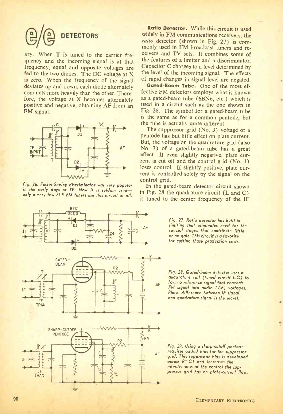
I@ DETECTORS
ary. When T is tuned to the carrier fre-
quency and the incoming signal is at that
frequency, equal and opposite voltages are
fed to the two diodes. The DC voltage at X
is zero. When the frequency of the signal
deviates up and down, each diode alternately
conducts more heavily than the other. There-
fore, the voltage at X becomes alternately
positive and negative, obtaining AF from an
FM signal.
Fig. 26. Foster -Seeley discriminator was very popular
in the early days of TV. Now it is seldom used -
only a very few hi -fi FM tuners use this circuit at all.
IF
IF
90
RFC
--1 (r, '000O' -
C4
Ratio Detector. While this circuit is used
widely in FM communications receivers, the
ratio detector (shown in Fig. 27) is com-
monly used in FM broadcast tuners and re-
ceivers and TV sets. It combines some of
the features of a limiter and a discriminator.
Capacitor C charges to a level determined by
the level of the incoming signal. The effects
of rapid changes in signal level are negated.
Gated -Beam Tube. One of the most ef-
fective FM detectors employs what is known
as a gated -beam tube (6BN6, etc.) which is
used in a circuit such as the one shown in
Fig. 28. The symbol for a gated -beam tube
is the same as for a common pentode, but
the tube is actually quite different.
The suppressor grid (No. 3) voltage of a
pentode has but little effect on plate current.
But, the voltage on the quadrature grid (also
No. 3) of a gated -beam tube has a great
effect. If even slightly negative, plate cur-
rent is cut off and the control grid (No. 1)
loses control. If slightly positive, plate cur-
rent is controlled solely by the signal on the
control grid.
In the gated -beam detector circuit shown
in Fig. 28 the quadrature circuit (L and C)
is tuned to the center frequency of the IF
IN
AF
D2
GATED -
8EAM
T
TRA
SHARP-CUTOFF
PENTODE Iii'
IF
TRAN
AF
R4
AF
Fig. 27. Ratio detector has built -in
limiting that eliminates need for the
special stages that contribute little
or no gain. This circuit is a favorite
for cutting those production costs.
Fig. 28. Gated -beam detector uses o
quadrature coil (tuned circuit L -C) fo
form a reference signal that converts
FM signal into audio (AF) voltages.
Phase difference between IF signal
and quadrature signal is the secret.
Fig. 29. Using a sharp -cutoff pentode
requires added bias for the suppressor
grid. This suppressor bias is developed
across RI -CI and increases the
effectiveness of the control the sup-
pressor grid has on plate -current flow.
ELEMENTARY ELECTRONICS
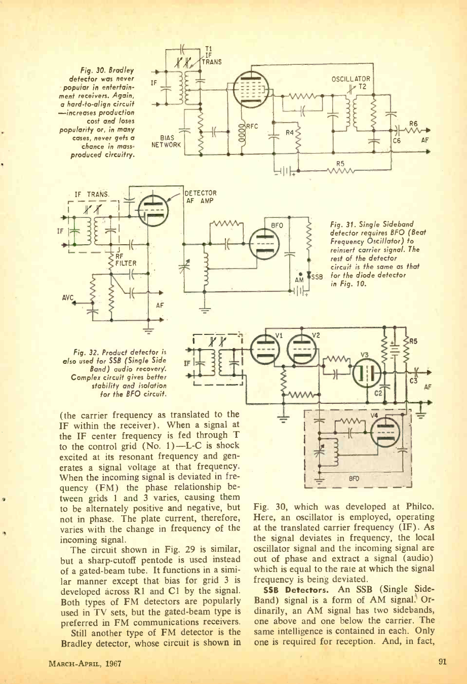
Fig. 30. Bradley
detector was never
popular in entertain-
ment receivers. Again,
o hard -fo -align circuit
-increases production
cost and loses
popularity or, in many
cases, never gets a BIAS
chance in mass- NETWORK
produced circuitry.
IE TI IF
TRANS
Fig. 32. Product detector is
also used for SSB (Single Side
Band) audio recovery.
Complex circuit gives better
stability and isolation
for the BFO circuit.
OSCILLATOR
II, T2
DETECTOR
AF AMP
AM SSB
R5
vvvv
R6
-'VVV-110
C6 AF
Fig. 31. Single Sideband
defector requires BFO (Beat
Frequency Oscillator) to
reinsert carrier signal. The
rest of the detector
circuit is the same as that
for the diode detector
in Fig. 10.
(the carrier frequency as translated to the
IF within the receiver). When a signal at
the IF center frequency is fed through T
to the control grid (No. 1) -L -C is shock
excited at its resonant frequency and gen-
erates a signal voltage at that frequency.
When the incoming signal is deviated in fre-
quency (FM) the phase relationship be-
tween grids 1 and 3 varies, causing them
to be alternately positive and negative, but
not in phase. The plate current, therefore,
varies with the change in frequency of the
incoming signal.
The circuit shown in Fig. 29 is similar,
but a sharp -cutoff pentode is used instead
of a gated -beam tube. It functions in a simi-
lar manner except that bias for grid 3 is
developed across R1 and Cl by the signal.
Both types of FM detectors are popularly
used ln I v sets, out me gaLeu-vc ssIs LYYC
preferred in FM communications receivers.
Still another type of FM detector is the
Bradley detector, whose circuit is shown in
MARCH- APRIL, 1967
Fig. 30, which was developed at Philco.
Here, an oscillator is employed, operating
at the translated carrier frequency (IF). As
the signal deviates in frequency, the local
oscillator signal and the incoming signal are
out of phase and extract a signal (audio)
which is equal to the rate at which the signal
frequency is being deviated.
SSB Detectors. An SSB (Single Side -
Band) signal is a form of AM signals Or-
dinarily, an AM signal has two sidebands
one above and one below the carrier. The
same intelligence is contained in each. Only
one is required for reception. And, in fact,
91
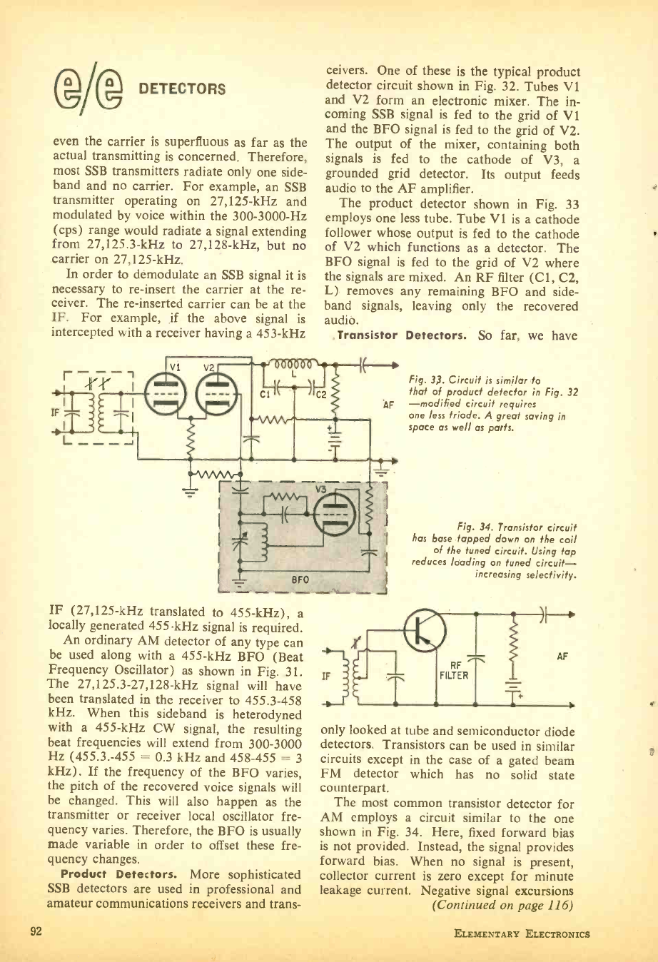
DETECTORS
even the carrier is superfluous as far as the
actual transmitting is concerned. Therefore,
most SSB transmitters radiate only one side -
band and no carrier. For example, an SSB
transmitter operating on 27,125 -kHz and
modulated by voice within the 300 -3000 -Hz
(cps) range would radiate a signal extending
from 27,125.3 -kHz to 27,128 -kHz, but no
carrier on 27,125 -kHz.
In order to demodulate an SSB signal it is
necessary to re- insert the carrier at the re-
ceiver. The re- inserted carrier can be at the
IF. For example, if the above signal is
intercepted with a receiver having a 453 -kHz
ceivers. One of these is the typical product
detector circuit shown in Fig. 32. Tubes V1
and V2 form an electronic mixer. The in-
coming SSB signal is fed to the grid of V1
and the BFO signal is fed to the grid of V2.
The output of the mixer, containing both
signals is fed to the cathode of V3, a
grounded grid detector. Its output feeds
audio to the AF amplifier.
The product detector shown in Fig. 33
employs one less tube. Tube VI is a cathode
follower whose output is fed to the cathode
of V2 which functions as a detector. The
BFO signal is fed to the grid of V2 where
the signals are mixed. An RF filter (C1, C2,
L) removes any remaining BFO and side -
band signals, leaving only the recovered
audio.
Transistor Detectors. So far, we have
Fig. 33. Circuit is similar lo
that of product defector in Fig. 32
-modified circuit requires
one less triode. A great saving in
space as well as parts.
Fig. 34. Transistor circuit
has base tapped down on the coil
of the tuned circuit. Using tap
reduces loading on tuned circuit -
increasing selectivity.
IF (27,125 -kHz translated to 455 -kHz), a
locally generated 455-kHz signal is required.
An ordinary AM detector of any type can
be used along with a 455 -kHz BFO (Beat
Frequency Oscillator) as shown in Fig. 31.
The 27,125.3- 27,128 -kHz signal will have
been translated in the receiver to 455.3 -458
kHz. When this sideband is heterodyned
with a 455 -kHz CW signal, the resulting
beat frequencies will extend from 300 -3000
Hz (455.3. -455 = 0.3 kHz and 458 -455 = 3
kHz). If the frequency of the BFO varies,
the pitch of the recovered voice signals will
be changed. This will also happen as the
transmitter or receiver local oscillator fre-
quency varies. Therefore, the BFO is usually
made variable in order to offset these fre-
quency changes.
Product Detectors. More sophisticated
SSB detectors are used in professional and
amateur communications receivers and trans-
IF
only looked at tube and semiconductor diode
detectors. Transistors can be used in similar
circuits except in the case of a gated beam
FM detector which has no solid state
counterpart.
The most common transistor detector for
AM employs a circuit similar to the one
shown in Fig. 34. Here, fixed forward bias
is not provided. Instead, the signal provides
forward bias. When no signal is present,
collector current is zero except for minute
leakage current. Negative signal excursions
92
(Continued on page 116)
ELEMENTARY ELECTRONICS
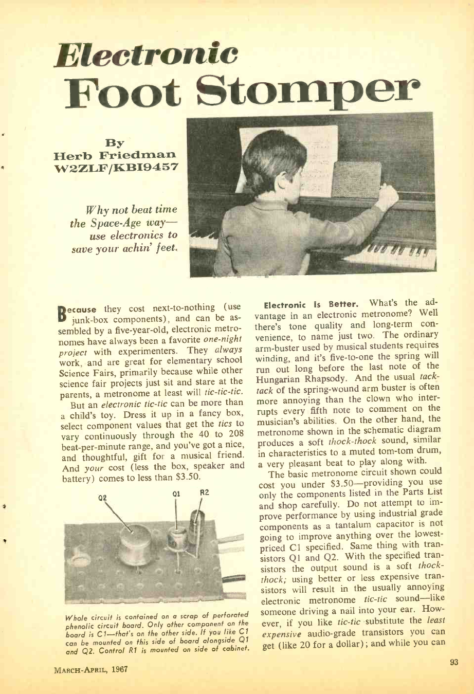
Electronic
Foot Stomper
By
Herb Friedman
W2ZLF /KBI9457
Why not beat time
the Space -Age way -
use electronics to
save your achin' feet.
Because they cost next -to- nothing (use
junk -box components), and can be as-
sembled by a five -year -old, electronic metro-
nomes have always been a favorite one -night
project with experimenters. They always
work, and are great for elementary school
Science Fairs, primarily because while other
science fair projects just sit and stare at the
parents, a metronome at least will tic- tic -tic.
But an electronic tic -tic can be more than
a child's toy. Dress it up in a fancy box,
select component values that get the tics to
vary continuously through the 40 to 208
beat -per- minute range, and you've got a nice,
and thoughtful, gift for a musical friend.
And your cost (less the box, speaker and
battery) comes to less than $3.50.
QE of R2
Whole circuit is contained on a scrap of perforated
phenolic circuit board. Only other component on the
board is C1- that's on the other side. If you like Cl
can be mounted on this side of board alongside Q1
and Q2. Control R1 is mounted on side of cabinet.
MARCH -APRIL, 1967
Electronic Is Better. What's the ad-
vantage in an electronic metronome? Well
there's tone quality and long -term con-
venience, to name just two. The ordinary
arm- buster used by musical students requires
winding, and it's five -to -one the spring will
run out long before the last note of the
Hungarian Rhapsody. And the usual tack -
tack of the spring -wound arm buster is often
more annoying than the clown who inter-
rupts every fifth note to comment on the
musician's abilities. On the other hand, the
metronome shown in the schematic diagram
produces a soft thock -thock sound, similar
in characteristics to a muted tom -tom drum,
a very pleasant beat to play along with.
The basic metronome circuit shown could
cost you under $3.50- providing you use
only the components listed in the Parts List
and shop carefully. Do not attempt to im-
prove performance by using industrial grade
components as a tantalum capacitor is not
going to improve anything over the lowest -
priced Cl specified. Same thing with tran-
sistors Q1 and Q2. With the specified tran-
sistors the output sound is a soft thock-
thock; using better or less expensive tran-
sistors will result in the usually annoying
electronic metronome tic -tic sound -like
someone driving a nail into your ear. How-
ever, if you like tic -tic substitute the least
expensive audio -grade transistors you can
get (like 20 for a dollar) ; and while you can
93
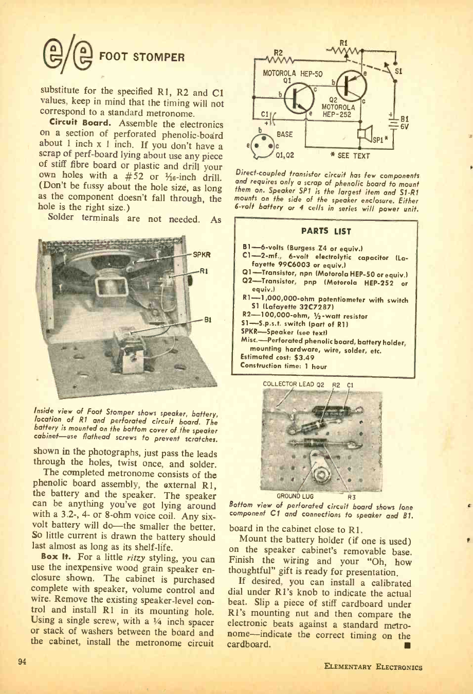
®Ag FOOT STOMPER
substitute for the specified R1, R2 and CI
values, keep in mind that the timing will not
correspond to a standard metronome.
Circuit Board. Assemble the electronics
on a section of perforated phenolic -board
about 1 inch x 1 inch. If you don't have a
scrap of perf -board lying about use any piece
of stiff fibre board or plastic and drill your
own holes with a #52 or 1,4e -inch drill.
(Don't be fussy about the hole size, as long
as the component doesn't fall through, the
hole is the right size.)
Solder terminals are not needed. As
Inside view of Foot Stomper shows speaker, battery,
location of 121 and perforated circuit board. The
battery is mounted on the bottom cover of the speaker
cabinet -use flathead screws to prevent scratches.
shown in the photographs, just pass the leads
through the holes, twist once, and solder.
The completed metronome consists of the
phenolic board assembly, the external R1,
the battery and the speaker. The speaker
can be anything you've got lying around
with a 3.2 -, 4- or 8 -ohm voice coil. Any six -
volt battery will do -the smaller the better.
So little current is drawn the battery should
last almost as long as its shelf -life.
Box It. For a little ritzy styling, you can
use the inexpensive wood grain speaker en-
closure shown. The cabinet is purchased
complete with speaker, volume control and
wire. Remove the existing speaker -level con-
trol and install R1 in its mounting hole.
Using a single screw, with a 1/4 inch spacer
or stack of washers between the board and
the cabinet, install the metronome circuit
R1
Direct -coupled transistor circuit has few components
and requires only a scrap of phenolic board to mount
them on. Speaker SPI is the largest item and S1 -R1
mounts on the side of the speaker enclosure. Either
6 -volt battery or 4 cells in series will power unit.
PARTS LIST
B1 -6 -volts (Burgess Z4 or equiv.)
C1- 2 -mf., 6 -volt electrolytic capacitor (La-
fayette 99C6003 or equiv.)
Q1- Transistor, npn (Motorola HEP -50 or equiv.)
Q2- Transistor, pnp (Motorola HEP -252 or
equiv.)
R1- 1,000,000 -ohm potentiometer with switch
Si (Lafayette 32C7287)
R2- 100,000 -ohm, 1/2-watt resistor
S1- S.p.s.t. switch (part of R1)
SPKR- Speaker (see text)
Misc.- Perforated phenolic board, battery holder,
mounting hardware, wire, solder, etc.
Estimated cost: $3.49
Construction time: 1 hour
COLLECTOR LEAD Q2 R2 Cl
GROUND LUG R3
Bottom view of perforated circuit board shows lone
component Cl and connections to speaker and BI.
board in the cabinet close to Rl.
Mount the battery holder (if one is used)
on the speaker cabinet's removable base.
Finish the wiring and your "Oh, how
thoughtful" gift is ready for presentation.
If desired, you can install a calibrated
dial under R1's knob to indicate the actual
beat. Slip a piece of stiff cardboard under
RI's mounting nut and then compare the
electronic beats against a standard metro-
nome- indicate the correct timing on the
cardboard.
c
r
94 ELEMENTARY ELECTRONICS
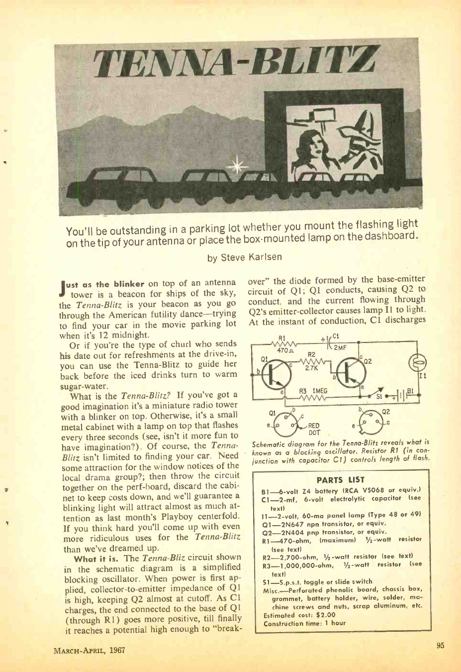
TENNA-Bil
You'll be outstanding in a parking lot
on the tip of your antenna or place the
by Steve
whether you mount the flashing light
box -mounted lamp on the dashboard.
Just as the blinker on top of an antenna
tower is a beacon for ships of the sky,
the Tenna -Blitz is your beacon as you go
through the American futility dance -trying
to find your car in the movie parking lot
when it's 12 midnight.
Or if you're the type of churl who sends
his date out for refreshments at the drive -in,
you can use the Tenna -Blitz to guide her
back before the iced drinks turn to warm
sugar- water.
What is the Tenna -Blitz? If you've got a
good imagination it's a miniature radio tower
with a blinker on top. Otherwise, it's a small
metal cabinet with a lamp on top that flashes
every three seconds (see, isn't it more fun to
have imagination ?). Of course, the Tenna-
Blitz isn't limited to finding your car. Need
some attraction for the window notices of the
local drama group ?; then throw the circuit
together on the perf- board, discard the cabi-
net to keep costs down, and we'll guarantee a
blinking light will attract almost as much at-
tention as last month's Playboy centerfold.
If you think hard you'll come up with even
more ridiculous uses for the Tenna -Blitz
than we've dreamed up.
What it is. The Tenna -Bliz circuit shown
in the schematic diagram is a simplified
blocking oscillator. When power is first ap-
plied, collector -to- emitter impedance of Q1
is high, keeping Q2 almost at cutoff. As Cl
charges, the end connected to the base of Q1
(through R1) goes more positive, till finally
it reaches a potential high enough to "break-
MARCH -APRIL, 1967
Karlsen
over" the diode formed by the base -emitter
circuit of Q1; Q1 conducts, causing Q2 to
conduct, and the current flowing through
Q2's emitter- collector causes lamp I1 to light.
At the instant of conduction, C1 discharges
R1
470a
Q1 R2
ci
2MF
I1
Qi
e RED
DOT .
Schematic diagram for the Tenna -Blitz reveals what is
known as a blocking oscillator. Resistor R1 (M con-
junction with capacitor Cl) controls length of flash.
PARTS LIST
B1-6 -volt Z4 battery (RCA VS068 or equiv.)
C1 -2 -mf, 6 -volt electrolytic capacitor (see
text)
11 -2 -volt, 60 -ma panel lamp (Type 48 or 49)
Q1 -2N647 npn transistor, or equiv.
Q2 -2N404 pnp transistor, or equiv.
R1-470 -ohm, (maximum) Ys -watt resistor
(see text)
R2- 2,700 -ohm, 1/2 -watt resistor (see text)
R3- 1,000,000 -ohm, 1/2 -watt resistor (see
text)
S1- S.p.s.t. toggle or slide switch
Misc.-Perforated phenolic board, chassis box,
grommet, battery holder, wire, solder, ma-
chine screws and nuts, scrap aluminum, etc.
Estimated cost: $2.00
Construction time: 1 hour
95
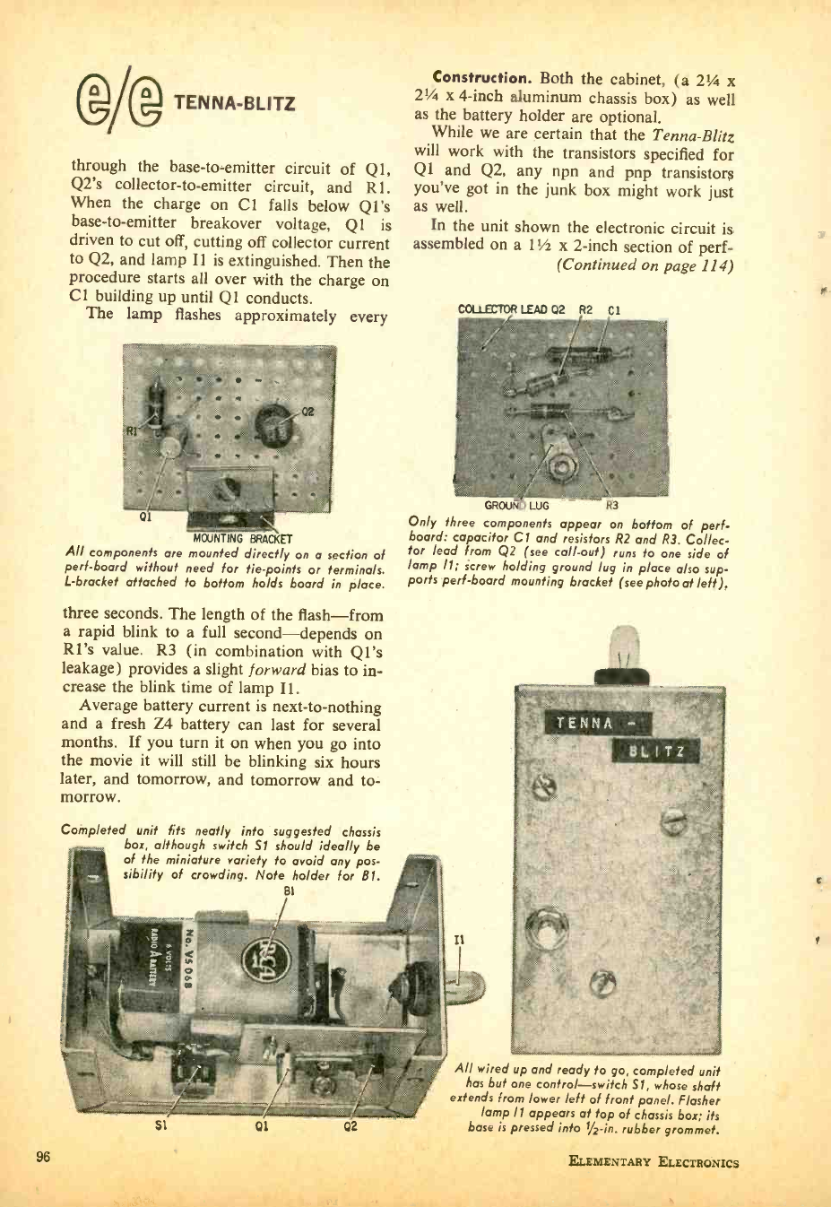
TENNA-BLITZ
through the base -to- emitter circuit of QI,
Q2's collector -to- emitter circuit, and R1.
When the charge on Cl falls below Q1's
base -to- emitter breakover voltage, Q1 is
driven to cut off, cutting off collector current
to Q2, and lamp I1 is extinguished. Then the
procedure starts all over with the charge on
Cl building up until Ql conducts.
The lamp flashes approximately every
01 illga Ma-
MOUNTING BRACKET
All components are mounted directly on a section of
pert -board without need for tie -points or terminals.
L- bracket attached to bottom holds board in place.
three seconds. The length of the flash -from
a rapid blink to a full second -depends on
RU's value. R3 (in combination with Q1's
leakage) provides a slight forward bias to in-
crease the blink time of lamp Il.
Average battery current is next -to- nothing
and a fresh Z4 battery can last for several
months. If you turn it on when you go into
the movie it will still be blinking six hours
later, and tomorrow, and tomorrow and to-
morrow.
Completed unit fits neatly into suggested chassis
box, although switch S1 should ideally be
of the miniature variety to avoid any pos-
sibility of crowding. Note holder for B1.
BI
Construction. Both the cabinet, (a 21/4 x
21/4 x 4 -inch aluminum chassis box) as well
as the battery holder are optional.
While we are certain that the Tenna -Blitz
will work with the transistors specified for
Q1 and Q2, any npn and pnp transistors
you've got in the junk box might work just
as well.
In the unit shown the electronic circuit is
assembled on a 11 x 2 -inch section of perf-
(Continued on page 114)
COLLECTOR LEAD 02 R2 C1
GROUND LUG R3
Only three components appear on bottom of perf-
board: capacitor C 1 and resistors R2 and R3. Collec-
tor lead from Q2 (see call -out) runs to one side of
lamp 11; screw holding ground lug in place also sup-
ports perf -board mounting bracket (see photo at left).
SI
96
01 02
II
All wired up and ready to go, completed unit
has but one control- switch SI, whose shaft
extends from lower left of front panel. Flasher
lamp 11 appears at top of chassis box; its
base is pressed into 1 /2 -in. rubber grommet.
ELEMENTARY ELECTRONICS
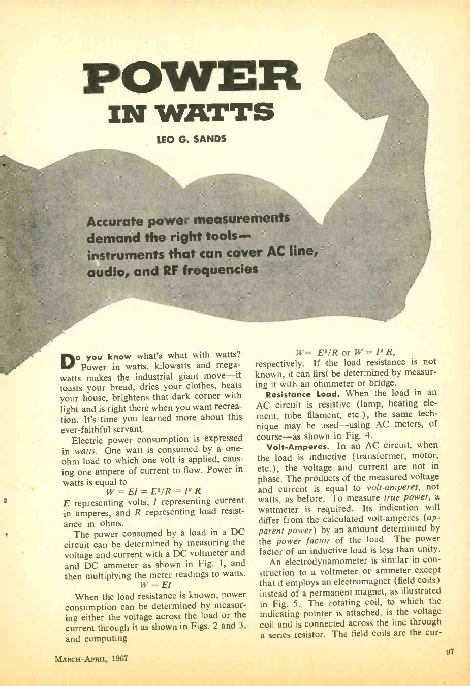
POWER
IN WATTS
LEO G. SANDS
Accurate power measurements
demand the right toots- -
instruments that can cover AC line,
audio, and RF frequencies
Do you know what's what with watts?
Power in watts, kilowatts and mega-
watts makes the industrial giant move -it
toasts your bread, dries your clothes, heats
your house, brightens that dark corner with
light and is right there when you want recrea-
tion. It's time you learned more about this
ever -faithful servant.
Electric power consumption is expressed
in watts. One watt is consumed by a one-
ohm load to which one volt is applied, caus-
ing one ampere of current to flow. Power in
watts is equal to
W= E1= E2 /R =12R
E representing volts, 1 representing current
in amperes, and R representing load resist-
ance in ohms.
The power consumed by a load in a DC
circuit can be determined by measuring the
voltage and current with a DC voltmeter and
and DC ammeter as shown in Fig. 1, and
then multiplying the meter readings to watts.
W = El
When the load resistance is known, power
consumption can be determined by measur-
ing either the voltage across the load or the
current through it as shown in Figs. 2 and 3,
and computing
W= E2 /R or W = 12 R,
respectively. If the load resistance is not
known, it can first be determined by measur-
ing it with an ohmmeter or bridge.
Resistance Load. When the load in an
AC circuit is resistive (lamp, heating ele-
ment, tube filament, etc.) , the same tech-
nique may be used -using AC meters, of
course -as shown in Fig. 4.
Volt- Amperes. In an AC circuit, when
the load is inductive (transformer, motor,
etc.) , the voltage and current are not in
phase. The products of the measured voltage
and current is equal to volt -amperes, not
watts, as before. To measure true power, a
wattmeter is required. Its indication will
differ from the calculated volt- amperes (ap-
parent power) by an amount determined by
the power factor of the load. The power
factor of an inductive load is less than unity.
An electrodynamometer is similar in con-
struction to a voltmeter or ammeter except
that it employs an electromagnet (field coils)
instead of a permanent magnet, as illustrated
in Fig. 5. The rotating coil, to which the
indicating pointer is attached, is the voltage
coil and is connected across the line through
a series resistor. The field coils are the cur-
MARCH-APRIL, 1967 97
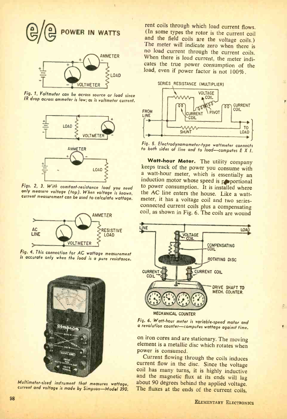
IV® POWER IN WATTS
AMMETER
LOAD
Fig. 1. Voltmeter can be across source or load since
IR drop across ammeter is low; as is voltmeter current.
AMMETER
Figs. 2, 3. With constant- resistance load you need
only measure voltage (top). When voltage is known,
current measurement can be used to calculate wattage.
AC
LINE RESISTIVE
LOAD
Fig. 4. This connection for AC wattage measurement
is accurate only when the load is a pure resistance.
Multimeter -sized instrument that measures wattage,
current and voltage is made by Simpson -Model 390.
98
rent coils through which load current flows.
(In some types the rotor is the current coil
and the field coils are the voltage coils.)
The meter will indicate zero when there is
no load current through the current coils.
When there is load current, the meter indi-
cates the true power consumption of the
load, even if power factor is not 100 %.
SERIES RESISTANCE (MULTIPLIER)
CURRENT
FROM PIVOT COIL
LINE CURRENT
CO L
TO
SHUNT LOAD
Fig. 5. E ectrodynamometer -type wattmeter connects
to both s'des of line and to load- computes E X I.
Watt -hour Meter. The utility company
keeps track of the power you consume with
a watt -hour meter, which is essentially an
induction motor whose speed is çportional
to power consumption. It is installed where
the AC line enters the house. Like a watt-
meter, it has a voltage coil and two series -
connected current coils plus a compensating
coil, as shown in Fig. 6. The coils are wound
INE
VOLTAGE
CURRENT
COIL
COMPENSATING
COIL
ROTATING DISC
CURRENT COIL
LOA
DRIVE SHAFT TO
MECH. COUNTER.
MECHANICAL COUNTER
Fig. 6. Watt -hour meter is variable -speed motor and
a revolution counter -computes wattage against time.
on iron cores and are stationary. The moving
element is a metallic disc which rotates when
power is consumed.
Current flowing through the coils induces
current flow in the disc. Since the voltage
coil has many turns, it is highly inductive
and the magnetic flux at its ends will lag
about 90 degrees behind the applied voltage.
The fluxes at the ends of the current coils,
ELEMENTARY ELECTRONICS
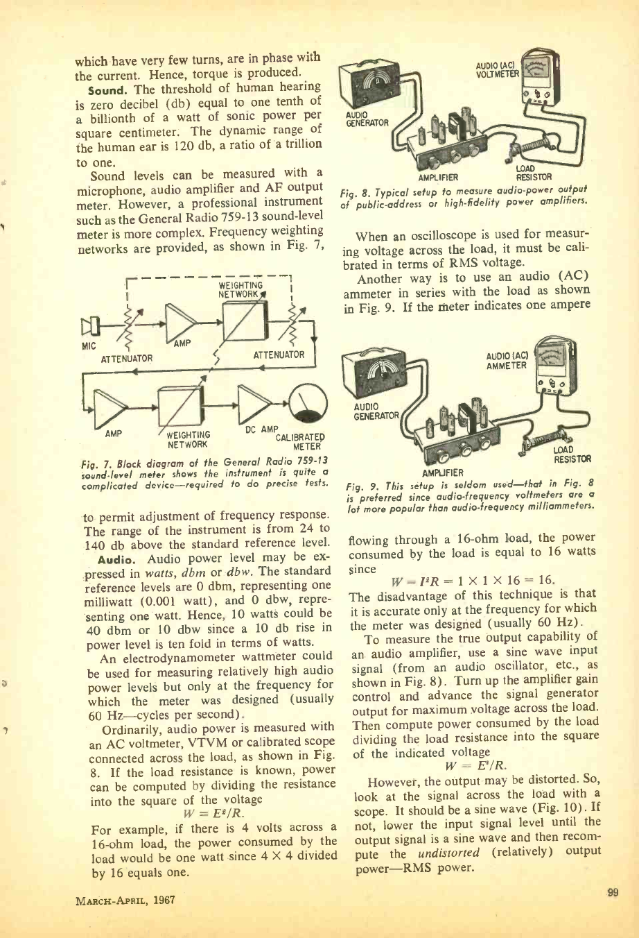
which have very few turns, are in phase with
the current. Hence, torque is produced.
Sound. The threshold of human hearing
is zero decibel (db) equal to one tenth of
a billionth of a watt of sonic power per
square centimeter. The dynamic range of
the human ear is 120 db, a ratio of a trillion
to one.
Sound levels can be measured with a
microphone, audio amplifier and AF output
meter. However, a professional instrument
such as the General Radio 759 -13 sound -level
meter is more complex. Frequency weighting
networks are provided, as shown in Fig. 7,
r
MIC S
ATTENUATOR
AMP
WEIGHTING
NETWORK
ATTENUATOR
1* ril °
AMP WEIGHTING DC AMP CALIBRATED
NETWORK METER
Fig. 7. Block diagram of the General Radio 759 -13
sound -level meter shows the instrument is quite a
complicated device -required fo do precise tests.
to permit adjustment of frequency response.
The range of the instrument is from 24 to
140 db above the standard reference level.
Audio. Audio power level may be ex-
pressed in watts, dbm or dbw. The standard
reference levels are 0 dbm, representing one
milliwatt (0.001 watt), and 0 dbw, repre-
senting one watt. Hence, 10 watts could be
40 dbm or 10 dbw since a 10 db rise in
power level is ten fold in terms of watts.
An electrodynamometer wattmeter could
be used for measuring relatively high audio
power levels but only at the frequency for
which the meter was designed (usually
60 Hz- cycles per second) .
Ordinarily, audio power is measured with
an AC voltmeter, VTVM or calibrated scope
connected across the load, as shown in Fig.
8. If the load resistance is known, power
can be computed by dividing the resistance
into the square of the voltage
W = E2 /R.
For example, if there is 4 volts across a
16 -ohm load, the power consumed by the
load would be one watt since 4 X 4 divided
by 16 equals one.
MARCH -APRIL, 1967
AUDIO
AMPLIFIER RESISTOR
Fig. 8. Typical setup fo measure audio -power output
of public -address or high -fidelity power amplifiers.
When an oscilloscope is used for measur-
ing voltage across the load, it must be cali-
brated in terms of RMS voltage.
Another way is to use an audio (AC)
ammeter in series with the load as shown
in Fig. 9. If the meter indicates one ampere
AUDIO (AC)
AMMETER
AUDIO
GENERATOR
LOAD
RESISTOR
AMPUF1ER
Fig. 9. This setup is seldom used -that in Fig. 8
is preferred since audio -frequency voltmeters are a
lot more popular than audio- frequency milliammeters.
flowing through a 16 -ohm load, the power
consumed by the load is equal to 16 watts
since W= I2R= 1X1X16 =16.
The disadvantage of this technique is that
it is accurate only at the frequency for which
the meter was designed (usually 60 Hz).
To measure the true output capability of
an audio amplifier, use a sine wave input
signal (from an audio oscillator, etc., as
shown in Fig. 8). Turn up the amplifier gain
control and advance the signal generator
output for maximum voltage across the load.
Then compute power consumed by the load
dividing the load resistance into the square
of the indicated voltage
W = E'/R.
However, the output may be distorted. So,
look at the signal across the load with a
scope. It should be a sine wave (Fig. 10). If
not, lower the input signal level until the
output signal is a sine wave and then recom-
pute the undistorted (relatively) output
power -RMS power.
99
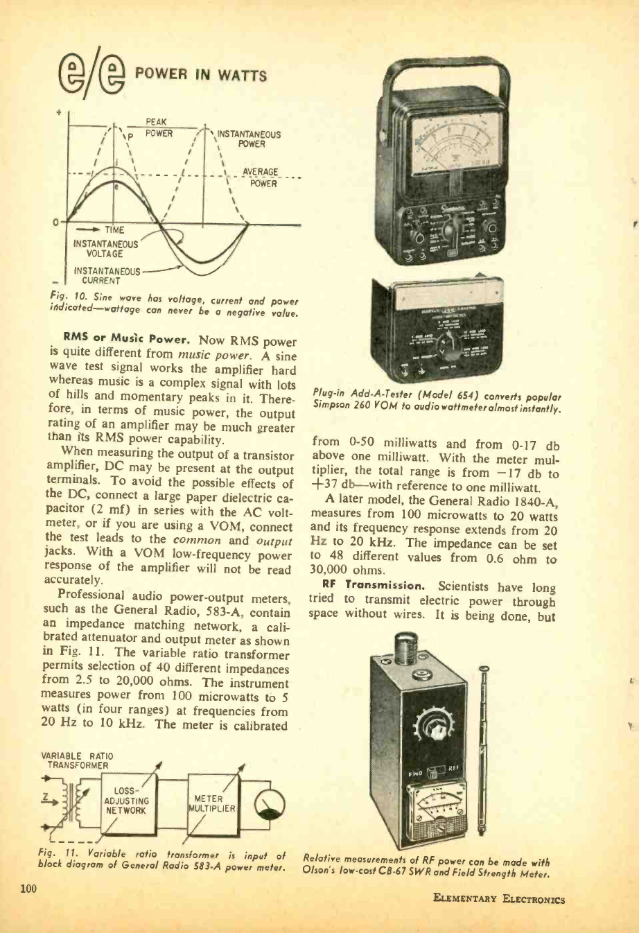
@AD POWER IN WATTS
PEAK
N P POWER ! ' INSTANTANEOUS
POWER
AVERAGE
POWER
- TIME
INSTANTANEOUS
VOLTAGE
INSTANTANEOUS
CURRENT
Fig. 10. Sine wave has voltage, current and power
indicated -wattage can never be a negative value.
RMS or Music Power. Now RMS power
is quite different from music power. A sine
wave test signal works the amplifier hard
whereas music is a complex signal with lots
of hills and momentary peaks in it. There-
fore, in terms of music power, the output
rating of an amplifier may be much greater
than its RMS power capability.
When measuring the output of a transistor
amplifier, DC may be present at the output
terminals. To avoid the possible effects of
the DC, connect a large paper dielectric ca-
pacitor (2 mf) in series with the AC volt-
meter, or if you are using a VOM, connect
the test leads to the common and output
jacks. With a VOM low -frequency power
response of the amplifier will not be read
accurately.
Professional audio power- output meters,
such as the General Radio, 583 -A, contain
an impedance matching network, a cali-
brated attenuator and output meter as shown
in Fig. 11. The variable ratio transformer
permits selection of 40 different impedances
from 2.5 to 20,000 ohms. The instrument
measures power from 100 microwatts to 5
watts (in four ranges) at frequencies from
20 Hz to 10 kHz. The meter is calibrated
VARIABLE RATIO
TRANSFORMER
LOSS -
ADJUSTING
NETWORK
METER
ULTIPLIER
Plug -in Add -A- Tester (Model 654) converts popular
Simpson 260 VOM to audio wattmeter almost instantly.
from 0 -50 milliwatts and from 0 -17 db
above one milliwatt. With the meter mul-
tiplier, the total range is from -17 db to
+37 db -with reference to one milliwatt.
A later model, the General Radio 1840 -A,
measures from 100 microwatts to 20 watts
and its frequency response extends from 20
Hz to 20 kHz. The impedance can be set
to 48 different values from 0.6 ohm to
30,000 ohms.
RF Transmission. Scientists have long
tried to transmit electric power through
space without wires. It is being done, but
0
Fig. 11. Variable ratio tran former is input of Relative measurements of RF power can be mode with
block diagram of General Radio 583 -A power meter. Olson's low -cost C8 -67 SWR and Field Strenath Meter_
100 ELEMENTARY ELECTRONICS
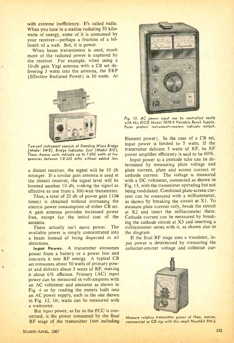
with extreme inefficiency. It's called radio.
When you tune in a station radiating 50 kilo-
watts of energy, some of it is consumed by
your receiver -perhaps a fraction of a bil-
lionth of a watt. But, it is power.
When beam transmission is used, much
more of the radiated power is captured by
the receiver. For example, when using a
10 -db gain Yagi antenna with a CB set de-
livering 3 watts into the antenna, the ERP
(Effective Radiated Power) is 30 watts. At
Two -unit instrument consists of Standing Wave Bridge
(Model SWB), Bridge Indicator Unit (Model B/U).
These Ameco units indicate up to 1,000 watts at fre-
quencies between 1.8.225 MHz without added loss.
a distant receiver, the signal will be 10 db
stronger. If a similar gain antenna is used at
the distant receiver, the signal level will be
boosted another 10 db, making the signal as
effective as one from a 300 -watt transmitter.
Thus, a total of 20 db of power gain (100
times) is obtained without increasing the
electric power consumption of either CB set.
A gain antenna provides increased power
free, except for the initial cost of the
antenna.
There actually isn't more power. The
available power is simply concentrated into
a beam instead of being dispersed in all
directions.
Input Power. A transmitter consumes
power from a battery or a power line and
converts it into RF energy. A typical CB
set consumes about 50 watts of primary pow-
er and delivers about 3 watts of RF, making
it about 6% efficient. Primary (AC) input
power can be measured in volt- amperes with
an AC voltmeter and ammeter as shown in
Fig. 4 or by reading the meters built into
an AC power supply, such as the one shown
in Fig. 12. Or, watts can be measured with
a wattmeter.
But input power, as far as the FCC is con-
cerned, is the power consumed by the final
RF ctage of the transmitter (not including
Fig. 12. AC power input can be controlled easily
with this E/CO Model 1078 -K Variable Bench Supply.
Fuses protect instrument- meters indicate output.
filament power). In the case of a CB set,
input power is limited to 5 watts. If the
transmitter delivers 3 watts of RF, its RF
power amplifier efficiency is said to be 60 %.
Input power to a pentode tube can be de-
termined by measuring plate voltage and
plate current, plate and screen current or
cathode current. The voltage is measured
with a DC voltmeter, connected as shown in
Fig. 13, with the transmitter operating but not
being modulated. Combined plate- screen cur-
rent can he measured with a milliammeter,
as shown by breaking the circuit at X1. To
measure plate current only, break the circuit
at X2 and insert the milliammeter there.
Cathode current can be measured by break-
ing the cathode circuit at X3 and inserting a
milliammeter series with it, as shown also in
the diagram.
If the final RF stage uses a transistor, in-
put power is determined by measuring the
collector- emitter voltage and collector cur-
Measure relative transmitter power of Ham, marine,
eammoreiol or CB rias with this small Heathkit PM -2.
MARCH -APRIL, 1967 101
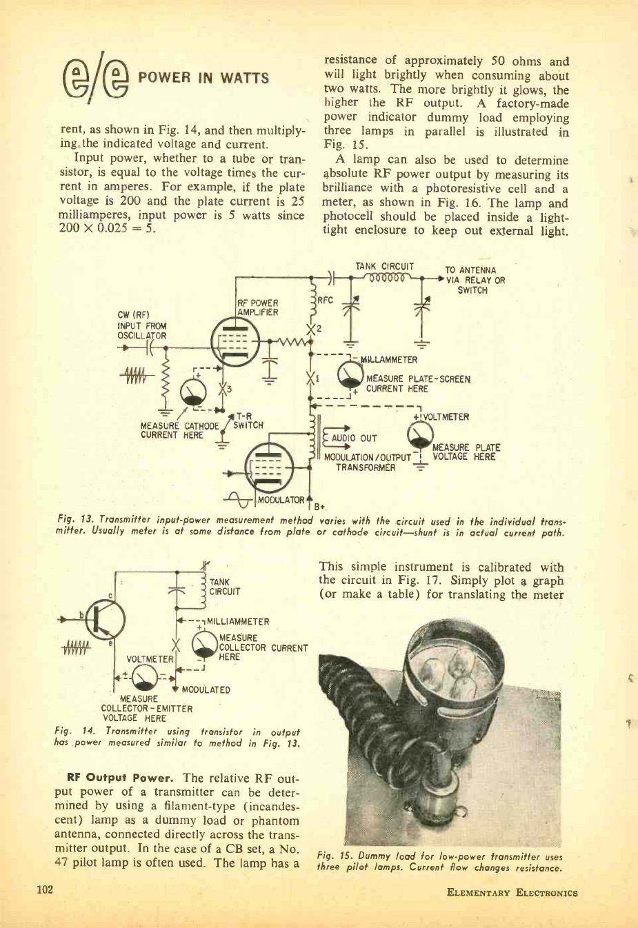
POWER IN WATTS
rent, as shown in Fig. 14, and then multiply -
ing.the indicated voltage and current.
Input power, whether to a tube or tran-
sistor, is equal to the voltage times the cur-
rent in amperes. For example, if the plate
voltage is 200 and the plate current is 25
milliamperes, input power is 5 watts since
200 X 0.025 = 5.
CW (RF)
INPUT FROM
OSCILLATOR
resistance of approximately 50 ohms and
will light brightly when consuming about
two watts. The more brightly it glows, the
higher the RF output. A factory -made
power indicator dummy load employing
three lamps in parallel is illustrated in
Fig. 15.
A lamp can also be used to determine
absolute RF power output by measuring its
brilliance with a photoresistive cell and a
meter, as shown in Fig. 16. The lamp and
photocell should be placed inside a light -
tight enclosure to keep out external light.
RF POWER
AMPLIFIER
RFC
X2
+
X3
% ` -- T -R
MEASURE CATHODE SWITCH
CURRENT HERE
TANK CIRCUIT
MILLAMMETER
TO ANTENNA
VIA RELAY OR
SWITCH
MEASURE PLATE - SCREEN
+ CURRENT HERE
+I VOLTMETER
AUDIO OUT MEASURE PLATE
MODULATION /OUTPUT I VOLTAGE HERE
TRANSFORMER
MODULATOR 8 +.
Fig. 13. Transmitter input -power measurement method varies with the circuit used in the individual trans-
mitter. Usually meter is at some distance from plate or cathode circuit -shunt is in actual current path.
r TANK
CIRCUIT
-- iMILLIAMMETER
MEASURE
COLLECTOR CURRENT
HERE
VOLTMETER
"1-.©_-_
MODULATED
MEASURE
COLLECTOR-EMITTER
VOLTAGE HERE
Fig. 14. Transmitter using transistor in output
has power measured similar to method in Fig. 13.
RF Output Power. The relative RF out-
put power of a transmitter can be deter-
mined by using a filament -type (incandes-
cent) lamp as a dummy load or phantom
antenna, connected directly across the trans-
mitter output. In the case of a CB set, a No.
47 pilot lamp is often used. The lamp has a
This simple instrument is calibrated with
the circuit in Fig. 17. Simply plot a graph
(or make a table) for translating the meter
Fig. 15. Dummy load for low -power transmitter uses
three pilot lamps. Current flow changes resistance.
1
102 ELEMENTARY ELECTRONICS
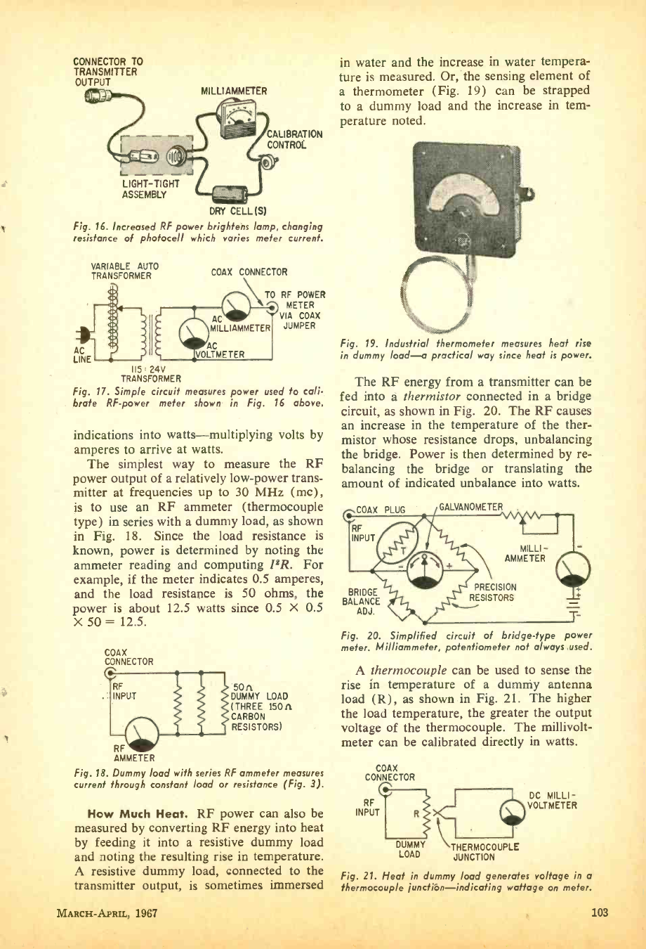
CONNECTOR TO
TRANSMITTER
OUTPUT MILLI AMMETER
CALIBRATION
CONTROL
L J
LIGHT -TIGHT
ASSEMBLY
DRY CELL(S)
Fig. 16. Increased RF power brightens lamp, changing
resistance of photocell which varies meter current.
VARIABLE AUTO
TRANSFORMER
AC
LINE r
115 24V
TRANSFORMER
Fig. 17. Simple circuit measures power used to cali-
brate RF -power meter shown in Fig. 16 above.
COAX CONNECTOR
,\ TO RF POWER
\ \\ METER
VIA COAX
JUMPER
1
AC
MILLIAMMETER
VOLTMETER
indications into watts -multiplying volts by
amperes to arrive at watts.
The simplest way to measure the RF
power output of a relatively low -power trans-
mitter at frequencies up to 30 MHz (mc),
is to use an RF ammeter (thermocouple
type) in series with a dummy load, as shown
in Fig. 18. Since the load resistance is
known, power is determined by noting the
ammeter reading and computing PR. For
example, if the meter indicates 0.5 amperes,
and the load resistance is 50 ohms, the
power is about 12.5 watts since 0.5 X 0.5
X 50 = 12.5.
COAX
CONNECTOR
RF 11
INPUT
RF
AMMETER
Fig. 18. Dummy load with series RF ammeter measures
current through constant load or resistance (Fig. 3).
50A
DUMMY LOAD
(THREE 150A
CARBON
RESISTORS)
How Much Heat. RF power can also be
measured by converting RF energy into heat
by feeding it into a resistive dummy load
and noting the result" ^g rise in temperature.
A resistive dummy load, connected to the
transmitter output, is sometimes immersed
in water and the increase in water tempera-
ture is measured. Or, the sensing element of
a thermometer (Fig. 19) can be strapped
to a dummy load and the increase in tem-
perature noted.
Fig. 19. Industrial thermometer measures heat rise
in dummy load -a practical way since heat is power.
The RF energy from a transmitter can be
fed into a thermistor connected in a bridge
circuit, as shown in Fig. 20. The RF causes
an increase in the temperature of the ther-
mistor whose resistance drops, unbalancing
the bridge. Power is then determined by re-
balancing the bridge or translating the
amount of indicated unbalance into watts.
COAX PLUG
RF
INPUT
GALVANOMETER
MILLI -
AMMETER
BRIDGE
BALANCE
ADJ.
PRECISION
RESISTORS
Fig. 20. Simplified circuit of bridge -type power
meter. Milliammeter, potentiometer not always used.
A thermocouple can be used to sense the
rise in temperature of a dummy antenna
load (R), as shown in Fig. 21. The higher
the load temperature, the greater the output
voltage of the thermocouple. The millivolt -
meter can be calibrated directly in watts.
COAX
CONNECTOR
RF
INPUT
DUMMY THERMOCOUPLE
LOAD JUNCTION
DC MILLI -
VOLTMETER
MARCH- APRIL, 1967
Fig. 21. Heat in dummy load generates voltage in a
thermocouple junctión- indicating wattage on meter.
103
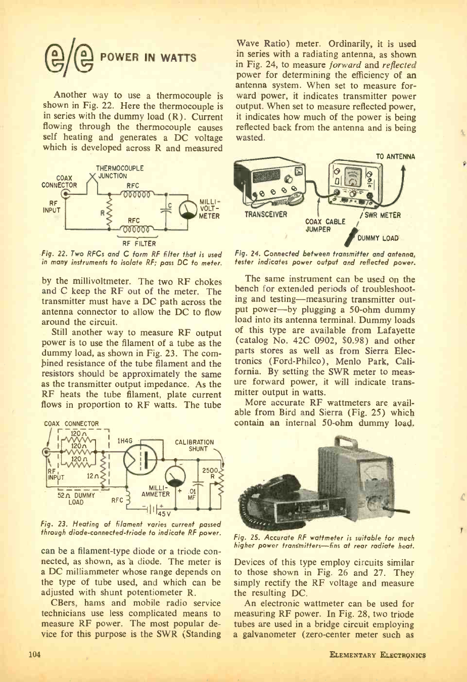
GM POWER IN WATTS
Another way to use a thermocouple is
shown in Fig. 22. Here the thermocouple is
in series with the dummy load (R). Current
flowing through the thermocouple causes
self heating and generates a DC voltage
which is developed across R and measured
COAX
CONNECTOR
RF
INPUT
THERMOCOUPLE
JUNCTION
RFC
RFC
RF FILTER
MILLI-
VOLT-
METER
Fig. 22. Two RFCs and C form RF filter that is used
in many instruments to isolate RF; pass DC to meter.
by the millivoltmeter. The two RF chokes
and C keep the RF out of the meter. The
transmitter must have a DC path across the
antenna connector to allow the DC to flow
around the circuit.
Still another way to measure RF output
power is to use the filament of a tube as the
dummy load, as shown in Fig. 23. The com-
bined resistance of the tube filament and the
resistors should be approximately the same
as the transmitter output impedance. As the
RF heats the tube filament, plate current
flows in proportion to RF watts. The tube
COAX CONNECTOR
Ir I
I
RF,
INPUT
120 n 1H4G CALIBRATION
SHUNT
Wave Ratio) meter. Ordinarily, it is used
in series with a radiating antenna, as shown
in Fig. 24, to measure forward and reflected
power for determining the efficiency of an
antenna system. When set to measure for-
ward power, it indicates transmitter power
output. When set to measure reflected power,
it indicates how much of the power is being
reflected back from the antenna and is being
wasted.
TRANSCEIVER /SWR METER
COAX CABLE /
JUMPER
/DUMMY LOAD
Fig. 24. Connected between transmitter and antenna,
fester indicates power output and reflected power.
The same instrument can be used on the
bench for extended periods of troubleshoot-
ing and testing- measuring transmitter out-
put power -by plugging a 50 -ohm dummy
load into its antenna terminal. Dummy loads
of this type are available from Lafayette
(catalog No. 42C 0902, $0.98) and other
parts stores as well as from Sierra Elec-
tronics (Ford -Philco), Menlo Park, Cali-
fornia. By setting the SWR meter to meas-
ure forward power, it will indicate trans-
mitter output in watts.
More accurate RF wattmeters are avail-
able from Bird and Sierra (Fig. 25) which
contain an internal 50 -ohm dummy load.
12rí
52n DUMMY
LOAD RFC
MILLI-
AMMETER
II 45V
Fig. 23. Heating of filament varies current passed
through diode -connected -triode to indicate RF power.
can be a filament -type diode or a triode con-
nected, as shown, as a diode. The meter is
a DC milliammeter whose range depends on
the type of tube used, and which can be
adjusted with shunt potentiometer R.
CBers, hams and mobile radio service
technicians use less complicated means to
measure RF power. The most popular de-
vice for this purpose is the SWR iStanding
104
Fig. 25. Accurate RF wattmeter is suitable for much
higher power transmitters -fins at rear radiate heat.
Devices of this type employ circuits similar
to those shown in Fig. 26 and 27. They
simply rectify the RF voltage and measure
the resulting DC.
An electronic wattmeter can be used for
measuring RF power. In Fig. 28, two triode
tubes are used in a bridge circuit employing
a galvanometer (zero- center meter such as
ELEMENTARY ELECTRONICS
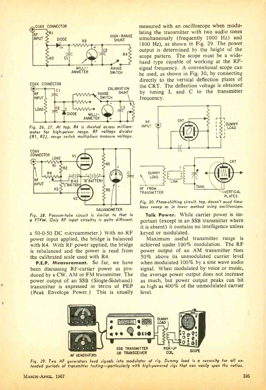
COAX CONNECTOR
R1
DIODE
RF
INPUT R3
HIGH - RANGE
SHUNT
C2
R4
COAX CONNECTOR
Cl
RF
INPUT
MILLI -
AMMETER RANGE
SWITCH .
CALIBRATION
RANGE SHUNT
SWITCH
LOAD C2
Fig. 26, 27. At top, R4 is shunted across milliam-
meter for high -power range. RF voltage divider
(R1, R2), range switch multipliers measure voltage.
COAX
CONNECTOR LOAD
GALVANOMETER
Fig. 28. Vacuum -tube circuit is similar to that in
a VTVM. Only RF input circuitry is quite different.
a 50 -0 -50 DC microammeter.) With no RF
power input applied, the bridge is balanced
with R4. With RF power applied, the bridge
is rebalanced and the power is read from
the calibrated scale used with R4.
P.E.P. Measurement. So far, we have
been discussing RF- carrier power as pro-
duced by a CW, AM or FM transmitter. The
power output of an SSB (Single -Sideband)
transmitter is expressed in terms of PEP
(Peak Envelope Power.) This is usually
AF GENERATORS
Fig. 29. Two AF generators feed signals into modulator of rig. Dummy load is a necessity for all ex-
tended periods of transmitter testing- particularly with high- powered rigs that can easily span the nation.
=
measured with an oscilloscope when modu-
lating the transmitter with two audio tones
simultaneously (frequently 1000 Hz) and
1800 Hz), as shown in Fig. 29. The power
output is determined by the height of the
scope pattern. The scope must be a wide -
band type capable of working at the RF-
signal frequency. A conventional scope can
be used, as shown in Fig. 30, by connecting
directly to the vertical deflection plates of
the CRT. The deflection voltage is obtained
by tuning L and C to the transmitter
frequency.
RF
INPUT :DUMMY
LOAD
J
DUMMY
LOAD
RF FROM
TRANSMITTER
LINK
VERTICAL
PLATES
Fig. 30. Phase -shifting circuit, top, doesn't need time -
base sweep as in lower method using oscilloscope.
Talk Power. While carrier power is im-
portant (except in an SSB transmitter where
it is absent) it contains no intelligence unless
keyed or modulated.
Maximum useful transmitter range is
achieved under 100% modulation. The RF
power output of an AM transmitter rises
50% above its unmodulated carrier level
when modulated 100% by a sine wave audio
signal. When modulated by voice or music,
the average power output does not increase
as much, but power output peaks can hit
as high as 400% of the unmodulated carrier
level.
41 IMO
SSO TRANSMITTER
OR TRANSCEIVER
MARCH -APRIL. 1y1í7 IUD
POWER IN WATTS
To achieve 100% modulation when using
plate modulation, the power output of the
modulator must be approximately the same
as the transmitter's RF output. In the case
of a 3 -watt RF output CB set, the modulator
usually delivers around 3 watts of audio.
The increase in power output of an AM
transmitter due to modulation can be meas-
ured with an RF output meter. When 100%
modulated by a sine wave test tone, the
power output reading should rise 50 %. If
an RF ammeter is used, as shown in Fig. 18,
the current should rise 22.5 %. For voice
modulation, the indicated power- output in-
crease will be less.
The RF -power output of an FM trans-
mitter, on the other hand, does not increase
under modulation. Instead, the carrier fre-
quency varies with modulation. The more
the frequency is deviated, the greater the
effective talk power. The RF power output
of an FM transmitter is measured with an
RF wattmeter which indicates carrier power.
Modulation level is measured with a devia-
tion meter which indicates frequency devia-
tion, not power.
RF- Power -Meter Connections. In all of
RF power measuring devices, coaxial con-
nectors are shown. Ordinarily, transmitters
are designed to work into a 50 -ohm antenna
system and coaxial connector -most accept
a PL -259 plug. Many measuring instru-
ments are also equipped with SO -239 re-
ceptacles (some use an N or UHF type con-
nector). Connections to the transmitter out-
put are made easier with a coaxial jumper,
Fig. 31. Length of co -axial cable with connectors
makes it easier to connect to transmitter, antenna.
106
Threaded connectors, along left edge of panel, mate
with those on ends of co -ax in Fig. 31. The Olson CB-
24 uses solid state circuitry to make seven important
tests on all types of Citizen's Band transceivers.
such as the one shown in Fig. 31. In this
case the jumper is a length of RG -58/U (50-
ohm) coaxial cable with a PL -259 plug at
each end. Some transmitters, (such as
medium frequency marine and some ham
types) have binding posts and their output
impedance may be other than 50 ohms.
Types of Power. Ordinarily, when deal-
ing with AC, AF and RF, we are concerned
with RMS (Root Mean Square) power.
Like an AC voltage, power has a peak
value which, in the case of a sine wave, is
1.414 times the RMS value or 1.57 times the
average value. It is the RMS value which is
the effective value, and which is normally
given in AC voltage specifications as 120 -
volts AC.
Power consumption may also be related to
time. I.f a load consumes one watt inter-
mittently for 10% of the time, the average
power is only one tenth of a watt. The peak
power of a radar pulse for example could
be 30 kilowatts. If each pulse is one micro-
second in duration and is repeated 500 times
per second, the average power would be only
15 watts since power is present only 2000th
of the time.
A small capacitor can be charged slowly,
consuming a very small amount of power'
over a period of time. When short circuited
it can release a tremendous amount of
power, but only momentarily -for an ex-
tremely short period of time.
Music contains peaks of considerable
power, often much higher than the rated
output of an amplifier. Yet, they can be
handled by a well designed amplifier since
ELEMENTARY ELECTRONICS
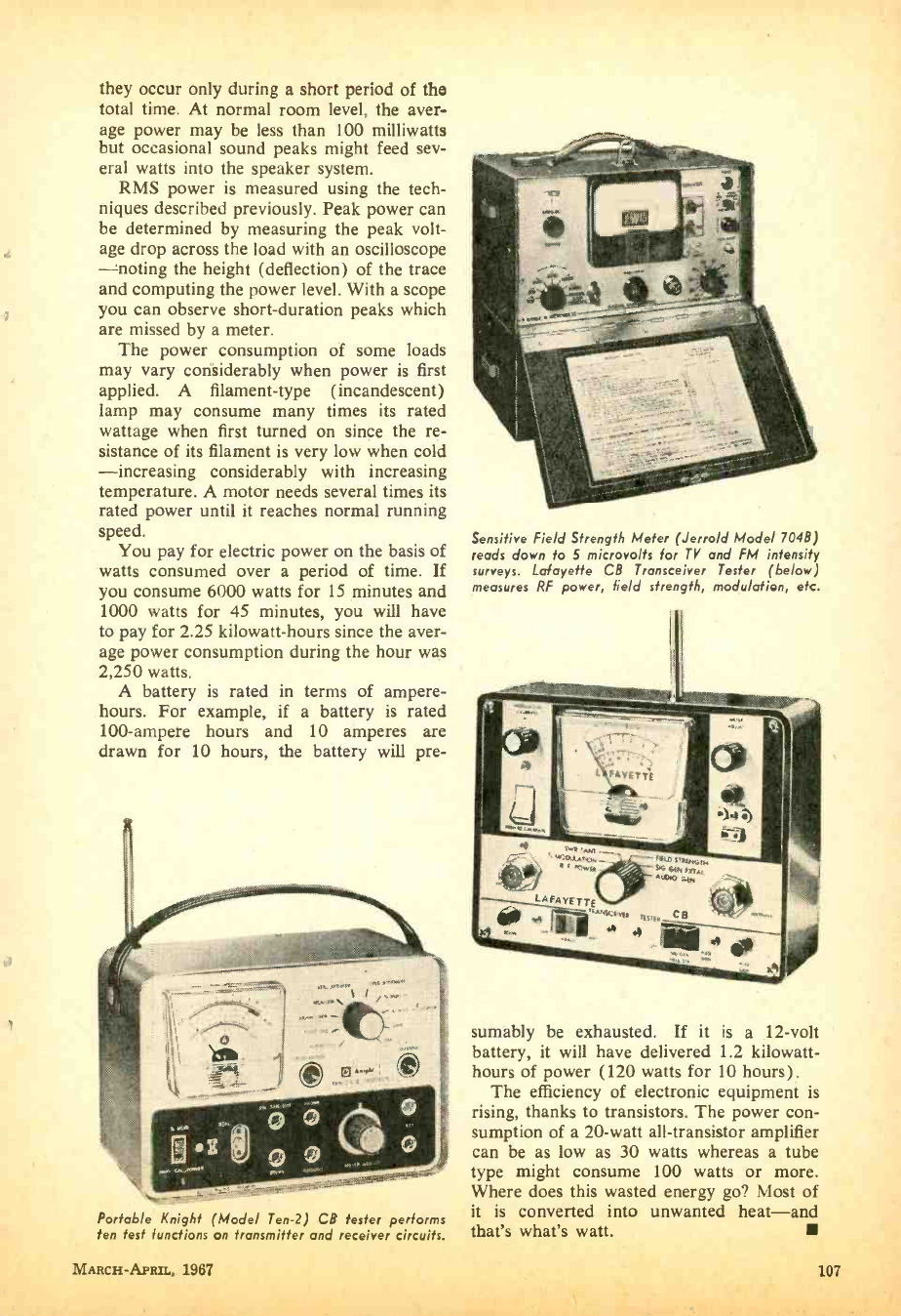
4
they occur only during a short period of the
total time. At normal room level, the aver-
age power may be less than 100 milliwatts
but occasional sound peaks might feed sev-
eral watts into the speaker system.
RMS power is measured using the tech-
niques described previously. Peak power can
be determined by measuring the peak volt-
age drop across the load with an oscilloscope
noting the height (deflection) of the trace
and computing the power level. With a scope
you can observe short -duration peaks which
are missed by a meter.
The power consumption of some loads
may vary considerably when power is first
applied. A filament -type (incandescent)
lamp may consume many times its rated
wattage when first turned on since the re-
sistance of its filament is very low when cold
-increasing considerably with increasing
temperature. A motor needs several times its
rated power until it reaches normal running
speed.
You pay for electric power on the basis of
watts consumed over a period of time. If
you consume 6000 watts for 15 minutes and
1000 watts for 45 minutes, you will have
to pay for 2.25 kilowatt -hours since the aver-
age power consumption during the hour was
2,250 watts.
A battery is rated in terms of ampere -
hours. For example, if a battery is rated
100- ampere hours and 10 amperes are
drawn for 10 hours, the battery will pre-
Portable Knight (Model Ten -2) CB tester performs
ten test functions on transmitter and receiver circuits.
MARCH- APRIL, 1967
Sensitive Field Strength Meter (Jerrold Model 704B)
reads down to 5 microvolts for TV and FM intensity
surreys. Lafayette CB Transceiver Tester (below)
measures RF power, field strength, modulation, etc.
sumably be exhausted. If it is a 12 -volt
battery, it will have delivered 1.2 kilowatt -
hours of power (120 watts for 10 hours) .
The efficiency of electronic equipment is
rising, thanks to transistors. The power con-
sumption of a 20 -watt all- transistor amplifier
can be as low as 30 watts whereas a tube
type might consume 100 watts or more.
Where does this wasted energy go? Most of
it is converted into unwanted heat -and
that's what's watt.
107
HEATNKR t967 LITERATURE
* Starred items indicate adver-
tisers in this issue. Consult
their ads for additional in-
formation and specifications.
LIBRARY
RADIO
wrIc
C8- BUSINESS RADIO
SHORTWAVE RADIO
115. Get the fully story on Poly -
Ironics Laboratories latest CB entry
-Carry-Comm. Full 5- watts, great
for mobile, base or portable use.
Works on 12 VDC or 115 AC.
*93. Heath Co. has a new 23 -chan-
nel all- transistor 5 -watt CB rig at the
lowest cost on the market, plus a full
line of CB gear. See their new 10-
band AM /FM /Shortwave portable
and line of shortwave radios.
101. If it's a CB product, chances
are International Crystal has it listed
in their colorful catalog. Whether kit
or wired, accessory or test gear, this
CB oriented company can be relied on
to fill the bill.
48. Hy- Gain's new CB antenna cata-
log is packed full of useful informa-
tion and product data that every
CB'er should know. Get a copy.
107. Get with the mobile set with
Tram's XL'100. The new Titan CB
base station, another Tram great, is
worth knowing about.
111. Get the scoop on Versa -
Tronics' Versa -Tenna with instant
magnetic mounting. Antenna models
available for CB'ers, hams and mobile
units from 27 MHz to 1000 MHz.
45. Catering to 2 -way radio buffs
for 30 years, World Radio Labora-
tories has a new free catalog which
includes the latest CB transceivers,
etc. Quarterly fliers chock -full of bar-
gains are also available.
50. Make your connection with
Amphenol -tune in to the latest on
CB product news with specs and pics
on new gear. Keep informed on
Amphenol's new products.
100. You can get increased CB range
and clarity using the "Cobra" trans-
ceiver with speech compressor -re-
ceiver sensitivity is excellent. Catalog
sheet will be mailed by B &K Division
of Dynascan Corporation.
54. A catalog for CB'ers, hams and
experimenters, with outstanding val-
ues. Terrific buys on Grove Electron-
ics' antennas. mikes and accessories.
96. If a rugged low cost business/
industrial two-way radio is what
you've been looking far, be sure to
send for the brochure on E. F. John-
son Co.'s brand new Messenger "202."
102. Sentry Mfg. Co. has some inter-
esting poop sheets on speech clippers,
converters, talk power kits and the
like for interested CB'ers, hams and
SWL'ers, too.
103. Squires- Sanders would like you
to know about their CB transceivers,
the "23'er" and the new "S5S." Also,
CB accessories that add versatility to
their 5- wattera.
108
KITS
*42. Here's a colorful 108 -page cat-
alog containing a wide assortment of
electronic kits. You'll find something
for any interest, any budget. And
Heath Co. will happily send you a
copy.
*44. EICO's new 48 -page 2 -color
pocket -size short form catalog is just
off the press. Over 250 products: Ham
radio, CB, hi -fi -in kit and wired
form -are illustrated. Also, discover
EICO's new experimenter kit line.
ELECTRONIC PRODUCTS
66. Try instant lettering to mark
control panels and component parts.
Datak's booklets and sample show
this easy dry transfer method.
108. Get the facts on Mercury's
line of test equipment kits- designed
to make troubleshooting easier, fast-
er and more profitable.
67. "Get the most measurement
value per dollar," says Electronics
Measurements Corp. Send for their
catalog and find out howl
92. How about installing a transis-
torized electronic ignition system in
your current car? AEC Laboratories
will mail their brochure giving you
specifications, schematics.
109. Seco offers a line of special-
ized and standard test equipment
that's ideal for the home experimenter
and pro. Get specs and prices today.
HI -FI /AUDIO
26. Always a leader, H. H. Scott
introduces a new concept in stereo
console catalogs. "At Home With
Stereo," offers decorating ideas, a
complete explanation of the more
technical aspects of stereo consoles.
85. Need a tuner? Preamp? Amp?
Tape deck? Then inspect Dyna for
kits or wired units. It's worthwhile
looking at test reports Dyna sends
your way.
110. Get the latest facts on sound
columns. American Geloso Electronics
Inc. offers a ten -page booklet giving
the bows and whys plus method of
installation and arrangement of sound
columns.
15. A name well -known in audio
circles is Acoustic Research. Here's
its booklet on the famous AR speak-
ers and the new AR turntable.
16. Discover how Cueing Control,
anti -scating and other Garrard fea-
tures in the Lab 80 offer tops in audio
listening. 32 -page Garrard Compara-
tor Guide will make you a wiser
buyer -get it.
17. Build your own bass reflex en-
closures from fool -proof plans offered
by Electro- Voice. At the same time
get the specs on EV's solid -state hi -fi
line -a new pace setter for the audio
industry.
19. Empire Scientific's new 8 -page,
full color catalog is now available to
our readers. Don't miss the sparkling
decorating- with -sound ideas.
24. Need a hi -fl or PA mike? Uni-
versity Sound has an interesting mi-
crophone booklet audio fans should
read before making a purchase.
27. An assortment of high fidelity
components and cabinets are described
in the Sherwood brochure. The cab-
inets can almost be designed to your
requirements, as they use modules.
95. Confused about stereo? Want to
beat the high cost of hi -fi without
compromising on the results? Then
you need the new 24-page catalog by
Jensen Manufacturing.
99. Get the inside info on why
Acoustech's solid -state amplifiers are
the rage of the experts. Colorful bro-
chure answers all your questions.
34. You can't pick the tape recorder
you need without a program -and
Sony Superscope has one. Full color
16 -page booklet is as good as your
dealer's showcase. Includes acces-
sories.
TAPE RECORDERS AND TAPE
113. Scotch is the product and it's
made by Minnesota Mining and Mfg.
Co. (3M). Get a packet full of facts
and tape data from 3M and learn all
about your tape recorder and the
tape it needs.
31. All the facts about Concord
Electronics Corp. tape recorders are
yours for the asking in a free book-
let. Portable, battery operated to four -
track, fully transistorized stereos cov-
er every recording need.
32. "Everybody's Tape Recording
Handbook" is the title of a booklet
that Sarkes -Tarzian will send you.
It's 24-pages jam -packed with info for
the home recording enthusiast. In-
cludes a valuable table of recording
times for various tapes.
33. Become the first to learn about
Norelco's complete Carry- Corder 150
portable tape recorder outfit. Four -
color booklet describes this new car-
tridge- tape unit.
35. If you are a serious tape audio-
phile, you will be interested in the
new Viking of Minneapolis line -they
carry both reel and cartridge re-
corders you should know about.
91. Sound begins and ends with a
Uher tape recorder. Write for this
new 20 page catalog showing the en-
tire line of Uher recorders and acces-
sories. How to synchronize your slide
projector, execute sound on sound,
and many other exclusive features.
ELEMENTARY ELECTRONICS
HI -FI ACCESSORIES
112. Telex would like you to know
about their improved Serenata Head-
set -and their entire line of quality
stereo headsets.
39. A 12 -page catalog describing the
audio accessories that make hi -fi liv-
ing a bit easier is yours from Switch -
craft, Inc. The cables, mike mixers.
and junctions are essentials!
98. Swinging to hi -fi stereo head-
sets? Then get your copy of Superex
Electronics' 16 -page catalog featuring
a large selection of quality headsets.
104. You can't hear FM stereo un-
less your FM antenna can pull 'em in.
Learn more and discover what's avail-
able from Finco's 6 -pager "Third Di-
mensional Sound."
AMATEUR RADIO
46. A long -time builder of ham
equipment, Hallierafters will send you
lots of info on the ham, CB and com-
mercial radio-equipment.
SCHOOLS AND EDUCATIONAL
114. Prepare for tomorrow by
studying at home with Technical
Training International. Get the facts
today on how you can step up in
your present job.
59. For a complete rundown on
curriculum, lesson outlines, and full
details from a leading electronic
school, ask for this brochure from the
Indiana Home Study Institute.
*61. ICS (International Corre-
spondence Schools) offers 236 courses
including many in the fields of radio,
TV, and electronics. Send wr Lice
booklet "It's Your Future."
*74. How to get an F.C.C. license,
plus a description of the complete
electronic courses offered by Cleve-
land Institute of Electronics are in
their free catalog.
105. Get the low -down on the latest
in educational electronic kits from
Trans -Tek. Build light dimmers.
amplifiers, metronomes, and many
more. Trans -Tek helps you to learn
while building.
TOOLS
*78. Learn about Xcelite's line of
pliers and snips, specialized for radio,
TV and electronic work. Xcelite's
hand tools offer many advantages
worth looking into. Bulletin N464
and N664.
TELEVISION
*70. The Heath Co. now has a 19"
color TV to complement their 21"
and 25" models. A new B &W port-
able model will be a hot seller for
the mobile set. Get the facts today!
72. Get your 1967 catalog of Cistin's
TV, radio, and hi -fi service books.
Bonus -TV tube substitution guide
and trouble- chaser chart is yours for
the asking.
29. Install your own TV or FM an-
tenna! Jefferson- King's exclusive free
booklet reveals secrets of installation,
orientation; how to get TV -FM trans-
mission data.
97. Interesting, helpful brochures
describing the TV antenna discovery
of the decade -the log periodic an-
tenna for UHF and UHF -TV, and
FM stereo. From JFD Electronics
Corporation.
ELECTRONIC PARTS
*1. Allied's catalog is so widely
used as a reference book, that it's re-
garded as a standard by people in the
electronics industry. Don't you have
the latest Allied Radio catalog? The
surprising thing is that it's free!
*2. The new 1967 Edition of Lafay-
erte's catalog features sections on
stereo hi -fi, CB, ham gear, test equip-
ment, cameras, optics, tools and much
more. Get your copy today.
*3. Bargains galore! Parts, tools,
test equipment, radios and many more
specials at ultra -low prices. Progres-
sive Edu -Kits will send latest catalog.
*4. Olson's catalog is a multi-
colored newspaper that's packed with
more bargains than a phone book has
names. Don't believe us? Get a copy.
*23. No electronics bargain hunter
should be caught without the 1967
copy of Radio Shack's catalog. Some
equipment and kit offers are so low.
they look like misprints. Buying is
believing.
*5. Edmund Scientific's new cata-
log contains over 4000 products that
embrace many interests and fields.
It's an 148 -page buyers' guide for
Science Fair fans.
*106. With 70 million TV's and 240
million radios somebody somewhere
will need a vacuum tube replacement
at the rate of one a second! Get Uni-
versal Tube Co.'s Troubleshooting
Chart and facts on their $1 flat rate
per tube.
7. Whether you buy surplus or
new, you will be interested in Fair
Radio Sales Co.'s latest catalog -
chuck full of surplus buys for every
experimenter.
8. Want a colorful catalog of
goodies? John Meshna, Jr. has one
that covers everything from assem-
blies to zener diodes. Listed are gov-
ernment surplus radio, radar, parts,
etc. All at unbelievable prices.
6. Bargains galore, that's what's
in store! Poly -Paks Co. will send you
their latest eight -page flyer listing the
latest in merchandise available, in-
cluding a giant $1 special sale.
10. Burstein- Applebee offers a new
giant catalog containing 100's of big
pages crammed with savings includ-
ing hundreds of bargains on hi -fi kits.
power tools, tubes, and parts.
11. Now available from EDI (Elec-
tronic Distributors. Inc.) a catalog
containing hundreds of electronic
items. EDI will be happy to place you
on their mailing List.
12. VHF listeners will want the
latest catalog from Kuhn Electronics.
All types and forms of complete re-
ceivers and converters.
ELEMENTARY ELECTRONICS, Dept. 367
505 Park Avenue, New York, N. Y. 10022
Please have literature whose numbers I have en-
circled sent to me as soon as possible. I am enclos-
ing 25G (no stamps) to cover handling charges.
1 2 3 4 5 6 7 8 10 11 12 15 16 17
19 23 24 26 27 29 31 32 33 34 35 39 42 44
45 46 48 50 54 57 59 61 66 67 70 72 74 78
85 91 92 93 95 96 97 98 99 100 101 102 103 104
105 106 107 108 109 110 111 112 113 114
I am a subscriber
Indicate total number
of booklets requested
7
NAME (Print clearly)
ADDRESS
CITY STATF ZIP CODE J
MARCH -APRIL, 1967 109
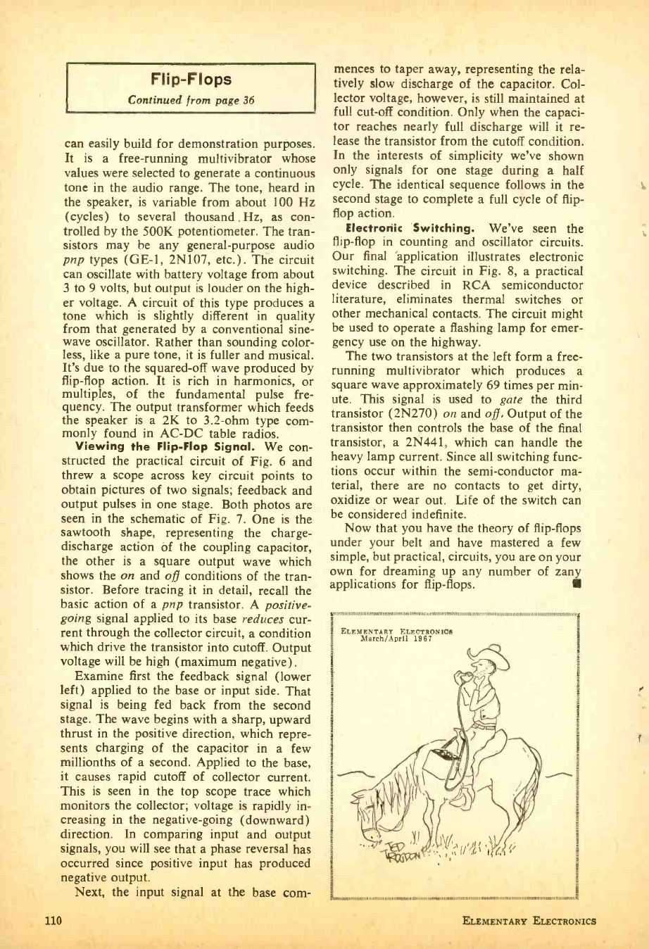
Flip -Flops
Continued from page 36
can easily build for demonstration purposes.
It is a free -running multivibrator whose
values were selected to generate a continuous
tone in the audio range. The tone, heard in
the speaker, is variable from about 100 Hz
(cycles) to several thousand . Hz, as con-
trolled by the 500K potentiometer. The tran-
sistors may be any general- purpose audio
pnp types (GE -1, 2N107, etc.). The circuit
can oscillate with battery voltage from about
3 to 9 volts, but output is louder on the high-
er voltage. A circuit of this type produces a
tone which is slightly different in quality
from that generated by a conventional sine -
wave oscillator. Rather than sounding color-
less, like a pure tone, it is fuller and musical.
It's due to the squared -off wave produced by
flip -flop action. It is rich in harmonics, or
multiples, of the fundamental pulse fre-
quency. The output transformer which feeds
the speaker is a 2K to 3.2 -ohm type com-
monly found in AC -DC table radios.
Viewing the Flip -Flop Signal. We con-
structed the practical circuit of Fig. 6 and
threw a scope across key circuit points to
obtain pictures of two signals; feedback and
output pulses in one stage. Both photos are
seen in the schematic of Fig. 7. One is the
sawtooth shape, representing the charge -
discharge action of the coupling capacitor,
the other is a square output wave which
shows the on and off conditions of the tran-
sistor. Before tracing it in detail, recall the
basic action of a pnp transistor. A positive -
going signal applied to its base reduces cur-
rent through the collector circuit, a condition
which drive the transistor into cutoff. Output
voltage will be high (maximum negative).
Examine first the feedback signal (lower
left) applied to the base or input side. That
signal is being fed back from the second
stage. The wave begins with a sharp, upward
thrust in the positive direction, which repre-
sents charging of the capacitor in a few
millionths of a second. Applied to the base,
it causes rapid cutoff of collector current.
This is seen in the top scope trace which
monitors the collector; voltage is rapidly in-
creasing in the negative -going (downward)
direction. In comparing input and output
signals, you will see that a phase reversal has
occurred since positive input has produced
negative output.
Next, the input signal at the base corn-
110
mences to taper away, representing the rela-
tively slow discharge of the capacitor. Col-
lector voltage, however, is still maintained at
full cut -off condition. Only when the capaci-
tor reaches nearly full discharge will it re-
lease the transistor from the cutoff condition.
In the interests of simplicity we've shown
only signals for one stage during a half
cycle. The identical sequence follows in the
second stage to complete a full cycle of flip -
flop action.
Electronic Switching. We've seen the
flip -flop in counting and oscillator circuits.
Our final application illustrates electronic
switching. The circuit in Fig. 8, a practical
device described in RCA semiconductor
literature, eliminates thermal switches or
other mechanical contacts. The circuit might
be used to operate a flashing lamp for emer-
gency use on the highway.
The two transistors at the left form a free -
running multivibrator which produces a
square wave approximately 69 times per min-
ute. This signal is used to gate the third
transistor (2N270) on and off. Output of the
transistor then controls the base of the final
transistor, a 2N441, which can handle the
heavy lamp current. Since all switching func-
tions occur within the semi -conductor ma-
terial, there are no contacts to get dirty,
oxidize or wear out. Life of the switch can
be considered indefinite.
Now that you have the theory of flip -flops
under your belt and have mastered a few
simple, but practical, circuits, you are on your
own for dreaming up any number of zann
applications for flip -flops.
n
ELEMENTARY rELECTRONICa
March/April 198?
1111111 11111 11 11 1111 rrr11111111111111 n rnn nnnnrnnnrr rrrnrnn,n,rnnnnnn
ELEMENTARY ELECTRONICS
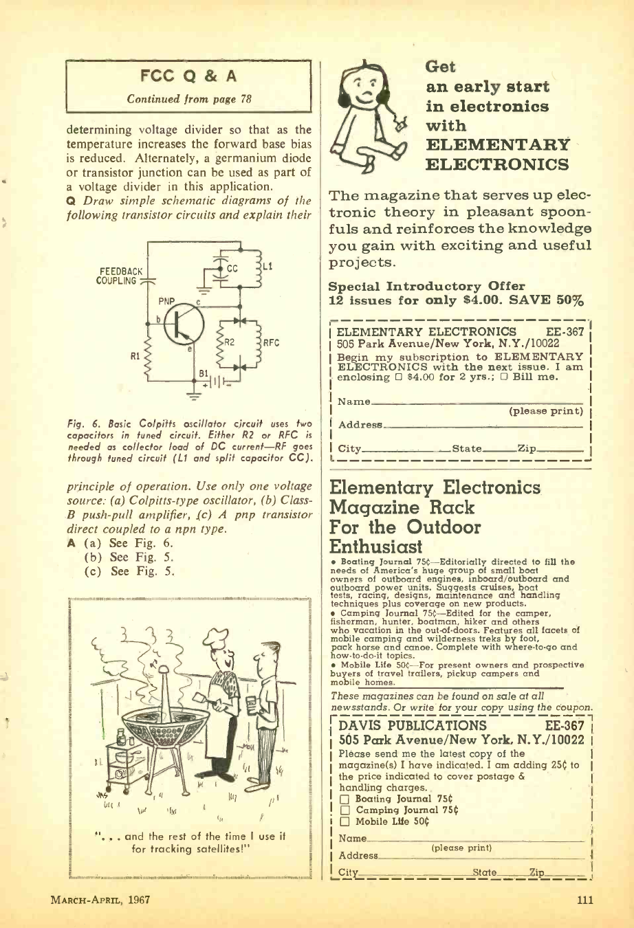
FCC Q & A
Continued from page 78
determining voltage divider so that as the
temperature increases the forward base bias
is reduced. Alternately, a germanium diode
or transistor junction can be used as part of
a voltage divider in this application.
Q Draw simple schematic diagrams of the
following transistor circuits and explain their
FEEDBACK
COUPLING
R1
LI
RFC
Fig. 6. Basic Colpitts oscillator circuit uses two
capacitors in tuned circuit. Either R2 or RFC is
needed as collector load of DC current -RF goes
through tuned circuit (L1 and split capacitor CC).
principle of operation. Use only one voltage
source: (a) Colpitts -type oscillator, (b) Class -
B push -pull amplifier, (c) A pnp transistor
direct coupled to a npn type.
A (a) See Fig. 6.
(b) See Fig. 5.
(c) See Fig. 5.
ittninillimiJlzu.numitilitatirtoirml.11111111militnnimosmtovimmnnimillimamillitnimilimilminumin111111nnlInmmn
"... and the rest of the time I use it
for tracking satellites!"
rt
MARCH- APRIL, 1967
Get
an early start
in electronics
with
ELEMENTARY
ELECTRONICS
The magazine that serves up elec-
tronic theory in pleasant spoon-
fuls and reinforces the knowledge
you gain with exciting and useful
projects.
Special Introductory Offer
12 issues for only $4.00. SAVE 50%
ELEMENTARY ELECTRONICS EE -367
505 Park Avenue /New York, N.Y. /10022
Begin my subscription to ELEMENTARY
ELECTRONICS with the next issue. I am
enclosing D $4.00 for 2 yrs.; D Bill me.
Name
Address
City
L
(please print)
State Zip
Elementary Electronics
Magazine Rack
For the Outdoor
Enthusiast
Boating Journal 75t- Editorially directed to fill the
needs of America's huge group of small boat
owners of outboard engines, inboardjoutboard and
outboard power units. Suggests cruises, boat
tests, racing, designs, maintenance and handling
techniques plus coverage on new products.
Camping Journal 75(- Edited for the camper,
fisherman, hunter, boatman, hiker and others
who vacation in the out-of-doors. Features all facets of
mobile camping and wilderness treks by foot,
pack horse and canoe. Complete with where -to -go and
how- to -do -it topics.
Mobile Life 50C -For present owners and prospective
buyers of travel trailers, pickup campers and
mobile homes.
These magazines can be found on sale at all
newsstands. Or write for your copy using the coupon.
EDAVIS PUBLICATIONS EE -367,
505 Park Avenue /New York, N.Y. /10022
Please send me the latest copy of the
magazine(s) I have indicated. I am adding 250 to
the price indicated to cover postage &
handling charges.
Boating Journal 750
Camping Journal 750
I Mobile Life 500
Name
Address (please print)
City State -Zip
Ham Shack Heart
Continued from page 45
to either the normal speaker- headphone ar-
rangement or to a telegraph converter. This
latter is a vacuum -tube device employing a
sensitive polar relay which accepts the re-
ceiver output, amplifies it and transfers it
to a conventional telegraph sounder. The
owner of this control center is a member
of a charmed circle who often work each
other in the Continental Morse telegraph
code rather than International, hence the
sounder arrangement! Now to the right of
the main panel, there are two rotary switch-
es just below the slide- switch sub -panel. The
left hand rotary switch connects the output
of any of the four receivers to the speaker,
headphones or telegraph sounder as selected.
The other rotary switch provides two values
of audio -tone filtering as well as a position
to cut the filter out of the circuit.
Above the right hand slide- switch sub -
panel is a potentiometer to control the audio
noise limiter -a slide switch directly below
it switches it in or out of the circuit. In a
horizontal row along the bottom of the
panel, eight fuses protect the four trans-
mitters and four receivers. The main fuse
(to the right of the clock) and the main
switch (to the left of the clock) remove all
power from the entire control unit -turning
off all equipment connected to it by merely
flipping one switch. The clock, of course,
has a separate, fused circuit which remains
"hot" at all times. Fusing for the clock,
RF- monitor power supply and the telegraph
converter are on the back panel. While
conveniently reached for possible replace-
ment, these fuses were not deemed sufficient-
ly important to warrant front -panel space
as they are not pertinent to actual com-
munication operation.
The indicator lights (one for each re-
ceiver and transmitter and one for the main
incoming power as well as one for the keying
monitor supply) are of novel design. They
are small neon lamps with a built -in resistor
for 11.5-volt operation and are press -fitted
into appropriate panel holes. Amber jewels
are used for the receivers and keying moni-
tor and red for transmitters and main power.
All external wiring from the control center
to the equipment is terminated in a series
oI plugs anu sucxels un we rear parlel-
eliminating all screw or solder type terminals.
112
The complete control center can be un-
plugged from all equipment and removed
in less than a minute. With the exception
of the transmitter and receiver AC- supply
plugs, no two plug- and -socket assemblies are
alike, preventing any misconnection. Should
the two AC power plugs (both of the octal
type) be reversed in connecting, no harm
is done. The transmitter switches would
then simply activate the receivers and vice -
versa which would immediately make the
transposition obvious. As a further safe-
guard however, one plug and socket assem-
bly is painted bright red, the other brilliant
green. While hardly in a class with Gemini
Control, this versatile control center appar-
ently overlooks nothing which could be con-
sidered as a station operating convenience
and most certainly provides finger -tip con-
trol of everything, directly from the operat-
ing position.
Design Your Own. From the foregoing
description and the accompanying illustra-
tions it should appear rather evident that
wide leeway in the design of a control center
is possible. From the simplest little transmit-
ter- receiver AC control box to the "grand-
daddy" unit, these control centers offer a
broad range for exercise of ingenuity and in-
itiative to produce a control center to suit your
equipment. Individual ideas of the "home -
brew" designer and builder can run ramp-
ant. Regardless of the end result, grouping
controls at one central point is about the
handiest and most convenient station layout
imaginable. The block diagrams offer some
ideas for various control groupings; almost
any item of station equipment can be deleted
or added and the arrangements shown are
sufficiently flexible to provide for wide lee-
way in modifications to suit the builders'
fancy.
mum n Aunt= n --"
ELEMENTARY ELECTRONICS
50)t Transistor Tester
Continued from page 66
or no resistance change is noted upon apply-
ing base current, the transistor cap be as-
sumed to be defective.
Base Leakage. The next test checks Icbo,
the collector -to-base leakage current with
emitter open, in terms of resistance or cur-
rent if desired. Excessive Icbo leakage biases
or shifts the transistor operating points up-
wards to higher collector currents- leading
to excess heating, large -signal distortion and
other effects. A transistor with higher -than-
normal Icbo leakage may or may not oper-
ate properly depending on the particular cir-
cuit and other factors.
Switch the VTVM to the R X 10K -ohm
range. Maximum test current on this range
is 15 microamperes with leads shorted. Open
Si and connect the positive -voltage ohms
lead to the base. The indicated resistance
should fall in the upper third of the scale
corresponding to a test -lead current of five
microamperes or less. Most transistors will
read higher than one megohm on this ohms
range -the lower the resistance, the higher
the leakage current.
A high -leakage transistor will indicate near
zero ohms on the R X 10K -ohms range. An
appreciable downward drift of the meter
pointer indicates unstable leakage current
leading to transistor drift. No sharp division
line exists, but resistance readings well below
200K at these test voltages indicate higher -
than- normal leakages for low -power transis-
tors. Silicon transistors, which have extreme-
ly -low Icbo leakages, will read near infinity
on the R X 10K range.
These tests and resistance guidelines were
established by checking a number of low -
power germanium junction transistors in-
cluding not only good but also defective
transistors to insure their rejection. Although
infrequently, a transistor passing these tests
may fail to operate properly in the circuit
(at normal voltages) if the transistor has an
abnormally- rising Icbo leakage current with
an increase in collector voltage.
When running these tests, do not inad-
vertently set the ohms range to R X 1 ohm.
This range supplies about 150 milliamperes
of test current -which could damage some
converter -mixer type transistors. And just
reverse all polarities shown and mentioned
when checking npn transistors.
MARCH-APRIL, 1967
Way -Down SWL'ing
Continued from page 79
and Iraq are also members of the high
power society. Relay stations of the BBC
and the VOA make Malaysia and the Ryu-
kyu Islands voices of the Far East. Aus-
tralian territories of Papua and New Guinea
operate regional stations of 10 kw each.
Europe. Very few European transmitters
broadcast on 90 meters, mainly because re-
gional broadcasting can be done on the stand-
ard broadcast and FM bands (without the
high levels of static, usual in tropical areas,
on these bands). All of the European sta-
tions broadcasting on 90 meters are high
powered -such as the BBC in London,
Radio Budapest in Hungary, and Radio Free
Europe in Germany.
South America. With South America be-
ing mostly tropical, many stations operate on
this band. These stations, however, are pre-
dominantly low powered. Radio TV Do-
minicana, Santo Domingo, is one of the few
South Americans running over 5 kw in this
band. Since this country has just been
through a rebellion, logging it is fun.
Sky Wires. Antennas for the 90 -meter
band present no problem. A longwire an-
tenna is sufficient. Generally speaking, log-
ging Africa is easier on the east coast, and
Asia easier on the west coast. QSLing these
stations require a better than average report
because of their regional broadcasting.
Listening on 90 meters offers you a chance
at logging many rare stations. Just keep
those ears ready for anything and take a slow
twirl on that dial!
,,..o,,,,,,.,,,,,,,,,,,,,,,,,,,,.,.mm.lii,loli,.,..i..,mu..,ium,m.,,i,n .,,,,.,,,,, mm,,,,,
"While the current was going through,
did you notice any grid leak ?
113
L
Tenna -Blitz
Continued from page 96
board. To make connections, simply push the
component leads through the holes in the
board, twist them together, and solder.
There's no need for terminals.
If you're building the unit as shown, form
a bracket for mounting the perf -board from
scrap aluminum (as shown in the photo-
graphs). The bracket provides the ground
connection for the circuit via a solder lug
which is held in place by the bracket mount-
ing screw.
Wide variation is permitted in component
values. R1, which controls the length of the
flash, may be eliminated and replaced with a
jumper for a "quick burst" of light. The
higher you make the value of R 1 the longer
the flash will be. But do not exceed 470
ohms. If the flash is too long (caused by
more than 470 ohms) Q2 will overheat and
literally burn up.
Protection resistor R2 (2700 ohms) allows
experimentation with different transistors. If
you use the transistors specified in the parts
list R2 may be eliminated and replaced with
a jumper. R3 provides a slight bias for Q1
and its value may range from 470K to 2.2
megohms.
The value of capacitor Cl should be be-
tween 2 and 4 microfarads. Too small, the
lamp won't blink; and too large, the period
between flashes will be excessive.
Lamp I1 must be a type 48 or 49 or an
equivalent 2 -volt, 60 milliampere lamp. It is
press -fit into a 7/i -inch rubber grommet (no
need for the expense of a lamp holder). Just
make certain you solder the wires to I1 very
quickly -use flux if necessary to insure a fast
flow joint.
A Touch Of Schmaltz. If you use the
Tenna -Blitz as a car beacon it is normally
placed on the rear deck or the dashboard. But
you can attach a small clip to I1 and mount it
on the tip of the antenna running the wires
back to the control unit inside the car. Of
course, while the local hoodlums will pass -by
the blinker on the dash -thinking it's a
child's toy, you can almost bet a tower light
on the antenna will attract them from every
nook and gutter (don't say we didn't warn
you) .
Can you power the Tenna -Blitz from your
12 v. car battery? No! The excess current
will destroy Q2 and I1.
114
Speech Processer
Continued from page 54
_.]
Using the Speech Processor. To use the
speech processor simply unplug the micro-
phone from your rig and plug the micro-
phone into the Speech Processor and plug
the Speech Processor into the microphone
input of your rig. Turn on the AC. Wait a
few seconds for voltages to stabilize and with
the level control set to about mid -range make
a call. Unless a low- output dynamic micro-
phone is used the HI -LO gain switch (SI)
can be left in the low -gain position. With a
scope (or the help of a friend) adjust the
level control (R22) for just a little less than
100% modulation.
Now move the microphone to arm's length
and talk in a normal level voice. Modulation
should stay about the same. The bass and
treble controls are adjusted to suit individual
preferences and band conditions; with both
controls fully advanced the voice should
sound more penetrating and less natural.
The clipper will probably be used only
when conditions are bad as there is some loss
of naturalness. However, this is a small price
to pay for the difference of making and losing
a contact.
{TAMMY 87 8WN20MM. A4NAOMMMT ANO CNKINAM7N I s.w
.ya.r.» 4 n..l..,r...crr r....ar+..r.-
OsMNr 1, 1900 I' w. {1.os.t.rT RNArala
, rr-.awl MNr,A1T
urwa.r....w. TOT Pert Ave., by Tart, P. T. 10072
, ..........orto.,.,..,_-..
7M boa An., Per T..k, P. T. 10012
......»....r.a,.».,...<.............,.
ma 1
..... 0. Darts 707 hat An., In Tar, P. T. 10012
"".' J.l 11.'{1..t3nla 7D7 Perk An., Pee Ta.l, P. T. 10027
' JenTA D.ffr a 907 hot An., Pa Tart, P. T. 10012
r......,.......
r..i.........u.7.P.r*ti. ..,..,..............- ........
.....r u......,n.*.. í- .
....W i....... w...r .`r- r...+.. w-.-,._.w ......
klage I NatallaA Pull. b.
hrl. wJl.r..a. T. +07 Pert An P.. T..t, )
90S Peek AT... In Tat. l. T. 10012
.I LrL 909 P.R Ave be Tort. P. }9.,
afOfYó r+991..
rlhów ßwx....a...w...r rn. raa1IP001Rat..`sÌ .e. a.arr..u..
s.o.rt.a....... a ar..w... IV .. .
ra«
. ./.11:,71: .... ..
....... M,.;--.......,...~W'*sr.:*
r..r..- r:. : , ... ,. _ .........
..........,..... :
r:... '.. . ~ .:~.
is _.. _.... ...,...,._..._
r...._.......r........._................. :1T -.,.. OP
- -n.:,r
.....rw.r.r,-.... 140.017 131. SST
..arnr..r.-... ass swam M.921 47,000
, ....s.-. An 3,310
, .......-.... 70.370 00,500
no ems* .-... -..., r cow a w s.. 1.026 710
-. rr.. ,........ 71.60A 09r710
wa..«....e....M.-MONO 09,M3 02.2A3
.,r......._. 1A0, OAT 131.073
.r-°'.,..: .,'"....rM-.....r...,s,.i...-0 ét-el1:. P.: Ne41;'
MS. 7P1{ s ..
ELEMENTARY ELECTRONICS
Ci7tar/ief(ace
E
FOR BIGGER PROFITS! NEW CAREER OPPORTUNITIES!
READ AND REPLY TO THESE CLASSIFIED ADS
Classified Ads 55(: per word, each insertion, minimum 10 words, payable in advance. To be included in the next available
issue of ELEMENTARY ELECTRONICS, copy must be in our New York Office by March 10th. Address orders to C. D. Wilson,
Manager, Classified Advertising, ELEMENTARY ELECTRONICS, 505 Park Ave., New York, N. Y. 10022.
ADDITIONAL INCOME
MAKE Your Classified Ad Pay. Get
"How To Write a Classified Ad That
Pulls." Includes certificate worth $2.00
towards classified ad in S & M. Send $1.00
to C. D. Wilson, Science & Mechanics,
505 Park Ave., New York, N. Y. 10022.
AUTO PARTS & ACCESSORIES
CAR REPAIR: Dedicated to mechani-
cally minded readers. Send $1.00 (includes
postage & handling) to Car Repair. 605
Park Ave., New York, New York 10022.
BOATS. MOTORS & MARINE SUPPLIES
Full size, cut -to -shape boat patterns,
blueprints. Send 604 for big New illus-
trated "Build a Boat" catalog includes
Fishing Boats, Garvies, Cruisers. Catama-
rans, Houseboats - Outboards, Inboards,
Sailboats -712 to 38'. "How to Build a
Boat" booklet $2.50. Cleveland Boat Blue-
print Co., Box 18250, Cleveland. Ohio.
BOAT Kits. Save money- assemble
yourself. Factory molded fiberglass or
pre -assembled plywood. 12, to 32, Cruisers,
Runabouts, Houseboats, Sail Boats. Big
Line accessories, motors, trailers. Easy
terms. Free catalog. Luger, Dept. UC -67,
9200 Bloomington Freeway. Bloomington,
Minn. 55435.
BOOKS & PERIODICALS
1000 ELECTRONIC Books Available By
Mail. Free Catalog. Books, Box 796 -C.
Montreal, Canada.
FREE LIST. Inspirational and Self -Help
Books. Write: Aubrey, Box 221, Cranford,
New Jersey 07016.
CATALOG of all Science & Mechanics
Craftprints. Send 25$ to cover postage
and handling to Craftprint Div., Science
& Mechanics, 505 Park Ave., New York,
New York 10022.
BUSINESS OPPORTUNITIES
I MADE $40,000.00 a year by Mailorder!
Helped others make money! Start with
$10.00 -Free Proof! Torrey, Box 318 -T,
Ypsilanti, Michigan, 48197.
FREE Book "990 Successful Little -
Known Businesses." Fascinating! Work
home! Plymouth 911 -T, Brooklyn, N. Y.
11216.
MONEYMAKING Mail -Order Opportu-
nities, $200.00 weekly possible. Litton,
33MC, Randallstown, Maryland.
For Business Opportunities -read Sci-
ence & Mechanics. 12 issues $4.00. Write
Science & Mechanics, 505 Park Ave., New
York, N. Y. 10022.
EARTHWORMS
BIG Money Raising Flshworms and
Crickets. Free literature. Carter Farm -O,
Plains, Georgia 31780.
EDUCATION & INSTRUCTION
BUILD Your Own Test Equipment and
a Stereo AM -FM Radio. Practical Home
Study Courses in Electronics in Theory,
Practice and Servicing with complete kits
and tools included in price. Write for free
booklet with no obligation to: Inesco.
Intercontinental Electronics School, Dept.
16B, 9100 St. Lawrence Blvd., Montreal 11,
Quebec, Canada.
CORRESPONDENCE Courses - B.Sc.,
Engineering, Electronics. Catalog $1.00.
Canadian Institute of Science & Technol-
ogy, 263.1 Adelaide St. W., Toronto.
ENGINES, MOTORS, DYNAMOS
STEAM Boat & Steam Automobile Bro-
chure. Send Only Two Dollars. Shaw, Box
21204, Concord, Calif. 94521.
FOR INVENTORS
PATENT Searches -48 hour airmail
service, $6.00, including nearest patent
copies. More than 200 registered patent
attorneys have used my service. Free
invention protection Forms. Write Miss
Ann Hastings, Patent Searcher, P. O. Box
176, Washington. D. C. 20004.
HYPNOTISM
NEW concept teaches you self -hypnosis
quickly! Free literature. Smith- McKinley,
Box 3038, San Bernardino, Calif.
FREE!! Gigantic Hypnotism Catalog!
Azadiah, 5786 So, Elm, Fresno, Calif.
93760.
INVENTIONS WANTED
WE either sell your invention or pay
cash bonus. Write for details. Universal
Inventions, 298 -3, Marion, Ohio.
LEATHERCRAFT
FREE "Do -it- yourself" Leathercraft
Manual. Tandy Leather Company, 1001
Foch, N58, Fort Worth, Texas.
MODELS & MODEL SUPPLIES
SHIP Models. New Catalog 154. Scien
tific, Inc., 113N Monroe, Newark, New
Jersey 07105.
MONEYMAKING OPPORTUNITIES
HOW To Make A Home Operated Mail
Business Pay! Details- Carpenter, 2907 -J
West 39th Place, Chicago, Ill. 60632.
START Profitable Business in spare
time. Investigate many money -making
agency and franchise opportunities. Send
104 for sample copy of Income Opportuni-
ties Magazine, 505 Park Avenue, New
York, 10022. Dept. S.
PATENT SERVICE
PATENT Searches -48 hour airmail
service, $6.00, including nearest patent
copies. More than 200 registered patent
attorneys have used my service. Free
invention protection Forms. Write Miss
Ann Hastings, Patent Searcher, P. O. Box
176, Washington 4, D. C.
PERSONAL
BILL Problems? Poor credit no trouble.
Not a loan company. Send for free appli-
cation. Automatic Acceptance, 318DC
Broadway Blvd., Reno, Nevada or 307DC
Pocasset Ave., Providence, R. I.
PETS -DOGS, BIRDS, RABBITS.
HAMSTERS. ETC.
MAKE big money raising rabbits for us.
Information 25f. Keeney Brothers. New
Freedom. Penna.
RADIO & TELEVISION
McGEE Radio Company. Big 1966 -1967
Catalog Sent Free. America's Best Values.
Hi -Fi, Amplifiers, Speakers, Electronic
Parts. Send Name, Address and Zip Code
Number to McGee Radio Company, 1901
McGee Street, Dept. EE, Kansas City,
Missouri 64108.
FREE Catalog. Electronics parts, tubes.
Wholesale. Thousands of items. Unbeat-
able prices. Arcturus Electronics -RT.
502 22nd St., Union City, N. J. 07087.
CANADIANS -Giant Electronics Cata-
logs. Hi -Fi, Shortwave, Ham, CB. Rush
$1.00. ETCO, Dept. EZ. Box 741, Mon-
treal, Canada.
SEND $5.00 for giant size Experiment-
ers' Parts Assortment. J. C. Electronics,
14221 Sommermeyer, Houston, Texas 77040.
SCIENCE EXPERIMENTS
SCIENCE Experimenter -the magazine
dedicated to the youth who is interested in
experimentation, construction and Science
Fair entries. Send $1.00, includes Postage,
to Science Experimenter. 505 Park Ave..
New York. N. Y. 10022,
SONGWRITERS
POEMS Wanted for musical setting and
recording. Send poems. Free examination.
Crown Music, 49 -SC West 32, New York 1.
TREASURE FINDERS -PROSPECTING
EQUIPMENT
"NEW" Scientific Instrument detects
buried gold, silver, coins, treasures. $19.95
up. Free catalog. Relco -A30, Box 10563,
Houston, Texas 77018.
DIAMONDS, Gold. Find Them. Pam-
phlet Free. 18788 Cajon, San Bernardino.
California 92407.
THERE IS NO CHARGE FOR THE ZIP CODE- PLEASE USE IT IN YOUR CLASSIFIED AD
MARCH -APRIL, 1967 115
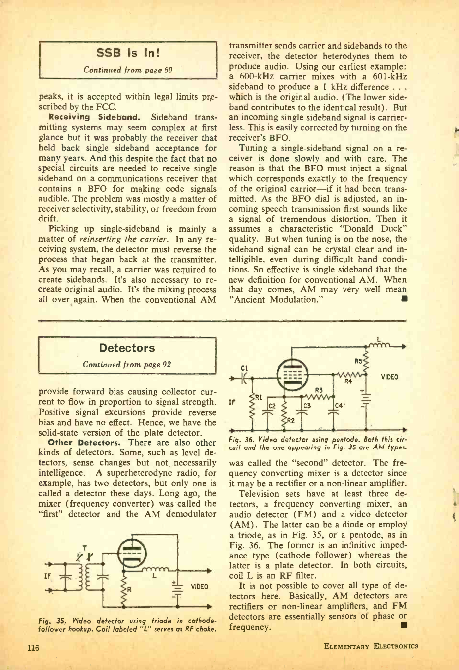
SSB Is In!
Continued from page 60
peaks, it is accepted within legal limits pre-
scribed by the FCC.
Receiving Sideband. Sideband trans-
mitting systems may seem complex at first
glance but it was probably the receiver that
held back single sideband acceptance for
many years. And this despite the fact that no
special circuits are needed to receive single
sideband on a communications receiver that
contains a BFO for making code signals
audible. The problem was mostly a matter of
receiver selectivity, stability, or freedom from
drift. Picking up single -sideband is mainly a
matter of reinserting the carrier. In any re-
ceiving system, the detector must reverse the
process that began back at the transmitter.
As you may recall, a carrier was required to
create sidebands. It's also necessary to re-
create original audio. It's the mixing process
all over, again. When the conventional AM
transmitter sends carrier and sidebands to the
receiver, the detector heterodynes them to
produce audio. Using our earliest example:
a 600 -kHz carrier mixes with a 601 -kHz
sideband to produce a 1 kHz difference .. .
which is the original audio. (The lower side -
band contributes to the identical result). But
an incoming single sideband signal is carrier -
less. This is easily corrected by turning on the
receiver's BFO.
Tuning a single -sideband signal on a re-
ceiver is done slowly and with care. The
reason is that the BFO must inject a signal
which corresponds exactly to the frequency
of the original carrier -if it had been trans-
mitted. As the BFO dial is adjusted, an in-
coming speech transmission first sounds like
a signal of tremendous distortion. Then it
assumes a characteristic "Donald Duck"
quality. But when tuning is on the nose, the
sideband signal can be crystal clear and in-
telligible, even during difficult band condi-
tions. So effective is single sideband that the
new definition for conventional AM. When
that day comes, AM may very well mean
"Ancient Modulation."
Detectors
Continued from page 92
provide forward bias causing collector cur-
rent to flow in proportion to signal strength.
Positive signal excursions provide reverse
bias and have no effect. Hence, we have the
solid -state version of the plate detector.
Other Detectors. There are also other
kinds of detectors. Some, such as level de-
tectors, sense changes but not, necessarily
intelligence. A superheterodyne radio, for
example, has two detectors, but only one is
called a detector these days. Long ago, the
mixer (frequency converter) was called the
"first" detector and the AM demodulator
Fig. 35. Video detector using triode in cathode-
follower hookup. Coil labeled "L" serves as RF choke.
Fig. 36. Video detector using pentode. Both this cir-
cuit and the one appearing in Fig. 35 are AM types.
was called the "second" detector. The fre-
quency converting mixer is a detector since
it may be a rectifier or a non -linear amplifier.
Television sets have at least three de-
tectors, a frequency converting mixer, an
audio detector (FM) and a video detector
(AM). The latter can be a diode or employ
a triode, as in Fig. 35, or a pentode, as in
Fig. 36. The former is an infinitive imped-
ance type (cathode follower) whereas the
latter is a plate detector. In both circuits,
coil L is an RF filter.
It is not possible to cover all type of de-
tectors here. Basically, AM detectors are
rectifiers or non -linear amplifiers, and FM
detectors are essentially sensors of phase or
frequency.
116 ELEMENTARY ELECTRONICS
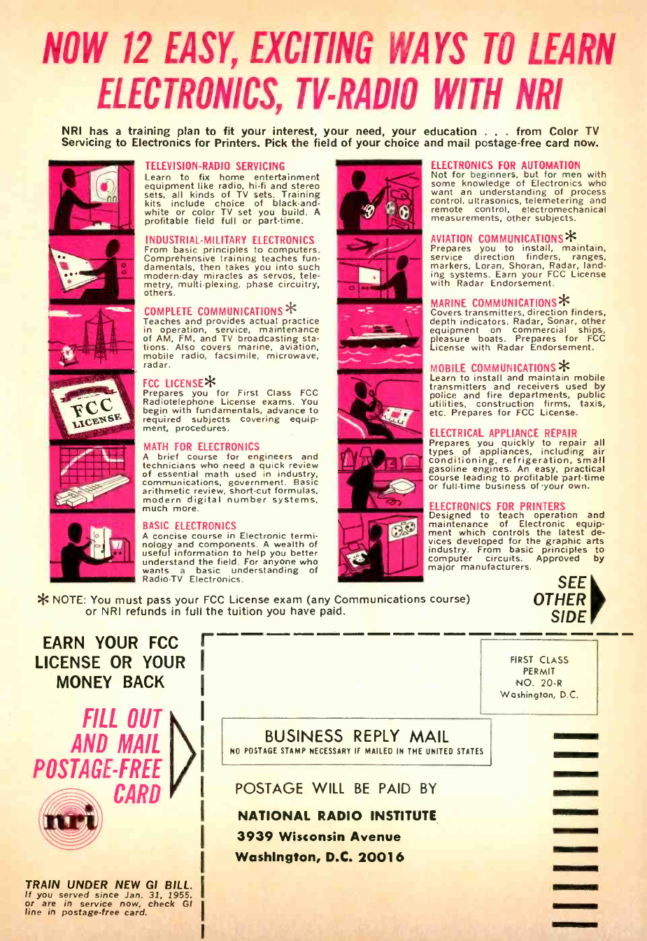
NOW 12 EASY, EXCITING WAYS TO LEARN
ELECTRONICS, TV-RADIO WITH NRI
NRI has a training plan to fit your interest, your need, your education . from Color TV
Servicing to Electronics for Printers. Pick the field of your choice and mail postage -free card now.
TELEVISION -RADIO SERVICING
Learn to fix home entertainment
equipment like radio, hi -fi and stereo
sets, all kinds of TV sets. Training
kits include choice of black -and-
white or color TV set you build. A
profitable field full or part -time.
INDUSTRIAL -MILITARY ELECTRONICS
From basic principles to computers.
Comprehensive training teaches fun-
damentals, then takes you into such
modern -day miracles as servos, tele-
metry, multi plexing, phase circuitry,
others.
COMPLETE COMMUNICATIONS*
Teaches and provides actual practice
in operation, service, maintenance
of AM, FM, and TV broadcasting sta-
tions. Also covers marine, aviation,
mobile radio, facsimile, microwave,
radar.
FCC LICENSE*
Prepares you for First Class FCC
Radiotelephone License exams. You
begin with fundamentals, advance to
required subjects covering equip-
ment, procedures.
MATH FOR ELECTRONICS
A brief course for engineers and
technicians who need a quick review
of essential math used in industry,
communications, government. Basic
arithmetic review, short -cut formulas,
modern digital number systems,
much more.
BASIC ELECTRONICS
A concise course in Electronic termi-
nology and components. A wealth of
useful information to help you better
understand the field. For anyone who
wants a basic understanding of
Radio -TV Electronics.
ELECTRONICS FOR AUTOMATION
Not for beginners, but for men with
some knowledge of Electronics who
want an understanding of process
control, ultrasonics, telemetering and
remote control, electromechanical
measurements, other subjects.
AVIATION COMMUNICATIONS*
Prepares you to install, maintain,
service direction finders, ranges,
markers, Loran, Shoran, Radar, land-
ing systems. Earn your FCC License
with Radar Endorsement.
MARINE COMMUNICATIONS*
Covers transmitters, direction finders,
depth indicators. Radar, Sonar, other
equipment on commercial ships,
pleasure boats. Prepares for FCC
License with Radar Endorsement.
MOBILE COMMUNICATIONS*
Learn to install and maintain mobile
transmitters and receivers used by
police and fire departments, public
utilities, construction firms, taxis,
etc. Prepares for FCC License.
ELECTRICAL APPLIANCE REPAIR
Prepares you quickly to repair all
types of appliances, including air
conditioning, refrigeration, small
gasoline engines. An easy, practical
course leading to profitable part -time
or full -time business of-your own.
ELECTRONICS FOR PRINTERS
Designed to teach operation and
maintenance of Electronic equip-
ment which controls the latest de-
vices developed for the graphic arts
industry. From basic principles to
computer circuits. Approved by
major manufacturers.
* NOTE: You must pass your FCC License exam (any Communications course)
or NRI refunds in full the tuition you have paid.
EARN YOUR FCC r
LICENSE OR YOUR I
MONEY BACK I
FILL OUT !
AND MAIL I
POSTAGE -FREE I
/n CARD I
I
TRAIN UNDER NEW GI BILL.
If you served since Jan. 31, 1955,
or are in service now, check GI
line in postage -free card.
SEE
OTHER
SIDE
FIRST CLASS
PERMIT
NO. 20 -R
Washington, D.C.
BUSINESS REPLY MAIL
NO POSTAGE STAMP NECESSARY IF MAILED IN THE UNITED STATES
POSTAGE WILL BE PAID BY
NATIONAL RADIO INSTITUTE
3939 Wisconsin Avenue
Washington, D.C. 20016
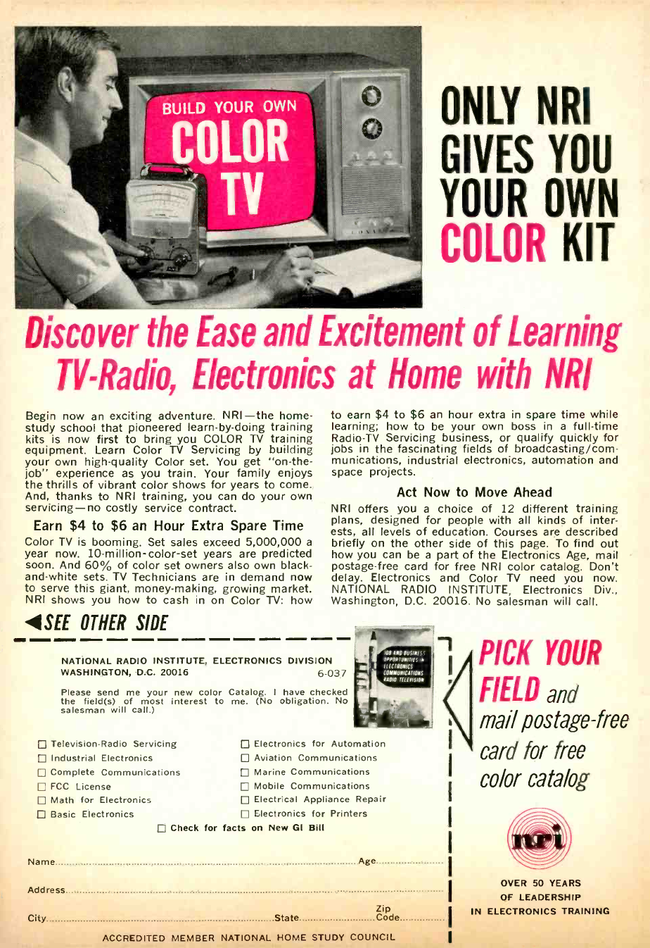
ONLY NRI
GIVES YOU
YOUR OWN
COLOR KIT
Discover the Ease and Excitement of Learning
TV-Radio, Electronics at Home with NRI
Begin now an exciting adventure. NRI -the home -
study school that pioneered learn -by -doing training
kits is now first to bring you COLOR TV training
equipment. Learn Color TV Servicing by building
your own high -quality Color set. You get "on -the-
job" experience as you train. Your family enjoys
the thrills of vibrant color shows for years to come.
And, thanks to NRI training, you can do your own
servicing -no costly service contract.
Earn $4 to $6 an Hour Extra Spare Time
Color TV is booming, Set sales exceed 5,000,000 a
year now. 10- million - color -set years are predicted
soon. And 60% of color set owners also own black -
and -white sets. TV Technicians are in demand now
to serve this giant, money- making, growing market.
NRI shows you how to cash in on Color TV: how
4 SEE OTHER SIDE
to earn $4 to $6 an hour extra in spare time while
learning; how to be your own boss in a full -time
Radio -TV Servicing business, or qualify quickly for
jobs in the fascinating fields of broadcasting/com -
munications, industrial electronics, automation and
space projects.
Act Now to Move Ahead
NRI offers you a choice of 12 different training
plans, designed for people with all kinds of inter-
ests, all levels of education. Courses are described
briefly on the other side of this page. To find out
how you can be a part of the Electronics Age, mail
postage -free card for free NRI color catalog. Don't
delay. Electronics and Color TV need you now.
NATIONAL RADIO INSTITUTE, Electronics Div.,
Washington, D.C. 20016. No salesman will call.
NATIONAL RADIO INSTITUTE, ELECTRONICS DIVISION
WASHINGTON, D.C. 20016 6 -037
Please send me your new color Catalog. I have checked
the field(s) of most interest to me. (No obligation. No
salesman will call.)
Television -Radio Servicing
Industrial Electronics
Complete Communications
FCC License
Math for Electronics
Basic Electronics
LOB 1N0 BUSINESS
OPPORTUNITIES N
1 ELECTRONICS
COMMUNICATIONS
RADIOTELEVISION
Electronics for Automation
Aviation Communications
Marine Communications
Mobile Communications
Electrical Appliance Repair
Electronics for Printers
Check for facts on New GI Bill
Name Age
Address
Zip
City State Code
ACCREDITED MEMBER NATIONAL HOME STUDY COUNCIL
PICK YOUR
FIELD and
mail postage -free
card for free
color catalog
OVER 50 YEARS
OF LEADERSHIP
IN ELECTRONICS TRAINING
