Em50_assembling1 EM 50 Em50 Assembly & Spare Parts List
User Manual: EM-50
Open the PDF directly: View PDF ![]() .
.
Page Count: 23

Munters euroemme S.p.A. Strada Piani, 2 I-18027 Chiusavecchia (Imperia) - Italy
Tel. +39 0183 5211 Fax +39 0183 521333 http://www.munters.com e-mail:info@munterseuroemme.it
SPARE PARTS LIST AND
ASSEMBLING GUIDELINE
FOR
EM 50 FAN

NOTE page 2
01.2002 EM 50 SPARE PARTS LIST
!Date of release: January 2002.
! reserves the right to make alterations to specifications,
quantities, etc., for production or other reasons, subsequent to publication.
!
!All rights reserved. No part of this manual may be reproduced in any manner what-
soever without the expressed written permission of
!The contents of this manual are subject to change without notice.
!The quantities indicated refer to one fan.
!Components marked with * are delivered assembled as complete pieces. They are
also available loose for purchase as spare parts.
COPY RIGHT 2001 BY
VERSION 1.0
Munters euroemme Spa
Munters euroemme Spa
Munters euroemme Spa
Munters euroemme Spa
cannot guarantee that you will receive information
about change of the product or the manual.
in
each case.

CONTENTS page 3
01.2002 EM 50 SPARE PARTS LIST
CONTENTS
1. Spare parts list for EM 50 fan......... ............................................................................4-7
4. Assembling tools..........................................................................................................11-12
2. Spare parts list for CE protection (option)........................................................................8
2.1 Spare parts list for pyramidal shape mesh for CE protection............................8
3. Bolts and nuts description..............................................................................................9-10
5. Assembling guideline.....................:..................................................................................13
5.1 Housing assembling..................................................................................13-16
5.2 Centrifugal system and pulley to propeller assembling.............................16-17
5.3 Shutter blades assembling........................................................................18-19
5.4 Safety meshes guard assembling.....................................................................20
5.5 CE kit assembling...........................................................................................21
5.6 Pyramidal shape mesh assembling.................................................................22
6. Ordering code....................................................................................................................23
6.1 Assembled motors codes table.......................................................................23
6.2 Motors codes table........................................................................................23
6.3 Assembled motors codes table.......................................................................23
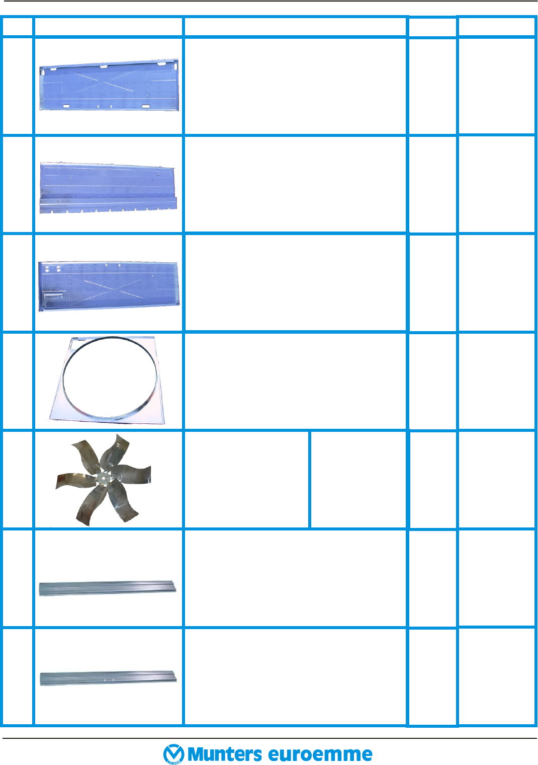
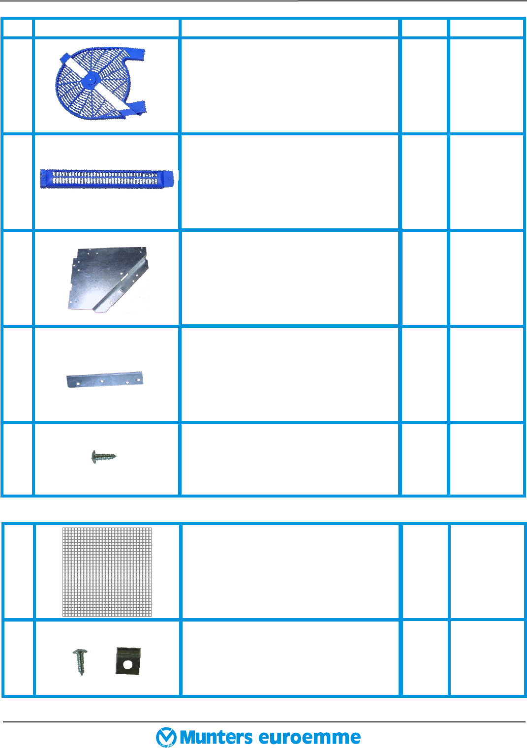
REF. PHOTOS DESCRIPTION
2433800
CODE
1
2
3
4
5
6/
A
6/
B
Bottom panel.
Side panel.
Top panel.
Venturi.
Complete propeller
(available as assem-
bled part only).
Shutter blade 6/10.
Central shutter blade 12/10 with
Holes.
2435200
2443700
2434900
2515500
2515800
2514200
2439100
239600
1
QTY
2
1
1
1
1
1
9
1
Stainless steel
Pre-coated
Galvanized
1. SPARE PARTS LIST FOR EM 50 FAN page 4
01.2002 EM 50 SPARE PARTS LIST
7
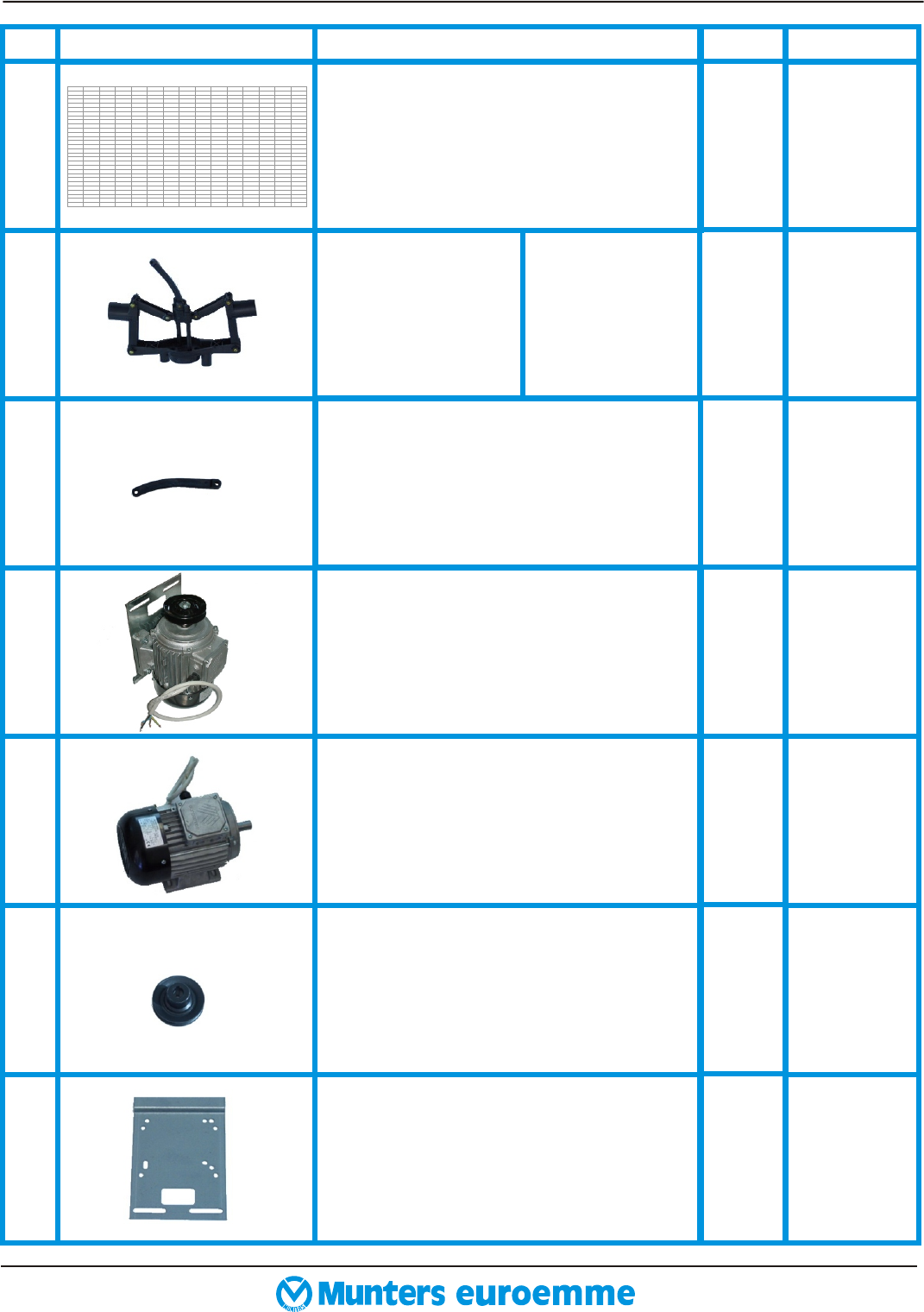
REF. PHOTOS
Safety mesh guard.
DESCRIPTION
2252300
CODE
Centrifugal system
(available as as-
sembled part only).
Connecting rod.
Complete electric motor (assembled
only).
Electic motor (not assembled).
Motor pulley.
Motor slide.
8
8/
A
9
9/
A
9/
B
9/
C
2264800
2510800
2511100
See table
6.1
page 23
See table
6.2
page 23
See table
6.3
Page 23
2441700
2
QTY
1
1
1
*
*
*
*
For multispeed
motor
For singlespeed
motor
1. SPARE PARTS LIST FOR EM 50 FAN page 5
01.2002 EM 50 SPARE PARTS LIST
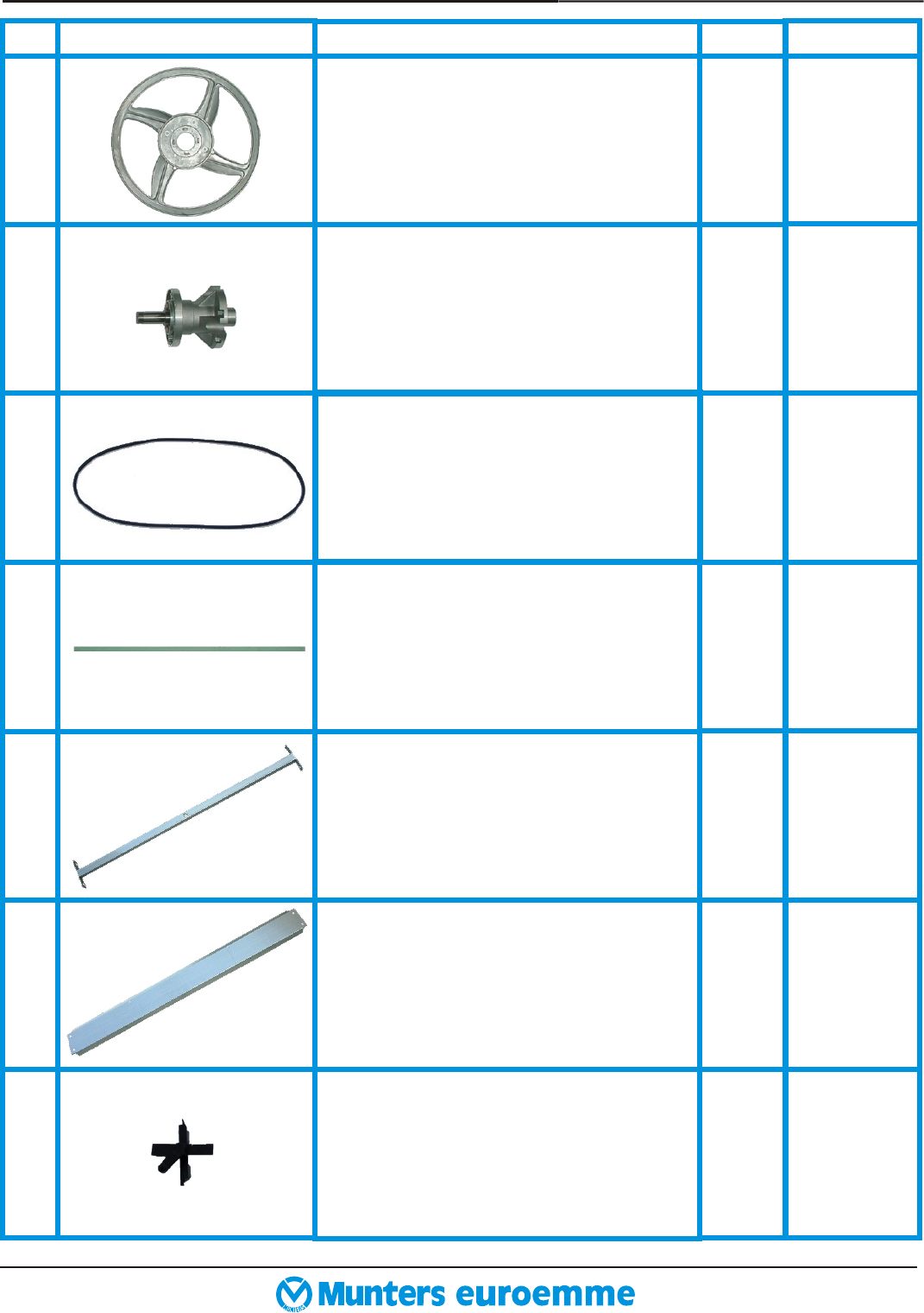
REF. PHOTOS
Central pulley.
DESCRIPTION
2472700
CODE
10/
A
10/
B
Hub. 2511600
10/
C
Pvc tie-rod with 10 holes.
11
12
13
14/
A
Propeller central support.
Right shutter bearings.
2473700
2455300
2431200
2524100
Cover plates.
2246500
1
QTY
1
2
1
1
2
9
1. SPARE PARTS LIST FOR EM 50 FAN page 6
01.2002 EM 50 SPARE PARTS LIST
REF. PHOTOS DESCRIPTION
2524300
CODE
14/
B
14/
C
14/
D
15/
A
15/
B
15/
C
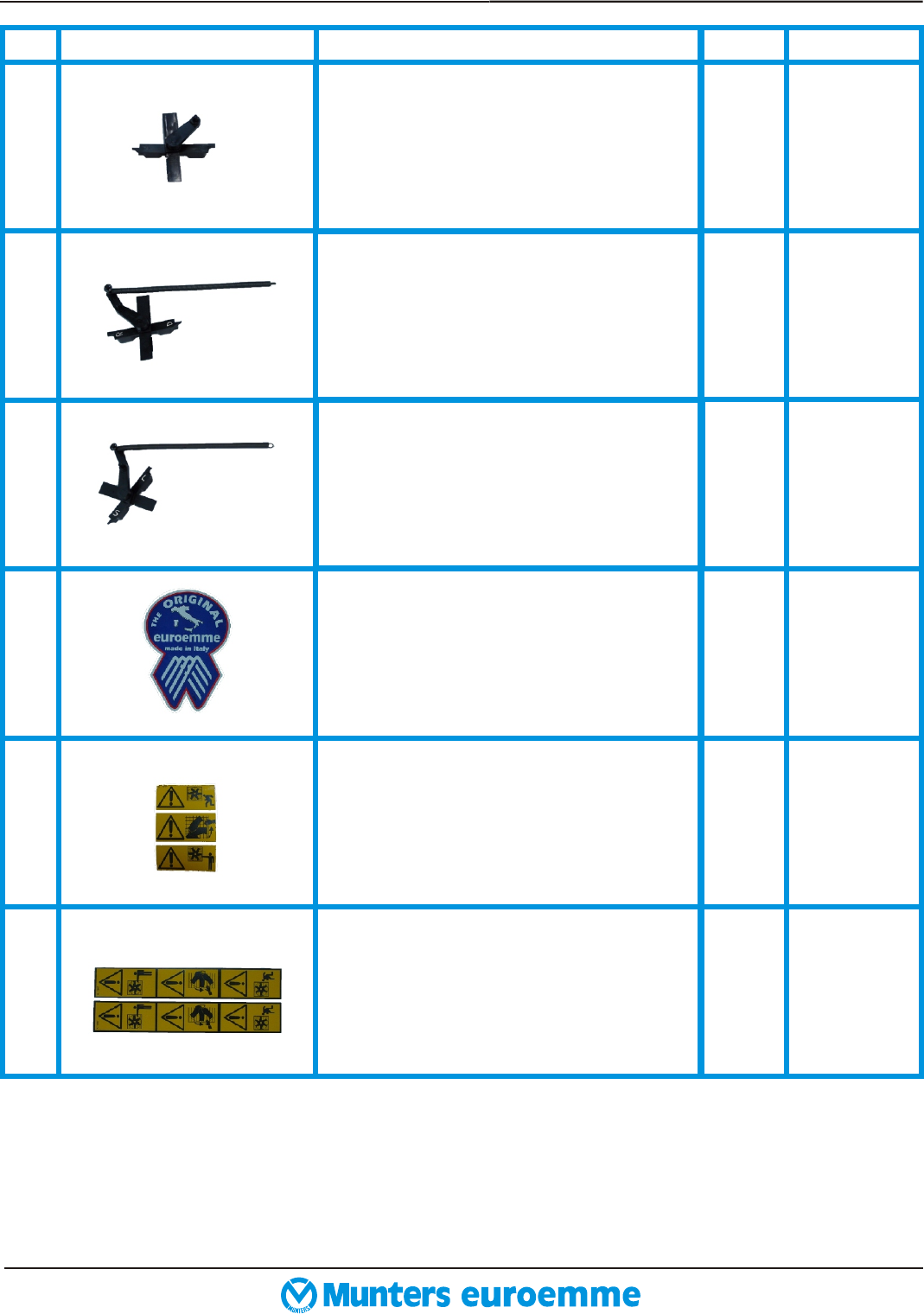
Right shutter bearings with spring.
Left shutter bearings with spring.
Cockade sticker.
Short warning sticker.
Long warning stickers.
2524500
2524700
2262400
2262600
2262500
Left shutter bearings. 9
QTY
1
1
1
1
2
1. SPARE PARTS LIST FOR EM 50 FAN page 7
01.2002 EM 50 SPARE PARTS LIST
REF. PHOTOS DESCRIPTION
2267300
CODE
16/
A
16/
B
16/
C
16/
D
16/
E
17/
A
17/
B
Plastic safety protection for central
pulley.
Plastic safety protection for belt .
Metal safety protection for motor
pulley.
Fixing metal clip.
Self tapping hex screw Ø 6.3 x 19
mm.
Pyramidal safety mesh.
A: metal clips to fix pyramidal safety
mesh
B: self tapping hex screw Ø 6.3 X 19
mm.
2267400
2454400
2454300
2278800
2474900
2448600
2278800
1
QTY
2
1
1
4
2
6
6
A
B
2. SPARE PARTS LIST FOR CE PROTECTION (OPTION) page 8
01.2002 EM 50 SPARE PARTS LIST
2.1 SPARE PARTS LIST FOR PYRAMIDAL SHAPE MESH FOR CE PROTECTION (OPTION)

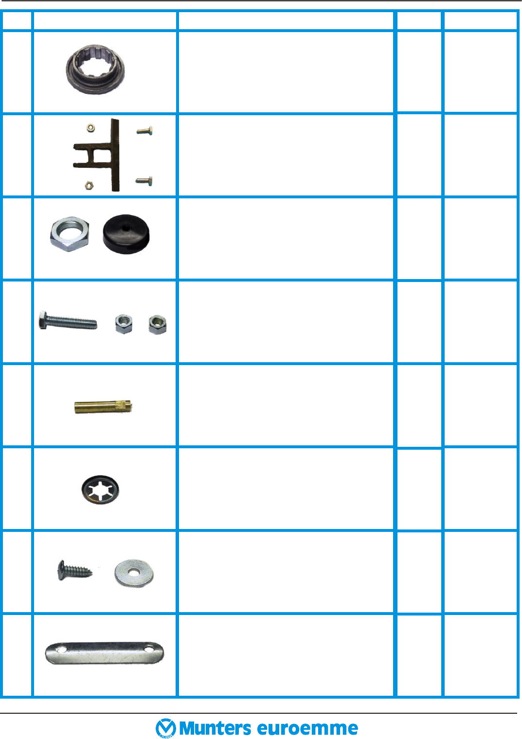
3. BOLTS AND NUTS DESCRIPTION FOR EM 50 FAN page 9
REF. DESCRIPTION CODE
18
19
20
21
22
23
24
25
A: threaded bushes M 8 short. Purpose : to
insert on the top panel.
B: threaded bushes M 8 long. Purpose : to
insert on the housing.
A: bolts M 8 x 16 mm.
B: washer Ø 8 x 32 mm.
Purpose : to fix motor to the top panel.
A: bolts M 10 x 30 mm.
B: washer Ø 10 mm.
C: nuts M 10.
D: oval plate 170 x 40 x 8 mm.
Purpose : to fix the propeller central
support to the housing.
Rubber grommet.
Purpose : to avoid cable damage.
A: bolts M 6 x 30 mm.
B: washer Ø 6 mm.
C: nuts M 6 x6 mm.
Purpose : to fix the central pulley to the
hub.
A: bolts M 8 x 25 mm.
B: washers Ø 8 mm.
C: nuts M 8.
Purpose : to fix the propeller to the hub.
A: bolts M 8 x 55 mm.
B: washers Ø 8 mm.
C: nuts M 8.
Purpose : to fix the centrifugal system
to the propeller.
2270700
2270800
2271100
2280200
2277100
2282000
2275300
2274000
2263900
2239600
2279600
2275400
2273400
2280600
2275100
2273700
2278800
2275700
2273700
Pop rivets Ø 6.4 x 10 mm.
Purpose : for housing and Venturi
assembling.
PHOTOS
20
QTY
2
8
4
4
4
2
2
2
1
4
4
4
4
4
4
2
2
2
BA
01.2002 EM 50 SPARE PARTS LIST
B
A
A
D
B
C
AB C
A B C
A B C
REF. DESCRIPTION CODE
26
27
28
29
30
31
32
33
A: central shutter blade fork.
B: bolts M 6 x 16 mm.
C: nuts M 6 x 5 mm.
Purpose : to fix the central shutter blade
fork to the central shutter blade.
A: nut M 25 x 10 mm.
B: cap cover nut ( only w/o CE kit ).
Purpose : to fix the hub to the propeller
Central support.
A: bolts M 6 x 30 mm.
B: nuts M 6 x 6 mm.
Purpose : to fix the two springs of
Central shutter blade to the side panel.
Knurled axle Ø 6 x 30 mm.
Purpose : to fix the tie-rod to the central
shutter blade fork (ref. 27/a).
Stop collars Ø 7 mm.
Purpose : to fix the two pvc tie-rod with
ten holes to left and right shutter blade
Fork.
A: self tapping hex screws Ø 6.3 x 19 mm.
B: washer Ø 6 x 24 mm.
Purpose : for cover plate and wire
meshes assembling.
Central clips for meshes.
Purpose : to fix the safety meshes guard
to the housing.
2472000
2264900
2279100
2270700
2273600
2264500
2279500
2273400
2430600
2268400
2278800
2276300
2449100
PHOTOS
Waterproof distance piece Ø ( ID 40 /
OD 52 ) x 15 mm.
Purpose : to distance the hub from the
propeller central support.
1
QTY
1
2
2
2
4
1
1
1
20
19
1
2
3. BOLTS AND NUTS DESCRIPTION FOR EM 50 FAN page 10
01.2002 EM 50 SPARE PARTS LIST
B
A B
AB
AB
B
A
C
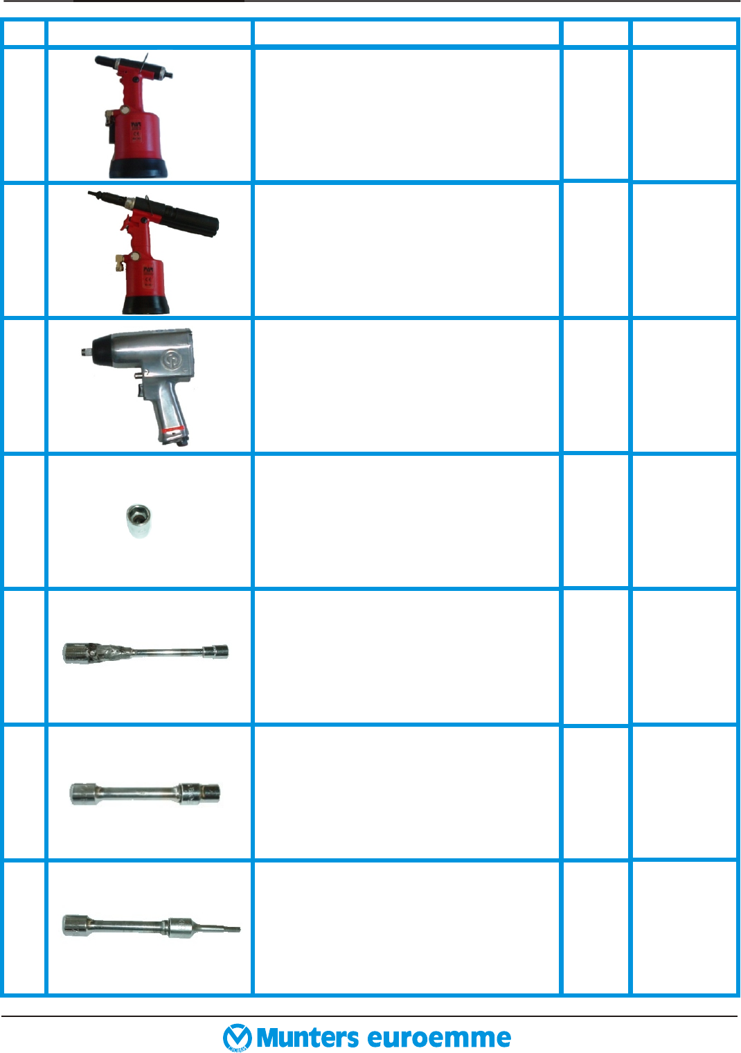
PHOTOS DESCRIPTION
REF.
35
36
Inserting machine kj 40.
17 mm spanner.
36/
A
2284200
2284300
CODE
34
36/
B
36/
C
36/
D
10 mm long spanner.
13 mm long spanner.
6 mm long allen spanner.
Riveting machine rac 165.
Pneumatic screw-driver.
1
QTY
1
1
1
1
1
1
4. page 11ASSEMBLING TOOLS
01.2002 EM 50 SPARE PARTS LIST
36/
E
36/
F
37
38
39
40
41
REF. PHOTOS DESCRIPTION CODE
Philips screw head adaptor.
Ratchet drive.
13 mm spanner.
Ratchet drive extension.
Screw driver.
Small hammer.
36 mm spanner.
10 mm spanners.
1
QTY
1
1
1
1
2
1
1
4. page 12ASSEMBLING TOOLS
01.2002 EM 50 SPARE PARTS LIST
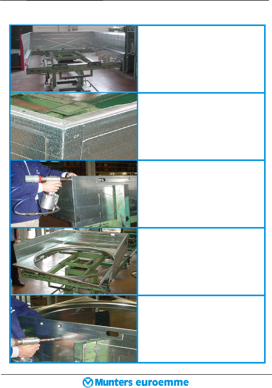
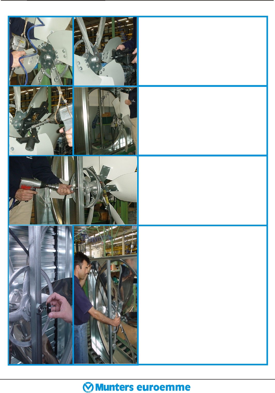
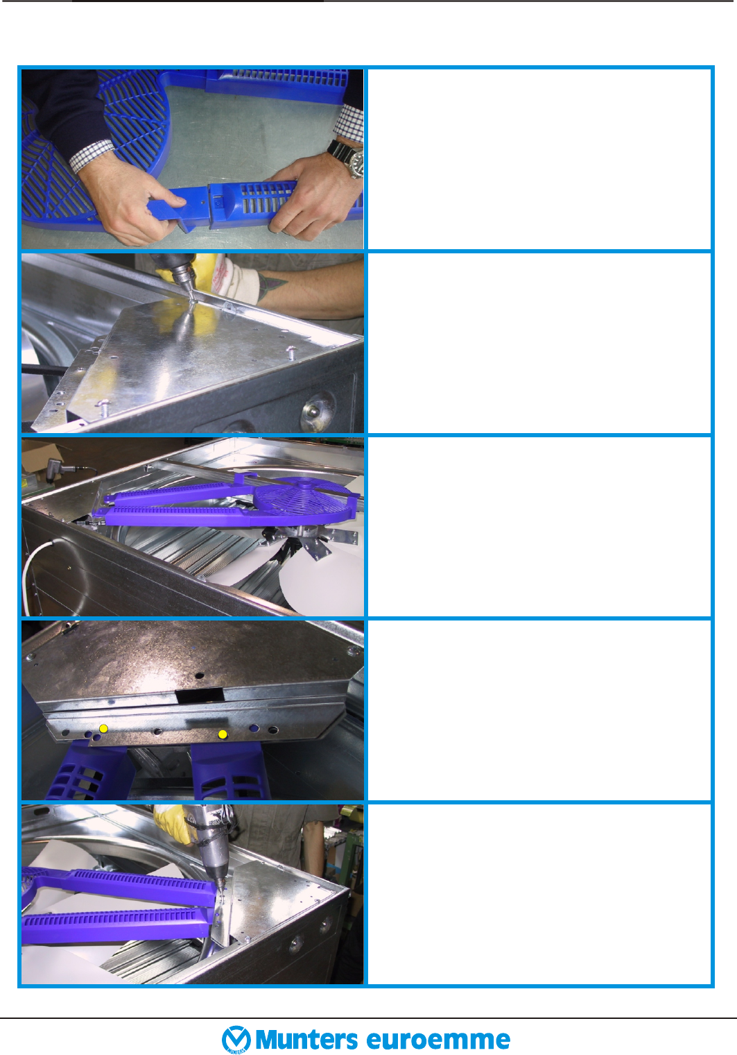
Take the bottom panel (ref. 1), the
side panels (ref. 2) and place these
taking care that slot for the plastic
bea ring is downward.
Before fixing the bottom and the
side panels make sure that these
pieces are in the right position as in
the picture.
Join bottom panel to side panels and
fix qty. 4 pop rivets (ref. 18) for
each edge by using riveting machine
(ref. 34).
Insert Venturi (ref. 4) into the hous-
ing on the right side as in the picture.
Fix Venturi to bottom panel and
then to side panels with qty. 1 pop
rivets for side.
5. page 13ASSEMBLING GUIDELINE
01.2002 EM 50 SPARE PARTS LIST
5.1 HOUSING ASSEMBLING
Place the top panel (ref. 3) with
motor support in correspondence
with motor slot on the Venturi. Then
fix it to side panels with qty. 4 pop
rivet for side and to Venturi with qty.
1 pop rivet.
Place the qty. 2 short threaded bush-
es (ref. 19) on the top panel by us-
ing inserting machine (ref. 35).
Place long threaded bushes (ref. 19)
in correspondence of proper holes
around the housing. Qty. 2 long
threaded bushes for each panel.
Make sure that Venturi and each
panel are joined by the long
threaded bushes.
Place the rubber grommet (ref. 22)
For electric cable protection on the
side panel in correspondence with
the motor slot.
5. page 14 ASSEMBLING GUIDELINE
01.2002 EM 50 SPARE PARTS LIST
The propeller central support (ref.
12) shall be fixed to housing by
means of qty. 4 bolts (ref. 21), qty.4
washes (ref. 21), qty. 4 nuts (ref.21)
and qty. 2 oval plates (ref. 21).
Place the oval plates between pro-
peller central support and panels.
Place the oval plate over support
frame and then start to screw the
nuts.
Tighten the nuts with pneumatic
screw-driver (ref. 36/a) in order to
fix the propeller central support to
the top and bottom panels.
For mounting of electric motor (ref.
9) insert this into its slot taking care
to fix it over proper track fixed on
the top side.
5. page 15ASSEMBLING GUIDELINE
01.2002 EM 50 SPARE PARTS LIST
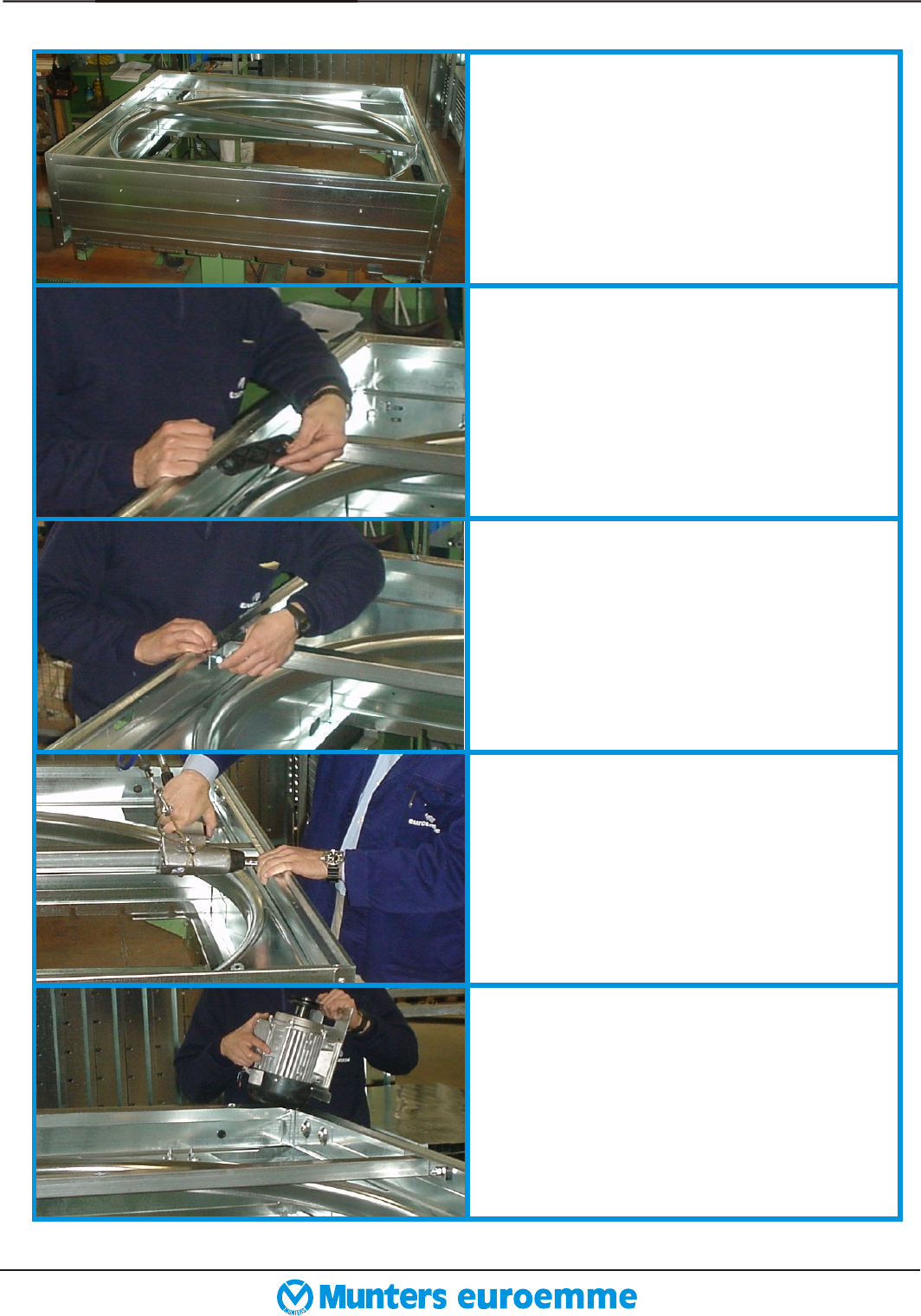
5.2 CENTRIFUGAL SYSTEM AND PULLEY
TO PROPELLER ASSEMBLING
Fix motor slide to top panel by
means qty. 2 bolts (ref. 20)and qty. 2
washers (ref. 20). Tighten bolts by
using 13 mm spanner (ref. 37).
12
12
12
12
Take the pulley (ref. 10/a) and insert
the bolts (ref. 23) from the external
side of it. Turn up side
down and place the hub (ref. 10/b)
on it.
the pulley
Insert the washers (ref. 23) and fix
the nuts (ref. 23) over the bolts.
Tighten the nuts by using pneumatic
screw-driver (ref.36/b).
Place the waterproof distance piece
(ref. 24) on the axle and then place
the axle on a support. After that pla-
ce the v-belt (ref. 10/c) on the cen-
tral pulley.
Place the propeller (ref. 5) on the
central pulley assembly. Fix the
bolts (ref. 24), the washers (ref. 24)
and nuts (ref. 24) in order to fix the
propeller.
5. page 16ASSEMBLING GUIDELINE
01.2002 EM 50 SPARE PARTS LIST
12
12
12
Tighten the nuts by using
pneumatic screw-driver (ref. 36/c).
Place bolts (ref. 25) on the
centrifugal system (ref. 8) and then
place it on the propeller.
Tighten bolts , washers (ref. 25) and
nuts (ref. 25) in order to fix the cen-
trifugal system to the propeller by
using pneumatic screw-driver (ref.36/
d). Place the complete assembly you
have obtained on the fan, inserting the
axle trought the central supportole.
Place M 25 nut (ref. 28) on the axle
and then tighten it by mean of
pneumatic screw-driver (ref. 36/e).
Put cap cover nut (ref. 28) over M
25 nut ( only for fan without CE
kit ). Place v-belt on the pulley and
then rotate clock-wise
in order to tighten the v-belt on the
pulley.
the propeller
right tensioning is obtained when
maximum deflexion on one side
only ( half-way from motor and
central pulley ) is about 15 mm.
CHECK TENSIONING :
5. page 17ASSEMBLING GUIDELINE
01.2002 EM 50 SPARE PARTS LIST
5.3 SHUTTER BLADES ASSEMBLING
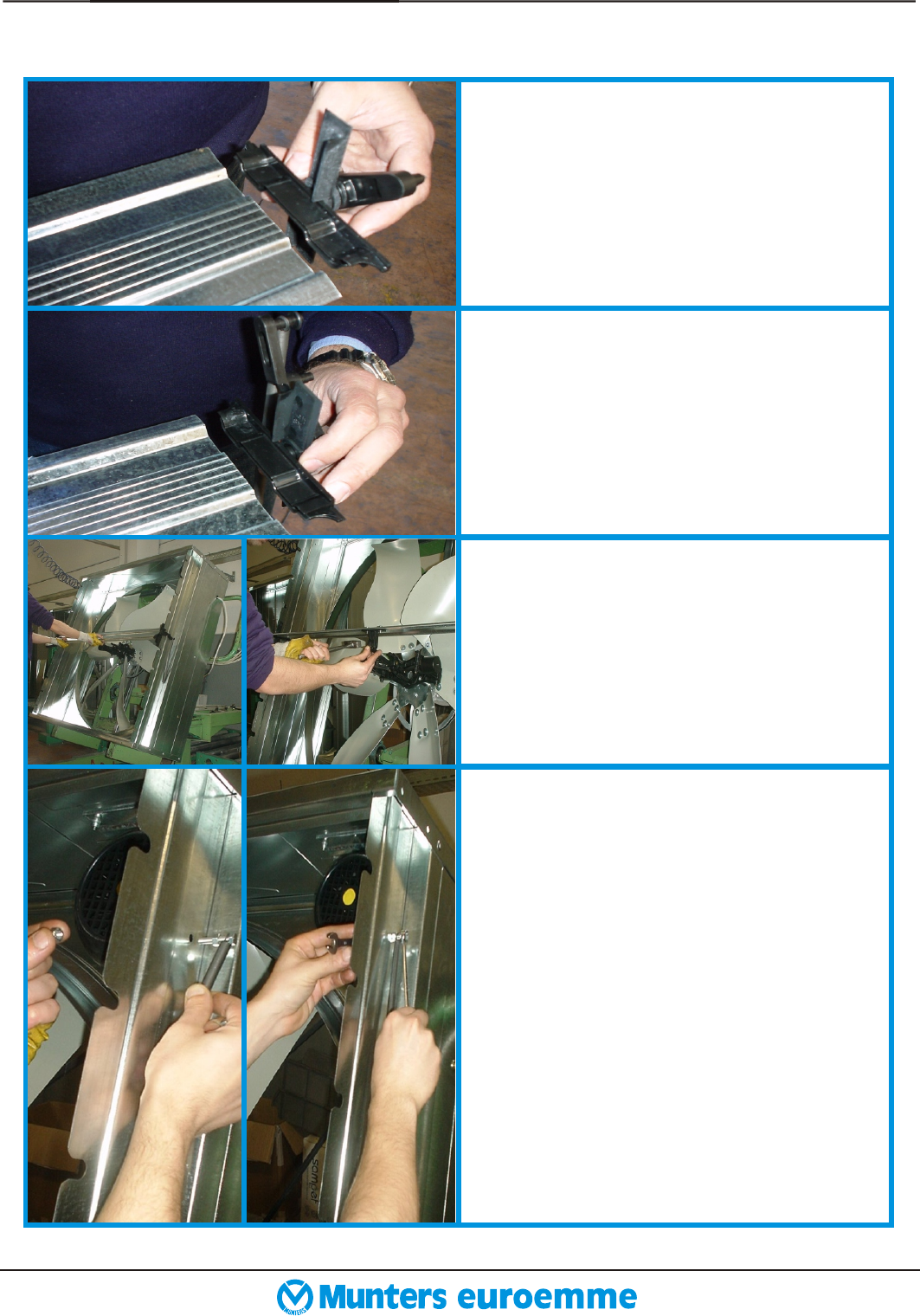
Insert plastic bearings (ref. 14/a ,
14/ b) without spring on shutter
blades (ref.6/a). Plastic bearings
marked with“SX” are for left side,
plastic bearings with “DX” are for
right side.
Insert plastic bearing with spring
(ref. 14/c , 14/d) on central shutter
blade (ref.6/b).”SX” is for left side,
“DX” is for right side. Fix the
plastic fork (ref. 27) with qty. 2 bolt
(ref. 27) on the central shutter blade.
Fit central shutter blade on the
central slot on the housing. Insert
knurled axle (ref. 30) by the smooth
side on the plastic fork, then take
plastic shutter rod on the centrifugal
system and fix them together by
using a small hammer (ref. 38).
Insert free looped-end of spring on
bolt (ref. 29), then place a nut
(ref.29)and leave about 10 mm of
space between the nut and the bolt
head.
Insert the bolt into hole of the side
panel and then fix it by means of a
second nut (ref. 29). Tighten the
nuts by using two 10 mm spanners
(ref. 39). Repeat this operation for
the other side.
12
12
5. page 18ASSEMBLING GUIDELINE
01.2002 EM 50 SPARE PARTS LIST
Insert all the shutter blades (qty. 9
normal + qty. 1 central) on the fan
housing and then place the fan
horizontally.
Place the pvc tie-rod (ref.11) on
plastic bearing pivots.
Insert all stop collars (ref. 31) on
plastic pivots.
Put cover plate (ref. 13) over the
plastic bearing mechanism.
By means of a screw-driver (ref. 40)
insert cover plate over the fan hous-
ing. Fix the cover plate on each side
by using the screws (ref. 32) with
pneumatic screw-driver (ref. 36/f).
12
12
5. ASSEMBLING GUIDELINE page 19
01.2002 EM 50 SPARE PARTS LIST
(BEFORE THIS STEP IT’S NECESSARY TO MOUNT CE KIT ONLY IF REQUIRED)
5.4 SAFETY MESHES GUARD ASSEMBLING
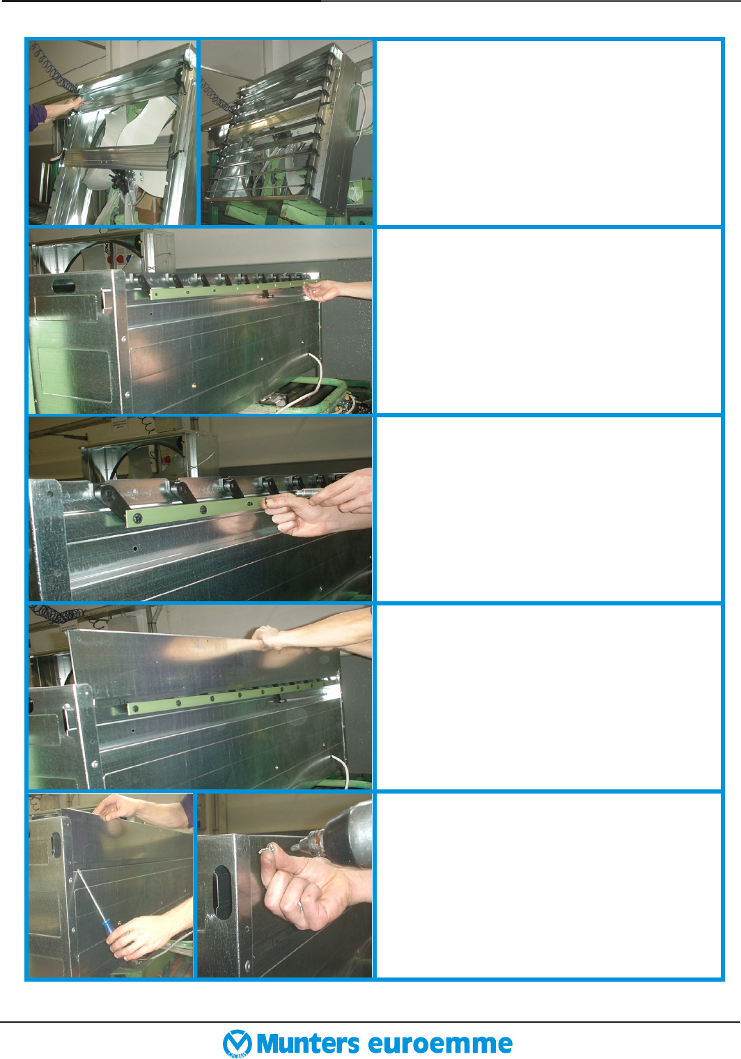
Turn up side down and insert
the electric cable into the proper hole
placed on the side panel.
the fan
Put the qty. 2 safety meshes guard
(ref. 7)on the inlet side of the fan.
Fix the qty. 6 screws (ref.32) on the
fan side (qty. 3 for each are requi-
red).
Fix the screws (ref. 32) with the
central clips (ref.33) in correspon-
dence of the propeller central sup-
port on the top panel and the bottom
panel.
Fix the screw (ref. 32) with the
washer (ref. 32) into the central
pulley axle. Fix all the components
by using the pneumatic screw-driver
(Ref. 36/f).
5. page 20ASSEMBLING GUIDELINE
01.2002 EM 50 SPARE PARTS LIST
Before safety meshes
complete the CE kit. Join the plastic
safety protection for central pulley
(ref. 16/a) with plastic safety
protection for the v-belt (ref.16/b).
assembling the
Fix by qty. 3 screws (ref. 16/e) the
metal safety protection for the motor
pulley (ref. 16/c). Qty. 2 on top
panel, qty.1 on side panel. Fix it by
using a pneumatic screw-driver (ref.
36/f).
Put the assembled CE plastic kit
protection as (on the
metal safety protection for the motor
pulley).
in the picture
Put the metal clip (ref. 16/d) on the
CE plastic kit in the correct position
as shown in the picture and fix it by
qty.1 screw (ref. 16/e). SEE THE
YELLOW POINTS
Fix it by means a pneumatic screw-
driver. After that follow the safety
meshes guard assembling.
5.5 CE KIT ASSEMBLING
5. page 21ASSEMBLING GUIDELINE
01.2002 EM 50 SPARE PARTS LIST
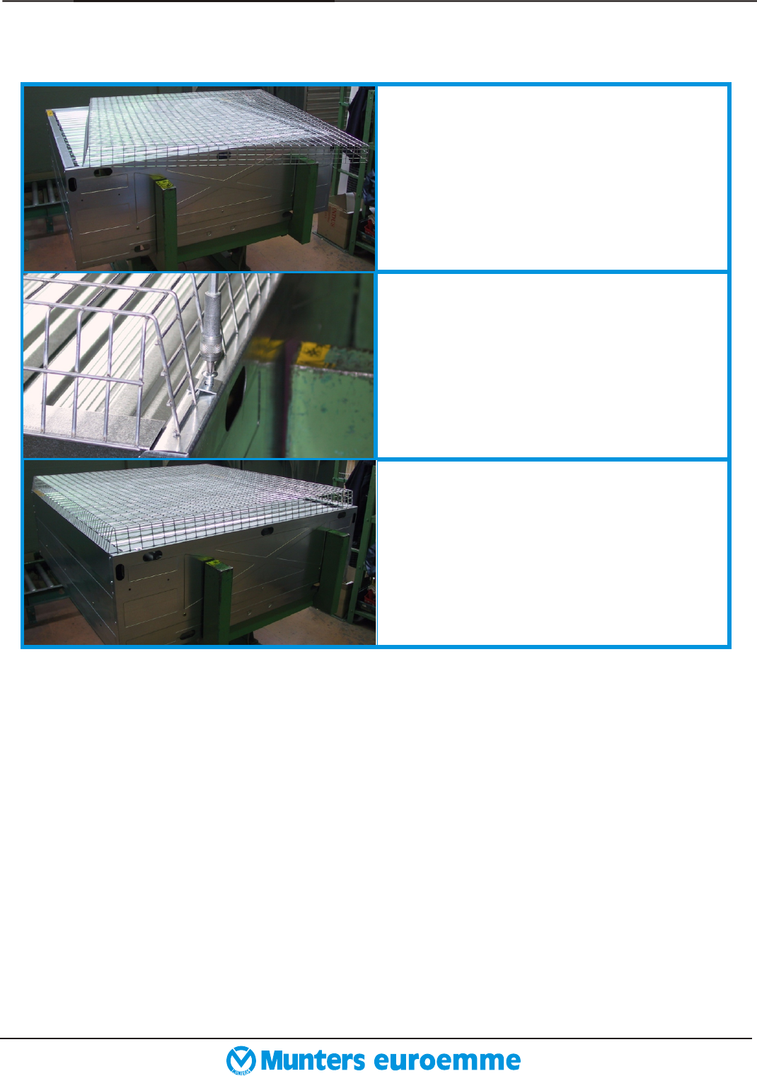
5.6 PYRAMIDAL SHAPE MESH ASSEMBLING
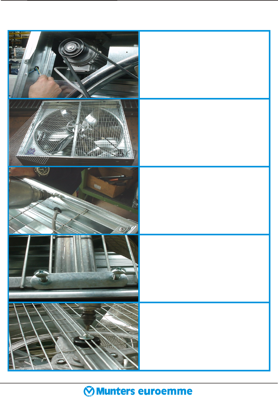
Fix it to the bottom and top panels
by mean of qty. 6 metal clips (ref.
17/b) and qty. 6 screw (ref. 17/b).
The metal clips must be fixed in the
position as in the picture.
Put the pyramidal shape mesh (ref.
17/a) on the fan as in the picture.
The rectangular holes must be
positioned horizontally.
Fix it by using a pneumatic screw-
driver (ref. 41).
5. page 22ASSEMBLING GUIDELINE
01.2002 EM 50 SPARE PARTS LIST
6. ORDERING CODE page 23
01.2002 EM 50 SPARE PARTS LIST
6.1 ASSEMBLED MOTORS CODES TABLE
6.2 MOTORS CODES TABLE
6.1 PULLEY CODES TABLE
Type Speed Frequency Voltage Current Rpm Motor
[W] [hp] phases [Hz] [V] [A] code
735 1,0 1 single 50 230 5 1380 2525700
735 1,0 1 multi 50 230 5 1380 2523700
735 1,0 1 single 60 220-240 5,7 1700 2523800
735 1,0 3 single 50 230/400 3,5/2 1400 2523200
735 1,0 3 single 60 230/400 3,5/2 1700 2522700
880 1,2 3 multi 50 230/400 4,3/2,5 1380 2523300
880 1,2 3 multi 60 230/400 4,3/2,5 1600 2523302
1100 1,5 1 single 50 230 7,3 1400 2523900
1100 1,5 1 single 60 220-240 7,3 1700 2524000
1100 1,5 3 single 50 230/400 5,2/3 1400 2523500
1100 1,5 3 multi 50 230/400 5,2/3 1380 2522900
1100 1,5 3 single 60 230/400 5,2/3 1700 2523400
1100 1,5 3 multi 60 230/400 5,2/3 1670 2523401
Nominal Power
Type Speed Frequency Voltage Current Rpm Motor
[W] [hp] phases [Hz] [V] [A] code
735 1,0 1 single 50 230 5 1380 2202800
735 1,0 1 multi 50 230 5 1380 2202800
735 1,0 1 single 60 220-240 5,7 1700 2202900
735 1,0 3 single 50/60 230/400 3,5/2 1400 2206100
880 1,2 3 multi 50/60 230/400 4,3/2,5 1380 2203000
1100 1,5 1 single 50 230 7,3 1400 2203500
1100 1,5 1 single 60 220-240 7,3 1700 2203700
1100 1,5 3 single 50/60 230/400 5,2/3 1400 2206800
1100 1,5 3 multi 50/60 230/400 5,2/3 1380 2203900
Nominal Power
Frequency Type Speed Pulley Pulley
[W] [hp] [hz] phases description code
735 or 880 1 or 1,2 50 3 or 1 single or multi DP85 M43 F19 C6 2247000
735 or 880 1 or 1,2 60 3 or 1 single or multi DP70 M43 F19 C6 2248000
1100 1,5 50 3 or 1 single or multi DP100 M51 F24 C8 2249000
1100 1,5 50 3 or 1 single or multi DP80 M51 F24 C8 2248900
Nominal Power
