Encoding Real X86 Instructions
User Manual:
Open the PDF directly: View PDF ![]() .
.
Page Count: 21

12/25/2017 Encoding Real x86 Instructions
http://www.c-jump.com/CIS77/CPU/x86/lecture.html 1/21
CIS-77 Home http://www.c-jump.com/CIS77/CIS77syllabus.htm
Encoding Real x86 Instructions
1. Encoding Real x86 Instructions
2. x86 Instructions Overview
3. x86 Instruction Format Reference
4. x86 Opcode Sizes
5. x86 ADD Instruction Opcode
6. Encoding x86 Instruction Operands, MOD-REG-R/M Byte
7. General-Purpose Registers
8. REG Field of the MOD-REG-R/M Byte
9. MOD R/M Byte and Addressing Modes
10. SIB (Scaled Index Byte) Layout
11. Scaled Indexed Addressing Mode
12. Encoding ADD Instruction Example
13. Encoding ADD CL, AL Instruction
14. Encoding ADD ECX, EAX Instruction
15. Encoding ADD EDX, DISPLACEMENT Instruction
16. Encoding ADD EDI, [EBX] Instruction
17. Encoding ADD EAX, [ ESI + disp8 ] Instruction
18. Encoding ADD EBX, [ EBP + disp32 ] Instruction
19. Encoding ADD EBP, [ disp32 + EAX*1 ] Instruction
20. Encoding ADD ECX, [ EBX + EDI*4 ] Instruction
21. Encoding ADD Immediate Instruction
22. Encoding Eight, Sixteen, and Thirty-Two Bit Operands
23. Encoding Sixteen Bit Operands
24. x86 Instruction Prefix Bytes
25. Alternate Encodings for Instructions
26. x86 Opcode Summary
27. MOD-REG-R/M Byte Summary
28. ISA Design Considerations
29. ISA Design Challenges
30. Intel Architecture Software Developer's Manual
31. Intel Instruction Set Reference (Volume2)
32. Chapter 3 of Intel Instruction Set Reference
33. Intel Reference Opcode Bytes
34. Intel Reference Opcode Bytes, Cont.
35. Intel Reference Opcode Bytes, Cont.
36. Intel Reference Opcode Bytes, Cont.
37. Intel Reference Opcode Bytes, Cont.
38. Intel Reference Opcode Bytes, Cont.
39. Intel Reference Instruction Column
1. Encoding Real x86 Instructions
It is time to take a look that the actual machine instruction format of the x86 CPU family.
They don't call the x86 CPU a Complex Instruction Set Computer (CISC) for nothing!
Although more complex instruction encodings exist, no one is going to challenge that the x86 has a complex instruction
encoding:

12/25/2017 Encoding Real x86 Instructions
http://www.c-jump.com/CIS77/CPU/x86/lecture.html 2/21
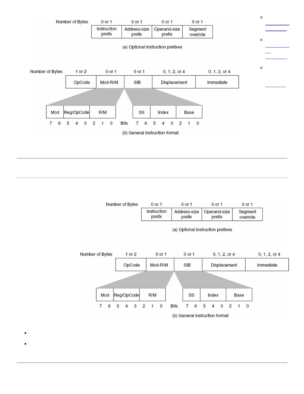
2. x86 Instructions Overview
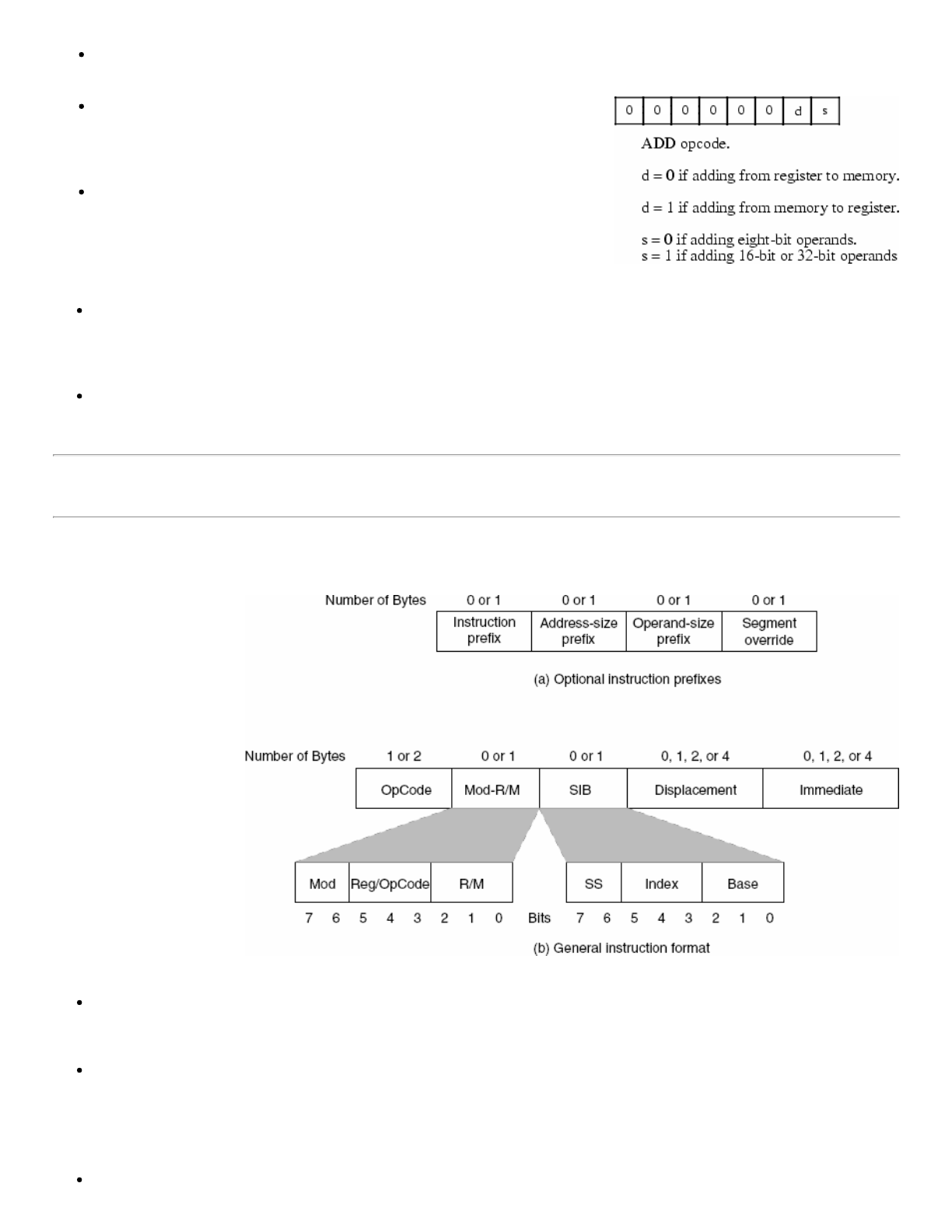
Although the diagram
seems to imply that
instructions can be up to
16 bytes long, in actuality
the x86 will not allow
instructions greater than
15 bytes in length.
The prefix bytes are not
the opcode expansion
prefix discussed earlier -
they are special bytes to
modify the behavior of
existing instructions.
x86 Instruction Encoding:
3. x86 Instruction Format Reference
Another view of the x86 instruction format:
Additional
reference:
12/25/2017 Encoding Real x86 Instructions
http://www.c-jump.com/CIS77/CPU/x86/lecture.html 3/21
Intel x86
instructions
by opcode
Intel x86
instructions
by
mnemonic
Brief Intel
x86
instruction
reference.
4. x86 Opcode Sizes
The x86 CPU
supports two
basic opcode
sizes:
1. standard
one-byte
opcode
2. two-byte
opcode
consisting
of a 0Fh
opcode
expansion
prefix byte.
The
second
byte then
specifies
the actual
instruction.
x86 instruction format:
The x86 opcode bytes are 8-bit equivalents of iii field that we discussed in simplified encoding.
This provides for up to 512 different instruction classes, although the x86 does not yet use them all.
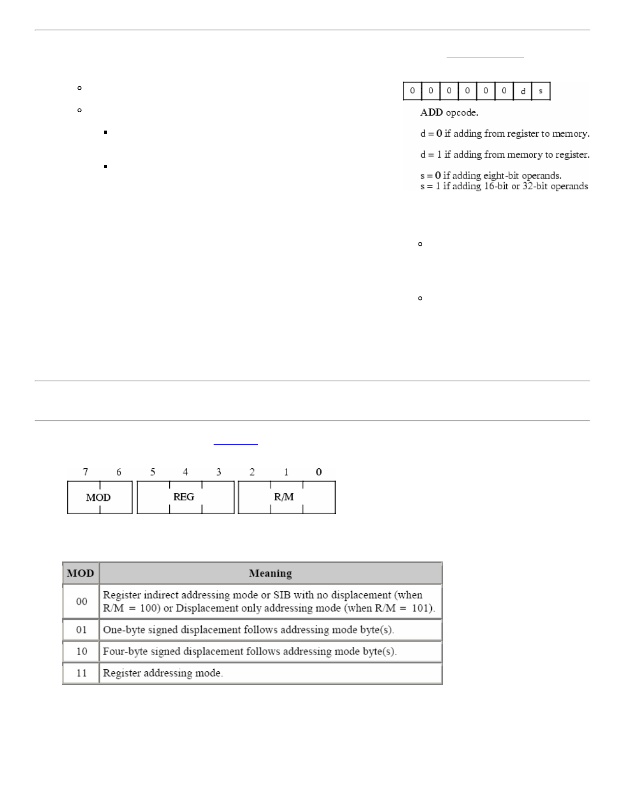
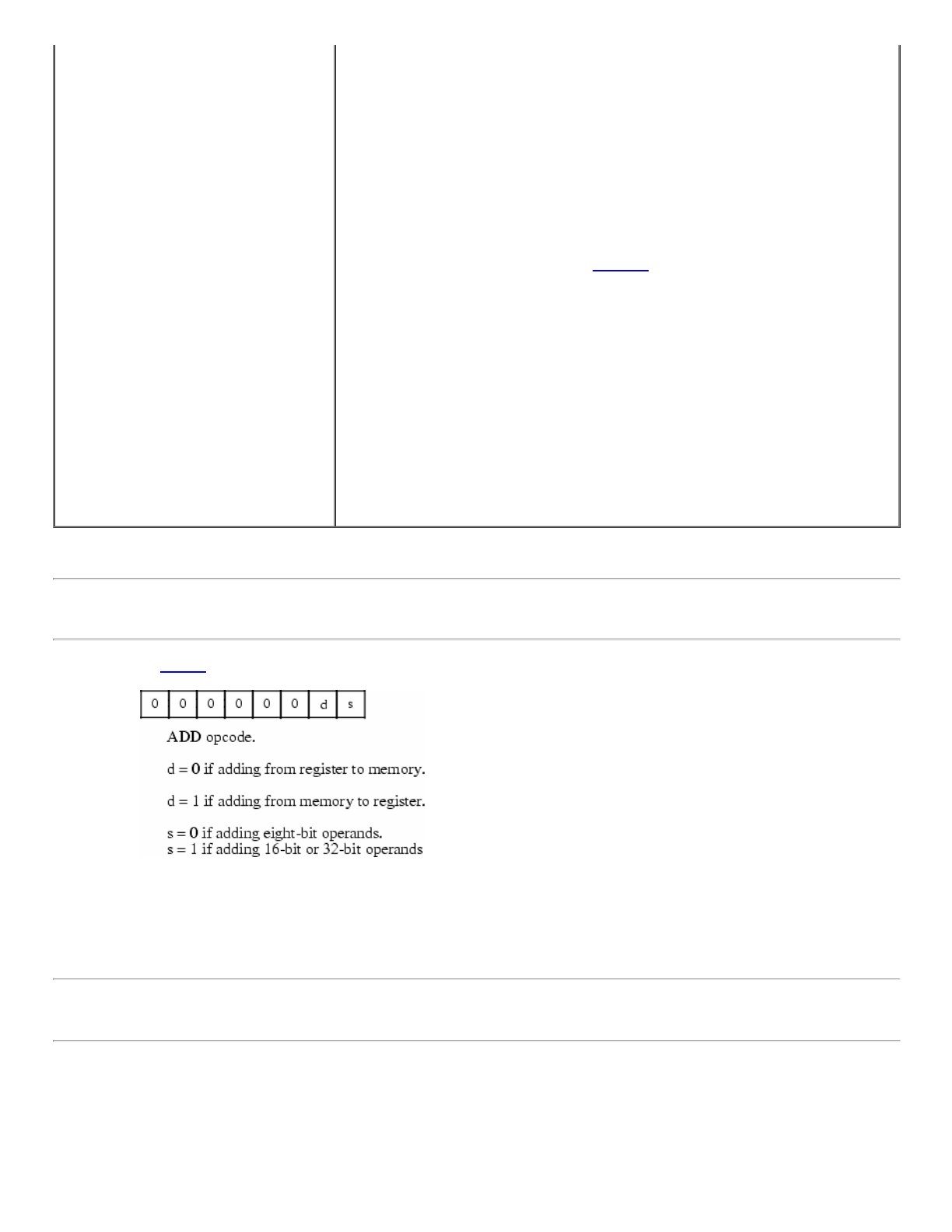
5. x86 ADD Instruction Opcode
12/25/2017 Encoding Real x86 Instructions
http://www.c-jump.com/CIS77/CPU/x86/lecture.html 4/21
Bit number zero marked s specifies the size of the operands the ADD
instruction operates upon:
If s = 0 then the operands are 8-bit registers and memory locations.
If s = 1 then the operands are either 16-bits or 32-bits:
Under 32-bit operating systems the default is 32-bit operands
if s = 1.
To specify a 16-bit operand (under Windows or Linux) you
must insert a special operand-size prefix byte in front of the
instruction (example of this later.)
_________________________
You'll soon see that this direction bit d creates a problem that results in
one instruction have two different possible opcodes.
x86 ADD instruction opcode :
Bit number one, marked d, specifies the
direction of the data transfer:
If d = 0 then the destination operand
is a memory location, e.g.
add [ebx], al
If d = 1 then the destination operand
is a register, e.g.
add al, [ebx]
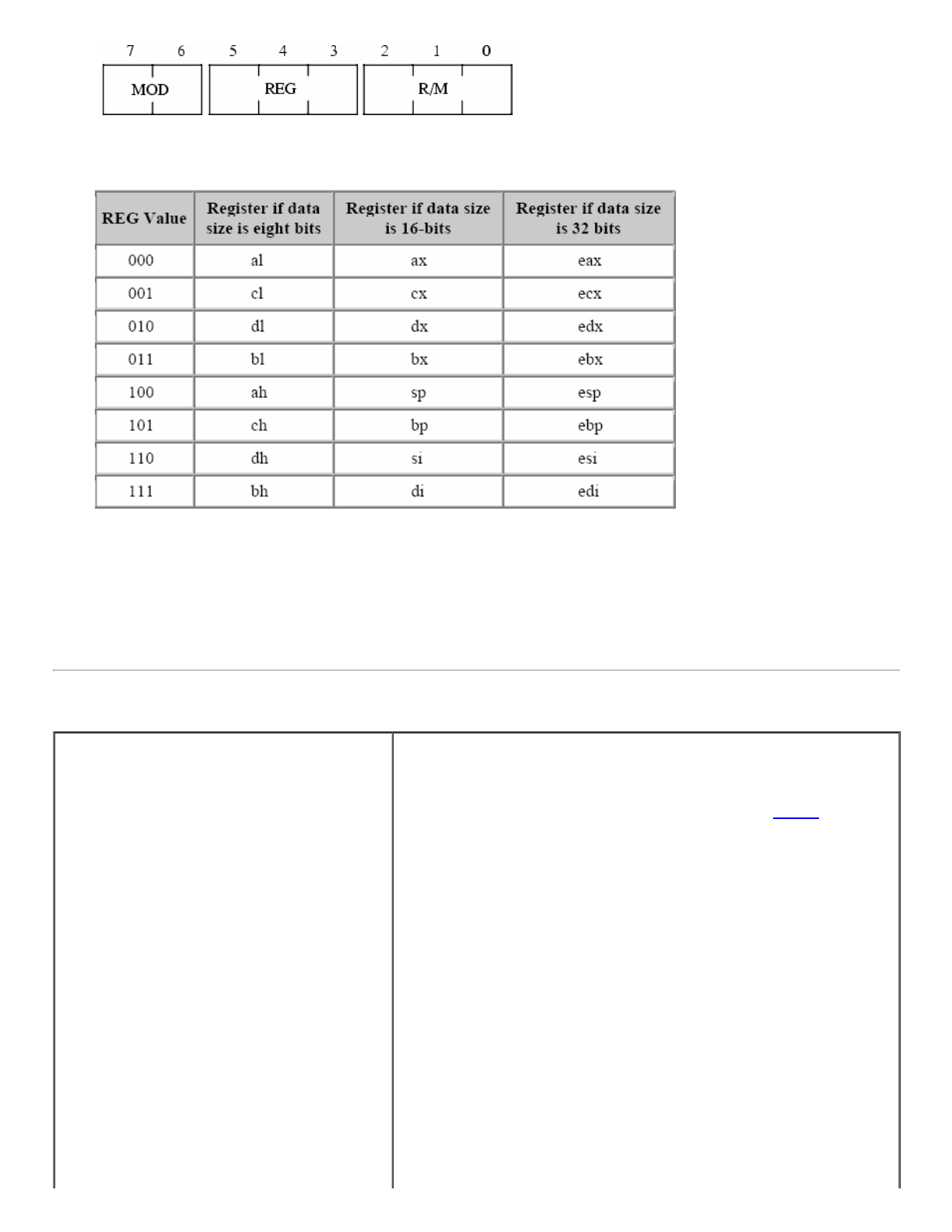
6. Encoding x86 Instruction Operands, MOD-REG-R/M Byte
The MOD-REG-R/M byte specifies instruction operands and their addressing mode(*):
The MOD field specifies x86 addressing mode:
The REG field specifies source or destination register:
The R/M field, combined
with MOD, specifies either
1. the second operand in
a two-operand
instruction, or
2. the only operand in a
single-operand
instruction like NOT
or NEG.
The d bit in the opcode
determines which operand
is the source, and which is
the destination:
d=0: MOD R/M <-
REG, REG is the
source
d=1: REG <- MOD
R/M, REG is the
destination
___________
value in al is stored at the address in the ebx register
value at the address that ebx contains will be copied to al register
both specifies a
operand - desitnation
is a memory location
it specifies a operand -
destination is a register
see page 9
for what
problem it
causes
12/25/2017 Encoding Real x86 Instructions
http://www.c-jump.com/CIS77/CPU/x86/lecture.html 5/21
(*) Technically, registers do
not have an address, but we
apply the term addressing
mode to registers
nonetheless.
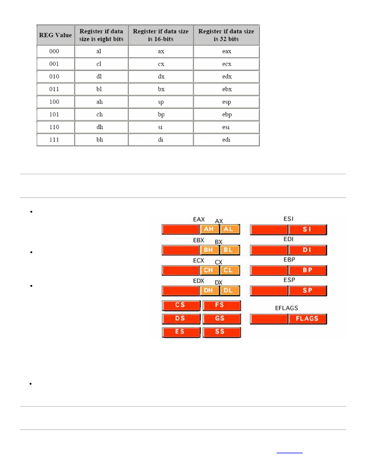
7. General-Purpose Registers
The EAX, EDX, ECX, EBX, EBP,
EDI, and ESI registers are 32-bit
general-purpose registers, used for
temporary data storage and memory
access.
The AX, DX, CX, BX, BP, DI, and SI
registers are 16-bit equivalents of the
above, they represent the low-order 16
bits of 32-bit registers.
The AH, DH, CH, and BH registers
represent the high-order 8 bits of the
corresponding registers.
Since the processor accesses registers more quickly than it accesses memory,
you can make your programs run faster by keeping the most-frequently used
data in registers.
Similarly, AL, DL, CL, and BL represent the low-order 8 bits of the registers.
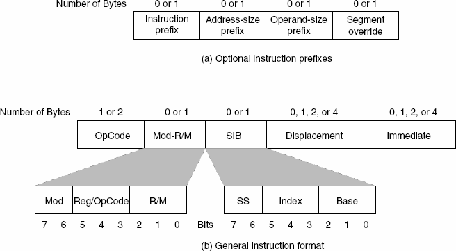
8. REG Field of the MOD-REG-R/M Byte
Depending on the
instruction , this can be
12/25/2017 Encoding Real x86 Instructions
http://www.c-jump.com/CIS77/CPU/x86/lecture.html 6/21
The REG field specifies an x86 register(*):
either the source or the
destination operand.
Many instructions have the
d (direction) field in their
opcode to choose REG
operand role:
1. If d=0, REG is the
source,
MOD R/M <- REG.
2. If d=1, REG is the
destination,
REG <- MOD R/M.
___________
(*) For certain (often single-operand or immediate-operand) instructions, the REG field may contain an opcode extension
rather than the register bits. The R/M field will specify the operand in such case.
9. MOD R/M Byte and Addressing Modes
MOD R/M Addressing Mode
=== === ================================
00 000 [ eax ]
01 000 [ eax + disp8 ] (1)
10 000 [ eax + disp32 ]
11 000 register ( al / ax / eax ) (2)
00 001 [ ecx ]
01 001 [ ecx + disp8 ]
10 001 [ ecx + disp32 ]
11 001 register ( cl / cx / ecx )
00 010 [ edx ]
01 010 [ edx + disp8 ]
10 010 [ edx + disp32 ]
11 010 register ( dl / dx / edx )
00 011 [ ebx ]
01 011 [ ebx + disp8 ]
10 011 [ ebx + disp32 ]
11 011 register ( bl / bx / ebx )
00 100 SIB Mode (3)
01 100 SIB + disp8 Mode
10 100 SIB + disp32 Mode
11 100 register ( ah / sp / esp )
00 101 32-bit Displacement-Only Mode (4)
01 101 [ ebp + disp8 ]
10 101 [ ebp + disp32 ]
11 101 register ( ch / bp / ebp )
00 110 [ esi ]
01 110 [ esi + disp8 ]
10 110 [ esi + disp32 ]
1. Addressing modes with 8-bit displacement fall in the range -128..+127
and require only a single byte displacement after the opcode (Faster!)
2. The size bit in the opcode specifies 8 or 32-bit register size. To select a
16-bit register requires a prefix byte.
3. The so-called scaled indexed addressing modes, SIB = scaled index
byte mode.
4. Note that there is no [ ebp ] addressing. It's slot is occupied by the 32-
bit displacement only addressing mode. Intel decided that programmers
can use [ ebp+ disp8 ] addressing mode instead, with its 8-bit
displacement set equal to zero (instruction is a little longer, though.)
it is a trick , note it carefully
12/25/2017 Encoding Real x86 Instructions
http://www.c-jump.com/CIS77/CPU/x86/lecture.html 7/21
11 110 register ( dh / si / esi )
00 111 [ edi ]
01 111 [ edi + disp8 ]
10 111 [ edi + disp32 ]
11 111 register ( bh / di / edi )
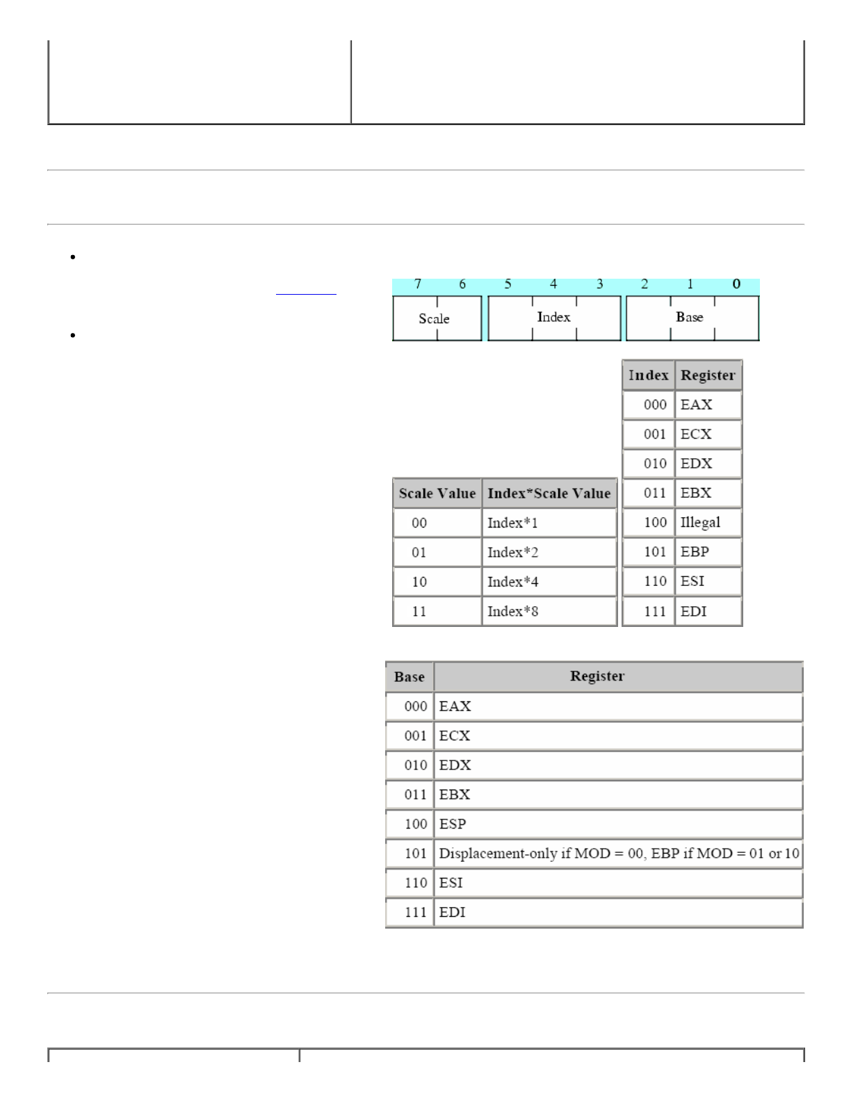
10. SIB (Scaled Index Byte) Layout
Scaled indexed addressing mode uses the
second byte (namely, SIB byte) that follows
the MOD-REG-R/M byte in the instruction
format.
The MOD field still specifies the
displacement size of zero, one, or four bytes.
The MOD-REG-R/M and SIB bytes
are complex, because Intel reused 16-
bit addressing circuitry in the 32-bit
mode, rather than simply abandoning
the 16-bit format in the 32-bit mode.
There are good hardware reasons for
this, but the end result is a complex
scheme for specifying addressing
modes in the opcodes.
Scaled index byte layout:
11. Scaled Indexed Addressing Mode
intel
reserved
ESP
register
for future
devpmnt
there will be no BASE register if
MOD=00 and BASE=101
when base is 101 and mode 00
only displacement and no base
no 100 --> so no ESP
12/25/2017 Encoding Real x86 Instructions
http://www.c-jump.com/CIS77/CPU/x86/lecture.html 8/21
[ reg32 + eax*n ] MOD = 00
[ reg32 + ebx*n ]
[ reg32 + ecx*n ]
[ reg32 + edx*n ]
[ reg32 + ebp*n ]
[ reg32 + esi*n ]
[ reg32 + edi*n ]
[ disp + reg8 + eax*n ] MOD = 01
[ disp + reg8 + ebx*n ]
[ disp + reg8 + ecx*n ]
[ disp + reg8 + edx*n ]
[ disp + reg8 + ebp*n ]
[ disp + reg8 + esi*n ]
[ disp + reg8 + edi*n ]
[ disp + reg32 + eax*n ] MOD = 10
[ disp + reg32 + ebx*n ]
[ disp + reg32 + ecx*n ]
[ disp + reg32 + edx*n ]
[ disp + reg32 + ebp*n ]
[ disp + reg32 + esi*n ]
[ disp + reg32 + edi*n ]
[ disp + eax*n ] MOD = 00, and
[ disp + ebx*n ] BASE field = 101
[ disp + ecx*n ]
[ disp + edx*n ]
[ disp + ebp*n ]
[ disp + esi*n ]
[ disp + edi*n ]
Note: n = 1, 2, 4, or 8.
In each scaled indexed addressing mode the MOD field in MOD-REG-R/M
byte specifies the size of the displacement. It can be zero, one, or four bytes:
MOD R/M Addressing Mode
--- --- ---------------------------
00 100 SIB
01 100 SIB + disp8
10 100 SIB + disp32
The Base and Index fields of the SIB byte select the base and index registers,
respectively.
Note that this addressing mode does not allow the use of the ESP register as an
index register. Presumably, Intel left this particular mode undefined to provide
the ability to extend the addressing modes in a future version of the CPU.
12. Encoding ADD Instruction Example
The ADD opcode can be decimal 0, 1, 2, or 3, depending on the direction and size bits in the opcode:
How could we encode various forms of the ADD instruction using different addressing modes?
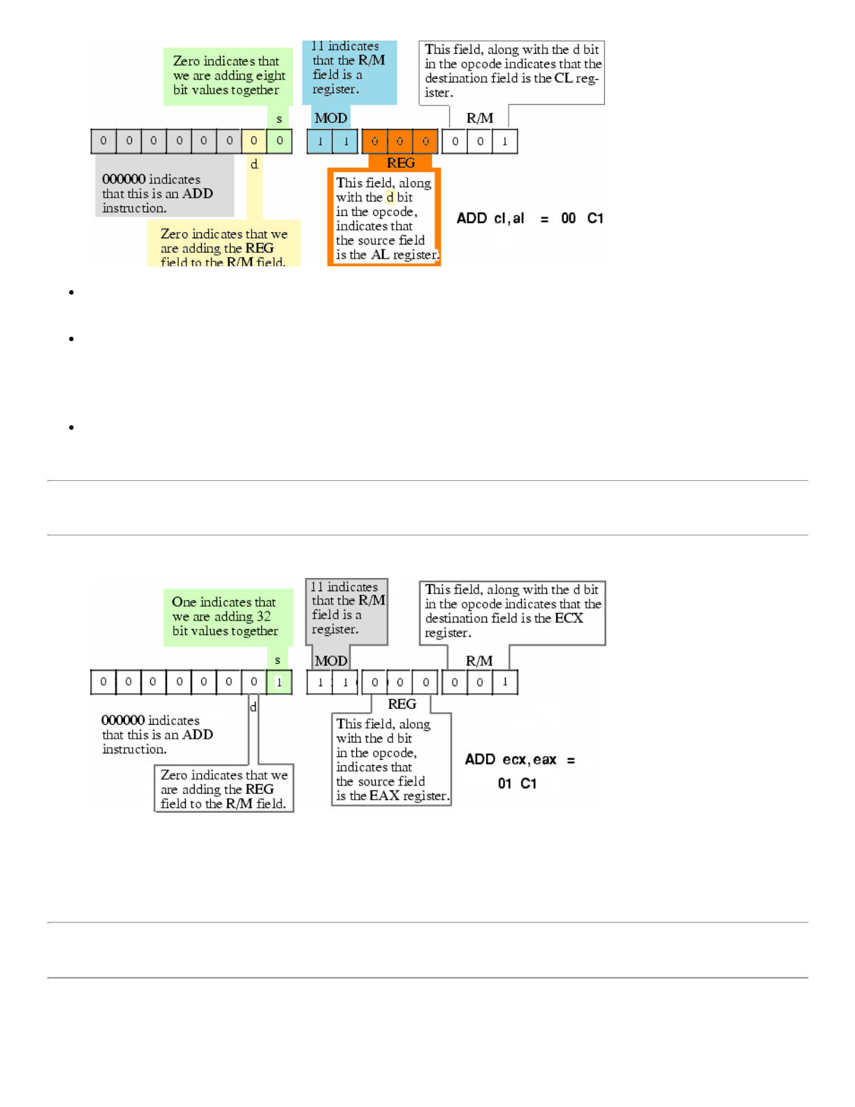
13. Encoding ADD CL, AL Instruction
any GP register can be used here
displacement only
12/25/2017 Encoding Real x86 Instructions
http://www.c-jump.com/CIS77/CPU/x86/lecture.html 9/21
Interesting side effect of the direction bit and the MOD-REG-R/M byte organization: some instructions can have two
different opcodes, and both are legal!
For example, encoding of
add cl, al
could be 00 C1 (if d=0), or 02 C8, if d bit is set to 1.
The possibility of opcode duality issue here applies to all instructions with two register operands.
14. Encoding ADD ECX, EAX Instruction
add ecx, eax
Note that we could also encode ADD ECX, EAX using the bytes 03 C8.
15. Encoding ADD EDX, DISPLACEMENT Instruction
Encoding the ADD EDX, DISP Instruction:
both opcodes does the same job
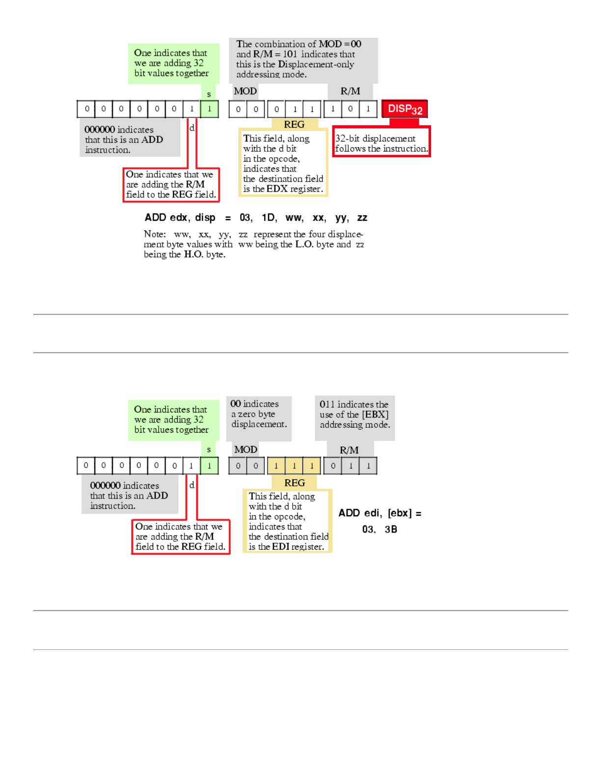
12/25/2017 Encoding Real x86 Instructions
http://www.c-jump.com/CIS77/CPU/x86/lecture.html 10/21
add edx, disp
16. Encoding ADD EDI, [EBX] Instruction
Encoding the ADD EDI, [ EBX ] instruction:
add edi, [ebx]
17. Encoding ADD EAX, [ ESI + disp8 ] Instruction
Encoding the ADD EAX, [ ESI + disp8 ] instruction:
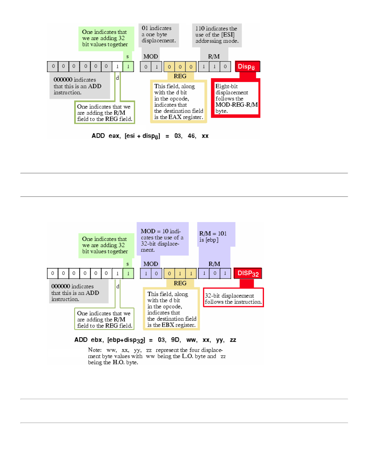
12/25/2017 Encoding Real x86 Instructions
http://www.c-jump.com/CIS77/CPU/x86/lecture.html 11/21
add eax, [ esi + disp8 ]
18. Encoding ADD EBX, [ EBP + disp32 ] Instruction
Encoding the ADD EBX, [ EBP + disp32 ] instruction:
add ebx, [ ebp + disp32 ]
19. Encoding ADD EBP, [ disp32 + EAX*1 ] Instruction
Encoding the ADD EBP, [ disp32 + EAX*1 ] Instruction
base + index*scacle
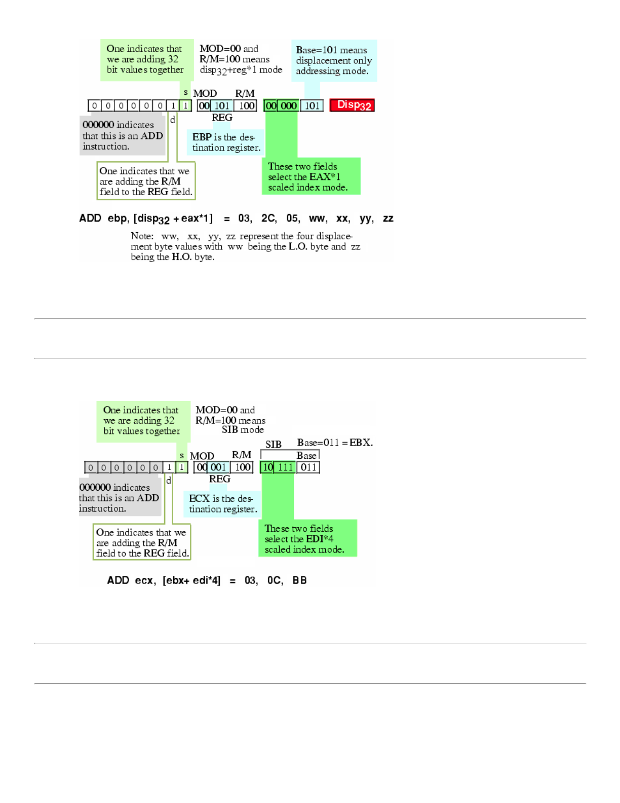
12/25/2017 Encoding Real x86 Instructions
http://www.c-jump.com/CIS77/CPU/x86/lecture.html 12/21
add ebp, [ disp32 + eax*1 ]
20. Encoding ADD ECX, [ EBX + EDI*4 ] Instruction
Encoding the ADD ECX, [ EBX + EDI*4 ] Instruction
add ecx, [ ebx + edi*4 ]
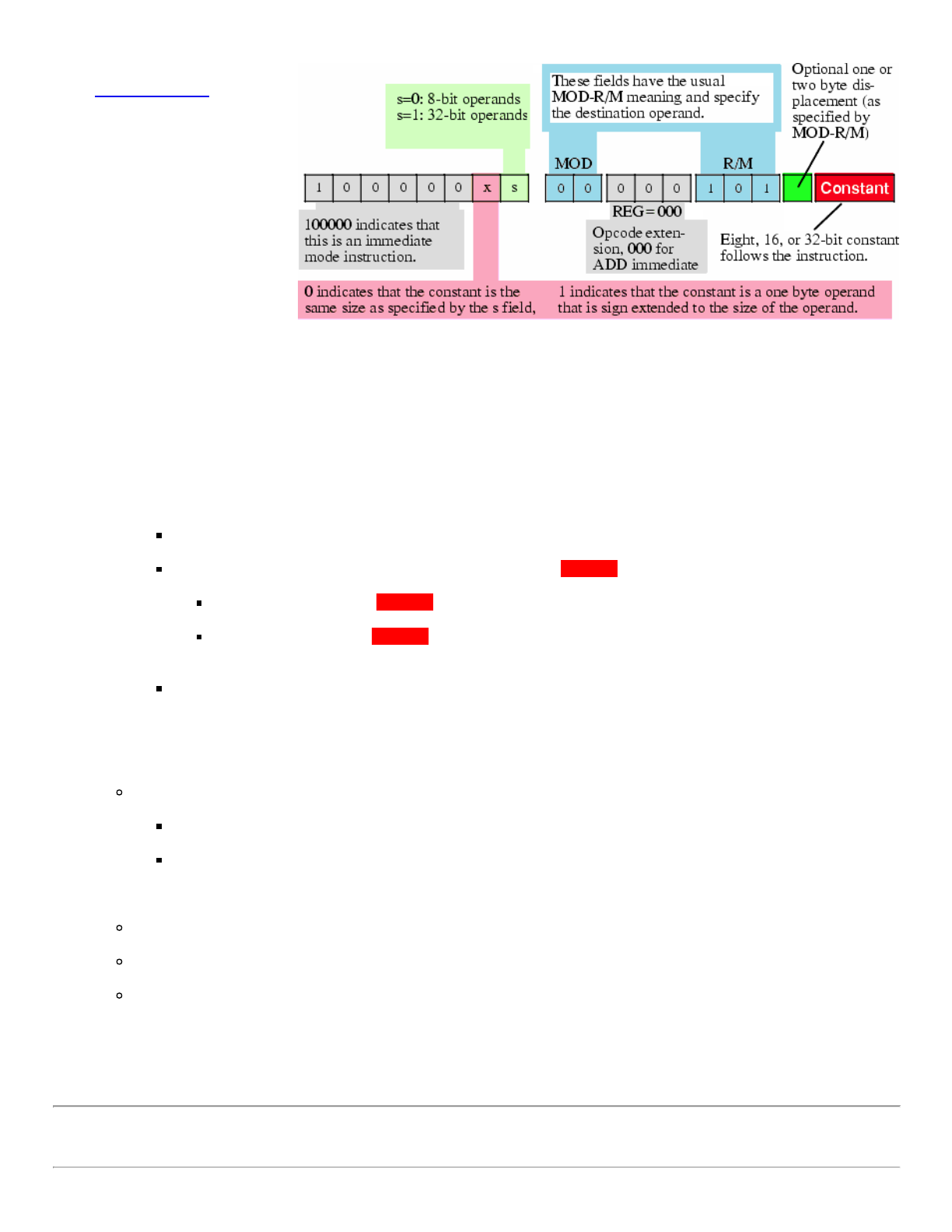
21. Encoding ADD Immediate Instruction
MOD-REG-R/M and
SIB bytes have no bit
combinations to specify
an immediate operand.
Encoding x86 immediate operands:
12/25/2017 Encoding Real x86 Instructions
http://www.c-jump.com/CIS77/CPU/x86/lecture.html 13/21
Instead, x86 uses a
entirely different
instruction format to
specify instruction with
an immediate operand.
There are three rules that
apply:
1. If opcode high-order bit set to 1, then instruction has an immediate constant.
2. There is no direction bit in the opcode:
: indeed, you cannot specify a constant as a destination operand!
Therefore, destination operand is always the location encoded in the MOD-R/M bits of the the MOD-REG-R/M byte.
In place of the direction bit d, the opcode has a sign extension x bit instead:
For 8-bit operands, the CPU ignores x bit.
For 16-bit and 32-bit operands, x bit specifies the size of the Constant following at the end of the instruction:
If x bit contains zero, the Constant is the same size as the operand (i.e., 16 or 32 bits).
If x bit contains one, the Constant is a signed 8-bit value, and the CPU sign-extends this value to the
appropriate size before adding it to the operand.
This little x trick often makes programs shorter, because adding small-value constants to 16 or 32 bit operands is
very common.
3. The third difference between the ADD-immediate and the standard ADD instruction is the meaning of the REG field in the
MOD-REG-R/M byte:
Since the instruction implies that
the source operand is a constant, and
MOD-R/M fields specify the destination operand,
the instruction does not need to use the REG field to specify an operand.
Instead, the x86 CPU uses these three bits as an opcode extension.
For the ADD-immediate instruction the REG bits must contain zero.
Other bit patterns would correspond to a different instruction.
Note that when adding a constant to a memory location, the displacement (if any) immediately precedes the immediate
(constant) value in the opcode sequence.
22. Encoding Eight, Sixteen, and Thirty-Two Bit Operands
12/25/2017 Encoding Real x86 Instructions
http://www.c-jump.com/CIS77/CPU/x86/lecture.html 14/21
When Intel designed the 8086, one bit in the opcode, s, selected between 8
and 16 bit integer operand sizes.
Later, when CPU added 32-bit integers to its architecture on 80386 chip,
there was a problem:
three encodings were needed to support 8, 16, and 32 bit sizes.
Solution was an operand size prefix byte.
x86 ADD Opcode:
Intel studied x86 instruction set and came to the conclusion:
in a 32-bit environment, programs were more likely to use 8-bit and 32-bit operands far more often than 16-bit
operands.
So Intel decided to let the size bit s in the opcode select between 8- and 32-bit operands.
23. Encoding Sixteen Bit Operands
32-bit programs
don't use 16-bit
operands that
often, but they
do need them
now and then.
To allow for 16-
bit operands,
Intel added
prefix a 32-bit
mode
instruction with
the operand size
prefix byte with
value 66h.
This prefix byte
tells the CPU to
operand on 16-
bit data rather
than 32-bit data.
x86 instruction format:
There is nothing programmer has to do explicitly to put an operand size prefix byte in front of a 16-bit instruction:
the assembler does this automatically as soon as 16-bit operand is found in the instruction.
However, keep in mind that whenever you use a 16-bit operand in a 32-bit program, the instruction is longer by one byte:
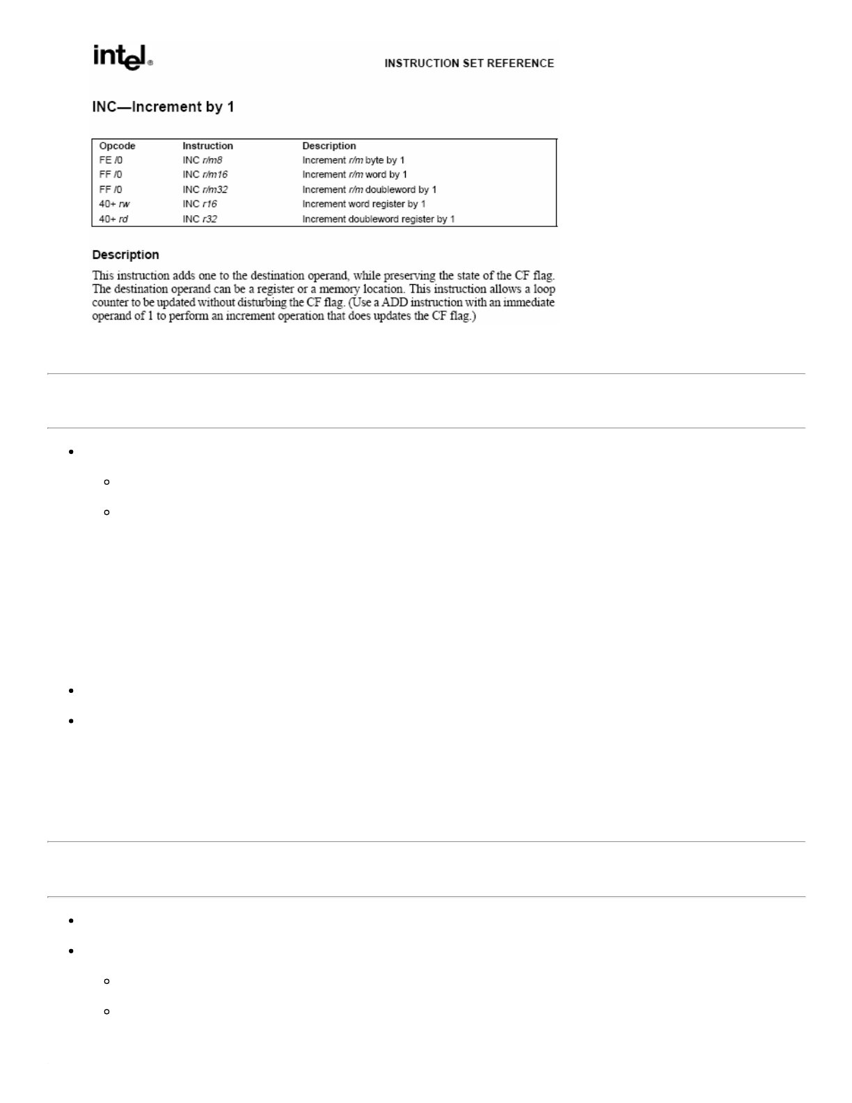
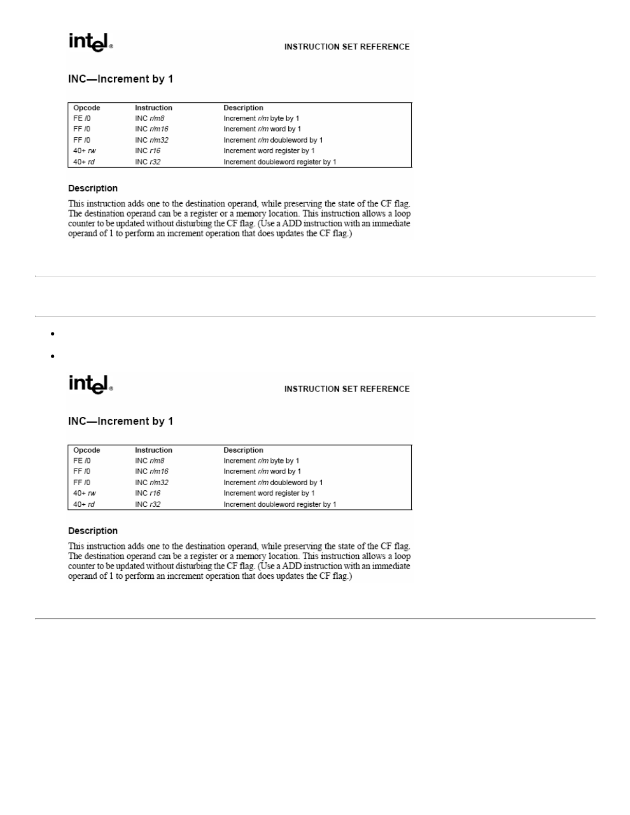
Opcode Instruction
-------- ------------
41h INC ECX
66h 41h INC CX
Be careful about using 16-bit instructions if size (and to a lesser extent, speed) are important, because
why s bit determines
8 bit and 32 bit
operands

12/25/2017 Encoding Real x86 Instructions
http://www.c-jump.com/CIS77/CPU/x86/lecture.html 15/21
1. instructions are longer, and
2. slower because of their effect on the instruction cache.
24. x86 Instruction Prefix Bytes
x86 instruction can have up to 4 prefixes.
Each prefix adjusts interpretation of the opcode:
1. Repeat/lock prefix byte guarantees that instruction will have exclusive use of all shared memory, until the instruction
completes execution:
F0h = LOCK
2. String manipulation instruction prefixes
F3h = REP, REPE
F2h = REPNE
where
REP repeats instruction the number of times specified by iteration count ECX.
REPE and REPNE prefixes allow to terminate loop on the value of ZF CPU flag.
Related string manipulation instructions are:
MOVS, move string
STOS, store string
SCAS, scan string
CMPS, compare string, etc.
See also string manipulation sample program: rep_movsb.asm
3. Segment override prefix causes memory access to use specified segment instead of default segment designated for
instruction operand.
2Eh = CS
36h = SS
3Eh = DS
26h = ES
64h = FS
65h = GS
4. Operand override, 66h. Changes size of data expected by default mode of the instruction e.g. 16-bit to 32-bit and vice
versa.
5. Address override, 67h. Changes size of address expected by the instruction. 32-bit address could switch to 16-bit and
vice versa.

12/25/2017 Encoding Real x86 Instructions
http://www.c-jump.com/CIS77/CPU/x86/lecture.html 16/21
25. Alternate Encodings for Instructions
To shorten program code, Intel created alternate (shorter) encodings of some very commonly used instructions.
For example, x86 provides a single byte opcode for
add al, constant ; one-byte opcode and no MOD-REG-R/M byte
add eax, constant ; one-byte opcode and no MOD-REG-R/M byte
the opcodes are 04h and 05h, respectively. Also,
These instructions are one byte shorter than their standard ADD immediate counterparts.
Note that
add ax, constant ; operand size prefix byte + one-byte opcode, no MOD-REG-R/M byte
requires an operand size prefix just as a standard ADD AX, constant instruction, yet is still one byte shorter than the
corresponding standard version of ADD immediate.
Any decent assembler will automatically choose the shortest possible instruction when translating program into machine code.
Intel only provides alternate encodings only for the accumulator registers AL, AX, EAX.
This is a good reason to use accumulator registers if you have a choice
(also a good reason to take some time and study encodings of the x86 instructions.)
26. x86 Opcode Summary
x86 opcodes are represented by one or two bytes.
Opcode could extend into unused bits of MOD-REG-R/M byte.
Opcode encodes information about
operation type,
operands,
size of each operand, including the size of an immediate operand.
27. MOD-REG-R/M Byte Summary
MOD-REG-R/M byte follows one or two opcode
bytes of the instruction
It provides addressing mode information for one or
two operands.
MOD-REG-R/M Byte:
If operand is in memory, or operand is a register:

12/25/2017 Encoding Real x86 Instructions
http://www.c-jump.com/CIS77/CPU/x86/lecture.html 17/21
MOD field (bits [7:6]), combined with the R/M field (bits [2:0]), specify memory/register operand, as well as its
addressing mode.
REG field (bits [5:3]) specifies another register operand in of the two-operand instruction.
28. ISA Design Considerations
Instruction set architecture design that can stand the test of time is a true intellectual challenge.
It takes several compromises between space and efficiency to assign opcodes and encode instruction formats.
Today people are using Intel x86 instruction set for purposes never intended by original designers.
Extending the CPU is a very difficult task.
The instruction set can become extremely complex.
If x86 CPU was designed from scratch today, it would have a totally different ISA!
Software developers usually don't have a problem adapting to a new architecture when writing new software...
...but they are very resistant to moving existing software from one platform to another.
This is the primary reason the Intel x86 platform remains so popular to this day.
29. ISA Design Challenges
Allowing for future expansion of the chip requires some undefined opcodes.
From the beginning there should be a balance between the number of undefined opcodes and
1. the number of initial instructions, and
2. the size of your opcodes (including special assignments.)
Hard decisions:
Reduce the number of instructions in the initial instruction set?
Increase the size of the opcode?
Rely on an opcode prefix byte(s), which makes later added instructions longer?
There are no easy answers to these challenges for CPU designers!
30. Intel Architecture Software Developer's Manual
Classic Intel Pentium II Architecture Software Developer's Manual contains three parts:
1. Volume 1 , Intel Basic Architecture: Order Number 243190 , PDF, 2.6 MB.

12/25/2017 Encoding Real x86 Instructions
http://www.c-jump.com/CIS77/CPU/x86/lecture.html 18/21
2. Volume 2 , Instruction Set Reference: Order Number 243191 , PDF, 6.6 MB.
3. Volume 3 , System Programing Guide: Order Number 243192 , PDF, 5.1 MB.
It is highly recommended that you download the above manuals and use them as a reference.
31. Intel Instruction Set Reference (Volume2)
Chapter 3 of the Instruction Set Reference describes
each Intel instruction in detail
algorithmic description of each operation
effect on flags
operand(s), their sizes and attributes
CPU exceptions that may be generated.
The instructions are arranged in alphabetical order.
Appendix A provides opcode map for the entire Intel Architecture instruction set.
32. Chapter 3 of Intel Instruction Set Reference
Chapter 3 begins with instruction format example and explains the Opcode column encoding.
The Opcode column gives the complete machine codes as it is understood by the CPU.
When possible, the actual machine code bytes are given as exact hexadecimal bytes, in the same order in which they appear in
memory.
However, there are opcode definitions other than hexadecimal bytes...
33. Intel Reference Opcode Bytes
Fow example,
12/25/2017 Encoding Real x86 Instructions
http://www.c-jump.com/CIS77/CPU/x86/lecture.html 19/21
34. Intel Reference Opcode Bytes, Cont.
/digit - A digit between 0 and 7 indicates that
The reg field of Mod R/M byte contains the instruction opcode extension.
The r/m (register or memory) operand of Mod R/M byte indicates
R/M Addressing Mode
=== ===========================
000 register ( al / ax / eax )
001 register ( cl / cx / ecx )
010 register ( dl / dx / edx )
011 register ( bl / bx / ebx )
100 register ( ah / sp / esp )
101 register ( ch / bp / ebp )
110 register ( dh / si / esi )
111 register ( bh / di / edi )
The size bit in the opcode specifies 8 or 32-bit register size.
A 16-bit register requires a prefix byte:
Opcode Instruction
-------- ------------
41h INC ECX
66h 41h INC CX
35. Intel Reference Opcode Bytes, Cont.
/r - Indicates that the instruction uses the Mod R/M byte of the instruction.
Mod R/M byte contains both
a register operand reg and
an r/m (register or memory) operand.

12/25/2017 Encoding Real x86 Instructions
http://www.c-jump.com/CIS77/CPU/x86/lecture.html 20/21
36. Intel Reference Opcode Bytes, Cont.
cb, cw, cd, cp - A 1-byte (cb), 2-byte (cw), 4-byte (cd), or 6-byte (cp) value,
following the opcode, is used to specify
a code offset,
and possibly a new value for the code segment register CS.
37. Intel Reference Opcode Bytes, Cont.
ib, iw, id - A 1-byte (ib), 2-byte (iw), or 4-byte (id) indicates presence of the immediate operand in the instruction.
Typical order of opcode bytes is
opcode
Mod R/M byte (optional)
SIB scale-indexing byte (optional)
immediate operand.
The opcode determines if the operand is a signed value.
All words and doublewords are given with the low-order byte first (little endian).
38. Intel Reference Opcode Bytes, Cont.
+rb, +rw, +rd - A register code, from 0 through 7, added to the hexadecimal byte given at the left of the plus sign to form a
single opcode byte.
Register Encodings Associated with the +rb, +rw, and +rd:
For example,
12/25/2017 Encoding Real x86 Instructions
http://www.c-jump.com/CIS77/CPU/x86/lecture.html 21/21
39. Intel Reference Instruction Column
The Instruction column gives the syntax of the instruction statement as it would appear in a 386 Assembly program.
For example,
