Expansion & Contraction
User Manual: Expansion & Contraction
Open the PDF directly: View PDF ![]() .
.
Page Count: 12

6.01
GEORGE FISCHER ‡
6
Expansion & Contraction
Page
Expansion & Contraction Introduction 6.02
Change in length 6.03
Allowing for expansion or contraction 6.04 - 6.07
Bracket spacing 6.08 - 6.12

6.02 GEORGE FISCHER ‡
Expansion and Contraction
All materials expand or contract with
the increase or decrease in
temperature. The amount of this
expansion or contraction is
dependent on the coefficient of linear
expansion α. This coefficient is very
rarely linear for a material, however
for most calculations a good average
is used.
The average linear expansion
coefficient of polybutylene (PB):
α = 0.013 mm/m°C
Therefore
∆L = α x L x ∆t
Where ∆L = change in length in mm
α= coefficient of expansion
L = original length in mm
∆t = temperature difference
in °C
Example
How much will a 10m length of PB
(INSTAFLEX) expand if the working
temperature is 60°C and the
installation temperature is 15°C?
∆t = working temperature -
installation temperature
∆t= 60°C –15°C
∆t= 45°C
Therefore
∆L= 0.13 x 10 x 45
∆L= 58.5mm
Important
Please note that ∆t is the
difference between the
installation temperature and
the working temperature.
∆L = change in length
L = pipe length
Change in length ∆ L in mm for PB pipes
Pipe l.
in m
Temperature difference ∆t in °C
10 20 30 40 50 60 70 80
0.1 0.1 0.3 0.4 0.5 0.7 0.8 0.9 1.0
0.2 0.3 0.5 0.8 1 .0 2.0 2.3 2.7 3.1
0.3 0.4 0.8 1 .2 1 .6 2.0 2.3 2.7 3.1
0.4 0.5 1 .0 1 .6 2.1 2.6 3.1 3.6 4.2
0.5 0.6 1.3 2.0 2.6 3.3 3.9 4.6 5.2
0.6 0.8 1.6 2.3 3.1 3.9 4.7 5.5 6.2
0.7 0.9 1.8 2.7 3.6 4.6 5.5 6.4 7.3
0.8 1 .0 2.1 3.1 4.2 5.2 6.2 7.3 8.3
0.9 1 .2 2.3 3.5 4.7 5.9 7.0 8.2 9.4
1 .0 1 .3 2.6 3.9 5.2 6.5 7.8 9.1 10.4
2.0 2.6 5.2 7.8 10.4 13.0 15.6 18.2 20.8
3.0 3.9 7.8 11 .7 15.6 19.5 23.4 27.3 31 .2
4.0 5.2 10.4 15.6 20.8 26.0 31 .2 36.4 41 .6
5.0 6.5 13.0 19.5 26.0 32.5 39.0 45.5 52.0
6.0 7.8 15.6 23.4 31 .2 39.0 46.8 54.6 62.4
7.0 9.1 18.2 27.3 36.4 45.5 54.6 63.7 72.8
8.0 10.4 20.8 31 .2 41 .6 52.0 62.4 72.8 83.2
9.0 11 .7 23.4 35.1 46.8 58.5 70.2 81 .9 93.6
10.0 13.0 26.0 39.0 52.0 65.0 78.0 91 .0 104.0
11 .0 14.3 28.6 42.9 57.2 71 .5 85.8 100.1 114.4
12.0 15.6 31 .2 46.8 62.4 78.0 93.6 109.2 124.8
Example from table
A 5m long pipe working at a
temperature of 50°C will expand or
contract by 32.5mm.
6.03
GEORGE FISCHER ‡
6
Temperature Difference ∆t in °C
Change in length ∆L in mm
0 10 20 30 40 50 60 70 80 90 100 110 120 130
Pipe length L in m
Change in length ∆ L in mm for PB pipes
6.04 GEORGE FISCHER ‡
Allowing for Expansion or Contraction
1. General
Being a member of the thermoplastic
family, INSTAFLEX PB is subject to
greater thermal movement than
metals. As all materials expand or
contract and since the modulus of
elasticity (E) of INSTAFLEX is very low,
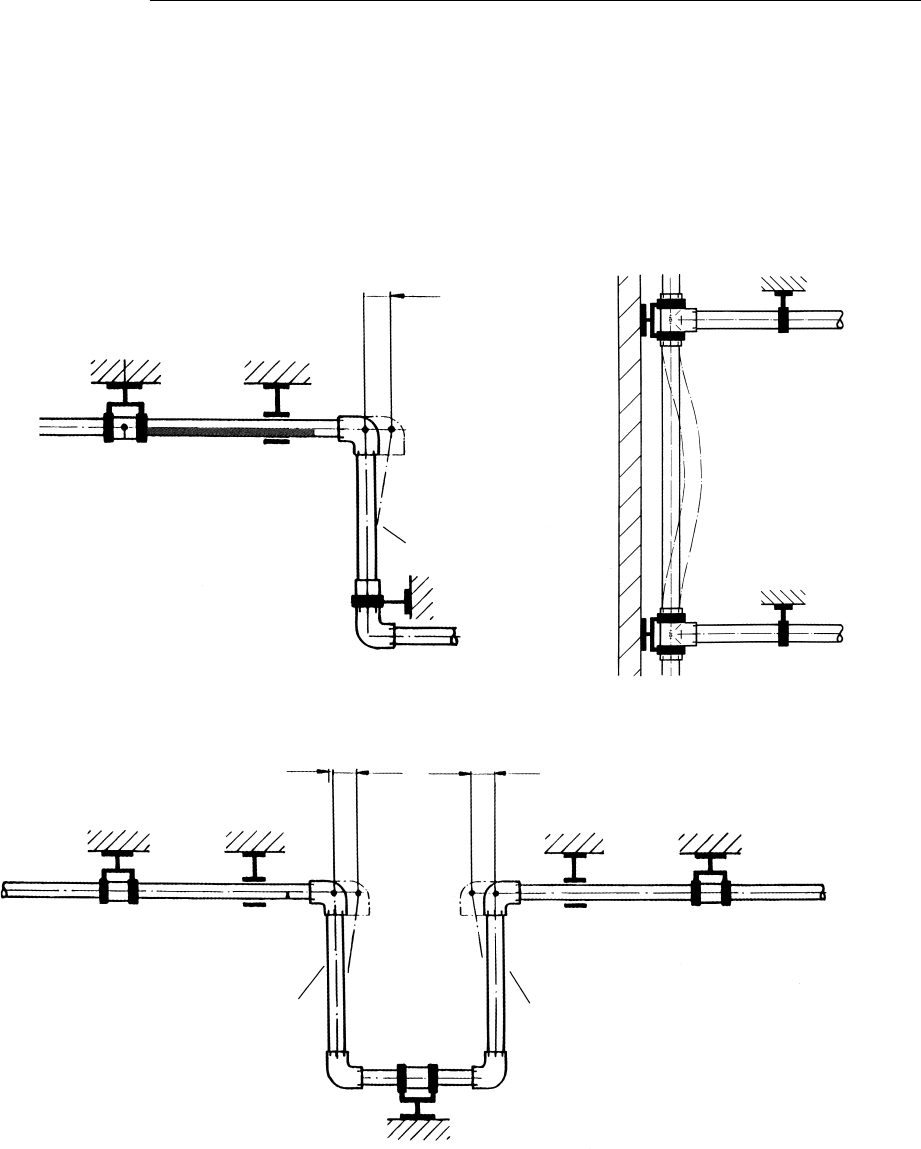
Method 1
By optimising the flexibility of PB by
using the changes of direction found
in most installations or to install
expansion loops. This method is most
Flexible expansion leg Pipe lateral yielding in riser
Expansion Loop
Expansion
Expansion
Flexible Leg
Fixed point
bracket
Sliding
bracket
Fixed point
bracket
Sliding
bracket
Fixed point
bracket
Sliding
bracket
Flexible LegFlexible Leg
Fixed point
bracket
at 350N/mm2, overcoming the effects
of expansion or contraction is
generally easier than with metals.
There are three principal methods
to overcome the effects of thermal
movement.
commonly used in places where the
pipework is not visible, i.e. in ceiling
voids or riser ducts.
6.05
GEORGE FISCHER ‡
6
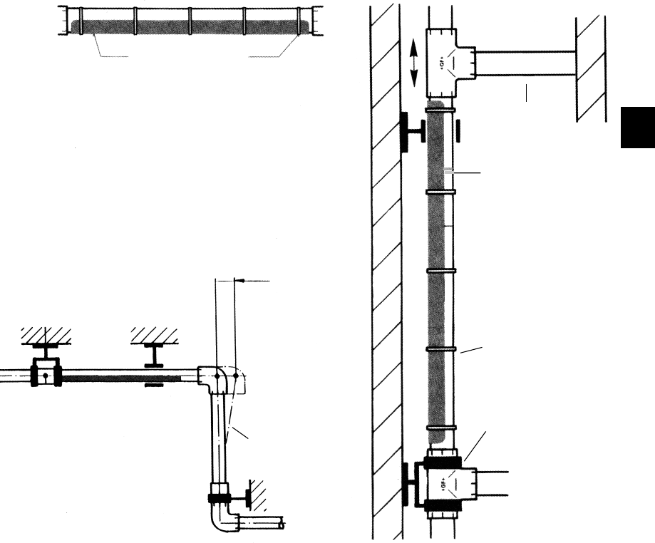
Method 2
Similar to Method 1 but using pipe
carrier to continually support the
pipe. The advantage of this
approach is that pipe is continually
supported and the bracket centers
Expansion
Flexible Leg
Fixed point
bracket
Sliding
bracket
Flexible Expansion Leg
with carrier
Typical Pipe Carrier Pipe in Riser Carrier
Pipe carrier Pipe ties
Flexible Leg
Pipe carrier
Pipe ties
Fixed point
bracket
∆L
can be much further apart.
Ideal for use in areas where the pipe
is visible.
6.06 GEORGE FISCHER ‡
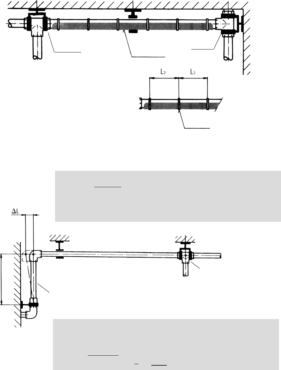
Method 3
This method utilises the unique feature
of INSTAFLEX, namely its ability to
absorb any thermal movement within
itself without detriment to the material
or system. This is achieved by rigidly
fixing the pipework to prevent any
thermal movement.
This system is commonly used where
there are long pipe runs with laterals.
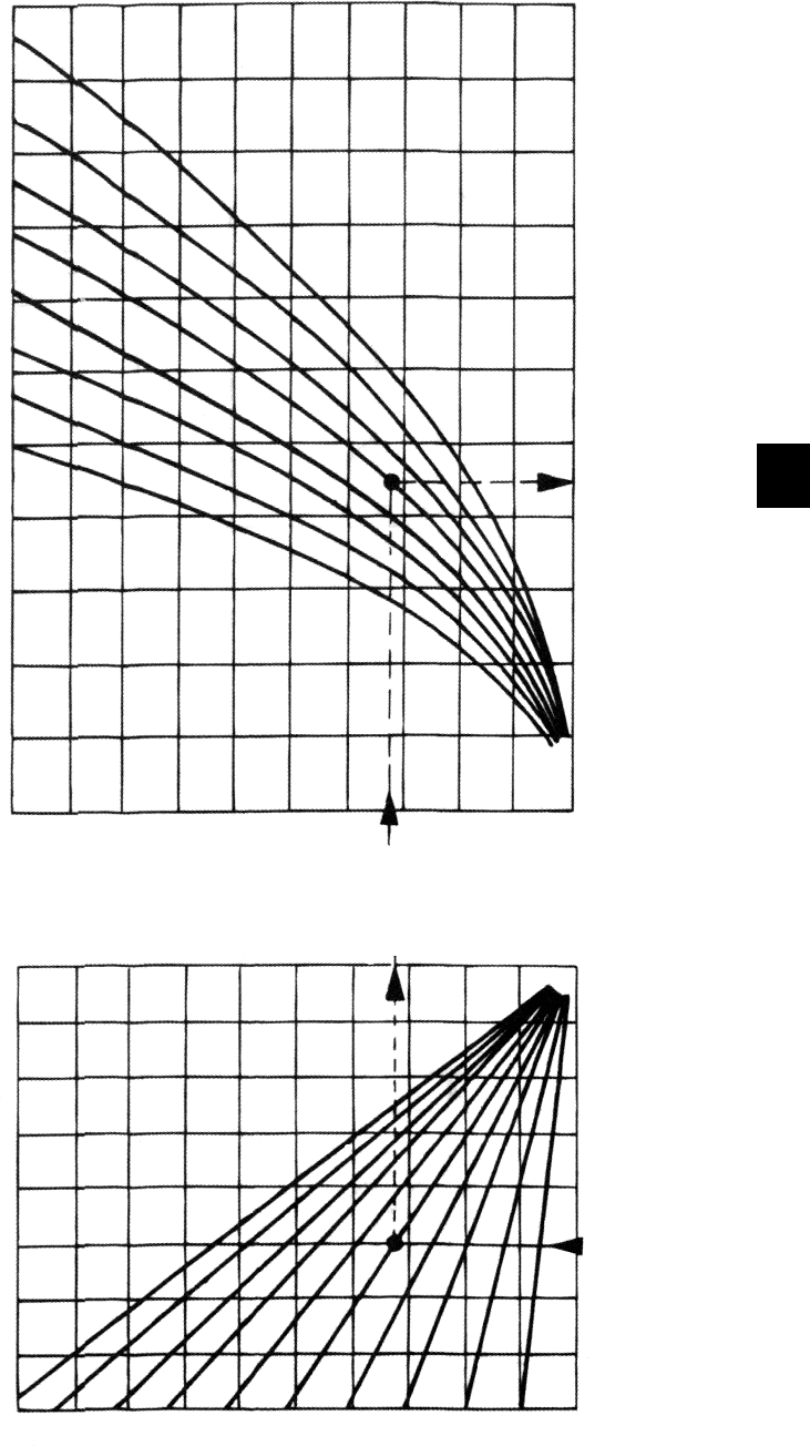
Calculating the Flexible Leg for
Methods 1 and 2.
where a = flexible leg in cm
k = constant PB = 10
∆L= Expansion or Contraction in cm
a = k x √ ∆L x od
Example
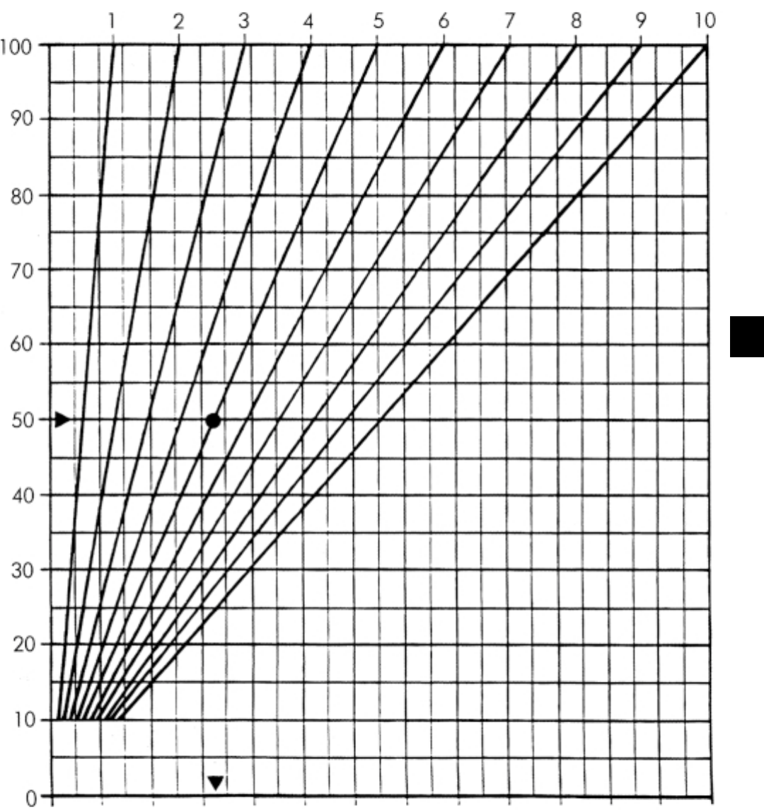
How long should leg “a” be if the expansion ∆L is 3.25cm
on a 6.3cm od pipe?
a = 10 x √ 3.25 x 6.3 ~ 45cm
Flexible Leg
Sliding
Bracket Fixed Point
Bracket
“a”
Fixed point
bracket
Sliding bracket
Pipe carrier
Fixed point
bracket
Pipe ties
6.07
GEORGE FISCHER ‡
6
General Guidelines
1 . Control the direction and
amount of thermal movement
by careful positioning of fixed
points.
2. Take care to ensure the
pipe can move freely within
the loose brackets.
3. Never create a fixed point
by tightening the bracket to
squeeze the pipe.
4. Ensure that the positioning
of loose bracket does not
inadvertently create a fixed
point.
Graphical method for Determining the Flexible Leg “a”
For methods 1 and 2
Temperature difference ∆t in °C
length of pipe run in m
Flexible Leg “a”
Change in length ∆L in cm
d110
d90
d75
d63
d50
d40
d32
d25
109876 54321
110
100
90
80
70
60
50
40
30
20
10
45
10 9 8 7 6 5 4 3 2 1

6.08 GEORGE FISCHER ‡
Method 1 º Bracket Spacing
The pipe bracket spacing may be
increased by 30% in the case of
vertical pipes. i.e. multiply the values
given by 1 .3.
Method 2 º Loose Bracket Spacing with support tray
16 70 70 65 65 60 60
2075 80 75 75 7070
2580 80 80 75 75 70
32 90 90 90 90 85 80
40 105 100 100 95 95 90
50 115 115 110 110 105 100
63 130 130 125 120 120 110
75 140 140 135 130 130 120
90 155 150 150 145 140 130
110 190 190 180 180 170 160
20°C30°C40°C50°C60°C80°C
Pipe bracket intervals in cm
Pipe size
d
Pipe size
dAll Temperatures Tie Spacing
16 to 75mm 1 .5 to 2m maximum approx. every 30cm
90 & 110 1 .5 to 2m maximum approx. every 30cm
No support tray
The bracket spacings above are
based on a maximum deflection of
0.25cm between the brackets.
6.09
GEORGE FISCHER ‡
6
Pre-stressing
An alternative solution for Methods 1
and 2 is to cut the pipe short by the
amount that it is calculated that it will
expand or contract, such that when it
Position at ambient temperature Position at operating temperature
Note
There must be a
Flexible Leg “a”
Bracket distances for hot water pipes
Pipe dim
d mm
Fixed point
distances
L
Loose bracket
distances
L1
Pipe binder
distances
L2
16
20
25
32
40
50
63
75
maximum
6m between
fixed points
1 .5 to 2m max. approx every 30cm
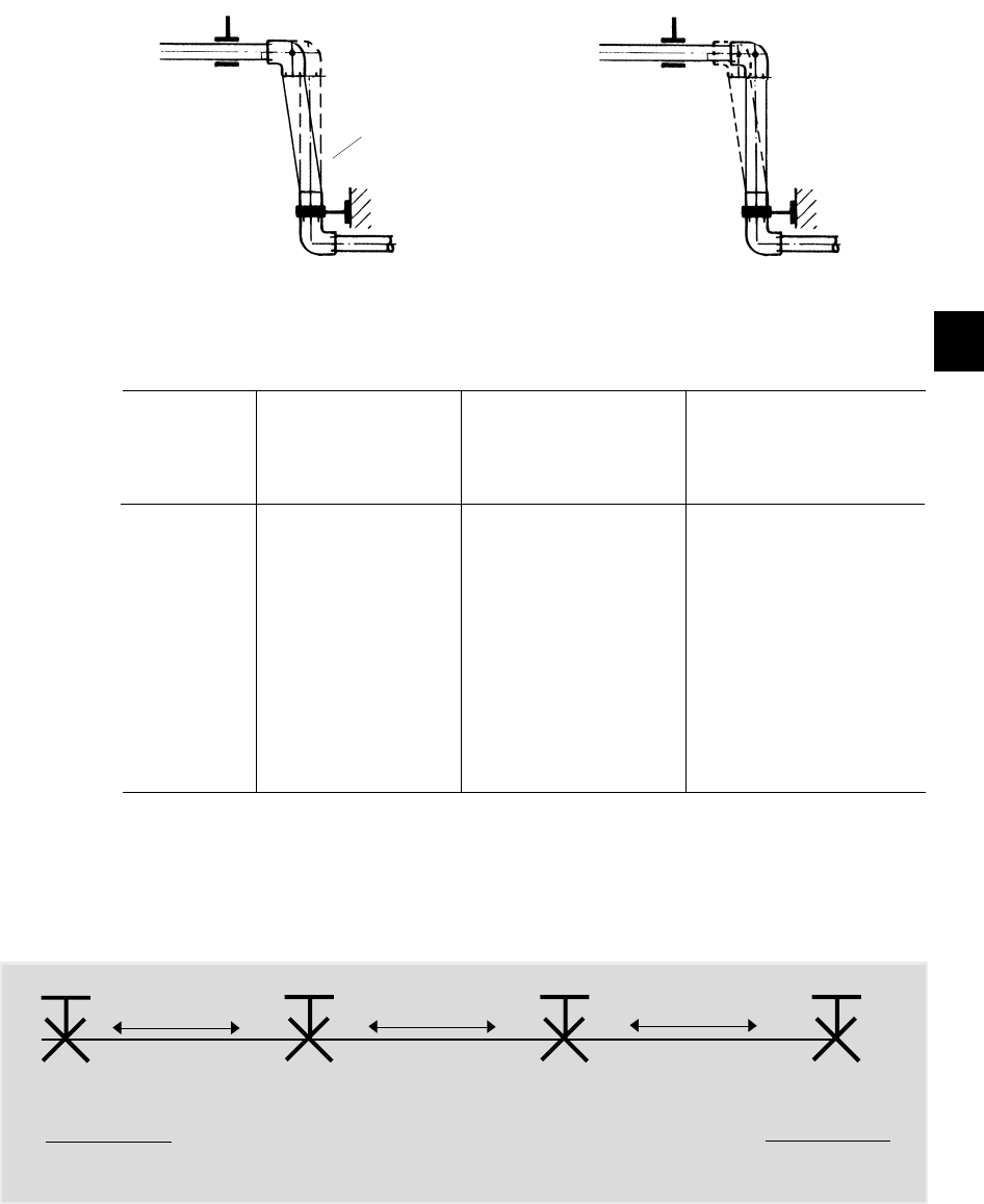
Fixed point assembly Method 3 º Bracket Spacing
For fixed installations the expansion
force of the pipe is transferred to the
is at its normal operating
temperature the expansion leg or
loop is straight.
last fixed point brackets.
expansion force expansion force expansion force
Force on bracket
= expansion force
2
Force on bracket
= 0
Force on bracket
= 0
Force on bracket
= expansion force
2
Flexible leg ‘a’
6.10 GEORGE FISCHER ‡
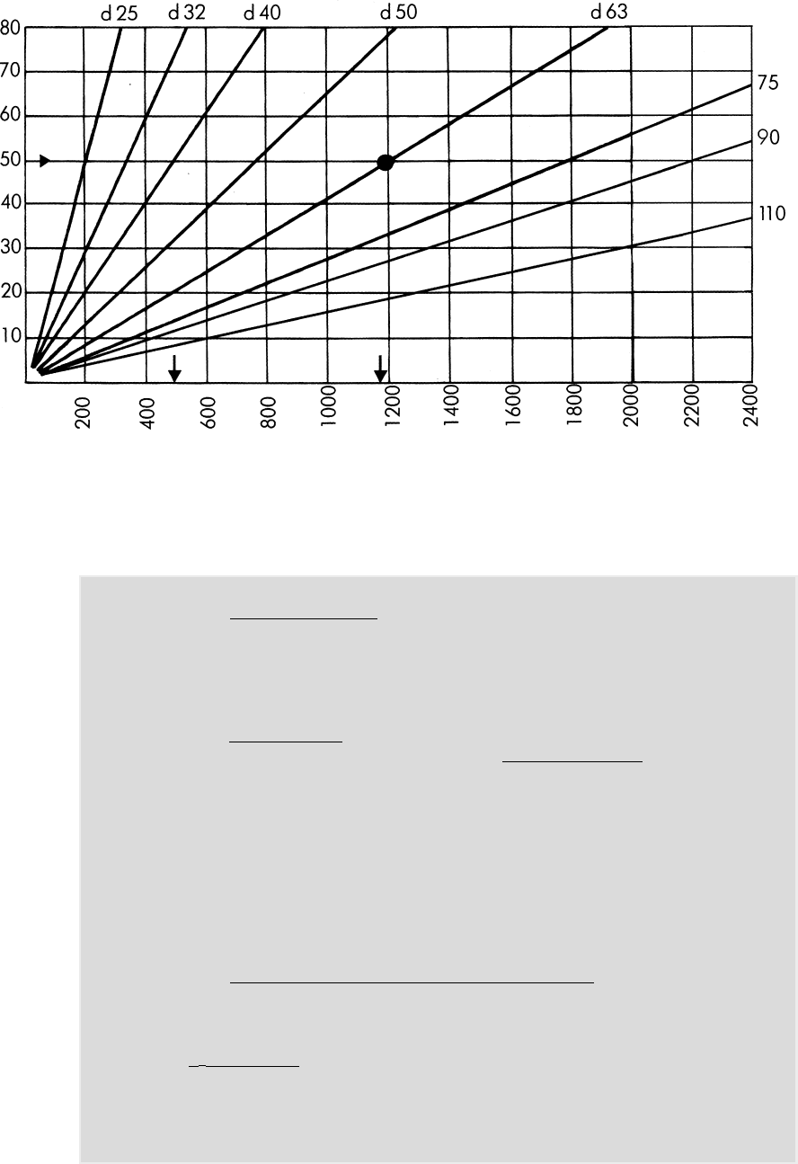
Expansion Forces generated by PB pipes for Temperature Differences
Temp. Difference ∆t in °C.
Expansion Force FR in N
To calculate the expansion force, the following formula may be used;
FR = A x E x α x ∆t°C. A = pipe cross section area mm2
E = modulus of elasticity 350N/mm2
α= coefficient of linear expansion
= 0.013mm/m°C
∆t = temperature difference °C
FR= expansion force
2
A = (D2 - d2) π
4
Example
What is the force acting on an end bracket for a 63 mm od pipe with a
temperature difference of 50°C?
FR = (632 - 51 .42) π x 350 x 0.013mm/°C x 50
4 x 2
FR = 1185 N
2
where
6.11
GEORGE FISCHER ‡
6
Forces due to expansion of various
sizes of PB pipe which would be
transferred to a fixed point pipe
support clamp, can be read from the
graph on page 11 . Depending on
how far the centerline of the pipe
needs to be from the supporting
structure will effect the required
diameter of the fastening rod used to
hold the fixed point in place. This can
be determined using the graph
below and the expansion forces on
page 11 .
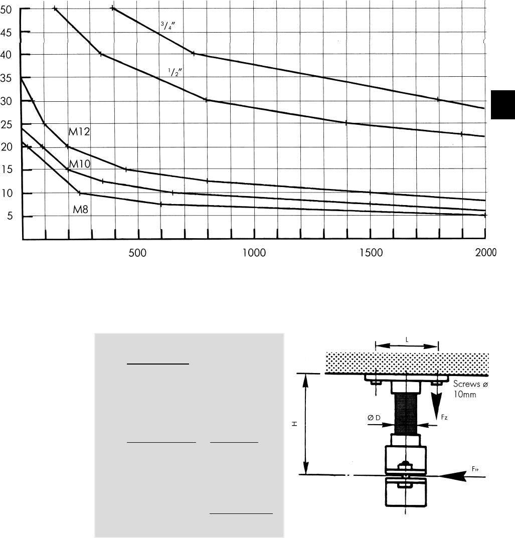
Choosing the Diameter of the Fastening Rods for the Pipe Clamp
and Bass Plate
Expansion Force Fz in N
Hanger length H in cm
Calculating the Fixed Point Support Clamp
D Diameter of the fastener
rods
H Distance to ceiling or
wall from the pipe
L Distance between screws
X Number of screws with
tensile strength
FRFixed point forces (N)
FZScrew or dowel retention
force (N)
2-hole base plate
x = 1
4-hole base plate
x = 2
Fz = FR x H
L x X [N]
Example:
Fz = 1200N x 20cm
12cm x 2
= 1000N
Retention force per screw:
Fz = 1000N
6.12 GEORGE FISCHER ‡
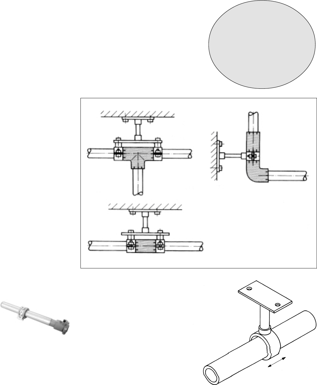
Arrangement of fixed point
support brackets
Fixed points direct thermal expansion
of the pipe in the desired direction.
Fixed points should ideally be
installed at a fitting and should
support it on both sides or be
installed in between the two fittings.
Sliding support brackets
Sliding brackets allow an axial
movement of the pipe. The bracket
must be in line with the pipe. Sliding
brackets should be lined with rubber
inserts suitable for plastic pipe, or of
such a design to prevent any
damage to the pipe.
All commercially available pipe
clamps and fastening materials,
which are suitable for plastic pipe
installations can be used as fixed
points or sliding pipe supports for
INSTAFLEX.
Fixed Point and Sliding Brackets
Attention!
Pipe brackets for fixed point
and sliding support should
be lined with suitable rubber
inserts or of such a design to
prevent any damage
to the pipe.
Tee
Elbow
Connecting socket
Valve connection
Typical fixed point assembly
