Experimenters Handbook 1965 Fall
User Manual: Experimenters-Handbook-1965-Fall
Open the PDF directly: View PDF ![]() .
.
Page Count: 150 [warning: Documents this large are best viewed by clicking the View PDF Link!]

FALL EDITION $1.2b
1 9 6OMIif
. 5 ELECTRONIC
e.uu
ELECTY
EXPERIMENTER'S
HANDBOOK
PROJECTS
GALORE
----SCIENCE FAIR
AUDIO
HOUSEHOLD
AUTOMOTIVE
TEST EQUIPMENT
HI-FI
FISHING
HAM RADIO
CB AND TV
PLUS:
SPECIAL
SECTION
"THE
FABULOUS
DIODES"
BETTER THAN EVER!
Mail the Card Today for Your FREE Catalog
No Money Down Easy Pay Terms
1966
ssó Live Better Electronically With
LAFAYETTE
RADIOELECTRONICS
OUR 45th YEAR
CttaLeg á6O
1 x-Pate547
L AF METZE
RADtß EIECtRflNKS
MA 11 Oi+nta#t sAi=sCEMEq
M1
Featuring Everything in Electronics for
HOME INDUSTRY LABORATORY
from the
"World's Hi-Fi & Electronics Center'.
LAFAYETTE Radio ELECTRONICS
Dept. EH -J-3-5, P.O. Box 10
Syosset, L.I., N.Y. 11791
Name
Address
City State
f Zip
Send
FREE Lafayette
Catalog
(Please Give Your Zip Code No.)
i
Over 500 Pages
FR E E 1
TV Tubes and Parts
Electronic Parts
Test Equipment
Citizens Band
Tools
Ham Gear
J Stereo Hi-Fi
Tape Recorders
Walkie-Talkes
Auto Accessories
LAFAYETTE'S MAIL ORDER &
LONG ISLAND
SALES CENTER
111 Jericho Turnpike
Syosset, Long Island, New York
OTHER LOCATIONS
NEW YORK -45th ST.
71 West 45 St.
BROOKLYN, NEW YORK
2265 Bedford Avenue
NEW YORK, NEW YORK
17 Union Square W.
(cor. 15 St.)
JAMAICA, NEW YORK
165-08 Liberty Avenue
SCARSDALE, NEW YORK
691 Central Avenue
BRONX, NEW YORK
542 E. Fordham Road
MT. RAINIER/
HYATTSVILLE, MD.
3191 Queens Chalet Road
NEWARK, NEW JERSEY
24 Central Avenue
PLAINFIELD, NEW JERSEY
139 West 2 Stree-
PARAMUS, NEW JERSEY
182 Route 17
BOSTON, MASS.
584 Commonweath Avenue
NATICK, MASS.
1400 Worcester street
CIRCLE NO. 12 ON READER SERVICE CARD
et:
Prepare
At HOME or
in our CHICAGO
or TORONTO
I aboratories
"Learn -by -seeing"
training MOVIES
DESIGN CONSOLE for
practical experiments
O a
Build & Keep a
5" OSCILLOSCOPE
Build & Keep a
TRANSISTORIZED METER
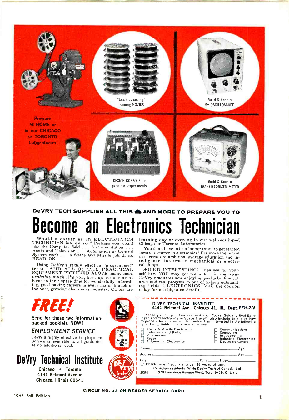
DeVRY TECH SUPPLIES ALL THIS- AND MORE TO PREPARE YOU TO
Become an Electronics Technician
Would a career as an ELECTRONICS
TECHNICIAN interest you? Perhaps you would
like the Computer field . . Instrumentation .
Radio and Television ... Automation or Control
System work ... a Space and Missile job. If so,
READ ON.
Using DeVry's highly effective "programmed"
texts - AND ALL OF THE PRACTICAL
EQUIPMENT PICTURED ABOVE, many men,
probably much like you, are now preparing at
home in their spare time for wonderfully interest-
ing, good -paying careers in every major branch of
the vast, growing electronics industry. Others are
FREE.'
Send for these two information -
packed booklets NOW!
EMPLOYMENT SERVICE
DeVry's highly effective Employment
Service is available to all graduates
at no additional cost.
DeVry Technical Institute
Chicago Toronto
4141 Belmont Avenue
Chicago, Illinois 60641
learning day or evening in our well-equipped
Chicago or Toronto Laboratories.
You don't have to be a "super type" to get started
toward a career in electronics! Far more important
to success are ambition, average education and in-
telligence, interest in mechanical or electri-
cal things.
SOUND INTERESTING? Then see for your-
self how YOU may get ready to join the many
DeVry graduates now enjoying good jobs, fine sal-
aries and real progress in one of today's outstand-
ing fields-ELECTRONICS. Mail the coupon
today for no -obligation details.
r DeVRY TECHNICAL INSTITUTE
4141 Belmont Ave., Chicago 41, III., Dept.EEH-2-V
Please give me your two free booklets. "Pocket Guide to Real Earn-
ings" and "Electronics in Space Travel"; also include details on how
to prepare fora career in Electronics. I am interested in the following
opportunity fields (check one or more):
E Space & Missile Electronics D Communications
Television and Radio Computers
D Microwaves Broadcasting
D Radar pp Industrial Electronics
Automation Electronics Electronic Control
Name Age __ ---
Address Apt
City cone State
D Check here if you are under 16 years of age.
Canadian residents: Write DeVry Tech of Canada, Ltd
2094 970 Lawrence Avenue West, Toronto 19, Ontario
CIRCLE NO. 33 ON READER SERVICE CARD
1965 Fall Edition

N EW FROM
INTERNATIONAL
VHF/UHF
UNITIZED TRANSMITTERS
50 mc -420 mc
50 or 70 mc
DRIVER/TRANSMITTER
The AOD-57 completely wired
with one 6360 tube, two
12BY7 tubes and crystal
(specify frequency). Heater
power: 6.3 volts @ 1.2 amps.
Plate power: 250 vdc @ 50 ma.
AOD-57 complete $69.50
420 mc
MULTIPLIER/AMPLIFIER
The AOA-420 uses two 6939
tubes providing 4 to 8 watts
output on 420 mc. Requires
ADA -57 plus AOA-144 for
drive. Heater: 6.3 volts @ 1.2
amps. Plate: 220 vdc @ 130
ma.
AOA-420 complete $69.50
MODULATOR
The AMD-10 is designed as a com-
panion unit to the AOA series of trans-
mitters. Uses 6AN8 speech amplifier
and driver, 1635 modulator. Output: 10
watts. Input: crystal mic. (High Imped.)
Requires 300 vdc 20 ma, no signal, 70
ma peak: 6.3 vac @ 1.05 amps.
AMD-10 complete $24.50
CIRCLE NO, 13
International's new unitized VHF/UHF transmitters make
it extremely easy to get on the air in the 50-420 mc range
with a solid signal. Start with the basic 50 or 70 mc
driver. For higher frequencies add a multiplier -amplifier.
All units are completely wired. Plug-in cables are used to
interconnect the driver and amplifier.
144 mc
MULTIPLIER/AMPLIFIER
The ADA -144 uses two 6360
tubes providing 6 to 10 watts
output. Requires AOD-57 for
driver. Heater power: 6.3
volts @ 1.64 amps. Plate
power: 250 vdc @ 180 ma.
AOA-144 complete $39.50
RELAY BOX
Four circuit double throw.
Includes coil rectifier for 6.3
vac operation.
ARY-4 Relay Box
complete $12.50
220 mc
MULTIPLIER/AMPLIFIER
The AOA-220 uses two 6360
tubes providing 6 to 8 watts
output on 220 mc. Requires
ADD -57 for driver. Heater
power: 6.3 volts @ 1.64 amps.
Plate: 250 vdc @ 150 ma.
AOA-220 complete $39.50
FILAMENT
SUPPLY
The APD-610 provides 6.3 vac
@ 10 amperes.
APD-610 complete $9.50
COMPLETE TRANSMITTER
6 METERS 50 mc A00-57
2 METERS 144 mc AOD-57 PLUS AOA-144
220 mc AOD-51 PLUS AOA-220
420 mc AOD-57 PLUS AOA-144 PLUS AOA-420
i
INTERNATIONAL
CRYSTAL MFG. CO., INC.
la NO. LEE OKLA. CITY, OKLA. 73102
ON READER SERVICE CARD
Order Direct
from International
Electronic Experimenter's Handbook
2

FALL EDITION
1965ELECTRONIC
POPLILA
ELICT.ONICS
EXPERIMENTER'S
HANI7HOCJK
PHILLIP T. HEFFERNAN
Publisher
OLIVER P. FERRELL
Editor
ROBERT CORNELL
Managing Editor
JOHN D. DRUMMOND
Technical Editor
WILLIAM GALBREATH
Art Editor
MARGARET MAGNA
Associate Editor
ANDRE DUZANT
Technical Illustrator
NINA CHIRKO
Editorial Assistant
PATTI MORGAN
Editorial Assistant
LAWRENCE SPORN
Advertising Sales Manager
ARDYS C. MORAN
Advertising Service Manager
ZIFF-DAVIS PUBLISHING COMPANY
Editorial and Executive Offices (212 ORegon 9-7200)
One Park Avenue, New York, New York 10016
William B. Ziff, Chairman of the Board (1946-1953)
William Ziff, President
W. Bradford Briggs, Executive Vice President
Hershel B. Sarbin, Vice President and General Manager
Philip Sine, Financial Vice President
Walter S. Mills, Jr., Vice President, Circulation
Stanley R. Greenfield, Vice President, Marketing
Phillip T. Heffernan, Vice President
Frank Pomerantz, Vice President, Creative Services
Arthur W. Butzow, Vice President, Production
New York Office (212 ORegon 9-7200)
One Pork Avenue, New York, New York 10016
Eastern Advertising Manager, RICHARD J. HALPERN
Midwestern Office (312-726-0892)
307 North Michigan Avenue, Chicago, Illinois 60601
Midwestern Advertising Manager, JAMES WEAKLEY
Western Office (213 CRestview 4-0265)
9025 Wilshire Boulevard, Beverly Hills, California 90211
Western Advertising Manager, BUD DEAN
Circulation Office
One Park Avenue
New York, New York 10016
M PA
1965 ELECTRONIC EXPERIMENTER'S HANDBOOK, Fall
Edition, published by the Ziff -Davis Publishing Com-
pany, One Park Avenue, New York, New York 10016.
Also publishers of Popular Electronics, Electronics World,
HiFi/Stereo Review, Communications Handbook, Tape
Recorder Annual, Stereo/Hi-Fi Directory, Electronics
Installation and Servicing Handbook. Copyright © 1965
by Ziff -Davis Publishing Company. All rights reserved.
The Fall Edition of the ELEC-
TRONIC EXPERIMENTER'S
HANDBOOK is the tenth in a series
that began in 1957. Due to the in-
creasing popularity of electronics
project building and experimenta-
tion, two editions of the EXPERI-
MENTER'S HANDBOOK are now
being printed every year. In Febru-
ary we publish a Spring Edition, in
October a Fall Edition. As in the
preceding nine editions, this one con-
tains construction projects and fea-
ture articles especially selected by
the Editors of POPULAR ELEC-
TRONICS.
We are particularly pleased with,
the projects in this Fall Edition and
direct our readers' attention to the
new chapter category of Science Fair
Projects. It is anticipated that this
chapter will be enlarged in future
issues.
In the center of this Edition you
will find a special 16 -page article by
Louis Garner on solid-state technol-
ogy as it particularly applies to
diodes. This is a state-of-the-art re-
port and is comparable to feature
articles of a similar nature that ap-
pear from time to time in POPULAR
ELECTRONICS. Also in this Edi-
tion are several projects that first
saw the light of day in our next -door -
neighbor publication, ELECTRON-
ICS WORLD. These articles have
been completely revised for use in
the EXPERIMENTER'S HAND-
BOOK.
If you have suggestions for future
content, please don't hesitate to write
to us. THE EDITORS
1965 Fall Edition
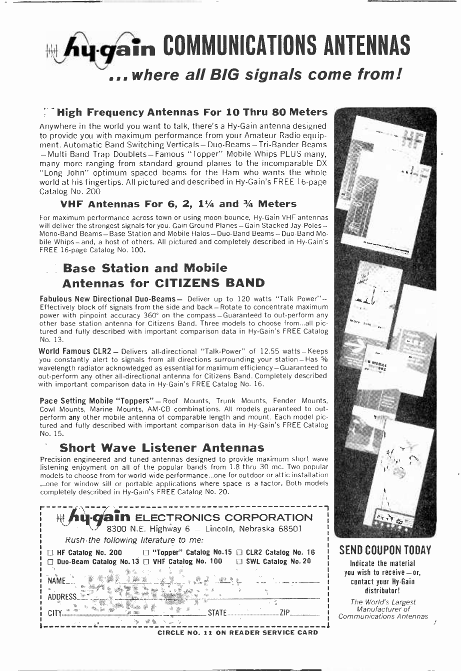
6ÿ.q aln COMMUNICATIONS ANTENNAS
... .ne.e all BIG signals come from!
High Frequency Antennas For 10 Thru 80 Meters
Anywhere in the world you want to talk, there's a Hy -Gain antenna designed
to provide you with maximum performance from your Amateur Radio equip-
ment. Automatic Band Switching Verticals - Duo -Beams -Tri -Bander Beams
-Multi -Band Trap Doublets-Famous "Topper" Mobile Whips PLUS many,
many more ranging from standard ground planes to the incomparable DX
"Long John" optimum spaced beams for the Ham who wants the whole
world at his fingertips. All pictured and described in Hy -Gain's FREE 16 -page
Catalog No. 200
VHF Antennas For 6, 2, 11/4 and 3/4 Meters
For maximum performance across town or using moon bounce, Hy -Gain VHF antennas
will deliver the strongest signals for you. Gain Ground Planes-Gain Stacked Jay -Poles -
Mono -Band Beams-Base Station and Mobile Halos-Duo-Band Beams-Duo-Band Mo-
bile Whips-and, a host of others. All pictured and completely described in Hy -Gain's
FREE 16 -page Catalog No. 100.
Base Station and Mobile
Antennas for CITIZENS BAND
Fabulous New Directional Duo -Beams- Deliver up to 120 watts "Talk Power"-
Effectively block off signals from the side and back-Rotate to concentrate maximum
power with pinpoint accuracy 360° on the compass-Guaranteed to out -perform any
other base station antenna for Citizens Band. Three models to choose from...all pic-
tured and fully described with important comparison data in Hy -Gain's FREE Catalog
No. 13.
World Famous CLR2- Delivers all -directional "Talk -Power" of 12.55 watts-Keeps
you constantly alert to signals from all directions surrounding your station-Has 5/6
wavelength radiator acknowledged as essential for maximum efficiency-Guaranteed to
out -perform any other all -directional antenna for Citizens Band. Completely described
with important comparison data in Hy -Gain's FREE Catalog No. 16.
Pace Setting Mobile "Toppers"- Roof Mounts, Trunk Mounts, Fender Mounts,
Cowl Mounts, Marine Mounts, AM -CB combinations. All models guaranteed to out-
perform any other mobile antenna of comparable length and mount. Each model pic-
tured and fully described with important comparison data in Hy -Gain's FREE Catalog
No. 15.
Short Wave Listener Antennas
Precision engineered and tuned antennas designed to provide maximum short wave
listening enjoyment on all of the popular bands from 1.8 thru 30 mc. Two popular
models to choose from for world-wide performance...one for outdoor or attic installation
...one for window sill or portable applications where space is a factor. Both models
completely described in Hy -Gain's FREE Catalog No. 20.
r ,Ç 41m111 ELECTRONICS CORPORATION
S--- 8300 N.E. Highway 6 - Lincoln, Nebraska 68501
Rush the following literature to me:
HF Catalog No. 200 D "Topper" Catalog No.15 L CLR2 Catalog No. 16
L] Duo -Beam Catalog No.13 VHF Catalog No. 100 LI SWL Catalog No.20
NAME
ADDRESS__
CITY STATE _ ZIP
SEND COUPON TODAY
Indicate the material
you wish to receive-or,
contact your Hy -Gain
distributor!
The World's Largest
Manufacturer of
Communications Antennas
CIRCLE NO. 11 ON READER SERVICE CARD

FALL EDITION
' 96-Z ELECTRONIC
EXPERIMENTER'S
H A N D B O O K
CONTENTS
1
USEFUL
HOUSEHOLD
PROJECTS
2
AUDIO
STEREO
HI-FI
PROJECTS
3
THE
FABULOUS
DIODES
4
SCIENCE
FAIR
PROJECTS
5
COMMUNI-
CATIONS
SWL
CB
HAM
6
TEST
EQUIPMENT
PROJECTS
7 "CQ Fish"-Panic Alarm-Pocketable Metronome
-For Greater Safety Flash Those Lights-Elec-
tronic Candles Dance and Glow-Add D.C. Resto-
ration to TV-Multi-Trol-High Wattage Reducer
-Nonsense Box
39 For Better Sound Build the Bi-Coupler-Stereo
S'Lector-Vibrato Simulator-Hi-Fi Volume Com-
pressor Expander-Hi-Fi Interlock-Shotgun
Sound Snooper
67 The Fabulous Diodes: Zener Diodes-Diode
Switches-Photodiodes-Tunnel Diodes-Capacitor
Diodes-Power Diodes-Surge Suppressors-Ther-
moelectric Diodes-Special Diodes
87 60 -Cycle Repulsion Coil-Resonance Engine-Big
TC-Li'l TC
103
Transistorized 6 -Meter Converter-Adjustable
Speech Filter-Companion 6 -Meter Transmitter-
Soup Up That AM Broadcast Receiver -6 -Meter
7 and 2 Preamp
123
Hybrid Circuit for Transistor Power-SCR Tester
-Field -Effect Transistor Voltmeter-Multiple
Meter Test Set-Multi-Output Zener Voltage Reg-
ulator-Best of Tips and Techniques
1965 Fall Edition 5
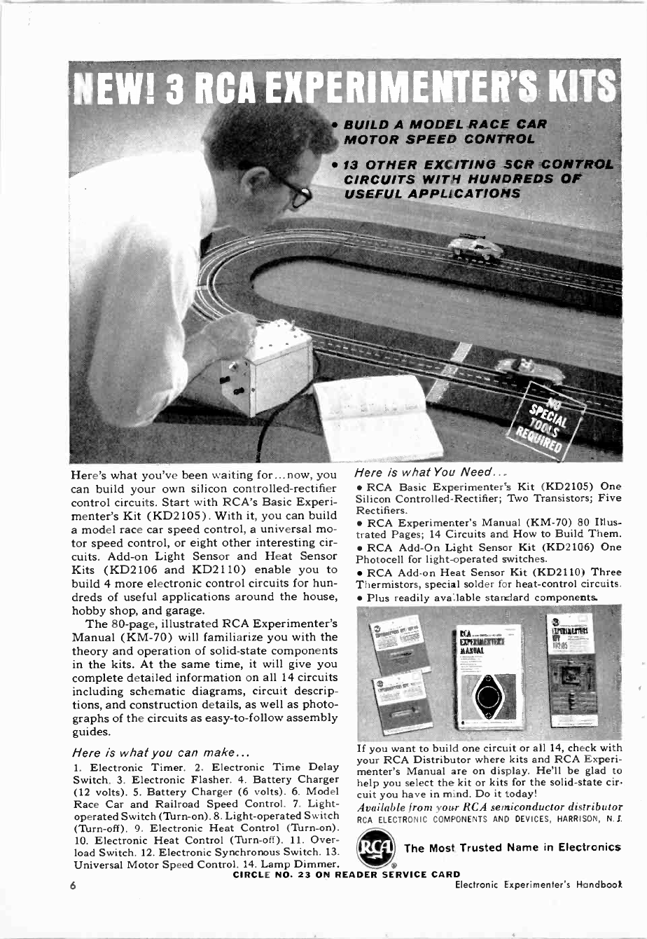
NEW! _ I CA EXPL IM NTER!S KITS
BUILD A MODEL RACE CAR
MOTOR SPEED CONTROL
13 OTHER EXCITING SCR CONTROL
CIRCUITS WITH HUNDREDS OF
USEFUL APPLICATIONS
Here is what You Need...
RCA Basic Experimenter's Kit (KD2105) One
Silicon Controlled -Rectifier; Two Transistors; Five
Rectifiers.
RCA Experimenter's Manual (KM -70) 80 Illus-
trated Pages; 14 Circuits and How to Build Them.
RCA Add -On Light Sensor Kit (KD2106) One
Photocell for light -operated switches.
RCA Add-on Heat Sensor Kit (KD2110) Three
Thermistors, special solder for heat -control circuits.
Plus readily available standard components.
1f you ,,cant to build one circuit or all 1 r, check with
your RCA Distributor where kits and RCA Experi-
menter's Manual are on display. He'll be glad to
help you select the kit or kits for the solid-state cir.
cuit you have in mind. Do it today!
Available from your RCA semiconductor distributor
RCA ELECTRONIC COMPONENTS AND DEVICES, HARRISON, N.J.
Ilri
Universal Motor Speed Control. 14. Lamp Dimmer. . CIRCLE NO. 23 ON READER SERVICE CARD
6 Electronic Experimenter's HSndboo)..
Here's what you've been waiting for...now, you
can build your own silicon controlled -rectifier
control circuits. Start with RCA's Basic Experi-
menter's Kit (KD2105). With it, you can build
a model race car speed control, a universal mo-
tor speed control, or eight other interesting cir-
cuits. Add-on Light Sensor and Heat Sensor
Kits (KD2106 and KD2110) enable you to
build 4 more electronic control circuits for hun-
dreds of useful applications around the house,
hobby shop, and garage.
The 80 -page, illustrated RCA Experimenter's
Manual (KM -70) will familiarize you with the
theory and operation of solid-state components
in the kits. At the same time, it will give you
complete detailed information on all 14 circuits
including schematic diagrams, circuit descrip-
tions, and construction details, as well as photo-
graphs of the circuits as easy -to -follow assembly
guides.
Here is what you can make...
1. Electronic Timer. 2. Electronic Time Delay
Switch. 3. Electronic Flasher. 4. Battery Charger
(12 volts). 5. Battery Charger (6 volts). 6. Model
Race Car and Railroad Speed Control. 7. Light -
operated Switch (Turn -on). 8. Light -operated Switch
(Torn -off). 9. Electronic Heat Control (Turn -on).
10. Electronic Heat Control (Turn-off). 11. Over-
load Switch. 12. Electronic Synchronous Switch. 13. The Most Trusted Name in Electronics

CHAPTER
1
USEFUL,
HOUSEHOLD
PROJECTS
Construction projects to be used around the
house are generally of great interest to readers of
the ELECTRONIC EXPERIMENTER'S HAND-
BOOK, since such projects can be displayed and
operated by the "non -electronically % inded"
members of the family. They "prove" that the
hobbyist -experimenter is not just fooling around
and wasting his time. The projects in this chap-
ter have been selected to appeal to the entire
family-even though the first project ("CQ Fish"
on page 8) is for the OM himself.
The "Panic Alarm" (page 11) and "Nonsense
Box" (page 36) are wonderful electronic "gags."
Both of these projects appear in the stores at
Christmas time-selling for 5 to 10 times the cost
of building one with brand-new parts. The metro-
nome (page li), safety flasher (page 15), and
"Multi-trol" (page 28) are all handy household
items. And, speaking of Christmas, take a look
at the electronic device to make your tree lights
twinkle (page 17). The d.c. restorer project
(page 22) is one you should consider if you have
a TV set that could use some improvement in
black and white picture reproduction.
8
"CQ FISH" Bill Billick
11
PANIC ALARM Roy E. Pafenberg, W4WKM
14
POCKETABLE METRONOME Sal Stella
15
FOR GREATER SAFETY FLASH THOSE LIGHTS Louis F. Cortina
17
ELECTRONIC CANDLES DANCE AND GLOW Jeff H. Taylor
22
ADD D.C. RESTORATION TO TV Charles E. Cohn
28
MULTI-TROL Ryder Wilson
31
HIGH WATTAGE REDUCER Frank A. Parker
36
NONSENSE BOX Alan L. Danzis
1965 Fall Edition 7
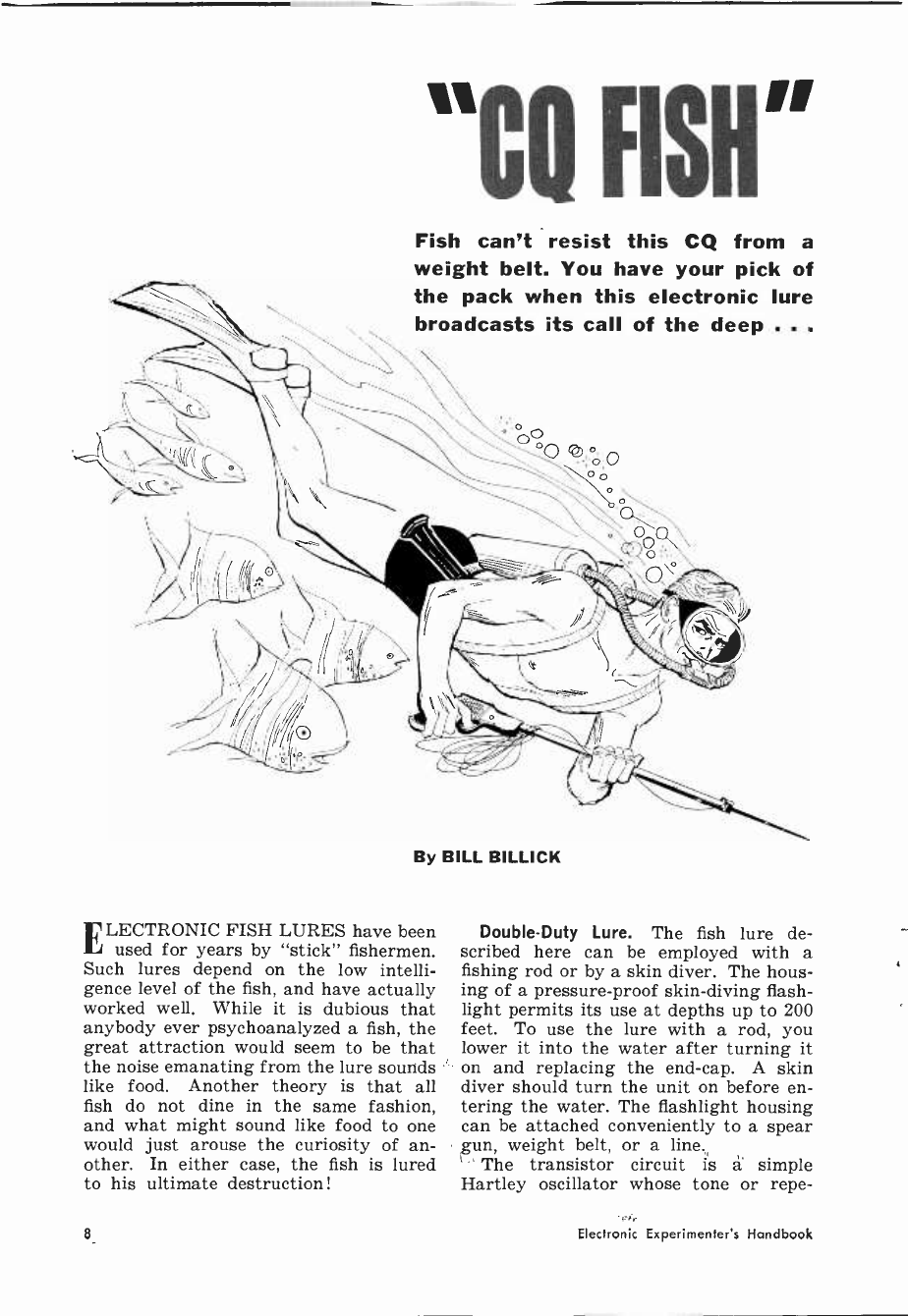
"CO FISH"
Fish can't resist this CQ from a
weight belt. You have your pick of
the pack when this electronic lure
broadcasts its call of the deep . . .
By BILL BILLICK
ELECTRONIC FISH LURES have been
used for years by "stick" fishermen.
Such lures depend on the low intelli-
gence level of the fish, and have actually
worked well. While it is dubious that
anybody ever psychoanalyzed a fish, the
great attraction would seem to be that
the noise emanating from the lure sounds
like food. Another theory is that all
fish do not dine in the same fashion,
and what might sound like food to one
would just arouse the curiosity of an-
other. In either case, the fish is lured
to his ultimate destruction !
Double -Duty Lure. The fish lure de-
scribed here can be employed with a
fishing rod or by a skin diver. The hous-
ing of a pressure -proof skin-diving flash-
light permits its use at depths up to 200
feet. To use the lure with a rod, you
lower it into the water after turning it
on and replacing the end -cap. A skin
diver should turn the unit on before en-
tering the water. The flashlight housing
can be attached conveniently to a spear
gun, weight belt, or a line.
The transistor circuit is á simple
Hartley oscillator whose tone or repe-
Electronic Experimenter's Handbook
TI R2
Earpher.e
SI
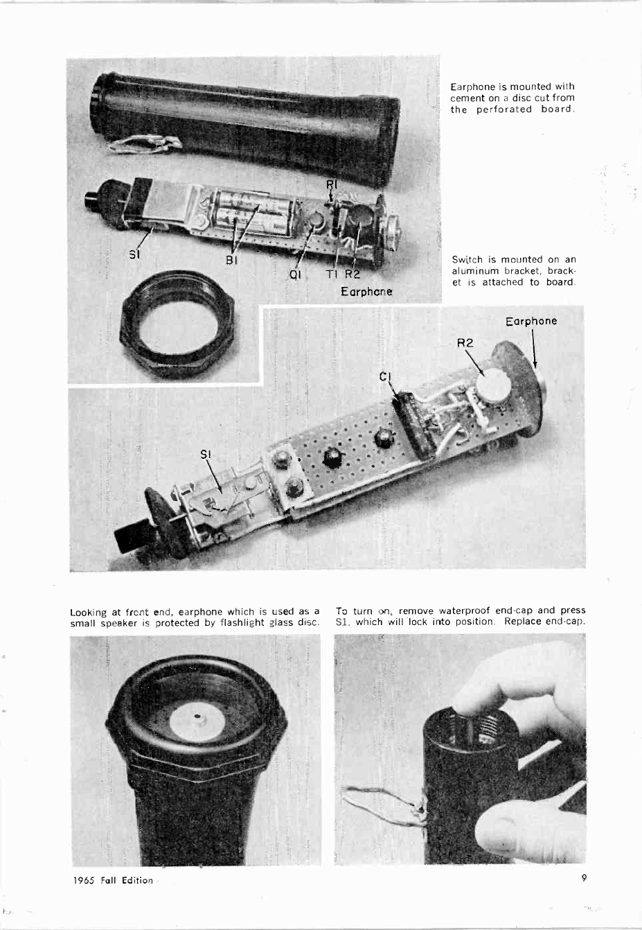
Earphone is mounted with
cement on a disc cut from
the perforated board.
Switch is mounted on an
aluminum bracket, brack-
et is attached to board.
R2
Earphone
Looking at frcnt end, earphone which is used as a To turn on. remove waterproof end -cap and press
small speaker is protected by flashlight glass disc. Sl, which will lock into position. Replace end -cap.
1965 Fall Edition 9
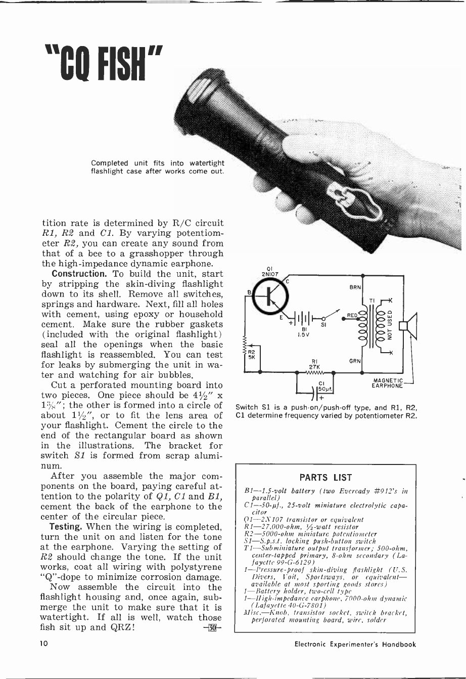
"CO FISH"
Completed unit fits into watertight
flashlight case after works come out.
tition rate is determined by R/C circuit
R1, R2 and Cl. By varying potentiom-
eter R2, you can create any sound from
that of a bee to a grasshopper through
the high -impedance dynamic earphone.
Construction. To build the unit, start
by stripping the skin-diving flashlight
down to its shell. Remove all switches,
springs and hardware. Next, fill all holes
with cement, using epoxy or household
cement. Make sure the rubber gaskets
( included with the original flashlight)
seal all the openings when the basic
flashlight is reassembled. You can test
for leaks by submerging the unit in wa-
ter and watching for air bubbles.
Cut a perforated mounting board into
two pieces. One piece should be 41/2" x
13/K"; the other is formed into a circle of
about 11/2", or to fit the lens area of
your flashlight. Cement the circle to the
end of the rectangular board as shown
in the illustrations. The bracket for
switch 21 is formed from scrap alumi-
num. After you assemble the major com-
ponents on the board, paying careful at-
tention to the polarity of Q1, C1 and B1,
cement the back of the earphone to the
center of the circular piece.
Testing. When the wiring is completed,
turn the unit on and listen for the tone
at the earphone. Varying the setting of
R2 should change the tone. If the unit
works, coat all wiring with polystyrene
"Q" -dope to minimize corrosion damage.
Now assemble the circuit into the
flashlight housing and, once again, sub-
merge the unit to make sure that it is
watertight. If all is well, watch those
fish sit up and QRZ! -®-
01
2N107
MAGNETIC
EARPHONE
Switch Si is a push-on/push-off type, and Rl, R2,
Cl determine frequency varied by potentiometer R2.
PARTS LIST
B1 -1.5 -volt battery (two Eveready #912's in
parallel)
CI -50-µf., 25 -volt miniature electrolytic capa-
citor
Q1 -2N107 transistor or equivalent
R1 -27,000 -ohm, ,A -watt resistor
R2 -5000 -ohm miniature potentiometer
S1-S.p.s.t. locking push-button switch
T1-Subminiature output transformer; 500 -ohm,
center -tapped primary, 8 -ohm secondary (La-
fayette 99-G-6129)
1-Pressure-proof skin-diving flashlight (U.S.
Divers, Voit, Sportsways, or equivalent-
available at most sporting goods stores)
1-Battery holder, two -cell type
1-High-impedance earphone, 7000 -ohm dynamic
(Lafayette 40-G-7801)
Misc.-Knob, transistor socket, switch bracket,
perforated mounting board, wire, solder
to Electronic Experimenter's Handbook
BUILD
p41e
ALARM
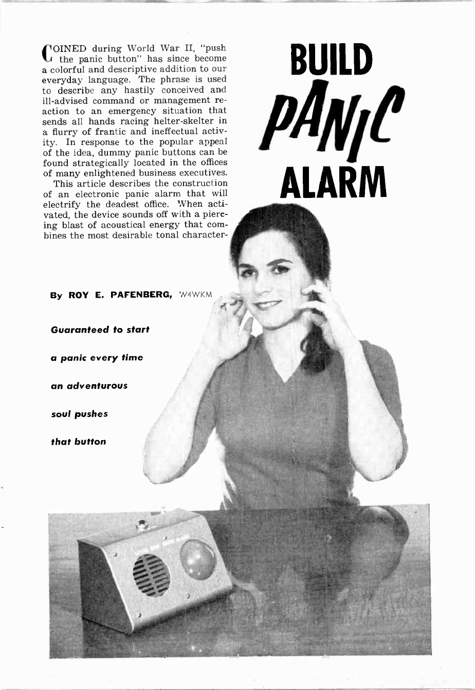
COINED during World War II, "push
the panic button" has since become
a colorful and descriptive addition to our
everyday language. The phrase is used
to describe any hastily conceived and
ill-advised command or management re-
action to an emergency situation that
sends all hands racing helter-skelter in
a flurry of frantic and ineffectual activ-
ity. In response to the popular appeal
of the idea, dummy panic buttons can be
found strategically located in the offices
of many enlightened business executives.
This article describes the construction
of an electronic panic alarm that will
electrify the deadest office. When acti-
vated, the device sounds off with a pierc-
ing blast of acoustical energy that com-
bines the most desirable tonal character -
By ROY E. PAFENBERG, 'N4WKM
Guaranteed to start
a panic every time
an adventurous
soul pushes
that button

The author mounted his alarm in a sloping
front cabinet, but there is no reason why
other design housings won't work as well.
As mentioned above, the
layout can be modified to
suit the individual re-
quirements of the builder.
If you want to follow the
author's model, this pho-
tograph will spot some
of the more important
components for you. Be
sure that none of the cir-
cuitry contacts the metal
chassis. See text for
parts value changes to
alter output tone. KI
istics of a fire engine siren, a submarine
diving alarm, and a hound with its tail
caught in the screen door.
The panic alarm is activated by a de-
ceptively labeled PUSH TO TEST switch.
A special latching relay circuit is pro-
vided to keep the alarm sounding until
the a.c. line cord is disconnected. The
panic-stricken confusion that continues
until someone finally unplugs the power
cord adds greatly to the effectiveness
(?) of the device.
A simple, easily wired circuit is used
in the panic alarm. As shown in the pho-
tographs, the circuitry is housed in a
small sloping -panel aluminum cabinet
(Bud AC -1613). The front panel con-
tains a speaker cutout with a red painted
grille and a large matching, attention -
getting red lamp. The PUSH TO TEST
switch is mounted on the top of the
cabinet.
Perforated board is held to the bottom of the
box with four bolts. The 25 -watt lamp has no
socket; the connections are soldered in place.
R5 C4 VI Cl C2 I2II
Theory. The heart of the circuit is a
rather unusual dual neon lamp relaxa-
tion oscillator. Because of the relatively
long time constant of capacitor Cl and
resistor R2, the circuit of lamp 11 oscil-
lates at a subaudible rate. This results
in a varying d.c. voltage at the junction
of resistors R1 and R2.
The time constant of capacitor C2 and
resistor R3 is such that the circuit of
lamp 12 oscillates at an audible rate.
Since the voltage for this circuit is ob-
tained at the junction of R1 and R2, the
output frequency of this oscillator is
swept at a rate determined by the fre-
quency of the 11 oscillator. Time con-
stants of both circuits have been chosen
to produce a very distinctive swept -tone
siren effect. Output of the 12 oscillator
is coupled to a conventional audio output
stage through capacitor C3.
A 25 -watt, 117 -volt red -frosted lamp
12 Electronic Experimenter's Handbook
VI
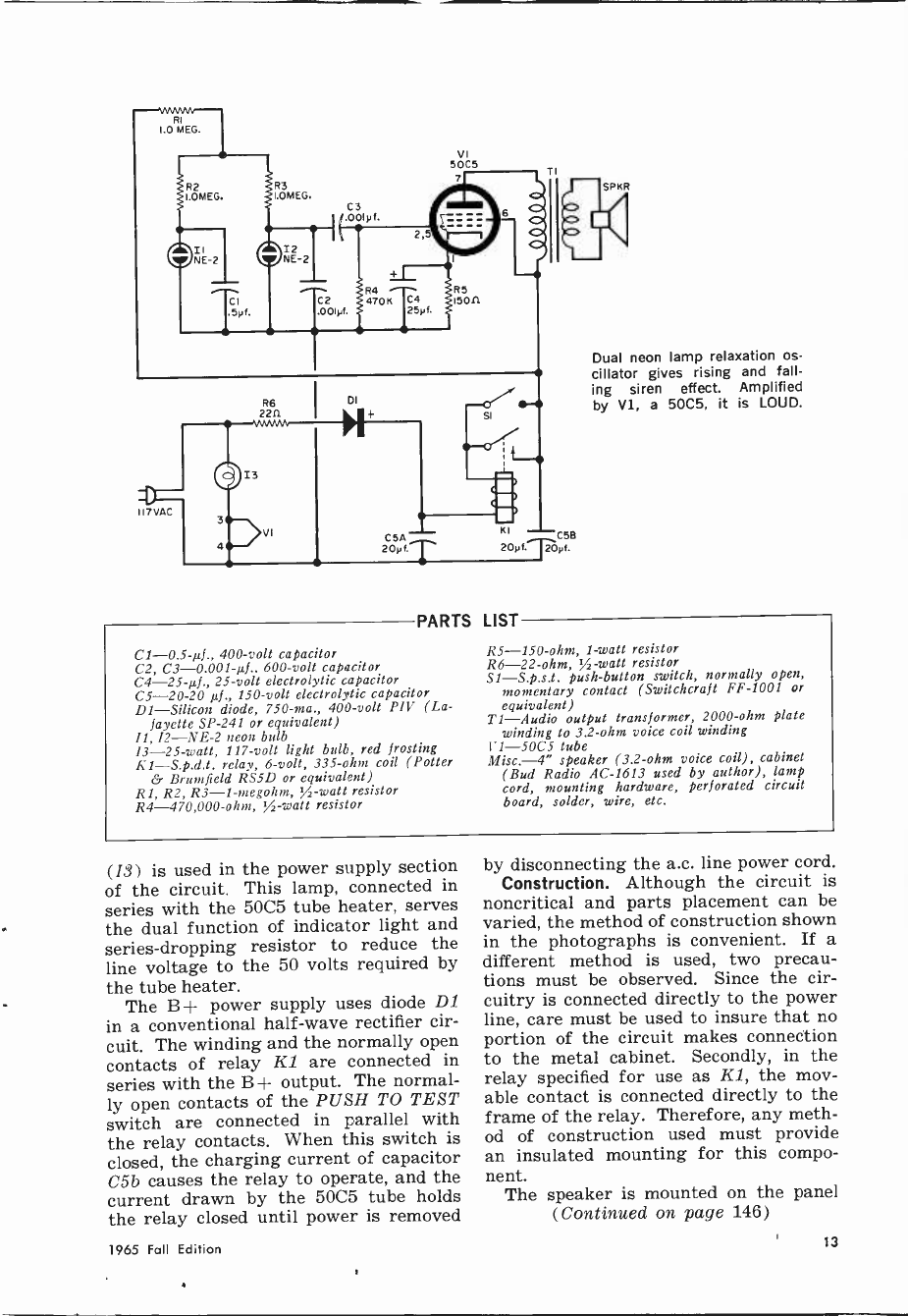
PARTS
C1 -0.5-µf., 400 -volt capacitor
C2, C3 -0.001-µf., 600 -volt capacitor
C4 -25-µf., 25 -volt electrolytic capacitor
C5-20-20 µf., 150 -volt electrolytic capacitor
D1-Silicon diode, 750 -ma., 400 -volt PIV (La-
fayette SP -241 or equivalent)
11, 12-NE-2 neon bulb
I3 -25 -watt, 117 -volt light bulb, red frosting
K1-S.p.d.t. relay, 6 -volt, 335 -ohm coil (Potter
& Brumfield RS5D or equivalent)
R1, R2, R3-1-megohm, %-watt resistor
R4 -470,000 -ohm, 3/2 -watt resistor
LIST
Dual neon lamp relaxation os-
cillator gives rising and fall-
ing siren effect. Amplified
by V1, a 5005, it is LOUD.
R5 -150 -ohm, 1 -watt resistor
R6 -22 -ohm, ,A -watt resistor
S1-S.p.s.t. push-button switch, normally open,
momentary contact (Switchcraft FF -1001 or
equivalent)
Ti-Audio output transformer, 2000 -ohm plate
winding to 3.2 -ohm voice coil winding
V1-SOCS tube
Misc.-4" speaker (3.2 -ohm voice coil), cabinet
(Bud Radio AC -1613 used by author), lamp
cord, mounting hardware, perforated circuit
board, solder, wire, etc.
(13) is used in the power supply section
of the circuit. This lamp, connected in
series with the 5005 tube heater, serves
the dual function of indicator light and
series -dropping resistor to reduce the
line voltage to the 50 volts required by
the tube heater.
The B + power supply uses diode D1
in a conventional half -wave rectifier cir-
cuit. The winding and the normally open
contacts of relay KZ are connected in
series with the B + output. The normal-
ly open contacts of the PUSH TO TEST
switch are connected in parallel with
the relay contacts. When this switch is
closed, the charging current of capacitor
C5b causes the relay to operate, and the
current drawn by the 5005 tube holds
the relay closed until power is removed
by disconnecting the a.c. line power cord.
Construction. Although the circuit is
noncritical and parts placement can be
varied, the method of construction shown
in the photographs is convenient. If a
different method is used, two precau-
tions must be observed. Since the cir-
cuitry is connected directly to the power
line, care must be used to insure that no
portion of the circuit makes connection
to the metal cabinet. Secondly, in the
relay specified for use as Kl, the mov-
able contact is connected directly to the
frame of the relay. Therefore, any meth-
od of construction used must provide
an insulated mounting for this compo-
nent. The speaker is mounted on the panel
(Continued on page 146)
1965 Fall Edition 13

POCKETABLE
METRONOME
A variable -speed pacer
will be a boon for any
tyro instrumentalists
PEOPLE are rhythm -conscious, and if you are learning to type,
play an instrument, dance, exercise, or any of countless other
rhythmical functions, this metronome will mark the beat for you at
a rate of from 80 to 300 clicks per minute. It is small enough to
fit in a pocket, and the earphone stores nicely in the roomy case.
The metronome circuit is a simple relaxation oscillator with a
20-µf. emitter bypass capacitor (C2) to stabilize the circuit. Two
holes in the circuit board are enlarged to accept jack J1 and po-
tentiometer R1. As these components also hold the circuit board to
the plastic case, the jack hole should be enlarged sufficiently to
pass the collar of the jack.
Before permanently wiring the circuit, check the range of clicks.
If they are too slow, decrease the resistance of R2; if they are
too fast, increase R2's value. Potentiometer RZ has a tapered re-
sistance, and both outer terminals should be tried to see which
gives the greater spread of click range.
Metronomes are usually bulky affairs, never thought of as port-
able. This one is a departure from the norm, with more applica-
tions than a normal metronome could shake its pendulum at!
-Sal Stella
Switch SI, on back of Rl, closes when
knob is turned; Rl varies click speed.
PARTS
BI -9 -volt battery
C1 -8-µf., 15 -volt miniature
electrolytic capacitor
C2 -20-µf., 15 -volt minia-
ture electrolytic capacitor
11-Miniature phone jack
Q1 -2N107 transistor
R1 -500,000 -ohm miniature
potentiometer with switch
S1 (Lafayette 32-G-7368
or equivalent)
R2- 68,000 -ohm resistor
LIST
51- -S.p.s.t. switch (part of
R1)
TI-Transistor miniature
output transformer (La-
fayette 99-G-6127 or
equivalent)
1 -6 -ohm earphone
1-Battery connector
1-7/3" x 17/8" circuit board
I-Plastic hinged box or
other housing approx. 1" x
2"x2A"
14 Electronic Experimenter's Handbook

It's night. Suddenly a
tire blows. You pull
over to the side, but
another car is coming
up fast from behind...
Photo courtesy National Safety Council
For Greater Safety
Flash Those LlOht5! By LOUIS F. CORTINA
IF YOU'VE ever had to stop your car
on or near the road while driving at
night, you know how nerve-wracking
this experience can be. Most of us have
thought at one time or another of buy-
ing flares for use in such an emergency,
but how many drivers actually carry
them? The news stories concerning rear -
end collisions with stalled vehicles point
up the danger involved in not having
some positive means available to alert
other drivers.
Of course, you can pump your brake
pedal to flash your rear lights, but this
Fig. 1. A two -light flashing arrangement re-
quires only the connection of a s.p.s.t. switch
between the flasher and brake -switch leads.
IGNITION FI
SWITCH I4AMP
ACCESSORY
TERMINAL
FLASHER
THIRD TERMINAL
ON SOME FLASHERS
FOR PANEL LIGHT
BRAKE
F2 SWITCH
BATTERY ISAMP
SWITCH ON
STEERING COLUMN
becomes tiresome very quickly. However,
there is a practically tireless device on
almost all cars which can be used to per-
form the same job-the flasher which
operates your turn -signal lights. Some
stalled drivers have the presence of mind
to use this device in its normal manner,
that is, to operate the turn signals. The
danger here is that the driver in back
may not realize until too late that the
car is not moving, but standing still.
Two -Light Flasher. The additional wir-
ing needed to make the flasher operate
both rear lights is quite simple. The
RIGHT
FRONT
RIGHT
REAR
1965 Fall Edition 15
IGNITION FI
FLASHER
BRAKE
SWITCH
EMERGENCY
SWITCH
ADDED
RIGHT
PANEL
1 V RIGHT
FONT
SWITCH ON
STEERING COLUMN
LEFT
¡'_FRROOON'NTT
LEFT
--'PANNELL
y V
RIGHT
REAR
LEFT
REAR
18ATTERY F2
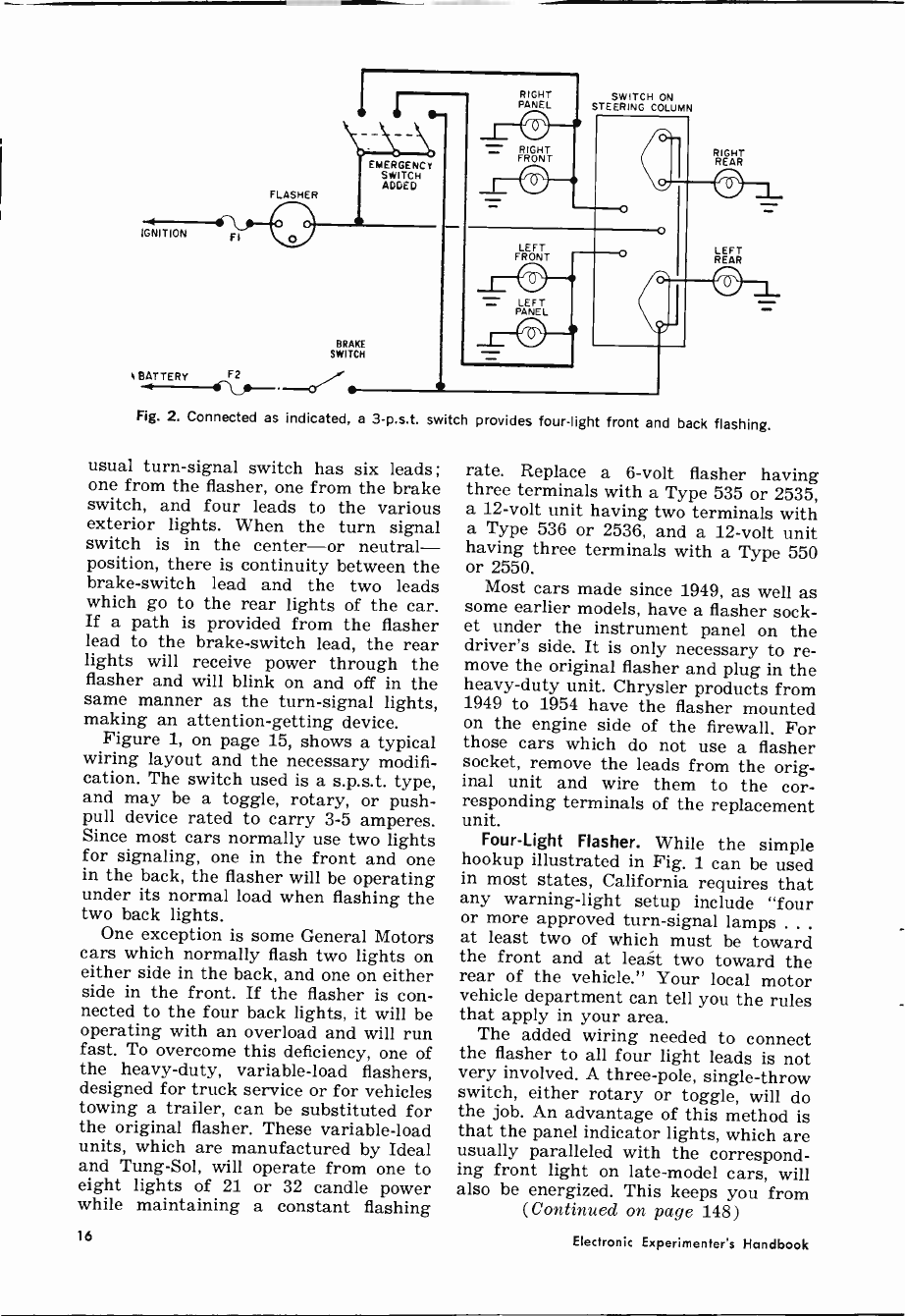
Fig. 2. Connected as indicated, a 3-p.s.t. switch provides four -light front and back flashing.
usual turn -signal switch has six leads;
one from the flasher, one from the brake
switch, and four leads to the various
exterior lights. When the turn signal
switch is in the center-or neutral-
position, there is continuity between the
brake -switch lead and the two leads
which go to the rear lights of the car.
If a path is provided from the flasher
lead to the brake -switch lead, the rear
lights will receive power through the
flasher and will blink on and off in the
same manner as the turn -signal lights,
making an attention -getting device.
Figure 1, on page 15, shows a typical
wiring layout and the necessary modifi-
cation. The switch used is a s.p.s.t. type,
and may be a toggle, rotary, or push-
pull device rated to carry 3-5 amperes.
Since most cars normally use two lights
for signaling, one in the front and one
in the back, the flasher will be operating
under its normal load when flashing the
two back lights.
One exception is some General Motors
cars which normally flash two lights on
either side in the back, and one on either
side in the front. If the flasher is con-
nected to the four back lights, it will be
operating with an overload and will run
fast. To overcome this deficiency, one of
the heavy-duty, variable -load flashers,
designed for truck service or for vehicles
towing a trailer, can be substituted for
the original flasher. These variable -load
units, which are manufactured by Ideal
and Tung -Sol, will operate from one to
eight lights of 21 or 32 candle power
while maintaining a constant flashing
rate. Replace a 6 -volt flasher having
three terminals with a Type 535 or 2535,
a 12 -volt unit having two terminals with
a Type 536 or 2536, and a 12 -volt unit
having three terminals with a Type 550
or 2550.
Most cars made since 1949, as well as
some earlier models, have a flasher sock-
et under the instrument panel on the
driver's side. It is only necessary to re-
move the original flasher and plug in the
heavy-duty unit. Chrysler products from
1949 to 1954 have the flasher mounted
on the engine side of the firewall. For
those cars which do not use a flasher
socket, remove the leads from the orig-
inal unit and wire them to the cor-
responding terminals of the replacement
unit. Four -Light Flasher. While the simple
hookup illustrated in Fig. 1 can be used
in most states, California requires that
any warning -light setup include "four
or more approved turn -signal lamps .. .
at least two of which must be toward
the front and at least two toward the
rear of the vehicle." Your local motor
vehicle department can tell you the rules
that apply in your area.
The added wiring needed to connect
the flasher to all four light leads is not
very involved. A three -pole, single -throw
switch, either rotary or toggle, will do
the job. An advantage of this method is
that the panel indicator lights, which are
usually paralleled with the correspond-
ing front light on late -model cars, will
also be energized. This keeps you from
(Continued on page 148)
16 Electronic Experimenter's Handbook
..._ ._.
Electronic Candles
Dance and Glow
Ordinary incandescent bulbs become sparkling, flickering holiday
decorations when they're powered by the Electronic Candlelighter
By JEFF H. TAYLOR
THERE'S NOTHING LIKE the warm glow of candlelight for fes-
tive occasions. Unfortunately, in modern times, the candle flame
with its rhythmic, yet random, light has been largely replaced by
the more intense, steady brilliance of incandescent bulbs. This arti-
cle describes a method of reproducing the effect of candlelight, how-
ever, using ordinary electric light bulbs. And, unlike the candle,
there's no smoke, melted wax, or fire hazards to contend with. You
simply plug a lamp or string of decorative lights into the "Elec-
tronic Candlelighter," sit back, and enjoy the age-old effect of flick-
ering, dancing candlelight.
1965 Pall Edition 17
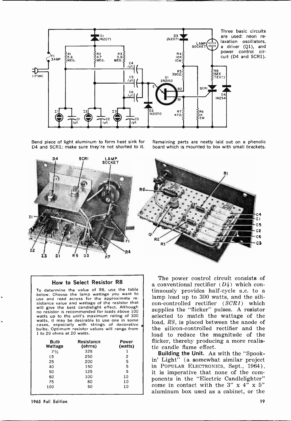
How It Works. The "Electronic Candle -
lighter" provides a half -cycle sine wave
to the lamp (s) continuously, plus other
random currents during the remaining
half -cycle. These random signals are
generated by three neon -bulb relaxation
oscillators operating at three slightly
different frequencies. The oscillators
beat with each other and the 60 -cycle
line frequency to produce a flicker in the
lamp which is plugged into the socket.
The unit has three basic circuits : the
neon relaxation oscillators, the driver, and
the power control circuit. The oscillators
are capacitively coupled to the driver
through C4, C5, and C6. These capaci-
tors prevent oscillator interaction.
The neon lamp oscillators are supplied
with a negative charging potential so
that when they fire they produce the
positive -going waveform necessary to
forward -bias unijunction transistor Q1.
The driver circuit consists of the tran-
sistor (Q1) to which the oscillators are
coupled. Base 2 of the unijunction is
supplied with positive pulses through
diode D3. The voltage on base 2 has a
peak excursion of about 15 volts. The
oscillator pulses at the emitter of Q1
which are in phase with the half -cycle
positive pulses on base 2 produce pulses
at base 1 which are coupled to the sili-
con -controlled rectifier, SCR1. Diode D2
provides d.c. restoration without loading
the signal portion of the oscillator out-
put.
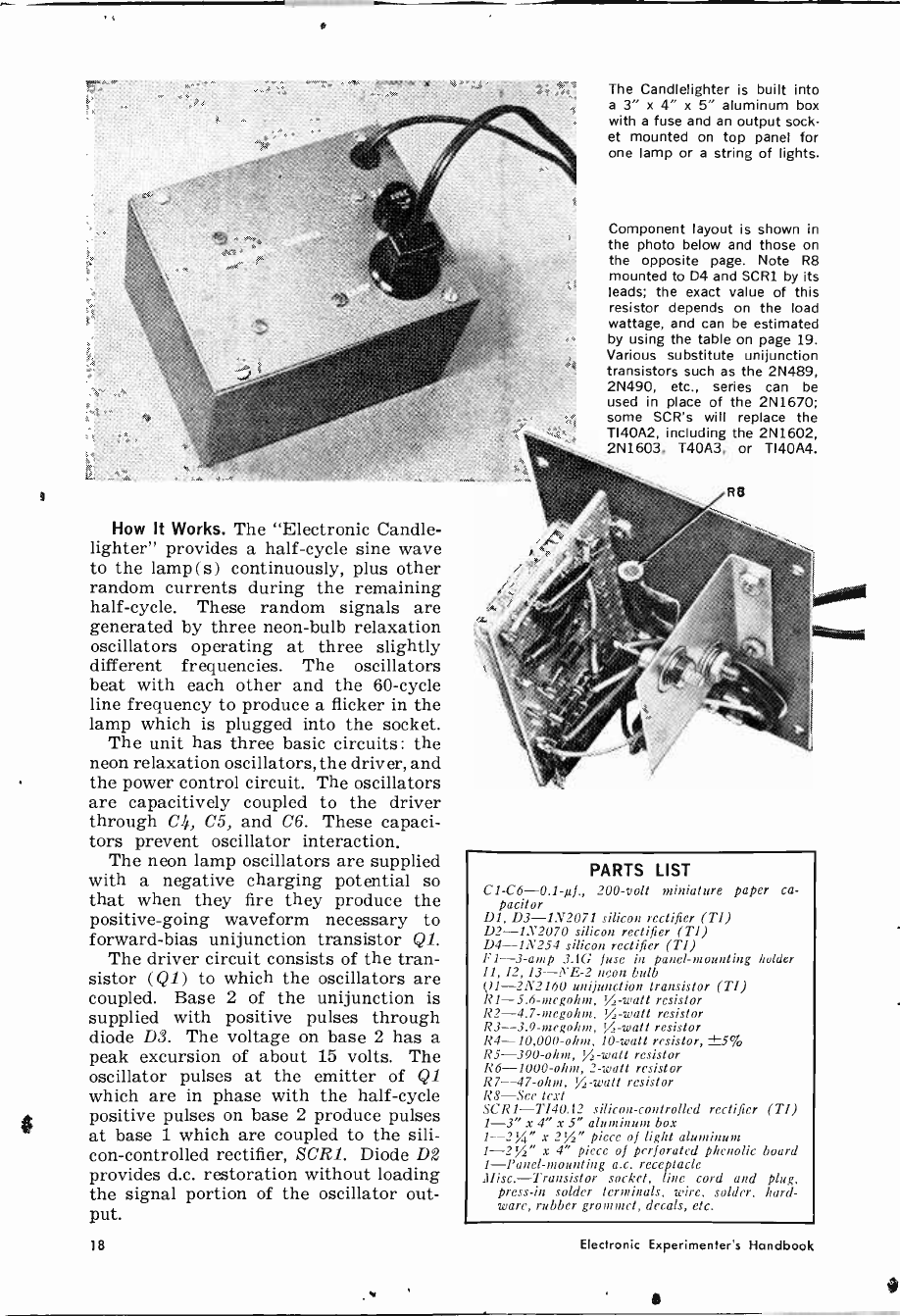
The Candlelighter is built into
a 3" x 4" x 5" aluminum box
with a fuse and an output sock-
et mounted on top panel for
one lamp or a string of lights.
Component layout is shown in
the photo below and those on
the opposite page. Note R8
mounted to D4 and SCR1 by its
leads; the exact value of this
resistor depends on the load
wattage, and can be estimated
by using the table on page 19.
Various substitute unijunction
transistors such as the 2N489,
2N490, etc., series can be
used in place of the 2N1670;
some SCR's will replace the
TI40A2, including the 2N1602,
2N1603, T40A3, or TI40A4.
R8
,%1
PARTS LIST
C1 -C6 -0.1-µf., 200 -volt miniature paper ca-
pacitor
Dl, D3 -1N2071 silicon rectifier (TI)
D2 -1N2070 silicon rectifier (TI)
D4 -1N254 silicon rectifier (TI)
F1 -3 -amp 3AIG fuse in panel -mounting holder
11, 12, 13--''E-2 neon bulb
Q1 -2N2160 unijunction transistor (TI)
R1-5.6-megohm, V, -watt resistor
R2-4.7-megohm, %,-watt resistor
R3-39-megohm, V, -watt resistor
R4 -10,000 -ohm, 10 -watt resistor, ±5%
R5 -390 -ohm, /,-watt resistor
R6 -1000 -ohm, 2 -watt resistor
R7 -47 -ohm, yj-watt resistor
R8-Sec text
SCR1-T140Á2 silicon -controlled rectifier (TI)
1-3" x 4" x 5" aluminum box
1-2%" x 2%" piece of light aluminum
1-21/2" x 4" piece of perforated phenolic board
1-Panel-mounting a.c. receptacle
111isc.-Transistor socket, line cord and plug,
press -in solder terminals, wire, solder, hard-
ware, rubber grommet, decals, etc.
18 Electronic Experimenter's Handbook
117 VAC
C2
Tyf.
I3
C4
C5
I(
03
1N 2071
R4
10K
ION/
R5
39011
01
2N2160
D2
IN2070
BI
R7 R6
47R IK 2W
Three basic circuits
are used: neon re-
laxation oscillators,
a driver (Q1), and
power control cir-
cuit (D4 and SCR1).
Bend piece of light aluminum to form heat sink for Remaining parts are neatly laid out on a phenolic
D4 and SCR1; make sure they're not shorted to it. board which is mounted to box with small brackets.
D4 SCRI LAMP
SOCKET
How to Select Resistor R8
To determine the value of R8, use the table
below. Choose the lamp wattage you want to
use and read across for the approximate re-
sistance value and wattage of the resistor that
will give the best candlelight effect. Although
no resistor is recommended for loads above 100
watts up to the unit's maximum rating of 300
watts, it may be desirable to use one in some
cases, especially with strings of decorative
bulbs. Optimum resistor values will range from
1 to 20 ohms at 20 watts.
Bulb Resistance Power
Wattage (ohms) (watts)
71/2 325 1
15 250 2
25 200 5
40 150 5
50 125 5
60 100 10
75 80 10
100 50 10
The power control circuit consists of
a conventional rectifier (Di) which con-
tinuously provides half -cycle a.c. to a
lamp load up to 300 watts, and the sili-
con -controlled rectifier (SCR1) which
supplies the "flicker" pulses. A resistor
selected to match the wattage of the
load, R8, is placed between the anode of
the silicon -controlled rectifier and the
load to reduce the magnitude of the
flicker, thereby producing a more realis-
tic candle flame effect.
Building the Unit. As with the "Spook -
in' Light" (a somewhat similar project
in POPULAR ELECTRONICS, Sept., 1964) ,
it is imperative that none of the com-
ponents in the "Electric Candlelighter"
come in contact with the 3" x 4" x 5"
aluminum box used as a cabinet, or the
1965 Fall Edition 19

PARTS PROBLEMS?
We can supply parts kits and
circuit boards for:
Adjustable Speech Filter
Bargain Page Amplifier
This Issue-and
Ultrasonic Sniffer Mar. 1963
Ultrasonic Trans. Sept. 1964
RC Receiver Apr. 1965
RC Transmitter June 1965
Others
Send for free catalog listing
these projects and others plus
circuit board type components
DEMCO
Box 16297
San Antonio, Texas 78216
CIRCLE NO. 5 ON READER SERVICE CARD
To Home or Shop...
for business or personal use!
"Messenger" Citizens Radio opens
up the exciting field of personal com-
munications to everyone - in any
application. Used by builders, con-
tractors, trucking, delivery services,
garages on-the-job-ideal for sports-
men, hunters, fishermen and camp-
ers! Anyone can operate - license
issued on request, Investigate the
"Messenger" line - nation's most
popular, most reliable Citizens Band
equipment!
YOUR OWN
2-WAY RADIO
YEn
Write Today
E. F. JOHNSON CO.
® 2521 10th Av. S.W. Waseca, Minn. 56093
JOHNSON
CIRCLE NO. 14 ON READER SERVICE CARD
aluminum heat sink on which SCR1 and
D4 are mounted. Use a 21/2" x 4" piece
of Vectorbord and press -in solder ter-
minals for mounting all of the other
components, following the general layout
shown in the photographs. The semicon-
ductors are all Texas Instruments types,
but equivalent units made by other man-
ufacturers could be employed instead.
Due to the fact that NE -2's tend to be
photosensitive, cover each one with black
plastic tape before wiring them in place.
Transistor Q1 is mounted in a socket
which is force -fitted into a hole drilled
in the Vectorbord; the mounting board
is attached to the front panel of the cabi-
net with two small angle brackets.
To make the heat sink, simply bend a
21/4" x 21/2" piece of light aluminum to
form a mounting bracket at one end (see
photos). Drill mounting holes in the
heat sink for SCR1 and D4, and mount
them with mica insulating washers. As
an additional safety measure, check with
an ohmmeter to make sure there is no
electrical contact between the diodes and
the heat sink.
To complete the unit, mount the lamp
socket, fuse holder, heat sink and cir-
cuit board to the front panel, and install
the line cord through a hole lined with a
rubber grommet.
Operation. Select R8 by referring to
the table on page 19. The resistance
values are not critical; simply select
one close to the recommended value.
Remember to calculate the total wattage
if the unit is to be used with a string of
decorative lights rather than with a sin-
gle bulb. Check the wiring carefully,
then try the unit out in a dimly lit room.
For a festive or romantic atmosphere,
use electronic candlelight! -1 -
II
"And this is Fred's quote, workshop, unquote."
20 Electronic Experimenter's Handbook
Choose Your Tailor -Made
Course in N.T. S.'PROIECT
METHOD" ELECTRONICS!
Now! N.T.S. - one of America's oldest leading home -study and resident
technical schools - offers you GREATER CAREER OPPORTUNITIES
IN ELECTRONICS. N.T.S. "Project Method" home training lessons
are shop -tested in the Resident School in Los Angeles. You
work on practical job projects, learn to use shop
manuals and schematics. Your N.T.S. training is
individual. You proceed at your own pace. The Schools'
practical methods, plus more than 60 years of experience,
have helped thousands of students all over the world to
successful careers. Prepare now for a secure future in one of 8
N.T.S. Electronics Courses designed to fit your own particular needs.
Work
on the
electronic
"brains"et
industry -
computers, data
processing and
other automation
equipment. Become
a TV-Radio Technician,
an electronics field engineer,
or succeed in your own business.
CHOOSE YOUR FIELD -INSURE YOUR FUTURE!
ELECTRONICS -TV -RADIO -SERVICING & COMMU- STEREO, HI-FI AND SOUND SYSTEMS A grow -
I NICATIONS A basic course thoroughly covering U ing field. Prepares you to build, install and service
fundamentals of electronics, radio, TV servicing modern sound equipment for home or industry.
and communications.
2 MASTER COURSE IN ELECTRONICS -TV-RADIO,
PLUS ADVANCED TV & INDUSTRIAL ELECTRON-
ICS This course covers everything included in
Course No. 1 plus Automation and every phase of
the Electronics industry.
3FCC LICENSE Preparation for this government
license essential for interesting jobs in radar,
radio, television, communications, guided missiles,
many others. Upon completion of this course, if
you do not pass the FCC exam for a 1st Class
Commercial Radiotelephone License your tuition
will be refunded.
4 RADIO SERVICING (AM -FM -Transistors) Train for
radio sales and service with dealer or distributor.
5 TELEVISION SERVICING ( Including Color) Covers
installation, adjustment, repair and servicing of
black and white and color television ... prepares
you for your own sales and service business.
7BASIC ELECTRONICS Gives you the fundamen-
tals you must know to build on for a future
Electronics career. Also offers an excellent back-
ground for Salesmen, Purchasing Agents, and
others in Electronics.
ELECTRONICS MATH Simple, easy -to -follow in-
structions in the specialized math you need in
many electronics jobs.
Most courses include Equipment Kits. THERE ARE NO KIT DEPOSITS.
Everything included in
your low tuition.
;
CLASSROOM TRAINING AT
LOS ANGELES
You can take classroom training in our
famous Resident School at Los Angeles
in Sunny Southern California. N.T.S. is
the oldest and largest school of its
kind. Associate in Science Degree also
offered in our Resident Program. Check
Resident School box in coupon for full
details.
HIGH SCHOOL AT HOME
Learn easily. New modern method. Na-
tional also offers accredited high school
programs for men and women. Take
only subjects you need. Study at your
own pace. Latest approved textbooks-
yours to keep-everything included at
one low tuition. Check Nigh School boo
in coupon for information.
MAIL COUPON TODAY
FOR FREE BOOK AND
SAMPLE LESSON In Field of Your Choice.
You enroll by Mail - and Save Money. No Salesmen: This
means lower tuition for you. Accredited Member N.H.S.C.
rr
NATIONAL SCHOOLS
TRAINING
4000 S. Figueroa St., Los Angeles, California 90037
NATIONAL TECHNIrtAL SCHOOLS (3
4000 S. Figueroa St., Los Angeles, California 90037
Please Rush FREE Electronics "Opportunity Book" a
1 and sample lesson on course checked below:
' Electronics -TV-Radio Servicing & Communications g
" Master Course in Electronics -TV-RADIO ,
Advanced TV & Industrial Electronics
FCC License De t.
i Radio Servicing (AM -FM -Transistors) P ,
Television Servicing (Including Color) 221-105 , 1 Stereo, Hi-Fi and Sound Systems
j Basic Electronics Electronics Math I
1 Name Age
Address
City State Zip '
i Checkhere if interested ONLY in Classroom
I Training at L.A.
'I Check here for High School Department Catalog
only.
CIRCLE NO. 35 ON READER SERVICE CARD
1965 Fall Edition 21
ADD
D.C.
restoration
to TV
BY CHARLES E. COHN
When they cut the costs
they leave out
this important picture circuit
ALTHOUGH the d.c. restorer was reg-
ularly used in the earliest TV sets,
it is a neglected feature in today's re-
ceivers. The omission is regrettable,
since this circuit makes a valuable con-
tribution to picture fidelity. However,
it is not difficult to add to a set.
The need for d.c. restoration stems
from the manner in which a signal is
generally applied to the picture tube.
To simplify comparison, assume the de-
tector's video polarity is such that a
positive signal (see drawing) corre-
sponds to black information, with small-
er voltages corresponding to lighter gray
shades until white is reached with the
smallest voltage.
If this signal is directly coupled from
detector to picture tube, a given voltage
always corresponds to the same shade.
Reproduction of the black -to -white scale
would then always be correct, provided
only that the receiver's brightness con-
trol is properly set.
Where Restorer Comes In. While some
TV receivers use d.c. coupling to the pic-
ture tube, most sets use RC coupling.
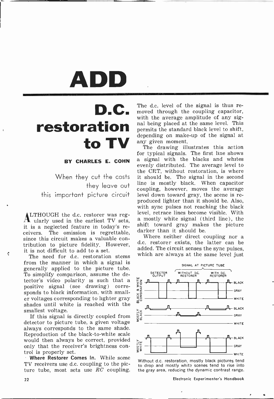
The d.c. level of the signal is thus re-
moved through the coupling capacitor,
with the average amplitude of any sig-
nal being placed at the same level. This
permits the standard black level to shift,
depending on make-up of the signal at
any given moment.
The drawing illustrates this action
for typical signals. The first line shows
a signal with the blacks and whites
evenly distributed. The average level to
the CRT, without restoration, is where
it should be. The signal in the second
line is mostly black. When capacitor
coupling, however, moves the average
level down toward gray, the scene is re-
produced lighter than it should be. Also,
with sync pulses not reaching the black
level, retrace lines become visible. With
a mostly white signal (third line) , the
shift toward gray makes the picture
darker than it should be.
Where neither direct coupling nor a
d.c. restorer exists, the latter can be
added. The circuit senses the sync pulses,
which are always at the same level just
DETECTOR
OUTPUT
SIGNAL AT PICTURE TUBE
WITHOUT WITH D.C.
RESTORER RESTORER
r-,
BLACK
GRAY
WHITE
BLACK
GRAY
WHITE
BLACK
GRAY
WHITE
Without d.c. restoration, mostly black pictures tend
to drop and mostly whits scenes tend to rise into
the gray area, reducing the dynamic contrast range.
22 Electronic Experimenter's Handbook
beyond black, and adjusts CRT bias ac-
cordingly to compensate for the shift
produced by capacitive coupling.
The circuit shown here is easy to in-
stall in an existing set, can be used
wherever a video signal is applied to the
picture -tube cathode, and the brightness
control is also located there. This ar-
rangement is usual. The circuit requires
the addition of only one tube, two ca-
pacitors, and three resistors.
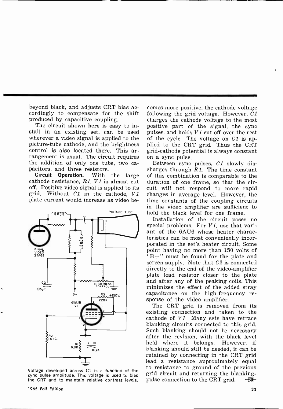
Circuit Operation. With the large
cathode resistance, RI, V 1 is almost cut
off. Positive video signal is applied to its
grid. Without Cl in the cathode, V1
plate current would increase as video be -
FINAL
VIDEO
STAGE
PICTURE TUBE
Voltage developed across Cl is a function of the
sync pulse amplitude. This voltage is used to bias
the CRT and to maintain relative contrast levels.
comes more positive, the cathode voltage
following the grid voltage. However, Cl
charges the cathode voltage to the most
positive part of the signal, the sync
pulses, and holds V1 cut off over the rest
of the cycle. The voltage on Cl is ap-
plied to the CRT grid. Thus the CRT
grid -cathode potential is always constant
on a sync pulse.
Between sync pulses, Cl slowly dis-
charges through Rl. The time constant
of this combination is comparable to the
duration of one frame, so that the cir-
cuit will not respond to more rapid
changes in average level. However, the
time constants of the coupling circuits
in the video amplifier are sufficient to
hold the black level for one frame.
Installation of the circuit poses no
special problems. For V 1, use that vari-
ant of the 6AU6 whose heater charac-
teristics can be most conveniently incor-
porated in the set's heater circuit. Some
point having no more than 150 volts of
"B-}-" must be found for the plate and
screen supply. Note that C2 is connected
directly to the end of the video -amplifier
plate load resistor closer to the plate
and after any of the peaking coils. This
minimizes the effect of the added stray
capacitance on the high -frequency re-
sponse of the video amplifier.
The CRT grid is removed from its
existing connection and taken to the
cathode of V1. Many sets have retrace
blanking circuits connected to this grid.
Such blanking should not be necessary
after the revision, with the black level
held where it belongs. However, if
blanking should still be needed, it can be
retained by connecting in the CRT grid
lead a resistance approximately equal
to resistance to ground of the previous
grid circuit and returning the blanking -
pulse connection to the CRT grid.
1965 Fall Edition 23
V -BATTERY
EXPERIMENTER/HOBBYIST ELECTRONIC COMPONENTS
iry
1
LAMP
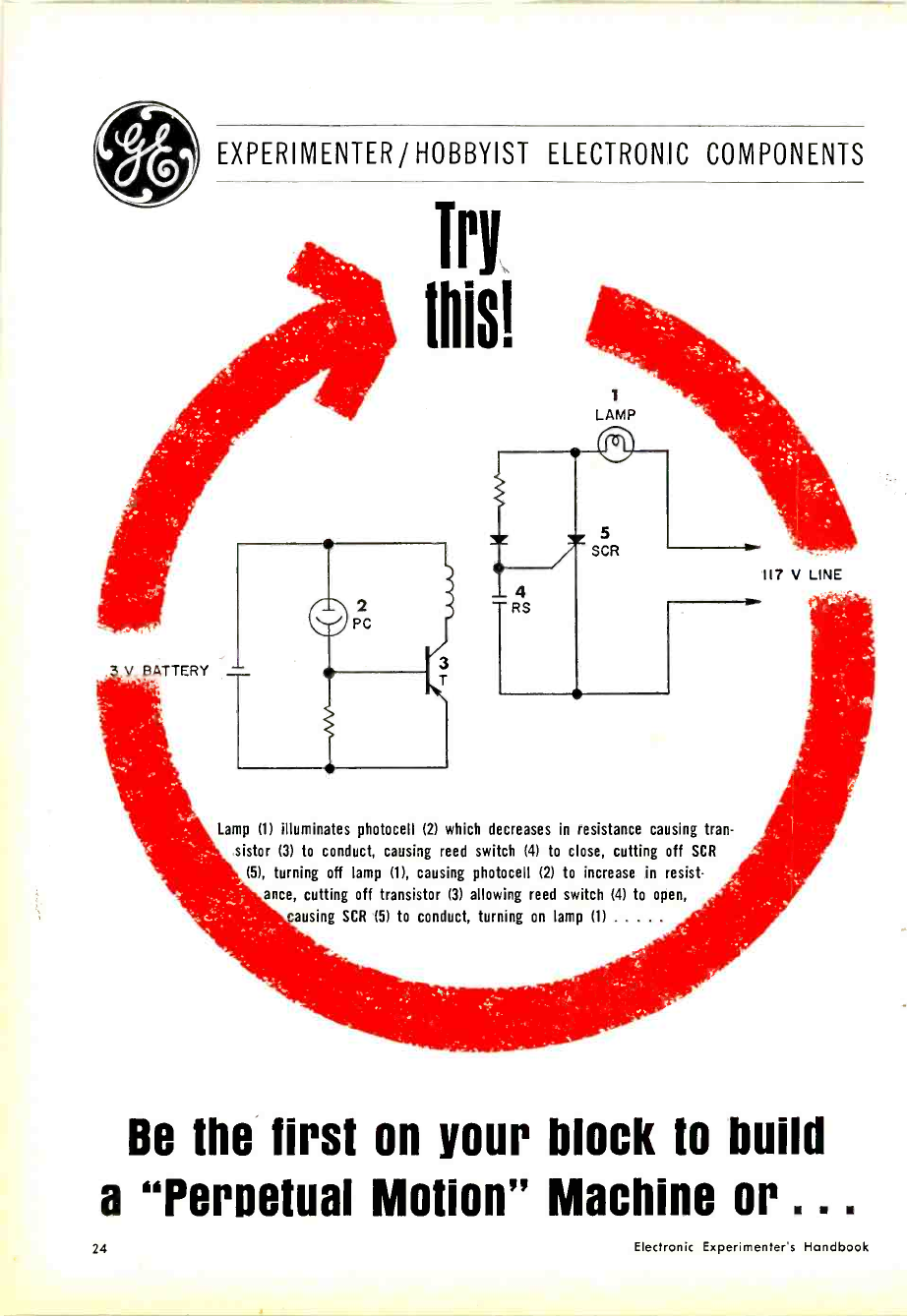
Lamp (1) illuminates photocell (2) which decreases in resistance causing tran-
sistor (3) to conduct, causing reed switch (4) to close, cutting off SCR
(5), turning off lamp (1), causing photocell (2) to increase in resist-
ance, cutting off transistor (3) allowing reed switch (4) to open,
ausing SCR (5) to conduct, turning on lamp (1)
117 V LINE
Be the first on your block to build
a "Pergetual Motion" Machine or .. .
24 Electronic Experimenter's Handbook
...build any number of useful devices
with these G -E Electronic Components
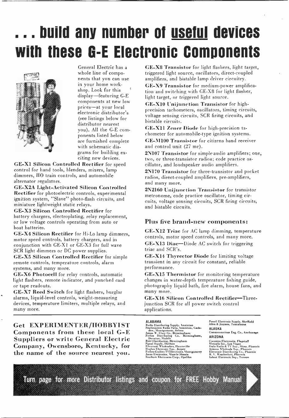
General Electric has a
whole line of compo-
nents that you can use
in your home work-
shop. Look for this
display-featuring G -E
components at new low
prices-at your local
electronic distributor's
(see listings below for
distributor nearest
you). All the G -E com-
ponents listed below
are furnished complete
with schematic dia-
grams for building ex-
citing new devices.
GE -X1 Silicon Controlled Rectifier for speed
control for hand tools, blenders, mixers, lamp
dimmers, HO train controls, and automobile
alternator regulators.
GE-X2A Light -Activated Silicon Controlled
Rectifier for photoelectric controls, experimental
ignition system, "Slave" photo -flash circuits, and
miniature lightweight static relays.
GE -X3 Silicon Controlled Rectifier for
battery chargers, electroplating, relay replacement,
or low voltage controls operating from auto or
boat batteries.
GE -X4 Silicon Rectifier for Hi -Lo lamp dimmers,
motor speed controls, battery chargers, and in
conjunction with GE -X1 or GE -X3 for full wave
SCR light dimmers or DC power supplies.
GE -X5 Silicon Controlled Rectifier for simple
remote controls, temperature controls, alarm
systems, and many more.
GE -X6 Photocell for relay controls, automatic
light flashers, remote indicator, and punched card
or tape readouts.
GE -X7 Reed Switch for light flashers, burglar
alarms, liquid -level controls, weight -measuring
devices, temperature limiters, multiple relays, and
many more.
GE -X8 Transistor for light flashers, light target,
triggered light source, oscillators, direct -coupled
amplifiers, and bistable lamp driver circuitry.
GE -X9 Transistor for medium -power amplifica-
tion and switching with GE -X8 for light flasher,
light target, or triggered light source.
GE -X10 Unijunction Transistor for high -
precision tachometers, oscillators, timing circuits,
voltage sensing circuits, SCR firing circuits, and
bistable circuits.
GE -X11 Zener Diode for high -precision ta-
chometer for automobile -type ignition systems.
GE -M100 Transistor for citizens band receiver
and control unit (27 mc).
2N107 Transistor for simple audio amplifiers; one,
two, or three -transistor radios; code practice os-
cillator, and loudspeaker audio amplifiers.
2N170 Transistor for three -transistor and pocket
radios, direct -coupled amplifiers, pre -amplifiers,
and many more.
2N2160 Unijunction Transistor for transistor
metronome, code practice oscillator, timing cir-
cuits, voltage sensing circuits, SCR firing circuits,
and bistable circuits.
Plus five brand-new components:
GE -X12 Triac for AC lamp dimming, temperature
controls, motor speed controls, and many more.
GE -X13 Diac-Diode AC switch for triggering
triac and SCR's.
GE -X14 Thyrector Diode for limiting voltage
transient in any circuit for constant, reliable
performance.
GE -X15 Thermistor for monitoring temperature
changes in water -depth temperature fishing guide,
photography liquid bath, fire alarm, house fans, and
many more.
GE -X16 Silicon Controlled Rectifier-Three-
junction SCR for all power switch control
applications.
Get EXPERIMENTER/HOBBYIST
Components from these local G -E
Suppliers or write General Electric
Company, Owensboro, Kentucky, for
the name of the source nearest you.
ALABAMA
Radio Distributing Supply. Anniston
Southeastern Radio Pere, Anniston, Cede.
den, Montgomery, Selma
James W. Cl.,Y Co., Birmingham
Forbes Distributing Co., Birmingham,
Decatur. Mobile
Reid Distributing, Birmingham
Eger l S W oDhan a lie
Rughe, Electronic Jasper
Fones ECodrnics,ey ice.Moeigomery
Jones Electronic., Muscle Shoal.
Southern Elccieoaico Corp., Opelika
Powell Electronic Supply. Sheffield
Allen & Jemi.on, Tusmloosa
ALASKA
Communication. Eng. Co.. Anchorage
ARIZONA
Coconino Electronics. Flagstaff
Metcalfe Inc., tas Vegas
Delis Radio & TV Sup., Mena, Phoenix
Arizona Wholesale Sup., Phoenix
Electronic Distributing Co.. Phoenix
R. V. Weatherford, Phoenix
Inland Electronic Sup., Tucson
Turn page for more Distributor listings and coupon for FREE Hobby Manual

EXPERIMENTER/HOBBYIST ELECTRONIC COMPONENTS
ARKANSAS
David White Radio Sup., Fayetteville,
Harrison, Hot Springs, Little Rock,
Monroe, Pine Bluff
Carlton Bates Co., Fort Smith, Little Rock
Carter Electronic Supply. Fort Smith
Wise Radio Sup., Fort Smith
Martin Wholeale, Jonesboro, Paragould
Lavender Radio TV Sup Memphis
Springdale Radio & TV Sop., Springdale
CALIFORNIA
Kiesub, Anaheim, Bakersfield, Long
Beach, Oxnard, San Bernardino, Van
Nuys
Orvac Electronics, Anaheim
WRESCO, Anderson, Gehenna, Peta-
luma, San Carlos, San Francisco
J. C. Arbuckle Wholesale Parts Sup.,
Bakersfield, Fresno
Pacific Electronics, Berkeley, Concord,
Richmond
Andrew. Electronic, Burbank
Electronic City, Burbank
Hagerty Radio Sup., Burbank
Sandy'. Electronic Sup., Canoga Park
Wee Valley Electric Sales. Canoga Park
Whole le Electronic Specialists, Cathedral
City
JSH Electronics, Culver City
Southland TV Sup El Cajon
Kimball & Start, E1 Monte
I. F. A. Electronics, Encino
Imperial Sound Co., Encino
Inland Electronns, Fresno, M odesto
We. Electronic Sup., Freen
Santa i-Bell Electronics, Garde na
Loan Electronics, Glendale
R. V. Weatherford, Glendale, San Diego
North Valley Elecerooiee, Granada lulls
Bement Electronics, Harbor City
Hollywood Radio & E e, Hollywood
Pacific Radio Exchange,e. HollywoodHll
Yak Radio Electric, Hollywood
Marn Distributing, Huntington Park
Hurley Electronics of Inglewood, Inglewood
Inglewood Eleceronics Sup , Inglewood
Manley Electronic Sup., Lon ,ter
Scott Radio Sup., Long Beach
Bell Radio Sup., Los Angeles
Clarion Shoji, Los Angeles
Electronic Kite Sup., Los Angeles
Figarte Radio Sup., Los Angelo,.
Hmehkit Electronic Cemcr, Lon Angeles,
San Diego
Henry Roth.. Los Angeles
International Television, Los AngelesK
od,, ff Electronics, Lon .Angeles
Ro Produces Sales, Los Angeles
Reeve. Electronic, Loa Angeles
Universal Radio, los Angeles
Pacific Teleuoeic Radio sup., ModestoHonig
Distributing North Hollywood,
Sylmar,
Brill Electronics, Oakland
Elmar Electronics, Oakland
Millers Radio & TV Sup., Oakland, Santa
Rosa, Walnut Creek
Panorama Electronim, Pacoima
Elwyn W. Ley, Paramount
Allied Radio, Pasadena
Electronic .
Comp n Pasadena
EmpireElectm Distributors, Pasadena
Bay Electronics, Redondo Beach
Colorvieion Sup., Beene,
Electronic Sup., Riverside. San Bernardino
Mission Hemp Sup., Riverside
Noro.l Electronics, Sacramento
Sacramento Elec i Su iu cam
Fortune Eke onic, S . Sen Fran-
cisco
Southland Eleceronea, San Diego
Shanks & Wright. San Diego
Southland Electronic., San Diego
Western Radio & TV Sup.. San Diego
EDISCO, San Francisco, San Raphael
Pacific Electronic Distributing, San Fran-
ciscoS
Fra deco Radio Sup San Francis,
Millers Electronics, Sa Joee
pic t I.den Cal Eleceronice. Son Jose
Channel Radio, Santa Barbara
Lectronic Kit & Porte Center. San ea Barbara
Mobile Radio, Santa Fe Springn
Lombard. Electronic.. Sana Morio, Ven-
tura
Midway Electronics, Santa danse,
Military Electronic Sup., Seaside
Sunnyvale Electronics, Sunnyvale
Wholesale Electronic Supply, Ventura
COLORADO
Dagg Eke.. Dice Corp.. Boulder
Burstein Applebee of Coln., Denver
Electronic Pars Co., Denver
Hea,bkit Elect. Center, Denver
Radio Specialists Co.. Denver
Welker Radio Co.. L. B., Denver, Grand
Junction, Pueblo, Sterling
CONNECTICUT
Pilgrim Elect. Co. Inc., The, Danbury
Crooner Elect. Inc., Hamden
Signal Center loc., Hartford
Modem Electron Sply Inc.. Kensington
Addy. Electronic Slyly.. New London
Arrow Electronic.. Norwalk
Bond Radio Sup., Waterbury
DELAWARE
Almo Radio, Wilmington
FLORIDA
Dell Electronics, TaBahae.ee
Dow Electronics, Sarasota
Goddard. Inc.. Eau Genie, Miami, W.
Palm Beach
Come Electronic, West Palm Beach
East Coast Electronim, Miami
Sou,heaet Electronics, Jeckma ville
Southeastern Wholesale Miami
Thurow Elentronico, Bradenton, Clear-
water, Cocoa, Daytona Bch, Ft.
Lauderdale, Ft. ea
t. Myers, Ft. Pierce,
Gainesville, Ilomestead, Key West,
Jacksonville. Lakeland. Miami. (seal,,
Orlando, Panama City, Pensacola,
Sarasota, St. Petersburg, Tollehes.ee,
Tampa, West Palm Beach
Hammond Electronics, Daytona Beach.
Jacksonville, lakelend,Orlando,Tantpa
Electronic Wholesales, SIciboun,e, Miami
Electronic Equipm t, Miami
Cooper Radio, St. Petersburg
Welch Radio, St. Petersburg
GEORGIA
Southeastern Radio Parte, Albany, Athens,
Atlanta, Gainesville, La Grange, Ma-
con, Rome, Savannah
Wcis Electronic Sup.. Atlanta
orld Electronics. Atlanta
Augulu Wholesale Electronics, Augusta
Hamilton Electronic Sup., Auguella
Radio Sales & Service, Columbine
Curls Radio Sup., Dalton
HAWAII
American Factors, Ltd., Ilonolulu
Pacific Electronics, Honolulu
Precision Radio, Ltd., Honolulu
'Radio Wholesale & Sup., Honolulu
W. A. Ramsay Co., Honolulu
Comte) Engineering, Honolulu
IDAHO
A -Gen Simply Co., Boise, Caldwell
Roos, S. II., Inc., Boise
Billmeyen Inc., Pocatello
ILLINOIS
York Radio, Bloomington, Champaign,
Decatur, Kankakee, Springfield
Ohio Valley Sound, Centralia
Electronic Parts, Champaign
Radio Dutton, Champaign
Allied Radio Corp.. Chicago, Forest Park,
Gary, Maywood, Skokie
1. G. Bowman & Company, Chicago
Cooper, Jr., R., Chicago
Electronic Dian. Inc, Chicago
Newark Electronics Corp., Chicago
Bud Electronic Sup., Danville
Acro Electronic Dut., East Chicago
Knox Electric Supply Inc., Galabue,
Baptist Electronic Su ,., Jacksonville
lleathkit Electronic Center, Lincolnwood
Wahaeh Electronics, Mt. Carmel
Melvin Electronics, Oak Park
Crescent Electric Supply Co.. Peoria
Klaus Ridio & Electric Co., Peoria
Waihle Electronic, Peoria
Yeomans Dintrìhu,ing Co., Peoria
Joyeroice, Rockford
Melvin Elec,roneo Inc., Rockford
Midwc Associated Distr., Rockford
Bruce Electronics, Springfield
INDIANA
Electronic Supply Co., Redford
Staneifer Radin, Bloomington,
Williams Co., II. A., Bloomington, Colum-
bus, Richmond
llutuh & Son. Evansville
Ohio Valley Sound, Evansville, Vincennes
Wesco Radio Part,, Evansville
Brown òlec e Inc., Fort Wayne
Pemblee n Labors. Fort Wayne
Protective Electrical Supply, Fort Wayne
Warren Radio Co.. Fort Wayne, Indian-
alio
AlhaÌ Radio, Gary
Coemopelitan Radio. Gary
Electronic Dot. Inc., Indianapolis
Graham Electronics, Indianapolis
Hoosier Rodio Supply, Indianapolis
Radio Di,tg. Co., Indianapolis
George, Electronic Supplies. Kokomo
Television Radio Diets., Kokomo, Lome.-
CrAllecVnics, Lafayette
Madison Electronic, Madio.,,
Myers Radio Supply Inc., Marion
Tri-State Electric Co., Slichigen City
Rodefeld, Richmond
Colfax Co., South Bend
C. T. Eninger, erre Haute
Bon & Aesociateo, Jro,, Valparaiso
IOWA
Mid -State Distributing Co., Ames, Carroll,
Cedar Rapide Centerville, Creston,
Dee Moines, lows City, Marshalltown,
Mason City, Oskaloosa, Ottumwa,
Spencer, Strawberry Point, Waterloo
Crescent Electric Supply Co., Burlington,
Davenport, Dubuque, Sioux City
Iowa Radio Supply Co., Ceder Rapids
Radio Trade Supply Co.,
lltown Des Moines Ft.
Dodge d
York Radio & TV, Ft. Madison
Water, Electronic Supply. Mason City
Moletad Distributing, Sioux City
F,poeworeh Electron cs, Waterloo,.
KANSASNorman
Electronic Sup.. Coffeyville
Interstate Electronic Sup.. Dodge City.
Hay,, Ilutchinton, Topeka, Wichita
Electronics Sup., Great Bend
Renshaw TV Sup., Kma, City, Mission
Acme Radio Sup., Manhattan, Topeka
KENTUCKY
Crescent Radio Supply, Bowling Green,
Somerset
Arol.y Chesney Electronic, Corbin
Anle Electronicu, Danville, Louisville
Radio Inc., Lexington
Radio Elect. Equipment Co. Inc., Lexington
P. I. Burks Co., Louisville
Peerless Elect. Equip. Co., Louisville
Universal Electronic Sy., Louisville
Ohio Valley Sound, Owensboro
Warren Radio, Paducah
LOUISIANA
Electronic Service Sup., Alexandria
Davis Electronic Sup., Baton Rouge
Ralph, of Lafayette, Baton Rouge, Lafay-
ette, Labe Charles, Morgan City, New
Iberia
Epcor, Gretna, New Orleans
Crescent, Electronic Sup., Houma, Metairie,
New Orleans
Sterling Electronics, Lafayette
Graybar Electric, lake Charles, Shreve-
port
W'holeeally Radio Equipment, Lake Charles
TV Wholesale Sup., Monroe, W. Monroe
Radio Parts, New Orleans
Shuler Sup., New Orleans
Walther Be,,..New Orleans
(»clow, Radio Equipment, Opelousas
B&S Elcctronia, Shreveport
Koelemay Sales, Shreveport
MAINE
Radio Supply Co., Inc., Auburn, Bangor,
Waterville
MARYLAND
A. R. Spa Co., Baltimore
n, At g Co., Baltimore
Kann -Ellen Eke. Inc., Baltimore
W'holeeak Rodio Par. Co., Baltimore
Allegheny Electronics Inc., Cumberland
Acuson of Maryland Inc., Glen Burnie
Stoddard Supply Co., Ilageretown
Lafayette Radio Elect., Mt. Rainier
Alm. Radio, Seli,hury
Standard Elect. Supply Co. Inc., Salisbury
Bayneeville Electromm, Towson
MASSACHUSETTS
Gerber Radio Supply. B,,tun
Lafayette Radio Corp., Boston
O'Donnell Elect. Spey. Co., Bunton
Tre Vec Sply Co., Brockton, Jameio.
Plain, Lowell, Peabody
Ware Radio Supply. Brookto
Electrical Supply Corp., Cambridge
Rona Co., E. A.. Fall River
Alen Eleeronics Inc., Lawrence
Dee Roberts. Lynn
Land Electronic Supply, Lynn
Durrell Electronics, SIcdford, Natick, Sen-
ates, Walthem
Wayne to Ind. Elect., Natick
Industrial Elect. Sply., Inc., Needham
Heights
Cramer Eke. Inc.. Newton
Green Shaw Co. Inc.. Newton
Abbott Electronics Co., North Woburn
Pilgrim Elect. Sply. Corp., Quincy
Cushing Inc., T. F'., Springfield
Bounden Electronic Sply Co., Springfield
M Radio aeneenance Sply., Worcester
MICHIGAN
Purchase Radio Supply, Ann Arbor
Electronic Supply Corp., Battle (:reek
Warren Radio Company, Ileetle Creek,
Ferndale, Grand Rapid,, KalaD.,w,,
Owosso
Benton Electronic Supply, Benton Harbor
Radio Electronic Supply, Cadillac, Detroit,
Grand Rapid.
Strains Dicer. Inc., Cheboygan, Sault Ste.
Marie
Glendale Elect. Supply Co., Detroit, Lan-
Ma,ter Elect. Supply Co.. Detroit
Newark Ferguson Elect. Inc.. Detroit
Radio Specialties Co., Detroit, Redford,
Wyandotte
Midway Ekmronic Sy. Co.. Ferndale
Lifney Distributing Co.. Flint
Taylor Elect. Sup1,by, Flint
Elect. Supply of Pontiac, Fort Huron,
Pontiac
TAW Electronic, Inc., Grand Rapids
FltaPatrlck Elm. Supply Co., Holland,
M uekegon
Fulton Radio Supply Co., Jackman, Lansing
Northwest Radio Supply Inc., Nlarquette
Them Doe,, Co., Saginaw
Radio Part, Co., Saginaw
Deyet om Products Corp., St. Joseph
Lafayette Radio Supply Co., Utica
MINNESOTA
Northwest Radio, Duluth
Stark Electronic Supply Co., Duluth, La
Crosse, Minneapolis, St. Cloud, St.
Paul
Admiral Diet. Inc., Mlnneapolie
Bonn Co., Lew, Minne,ppoolin, Rochester
Electronic Center Inc., Minneapolis
Radio Electric Supply, MDoneapolie
Gopher Electronics, St. Paul
Slvl'W.KEE-LINE Elem. Corp., St. Paul
MISSISSIPPI
Pat, Electronic, Clarksdale, Tupelo
Columbus Electronics, Columbus
Parham Electrons., Greenwood
Creneene Electronic Sup., Gulfport
Ellington Electronic Sup., Jackson
May & Jackson Dietrihu,ors, Jackman
Radio & TV E.nentiah, Laurel
TV Wholesale Sup., Natchez
MISSOURI
Snedekurn Electronic Sup.. Cape Girardeau
York Rodio & TV, Hannibal
Ilco,haw TV Sup., Independence, Kansas
City
Robertson Electronic., Jefferson City
Wholesale TV S"l' 1,0,. JeRereon City
Four State Radio Sup.. Joplin
Norman Electronic Sup.. Joplin, Springfield
Burstein Appeaser, Kunma, City
ManhattanKaman Radio & Equipment, Kaas
City
SlcCee Radio, Kansas City
Radeolab, Kansas City
Acme Radio Sup., St. Joseph
Electronic Compu ente for Industry, St.
Loue
Electronic Mart, St. Louis
Hollander & Company, St. Louie
Van Sickle Radio Elecernnici, St. Louie
Olive Electronic Supply. University City
MONTANA
Electronic Supply Co., Billings
i
Electronic D n Inc.,Great ., G t Falls
NEBRASKA
Radio E. uipment. Beatrice, Grand Island.
Norfolk, (Omaha
Central R,deo Sup., Hastings
Scott Electronic Sup.. Lincoln, North
Platte
Omaha Electronic,, Omaha
Joachim Radio Supply Inc., Scot Bluff
Tri.State Eleceronece, Scotts Bluff.
NEVADA
Electronic Distributing Co., of Nev., Reno
NEW HAMPSHIRE
American Radio Corp., Dover
NEW JERSEY
Almo Radio, Atlantic City, Camden,
Trenton, Vineland
Kean Elect. Produces Inc., Atlantic City
Gem Electronics, Bayonne, East Bruna-
ick, East Orange, Paramus, Spring-
field, Totowa
Miid,tatc Radio Supply Co.. Berlin
Joe', Radio
General Radio Sú pl Camden
Eastern Radio Corp., Clifton
Emeco Electronics, Hackensack
Nidixe.,. Ilackennack, Jersey City, Passaic,
Ridgefield, Trenton, Union City
State Elect. Parts Corp., lfanover
Leader Electronic Suppi , Ilellnide.
Bay Electronic Doug: Co., New Brun,weck
Lafayette Radio & Elect., Newark, Pa -
ranee, Plainfield
Asbury Electronice Supply, Ocean Grove
Jersey Electron Dis l'aterman
'Wilma) Elect. Con Corp.,., Paterson
Penn Electronic, Pte., Pennsauken, Pkila-
delphia
Allas Elect. Inc., Perth Amboy
Carl B. Williams, Phillipsburg
Leon Television Part, Co., Plainfield
Moyer Electric Supply, Pottsville
Sun Radio & Electronic,
Monmouth Radio Supply, Red Bank
Federated Purchaser, Sbrewebury, Spring-
field
NEW MEXICO
KicrulU, Alamogordo, .Albuquerque
Graybar Electric Co. Inc., Albuquerque
Yucca Wholesalers Inc., Albuquerque
B,,in Electronic Supply, Farmington
alley Engineering, Loa Alamo,
Southwestern Elect. Parts, Santa Fe
NEW YORK
Fort Orange Radio, Albany
Havens Electric Co. Inc., Albany
Knickerbocker Appl. Service, Albany
Taylor, Edwin E., Albany
Adirondack Radio Supply, Amsterdam
Gem Electronic., Beedsore, Belleroee,
Bronx, Brooklyn, Farmingdale. Foret
11i11,, Great Neck, Ilickaville, Hunting-
ton, Menands, tlount Vernon, New
York, Plainview, St. Jaynes, y
Stream, West Bronx, Yonkers
Lafayette Radio & Electronic, Bronx,
Brooklyn, Jamaica, New York, Scene
dale, Syosset
Rim Electronics Inc., Bronx
Economy Electronic, Corp.. Brooklyn
Electronic Equip., Brooklyn
Graham Ekctronice Diet., Brooklyn
Rygrade Electronic. Co.. Brooklyn
Loco Electronics, Brooklyn
(luron Elect. Supply Co. Inc., Buffalo
26 Electronic Experimenter's Handbook

DISTRIBUTOR LISTINGS -CONTINUED
Manfred Elnrronies. Corona
Electronic Supply Corp:. Elmhurst
Eddy Electronics. Elmira
Arrow Eketronicn, Farmingdale, Mineola,
New York
Emerald Electronics, Floral Park
Allen Electronic. Inc., Flushing, L. I.
Ray Supply Inc.. Glenn Falls, Plat rnburgh
Norman Radio Dine. Inc.. Ja moira, L. I.
Johnmn Radio Co.. Jamestown
Aram Elect. Dist., Kingston
Greylock Electronic Die.,Kingston,Pough-
keepsie
Peerless Radio Corp.. Lynbrook
S&P Elm. Inc., Ma.eapegna
Seaway .ies. n a
Certified Elect. Inc., Middletown
Atlas Electronics Corp.- New York
Beko Dina. Inc., New York
Calvert Electronics Inc., New York
Elect. Parts Dibtg. Co., New York
Elect. Tube Sales Inc., New York
Grand Central Radio, New York
Harvey Radio, New York
Metropolitan Supply Co., New York
Midway Radio & TV, New York
Milo Electronics Corp.- New York
Terminal Iludion Elect., New York
Atlas Electronic. Inc.. Plain, iew
Higg'ne & Sheer Elect. Dist., Poughkeepsie
Elect. io,e tg. Corp., Richmond hill
Alfred Rorp., er
Road tro ic., Corp., Rockville Centre
Rome dlmmnict r Rome
Adirondack Electronic.Inc.. Schenectady
Electric City Elect. Supply. Schenectady
Schenectady Sleet. Island Schenectady"
R&DLNL Disrg., Staten Inland
God D atg.Ela Corp., SymSy orL.
Gordon&
O'Brien,roninInc..Ise.-
Syracuse
Robertsbet & Oul Syracuse
Salina Elect. Supply Co. Inc.. Syracuse
Watertown Watertown
Melville White Plains
Thruway Elect., White Pline
NORTH CAROLINA
Frock Radio & Sup.. Asheville
Dixie Radio Sup., Charlotte, Gastonia
World Electronics, Charlotte
Vickers Electronic Sup., Durham
Sourheaotcrn Radio Sup.. Fayetteville.
Greensboro, Hickory, Jacksonville,
Kingston, Raleigh, Salisbury, Wil-
mington, Wilson
Electronic Wholesaler.. Winston-Salem
Walker -Martin, Charlotte, Raleigh
NORTH DAKOTA
Bristol
rGrand
' tol D't rib t Co., Bismarck, Fargo,
GrandFork», Minot
John Iverson Co.. Mandan, Minot
OHIO
Akron Electronics Supply Co., Akron
Main TV Supply Co., Akron
Olson Radio (Company, Akron
Sun Radio, Akron
Warren Radio, Akron. Lima, Toledo
Serves, Ashland, Delaware, Fremont,
Mansfield, Marion, Alt. Vernon, San-
dusk San-
dusky. Tiffin, W' n
Canton Electronics. Cat
Sommer Electric Co.. Canton
TV Pane, Canton
Buckeye Elec., Chillicothe. Columbus.
Lancaster. Newark, Zanesville
Holub Dist., Cincinnati, Newport
Higbee -Pet s, Cincinnati, Columbus
Myer Cincinnati
Ne H ark - roger Elect., Cincinnati
Broadway Elec. Supply Co.. Cleveland
Pioncer, Cleveland, Lorain. Sandusky
Seaway Elm.. Cleveland
Con n Elec nos, los., Dayton. Fairborn,
Ha m il to
Rankin & Mouser Inc.. Dayton
Srepco Electronics. Dayton, Hamilton,
Middletown, Piqua
Stotts -Friedman. Davlon
Euclid Radio Part. Corp.. East Cleveland
United Elerironics, East Liverpool
Lima Radio Paris Co., Findlay, Lima,
Van Wert
JAB Electronics, Fremont
Standard Radio. Springfield
DAR Radio Supply, Steubenville
Toledo Radio Specialties. Toledo
Rem Elec Ra
Glen Elect. s.
Supply Corp.. Youngstown
Roan Radio, Youngstown
OKLAHOMA
Trier Rholesale Electronic.. Ardmore. Enid,
Lawton, McAlester, Muskogee, Okla-
homa City, Okmulgee, Ponca City,
Tulsa
Noria° Electronics Sup., Bartlesville
Bols Amateur Electronics. Oklahoma City
John ll. Cole, Oklahoma City
Industrial Electronics. Oklahoma City
Grayler Electric, Oklahoma City, Tulsa
Radio. Inc., Oklahoma City, Tultra
Oil Capitol Electronics. Tulsa
SAS Radio Sup., Tulsa
OREGON
Ace Electronics Inc.. Eugene
United Radio Supply, Eugene, Medford.
Portland
Walker, Vml G., Medford
Pelle Radin Supply, North Bend
Round -('p Electronics- Pendleton
Eboroolech Inc./Nemronir, Portland
lohmoi, Co., Lou, Portland
Television A Radin Supply,lorrland
Willamette Radio Supply,
PENNSYLVANIA
A. A. Peter., Allentown
Gem Electronics, Alle,own
Allegheny Electronics lac.. Altoona, Johns-
town
Television Parts Co., Ambridge, Butler,
New Brighton, New Castle
Powell Electronic Sales, Bristol
County Sup dy Co.. C.oamnvlllc
Duncombe Co., J. V. Erie
Radio Distributing, Harrisburg
Barpo Radio Company, Mc Keeepert
Almo Radio, Norristown, Philadelphia
A. C. Radio Sply., Philadelphia
Allied Elm. App. Pain Inc.- Philadelphia
Leetronic Dist n., Philadelphia
Lectronic Res. Labs., Philadelphia
Sidney Wagner Elect. Sply., Philadelphia
Simm Elem., Philadelphia ph,
Electronic Parts Co..C Pittsburgh
Triangle Electronics Co- Pittsburgh
Trrdingo(:nmp¡, YY Pi.t ahnrgh
F:lem r &'l'V Ui.., Reading
Connl(Jrd Distge Scranton
Kesel(
University Elect. Co. Inc.. Sa te College
Huston Dine.Inc, r
General Radio EIm., Wilkes-Barre
Boron Electron
Wholesale Radio Pane. York
RHODE ISLAND
Jabhour Electronic Spy., Pawtucket
W. H. Edwards, Providence
GENERAL
FREE! Fill in this coupon and take
it to the nearest Authorized G -E
Electronic Components Distributor
listed above and receive a free edi-
tion of G.E.'s new HOBBY MANUAL.
General Electric is anxious to pro-
vide new components and new ideas
for your home electronic workshop.
You can help us, and earn your free
HOBBY MANUAL, by recommending
three new electronic components
you could use in your experiments.
SOUTH CAROLINA
Dixie Radio Sup., Anderson, Columbia.
Florence, Grenville, Greenwood.
Spartanburg, Sumter
Wholesale Radio Sup.. Charleston
Southeastern It adio Sup.. Columbia
SOUTH DAKOTA
Burghard. Radio Supply, Aberdeen, Sioux
Falls, Watertown. Rapid City
F.Imronie Supply Co.- Alitrhell
Ellis Elect°mica, Rapid City
Gourley Dis.g. Co., Sioux Falls
TENNESSEE
Clark Radio Sup.. Bristol, Morristown
I:urle Radio Supply. Chattanooga
Darne Electronic Distributor.. Ghat Iacocca
Warren Radio. Dyersburg, Memphis
Chemriiy Electronics. Johnson City, Kings-
port
R lio Ekr,rir Sup.. Kingsport
}Intolerant Bros., Knoxville
WAS, Distributing Co.. Memphis
Braid Electric, Nashville
(ascent Radio Supply, Nashville
Electra Distributing. Nashville
TEXAS
KEA Electronic Sup.. Abilene, Midland
Graybar Electric, Abilene, Arlington.
Dalles. Fort Worth, Odessa
Radio Communications Sup.. .Abilene
Allironic Sup., Amarillo
Wyat Texas Electronics, Amarillo. Lub-
bock, Midland
Beta Electronic, Arlington
(ember Electric, .Austin, Beaumont.
Corpus Christi. San .Antonio
Margin A.M. Austin
Texas Electronic Sup.. Austin
Wholesale Electronic Sup., Austin
Electronic Equipment & Engineering,
Brow run, ills, Corpus Christ i, Harlingen,
Houston, Victoria
Rio Radio Sup., Brownsville. Harlingen.
McAllen
Stirling Electronic, Beaumont, Bryan,
Lufkin. Houston. San Antonio
Leader Electronic Sup., Corpus Cl ' '
Wick. Radio Equipment, Corpus Christi
All State Electronics, Dallas
Allied Electronics. Dallas
Co,n.Suppbv. Dallas
Crabtree. Wholesale Electronics, Dallas
Southwest Radio Sup., Dallas
Trice Wholesale Electronic, Dallas, Ft.
Wort,
Wholesale Electronic Sup., Dallas, Ft.
Worth, Sherman, Waco. Wichita Falls
Wilkinson Bros., Dulles
Ale Nicol Inc., El Paso
S,u,lao, Supply Co.. Inc.. El Paso
Rural Electronic., Ft. Worth
Electronic Corp. of Texas, Galveston.
Ilomston
Aum,mtrE Distributing,.pooston
Bueecker Electronic Equipment. Houston
Electronic Component Dirnibu.or, Houston
Gilbert Electronics, Houston
Bell Electronics, Killeen, Temple
l'an American Electronic Co.. Laredo
P&L Radio & TV Sup., Lubbock
Diehl Radio A TV Sup.- l'or. Arthur
Gumer Wholesale, San Angelo
Modern Electronics, San Antonio
Olen Radio Sup., San Antonio
Radio &'TV Parus. Sen Anìonio
Sherman Electronic. Sup., San Antonio
McCullock Wholesale TV Sup., Texarkana
Electronic Sup., Texas City
Fast Texan Electronic,, Tyler
L&M Salon, Waco
Goer Radio Sup., Wichita Falls
UTAH
Ballard Sop by Co., Ogden
Tri State Elect. Supply, Ogden
Alpine Elrcmmie Supply, Provo
Manwill S,q, dy Co.. Sall Lake City
O'I.m,gc.,ns Radio Suppply, Salt Lek. City
Rona Inc., S.R., Salt lake City
VERMONT
Rutland Elect. Direr., Rutland
Electronic Sply. Inc., White River Junction
VIRGINIA
Certified Electronic, Alexandria
Arlington Elect. Wholesaler, Inc., Arlington
Kann -Eller. Elect. Inc., Charlottesville,
Winchester
Virginia Radio Supply Co., Charlottesville
Cain Elecrooio Inc., Hampton, Norfolk,
Portsmouth
Electronic W holaalers, IorrisonLurg
Electrical Wholesalers Inc., Harrisonburg
World Elect., Norfolk
Electronic Supply Co., Petersburg
Mabee Elect. IliSupply, Richmond
Elem., R
Meridian chmond
WASHINGTON
CAC: Electronics Co.. Aberdeen, Bremer-
ton. Centralia, Longview, Olympia,
Seattle. Turman
Advanced Electronics, Bellingham
Skagit.A !memo Elect. Supply, Bellingham.
Mt. Vernon
Geiger Radio, W. A., Ellensburg
Pringle Elect. Supply Inc., Everett
Columbia Electric Co.. Kennewick
Radio Supply Co., Seattle
Norrbw a. Electronic, c Spokane
SJmkane Elect. Supply. Spokane
Electra -Tech Inc (,Newironic, Vancouver
Yakima u!McBee Radio Co., Yakima
WASHINGTON, D. C.
Fairway Elects. Inc.
Silberne Radio & Elect. Sala
Sun Parts
WEST VIRGINIA
Bluefield Supply Co., Bluefield
Meyer, Electronics Inc., Bluefield
Mountain Electronics Co., Charleston.
('la ksbor
State Electronics Co., Fairmont
Electronic. Supply Inc.. Huntington
Chennity Electronic,, Parkersburg
General Elect. Dietr. Inc., Wheeling
WISCONSIN
Elect. Expeditors Inc, Appleton, Gras
Iluy, Ablwaukcc
Bunhhnd Radio Specialties. Eau Claire
Marri, Radio. Fond du Lac
Northern Radio & TV Co., Green Bay
Thompson Elec can ,title
Ke,osl,aElec a, Kenosha
Acme Radio Supply Co.. /Milwaukee
Dykrn Distributors Inc., Milwaukee
Radio Part, Co. Inc., Milwaukee
Badger Electronic Parts Co.. Racine
Koepeell Co., J. J., Sheboygan
Marsh Radio Supply Co.. West Allis
WYOMING
Fleming Supply Inc., Casper
G,rrod Eng. & Supply Inc., Laramie
ELECTRIC
(3)
NAME
ADDRESS
CITY STATE
1965 Fall Edition 27
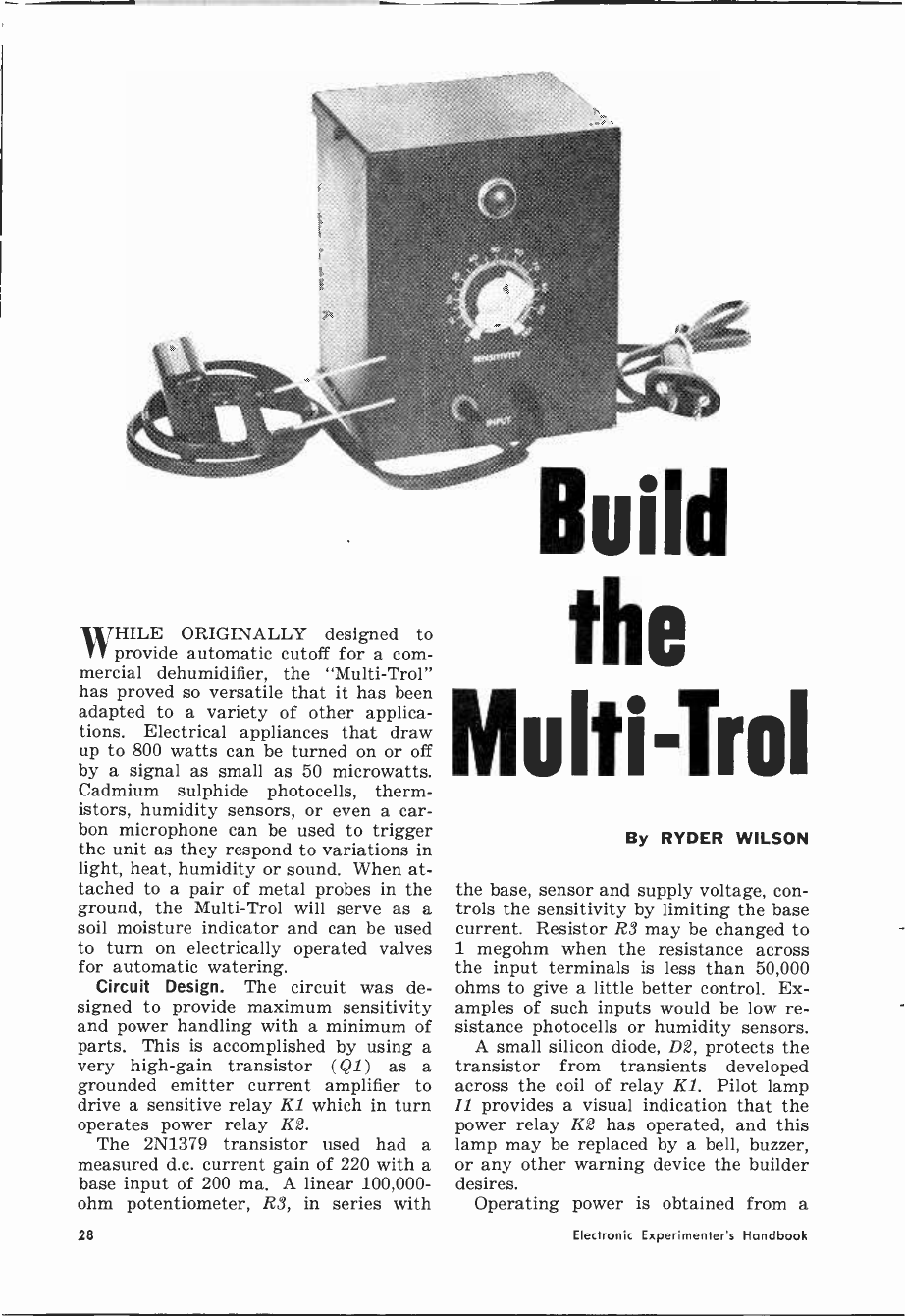
WHILE ORIGINALLY designed to
provide automatic cutoff for a com-
mercial dehumidifier, the "Multi-Trol"
has proved so versatile that it has been
adapted to a variety of other applica-
tions. Electrical appliances that draw
up to 800 watts can be turned on or off
by a signal as small as 50 microwatts.
Cadmium sulphide photocells, therm-
istors, humidity sensors, or even a car-
bon microphone can be used to trigger
the unit as they respond to variations in
light, heat, humidity or sound. When at-
tached to a pair of metal probes in the
ground, the Multi-Trol will serve as a
soil moisture indicator and can be used
to turn on electrically operated valves
for automatic watering.
Circuit Design. The circuit was de-
signed to provide maximum sensitivity
and power handling with a minimum of
parts. This is accomplished by using a
very high -gain transistor (Q1) as a
grounded emitter current amplifier to
drive a sensitive relay K1 which in turn
operates power relay K2.
The 2N1379 transistor used had a
measured d.c. current gain of 220 with a
base input of 200 ma. A linear 100,000 -
ohm potentiometer, R3, in series with
Build
the
Multi-Trol
By RYDER WILSON
the base, sensor and supply voltage, con-
trols the sensitivity by limiting the base
current. Resistor R3 may be changed to
1 megohm when the resistance across
the input terminals is less than 50,000
ohms to give a little better control. Ex-
amples of such inputs would be low re-
sistance photocells or humidity sensors.
A small silicon diode, D2, protects the
transistor from transients developed
across the coil of relay Kl. Pilot lamp
IZ provides a visual indication that the
power relay K2 has operated, and this
lamp may be replaced by a bell, buzzer,
or any other warning device the builder
desires.
Operating power is obtained from a
28 Electronic Experimenter's Handbook
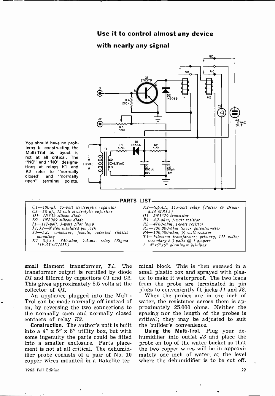
Use it to control almost any device
with nearly any signal
You should have no prob-
lems in constructing the
Multi-Trol as layout is
not at all critical. The
"NC" and "NO" designa-
tions at relays K1 and
K2 refer to "normally
closed" and "normally
open" terminal points.
PARTS
C1 -100-µf., 15 -volt electrolytic capacitor
C2-5094., 15 -volt electrolytic capacitor
D1 -1N536 silicon diode
D2 -1N2069 silicon diode
11 -117 -volt, 3 -watt pilot lamp
J1, J2-Nylon insulated pin jack
J3-A.c. connector, female, recessed chassis
mounting
Kl-S.p.s.t., 550 -ohm, 9.5 -ma. relay (Sigma
11F-550-G/SIL)
LIST
lit-S.p.d.t., 115 -volt relay (Potter & Brum-
field MRS A)
Q1 -2N1379 transistor
R1 -4.7 -ohm, 1 -watt resistor
R2 -4700 -ohm, 1 -watt resistor
R3 -100,000 -ohm linear potentiometer
R4 -100,000 -ohm, /2 -watt resistor
TI-Filament transformer; primary, 117 volts;
secondary 6.3 volts @ 1 ampere
1-4"x5"x6" aluminum Minibox
small filament transformer, Ti. The
transformer output is rectified by diode
DI and filtered by capacitors Cl and C2.
This gives approximately 8.5 volts at the
collector of Ql.
An appliance plugged into the Multi-
Trol can be made normally off instead of
on, by reversing the two connections to
the normally open and normally closed
contacts of relay K2.
Construction. The author's unit is built
into a 4" x 5" x 6" utility box, but with
some ingenuity the parts could be fitted
into a smaller enclosure. Parts place-
ment is not at all critical. The dehumid-
ifier probe consists of a pair of No. 10
copper wires mounted in a Bakelite ter -
minal block. This is then encased in a
small plastic box and sprayed with plas-
tic to make it waterproof. The two leads
from the probe are terminated in pin
plugs to conveniently fit jacks JI and J2.
When the probes are in one inch of
water, the resistance across them is ap-
proximately 25,000 ohms. Neither the
spacing nor the length of the probes is
critical; they may be adjusted to suit
the builder's convenience.
Using the Multi-Trol. Plug your de-
humidifier into outlet J3 and place the
probe on top of the water bucket so that
the two copper wires will be in approxi-
mately one inch of water, at the level
where the dehumidifier is to be cut off.
1965 Fall Edition 29
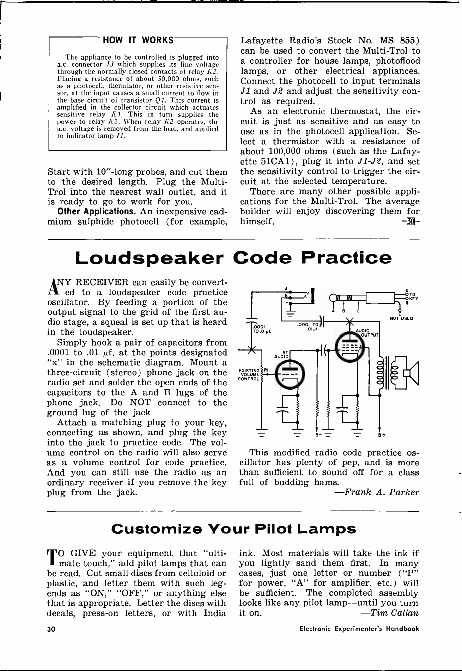
HOW IT WORKS
The appliance to be controlled is plugged into
a.c. connector J3 which supplies its line voltage
through the normally closed contacts of relay K2.
Placing a resistance of about 50,000 ohms, such
as a photocell, thermistor, or other resistive sen-
sor, at the input causes a small current to flow in
the base circuit of transistor Ql. This current is
amplified in the collector circuit which actuates
sensitive relay Kl. This in turn supplies the
power to relay K2. When relay K2 operates, the
a.c. voltage is removed from the load, and applied
to indicator lamp Il.
Start with 10" -long probes, and cut them
to the desired length. Plug the Multi-
Trol into the nearest wall outlet, and it
is ready to go to work for you.
Other Applications. An inexpensive cad-
mium sulphide photocell (for example,
Lafayette Radio's Stock No. MS 855)
can be used to convert the Multi-Trol to
a controller for house lamps, photoflood
lamps, or other electrical appliances.
Connect the photocell to input terminals
J1 and J2 and adjust the sensitivity con-
trol as required.
As an electronic thermostat, the cir-
cuit is just as sensitive and as easy to
use as in the photocell application. Se-
lect a thermistor with a resistance of
about 100,000 ohms (such as the Lafay-
ette 51CA1) , plug it into J1 -J2, and set
the sensitivity control to trigger the cir-
cuit at the selected temperature.
There are many other possible appli-
cations for the Multi-Trol. The average
builder will enjoy discovering them for
himself. -®-
Loudspeaker Code Practice
ANY RECEIVER can easily be convert-
ed to a loudspeaker code practice
oscillator. By feeding a portion of the
output signal to the grid of the first au-
dio stage, a squeal is set up that is heard
in the loudspeaker.
Simply hook a pair of capacitors from
.0001 to .01 µf. at the points designated
"x" in the schematic diagram. Mount a
three -circuit (stereo) phone jack on the
radio set and solder the open ends of the
capacitors to the A and B lugs of the
phone jack. Do NOT connect to the
ground lug of the jack.
Attach a matching plug to your key,
connecting as shown, and plug the key
into the jack to practice code. The vol-
ume control on the radio will also serve
as a volume control for code practice.
And you can still use the radio as an
ordinary receiver if you remove the key
plug from the jack.
rVÓ
VOLUME
CONTROL
This modified radio code practice os-
cillator has plenty of pep, and is more
than sufficient to sound off for a class
full of budding hams. -Frank A. Parker
Customize Your Pilot Lamps
TO GIVE your equipment that "ulti-
mate touch," add pilot lamps that can
be read. Cut small discs from celluloid or
plastic, and letter them with such leg-
ends as "ON," "OFF," or anything else
that is appropriate. Letter the discs with
decals, press -on letters, or with India
ink. Most materials will take the ink if
you lightly sand them first. In many
cases, just one letter or number ("P"
for power, "A" for amplifier, etc.) will
be sufficient. The completed assembly
looks like any pilot lamp-until you turn
it on. -Tim Callan
30 Electronic Experimenter's Handbook
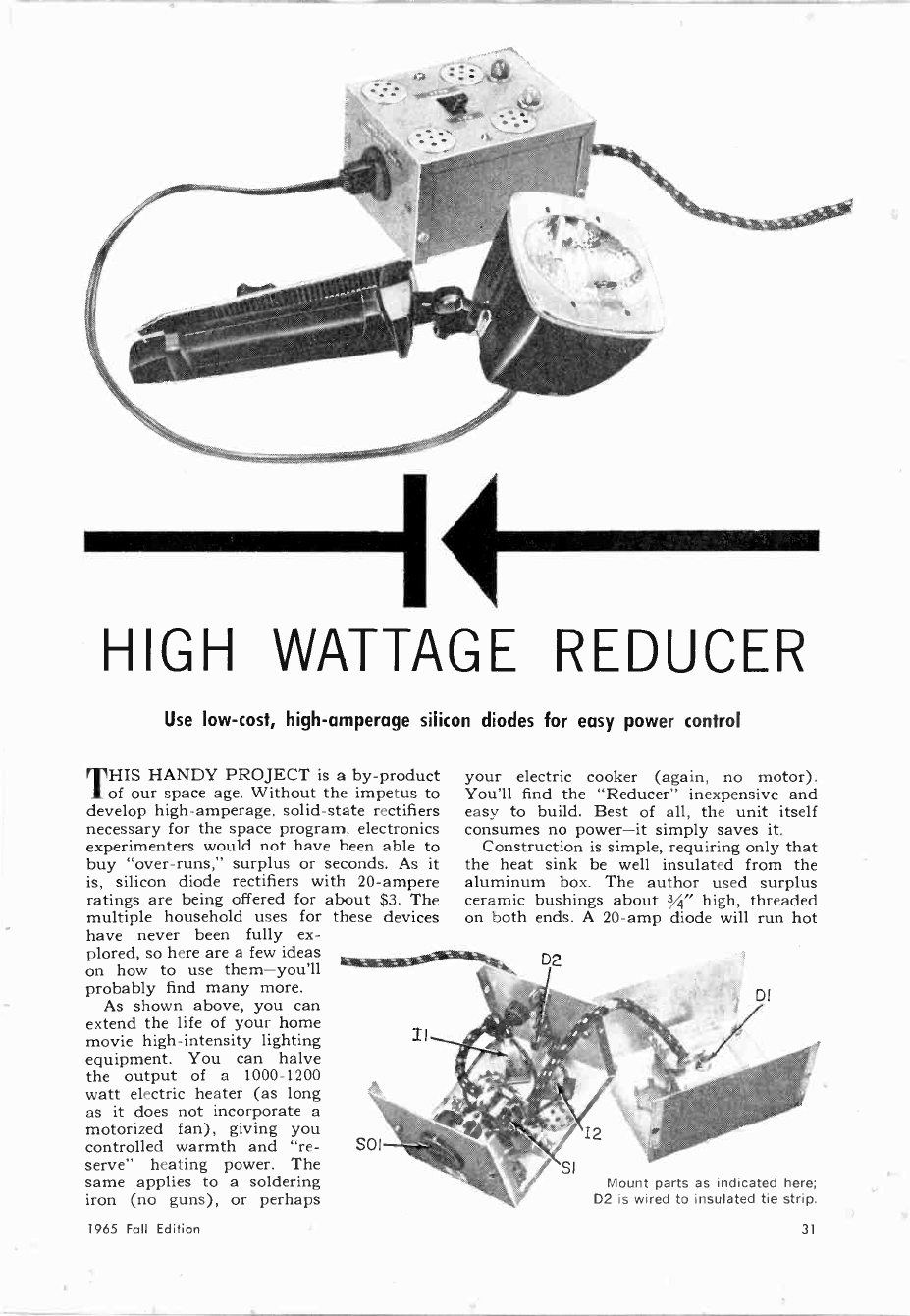
1111111111111111111111111111
HIGH WATTAGE REDUCER
Use low-cost, high -amperage silicon diodes for easy power control
THIS HANDY PROJECT is a by-product
of our space age. Without the impetus to
develop high -amperage, solid-state rectifiers
necessary for the space program, electronics
experimenters would not have been able to
buy "over -runs," surplus or seconds. As it
is, silicon diode rectifiers with 20 -ampere
ratings are being offered for about $3. The
multiple household uses for these devices
have never been fully ex-
plored, so here are a few ideas
on how to use them-you'll
probably find many more.
As shown above, you can
extend the life of your home
movie high -intensity lighting
equipment. You can halve
the output of a 1000-1200
watt electric heater (as long
as it does not incorporate a
motorized fan), giving you
controlled warmth and "re- SOI
serve" heating power. The
same applies to a soldering
iron (no guns), or perhaps
1965 Fall Edition
your electric cooker (again, no motor).
You'll find the "Reducer" inexpensive and
easy to build. Best of all, the unit itself
consumes no power-it simply saves it.
Construction is simple, requiring only that
the heat sink be well insulated from the
aluminum box. The author used surplus
ceramic bushings about 3/4" high, threaded
on both ends. A 20 -amp diode will run hot
Mount parts as indicated here;
D2 is wired to insulated tie strip.
31

CI
.01y1.
I000VDC
II I2
"LOW" "HIGH"
Diagram shows simplicity of High Wattage Reducer.
PARTS LIST
C1--0.01-µ1., 1000 -volt ceramic disc capacitor
D1 -20 -ampere, 400 PIV silicon diode, stud
mounting
D2 -50 -ma., 2110 PIV silicon diode
11-Neon lamp assembly with built-in resistor,
amber color lens
12 --Neon lamp assembly with built-in resistor,
red color lens
Sl-S.p.s.t. switch, heavy-duty (15 -ampere mini-
mum rating)
S01--Chassis-mount a.c. socket
1-3" x 4" x 5" Minibox
1-Heat sink (Carl Cordover HSR-4 or equiva-
lent)
Misc.-Four threaded ceramic bushings to hold
heat sink, heavy-duty a.c. cord, terminal strip,
wire, solder, hardware
in addition to mounting Dl on heat sink,
ventilation holes should be provided to
dissipate heat generated in operation.
in series with appliances that have a rated
power drain of 1400-1500 watts, so the heat
sink is a must-it also makes a convenient
mount for the diode.
Holes for ventilation should be punched
in the aluminum box as in the photos. Two
neon lamps (optional) were incorporated in
the circuit to show operation. When switch
Si is open, D1 and D2 are back-to-back,
and 12 will go out. When switch SI is closed,
both neons go on and the silicon diode is
switched out of the "Reducer" circuit.
-Frank A. Parker
CB Dummy Load
CITIZENS BAND regulations prohibit the
practice of tuning up your transmitter
while putting a "dead" carrier on the air.
The commonly -used light bulb dummy an-
tenna prevents this, but it changes resistance
with brightness.
The dummy load shown at right is easily
made by soldering a bus bar to the center
post of a coax connector and two resistors
between the bus bar and the shell. If your
CB transmitter uses 52 -ohm coax line, make
the load of two 100 -ohm, 2- or 3 -watt re-
sistors. For 72 -ohm line, use two 150 -ohm,
2- or 3 -watt resistors. Be sure that the
resistors are carbon and not wire -wound.
Wire -wound units will introduce inductance
and upset readings.
Tune up with the dummy load using the
internal metering in your CB unit or the
r.f. probe of a VTVM clipped across the
load. A reading of 13-13'/ volts corresponds
to 3.5 watts output with 52 -ohm line.
-Alex F. Burr, 16W2941
32 Electronic Experimenter's Handbook
.ALL/ED
ELECTRONICS
FOR EVERYONE 1866
OUP ALFA YEAR
CATALOG 250'
nMlx 1.4F 98Y
COMPLETE knight'ki CATALOG
PACES 0 96
ALLIED RADIO
100. N. WESTERN AVE. CHICAGO. ILL. 00880. HA I-60001AF0. Cod* 712)
Satisfaction Guaranteed or roue Money Beck
HEW in the wonderful world of
knight -kits®
See the latest solid-state stereo hi-fi,
advanced CB 2 -way radios-complete
selection of electronic kits for every need,
including Hobby, Short -Wave, Amateur,
Automotive, Intercom, Test Instrument
-wonderfully easy to build.
EASY TERMS:
Use the Allied Credit
Fund Plan - over 24
Months to pay.
satisfaction guaranteed
or your money hack
ALLIED RADIO
world's largest electronic supply house
CIRCLE NO,. 1 ON
send today for your
/.ILL/ED
1966 CATALOG
508 VALUE -PACKED PAGES
world's biggest selection
SAVE MOST ON:
Stereo Hi-fi
Tape Recording
CB 2 -Way Radio
FM -AM & AM Radios
Portable TV Phonographs
Short Wave & Ham Gear
Automotive Electronics
Test Instruments
TV Tubes & Antennas
Power Tools, Hardware
Parts, Tubes, Transistors
SEND COUPON TODAY:
ALLIED RADIO, Dept. 41-K
100 N. Western Ave., Chicago, Illinois 60680
Send FREE 1966 Allied Catalog
Name
vtA..0 rAiMT
Address
City State Zip
READER SERVICE CARD
1965 Fall Edition 35
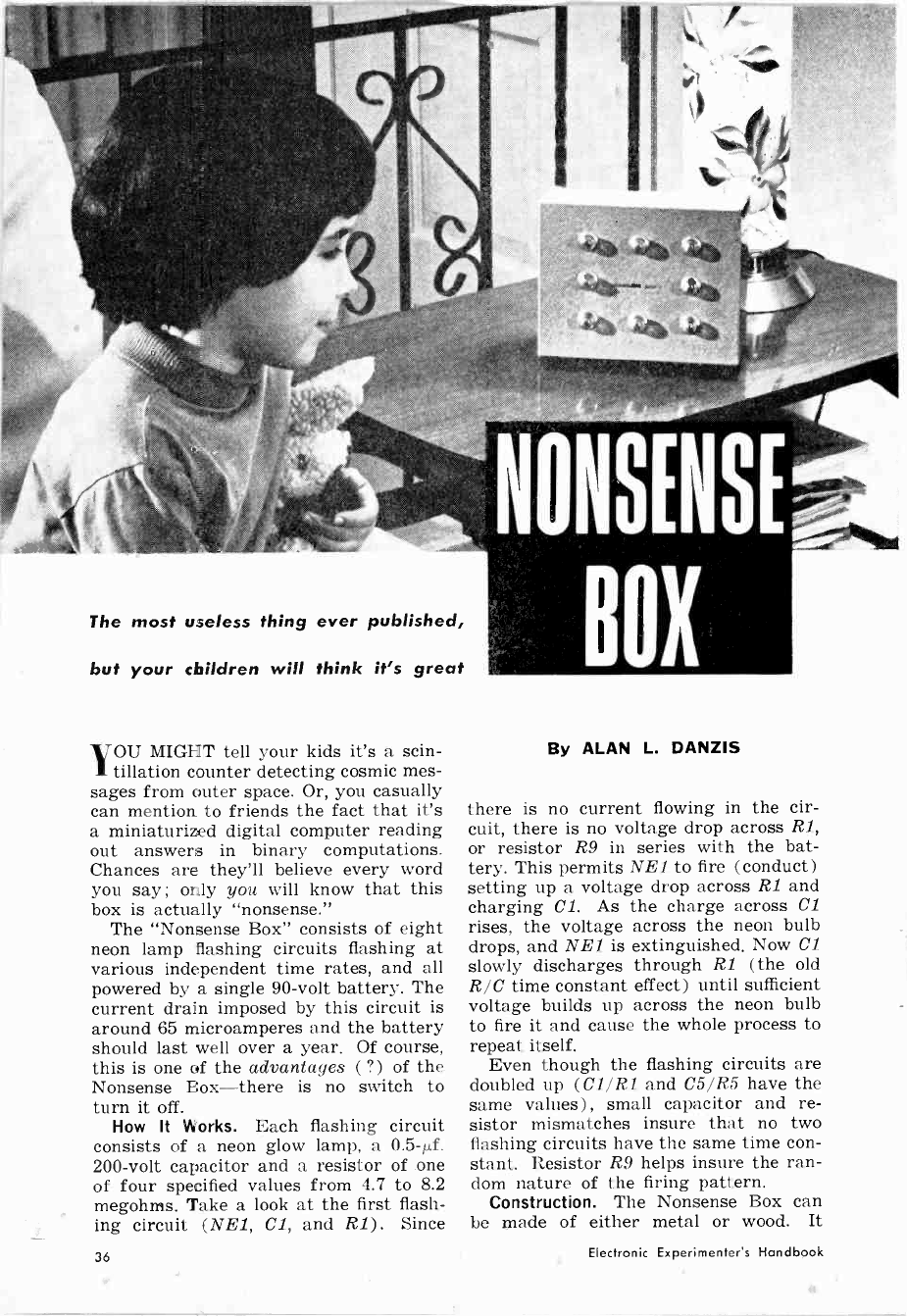
The most useless thing ever published,
but your children will think it's great
OU MIGHT tell your kids it's a scin-
1 tillation counter detecting cosmic mes-
sages from outer space. Or, you casually
can mention to friends the fact that it's
a miniaturized digital computer reading
out answers in binary computations.
Chances are they'll believe every word
you say ; only you will know that this
box is actually "nonsense."
The "Nonsense Box" consists of eight
neon lamp flashing circuits flashing at
various independent time rates, and all
powered by a single 90 -volt battery. The
current drain imposed by this circuit is
around 65 microamperes and the battery
should last well over a year. Of course,
this is one of the advantages (?) of the
Nonsense Box-there is no switch to
turn it off.
How It Works. Each flashing circuit
consists of a neon glow lamp, a 0.5-µf.
200 -volt capacitor and a resistor of one
of four specified values from 4.7 to 8.2
megohms. Take a look at the first flash-
ing circuit (NE1, Cl, and R1). Since
By ALAN L. DANZIS
there is no current flowing in the cir-
cuit, there is no voltage drop across Rl,
or resistor R9 in series with the bat-
tery. This permits NE1 to fire (conduct)
setting up a voltage drop across Rl and
charging Cl. As the charge across Cl
rises, the voltage across the neon bulb
drops, and NE1 is extinguished. Now Cl
slowly discharges through R1 (the old
R/C time constant effect) until sufficient
voltage builds up across the neon bulb
to fire it and cause the whole process to
repeat itself.
Even though the flashing circuits are
doubled up (Cl/R1 and C5/R5 have the
same values) , small capacitor and re-
sistor mismatches insure that no two
flashing circuits have the same time con-
stant. Resistor R9 helps insure the ran-
dom nature of the firing pattern.
Construction. The Nonsense Box can
be made of either metal or wood. It
36 Electronic Experimenter's Handbook
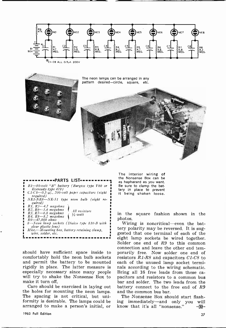
C8 ALL 0 50f. 200V
PARTS LIST -
NEB
R8
8.2
MEG.
The neon lamps can be arranged in any
pattern desired-circle, square, etc.
B1 -90 -volt "B" battery (Burgess type V60 or
Eveready type 479)
C1 -C8 -0.5-µf., 200 -volt paper capacitors (eight
required)
.ß"E1-NE8-NE-51 type neon bulb (eight re-
quired)
R1, R5-4.7 megohms
R2, R6-5.6 megohms All resistors
R3, R7-6.8 megohms ¡ /-watt
R4, R8-8.2 megohms )1
R9-47,000 ohms
8-Neon lamp sockets (Dialco type 810-B with
clear plastic lens)
Misc.-Mounting box, battery retaining clamp,
wire, solder, etc.
should have sufficient space inside to
comfortably hold the neon bulb sockets
and permit the battery to be mounted
rigidly in place. The latter measure is
especially necessary since many people
will try to shake the Nonsense Box to
make it turn off.
Care should be exercised in laying out
the holes for mounting the neon lamps.
The spacing is not critical, but uni-
formity is desirable. The lamps could be
arranged to make a person's initial, or
The interior wiring of
the Nonsense Box can be
as haphazard as you want.
Be sure to clamp the bat-
tery in place to prevent
it being shaken loose.
in the square fashion shown in the
photos.
Wiring is noncritical-even the bat-
tery polarity may be reversed. It is sug-
gested that one terminal of each of the
eight lamp sockets be wired together.
Solder one end of R9 to this common
connection and leave the other end tem-
porarily free. Now solder one end of
resistors R1 -R8 and capacitors C1 -C8 to
each of the unused lamp socket termi-
nals according to the wiring schematic.
Bring all 16 free leads from these ca-
pacitors and resistors to a common bus
bar and solder. The two leads from the
battery connect to the free end of R9
and the common bus bar.
The Nonsense Box should start flash-
ing immediately-and only you will
know that it's all "nonsense."
1965 Fall Edition 37
Zip through Scott's new solid state FM stereo tuner
kit in one afternoon
Four to six hours! That's all you need to zip
through Scott's new LT -112 FM stereo tuner kit.
Start after lunch-enjoy superb stereo at dinner.
Scott solid state circuitry is the key to the
LT -112's superior performance. Costly silicon
transistors give performance unapproached by
any other kit on the market. The LT -112 is kit -
brother to Scott's best-selling 312 solid state
stereo tuner, of which Audio said, "... one of
the finest tuners anywhere."
Your LT -112 arrives with all critical circuitry
pre -wired, pre -tested, pre -aligned, and mounted
on heavy-duty printed circuit boards. Scott's ex-
--
elusive life-size, full -color construction book
details every step ... makes perfect wiring al-
most automatic.
You'd never believe a kit so easy to build
could be so packed with features. Built into the
LT -112 is a new Scott invention ... the Tri -
modulation meter, used for a Signal Strength
Indicator, Zero Center Indicator, and Align-
ment Meter.
See your Scott dealer today, and pick up an
LT -112 tuner kit ... $179.95 plus one enjoy-
able afternoon will net you a lifetime of listen-
ing pleasure.
MW
SCOTT "
For Complete information on Scott's kits & componerrts write: Dept. 521-10. -I. H. Scott, Inc., 111 Powdermill Road, Maynard, Mass.
Export: Scott International, Maynard, Mass. Cable HIFI. Prices slightly higher west of Rockies.
Prices and specifications subject to change without notice.
CIRCLE NO. 27 ON READER SERVICE CARD
38 Electronic Experimenter's Handbook
CHAPTER
2
AUDIO
STEREO
HI-FI
PROJECTS
If you are one of those electronics experiment-
ers who think that audio/hi-fi/stereo construction
is a thing of the past, you'll be surprised at the
content of this chapter. The kickoff project is a
novel speaker enclosure embracing an unusual
principle called "bi -coupling." Constructed by
well-known enclosure designer, David Weems, the
"Bi -Coupler" (page 40) is a modified labyrinth
using 8" full -range speakers. Builders of the
"Bi -Coupler" will be pleasantly surprised by the
smooth sound and stereo effectiveness. Next pro-
ject in line is the "Stereo S'Lector" (page .44)
-a convenience for those who like automation in
their FM listening.
The "Vibrato Simulator" and "Volume Ex-
pander" are also projects that can be classified as
"unusual." The "Simulator" (page 47) will ap-
peal to budding musicians who have a guitar, and
the "Expander" (page 51) is a device for the
serious audiophile. The latter can be used mono-
phonically as well as in the featured stereo ver-
sion. Shutting your hi-fi off with the record player
is not new, but the ideas presented on page 58
sure are. You'll admire the versatility of the
"Hi-Fi Interlock" and the safety features it in-
corporates. Last but not least is the "Shotgun
Sound Snooper" (page 61). This highly direc-
tional microphone has created considerable in-
terest and the designers have completely revised
the story to include answers to many questions
raised by readers of POPULAR ELECTRONICS.
40
FOR BETTER SOUND BUILD THE BI -COUPLER David B. Weems
44
THE STEREO S'LECTOR Alton B. Otis, Jr.
47
VIBRATO SIMULATOR Fred Ippolito, Jr.
51
HI-FI VOLUME COMPRESSOR EXPANDER Roger H. Russell
58
HI-FI INTERLOCK Charles L. Ulrick
61
SHOTGUN SOUND SNOOPER
James R. Hollinger & John E. Mulligan, K3TIB
1965 Pall Edition 39
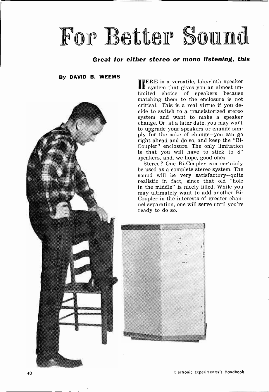
For Better und
Great for either stereo or mono listening, this
By DAVID B. WEEMS HERE is a versatile, labyrinth speaker
11 system that gives you an almost un-
limited choice of speakers because
matching them to the enclosure is not
critical. This is a real virtue if you de-
cide to switch to a transistorized stereo
system and want to make a speaker
change. Or, at a later date, you may want
to upgrade your speakers or change sim-
ply for the sake of change-you can go
right ahead and do so, and keep the "Bi -
Coupler" enclosure. The only limitation
is that you will have to stick to 8"
speakers, and, we hope, good ones.
Stereo? One Bi -Coupler can certainly
be used as a complete stereo system. The
sound will be very satisfactory-quite
realistic in fact, since that old "hole
in the middle" is nicely filled. While you
may ultimately want to add another Bi -
Coupler in the interests of greater chan-
nel separation, one will serve until you're
ready to do so.
40 Electronic Experimenter's Handbook
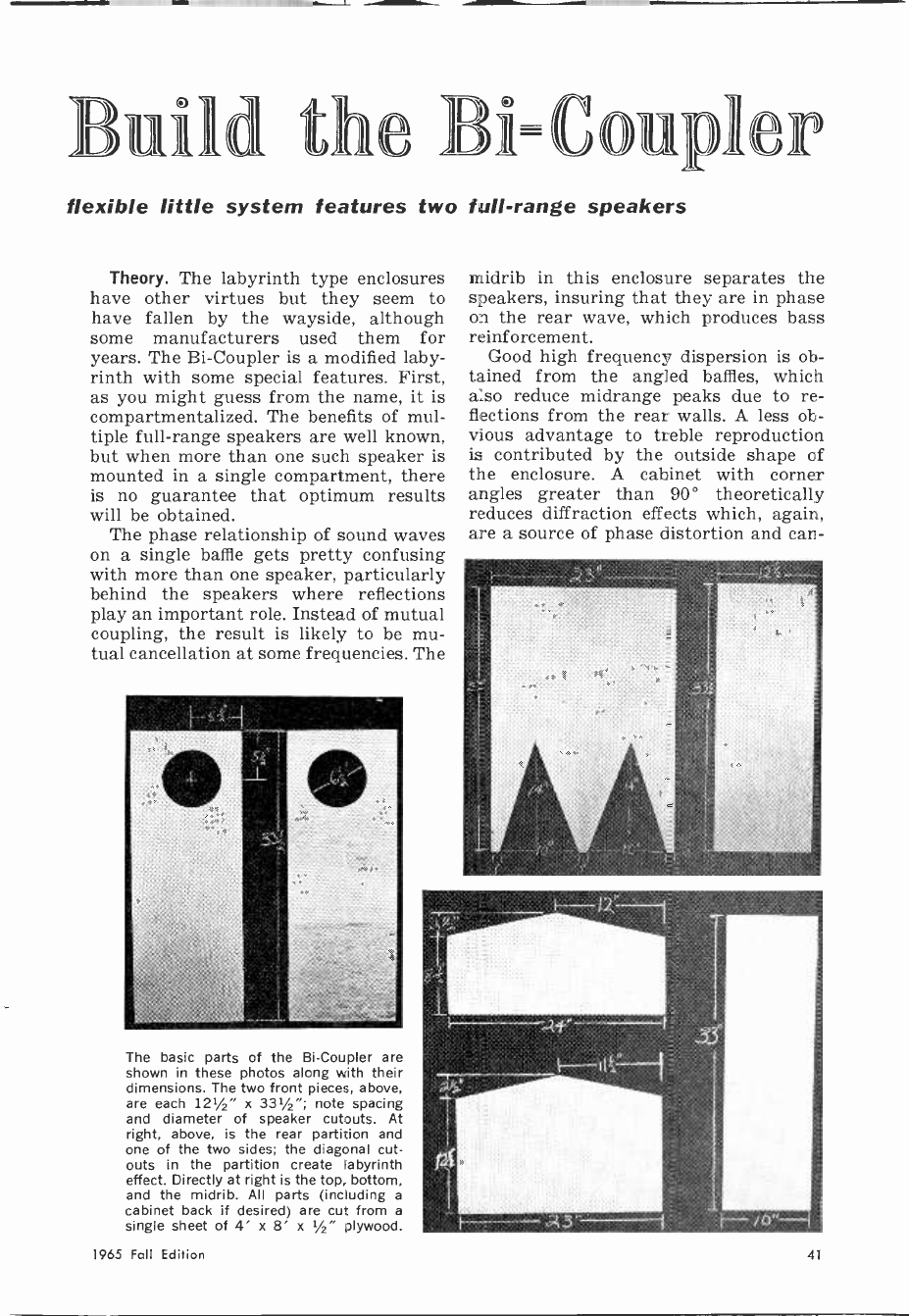
Build the Bi=&nipler
flexible little system features two full -range speakers
Theory. The labyrinth type enclosures
have other virtues but they seem to
have fallen by the wayside, although
some manufacturers used them for
years. The Bi -Coupler is a modified laby-
rinth with some special features. First,
as you might guess from the name, it is
compartmentalized. The benefits of mul-
tiple full -range speakers are well known,
but when more than one such speaker is
mounted in a single compartment, there
is no guarantee that optimum results
will be obtained.
The phase relationship of sound waves
on a single baffle gets pretty confusing
with more than one speaker, particularly
behind the speakers where reflections
play an important role. Instead of mutual
coupling, the result is likely to be mu-
tual cancellation at some frequencies. The
The basic parts of the Bi -Coupler are
shown in these photos along with their
dimensions. The two front pieces, above,
are each 121/2" x 331/2"; note spacing
and diameter of speaker cutouts. At
right, above, is the rear partition and
one of the two sides; the diagonal cut-
outs in the partition create labyrinth
effect. Directly at right is the top, bottom,
and the midrib. All parts (including a
cabinet back if desired) are cut from a
single sheet of 4' x 8' x 1/2" plywood.
midrib in this enclosure separates the
speakers, insuring that they are in phase
on the rear wave, which produces bass
reinforcement.
Good high frequency dispersion is ob-
tained from the angled baffles, which
also reduce midrange peaks due to re-
flections from the rear walls. A less ob-
vious advantage to treble reproduction
is contributed by the outside shape of
the enclosure. A cabinet with corner
angles greater than 90° theoretically
reduces diffraction effects which, again,
are a source of phase distortion and can -
1965 Fall Edition 41
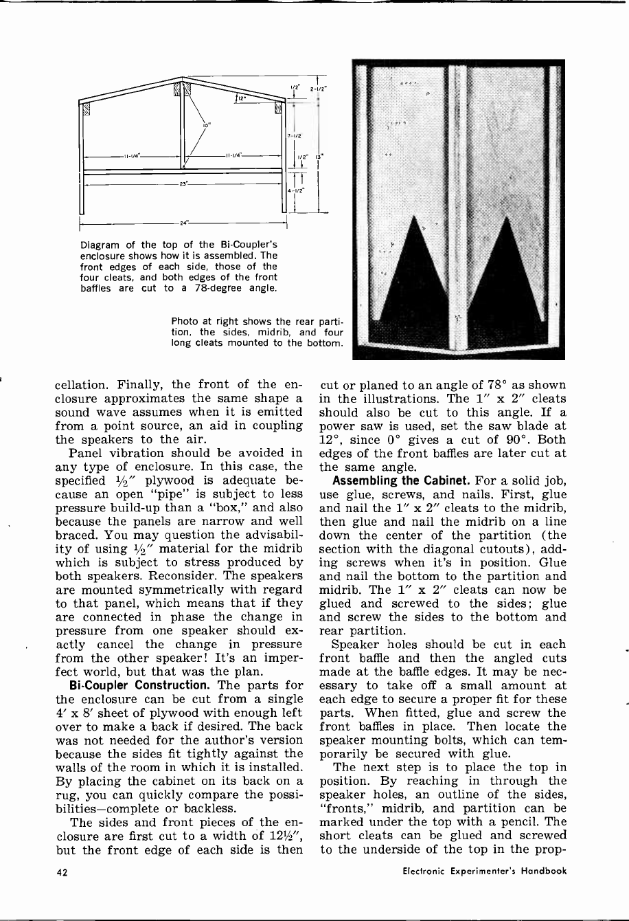
Diagram of the top of the Bi -Coupler's
enclosure shows how it is assembled. The
front edges of each side, those of the
four cleats, and both edges of the front
baffles are cut to a 78 -degree angle.
Photo at right shows the rear parti-
tion, the sides, midrib, and four
long cleats mounted to the bottom.
cellation. Finally, the front of the en-
closure approximates the same shape a
sound wave assumes when it is emitted
from a point source, an aid in coupling
the speakers to the air.
Panel vibration should be avoided in
any type of enclosure. In this case, the
specified 1/2" plywood is adequate be-
cause an open "pipe" is subject to less
pressure build-up than a "box," and also
because the panels are narrow and well
braced. You may question the advisabil-
ity of using 1/2" material for the midrib
which is subject to stress produced by
both speakers. Reconsider. The speakers
are mounted symmetrically with regard
to that panel, which means that if they
are connected in phase the change in
pressure from one speaker should ex-
actly cancel the change in pressure
from the other speaker! It's an imper-
fect world, but that was the plan.
Bi -Coupler Construction. The parts for
the enclosure can be cut from a single
4' x 8' sheet of plywood with enough left
over to make a back if desired. The back
was not needed for the author's version
because the sides fit tightly against the
walls of the room in which it is installed.
By placing the cabinet on its back on a
rug, you can quickly compare the possi-
bilities-complete or backless.
The sides and front pieces of the en-
closure are first cut to a width of 121A",
but the front edge of each side is then
cut or planed to an angle of 78° as shown
in the illustrations. The 1" x 2" cleats
should also be cut to this angle. If a
power saw is used, set the saw blade at
12°, since 0° gives a cut of 90°. Both
edges of the front baffles are later cut at
the same angle.
Assembling the Cabinet. For a solid job,
use glue, screws, and nails. First, glue
and nail the 1" x 2" cleats to the midrib,
then glue and nail the midrib on a line
down the center of the partition (the
section with the diagonal cutouts) , add-
ing screws when it's in position. Glue
and nail the bottom to the partition and
midrib. The 1" x 2" cleats can now be
glued and screwed to the sides; glue
and screw the sides to the bottom and
rear partition.
Speaker holes should be cut in each
front baffle and then the angled cuts
made at the baffle edges. It may be nec-
essary to take off a small amount at
each edge to secure a proper fit for these
parts. When fitted, glue and screw the
front baffles in place. Then locate the
speaker mounting bolts, which can tem-
porarily be secured with glue.
The next step is to place the top in
position. By reaching in through the
speaker holes, an outline of the sides,
"fronts," midrib, and partition can be
marked under the top with a pencil. The
short cleats can be glued and screwed
to the underside of the top in the prop -
42 Electronic Experimenter's Handbook

Nails, glue, and screws are used to
tightly bond the parts of the enclo-
sure together, and eliminate vibration.
BILL OF MATERIALS
Cut from one 4' x 8' x %" plywood sheet:
4-123/2" x 33%" pieces for sides and fronts
1-10" x 33" piece for midrib
1-23" x 33" piece for rear partition
1-11" x 24" piece (less cut-offs) for top
1-15" x 23" piece (less cut-offs) for bottom
Cut from 1" x 2" lumber (actual
material size approx. g" x 1w):
4-33" pieces for front and side cleats
2-10%" pieces for top cleats
2-9" pieces for top cleats
2-4%" pieces for top cleats
1-21" piece for foot (optional)
2-10,A" pieces for foot (optional)
busc. Four dozen #6 x 1%" screws, 6-d box
nails, glue, eight 3/16" x 1%" bolts for
speakers, grille cloth
er position to receive screws from the
outside of the cabinet.
It is a convenience to have an outside
connection for each speaker post. In the
prototype, this was done by drilling
holes in the rear partition and running
wires from the speaker terminals to
bolts on the back. Thus, the speakers can
be connected in series, parallel, or to
separate circuits as desired without tear-
ing into the cabinet. When the speakers
are mounted, a test should be run to de-
termine how much padding is necessary.
(Continued on page 147)
T 4-V2" 4-I/2
10 I/2" 10 1/2-^1
B -V2 "
Diagram above shows placement of top
cleats; these are positioned 1" from edges.
Last step is to
add padding in
cabinet top, and
to sides and rear
of speakers. How
much is mostly a
matter of taste.
Terminals permit the speakers to be con-
nected in series, parallel, or separately.
1965 Fall Edition 43
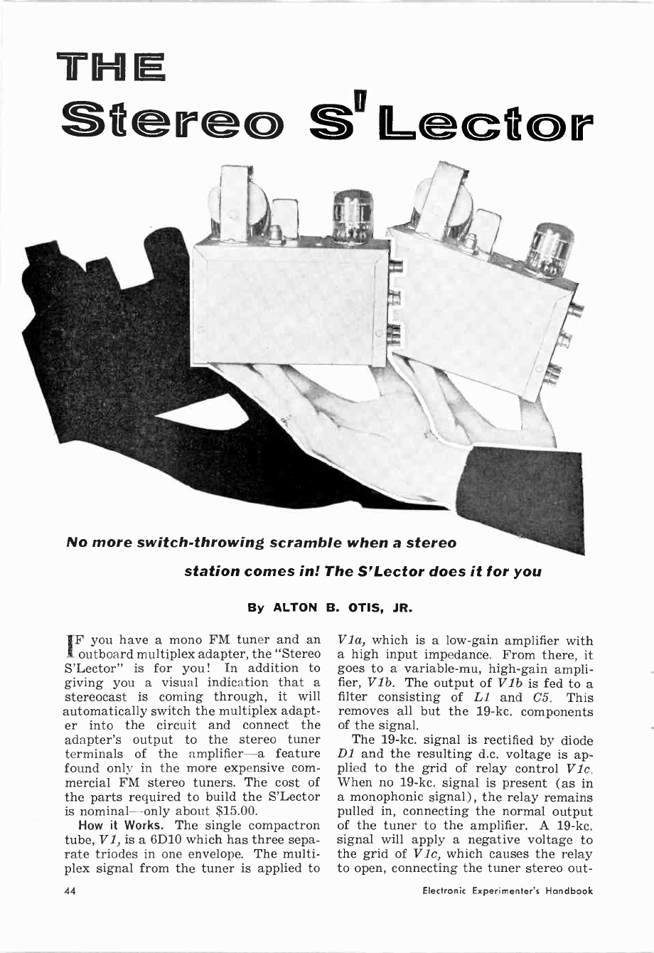
THE
St re s''
No more switch -throwing scramble when a stereo
c
station comes in! The S'Lector does it for you
By ALTON B. OTIS, JR.
IF you have a mono FM tuner and an
outboard multiplex adapter, the "Stereo
S'Lector" is for you! In addition to
giving you a visual indication that a
stereocast is coming through, it will
automatically switch the multiplex adapt-
er into the circuit and connect the
adapter's output to the stereo tuner
terminals of the amplifier-a feature
found only in the more expensive com-
mercial FM stereo tuners. The cost of
the parts required to build the S'Lector
is nominal-only about $15.00.
How it Works. The single compactron
tube, V1, is a 6D10 which has three sepa-
rate triodes in one envelope. The multi-
plex signal from the tuner is applied to
Via, which is a low -gain amplifier with
a high input impedance. From there, it
goes to a variable -mu, high -gain ampli-
fier, V1b. The output of V1b is fed to a
filter consisting of L1 and C5. This
removes all but the 19-kc. components
of the signal.
The 19-kc. signal is rectified by diode
D1 and the resulting d.c. voltage is ap-
plied to the grid of relay control Vic.
When no 19-kc. signal is present (as in
a monophonic signal) , the relay remains
pulled in, connecting the normal output
of the tuner to the amplifier. A 19-kc.
signal will apply a negative voltage to
the grid of Vie, which causes the relay
to open, connecting the tuner stereo out -
44 Electronic Experimenter's Handbook
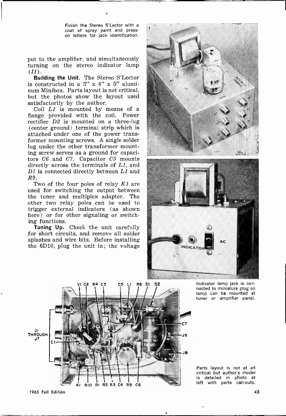
Finish the Stereo S'Lector with a
coat of spray paint and press -
on letters for jack identification.
put to the amplifier, and simultaneously
turning on the stereo indicator lamp
(I1). Building the Unit. The Stereo S'Lector
is constructed in a 3" x 4" x 5" alumi-
num Minibox. Parts layout is not critical,
but the photos show the layout used
satisfactorily by the author.
Coil Li is mounted by means of a
flange provided with the coil. Power
rectifier D2 is mounted on a three -lug
(center ground) terminal strip which is
attached under one of the power trans-
former mounting screws. A single solder
lug under the other transformer mount-
ing screw serves as a ground for capaci-
tors C6 and C7. Capacitor C5 mounts
directly across the terminals of Li, and
D1 is connected directly between LZ and
R9. Two of the four poles of relay Kl are
used for switching the output between
the tuner and multiplex adapter. The
other two relay poles can be used to
trigger external indicators (as shown
here) or for other signaling or switch-
ing functions.
Tuning Up. Check the unit carefully
for short circuits, and remove all solder
splashes and wire bits. Before installing
the 6D10, plug the unit in; the voltage
VI C2 R4 C3
JI
THROUGH
J7
CS LI R8 DI D2
I I I
KI RIO RI R2 R3 C4 R9 C6
Indicator lamp jack is con-
nected to miniature plug so
lamp can be mounted at
tuner or amplifier panel.
Parts layout is not at all
critical but author's model
is detailed in photo at
left with parts calf -outs.
1965 Fall Edition 45

.002,1
J3
J4
J5
J6
J7
IA I/3 -6D18012
C2 ,
0023f.
II
NE -2H
R7
33K
C6
lyf.
DI INGO
7
12
R8
33K
r a a LI
A single compactron tube does the work of three in the Stereo S'Lector circuit.
PARTS
Cl, C2 -0.002-µf., 200 -voll Mylar capacitor
C3, C4, C6 -0.1-µf., 100 -volt Mylar capacitor
C5 -0.01-µf. ceramic disc capacitor
C7 -40-µf., 150 -volt electrolytic capacitor
D1 -1N60 diode (or equivalent)
D2 -50 -ma., 400-PIV silicon rectifier
II-NE-2H neon lamp
11-17-Phono jack (single -hole type)
18 -117 -volt accessory outlet
19-Miniature phone jack
K1-4-p.d.t. relay, 5300 -ohm coil, 6.6 -ma. pull -
in (Lafayette 99-G-6094 or equivalent)
L1-19-kc. oscillator coil (J. W. Miller 1354)
PLI-Miniature phone plug
R1, R5-1.2-megohm, %-watt resistor
LIST
R2 -470 -ohm, 5/2 -watt resistor
R3 -4700 -ohm, %-watt resistor
R4 -22,000 -ohm, %-watt resistor
R6 -1000 -ohm, %-watt resistor
R7, R8 -33,000 -ohm, /2 -watt resistor
R9 -500,000 -ohm linear taper potentiometer
R10 -56,000 -ohm, V2 -watt resistor
Tl-Power transformer; primary, 117 volts;
secondaries, 125 volts, 15 ma., and 6.3 volts,
0.6 -amps. (Lafayette 33-G-3405, Stancor PS -
8415, or equivalent)
VI -6D10 compactron tube
1-3" x 4" x 5" aluminum Minibox
Mise -l2 -pin compactron socket, terminal strips,
wire, solder, line cord, etc.
across capacitor C7 should read about
200 volts. Install the tube and allow a
short warm-up period. Voltage across C7
should now read about 140-150 volts, d.c.
If it is substantially lower, pull the plug
and inspect the unit again for shorts.
Connect the Stereo S'Lector to the
tuner with jacks, as follows: J1 to mul-
tiplex output of tuner; J2 to input of
multiplex adapter; J3 to monophonic out-
put of tuner; J6 and J7 to the stereo
amplifier inputs ; J.4 and J5 to the out-
put of the multiplex adapter.
With the tuner set to a strong stereo
station, adjust the slug in 1,1 for maxi-
mum a.c. voltage across the coil. The
reading may fluctuate at this point, de-
pending on the program material. Start-
ing with the wiper of R9 at the ground
end, advance the wiper toward D1 until
the relay drops out, then about five or
ten degrees more. The unit is now ad-
justed and ready for use.
The model built by the author has per-
formed very reliably, never confusing
interchannel noise and a stereo broad-
cast. If you build the S'Lector, you'll
find it a valuable adjunct to your stereo
system, one that you will wonder how
you ever got along without.
46 Electronic Experimenter's Handbook

\\\\\\\\\\\\\ \\\\\e %i\%i%%%%%%%%%%\////%
iiiirrrrrrrrrrrrrrr(
rrr
lr
\\\\\\\\\\\\ ,vvvvvvvvvvvv
//r///////////r//rr/rrl,///,..:,I>ilìhllll///////////l///
\\\\\\\\\\\\\\\\\\ \1\\\1\\\\\\\\\\\\\\\\\
///////////////////////////
arirrrrrrrrrrrrrrrr1 ' \\11\\ti\\\\\11\\\
,riiiiiiiiiii
rrrrrrrrrrrrrll
r1 ,
i \``
////////////,,,,,, 1?rrrrrrrrrrrr
\\\\\\1\\1\\ "wvvvvvvvvvv
?I1?r111?1111rlrllll/l
/////rlrlr/Ilr/ll/ll//ll//ii/i' '
\\\\\\\\\\\\\\\\\\\\\ell » >> /llhl%/A/Al\/A/\%/\/\/\/\/\/\/\/\/\/\/\/\/\/\/
11rirrrrrrrrrrrrrrrrrrrr?1<<<< i,// /////
iiil
))
\,((
1rrrrrrrr
?Ì1111rvl1vrlv)Ìiíviívi
/ü///\/1//titiiiii
,iiiri/ /
1
eer1\
111r»/Iii
rrrrrrrrrrrrrrrr
:>...
(
%/77777/%%%%iiiiiii
\ vvvvv
//////l//////l////lr/r7/l"ll/%/llrl
``````ii`i`r`r`i`í\r\r`r`r`rrrrrrrrrrrrr
\\\\\\\\\\\\\\\\\\\\\\\\\\\\\{I
r,rrr,rr,rrrrlr
rrrrrrrrrrrr1
Il/l.
«<rrrrl `
i>,,,,,,.,, /
1 //iiii,,, `
\\ iiiia iiiiiiiiiiiiii/
%%%%%,/%%/%%%%/%l/%%//l%(/'%ll¡'(l'l'((((
\\\V\\\\\\\\\\\\\\1V , , -// //////// %/%%/'
wwww"rrvrrrr
VIBRATO
SIMULATOR
By FRED IPPOLITO, Jr.
Low-cost transistorized
circuit is inserted
between guitar and
amplifier. Player controls
simulator with
homemade foot switch
THIS article describes the construc-
tion of a simple, low-cost, transistor-
ized vibrato simulator which can provide
most musical instrument amplifiers with
a vibrato effect. When used in conjunc-
tion with a guitar and amplifier, it
produces a pleasant -sounding amplitude -
modulated signal, similar to the effect
of varying the volume control on the
guitar.
The vibrato simulator is battery -op-
erated and completely self-contained. No
external power source is required and
no circuit modifications to the ampli-
fier are necessary. Installation of the
simulator consists of plugging it into
the amplifier and plugging the instru-
ment into the simulator. The current
drain on the battery is so low that in
normal use the life of the battery should
approach its shelf life. Construction costs
are small, less than $10, even when all
the parts are purchased. But you will
probably have some of the parts avail-
able, reducing the cost even further.
Two controls are provided; one for ad-
justing the desired intensity and the
other for adjusting the vibrato speed.
A foot switch is also provided so that
the musician can switch the vibrato ef-
fect in or out while playing.
1965 Fall Edition 47
s

R2 R4 01 C3 R5 CI C4 RI R6 ûi=; BI PI
JI 42 R3 R8 R9 C2 R7
With the self-contained
battery, the author wired
the simulator so it would
always be off unless mo-
mentary d.p.s.t. switch Si
was closed. The guitarist
slips this switch on
its doorstop mount under
his right or left foot.
1 '
si DOOR /STOP 4-COND. CABLE
Underside view of the sim-
ulator shows compact, sturdy
construction used by the
author. All connections are
made to the potentiometer
terminals or to one of the
66 -terminal tie strips mount-
ed at either end of the box.
About the Circuit. Transistor Q1 is used
in a sub -audio phase -shift oscillator cir-
cuit to produce the vibrato speed or
frequency. Transistor Q2 is used in a
voltage -divider network to modulate the
incoming signal. The effectiveness and
efficiency of the vibrato oscillator is re-
markable. Using a 15 -volt battery, the
sine -wave output signal at the collector
is 8 volts peak -to -peak, with a current
drain on the battery of only 300 µa.
Common, low-cost transistors can be
used. In testing the circuit, the writer
tried at least ten 2N1265/5 transistors,
with each providing satisfactory results.
Although a 15 -volt battery is used to
provide sufficient output for this ap-
plication, the circuit will oscillate with
a voltage of 9 to 12 volts.
The oscillator operates at a frequency
of 6 cycles, since this is the most com-
monly used frequency in commercially
available units and in electronic organs.
Potentiometer R2 provides for an oscil-
lator range of approximately 4 to 14
cycles. Resistor R4 prevents oscillator
cutoff at the maximum clockwise rota-
tion of R2, which is the fastest speed.
Capacitor C4 couples the oscillator
signal to potentiometer R6, which is
used to adjust the vibrato intensity.
Switch S1 is a momentary d.p.s.t. (nor-
mally open) type, used to make and
break both the oscillator and modulator
circuits. It is mounted in a molded plas-
tic door stop and is used as a foot
switch so that the vibrato effect can be
switched in and out.
48 Electronic Experimenter's Handbook
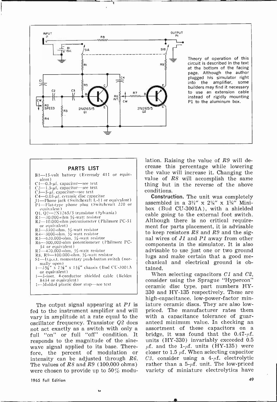
INPUT OUTPUT
JI RB PI
l T 15V. SIA SIB
Theory of operation of this
circuit is described in the text
at the bottom of the facing
page. Although the author
plugged his simulator right
into the amplifier, some
builders may find it necessary
to use an extension cable
instead of rigidly mounting
Pl to the aluminum box.
PARTS LIST
B1 -15 -volt battery (Eveready 411 or equiv-
alent)
C1-0.5-4. capacitor-see text
C2-1.5-4. capacitor-see text
C3-5-4. capacitor-see text
C4-0.05-4. ceramic disc capacitor
J1-Phone jack (Switchcraft 1.-11 or equivalent)
P1-Flat-type phone plug (Switchcraft 220 or
equivalent)
QI, Q2-21\1265/5 transistor (Sylvania)
RI -30,000 -ohm 112 -watt resistor
R2 -10,000 -ohm potentiometer (Philmore PC -51
or equivalent)
R3 -3300 -ohm, .A -watt resistor
R4 -3000 -ohm, )/2 -watt resistor
R5 -620,000 -ohm, TA -watt resistor
R6 -500,000 -ohm potentiometer (Philmore PC -
54 or equivalent)
R7 -470,000 -ohm. %-watt resistor
RS, R9 -100,000 -ohm, 'A -watt resistor
S1-D.p.s.t. momentary push-button switch (nor-
mally open)
1-31/4" x 2%8" x 1) g" chassis (Bud CII-3001A
or equivalent)
1 -5 -foot, 4 -conductor shielded cable (Belden
8434 or equivalent)
1-Molded plastic door stop-see text
The output signal appearing at P1 is
fed to the instrument amplifier and will
vary in amplitude at a rate equal to the
oscillator frequency. Transistor Q2 does
not act exactly as a switch with only a
full "on" or full "off" condition. It
responds to the magnitude of the sine -
wave signal applied to its base. There-
fore, the percent of modulation or
intensity can be adjusted through R6.
The values of R8 and R9 (100,000 ohms)
were chosen to provide up to 50% modu-
lation. Raising the value of R9 will de-
crease this percentage while lowering
the value will increase it. Changing the
value of R8 will accomplish the same
thing but in the reverse of the above
conditions.
Construction. The unit was completely
assembled in a 31/4" x 21" x 11/2" Mini-
box (Bud CU -3001A) , with a shielded
cable going to the external foot switch.
Although there is no critical require-
ment for parts placement, it is advisable
to keep resistors R8 and R9 and the sig-
nal wires of JI and PI away from other
components in the simulator. It is also
advisable to use just one or two ground
lugs and make certain that a good me-
chanical and electrical ground is ob-
tained.
When selecting capacitors Cl and C2,
consider using the Sprague "Hypercon"
ceramic disc type, part numbers HY-
330 and HY-135 respectively. These are
high -capacitance, low -power -factor min-
iature ceramic discs. They are also low-
priced. The manufacturer rates them
with a capacitance tolerance of guar-
anteed minimum value. In checking an
assortment of these capacitors on a
bridge, it was found that the 0.47-µf.
units (HY-330) invariably exceeded 0.5
µf. and the 1-µf. units (HY-135) were
closer to 1.5 µf. When selecting capacitor
C3, consider using a 4-µf. electrolytic
rather than a 5-µf. unit. The low-priced
variety of miniature electrolytics have
1965 Fall Edition 49
capacitance tolerances of -20 to +150,
the higher tolerance usually being the
case. The capacitors listed above were used
in the author's model with excellent re-
sults. Of course, if standard -sized com-
ponents are employed, which normally
have a ± 20% tolerance, the specified
values of 0.5 µf., 1.5 µf., and 5µf. should
be used.
Phone plug P1 is a fiat type with the
plastic case removed. Drill a hole at one
end of the chassis large enough to pass
the plug connectors through. Drill three
additional holes corresponding to the
screw holes on the plug to facilitate
mounting it to the chassis. The three
screws removed with the plastic cover
can be used for this purpose.
Mount the phone jack (J1) on the op-
posite end of the chassis. The two minia-
ture potentiometers (R2 and R6) are
mounted on the bottom of the chassis.
All electrical components are assembled
using two 6 -terminal strips mounted on
the chassis bottom.
The foot switch is a momentary d.p.s.t.
push-button type mounted in an ordi-
nary molded plastic door stop, which can
be purchased at most hardware stores.
Since the simulator is battery -operated
and does not have a pilot light, a mo-
mentary switch was used to eliminate
the possibility of leaving the oscillator
on when the simulator was not in oper-
ation. A push -on, push -off type switch
can be employed if desired.
The cable for the foot switch is a
miniature four -conductor shielded type
(Belden 8434). This cable is excellent
for this purpose because it contains two
pairs of wire separately shielded. Using
an unshielded cable, it was noticed that
a small transient pulse caused by the
opening and closing of Si (A) was picked
up through the wires of 21(B) and
transmitted to the amplifier as a click.
If desired, two small -diameter, two -con-
ductor cables (one shielded) can be em-
ployed. Use the shielded pair for the
modulator circuit since this will also
help minimize stray hum and pickup.
The author made some attempt to
keep the unit small, which necessitated
the use of miniature parts. These parts
are generally more expensive and less
readily available than standard size
parts. There are, however, many differ-
ent ways in which the simulator can be
built. For example, the entire unit can be
assembled in a chassis fabricated to also
serve as a foot switch (Bud chassis
C-1606 can be used). This would elimi-
nate the need for the shielded cable to
the foot switch and would preclude the
possibility of transient or hum pickup.
The unit can also be assembled in a
chassis which has provisions for mount-
ing it to the amplifier case or chassis.
Another possibility would be to re-
place the 15 -volt battery with an a.c.-
operated power supply and assemble the
entire unit in a chassis attached to the
instrument amplifier chassis. In this
case, the simulator could be switched on
and off with the instrument power switch.
The oscillator circuit could be left run-
ning, which would eliminate the need
for switch SI(A), and an s.p.s.t. switch
could then be used for S1(B) to make
and break the modulator circuit.
Operation. Once the vibrato simulator
has been assembled, all that remains to
be done is to put it to use. Plug the unit
into the guitar amplifier and the guitar
cable plug into connector J1. Adjust the
guitar and amplifier controls for normal
operation. With the foot switch open,
the guitar operates in the normal man-
ner. Depressing the foot switch couples
the vibrato circuit into the amplifier in-
put. Adjust R2 for the desired vibrato
speed and R6 for the desired intensity.
It is unlikely that trouble will be en-
countered unless, of course, an error has
been made in wiring. In case of trouble,
carefully re -check the wiring, especially
the terminals of J1 and Pl, since it is
easy to reverse these connections and
thereby ground the input or output of
the unit. The oscillator can be checked
for oscillation by connecting a VTVM
between the collector and ground. A
reading of approximately -3 volts
should be obtained. Also, the pointer of
the meter will be moving at the oscil-
lator rate. Check to see if the circuit
oscillates through the complete rotation
of R2.
It is possible to get a 2N1265/5 tran-
sistor with an extremely low gain factor.
Therefore, try another transistor of the
same type if everything else appears
normal. The only other factor that could
cause a problem is the variance in capac-
itance tolerances of Cl, C2, or C3. -i--
50 Electronic Experimenter's Handbook
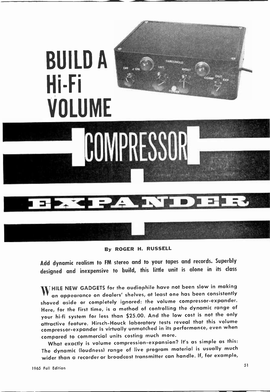
BUILD A
Hi-Fi
VOLUME
11113 3-1/113 1210742113 0 213 1
By ROGER H. RUSSELL
Add dynamic realism to FM stereo and to your tapes and records. Superbly
designed and inexpensive to build, this little unit is alone in its class
WHILE NEW GADGETS for the audiophile have not been slow in making
an appearance on dealers' shelves, at least one has been consistently
shoved aside or completely ignored: the volume compressor -expander.
Here, for the first time, is a method of controlling the dynamic range of
your hi-fi system for less than $25.00. And the low cost is not the only
attractive feature. Hirsch -Houck laboratory tests reveal that this volume
compressor -expander is virtually unmatched in its performance, even when
compared to commercial units costing much more.
What exactly is volume compression -expansion? It's as simple as this:
The dynamic (loudness) range of live program material is usually much
wider than a recorder or broadcast transmitter can handle. If, for example,
1965 Fall Edition 51

Controls on front of unit (photo above) are
threshold controls which determine the level
at which expansion or compression takes
place. Panel lamps 11 and 12 glow in propor-
tion to the voltage of the audio tapped from
speakers; switches control power, function.
the gain is set halfway up, the soft
parts will be accompanied by noise ( tape
hiss, hum, etc.) and the loud parts will
be distorted from overdriving the re-
cording or broadcast amplifier. Unfor-
tunately, the solution to this problem-
turning up the amplifier on soft passages
and turning it down on loud ones-de-
stroys the dynamic range of the original
program material.
Since automatic volume compression is
used to some extent in all commercial
recording and broadcasting, volume ex-
pansion offers the audiophile an easy
way to restore dynamic realism to a
broadcast or to a tape or disc recording.
On the other hand, the volume com-
pression of which this unit is capable
will be useful for those who want to
listen to background music or who want
to listen to the hi-fi without disturbing
their neighbors.
How It Works. The idea of using a
lamp and cadmium sulphide photocell in
a feedback circuit is not new, but few
experimenters have had the chance to
try this circuit in their hi-fi systems.
Use of transistor amplifiers-unique
with this unit-allows expansion and
compression at relatively low listening
levels.
Output voltage at the speaker ter-
minals of each stereo channel is used
to drive a transistor amplifier/limiter
which, in turn, controls the intensity of
Controls at rear of unit are d.c. balance
pots which are adjusted initially. A cart-
ridge, tuner, or other audio source is con-
nected to inputs; outputs go to amplifier.
Speaker jacks allow unit to sample amplifier
output at speakers and react accordingly.
O.0 BALANCE
R1GiT LEFT
a lamp. The intensity of the lamp causes
the resistance of a cadmium sulphide
photocell to change. The CdS cell is
switched in a voltage divider to either
aid or retard the input voltage to the
amplifier.
Since the input impedance of the
transistor amplifiers is high compared
to the impedance of the speakers, con-
necting the unit to the speaker terminals
has virtually no effect on speaker per-
formance. With the d.c. balance controls
(R1 and R2) adjusted so the lamps just
go out with no audio at the speakers,
a slight voltage input at the bases of
Q1 and Q2 will fire the transistors and
the lamps will begin to glow. The lamps
will glow brighter as higher voltage is
applied to the point where the transis-
tors begin to saturate. The amplifiers
act as limiters at this point-since a
higher input will not increase output-
preventing the bulbs from burning out.
Photocells PC1 and PC2 are placed
next to lamps Il and 12 respectively,
and vary in resistance from almost in-
finity when the lamps are dark to a few
hundred ohms when they are brightly
lighted. For volume expansion, the photo-
cells are switched into the part of a
voltage divider circuit in series with
the audio source ( tuner, phono cartridge,
etc.) and the audio amplifier. Resistors
R5 and R7 in the left channel, and R8
and R6 in the right channel, are selected
52 Electronic Experimenter's Handbook
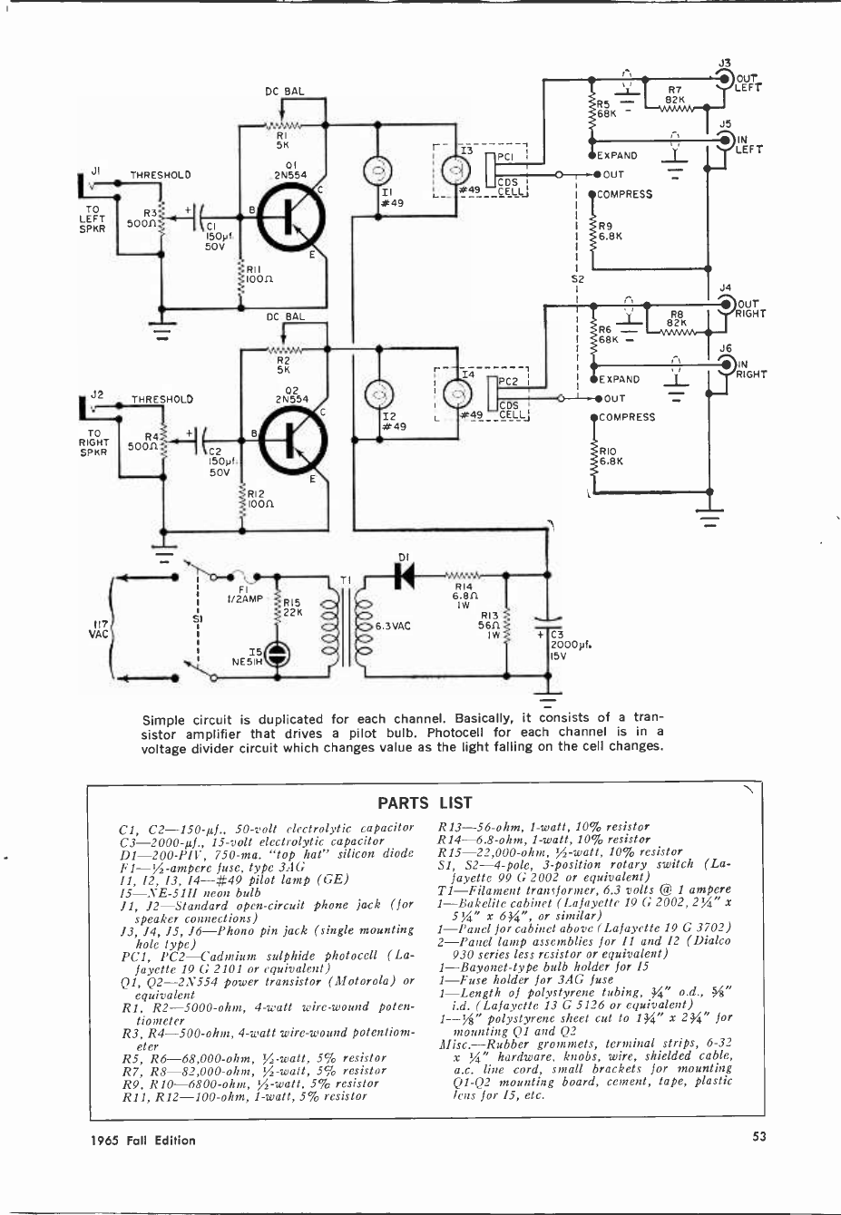
J3
JI
TO
LEFT
SPKR
J2
'V
TO
RIGHT
SPKR
Ili
VAC
THRESHOLD
CI 150yf.
50V
THRESHOLD
C2
150yf.
50V
DC BAL
RI 5K
01
2N554
loon
FI
1/2AMP
I5
NE51H
6.3 VAC
PCI
CDS
#49 -CELL
R14
6.811
1W R13
5611
1W + C3 2000pf.
+15V
E XPAND
OUT
COMPRESS
RIO
6.8K
Simple circuit is duplicated for each channel. Basically, it consists of a tran-
sistor amplifier that drives a pilot bulb. Photocell for each channel is in a
voltage divider circuit which changes value as the light falling on the cell changes.
OUT
LEFT
15
LEFT
J4
OUT
RIGHT
Je
3M RIGHT
PARTS
Cl, C2 -150-µf., 50 -volt electrolytic capacitor
C3 -2000-µf., 15 -volt electrolytic capacitor
D1-200-PIV, 750 -ma. "top hat" silicon diode
F1-/ -ampere fuse, type 3AG
11, 12, 13, 14-#49 pilot lamp (GE)
15-NE-51H neon bulb
11, 12-Standard open -circuit phone jack (for
speaker connections)
13, 14, 15, 16-Phono pin jack (single mounting
hole type)
PC1, PC2-Cadmium sulphide photocell (La-
fayette 19 G 2101 or equivalent)
Ql, Q2 -2N554 power transistor (Motorola) or
equivalent
R1, R2 -5000 -ohm, 4 -watt wire -wound poten-
tiometer
R3, R4 -500 -ohm, 4 -watt wire -wound potentiom-
eter
R5, R6 -68,000 -ohm, /-watt, 5% resistor
R7, R8 -82,000 -ohm, /-watt, 5% resistor
R9, R10 -6800 -ohm, /-watt, 5% resistor
R11, R12 -100 -ohm, 1 -watt, 5% resistor
LIST
R13 -56 -ohm, 1 -watt, 10% resistor
R14 -6.8 -ohm, 1 -watt, 10% resistor
R15 -22,000 -ohm, /-watt, 10% resistor
Sl, S2 -4 -pole, 3 -position rotary switch (La-
fayette 99 G 2002 or equivalent)
T1-Filament transformer, 6.3 volts @ 1 ampere
1-Bakelite cabinet (Lafayette 19 G 2002,2'4" x
x 634", or similar)
1-Panel for cabinet above (Lafayette 19 G 3702)
2-Panel lamp assemblies for 11 and 12 (Dialco
930 series less resistor or equivalent)
1-Bayonet-type bulb holder for 15
1-Fuse holder for 3AG fuse
1-Length of polystyrene tubing, " o.d., -"
i.d. (Lafayette 13 G 5126 or equivalent)
1--%" polystyrene sheet cut to 134" x 2 %" for
mounting Q1 and Q2
Misc.-Rubber grommets, terminal strips, 6-32
x %" hardware, knobs, wire, shielded cable,
a.c. line cord, small brackets for mounting
Q1 -Q2 mounting board, cement, tape, plastic
lens for 15, etc.
1965 Fall Edition 53
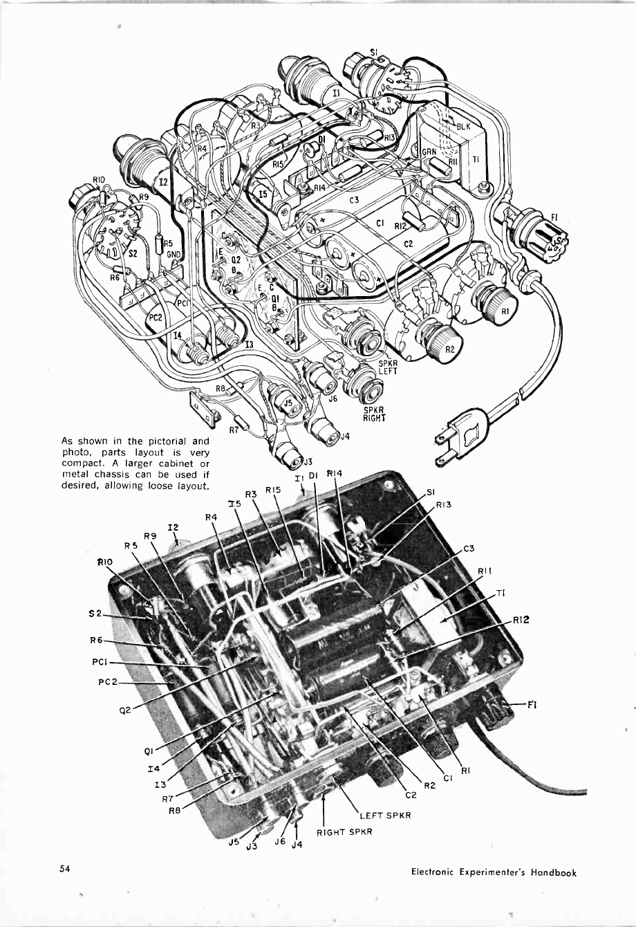
RIG
As shown in the pictorial and
photo, parts layout is very
compact. A larger cabinet or
metal chassis can be used if
desired, allowing loose layout.
12
R9
R5
RIO
S2
R6
PCI
PC2
QI
14
13
R7
R6
R4
Wk%
SI
1, ,.
j ,_; _ r, ..
R7
R3 R15 >t . SI
15 R13
J3 J6 J4
C2
LEFT SPKR
RIGHT SPKR
C3
RII
RI
CI
R2
TI
RIZ
F'I
FI
54 Electronic Experimenter's Handbook
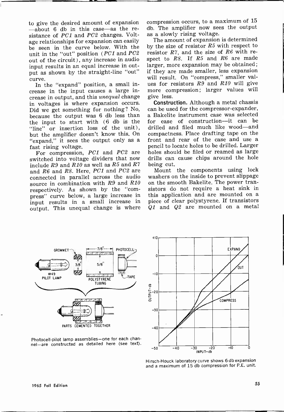
to give the desired amount of expansion
-about 6 db in this case-as the re-
sistance of PC1 and PC2 changes. Volt-
age relationships for expansion can easily
be seen in the curve below. With the
unit in the "out" position (PC1 and PC2
out of the circuit), any increase in audio
input results in an equal increase in out-
put as shown by the straight-line "out"
curve.
In the "expand" position, a small in-
crease in the input causes a large in-
crease in output, and this unequal change
in voltages is where expansion occurs.
Did we get something for nothing? No,
because the output was 6 db less than
the input to start with (6 db is the
"line" or insertion loss of the unit),
but the amplifier doesn't know this. On
"expand," it sees the output only as a
fast rising voltage.
For compression, PC1 and PC2 are
switched into voltage dividers that now
include R9 and R10 as well as R5 and R7
and R6 and R8. Here, PC1 and PC2 are
connected in parallel across the audio
source in combination with R9 and R10
respectively. As shown by the "com-
press" curve below, a large increase in
input results in a small increase in
output. This unequal change is where
*49
PILOT LAMP
!-'-7/8-'1 PHOTOCELL
f'/A,v
5/8"
POLYSTYRENE
TUBING
PARTS CEMENTED TOGETHER
TAPE
Photocell -pilot lamp assemblies-one for each chan-
nel-are constructed as detailed here (see text).
compression occurs, to a maximum of 15
db. The amplifier now sees the output
as a slowly rising voltage.
The amount of expansion is determined
by the size of resistor R5 with respect to
resistor R7, and the size of R6 with re-
spect to R8. If R5 and R6 are made
larger, more expansion may be obtained ;
if they are made smaller, less expansion
will result. On "compress," smaller val-
ues for resistors R9 and R10 will give
more compression; larger values will
give less.
Construction. Although a metal chassis
can be used for the compressor -expander,
a Bakelite instrument case was selected
for ease of construction-it can be
drilled and filed much like wood-and
compactness. Place drafting tape on the
front and rear of the case and use a
pencil to locate holes to be drilled. Larger
holes should be filed or reamed as large
drills can cause chips around the hole
being cut.
Mount the components using lock
washers on the inside to prevent slippage
on the smooth Bakelite. The power tran-
sistors do not require a heat sink in
this application and are mounted on a
piece of clear polystyrene. If transistors
Q1 and Q2 are mounted on a metal
ilu
O
10
20
30
40
EXPAND
OUT
COMPRESS
-50 INPUT-db
Hirsch -Houck laboratory curve shows 6 db expansion
and a maximum of 15 db compression for P.E. unit.
1965 Fall Edition 55
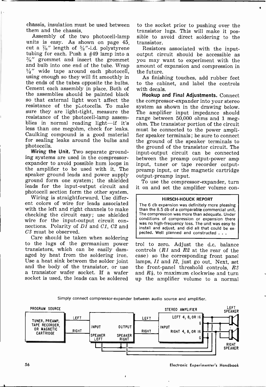
chassis, insulation must be used between
them and the chassis.
Assembly of the two photocell -lamp
units is easy. As shown on page 45,
cut a 7/8" length of i8"-i.d. polystyrene
tubing for each. Push a #49 lamp into a
3/8" grommet and insert the grommet
and bulb into one end of the tube. Wrap
1/4" wide tape around each photocell,
using enough so they will fit smoothly in
the ends of the tubes opposite the bulbs.
Cement each assembly in place. Both of
the assemblies should be painted black
so that external light won't affect the
resistance of the photocells. To make
sure they are light -tight, measure the
resistance of the photocell -lamp assem-
blies in normal reading light-if it's
less than one megohm, check for leaks.
Caulking compound is a good material
for sealing leaks around the bulbs and
photocells.
Wiring the Unit. Two separate ground-
ing systems are used in the compressor -
expander to avoid possible hum loops in
the amplifier to be used with it. The
speaker ground leads and power supply
ground form one system; the shielded
leads for the input-output circuit and
photocell section form the other system.
Wiring is straightforward. Use differ-
ent colors of wire for leads associated
with the left and right channels to make
checking the circuit easy ; use shielded
wire for the input-output circuit con-
nections. Polarity of D1 and Cl, C2 and
C3 must be observed.
Care should be taken when soldering
to the lugs of the germanium power
transistors, which can be easily dam-
aged by heat from the soldering iron.
Use a heat sink between the solder joint
and the body of the transistor, or use
a transistor wafer socket. If a wafer
socket is used, the leads can be soldered
to the socket prior to pushing over the
transistor lugs. This will make it pos-
sible to avoid direct soldering to the
transistor.
Resistors associated with the input-
output circuit should be accessible as
you may want to experiment with the
amount of expansion and compression in
the future.
As finishing touches, add rubber feet
to the cabinet, and label the controls
with decals.
Hookup and Final Adjustments. Connect
the compressor -expander into your stereo
system as shown in the drawing below.
The amplifier input impedance should
range between 50,000 ohms and 1 meg-
ohm. The transistor portion of the circuit
must be connected to the power ampli-
fier speaker terminals; be sure to connect
the ground of the speaker terminals to
the ground of the transistor circuit. The
input-output circuit can be connected
between the preamp output -power amp
input, tuner or tape recorder output-
preamp input, or the magnetic cartridge
output-preamp input.
To use the compressor -expander, turn
it on and set the amplifier volume con-
HIRSCH-HOUCK REPORT
The 6 db expansion was definitely more pleasing
than the 8.5 db of a comparable commercial unit.
The compression was more than adequate. Under
conditions of compression or expansion there
was no high -frequency loss. The unit was easy to
install and adjust, and did all that could be ex-
pected. Well planned and constructed .. .
trol to zero. Adjust the d.c. balance
controls (R1 and R2 at the rear of the
case) so the corresponding front panel
lamps, 11 and 12, just go out. Next, set
the front -panel threshold controls, R3
and R4, to maximum clockwise and turn
up the amplifier volume to a normal
Simply connect compressor -expander between audio source and amplifier.
PROGRAM SOURCE
TUNER, PREAMP,
TAPE RECORDER,
OR MAGNETIC
CARTRIDGE
STEREO AMPLIFIER
LEFT LEFT
INPUT OUTPUT INPUT
RIGHT RIGHT
SPEAKER SPEAKER
LEFT RIGHT
L
LEFT 4, 8, OR 16
G
RIGHT 4, 8, OR 16
G
LEFT
SPEAKER
I
L RIGHT
SPEAKER
56 Electronic Experimenters Handbook
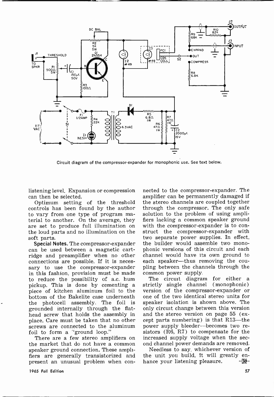
117
VAC
THRESHOLD
SI
I/2AMP
II
NE51H
DC BAL
I2 aR 49 L
i
PCI
#49 CÉLLj S2
R7
47R
Iw
E XPAND
OUT
COMPRESS
Re
6.85
+ C2
2000y(.
15V
_1L
Circuit diagram of the compressor -expander for monophonic use. See text below.
listening level. Expansion or compression
can then be selected.
Optimum setting of the threshold
controls has been found by the author
to vary from one type of program ma-
terial to another. On the average, they
are set to produce full illumination on
the loud parts and no illumination on the
soft parts.
Special Notes. The compressor -expander
can be used between a magnetic cart-
ridge and preamplifier when no other
connections are possible. If it is neces-
sary to use the compressor -expander
in this fashion, provision must be made
to reduce the possibility of a.c. hum
pickup. This is done by cementing a
piece of kitchen aluminum foil to the
bottom of the Bakelite case underneath
the photocell assembly, The foil is
grounded internally through the flat-
head screw that holds the assembly in
place. Care must be taken that no other
screws are connected to the aluminum
foil to form a "ground loop."
There are a few stereo amplifiers on
the market that do not have a common
speaker ground connection. These ampli-
fiers are generally transistorized and
present an unusual problem when con-
J2
OUTPUT
////J'''3 ' INPUT
nected to the compressor -expander. The
amplifier can be permanently damaged if
the stereo channels are coupled together
through the compressor. The only safe
solution to the problem of using ampli-
fiers lacking a common speaker ground
with the compressor -expander is to con-
struct the compressor -expander with
two separate power supplies. In effect,
the builder would assemble two mono-
phonic versions of this circuit and each
channel would have its own ground to
each speaker-thus removing the cou-
pling between the channels through the
common power supply.
The circuit diagram for either a
strictly single channel (monophonic)
version of the compressor -expander or
one of the two identical stereo units for
speaker isolation is shown above. The
only circuit change between this version
and the stereo version on page 55 (ex-
cept parts numbering) is that R13-the
power supply bleeder-becomes two re-
sistors (R6, R7) to compensate for the
increased supply voltage when the sec-
ond channel power demands are removed.
Needless to say, whichever version of
the unit you build, It will greatly en-
hance your listening pleasure. -{3-
1965 Fall Edition 57
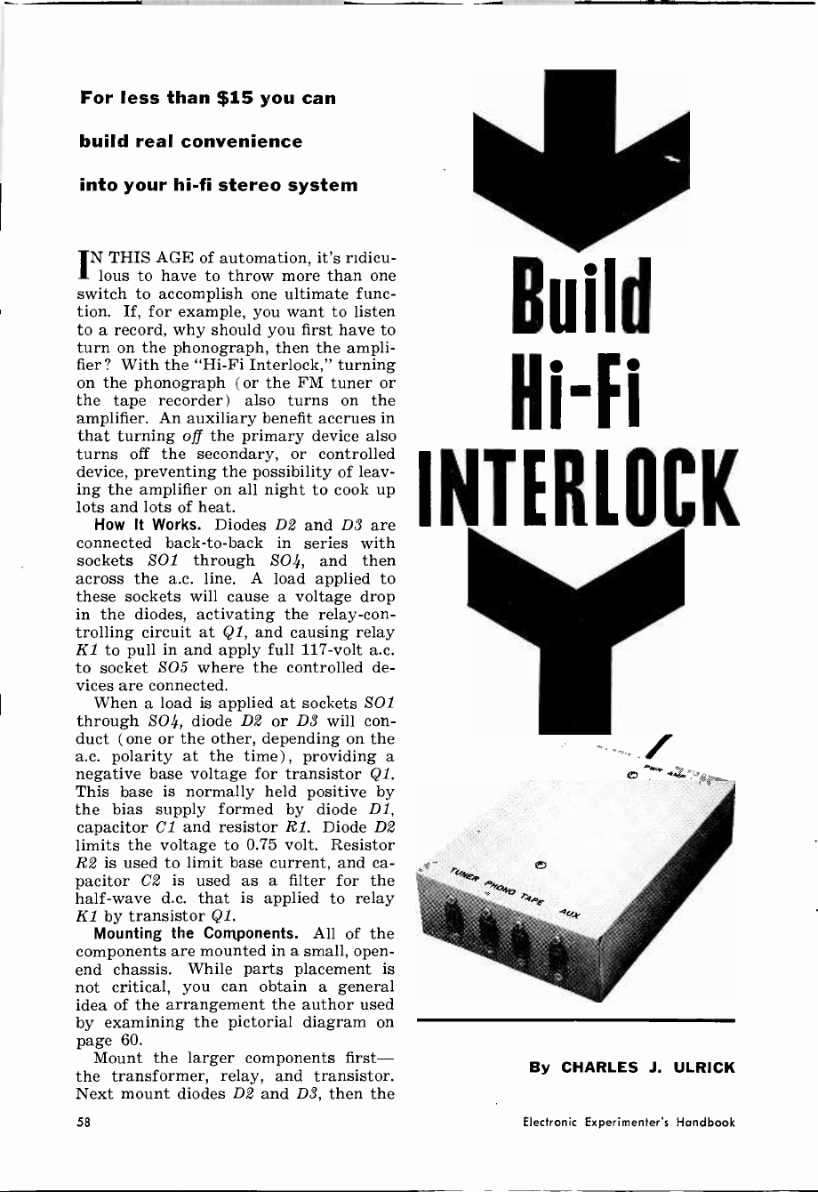
For less than $15 you can
build real convenience
into your hi-fi stereo system
IN THIS AGE of automation, it's ridicu-
lous to have to throw more than one
switch to accomplish one ultimate func-
tion. If, for example, you want to listen
to a record, why should you first have to
turn on the phonograph, then the ampli-
fier? With the "Hi-Fi Interlock," turning
on the phonograph (or the FM tuner or
the tape recorder) also turns on the
amplifier. An auxiliary benefit accrues in
that turning off the primary device also
turns off the secondary, or controlled
device, preventing the possibility of leav-
ing the amplifier on all night to cook up
lots and lots of heat.
How It Works. Diodes D2 and D3 are
connected back-to-back in series with
sockets SO1 through 204, and then
across the a.c. line. A load applied to
these sockets will cause a voltage drop
in the diodes, activating the relay -con-
trolling circuit at Q1, and causing relay
KZ to pull in and apply full 117 -volt a.c.
to socket SO5 where the controlled de-
vices are connected.
When a load is applied at sockets SO/
through 204, diode D2 or D3 will con-
duct ( one or the other, depending on the
a.c. polarity at the time) , providing a
negative base voltage for transistor Ql.
This base is normally held positive by
the bias supply formed by diode D1,
capacitor Cl and resistor Rl. Diode D2
limits the voltage to 0.75 volt. Resistor
R2 is used to limit base current, and ca-
pacitor C2 is used as a filter for the
half -wave d.c. that is applied to relay
Kl by transistor Ql.
Mounting the Components. All of the
components are mounted in a small, open-
end chassis. While parts placement is
not critical, you can obtain a general
idea of the arrangement the author used
by examining the pictorial diagram on
page 60.
Mount the larger components first-
the transformer, relay, and transistor.
Next mount diodes D2 and D3, then the
Build
INTERLOCK
By CHARLES J. ULRICK
58 Electronic Experimenter's Handbook
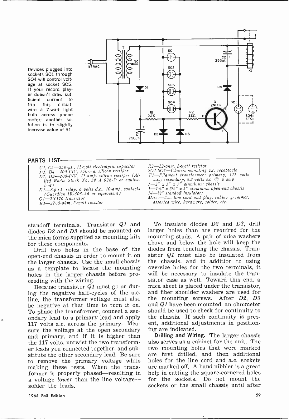
Devices plugged into
sockets SOl through
SO4 will control volt-
age at socket SO5.
If your record play-
er doesn't draw suf-
ficient current to
trip this circuit,
wire a 7 -watt light
bulb across phono
motor; another so-
lution is to slightly
increase value of Rl.
PARTS LIST
H7VAC
C1, C2 -250-µf., 12 -volt electrolytic capacitor
D1, D4-400-PIV, 750 -ma. silicon rectifier
D2, D3-200-PIV, 12 -amp. silicon rectifier (Al-
lied Radio Stock No. 39 A 926-D or equiva-
lent)
K1--S.p.s.t. relay, 6 volts d.c., 10 -amp. contacts
(Guardian IR -505-A6 or equivalent)
Q1 -2N176 transistor
R1 -2700 -ohm, 2 -watt resistor
R2 -22 -ohm, 2 -watt resistor
SO1-SO5-Chassis-mounting a.c. receptacle
TI-Filament transformer: primary, 117 volts
a.c.; secondary, 6.3 volts a.c. @ .6 amp
1-2" x 5" x 7" aluminum chassis
1-13/4" x 31" x 5" aluminum open-end chassis
14-122" standoff insulators
Misc.-A.c. line cord and plug, rubber grommet,
assorted wire, hardware, solder, etc.
standoff terminals. Transistor Q1 and
diodes D2 and D3 should be mounted on
the mica forms supplied as mounting kits
for these components.
Drill two holes in the base of the
open-end chassis in order to mount it on
the larger chassis. Use the small chassis
as a template to locate the mounting
holes in the larger chassis before pro-
ceeding with the wiring.
Because transistor Q1 must go on dur-
ing the negative half -cycles of the a.c.
line, the transformer voltage must also
be negative at that time to turn it on.
To phase the transformer, connect a sec-
ondary lead to a primary lead and apply
117 volts a.c. across the primary. Mea-
sure the voltage at the open secondary
and primary, and if it is higher than
the 117 volts, untwist the two transform-
er leads you connected together, and sub-
stitute the other secondary lead. Be sure
to remove the primary voltage while
making these tests. When the trans-
former is properly phased-resulting in
a voltage lower than the line voltage-
solder the leads.
To insulate diodes D2 and D3, drill
larger holes than are required for the
mounting studs. A pair of mica washers
above and below the hole will keep the
diodes from touching the chassis. Tran-
sistor Q1 must also be insulated from
the chassis, and in addition to using
oversize holes for the two terminals, it
will be necessary to insulate the tran-
sistor case as well. Toward this end, a
mica sheet is placed under the transistor,
and fiber shoulder washers are used for
the mounting screws. After D2, D3
and Q1 have been mounted, an ohmmeter
should be used to check for continuity to
the chassis. If such continuity is pres-
ent, additional adjustments in position-
ing are indicated.
Drilling and Wiring. The larger chassis
also serves as a cabinet for the unit. The
two mounting holes that were marked
are first drilled, and then additional
holes for the line cord and a.c. sockets
are marked off. A hand nibbler is a great
help in cutting the square -cornered holes
for the sockets. Do not mount the
sockets or the small chassis until after
1965 Fall Edition 59
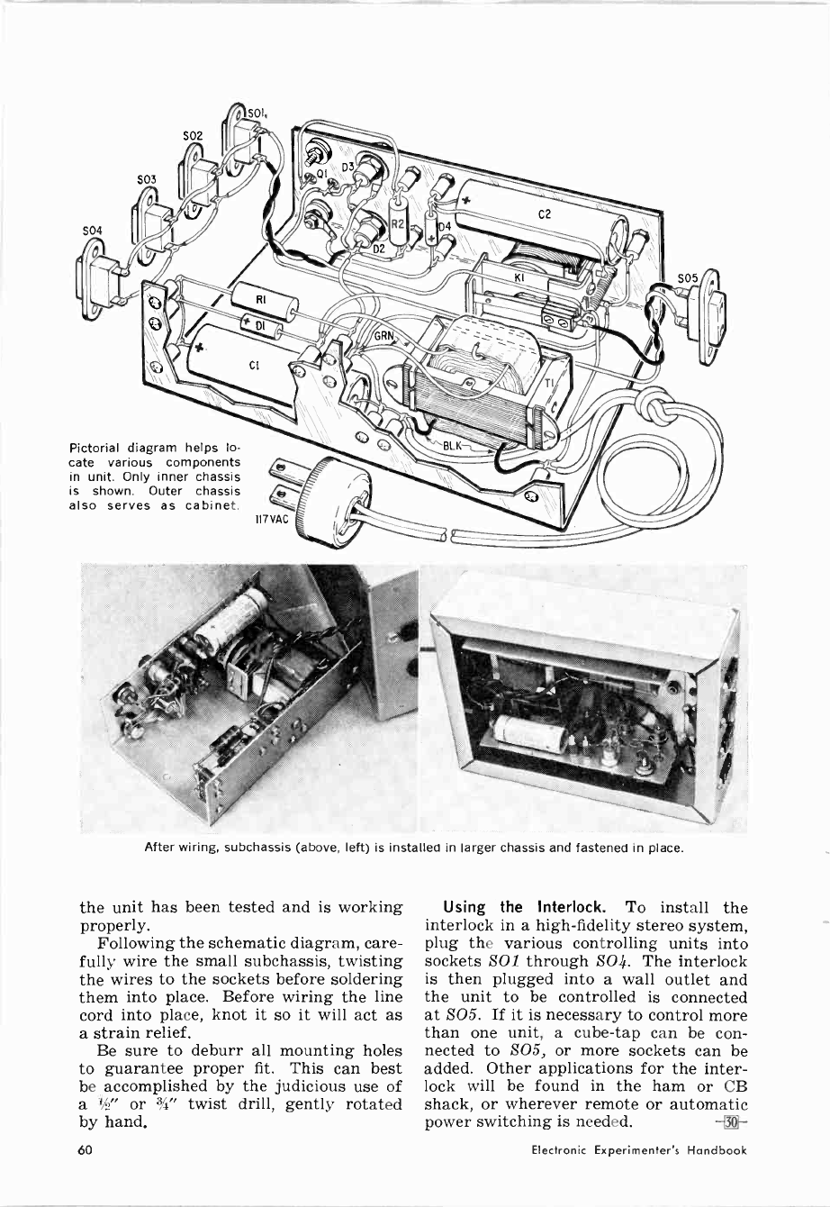
SO4
Pictorial diagram helps lo-
cate various components
in unit. Only inner chassis
is shown. Outer chassis
also serves as cabinet.
After wiring, subchassis (above, left) is installed in larger chassis and fastened in place.
the unit has been tested and is working
properly.
Following the schematic diagram, care-
fully wire the small subchassis, twisting
the wires to the sockets before soldering
them into place. Before wiring the line
cord into place, knot it so it will act as
a strain relief.
Be sure to deburr all mounting holes
to guarantee proper fit. This can best
be accomplished by the judicious use of
a 1 ' or 3/4" twist drill, gently rotated
by hand.
Using the Interlock. To install the
interlock in a high-fidelity stereo system,
plug the various controlling units into
sockets SO/ through 504. The interlock
is then plugged into a wall outlet and
the unit to be controlled is connected
at S05. If it is necessary to control more
than one unit, a cube -tap can be con-
nected to 205, or more sockets can be
added. Other applications for the inter-
lock will be found in the ham or CB
shack, or wherever remote or automatic
power switching is needed. -{3]0-
60 Electronic Experimenter's Handbook
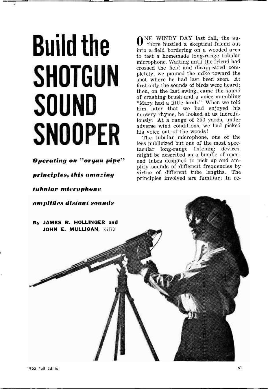
Build the
SHOTGUN
SOUND
SNOOPER
Operating on 'organ pipe"
principles, this amazing
tubular microphone
amplifies distant sounds
By JAMES R. HOLLINGER and
JOHN E. MULLIGAN, K3TIB
ONE WINDY DAY last fall, the au-
thors hustled a skeptical friend out
into a field bordering on a wooded area
to test a homemade long-range tubular
microphone. Waiting until the friend had
crossed the field and disappeared com-
pletely, we panned the mike toward the
spot where he had last been seen. At
first only the sounds of birds were heard ;
then, on the last swing, came the sound
of crashing brush and a voice mumbling
"Mary had a little lamb." When we told
him later that we had enjoyed his
nursery rhyme, he looked at us incredu-
lously. At a range of 250 yards, under
adverse wind conditions, we had picked
his voice out of the woods!
The tubular microphone, one of the
less publicized but one of the most spec-
tacular long-range listening devices,
might be described as a bundle of open-
end tubes designed to pick up and am-
plify sounds of different frequencies by
virtue of different tube lengths. The
principles involved are familiar: In re -
1965 Fall Edition 61
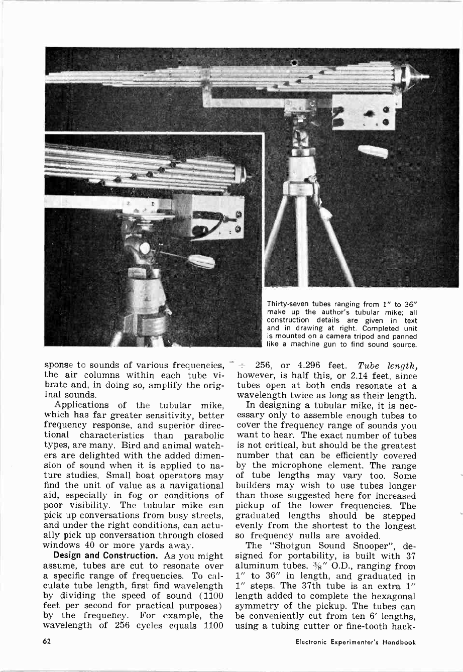
sponse to sounds of various frequencies,
the air columns within each tube vi-
brate and, in doing so, amplify the orig-
inal sounds.
Applications of the tubular mike,
which has far greater sensitivity, better
frequency response, and superior direc-
tional characteristics than parabolic
types, are many. Bird and animal watch-
ers are delighted with the added dimen-
sion of sound when it is applied to na-
ture studies. Small boat operators may
find the unit of value as a navigational
aid, especially in fog or conditions of
poor visibility. The tubular mike can
pick up conversations from busy streets,
and under the right conditions, can actu-
ally pick up conversation through closed
windows 40 or more yards away.
Design and Construction. As you might
assume, tubes are cut to resonate over
a specific range of frequencies. To cal-
culate tube length, first find wavelength
by dividing the speed of sound (1100
feet per second for practical purposes)
by the frequency. For example, the
wavelength of 256 cycles equals 1100
Thirty-seven tubes ranging from 1" to 36"
make up the author's tubular mike; all
construction details are given in text
and in drawing at right. Completed unit
is mounted on a camera tripod and panned
like a machine gun to find sound source.
256, or 4.296 feet. Tube length,
however, is half this, or 2.14 feet, since
tubes open at both ends resonate at a
wavelength twice as long as their length.
In designing a tubular mike, it is nec-
essary only to assemble enough tubes to
cover the frequency range of sounds you
want to hear. The exact number of tubes
is not critical, but should be the greatest
number that can be efficiently covered
by the microphone element. The range
of tube lengths may vary too. Some
builders may wish to use tubes longer
than those suggested here for increased
pickup of the lower frequencies. The
graduated lengths should be stepped
evenly from the shortest to the longest
so frequency nulls are avoided.
The "Shotgun Sound Snooper", de-
signed for portability, is built with 37
aluminum tubes, :%" O.D., ranging from
1" to 36" in length, and graduated in
1" steps. The 37th tube is an extra 1"
length added to complete the hexagonal
symmetry of the pickup. The tubes can
be conveniently cut from ten 6' lengths,
using a tubing cutter or fine-tooth hack -
62 Electronic Experimenter's Handbook
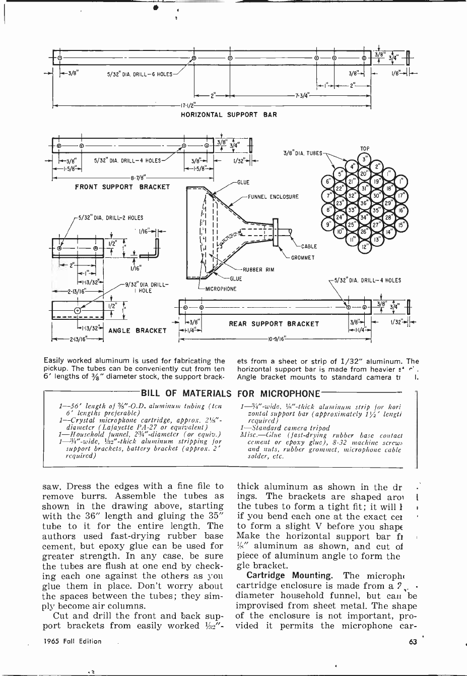
3/8" 5/32" DIA. DRILL -6 HOLES
5/32" DIA. DRILL -4 HOLES
8 7/8"
FRONT SUPPORT BRACKET
5/32' DIA. DRILL -2 HOLES
1/16H1. -
H3/32.-1.<
2-13/16'=-m-
9/32' DIA. DRILL -
I HOLE
ANGLE
71/2.
HORIZONTAL SUPPORT BAR
GLUE
FUNNEL ENCLOSURE
GLUE
--MICROPHONE
7-3/4"
3/8'
I-a-- 2"-
RUBBER RIM
CABLE
GROMMET
ö O
M3/8" REAR
BRACKET h-1-1/4"
la
Easily worked aluminum is used for fabricating the
pickup. The tubes can be conveniently cut from ten
6' lengths of 3/a" diameter stock, the support brack-
BILL OF MATERIALS
1-56' length of %"-O.D. aluminum tubing (ten
6' lengths preferable)
1-Crystal microphone cartridge, approx. 21/2" -
diameter (Lafayette PA -27 or equivalent)
1-Household funnel, 2'5/4" -diameter (or equiv.)
1---3/4"-wide, 's" -thick aluminum stripping for
support brackets, battery bracket (approx. 2'
required)
SUPPORT BRACKET
e-9/16"
TOP
30
f 1/8'-+1 '"
5/32"DIA. DRILL -4 HOLES
3%8 0 QQ
13/8+ ---
I -I/4
ets from a sheet or strip of 1/32" aluminum. The
horizontal support bar is made from heavier s' c*.
Angle bracket mounts to standard camera tr I.
FOR MICROPHONE
',á" -thick aluminum strip for hori
zontal support bar (approximately 1 % ' lengtl
required)
1-Standard camera tripod
tlüsc.-Glue (fast -drying rubber base contact
cement or epoxy glue), 8-32 machine screw,
and nuts, rubber grommet, microphone cable,
solder, etc.
saw. Dress the edges with a fine file to
remove burrs. Assemble the tubes as
shown in the drawing above, starting
with the 36" length and gluing the 35"
tube to it for the entire length. The
authors used fast -drying rubber base
cement, but epoxy glue can be used for
greater strength. In any case, be sure
the tubes are flush at one end by check-
ing each one against the others as you
glue them in place. Don't worry about
the spaces between the tubes; they sim-
ply become air columns.
Cut and drill the front and back sup-
port brackets from easily worked 'i3s"-
thick aluminum as shown in the dr
ings. The brackets are shaped aro
the tubes to form a tight fit ; it will I
if you bend each one at the exact cer
to form a slight V before you shape
Make the horizontal support bar fr
" aluminum as shown, and cut of
piece of aluminum angle to form the
gle bracket.
Cartridge Mounting. The microphl
cartridge enclosure is made from a ?
diameter household funnel, but can be
improvised from sheet metal. The shape
of the enclosure is not important, pro-
vided it permits the microphone car -
1965 Fall Edition 63
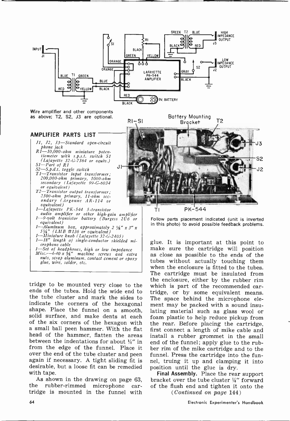
INPUT
J;
Wire amplifier and other components
as above; T2, S2, J3 are optional.
AMPLIFIER PARTS LIST
11, J2, J3-Standard open -circuit
phone jack
R1 -10,000 -ohm miniature poten-
tiometer with s.p.s.t. switch SI
(Lafayette 32-G-7364 or equiv.)
S1-Part of RI
S2-S.p.d.t. toggle switch
T1-Transistor input transformer;
200,000 -ohm primary, 1000 -ohm
secondary (Lafayette 99-G-6034
or equivalent)
T2-Transistor output transformer;
2500 -ohm primary, 11 -ohm sec-
ondary (Argonne AR -114 or
equivalent)
1-Lafayette PK-544 5 -transistor
audio amplifier or other high -gain amplifier
1 -9 -volt transistor battery (Burgess 2U6 or
equivalent)
1-Aluminum box, approximately 2 %" x 3" x
5%" (LMB #136 or equivalent)
1-Miniature knob (Lafayette 32-G-2405)
1-18" length of single -conductor shielded mi-
crophone cable
1-Set of headphones, high or low impedance
Misc.-4-40 x 54" machine screws and extra
nuts, scrap aluminum, contact cement or epoxy
glue, wire, solder, etc.
RI-SI
JI
tridge to be mounted very close to the
ends of the tubes. Hold the wide end to
the tube cluster and mark the sides to
indicate the corners of the hexagonal
shape. Place the funnel on a smooth,
solid surface, and make dents at each
of the six corners of the hexagon with
a small ball peen hammer. With the flat
head of the hammer, flatten the areas
between the indentations for about 'I" in
from the edge of the funnel. Place it
over the end of the tube cluster and peen
again if necessary. A tight sliding fit is
desirable, but a loose fit can be remedied
with tape.
As shown in the drawing on page 63,
the rubber -rimmed microphone car-
tridge is mounted in the funnel with
HIGH
IMPEDANCE
OUTPUT
LOW
IMPEDANCE
OUTPUT
J2
Battery Mounting
Bracket T2
TI PK-544
Follow parts placement indicated (unit is inverted
in this photo) to avoid possible feedback problems.
glue. It is important at this point to
make sure the cartridge will position
as close as possible to the ends of the
tubes without actually touching them
when the enclosure is fitted to the tubes.
The cartridge must be insulated from
the enclosure, either by the rubber rim
which is part of the recommended car-
tridge, or by some equivalent means.
The space behind the microphone ele-
ment may be packed with a sound insu-
lating material such as glass wool or
foam plastic to help reduce pickup from
the rear. Before placing the cartridge,
first connect a length of mike cable and
install a rubber grommet in the small
end of the funnel ; apply glue to the rub-
ber rim of the mike cartridge and to the
funnel. Press the cartridge into the fun-
nel, truing it up and clamping it into
position until the glue is dry.
Final Assembly. Place the rear support
bracket over the tube cluster 14" forward
of the flush end and tighten it onto the
(Continued on page 144)
64 Electronic Experimenter's Handbook

BUILD 20 RADIO
CIRCUITS AT HOME
with the Deluxe
PROGRESSIVE RADIO "EDU-KIT"®
A Practical Home Radio Course
Now Includes
* 12 RECEIVERS
* 3 TRANSMITTERS
* SQ. WAVE GENERATOR
* SIGNAL TRACER
* AMPLIFIER
* SIGNAL INJECTOR
* CODE OSCILLATOR
only
* No Knowledge of Radio Necessary ;
* No Additional Parts or Tools Needed
* EXCELLENT BACKGROUND FOR TV
* SCHOOL INQUIRIES INVITED
* Sold in 79 Countries
YOU DON'T HAVE TO SPEND
HUNDREDS OF DOLLARS FOR A RADIO COURSE
The "Etlu-Kit" Offers you an outslanu,ng PRACTICAL HOME RADIO COURSE at a
rock -bottom price. Our Kit Is designed to train Radio & Electronics Technicians, making
use of the most modern methods of home training. You will learn radio theory, construc-
tion practice and servicing. THIS IS A COMPLETE RADIO COURSE IN EVERY DETAIL.
You will learn how to build radios, using regular schematics; how to wire and solde
in a professional manner; how to service radios. You will work with the standard type o
punched metal chassis as well as the latest development of Printed Circuit chassis.
You will learn the basic principles of radio. You will construct, study and Work with
RF and AF amplifiers and oscillators, detectors, rectifiers, test equipment. You will learn
and practice code, using the Progressive Code Oscillator. YOu will learn and practice
trouble shooting, using the Progressive Signal Traceur, Progressive Signal Injector, Pro-
g^eessiinve Dynamic
yn mic/nadioa& Electronics Tester, Square Wave Generator and the accompany-
iYou will receive training for the Novice. Technician and General Classes of F.C.C. Radio
Amateur Licenses. You will build Receiver, Transmitter, Square Wave Generator, Code
Oscillator, Signal Tracer and Signal Injector circuits, and learn how to operate them. YOu
will receive an excellent background for television. HI -Fl and Electronics.
Absolutely no previous knowledge of radio or science is required. The "Edu-Kit" IS
the product of many years of teaching and engineering experience. The 'Edu-Kit" will
provide you with a basic education in Electronics and Radio, worth many times the lOW
Price you pay. The Signal Tracer alone Is worth mote than the price of the kit.
THE KIT FOR EVERYONE
You do not need the slightest background
In radio or science. Whether you are inter-
ested in Radio & Electronics because you
want an interesting hobby, a well paying
business or a job with a future, you will find
the "Edu-Kit" a worth -while investment.
Many thousands of individuals of all
ages and backgrounds have successfully
used the 'Edu-Kit" in more than 79 coun-
tries of the world. The "Edu-Kit" has been
carefully designed. Step by step, so that
you cannot make a mistake. The "Etlu-Kit"
allows you s o teach yourself at your own
rate. No instructor is necessary.
PROGRESSIVE TEACHING . METHOD
The Progressive Radio "Edu-Nit" is the foremost educational radio Kit in the world,
and is universally accepted as the standard in the field of electronics training. The "Edu-
Kit" uses the modern educational principle of "Learn by Doing." Therefore you construct.
learn Schematics, study theory, practice trouble shooting-all In a closely integrated Pro-
gram dsigned to provide an easily -learned, thorough and interesting background In radio.
You begin by examining the various radio parts of the "Edu-Kit." You then learn the
function, theory and wiring of these parts. Then you bulld a simple radio. With this first
set you will enloy listening to regular broadcast stations, learn theory, practice testing
and trouble shooting. Then you build a more advanced radio, learn more advanced theory
and techniques. Gradually, in a progressive manner, and at your own rate, you will
find yourself constructing more advanced multi -tube radio circuits, and doing work like a
professional Radio Technician.
Included in the "Edu-Kit" course are Receiver, Transmitter. Code Oscillator, Signal
Tracer, Square Wave Generator and Signal Infector Circuits. These are not unprofessional
''breadboard'' experiments, hut genuine radio circuits. Constructed by means of prOlesslonal
Wiring and soldering on metal chassis, plus the new method of radio construction known
as "Printed Circuitry." These circuits Operate on your regular AC or DC house current.
THE "EDU-KIT" IS COMPLETE
You will receive all parts and instructions necessary to build twenty different radio and
electronics circuits, each guaranteed to operate. Our Kilts contain tubes, tube sockets, vari.
able, electrolytic, mica, ceramic and paper dielectric condensers, resistors, tie strips,
hardware. tubing. punched metal chassis, Instruction Manuals, hook-up wire, solder.
selenium rectifiers, coils, volume controls and switches. etc.
In addition. you receive Printed Circuit materials. including Printed Circuit chassis.
special tube sockets, hardware and instructions. You also receive a useful set of tools a
professional electric soldering iron, and a self -powered Dynamic Radio and Electronics
Tester. The ' Edu-Kit" also Includes Code instructions and the Progressive Code Oscillator.
1eaddition to F.C.G. Radio Amateur License training. You will also receive lessons for
servicing with the Progressive Signal Tracer and the Progressive Signal Injector, a High
Fdelity Guide and a Quiz Bonk. You receive Membership In Radlo-TV Club. Free Consulta-
tion Service, Certificate of Merit and Discount Privileges. You receive all parts. tools.
Instructions, etc. Everything is yours to keep.
I PRINTED CIRCUITRY I
At no increase in price, the "Edu-Kit"
now includes Printed Circuitry. You build
a Printed Circuit Signal Injector, a
unique servicing instrument that can de-
tect many Radio and TV troubles. This
revolutionary new technique of radio
construction is now becoming popular
in commercial radio and TV sets.
A Printed Circuit is a special insulated
chassis on which has been deposited a
conducting material which takes the
place of wiring. The various parts are
merely plugged in and soldered to ter-
minals.
Printed Circuitry is the basis of mod-
ern Automation Electronics. A knowledge
of this subject is a necessity today for
anyone interested in Electronics.
;-----UNCONDITIONAL
9
Reg. U. S.
Pat. Off.
Training Electronics Technicians Since 1946
FREE EXTRAS
SET OF TOOLS
SOLDERING IRON
ELECTRONICS TESTER
PLIERS -CUTTERS
VALUABLE DISCOUNT CARD
CERTIFICATE OF MERIT
TESTER INSTRUCTION MANUAL
HIGH FIDELITY GUIDE QUIZZES
TELEVISION BOOK RADIO
TROUBLE -SHOOTING BOOK
MEMBERSHIP IN RADIO-TV CLUB:
CONSULTATION SERVICE FCC
AMATEUR LICENSE TRAINING
PRINTED CIRCUITRY
SERVICING LESSONS
You will learn trouble -shooting and
servicing In a progressive manner. You
will practice repairs on the sets that
you construct. You will learn symptoms
and causes of trouble In borne. portable
and car radios. You will learn how to
use the professional Signal Tracer, the
unique Signal Injector and the dynamic
Radio & Electronics Tester. While You
are learning in this practical way, you
will be able to do many a repair lob for
your friends and neighbors, and charge
fees which will far exceed the price of
the "Eau -Kit." Our Consultation Service
will help You with any technical prob-
lems you may have.
FROM OUR MAIL BAG
.1. Stataitls, of 25 Poplar Pl. Water-
bury, Conn.. writes: "I have repaired
several sets for my friends, and made
money. The "Edu-Kit' paid for itself. I
was ready to spend $240 for a Course.
but 1 found your ad and sent for your
Kit.' Ben o, P. O. Box 21. Magna.
Utah: "The are wonderful. Here
I am sending you the questions and also
the answers for them. I have been in
Radio for the last seven years, but like
to work with Radio Kits, and like to
build Radio Testing Equipment. 1 en-
joyed every minute I worked with the
different kits: the Signal Tracer works
fine. Also like to let you know that I
feel proud of becoming a member of your
Radio-TV Club."
Robert L. Snuff. 1534 Monroe Ave..
Huntington, W. Va.: "Thought I would
drop you a few lines to say that I re-
ceived my Edu-Kit. and was really amazed
that such a bargain can be had at such
started
low price. I have already re-
pairing radios and phonographs. My
friends were really surprised to see me
get uickly. The
Trnto the
ouble-shooting g of [
Tester that
so g
roucomes with
the Kit is really swell, and finds the
trouble, If there Is any to be found."
MONEY -BACK GUARANTEE ----1
ORDER FROM AD -RECEIVE FREE BONUS
RADIO & TV PARTS JACKPOT WORTH $15
G Send "EMI- Kit" postpaid. I enclose full payment of $26.95.
Send "Edu-Kit" C.O.D. I will pay $26.95 phis postage.
Rush me FREE descriptivo literature concerning "Edu-Kit."
Name
Address
PROGRESSIVE "EDU-KITS" INC.
I ATT: S. GOODMAN. M.S. In ED.. PRES.)
1186 Broadway, Dept. 5116R, Hewlett, N. Y. 11557 J
1965 Fall Edition
CIRCLE NO. 22 ON READER SERVICE CARD
65

on a subscription to
POPULAR ELECTRONICS
io=,ohs $y 300
mo
At the regular subscription rate these same 18
issues would cost all of $6.00! BUT NOT FOR
YOU. Your cost is only $3.00-HALF-PRICE!
Every month POPULAR ELECTRONICS brings you a
wealth of fascinating features aimed especially at
experimenters and do-it-yourselfers like yourself.
(Just glance to the right for a sample!)
You'll enjoy being right on top of the fast-growing
world of electronics with up-to-the-minute new prod-
uct reports, lab tests, buying guides, and electronics
breakthroughs you want to know about. Plenty of
articles on hi-fi, money -saving test equipment, tape
recorders, electronic games, computers, photo -aids,
short wave receivers, antenna systems, solar pow-
ered and transistorized equipment-and much more.
Construction projects galore! Clear -as -crystal dia-
grams guide you each step of the way through fun-
to -build projects you can put together in just a few
hours...for pennies! Turn friends green with envy by
building a super hi-fi rig they couldn't match in the
stores for hundreds of dollars! Or throw together a
fool -proof photoelectric burglar alarm to protect your
home and loved ones...or a remote control switch
that actually turns lights on and off when you whistle
a bar of your favorite tune!
POPULAR ELECTRONICS is definitely for men like
YOU. Take advantage of this HALF-PRICE OFFER to
readers of the Experimenter's Handbook. Just com-
plete and mail the card facing this page. Or, if some-
one has already used the card, write to:
POPULAR ELECTRONICS, Dept. 4080,
Portland Place, Boulder, Colorado 80311
EXCLUSIVE HAM, SW & CB
ARTICLES IN POPULAR ELECTRONICS
Amateur Radio and SWL
Make Your Signal Reports More Accurate
Safety in the Ham Station
Amateur License Fees and ARRL Petitions
Take Advantage of Changing Propagation
Conditions
Operating Another Ham's Station
Calling All SWL DX'ers
DX Awards
English -Language Newscasts to North
America
Radio Marathon Broadcasts Truth
To Cuba
Satellites on the Air
Short -Wave Broadcast Predictions
Short -Wave Report
North American Alliance of SWL Clubs
Welcome to the SWL Newcomer
Sure Cure for Ham/CB Mobile Noise
Citizens Band Radio
"DSRC," New CB Features
Equipment Buyer's Guide
Transmitters and Transceivers
Station Accessories
Antennas
Microphones
Hand -Held Transceivers
FCC Report
On the Citizens Band
Sure Cure for Ham/CB Mobile Noise
Vibrator Hash, Wipe Out
Build -It -Yourself
Antenna, 40 -Meter, for Small Roof
Antenna Adapter, Power Line
Code Bander
Crystal Super Calibrator
Double -Duty EICO 772
Hula-Hoop-a Ham or CB Antenna
Idento-Minder
Q -Multiplier, Nuvistor
Screen Modulator, One -Tube
Transmitter Crystal Switch, Plug-in
2 -Meter Simple Superhet
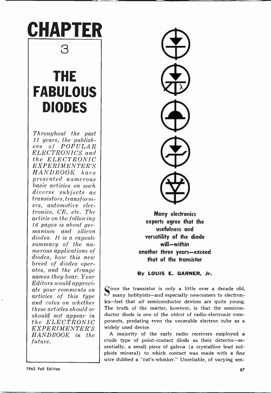
CHAPTER
3
THE
FABULOUS
DIODES
Throughout the past
11 years, the publish-
ers of POPULAR
ELECTRONICS and
the ELECTRONIC
EXPERIMENTER'S
HANDBOOK have
presented numerous
basic articles on such
diverse subjects as
transistors, trans f orm-
ers, automotive elec-
tronics, CB, etc. The
article on the following
16 pages is about ger-
manium and silicon
diodes. It is a capsule
summary of the nu-
merous applications of
diodes, how this new
breed of diodes oper-
ates, and the strange
names they bear. Your
Editors would appreci-
ate your comments on
articles of this type
and votes on whether
these articles should or
should not appear in
the ELECTRONIC
EXPERIMENTER'S
HANDBOOK in the
future.
Many electronics
experts agree that the
usefulness and
versatility of the diode
will-within
another three years-exceed
that of the transistor
By LOUIS E. GARNER, Jr.
ince the transistor is only a little over a decade old,
many hobbyists-and especially newcomers to electron-
ics-feel that all semiconductor devices are quite young.
The truth of the matter, however, is that the semicon-
ductor diode is one of the oldest of radio -electronic com-
ponents, predating even the venerable electron tube as a
widely used device.
A majority of the early radio receivers employed a
crude type of point -contact diode as their detector-es-
sentially, a small piece of galena (a crystalline lead sul-
phide mineral) to which contact was made with a fine
wire dubbed a "cat's -whisker." Unreliable, of varying sen -
1965 Fall Edition 67
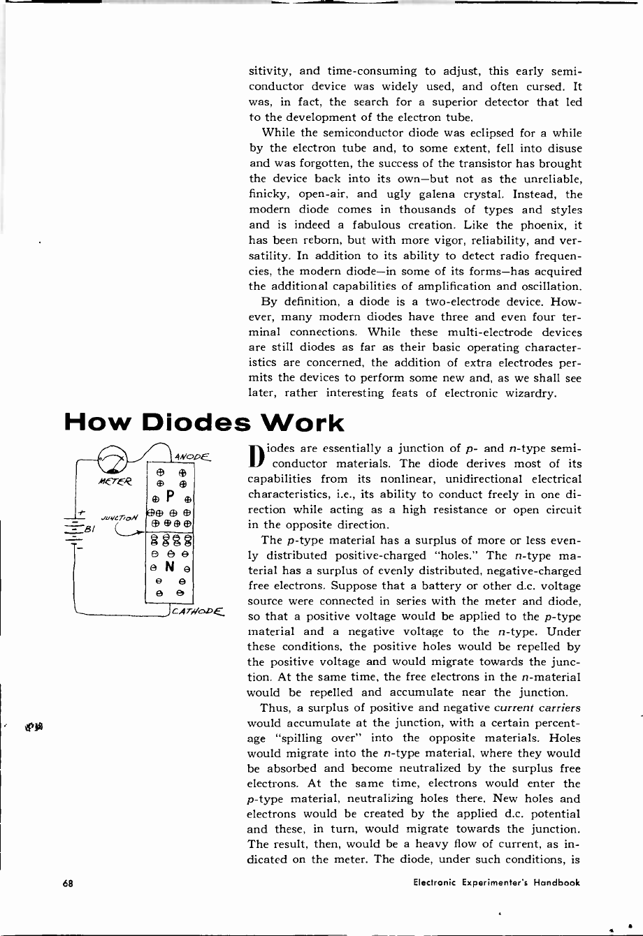
sitivity, and time-consuming to adjust, this early semi-
conductor device was widely used, and often cursed. It
was, in fact, the search for a superior detector that led
to the development of the electron tube.
While the semiconductor diode was eclipsed for a while
by the electron tube and, to some extent, fell into disuse
and was forgotten, the success of the transistor has brought
the device back into its own-but not as the unreliable,
finicky, open-air, and ugly galena crystal. Instead, the
modern diode comes in thousands of types and styles
and is indeed a fabulous creation. Like the phoenix, it
has been reborn, but with more vigor, reliability, and ver-
satility. In addition to its ability to detect radio frequen-
cies, the modern diode-in some of its forms-has acquired
the additional capabilities of amplification and oscillation.
By definition, a diode is a two -electrode device. How-
ever, many modern diodes have three and even four ter-
minal connections. While these multi -electrode devices
are still diodes as far as their basic operating character-
istics are concerned, the addition of extra electrodes per-
mits the devices to perform some new and, as we shall see
later, rather interesting feats of electronic wizardry.
How Diodes Work
qNooE,
® ®
e
e P e
_+ uyGea) ®ee®
=B 2égg
O ee
e N e
e e
e e
CAT{/ODE
Diodes are essentially a junction of p- and n -type semi-
conductor materials. The diode derives most of its
capabilities from its nonlinear, unidirectional electrical
characteristics, i.e., its ability to conduct freely in one di-
rection while acting as a high resistance or open circuit
in the opposite direction.
The p -type material has a surplus of more or less even-
ly distributed positive -charged "holes." The n -type ma-
terial has a surplus of evenly distributed, negative -charged
free electrons. Suppose that a battery or other d.c. voltage
source were connected in series with the meter and diode,
so that a positive voltage would be applied to the p -type
material and a negative voltage to the n -type. Under
these conditions, the positive holes would be repelled by
the positive voltage and would migrate towards the junc-
tion. At the same time, the free electrons in the n -material
would be repelled and accumulate near the junction.
Thus, a surplus of positive and negative current carriers
would accumulate at the junction, with a certain percent-
age "spilling over" into the opposite materials. Holes
would migrate into the n -type material, where they would
be absorbed and become neutralized by the surplus free
electrons. At the same time, electrons would enter the
p -type material, neutralizing holes there. New holes and
electrons would be created by the applied d.c. potential
and these, in turn, would migrate towards the junction.
The result, then, would be a heavy flow of current, as in-
dicated on the meter. The diode, under such conditions, is
68 Electronic Experimenter's Handbook
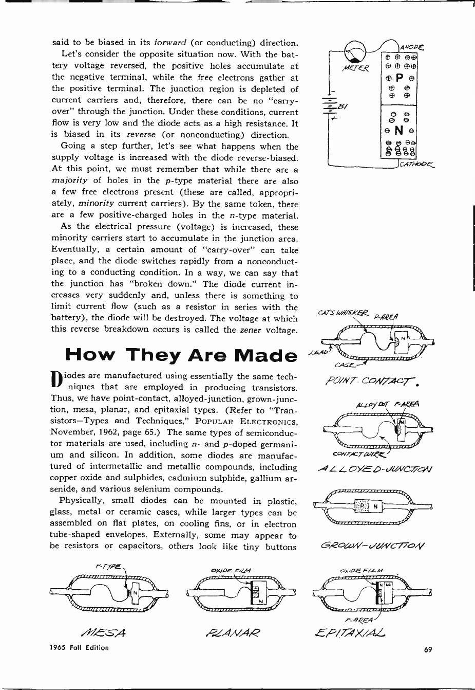
said to be biased in its forward (or conducting) direction.
Let's consider the opposite situation now. With the bat-
tery voltage reversed, the positive holes accumulate at
the negative terminal, while the free electrons gather at
the positive terminal. The junction region is depleted of
current carriers and, therefore, there can be no "carry-
over" through the junction. Under these conditions, current
flow is very low and the diode acts as a high resistance. It
is biased in its reverse (or nonconducting) direction.
Going a step further, let's see what happens when the
supply voltage is increased with the diode reverse -biased.
At this point, we must remember that while there are a
majority of holes in the p -type material there are also
a few free electrons present (these are called, appropri-
ately, minority current carriers). By the same token, there
are a few positive -charged holes in the n -type material.
As the electrical pressure (voltage) is increased, these
minority carriers start to accumulate in the junction area.
Eventually, a certain amount of "carry-over" can take
place, and the diode switches rapidly from a nonconduct-
ing to a conducting condition. In a way, we can say that
the junction has "broken down." The diode current in-
creases very suddenly and, unless there is something to
limit current flow (such as a resistor in series with the
battery), the diode will be destroyed. The voltage at which
this reverse breakdown occurs is called the zener voltage.
How They Are Made
Diodes are manufactured using essentially the same tech -
2 -7 niques that are employed in producing transistors.
Thus, we have point -contact, alloyed -junction, grown -junc-
tion, mesa, planar, and epitaxial types. (Refer to "Tran-
sistors-Types and Techniques," POPULAR ELECTRONICS,
November, 1962, page 65.) The same types of semiconduc-
tor materials are used, including n- and p -doped germani-
um and silicon. In addition, some diodes are manufac-
tured of intermetallic and metallic compounds, including
copper oxide and sulphides, cadmium sulphide, gallium ar-
senide, and various selenium compounds.
Physically, small diodes can be mounted in plastic,
glass, metal or ceramic cases, while larger types can be
assembled on flat plates, on cooling fins, or in electron
tube -shaped envelopes. Externally, some may appear to
be resistors or capacitors, others look like tiny buttons
AXE z -A
1965 Foil Edition
Merek
8/
t
r+IT'Skiif/sKóe o,9.?£A
CAS.e_
,po/Nr co,l/l-.acT.
,,L1.oyter P-A6S4
cO.vrAcrWí.e.
ALL. t2YEO-dUNGTicyV
G,2o(U,(/- d!/rVCToi{/
O)(lqE x.(/,i OXiOE F/LM
-yyyy
(/ N
P FIEA
4-P/7/70X/AZ
69
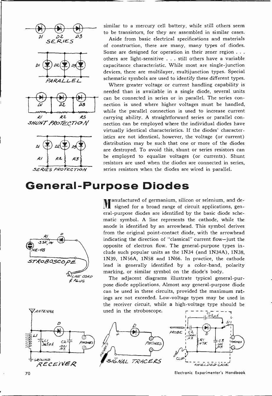
DI oz o3
SERJES
PARALLEL
At a3
AZ R3
s//[/NT P.H2TECT oN
5E.?/ES PROTECTioN
similar to a mercury cell battery, while still others seem
to be transistors, for they are assembled in similar cases.
Aside from basic electrical specifications and materials
of construction, there are many, many types of diodes.
Some are designed for operation in their zener region .. .
others are light-sensitive . . . still others have a variable
capacitance characteristic. While most are single -junction
devices, there are multilayer, multijunction types. Special
schematic symbols are used to identify these different types.
Where greater voltage or current handling capability is
needed than is available in a single diode, several units
can be connected in series or in parallel. The series con-
nection is used where higher voltages must be handled,
while the parallel connection is used to increase current
carrying ability. A straightforward series or parallel con-
nection can be employed where the individual diodes have
virtually identical characteristics. If the diodes' character-
istics are not identical, however, the voltage (or current)
distribution may be such that one or more of the diodes
are destroyed. To avoid this, shunt or series resistors can
be employed to equalize voltages (or currents). Shunt
resistors are used when the diodes are connected in series,
series resistors when the diodes are wired in parallel.
General -Purpose Diodes
ANTENNA
- GQcaUND
RECEiYE,Q
Manufactured of germanium, silicon or selenium, and de-
signed for a broad range of circuit applications, gen-
eral-purpose diodes are identified by the basic diode sche-
matic symbol. A line represents the cathode, while the
anode is identified by an arrowhead. This symbol derives
from the original point -contact diode, with the arrowhead
indicating the direction of "classical" current flow-just the
opposite of electron flow. The general-purpose types in-
clude such popular units as the 1N34 (and 1N34A), 1N38,
1N39, 1N56A, 1N58 and 1N66. In practice, the cathode
lead is generally identified by a color -band, polarity
marking, or similar symbol on the diode's body.
The adjacent diagrams illustrate typical general-pur-
pose diode applications. Almost any general-purpose diode
can be used in these circuits, provided the maximum rat-
ings are not exceeded. Low -voltage types may be used in
the receiver circuit, while a high -voltage type should be
used in the stroboscope. - - - - - - --
sir
PaoaE ; cz
Ì000l
SiGN,QL T,p.9CER_S CLIP L -1
-VAELDEO CASE
70 Electronic Experimenter's Handbook
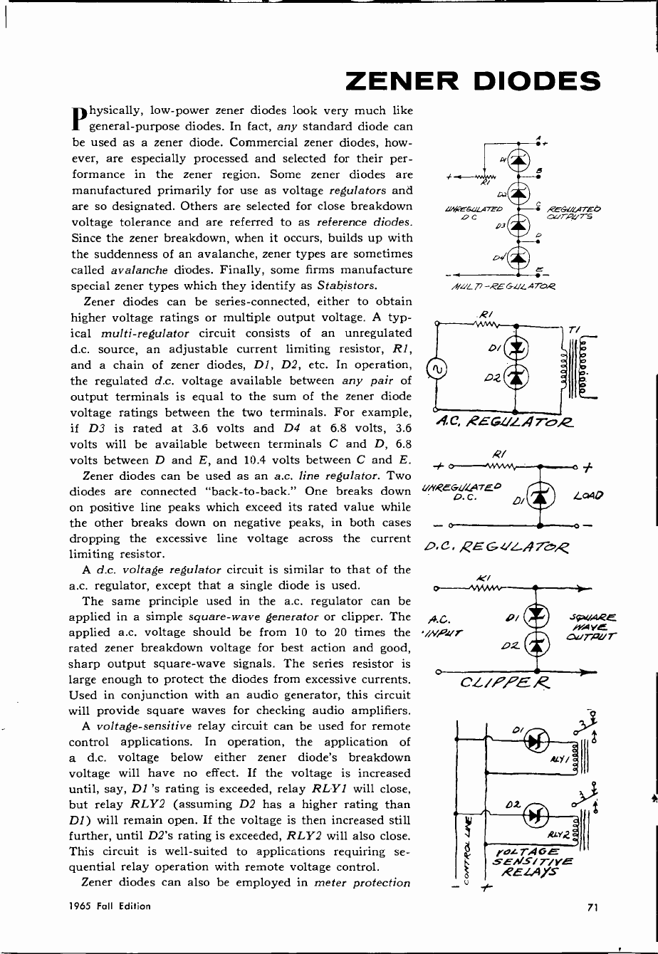
ZENER DIODES
Physically, low -power zener diodes look very much like
general-purpose diodes. In fact, any standard diode can
be used as a zener diode. Commercial zener diodes, how-
ever, are especially processed and selected for their per-
formance in the zener region. Some zener diodes are
manufactured primarily for use as voltage regulators and
are so designated. Others are selected for close breakdown
voltage tolerance and are referred to as reference diodes.
Since the zener breakdown, when it occurs, builds up with
the suddenness of an avalanche, zener types are sometimes
called avalanche diodes. Finally, some firms manufacture
special zener types which they identify as Stabistors.
Zener diodes can be series -connected, either to obtain
higher voltage ratings or multiple output voltage. A typ-
ical multi -regulator circuit consists of an unregulated
d.c. source, an adjustable current limiting resistor, R1,
and a chain of zener diodes, DI, D2, etc. In operation,
the regulated d.c. voltage available between any pair of
output terminals is equal to the sum of the zener diode
voltage ratings between the two terminals. For example,
if D3 is rated at 3.6 volts and D4 at 6.8 volts, 3.6
volts will be available between terminals C and D, 6.8
volts between D and E, and 10.4 volts between C and E.
Zener diodes can be used as an a.c. line regulator. Two
diodes are connected "back-to-back." One breaks down UNQEGl1(47E
4).C.
on positive line peaks which exceed its rated value while
the other breaks down on negative peaks, in both cases
dropping the excessive line voltage across the current
limiting resistor.
A d.c. voltage regulator circuit is similar to that of the
a.c. regulator, except that a single diode is used.
The same principle used in the a.c. regulator can be
applied in a simple square -wave generator or clipper. The
applied a.c. voltage should be from 10 to 20 times the
rated zener breakdown voltage for best action and good,
sharp output square -wave signals. The series resistor is
large enough to protect the diodes from excessive currents.
Used in conjunction with an audio generator, this circuit
will provide square waves for checking audio amplifiers.
A voltage -sensitive relay circuit can be used for remote
control applications. In operation, the application of
a d.c. voltage below either zener diode's breakdown
voltage will have no effect. If the voltage is increased
until, say, D1 's rating is exceeded, relay RLY1 will close,
but relay RLY2 (assuming D2 has a higher rating than
DI) will remain open. If the voltage is then increased still
further, until D2's rating is exceeded, RLY2 will also close.
This circuit is well -suited to applications requiring se-
quential relay operation with remote voltage control.
Zener diodes can also be employed in meter protection
D.C. ,QEGUL_,4Tv,e
cu
Uefle6L/L4rEel,
oC 03
RE6U(ArEb
aurvtrrs
i!/wc -,PEG[/LATo,e
R/
C. ,PEGLGATo,2.
LQaO
1965 Fall Edition 71
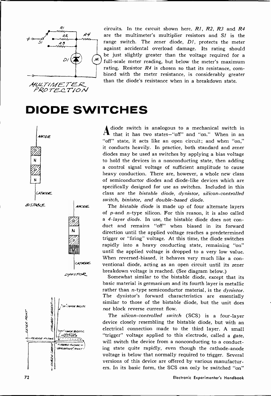
ziivz 7-/íuE7'EK
?go 7-70
circuits. In the circuit shown here, Rl, R2, R3 and R4
are the multimeter's multiplier resistors and SI is the
range switch. The zener diode, DI, protects the meter
against accidental overload damage. Its rating should
be just slightly greater than the voltage required for a
full-scale meter reading, but below the meter's maximum
rating. Resistor R4 is chosen so that its resistance, com-
bined with the meter resistance, is considerably greater
than the diode's resistance when in a breakdown state.
DIODE SWITCHES
MbDE
©
©
CA TAME
B/STii64,E
CATAIXIE.
DrNrsToe,_
Adiode switch is analogous to a mechanical switch in
that it has two states-"off" and "on." When in an
"off" state, it acts like an open circuit; and when "on,"
it conducts heavily. In practice, both standard and zener
diodes may be used as switches by applying a bias voltage
to hold the devices in a nonconducting state, then adding
a control signal voltage of sufficient amplitude to cause
heavy conduction. There are, however, a whole new class
of semiconductor diodes and diode -like devices which are
specifically designed for use as switches. Included in this
class are the bistable diode, dynistor, silicon -controlled
switch, binistor, and double -based diode.
The bistable diode is made up of four alternate layers
of p -and n -type silicon. For this reason, it is also called
a 4 -layer diode. In use, the bistable diode does not con-
duct and remains "off" when biased in its forward
direction until the applied voltage reaches a predetermined
trigger or "firing" voltage. At this time, the diode switches
rapidly into a heavy conducting state, remaining "on"
until the applied voltage is dropped to a very low value.
When reversed -biased, it behaves very much like a con-
ventional diode, acting as an open circuit until its zener
breakdown voltage is reached. (See diagram below.)
Somewhat similar to the bistable diode, except that its
basic material is germanium and its fourth layer is metallic
rather than n -type semiconductor material, is the dynistor.
The dynistor's forward characteristics are essentially
similar to those of the bistable diode, but the unit does
not block reverse current flow.
The silicon -controlled switch (SCS) is a four -layer
device closely resembling the bistable diode, but with an
electrical connection made to the third layer. A small
"trigger" voltage applied to this electrode, called a gate,
will switch the device from a nonconducting to a conduct-
ing state quite rapidly, even though the cathode -anode
voltage is below that normally required to trigger. Several
versions of this device are offered by various manufactur-
ers. In its basic form, the SCS can only be switched "on"
72 Electronic Experimenter's Handbook
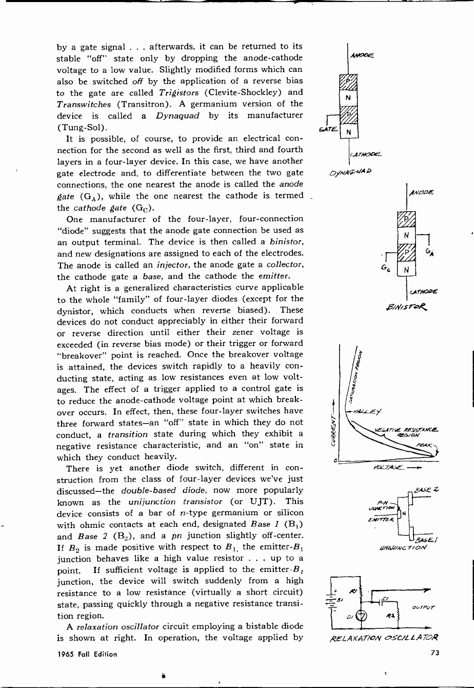
by a gate signal ... afterwards, it can be returned to its
stable "off" state only by dropping the anode -cathode
voltage to a low value. Slightly modified forms which can
also be switched off by the application of a reverse bias
to the gate are called Trigistors (Clevite-Shockley) and
Transwitches (Transitron). A germanium version of the
device is called a Dynaquad by its manufacturer
(Tung -Sol).
It is possible, of course, to provide an electrical con-
nection for the second as well as the first, third and fourth
layers in a four -layer device. In this case, we have another
gate electrode and, to differentiate between the two gate
connections, the one nearest the anode is called the anode
gate (GA), while the one nearest the cathode is termed
the cathode gate (Gc).
One manufacturer of the four -layer, four -connection
"diode" suggests that the anode gate connection be used as
an output terminal. The device is then called a binistor,
and new designations are assigned to each of the electrodes.
The anode is called an injector, the anode gate a collector,
the cathode gate a base, and the cathode the emitter.
At right is a generalized characteristics curve applicable
to the whole "family" of four -layer diodes (except for the
dynistor, which conducts when reverse biased). These
devices do not conduct appreciably in either their forward
or reverse direction until either their zener voltage is
exceeded (in reverse bias mode) or their trigger or forward
"breakover" point is reached. Once the breakover voltage
is attained, the devices switch rapidly to a heavily con-
ducting state, acting as low resistances even at low volt-
ages. The effect of a trigger applied to a control gate is
to reduce the anode -cathode voltage point at which break -
over occurs. In effect, then, these four -layer switches have
three forward states-an "off" state in which they do not
conduct, a transition state during which they exhibit a
negative resistance characteristic, and an "on" state in
which they conduct heavily.
There is yet another diode switch, different in con-
struction from the class of four -layer devices we've just
discussed-the double -based diode, now more popularly
known as the unijunction transistor (or UJT). This
device consists of a bar of n -type germanium or silicon
with ohmic contacts at each end, designated Base 1 (B1)
and Base 2 (B2), and a pn junction slightly off -center.
If B2 is made positive with respect to B1, the emitter -B1
junction behaves like a high value resistor . . . up to a
point. If sufficient voltage is applied to the emitter -B,
junction, the device will switch suddenly from a high
resistance to a low resistance (virtually a short circuit)
state, passing quickly through a negative resistance transi-
tion region.
A relaxation oscillator circuit employing a bistable diode
is shown at right. In operation, the voltage applied by
oymAP444o
SiNisTo
441Wrxw N
EM/171R
Z
Jg,cE¡
UNicRiNCT/oN
RELAXAT¡oN osC/LLATOR
1965 Fall Edition 73
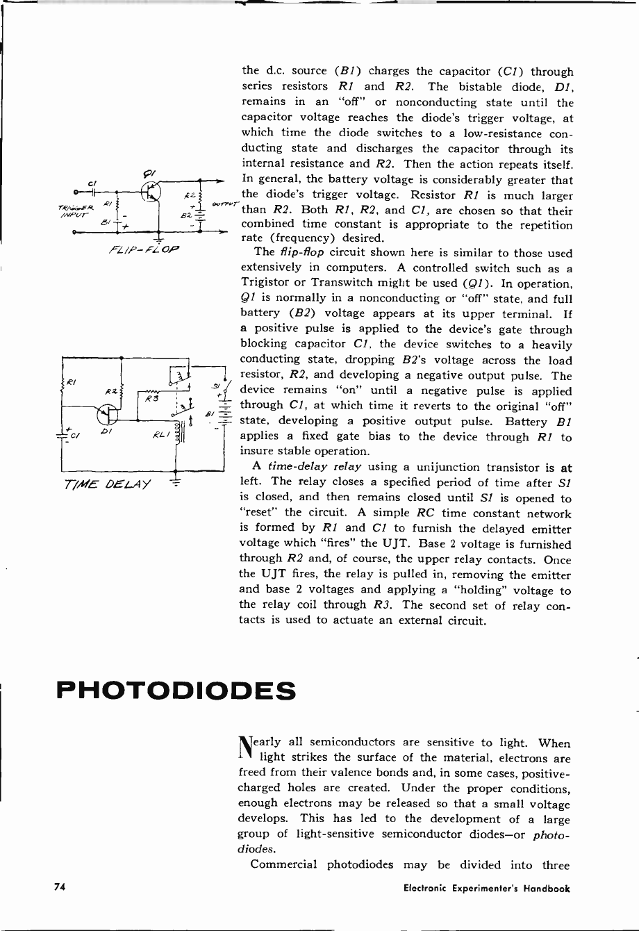
7R/GG.CR
/Nf(/T R/
FL/P- FL oP
T/ME DELAY
the d.c. source (BI) charges the capacitor (Cl) through
series resistors Rl and R2. The bistable diode, Dl,
remains in an "off" or nonconducting state until the
capacitor voltage reaches the diode's trigger voltage, at
which time the diode switches to a low -resistance con-
ducting state and discharges the capacitor through its
internal resistance and R2. Then the action repeats itself.
In general, the battery voltage is considerably greater that
the diode's trigger voltage. Resistor Rl is much larger
than R2. Both Rl, R2, and Cl, are chosen so that their
combined time constant is appropriate to the repetition
rate (frequency) desired.
The flip-flop circuit shown here is similar to those used
extensively in computers. A controlled switch such as a
Trigistor or Transwitch might be used (Q1). In operation,
Ql is normally in a nonconducting or "off" state, and full
battery (B2) voltage appears at its upper terminal. If
a positive pulse is applied to the device's gate through
blocking capacitor Cl, the device switches to a heavily
conducting state, dropping B2's voltage across the load
- resistor, R2, and developing a negative output pulse. The
device remains "on" until a negative pulse is applied
through Cl, at which time it reverts to the original "off"
B, state, developing a positive output pulse. Battery 131
applies a fixed gate bias to the device through RI to
insure stable operation.
A time -delay relay using a unijunction transistor is at
left. The relay closes a specified period of time after Si
is closed, and then remains closed until SI is opened to
"reset" the circuit. A simple RC time constant network
is formed by RI and Cl to furnish the delayed emitter
voltage which "fires" the UJT. Base 2 voltage is furnished
through R2 and, of course, the upper relay contacts. Once
the UJT fires, the relay is pulled in, removing the emitter
and base 2 voltages and applying a "holding" voltage to
the relay coil through R3. The second set of relay con-
tacts is used to actuate an external circuit.
PHOTODIODES
Nearly all semiconductors are sensitive to light. When
light strikes the surface of the material, electrons are
freed from their valence bonds and, in some cases, positive -
charged holes are created. Under the proper conditions,
enough electrons may be released so that a small voltage
develops. This has led to the development of a large
group of light-sensitive semiconductor diodes-or photo-
diodes.
Commercial photodiodes may be divided into three
74 Electronic Experimenter's Handbook

broad groups-photoresistive devices, photovoltaic devices,
and light -activated switches.
Photoresistive diodes have a resistance inversely pro-
portional to the amount of light falling on their sensitive
surface-the stronger the light, the lower their resistance.
Any of the standard semiconductor materials, including
germanium, silicon, and selenium, can be used for their
manufacture, but a good many are made with semicon-
ductor compounds such as cadmium sulphide.
Photovoltaic diodes ("sun batteries") generate a d.c.
voltage when light falls on their surface. In general, the
amplitude of the voltage developed is proportional to the
intensity of the light, up to a maximum fixed by the type
of material used in construction, while the amount of
current that can be delivered is proportional to the unit's
exposed sensitive area. Most present-day photovoltaic
diodes use either silicon or selenium as their basic material.
Light -activated switches are similar to four -layer diode
switches, except that they are mounted in a transparent
glass (or partial glass) enclosure to enable light to reach
the junction area. Their operation is similar to that of
diode switches, too, but with the gate trigger signal replaced
by light energy. The Photran, a unique type, has an elec-
trical connection provided for the normal gate terminal,
resulting in a three -electrode light-sensitive device.
The semiconductor laser is a special type of "photodiode"
which emits light. Typically, these units are made of
intermetallic compounds. Such a device may consist of a
small pn junction of gallium arsenide with the front and
back faces cut perfectly parallel to each other perpendic-
ular to the junction plane and highly polished. When
heavy current pulses are passed through the device, intense
coherent light is emitted perpendicular to the polished
surfaces along the pn junction. Typical pulse currents
may run as high as 20,000 amperes per square centimeter.
Electrical -to -light energy diode converters of this type are
nearly 100 per cent efficient. The emitted light, for a
gallium arsenide diode, is in the infrared region.
The standard photographic light meter circuit at right
is basically just a photovoltaic diode connected to a
sensitive microammeter. The meter scale may be cali-
brated either in terms of foot-candles or in camera
shutter/iris settings.
The automatic light switch consists of a photoresistive
diode connected in series with a sensitive relay and a d.c.
power source. As long as there is sufficient light on the
diode, its resistance is kept low and it passes sufficient
current to hold the relay closed. When darkness falls,
the diode's resistance increases, reducing relay coil current
and allowing the relay to drop out, closing the lamp
contacts.
Another photographic instrument circuit is a remote
slave flash. A light -activated switch is connected in series
6G ASS
CASE
UT//oDE
1 /LEAO
B
ANJLE
LEAD
L/U.s`rACT/.4TE0
TOP Et_ECTROOE
ALK
.lIMCT/O/(/
s/DE
rprTOM C[LCTPODD `L/GNY E.f//SLO/i/
LASER
G/!T il/ETEK
L/6//r ta//TrH
1965 Fall Edition
.r
75
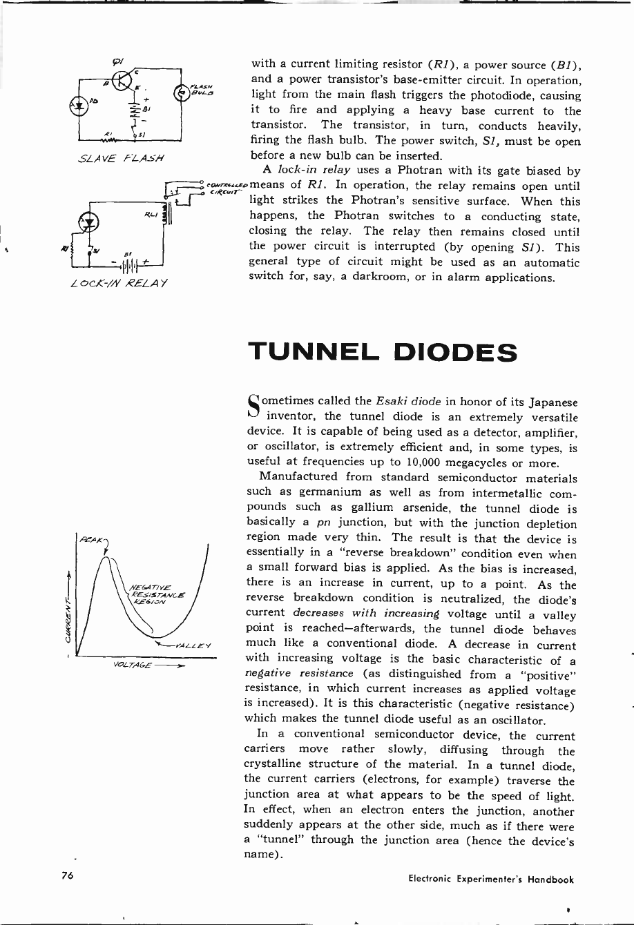
SLAVE FLAsN
FLA2M
BYLO light from the main flash triggers the photodiode, causing
it to fire and applying a heavy base current to the
transistor. The transistor, in turn, conducts heavily,
firing the flash bulb. The power switch, SI, must be open
before a new bulb can be inserted.
A lock -in relay uses a Photran with its gate biased by
eawxromeans of Rl. In operation, the relay remains open until
uecvs' light strikes the Photran's sensitive surface. When this
happens, the Photran switches to a conducting state,
closing the relay. The relay then remains closed until
the power circuit is interrupted (by opening Si). This
general type of circuit might be used as an automatic
switch for, say, a darkroom, or in alarm applications.
VOLTAGE -- -
with a current limiting resistor (R1), a power source (B1),
and a power transistor's base -emitter circuit. In operation,
TUNNEL DIODES
Sometimes called the Esaki diode in honor of its Japanese
inventor, the tunnel diode is an extremely versatile
device. It is capable of being used as a detector, amplifier,
or oscillator, is extremely efficient and, in some types, is
useful at frequencies up to 10,000 megacycles or more.
Manufactured from standard semiconductor materials
such as germanium as well as from intermetallic com-
pounds such as gallium arsenide, the tunnel diode is
basically a pn junction, but with the junction depletion
region made very thin. The result is that the device is
essentially in a "reverse breakdown" condition even when
a small forward bias is applied. As the bias is increased,
there is an increase in current, up to a point. As the
reverse breakdown condition is neutralized, the diode's
current decreases with increasing voltage until a valley
point is reached-afterwards, the tunnel diode behaves
much like a conventional diode. A decrease in current
with increasing voltage is the basic characteristic of a
negative resistance (as distinguished from a "positive"
resistance, in which current increases as applied voltage
is increased). It is this characteristic (negative resistance)
which makes the tunnel diode useful as an oscillator.
In a conventional semiconductor device, the current
carriers move rather slowly, diffusing through the
crystalline structure of the material. In a tunnel diode,
the current carriers (electrons, for example) traverse the
junction area at what appears to be the speed of light.
In effect, when an electron enters the junction, another
suddenly appears at the other side, much as if there were
a "tunnel" through the junction area (hence the device's
name).
76 Electronic Experimenter's Handbook
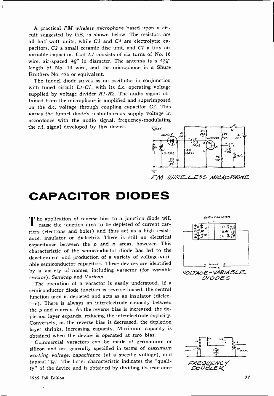
A practical FM wireless microphone based upon a cir-
cuit suggested by GE, is shown below. The resistors are
all half -watt units, while C3 and C4 are electrolytic ca-
pacitors, C2 a small ceramic disc unit, and Cl a tiny air
variable capacitor. Coil LI consists of six turns of No. 16
wire, air -spaced /8" in diameter. The antenna is a 43/4"
length of No. 14 wire, and the microphone is a Shure
Brothers No. 42G or equivalent.
The tunnel diode serves as an oscillator in conjunction
with tuned circuit Ll-C1, with its d.c. operating voltage
supplied by voltage divider R1 -R2. The audio signal ob-
tained from the microphone is amplified and superimposed
on the d.c. voltage through coupling capacitor C3. This
varies the tunnel diode's instantaneous supply voltage in
accordance with the audio signal, frequency -modulating
the r.f. signal developed by this device. ,M,r
/,W93
PM LU/RELE55 iN/C,QoPfiaVE
CAPACITOR DIODES
The application of reverse bias to a junction diode will
cause the junction area to be depleted of current car-
riers (electrons and holes) and thus act as a high resist-
ance, insulator or dielectric. There is still an electrical
capacitance between the p and n areas, however. This
characteristic of the semiconductor diode has led to the
development and production of a variety of voltage -vari-
able semiconductor capacitors. These devices are identified
by a variety of names, including varactor (for variable
reactor), Semicap and Varicap.
The operation of a varactor is easily understood. If a
semiconductor diode junction is reverse -biased, the central
junction area is depleted and acts as an insulator (dielec-
tric). There is always an interelectrode capacity between
the p and n areas. As the reverse bias is increased, the de-
pletion layer expands, reducing the interelectrode capacity.
Conversely, as the reverse bias is decreased, the depletion
layer shrinks, increasing capacity. Maximum capacity is
obtained when the device is operated at zero bias.
Commercial varactors can be made of germanium or
silicon and are generally specified in terms of maximum
working voltage, capacitance (at a specific voltage), and
typical "Q." The latter characteristic indicates the "quali-
ty" of the device and is obtained by dividing its reactance
I/jT.qy4Ms4
"%*
®®
®®
e eN e
e 2) e¢
t
se -e
VOLT,46E - VAR/ABLE
,D/ 00E S
t"er...r
FREQ!/ENC y
QpUgLER
1965 Fall Edition 77
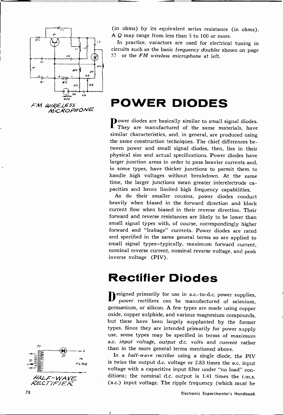
/ci
-.---,
utir
r
¡,(iZRELESS
miCROP/fONE
+
ro
Fic rEQ
NQLF- WAYE
RECT/F'/ER
(in ohms) by its equivalent series resistance (in ohms).
A Q may range from less than 5 to 100 or more.
In practice, varactors are used for electrical tuning in
circuits such as the basic frequency doubler shown on page
77 or the FM wireless microphone at left.
POWER DIODES
Power diodes are basically similar to small signal diodes.
They are manufactured of the same materials, have
similar characteristics, and, in general, are produced using
the same construction techniques. The chief differences be-
tween power and small signal diodes, then, lies in their
physical size and actual specifications. Power diodes have
larger junction areas in order to pass heavier currents and,
in some types, have thicker junctions to permit them to
handle high voltages without breakdown. At the same
time, the larger junctions mean greater interelectrode ca-
pacities and hence limited high frequency capabilities.
As do their smaller cousins, power diodes conduct
heavily when biased in the forward direction and block
current flow when biased in their reverse direction. Their
forward and reverse resistances are likely to be lower than
small signal types with, of course, correspondingly higher
forward and "leakage" currents. Power diodes are rated
and specified in the same general terms as are applied to
small signal types-typically, maximum forward current,
nominal reverse current, nominal reverse voltage, and peak
inverse voltage (PIV).
Rectifier Diodes
Designed primarily for use in a.c.-to-d.c. power supplies,
power rectifiers can be manufactured of selenium,
germanium, or silicon. A few types are made using copper
oxide, copper sulphide, and various magnesium compounds,
but these have been largely supplanted by the former
types. Since they are intended primarily for power supply
use, some types may be specified in terms of maximum
a.c. input voltage, output d.c. volts and current rather
than in the more general terms mentioned above.
In a half -wave rectifier using a single diode, the PIV
is twice the output d.c. voltage or 2.83 times the a.c. input
voltage with a capacitive input filter under "no load" con-
ditions; the nominal d.c. output is 1.41 times the r.m.s.
(a.c.) input voltage. The ripple frequency (which must be
78 Electronic Experimenter's Handbook
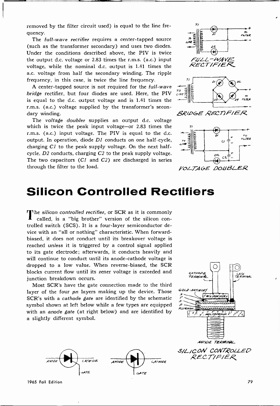
removed by the filter circuit used) is equal to the line fre-
quency.
The full -wave rectifier requires a center -tapped source
(such as the transformer secondary) and uses two diodes.
Under the conditions described above, the PIV is twice
the output d.c. voltage or 2.83 times the r.m.s. (a.c.) input
voltage, while the nominal d.c. output is 1.41 times the
a.c. voltage from half the secondary winding. The ripple
frequency, in this case, is twice the line frequency.
A center -tapped source is not required for the full -wave
bridge rectifier, but four diodes are used. Here, the PIV
is equal to the d.c. output voltage and is 1.41 times the
r.m.s. (a.c.) voltage supplied by the transformer's secon-
dary winding.
The voltage doubler supplies an output d.c. voltage
which is twice the peak input voltage-or 2.83 times the
r.m.s. (a.c.) input voltage. The PIV is equal to the d.c.
output. In operation, diode Dl conducts on one half -cycle,
charging Cl to the peak supply voltage. On the next half -
cycle, D2 conducts, charging C2 to the peak supply voltage.
The two capacitors (Cl and C2) are discharged in series
through the filter to the load.
T/
F.1/LL -/vsj
RECT/F/E
5,e/DGE RECT/F/ER
T/
TO
F tTPR
I -OL -TOGE DOUBLER
Silicon Controlled Rectifiers
The silicon controlled rectifier, or SCR as it is commonly
called, is a "big brother" version of the silicon con-
trolled switch (SCS). It is a four -layer semiconductor de-
vice with an "all or nothing" characteristic. When forward -
biased, it does not conduct until its breakover voltage is
reached unless it is triggered by a control signal applied
to its gate electrode; afterwards, it conducts heavily and
will continue to conduct until its anode -cathode voltage is
dropped to a low value. When reverse -biased, the SCR
blocks current flow until its zener voltage is exceeded and
junction breakdown occurs.
Most SCR's have the gate connection made to the third
layer of the four pn layers making up the device. Those
SCR's with a cathode gate are identified by the schematic
symbol shown at left below while a few types are equipped
with an anode gate (at right below) and are identified by
a slightly different symbol.
cAr.N DE ANODE c,A7NuoE
.!V E TERM/N4I_
S/L./CoN CONT,PoLLEO
1965 Fall Edition 79
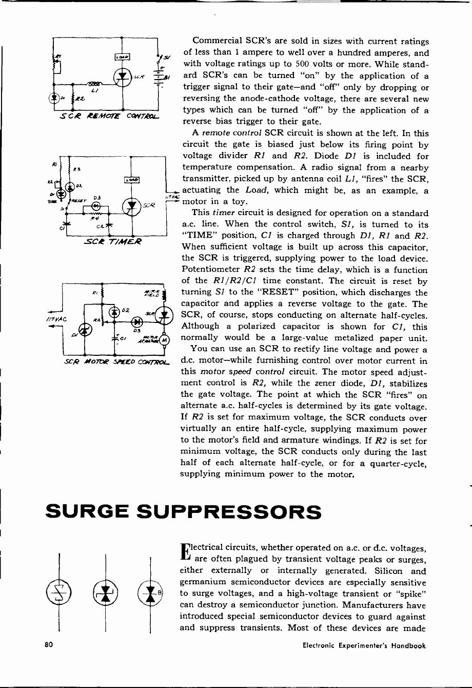
ei
nrr
S Coe ,eEMoTf C4Vri(ìCU_
see T/MER
SCR M0722Q SPEED CYWrR12L
Commercial SCR's are sold in sizes with current ratings
of less than 1 ampere to well over a hundred amperes, and
with voltage ratings up to 500 volts or more. While stand-
ard SCR's can be turned "on" by the application of a
trigger signal to their gate-and "off" only by dropping or
reversing the anode -cathode voltage, there are several new
types which can be turned "off" by the application of a
reverse bias trigger to their gate.
A remote control SCR circuit is shown at the left. In this
circuit the gate is biased just below its firing point by
voltage divider R1 and R2. Diode D1 is included for
temperature compensation. A radio signal from a nearby
transmitter, picked up by antenna coil Ll, "fires" the SCR,
actuating the Load, which might be, as an example, a
7vC motor in a toy.
This timer circuit is designed for operation on a standard
a.c. line. When the control switch, SI, is turned to its
"TIME" position, Cl is charged through DI, Rl and R2.
When sufficient voltage is built up across this capacitor,
the SCR is triggered, supplying power to the load device.
Potentiometer R2 sets the time delay, which is a function
of the R1/R2/C1 time constant. The circuit is reset by
turning SI to the "RESET" position, which discharges the
capacitor and applies a reverse voltage to the gate. The
SCR, of course, stops conducting on alternate half -cycles.
Although a polarized capacitor is shown for Cl, this
normally would be a large -value metalized paper unit.
You can use an SCR to rectify line voltage and power a
d.c. motor-while furnishing control over motor current in
this motor speed control circuit. The motor speed adjust-
ment control is R2, while the zener diode, D1, stabilizes
the gate voltage. The point at which the SCR "fires" on
alternate a.c. half -cycles is determined by its gate voltage.
If R2 is set for maximum voltage, the SCR conducts over
virtually an entire half -cycle, supplying maximum power
to the motor's field and armature windings. If R2 is set for
minimum voltage, the SCR conducts only during the last
half of each alternate half -cycle, or for a quarter -cycle,
supplying minimum power to the motor.
SURGE SUPPRESSORS
Electrical circuits, whether operated on a.c. or d.c. voltages,
are often plagued by transient voltage peaks or surges,
either externally or internally generated. Silicon and
germanium semiconductor devices are especially sensitive
to surge voltages, and a high -voltage transient or "spike"
can destroy a semiconductor junction. Manufacturers have
introduced special semiconductor devices to guard against
and suppress transients. Most of these devices are made
80 Electronic Experimenter's Handbook

up by connecting a suitable pair of selenium zener diodes
back-to-back and are identified by a variety of trade
names, depending on the manufacturer, including Voltrap,
Thyrector, Klip-Sel, and Silgard.
Typical surge protector applications are illustrated here.
A single unit is used in one circuit to protect the a.c. volt-
age supplied to a load by a transformer. A pair of units
are frequently used in a full -wave rectifier to protect the
rectifier diodes against transients. Circuit operation is
similar in both cases. Under normal conditions, the surge
suppressors act as open circuits, since one or the other of
the two diode elements making up the device is always
reverse -biased. If a transient voltage spike or surge occurs
which exceeds the device's rating, the unit goes into zener
breakdown, shorting out the surge.
SURGE PROTECT/ON
FLL 4'4E Su &E PROTECT/OÁ'
THERMOELECTRIC
DIODES
Although not a "diode" in the classical sense, the thermo-
electric diode is a thermocouple -type device with a
variety of applications. It consists of p- and n -type semi-
conductors bonded together by copper or similar high -
conductivity metal. Straps are connected to the opposite
ends of the semiconductor bars for electrical connections
and the two ends of the bars are thermally insulated.
If the connection straps are attached to an insulated heat
sink and heat is applied to the sides of the semiconductors
which are bonded together, the electrons and positive holes
in the n -type and p -type semiconductors, respectively,
70rAAre
e
o e
ewe
o
NEAT souvCE
11
A
CUVNCCJroNST:ZZAD
(NWIN20 M'NLK>iNK/
TffERMOEL ECTR/C D/ODE
undergo thermal diffusion from the high- to the low -
temperature side, developing a potential difference. This
voltage can be used as an effective power source for a
standard electrical load as long as a temperature difference
is maintained between the two sides of the device. Thus,
the unit becomes a heat -to -electrical energy converter.
The output voltage supplied by a single element is rela-
tively small, and commercial thermoelectric generators
generally are made up of a number of elements in a series -
parallel arrangement to obtain usable voltages at fairly
1965 Foil Edition if
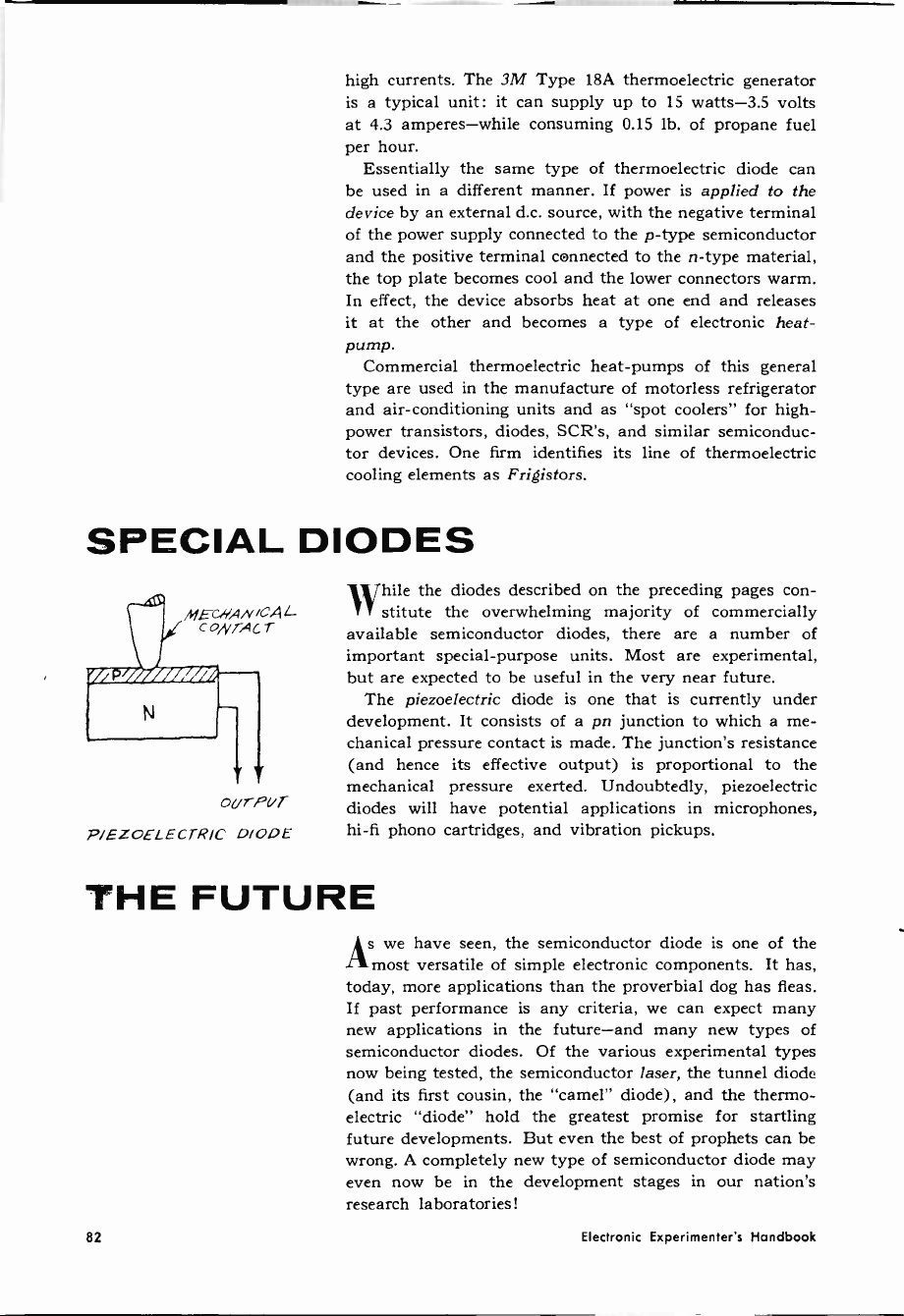
high currents. The 3M Type 18A thermoelectric generator
is a typical unit: it can supply up to 15 watts -3.5 volts
at 4.3 amperes-while consuming 0.15 lb. of propane fuel
per hour.
Essentially the same type of thermoelectric diode can
be used in a different manner. If power is applied to the
device by an external d.c. source, with the negative terminal
of the power supply connected to the p -type semiconductor
and the positive terminal connected to the n -type material,
the top plate becomes cool and the lower connectors warm.
In effect, the device absorbs heat at one end and releases
it at the other and becomes a type of electronic heat -
pump.
Commercial thermoelectric heat -pumps of this general
type are used in the manufacture of motorless refrigerator
and air-conditioning units and as "spot coolers" for high -
power transistors, diodes, SCR's, and similar semiconduc-
tor devices. One firm identifies its line of thermoelectric
cooling elements as Frigistors.
SPECIAL DIODES
oUrPUT
P/EZoELECTRIC D/ODE
While the diodes described on the preceding pages con-
stitute the overwhelming majority of commercially
available semiconductor diodes, there are a number of
important special-purpose units. Most are experimental,
but are expected to be useful in the very near future.
The piezoelectric diode is one that is currently under
development. It consists of a pn junction to which a me-
chanical pressure contact is made. The junction's resistance
(and hence its effective output) is proportional to the
mechanical pressure exerted. Undoubtedly, piezoelectric
diodes will have potential applications in microphones,
hi-fi phono cartridges, and vibration pickups.
THE FUTURE
As we have seen, the semiconductor diode is one of the
most versatile of simple electronic components. It has,
today, more applications than the proverbial dog has fleas.
If past performance is any criteria, we can expect many
new applications in the future-and many new types of
semiconductor diodes. Of the various experimental types
now being tested, the semiconductor laser, the tunnel diode
(and its first cousin, the "camel" diode), and the thermo-
electric "diode" hold the greatest promise for startling
future developments. But even the best of prophets can be
wrong. A completely new type of semiconductor diode may
even now be in the development stages in our nation's
research laboratories!
82 Electronic Experimenter's Handbook

SOMEONE SHOULD DEVELOP AN EASY WAY
TO LEARN ELECTRONICS AT HOME
RCA INSTITUTES DID!
RCA introduces new CAREER PROGRAMS
- beginning with the student -proved
"AUTOTEXT" Programmed Instruction
Method-the faster, easier way to learn.
You start to learn the field of your choice
immediately. No previous training or ex-
perience needed.
Pick the career of your choice-and RCA
Institutes will do the rest! RCA's new, rev-
olutionary "Career Programs" help you go
directly to the career you want! You waste
no time learning things you'll never use
on your job! Each Career Program is de-
signed to get you into the kind of job you
want in the fastest, easiest possible way!
SEPARATE COURSES
In addition, in order to meet specific
needs, RCA Institutes offers a wide variety
of separate courses which may be taken
independently of the above Career Pro-
grams, on all subjects from Electronics
Fundamentals to Computer Programming.
Complete information about these courses
will be sent with your other materials.
CHOOSE A CAREER PROGRAM NOW
your first step to the job of your choice!
Television Servicing
Telecommunications
FCC License Preparation
Automation Electronics
Automatic Controls
Digital Techniques
Industrial Electronics
Nuclear Instrumentation
Solid State Electronics
Electronics Drafting
RCA INSTITUTES BONUS EXTRAS
Only RCA Institutes offers you a Liberal
Tuition Plan, one of the most economical
ways to learn. Plus, you get top quality
equipment in all kits furnished to you with
your courses-yours to keep and use on
the job. And now, RCA's NEW PRO-
GRAMMED ELECTRONIC BREADBOARD
GIVES YOU LIMITLESS EXPERIMENTA-
TION-scientific laboratory procedures
right in your own home! You build a work-
ing signal generator, AM Receiver, Multi-
meter, Oscilloscope, and other valuable
equipment - ALL AS A PART OF YOUR
COURSE! Get the facts today!
Classroom Training Also Available. Day
and Evening Classes are available to you
in New York City at RCA Institutes Resi
dent School. You may be admitted with-
out any previous technical training; prep
courses are available if you haven't com-
pleted high school. Coeducational classes
start four times a year.
SEND ATTACHED POSTCARD TODAY FOR
COMPLETE INFORMATION. NO OBLIGA-
TION. NO SALESMAN WILL CALL. FREE
BOOK INCLUDED. CHECK HOME STUDY
OR CLASSROOM TRAINING.
RCA INSTITUTES, INC.,: s5
A Service of the Radio Corporat.on of America
350 West 4th St.. New York City 10014
The Most Trusted Name in Electronics
CIRCLE NO. 24 ON READER SERVICE CARD
1965 Fall Edition 85

NOW YOU CAN EASILY ADD
SOUND TO YOUR SLIDE
OR FILM SHOWS WITH
POPULAR PHOTOGRAPHY'S
EXCITING NEW
"SOUND FOR A
PICTURE EVENING"
RECORD ALBUM
SOUND FOR
A PICTL; R I+; EVENIN
"Sound For A Picture Everting"
Consists at selections (torn the music masters
of the Capitol Record Hollywood Library
High Fidefiry 1Z Inch vinyl album -33K RPM
'laying hme'. 40 minutes
AVAILABLE IN MONAURAL OR
ELECTRONIC STEREO AT NO EXTRA COST
EXPRESSLY CREATED FOR FILM
AND SLIDE SHOWS
No netter how good your film and slide shows are, sound will
make them better... more entertaining and certainly more pro-
fessional. But, it has to be the right kind of sound. Although
any t usical record can be used as a background for your film
and side shows, few, if any, can match the variety of actions.
situations. and scenes inherent in most shows. That's why
Popular Photography created this album. it's ideal for almost
every mood captured by your came,a. Whether your show is
simple, elaborate or somewhere in-between-"SOUND FOR A
PICTURE EVENING" provides a final, professional touch to
make it a complete success.
A POPULAR PHOTOGRAPHY
EXCLUSIVE
The 'Sound For A Picture Evening" album has been produced
by the editors of Popular Photography exclusively for our read
ers and is prepared by the Custom Services Division of Capitol
Records. This outstanding album cannot be purchased in any
store and is available by mail only to the readers of Popular
Photography and other Ziff'Oavis magazines.
ALBUM CONTENTS:
17 SPECIFIC MOOD MUSIC
BACKGROUNDS
8 TRACKS FOR SPECIAL
SOUND EFFECTS
THEMES TO MATCH YOUR
SUBJECTS... PERFECTLY!
3 FILM OPENINGS: Grandiose. Sweet and Gentle an
Dramatic 3 FILM CLOSINGS: Epic Finale, Hollyw
Style and Gentle 11 THEMES: HappyGoLucky G
Parte Vacation Tempo Traveling Happy Birthd
Part. Pomp of a Parade Sound of a Carousel C
cus Time Sentimental Moments Children's PM
time Christmas Time
DON'T MISS OUT ON THIS OUTSTANDING OFFER.
FILL IN AND MAIL TODAY
FOR SPECIAL SITUATIONS,
THESE WONDERFULLY REALISTIC
SOUND EFFECTS
Ocean Waves Train let Planes Baby Crying Crowd
1n Stadium Traffic Dog Barking Thunder
FREE! WITH YOUR ALBU
PURCHASE - IF YOU ORDER N
Complete Instruction Booklet-Here, in one comp
tooklet,is all the information you need to make y
side show a resounding success. You will find help
tow to build an effective sound track. choosing the rig
t round selections and sound effects. synchronization.
organizing your show, editing and much more.
AND POINTER-Fi
where to find the
Limbling and
This wonderful 12" longplaying album 'i
(a must for every slide and film show impressario)
can be yours for
ONLY $3.49 POSTPAID
MONAURAL OR ELECTRONIC STEREO
a small price to pay for an album you will enjoy
Z,12W,
"Sound For A Picture Evening"
POPULAR PHOTOGRAPH"-Dept. SD
One Park Avenue, New York, N.Y. 10016
Please send me albums at $3.49 each. My
check (or money order) for $ is enclosed I
understand that you will pay the postage. (Add 75q to
partially defray postage costs outside t:.S.A.)
CHECK ONE: MONO D STEREO
Name
Address
City State lip Code_
Sorry-No Charges or C.O.D. Orders ELM
86 Electronic Experimenter's Handbook
CHAPTER
4
SCIENCE
FAIR
PROJECTS
Each year tens of thousands of high school and
junior college students enter "Science Fair" con-
tests. Originated to encourage more interest in
science at school levels, the "Science Fair" has
gradually become a highly competitive event with
prizes worth hundreds and even thousands of dol-
lars. Electronics has always played a prominent
role in "Science Fairs"-partially because of the
space-age interest, and partially because of the
visual effects that electronics projects offer to the
public.
For this portion of the Fall 1965 ELECTRON-
IC EXPERIMENTER'S HANDBOOK, the Edit-
ors have selected three "Science Fair" projects
that are sure winners. In each story all of the
necessary construction details are presented to
make the project operative, but only a minimum
of background theory is included. This presenta-
tion is in keeping with the philosophy of "Science
Fairs" in that the student must analyze the sub-
ject matter and then demonstrate his findings.
The "Repulsion Coil" project on page 88 demon-
strates the principle of resonance using 60 -cycle
house current. Two visual effects offered by this
project are a reciprocal resonant engine and a
magnetic gun. The "Big TC" Tesla Coil (page
93) has been a "Science Fair" winner since its
original appearance in the July 1964 issue of
POPULAR ELECTRONICS. This article has
been brought up to date and, as can be seen in our
cover photo, the spark output greatly increased.
Extra safety precautions have been incorporated
in the revised circuit. A small Tesla coil using
commonly available TV components is shown on
page 99. This "Li'l TC" can be used to demon-
strate brush discharges from high -frequency,
high -voltage power supplies, or even to spin a
near -weightless aluminum vane.
88
A 60 -CYCLE REPULSION COIL-RESONANCE ENGINE
Walter B. Ford
93
BIG TC Charles Caringella, W6NJV
99
LI'L TC Edwin N. Kaufman
1965 Fall Edition 87
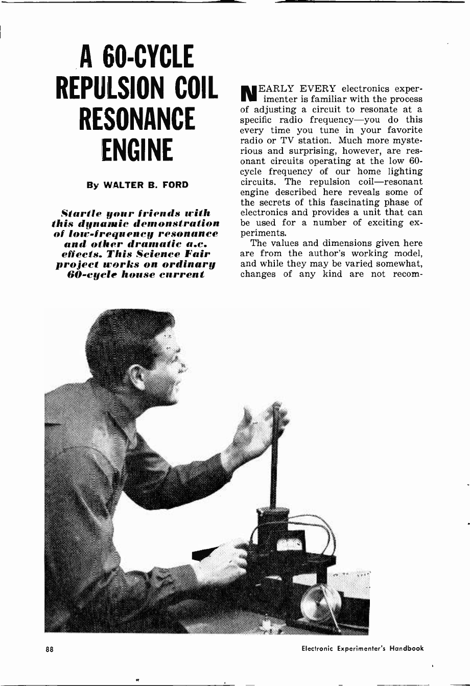
A 60 -CYCLE
REPULSION COIL
RESONANCE
ENGINE
By WALTER B. FORD
Startle your friends with
this dynamic. demonstration
of loir -frequency resonance
and other dramatic a.c.
effcris. This Science Fair
pro jeet Yorks on ordinary
60 -cycle house eurrent
NEARLY EVERY electronics exper-
imenter is familiar with the process
of adjusting a circuit to resonate at a
specific radio frequency-you do this
every time you tune in your favorite
radio or TV station. Much more myste-
rious and surprising, however, are res-
onant circuits operating at the low 60 -
cycle frequency of our home lighting
circuits. The repulsion coil-resonant
engine described here reveals some of
the secrets of this fascinating phase of
electronics and provides a unit that can
be used for a number of exciting ex-
periments.
The values and dimensions given here
are from the author's working model,
and while they may be varied somewhat,
changes of any kind are not recom-
88 Electronic Experimenter's Handbook

Constructed on a black lacquer wooden base, the
resonant -coil engine is an impressive -looking unit.
mended unless the experimenter under-
stands what effect the changes will have
on the operation of the unit. If, for ex-
ample, capacitors of lower value are
used, the stroke of the engine piston will
change. This will mean that there will
have to be a proportionate change in the
length of the flywheel crank.
Making the Coil. The inductive part of
the series -resonant LC circuit used in
the unit is in coil Li. Begin by making
up a coil form as shown in Fig. 1 (page
90) . Although plain wood discs may be
used for the ends, plywood, fiber, or Mi -
carta is preferred, since there is less
chance of breakage if the coil is acci-
dentally dropped. The center tubing can
be Micarta, Bakelite, or fiber, or can be
made by drilling a .3á " hole lengthwise in
a piece of 3/ ' dowel rod. Whichever ma-
terial is used, make sure the inside sur-
face is smooth, sanding if necessary, so
the engine piston will travel freely.
Complete the coil form by drilling
holes in the end discs that make a snug
fit around the center tubing, and gluing
the ends and tubing together with epoxy
glue. This step is important because there
will be considerable pressure against
the ends when the wire is in place on the
coil. Drill 146" holes through one end of
the coil form for the coil leads as indi-
cated in Fig. 1. Drill and tap two holes
for 6-32 machine screws in the same end
of the form to hold the completed coil
to its base (if wood is used, wood screws
can be used and the threaded holes will
not be needed). Wind the coil form with
21/2 pounds of 24 -gauge magnet wire.
While it is not necessary to wind the coil
perfectly, like thread on a spool, it
should not be allowed to pile up at any
one point.
Constructing the Cores. Uncoil enough
16- or 18 -gauge soft iron wire to make
the engine core, grip one end in a vise,
grasp the opposite end with a pair of
pliers, and pull until you can feel the
wire stretch somewhat. This will
straighten the wire. Cut the wire into
434 lengths and make forms to hold
the bundle in cylinder form from pieces
of thin -wall metal or plastic tubing.
Holes (/16") drilled in small pieces of
wood or cardboard can also serve the
purpose. Since the forms must be cut
away after the core is glued, keep their
outside dimensions down to a minimum.
Bundle the 43'," wires together and
insert them in the forms. Press the end
of a screw eye into the center of one
end of the core, and cut off the ends of
the wires forced out of the core at the
opposite end. Withdraw the screw eye-
it will be fastened permanently later.
Apply epoxy glue to the areas of the
core not covered by the forms holding
the core wires and allow the glue to set.
The type of epoxy glue that will set with
artificial heat is preferred for this, since
Straighten the iron wire for the cores by stretch-
ing it as explained in text. Then cut and bundle
the wires into cylindrical form as shown in Fig. 2.
1965 Fall Edition 89
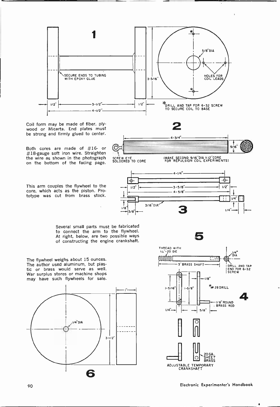
1
\SECURE ENDS TO TUBING
WITH EPDXY GLUE
--{ I/2' - 3 1/2"
I
I/2"
I 4 I/2"
Coil form may be made of fiber, ply-
wood or Micarta. End plates must
be strong and firmly glued to center.
Both cores are made of #16- or
#18 -gauge soft iron wire. Straighten
DRILL AND TAP FOR 6-32 SCREW
TO SECURE COIL TO BASE
2
4 3/4"
9i
the wire as shown in the photograph SCREW EYE
on the bottom of the facing page. SOLDERED TO CORE
This arm couples the flywheel to the
core, which acts as the piston. Pro-
totype was cut from brass stock.
Several small parts must be fabricated
to connect the arm to the flywheel.
At right, below, are two possible ways
of constructing the engine crankshaft.
The flywheel weighs about 15 ounces.
The author used aluminum, but plas-
tic or brass would serve as well.
War surplus stores or machine shops
may have such flywheels for sale.
6
(MAKE SECOND 9/16"DIA X 12"CORE
FOR REPULSION COIL EXPERIMENTS)
3/IB'DIA""
3 5/8"
4 5/8'
1/2
3
5
THREAD WITH
i -20 DIE
IIIIIIIIIIIIII--_
3" BRASS SHAFT-.1
1-5/16" I-5/8"
1/4"
LIDIA
DRILL AND TAP
ENO FOR 6-32
SCREW
I/B"
ak 28 DRILL
1 +-I/8'ROUND
1/4 I_ ROD
o
gQ20 GA.
SHEET
BRASS
ADJUSTABLE TEMPORARY
CRANKSHAFT
4
90 Electronic Experimenter's Handbook
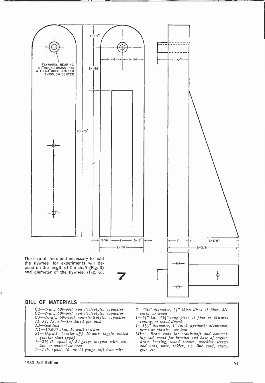
FLYWHEEL BEARING
I/2"ROUND BRASS ROD
WITH I/4"HOLE DRILLED
THROUGH CENTER
IC -1/8'
I-1/16"
2-1/16
I-1 /Ifi'-.
9/16" 1-41 '-.1 9/I6
2 1/8"
The size of the stand necessary to hold
the flywheel for experiments will de-
pend on the length of the shaft (Fig. 3)
and diameter of the flywheel (Fig. 6).
BILL OF MATERIALS
f., 600 -volt non -electrolytic capacitor
C2 -2-µf., 600 -volt non -electrolytic capacitor
C3 -10-µf., 600 -volt non -electrolytic capacitor
J1, 12, J3, J4-Insulated pin jack
L1-See text
R1 -10,000 -ohm, 10 -watt resistor
S1-D.p.d.t. (center -off) 10 -amp toggle switch
(motor start type)
spool of 24 -gauge magnet wire, cot-
ton- or enamel -covered
1 -1 -lb. spool, 16- or 18 -gauge soft iron wire
2 -33/4a' -diameter, 8" -thick discs of fiber, Mi -
carta, or wood
1-"-i.d., 4%" -long piece of fiber or Micarta
tubing, or wood dowel
1 -3%" -diameter, 1" -thick flywheel; aluminum,
brass or plastic-see text
Misc.-Brass rods for crankshaft and connect-
ing rod, wood for bracket and base of engine,
brass bearing, wood screws, machine screws
and nuts, wire, solder, a.c. line cord, epoxy
glue, etc.
1965 Fall Edition 91

A small coil connected to a flashlight bulb illus-
trates transformer action of mutual inductance.
Permissible changes in certain component values
are discussed in text. However, do not eliminate
discharge function of the d.p.d.t. toggle switch.
drying time is shortened and because
surplus glue may be more easily pared
off. After the glue has set, remove the
forms and apply epoxy to the uncov-
ered core areas. When this second ap-
plication is dry, remove any rough spots
on the core with a coarse file. Solder a
screw eye in the hole that was made in
the end of the core. The finished core
should look like Fig. 2, on page 90.
For the repulsion coil experiments,
make another core following exactly the
same procedure outlined, but using 12"
iron wires and omitting the screw eye.
Parts for the Engine. The connecting
rod (Fig. 3, page 90) is made with 3hu"
brass tubing soldered into pieces of 1/4" -
square brass, the ends of which have
been drilled and shaped as shown. This
4
This is how the various pieces for the resonant
engine shown in detail on page 90 are assembled.
construction was used to "dress up" the
prototype, and need not be duplicated
exactly. A rod made from a single solid
piece of brass will work as well.
The engine crankshaft is shown in
two forms in Fig. 4. If you want to ex-
periment with different values of capaci-
tors, or longer or shorter piston travel
with a corresponding change in speed,
build the slotted version so you can ad-
just its length. The two parts are held
together with a small machine screw
and nut. Since this is made of lighter
material, it is not recommended for per-
manent use. If all the values and meas-
urements given for the engine are fol-
lowed, make a solid crankshaft exactly
like that shown.
The engine flywheel is made of brass
or aluminum, and is 1" thick and 31/2" in
diameter. It is supported by a 1/4" brass
shaft 3" long (see Figs. 5 and 6, page
(Continued on page 141)
92 Electronic Experimenter's Handbook
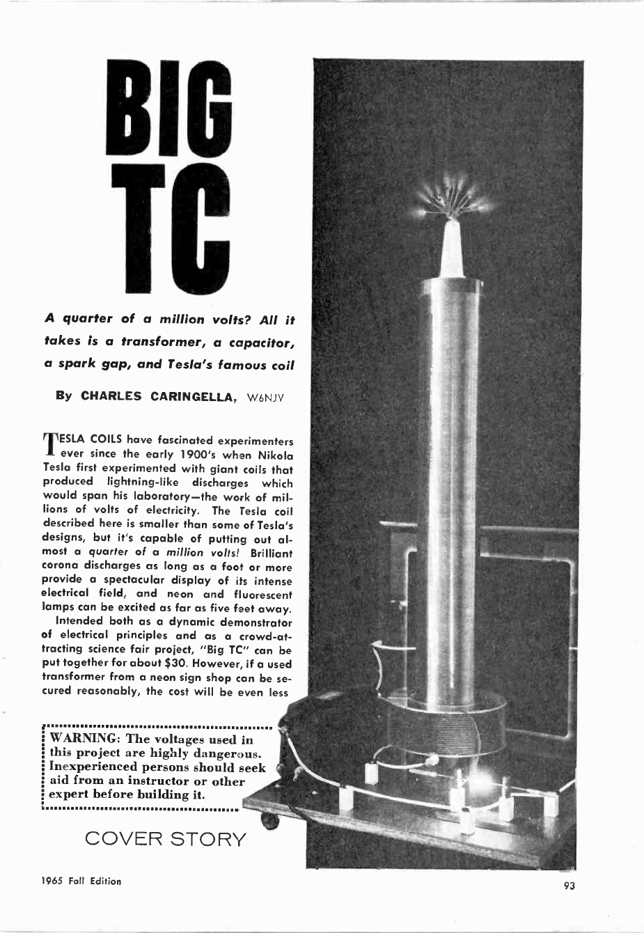
BIG
IC
A quarter of a million volts? All it
takes is a transformer, a capacitor,
a spark gap, and Tesla's famous coil
By CHARLES CARINGELLA, W6NJV
TESLA COILS have fascinated experimenters
ever since the early 1900's when Nikola
Tesla first experimented with giant coils that
produced lightning -like discharges which
would span his laboratory-the work of mil-
lions of volts of electricity. The Tesla coil
described here is smaller than some of Tesla's
designs, but it's capable of putting out al-
most a quarter of a million volts! Brilliant
corona discharges as long as a foot or more
provide a spectacular display of its intense
electrical field, and neon and fluorescent
lamps can be excited as far as five feet away.
Intended both as a dynamic demonstrator
of electrical principles and as a crowd -at-
tracting science fair project, "Big TC" can be
put together for about $30. However, if a used
transformer from a neon sign shop can be se-
cured reasonably, the cost will be even less
i WARNING: The voltages used in
this project are highly dangerous.
Inexperienced persons should seek
aid from an instructor or other
expert before building it.
COVER STORY
1965 Fall Edition 93

BIG TC
Mount Ll-L2 in center of base, Tl and Cl at edges.
A bigger base and greater component spacing will
permit greater voltage output with less arcing.
As shown in the schematic diagram
above, Ti steps the household line volt-
age up to 12,000 volts. The transformer
is the type commonly used to operate
neon signs. A high -voltage glass -plate
capacitor, Cl, is connected directly
across the high -voltage secondary wind-
ing of Ti. The capacitor serves as an
energy storage device, charging up to
Ti's secondary voltage and then dis-
charging in response to the 60 -cycle
a.c. voltage.
Discharging of Cl is through the
spark gap into coil Li. Each time the
spark gap "fires," a high current flows
through Ll. The larger capacitor Cl is
made, the larger will be the current
through Li. Discharges across the spark
gap produce extremely jagged pulses of
power which are very rich in r.f. har-
monics. The energy-due to the values
Spark gap generates r.f. energy to excite coil. It
consists of two copper rods mounted on standoffs.
The secondary of a neon sign transform-
er is usually grounded internally to the
metal case. Connect bottom of Tesla coil
secondary to case and to a good external
ground, such as a water pipe. This pre-
caution will keep danger of a short cir-
cuit in transformer at a bare minimum.
SPARK
GAP
T
I Ito
VAC CI
GLASS -PLATE
CAPACITOR
GOOD EARTH GROUND
(SUCH AS WATERPIPE)
of the components used-is greatest in
roughly the 100-kc. region.
Windings L1 and L2 form a air -core
step-up transformer, with LI the pri-
mary and L2 the high -voltage secon-
dary. The voltage at L2 will be 75,000
to 250,000 volts depending on the size
of Cl.
Design and Layout. The prototype of
"Big TC" was built on a plywood base
measuring 3/4" x 22" x 22", although a
larger base would be desirable for high -
voltage units to prevent arcing between
L2 and Ti and Cl. Mount L2 in the cen-
ter of the base and T1 and Cl as close
to the edges as possible ; if you plan
to operate the unit at voltages exceed-
ing 100,000 volts, make the base 3' x 3'
for even greater separation between
components.
Power transformer T1 is the only
DISCHARGE
ELECTRODE
L2
94 Electronic Experimenter's Handbook
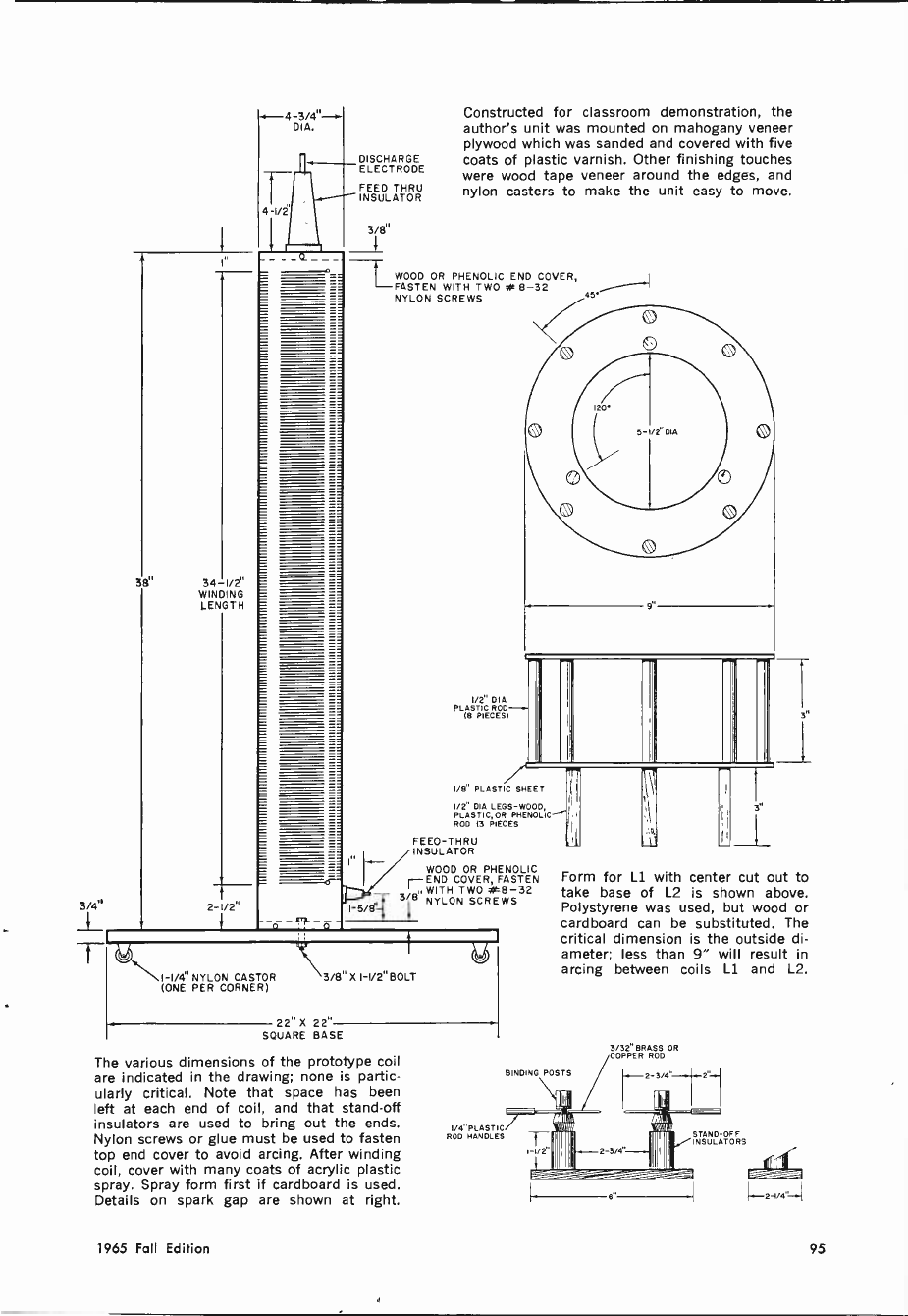
-3/4"-r
DIA. DIA.
DISCHARGE
ELECTRODE
FEED THRU
INSULATOR
4 1/2'
3/8°
381
3/4"
34-1/211
WINDING
LENGTH
2-1/2" I-5/8'
Constructed for classroom demonstration, the
author's unit was mounted on mahogany veneer
plywood which was sanded and covered with five
coats of plastic varnish. Other finishing touches
were wood tape veneer around the edges, and
nylon casters to make the unit easy to move.
WOOD OR PHENOLIC END COVER,
FASTEN WITH TWO *8-32
NYLON SCREWS 45
1/2" DIA
PLASTIC ROD-( -
(B PIECES)
I/8" PLASTIC SHEET
I/2" DIA LEGS -WOOD,
PLASTIC, OR PHENOLIC
ROD (3 PIECES
FEED-THRU
INSULATOR
WOOD OR PHENOLIC
r -END COVER, FASTEN
3/81. WITH TWO a0í8-32
NYLON SCREWS
I -I/4" NYLON CASTOR
(ONE PER CORNER) \3/811 X I-1/211BOLT
2211 X 22"
SQUARE BASE
The various dimensions of the prototype coil
are indicated in the drawing; none is partic-
ularly critical. Note that space has been
left at each end of coil, and that stand-off
insulators are used to bring out the ends.
Nylon screws or glue must be used to fasten
top end cover to avoid arcing. After winding
coil, cover with many coats of acrylic plastic
spray. Spray form first if cardboard is used.
Details on spark gap are shown at right.
I/4"PLASTIC
ROD HANDLES
3/32" BRASS OR
COPPER ROD
Form for Li with center cut out to
take base of L2 is shown above.
Polystyrene was used, but wood or
cardboard can be substituted. The
critical dimension is the outside di-
ameter; less than 9" will result in
arcing between coils Ll and L2.
BINDING POSTS
STAND-OFF
INSULATORS
1965 Fall Edition 95
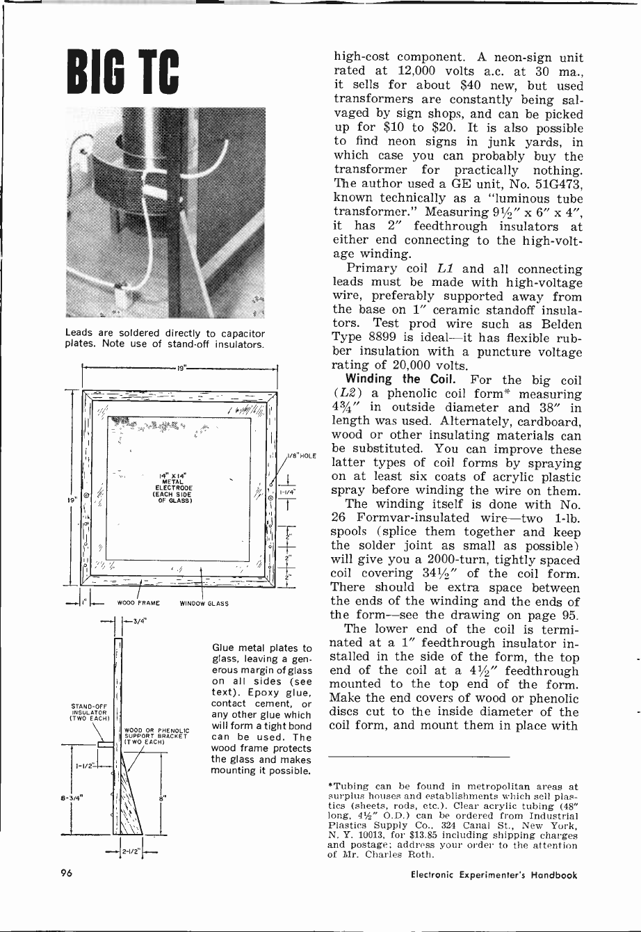
BIG IC
Leads are soldered directly to capacitor
plates. Note use of stand-off insulators.
(9'
19"
14" X14"
METAL
ELECTRODE
(EACH SIDE
OF GLASS)
LWOOD FRAME
I r3,4.
STAND-OFF
INSULATOR
(TWO EACH)
WINDOW GLASS
WOOD OR PHENOLIC
SUPPORT BRACKET
(TWO EACH)
1-1/2'
8-3/4"
I -I/4
T
+ +
-
Glue metal plates to
glass, leaving a gen-
erous margin of glass
on all sides (see
text). Epoxy glue,
contact cement, or
any other glue which
will form a tight bond
can be used. The
wood frame protects
the glass and makes
mounting it possible.
high -cost component. A neon -sign unit
rated at 12,000 volts a.c. at 30 ma.,
it sells for about $40 new, but used
transformers are constantly being sal-
vaged by sign shops, and can be picked
up for $10 to $20. It is also possible
to find neon signs in junk yards, in
which case you can probably buy the
transformer for practically nothing.
The author used a GE unit, No. 51G473,
known technically as a "luminous tube
transformer." Measuring 91/2" x 6" x 4",
it has 2" feedthrough insulators at
either end connecting to the high -volt-
age winding.
Primary coil L1 and all connecting
leads must be made with high -voltage
wire, preferably supported away from
the base on 1" ceramic standoff insula-
tors. Test prod wire such as Belden
Type 8899 is ideal-it has flexible rub-
ber insulation with a puncture voltage
rating of 20,000 volts.
Winding the Coil. For the big coil
(L2) a phenolic coil form* measuring
43/4" in outside diameter and 38" in
length was used. Alternately, cardboard,
wood or other insulating materials can
be substituted. You can improve these
latter types of coil forms by spraying
on at least six coats of acrylic plastic
spray before winding the wire on them.
The winding itself is done with No.
26 Formvar-insulated wire-two 1 -lb.
spools (splice them together and keep
the solder joint as small as possible)
will give you a 2000 -turn, tightly spaced
coil covering 341/2" of the coil form.
There should be extra space between
the ends of the winding and the ends of
the form-see the drawing on page 95.
The lower end of the coil is termi-
nated at a 1" feedthrough insulator in-
stalled in the side of the form, the top
end of the coil at a 41/2" feedthrough
mounted to the top end of the form.
Make the end covers of wood or phenolic
discs cut to the inside diameter of the
coil form, and mount them in place with
"Tubing can be found in metropolitan areas at
surplus houses and establishments which sell plas-
tics (sheets, rods, etc.). Clear acrylic tubing (48"
long, 41/2" O.D.) can be ordered from Industrial
Plastics Supply Co., 324 Canal St., New York,
N. Y. 10013, for $13.85 including shipping charges
and postage; address your order to the attention
of Mr. Charles Roth.
96 Electronic Experimenter's Handbook
This Mark Il version of "Big
TC" used a second outboard
capacitor-increasing the ca-
pacity across the primary by
0.0014 uf. Estimated output
of the Mark ll model was about
130,000 volts. See page 96.
nylon screws (metal screws at the top
end would produce corona discharges
which could burn the coil form). Al-
ternatively, the top coil cover can be
cemented in place with epoxy cement if
a sturdy coil form is used. The coil is
attached to the base with a 3/e" bolt.
Winding the coil is not nearly as
difficult as it appears-the author com-
pleted the task in about two hours.
Spray the entire winding with acrylic
plastic for added insulation, moisture
protection, and to keep the windings in
place. You can't overdo this step-the
author used the contents of an entire
aerosol spray can on the prototype, ap-
plying one thin layer at a time and
letting it dry before adding another.
Building the Primary. As shown on
page 93, the form for LI was made with
polystyrene rods and sheeting. While
the plastic has excellent insulating
qualities and looks attractive, wood or
even cardboard can be substituted. If
plastic is used, it can be strongly
"welded" together with acetone. Re-
gardless of the material used, the form
should have an outside diameter of at
least 9" to avoid arc -over between LI
and L2. The coil itself (L1) consists
of 20 turns of heavy test prod wire.
Spark Gap. The spark gap is simply
two ordinary binding posts mounted on
stand-off insulators. In turn, these are
mounted on a phenolic base measuring
3/g" x 21/4" x 6". The electrodes are
brass and copper rods with a gap on
the order of 1" between them. This
distance will vary slightly, depending
on the size of capacitor Cl.
Fabricating the Capacitor. The capaci-
tor consists of two 14" x 14" sheets of
tin cemented to a 181/2" -square piece
of window glass. Although aluminum
foil can be used for the capacitor plates,
tin was obtained from a sheet metal
shop for this purpose so that connect-
ing leads could be soldered directly to
it. If you use aluminum foil, a fairly
good connection can be had by making
leads of 1/2" -wide aluminum foil strips
and taping them down to the electrodes.
Glass is an excellent dielectric ma-
terial for this application since it has
an extremely high puncture voltage and
a high dielectric constant. As you will
note in the drawing on page 94, a bor-
der of glass is left around the capacitor
plates-this should be at least 11/2"
wide. The calculated capacity of Cl is
approximately 0.0027 µf.
Testing and Operation. Caution! Ad-
justments to the Tesla coil, and speci-
fically to the spark gap, should be made
only when the unit is off. Although the
output voltage of the Tesla coil may be
on the order of 150,000 volts, the cur-
rent capacity is only hundreds of mi-
croamps. This current can inflict a
nasty shock and r.f. burns, however.
Use EXTREME CAUTION around
the neon sign transformer. It delivers
12,000 volts at 30 ma., and this voltage
could be lethal under certain conditions.
1965 Fall Edition 97
Again, be sure the plug is out when you
make adjustments.
To adjust the spark gap, first open
it to about 11/2"; it will not fire at this
point. Gradually move the electrodes
together-unplugging the unit each
time you adjust the gap-until the point
is reached where the gap "fires."
The author's original version of "Big
TC" produced an output voltage of about
100,000 volts with the single plate glass
capacitor described above. To increase
the output of "Big TC," it is only neces-
sary to increase the capacity across the
primary by adding one or more plate
glass capacitors in parallel with Cl.
With two capacitors (both the same size
as detailed on page 94) , the author's pro-
totype produced over 150,000 volts out-
put; and with three capacitors in paral-
lel, the output exceeded 200,000 volts.
However, at such high voltage there was
a tendency for insulation breakdown be-
tween coil L2 and capacitor Cl. This
breakdown could have been overcome by
making the mounting base larger and
increasing the spacing between com-
ponents.
The author's Mark II version of "Big
TC" compromised by adding a second
capacitor with half the plate area of Cl.
Except for size, this new capacitor was
fabricated in exactly the same way and
had a measured capacitance of 0.0014 µf.
The new capacitor was attached to the
base board with a 6" x 9" piece of
thick phenolic board. Four retaining
screws held the board to the underside
of the base board and four more screws
affixed the phenolic to the wooden frame
of the outboard capacitor. With this
second capacitor (see cover photograph) ,
the voltage output was estimated to be
in the neighborhood of 130,000 volts.
The output of your Tesla coil can be
estimated by drawing an arc to a me-
tallic object attached to a long wooden
handle. Slowly increase the distance
between the object and the discharge
terminal until the arcing stops : a 6"
arc represents 100,000 volts, a 14" arc
about 200,000 volts, and a 21" arc some
300,000 volts. More amazing than fig-
ures, however, are the brilliant, spec-
tacular phenomena exhibited by high -
voltage, high -frequency electricity. -MI-
'TELEX
FOR QUALITY
The quality of Telex headsets has become well known to hams over the last
twenty-five years. Here are three Telex headsets that deliver the
kind of top grade performance that hams expect from Telex-
MAGNA-TWIN
For absolute maximum intelli-
gibility under difficult QRM con-
ditions ... Super -comfort foam
cushions... Rugged, moisture -
proof magnetic drivers give
broad response, excellent sen-
sitivity ... Sturdy construction
of high impact plastic.
TELESET
Lightweight, economy version
of the famous Magna -Twin ...
High performance, shock -proof
Magna -Twin drivers...Designed
especially for ham requirements.
Write for descriptive literature today.
Dept. EH -I
MONOSET
Feather -light at 1.2 oz.... Elim-
inates headset fatigue...Sound
from replaceable driver is fed
directly into your ears through
adjustable tone arms ... Telex
quality construction assures re-
liability.
TELEX/Acoustic Products
COMMUNICATIONS ACCESSORIES
3054 Excelsior Blvd. Mi nneapolisl6, Minn.
Yt
CIRCLE NO. 30 ON READER SERVICE CARD Electronic Experimenter's Handbook

TC
IF you have read the preceding article on
"Big TC," you will have learned that a
Tesla coil is simply a radio -frequency step-up
transformer carried to extreme limits. While
a coil that can generate 150,000-200,000 volts
is exciting and very dramatic, many of the
same visual effects can be demonstrated on a
smaller scale with "Li'l TC." In fact, "Li'l
TC" is much safer, easier to build, and less
expensive.
The only item many experimenters will have
to buy in order to build "Li'l TC" is the r.f.
coil. This coil is manufactured by the J. W.
Miller Co. for use in generating the high volt-
ages required in large -screen TV receivers.
It is an item that is not stocked by many
parts stores, although most of them can ob-
tain it for you within 48 hours. If you have
trouble finding the coil, it can be ordered from
Allied Radio Corp., 100 N. Western Ave., Chi-
cago 80, Ill., as their stock number 61G102 at
a price of $8.82 plus postage. An experienced
project builder may not find it necessary to
buy one of these coils, but may be able to
A potent "little brother" to "Big TC," this
Tesla coil version is inexpensive, easy to
build, and it can put out 30,000 volts!
By EDWIN N. KAUFMAN
TC
C2
C4
V2
Tuning capacitor C3 is
attached to the h.v. coil
with two bus -bar leads
so that it will be sus-
pended in mid-air away
from the coil and metal
chassis. Use an insulated
alignment tool to rotate
the setscrew adjustment.
RI
construct "Li'l TC" using a high -voltage
transformer from a large -screen old-
style TV receiver.
Construction. The mechanical layout
is not critical, and the design shown in
the photographs need not be followed
exactly. It is convenient to place the r.f.
coil off in one corner of the chassis
and to drop the connecting leads to V2
through grommeted holes in the chassis
deck. The high -voltage output lead of
the coil is shortened and a sewing needle
soldered to the end to show "point dis-
charge" effects.
The power supply is of conventional
design and the B -plus applied to the
plate of V2 can range from 250 to 500
volts. However, 250 - 350 volts is more
than ample for an output of between
12,000 and 15,000 volts. The output will
also vary according to the type of tube
used at V2. When you open the coil box,
you will see that a 6Y6 is recommended
Most of the parts are
grouped around the base
of tube V2. Leads to the
h.v. coil pass through
grommeted holes to the
terminal connections on
the Miller coil form.
by the manufacturer. However, notice-
ably improved effects were obtained by
the author by substituting a 6L6. A 6V6
or another equivalent power pentode
would do in a pinch.
Capacitor C3 is used to tune the pri-
mary of the h.v. coil. For convenience,
two bus -bar leads about 1" in length
were soldered to the capacitor and used
to support it in mid-air. The remaining
components are scattered around below
the chassis deck.
Firing Up Li'1 TC. When used in a TV
receiver, the high voltage generated by
this coil/oscillator arrangement is recti-
fied and filtered. It is then considerably
more dangerous than the unfiltered r.f.
generated by Li'l TC. Nevertheless, Li'l
TC should be treated with respect, for
the voltage can puncture the skin of a
finger, although high -frequency voltages
usually tend to flow relatively harmless-
ly along the skin's surface.
too Electronic Experimenter's Handbook
The numbered terminals shown in this wiring diagram
pertain to the Miller 4526 coil. A separate instruction
sheet accompanying the coil identifies the positions.
VANE
(SEE TEXT)
250-350 VDC
PARTS LIST
C1 -8.0-µf., 450 -volt electrolytic capacitor
C2 -0.1-µf., 600 -volt molded capacitor
C3-360-1000 pf. trimmer capacitor
C4 -82 -pf., 1.6 -kv. ceramic capacitor-see text
CS -0.004 -uf., 600 -volt mica capacitor
R1 -47,000 -ohm, /-watt resistor
RFC1-30-mh., 100 -ma. r.f. choke (J. W. Miller
692 or equivalent)
Sl-S.p.s.t. toggle switch
Tl-Power transformer: primary, 117 volts a.c.;
SEWING
NEEDLE
H.V. WIRE
secondaries, 500 volts, CT, 5 volts at 2 am-
peres, and 6.3 volts at 2.5 amperes (Thordar-
son 24R09Ú or equivalent)
V1 -5Y3 tube
V2 -6L6 tube-see text
1-High-voltage coil (J. W. Miller 4526-see
text)
1-Metal chassis (Premier ACH -404 or equiva-
lent)
Misc.-Tube sockets, wire, solder, etc.
After double-checking your wiring,
turn on the a.c. power and permit the
two tubes to warm up. Take an insulated
screwdriver-something like a long align-
ment tool-and adjust C3 for a brush
discharge from the needle point. If you
do not have enough range in C3 to tune
through the maximum discharge, change
the value of C4-add more capacitance
at C4 if the plates of C3 are tightly
meshed; use less if C3's are too loose.
You can set C3 for maximum discharge
by listening to the sound of the brush
effect-tune for a clean high-pitched hiss
and not a sputtering sound.
The brush discharge from Li'l TC will
be about 1" in height and can be seen
best in a dimly lighted room. Actually, a
brush corona will appear at any sharp
edge on the output lead, so be careful to
round out the soldered connections be-
tween the eye of the needle and the
shortened h.v. lead.
Ionic Propulsion Vane. Probably the
most impressive demonstration of a Tesla
coil is the ionic propulsion vane. You
can make one for Li'l TC by cutting out
the general pattern shown in the dia-
gram above.
Make the over-all length of the vane
about 1" to 11/2". Cut the vane from
aluminum foil and puncture the center so
that the vane is balanced. Use one of
your wife's extra beads as a bearing by
slipping it on the upright needle. Then
drop the vane over the needle so that it
rests on the bead and can rotate freely.
Put a piece of cork or rubber on the tip
of the needle to stop the vane from pick-
ing up so much speed that it spins right
off the needle.
The photograph on the first page of
this article is a two -second time expo-
sure (slightly enlarged) showing what
the brush corona discharge and rotating
vane should look like. --
101
1965 Fall Edition
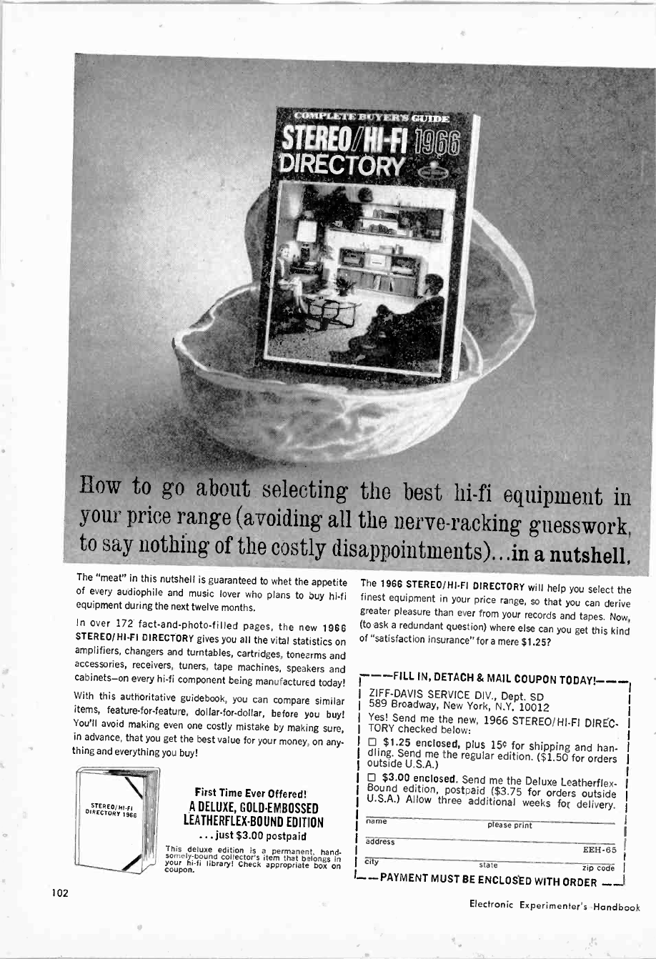
COMPLETE BUYER'S GUIDE
STEREO HI-FI ? L
DIRECTORY
How to go about selecting the best hi-fi equipment in
your price range (avoiding all the nerve-racking guesswork,
to say nothing of the costly disap.. ointnlents), , .in a nutshell.
The "meat" in this nutshell is guaranteed to whet the appetite
of every audiophile and music lover who plans to buy hi-fi
equipment during the next twelve months.
In over 172 fact -and -photo -filled pages, the new 1966
STEREO/HI-FI DIRECTORY gives you all the vital statistics on
amplifiers, changers and turntables, cartridges, tonearms and
accessories, receivers, tuners, tape machines, speakers and
cabinets-on every hi-fi component being manufactured today!
With this authoritative guidebook, you can compare similar
items, feature -for -feature, dollar -for -dollar, before you buy!
You'll avoid making even one costly mistake by making sure,
in advance, that you get the best value for your money, on any-
thing and everything you buy!
\ bRECTCR/T 1966
102
First Time Ever Offered!
A DELUXE, GOLD -EMBOSSED
LEATHERFLEX-BOUND EDITION
... just $3.00 postpaid
This deluxe edition is a permanent, hand-
somely -bound collector's item that belongs in
your hi-fi library) Check appropriate box on
coupon.
The 1966 STEREO/HI-FI DIRECTORY will help you select the
finest equipment in your price range, so that you can derive
greater pleasure than ever from your records and tapes. Now,
(to ask a redundant question) where else can you get this kind
of "satisfaction insurance" fora mere $1.25?
---FILL IN, DETACH & MAIL COUPON TODAY!---
ZIFF-DAVIS SERVICE DIV., Dept. SD
589 Broadway, New York, N.Y. 10012
Yes! Send me the new, 1966 STEREO/HI-FI DIRÉC-
TORY checked below:
D $1.25 enclosed, plus 15e for shipping and han-
dling. Send me the regular edition. ($1.50 for orders
outside U.S.A.)
O $3.00 enclosed. Send me the Deluxe Leatherflex-
Bound edition, postpaid ($3.75 for orders outside
U.S.A.) Allow three additional weeks for delivery.
name please print
address EEH-65
city state zip code I
--PAYMENT MUST BE ENCLOSED WITH ORDER --I
Electronic Experimenter's Handbook
CHAPTER
5
COMMUNI-
CATIONS
SWL
CB
HAM
Projects included in this chapter of the ELEC-
TRONIC EXPERIMENTER'S HANDBOOK are
aimed at the 6 -meter ham with a Technician Class
license. In case you are not already aware of it,
Technician Class hams can operate in the 50 -mc.
band and above. The license requires passing the
regular theory examination but only a 5 -wpm
code sending and receiving ability. It is issued
for a 5 -year period-unlike the Novice license
(1 year)-and can be renewed.
A companion unit to the 6 -meter receiver
(ELECTRONIC EXPERIMENTER'S HAND-
BOOK, 1964 Edition) is the 6 -meter transmitter
on page 111. If you want to improve receiver
sensitivity, the small outboard r.f. preamplifier
(page 121) may be your cup of tea. Also intended
for the Technician (or General Class ham) is the
solid-state converter (page 104). This converter
has extraordinary sensitivity and can be broad -
banded to cover 1.5 megacycles.
Two valuable projects round off this chapter:
a speech filter with fully adjustable controls
(page 107), and some excellent ideas on how t'o
pep up AM receiver sensitivity (page 116).
104
TRANSISTORIZED 6 -METER CONVERTER
107
AN ADJUSTABLE SPEECH FILTER
Roy C. Hejhall, K7QWR
111
THE COMPANION 6 -METER TRANSMITTER
116
SOUP UP THAT AM BROADCAST RECEIVER
121
THE 6 METER 7 AND 2 PREAMP
1965 Fall Edition
Daniel Meyer
Charles Green, W3IKH
F. J. Bauer, Jr., W6FP0
Joseph Tartas, W2YKT
103
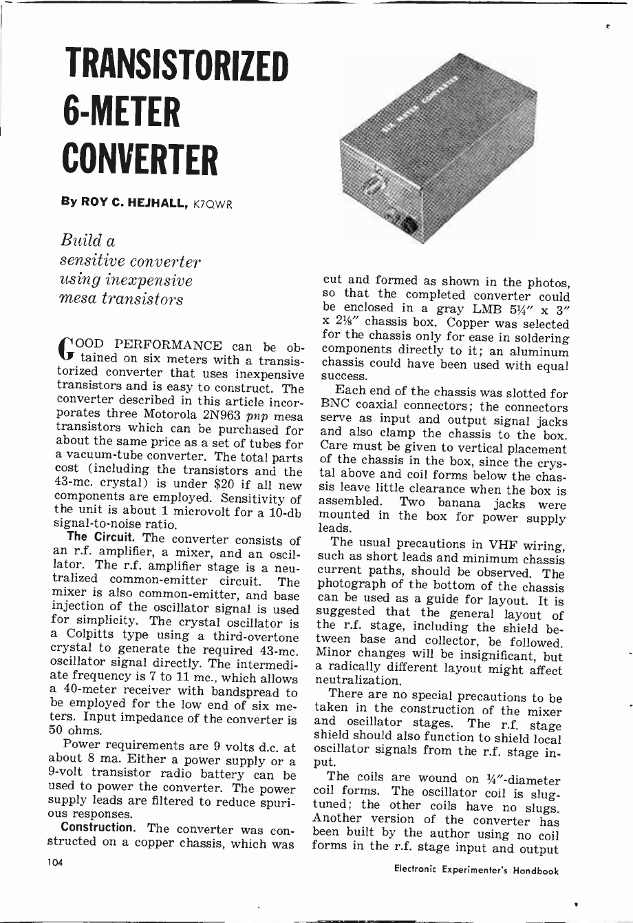
TRANSISTORIZED
6 -MEIER
CONVERTER
By ROY C. HEJHALL, K7QWR
Build a
sensitive converter
using inexpensive
mesa transistors
GOOD PERFORMANCE can be ob-
tained on six meters with a transis-
torized converter that uses inexpensive
transistors and is easy to construct. The
converter described in this article incor-
porates three Motorola 2N963 pnp mesa
transistors which can be purchased for
about the same price as a set of tubes for
a vacuum -tube converter. The total parts
cost (including the transistors and the
43 -mc. crystal) is under $20 if all new
components are employed. Sensitivity of
the unit is about 1 microvolt for a 10 -db
signal-to-noise ratio.
The Circuit. The converter consists of
an r.f. amplifier, a mixer, and an oscil-
lator. The r.f. amplifier stage is a neu-
tralized common -emitter circuit. The
mixer is also common -emitter, and base
injection of the oscillator signal is used
for simplicity. The crystal oscillator is
a Colpitts type using a third -overtone
crystal to generate the required 43 -me.
oscillator signal directly. The intermedi-
ate frequency is 7 to 11 mc., which allows
a 40 -meter receiver with bandspread to
be employed for the low end of six me-
ters. Input impedance of the converter is
50 ohms.
Power requirements are 9 volts d.c. at
about 8 ma. Either a power supply or a
9 -volt transistor radio battery can be
used to power the converter. The power
supply leads are filtered to reduce spuri-
ous responses.
Construction. The converter was con-
structed on a copper chassis, which was
104
cut and formed as shown in the photos,
so that the completed converter could
be enclosed in a gray LMB 51/4' x 3"
x 21/g" chassis box. Copper was selected
for the chassis only for ease in soldering
components directly to it; an aluminum
chassis could have been used with equal
success.
Each end of the chassis was slotted for
BNC coaxial connectors; the connectors
serve as input and output signal jacks
and also clamp the chassis to the box.
Care must be given to vertical placement
of the chassis in the box, since the crys-
tal above and coil forms below the chas-
sis leave little clearance when the box is
assembled. Two banana jacks were
mounted in the box for power supply
leads.
The usual precautions in VHF wiring,
such as short leads and minimum chassis
current paths, should be observed. The
photograph of the bottom of the chassis
can be used as a guide for layout. It is
suggested that the general layout of
the r.f. stage, including the shield be-
tween base and collector, be followed.
Minor changes will be insignificant, but
a radically different layout might affect
neutralization.
There are no special precautions to be
taken in the construction of the mixer
and oscillator stages. The r.f. stage
shield should also function to shield local
oscillator signals from the r.f. stage in-
put. The coils are wound on 1/4" -diameter
coil forms. The oscillator coil is slug -
tuned ; the other coils have no slugs.
Another version of the converter has
been built by the author using no coil
forms in the r.f. stage input and output
Electronic Experimenter's Handbook
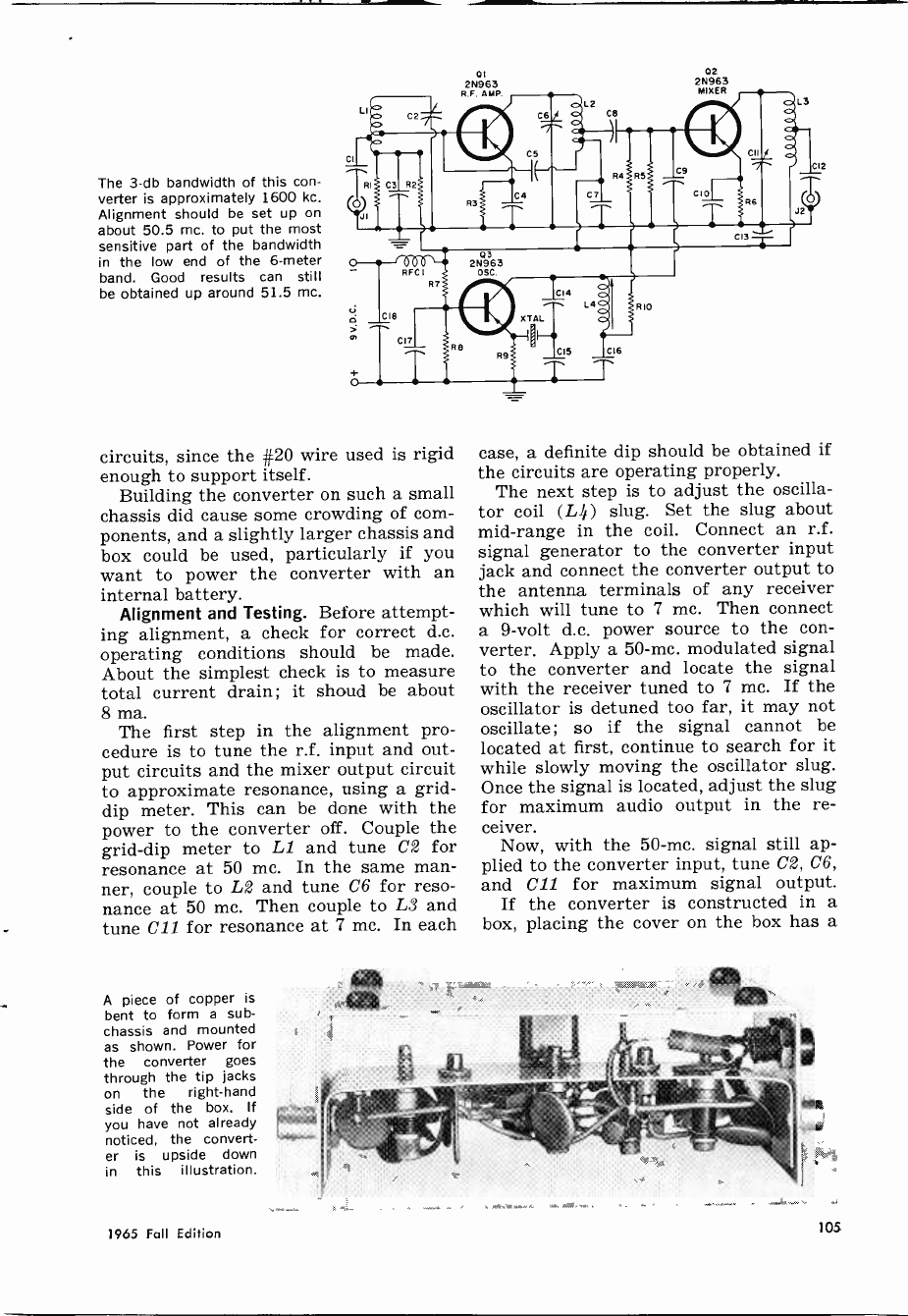
The 3 -db bandwidth of this con-
verter is approximately 1600 kc.
Alignment should be set up on
about 50.5 mc. to put the most
sensitive part of the bandwidth
in the low end of the 6 -meter
band. Good results can still
be obtained up around 51.5 mc.
circuits, since the #20 wire used is rigid
enough to support itself.
Building the converter on such a small
chassis did cause some crowding of com-
ponents, and a slightly larger chassis and
box could be used, particularly if you
want to power the converter with an
internal battery.
Alignment and Testing. Before attempt-
ing alignment, a check for correct d.c.
operating conditions should be made.
About the simplest check is to measure
total current drain; it shoud be about
8 ma.
The first step in the alignment pro-
cedure is to tune the r.f. input and out-
put circuits and the mixer output circuit
to approximate resonance, using a grid -
dip meter. This can be done with the
power to the converter off. Couple the
grid -dip meter to LI and tune C2 for
resonance at 50 mc. In the same man-
ner, couple to L2 and tune C6 for reso-
nance at 50 mc. Then couple to LS and
tune C11 for resonance at 7 mc. In each
A piece of copper is
bent to form a sub -
chassis and mounted
as shown. Power for
the converter goes
through the tip jacks
on the right-hand
side of the box. If
you have not already
noticed, the convert-
er is upside down
in this illustration.
1965 Fall Edition
Ot
2N963
R.F. AMP
02
2N963
MIXER
case, a definite dip should be obtained if
the circuits are operating properly.
The next step is to adjust the oscilla-
tor coil (L4) slug. Set the slug about
mid -range in the coil. Connect an r.f.
signal generator to the converter input
jack and connect the converter output to
the antenna terminals of any receiver
which will tune to 7 mc. Then connect
a 9 -volt d.c. power source to the con-
verter. Apply a 50 -mc. modulated signal
to the converter and locate the signal
with the receiver tuned to 7 mc. If the
oscillator is detuned too far, it may not
oscillate; so if the signal cannot be
located at first, continue to search for it
while slowly moving the oscillator slug.
Once the signal is located, adjust the slug
for maximum audio output in the re-
ceiver.
Now, with the 50 -mc. signal still ap-
plied to the converter input, tune C2, C6,
and CIZ for maximum signal output.
If the converter is constructed in a
box, placing the cover on the box has a
105
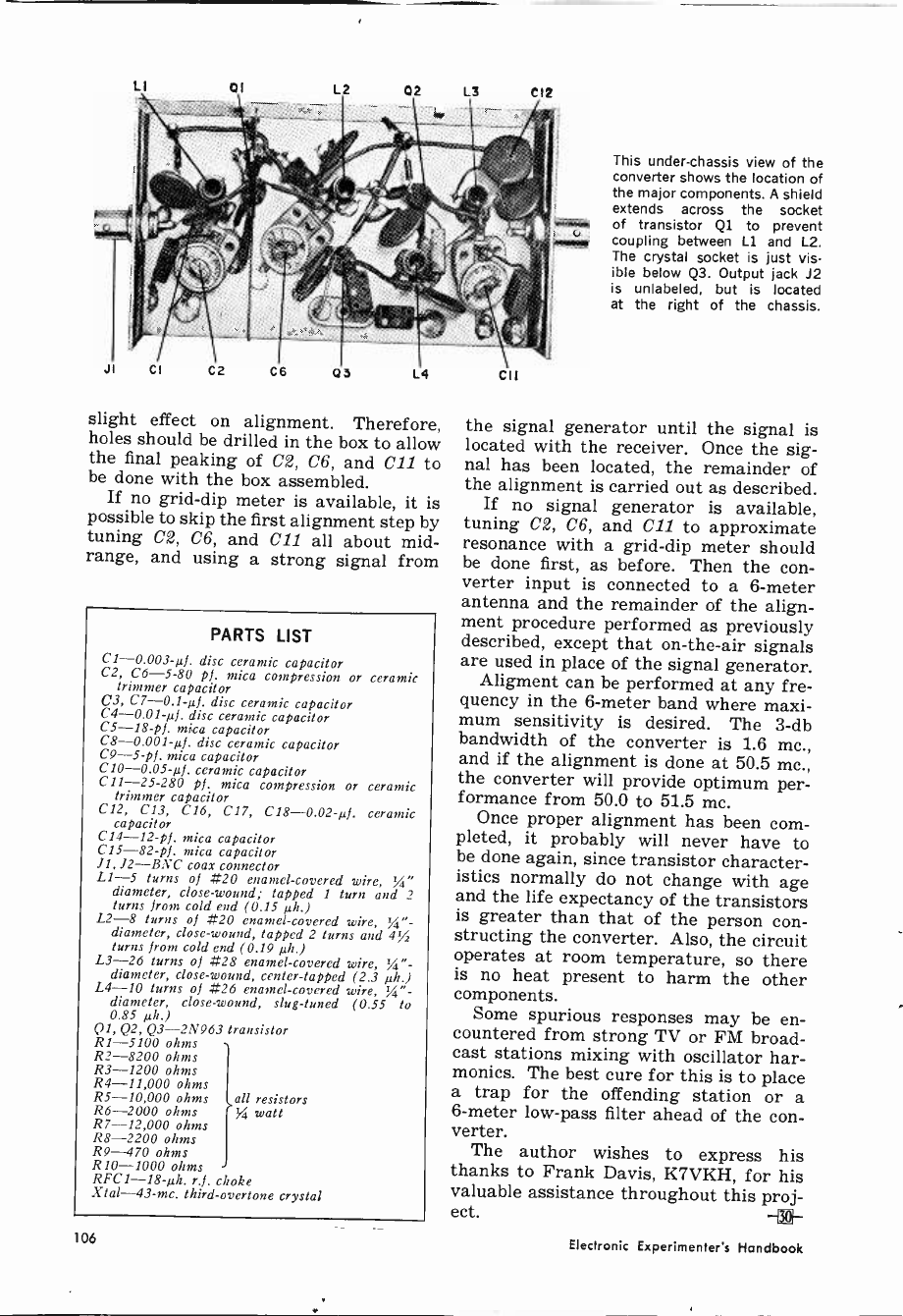
LI 0I L2 02 L3 C12
slight effect on alignment. Therefore,
holes should be drilled in the box to allow
the final peaking of C2, C6, and C11 to
be done with the box assembled.
If no grid -dip meter is available, it is
possible to skip the first alignment step by
tuning C2, C6, and C11 all about mid-
range, and using a strong signal from
PARTS LIST
C1 -0.003-µf, disc ceramic capacitor
C2, C6-5-80 pf. mica compression or ceramic
trimmer capacitor
C3, C7 -0.1-µf. disc ceramic capacitor
C4 -0.01-µf, disc ceramic capacitor
C5 -18 -pf. mica capacitor
C8 -0.001-µf. disc ceramic capacitor
C9 -5 -pf. mica capacitor
C10 -0.05-µf. ceramic capacitor
CI1-25-280 pf. mica compression or ceramic
trimmer capacitor
C12, C13, C16, C17, C18-0.02-1.4. ceramic
capacitor
C14 -12 -pf. mica capacitor
C15 -82 -pf. mica capacitor
11, 12-BNC coax connector
L1-5 turns of #20 enamel -covered wire,
diameter, close -wound; tapped I turn and 2
turns from cold end (0.15 µh.)
L2-8 turns of #20 enamel -covered wire, r/4" -
diameter, close -wound, tapped 2 turns and 4%
turns from cold end (0.19 µh.)
L3-26 turns of #28 enamel -covered wire, '//"-
diameter, close -wound, center -tapped (2.3 µh.)
L4-10 turns of #26 enamel -covered wire, %"-
diameter, close -wound, slug -tuned (0.55 to
0.85 µh.)
QI, Q2, Q3 -2N963 transistor
R1-5100 ohms
R2-8200 ohms
R3-1200 ohms
R4-11,000 ohms
R5-10,000 ohms all resistors
R6-2000 ohms watt
R7-12,000 ohms
R8-2200 ohms
R9-470 ohms
R10-1000 ohms
RFC1-18-µh. r.f. choke
Xtal-43-mc. third -overtone crystal
This under -chassis view of the
converter shows the location of
the major components. A shield
extends across the socket
of transistor Ql to prevent
coupling between Ll and L2.
The crystal socket is just vis-
ible below Q3. Output jack J2
is unlabeled, but is located
at the right of the chassis.
the signal generator until the signal is
located with the receiver. Once the sig-
nal has been located, the remainder of
the alignment is carried out as described.
If no signal generator is available,
tuning C2, C6, and C11 to approximate
resonance with a grid -dip meter should
be done first, as before. Then the con-
verter input is connected to a 6 -meter
antenna and the remainder of the align-
ment procedure performed as previously
described, except that on -the -air signals
are used in place of the signal generator.
Aligment can be performed at any fre-
quency in the 6 -meter band where maxi-
mum sensitivity is desired. The 3 -db
bandwidth of the converter is 1.6 mc.,
and if the alignment is done at 50.5 mc.,
the converter will provide optimum per-
formance from 50.0 to 51.5 mc.
Once proper alignment has been com-
pleted, it probably will never have to
be done again, since transistor character-
istics normally do not change with age
and the life expectancy of the transistors
is greater than that of the person con-
structing the converter. Also, the circuit
operates at room temperature, so there
is no heat present to harm the other
components.
Some spurious responses may be en-
countered from strong TV or FM broad-
cast stations mixing with oscillator har-
monics. The best cure for this is to place
a trap for the offending station or a
6 -meter low-pass filter ahead of the con-
verter.
The author wishes to express his
thanks to Frank Davis, K7VKH, for his
valuable assistance throughout this proj-
ect.
106 Electronic Experimenter's Handbook

o
-10
20
N
m
ó-30
40
-50
60
FUL L F I LT E R AC TION
20 30 40 50 70 100 150 200
LL
FILTER OUT
N 500 700 IK 1.5K 2K 3K 4K 5K 7K 10K 15K 20K 30K 40K50K
FREQUENCY -CPS
An Adjustable Speech Filter
Cut out noise and increase intelligibility with this
all-purpose amateur, CB, hi-fi, and recording filter
By DANIEL MEYER
WOULD YOU LIKE to have a speech
filter to use with your CB receiver
that could be adjusted to give the best
reception for various signals and noise
conditions? A filter that can also be
used with your transmitter to get more
modulation in the 300 to 3000 cycle
range where it will do the most good?
A versatile unit which can also be used
with your hi-fi system to clear up the
noise on old recordings or weak FM sig-
nals? If so, here is a simple three -
transistor circuit that will do these jobs
and more.
Two feedback -type filters are used to
produce the high and low frequency at-
tenuation. The circuit has zero unity
gain and may therefore be used at any
point in a system that has a signal level
of one volt or less. In addition, the
amount of high or low freeuency filter -
1965 Fall Edition
ing may be adjusted and either filter
may be switched out of the circuit to
give a flat response.
How It Works. Transistor Q1 is an
emitter follower which gives the filter a
high input impedance and also provides
a low impedance driving source for tran-
sistor Q2. Capacitor C2 and resistor R3
form a feedback loop around transistor
Q1 that reduces the loading effect of the
bias resistors R1 and R2 on the input of
the filter.
Transistor Q2, with its associated re-
sistors and capacitors, acts as a variable,
high-pass, active filter. Potentiometer R5
varies the cutoff frequency of the filter
from approximately 100 to 400 cycles.
In the "out" position of R5, switch Si
closes and shorts out the filter.
Transistor Q3, with its associated
components, is a variable, low-pass, ac -
107
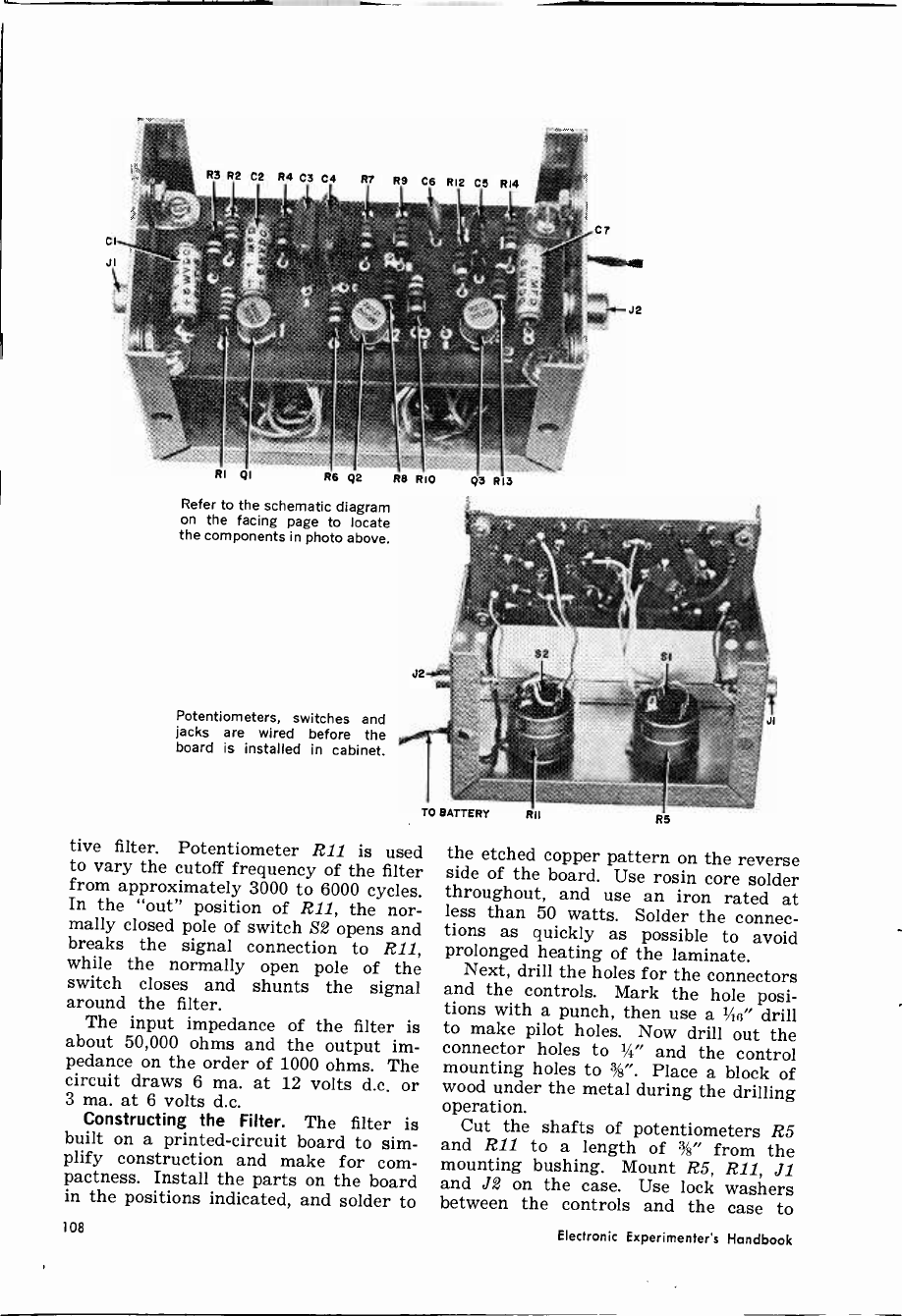
CI
JI
R3 R2 C2 R4 C3 C4 R7 R9 C6 R12 CS RI4
RI QI Re Q2 Re RIO
Refer to the schematic diagram
on the facing page to locate
the components in photo above.
Potentiometers, switches and
jacks are wired before the
board is installed in cabinet.
tive filter. Potentiometer R11 is used
to vary the cutoff frequency of the filter
from approximately 3000 to 6000 cycles.
In the "out" position of R11, the nor-
mally closed pole of switch S2 opens and
breaks the signal connection to R11,
while the normally open pole of the
switch closes and shunts the signal
around the filter.
The input impedance of the filter is
about 50,000 ohms and the output im-
pedance on the order of 1000 ohms. The
circuit draws 6 ma. at 12 volts d.c. or
3 ma. at 6 volts d.c.
Constructing the Filter. The filter is
built on a printed -circuit board to sim-
plify construction and make for com-
pactness. Install the parts on the board
in the positions indicated, and solder to
108
C7
mieubbser
J2
Q3 RI3
the etched copper pattern on the reverse
side of the board. Use rosin core solder
throughout, and use an iron rated at
less than 50 watts. Solder the connec-
tions as quickly as possible to avoid
prolonged heating of the laminate.
Next, drill the holes for the connectors
and the controls. Mark the hole posi-
tions with a punch, then use a x,4(3" drill
to make pilot holes. Now drill out the
connector holes to 1/4" and the control
mounting holes to %". Place a block of
wood under the metal during the drilling
operation.
Cut the shafts of potentiometers R5
and R11 to a length of %" from the
mounting bushing. Mount R5, R11, J1
and J2 on the case. Use lock washers
between the controls and the case to
Electronic Experimenter's Handbook
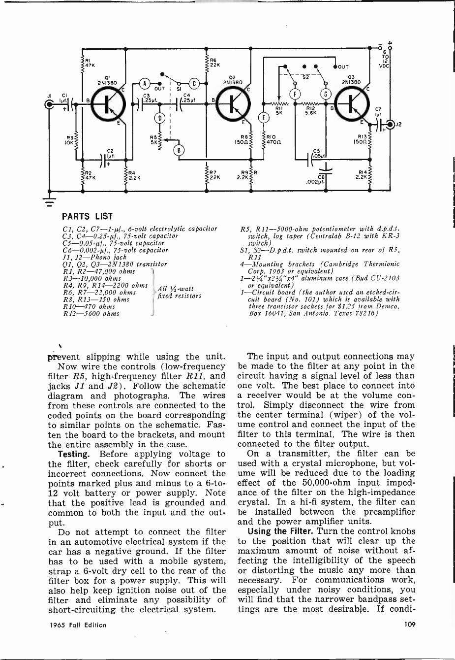
_4.
RI
47K
01
2NI380
I B
R8
15011
if92 R4 R7 R9 R
a7K 2.2K 22K 2.2K
5K
IC1r)
+
PARTS LIST
Cl, C2, C7 -1-µf., 6 -volt electrolytic capacitor
C3, C4 -0.25-µJ., 75 -volt capacitor
C5 -0.05-µf., 75 -volt capacitor
C6 -0.002-µj., 75 -volt capacitor
11, 12-Phono jack
Ql, Q2, Q3 -2N1380 transistor
R1, R2-47,000 ohms
R3-10,000 ohms
R4, R9, R14-2200 ohms
R6, R7-22,000 ohms
R8, R13-150 ohms
R10-470 ohms
R12-5600 ohms
All 'A -watt
fixed resistors
prevent slipping while using the unit.
Now wire the controls (low -frequency
filter R5, high -frequency filter R11, and
jacks J1 and J2) . Follow the schematic
diagram and photographs. The wires
from these controls are connected to the
coded points on the board corresponding
to similar points on the schematic. Fas-
ten the board to the brackets, and mount
the entire assembly in the case.
Testing. Before applying voltage to
the filter, check carefully for shorts or
incorrect connections. Now connect the
points marked plus and minus to a 6 -to -
12 volt battery or power supply. Note
that the positive lead is grounded and
common to both the input and the out-
put. Do not attempt to connect the filter
in an automotive electrical system if the
car has a negative ground. If the filter
has to be used with a mobile system,
strap a 6 -volt dry cell to the rear of the
filter box for a power supply. This will
also help keep ignition noise out of the
filter and eliminate any possibility of
short-circuiting the electrical system.
18--M.NvVJv
RI
5K
RIO
4TO11
C6
.002yf.
R14
2.2K
O6
TO 12
VDC
J
R5, R11 -5000 -ohm potentiometer with d.p.d.t.
switch, log taper (Centralab B-12 with KR -3
switch)
Sl, S2-D.p.d.t. switch mounted on rear of RS,
R11
4-Mounting brackets (Cambridge Thermionic
Corp. 1963 or equivalent)
1-2%"x234"x4" aluminum case (Bud CU -2103
or equivalent)
1-Circuit board (the author used an etched -cir-
cuit board (No. 101) which is available with
three transistor sockets for $1.25 from Demco,
Box 16041, San Antonio, Texas 78216)
The input and output connections may
be made to the filter at any point in the
circuit having a signal level of less than
one volt. The best place to connect into
a receiver would be at the volume con-
trol. Simply disconnect the wire from
the center terminal (wiper) of the vol-
ume control and connect the input of the
filter to this terminal. The wire is then
connected to the filter output.
On a transmitter, the filter can be
used with a crystal microphone, but vol-
ume will be reduced due to the loading
effect of the 50,000 -ohm input imped-
ance of the filter on the high -impedance
crystal. In a hi-fi system, the filter can
be installed between the preamplifier
and the power amplifier units.
Using the Filter. Turn the control knobs
to the position that will clear up the
maximum amount of noise without af-
fecting the intelligibility of the speech
or distorting the music any more than
necessary. For communications work,
especially under noisy conditions, you
will find that the narrower bandpass set-
tings are the most desirable. If condi-
1965 Fall Edition 109
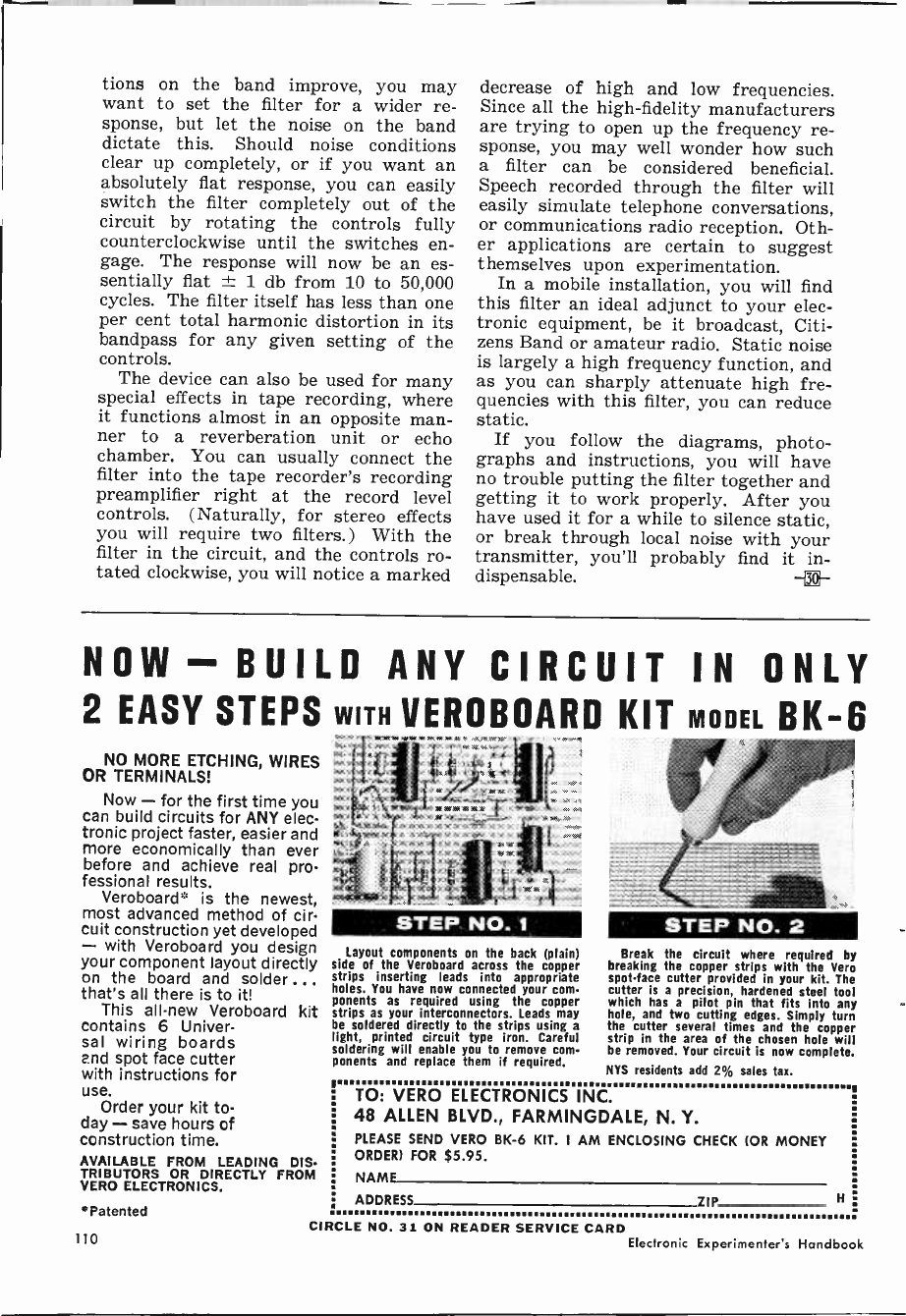
tions on the band improve, you may
want to set the filter for a wider re-
sponse, but let the noise on the band
dictate this. Should noise conditions
clear up completely, or if you want an
absolutely flat response, you can easily
switch the filter completely out of the
circuit by rotating the controls fully
counterclockwise until the switches en-
gage. The response will now be an es-
sentially flat 1 db from 10 to 50,000
cycles. The filter itself has less than one
per cent total harmonic distortion in its
bandpass for any given setting of the
controls.
The device can also be used for many
special effects in tape recording, where
it functions almost in an opposite man-
ner to a reverberation unit or echo
chamber. You can usually connect the
filter into the tape recorder's recording
preamplifier right at the record level
controls. (Naturally, for stereo effects
you will require two filters.) With the
filter in the circuit, and the controls ro-
tated clockwise, you will notice a marked
decrease of high and low frequencies.
Since all the high-fidelity manufacturers
are trying to open up the frequency re-
sponse, you may well wonder how such
a filter can be considered beneficial.
Speech recorded through the filter will
easily simulate telephone conversations,
or communications radio reception. Oth-
er applications are certain to suggest
themselves upon experimentation.
In a mobile installation, you will find
this filter an ideal adjunct to your elec-
tronic equipment, be it broadcast, Citi-
zens Band or amateur radio. Static noise
is largely a high frequency function, and
as you can sharply attenuate high fre-
quencies with this filter, you can reduce
static.
If you follow the diagrams, photo-
graphs and instructions, you will have
no trouble putting the filter together and
getting it to work properly. After you
have used it for a while to silence static,
or break through local noise with your
transmitter, you'll probably find it in-
dispensable.
NOW - BUILD ANY CIRCUIT IN ONLY
2 EASY STEPS WITH VEROBOARD KIT MODEL BK -6
NO MORE ETCHING, WIRES
OR TERMINALS!
Now - for the first time you
can build circuits for ANY elec-
tronic project faster, easier and
more economically than ever
before and achieve real pro-
fessional results.
Veroboard* is the newest,
most advanced method of cir-
cuit construction yet developed
- with Veroboard you design
your component layout directly
on the board and solder...
that's all there is to it!
This all -new Veroboard kit
contains 6 Univer-
sal wiring boards
and spot face cutter
with instructions for
use. Order your kit to-
day - save hours of
construction time.
AVAILABLE FROM LEADING DIS-
TRIBUTORS OR DIRECTLY FROM
VERO ELECTRONICS.
*Patented
STEP NO. 1
Layout components on the back (plain)
side of the Veroboard across the copper
strips inserting leads into appropriate
holes. You have now connected your com-
ponents as required using the copper
strips as your interconnectors. Leads may
be soldered directly to the strips using a
light, printed circuit type iron. Careful
soldering will enable you to remove com-
ponents and replace them if required.
STEP NO. 2
Break the circuit where required by
breaking the copper strips with the Vero
spot -face cutter provided in your kit. The
cutter is a precision, hardened steel tool
which has a pilot pin that fits into any
hole, and two cutting edges. Simply turn
the cutter several times and the copper
strip in the area of the chosen hole will
be removed. Your circuit is now complete.
NYS residents add 2% sales tax.
TO: VERO ELECTRONICS INC.
48 ALLEN BLVD., FARMINGDALE, N. Y.
PLEASE SEND VERO BK -6 KIT. I AM ENCLOSING CHECK (OR MONEY
ORDER) FOR $5.95.
NAMF
ADDRESS ZIP H
I
CIRCLE NO. 31 ON READER SERVICE CARD
110 Electronic Experimenter's Handbook
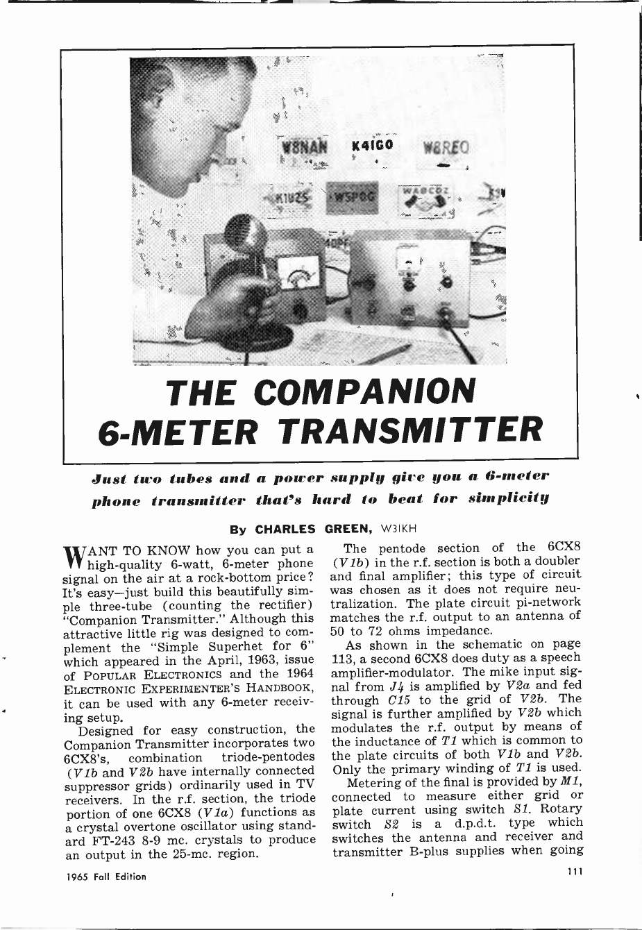
Just tiro tubes and a power supply gire you a 6 -meter
phone transmitter that's hard to beat for simplicity
By CHARLES
WANT TO KNOW how you can put a
high -quality 6 -watt, 6 -meter phone
signal on the air at a rock -bottom price?
It's easy-just build this beautifully sim-
ple three -tube (counting the rectifier)
"Companion Transmitter." Although this
attractive little rig was designed to com-
plement the "Simple Superhet for 6"
which appeared in the April, 1963, issue
of POPULAR ELECTRONICS and the 1964
ELECTRONIC EXPERIMENTER'S HANDBOOK,
it can be used with any 6 -meter receiv-
ing setup.
Designed for easy construction, the
Companion Transmitter incorporates two
6CX8's, combination triode -pentodes
(Vib and V2b have internally connected
suppressor grids) ordinarily used in TV
receivers. In the r.f. section, the triode
portion of one 6CX8 (Via) functions as
a crystal overtone oscillator using stand-
ard FT -243 8-9 mc. crystals to produce
an output in the 25 -mc. region.
GREEN, W3IKH
The pentode section of the 6CX8
(Vib) in the r.f. section is both a doubler
and final amplifier ; this type of circuit
was chosen as it does not require neu-
tralization. The plate circuit pi -network
matches the r.f. output to an antenna of
50 to 72 ohms impedance.
As shown in the schematic on page
113, a second 6CX8 does duty as a speech
amplifier -modulator. The mike input sig-
nal from J r is amplified by Va and fed
through C15 to the grid of V2b. The
signal is further amplified by V2b which
modulates the r.f. output by means of
the inductance of T1 which is common to
the plate circuits of both V1b and V2b.
Only the primary winding of Ti is used.
Metering of the final is provided by M1,
connected to measure either grid or
plate current using switch S1. Rotary
switch S2 is a d.p.d.t. type which
switches the antenna and receiver and
transmitter B -plus supplies when going
1965 Fall Edition 111
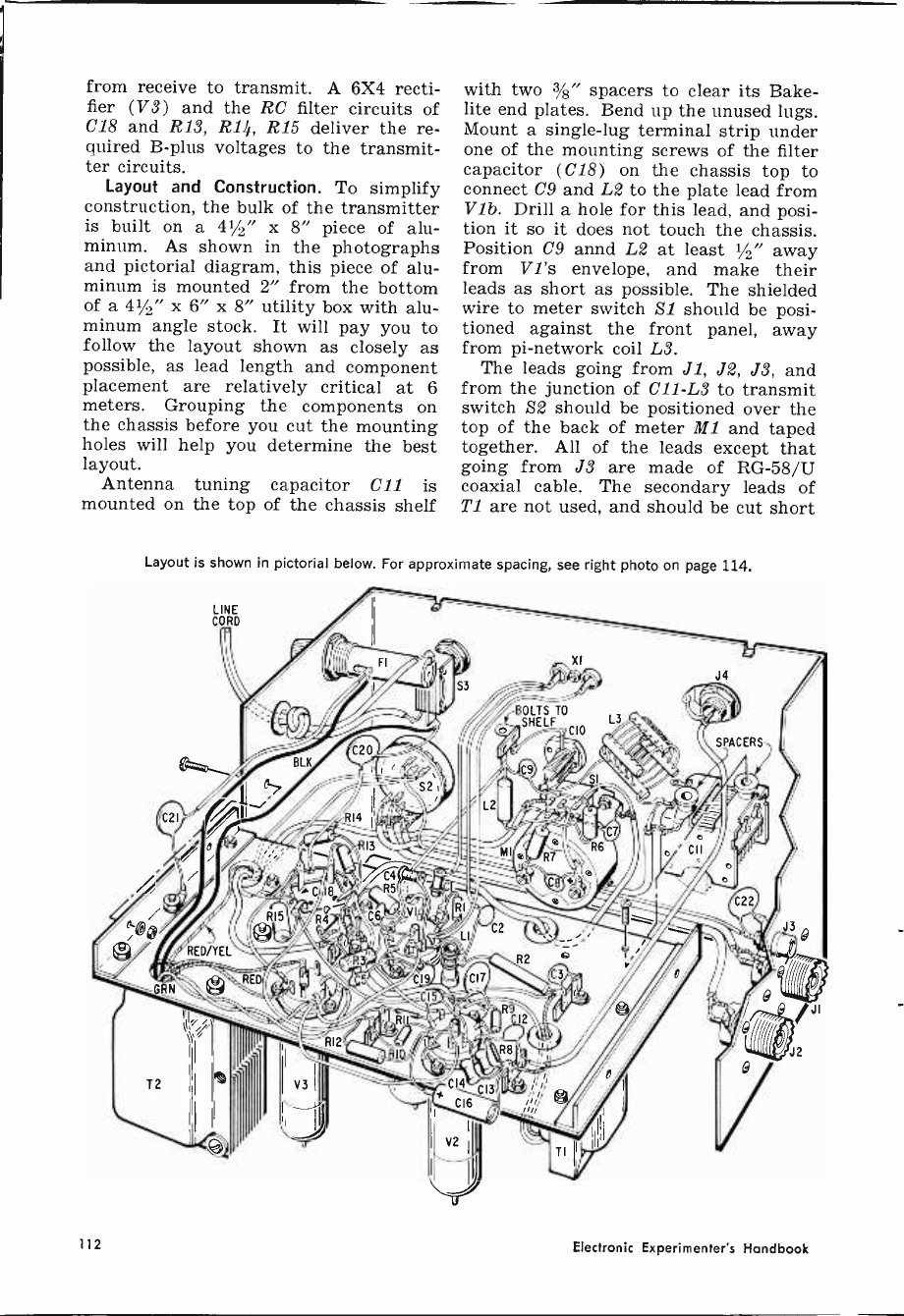
from receive to transmit. A 6X4 recti-
fier (V3) and the RC filter circuits of
C18 and R13, R14, R15 deliver the re-
quired B -plus voltages to the transmit-
ter circuits.
Layout and Construction. To simplify
construction, the bulk of the transmitter
is built on a 41/2" x 8" piece of alu-
minum. As shown in the photographs
and pictorial diagram, this piece of alu-
minum is mounted 2" from the bottom
of a 41/2" x 6" x 8" utility box with alu-
minum angle stock. It will pay you to
follow the layout shown as closely as
possible, as lead length and component
placement are relatively critical at 6
meters. Grouping the components on
the chassis before you cut the mounting
holes will help you determine the best
layout.
Antenna tuning capacitor C11 is
mounted on the top of the chassis shelf
with two 3/8" spacers to clear its Bake-
lite end plates. Bend up the unused lugs.
Mount a single -lug terminal strip under
one of the mounting screws of the filter
capacitor (C18) on the chassis top to
connect C9 and L2 to the plate lead from
V1b. Drill a hole for this lead, and posi-
tion it so it does not touch the chassis.
Position C9 annd L2 at least 1/2" away
from V1's envelope, and make their
leads as short as possible. The shielded
wire to meter switch S1 should be posi-
tioned against the front panel, away
from pi -network coil L3.
The leads going from J1, J2, J3, and
from the junction of C11 -L3 to transmit
switch S2 should be positioned over the
top of the back of meter M1 and taped
together. All of the leads except that
going from J3 are made of RG -58/U
coaxial cable. The secondary leads of
T1 are not used, and should be cut short
Layout is shown in pictorial below. For approximate spacing, see right photo on page 114.
112 Electronic Experimenter's Handbook
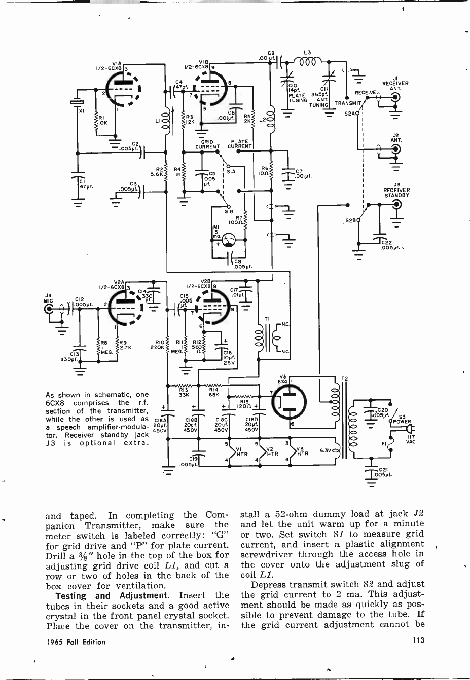
T
J4 C12
pf.
V'A
I/2-6CXB
2
-.005p3)
C3
.00S f.
As shown in schematic, one
6CX8 comprises the r.f.
section of the transmitter, -
while the other is used as c187, --
a speech amplifier -modula-
tor.
20yí.
Receiver standby jack --
J3 is optional extra.
R2
5.6K
RIO
220K
V I B
I/2-6CX8
C4
47.f
GRID PLATE
CURRENT CURRENT
V2B
I/2-6CX8
I
l (ja.
RII
MEG.
R7
I0011
MI
313 614
33K 6BK
+
CIBB
20p f.
450V
C19
OOSyf.
.005pf.
+ 12011 +
CIBC CUM
20pf. 20pf.
450V 450V
5 5
VI HTR
4 4
and taped. In completing the Com-
panion Transmitter, make sure the
meter switch is labeled correctly: "G"
for grid drive and "P" for plate current.
Drill a %" hole in the top of the box for
adjusting grid drive coil LI, and cut a
row or two of holes in the back of the
box cover for ventilation.
Testing and Adjustment. Insert the
tubes in their sockets and a good active
crystal in the front panel crystal socket.
Place the cover on the transmitter, in -
C9
.001pí
CI 4pf. CII
PLATE 365pí.
TUNING ANT.
TUNING
S2A
C7
T.00Ipf.
V3 HTR
RECEIVE. -
TRANSMIT
S28
RECEIVER
ANT.
J2
ANT.
J3
RECEIVER
STANDBY
C2 2
.005pf. .
J05pf.
C21
T05pf.
POWER
117
VAC
stall a 52 -ohm dummy load at jack J2
and let the unit warm up for a minute
or two. Set switch Si to measure grid
current, and insert a plastic alignment
screwdriver through the access hole in
the cover onto the adjustment slug of
coil Li.
Depress transmit switch S2 and adjust
the grid current to 2 ma. This adjust-
ment should be made as quickly as pos-
sible to prevent damage to the tube. If
the grid current adjustment cannot be
1965 Fall Edition 113
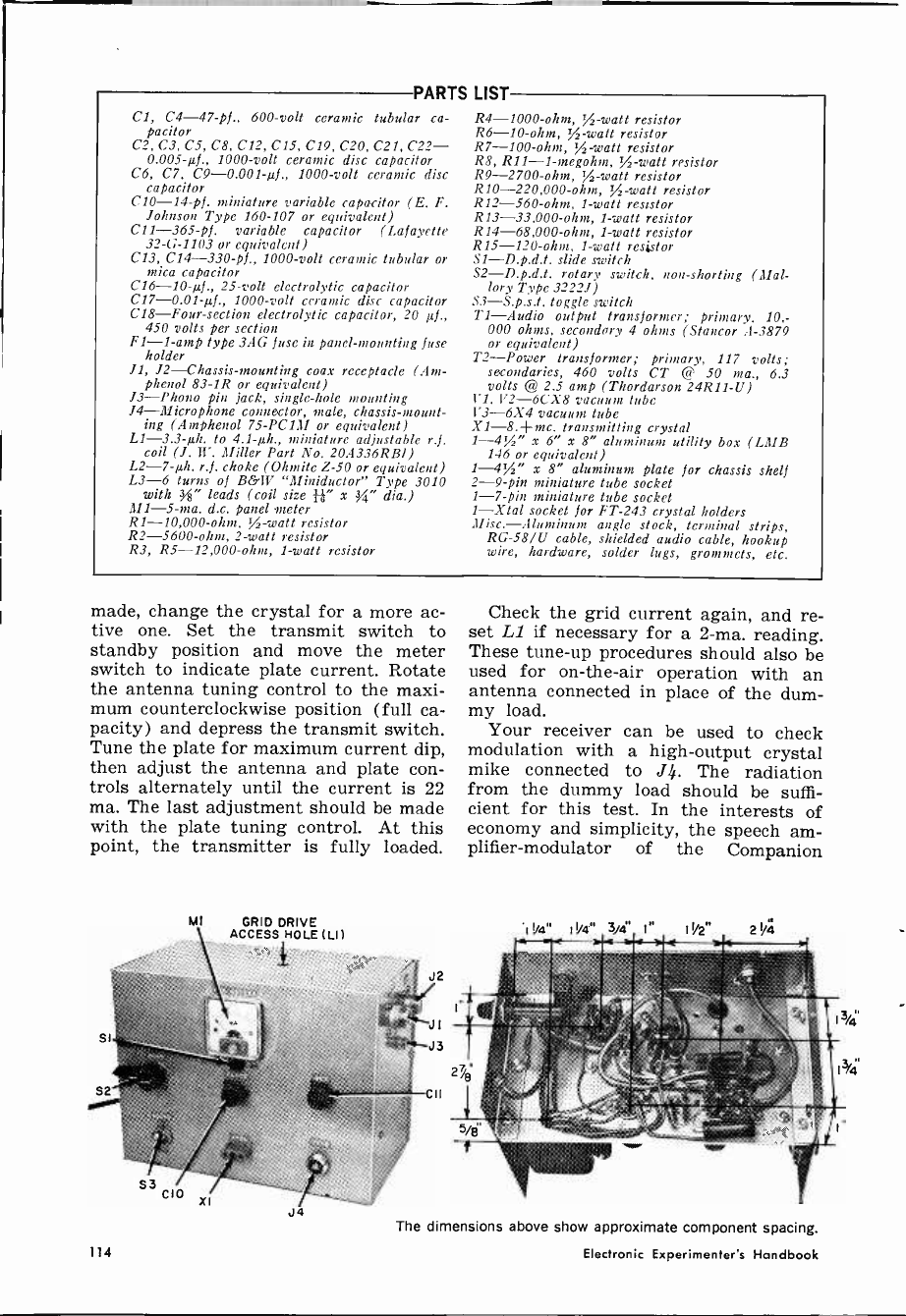
PARTS LIST
Cl, C4 -47 -pf., 600 -volt ceramic tubular ca-
pacitor
C2, C3, C5, C8, C12, C15, C19, C20, C21, C22-
0.005-µ5., 1000 -volt ceramic disc capacitor
C6, C7, C9 -0.001-µf., 1000 -volt ceramic disc
capacitor
C10 -14 -pf. miniature variable capacitor (E. F.
Johnson Type 160-107 or equivalent)
C11 -365 -pf. variable capacitor (Lafayette
32-G-1103 or equivalent)
C13, C14 -330 -pf., 1000 -volt ceramic tubular or
mica capacitor
C16 -10-µf., 25 -volt electrolytic capacitor
C17 -0.01-µf., 1000 -volt ceramic disc capacitor
C18-Four-section electrolytic capacitor, 20 µf.,
450 volts per section
F1 -1 -amp type 3AG fuse in panel -mounting fuse
holder
11, 12-Chassis-mounting coax receptacle (Am -
phenol 83-1R or equivalent)
13-Phono pin jack, single -hole mounting
J4-Microphone connector, male, chassis -mount-
ing (Amphenol 75-PC1M or equivalent)
L1 -3.3-µh. to 4.1-µh., miniature adjustable r.f.
coil (J. W. Miller Part No. 20A336RBI)
L2 -7-µh. r.f. choke (Ohmite Z-50 or equivalent)
L3-6 turns of B&W "Miniductor" Type 3010
with 3" leads (coil size fi" x " dia.)
M1 -5 -ma. d.c. panel -meter
R1 -10,000 -ohm, Vs -watt resistor
R2 -5600 -ohm, 2 -watt resistor
R3, R5 -12,000 -ohm, 1 -watt resistor
R4 -1000 -ohm, Vs -watt resistor
R6 -10 -ohm, Vs -watt resistor
R7 -100 -ohm, %-watt resistor
R8, R11-1-megohm, Vs -watt resistor
R9 -2700 -ohm, 'A -watt resistor
R10 -220,000 -ohm, Vs -watt resistor
R12 -560 -ohm, 1 -watt resistor
R13 -33,000 -ohm, 1 -watt resistor
R14 -68,000 -ohm, 1 -watt resistor
R15 -120 -ohm, 1 -watt resistor
SI-D.p.d.t. slide switch
S2-D.p.d.t. rotary switch, non -shorting (Mal-
lory Type 32227)
S3-S.p.s.t. toggle switch
TZ-Audio output transformer; primary, 10,-
000 ohms, secondary 4 ohms (Stancor A-3879
or equivalent)
T2-Power transformer; primary, 117 volts;
secondaries, 460 volts CT @ 50 ma., 6.3
volts @ 2.5 amp (Thordarson 24R11 -U)
V1, V2-6CX8 vacuum tube
V3 -6X4 vacuum tube
X1 -8. -+-mc. transmitting crystal
1--4%" x 6" x 8" aluminum utility box (LMB
146 or equivalent)
1-4%" x 8" aluminum plate for chassis shelf
2 -9 -pin miniature tube socket
1 -7 -pin miniature tube socket
1-Xtal socket for FT -243 crystal holders
Misc.-Aluminum angle stock, terminal strips,
RG -58/U cable, shielded audio cable, hookup
wire, hardware, solder lugs, grommets, etc.
made, change the crystal for a more ac-
tive one. Set the transmit switch to
standby position and move the meter
switch to indicate plate current. Rotate
the antenna tuning control to the maxi-
mum counterclockwise position (full ca-
pacity) and depress the transmit switch.
Tune the plate for maximum current dip,
then adjust the antenna and plate con-
trols alternately until the current is 22
ma. The last adjustment should be made
with the plate tuning control. At this
point, the transmitter is fully loaded.
MI
114
GRID DRIVE
ACCESS HOLE (LI)
J4 The d
Check the grid current again, and re-
set 1,1 if necessary for a 2 -ma. reading.
These tune-up procedures should also be
used for on -the -air operation with an
antenna connected in place of the dum-
my load.
Your receiver can be used to check
modulation with a high -output crystal
mike connected to J4. The radiation
from the dummy load should be suffi-
cient for this test. In the interests of
economy and simplicity, the speech am-
plifier -modulator of the Companion
*I %4" I 1/4" 3/4' 1" 11/2" 2 1/4
mensions above show approximate component spacing.
Electronic Experimenter's Handbook
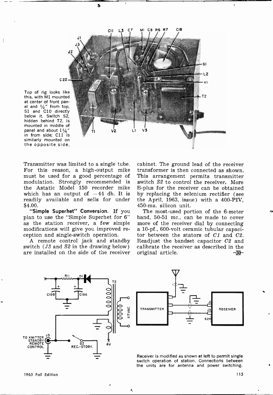
CII L3 C7 MI CB R6 R7
C22
Top of rig looks like
this, with M1 mounted
at center of front pan-
el and 1/2" from top,
Si and C10 directly
below it. Switch S2,
hidden behind T2, is
mounted in middle of
panel and about 11/4"
in from side; C11 is
similarly mounted on
the opposite side.
Transmitter was limited to a single tube.
For this reason, a high -output mike
must be used for a good percentage of
modulation. Strongly recommended is
the Astatic Model 150 recorder mike
which has an output of -44 db. It is
readily available and sells for under
$4.00.
"Simple Superhet" Conversion. If you
plan to use the "Simple Superhet for 6"
as the station receiver, a few simple
modifications will give you improved re-
ception and single -switch operation.
A remote control jack and standby
switch (J3 and S2 in the drawing below)
are installed on the side of the receiver
CI9B
TO XMITTER J3
STANDBY
REMOTE
CONTROL
RII DI
S2
REC.-STDBY. 6V
T2
a
CIB
cabinet. The ground lead of the receiver
transformer is then connected as shown.
This arrangement permits transmitter
switch S2 to control the receiver. More
B -plus for the receiver can be obtained
by replacing the selenium rectifier (see
the April, 1963, issue) with a 400 -Ply,
450 -ma. silicon unit.
The most -used portion of the 6 -meter
band, 50-51 mc., can be made to cover
more of the receiver dial by connecting
a 10 -pf., 600 -volt ceramic tubular capaci-
tor between the stators of Cl and C2.
Readjust the bandset capacitor C2 and
calibrate the receiver as described in the
original article. -
TRANSMITTER RECEIVER
Receiver is modified as shown at left to permit single
switch operation of station. Connections between
the units are for antenna and power switching.
1965 Fall Edition 115
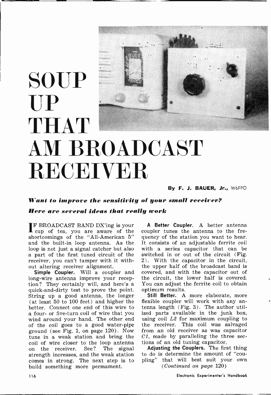
SOUP
UP
THAT
AM BROADCAST
RE('EIVER By F. J. BAUER, Jr., W6FPO
Want to improve the sensitivity of your small rereirer?
Here are several ideas that really work
IF BROADCAST BAND DX'ing is your
cup of tea, you are aware of the
shortcomings of the "All-American 5"
and the built-in loop antenna. As the
loop is not just a signal catcher but also
a part of the first tuned circuit of the
receiver, you can't tamper with it with-
out altering receiver alignment.
Simple Coupler. Will a coupler and
long-wire antenna improve your recep-
tion ? They certainly will, and here's a
quick -and -dirty test to prove the point.
String up a good antenna, the longer
(at least 50 to 100 feet) and higher the
better. Connect one end of this wire to
a four- or five -turn coil of wire that you
wind around your hand. The other end
of the coil goes to a good water -pipe
ground (see Fig. 1, on page 120) . Now
tune in a weak station and bring the
coil of wire closer to the loop antenna
on the receiver. See ? The signal
strength increases, and the weak station
comes in strong. The next step is to
build something more permament.
A Better Coupler. A better antenna
coupler tunes the antenna to the fre-
quency of the station you want to hear.
It consists of an adjustable ferrite coil
with a series capacitor that can be
switched in or out of the circuit (Fig.
2) . With the capacitor in the circuit,
the upper half of the broadcast band is
covered, and with the capacitor out of
the circuit, the lower half is covered.
You can adjust the ferrite coil to obtain
optimum results.
Still Better. A more elaborate, more
flexible coupler will work with any an-
tenna length (Fig. 3) . The author util-
ized parts available in the junk box,
using coil L2 for maximum coupling to
the receiver. This coil was salvaged
from an old receiver as was capacitor
Cl, made by paralleling the three sec-
tions of an old tuning capacitor.
Adjusting the Couplers. The first thing
to do is determine the amount of "cou-
pling" that will best suit your own
(Continued on page 120)
116 Electronic Experimenter's Handbook
FREE
CATALOG.
250 "Do -lt- Yourself"
Electronic Kits At
Up To 50% Savings
WHY BUILD HEATHKIT ELECTRONICS? A desire
for top-quality products at 50% savings, to be sure. But
it goes beyond that. The reason people choose Heathkit
is pride. Not just the pride of owning something new, but
something a bit better that you have created yourself!
From watching your Heathkit grow and take shape from
your own efforts. It's a labor of love and a lot of fun. The
large pictorial diagrams and simple, step-by-step instruc-
tions make it easy. And when you finish and turn it on
you'll know that unique self-satisfaction that comes with
"do-it-yourself." You will have joined the millions of peo-
ple, from ages l l to 79, people with no special electronic
skills or knowledge, who successfully build Heathkits.
People like you! Give it a try. Your FREE Heathkit
catalog is waiting for you now.
World's Largest Selection Of
NEW Low Price On Heathkit
21" Color TV ... Only $375.00
NEW Transistor FM Stereo
Tuner That Assembles In 6
Hours Or Less ... Only $49.95
NEW Low Prices On
Many Heathkit Stereo/Hi-Fi
Components
NEW Deluxe Shortwave
Radio ... Only $84.95
NEW 23 -Channel, 5 -Watt
AlI-Transistor CB Transceiver...
Only $89.95
r MAIL
COUPON
FOR YOUR
FREE'COPY
L
over
250
electrum kas -
rids largess selection
Electronic Kits
* See The Vast Selection Of Portable And Table
Model AM, FM and Shortwave Radios
* See The Famous Heathkit/Thomas Transistor
Electronic Organs
* See A Complete Selection Of Home & Hobby
Items ... Intercoms, Garage Door Opener, Auto-
motive Kits, Tools, Color TV Sets
* See All Heathkit Stereo/ Hi-Fi Components ..
Tuners, Amplifiers, Speakers, Turntables, Car-
tridges, Furniture
* See The Full Complement Of Heath Marine
Electronics
* See The Complete Line Of Citizen's Band Radio
Gear...Transceivers, Walkie-Talkies, Accessories
* See The Wide Selection Of Heath Educational
Kits For Home Or Classroom Study
* See The World's Largest Line Of Amateur Radio
Gear
* See The Full Line Of Heathkit Lab & Test Instru-
ments For Home Workshop, Industrial & Educa-
tional Use
HEATH COMPANY, Dept. 110-9
Benton Harbor, Michigan 49023
In Canada: Daystrom, Ltd., Cooksville, Ontario
Please send FREE 1966 Heathkit Catalog
Name
Address
City State lip
Prices & specifications subject to change without notice. CL -215 ,
CIRCLE NO.. 10 ON READER SERVICE CARD
1965 Foil Edition 119
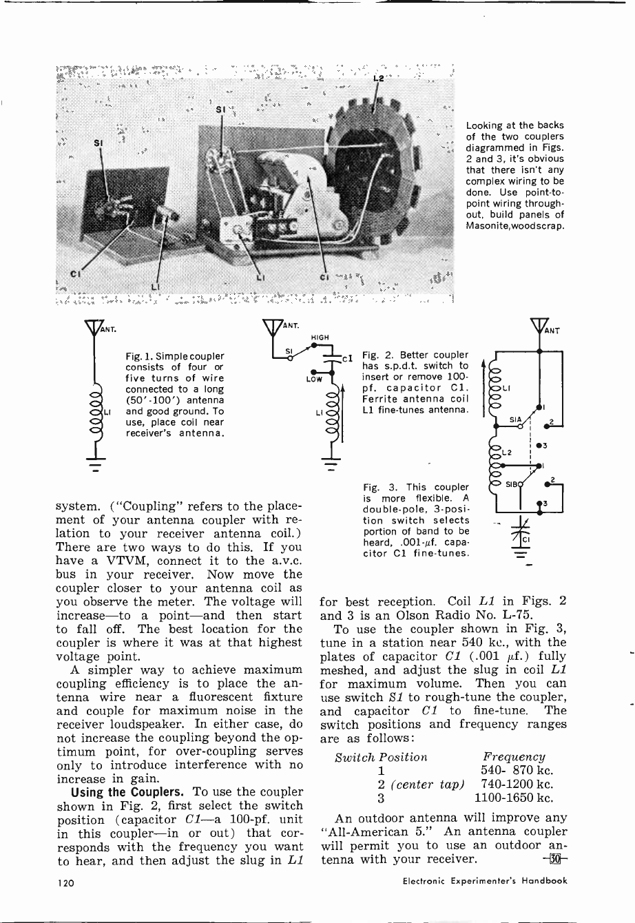
ANT.
lirl-
LI
LI
Fig. 1. Simple coupler
consists of four or
five turns of wire
connected to a long
(50'100') antenna
and good ground. To
use, place coil near
receiver's antenna.
system. ("Coupling" refers to the place-
ment of your antenna coupler with re-
lation to your receiver antenna coil.)
There are two ways to do this. If you
have a VTVM, connect it to the a.v.c.
bus in your receiver. Now move the
coupler closer to your antenna coil as
you observe the meter. The voltage will
increase-to a point-and then start
to fall off. The best location for the
coupler is where it was at that highest
voltage point.
A simpler way to achieve maximum
coupling efficiency is to place the an-
tenna wire near a fluorescent fixture
and couple for maximum noise in the
receiver loudspeaker. In either case, do
not increase the coupling beyond the op-
timum point, for over -coupling serves
only to introduce interference with no
increase in gain.
Using the Couplers. To use the coupler
shown in Fig. 2, first select the switch
position (capacitor Cl-a 100 -pf. unit
in this coupler-in or out) that cor-
responds with the frequency you want
to hear, and then adjust the slug in 1.1
Looking at the backs
of the two couplers
diagrammed in Figs.
2 and 3, it's obvious
that there isn't any
complex wiring to be
done. Use point-to-
point wiring through-
out, build panels of
Masonite,woodscrap.
Fig. 2. Better coupler
has s.p.d.t. switch to
insert or remove 100 -
pf. capacitor Cl.
Ferrite antenna coil
Ll fine-tunes antenna.
Fig. 3. This coupler
is more flexible. A
double -pole, 3 -posi-
tion switch selects
portion of band to be
heard, .001-0. capa-
citor Cl fine-tunes.
i
for best reception. Coil L1 in Figs. 2
and 3 is an Olson Radio No. L-75.
To use the coupler shown in Fig. 3,
tune in a station near 540 ke., with the
plates of capacitor Cl (.001 µf.) fully
meshed, and adjust the slug in coil L1
for maximum volume. Then you can
use switch S1 to rough -tune the coupler,
and capacitor Cl to fine-tune. The
switch positions and frequency ranges
are as follows :
Switch Position Frequency
1 540- 870 kc.
2 (center tap) 740-1200 kc.
3 1100-1650 kc.
An outdoor antenna will improve any
"All-American 5." An antenna coupler
will permit you to use an outdoor an-
tenna with your receiver. -[]-
140 Electronic Experimenter's Handbook
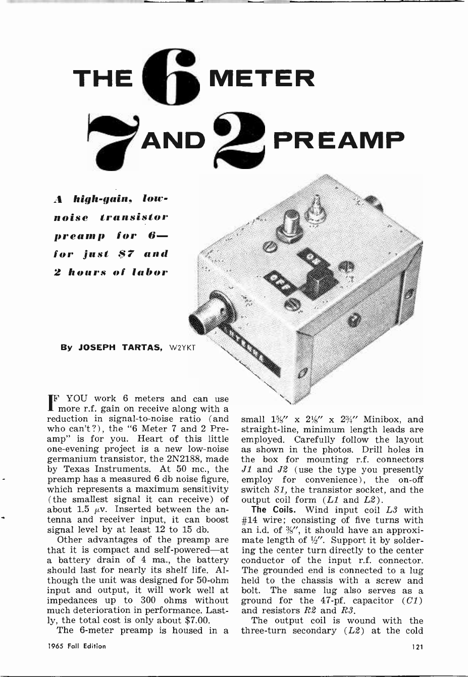
THE 6 METER
LAND 2 PR EAMP
.1 high -gain, low -
noise transistor
p eain p for 6-
for just ti7 and
2 hours of labor
By JOSEPH TARTAS, W2YKT
IF YOU work 6 meters and can use
more r.f. gain on receive along with a
reduction in signal-to-noise ratio (and
who can't ?) , the "6 Meter 7 and 2 Pre -
amp" is for you. Heart of this little
one -evening project is a new low -noise
germanium transistor, the 2N2188, made
by Texas Instruments. At 50 mc., the
preamp has a measured 6 db noise figure,
which represents a maximum sensitivity
(the smallest signal it can receive) of
about 1.5 µv. Inserted between the an-
tenna and receiver input, it can boost
signal level by at least 12 to 15 db.
Other advantages of the preamp are
that it is compact and self-powered-at
a battery drain of 4 ma., the battery
should last for nearly its shelf life. Al-
though the unit was designed for 50 -ohm
input and output, it will work well at
impedances up to 300 ohms without
much deterioration in performance. Last-
ly, the total cost is only about $7.00.
The 6 -meter preamp is housed in a
small 1%" x 21/2" x 23/4' Minibox, and
straight-line, minimum length leads are
employed. Carefully follow the layout
as shown in the photos. Drill holes in
the box for mounting r.f. connectors
J1 and J2 (use the type you presently
employ for convenience), the on -off
switch S1, the transistor socket, and the
output coil form (L1 and L2).
The Coils. Wind input coil L3 with
#14 wire; consisting of five turns with
an i.d. of 3', it should have an approxi-
mate length of '/2". Support it by solder-
ing the center turn directly to the center
conductor of the input r.f. connector.
The grounded end is connected to a lug
held to the chassis with a screw and
bolt. The same lug also serves as a
ground for the 47 -pf. capacitor (C1)
and resistors R2 and R3.
The output coil is wound with the
three -turn secondary (L2) at the cold
1965 Fall Edition 121
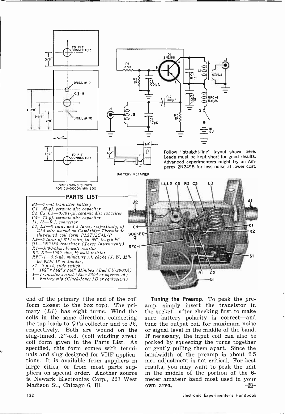
T
5/B"
5/8"
TO FIT
CONNECTOR
I«581
y1 TO FIT
(t
DIMENSIONS SHOWN
FOR CU -3000A MINIBOX
PARTS LIST
JI
1/2"
.001Ní.
47p f.
1/d
T
BATTERY RETAINER
re:s LI,L2
B1 -9 -volt transistor battery
C1 -47 -pf. ceramic disc capacitor
C2, C3, C5 -0.001-µf. ceramic disc capacitor
C4 -18 -pf. ceramic disc capacitor
JI, J2-R.f. connector
Ll, L2-8 turns and 3 turns, respectively, of
#24 wire wound on Cambridge Thermionic
slug -tuned coil form PLST/2C4L/P
L3-5 turns of #14 wire, i.d. %", length 1/2"
Q1 -2N2188 transistor (Texas Instruments)
R1 -3900 -ohm, 1 -watt resistor
R2, R3 -1000 -ohm, 1 -watt resistor
RFC -1-5.6-µh. miniature r.f. choke (J. W. Mil-
ler 9330-18 or similar)
Si-S.p.s.t. slide switch
1-1 "x2%"x23" Minibox (Bud CU -3000A)
1-Transistor socket (Elco 3304 or equivalent)
1-Battery clip (Cinch -Jones 5D or equivalent)
C4
SOCKET,
QI
RFC -1
end of the primary (the end of the coil
form closest to the box top). The pri-
mary (L1) has eight turns. Wind the
coils in the same direction, connecting
the top leads to Q1's collector and to J2,
respectively. Both are wound on the
slug -tuned, .2"-o.d. (coil winding area)
coil form given in the Parts List. As
specified, this form comes with termi-
nals and slug designed for VHF applica-
tions. It is available from suppliers in
large cities, or from most parts sup-
pliers on special order. Another source
is Newark Electronics Corp., 223 West
Madison St., Chicago 6, Ill.
o
2N2'8S
C3 001 f.
R3
IK
T .00 1
RFC -1
5.6yh.
J2
Follow "straight-line" layout shown here.
Leads must be kept short for good results.
Advanced experimenters might try an Am-
perex 2N2495 for less noise at lower cost.
C5 R3 C3 L3
Tuning the Preamp. To peak the pre -
amp, simply insert the transistor in
the socket-after checking first to make
sure battery polarity is correct-and
tune the output coil for maximum noise
or signal level in the middle of the band.
If necessary, the input coil can also be
peaked by squeezing the turns together
or gently pulling them apart. Since the
bandwidth of the preamp is about 2.5
mc., adjustment is not critical. For best
results, you may want to peak the unit
in the middle of the portion of the 6 -
meter amateur band most used in your
own area. -i®-
122 Electronic Experimenter's Handbook
CHAPTER
6
TEST
EQUIPMENT
PROJECTS
Because of the commercial availability of test
equipment-either in kit form or prewired-proj-
ects for the home constructor must be instruments
he can't buy. This is the philosophy used in se-
lecting projects for the Fall Edition of the 1965
ELECTRONIC EXPERIMENTER'S HAND-
BOOK.
The "Field -Effect Transistor Voltmeter" (page
127) is one of the first-if not the very first-
construction project to take advantage of the un-
usual characteristics of the field-effect transistor.
This device is simple to build and calibrate, and
has an input resistance comparable to that of a
VTVM. The "SCR Tester" (page 126) is a com-
panion piece to the "Automatic Diode Checker"
(in the 1963 Edition of the ELECTRONIC EX-
PERIMENTER'S HANDBOOK). It could also be
labeled "automatic"' since it checks operating
characteristics of the gate as well as checking
for opens and shorts.
This chapter is rounded off with several short
items and some of the best "Tips and Techniques"
from past issues of POPULAR ELECTRONICS.
124
HYBRID CIRCUIT FOR TRANSISTOR POWER Roy E. Pafenberg
126
SCR TESTER T. E. Hopkins
127
FIELD-EFFECT TRANSISTOR VOLTMETER Jeff H. Taylor
131
MULTIPLE METER TEST SET Roy E. Pafenberg
132
MULTI -OUTPUT ZENER VOLTAGE REGULATOR Harold Reed
133
BEST OF TIPS AND TECHNIQUES
1965 Fall Edition 123
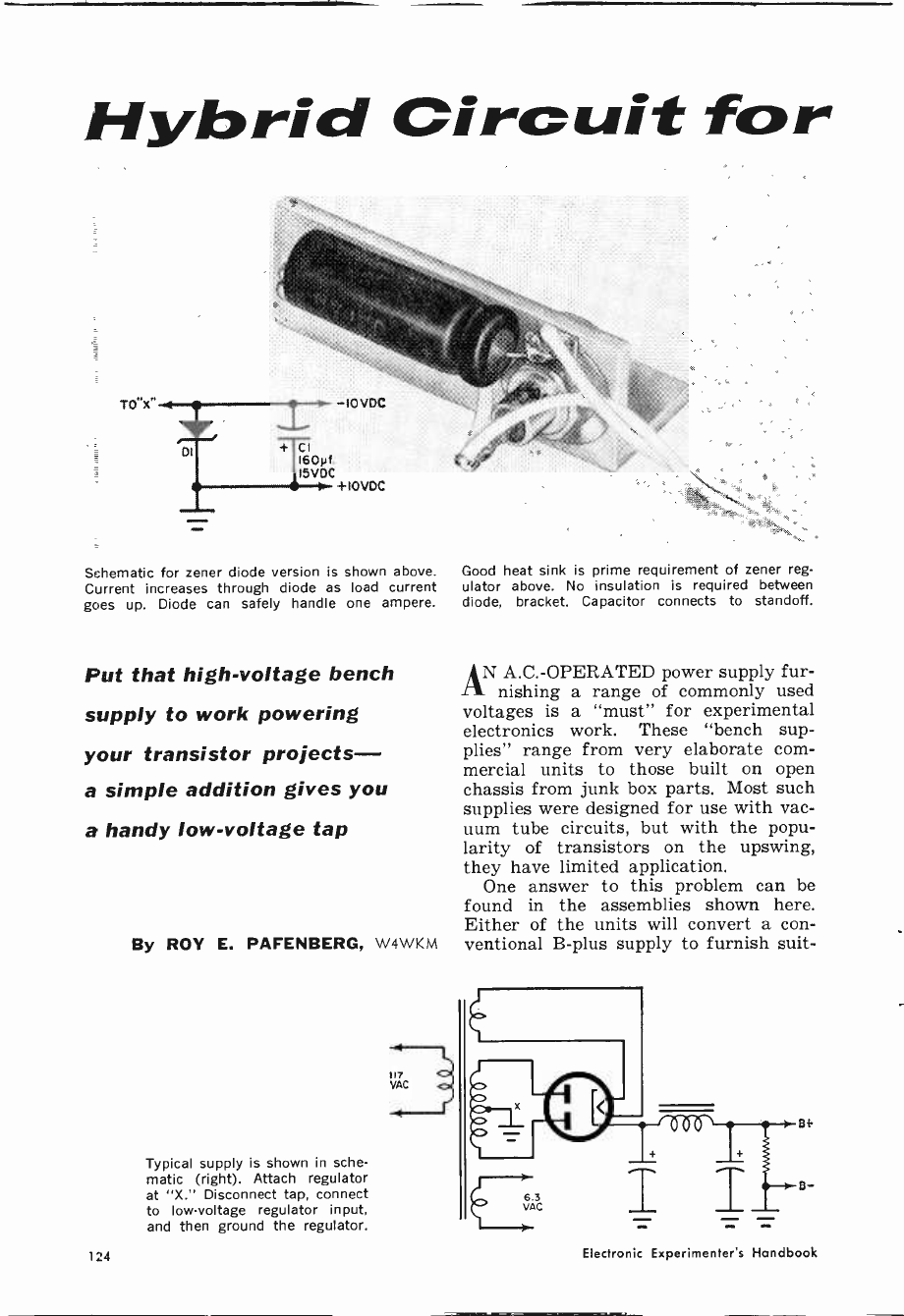
Hybrid Circuit for
TO"x
Di
IOVDC
+ CI i60yf.
i5 V OC
> +1OVDC
Schematic for zener diode version is shown above. Good heat sink is prime requirement of zener reg -
Current increases through diode as load current ulator above. No insulation is required between
goes up. Diode can safely handle one ampere. diode, bracket. Capacitor connects to standoff.
Put that high -voltage bench
supply to work powering
your transistor pro jects-
a simple addition gives you
a handy low -voltage tap
By ROY E. PAFENBERG, W4WKM
Typical supply is shown in sche-
matic (right). Attach regulator
at "X." Disconnect tap, connect
to low -voltage regulator input,
and then ground the regulator.
AN A.C.-OPERATED power supply fur-
nishing a range of commonly used
voltages is a "must" for experimental
electronics work. These "bench sup-
plies" range from very elaborate com-
mercial units to those built on open
chassis from junk box parts. Most such
supplies were designed for use with vac-
uum tube circuits, but with the popu-
larity of transistors on the upswing,
they have limited application.
One answer to this problem can be
found in the assemblies shown here.
Either of the units will convert a con-
ventional B -plus supply to furnish suit -
124 Electronic Experimenter's Handbook
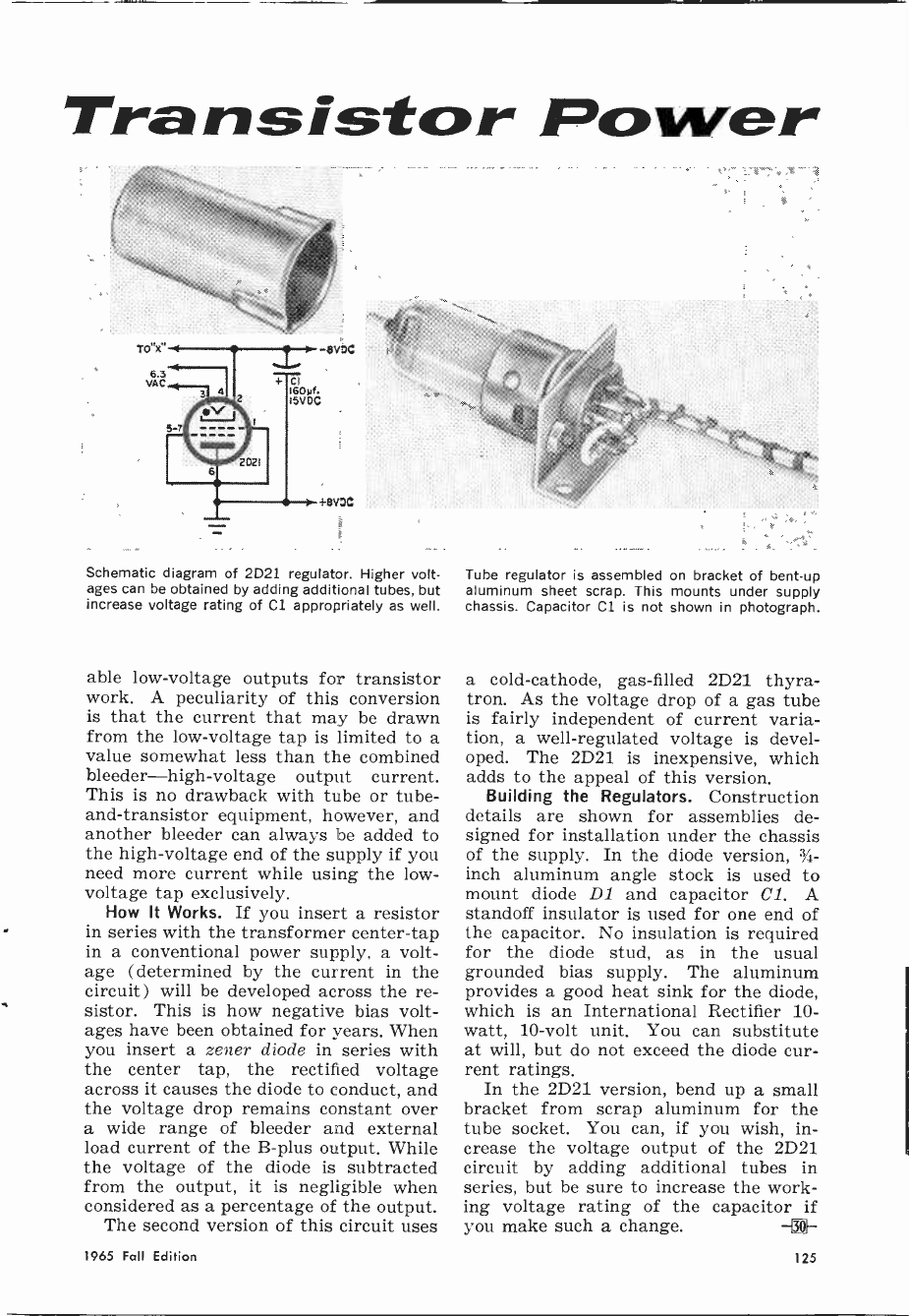
Tra n sistor Power
Schematic diagram of 2D21 regulator. Higher volt-
ages can be obtained by adding additional tubes, but
increase voltage rating of Cl appropriately as well.
able low -voltage outputs for transistor
work. A peculiarity of this conversion
is that the current that may be drawn
from the low -voltage tap is limited to a
value somewhat less than the combined
bleeder-high-voltage output current.
This is no drawback with tube or tube -
and -transistor equipment, however, and
another bleeder can always be added to
the high -voltage end of the supply if you
need more current while using the low -
voltage tap exclusively.
How It Works. If you insert a resistor
in series with the transformer center -tap
in a conventional power supply, a volt-
age (determined by the current in the
circuit) will be developed across the re-
sistor. This is how negative bias volt-
ages have been obtained for years. When
you insert a zener diode in series with
the center tap, the rectified voltage
across it causes the diode to conduct, and
the voltage drop remains constant over
a wide range of bleeder and external
load current of the B -plus output. While
the voltage of the diode is subtracted
from the output, it is negligible when
considered as a percentage of the output.
The second version of this circuit uses
Tube regulator is assembled on bracket of bent -up
aluminum sheet scrap. This mounts under supply
chassis. Capacitor Cl is not shown in photograph.
a cold -cathode, gas -filled 2D21 thyra-
tron. As the voltage drop of a gas tube
is fairly independent of current varia-
tion, a well -regulated voltage is devel-
oped. The 2D21 is inexpensive, which
adds to the appeal of this version.
Building the Regulators. Construction
details are shown for assemblies de-
signed for installation under the chassis
of the supply. In the diode version, 3/4 -
inch aluminum angle stock is used to
mount diode D1 and capacitor Cl. A
standoff insulator is used for one end of
the capacitor. No insulation is required
for the diode stud, as in the usual
grounded bias supply. The aluminum
provides a good heat sink for the diode,
which is an International Rectifier 10 -
watt, 10 -volt unit. You can substitute
at will, but do not exceed the diode cur-
rent ratings.
In the 2D21 version, bend up a small
bracket from scrap aluminum for the
tube socket. You can, if you wish, in-
crease the voltage output of the 2D21
circuit by adding additional tubes in
series, but be sure to increase the work-
ing voltage rating of the capacitor if
you make such a change.
1965 Fall Edition 125

SCR TESTER
By T. E. HOPKINS
There's no easy way of testing an SCR
but this handy gadget solves the problem
INCREASING commercial and domes-
tic use of silicon controlled rectifiers
(SCR's) in such popular devices as light
dimmers, for power tool speed control,
etc., has created a need for a simple,
quick, and reliable method of checking
the condition of those suspected of being
faulty.
An SCR is a four -layer semiconductor
device with two main conducting termi-
All of the components can be
readily fitted into a convenient
aluminum box. The wire from
switch Si to center binding post
J3 ("Gate") may not seem visible,
but it's really there. Numerous
inexpensive 24-25 transformers
are available as substitutes for
the filament transformer called
out in Parts List on page 139.
SI RI
nals and a gate terminal. It contains
junctions that are intended to block all
current in a reverse direction, block cur-
rent flow in the forward direction under
normal or ungated conditions, and allow
forward current flow when the gate is
energized or triggered. Thus, it is pos-
sible for an SCR to break down in either
the forward or reverse direction or both.
It is also possible for the gate connection
to become either shorted or open. There-
fore, it is not possible to determine the
condition of an SCR by simple ohmmeter
tests as may be done with a rectifier or
even, to some extent, with a transistor.
The device described in this article
will test both forward and reverse break-
down and gate operation. Transformer
T1 provides a 25 -volt, r.m.s. source of
a.c. to the circuit. This voltage is alter-
nately applied in the forward and re-
verse directions across the anode -cathode
connections of the SCR. If initial break-
down is present in either direction, cur-
rent will flow in that particular direction
and the current will be detected by either
the "Forward" or "Reverse" lamps.
(Continued on page 139)
R3 II
126 Electronic Experimenter's Handbook
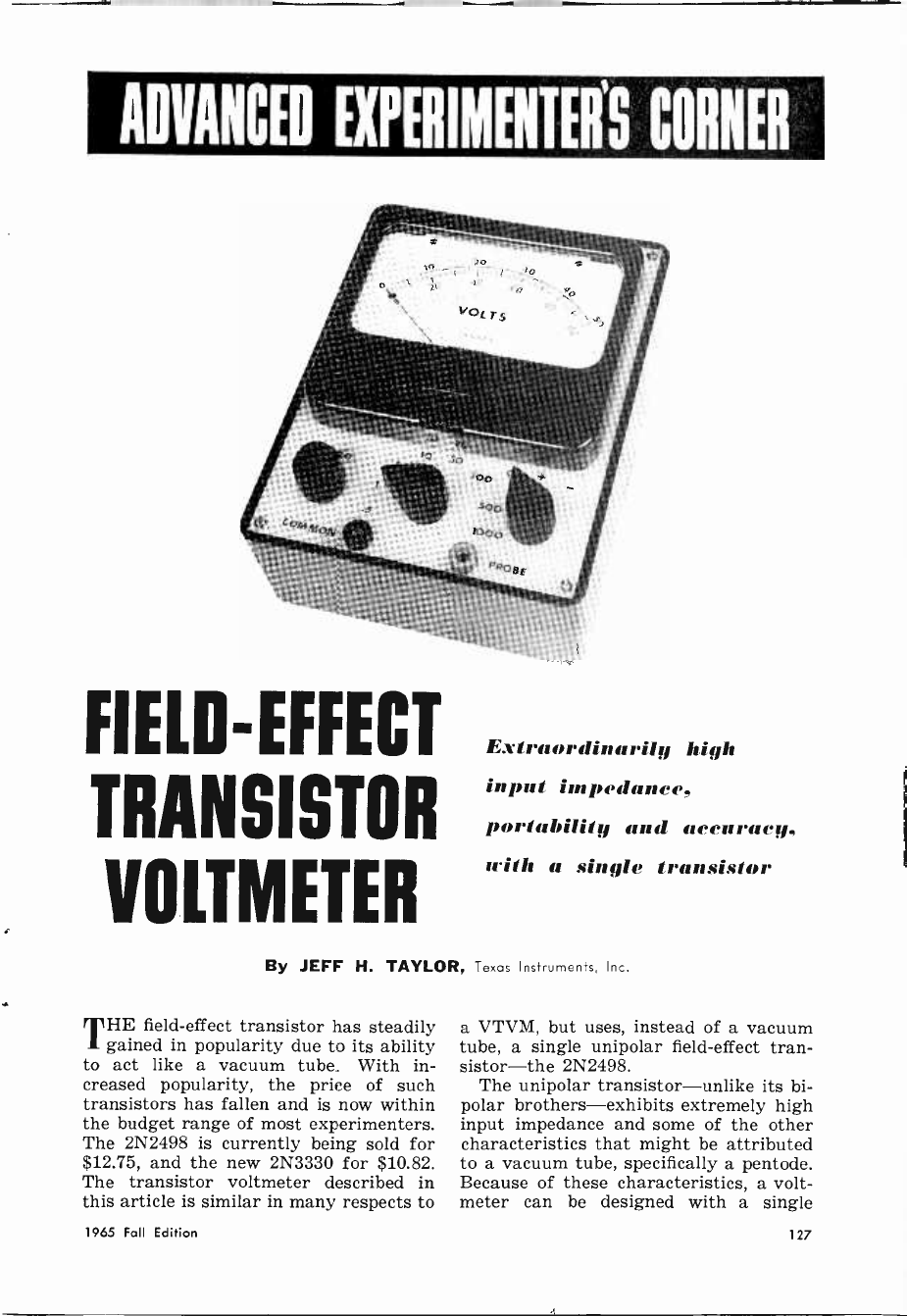
ADVANCED EXPERIMENTER'S CORNER
FIELD-EFFECT
TRANSISTOR
VOLTMETER
Extraordinarily high
input impedance,
portability and accuracy,
with a single transistor
By JEFF H. TAYLOR, Texas Instruments, Inc.
THE field-effect transistor has steadily
gained in popularity due to its ability
to act like a vacuum tube. With in-
creased popularity, the price of such
transistors has fallen and is now within
the budget range of most experimenters.
The 2N2498 is currently being sold for
$12.75, and the new 2N3330 for $10.82.
The transistor voltmeter described in
this article is similar in many respects to
a VTVM, but uses, instead of a vacuum
tube, a single unipolar field-effect tran-
sistor-the 2N2498.
The unipolar transistor-unlike its bi-
polar brothers-exhibits extremely high
input impedance and some of the other
characteristics that might be attributed
to a vacuum tube, specifically a pentode.
Because of these characteristics, a volt-
meter can be designed with a single
1965 Fall Edition 127
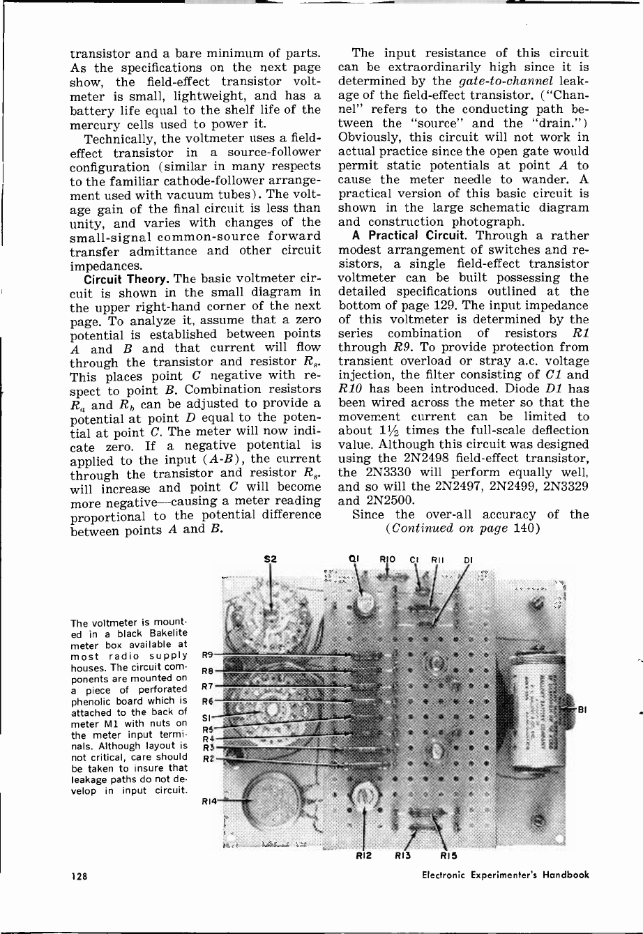
transistor and a bare minimum of parts.
As the specifications on the next page
show, the field-effect transistor volt-
meter is small, lightweight, and has a
battery life equal to the shelf life of the
mercury cells used to power it.
Technically, the voltmeter uses a field-
effect transistor in a source -follower
configuration (similar in many respects
to the familiar cathode -follower arrange-
ment used with vacuum tubes) . The volt-
age gain of the final circuit is less than
unity, and varies with changes of the
small -signal common -source forward
transfer admittance and other circuit
impedances.
Circuit Theory. The basic voltmeter cir-
cuit is shown in the small diagram in
the upper right-hand corner of the next
page. To analyze it, assume that a zerb
potential is established between points
A and B and that current will flow
through the transistor and resistor R8.
This places point C negative with re-
spect to point B. Combination resistors
R3 and Rb can be adjusted to provide a
potential at point D equal to the poten-
tial at point C. The meter will now indi-
cate zero. If a negative potential is
applied to the input (A -B) , the current
through the transistor and resistor R8.
will increase and point C will become
more negative-causing a meter reading
proportional to the potential difference
between points A and B.
The voltmeter is mount-
ed in a black Bakelite
meter box available at
most radio supply R9
houses. The circuit com-
ponents are mounted on
a piece of perforated
phenolic board which is
attached to the back of
meter M1 with nuts on
the meter input termi-
nals. Although layout is
not critical, care should
be taken to insure that
leakage paths do not de-
velop in input circuit.
R8
R7
R6 Ea'
SI ,_
R5
S2
R4 R3 R2
R14
The input resistance of this circuit
can be extraordinarily high since it is
determined by the gate -to -channel leak-
age of the field-effect transistor. ("Chan-
nel" refers to the conducting path be-
tween the "source" and the "drain.")
Obviously, this circuit will not work in
actual practice since the open gate would
permit static potentials at point A to
cause the meter needle to wander. A
practical version of this basic circuit is
shown in the large schematic diagram
and construction photograph.
A Practical Circuit. Through a rather
modest arrangement of switches and re-
sistors, a single field-effect transistor
voltmeter can be built possessing the
detailed specifications outlined at the
bottom of page 129. The input impedance
of this voltmeter is determined by the
series combination of resistors RI
through R9. To provide protection from
transient overload or stray a.c. voltage
injection, the filter consisting of Cl and
R10 has been introduced. Diode D1 has
been wired across the meter so that the
movement current can be limited to
about 11/2 times the full-scale deflection
value. Although this circuit was designed
using the 2N2498 field-effect transistor,
the 2N3330 will perform equally well,
and so will the 2N2497, 2N2499, 2N3329
and 2N2500.
Since the over-all accuracy of the
(Continued on page 140)
al
R12
RIO CI RII
1
DI
s
Y $ P
R13 R15
8I
128 Electronic Experimenter's Handbook
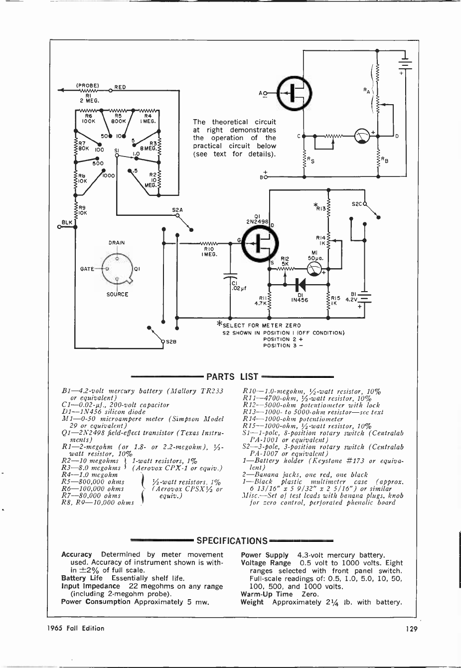
BLK
(PROBE) RED
RI
2 MEG.
R6 R5
IOOK 800K
50 10
R7
80K 100 SI
500
Rb 1000
10K
R9
10K
GATE
5
R4
I MEG.
R3
8 MEG.
1.0
R2
10
MEG.
S2A
DRAIN
SOURCE
01
The theoretical circuit
at right demonstrates
the operation of the
practical circuit below
(see text for details).
YANN
RIO
I MEG. I
01
2N2498
RI I
4.7K IK
*SELECT FOR
T I
S2 SHOWN IN
D
RI2
S 5K
*RI
R14 1
MI
Soya.
S2C
S2B
PARTS LIST
B1 -4.2 -volt mercury battery (Mallory TR233
or equivalent)
C1 -0.02-µf., 200 -volt capacitor
Dl -1N456 silicon diode
M1-0-50 microampere meter (Simpson Model
29 or equivalent)
QI -2N2498 field-effect transistor (Texas Instru-
ments)
R1-2-megohm (or 1.8- or 2.2-megohm), %-
watt resistor, 10%1
R2-10 megohms
7
1 -watt resistors, 1%
R3-8.0 megohms (Aerovox CPX-1 or equiv.)
R4-1.0 megohm
R5-800,000 ohms %-watt resistors, 1%
R6-100,000 ohms (Aerovox CPSX% or
R7-80,000 ohms equiv.)
R8, R9-10,000 ohms
81-1N456
IN456 R15 4.2V -
DI
METER ZERO
POSITION I (OFF COND TION)
POSITION 2 +
POSITION 3 -
R10-1.0-megohm, %-watt resistor, 10%
R11 -4700 -ohm, ,A -watt resistor, 10%
R12--5000-ohm potentiometer with lock
R13-1000- to 5000 -ohm resistor-see text
R14 -1000 -ohm potentiometer
R15 -1000 -ohm, ,A -watt resistor, 10%
S1 -1 -pole, 8 -position rotary switch (Centralab
PA -1001 or equivalent)
S2 -3 -pole, 3 -position rotary switch (Centralab
PA -1007 or equivalent)
1-Battery holder (Keystone #173 or equiva-
lent)
2-Banana jacks, one red, one black
1-Black plastic multimeter case (approx.
6 13/16" x 5 9/32" x 2 5/16") or similar
Misc.-Set of test leads with banana plugs, knob
for zero control, perforated phenolic board
SPECIFICATIONS
Accuracy Determined by meter movement
used. Accuracy of instrument shown is with-
in ±2% of full scale.
Battery Life Essentially shelf life.
Input Impedance 22 megohms on any range
(including 2-megohm probe).
Power Consumption Approximately 5 mw.
Power Supply 4.3 -volt mercury battery.
Voltage Range 0.5 volt to 1000 volts. Eight
ranges selected with front panel switch.
Full-scale readings of: 0.5, 1.0, 5.0, 10, 50,
100, 500, and 1000 volts.
Warm -Up Time Zero.
Weight Approximately 21/4 lb. with battery.
1965 Fall Edition 129
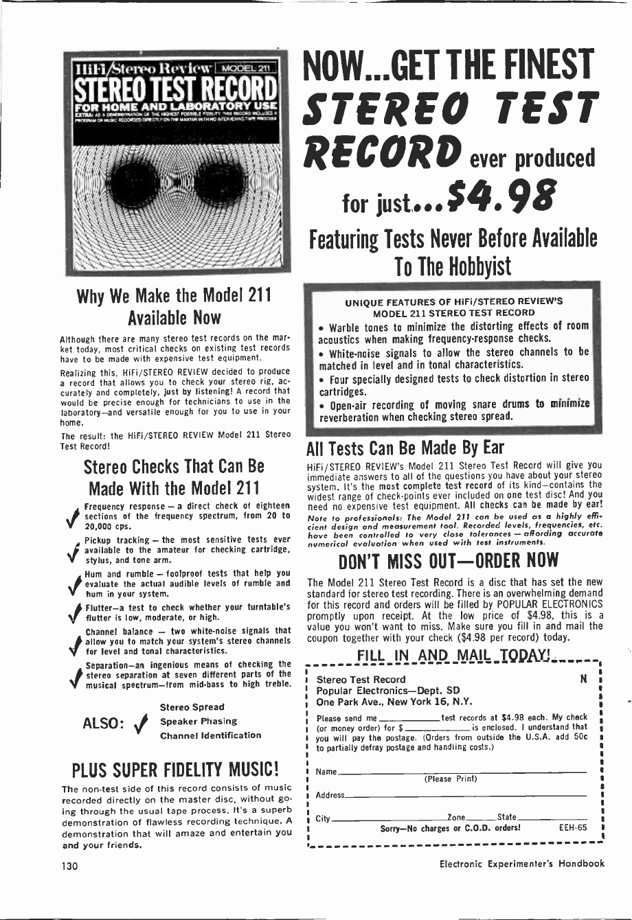
Inn/Stem) Review I MODEL 211
STEREO TEST RECORD
FOR HOME AND LABORATORY USE
QAT: or 000GmAnaa 1,E MWCT»STEPTYNIM6 TAPE
wowvweic icaaorn CIEClLYarne,uertn.wm,«cx,ener Cr*sewroo[m
Why We Make the Model 211
Available Now
Although there are many stereo test records on the mar-
ket today, most critical checks on existing test records
have to be made with expensive test equipment.
Realizing this, HiFi/STEREO REVIEW decided to produce
a record that allows you to check your stereo rig, ac-
curately and completely, just by listening! A record that
would be precise enough for technicians to use in the
laboratory-and versatile enough for you to use in your
home.
The result: the HiFi/STEREO REVIEW Model 211 Stereo
Test Record!
Stereo Checks That Can Be
Made With the Model 211
Frequency response - a direct check of eighteen
sections of the frequency spectrum, from 20 to
20,000 cps.
Pickup tracking - the most sensitive tests ever
available to the amateur for checking cartridge,
stylus, and tone arm.
`Hum and rumble - foolproof tests that help you
./ evaluate the actual audible levels of rumble and
V hum in your system.
jFlutter-a test to check whether your turntable's
flutter is low, moderate, or high.
Channel balance - two white -noise signals that
Jallow you to match your system's stereo channels
for level and tonal characteristics.
Separation-an ingenious means of checking the
stereo separation at seven different parts of the
musical spectrum-from mid -bass to high treble.
Stereo Spread
ALSO: Y Speaker Phasing
Channel Identification
PLUS SUPER FIDELITY MUSIC!
The non -test side of this record consists of music
recorded directly on the master disc, without go
ing through the usual tape process. It's a superb
demonstration of flawless recording technique. A
demonstration that will amaze and entertain you
and your friends.
NOW...GET THE FINEST
STEREO TEST
RECORD ever produced
for just... $4. 98
Featuring Tests Never Before Available
To The Hobbyist
UNIQUE FEATURES OF HiFi/STEREO REVIEW'S
MODEL 211 STEREO TEST RECORD
Warble tones to minimize the distorting effects of room
acoustics when making frequency -response checks.
White -noise signals to allow the stereo channels to be
matched in level and in tonal characteristics.
Four specially designed tests to check distortion in stereo
cartridges.
Open-air recording of moving snare drums to minimize
reverberation when checking stereo spread.
All Tests Can Be Made By Ear
HiFi/STEREO REVIEW's Model 211 Stereo Test Record will give you
immediate answers to all of the questions you have about your stereo
system. It's the most complete test record of its kind-contains the
widest range of check -points ever included on one test disc! And you
need no expensive test equipment. All checks can be made by ear!
Note to professionals: The Model 211 can be used as a highly effi-
cient design and measurement tool. Recorded levels, frequencies, etc.
have been controlled to very close tolerances - affording accurate
numerical evaluation when used with test instruments.
DON'T MISS OUT-ORDER NOW
The Model 211 Stereo Test Record is a disc that has set the new
standard for stereo test recording. There is an overwhelming demand
for this record and orders will be filled by POPULAR ELECTRONICS
promptly upon receipt. At the low price of $4.98, this is a
value you won't want to miss. Make sure you fill in and mail the
coupon together with your check ($4.98 per record) today.
FILL IN AND MAIL TQQA-YJ
Stereo Test Record
Popular Electronics-Dept. SD
One Park Ave., New York 16, N.Y.
N
Please send me test records at $4.98 each. My check
(or money order) for $ is enclosed. I understand that
you will pay the postage. (Orders from outside the U.S.A. add 50c
to partially defray postage and handling costs.)
Name
Address
City Zone State
Sorry-No charges or C.O.D. orders! EEH65
(Please Print)
130 Electronic Experimenter's Handbook
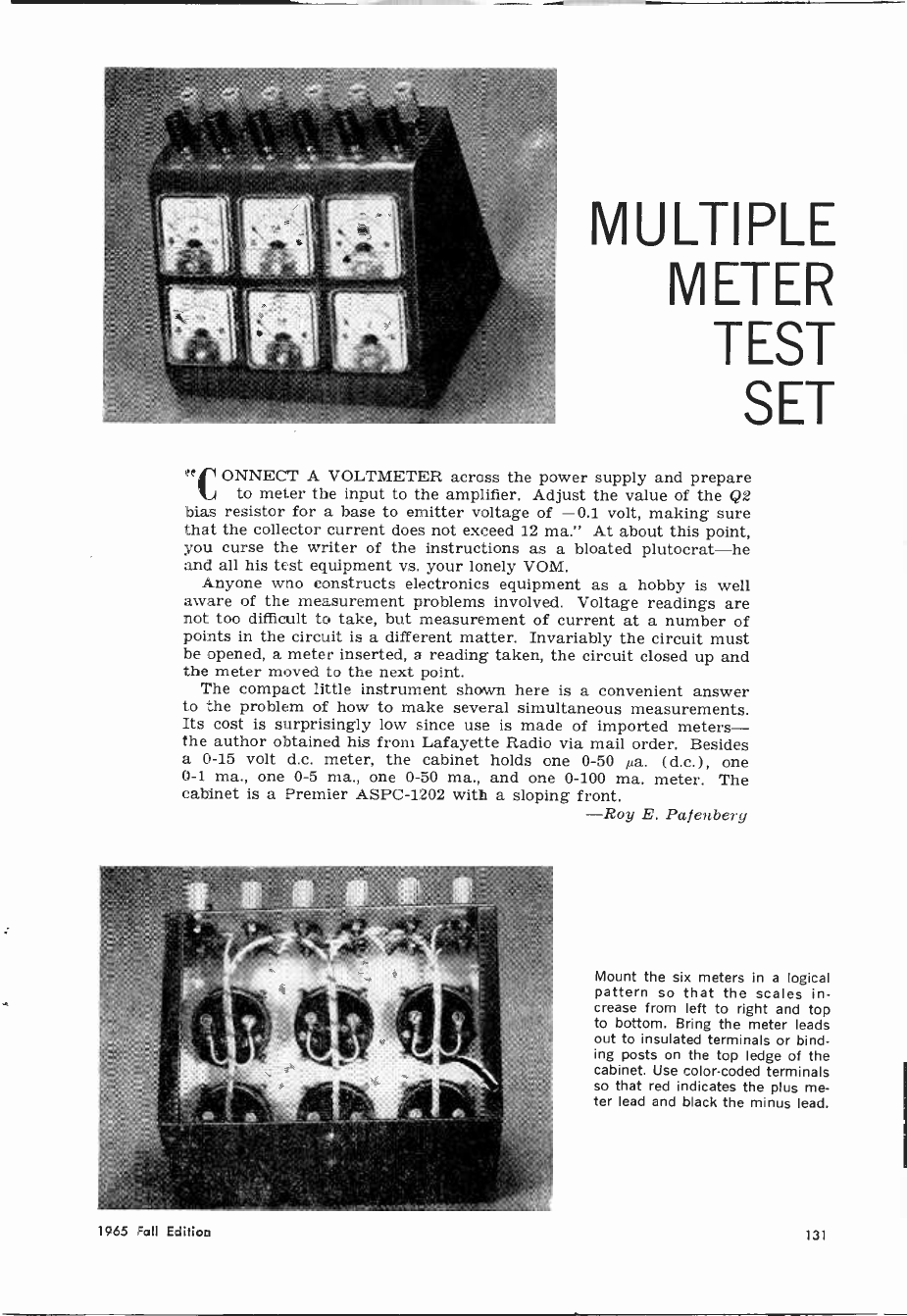
MULTIPLE
METER
TEST
SET
CONNECT A VOLTMETER across the power supply and prepare
to meter the input to the amplifier. Adjust the value of the Q2
bias resistor for a base to emitter voltage of -0.1 volt, making sure
that the collector current does not exceed 12 ma." At about this point,
you curse the writer of the instructions as a bloated plutocrat-he
and all his test equipment vs. your lonely VOM.
Anyone who constructs electronics equipment as a hobby is well
aware of the measurement problems involved. Voltage readings are
not too difficult to take, but measurement of current at a number of
points in the circuit is a different matter. Invariably the circuit must
be opened, a meter inserted, a reading taken, the circuit closed up and
the meter moved to the next point.
The compact little instrument shown here is a convenient answer
to the problem of how to make several simultaneous measurements.
Its cost is surprisingly low since use is made of imported meters-
the author obtained his from Lafayette Radio via mail order. Besides
a 0-15 volt d.c. meter, the cabinet holds one 0-50 µa. (d.c.) , one
0-i ma., one 0-5 ma., one 0-50 ma., and one 0-100 ma. meter. The
cabinet is a Premier ASPC-1202 with a sloping front.
-Roy E. Pafenbery
Mount the six meters in a logical
pattern so that the scales in-
crease from left to right and top
to bottom. Bring the meter leads
out to insulated terminals or bind-
ing posts on the top ledge of the
cabinet. Use color -coded terminals
so that red indicates the plus me-
ter lead and black the minus lead.
1965 Fall Edition 131
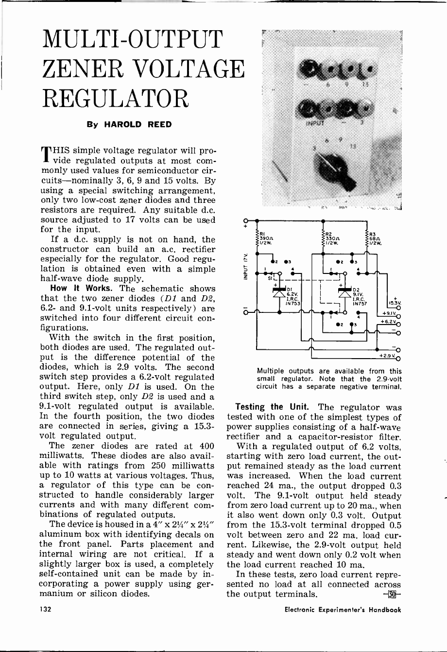
MULTI -OUTPUT
ZENER VOLTAGE
REGULATOR
By HAROLD REED
THIS simple voltage regulator will pro-
vide regulated outputs at most com-
monly used values for semiconductor cir-
cuits-nominally 3, 6, 9 and 15 volts. By
using a special switching arrangement,
only two low-cost zener diodes and three
resistors are required. Any suitable d.c.
source adjusted to 17 volts can be used
for the input.
If a d.c. supply is not on hand, the
constructor can build an a.c. rectifier
especially for the regulator. Good regu-
lation is obtained even with a simple
half -wave diode supply.
How It Works. The schematic shows
that the two zener diodes (DI and D2,
6.2- and 9.1 -volt units respectively) are
switched into four different circuit con-
figurations.
With the switch in the first position,
both diodes are used. The regulated out-
put is the difference potential of the
diodes, which is 2.9 volts. The second
switch step provides a 6.2 -volt regulated
output. Here, only Dl is used. On the
third switch step, only D2 is used and a
9.1 -volt regulated output is available.
In the fourth position, the two diodes
are connected in series, giving a 15.3 -
volt regulated output.
The zener diodes are rated at 400
milliwatts. These diodes are also avail-
able with ratings from 250 milliwatts
up to 10 watts at various voltages. Thus,
a regulator of this type can be con-
structed to handle considerably larger
currents and with many different com-
binations of regulated outputs.
The device is housed in a 4" x 21/4" x 21/4"
aluminum box with identifying decals on
the front panel. Parts placement and
internal wiring are not critical. If a
slightly larger box is used, a completely
self-contained unit can be made by in-
corporating a power supply using ger-
manium or silicon diodes.
6 9
Multiple outputs are available from this
small regulator. Note that the 2.9 -volt
circuit has a separate negative terminal.
Testing the Unit. The regulator was
tested with one of the simplest types of
power supplies consisting of a half -wave
rectifier and a capacitor -resistor filter.
With a regulated output of 6.2 volts,
starting with zero load current, the out-
put remained steady as the load current
was increased. When the load current
reached 24 ma., the output dropped 0.3
volt. The 9.1 -volt output held steady
from zero load current up to 20 ma., when
it also went down only 0.3 volt. Output
from the 15.3 -volt terminal dropped 0.5
volt between zero and 22 ma. load cur-
rent. Likewise, the 2.9 -volt output held
steady and went down only 0.2 volt when
the load current reached 10 ma.
In these tests, zero load current repre-
sented no load at all connected across
the output terminals. -[0]
132 Electronic Experimenter's Handbook
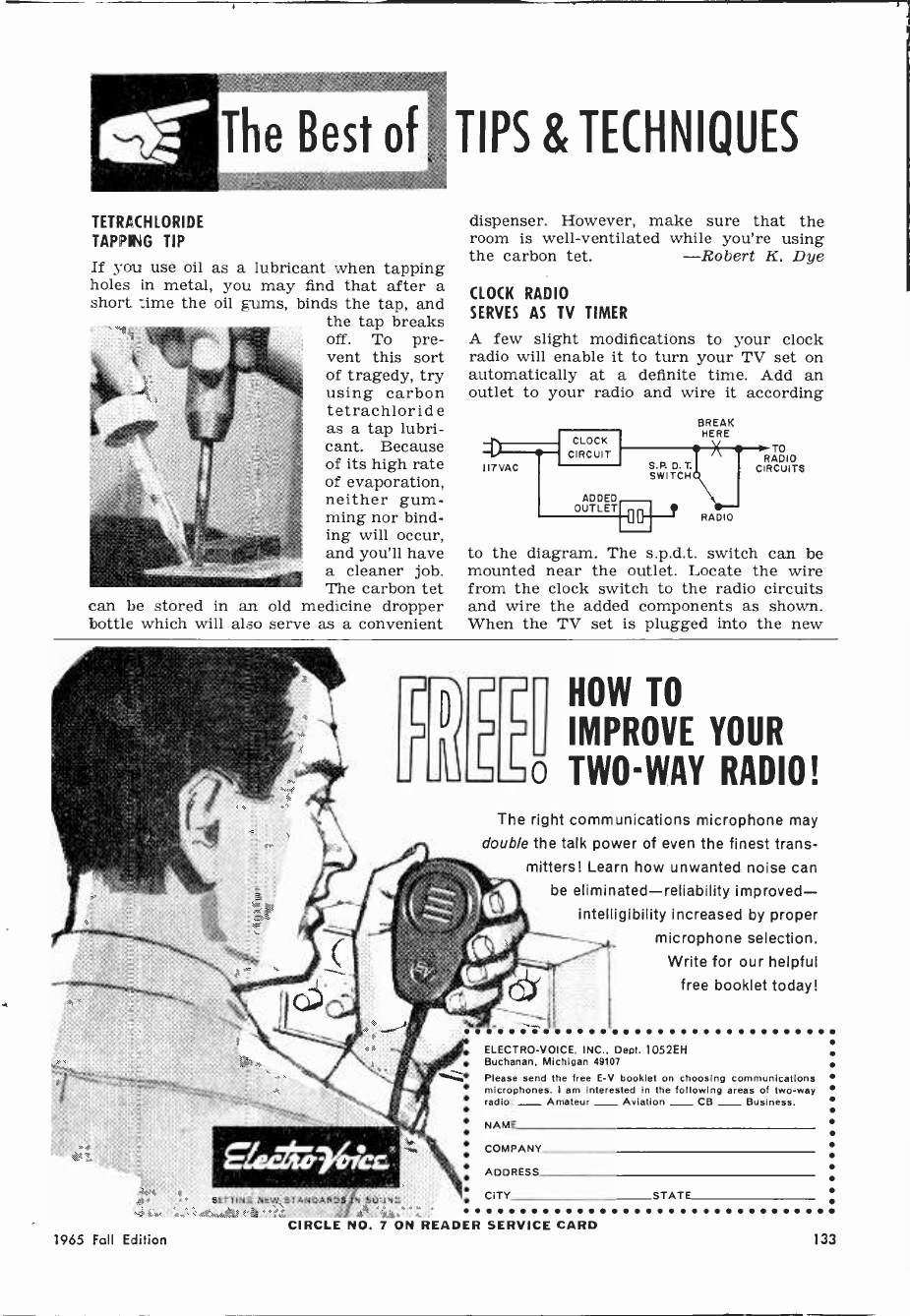
TETRACHLORIDE
TAPPING TIP
If you use oil as a lubricant when tapping
holes in metal, you may find that after a
short time the oil gums, binds the tap, and
the tap breaks
off. To pre-
vent this sort
of tragedy, try
using carbon
tetrachloride
as a tap lubri-
cant. Because
of its high rate
of evaporation,
neither gum-
ming nor bind-
ing will occur,
and you'll have
a cleaner job.
The carbon tet
can be stored in an old medicine dropper
bottle which will also serve as a convenient
TIPS & TECHNIQUES
dispenser. However, make sure that the
room is well -ventilated while you're using
the carbon tet. -Robert K. Dye
CLOCK RADIO
SERVES AS TV TIMER
A few slight modifications to your clock
radio will enable it to turn your TV set on
automatically at a definite time. Add an
outlet to your radio and wire it according
II? VAC
CLOCK
CIRCUIT
ADDED
OUTLET
S.P. D. T.
SWITCH
BREAK
HERE
RADIO
TO
RADIO
CIRCUITS
to the diagram. The s.p.d.t. switch can be
mounted near the outlet. Locate the wire
from the clock switch to the radio circuits
and wire the added components as shown.
When the TV set is plugged into the new
SETTING NEW STANDARS SVUNG
HOW TO
IMPROVE YOUR
TWO-WAY RADIO!
The right communications microphone may
double the talk power of even the finest trans-
mitters! Learn how unwanted noise can
be eliminated-reliability improved-
intelligibility increased by proper
microphone selection.
Write for our helpful
free booklet today!
ELECTRO -VOICE, INC., Dept. 1052EH
Buchanan, Michigan 49107
Please send the tree E -V booklet on choosing communications
microphones. I am Interested in the following areas of two-way
radio: - Amateur _ Aviation - CB _ Business.
NAME
COMPANY
ADDRESS
CITY STATE
CIRCLE NO. 7 ON READER SERVICE CARD
1965 Fall Edtion 133
mumummummalio
i SELLING YOUR
i TRANSCEIVER?
Il BUYING THAT
Il AMPLIFIER?
11Z- ` I
p,
The 400,000 Live Wires who buy POPULAR
ELECTRONICS each month will make it
worth your while to place a classified ad
at the low personal rate of only 55¢ a word.
This, the largest readership in its field
in the world, offers the perfect market for
making contacts. It's possible a great
many of these readers are practically
neighbors of yours, yet it is only through
the medium of our classified columns
that your mutual needs may be met.
Take advantage of our special personal
rate of 55¢ a word (including name and
address)
a saving of 35¢ a word from
our commercial rate of 90¢
NO MINIMUM REQUIRED
A small investment is sure to bring
large results. Write your ad today and
mail it with your payment, to:
Hal Cymes
Classified Advertising Manager
POPULAR ELECTRONICS
One Park Ave.. New York, N. Y. 10016
JANUARY ISSUE CLOSES NOV. 1ST
0 . I ,
al as mill
outlet, it will be controlled by the clock
mechanism if the switch is in the TV po-
sition. If the clock radio is equipped with
a "sleep switch," you can use this to shut
the set off automatically.
-Fred Blechman, K6UGT
SUBSTITUTING
RECTIFIER TUBES
Be wary about replacing a rectifier tube
such as a 5U4 with a 5DJ4 or similar tube.
While at first glance the tube pin numbers
and specifications may seem similar, many
manufacturers utilize unused socket termi-
nals as convenient tie points for components
5DJ4 5U4
PINS 1,3,5, AND 7
MAY BE USED AS
TIE POINTS
that may not even be a part of the rectifier
circuit. The 5DJ4 has internal connections
to tube pins that are not normally used in
the 5U4. For example, if your set has a
5U4 rectifier socket with pin 5 as a ground,
you'll have real trouble substituting a
5DJ4! -Carleton A. Phillips
NEAT LAYOUT FOR
PRINTED -CIRCUIT BOARDS
You'll find it easier to keep components on
a printed -circuit board aligned and neatly
arranged if you try this simple tip. Instead
of laying out the board with penciled guide
lines ( they tend to erase
themselves while you
work) , place a piece of
perforated board over
the copper laminated
board, and spray with
acrylic paint from a
height of at least two
feet. This will give you
a grid of small dots on
the circuit board to use
as component centers
and guides for the cop-
per runs. After laying
out the resist tapes,
quickly slosh the board
with lacquer thinner to
remove the paint; if
you work fast, the tapes will not be affected.
If you use the resistive ink method, the dots
can be removed with an ordinary ink
eraser. -Donald E. Lancaster
134 Electronic Experimenter's Handbook

HANDY HOLDER
FOR HARDWARE
If you attach a large and small rubber suc-
tion cup back to back, the result is a handy
stick -on hard-
ware holder.
Fill the hole
in the larger
cup with epoxy
cement, and in-
sert the screw
lug of the
smaller. The
hardware hold-
er can then be
attached to TV
cabinets, tool
box lids or other supports,
small parts, nuts, bolts or washers.
-John A. Comstock
STORING
ADAPTER SOCKETS
and used for
To keep your
adapter sock-
ets handy and
safe, there's no
better place to
put them than
in your tube
pin straighten-
ers. The adapt-
er socket pins
will be protected, and the sockets them-
selves will be ready for use at all times.
-Clyde C. Cook
CAP AEROSOL "WILDCATS"
TO AVOID MESSY ACCIDENTS
Don't discard the protective cap on the next
can of aerosol tuner cleaner you buy-it can
keep the contents of the can from being ac-
cidentally re-
leased, partic-
ularly when
the can is car-
ried from job
to job. As slip-
ping the cover
on and off and
attaching and
detaching the
extender for
each job would
be a nuisance,
you can neatly
trim out the top of the plastic cover with a
small knife. Then drill or punch a hole
on the side of the cap for the spray ex-
tender tube. When the can is empty, the
modified cap can be transferred to a new
can. -Elmer C. Carlson
1965 Fall Edition
You've got to SEE it to BELIEVE it!
dry transfer
MARKING KITS tor
ELECTRONIC EQUIPMENT
"Instant Lettering" marking kits bring you all the necessary
elements for completely marking electronic equipment,
drawings, prototypes, schematics, etc. in a fast new easy -
to -use form.
Words, letters, numerals, switch patterns, arcs, etc. are
printed on a special transparent carrier film. Rubbing over
one of these elements with a ballpoint pen releases it from
the carrier film and adheres it to your working surface.
"Instant Lettering" words and patterns transfer to almost
any surface including glass, plastic, metal... even crackled
finished metal. Now you can quickly mark all panels, even
especially calibrated two-color meter dials, tap switches,
panel nomenclatures, pilot light jewels, sub -assemblies, cir-
cuit boards, etc. Reproduction quality "Instant Lettering"
transfers are clean and sharp, leave no background haze or
film, make prototypes look like finished production equipment
and give all equipment and drawings a professional look.
TITLES FOR ELECTRONIC EQUIPMENT
This set contains hundreds of preprinted titles researched to
give you up to 95% of all electronic marking. For labeling,
marking, titling all electronic control panels, drawings, pro-
totypes, etc.
No. 958 - BLACK $4.95 No. 959 - WHITE $4.95
TERMINAL & CHASSIS MARKING KIT
Contains all the necessary letters, letter combinations and
numerals for marking chassis, printed circuit and terminal
boards, rotating components, etc.
No. 966 - BLACK $4.95 No. 967 - WHITE $4.95
METER & DIAL MARKING KIT
Arcs, dial patterns, lines, wedges, graduation lines, switch
symbols, alphabets and numerals in black, white and red for
marking standard and special rotary tap switches, potenti-
ometers and prototype and especially calibrated meter dials.
Colors provide contrast on scales and switches simplifying
usage of complex instruments.
No. 968 - METER & DIAL MARKING KIT $4.95
WRITE FOR FREE SAMPLE AND COMPLETE DETAILS
THE DATA K CORPORATION
63 - 71st St. Dept. 634 Guttenberg, N. J.
CIRCLE NO. 4 ON READER SERVICE CARD 135
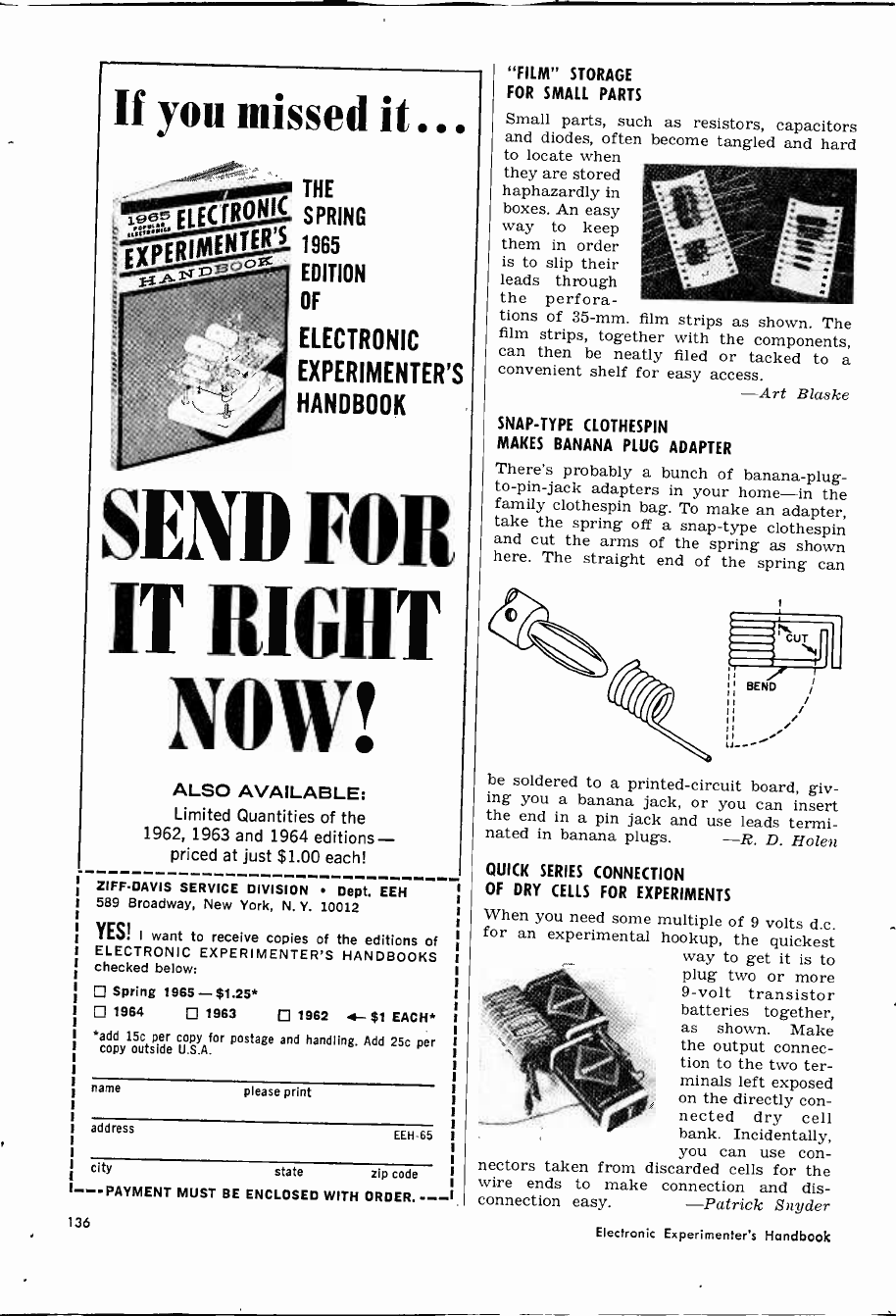
If you missed it ...
Is
19ßrRo=
EXPERIMEN,...-TER S
THE
SPRING
1965
EDITION
OF
ELECTRONIC
EXPERIMENTER'S
HANDBOOK
SEND FOR.
IT RIGHT
NOW!
ALSO AVAILABLE:
Limited Quantities of the
1962, 1963 and 1964 editions-
priced at just $1.00 each!
ZIFF-DAVIS SERVICE DIVISION Dept. EEH
589 Broadway, New York, N. Y. 10012
YES! I want to receive copies of the editions of
ELECTRONIC EXPERIMENTER'S HANDBOOKS
checked below:
Spring 1965-$1.25*
1964 0 1963 1962 a $1 EACH*
*add 15c per copy for postage and handling. Add 25c per
copy outside U.S.A.
name please print
address EEH-65
city state zip code
---PAYMENT MUST BE ENCLOSED WITH ORDER. ---
136
nectors taken
wire ends
connection
"FILM" STORAGE
FOR SMALL PARTS
Small parts, such as resistors, capacitors
and diodes, often become tangled and hard
to locate when
they are stored
haphazardly in
boxes. An easy
way to keep
them in order
is to slip their
leads through
the perfora-
tions of 35 -mm. film strips as shown. The
film strips, together with the components,
can then be neatly filed or tacked to a
convenient shelf for easy access. -Art Blaske
SNAP -TYPE CLOTHESPIN
MAKES BANANA PLUG ADAPTER
There's probably a bunch of banana -plug -
to -pin -jack adapters in your home-in the
family clothespin bag. To make an adapter,
take the spring off a snap -type clothespin
and cut the arms of the spring as shown
here. The straight end of the spring can
be soldered to a printed -circuit board, giv-
ing you a banana jack, or you can insert
the end in a pin jack and use leads termi-
nated in banana plugs. -R. D. Holen
QUICK SERIES CONNECTION
OF DRY CELLS FOR EXPERIMENTS
When you need some multiple of 9 volts d.c.
for an experimental hookup, the quickest
way to get it is to
plug two or more
9 -volt transistor
batteries together,
as shown. Make
the output connec-
tion to the two ter-
minals left exposed
on the directly con-
nected dry cell
bank. Incidentally,
you can use con -
from discarded cells for the
to make connection and dis -
easy. -Patrick Snyder
Electronic Experimenter's Handbook
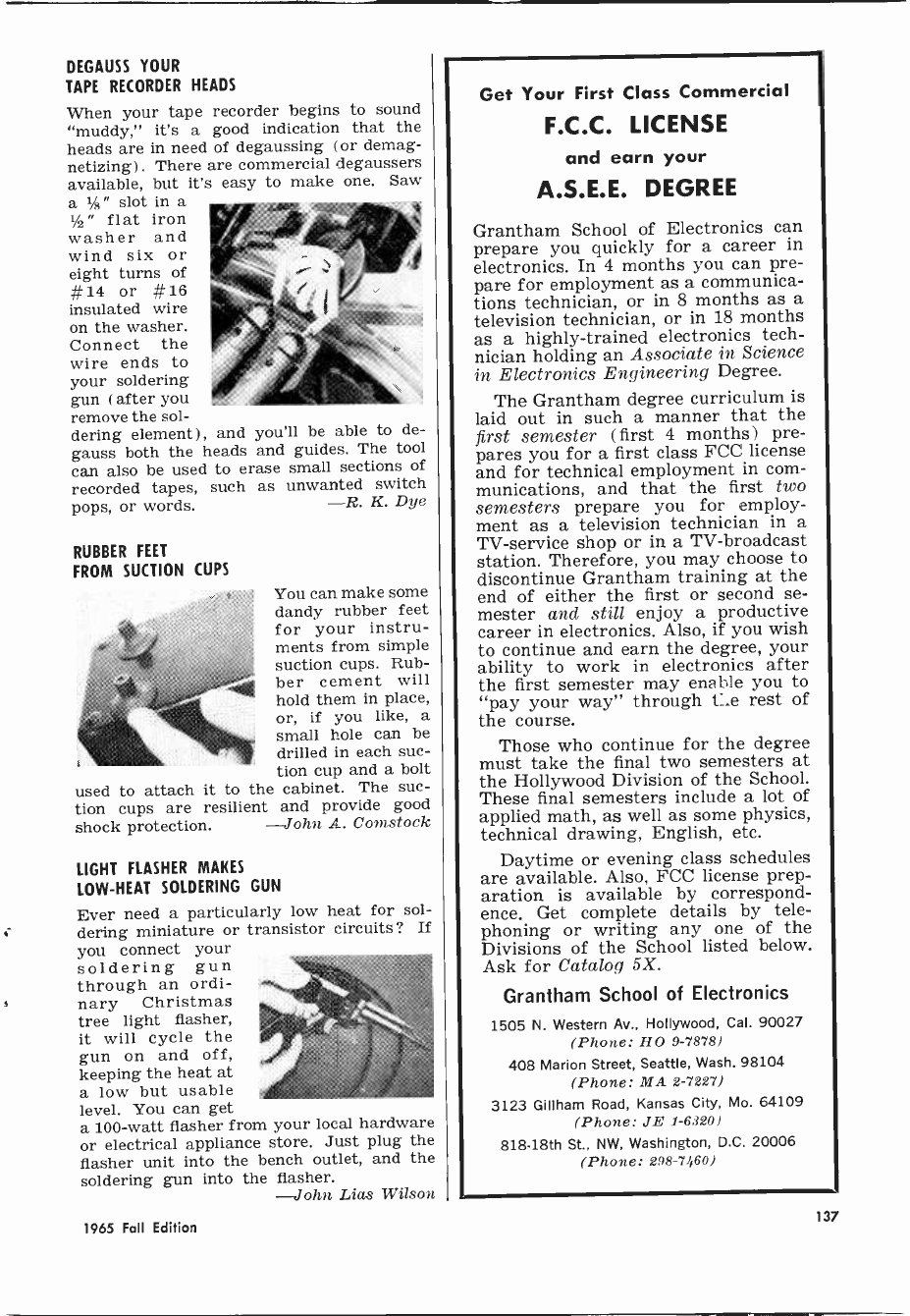
DEGAUSS YOUR
TAPE RECORDER HEADS
When your tape recorder begins to sound
"muddy," it's a good indication that the
heads are in need of degaussing (or demag-
netizing). There are commercial degaussers
available, but it's easy to make one. Saw
a 1/a" slot in a
1/2" flat iron
washer and
wind six or
eight turns of
#14 or #16
insulated wire
on the washer.
Connect the
wire ends to
your soldering
gun (after you
remove the sol-
dering element), and you'll be able to de-
gauss both the heads and guides. The tool
can also be used to erase small sections of
recorded tapes, such as unwanted switch
pops, or words. -R. K. Dye
RUBBER FEET
FROM SUCTION CUPS
used to
You can make some
dandy rubber feet
for your instru-
ments from simple
suction cups. Rub-
ber cement will
hold them in place,
or, if you like, a
small hole can be
drilled in each suc-
tion cup and a bolt
attach it to the cabinet. The suc-
tion cups are resilient and provide good
shock protection. -John A. Comstock
LIGHT FLASHER MAKES
LOW -HEAT SOLDERING GUN
Ever need a particularly low heat for sol-
dering miniature or transistor circuits ? If
you connect your
soldering gun
through an ordi-
nary Christmas
tree light flasher,
it will cycle the
gun on and off,
keeping the heat at
a low but usable
level. You can get
a 100 -watt flasher from your local hardware
or electrical appliance store. Just plug the
flasher unit into the bench outlet, and the
soldering gun into the flasher.
-John Lias Wilson
1965 Fall Edition
Get Your First Class Commercial
F.C.C. LICENSE
and earn your
A.S.E.E. DEGREE
Grantham School of Electronics can
prepare you quickly for a career in
electronics. In 4 months you can pre-
pare for employment as a communica-
tions technician, or in 8 months as a
television technician, or in 18 months
as a highly -trained electronics tech-
nician holding an Associate in Science
in Electronics Engineering Degree.
The Grantham degree curriculum is
laid out in such a manner that the
first semester (first 4 months) pre-
pares you for a first class FCC license
and for technical employment in com-
munications, and that the first two
semesters prepare you for employ-
ment as a television technician in a
TV -service shop or in a TV -broadcast
station. Therefore, you may choose to
discontinue Grantham training at the
end of either the first or second se-
mester and still enjoy a productive
career in electronics. Also, if you wish
to continue and earn the degree, your
ability to work in electronics after
the first semester may enable you to
"pay your way" through t_e rest of
the course.
Those who continue for the degree
must take the final two semesters at
the Hollywood Division of the School.
These final semesters include a lot of
applied math, as well as some physics,
technical drawing, English, etc.
Daytime or evening class schedules
are available. Also, FCC license prep-
aration is available by correspond-
ence. Get complete details by tele-
phoning or writing any one of the
Divisions of the School listed below.
Ask for Catalog 5X.
Grantham School of Electronics
1505 N. Western Av., Hollywood, Cal. 90027
(Phone: HO 9-7878)
408 Marion Street, Seattle, Wash. 98104
(Phone: MA 2-7227)
3123 Gillham Road, Kansas City, Mo. 64109
(Phone: JE 1-6320)
818 -18th St., NW, Washington, D.C. 20006
(Phone: 298-7460)
137

GIANT CR SALE!!
Hallmark Transceiver (Model 1250) SALE $99.99
Midland Walkie Talkie (Model 13-105) EACH $13.50
SPECIAL SALE 2 for $25.88
Ross Walkie Talkie (11 transistor) SALE $29.95
Ross 6 Transistor AM RADIO SALE $ 3.99
2 Station Transistor INTERCOM PAIR $ 7.99
BUILDER'S SPECIALS
Capacitor Substitution Box (600 WVDC) SALE $ 2.39
Resistor Substitution Box SALE $ 3.59
Test Oscillator-transistorized (Sig Gen) SALE $16.95
Volume Controls (10 ass'td) SALE 99¢
Timing Motors -110V (5 ass'td) SALE $ 1.99
Solder Gun -100W with spotlight SALE $ 2.49
TERRIFIC SALE PRICES ON HY-GAIN CB TOPPER ANTENNAS!
TLWR Roof mount Omni -Topper (reg $11.97) SPECIAL $ 9.88
TTMP AM -CB Duo -Topper (reg $14.95) SPECIAL $12.19
TLWT Telescoping Topper Whip (reg $7.20) SPECIAL $ 5.88
TLWM 50" Topper + Chr. Body Mount (reg
$8.95) SPECIAL $ 7.20
TRC Roof mount Omni -Topper (reg $14.95) SPECIAL $12.15
TMC All purp. Topper + Body Mount (reg
$12.95) SPECIAL $10.50
TLW 50" Top -loaded Whip (reg $6.96) SPECIAL $ 5.40
CB -3 3 element Beam Antenna (reg $19.95) SPECIAL $17.95
Command CB Crystals (.002%) EACH $ 1.79
SpeciFS-60f Model, Channel), 12 EACH
SWR Bridge & Field Str. Meter at
SALE $ 9.89
SN -3 Mobile Noise Suppressor Kit (15 pc) .SALE $ 4.99
Headset with Mike for CB SALE $ 4.88
Trumpet Horn Speaker (5"round-paging) SALE $ 7.49
SEND FOR GROVE BARGAIN FLYER-MAILED FREE!
Send check or money order, include postage, excess re
funded. Minimum order $5.00-50f service charge
under $1 0.00. 50 7 deposit on COD's.
GROVE ELECTRONIC SUPPLY COMPANY
4107 W. Belmont Ave. Chicago, III. 60641
CIRCLE NO. 9 ON READER SERVICE CARD
GIANT NEW CATALOG
Ì'
1OO's OF BIG P ' GES
CRAMMED WITH SAVINGS
BURSTEIN-APPLEBEE CO.
Dept. EX, 1012 McGee, Kansas City,Mo. 64106
L. Rush me FREE 1966 B -A Catalog.
Name
Address
I City State
I Please be sure to show your Zip No
!FREE
CIRCLE NO. 3 ON READER SERVICE CARD
CAMERA TRIPOD
PINCH-HITS AS MIKE STAND
A floor stand for
a microphone is
not often listed as
standard equip-
ment for a home
tape recordist. For
easy recording of
noise -free tapes,
however, it is al-
most a necessity.
If you own a cam-
era tripod, you can
attach your micro-
phone to the tri-
pod's swivel head with a simple clamp or
bracket, and derive all the benefits of a
good mike stand. -Glen F. Stillwell
EASY WAY TO MOUNT
PHONO JACK ON P -C BOARD
Here's how to mount a phono jack at right
angles to a printed circuit board with a
minimum of fuss. You'll need a crimp -on
closed -eye -terminal for a 1/4" stud and a
Cinch -Jones Y-142 adapter (available for
about three
cents from any
distributor) .
Cut the termi-
nal just at the
ferrule so you
have a 1/g " tab
projecting
from the origi-
nal eye. Flat-
ten the Y adapter. Now mount the terminal
and adapter near the edge of the board fac-
ing each other and about 7/16" apart. Insert
the phono jack, tighten the nut, and solder
the connections. The resulting mount is com-
pact, neat, and rugged. -Don Lancaster
PLASTIC CASES HOLD
METERS OR SPEAKERS
Discarded plastic TV booster or antenna
rotor control cases of the type shown in the
photo make excellent
mounts for meters or
for a miniature speak-
er. Strip the parts and
chassis from the case,
and, if you're lucky,
the meter or speaker
will fit in the hole left
by the dial without
further modifications.
If necessary, enlarge
the mounting hole
with a hacksaw blade, and drill holes for
mounting screws around the perimeter.
-Carleton A. Phillips
138 Electronic Experimenter's Handbook
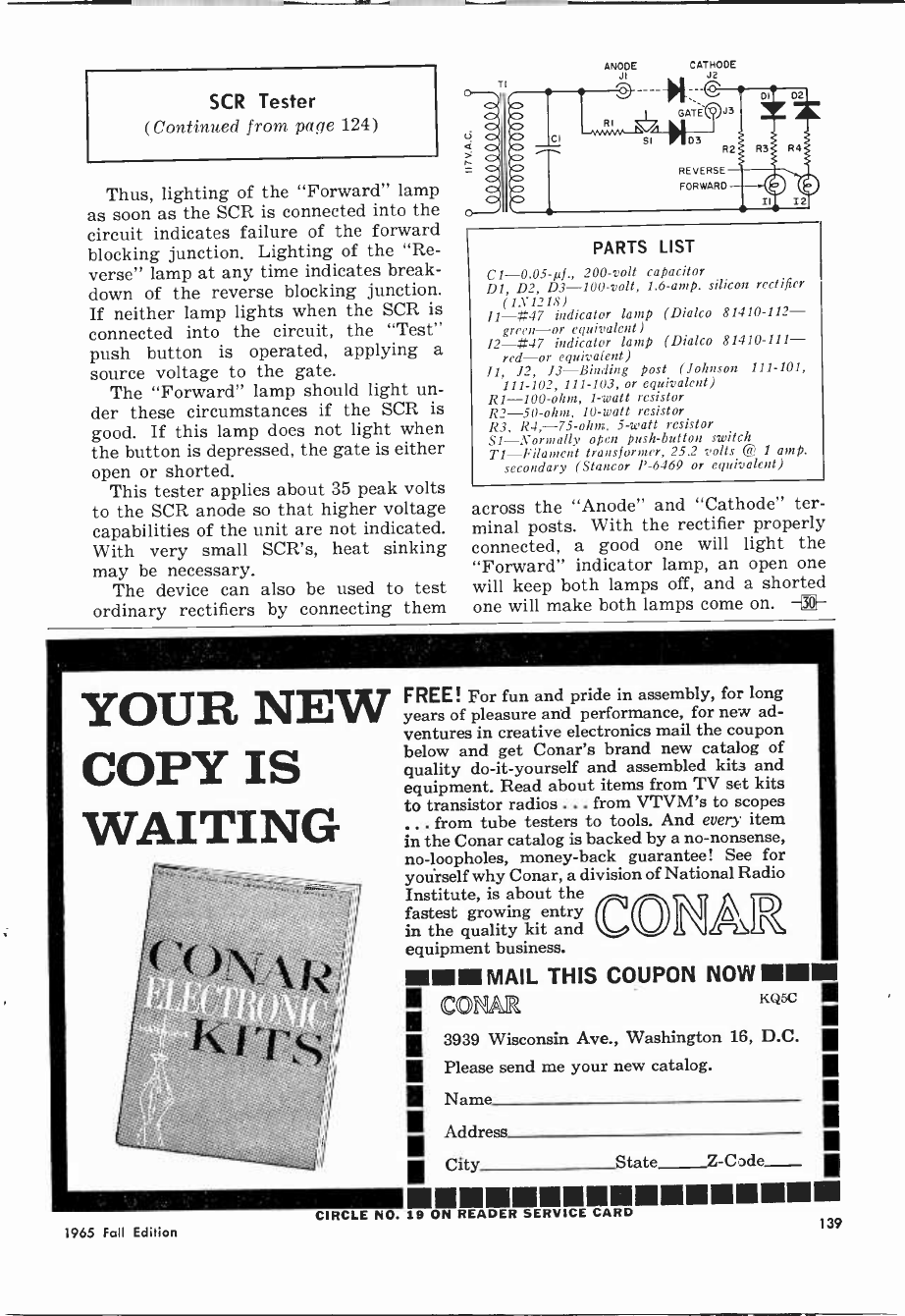
SCR Tester
(Continued from page 124)
Thus, lighting of the "Forward" lamp
as soon as the SCR is connected into the
circuit indicates failure of the forward
blocking junction. Lighting of the "Re-
verse" lamp at any time indicates break-
down of the reverse blocking junction.
If neither lamp lights when the SCR is
connected into the circuit, the "Test"
push button is operated, applying a
source voltage to the gate.
The "Forward" lamp should light un-
der these circumstances if the SCR is
good. If this lamp does not light when
the button is depressed, the gate is either
open or shorted.
This tester applies about 35 peak volts
to the SCR anode so that higher voltage
capabilities of the unit are not indicated.
With very small SCR's, heat sinking
may be necessary.
The device can also be used to test
ordinary rectifiers by connecting them
ANOJIDE CATHODE
J2 ¡ GATE\y'/J3
SI 03 R2
REVERSE
FORWARD
PARTS LIST
C1 -0.05-µf., 200 -volt capacitor
DI, D2, D3 -100 -volt, 1.6 -amp. silicon rectifier
(1X1218)
I1-#47 indicator lamp (Dialco 81410-112--
green-or equivalent)
12-#47 indicator lamp (Dialco 81410-111-
red-or equivalent)
11, 12, J3-Binding post (Johnson 111-101,
111-102, 111-103, or equivalent)
R1 -100 -ohm, 1 -watt resistor
R2 -50 -ohm, 10 -watt resistor
R3, R4, -75 -ohm, 5 -watt resistor
SI-Normally open push-button switch
TI-Filament transformer, 25.2 volts @ 1 amp.
secondary (Stancor P-6469 or equivalent)
across the "Anode" and "Cathode" ter-
minal posts. With the rectifier properly
connected, a good one will light the
"Forward" indicator lamp, an open one
will keep both lamps off, and a shorted
one will make both lamps come on. -i[-
YOUR NEW
COPY IS
WAITING
1965 Fall Edition
FREE! For fun and pride in assembly, for long
years of pleasure and performance, for new ad-
ventures in creative electronics mail the coupon
below and get Conar's brand new catalog of
quality do-it-yourself and assembled kits and
equipment. Read about items from TV set kits
to transistor radios ... from VTVM's to scopes
.. from tube testers to tools. And every item
in the Conar catalog is backed by a no-nonsense,
no -loopholes, money -back guarantee! See for
yourself why Conar, a division of National Radio
Institute, is about the CON
fastest growing entry
in the quality kit and
equipment business.
MINIM MAIL THIS COUPON NOW MIMIC
tu15c 111
CEO
. 3939 Wisconsin Ave., Washington 16, D.C.
Please send me your new catalog.
Address
City State_Z-Code
CIRCLE NO. 19 ON READER SERVICE CARD
I Name
111
139
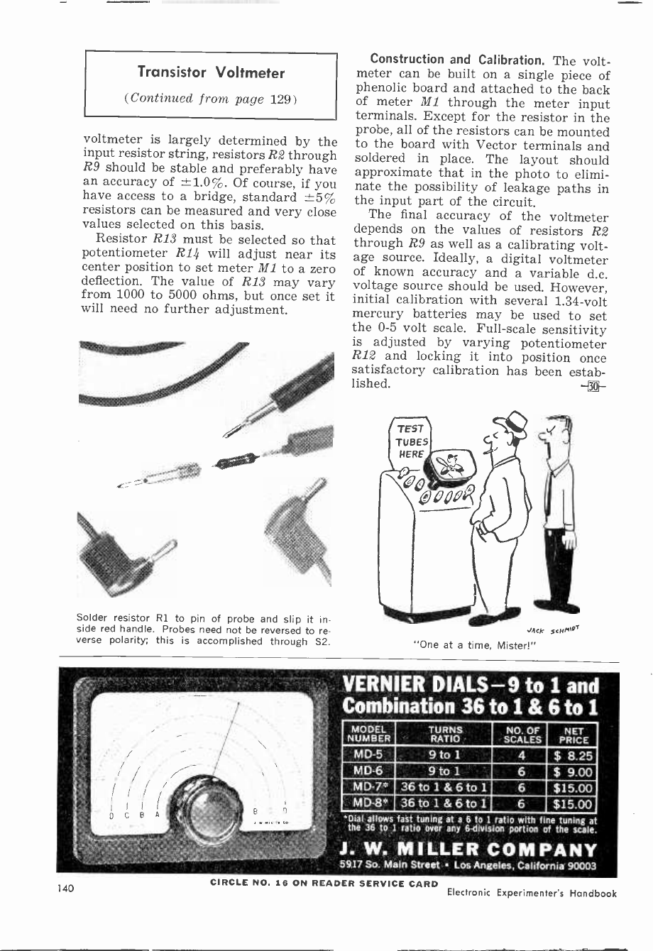
Transistor Voltmeter
(Continued from page 129)
voltmeter is largely determined by the
input resistor string, resistors R2 through
R9 should be stable and preferably have
an accuracy of -±1.0%. Of course, if you
have access to a bridge, standard ±5%
resistors can be measured and very close
values selected on this basis.
Resistor R13 must be selected so that
potentiometer R14 will adjust near its
center position to set meter M1 to a zero
deflection. The value of R13 may vary
from 1000 to 5000 ohms, but once set it
will need no further adjustment.
Solder resistor R1 to pin of probe and slip it in-
side red handle. Probes need not be reversed to re-
verse polarity; this is accomplished through S2.
Construction and Calibration. The volt-
meter can be built on a single piece of
phenolic board and attached to the back
of meter MI through the meter input
terminals. Except for the resistor in the
probe, all of the resistors can be mounted
to the board with Vector terminals and
soldered in place. The layout should
approximate that in the photo to elimi-
nate the possibility of leakage paths in
the input part of the circuit.
The final accuracy of the voltmeter
depends on the values of resistors R2
through R9 as well as a calibrating volt-
age source. Ideally, a digital voltmeter
of known accuracy and a variable d.c.
voltage source should be used. However,
initial calibration with several 1.34 -volt
mercury batteries may be used to set
the 0-5 volt scale. Full-scale sensitivity
is adjusted by varying potentiometer
R12 and locking it into position once
satisfactory calibration has been estab-
lished. -
smek scum,'
"One at a time, Mister!"
VERNIER DIALS -9 to 1 and
Combination 36 to 1 & 6 to i
MODEL
NUMBER TURNS
RATIO NO. OF
SCALES NET
PRICE
M D-5 9 to 1 4 $ 8.25
M D-6 9 to 1 6 $ 9.00
MD -7" 36 tot&6to1 6 $15.00
M D-8* 36 tot&6to1 6 $15.00
*Dial allows fast tuning at a 6 to 1 ratio with fine tuning at
the 36 to 1 ratio over any 6 -division portion of the scale.
J. W. MILLER COMPANY
59.17 So. Main Street Los Angeles, California 90003
140 CIRCLE NO. 16 ON READER SERVICE CARD Electronic Experimenter's Handbook
Resonance Engine
(Continued from page 92)
90). Although the weight of the fly-
wheel should not be too critical, some
experimenting may be in order. The
author's was made of aluminum and
weighed about 15 ounces. Drill and tap
one end of the flywheel shaft for a 6-32
machine screw and thread the opposite
end with a 1"-20 die.
The flywheel shaft bearing-a 11/2"
brass rod 1/2" in diameter with a 1/4" hole
drilled through the center-is mounted
in the bracket shown in Fig. 7 and in
the assembly drawing. The bracket is
made with a stiffening buttress so that
it will stand up under the vibration of
the engine. In the author's unit, the
bracket was mounted to the coil platform
by tapping three small pieces of brass
rod and cementing them into holes
drilled into the bottom of the bracket.
Wing bolts thread into the holes from
the bottom of the coil platform, making
it easy to disassemble the engine for
other experiments. In any case, drill a
1/2" hole in the bracket at the height
shown in Fig. 7, and cement the bearing
in it with epoxy glue.
Mounting Stand. Make a double -deck
stand as shown in the photos and secure
the capacitors, Cl, C2, C3, to the lower
section. Mount the d.p.d.t. toggle switch,
Si, and four pin jacks, J1, J2, J3, J4,
on the upper deck of the stand in front
of the coil position. Drill holes in the
upper deck for coil leads, coil mounting
screws, bracket mounting screws, and
for the engine piston. The piston hole
should be large enough to provide ample
clearance.
Mount all of the parts on the stand
as shown in the assembly view on page
92. Solder the end of the flywheel shaft
to the end of the crankshaft where the
two join together. To hold the long 12"
core in place for repulsion coil experi-
ments, drill and tap the top disc for a
setscrew that extends from the outer rim
into the center hole.
Connect the parts as shown in the
schematic diagram on page 92. You will
note that the diagram shows a "dis-
charge" position for 21. This is a safety
1965 Fall Edition 141
Thinking of college and
a space age career in
electronics ?
Send for this booklet on
ENGINEERING TECHNOLOGY
AND ENGINEERING
Learn how you can prepare for a dynamic
career as an electrical or mechanical engi-
neering technician or engineer in such
exciting, growing fields as avionics, mis-
siles, reliability control, fluid mechanics,
data processing, metallurgy, microelectron-
ics, and advanced aerospace research.
MSOE offers residence study programs
leading to these degrees in engineering
technology and engineering:
2 years - Associate in Applied Science
4 years - Bachelor of Science
Also get facts about scholarships and fi-
nancial aids, job placement and other
student services, plus photographs of
MSOE technical laboratories and
student activities. For your copy,
just mail the coupon -
no obligation.
Milwaukee School of Engineering
Milwaukee School of Engineering
Dept.EXH-865,1025 N. Milwaukee Street
Milwaukee, Wisconsin 53201
Please send the "Your Career" booklet.
I'm interested in
n Electrical fields Mechanical fields
Name Age
Address
City State ZIP M5.227
CIRCLE NO. 17 ON READER SERVICE CARD

New from TECIIPRESS
Badar-Principles and Practices Ls a basic
study of land, marine, and airborne radar.
Includes fundamentals of transmitters,
receivers, antennas, synchros and servos.
Discusses radar systems, test equipment,
all types of oscillators, amplifiers, wave -
guides, and hardware used in radar. An
ideal introduction to small and large craft radar.
An absolute must for broadening your horizons!
6" x 9" 260 pages Cat. No. 01 -RP -only $4.95
Receiving Tube Specifications and Substitutions
contains over 2,000 American and foreign tubes listed
both according to type and characteristic. Lists
entertainment, industrial, and military tubes. Specs
include all cathode and plate voltages and currents,
cathode type, gain, capacitances, etc. Includes suo-
atitutes listing, basing information, etc.
6" x 9" 140 pages Cat. No. 01 -VT only 51.95
Transistor Specifications and Substitution Hand-
book lists over 5,000 American and foreign types,
and over 16,000 subs. Specs comprise: Pc, Ic, Vice,
Vcb, Veb, life, Icb, Pt, type and use. Base diagrams
and other valuable information included.
6" x 9" 128 pages Cat. No. "'SSH-2 only 31.95
Diode Select -A -Spec is a compilation of the specs
and substitutes for .both signal and power diodes.
Specs include: Vw, PRV, If, Vf, and Ir. Over 20,000
American and foreign substitutes listed.
6" x 9" 138 pages Cat. No. 01 -DS. only $2.95
Selected Semiconductor Circuits contains simple,
easy -to -build circuits on power supplies, converters.
RF and AP amplifiers and oscillators. Many others.
6" x 9. 80 pages Cat. No. 01 -SC only $1.26
7echPrem PablIcatirn
Browitebery, ,9><diaha, 46/12
CIRCLE NO. 29 ON READER SERVICE CARD
Clever Kleps 30
Push the plunger. A spring -steel forked
tongue spreads out. Like this S'
Hang it onto a wire or terminal, let go
the plunger, and Kleps 30 holds tight. Bend it, pull it, let
it carry dc, sine waves, pulses to 5,000 volts peak. Not a
chance of a short. The other end takes a banana plug or a
bare wire test lead. Slip on a bit of shield braid to make a
shielded probe. What more could you want in a test probe?
Available through your local $147
distributor, or write to:
RYE SOUND CORPORATION
so,,,.o 130 Spencer Place, Mamaroneck, N.Y.
CIRCLE NO. 25 ON READER SERVICE CARD
device to discharge the capacitors after
the unit has been in use. Label SZ's posi-
tions (Si is a center -off type) "On,"
"Off," and "Discharge."
Testing the Engine. When the assembly
and wiring are done, spin the flywheel
by hand to make certain there is no un-
due friction. Use light oil on all bear-
ings and piston surface. With everything
ready to go, plug the unit in, turn the
switch on, and give the flywheel a turn
in either direction. The flywheel will
pick up speed and be on its way. Like
most single -cylinder reciprocating en-
gines, your engine will require an ini-
tial start, unless the crank is turned to
its upper position, slightly off center.
Theory. How does the resonant engine
operate ? One of the laws governing a
series -resonant circuit is that when the
reactance of the capacitor equals the
reactance of the coil, the maximum
amount of current will flow in the circuit.
The reactance of the capacitors is fixed ;
the reactance of the coil depends on the
piston core's position.
When the piston core is slightly above
its lowest point of travel, or the same
distance below its upper point of travel,
the reactance of the coil equals that of
the capacitor, and the circuit is reso-
nant. In operation, the piston is drawn
toward one of the resonant positions,
but the flywheel carries it beyond that
point and the circuit drops sharply out
of resonance. From there on, the piston
is carried by the momentum of the fly-
wheel to the next resonant position.
The value of the capacitance needed
for the resonant engine is 10.6 µf. As
shown in the schematic, the author got
this value by connecting 1- and 2-µf.
units in series, and then connecting them
in parallel with a 10-µf. unit. Other com-
binations can, of course, be used to ar-
rive at 10.6 µf.
Other Experiments. Want to make a
step-down transformer? Wind a 40 -turn
coil of wire and connect it to a flashlight
bulb. Position the long core in the en-
gine coil, tighten the setscrew, and slow-
ly bring the flashlight bulb and coil down
over the core. An interesting variation
is to try the same thing with the capaci-
tor shorted out by means of a jumper
across the two capacitor pin jacks. The
increased brilliancy of the bulb with the
capacitor in the circuit shows how much
142 Electronic Experimenter's Handbook
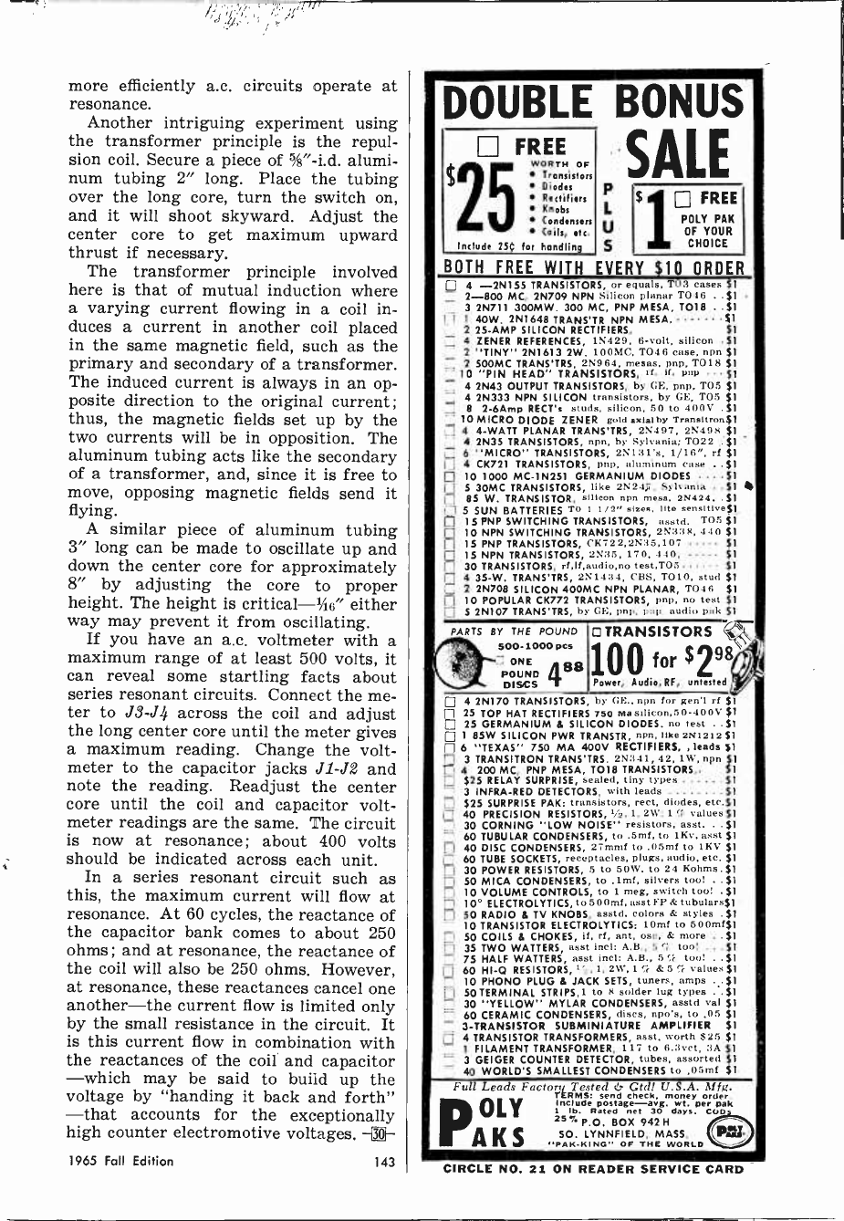
more efficiently a.c, circuits operate at
resonance.
Another intriguing experiment using
the transformer principle is the repul-
sion coil. Secure a piece of %"-i.d. alumi-
num tubing 2" long. Place the tubing
over the long core, turn the switch on,
and it will shoot skyward. Adjust the
center core to get maximum upward
thrust if necessary.
The transformer principle involved
here is that of mutual induction where
a varying current flowing in a coil in-
duces a current in another coil placed
in the same magnetic field, such as the
primary and secondary of a transformer.
The induced current is always in an op-
posite direction to the original current;
thus, the magnetic fields set up by the
two currents will be in opposition. The
aluminum tubing acts like the secondary
of a transformer, and, since it is free to
move, opposing magnetic fields send it
flying.
A similar piece of aluminum tubing
3" long can be made to oscillate up and
down the center core for approximately
8" by adjusting the core to proper
height. The height is critical-%6" either
way may prevent it from oscillating.
If you have an a.c. voltmeter with a
maximum range of at least 500 volts, it
can reveal some startling facts about
series resonant circuits. Connect the me-
ter to J3 -J4 across the coil and adjust
the long center core until the meter gives
a maximum reading. Change the volt-
meter to the capacitor jacks J1 -J2 and
note the reading. Readjust the center
core until the coil and capacitor volt-
meter readings are the same. The circuit
is now at resonance ; about 400 volts
should be indicated across each unit.
In a series resonant circuit such as
this, the maximum current will flow at
resonance. At 60 cycles, the reactance of
the capacitor bank comes to about 250
ohms; and at resonance, the reactance of
the coil will also be 250 ohms. However,
at resonance, these reactances cancel one
another-the current flow is limited only
by the small resistance in the circuit. It
is this current flow in combination with
the reactances of the coil and capacitor
-which may be said to build up the
voltage by "handing it back and forth"
-that accounts for the exceptionally
high counter electromotive voltages. -3]--
DOUBLE BONUS
SALE
U FREE
WORTH OF
Transistors
Diodes
Rectif fers
Knobs
Condensers
Coils, etc.
Include 25Ç for handling
P
L
V
s
$ FREE
POLY PAK
OF YOUR
CHOICE
BOTH FREE WITH EVERY $10 ORDER
7 4 -2N155 TRANSISTORS, or equals, TOS cases $1
2-800 MC, 25709 NPN Silicon planar T046 $1
3 2N711 300MW. 300 MC, PNP MESA, T018 . $1
ri 1 40W. 2N1648 TRANS'TR NPN MESA, $1
2 25 -AMP SILICON RECTIFIERS, $1
4 ZENER REFERENCES, 15429, 6 -volt, silicon .$1
2 "TINY" 2N1613 2W. 100MC, TO46 case, npn $1
2 500MC TRANS'TRS, 2N964, mesas, pnp, TO18 $1
10 "PIN HEAD" TRANSISTORS, rl. if, pop $1
4 2N43 OUTPUT TRANSISTORS, by CE, pnp, T05 $1
E 4 25333 NPN SILICON transistors, by GE, T05 $1
E 8 2-6Amp RECT's studs, silicon, 50 to 400V .S1
10 MICRO DIODE ZENER gold aslalby Trnnstlron$1
E 4 4 -WATT PLANAR TRANS'TRS, 25497, 25498 $1
E 4 2N35 TRANSISTORS, npn, by Sylvania; T022 $1
E 6 "MICRO" TRANSISTORS, 25131'x, 1/16", rf $1
4 CK721 TRANSISTORS, psp, aluminum case $1
E 10 1000 MC -1N251 GERMANIUM DIODES . , S1
E S 30MC TRANSISTORS, like 2N24í, Sylvania $1
E 85 W. TRANSISTOR, silicon npn mes., 25424. S1
f-1 5 SUN BATTERIES TO 1 1/2" sizes, lite sensitive$1
15 PNP SWITCHING TRANSISTORS, asstd. TO5 $1
10 NPN SWITCHING TRANSISTORS, 253:18, 440 $1
E 15 PNP TRANSISTORS, CK722,2N35,107 $1
E 15 NPN TRANSISTORS, 2N35, 170, 440, $1
E 30 TRANSISTORS, rf,lf,audio,no test,T05 $1
E 4 35-W. TRANS'TRS, 251434, CBS, T010, stud $1
[] 2 2N708 SILICON 400MC NPN PLANAR, T041, $1
10 POPULAR CK772 TRANSISTORS, Imp, no test 51
E 5 2N107 TRANS'TRS, by GE, pop, pop. audio pal< $1
PARTS BY THE POUND
500-1000 pen
ONE
POUND
DISCS 488
O TRANSISTORS J ,
loo for $298i/
Power, Audio,RF, untested
E 4 2N170 TRANSISTORS by GE., npn for gen'l rf $1
E 25 TOP HAT RECTIFIER 750 Ma silicon,50-400V $1
E 25 GERMANIUM 8 SILICON DIODES. no test S1
1 85W SILICON PWR TRANSTR, npn, like 251212 ft
f, 6 "TEXAS" 750 MA 400V RECTIFIERS. , leads $1
3 TRANSITRON TRANS'TRS. 25341, 42, 1W, npn $f1
LJ 4 200 MC, PNP MESA, TO18 TRANSISTORS,. Si
$25 RELAY SURPRISE, sealed, tiny types $1
E 3 INFRA -RED DETECTORS, with leads $1
E $25 SURPRISE PAK: transistors, reef, diodes, etr.$1
E 40 PRECISION RESISTORS, 0/a, 1, 2W; 1 ri. values $1
30 CORNING "LOW NOISE" resistors, asst. $1
60 TUBULAR CONDENSERS, to .5mf, to 1Kv, asst $1
40 DISC CONDENSERS, 27mmf to .05mí to 1KV 51
E 60 TUBE SOCKETS, receptacles, plugs, audio, etc. $1
30 POWER RESISTORS, 5 to 60W. to 24 Kolsms.$1
50 MICA CONDENSERS, to ,lmf, silvers too! $1
10 VOLUME CONTROLS, to 1 meg, switch too! 51
10° ELECTROLYTICS, to 500mí, asst S'P & tubulurs$1
E 50 RADIO 8 TV KNOBS, asstd. colora & styles . $1
10 TRANSISTOR ELECTROLYTICS: 10mí to 500mí$1
E 50 COILS 6 CHOKES, if, rf, ant, osc, & more S1
35 TWO WATTERS, asst inrl: A.B., 5 too! $1
E 75 HALF WATTERS, asst incl: AB., 5íE tool $1
60 HI -0 RESISTORS, i 1, 2W', 1 Ti & 5 Cr values $1
E 10 PHONO PLUG 8 JACK SETS, tuners, amps S1
E 50 TERMINAL STRIPS,1 to 8 solder lug types .' $1
30 "YELLOW" MYLAR CONDENSERS, asstd val $1
E 60 CERAMIC CONDENSERS, discs, npo's, to .05 $1
E 3 -TRANSISTOR SUBMINIATURE AMPLIFIER $1
4 TRANSISTOR TRANSFORMERS, asst. worth $25 $1
E I FILAMENT TRANSFORMER, 117 to 6.3vct, :3A $1
3 GEIGER COUNTER DETECTOR, tubes, assorted $1
E 40 WORLD'S SMALLEST CONDENSERS to ,O.Rmf $1.
Full Leads Factor,, Tested & cñtd! U.S.A. Mfg.
1n aced n-arg. per oak
1 Ile Rated net 30 days. Coo pa
money order.
25% P.O. BOX 942 H
PA K S SO. LYNNFIELD, MASS.
PAS -KING" OF THE WORLD
OLY
1965 Fall Edition 143 CIRCLE NO. 21 ON READER SERVICE CARD

GOV'T. SURPLUS
ELECTRONIC BARGAINS
SCR -625 Mine Detector
(treasure locator) new, with btrys $ 45.00
4 Conductor Wire, flat, roll 150 feet 1.50
Carbon Mike, Canadian Air Force, new, noise cancelling 1.25
British Snooperscope Tube,
new, w/specs. (see in dark) 4.00
US Snooperscope Tube #6032 w/sheet 6.50
Infra Red Filter (use on lights) passes infra red 1.75
Infra Red Detector Capsule new 1.25
T-45 Air Force Lip Mike (carbon) .75
T-30 Air Force Throat Mike
(makes underwater intercom)
Polaroid Polarizing Filters 2 sheets 5x5 inches
SCR Light Dimmer Kit with instructions
Epitaxial Transistors 300 mc, TO -18, like 2N960
100 Watt Power Transistors like 2N277
.50
1.00
4.50
3/1.00
2/1.00
SCR 100 PIV 20 amps...$1.25 50 PIV 20 amps 1.00
Transistors Factory Marked, Your Choice
75c each 12 for 7.50
2N339 -2N340 -2N341 -2N342 -2N343 -2N497 -2N498 -
2N547 -2N548 -2N549 -2N551 -2N552 -2N657 -2N728 -
2N755 -2N754 -2N841 -2N843 -2N 1117-2N 1206
Prism, Pocket Rainbow, hold in sun for spectrum .60
M-3 Military Infra Red Sniperscope, operational 225.00
Selenium Sun Cells electricity from sun, 5 with book 1.50
3AP1 Oscilloscope Tube 1.00
Crystal Mike w/cord & plug, for tape recorders, etc 1.35
Radiosonde Transmitter w/tubes, new 1.25
Dynamic Earphone hearing aid type, w/cord & plug .60
Wired Memory Planes
4096....$12.50; 8192....$15.00; 16,384 35.00
IBM Ferrite Memory Cores,
loose, with spec sheet 200/1.00
Above is a sampling from our 80 page catalog. Send 25f for
catalog. All material listed FOB Lynn, Mass. (you pay shipping).
JOHN MESHNA, JR.
21 ALLERTON ST., LYNN. MASS.
CIRCLE NO. 15 ON READER SERVICE; CARD
ERSIN
MULTICORE
5 -CORE SOLDER
ONLY 69C
BUY IT AT RADIO-TV PARTS STORES
MULTICORE SALES CORP., WESTBURY, N.Y. 11591
Shotgun Sound Snooper
(Continued from page 64)
cluster with a 6-32 x 3/s" machine screw
and bolt. Install the front bracket the
same way, and slide the horizontal sup-
port bar between the brackets, aligning
the holes in the bar with the lower ones
in the brackets. Bolt the horizontal bar
in place along with the angle bracket for
mounting the microphone to the pan
head of a camera tripod. Now fit the
microphone enclosure over the tubes ; it
can be taped on if necessary with a strip
of masking or metalized Mylar tape
around the enclosure and the rear sup-
port bracket. The Mylar tape is not nec-
essary, but looks better.
The Amplifier. Weak or distant sounds
naturally require a high -gain amplifier.
Tube type amplifiers, because of their
inherent hum at high gain settings, defi-
nitely are not recommended. The five -
transistor Lafayette PK-544 is an ideal
choice for this purpose, and the cost
is low. The high -impedance microphone
cartridge is matched to the low -imped-
ance amplifier input with a transformer.
As 8-11 ohm output transformer is an
integral part of the PK-544. The high -
impedance output shown in the sche-
matic on page 64 is optional; T2, S2,
and J3 may be omitted if low -impedance
output will suffice.
The PK-544, RI, S1 (part of R1) T2,
S2, and J1, J2, and J3 are mounted in
half of a 21/2" x 3" x 51/4" aluminum box
(LMB #136) . As a matter of conven-
ience, the authors first mounted input
transformer T1 to the board of the
PK-544 amplifier. To do this, you bend
off the mounting tabs of the transform-
er. Then apply quick -drying cement to
the bottom of T1 and to an open area
on the amplifier board near the input
leads. Mount transformer T1 in this
area. When the cement is dry, remove the
PK-544 input leads where they fasten to
the board. Referring to the schematic,
trim the low -impedance leads of T1 and
solder them to the board where the orig-
inal input leads were attached. The
high -impedance primary of T1 is later
connected to J1.
CIRCLE NO. 18 ON READER SERVICE CARD 144 Electronic Experimenter's Handbook
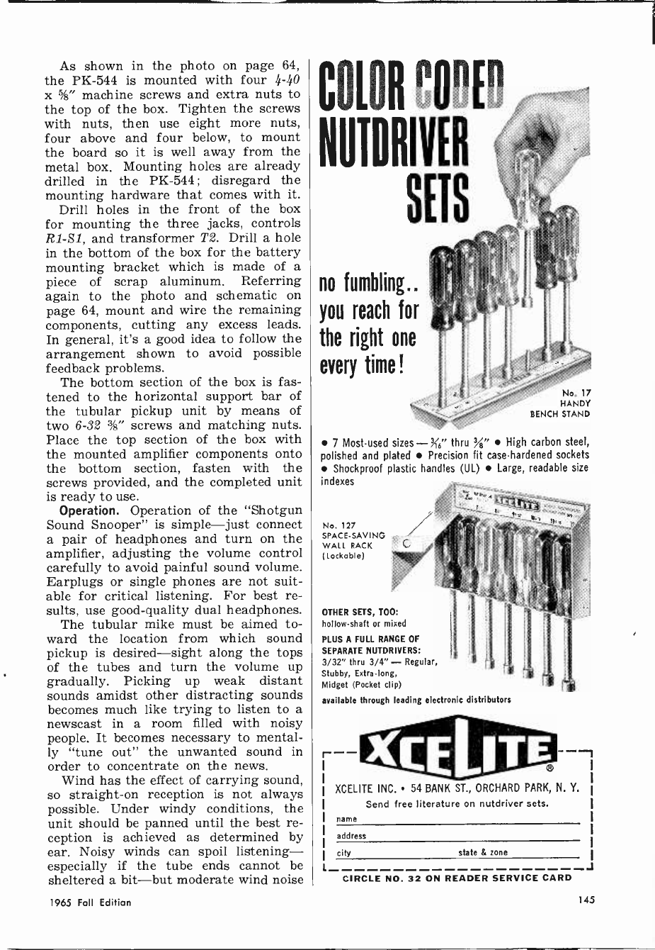
As shown in the photo on page 64,
the PK-544 is mounted with four 4-40
x %" machine screws and extra nuts to
the top of the box. Tighten the screws
with nuts, then use eight more nuts,
four above and four below, to mount
the board so it is well away from the
metal box. Mounting holes are already
drilled in the PK-544; disregard the
mounting hardware that comes with it.
Drill holes in the front of the box
for mounting the three jacks, controls
R1 -S1, and transformer T2. Drill a hole
in the bottom of the box for the battery
mounting bracket which is made of a
piece of scrap aluminum. Referring
again to the photo and schematic on
page 64, mount and wire the remaining
components, cutting any excess leads.
In general, it's a good idea to follow the
arrangement shown to avoid possible
feedback problems.
The bottom section of the box is fas-
tened to the horizontal support bar of
the tubular pickup unit by means of
two 6-32 %" screws and matching nuts.
Place the top section of the box with
the mounted amplifier components onto
the bottom section, fasten with the
screws provided, and the completed unit
is ready to use.
Operation. Operation of the "Shotgun
Sound Snooper" is simple-just connect
a pair of headphones and turn on the
amplifier, adjusting the volume control
carefully to avoid painful sound volume.
Earplugs or single phones are not suit-
able for critical listening. For best re-
sults, use good -quality dual headphones.
The tubular mike must be aimed to-
ward the location from which sound
pickup is desired-sight along the tops
of the tubes and turn the volume up
gradually. Picking up weak distant
sounds amidst other distracting sounds
becomes much like trying to listen to a
newscast in a room filled with noisy
people. It becomes necessary to mental-
ly "tune out" the unwanted sound in
order to concentrate on the news.
Wind has the effect of carrying sound,
so straight -on reception is not always
possible. Under windy conditions, the
unit should be panned until the best re-
ception is achieved as determined by
ear. Noisy winds can spoil listening-
especially if the tube ends cannot be
sheltered a bit-but moderate wind noise
COL1:R CODED
NUIDRITER
SETS
no fumbling..
you reach for
the right one
every time!
No. 17
HANDY
BENCH STAND
7 Most -used sizes-X6" thru %" High carbon steel,
polished and plated Precision fit case-hardened sockets
Shockproof plastic handles (UL) Large, readable size
indexes
No. 127
SPACE -SAVING
WALL RACK
(Lockable)
OTHER SETS, TOO:
hollow -shaft or mixed
PLUS A FULL RANGE OF
SEPARATE NUTDRIVERS:
3/32" thru 3/4" - Regular,
Stubby, Extralong,
Midget (Pocket clip)
available through leading electronic distributors
XCELITE INC. 54 BANK ST., ORCHARD PARK, N. Y.
Send free literature on nutdriver sets.
name
address
city state & zone
J
CIRCLE NO. 32 ON READER SERVICE CARD
1965 Fall Edition 145
Fill in coupon for a FREE One Year Subscrip-
tion to OLSON ELECTRONICS' Fantastic Value
Packed Catalog-Unheard of LOW, LOW PRICES
on Brand Name Speakers, Changers, Tubes,
Tools, Stereo Amps, Tuners, CB, and other Val-
ues. Credit plan available.
If you have a friend interested in electronics
his name and address for a FREE subscription
OLSON. ELECTRONICS
INCORPORATED
362 S. Forge Street Akron, Ohio 44308
CIRCLE NO. 20 ON READER SERVICE CARD
Ì EARN YOUR DEGREE
in ELECTRONICS
ENGINEERING
at home
Our A.S.E.E. degree is recognized the
world over by personnel men in the
electronics industry. Our graduates are
always in demand.
College level HOME STUDY courses
-taught so that you can easily under-
stand them. Continue your education.
... Earn more in the highly paid elec-
tronics industry.
Learn about Missiles, Computers,
Transistors, Automation, complete elec-
tronics.
Over 27,000 graduates now employed
by industry. Resident school also avail-
able at our Chicago Campus.-Founded
1934. Send for our FREE course catalog.
AMERICAN INSTITUTE OF
ENGINEERING & TECHNOLOGY
1137-1139 West Ful:erton Pkwy.-Chicago 14, Illinois
can be cut down by draping the mike
with a cloth.
If you enjoy experimenting, you'll find
the "Shotgun Sound Snooper" a unique,
fascinating project. Endless variations
are possible, of course-in tube length
and diameter, in the microphone car-
tridge, the amplifier, etc. Just as endless
are the applications you'll find for the
microphone. Construction is easy, and
the cost is reasonable. Don't delay! -0-
Build Panic Alarm
(Continued from page 13)
behind a 21%" cutout, and a scrap of per-
forated sheet metal stock is painted red
and used as the speaker grille. A match-
ing 2's" round hole is cut in the panel
to allow the bulb of the 25 -watt lamp
to protrude. The balance of the com-
ponents are mounted on a 2%o" x 61/2"
piece of Vector perforated breadboard
stock, which is secured to the bottom of
the cabinet using 1/2" -long, %"-diameter,
internally threaded brass stand-off posts.
Although assembly is not especially
crowded, care must be exercised in the
placement of components to insure ade-
quate clearance for the 25 -watt lamp and
the speaker. The writer used brass eye-
lets for component connection; push -in
terminals may be used if deired, how-
ever. A socket was not used for the 25 -
watt lamp in the writer's model. In-
stead, the lamp was inserted in position
with the base against the perforated
board, eyelets were installed in the board
and #16 solid copper wire used to secure
the lamp base and make the required
connections. Since brass-instead of the
more common aluminum-is used in the
base of the red -frosted lamp, soldering
the lamp in place provides a simple and
effective method of mounting.
Testing and Adjustment. Check your
work carefully, using an ohmmeter to
test for continuity and the absence of
shorts. Be sure that no portion of the
circuit is shorted to the metal cabinet.
When you're satisfied that the wiring is
correct, apply power to the unit. The
25 -watt lamp should glow at approxi-
mately half brilliance and the 5005 heat -
CIRCLE NO. 2 ON READER SERVICE CARD 146 Electronic Experimenter's Handbook
er should light. A voltmeter connected
across capacitor C5a should measure
approximately 150 volts d.c. Now brace
yourself and push the panic button. Re-
lay K1 should close and a very loud ris-
ing and falling audio tone should be
heard from the speaker. Lamp II should
flicker at a rate corresponding to the
warble of the tone and lamp 12 should
appear to glow continuously.
The time constants of the two neon
lamp oscillators have been selected for
optimum results. However, you may
want to change the frequency of the out-
put tone or the rate of warble. To in-
crease the rate of warble, reduce the
value of resistor R2; to decrease the rate
of warble, increase the value of this re-
sistor. Reduce the value of resistor R3
to increase the frequency of the output
tone, and increase the value of this re-
sistor to reduce the frequency. You will
note some interaction between the two
oscillator circuits, and trial and error
adjustment of the resistor values may be
required to obtain exactly the effect you
desire.
When the alarm functions to your sat-
isfaction, button up the project. Decals
will serve to give it a commercial ap-
pearance, and a very light coat of clear
spray lacquer will protect the decals
after they have been applied.
Furnishing application instructions
for the panic alarm would be gilding
the lily. Analyze the moods of your boss,
and when the prognosis is favorable, in-
troduce the panic alarm.
Build the Bi -Coupler
(Continued from page 43)
The area at the top, sides, and rear of
each speaker should be padded, but any-
thing beyond this is a matter of taste.
The top is screwed into place through
the sides, fronts, and rear partition -
don't use glue here, as you may want to
make the speaker change for which this
enclosure was planned.
The final touches are up to you. The
author's Bi -Coupler was wrapped in
grille cloth and wood trim was added at
top and bottom as shown in the photos.
LATEST SAMS BOOKS FOR
EVERYONE IN ELECTRONICS
r Use This Handy Order Form -,A209
I I
Electronic Gadgets for Your Car. Practical projects for
building a tachometer, transistorized battery
® checker/charger, handbrake protector, other auto-
motive electronic devices. Order CAR -1, only $2.95
CB Radio Construction Projects. Complete details for
building S -meter, portable antenna, pocket monitor
receiver, selective call system, SWR meter, modula-
tion monitor. etc. Order CBG-1, only $2.50
Hi-Fi Projects for the Hobbyist. Improve your present
hi-fi system -build low-cost rumble filter, noise filter,
hi -gain antenna, transistorized mike preamp, FM
tuner, tape recorder, etc. Order HFF-1, only $2.50
D Amateur Radio Construction Projects. Shows how to build
40-80 meter novice transmitter; 30 -watt, 15, 40, 80
meter transmitter; crystal -controlled converters,
and other ham gear. Order ARP -1, only $2.50
ABC's of Electronics. ELW-1 51.95
D How to Read Schematic Diagrams. RSD-1 1.50
Electronics For the Beginner. BHJ-1 3.95
Having Fun With Transistors. THE -1 2.50
Radio Receiver Servicing. RS -2 2.95
Transistor Ignition Systems Handbook. IGS-1 2.50
Garage Door Openers. GDO-1 2.95
D Modern Dictionary of Electronics. DIC-2 6.95
So You Want To Be a Ham. HAM -3 2.95
TV Servicing Guide. SGS-1 2.00
ABC's of HI-FI and Stereo. HSF-1 1.95
D ABC's of Short -Wave Listening. SWL-1 1.95
ABC's of Citizens Band Radio. ACR-1 1.95
Electronic Games & Toys You Can Build. EGT-1 2.50
D Science Projects in Electronics. SPJ-1 2.95
D Practical Projects in Radio Electronics. RSM -1 4.95
Science Projects In Electricity. SPE -1 2.95
Computer Circuit Projects You Can Build. BOC-t 2.95
D Tape Recorders -How They Work. TRW -2 3.95
D Electronic Experiments & Projects. ESE -1 2.50
ABC's of Transistors. TRA -1 1.25
ABC's of Electronic Organs. ECO -1 1.95
ABC's of Ham Radio. HAP -2 1.95
D ABC's of Computers. ABC -1 1.95
D Electronic Servicing For the Beginner. BSJ-1 2.95
ABC's of Television Servicing. STA -1 1.95
Short -Wave Listeners Guide. SLG-1 1.25
How to Repair Small Appliances. APP -1 2.50
Know Your VOM-VTVM. KVM-1 2.50
D Automotive Electronics Test Equipment. AEL-1 2.50
D ABC's of Electronic Test Equipment. STß-1 1.95
D 101 Ways to Use Your Oscilloscope. TEM-2 2.50
Electronic Musical Instrument Handbook. EMI -1 2.50
Citizens Band Radio Handbook. CBH-2 2.95
D Sams International Code Training System. CTG -1 6.95
Handbook of Electronic Tables & Formulas. HTF-2 3.95
Electronics Math Simplified. 2 Vols. MAT -20 7.95
Tube Substitution Guide. TUB -0 1.50
Understanding Electronic Components. UEC-1 2.95
Understanding Electronic Circuits. UEW-1 2.95
FREE,
Ask for the Sams Booklist, describing
over 300 important books.
FREE!
Index to Photofact, world's finest cir-
cuit data on 65,000 TV & radio models.
HOWARD W. SAMS & CO., INC.
Order from any Electronic Parts Distributor, or
mail to Howard W. Sams & Co., Inc., Dept. EX -10
4300 W. 62nd St., Indianapolis, Ind. 46206
Send books checked above. $ enclosed.
D Send FREE Booklist D Send Photofact Index
Name
Address
City State Zip r
mom IN CANADA: A. C. Simmonds & Sons, Ltd., Toronto Iss ...11
CIRCLE NO. 26 ON READER SERVICE CARD
i
1965 Fall Edition 147

Hooking -Up. Assuming your speakers
are 8 -ohm units, you can connect them
in parallel to match your amplifier's
4 -ohm output, or in series for a 16 -ohm
output. For stereo, of course, each
speaker goes to its individual 8 -ohm
output. Again, for optimum separation,
you may want another speaker for
stereo, but you can settle back and enjoy
your first Bi -Coupler until your system
grows its second one. -C7
For Greater Safety
(Continued from page 16)
inadvertently leaving the emergency
switch on. Figure 2, page 16, shows the
necessary changes for a four -light flash-
ing switch.
The most convenient way to connect
the leads from the emergency switch to
the turn -signal switch leads is to strip
the free ends about 3/8", fan out the
strands, and insert the lead into the
socket half of the proper bullet connec-
tor. Then reassemble the connector, mak-
ing sure no bare wire is left exposed.
To keep from distorting the connec-
tors, light gauge wire (#22 or #24)
should be used on the emergency switch.
Since these leads will probably be less
than a foot long, no appreciable voltage
drop will be introduced. To make the job
even easier, it's a good idea to prewire
the switch with the proper length leads
for the mounting location chosen, then
mount the switch.
The author's car, a 1962 Ford, already
had cutouts in the lower face of the in-
strument panel for mounting accessory
controls. These were concealed by an
aluminum trim panel, making it easy to
bore a hole for a three -pole rotary switch.
To give the installation more of a built-
in look, a matching replacement knob
was purchased and the switch shaft
turned down to fit into it.
No matter how simple or elaborate
your installation, the important thing is
the large amount of safety that can be
bought with a light -flashing switch cost-
ing literally pennies.
U.UU. ..U.U000UUUUUUIIUUU UUUUUU
I ilUUUUUUIUUUUUUUUUUU..000UUUUUUI
RESISTORS, Component boards, Meters, Instruments.
Ames Surplus, 4723 Lincoln Way, Ames, Iowa 50010.
FOR SALE
RESISTORS, newest type metal -film, Copper Circuit
Board, Capacitors, Barrier Terminal Blocks, Farnsworth
Electronic Components, 88 Berkeley St., Rochester, N.Y.
SURPLUS Buys, transistors, capacitors, diodes and
miniature electronic parts. Send for free catalog. ELEC-
TRONIC CONTROL DESIGN CO., P. O. Box 1432-T,
Plainfield, N.J. 07061.
TRANSISTORIZED buried or concealed pipe, cable find- TAPE AND RECORDERS
ers. Free information. Relco-D4, Box 10563, Houston 18,
Texas.
PRINTED CIRCUIT Boards. Hams, Experimenters. Catalog
100. P/M Electronics, Box 6288, Seattle, Wash. 98188.
EXPERIMENTERS' CATALOG-TV Camera Parts, Transis-
tors, Tubes, Diodes, Relays, Transformers. Spera Elec-
tronics, 37-10 33rd Street, Long Island City, New York.
BUILD THE SHOTGUN SOUND SNOOPER-described
this issue. Aluminum tubing $10.00 plus $1.50 packing
and postage. Penna. residents include 50¢ sales tax. Pay-
ment must accompany order. J.R.S., 646 West Market
Street, York, Penna. 17404.
AMAZING GLOBAL WRIST WATCH! 24 -hour WORLD/
LOCAL Time Conversion. Brochure Free. NORDLUND;
7635 Irving Park, Chicago, Ill. 60634.
ASSEMBLE components easily. Magnasighter $7.50. Bro-
chure. Magnasighter, 2021 Lemon Heights, Santa Ana,
Calif.
RENT STEREO LP's. Record Those Tapes Yourself. De-
tails-Varmint Distributing, Silvis, III. 61282.
TREASURE FINDERS
NEW Supersensitive transistor locators detect buried
gold, silver, coins. Kits, assembled models. $19.95 up.
Underwater models available. Free catalog. Relco-A45,
Box 10563, Houston 18, Texas.
BOOKS
15¢ BOOKS 7 for $1.00 Postpaid. Catalog send stamp.
M & M Books, 536 Tracy, Peoria, III. 61603.
148 Electronic Experimenter's Handbook

INSTRUCTION AUTO SUPPLIES & EQUIPMENT
FREE Career Guide to success in Electronics, Automation.
Practical "job oriented' home study training. Beginners,
intermediate advanced college level. Tuition refund sure-
ty. Since 1931. Write Central Technical Institute, Dept.
16015, 1655 Wyandotte, Kansas City, Mo. 64108.
LEARN Morse International Code Alphabet in Half Hour.
Mail $2.00 check or money order for Laminated, Pocket -
Size, Fifty Word Mnemonic to: MNEMONICS ASSO-
CIATES, 56 Grand Street, White Plains, New York.
ELECTRONIC Courses. Industrial training programs now
released to the public. Inexpensive. Subjects include
Fundamental Electronics, Transistors, Digital Computers,
Synchros, etc. Ideal for experimenters and hobbyists.
Free information. Huntington Institute, division of Lantec.
Box 2244E, Huntington Park, Calif.
LEARN CODE THE V METHOD FIRSTS IN-Guided Send-
ing, always available-Oscillator in Key base (no wires)-
Fundamental 455 plus 1250 Kc.-Variable Audio-Trans-
mit to any AM Radio or Speaker connect-No tuning,
switching, or beat Frequency -3" Tapes Capstan or Rim
drive -12" color coded records-Multiple choice of true
letters-Special lesson papers-No visual sight of Dots
and Dashes-No comparison one letter to another. Oscil-
lator Ideal signal insert tester. Write-PAGE ELECTRON-
ICS INSTITUTE, 1158 WEST 54 ST., LOS ANGELES,
CALIF. 90037.
HIGH FIDELITY
ARISTOCRAT of SPEAKER SYSTEMS for perfectionists.
"Designing the Ducted Post Bass Reflex Enclosure",
$1.00. How to double the bass output of any loudspeaker.
Formulas, charts, trade secrets. Also free literature on
guaranteed basic speaker systems, unbelievable prices.
ESW Speaker Systems, 1602 Alta, Wichita, Kansas 67216.
RADIO-TV
CONVERT any television to sensitive, big -screen oscillo-
scope. Only minor changes required. No electronic expe-
rience necessary. Illustrated plans, $2.00. Relco-A45, Box
10563, Houston 18, Texas,
TRANSISTORIZED Two Band Radio Kit, Tunes, Broad-
cast. Foreign, Police, Aircraft, Phone Stations From all
over the World. Tube and Transistor, Included $5.00.
Phones $2.00. EKERADIO, Box 131, Temple City, Calif.
BUSINESS OPPORTUNITIES
SIMPLE, pleasant mailorder can net $12,000 year. Write
Rutward 2683 Bryant, Columbia Station, Ohio.
SELL CB EQUIPMENT-Dealerships available to aggres-
sive people who can sell Citizens Band Radio full or part
time. Knox Electronic, Dept. EF5, Galesburg, III. 61401.
SEEKING ADDITIONAL OUTLETS FOR YOUR BUSINESS
OPPORTUNITIES? If so, your ad belongs here. Write today
for complete information to: Hal Cymes, Classified Ad-
vertising Mgr., ELECTRONIC EXPERIMENTER'S HAND-
BOOK, Dept. F-65, One Park Avenue, New York, New
York 10016.
MUSICAL INSTRUMENTS
"PRACTICAL Violin Making" With Patterns $2.00 Sup-
plies. Chelsea Fraser, 2025 Stark, Saginaw, Mich.
IGNITION. Delta's Patented Mark Ten Capacitive Dis-
charge Ignition System, the world's largest selling SCR
Ignition, fits all cars. Easy assembled Kit $34.95, as-
sembled $49.50. Acknowledged by engineers as the ulti-
mate ignition system in feature articles in POPULAR
ELECTRONICS, ELECTRONICS WORLD, ELECTRONICS,
and other engineering publications. Proven on thousands
of cars, trucks, and boats. Connects to standard coil, no
rewiring. Saves gas and 80% of ignition tuneups. Plugs
last 5 times longer. Give you and your car a "treat", order
your Mark Ten today. Satisfaction Guaranteed. Shipped
postpaid. State Voltage & Polarity. Delta Products, Inc.,
P. O. Box 1147, Grand Junction, Colorado.
ELECTRONICS
FREE Catalog-Electronic Parts and Equipment. Bigelow
Electronics, Bluffton, Ohio.
KITS, Diode Radio, $1.25, Audio Amplifier $1.50, Solar
Powered Radio $3.95, Wireless Transmitter $4.95. LEC-
TRONIX, Box 1067 EEH, Southgate, Mich. 48195.
PLANS & KITS
WEBBER Labs. Transistorized converter kit $5.00. Two
models using car radio 30-50Mc or 100-200Mc, one Mc
spread. Easily constructed. Webber, 40 Morris, Lynn,
Mass.
KIT -OF -THE -MONTH CLUB, New, Unique, low cost kits.
Free Information, Box 44718 -KG, Los Angeles, Calif.
90044.
MISCELLANEOUS
FREE 'HIT SONG gift for you, friends. Send names, ad-
dresses; Nordyke Songs, 6000-3A Sunset, Hollywood,
Calif. 90028.
INCREDIBLY COOL -SMOKING PIPE Unique air-cooled
stem makes the difference, removes hot moisture and
tars. You agree or money returned. Inquire and receive
free pipe cleaners. Write: Monarch Pipes, Dept. N, Box
1431, Tulsa, Oklahoma.
HORSE RACE COMPUTER. Dial time for each horse. Any
distance, Any track. 42 Distances, 91 Tracks listed. Fas-
cinating, Exciting, Fun. $5.00 Delivered. Lehtonen Corn-
putalizer, 914 Pulaski Hwy., Joppa, Md. 21085.
STELLAR Aberration Einstein Forgot. $.50 Thomas, 105 N.
Halifax, Daytona Beach, Fla.
"LOVE -BUG." Build her one for Christmas - see what
happens! Oolala-I dare you! Easy instructions $2.00.
N -S Enterprises, Dept. LX, 103 W. Agarita, San Antonio,
Texas 78212.
FREE wine recipes and home brewing supplies catalog.
COUNTRY WINEMAKER, Box 243EE, Lexington, Mass.
ARE YOU A CLASSIFIED ADVERTISER? If you are, and
you're looking for media which will produce outstanding
responses, then your advertising message belongs in one
or all of the Ziff -Davis Electronics Division Annuals or
Handbooks.
The 1966 COMMUNICATIONS HANDBOOK closes October
25th-on sale December 21st. The Spring 1966 ELEC-
TRONIC EXPERIMENTER'S HANDBOOK closes December
28th-on sale January 17, 1966. The Fall 1966 ELEC-
TRONIC EXPERIMENTER'S HANDBOOK will be distrib-
uted early in October, 1966.
For information concerning rates, circulation and special
group discounts, be sure to write today to: Hal Cymes,
Classified Advertising Mgr., ELECTRONIC EXPERIMENT-
ER'S HANDBOOKS, Dept. F-65, 1 Park Avenue, New York,
N.Y. 10016.
1965 Fall Edition 149
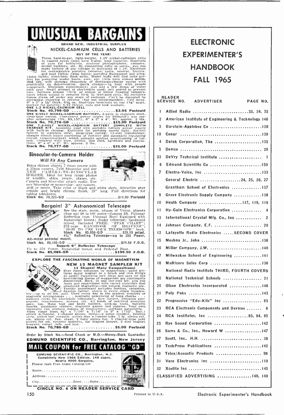
UNUSUAL BARGAINS
r°s
M
BRAND NEW, INDUSTRIAL SURPLUS
NICKEL -CADMIUM CELLS AND BATTERIES
BUY OF THE YEAR:
These hard -to -get, light -weight, 1.2V nickel -cadmium cells
in rugged nylon cases have 4 -amp. hour capacity. Hundreds
of uses for hobbyists, amateur photographers, campers,
model builders, etc. By connecting cells in series, you can
make battery of any voltage In multiples of 1.2V. Excellent
for rechargeable portable lanterns; cycle, scooter, bicycle,
and boat lights; camp lights; portable fluorescent and ultra-
iutet lights; electronic flash units. Model buffs will find cells per-
fect for powering model boats, cars, etc. Cells have almost unlim-
ited life, will undergo thousands of discharge -charge cycles with
Practically no deterioration. Quick charge -1/2 hour with proper
equipment. Minimum maintenance: just add a few drops of water
each year. Small amount of electrolyte used; cell sealed to prevent
loss. Delivers almost 100% of output at below freezing tempera-
tures where output is reduced 50% in lead -acid cells. No corrosive
fumes given off under any stage of recharge. Can't be damaged by
accidental charging in r rse (but not recommended). Cell meas.
6" x 2" x I/z" thick. 61/2 oz. Stud -type terminals on top 11/8" apart,
irked for polarity: 6-:12 thread, nuts and lock washers.
ONE 1.2 NICKEL -CADMIUM CELL
Stock No. 40,798 -GD ................... $3.95 Postpaid
ONE 6 -VOLT NICKEL -CADMIUM BATTERY, 5 -cells In stainless steel.
strap -type casing. Convenient power source for Edmund's war
Pius sniper rope (No. 85,157). 6" x 2"cx 4". Wt. approx. 2 lbs.
Stock No. 70,776 -GD ................. $15.00 Postpaid
ONE 7.2 -VOLT NICKEL -CADMIUM BATTERY COMPLETE WITH
CHARGER KIT. Assemble your own portable battery power supply
with built-in chorgar. Excellent for portable movie light. Six -cell
battery in stainless steel, strap -type casing; 12 -volt transformer;
charger circuit board consisting of rectifier and automatic regulating
circuit (transistorized) which protects against overcharging of hat-
. Complete with wire, switch, line cord, hardware and Instruc-
tions. 6" x 5" v 2". (Vt. approx. 2 Il,s.
Stock No. 70,777 -GD $25.00 Postpaid
Binocular -to -Camera Holder
Will Fit Any Camera
Bring distant objects 7 tines nearer with
a 35min camera. 7x50 binocular and our
NEW CAMERA -TO -BINOCULAR
HOLDER. Ideal for long range photos
of wildlife, .ships, people, planes, etc.
Camera and binocular attach easily. Use
anv binocular or monocular-any camera.
still or movie. Take color or black and white shots. Attractive gray
crinkle and bright chrome finish. 10" long. Full directions for
taking telephotos.
Stock No. 70,223 -GD $11.50 Postpaid
Bargain! 3" Astronomical Telescope
See the sä0., moon, phases of Venus, planets
lose upl 60 5to 180 power-famous Sit. Palomar
Reflecting type. Unusual Buyl Equipped with
Equatorial mount; finder telescope; hardwood
tripod. Included FREE: "STAR CHART";
272 -page HANDBOOK OF HEAVENS":
"(IOW TO USE YOUR TELESCOPE" book.
Stock No. 85,050-G D $29.95 pstpd.
7 +T 41/4" Reflecting Telescope-up to 255 Power,
All -metal pedestal mount.
Stock No. 85,105 -GD $79.50 F.O.B.
Superb 6" Reflector Telescope
lIp to 576 Power. Equatorial 111011M and Pedestal Base.
Stock No. 85,086 -GD $199.50 F.O.B.
EXPLORE THE FASCINATING WORLD OF MAGNETISM
NEW 15 MAGNET SAMPLER KIT
11 Shapes! Many Compositions!
Ever ripen tomatoes by magnetism-paint pic-
tures using magnet as a brush and iron filings
as paint? Surprising new ideas and uses for the
bewildering forces of magnetism a continually
discovered. Here, in one low-cost kit, you can
learn and experiment with varied materials that
obsoleted Magnetite-the natural magnetic ore.
Terrific assortment includes ferrites, ceramics,
flexible rubber. alnico in every shape imagina-
ble-up to 20 lbs. pull. Used every day in the modem wonders of
nagnetic microphones magnetic processing of bank checks .
memory cores for electronic computers, flow meters, immense gen-
erators, transformers, motors, etc. All kinds of practical everyday
uses, too. Make tool and knife holders, pick-up tools, bulletin
boards, automatic stirrers, magnetic games and puzzles. Your own
ingenuity can produce dozens of innovations-perhaps patentable.
Sizes range from 2/4" x 7/18" x 7/16" to 3" x 1/32". Incl.:
alnico /handle, U-shaped alnico, three -2 sided ceramic, flexible
strip, alnico bar, ceramic, alnico disc W Icenter hole, 2 lg. alnico Cy'.
alnico cyl. flex. sheet, 2 baby alnico bar, 3 channel -type pole
pieces for sm.ceramic magnets, bar magnet keeper, 2 disc magnet
m Peepers, c il info. and inst.
Stock No.t 70,780 -GD $5.00 Postpaid
Order by Stock No.-Send Check or M.O.-Money-Back Guarantee
EDMUND SCIENTIFIC CO., Barrington, New Jersey
MAIL COUPON for FREE CATALOG "GD"
EDMUND SCIENTIFIC CO., Barrington, N.J.
Completely New 1966 Edition. 148 pages.
Nearly 4000 Bargains.
Please rush Free Giant Catalog -GD
Name
Lcity cone . .Mate
CIRCLE NO. 6 ON READER SERVICE CARD
nre
Address 1942419
ELECTRONIC
EXPERIMENTER'S
HANDBOOK
FALL 1965
READER
SERVICE NO. ADVERTISER PAGE NO.
I Allied Radio 33, 34, 35
2 American Institute of Engineering & Technology 146
3 Burstein-Applebee Co 138
19 Conar 139
4 Datak Corporation, The 135
5 Demco 20
33 DeVry Technical Institute
6 Edmund Scientific Co 150
7 Electro -Voice, Inc 133
General Electric 24, 25, 26, 27
Grantham School of Electronics 137
9 Grove Electronic Supply Company 138
10 Heath Company 117, 118, 119
I1 Hy -Gain Electronics Corporation 4
13 International Crystal Mfg. Co., Inc 2
14 Johnson Company, E.F 20
12 Lafayette Radio Electronics SECOND COVER
15 Meshna Jr., John 136
16 Miller Company, J.W. 140
17 Milwaukee School of Engineering 141
18 Multicore Sales Corp 136
National Radio Institute THIRD, FOURTH COVERS
35 National Technical Schools 21
20 Olson Electronics Incorporated 146
21 Poly Paks 143
22 Progressive "Edu-Kits" Inc 65
23 RCA Electronic Components and Devices 6
24 RCA Institutes, Inc 83, 84, 85
25 Rye Sound Corporation 142
26 Sams & Co., Inc., Howard W 147
27 Scott, Inc., H.H 38
29 TechPress Publications 142
30 Telex/Acoustic Products 98
31 Vero Electronics Inc 110
32 Xcelite Inc 145
CLASSIFIED ADVERTISING 148, 149
150 Printed In U.S.A. Electronic Experimenter's Handbook
1965
POPULAR ELECTRONICS'
ELECTRONIC
EXPERIMENTER'S
HANDBOOK FinoN
INFORMATION
SERVICE
Here's how you can get additional in-
formation, promptly and at no charge.
concerning products advertised in this
Handbook.
1 Tear out one of the perforated
postage -free cards. Print or type
your name and address where
indicated.
2m Circle the number on the card
that corresponds to the key num-
ber at the bottom of the adver-
tisement that interests you. Key
numbers for advertised products
also appear in the Advertisers'
Index.
3 Simply mail the card. No postage
is necessary.
4w Please use this address only for
requests to manufacturers.
1 2 3 4 5 6 7 8 9 10
11 12 13 14 15 16 17 18 19 20
21 22 23 24 25 26 27 28 29 30
31 32 33 34 35 36 37 38 39 40
41 42 43 44 45 46 47 48 49 50
name (please print)
address
city
state zip code a
H Check this box if you are a subscriber to
POPULAR ELECTRONICS Magazine.
(Void After January 31, 1966)
1 2 3 4 5 6 7 8 9 10
11 12 13 14 15 16 17 18 19 20
21 22 23 24 25 26 27 28 29 30
31 32 33 34 35 36 37 38 39 40
41 42 43 44 45 46 47 48 49 50
name (please print)
address
City
state zip code x
E Check this box if you are a subscriber to
(Void After January 81, 1966) POPULAR ELECTRONICS Magazine.
(Void A ter January 31, 1966)
...read each month
by more than
400,000 electronics
hobbyists, students
and experimenters...
the leading magazine
in the field
throughout the world!
Game Uses *ureter Logic
Magic Box Níái Speaker Enclosure
About Neon Clow Lamps
144 -Mk. paarBaad Transmitter
The Saga of One QSl Teo Nlanf
RIC
wild 12-/ w '
Receiver
POPULAR
ELECTRONI CS
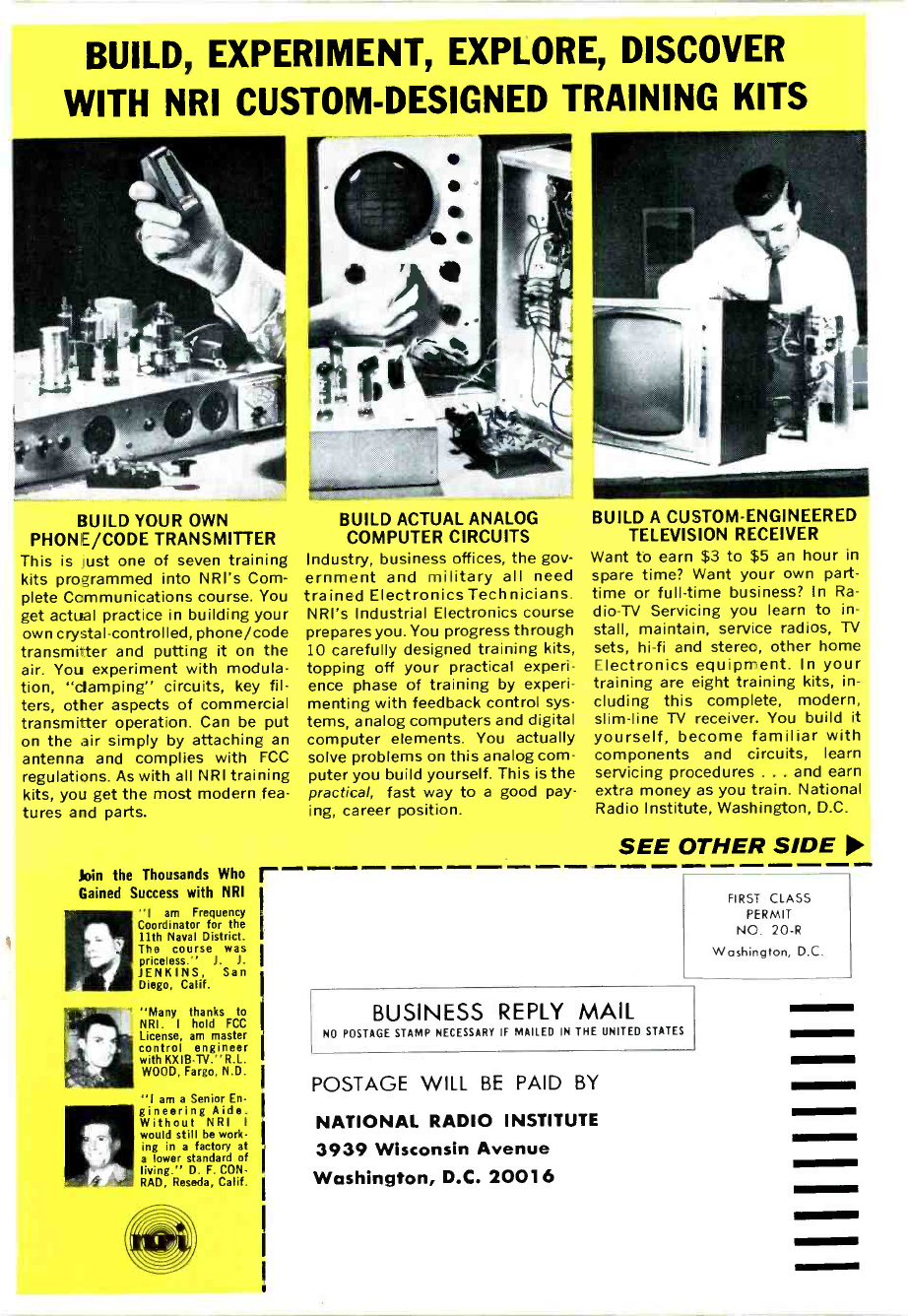
BUILD, EXPERIMENT, EXPLORE, DISCOVER
WITH NRI CUSTOM -DESIGNED TRAINING KITS
BUILD YOUR OWN
PHONIE/CODE TRANSMITTER
This is ',lust one of seven training
kits programmed into NRI's Com-
plete Communications course. You
get actual practice in building your
own crystal -controlled, phone/code
transmitter and putting it on the
air. You experiment with modula-
tion, "damping" circuits, key fil-
ters, other aspects of commercial
transmitter operation. Can be put
on the air simply by attaching an
antenna and complies with FCC
regulations. As with all NRI training
kits, you get the most modern fea-
tures and parts.
Join the Thousands Who
Gained Success with NRI
"I am Frequency
Coordinator for the
11th Naval District.
The course was
priceless." J. J.
JENKINS, San
Diego, Calif.
"Many thanks to
NRI. I hold FCC
License, am master
control engineer
with KXIB-TV."R.L.
WOOD, Fargo, N.D.
"I am a Senior En-
gineering Aide.
Without NRI I
would still be work-
ing in a factory at
a lower standard of
living." D. F. CON-
RAD, Reseda, Calif.
r
BUILD ACTUAL ANALOG
COMPUTER CIRCUITS
Industry, business offices, the gov-
ernment and military all need
trained Electronics Technicians.
NRI's Industrial Electronics course
prepares you. You progress through
10 carefully designed training kits,
topping off your practical experi-
ence phase of training by experi-
menting with feedback control sys-
tems, analog computers and digital
computer elements. You actually
solve problems on this analog com-
puter you build yourself. This is the
practical, fast way to a good pay-
ing, career position.
BUILD A CUSTOM -ENGINEERED
TELEVISION RECEIVER
Want to earn $3 to $5 an hour in
spare time? Want your own part-
time or full-time business? In Ra-
dio-TV Servicing you learn to in-
stall, maintain, service radios, TV
sets, hi-fi and stereo, other home
Electronics equipment. In your
training are eight training kits, in-
cluding this complete, modern,
slim -line TV receiver. You build it
yourself, become familiar with
components and circuits, learn
servicing procedures ... and earn
extra money as you train. National
Radio Institute, Washington, D.C.
SEE OTHER SIDE
FIRST CLASS
PERMIT
NC. 20-R
Washington, D.C.
BUSINESS REPLY MAIL
NO POSTAGE STAMP NECESSARY IF MAILED IN THE UNITED STATES
POSTAGE WILL BE PAID BY
NATIONAL RADIO INSTITUTE
3939 Wisconsin Avenue
Washington, D.C. 20016
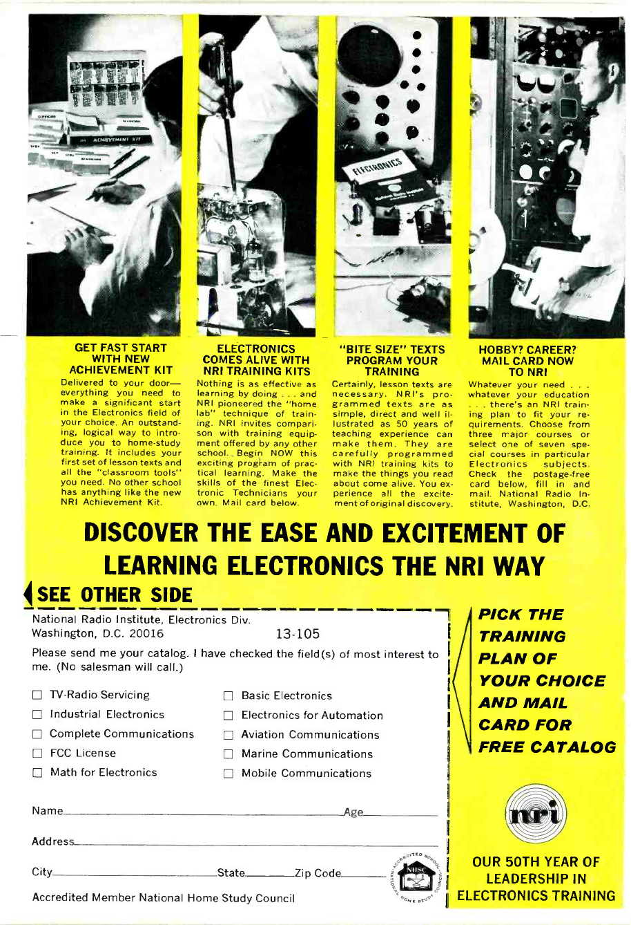
GET FAST START
WITH NEW
ACHIEVEMENT KIT
Delivered to your door-
everything you need to
make a significant start
in the Electronics field of
your choice. An outstand-
ing, logical way to intro-
duce you to home -study
training. It includes your
first set of lesson texts and
all the "classroom tools"
you need. No other school
has anything like the new
NRI Achievement Kit.
LA -
ELECTRONICS
COMES ALIVE WITH
NRI TRAINING KITS
Nothing is as effective as
learning by doing ... and
NRI pioneered the "home
lab" technique of train-
ing. NRI invites compari-
son with training equip-
ment offered by any other
school. Begin NOW this
exciting program of prac-
tical learning. Make the
skills of the finest Elec-
tronic Technicians your
own. Mail card below.
"BITE SIZE" TEXTS
PROGRAM YOUR
TRAINING
Certainly, lesson texts are
necessary. NRI's pro-
grammed texts are as
simple, direct and well il-
lustrated as 50 years of
teaching experience can
make them. They are
carefully programmed
with NRI training kits to
make the things you read
about come alive. You ex-
perience all the excite-
ment of original discovery.
HOBBY? CAREER?
MAIL CARD NOW
TO NRI
Whatever your need .
whatever your education
. there's an NRI train-
ing plan to fit your re-
quirements. Choose from
three major courses or
select oie of seven spe
cial courses in particular
Electronics subjects.
Check the postage -free
card below, fill in and
mail. National Radio In-
stitute, Washington, D.C.
DISCOVER THE EASE AND EXCITEMENT OF
LEARNING ELECTRONICS THE NRI WAY
4 SEE OTHER SIDE
National Radio Institute, Electronics Div.
Washington, D.C. 20016 13-105
Please send me your catalog. I have checked the field(s)
me. (No salesman will call.)
D TV-Radio Servicing
D Industrial Electronics
D Complete Communications
D FCC License
D Math for Electronics
of most interest to
Basic Electronics
Electronics for Automation
Aviation Communications
Marine Communications
Mobile Communications
Name Age
Address
City State Zip Code
Accredited Member National Home Study Council
wec
PICK THE
TRAINING
PLAN OF
YOUR CHOICE
AND MAIL
CARD FOR
FREE CATALOG
OUR 50TH YEAR OF
LEADERSHIP IN
ELECTRONICS TRAINING
