AM15T ML 130039 F35320 (10 12)
User Manual: AM15T ML-130039
Open the PDF directly: View PDF ![]() .
.
Page Count: 32

701 S. RIDGE AVENUE
TROY, OHIO 45374-0001
937 332-3000
www.hobartcorp.com FORM 35320 Rev. E (October 2012)
AM SELECT DISHWASHERS
MODELS
AM15 ML-130038
AM15F ML-130045
AM15T ML-130039
AM15VL ML-130153
AM15VLF ML-130155
AM15VLT ML-130154
– 2 –
POST IN A PROMINENT LOCATION THE INSTRUCTIONS TO BE FOLLOWED IN THE
EVENT THE SMELL OF GAS IS DETECTED. THIS INFORMATION CAN BE OBTAINED
FROM THE LOCAL GAS SUPPLIER.
IMPORTANT
IN THE EVENT A GAS ODOR IS DETECTED, SHUT
DOWN UNIT(S) AT MAIN SHUTOFF VALVE AND
CONTACT THE LOCAL GAS COMPANY OR GAS
SUPPLIER FOR SERVICE.
FOR YOUR SAFETY
DO NOT STORE OR USE GASOLINE OR OTHER
FLAMMABLE VAPORS OR LIQUIDS IN THE
VICINITY OF THIS OR ANY OTHER APPLIANCE.
© HOBART CORPORATION, 2009
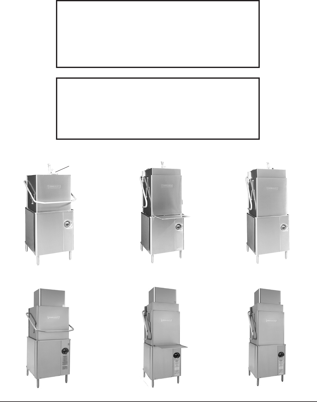
PRESSURE
GAUGE
Model AM15 Model AM15F Model AM15T
Fig. 1
Model AM15VL Model AM15VLF Model AM15VLT

– 3 –
TABLE OF CONTENTS
GENERAL ....................................................................4
INSTALLATION ................................................................5
Unpacking .................................................................5
Installation Codes ...........................................................5
Location ...................................................................5
Corner Installation ...........................................................6
Water Requirements .........................................................7
Plumbing Connections ........................................................8
Drain Connection ........................................................8
Water Connection ........................................................8
Without Electric Booster Water Heater - Models AM15, AM15F, and AM15T. . . . . . . . . . . 8
With Electric Booster Water Heater - Models AM15, AM15F, and AM15T .............9
With Electric Booster Water Heater - Models AM15VL, AM15VLF, and AM15VLT .......9
GasTankHeat(WhenSpecied) ..............................................10
Venting Requirements - with Gas Tank Heat ......................................11
Rate of Exhaust Flow Calculations ..........................................12
Table A Heat Dissipation ..................................................13
Electrical Connections .......................................................14
Dishwasher without Electric Booster ........................................15
MotorRotation(Three-PhaseMachinesOnly) .................................15
DishwasherWithElectricBooster(SeparatelyConnected) .......................15
DishwasherWithElectricBooster(SinglePointElectricalConnection) ..............16
Equipment Connections ......................................................16
Vent Fan Control ........................................................16
Remote Booster Control ..................................................16
Detergent, Rinse Aid, Sanitizer Dispensers — Tubing Installation .....................17
Detergent Dispenser .....................................................17
Rinse Aid Dispenser .....................................................18
Chemical Sanitizer Dispenser - AM15, AM15F, and AM15T Models Only ............18
Detergent, Rinse Aid, Sanitizer Dispensers — Equipment connections .................19
DetergentDispenser(Fig.22) .............................................19
RinseAid/SanitizerDispenser(s)(Fig.22) ...................................19
Setup(AM15,AM15F,andAM15TModelsOnly) ..................................20
Sanitizing Mode ........................................................20
End of Cycle Buzzer - All Models ...........................................20
OPERATION .................................................................21
Preparation ...............................................................21
Dishwashing ..............................................................22
CLEANING ..................................................................24
For Models AM15VL,AM15VLF and AM15VLT: ....................................25
Delime Instructions .........................................................27
Dos and Don'ts for Your New Hobart Warewasher .................................27
MAINTENANCE ..............................................................28
Wash arms ................................................................28
Motor(s) ..................................................................28
Flue(MachinesEquippedWithGasTankHeatOnly) ..............................28
TROUBLESHOOTING .........................................................28
Manual Reset Button on Pump Motor ...........................................28
SERVICE ....................................................................31

– 4 –
Installation, Operation and Care Of
AM SELECT DISHWASHERS
SAVE THESE INSTRUCTIONS
GENERAL
ModelsAM15,AM15VL,AM15T,andAM15VLTdishwasherscanbecongured
for both straight through or corner operation. Models AM15F and AM15VLF are
conguredforfrontloading.AM15,AM15VL,AM15T,andAM15VLTdishwashers
are shipped from the factory in straight-through conguration. Straight-through
machines can easily be converted to corner operation. Models AM15F and AM15VLF
include a front-loader shelf and left- and right-side shields as standard equipment.
The front-loader shelf on the AM15F and AM15VLF can be positioned up (inside
themachineduringoperation)ordown(outsidethemachineduringoperation).
The AM15, AM15F and AM15T dishwashers are designed to operate in one of two
modes: Hot water sanitizing mode (designated by the letters “AH” or “AP” on the
displaywhenthemachineisturnedon),orachemicalsanitizingmode(designatedby
the letters“AC”onthedisplaywhenthemachineisturnedon).AM15VL,AM15VLF
and AM15VLT dishwashers are designed to operate in hot water sanitizing mode
only(designatedbytheletters“HL”onthedisplaywhenthemachineisturnedon).
The serial number can be found on the machine data plate located on the bottom of
the front panel. The pump motor is rated 2 H.P. and has thermal overload protection.
DO NOT attempt to operate this dishwasher in the chemical sanitizing mode without
aproperlyinstalled,NSFCertied,chemicalsanitizerfeeder(customersupplied).
Contact an authorized detergent representative for information about a chemical
sanitizer feeder.
Thelllineincorporateseitheranatmosphericvacuumbreakerfornon"VL"models
oranairgapfor"VL"modelstopreventanyreverseowofwaterfromthedishwasher
intothepotablewatersupply.Theunit,onceturnedon,llsthewashtanktothe
appropriatelevelandautomaticallystopsllingoncethelevelisreached.Aoat,
located in the wash tank, shuts off the heat supply if the water level becomes too low.
When the water returns to the proper level, the heating circuit is again operational.
A frame-mounted 8.5 kW electric booster water heater is available as an option
for models equipped with electric tank heat. The booster water heater is standard
for"VL"models.FormodelsAM15,AM15F,andAM15Ttheboosterwaterheater
isdesignedtomaintainaminimumnalrinsetemperatureof180°Fprovidedthe
incomingwatertotheboosterheaterisatleast110°F.ForventlessmodelsAM15VL,
AM15VLF, and AM15VLT, the booster water heater is designed to maintain a minimum
nalrinsetemperatureof180°Fwithcoldincomingwater.
Ventless models AM15VL, AM15VLF, and AM15VLT do not require a vent hood.
They use an internal condensing system to minimize the water vapor escaping
from the unit during loading and unloading. High-temperature AM15, AM15F and
AM15T models or gas heat dishwashers typically require a hood or vent over the
dishwasher to meet local codes. Low-temperature chemical sanitizing machines
or low usage electric heat dishwashers may not require individual venting of the
machine if the room is amply exhausted. Refer to pages 10 and 11 for venting and
hoodrequirements.Verifywithlocalcodesfornalauthority.
– 5 –
INSTALLATION
UNPACKING
Immediately after unpacking the dishwasher, check for possible shipping damage.
If this machine is found to be damaged, save the packaging material and contact
the carrier within 15 days of delivery.
Prior to installation, test the electrical service to make sure it agrees with the
specicationsonthemachinedataplate;thisincludestheoptionalelectricbooster,
if equipped. The dishwasher data plate is located at the bottom of the front panel.
INSTALLATION CODES
Installation must be in accordance with state and local codes, or in the absence
oflocalcodes,withtheNationalFuelGasCode,ANSIZ223.1(latestedition)if
applicable,and the NationalElectrical Code ANSI/NFPA 70(latestedition). In
Canada, the installation standards are: CAN/CGA B149.1, CAN/CGA B149.2, and
CSAC22.2No.1(latesteditions).
LOCATION
Beforenalizingthelocation,makesurethatconsiderationhasbeengivenforthe
electrical conduit, water supply, drain connection, gas supply and venting (if
applicable),tabling(ifneeded),chemicalfeederreplenishment(ifapplicable)and
adequate clearance for opening the door.
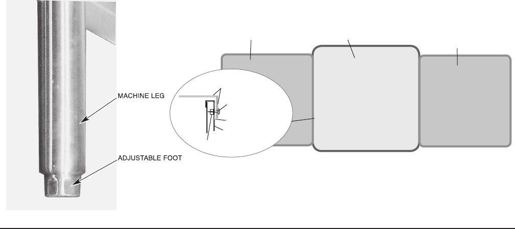
The dishwasher must be level before any connections are made. Turn the threaded
feet(Fig.2)asrequiredtolevelthemachineandadjusttothedesiredheight.
The edge of dish table that overhangs the AM15 wash tank should be turned down
andttedoverthetopofthedishwashertank(Fig.3).ApplyanNSFapproved
sealant between the overhang of the dish table and the inner wall of the wash tank
topreventleakage(Fig.3).Fastenthedishtablestotheinnerwallofthewash
tankwithnon-rustingtrussheadscrewsorrivets(Fig.3).
For straight-through installations, clearance at the front and 15 inches out from the
dishwasherattherightsideby27inchesabovethenishedoormustbeprovided
for servicing.
Fig. 2
Fig. 3
WASH TANK
DISH TABLE
DISH TABLE
STRAIGHT-THROUGH OPERATION SHOWN
INNER WALL OF
WASH TAN K
SEALANT
NUT
DISH TABLE
MACHINE SCREW
OR RIVET
– 6 –
CORNER INSTALLATION
Beforeplacingthedishwasherinitsoperatinglocation,checkmachineconguration.
Ifthemachineisbeinginstalledinacorner(Figs.4,5),clearancesof20inchesout
fromthedishwasherundertheleft-handtablingby27inchesabovethenished
oorand15inchesoutfromthedishwasherattherightsideby27inchesabove
thenishedoormustbeprovidedforservicing.Forproperinstallationofacorner
machine, the control and display should be positioned at the front corner for operator
access(Fig.5).
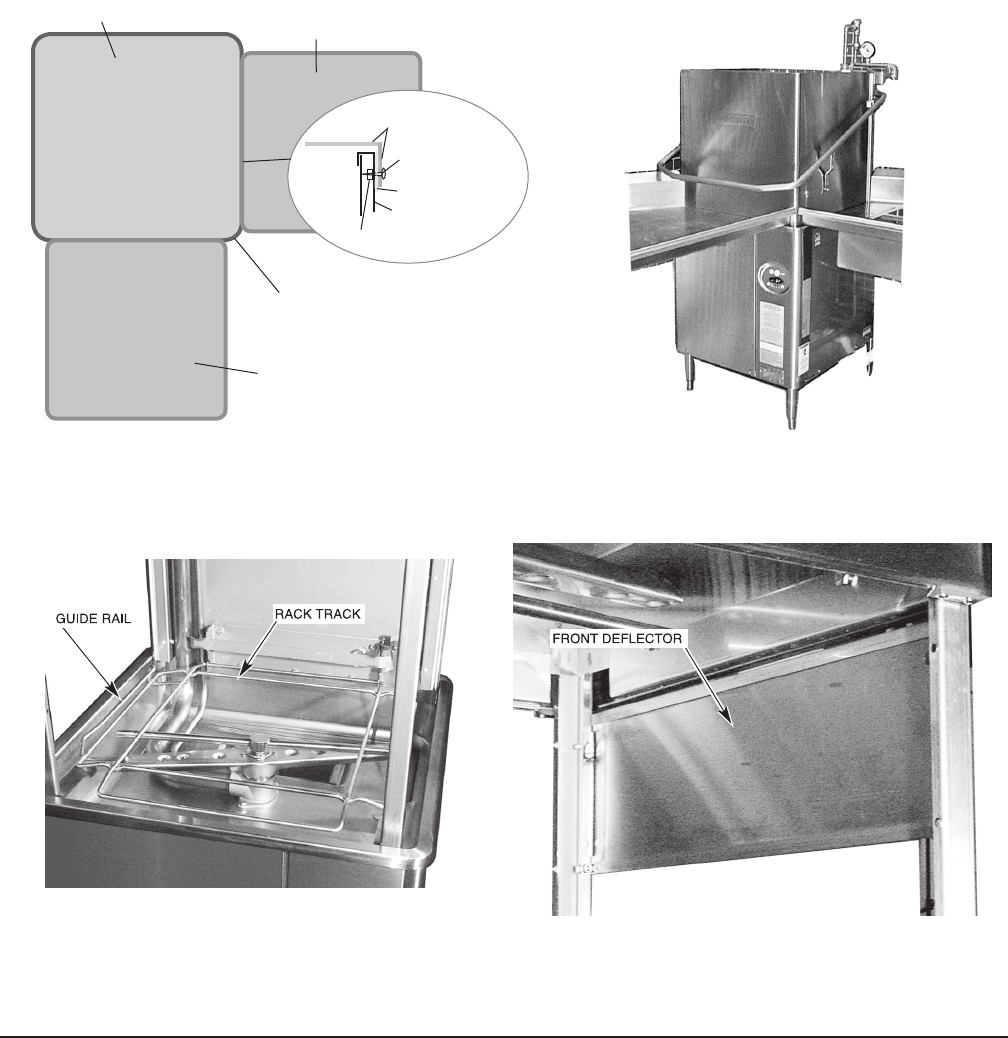
For corner installation, rotate the rack track so the guide rail is positioned on the
leftside(Fig.6).Forcornermachines,removethefrontdoordeector(unscrew
threebolts/nuts,Fig.7).
Fig. 6 Fig. 7
Fig. 4 Fig. 5
WASH TANK
DISH TABLE
DISH TABLE
CORNER OPERATION SHOWN
DISH TABLE
INNER WALL OF
WASH TAN K
SEALANT
MACHINE SCREW
OR RIVET
NUT
CONTROLS MUST BE ACCESSIBLE
AT FRONT CORNER.
– 7 –
WATER REQUIREMENTS
Proper water quality can improve warewashing performance by reducing spotting,
lowering chemical supply costs, improving productivity and extending equipment
life. Local water conditions vary from one location to another. The recommended
proper water treatment for effective and efcient use of this equipment will
also vary depending on the local water conditions. Ask your municipal water
supplierfordetailsaboutlocalwaterspecicspriortoinstallation.
Recommended water hardness is 3 grains of hardness per gallon or less. Chlorides
must not exceed 30 parts per million. Water hardness above 3 grains per gallon
shouldbetreatedbyawaterconditioner(watersoftenerorin-linetreatment).Water
treatment has been shown to reduce costs associated with machine cleaning,
reduce the need for deliming the dishwasher and reduce detergent usage.
Sediment, silica, chlorides or other dissolved solids may lead to a recommendation
forparticulateltrationorreverseosmosistreatment.
If an inspection of the dishwasher or booster heater reveals lime build-up after the
equipment has been in service, in-line water treatment should be considered, and,
if recommended, should be installed and used as directed. Contact your Hobart
Serviceofceforspecicrecommendations.
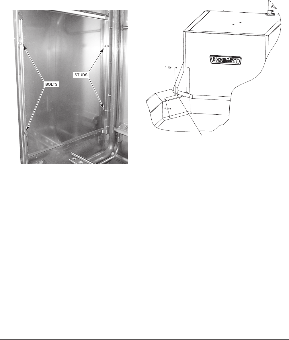
A NOTCH MUST BE ADDED TO BACKSPLASHES
OVER6"HIGHONCORNERMACHINESTOPREVENT
INTERFERENCE WITH DOOR MECHANISM. NOTCH
MUSTEXTEND5"FROMFACEOFTHEMACHINE.
Asplashshieldisavailable(atextracost)forcornerinstallationstocovertheleft
sideopeningtothewall.Installthesplashshieldontheleftsideusingthetwo1⁄4-
20studsontheleftrearcornerwithalockwasherandnutforeach(Fig.8)and
usingthetwo1⁄4-20bolts,lockwashersandnutsontheleftfrontcorner(fasteners
areprovidedinthekit).
Forcornerinstallations,tablingwithbacksplashesover6"highrequirethatanotch
beprovidedtopreventinterferencewiththedoormechanism(Fig.9).
Fig. 8 Fig. 9
– 8 –
PLUMBING CONNECTIONS
Plumbing connections must comply with applicable sanitary,
safety, and plumbing codes.
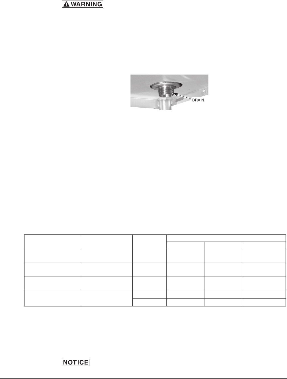
Drain Connection
The drain connection is a 11⁄2 inch externally threaded pipe connected
straightdownfromthebottomofthewashtank(Fig.10).Theconnectioncanbe
madeinanydirectionbyusingthepropertting(notsupplied)androutingtothe
appropriate drain line.
Ifagreasetrapisrequiredbycode,itshouldhaveaminimumowcapacityof38
gallons per minute.
Water Connection
Asuitablewaterhammerarrestorshouldbeinstalledinthewaterlinejustahead
of the dishwasher.
Without Electric Booster Water Heater - Models AM15, AM15F, and AM15T
Thewatersupplylineisconnectedtothelinestrainer(toprear,Fig.1)with3⁄4inch
or1⁄2inchpipe.Amanualshutoffvalveandpipeunionarerequired(customer
supplied).
For AM15, AM15F, and AM15T models, proper dishwasher operation requires a
owingpressureof20±5psigatthedishwasher.Iftheowingpressureexceeds
25psig,apressurereducingvalve(customersupplied)mustbeinstalledinthewater
supplyline.Apressuregauge(Fig.1)isprovided(notinstalled)forvericationof
proper water pressure. The water pressure is monitored when the solenoid valve
isopenandwaterisowing.
The water pressure regulator must have a relief by-pass. Failure to use
the proper type of pressure regulator may result in damage to the unit.
Fig. 10
REQUIRED INCOMING WATER TEMPERATURE
Model Sanitizing Mode Connection Water Supply
Minimum Maximum Recommended
Without Built-in
Booster
Hot Water
Sanitizing Hot Water 180°F(82°C) 194°F(90°C) 180°F(82°C)
Without Built-in
Booster Chemical Sanitizing Hot Water 120°F(49°C) N/A 140°F(60°C)
With Built-in Booster Hot Water
Sanitizing Hot Water 110°F(43°C) N/A 140°F(60°C)
VL Models Hot Water
Sanitizing
Cold Water N/A 90°F(32°C) 65°F(18°C)
Hot Water 110°F(43°C) N/A 140°F(60°C)

– 9 –
With Electric Booster Water Heater - Models AM15, AM15F, and AM15T
Thewatersupplylineisconnectedbelowtheboosterwiththelinestrainer(supplied)
a n d 3 ⁄ 4 i n c h p i p e . A m a n u a l s h u t o f f va l v e a n d p i p e u n i o n a r e r e q u i r e d (n o t s u p p l i e d) .
Thewatersupplymusthaveaminimumtemperatureof110°F(43°C),andaowing
pressureof20±5psigatthepressuregaugeontopofthemachine.Iftheowing
pressureexceeds25psig,apressurereducingvalve(notsupplied)mustbeinstalled
in the water supply line.
The water pressure regulator must have a relief by-pass. Failure to
use the proper type of pressure regulator may result in damage to the unit.
Incomingwatertemperaturebelow110°F(43°C)mayrequirelongerwashcycle
timethanthe57secondcycle;refertoOPER ATION, pages 17 – 18.
Whenthell/nalrinsevalveison,waterfromtheboostertankentersthedishwasher
throughthenalrinsearms.Duringtherinsecycle,thiswateris180°F(82°C).
A small amount of water will likely dribble out of the lower rinse arm into the tank
between cycles due to the natural expansion of water as it is being heated.
With Electric Booster Water Heater - Models AM15VL, AM15VLF, and AM15VLT
Ventless models require both a cold water supply connection and a hot water supply
connection. The cold water supply line is connected to the line strainer at the top of
the machine with a 1⁄2 inch pipe. A pressure regulator and pressure gauge are not
required.Amanualshut-offvalveandpipeunionarerequired(customersupplied).
Thecoldwatersupplymustnotexceed90°F(32°C)forproperoperation.
Optimalresultsareobtainedwhencoldwatersupplytemperatureisbelow65°F
(18°C).Forbestresults,itmaybenecessarytouse1⁄2 inch pipe for the cold water
pipe size and minimize the distance between the dishwasher and the entrance into
the building. Pipe insulation will also improve results.
Ifcoldwatersupplytemperatureisconsistentlyabove90°F(32°C)orifexcessive
water vapor or steam is entering the room after the condensing cycle is complete,
contact Hobart Service to increase condensing time.
The hot water supply line is connected to the line strainer at the rear of the machine
with a 1⁄2 inch pipe. A pressure regulator and pressure gauge are not required as
this is a pumped rinse machine. A manual shut-off valve and pipe union are required
(customersupplied).
– 10 –
GAS TANK HEAT (WHEN SPECIFIED)
Check the gas data plate attached to the dishwasher or the tag attached to the
incominggaspipingforthetypeofgastobeused.Theburnerisnotadjustable.
ThemaximumowinginletgaspressuremustnotexceedtheMaximumvaluein
the table. If line pressure exceeds the Maximum value in the table, an additional
pressureregulator(notsupplied)mustbeinstalledinthesupplyline.
Static inlet line pressure should not exceed 14 inches W.C. The minimum value
isforinputadjustment.
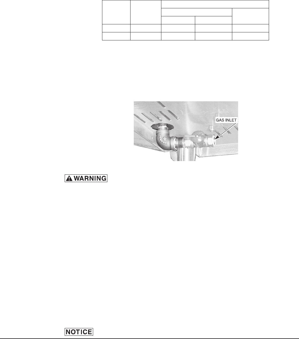
The gas valve is provided with a pressure tap to measure the gas pressure downstream,
which is also the manifold pressure. Gas supply piping must have a sediment trap
(suppliedbyothers)installedaheadofthedishwasher’sgascontrol.Connectthegas
supplytothe1⁄2inchNPTgasinletunderneaththemachine(Fig.11).
Do not use Teon tape on gas line pipe threads. For gas line
pipe connections, use Loctite 565, Hobart part 546292, or a exible sealant
suitable for use with Natural and Propane Gases.
The appliance and its gas connections must be leak tested before placing the
appliance in operation. Use soapy water for leak test. Do notuseopename.
The installation must conform with local codes, or in the absence of local codes,
withtheNationalFuelGasCode,ANSIZ223.1(latestedition).Copiesmaybe
obtained from American Gas Association, Inc., 1515 Wilson Boulevard, Arlington,
VA 22209.
The appliance and its individual shutoff valve must be disconnected from the gas
supply piping system during any pressure testing of that system at test pressures
in excess of 1⁄2psig(3.45kPa).
The appliance must be isolated from the gas supply piping system by closing
its individual manual shutoff valve during any pressure testing of the gas supply
piping system at test pressures equal to or less than 1⁄2psig(3.45kPa).Dissipate
test pressure from the gas supply line before re-connecting the appliance and its
manual shutoff valve to the gas supply line.
Failure to follow this procedure may damage the gas valve.
Fig. 11
GAS PRESSURE SPECIFICATION
[FLOWING GAS PRESSURE — NOT STATIC]
Type
of
Gas
BTU/HR
Inches W.C. (Water Column) FLOWING
Incoming Line Pressure Manifold
Pressure
Minimum Maximum
Natural 25,000 3.5 7.0 3.2
Propane 25,000 9.0 11.0 8.2
– 11 –
Fig. 12 Fig. 13
31⁄2"
6" ➤
➤
➤
➤
➤
➤
4"
➤
3" x 3" DUCT INTO
CURRENT SYSTEM
➤
5"GAP
MINIMUM
➤
➤
MINI VENT HOOD
DISHWASHER FLUE EXIT
➤
➤
➤
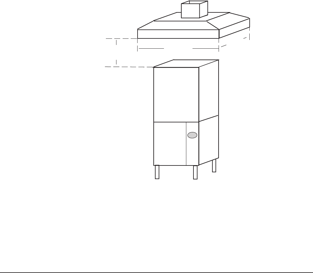
6"
MINIMUM
OVERHANG
ON ALL SIDES
➤
➤
1' TO 4'
CLEARANCE
➤
➤
18"OVERHANG
RECOMMENDED
OVER LOADING OR
UNLOADING DOORS
Thedishwashermustbeinstalledsothattheowofcombustionandventilationair
isnotobstructed.Donotstorematerialunderneaththemachine;airopeningsinto
the combustion chamber must not be blocked. Make sure there is an adequate
supply of make-up air in the room to allow for combustion of the gas at the burner.
Keep the appliance area free and clear from all combustible substances.
Donotobstructtheowofcombustionandventilationair.Thedishwasher
must have a minimum clearance from combustible construction of 1 inch
from the ueatthe rear.Clearancesof20 inches outfromthedishwasherat
the front (or left side in a corner installation) by 27 inches above the nished
oor and 15 inches out from the dishwasher at the right side by 27 inches
above the nished oor must be provided for servicing. The burner is ignited
automaticallybysolidstateelectroniccircuitry;thereisnopilotlight.Gasow
is regulated by the temperature control circuit.
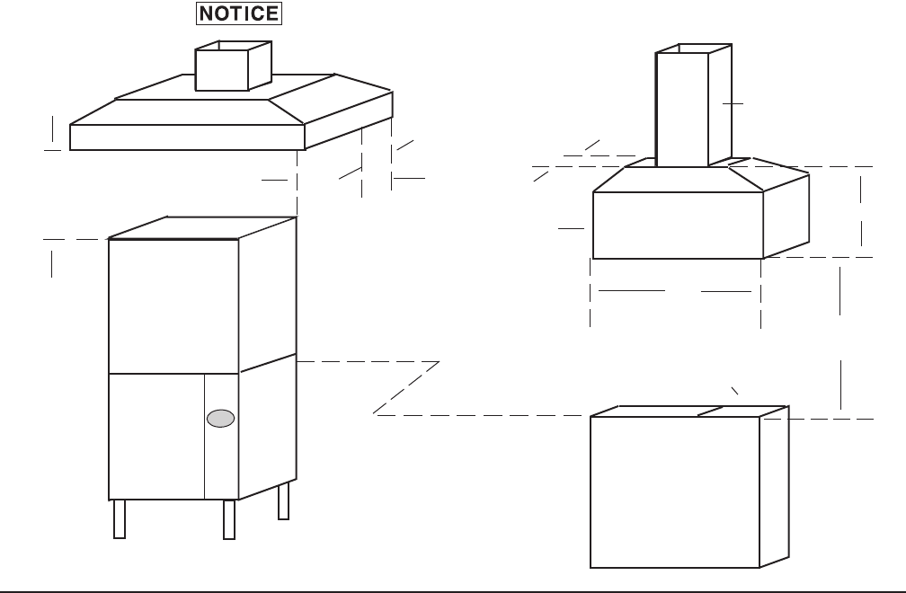
VENTING REQUIREMENTS — WITH GAS TANK HEAT
Hobart model AM15, AM15F or AM15T dishwashers equipped for gas tank heat
arenotprovidedwithauecollarandarenotintendedtohavetheuedirectly
connected to a ventilation system. However, the products of combustion must be
vented to the outside air. The most common method of venting is a vent hood over
theentiredishwasher(Fig.12).RefertoRateofExhaustFlowCalculationsonthe
next page for calculations of the proper vent rate for your hood. Another method
isasmallventhood(Fig.13)positionedaboutveinchesabovetheueexitat
the rear of the dishwasher and connected to existing ductwork. In either case,
anelectricalinterlockmustbeinstalledtoallowtheowofgastothedishwasher
burner ONLY when the exhaust system is energized. For additional information,
refer to the National Fuel Gas Code, ANSI Z223.1, NFPA 54.
Make sure the installation meets the local code for your area.
– 12 –
NOTE: Any listed and labeled factory-built commercial exhaust hood tested in
accordance with UL Standard 710 by a nationally recognized testing laboratory,
must be installed according to the terms of its listing and the manufacturer’s
installation instructions.
Rate of Exhaust Flow Calculations
Based on the 2009 International Mechanical Code.
TheminimumnetairowforTypeIIhoodsusedfordishwashingappliancesshall
be 100 cfm per linear foot of hood length. The net quantity of exhaust air shall be
calculatedbysubtractinganyairowsupplieddirectlytoahoodcavityfromthetotal
exhaustowrateofahood.
Ventless models AM15VL, AM15VLF, and AM15VLT do not require a Type II vent
hood. According to 507.22 of the 2009 IMC, Type II hoods are not required where
the heat and moisture load is incorporated into the HVAC system design. See Table
A for heat dissipation or heat gain to space.
➤
➤
LENGTH
➤
➤
CLEARANCE
HEIGHT
➤
➤
WIDTH
Fig. 14

– 13 –
TABLE A: HEAT DISSIPATION
Model Electric
Heat
Gas
Heat
13 kW
Electric
Booster
8.5 kW
Electric
Booster
Steam
Booster
Latent
Heat
(BTU/
HR)
Sensible
Heat
(BTU/
HR)
Hot
Water
Sanitizing
AM15
X7, 40 0 3,200
X X 22,900 9,800
X X 17, 5 0 0 7, 5 0 0
X X 2 7,8 0 0 11,9 00
X10,900 4,700
X X 31,200 13,400
AM15T, AM15F
X10,400 4,400
X X 32,10 0 13,800
X X 24,600 10,500
X X 38,900 16,700
X15,200 6,500
X X 43,700 18,700
AM15, AM15T,
AM15F with power
vent fan option
X1,200 1,300
X X 3,700 4,200
X X 2,800 3,200
X X 4,500 5,10 0
X1,800 2,000
X X 5,000 5,700
AM15VL X X 9,300 3,400
AM15VLT,
AM15VLF X X 13,000 4,800
Chemical
Sanitizing
AM15 X9,400 2,800
X10,900 4,600
AM15T, AM15F X13,200 3,900
X15,200 6,500
Assumptions: 1. Machines operate 70% of each hour while in use.
2. All heat dissipated enters the room except for models with power vent fan
option and gas heat models. Gas heat models must be provided with vent
hood which directs 40% of heat to outside atmosphere.
3. 70% of heat output is latent, 30% is sensible.
4. Chemical sanitizing models operate at 60% of the heat output of equivalent
hot water sanitizing models.
– 14 –
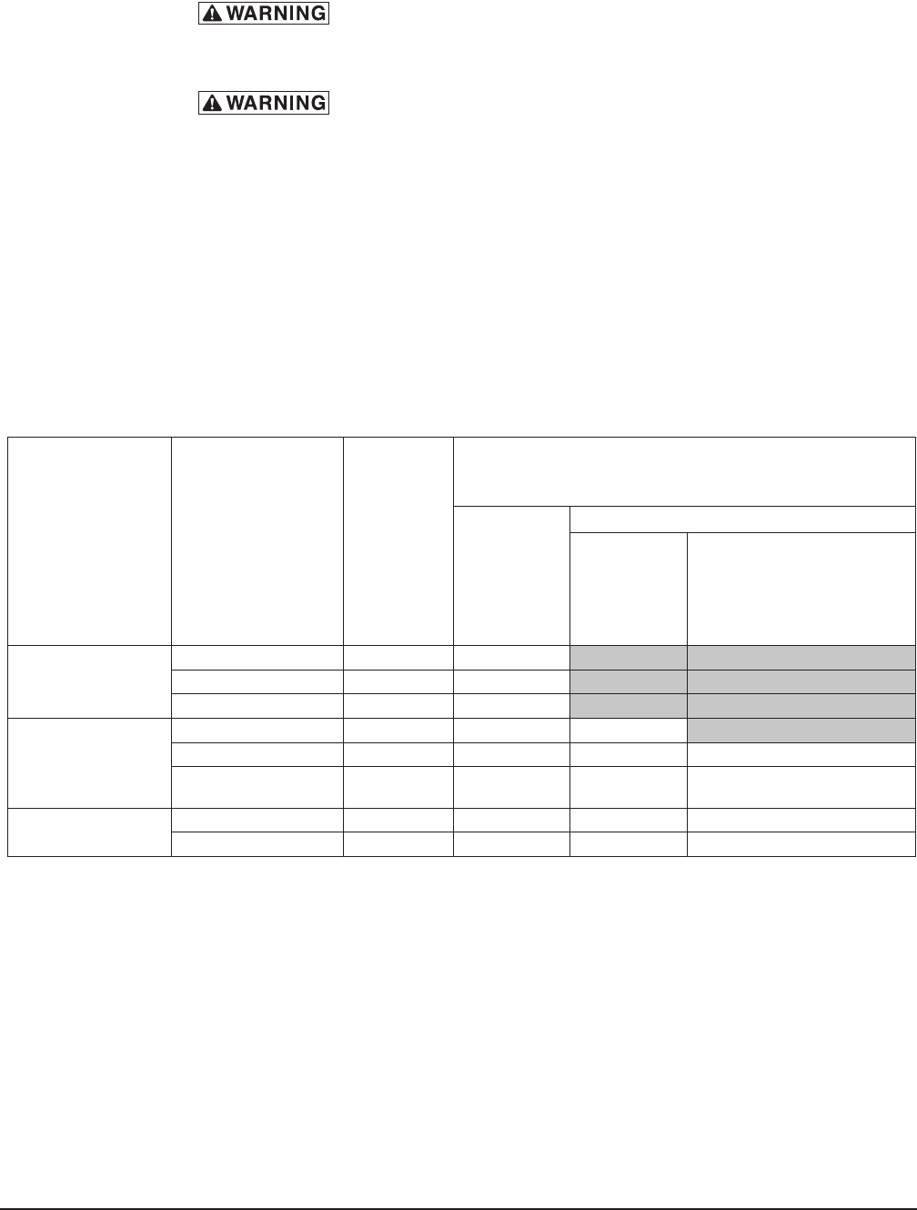
ELECTRICAL DATA
Models Volts / Hz / Ph Tank Heat
Minimum Circuit Ampacity
Maximum Protective Device
AMPS
Dishwasher
ONLY
Optional 8.5 KW Electric Booster
8.5 KW
Booster
ONLY
Optional Single Point
Electrical Connection
3 Phase Only
Dishwasher and
Booster
AM15
AM15F
AM15T
208 - 240 / 60 / 1 Gas 20
208 - 240 / 60 / 3 Gas 15
480 / 60 / 3 Gas 15
AM15, AM15F
AM15T, AM15VL
A M15 VL F,
AM15 VLT
208 - 240 / 60 / 1 Electric 50 50
208 - 240 / 60 / 3 Electric 30 30 60
480 / 60 / 3 Electric 15 15 30
AM15, AM15F,
AM15T
200 - 240 / 50 / 3 Electric 30 30 60
380 - 415 / 50 / 3 Electric 15 15 30
Compiledinaccordancewiththenationalelectricalcode,NFPA70(latestedition).
ELECTRICAL CONNECTIONS
Electrical and grounding connections must comply with the
applicable portions of the National Electrical Code, NFPA 70 (latest edition)
and / or other local electrical codes.
Disconnect the electrical power to the machine (both dishwasher
and booster if applicable) and follow lockout / tagout procedures. Be sure all
circuits are disconnected.
Refer to the wiring diagram attached inside the front trim panel and to the machine
data plate for service size requirements when connecting the dishwasher. Also,
refer to Electrical Data, page 12.
To access the controls area, remove the right side panel, remove the front panel
and open the control panel door. The dishwasher electrical service connection can
be made through the 13⁄32 inch diameter hole for 3⁄4 inch trade size conduit located
on the right side at the rear of the machine. By removing a knockout, this hole can
be enlarged to 13⁄8"diameterfor1inchtradesizeconduit,ifrequired.
Afuseddisconnectswitchorcircuitbreaker(customersupplied)mustbeinstalled
in the electrical service line(s) supplying this dishwasher and should meet the
requirements of your local electrical code.
– 15 –
Dishwasher without Electric Booster
For single-phase machines, power supply connections are made to terminal blocks.
For three-phase machines connections are made to contactor lugs. The machine
mustbegroundedaccordingtoelectricalcode(s);agroundinglugisprovidedin
the controls area. Electrical connections for machines with gas tank heat are made
to contactor 1CON in the controls area.
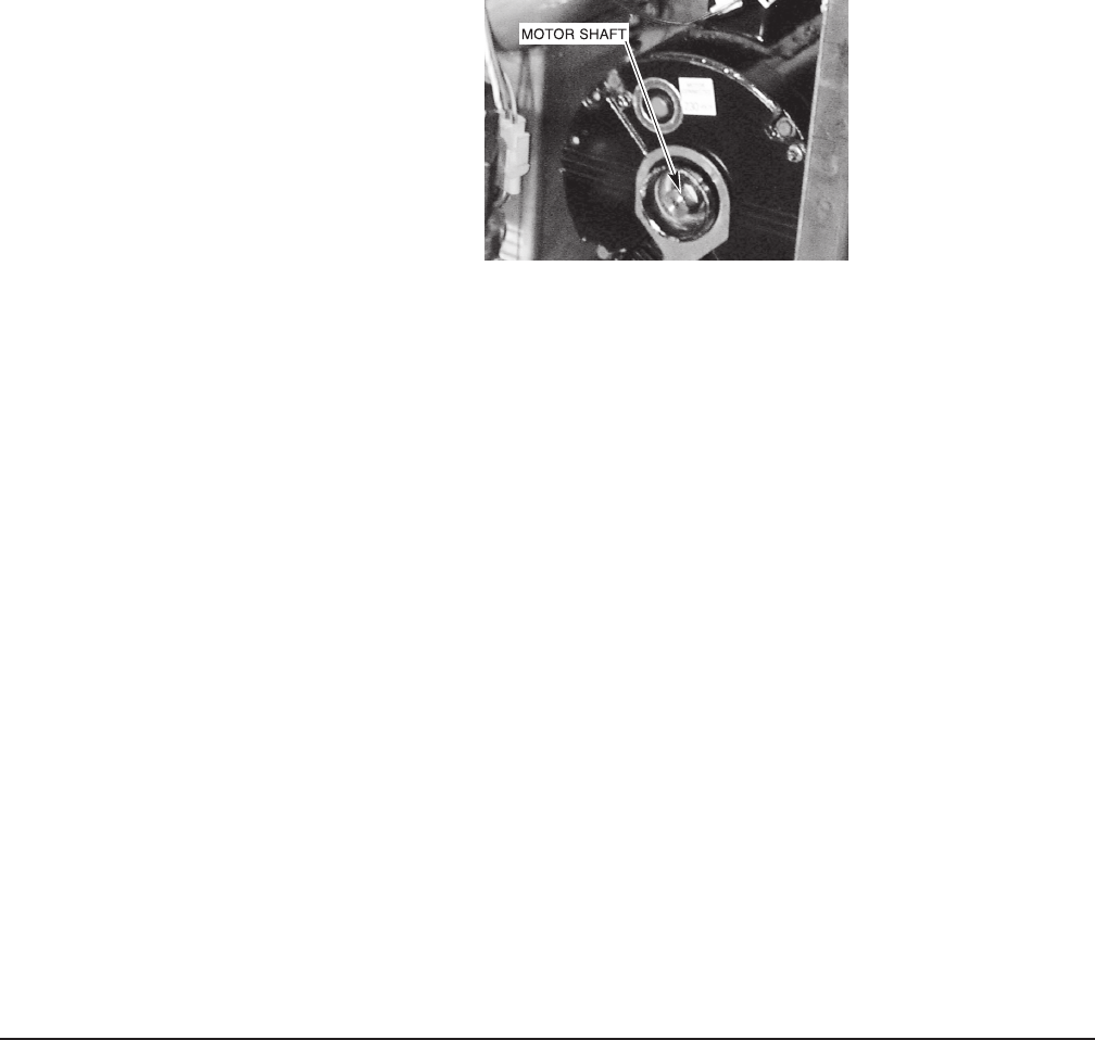
Motor Rotation (Three-Phase Machines Only)
Three-phase motors must rotate in the direction of the arrow on the pump housing.
In order to check rotation, remove the bearing cap to observe the motor shaft
(Fig.15).ClosethemachinedoorsandpressthepowerswitchtoON.Whenthe
machineiscompletelylled,openandclosemachinedoorstoverifythatthemotor
shaft rotates in the clockwise direction.
If the rotation is incorrect, DISCONNECT ELECTRICAL POWER SUPPLY and
interchange any two of the incoming power supply leads. Reconnect the power
supply and verify correct rotation. Replace the motor bearing cap.
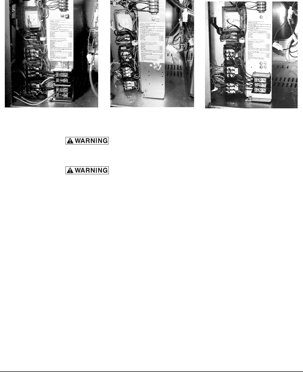
Dishwasher With Electric Booster (Separately Connected)
Single phase machines with an electric booster require two separate connections,
one for the booster and the other for the dishwasher (including motor, controls and
tankheat).Forsingle-phasemachines,allpowersupplyconnectionsaremadeto
terminalblocks(Fig.16).Thesinglephasedishwasherisconnectedtoterminal
block 1TB in the controls area. The single phase booster is connected to terminal
block 2TB in the controls area.
If the machine is three phase, the electrical connection for the dishwasher is made
to the contactor 2CON in the controls area The electrical connection for the three
phaseboosterismadetothecontactor3CONinthecontrolsarea(Fig.17).
Fig. 15
– 16 –
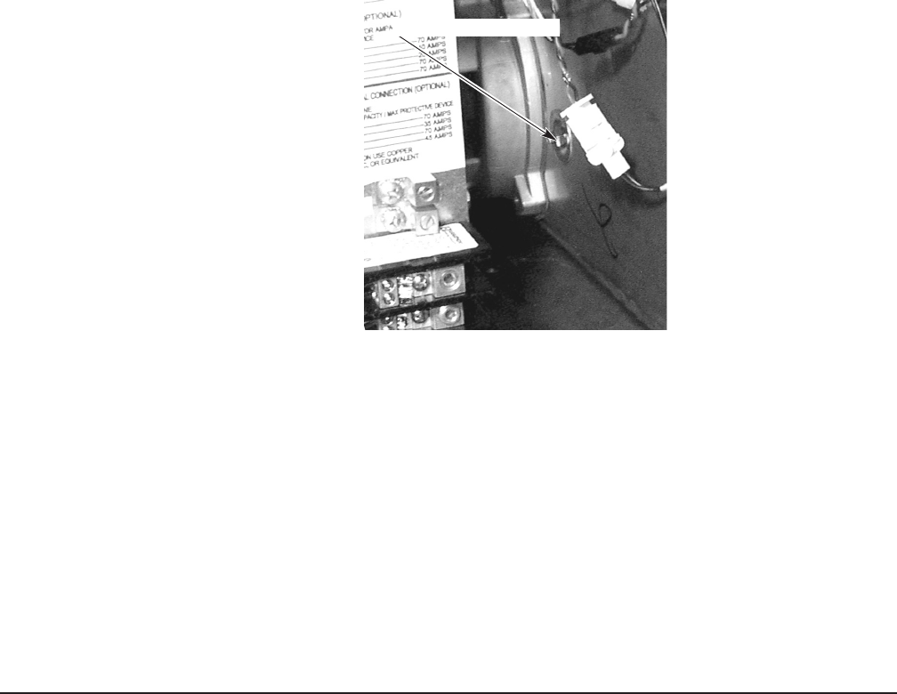
Dishwasher With Electric Booster (Single Point Electrical Connection)
Threephasemachinesconguredwiththeoptionalsinglepointelectricalconnection
areconnectedtoterminalblock1TBinthecontrolsarea(Fig.18).Themachine
mustbegroundedaccordingtoelectricalcode(s);agroundinglugisprovided.
Fig. 16 Fig. 17 Fig. 18
EQUIPMENT CONNECTIONS
Electrical and grounding connections must comply with the
applicable portions of the National Electrical Code, NFPA 70 (latest edition)
and / or other local electrical codes.
Disconnect the electrical power to the machine (both dishwasher
and booster if applicable) and follow lockout / tagout procedures. Be sure all
circuits are disconnected.
Vent Fan Control
The vent fan control feature is standard on models AM15, AM15F, and AM15T. This
feature is not available on ventless models AM15VL, AM15VLF, and AM15VLT. The
vent fan control relay provides switch contacts only and does not provide power to
the vent fan motor. The rating for a vent fan control relay connected to terminals
VFC1 and VFC2 is 1.5 Amps at 240 Volts maximum. When the dishwasher is
connected to the vent fan, the vent fan is switched on when the dishwasher is on,
and off when the dishwasher is off.
Remote Booster Control
The booster control feature is standard on models AM15, AM15F, and AM15T.
This feature is not available on ventless models AM15VL, AM15VLF, and
AM15VLT. The load rating for remote booster control connections to BSTR1
and BSTR2 is 0.1 Amp. at 120 Volts maximum. The booster control provides
a control signal only and does not provide power to the remote booster.
When a remote booster is connected to the dishwasher, the booster is on when
the dishwasher is on and off when the dishwasher is off.
– 17 –
DETERGENT, RINSE AID, SANITIZER DISPENSERS — TUBING INSTALLATION
Detergent,rinseaidand/orsanitizerdispensers(notprovidedbyHobart)musthave
all connections sealed against leakage.
Th edishwasheruse s0.74gall on so fr i ns ewate rp errac kata owrateof4.4 ga ll ons
perminuteat20psigowingpressure.Thisinformationisusedwhensettingthe
detergent, rinse aid or sanitizer pumps.
NOTE: Ventless"VL"modelsdonothaveapressuregauge.
See Hobart form F15523 for sanitizer volumes and installation instructions.
Detergent Dispenser
The dishwasher has two 7⁄8 inch diameter plugged holes, one on the rear of the
chamberandoneonthelowerpartofthetanknearthepump(Fig.19).Withthe
tank empty, remove both plugs to install the detergent dispenser.
• The chamber hole is for installation of the detergent feeder tube.
• The lower tank hole is used for installation of the detergent sensor.
Fig. 19
DETERGENT SENSOR PORT
– 18 –
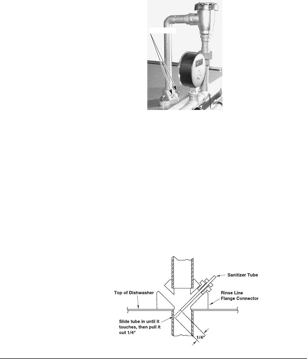
Rinse Aid Dispenser
Therinselineangeconnectorontopofthedishwasherhastwo1⁄8 inch NPT pipe
plugs(Fig.20).
• Removetheplug(s)(Fig.20)forinstallationoftherinseaiddispensertubeand
/ or chemical sanitizer tube, as needed.
Chemical Sanitizer Dispenser - AM15, AM15F, and AM15T Models Only
When the dishwasher is to be operated in the chemical sanitizing mode, the
machine must be converted to low-temperature sanitization (refer to Setup, page
16).AchemicalsanitizerdispenserthathasbeentestedandcertiedbyNSF
International must be installed.
• Removethepipeplug(Fig.20)forinstallationofthechemicalsanitizertube.To
assureanunobstructedowofsanitizer,locatethesanitizertubeinthecenterof
waterowbydrillingthesanitizertubettingsothatitsinsidediameterisequal
to the outside diameter of the tube.Slidethetubeintotheangeuntilittouches
the opposite side and then pull it back out 1⁄4inch(Fig.21).
• Rate for 6% Sodium hypochlorite (bleach) - 3 ml. within 10 seconds
(maximum).
• Rate for 8.4% Sodium hypochlorite (bleach) - 2 ml. within 10 seconds
(maximum).
Fig. 20
Fig. 21
PIPE PLUGS
– 19 –
DETERGENT, RINSE AID, SANITIZER DISPENSERS — EQUIPMENT CONNECTIONS
Electrical and grounding connections must comply with the
applicable portions of the National Electrical Code, NFPA 70 (latest edition)
and / or other local electrical codes.
Disconnect the electrical power to the machine (both dishwasher
and booster if applicable) and follow lockout / tagout procedures. Be sure all
circuits are disconnected.
This machine must be operated with an automatic detergent feeder and, if applicable,
an automatic chemical sanitizer feeder, including a visual means to verify that
detergents and sanitizers are delivered or a visual or audible alarm to signal if
detergents and sanitizers are not available for delivery to the respective washing
and sanitizing systems. Refer to the installation section of this manual and to the
chemicalfeederequipmentmanual(s).
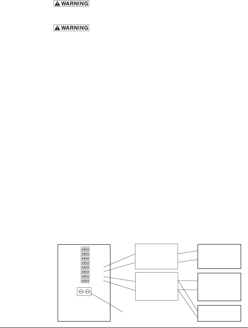
Detergent Dispenser (Fig. 22)
Terminals DPS1 and DPS2 are supplied with controlled machine line voltage.
They are ON during the wash cycle and OFF between cycles or when the machine
power supply is OFF Maximum rating for detergent dispenser connected to DPS1
and DPS2 is 1.5 Amps at line voltage. Check the machine supply voltage and
use corresponding feeder transformer voltage. Use UL Listed 600 volt minimum
insulated wire for the connections. Do not use bell wire, lamp cord or similar type
wire. Splice connections, if required, must be made in the feeder transformer
junctionbox-notinthemaincontrolsenclosure.Remove7⁄8"diametercapplug(s)
for 1⁄2"tradesizeconduitttingsfromtherearoftheenclosure.Removetheside
panel.Strainreliefttingsmustbeprovidedforallwiring.
Rinse Aid / Sanitizer Dispenser(s) (Fig. 22)
Terminals RPS1 and RPS2 are supplied with controlled machine line voltage and are
ON during the rinse cycle only. Maximum rating for rinse aid dispenser connected
to RPS1 and RPS2 is 1.5 Amps at line voltage. Check the machine supply voltage
and use corresponding feeder transformer voltage. Use UL Listed 600 volt minimum
insulated wire for the connections. Do not use bell wire, lamp cord or similar type
wire. Splice connections, if required, must be made in the feeder transformer
junctionbox(suppliedbyothers)—notinthemaincontrolsenclosure.Remove
7⁄8inchdiametercapplug(s)for1⁄2inchtradesizeconduitttingsfromtherearof
theenclosure.Strainreliefttingsmustbeprovidedforallwiring.
Fig. 22
— VFC1
— VFC2
— BSTR1
— BSTR2
— DPS1
— DPS2
— RPS1
— RPS2
DETERGENT
DISPENSER
TRANSFORMER
PRIMARY
SECONDARY
RINSE AGENT
DISPENSER
CHEMICAL
SANITIZER
DISPENSER
RIGHT SIDE OF
CONTROL AREA
TRANSFORMER
PRIMARY
SECONDARY
GROUND LUG
– 20 –
SETUP (AM15, AM15F, AND AM15T MODELS ONLY)
Sanitizing Mode
1. With the machine OFF, press and hold the OFF key.
2. Press and release the ON key.
The display initializes until 88 displays.
3. Release the OFF key.
SET X°F
°C displays. X can be H, C or P:
H = Hot Water Sanitizing, Internal Booster.
C = Chemical Sanitizing, No Booster.
P = Hot Water Sanitizing, External Booster.
4. Press CYCLE to select P, H, or C as the sanitizing mode.
After 15 seconds, the selection is saved and the machine turns off.
End of Cycle Buzzer - All Models
1. With the machine OFF, press and hold the OFF key.
2. Press and release the ON key.
The display initializes until 88 displays.
3. Release the OFF key.
SET X°F
°C displays. XcanbeP,HorC.(Seeabove).
5. Press and release the OFF key.
SET WASH XX displays. XX can be On or OF:
SET WASH On = End of Cycle Buzzer is ON.
SET WASH OF = End of Cycle Buzzer is OFF.
6. Press CYCLE to select On or OF for the End of Cycle Buzzer.
After 15 seconds, the selection is saved and the machine turns off.
SHORTCUT IF
PROGRAMMING BOTH FEATURES
AT THE SAME TIME.
SET WASH OF
SET WASH On
SET C°F
°C
SET P°F
°C
SET H°F
°C
– 21 –
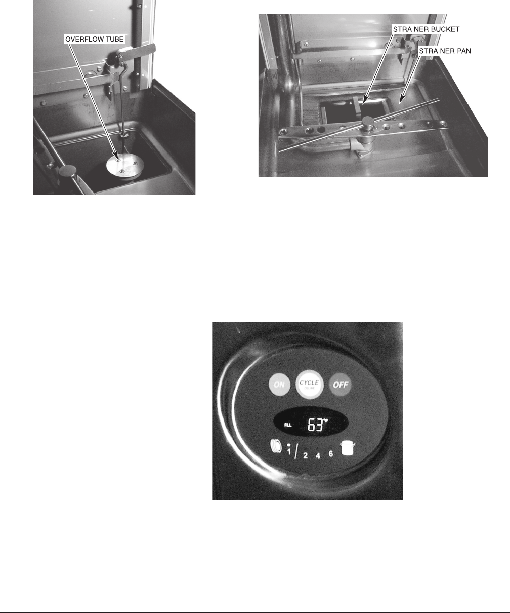
OPERATION
PREPARATION
Theoverowtubemustbeinitsproperlocationbelowthestrainerpan(Fig.23).
Placethestrainerpanandthestrainerbucketintheirproperpositions(Fig.24).
Fig. 23
Anautomaticdetergentdispenserisrequired.Closelyfollowsupplier’sinstructions.
Closethedoor;thiswillautomaticallyclosethedrain.
Openthemanualgasvalve(ifapplicable).PresstheONbuttontoturnthepower
on(Fig.25).Ifthemachine’sdoorisclosedandnowaterisinthetank,thellcycle
willbeginautomatically.Duringthellcycle,thewordFILLisdisplayed.
Fig. 24
Fig. 25
– 22 –
When washing or in idle mode, the readout displays the wash temperature. During
the rinse cycle, the rinse icon and temperature are displayed. Select the wash
cycle: 1 for normal serving ware, 2, 4 or 6 for pots and pans. Each wash cycle is
followed by an automatic rinse. When the rinse cycle is complete and the rinse
icon turns off, the door can be opened.
For ventless models, the door must remain closed until the condensing cycle is
complete and the cycle light turns off. A cycle countdown in seconds is displayed
during the condensing cycle. Failure to follow these instructions will result in excess
water vapor in the room.
DISHWASHING
Scrape the dishes to remove large particles of food and debris. Never use steel
wool on ware to be loaded into the dishmachine.
Arrange the dishes in a rack. Do not stack dishes one on top of another, as
water must have free access to all sides of every dish. Stand plates and dishes
upedgewiseinapeg-typerack(Fig.27).Cups,glasses,andbowlsshouldbe
invertedinanopen-typeorcompartmenttyperack(Fig.27).Silverwareandother
smallpiecesmaybescatteredlooselyoverthebottomofaatbottomrack.
Donotallowforeignobjectstoentertheunit,especiallymetalliccontaminants.
Afterllingarack,openthedoor,slidetherackintothedishwasherandclosethe
door.
Throughout the wash cycle, the tank water temperature is displayed on the front
panel display, along with the word WASH and an icon. During the rinse cycle,
the rinse water temperature is displayed, along with the word RINSE and an icon.
When the rinse cycle is completed, the readout displays the tank water temperature.
Fig. 26
Fig. 27

– 23 –
On AM15VL, AM15VLF, and AM15VLT models, a countdown of the remaining cycle
time, along with the rinse icon only, is displayed during a condense cycle.
Whenthecycleisnishedandtherinseicondisappears,orthecondensingcycle
lightgoesoutfor"VL"models,openthedoor,removethecleandishes,slidein
another rack and close the door.
To add a dish after the wash cycle has started, open the door slightly. Wait
10 seconds to allow the wash arm to coast down and to avoid water splashing
before opening the door fully.
Operating temperatures for all models are as follows:
Model AM15F and AM15VLF have a front loader door and loading tray. The machine
c ano peratewit ht heloade rt rayp os it io nedver tic alinsi de th ec hamber (u pp ositio n)
orpositionedhorizontaloutsidethechamber(downposition).
For "VL" models only - If excessive amounts of steam or water vapor exit the
machine after condensing cycle light goes out and door is opened, incoming cold
watertemperaturemaybetoohigh.ContactHobartServicetoadjusttherinse
andcondensetimesaccordingtotheadjustmenttable.Increasingcycletimewill
increase water consumption and decrease the racks per hour, but should reduce
the water vapor entering the room.
Sanitizing Mode Wash Temperature Rinse Temperature
Minimum Wash Recommended Wash Minimum Rinse Recommended Rinse
Hot Water 150°F(66°C) 150°F(66°C) 180°F(82°C) 180°F(82°C)
Chemical 120°F(49°C) 140°F(60°C) 120°F(49°C) 140°F(60°C)
Incoming Water
Temp.°F(°C)
Condense
Time (Sec.)
Rinse
Time
(Sec)
Racks per
Hour (1 min
cycle)
60(16) 30 10 40
65(18) 33 11 38
70(21) 36 12 37
75(24) 39 13 35
80(27) 42 14 34
85+(29+) 45 15 33
RECOMMENDED CONDENSE TIME (Based on
Incoming Water Temp.)
– 24 –
CLEANING
The machine must be thoroughly cleaned at the end of each working shift or at
least daily. Never use steel wool to clean warewasher surfaces. Use only products
formulated to be safe on stainless steel.
1. Push the OFF button.
2. Open the machine door.
3. Clean off the dish tables into the dishwasher.
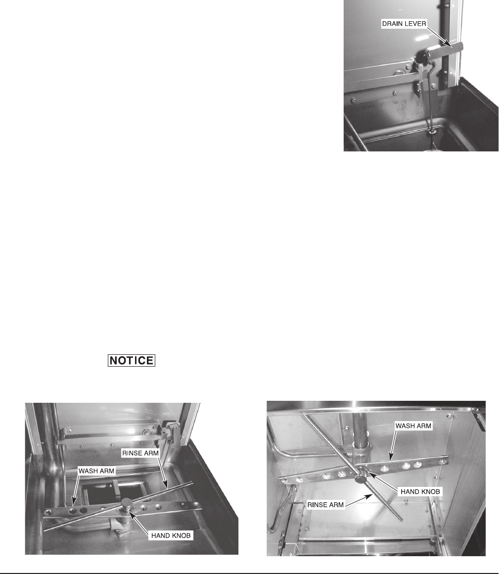
4. Drain the machine by lifting up the drain
lever.
5.Thoroughlycleanseandushthedishwasherinterior.Removeremainingsoil
with a soft cloth or brush and mild cleanser. Rinse again.
6. Remove and empty the strainer bucket and pan. Wash and rinse them thoroughly.
7. Clean the pump cover with a soft cloth or brush. Do not allow food soil to
accumulate on the tank bottom or to enter the drain.
8.Removetheoverowtube.Washandrinsetheoverowtubeinsideandout.
9. Make sure that the wash and rinse arms rotate freely and are free of any
obstructions. If not, remove arms and clear out any obstructions.
10.Removeandcheckwasharmsandrinsenozzles(Figs.29,30)tomakesure
they are free of any lime and solids. Refer to Maintenance, page 26.
Do not bang wash arms or rinse arms to clean.
11. Replace all removed parts. Leave machine door open to allow interior to air
out and dry.
Fig. 28
Fig. 29 Fig. 30
– 25 –
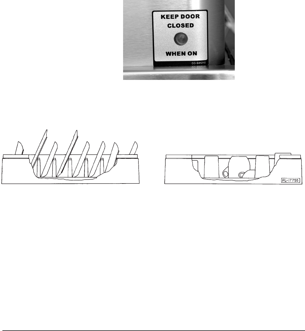
FOR MODELS AM15VL,AM15VLF AND AM15VLT:
Inadditiontonormalcleaning,thebafes,locatedontheupperchamberonthe
inside of the machine, may need periodic cleaning.
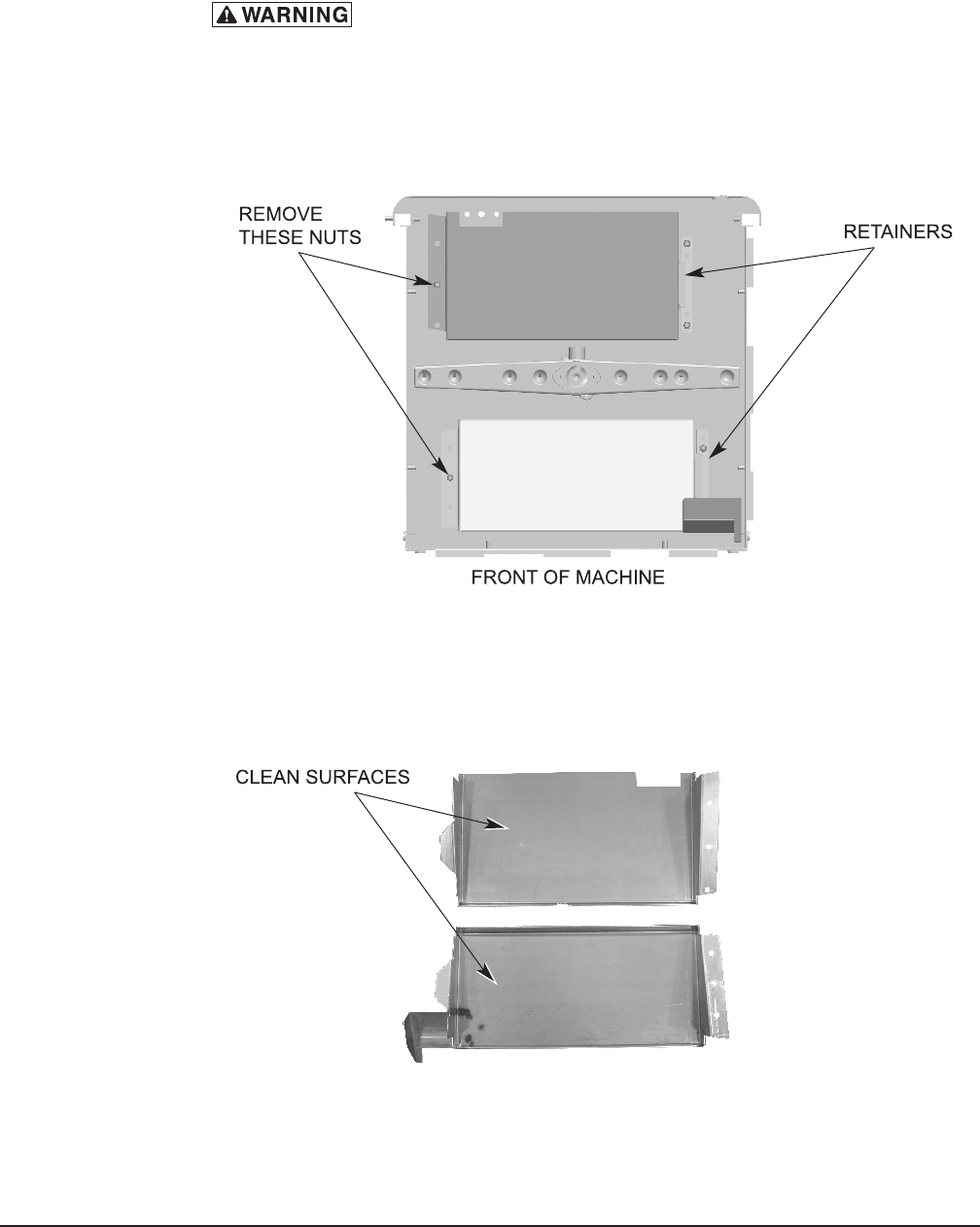
Disconnect the electrical power to the machine (both dishwasher
and booster if applicable) and follow lockout/tagout procedures. Be sure all
circuits are disconnected.
1.Loosenandremovethenutfromeachbafeandremovethebafesbysliding
the tab out of the retainer.
2.Debrismaycollectontopsurfacesofbafesandshouldbewashedinasink
with a mild detergent and rinsed.
Fig. 31
Fig. 32
– 26 –
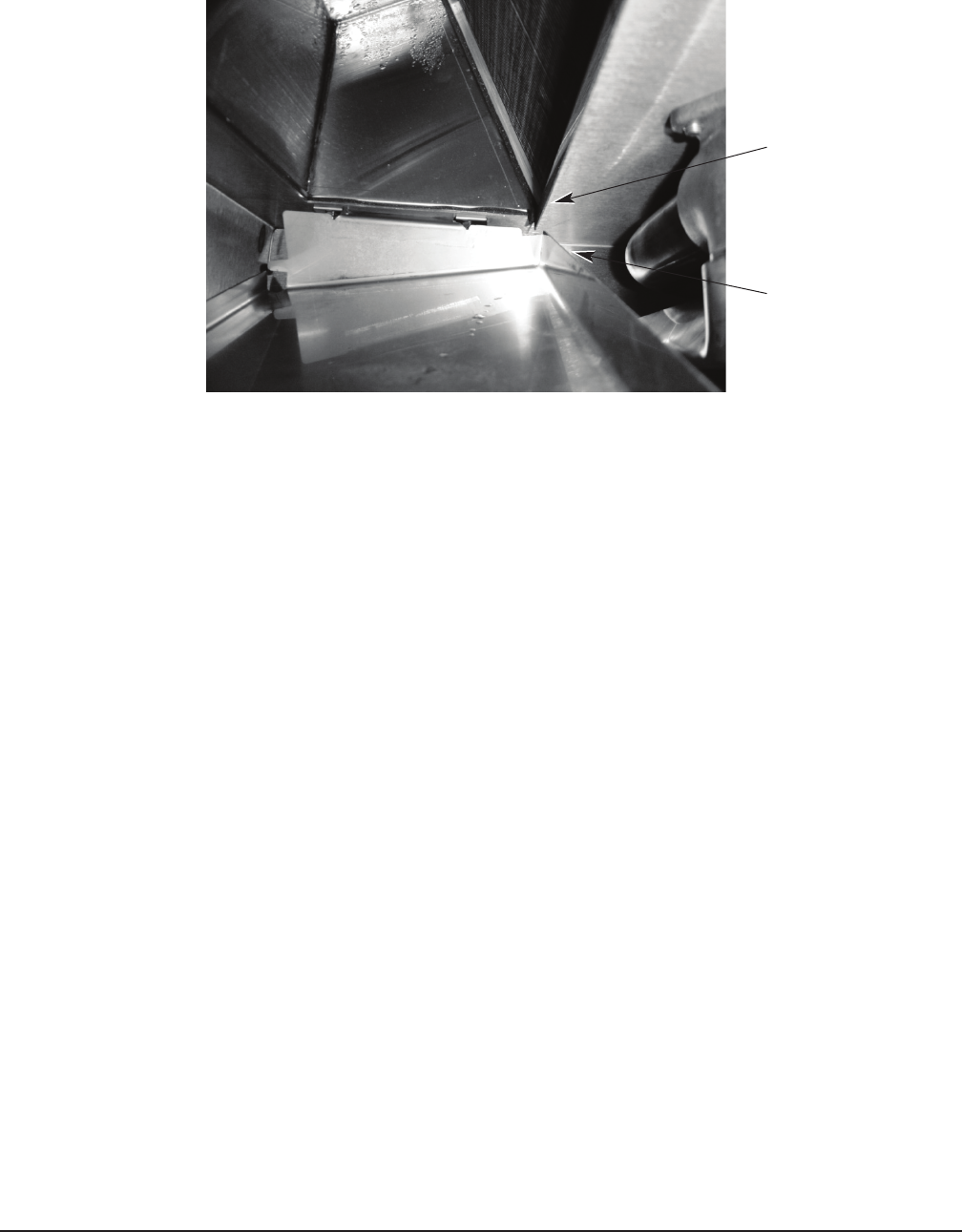
3.Replaceallremovedparts.Whenreplacingthefrontbafebesurethatthe
backsideofthebafeisontheoutsideoftheductliponthechambertop.
LIP ON
CHAMBER TOP
REAR OF
FRONT
BAFFLE
4. Leave machine door open to allow interior to air out and dry.

– 27 –
DELIME INSTRUCTIONS
IftheoptionaldelimenoticationisactivatedandtheDELIMElightison,follow
the instructions, below. Delime is also necessary if deposits are visible inside or
outside the machine.
DOS AND DON'TS FOR YOUR NEW HOBART WAREWASHER
DO assure prOper water harDness (3 graIns Or less per gallOn Is recOmmenDeD).
DO pre-scrap DIshes thOrOughly.
DO use Only Detergents recOmmenDeD by yOur chemIcal prOfessIOnal.
DO at the enD Of the Day, thOrOughly cleanse the machIne, rInse anD Dry (leave DOOr
Open).
DO clOsely fOllOw yOur chemIcal prOfessIOnal’s prescrIbeD DelImIng scheDule.
DO use Only prODucts fOrmulateD tO be safe On staInless steel.
DO nOt use Detergents fOrmulateD fOr resIDentIal DIshwashers.
DO nOt allOw fOOD sOIl tO accumulate On the tank bOttOm.
DO nOt exceeD chemIcal manufacturer’s recOmmenDeD cOncentratIOns fOr Detergent,
sanItIzer, rInse aID Or lIme scale remOver.
DO nOt use steel wOOl tO clean ware Or warewasher surfaces.
DO nOt allOw fOreIgn Objects tO enter the unIt, especIally metallIc cOntamInants
such as paper clIps, retaIners, etc.
nOte: faIlure tO fOllOw use, care anD maIntenance InstructIOns may vOID yOur
hObart warewasher warranty.
DELIME INSTRUCTIONS
1. Remove rack, drain tank, press “OFF”.
2. Press and hold “CYCLE” & “ON” for 3 seconds;
close door, unit lls then indicates “ADD DELIME”.
3. Open door & add delime agent per supplier
instructions for 14 gallon tank.
4. Close door, pump starts & display ashes “DELIME”.
After 12 minutes display scrolls “DRAIN”.
5. Check interior, close door to run additional cycles
if necessary.
6. Drain tank, turn unit off.

– 28 –
MAINTENANCE
Disconnect the electrical power to the machine (both dishwasher
and booster if applicable) and follow lockout / tagout procedures. Be sure all
circuits are disconnected.
WASH ARMS
Upperandlowerwashandrinsearms(Figs.29,30)shouldturnfreelyandcontinue
turning for a few seconds after being whirled by hand. To check, rotate arms and
remove any obstructions causing improper operation.
If either the strainer pan or the strainer bucket is not properly in place, obstructions
(suchasfoodparticlesorbones)mayclogthewasharmnozzles.Thewasharms
are easily removed for cleaning.
To remove the lower wash arm, unscrew the hand knob and lift the rinse arm off
(Fig.29).Thewasharmcanbeliftedoffoncetherinsearmisremoved.
The upper wash and rinse arms are removed by unscrewing the hand knob (Fig.
30)andloweringbotharmstogether.Becarefulnottodropthesearms.
MOTOR(S)
Thewashpumpmotor,rinsepumpmotor("VL"modelsonly),fanmotor("VL"models
only) and the blower motor (gas heat models) are equipped with permanently
lubricated bearings and require no lubrication maintenance.
FLUE (MACHINES EQUIPPED WITH GAS TANK HEAT ONLY)
Whencool,checktheueopeningeverythreemonthsforobstructions.
TROUBLESHOOTING
MANUAL RESET BUTTON ON PUMP MOTOR
If the pump motor becomes overheated, the thermal overload protector will cause
the motor to not operate. If this occurs, contact Service.
To avoid a service call, check symptoms and related possible causes. If machine
still does not operate properly, contact Service.

– 29 –
SYMPTOM POSSIBLE CAUSE
No machine operation. 1. Machine off, turn machine on.
2. Blown fuse or tripped circuit breaker at power supply.
3. Check tank water level.
Dishesnotclean. 1. Insufcientwashwaterduetodrainobstructionpreventingproperdrainclosing.
2. Worn or torn drain O-ring allowing wash water to drain.
3. Loss of water pressure due to pump obstruction.
Disconnect electrical power supply (both
dishwasher and booster if applicable) and drain tank.
Check for any obstruction at the pump intake.
4. Incorrectwatertemperature.ContactServiceforadjustmentorrepair.
5. Incorrect detergent dispensing. Contact your detergent representative.
6. Excessive mineral deposits throughout wash and rinse system. Deliming
may be necessary, refer to page 25.
7. Check wash and rinse arms to make sure they rotate properly.
8. Strainerscloggedcausinginadequatewatersupplyto pump;cleanmachine
according to Cleaning, page 24.
9. Obstructioninwasharmsorwasharmswillnotturn;cleanmachineaccording
to Cleaning, page 24.
10. Detergent dispenser may be clogged.
11. Excessivesoilquantity;scrapedishesbeforecycle.
12. Improperrackloading;refertoPreparationandDishwashing,pages21,22.
13. Incoming water supply turned off.
Spotting silverware, 1. Improperly loaded racks.
glasses and dishes. 2. Incorrect rinse water temperature or rinse pressure.
3. Loss of water pressure due to pump obstruction.
Disconnect electrical power supply (both
dishwasher and booster if applicable) and drain tank.
Check for any obstruction at the pump intake.
4. Excessively hard water.
5. Incorrect detergent for water type.
6. Incorrect rinse additive for water type.
7. Incorrect concentration of detergent, rinse additive and/or sanitizer.
8. Excessivesoilquantity;scrapedishesbeforecycle.
Excessivesteamorwater 1. Incomingcoldwatertoowarm.ContactHobartServiceforadjustment
vapor after cycle is of condensing cycle time.
complete - AM15VL,
AM15VLF, and AM15VLT
models only.
Inadequaterinseorrinse 1. Dirtylinestrainercausingreducedwaterow.Turnoffwatersupply,remove
water temperature too low. strainer cap, withdraw and clean screen. Reassemble.
Possible EE display. Note: AM15VL, AM15VLF, and AM15VLT models have 2 supply lines.
2. Low supply line pressure.
3. Excessive mineral deposits throughout wash and rinse system. Deliming may
be necessary, refer to page 25.
4. Incoming water temperature to booster (if applicable) below 110°F. Machine
will automatically extend wash time until booster heats up (this applies to
AM15,AM15F,andAM15Tboosterequippedmachinesonly).
5. If EE displays: Booster did not reach temperature within 8 minutes after initial
ll.PressOFF,wait5secondsandpressON.Maybeboosterheaterfailure.

– 30 –
SYMPTOM POSSIBLE CAUSE
Leaking valve. 1. Foreign material preventing proper valve operation. NOTE: A critical period
is soon after installation when pipe compound or metal shavings may lodge
at the valve seat. Shut off supply line. Unscrew and lift bonnet from valve
body. Clean valve and reassemble.
Note: AM15VL, AM15VLF, and AM15VLT models have 2 supply lines.
2. If a solenoid valve is malfunctioning (not opening or not closing), it is
recommended that you contact Hobart Service.
No wash tank heat. 1. The machine is equipped with a low water safety device which shuts off heat
if the water level drops. Check for proper water level. If the water level is
too low, the overow tube might be out of position. Or, something may be
inhibitingfreemovementofthelowwateroat;removeanyforeignobjectfrom
aroundthelowwateroatoritsmagnet.
2. Gas line closed.
3. Blown fuse or tripped circuit breaker at power supply.
If a failure occurs due to the gas heat control board or gas pressure,
contact Hobart Service.
Noorslowll. 1. Debrismaybeobstructingstandpipemovementallowingllwatertodrain.
PossibleE2display. 2. Watersupplymaybeoff;makesurehotwatersupplyvalveisopen.
3. Dirtylinestrainercausingreducedwaterow.Turnoffhotwatersupply,remove
strainer cap, withdraw and clean screen. Reassemble.
4. Worn or torn drain O-ring allowing wash water to drain.
5. IfE2displays:Waterdidnotreachtheoatduringallwithin2.5minutes.Press
OFF, wait 5 seconds and press ON.
Possible Ed display. 1. Slow leak. Make sure the drain lever is closed, the standpipe is seated and
the O-ring is clear of all food soil or other debris.
Dribbling water from lower 1. If equipped with electric booster, normal dripping from the lower rinse arm
rinse arm. will occur during water heating due to expansion of the water. This will occur
once between machine cycles.
2. If water dribbles or leaks continuously from rinse arms on any machine, refer to
Leaking Valve, above.
PossibleE6display. 1. ContactyourlocalHobartServiceOfce.
WrenchlightsupandP1, 1. ContactyourlocalHobartServiceOfce.
P2 or P3 displays.
"VL"Models-water 1. Waterlevelprobeinholdingtankmaybecontaminatedorfailed.Contact
continuouslylling HobartService.
through chamber/holding 2. Refer to Leaking Valve above.
tank.

– 31 –
SERVICE
ContactyourlocalHobart-authorizedserviceofceforanyrepairsoradjustments
neededonthisequipment.Ifagasoricettingistobereplaced,haveitserviced
byqualiedHobart-authorizedservicepersonnel.Long-termservicecontractsare
available on this and other Hobart products. Call 1-888-4HOBART for Hobart
Service 24 hours a day.

– 32 –
FORM 35320 Rev. E (October 2012) PRINTED IN U.S.A.
