F8 Digger Ops&Parts Manual
User Manual: F8 Digger Ops&Parts Manual
Open the PDF directly: View PDF ![]() .
.
Page Count: 24
Quality & Innovation
Made in the U.S.A.
a
DANGER
Si no entiende ingles, se
.
prefiere que
busque a alguien que interprete las
instrucciones para usted.
Owner:
Date Purchased:
Model #:
F8
Serial #:
Manual #:
9MF82452045
Since 1910
DANUSER
Owner 's Manual
Danuser Machine Company, Inc.
500 East Third Street
Fulton, Missouri 65251-0368
Phone: (573) 642-2246
Fax: (573) 642-2240
E-mail: sales@danuser.com
Website: www.danuser.com

Today, a new, modern plant built by my father, Hemy Danuser, is
located on the original site. This building and those who work in it are
dedicated to the tradition of fine craftsmanship and to the production
of quality implements. The challenge of changing economic
conditions is being met with improved manufacturing methods. From
this sound growth will come new products, designed to better serve
agriculture and industry.
Jerry Danuser
My grandfather, K. B. Danuser, began building
wagons and repairing all types of machinery in a
small shop in Fulton, Missouri in 1910. With
pride in his Swiss craftsmanship, he established
one policy for his concern which is the hallmark
of Danuser Machine Company, Inc. to this day:
"Good enough won't do - it must be right."
nce
1910
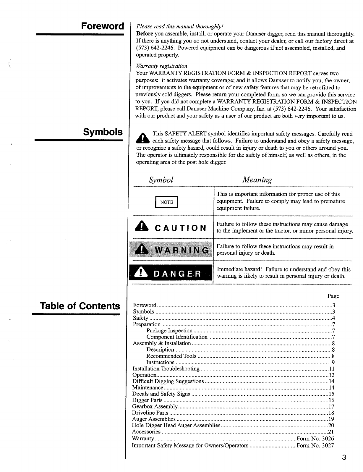
Symbol
Meaning
This is important information for proper use of this
equipment. Failure to comply may lead to premature
equipment failure.
I
NOTE
I
A
CAUTION
Failure to follow these instructions may cause damage
to the implement or the tractor, or minor personal injury.
Failure to follow these instructions may result in
personal injury or death.
Immediate hazard! Failure to understand and obey this
warning is likely to result in personal injury or death.
WARNING
A
DANGER
Please read this manual thoroughly!
Before
you assemble, install, or operate your Danuser digger, read this manual thoroughly.
If there is anything you do not understand, contact your dealer, or call our factory direct at
(573) 642-2246. Powered equipment can be dangerous if not assembled, installed, and
operated properly.
Warranty registration
Your WARRANTY REGIS
I
RATION FORM & INSPECTION REPORT serves two
purposes: it activates warranty coverage; and it allows Danuser to notify you, the owner,
of improvements to the equipment or of new safety features that may be retrofitted to
previously sold diggers. Please return your completed form, so we can provide this service
to you. If you did not complete a WARRANTY REGISTRATION FORM & INSPECTION
REPORT, please call Danuser Machine Company, Inc. at (573) 642-2246. Your satisfaction
with our product and your safety as a user of our product are both very important to us.
A
This SAFETY ALERT symbol identifies important safety messages. Carefully read
each safety message that follows. Failure to understand and obey a safety message,
or recognize a safety hazard, could result in injury or death to you or others around you.
The operator is ultimately responsible for the safety of himself, as well as others, in the
operating area of the post hole digger.
Foreword
Symbols
Page
Foreword
3
Symbols
3
Safety
4
Preparation
7
Package Inspection
7
Component Identification
7
Assembly & Installation
8
Description
8
Recommended Tools
8
Instructions
9
Installation Troubleshooting
11
Operation
12
Difficult Digging Suggestions
14
Maintenance
14
Decals and Safety Signs
15
Digger Parts
16
Gearbox Assembly
17
Driveline Parts
18
Auger Assemblies
19
Hole Digger Head Auger Assemblies
20
Accessories
21
Warranty
Form No. 3026
Important Safety Message for Owners/Operators
Form No. 3027
3
Table of Contents
WARNING!
Working with unfamiliar equipment can lead to careless injuries. Read and understand this manual and
the manual for your tractor before assembling, installing, or operating this post hole digger. If there is
anything in this manual you do not understand, contact your dealer or Danuser Machine Company, Inc.
The safe use of this machine is strictly up to you, the operator. If this unit is used, loaned, or rented by
any other person, it is the owner's responsibility to make certain that the operator prior to operating:
•
Reads and understands the Owner's Manuals
•Is instructed in safe and proper use
The majority of accidents involve entanglement on the driveline or auger. This entanglement risk
becomes greater when you replace the shear bolt or the auger retaining bolt with a bolt longer than
specified by Danuser Machine Company, Inc. This improper replacement occurs most often on machines
that are loaned or rented to someone who has not read the Owner's Manual and is not familiar with a post
hole digger.
•
This post hole digger is designed for one-man operation from the tractor seat. It is the responsibility
of the operator to see that no one is within twenty-five feet (25') of the digger when it is started or in
use. Do not operate the digger with another person near or in contact with any part of the digger,
driveline, or auger. Serious personal injury or death may result if any attempt is made to assist
digger operation by hand.
•The use of this equipment is subject to certain hazards which cannot be protected against by
mechanical means or product design. All operators of this equipment must read and understand this
entire manual, paying particular attention to safety messages and operation instructions, prior to
assembling, installing, or operating the digger.
•
Please remember it is also important that you read, understand, and follow the safety signs on the
post hole digger. Clean or replace all safety signs if they cannot be clearly read and understood.
They are there for your safety as well as the safety of others. Danuser Machine Company, Inc. will
furnish new safety signs upon request at no charge.
•
All things with moving parts are potentially hazardous. There is no substitute for a cautious, safe-
minded operator who recognizes potential hazards and follows reasonable safety practices. Danuser
Machine Company, Inc. has designed this post hole digger to be used with all its safety equipment
properly attached, to minimize the chance of accidents. Study this manual to make sure you have all
safety equipment properly attached.
•If a safety shield or guard is removed for any reason, it must be replaced before the machine is again
operated. Always use, and maintain in place, all shields and guards furnished with the digger and
with the tractor.
•Personal protection equipment including hard hat, safety glasses, safety shoes, and gloves are
recommended during assembly, installation, operation, adjustment, maintenance, repair, removal, or
movement of the digger. During post hole digger operation, no one is to be within twenty-five feet
(25') of the digger.
•When the use of hand tools is required to perform any part of assembly, installation, adjustment,
maintenance, repair, removal, or movement of the digger, be sure the tools used are designed and
recommended by the tool manufacturer for that specific task.
•Always use two people to handle heavy, unwieldy components during assembly, installation,
adjustment, maintenance, repair, removal, or movement of the digger.
•
Never place any part of your body where it would he in danger if movement should occur during
assembly, installation, adjustment, operation, maintenance, repair, removal, or movement of the
digger.
Safety
4
Safety
•
Only properly trained people should operate this equipment. Do not allow anyone who has not read
this entire manual and understood the safety rules, safety signs, and operation instructions to use this
post hole digger.
(continued)
•
Never allow children to operate or be around this post hole digger.
•
Do not allow riders on the digger or tractor at any time. There is no safe place for any riders.
•
This post hole digger is designed for use only on tractors with 540 RPM power take-off. Never
attach or attempt to operate this digger with any unit exceeding 540 RPM power take-off.
•
Never use alcoholic beverages or drugs which can hinder alertness or coordination while operating
this equipment. Consult your doctor about operating this machine while taldng prescription
medications.
•
Consult local utility companies to make certain there are no buried gas lines, electrical cables, etc., in
the work area before beginning operation.
•
Before beginning operation, clear the work area of objects which might be picked up and thrown by
or entangled in the auger.
•
Before you operate the digger, check over all pins, bolts, and connections to be sure all are securely
in place. Replace any damaged or worn parts immediately.
•
Do not operate the post hole digger without all safety shields and guards in place.
Never replace the shear bolt or the auger retaining bolt with anything other than the specified length
bolt in this manual. A longer, or protruding, fastener is more likely to grab clothing or gloves, which
can result in serious injury or death.
•Keep hands, feet, hair, jewelry, and clothing away from all moving and/or rotating parts.
•Never place yourself between the tractor and digger while the tractor is running.
•
To prevent entanglement and possible serious injury or death, never use body weight to try to push
auger into the ground.
•
Worn edges or a slightly rounded point can seriously affect auger penetration. Check for wear before
each use, and replace as necessary.
•
Never position the auger point by hand or with any tool when the tractor is running.
•
Never position the auger point by putting your hands on the auger, gearbox, boom, or driveline.
•
Do not shovel dirt away from a rotating auger, as the shovel can be caught and thrown by the auger.
•
Do not walk or work under a raised digger unless it is securely blocked or held in position. Do not
depend on the tractor hydraulic system to hold the digger in place.
•
A heavy load can cause instability of the tractor. Use extreme care during travel. Slow down on
turns and watch out for bumps. The tractor may need front counterweights to counterbalance the
weight of the digger. It is recommended the tractor be equipped with a Rollover Protection System
(ROPS) and a seat belt is used.
Use stabilizer bars, adjustable sway chains, or sway blocks on your tractor lift arms to keep the post
hole digger from swinging side to side. Adjust as tight as practical for best performance.
•
Do not operate the digger on steep hillsides. When digging on uneven or hilly terrain, position the
tractor with the post hole digger uphill. With the post hole digger downhill, the tractor could tip
when attempting to pull the auger from its hole.
5
•
To prevent rapid wear of U-joints and possible failure of drivelines, never lift the auger point more
than twelve inches (12") off the ground when the PTO is operating.
•
To prevent possible instantaneous driveline failure, never move the digger from hole to hole, or
transport, while the auger is rotating. This could lead to injury from flying pieces of the failed
driveline.
•
Always stop the PTO, set the brake, shut off the tractor engine, and remove the tractor key before
dismounting the tractor. Never leave equipment unattended with the tractor running
•
Most accidents occur because of neglect or carelessness. Keep all helpers and bystanders twenty-five
feet (25') away from an operating digger.
•
Always use care when operating a post hole digger.
Safety is a primary concern in the design, manufacture, sale, and use of post hole diggers. As the
manufacturer of your post hole digger, we want to confirm to you, our customer, our concern for safety.
Our current production post hole diggers include, as standard equipment, safety signs and shields or
guards for auger adapters, pinions, and drivelines. Older machines can be retrofitted to add these safety
signs and shields or guards. If you have an older Danuser post hole digger which does not have current
standard safety equipment, please contact your dealer about bringing your machine up to the current level
of safety.
a
DANGER
Improper operation of this post hole digger can cause serious personal injury or death.
Operation of this post hole digger should only be done by a competent adult acting in
compliance with the Owner's Manual. Since post hole digging operations are beyond
our control, we disclaim all liability for any damages, injuries or death which may result.
Safety
(continued)
6
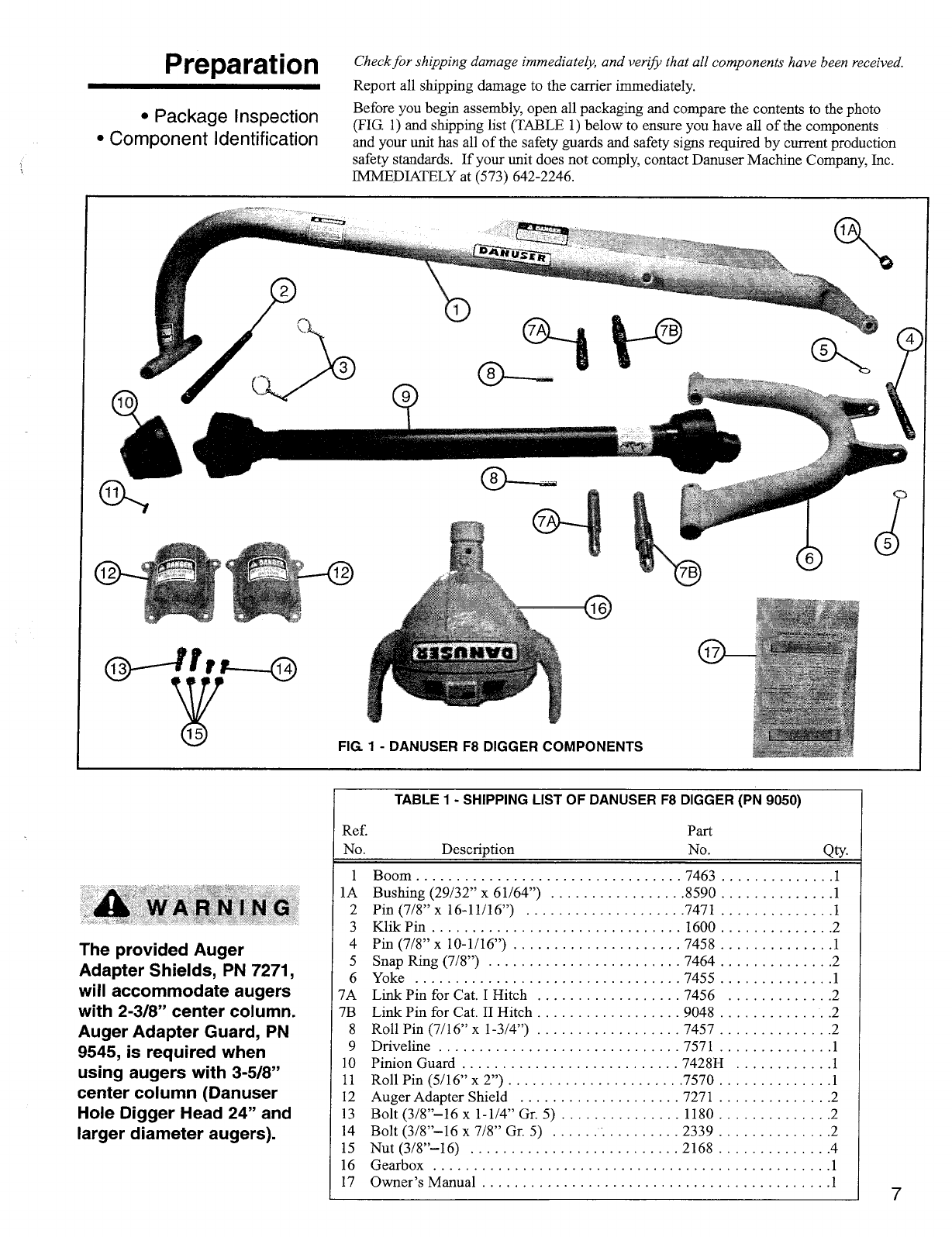
TABLE 1 - SHIPPING LIST OF DANUSER F8 DIGGER (PN 9050)
Ref.
No.
Description
Part
No.
QtY.
1
Boom
7463
1
1 A
Bushing (29/32" x 61/64")
8590
1
2
Pin (7/8" x 16-11/16")
7471
1
3
Klik Pin
1600
2
4
Pin (7/8" x 10-1/16")
7458
1
5
Snap Ring (7/8")
7464
2
6
Yoke
7455
1
7A
Link Pin for Cat. I Hitch
7456
2
7B
Link Pin for Cat. II Hitch
9048
2
8
Roll Pin (7/16" x 1-3/4")
7457
2
9
Driveline
7571
1
10
Pinion Guard
742811
1
11
Roll Pin (5/16" x 2")
7570
1
12
Auger Adapter Shield
7271
2
13
Bolt (3/8"-16 x 1-1/4" Gr. 5)
1180
2
14
Bolt (318"-16 x 7/8" Gr. 5)
2339
2
15
Nut (3/8"-16)
2168
4
16
Gearbox
1
17
Owner's Manual
1
7
Preparation
Check for shipping damage immediately, and verib) that all components have been received.
Report all shipping damage to the carrier immediately.
Before you begin assembly, open all packaging and compare the contents to the photo
(FIG 1) and shipping list (TABLE 1) below to ensure you have all of the components
and your unit has all of the safety guards and safety signs required by current production
safety standards. If your unit does not comply, contact Danuser Machine Company, Inc.
IMMEDIATELY at (573) 642-2246.
•Package Inspection
•
Component Identification
WARNING
The provided Auger
Adapter Shields, PN 7271,
will accommodate augers
with 2-3/8" center column.
Auger Adapter Guard, PN
9545, is required when
using augers with 3-5/8"
center column (Danuser
Hole Digger Head 24" and
larger diameter augers).
= Safety Sign Location
2168
7271
2339 1180
7467
7456
8590
9048
Description
The Danuser F8 Digger is built to the exacting standards of high quality which have
become synonymous with the name Danuser. The F8 Digger is designed for one-man
operation from the tractor seat to "Dig Holes Sitting Down". The precision-cut steel
gears, heavy-duty roller bearings, cast steel gear housing and heavy tubular crane boom
all form an integrated design to provide utility and reliability. The F8 Digger is designed
for 40 horsepower and above, Category I or II three-point hitch, 540 RPM PTO tractors
using sway stabilizers. The digger has a 2-9/16 inch round spindle for auger attachment.
Augers are available in lengths of 40 and 52 inches, and auger extensions are available in
lengths of 7, 14, and 21 inches. Auger diameters range from 4 to 30 inches. Auger
diameter must not exceed 30 inches. Danuser augers are built with special wear-resistant
steel on the lower flights, replaceable cutting edges, and replaceable points. A special
retaining bolt feature in Danuser augers keeps the auger in place on the spindle should the
shear bolt release. Read and understand this manual and the manual for your tractor
before attempting to assemble, install, or operate this post hole digger. If you have any
questions, contact your dealer or Danuser Machine Company, Inc. at (573) 642-2246.
Assembly &
Installation
•
Description
•
Recommended Tools
•
Instructions
Recommended Tools
•
Snap ring pliers (expanding)
•Hammer or mallet
•
Roll pin punch
•
Emery cloth (for removal of excess paint)
• 9/16" wrenches and 3/4" wrenches
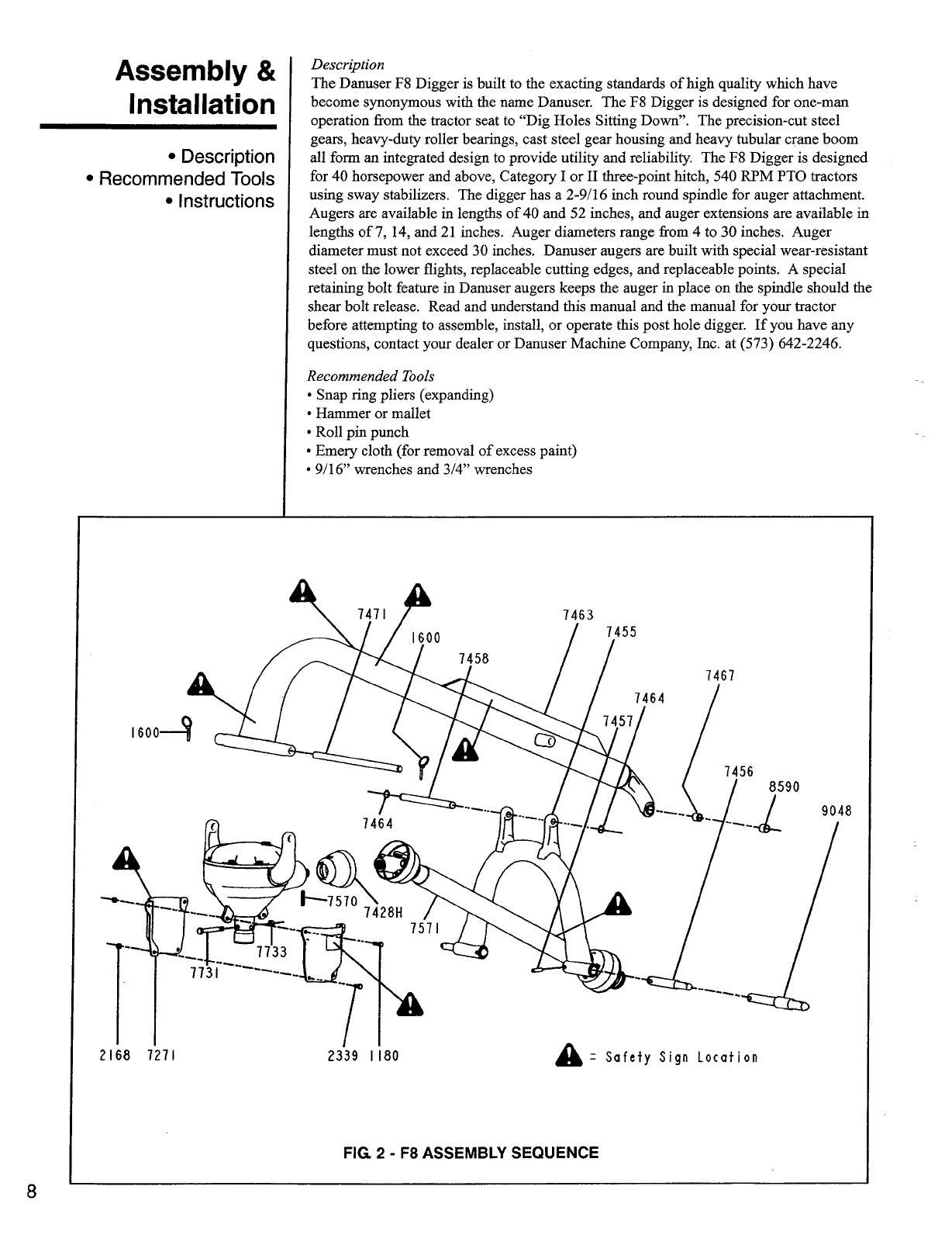
FIG. 2
-
F8 ASSEMBLY SEQUENCE
8
Assembly &
Installation
(continued)
Personal protection
equipment including hard
hat, safety glasses, safety
shoes, and gloves are
recommended during
assembly, installation,
operation, adjustment,
maintenance, repair,
removal, or movement of
the digger. Do not allow
long hair, loose fitting
clothing, or jewelry to be
around moving parts.
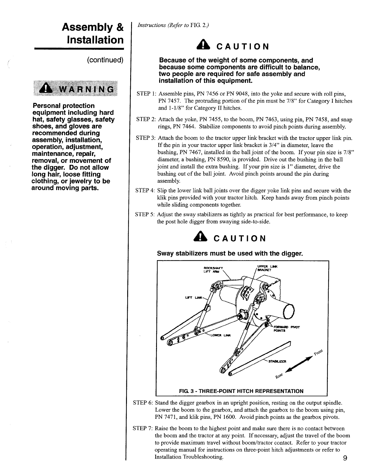
FIG. 3 - THREE-POINT HITCH REPRESENTATION
Instructions (Refer to
FIG. 2.)
A
CAUTION
Because of the weight of some components, and
because some components are difficult to balance,
two people are required for safe assembly and
installation of this equipment.
STEP 1: Assemble pins, PN 7456 or PN 9048, into the yoke and secure with roll pins,
PN 7457. The protruding portion of the pin must be 7/8" for Category I hitches
and 1-1/8" for Category II hitches.
STEP 2: Attach the yoke, PN 7455, to the boom, PN 7463, using pin, PN 7458, and snap
rings, PN 7464. Stabilize components to avoid pinch points during assembly.
STEP 3: Attach the boom to the tractor upper link bracket with the tractor upper link pin.
If the pin in your tractor upper link bracket is 3/4" in diameter, leave the
bushing, PN 7467, installed in the ball joint of the boom. If your pin size is 7/8"
diameter, a bushing, PN 8590, is provided. Drive out the bushing in the ball
joint and install the extra bushing. If your pin size is 1" diameter, drive the
bushing out of the ball joint. Avoid pinch points around the pin during
assembly.
STEP 4: Slip the lower link ball joints over the digger yoke link pins and secure with the
klik pins provided with your tractor hitch. Keep hands away from pinch points
while sliding components together.
STEP 5: Adjust the sway stabilizers as tightly as practical for best performance, to keep
the post hole digger from swaying side-to-side.
A
CAUTION
Sway stabilizers must be used with the digger.
STEP 6: Stand the digger gearbox in an upright position, resting on the output spindle.
Lower the boom to the gearbox, and attach the gearbox to the boom using pin,
PN 7471, and klik pins, PN 1600. Avoid pinch points as the gearbox pivots.
STEP 7: Raise the boom to the highest point and make sure there is no contact between
the boom and the tractor at any point. If necessary, adjust the travel of the boom
to provide maximum travel without boom/tractor contact. Refer to your tractor
operating manual for instructions on three-point hitch adjustments or refer to
Installation Troubleshooting.
9
I NOTE I
Because of tight manufacturing tolerances, it may be helpful to slide the
driveline over the pinion splines several times to make assembly easier
before proceeding with STEP 10.
Assembly &
Installation
STEP 8: Grease the inside of the auger adapter liberally, and attach the auger with the
Danuser 1/2"-13 x 4" (3/4" of thread) special shear bolt, PN 7731, and nut,
PN 7733 (see page 19). NEVER use a bolt longer than 4".
Each time an auger or auger extension is attached to the gearbox, the
inside of the auger adapter should be coated liberally with grease.
I NOTE I
STEP 9: Install the special 1/2-13 x 7/16" retaining bolt, PN 7676, which keeps the
auger connected to the gearbox spindle if the shear bolt breaks.
To prevent damaging the driveline and safety shields when removing the
digger from the tractor, disconnect the driveline from the tractor PTO
before lowering the digger to the ground.
Refer to your tractor operating manual for instructions on tractor operation,
tire inflation, and safety when using a three-point hitch mounted implement.
The gearbox of the Danuser F8 Digger has been filled at the factory with
three pounds of Texaco MultiFax-EP2 grease. When adding grease to the
gearbox, add Texaco MultiFax-EP2 or equivalent.
10
(continued)
FIG. 6 - AUGER ADAPTER
GUARD INSTALLED
FIG. 4 - PINION GUARD
FIG. 5 - RETRACT RING FOR
INSTALLATION
I NOTE I
I NOTE I
I
NOTE
I
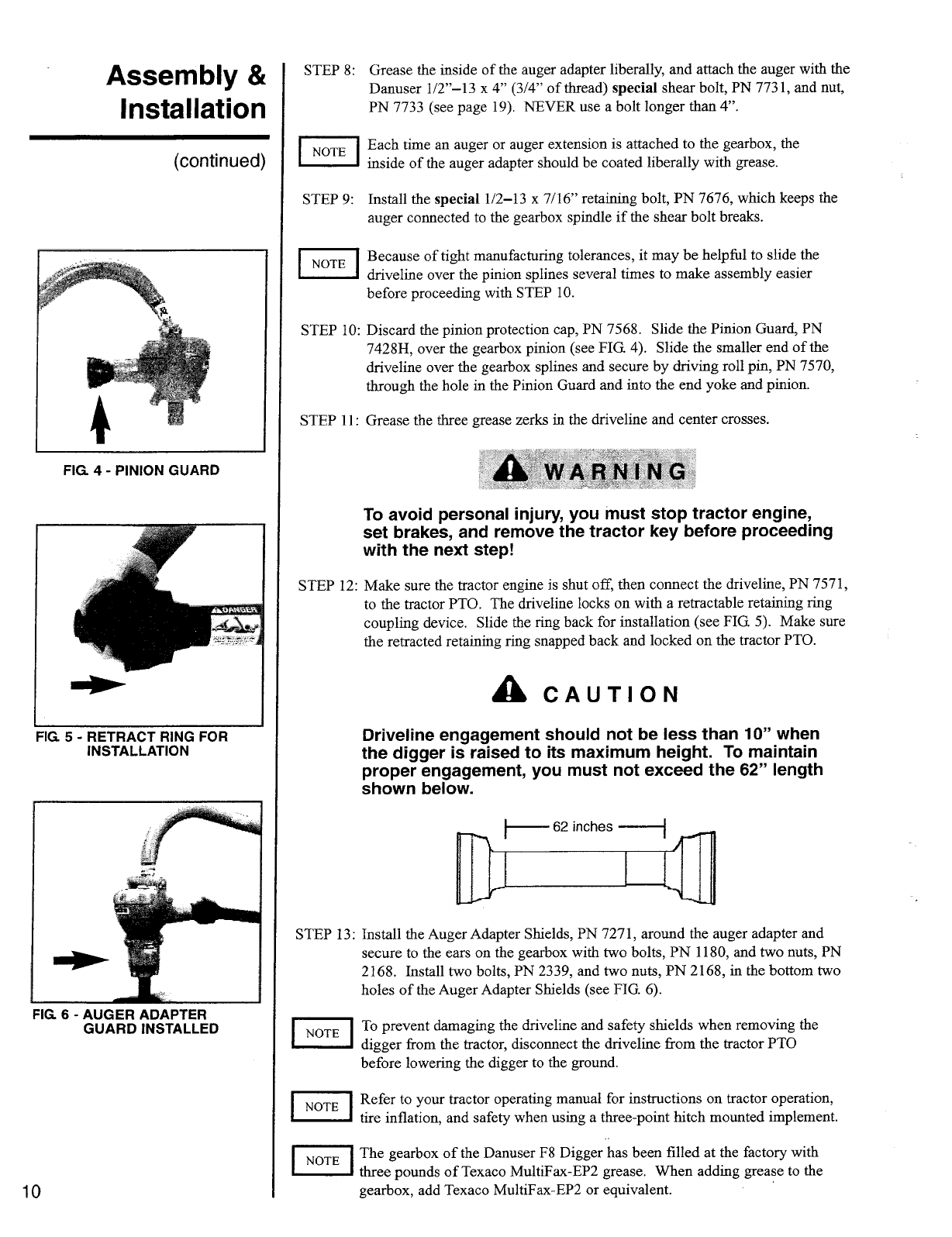
STEP 10: Discard the pinion protection cap, PN 7568. Slide the Pinion Guard, PN
7428H, over the gearbox pinion (see FIG 4). Slide the smaller end of the
driveline over the gearbox splines and secure by driving roll pin, PN 7570,
through the hole in the Pinion Guard and into the end yoke and pinion.
STEP 11: Grease the three grease zerks in the driveline and center crosses.
a
WARNING
To avoid personal injury, you must stop tractor engine,
set brakes, and remove the tractor key before proceeding
with the next step!
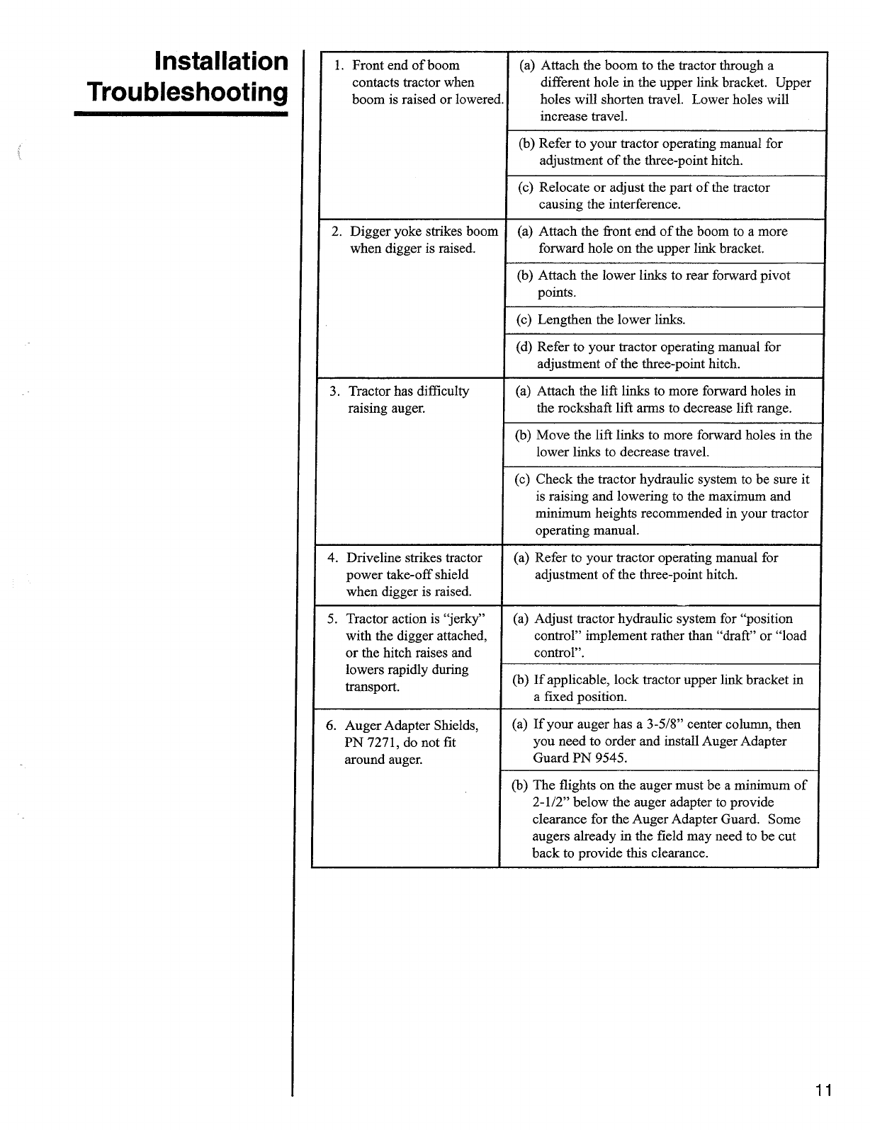
STEP 12: Make sure the tractor engine is shut off, then connect the driveline, PN 7571,
to the tractor PTO. The driveline locks on with a retractable retaining ring
coupling device. Slide the ring back for installation (see FIG. 5). Make sure
the retracted retaining ring snapped back and locked on the tractor PTO.
A
CAUTION
Driveline engagement should not be less than 10" when
the digger is raised to its maximum height. To maintain
proper engagement, you must not exceed the 62" length
shown below.
I
-- 62 inches —I
■■■
1..
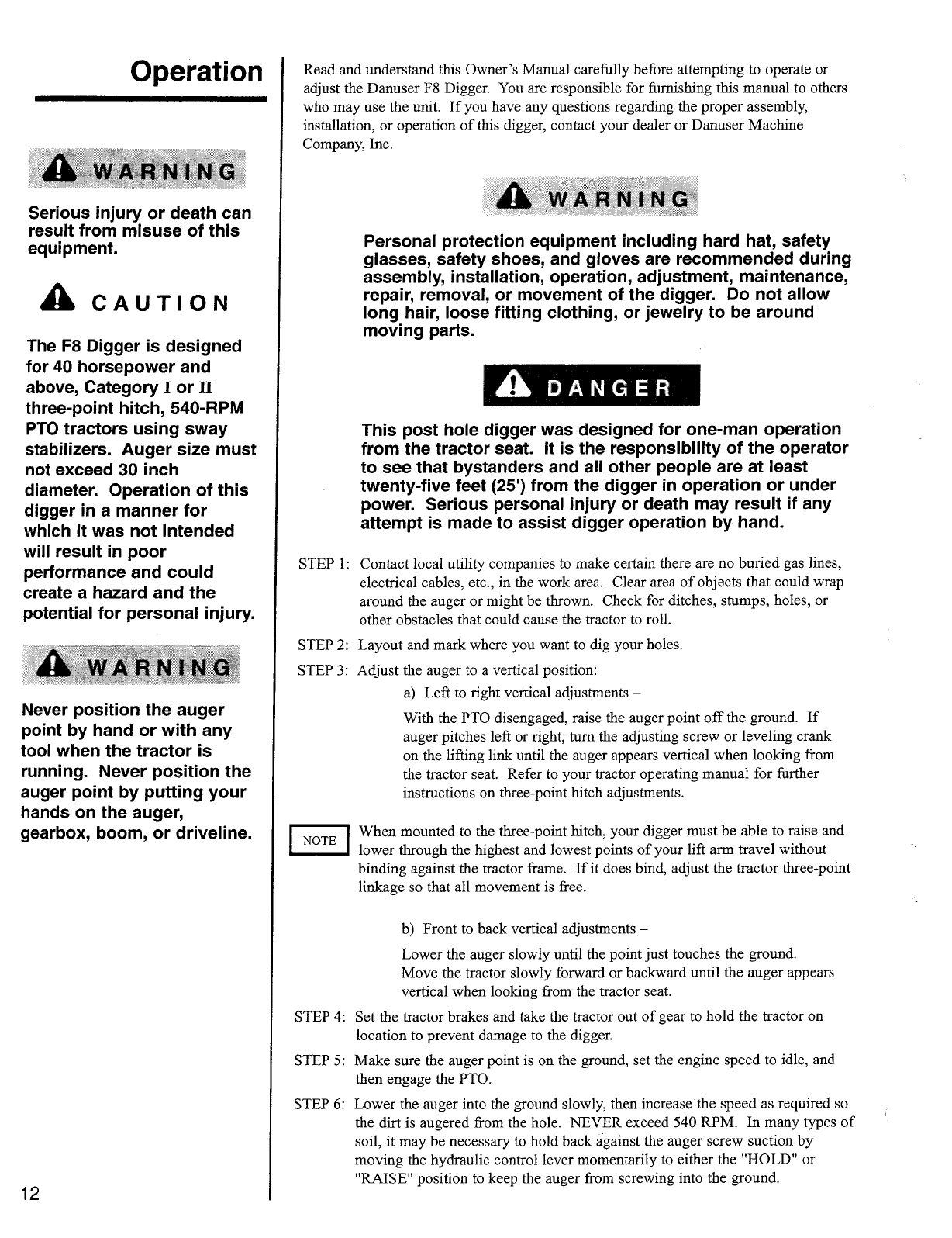
STEP 13: Install the Auger Adapter Shields, PN 7271, around the auger adapter and
secure to the ears on the gearbox with two bolts, PN 1180, and two nuts, PN
2168. Install two bolts, PN 2339, and two nuts, PN 2168, in the bottom two
holes of the Auger Adapter Shields (see FIG. 6).
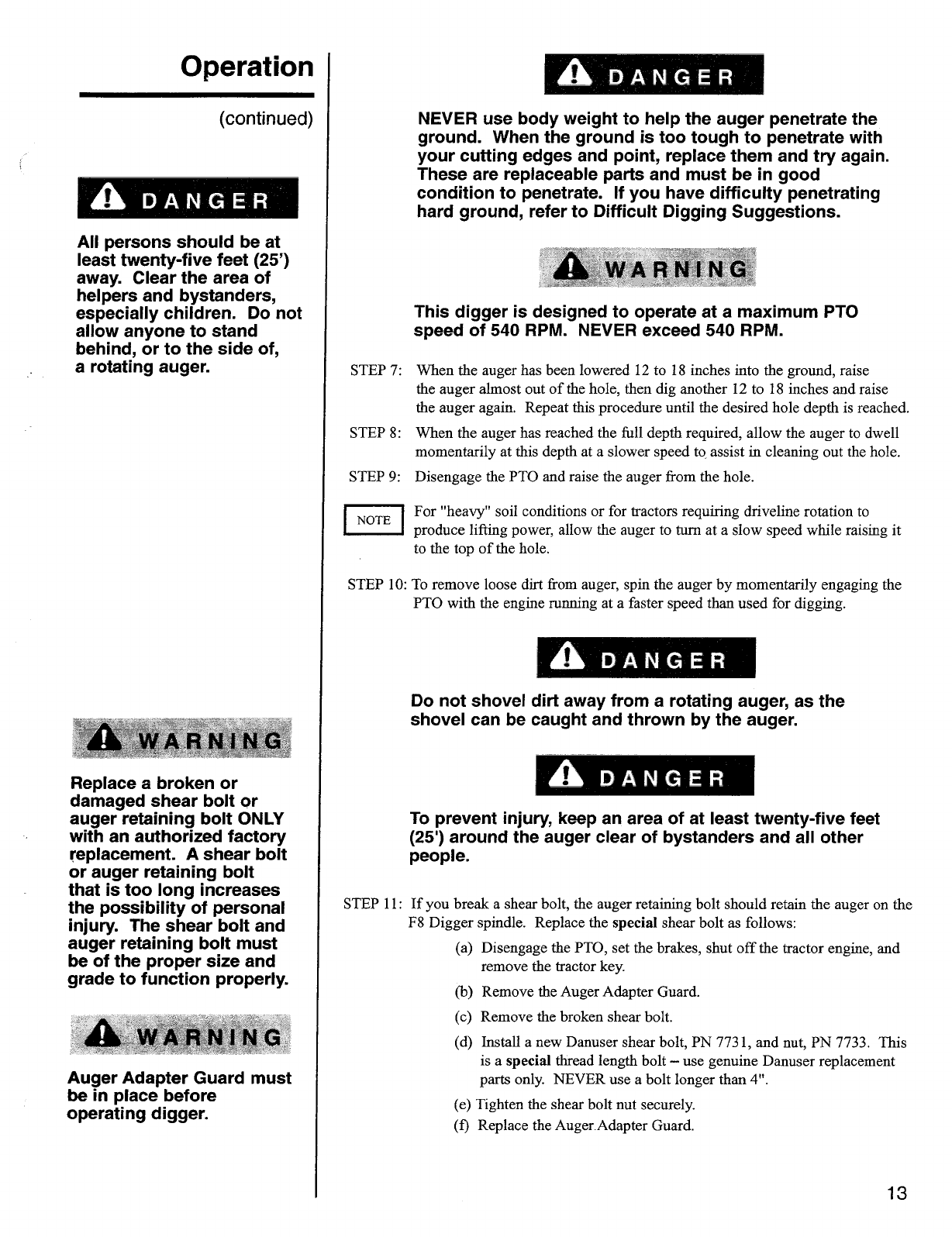
1. Front end of boom
contacts tractor when
boom is raised or lowered,
(a)
Attach the boom to the tractor through a
different hole in the upper link bracket. Upper
holes will shorten travel. Lower holes will
increase travel.
(b)
Refer to your tractor operating manual for
adjustment of the three-point hitch.
(c)
Relocate or adjust the part of the tractor
causing the interference.
2. Digger yoke strikes boom
when digger is raised,
(a)
Attach the front end of the boom to a more
forward hole on the upper link bracket.
(b)
Attach the lower links to rear forward pivot
points.
(c)
Lengthen the lower links.
(d)
Refer to your tractor operating manual for
adjustment of the three-point hitch.
3. Tractor has difficulty
raising auger.
(a)
Attach the lift links to more forward holes in
the rockshaft lift arms to decrease lift range.
(b)
Move the lift links to more forward holes in the
lower links to decrease travel.
(c)
Check the tractor hydraulic system to be sure it
is raising and lowering to the maximum and
minimum heights recommended in your tractor
operating manual.
4. Driveline strikes tractor
power take-off shield
when digger is raised.
(a) Refer to your tractor operating manual for
adjustment of the three-point hitch.
5. Tractor action is "jerky"
with the digger attached,
or the hitch raises and
(a)
Adjust tractor hydraulic system for "position
control" implement rather than "draft" or "load
control".
lowers rapidly during
transport .
(b)
If applicable, lock tractor upper link bracket in
a fixed position.
6. Auger Adapter Shields,
PN 7271, do not fit
around auger.
(a)
If your auger has a 3-5/8" center column, then
you need to order and install Auger Adapter
Guard PN 9545.
(b)
The flights on the auger must be a minimum of
2-1/2" below the auger adapter to provide
clearance for the Auger Adapter Guard. Some
augers already in the field may need to be cut
back to provide this clearance.
11
I
NOTE
I
STEP 4:
STEP 5:
STEP 6:
Read and understand this Owner's Manual carefully before attempting to operate or
adjust the Danuser F8 Digger. You are responsible for furnishing this manual to others
who may use the unit. If you have any questions regarding the proper assembly,
installation, or operation of this digger, contact your dealer or Danuser Machine
Company, Inc.
A
WARNING
Personal protection equipment including hard hat, safety
glasses, safety shoes, and gloves are recommended during
assembly, installation, operation, adjustment, maintenance,
repair, removal, or movement of the digger. Do not allow
long hair, loose fitting clothing, or jewelry to be around
moving parts.
A
DANGER
This post hole digger was designed for one-man operation
from the tractor seat. It is the responsibility of the operator
to see that bystanders and all other people are at least
twenty-five feet (25') from the digger in operation or under
power. Serious personal injury or death may result if any
attempt is made to assist digger operation by hand.
STEP 1: Contact local utility companies to make certain there are no buried gas lines,
electrical cables, etc., in the work area. Clear area of objects that could wrap
around the auger or might be thrown. Check for ditches, stumps, holes, or
other obstacles that could cause the tractor to roll.
STEP 2: Layout and mark where you want to dig your holes.
STEP 3: Adjust the auger to a vertical position:
a) Left to right vertical adjustments —
With the PTO disengaged, raise the auger point off the ground. If
auger pitches left or right, turn the adjusting screw or leveling crank
on the lifting link until the auger appears vertical when looking from
the tractor seat. Refer to your tractor operating manual for further
instructions on three-point hitch adjustments.
When mounted to the three-point hitch, your digger must be able to raise and
lower through the highest and lowest points of your lift arm travel without
binding against the tractor frame. If it does bind, adjust the tractor three-point
linkage so that all movement is free.
b) Front to back vertical adjustments —
Lower the auger slowly until the point just touches the ground.
Move the tractor slowly forward or backward until the auger appears
vertical when looking from the tractor seat.
Set the tractor brakes and take the tractor out of gear to hold the tractor on
location to prevent damage to the digger.
Make sure the auger point is on the ground, set the engine speed to idle, and
then engage the PTO.
Lower the auger into the ground slowly, then increase the speed as required so
the dirt is augered from the hole. NEVER exceed 540 RPM. In many types of
soil, it may be necessary to hold back against the auger screw suction by
moving the hydraulic control lever momentarily to either the "HOLD" or
"RAISE" position to keep the auger from screwing into the ground.
Operation
A
WARNING
Serious injury or death can
result from misuse of this
equipment.
A
CAUTION
The F8 Digger is designed
for 40 horsepower and
above, Category I or II
three-point hitch, 540-RPM
PTO tractors using sway
stabilizers. Auger size must
not exceed 30 inch
diameter. Operation of this
digger in a manner for
which it was not intended
will result in poor
performance and could
create a hazard and the
potential for personal injury.
A
WARNING
Never position the auger
point by hand or with any
tool when the tractor is
running. Never position the
auger point by putting your
hands on the auger,
gearbox, boom, or driveline.
12
NEVER use body weight to help the auger penetrate the
ground. When the ground is too tough to penetrate with
your cutting edges and point, replace them and try again.
These are replaceable parts and must be in good
condition to penetrate. If you have difficulty penetrating
hard ground, refer to Difficult Digging Suggestions.
A
WARNING
This digger is designed to operate at a maximum PTO
speed of 540 RPM. NEVER exceed 540 RPM.
STEP 7: When the auger has been lowered 12 to 18 inches into the ground, raise
the auger almost out of the hole, then dig another 12 to 18 inches and raise
the auger again. Repeat this procedure until the desired hole depth is reached.
STEP 8: When the auger has reached the full depth required, allow the auger to dwell
momentarily at this depth at a slower speed to assist in cleaning out the hole.
S I EP 9: Disengage the PTO and raise the auger from the hole.
I
NOTE
I
For "heavy" soil conditions or for tractors requiring driveline rotation to
produce lifting power, allow the auger to turn at a slow speed while raising it
to the top of the hole.
STEP 10: To remove loose dirt from auger, spin the auger by momentarily engaging the
PTO with the engine running at a faster speed than used for digging.
A
DANGER
Do not shovel dirt away from a rotating auger, as the
shovel can be caught and thrown by the auger.
DANG R
To prevent injury, keep an area of at least twenty-five feet
(25') around the auger clear of bystanders and all other
people.
STEP 11: If you break a shear bolt, the auger retaining bolt should retain the auger on the
F8 Digger spindle. Replace the special shear bolt as follows:
(a)
Disengage the PTO, set the brakes, shut off the tractor engine, and
remove the tractor key.
(b)
Remove the Auger Adapter Guard.
(c) Remove the broken shear bolt.
(d)
Install a new Danuser shear bolt, PN 7731, and nut, PN 7733. This
is a special thread length bolt — use genuine Danuser replacement
parts only. NEVER use a bolt longer than 4".
(e)
Tighten the shear bolt nut securely.
(f) Replace the Auger Adapter Guard.
13
Operation
(continued)
A
DANGER
All persons should be at
least twenty-five feet (25')
away. Clear the area of
helpers and bystanders,
especially children. Do not
allow anyone to stand
behind, or to the side of,
a rotating auger.
A
WARNING
Replace a broken or
damaged shear bolt or
auger retaining bolt ONLY
with an authorized factory
replacement. A shear bolt
or auger retaining bolt
that is too long increases
the possibility of personal
injury. The shear bolt and
auger retaining bolt must
be of the proper size and
grade to function properly.
a
WARNING
Auger Adapter Guard must
be in place before
operating digger.
DANGER
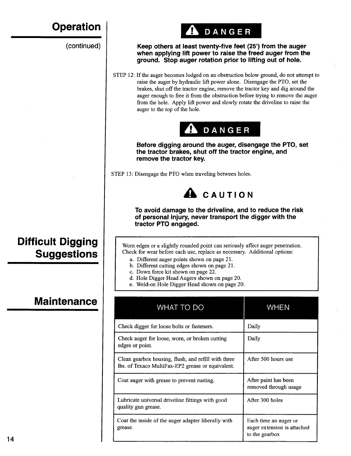
Keep others at least twenty-five feet (25') from the auger
when applying lift power to raise the freed auger from the
ground. Stop auger rotation prior to lifting out of hole.
STEP 12: If the auger becomes lodged on an obstruction below ground, do not attempt to
raise the auger by hydraulic lift power alone. Disengage the PTO, set the
brakes, shut off the tractor engine, remove the tractor key and dig around the
auger enough to free it from the obstruction before trying to remove the auger
from the hole. Apply lift power and slowly rotate the driveline to raise the
auger to the top of the hole.
A
DANGER
Before digging around the auger, disengage the PTO, set
the tractor brakes, shut off the tractor engine, and
remove the tractor key.
STEP 13: Disengage the PTO when traveling between holes.
A
CAUTION
To avoid damage to the driveline, and to reduce the risk
of personal injury, never transport the digger with the
tractor PTO engaged.
Worn edges or a slightly rounded point can seriously affect auger penetration.
Check for wear before each use, replace as necessary. Additional options:
a. Different auger points shown on page 21.
b.
Different cutting edges shown on page 21.
c. Down force kit shown on page 22.
d. Hole Digger Head Augers shown on page 20.
e. Weld-on Hole Digger Head shown on page 20.
WHAT TO DO
Check digger for loose bolts or fasteners.
WHEN
Daily
Check auger for loose, worn, or broken cutting
edges or point.
Daily
Clean gearbox housing, flush, and refill with three
After 500 hours use
lbs. of Texaco MuiliFax-EP2 grease or equivalent.
Coat auger with grease to prevent rusting.
After paint has been
removed through usage
Lubricate universal driveline fittings with good
quality gun grease.
After 300 holes
Coat the inside of the auger adapter liberally with
grease.
Each time an auger or
auger extension is attached
to the gearbox
Operation
(continued)
Difficult Digging
Suggestions
Maintenance
14
WOODS'•
Serial Number
Decals and
Safety Signs
10e
.
:4
,
1
•
Mal
add
widsmsla;rd maser s romusl *breams
art Operas
•
-
aea :twit me
Sabra:tar si
•
rasu
1
• weirdo
18 fasts lari kap
inlaid or le kaka ago powil u•••
rapt
•
FAali Tiny tall allbor. autiori Wad
.eq
2
_
TO PREVENT SERIOUS INJURY OR &LAM
Si'
no
Ave.r1c.
ino
,
:ts se
vAere
-
yoe tk.m
,
•
..iIcipe/
-
CV!' .
,
V.Ortet
,
Fleael awl ..a/senImul [Amer -
1 runs] Wont
operating.
•
Divw•te
IsHy
FranH. Neer ..ta/.
•
May 1WI frani !Mitt% parts. Aem
FIWTt
•
DO
ern
dig
eInkri
,
d
RAN WM
IMINO cNeekin•
arai Adlit
,
rt vs.
t4ttv,
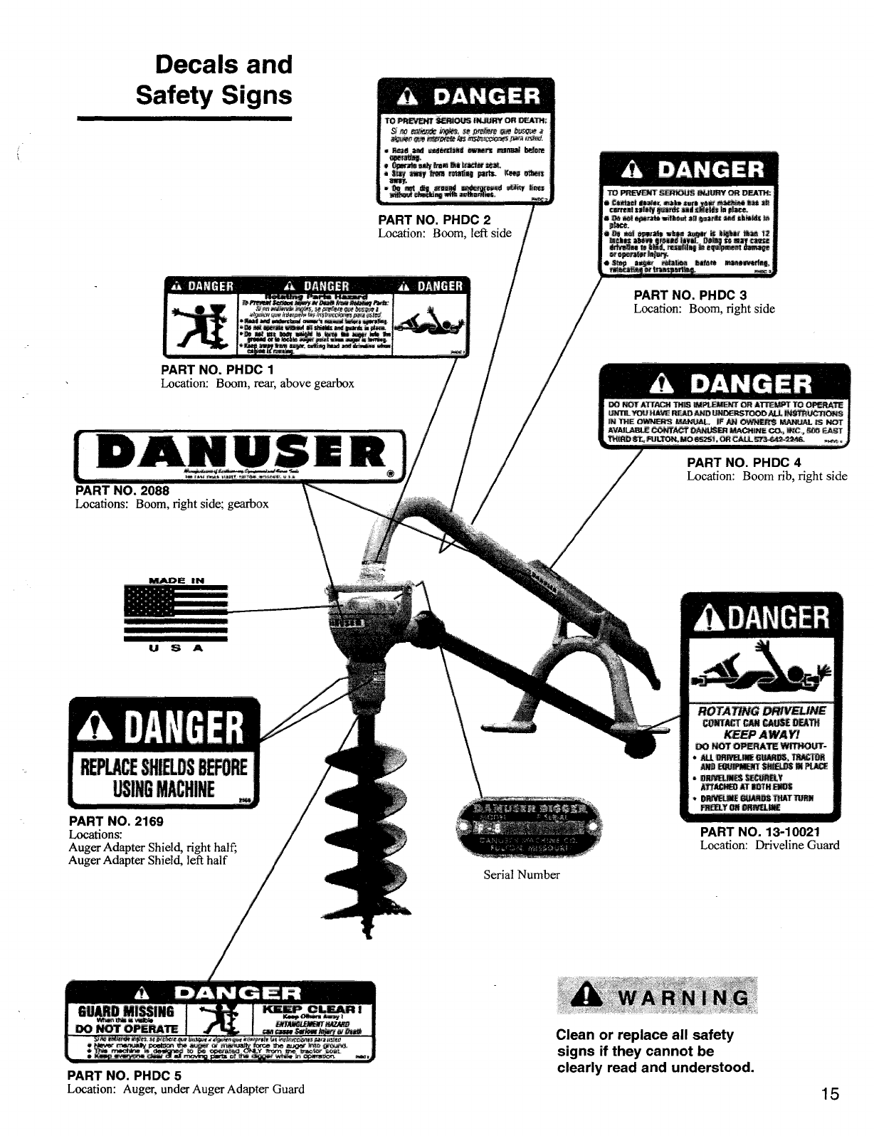
PART NO. PHDC 2
Location: Boom, left side
US INJURY OR DEAN:
•
tatIam I num,
grIA kW
Sure yI
maehite Ile ah
c !urea! :MINI pards ind shields In 1a
e
.
•
Do act
&wail wig tut an
elf
Ind slmdt
Place.
•
Pe Tkni •pluAL• Sten maw is Ii•IN !Ian I/
Man Wei grained 11111 T
I ri
Ray eans•
dittelite
se Ibid.. rmlItIng1
Orneril Milne
or Sperairpr
Injury,
Ittp annar rotation Im!/ ai Paler/earn
relmatinn Nlmasparliel.
PART NO. PHDC
3
Location: Boom, right side
PART NO. PHDC 1
Location: Boom, rear, above gearbox
DANGER
46 DANGER
a
DANGER
ANGER
DA.NUSE
ft
PART NO. 2088
Locations: Boom, right side; gearbox
PAAJDE
IN
INIIIIINMINIM1111111111•11111111111
S A
REPLACE SHIELDS BEFORE
USING MACHINE
DO NOT AT IACH THIS IMPLEMENT OR ATTEMPT TO OPERATE
UNTIL YOU I IAVE READ AND LPIOERSTOOD
ALL
INSTRUCTIONS
IN THE OWNEHts MANUAL . IF AN OWNERS MANUAL IS NOT
AVAILABLE
CONTACT DANUSER MACHINA CO., INC, SAD EAST
THIRD ST.,PULTON,A10•525I, OR CALL .773..G42-254A.
PART NO. PHDC 4
Location: Boom rib, right side
ROTATING DRIVELINE
CONTACT CAN
CAUSE DEAN
KEEP AWAY/
Do
NOT OPERATE
wrniour-
•
ALL
DRIVEUNE GOMM TRAI
ItI
AND EQUIP/KV MOLDS NI PLACE
•
mamma
SECURELY
ATTACHED
AT
BOTH ENDS
•
WWI INF WARM THAT MRS
FREELY ON ORAILINE
PART NO. 2169
Locations:
Auger Adapter Shield, right half;
Auger Adapter Shield, left half
PART NO. 13
-
10021
Location: Driveline Guard
GUARD MISSING
KEEP CLEAR
I
Neap °Wars
Sarni
Whin this
ia rabia
DO
HOT OPERATE
iNPUKLIAtflff WIZ4ffg
can cusp Sews On*,
or Osolib
srao lort,r4s r.r.ipes ICDcIez
c"..>
6.0•
r
.
wee:AS
ir25,011.1
STIO2761111v
postsx, It,.
Aa4y5,
rrronuallv tome ther.
2124)1f
orlo,no
frgbehk• C14313/11
,
GO
r
mom b
.
.< ve.evy
—or:whore
•orro.-o•
at.
PART NO. PHDC 5
Location: Auger, under Auger Adapter Guard
a
WARNING
Clean or replace all safety
signs if they cannot be
clearly read and understood.
15
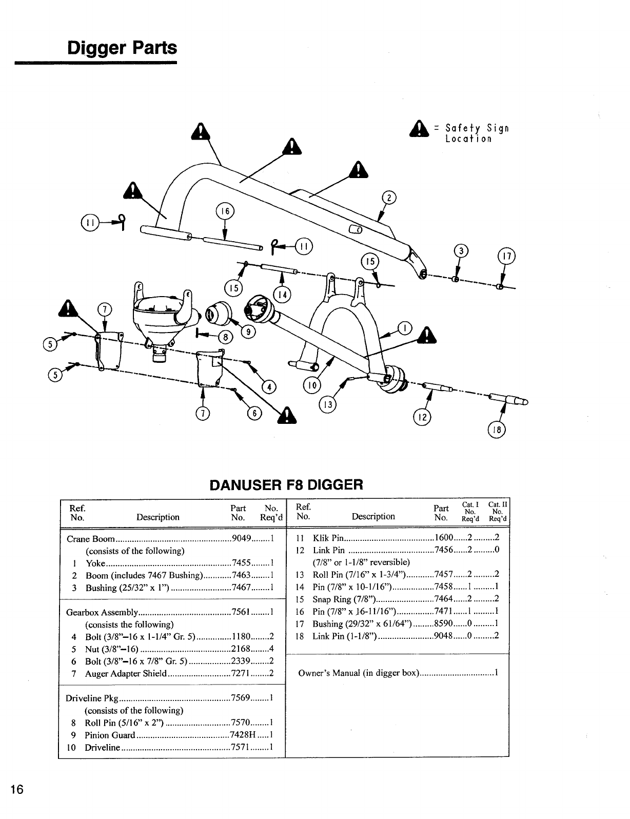
A=
Safety Sign
Location
Digger Parts
DANUSER F8 DIGGER
Ref.
No.
Description
Part
No.
No.
Reci'd
Ref.
No.
Description
Part
Na
Cat I
Cat. II
No
'
.
No.
Reci'd
Re01
Crane Boom
9049
1
11
Klik Pin
1600
2
2
(consists of the following)
12
Link Pin
7456
2
0
1
Yoke
7455
1
(7/8" or 1-1/8" reversible)
2
Boom (includes 7467 Bushing)
7463
1
13
Roll Pin (7/16" x 1-3/4")
7457
2
2
3
Bushing (25/32" x 1")
7467
1
14
Pin (7/8" x 10-1/16")
7458
1
1
15
Snap Ring (7/8")
7464
2
2
Gearbox Assembly
7561
1
16
Pin (7/8" x 16-11/16")
7471
1
1
(consists the following)
17
Bushing (29/32" x 61/64")
8590
0
1
4
Bolt (3/8"-16 x 1-1/4" Gr. 5)
1180
2
18
Link Pin (1-1/8")
9048
0
2
5
Nut (3/8"-16)
2168
4
6
Bolt (3/8"-16 x 7/8" Gr. 5)
2339
2
7
Auger Adapter Shield
7271
2
Owner's Manual (in digger box)
1
Driveline Pkg
(consists of the following)
7569
1
8
Roll Pin (5/16" x 2")
7570
1
9
Pinion Guard
7428H
1
10
Driveline
7571
1
16
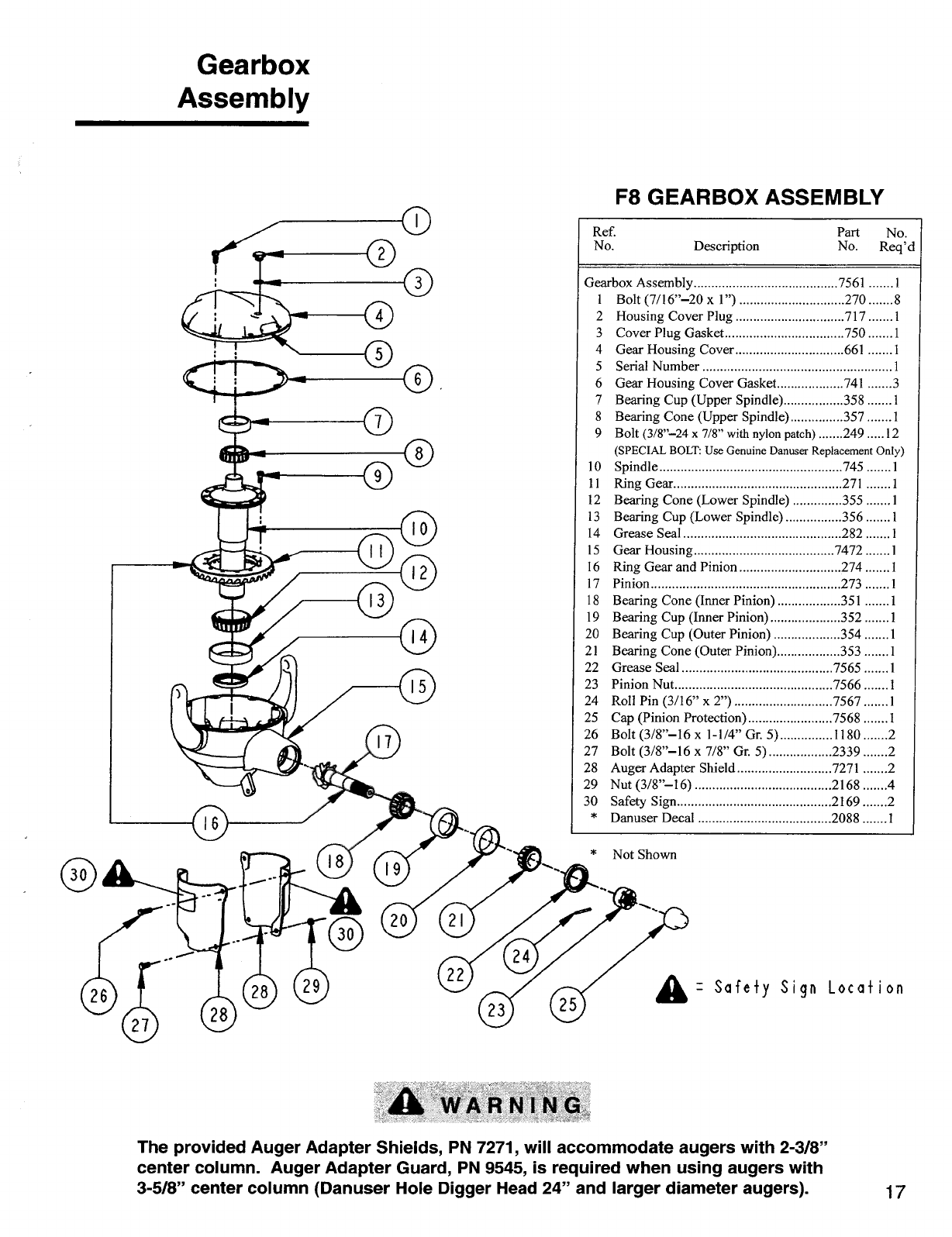
F8 GEARBOX ASSEMBLY
Ref.
No.
Description
Part
No.
No. Req'd
Gearbox
Assembly
21
22
23
24
25
26
27
28
29
30
*
Gearbox Assembly
7561
1
1 Bolt (7/16"-20 x 1")
270
8
2 Housing Cover Plug
717
1
3 Cover Plug Gasket
750
1
4 Gear Housing Cover
661
1
5 Serial Number
1
6 Gear Housing Cover Gasket
741
3
7 Bearing Cup (Upper Spindle)
358
1
8 Bearing Cone (Upper Spindle)
357
1
9 Bolt (3/8"-24 x 7/8" with nylon patch)
249
12
(SPECIAL BOLT: Use Genuine Danuser Replacement Only)
10 Spindle
745
1
11 Ring Gear
271
1
12 Bearing Cone (Lower Spindle)
355
1
13 Bearing Cup (Lower Spindle)
356
1
14 Grease Seal
282
1
15 Gear Housing
7472
1
16 Ring Gear and Pinion
274
1
17 Pinion
273
1
18 Bearing Cone (Inner Pinion)
351
1
19 Bearing Cup (Inner Pinion)
352
1
20 Bearing Cup (Outer Pinion)
354
1
Bearing Cone (Outer Pinion)
353
1
Grease Seal
7565
1
Pinion Nut
7566
1
Roll Pin (3/16" x 2")
7567
1
Cap (Pinion Protection)
7568
1
Bolt (3/8"-16 x 1-1/4" Gr. 5)
1180
2
Bolt (3/8"-16 x 7/8" Gr. 5)
2339
2
Auger Adapter Shield
7271
2
Nut (3/8"-16)
2168
4
Safety Sign
2169
2
Danuser Decal
2088
1
* Not Shown
= Safety Sign Location
41
WARNING
The provided Auger Adapter Shields, PN 7271, will accommodate augers with 2-3/8"
center column. Auger Adapter Guard, PN 9545, is required when using augers with
3-5/8" center column (Danuser Hole Digger Head 24" and larger diameter augers).
17
ADANGER
ROTATING ORIVELJNE
CONTACT CAN CAUSE DEATH
KEEP AWAY!
00 MOT
OPERATE WITHOUT-
•
ALL ORWEitki GUARDS, TRACTOR
AND EQUIPMENT SHIELDS WM=
•
DRIVE/WES SECURELY
ATTACHED AI uo
Di
EMS
•
DAMMUNE GUARDS THAT DOW
FREELY 1111 LIRALLIgE
//
a,
Safety Sign Location
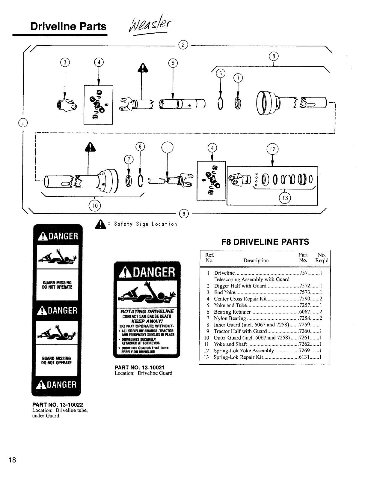
F8 DRIVELINE PARTS
Ref.
No.
Description
Part
No.
No.
Req'd
1
Driveline
7571
1
Telescoping Assembly with Guard
2
Digger Half with Guard
7572
1
3
End Yoke
7573
1
4
Center Cross Repair Kit
7590
2
5
Yoke and Tube
7257
1
6
Bearing Retainer
6067
2
7
Nylon Bearing
7258
2
8
Inner Guard (Mcl. 6067 and 7258)
7259
1
9
Tractor Half with Guard
7260
1
10
Outer Guard (incl. 6067 and 7258)
7261
1
11
Yoke and Shaft
7262
1
12
Spring-Lok Yoke Assembly
7269
1
13
Spring-Lok Repair Kit
6131
1
PART NO. 13-10021
Location: Driveline Guard
Driveline Parts
/04.c/er
PART NO. 13-10022
Location: Driveline tube,
under Guard
18
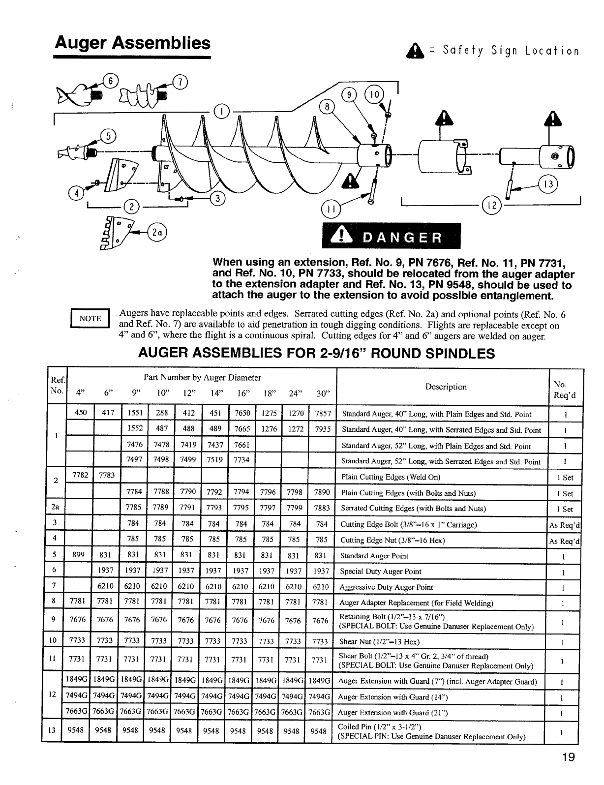
Auger Assemblies
=
Safety Sign Location
When using an extension, Ref. No. 9, PN 7676, Ref. No. 11, PN 7731,
and Ref. No. 10, PN 7733, should be relocated from the auger adapter
to the extension adapter and Ref. No. 13, PN 9548, should be used to
attach the auger to the extension to avoid possible entanglement.
Augers have replaceable points and edges. Serrated cutting edges (Ref. No. 2a) and optional points (Ref. No. 6
and Ref. No. 7) are available to aid penetration in tough digging conditions. Flights are replaceable except on
4" and 6", where the flight is a continuous spiral. Cutting edges for 4" and 6" augers are welded on auger.
AUGER ASSEMBLIES FOR 2-9/16" ROUND SPINDLES
I NOTE I
Ref.
No.
Part Number by Auger Diameter
4"
6"
9"
10"
12"
14"
16"
18"
24"
30"
Description
No.
Reci'd
I
450
417
1551
288
412
451
7650
1275 1270
7857
Standard Auger, 40" Long, with Plain Edges and Std. Point
1
1552
487
488
489
7665
1276
1272
7935
Standard Auger, 40" Long, with Serrated Edges and Std. Point
1
7476
7478
7419
7437
7661
Standard Auger, 52" Long, with Plain Edges and Std. Point
1
7497
7498
7499 7519
7734
Standard Auger, 52" Long, with Serrated Edges and Std. Point
1
2
7782
7783
Plain Cutting Edges (Weld On)
1 Set
7784
7788
7790 7792
7794 7796 7798
7890
Plain Cutting Edges (with Bolts and Nuts)
I Set
2a
7785 7789
7791
7793
7795
7797 7799 7883
Serrated Cutting Edges (with Bolts and Nuts)
I Set
3
784
784
784
784
784
784
784 784
Cutting Edge Bolt (3/8"-16 x 1" Carriage)
As Req'd
4
785
785
785
785
785
785
785
785
Cutting Edge Nut (3/8"-16 Hex)
As Req'd
5
899
831
831
831
831 831
831
831
831 831
Standard Auger Point
1
6
1937
1937
1937 1937
1937 1937
1937
1937
1937
Special Duty Auger Point
1
7
6210
6210
6210 6210
6210
6210
6210
6210 6210
Aggressive Duty Auger Point
1
8
7781
7781
7781 7781 7781 7781
7781
7781
7781
7781
Auger Adapter Replacement (for Field Welding)
1
9
7676 7676
7676
7676 7676
7676 7676
7676
7676
7676
Retaining Bolt (1/2"-13 x 7/16")
(SPECIAL BOLT: Use Genuine Danuser Replacement Only)
1
10
7733
7733
7733
7733 7733
7733
7733 7733 7733
7733
Shear Nut (1/2"-13 Hex)
1
11
7731
7731
7731
7731 7731
7731
7731
7731 7731
7731
Shear Bolt (1/2"-13 x 4" Gr. 2, 3/4" of thread)
(SPECIAL BOLT: Use Genuine Danuser Replacement Only)
1
1849G
I 849G
1849G
18496
1849G 1849G
18496
18490
18490
1849G
Auger Extension with Guard (7") (incl. Auger Adapter Guard)
I
12
74946
74946
74946
7494G 7494G
7494G
7494G 7494G 7494G
7494G
Auger Extension with Guard (14")
1
7663G
7663G
7663G
7663G
7663G 7663G
7663G
7663G 7663G
7663G
Auger Extension with Guard (21")
1
13
9548
9548
9548
9548
9548
9548
9548 9548
9548
9548
Coiled Pin (1/2" x 3-1/2")
(SPECIAL PIN: Use Genuine Danuser Replacement Only)
I
19
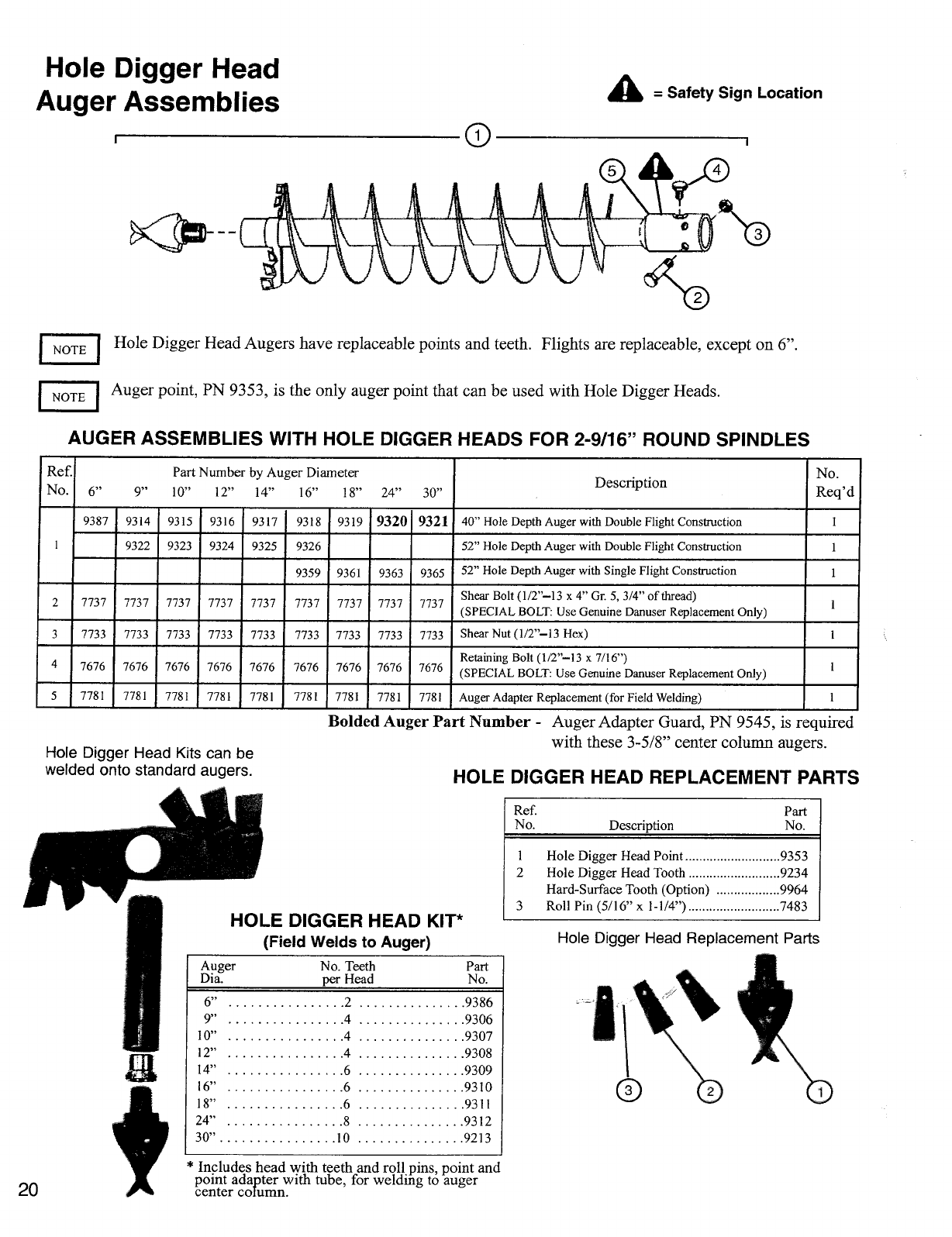
Hole Digger Head
Auger Assemblies
Safety Sign Location
NOTE I
Hole Digger Head Augers have replaceable points and teeth. Flights are replaceable, except on 6".
I NOTE I
Auger point, PN 9353, is the only auger point that can be used with Hole Digger Heads.
AUGER ASSEMBLIES WITH HOLE DIGGER HEADS FOR 2-9/16" ROUND SPINDLES
Ref.
No.
Part Number by Auger Diameter
6"
9"
10"
12"
14"
16"
18"
24"
30"
Description
No.
Req'd
1
9387
9314
9315
9316
9317
9318
9319
9320
9321
40" Hole Depth Auger with Double Flight Construction
1
9322
9323
9324 9325 9326
52" Hole Depth Auger with Double Flight Construction
1
9359
9361
9363
9365
52" Hole Depth Auger with Single Flight Construction
1
2
7737
7737 7737 7737
7737
7737
7737 7737
7737
Shear Bolt (1/2"-13 x 4" Gr. 5, 3/4" of thread)
(SPECIAL BOLT: Use Genuine Danuser Replacement Only)
1
3
7733
7733 7733 7733
7733
7733
7733
7733
7733
Shear Nut (
1
/
2
"
-1
3 Hex)
1
4
7676 7676 7676
7676
7676
7676 7676
7676
7676
Retaining Bolt (1/2"-13 x 7/16")
(SPECIAL BOLT: Use Genuine Danuser Replacement Only)
1
5
7781
7781
7781 7781
7781
7781
7781 7781
7781
Auger Adapter Replacement (for Field Welding)
1
Hole Digger Head Kits can be
welded onto standard augers.
Bolded Auger Part Number
-
Auger Adapter Guard, PN 9545, is required
with these 3-5/8" center column augers.
HOLE DIGGER HEAD REPLACEMENT PARTS
HOLE DIGGER HEAD KIT*
(Field Welds to Auger)
Auger
Dia.
No. Teeth
per Head
Part
No.
6"
2
9386
9"
4
9306
10"
4
9307
12"
4
9308
14"
6
9309
16"
6
9310
18"
6
9311
24"
8
9312
30"
10
9213
Ref.
Part
No.
Description
No.
1
Hole Digger Head Point
9353
2 Hole Digger Head Tooth
9234
Hard-Surface Tooth (Option)
9964
3
Roll Pin (5/16" x 1-1/4")
7483
Hole Digger Head Replacement Parts
20
* Includes head with teeth and roll
.
pins, point and
point adapter with tube, for welding to auger
center column.
Ref.
No.
Description
Part
No.
Ref.
No.
Description Part
No.
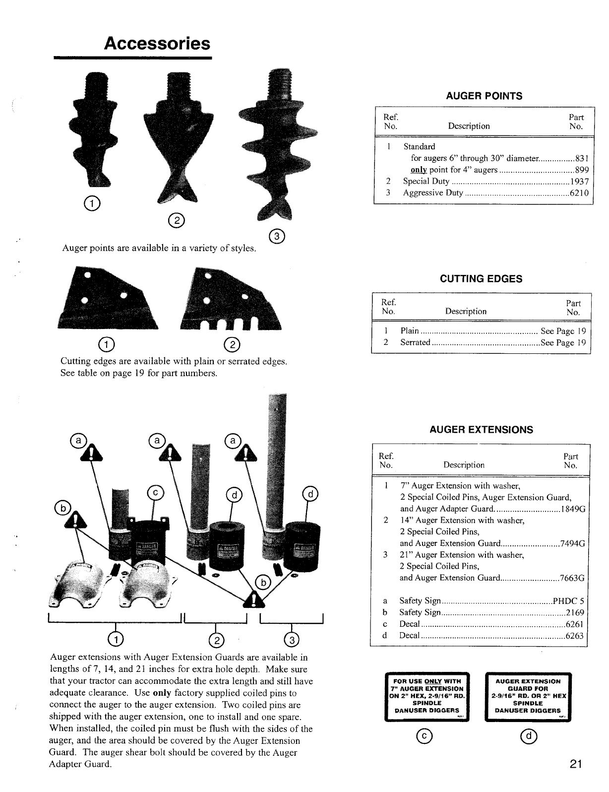
Auger points are available in a variety of styles.
AUGER POINTS
CUTTING EDGES
1
Standard
for augers 6" through 30" diameter
831
only
point for 4" augers
899
2 Special Duty
1937
3 Aggressive Duty
6210
1
Plain
See Page 19
2 Serrated
See Page 19
I FOR USE
ONLY
WITH
7" AUGER EXTENSION
ON 2" HEX, 2•9/16" RD.
SPINDLE
DANUSER DIGGERS
CM
S
I
AUGER EXTENSION
GUARD FOR
2-9/16" RD. OR 2" HEX
SPINDLE
DANUSER DIGGERS
...,
Accessories
Cutting edges are available with plain or serrated edges.
See table on page 19 for part numbers.
AUGER EXTENSIONS
Ref.
Part
No.
Description
No.
1 7" Auger Extension with washer,
2 Special Coiled Pins, Auger Extension Guard,
and Auger Adapter Guard
1849G
2 14" Auger Extension with washer,
2 Special Coiled Pins,
and Auger Extension Guard
7494G
3 21" Auger Extension with washer,
2 Special Coiled Pins,
and Auger Extension Guard
7663G
a Safety Sign
PHDC 5
b Safety Sign
2169
c Decal
6261
d Decal
6263
Auger extensions with Auger Extension Guards are available in
lengths of 7, 14, and 21 inches for extra hole depth. Make sure
that your tractor can accommodate the extra length and still have
adequate clearance. Use only factory supplied coiled pins to
connect the auger to the auger extension. Two coiled pins are
shipped with the auger extension, one to install and one spare.
When installed, the coiled pin must be flush with the sides of the
auger, and the area should be covered by the Auger Extension
Guard. The auger shear bolt should be covered by the Auger
Adapter Guard.
21
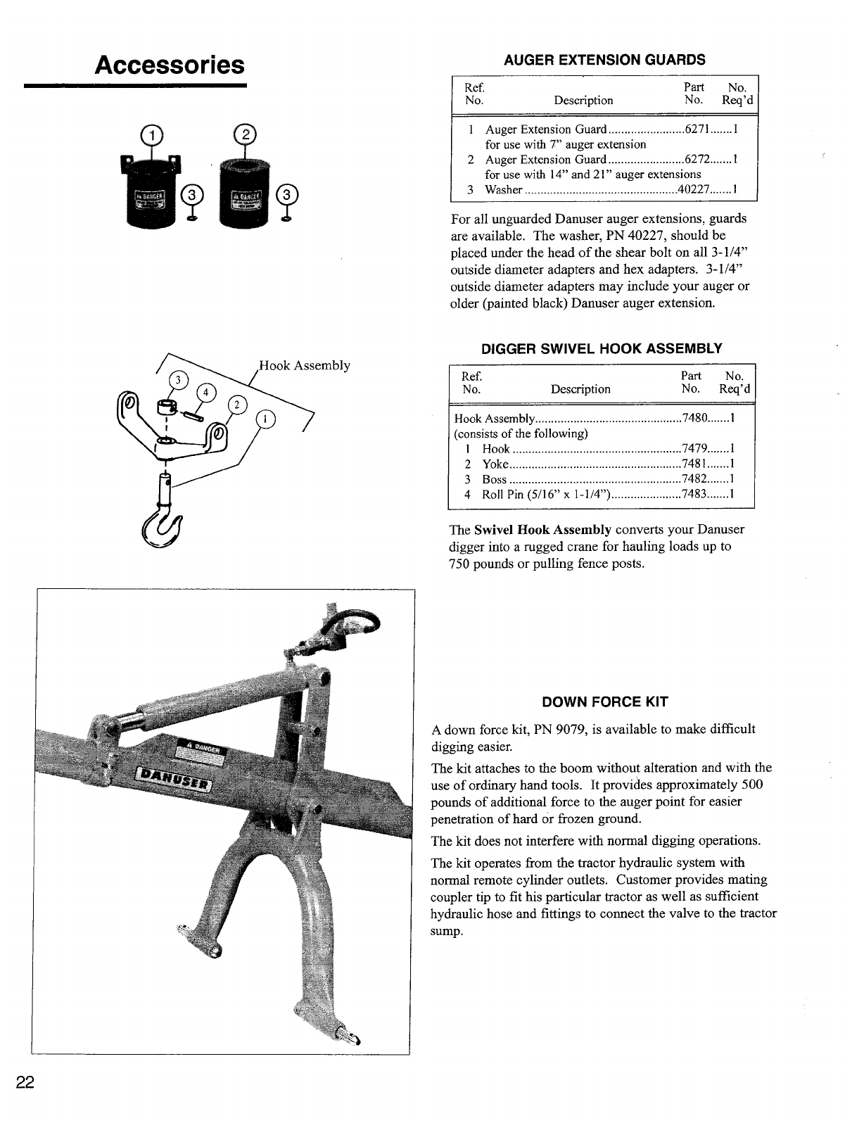
Hook Assembly
Accessories
AUGER EXTENSION GUARDS
Ref.
Part
No.
No.
Description
No. Req'd
1 Auger Extension Guard
6271
1
for use with 7" auger extension
2 Auger Extension Guard
6272
1
for use with 14" and 21" auger extensions
3 Washer
40227
1
For all unguarded Danuser auger extensions, guards
are available. The washer, PN 40227, should be
placed under the head of the shear bolt on all 3-1/4"
outside diameter adapters and hex adapters. 3-1/4"
outside diameter adapters may include your auger or
older (painted black) Danuser auger extension.
DIGGER SWIVEL HOOK ASSEMBLY
Ref.
No.
Description
Part
No.
No.
Req'd
Hook Assembly
(consists of the following)
1
Hook
7480
7479
1
1
2
Yoke
7481
1
3
Boss
7482
1
4
Roll Pin (5/16" x 1-1/4")
7483
1
The Swivel Hook Assembly converts your Danuser
digger into a rugged crane for hauling loads up to
750 pounds or pulling fence posts.
DOWN FORCE KIT
A down force kit, PN 9079, is available to make difficult
digging easier.
The kit attaches to the boom without alteration and with the
use of ordinary hand tools. It provides approximately 500
pounds of additional force to the auger point for easier
penetration of hard or frozen ground.
The kit does not interfere with normal digging operations.
The kit operates from the tractor hydraulic system with
normal remote cylinder outlets. Customer provides mating
coupler tip to fit his particular tractor as well as sufficient
hydraulic hose and fittings to connect the valve to the tractor
sump.
22
This Warranty is extended only to the original purchaser of our products. Danuser Machine Company,
Inc. warrants this product to be free from defects in material and workmanship for a period of one year,
with the exception of the G20/40 gearbox, which is warranted for a period of five years from the
purchase date from an authorized Danuser Dealer. The warranty period of the F8 gearbox and 8200,
8300, 8800, and 8900 hydraulic units (gearbox and housing) can be extended to five years if the
extension coupon and the WARRANTY REGISTRATION FORM & INSPECTION REPORT have
been completed and are on file at Danuser Machine Company, Inc. Start of the warranty period is
determined by purchase date given on your WARRANTY REGISTRATION FORM & INSPECTION
REPORT. Proof of purchase and serial number may be required.
1. Our obligation under this warranty is limited to repair or replacement at our factory of the part(s) of
Danuser products which Danuser Machine Company, Inc. determines to be defective. Our sole
obligation and your exclusive remedy under this warranty shall be limited to such repair and/or
replacement at our factory.
2.
This warranty shall not obligate Danuser Machine Company, Inc. to bear any cost of labor for field
replacement, testing, or adjustment.
3. Parts may not be returned without authorization by Danuser Machine Company, Inc.
4.
To file a warranty inspection claim, your dealer must contact his Danuser Distributor for a Service
Adjustment Request (SAR). The Danuser Distributor should complete this form and forward a copy
to Danuser Machine Company, Inc. If the return of the part(s) listed on the SAR is approved for
warranty inspection, Danuser will issue a SAR number for the return of parts. Your dealer should
then tag the part(s) with the SAR number and return the part(s) to Danuser. Shipments arriving at
our factory on a freight collect basis will be refused by our receiving depai
tment.
5. All parts returned under a warranty inspection claim must be returned PREPAID to our factory. The
freight charge will be credited, if the parts are determined by Danuser Machine Company, Inc. to be
defective.
6.
Products or parts thereof which, as determined by Danuser Machine Company, Inc.'s examination,
show wear from normal use, have been improperly operated, damaged by accident or negligence,
field repaired, or altered are not considered defective and are not covered by this warranty.
7. Some purchased components, including, but not limited to, hydraulic motors, valves, and cylinders,
are subject to the inspection and warranty of the respective manufacturer. Thus, delays in a warranty
determination can be expected while we await their decisions. NOTE: Hydraulic valves, motors,
and cylinders must arrive with all ports sealed from dirt and moisture. If they arrive with open ports,
the warranty is void and no inspection will be made.
8. The foregoing warranty is exclusive and in lieu of all other express warranties, if any, including the
implied warranties of merchantability and fitness for a particular purpose. It shall not extend beyond
the duration of the expressed warranty provided herein and the remedy for violations of any implied
warranty shall be limited repair or replacement of the defective product pursuant to the terms
contained herein. Danuser Machine Company, Inc. shall not be liable for any consequential or
incidental damages whatsoever.
9. We reserve the right to change our specifications and design at any time.
Danuser Machine Company, Inc.
500 East Third Street
P. 0. Box 368
Fulton, Missouri 65251-0368
Phone: (573) 642-2246
Fax:
(573) 642-2240
E-mail: sales@danuser.com
Website: www.danuser.com
Warranty
DANUSER MACHINE COMPANY, INC.
SERVICE ADJUSTMENT POLICY
LIMITED WARRANTY
DANUSER MACHINE COMPANY, INC.
Fulton, Missouri 65251-0368
Form No. 3026
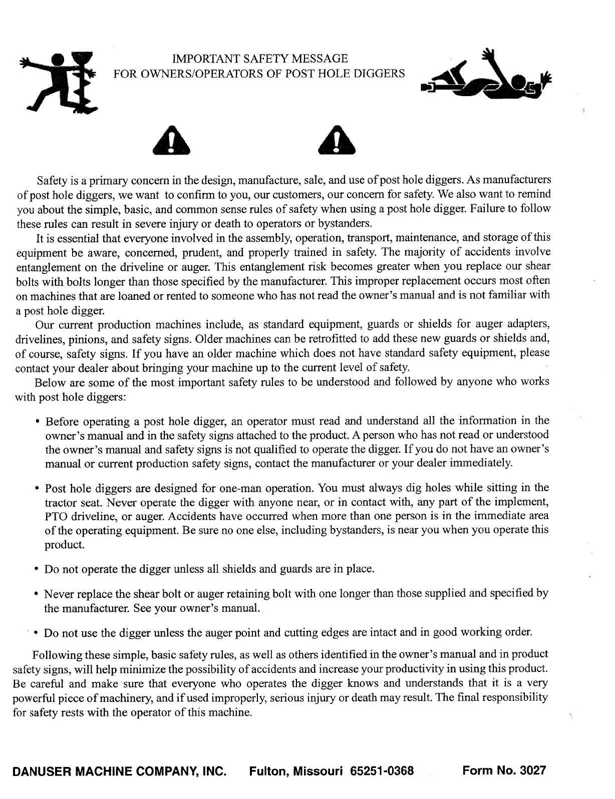
IMPORTANT SAFETY MESSAGE
FOR OWNERS/OPERATORS OF POST HOLE DIGGERS
Safety is a primary concern in the design, manufacture, sale, and use of post hole diggers. As manufacturers
of post hole diggers, we want to confirm to you, our customers, our concern for safety. We also want to remind
you about the simple, basic, and common sense rules of safety when using a post hole digger. Failure to follow
these rules can result in severe injury or death to operators or bystanders.
It is essential that everyone involved in the assembly, operation, transport, maintenance, and storage of this
equipment be aware, concerned, prudent, and properly trained in safety. The majority of accidents involve
entanglement on the driveline or auger. This entanglement risk becomes greater when you replace our shear
bolts with bolts longer than those specified by the manufacturer. This improper replacement occurs most often
on machines that are loaned or rented to someone who has not read the owner's manual and is not familiar with
a post hole digger.
Our current production machines include, as standard equipment, guards or shields for auger adapters,
drivelines, pinions, and safety signs. Older machines can be retrofitted to add these new guards or shields and,
of course, safety signs. If you have an older machine which does not have standard safety equipment, please
contact your dealer about bringing your machine up to the current level of safety.
Below are some of the most important safety rules to be understood and followed by anyone who works
with post hole diggers:
•
Before operating a post hole digger, an operator must read and understand all the information in the
owner's manual and in the safety signs attached to the product. A person who has not read or understood
the owner's manual and safety signs is not qualified to operate the digger. If you do not have an owner's
manual or current production safety signs, contact the manufacturer or your dealer immediately.
•
Post hole diggers are designed for one-man operation. You must always dig holes while sitting in the
tractor seat. Never operate the digger with anyone near, or in contact with, any part of the implement,
PTO driveline, or auger. Accidents have occurred when more than one person is in the immediate area
of the operating equipment. Be sure no one else, including bystanders, is near you when you operate this
product.
•
Do not operate the digger unless all shields and guards are in place.
•
Never replace the shear bolt or auger retaining bolt with one longer than those supplied and specified by
the manufacturer. See your owner's manual.
•
Do not use the digger unless the auger point and cutting edges are intact and in good working order.
Following these simple, basic safety rules, as well as others identified in the owner's manual and in product
safety signs,
will help minimize the possibility of accidents and increase your productivity in using this product.
Be careful and make sure that everyone who operates the digger knows and understands that it is a very
powerful piece of machinery, and if used improperly, serious injury or death may result. The final responsibility
for safety rests with the operator of this machine.
DANUSER MACHINE COMPANY, INC. Fulton, Missouri 65251-0368
Form No. 3027
